Embed Size (px)
Citation preview
STATE OF WISCONSIN Mail to:
Department of Safety and Professional Services PO Box 8368 1400 East Washington Avenue Madison WI 53708-8368 Madison WI 53703
E-mail: [email protected] Web: http://dsps.wi.gov
Governor Scott Walker Secretary Dave Ross Phone: 608-266-2112
COMMERCIAL BUILDING CODE COUNCIL MEETING
Room 121A, 1400 East Washington Avenue, Madison
Contact: Sandra Cleveland (608) 266-0797
April 5, 2016
The following agenda describes the issues that the Council plans to consider at the meeting. At the
time of the meeting, items may be removed from the agenda. Please consult the resulting meeting
minutes for a description of the recommendations of the Council.
AGENDA
9:00 A.M.
CALL TO ORDER – ROLL CALL
A. Adoption of Agenda (1)
B. Approval of Minutes of March 1, 2016 (2)
C. Department Update
D. Division of Facilities Development Suggestions (3-6) 1) DFD Presentation with Doug Schorr and Rick Cibulka
2) Council Discussion
E. Review of Preliminary Draft Language (7-128)
F. Significant Changes to the IECC Chapters 1-6 and Appendices as Time Allows (129-312) 1) Code Revisions
2) Wisconsin Considerations
3) Engineers Newsletter (313-322)
4) Fan Efficiency Grades (323-325)
5) Fan Efficiency Ratios (326-335)
G. Public Comments
H. Future Business
I. Adjournment
1
Commercial Building Code Council
Meeting Minutes
March 1, 2016
Page 1 of 1
COMMERCIAL BUILDING CODE COUNCIL
MEETING MINUTES
March 1, 2016
PRESENT: Kevin Bierce (via GoToMeeting), Hunter Bohne, David Enigl (arrived at 9:28 a.m.),
Samuel Lawrence, Michael Mamayek, Irina Ragozin (arrived at 9:11 a.m.), Corey
Rockweiler, Peter Scheuerman
EXCUSED: Steven Howard, Steven Klessig
STAFF: Dan Smith, Rules Coordinator; Randy Dahmen, Building Plan Reviewer; Jeff Grothman,
Legislative Liaison; Jason Hansen, Building Plan Reviewer; Robin Zentner, Section
Chief-Field Operations; Kimberly Wood, Program Assistant Supervisor; and Nifty Lynn
Dio, Bureau Assistant
CALL TO ORDER
Michael Mamayek, Chair, called the meeting to order at 9:00 a.m. A quorum of six (6) members was
confirmed.
ADOPTION OF AGENDA
MOTION: Hunter Bohne moved, seconded by Samuel Lawrence, to adopt the agenda as
published. Motion carried unanimously.
APPROVAL OF MINUTES
MOTION: Samuel Lawrence moved, seconded by Corey Rockweiler, to approve the minutes
of February 15, 2016 as published. Motion carried unanimously.
(Irina Ragozin arrived at 9:11 a.m. and David Enigl arrived at 9:28 a.m.)
DEPARTMENT UPDATE
MOTION: Hunter Bohne moved, seconded by Peter Scheuerman, to recommend adoption of
the Commercial Building Code updates effective of Spring 2017. Motion carried
unanimously.
SIGNIFICANT CHANGES TO THE INTERNATIONAL FUEL GAS CODE (IFGC)
CHAPTERS 1-8 AND APPENDICES
Code Revisions
MOTION: Peter Scheuerman moved, seconded by Hunter Bohne, to skip review of
Significant Changes to Chapter 4 - Gas piping insulation, in both the 2012 and
2015 IFCG, due to the adoption of NFPA 54 in lieu of this chapter. Motion
carried unanimously.
ADJOURNMENT
MOTION: Hunter Bohne moved, seconded by Irina Ragozin, to adjourn the meeting. Motion
carried unanimously.
The meeting adjourned at 2:51 p.m.
2
2012 and 2015 International Code Adoption Comments February 2016 Bureau of Engineering and Architecture Division of Facilities Development State of Wisconsin IMC
1. 401.2 Ventilation Required This passage does not allow the use of natural ventilation in spaces that do not have a very high air infiltration rate. This would preclude the use of natural ventilation in virtually any new building including dorm rooms within college resident hall buildings. State projects have successfully utilized natural ventilation in virtually all dorm sleeping rooms while providing piped heating and sometimes cooling fan coils to maintain space temperature. The Partial Preliminary Proposed Draft Language dated December 21, 2015 proposes retaining the use of natural ventilation in occupancies specified in SPS Table 364.0402. We support retaining this modification to the IMC. We recommend the modification also refer to IMC 401.2 in addition to referring to IBC 1203.5 since IMC 401.2 spells out where natural ventilation can and cannot be utilized.
IECC 2. C403.2.7 Energy Recovery Ventilation Systems
This section requires energy recovery ventilation systems for as little as 10% design minimum outside air ventilation depending on system size. The State utilizes demand control ventilation by both CO2 sensing and occupancy sensing. Therefore, the majority of the time the actual minimum outside air volume is well below the design minimum outside air volume. During the heating season we frequently operate building with more than the design minimum outside air ventilation to provide the desired air handling unit mixed air temperature for internal heat gain dominated buildings. We do not believe that life cycle cost savings can be justified for energy recovery ventilation systems in buildings that have unoccupied periods when outside air is not introduced, have low minimum outside air requirements and/or incorporate demand control ventilation.
3. C403.3 Economizers (prescriptive) We support the current Wisconsin modifications (SPS 363.0503(4) and (5)) to IECC 503.3.1 and 503.4.1 (old code numbers) which require supply air economizers on cooling systems greater or equal to 33,000 btu/hr for packaged rooftop units and greater or equal to 54,000 btu/hr for all other systems. However very small (3-5 ton) economizers on small unitary equipment will not be regularly maintained leading to malfunctions, which will cause them to become a significant source of wasted energy. Applications of small unitary equipment such as this include DNR park entrance buildings, dorm rooms and similar occupancies with operable windows. Occupants generally open the windows in lieu of using mechanical cooling when outdoor conditions are favorable, thereby negating the use or value of an economizer and providing greater savings than an economizer. Requiring
3
economizers for small unitary equipment serving dorm resident rooms, nursing resident rooms and similar occupancies prohibits the use of fan coils in these applications due to the impracticality of applying economizers to this equipment. The 2013 ASHRAE 90.1, Table 6.5.1-1 indicates that for most climate zones, economizers are required on systems greater or equal to 54,000 btu/hr (same as the current SPS code requirements). ASHRAE 6.5.1 exception 5 indicates that the limit is 5 times higher for residential spaces. However the IECC appears to have strayed from this ASHRAE exception significantly and is not supported in 90.1. Also Table C403.3(1), District Chilled-Water Systems for Wisconsin Climate Zones is unclear as to whether the 1,720,000 Btu/h reference applies to a building or to the district cooling plant. If this code is not otherwise modified, this reference will require better definition. If this is defined as applying to the district cooling plant, virtually all college campuses, veteran’s homes and similar institutions with district cooling systems would prohibit the use of chilled water fan coils serving each resident room or require costly and prone to fail economizers on each fan coil. Again, this does not appear to be the intent of ASHRAE 90.1.
4. C404.7 Demand recirculation controls for service water heating restricts recirculation pump operation to times when plumbing fixtures are actively used and the recirculated water has reached 104 degrees F. However this will lead to stagnant tepid water systems which are prime breeding environments for Legionella and similar bacteria. ASHRAE Guideline 12, Standard 188 and ASTM Standard D5952 highlight these conditions as factors associated with Legionella. These conditions pose significant health and safety risks, particularly in health care and elderly care facilities serving immune suppressed populations. Furthermore widespread institutional incidences of microbial induced corrosion resulting in largescale piping and plumbing equipment failures as well as water quality issues have been traced to these stagnant tepid water conditions. The State is expending significant resources to mitigate these issues in water distribution piping systems and plumbing equipment. We recommend an exception be added for systems where recirculation is used as a bacterial control measure.
5. ASHRAE 90.1-2010, Section 8.4.2 requires automatic receptacle control of at least 50% of all 15
and 20 Amp receptacles, located in private offices, open offices and computer classrooms including those in modular partitions. ASHRAE 90.1-2013 expands this requirement to include conference rooms, break rooms, print/copy rooms, classrooms, and individual work stations.
We do not support this requirement and recommend it not be accepted for the following reasons:
4
A) Safety. Occupants can easily circumvent the system by plugging their devices into the un-switched receptacles. This will lead to an increased use of extension cords which will create safety hazards. B) Cost. The addition of automatic controls, control wiring, switch legs and system complexity will result in a significant cost increase to the branch circuit wiring system in affected areas. Also, it will inevitably result in an increased number of receptacles installed in these areas further increasing the cost. C) Effectiveness. Unlike most energy conservation measures designed into building systems, this requirement can be easily circumvented by simply plugging electrical devices into the un-switched receptacles. It is questionable as to how much energy will actually be saved by this requirement. D) Environmental. The environmental impact of producing more controls, wiring and components may outweigh any benefit gained from this requirement.
6. ASHRAE 90.1-2013, Section 8.4.3 requires new buildings to include energy measuring devices to
monitor electrical energy use separately for the total building, HVAC systems, interior lighting, exterior lighting, and receptacle circuits.
We support monitoring the total energy usage. However, we oppose the requirement to separately meter various parts of the electrical system due to the cost impact. Monitoring the defined portions of the electrical system will require separating the electrical infrastructure throughout the building. At a minimum, this will require additional electrical feeders and panel boards along with the required metering equipment. This additional infrastructure will significantly increase the cost of the electrical system. Also, the data gathered will not necessarily lead to a reduction in energy since there is no requirement to react to the data.
IBC 7. IBC 716.3.3.2 & IMC 607.3.3.2 Smoke Damper Actuation
Provide an exception that allows the elimination of duct smoke detectors within 5 feet of the smoke damper or spot detectors as required by code for supply air ductwork if a duct smoke detector is installed in the discharge supply air ductwork downstream of the supply fan ahead of any branch duct connection and upon initiation of the duct detector the supply air system is shut down and all supply smoke dampers are closed. One smoke detector located in the discharge supply ductwork downstream of the supply fan and ahead of any branch duct connection, as recommended by NFPA-90A 6.4.2.1, will provide complete smoke detection for the entire supply air system. Additional local mounted smoke detectors adjacent to supply air smoke dampers would be redundant and not needed. This duct smoke detector arrangement provides the equivalent protection of multiple duct smoke detectors. All duct smoke dampers shall close whenever the AHU is shutdown per IMC which requires the dampers to close “where local smoke detectors require a minimum velocity to operate”. This variance has been successfully approved on multiple State of Wisconsin construction projects on UW Madison, UW Oshkosh, UW Parkside, UW Whitewater, and other locations. There is substantial maintenance cost involved with testing of duct smoke detectors. The use of duct smoke detectors is also the cause of high rates of false alarms that cause building occupants to ignore the fire alarm system.
5

Due to shortages in maintenance staff, the required testing is not occurring at the rates necessary. False alarms are a constant problem on buildings with large numbers of duct smoke detectors. If this change is not made we will continue to request variances to eliminate the redundant duct smoke detectors. This change would simplify design of buildings, reduce maintenance and first cost, and eliminate petitions for variances on this subject.
End of comments.
6
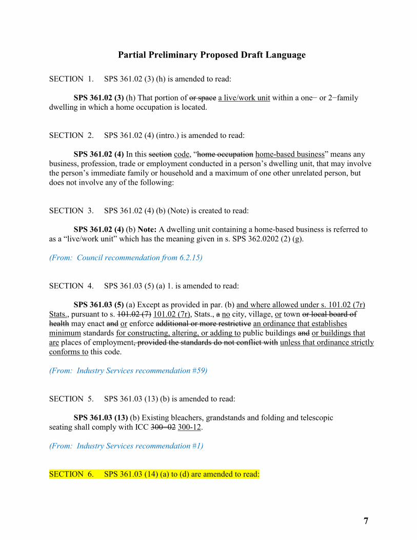
Partial Preliminary Proposed Draft Language
SECTION 1. SPS 361.02 (3) (h) is amended to read: SPS 361.02 (3) (h) That portion of or space a live/work unit within a one− or 2−family dwelling in which a home occupation is located. SECTION 2. SPS 361.02 (4) (intro.) is amended to read: SPS 361.02 (4) In this section code, “home occupation home-based business” means any business, profession, trade or employment conducted in a person’s dwelling unit, that may involve the person’s immediate family or household and a maximum of one other unrelated person, but does not involve any of the following: SECTION 3. SPS 361.02 (4) (b) (Note) is created to read: SPS 361.02 (4) (b) Note: A dwelling unit containing a home-based business is referred to as a “live/work unit” which has the meaning given in s. SPS 362.0202 (2) (g). (From: Council recommendation from 6.2.15) SECTION 4. SPS 361.03 (5) (a) 1. is amended to read: SPS 361.03 (5) (a) Except as provided in par. (b) and where allowed under s. 101.02 (7r) Stats., pursuant to s. 101.02 (7) 101.02 (7r), Stats., a no city, village, or town or local board of health may enact and or enforce additional or more restrictive an ordinance that establishes minimum standards for constructing, altering, or adding to public buildings and or buildings that are places of employment, provided the standards do not conflict with unless that ordinance strictly conforms to this code. (From: Industry Services recommendation #59) SECTION 5. SPS 361.03 (13) (b) is amended to read: SPS 361.03 (13) (b) Existing bleachers, grandstands and folding and telescopic seating shall comply with ICC 300−02 300-12. (From: Industry Services recommendation #1) SECTION 6. SPS 361.03 (14) (a) to (d) are amended to read:
7
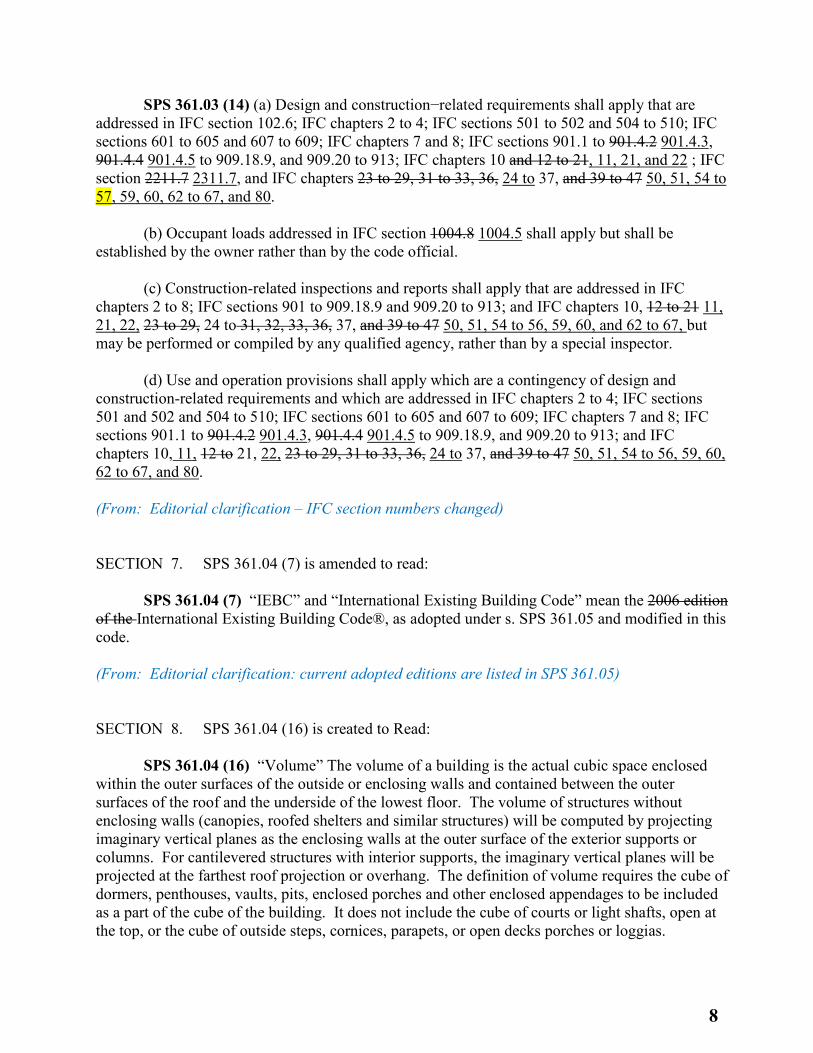
SPS 361.03 (14) (a) Design and construction−related requirements shall apply that are addressed in IFC section 102.6; IFC chapters 2 to 4; IFC sections 501 to 502 and 504 to 510; IFC sections 601 to 605 and 607 to 609; IFC chapters 7 and 8; IFC sections 901.1 to 901.4.2 901.4.3, 901.4.4 901.4.5 to 909.18.9, and 909.20 to 913; IFC chapters 10 and 12 to 21, 11, 21, and 22 ; IFC section 2211.7 2311.7, and IFC chapters 23 to 29, 31 to 33, 36, 24 to 37, and 39 to 47 50, 51, 54 to 57, 59, 60, 62 to 67, and 80. (b) Occupant loads addressed in IFC section 1004.8 1004.5 shall apply but shall be established by the owner rather than by the code official. (c) Construction-related inspections and reports shall apply that are addressed in IFC chapters 2 to 8; IFC sections 901 to 909.18.9 and 909.20 to 913; and IFC chapters 10, 12 to 21 11, 21, 22, 23 to 29, 24 to 31, 32, 33, 36, 37, and 39 to 47 50, 51, 54 to 56, 59, 60, and 62 to 67, but may be performed or compiled by any qualified agency, rather than by a special inspector. (d) Use and operation provisions shall apply which are a contingency of design and construction-related requirements and which are addressed in IFC chapters 2 to 4; IFC sections 501 and 502 and 504 to 510; IFC sections 601 to 605 and 607 to 609; IFC chapters 7 and 8; IFC sections 901.1 to 901.4.2 901.4.3, 901.4.4 901.4.5 to 909.18.9, and 909.20 to 913; and IFC chapters 10, 11, 12 to 21, 22, 23 to 29, 31 to 33, 36, 24 to 37, and 39 to 47 50, 51, 54 to 56, 59, 60, 62 to 67, and 80. (From: Editorial clarification – IFC section numbers changed) SECTION 7. SPS 361.04 (7) is amended to read: SPS 361.04 (7) “IEBC” and “International Existing Building Code” mean the 2006 edition of the International Existing Building Code®, as adopted under s. SPS 361.05 and modified in this code. (From: Editorial clarification: current adopted editions are listed in SPS 361.05) SECTION 8. SPS 361.04 (16) is created to Read: SPS 361.04 (16) “Volume” The volume of a building is the actual cubic space enclosed within the outer surfaces of the outside or enclosing walls and contained between the outer surfaces of the roof and the underside of the lowest floor. The volume of structures without enclosing walls (canopies, roofed shelters and similar structures) will be computed by projecting imaginary vertical planes as the enclosing walls at the outer surface of the exterior supports or columns. For cantilevered structures with interior supports, the imaginary vertical planes will be projected at the farthest roof projection or overhang. The definition of volume requires the cube of dormers, penthouses, vaults, pits, enclosed porches and other enclosed appendages to be included as a part of the cube of the building. It does not include the cube of courts or light shafts, open at the top, or the cube of outside steps, cornices, parapets, or open decks porches or loggias.
8
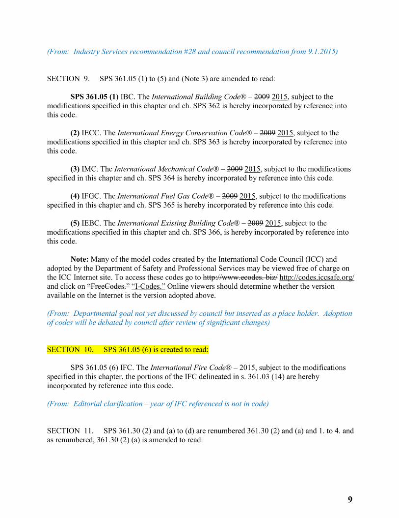
(From: Industry Services recommendation #28 and council recommendation from 9.1.2015) SECTION 9. SPS 361.05 (1) to (5) and (Note 3) are amended to read: SPS 361.05 (1) IBC. The International Building Code® – 2009 2015, subject to the modifications specified in this chapter and ch. SPS 362 is hereby incorporated by reference into this code. (2) IECC. The International Energy Conservation Code® – 2009 2015, subject to the modifications specified in this chapter and ch. SPS 363 is hereby incorporated by reference into this code. (3) IMC. The International Mechanical Code® – 2009 2015, subject to the modifications specified in this chapter and ch. SPS 364 is hereby incorporated by reference into this code. (4) IFGC. The International Fuel Gas Code® – 2009 2015, subject to the modifications specified in this chapter and ch. SPS 365 is hereby incorporated by reference into this code. (5) IEBC. The International Existing Building Code® – 2009 2015, subject to the modifications specified in this chapter and ch. SPS 366, is hereby incorporated by reference into this code. Note: Many of the model codes created by the International Code Council (ICC) and adopted by the Department of Safety and Professional Services may be viewed free of charge on the ICC Internet site. To access these codes go to http://www.ecodes. biz/ http://codes.iccsafe.org/ and click on “FreeCodes.” “I-Codes.” Online viewers should determine whether the version available on the Internet is the version adopted above. (From: Departmental goal not yet discussed by council but inserted as a place holder. Adoption of codes will be debated by council after review of significant changes) SECTION 10. SPS 361.05 (6) is created to read: SPS 361.05 (6) IFC. The International Fire Code® – 2015, subject to the modifications specified in this chapter, the portions of the IFC delineated in s. 361.03 (14) are hereby incorporated by reference into this code. (From: Editorial clarification – year of IFC referenced is not in code) SECTION 11. SPS 361.30 (2) and (a) to (d) are renumbered 361.30 (2) and (a) and 1. to 4. and as renumbered, 361.30 (2) (a) is amended to read:
9
SPS 361.30 (2) (a) Plans for all of the following types of structures shall be submitted to and approved by the department or authorized representative prior to commencement of the project: (From: Editorial clarification) SECTION 12. SPS 361.30 (2) (b) is created to read: SPS 361.30 (2) (b) Plans for fire service drill towers used exclusively for hands-on training reflecting emergency conditions are not subject to plan submittal and review, but are required to meet applicable code requirements, including minimum structural requirements. (From: Industry Services recommendation #17) SECTION 13. SPS 361.30 (2) (d) (Note) is created to read: SPS 361.30 (2) (d) Note: Plans for a freestanding columbarium that is not within a mausoleum structure are not required to be submitted and approved. (From: Industry Services recommendation #46) SECTION 14. SPS 361.36 (1) (g) is created to read: SPS 361.36 (1) (g) Bleachers and canopies. Plan approval by the department or its authorized representative for bleachers or free standing canopies shall expire 2 years after the approval date on the approved plans of the structure. (From: Industry Services recommendation #18) SECTION 15. SPS 361.40 (3) is renumbered 361.40 (3) (title) and (a). SECTION 16. SPS 361.40 (3) (b) is created to read: SPS 361.40 (3) (b) If the supervising architect, engineer, or designer withdraws from the project, the owner of the building or structure shall retain a new supervising professional within 30 days and provide the authority that issued plan approval the name and Wisconsin registration number of the replacement supervising professional. (From: Industry Services recommendation #71) SECTION 17. SPS 361.60 (2) (c) 2. is amended to read:
10
SPS 361.60 (2) (c) 2. Provide a monthly report at least quarterly to the department of all projects completed under this subsection, in an electronic−based format prescribed by the department. (From: Industry Services recommendation #73) SECTION 18. SPS 361 Subchapters V and VI are renumbered 361 Subchapters VI and VII. SECTION 19. SPS 361 Subchapter V is created to read:
SUBCHAPTER V
APPROVAL AND INSPECTION OF MODULAR MULTI-FAMILY DWELLINGS AND THEIR COMPONENTS.
SPS 361.45 Modular Multi-Family Housing Scope. This part shall govern the design, manufacture, installation and inspection of modular multi-family housing, manufactured multi-family building systems and the components of the building systems displaying the Wisconsin insignia.
361.46 Manufacture, sale and installation of dwellings. (1) MANUFACTURE AND SALE. No modular multi-family dwelling, manufactured building system or component of the building system subject to this part shall be manufactured for use, sold for initial use or installed in this state unless it is approved by the department and it bears the Wisconsin insignia issued.
(2) INSTALLATION. Building plan review and approval shall be obtained in accordance with SPS 361 Subchapter III before any on−site construction within the scope of this code is commenced for a modular multi-family dwelling
361.47 Approval procedures. (1) APPLICATION FOR APPROVAL. (a) An application for approval of any modular multi-family dwelling, building system or component shall be submitted to the department in the form required by the department, along with the appropriate fees in accordance with s. SPS 302.3.
(b) The department shall review and make a determination on an application for approval of a modular multi-family dwelling, building system or component within 3 months.
(2) APPROVAL OF BUILDING SYSTEMS AND COMPONENTS. (a) Approval of building systems.
1. ‘Plans and specifications.’ All of the following plans and specifications shall be submitted to the department according to subd. 1. a.: 4 complete sets of building, structural, and HVAC plans, (including elevations, sections and details), specifications and calculations shall be submitted to the department on behalf of the manufacturer for examination and approval.
Note: Plumbing plans submission criteria can be found in SPS 384.
11
2. ‘Compliance assurance program.’ a. Three sets of the compliance assurance program
shall be submitted for examination and approval. b. The compliance assurance program shall meet the standards of the Model Documents for
the Evaluation, Approval and Inspection of Manufactured Buildings or an equivalent standard acceptable to the department.
(b) Approval of building components. 1. ‘Plans and specifications.’ All of the following
plans and specifications shall be submitted to the department according to subd. 1. a.: at least 4 complete sets of plans and specifications for manufactured dwelling building components shall be submitted to the department on behalf of the manufacturer for examination and approval. 2. ‘Compliance assurance program.’ a. Three sets of the compliance assurance program shall be submitted to the department for examination and approval of components.
b. The compliance assurance program shall meet the requirements established by the department or, where applicable, be in the form of the Model Documents for the Evaluation, Approval and Inspection of Manufactured Buildings or an equivalent standard acceptable to the department.
(3) NOTIFICATION OF APPROVAL OR DENIAL OF PLANS, SPECIFICATIONS AND COMPLIANCE
ASSURANCE PROGRAM. (a) Conditional approval. If the department determines that the plans, specifications, compliance assurance program and application for approval submitted for such building system or component substantially conform to the provisions of this code, a conditional approval shall be issued. A conditional approval issued by the department shall not constitute an assumption of any liability for the design or construction of the manufactured building.
1. ‘Written notice.’ The conditional approval shall be in writing and sent to the manufacturer and the person submitting the application for approval. Any noncompliance specified in the conditional approval shall be corrected before the manufacture, sale or installation of the dwelling, building system or component.
2. ‘Stamping of plans, specifications and compliance assurance program.’ Approved plans,
specifications and compliance assurance programs shall be stamped “conditionally approved.” At least 3 copies shall be returned to the person designated on the application for approval; one copy shall be retained by the department.
(b) Denial. If the department determines that the plans, specifications, compliance assurance program or the application for approval do not substantially conform to the provisions of this code, the application for approval shall be denied.
1. ‘Written notice.’ The denial shall be in writing and sent to the manufacturer and the
person submitting the application for approval. The notice shall state the reasons for denial.
2. ‘Stamping of plans, specifications and compliance assurance program.’ Plans, specifications and compliance assurance programs shall be stamped “not approved.” At least 3
12
copies shall be returned to the person submitting the application for approval; one copy shall be retained by the department.
(4) EVIDENCE OF APPROVAL. The manufacturer shall keep at each manufacturing plant
where such building system or component is manufactured, one set of plans, specifications and compliance assurance program bearing the stamp of conditional approval. The conditionally approved plans, specifications and compliance assurance program shall be available for inspection by an authorized representative of the department during normal working hours.
(5) INSPECTIONS. Manufacturers shall contract with an independent inspection agency to
conduct in−plant inspections to assure that the building system and components manufactured are in compliance with the plans, specifications and the compliance assurance program approved by the department. All inspections, for the purpose of administering and enforcing this code, shall be performed by a Wisconsin certified Commercial Building inspector or inspectors.
Note: Electrical installation inspection criteria can be found in SPS 316. Note: Plumbing installation inspection criteria can be found in SPS 382. (6) WISCONSIN INSIGNIA. Upon departmental approval of the plans, specifications and
compliance assurance program, and satisfactory in−plant inspections of the building system and components, Wisconsin insignias shall be purchased from the department in accordance with the fee established in s. SPS 302.34. A manufacturer shall be entitled to display the Wisconsin insignia on any approved system or component.
(a) Lost or damaged insignia. 1. ‘Notification.’ If Wisconsin insignias become lost or damaged, the department shall be notified immediately, in writing, by the manufacturer or dealer.
2. ‘Return of damaged insignias.’ If Wisconsin insignias become damaged, the insignia shall be returned to the department with the appropriate fee to obtain a new insignia.
(b) Affixing Wisconsin insignias. Each Wisconsin insignia shall be assigned and affixed to a specific manufactured dwelling or component in the manner approved by the department before the dwelling is shipped from the manufacturing plant.
(c) Insignia records. 1. ‘Manufacturer’s insignia records.’ The manufacturer shall keep
permanent records regarding the handling of all Wisconsin insignias, including construction compliance certificates, indicating the number of Wisconsin insignias which have been affixed to manufactured dwellings or manufactured building components (or groups of components); which Wisconsin insignias have been applied to which manufactured dwelling or manufactured building component; the disposition of any damaged or rejected Wisconsin insignias; and the location and custody of all unused Wisconsin insignias. The records shall be maintained by the manufacturer or by the independent inspection agency for at least 10 years. A copy of the records shall be sent to the department upon request.
2. ‘Construction compliance certificate.’ Within 30 days after receiving the original Wisconsin insignias from the department, and at the end of each month thereafter, the
13
manufacturer shall submit a construction compliance certificate, in the form determined by the department, for each manufactured dwelling intended for sale, use or installation in the state.
(d) Unit identification. Each modular dwelling and major transportable section or
component shall be assigned a serial number. The serial number shall be located on the manufacturer’s data plate.
(e) Manufacturer’s data plate. The manufacturer’s data plate for building systems shall contain all of the following information, where applicable:
1. Manufacturer’s name and address. 2. Date of manufacture. 3. Serial number of unit. 4. Model designation. 5. Identification of type of gas required for appliances and directions for water and drain
connections. 6. Identification of date of the codes or standards complied with. 7. State insignia number. 8. Design loads. 9. Special conditions or limitations of unit. 10. Electrical ratings; instructions and warnings on voltage, phase, size and connections of
units and grounding requirements. 361.475 Effect of approval. (1) RIGHT TO BEAR INSIGNIA. A manufactured multi-family
dwelling or building component approved by the department, and manufactured and inspected in accordance with this code, shall be entitled to bear the Wisconsin insignia.
(2) EFFECT OF INSIGNIA. Manufactured multi-family dwellings and manufactured building components bearing the Wisconsin insignia are deemed to comply with this code, except as to installation site requirements, regardless of the provisions of any other ordinance, rule, regulation or requirement.
(3) RIGHT TO INSTALL. Manufactured multi-family dwellings and components bearing the
Wisconsin insignia may be manufactured, offered for sale and shall be entitled to be installed anywhere in Wisconsin where the installation site complies with the other provisions of this code.
361.48 Suspension and revocation of approval. The department shall suspend or revoke its approval of a manufactured building system or manufactured building component if it
14
determines that the standards for construction or the manufacture and installation of a manufactured building system or manufactured building component do not meet this code or that such standards are not being enforced as required by this code. The procedure for suspension and revocation of approval shall be as follows:
(1) FILING OF COMPLAINT. Proceedings to suspend or revoke an approval shall be initiated by the department or an independent inspection agency or Wisconsin Commercial Building certified inspector having a contract with the manufacturer whose approval is sought to be suspended or revoked. Initiation shall be by a signed, written complaint filed with the department. Any alleged violation of the code shall be set forth in the complaint with particular reference to time, place and circumstance.
(2) INVESTIGATION AND NOTIFICATION. The department may investigate alleged violations
on its own initiative or upon the filing of a complaint. If it is determined that no further action is warranted, the department shall notify the persons affected. If the department determines that there is probable cause, it shall order a hearing and notify the persons affected.
(3) MAILING. Unless otherwise provided by law, all orders, notices and other papers may be served by the department by certified mail to the persons affected at their last known address. If the service is refused, service may be made by sheriff without amendment of the original order, notice or other paper.
(4) RESPONSE. Upon receipt of notification of hearing from the department, the person
charged with noncompliance or nonenforcement may submit to the department a written response within 30 days of the date of service. If the person charged files a timely written response, such person shall thereafter be referred to as the respondent.
(5) CONCILIATION AGREEMENT PRIOR TO HEARING. If the department and the respondent are
able to reach agreement on the disposition of a complaint prior to a hearing, such agreement shall be transmitted in writing to the secretary. Until the agreement has been accepted by the secretary, it is not considered a waiver of any defense, nor is it considered an admission of any fact, and is not binding upon any party until signed by all parties.
(6) HEARINGS. (a) Subpoenas; witness fees. Subpoenas shall be signed and issued by the department or the clerk of any court of record. Witness fees and mileage of witnesses subpoenaed on behalf of the department shall be paid at the rate prescribed for witnesses in circuit court.
(b) Conduct of hearings. All hearings shall be conducted by persons selected by the
department. Persons so designated may administer oaths or affirmations and may grant continuances and adjournments for cause shown. The respondent shall appear in person and may be represented by an attorney−at−law. Witnesses may be examined by persons designated by all parties.
(7) FINDINGS. The department shall make findings and enter its order within 14 days of the
hearing. Any findings as a result of petition or hearing shall be in writing and shall be binding unless appealed to the secretary.
15
(8) APPEAL ARGUMENTS. Appeal arguments shall be submitted to the department in writing in accordance with ch. 227, Stats., unless otherwise ordered. The department shall review and make a determination on an appeal of notification of suspension or revocation of approval within 45 business days of receipt of the appeal.
361.485 Effect of suspension and revocation. (1) BEARING OF INSIGNIA. Upon suspension or revocation by the department of the approval
of any modular dwelling or manufactured building component, no further insignia shall be attached to any dwelling or building component manufactured with respect to which the approval was suspended or revoked. Upon termination of such suspension or revocation, insignias may again be attached to the dwelling or building component manufactured after the date approval is reinstated. Should any dwelling or building component have been manufactured during the period of suspension or revocation, it shall not be entitled to bear the Wisconsin insignia unless the department has inspected, or caused to be inspected, such modular dwelling or manufactured building component and is satisfied that all requirements for certification have been met.
(2) RETURN OF INSIGNIAS. The manufacturer shall return to the department all insignias
allocated for a modular dwelling or manufactured building component no later than 30 days from the effective date of any suspension or revocation of the approval by the department. The manufacturer shall also return to the department all insignias which it determines for any reason are no longer needed. (From: Industry Services recommendation) SECTION 20. SPS 362.0202 (1) is renumbered SPS 362.0202 (1) (title) and (a), and amended to read: SPS 362.0202 Definitions. (1) ADDITIONS. This is a These are department definition definitions for this chapter in addition to the definitions in IBC section 202: (a) “High−piled combustible storage” means storage of combustible materials in closely packed piles, or on pallets, in racks or on shelves, where the top of storage is greater than 12 feet in height. When required by the fire code official, high−piled combustible storage also includes certain high−hazard commodities, such as rubber tires, Group A plastics, flammable liquids, idle pallets and similar commodities, where the top of storage is greater than 6 feet in height. SECTION 21. SPS 362.0202 (1) (b) is created to read: SPS 362.0202 (1) (b) “Neutral Plane” A deep foundation’s neutral plane is the level at which drag load, accumulated from the top down, added to the long−term static service load, equals the upward acting shaft resistance accumulated from the bottom up, added to the deep foundation’s toe resistance. SECTION 22. SPS 362.0202 (2) is renumbered SPS 362.0202 (2) and (a) and amended to read:
16
SPS 362.0202 (2) SUBSTITUTIONS. Substitute the following definition definitions for the corresponding definition in IBC section 202: (a) “Approved” means acceptable to the department. SECTION 23. SPS 362.0202 (2) (b) to (g) and (Note) and (h) are created to read: SPS 362.0202 (2) (b) “Automatic sprinkler system” or “Automatic fire sprinkler system” has the meaning given in s. 145.01 (2), Stats. (c) “Fire area” means the aggregate floor area enclosed and bounded by fire walls, fire barriers, exterior walls or fire−resistance−rated horizontal assemblies of a building. (d) “Fire separation distance” means the distance measured at right angles from the face of the building wall to one of the following: (e) “Fuel−burning appliance” means a device that is installed in a building and burns fossil−fuel or carbon based fuel where carbon monoxide is a combustion by−product, including ranges, ovens, grills, clothes dryers, furnaces, boilers, water heaters, heaters, fireplaces and stoves. (f) “Immediately dangerous to life and health (IDLH)” means a concentration of air−borne contaminants which poses a threat of death, immediate or delayed permanent adverse health effects, or effects which could prevent escape from such an environment. This contaminant concentration level is established by the National Institute of Occupational Safety and Health based on both toxicity and flammability. It generally is expressed in parts per million by volume, or milligrams per cubic meter. (g) “Live/work unit” means a dwelling unit which includes a “home-based business” as defined in s. SPS 361.02 (4). Note: SPS 361.02 (4), reads as follows: In this code, “home-based business” means any business, profession, trade or employment conducted in a person’s dwelling unit, that may involve the person’s immediate family or household and a maximum of one other unrelated person, but does not involve any of the following: (a) Explosives, fireworks or repair of motor vehicles. (b) More than 25% of the habitable floor area of the dwelling unit. (h) “Sealed combustion appliance” means a listed appliance that acquires all air for combustion through a dedicated sealed passage from the outside to a sealed combustion chamber and all combustion products are vented to the outside through a separate dedicated sealed vent. SECTION 24. SPS 362.0202 (3) is amended to read:
SPS 362.0202 (3) (d) DELETIONS. The following terms and corresponding definitions
in IBC section 202 are not included as part of this code: approved agency, approved fabricator, base flood, base flood elevation, certificate of compliance, design flood, design flood elevation, designated seismic system, dry floodproofing, existing construction, fabricated item, inspection
17
certificate, label, lowest floor, manufacturer’s designation, mark, special continuous inspection, special flood hazard area, special inspection, special periodic inspection, sprayed fire−resistant materials, start of construction, and structural observation. SECTION 25. SPS 362.0308 is created to read: SPS 362.0308 Five or fewer persons receiving medical care. Substitute the following wording for IBC section 308.4.2: Five or fewer persons receiving medical care. A facility with five or fewer persons receiving medical care shall be classified as Group R-3. (From: Editorial clarification and Council recommendation from 6.2.15) SECTION 26. SPS 362.0406 is repealed. (From: Editorial clarification - IBC section that is modified no longer exists) SECTION 27. SPS 362.0412 (intro.) is renumbered 362.0412 and (1) (intro.) and amended to read: SPS 362.0412 Aircraft related occupancies. (1) Substitute the following wording for exception 1 in IBC section 412.2.4 412.4.4: Heating equipment that is suspended at least 10 feet above the upper surface of wings or engine enclosures of the highest aircraft which may be housed in the hangar; or at least 8 feet above the floor in shops, offices and other sections of the hangar communicating with storage or service areas. (From: Editorial clarification – code referenced wrong section) SECTION 28. SPS 362.0412 (2) is created to read: SPS 362.0412 (2) Substitute the following wording for the requirements, but not the exception, in IBC section 412.4.3: Floor Surface. Floors shall be graded and drained to meet the requirements of s. SPS 382.34 (2). (From: Industry Services recommendation #10) SECTION 29. SPS 362.0415 (1) is amended to read: SPS 362.0415 (1) Substitute the following wording definition in s. SPS 362.0202 (2) for the corresponding definition listed in IBC section 415.2: “Immediately dangerous to life and health (IDLH).” The concentration of air−borne contaminants which poses a threat of death, immediate or delayed permanent adverse health effects, or effects which could prevent escape from such an environment. This contaminant concentration level is established by the National Institute of
18
Occupational Safety and Health based on both toxicity and flammability. It generally is expressed in parts per million by volume, or milligrams per cubic meter. (From: Editorial clarification and Council recommendation from 6.2.15) SECTION 30. SPS 362.0509 is created to read: SPS 362.0509 Incinerator rooms. In IBC section 509, Table 509, “incinerator rooms” does not include crematories as defined in s. 440.70 (8) Stats. (From: Industry Services recommendation #46) SECTION 31. SPS 362.0702 (1) to (4) are renumbered 362.0202 (2) (d) 1. to 4. SECTION 32. SPS 362.0702 is amended to read: SPS 362.0702 Substitute the following definition in s. SPS 362.0202 (2) for the corresponding definition listed in IBC section 702: “Fire separation distance.” means the distance measured at right angles from the face of the building wall to one of the following: SECTION 33. SPS 362.0702 (title) is repealed and recreated to read: SPS 362.0702 Definitions. (From: Editorial clarification and Council recommendation from 6.2.15) SECTION 34. SPS 362.0707 is repealed. SECTION 35. SPS 362.0708 is repealed. SECTION 36. SPS 362.0713 is created to read: SPS 362.0713 Chute discharge room. This is a department rule in addition to the requirements in IBC section 713: the requirements of IBC 713.13.4 shall apply to recycling chutes in addition to waste and linen chutes. SECTION 37. SPS 362.0716 (1) (title) and (2) are repealed.
19
SECTION 38. SPS 362.0716 and (1) are renumbered 362.0717. (From: Council recommendations from 7.7.15) SECTION 39. SPS 362.0721 is renumbered 362.0722; and 362.0722 (1) and (2), as renumbered, are amended to read: SPS 362.0722 (1) Substitute the following wording for the exception in each of IBC sections 721.2.1.4.3 722.2.1.4.3, 721.3.2.3 722.3.2.3 and 721.4.1.4 722.4.1.4: Exception: For an exterior wall with a fire separation distance greater than 10 feet, the fire shall be assumed to occur on the interior side only. SPS 362.0722 (2) Substitute the following wording for IBC Section 721.6.2.3 722.6.2.3: For an exterior wall with a fire separation distance greater than 10 feet, the wall is assigned a rating dependant dependent on the interior membrane and the framing as described in IBC Tables 721.6.2(1) 722.6.2(1) and 721.6.2(2) 722.6.2(2). The membrane on the outside of the nonfire−exposed side of exterior walls with a fire separation distance greater than 10 feet may consist of sheathing, sheathing paper and siding as described in IBC Table 721.6.2(3) 722.6.2(3). (From: Editorial clarification - IBC section number changed) SECTION 40. SPS 362.0902 (1) (Note) is renumbered SPS 362.0202 (2) (b) (Note). SECTION 41. SPS 362.0902 (1) and (2) are amended to read: SPS 362.0902 Definitions. Substitute the following definitions and informational note in s. SPS 362.0202 (2) for the corresponding definitions listed in IBC section 902.1: (1) “Automatic sprinkler system” or “Automatic fire sprinkler system.” has the meaning given in s. 145.01 (2), Stats. (2) “Fire area.” means the aggregate floor area enclosed and bounded by fire walls, fire barriers, exterior walls or fire−resistance−rated horizontal assemblies of a building. (From: Editorial clarification and Council recommendation from 6.2.15) SECTION 42. SPS 362.0903 (5) (c) is repealed. (From: Industry Services recommendation) SECTION 43. SPS 362.0903 (12) is created to read:
20
SPS 362.0903 (12) The requirements of IBC 903.2.11.2 shall apply to recycling chutes in addition to rubbish and linen chutes. SECTION 44. SPS 362.0903 (13) is created to read: SPS 362.0903 (13) ALTERNATE AUTOMATIC FIRE SPRINKLER SYSTEM DESIGN STANDARD. This is a department rule in addition to the requirements of IBC 903.3.1.1: Where the provisions of this code require that a building or portion thereof be equipped with an automatic sprinkler system in accordance with this section, sprinklers shall be allowed to be installed throughout in accordance with the alternate design standard of the most recent publication of FM Global Loss Prevention Data Sheets 2-0 Installation Guidelines for Automatic Sprinklers and 8-9 Storage of Class 1, 2, 3, 4 and Plastic Commodities. (From: Industry Services recommendation) SECTION 45. SPS 362.0904 (2) (a) is repealed. SECTION 46. SPS 362.0904 (2) (c) is created to read: SPS 362.0904 (2) (c) Substitute the following wording for IBC 904.12.2: System interconnection. The actuation of the fire suppression system shall automatically shut down all sources of fuel and power to all equipment located beneath the exhaust hood and protected by the suppression system. The fuel and power reset shall be manual. (From: Council recommendations from 7.7.15) SECTION 47. SPS 362.0907 (4) is amended to read: SPS 362.0907 (4) Substitute the following wording for the requirements exception in IBC section 907.5.2.3.2 907.5.2.3.1: Where employee work areas have audible alarm coverage, the alarm system shall be designed so that visible notification appliances can be integrated into the system. (From: Editorial clarification - IBC section language changed) SECTION 48. SPS 362.0910 (1) and (2) are amended to read: SPS 362.0910 (1) Substitute the following wording for exception 1. in IBC section 910.1 910.2: Buildings protected by an approved automatic sprinkler system. (2) Substitute the following wording for the requirements, but not the exception, in IBC section 910.2.1: Buildings and portions thereof used as Group F–1 or S–1 occupancies having
21
more than 50,000 square feet in area that is undivided by full−height walls having smoke resisting characteristics which are similar to those under IBC section 910.3.5.1 constructed of sheet metal, lath and plaster, gypsum board or other approved materials which provide equivalent performance to resist the passage of smoke. Joints and connections shall be smoke tight. (From: Editorial clarification – language from IBC 2009 which was formerly referenced no longer exists and was thus incorporated in sub. (2) to replace the IBC reference) SECTION 49. SPS 362.1004 is amended to read: SPS 362.1004 Substitute the following wording for the requirements, but not the exceptions, in IBC section 1004.8 1004.5: Yards, patios, courts and similar outdoor areas accessible to and usable by the building occupants shall be provided with means of egress as required by this chapter. The occupant load of such outdoor areas shall be based on the anticipated use. Where outdoor areas are to be used by persons in addition to the occupants of the building, and the path of egress travel from the outdoor areas passes through the building, means of egress requirements for the building shall be based on the sum of the occupant load of the building plus the outdoor areas. SECTION 50. SPS 362.1006 (3) is created to read: SPS 362.1006 (3) This is a department exception to the requirements in IBC table 1006.2.1: A single exit is allowed and the common path of travel can be the same as the maximum allowable exit access travel distance (250’) in buildings or portions of buildings used exclusively for bulk material storage in piles including but not limited to salt storage sheds, sand storage, etc. where the building walls provide containment for the materials stored. (From: Industry Services recommendation) SECTION 51. SPS 362.1008 is renumbered 362.1010; and SPS.1010 (1) and (2), as renumbered, are amended to read: SPS 362.1010 (1) This is a department exception to the requirements in IBC section 1008.1.1 1010.1.1: The clear door opening for a nonaccessible toilet stall, shower stall, or other similar compartment, may be less than 32− inches wide. SPS 362.1010 (2) This is a department exception to the requirements in IBC section 1008.1.8 1010.1.8: Where maneuvering space is provided between the doors in accordance with IBC section 1101.2 such that use by an individual in a wheelchair will not block the operation of the doors. SECTION 52. SPS 362.1009 is renumbered 362.1011 and amended to read:
22
SPS 362.1011 This is a department rule in addition to the requirements in IBC section 1009.1 1011.1: Where installing an inclined platform lift or stairway chairlift, the clear−passage width shall be provided with the lift in the unfolded, usable position. (From: Editorial clarifications - IBC section numbers changed) SECTION 53. SPS 362.1009 is created to read: SPS 362.1009 This is a department exception in addition to the exceptions in IBC section 1009.3: Areas of refuge are not required at floors that are not required to be accessible. (From: Council recommendation from 12/1/15 meeting) SECTION 54. SPS 362.1011 is created to read: SPS 362.1011 This is a department rule in addition to the requirements in IBC section 1011.7: For platform buildings designed per IBC section 510.2 where a stair shaft serves two or more classes of construction and one of those classes of construction allows combustible materials the entire stair construction within the enclosure may be of combustible materials. (From: Industry Services recommendation) SECTION 55. SPS 362.1014, (title) and (intro.) and (1) and (2) are renumbered 362.1006, (1) (title) and (intro) and (a) and (b); and 362.1006 (1) and (1) (b), as renumbered, are amended to read: SPS 362.1006 (1) EXIT ACCESS. This is a department exception to the requirements in IBC section 1014.3 1006.2.1: The length of a common path of egress travel requirements shall not be limited within townhouse dwelling units provided the townhouse complies with all of the following: (b) Each dwelling unit within the townhouse is separated from other dwelling units by at least 2−hour fire−resistive−rated separation walls constructed in accordance with the requirements of IBC section 705 706 and do not contain any openings and plumbing equipment or mechanical equipment. The separation wall does not have to comply with the structural stability requirements of IBC section 705.2 706.2 and the horizontal continuity requirements of IBC section 705.5 706.5. (From: Council recommendation from 8.4.15) SECTION 56. SPS 362.1015 and (title) are renumbered 362.1006 (2) and (title) and 362.1006 (2), as renumbered, is amended to read:
23
SPS 362.1006 (2) Substitute the following wording for the exception in IBC section 1015.5 1006.2.2.3: Where using refrigerants in quantities limited to the amounts based on the volume set forth in ch. SPS 345. (From: IBC section number changed) SECTION 57. SPS 362.1015 is created to read: SPS 362.1015 Substitute the following wording for the requirements, but not the exception in IBC section 1015.2: Guards shall be located along the open side of walking surfaces, balconies, mezzanines, stairs, ramps, landings, roofs and similar surfaces intended to be used by building occupants or the public where the change in elevation is more than 30 inches (762 mm) to the floor or roof below or more than 30 inches (762 mm) measured vertically to the grade below at any point within 36 inches (914 mm) horizontally to the edge of the open side. Guards shall be adequate in strength and attachment in accordance with Section 1607.8. (From: Recommendation from Harry Sulzer, City of Madison) SECTION 58. SPS 362.1016 is created to read: SPS 362.1016 This is a department exception to the requirements in IBC section 1016: Buildings or portions of buildings used exclusively for bulk material storage in piles including but not limited to salt or sand storage sheds where building walls provide containment for the materials stored may have a single exit and are allowed to have a common path of travel to be the same as the maximum allowable exit access travel distance. (From: Recommendation from DSPS/ DOT meeting) SECTION 59. SPS 362.1018 is renumbered 362.1020 and amended to read: SPS 362.1020 This is a department exception to the requirements in IBC section 1018.6 1020.6: Other spaces or rooms constructed as required for corridors, and that are adjacent to a fire−resistance−rated corridor, shall not be construed as intervening rooms; and may be open to the corridor when all of the following are satisfied: (From: Editorial clarifications - IBC section numbers changed) SECTION 60. SPS 362.1021 (1) is repealed. SECTION 61. SPS 362.1021 (title) and (2) are renumbered 362.1006 (3) and (title) and amended to read:
24
SPS 362.1006 (3) This is a department exception to the requirements in IBC section 1021.1 1006.3: Buildings of Group I−3 occupancy that are used as guard towers, provided the towers are no higher than 2 stories above grade, accommodate no more than 10 occupants, and have a travel distance of no more than 75 feet. SECTION 62. SPS 362.1022 is repealed. (From: Council recommendation from 8.4.15) SECTION 63. SPS 362.1103 is amended to read: SPS 362.1103 Substitute the following wording for the requirements in IBC section 1103.2.8 1103.2.7: (From: Editorial clarification - IBC section number changed) SECTION 64. SPS 362.1104 (2) is repealed. (From: Council recommendation from 8.4.15) SECTION 65. SPS 362.1109 is repealed. SECTION 66. SPS 362.1110 is renumbered 362.1111 and, as renumbered, 361.1111 (1) (a), (2) (a), and (2) (b) are amended to read: SPS 362.1111 (1) (a) Substitute the following wording for the requirements for location 1 in IBC section 1110.1 1111.1: Except as specified par. (b), accessible parking spaces required in IBC section 1106 for the general public shall be identified with a sign complying with the accessible parking sign requirements specified in s. Trans 200.07. (2) (a) Substitute the following wording for the introductory paragraph of IBC section 1110.2 1111.2: Signage indicating directional information or information about functional spaces or signage indicating special accessibility provisions shall comply with ICC A117.1 and be provided at the following locations: (2) (b) This is a department informational note to be used under IBC section 1110.3 1111.3. (From: Editorial clarification - IBC section number changed)
25
SECTION 67. SPS 362.1200 is renumbered 362.0915 and 362.0915 (title) and (intro.) and (1) (b) and (d), as renumbered, are amended to read: SPS 362.0915 Carbon monoxide alarms detection. These are department rules in addition to Substitute the following wording for the requirements in IBC chapter 12 section 915: (1) (b) “Fuel−burning appliance” means a device that is installed in a building and burns fossil−fuel or carbon based fuel where carbon monoxide is a combustion by−product, including stoves, ovens, grills, clothes dryers, furnaces, boilers, water heaters, heaters, fireplaces and stoves has the meaning as given in s. SPS 362.0202 (2). (d) “Sealed combustion appliance” means a listed appliance that acquires all air for combustion through a dedicated sealed passage from the outside to a sealed combustion chamber and all combustion products are vented to the outside through a separate dedicated sealed vent has the meaning as given in s. SPS 362.0202 (2). (From: Council recommendation from 6.2.15) SECTION 68. SPS 362.1203 is created to read: SPS 362.1203 Natural Ventilation. This is a department rule in addition to the requirements in IMC section 402 IBC section 1203.5: The use of natural ventilation shall be permitted under either of the following: (1) In occupancies specified in s. SPS 364.0402, Table 364.0402. (2) For any occupancy, provided an engineered design satisfies the ventilation needs of the occupancy, with adequate justification found acceptable by the department. (From: Council recommendations from 8.4.15) SECTION 69. SPS 362.1210 (intro) and (1) and (2) and (a) to (c) are renumbered 362.1210 (1) and (a) and (b) and 1. to 3., and as renumbered, 362.1210 is amended to read: SPS 362.1210 These are department rules in addition to the requirements in IBC section 1210.5 1210: (From: Editorial clarification - IBC section number changed) SECTION 70. SPS 362.1210 (2) is created to read: SPS 362.1210 (2) Substitute the following wording for the requirements in IBC section 1210.3.2: Urinals shall be arranged individually with or without partitions.
26
(From: Editorial clarification - IBC section number changed so the portion of SPS 362.2900 (3) (a) regarding partitions has been moved to 362.1210) SECTION 71. SPS 362.1405 (1) and (2) are renumbered 362.1405 (2) and (3), and 362.1405 (2), as renumbered, is amended to read: SPS 362.1405 (2) This is a department exception in addition to the exceptions in IBC section 1405.3 1405.3.1: Where other approved means to avoid condensation in unventilated framed wall, floor, roof and ceiling cavities and box sills are provided. (From: Editorial clarification - IBC section number changed) SECTION 72. SPS 362.1405 (1) is created to read: SPS 362.1405 (1) Substitute the following wording for the requirements, but not the exceptions, in IBC section 1405.3.1: Class I and II vapor retarders. Class I or II vapor retarders shall be provided on the interior side of frame walls and ceiling assemblies. (From: Industry Services recommendation #4) SECTION 73. SPS 362.1503 is created to read: SPS 362.1503 Roof drainage. Substitute the following wording for IBC section 1503.4: Design and installation of roof drainage systems shall comply with section 1503 of the IBC and all applicable provisions in chapter SPS 382. (From: Council recommendations from 9.1.15) SECTION 74. SPS 362.1509 is renumbered 362.1510 and amended to read: SPS 362.1510 This is a department informational note to be used under IBC section 509: requirement in addition to the requirements of IBC section 1510.7: Rooftop photovoltaic systems shall meet the requirements in s. SPS 314.01 (2) 3. a. and b. SECTION 75. SPS 362.1509 (note) is repealed. (From: Industry Services recommendation #67) SECTION 76. SPS 362.1607 (1) and (Table) 1607.1 and (2) are amended to read:
27
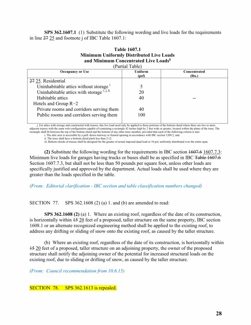
SPS 362.1607.1 (1) Substitute the following wording and live loads for the requirements in line 27 25 and footnote j of IBC Table 1607.1:
Table 1607.1 Minimum Uniformly Distributed Live Loads
and Minimum Concentrated Live Loadsg
(Partial Table) Occupancy or Use Uniform
(psf) Concentrated
(lbs.) 27 25. Residential
Uninhabitable attics without storage i Uninhabitable attics with storage i, j, k Habitable attics
Hotels and Group R−2 Private rooms and corridors serving them Public rooms and corridors serving them
5 20 40
40 100
--
j. For attics with storage and constructed with trusses, this live load need only be applied to those portions of the bottom chord where there are two or more adjacent trusses with the same web configuration capable of containing a rectangle 42 inches high by 2 feet wide or greater, located within the plane of the truss. The rectangle shall fit between the top of the bottom chord and the bottom of any other truss member, provided that each of the following criteria is met:
i. The attic area is accessible by a pull−down stairway or framed opening in accordance with IBC section 1209.2, and ii. The truss shall have a bottom chord pitch less than 2:12.
iii. Bottom chords of trusses shall be designed for the greater of actual imposed dead load or 10 psf, uniformly distributed over the entire span. (2) Substitute the following wording for the requirements in IBC section 1607.6 1607.7.3: Minimum live loads for garages having trucks or buses shall be as specified in IBC Table 1607.6 Section 1607.7.3, but shall not be less than 50 pounds per square foot, unless other loads are specifically justified and approved by the department. Actual loads shall be used where they are greater than the loads specified in the table. (From: Editorial clarification - IBC section and table classification numbers changed) SECTION 77. SPS 362.1608 (2) (a) 1. and (b) are amended to read: SPS 362.1608 (2) (a) 1. Where an existing roof, regardless of the date of its construction, is horizontally within 15 20 feet of a proposed, taller structure on the same property, IBC section 1608.1 or an alternate recognized engineering method shall be applied to the existing roof, to address any drifting or sliding of snow onto the existing roof, as caused by the taller structure. (b) Where an existing roof, regardless of the date of its construction, is horizontally within 15 20 feet of a proposed, taller structure on an adjoining property, the owner of the proposed structure shall notify the adjoining owner of the potential for increased structural loads on the existing roof, due to sliding or drifting of snow, as caused by the taller structure. (From: Council recommendation from 10.6.15) SECTION 78. SPS 362.1613 is repealed.
28
(From: Editorial clarification – USGS no longer has the zip code input feature) SECTION 79. SPS 362.1700 is amended to read: SPS 362.1700 The requirements in IBC chapter 17, except for the requirements in IBC sections 1711 to 1716 1706 to 1709, are not included as part of this code. (From: Editorial clarification – some IBC section numbers changed and some were deleted) SECTION 80. SPS 362.1802 is amended to read: SPS 362.1802 Definition of neutral plane. Definitions. This is a department definition in In addition to the definitions listed in IBC section 1802.1, the following term has the meaning given in s. SPS 362.0202 (1): NEUTRAL PLANE. A deep foundation’s neutral plane is the level at which drag load, accumulated from the top down, added to the long−term static service load, equals the upward acting shaft resistance accumulated from the bottom up, added to the deep foundation’s toe resistance. “Neutral Plane.” (From: Council recommendation from 6.2.15) SECTION 81. SPS 362.1809 (intro) and (1) and (2) are renumbered SPS 362.1809 (1) and (a) and (b). SECTION 82. SPS 262.1809 (2) is created to read: SPS 362.1809 (2) This is a department exception in addition to the exception in IBC 1809.5: Floating slabs used with non-masonry, unheated, non-occupied, single-story buildings in Risk Category I that are less than 12,000 square feet are exempt from the requirements for frost protection. (From: Council recommendation from 10.6.15 and Industry Services recommendation #37) SECTION 83. SPS 362.1913 is renumbered 362.1908 and amended to read: SPS 362.1908 Substitute the following wording for the exception under IBC section 1913.4.2 1908.4.2: Subject to the approval of the department, required clearances may be reduced where it is demonstrated by preconstruction tests that adequate encasement of the bars used in the design will be achieved. (From: Editorial clarification –IBC section number changed)
29
SECTION 84. SPS 362.2103 is repealed. (From: Council recommendation from 10.6.15) SECTION 85. SPS 362.2210 is renumbered 362.2211 and amended to read: SPS 362.2211 The requirements in IBC section 2210.3.4 2211.3.3 are not included as part of this code. SECTION 86. SPS 362.2304 is amended to read: SPS 362.2304 This is a department rule in addition to the requirements in IBC section 2304.11.2.5 2304.12.2.1: A moisture barrier shall be provided between an untreated or nondurable wood girder and an exterior masonry or concrete bearing surface. (From: Editorial clarifications –IBC section numbers changed) SECTION 87. SPS 362.2510 is created to read: SPS 362.2510 This is a department rule in addition to the requirements in IBC section 2510.6: The vertical leg of flashing at the base of a wall with two layers of water-resistive barrier shall be installed behind both layers of water-resistive barrier. (From: Council recommendation from 10.6.15) SECTION 88. SPS 362.2900 (3) (b) 1. and 2. are repealed. (From: Industry Services recommendation #24 and editorial clarification – these are now addressed in exceptions 1 and 2 in IBC section 1210.3.1) SECTION 89. SPS 362.2900 (3) (title) and (a) are consolidated and renumbered 362.2900 (3) and as renumbered, are amended to read: SPS 362.2900 (3) ENCLOSURE OF FIXTURES URINALS Water closets and urinals within a toilet room shall be arranged to ensure privacy. Except as provided in par. (b), each water closet shall occupy a separate compartment with walls or partitions and a door enclosing the fixtures to ensure privacy. Urinals shall be placed against walls at least 6 feet 8 inches high and arranged individually with or without partitions. SECTION 90. SPS 362.2900 (3) (b) 3. is renumbered 362.1210 (1) (a) 4.
30
(From: Industry Services recommendation #24 and editorial clarification) SECTION 91. SPS 362.2902 (1) (a) 2. is amended to read: SPS 362.2902 (1) (a) 2. Where water is served in restaurants or other occupancies, or where other acceptable arrangements are made to provide drinking water, drinking fountains are not required, other reasonable alternatives are acceptable. (From: Industry Services recommendation #45) SECTION 92. SPS 362.2902 (1) (e) is created to read: SPS 362.2902 (1) (e) Alternative to IBC Table 2902.1 This is a department alternative to the minimum fixture requirements of IBC Table 2902.1: The required number of toilet fixtures may be based on the actual occupancy load rather than the load determined by square footage per IBC Table 1004.1.1. The actual occupancy load shall be based on justification found acceptable to the department and deemed reasonable. (From: Industry Services recommendation #66) SECTION 93. SPS 362.3002 (title), (intro) and (1) to (3) are renumbered 362.3002 (1) (title), (intro) and (a) to (c). SECTION 94. SPS 362.3002 (title) is created to read: SPS 362.3002 Hoistway Enclosures. SECTION 95. SPS 362.3004 (1) to (3) are renumbered 362.3002 (2) to (4) and amended to read: SPS 362.3002 (2) This is a department rule in addition to the requirements in IBC section 3004.3 3002: A ventilation opening in a hoistway wall, where provided, shall have guards securely anchored to the supporting structure inside the hoistway. The guards shall consist of a wire−mesh screen of at least 0.0915−inch diameter steel wire with openings that will reject a ball one−inch in diameter, or expanded metal screen of equivalent strength and open area. (3) This is a department rule in addition to the requirements in the exception under IBC 3004.3 section 3002: Where vent openings automatically open upon detection of smoke in the elevator lobbies or hoistway, upon power failure and upon activation of a manual override control, The the manual override control shall comply with all of the following:
31
(a) Be a keyed switch of the open−auto−close type with the three positions labeled, that is operated with an FEO−K1 key or other approved key. (b) Be located adjacent to the elevator hoistway door frame at the level of fire department vehicle access, approximately 48 inches above the floor, or other approved location. This location may be behind a locked panel. (c) Be labeled “hoistway vent control.” (From: Editorial clarification - hoistway venting is no longer required by the IBC but if provided, should still meet old requirements) SECTION 96. SPS 362.3004 (3) is renumbered 362.3002 (2) and amended to read: SPS 362.3002 (4) Substitute the following wording for the requirements and the exception in IBC section 3004.4 3002.9: (From: Editorial clarification - IBC section number changed) SECTION 97. SPS 362.3006 and (1) to (5) are renumbered 362.3005 and (1) to (5) and amended to read: SPS 362.3005 (1) SCOPE. This is a department rule in addition to the requirements in IBC section 3006 3005: This section applies to elevator machine rooms, machinery spaces, control rooms and control spaces not within the hoistway. (2) ACCESS. This is a department informational note to be used under IBC section 3006.1 3005.1: (3) TEMPERATURE AND HUMIDITY. Substitute the following wording for the requirements in IBC section 3006.2 3005.2: Elevator machine rooms that contain solid−state equipment for elevator operation shall be provided with an independent means to control the temperature and humidity in the machine room. (4) PRESSURIZATION. This is a department exception to the requirements in IBC section 3006.3 3005.3: An elevator machine room which serves a pressurized elevator hoistway and which is not directly connected to the pressurized elevator shaft is not required to be pressurized. (5) PLUMBING SYSTEMS. Substitute the following wording for the requirements in IBC section 3006.6 3005.6: Plumbing systems not used in connection with the operation of the elevator may not be located in elevator equipment rooms. SECTION 98. SPS 362.3103 is amended to read:
32
SPS 362.3103 This is a department rule in addition to the requirements in IBC section 3103: Under IBC sections 3103.1.1 3103.1.2 and 3103.2, the requirements for permits and construction documents for temporary structures are at the option of the local code official. (From: Editorial clarifications – IBC section numbers changed) SECTION 99. SPS 362.3400 is repealed. (From: Editorial clarifications – IBC chapter eliminated) SECTION 100. SPS 362.3500 (3) (b) is repealed. SECTION 101. SPS 362.3500 (3) (c) and (d) are amended to read: SPS 362.3500 (3) (c) NFPA 45–2004 45 - 2015, Standard on Fire Protection for Laboratories Using Chemicals. (d) NFPA 750–2010 750 - 2015, Standard on Water Mist Fire Protection Systems. SECTION 102. SPS 362.3500 (3) (e) is repealed. SECTION 103. SPS 362.3500 (3) (f) and (Note) are amended to read: SPS 362.3500 (3) (f) UL 2075–2007 2075 - 2013, Gas and Vapor Detectors and Sensors. Note: ANSI/ASAE standards may be purchased from the American Society of Agricultural Engineers, 2950 Niles Road, St. Joseph, MI 49085−9659. NFPA standards may be purchased from the National Fire Protection Association, One Batterymarch Park, P.O. Box 9101, Quincy, MA 02269−9101. UL standards may be purchased for Underwriters Laboratories, Inc., 333 Pfingsten Road, Northbrook, IL 60062−2096. Copies of the standards adopted under this section are on file in the offices of the department and the legislative reference bureau. SECTION 104. SPS 362.3600 (1) is amended to read: SPS 362.3600 (1) The provisions in IBC Appendices A, B, D, and F to K, and M are not included as part of this code. (From: Editorial clarification - IBC appendix added)
33
SECTION 105. SPS 363.002 (1) is amended to read: SPS 363.002 (1) Where a building includes both residential and commercial occupancies, each occupancy shall be separately considered and meet the applicable provisions of IECC chapter 4 residential provisions for residential occupancies or IECC chapter 5 commercial provisions for commercial occupancies. SECTION 106. SPS 363.0100 (Note) is amended to read: SPS 363.0100 Note: The sections in this chapter are generally numbered to correspond to the numbering used in the IECC, with a 0 to the right of the decimal point referring to the Commercial Provisions and a 5 to the right of the decimal point referring to the Residential Provisions of the IECC, i.e., s. SPS 363.0101 refers to section IECC 101 C101 and s. SPS 363.5101 refers to section IECC R101.. SECTION 107. SPS 363.0101 is amended to read: SPS 363.0101 Except for IECC 101.5.2, the The requirements in IECC sections 101 and 103 to 109 C101, and C103 to C109 are not included as part of this chapter. SECTION 108. SPS 363.0202 (1) and (2) are amended to read: SPS 363.0202 (1) This is a department definition for this chapter in addition to the definitions in IMC IECC section 202 C202: “Effective aperture” or “EA” means for windows, the visible light transmittance times the window wall ratio per wall; and for sky lights, the well efficiency times the visible light transmittance times the sky light area times 0.85 divided by the gross exterior roof area. (2) Substitute the following definition for the corresponding definition listed in IECC section 202 C202: “Approved” has the meaning given in s. SPS 362.0202 (2). SECTION 109. SPS 363.0302 is amended to read: SPS 363.0302 These are department rules in addition to the requirements in IECC section 302 C302: The exterior design temperatures used for heating and cooling load calculations shall be as specified under Table 363.0302. SECTION 110. SPS 363.0303 is amended to read: SPS 363.0303 These are department rules in addition to the requirements in IECC section 303 C303.
34
SECTION 111. SPS 363.0401 is renumbered 363.5401 and amended to read: SPS 363.5401 The requirements in IECC section 401.3 R401.3 are not included as part of this code. SECTION 112. SPS 363.0403 and (1) and (2) are renumbered 363.5403 and (1) and (2) and amended to read: SPS 363.5403 (1) This is a department rule in addition to the requirements in IECC section 403 R403: In residential buildings having individual dwelling units, provisions shall be made to determine the electrical energy consumed by each tenant by separately metering individual dwelling units. (2) Substitute the following wording for the requirements in IECC section 403.2.2 R403.3.2: All ducts, air handlers, and filter boxes shall be sealed. Joints and seams shall comply with IMC section 603.9. SECTION 113. SPS 363.0405 and (Note) are renumbered 363.5405 and (Note) and amended to read: SPS 363.5405 This is a department informational note to be used under IECC section 405.6 R405.6: Note: The federal Department of Energy has developed REScheckTM, a computer program that may be used in demonstrating compliance for a residential building which has no more than 3 stories above grade and has 3 or more dwelling units. The REScheck program may be downloaded at http://www.energycodes.gov/. When using the program, the applicable code must be defined as the “2009 IECC 2015 IECC.” The use of the “Wisconsin” option will apply requirements associated with a 1 or 2 family dwelling, which are more restrictive than those associated with low−rise multifamily buildings. SECTION 114. SPS 363.0501 is renumbered 363.0401 and amended to read: SPS 363.0401 General application. This is a department rule in addition to the requirements in IECC section 501.2 R401.2: All of the following rules shall apply regardless of whether the IECC chapter 5 4 [CE] or ASHRAE 90.1 standard is used to determine compliance:
(1) Section SPS 363.0503 SPS 363.0403 (1) relating to design loads.
(2) Sections SPS 363.0503 SPS 363.0403 (3) and (4) relating to economizers.
(3) Section SPS 363.0505 SPS 363.0405 relating to lighting systems.
35
(4) IECC section 505.2.2.1 C405.2.2.2 relating to dual switching. SECTION 115. SPS 363.0503 (5) is repealed. SECTION 116. SPS 363.0503 and (1) to (4) and (6) are renumbered 363.0403 and (1) to (4) and (5) and 363.0503 and (1) to (4) and (a) and (5), as renumbered, are amended to read: SPS 363.0403 (1) The following wording is a department requirement in addition to the requirements in IECC section 503.2.1 C403.2.1: Design heating and cooling loads shall be determined in accordance with s. SPS 363.0302 and Table 363.0302. (2) Substitute the following wording for the requirements and the exceptions in IECC section 503.2.2 C403.2.2: Heating and cooling equipment and systems shall be sized to provide the minimum space and system loads calculated in accordance with s. SPS 363.0302. (3) The requirements in IECC sections 503.2.9 to 503.2.9.3 section C408 are not included as part of this chapter. (4) Substitute the following wording for the requirements in IECC section 503.3.1 C403.3 the first paragraph and Table 503.3.1 (1): Supply air economizers shall be provided on the following cooling systems: (a) Package roof top units > 33,000Btu/h. (5) Substitute the following wording for the requirements in IECC section 503.4.3.3.2.2 C403: For climate Zones 5 through 8 as indicated in IECC Figure 301.1 C301.1 and Table 301.1 C301.1, if an open−circuit cooling tower is used, then a separate heat exchanger shall be required to isolate the cooling tower from the heat pump loop, and heat loss shall be controlled by shutting down the circulation pump on the cooling tower loop and providing an automatic valve to stop the flow of fluid. SECTION 117. SPS 363.0504 is renumbered 363.0404 and amended to read: SPS 363.0404 (1) TEMPERATURE CONTROLS. The requirements in IECC section 504.3 C404.3 are not included as part of this chapter.
(2) HEAT TRAPS. The requirements in IECC section 504.4 C404.3 are not included as part of this chapter.
(3) POOL COVERS POOLS AND SPAS. The requirements in IECC section 504.7.3 sections C404.9.2 and C404.9.3 are not included as part of this chapter. SECTION 118. SPS 363.0505 is renumbered 363.0405 and amended to read:
36
SPS 363.0405 (1) CONTROLS. These are department rules in addition to the requirements in IECC section 505 C405:
(a) General. Except as provided in par. (b), daylight zones in any interior enclosed space greater than 250 square feet and a lighting density more than 0.6 W/ft2 shall have at least one control that meets all of the following requirements:
1. Controls only luminaires in the daylight zones.
2. Controls at least 50% of the lamps or luminaires in the daylight zone, in a manner described in IECC section 505.2.2.1.
(b) Exceptions. The requirements of this subsection do not apply to any of the following:
1. Daylight zones where the effective aperture of glazing is equal or less than 0.1 for vertical glazing and 0.01 for horizontal glazing.
2. Daylight zones where existing adjacent structures or natural objects obstruct daylight to the extent that effective use of daylighting is not feasible.
(2) LINE−VOLTAGE LIGHTING TRACK AND PLUG−IN BUSYWAY BUSWAY. Substitute the following for the requirements in IECC section 505.5.1.4 C405: The wattage of line−voltage lighting track and plug−in busway which allows the addition or relocation of luminaires without altering the wiring of the system shall be the volt−ampere rating of the branch circuit feeding the luminaries or an integral current limiter controlling the luminaires, or the higher of the maximum relamping rated wattage of all of the luminaires included in the system, listed on a permanent factory installed label, or 30 W/linear foot. SECTION 119. SPS 363.0506 and (Note) are renumbered 363.0406 and (Note) and amended to read: SPS 363.0406 This is a department informational note to be used under IECC section 506 C406: Note: ComCheck is a computer program that may be used only for determining building envelope or lighting compliance. The ComCheck computer program may be downloaded at: http:/www.energycodes.gov/. The most recent version of COMcheck shall be used for demonstration of code compliance. The 2015 IECC option should be selected. SECTION 120. SPS 363.0900 (1) to (4) are amended to read: SPS 363.0900 (1) ASTM C177−04 ASTM C177-13, Test method for steady−state heat flux measurements and thermal transmission properties by means of the guarded−hot−plate apparatus.
37
(2) ASTM C335−05 C335/C335M-10, Test method for steady state heat transfer properties of horizontal pipe insulation. (3) ASTM C518−04 C518-15, Test Method for steady−state thermal transmission properties by means of the heat flow meter apparatus. (4) ASTM C1363−05 C1363-13, Test method for thermal performance of materials and envelope assemblies by means of a hot box apparatus. SECTION 121. SPS 363.5101 is created to read: SPS 363.5101 Administration and Enforcement. The requirements in IECC sections R101, and R103 to R109 are not included as part of this chapter. SECTION 122. SPS 363.5202 is created to read: SPS 363.5202 Substitutions. Substitute the following definition for the corresponding definition listed in IECC section R202: “Approved” has the meaning given in s. SPS 362.0202 (2). SECTION 123. SPS 363.5302 is created to read: SPS 363.5302 Exterior design conditions. These are department rules in addition to the requirements in IECC section 302 R302: The exterior design temperatures used for heating and cooling load calculations shall be as specified under Table 363.0302. SECTION 124. SPS 363.5303 is created to read: SPS 363.5303 Materials, systems and equipment. These are department rules in addition to the requirements in IECC section R303. (1) GENERAL. Except as specified in sub. (2), when available, information on thermal properties, performance of building envelope sections, and components and heat transfer shall be obtained from ASHRAE Handbook of Fundamentals.
(2) EXCEPTIONS. (a) When the information is not available from ASHRAE Handbook of Fundamentals, the data shall be obtained from laboratory or field−test measurements. If laboratory or field test measurements are used for envelope heat transmission, the measurements shall be obtained using one of the following test methods:
1. ASTM C177, Test method by guarded hot plate apparatus.
38
2. ASTM C335, Test method of horizontal pipe insulation.
3. ASTM C518, Test method by means of the heat flow meter apparatus. 4. ASTM C1363, Test method by means of a hot box apparatus.
(b) For foam plastic insulation that incorporates a substance other than air as the insulating
medium, laboratory or field tests shall be conducted on representative samples that have been aged for the equivalent of 5 years or until the R–Value has stabilized to determine thermal properties or performance. The tests shall be conducted by an independent third party.
(c) Integrally insulated concrete masonry systems within the scope of the National Concrete Masonry Association (NCMA) shall be evaluated for the thermal performance of the masonry or concrete units in accordance with one of the following:
1. NCMA Evaluation Procedures for the Integrally−Insulated Concrete Masonry Walls.
2. Default values as approved by the department.
(d) All other concrete or masonry units not within the scope of the NCMA Evaluation Procedures shall comply with one of the following methods for determining the thermal performance of the assembly or system:
1. Default values as approved by the department.
2. Laboratory or field−test measurements specified in par. (a).
3. Department material approval process as specified in ch. SPS 361 to determine the
U−factor. (From: Editorial clarifications – IECC section numbers changed) SECTION 125. SPS 364.0101 is created to read: SPS 364.0101 Administration. Except for IMC section 102.8, the requirements in IMC chapter 1 are not included as part of this chapter. SECTION 126. SPS 364.0202 (1) (d) is amended to read: SPS 364.0202 (1) (d) “Health care facility” means a hospital, nursing home, or outpatient surgical facility, or community based residential facility (CBRF). (From: Editorial clarification)
39
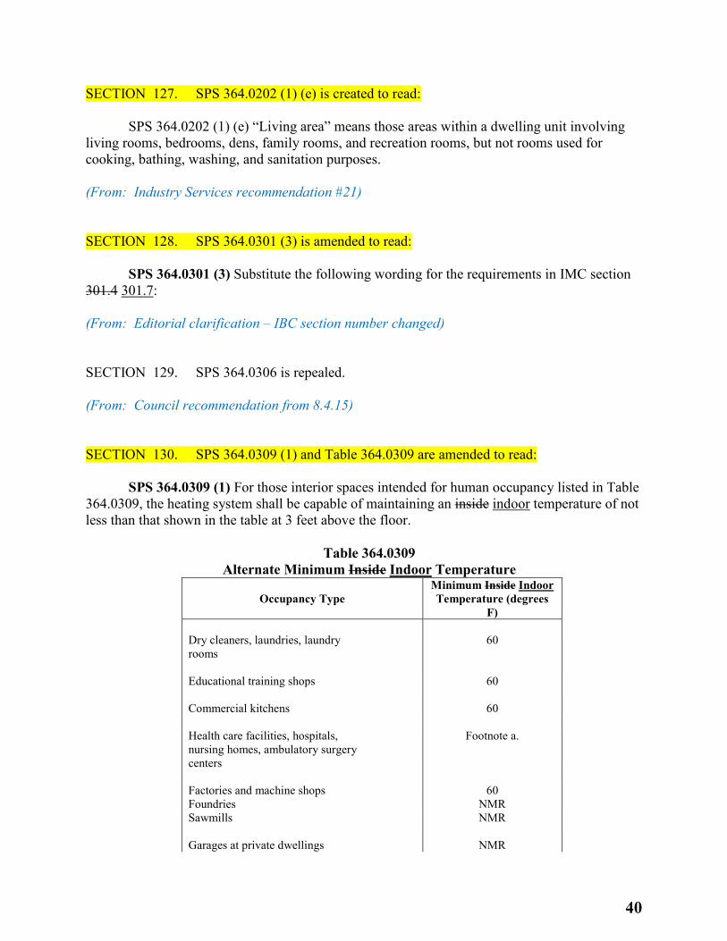
SECTION 127. SPS 364.0202 (1) (e) is created to read: SPS 364.0202 (1) (e) “Living area” means those areas within a dwelling unit involving living rooms, bedrooms, dens, family rooms, and recreation rooms, but not rooms used for cooking, bathing, washing, and sanitation purposes. (From: Industry Services recommendation #21) SECTION 128. SPS 364.0301 (3) is amended to read: SPS 364.0301 (3) Substitute the following wording for the requirements in IMC section 301.4 301.7: (From: Editorial clarification – IBC section number changed) SECTION 129. SPS 364.0306 is repealed. (From: Council recommendation from 8.4.15) SECTION 130. SPS 364.0309 (1) and Table 364.0309 are amended to read: SPS 364.0309 (1) For those interior spaces intended for human occupancy listed in Table 364.0309, the heating system shall be capable of maintaining an inside indoor temperature of not less than that shown in the table at 3 feet above the floor.
Table 364.0309 Alternate Minimum Inside Indoor Temperature
Occupancy Type Minimum Inside Indoor Temperature (degrees
F) Dry cleaners, laundries, laundry rooms
60
Educational training shops 60 Commercial kitchens 60 Health care facilities, hospitals, nursing homes, ambulatory surgery centers
Footnote a.
Factories and machine shops 60 Foundries NMR Sawmills NMR Garages at private dwellings NMR
40

Automotive service and repair garages
60
Car washes, enclosed: Self−serve NMR All other types 60 Ice skating rinks (indoor) NMR Natatoriums 76 Roller skating rinks (indoors) 60 Storage NMR Elevator cars NMR Janitor closets NMR Locker and dressing rooms 70 Shower rooms 70 Food processing NMR Printing 60
NMR = No minimum requirement a For inside indoor temperature requirements in health care facilities, use American Institute of Architects (AIA) Guidelines for Design and Construction of Hospital and Health Care Facilities.
(From: Industry Services recommendation #12) SECTION 131. SPS 364.0309 (3) is created to read: SPS 364.0309 (3) SPOT HEATING. Spot heating may be used to heat individual work stations in industrial buildings in lieu of heating the entire space s specified in IMC 309, provided the design temperature at the fixed work station is at least 60° F. (From: Industry Services recommendation #5) SECTION 132. SPS 364.0312 (Note) is amended to read: SPS 364.0312 Note: For design parameters in the IECC refer to ch. SPS 363 or IECC section 503 C403. SECTION 133. SPS 364.0401 (4) (b) is amended to read: SPS 364.0401 (4) (b) Substitute the following wording for the requirements in IMC section 401.4., item 2.: Intake openings shall be located not less than 10 feet horizontally from any hazardous or noxious contaminant source except as specified in IMC section 401.4, item 3 and section 501.3.1.
41
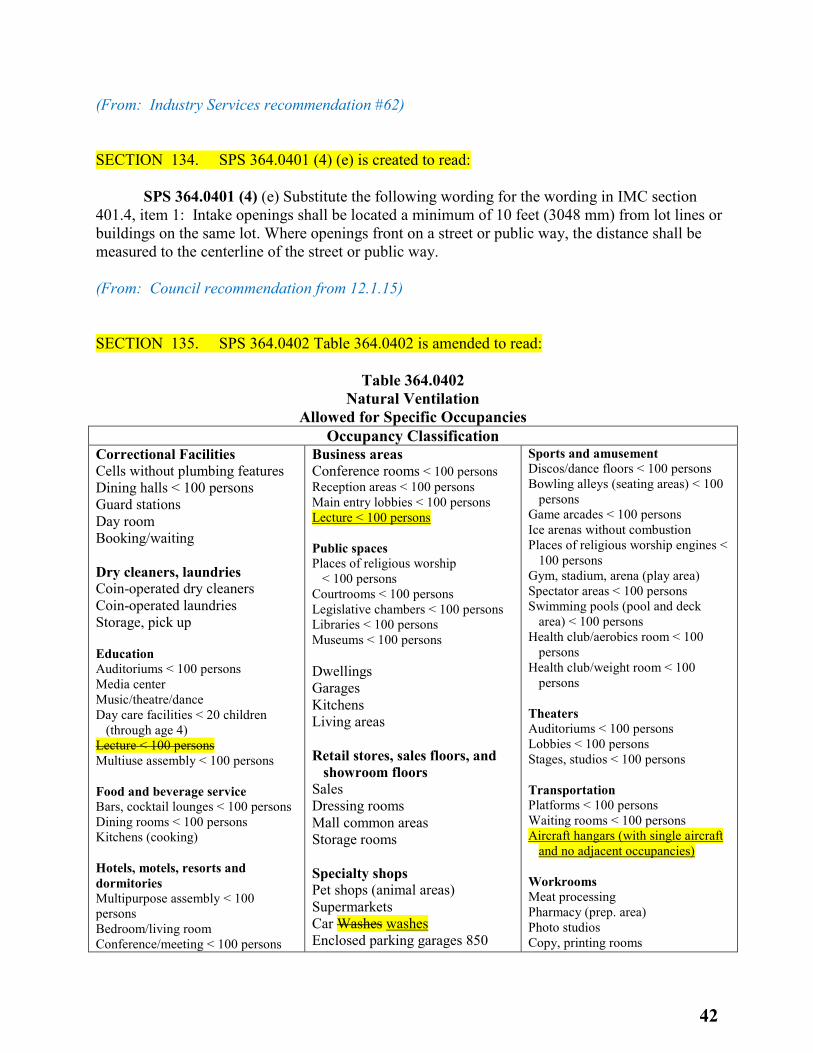
(From: Industry Services recommendation #62) SECTION 134. SPS 364.0401 (4) (e) is created to read: SPS 364.0401 (4) (e) Substitute the following wording for the wording in IMC section 401.4, item 1: Intake openings shall be located a minimum of 10 feet (3048 mm) from lot lines or buildings on the same lot. Where openings front on a street or public way, the distance shall be measured to the centerline of the street or public way. (From: Council recommendation from 12.1.15) SECTION 135. SPS 364.0402 Table 364.0402 is amended to read:
Table 364.0402 Natural Ventilation
Allowed for Specific Occupancies Occupancy Classification
Correctional Facilities Cells without plumbing features Dining halls < 100 persons Guard stations Day room Booking/waiting Dry cleaners, laundries Coin-operated dry cleaners Coin-operated laundries Storage, pick up Education Auditoriums < 100 persons Media center Music/theatre/dance Day care facilities < 20 children (through age 4) Lecture < 100 persons
Multiuse assembly < 100 persons Food and beverage service Bars, cocktail lounges < 100 persons Dining rooms < 100 persons Kitchens (cooking) Hotels, motels, resorts and dormitories Multipurpose assembly < 100 persons Bedroom/living room Conference/meeting < 100 persons
Business areas Conference rooms < 100 persons Reception areas < 100 persons Main entry lobbies < 100 persons Lecture < 100 persons Public spaces Places of religious worship < 100 persons Courtrooms < 100 persons Legislative chambers < 100 persons Libraries < 100 persons Museums < 100 persons Dwellings Garages Kitchens Living areas Retail stores, sales floors, and
showroom floors Sales Dressing rooms Mall common areas Storage rooms Specialty shops Pet shops (animal areas) Supermarkets Car Washes washes Enclosed parking garages 850
Sports and amusement Discos/dance floors < 100 persons Bowling alleys (seating areas) < 100
persons Game arcades < 100 persons Ice arenas without combustion Places of religious worship engines <
100 persons Gym, stadium, arena (play area) Spectator areas < 100 persons Swimming pools (pool and deck
area) < 100 persons Health club/aerobics room < 100
persons Health club/weight room < 100
persons Theaters Auditoriums < 100 persons Lobbies < 100 persons Stages, studios < 100 persons Transportation Platforms < 100 persons Waiting rooms < 100 persons Aircraft hangars (with single aircraft
and no adjacent occupancies) Workrooms Meat processing Pharmacy (prep. area) Photo studios Copy, printing rooms
42
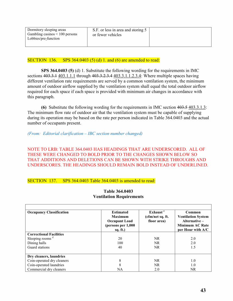
Dormitory sleeping areas Gambling casinos < 100 persons Lobbies/pre-function
S.F. or less in area and storing 5 or fewer vehicles
SECTION 136. SPS 364.0403 (5) (d) 1. and (6) are amended to read: SPS 364.0403 (5) (d) 1. Substitute the following wording for the requirements in IMC sections 403.3.1 403.1.1.1 through 403.3.2.3.4 403.3.1.1.2.3.4: Where multiple spaces having different ventilation rate requirements are served by a common ventilation system, the minimum amount of outdoor airflow supplied by the ventilation system shall equal the total outdoor airflow required for each space if each space is provided with minimum air changes in accordance with this paragraph. (6) Substitute the following wording for the requirements in IMC section 403.5 403.3.1.3: The minimum flow rate of outdoor air that the ventilation system must be capable of supplying during its operation may be based on the rate per person indicated in Table 364.0403 and the actual number of occupants present. (From: Editorial clarification – IBC section number changed) NOTE TO LRB: TABLE 364.0403 HAS HEADINGS THAT ARE UNDERSCORED. ALL OF THESE WERE CHANGED TO BOLD PRIOR TO THE CHANGES SHOWN BELOW SO THAT ADDITIONS AND DELETIONS CAN BE SHOWN WITH STRIKE THROUGHS AND UNDERSCORES. THE HEADINGS SHOULD REMAIN BOLD INSTEAD OF UNDERLINED. SECTION 137. SPS 364.0403 Table 364.0403 is amended to read:
Table 364.0403 Ventilation Requirements
Occupancy Classification Estimated Maximum
Occupant Load (persons per 1,000
sq. ft.)
Exhaust c (cfm/net sq. ft.
floor area)
Common Ventilation System
Alternative – Minimum AC Rate per Hour with A/C
Correctional Facilities Sleeping rooms d Dining halls Guard stations
20
100 40
NR NR NR
2.0 2.0 1.5
Dry cleaners, laundries Coin-operated dry cleaners Coin-operated laundries Commercial dry cleaners
8 8
NA
NR NR 2.0
1.0 1.0 NR
43
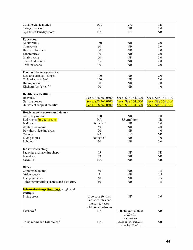
Commercial laundries Storage, pick up Apartment laundry rooms
NA 8
NA
2.0 NR 0.5
NR 1.0 NR
Education Auditoriums Classrooms Day care facilities Laboratories Music rooms Special education Training shops
150 50 30 30 50 35 30
NR NR NR NR NR NR NR
2.0 2.0 2.0 2.0 2.0 2.0 2.0
Food and beverage service Bars and cocktail lounges Cafeterias, fast food Dining rooms Kitchens (cooking) d, c
100 100 70 20
NR NR NR NR
2.0 2.0 2.0 1.0
Health care facilities Hospitals Nursing homes Outpatient surgical facilities
See s. SPS 364.0300 See s. SPS 364.0300 See s. SPS 364.0300
See s. SPS 364.0300 See s. SPS 364.0300 See s. SPS 364.0300
See s. SPS 364.0300 See s. SPS 364.0300 See s. SPS 364.0300
Hotels, motels, resorts and dorms Assembly rooms Bathrooms for guest rooms c, d Bedroom Conference rooms Dormitory sleeping areas Casinos Living rooms Lobbies
120 NA
footnote f 50 20 NA
footnote f 30
NR
35 cfm/room NR NR NR 2.0 NR NR
2.0 NR 1.0 2.0 1.0 NR 1.0 2.0
Industrial/Factory Factories and machine shops Foundries Sawmills
13 13 NA
NR NR NR
NR NR NR
Office Conference rooms Office spaces Reception areas Telecommunication canters and data entry
50 7 60 60
NR NR NR NR
1.5 1.5 1.5 1.5
Private dwellings Dwellings, single and multiple Living areas Kitchens d Toilet rooms and bathrooms d
2 persons for first bedroom, plus one
person for each additional bedroom
NA
NA
NR
100 cfm intermittent or 20 cfm
continuous Mechanical exhaust
capacity 50 cfm
1.0
NR
NR
44
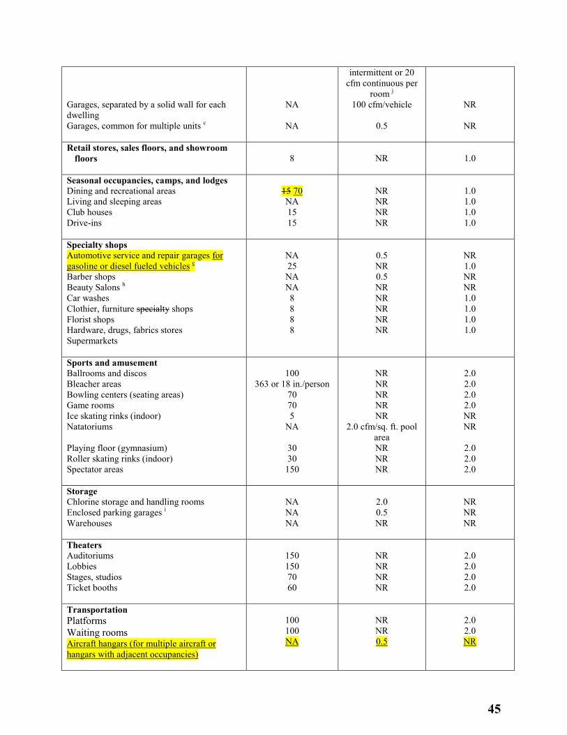
Garages, separated by a solid wall for each dwelling Garages, common for multiple units c
NA
NA
intermittent or 20 cfm continuous per
room j 100 cfm/vehicle
0.5
NR
NR
Retail stores, sales floors, and showroom floors
8
NR
1.0
Seasonal occupancies, camps, and lodges Dining and recreational areas Living and sleeping areas Club houses Drive-ins
15 70 NA 15 15
NR NR NR NR
1.0 1.0 1.0 1.0
Specialty shops Automotive service and repair garages for gasoline or diesel fueled vehicles c Barber shops Beauty Salons h Car washes Clothier, furniture specialty shops Florist shops Hardware, drugs, fabrics stores Supermarkets
NA 25 NA NA 8 8 8 8
0.5 NR 0.5 NR NR NR NR NR
NR 1.0 NR NR 1.0 1.0 1.0 1.0
Sports and amusement Ballrooms and discos Bleacher areas Bowling centers (seating areas) Game rooms Ice skating rinks (indoor) Natatoriums Playing floor (gymnasium) Roller skating rinks (indoor) Spectator areas
100
363 or 18 in./person 70 70 5
NA
30 30
150
NR NR NR NR NR
2.0 cfm/sq. ft. pool area NR NR NR
2.0 2.0 2.0 2.0 NR NR
2.0 2.0 2.0
Storage Chlorine storage and handling rooms Enclosed parking garages i Warehouses
NA NA NA
2.0 0.5 NR
NR NR NR
Theaters Auditoriums Lobbies Stages, studios Ticket booths
150 150 70 60
NR NR NR NR
2.0 2.0 2.0 2.0
Transportation Platforms Waiting rooms Aircraft hangars (for multiple aircraft or hangars with adjacent occupancies)
100 100 NA
NR NR 0.5
2.0 2.0 NR
45
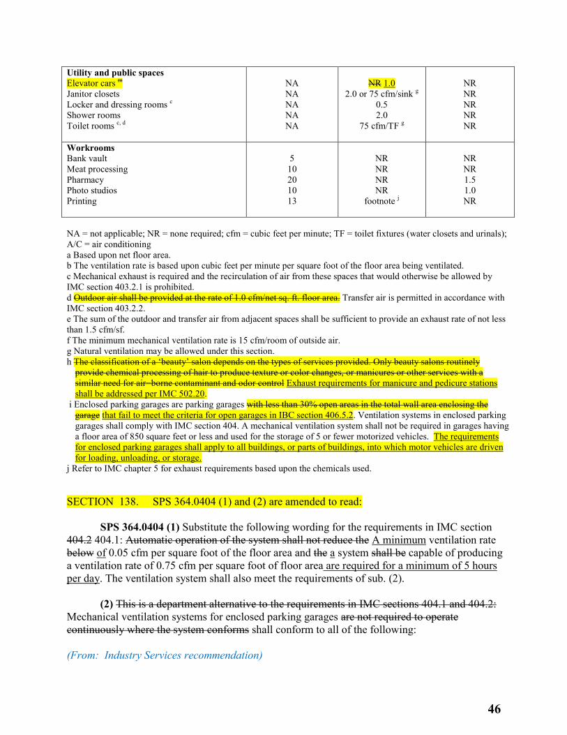
Utility and public spaces Elevator cars m Janitor closets Locker and dressing rooms c Shower rooms Toilet rooms c, d
NA NA NA NA NA
NR 1.0
2.0 or 75 cfm/sink g 0.5 2.0
75 cfm/TF g
NR NR NR NR NR
Workrooms Bank vault Meat processing Pharmacy Photo studios Printing
5 10 20 10 13
NR NR NR NR
footnote j
NR NR 1.5 1.0 NR
NA = not applicable; NR = none required; cfm = cubic feet per minute; TF = toilet fixtures (water closets and urinals); A/C = air conditioning a Based upon net floor area. b The ventilation rate is based upon cubic feet per minute per square foot of the floor area being ventilated. c Mechanical exhaust is required and the recirculation of air from these spaces that would otherwise be allowed by IMC section 403.2.1 is prohibited. d Outdoor air shall be provided at the rate of 1.0 cfm/net sq. ft. floor area. Transfer air is permitted in accordance with IMC section 403.2.2. e The sum of the outdoor and transfer air from adjacent spaces shall be sufficient to provide an exhaust rate of not less than 1.5 cfm/sf. f The minimum mechanical ventilation rate is 15 cfm/room of outside air. g Natural ventilation may be allowed under this section. h The classification of a ‘beauty’ salon depends on the types of services provided. Only beauty salons routinely
provide chemical processing of hair to produce texture or color changes, or manicures or other services with a similar need for air−borne contaminant and odor control Exhaust requirements for manicure and pedicure stations shall be addressed per IMC 502.20.
i Enclosed parking garages are parking garages with less than 30% open areas in the total wall area enclosing the garage that fail to meet the criteria for open garages in IBC section 406.5.2. Ventilation systems in enclosed parking garages shall comply with IMC section 404. A mechanical ventilation system shall not be required in garages having a floor area of 850 square feet or less and used for the storage of 5 or fewer motorized vehicles. The requirements for enclosed parking garages shall apply to all buildings, or parts of buildings, into which motor vehicles are driven for loading, unloading, or storage.
j Refer to IMC chapter 5 for exhaust requirements based upon the chemicals used. SECTION 138. SPS 364.0404 (1) and (2) are amended to read: SPS 364.0404 (1) Substitute the following wording for the requirements in IMC section 404.2 404.1: Automatic operation of the system shall not reduce the A minimum ventilation rate below of 0.05 cfm per square foot of the floor area and the a system shall be capable of producing a ventilation rate of 0.75 cfm per square foot of floor area are required for a minimum of 5 hours per day. The ventilation system shall also meet the requirements of sub. (2). (2) This is a department alternative to the requirements in IMC sections 404.1 and 404.2: Mechanical ventilation systems for enclosed parking garages are not required to operate continuously where the system conforms shall conform to all of the following: (From: Industry Services recommendation)
46
SECTION 139. SPS 364.0407 (title) is repealed. SECTION 140. SPS 364.0407 is renumbered 364.0401 (1) (a) 3. and amended to read: SPS 364.0401 (1) (a) 3. This is a department rule in addition to the requirements in IMC section 400: Chemical or septic toilets and composting privies are prohibited in spaces under negative pressure. Toilet rooms with chemical or septic toilets shall be provided with natural ventilation via a window, louver or skylight with at least 2 square feet of area openable directly to the outside. The opening shall be provided with a screen to limit the passage of insects and vermin. (From: Editorial clarification – no section 400) SECTION 141. SPS 364.0502 (2) (Note) is amended to read: SPS 364.0502 Note: Under s. SPS 361.03 (14) (a), IFC section 2211.7 2311.7 exempts a natural−gas motor−vehicle repair garage from the requirements of IMC section 502.16 if no work is performed on the fuel system in the vehicles, and the work is also limited to exchanging parts and maintenance that does not include any open flame or welding. (From: Editorial clarification – IBC section number changed) SECTION 142. SPS 364.0507 (1) and (2) are amended to read: SPS 364.0507 (1) Substitute the following wording for the introductory paragraph in IMC section 507.13 507.5: Commercial food service hoods shall exhaust a minimum net quantity of air determined either through engineering analysis or in accordance with this subsection and IMC sections 507.13.1 507.5.1 through 507.13.4 507.5.4. The net quantity of exhaust air shall be calculated by subtracting any airflow supplied directly to a hood cavity from the total exhaust flow rate of a hood. Where any combination of heavy−duty, medium−duty and light−duty cooking appliances are utilized under a single hood, the exhaust rate required by IMC sections 507.13.1 507.5.1 through 507.13.4 507.5.4 for the heaviest duty appliance covered by the hood shall be used for the entire hood. (2) The requirements of IMC section 507.13.5 507.5.5 are not included as part of this chapter. (From: Editorial clarification – IBC section numbers changed) SECTION 143. SPS 364.0602 is amended to read:
47
SPS 364.0602 Substitute the following wording for the requirements, but not the exceptions, in IMC section 602.2.1: Except as required by Sections 602.2.1.1 through 602.2.1.5 602.2.1.6, materials within plenums shall be noncombustible or shall have a flame spread index of not more than 25 and a smoke−developed index of not more than 50 when tested in accordance with ASTM E84, CAN/ULC S102.2 or UL 723. (From: Editorial clarification – IBC section number changed) SECTION 144. SPS 364.0701 and (Note) are created to read: SPS 364.0701 Combustion air. This is a department informational note to be used under IMC chapter 7. Note: The intent of the IMC is that barometric dampers are not allowed for combustion air. SECTION 145. SPS 364.0801 (2) is amended to read: SPS 364.0801 (2) This is a department rule in addition to the requirements in IMC section 801.2: Portable or permanently installed, fuel−fired, unvented heating appliances, shall not be installed except during construction or demolition of a building if the appliances are provided in accordance with ch. SPS 314. (From: Editorial clarification – incomplete sentence) SECTION 146. SPS 364.1500 (2) (a) is amended to read: SPS 364.1500 (2) (a) FGI Guidelines for Design and Construction of Health Care Facilities, 2010 Hospitals and Outpatient Facilities, 2014. SECTION 147. SPS 364.1500 (2) (am) is created to read: SPS 364.1500 (2) (am) FGI Guidelines for Design and Construction of Residential Health, Care, and Support Facilities, 2014. (From: Recommendations from DHS/DQA) SECTION 148. SPS 366.0101 (2) is amended to read: SPS 366.0101 (2) (a) Except as provided in par. (b), where a building or portion of a building that has not been previously occupied or used as a public building or place of employment is to be changed to an occupancy or use that constitutes a public building or place of employment, the building or portion of a building shall comply with the IBC for new construction IEBC Chapter 14, Performance Compliance Methods.
48
(From: Recommendation from Tom Kasper) SECTION 149. SPS 366.0101 (3) and (a) to (d) are renumbered 366.0101 (3) (a) and 1. to 4. SECTION 150. SPS 366.0101 (3) (b) is created to read: SPS 366.0101 (3) (b) Locally permitted temporary uses may be over-ridden by state corrective building orders. (From: Recommendation from Tom Kasper) SECTION 151. SPS 366.0101 (4) (b) and (c) are amended to read: SPS 366.0101 (4) (b) Repairs, alterations, additions, changes in occupancy, and relocated buildings complying with the applicable requirements of IEBC chapters 4 5 through 12 13 shall be considered in compliance with the provisions of this code. (c) Repairs, alterations, additions, changes in occupancy, and relocated buildings complying with IEBC chapter 13 14 shall be considered in compliance with the provisions of this code. (From: Editorial clarification – IEBC chapter numbers changed) SECTION 152. SPS 366.0202 is created to read: SPS 366.0202 Definitions. Substitute the following definition for the corresponding definition in IEBC section 202: “Work area” means that portion or portions of a building consisting of all reconfigured spaces as indicated on the construction documents. Work area excludes other portions of the building where incidental work entailed by the intended work must be performed and portions of the building where work not initially intended by the owner is specifically required by this code. The work area is the area reconfigured with full height walls and the area that has its required egress reconfigured. (From: Recommendation from Tom Kasper) SECTION 153. SPS 366.0300 is renumbered 366.0400 and amended to read: SPS 366.0400 The requirements in IEBC Chapter 3 4 are not included as part of this code, except for the requirements in IEBC Section 310 410 when applied by IEBC Section 1301.2.5 1401.2.5.
49
SECTION 154. SPS 366.0500 is renumbered 366.0600 and amended to read: SPS 366.0600 These are department rules in addition to the requirements in IEBC chapter 5 6 and are established under the authority of s. 101.127, Stats.: SECTION 155. SPS 366.0506 is renumbered 366.0606 and amended to read: SPS 366.0606 The requirements in IEBC sections 506.2 606.2 to 506.2.5 606.2.5 are not included as part of this code. SECTION 156. SPS 366.0509 is renumbered 366.0609 and amended to read: SPS 366.0609 The requirements in IEBC section 509 609 are not included as part of this code. SECTION 157. SPS 366.0602 and (1) and (2) is renumbered 366.0702 and (1) and (2) and amended to read: SPS 366.0702 (1) MATERIALS AND METHODS. Substitute the following wording for the requirements in IEBC section 602.4 702.4: All new work shall comply with materials and methods requirements in the IBC, IECC, IFGC, IMC, and IPC, as applicable, that specify material standards, detail of installation and connection, joints, penetrations, and continuity of any element, component, or system in the building. (2) INTERNATIONAL FUEL GAS CODE. The requirements in IEBC section 602.4.1 are not included as part of this code. SECTION 158. SPS 366.0604 is renumbered 366.0704 and amended to read: SPS 366.0704 This is a department rule in addition to the requirements in IEBC section 604 704: Where installing an inclined platform lift or stairway chairlift, the clear−passage width shall be provided with the lift in the unfolded, usable position — except where an existing, previously approved lift is being replaced, the clear−passage width may remain as it was with the original lift in place, but it may not be reduced by the replacement. (From: Editorial clarifications – IEBC chapter numbers changed) SECTION 159. SPS 366.0605 is repealed and recreated to read:
50
SPS 366.0605 Accessibility. Substitute the following wording for the requirements in IEBC section 605.1: General. Repairs shall be done in a manner that maintains any required accessibility in accordance with IEBC section 705.1.13. (From: IEBC now includes these provisions which were taken from the 2012 IECC and recommendation from Tom Kasper) SECTION 160. SPS 366.0607 is repealed. (From: IEBC now includes these provisions which were taken from the 2012 IECC) SECTION 161. SPS 366.0701 is created to read: SPS 366.0701 General. Substitute the following wording for the requirements in IEBC section 701.2: Conformance. An existing building or portion thereof shall not be altered such that the building becomes less safe than was required in its existing condition. SECTION 162. SPS 366.0703 is created to read: SPS 366.0703 Fire Protection. Substitute the following wording for the requirements in IEBC section 703.1: General. Alterations shall be done in a manner that maintains the level of fire protection required prior to the alteration. (From: Recommendation from Tom Kasper) SECTION 163. SPS 366.0704 is renumbered 366.0804 and amended to read: SPS 366.0804 This is a department exception to the requirement in IEBC section 704.2 804.2: The installation or extension of an automatic sprinkler system may exclude the protection of combustible concealed spaces that are not accessible in existing buildings. This exclusion is also applicable to sprinkler systems triggered by changes of use or additions. (From: Editorial clarifications – IEBC chapter numbers changed and recommendation from Tom Kasper) SECTION 164. SPS 366.0704 is created to read: SPS 366.0704 Means of Egress. Substitute the following wording for the requirements in IEBC section 704.1: General. Alterations shall be done in a manner that maintains the level of protection required for the means of egress prior to the alteration. (From: Recommendation from Tom Kasper)
51
SECTION 165. SPS 366.0709 is renumbered 366.0809 and amended to read: SPS 366.0809 The exception to the requirements in IEBC section 709.1 809.1 and the requirements in IEBC section 709.2 809.2 are not included as part of this code. SECTION 166. SPS 366.0710 is renumbered 366.0810 and amended to read: SPS 366.0810 Substitute the following wording for the requirements in IEBC section 710.1 810.1: Where the occupant load of a story is increased by more than 20 percent, plumbing fixtures for the story shall be provided in quantities specified in the IBC based on the increased occupant load. (From: Editorial clarifications – IEBC chapter numbers changed) SECTION 167. SPS 366.0711 is repealed. (From: IEBC now includes these provisions which were taken from the 2012 IECC) SECTION 168. SPS 366.0802 is renumbered 366.0902 and amended to read: SPS 366.0902 The requirements in IEBC section 802.2.1 902.2.1 are not included as part of this code. SECTION 169. SPS 366.0803 is created to read: SPS 366.0803 Building elements and materials. Substitute the following wording for the requirements in IEBC section 803.2.1: All existing interior vertical openings in the work area connecting two or more floors shall be enclosed with approved assemblies having a fire resistance rating of not less than one hour with approved opening protectives. (From: Recommendation from Tom Kasper) SECTION 170. SPS 366.0808 is repealed. (From: IEBC now includes these provisions which were taken from the 2012 IECC) SECTION 171. SPS 366.0809 is renumbered 366.0909 and amended to read:
52
SPS 366.0909 These are department rules in addition to the requirements in IEBC chapter 8 9: SECTION 172. SPS 366.0901 and (1) to (3) are renumbered 366.1001 and (1) to (3) and amended to read: SPS 366.1001 (1) CHANGE IN OF OCCUPANCY WITH NO OCCUPANCY CLASSIFICATION. Substitute the following wording for the requirements in IEBC section 901.2 1001.2: A change in of occupancy, as defined in IEBC section 202, with no or a change of occupancy classification within a space where there is a different fire protection system threshold requirement in Chapter 9 of the International Building Code may not be made to any structure that will subject the structure to any special provisions of this code, including the provisions of IEBC sections 902 through 911, without the approval of the code official. An increased occupant load may trigger additional means of egress or fire protection requirements. (2) CHANGE OF OCCUPANCY CLASSIFICATION. This is a department rule in addition to the requirements in IEBC section 901.3 1001.2.2: Buildings undergoing a change in occupancy that would result in an increase in demand for either fossil fuel or electrical energy shall comply with the IECC. (3) CERTIFICATION OF OCCUPANCY REQUIRED. The requirements in IEBC section 901.4 1001.3 are not included as part of this code. (From: Editorial clarifications – IEBC chapter and section numbers and section titles changed, section content changed, and recommendation from Tom Kasper) SECTION 173. SPS 366.0901 (4) is renumbered 366.1012 and amended to read: SPS 366.1012 Standpipe systems. This is a department rule in addition to the requirements in IEBC section 912.2 1012.2: Standpipe systems shall be provided in existing buildings and structures or portions of existing buildings and structures in accordance with chapter 9 of the IBC when existing buildings or structures that are greater than 60 feet in height are changed to include a Group R−1 or R−2 occupancy. SECTION 174. SPS 366.0902 is created to read: SPS 366.0902 Boiler and furnace equipment rooms. Substitute the following wording for the requirements, but not the exceptions, in IEBC section 902.2: Boiler and furnace equipment rooms. Boiler and furnace equipment rooms adjacent to or within Groups I-1, I-2, I-4, R-1, R-2 and R-4 occupancies shall be enclosed in compliance with IBC 509 heating equipment enclosure requirements. (From: Recommendation from Tom Kasper)
53
SECTION 175. SPS 366.0911 is renumbered 366.1011 and amended to read: SPS 366.1011 (1) ELEVATOR RECALL. This is a department rule in addition to the requirements in IEBC section 911 1011: At least one existing elevator shall be provided with emergency recall operation and emergency in−car operation complying with ch. SPS 318 when an existing building or structure that is greater than 60 feet in height is changed to include a Group R−1 or R−2 occupancy. (2) CARBON MONOXIDE ALARMS. This is a department rule in addition to the requirements in IEBC section 911 1011: A building or a portion of a building changed to be or include a residential building as defined under s. 101.149 (1) (b), Stats., shall be provided with carbon monoxide alarms or detectors in accordance with s. SPS 362.1200. SECTION 176. SPS 366.0912 is renumbered 366.1010 and amended to read: SPS 366.1010 Substitute the following wording for the requirements in IEBC section 910 1010: Where the occupant load of a story is increased by more than 20 percent, plumbing fixtures for the story shall be provided in quantities specified in the IBC based on the increased occupant load. SECTION 177. SPS 366.1002 is renumbered 366.1102 and amended to read: SPS 366.1102 This is a department exception to the requirements in IEBC section 1002.3 1102.3: An automatic sprinkler system is not required for additions to individual dwelling units within existing townhouses that are not already protected with an automatic sprinkler system. (From: Editorial clarifications – IEBC chapter numbers changed) SECTION 178. SPS 366.1012 and (1) and (2) are created to read: SPS 366.1012 Change of Occupancy Classification. (1) This is a department requirement in addition to the requirements in IEBC section 1012.1.1: The provision of chapters 7 to 9 of the IEBC are applicable to the work area. (2) Substitute the following wording for the requirements, but not the exceptions, in IEBC section 1012.2.1: Fire sprinkler system. Where a change in occupancy classification occurs or where there is a change of occupancy within a space where there is a different fire protection system threshold requirement in Chapter 9 of the International Building Code that requires an automatic fire sprinkler system to be provided based on the new occupancy in accordance with Chapter 9 of the International Building Code, such system shall be provided throughout the work area. (From: Recommendations from Tom Kasper)
54
SECTION 179. SPS 366.1101 is renumbered 366.1201 and amended to read: SPS 366.1201 (1) SCOPE. This is a department rule in addition to the requirements in IEBC section 1101.1 1201.1: Any historic building is exempt from the energy requirements of this code. (2) REPORT. The requirements in IEBC section 1101.2 1202.2 are not included as part of this code. (From: Editorial clarifications – IEBC chapter numbers changed) SECTION 180. SPS 366.1102 is created to read: SPS 366.1102 This is a department exception in addition to the exception in IEBC section1102.2: Buildings meeting the legacy Wisconsin unlimited area provisions are allowed to have unlimited area additions per the current code without a separating firewall. (From: Recommendations from Tom Kasper) SECTION 181. SPS 366.1105 is renumbered 366.1205 and 366.1205 (intro) as renumbered, is amended to read: SPS 366.1205 (intro) These are department rules in addition to the requirements in IEBC section 1105 1205: Historic buildings to be used as exhibit buildings shall comply with all of the following requirements: SECTION 182. SPS 366.1204 is created to read: SPS 366.1204 Historic buildings. Historic buildings shall not be required to comply with the International Energy Conservation Code for building envelope compliance except as follows: (1) Existing ceiling, wall or floor cavities exposed during alterations shall be filled with insulation. (2) All replacement skylight, window and/or door assemblies shall meet the minimum code requirements of the International Energy Conservation Code unless specifically designed to address unique aesthetics associated with the historic nature of the building. Glass only replacements in an existing sash and frame are exempt from the application of the IECC. (3) Roofs without insulation in the cavity and where the sheathing or insulation is exposed during reroofing shall be insulated either above or below the sheathing. (From: Recommendations from Industry Services)
55
SECTION 183. SPS 366.1301 is renumbered 366.1401 and amended to read: SPS 366.1401 Applicability General (1) APPLICABILITY. Substitute the following wording for the requirements in IEBC section 1301.2 1401.2: The provisions of sections 1301.2.1 1401.2.1 through 1301.2.5 1401.2.5 shall apply to existing occupancies that will continue to be, or are proposed to be, in Groups A, B, E, F, M, R and S. These provisions shall not apply to buildings with occupancies in Group H or Group I. (2) ACCESSIBILITY REQUIREMENTS. Substitute the following wording for the requirements in IEBC section 1301.2.5 1401.2.5: All portions of the buildings proposed for change of occupancy or being altered shall conform to the accessibility provisions of IEBC section 310. (3) OTHER CODES. The requirements in IEBC section 1301.3.2 1401.3.2 are not included as part of this code. SECTION 184. SPS 366.1401 (4) is created to read: SPS 366.1401 (4) Minimum plumbing fixtures. This is a department rule in addition to the requirements in IEBC section 1401.2: Where the occupant load of a story is increased by more than 20 percent, plumbing fixtures for the story shall be provided in quantities specified in the IBC based on the increased occupant load. (From: Recommendations from Tom Kasper) SECTION 185. SPS 366.1400 is renumbered 366.1500 and amended to read: SPS 366.1500 The requirements in IEBC chapter 14 15 are not included as part of this code. (From: Editorial clarifications – IEBC chapter numbers changed) SECTION 186. Chapters SPS 361 – 366 Appendix A is deleted. (From: Industry Services recommendation #77) SECTION 187. Chapters SPS 361 – 366 Appendix B is renumbered SPS 361 to 366 Appendix B. (From: Editorial clarification)
56

SECTION 188. EFFECTIVE DATE. The rules adopted in this order shall take effect on the first day of the month following publication in the Wisconsin administrative register, pursuant to s. 227.22 (2) (intro.), Stats. File reference: SPS 361-366/partial proposed draft language 10
57
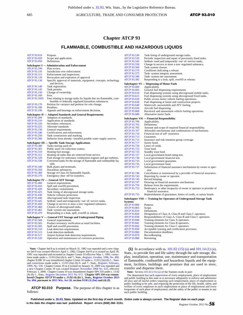
685 ATCP 93.010AGRICULTURE, TRADE AND CONSUMER PROTECTION
Published under s. 35.93, Wis. Stats., by the Legislative Reference Bureau.
Published under s. 35.93 , Stats. Updated on the first day of each month. Entire code is always current. The Register date on each pageis the date the chapter was last published. Report errors (608) 266−3151. Register October 2013 No. 694
Chapter ATCP 93
FLAMMABLE, COMBUSTIBLE AND HAZARDOUS LIQUIDS
ATCP 93.010 Purpose.ATCP 93.020 Scope and application.ATCP 93.050 Definitions.
Subchapter I — Administration and EnforcementATCP 93.100 Plan review.ATCP 93.110 Jurisdiction over enforcement.ATCP 93.115 Enforcement and inspections.ATCP 93.120 Revocation and expiration of approval.ATCP 93.130 Specific approval of materials, equipment, concepts, technology
and devices.ATCP 93.140 Tank registration.ATCP 93.145 Tank permits.ATCP 93.150 Change of ownership.ATCP 93.160 Fees.ATCP 93.1605 Fees relating to storage tanks for liquids that are flammable, com-
bustible or federally regulated hazardous substances.ATCP 93.170 Petition for variance and petition for rule change.ATCP 93.180 Penalties.ATCP 93.190 Appeals and hearings on enforcement decisions.
Subchapter II — Adopted Standards and General RequirementsATCP 93.200 Adoption of standards.ATCP 93.210 Application of standards.ATCP 93.220 Secondary references.ATCP 93.225 Alternate standards.ATCP 93.230 General requirements.ATCP 93.240 Certifications and enforcement.ATCP 93.250 Tank construction and marking.ATCP 93.260 Setbacks from already−installed potable water supply sources.
Subchapter III — Specific Tank Storage ApplicationsATCP 93.300 Tanks storing used oil.ATCP 93.305 Public used−oil collection centers.ATCP 93.310 Heating fuel storage.ATCP 93.315 Heating oil tanks that are removed from service.ATCP 93.320 Fuel storage for stationary combustion engines and gas turbines.ATCP 93.330 Converted tanks for the storage of flammable and combustible liq-
uids.ATCP 93.340 Bulk plants and terminals.ATCP 93.350 Hazardous substances.ATCP 93.360 Storage of Class IA flammable liquids.ATCP 93.370 Emergency shut−off for transfers.
Subchapter IV — General AST StorageATCP 93.400 General requirements.ATCP 93.410 Spill and overfill prevention.ATCP 93.420 Secondary containment.ATCP 93.425 Tank lining of aboveground storage tanks.ATCP 93.430 Vehicle collision protection.ATCP 93.440 Aboveground tank inspection.ATCP 93.445 Seldom−used and temporarily−out−of−service tanks.ATCP 93.450 Change in service to store a non−regulated substance.ATCP 93.460 Closure of aboveground tanks.ATCP 93.465 Tank−system site assessment.ATCP 93.470 Responding to a leak, spill, overfill or release.
Subchapter V — General UST Storage and Underground PipingATCP 93.500 General requirements.ATCP 93.503 Product inventory verification at retail facilities.ATCP 93.505 Spill and overfill prevention.ATCP 93.510 Leak detection requirements.ATCP 93.515 Leak detection methods.ATCP 93.517 Airport hydrant leak detection requirements.ATCP 93.520 Operation and maintenance of corrosion protection.
ATCP 93.530 Tank lining of underground storage tanks.ATCP 93.535 Periodic inspection and repair of previously lined tanks.ATCP 93.545 Seldom−used and temporarily−out−of−service tanks.ATCP 93.550 Change in service to store a non−regulated substance.ATCP 93.560 Tank system closure.ATCP 93.570 Conditions indicating a release.ATCP 93.575 Tank−system integrity assessment.ATCP 93.580 Tank−system site assessment.ATCP 93.585 Responding to a leak, spill, overfill or release.
Subchapter VI — Dispensing of Motor FuelsATCP 93.600 Applicability.ATCP 93.605 General fuel dispensing requirements.ATCP 93.610 Fuel dispensing systems using aboveground mobile tanks.ATCP 93.615 Fuel dispensing systems using aboveground fixed tanks.ATCP 93.620 Public access motor vehicle fueling operations.ATCP 93.630 Fuel dispensing at farms and construction projects.ATCP 93.640 Watercraft, snowmobile and ATV fueling.ATCP 93.650 Aircraft fuel dispensing.ATCP 93.660 Racetrack and amusement vehicle fueling operations.ATCP 93.680 Alternative motor fuels.
Subchapter VII — Financial ResponsibilityATCP 93.700 Applicability.ATCP 93.703 Definitions.ATCP 93.705 Amount and scope of required financial responsibility.ATCP 93.707 Allowable mechanisms and combinations of mechanisms.ATCP 93.710 Financial test of self−insurance.ATCP 93.713 Guarantee.ATCP 93.715 Insurance and risk retention group coverage.ATCP 93.717 Surety bond.ATCP 93.720 Letter of credit.ATCP 93.723 Trust fund.ATCP 93.725 Standby trust fund.ATCP 93.727 Local government bond rating test.ATCP 93.730 Local government financial test.ATCP 93.733 Local government guarantee.ATCP 93.735 Local government fund.ATCP 93.737 Substitution of financial assurance mechanisms by owner or oper-
ator.ATCP 93.740 Cancellation or nonrenewal by a provider of financial assurance.ATCP 93.743 Reporting by owner or operator.ATCP 93.745 Record keeping.ATCP 93.747 Drawing on financial assurance mechanisms.ATCP 93.750 Release from the requirements.ATCP 93.753 Bankruptcy or other incapacity of owner or operator or provider of
financial assurance.ATCP 93.755 Replenishment of guarantees, letters of credit, or surety bonds.
Subchapter VIII — Training for Operators of Underground Storage TankSystemsATCP 93.800 Purpose.ATCP 93.805 Scope.ATCP 93.810 Definitions.ATCP 93.820 Designation of Class A, Class B and Class C operators.ATCP 93.830 Responsibilities of Class A, Class B and Class C operators.ATCP 93.840 Training elements for Class A operators.ATCP 93.841 Training elements for Class B operators.ATCP 93.842 Training elements for Class C operators.ATCP 93.850 Acceptable training and certification processes.ATCP 93.860 Documentation deadlines.ATCP 93.870 Recordkeeping.ATCP 93.880 Retraining.
Note: Chapter Ind 8 as it existed on March 31, 1982 was repealed and a new chap-ter Ind 8 was created effective April 1, 1982; Chapter Ind 8 as it existed on April 30,1991 was repealed and recreated as chapter Comm 10 effective May 1, 1991; correc-tions made under s. 13.93 (2m) (b) 6. and 7., Stats., Register, October, 1996, No. 490;chapter ILHR 10 was renumbered chapter Comm 10 under s. 13.93 (2m) (b) 1., Stats.and corrections made under s. 13.93 (2m) (b) 6. and 7., Stats., Register, February,1999, No. 518. Chapter Comm 10 as it existed on January 31, 2009 was repealed anda new Chapter Comm 10 was created Register November 2008 No. 635, effectiveFebruary 1, 2009. Chapter Comm 10 was renumbered chapter SPS 310 under s. 13.92(4) (b) 1., Stats., Register December 2011 No. 672. Chapter SPS 310 was renum-bered Chapter ATCP 93 under s. 13.92 (4) (b) 1., Stats., Register October 2013No. 694, pursuant to 2013 Wis. Act 20, section 9138 (3) (fm) and (4) (f).
ATCP 93.010 Purpose. The purpose of this chapter is asfollows:
(1) In accordance with ss. 101.02 (15) (a) and 101.14 (1) (a),Stats., to provide fire and life safety through the safe storage, dis-play, installation, operation, use, maintenance and transportationof flammable, combustible and hazardous liquids and the equip-ment, facilities, buildings and premises that are used to store,transfer and dispense them.
Note: Section 101.02 (15) (a) of the Statutes reads in part:The department has such supervision of every employment, place of employment
and public building in this state as is necessary adequately to enforce and administerall laws and all lawful orders requiring such employment, place of employment orpublic building to be safe, and requiring the protection of the life, health, safety andwelfare of every employee in such employment or place of employment and everyfrequenter of such place of employment, and the safety of the public or tenants in anysuch public building.
58
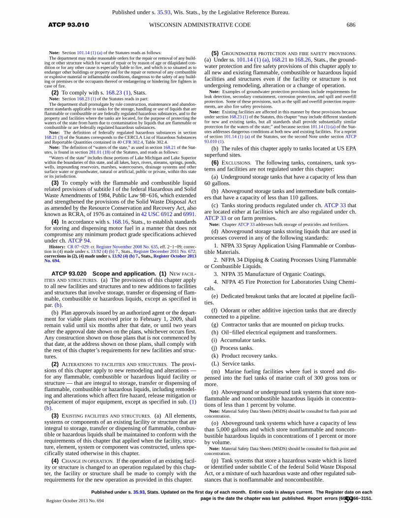
686 ATCP 93.010 WISCONSIN ADMINISTRATIVE CODE
Published under s. 35.93, Wis. Stats., by the Legislative Reference Bureau.
Published under s. 35.93 , Stats. Updated on the first day of each month. Entire code is always current. The Register date on eachpage is the date the chapter was last published. Report errors (608) 266−3151.Register October 2013 No. 694
Note: Section 101.14 (1) (a) of the Statutes reads as follows:The department may make reasonable orders for the repair or removal of any build-
ing or other structure which for want of repair or by reason of age or dilapidated con-dition or for any other cause is especially liable to fire, and which is so situated as toendanger other buildings or property and for the repair or removal of any combustibleor explosive material or inflammable conditions, dangerous to the safety of any build-ing or premises or the occupants thereof or endangering or hindering fire fighters incase of fire.
(2) To comply with s. 168.23 (1), Stats.Note: Section 168.23 (1) of the Statutes reads in part:The department shall promulgate by rule construction, maintenance and abandon-
ment standards applicable to tanks for the storage, handling or use of liquids that areflammable or combustible or are federally regulated hazardous substances, and to theproperty and facilities where the tanks are located, for the purpose of protecting thewaters of the state from harm due to contamination by liquids that are flammable orcombustible or are federally regulated hazardous substances.
Note: The definition of federally regulated hazardous substances in section168.21 (3) of the Statutes corresponds to the CERCLA List of Hazardous Substancesand Reportable Quantities contained in 40 CFR 302.4, Table 302.4.
Note: The definition of “waters of the state,” as used in section 168.21 of the Stat-utes, is found in section 281.01 (18) of the Statutes, and reads as follows:
“Waters of the state” includes those portions of Lake Michigan and Lake Superiorwithin the boundaries of this state, and all lakes, bays, rivers, streams, springs, ponds,wells, impounding reservoirs, marshes, watercourses, drainage systems and othersurface water or groundwater, natural or artificial, public or private, within this stateor its jurisdiction.
(3) To comply with the flammable and combustible liquidrelated provisions of subtitle I of the federal Hazardous and SolidWaste Amendments of 1984, Public Law 98−616, which extendedand strengthened the provisions of the Solid Waste Disposal Actas amended by the Resource Conservation and Recovery Act, alsoknown as RCRA, of 1976 as contained in 42 USC 6912 and 6991.
(4) In accordance with s. 168.16, Stats., to establish standardsfor storing and dispensing motor fuel in a manner that does notcompromise any minimum product grade specifications achievedunder ch. ATCP 94.
History: CR 07−029: cr. Register November 2008 No. 635, eff. 2−1−09; correc-tion in (4) made under s. 13.92 (4) (b) 7., Stats., Register December 2011 No. 672;corrections in (2), (4) made under s. 13.92 (4) (b) 7., Stats., Register October 2013No. 694.
ATCP 93.020 Scope and application. (1) NEW FACIL-ITIES AND STRUCTURES. (a) The provisions of this chapter applyto all new facilities and structures and to new additions to facilitiesand structures that involve storage, transfer or dispensing of flam-mable, combustible or hazardous liquids, except as specified inpar. (b).
(b) Plan approvals issued by an authorized agent or the depart-ment for viable plans received prior to February 1, 2009, shallremain valid until six months after that date, or until two yearsafter the approval date shown on the plans, whichever occurs first.Any construction shown on those plans that is not commenced bythat date, at the address shown on those plans, shall comply withthe rest of this chapter’s requirements for new facilities and struc-tures.
(2) ALTERATIONS TO FACILITIES AND STRUCTURES. The provi-sions of this chapter apply to new remodeling and alterations —for any flammable, combustible or hazardous liquid facility orstructure — that are integral to storage, transfer or dispensing offlammable, combustible or hazardous liquids, including remodel-ing and alterations which affect fire hazard, release mitigation orreplacement of major equipment, except as specified in sub. (1)(b).
(3) EXISTING FACILITIES AND STRUCTURES. (a) All elements,systems or components of an existing facility or structure that areintegral to storage, transfer or dispensing of flammable, combus-tible or hazardous liquids shall be maintained to conform with therequirements of this chapter that applied when the facility, struc-ture, element, system or component was constructed, unless spe-cifically stated otherwise in this chapter.
(4) CHANGE IN OPERATION. If the operation of an existing facil-ity or structure is changed to an operation regulated by this chap-ter, the facility or structure shall be made to comply with therequirements for the new operation as provided in this chapter.
(5) GROUNDWATER PROTECTION AND FIRE SAFETY PROVISIONS.
(a) Under ss. 101.14 (1) (a), 168.21 to 168.26, Stats., the ground-water protection and fire safety provisions of this chapter apply toall new and existing flammable, combustible or hazardous liquidfacilities and structures even if the facility or structure is notundergoing remodeling, alteration or a change of operation.
Note: Examples of groundwater protection provisions include requirements forleak detection, secondary containment, corrosion protection, and spill and overfillprotection. Some of these provisions, such as the spill and overfill protection require-ments, are also fire safety provisions.
Note: Existing facilities are affected in this manner by these provisions becauseunder section 168.23 (1) of the Statutes, this chapter “may include different standardsfor new and existing tanks, but all standards shall provide substantially similarprotection for the waters of the state;” and because section 101.14 (1) (a) of the Stat-utes addresses dangerous conditions at both new and existing facilities. For a reprintof section 101.14 (1) (a) of the Statutes, see the second Note under section ATCP93.010 (1).
(b) The rules of this chapter apply to tanks located at US EPAsuperfund sites.
(6) EXCLUSIONS. The following tanks, containers, tank sys-tems and facilities are not regulated under this chapter:
(a) Underground storage tanks that have a capacity of less than60 gallons.
(b) Aboveground storage tanks and intermediate bulk contain-ers that have a capacity of less than 110 gallons.
(c) Tanks storing products regulated under ch. ATCP 33 thatare located either at facilities which are also regulated under ch.ATCP 33 or on farm premises.
Note: Chapter ATCP 33 addresses bulk storage of pesticides and fertilizers.
(d) Aboveground storage tanks storing liquids that are used inprocesses covered in any of the following standards:
1. NFPA 33 Spray Application Using Flammable or Combus-tible Materials.
2. NFPA 34 Dipping & Coating Processes Using Flammableor Combustible Liquids.
3. NFPA 35 Manufacture of Organic Coatings.4. NFPA 45 Fire Protection for Laboratories Using Chemi-
cals.(e) Dedicated breakout tanks that are located at pipeline facili-
ties.(f) Odorant or other additive injection tanks that are directly
connected to a pipeline.(g) Contractor tanks that are mounted on pickup trucks.(h) Oil−filled electrical equipment and transformers.(i) Accumulator tanks.(j) Process tanks.(k) Product recovery tanks.(L) Service tanks.(m) Marine fueling facilities where fuel is stored and dis-
pensed into the fuel tanks of marine craft of 300 gross tons ormore.
(n) Aboveground or underground tank systems that store non-flammable and noncombustible hazardous liquids in concentra-tions of less than 1 percent by volume.
Note: Material Safety Data Sheets (MSDS) should be consulted for flash point andconcentration.
(o) Aboveground tank systems which have a capacity of lessthan 5,000 gallons and which store nonflammable and noncom-bustible hazardous liquids in concentrations of 1 percent or moreby volume.
Note: Material Safety Data Sheets (MSDS) should be consulted for flash point andconcentration.
(p) Tank systems that store a hazardous waste which is listedor identified under subtitle C of the federal Solid Waste DisposalAct, or a mixture of such hazardous waste and other regulated sub-stances that is nonflammable and noncombustible.
59
686−1 ATCP 93.050AGRICULTURE, TRADE AND CONSUMER PROTECTION
Published under s. 35.93, Wis. Stats., by the Legislative Reference Bureau.
Published under s. 35.93 , Stats. Updated on the first day of each month. Entire code is always current. The Register date on each pageis the date the chapter was last published. Report errors (608) 266−3151. Register October 2013 No. 694
(q) Any wastewater treatment tank system that is part of awastewater treatment facility regulated under section 307 (b) or402 of the federal Clean Water Act.
(r) Underground storage tank systems that contain radioactivematerial which is regulated under the federal Atomic Energy Actof 1954.
Note: The Atomic Energy Act of 1954 is contained in 42 USC 2011 et seq.
(s) Underground storage tank systems that are part of an emer-gency generator system at nuclear power generation facilities reg-ulated by the Nuclear Regulatory Commission under 10 CFR 50Appendix A.
(t) Asphalt−plant AC tanks which are used as burner or materi-al−supply tanks in the process of making asphalt and which com-ply with all of the following:
1. Tank configurations are single−wall or double−wall, withor without heating coils.
2. The products stored in the tank are Class II or III liquidsranging from heating oil to used oil, to #4 or #5 heavy oils.
3. The asphalt process equipment and the tank are typicallylocated at an isolated location, such as a quarry, and are generallyrelocated from year to year or every couple of years.
(u) 1. Facilities located on Indian reservation land that are heldeither in trust by the United States, or in fee by the tribe or a tribalmember.
2. Facilities which are located on off−reservation Indian landthat is held in trust by the United States, and which are held eitherin trust by the United States, or in fee by the tribe or a tribal mem-ber.
Note: Chapter SPS 314 has fire prevention requirements that may apply to tankswhich are not regulated by chapter ATCP 93, such as service tanks, and to portabletanks or containers which have a capacity of less than 110 gallons and which are usedfor flammable or combustible liquids, or for other liquids that are hazardous. Also,in conjunction with addressing the quality and retail sales of petroleum products,chapter ATCP 94 regulates containers which have a capacity of less than 275 gallonsand which are used for storing gasoline or any other petroleum product that has a flashpoint of less than 100�F. ATCP 94 requires these containers to be colored red andappropriately labeled, and prohibits using red containers for storing petroleum prod-ucts that have a flash point of 100oF or more.
(7) DIFFERING RULES. (a) Where any department−written rulein this chapter differs from a requirement within a standard refer-enced in this chapter, the department−written rule shall govern.
(b) Where a rule prescribes a general requirement and anotherrule prescribes a specific or more detailed requirement regardingthe same subject, the specific or more detailed requirement shallgovern, except as provided in par. (a).
(c) Where different sections of this chapter specify conflictingrequirements, the most restrictive requirement, as determined bythe department, shall govern, except as provided in pars. (a) and(b).
(8) LOCAL REGULATIONS. (a) This chapter does not limit thepower of municipalities to make or enforce additional or morestringent regulations, provided the regulations do not conflict withthis chapter or with any other rule of the department, except asprovided in par. (b).
(b) A first class city may apply different requirements foradministering plan review and inspections by the city.
Note: As of February 1, 2009, only the City of Milwaukee had become a first classcity.
(9) RETROACTIVITY. The provisions of this chapter are not ret-roactively applied to existing facilities unless specifically statedin the administrative rule.
(10) INTERPRETATIONS. Under s. 168.23, Stats., the depart-ment reserves the right to interpret the requirements in this chapterand in all adopted codes and standards.
History: CR 07−029: cr. Register November 2008 No. 635, eff. 2−1−09; correc-tion in (5), (10) made under s. 13.92 (4) (b) 7, Stats., Register October 2013 No.694.
ATCP 93.050 Definitions. In this chapter:
(1) “Aboveground storage tank” or “AST” means any vesselthat has a liquid capacity of 110 gallons or more, is intended forfixed installation, is not solely used for processing, and does notmeet the definition of an underground storage tank.
(2) “Accessible to the public” means any whole or part ofproperty that due to its location and commercial or public purpose,the public or a section of the public has or may reasonably beexpected to have access to.
(3) “Aircraft” has the meaning given in s. 114.002 (3), Stats.Note: Section 114.002 (3) of the Statutes reads as follows:“Aircraft” means any contrivance invented, used or designed for navigation of or
flight in the air, but does not include spacecraft.
(4) “Airport” means any area of land or water that is designedfor the landing and take−off of aircraft, regardless of whetherbuildings are provided for the shelter, servicing, or repair of air-craft or for receiving or discharging passengers or cargo, and allappurtenant areas used or suitable for aircraft, and all appurtenantrights of way, whether new or existing, which are either public,private or federal.
(5) “Alteration” means any modification to an installed tanksystem that involves cutting, drilling or welding on the tank shellor associated piping.
(6) “Ancillary equipment” means any device, including suchdevices as piping, fittings, flanges, valves, and pumps, that is usedto distribute, meter, or control the flow of regulated substances toand from a storage tank.
(7) “Annual” means a period of time less than or equal to 365calendar days.
(8) “Approved” means acceptable to the department.(9) “ATV” or “all−terrain vehicle” means a self−propelled
motor−driven vehicle with wheels or tracks, used to transportpeople on land, snow, ice or water for purposes of sport or recre-ation and which cannot be licensed through the department oftransportation for highway use.
(10) “Authorized agent” means either a local program opera-tor or a first class city, or their authorized representatives.
Note: See subsection (66) for a definition of local program operator. As of Febru-ary 1, 2009, only the City of Milwaukee had become a first class city.
(11) “Automatic leak detection” means a release or leakdetection or monitoring system that will provide continuous 24hour monitoring for the detection of a release or leak of vapor orproduct and immediately communicate the detection of therelease or leak to an electronic signaling device.
(12) “Automatic line leak detection” means a method of leakdetection which alerts the operator to the presence of a leak with-out any manual effort on the part of the operator, including adevice or mechanism that signals the presence of a leak by restrict-ing or shutting off the flow of a hazardous substance through pip-ing, or by triggering an audible or visual alarm, and which detectsleaks of 3 gallons per hour at 10 psi line pressure within 1 hour.
(13) “Authority having jurisdiction” means the department oran authorized agent or deputy responsible for approving equip-ment, installations or procedures.
(14) “Biodiesel fuel” means a fuel that is comprised of mono-alkyl esters of long chain fatty acids derived from vegetable oilsor animal fats.
Note: Under section 168.14 (2m) (b) 2. of the Statutes, pure biodiesel fuel is gener-ally identified with the alphanumeric B100, and does not contain any petroleum prod-uct, any additive, or other foreign material. A fuel that is a blend of biodiesel andpetroleum−based fuel generally has a volume percentage of the biodiesel fuel to thepetroleum−based fuel of at least 2 percent. B20 would identify a blend as being 20percent biodiesel and 80 percent petroleum−based fuel, by volume.
(15) “Bulk plant” means a facility where flammable or com-bustible liquids are stored or blended in bulk, prior to further dis-tribution.
(16) “Business day” means any day Monday to Friday,excluding Wisconsin legal holidays.
60
686−2 ATCP 93.050 WISCONSIN ADMINISTRATIVE CODE
Published under s. 35.93, Wis. Stats., by the Legislative Reference Bureau.
Published under s. 35.93 , Stats. Updated on the first day of each month. Entire code is always current. The Register date on eachpage is the date the chapter was last published. Report errors (608) 266−3151.Register October 2013 No. 694
(17) “CERCLA” means the federal Comprehensive Environ-mental Response, Compensation, and Liability Act of 1980, asamended.
(18) “Certified cathodic protection tester” means a personcertified in accordance with ch. SPS 305 who demonstrates anunderstanding of the principles and measurements of all commontypes of cathodic protection systems as applied to buried or sub-merged metal piping systems and metal tanks.
(19) “Certified corrosion expert” means a person certified inaccordance with ch. SPS 305 who is qualified to engage in thepractice of corrosion control on buried or submerged metal pipingsystems and metal tanks by reason of thorough knowledge of thephysical sciences and the principles of engineering and mathe-matics acquired by a professional education and related practicalexperience.
(20) “Certified tank system inspector” means a person certi-fied in accordance with ch. SPS 305 to inspect storage tank sys-tems.
(21) “Certified installer” means either of the following:(a) For aboveground tank systems, a person certified in
accordance with ch. SPS 305 to install and repair abovegroundstorage tank systems — and for underground tank systems, a per-son certified in accordance with ch. SPS 305 to install and repairunderground storage tank systems.
(b) A registered professional engineer who directly supervisesan installation by being present during the activities specified ins. SPS 305.84 (5) or 305.85 (5), and who is competent in the engi-neering methods and requirements in Wisconsin for designing andinstalling storage tank systems for flammable, combustible orhazardous liquids, except the registration requirement does notapply where exempted under s. 443.14, Stats.
(22) “Certified remover−cleaner” means a person certified inaccordance with ch. SPS 305 to remove storage tank systems andto remove accumulated sludge and remaining product from tanksthat are to be closed, undergo a change in service, or otherwise becompletely emptied and made inert.
(23) “Certified tank system liner” means a person certified inaccordance with ch. SPS 305 to install interior linings for storagetanks.
(24) “Certified tank−system site assessor” means a personcertified in accordance with ch. SPS 305 to conduct tank−systemsite assessments and to collect samples necessary for those assess-ments.
(25) “Certified tank system tightness tester” means a personcertified in accordance with ch. SPS 305 to perform precisiontightness testing to determine the presence of leaks in storage tanksystems.
(26) “Change in service” means continued use of a storagetank system in another status; or continued use of a tank that pre-viously stored a regulated substance, to store a non−regulated sub-stance.
Note: An example of change−of−service resulting from another status is an “In−use” tank that moves to “Temporary−out−of service” status. An example of change−of−service resulting from previously storing a regulated substance, to storing a non−regulated substance is a tank that is converted from storing heating oil to storingwater.
(27) “Class I liquid” means a flammable liquid.Note: See subsection (30) and Note for Class II and III liquids.
(28) “Cleaned tank system” means a tank system that is freeof all residue and vapors.
(29) “Closure” means the procedure by which a tank systemis evaluated and permanently rendered safe from contributing tohuman danger, fire, explosion, and environmental contamination.
(30) “Combustible liquid” means a liquid having a flash pointat or above 100°F.
Note: Under NFPA 30 section 4.3.2, combustible liquids are further classified asbeing Class II, IIIA or IIIB liquids.
(31) “Connected piping” means all underground pipingincluding valves, elbows, joints, flanges, and flexible connectorsattached to a tank system through which regulated substancesflow.
Note: For the purpose of determining how much piping is connected to any indi-vidual underground storage tank system, the piping that joins 2 underground storagetank systems should be allocated equally between them.
(32) “Construction project” means a site or project that isunder development, renovation or demolition, and is temporary innature and has restricted public access.
Note: A construction project may involve a transportation corridor, building orstructure, excavation or landscaping, or the replacement or upgrade of an existingstorage tank system.
(33) “Consumptive use” means consumed on the premiseswhere the storage tank system is located.
(34) “Continuous monitoring” means a leak detection methodusing equipment that routinely performs the required monitoringon a periodic or cyclic basis throughout each day.
(35) “Contractor” means a person or firm undertaking to dowork or supply goods or a service.
(36) “Day” means any calendar day unless specifically statedotherwise in the rule.
(37) “Department” means the department of agriculture, tradeand consumer protection.
(38) “Dispenser” means a device or configuration of compo-nents consisting of a motor or fluid control, and an area for storinga hose nozzle valve with or without a pump, that dispenses andmeasures the amount of product dispensed by means of a mechan-ical or electronic metering mechanism.
(39) “Dispensing” means the transfer of fuel into a vehicle orportable container from a storage tank system.
(40) “Dispensing area” means a zone around the dispenserthat extends a distance of 20 feet horizontally from the dispenserbody, exclusive of the length of the hose and nozzle.
(41) “Dispensing system” or “product transfer system”includes the dispensers, nozzles, dispensing hoses, suction fuelpump, pipe and any necessary core components between theemergency shut−off valve and dispensing nozzle that allow thedispensing system to function as intended and in accordance withthe installation requirements.
Note: In a typical fueling island, the dispensing system begins immediately down-stream of the emergency shut−off valve, and all components upstream of that point,including the shut−off valve, are part of the tank system, as defined in section ATCP93.050 (115).
(42) “Electronic monitoring” means an electrical deviceinstalled to monitor tanks or piping for leaks.
Note: Typically, electronic monitoring uses an audible or visual alarm and mayincorporate an automatic shut down of the dispensing system. Examples includeelectronic line leak detectors and sump or interstitial liquid sensors.
(43) “Empty tank system” means a tank system from whichall materials have been removed using commonly employed prac-tices so that no more than 1 inch of residue remains in the system.
(44) “Excavation zone” means the volume containing thetank system and backfill material bounded by the ground surface,walls, and floor of the pit and trenches into which the undergroundstorage tank system is placed at the time of installation.
(45) “Existing” means installed or in place since before Feb-ruary 1, 2009.
(46) “Existing tank system” means a tank system used to con-tain an accumulation of regulated substances, or for which instal-lation commenced, prior to February 1, 2009. Installation is con-sidered to have commenced if the owner or operator has obtainedall federal, state, and local approvals or permits necessary to beginphysical construction of the tank system site or installation of thetank system, and a continuous on−site physical construction orinstallation program has begun.
(47) “Facility” means a plot of land developed or designatedto serve a particular function.
61
686−3 ATCP 93.050AGRICULTURE, TRADE AND CONSUMER PROTECTION
Published under s. 35.93, Wis. Stats., by the Legislative Reference Bureau.
Published under s. 35.93 , Stats. Updated on the first day of each month. Entire code is always current. The Register date on each pageis the date the chapter was last published. Report errors (608) 266−3151. Register October 2013 No. 694
(48) “Farm premises” and “farming” have the meaning givenin s. 102.04 (3), Stats.
Note: Section 102.04 (3) of the Statutes, reads as follows:As used in this chapter, ‘farming’ means the operation of farm premises owned or
rented by the operator. ‘Farm premises’ means areas used for operations herein setforth, but does not include other areas, greenhouses or other similar structures unlessused principally for the production of food and farm plants. ‘Farmer’ means any per-son engaged in farming as defined. Operation of farm premises shall be deemed tobe the planting and cultivating of the soil thereof; the raising and harvesting of agri-cultural, horticultural or arboricultural crops thereon; the raising, breeding, tending,training and management of livestock, bees, poultry, fur−bearing animals, wildlife oraquatic life, or their products, thereon; the processing, drying, packing, packaging,freezing, grading, storing, delivering to storage, to market or to a carrier for trans-portation to market, distributing directly to consumers or marketing any of the above−named commodities, substantially all of which have been planted or producedthereon; the clearing of such premises and the salvaging of timber and managementand use of wood lots thereon, but not including logging, lumbering or wood cuttingoperations unless conducted as an accessory to other farming operations; the manag-ing, conserving, improving and maintaining of such premises or the tools, equipmentand improvements thereon and the exchange of labor, services or the exchange of useof equipment with other farmers in pursuing such activities. The operation for notto exceed 30 days during any calendar year, by any person deriving the person’s prin-cipal income from farming, of farm machinery in performing farming services forother farmers for a consideration other than exchange of labor shall be deemed farm-ing.
(49) “Flammable liquid” means any liquid that has a flashpoint below 100°F.
Note: Under NFPA 30 section 4.3.1, flammable liquids are classified as beingClass I liquids, and are subclassified as Class IA, IB or IC liquids.
(50) “Flash point” means the minimum temperature at whicha liquid will give off sufficient vapor to form an ignitable mixturewith air near the surface of the liquid or within the test vessel.
Note: See NFPA 30 for the appropriate test method for a specific liquid.
(51) “Free product” means any regulated substance that existsoutside of a tank system, a dispenser system or a container fortransporting the substance.
(51m) “Hazardous liquid” means any liquid that is a federallyregulated hazardous substance as defined in s. 168.21, Stats.
Note: The definition of federally regulated hazardous substances in s. 168.21,Stats., corresponds to the CERCLA List of Hazardous Substances and ReportableQuantities contained in 40 CFR 302.4, Table 302.4.
(52) “Hazardous substance storage tank system” means astorage tank system which contains a hazardous substancedefined in section 101 (14) of CERCLA — but not including anysubstances regulated as hazardous wastes under subtitle C, or anymixture of such substances and petroleum products — and whichis not a petroleum storage tank system.
(53) “Heating device” means equipment, fueled by liquidsregulated by this chapter, intended to create or generate heat forthe purpose of providing direct heat or heating another media forspace heating, food processing, commercial and industrialmanufacturing, or energy generation.
(54) “Heating fuel” or “heating oil” means petroleum that isNo. 1, No. 2, No. 4−light, No. 4−heavy, No. 5−light, No. 5−heavy,and No. 6 technical grades of fuel oil; other residual fuel oils,including Navy Special Fuel Oil and Bunker C; and other fuelswhen used as substitutes for one of these, including used oil orused cooking oils when used in an oil burner to provide space heator processing heat for consumptive use on the property.
History: Heating fuel used to produce steam for power generation such as elec-tricity or emergency power does not apply to the general heating fuel application.
(55) “Housekeeping” means a facility management activityof keeping flammable, combustible and hazardous liquid storageorganized and free of debris, vegetation, combustible goods andmerchandise and non−essential combustible materials or prod-ucts.
(56) “Hydrant system” means an underground pipe system,typically at airports, that carries fuel to various locations. At eachof these locations, an access way typically provides connectionpoints, or hydrants, for connecting filtering, metering or pumpingequipment used to transfer the fuel from the piping system to thecraft powered by the fuel. A storage tank is not considered partof the hydrant system, and the hydrant system is not consideredpart of an aboveground or underground storage tank system.
(57) “Important building” or “important building or struc-ture” means a building or structure that is not considered by theowner, the authorized agent or the department to be expendablein an exposure fire.
Note: Examples include buildings occupied by 1 or more persons for other thanincidental use, buildings that have a high−hazard use where products from fire canharm the community or the environment, control buildings that need the presence ofpersonnel for orderly shutdown of important or hazardous processes, buildings thatcontain high−value contents or critical equipment or supplies, and buildings that aresited with respect to a storage tank system such that they will have a detrimental effecton release−response or fire−control activities.
(58) “Impressed current system” means a method of corro-sion protection that generates cathodic current from an external,direct−current power source.
(59) “Intermediate bulk container or IBC” means a containerthat is manufactured and marked in accordance with 49 CFR 178,is intended for the storage of regulated substances within ware-houses and other storage areas with automatic wet−pipe sprinklersystems, and has a liquid capacity of 793 gallons or less.
(60) “Interstitial monitoring” means a leak detection methodthat entails the surveillance of the space between a tank system’swalls and the secondary containment system, for a change insteady−state conditions.
(61) “Inventory controls” means techniques used to identifya loss of product that are based on volumetric measurements in thetank and reconciliation of those measurements with product deliv-ery and withdrawal records.
(62) “Leak” means any discharge of a regulated substancefrom a point in a tank system or dispensing system, that is notintended to be a discharge or dispensing point.
Note: See subsection (76) for a definition of “obvious release,” subsection (103)for a definition of “release” and subsection (113) for a definition of “suspectedrelease.”
(63) “Leak detection” means determining whether a dis-charge of regulated substance has occurred from a storage tanksystem into the environment or into the interstitial space betweenthe storage tank system and its secondary barrier or secondarycontainment around it.
(64) “Liquid” means any material that has both a fluiditygreater than that of 300 penetration asphalt when tested in accord-ance with ASTM D 5 at standard conditions of temperature andpressure, and a vapor pressure of 40 pounds per square inch abso-lute (psia) or lower at 100oF as determined by ASTM D 323 or4953. For materials outside the scope of the ASTM D 5 test, liquidmeans any material that both starts to melt at temperatures lessthan 100�F and has a vapor pressure of 40 psia or lower at 100�F.
Note: For example, #5 and #6 fuel oil do not meet the criteria for a liquid and there-fore are not regulated by this chapter.
(65) “Listed and labeled” means equipment or materials towhich has been attached a label or identifying mark by, and whichis included in a list published by, an organization acceptable to thedepartment that is concerned with product evaluation, that main-tains periodic inspections of listed and labeled equipment or mate-rials, and by whose labeling the manufacturer indicates com-pliance with appropriate standards or performance for a specifiedpurpose.
(66) “Local program operator” or “LPO” means an entity,either public or private, under contract with the department toenforce the provisions of this chapter and provide tank systemplan review and inspection services in a specific region of thestate.
(67) “Lowest floor, story, cellar or basement” means the low-est space in which heavier−than−air vapors can accumulate.
(68) “Maintenance” means the normal operational upkeep toprevent a storage tank system from releasing product, or to main-tain the structural and operational condition of any portion of thesystem.
(69) “Marine−craft tank vehicle” means any tank having a liq-uid capacity of 110 gallons or more, used for carrying flammableor combustible liquids and mounted permanently or otherwise
62
686−4 ATCP 93.050 WISCONSIN ADMINISTRATIVE CODE
Published under s. 35.93, Wis. Stats., by the Legislative Reference Bureau.
Published under s. 35.93 , Stats. Updated on the first day of each month. Entire code is always current. The Register date on eachpage is the date the chapter was last published. Report errors (608) 266−3151.Register October 2013 No. 694
upon a vessel or barge capable of water transportation. The tankis not solely for the purpose of supplying fuel for the propulsionof, or support of equipment on, the vessel upon which the tank ismounted.
Note: Section ATCP 93.130 requires marine−craft tank vehicles to have a materialapproval before being placed into service.
(70) “Mechanical monitoring” means a mechanical devicenot dependent upon electricity, installed to monitor tanks and pip-ing for leaks.
Note: An example is a mechanical line leak detector.
(71) “Monthly monitoring” means an approved electronic ornon−electronic method of testing a tank or pipe for a leak at leastmonthly. The test must detect a 0.2 gallon per hour leak rate witha probability of detection of 0.95 and a probability of false alarmof 0.05.
Note: For purposes of monitoring on a monthly cycle, the Department will accepttests no further than 30 days apart.
(72) “Motor fuel” means flammable or combustible liquidthat is used in the operation of an internal combustion engine.
(73) “Motor vehicle” means a self−propelled motor−drivenvehicle that is used for moving people or products on land, wateror air.
Note: “Motor vehicle” in this definition is intended to apply to motorized equip-ment transporting people and goods for pleasure, construction or commerce, ratherthan equipment dedicated to warehousing and yard operations, such as forklifts; orfor grounds and facility maintenance, such as lawnmowers; or for amusement facili-ties, such as go−carts.
(74) “New” means installed or constructed on or after Febru-ary 1, 2009.
(75) “Non−discriminating” means not discriminating as to thetype of liquid.
(76) “Obvious release” means there is an indication of arelease, and there is both environmental evidence, such as soil dis-coloration, observable free product, or odors — and a knownsource, such as a tank or piping with cracks, holes or rust plugs,or leaking joints.
Note: See subsection (62) for a definition of “leak,” subsection (103) for a defini-tion of “release” and subsection (113) for a definition of “suspected release.”
(77) “Oil−burning equipment” means an oil burner of anytype, together with its tank, piping, wiring, controls and relateddevices, and including all oil burners, oil−fired units and heatingand cooking appliances.
(78) “Operational life” means the period beginning wheninstallation of the tank system has commenced and extending towhen the tank system is properly closed.
(79) “Operator” means any person in control of, or havingresponsibility for, the daily operation of a storage tank system.
(80) “Owner” means either of the following:(a) In the case of an in−use storage tank system, any person
who owns at least the tank storage portion of a storage tank systemused for storage or dispensing of regulated substances, or the per-son owning the property on which the storage tank system islocated.
(b) In the case of a storage tank system not in use, any personwho owned at least the tank storage portion of the storage tank sys-tem immediately before the discontinuation of its use, or the per-son owning the property on which the storage tank system islocated.
(81) “Person” means an individual, trust, firm, joint stockcompany, federal agency, corporation, state, municipality, com-mission, political subdivision of a state, or any interstate body, andincludes a consortium, joint venture, commercial entity, and theUnited States government.
(82) “Petroleum” means crude oil, crude oil fractions, andrefined petroleum fractions, including gasoline, kerosene, heatingoils, and diesel fuels.
(83) “Petroleum storage tank system” means a storage tanksystem that primarily contains petroleum products, such as motor
fuels, jet fuels, fuel oils, lubricants, petroleum solvents, and usedoil.
(84) “Pier” means any structure, such as a dock, whichextends into navigable waters from the shore, with water on bothsides, and which is built or maintained for the purpose of servicingwatercraft, providing a berth for watercraft, or for loading orunloading cargo or passengers onto or from watercraft. A piermay be an open−deck or solid−fill structure.
(85) “Pipe” or “piping” means a pressure−tight cylinder usedto convey, transfer or move a fluid, and is ordinarily designated“pipe” in applicable material specifications. Materials designatedas tube or tubing in the specifications are considered pipe whenintended for pressure service. This term includes pipe emanatingfrom or feeding storage tanks, or transferring product to or fromstorage tanks.
(86) “Pipe system” or “piping system” means the primary pip-ing, secondary containment, leak detection devices, tubing,including suction line drop tube, flanges, bolts, gaskets, valves,fittings, flexible connectors, the pressure−containing parts ofother components such as expansion joints and strainers, anddevices that serve such purposes as mixing, separating, distribut-ing, metering, or controlling flow, and any core componentswhich allow the piping system to function as intended and inaccordance with the installation requirements.
Note: For a typical underground system, the pipe system would be from the pointof connection at the tank to the connection to the dispenser, immediately downstreamof the emergency shut−off valve.
(87) “Pipeline facilities,” including gathering lines, meansnew and existing pipe rights−of−way and any equipment, facili-ties, or buildings.
(88) “Place of employment” includes every place, whetherindoors or out or underground and the premises appurtenantthereto where either temporarily or permanently any industry,trade or business is carried on, or where any process or operation,directly or indirectly related to any industry, trade or business, iscarried on, and where any person is, directly or indirectly,employed by another for direct or indirect gain or profit, but doesnot include any place where persons are employed in privatedomestic service which does not involve the use of mechanicalpower or in farming.
Note: This definition is taken from section 101.01 (11) of the Statutes.
(89) “Point−of−sale,” or “POS” means a marketing or dis-pensing practice that accommodates a cash, credit card, key, per-sonal identification number or similar dispenser−authorizedtransfer of fuel into a motor vehicle without the direct oversight,supervision or intervention of an employee of the fueling facility.
(90) “Precision tightness testing” or “precision tightness test”means a procedure for testing the ability of a tank system to pre-vent a release of a regulated substance, that is capable of detectinga 0.1 gallon per hour leak rate with a probability of detection of0.95 and a probability of false alarm of 0.05.
(91) “Pressurized piping” means product piping that experi-ences product pressure above normal atmospheric pressure.Product pressure may be generated from a pump or static head ofan aboveground storage tank.
(92) “Pressurized system” or “remote pumping system”means a dispensing system where the pump is not located at, or isremote from, the dispenser.
(93) “Product” means any regulated substance in a storagetank.
(94) “Public access fueling” means the use of a facility by per-sons who are not employees of the facility to dispense fuel intovehicles, or to transfer fuel for resale into vehicles that are notowned or operated by the facility.
(95) “Public building” means any structure, including exte-rior parts of the building, such as a porch, exterior platform orsteps providing means of ingress or egress, used in whole or in part
63
686−5 ATCP 93.050AGRICULTURE, TRADE AND CONSUMER PROTECTION
Published under s. 35.93, Wis. Stats., by the Legislative Reference Bureau.
Published under s. 35.93 , Stats. Updated on the first day of each month. Entire code is always current. The Register date on each pageis the date the chapter was last published. Report errors (608) 266−3151. Register October 2013 No. 694
as a place of resort, assemblage, lodging, trade, traffic, occupancy,or use by the public or by 3 or more tenants.
Note: This definition is taken from section 101.01 (12) of the Statutes.
(96) “Public used−oil collection center” means any used−oilcollection facility that allows an individual who is not anemployee of the facility to transfer used oil from a portable con-tainer into a storage tank.
(97) “Public way” means any public thoroughfare, sidewalk,dedicated alley, railroad, waterway or right−of−way. The point ofmeasurement is from the engineered or natural borders of thevehicle or pedestrian traffic lanes.
(98) “Readily accessible” means capable of being reachedeasily and quickly for operation, maintenance and inspection.
(99) “Re−commission” means the process of returning a sys-tem, component or process to a code−complying, in−service con-dition.
(100) “Recreational vehicle” means any self−propelledmotor−driven vehicle that is used for moving people typically off−road, on land, snow, ice or water for sport or recreation, such assnowmobiles and all−terrain vehicles.
(101) “Red−tag” means a red tag secured to a component ofa storage or dispensing system, which gives notice that the systemor the product stored is under enforcement action for failure tocomply with the requirements of either this chapter or ch. ATCP94, and which prohibits operation of the system until the tag isremoved by an inspector.
(102) “Regulated substance” means any flammable or com-bustible liquid and any liquid that is a federally regulated hazard-ous substance as defined in s. 168.21, Stats.
Note: The definition of federally regulated hazardous substances in section168.21 (3) of the Statutes corresponds to the CERCLA List of Hazardous Substancesand Reportable Quantities contained in 40 CFR 302.4, Table 302.4.
(103) “Release” means any discharge, including spilling,leaking, pumping, pouring, emitting, emptying, leaching, dump-ing or disposal of a regulated substance into groundwater, surfacewater or subsurface soils.
Note: See subsection (62) for a definition of “leak,” subsection (76) for a defini-tion of “obvious release” and subsection (113) for a definition of “suspected release.”
(104) “Release detection” means determining whether a dis-charge of regulated substance has occurred from a storage tanksystem into the environment or into the interstitial space betweenthe storage tank system and its secondary barrier or secondarycontainment around it.
(105) “Repair” means any work necessary to correct orrestore a tank or related storage tank system component to a condi-tion suitable for safe operation.
(106) “Residential watercraft fueling facility” means thatportion of a 1− or 2−family residential property where liquid fuelsare stored in or dispensed for non−retail purposes from fixedequipment on land into the fuel tanks of self−propelled watercraft,including all facilities used for the storage, dispensing, and han-dling of flammable and combustible liquids.
(107) “Sacrificial anode system” means a method of corro-sion protection that generates cathodic current from the galvaniccorrosion of an expendable anode which is more electrochemi-cally active than the structure being protected.
(108) “Secondary containment” means an approved barrierinstalled around a storage tank system that is designed to preventa leak from the primary tank or piping from contacting the sur-rounding earth or the waters of the state before the leak can bedetected and cleaned up.
(109) “Significant noncompliance” means the existence ofone or more of the following:
(a) A violation that causes, or may cause, a substantial, contin-uing risk to public health or the environment.
(b) A violation that substantially deviates from a requirementof this chapter.
(c) A violation that includes failure to install, maintain or oper-ate equipment essential to preventing or detecting leaks.
(d) A violation that is observed to reoccur repeatedly as a resultof intentional or unintentional administrative or operational over-sight.
(110) “Space heating” means heating of areas intended foroccupancy or storage.
(111) “Storm water or wastewater collection system” meanspiping, pumps, conduits, and any other equipment necessary tocollect and transport the flow of surface water run−off resultingfrom precipitation, or domestic, commercial, or industrial waste-water to and from retention areas or any areas where treatment isdesignated to occur. The collection of storm water and wastewaterdoes not include treatment except where incidental to convey-ance.
(112) “Structure” means an assembly of materials forming aconstruction for occupancy, storage, use, shelter or weatherprotection meeting the definition of place of employment or pub-lic building.
Note: The Department does not consider a tank to be a structure although localor municipal regulations may classify a tank as a structure.
(113) “Suspected release” means either of the following:(a) There is indication that a tank system or dispensing system
has leaked — such as inventory losses; observable free product orevidence of free product in secondary containment at dispensers,submersible pumps or spill buckets; petroleum odors; unex-plained presence of water in a tank; or activation of a leak detec-tion alarm system — but there is no observable environmental evi-dence of a release.
(b) There is observable environmental evidence of a release,such as soil discoloration or free product, but the source isunknown.
Note: See subsection (62) for a definition of “leak,” subsection (76) for a defini-tion of “obvious release” and subsection (103) for a definition of “release.”
(114) “Tank” means a device designed to contain an accu-mulation of regulated substance and constructed of non−earthenmaterials such as concrete, steel, fiberglass or plastic, and includ-ing the following types of tanks, which have the following mean-ings:
(a) “Abandoned tank” means an aboveground or undergroundtank with or without product, that is not recognized by this chapteras in−use, temporarily−out−of−service or closed.
(b) “Accumulator tank” or “accumulator reservoir” means acontainer, integral to the closed−loop mechanical system opera-tion of equipment, that is used to provide product on demand orto store product which is displaced from the functioning equip-ment, such as an elevator or hydraulic lift.
Note: Accumulator tanks are outside the scope of this chapter.
(c) “Breakout tank” means a tank that is used to relieve surgesin an oil pipeline system or to receive and store oil transported bya pipeline for reinjection and continued transportation by a pipe-line. Tanks considered by this chapter to be breakout tanks do nothave piping that transfers product directly to or from a loadingrack.
(d) “Day tank” means an intermediate tank in a product trans-fer system between a storage tank and the end use of the product,usually a generator. The purpose of a day tank is to provide imme-diate product to the end source where the supply may otherwisebe influenced by product temperature, viscosity or inadequatesupply pressure.
(e) “Farm tank” means a tank that is constructed in accordancewith NFPA 30A section 13.2 and installed on a farm premises.
(f) “Field−erected tank” means a tank that is built on the sitefrom sections and components.
Note: See par. (p) for a definition of “fixed tank.”
(g) “Gravity tank” means a supply tank from which the productis delivered directly by gravity.
64
686−6 ATCP 93.050 WISCONSIN ADMINISTRATIVE CODE
Published under s. 35.93, Wis. Stats., by the Legislative Reference Bureau.
Published under s. 35.93 , Stats. Updated on the first day of each month. Entire code is always current. The Register date on eachpage is the date the chapter was last published. Report errors (608) 266−3151.Register October 2013 No. 694
(h) “Integral tank” means a vessel with a liquid capacity of lessthan 110 gallons, which supplies fuel to an engine and which isassembled and used with the engine as a single unit of equipment.
Note: Vessels with a capacity of 110 gallons or more are included in the definitionof storage tank in paragraph (p).
(i) “Movable tank” means an aboveground storage tank thatmeets all of the following:
1. Has a liquid capacity of 110 gallons or more, and is usedfor storing and dispensing liquid motor vehicle fuel.
2. Is supported on skids, wheels without axles, or similarmeans and is not mounted upon a tank vehicle or chassis capableof road travel.
3. Is designed and constructed in accordance with s. ATCP93.250.
4. Is not intended for permanent placement.Note: Movable tanks are acceptable for use at construction projects, farms, and
other locations recognized in subchapter VI, where it is more practical to move thetank, typically by lifting equipment, to off−road motorized equipment for dispensing,rather than drive the motorized equipment to the tank.
(j) “Multi−compartment tank” or “multi−chamber tank”means a vessel that contains 2 or more compartments created bythe presence of an interior wall so that 2 or more substances canbe stored at the same time within a single tank shell.
Note: In accordance with section ATCP 93.250, each compartment of a multi−compartment tank is considered a separate tank, even if the same substance is storedin more than 1 compartment.
(k) “Portable tank” means an aboveground closed vessel thathas a liquid capacity of 110 gallons or more; is not otherwisedefined in this chapter; is equipped with skids, mountings oraccessories to facilitate handling of the tank by mechanicalmeans; and is not intended for fixed installation or for highwayvehicle fueling; and includes intermediate bulk containers.
(L) 1. “Process tank” or “flow−through process tank” meansa tank that forms an integral part of a production process throughwhich there is a steady, variable, recurring, or intermittent flow ofmaterials during the operation of the process and the tank is uti-lized to carry out or control the heating, cooling, mixing, blending,separating, metering, or chemical action of materials. The pro-cessing is done on a regular basis and it is the primary function ofthe tank.
2. “Process tank” or “flow−through process tank” does notinclude a tank that is used for the storage of materials before theirintroduction into the production process or for the storage of fin-ished products or by−products from the production process, or atank that is only used to recirculate materials. A process tankwould be considered a storage tank if the vessel is used as storagefor a period exceeding 96 hours after the processing ends.
Note: Process tanks are outside the scope of this chapter.
(m) “Product recovery tank” means a tank that forms an inte-gral part of a ch. ATCP 93 regulated substance spill control systemfor a storage, processing or transfer area. The purpose of the tankis spill recovery and temporary containment. A product recoverytank does not include a tank that is used for the storage of materialsor by−products from a flow−through reclamation process. Aproduct recovery tank will be considered a storage tank if the ves-sel is used as storage for a period exceeding 96 hours after the con-trol of a release or spill.
Note: Product recovery tanks are outside the scope of this chapter.
(n) “Residential tank” means a tank located on the same prop-erty as a 1− or 2−family dwelling or a residential building that fallswithin the scope of chs. SPS 361 to 366 and used only by the resi-dents of the property or for the maintenance of the property.
(o) “Service tank” means a tank that is used for a limited periodof time during the servicing of liquid−bearing equipment, to tem-porarily hold liquids during the servicing, cleaning or relocationof the equipment.
Note: Service tanks are outside the scope of this chapter. Service tanks includethe defueling and refueling tanks that are used in commercial aviation environments.These tanks are used for removal of fuel from an aircraft to facilitate other mainte-nance for the aircraft, and for return of that fuel to the aircraft immediately thereafter.They are typically not moved from one site to another, and are operated by employees
of an aviation service company under aviation service protocols and monitored situa-tions.
(p) “Stationary tank” or “fixed tank” means a storage vesselintended for stationary installation and not intended for reloca-tion, loading, unloading, or attachment to a transport vehicle, aspart of its normal operation in the process of use.
(q) “Storage tank” means a liquid−tight vessel that is intendedfor fixed or stationary use or a tank that is used for fuel dispensingunder subch. VI, but is not used for any of the excepted purposesin s. ATCP 93.020 (6). This term includes a vessel which has aliquid capacity of 110 gallons or more and which is assembled andused with an engine as a single unit of equipment.
(r) “Work−top tank” means an aboveground steel rectangulartank for combined use as a working surface and a storage tank forClass IIIB liquids.
(115) “Tank system” includes the primary tank and pipe, inte-gral secondary containment, integral supports, leak detection,overfill prevention, spill containment, anti−siphon devices, andthe necessary core components that allow the tank system to func-tion as intended and in accordance with the installation require-ments. Tank system configurations include on−shore under-ground storage tanks, on−shore aboveground storage tanks, andstorage tanks over water that are integral with a stationary pier,floating vessel or floating structure for the purpose of storage orvehicle fueling.
Note: In a typical fueling island, the dispensing system, as defined in sectionATCP 93.050 (41), begins immediately downstream of the emergency shut−offvalve, and all components upstream of that point, including the shut−off valve, arepart of the tank system.
(116) “Tank−system integrity assessment” or “TSIA” meansthe process by which the department seeks to determine if theintegrity of a tank system or any component thereof has been com-promised. This process includes precision tightness testing,inventory reconciliation, visual inspection of system components,and calibration checks of dispensers and automatic tank gauges.
Note: In general, TSIAs are to be performed if there are indications that the integ-rity of a system has been compromised.
(117) “Tank−system site assessment” or “TSSA” means theprocess by which the department expects tank−system owners oroperators to determine if a tank system or any component of thatsystem has released petroleum products or other hazardous sub-stances into the soil, groundwater or surface waters. This processincludes all of the following:
(a) Observation of field conditions, such as stained soils;odors; pitting, holes or cracks in tank system components; observ-able leaks; and elevated in−field soil−gas readings.
(b) Collection of soil samples for laboratory analysis of petro-leum products or other hazardous substances, as prescribed in thedepartment’s Assessment and Reporting of Suspected andObvious Releases From Underground and Aboveground StorageTank Systems.
(c) Reporting of the field observations and sampling results ina format prescribed by the department.
Note: In general, TSSAs are to be performed at the time a storage tank system, orsome component thereof, is to be permanently closed, upgraded or repaired, or if achange in service is to take place.
Note: Assessment and Reporting of Suspected and Obvious Releases FromUnderground and Aboveground Storage Tank Systems (Stock number 61D) isavailable from Document Sales and Distribution at 4622 University Avenue, Madi-son, WI 53705−2156; or at telephone (800) 362−7253; or at http:/[email protected]; or from the Department’s Web site at http://datcp.wi.gov/Consumer/Weights_and_Measures/index.aspx.
(118) “Tank vehicle” means a tank truck or trailer systemdesigned and constructed to comply with NFPA 385.
Note: NFPA 385 recognizes 3 types of tank vehicles: (1) a tank truck in whichthe cargo tank is supported entirely on the truck chassis, (2) a tank semi−trailer inwhich the cargo tank is supported by both the truck chassis and trailer chassis, and(3) a tank full−trailer in which the cargo tank is supported entirely on the trailer chas-sis.
(119) “Tank wagon” means a tank that is affixed to a trailersystem with at least 1 axle, is constructed in accordance with s.ATCP 93.610 (1), has a liquid capacity of 1,100 gallons or less,and is used for storing and dispensing liquid motor vehicle fuel for
65
686−7 ATCP 93.100AGRICULTURE, TRADE AND CONSUMER PROTECTION
Published under s. 35.93, Wis. Stats., by the Legislative Reference Bureau.
Published under s. 35.93 , Stats. Updated on the first day of each month. Entire code is always current. The Register date on each pageis the date the chapter was last published. Report errors (608) 266−3151. Register October 2013 No. 694
equipment used on the site, or is used for storing other liquids reg-ulated under this chapter. A tank wagon is not constructed to com-ply with NFPA 385.
Note: Since a tank wagon is not designed and constructed under NFPA 385 crite-ria, it must be towed empty on the road for transport and placement in accordancewith s. ATCP 93.610 (1).
(120) “Temporarily−out−of−service” means a storage tanksystem that is not being used, but is intended to be placed back intooperation within the next annual registration period.
Note: Temporarily−out−of−service does not apply to stationary tanks that are ofseasonal use, such as heating fuel storage tanks.
(121) “Transfer area” means the area where product is trans-ferred, commonly referred to as loading or unloading, between astorage tank and a transport vehicle. Transfer areas are located atterminals, as well as at end−user and intermediate vendors in theproduct distribution stream. The transfer area may involve load-ing racks, pipe stands, or direct hose−to−valve connections, andaccommodate top or bottom transfer.
(122) (a) “Underground storage tank system” or “UST”means any one or combination of tanks, including connectedpipes, that is used to contain an accumulation of regulated sub-stances, and the volume of which, including the volume of con-nected underground pipes, is 10 percent or more beneath the sur-face of the ground.
(b) “Underground storage tank system” or “UST” does notinclude any of the following or pipes connected to any of the fol-lowing:
1. Surface impoundment, pit, pond, or lagoon.2. Storm water or wastewater collection system.3. A liquid trap or associated gathering lines directly related
to oil or gas production and gathering operations.4. A storage tank situated in an underground area, such as a
basement, cellar, mine shaft or tunnel, if the storage tank is situ-ated upon or above the surface of the floor and not surrounded byearth.
5. A pipeline facility, including gathering lines, regulatedunder any of the following:
a. The federal Natural Gas Pipeline Safety Act of 1968 (49USC App. 1671, et seq.).
b. The federal Hazardous Liquid Pipeline Safety Act of 1979(49 USC App. 2001, et seq.).
c. An intrastate pipeline facility regulated under state lawscomparable to the provisions of the law referred to in this section.
(123) “Upgrade” means the addition to or retrofit of some partof a storage tank system, such as cathodic protection, leak detec-tion, lining, or spill and overfill controls, to improve the ability ofa storage tank system to prevent the release of product.
(124) “Used oil” or “waste oil” means any oil refined fromcrude oil, or any synthetic oil, that has been used and as a resultof such use is contaminated by physical or chemical impurities;and means used cooking oils that are used as fuel for purposessuch as space heating or fueling motor vehicles.
Note: See chapter NR 679 and section 287.15 of the Statutes for other definitionsof used oil and waste oil, and for requirements relating to those definitions, such ascriteria for transporting or recycling these liquids.
(125) “Vehicle collision protection” means a structure ormechanism to protect a tank or system component from vehicleimpact.
(126) “Vehicle fueling” means the process of adding motorfuel to the engine fuel supply tank for motor driven vehicles,including aircraft, watercraft, on− or off−road vehicles andvehicles on rails.
Note: For definitions of terms associated with petroleum storage facilities orpetroleum equipment, not provided in this list of definitions, refer to the PetroleumEquipment Lexicon.
History: CR 07−029: cr. Register November 2008 No. 635, eff. 2−1−09; CR09−017: am. (15) and (114) (k), cr. (51m) and (114) (p), renum. (114) (p) and (q) tobe (114) (q) and (r) Register July 2009 No. 643, eff. 8−1−09; correction in (18), (19),(20), (21) (a), (b), (22), (23), (24), (25), (37), (101), (114) (i) 3., (m), (n), (q), (119)made under s. 13.92 (4) (b) 6., 7., Stats., Register December 2011 No. 672; correc-
tions in (37), (51m), (101), (102), (114) (i) 3., (m), (q), (119) made under s. 13.92(4) (b) 6., 7., Stats., Register October 2013 No. 694.
Subchapter I — Administration and Enfor cement
ATCP 93.100 Plan review . (1) GENERAL. (a) Planreview and written approval from the authorized agent or thedepartment shall be obtained before any of the following activitiesare performed on storage tank systems used to store a regulatedsubstance, except where exempted under par. (b):
1. Commencing any construction of new or additional tankor piping installation.
2. Changing the operation of a tank system from storage ofa non−regulated substance to a regulated substance.
3. Adding or modifying tank or pipe corrosion protection.4. Adding leak detection or modifying leak detection as speci-
fied in s. ATCP 93.110 (3) (e) when performed in conjunction withother changes that require plan review. A certified installer is notrequired to perform the modification of leak detection.
Note: Under subsection (3) (a) 5. c., the Department’s leak detection installationform (ERS−9 LD) must be filled out and submitted anytime leak detection equipmentis added or modified, whether or not plan review is required. This form is availablefrom the Bureau of Weights and Measures, PO Box 8911, Madison, WI 53708−8911,or at telephone (608) 224−4942, or from the Bureau’s Web site at http://datcp.wi.gov/Consumer/Weights_and_Measures/index.aspx.
5. Upgrading or modifying spill or overfill protection.6. Lining or relining of underground tanks.7. Converting a full−service motor fuel dispensing facility or
a self−service motor fuel dispensing facility to the use of a point−of−sale dispensing system or device. A certified installer is notrequired to perform the conversion to a point−of−sale dispensingsystem. The installer shall fill out the department’s point−of−salefueling installation form (ERS−6294 POS) and shall provide theform to the authorized agent or the department, for inspection ofthe system.
Note: Form ERS−6294 POS is available from the Bureau of Weights and Mea-sures, PO Box 8911, Madison, WI 53708−8911, or at telephone (608) 224−4942,http://datcp.wi.gov/Consumer/Weights_and_Measures/index.aspx.
8. a. Converting from the storage and dispensing of flam-mable or combustible liquids containing 10 percent or less ethanolby volume to liquids containing more than 10 percent ethanol byvolume.
b. Converting from the storage and dispensing of flammableor combustible liquids containing 5 percent or less biodiesel fuelby volume to liquids containing more than 5 percent biodiesel fuelby volume.
9. Using a tank system to store a substance that poses a signifi-cant fire hazard or safety hazard to people or the environment dueto material compatibility, equipment functionality or productcharacteristics, as determined by the authorized agent or thedepartment, or fire department.
10. Adding or modifying any device or system componentmaking an underground connection to a tank, product pipe or ventpipe.
(b) Plan review and approval is not required for any of the fol-lowing:
1. Oil−burning installations for a 1− or 2−family dwellingwhich are located aboveground or in a basement, and which havea capacity of less than 1,100 gallons.
2. Integral fuel supply tanks of a motor vehicle, aircraft,watercraft, mobile power plant or mobile heating plant.
3. Aboveground tanks which have a capacity of less than1,100 gallons and which store Class IIIB liquids other than usedoil.
4. Reconfiguration of product piping that is located above-ground, from storage tanks supplying a regulated substance to amanufacturing, industrial or blending process.
5. Tank wagons, tank vehicles, or movable tanks, that are usedfor vehicle fueling operations under subch. VI .
66
686−8 ATCP 93.100 WISCONSIN ADMINISTRATIVE CODE
Published under s. 35.93, Wis. Stats., by the Legislative Reference Bureau.
Published under s. 35.93 , Stats. Updated on the first day of each month. Entire code is always current. The Register date on eachpage is the date the chapter was last published. Report errors (608) 266−3151.Register October 2013 No. 694
6. Aboveground tank systems that store hazardous liquidswhich are not also flammable or combustible liquids, if the con-struction is supervised by a qualified engineer.
Note: See section ATCP 93.140 for registration requirements for tanks that storefederally regulated hazardous substances. Section ATCP 93.350 requires above-ground hazardous substance tank systems to be designed by a qualified engineer.
7. Portable tanks that are not used as fixed tanks.8. Tanks that are located at a US EPA superfund site.9. Aboveground tanks which are used at a farm premises or
construction project in accordance with s. ATCP 93.630, andwhich meet all of the following conditions:
a. Have a capacity of less than 1,100 gallons.b. Are located at least 40 feet from either the buildings and
structures listed in s. ATCP 93.630 (2) (a), or important buildingsor structures.
Note: See section ATCP 93.630 (3) for administrative requirements for ASTslocated at farms and construction projects.
10. Fuel supply tanks which are used for a mobile power plantor mobile heating plant and which meet all of the followingrequirements:
a. The tank system is built and operated in accordance witha national standard.
b. The tank system is intended to be at the site for a period of24 months or less.
c. The tank system has an aggregate capacity of less than1,100 gallons.
d. The tank system does not use any Class I liquids.11. Where the department determines that the review of a spe-
cific application, modification or contractor activity would notmeet the regulatory oversight objective for technical plan reviewand approval.
(2) PLANS, SPECIFICATIONS AND INFORMATION. Plans, specifi-cations and information submitted to the authorized agent or thedepartment for review and approval shall contain all of the follow-ing:
(a) At least 5 sets of plans and specifications, that are clear, leg-ible and permanent copies, along with fees and a completed instal-lation application.
(b) 1. The name of the owner.2. The name of the person, firm or corporation proposing the
installation, if other than the owner.3. The address of the facility, including the names of adjacent
streets and highways.(c) 1. A plot plan, drawn to a minimum scale of 1 inch equals
20 feet, indicating the location of the installation with respect toproperty lines; adjoining streets or alleys; fences, including thoseinstalled over or through any part of the system; and other build-ings on the same property. The plot plan shall indicate the locationof buildings; other tanks; loading and unloading points; utilities;sanitary or storm sewers; water mains; water service piping; com-munity and private potable water wells or other potable watersource on the subject property; any private potable water wells onadjacent property that are within 100 feet of the tank, piping or dis-penser; and any offsite community wells that are within 1200 feetof the tank, piping or dispenser.
Note: See section ATCP 93.260 for minimum separating distances between tanksystems and potable water supply sources. See section ATCP 93.500 (1) for addi-tional rules and information regarding separation from water wells and reservoirs.
Note: Chapter NR 116 requires municipalities to prohibit any storage of materialsthat are buoyant, flammable, explosive or injurious to animal, plant or aquatic life,in floodway areas of floodplains.
Note: For installations where cathodic protection will be installed, buried metalunderground structures and components within 200 feet, such as culverts and guywire anchor points, should be included in the plan drawing.
2. The class of construction of each building or room in abuilding that contains a storage tank shall also be indicated.
(d) The location, size and capacity of each tank and the follow-ing information on the contents of the tank:
1. The name of the stored liquid.
2. The flammability or combustibility classification of thestored liquid.
Note: Flammability and combustibility classifications are established in NFPA 30sections 4.3.1 and 4.3.2, and are expressed as a roman numeral and a letter, such asIB or IIIA.
3. Whether the stored liquid is classified in any of the follow-ing hazard categories as defined in the applicable model fire codeadopted by reference under ch. SPS 314:
a. Explosive or pyrophoric.b. Oxidizer or organic peroxide.c. Unstable or water reactive.d. Toxic or highly toxic.e. Cryogenic or corrosive to living tissue.
(e) The location of all piping runs and spacing between alltanks and piping.
(f) The type of tank supports and clearances, including clear-ances between tanks.
(g) The type of venting and pressure relief used and combinedcapacity of all venting and relief valves on each abovegroundtank.
(h) The location of fill, gauge and vent pipes and other open-ings for the tank.
(i) Location of burners, tanks, pumps, piping and controlvalves and the relative elevations of any areas within the buildingwhere heavier−than−air vapors can accumulate.
(j) The distances to dispensers, sizes of islands and traffic flowpatterns or vehicle routes around or through the facility.
(k) Information and specifications describing the design andplacement of leak detection systems.
(L) 1. Information regarding the type and operation of corro-sion protection systems for tanks and piping.
2. For impressed current systems, the location and materialsof gas mains and gas service lines serving the facility.
(m) Information regarding the type of secondary containmentsystem.
(n) Specifications describing the spill and overfill protectiondevices.
(o) Information regarding the compatibility of the tank andpiping system with the regulated substance.
(p) A copy of any easement that reflects any property notowned by the system operator on which any portion of the systemis located or any vehicle is parked while transferring product.
(q) Any material−approval numbers issued under s. ATCP93.130.
(r) Information and specifications on materials, equipment anddevices to be used in the project which do not have material−ap-proval numbers issued under s. ATCP 93.130 and which have adirect impact on the regulated system.
Note: Examples of this equipment include valves, nozzles and hoses.
(s) Additional data and information regarding storage of regu-lated substances within buildings or enclosures to demonstratecompliance with the requirements of this chapter.
(t) Any other information necessary for the reviewer to deter-mine code compliance.
(3) APPLICATION AND APPROVAL PROCESS. (a) Submission offorms. 1. ‘General.’ The department’s installation applicationform (ERS−9) shall be completed and included with each applica-tion for approval, except as provided in subd. 5.
2. ‘POS fueling.’ For facilities that include dispenser point−of−sale fueling, the first page of the department’s POS fuelinginstallation form (ERS−6294 POS) shall also be completed andsubmitted.
3. ‘Leak detection.’ For facilities that include leak detectioninstallation during the overall installation process, the first pageof the department’s leak detection installation form (ERS−9 LD)shall also be completed and submitted.
67
686−9 ATCP 93.110AGRICULTURE, TRADE AND CONSUMER PROTECTION
Published under s. 35.93, Wis. Stats., by the Legislative Reference Bureau.
Published under s. 35.93 , Stats. Updated on the first day of each month. Entire code is always current. The Register date on each pageis the date the chapter was last published. Report errors (608) 266−3151. Register October 2013 No. 694
4. ‘Alternative motor fuels.’ For facilities that include etha-nol− or biofuel−blended motor fuel, as regulated under s. ATCP93.680, Part I of the department’s alternative fuel installation/con-version application form (ERS−9 Alternative Fuels) shall be com-pleted and submitted for approval. Part II shall serve as an adden-dum to the inspection checklist.
5. ‘Exceptions.’ a. For aboveground storage tanks that havea capacity of less than 1,100 gallons, at a farm premises or con-struction project, the department’s farm and construction ASTinstallation notification form (ERS−10764) shall be completedand submitted as notification to the authorized agent or the depart-ment at the time of installation inspection. This form shall alsoserve as the plan submittal application and the installation check-list.
b. Where conversion to point−of−sale fueling is the onlychange at a facility, the department’s POS fueling installationform (ERS−6294 POS) shall be completed and submitted to theauthorized agent or the department at least 10 days prior to con-version. This form shall also serve as the plan submittal applica-tion and the installation checklist.
c. Where an upgrade, exchange or conversion of installedleak detection methodology to another approved methodology ormanufacturer is the only change at a facility, the department’s leakdetection installation form (ERS−9 LD) shall be completed andsubmitted to the department within 5 days of installation. Thisform shall also serve as the plan submittal application and theinstallation checklist.
d. Where conversion to storage and dispensing of alternativemotor fuels is the only change at a facility, Part I of the depart-ment’s alternative fuel installation/conversion application form(ERS−9 Alternative Fuels) shall be completed and submitted tothe department prior to conversion. Part I shall serve as the plansubmittal application and Part II as the installation checklist.
Note: Forms ERS−9 — Flammable/Combustible Liquid Tanks InstallationApplication, ERS−6294 POS — Point−of−Sale Fueling Installation Notification,ERS−9 LD — Storage Tank Leak Detection Installation or Upgrade Application /Notification, ERS−9 Alternative Fuels — Storage Tank Alternative Fuel Installation/Conversion Application, and ERS−10764 — Farm & Construction AST InstallationNotification, are available from the Bureau of Weights and Measures, PO Box 8911,Madison, WI 53708−8911, or at telephone (608) 224−4942, or from the Bureau’sWeb site at http://datcp.wi.gov/Consumer/Weights_and_Measures/index.aspx.
Note: Within a first class city, the provisions in subds. 5. c. and d. may be adminis-tered by that city instead of the department, as authorized in sections ATCP 93.020(8) (b) and 93.110 (3) and (4). As of February 1, 2009, only the City of Milwaukeehad become a first class city.
(b) Review time. The authorized agent or the department shallreview and make a determination on an application for installationapproval and plan review within 15 business days of receiving allof the required information and fees.
Note: Chapter SPS 302 addresses fees associated with ATCP 93 plan submittal,review and inspection.
Note: Chapter SPS 302 authorizes double fees when construction is initiated with-out the required plan approval.
(c) Conditional approval. 1. If the authorized agent or thedepartment determines that the plans and the application substan-tially conform to the provisions of this chapter, a conditionalapproval shall be granted in writing.
2. All conditions stated in the conditional approval shall bemet before or during construction or installation.
3. A conditional approval issued by the authorized agent orthe department is not an assumption of any responsibility for thedesign, construction or maintenance of the facility.
Note: Various sections of this chapter address the responsibilities that contractorshave, under section 168.22 (1) of the Statutes, in achieving compliance with the tech-nical requirements of this chapter, after plans and specifications are approved. Forexample, section ATCP 93.115 (2) (b) 2. a. has requirements about completing a pre−construction installation form, and meeting then with an inspector; section ATCP93.115 (2) (b) 3. has requirements about notifying an inspector before starting aninstallation; sections ATCP 93.400 (5) (b) and 93.500 (6) (a) have requirements aboutinstalling aboveground and underground tank systems according to the manufactur-er’s instructions, the applicable national standards in section ATCP 93.200, plans andspecifications approved under section ATCP 93.100 and this chapter; sections ATCP93.400 (5) (f) and 93.500 (6) (d) have requirements about completing a checklist dur-ing installation of aboveground and underground tanks or piping; and section ATCP
93.500 (9) (a) 2. has requirements about documenting the performance of newlyinstalled leak detection equipment. Contractors also have compliance responsibili-ties under various other sections, such as notifying an inspector about installing smalltanks at farms and construction sites, in section ATCP 93.630 (3) (c); notifying aninspector about converting a dispensing facility to a point−of−use dispenser, in sec-tion ATCP 93.100 (1) (a) 7.; performing tank linings for underground tanks, in sectionATCP 93.530; applying for approval to convert an installed tank system to store alter-native fuel, in section ATCP 93.680 (4) (b); not allowing releases to occur, in sectionATCP 93.230 (a); stopping leaks and preventing migration of free product into theenvironment, in section ATCP 93.585 (1); reporting releases to the Department ofNatural Resources, in section ATCP 93.585 (2); and cleaning or removing tanks dur-ing closure, in sections ATCP 93.315 (2) and 93.560 (2).
Note: Section ATCP 93.115 (2) (b) 4. addresses the responsibility of the autho-rized agent or the Department to inspect installation of shop−built tanks, and to recordthe results on the installation checklist.
(d) Plan sets. 1. A letter shall be sent to the designer and theowner of record with a statement relating to the examination of theplans and specifications and citing the conditions of approval ordenial.
2. The plans and specifications shall be dated and stampedeither “Conditionally Approved” or “Not Approved.”
3. For all projects reviewed by the department, the depart-ment shall retain 2 copies of the plans and specifications — andshall forward 1 copy of the plans and specifications, the approvalletter, and the installation application to the corresponding LPOif there is one.
4. The remaining 2 sets of plans and specifications and theapproval letter shall be returned to the person designated on theinstallation application.
Note: Under sections ATCP 93.400 (11) (b) and 93.500 (9) (b), the approved plansand specifications and approval letter must be kept on site and available to the autho-rized agent or the department during all phases of installation. After installation iscompleted, the plans and and specifications and approval letter must be made avail-able to the authorized agent or the department upon request.
(e) Plan denial. If the authorized agent or the departmentdetermines that the plans and specifications or application do notsubstantially conform to the provisions of this chapter, theapplication shall be denied in writing, specifying the reasons fordenial.
(f) Appeals. In the event of a dispute as to whether the informa-tion submitted to an authorized agent shows compliance with theprovisions of this chapter, the application may be submitted to thedepartment for informal review, instead of filing a formal appealunder s. ATCP 93.190, and the decision of the department shallthen govern.
(4) PLAN CHANGES. (a) Submittal as new installation. Addi-tions or modifications to systems that occur or become knownafter the closing of the excavation and commencement of systemoperation shall be submitted for review as a new installation.
(b) Submittal as a revision. 1. Additions or modificationswhich deviate from the original conditionally approved plans andspecifications and which are made before closing the excavationand using the system shall be submitted for plan review andapproval as a revision.
2. The replacement of parts or components shall be submittedfor plan review and approval as a revision, unless they will beidentical in function to the previously approved parts or compo-nents, and they will be in the identical location of the previouslyapproved parts or components.
Note: Examples of modifications that require plan review as a revision includechanges in tank placement, size of tank, length or direction of piping run, additionalsystem components, and changes in monitoring equipment. The Department willdetermine if the number and importance of items submitted for revision would beaddressed more appropriately through a new plan submittal.
History: CR 07−029: cr. Register November 2008 No. 635, eff. 2−1−09; CR09−017: am. (1) (b) 6. Register July 2009 No. 643, eff. 8−1−09; correction in (1) (a)4., (b) 9. (intro.), b., (2) (d) 3. (intro.), (q), (r), (3) (a) 4., (f) made under s. 13.92 (4)(b) 7., Stats., Register December 2011 No. 672; corrections in (1) (a) 4., (b) 9.(intr o.), b., (2) (q), (r), (3) (a) 4., (f) made under s. 13.92 (4) (b) 7., Stats., RegisterOctober 2013 No. 694.
ATCP 93.110 Jurisdiction over enforcement.(1) DEPARTMENT APPROVAL OF LPO. (a) With the approval of thechief elected municipal official, the municipality shall determineif a municipal department or other agent approved by the depart-
68
686−10 ATCP 93.110 WISCONSIN ADMINISTRATIVE CODE
Published under s. 35.93, Wis. Stats., by the Legislative Reference Bureau.
Published under s. 35.93 , Stats. Updated on the first day of each month. Entire code is always current. The Register date on eachpage is the date the chapter was last published. Report errors (608) 266−3151.Register October 2013 No. 694
ment will exercise jurisdiction over the provisions of this chapteras the local program operator.
(b) The review of plans and specifications and the installationinspection for administering and enforcing this chapter shall beperformed by a certified tank system inspector.
Note: LPOs are under contract with the Department. The contract specifies LPOqualifications and responsibilities, such as plan review, inspection and consultation.
(c) The department may revoke its approval of a local programoperator where the plan examiners or inspectors do not meet thestandards specified by the department or where other require-ments of the department are not met.
(2) PLAN REVIEW BY LPO. All of the following types of plansshall be submitted to the LPO for review and approval, except asprovided in sub. (3) (b):
(a) Plans in which all tanks for the storage, handling or use offlammable or combustible liquids have an individual capacity ofless than 5000 gallons.
(b) Plans that consist solely of converting a full− or self−ser-vice motor fuel dispensing facility to the use of a point−of−saledispensing system or device, regardless of tank size.
Note: Conversion to a point−of−sale dispensing system or device does not requirea certified installer.
(3) DEPARTMENTAL PLAN REVIEW. Plan review and approvalshall be obtained from the department in all of the following situa-tions, except as provided in sub. (4):
(a) Where 1 or more tanks for storage of a regulated substancehave an individual capacity of 5,000 gallons or more.
(b) Where the tank system is located in an area where there isno LPO.
(c) Where there is installation of, or an upgrade or addition to,the corrosion protection system, regardless of tank size.
(d) Where there is initial installation of leak detection to a tanksystem, regardless of tank size.
(e) Where there is an upgrade or addition to the leak detectionsystem, regardless of tank size, including any of the following:
1. A change in manufacturer.2. A change in model number.3. A change in methodology.
Note: Examples of changes in methodology include switching from a mechanicalline leak detector to an electronic one or changing from statistical inventory reconcili-ation (SIR) to an automatic tank gauge (ATG).
Note: A change from another leak detection methodology to statistical inventoryreconciliation (SIR) is not required to have plan review but must follow the registra-tion requirements in section ATCP 93.140 (2).
(f) Where there is a conversion from the storage and dispens-ing of flammable or combustible liquids containing 10 percent orless ethanol by volume to liquids containing more than 10 percentethanol by volume.
(g) Where there is a conversion from the storage and dispens-ing of flammable or combustible liquids containing 5 percent orless biodiesel fuel by volume to liquids containing more than 5percent biodiesel fuel by volume.
(4) PLAN REVIEW BY FIRST CLASS CITY. All plans for facilitieswithin a first class city shall be submitted to that city for reviewand approval.
Note: As of February 1, 2009, only the City of Milwaukee had become a first classcity.
(5) SEQUENCE OF JURISDICTION. Where an authorized agenthas jurisdiction under this chapter, and a provision of this chapterrefers to the authorized agent or the department, the authorizedagent’s jurisdiction shall be exercised in advance of the depart-ment’s jurisdiction.
Note: Under section ATCP 93.020 (10), the Department reserves the right to inter-pret the requirements in this chapter and in all adopted codes and standards.
History: CR 07−029: cr. Register November 2008 No. 635, eff. 2−1−09.
ATCP 93.115 Enforcement and inspections.(1) GENERAL ENFORCEMENT. (a) Enforcing agents. This chaptershall be enforced by the authorized agent and the department and
by other code officials having jurisdiction and authority under thischapter.
(b) Access. The authorized agent or the department or othercode official is authorized to enter any building, facility or prem-ises and examine any tank system or component and associatedrecords for the purpose of enforcing this chapter.
(c) Re−exposure. If any tank system or component that is sub-ject to inspection is covered or concealed without the prior knowl-edge and authorization of the authorized agent or the departmentor other code official, the agent or department or official has theauthority to require such work be exposed for inspection.
(d) Tampering. Signs, red−tags or seals posted or affixed bythe authorized agent or the department or other code official maynot be removed, mutilated or tampered with unless authorized bythe agent, the department or official.
Note: Code officials with chapter ATCP 93 enforcement responsibility have theauthority to shut down a system or to prohibit specific actions relating to the operationof a system, dispensing product from the system, or adding product to a tank, bysecuring a “red−tag” to a component of the system marking the respective componentinoperable until compliance has been achieved. A chapter ATCP 93 code official isthe only individual authorized to grant the removal of the red−tag.
(2) INSPECTIONS. (a) General. 1. Tank system inspections foradministering and enforcing this chapter shall be conducted bycertified tank system inspectors.
2. Fire safety inspections involving flammable, combustibleor hazardous liquids shall be conducted by either the authorizedagent or the department or by an authorized member of the localfire department.
3. This chapter is not intended to limit or deny the ability ofdepartment of safety and professional services deputies to con-duct the activities under s. 101.14 (1) (a) and (b), Stats., for thepurpose of ascertaining and causing to be corrected any conditionliable to cause fire, or any violation of any law or order relatingto fire hazards or to the prevention of fire.
Note: See chapter SPS 314 for requirements for fire prevention not otherwise cov-ered in this chapter.
(b) New and replacement installations. 1. Inspections shallbe conducted during the installation of new or replacement stor-age tanks or piping systems within the plan review scope of s.ATCP 93.100.
2. There shall be a minimum of 3 inspections performed onunderground storage tank systems or on any system that hasunderground piping, at the following installation points:
a. At a pre−construction meeting. For installations involvingunderground tanks or piping, the department’s pre−constructioninstallation form (ERS−6294 PCM) shall be filled out by the certi-fied installer, and a copy shall be provided to the certified tank sys-tem inspector at the end of the meeting. Where an LPO has juris-diction, the LPO shall send a copy of the form to the department.
Note: Form ERS−6294 PCM — Pre−Construction UST/PIPE Installation is avail-able from the Bureau of Weights and Measures, PO Box 8911, Madison, WI53708−8911, or at telephone (608) 266−7874, or from the Bureau’s Web site athttp://datcp.wi.gov/Consumer/Weights_and_Measures/index.aspx.
b. During the line−pressure tests.c. At the pre−commissioning start up in accordance with the
applicable standard listed in s. ATCP 93.200.3. The certified installer shall notify the authorized agent or
the department, on form ERS−9198, at least 5 business daysbefore starting an installation, to arrange for inspections.
Note: Form ERS−9198 — ATCP 93 Notification Record is available from theBureau of Weights and Measures, PO Box 8911, Madison, WI 53708−8911, or at tele-phone (608) 224−4942, or from the Bureau’s Web site at http://datcp.wi.gov/Con-sumer/Weights_and_Measures/index.aspx.
4. a. Before a shop−built tank system is placed into operation,including back into operation after undergoing a modification orupgrade that is required to have plan approval or registration, theauthorized agent or the department shall inspect the installation,and shall record the results by completing and signing the installa-tion checklist, form ERS−9658, or ERS−6294 UST, as receivedfrom the installer, under s. ATCP 93.400 (5) (f) or 93.500 (6) (e).
69
686−11 ATCP 93.130AGRICULTURE, TRADE AND CONSUMER PROTECTION
Published under s. 35.93, Wis. Stats., by the Legislative Reference Bureau.
Published under s. 35.93 , Stats. Updated on the first day of each month. Entire code is always current. The Register date on each pageis the date the chapter was last published. Report errors (608) 266−3151. Register October 2013 No. 694
b. The original of the installation checklist, form ERS−9658,or ERS−6294 UST, shall be completed and submitted to thedepartment. A copy of the checklist shall be furnished to theowner, and a copy shall be retained by the authorized agent if thereis one.
5. The owner or operator of a facility shall notify the autho-rized agent or the department before placing a tank into service.
Note: Section ATCP 93.145 specifies where a permit to operate must also beapplied for before placing a tank into service.
(c) Operating facilities. Inspections at operating facilities, asdetermined by the authorized agent or the department, shall beconducted periodically by the authorized agent or the departmentto determine if the installation remains in conformance with theprovisions of this chapter.
(d) Written order. When the tank system is inspected by a certi-fied tank system inspector, any violations of this chapter shall bespecifically listed, along with an allotted time to correct the viola-tion.
(3) SYSTEM SHUTDOWN. Persons with enforcement authorityunder this chapter may shut down any part of a tank system, usingthe department−issued red−tag procedure, under any of the fol-lowing conditions:
(a) Immediate shutdown. The following tank systems shall besubject to immediate shutdown:
1. Tank systems or their components that pose an immediatedanger to life, safety or health. Conditions that cause immediatedanger to life, safety, or health include visual evidence of leakageof a regulated substance, immediate human exposure to a regu-lated substance in the environment, defective equipment resultingin release of a regulated substance, overfill prevention that is notfunctioning properly or inadequate tank venting.
2. Tank systems that do not have leak detection, corrosionprotection or spill and overfill protection installed as requiredunder this chapter.
Note: Immediate shutdown is not authorized under subdivision 2. where equip-ment is installed properly but is operating improperly, such as a sacrificial anode sys-tem that fails to meet the negative 850−millivolt threshold in section ATCP 93.520(2).
3. Tank wagons and movable tanks that are located, used ormoved in a manner which presents an immediate environmentalor safety hazard.
4. Tank systems undergoing installation that are not in com-pliance with this chapter, until the certified installer, professionalengineer or owner obtains a petition for variance or code inter-pretation from the department showing that the action in questionprovides an equivalent degree of fire and environmental protec-tion as the requirement in this chapter.
5. Tank systems that have experienced a lapse in financialresponsibility required under subch. VII , until financial responsi-bility is obtained and the tank system is issued a permit to operate.
6. Tank systems used to store liquids that have been shownto be corrosive, reactive or otherwise incompatible with materialsused in the construction of the tank system.
7. Tank systems with any breach that has the potential for liq-uid or vapor release, discovered as a result of an actual leak or aleak detection test, until the breach is repaired or otherwise cor-rected.
8. Tank systems that undergo a change of ownership in viola-tion of s. ATCP 93.150, until all the requirements of that sectionare met.
(b) Shutdown after investigation or inspection. The followingtank systems shall be subject to shutdown after investigation orinspection:
1. Tank systems or their components for which there is clearevidence of a release to the environment.
Note: Data sources that can yield evidence of these releases include inventoryrecords, precision tightness testing results, and leak detection system results.
2. Tank systems that show evidence of attempts to mislead theauthorized agent or the department regarding code compliance.
Note: Examples of this evidence include obviously falsified records, sensors thatare altered or rendered inoperative, or spill and overfill prevention equipment that hasbeen tampered with or altered.
(c) Shutdown after continued violation. 1. Tank systems orcomponents for which there is a continuing code violation underthis chapter are subject to shutdown provided all of the followingconditions are met, except as specified in subd. 2.:
a. An initial order, allowing a period for compliance of at least10 days, is issued with a specific compliance date.
b. The first re−inspection made after the specified compliancedate shows that compliance has not been achieved.
c. A second specific compliance date, allowing at least 5 days,is set.
d. Re−inspection after the second compliance date shows thatcompliance has still not been achieved.
e. The owner has not filed a written appeal with the depart-ment within 15 calendar days of receiving the original order.
2. If the owner files a written appeal with the departmentwithin 15 calendar days of receiving the original order, enforce-ment action shall proceed until such time as a decision is issuedin relation to the appeal, overturning or modifying the order.
Note: See section ATCP 93.190 for further requirements relating to appeals.
(d) Required information. The owner or operator shall providethe authorized agent or the department with all of the followinginformation when a system is shut down:
1. The type and volume of product in the tank system.2. The date of last delivery into the tank system.3. The name of the transport provider.
(4) PRODUCT DELIVERY INTO NONCOMPLYING TANK SYSTEMS.(a) It is a violation of this chapter for any person to knowinglydeliver or place a regulated substance into a tank system that hasbeen shut down by an enforcement action under this section.
(b) The department may authorize delivery in human welfareor emergency situations, on a case−by−case basis, such as foremergency generator systems serving healthcare facilities.
(5) EQUIPMENT TAMPERING. It is a violation of this chapter forany person to tamper with or disable systems that provide corro-sion protection, leak detection or spill and overfill protection.
(6) STOP−WORK ORDER. (a) When the code official determinesthat tank systems, components or work methods regulated undereither this chapter or ch. SPS 305 are contrary to the provisions ofthese chapters, or are unsafe or dangerous in any manner, the offi-cial is authorized to issue an order to stop the work or activity untilthe unsafe or dangerous act or condition is corrected.
(b) The stop−work order shall be issued verbally to the individ-ual responsible for supervising the actions.
(c) If the actions cannot be corrected immediately and wit-nessed by the code official, the code official shall issue a writtenorder within 6 hours of the verbal stop−work directive.
(d) The written order shall state the reason for the order and theconditions under which the cited work activity is authorized toresume.
History: CR 07−029: cr. Register November 2008 No. 635, eff. 2−1−09; correc-tion in (2) (b) 1., 2. c., 4. a., (3) (a) 8., (6) (a) made under s. 13.92 (4) (b) 7., Stats.,Register December 2011 No. 672; corrections in (2) (a) 3., (b) 1., 2. c., 4. a., (3) (a)8. made under s. 13.92 (4) (b) 6., 7., Stats., Register October 2013 No. 694.
ATCP 93.120 Revocation and expiration ofapproval. (1) The authorized agent or the department mayrevoke any approval issued under the provisions of this chapter forany false statements or misrepresentation of facts upon which theapproval was based.
(2) Plan approval by the authorized agent or the departmentshall expire 2 years after the date indicated on the approved plansif construction has not commenced within that 2 year period.
History: CR 07−029: cr. Register November 2008 No. 635, eff. 2−1−09.
ATCP 93.130 Specific approval of materials, equip -ment, concepts, technology and devices. (1) SPECIFIC
70
686−12 ATCP 93.130 WISCONSIN ADMINISTRATIVE CODE
Published under s. 35.93, Wis. Stats., by the Legislative Reference Bureau.
Published under s. 35.93 , Stats. Updated on the first day of each month. Entire code is always current. The Register date on eachpage is the date the chapter was last published. Report errors (608) 266−3151.Register October 2013 No. 694
APPROVAL REQUIRED. Specific approval shall be obtained in writ-ing from the department for any of the following items:
(a) Any leak detection method for tanks or piping used to com-ply with a leak detection requirement under this chapter or federallaw.
(b) Flexible non−metallic piping.(c) Synthetic flexible dike liners.(d) Prefabricated dike systems with integrated collision
protection.(e) Marine−craft tank vehicles.(2) DISCRETIONARY APPROVAL. (a) The department may
require specific, written approval in accordance with sub. (3) foruse of new, unique or unproven materials, equipment, concepts,technology or devices. This approval may specify conditions orlimitations.
(b) Any person may request specific, written approval inaccordance with sub. (3) for use of new or unproven materials,equipment, concepts, technology or devices not specified in thischapter.
(3) APPLICATION FOR APPROVAL. (a) General. 1. Applicationfor approval shall be made on the department’s material approvalapplication form (ERS−8028A) and shall include sufficient testresults or other evidence from an independent third party to provethat the material, equipment, concept, technology or device meetsthe requirements or the intent of this chapter.
2. Application for approval shall include information oninspection, testing and maintenance of the product.
3. Upon receipt of a completed application, the fee specifiedin ch. SPS 302, and all information and documentation needed tocomplete the review, the department shall review and make adetermination on the application within 60 business days.
(b) Leak detection methods. 1. The application for approvalof leak detection methods specified in sub. (1) (a) shall includecertification from an independent third party that the method hasbeen evaluated in accordance with the applicable US EPA stan-dard test procedure for evaluating the method.
Note: US EPA test protocols require precision tightness testing for tanks to becapable of detecting a 0.1 gallon per hour leak rate from any portion of the tank thatroutinely contains product when the tank is 95 percent full, with a probability ofdetection of 0.95 and probability of false alarm of 0.05. Precision tightness testingfor piping must be capable of detecting a 0.1 gallon per hour leak rate with a probabil-ity of detection of 0.95 and a probability of false alarm of 0.05. Automatic tankgauges and all methods of monthly monitoring must be capable of detecting a 0.2 gal-lon per hour leak rate from any portion of the tank that routinely contains product witha probability of detection of 0.95 and probability of false alarm of 0.05.
2. The test methods shall be capable of detecting the mini-mum leak rate with the required probability of detection and falsealarm, while accounting for the effects of thermal expansion orcontraction of the product, vapor pockets, tank deformation,evaporation or condensation, and the height of the water table.
3. Manufacturers of leak detection methods shall specifywhat threshold leak rate is used with their test methods to indicatea leak.
Note: Section ATCP 93.515 (5) (b) requires automatic tank gauges to be providedwith a printer that prints out the measured leak rate, and to state whether that leak rateindicates an actual leak in the system.
(c) Flexible non−metallic piping. The application for approvalof flexible non−metallic piping shall include certification from anindependent third party that the material has been evaluated inaccordance with UL 971 — Nonmetallic Underground Piping forFlammable Liquids or an equivalent standard.
(d) Synthetic flexible dike liners. 1. The application forapproval of synthetic flexible dike liners shall include certifica-tion from an independent third party that the material has beenevaluated according to a protocol acceptable to the department,along with information on product compatibility, constructionmethods and specifications, field installation, seam testing proce-dures, bedding specifications and any required soil cover.
2. For flexible dike liners that are not required to have a soilcover, information and test results shall be submitted to assess thefire hazard of the exposed liner material.
Note: NFPA 701 (Test Method 2) is an example of an appropriate fire test.
(e) Marine−craft tank vehicles. Marine−craft tank vehiclesshall be evaluated on an individual basis considering the proposedarea of operation.
(4) EXPIRATION OF APPROVAL. (a) Approvals issued under thissection are valid for a period of 3 years, with an expiration date ofDecember 31 of the third full year after initial approval, except asprovided in par. (b).
(b) Approvals designated as experimental are issued for a max-imum term of 12 months.
(c) Approvals may be terminated at any time the departmentconsiders them to be in noncompliance with the assumptions onwhich the approval was based or with the conditions of approval.
Note: Form ERS−8028−A — Wisconsin Material Approval Application is avail-able from the Bureau of Weights and Measures, PO Box 8911, Madison, WI53708−8911, or at telephone (608) 224−4942, or from the Bureau’s Web site athttp://datcp.wi.gov/Consumer/Weights_and_Measures/index.aspx.
(5) PRODUCTS REQUIRING LISTING AND LABELING. The follow-ing products or materials shall be listed and labeled to show com-pliance with a standard recognized by the department, that hasbeen developed by a nationally recognized association or inde-pendent testing laboratory:
(a) Metallic flex connectors.(b) Shop−built aboveground and underground storage tanks
used for public access fueling of automobiles, trucks, watercraft,ATVs, snowmobiles or aircraft as specified in s. ATCP 93.620.
(c) Shop−built aboveground and underground storage tanksused for fueling fleet vehicles that are licensed for public highwayuse except for tank wagons, movable tanks, farm tanks and tankvehicles as defined in this chapter and used in accordance with s.ATCP 93.610 or 93.630.
(d) Work−top tanks.(e) Any product or material required to be either listed or listed
and labeled by a standard adopted in ss. ATCP 93.200 to 93.220.Note: Examples include required listings for dispensing devices for Class I and
II liquids under NFPA 30A section 6.3.2; aboveground tanks under NFPA 30 section25.3.1.4; and used−oil burners and the tanks that supply them, under NFPA 31 section7.5.
History: CR 07−029: cr. Register November 2008 No. 635, eff. 2−1−09; correc-tion in (3) (a) 3., (5) (b), (c), (e) made under s. 13.92 (4) (b) 7., Stats., Register Decem-ber 2011 No. 672; corrections in (5) (b), (c), (e) made under s. 13.92 (4) (b) 7.,Stats., Register October 2013 No. 694.
ATCP 93.140 Tank registration. (1) GENERAL. All newand existing storage tanks that are used to store a regulated sub-stance shall be registered with the department, except this require-ment does not apply to any of the following tanks:
(a) Aboveground tanks which have a capacity of less than1,100 gallons and which have any of the following characteristics:
1. Are farm tanks, or are located at and serve a constructionproject.
2. Are used to store heating oil or used oil, for consumptiveuse on the premises.
3. Are used to store Class IIIB liquids other than used oil.Note: There is no exemption for used oil unless it is consumed on the premises
where stored. Therefore used−oil storage tanks that have a capacity of 110 gallonsor more must be registered.
4. Are located inside a building and are used for industrialprocesses, if that use occurs through piping which connects thetank to the process.
(b) Aboveground tanks which are used to store nonflammableor noncombustible federally regulated hazardous substances andwhich have a capacity of less than 5,000 gallons.
Note: The list of federally regulated hazardous substances covered in this sub-chapter, also known as the CERCLA List, is located in 40 CFR 302.4, Table 302.4.
Note: Registration is not required for aboveground or underground tanks that areused to store nonflammable and noncombustible federally regulated hazardous sub-
71
686−13 ATCP 93.145AGRICULTURE, TRADE AND CONSUMER PROTECTION
Published under s. 35.93, Wis. Stats., by the Legislative Reference Bureau.
Published under s. 35.93 , Stats. Updated on the first day of each month. Entire code is always current. The Register date on each pageis the date the chapter was last published. Report errors (608) 266−3151. Register October 2013 No. 694
stances in concentrations of less than 1 percent by volume, because section ATCP93.020 (6) (o) excludes those tanks from this chapter.
(c) Tank vehicles.(d) Tank wagons, portable tanks and movable tanks, that are
located on a property for less than 24 months.(e) Tanks that are located at a US EPA superfund site.
Note: Per Wisconsin Statutes, eligibility for Petroleum Environmental CleanupFund Act (PECFA) funds is conditioned upon prior tank registration.
(2) REGISTRATION DEADLINES AND RESPONSIBLE PARTY. (a) Theowner of a newly−installed storage tank shall have the tank regis-tered with the department in accordance with sub. (3) within 15business days of completion of the installation.
Note: See section ATCP 93.150 for the deadline and other procedures for notify-ing the Department of a change in ownership for a registered storage tank.
(b) An owner of a registered tank who changes their name ormailing address, or an owner of a registered tank at a facility thatundergoes a name change, shall have the change registered withthe department on form ERS−7437, ERS−8731 or ERS−10861 E,as provided by the department, within 15 business days of thechange.
Note: Form ERS−7437 — Underground Storage Tank Registration, formERS−8731– Aboveground Storage Tank Registration, and form ERS−10861 E —Change of Ownership, Flammable/Combustible/Hazardous Liquid Storage TankRegistration are available from the Bureau of Weights and Measures, PO Box 8911,Madison, WI 53708−8911, or at telephone (608) 224−4942. Forms ERS−7437 and8731 are also available from the Bureau’s Web site at http://datcp.wi.gov/Con-sumer/Weights_and_Measures/index.aspx.
(c) The owner of a registered tank system that undergoes anyof the following changes or modifications shall have the changeor modification registered with the department in accordance withsub. (3) (a) and (c) or (d) within 15 business days of completionof the change or modification:
1. Change in service, where the subsequent service is storinga regulated substance.
2. Addition of leak detection, spill or overfill control or corro-sion protection for any part of the system; or upgrade, exchangeor conversion of installed leak detection methodology to anotherapproved methodology or manufacturer.
3. Converting to point−of−sale fueling.(d) The owner of a tank system that is undergoing any of the
following changes shall have the change registered with thedepartment in accordance with sub. (3) (a) within 15 businessdays of the change:
1. Conversion to being either temporarily out of service orback into service.
2. Disconnecting and discontinuing use of a stage II vapor−re-covery system.
(e) The owner of land on which unregistered tanks are discov-ered, including any that are permanently closed, shall have thetanks registered with the department in accordance with sub. (3)(a) and (b) within 15 business days of discovery.
Note: See section ATCP 93.400 (6) (c) for registration requirements that applywhen an AST is relocated to a property with a different street address.
Note: See section ATCP 93.450 or 93.550 (1) (e) for registration requirements thatapply when an AST or UST, respectively, is changed from storing a regulated sub-stance to storing a non−regulated substance.
Note: See section ATCP 93.460 (4) or 93.560 (2) (d) for registration requirementsthat apply during permanent closure or removal of an AST or UST system, respec-tively.
Note: See section ATCP 93.530 (2) (f) for registration requirements that applywhen a UST lining is installed.
(3) REGISTRATION PROCEDURE. (a) General. A storage tankregistration form, form ERS−7437 or ERS−8731, shall be com-pleted, signed by the owner and submitted to the department, foreach tank which stores regulated substances and which is notexempted in sub. (1).
Note: Form ERS−7437 — Underground Flammable/Combustible/HazardousLiquid Storage Tank Registration, and form ERS−8731 — Aboveground Flammable/Combustible/Hazardous Liquid Storage Tank Registration, are available from theBureau of Weights and Measures, PO Box 8911, Madison, WI 53708−8911, or at tele-phone (608) 224−4942, or from the Bureau’s Web site at http://datcp.wi.gov/Con-sumer/Weights_and_Measures/index.aspx.
(b) Proof of financial responsibility. For a tank owner meetingany of the conditions in sub. (2) (a) and (e), except for permanentlyclosed tanks, proof of any required financial responsibility and anaffidavit of financial responsibility, in accordance with subch. VIIshall be submitted with the registration form.
Note: See section ATCP 93.700 (1) for the types of tanks that must have financialresponsibility. See section ATCP 93.745 (2) (j) for requirements for an affidavit offinancial responsibility.
(c) Tank installation checklist and tests. 1. Submittal of a reg-istration form for a newly installed shop−built tank system, or fora registered shop−built tank system addressed in sub. (2) (c), shallinclude the original of the tank installation inspection checklist,form ERS−9658, or ERS−6294 UST, as completed by the certifiedtank system inspector under s. ATCP 93.115 (2) (b) 4., except asspecified in par. (d).
2. Submittal of a registration form for a newly installed USTsystem shall include the results of the installation tests required ins. ATCP 93.500 (6).
(d) Exceptions. In the following circumstances, the specifieddocuments shall be submitted instead of form ERS−9658 orERS−6294 UST:
1. ‘Newly installed aboveground tanks storing federally regu-lated hazardous substances.’ Submittal of a registration form foran aboveground tank which stores federally regulated hazardoussubstances and which is put into service on or after February 1,2009, shall include a statement from the qualified engineerresponsible for designing and overseeing the construction of thetank system. The statement shall include the name, businessaddress and signature of the qualified engineer and a summary listof design standards used.
Note: The list of federally regulated hazardous substances referred to in this subdi-vision, also known as the CERCLA List, is located in 40 CFR 302.4, Table 302.4.
2. ‘Conversion to point−of−sale fueling.’ Where conversionto point−of−sale fueling is the only change at a facility, submittalof the registration form shall include the POS fueling installationform (ERS−6294 POS) completed under s. ATCP 93.100 (3) (a)5. b.
3. ‘Upgrade, exchange or conversion of installed leak detec-tion methodology to another approved methodology or manufac-turer.’ Where upgrade, exchange or conversion of installed leakdetection methodology to another approved methodology ormanufacturer is the only change at a facility, submittal of the regis-tration form shall include the leak detection installation form(ERS−9 LD) completed under s. ATCP 93.100 (3) (a) 5. c.
4. ‘Conversion to storage and dispensing of alternative motorfuels.’ Where conversion to storage and dispensing of alternativemotor fuels is the only change at a facility, submittal of the regis-tration form shall include Part II of form ERS−9 Alternative Fuels,as completed by the tank owner under s. ATCP 93.100 (3) (a) 5.d.
History: CR 07−029: cr. Register November 2008 No. 635, eff. 2−1−09; correc-tions in (3) (d) 2. to 4. made under s. 13.92 (4) (b) 7., Stats., Register November 2008No. 635; correction in (3) (c) 1., 2., (d) 2., 3., 4. made under s. 13.92 (4) (b) 7., Stats.,Register December 2011 No. 672; corrections in (3) (c) 1., 2., (d) 2. to 4. madeunder s. 13.92 (4) (b) 7., Stats., Register October 2013 No. 694.
ATCP 93.145 Tank permits. (1) GENERAL. All in−useand temporarily−out−of−service storage tanks, whether new orexisting, that are used to store a regulated substance shall have apermit to operate from the department, except this requirementdoes not apply to any of the following tanks:
(a) Aboveground tanks.(b) Farm and residential underground storage tanks which
have a capacity of less than 1,100 gallons and which are used forstoring motor fuel.
(c) Underground storage tanks storing heating oil for con-sumptive use on the premises.
(d) Tanks located at a US EPA superfund site.
72
686−14 ATCP 93.145 WISCONSIN ADMINISTRATIVE CODE
Published under s. 35.93, Wis. Stats., by the Legislative Reference Bureau.
Published under s. 35.93 , Stats. Updated on the first day of each month. Entire code is always current. The Register date on eachpage is the date the chapter was last published. Report errors (608) 266−3151.Register October 2013 No. 694
(2) PERMIT APPLICATION TIMELINE. The tank owner shall applyfor a permit to operate, in accordance with sub. (3), after allrequirements for plan approval under s. ATCP 93.100 and regis-tration under s. ATCP 93.140 are completed and the tank isinstalled, but before the tank is placed into service.
(3) PERMIT APPLICATION PROCEDURE. (a) The owner shallcomplete 1 permit application, form ERS−7658, as provided bythe department, for each tank and submit it to the departmentalong with the information required on the application, except asspecified in par. (b), and with any fees due to the department asassessed under this chapter or ch. ATCP 94.
(b) Where registration information in full compliance with s.ATCP 93.140 (3) is submitted for a newly installed tank, thedepartment shall use that information as the permit application.
(4) PERMIT PROCESSING. (a) The department shall review andmake a determination on the permit application within 30 businessdays of receipt of the completed forms and required information.
(b) Upon review and acceptance of the required forms, infor-mation and fees specified in sub. (3), the department shall issue anunderground storage tank operating permit for each storage tank.
(c) The department may decide to not issue or to not renew anoperating permit for a tank if the department finds that there hasbeen significant noncompliance with either this chapter or ordersissued pursuant to this chapter. Upon making this decision, thedepartment shall inform the owner or operator in writing of thereasons for the decision.
Note: See section ATCP 93.190 for requirements relating to appealing a decisionby the department.
(5) PERMIT POSTING. Each permit to operate shall be posted atthe premises where the tank is located, and in a location where thepermit is visible to the public. The posted permit shall be main-tained in a legible state.
(6) PERMIT EXPIRATION AND RENEWAL. (a) 1. The undergroundstorage tank permit to operate shall annually expire on the 28th dayof the month specified in the initially issued permit, except as pro-vided in subd. 2.
2. When a change of ownership occurs, the permit to operateshall expire upon completion of the real−estate transaction.
(b) 1. The department shall send the tank owner of record apermit renewal notice, and a permit application, form ERS−7658,for each tank, before the expiration of the current permit, exceptas provided in subd. 2.
2. Where a change of ownership occurs, the department shallsend the new tank owner a permit application, form ERS−7658,within 15 business days of being notified of the change of own-ership, as addressed in s. ATCP 93.150.
(c) To renew a permit, the tank owner shall complete theapplication received under par. (b) 1. and submit it to the depart-ment along with the information required on the application, andwith all of the following:
1. Proof of financial responsibility in accordance with subch.VII .
2. An affidavit of financial responsibility in accordance withs. ATCP 93.745 (2) (j)
3. Any fees due to the department as assessed under this chap-ter or ch. ATCP 94.
(7) PERMIT SUSPENSION. (a) 1. The department may suspendany permit issued under this section, upon determining that opera-tion of any involved tank constitutes an imminent hazard tohuman health or the environment, or that financial responsibilityrequired in subch. VII has been discontinued.
2. When suspending a permit, the department shall inform theowner or operator in writing of the reasons for the suspension.
(b) Upon suspension of a permit, all dispensing from anyinvolved tank shall cease, and the department may order theowner or operator to properly empty the tank.
(c) The department may reinstate a suspended permit upondetermining that the hazard or financial−responsibility failurewhich resulted in the suspension no longer exists.
Note: See section ATCP 93.190 for requirements relating to appealing a decisionby the Department.
History: CR 07−029: cr. Register November 2008 No. 635, eff. 2−1−09; correc-tion in (2), (3) (a), (b), (6) (b) 2., (c) 2., 3. made under s. 13.92 (4) (b) 7., Stats., Regis-ter December 2011 No. 672; corrections in (2), (3) (a), (b), (6) (b) 2., (c) 2., 3. madeunder s. 13.92 (4) (b) 7., Stats., Register October 2013 No. 694.
ATCP 93.150 Change of ownership. (1) An individualor company taking ownership of property with a storage tank reg-istered under s. ATCP 93.140 shall notify the department of thechange of ownership within 15 business days of completing thereal−estate transaction.
(2) The ownership−change notification shall be on formERS−7437, ERS−8731 or ERS−10861 E, as provided by thedepartment, and shall include all of the following:
(a) The name and address of the new owner and of a local con-tact person.
(b) The date the documents evidencing the property transferare executed.
(c) The name of the previous owner.(d) The address of all locations included in the real−estate
transaction that have tanks which are subject to the registrationrequirements in s. ATCP 93.140.
(e) A copy of the newly recorded deed showing the new owner.Note: Form ERS−7437 — Underground Storage Tank Registration, form
ERS−8731– Aboveground Storage Tank Registration, and form ERS−10861 E —Change of Ownership, Flammable/Combustible/Hazardous Liquid Storage TankRegistration are available from the Bureau of Weights and Measures, PO Box 8911,Madison, WI 53708−8911, or at telephone (608) 224−4942. Forms ERS−7437 and8731 are also available from the Division’s Web site at http://datcp.wi.gov/Con-sumer/Weights_and_Measures/index.aspx.
(3) A permit application, form ERS−7658, if received unders. ATCP 93.145 (6) (b) 2., shall be completed and submitted to thedepartment within 15 business days of its receipt; and shallinclude all of the following:
(a) Proof of financial responsibility in accordance with subch.VII .
(b) An affidavit of financial responsibility in accordance withs. ATCP 93.745 (2) (j)
(c) Any fees due to the department as assessed under chs.ATCP 94.
(4) All records that are required to be retained under either s.ATCP 93.400 (11) or 93.500 (9) shall be transferred to the newowner or operator.
(5) The authorized agent or the department shall inspect thetank system and dispensing system before the new owner puts thetank system into service.
Note: Marketer facilities should refer to: http://dsps.wi.gov/er/pdf/bst/Forms_FM/ER−BST−FM−8592−BRPSmap.pdf.Non−marketer facilities should refer to: http://dsps.wi.gov/er/pdf/bst/Forms_FM/ER−BST−Fm−9687TankerMap.pdf.
History: CR 07−029: cr. Register November 2008 No. 635, eff. 2−1−09; correc-tion in (3) made under s. 13.92 (4) (b) 1., Stats., Register November 2008 No. 635;CR 09−017: cr. (2) (e) Register July 2009 No. 643, eff. 8−1−09; correction in (1), (2)(d), (3) (intro.), (b), (c), (4) made under s. 13.92 (4) (b) 7., Stats., Register December2011 No. 672; corrections in (1), (2) (d), (3) (intro.), (b), (c), (4) made under s.13.92 (4) (b) 7., Stats., Register October 2013 No. 694.
ATCP 93.160 Fees. (1) Fees shall be submitted to thedepartment as specified in this chapter or ch. ATCP 94.
(2) Fees shall be submitted at the time of application.(3) No examinations, approvals, variances, permits or inspec-
tions may be given until all fees are received.History: CR 07−029: cr. Register November 2008 No. 635, eff. 2−1−09; correc-
tion in (1) made under s. 13.92 (4) (b) 7., Stats., Register December 2011 No. 672;correction in (1) made under s. 13.92 (4) (b) 7., Stats., Register October 2013 No.694.
ATCP 93.1605 Fees relating to storage tanks for liq -uids that are flammable, combustible or federally regu-lated hazardous substances. (1) PLAN EXAMINATION AND
73
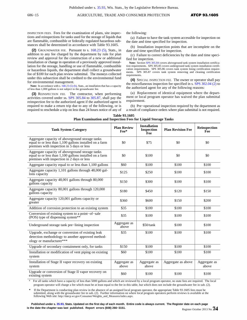
686−15 ATCP 93.1605AGRICULTURE, TRADE AND CONSUMER PROTECTION
Published under s. 35.93, Wis. Stats., by the Legislative Reference Bureau.
Published under s. 35.93 , Stats. Updated on the first day of each month. Entire code is always current. The Register date on each pageis the date the chapter was last published. Report errors (608) 266−3151. Register October 2013 No. 694
INSPECTION FEES. Fees for the examination of plans, site inspec-tions and reinspections for tanks used for the storage of liquids thatare flammable, combustible or federally regulated hazardous sub-stances shall be determined in accordance with Table 93.1605.
(2) GROUNDWATER FEE. Pursuant to s. 168.23 (5), Stats., inaddition to any fee charged by the department by rule for planreview and approval for the construction of a new or additionalinstallation or change in operation of a previously approved instal-lation for the storage, handling or use of flammable, combustibleor hazardous liquids, the department shall collect a groundwaterfee of $100 for each plan review submittal. The moneys collectedunder this subsection shall be credited to the environmental fundfor environmental management.
Note: In accordance with s. 168.23 (5) (b), Stats., an installation that has a capacityof less than 1,000 gallons is not subject to the groundwater fee.
(3) REINSPECTION FEE. The contractor, when performingactivities covered under ss. SPS 305.84 to 305.87, shall pay thereinspection fee to the authorized agent if the authorized agent isrequired to make a return trip due to any of the following, or isrequired to reschedule a trip on less than 24 hours notice of any of
the following:(a) Failure to have the tank system accessible for inspection on
the date and time specified for inspection.
(b) Installation inspection points that are incomplete on thedate and time specified for inspection.
(c) Failure to correct deficiencies by the date and time speci-fied for inspection.
Note: Section SPS 305.84 covers aboveground tank system installation certifica-tion requirements. SPS 305.85 covers underground tank system installation certifi-cation requirements. SPS 305.86 covers tank system lining certification require-ments. SPS 305.87 covers tank system removing and cleaning certificationrequirements.
(4) SPECIAL INSPECTION FEE. The owner or operator shall paythe miscellaneous inspection fee specified in s. SPS 302.04 (2) tothe authorized agent for any of the following reasons:
(a) Replacement of identical equipment where the depart-ment or local program operator has waived the plan submittalrequirement.
(b) Pre−operational inspection required by the department asa result of compliance orders where plan submittal is not required.
Table 93.1605Plan Examination and Inspection Fees for Liquid Storage Tanks
Tank System Category Plan ReviewFee*
InstallationInspection
FeePlan Revision Fee Reinspection
Fee
Aggregate capacity of aboveground storage tanksequal to or less than 1,100 gallons installed on a farmpremises with inspection in 5 days or less
$0 $75 $0 $0
Aggregate capacity of aboveground storage tanksequal to or less than 1,100 gallons installed on a farmpremises with inspection in 2 days or less
$0 $100 $0 $0
Aggregate capacity equal to or less than 1,100 gallons $60 $100 $100 $100
Aggregate capacity 1,101 gallons through 48,000 gal-lons capacity $125 $250 $100 $100
Aggregate capacity 48,001 gallons through 80,000gallons capacity $150 $300 $100 $100
Aggregate capacity 80,001 gallons through 120,000gallons capacity $180 $450 $120 $150
Aggregate capacity 120,001 gallons capacity orgreater $360 $600 $150 $200
Addition of corrosion protection to an existing system $35 $100 $100 $100
Conversion of existing system to a point−of−sale(POS) type of dispensing system** $35 $100 $100 $100
Underground storage tank pre−lining inspection Aggregate asabove $50/tank $100 $100
Upgrade, exchange or conversion of existing leakdetection methodology to another approved method-ology or manufacturer***
$35 $100 $100 $100
Upgrade of secondary containment only, for tanks $150 $100 $100 $100
Installation or modification of vent piping on existingsystem
$60 $100 $100 $100
Installation of Stage II vapor recovery on existingsystem
Aggregate asabove
Aggregate asabove
Aggregate as above Aggregate asabove
Upgrade or conversion of Stage II vapor recovery onexisting system $60 $100 $100 $100
a For all tanks which have a capacity of less than 5000 gallons and which are reviewed by a local program operator, no state fees are required. The localprogram operator will charge a fee which must be at least equal to the fee in this table, but which does not include the groundwater fee in sub. (2).
* If the Department is conducting plan review in the absence of an assigned local program operator, the appropriate Table 93.1605 fees must besubmitted, along with the groundwater fee in sub. (2). Further information on where local program operators perform reviews is available at thefollowing Web site: http://datcp.wi.gov/Consumer/Weights_and_Measures/index.aspx.
74
686−16 ATCP 93.1605 WISCONSIN ADMINISTRATIVE CODE
Published under s. 35.93, Wis. Stats., by the Legislative Reference Bureau.
Published under s. 35.93 , Stats. Updated on the first day of each month. Entire code is always current. The Register date on eachpage is the date the chapter was last published. Report errors (608) 266−3151.Register October 2013 No. 694
** A point−of−sale system is any dispensing system that will authorize fuel dispensing by means of key, card or code activation. These conversions arereviewed by local program operators.
*** These reviews are performed only by the Department.History: Cr. Register, June, 1992, No. 438, eff. 7−1−92; am. Table, Register, March, 1996, No. 483, eff. 4−1−96; correction in Table 2.43 made under s. 13.93 (2m) (b)
7., Stats., Register, November, 1999, No. 527; am. Table 2.43, Register, July, 2000, No. 535, eff. 9−1−00; CR 05−038: r. and recr. Register October 2005 No. 598, eff. 11−1−05;CR 07−029: am. Table 2.43 Register November 2008 No. 635, eff. 2−1−09; CR 09−017: am. (title) and (1) Register July 2009 No. 643, eff. 8−1−09; correction in (1), (3) (intro.),(4) (intro.) made under s. 13.92 (4) (b) 7., Stats., Register December 2011 No. 672; SPS 302.43 renum. ATCP 93.1605 under s. 13.92 (4) (b) 1., Stats.; (title) revised unders. 13.92 (4) (b) 2., Stats.; corrections in (1), (2) made under s. 13.92 (4) (b) 7., Stats., Register October 2013 No. 694.
ATCP 93.170 Petition for variance and petition forrule change. (1) PETITION FOR VARIANCE. The department shallconsider and may grant a variance to a provision of this chapterin accordance with ch. SPS 303. The petition for variance shallinclude, where applicable, a position statement from the firedepartment having jurisdiction.
Note: Chapter SPS 303 requires submittal of a petition for variance form(ERS−9890−A) and a fee, and that an equivalency is established in the petition forvariance which meets the intent of the rule being petitioned. Chapter SPS 303 alsorequires the Department to process regular petitions within 30 business days andpriority petitions within 10 business days. A position statement from the fire depart-ment is applicable when the rule being petitioned relates to fire safety issues.
Note: Form ERS−9890−A is available from the Bureau of Weights and Measures,PO Box 8911, Madison, WI 53708−8911, or at telephone (608) 224−4942, or fromthe Bureau’s Web site at http://datcp.wi.gov/Consumer/Weights_and_Measures/index.aspx.
(2) PETITION FOR RULE CHANGE. As specified in s. 227.12,Stats., any municipality; any association which is representativeof a farm, labor, business or professional group; or any 5 or morepersons having an interest in a rule may petition the departmentrequesting the adoption, amendment or repeal of the rule.
History: CR 07−029: cr. Register November 2008 No. 635, eff. 2−1−09; correc-tion in (1) made under s. 13.92 (4) (b) 7., Stats., Register December 2011 No. 672.
ATCP 93.180 Penalties. Penalties for violations of thischapter shall be assessed in accordance with s. 168.26, Stats., andshall apply separately to each tank that is in violation of this chap-ter.
Note: Section 168.26 of the Statutes states “Any person who violates this sectionor any rule or order adopted under this section shall forfeit not less than $10 nor morethan $5,000 for each violation. Each violation of this section or any rule or orderunder this section constitutes a separate offense and each day of continued violationis a separate offense.”
Note: Section 40 CFR 281.41 allows the US EPA to assess fines of $5,000 or morefor each tank for each day of violation.
History: CR 07−029: cr. Register November 2008 No. 635, eff. 2−1−09; correc-tion made under s. 13.92 (4) (b) 7., Stats., Register October 2013 No. 694.
ATCP 93.190 Appeals and hearings on enforcementdecisions. (1) HEARINGS. (a) General. The owner or operatorof a tank system may request a hearing with the department, asspecified in s. ATCP 1.06 on any decision affecting that person’slegal rights, including enforcement orders and any petition−for−variance, material−approval or permit decision issued under thescope of this chapter.
(b) Appeal requirements. 1. All appeals of enforcement ordersissued under this chapter shall be in writing and shall be receivedby the department no later than 15 calendar days after the date ofthe enforcement order or decision being appealed, except as pro-vided in subd. 2.
2. All appeals of petitions for variance or material−approvalor permit decisions issued under this chapter shall be in writingand shall be received by the department no later than 30 calendardays after the date of the decision being appealed.
3. The department may make a determination not to proceedwith a request for a hearing depending on the nature of the issuebeing appealed.
4. Appeals received after the appeal deadline shall be dis-missed.
5. For purposes of this section, appeals filed after 4:30 p.m.shall be considered received on the next business day.
Note: The appellant or an attorney representing the appellant may request anadministrative hearing to review this action by delivering, mailing, or faxing a writtenrequest for a hearing to one of the following:
In−person delivery address:
Department of Agriculture, Trade and Consumer Protection2811 Agriculture Drive.Madison, Wisconsin 53708
Mailing address:Secretary of Department of Agriculture, Trade and Consumer ProtectionP.O. Box 8911Madison WI 53708−8911
6. An appeal shall be signed by the person whose legal rightsare affected by the decision being appealed or an attorney repre-senting such person. Any appeal filed by a person other than theperson whose legal rights are affected by the decision beingappealed or an attorney representing that affected person shall bedismissed.
7. The written appeal shall list every reason the department’sor authorized agent’s decision is incorrect and shall identify everyissue to be considered at the hearing. Issues not raised in the writ-ten appeal under this paragraph are considered waived and shallbe dismissed.
(c) Response. Upon receipt of notification of hearing from thedepartment, the affected party shall submit to the department awritten response within 15 calendar days of the date of service.Failure to respond within the prescribed time limit, or failure toappear at the scheduled hearing, may result in the allegationsspecified in the complaint being accepted as true and accurate.
(d) Settlement agreement prior to hearing. 1. If the depart-ment and the affected party are able to reach preliminary agree-ment on disposition of a complaint prior to a hearing, such agree-ment shall be processed in accordance with all of the following:
a. Be transmitted in writing to the secretary of the departmentor the person so designated by the secretary.
b. Not be binding upon any party until accepted by the secre-tary of the department or the person so designated by the secretary.
2. The settlement agreement shall be considered a jointmotion by the parties to dismiss the appeal in its entirety withprejudice or to dismiss such portions of the appeal with prejudiceas may be covered by the terms of the settlement agreement.
(e) Witness fees. Witness fees and mileage of witnesses sub-poenaed on behalf of the department shall be paid at the rate pre-scribed for witnesses in circuit court.
(2) CONDUCT OF HEARINGS. (a) All hearings shall be con-ducted by persons selected by the department in accordance withch. 227, Stats.
(b) Persons selected under par. (a) may administer oaths oraffirmations and may grant continuances and adjournments forcause shown.
(c) The affected party shall appear in person and may be repre-sented by legal counsel.
(d) Witnesses may be examined by persons designated by thedepartment.
(e) There shall be no prehearing discovery except as providedin s. 227.45 (7), Stats.
(3) DETERMINATIONS. (a) The department may make deter-minations and enter its order on the basis of the facts revealed byits investigation.
(b) Any determinations as a result of petition or hearing shallbe in writing and shall be binding unless appealed to the secretaryof the department.
(4) APPEAL ARGUMENTS. Appeal arguments shall be submittedto the department in writing unless otherwise ordered.
75
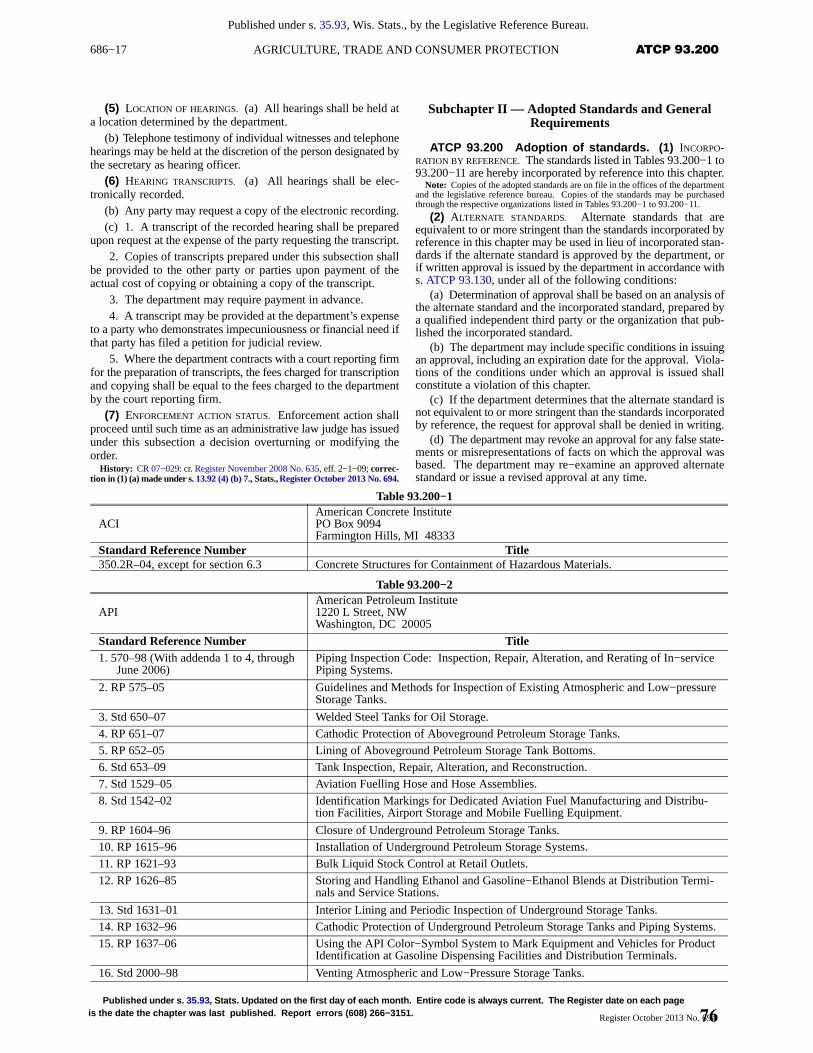
686−17 ATCP 93.200AGRICULTURE, TRADE AND CONSUMER PROTECTION
Published under s. 35.93, Wis. Stats., by the Legislative Reference Bureau.
Published under s. 35.93 , Stats. Updated on the first day of each month. Entire code is always current. The Register date on each pageis the date the chapter was last published. Report errors (608) 266−3151. Register October 2013 No. 694
(5) LOCATION OF HEARINGS. (a) All hearings shall be held ata location determined by the department.
(b) Telephone testimony of individual witnesses and telephonehearings may be held at the discretion of the person designated bythe secretary as hearing officer.
(6) HEARING TRANSCRIPTS. (a) All hearings shall be elec-tronically recorded.
(b) Any party may request a copy of the electronic recording.(c) 1. A transcript of the recorded hearing shall be prepared
upon request at the expense of the party requesting the transcript.2. Copies of transcripts prepared under this subsection shall
be provided to the other party or parties upon payment of theactual cost of copying or obtaining a copy of the transcript.
3. The department may require payment in advance.4. A transcript may be provided at the department’s expense
to a party who demonstrates impecuniousness or financial need ifthat party has filed a petition for judicial review.
5. Where the department contracts with a court reporting firmfor the preparation of transcripts, the fees charged for transcriptionand copying shall be equal to the fees charged to the departmentby the court reporting firm.
(7) ENFORCEMENT ACTION STATUS. Enforcement action shallproceed until such time as an administrative law judge has issuedunder this subsection a decision overturning or modifying theorder.
History: CR 07−029: cr. Register November 2008 No. 635, eff. 2−1−09; correc-tion in (1) (a) made under s. 13.92 (4) (b) 7., Stats., Register October 2013 No. 694.
Subchapter II — Adopted Standards and GeneralRequirements
ATCP 93.200 Adoption of standards. (1) INCORPO-RATION BY REFERENCE. The standards listed in Tables 93.200−1 to93.200−11 are hereby incorporated by reference into this chapter.
Note: Copies of the adopted standards are on file in the offices of the departmentand the legislative reference bureau. Copies of the standards may be purchasedthrough the respective organizations listed in Tables 93.200−1 to 93.200−11.
(2) ALTERNATE STANDARDS. Alternate standards that areequivalent to or more stringent than the standards incorporated byreference in this chapter may be used in lieu of incorporated stan-dards if the alternate standard is approved by the department, orif written approval is issued by the department in accordance withs. ATCP 93.130, under all of the following conditions:
(a) Determination of approval shall be based on an analysis ofthe alternate standard and the incorporated standard, prepared bya qualified independent third party or the organization that pub-lished the incorporated standard.
(b) The department may include specific conditions in issuingan approval, including an expiration date for the approval. Viola-tions of the conditions under which an approval is issued shallconstitute a violation of this chapter.
(c) If the department determines that the alternate standard isnot equivalent to or more stringent than the standards incorporatedby reference, the request for approval shall be denied in writing.
(d) The department may revoke an approval for any false state-ments or misrepresentations of facts on which the approval wasbased. The department may re−examine an approved alternatestandard or issue a revised approval at any time.
Table 93.200−1
ACIAmerican Concrete InstitutePO Box 9094Farmington Hills, MI 48333
Standard Reference Number Title350.2R–04, except for section 6.3 Concrete Structures for Containment of Hazardous Materials.
Table 93.200−2
APIAmerican Petroleum Institute1220 L Street, NWWashington, DC 20005
Standard Reference Number Title1. 570–98 (With addenda 1 to 4, through
June 2006)Piping Inspection Code: Inspection, Repair, Alteration, and Rerating of In−servicePiping Systems.
2. RP 575–05 Guidelines and Methods for Inspection of Existing Atmospheric and Low−pressureStorage Tanks.
3. Std 650–07 Welded Steel Tanks for Oil Storage.
4. RP 651–07 Cathodic Protection of Aboveground Petroleum Storage Tanks.
5. RP 652–05 Lining of Aboveground Petroleum Storage Tank Bottoms.
6. Std 653–09 Tank Inspection, Repair, Alteration, and Reconstruction.
7. Std 1529–05 Aviation Fuelling Hose and Hose Assemblies.
8. Std 1542–02 Identification Markings for Dedicated Aviation Fuel Manufacturing and Distribu-tion Facilities, Airport Storage and Mobile Fuelling Equipment.
9. RP 1604–96 Closure of Underground Petroleum Storage Tanks.
10. RP 1615–96 Installation of Underground Petroleum Storage Systems.
11. RP 1621–93 Bulk Liquid Stock Control at Retail Outlets.
12. RP 1626–85 Storing and Handling Ethanol and Gasoline−Ethanol Blends at Distribution Termi-nals and Service Stations.
13. Std 1631–01 Interior Lining and Periodic Inspection of Underground Storage Tanks.
14. RP 1632–96 Cathodic Protection of Underground Petroleum Storage Tanks and Piping Systems.
15. RP 1637–06 Using the API Color−Symbol System to Mark Equipment and Vehicles for ProductIdentification at Gasoline Dispensing Facilities and Distribution Terminals.
16. Std 2000–98 Venting Atmospheric and Low−Pressure Storage Tanks.
76
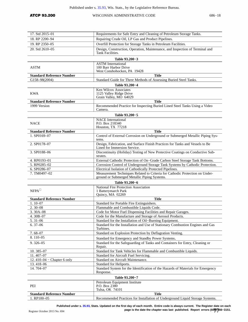
686−18 ATCP 93.200 WISCONSIN ADMINISTRATIVE CODE
Published under s. 35.93, Wis. Stats., by the Legislative Reference Bureau.
Published under s. 35.93 , Stats. Updated on the first day of each month. Entire code is always current. The Register date on eachpage is the date the chapter was last published. Report errors (608) 266−3151.Register October 2013 No. 694
17. Std 2015–01 Requirements for Safe Entry and Cleaning of Petroleum Storage Tanks.18. RP 2200–94 Repairing Crude Oil, LP Gas and Product Pipelines.19. RP 2350–05 Overfill Protection for Storage Tanks in Petroleum Facilities.20. Std 2610–05 Design, Construction, Operation, Maintenance, and Inspection of Terminal and
Tank Facilities.
Table 93.200−3
ASTMASTM International100 Barr Harbor DriveWest Conshohocken, PA 19428
Standard Reference Number TitleG158–98(2004) Standard Guide for Three Methods of Assessing Buried Steel Tanks.
Table 93.200−4
KWAKen Wilcox Associates1125 Valley Ridge DriveGrain Valley, MO 64029
Standard Reference Number Title1999 Version Recommended Practice for Inspecting Buried Lined Steel Tanks Using a Video
Camera.
Table 93.200−5
NACENACE InternationalP.O. Box 218340Houston, TX 77218
Standard Reference Number Title1. SP0169–07 Control of External Corrosion on Underground or Submerged Metallic Piping Sys-
tems.2. SP0178–07 Design, Fabrication, and Surface Finish Practices for Tanks and Vessels to Be
Lined for Immersion Service.3. SP0188–06 Discontinuity (Holiday) Testing of New Protective Coatings on Conductive Sub-
strates.4. RP0193–01 External Cathodic Protection of On−Grade Carbon Steel Storage Tank Bottoms.5. RP0285–02 Corrosion Control of Underground Storage Tank Systems by Cathodic Protection.6. SP0286–07 Electrical Isolation of Cathodically Protected Pipelines.7. TM0497–02 Measurement Techniques Related to Criteria for Cathodic Protection on Under-
ground or Submerged Metallic Piping Systems.
Table 93.200−6
NFPANational Fire Protection Association1 Batterymarch ParkQuincy, MA 02269
Standard Reference Number Title1. 10–07 Standard for Portable Fire Extinguishers.2. 30–08 Flammable and Combustible Liquids Code.3. 30A–08 Code for Motor Fuel Dispensing Facilities and Repair Garages.4. 30B–07 Code for the Manufacture and Storage of Aerosol Products.5. 31–06 Standard for the Installation of Oil−Burning Equipment.6. 37–06 Standard for the Installation and Use of Stationary Combustion Engines and Gas
Turbines.7. 68–07 Standard on Explosion Protection by Deflagration Venting.8. 110–05 Standard for Emergency and Standby Power Systems.9. 326–05 Standard for the Safeguarding of Tanks and Containers for Entry, Cleaning or
Repair.10. 385–07 Standard for Tank Vehicles for Flammable and Combustible Liquids.11. 407–07 Standard for Aircraft Fuel Servicing.12. 410–04 − Chapter 6 only Standard on Aircraft Maintenance.13. 418–06 Standard for Heliports.14. 704–07 Standard System for the Identification of the Hazards of Materials for Emergency
Response.
Table 93.200−7
PEIPetroleum Equipment InstituteP.O. Box 2380Tulsa, OK 74101
Standard Reference Number Title1. RP100–05 Recommended Practices for Installation of Underground Liquid Storage Systems.
77
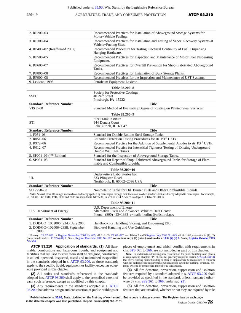
686−19 ATCP 93.210AGRICULTURE, TRADE AND CONSUMER PROTECTION
Published under s. 35.93, Wis. Stats., by the Legislative Reference Bureau.
Published under s. 35.93 , Stats. Updated on the first day of each month. Entire code is always current. The Register date on each pageis the date the chapter was last published. Report errors (608) 266−3151. Register October 2013 No. 694
2. RP200–03 Recommended Practices for Installation of Aboveground Storage Systems forMotor−Vehicle Fueling.
3. RP300–04 Recommended Practices for Installation and Testing of Vapor−Recovery Systems atVehicle−Fueling Sites.
4. RP400–02 (Reaffirmed 2007) Recommended Procedure for Testing Electrical Continuity of Fuel−DispensingHanging Hardware.
5. RP500–05 Recommended Practices for Inspection and Maintenance of Motor Fuel DispensingEquipment.
6. RP600–07 Recommended Practices for Overfill Prevention for Shop−Fabricated AbovegroundTanks.
7. RP800–08 Recommended Practices for Installation of Bulk Storage Plants.8. RP900–08 Recommended Practices for the Inspection and Maintenance of UST Systems.9. Lexicon, 1995 Petroleum Equipment Lexicon.
Table 93.200−8
SSPCSociety for Protective Coatings40 24th StreetPittsburgh, PA 15222
Standard Reference Number TitleVIS 2–00 Standard Method of Evaluating Degree of Rusting on Painted Steel Surfaces.
Table 93.200−9
STISteel Tank Institute944 Donata CourtLake Zurich, IL 60047
Standard Reference Number Title1. F051–06 Standard for Double Bottom Steel Storage Tanks.2. R051–06 Cathodic Protection Testing Procedures for sti−P3 USTs.3. R972–06 Recommended Practice for the Addition of Supplemental Anodes to sti−P3 USTs.4. R012–07 Recommended Practice for Interstitial Tightness Testing of Existing Underground
Double Wall Steel Tanks.5. SP001–06 (4th Edition) Standard for the Inspection of Aboveground Storage Tanks.6. SP031–08 Standard for Repair of Shop−Fabricated Aboveground Tanks for Storage of Flam-
mable and Combustible Liquids.
Table 93.200−10
ULUnderwriters Laboratories Inc.333 Pfingsten RoadNorthbrook, IL 60062−2096 USA
Standard Reference Number TitleSU 2258–08 Nonmetallic Tanks for Oil−Burner Fuels and Other Combustible Liquids.Note: Several other UL design standards are indirectly applied by this chapter through their inclusion in other standards that are directly adopted in this chapter. For example,
UL 58, 80, 142, 1316, 1746, 2080 and 2085 are included in NFPA 30, in section 21.4.2, which is adopted in Table 93.200−6.
Table 93.200−11
U.S. Department of EnergyU.S. Department of EnergyAlternative Fuels and Advanced Vehicles Data CenterPhone: (800) 423−1363 e−mail: [email protected]
Standard Reference Number Title1. DOE/GO−1002006−2343, July 2006 Handbook for Handling, Storing, and Dispensing E85.2. DOE/GO−102006−2358, September
2006Biodiesel Handling and Use Guidelines.
History: CR 07−029: cr. Register November 2008 No. 635, eff. 2−1−09; CR 09−017: am. Tables 2 and 9 Register July 2009 No. 643, eff. 8−1−09; correction in (1), (2)(intro.) made under s. 13.92 (4) (b) 7., Stats., Register December 2011 No. 672; corrections in (1), (2) (intro.) made under s. 13.92 (4) (b) 7., Stats., Register October 2013No. 694.
ATCP 93.210 Application of standards. (1) All flam-mable, combustible and hazardous liquids, and equipment andfacilities that are used to store them shall be designed, constructed,installed, operated, inspected, tested and maintained as specifiedin the standards adopted in s. ATCP 93.200, as those standardsapply to the specific liquid, equipment or facility, except as other-wise provided in this chapter.
(2) All codes and standards referenced in the standardsadopted in s. ATCP 93.200 shall apply to the prescribed extent ofeach such reference, except as modified by this chapter.
(3) Any requirements in the standards adopted in s. ATCP93.200 that address design and construction of public buildings or
places of employment and which conflict with requirements inchs. SPS 361 to 366, are not included as part of this chapter.
Note: In addition to addressing new construction for public buildings and placesof employment, chapters SPS 361 to 366 generally require in section SPS 361.03 (13)that every existing public building or place of employment be maintained to conformwith the building code requirements which applied when the building, structure, ele-ment, system, or component thereof was constructed.
(4) All fire detection, prevention, suppression and isolationfeatures required by a standard adopted in s. ATCP 93.200 shallbe provided as specified in the standard, unless mandated other-wise by chs. SPS 361 to 366, under sub. (3).
(5) All fire detection, prevention, suppression and isolationfeatures that are installed, whether or not they are required by rule
78
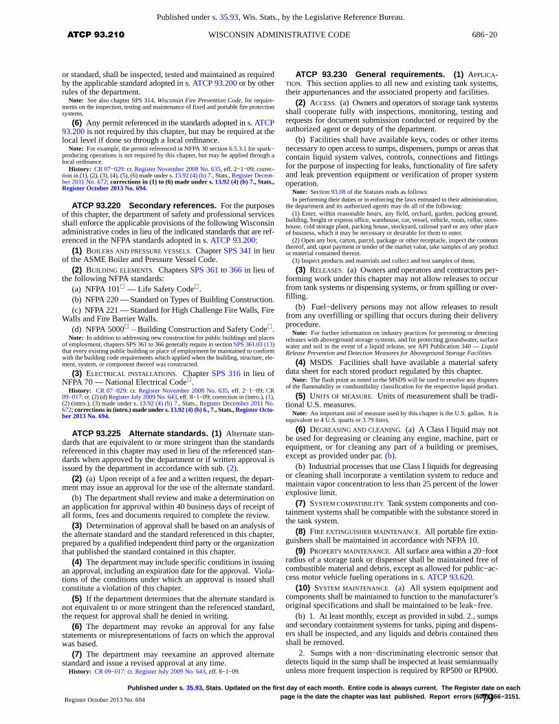
686−20 ATCP 93.210 WISCONSIN ADMINISTRATIVE CODE
Published under s. 35.93, Wis. Stats., by the Legislative Reference Bureau.
Published under s. 35.93 , Stats. Updated on the first day of each month. Entire code is always current. The Register date on eachpage is the date the chapter was last published. Report errors (608) 266−3151.Register October 2013 No. 694
or standard, shall be inspected, tested and maintained as requiredby the applicable standard adopted in s. ATCP 93.200 or by otherrules of the department.
Note: See also chapter SPS 314, Wisconsin Fire Prevention Code, for require-ments on the inspection, testing and maintenance of fixed and portable fire protectionsystems.
(6) Any permit referenced in the standards adopted in s. ATCP93.200 is not required by this chapter, but may be required at thelocal level if done so through a local ordinance.
Note: For example, the permit referenced in NFPA 30 section 6.5.3.1 for spark−producing operations is not required by this chapter, but may be applied through alocal ordinance.
History: CR 07−029: cr. Register November 2008 No. 635, eff. 2−1−09; correc-tion in (1), (2), (3), (4), (5), (6) made under s. 13.92 (4) (b) 7., Stats., Register Decem-ber 2011 No. 672; corrections in (1) to (6) made under s. 13.92 (4) (b) 7., Stats.,Register October 2013 No. 694.
ATCP 93.220 Secondary references. For the purposesof this chapter, the department of safety and professional servicesshall enforce the applicable provisions of the following Wisconsinadministrative codes in lieu of the indicated standards that are ref-erenced in the NFPA standards adopted in s. ATCP 93.200:
(1) BOILERS AND PRESSURE VESSELS. Chapter SPS 341 in lieuof the ASME Boiler and Pressure Vessel Code.
(2) BUILDING ELEMENTS. Chapters SPS 361 to 366 in lieu ofthe following NFPA standards:
(a) NFPA 101 — Life Safety Code .(b) NFPA 220 — Standard on Types of Building Construction.(c) NFPA 221 — Standard for High Challenge Fire Walls, Fire
Walls and Fire Barrier Walls.(d) NFPA 5000 – Building Construction and Safety Code .
Note: In addition to addressing new construction for public buildings and placesof employment, chapters SPS 361 to 366 generally require in section SPS 361.03 (13)that every existing public building or place of employment be maintained to conformwith the building code requirements which applied when the building, structure, ele-ment, system, or component thereof was constructed.
(3) ELECTRICAL INSTALLATIONS. Chapter SPS 316 in lieu ofNFPA 70 — National Electrical Code .
History: CR 07−029: cr. Register November 2008 No. 635, eff. 2−1−09; CR09−017: cr. (2) (d) Register July 2009 No. 643, eff. 8−1−09; correction in (intro.), (1),(2) (intro.), (3) made under s. 13.92 (4) (b) 7., Stats., Register December 2011 No.672; corrections in (intr o.) made under s. 13.92 (4) (b) 6., 7., Stats., Register Octo-ber 2013 No. 694.
ATCP 93.225 Alternate standards. (1) Alternate stan-dards that are equivalent to or more stringent than the standardsreferenced in this chapter may used in lieu of the referenced stan-dards when approved by the department or if written approval isissued by the department in accordance with sub. (2).
(2) (a) Upon receipt of a fee and a written request, the depart-ment may issue an approval for the use of the alternate standard.
(b) The department shall review and make a determination onan application for approval within 40 business days of receipt ofall forms, fees and documents required to complete the review.
(3) Determination of approval shall be based on an analysis ofthe alternate standard and the standard referenced in this chapter,prepared by a qualified independent third party or the organizationthat published the standard contained in this chapter.
(4) The department may include specific conditions in issuingan approval, including an expiration date for the approval. Viola-tions of the conditions under which an approval is issued shallconstitute a violation of this chapter.
(5) If the department determines that the alternate standard isnot equivalent to or more stringent than the referenced standard,the request for approval shall be denied in writing.
(6) The department may revoke an approval for any falsestatements or misrepresentations of facts on which the approvalwas based.
(7) The department may reexamine an approved alternatestandard and issue a revised approval at any time.
History: CR 09−017: cr. Register July 2009 No. 643, eff. 8−1−09.
ATCP 93.230 General requirements. (1) APPLICA-TION. This section applies to all new and existing tank systems,their appurtenances and the associated property and facilities.
(2) ACCESS. (a) Owners and operators of storage tank systemsshall cooperate fully with inspections, monitoring, testing andrequests for document submission conducted or required by theauthorized agent or deputy of the department.
(b) Facilities shall have available keys, codes or other itemsnecessary to open access to sumps, dispensers, pumps or areas thatcontain liquid system valves, controls, connections and fittingsfor the purpose of inspecting for leaks, functionality of fire safetyand leak prevention equipment or verification of proper systemoperation.
Note: Section 93.08 of the Statutes reads as follows:In performing their duties or in enforcing the laws entrusted to their administration,
the department and its authorized agents may do all of the following:(1) Enter, within reasonable hours, any field, orchard, garden, packing ground,
building, freight or express office, warehouse, car, vessel, vehicle, room, cellar, store-house, cold storage plant, packing house, stockyard, railroad yard or any other placeof business, which it may be necessary or desirable for them to enter.
(2) Open any box, carton, parcel, package or other receptacle, inspect the contentsthereof, and, upon payment or tender of the market value, take samples of any productor material contained therein.
(3) Inspect products and materials and collect and test samples of them.
(3) RELEASES. (a) Owners and operators and contractors per-forming work under this chapter may not allow releases to occurfrom tank systems or dispensing systems, or from spilling or over-filling.
(b) Fuel−delivery persons may not allow releases to resultfrom any overfilling or spilling that occurs during their deliveryprocedure.
Note: For further information on industry practices for preventing or detectingreleases with aboveground storage systems, and for protecting groundwater, surfacewater and soil in the event of a liquid release, see API Publication 340 — LiquidRelease Prevention and Detection Measures for Aboveground Storage Facilities.
(4) MSDS. Facilities shall have available a material safetydata sheet for each stored product regulated by this chapter.
Note: The flash point as noted in the MSDS will be used to resolve any disputesof the flammability or combustibility classification for the respective liquid product.
(5) UNITS OF MEASURE. Units of measurement shall be tradi-tional U.S. measures.
Note: An important unit of measure used by this chapter is the U.S. gallon. It isequivalent to 4 U.S. quarts or 3.79 liters.
(6) DEGREASING AND CLEANING. (a) A Class I liquid may notbe used for degreasing or cleaning any engine, machine, part orequipment, or for cleaning any part of a building or premises,except as provided under par. (b).
(b) Industrial processes that use Class I liquids for degreasingor cleaning shall incorporate a ventilation system to reduce andmaintain vapor concentration to less than 25 percent of the lowerexplosive limit.
(7) SYSTEM COMPATIBILITY. Tank system components and con-tainment systems shall be compatible with the substance stored inthe tank system.
(8) FIRE EXTINGUISHER MAINTENANCE. All portable fire extin-guishers shall be maintained in accordance with NFPA 10.
(9) PROPERTY MAINTENANCE. All surface area within a 20−footradius of a storage tank or dispenser shall be maintained free ofcombustible material and debris, except as allowed for public−ac-cess motor vehicle fueling operations in s. ATCP 93.620.
(10) SYSTEM MAINTENANCE. (a) All system equipment andcomponents shall be maintained to function to the manufacturer’soriginal specifications and shall be maintained to be leak−free.
(b) 1. At least monthly, except as provided in subd. 2., sumpsand secondary containment systems for tanks, piping and dispens-ers shall be inspected, and any liquids and debris contained thenshall be removed.
2. Sumps with a non−discriminating electronic sensor thatdetects liquid in the sump shall be inspected at least semiannuallyunless more frequent inspection is required by RP500 or RP900.
79
686−21 ATCP 93.250AGRICULTURE, TRADE AND CONSUMER PROTECTION
Published under s. 35.93, Wis. Stats., by the Legislative Reference Bureau.
Published under s. 35.93 , Stats. Updated on the first day of each month. Entire code is always current. The Register date on each pageis the date the chapter was last published. Report errors (608) 266−3151. Register October 2013 No. 694
(c) Deficiencies in product lines or structural or transitioncomponents that allow for liquid leaks or water intrusion shall berepaired or corrected.
(d) Leak detection, fill and overfill prevention equipment shallbe maintained in a functional condition.
(e) Fire and leak prevention and detection equipment installed,but not required by the department’s rules, shall be maintainedfunctional or be removed.
Note: Section ATCP 93.115 (3) (a) 7. allows the authorized agent or the Depart-ment or fire department to shut down the tank system until any breach in the tank sys-tem is repaired or otherwise corrected.
(11) DAMAGE TO UNDERGROUND COMPONENTS. (a) Whendamage has occurred to underground pressurized tank systemcomponents or to underground vent and remote fill lines, theaffected portion of the tank system shall be removed from service,and the following actions shall be taken before that portion of thesystem is put back into service, except as provided in par. (b):
1. Perform third−party precision tightness testing of the por-tion of the tank system where damage occurred, in accordancewith s. ATCP 93.515 (4) (a) 1.
2. Isolate system components through the use of pressure−re-taining components.
3. Perform functional operational tests of existing monitoringequipment.
4. Perform any additional monitoring, processes, or proce-dures needed to verify system integrity.
5. Comply with the tank−system site assessment and responserequirements in ss. ATCP 93.575 to 93.585 if a release is sus-pected.
(b) The actions in par. (a) 1. to 4. are not required where thedamage is limited to dispenser system components that are iso-lated from the rest of the dispenser or tank system through the useof pressure−retaining components.
Note: These are minimum requirements for the restart of a damaged system,dependent on the situation at the incident site. Additional safety or environmentalprotection actions or repairs may be needed by the owner or operator.
(12) PRODUCT COLOR CODING FOR FILL PIPE CAPS AND MANHOLE
COVERS. (a) General. 1. All fill pipe caps and manhole coversfor underground fuel tanks at distribution terminals, bulk plantsand motor fuel dispensing facilities shall be identified by the stan-dard color and symbol coding in API 1637.
2. Products containing extenders such as ethanol shall be des-ignated by the addition of a black border around white symbolsand a white border around other colored symbols.
Note: Extenders or oxygenates are added to gasoline and typically comprise amaximum of 10 percent of the fuel by volume.
3. Vapor−recovery connections and manholes shall bemarked with orange circles.
4. a. Observation and monitoring wells shall be marked witha black triangle on a white background.
b. The well shall be provided with a durable label warningagainst the introduction of petroleum products into the well.
(b) Location of identification. 1. The color coding requiredin par. (a) shall be applied to the fill pipe cap and manhole coveror within the spill containment.
2. At all facilities with more than one tank, the color codingapplied to the fill cap or manhole cover shall extend at least 12inches beyond the edge of the cap or cover onto adjacent concreteor pavement.
Note: See section ATCP 93.340 for additional information on product identifica-tion at bulk plants and terminals.
(13) DEACTIVATION OF VAPOR RECOVERY. When deactivatinga stage II vapor−recovery system or a portion thereof, the deacti-vated pipe shall be removed, or be capped or plugged at the dis-penser. If the pipe is removed, the connection to the tank shall becapped or plugged.
Note: Each connection of a tank to deactivated, unremoved vapor−recovery pipeshould be capped or plugged at the tank, if readily accessible, to minimize the poten-tial for water intrusion from the pipe.
History: CR 07−029: cr. Register November 2008 No. 635, eff. 2−1−09; correc-tion in (9), (11) (a) 1., 5. made under s. 13.92 (4) (b) 7., Stats., Register December2011 No. 672; corrections in (9), (11) (a) 1., 5. made under s. 13.92 (4) (b) 7., Stats.,Register October 2013 No. 694.
ATCP 93.240 Certifications and enforcement.(1) CERTIFICATIONS. Persons and firms providing or supervisingany of the following services shall be credentialed by the depart-ment in accordance with ch. SPS 305:
(a) Tank−system site assessment as referenced in s. ATCP93.465 for aboveground tanks and s. ATCP 93.580 for under-ground tanks.
(b) Underground tank system lining under ss. ATCP 93.530and 93.535.
(c) The cleaning and removal of underground storage tanksand stationary shop−built aboveground storage tanks.
(d) Storage tank system precision tightness testing usingequipment that is not permanently installed on the tank system.
Note: All methods of precision tightness testing are required to be approved bythe department in accordance with section ATCP 93.130
(e) Corrosion protection services as required in s. ATCP93.520.
(f) Installation of underground storage tanks and shop−builtaboveground storage tanks, except this requirement does notapply to any of the following tanks:
1. Aboveground heating oil tanks at 1− or 2−family dwell-ings.
2. Tanks or piping that are installed or constructed under thedirect supervision of a registered professional engineer.
Note: “Under the direct supervision of a registered professional engineer” meansthe registered professional engineer must be on the site during, and responsible for,the key installation and test activities described in section SPS 305.84 (5) or 305.85(5).
(2) ENFORCEMENT ACTIONS. (a) The department may takeactions to ensure compliance with the provisions of this chapter,including revoking or suspending credentials.
Note: Section 168.23 (3) of the Statutes, reads in partAny rule requiring certification or registration shall also authorize the revocation
or suspension of the certification or registration.Note: See chapter SPS 305 for revocation and suspension criteria.Note: Sections SPS 305.83, 305.88 and 305.89 prohibit a person from engaging
in tank−system site assessment, tank system tightness testing, or cathodic protectionspecialties if the person or the person’s employer has a personal or financial interestin the facility.
(b) The department may require attendance at a specifiededucation class.
(c) The department may commence civil action or administra-tive action under the provisions of ss. 168.25 and 168.26, Stats.
History: CR 07−029: cr. Register November 2008 No. 635, eff. 2−1−09; correc-tion in (1) (intro.), (a), (b), (e) made under s. 13.92 (4) (b) 7., Stats., Register Decem-ber 2011 No. 672; corrections in (1) (a), (b), (e), (2) (c) made under s. 13.92 (4) (b)7., Stats., Register October 2013 No. 694.
ATCP 93.250 Tank construction and marking.(1) MULTI−COMPARTMENT TANKS. Each compartment of a multi−compartment tank shall be considered a separate tank, even if thesame substance is stored in 2 or more of the compartments.
(2) CONSTRUCTION. Tanks containing flammable or com-bustible liquids shall be constructed to one of the recognizeddesign standards in NFPA 30 section 21.4.2, or to another standardor design approved by the department, except this requirementdoes not apply to any of the following tanks:
(a) Tanks that contain liquids which are also hazardous sub-stances.
Note: Section ATCP 93.350 requires hazardous substance tanks to be designedand constructed under the supervision of a qualified engineer.
(b) Tank wagons, farm tanks and tank vehicles used in accord-ance with the requirements in ss. ATCP 93.610 and 93.630, for
80
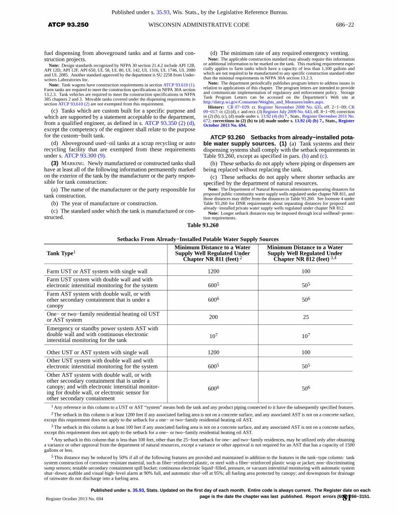
686−22 ATCP 93.250 WISCONSIN ADMINISTRATIVE CODE
Published under s. 35.93, Wis. Stats., by the Legislative Reference Bureau.
Published under s. 35.93 , Stats. Updated on the first day of each month. Entire code is always current. The Register date on eachpage is the date the chapter was last published. Report errors (608) 266−3151.Register October 2013 No. 694
fuel dispensing from aboveground tanks and at farms and con-struction projects.
Note: Design standards recognized by NFPA 30 section 21.4.2 include API 12B,API 12D, API 12F, API 650, UL 58, UL 80, UL 142, UL 1316, UL 1746, UL 2080and UL 2085. Another standard approved by the department is SU 2258 from Under-writers Laboratories Inc.
Note: Tank wagons have construction requirements in section ATCP 93.610 (1).Farm tanks are required to meet the construction specifications in NFPA 30A section13.2.3. Tank vehicles are required to meet the construction specifications in NFPA385 chapters 2 and 3. Movable tanks covered under the dispensing requirements insection ATCP 93.610 (2) are not exempted from this requirement.
(c) Tanks which are custom built for a specific purpose andwhich are supported by a statement acceptable to the department,from a qualified engineer, as defined in s. ATCP 93.350 (2) (d),except the competency of the engineer shall relate to the purposefor the custom−built tank.
(d) Aboveground used−oil tanks at a scrap recycling or autorecycling facility that are exempted from these requirementsunder s. ATCP 93.300 (9).
(3) MARKING. Newly manufactured or constructed tanks shallhave at least all of the following information permanently markedon the exterior of the tank by the manufacturer or the party respon-sible for tank construction:
(a) The name of the manufacturer or the party responsible fortank construction.
(b) The year of manufacture or construction.(c) The standard under which the tank is manufactured or con-
structed.
(d) The minimum rate of any required emergency venting.Note: The applicable construction standard may already require this information
or additional information to be marked on the tank. This marking requirement espe-cially applies to farm tanks which have a capacity of less than 1,100 gallons andwhich are not required to be manufactured to any specific construction standard otherthan the minimal requirements in NFPA 30A section 13.2.3.
Note: The department periodically publishes program letters to address issues inrelation to applications of this chapter. The program letters are intended to provideand communicate implementation of regulatory and enforcement policy. StorageTank Program Letters can be accessed on the Department’s Web site athttp://datcp.wi.gov/Consumer/Weights_and_Measures/index.aspx.
History: CR 07−029: cr. Register November 2008 No. 635, eff. 2−1−09; CR09−017: cr. (2) (d), r. and recr. (3) Register July 2009 No. 643, eff. 8−1−09; correctionin (2) (b), (c), (d) made under s. 13.92 (4) (b) 7., Stats., Register December 2011 No.672; corrections in (2) (b) to (d) made under s. 13.92 (4) (b) 7., Stats., RegisterOctober 2013 No. 694.
ATCP 93.260 Setbacks from already−installed pota-ble water supply sources. (1) (a) Tank systems and theirdispensing systems shall comply with the setback requirements inTable 93.260, except as specified in pars. (b) and (c).
(b) These setbacks do not apply where piping or dispensers arebeing replaced without replacing the tank.
(c) These setbacks do not apply where shorter setbacks arespecified by the department of natural resources.
Note: The Department of Natural Resources administers separating distances forproposed public community water supply wells regulated under chapter NR 811, andthose distances may differ from the distances in Table 93.260. See footnote 4 underTable 93.260 for DNR requirements about separating distances for proposed andalready−installed private water supply wells regulated under chapter NR 812.
Note: Longer setback distances may be imposed through local wellhead−protec-tion requirements.
Table 93.260
Setbacks From Already−Installed Potable Water Supply Sources
Tank Type1Minimum Distance to a WaterSupply Well Regulated Under
Chapter NR 811 (feet) 2
Minimum Distance to a WaterSupply Well Regulated Under
Chapter NR 812 (feet) 3,4
Farm UST or AST system with single wall 1200 100Farm UST system with double wall and withelectronic interstitial monitoring for the system 6005 505
Farm AST system with double wall, or withother secondary containment that is under acanopy
6006 506
One− or two−family residential heating oil USTor AST system 200 25
Emergency or standby power system AST withdouble wall and with continuous electronicinterstitial monitoring for the tank
107 107
Other UST or AST system with single wall 1200 100Other UST system with double wall and withelectronic interstitial monitoring for the system 6005 505
Other AST system with double wall, or withother secondary containment that is under acanopy; and with electronic interstitial monitor-ing for double wall, or electronic sensor forother secondary containment
6006 506
1 Any reference in this column to a UST or AST “system” means both the tank and any product piping connected to it have the subsequently specified features.2 The setback in this column is at least 1200 feet if any associated fueling area is not on a concrete surface, and any associated AST is not on a concrete surface,
except this requirement does not apply to the setback for a one− or two−family residential heating oil AST.3 The setback in this column is at least 100 feet if any associated fueling area is not on a concrete surface, and any associated AST is not on a concrete surface,
except this requirement does not apply to the setback for a one− or two−family residential heating oil AST.4 Any setback in this column that is less than 100 feet, other than the 25−foot setback for one− and two−family residences, may be utilized only after obtaining
a variance or other approval from the department of natural resources, except a variance or other approval is not required for an AST that has a capacity of 1500gallons or less.
5 This distance may be reduced by 50% if all of the following features are provided and maintained in addition to the features in the tank−type column: tanksystem construction of corrosion−resistant material, such as fiber−reinforced plastic, or steel with a fiber−reinforced plastic wrap or jacket; non−discriminatingsump sensors; testable secondary containment spill bucket; continuous electronic liquid−filled, pressure, or vacuum interstitial monitoring with automatic systemshut−down; audible and visual high−level alarm at 90% full, and automatic shut−off at 95%; all fueling area protected by canopy; and downspouts for drainageof rainwater do not discharge into a fueling area.
81
686−23 ATCP 93.300AGRICULTURE, TRADE AND CONSUMER PROTECTION
Published under s. 35.93, Wis. Stats., by the Legislative Reference Bureau.
Published under s. 35.93 , Stats. Updated on the first day of each month. Entire code is always current. The Register date on each pageis the date the chapter was last published. Report errors (608) 266−3151. Register October 2013 No. 694
6 This distance may be reduced by 50% if all of the following features are provided and maintained in addition to the features in the tank−type column: eithercontinuous non−discriminating electronic interstitial monitoring for double wall, or continuous non−discriminating electronic sensor for other secondary contain-ment; audible and visual high−level alarm at 90% full, and either automatic shut−off at 95% or no latch−open device is used with any manual−shutoff nozzle; alldispensing by suction pump fuel transfer; all motor vehicle fueling limited to private or fleet use; all fueling area protected by canopy; and downspouts for drainageof rainwater do not discharge into a fueling area.
7 This reduced setback is only permitted for emergency or standby power systems that are operated by the same facility which operates the well, and only ifall of the following features are provided and maintained in addition to the features in the tank−type column: audible and visual high−level alarm at 90% full, andeither automatic shut−off at 95% or no latch−open device is used with any manual−shutoff nozzle. This setback may be reduced further where approved in writingby the department, upon submittal of an explanation of why reducing the setback is needed, along with demonstration that additional features will be included whichwill provide adequate protection for the well.
Note: Aboveground storage tanks (ASTs) include tanks that are inside a building and have a liquid capacity of 110 gallons or more, are intended for fixed installation,and are not solely used for processing.
(2) Tank systems and their dispensing systems shall be at least50 feet from ground−level potable water reservoirs regulatedunder ch. NR 811, except as specified in sub. (1) (b) and (c).
(3) Tank systems and their dispensing systems shall be at least25 feet from potable water mains regulated under ch. NR 811,except as specified in sub. (1) (b) and (c).
History: CR 07−029: cr. Register November 2008 No. 635, eff. 2−1−09; correc-tion in (1) (a) made under s. 13.92 (4) (b) 7., Stats., Register December 2011 No. 672;correction in (1) (a) made under s. 13.92 (4) (b) 7., Stats., Register October 2013No. 694.
Subchapter III — Specific Tank Storage Applications
ATCP 93.300 Tanks storing used oil. (1) GENERAL.(a) Used oil shall be considered a Class IIIB liquid unless desig-nated otherwise in this chapter or as shown by product flashpointtesting.
(b) Tanks used to store used oil to supply an oil burner shallcomply with the heating−fuel storage requirements in s. ATCP93.310 and NFPA 31 section 7.2.9.
Note: Devices that burn used oil are regulated by the Commercial Building Code,chapters SPS 361 to 366, and the Fire Prevention Code, chapter SPS 314. The tankthat stores the oil is regulated by this chapter.
Note: NFPA 31 section 12.9.1 requires tanks that supply used oil to an oil burnerto be listed.
(2) TANK CONSTRUCTION AND INSTALLATION. (a) Tanks for thestorage of used oil shall comply with the construction and markingrequirements in s. ATCP 93.250 anytime a tank system isinstalled.
(b) Aboveground tanks for used−oil storage that have a capac-ity of less than 750 gallons are not required to be listed, or markedin accordance with s. ATCP 93.250 (3), except for tanks whichsupply oil to an oil burner.
Note: See section ATCP 93.250 for minimum marking requirements for newlymanufactured or constructed tanks.
(c) Tanks shall be constructed of noncombustible materials,unless constructed and utilized in accordance with SU 2258 fromUnderwriters Laboratories Inc.
(d) The fill opening shall be screened to prevent the passageof solid objects into the tank.
(e) The fill opening may be located directly at the tank.(f) The fill opening shall be closed except when a transfer is
actually taking place.(g) Tanks that store used oil shall be installed by or under the
supervision of a certified installer.(h) The building setback for tanks which have a capacity of
less than 1,100 gallons and which store used oil may be less thanthe setbacks listed in NFPA 30 Table 22.4.1.6 if approved in writ-ing by the authorized agent or the department; and that approvalshall be based on consideration of the construction material for thebuilding wall, the size of the tank, and the adjacent vehicular traf-fic.
Note: See section ATCP 93.260 for minimum separating distances between tanksand water supply wells.
(3) SPILL AND OVERFILL PREVENTION. All tanks, whether newor existing, shall comply with all of the following:
(a) The fill opening shall be provided with spill containment.(b) If the fill opening is located outdoors, the opening shall be
located in a watertight enclosure of noncombustible construction.
(c) 1. If the fill point is remote from the tank or if the deliveryperson cannot readily observe the tank gauge, an overfill alarmshall be provided at the fill point.
2. The alarm shall be readily audible or visible at the fill pointand shall alert the delivery person when the tank is 90 percent full.
3. All overfill alarms shall be labeled as such.(4) SIGNAGE. All tanks, whether new or existing, shall be pro-
vided with a permanent and durable sign installed at the used−oilhandler site or facility, that includes all of the following:
(a) “NO SMOKING.”(b) “USED−OIL COLLECTION ONLY.”(c) “DEPOSITING OTHER MATERIAL IS PROHIBITED.”(5) VEHICLE COLLISION PROTECTION. Vehicle collision protec-
tion shall be provided for aboveground tanks in accordance withs. ATCP 93.430 unless the authorized agent or the departmentdetermines the tank system is not subject to vehicle collision.
(6) SECONDARY CONTAINMENT. (a) Aboveground tankslocated outdoors shall have secondary containment that complieswith s. ATCP 93.420 (1) to (4).
(b) Tanks located inside a building shall have secondary con-tainment for 100 percent of the tank capacity if a leak from thestorage tank could reach a floor drain, the exterior of the buildingor areas that pose an ignition hazard.
Note: An oil−water separator connected to a floor drain may be used for all or aportion of the required secondary containment, depending on the system capacity.
(7) UNDERGROUND TANKS. (a) General. Underground tanksfor used−oil storage shall comply with the applicable portions ofNFPA 30 and this section.
(b) Spill protection. For underground tanks that store used oil,spill protection is not required at any point other than the fill point,if the tank meets all of the following conditions:
1. The tank receives used oil in batches of 25 gallons or lessby manual transfer.
2. The tank is emptied only by suction transfer.(c) Corrosion protection. Corrosion protection shall be pro-
vided in accordance with s. ATCP 93.520 except this protectionis not required for piping that is associated with an undergroundtank which stores used oil, provided the tank and piping meet allof the following conditions:
1. The tank receives used oil in batches of 25 gallons or lessby manual transfer.
2. All piping that is underground is sloped at an angle of atleast 30 degrees from horizontal between the point at which itenters the ground and the tank, to allow for the free flow of oil.
Note: This section does not exempt the tank itself from corrosion protectionrequirements.
(d) Leak detection. Leak detection shall be provided in accord-ance with ss. ATCP 93.510 and 93.515.
(8) TANK CLOSURE AND GENERAL ADMINISTRATIVE REQUIRE-MENTS. (a) Aboveground tanks. Aboveground tanks that storeused oil shall comply with ss. ATCP 93.440 to 93.470.
Note: Sections ATCP 93.440 to 93.470 address inspections; seldom−used andtemporarily−out−of−service tanks; change in service to store a non−regulated sub-stance; tank closures; tank−system site assessments; and confirming and respondingto leaks, spills, overfills and releases.
(b) Underground tanks. Underground tanks that store used oilshall comply with ss. ATCP 93.545 to 93.585.
82
686−24 ATCP 93.300 WISCONSIN ADMINISTRATIVE CODE
Published under s. 35.93, Wis. Stats., by the Legislative Reference Bureau.
Published under s. 35.93 , Stats. Updated on the first day of each month. Entire code is always current. The Register date on eachpage is the date the chapter was last published. Report errors (608) 266−3151.Register October 2013 No. 694
Note: Sections ATCP 93.545 to 93.585 address seldom−used and temporarily−out−of−service tanks; change in service to store a non−regulated substance; tank sys-tem closures; conditions indicating releases; tank−system integrity assessments;tank−system site assessments; and responding to leaks, spills, overfills and releases.
(9) SCRAP RECYCLING AND AUTOMOBILE RECYCLING FACILITIES.Subsections (1) (a), (2) (a), (c) to (h), (3) to (5), (6) (a), (7) and (8)do not apply to a new or existing aboveground tank which con-tains used oil and which is located at a scrap recycling or automo-bile recycling facility adequately participating in a cooperativecompliance program approved by the department of naturalresources, provided all of the following requirements are met:
(a) The tank is constructed of a durable material acceptable tothe department.
(b) If located outside of a building, the tank has secondary con-tainment acceptable to the department.
(c) If located inside a building, the tank has venting and fireprevention features acceptable to the department.
History: CR 07−029: cr. Register November 2008 No. 635, eff. 2−1−09; CR09−017: am. (2) (h), cr. (9) Register July 2009 No. 643, eff. 8−1−09; correction in (1)(b), (2) (a), (b), (5), (6) (a), (7) (c) (intro.), (d), (8) (a), (b) made under s. 13.92 (4) (b)7., Stats., Register December 2011 No. 672; corrections in (1) (b), (2) (a), (b), (5),(6) (a), (7) (c) (intro.), (d), (8) (a), (b) made under s. 13.92 (4) (b) 7., Stats., RegisterOctober 2013 No. 694.
ATCP 93.305 Public used−oil collection centers.(1) GENERAL. Public used−oil collection centers shall complywith s. ATCP 93.300 and this section.
Note: Also see chapter NR 679 for additional rules pertaining to used−oil collec-tion centers, such as operational criteria.
(2) TANK CONSTRUCTION. The tank shall be constructed to oneof the recognized design standards in NFPA 30 chapter 21 unlessotherwise accepted by the department.
Note: Design standards recognized by NFPA 30 chapter 21 include API 12B, API12D, API 12F, API 650, UL 58, UL 80, UL 142, UL 1316, UL 1746, UL 2080 andUL 2085.
(3) TANK SIZE AND INSTALLATION REQUIREMENTS. (a) The tankmay be of any size.
(b) Tanks located outdoors shall comply with the setbackrequirements of NFPA 30 Tables 22.4.1.1(a) and (b) for a ClassIIIA liquid.
(c) Tanks located inside a building shall have venting that ter-minates outdoors.
(4) DIKING. (a) A single−wall tank shall be placed within adiked area that meets the requirements of s. ATCP 93.420.
(b) A tank of double−wall construction, that is accessible to thepublic, shall be placed within secondary containment which meetsall of the following requirements:
1. Any curb shall have a height of at least 4 inches.2. The containment shall extend at least 2 feet beyond the
greatest tank dimension in all directions.(c) The tank shall be set back from the curb or dike wall such
that an overflow of the tank will be contained within the diked orcurbed area.
(d) The fill opening with spill containment shall be locatedwithin the diked or curbed area.
History: CR 07−029: cr. Register November 2008 No. 635, eff. 2−1−09; correc-tion to (4) (d) made under s. 13.92 (4) (b) 1., Stats., Register November 2008 No. 635;correction in (1), (4) (a) made under s. 13.92 (4) (b) 7., Stats., Register December2011 No. 672; corrections in (1), (4) (a) made under s. 13.92 (4) (b) 7., Stats., Reg-ister October 2013 No. 694.
ATCP 93.310 Heating fuel storage. (1) SCOPE. Thissection applies to any new or existing aboveground or under-ground tank that is used to supply liquid fuel to a heating device,including a used oil burner, if the device and the fuel have the fol-lowing characteristics:
(a) The heating device is used for space heating, processing ormanufacturing.
(b) The fuel is consumed on the premises where stored.Note: Number 5 and #6 fuel oil do not meet the criteria for a liquid and therefore
are not regulated by this chapter.
(2) INSTALLATION, USE AND MAINTENANCE. (a) Tanks that sup-ply oil−burning equipment shall be installed, used and maintainedin accordance with NFPA 31 chapters 7 and 12, and this section.
(b) Tanks used to store heating fuel shall be installed by orunder the supervision of a certified installer.
Note: Tanks installed at 1− or 2−family dwellings are not required to have planreview under section ATCP 93.100, and aboveground tanks that have a capacity ofless than 1,100 gallons are not required to have registration under section ATCP93.140.
Note: Devices that burn used oil are regulated by the Commercial Building Code,chapters SPS 361 to 366, and the Fire Prevention Code, chapter SPS 314. The tankthat stores the oil is regulated by this chapter.
(3) UNDERGROUND TANKS THAT HAVE A CAPACITY OF 4000 GAL-LONS OR LESS. Underground heating oil tank systems that have acapacity of 4000 gallons or less shall have all of the following:
(a) A vent whistle, or equivalent means of overfill protection.(b) Corrosion protection that complies with s. ATCP 93.520,
except this requirement does not apply to tanks that were installedbefore November 1, 1994.
(c) 1. Precision tightness testing every 2 years or leak detec-tion in accordance with s. ATCP 93.510, except this requirementdoes not apply to residential tanks which have a capacity of lessthan 1,100 gallons and which were installed before October 29,1999, for consumptive use on the property where stored.
2. The tightness testing or leak detection methods used tocomply with subd. 1. shall be specifically approved for use withthe specific type of heating oil in accordance with s. ATCP 93.130.
(4) UNDERGROUND TANKS THAT HAVE A CAPACITY OF MORETHAN 4000 GALLONS. Underground heating oil storage tanks thathave a capacity of more than 4000 gallons shall have leak detec-tion that complies with s. ATCP 93.510 and corrosion protectionthat complies with s. ATCP 93.520.
(5) SPILL AND OVERFILL PREVENTION. (a) Spill and overfill pre-vention for aboveground tanks shall be provided in accordancewith s. ATCP 93.300 (3).
(b) Spill and overfill prevention for underground tanks shallbe provided in accordance with s. ATCP 93.505.
(c) Fill pipes for used−oil tanks that are part of a heating systemmay be located inside a building.
(6) TANK CLOSURE AND GENERAL ADMINISTRATIVE REQUIRE-MENTS. (a) Aboveground tanks. Aboveground tanks that storeheating oil shall comply with ss. ATCP 93.440 to 93.470.
Note: Sections ATCP 93.440 to 93.470 address inspections; seldom−used andtemporarily−out−of−service tanks; change in service to store a non−regulated sub-stance; tank closures; tank−system site assessments; and confirming and respondingto leaks, spills, overfills and releases.
(b) Underground tanks. Underground tanks that store heatingoil shall comply with ss. ATCP 93.545 to 93.585.
Note: Sections ATCP 93.545 to 93.585 address seldom−used and temporarily−out−of−service tanks; change in service to store a non−regulated substance; tank sys-tem closures; conditions indicating releases; tank−system integrity assessments;tank−system site assessments; and responding to leaks, spills, overfills and releases.
History: CR 07−029: cr. Register November 2008 No. 635, eff. 2−1−09; correc-tion in (3) (b), (c) 1., 2., (4), (5) (a), (b), (6) (a), (b) made under s. 13.92 (4) (b) 7.,Stats., Register December 2011 No. 672; corrections in (3) (b), (c) 1., 2., (4), (5) (a),(b), (6) (a), (b) made under s. 13.92 (4) (b) 7., Stats., Register October 2013 No.694.
ATCP 93.315 Heating oil tanks that are removedfrom service. (1) APPLICATION. This section applies to above-ground heating oil storage tanks which are connected to heatingappliances and which store heating oil that is consumed on thepremises.
(2) GENERAL. Placing a heating oil storage tank out of servicefor any reason other than immediate repair or replacement shallfollow the procedure in either par. (a) or (b):
(a) The tank and all connected piping, including the vent andfill piping, shall be emptied, cleaned and removed from the prem-ises.
(b) 1. The tank and all connected piping shall be emptied andpurged of all vapors.
83
686−25 ATCP 93.340AGRICULTURE, TRADE AND CONSUMER PROTECTION
Published under s. 35.93, Wis. Stats., by the Legislative Reference Bureau.
Published under s. 35.93 , Stats. Updated on the first day of each month. Entire code is always current. The Register date on each pageis the date the chapter was last published. Report errors (608) 266−3151. Register October 2013 No. 694
2. If the tank is not removed, the tank vent shall be left intactand open.
3. If the fill pipe is not removed, it shall be filled to the top withconcrete and capped.
4. Any piping that is not removed, other than a tank vent, shallbe capped or otherwise sealed.
(3) RESPONSIBLE PARTIES. (a) Contractors. A person who isunder contract, with the person who owns or controls a property,to remove a heating oil storage tank or to place a heating oil stor-age tank out of service shall comply with the requirements in sub.(2).
Note: A contractor must be certified in accordance with chapter SPS 305 to per-form tank cleaning and tank removal at other than 1− and 2−family dwellings. Sec-tion ATCP 93.460 states that certification is not required for persons performingcleaning and removal of heating fuel tanks located aboveground or in basements at1− and 2−family dwellings.
(b) Owners. If there is no contractor, the person who owns orcontrols a property from which a heating oil storage tank isremoved, or on which a heating oil storage tank is placed out ofservice, shall comply with the requirements in sub. (2).
(4) NOTIFICATION REQUIREMENT. The person who owns or con-trols property from which a heating oil storage tank has beenremoved, or on which a heating oil storage tank has been placedout of service, shall provide written notice to the current heatingoil vendor within 7 days after removing the tank or placing thetank out of service. If there is a scheduled delivery in less than 7days, notification may be given verbally provided it is followedby written notification within 7 days after verbal notification.
History: CR 07−029: cr. Register November 2008 No. 635, eff. 2−1−09.
ATCP 93.320 Fuel storage for stationary combus-tion engines and gas turbines. (1) INSTALLATION AND USE.
(a) General. This section applies to the fuel storage tanks of sta-tionary combustion engines and gas turbines, except when usedat a farm premises or construction project.
Note: Stationary combustion engines are commonly used to power emergencygenerators and pumps that provide fire protection. For setbacks for storage tanks thatare used to fuel stationary combustion engines at a farm premises or constructionproject, see section ATCP 93.630 (2).
(b) Certified installer. The installation of tanks used to storefuel for stationary combustion engines and gas turbines shall besupervised by a certified installer.
Note: See section ATCP 93.100 (1) (b) 11. for criteria that can be used to exemptthese tanks from plan review.
(c) Marking. 1. Aboveground tanks with the fill point remotefrom the tank and all new and existing underground storage tanksused to store fuel for stationary combustion engines and gas tur-bines shall have the fill point labeled with the type of fuel.
2. Aboveground storage tanks used to store fuel for stationarycombustion engines and gas turbines shall have the tank labeledwith the type of fuel.
(d) Aboveground storage tanks located in buildings. Above-ground storage tanks located in buildings and used to store fuel forstationary combustion engines and gas turbines shall comply withNFPA 37 chapter 6 and all of the following:
1. The fill connection shall be located outside the building.2. Spill and overfill prevention shall be provided in accord-
ance with s. ATCP 93.410.(e) Aboveground storage tanks not located in a building.
Aboveground storage tanks not located in a building and used tostore fuel for stationary combustion engines and gas turbines shallcomply with subch. IV and NFPA 37 chapter 5, except thatdouble−wall tanks which are only filled with a manual−shutoffnozzle without a latching mechanism are not required to haveadditional spill prevention at the fill point.
(f) Underground storage tanks. Underground storage tanksused to store fuel for stationary combustion engines and gas tur-bines shall comply with subch. V and NFPA 37 chapter 5.
(2) SPILL AND OVERFILL PREVENTION. (a) Spill and overfill pre-vention shall be provided in accordance with s. ATCP 93.410,except as exempted in par. (b).
(b) Tanks that are filled by hand using a nozzle without a latch−open device are not required to have spill containment at the fillpoint.
(3) TANK CLOSURE AND GENERAL ADMINISTRATIVE REQUIRE-MENTS. (a) Aboveground tanks. Aboveground tanks that storefuel for stationary combustion engines and gas turbines shall com-ply with ss. ATCP 93.440 to 93.470.
Note: Sections ATCP 93.440 to 93.470 address inspections; seldom−used andtemporarily−out−of−service tanks; change in service to store a non−regulated sub-stance; tank closures; tank−system site assessments; and confirming and respondingto leaks, spills, overfills and releases.
(b) Underground tanks. Underground tanks that store fuel forstationary combustion engines and gas turbines shall comply withss. ATCP 93.545 to 93.585.
Note: Sections ATCP 93.545 to 93.585 address seldom−used and temporarily−out−of−service tanks; change in service to store a non−regulated substance; tank sys-tem closures; conditions indicating releases; tank−system integrity assessments;tank−system site assessments; and responding to leaks, spills, overfills and releases.
History: CR 07−029: cr. Register November 2008 No. 635, eff. 2−1−09; correc-tion in (1) (d) 2., (2) (a), (3) (a), (b) made under s. 13.92 (4) (b) 7., Stats., RegisterDecember 2011 No. 672; corrections in (1) (d) 2., (2) (a), (3) (a), (b) made unders. 13.92 (4) (b) 7., Stats., Register October 2013 No. 694.
ATCP 93.330 Converted tanks for the storage offlammable and combustible liquids. (1) APPLICATION.This section applies to all converted tanks, whether new or exist-ing.
(2) GENERAL INSTALLATION AND USE. Converted tanks for thestorage of flammable and combustible liquids shall be installed bya certified installer.
(3) PRESSURE VESSELS. (a) Low−pressure tanks and pressurevessels that are being converted to the storage of flammable orcombustible liquids at atmospheric pressure shall meet the appli-cable tank storage requirements of this chapter, specific to the liq-uid stored.
(b) Tank supports shall be capable of supporting a static loadequal to at least 2 times the weight of the full tank. This capabilityshall be confirmed by engineering structural analysis, field test-ing, or by reference to an approved design standard.
(4) TANK VEHICLES. (a) The cargo tank of a tank vehicle thatis converted to a stationary tank for the storage of flammable orcombustible liquids shall meet the applicable tank storagerequirements of this chapter, specific to the liquid stored, alongwith the requirements in pars. (b) to (d).
(b) Cargo tanks for permanent stationary use shall be con-structed of steel only.
(c) The cargo tank vehicle platform shall be supported off thevehicle wheels and landing gear, and secured against movement,by the use of blocking devices and anchoring mechanisms that areacceptable to the department.
(d) Venting of the cargo tank shall follow the requirements ofeither NFPA 385 chapter 5 or this chapter.
(5) GENERAL ADMINISTRATIVE REQUIREMENTS. Convertedtanks shall follow the operating requirements of this chapter appli-cable to their current use.
History: CR 07−029: cr. Register November 2008 No. 635, eff. 2−1−09; CR09−017: am. (4) (c) Register July 2009 No. 643, eff. 8−1−09.
ATCP 93.340 Bulk plants and terminals. (1) CLEAR-ANCES AT BULK PLANTS THAT WERE IN EXISTENCE ON MAY 1, 1991.Bulk plant facilities that were in existence on May 1, 1991, withsetbacks less than those specified in NFPA 30 section 22.4 may berenovated or updated, but no additional storage capacity may beadded in violation of the specified clearances.
(2) PRODUCT IDENTIFICATION. (a) Standard color code. Allnew and existing tanks and piping at bulk plants and terminalsshall use the identification scheme in API 1637.
84
686−26 ATCP 93.340 WISCONSIN ADMINISTRATIVE CODE
Published under s. 35.93, Wis. Stats., by the Legislative Reference Bureau.
Published under s. 35.93 , Stats. Updated on the first day of each month. Entire code is always current. The Register date on eachpage is the date the chapter was last published. Report errors (608) 266−3151.Register October 2013 No. 694
Note: See section ATCP 93.230 (11) for color coding of fill pipe caps and manholecovers, for underground tanks.
(b) Type of identification. The product identification schemein API 1637 shall be accomplished by one of the following meth-ods:
1. A disc tag of non−sparking material.2. A label using minimum 1−inch block letters.3. Painted sections at least 12 inches long.
(c) Location of identification. Tags shall be permanentlyaffixed to the valve at the unloading riser, the pump control valves,the valve of a storage tank and load rack and on the product pipelines in at least 3 locations equally spaced between terminatingpoints or valves.
(3) PROPERTY MAINTENANCE. Tank yards and diked areas shallbe kept free from weeds, high grass, rubbish and combustiblematerials that are not essential to the operation and shall be keptclean and orderly.
(4) SECURITY AT BULK PLANTS AND TERMINAL STORAGE FACILI-TIES. Owners and operators shall be aware of regulations, stan-dards and operating practices that relate to facility security.
Note: Information on how to develop a comprehensive site security program isavailable in the API document Security Guideline for the Petroleum Industry, or theAmerican Chemistry Council document Site Security Guidelines for the U.S. Chemi-cal Industry.
(5) TRANSFER OPERATIONS. In order to prevent a spill frommoving beyond the loading or unloading area, any new or existingaboveground tank that has a capacity of 5000 gallons or more shallbe provided with a catchment basin or treatment facility to containthe maximum capacity of the largest compartment of a tank car ortank vehicle loaded or unloaded at the facility. Existing tanks shallcomply with this subsection within 2 years after December 31,2009.
Note: Federal Spill Prevention Control and Countermeasure requirements in 40CFR 112 may apply to smaller product transfers.
(6) GENERAL REQUIREMENTS. (a) Aboveground tanks at exist-ing facilities. Aboveground tank systems at existing bulk plantsand terminals shall comply with subch. IV.
(b) Underground tanks at existing facilities. Undergroundtank systems at existing bulk plants and terminals shall complywith subch. V.
(c) New facilities. New bulk plants and terminals shall complywith PEI RP800; aboveground tank systems there shall also com-ply with s. ATCP 93.400 (3), (4), (5) and (7) to (11); and under-ground tank systems there shall also comply with subch. V.
History: CR 07−029: cr. Register November 2008 No. 635, eff. 2−1−09; CR09−017: am. (5), (6) (a) and (b), cr. (6) (c) Register July 2009 No. 643, eff. 8−1−09;correction in (6) (c) made under s. 13.92 (4) (b) 7., Stats., Register December 2011No. 672; correction in (6) (c) made under s. 13.92 (4) (b) 7., Stats., Register Octo-ber 2013 No. 694.
ATCP 93.350 Hazardous substances. (1) SCOPE ANDAPPLICATION. (a) General. 1. The requirements of this sectionapply to tanks that store, handle or use liquids which are federallyregulated hazardous substances, in any concentration of 1 percentor more by volume, for the purpose of protecting the waters of thestate from contamination.
Note: The list of federally regulated hazardous substances covered in this sub-chapter, also known as the CERCLA List, is located in 40 CFR 302.4, Table 302.4.
Note: Other sections of this chapter regulate the storage and use of flammable andcombustible liquids. Chapter SPS 314 — the Wisconsin Fire Prevention Code,through the adoption of NFPA 1, Fire Code also regulates the storage and use of liq-uids that have properties such as being flammable, combustible, toxic, water reactive,explosive, and corrosive.
2. Liquids within the scope of subd. 1. that are flammable orcombustible shall also meet the requirements of this chapterwhich apply to flammable or combustible liquids.
(b) Exemptions. The requirements of this section do not applyto any of the following:
1. Hazardous waste storage tanks that are licensed under s.291.25, Stats., except any tank containing a flammable or com-bustible mixture of hazardous wastes regulated under that section,and other liquids, is not exempt from this chapter.
2. Aboveground tanks which are used to store a federally reg-ulated hazardous substance and which have a capacity of less than5,000 gallons, and transfer operations involving these tanks,unless the substance is flammable or combustible.
Note: Section ATCP 93.140 requires registration with the department for allaboveground storage tanks that have a capacity of 5000 gallons or more and all under-ground tanks, unless the stored substance is nonflammable and noncombustible, andhas a concentration of less than 1 percent by volume.
3. Accumulator tanks, process tanks or service tanks.4. Portable tanks containing liquids that are not flammable or
combustible.5. Tanks regulated under, and maintained in compliance with
the rules in 40 CFR 430.03.Note: 40 CFR 430.03 is entitled “Best Management Practices for Spent Pulping
Liquor, Soap, and Turpentine Management, Spill Prevention and Control.”
(2) TANK SYSTEM DESIGN AND CONSTRUCTION. (a) General. 1.Design, construction and maintenance of tank systems for thestorage of federally regulated hazardous substances shall be inaccordance with good engineering practices and this chapter andshall be under the supervision of a qualified engineer, except asprovided in subd. 2.
2. Construction supervision by a qualified engineer is notrequired where all of the following occur:
a. Plans for the tank system are approved by an authorizedagent or the department.
b. Construction is by a certified installer.c. An authorized agent or the department inspects and accepts
the construction.(b) Notification. The qualified engineer shall notify the
department, on form ERS−9198, of an impending installation ofa tank system under this section, unless this notice is providedunder s. ATCP 93.115 (2) (b) 3.
(c) Testing. All new tanks and pipe systems shall have pressureor vacuum testing that shall assure that all components and con-nections are tight, in a manner equivalent to the protocol andparameters specified in NFPA 30 section 21.5 and PEI RP 100 sec-tions 11 and 14, before the tanks and pipe systems are placed intoservice.
(d) Qualified engineer. 1. The qualified engineer responsiblefor design and oversight of construction of federally regulatedhazardous substance liquid storage tank systems under this chap-ter shall meet the requirements of this paragraph.
2. The qualified engineer shall be competent in the engineer-ing methods for designing and installing hazardous liquid tanksystems.
3. The qualified engineer shall be a registered professionalengineer, unless one of the exemptions in s. 443.14, Stats., applies.
(3) GENERAL REQUIREMENTS FOR TANKS. Storage tanks shallmeet all of the following requirements:
(a) Structural. Tanks shall have a stable foundation, under alloperating conditions, and be of sufficient structural strength towithstand normal handling and use.
(b) Chemical compatibility. Tanks shall be chemically com-patible with the substance being stored.
(c) Wear, vibration, shock and corrosion. Tanks shall be pro-tected from failure due to internal and external wear, vibration,shock and corrosion.
(d) Fire, heat, vacuum and pressure. Tanks shall be protectedfrom fire, heat, vacuum and pressure that might cause tank failure.
(e) Collision protection. Tanks that are subject to vehicle colli-sion shall be protected from collision damage by vehicles andequipment.
(f) Fiberglass−reinforced plastic. If fiberglass−reinforcedplastic material is used, the material shall be of sufficient densityand strength to form a hard, impermeable shell that will not crack,wick, wear, soften or separate under normal service conditions.
(g) National standards. Tanks shall be designed, constructedand installed or certified by a qualified engineer in accordance
85
686−27 ATCP 93.350AGRICULTURE, TRADE AND CONSUMER PROTECTION
Published under s. 35.93, Wis. Stats., by the Legislative Reference Bureau.
Published under s. 35.93 , Stats. Updated on the first day of each month. Entire code is always current. The Register date on each pageis the date the chapter was last published. Report errors (608) 266−3151. Register October 2013 No. 694
with a standard, recognized by the department, that is developedby a nationally recognized association or independent testing lab-oratory.
Note: Examples of recognized standards include NACE RP 0178 — FabricationDetails, Surface Finish Requirements, and Proper Design Considerations for Tanksand Vessels to Be Lined for Immersion Service; UL 142 — Steel Aboveground Tanksfor Flammable and Combustible Liquids; API 620 — Design and Construction ofLarge, Welded, Low−Pressure Storage Tanks; API 650 — Welded Steel Tanks for OilStorage; ULC−S601−2000 — Aboveground Horizontal Shop−Fabricated SteelTanks; ULC−S630−1993 — Aboveground Vertical Shop−Fabricated Steel Tanks;ASTM D 4097 — Standard Specification for Contact−Molded Glass−Fiber−Rein-forced Thermoset Resin Corrosion−Resistant Tanks; and ASTM D 3299 — StandardSpecification for Filament−Wound Glass−Fiber−Reinforced Thermoset ResinCorrosion−Resistant Tanks.
(h) Listing. Tanks used for underground storage shall be listedor shall be approved by the department.
(i) Reinstallation of used tank systems. 1. Used tank systemsthat do not meet the standards for new tanks under par. (g) or newpiping under sub. (4) may not be reinstalled for hazardous sub-stance storage.
2. If a used tank meets the standards for new tanks under par.(g), it may be reinstalled provided it is certified by a qualified engi-neer for use.
(j) Compliance schedules for existing tanks. 1. All tankswithin the scope of this section that were in existence or underconstruction before February 1, 2009, shall comply with the reg-istration requirements in s. ATCP 93.140 within 6 months afterthat date.
2. All tank systems within the scope of this section that werein existence or under construction before February 1, 2009, shallcomply with the secondary containment requirements in sub. (5)(a) by December 31 of the fifth year after that date.
(k) Spill prevention at pumps and valves. The owner or opera-tor shall prevent spills and leaks at all pumps and valves that con-trol a liquid hazardous substance, by using one or more of the fol-lowing methods:
1. Installation of seal−less pumps and valves, double−sealpumps and valves or equivalent technology.
2. a. Implementation of a pump and valve inspection, mainte-nance and repair program that complies with subd. 2. b.
b. The frequency of inspection and scope of maintenance andrepair shall be based on a minimum of 5 years of actual operatingand service records, manufacturer’s recommendation or recordsfor similar operations.
3. a. Installation of pumps and valves within a catchmentbasin, such as a drip pan, pad or secondary containment system,that complies with subd. 3. b. and c.
b. The catchment basin shall be compatible with the sub-stance stored for a period of time that will allow for cleanup underall operating conditions.
c. The catchment basin shall be inspected each day of opera-tion for accumulation of liquid and shall have the capacity to con-tain all spills likely to accumulate in the basin.
(L) Tanks subject to melting. Aboveground storage tanks con-structed of a material subject to melting when exposed to fire shallbe located so that any spill or leak resulting from the failure of thematerial could not unduly expose persons, structures or the envi-ronment.
(m) Tanks subject to scouring. 1. Storage tanks subject toscouring by the inflow of materials, or subject to wear frommanual gauging shall be equipped with wear plates, diffusers orother means to prevent localized wear or corrosion.
2. If wear plates are used, they shall cover an area of at least1 square foot and be installed in a manner that prevents crevicecorrosion of the tank.
(n) Explosion protection. Tanks shall be protected from explo-sion in accordance with generally accepted engineering practices.Protection shall be provided by cooling systems, fire−resistancemeasures, depressurizing valves, foundation sloping to prevent
burning liquids from accumulating under the tank, or other meansdetermined by a qualified engineer and acceptable to the depart-ment.
(o) Protection from freezing. Tanks, piping, valves and otherancillary equipment shall be protected from physical damage byfreezing.
(4) PIPING SYSTEMS. (a) General requirements. Piping sys-tems serving hazardous substance storage tanks shall meet all ofthe following requirements:
1. Piping systems shall be compatible with the substancestored and be protected from failure due to internal and externalwear, vibration, shock and corrosion.
2. Piping systems shall be free of leakage, structurally sound,properly supported under all operating conditions and be pro-tected from fire, heat, vacuum and pressure that would cause thesystem to fail.
3. Piping systems shall be designed, installed and maintainedto prevent damage from expansion, jarring, vibration, contractionand frost.
4. Piping systems shall be protected from collision damageor crushing loads by vehicles and equipment.
5. Joint compounds and gaskets shall be compatible with thesubstance stored.
6. Piping with pump or compressor connections shall be pro-vided with shut−off valves located adjacent to the connections.
7. Flexible connectors, elbows, loops, expansion chambers orsimilar measures shall be installed to allow for movement and pre-vent damage from water hammer.
8. Piping systems that carry liquids which expand upon freez-ing shall be protected from freezing or shall have provisions toprevent rupture due to freezing.
9. Refrigerated piping systems shall be constructed of materi-als suitable for extreme temperatures and pressures in the storagesystem.
(b) National standards. Hazardous substance piping systemsserving storage tanks shall be designed, constructed and installedor certified by a qualified engineer in accordance with a standard,as recognized by the department, that is developed by a nationallyrecognized association or independent testing laboratory.
Note: Examples of recognized standards include ORD−C107.7 — Glass−FibreReinforced Plastic Pipe and Fittings; and ASTM D 2996 — Standard Specificationfor Filament−Wound “Fiberglass” (Glass−Fiber−Reinforced Thermosetting Resin)Pipe.
(5) SECONDARY CONTAINMENT. (a) General. 1. Tank systemsused to store hazardous liquids shall be provided with secondarycontainment.
2. Secondary containment systems shall be designed, con-structed and installed to prevent the release of regulated sub-stances to the environment at any time during the operational lifeof a tank system by containing a leak or spill from the system untilthe leak or spill is detected and removed.
3. A building may serve as secondary containment if at leastone of the following requirements is met:
a. The building is an enclosed structure resting on or aboveimpermeable surfaces, from which a discharge of the entire con-tents of the largest tank would not escape through any doorway,floor drain or other means.
b. The building drains and spillways are connected to anonsite wastewater treatment facility and are designed and main-tained such that any leak or spill cannot drain elsewhere.
c. The building drains and spillways are connected to amunicipal wastewater treatment facility with agreement of themunicipality on the specific materials stored, and drains and spill-ways are designed and maintained such that any leak or spill can-not drain elsewhere.
4. Secondary containment systems shall be checked for evi-dence of a leak or spill at least every 30 days.
86
686−28 ATCP 93.350 WISCONSIN ADMINISTRATIVE CODE
Published under s. 35.93, Wis. Stats., by the Legislative Reference Bureau.
Published under s. 35.93 , Stats. Updated on the first day of each month. Entire code is always current. The Register date on eachpage is the date the chapter was last published. Report errors (608) 266−3151.Register October 2013 No. 694
5. Double−walled tanks shall be designed, constructed, andinstalled to contain a leak from any portion of the inner tank, andto detect a failure of the inner or outer wall.
6. Capacity requirements for secondary containment struc-tures may be reduced by the amount of available treatment plantcapacity that is directly accessible to the tank.
7. Secondary containment, including liners and vaults, shallbe designed, constructed, and installed to do all of the following:
a. Contain 100 percent of the capacity of the largest tankwithin the containment area, except as provided in subd. 8.
b. Prevent precipitation or groundwater intrusion from inter-fering with the ability to contain or detect a leak or spill of a regu-lated substance.
c. Surround the tank completely and be capable of preventingmigration of a regulated substance.
d. Use materials that are compatible with the substancesstored and the environment.
e. Isolate incompatible liquids and tank materials from eachother and from the environment.
8. a. Permanent containment structures that are not protectedfrom the weather shall be designed and maintained to allow for thecontainment of 125 percent of the volume of the largest tankwithin the containment area.
b. Precipitation and debris shall be removed from the contain-ment structure on a regular basis.
c. No precipitation, ice or debris that is noticeably contami-nated may be discharged to the environment.
9. Underground piping shall be provided with secondary con-tainment and leak detection in accordance with sub. (8).
10. a. Connections to tanks shall be located within a contain-ment structure constructed of compatible material and capable ofcontaining leaks from the connections.
b. The containment structure for underground tanks shallhave an access way so connections can be inspected and repaired.
(b) Secondary containment systems for product transfers.Transfer of hazardous substances shall take place within a secon-dary containment system that meets all of the following require-ments:
1. a. For facilities that are designed on or after February 1,2009, the system shall be capable of containing leaks and spillsfrom the largest compartment of the vehicle being loaded orunloaded, including leaks or spills from connections, couplings,vents, pumps and valves, hose failure or overturning of a con-tainer.
b. For facilities designed or installed before February 1, 2009,the system shall be capable of containing the volume of any leakor spill deemed likely to occur, in the professional judgment of aqualified engineer. Facility modifications to meet this require-ment shall be completed no later than December 31 of the fifthyear following February 1, 2009.
c. Open−ended fill lines shall be located within the secondarycontainment system.
2. a. The system shall be designed, installed, and operated toprevent any migration of hazardous substances into the soil or thewaters of the state, before cleanup occurs, except as allowed insubd. 2. b.
b. The system may allow migration of the gaseous componentof a spill.
3. The system shall be constructed, coated, or lined withmaterials that are compatible with the substances to be transferredand the environment.
4. a. Product transfers using temporary containment struc-tures shall be constantly attended.
b. The attendant shall be familiar with emergency proceduressuch that the secondary containment capacity will not beexceeded in the event of a leak or spill.
5. a. Permanent containment structures shall have sufficientstrength and thickness to withstand wear, hydrostatic forces, frostheaving and weathering.
b. The structure shall support any vehicle brought into thetransfer area.
6. Permanent containment structures shall have a foundationthat prevents failure due to settlement, compression, or uplift.
7. a. Permanent containment structures shall be designedwith a manually controlled drainage system to permit the drainageof liquids resulting from leaks, spills and precipitation, such as amanually controlled pump or siphon or a manually controlled dikevalve.
b. Pump, siphon and valve controls shall be located outsideof the diked area.
c. All drainage systems shall be locked in a closed positionwhen a transfer of a hazardous substance is in progress.
d. Spilled or leaked substances shall be removed from thecontainment system to prevent a release to the waters of the state.
(6) PRESSURE RELIEF AND VENTING. (a) General pressure reliefand venting requirements. 1. a. Tanks shall be protected fromover−pressurization and excessive vacuum that may be caused byoperator error, filling, emptying, atmospheric temperaturechanges, pumping, refrigeration, heating and fire exposure.
b. Tanks subject to failure due to pressure or vacuum shall beprovided with pressure control devices as determined by the quali-fied engineer.
c. Protection shall be provided by vents, rupture discs, pres-sure or vacuum relief devices, controllers, fail−safe vessel designsor other means determined by a qualified engineer.
2. If a pilot−operated relief valve is used, it shall be designedso the main valve will open automatically and will protect the tankin the event of failure of the pilot valve or other device.
3. Venting used on a tank containing a flammable or combus-tible hazardous substance shall follow the requirements of NFPA30 sections 21.4.3 and 22.7.
4. Vent discharge openings shall be designed and constructedto prevent interference of operation due to precipitation.
5. Vents shall have provisions for draining any condensatethat may accumulate.
6. Vents shall be protected from tampering.7. Vents shall have direct contact with the vapor space of the
tank.8. Venting shall be sized to limit the back pressure to less than
the maximum pressure allowed by the design of the system.9. Tanks fitted with relief valves may not be equipped with
an isolation valve below the relief valve unless 2 or more reliefvalves are provided, and isolation valves are interlocked.
10. Cooled tanks with sealed double−wall construction shallhave a pressure relief valve on the outer wall in addition to a pres-sure relief valve or safety disk on the inner tank.
(b) Normal venting. Closed−roof atmospheric tanks and low−pressure tanks shall be equipped with normal vents designed toaccommodate all of the following conditions:
1. Inbreathing resulting from maximum outflow of liquidfrom the tank.
2. Inbreathing resulting from contraction of vapors caused bya decrease in atmospheric temperature.
3. Out−breathing resulting from maximum inflow of liquidinto the tank and maximum evaporation caused by the inflow.
4. Out−breathing resulting from expansion and evaporationthat result from maximum increase in atmospheric temperature.
Note: Examples of normal venting include pilot−operated relief valves, pressurerelief valves, pressure−vacuum valves, conservation vents, open vents or a combina-tion of devices.
(c) Emergency venting. 1. Atmospheric, low−pressure andhigh−pressure aboveground tanks shall have emergency ventingto insure that the maximum pressure for the tank is not exceeded.
87
686−29 ATCP 93.400AGRICULTURE, TRADE AND CONSUMER PROTECTION
Published under s. 35.93, Wis. Stats., by the Legislative Reference Bureau.
Published under s. 35.93 , Stats. Updated on the first day of each month. Entire code is always current. The Register date on each pageis the date the chapter was last published. Report errors (608) 266−3151. Register October 2013 No. 694
2. Emergency venting shall be designed by a qualified engi-neer in accordance with good engineering practices.
Note: Examples of emergency venting include larger or additional open vents,pressure−vacuum valves, pressure relief valves, a gauge hatch that permits the coverto lift under abnormal internal pressure or a manhole cover that lifts when exposedto abnormal internal pressure.
(d) Labeling of pressure relief valves. 1. Where safety, pres-sure relief or vacuum relief valves are used, each valve shall bepermanently labeled with all of the following information:
a. The name or identifying trademark of the manufacturer.b. The manufacturer’s design or type number.c. The pipe size of the inlet.d. The set pressure or vacuum, in pounds per square inch
gauge.e. The full open pressure or vacuum, in pounds per square
inch gauge.f. The capacity at the indicated pressure or full open vacuum,
in either cubic feet of gas per minute or cubic feet of gas per hour.2. The labeling shall be provided either on the valve itself or
on a plate securely fastened to the valve.(7) TEMPERATURE MONITORING. (a) Temperature indicators
and corresponding alarms shall be provided for storage tankswhere heat from a reaction could cause damage to the system ora release to the environment.
(b) Heated or cooled tanks shall be equipped with appropriatethermal controls and gauges.
(c) Protection against overheating or overcooling shall be pro-vided for heated or cooled tanks in accordance with generallyaccepted engineering practices.
Note: Means of protection may include temperature controllers, insulation,alarms, cooling systems and special material selection.
(8) LEAK DETECTION FOR UNDERGROUND TANK SYSTEMS. (a)Underground storage tank systems that contain federally regu-lated hazardous substances shall be equipped with a leak detectionsystem which will detect a leak in the primary containment of thetank and piping.
(b) The leak detection method shall be capable of meeting therequirements in s. ATCP 93.510, except as provided in par. (c).
(c) Other methods of leak detection may be used if approvalfrom the department is obtained before the installation and opera-tion of the new UST system.
(9) CORROSION PROTECTION. Corrosion protection shall beprovided in accordance with s. ATCP 93.520 for undergroundstorage tank systems or s. ATCP 93.400 for aboveground storagetank systems.
(10) IDENTIFICATION AND LABELING. (a) Transfer points shallbe labeled with the name of the substance transferred.
(b) Aboveground tanks storing hazardous substances withinthe scope of this section shall be identified and labeled in accord-ance with s. ATCP 93.400 (7).
Note: Section ATCP 93.400 (7) requires conformance with NFPA 704.
(c) All tanks on a property shall have a unique tank identifica-tion number that is readily visible to emergency response person-nel.
(11) INSPECTIONS, CHANGES IN SERVICE, TANK CLOSURE AND
RELEASES FROM A TANK. (a) Aboveground storage tanks. 1.Aboveground storage tanks shall comply with ss. ATCP 93.440 to93.470, except as provided in subd. 2.
2. Periodic inspections of aboveground tanks may be con-ducted in accordance with any nationally recognized standard thatis more applicable to hazardous tanks than STI SP001.
Note: Aboveground storage tanks which store hazardous substances and whichhave a capacity of less than 5,000 gallons are exempt from this chapter unless the sub-stance is also flammable or combustible.
Note: Sections ATCP 93.440 to 93.470 address inspections; seldom−used andtemporarily−out−of−service tanks; change in service to store a non−regulated sub-stance; tank closures; tank−system site assessment; and confirming and respondingto leaks, spills, overfills and releases.
(b) Underground storage tanks. Underground storage tanksshall comply with ss. ATCP 93.545 to 93.585.
Note: Sections ATCP 93.545 to 93.585 address seldom−used and temporarily−out−of−service tanks; change in service to store a non−regulated substance; tank sys-tem closures; conditions indicating releases; tank−system integrity assessments;tank−system site assessments; and responding to leaks, spills, overfills and releases.
(12) QUALIFICATIONS OF TANK INSTALLERS. The installation ofa storage tank under this section shall be performed under thedirect supervision of a qualified engineer who is competent in theengineering methods for installing hazardous substance tank sys-tems.
(13) SECURITY AT CHEMICAL STORAGE FACILITIES. Owners andoperators shall be aware of regulations, standards and operatingpractices that relate to facility security.
Note: Information on how to develop a comprehensive site security program isavailable in the API document Security Guideline for the Petroleum Industry, or theAmerican Chemistry Council document Site Security Guidelines for the U.S. Chemi-cal Industry.
History: CR 07−029: cr. Register November 2008 No. 635, eff. 2−1−09; correc-tion in (3) (k) 3. a. made under s. 13.92 (4) (b) 7., Stats., Register November 2008 No.635; CR 09−017: am. (2) (a) to (c) Register July 2009 No. 643, eff. 8−1−09; correctionin (2) (b), (3) (j) 1., (8) (b), (9), (10) (b), (11) (a) 1., (b) made under s. 13.92 (4) (b)7., Stats., Register December 2011 No. 672; corrections in (2) (b), (3) (j), (8) (b), (9),(10) (b), (11) (a) 1., (b) made under s. 13.92 (4) (b) 7., Stats., Register October2013 No. 694.
ATCP 93.360 Storage of Class IA flammable liquids.(1) All storage, whether new or existing, of Class IA flammableliquids with a Reid vapor pressure not exceeding 25.3 psig (40psia) and a boiling point of less than 100oF shall comply with theapplicable requirements of NFPA 30 and this chapter, except asprovided in sub. (2).
(2) Design standards for new tank systems do not apply toexisting tank systems unless specified otherwise.
Note: See chapter SPS 341 for additional requirements that may apply to flam-mable liquid storage in pressure vessels at pressures greater than 15 psig.
History: CR 07−029: cr. Register November 2008 No. 635, eff. 2−1−09.
ATCP 93.370 Emergency shut−off for transfers. Anemergency electrical shut−off shall be installed in accordancewith NFPA 30A section 6.7 on any new or existing system thatprovides for the transfer of product from a fixed storage tank sys-tem to a tank vehicle, rail tank car or vehicle fuel tank. Existingsystems shall comply with this section within 2 years afterDecember 31, 2009.
History: CR 07−029: cr. Register November 2008 No. 635, eff. 2−1−09; CR09−017: am. Register July 2009 No. 643, eff. 8−1−09.
Subchapter IV — General AST Storage
ATCP 93.400 General requirements. (1) ABOVE-GROUND TANK DESIGN. (a) General. Tanks designed and built forunderground use may not be used aboveground.
(b) Tanks for Class I, II or IIIA liquids. Tanks used for above-ground storage of Class I, II or IIIA liquids shall comply with thetank construction and marking requirements in s. ATCP 93.250.
(c) Tanks for Class IIIB liquids. Tanks which have a capacityof 1,100 gallons or more and which are used for aboveground stor-age of Class IIIB liquids shall be listed or shall be acceptable tothe department.
Note: See section ATCP 93.130 (5) for listing and labeling requirements foraboveground tanks.
(d) Tank foundations. Tank foundations shall be designed toprevent uneven settling of the tank. Tank supports shall be placedon a prepared, flat, smooth, solid surface.
(2) CORROSION PROTECTION. (a) General. Aboveground stor-age tank systems shall be protected from excessive external corro-sion through the use of paint, protective coatings, or corrosionresistant materials that are applied after the surface has been pre-pared in accordance with the manufacturer’s recommendations.
(b) Tank systems. Any portion of an aboveground tank systemthat is in contact with the ground shall be protected from corrosionby one of the following methods:
88
686−30 ATCP 93.400 WISCONSIN ADMINISTRATIVE CODE
Published under s. 35.93, Wis. Stats., by the Legislative Reference Bureau.
Published under s. 35.93 , Stats. Updated on the first day of each month. Entire code is always current. The Register date on eachpage is the date the chapter was last published. Report errors (608) 266−3151.Register October 2013 No. 694
1. The tank system is constructed of an inherently corrosion−resistant material.
2. The tank system is isolated from the ground by a methodacceptable to the department.
Note: Methods of isolation acceptable to the Department include dielectric coat-ing, placement on clean concrete, placement on an elevated ring wall or mounting onlisted saddles.
3. The tank system is protected by a sacrificial anode orimpressed current system.
4. a. Single− or double−wall tanks which are constructed ofmaterial subject to corrosion and which are supported on runnersor tank supports shall be constructed such that the bottom of thetank shell is at least 3 inches but no more than 12 inches abovegrade, as measured from the lowest point of the tank shell, exceptthe 12−inch maximum does not apply where subd. 4. b. is met.
b. The 12−inch maximum in subd. 4. a. may be exceededwhere structural fire resistance is provided that complies withNFPA 30 section 22.5.2.4.
(c) Underground piping. All new and existing undergroundpiping connected to an aboveground tank shall be protected fromcorrosion using one of the methods in s. ATCP 93.520 (1). Exist-ing piping shall comply with this paragraph and par. (d) within 2years after February 1, 2009.
(d) Designed corrosion protection systems. 1. Abovegroundtank systems equipped with a new sacrificial anode or impressedcurrent corrosion protection system shall follow the installation,operation, maintenance and testing requirements in s. ATCP93.520.
2. Existing sacrificial anode or impressed current corrosionprotection systems shall follow the operation, maintenance andtesting requirements in s. ATCP 93.520.
(3) SECONDARY CONTAINMENT FOR PIPING. (a) When anyunderground piping is installed as part of a new tank system orwhen 50 percent or more of a run is replaced, the piping shall beprovided with approved secondary containment with approvednon−discriminating interstitial monitoring, except as specified inpar. (g).
(b) 1. The material used for fabricating both the primary andsecondary containment shall be listed in accordance with a stan-dard that assures liquid− and vapor−tightness.
2. a. Secondary containment sumps shall be fabricated andinstalled in a manner that prevents release of liquids. These sumpsshall be tested for leaks hydrostatically at installation, to the levelsspecified in subd. 2. b. to d., in accordance with the manufactur-er’s instructions and the requirements of this chapter, for a periodof not less than 60 minutes.
b. To no less than 1 inch over the top of the highest penetra-tion.
c. To no less than 1 inch over the top of any horizontal jointbetween wall sections.
d. To no lower than the top of any vertical joint.(c) All pipe connections at a dispenser for motor vehicle fuel-
ing that are installed or replaced on or after February 1, 2009, shallbe placed within a secondary containment sump at the time ofinstallation or replacement, except as exempted in par. (e).
(d) All pipe connections at a dispenser for motor vehicle fuel-ing that were in existence or under construction before February1, 2009, shall be placed within a secondary containment sump byDecember 31 of the fifth year following February 1, 2009, exceptas exempted in par. (e).
(e) A secondary containment sump is not required under thepipe connections at a dispenser if the storage tank system meetsall of the following conditions:
1. All piping is aboveground and readily accessible forinspection.
2. The dispenser and all the pipe connections at the dispenserare on or above a surface that is at least as impermeable as concrete.
(f) All pipe connections at a transition between abovegroundand underground piping that are installed or replaced on or afterFebruary 1, 2009, shall be placed within a secondary containmentsump at the time of installation or replacement.
(g) Secondary containment is not required for undergroundpiping that is evaluated and maintained in accordance with APIStandard 570, by organizations that maintain or use an authorizedinspection agency, a repair organization, and technically qualifiedpiping engineers, inspectors and examiners, all as defined in API570.
(h) 1. Secondary containment sumps provided under this sub-section shall have non−discriminating electronic sensors that willdetect liquids in the sump, unless approved otherwise by thedepartment.
2. Piping that is installed or replaced on or after August 1,2009, at secondary containment sumps provided under this sub-section may not pass through the bottom of the sump.
3. All electrical conduit and wiring that is installed or replacedon or after August 1, 2009, at secondary containment sumps pro-vided under this subsection for dispensers shall pass over the topof the sump wall rather than through the wall or bottom of thesump.
Note: This subsection recognizes dispenser pans, spray−on liners, brushed−on lin-ers, formed−in−place containment products, and other effective secondary contain-ment practices that are currently in use.
(4) LEAK DETECTION FOR PIPING. (a) All new and existingunderground piping connected to an aboveground tank shall beprovided with approved leak detection in accordance with s.ATCP 93.510 (4), except as specified in par. (c). Existing pipingshall comply with this paragraph within 2 years after February 1,2009.
(b) Leak detection in accordance with par. (a) shall be installedimmediately at the time of new installation or replacement of pipe.
(c) 1. Piping over 4 inches in diameter shall follow the planand system requirements and deadlines in s. ATCP 93.517, exceptas specified in subd. 2. Leak detection for piping of 4 inches indiameter or less may be provided as specified in subd. 2. only ifapproved in writing by the department.
2. Leak detection for piping may consist of evaluations thatare performed in accordance with API 570, by organizations thatmaintain or use an authorized inspection agency, a repair orga-nization, and technically qualified piping engineers, inspectorsand examiners, all as defined in API 570.
(5) INSTALLATION. (a) 1. The installation of shop−built tanksand associated piping shall be performed or supervised by a certi-fied installer.
2. A certified installer shall verify that the installation of theelectrical components for a tank system does not conflict with thischapter, except this verification is not required for the electricalcriteria in ch. SPS 316.
(b) All installation shall be in accordance with the manufactur-er’s instructions, the applicable national standards adopted in s.ATCP 93.200, plans and specifications approved under s. ATCP93.100 and this chapter.
(c) Single wall horizontal−cylindrical and rectangular above-ground storage tanks shall be installed to allow full visual inspec-tion of the outer tank shell, except for any portion of the shell thatis in contact with a support for it.
(d) The foundations for all types of tanks shall be designed tominimize the possibility of uneven settling, and to minimize cor-rosion in any part of the tank resting on the foundation.
(e) Tank supports shall be placed on a prepared, flat, com-pacted surface.
(f) Upon completion of any installation of new or replacementshop−built tanks or piping, or any modification or upgrade theretothat requires plan approval or registration, the certified installer
89
686−31 ATCP 93.400AGRICULTURE, TRADE AND CONSUMER PROTECTION
Published under s. 35.93, Wis. Stats., by the Legislative Reference Bureau.
Published under s. 35.93 , Stats. Updated on the first day of each month. Entire code is always current. The Register date on each pageis the date the chapter was last published. Report errors (608) 266−3151. Register October 2013 No. 694
shall provide the authorized agent or the department with a com-pleted tank installation checklist, form ERS−9658.
Note: Form ERS−9658 − Checklist for Aboveground Tank Installation is availablefrom the Bureau of Weights and Measures, PO Box 8911, Madison, WI 53708−8911,or at telephone (608) 224−4942, or from the Bureau’s Web site at http://datcp.wi.gov/Consumer/Weights_and_Measures/index.aspx.
(6) MOVING SHOP−BUILT TANKS. Aboveground shop−builttanks that are moved from one location to another shall meet allof the following requirements, except for tanks covered in s.ATCP 93.610:
(a) The tank shall meet all the plan review, installation and reg-istration requirements in this chapter for the new location.
(b) If the tank contained Class I liquids, it shall be rendered freeof flammable vapors before the move and maintained vapor−freeuntil placed into service at the new location.
(c) If the tank is relocated to a property with a different streetaddress, a revised tank registration, form ERS−8731 orERS−10861 E, and part A of a tank−system service and closureassessment report, form ERS−8951, shall be completed and sub-mitted to the department for the former location.
Note: Form ERS−8731 — Aboveground Flammable/Combustible/HazardousLiquid Storage Tank Registration; form ERS−10861 E — Change of Ownership,Flammable/Combustible/Hazardous Liquid Storage Tank Registration; and formERS−8951 — Tank System Service and Closure Assessment Report are availablefrom the Bureau of Weights and Measures, PO Box 8911, Madison, WI 53708−8911,or at telephone (608) 224−4942. Forms ERS−8731 and 8951 are also available fromthe Bureau’s Web site at http://datcp.wi.gov/Consumer/Weights_and_Measures/index.aspx.
(d) The tank shall undergo pre−operational testing and inspec-tion in accordance with PEI RP200 chapter 14.
(e) The tank shall have an inspection performed by an certifiedtank system inspector before being placed into operation.
(f) The tank shall continue to follow the inspection schedulein STI SP001 that was established at the former location.
(7) ABOVEGROUND TANK MARKING. (a) 1. All abovegroundtanks, whether new or existing, that store Class I liquids, otherthan at refineries or at marine, pipeline or transport terminals shallhave attached, the wording “FLAMMABLE—KEEP FIREAWAY.”
2. The wording shall be clearly visible and written in lettersof a contrasting color at least 5 inches high with a minimum strokewidth of 1 inch.
(b) 1. All aboveground tanks, whether new or existing, thatstore flammable or combustible liquids shall be labeled in accord-ance with NFPA 704.
2. The visibility and size of the label shall be in accordancewith Table 93.400.
Table 93.400Tank Labels
Tank Capacityin Gallons
Distance FromWhich the LabelShall Be Visible
Minimum Sizeof Label
Up to 5,000 75 feet 5� x 5�
5,001 to 50,000 100 feet 10� x 10�
50,001 to 250,000
200 feet 12� x 12�
Greater than 250,000
300 feet 15� x 15�
(8) MAINTENANCE. (a) Tanks. 1. a. All shop−built above-ground steel storage tanks, whether new or existing, shall be main-tained and repaired in accordance with STI SP031.
b. All repairs or modifications under STI SP031 shall berecorded on the department’s ERS−10873 form.
Note: Form ERS−10873–STI SP031 Tank Repair/Modification Summary, isavailable from the Bureau of Weights and Measures, PO Box 8911, Madison, WI53708−8911, or at telephone (608) 224−4942, or from the Bureau’s Web site athttp://datcp.wi.gov/Consumer/Weights_and_Measures/index.aspx.
c. A copy of the completed ERS−10873 form shall be pro-vided to the tank owner or operator.
d. The tank owner or operator shall have the completedERS−10873 form on site and available for inspection within 30days after receiving it from the party that performed the repair.
2. Field−erected aboveground storage tanks shall be main-tained and repaired in accordance with API 653.
(b) Property. Tank yards and diked areas shall be kept freefrom weeds, high grass, rubbish, and combustible materials thatare not essential to the operation, and shall be kept clean andorderly.
(9) FACILITY LIGHTING. Adequate lighting shall be providedfor loading, unloading and dispensing operations.
(10) SYSTEM ACCESS. (a) All new aboveground storage tanksystems shall be designed and constructed to allow access to allconnections between the tank and piping, venting, and appurte-nances that require maintenance or replacement.
(b) The means of access shall be sufficient in size to allow forinstallation, maintenance and inspection of all connections andappurtenances.
(11) RECORD KEEPING. (a) General. Operators of new andexisting aboveground storage tank systems shall maintain all ofthe following records:
1. Documentation of any system repairs, alterations or upgra-des — including software and hardware upgrades — and anyinspections required under this chapter.
2. Testing results obtained from any leak detection equip-ment, as retained from the equipment’s printer or a hand−writtenlog kept on site.
3. Documentation maintained for all calibration, inspection,monitoring, testing, repair, and annual performance verificationof any leak detection equipment, if so equipped.
4. Response to and investigation of any leak detection alarms.5. Documentation maintained for all calibration, inspection,
monitoring, testing, repair, and periodic performance verificationof any corrosion protection equipment permanently located on−site.
6. Records of any environmental information that has accruedfor a site, such as from site investigations, phase I or II environ-mental site assessments, repairs and tank−system site assess-ments.
7. Results of functional testing of impact and emergencyshut−off valves.
8. Electrical continuity testing for dispensers of motor fuelsthat are Class I liquids.
9. One set of stamped, approved plans and specifications anda copy of the approval letter.
(b) Availability of records. 1. Operators shall maintain therequired records at the site, except as provided in subds. 2. and 3.,and par. (c) 9.
2. Owners and operators of unattended sites shall make therecords available for inspection at the site when given 72 hours ofprior notice.
3. The approved plans and specifications and approval lettershall be kept on site and available to the authorized agent or thedepartment during all phases of installation. After installation iscompleted, the approved plans and specifications and approvalletter shall be made available to the authorized agent or the depart-ment upon request.
4. Records may be kept electronically, provided they are ina format acceptable to the department.
(c) Maintenance of records. Records shall be maintained forthe following periods from the date of the most recent test, inspec-tion or upgrade:
1. Monthly leak detection monitoring for underground piping— 1 year.
90
686−32 ATCP 93.400 WISCONSIN ADMINISTRATIVE CODE
Published under s. 35.93, Wis. Stats., by the Legislative Reference Bureau.
Published under s. 35.93 , Stats. Updated on the first day of each month. Entire code is always current. The Register date on eachpage is the date the chapter was last published. Report errors (608) 266−3151.Register October 2013 No. 694
2. Annual precision tightness testing for underground piping— 1 year.
3. Impressed current corrosion protection system, 60−dayinspection — the previous 3 inspections.
4. Corrosion protection system, annual test — the previous 3tests.
5. Annual performance verification of leak detection equip-ment and flow restrictor, for underground piping — 2 years.
6. Results of functional testing of impact and emergencyshut−off valves and electrical continuity testing for dispensers —2 years.
7. The owner’s manual provided by the leak detection equip-ment manufacturer — until the leak detection system is replacedor no longer used.
8. Any tank or pipe system modification or repair — the lifeof the system.
9. Inspection records — 3 years or the interval betweenrequired inspections, whichever is longer.
10. Tank−system site assessments and other environmentalassessments, such as assessments for property transactions — 3years after completion of any permanent closure, upgrade, repairor change in service. These records shall be maintained at one ofthe following locations:
a. With the owner or operator who took the AST system outof service.
b. With the current operator of the AST system site.c. With the department if records cannot be maintained at the
closed facility.11. Leak detection alarm investigation — 2 years.
Note: All leak detection records should be retained. The documentation could behelpful to exclude the site as a possible source of contamination at a later date.
12. One set of stamped, approved plans and specificationsand a copy of the approval letter — the life of the system.
(12) TANKS AT REMEDIATION SITES. (a) 1. Recovery systemsusing oil water separators or recovery systems pumping free prod-uct at the rate of 60 gallons or more per week shall comply withthis paragraph.
2. Recovery product piping and storage tanks shall complywith either the plan review requirements in s. ATCP 93.100 or thedesign and construction requirements in s. ATCP 93.350 (2) forhazardous substances.
3. Tanks shall be registered in accordance with s. ATCP93.140.
4. Tank construction and marking shall comply with therequirements in ss. ATCP 93.250 and 93.400 (7).
(b) Tanks used in recovery systems that pump free product atthe rate of less than 60 gallons per week shall be constructed andmarked in accordance with ss. ATCP 93.250 and 93.400 (7).
History: CR 07−029: cr. Register November 2008 No. 635, eff. 2−1−09; CR09−017: am. (2) (b) (title), (intro.) to 3., (3) (a), (c), and (d), renum. (3) (e) to (g) tobe (3) (f) to (h) and am. (3) (h) 2. and 3., cr. (3) (e) Register July 2009 No. 643, eff.8−1−09; correction in (1) (b), (2) (c), (d) 1., 2., (4) (a), (c) 1., (5) (a) 2., (b), (6) (intro.),(7) (b) 2., (12) (a) 2., 3., 4., (b) made under s. 13.92 (4) (b) 7., Stats., Register Decem-ber 2011 No. 672; corrections in (1) (b), (2) (c), (d) 1., 2., (4) (a), (c) 1., (5) (b), (6)(intr o.), (7) (b) 2., (12) (a) 2. to 4., (b) made under s. 13.92 (4) (b) 7., Stats., RegisterOctober 2013 No. 694.
ATCP 93.410 Spill and overfill prevention. (1) Priorto delivery, the operator of the product delivery equipment that istransferring the product shall ensure that the volume available inthe tank is greater than the volume of product to be transferred tothe tank.
(2) The transfer operation shall be monitored constantly bythe operator of the delivery equipment so as to prevent overfillingand spilling.
(3) Equipment shall be clearly marked so visual and audiblewarning signals are recognizable to the delivery person.
(4) Spill and overflow prevention equipment shall be main-tained to work as originally designed and installed.
(5) The fill opening shall be separate from the vent opening.(6) (a) All aboveground storage tanks, whether new or exist-
ing, with the fill point not located within a diked area shall be pro-vided with a catch basin or similar containment, except for tanksexempted by par. (d) and tanks that are exempted from secondarycontainment by s. ATCP 93.420 (1) (a) to (c). Existing tanks shallcomply with this paragraph within 1 year after February 1, 2009.
(b) The catch basin or similar containment to contain spillageat the fill point shall have a minimum liquid capacity of 5 gallons,except where the catch basin or similar containment was installedbefore February 1, 2009.
(c) The basin shall be equipped with a method to remove prod-uct or a drain system that directs spilled product into the tank.
(d) The following tanks are exempt from this requirement:1. Tanks provided with controls before February 1, 2009 that
comply with this subsection.2. Tanks filled with a manual−shutoff nozzle without a latch−
open device.3. Tanks filled with a tight−connect with either a dry break
connection or a manual shutoff valve on the hose−end connection.(7) Tanks that are filled via hand−held nozzles shall be
constantly attended during product delivery and shall be providedwith a vent whistle or with other overfill prevention equipmentwhich provides a visual signal at 90 percent of the tank’s capacity.
(8) Tanks located remote from the fill point, that are filled onlywith a manual−shutoff nozzle without a latching mechanism shallbe provided with overfill prevention equipment which notifies theperson filling the tank, with both an audible and a visual signal,that the liquid level has reached 90 percent of the tank’s capacity.
(9) (a) The following new and existing tanks that have a fillpoint not located within a diked area shall be provided with over-fill prevention equipment which notifies the person filling thetank, with both an audible and a visual signal, that the liquid levelhas reached 90 percent of the tank’s capacity, and which automati-cally shuts off flow when the quantity of liquid in the tank reaches95 percent of the tank’s capacity:
1. Tanks using tight−connect delivery.2. Tanks located remote from the fill point, that use delivery
nozzles with latch−open devices.(b) Existing tank systems shall comply with this subsection
within 2 years after August 1, 2009.(10) (a) Operators shall utilize the procedures and equipment
as specified in PEI RP600 for preventing overfilling of new andexisting shop−built aboveground tanks.
(b) Fuel−delivery persons shall utilize the procedures in PEIRP600 for preventing overfilling of new and existing shop−builtaboveground tanks, and may not interfere with equipment that isintended to prevent overfilling.
Note: PEI RP600 does not mandate installation of equipment, but insteadaddresses how to effectively use the equipment that is provided, as required by othersections and referenced standards in this chapter.
Note: Under sections ATCP 93.470 and ATCP 93.585 (2) (b), fuel−delivery per-sons must immediately inform the owner or operator of any spilling or overfillingwhich occurs during the delivery procedure and which may result in or be a release.Requirements for the owner or operator to report, investigate and clean up any spillsand overfills are contained in sections ATCP 93.575 to 93.585.
History: CR 07−029: cr. Register November 2008 No. 635, eff. 2−1−09; CR09−017: am. (6) (c) and (9) Register July 2009 No. 643, eff. 8−1−09; correction in (6)(a) made under s. 13.92 (4) (b) 7., Stats., Register December 2011 No. 672; correc-tion in (6) (a) made under s. 13.92 (4) (b) 7., Stats., Register October 2013 No. 694.
ATCP 93.420 Secondary containment. (1) APPLICA-TION. Aboveground storage tanks using secondary containmentas a method of spill control shall comply with the secondary con-tainment requirements in NFPA 30 section 22.11 and this section,except this requirement does not apply to any of the followingtanks:
91
686−33 ATCP 93.425AGRICULTURE, TRADE AND CONSUMER PROTECTION
Published under s. 35.93, Wis. Stats., by the Legislative Reference Bureau.
Published under s. 35.93 , Stats. Updated on the first day of each month. Entire code is always current. The Register date on each pageis the date the chapter was last published. Report errors (608) 266−3151. Register October 2013 No. 694
(a) Tanks covered in ss. ATCP 93.610 (1) to (3) and 93.630.Note: Sections ATCP 93.610 (1) to (3) and 93.630 cover tank wagons, movable
tanks, tank vehicles and aboveground farm tanks.
(b) Tanks storing Class IIIB liquids other than used oil.Note: Federal regulations, such as the Spill Prevention Control and Countermea-
sure requirements in 40 CFR 112, may also apply to these tanks and be more restric-tive, but are not enforced by the Department.
(c) Tanks storing Class IIIB liquids that are not in the samediked area as a tank containing Class I, II, or IIIA liquids.
(2) DIKE SYSTEMS FOR TANKS. (a) Weather exposure. Wherea dike system is used to provide secondary containment for a tanksystem that is exposed to the weather, the dike system shall be con-structed in accordance with NFPA 30 section 22.11; ACI 350.2R,if concrete is used; and this subsection.
(b) Capacity. The capacity of a dike system open to theweather shall be 25 percent larger than required under NFPA 30section 22.11.1.2 or 22.11.2.2.
(c) Construction. The walls and floor of the dike system shallbe constructed of earth, solid masonry, steel, pre−cast concrete,engineered poured concrete, or other materials approved by thedepartment.
(d) Sealing. Dike systems with the walls and floor made ofsteel or poured or pre−cast concrete shall have all cracks, seamsand joints sealed to be liquid−tight.
(e) New earthen or masonry dikes. 1. New dike systems thathave walls or floor made of earth or masonry shall be lined witha synthetic material having a permeability of no faster than 10−6
centimeters per second for the substance stored, except as pro-vided in subd. 2.
2. a. Tanks included in either subd. 2. b. or c. may have dikesystems designed by an engineer, with the walls and floor madeof clay material having a permeability of no faster than 10−6 centi-meters per second for the substance stored. The dike system shallbe designed to maintain the permeability for a minimum of 35years.
b. Tanks that have a double bottom which includes interstitialmonitoring.
c. Single−bottom tanks that are constructed to ensure that anyleaks from the bottom will drain to a conspicuous location and becontained there.
Note: A method to achieve compliance with subdivision 2. c. could include plac-ing a tank over coarse aggregate that rests on a concrete base which is configured toprovide the specified drainage and containment.
Note: As applied under sections ATCP 93.440 (2) and (3), API 653 requires rou-tine inspection of field−erected tanks, and STI SP001 requires periodic inspection ofshop−built tanks, for evidence of leaks. Section ATCP 93.440 (6) requires submittingrecords of these inspections to the Department, for all tanks within a dike system thathas walls or floor made of earth or masonry.
(f) Existing earthen or masonry dikes. 1. Tanks may beinstalled within an existing dike system that has walls or floormade of earth or masonry only if all of the following conditionsare met:
a. The dike system complies with par. (b).b. The new tanks comply with par. (e) 2. b. or c.c. All other tanks within the dike system have overfill protec-
tion as specified in NFPA 30 section 21.7.1.2. An existing dike system that has walls or floor made of
earth or masonry may be expanded with materials which are simi-lar to the materials in the existing walls and floor. After thatexpansion, tanks may be installed within the dike system only ifall of the conditions in subd. 1. a. to c. are met.
3. Tanks within an existing dike system that has walls or floormade of earth or masonry may be converted from storing anunregulated substance to storing a regulated substance only if allof the following conditions are met:
a. The dike system complies with par. (b).b. The converted tanks comply with par. (e) 2. b. or c.
c. All other tanks within the dike system have overfill protec-tion as specified in NFPA 30 section 21.7.1.
(g) Installation of synthetic liners. Synthetic liners shall beinstalled under the direct supervision of a qualified representativeof the manufacturer.
(h) Testing and maintenance. All new and existing syntheticliners and their seams shall be tested and maintained in accord-ance with the manufacturer’s recommendations.
(i) Inspection of seams. Dike systems shall be constructed andmaintained such that the liquid−tight seams can be visuallyinspected, except as provided in pars. (j) and (k).
(j) Seam exceptions. The following dike systems are notrequired to have seams that can be visually inspected:
1. Concrete or steel systems that are coated with a liquid−proof sprayed coating.
2. Systems using an additional synthetic liner.3. Systems using a synthetic liner that is covered with earthen
material.(k) Existing seams. For existing dike systems, the seams
directly under the tank are not required to be visible for inspection.(L) Separation. A separation of at least 2 feet shall be provided
between any new tank and the toe of any new or existing dike wall,and a minimum of 3 inches shall be provided between the bottomof any new tank and the dike floor, to allow for visual inspectionof the exterior tank surface — except this 3−inch requirement doesnot apply to tanks that comply with par. (e) 2. b. or c., or whereotherwise approved by the department.
(m) Drainage. Permanent containment structures shall bedesigned with a manually controlled drainage system to permit thedrainage of liquids resulting from leaks, spills and precipitation,such as a manually controlled pump or siphon or a manually con-trolled dike valve.
(3) SECONDARY CONTAINMENT TANKS. (a) The departmentmay accept secondary containment tanks of any size as providingacceptable secondary containment, except where dike systems arespecifically required by this chapter.
(b) Secondary containment tanks shall be provided with anapproved method of interstitial leak detection.
(4) PIPING. All underground piping connected to an above-ground tank shall comply with the secondary containmentrequirements in s. ATCP 93.400 (3).
(5) TRANSFER OPERATIONS. In order to prevent a spill frommoving beyond the loading or unloading area, any tank which hasa capacity of 5,000 gallons or more and which is involved in trans-fer operations for bulk loading and unloading of tank cars or tankvehicles at facilities that refine, process, distribute or manufactureliquids regulated under this code shall be provided with a catch-ment basin or treatment facility to contain the maximum capacityof the largest compartment of a tank car or tank vehicle loaded orunloaded at the facility.
Note: This transfer requirement does not apply to transfers of used oil or fuel oilfor heating or other burning purposes.
Note: For further information on industry practices for preventing or detectingreleases with aboveground storage systems, and for protecting groundwater, surfacewater and soil in the event of a liquid release, see API Publication 340 — LiquidRelease Prevention and Detection Measures for Aboveground Storage Facilities.
History: CR 07−029: cr. Register November 2008 No. 635, eff. 2−1−09; correc-tion in (2) (L) made under s. 13.92 (4) (b) 7., Stats., Register November 2008 No. 635;CR 09−017: am. (5) Register July 2009 No. 643, eff. 8−1−09; correction in (1) (a),(4) made under s. 13.92 (4) (b) 7., Stats., Register December 2011 No. 672; correc-tions in (1) (a), (4) made under s. 13.92 (4) (b) 7., Stats., Register October 2013No. 694.
ATCP 93.425 Tank lining of aboveground storagetanks. (1) The installation or repair of tank linings or coatingsfor aboveground storage tanks shall comply with API 652 and thissection.
92
686−34 ATCP 93.425 WISCONSIN ADMINISTRATIVE CODE
Published under s. 35.93, Wis. Stats., by the Legislative Reference Bureau.
Published under s. 35.93 , Stats. Updated on the first day of each month. Entire code is always current. The Register date on eachpage is the date the chapter was last published. Report errors (608) 266−3151.Register October 2013 No. 694
(2) The interior lining or coating of aboveground storage tanksor the repair of such linings or coatings shall be supervised and con-ducted by persons as required by the material manufacturer.
(3) Any openings cut for tank lining or similar purposes shallcomply with API 653 for field−erected tanks and STI SP031 forshop−built tanks.
History: CR 07−029: cr. Register November 2008 No. 635, eff. 2−1−09.
ATCP 93.430 Vehicle collision protection. (1) Per-manent vehicle collision protection shall be provided for any newor existing tank or system component that could result in a releaseof product when damaged, in any area where impact due to speed,turning, or backing of any type of motorized or self−propelledvehicle is likely to occur, except for tanks covered in ss. ATCP93.610 (1) to (3) and 93.630.
Note: Sections ATCP 93.610 (1) to (3) and 93.630 cover tank wagons, movabletanks, tank vehicles and aboveground farm tanks.
Note: Vehicle collision protection is required for tanks located outside or insidea building in motorized−vehicle or self−propelled−equipment traffic areas, whereimpact resulting from vehicle speed, turning or backing is a risk factor. For example,vehicle collision protection is required for tanks located adjacent to traffic areas thataccommodate public and fleet fueling, service and delivery vehicles, self−propelledconstruction and service equipment, and forklift equipment.
Vehicle collision protection is not required for tanks adjacent to vehicle and equip-ment service bays where traffic patterns and speed would not be expected to impactthe tank system.
Vehicle collision protection is generally not required at a terminal where roadwaysare clearly defined, access is restricted to authorized personnel, and vehicle driversare familiar with the layout of the facilities.
(2) At least 24 inches of clearance shall be provided betweena vehicle impact barrier and the tank or system component to beprotected, unless otherwise approved by the department.
(3) Impact barriers shall be designed to protect the tank orcomponent from impact damage by the force of the largest vehicleroutinely in the traffic area traveling at 5 miles per hour or at theaverage traveling speed, if higher than 5 miles per hour, except asprovided in sub. (4).
(4) (a) For impact barriers designed primarily to protect fromthe impact of automobiles, the portion determined to be most vul-nerable to vehicle impact shall be capable of withstanding a singleimpact of 12,000−lb force applied at 10 miles per hour or equiva-lent impact energy.
(b) The impact shall be applied using a minimum 0.5−inchthick steel plate having a frontal surface area of 12 inches by 12inches centered at 18 inches above grade.
Note: For many applications, the Department will accept either D.O.T. guardrailsor 4−inch steel posts filled with concrete, set at least 3 feet into the ground and spacedno more than 4 feet on center.
(5) Vehicle impact barriers shall have a minimum height of 3feet above grade or as acceptable to the authorized agent or thedepartment.
History: CR 07−029: cr. Register November 2008 No. 635, eff. 2−1−09; correc-tion in (1) made under s. 13.92 (4) (b) 7., Stats., Register December 2011 No. 672;correction in (1) made under s. 13.92 (4) (b) 7., Stats., Register October 2013 No.694.
ATCP 93.440 Aboveground tank inspection.(1) DELAYED EFFECTIVE DATE FOR EXISTING TANKS. The require-ments in this section shall become effective for existing tankswithin 1 year after February 1, 2009.
(2) INSPECTION OF FIELD−ERECTED METALLIC ABOVEGROUND
STORAGE TANKS. (a) Metallic aboveground storage tanks withinthe scope of API 653 shall be inspected in accordance with therequirements of API 653.
(b) Initial inspections shall be conducted as required in Table93.440.
(c) 1. The agency conducting an API 653 inspection shallreport all applicable information from the inspection on an API653 tank inspection summary form supplied by the department.
Note: Form ERS−10737−API 653 Tank Inspection Summary is available from theBureau of Weights and Measures, PO Box 8911, Madison, WI 53708−8911, or at tele-phone (608) 224−4942, or from the Bureau’s Web site at http://datcp.wi.gov/Con-sumer/Weights_and_Measures/index.aspx.
2. A copy of the API 653 tank inspection summary shall beprovided to the tank owner or operator along with the completeAPI 653 inspection report.
(d) The tank owner or operator shall have the API 653 inspec-tion summary on site and available for inspection within 30 daysafter receiving it from the agency that performed the inspection.
(e) For tanks undergoing a transition from storing an unregu-lated substance to storing a regulated substance, any inspection inTable 93.440 that has not occurred shall be performed before put-ting the regulated substance into the tank. For the purposes of thisparagraph, the service date is the date the tank was initially placedinto service after construction.
Table 93.440Inspection Type and Schedule
API 653Inspection Type
First RequiredInspection
From InitialService Date
Re−InspectionFrequency
In−Service 1 month Monthly
External 5 years Follow API 653
Ultrasonic, external
5 years Follow API 653
Internal 10 years Follow API 653
(3) INSPECTION OF SHOP−BUILT METALLIC ABOVEGROUND STOR-AGE TANKS. (a) 1. The owner or operator of all shop−built metallicaboveground fixed storage tanks shall have the tanks inspected inaccordance with STI SP001, except as provided in subd. 2.
2. a. An alternate inspection procedure that provides equiva-lent environmental and fire safety protection may be used ifaccepted in writing by the department, or if developed by the certi-fying engineer for a facility in accordance with the federal spillprevention control and countermeasure regulations in 40 CFR112.
b. This paragraph does not apply to tanks that have a capacityof less than 1,100 gallons.
c. This paragraph does not apply to heating oil tanks or totanks at farms and construction projects.
Note: STI SP001 requires monthly and annual inspections, and requires maintain-ing records of these inspections. For almost all ASTs that have a capacity of 5000gallons or less, these inspections are only required to be visual. For most tanks thathave a capacity of more than 5,000 gallons, the requirements include, but are not lim-ited to, having a certified inspection every 20 years, consisting of a visual exam andspot, ultrasonic examination, with no requirement for an integrity pressure test. STISP001 includes optional checklists that may be used for the required recordkeeping.These checklists and a compendium that contains further guidance for these inspec-tions are available from the Bureau of Weights and Measures, PO Box 8911, Madi-son, WI 53708−8911, or at telephone (608) 224−4942, or from the Bureau’s Web siteat http://datcp.wi.gov/Consumer/Weights_and_Measures/index.aspx.
Note: Tanks that are not required by this paragraph to have periodic inspectionsmay otherwise be required to have periodic inspections, by the federal Spill Preven-tion Control and Countermeasure regulations in 40 CFR 112.
Note: Heating oil tanks and tanks at farms and construction projects are subjectto the requirements in NFPA 31 or 30A, under sections ATCP 93.310 and 93.630,respectively.
(b) 1. The inspection schedule required in par. (a) shall beimplemented as stated, for tanks put into service on or after Febru-ary 1, 2009.
2. The inspection schedule required in par. (a) shall be imple-mented within 4 years after February 1, 2009, for tanks put intoservice before February 1, 2009.
3. The inspection schedule required in par. (a) shall be basedon the tank’s time in service.
4. Monthly inspections may be omitted for seasonal−usetanks during periods when the tank does not contain a regulatedsubstance.
(c) If product is found within a tank’s interstitial space duringan inspection under this subsection, delivery of product into the
93
686−35 ATCP 93.465AGRICULTURE, TRADE AND CONSUMER PROTECTION
Published under s. 35.93, Wis. Stats., by the Legislative Reference Bureau.
Published under s. 35.93 , Stats. Updated on the first day of each month. Entire code is always current. The Register date on each pageis the date the chapter was last published. Report errors (608) 266−3151. Register October 2013 No. 694
tank shall be immediately suspended, and either of the followingactions shall be taken within 10 business days:
1. A vacuum or pressure test shall be performed in accordancewith the manufacturer’s recommendations.
2. The tank shall be closed in accordance with s. ATCP93.460.
Note: See subsection (5) for further requirements for corrective action.
(4) INSPECTION OF NON−METALLIC ABOVEGROUND STORAGETANKS. (a) The owner or operator of all non−metallic above-ground storage tanks — including concrete, tile−lined, fiber−rein-forced plastic, and homogeneous plastic tanks — that have acapacity of 1,100 gallons or more shall have the tanks inspectedin accordance with all of the following:
1. ‘Monthly inspection.’ a. At least monthly there shall bea visual inspection of the tank exterior, pipe connections and sec-ondary containment, for signs of leakage, physical damage, andenvironmentally induced degradation.
b. Any product or water present in the secondary containmentshall be removed.
2. ‘Annual inspection.’ a. At least annually there shall be avisual inspection of tank supports and foundation for signs ofphysical damage and chemical or environmentally induced degra-dation.
b. At least annually there shall be a test of the functionalityof the tank venting system, if so equipped.
3. ‘Qualifications for inspection.’ The monthly and annualinspections shall be done by owners, contractors or operationspersonnel, who are knowledgeable of the facility operations, thetank construction and operation, and the characteristics of theproduct stored.
4. ‘Every 5 years.’ At least every 5 years there shall be anexternal and internal examination of tank and pipe connections forphysical or chemical damage or environmentally induced degra-dation, conducted by personnel trained and experienced inexamining the specific tank construction type.
(b) Inspection records shall be maintained at the site and avail-able for review by the authorized agent or the department uponrequest.
(5) CORRECTIVE ACTION. (a) If a suspected or obvious releaseis encountered during the inspections under this section, a tank−system site assessment shall be conducted in accordance with s.ATCP 93.465 before the tank is returned to service.
(b) All corrective actions, including repairs, that are indicatedby the inspections under this section shall be completed before thetank system is returned to service.
(6) SUBMITTAL OF INSPECTION RECORDS. (a) For all tankswithin a new or existing dike system that has walls or floor madeof earth or masonry, all inspections required by API 653 or STISP001 section 1.6 shall be documented as required or recom-mended by those standards. Each of these inspection records shallbe submitted to the department no later than 1 month after theinspection, except as specified in par. (b).
(b) For all tanks within an existing dike system that has wallsor floor made of earth or masonry, a record of the most recentinspection shall be submitted to the department no later than 6months after February 1, 2009, and records of subsequent inspec-tions shall be submitted to the department no later than 1 monthafter each inspection.
History: CR 07−029: cr. Register November 2008 No. 635, eff. 2−1−09; correc-tion in (2) (b), (e), (3) (c) 2., (5) (a) made under s. 13.92 (4) (b) 7., Stats., RegisterDecember 2011 No. 672; corrections in (2) (b), (e), (3) (c) 2., (5) made under s.13.92 (4) (b) 7., Stats., Register October 2013 No. 694.
ATCP 93.445 Seldom−used and temporarily−out−of−service tanks. (1) OPERATIONAL REQUIREMENTS. Ownersor operators of aboveground seldom−used and temporarily−out−of−service tanks shall comply with the applicable requirements ofs. ATCP 93.545 (1).
(2) PLACING A TANK BACK INTO SERVICE. (a) The respectiveAPI 653 or STI SP001 inspection cycle shall be current for a tankbefore it is placed back into service.
(b) All leak detection, overfill, vent and fire valve devices shallbe verified as functional before being placed back into service.
(c) Tank systems out of service for more than 365 days shallhave a pressure test of the ullage portion to assure that tank con-nections are tight before the tanks are placed back into service.
(3) NON−COMPLYING TANKS. Tanks that are placed out of ser-vice which do not comply with this section shall be permanentlyclosed in accordance with s. ATCP 93.460 within 60 calendardays.
History: CR 07−029: cr. Register November 2008 No. 635, eff. 2−1−09; CR09−017: r. and recr. Register July 2009 No. 643, eff. 8−1−09; correction in (1), (3)made under s. 13.92 (4) (b) 7., Stats., Register December 2011 No. 672; correctionsin (1), (3) made under s. 13.92 (4) (b) 7., Stats., Register October 2013 No. 694.
ATCP 93.450 Change in service to store a non−reg -ulated substance. Owners or operators of aboveground tanksshall comply with the change−in−service requirements of s. ATCP93.550, except a revised registration for aboveground tanks, formERS−8731, shall be completed and submitted.
Note: Form ERS−8731 — Aboveground Flammable/Combustible/HazardousLiquid Storage Tank Registration is available from the Division of Trade and Con-sumer Protection, PO Box 8911, Madison WI, 53708−8911, or at telephone (608)224−4942, or from the Division’s Web site at http://datcp.wi.gov.
History: CR 07−029: cr. Register November 2008 No. 635, eff. 2−1−09; correc-tion made under s. 13.92 (4) (b) 7., Stats., Register December 2011 No. 672; correc-tion made under s. 13.92 (4) (b) 7., Stats., Register October 2013 No. 694.
ATCP 93.460 Closure of aboveground tanks.(1) GENERAL. Owners or operators of aboveground tanks shallcomply with the closure requirements of s. ATCP 93.560, exceptas provided in this section.
(2) CERTIFICATIONS. Certified persons are not required to per-form the following closure functions:
(a) Cleaning and removal of heating fuel tanks, at 1− and2−family dwellings, that are located aboveground or in the base-ment.
(b) Cleaning and removal of field−erected tanks.(c) Cleaning and removal of tanks storing a Class III liquid that
is neither petroleum nor CERCLA−listed.(3) MARKINGS. (a) All aboveground tanks closed before, on
or after February 1, 2009, and not immediately removed from thesite shall have the word “CLOSED” and the date of permanentclosure permanently marked on the exterior tank wall, at least 3feet above grade, with lettering at least 3 inches in height.
(b) A certified tank system inspector may perform the markingspecified in par. (a).
(4) FORMS. When an aboveground tank is closed, a revisedtank registration, form ERS−8731, and part A of a tank−systemservice and closure assessment report, form ERS−8951, shall becompleted and submitted to the department within 21 businessdays of closure.
Note: Form ERS−8731, Aboveground Flammable/Combustible/Hazardous Liq-uid Storage Tank Registration, and form ERS−8951, Tank System Service and Clo-sure Assessment Report are available from the Bureau of Weights and Measures, POBox 8911, Madison, WI 53708−8911, or at telephone (608) 224−4942, or from theBureau’s Web site at http://datcp.wi.gov/Consumer/Weights_and_Measures/index.aspx.
History: CR 07−029: cr. Register November 2008 No. 635, eff. 2−1−09; renum-bering in (2) made under s. 13.92 (4) (b) 1., Stats., Register November 2008 No. 635;correction in (1) made under s. 13.92 (4) (b) 7., Stats., Register December 2011 No.672; correction in (1) made under s. 13.92 (4) (b) 7., Stats., Register October 2013No. 694.
ATCP 93.465 Tank−system site assessment.(1) GENERAL. (a) Tank−system site assessments for above-ground tanks shall comply with this section and the assessmentrequirements in s. ATCP 93.580, except as provided in sub. (2).
(b) Tank−system site assessments for aboveground storagetank systems shall include assessment of any underground piping,the loading rack or transfer area, and the area under each tank; and
94
686−36 ATCP 93.465 WISCONSIN ADMINISTRATIVE CODE
Published under s. 35.93, Wis. Stats., by the Legislative Reference Bureau.
Published under s. 35.93 , Stats. Updated on the first day of each month. Entire code is always current. The Register date on eachpage is the date the chapter was last published. Report errors (608) 266−3151.Register October 2013 No. 694
shall be performed after notifying the authorized agent or thedepartment but before completing any permanent closure.
Note: For further information on sampling and reporting for these assessments,see the Department’s Assessment and Reporting of Suspected and Obvious ReleasesFrom Underground and Aboveground Storage Tank Systems (Stock number 61D)which is available from Document Sales and Distribution at 4622 University Avenue,Madison, WI 53705−2156; or at telephone (800) 362−7253; or at [email protected]; or from the Department’s Web site at http://datcp.wi.gov/Consumer/Weights_and_Measures/index.aspx.
Note: The format for the reporting is available at http://datcp.wi.gov/Consumer/Weights_and_Measures/index.aspx.
(2) EXCEPTIONS. (a) Aboveground storage tanks or under-ground piping that have been placed in secondary containmentcomplying with s. ATCP 93.420 (2) (d), (e) or (g) for their entireoperational life, and loading rack or transfer areas that have beenplaced in secondary containment complying with s. ATCP 93.420(5) for their entire operational life are exempt from tank−systemsite assessment requirements, unless there is a suspected orobvious release outside the secondary containment.
(b) Aboveground storage tanks that have a capacity of less than5,000 gallons are exempt from tank−system site assessmentrequirements unless a suspected or obvious release is present.
(c) A tank−system site assessment is not required for closureof double−wall pipe when modification or upgrading is conductedon an existing system that will remain in operation, unless a sus-pected or obvious release is present.
History: CR 07−029: cr. Register November 2008 No. 635, eff. 2−1−09; correc-tion in (1) (a), (2) (a) made under s. 13.92 (4) (b) 7., Stats., Register December 2011No. 672; corrections in (1) (a), (2) (a) made under s. 13.92 (4) (b) 7., Stats., Regis-ter October 2013 No. 694.
ATCP 93.470 Responding to a leak, spill, overfill orrelease. Owners or operators, contractors and fuel−delivery per-sons for aboveground tanks shall comply with the requirementsrelating to the presence of a leak, spill, overfill or release, and theassessment of, and response to a leak or release, in ss. ATCP93.570 to 93.585.
Note: In section ATCP 93.585, releases are required to be reported to the Depart-ment of Natural Resources. Failure to notify the DNR of a release may have seriousconsequences — such as forfeitures under section 168.26 of the Statutes of $10 to$5000 for each violation. Each day of continued violation is a separate offense, andunder section ATCP 93.180, each tank that is in violation is a separate offense.
History: CR 07−029: cr. Register November 2008 No. 635, eff. 2−1−09; correc-tion made under s. 13.92 (4) (b) 7., Stats., Register December 2011 No. 672; correc-tion made under s. 13.92 4. (b) 7., Stats., Register October 2013 No. 694.
Subchapter V — General UST Storage andUnderground Piping
ATCP 93.500 General requirements. (1) SECONDARYCONTAINMENT. (a) General. All new and replacement under-ground storage tanks and piping systems shall be provided withsecondary containment and continuous electronic interstitialmonitoring, except as provided in par. (b).
Note: This section is coordinated with the federal Energy Policy Act of 2005,which addresses secondary containment for federally regulated tanks or pipinginstalled within 1,000 feet of any community water system or any potable drinkingwater well, and which requires interstitial monitoring for any associated double−walltanks or piping.
(b) Exceptions. This section does not apply to any of the fol-lowing:
1. Any farm or residential underground storage tank systemwhich has a capacity of less than 1,100 gallons and which is usedfor storing motor fuel for noncommercial purposes.
2. Any underground storage tank system which has a capacityof less than 4,000 gallons and which is used for storing heating oilfor consumptive use on the premises where stored.
3. Piping of safe suction systems, that is installed beforeAugust 1, 2009.
4. A pipe manifold connecting 2 or more tanks, that isinstalled before August 1, 2009.
5. Airport fuel hydrant systems.(c) Motor fuel dispenser containment. All new motor fuel dis-
pensing systems and all new dispensers added to an existing island
or to an extension of existing pipe shall have under−dispenser con-tainment.
(2) FLEXIBLE CONNECTIONS. Flexible piping approved unders. ATCP 93.130 or listed metallic flex connectors shall be used inall of the following locations:
(a) At the top of the tank.(b) Between the tank and the vent pipe.(c) Below the dispenser.(d) In fiberglass pipe, where there are sections less than 4 feet
long between turns.(3) UNDERGROUND TANK DESIGN. (a) General. Tanks
designed and built for underground use may not be used above-ground.
(b) Tanks for Class I, II, IIIA or IIIB liquids. Tanks used forunderground storage of Class I, II, IIIA or IIIB liquids shall belisted and shall comply with the construction and marking require-ments in s. ATCP 93.250.
Note: See section ATCP 93.130 (5) for listing and labeling requirements forunderground tanks.
(c) Reuse of tanks. Tanks that are moved from one under-ground location to another shall meet all of the following require-ments:
1. The integrity of the tank shall be assessed and certified bythe manufacturer, or a registered professional engineer, statingthat the tank still meets the construction requirements in s. ATCP93.250. The certification and a report of the assessment shall beincluded in the plan review documentation for the new installa-tion.
2. The integrity assessment required in subd. 1. shall occurafter the tank has been removed.
3. The tank shall meet all the installation requirements in thischapter.
(4) SYSTEM ACCESS. (a) Underground storage tank systemsshall be designed and constructed to allow access to all connec-tions between the tank and piping, venting, and appurtenancesthat require maintenance, inspection or replacement.
Note: Piping elbows are an example of connections that do not need accessbecause typically they do not need maintenance or inspection. Valves, extractor fit-tings, flex connectors, corrosion−protection test connections and overfill preventiondevices are examples of connections that need this access.
(b) The means of access shall be sufficient in size to allow forinstallation, maintenance and inspection of all system appurte-nances.
(c) The means of access shall allow sufficient clearance forproper drainage from surface water incursion.
(5) SECONDARY CONTAINMENT FOR PIPING. (a) 1. When anyunderground product piping is installed as part of a new tank sys-tem or when 50 percent or more of a run is replaced, the pipingshall be provided with approved secondary containment withnon−discriminating electronic interstitial monitoring, except asspecified in subd. 2.
Note: Underground fill piping is included in the piping that is addressed by thisparagraph.
2. a. Sumps for new or replacement underground fill pipingthat does not drop vertically into a tank may be monitored visuallyon a monthly basis, instead of monitored with an electronic sensor.
b. Secondary containment is not required for underground fillpiping that drops vertically into a tank.
(b) The material used for fabricating both the primary and sec-ondary containment shall be listed in accordance with a standardthat assures liquid− and vapor−tightness.
Note: The UL 971 standard meets this requirement.
(c) All pipe connections provided at the dispenser and at thetop of the tank, that routinely contain product and are installed orreplaced on or after February 1, 2009, shall be placed within a sec-ondary containment sump.
(d) All existing pipe connections at the top of the tank andbeneath all freestanding pumps and dispensers, that routinely con-
95
686−37 ATCP 93.500AGRICULTURE, TRADE AND CONSUMER PROTECTION
Published under s. 35.93, Wis. Stats., by the Legislative Reference Bureau.
Published under s. 35.93 , Stats. Updated on the first day of each month. Entire code is always current. The Register date on each pageis the date the chapter was last published. Report errors (608) 266−3151. Register October 2013 No. 694
tain product shall be placed within secondary containment sumpsby December 31 of the fifth year following February 1, 2009.
(e) All pipe connections at a transition between abovegroundand underground piping that are installed or replaced on or afterFebruary 1, 2009, shall be placed within a secondary containmentsump at the time of installation or replacement.
(f) 1. Secondary containment sumps provided under this sub-section shall have non−discriminating electronic sensors that willdetect liquids in the sump, unless approved otherwise by thedepartment.
2. Piping that is installed or replaced on or after August 1,2009, at secondary containment sumps provided under this sub-section may not pass through the bottom of the sump.
3. All electrical conduit and wiring that is installed or replacedon or after August 1, 2009, at secondary containment sumps pro-vided under this subsection for dispensers shall pass over the topof the sump wall rather than through the wall or bottom of thesump.
Note: This subsection recognizes dispenser pans, spray−on liners, brushed−on lin-ers, formed−in−place containment products, and other effective secondary contain-ment practices that are currently in use.
(6) INSTALLATION. (a) General. 1. a. The installation ofunderground tanks and associated piping shall be performed orsupervised by a certified installer.
b. A certified installer shall verify that the installation of theelectrical components for a tank system does not conflict with thischapter, except this verification is not required for the electricalcriteria in ch. SPS 316.
2. All installation shall be in accordance with the manufactur-er’s instructions, the applicable national standards adopted in s.ATCP 93.200, plans and specifications approved under s. ATCP93.100 and this chapter.
(b) Tanks. 1. Tanks shall have an air pressure and soap testperformed after unloading.
2. a. All new tanks and pipe systems shall have pressure orvacuum testing that shall assure that the tank, pipe and all connec-tions are tight in accordance with NFPA 30 section 21.5 and PEIRP100 sections 11 and 14 before the tanks and pipe systems areplaced into service.
Note: For further guidance, see the program letter at the following Web site:http://datcp.wi.gov/Consumer/Weights_and_Measures/index.aspx.
b. If a volumetric tank integrity test is used, it shall be capableof detecting a release of 0.1 gallon per hour from any portion ofthe tank when the tank is at least 70 percent full of product, shallbe approved in accordance with s. ATCP 93.130, and shall be con-ducted in accordance with the approval. In addition, a precisiontightness test shall be performed on the ullage portion of the tank.
Note: Volumetric tests approved under section ATCP 93.130 at 90 percent capac-ity are acceptable under this section at 70 percent capacity in combination with theullage test.
c. If a non−volumetric tank integrity test is used, it shall becapable of detecting a release of 0.1 gallon per hour from any por-tion of the tank at any product level.
d. The volumetric or non−volumetric tests performed underthis section shall be conducted by a certified tank system tightnesstester.
3. If the tank has integral secondary containment, both the pri-mary and secondary containment shall be tested in accordancewith this section.
(c) Piping. 1. Piping shall be shown to be leak free by testingbefore backfilling and after backfilling.
2. Pressure piping, or suction piping with a check valvelocated at the tank, shall pass an approved precision tightness testbefore being placed into service.
3. Piping that has leak detection provided by electronic lineleak detection shall have the leak detection system certified asoperable by performing a functional leak test in accordance with
the material approval issued under s. ATCP 93.130, before the pip-ing is placed into service.
4. Any aboveground product or vent piping that is adjacentto or in the path of motorized vehicles or equipment shall havevehicle collision protection meeting the performance require-ments in s. ATCP 93.430, unless approved otherwise by the autho-rized agent or the department.
(d) Sumps. 1. Secondary containment sumps shall be fabri-cated and installed in a manner that prevents release of liquids.These sumps shall be tested for leaks hydrostatically at installa-tion, to the levels specified in subds. 2. to 4., in accordance withthe manufacturer’s instructions and the requirements of this chap-ter, for a period of not less than 60 minutes.
2. To no less than 1 inch over the top of the highest penetra-tion.
3. To no less than 1 inch over the top of any horizontal jointbetween wall sections.
4. To no lower than the top of any vertical joint.(e) Installation checklist. Upon completion of any installation
of new or replacement shop−built tanks or piping, or any systemmodification or upgrade that requires plan approval or registrationor permitting, the certified installer shall provide the authorizedagent or the department with a completed tank installation check-list, form ERS−6294 UST.
Note: Form ERS−6294 UST, Checklist for Underground Tank Installation, isavailable from the Bureau of Weights and Measures, PO Box 8911, Madison, WI53708−8911, or at telephone (608) 224−4942, or from the Bureau’s Web site athttp://datcp.wi.gov/Consumer/Weights_and_Measures/index.aspx.
Note: Section ATCP 93.140 (3) (c) requires the tank installation checklist to besubmitted to the Department as part of the tank registration process.
(7) REPAIRS. (a) General. Owners and operators of tank sys-tems shall ensure that repairs will prevent releases due to struc-tural failure or corrosion as long as the tank system is used to storeregulated substances.
(b) Standards. Repairs to tank systems shall be made by themanufacturer’s authorized representative or in accordance with acode of practice developed by a nationally recognized associationor an independent testing laboratory that is acceptable to thedepartment.
(c) Pipe repair and replacement. Metal pipe and fittings thathave released product as a result of corrosion or other damageshall be replaced. Fiberglass pipe and fittings that have releasedproduct shall be replaced or repaired in accordance with themanufacturer’s specifications.
(d) Tank−system site assessment. When repairs are made topiping or fittings that have released product to the environment,an assessment of the piping run, to identify points of release, shallbe performed in accordance with ss. ATCP 93.575 to 93.585.
(e) Precision tightness testing. Repaired tanks and piping shallhave precision tightness testing in accordance with s. ATCP93.515 (4) before being placed back into service.
(8) INSPECTION AND MAINTENANCE OF UST SYSTEMS. Operatorsof new and existing UST systems shall conduct routine and peri-odic inspection and maintenance in accordance with the applica-ble sections of PEI RP900.
(9) RECORD KEEPING. (a) General. Operators of new andexisting underground storage tank systems shall maintain all ofthe following records:
1. Documentation of any system repairs, alterations or upgra-des, including software and hardware upgrades, and any inspec-tions required under this chapter.
2. Documentation demonstrating conformance with leakdetection requirements, and the manner in which these claimshave been justified or tested by the equipment manufacturer andcertified installer, including all of the following:
a. Information pertaining to the leak detection system, includ-ing the material approval as issued under s. ATCP 93.130 that wasvalid when the system was installed; operator manual; warranty;
96
686−38 ATCP 93.500 WISCONSIN ADMINISTRATIVE CODE
Published under s. 35.93, Wis. Stats., by the Legislative Reference Bureau.
Published under s. 35.93 , Stats. Updated on the first day of each month. Entire code is always current. The Register date on eachpage is the date the chapter was last published. Report errors (608) 266−3151.Register October 2013 No. 694
and documentation verifying that the equipment has beeninstalled, programmed and tested to perform as required in thischapter.
b. Testing results obtained from leak detection equipment, asretained from the equipment’s printer or a hand−written log kepton site.
c. Documentation maintained for all calibration, inspection,monitoring, testing, repair, and annual performance verificationof leak detection equipment permanently located on−site.
3. Response to and investigation of leak detection alarms.4. Documentation maintained for all calibration, inspection,
monitoring, testing, repair, and periodic performance verificationof any corrosion protection equipment permanently located on−site.
5. Analysis from a corrosion expert of site corrosion potentialif corrosion protection equipment is not used.
6. Records of any environmental information that has accruedfor a site, such as from site inspections or investigations, phase Ior II environmental site assessments, or repairs, or from tank−system site assessments conducted under ss. ATCP 93.560 to93.585.
7. Documentation of product inventory verification, at facili-ties that are subject to the requirements of ch. ATCP 94.
8. Results of functional testing of impact and emergencyshut−off valves.
Note: See NFPA 30A section 6.3.9.1 for testing requirements.
9. Electrical continuity testing for dispensers of motor fuelsthat are Class I liquids.
10. One set of stamped, approved plans and specificationsand a copy of the approval letter.
(b) Availability of records. 1. Operators shall maintain therequired records at the site, except as provided in subds. 2. and 3.,and par. (c) 11.
2. Operators of unattended sites shall make the records avail-able for inspection at the site when given 72 hours of prior notice.
3. The approved plans and specifications and approval lettershall be kept on site and available to the authorized agent or thedepartment during all phases of installation. After installation iscompleted, the approved plans and specifications and approvalletter shall be made available to the authorized agent or the depart-ment upon request.
4. Records may be kept electronically, provided they are ina format acceptable to the department.
(c) Maintenance of records. Records shall be maintained forthe following periods from the date of the most recent test, inspec-tion or upgrade:
1. Monthly leak detection monitoring — 1 year.2. Annual precision tightness testing — 1 year.3. Periodic precision tightness testing in association with
inventory control — until the next test is conducted.4. Impressed current corrosion protection system, 60−day
inspection — the previous 3 inspections.5. Corrosion protection system, annual test — the previous 3
tests.6. Internal inspection associated with underground tank lin-
ing — 10 years.7. Annual performance verification of leak detection equip-
ment and flow restrictor — 2 years.8. Results of functional testing of impact and emergency
shut−off valves and electrical continuity testing for dispensers —2 years.
9. The owner’s manual provided by the leak detection equip-ment manufacturer — until the leak detection system is replacedor no longer used.
10. Any tank or pipe system modification or repair — the lifeof the system.
Note: Lifetime maintenance of upgrading records is required by 40 CFR 281.32(e).
11. Inspection records — 3 years or the interval betweenrequired inspections, whichever is longer.
12. Tank−system site assessments and other environmentalassessments, such as assessments for property transactions — 3years after completion of any permanent closure, upgrade, repairor change in service. These records shall be maintained at one ofthe following locations:
a. With the owner or operator who took the UST system outof service.
b. With the current operator of the UST system site.c. With the department if records cannot be maintained at the
closed facility.13. Leak detection alarm investigation — 2 years.14. Product inventory verification in accordance with s.
ATCP 93.503, inventory control in accordance with s. ATCP93.515 (2), or statistical inventory reconciliation in accordancewith s. ATCP 93.515 (6) — 10 years.
15. One set of stamped, approved plans and specificationsand a copy of the approval letter — the life of the system.
Note: All leak detection records should be retained permanently. The documenta-tion could be helpful to exclude the site as a possible source of contamination at a laterdate.
Note: Section ATCP 93.870 has recordkeeping requirements for operator training,for USTs that are required to have a permit to operate from the department.
History: CR 07−029: cr. Register November 2008 No. 635, eff. 2−1−09; CR09−017: am. (1) (b) 3., 4., (5) (a) 2. a., (f) 2., 3., (6) (b) 2. a. and (9) (c) 14. RegisterJuly 2009 No. 643, eff. 8−1−09; correction in (2) (intro.), (3) (b), (c) 1., (6) (a) 1. b.,2., (b) 2. b., (c) 3., 4., (7) (d), (e), (9) (a) 2. a., 6., 7., (c) 14. made under s. 13.92 (4)(b) 7., Stats., Register December 2011 No. 672; corrections in (2) (intro.), (3) (b),(c) 1., (6) (a) 2., (b) 2. b., (c) 3., 4., (7) (d), (e), (9) (a) 2. a., 6., 7., (c) 14. made unders. 13.92 (4) (b) 7., Stats., Register October 2013 No. 694.
ATCP 93.503 Product inventory verification at retailfacilities. (1) This section applies to any tank system fromwhich products are offered for retail sale to the public that are sub-ject to the requirements of ch. ATCP 94.
Note: Inventory verification can be particularly effective during regulatory inves-tigations of consumer complaints about the quality of purchased fuels.
Note: The inventory verification specified in this section is not required to con-form to the inventory control specifications in API 1621.
(2) To verify and maintain the integrity and quantity of deliv-ered products, product inventory verification shall be conductedmonthly for the life of the tank system, and reconciled on amonthly basis, in the following manner:
(a) Inventory volume measurements for regulated substanceinputs, withdrawals, and the amount still remaining in the tank arerecorded each operating day.
(b) The equipment used is capable of measuring the level ofproduct over the full range of the tank’s height, to the nearest one−eighth of an inch.
(c) The regulated substance inputs are reconciled with deliveryreceipts by measurement of the tank inventory volume before andafter delivery. Where tanks are interconnected by a manifold,reconciliation may address all of the interconnected tanks as agroup rather than as individual tanks.
(d) Product dispensing is metered and recorded in accordancewith applicable requirements in ch. ATCP 92 for meter calibra-tion, or an accuracy of 6 cubic inches for every 5 gallons of prod-uct withdrawn.
(e) The measurement of any water level in the bottom of thetank is made to the nearest one−eighth of an inch at least once amonth.
(3) The reconciliation under sub. (2) shall be used to deter-mine whether either of the following are indicated:
(a) A leak detection method has failed, as addressed in s. ATCP93.570 (4).
97
686−39 ATCP 93.510AGRICULTURE, TRADE AND CONSUMER PROTECTION
Published under s. 35.93, Wis. Stats., by the Legislative Reference Bureau.
Published under s. 35.93 , Stats. Updated on the first day of each month. Entire code is always current. The Register date on each pageis the date the chapter was last published. Report errors (608) 266−3151. Register October 2013 No. 694
(b) Unauthorized product mixing has occurred, as addressedin ch. ATCP 94.
Note: Where inventory control is used as the leak detection method, under sectionATCP 93.515 (2), the measurements and procedures followed there will satisfy therequirements for inventory verification in this section.
Note: Where statistical inventory reconciliation (SIR) is used as the leak detectionmethod, under section ATCP 93.515 (6), the same data may be used for the SIR andthe inventory verification in this section, provided the requirements of the SIR vendorand this section are both met, including the monthly reconciliation in this section.
History: CR 07−029: cr. Register November 2008 No. 635, eff. 2−1−09; correc-tion in (2) (d) made under s. 13.92 (4) (b) 7., Stats., Register November 2008 No. 635;CR 09−017: am. (1), (2) (intro.) and (c) Register July 2009 No. 643, eff. 8−1−09;correction in (1), (3) (a), (b) made under s. 13.92 (4) (b) 7., Stats., Register December2011 No. 672; corrections in (1), (3) (a), (b) made under s. 13.92 (4) (b) 7., Stats.,Register October 2013 No. 694.
ATCP 93.505 Spill and overfill prevention. (1) GEN-ERAL. (a) Prior to delivery, the operator of the fuel delivery equip-ment that is transferring the product shall ensure that the volumeavailable in the tank is greater than the volume of product to betransferred to the tank.
(b) The transfer operation shall be monitored constantly by theoperator of the delivery equipment so as to prevent overfilling andspilling.
(2) EQUIPMENT. All underground storage tank systems,whether new or existing, shall meet all of the following require-ments:
(a) 1. A liquid−tight containment system with a minimumcapacity of 5 gallons shall be provided on top of the tank whereconnections are made for product fill piping, except the 5−gallonminimum does not apply to containment that was installed beforeFebruary 1, 2009.
2. The basin shall be equipped with either a drain system thatdirects spilled product into the tank, or a mechanism to pumpproduct out of the basin.
(b) Storage tank overfill prevention equipment shall be pro-vided that complies with NFPA 30 section 21.7.1.5 and PEIRP100 chapter 7. Existing tank systems shall comply with thisparagraph within 2 years after February 1, 2009.
Note: NFPA 30 section 21.7.1.5 requires equipment that will (1) automaticallyshut off the flow into a tank when the tank is no more than 95 percent full; and (2)alert the transfer operator when the tank is no more than 90 percent full, by restrictingthe flow into the tank or triggering a high−level alarm. Retrofit equipment is availablewhich complies with these requirements and which can be installed in a tank withoutremoving pavement. See PEI RP100 section 7.3.2 for description of how the contentsof the delivery hose can be drained into the tank after an automatic shut−off valvecloses.
(3) MAINTENANCE. All new and existing spill and overfillprotection shall be maintained to perform as originally intended.
Note: Under section ATCP 93.585 (2) (b), fuel−delivery persons must immedi-ately inform the owner or operator of any spilling or overfilling which occurs duringthe delivery procedure and which may result in or be a release. Requirements for theowner or operator to report, investigate and clean up any spills and overfills are con-tained in sections ATCP 93.575 to 93.585.
History: CR 07−029: cr. Register November 2008 No. 635, eff. 2−1−09; CR09−017: am. (2) (a) 2. Register July 2009 No. 643, eff. 8−1−09.
ATCP 93.510 Leak detection requirements. (1) GEN-ERAL. (a) All new and existing underground tank systems used tostore regulated substances shall be provided with a method of leakdetection that complies with this section and s. ATCP 93.515,except as exempted in par. (d).
(b) The method of leak detection shall be approved in accord-ance with s. ATCP 93.130.
(c) All monitoring equipment used to satisfy the requirementsof this section shall be installed, calibrated, operated and main-tained to perform as originally intended in accordance with themanufacturer’s instructions and the department’s approval, suchas issued under s. ATCP 93.130.
(d) Leak detection is not required for any of the followingtanks:
1. Tanks which have a capacity of less than 1,100 gallons andwhich are located on farm premises or at private residences.
2. Tanks storing Class IIIB liquids that are neither petroleumnor CERCLA−listed products.
(e) If a tank system exhibits a continuing pattern of failing andthen not failing leak detection testing, a precision tightness testshall be performed within 10 business days in accordance with s.ATCP 93.515 (4), and if a tank system fails to pass that test, thesite shall be assessed for the presence of a release in accordancewith ss. ATCP 93.575 to 93.585.
(2) ANNUAL CALIBRATION VERIFICATION. (a) The followingequipment shall be verified by a qualified person every 12 monthsfor the same degree of operability and capability as when theequipment was newly installed:
1. Equipment for measuring product levels that is used formanual tank gauging or statistical inventory reconciliation.
2. Automatic tank gauging equipment used for monthlymonitoring, statistical inventory reconciliation or precision tight-ness testing.
3. Interstitial monitoring equipment.4. Sensors used to detect leaks in tanks, lines or sumps.
(b) Under this subsection, a qualified person is a person certi-fied by the equipment manufacturer as being trained in the opera-tional characteristics of the equipment.
(c) Annual monitoring equipment certification shall be madeon the department’s underground tank system prevention anddetection functionality verification form (ERS−10778) and shallbe maintained onsite in accordance with s. ATCP 93.500 (9) (a).
Note: Form ERS−10778, Underground Tank System Prevention and DetectionFunctionality Verification, is available from the Bureau of Weights and Measures, POBox 8911, Madison, WI 53708−8911, or at telephone (608) 224−4942, or from theBureau’s Web site at http://datcp.wi.gov/Consumer/Weights_and_Measures/index.aspx.
(3) LEAK DETECTION FOR TANKS. (a) General. 1. Tanks shallbe monitored at least every 30 days for leaks using one of themethods listed in s. ATCP 93.515, except as provided in subd. 2.
2. Tanks that have a capacity of 1,000 gallons or less may usemanual tank gauging conducted in accordance with s. ATCP93.515 (3) as the sole means of leak detection provided it is per-formed weekly.
Note: Under section section ATCP 93.500 (1) (a), continuous electronic intersti-tial monitoring is generally required for all secondary containment installed on orafter February 1, 2009.
(b) Failed tests. If a passing test using monthly monitoring isnot achieved for 2 consecutive months, a precision tightness testshall be performed within 10 business days in accordance with s.ATCP 93.515 (4), and if a tank fails to pass that test, the site shallbe assessed for the presence of a release in accordance with ss.ATCP 93.575 to 93.585.
(c) Inconsistent results. The authorized agent or the depart-ment may require a precision tightness test to be performed whereany of the following events occur:
1. A tank system is accumulating water for no apparent rea-son.
2. A leak detection method is providing erratic results.3. A tank system is tested with multiple leak detection meth-
ods that show different results.(d) Inventory control as leak detection. Tank systems may use
monthly inventory control performed in accordance with s. ATCP93.515 (2) as leak detection provided all of the following condi-tions are met:
1. The tank is 10 years old or less.2. The tank has precision tank tightness testing conducted in
accordance with s. ATCP 93.515 (4) at least once every 5 yearsfrom the date of installation until the tank is 10 years old.
3. The tank system has corrosion protection in accordancewith s. ATCP 93.520.
(4) LEAK DETECTION FOR PIPING. (a) Pressurized piping.Underground piping that conveys regulated substances under
98
686−40 ATCP 93.510 WISCONSIN ADMINISTRATIVE CODE
Published under s. 35.93, Wis. Stats., by the Legislative Reference Bureau.
Published under s. 35.93 , Stats. Updated on the first day of each month. Entire code is always current. The Register date on eachpage is the date the chapter was last published. Report errors (608) 266−3151.Register October 2013 No. 694
pressure shall comply with all of the following requirementsunless all of the piping is visible:
1. The system shall be equipped with an automatic line leakdetector in accordance with s. ATCP 93.515 (8) (b).
2. Single−wall piping systems shall have at least one of thefollowing leak detection methods:
a. An annual precision tightness test.b. Monthly monitoring to the 0.2 gallon per hour rate.3. Double−wall piping systems shall use one of the leak detec-
tion methods in subd. 2., or statistical inventory reconciliation, orcontinuous interstitial monitoring.
Note: Under section s. ATCP 93.500 (1) (a), continuous electronic interstitialmonitoring is generally required for all secondary containment installed on or afterFebruary 1, 2009.
4. If a passing test using monthly monitoring is not achievedfor 2 consecutive months, a precision tightness test shall be per-formed within 10 business days in accordance with s. ATCP93.515 (4), and if the piping fails to pass that test, the site shall beassessed for the presence of a release in accordance with ss. ATCP93.575 to 93.585.
(b) Suction piping. 1. Piping which conveys regulated sub-stances under suction and which is not entirely visible shall useone of the following leak detection methods, except as providedin subd. 2.:
a. A precision tightness test conducted at least every 3 years.b. Interstitial monitoring.2. Leak detection may be omitted for suction piping that
meets all of the following requirements:a. The below−grade piping operates at less than atmospheric
pressure.b. The below−grade piping is sloped so that the contents of
the pipe will drain back into the storage tank if the suction isreleased.
c. Only 1 check valve is included in each suction line.d. The check valve is visibly located directly below and as
close as practical to the suction pump.e. A method is provided that allows compliance with subd. 2.
b. to d. to be readily observed or otherwise determined.(c) Inventory control as leak detection. Piping connected to
a tank using inventory control in accordance with sub. (3) (d) shallcomply with one of the following:
1. Pressurized piping shall have leak detection complyingwith par. (a).
2. Suction piping shall have leak detection complying withpar. (b).
History: CR 07−029: cr. Register November 2008 No. 635, eff. 2−1−09; CR09−017: am. (2) (title) and (c) Register July 2009 No. 643, eff. 8−1−09; correction in(1) (a), (b), (c), (e), (2) (c), (3) (a) 1., 2., (b), (d) (intro.), 2., 3., (4) (a) 1., 4. made unders. 13.92 (4) (b) 7., Stats., Register December 2011 No. 672; corrections in (1) (a) to(c), (e), (2) (c), (3) (a) 1., 2., (b), (d) (intro.), 2., 3., (4) (a) 1., 4. made under s. 13.92(4) (b) 7., Stats., Register October 2013 No. 694.
ATCP 93.515 Leak detection methods. (1) GENERAL.(a) Leak detection methods for tank systems shall meet therequirements of this section.
(b) The leak detection test information reports submitted to thedepartment, or maintained on site as required in s. ATCP 93.500(9), shall include at least all of the following:
1. Site information including the name of the business, thestreet address, and the municipality in which the site is located.
2. Tank system information including the department−as-signed tank identification number, the site identification numberdesignated by the owner or operator, the tank capacity, the productin the tank, the type of pipe system, and whether there are pipemanifolds in the tank system.
3. Test method information including the name of the methodor equipment used, the material approval number as issued unders. ATCP 93.130, the date the test was performed, the threshold
value used to declare a leak, the rate of volumetric change,whether the final result was a pass or fail, and the name and certi-fication of the technician performing the test.
(2) INVENTORY CONTROL. (a) General methodology. Inven-tory control that is used as the leak detection method shall be con-ducted in accordance with API 1621 and with this subsection.
(b) Prescriptive requirements. Product inventory control shallbe conducted monthly and reconciled to detect a leak rate of atleast 0.5 percent of throughput on a monthly basis, in the follow-ing manner:
Note: A leak rate of 0.5 percent is equal to 5 gallons out of every 1000 gallons ofthroughput.
1. Inventory volume measurements for inputs, withdrawals,and the amount still remaining in the tank shall be recorded eachoperating day.
2. The equipment used shall be capable of measuring the levelof product over the full range of the tank’s height, to the nearestone−eighth of an inch.
3. a. The inputs shall be reconciled with delivery receipts bymeasurement of the tank inventory volume before and after deliv-ery.
b. Where tanks are interconnected by a manifold, reconcilia-tion may address all of the interconnected tanks as a group ratherthan as individual tanks.
4. The measurement of any water level in the bottom of thetank shall be electronically or manually gauged to the nearest one−eighth of an inch at least once a month and recorded.
(c) Product losses. Tank systems that exceed the lossesallowed under par. (b) for 2 consecutive months shall follow therequirements in ss. ATCP 93.575 to 93.585 for assessing andresponding to a release.
(d) Precision tightness test. A precision tightness test shall beperformed within 10 business days of notification from the autho-rized agent or the department for any of the following reasons:
1. Failure to provide monthly inventory control data for thepast 12 months.
2. Incomplete or inconsistent data entry reflected during any2 months of data entry out of the most recent 3 months of inven-tory control recordkeeping.
(3) MANUAL TANK GAUGING. (a) Where allowed. 1. Manualtank gauging may be used as the sole method of leak detection fortanks that have a capacity of 1,000 gallons or less, for the life ofthe tank.
2. For tanks that have a capacity of more than 1000 gallons,to 2,000 gallons, manual tank gauging may be used if all of the fol-lowing conditions are met:
a. The tank system has a precision tightness test performed inaccordance with sub. (4) at least once every 5 years.
b. The tank is less than 10 years old.c. The piping either receives an annual precision tightness test
or has electronic line leak detection testing, and this tightness testor leak detection testing is performed in accordance with the capa-bilities specified in s. ATCP 93.130 (3) (b).
3. Tanks which have a capacity of more than 1000 gallons, to2,000 gallons and which are more than 10 years old shall be pro-vided with monthly monitoring in accordance with sub. (5), (6) or(7).
4. Tanks that have a capacity of more than 2,000 gallons maynot use manual tank gauging as the method of required leak detec-tion.
(b) Manual tank gauging procedures. Manual tank gaugingshall meet all of the following requirements:
1. Liquid level measurements shall be taken with a gaugestick that is marked to measure the liquid to the nearest one−eighthof an inch over the full range of the tank’s height.
99
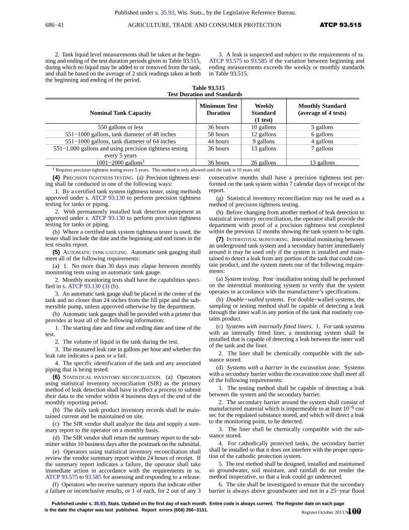
686−41 ATCP 93.515AGRICULTURE, TRADE AND CONSUMER PROTECTION
Published under s. 35.93, Wis. Stats., by the Legislative Reference Bureau.
Published under s. 35.93 , Stats. Updated on the first day of each month. Entire code is always current. The Register date on each pageis the date the chapter was last published. Report errors (608) 266−3151. Register October 2013 No. 694
2. Tank liquid level measurements shall be taken at the begin-ning and ending of the test duration periods given in Table 93.515,during which no liquid may be added to or removed from the tank,and shall be based on the average of 2 stick readings taken at boththe beginning and ending of the period.
3. A leak is suspected and subject to the requirements of ss.ATCP 93.575 to 93.585 if the variation between beginning andending measurements exceeds the weekly or monthly standardsin Table 93.515.
Table 93.515Test Duration and Standards
Nominal Tank CapacityMinimum T est
Duration Weekly Standard(1 test)
Monthly Standard(average of 4 tests)
550 gallons or less 36 hours 10 gallons 5 gallons551−1000 gallons, tank diameter of 48 inches 58 hours 12 gallons 6 gallons551−1000 gallons, tank diameter of 64 inches 44 hours 9 gallons 4 gallons
551−1,000 gallons and using precision tightness testingevery 5 years
36 hours 13 gallons 7 gallons
1001−2000 gallons1 36 hours 26 gallons 13 gallons1 Requires precision tightness testing every 5 years. This method is only allowed until the tank is 10 years old.
(4) PRECISION TIGHTNESS TESTING. (a) Precision tightness test-ing shall be conducted in one of the following ways:
1. By a certified tank system tightness tester, using methodsapproved under s. ATCP 93.130 to perform precision tightnesstesting for tanks or piping.
2. With permanently installed leak detection equipment asapproved under s. ATCP 93.130 to perform precision tightnesstesting for tanks or piping.
(b) Where a certified tank system tightness tester is used, thetester shall include the date and the beginning and end times in thetest results report.
(5) AUTOMATIC TANK GAUGING. Automatic tank gauging shallmeet all of the following requirements:
(a) 1. No more than 30 days may elapse between monthlymonitoring tests using an automatic tank gauge.
2. Monthly monitoring tests shall have the capabilities speci-fied in s. ATCP 93.130 (3) (b).
3. An automatic tank gauge shall be placed in the center of thetank and no closer than 24 inches from the fill pipe and the sub-mersible pump, unless approved otherwise by the department.
(b) Automatic tank gauges shall be provided with a printer thatprovides at least all of the following information:
1. The starting date and time and ending date and time of thetest.
2. The volume of liquid in the tank during the test.3. The measured leak rate in gallons per hour and whether this
leak rate indicates a pass or a fail.4. The specific identification of the tank and any associated
piping that is being tested.(6) STATISTICAL INVENTORY RECONCILIATION. (a) Operators
using statistical inventory reconciliation (SIR) as the primarymethod of leak detection shall have in effect a process to submittheir data to the vendor within 4 business days of the end of themonthly reporting period.
(b) The daily tank product inventory records shall be main-tained current and be maintained on site.
(c) The SIR vendor shall analyze the data and supply a sum-mary report to the operator on a monthly basis.
(d) The SIR vendor shall return the summary report to the sub-mitter within 10 business days after the postmark on the submittal.
(e) Operators using statistical inventory reconciliation shallreview the vendor summary report within 24 hours of receipt. Ifthe summary report indicates a failure, the operator shall takeimmediate action in accordance with the requirements in ss.ATCP 93.575 to 93.585 for assessing and responding to a release.
(f) Operators who receive summary reports that indicate eithera failure or inconclusive results, or 1 of each, for 2 out of any 3
consecutive months shall have a precision tightness test per-formed on the tank system within 7 calendar days of receipt of thereport.
(g) Statistical inventory reconciliation may not be used as amethod of precision tightness testing.
(h) Before changing from another method of leak detection tostatistical inventory reconciliation, the operator shall provide thedepartment with proof of a precision tightness test completedwithin the previous 12 months showing the tank system to be tight.
(7) INTERSTITIAL MONITORING. Interstitial monitoring betweenan underground tank system and a secondary barrier immediatelyaround it may be used only if the system is installed and main-tained to detect a leak from any portion of the tank that could con-tain product, and the system meets one of the following require-ments:
(a) System testing. Post−installation testing shall be performedon the interstitial monitoring system to verify that the systemoperates in accordance with the manufacturer’s specifications.
(b) Double−walled systems. For double−walled systems, thesampling or testing method shall be capable of detecting a leakthrough the inner wall in any portion of the tank that routinely con-tains product.
(c) Systems with internally fitted liners. 1. For tank systemswith an internally fitted liner, a monitoring system shall beinstalled that is capable of detecting a leak between the inner wallof the tank and the liner.
2. The liner shall be chemically compatible with the sub-stance stored.
(d) Systems with a barrier in the excavation zone. Systemswith a secondary barrier within the excavation zone shall meet allof the following requirements:
1. The testing method shall be capable of detecting a leakbetween the system and the secondary barrier.
2. The secondary barrier around the system shall consist ofmanufactured material which is impermeable to at least 10−6 cm/sec for the regulated substance stored, and which will direct a leakto the monitoring point, to be detected.
3. The liner shall be chemically compatible with the sub-stance stored.
4. For cathodically protected tanks, the secondary barriershall be installed so that it does not interfere with the proper opera-tion of the cathodic protection system.
5. The test method shall be designed, installed and maintainedso groundwater, soil moisture, and rainfall do not render themethod inoperative, so that a leak could go undetected.
6. The site shall be investigated to ensure that the secondarybarrier is always above groundwater and not in a 25−year flood
100
686−42 ATCP 93.515 WISCONSIN ADMINISTRATIVE CODE
Published under s. 35.93, Wis. Stats., by the Legislative Reference Bureau.
Published under s. 35.93 , Stats. Updated on the first day of each month. Entire code is always current. The Register date on eachpage is the date the chapter was last published. Report errors (608) 266−3151.Register October 2013 No. 694
plain, unless the barrier and monitoring designs are for use undersuch conditions.
7. Monitoring wells shall be clearly marked and secured toavoid unauthorized access and tampering.
(8) METHODS OF LEAK DETECTION FOR PIPING. (a) General.Leak detection for piping shall follow the requirements of s. ATCP93.510 (4) and this section.
(b) Automatic line leak detectors. Underground piping sys-tems serving a storage tank with a submersible pump or pressur-ized booster pump shall be provided with an automatic line leakdetector that alerts the operator to the presence of a leak byrestricting or shutting off flow from the pump, when it detectsleaks of 3 gallons per hour at 10 pounds per square inch line pres-sure within 1 hour.
(c) Line tightness testing. 1. In addition to the automatic lineleak detection required by par. (b), a periodic precision tightnesstest of piping shall be conducted in accordance with sub. (4),except as provided in subds. 2 and 3. The test shall be performedby a certified tank system tightness tester.
2. Where piping leak detection is installed that has the capa-bility to perform monthly monitoring, a separate precision tight-ness test is not required.
3. Any of the methods in subs. (6) and (7) may be used in lieuof complying with subd. 1. if they are designed and approvedunder s. ATCP 93.130 to detect a leak from any portion of theunderground piping that routinely contains product.
(d) Periodic line leak detection equipment testing. 1. Astart−up functionality test of the operation of the leak detectorshall be conducted in accordance with the manufacturer’s proce-dures for testing to the leak thresholds in par. (b) by inducing aphysical line leak.
2. A functionality test of the operation of a mechanical lineleak detector shall be conducted annually in accordance with themanufacturer’s procedures for testing to the leak thresholds in par.(b) by inducing a physical line leak.
3. A functionality test of the operation of an electronic lineleak detector shall be conducted at least annually in accordancewith the manufacturer’s procedures for periodic testing to the leakthresholds in par. (b) by inducing a physical line leak, except asprovided in subd. 4.
4. A leak shall be introduced to the line system to prove thefunctionality of the electronic line leak detector unless themanufacturer has an alternate approved or equivalent method fortesting whether the detector is functioning as intended by themanufacturer. This testing shall be conducted annually by an indi-vidual who has no financial interest in the facility and who is certi-fied by the manufacturer to perform the testing, and it shall includeall of the following elements:
a. Review of the test diagnostics for a 3 and 0.2 gallon perhour leak test and the history reports for the leak detector showingmonthly leak tests.
b. Verification that the programming parameters are correctlyset.
c. Verification that the leak detector is producing normalpump−on pressures, by activating a 3 gallon per hour test from thetank monitor console.
d. Verification that electrical wiring and connections have notdeteriorated.
e. Verification that associated sensors are functioning asintended.
(9) OTHER METHODS. The department may approve othermethods of leak detection in accordance with s. ATCP 93.130.
History: CR 07−029: cr. Register November 2008 No. 635, eff. 2−1−09; CR09−017: am. (2) (b) 3. b., r. (5) (b) and (c), renum. (5) (d) and (6) (b) to (g) to be (5)(b) and (6) (c) to (h), cr. (6) (b) Register July 2009 No. 643, eff. 8−1−09; correctionin (1) (b) (intro.), 3., (2) (c), (3) (a) 2. c., (b) 2., 3., (4) (a) 1., 2., (5) (a) 2., (6) (e), (8)(a), (c) 3., (9) made under s. 13.92 (4) (b) 7., Stats., Register December 2011 No. 672;corrections in (1) (b) (intro.), 3., (2) (c), (3) (a) 2. c., (b) 2., 3., (4) (a) 1., 2., (5) (a)
2., (6) (e), (8) (a), (c) 3., (9) made under s. 13.92 (4) (b) 7., Stats., Register October2013 No. 694.
ATCP 93.517 Airport hydrant leak detection require -ments. (1) GENERAL. All new and existing airport fuel hydrantsystems shall comply with this section.
(2) LEAK DETECTION PLANS. All fuel hydrant systems shallhave a leak detection plan that is specifically approved by thedepartment in accordance with s. ATCP 93.130.
(3) PLAN DEADLINES. (a) For new fuel hydrant systems, leakdetection plans shall be submitted to the department before thesystem becomes operational.
(b) For existing fuel hydrant systems, leak detection plansshall be submitted to the department within 10 years after Febru-ary 1, 2009.
(4) PLAN REQUIREMENTS. Fuel hydrant leak detection plansshall include all of the following:
(a) A description of the fuel hydrant system.(b) A description of the leak detection method used.
Note: A designer of an airport hydrant leak detection system who does not havea financial interest in the airport may be considered to be the independent third partythat is required in section ATCP 93.130 (3) (b) 1. for leak detection methods.
(c) A schedule for testing the system.(d) Any limitations of the leak detection method.(e) An action plan in the event a leak is identified.(5) SYSTEM REQUIREMENTS. (a) All new fuel hydrant systems
shall be designed and equipped with isolation valves appropriatefor leak testing.
(b) Any repair or upgrade to an existing fuel hydrant systemshall include the installation of isolation valves in the section thatis repaired or upgraded.
(c) Existing fuel hydrant systems shall have isolation valvesfor leak testing installed within 10 years after February 1, 2009.
History: CR 07−029: cr. Register November 2008 No. 635, eff. 2−1−09; correc-tion in (2) made under s. 13.92 (4) (b) 7., Stats., Register December 2011 No. 672;correction in (2) made under s. 13.92 (4) (b) 7., Stats., Register October 2013 No.694.
ATCP 93.520 Operation and maintenance of corro-sion protection. (1) GENERAL. (a) Where required. Vent lines,vapor lines and any portion of a single or double−wall tank sys-tem, whether new or existing, that routinely contains product andis in contact with the ground or with water shall be protected fromcorrosion by one of the following methods:
1. The tank and piping are constructed of an inherentlycorrosion−resistant material.
2. a. The tank and piping are installed at a site that is deter-mined by a certified corrosion expert to be non−corrosive duringthe operational life of the system.
b. A certified corrosion expert retained for the purpose ofdetermining a non−corrosive site shall make at least 1 personalvisit to each tank site during the design stage.
Note: See section ATCP 93.200, Table 93.200–5 for information on contactingNACE.
3. The tank is a listed composite or jacketed tank designatedas complying with UL 1746, and the piping is protected by one ofthe methods in this subsection.
Note: In addition to composite and jacketed tanks, the UL 1746 standard alsoincludes requirements for coated tanks and tanks with pre−engineered cathodicprotection systems. These last 2 types of cathodic protection are not included in theblanket approval under this section.
4. The tank and piping are protected with a sacrificial anodesystem in accordance with a standard developed by a nationallyrecognized association or independent testing laboratory that isacceptable to the department.
5. a. The tank and piping are protected with a corrosionprotection system designed by a certified corrosion expert andmeet the requirements of either sub. (2) or (3).
b. A corrosion expert retained for the purpose of designing animpressed current corrosion protections system shall make at least1 personal visit to each tank site during the design stage.
101
686−43 ATCP 93.520AGRICULTURE, TRADE AND CONSUMER PROTECTION
Published under s. 35.93, Wis. Stats., by the Legislative Reference Bureau.
Published under s. 35.93 , Stats. Updated on the first day of each month. Entire code is always current. The Register date on each pageis the date the chapter was last published. Report errors (608) 266−3151. Register October 2013 No. 694
(b) Design and construction. 1. To allow for periodic testing,new and replacement factory− or field−installed corrosion protec-tion systems shall have appropriate connections, insulated leadwires and accessible test stations, including as specified in subds.2. and 3.
2. All lead wires connected to a tank, anode, reference elec-trode, or other component associated with the corrosion protec-tion system shall terminate at a test station.
3. The termination of each lead wire at a test station shall beclearly labeled or coded to identify the specific component towhich it is connected.
4. Impressed current systems shall be designed to preventstray current conditions that may negatively impact other under-ground structures, utility lines, or cable anchors, or any impressedcurrent systems protecting those items.
5. Local utilities shall be notified by the contractor whenimpressed current systems are installed, repaired or adjusted,including where an increase in rectifier amperage or voltage out-put occurs.
(c) Operation and maintenance. 1. Operation and mainte-nance of corrosion protection systems shall be in accordance withnational standards acceptable to the department.
2. All new and existing corrosion protection systems shall beoperated and maintained to continuously provide corrosionprotection for the life of the tank system.
3. For impressed current systems, operation and maintenancepractices and procedures shall be evaluated, and conducted in amanner that minimizes DC interference to or from any under-ground structure, utility line or cable anchors in the area.
(d) Testing periods. 1. a. All new and existing corrosionprotection for UST systems shall be tested within 6 months ofinstallation or repair and at least annually, except as provided insubd. 3.
b. Structure−to−soil potential readings shall be conductedwith a minimum of three readings per tank along the center line,located at the ends and in the middle, and with one reading remotefrom the structure.
c. For each product line, structure−to−soil potentials shall betaken above the piping, at the ends and middle, away from theanode locations. Piping runs over 30 feet shall have additionalreadings taken every 10 feet.
d. For impressed current systems, the annual test shall includeinstant−off potentials.
2. In addition to the requirements in subd. 1., impressed cur-rent corrosion protection systems shall be inspected and evaluatedby the site operator at least every 60 days to ensure the equipmentis providing adequate current in accordance with its design.
3. Tanks designated as sti−P3 , equipped with a pre−installedsacrificial anode system and test station, shall be tested in accord-ance with all of the following:
a. Testing shall occur within 6 months of installation and atleast every 3 years thereafter until the tank is 10 years old.
b. Testing shall occur annually in accordance with subd. 1.after the tank is 10 years old.
4. The results of the inspections, evaluations and testingunder this paragraph shall be summarized on the department’sform ERS−10785, and retained at the site in accordance with s.ATCP 93.500 (9).
Note: Form ERS−10785, Underground Tank System Corrosion Protection Sum-mary Documentation, is available from the Bureau of Weights and Measures, PO Box8911, Madison, WI 53708−8911, or at telephone (608) 224−4942, or from theBureau’s Web site at http://datcp.wi.gov/Consumer/Weights_and_Measures/index.aspx.
Note: Section ATCP 93.500 (9) specifies retention requirements for testing andrepair records of corrosion protection systems.
(e) Certifications for corrosion protection. 1. A certifiedcathodic protection tester shall be on the site to supervise and
monitor the initial post−installation start−up of impressed currentcorrosion protection systems.
Note: NACE requires a person with Senior Corrosion Technologist certificationor higher for corrosion protection system commissioning.
2. A certified cathodic protection tester shall perform orsupervise the performance of reinstallation or replacement ofanodes.
Note: NACE requires a person with Level 1 Cathodic Protection Tester certifica-tion or higher for reinstallation or replacement of anodes.
3. a. All new and existing corrosion protection for UST sys-tems shall be tested by a certified cathodic protection tester,except as provided in subd. 3. b.
Note: NACE requires a person with corrosion technologist certification or higheror a person with corrosion technician certification who is directly supervised by a cer-tified corrosion technologist or higher to perform work as a state−certified cathodicprotection tester.
b. Tanks designated as sti−P3 shall be tested by a personholding a certification from the Steel Tank Institute or one of thecertifications in subd. 3. a.
Note: Additional information on corrosion protection certifications is availablefrom the Department’s Web site at http://datcp.wi.gov/Consumer/Weights_and_Measures/index.aspx.
(2) SACRIFICIAL ANODE SYSTEMS. (a) General. All new andexisting sacrificial anode systems shall maintain the standardprotection threshold reading of at least negative 850 millivolts orshall comply with the requirements of par. (b).
(b) Failing sacrificial anode systems. 1. Unless arrangementsare made with the authorized agent or the department to conductfollow−up testing, the cause of the failure shall be investigated andrepaired within 90 days of the failed reading; or the entire tank sys-tem shall be emptied in accordance with s. ATCP 93.545 (1) (a)2. b. within 90 days of the failed reading, and shall remain emptyuntil the repair is completed.
2. If more than 2 years has elapsed since the previous corro-sion protection test, or if the corrosion protection system has beeninoperative for 2 years or more, an internal inspection shall be per-formed by a third party in accordance with one of the followingstandards:
a. For lined tanks, the internal inspection shall be in accord-ance with API 1631 or KWA.
b. For unlined tanks, the internal inspection shall be in accord-ance with ASTM G 158.
3. If the tank fails the internal inspection, one of the followingshall occur:
a. The tank system shall be permanently closed.b. The tank system shall be lined or any present lining shall
be repaired in accordance with API 1631, and an impressed cur-rent corrosion protection system shall be installed.
4. After an inspection under this paragraph, if the tank is notclosed under subd. 3. a., a precision tightness test shall be per-formed on the tank system in accordance with s. ATCP 93.515 (4).The tightness test shall test 100 percent of the tank’s volume.
(3) IMPRESSED CURRENT SYSTEMS. (a) General. 1. Equipmentfor impressed current systems shall be served by a dedicated andclearly marked electrical circuit that remains energized at alltimes.
2. All new and existing impressed current systems shall main-tain either of the following standard protection levels:
a. An instant−off reading of at least negative 850 millivolts.b. A 100 millivolt or greater polarization shift from the
instant−off reading.3. When a new impressed current system is installed or an
existing system is replaced in whole or in part, an ammeter shallbe installed, along with an hour meter that totals the number ofhours during which electric current flows through the system.
(b) Failing impressed current systems. If impressed currentcorrosion protection readings taken in accordance with sub. (1)(d) 2. indicate the system is not maintaining adequate continuousprotection, the system shall be analyzed by a certified corrosion
102
686−44 ATCP 93.520 WISCONSIN ADMINISTRATIVE CODE
Published under s. 35.93, Wis. Stats., by the Legislative Reference Bureau.
Published under s. 35.93 , Stats. Updated on the first day of each month. Entire code is always current. The Register date on eachpage is the date the chapter was last published. Report errors (608) 266−3151.Register October 2013 No. 694
expert for site corrosion potential and qualification of systemfunctionality.
(c) Inoperative impressed current systems. 1. Impressed cur-rent systems that have been inoperative for 120 days or less shallcomply with all of the following requirements:
a. Power shall be restored and the system shall be tested bya certified cathodic protection tester for system functionality.
b. If the impressed current system is damaged or inoperable,a certified corrosion expert shall repair, survey and re−commis-sion the system.
2. Impressed current systems that have been inoperative for121 to 180 days shall comply with all of the following require-ments:
a. A precision tightness test shall be performed on the tanksystem in accordance with s. ATCP 93.515 (4) within 15 days ofdiscovery.
b. Power shall be restored and the system shall be tested forsystem functionality by a certified cathodic protection tester.
c. If the impressed current system is damaged or inoperable,a certified corrosion expert shall repair, survey and re−commis-sion the system.
3. Impressed current systems that have been inoperative for181 to 365 days shall comply with all of the following require-ments:
a. A precision tightness test shall be performed on the tanksystem in accordance with s. ATCP 93.515 (4) within 15 days ofdiscovery.
b. A certified corrosion expert shall assess, survey and re−commission the impressed current system and perform any neces-sary repairs.
4. Impressed current systems that have been inoperative formore than 365 days shall comply with all of the following require-ments:
a. An internal inspection of the tank shall be performed inaccordance with sub. (2) (b) 2.
b. If the tank fails the internal inspection, the tank owner shalleither have the tank repaired and lined, or have the lining repairedin accordance with s. ATCP 93.530, or have the tank permanentlyclosed and removed in accordance with s. ATCP 93.560.
c. If the tank is not closed under subd. 4. b., a certified corro-sion expert shall assess, survey and re−commission the impressedcurrent system and perform any necessary repairs.
d. If the tank is not closed under subd. 4. b., a precision tight-ness test shall be performed on the tank system in accordance withs. ATCP 93.515 (4). The tightness test shall test 100 percent of thetank’s volume.
History: CR 07−029: cr. Register November 2008 No. 635, eff. 2−1−09; correc-tion in (3) (c) 4. a. made under s. 13.92 (4) (b) 7., Stats., Register November 2008 No.635; CR 09−017: am. (1) (b) 1., cr. (2) (b) 4. Register July 2009 No. 643, eff. 8−1−09;correction in (1) (d) 4., (2) (b) 1., 4., (3) (c) 2. a., 3. a., 4. b., d. made under s. 13.92(4) (b) 7., Stats., Register December 2011 No. 672; corrections in (1) (d) 4., (2) (b)1., 4., (3) (c) 2. a., 3. a., 4. b., d. made under s. 13.92 (4) (b) 7., Stats., Register Octo-ber 2013 No. 694.
ATCP 93.530 Tank lining of underground storagetanks. (1) GENERAL. (a) The installation of interior tank liningfor underground storage tanks shall comply with API 1631 andthis section.
(b) An underground storage tank that does not meet the struc-tural requirements specified in API 1631 may not be upgraded orrepaired by lining and shall be permanently closed in accordancewith this chapter.
(c) When lining a tank, an access way for an inspector to enterthe tank shall be installed from the tank interior to finished grade,if not already provided.
(2) INSPECTION AND REPORTING REQUIREMENTS FOR TANK LIN-ING. (a) General. 1. It is the responsibility of the lining contractor
to communicate with the authorized agent or the department toestablish the time for inspections.
2. The lining contractor shall give the authorized agent or thedepartment at least 5 days written notice before beginning the tanklining or any excavation preliminary to tank lining.
(b) Plan approval. The tank owner is responsible for obtainingplan approval from the authorized agent or the department inaccordance with s. ATCP 93.100 before beginning the tank liningor any excavation preliminary to tank lining.
(c) Tank integrity assessment before lining. 1. The tank−liningcontractor shall provide the tank owner and the authorized agentor the department with a written report of the assessment of theinterior surface and structural condition of the tank, before leavingthe site and before installing the lining.
2. The tank integrity assessment shall include all of the fol-lowing:
a. A description of the internal wall condition including anydeflection and any defects, rust plugs, holes or leaks, regardlessof size or number.
b. A description of any repair or other conditioning necessaryto prepare the tank for interior lining.
c. A description of the degree of compliance with all require-ments under API 1631 regarding structural qualification, tankcleaning and other pre−lining activities.
Note: Section 292.11 of the Statutes requires immediate notification of the Depart-ment of Natural Resources in the event of a hazardous substance discharge.
3. If holes or rust plugs are observed during the visual internalinspection, the tank−lining contractor shall notify the owner,before lining the tank, that a tank−system site assessment must beperformed, and that assessment shall be performed in accordancewith ss. ATCP 93.575 to 93.585.
(d) Inspection before lining. 1. The authorized agent or thedepartment shall be at the site before the actual application of thelining.
2. The application of the interior lining may proceed onlywhen authorized by the authorized agent or the department afterverifying all of the following:
a. The tank integrity assessment and any required tank−sys-tem site assessment have been completed.
b. An approved set of plans is on the site.c. The condition of the tank has been communicated to the
owner.(e) Completion of forms. 1. a. The certified tank system liner
shall provide a completed, signed and notarized API 1631 FormB inspection affidavit to the tank owner within 10 business daysof completing the lining procedure.
b. The signature on API 1631 Form B shall be that of the certi-fied tank system liner who conducted the pre−lining tank integrityassessment and the lining procedure.
2. An underground tank installation checklist, formERS−6294 UST, shall be completed and signed by the certifiedtank system liner and the certified tank system inspector.
Note: Form ERS−6294 UST — Checklist For Underground Tank Installation isavailable from the Bureau of Weights and Measures, PO Box 8911, Madison, WI53708−8911, or at telephone (608) 224−4942, or from the Bureau’s Web site athttp://datcp.wi.gov/Consumer/Weights_and_Measures/index.aspx.
Note: See chapter SPS 305, Licenses, Certifications and Registrations, forrequirements that certified tank system liners supervise specific lining−related activi-ties involving underground storage tanks.
(f) Submittal of forms. The tank owner shall have all of the fol-lowing documents submitted to the department within 15 businessdays of completing the lining procedure:
1. The pre−lining tank integrity assessment under par. (c).2. The completed and signed API 1631 Form B under par. (e)
1.3. The tank installation checklist under par. (e) 2.4. A revised tank registration, form ERS−7437.
103
686−45 ATCP 93.550AGRICULTURE, TRADE AND CONSUMER PROTECTION
Published under s. 35.93, Wis. Stats., by the Legislative Reference Bureau.
Published under s. 35.93 , Stats. Updated on the first day of each month. Entire code is always current. The Register date on each pageis the date the chapter was last published. Report errors (608) 266−3151. Register October 2013 No. 694
Note: Form ERS−7437 — Underground Flammable/Combustible/HazardousLiquid Storage Tank Registration is available from the Bureau of Weights and Mea-sures, PO Box 8911, Madison, WI 53708−8911, or at telephone (608) 224−4942, orfrom the Bureau’s Web site at http://datcp.wi.gov/Consumer/Weights_and_Mea-sures/index.aspx.
History: CR 07−029: cr. Register November 2008 No. 635, eff. 2−1−09; CR09−017: cr. (1) (c) Register July 2009 No. 643, eff. 8−1−09; correction in (2) (b), (c)3. made under s. 13.92 (4) (b) 7., Stats., Register December 2011 No. 672; correc-tions in (2) (b), (c) 3. made under s. 13.92 (4) (b) 7., Stats., Register October 2013No. 694.
ATCP 93.535 Periodic inspection and repair of pre-viously lined tanks. (1) (a) The owner of a lined tank shallobtain an internal inspection of the tank lining within 5 years afterthe date of initial tank lining, or repair to a previously installedtank lining, and at least every 5 years thereafter. The first inspec-tion shall be conducted within the years specified in Table 93.535.
(b) This section applies whether or not cathodic protection hasbeen added to the tank system.
Table 93.535Year of Initial Requir ed Lining Inspection
Date of Initial Liningor Repair
First Required 5−YearInspection
1993–2004 20092005 and after Within 5 years after initial lin-
ing or repair(2) Any complete or partial tank lining conducted anytime
after the original tank lining was installed is considered a repairof the lining.
(3) The owner shall notify the authorized agent or the depart-ment in writing at least 5 business days before having the inspec-tion performed.
(4) (a) Tank lining inspections shall use one or more of the fol-lowing methods:
1. Video camera in accordance with KWA.2. Ultrasound tester.3. Other method acceptable to the department.
(b) The use of the equipment to perform the inspection underpar. (a) 2. and 3. shall be in accordance with national consensusstandards.
(5) The person performing the inspection shall be certified bythe manufacturer of the inspection equipment and acceptable tothe department.
(6) (a) The person performing the inspection shall ascertainthat the tank has been adequately emptied and cleaned to allow fora complete inspection of the tank.
(b) The authorized agent or the department may not accept aninspection that does not include all interior portions of the tank.
(7) The person performing the inspection shall provide areport to the owner and to the authorized agent and the departmentwithin 15 days of completing the inspection, that describes all ofthe following items in addition to those required in API 1631:
(a) The type of repairs that have been made.(b) The total dimension of the area in square inches that has
been repaired by lining.(c) A schematic drawing of the tank showing the area of
repairs.(8) A previously lined tank that is repaired to more than 10
percent of the lined surface may be returned to service only if allof the following conditions are met:
(a) The tank meets the structural requirements for lining whentested in accordance with API 1631 before the lining repair.
(b) The tank has impressed current corrosion protectioninstalled in accordance with s. ATCP 93.520 before being placedback into service.
(9) Prior to placing any tank back into service under this sec-tion, both of the following shall occur, in the following order:
(a) An access way for an inspector to enter the tank shall beinstalled from the tank interior to finished grade, if not alreadyprovided.
(b) A precision tightness test shall be performed on the tanksystem in accordance with s. ATCP 93.515 (4). The tightness testshall test 100 percent of the tank’s volume.
History: CR 07−029: cr. Register November 2008 No. 635, eff. 2−1−09; CR09−017: cr. (9) Register July 2009 No. 643, eff. 8−1−09; correction in (1) (a), (8) (b),(9) (b) made under s. 13.92 (4) (b) 7., Stats., Register December 2011 No. 672;corrections in (1) (a), (8) (b), (9) (b) made under s. 13.92 (4) (b) 7., Stats., RegisterOctober 2013 No. 694.
ATCP 93.545 Seldom−used and temporarily−out−of−service tanks. (1) OPERATIONAL REQUIREMENTS. When astorage tank system is placed temporarily out of service, the owneror operator shall comply with all of the following:
(a) 1. Operation and maintenance of corrosion protection andleak detection systems shall be continued, except as provided insubd. 2.
2. a. Leak detection shall be maintained in accordance withthis chapter unless the tank system is empty.
b. The tank system is empty when all liquid has been removedfrom the tank and the associated piping so that no more than 1 inchof residue, or 0.3 percent by weight of the total capacity of the tanksystem, remains in the system.
(b) The tank shall be protected against floatation caused byflooding or soil saturation.
(c) 1. The tank, piping, dispensing equipment, lines, pumps,manways, and other ancillary equipment shall be secured to pre-vent tampering, except as exempted in subd. 2.
2. Facilities that are in operation and secured against generalpublic access are not required to have the additional securityrequired in subd. 1.
(d) All vent lines shall be left open and functioning.(e) All periodic inspections and maintenance shall be per-
formed as if the tank were still in service.(f) Financial responsibility requirements of subch. VII shall be
maintained.(2) PLACING A TANK BACK INTO SERVICE. (a) A precision tight-
ness test shall be performed on the tank and piping in accordancewith s. ATCP 93.515 (4) before placing the tank system back intoservice.
(b) Tank systems out of service for more than 365 days shallhave a pressure test of the ullage portion to assure that tank con-nections are tight and shall fully comply with this chapter beforebeing placed back into service, except double−wall constructionis not newly required for tank systems installed before February1, 2009.
(c) Tank systems covered in par. (a) shall immediately have theleak detection system verified in accordance with s. ATCP 93.510(2).
(d) Tanks covered in par. (b) shall have all the respective com-ponents documented as functional on form ERS−10778.
Note: Form ERS−10778, Underground Tank System Release and Leak Monitor-ing Functionality Verification, is available from the Bureau of Weights and Measures,PO Box 8911, Madison, WI 53708−8911, or at telephone (608) 224−4942, or fromthe Bureau’s Web site at http://datcp.wi.gov/Consumer/Weights_and_Measures/index.aspx.
(3) NON−COMPLYING TANK SYSTEMS. Tank systems that areplaced out of service which do not comply with this section shallbe permanently closed in accordance with s. ATCP 93.560 within60 calendar days.
History: CR 07−029: cr. Register November 2008 No. 635, eff. 2−1−09; CR09−017: am. (1) (a) 2. b., (2) (b), (c), and (3), cr. (2) (d) Register July 2009 No. 643,eff. 8−1−09; correction in (2) (a), (c), (3) made under s. 13.92 (4) (b) 7., Stats., Reg-ister December 2011 No. 672; corrections in (2) (a), (c), (3) made under s. 13.92(4) (b) 7., Stats., Register October 2013 No. 694.
ATCP 93.550 Change in service to store a non−reg -ulated substance. (1) When a tank system that held a regu-lated substance undergoes a change in service to store a non−regu-
104
686−46 ATCP 93.550 WISCONSIN ADMINISTRATIVE CODE
Published under s. 35.93, Wis. Stats., by the Legislative Reference Bureau.
Published under s. 35.93 , Stats. Updated on the first day of each month. Entire code is always current. The Register date on eachpage is the date the chapter was last published. Report errors (608) 266−3151.Register October 2013 No. 694
lated substance, the owner or operator shall comply with all of thefollowing requirements:
(a) At least 5 business days before beginning a change in ser-vice, the owner or operator shall notify the authorized agent or thedepartment of the intended change.
(b) Before a change in service, the owner or operator shall havethe tank emptied and cleaned, by removing all liquid and accumu-lated sludge in accordance with the procedures specified in API2015.
(c) A tank−system integrity assessment, and if necessary, atank−system site assessment shall be performed for the tank sys-tem in accordance with ss. ATCP 93.575 to 93.585 after notifyingthe authorized agent or the department but before completing thechange in service.
(d) Cleaning of tanks and tank−system site assessments shallbe performed by persons certified in accordance with ss. SPS305.82 to 305.89.
(e) The owner shall have a revised tank registration, formERS−7437, and part A of the department’s tank−system serviceand closure assessment report, form ERS−8951, completed andsubmitted to the department within 21 business days of changinga tank system to storage of a non−regulated substance.
Note: Forms ERS−7437 − Underground Flammable/Combustible/HazardousLiquid Storage Tank Registration, and form ERS−8951 – Tank System Service andClosure Assessment Report are available from the Bureau of Weights and Measures,PO Box 8911, Madison, WI 53708−8911, or at telephone (608) 224−4942, or fromthe Bureau’s Web site at http://datcp.wi.gov/Consumer/Weights_and_Measures/index.aspx.
(2) When a tank system that held a non−regulated substanceundergoes a change in service to store a regulated substance, allapplicable requirements of this chapter apply upon placing thetank system into service.
History: CR 07−029: cr. Register November 2008 No. 635, eff. 2−1−09; correc-tion in (1) (c), (d) made under s. 13.92 (4) (b) 7., Stats., Register December 2011 No.672; corrections in (1) (c), (d) made under s. 13.92 (4) (b) 7., Stats., Register Octo-ber 2013 No. 694.
ATCP 93.560 Tank system closure. (1) NOTIFICATION.At least 5 business days before beginning permanent closure of atank system, the owner or operator shall notify the authorizedagent or the department of the intended closure, on formERS−9198, except a shorter notification period is permitted whereunexpected closure is commenced upon finding adverse condi-tions during a corrective action conducted under s. ATCP 93.585.
Note: Form ERS−9198 – ATCP 93 Notification Record is available from theBureau of Weights and Measures, PO Box 8911, Madison, WI 53708−8911, or at tele-phone (608) 224−4942, or from the Bureau’s Web site at http://datcp.wi.gov/Con-sumer/Weights_and_Measures/index.aspx.
(2) CLOSURE PROCEDURES. (a) To permanently close an under-ground tank system, the owner or operator shall have the tank andpiping emptied and cleaned, by removing all liquids and accumu-lated sludge, and shall remove the tank and piping from the siteunless allowed otherwise under par. (e). Tanks that are removedshall be scrapped unless reused in accordance with s. ATCP93.350 (3) (i) or 93.500 (3) (c).
(b) Tank cleaning processes shall comply with the appropriatenational standard referenced in s. ATCP 93.200.
(c) Individuals cleaning tanks or removing tanks or portionsof tank systems shall be certified in accordance with ss. SPS305.82 to 305.89.
(d) When an underground tank is closed, or when a previouslyclosed tank is removed under sub. (4), the owner shall have arevised tank registration, form ERS−7437, and part A of thedepartment’s tank−system service and closure assessment report,form ERS−8951, completed and submitted to the departmentwithin 21 business days of closure or removal.
Note: Form ERS−7437 — Underground Flammable/Combustible/HazardousLiquid Storage Tank Registration, and form ERS−8951 – Tank System Service andClosure Assessment Report are available from the Bureau of Weights and Measures,PO Box 8911, Madison, WI 53708−8911, or at telephone (608) 224−4942, or fromthe Bureau’s Web site at http://datcp.wi.gov/Consumer/Weights_and_Measures/index.aspx.
(e) Underground tanks systems may be closed in−place by fill-ing with an inert, solid material, after emptying and cleaning, if theauthorized agent or the department determines, upon writtenrequest from the owner or operator, that one or more of the follow-ing conditions exist:
1. Excavation would impact the structural integrity of an adja-cent building or structure.
2. Overhead utilities at a commercial site pose a safety hazard.3. Excavation would impact adjacent transformers or substa-
tions.4. Unauthorized encroachment would occur onto neighbor-
ing property under different ownership.5. The tank location is inaccessible to necessary equipment.6. Excavation would result in the destruction of mature trees.7. Excavation would encroach upon a public way.8. Excavation would necessitate the disconnection or reloca-
tion of underground utilities.Note: Closing a tank in−place does not exempt the tank from tank−system site
assessment requirements.
(3) TANK−SYSTEM SITE ASSESSMENT. A tank−system siteassessment shall be performed in accordance with ss. ATCP93.575 to 93.585 after notifying the authorized agent or thedepartment but before installing a new system or backfilling thetank basin and the piping trenches.
Note: The Department and the Department of Natural Resources share jurisdic-tion over tank closures and tank−system site assessments. The DNR must be notifiedif a release is discovered.
(4) APPLICABILITY TO PREVIOUSLY CLOSED SYSTEMS. (a) Gen-eral. When directed by the department, the owner or operator ofany tank system closed in−place before December 22, 1988, shallhave the system removed in accordance with this section and havethe tank basin assessed in conformance with s. ATCP 93.580.
(b) Systems previously closed without solid, inert fill. Theowner or operator of any tank system that was closed before Octo-ber 1, 1971, without removing the tank from the site but by fillingthe tank with water, shall bring the closed system into compliancewith sub. (2) within a time period established by the departmenton a case−by−case basis, except that the tank−system site assess-ment in s. ATCP 93.580 is not required unless there is a suspectedor obvious release. Written documentation shall be provided toprove closure with water before September 1, 1971.
Note: Before September 1, 1971, chapter Ind 8 — Flammable and CombustibleLiquids Code allowed UST systems to be filled with water when closed or abandonedin−place.
(c) Other tanks. Empty or improperly closed or abandonedtanks that do not meet the requirements of sub. (2) or the exemp-tion under par. (b) shall be permanently closed in accordance withall of the provisions of this section.
(5) ABANDONED TANKS. Tanks that are abandoned with orwithout product shall be permanently closed within 60 days ofbeing abandoned or discovered.
History: CR 07−029: cr. Register November 2008 No. 635, eff. 2−1−09; correc-tion in (1), (2) (a), (b), (c), (3), (4) (a), (b) made under s. 13.92 (4) (b) 7., Stats., Regis-ter December 2011 No. 672; corrections in (1), (2) (a) to (c), (3), (4) (a), (b) madeunder s. 13.92 (4) (b) 7., Stats., Register October 2013 No. 694.
ATCP 93.570 Conditions indicating a release. Theowner or operator of a storage tank system shall follow the proce-dures in s. ATCP 93.575 when any of the following conditionsexist or when ordered to do so by the department:
(1) OPERATING CONDITIONS. Unusual operating conditionsexist, such as erratic behavior of product dispensing equipment,loss of product from the tank system or an unexplained presenceof water in the tank.
Note: Significant damage to equipment would be considered to be an unusualoperating condition that could result in needing to perform the assessments specifiedin section ATCP 93.575.
(2) MONITORING RESULTS. Results from a leak detectionmethod indicate that a release may have occurred.
105
686−47 ATCP 93.585AGRICULTURE, TRADE AND CONSUMER PROTECTION
Published under s. 35.93, Wis. Stats., by the Legislative Reference Bureau.
Published under s. 35.93 , Stats. Updated on the first day of each month. Entire code is always current. The Register date on each pageis the date the chapter was last published. Report errors (608) 266−3151. Register October 2013 No. 694
(3) OFFSITE IMPACTS. Offsite impacts appear, such as the pres-ence of contaminated soils or free product, dissolved phase prod-uct or vapors in soils, basements, sewer or utility lines or nearbywaters of the state.
(4) INVENTORY VERIFICATION. Inventory verification resultsindicate that a required method of leak detection has failed.
History: CR 07−029: cr. Register November 2008 No. 635, eff. 2−1−09; correc-tion in (intro.) made under s. 13.92 (4) (b) 7., Stats., Register December 2011 No. 672;correction in (intr o.) made under s. 13.92 (4) (b) 7., Stats., Register October 2013No. 694.
ATCP 93.575 Tank−system integrity assessment.(1) GENERAL. The owner or operator shall assess all suspected orobvious releases in accordance with sub. (2) within 7 businessdays of discovery of any of the conditions described in s. ATCP93.570, unless any of the following conditions occur:
(a) System equipment or the monitoring device is found to bedefective and is immediately repaired, re−calibrated or replaced,and additional monitoring does not confirm the initial result.
(b) Inventory control is the method of leak detection, asallowed by s. ATCP 93.510 (3) (d), and the data is re−evaluatedusing an additional 7 days of data, and the re−evaluation does notshow a loss.
(2) ASSESSMENT. The owner or operator shall evaluate andconfirm all suspected or obvious releases by taking one or all ofthe following actions and shall also do so in accordance with anycorresponding directive of the department:
(a) Tank−system integrity assessment. The owner or operatorshall have a precision tightness test conducted in accordance withs. ATCP 93.515 (4) to determine whether a leak exists.
(b) Tank−system site assessment. The owner or operator shallhave the site assessed for the presence of a release in accordancewith s. ATCP 93.580.
History: CR 07−029: cr. Register November 2008 No. 635, eff. 2−1−09; CR09−017: am. (2) (intro.) Register July 2009 No. 643, eff. 8−1−09; correction in (1)(intro.), (b), (2) (a), (b) made under s. 13.92 (4) (b) 7., Stats., Register December 2011No. 672; correction in (1) (intro.), (b), (2) (a), (b) made under s. 13.92 (4) (b) 7.,Stats., Register October 2013 No. 694.
ATCP 93.580 Tank−system site assessment.(1) GENERAL. When a tank−system site assessment is required bythis chapter, or when directed by the department, the owner oroperator shall have the site evaluated for the presence of a sus-pected or obvious release in accordance with sub. (3).
Note: An “obvious release” means there is an indication of a release, and there isboth environmental evidence, such as soil discoloration, observable free product, orodors — and a known source, such as a tank or piping with cracks, holes or rust plugs,or leaking joints.
A “suspected release” means either of the following: (a) There is an indication thata tank system has leaked — such as inventory losses; observable free product or evi-dence of free product in secondary containment at dispensers, submersible pumps orspill buckets; petroleum odors; or leak detection alarm system activation — but thereis no observable environmental evidence of a release; or (b) There is observable envi-ronmental evidence of a release, such as soil discoloration or free product, but thesource is unknown.
(2) EXEMPTION FROM ASSESSMENT. A tank−system site assess-ment is required for the following tank systems or componentsonly if there is a suspected or obvious release:
(a) Tanks which have a capacity of less than 4,000 gallons andwhich stored heating oil for consumptive use on the premiseswhere stored.
(b) Tanks located at a private residence or on a farm premises,which have a capacity of less than 1,100 gallons, and which storedfuel for dispensing into motorized vehicles.
(c) The closure of double−wall pipe when modification orupgrading is conducted on a system that will remain in operation,unless the piping is to be closed in−place.
(d) Where the entire tank system, including the connections atthe tank and dispensers, has been placed in liquid−tight secondarycontainment for the entire life of the system.
(3) TANK−SYSTEM SITE ASSESSMENT PROCEDURES. (a) General.When a tank−system site assessment is required, the owner oroperator shall have a certified tank−system site assessor document
field observations and sample for the presence of a release wher-ever contamination is identified or is most likely to be present atthe tank site. If the assessor discovers obvious contamination, heor she shall complete the appropriate assessment sampling, suchas for the entire system; or for only the tank, or piping, or sumps,or dispensers, and complete the documentation and reporting inits entirety. All sampling, documentation and reporting under thisparagraph shall be in a format prescribed by the department.
Note: The sampling documentation and reporting prescribed by the Departmentis contained in Assessment and Reporting of Suspected and Obvious Releases FromUnderground and Aboveground Storage Tank Systems (Stock number 61D) which isavailable from Document Sales and Distribution at 4622 University Avenue, Madi-son, WI 53705−2156; or at telephone (800) 362−7253; or at [email protected]; or from the Department’s Web site athttp://165.189.64.111/Documents/Industry%20Services/ERS/BST/ER−BST−PL−TSSA_Guide.pdf.
Note: The format for the reporting is available at http://datcp.wi.gov/Consumer/Weights_and_Measures/index.aspx..
Note: In section ATCP 93.585, releases are required to be reported to the Depart-ment of Natural Resources. Failure to notify the DNR of a release may have seriousconsequences – such as forfeitures under section 168.26 of the Statutes of $10 to$5000 for each violation. Each day of continued violation is a separate offense, andunder section ATCP 93.180, each tank that is in violation is a separate offense.
(b) Exception. A person who is not a certified tank−system siteassessor may perform assessments if directly supervised by a cer-tified tank−system site assessor who is on the site during the entireassessment.
(c) Filing. 1. The documentation required in par. (a) shall befiled with the owner or operator no later than 21 business daysafter discovery of the conditions that resulted in the assessment.
2. For all tank or piping removals, and for all releases thatmust be reported to the department of natural resources under s.ATCP 93.585 (2), the documentation required in par. (a) shall alsobe filed with the department of natural resources no later than 21business days after the tank removal or the discovery of therelease.
Note: Send the documentation that must be filed with the Department of NaturalResources under this section to the Environmental Program Associate in the applica-ble DNR regional office. A map of those regions and the contact information for theEnvironmental Program Associates is available through the following DNR Web site:http://dnr.wi.gov/topic/brownfields/contact.html.
History: CR 07−029: cr. Register November 2008 No. 635, eff. 2−1−09; correc-tion in (3) (c) 2. made under s. 13.92 (4) (b) 7., Stats., Register December 2011 No.672; correction in (3) (c) 2. made under s. 13.92 (4) (b) 7., Stats., Register October2013 No. 694.
ATCP 93.585 Responding to a leak, spill, overfill orrelease. (1) GENERAL. (a) Leaks. Immediately upon discoveryof any evidence of a leak from a tank system or dispensing system,the owner or operator or any contractor performing work underthis chapter shall take all measures necessary to stop the leak andto prevent migration of any free product into the environment.
(b) Releases. Immediately upon confirming any suspectedrelease or discovering any obvious release, the owner or operatorshall investigate the extent of contamination, and undertake cor-rective and mitigation actions in accordance with s. 292.11 (3),Stats.
(2) REPORTING A RELEASE. (a) Reporting to the department ofnatural resources. The owner or operator or a person who causesit shall immediately report any release of a regulated substance tothe department of natural resources in accordance with s. 292.11(2), Stats.
Note: Releases that must be reported to the Department of Natural Resourcesunder section 292.11 (2) of the Statutes include the discovery of contaminated soilsor free product; dissolved phase product or vapors, in soils, in basements, in seweror utility lines, or in surface water or groundwater either at the tank site or in the sur-rounding area; and spills or overfills.
Note: Releases of substances defined in section 101 (14) of CERCLA that are notflammable or combustible liquids must also be reported to the Department of NaturalResources in accordance with chapter 292 of the Statutes.
Note: For more information about reporting releases to the Department of NaturalResources, refer to the DNR Web site at http://dnr.wi.gov/topic/Spills/Report.html.That site includes a notice to use a 24−hour hotline number of 800−943−0003 forreporting spills.
Note: Failure to notify the DNR of a release may have serious consequences —such as forfeitures under section 168.26 of the Statutes of $10 to $5000 for each viola-tion. Each day of continued violation is a separate offense, and under section ATCP93.180, each tank that is in violation is a separate offense.
106
686−48 ATCP 93.585 WISCONSIN ADMINISTRATIVE CODE
Published under s. 35.93, Wis. Stats., by the Legislative Reference Bureau.
Published under s. 35.93 , Stats. Updated on the first day of each month. Entire code is always current. The Register date on eachpage is the date the chapter was last published. Report errors (608) 266−3151.Register October 2013 No. 694
Note: Department of Agriculture, Trade and Consumer Protection staff and autho-rized agents of the Department, such as Local Program Operators, periodicallyinspect storage facilities for petroleum products and other hazardous substances.These inspectors have authority to report any release encountered during theseinspections that has not been reported to the DNR by the owner or operator — andthese releases may become the subject of formal enforcement actions.
(b) Reporting to the owner or operator. Fuel−delivery personsshall immediately inform the owner or operator of any overfillingor spilling which occurs during the delivery procedure and whichmay result in or be a release.
(c) Reporting under CERCLA. The release of a regulated sub-stance to the environment, that equals or exceeds its reportablequantity under CERCLA shall be reported immediately to theU.S. environmental protection agency.
Note: The CERCLA List of Hazardous Substances and Reportable Quantities iscontained in 40 CFR 302.4, Table 302.4.
(3) FIRE HAZARD RESPONSE. The owner or operator shall iden-tify, mitigate and monitor fire and explosion hazards, such as thepresence of free product or vapors in structures.
(4) PREVENTION OF FURTHER RELEASE. The owner or operatorshall take action to prevent further release of the regulated sub-stance to the environment, including all of the following:
(a) Removing and safely storing as much of the regulated sub-stance from the tank system as necessary to prevent further releaseto the environment.
(b) Taking steps to prevent migration of the substance, includ-ing managing any contaminated soils or water in accordance withch. 292, Stats.
(5) DEMONSTRATION OF ADEQUATE CORRECTIVE ACTION. (a)No later than 21 business days after reporting a release under thissection, the owner or operator shall submit documentation to thedepartment of natural resources demonstrating compliance withsubs. (1) (b) and (4), and demonstrating that the corrective andmitigation actions which were taken have accomplished or willaccomplish all of the following:
1. Restoration of the environment to the extent practical.2. Minimization of the harmful effects from the release to the
air, lands or waters of Wisconsin.(b) Any repairs or changes to a tank system that are made
because of a release reported under this section shall be reportedto the department within 21 business days of completing the repairor change.
History: CR 07−029: cr. Register November 2008 No. 635, eff. 2−1−09.
Subchapter VI — Dispensing of Motor Fuels
ATCP 93.600 Applicability. This subchapter applies toall new and existing motor fuel dispensing facilities, except wherespecified otherwise.
History: CR 07−029: cr. Register November 2008 No. 635, eff. 2−1−09.
ATCP 93.605 General fuel dispensing require-ments. (1) STANDARDS AND INSPECTIONS. (a) General. Periodicand annual inspections and maintenance shall be conducted inaccordance with PEI RP500 and RP900.
(b) Electrical continuity. At least once each calendar year, dis-pensers for motor fuel that is a Class I liquid shall be tested forelectrical continuity in accordance with PEI RP400.
(c) Records. Records shall be maintained for undergroundtanks in accordance with s. ATCP 93.500 (9), and for above-ground tanks in accordance with s. ATCP 93.400 (11).
(d) Nozzles. 1. Nozzles used for dispensing motor fuel shallbe listed and shall be automatic closing.
Note: Latch−open nozzles may be prohibited in some of the circumstancesaddressed by this chapter.
2. New and replacement nozzle spouts shall comply with oneof the following:
a. Nozzle spouts used for spark−ignition fuels shall have anoutside diameter of 0.807 to 0.840 inches.
b. Nozzle spouts used for compression−ignition fuels for pas-senger cars and light−duty trucks shall have an outside diameterof 0.929 to 0.9375 inches.
c. Nozzle spouts used for compression−ignition fuels forheavy−duty trucks and off−road heavy equipment shall have anoutside diameter of either 1.122 to 1.250 inches or 0.929 to 0.9375inches.
(e) Hose. 1. Hose used for dispensing motor fuels shall belisted and labeled.
Note: Per section ATCP 93.650, hose used for fueling aircraft must also meet therequirements of API 1529.
2. Where fueling hose is allowed to be longer than 18 feet, thehose shall be reeled or racked unless approved otherwise by theauthorized agent or the department.
3. All fueling hose shall be protected from damage.4. Hose and fittings used for dispensing motor fuels shall be
maintained in a manner where they are not subject to being drivenover by vehicle traffic.
5. Hose and fittings used for dispensing of flammable andcombustible liquids shall be periodically inspected for wear andstress. Hose or fittings that are suspect or have the appearance ofwear shall be immediately replaced.
(f) Emergency shut−off valve. 1. All new or replacement dis-pensing devices for Class I liquids shall be provided with adouble−poppet, heat−actuated emergency shut−off valve that willstop the flow of fuel if the dispenser is displaced from its base, orif the fusible link is activated.
2. Anytime an emergency shut−off valve is replaced, thevalve shall meet the requirements of subd. 1.
(g) Water level in tanks. 1. Tanks used to store motor fuels orkerosene shall have the water level checked and recorded at leastonce per month.
2. Anytime the water level exceeds 2 inches, the water shallbe removed within 5 days.
(2) PORTABLE CONTAINERS. (a) Portable containers for the saleor purchase of a flammable or combustible liquid shall be clearlymarked with the name of the product.
(b) Liquids having a flash point of less than 100oF may not bedispensed into a portable container or portable tank unless all ofthe following conditions are met:
1. The container or tank is substantially bright red in color.2. The container or tank has a listing mark from an indepen-
dent testing agency.(c) No kerosene, fuel oil or similar liquids having a flash point
of 100oF or more may be filled into any portable container or por-table tank that is colored red.
(3) DISPENSING OPERATIONS. (a) All dispensing areas shall beprovided with lighting where fueling operations are performedduring hours of darkness.
(b) Dispenser displays shall be located to be fully visible to theperson fueling the vehicle.
(c) All surface area within a 30 foot radius of the dispensershall be maintained free of high grass, weeds and debris.
(d) Fuel may not be dispensed using tank pressurization.(4) DISPENSER LABELING. Dispensers at facilities subject to the
requirements of ch. ATCP 94 shall be labeled in accordance withthe requirements of that chapter.
(5) ATTENDED AND UNATTENDED FUELING. (a) To be consid-ered as being an attended fueling facility, there shall be at least 1attendant regularly on duty on a daily basis, but not necessarilyduring all hours of operation, to supervise, observe and control theactual dispensing of fuel.
(b) All point−of−sale dispensing systems, whether attended ornot, shall meet the requirements in NFPA 30A section 9.5 for unat-tended self−service motor fuel dispensing facilities.
(c) 1. All new fueling facilities that are not attended as speci-fied in par. (a) shall have pipeline catastrophic leak detection, and
107
686−49 ATCP 93.610AGRICULTURE, TRADE AND CONSUMER PROTECTION
Published under s. 35.93, Wis. Stats., by the Legislative Reference Bureau.
Published under s. 35.93 , Stats. Updated on the first day of each month. Entire code is always current. The Register date on each pageis the date the chapter was last published. Report errors (608) 266−3151. Register October 2013 No. 694
sump monitors if so equipped, that will automatically shut downeither the submersible pump or the dispenser operation upondetection of a system leak.
2. All existing fueling facilities that are not attended as speci-fied in par. (a) shall have pipeline catastrophic leak detection, andsump monitors if so equipped, that will do either of the followingupon detection of a system leak:
a. Automatically shut down either the submersible pump orthe dispenser operation.
b. Send an alarm to a facility that is staffed 24 hours a day, 7days a week.
Note: As an example, paragraph (c) would not apply to a convenience store andretail station that closes each day at 10:00 p.m. and then continues to operate its point−of−sale, card−reader dispensers until the store and station reopen the next day.
(6) OVERFILL PROTECTION. Before delivery of product into astorage tank, the driver, operator or attendant of the tank vehicle shallmeasure the available capacity of the tank. The available capacityshall be more than the volume of the product to be delivered.
(7) PRODUCT TRANSFERS. Fuel from public access fueling dis-pensers may only be transferred into integral vehicle and equip-ment fuel supply tanks, contractor pickup mounted cross−overtanks, and approved portable containers that have a capacity of 10gallons or less.
History: CR 07−029: cr. Register November 2008 No. 635, eff. 2−1−09; CR09−017: (1) (f) and (g) renum. from Comm 10.615 (5) (a) 1., 2. and (6) (b), cr. (1) (f)(title) and (g) (title) Register July 2009 No. 643, eff. 8−1−09; correction in (1) (c), (4)made under s. 13.92 (4) (b) 7., Stats., Register December 2011 No. 672; correctionsin (1) (c), (4) made under s. 13.92 (4) (b) 7., Stats., Register October 2013 No. 694.
ATCP 93.610 Fuel dispensing systems usingaboveground mobile tanks. (1) TANK WAGONS. (a) General.1. Tank wagons shall be constructed and used in accordance withthis subsection.
2. Existing tank wagons shall be brought into compliancewith the requirements in par. (e) within 5 years after February 1,2009.
Note: In accordance with section ATCP 93.700, tank wagon owners and operatorsare required to comply with the financial responsibility requirements in subchapterVII.
(b) Duration of use. A tank wagon may stay on the customer’spremises for a maximum of 24 months.
(c) Location and type of use. The use of tank wagons is limitedto the fueling of vehicles and equipment in the following opera-tions:
1. Landfill and mine, pit and quarry operations.2. Highway or runway construction, including associated
material processing sites.3. Construction projects for buildings, structures and utilities.4. Logging and woodcutting operations.5. De−watering operations.6. Farming operations included under the definition of farm-
ing.7. Trail grooming.8. Fueling of heating or cooling units on semi−trailers.
(d) Limitations on location and type of use. 1. Tank wagonsmay not be used for fueling vehicles unless the vehicles are dedi-cated to the operation of the specific project or facility.
2. Tank wagons may not be used for general fueling of fleetvehicles or any retail sales.
(e) Specifications for tank wagons. Tank wagons shall be con-structed in accordance with all of the following:
1. The maximum total capacity of a tank wagon shall be 1,100gallons.
2. The maximum capacity of a tank or individual compart-ment used to store Class I liquids shall be 330 gallons.
3. The tank shall be permanently affixed to the chassis.4. Tanks shall be coated on the exterior to inhibit rust.
5. Tank wall thickness and joint configuration shall be inaccordance with UL 142.
6. a. The fill opening for the tank shall be liquid tight, lock-able and separate from any other opening.
b. Tanks used to dispense gasoline shall be equipped with adrop tube at the fill opening, that terminates within 6 inches of thetank bottom.
7. Tanks shall be provided with an updraft−type vent affixedto an 18−inch high standpipe, and the vent shall comply with oneof the following:
a. For tanks up to 660 gallons — a 2−inch vent.b. For tanks of 661 to 900 gallons — a 2.5−inch vent.c. For tanks of 901 to 1,100 gallons — a 3−inch vent.8. Tanks shall be provided with a liquid−level gauge.9. a. Tanks that store Class I liquids shall be provided with
a permanently mounted, listed pumping device.b. A pump using a gasoline combustion engine may only be
used on tanks containing Class II or III liquids.10. Tank wagons shall be provided with listed fueling hose
that is stored and secured on a hanger or hose reel.11. The pump shall be equipped with a manufactured anti−
siphon device.12. Where Class I or II liquids are dispensed, means shall be
provided to electrically bond the tank to the equipment beingfueled.
13. Frames, chassis, tires, and rims shall be constructed andmaintained so they are adequate to support the weight of the sys-tem and keep it stable.
14. a. The product stored in the tank shall be clearly markedon the tank.
b. Tanks with multiple compartments shall also be marked atthe fill point of the tank.
15. Nozzles may not have a latch−open device.(f) Operations involving tank wagons. 1. Tank wagons shall
be empty of liquid product while being towed off the premiseswhere used or on any public−access road, lane or highway.
2. Tank wagons shall be protected from public access andpublic vehicle collision while on the premises where used.
3. Tanks placed within 25 feet of a public roadway shall beprotected by collision protection.
4. Tank wagons that contained Class I liquids immediatelybefore transport shall be purged of flammable vapors before trans-port off of the premises where used.
5. The fueling operator shall remain in attendance at the dis-pensing nozzle while fuel is flowing.
6. Fuel may not be dispensed using gravity discharge.7. No more than 1 tank wagon may be towed at one time by
a transport vehicle.8. Support shall be provided for single−axle units to prevent
tipping.9. a. Tank placements shall comply with the setback require-
ments in s. ATCP 93.630 (2) (a), except as provided in subd. 9. b.b. Where setbacks required in subd. 9. a. cannot be met, the
setbacks from buildings and public ways shall be the maximumallowed by the current conditions at the site, as approved by theauthorized agent or the department.
(2) MOVABLE TANKS. (a) General. This section applies to tem-porary uses of aboveground storage tanks constructed in accord-ance with NFPA 30 section 21.4.2. or a similar standard recog-nized by the department.
(b) Duration of use. A movable tank may be used on the cus-tomer’s property for a maximum of 24 months.
(c) Location and type of use. Movable tanks may be used onlyfor fueling of vehicles and equipment in the following situations:
1. In accordance with sub. (1) (c) 1. to 7.
108
686−50 ATCP 93.610 WISCONSIN ADMINISTRATIVE CODE
Published under s. 35.93, Wis. Stats., by the Legislative Reference Bureau.
Published under s. 35.93 , Stats. Updated on the first day of each month. Entire code is always current. The Register date on eachpage is the date the chapter was last published. Report errors (608) 266−3151.Register October 2013 No. 694
2. At recycling centers and refuse centers.3. At power generating stations.4. For short−term use during fuel storage equipment change-
overs.(d) Limitations on location and type of use. Movable tanks
may not be used for any retail sales, or for fueling vehicles unlessthe vehicles are dedicated to the operation of the specific projector facility.
(e) Specifications for movable tanks. 1. Movable tanks shallbe constructed in accordance with the design standards of NFPA 30section 21.4.2 or a similar standard recognized by the department.
2. Nozzles may not have a latch−open device.3. The maximum capacity of a movable tank shall be 1,100
gallons.4. Movable tanks are not required to be listed.
(f) Operations involving movable tanks. 1. a. Tank place-ments shall comply with the setback requirements in s. ATCP93.630 (2) (a), except as provided in subd. 1. b.
b. Where setbacks required in subd. 1. a. cannot be met, thesetbacks from buildings and public ways shall be the maximumallowed by the current conditions at the site, as approved by theauthorized agent or the department.
Note: For farming operations, there are additional setback requirements in sectionATCP 93.630.
2. Movable tanks shall be protected from public access andpublic vehicle collision.
3. Tanks placed within 25 feet of a public roadway shall beprotected by collision protection.
4. The fueling operator shall remain in attendance at the dis-pensing nozzle while fuel is flowing.
(3) TANK VEHICLES. (a) General. This section applies to tem-porary uses of tank vehicles that are constructed in accordancewith NFPA 385.
Note: See section ATCP 93.330 (4) for requirements for converting a tank vehicleto a stationary tank.
Note: In accordance with section ATCP 93.700, owners or operators of tankvehicles who conduct fueling in accordance with this section are required to complywith the financial responsibility requirements in subchapter VII.
(b) Duration of use. Tank vehicles may remain on the custom-er’s property for a maximum of 5 days unless any of the followingconditions apply:
1. The tank vehicle is used to fill aircraft in accordance withs. ATCP 93.650, or aircraft support equipment.
2. Prior to the tank vehicle arriving at the customer’s property,the local fire department has approved conditional use for morethan 5 days.
3. The tank vehicle is converted to a stationary tank in accord-ance with s. ATCP 93.330.
Note: Federal Spill Prevention Control and Countermeasure requirements in 40CFR 112 include provisions for secondary containment for tank vehicles while parked.
(c) Location and type of use. Tank vehicles may be used onlyfor transferring fuel into a fixed−tank system, or for fueling ofvehicles and equipment in the following situations:
1. With the expressed permission of the local fire department.2. Fueling of vehicles and equipment on the customer’s prem-
ises and in connection with the business, for the uses listed in subs.(1) (c) 1. to 7. and (2) (c) 2.
3. Fueling of fleet vehicles or locomotives in accordance withthis subsection.
Note: This type of fueling is also known by the term “wet−hose fueling.”
4. Fueling of watercraft under emergency conditions inaccordance with s. ATCP 93.640 (5) or as allowed under NFPA30A section 9.6.
Note: NFPA 30A section 11.9 allows fueling of Class II fuels directly from a tankvehicle, for commercial or governmental watercraft used in connection with the busi-ness.
5. Fueling of aircraft in accordance with s. ATCP 93.650.
(d) Specifications for tank vehicles. 1. Tank vehicles shall beconstructed in accordance with NFPA 385.
2. Readily accessible and functional portable fire extinguish-ers shall be carried on the vehicle as required by NFPA 385.
Note: NFPA 385 requires 1 portable fire extinguisher with a minimum rating of4A, 40−B:C – or 2 or more extinguishers, each having a minimum rating of 2A,20−B:C. NFPA 385 and this chapter require portable fire extinguishers to be main-tained in accordance with NFPA 10.
3. Tank vehicles shall carry all of the following supplies:a. A storm drain plug kit.b. A containment berm with a minimum effective length of
12 feet.c. Non−water absorbent material capable of absorbing a mini-
mum of 25 gallons of fuel.(e) Transfer into tank vehicles. Fuel may be transferred into
a tank vehicle only from a fixed storage tank system, except wherethis chapter permits otherwise for emergencies.
(f) Operations involving tank vehicles. All operations involv-ing tank vehicles shall be in accordance with all of the followingrequirements:
1. The fueling operation shall take place outdoors, and thepoint of transfer shall be at least 15 feet from a building.
2. Fuel may not be dispensed using gravity discharge.3. Expansion space shall be left in each tank to prevent over-
flow in the event of a rise in temperature.4. Nighttime deliveries shall be made in well−lighted areas,
or a means of lighting shall be provided for the dispensing anddelivery area.
5. The tank vehicle shall have its flasher lights in operationduring fueling.
6. Fueling operations are prohibited within 25 feet of an igni-tion source.
7. Dispensing operations may not take place where either theoperation or a fuel spill would impede either egress from a build-ing or facility access by emergency response personnel.
8. Fueling operations shall take place in locations that utilizenatural features or manmade barriers such that a spill will not flowinto a building or into the waters of the state.
9. The company providing the mobile fueling service shallmaintain an agreement with a local emergency response providerunless the company is equipped to provide emergency response.
10. The 2 vehicles shall be electrically bonded when dispens-ing Class I or II liquids.
11. a. Where the fueling operation is accessible to the public,precautions shall be taken, such as the placement of signs, tonotify the public that fueling is in process.
b. The signs shall have black letters at least 2 inches high witha minimum stroke width of ½ inch on a yellow background.
c. The signs shall read as follows:
“NO SMOKINGFUELING IN PROGRESS
AUTHORIZED PERSONNEL ONLY”12. All engines, motors, and electrical equipment not essen-
tial to the fueling operation shall be shut down.13. The fuel delivery nozzle shall be put in contact with the
fill pipe before the flow of fuel begins, and this contact shall becontinuously maintained until the flow stops.
14. The operator shall remain in attendance at the dispensingnozzle while fuel is flowing.
(4) OTHER MOBILE TANKS. Written approval shall be obtainedfrom the department prior to dispensing fuel from any mobile tankthat is not addressed in subs. (1) to (3).
History: CR 07−029: cr. Register November 2008 No. 635, eff. 2−1−09; correc-tion in (1) (f) 9. a., (2) (f) 1. a., (3) (b) 1., 3., (c) 4., 5. made under s. 13.92 (4) (b) 7.,Stats., Register December 2011 No. 672; corrections in (1) (f) 9. a., (2) (f) 1. a., (3)(b) 1., 3., (c) 4., 5. Register October 2013 No. 694.
109
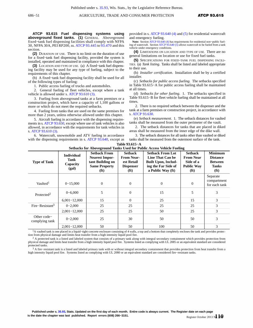
686−51 ATCP 93.615AGRICULTURE, TRADE AND CONSUMER PROTECTION
Published under s. 35.93, Wis. Stats., by the Legislative Reference Bureau.
Published under s. 35.93 , Stats. Updated on the first day of each month. Entire code is always current. The Register date on each pageis the date the chapter was last published. Report errors (608) 266−3151. Register October 2013 No. 694
ATCP 93.615 Fuel dispensing systems usingaboveground fixed tanks. (1) GENERAL. Abovegroundfixed−tank fuel dispensing facilities shall comply with NFPA30, NFPA 30A, PEI RP200, ss. ATCP 93.445 to 93.470 and thissection.
(2) DURATION OF USE. There is no limit on the duration of usefor a fixed−tank fuel dispensing facility, provided the system isinstalled, operated and maintained in compliance with this chapter.
(3) LOCATION AND TYPE OF USE. (a) A fixed−tank fuel dispens-ing facility may be used for any type of fueling, subject to therequirements of this chapter.
(b) A fixed−tank fuel dispensing facility shall be used for allof the following types of fueling:
1. Public access fueling of trucks and automobiles.2. General fueling of fleet vehicles, except where a tank
vehicle is allowed under s. ATCP 93.610 (3).3. Fueling from aboveground tanks at a farm premises or a
construction project, which have a capacity of 1,100 gallons ormore or which do not meet the required setbacks.
4. Fueling from tanks that are used on the same premises formore than 2 years, unless otherwise allowed under this chapter.
5. Aircraft fueling in accordance with the dispensing require-ments in s. ATCP 93.650, except where use of tank vehicles is alsoallowed, in accordance with the requirements for tank vehicles ins. ATCP 93.610 (3).
6. Watercraft, snowmobile and ATV fueling in accordancewith the dispensing requirements in s. ATCP 93.640, except as
provided in s. ATCP 93.640 (4) and (5) for residential watercraftand emergency fueling.
Note: Section ATCP 93.640 (4) has requirements for residential non−public fuel-ing of watercraft. Section ATCP 93.640 (5) allows watercraft to be fueled from a tankvehicle under emergency conditions.
(4) LIMITATIONS ON LOCATION AND TYPE OF USE. There are nogeneral limitations on location or use for fixed fuel tanks.
(5) SPECIFICATIONS FOR FIXED−TANK FUEL DISPENSING FACILI-TIES. (a) Tank listing. Tanks shall be listed and labeled appropriateto their use.
(b) Installer certification. Installation shall be by a certifiedinstaller.
(c) Setbacks for public access fueling. The setbacks specifiedin Table 93.615−A for public access fueling shall be maintainedat all times.
(d) Setbacks for other fueling. 1. The setbacks specified inTable 93.615−B for fleet vehicle fueling shall be maintained at alltimes.
2. There is no required setback between the dispenser and thetank at a farm premises or construction project, in accordance withs. ATCP 93.630.
(e) Setback measurement. 1. The setback distances for vaultedtanks shall be measured from the outer perimeter of the vault.
2. The setback distances for tanks that are placed in dikedareas shall be measured from the inner edge of the dike wall.
3. The setback distances for all tanks other than vaulted or dikedtanks shall be measured from the outermost surface of the tank.
Table 93.615−ASetbacks for Aboveground Tanks Used for Public Access Vehicle Fueling
Type of Tank
IndividualTank
Capacity(gal)
Setback FromNearest Impor-tant Building onSame Property
(ft)
SetbackFrom Near-est RetailDispenser
(ft)
Setback From LotLine That Can be
Built Upon, Includ-ing the Far Side ofa Public Way (ft)
SetbackFrom NearSide of a
Public Way(ft)
MinimumDistanceBetweenTanks
(ft)
Vaulted1 0−15,000 0 0 0 0
Separatecompartmentfor each tank
Protected20−6,000 5 0 15 5 3
6,001−12,000 15 0 25 15 3
Fire−Resistant3 0−2,000 25 25 25 25 3
2,001−12,000 25 25 50 25 3
Other code−complying tank
0−2,000 25 30 50 50 3
2,001−12,000 50 50 100 50 31A vaulted tank is one placed in a liquid−tight concrete enclosure consisting of 4 walls, a top and a bottom that completely encloses the tank and provides protec-
tion from physical damage and limits heat transfer from a high intensity liquid pool fire.2 A protected tank is a listed and labeled system that consists of a primary tank along with integral secondary containment which provides protection from
physical damage and limits heat transfer from a high intensity liquid pool fire. Systems listed as complying with UL 2085 or an equivalent standard are consideredprotected tanks.
3 A fire−resistant tank is a listed and labeled primary tank with or without integral secondary containment that provides protection from heat transfer from ahigh intensity liquid pool fire. Systems listed as complying with UL 2080 or an equivalent standard are considered fire−resistant tanks.
110
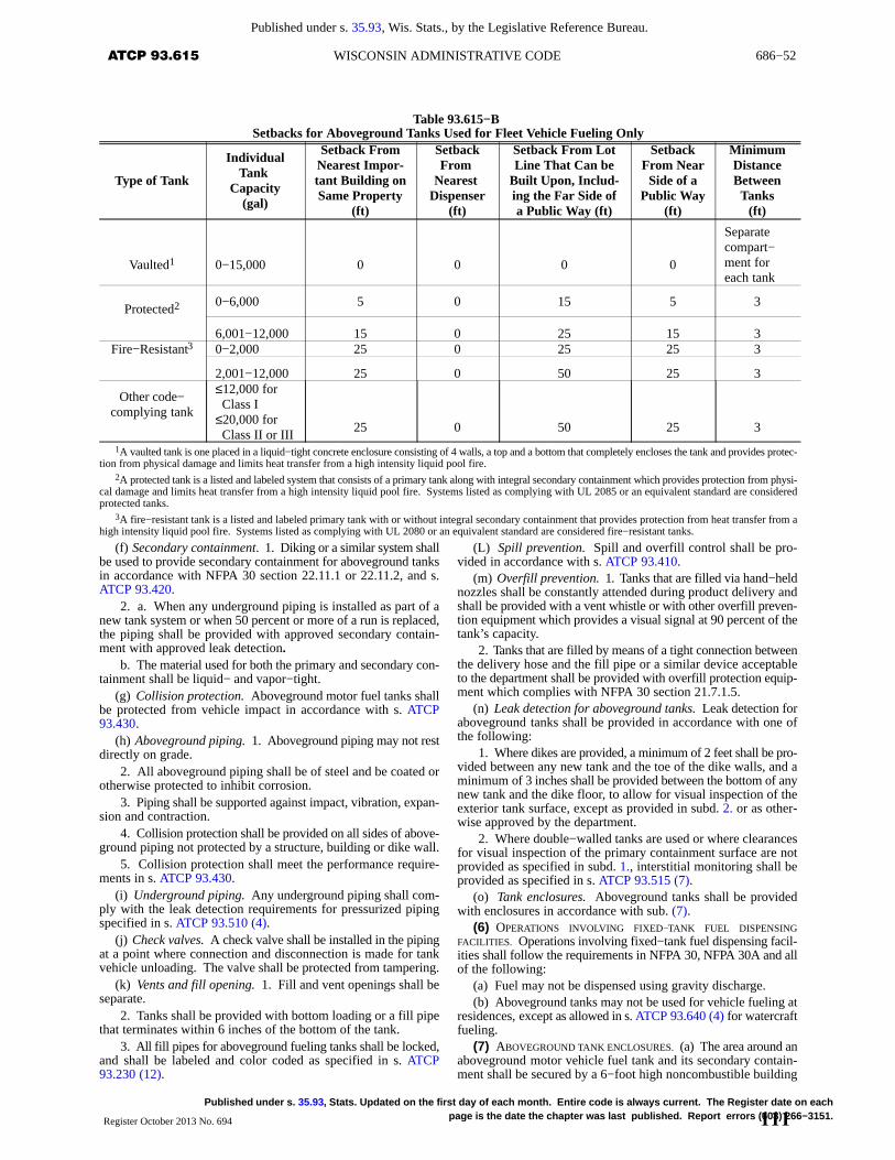
686−52 ATCP 93.615 WISCONSIN ADMINISTRATIVE CODE
Published under s. 35.93, Wis. Stats., by the Legislative Reference Bureau.
Published under s. 35.93 , Stats. Updated on the first day of each month. Entire code is always current. The Register date on eachpage is the date the chapter was last published. Report errors (608) 266−3151.Register October 2013 No. 694
Table 93.615−BSetbacks for Aboveground Tanks Used for Fleet Vehicle Fueling Only
Type of Tank
IndividualTank
Capacity(gal)
Setback FromNearest Impor-tant Building onSame Property
(ft)
SetbackFrom
Nearest Dispenser
(ft)
Setback From LotLine That Can be
Built Upon, Includ-ing the Far Side ofa Public Way (ft)
SetbackFrom NearSide of a
Public Way(ft)
MinimumDistanceBetweenTanks
(ft)
Vaulted1 0−15,000 0 0 0 0
Separatecompart−ment foreach tank
Protected20−6,000 5 0 15 5 3
6,001−12,000 15 0 25 15 3Fire−Resistant3 0−2,000 25 0 25 25 3
2,001−12,000 25 0 50 25 3
Other code−complying tank
≤12,000 for Class I≤20,000 for Class II or III
25 0 50 25 3
1A vaulted tank is one placed in a liquid−tight concrete enclosure consisting of 4 walls, a top and a bottom that completely encloses the tank and provides protec-tion from physical damage and limits heat transfer from a high intensity liquid pool fire.
2A protected tank is a listed and labeled system that consists of a primary tank along with integral secondary containment which provides protection from physi-cal damage and limits heat transfer from a high intensity liquid pool fire. Systems listed as complying with UL 2085 or an equivalent standard are consideredprotected tanks.
3A fire−resistant tank is a listed and labeled primary tank with or without integral secondary containment that provides protection from heat transfer from ahigh intensity liquid pool fire. Systems listed as complying with UL 2080 or an equivalent standard are considered fire−resistant tanks.
(f) Secondary containment. 1. Diking or a similar system shallbe used to provide secondary containment for aboveground tanksin accordance with NFPA 30 section 22.11.1 or 22.11.2, and s.ATCP 93.420.
2. a. When any underground piping is installed as part of anew tank system or when 50 percent or more of a run is replaced,the piping shall be provided with approved secondary contain-ment with approved leak detection.
b. The material used for both the primary and secondary con-tainment shall be liquid− and vapor−tight.
(g) Collision protection. Aboveground motor fuel tanks shallbe protected from vehicle impact in accordance with s. ATCP93.430.
(h) Aboveground piping. 1. Aboveground piping may not restdirectly on grade.
2. All aboveground piping shall be of steel and be coated orotherwise protected to inhibit corrosion.
3. Piping shall be supported against impact, vibration, expan-sion and contraction.
4. Collision protection shall be provided on all sides of above-ground piping not protected by a structure, building or dike wall.
5. Collision protection shall meet the performance require-ments in s. ATCP 93.430.
(i) Underground piping. Any underground piping shall com-ply with the leak detection requirements for pressurized pipingspecified in s. ATCP 93.510 (4).
(j) Check valves. A check valve shall be installed in the pipingat a point where connection and disconnection is made for tankvehicle unloading. The valve shall be protected from tampering.
(k) Vents and fill opening. 1. Fill and vent openings shall beseparate.
2. Tanks shall be provided with bottom loading or a fill pipethat terminates within 6 inches of the bottom of the tank.
3. All fill pipes for aboveground fueling tanks shall be locked,and shall be labeled and color coded as specified in s. ATCP93.230 (12).
(L) Spill prevention. Spill and overfill control shall be pro-vided in accordance with s. ATCP 93.410.
(m) Overfill prevention. 1. Tanks that are filled via hand−heldnozzles shall be constantly attended during product delivery andshall be provided with a vent whistle or with other overfill preven-tion equipment which provides a visual signal at 90 percent of thetank’s capacity.
2. Tanks that are filled by means of a tight connection betweenthe delivery hose and the fill pipe or a similar device acceptableto the department shall be provided with overfill protection equip-ment which complies with NFPA 30 section 21.7.1.5.
(n) Leak detection for aboveground tanks. Leak detection foraboveground tanks shall be provided in accordance with one ofthe following:
1. Where dikes are provided, a minimum of 2 feet shall be pro-vided between any new tank and the toe of the dike walls, and aminimum of 3 inches shall be provided between the bottom of anynew tank and the dike floor, to allow for visual inspection of theexterior tank surface, except as provided in subd. 2. or as other-wise approved by the department.
2. Where double−walled tanks are used or where clearancesfor visual inspection of the primary containment surface are notprovided as specified in subd. 1., interstitial monitoring shall beprovided as specified in s. ATCP 93.515 (7).
(o) Tank enclosures. Aboveground tanks shall be providedwith enclosures in accordance with sub. (7).
(6) OPERATIONS INVOLVING FIXED−TANK FUEL DISPENSINGFACILITIES. Operations involving fixed−tank fuel dispensing facil-ities shall follow the requirements in NFPA 30, NFPA 30A and allof the following:
(a) Fuel may not be dispensed using gravity discharge.(b) Aboveground tanks may not be used for vehicle fueling at
residences, except as allowed in s. ATCP 93.640 (4) for watercraftfueling.
(7) ABOVEGROUND TANK ENCLOSURES. (a) The area around anaboveground motor vehicle fuel tank and its secondary contain-ment shall be secured by a 6−foot high noncombustible building
111
686−53 ATCP 93.630AGRICULTURE, TRADE AND CONSUMER PROTECTION
Published under s. 35.93, Wis. Stats., by the Legislative Reference Bureau.
Published under s. 35.93 , Stats. Updated on the first day of each month. Entire code is always current. The Register date on each pageis the date the chapter was last published. Report errors (608) 266−3151. Register October 2013 No. 694
or by a 6−foot high noncombustible fence with a gate, exceptwhere exempted under par. (b) or (c).
(b) If the property on which the tanks are located has a perime-ter security fence, additional enclosure of the tank system is notrequired.
(c) For tanks that have a capacity of 1320 gallons or less, enclo-sure of the tank and secondary containment by one of the struc-tures listed in par. (a) is not required if all of the following condi-tions are met:
1. The fill opening of the tank is kept locked.2. The electrical control panel is secured inside of a building.3. The dispenser is secured against unauthorized use.4. The top of the tank is at least 6 feet above grade.5. Dusk−to−dawn lighting is provided above the tank area.6. All tank system vents terminate at least 12 feet above grade.
Note: Federal Spill Prevention Control and Countermeasure regulations in 40CFR 112 may require fencing for tanks with capacities of more than 1320 gallons.
(d) Buildings or fences under this subsection shall be madeentirely of noncombustible materials and have a minimum of 1exit in compliance with chs. SPS 361 to 366.
(e) Buildings or fences may not be supported by the tanks theyenclose.
(f) Buildings or fenced enclosures shall not be used for occu-pancy, storage or any other use unless specifically allowed underchs. SPS 361 to 366.
(g) Fences surrounding tanks shall be of chain−link design orother open fencing approved by the department.
(h) Gates and doors shall be normally locked.History: CR 07−029: cr. Register November 2008 No. 635, eff. 2−1−09; correc-
tion in (5) (n) 2. made under s. 13.92 (4) (b) 7., Stats., Register November 2008 No.635; CR 09−017: am. (1), renum. (5) (a) 1., 2., and (6) (b) to be Comm 10.605 (1) (f)and (g), renum (5) (b) to (p) and (6) (c) to be (5) (a) to (o) and (6) (b), r. (5) (a) (title)and 3. to 6. Register July 2009 No. 643, eff. 8−1−09; correction in (1), (3) (b) 2., 5.,6., (5) (c), (d) 1., 2., (f) 1., (g), (h) 5., (i), (k) 3., (L), (n) 2., (6) (b), (7) (d), (f) madeunder s. 13.92 (4) (b) 7., Stats., Register December 2011 No. 672; corrections in (1),(3) (b) 2., 5., 6., (5) (c), (d) 1., 2., (f) 1., (g), (h) 5., (i), (k) 3., (L), (n) 2., (6) (b) madeunder s. 13.92 (4) (b) 7., Stats., Register October 2013 No. 694.
ATCP 93.620 Public access motor vehicle fuelingoperations. (1) GENERAL. (a) Public access fueling operationsshall follow the operational requirements of NFPA 30A and thissection.
(b) When the product dispensed from a tank system is changedfrom a Class I liquid to a Class II or III liquid, the department’sdistrict petroleum products inspection office shall be notified, andthe new product shall be tested and approved before being dis-pensed.
Note: See the Department’s Web site at http://datcp.wi.gov/Consumer/Weights_and_Measures/index.aspx.
(2) DISPENSING AREA SAFETY. (a) Equipment or devices notrequired for, or not integral to the fueling operation, such as vend-ing machines or automated teller machines, may only be installedoutside of the fuel dispensing area.
(b) Containers of LP gas and similar fuels may not be locatedwithin 20 feet of any motor fuel dispenser.
(c) No Class I liquid, other than fuel being dispensed, may belocated within 20 feet of any motor fuel dispenser.
(d) A person shall be at least 14 years old to dispense fuel intothe fuel tank of a motor vehicle.
(e) Combustible merchandise placed within 20 feet of a fueldispenser shall meet all of the following requirements:
1. No combustible merchandise, including pallets and pack-aging material, may be within 3 feet horizontally of the dispensercabinet.
2. The height of the merchandise display, including palletsand packaging material, may not exceed 3 feet above grade.
Note: Trash receptacles and window washing containers that are for public useare not considered merchandise under this section. Window washing solution in con-tainers for sale to the public would be considered merchandise under this section.
(f) A means of two−way voice communication between thecustomer and attendant shall be maintained while the facility isopen to the public and an attendant is on duty.
(g) No vehicle may be fueled from an aboveground storagetank while the storage tank is being filled.
History: CR 07−029: cr. Register November 2008 No. 635, eff. 2−1−09.
ATCP 93.630 Fuel dispensing at farms and con-struction projects. (1) GENERAL. (a) Aboveground tanks.Aboveground storage tank systems for fueling operations at afarm premises or construction project shall comply with therequirements of NFPA 30A chapter 13 and this section.
(b) Limitations on location and type of use. The tanks may notbe used for fueling vehicles unless the vehicles are dedicated tothe operation of the farm premises or construction project.
(c) Specifications for tanks. 1. The tanks shall be constructedin accordance with NFPA 30A chapter 13 and this section.
2. Nozzles may not have a latch−open device.3. There is no minimum required setback between the tank
and the dispenser.(d) Operations involving tanks. Operations shall be in accord-
ance with NFPA 30A chapter 13.(e) Security. The tank system shall be equipped so either the
hose, hanger or outlet valve can be locked to prevent tampering.(2) MODIFICATIONS TO SETBACKS IN NFPA 30A SECTION 13.2.3.6.
(a) Farming operations. For farming operations using a tankwithout secondary containment, the tank and the fueling opera-tion shall be placed outside of a building and at least 40 feet fromthe near side of a public way and from a building or structure usedfor any of the following purposes:
1. Human occupancy.2. Housing of any livestock.3. Storage or repair of any motor−driven vehicle or machine.4. Storage of chemicals, pesticides or other fuels.5. Storage of hay or similar crops susceptible to spontaneous
combustion, if stored in a combustible building or structure.(b) Other operations. For all operations within the scope of
this section using a tank without secondary containment, otherthan farming, the tank and the fueling operation shall be placedoutside and at least 40 feet from the near side of a public way andfrom any important building or structure.
(c) Operations using secondary containment tanks. All opera-tions within the scope of this section using a tank with secondarycontainment shall follow the setback requirements in Table93.630.
(3) TANKS OF LESS THAN 1,100 GALLONS. (a) Abovegroundtanks that have a capacity of less than 1,100 gallons shall complywith this subsection before use.
(b) Installation shall be by a certified installer.(c) The certified installer shall fill out a tank installation notifi-
cation, form ERS−10764, and provide the form to the authorizedagent or the department for inspection of the tank system.
Note: Form ERS−10764 — Farm & Construction AST Installation Notificationis available from the Bureau of Weights and Measures, PO Box 8911, Madison, WI53708−8911, or at telephone (608) 224−4942, or from the Bureau’s Web site athttp://datcp.wi.gov/Consumer/Weights_and_Measures/index.aspx.
(d) Before a tank may be filled or used, the tank system shallbe inspected or authorized for use by the authorized agent or thedepartment, except as allowed otherwise by par. (g).
(e) The owner shall remit the inspection fee under ch. SPS 302to the authorized agent or the department before filling or usingthe tank.
(f) The tank shall be inspected within 5 business days afternotification for a standard inspection and within 2 business daysafter notification for a priority inspection, except as provided inpar. (g).
112
686−54 ATCP 93.630 WISCONSIN ADMINISTRATIVE CODE
Published under s. 35.93, Wis. Stats., by the Legislative Reference Bureau.
Published under s. 35.93 , Stats. Updated on the first day of each month. Entire code is always current. The Register date on eachpage is the date the chapter was last published. Report errors (608) 266−3151.Register October 2013 No. 694
(g) The tank may be filled and used if the inspection has notbeen completed within the time limits after notification specifiedin par. (f).
(h) Tanks that are filled via hand−held nozzles shall beconstantly attended during product delivery and shall be providedwith a vent whistle or with other overfill prevention equipmentthat provides a visual signal at 90 percent of the tank’s capacity.
(i) 1. Tanks shall be mounted on noncombustible supports thatare adequate to provide stability.
2. The base of the tank supports shall be at the same gradelevel as the vehicles when positioned for fueling.
3. The bottom of the tank, irrespective of any supports, shallbe elevated at least 6 inches above the surrounding grade.
(4) TANKS OF 1,100 GALLONS OR MORE, OR LOCATED LESS THAN
40 FEET FROM BUILDINGS. Aboveground tanks which have a capac-ity of 1,100 gallons or more, or which are located less than 40 feetfrom either the buildings and structures listed in sub. (2) (a), orimportant buildings or structures, shall comply with all of the fol-lowing:
(a) Tank listing. The tank shall be listed and labeled for above-ground use.
(b) System design and location. The tank system shall complywith the specifications for dispensing facilities in s. ATCP 93.615(5), with the following exceptions:
1. The tank system and the fueling operation shall be locatedin accordance with Table 93.630.
2. Vehicle collision protection may be omitted where a dikemeeting the requirements of this chapter is provided for secondarycontainment.
Table 93.630Tank System Setbacks for Tanks With Secondary Containment
AggregateCapacity(gallons)
Distance to Nearest Building, Haystack or CombustibleStructur e or Nearest Side of Any Public Way
Distance to Property Line That Is or Can Be BuiltUpon, Including the Opposite Side of a Public Way
275 or less 5 feet 5 feet276−750 5 feet 10 feet
751−12,000 5 feet 15 feet12,001−30,000 5 feet 20 feet
Any size The minimum setback between multiple tank fueling systems is 200 feet.
(c) Administrative requirements. 1. The tank system shall beinstalled in accordance with the manufacturer’s instructions, theapplicable national standards adopted in s. ATCP 93.200, plansand specifications approved under s. ATCP 93.100 and this chap-ter.
2. The tank system installation shall be performed or super-vised by a certified installer.
3. The tank system shall be inspected in accordance with s.ATCP 93.115 (2).
4. The tank shall be registered in accordance with s. ATCP93.140.
History: CR 07−029: cr. Register November 2008 No. 635, eff. 2−1−09; correc-tion in (2) (c), (3) (e), (4) (b) (intro.), 1., (c) 1., 3., 4. made under s. 13.92 (4) (b) 7.,Stats., Register December 2011 No. 672; corrections in (2) (c), (4) (b) (intro.), 1.,(c) 1., 3., 4. made under s. 13.92 (4) (b) 7., Stats., Register October 2013 No. 694.
ATCP 93.640 Watercraft, snowmobile and A TV fuel -ing. (1) GENERAL REQUIREMENTS. (a) General. Use of above-ground storage tank systems and fueling operations for watercraft,snowmobiles and ATVs shall comply with NFPA 30A chapter 11,the requirements for dispensing systems in s. ATCP 93.615, andthe requirements of this section, except as otherwise approvedunder this chapter.
(b) Tank location. 1. Aboveground tanks located on land shallbe set back at least 10 feet from the ordinary high water mark ofa navigable body of water.
Note: The ordinary high water mark is determined by the county zoning depart-ment or the Department of Natural Resources.
Note: The municipality in which the tank is located may have additional require-ments for the siting of the tank.
2. Tanks shall follow the setback requirements of Table93.615−A, except that there is no required separation between thetank and the dispenser if the tank is used exclusively for water-craft, snowmobile or ATV fueling.
(c) Tank appurtenances. 1. Any dispenser used for a fuelingoperation above or within 100 feet of navigable water shall use adry−break connection or a listed no−drip nozzle with automaticshutoff.
2. A nozzle latch−open device may not be installed or usedabove or within 100 feet of navigable water.
(d) Hose. Hose lengths more than 18 feet long, used for dis-pensing fuel, shall be reeled, racked or otherwise protected fromdamage.
(2) PUBLIC ACCESS WATERCRAFT FUELING. (a) General. 1. Alltanks, and any associated pump that is not integral with the dis-pensing device, which are used in fueling watercraft shall belocated on land or on a pier of solid−fill construction, except asallowed otherwise in subd. 2.
Note: The placement of piers is subject to the requirements of chapter 30 of theStatutes, and may need permits from the Department of Natural Resources or localzoning or building departments.
2. The components listed in subd. 1. may be located on othertypes of piers if all of the following conditions are met:
a. The plans submitted for review clearly describe the size andtype of pier.
b. The tank is a listed and labeled double−wall tank.c. The primary tank has a capacity of 1,100 gallons or less.
(b) Piping. 1. ‘General.’ Piping that extends from shore ontoa pier shall meet the requirements of NFPA 30 chapter 27 and thisparagraph.
2. ‘Material requirements.’ Piping used along a pier shall beone of the following types:
a. Steel piping that is coated to prevent corrosion.b. Flexible piping that is listed and rated for aboveground
marine use.c. Fiberglass piping placed in steel containment that has
standoffs to maintain clearance between the piping and the con-tainment.
3. ‘Flex connectors.’ a. At least 1 flex connector, listed andlabeled for aboveground use, shall be placed between rigid pipethat is connected to the shore and rigid pipe that serves a dispenserlocated on a pier.
b. An accessible shutoff valve with an expansion relief deviceshall be located on at least one end of the flex connector, where itconnects to the rigid pipe from shore.
(3) SEASONAL INSTALLATION OF A FUELING SYSTEM ON A PIER.(a) Plan requirements. Before installing a fueling system on apier, plans shall be submitted for review and shall specify therequirements of this subsection.
(b) Pipe and tank requirements. 1. All connections that arebroken shall use dry−break couplings listed for use with petro-leum products.
2. Broken connections shall be plugged during storage.3. The tank vent shall be left open.
113
686−55 ATCP 93.680AGRICULTURE, TRADE AND CONSUMER PROTECTION
Published under s. 35.93, Wis. Stats., by the Legislative Reference Bureau.
Published under s. 35.93 , Stats. Updated on the first day of each month. Entire code is always current. The Register date on each pageis the date the chapter was last published. Report errors (608) 266−3151. Register October 2013 No. 694
(c) Management plan. 1. The owner shall develop and main-tain onsite, a written plan for safely draining the tank and pipe sys-tem before disassembly.
2. For systems first installed on or after February 1, 2009, thedisassembly plan shall also be submitted with the plans at the timeof review.
(4) RESIDENTIAL WATERCRAFT FUELING OPERATIONS. (a)Aboveground tanks for watercraft fueling for noncommercialpurposes at a private residence shall comply with the requirementsfor aboveground tanks in ss. ATCP 93.400 to 93.420, and this sub-section.
(b) No more than 2 tanks are allowed at any residence.(c) Tanks shall be listed and may not exceed 600 gallons in
aggregate capacity.(d) The tank shall be used only by the residents of the property,
for fueling their watercraft or for maintenance of their property.(e) 1. The tank shall be located outdoors, on land, at least 25
feet from the dwelling and other important buildings, and at least10 feet from the ordinary high water mark of a navigable water-way, public roadway or property line.
2. All setbacks shall be measured from the inside of the dikewall to the dwelling, important building, ordinary high watermark, public roadway or property line.
(f) A means shall be provided to prevent the discharge of liquiddue to a siphoning effect. Gravity dispensing systems may not beused.
(g) Transfer of product shall be from a tank by means of anapproved, fixed, fuel dispensing hand pump or a listed, fixed,electrical pump.
(5) EMERGENCY FUELING FROM A TANK VEHICLE. Where fixeddispensing facilities are not available, dispensing of Class I or IIliquids directly from a tank vehicle into permanently installed fueltanks of self−propelled watercraft shall be permitted for emer-gency fueling, provided the operation is in accordance with therequirements for tank vehicles in s. ATCP 93.610 (3).
(6) SNOWMOBILE AND ATV FUELING. (a) General. Tank sys-tems used for fueling snowmobiles or ATVs shall meet therequirements for dispensing systems in s. ATCP 93.615 and thissubsection.
(b) Tank location. Tank systems adjacent to a body of watershall also meet the requirements for watercraft fueling.
(c) Collision protection. 1. Aboveground tank systems usedfor snowmobile and ATV fueling shall be provided with collisionprotection.
2. The collision protection shall be spaced no more than 30inches on center.
3. If the fueling area is adjacent to vehicle traffic or a parkingarea, bollards or equivalent protection shall be placed to separatethe snowmobile or ATV fueling area from motor vehicle traffic.
History: CR 07−029: cr. Register November 2008 No. 635, eff. 2−1−09; correc-tion in (1) (a), (b) 2., (4) (a), (5), (6) (a) made under s. 13.92 (4) (b) 7., Stats., RegisterDecember 2011 No. 672; corrections in (1) (a), (4) (a), (5), (6) (a) made under s.13.92 (4) (b) 7., Stats., Register October 2013 No. 694.
ATCP 93.650 Aircraft fuel dispensing. (1) GENERAL
REQUIREMENTS. Fueling operations shall follow the requirementsin s. ATCP 93.610 (3) or 93.615, NFPA 407, NFPA 418 and thissubchapter.
(2) SETBACKS. (a) Aboveground tanks used for public accessfueling shall be at least 30 feet from the point of fuel transfer intothe aircraft.
(b) Aboveground tank setbacks from buildings, public waysand property lines shall follow the requirements in Table93.615−B.
(c) 1. The point of fuel transfer into the aircraft, from any tankor truck supply source, shall be at least 100 feet from public traffic
or assembly areas at public events, unless a reduced distance isauthorized by the fire chief.
2. The public events referred to in subd. 1. do not include pas-senger terminals, fixed base operators, or persons entering or exit-ing the aircraft.
(3) COLLISION PROTECTION. (a) Barriers shall be provided toprotect tanks, pumps, dispensers and vents from collision damagefrom aircraft or other vehicles in accordance with s. ATCP 93.430.
(b) Where subject to collision from aircraft, barriers protectingan aboveground tank shall extend at least 12 inches above the topof the tank.
(4) PRODUCT IDENTIFICATION. (a) All fuel handling equipmentand installations within the scope of API 1542, whether new orexisting, shall be marked as referenced in the standard.
(b) All aboveground tanks and fill pipes for undergroundtanks, whether new or existing, shall be labeled or otherwisemarked using the identification scheme in API 1542.
Note: API 1542 has requirements for identifying aviation gasoline (AVGAS) andturbine fuels and the equipment used to store and dispense them.
(5) FUELING HOSE. (a) All public access, self−service fuelinghose that is installed or replaced on or after February 1, 2009, shallbe reeled or racked unless approved otherwise by the authorizedagent or the department.
(b) All fueling hose shall be protected from damage.(6) OPERATIONS. (a) General. Individuals who dispense fuel
into aircraft shall be knowledgeable in operations and emergencyprocedures specific to the fuel and fueling systems they are oper-ating.
(b) Amphibious aircraft. Shoreline fuel dispensing systemsfor amphibious aircraft shall follow the requirements of s. ATCP93.640.
History: CR 07−029: cr. Register November 2008 No. 635, eff. 2−1−09; correc-tion in (1), (2) (b), (3) (a), (6) (b) made under s. 13.92 (4) (b) 7., Stats., RegisterDecember 2011 No. 672; corrections in (1), (2) (b), (3) (a), (6) (b) made under s.13.92 (4) (b) 7., Stats., Register October 2013 No. 694.
ATCP 93.660 Racetrack and amusement vehiclefueling operations. (1) Racing vehicles and amusement ridevehicles with integral internal combustion engines shall followthe requirements of this section.
(2) The fuel tanks of racing vehicles shall be filled from safetycans or a fixed fueling system meeting the requirements of s.ATCP 93.615.
(3) During a race in which the vehicle is competing, thevehicle may be refueled with the engine running, if the racetrackis equipped with onsite fire protection that is capable of respond-ing adequately to fires ignited during the fueling.
(4) Fueling areas shall be posted with signs that read as fol-lows:
“NO SMOKING OR OPEN FLAMES”(5) A portable fire extinguisher with a minimum 40−B:C rat-
ing shall be provided at each fueling area, including pit stalls, pitwork areas and garages.
(6) Fueling areas that use methanol shall provide a minimumof 10 gallons of water at each fueling area, including pit stalls, pitwork areas and garages, for the purpose of diluting a methanolfire.
History: CR 07−029: cr. Register November 2008 No. 635, eff. 2−1−09; correc-tion in (2) made under s. 13.92 (4) (b) 7., Stats., Register December 2011 No. 672;correction in (2) made under s. 13.92 (4) (b) 7., Stats., Register October 2013 No.694.
ATCP 93.680 Alternative motor fuels. (1) APPLICA-TION. All storage or dispensing systems for fuel consisting of morethan 10 percent ethanol by volume shall follow the requirementsof this section.
Note: Alternative motor fuels include ethanol blends greater than 10 percent byvolume, and biodiesel blends greater than 5 percent by volume.
114
686−56 ATCP 93.680 WISCONSIN ADMINISTRATIVE CODE
Published under s. 35.93, Wis. Stats., by the Legislative Reference Bureau.
Published under s. 35.93 , Stats. Updated on the first day of each month. Entire code is always current. The Register date on eachpage is the date the chapter was last published. Report errors (608) 266−3151.Register October 2013 No. 694
(2) MATERIAL COMPATIBILITY. Equipment used to store or dis-pense fuel consisting of more than 10 percent ethanol by volumemay not contain or consist of any of the following materials:
(a) Metals. Zinc, lead, aluminum or alloys containing thesemetals, such as brass or terne.
Note: Terne−plated steel and lead−based solder are commonly used in equipmentthat handles gasoline. These materials will dissolve when in contact with high con-centrations of ethanol.
(b) Natural materials. Cork, leather or natural rubber.(c) Polymers. Polyurethane, polyvinyl chloride, polyamides,
or methyl−methacrylate plastics.Note: Materials that have been shown to be generally compatible with high con-
centrations of ethanol include unplated steel, stainless steel, black iron, bronze, Neo-prene rubber, Buna−N, polypropylene, nitrile, Viton, Teflon, thermoset reinforcedfiberglass and thermoplastic piping material.
(3) GENERAL REQUIREMENTS. (a) Tank cleaning. 1. If anothertype of fuel was stored in the tank, the tank shall be cleaned inaccordance with API 2015 or another method approved by thedepartment, before introducing the ethanol−blended fuel.
2. All cleaning work shall be performed by a certified tankcleaner unless specifically approved by the department based onan alternate cleaning method.
Note: Most metal storage tanks and pipe are compatible with ethanol. However,some fiberglass storage tank systems manufactured before 1992 might not be com-patible with higher levels of ethanol. The tank manufacturer and installation con-tractor should be consulted for additional information on the reuse of undergroundstorage tanks.
(b) Tightness testing. A precision tightness test shall be per-formed on the tank and piping in accordance with s. ATCP 93.515(4) before placing the tank system back into service.
(c) Equipment requirements. 1. ‘Listed equipment.’ Equip-ment used for dispensing ethanol−blended motor fuel shall belisted or shall be recognized by the manufacturer as being compat-ible with ethanol−blended fuel, except where otherwise approvedin writing by the department.
2. ‘Dispenser nozzles and hoses.’ Dispensers that areinstalled on or after February 1, 2009, shall use a separate fuelingnozzle and hose for dispensing ethanol−blended motor fuels ofmore than 10 percent ethanol by volume.
Note: See chapter ATCP 94 for signage requirements for ethanol−blended fuels.
3. ‘In−line filters.’ A 1− or 2−micron in−line filter shall beused for dispensing ethanol−based fuel.
4. ‘Lined tanks.’ Tanks with linings regulated under s. ATCP93.530 may not be used to store ethanol−blended fuels.
(4) NOTIFICATION PROCEDURES. (a) Before commencing nor-mal fueling operations using ethanol−blended fuel, the operatorshall notify the department’s district petroleum products inspec-tion office.
Note: See the Department’s Web site at http://datcp.wi.gov/Consumer/Weights_and_Measures/index.aspx.
(b) A certified installer or professional engineer shall completepart I of the department’s alternative fuel installation/conversionapplication form (ERS−9 Alternative Fuels) and submit it to thedepartment as part of the plan review submittal.
Note: Within a first class city, the provisions in par. (b) may be administered bythat city instead of the department, as authorized in sections ATCP 93.020 (8) and93.110 (3) and (4). As of February 1, 2009, only the City of Milwaukee had becomea first class city.
(c) Before commencing normal fueling operations using etha-nol−blended fuel, the operator shall complete part II of the depart-ment’s alternative fuel installation/conversion application form(ERS−9 Alternative Fuels) and provide the completed form to thecertified tank system inspector performing the pre−operationalinspection.
Note: Form ERS−9 Alternative Fuels — Storage Tank Alternative Fuel Installa-tion/Conversion Application is available from the Bureau of Weights and Measures,PO Box 8911, Madison, WI 53708−8911, or at telephone (608) 224−4942, or fromthe Bureau’s Web site at http://datcp.wi.gov/Consumer/Weights_and_Measures/index.aspx.
Note: Plan review is required in section ATCP 93.100 for facilities converted tostore and dispense ethanol−based fuels.
History: CR 07−029: cr. Register November 2008 No. 635, eff. 2−1−09; correc-tion in (3) (b), (c) 4. made under s. 13.92 (4) (b) 7., Stats., Register December 2011
No. 672; corrections in (3) (b), (c) 4. made under s. 13.92 (4) (b) 7., Stats., RegisterOctober 2013 No. 694.
Subchapter VII — Financial Responsibility
ATCP 93.700 Applicability . (1) This subchapter appliesto owners and operators of any of the following storage tank sys-tems, whether new or existing, that are in−use, seldom−used ortemporarily−out−of−service:
(a) Petroleum underground storage tank systems.(b) Petroleum aboveground storage tank systems located on
piers that are not of solid−fill construction.(c) Petroleum aboveground storage tank systems, located on
floating structures or watercraft, that are not used exclusively forthe propulsion of that floating structure or watercraft.
(d) Tank wagons. Financial responsibility requirements fortank wagons shall begin 1 year after February 1, 2009.
(e) Tank vehicles that perform fueling operations covered ins. ATCP 93.610 (3).
(f) Petroleum aboveground storage tank systems using tankswith individual capacities of 5,000 gallons or more, with singlebottoms, that were upgraded with tank lining but not placed inimpermeable dike systems.
(g) Petroleum aboveground storage tank systems using tankswith individual capacities of 5,000 gallons or more, with doublebottoms, that are not provided with interstitial monitoring and notplaced in impermeable dike systems.
(2) This subchapter does not apply to owners and operators ofthe following storage tank systems:
(a) State and federal government entities whose debts and lia-bilities are the debts and liabilities of a state or the United States.
(b) Farm and residential underground storage tanks whichhave a capacity of less than 1,100 gallons and which are used forstoring motor fuel for noncommercial purposes.
(c) Storage tanks used for storing heating oil for consumptiveuse on the premises.
(d) Any portion of an airport hydrant fuel distribution systemexcept for the underground storage tanks included in those sys-tems.
(e) Any tank in sub. (1) (a) that is permanently closed, or regis-tered as temporarily−out−of−service, with an environmentalassessment which demonstrates the absence of a release of prod-uct from the tank.
(3) If the owner and operator of a petroleum storage tank areseparate persons, only 1 person is required to demonstrate finan-cial responsibility; however, both parties are liable in event ofnoncompliance.
History: CR 07−029: cr. Register November 2008 No. 635, eff. 2−1−09; correc-tion in (1) (e) made under s. 13.92 (4) (b) 7., Stats., Register December 2011 No. 672;correction in (1) (e) made under s. 13.92 (4) (b) 7., Stats., Register October 2013No. 694.
ATCP 93.703 Definitions. In this subchapter:(1) “Accidental release” means any release of petroleum from
a storage tank system that results in a need for compensation forbodily injury or property damage neither expected nor intendedby the tank owner or operator or corrective action, or both.
(2) “Affidavit of financial responsibility” means a form, sup-plied by the department on which the owner and operator attest tocompliance with 40 CFR 280.111.
Note: The affidavit of financial responsibility is available from the Bureau ofWeights and Measures, PO Box 8911, Madison, WI 53708−8911, or at telephone(608) 224−4942, or from the Bureau’s Web site at http://datcp.wi.gov/Consumer/Weights_and_Measures/index.aspx.
Note: The affidavit of financial responsibility is required in addition to the certifi-cation showing the specific type of financial responsibility. See section ATCP 93.745(2) (j) for further information.
(3) “Aggregate” means an accident or a continuous orrepeated exposure to conditions that result in a release from a stor-age tank system which might occur in 1 year.
115
686−57 ATCP 93.705AGRICULTURE, TRADE AND CONSUMER PROTECTION
Published under s. 35.93, Wis. Stats., by the Legislative Reference Bureau.
Published under s. 35.93 , Stats. Updated on the first day of each month. Entire code is always current. The Register date on each pageis the date the chapter was last published. Report errors (608) 266−3151. Register October 2013 No. 694
Note: This definition is intended to assist in the understanding of these regulationsand is not intended either to limit the meaning of “aggregate” in a way that conflictswith standard insurance usage or to prevent the use of other standard insurance termsin place of “aggregate.”
(4) “Bodily injury” has the meaning given to this term byapplicable Wisconsin statutes; however, this term does notinclude those liabilities that, consistent with standard insuranceindustry practices, are excluded from coverage in liability insur-ance policies for bodily injury.
Note: For further information about this term, see chapter Ins 6, which interpretsthis term as it is used in section 292.63 (1) (ad) of the Statutes, for petroleum storageenvironmental cleanup.
(5) “Controlling interest” means direct ownership of at least50 percent of the voting stock of another entity.
(6) “Financial reporting year” means the latest consecutive12−month period for which any of the following reports are pre-pared:
(a) A 10−K report submitted to the US securities and exchangecommission.
(b) An annual report of tangible net worth submitted to Dunand Bradstreet.
(c) An annual report submitted to the federal energy informa-tion administration or rural electrification administration.
Note: “Financial reporting year” may thus comprise a fiscal or a calendar yearperiod.
(7) “Legal defense cost” means any expense that an owner oroperator or provider of financial assurance incurs in defendingagainst claims or actions brought by any of the following:
(a) By the US EPA or the department to require correctiveaction or to recover the costs of corrective action.
(b) By or on behalf of a third party for bodily injury or propertydamage caused by an accidental release.
(c) By any person to enforce the terms of a financial assurancemechanism.
(8) “Occurrence” means an accident or a continuous orrepeated exposure to conditions, that results in a release from astorage tank system.
Note: This definition is intended to assist in the understanding of these regulationsand is not intended either to limit the meaning of “occurrence” in a way that conflictswith standard insurance usage or to prevent the use of other standard insurance termsin place of “occurrence.”
(9) “Operation” or “in operation” means the undergroundstorage tank was used to store a regulated substance at any timeafter December 22, 1988, regardless of the current status of thetank.
(10) “Owner or operator,” when the owner or operator areseparate parties, means the party that is obtaining or has obtainedfinancial assurances.
(11) “Petroleum marketing facilities” means all facilities atwhich petroleum is produced or refined and all facilities fromwhich petroleum is sold or transferred to other petroleum market-ers or to the public.
(12) “Petroleum marketing firms” means all firms owningpetroleum marketing facilities. Firms owning other types of facil-ities with tanks covered in the scope of this subchapter as well aspetroleum marketing facilities are considered to be petroleummarketing firms.
(13) “Property damage” has the meaning given to this term byadministrative rules of the office of commissioner of insurance.This term does not include those liabilities that, consistent withstandard insurance industry practices, are excluded from cover-age in liability insurance policies for property damage. However,such exclusions for property damage do not include correctiveaction associated with releases from tanks that are covered by thepolicy.
Note: For further information about this term, see chapter Ins 6, which interpretsthis term as it is used in section 292.63 (1) (ad) of the Statutes, for petroleum storageenvironmental cleanup.
(14) “Provider of financial assurance” means an entity thatprovides financial assurance to an owner or operator of a tank sys-
tem covered in this subchapter through one of the mechanismslisted in ss. ATCP 93.710 to 93.735, including a guarantor, insurer,risk retention group, surety, issuer of a letter of credit, issuer of astate−required mechanism, or a state.
(15) “Substantial business relationship” means the extent ofa business relationship necessary under Wisconsin law to make aguarantee contract issued incident to that relationship valid andenforceable. A guarantee contract is issued incident to that rela-tionship if it arises from and depends on current economic transac-tions between the guarantor and the owner or operator.
(16) “Tangible net worth” means the tangible assets thatremain after deducting liabilities; the assets do not include intan-gibles such as goodwill and rights to patents or royalties. For pur-poses of this definition, “assets” means all current and all probablefuture economic benefits obtained or controlled by a particularentity as a result of past transactions.
History: CR 07−029: cr. Register November 2008 No. 635, eff. 2−1−09; correc-tion in (14) made under s. 13.92 (4) (b) 7., Stats., Register December 2011 No. 672;correction in (14) made under s. 13.92 (4) (b) 7., Stats., Register October 2013No. 694.
ATCP 93.705 Amount and scope of required finan-cial responsibility . (1) Owners or operators of petroleum stor-age tank systems within the scope of this subchapter shall demon-strate financial responsibility for taking corrective action and forcompensating third parties for bodily injury and property damagecaused by accidental releases arising from the operation of petro-leum storage tank systems within the scope of this subchapter inat least the following per−occurrence amounts:
(a) For owners or operators of petroleum underground storagetank systems that are located at petroleum marketing facilities, orthat throughput an average of more than 10,000 gallons of petro-leum per month based on annual throughput for the previous cal-endar year; $1 million.
(b) For all other owners or operators of petroleum storage tanksystems covered in s. ATCP 93.700 (1); $500,000.
(2) Owners or operators of petroleum underground storagetank systems shall demonstrate financial responsibility for takingcorrective action and for compensating third parties for bodilyinjury and property damage caused by accidental releases arisingfrom the operation of petroleum underground storage tank sys-tems in at least the following annual aggregate amounts:
(a) For owners or operators of 1 to 100 petroleum undergroundstorage tanks; $1 million.
(b) For owners or operators of 101 or more petroleum under-ground storage tanks; $2 million.
(c) For the purposes of this subsection, a petroleum under-ground storage tank means a single containment unit and does notmean combinations of single containment units.
(3) Owners or operators of petroleum aboveground storagetanks covered in this subchapter shall demonstrate financialresponsibility for taking corrective action and for compensatingthird parties for bodily injury and property damage caused byaccidental releases arising from their operation in the amount of$1 million per occurrence.
(4) If the owner or operator uses separate mechanisms or sepa-rate combinations of mechanisms to demonstrate financialresponsibility, the amount shall be in the full amount specified insubs. (1) to (3) for any of the following, except as provided in sub.(5):
(a) Taking corrective action.(b) Compensating third parties for bodily injury and property
damage caused by sudden accidental releases.(c) Compensating third parties for bodily injury and property
damage caused by non−sudden accidental releases.(5) If an owner or operator uses separate mechanisms or sepa-
rate combinations of mechanisms to demonstrate financialresponsibility for different petroleum storage tank systems, theannual aggregate required shall be based on the number of tanks
116
686−58 ATCP 93.705 WISCONSIN ADMINISTRATIVE CODE
Published under s. 35.93, Wis. Stats., by the Legislative Reference Bureau.
Published under s. 35.93 , Stats. Updated on the first day of each month. Entire code is always current. The Register date on eachpage is the date the chapter was last published. Report errors (608) 266−3151.Register October 2013 No. 694
covered by each such separate mechanism or combination ofmechanisms.
(6) (a) Owners or operators shall review the amount of aggre-gate assurance provided whenever additional petroleum storagetank systems are acquired or installed.
(b) If the number of petroleum storage tank systems for whichassurance is needed exceeds 100, the owner or operator shall dem-onstrate financial responsibility in the amount of at least $2 mil-lion of annual aggregate assurance by the anniversary of the dateon which the mechanism demonstrating financial responsibilitybecame effective.
(c) If assurance is being demonstrated by a combination ofmechanisms, the owner or operator shall demonstrate financialresponsibility in the amount of at least $2 million of annual aggre-gate assurance by the first−occurring effective date anniversary ofany one of the mechanisms combined, other than a financial testor guarantee, to provide assurance.
(7) The amounts of assurance required in this section excludelegal defense costs.
(8) The required per−occurrence and annual aggregate cover-age amounts do not in any way limit the liability of the owner oroperator.
History: CR 07−029: cr. Register November 2008 No. 635, eff. 2−1−09; correc-tion in (1) (b) made under s. 13.92 (4) (b) 7., Stats., Register December 2011 No. 672;correction in (1) (b) made under s. 13.92 (4) (b) 7., Stats., Register October 2013No. 694.
ATCP 93.707 Allowable mechanisms and com-binations of mechanisms. (1) Subject to the limitations ofsubs. (3) and (4), an owner or operator may use any one or com-bination of the mechanisms listed in ss. ATCP 93.710 to 93.735to demonstrate financial responsibility under this subchapter for1 or more storage tank systems.
(2) Subject to the limitations of subs. (3) and (4), a local gov-ernment owner or operator may use any one or combination of themechanisms listed in ss. ATCP 93.727 to 93.735 to demonstratefinancial responsibility under this subchapter for 1 or more stor-age tank systems.
(3) An owner or operator may use a guarantee or surety bondto establish financial responsibility only if “for value received” isincluded in the guarantee or surety bond mechanisms.
(4) An owner or operator may use self−insurance in combina-tion with a guarantee only if, for the purpose of meeting therequirements of the financial test under this subchapter, the finan-cial statements of the owner or operator are not consolidated withthe financial statements of the guarantor.
History: CR 07−029: cr. Register November 2008 No. 635, eff. 2−1−09; correc-tion in (1), (2) made under s. 13.92 (4) (b) 7., Stats., Register December 2011 No. 672;corrections in (1), (2) made under s. 13.92 (4) (b) 7., Stats., Register October 2013No. 694.
ATCP 93.710 Financial test of self−insurance.(1) To use the financial test of self−insurance to meet the financialresponsibility requirements of s. ATCP 93.705, an owner or oper-ator, or guarantor, or both, shall meet the criteria of either sub. (2)or (3) based on year−end financial statements for the latest com-pleted fiscal year.
(2) (a) The owner or operator, or guarantor, or both, shall havea tangible net worth of at least 10 times each one of the following:
1. The total of the applicable aggregate amount required bys. ATCP 93.705, based on the number of storage tank systems forwhich a financial test is used to demonstrate financial responsibil-ity to the department.
2. The sum of the corrective action cost estimates, the currentclosure and post−closure care cost estimates, and amount of liabil-ity coverage for which a financial test is used to demonstratefinancial responsibility to the department.
3. The sum of current plugging and abandonment cost esti-mates for which a financial test is used to demonstrate financialresponsibility to the department.
(b) The owner or operator, or guarantor, or both, shall have atangible net worth of at least $10 million.
(c) The owner or operator, or guarantor, or both, shall have aletter signed by the chief financial officer as specified in sub. (4).
(d) The owner or operator, or guarantor, or both, shall do oneof the following:
1. File financial statements annually with the U.S. securitiesand exchange commission, energy information administration, orrural electrification administration.
2. Report annually the firm’s tangible net worth to Dun andBradstreet, if Dun and Bradstreet has assigned the firm a financialstrength rating of 4A or 5A.
(e) The firm’s year−end financial statements, if independentlyaudited, may not include an adverse auditor’s opinion, a dis-claimer of opinion, or a going concern qualification.
(3) (a) The owner or operator, or guarantor, or both, shall meetthe financial test requirements of 40 CFR 264.147(f)(1), substi-tuting the appropriate amounts specified in s. ATCP 93.705 (2) or(3) for the amount of liability coverage each time specified in thatsection.
(b) The fiscal year−end financial statements of the owner oroperator, or guarantor, or both, shall be examined by an indepen-dent certified public accountant and be accompanied by theaccountant’s report of the examination.
(c) The firm’s year−end financial statements may not includean adverse auditor’s opinion, a disclaimer of opinion, or a goingconcern qualification.
(d) The owner or operator, or guarantor, or both, shall have aletter signed by the chief financial officer as specified in sub. (4).
(e) If the financial statements of the owner or operator or guar-antor, or both, are not submitted annually to the U.S. securities andexchange commission, energy information administration or ruralelectrification administration, the owner or operator, or guarantor,or both, shall obtain a special report by an independent certifiedpublic accountant stating all of the following:
1. The accountant has compared the data that the letter fromthe chief financial officer specifies as having been derived fromthe latest year−end financial statements of the owner or operator,or guarantor, or both, with the amounts in such financial state-ments.
2. In connection with that comparison, no matters came to theattention of the accountant which caused him or her to believe thatthe specified data should be adjusted.
(4) To demonstrate that the financial test is met under sub. (2)or (3), the chief financial officer of the owner or operator, or guar-antor, shall sign, within 120 days of the close of each financialreporting year, as defined by the 12−month period for whichfinancial statements used to support the financial test are pre-pared, a letter worded exactly as found in 40 CFR 280.95(d)except for the following:
(a) The instructions in brackets in the letter shall be replacedby the relevant information and the brackets deleted.
(b) If financial responsibility for aboveground tanks within thescope of this subchapter is demonstrated using this method, all ofthe following changes shall be made:
1. Reference in the letter to underground tanks shall beamended to refer to aboveground tanks.
2. Certification that wording is identical to the wordingrequired in 40 CFR 280.95(d) shall be deleted.
Note: A link to 40 CFR 280 is available at the following U.S. EPA Web site:http://www.epa.gov/oust/fedlaws/otgg_final080807.pdf
(5) If an owner or operator using the test to provide financialassurance finds that he or she no longer meets the requirements ofthe financial test based on the year−end financial statements, theowner or operator shall obtain alternative coverage within 150days of the end of the year for which financial statements havebeen prepared.
117
686−59 ATCP 93.717AGRICULTURE, TRADE AND CONSUMER PROTECTION
Published under s. 35.93, Wis. Stats., by the Legislative Reference Bureau.
Published under s. 35.93 , Stats. Updated on the first day of each month. Entire code is always current. The Register date on each pageis the date the chapter was last published. Report errors (608) 266−3151. Register October 2013 No. 694
(6) The department may require reports of financial conditionat any time from the owner or operator, or guarantor, or both. Ifthe department finds, on the basis of such reports or other informa-tion, that the owner or operator, or guarantor, or both, no longermeet the financial test requirements of either sub. (2) or (3), andsub. (4), the owner or operator shall obtain alternate coveragewithin 30 days after notification of such a finding.
(7) If the owner or operator fails to obtain alternate assurancewithin 150 days of finding that he or she no longer meets therequirements of the financial test based on the year−end financialstatements, or within 30 days of notification by the departmentthat he or she no longer meets the requirements of the financialtest, the owner or operator shall notify the department of such fail-ure within 10 days.
History: CR 07−029: cr. Register November 2008 No. 635, eff. 2−1−09; correc-tion in (1), (2) (a) 1., (3) (a) made under s. 13.92 (4) (b) 7., Stats., Register December2011 No. 672; corrections in (1), (2) (a) 1., (3) (a) made under s. 13.92 (4) (b) 7.,Stats., Register October 2013 No. 694.
ATCP 93.713 Guarantee. (1) To use a guarantee to meetthe financial responsibility requirements of s. ATCP 93.705, anowner or operator shall obtain a guarantee that conforms to therequirements of this section. The guarantor shall be a firm that isengaged in a substantial business relationship with the owner oroperator and issues the guarantee as an act incident to that busi-ness relationship or the guarantor shall be a firm that meets at leastone of the following requirements:
(a) The firm possesses a controlling interest in the owner oroperator.
(b) The firm possesses a controlling interest in a firm describedunder par. (a).
(c) The firm is controlled through stock ownership by a com-mon parent firm that possesses a controlling interest in the owneror operator.
(2) (a) Within 120 days of the close of each financial reportingyear, the guarantor shall demonstrate that it meets the financialtest criteria of s. ATCP 93.710 based on year−end financial state-ments for the latest completed financial reporting year by com-pleting the letter from the chief financial officer described in s.ATCP 93.710 (4), and the guarantor shall deliver the letter to theowner or operator.
(b) If the guarantor fails to meet the requirements of the finan-cial test at the end of any financial reporting year, within 120 daysof the end of that financial reporting year, the guarantor shall sendby certified mail, before cancellation or non−renewal of the guar-antee, notice to the owner or operator.
(c) If the department notifies the guarantor that he or she nolonger meets the requirements of the financial test of s. ATCP93.710 (2) or (3), the guarantor shall notify the owner or operatorwithin 10 days of receiving such notification from the department.
(d) Under either par. (b) or (c), the guarantee shall terminateno less than 120 days after the date the owner or operator receivesthe notification, as evidenced by the return receipt.
(e) The owner or operator shall obtain alternative coverage asspecified in s. ATCP 93.753.
(3) The guarantee shall be worded exactly as found in 40 CFR280.96(c), except for the following:
(a) The instructions in brackets in the guarantee shall bereplaced by the relevant information and the brackets deleted.
(b) If financial responsibility for aboveground tanks within thescope of this subchapter is demonstrated using this method, all ofthe following changes shall be made:
1. Reference in the guarantee to underground tanks shall beamended to refer to aboveground tanks.
2. Certification that wording is identical to the wordingrequired in 40 CFR 280.96(c) shall be deleted.
Note: A link to 40 CFR 280 is available at the following U.S. EPA Web site:http://www.epa.gov/oust/fedlaws/cfr.htm.
(4) (a) An owner or operator who uses a guarantee to satisfythe requirements of s. ATCP 93.705 shall establish a standby trustfund when the guarantee is obtained.
(b) Under the terms of the guarantee, all amounts paid by theguarantor under the guarantee shall be deposited directly into thestandby trust fund in accordance with instructions from thedepartment under s. ATCP 93.747.
(c) This standby trust fund shall meet the requirements forstandby trust funds in s. ATCP 93.725.
History: CR 07−029: cr. Register November 2008 No. 635, eff. 2−1−09; correc-tion in (1) (intro.), (2) (a), (c), (e), (4) (a), (b), (c) made under s. 13.92 (4) (b) 7., Stats.,Register December 2011 No. 672; corrections in (1), (2) (a), (c), (e), (4) (a) to (c)Register October 2013 No. 694.
ATCP 93.715 Insurance and risk retention groupcoverage. (1) To use insurance and risk retention group cover-age to meet the financial responsibility requirements of s. ATCP93.705, an owner or operator shall obtain liability insurance thatconforms to the requirements of this section from a qualifiedinsurer or risk retention group. Such insurance may be in the formof a separate insurance policy or an endorsement to a currentinsurance policy.
(2) “Termination,” as used in the forms required under thissection, means only those changes that would result in a gap incoverage as where the insured has not obtained required coverageor has obtained required coverage with a different retroactive datethan the retroactive date of the original policy.
(3) Each insurance policy shall be issued by an insurer or a riskretention group that is licensed to transact the business of insur-ance or eligible to provide insurance as an excess or surplus linesinsurer in 1 or more states.
(4) Each insurance policy shall be amended by an endorse-ment worded as specified in 40 CFR 280.97(b)(1), or evidencedby a certificate of insurance worded as specified in 40 CFR280.97(b)(2), except for the following:
(a) The instructions in brackets in the endorsement or certifi-cate shall be replaced by the relevant information and the bracketsdeleted.
(b) If financial responsibility for aboveground tanks within thescope of this subchapter is demonstrated using this method, all ofthe following changes shall be made:
1. Reference in the endorsement or certificate to undergroundtanks shall be amended to refer to aboveground tanks.
2. Certification that wording is identical to the wordingrequired in 40 CFR 280.97(b)(1) or (2) shall be deleted.
Note: A link to 40 CFR 280 is available by accessing the following Web site:http://www.epa.gov/oust/fedlaws/cfr.htm.
(5) (a) The owner of the property on which tanks are locatedhas ultimate responsibility under this chapter and shall be listedas a co−beneficiary of any policy issued.
(b) This subsection shall take effect on the first policy renewaldate or issuance date following February 1, 2009.
(6) (a) If the insurer or group terminates coverage for any rea-son, the insurer or group shall notify the department of such ter-mination at the same time the insured is notified.
(b) If the insured allows coverage to lapse or changes insurersor groups, the insured shall notify the department within 10 days.
History: CR 07−029: cr. Register November 2008 No. 635, eff. 2−1−09; correc-tion in (1) made under s. 13.92 (4) (b) 7., Stats., Register December 2011 No. 672;correction in (1) made under s. 13.92 (4) (b) 7., Stats., Register October 2013 No.694.
ATCP 93.717 Surety bond. (1) To use a surety bond tomeet the financial responsibility requirements of s. ATCP 93.705,an owner or operator shall obtain a surety bond that conforms tothe requirements of this section. The surety company issuing thebond shall be listed as an acceptable surety on federal bonds in thelatest Circular 570 of the U.S. department of the treasury.
(2) The surety bond shall be worded exactly as found in 40CFR 280.98(b), except for the following:
118
686−60 ATCP 93.717 WISCONSIN ADMINISTRATIVE CODE
Published under s. 35.93, Wis. Stats., by the Legislative Reference Bureau.
Published under s. 35.93 , Stats. Updated on the first day of each month. Entire code is always current. The Register date on eachpage is the date the chapter was last published. Report errors (608) 266−3151.Register October 2013 No. 694
(a) The instructions in brackets in the surety bond shall bereplaced by the relevant information and the brackets deleted.
(b) If financial responsibility for aboveground tanks within thescope of this subchapter is demonstrated using this method, all ofthe following changes shall be made:
1. Reference in the surety bond to underground tanks shall beamended to refer to aboveground tanks.
2. Certification that wording is identical to the wordingrequired in 40 CFR 280.98(b) shall be deleted.
Note: A link to 40 CFR 280 is available at the following U.S. EPA Web site:http://www.epa.gov/oust/fedlaws/cfr.htm.
(3) Under the terms of the bond, the surety shall be liable onthe bond obligation when the owner or operator fails to performas guaranteed by the bond. In all cases, the surety’s liability is lim-ited to the per−occurrence and annual aggregate penal sums.
(4) (a) The owner or operator who uses a surety bond to satisfythe requirements of s. ATCP 93.705 shall establish a standby trustfund when the surety bond is acquired.
(b) Under the terms of the bond, all amounts paid by the suretyunder the bond shall be deposited directly into the standby trustfund in accordance with instructions from the department unders. ATCP 93.747.
(c) This standby trust fund shall meet the requirements forstandby trust funds in s. ATCP 93.725.
History: CR 07−029: cr. Register November 2008 No. 635, eff. 2−1−09; correc-tion in (1), (4) (a), (b), (c) made under s. 13.92 (4) (b) 7., Stats., Register December2011 No. 672; corrections in (1), (4) (a) to (c) made under s. 13.92 (4) (b) 7., Stats.,Register October 2013 No. 694.
ATCP 93.720 Letter of credit. (1) To use a letter ofcredit to meet the financial responsibility requirements of s. ATCP93.705, an owner or operator shall obtain an irrevocable standbyletter of credit that conforms to the requirements of this section.The issuing institution shall be authorized to issue letters of creditin each state where the letters are used and the institution’s letter−of−credit operations shall be regulated and examined by a federalor state agency.
(2) The letter of credit shall be worded exactly as found in 40CFR 280.99(b), except for the following:
(a) The instructions in brackets in the letter shall be replacedby the relevant information and the brackets deleted.
(b) If financial responsibility for aboveground tanks within thescope of this subchapter is demonstrated using this method, all ofthe following changes shall be made:
1. Reference in the letter to underground tanks shall beamended to refer to aboveground tanks.
2. Certification that wording is identical to the wordingrequired in 40 CFR 280.99(b) shall be deleted.
Note: A link to 40 CFR 280 is available at the following U.S. EPA Web site:http://www.epa.gov/oust/fedlaws/cfr.htm.
(3) (a) An owner or operator who uses a letter of credit to sat-isfy the requirements of s. ATCP 93.705 shall also establish astandby trust fund when the letter of credit is acquired.
(b) Under the terms of the letter of credit, all amounts paid pur-suant to a draft by the department shall be deposited by the issuinginstitution directly into the standby trust fund in accordance withinstructions from the department under s. ATCP 93.747.
(c) This standby trust fund shall meet the requirements forstandby trust funds in s. ATCP 93.725.
(4) (a) The letter of credit shall be irrevocable with a termspecified by the issuing institution.
(b) The letter of credit shall provide that credit be automati-cally renewed for the same term as the original term, unless, atleast 120 days before the current expiration date, the issuing insti-tution notifies the owner or operator by certified mail of its deci-sion not to renew the letter of credit.
(c) Under the terms of the letter of credit, the 120 days shallbegin on the date the owner or operator receives the notice, as evi-denced by the return receipt.
History: CR 07−029: cr. Register November 2008 No. 635, eff. 2−1−09; correc-tion in (1), (3) (a), (b), (c) made under s. 13.92 (4) (b) 7., Stats., Register December2011 No. 672; corrections in (1), (3) (a) to (c) made under s. 13.92 (4) (b) 7., Stats.,Register October 2013 No. 694.
ATCP 93.723 Trust fund. (1) To use a trust fund to meetthe financial responsibility requirements of s. ATCP 93.705, anowner or operator shall establish a trust fund that conforms to therequirements of this section. The trustee shall be an entity that hasthe authority to act as a trustee and whose trust operations are reg-ulated and examined by a federal agency or an agency of the statein which the fund is established.
(2) The wording of the trust agreement shall be identical to thewording specified in 40 CFR 280.103(b)(1), except for the follow-ing:
(a) The instructions in brackets in the agreement shall bereplaced by the relevant information and the brackets deleted.
(b) If financial responsibility for aboveground tanks within thescope of this subchapter is demonstrated using this method, all ofthe following changes shall be made:
1. Reference in the agreement to underground tanks shall beamended to refer to aboveground tanks.
2. Certification that wording is identical to the wordingrequired in 40 CFR 280.103(b)(1) shall be deleted.
Note: A link to 40 CFR 280 is available at the following U.S. EPA Web site:http://www.epa.gov/oust/fedlaws/cfr.htm.
(3) The trust agreement shall be accompanied by a formal cer-tification of acknowledgment as specified in 40 CFR280.103(b)(2).
(4) The trust fund, when established, shall be funded for thefull required amount of coverage, or funded for part of therequired amount of coverage and used in combination with othermechanisms that provide the remaining required coverage.
(5) If the value of the trust fund is greater than the requiredamount of coverage, the owner or operator may submit a writtenrequest to the department for release of the excess.
(6) If other financial assurance as specified in this subchapteris substituted for all or part of the trust fund, the owner or operatormay submit a written request to the department for release of theexcess.
(7) Within 60 days after receiving a request from the owner oroperator for release of funds as specified in sub. (5) or (6), thedepartment shall instruct the trustee to release to the owner oroperator such funds as the department specifies in writing.
History: CR 07−029: cr. Register November 2008 No. 635, eff. 2−1−09; correc-tion in (1) made under s. 13.92 (4) (b) 7., Stats., Register December 2011 No. 672;correction in (1) made under s. 13.92 (4) (b) 7., Stats., Register October 2013 No.694.
ATCP 93.725 Standby trust fund. (1) (a) An owner oroperator using any one of the mechanisms authorized by s. ATCP93.713, 93.717, or 93.720 shall establish a standby trust fundwhen the mechanism is acquired.
(b) The trustee of the standby trust fund shall be an entity thathas the authority to act as a trustee and whose trust operations areregulated and examined by a federal agency or an agency of thestate in which the fund is established.
(2) The wording of the standby trust agreement, or trust agree-ment, shall be identical to the wording specified in 40 CFR280.103(b)(1), except for the following:
(a) The instructions in brackets in the agreement shall bereplaced by the relevant information and the brackets deleted.
(b) If financial responsibility for aboveground tanks within thescope of this subchapter is demonstrated using this method, all ofthe following changes shall be made:
119
686−61 ATCP 93.730AGRICULTURE, TRADE AND CONSUMER PROTECTION
Published under s. 35.93, Wis. Stats., by the Legislative Reference Bureau.
Published under s. 35.93 , Stats. Updated on the first day of each month. Entire code is always current. The Register date on each pageis the date the chapter was last published. Report errors (608) 266−3151. Register October 2013 No. 694
1. Reference in the agreement to underground tanks shall beamended to refer to aboveground tanks.
2. Certification that wording is identical to the wordingrequired in 40 CFR 280.103(b)(1) shall be deleted.
Note: A link to 40 CFR 280 is available at the following U.S. EPA Web site:http://www.epa.gov/oust/fedlaws/cfr.htm.
(3) The department shall instruct the trustee to refund the bal-ance of the standby trust fund to the provider of financial assur-ance if the department determines that no additional correctiveaction costs or third−party liability claims will occur as a result ofa release covered by the financial assurance mechanism for whichthe standby trust fund was established.
(4) An owner or operator may establish one trust fund as thedepository mechanism for all funds assured in compliance withthis section.
History: CR 07−029: cr. Register November 2008 No. 635, eff. 2−1−09; correc-tion in (1) (a) made under s. 13.92 (4) (b) 7., Stats., Register December 2011 No. 672;correction in (1) (a) made under s. 13.92 (4) (b) 7., Stats., Register October 2013No. 694.
ATCP 93.727 Local government bond rating test.(1) (a) To use the bond rating test to meet the financial responsi-bility requirements of s. ATCP 93.705, a general purpose localgovernment owner or operator or local government serving as aguarantor shall have a currently outstanding issue or issues of gen-eral obligation bonds of $1 million or more, excluding refundedobligations, with a Moody’s rating of Aaa, Aa, A, or Baa, or aStandard & Poor’s rating of AAA, AA, A, or BBB.
(b) Where a local government has multiple outstanding issues,or where a local government’s bonds are rated by both Moody’sand Standard and Poor’s, the lowest rating shall be used to deter-mine eligibility.
(c) Bonds that are backed by credit enhancement other thanmunicipal bond insurance may not be considered in determiningthe amount of applicable bonds outstanding.
(2) (a) A local government owner or operator or local govern-ment serving as a guarantor that is not a general purpose local gov-ernment and does not have the legal authority to issue generalobligation bonds may satisfy the requirements of s. ATCP 93.705by having a currently outstanding issue or issues of revenue bondsof $1 million or more, excluding refunded issues, and by also hav-ing a Moody’s rating of Aaa, A, A, or Baa, or a Standard & Poor’srating of AAA, AA, A, or BBB as the lowest rating for any ratedrevenue bond issued by the local government.
(b) Where bonds are rated by both Moody’s and Standard &Poor’s, the lower rating for each bond shall be used to determineeligibility.
(c) Bonds that are backed by credit enhancement may not beconsidered in determining the amount of applicable bonds out-standing.
(3) The local government owner or operator or guarantor shallmaintain a copy of its bond rating published within the last 12months by Moody’s or Standard & Poor’s.
(4) To demonstrate that it meets the local government bondrating test, the chief financial officer of a general purpose localgovernment owner or operator or guarantor shall sign a letter thatis identical to the letter specified in 40 CFR 280.104(d), except forthe following:
(a) The instructions in brackets in the letter shall be replacedby the relevant information and the brackets deleted.
(b) If financial responsibility for aboveground tanks within thescope of this subchapter is demonstrated using this method, all ofthe following changes shall be made:
1. Reference in the letter to underground tanks shall beamended to refer to aboveground tanks.
2. Certification that wording is identical to the wordingrequired in 40 CFR 280.104(d) shall be deleted.
Note: A link to 40 CFR 280 is available at the following U.S. EPA Web site:http://www.epa.gov/oust/fedlaws/cfr.htm.
(5) To demonstrate that it meets the local government bondrating test, the chief financial officer of a local government owneror operator or guarantor other than a general purpose governmentshall sign a letter which is identical to the letter specified in 40CFR 280.104(e), except for the following:
(a) The instructions in brackets in the letter shall be replacedby the relevant information and the brackets deleted.
(b) If financial responsibility for aboveground tanks within thescope of this subchapter is demonstrated using this method, all ofthe following changes shall be made:
1. Reference in the letter to underground tanks shall beamended to refer to aboveground tanks.
2. Certification that wording is identical to the wordingrequired in 40 CFR 280.104(e) shall be deleted.
Note: A link to 40 CFR 280 is available at the following U.S. EPA Web site:http://www.epa.gov/oust/fedlaws/cfr.htm.
(6) The department may require reports of financial conditionat any time from the local government owner or operator, or localgovernment guarantor. If the department finds that the local gov-ernment owner or operator or guarantor no longer meets the localgovernment bond rating test requirements of this section, the localgovernment owner or operator shall obtain alternative coveragewithin 30 days after notification of such a finding.
(7) If a local government owner or operator using the bond rat-ing test to provide financial assurance finds that it no longer meetsthe bond rating test requirements, the local government owner oroperator shall obtain alternative coverage within 150 days of thechange in status.
History: CR 07−029: cr. Register November 2008 No. 635, eff. 2−1−09; correc-tion in (1) (a), (2) (a) made under s. 13.92 (4) (b) 7., Stats., Register December 2011No. 672; corrections in (1) (a), (2) (a) made under s. 13.92 (4) (b) 7., Stats., Regis-ter October 2013 No. 694.
ATCP 93.730 Local government financial test.(1) To use a financial test to meet the financial responsibilityrequirements of s. ATCP 93.705, a local government owner oroperator shall pass the financial test specified in this section. Tobe eligible to use the financial test, the local government owner oroperator shall have the ability and authority to assess and levytaxes or to freely establish fees and charges. To pass the local gov-ernment financial test, the owner or operator shall meet the criteriaof this section based on year−end financial statements for the lat-est completed fiscal year.
(2) The local government owner or operator shall have the fol-lowing information available, as shown in the year−end financialstatements for the latest completed fiscal year:
(a) Total revenues consisting of the sum of general fund oper-ating and non−operating revenues including net local taxes,licenses and permits, fines and forfeitures, revenues from use ofmoney and property, charges for services, investment earnings,sales of assets such as property and publications, restricted andunrestricted intergovernmental revenues, and total revenues fromall other governmental funds including enterprise, debt service,capital projects, and special revenues, but excluding revenues tofunds held in a trust or agency capacity. For purposes of this test,the calculation of total revenues excludes all transfers betweenfunds under the direct control of the local government using thefinancial test, liquidation of investments and issuance of debt.
(b) Total expenditures consisting of the sum of general fundoperating and non−operating expenditures including publicsafety, public utilities, transportation, public works, environ-mental protection, cultural and recreational, community develop-ment, revenue sharing, employee benefits and compensation,office management, planning and zoning, capital projects, interestpayments on debt, payments for retirement of debt principal, andtotal expenditures from all other governmental funds includingenterprise, debt service, capital projects and special revenues. Forpurposes of this test, the calculation of total expenditures excludesall transfers between funds under the direct control of the localgovernment using the financial test.
120
686−62 ATCP 93.730 WISCONSIN ADMINISTRATIVE CODE
Published under s. 35.93, Wis. Stats., by the Legislative Reference Bureau.
Published under s. 35.93 , Stats. Updated on the first day of each month. Entire code is always current. The Register date on eachpage is the date the chapter was last published. Report errors (608) 266−3151.Register October 2013 No. 694
(c) Local revenues consisting of total revenues, as defined inpar. (a), minus the sum of all transfers from other governmentalentities, including all monies received from federal, state or localgovernment sources.
(d) Debt service consisting of the sum of all interest and princi-pal payments on all long−term credit obligations and all interest−bearing short−term credit obligations. For purposes of this test,debt service includes interest and principal payments on generalobligation bonds, revenue bonds, notes, mortgages, judgmentsand interest bearing warrants. For purposes of this test, debt ser-vice excludes payments on non−interest−bearing short−termobligations, interfund obligations, amounts owed in a trust oragency capacity and advances and contingent loans from othergovernments.
(e) Total funds consisting of the sum of cash and investmentsecurities from all funds, including general, enterprise, debt ser-vice, capital projects and special revenue funds, but excludingemployee retirement funds, at the end of the local government’sfinancial reporting year. For purposes of this test, the calculationof total funds includes federal securities, federal agency securi-ties, state and local government securities, and other securitiessuch as bonds, notes and mortgages. For purposes of this test, thecalculation of total funds excludes agency funds, private trustfunds, accounts receivable, value of real property and other non−security assets.
(f) Population consisting of the number of people in the areaserved by the local government.
(3) The local government’s year−end financial statements, ifindependently audited, may not include an adverse auditor’s opin-ion or a disclaimer of opinion. The local government may nothave outstanding issues of general obligation or revenue bondsthat are rated as less than investment grade.
(4) To demonstrate that it meets the financial test of this sec-tion, the chief financial officer of the local government owner oroperator, shall sign, within 120 days of the close of each financialreporting year, as defined by the 12−month period for whichfinancial statements used to support the financial test are pre-pared, a letter which is identical to the letter specified in 40 CFR280.105(c), except for the following:
(a) The instructions in brackets in the letter shall be replacedby the relevant information and the brackets deleted.
(b) If financial responsibility for aboveground tanks within thescope of this subchapter is demonstrated using this method, all ofthe following changes shall be made:
1. Reference in the letter to underground tanks shall beamended to refer to aboveground tanks.
2. Certification that wording is identical to the wordingrequired in 40 CFR 280.105(c) shall be deleted.
Note: A link to 40 CFR 280 is available at the following U.S. EPA Web site:http://www.epa.gov/oust/fedlaws/cfr.htm.
(5) If a local government owner or operator using the test toprovide financial assurance finds that it no longer meets therequirements of the financial test based on the year−end financialstatements, the owner or operator shall obtain alternative cover-age within 150 days of the end of the year for which financialstatements have been prepared.
(6) The department may require reports of financial conditionat any time from the local government owner or operator. If thedepartment finds that the local government owner or operator nolonger meets the financial test requirements of this section, theowner or operator shall obtain alternate coverage within 30 daysafter notification of such a finding.
(7) If the local government owner or operator fails to obtainalternate assurance within 150 days of finding that it no longermeets the requirements of the financial test based on the year−endfinancial statements or within 30 days of notification by thedepartment that it no longer meets the requirements of the finan-
cial test, the owner or operator shall notify the department of suchfailure within 10 days.
History: CR 07−029: cr. Register November 2008 No. 635, eff. 2−1−09; correc-tion in (1) made under s. 13.92 (4) (b) 7., Stats., Register December 2011 No. 672;correction in (1) made under s. 13.92 (4) (b) 7., Stats., Register December 2013No. 694.
ATCP 93.733 Local government guarantee. (1) Touse a guarantee to meet the financial responsibility requirementsof s. ATCP 93.705, a local government owner or operator shallobtain a guarantee that conforms to the requirements of this sec-tion. The guarantor shall be either the state in which the local gov-ernment owner or operator is located or a local government havinga substantial governmental relationship with the owner and opera-tor and issuing the guarantee as an act incident to that relationship.
(2) A local government acting as the guarantor shall do one ofthe following:
(a) Demonstrate that it meets the bond rating test requirementof s. ATCP 93.727 and deliver a copy of the chief financial offi-cer’s letter as contained in s. ATCP 93.727 (4) to the local govern-ment owner or operator.
(b) Demonstrate that it meets the worksheet test requirementsof s. ATCP 93.730 and deliver a copy of the chief financial offi-cer’s letter as contained in s. ATCP 93.730 (4) to the local govern-ment owner or operator.
(c) Demonstrate that it meets the local government fundrequirements of s. ATCP 93.735 (1) and deliver a copy of the chieffinancial officer’s letter as contained in s. ATCP 93.735 (2) to thelocal government owner or operator.
(3) If the local government guarantor is unable to demonstratefinancial assurance under any of s. ATCP 93.727, 93.730 or93.735 (1) at the end of the financial reporting year, the guarantorshall send by certified mail, before cancellation or non−renewalof the guarantee, notice to the owner or operator. The guaranteeshall terminate no less than 120 days after the date the owner oroperator receives the notification, as evidenced by the returnreceipt. The owner or operator shall obtain alternative coverageas specified in s. ATCP 93.753.
(4) (a) The guarantee agreement shall be worded as specifiedin subs. (5) to (8) of this section, depending on which of the fol-lowing alternative guarantee arrangements is selected:
1. If, in the default or incapacity of the owner or operator, theguarantor guarantees to fund a standby trust as directed by thedepartment, the guarantee shall be worded as specified in subs. (5)or (6).
2. If, in the default or incapacity of the owner or operator, theguarantor guarantees to make payments as directed by the depart-ment for taking corrective action or compensating third parties forbodily injury and property damage, the guarantee shall be wordedas specified in subs. (7) or (8).
(b) The local government guarantor shall sign a guarantee thatis identical to the guarantee specified in the CFR section refer-enced in subs. (5) to (8), except for the following:
1. The instructions in brackets in the guarantee shall bereplaced by the relevant information and the brackets deleted.
2. If financial responsibility for aboveground tanks within thescope of this subchapter is demonstrated using this method, all ofthe following changes shall be made:
a. Reference in the guarantee to underground tanks shall beamended to refer to aboveground tanks.
b. Certification that wording is identical to the wordingrequired in 40 CFR 280.106(d) or 40 CFR 280.106(e) shall bedeleted.
Note: A link to 40 CFR 280 is available at the following U.S. EPA Web site:http://www.epa.gov/oust/fedlaws/cfr.htm. There are 2 different documents specifiedin 40 CFR 280.106.
(5) If the guarantor is a state, the local government guaranteewith standby trust shall be identical to the wording found in 40CFR 280.106(d), except as modified under sub. (4).
121
686−63 ATCP 93.740AGRICULTURE, TRADE AND CONSUMER PROTECTION
Published under s. 35.93, Wis. Stats., by the Legislative Reference Bureau.
Published under s. 35.93 , Stats. Updated on the first day of each month. Entire code is always current. The Register date on each pageis the date the chapter was last published. Report errors (608) 266−3151. Register October 2013 No. 694
Note: A link to 40 CFR 280 is available at the following U.S. EPA Web site:http://www.epa.gov/oust/fedlaws/cfr.htm.
(6) If the guarantor is a local government, the local govern-ment guarantee with standby trust shall be identical to the wordingfound in 40 CFR 280.106(d), except as modified under sub. (4).
Note: A link to 40 CFR 280 is available at the following U.S. EPA Web site:http://www.epa.gov/oust/fedlaws/cfr.htm.
(7) If the guarantor is a state, the local government guaranteewithout standby trust shall be identical to the wording found in 40CFR 280.106(e), except as modified under sub. (4).
Note: A link to 40 CFR 280 is available at the following U.S. EPA Web site:http://www.epa.gov/oust/fedlaws/cfr.htm.
(8) If the guarantor is a local government, the local govern-ment guarantee without standby trust shall be identical to thewording found in 40 CFR 280.106(e), except as modified undersub. (4).
Note: A link to 40 CFR 280 is available at the following U.S. EPA Web site:http://www.epa.gov/oust/fedlaws/cfr.htm.
History: CR 07−029: cr. Register November 2008 No. 635, eff. 2−1−09; correc-tion in (1), (2) (a), (b), (c), (3) made under s. 13.92 (4) (b) 7., Stats., Register Decem-ber 2011 No. 672; corrections in (1), (2) (a) to (c), (3) made under s. 13.92 (4) (b)7., Stats., Register October 2013 No. 694.
ATCP 93.735 Local government fund. (1) (a) To usea local government fund to meet the financial responsibilityrequirements of s. ATCP 93.705, a local government owner oroperator shall establish a dedicated fund account that conforms tothe requirements of this section. A dedicated fund may not becommingled with other funds or otherwise used in normal opera-tions, except as specified in par. (c). A dedicated fund shall beconsidered eligible if it meets the requirements in one of pars. (b),(c) or (d).
(b) The fund is dedicated by state constitutional provision, orlocal government statute, charter, ordinance, or order to pay fortaking corrective action and for compensating third parties forbodily injury and property damage caused by accidental releasesarising from the operation of petroleum underground storagetanks and is funded for the full amount of coverage required unders. ATCP 93.705, or funded for part of the required amount of cov-erage and used in combination with other mechanisms that pro-vide the remaining coverage.
(c) 1. The fund is dedicated by state constitutional provision,or local government statute, charter, ordinance, or order as a con-tingency fund for general emergencies, including taking cor-rective action and compensating third parties for bodily injury andproperty damage caused by accidental releases arising from theoperation of petroleum underground storage tanks, and is fundedfor 5 times the full amount of coverage required under s. ATCP93.705, or funded for part of the required amount of coverage andused in combination with other mechanisms that provide theremaining coverage.
2. If the fund is funded for less than 5 times the amount of cov-erage required under s. ATCP 93.705, the amount of financialresponsibility demonstrated by the fund may not exceed one−fifththe amount in the fund.
(d) 1. The fund is dedicated by state constitutional provision,or local government statute, charter, ordinance or order to pay fortaking corrective action and for compensating third parties forbodily injury and property damage caused by accidental releasesarising from the operation of petroleum storage tanks.
2. A payment is made to the fund once every year for 7 yearsuntil the fund is fully funded. This 7−year period is hereafterreferred to as the pay−in period.
3. The amount of each payment shall be determined by theformula (TF − CF)/Y, where TF is the total required financialassurance for the owner or operator, CF is the current amount inthe fund, and Y is the number of years remaining in the pay−inperiod.
4. If the method in this paragraph is chosen, one of the follow-ing is also required:
a. The local government owner or operator has availablebonding authority, approved through voter referendum if suchapproval is necessary prior to the issuance of bonds, for an amountequal to the difference between the required amount of coverageand the amount held in the dedicated fund. This bonding authorityshall be available for taking corrective action and for compensat-ing third parties for bodily injury and property damage caused byaccidental releases arising from the operation of petroleum stor-age tanks.
b. The local government owner or operator has a letter signedby the appropriate state attorney general stating that the use of thebonding authority will not increase the local government’s debtbeyond the legal debt ceilings established by Wisconsin statutes.The letter shall also state that prior voter approval is not necessarybefore use of the bonding authority.
(2) To demonstrate that it meets the requirements of the localgovernment fund, the chief financial officer of the local govern-ment owner or operator or guarantor shall sign a letter wordedexactly as specified in 40 CFR 280.107(d), except for the follow-ing:
(a) The instructions in brackets in the letter shall be replacedby the relevant information and the brackets deleted.
(b) If financial responsibility for aboveground tanks within thescope of this subchapter is demonstrated using this method, all ofthe following changes shall be made:
1. Reference in the letter to underground tanks shall beamended to refer to aboveground tanks.
2. Certification that wording is identical to the wordingrequired in 40 CFR 280.107(d) shall be deleted.
Note: A link to 40 CFR 280 is available at the following U.S. EPA Web site:http://www.epa.gov/oust/fedlaws/cfr.htm.
History: CR 07−029: cr. Register November 2008 No. 635, eff. 2−1−09; correc-tion in (1) (a), (b), (c) 1., 2. made under s. 13.92 (4) (b) 7., Stats., Register December2011 No. 672; corrections in (1) (a), (b), (c) 1., 2. made under s. 13.92 (4) (b) 7.,Stats., Register October 2013 No. 694.
ATCP 93.737 Substitution of financial assurancemechanisms by owner or operator . (1) An owner or opera-tor may substitute any alternate financial assurance mechanismsas specified in this subchapter, provided that at all times an effec-tive financial assurance mechanism or combination of mecha-nisms is maintained which satisfies the financial responsibilityrequirements of s. ATCP 93.705.
(2) After obtaining alternate financial assurance as specifiedin this subchapter, an owner or operator may cancel a financialassurance mechanism by providing notice to the provider offinancial assurance.
History: CR 07−029: cr. Register November 2008 No. 635, eff. 2−1−09; correc-tion in (1) made under s. 13.92 (4) (b) 7., Stats., Register December 2011 No. 672;correction in (1) made under s. 13.92 (4) (b) 7., Stats., Register October 2013 No.694.
ATCP 93.740 Cancellation or nonrenewal by a pro-vider of financial assurance. (1) (a) Except as otherwiseprovided, a provider of financial assurance may cancel or fail torenew an assurance mechanism by sending a notice of terminationby certified mail to the owner or operator.
(b) Termination of a guarantee, a surety bond, or a letter ofcredit may not occur until 120 days after the date on which theowner or operator receives the notice of termination, as evidencedby the return receipt.
(c) 1. Termination of insurance or risk retention group cover-age or state−funded assurance, except for nonpayment or misrep-resentation by the insured, may not occur until 60 days after thedate on which the owner or operator received notice of termina-tion, as evidenced by the return receipt.
2. Termination for nonpayment of premium or misrepresenta-tion by the insured may not occur until a minimum of 10 days afterthe date on which the owner or operator receives the notice of ter-mination, as evidenced by the return receipt.
122
686−64 ATCP 93.740 WISCONSIN ADMINISTRATIVE CODE
Published under s. 35.93, Wis. Stats., by the Legislative Reference Bureau.
Published under s. 35.93 , Stats. Updated on the first day of each month. Entire code is always current. The Register date on eachpage is the date the chapter was last published. Report errors (608) 266−3151.Register October 2013 No. 694
(2) (a) If a provider of financial responsibility cancels or failsto renew for reasons other than incapacity of the provider as speci-fied in s. ATCP 93.753, the owner or operator shall obtain alter-nate coverage as specified in this subchapter within 60 days afterreceipt of the notice of termination.
(b) If the owner or operator fails to obtain alternate coveragewithin 60 days after receipt of the notice of termination, the owneror operator shall notify the department of such failure and submitall of the following to the department:
1. The name and address of the provider of financial assur-ance.
2. The effective date of termination.3. The evidence of the financial assistance mechanism sub-
ject to the termination maintained in accordance with s. ATCP93.745 (2).
History: CR 07−029: cr. Register November 2008 No. 635, eff. 2−1−09; CR09−017: am. (2) (a) Register July 2009 No. 643, eff. 8−1−09; correction in (2) (a), (b)3. made under s. 13.92 (4) (b) 7., Stats., Register December 2011 No. 672; correc-tions in (2) (a), (b) 3. made under s. 13.92 (4) (b) 7., Stats., Register October 2013No. 694.
ATCP 93.743 Reporting by owner or operator .(1) GENERAL. The owner or operator of a petroleum storage tanksubject to financial responsibility requirements under the scope ofthis subchapter shall submit a copy of the applicable forms listedin s. ATCP 93.745 (2) documenting current evidence of financialresponsibility to the department in accordance with this section.
(2) TIMING. (a) Underground tanks. Copies of the applicableforms listed in s. ATCP 93.745 (2) shall be submitted to the depart-ment upon annual permit renewal as required in s. ATCP 93.145,along with all of the following:
1. The specific location and designated regulated object num-ber of tanks at each facility covered by the respective mechanismof financial responsibility.
2. If insurance and risk retention under s. ATCP 93.715 isused, the insurance underwriter certificate of insurance, andschedule of covered locations and storage tanks as provided by theinsurer, reflecting pollution coverage in the amounts requiredunder s. ATCP 93.705.
(b) Aboveground tanks. Copies of the applicable forms listedin s. ATCP 93.745 (2) shall be submitted to the department within30 days after the owner or operator identifies a release from anaboveground storage tank, that is required to be reported under s.ATCP 93.585.
(c) All tanks. If the owner or operator of an underground oraboveground petroleum storage tank fails to obtain alternate cov-erage as required by this subchapter, copies of the applicableforms listed in s. ATCP 93.745 (2) shall be submitted to the depart-ment within 30 days after the owner or operator receives notice ofany of the following:
1. Commencement of a proceeding under Title 11, U.S. Code,naming a provider of financial assurance as a debtor.
2. Suspension or revocation of the authority of a provider offinancial assurance to issue a financial assurance mechanism.
3. Failure of a guarantor to meet the requirements of the finan-cial test.
4. Other incapacity of a provider of financial assurance.(3) NEW TANKS. The owner or operator of an underground
petroleum storage tank, or an aboveground petroleum storagetank used or intended for use over water, shall certify compliancewith the financial responsibility requirements of this subchapteras specified in the new tank registration form when notifying thedepartment of the installation of a new storage tank as required ins. ATCP 93.140.
(4) ADDITIONAL SUBMITTALS. The department may require anowner or operator to submit evidence of financial assurance as
described in s. ATCP 93.745 (2) or other information relevant tocompliance with this subchapter at any time.
History: CR 07−029: cr. Register November 2008 No. 635, eff. 2−1−09; correc-tion in (1), (2) (a) (intro.), 2., (b), (c) (intro.), (3), (4) made under s. 13.92 (4) (b) 7.,Stats., Register December 2011 No. 672; corrections in (1), (2) (a) (intro.) 2., (b),(c) (intro.), (3), (4) made under s. 13.92 (4) (b) 7., Stats., Register October 2013No. 694.
ATCP 93.745 Record keeping. (1) (a) Owners or oper-ators shall maintain evidence of all financial assurance mech-anisms used to demonstrate financial responsibility under thissubchapter until released from the requirements of this subchapterunder s. ATCP 93.750.
(b) An owner or operator shall maintain such evidence at thestorage tank site or the owner’s or operator’s place of business.
(c) Records maintained off−site shall be made available to thedepartment or authorized agent upon request.
(2) An owner or operator shall maintain the following types ofevidence of financial responsibility:
(a) An owner or operator using an assurance mechanism speci-fied in ss. ATCP 93.710 to 93.720, or in ss. ATCP 93.727 to93.735, or in s. ATCP 93.723 shall maintain a copy of the instru-ment.
(b) An owner or operator using a financial test or guarantee,or a local government financial test or a local government guaran-tee supported by the local government financial test shall maintaina copy of the chief financial officer’s letter based on year−endfinancial statements for the most recent completed financialreporting year. Such evidence shall be on file no later than 120days after the close of the financial reporting year.
(c) An owner or operator using a guarantee, surety bond, or let-ter of credit shall maintain a copy of the signed standby trust fundagreement and copies of any amendments to the agreement.
(d) A local government owner or operator using a local gov-ernment guarantee under s. ATCP 93.733 (4) shall maintain a copyof the signed standby trust agreement and copies of any amend-ments to the agreement.
(e) A local government owner or operator using the local gov-ernment bond rating test under s. ATCP 93.727 shall maintain acopy of its bond rating published within the last 12 months byMoody’s or Standard & Poor’s.
(f) A local government owner or operator using the local gov-ernment guarantee under s. ATCP 93.733 where the guarantor’sdemonstration of financial responsibility relies on the bond ratingtest under s. ATCP 93.727 shall maintain a copy of the guarantor’sbond rating published within the last 12 months by Moody’s orStandard & Poor’s.
(g) An owner or operator using an insurance policy or riskretention group coverage shall maintain a copy of the signedinsurance policy or risk retention group coverage policy, with theendorsement or certificate of insurance and any amendments tothe agreements.
(h) An owner or operator using a local government fund unders. ATCP 93.735 shall maintain all of the following documents:
1. A copy of the state statute or provision or local governmentordinance or order that dedicates the fund.
2. a. Year−end financial statements for the most recent com-pleted financial reporting year showing the amount in the fund.
b. If the fund is established using incremental funding backedby bonding authority, financial statements showing the previousyear’s balance, the amount of funding during the year and the clos-ing balance in the fund.
3. If the fund is established using incremental funding backedby bonding authority, documentation showing the required bond-ing authority, including either the results of a voter referendum orattestation by the Wisconsin attorney general.
123
686−65 ATCP 93.755AGRICULTURE, TRADE AND CONSUMER PROTECTION
Published under s. 35.93, Wis. Stats., by the Legislative Reference Bureau.
Published under s. 35.93 , Stats. Updated on the first day of each month. Entire code is always current. The Register date on each pageis the date the chapter was last published. Report errors (608) 266−3151. Register October 2013 No. 694
(i) A local government owner or operator using the local gov-ernment guarantee supported by the local government fund shallmaintain a copy of the guarantor’s year−end financial statementsfor the most recent completed financial reporting year showingthe amount of the fund.
(j) 1. An owner or operator using an assurance mechanismspecified in ss. ATCP 93.710 to 93.735 shall maintain an updatedcopy of an affidavit of financial responsibility worded exactly asspecified in 40 CFR 280.111(b)(11)(i), except as specified insubds. 2. and 3.
2. The instructions in brackets in the affidavit shall bereplaced by the relevant information and the brackets deleted.
3. If financial responsibility for aboveground tanks within thescope of this subchapter is demonstrated using this method, all ofthe following changes shall be made:
a. Any reference in the affidavit to underground tanks shallbe amended to refer to aboveground tanks.
b. Any certification that wording is identical to the wordingrequired in 40 CFR 280.111(b)(11)(i) shall be deleted.
Note: A copy of the affidavit of financial responsibility required in 40 CFR280.111(b)(11)(i) is available from the Department’s Web site at http://datcp.wi.gov/Consumer/Weights_and_Measures/index.aspx
4. The owner or operator shall update the affidavit referencedin subd. 1. annually and whenever the financial assurance mecha-nisms used to demonstrate financial responsibility change orwhen requested by the department.
History: CR 07−029: cr. Register November 2008 No. 635, eff. 2−1−09; correc-tion in (1) (a), (2) (a), (d), (e), (f), (h) (intro.), (j) 1. made under s. 13.92 (4) (b) 7.,Stats., Register December 2011 No. 672; corrections in (1) (a), (2) (a), (d) to (f), (h)(intr o.), (j) 1. made under s. 13.92 (4) (b) 7., Stats., Register October 2013 No 694.
ATCP 93.747 Drawing on financial assurance mech -anisms. (1) (a) The department shall require the guarantor,surety, or institution issuing a letter of credit to place the amountof funds stipulated by the department, up to the limit of funds pro-vided by the financial assurance mechanism, into the standby trustif the conditions under either par. (b) or (c) apply.
(b) 1. The owner or operator fails to establish alternate finan-cial assurance within 60 days after receiving notice of cancellationof the guarantee, surety bond, letter of credit, or other financialassurance mechanism.
2. The department determines or suspects that a release froma storage tank covered by the mechanism has occurred and so noti-fies the owner or operator, or the owner or operator has notifiedthe department of natural resources pursuant to s. ATCP 93.585of a release from a storage tank covered by the mechanism.
(c) The conditions of sub. (2) (b) or (c) 1. or 2. are satisfied.(2) (a) The department may draw on a standby trust fund
when the conditions under either par. (b) or (c) apply.(b) The department makes a final determination that a release
has occurred and immediate or long−term corrective action for therelease is needed, and the owner or operator, after appropriatenotice and opportunity to comply, has not conducted correctiveaction in accordance with ss. ATCP 93.570 to 93.585.
(c) The department has received one of the following:1. Certification from the owner or operator and the third−
party liability claimants and from attorneys representing theowner or operator and the third−party liability claimants that athird−party liability claim should be paid. The certification shallbe worded exactly as specified in 40 CFR 280.112(b)(2)(i), exceptfor the following:
a. The instructions in brackets in the certification shall bereplaced by the relevant information and the brackets deleted.
b. If financial responsibility for aboveground tanks within thescope of this subchapter is demonstrated using this method, ref-erence in the certification to underground tanks shall be amendedto refer to aboveground tanks, and any certification that wordingis identical to the wording required in 40 CFR 280.112(b)(2)(i)shall be deleted.
Note: A copy of the affidavit of financial responsibility required in 40 CFR280.111(b)(2)(i) is available from the Department’s Web site at http://datcp.wi.gov/Consumer/Weights_and_Measures/index.aspx.
2. A valid final court order establishing a judgment againstthe owner or operator for bodily injury or property damage causedby an accidental release from a storage tank covered by financialassurance under this subchapter and the department determinesthat the owner or operator has not satisfied the judgment.
(3) If the department determines that the amount of correc-tive−action costs and third−party liability claims eligible for pay-ment under sub. (2) may exceed the balance of the standby trustfund and the obligation of the provider of financial assurance, thefirst priority for payment shall be corrective action costs necessaryto protect human health and the environment. The departmentshall pay third−party liability claims in the order in which thedepartment receives certifications under sub. (2) (c) 1. and validcourt orders under sub. (2) (c) 2.
History: CR 07−029: cr. Register November 2008 No. 635, eff. 2−1−09; correc-tion in (1) (b) 2., (2) (b) made under s. 13.92 (4) (b) 7., Stats., Register December 2011No. 672; corrections in (1) (b) 2., (2) (b) made under s. 13.92 (4) (b) 7., Stats., Reg-ister October 2013 No. 694.
ATCP 93.750 Release from the requirements. Anowner or operator is no longer required to maintain financialresponsibility under this subchapter for a storage tank after thetank has been permanently closed or, if corrective action isrequired, after corrective action has been completed and the tankhas been permanently closed in accordance with ss. ATCP 93.560to 93.585 for underground tanks and ss. ATCP 93.460 to 93.470for aboveground tanks.
History: CR 07−029: cr. Register November 2008 No. 635, eff. 2−1−09; correc-tion made under s. 13.92 (4) (b) 7., Stats., Register December 2011 No. 672; correc-tion made under s. 13.92 (4) (b) 7., Stats., Register October 2013 No. 694.
ATCP 93.753 Bankruptcy or other incapacity ofowner or operator or provider of financial assurance.(1) Within 10 days after commencement of a proceeding underTitle 11, U.S. Code, naming an owner or operator as debtor, theowner or operator shall notify the department by certified mail ofsuch commencement and submit the appropriate forms listed in s.ATCP 93.745 (2) documenting current financial responsibility.
(2) Within 10 days after commencement of a proceedingunder Title 11, U.S. Code, naming a guarantor providing financialassurance as debtor, such guarantor shall notify the owner or oper-ator by certified mail of such commencement as required underthe terms of the guarantee specified in s. ATCP 93.713.
(3) (a) An owner or operator who obtains financial assuranceby a mechanism other than the financial test of self−insuranceshall be deemed to be without the required financial assurance inthe event of a bankruptcy or incapacity of its provider of financialassurance, or a suspension or revocation of the authority of theprovider of financial assurance to issue a guarantee, insurancepolicy, risk retention group coverage policy, surety bond, letter ofcredit, or state−required mechanism.
(b) The owner or operator shall obtain alternate financialassurance as specified in this subchapter within 30 days afterreceiving notice of such an event.
(c) If the owner or operator does not obtain alternate coveragewithin 30 days after such notification, he or she shall notify thedepartment.
(4) Within 30 days after receipt of notification that the statefund or other state assurance has become incapable of paying forassured corrective action or third−party compensation costs, theowner or operator shall obtain alternate financial assurance.
History: CR 07−029: cr. Register November 2008 No. 635, eff. 2−1−09; correc-tion in (1), (2) made under s. 13.92 (4) (b) 7., Stats., Register December 2011 No. 672;corrections in (1), (2) made under s. 13.92 (4) (b) 7., Stats., Register October 2013No. 694.
ATCP 93.755 Replenishment of guarantees, lettersof credit, or surety bonds. (1) If at any time after a standbytrust is funded upon the instruction of the department with fundsdrawn from a guarantee, letter of credit, or surety bond, and the
124
686−66 ATCP 93.755 WISCONSIN ADMINISTRATIVE CODE
Published under s. 35.93, Wis. Stats., by the Legislative Reference Bureau.
Published under s. 35.93 , Stats. Updated on the first day of each month. Entire code is always current. The Register date on eachpage is the date the chapter was last published. Report errors (608) 266−3151.Register October 2013 No. 694
amount in the standby trust is reduced below the full amount ofcoverage required, the owner or operator shall comply with eithersub. (2) or (3) by the anniversary date of the financial mechanismfrom which the funds were drawn.
(2) The owner or operator shall replenish the value of finan-cial assurance to equal the full amount of coverage required.
(3) The owner or operator shall acquire another financialassurance mechanism for the amount by which funds in thestandby trust have been reduced.
(4) For purposes of this section, the full amount of coveragerequired is the amount of coverage to be provided under s. ATCP93.705. If a combination of mechanisms was used to provide theassurance funds that were drawn upon, replenishment shall occurby the earliest anniversary date among the mechanisms.
History: CR 07−029: cr. Register November 2008 No. 635, eff. 2−1−09; correc-tion in (4) made under s. 13.92 (4) (b) 7., Stats., Register December 2011 No. 672;correction in (4) made under s. 13.92 (4) (b) 7., Stats., Register October 2013 No.694.
Subchapter VIII — T raining for Operators ofUnderground Storage Tank Systems
ATCP 93.800 Purpose. The purpose of this subchapter isto implement the operator−training requirements issued by theU.S. environmental protection agency in response to the federalEnergy Policy Act of 2005.
Note: The USEPA operator−training requirements, as contained in publicationEPA−510−R−07−005, are available through the following Web site:http://www.astswmo.org/Files/Policies_and_Publications/Tanks/2011.06_Opera-tor_Training_Resource_Guide.pdf.
History: CR 09−017: cr. Register July 2009 No. 643, eff. 8−1−09.
ATCP 93.805 Scope. This subchapter applies to all under-ground storage tank systems that are required by s. ATCP 93.145to have a permit to operate from the department.
Note: This subchapter generally does not specify operation or maintenancerequirements. For applicable operation or maintenance requirements, refer to pre-vious sections of this chapter, such as section ATCP 93.605 (1) (a), which requiresfuel dispensing facilities to have periodic and annual inspections and maintenance inaccordance with PEI RP500 and RP900.
History: CR 09−017: cr. Register July 2009 No. 643, eff. 8−1−09; correction madeunder s. 13.92 (4) (b) 7., Stats., Register December 2011 No. 672; correction madeunder s. 13.92 (4) (b) 7., Stats., Register October 2013 No. 694.
ATCP 93.810 Definitions. In this subchapter:(1) “Class A operator” means an individual who has primary
responsibility to operate and maintain an underground storagetank system in accordance with this chapter.
Note: In general, this individual focuses on the broader aspects of the statutory andregulatory requirements and standards necessary to properly operate and maintain anunderground storage tank system, such as the requirements in 40 CFR 280 and thischapter.
(2) “Class B operator” means an individual who implements,on−site, the day−to−day aspects of operating, maintaining andrecordkeeping for an underground storage tank system.
Note: This individual generally focuses on field implementation of applicableUST requirements and the day−to−day aspects of operating, maintaining, and record-keeping for USTs at one or more facilities.
(3) “Class C operator” means an individual who has on−siteresponsibility to respond to emergencies or alarms relating tospills, leaks or releases from an underground storage tank system.
Note: This individual typically is the first line of response to alarms and to eventsindicating emergency conditions. Not all employees of the facility are necessarilyClass C operators.
History: CR 09−017: cr. Register July 2009 No. 643, eff. 8−1−09.
ATCP 93.820 Designation of Class A, Class B andClass C operators. (1) GENERAL. Beginning no later than Jan-uary 1, 2012, each new or existing underground storage tank sys-tem or group of underground storage tank systems at a facilityshall have a Class A operator, a Class B operator and a Class Coperator, as designated by the owner or operator, and as accreditedin accordance with this subchapter, except as provided in sub. (2).
(2) SMALL BUSINESS EXCEPTION. For any entity demonstratingto the authorized agent or the department that it meets the defini-
tion of small business in s. 227.114 (1), Stats., the beginning datefor having an accredited Class A, Class B and Class C operator isAugust 8, 2012.
Note: Section 227.114 (1) of the Statutes reads in part:“Small business” means a business entity, including its affiliates, which is indepen-
dently owned and operated and not dominant in its field, and which employs 25 orfewer full−time employees or which has gross annual sales of less than $5,000,000.”
Note: This subchapter does not preclude any individual from being designated tomore than one of the operator classes, provided the individual complies with therequirements for each designated class.
Note: This subchapter does not preclude any individual from being a designatedoperator for more than one facility that includes an underground storage tank system.
Note: This subchapter does not preclude an owner or operator from contractingwith another party to provide Class A, Class B and Class C operators.
Note: There may be occasions when a Class A, Class B or Class C operator willnot be present at a facility. For example, operators are frequently not present atunmanned facilities, such as emergency generators at telecommunication towers, andcard lock/card access facilities. However, these operators are still responsible foroperation and maintenance activities or responding to emergencies or alarms, and arestill subject to the requirements of this subchapter.
(3) If the owner and operator of the tank system are separatepersons, either the owner or operator may designate the Class A,Class B and Class C operators at the facility, but both the ownerand the operator are under the same responsibility under this sec-tion to ensure that Class A, Class B and Class C operators are des-ignated.
History: CR 09−017: cr. Register July 2009 No. 643, eff. 8−1−09.
ATCP 93.830 Responsibilities of Class A, Class Band Class C operators. (1) CLASS A OPERATORS. Responsi-bilities of a Class A operator include all of the following:
(a) Managing resources and personnel, such as establishingwork assignments, to achieve and maintain compliance with regu-latory requirements.
(b) Ensuring that appropriate individuals do all of the follow-ing:
1. Properly operate and maintain the underground storagetank system.
2. Maintain appropriate records.3. Receive training to operate and maintain the underground
storage tank system and keep records.4. Properly respond to emergencies or alarms relating to
spills, leaks or releases from the underground storage tank system.5. Make financial responsibility documents available to the
authorized agent or the department as required.(2) CLASS B OPERATORS. Responsibilities of a Class B operator
include ensuring that all of the following occur:(a) Requirements for leak or release detection methods,
recordkeeping and reporting are met.(b) Requirements for leak or release prevention equipment,
recordkeeping and reporting are met.(c) All relevant equipment complies with performance stan-
dards.(d) Appropriate individuals are trained to properly respond to
emergencies or alarms relating to spills, leaks or releases from theunderground storage tank system.
(e) All Class C operators are provided with written instructionsthat include all of the following:
1. Emergency response procedures, including all of the fol-lowing:
a. Procedures for overfill protection during delivery of regu-lated substances.
b. Operation of emergency shut−off systems.c. Appropriate responses to all alarms.d. Reporting of leaks, spills and releases.e. Any site−specific emergency procedures.2. The name and other information needed for contacting
appropriate parties if a leak, spill, release or alarm occurs.
125
686−67 ATCP 93.850AGRICULTURE, TRADE AND CONSUMER PROTECTION
Published under s. 35.93, Wis. Stats., by the Legislative Reference Bureau.
Published under s. 35.93 , Stats. Updated on the first day of each month. Entire code is always current. The Register date on each pageis the date the chapter was last published. Report errors (608) 266−3151. Register October 2013 No. 694
(f) 1. A Class C operator is present during all operating hoursof the underground storage tank system, except as provided insubd. 2.
2. a. For fueling facilities which are attended as specified ins. ATCP 93.605 (5) (a) and which include hours of operation whenno attendant is on duty, a sign shall be posted in a conspicuousplace, stating the emergency shut−off procedures and the name,address and telephone number of the Class B operator, along withthe name and telephone number of the local emergency respond-ers, including 911 personnel.
Note: Section ATCP 93.605 (5) (a) reads as follows:To be considered as being an attended fueling facility, there shall be at least 1
attendant regularly on duty on a daily basis, but not necessarily during all hours ofoperation, to supervise, observe and control the actual dispensing of fuel.
b. For fueling facilities that are not attended as specified in s.ATCP 93.605 (5) (a), signage shall be posted in accordance withthe location and information requirements in subd. 2. a.
c. For facilities which are not addressed in subd. 2. a. or b. andwhich typically are unmanned, such as emergency generators,signage shall be posted in accordance with the location and infor-mation requirements in subd. 2. a.
(3) CLASS C OPERATORS. Responsibilities of a Class C operatorinclude all of the following:
(a) Initially responding to alarms, spills, leaks or releases.(b) Notifying the Class B or Class A operator and appropriate
emergency responders, including 911 personnel, when necessary.(c) Controlling or monitoring the dispensing or sale of regu-
lated substances.History: CR 09−017: cr. Register July 2009 No. 643, eff. 8−1−09; correction in
(2) (f) 2. a., b. made under s. 13.92 (4) (b) 7., Stats., Register December 2011 No. 672;corrections in (2) (f) 2. a., b. made under s. 13.92 (4) (b) 7., Stats., Register Octo-ber 2013 No. 694.
ATCP 93.840 Training elements for Class A opera-tors. Each Class A operator shall be trained in all of the follow-ing:
(1) Basic underground storage tank system requirements, sothat he or she can make informed decisions regarding complianceand ensure appropriate individuals are fulfilling operation, main-tenance, and recordkeeping requirements and standards of thischapter regarding all of the following:
(a) Spill prevention.(b) Overfill prevention.(c) Leak and release detection.(d) Corrosion protection.(e) Emergency response.(f) Product compatibility.(2) Financial responsibility documentation requirements.(3) Notification requirements.(4) Requirements for reporting obvious and suspected
releases.(5) Requirements for permanently closing a tank system and
for placing a tank system temporarily out of service.(6) Operator training requirements.
History: CR 09−017: cr. Register July 2009 No. 643, eff. 8−1−09.
ATCP 93.841 Training elements for Class B opera-tors. (1) Compared with training for a Class A operator, trainingfor a Class B operator shall provide a more in−depth understand-ing of operation and maintenance aspects, but may cover a morenarrow breadth of applicable regulatory requirements.
(2) Each Class B operator shall receive either of the following:(a) Site−specific operator training that is focused only on
equipment used at the operator’s underground storage tank systemfacility.
(b) Broader training regarding regulatory requirements thatencompass all of the following:
1. Components of underground storage tank systems.2. Materials of underground storage tank system components.3. Methods of leak and release detection, and leak and release
prevention applied to underground storage tank system compo-nents.
4. Operation and maintenance requirements of this chapterwhich apply to underground storage tank systems and whichaddress each of the following:
a. Spill prevention.b. Overfill prevention.c. Leak and release detection.d. Corrosion protection.e. Emergency response.f. Product compatibility.5. Reporting and recordkeeping requirements.6. Class C operator training requirements.
History: CR 09−017: cr. Register July 2009 No. 643, eff. 8−1−09.
ATCP 93.842 Training elements for Class C opera-tors. (1) Each Class C operator shall be trained to take appropri-ate action in response to both of the following:
(a) Emergencies, including situations which pose an immedi-ate danger or threat to the public or to the environment and whichrequire immediate action.
(b) Alarms caused by spills, leaks or releases from an under-ground storage tank system.
(2) Each Class C operator shall be trained to understand theinstructions specified in s. ATCP 93.830 (2) (e).
History: CR 09−017: cr. Register July 2009 No. 643, eff. 8−1−09; correction in(2) made under s. 13.92 (4) (b) 7., Stats., Register December 2011 No. 672; correc-tion in (2) made under s. 13.92 (4) (b) 7., Stats., Register October 2013 No. 694.
ATCP 93.850 Acceptable training and certificationprocesses. (1) Operator training shall include evaluation andaccreditation of the operator’s knowledge of the applicablerequirements in ss. ATCP 93.840 to 93.842.
(2) Acceptable methods for meeting the requirements in sub.(1) and ss. ATCP 93.840 to 93.842 include all of the following:
(a) Class A and Class B Operators. Class A and Class B opera-tors shall obtain either of the following, except as provided in sub.(4):
1. A certificate issued by the International Code Council
showing that the individual has passed the Wisconsin UST opera-tor examination for the class the individual is designated to.
2. a. Written proof of successfully completing an equivalent,alternate operator training program that has received prior writtenapproval from the department.
b. Any alternate program under subd. 2. a. shall include anevaluation and accreditation of operator knowledge through test-ing, practical demonstration or other tools that the departmentdetermines are acceptable.
(b) Class C Operators. Class C operators shall obtain a certifi-cate issued by an accredited Class A or Class B operator showingthat the Class C operator has successfully completed training con-ducted or authorized by an accredited Class A or Class B operatorfor the facility where the Class C operator is employed.
(3) For a Class B training program that focuses on the site−specific training specified in s. ATCP 93.841 (2) (a), the writtenproof in sub. (2) (a) shall also include identification of the type oftank system addressed in the training.
(4) (a) To address Class A and Class B operators who areresponsible for underground storage tank systems in multiplestates, the department may accept operator training verificationfrom other states that have equivalent operator training require-ments.
126
686−68 ATCP 93.850 WISCONSIN ADMINISTRATIVE CODE
Published under s. 35.93, Wis. Stats., by the Legislative Reference Bureau.
Published under s. 35.93 , Stats. Updated on the first day of each month. Entire code is always current. The Register date on eachpage is the date the chapter was last published. Report errors (608) 266−3151.Register October 2013 No. 694
(b) Class A and Class B operators who choose to proceedunder this subsection shall obtain written proof of their trainingverification and the department acceptance, as specified in par.(a).
History: CR 09−017: cr. Register July 2009 No. 643, eff. 8−1−09; correction in(1), (2) (intro.), (3) made under s. 13.92 (4) (b) 7., Stats., Register December 2011 No.672; corrections in (1), (2) (intro.), (3) made under s. 13.92 (4) (b) 7., Stats., Regis-ter October 2013 No. 694.
ATCP 93.860 Documentation deadlines. (1) CLASSA, CLASS B AND CLASS C OPERATORS. All Class A, Class B andClass C operators shall obtain the documentation specified in s.ATCP 93.850 before assuming their responsibilities under thissubchapter, except as provided in sub. (2).
(2) EXISTING, COMPLIANT FACILITIES. An incoming Class A orClass B operator for a facility that was complying with sectionATCP 93.820 immediately before that personnel change mayobtain the documentation specified in s. ATCP 93.850 no laterthan 30 days after assuming the responsibilities under this sub-chapter.
History: CR 09−017: cr. Register July 2009 No. 643, eff. 8−1−09; correction in(1), (2) made under s. 13.92 (4) (b) 7., Stats., Register December 2011 No. 672;corrections in (1), (2) made under s. 13.92 (4) (b) 7., Stats., Register October 2013No. 694.
ATCP 93.870 Recordkeeping. (1) The owner or oper-ator shall maintain the documentation specified in s. ATCP 93.850at the underground storage tank system site and have it immedi-ately available for inspection by the authorized agent or thedepartment, except as provided in sub. (2).
(2) For fueling facilities that are not attended as specified ins. ATCP 93.605 (5) (a), and facilities that typically are unmanned,such as emergency generators, the owner or operator shall main-tain the documentation specified in s. ATCP 93.850 at a readilyavailable site and provide it for inspection to the authorized agentor the department upon request.
Note: Section ATCP 93.605 (5) (a) reads as follows:To be considered as being an attended fueling facility, there shall be at least 1
attendant regularly on duty on a daily basis, but not necessarily during all hours ofoperation, to supervise, observe and control the actual dispensing of fuel.
(3) The documentation referenced in sub. (1) or (2) shall beaccompanied with contact information for each designated opera-tor, including a telephone number and mailing address.
History: CR 09−017: cr. Register July 2009 No. 643, eff. 8−1−09; correction in(1), (2) made under s. 13.92 (4) (b) 7., Stats., Register December 2011 No. 672;corrections in (1), (2) made under s. 13.92 (4) (b) 7., Stats., Register October 2013No. 694.
ATCP 93.880 Retraining. (1) (a) If the authorized agentor the department determines that an underground storage tanksystem is not in significant compliance with this chapter, the ClassB operator shall be retrained within either 60 days or another timeperiod prescribed by the department, in the areas that are deter-mined to not be in compliance, except both the Class A and ClassB operators shall be retrained if so directed by the department.
(b) Retraining under this section shall be in accordance witha directive by the department.
Note: Significant operational compliance performance measures for release pre-vention and release detection, as developed by the U.S. environmental protectionagency, are available at the following Web site: http://www.epa.gov/oust/cmplastc/soc.htm.
(2) In this section, “significant compliance” means, in addi-tion to release prevention and release detection efforts, that anample amount of the required activity is performed through a con-certed effort aimed at total compliance. A determination of signif-icant compliance is obtained through a common−sense approachto evaluating whether enough effort was made to comply with theapplicable requirements. Substantial compliance is not a specificnumber or percent of compliance.
Note: Section ATCP 93.115 (3) (c) allows shutdown of any underground storagetank system for which there is a continuing violation of the requirements in thischapter.
History: CR 09−017: cr. Register July 2009 No. 643, eff. 8−1−09.
127
State of Wisconsin DEPARTMENT OF SAFETY AND PROFESSIONAL SERVICES
MEMORANDUM
DATE: 3/23/2016 TO: Jeff Weigand, Michael Berndt, and Kirsten Reader FROM: Zachary Hetfield SUBJECT: Exhaust Requirements at West Allis Self Storage Does the storage of boats in West Allis Self Storage require the installation of a mechanical exhaust system? Wis. Admin. Code SPS Table 364.0403 (which is the Department’s version of 2009 International Mechanical Code (IMC) Table 403.3) lists two occupancy classifications that would potentially apply to the usage that is occurring at West Allis Self Storage; enclosed parking garage or warehouse. An enclosed parking garage occupancy classification would require the installation of a mechanical exhaust system capable of producing a ventilation rate of 0.75 cfm per square foot of floor area, whereas a warehouse occupancy classification would not require this installation. The 2009 International Building Code (IBC), which is a companion code to the IMC, defines enclosed parking garage as a structure used for the parking or storage of private motor vehicles which is not open on two or more sides. IBC §§ 406.3.2 & 406.4.1. There is no direct answer as to whether or not a boat constitutes a motor vehicle as the Department of Safety and Professional Services (Department) does not have a definition, in statute or code, of a motor vehicle. The Wisconsin Statutes do not provide a definitive answer as the various definitions of motor vehicle are not consistent as to whether or not a boat is a motor vehicle. The Department’s code has provisions that apply when a usage does not fit entirely within one of the defined occupancy classes in either the IBC or IMC. The Department has specifically modified IMC § 403.3 to this end. Ventilation rates for occupancies not represented in Wis. Admin. Code SPS Table 364.0403 shall be determined by using the most similar occupancy in the table. Wis. Admin. Code § SPS 364.0403(5)(a)2.d. The storage of a boat is more similar to storage of a vehicle than it is to a general warehouse usage. Additionally, when different rules prescribe a general requirement and the other a more specific requirement, on the same subject, the more specific shall govern. Wis. Admin. Code § SPS 361.03(3)(c). Both of the storage occupancy classifications listed in Wis. Admin. Code SPS Table 364.0403 and IMC Table 403.3 could potentially relate to the storage of boats; however, enclosed parking structure is a more specific designation. The guidelines present in both Wis. Admin. Code §§ 364.0403(5)(a)2.d. and 361.03(3)(c) support requiring boat storage to comply with the exhaust requirements of an enclosed parking garage.
128
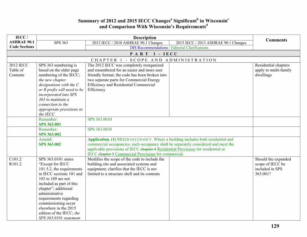
Summary of 2012 and 2015 IECC Changesa Significantb in Wisconsinc and Comparison With Wisconsin’s Requirementsd
IECC /
ASHRAE 90.1 Code Sections
Description Comments SPS 363 2012 IECC / 2010 ASHRAE 90.1 Changes 2015 IECC / 2013 ASHRAE 90.1 Changes DIS Recommendations / Editorial Clarifications P A R T 1 - I E C C
C H A P T E R 1 - S C O P E A N D A D M I N I S T R A T I O N 2012 IECC Table of Contents
SPS 363 numbering is based on the older page numbering of the IECC; the new chapter designations with the C or R prefix will need to be incorporated into SPS 363 to maintain a connection to the appropriate provisions in the IECC
The 2012 IECC was completely reorganized and renumbered for an easier and more user friendly format; the code has been broken into two separate parts for Commercial Energy Efficiency and Residential Commercial Efficiency
Residential chapters apply to multi-family dwellings
Renumber: SPS 363.001
SPS 363.0010
Renumber: SPS 363.002
SPS 363.0020
Amend: SPS 363.002
Application. (1) MIXED OCCUPANCY. Where a building includes both residential and commercial occupancies, each occupancy shall be separately considered and meet the applicable provisions of IECC chapter 4 Residential Provisions for residential or IECC chapter 5 Commercial Provisions for commercial.
C101.2 R101.2
SPS 363.0101 states “Except for IECC 101.5.2, the requirements in IECC sections 101 and 103 to 109 are not included as part of this chapter”; additional administrative requirements regarding commissioning occur elsewhere in the 2015 edition of the IECC; the SPS 363.0101 statement
Modifies the scope of the code to include the building site and associated systems and equipment; clarifies that the IECC is not limited to a structure shell and its contents
Should the expanded scope of IECC be included in SPS 363.001?
129
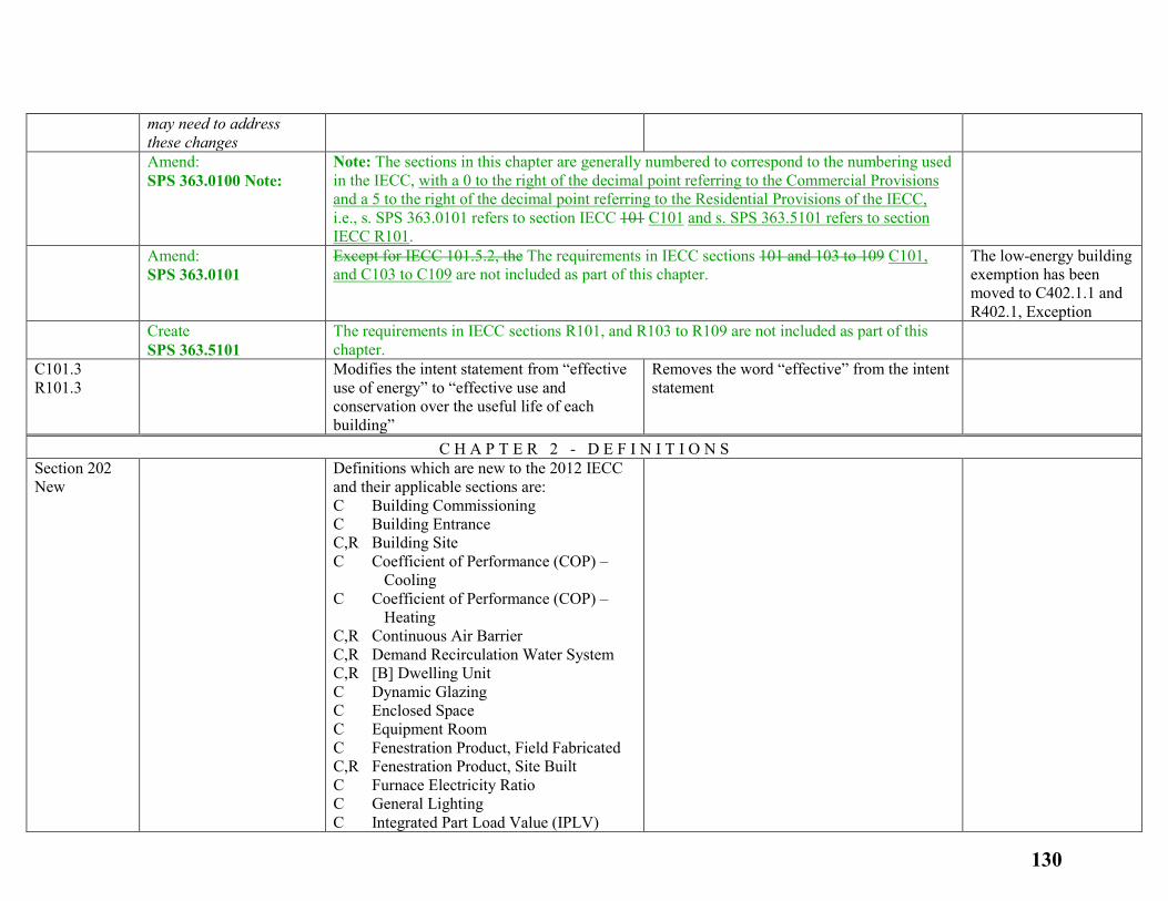
may need to address these changes
Amend: SPS 363.0100 Note:
Note: The sections in this chapter are generally numbered to correspond to the numbering used in the IECC, with a 0 to the right of the decimal point referring to the Commercial Provisions and a 5 to the right of the decimal point referring to the Residential Provisions of the IECC, i.e., s. SPS 363.0101 refers to section IECC 101 C101 and s. SPS 363.5101 refers to section IECC R101.
Amend: SPS 363.0101
Except for IECC 101.5.2, the The requirements in IECC sections 101 and 103 to 109 C101, and C103 to C109 are not included as part of this chapter.
The low-energy building exemption has been moved to C402.1.1 and R402.1, Exception
Create SPS 363.5101
The requirements in IECC sections R101, and R103 to R109 are not included as part of this chapter.
C101.3 R101.3
Modifies the intent statement from “effective use of energy” to “effective use and conservation over the useful life of each building”
Removes the word “effective” from the intent statement
C H A P T E R 2 - D E F I N I T I O N S Section 202 New
Definitions which are new to the 2012 IECC and their applicable sections are: C Building Commissioning C Building Entrance C,R Building Site C Coefficient of Performance (COP) – Cooling C Coefficient of Performance (COP) – Heating C,R Continuous Air Barrier C,R Demand Recirculation Water System C,R [B] Dwelling Unit C Dynamic Glazing C Enclosed Space C Equipment Room C Fenestration Product, Field Fabricated C,R Fenestration Product, Site Built C Furnace Electricity Ratio C General Lighting C Integrated Part Load Value (IPLV)
130
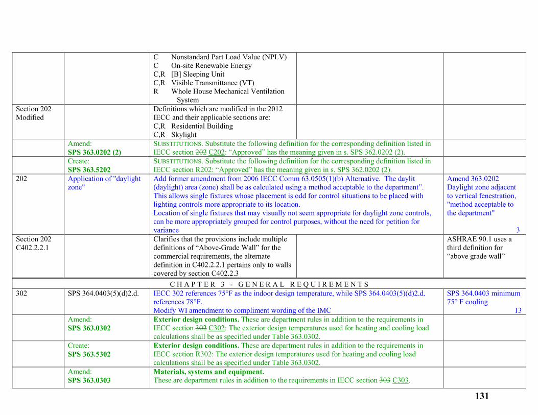
C Nonstandard Part Load Value (NPLV) C On-site Renewable Energy C,R [B] Sleeping Unit C,R Visible Transmittance (VT) R Whole House Mechanical Ventilation System
Section 202 Modified
Definitions which are modified in the 2012 IECC and their applicable sections are: C,R Residential Building C,R Skylight
Amend: SPS 363.0202 (2)
SUBSTITUTIONS. Substitute the following definition for the corresponding definition listed in IECC section 202 C202: “Approved” has the meaning given in s. SPS 362.0202 (2).
Create: SPS 363.5202
SUBSTITUTIONS. Substitute the following definition for the corresponding definition listed in IECC section R202: “Approved” has the meaning given in s. SPS 362.0202 (2).
202 Application of "daylight zone"
Add former amendment from 2006 IECC Comm 63.0505(1)(b) Alternative. The daylit (daylight) area (zone) shall be as calculated using a method acceptable to the department”. This allows single fixtures whose placement is odd for control situations to be placed with lighting controls more appropriate to its location. Location of single fixtures that may visually not seem appropriate for daylight zone controls, can be more appropriately grouped for control purposes, without the need for petition for variance
Amend 363.0202 Daylight zone adjacent to vertical fenestration, "method acceptable to the department" 3
Section 202 C402.2.2.1
Clarifies that the provisions include multiple definitions of “Above-Grade Wall” for the commercial requirements, the alternate definition in C402.2.2.1 pertains only to walls covered by section C402.2.3
ASHRAE 90.1 uses a third definition for “above grade wall”
C H A P T E R 3 - G E N E R A L R E Q U I R E M E N T S 302 SPS 364.0403(5)(d)2.d. IECC 302 references 75°F as the indoor design temperature, while SPS 364.0403(5)(d)2.d.
references 78°F. Modify WI amendment to compliment wording of the IMC
SPS 364.0403 minimum 75° F cooling 13
Amend: SPS 363.0302
Exterior design conditions. These are department rules in addition to the requirements in IECC section 302 C302: The exterior design temperatures used for heating and cooling load calculations shall be as specified under Table 363.0302.
Create: SPS 363.5302
Exterior design conditions. These are department rules in addition to the requirements in IECC section R302: The exterior design temperatures used for heating and cooling load calculations shall be as specified under Table 363.0302.
Amend: SPS 363.0303
Materials, systems and equipment. These are department rules in addition to the requirements in IECC section 303 C303.
131
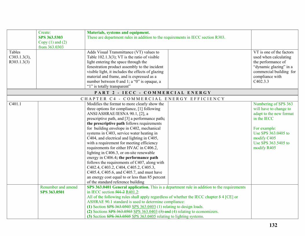
Create: SPS 363.5303 Copy (1) and (2) from 363.0303
Materials, systems and equipment. These are department rules in addition to the requirements in IECC section R303.
Tables C303.1.3(3), R303.1.3(3)
Adds Visual Transmittance (VT) values to Table 102.1.3(3); VT is the ratio of visible light entering the space through the fenestration product assembly to the incident visible light, it includes the effects of glazing material and frame, and is expressed as a number between 0 and 1; a “0” is opaque, a “1” is totally transparent”
VT is one of the factors used when calculating the performance of “dynamic glazing” in a commercial building for compliance with C402.3.3
P A R T 2 - I E C C - C O M M E R C I A L E N E R G Y C H A P T E R C 4 - C O M M E R C I A L E N E R G Y E F F I C I E N C Y
C401.1
Modifies the format to more clearly show the three options for compliance, [1] following ANSI/ASHRAE/IESNA 90.1, [2], a prescriptive path, and [3] a performance path; the prescriptive path follows requirements for building envelope in C402, mechanical systems in C403, service water heating in C404, and electrical and lighting in C405, with a requirement for meeting efficiency requirements for either HVAC in C406.2, lighting in C406.3, or on-site renewable energy in C406.4; the performance path follows the requirements of C407, along with C402.4, C403.2, C404, C405.2, C405.3, C405.4, C405.6, and C405.7, and must have an energy cost equal to or less than 85 percent of the standard reference building
Numbering of SPS 363 will have to change to adapt to the new format in the IECC For example: Use SPS 363.0405 to modify C405 Use SPS 363.5405 to modify R405
Renumber and amend SPS 363.0501
SPS 363.0401 General application. This is a department rule in addition to the requirements in IECC section 501.2 R401.2: All of the following rules shall apply regardless of whether the IECC chapter 5 4 [CE] or ASHRAE 90.1 standard is used to determine compliance: (1) Section SPS 363.0503 SPS 363.0403 (1) relating to design loads. (2) Sections SPS 363.0503 SPS 363.0403 (3) and (4) relating to economizers. (3) Section SPS 363.0505 SPS 363.0405 relating to lighting systems.
132
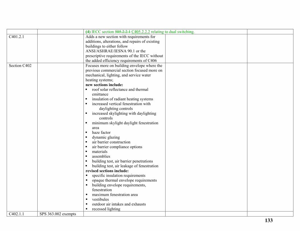
(4) IECC section 505.2.2.1 C405.2.2.2 relating to dual switching. C401.2.1
Adds a new section with requirements for additions, alterations, and repairs of existing buildings to either follow ANSI/ASHRAE/IESNA 90.1 or the prescriptive requirements of the IECC without the added efficiency requirements of C406
Section C402
Focuses more on building envelope where the previous commercial section focused more on mechanical, lighting, and service water heating systems; new sections include: roof solar reflectance and thermal
emittance insulation of radiant heating systems increased vertical fenestration with
daylighting controls increased skylighting with daylighting
controls minimum skylight daylight fenestration
area haze factor dynamic glazing air barrier construction air barrier compliance options materials assemblies building test, air barrier penetrations building test, air leakage of fenestration revised sections include: specific insulation requirements opaque thermal envelope requirements building envelope requirements,
fenestration maximum fenestration area vestibules outdoor air intakes and exhausts recessed lighting
C402.1.1 SPS 363.002 exempts
133
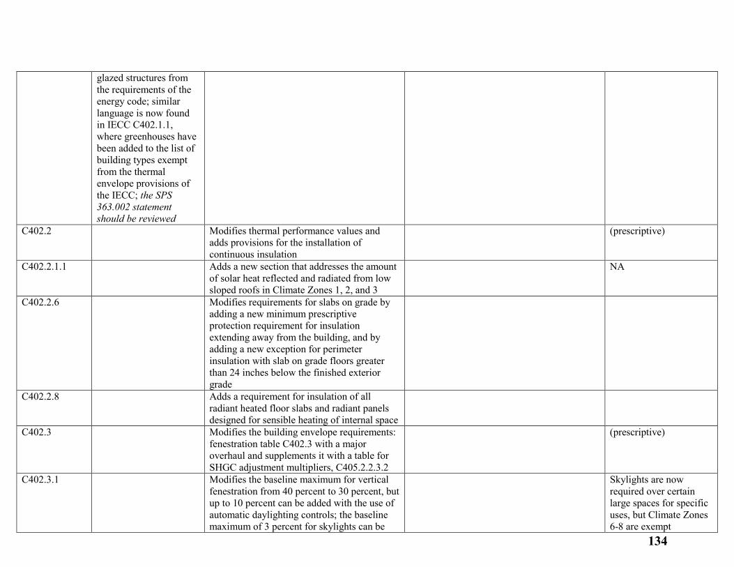
glazed structures from the requirements of the energy code; similar language is now found in IECC C402.1.1, where greenhouses have been added to the list of building types exempt from the thermal envelope provisions of the IECC; the SPS 363.002 statement should be reviewed
C402.2
Modifies thermal performance values and adds provisions for the installation of continuous insulation
(prescriptive)
C402.2.1.1
Adds a new section that addresses the amount of solar heat reflected and radiated from low sloped roofs in Climate Zones 1, 2, and 3
NA
C402.2.6
Modifies requirements for slabs on grade by adding a new minimum prescriptive protection requirement for insulation extending away from the building, and by adding a new exception for perimeter insulation with slab on grade floors greater than 24 inches below the finished exterior grade
C402.2.8
Adds a requirement for insulation of all radiant heated floor slabs and radiant panels designed for sensible heating of internal space
C402.3
Modifies the building envelope requirements: fenestration table C402.3 with a major overhaul and supplements it with a table for SHGC adjustment multipliers, C405.2.2.3.2
(prescriptive)
C402.3.1
Modifies the baseline maximum for vertical fenestration from 40 percent to 30 percent, but up to 10 percent can be added with the use of automatic daylighting controls; the baseline maximum of 3 percent for skylights can be
Skylights are now required over certain large spaces for specific uses, but Climate Zones 6-8 are exempt
134
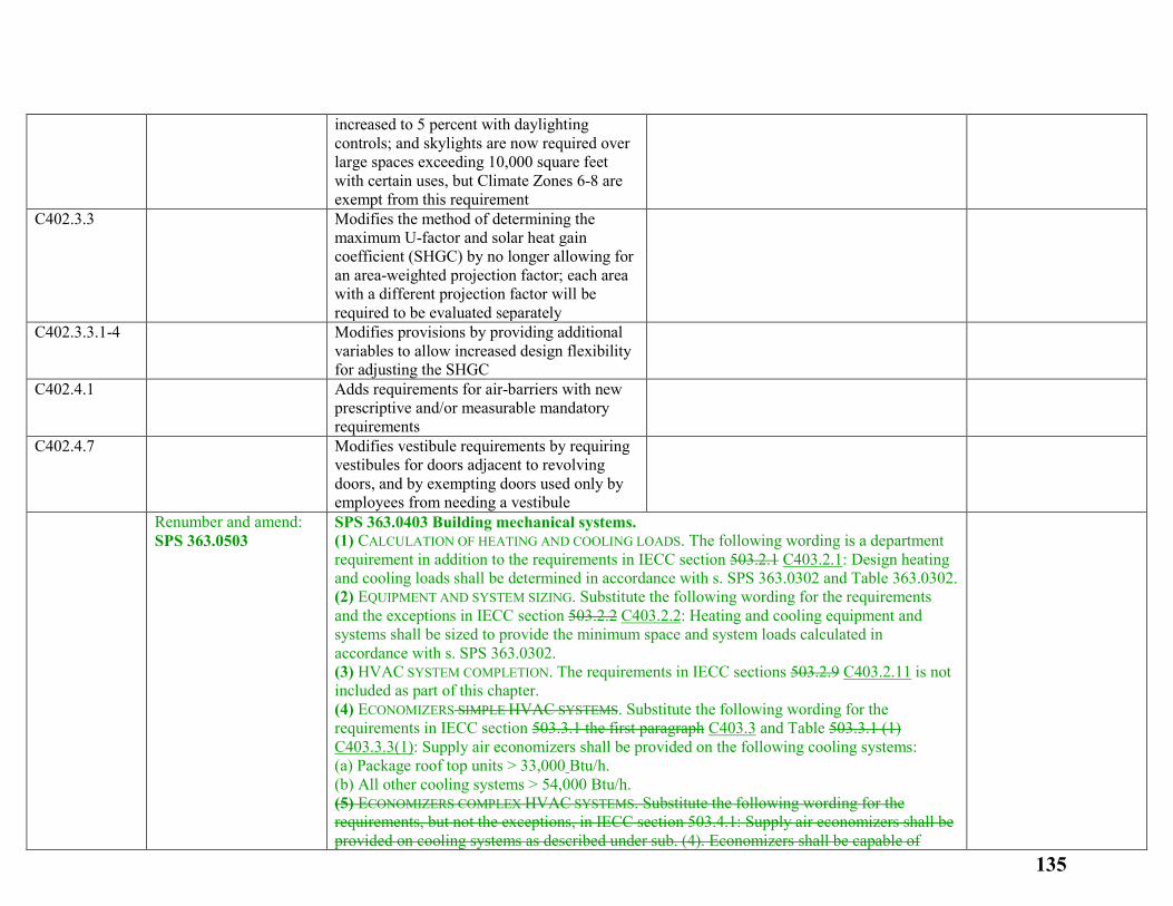
increased to 5 percent with daylighting controls; and skylights are now required over large spaces exceeding 10,000 square feet with certain uses, but Climate Zones 6-8 are exempt from this requirement
C402.3.3
Modifies the method of determining the maximum U-factor and solar heat gain coefficient (SHGC) by no longer allowing for an area-weighted projection factor; each area with a different projection factor will be required to be evaluated separately
C402.3.3.1-4
Modifies provisions by providing additional variables to allow increased design flexibility for adjusting the SHGC
C402.4.1
Adds requirements for air-barriers with new prescriptive and/or measurable mandatory requirements
C402.4.7
Modifies vestibule requirements by requiring vestibules for doors adjacent to revolving doors, and by exempting doors used only by employees from needing a vestibule
Renumber and amend: SPS 363.0503
SPS 363.0403 Building mechanical systems. (1) CALCULATION OF HEATING AND COOLING LOADS. The following wording is a department requirement in addition to the requirements in IECC section 503.2.1 C403.2.1: Design heating and cooling loads shall be determined in accordance with s. SPS 363.0302 and Table 363.0302. (2) EQUIPMENT AND SYSTEM SIZING. Substitute the following wording for the requirements and the exceptions in IECC section 503.2.2 C403.2.2: Heating and cooling equipment and systems shall be sized to provide the minimum space and system loads calculated in accordance with s. SPS 363.0302. (3) HVAC SYSTEM COMPLETION. The requirements in IECC sections 503.2.9 C403.2.11 is not included as part of this chapter. (4) ECONOMIZERS SIMPLE HVAC SYSTEMS. Substitute the following wording for the requirements in IECC section 503.3.1 the first paragraph C403.3 and Table 503.3.1 (1) C403.3.3(1): Supply air economizers shall be provided on the following cooling systems: (a) Package roof top units > 33,000 Btu/h. (b) All other cooling systems > 54,000 Btu/h. (5) ECONOMIZERS COMPLEX HVAC SYSTEMS. Substitute the following wording for the requirements, but not the exceptions, in IECC section 503.4.1: Supply air economizers shall be provided on cooling systems as described under sub. (4). Economizers shall be capable of
135
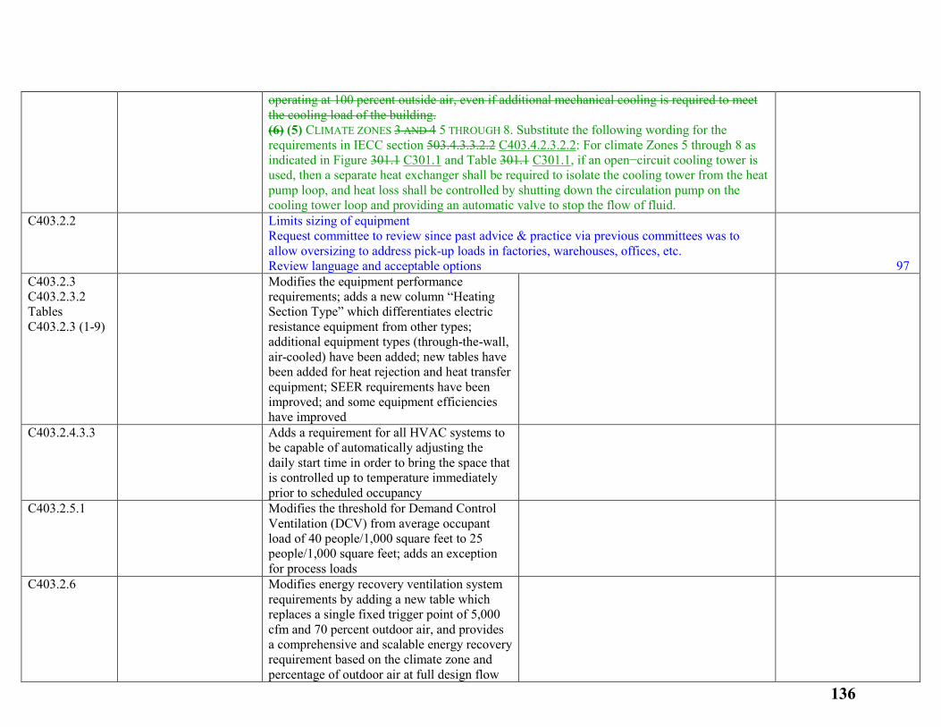
operating at 100 percent outside air, even if additional mechanical cooling is required to meet the cooling load of the building. (6) (5) CLIMATE ZONES 3 AND 4 5 THROUGH 8. Substitute the following wording for the requirements in IECC section 503.4.3.3.2.2 C403.4.2.3.2.2: For climate Zones 5 through 8 as indicated in Figure 301.1 C301.1 and Table 301.1 C301.1, if an open−circuit cooling tower is used, then a separate heat exchanger shall be required to isolate the cooling tower from the heat pump loop, and heat loss shall be controlled by shutting down the circulation pump on the cooling tower loop and providing an automatic valve to stop the flow of fluid.
C403.2.2 Limits sizing of equipment Request committee to review since past advice & practice via previous committees was to allow oversizing to address pick-up loads in factories, warehouses, offices, etc. Review language and acceptable options
97
C403.2.3 C403.2.3.2 Tables C403.2.3 (1-9)
Modifies the equipment performance requirements; adds a new column “Heating Section Type” which differentiates electric resistance equipment from other types; additional equipment types (through-the-wall, air-cooled) have been added; new tables have been added for heat rejection and heat transfer equipment; SEER requirements have been improved; and some equipment efficiencies have improved
C403.2.4.3.3
Adds a requirement for all HVAC systems to be capable of automatically adjusting the daily start time in order to bring the space that is controlled up to temperature immediately prior to scheduled occupancy
C403.2.5.1
Modifies the threshold for Demand Control Ventilation (DCV) from average occupant load of 40 people/1,000 square feet to 25 people/1,000 square feet; adds an exception for process loads
C403.2.6
Modifies energy recovery ventilation system requirements by adding a new table which replaces a single fixed trigger point of 5,000 cfm and 70 percent outdoor air, and provides a comprehensive and scalable energy recovery requirement based on the climate zone and percentage of outdoor air at full design flow
136
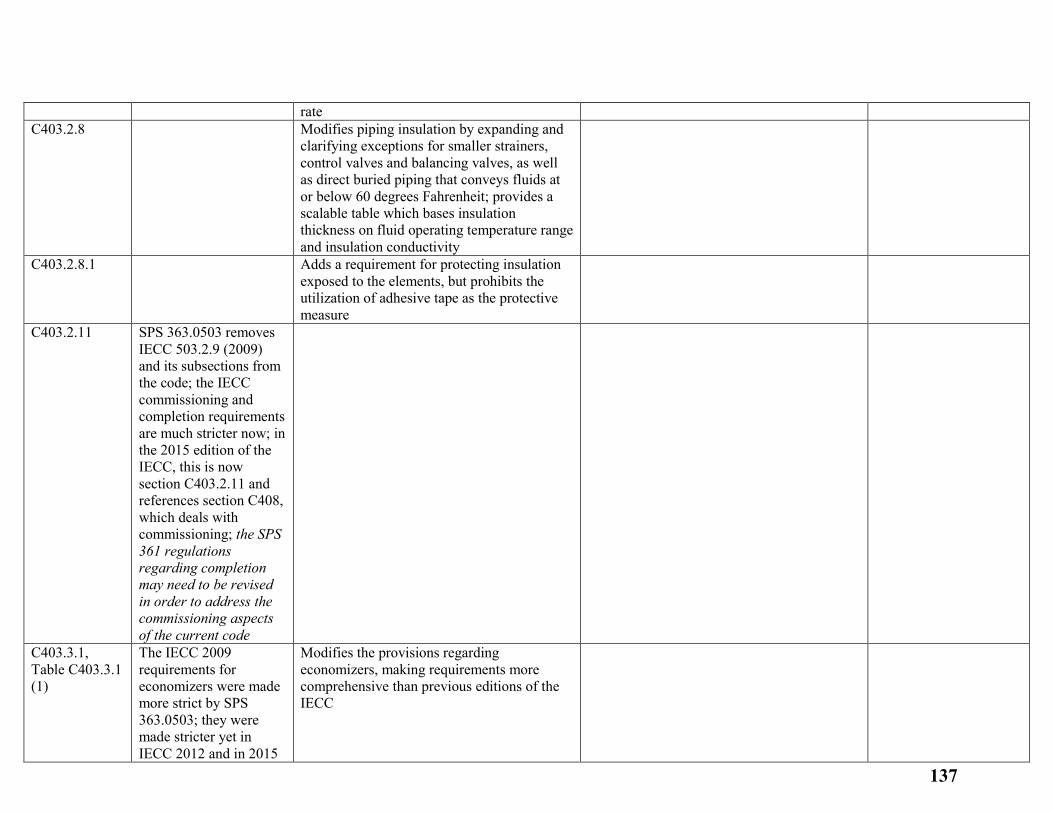
rate C403.2.8
Modifies piping insulation by expanding and clarifying exceptions for smaller strainers, control valves and balancing valves, as well as direct buried piping that conveys fluids at or below 60 degrees Fahrenheit; provides a scalable table which bases insulation thickness on fluid operating temperature range and insulation conductivity
C403.2.8.1
Adds a requirement for protecting insulation exposed to the elements, but prohibits the utilization of adhesive tape as the protective measure
C403.2.11 SPS 363.0503 removes IECC 503.2.9 (2009) and its subsections from the code; the IECC commissioning and completion requirements are much stricter now; in the 2015 edition of the IECC, this is now section C403.2.11 and references section C408, which deals with commissioning; the SPS 361 regulations regarding completion may need to be revised in order to address the commissioning aspects of the current code
C403.3.1, Table C403.3.1 (1)
The IECC 2009 requirements for economizers were made more strict by SPS 363.0503; they were made stricter yet in IECC 2012 and in 2015
Modifies the provisions regarding economizers, making requirements more comprehensive than previous editions of the IECC
137
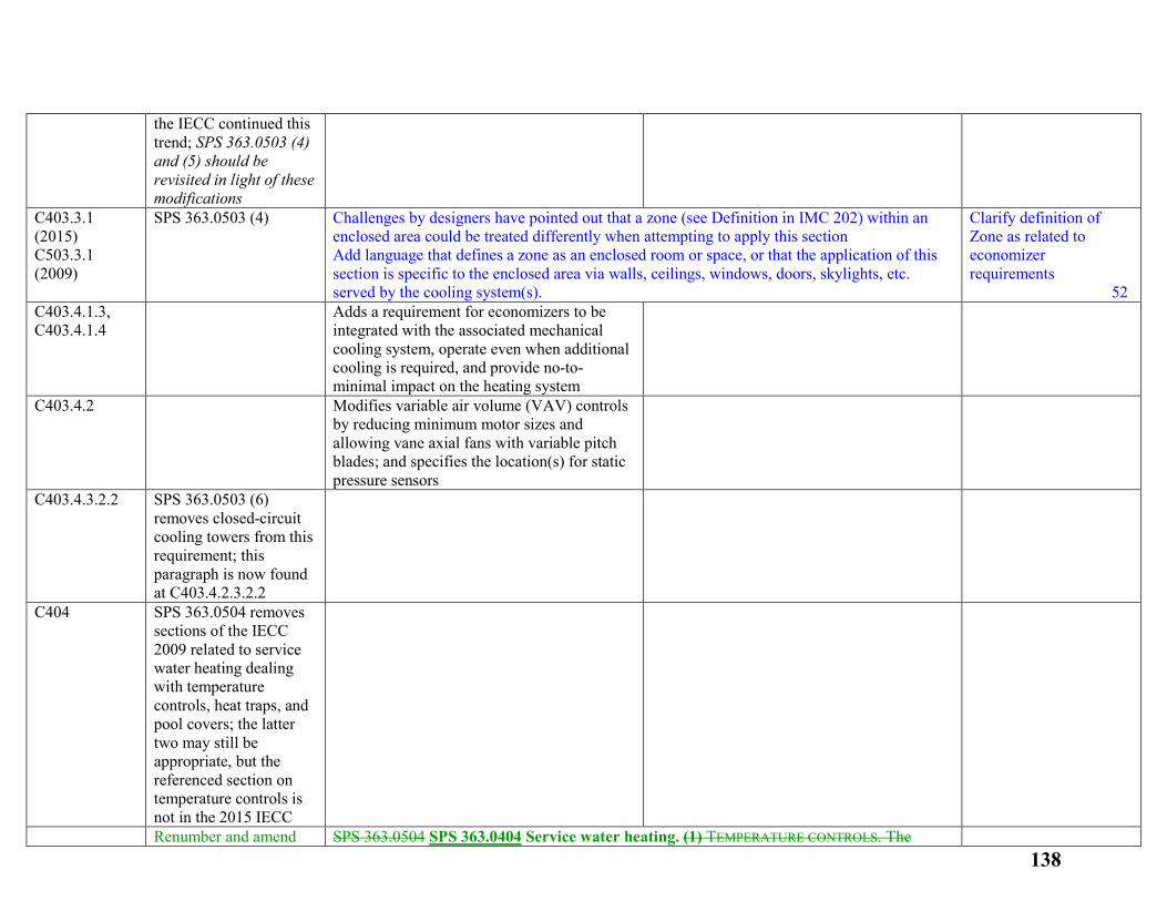
the IECC continued this trend; SPS 363.0503 (4) and (5) should be revisited in light of these modifications
C403.3.1 (2015) C503.3.1 (2009)
SPS 363.0503 (4) Challenges by designers have pointed out that a zone (see Definition in IMC 202) within an enclosed area could be treated differently when attempting to apply this section Add language that defines a zone as an enclosed room or space, or that the application of this section is specific to the enclosed area via walls, ceilings, windows, doors, skylights, etc. served by the cooling system(s).
Clarify definition of Zone as related to economizer requirements 52
C403.4.1.3, C403.4.1.4
Adds a requirement for economizers to be integrated with the associated mechanical cooling system, operate even when additional cooling is required, and provide no-to-minimal impact on the heating system
C403.4.2
Modifies variable air volume (VAV) controls by reducing minimum motor sizes and allowing vane axial fans with variable pitch blades; and specifies the location(s) for static pressure sensors
C403.4.3.2.2 SPS 363.0503 (6) removes closed-circuit cooling towers from this requirement; this paragraph is now found at C403.4.2.3.2.2
C404 SPS 363.0504 removes sections of the IECC 2009 related to service water heating dealing with temperature controls, heat traps, and pool covers; the latter two may still be appropriate, but the referenced section on temperature controls is not in the 2015 IECC
Renumber and amend SPS 363.0504 SPS 363.0404 Service water heating. (1) TEMPERATURE CONTROLS. The 138
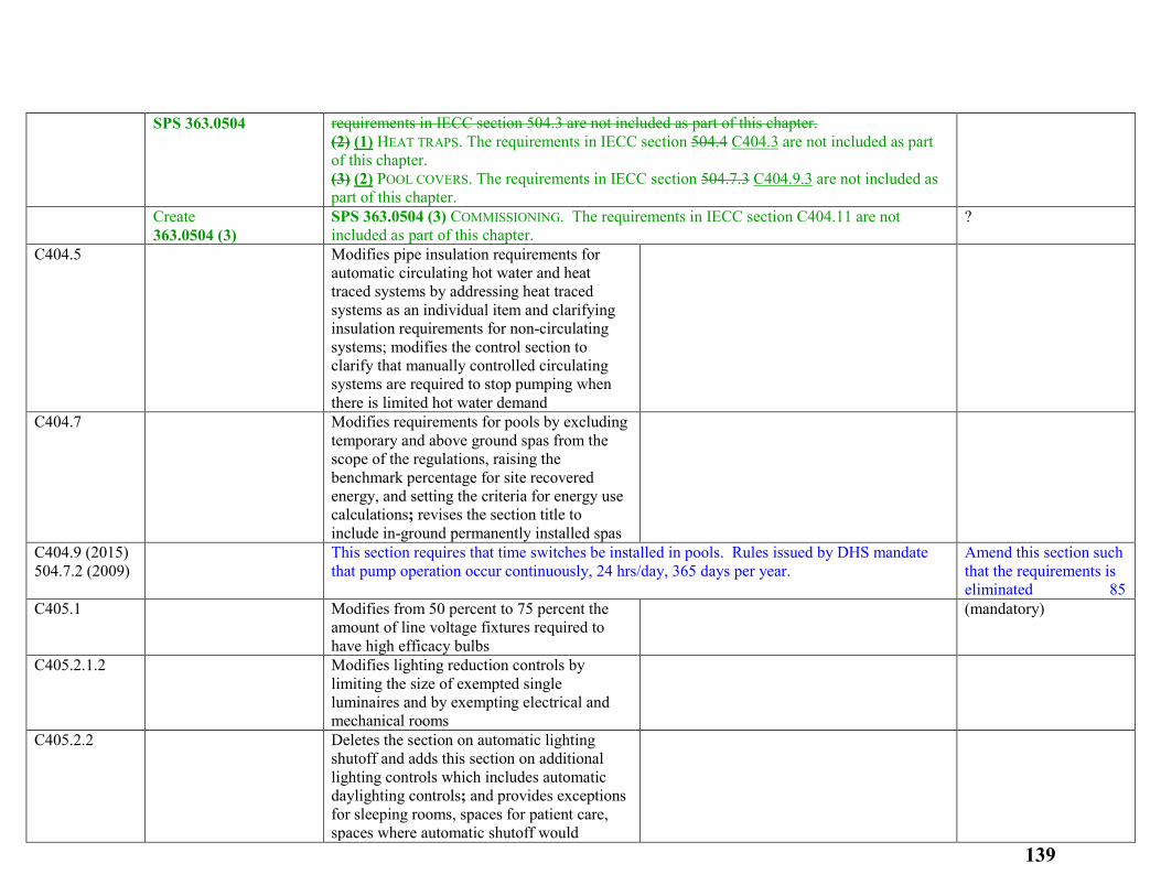
SPS 363.0504 requirements in IECC section 504.3 are not included as part of this chapter. (2) (1) HEAT TRAPS. The requirements in IECC section 504.4 C404.3 are not included as part of this chapter. (3) (2) POOL COVERS. The requirements in IECC section 504.7.3 C404.9.3 are not included as part of this chapter.
Create 363.0504 (3)
SPS 363.0504 (3) COMMISSIONING. The requirements in IECC section C404.11 are not included as part of this chapter.
?
C404.5
Modifies pipe insulation requirements for automatic circulating hot water and heat traced systems by addressing heat traced systems as an individual item and clarifying insulation requirements for non-circulating systems; modifies the control section to clarify that manually controlled circulating systems are required to stop pumping when there is limited hot water demand
C404.7
Modifies requirements for pools by excluding temporary and above ground spas from the scope of the regulations, raising the benchmark percentage for site recovered energy, and setting the criteria for energy use calculations; revises the section title to include in-ground permanently installed spas
C404.9 (2015) 504.7.2 (2009)
This section requires that time switches be installed in pools. Rules issued by DHS mandate that pump operation occur continuously, 24 hrs/day, 365 days per year.
Amend this section such that the requirements is eliminated 85
C405.1
Modifies from 50 percent to 75 percent the amount of line voltage fixtures required to have high efficacy bulbs
(mandatory)
C405.2.1.2
Modifies lighting reduction controls by limiting the size of exempted single luminaires and by exempting electrical and mechanical rooms
C405.2.2
Deletes the section on automatic lighting shutoff and adds this section on additional lighting controls which includes automatic daylighting controls; and provides exceptions for sleeping rooms, spaces for patient care, spaces where automatic shutoff would
139
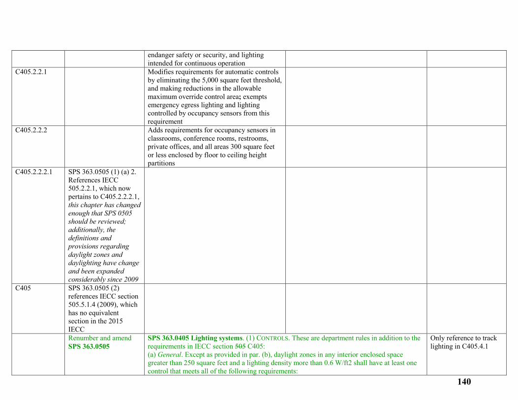
endanger safety or security, and lighting intended for continuous operation
C405.2.2.1
Modifies requirements for automatic controls by eliminating the 5,000 square feet threshold, and making reductions in the allowable maximum override control area; exempts emergency egress lighting and lighting controlled by occupancy sensors from this requirement
C405.2.2.2
Adds requirements for occupancy sensors in classrooms, conference rooms, restrooms, private offices, and all areas 300 square feet or less enclosed by floor to ceiling height partitions
C405.2.2.2.1 SPS 363.0505 (1) (a) 2. References IECC 505.2.2.1, which now pertains to C405.2.2.2.1, this chapter has changed enough that SPS 0505 should be reviewed; additionally, the definitions and provisions regarding daylight zones and daylighting have change and been expanded considerably since 2009
C405 SPS 363.0505 (2) references IECC section 505.5.1.4 (2009), which has no equivalent section in the 2015 IECC
Renumber and amend SPS 363.0505
SPS 363.0405 Lighting systems. (1) CONTROLS. These are department rules in addition to the requirements in IECC section 505 C405: (a) General. Except as provided in par. (b), daylight zones in any interior enclosed space greater than 250 square feet and a lighting density more than 0.6 W/ft2 shall have at least one control that meets all of the following requirements:
Only reference to track lighting in C405.4.1
140
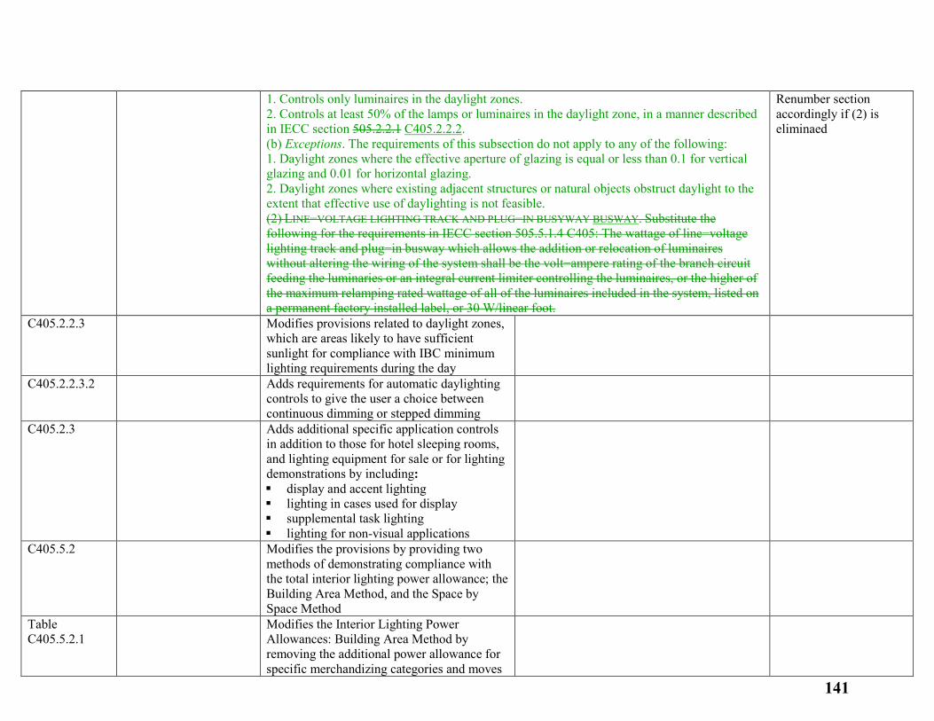
1. Controls only luminaires in the daylight zones. 2. Controls at least 50% of the lamps or luminaires in the daylight zone, in a manner described in IECC section 505.2.2.1 C405.2.2.2. (b) Exceptions. The requirements of this subsection do not apply to any of the following: 1. Daylight zones where the effective aperture of glazing is equal or less than 0.1 for vertical glazing and 0.01 for horizontal glazing. 2. Daylight zones where existing adjacent structures or natural objects obstruct daylight to the extent that effective use of daylighting is not feasible. (2) LINE−VOLTAGE LIGHTING TRACK AND PLUG−IN BUSYWAY BUSWAY. Substitute the following for the requirements in IECC section 505.5.1.4 C405: The wattage of line−voltage lighting track and plug−in busway which allows the addition or relocation of luminaires without altering the wiring of the system shall be the volt−ampere rating of the branch circuit feeding the luminaries or an integral current limiter controlling the luminaires, or the higher of the maximum relamping rated wattage of all of the luminaires included in the system, listed on a permanent factory installed label, or 30 W/linear foot.
Renumber section accordingly if (2) is eliminaed
C405.2.2.3
Modifies provisions related to daylight zones, which are areas likely to have sufficient sunlight for compliance with IBC minimum lighting requirements during the day
C405.2.2.3.2
Adds requirements for automatic daylighting controls to give the user a choice between continuous dimming or stepped dimming
C405.2.3
Adds additional specific application controls in addition to those for hotel sleeping rooms, and lighting equipment for sale or for lighting demonstrations by including: display and accent lighting lighting in cases used for display supplemental task lighting lighting for non-visual applications
C405.5.2
Modifies the provisions by providing two methods of demonstrating compliance with the total interior lighting power allowance; the Building Area Method, and the Space by Space Method
Table C405.5.2.1
Modifies the Interior Lighting Power Allowances: Building Area Method by removing the additional power allowance for specific merchandizing categories and moves
141
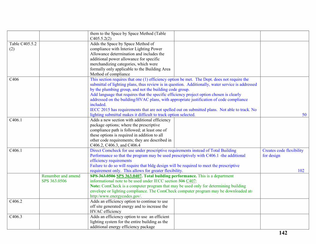
them to the Space by Space Method (Table C405.5.2(2)
Table C405.5.2 (2)
Adds the Space by Space Method of compliance with Interior Lighting Power Allowance determination and includes the additional power allowance for specific merchandizing categories, which were formally only applicable to the Building Area Method of compliance
C406 This section requires that one (1) efficiency option be met. The Dept. does not require the submittal of lighting plans, thus review is in question. Additionally, water service is addressed by the plumbing group, and not the building code group. Add language that requires that the specific efficiency project option chosen is clearly addressed on the building/HVAC plans, with appropriate justification of code compliance included. IECC 2015 has requirements that are not spelled out on submitted plans. Not able to track. No lighting submittal makes it difficult to track option selected.
50
C406.1
Adds a new section with additional efficiency package options; where the prescriptive compliance path is followed; at least one of these options is required in addition to all other code requirements; they are described in C406.2, C406.3, and C406.4
C406.1 Direct Comcheck for use under prescriptive requirements instead of Total Building Performance so that the program may be used prescriptively with C406.1 -the additional efficiency requirements Failure to do so will require that bldg design will be required to meet the prescriptive requirement only. This allows for greater flexibility.
Creates code flexibility for design 102
Renumber and amend SPS 363.0506
SPS 363.0506 SPS 363.0407. Total building performance. This is a department informational note to be used under IECC section 506 C407: Note: ComCheck is a computer program that may be used only for determining building envelope or lighting compliance. The ComCheck computer program may be downloaded at: http:/www.energycodes.gov/.
C406.2
Adds an efficiency option to continue to use off site generated energy and to increase the HVAC efficiency
C406.3
Adds an efficiency option to use an efficient lighting system for the entire building as the additional energy efficiency package
142
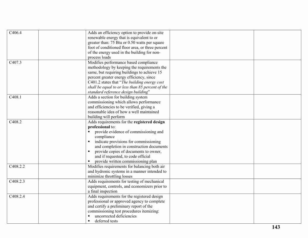
C406.4
Adds an efficiency option to provide on-site renewable energy that is equivalent to or greater than: 75 Btu or 0.50 watts per square foot of conditioned floor area, or three percent of the energy used in the building for non-process loads
C407.3
Modifies performance based compliance methodology by keeping the requirements the same, but requiring buildings to achieve 15 percent greater energy efficiency, since C401.2 states that “The building energy cost shall be equal to or less than 85 percent of the standard reference design building”
C408.1
Adds a section for building system commissioning which allows performance and efficiencies to be verified, giving a reasonable idea of how a well maintained building will perform
C408.2
Adds requirements for the registered design professional to: provide evidence of commissioning and
compliance indicate provisions for commissioning
and completion in construction documents provide copies of documents to owner,
and if requested, to code official provide written commissioning plan
C408.2.2
Modifies requirements for balancing both air and hydronic systems in a manner intended to minimize throttling losses
C408.2.3
Adds requirements for testing of mechanical equipment, controls, and economizers prior to a final inspection
C408.2.4
Adds requirements for the registered design professional or approved agency to complete and certify a preliminary report of the commissioning test procedures itemizing: uncorrected deficiencies deferred tests
143
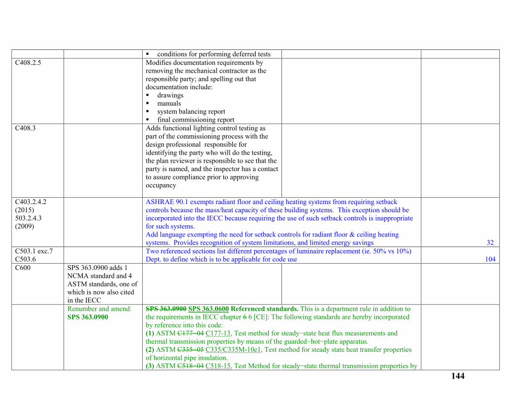
conditions for performing deferred tests C408.2.5
Modifies documentation requirements by removing the mechanical contractor as the responsible party; and spelling out that documentation include: drawings manuals system balancing report final commissioning report
C408.3
Adds functional lighting control testing as part of the commissioning process with the design professional responsible for identifying the party who will do the testing, the plan reviewer is responsible to see that the party is named, and the inspector has a contact to assure compliance prior to approving occupancy
C403.2.4.2 (2015) 503.2.4.3 (2009)
ASHRAE 90.1 exempts radiant floor and ceiling heating systems from requiring setback controls because the mass/heat capacity of these building systems. This exception should be incorporated into the IECC because requiring the use of such setback controls is inappropriate for such systems. Add language exempting the need for setback controls for radiant floor & ceiling heating systems. Provides recognition of system limitations, and limited energy savings
32
C503.1 exc.7 C503.6
Two referenced sections list different percentages of luminaire replacement (ie. 50% vs 10%) Dept. to define which is to be applicable for code use
104
C600 SPS 363.0900 adds 1 NCMA standard and 4 ASTM standards, one of which is now also cited in the IECC
Renumber and amend: SPS 363.0900
SPS 363.0900 SPS 363.0600 Referenced standards. This is a department rule in addition to the requirements in IECC chapter 6 6 [CE]: The following standards are hereby incorporated by reference into this code: (1) ASTM C177−04 C177-13, Test method for steady−state heat flux measurements and thermal transmission properties by means of the guarded−hot−plate apparatus. (2) ASTM C335−05 C335/C335M-10e1, Test method for steady state heat transfer properties of horizontal pipe insulation. (3) ASTM C518−04 C518-15, Test Method for steady−state thermal transmission properties by
144
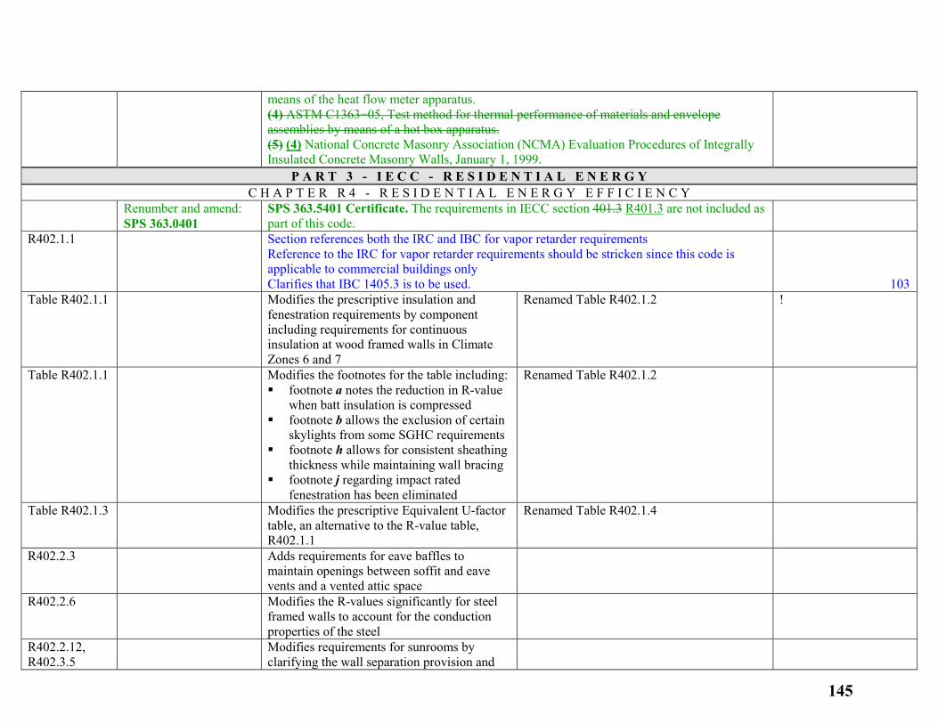
means of the heat flow meter apparatus. (4) ASTM C1363−05, Test method for thermal performance of materials and envelope assemblies by means of a hot box apparatus. (5) (4) National Concrete Masonry Association (NCMA) Evaluation Procedures of Integrally Insulated Concrete Masonry Walls, January 1, 1999.
P A R T 3 - I E C C - R E S I D E N T I A L E N E R G Y C H A P T E R R 4 - R E S I D E N T I A L E N E R G Y E F F I C I E N C Y
Renumber and amend: SPS 363.0401
SPS 363.5401 Certificate. The requirements in IECC section 401.3 R401.3 are not included as part of this code.
R402.1.1 Section references both the IRC and IBC for vapor retarder requirements Reference to the IRC for vapor retarder requirements should be stricken since this code is applicable to commercial buildings only Clarifies that IBC 1405.3 is to be used.
103
Table R402.1.1
Modifies the prescriptive insulation and fenestration requirements by component including requirements for continuous insulation at wood framed walls in Climate Zones 6 and 7
Renamed Table R402.1.2 !
Table R402.1.1
Modifies the footnotes for the table including: footnote a notes the reduction in R-value
when batt insulation is compressed footnote b allows the exclusion of certain
skylights from some SGHC requirements footnote h allows for consistent sheathing
thickness while maintaining wall bracing footnote j regarding impact rated
fenestration has been eliminated
Renamed Table R402.1.2
Table R402.1.3
Modifies the prescriptive Equivalent U-factor table, an alternative to the R-value table, R402.1.1
Renamed Table R402.1.4
R402.2.3
Adds requirements for eave baffles to maintain openings between soffit and eave vents and a vented attic space
R402.2.6
Modifies the R-values significantly for steel framed walls to account for the conduction properties of the steel
R402.2.12, R402.3.5
Modifies requirements for sunrooms by clarifying the wall separation provision and
145
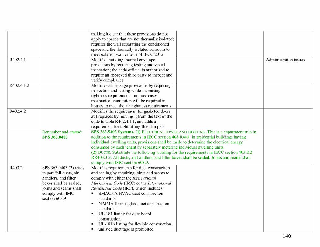
making it clear that these provisions do not apply to spaces that are not thermally isolated; requires the wall separating the conditioned space and the thermally isolated sunroom to meet exterior wall criteria of IECC 2012
R402.4.1
Modifies building thermal envelope provisions by requiring testing and visual inspection; the code official is authorized to require an approved third party to inspect and verify compliance
Administration issues
R402.4.1.2
Modifies air leakage provisions by requiring inspection and testing while increasing tightness requirements; in most cases mechanical ventilation will be required in houses to meet the air tightness requirements
R402.4.2
Modifies the requirement for gasketed doors at fireplaces by moving it from the text of the code to table R402.4.1.1; and adds a requirement for tight fitting flue dampers
Renumber and amend: SPS 363.0403
SPS 363.5403 Systems. (1) ELECTRICAL POWER AND LIGHTING. This is a department rule in addition to the requirements in IECC section 403 R403: In residential buildings having individual dwelling units, provisions shall be made to determine the electrical energy consumed by each tenant by separately metering individual dwelling units. (2) DUCTS. Substitute the following wording for the requirements in IECC section 403.2.2 RR403.3.2: All ducts, air handlers, and filter boxes shall be sealed. Joints and seams shall comply with IMC section 603.9.
R403.2
SPS 363 0403 (2) reads in part “all ducts, air handlers, and filter boxes shall be sealed, joints and seams shall comply with IMC section 603.9
Modifies requirements for duct construction and sealing by requiring joints and seams to comply with either the International Mechanical Code (IMC) or the International Residential Code (IRC), which includes: SMACNA HVAC duct construction
standards NAIMA fibrous glass duct construction
standards UL-181 listing for duct board
construction UL-181b listing for flexible construction unlisted duct tape is prohibited
146
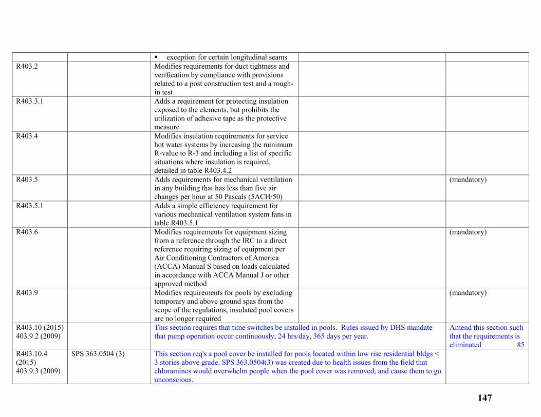
exception for certain longitudinal seams R403.2
Modifies requirements for duct tightness and verification by compliance with provisions related to a post construction test and a rough-in test
R403.3.1
Adds a requirement for protecting insulation exposed to the elements, but prohibits the utilization of adhesive tape as the protective measure
R403.4
Modifies insulation requirements for service hot water systems by increasing the minimum R-value to R-3 and including a list of specific situations where insulation is required, detailed in table R403.4.2
R403.5
Adds requirements for mechanical ventilation in any building that has less than five air changes per hour at 50 Pascals (5ACH/50)
(mandatory)
R403.5.1
Adds a simple efficiency requirement for various mechanical ventilation system fans in table R403.5.1
R403.6
Modifies requirements for equipment sizing from a reference through the IRC to a direct reference requiring sizing of equipment per Air Conditioning Contractors of America (ACCA) Manual S based on loads calculated in accordance with ACCA Manual J or other approved method
(mandatory)
R403.9
Modifies requirements for pools by excluding temporary and above ground spas from the scope of the regulations, insulated pool covers are no longer required
(mandatory)
R403.10 (2015) 403.9.2 (2009)
This section requires that time switches be installed in pools. Rules issued by DHS mandate that pump operation occur continuously, 24 hrs/day, 365 days per year.
Amend this section such that the requirements is eliminated 85
R403.10.4 (2015) 403.9.3 (2009)
SPS 363.0504 (3) This section req's a pool cover be installed for pools located within low rise residential bldgs < 3 stories above grade. SPS 363.0504(3) was created due to health issues from the field that chloramines would overwhelm people when the pool cover was removed, and cause them to go unconscious.
147
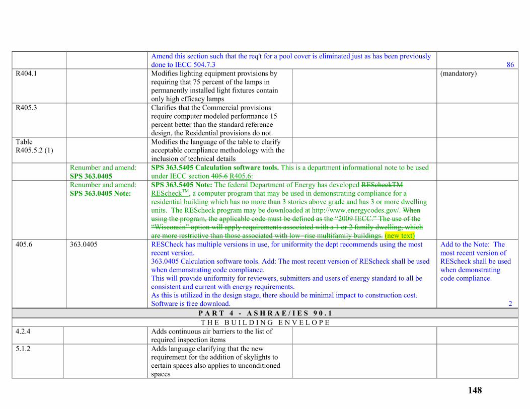
Amend this section such that the req't for a pool cover is eliminated just as has been previously done to IECC 504.7.3
86
R404.1
Modifies lighting equipment provisions by requiring that 75 percent of the lamps in permanently installed light fixtures contain only high efficacy lamps
(mandatory)
R405.3
Clarifies that the Commercial provisions require computer modeled performance 15 percent better than the standard reference design, the Residential provisions do not
Table R405.5.2 (1)
Modifies the language of the table to clarify acceptable compliance methodology with the inclusion of technical details
Renumber and amend: SPS 363.0405
SPS 363.5405 Calculation software tools. This is a department informational note to be used under IECC section 405.6 R405.6:
Renumber and amend: SPS 363.0405 Note:
SPS 363.5405 Note: The federal Department of Energy has developed REScheckTM REScheckTM, a computer program that may be used in demonstrating compliance for a residential building which has no more than 3 stories above grade and has 3 or more dwelling units. The REScheck program may be downloaded at http://www.energycodes.gov/. When using the program, the applicable code must be defined as the “2009 IECC.” The use of the “Wisconsin” option will apply requirements associated with a 1 or 2 family dwelling, which are more restrictive than those associated with low−rise multifamily buildings. (new text)
405.6 363.0405 RESCheck has multiple versions in use, for uniformity the dept recommends using the most recent version. 363.0405 Calculation software tools. Add: The most recent version of REScheck shall be used when demonstrating code compliance. This will provide uniformity for reviewers, submitters and users of energy standard to all be consistent and current with energy requirements. As this is utilized in the design stage, there should be minimal impact to construction cost. Software is free download.
Add to the Note: The most recent version of REScheck shall be used when demonstrating code compliance. 2
P A R T 4 - A S H R A E / I E S 9 0 . 1 T H E B U I L D I N G E N V E L O P E
4.2.4
Adds continuous air barriers to the list of required inspection items
5.1.2
Adds language clarifying that the new requirement for the addition of skylights to certain spaces also applies to unconditioned spaces
148
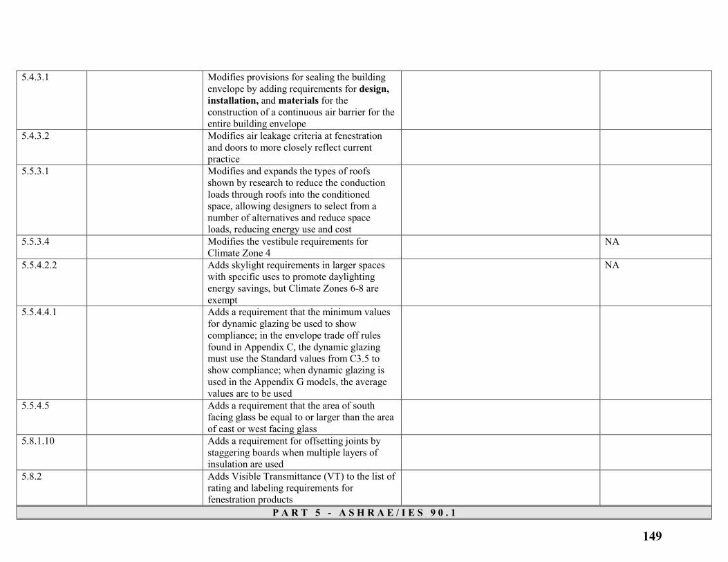
5.4.3.1
Modifies provisions for sealing the building envelope by adding requirements for design, installation, and materials for the construction of a continuous air barrier for the entire building envelope
5.4.3.2
Modifies air leakage criteria at fenestration and doors to more closely reflect current practice
5.5.3.1
Modifies and expands the types of roofs shown by research to reduce the conduction loads through roofs into the conditioned space, allowing designers to select from a number of alternatives and reduce space loads, reducing energy use and cost
5.5.3.4
Modifies the vestibule requirements for Climate Zone 4
NA
5.5.4.2.2
Adds skylight requirements in larger spaces with specific uses to promote daylighting energy savings, but Climate Zones 6-8 are exempt
NA
5.5.4.4.1
Adds a requirement that the minimum values for dynamic glazing be used to show compliance; in the envelope trade off rules found in Appendix C, the dynamic glazing must use the Standard values from C3.5 to show compliance; when dynamic glazing is used in the Appendix G models, the average values are to be used
5.5.4.5
Adds a requirement that the area of south facing glass be equal to or larger than the area of east or west facing glass
5.8.1.10
Adds a requirement for offsetting joints by staggering boards when multiple layers of insulation are used
5.8.2
Adds Visible Transmittance (VT) to the list of rating and labeling requirements for fenestration products
P A R T 5 - A S H R A E / I E S 9 0 . 1
149
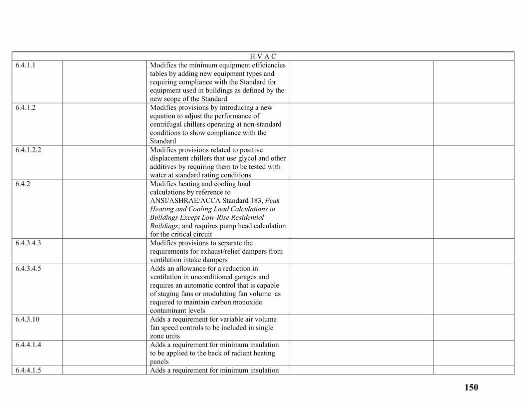
H V A C 6.4.1.1
Modifies the minimum equipment efficiencies tables by adding new equipment types and requiring compliance with the Standard for equipment used in buildings as defined by the new scope of the Standard
6.4.1.2
Modifies provisions by introducing a new equation to adjust the performance of centrifugal chillers operating at non-standard conditions to show compliance with the Standard
6.4.1.2.2
Modifies provisions related to positive displacement chillers that use glycol and other additives by requiring them to be tested with water at standard rating conditions
6.4.2
Modifies heating and cooling load calculations by reference to ANSI/ASHRAE/ACCA Standard 183, Peak Heating and Cooling Load Calculations in Buildings Except Low-Rise Residential Buildings; and requires pump head calculation for the critical circuit
6.4.3.4.3
Modifies provisions to separate the requirements for exhaust/relief dampers from ventilation intake dampers
6.4.3.4.5
Adds an allowance for a reduction in ventilation in unconditioned garages and requires an automatic control that is capable of staging fans or modulating fan volume as required to maintain carbon monoxide contaminant levels
6.4.3.10
Adds a requirement for variable air volume fan speed controls to be included in single zone units
6.4.4.1.4
Adds a requirement for minimum insulation to be applied to the back of radiant heating panels
6.4.4.1.5 Adds a requirement for minimum insulation
150
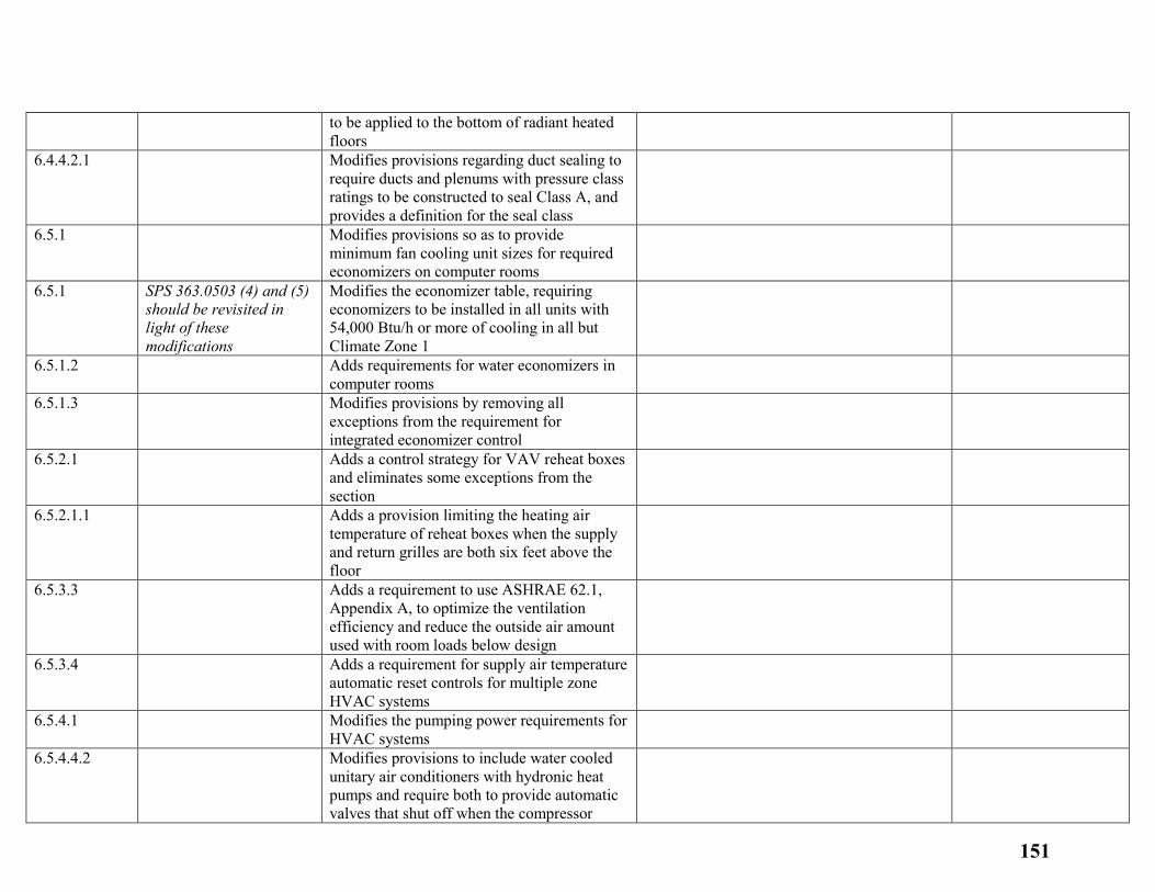
to be applied to the bottom of radiant heated floors
6.4.4.2.1
Modifies provisions regarding duct sealing to require ducts and plenums with pressure class ratings to be constructed to seal Class A, and provides a definition for the seal class
6.5.1
Modifies provisions so as to provide minimum fan cooling unit sizes for required economizers on computer rooms
6.5.1
SPS 363.0503 (4) and (5) should be revisited in light of these modifications
Modifies the economizer table, requiring economizers to be installed in all units with 54,000 Btu/h or more of cooling in all but Climate Zone 1
6.5.1.2
Adds requirements for water economizers in computer rooms
6.5.1.3
Modifies provisions by removing all exceptions from the requirement for integrated economizer control
6.5.2.1
Adds a control strategy for VAV reheat boxes and eliminates some exceptions from the section
6.5.2.1.1
Adds a provision limiting the heating air temperature of reheat boxes when the supply and return grilles are both six feet above the floor
6.5.3.3
Adds a requirement to use ASHRAE 62.1, Appendix A, to optimize the ventilation efficiency and reduce the outside air amount used with room loads below design
6.5.3.4
Adds a requirement for supply air temperature automatic reset controls for multiple zone HVAC systems
6.5.4.1
Modifies the pumping power requirements for HVAC systems
6.5.4.4.2
Modifies provisions to include water cooled unitary air conditioners with hydronic heat pumps and require both to provide automatic valves that shut off when the compressor
151
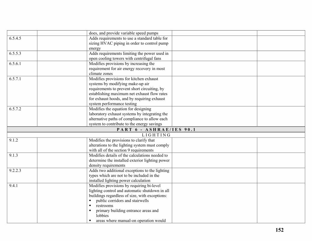
does, and provide variable speed pumps 6.5.4.5
Adds requirements to use a standard table for sizing HVAC piping in order to control pump energy
6.5.5.3
Adds requirements limiting the power used in open cooling towers with centrifugal fans
6.5.6.1
Modifies provisions by increasing the requirement for air energy recovery in most climate zones
6.5.7.1
Modifies provisions for kitchen exhaust systems by modifying make-up air requirements to prevent short circuiting, by establishing maximum net exhaust flow rates for exhaust hoods, and by requiring exhaust system performance testing
6.5.7.2
Modifies the equation for designing laboratory exhaust systems by integrating the alternative paths of compliance to allow each system to contribute to the energy savings
P A R T 6 - A S H R A E / I E S 9 0 . 1 L I G H T I N G
9.1.2
Modifies the provisions to clarify that alterations to the lighting system must comply with all of the section 9 requirements
9.1.3
Modifies details of the calculations needed to determine the installed exterior lighting power density requirements
9.2.2.3
Adds two additional exceptions to the lighting types which are not to be included in the installed lighting power calculation
9.4.1
Modifies provisions by requiring bi-level lighting control and automatic shutdown in all buildings regardless of size, with exceptions: public corridors and stairwells restrooms primary building entrance areas and
lobbies areas where manual-on operation would
152
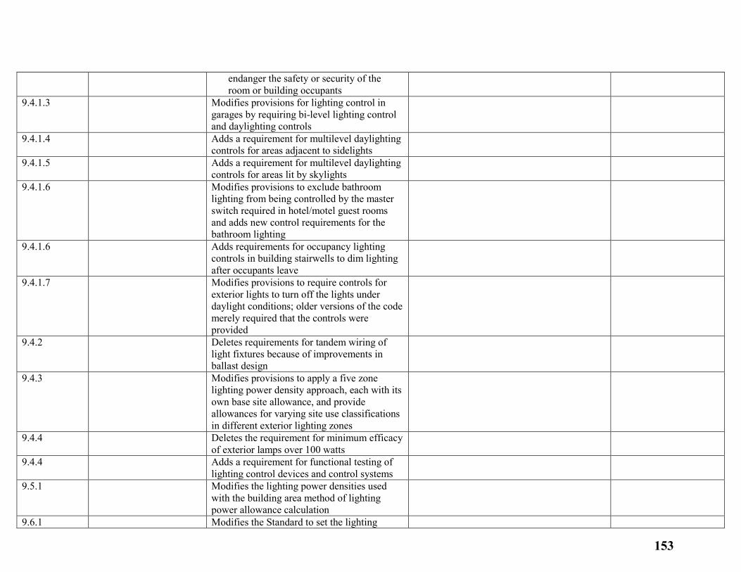
endanger the safety or security of the room or building occupants
9.4.1.3
Modifies provisions for lighting control in garages by requiring bi-level lighting control and daylighting controls
9.4.1.4
Adds a requirement for multilevel daylighting controls for areas adjacent to sidelights
9.4.1.5
Adds a requirement for multilevel daylighting controls for areas lit by skylights
9.4.1.6
Modifies provisions to exclude bathroom lighting from being controlled by the master switch required in hotel/motel guest rooms and adds new control requirements for the bathroom lighting
9.4.1.6
Adds requirements for occupancy lighting controls in building stairwells to dim lighting after occupants leave
9.4.1.7
Modifies provisions to require controls for exterior lights to turn off the lights under daylight conditions; older versions of the code merely required that the controls were provided
9.4.2
Deletes requirements for tandem wiring of light fixtures because of improvements in ballast design
9.4.3
Modifies provisions to apply a five zone lighting power density approach, each with its own base site allowance, and provide allowances for varying site use classifications in different exterior lighting zones
9.4.4
Deletes the requirement for minimum efficacy of exterior lamps over 100 watts
9.4.4
Adds a requirement for functional testing of lighting control devices and control systems
9.5.1
Modifies the lighting power densities used with the building area method of lighting power allowance calculation
9.6.1 Modifies the Standard to set the lighting
153
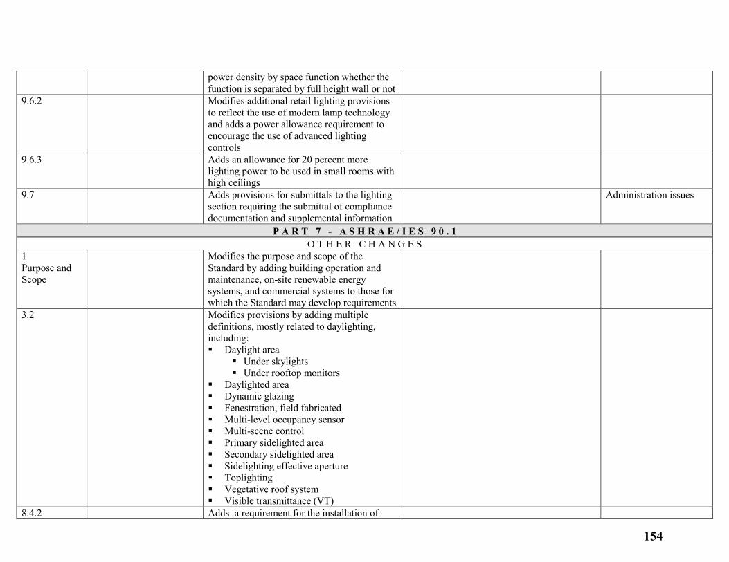
power density by space function whether the function is separated by full height wall or not
9.6.2
Modifies additional retail lighting provisions to reflect the use of modern lamp technology and adds a power allowance requirement to encourage the use of advanced lighting controls
9.6.3
Adds an allowance for 20 percent more lighting power to be used in small rooms with high ceilings
9.7
Adds provisions for submittals to the lighting section requiring the submittal of compliance documentation and supplemental information
Administration issues
P A R T 7 - A S H R A E / I E S 9 0 . 1 O T H E R C H A N G E S
1 Purpose and Scope
Modifies the purpose and scope of the Standard by adding building operation and maintenance, on-site renewable energy systems, and commercial systems to those for which the Standard may develop requirements
3.2
Modifies provisions by adding multiple definitions, mostly related to daylighting, including: Daylight area
Under skylights Under rooftop monitors
Daylighted area Dynamic glazing Fenestration, field fabricated Multi-level occupancy sensor Multi-scene control Primary sidelighted area Secondary sidelighted area Sidelighting effective aperture Toplighting Vegetative roof system Visible transmittance (VT)
8.4.2 Adds a requirement for the installation of
154
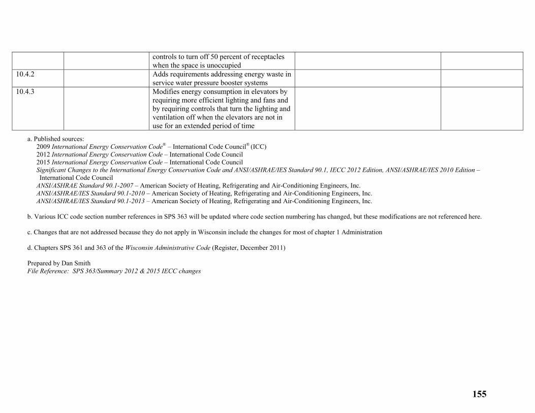
controls to turn off 50 percent of receptacles when the space is unoccupied
10.4.2
Adds requirements addressing energy waste in service water pressure booster systems
10.4.3
Modifies energy consumption in elevators by requiring more efficient lighting and fans and by requiring controls that turn the lighting and ventilation off when the elevators are not in use for an extended period of time
a. Published sources: 2009 International Energy Conservation Code® – International Code Council® (ICC) 2012 International Energy Conservation Code – International Code Council 2015 International Energy Conservation Code – International Code Council Significant Changes to the International Energy Conservation Code and ANSI/ASHRAE/IES Standard 90.1, IECC 2012 Edition, ANSI/ASHRAE/IES 2010 Edition – International Code Council
ANSI/ASHRAE Standard 90.1-2007 – American Society of Heating, Refrigerating and Air-Conditioning Engineers, Inc. ANSI/ASHRAE/IES Standard 90.1-2010 – American Society of Heating, Refrigerating and Air-Conditioning Engineers, Inc. ANSI/ASHRAE/IES Standard 90.1-2013 – American Society of Heating, Refrigerating and Air-Conditioning Engineers, Inc.
b. Various ICC code section number references in SPS 363 will be updated where code section numbering has changed, but these modifications are not referenced here. c. Changes that are not addressed because they do not apply in Wisconsin include the changes for most of chapter 1 Administration d. Chapters SPS 361 and 363 of the Wisconsin Administrative Code (Register, December 2011) Prepared by Dan Smith File Reference: SPS 363/Summary 2012 & 2015 IECC changes
155

The International Energy Conservation Code® (IECC®) is recognized as the national model energy code of choice for U.S. cities, counties and states that adopt codes. The IECC and its predecessor, the Model Energy Code (MEC), are cited throughout Federal law for national private and public housing initiatives.
The 2015 edition of the IECC is intended to provide flexibility to permit the use of innovative approaches and techniques. This is achieved by allowing the choice of a prescriptive or performance-based compliance path for both commercial and residential buildings.
Goal
Participants will be able to use this document to identify changes from the 2012 IECC to the 2015 IECC, allowing them to apply these code requirements to the design, plan review, inspection and commissioning of both residential and commercial buildings.
Objectives
Upon completion, participants will be better able to:
Identify the most significant differences between the 2012 IECC and the 2015 IECC
Explain the differences between the commercial and residential provisions
Understand the choice of compliance paths
Identify newly-regulated systems and components
Identify the applicability of design, plan review, inspection and commissioning requirements
The 2015 edition has numerous changes that provide users of the Code considerably more compliance choices without trading energy efficiency. While there will be regional variability in the technology advances, a preliminary estimate from U.S. Department of Energy (DOE) suggests the 2015 IECC will at least as energy efficient as the 2012 edition [reference: PNNL-23438], which yielded a 32 percent energy savings over the 2006 IECC. Homes built to the IECC consume less energy, and families who live in those homes save energy costs.
The 2015 IECC contains two separate sets of provisions—one for commercial buildings and one for residential buildings. Each set is applied separately to buildings within its scope.
The IECC—Residential Provisions are referenced as R before the section number. They apply to detached one- and two-family dwellings and multiple single-family dwellings, as well as Group R-2, R-3 and R-4 buildings, three stories or less in height.
IECC—Commercial Provisions are referenced as C before the section number and apply to all others.
156
2015 IECC Update
Page 2
The Commercial and Residential Provisions are independent; and each contains the following chapters:
1. Scope and Administration 2. Definitions 3. Climate Zones and General Materials Requirements 4. Energy Efficiency Requirements (applicable to buildings within its scope) 5. Existing Buildings 6. Referenced Standards
2015 IECC Table of Contents for both Residential and Commercial Provisions
Chapters 1, 2 and 3 are nearly identical for the Commercial and Residential Provisions and have been marked as Section C and R accordingly. For the purpose of this document, they will be explained together, and the differences will be highlighted. Chapter 4 of the Commercial and Residential Provisions contains the technical requirements for energy efficiency. Chapter 5 of the Commercial and Residential Provisions contains requirements for existing building. Chapter 6 of the Commercial and Residential Provisions contains the Referenced Standards. The 2015 edition of the IECC remains fully compatible with all the International Codes® (I-Codes®) published by the International Code Council® (Code Council®).
157
2015 IECC Update
Page 3
Chapter 1: Scope and Administration
Code Section Section Title Description of Change
2015 2012
C103.2.1
R103.2.1
NEW Building Thermal
Envelope
Depiction
Code now requires the building thermal envelope to be explicitly shown on
the construction drawings.
C104.1
R104.4
NEW Inspections -
General
Improved and enhanced details governing inspection of construction. The
provisions are more specific and written to relate to the Energy Code.
C104.2
R104.2
NEW Required
Inspections
C104.3
R104.3
NEW Reinspection
C104.4
R104.4
NEW Approved
Inspection
Agencies
158
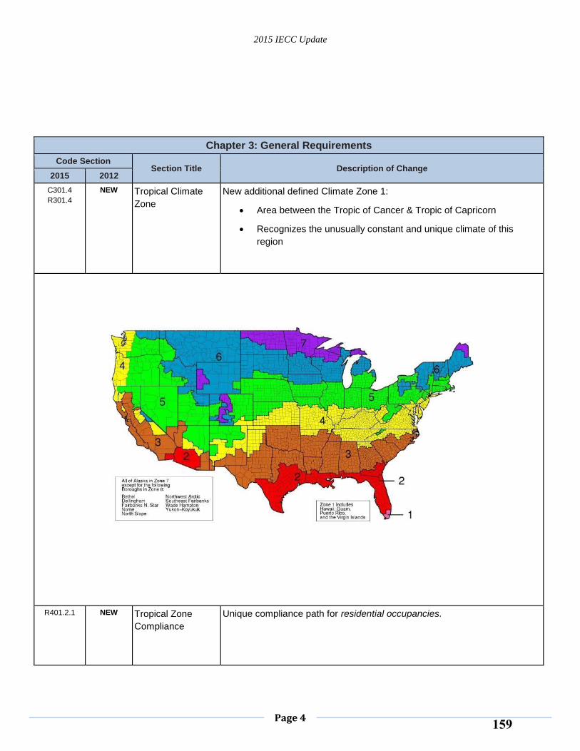
2015 IECC Update
Page 4
Chapter 3: General Requirements
Code Section Section Title Description of Change
2015 2012
C301.4
R301.4
NEW Tropical Climate
Zone
New additional defined Climate Zone 1:
Area between the Tropic of Cancer & Tropic of Capricorn
Recognizes the unusually constant and unique climate of this
region
R401.2.1 NEW Tropical Zone
Compliance
Unique compliance path for residential occupancies.
159
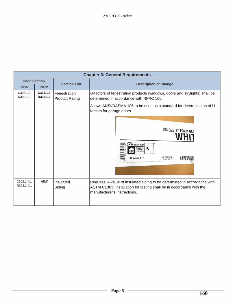
2015 IECC Update
Page 5
Chapter 3: General Requirements
Code Section Section Title Description of Change
2015 2012
C303.1.3
R303.1.3
C303.1.3
R303.1.3 Fenestration
Product Rating
U-factors of fenestration products (windows, doors and skylights) shall be
determined in accordance with NFRC 100.
Allows ANSI/DASMA 105 to be used as a standard for determination of U-
factors for garage doors
C303.1.4.1
R303.1.4.1
NEW Insulated
Siding
Requires R-value of insulated siding to be determined in accordance with
ASTM C1363. Installation for testing shall be in accordance with the
manufacturer’s instructions.
160
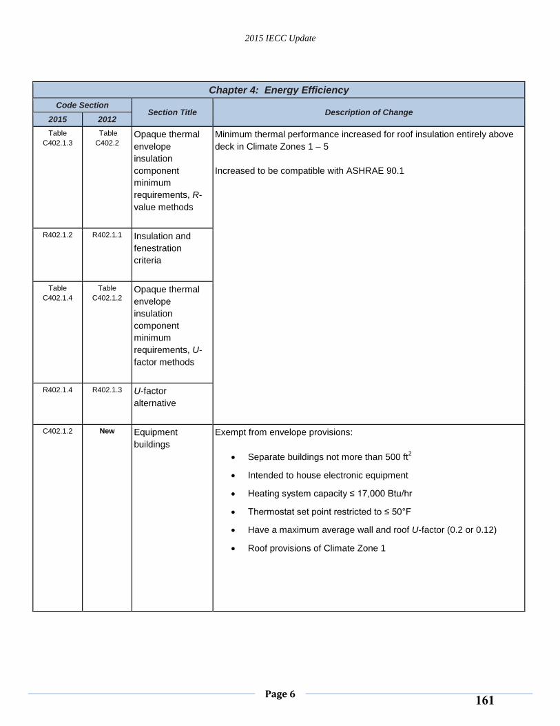
2015 IECC Update
Page 6
Chapter 4: Energy Efficiency
Code Section Section Title Description of Change
2015 2012
Table
C402.1.3
Table
C402.2 Opaque thermal
envelope
insulation
component
minimum
requirements, R-
value methods
Minimum thermal performance increased for roof insulation entirely above
deck in Climate Zones 1 – 5
Increased to be compatible with ASHRAE 90.1
R402.1.2 R402.1.1 Insulation and
fenestration
criteria
Table
C402.1.4
Table
C402.1.2 Opaque thermal
envelope
insulation
component
minimum
requirements, U-
factor methods
R402.1.4 R402.1.3 U-factor
alternative
C402.1.2 New Equipment
buildings
Exempt from envelope provisions:
Separate buildings not more than 500 ft2
Intended to house electronic equipment
Heating system capacity ≤ 17,000 Btu/hr
Thermostat set point restricted to ≤ 50°F
Have a maximum average wall and roof U-factor (0.2 or 0.12)
Roof provisions of Climate Zone 1
161
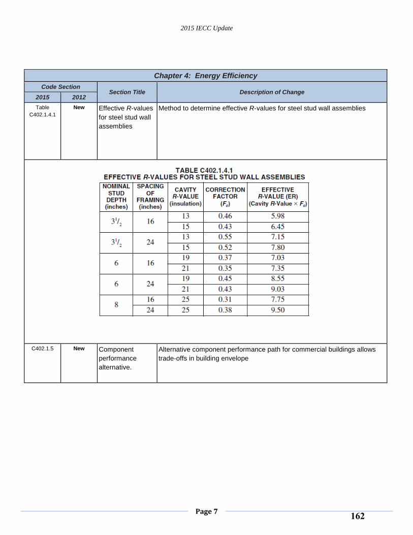
2015 IECC Update
Page 7
Chapter 4: Energy Efficiency
Code Section Section Title Description of Change
2015 2012
Table
C402.1.4.1
New Effective R-values
for steel stud wall
assemblies
Method to determine effective R-values for steel stud wall assemblies
C402.1.5 New Component
performance
alternative.
Alternative component performance path for commercial buildings allows
trade-offs in building envelope
162
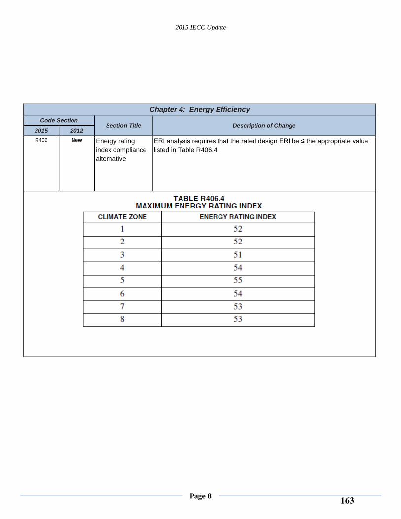
2015 IECC Update
Page 8
Chapter 4: Energy Efficiency
Code Section Section Title Description of Change
2015 2012
R406 New Energy rating
index compliance
alternative
ERI analysis requires that the rated design ERI be ≤ the appropriate value
listed in Table R406.4
163
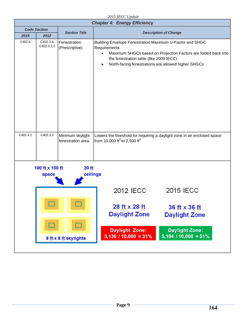
2015 IECC Update
Page 9
Chapter 4: Energy Efficiency
Code Section Section Title Description of Change
2015 2012
C402.4 C402.3 &
C402.3.3.1 Fenestration
(Prescriptive)
Building Envelope Fenestration Maximum U-Factor and SHGC
Requirements
Maximum SHGCs based on Projection Factors are folded back into
the fenestration table (like 2009 IECC)
North-facing fenestrations are allowed higher SHGCs
C402.4.2 C402.3.2 Minimum skylight
fenestration area.
Lowers the threshold for requiring a daylight zone in an enclosed space
from 10,000 ft2 to 2,500 ft
2
164
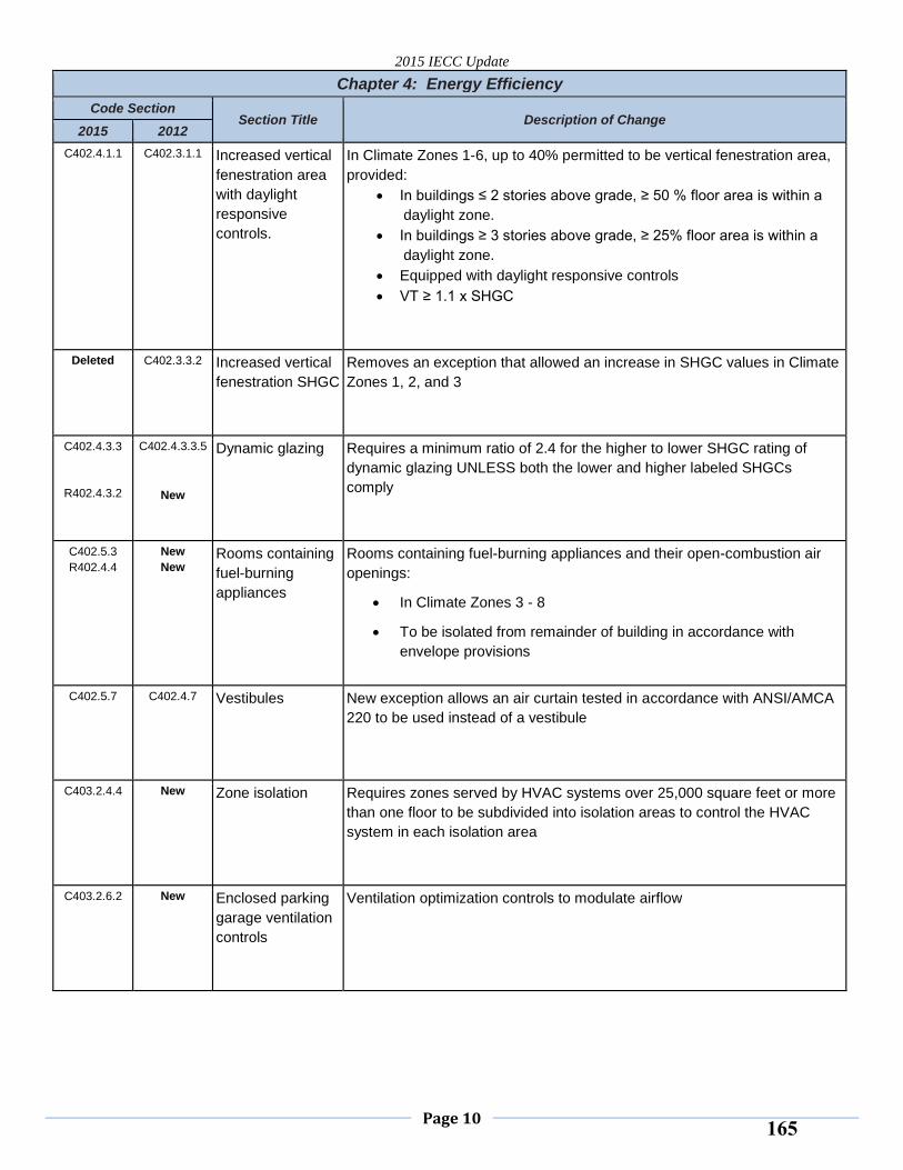
2015 IECC Update
Page 10
Chapter 4: Energy Efficiency
Code Section Section Title Description of Change
2015 2012
C402.4.1.1 C402.3.1.1 Increased vertical
fenestration area
with daylight
responsive
controls.
In Climate Zones 1-6, up to 40% permitted to be vertical fenestration area,
provided:
In buildings ≤ 2 stories above grade, ≥ 50 % floor area is within a
daylight zone.
In buildings ≥ 3 stories above grade, ≥ 25% floor area is within a
daylight zone.
Equipped with daylight responsive controls
VT ≥ 1.1 x SHGC
Deleted C402.3.3.2 Increased vertical
fenestration SHGC
Removes an exception that allowed an increase in SHGC values in Climate
Zones 1, 2, and 3
C402.4.3.3
R402.4.3.2
C402.4.3.3.5
New
Dynamic glazing Requires a minimum ratio of 2.4 for the higher to lower SHGC rating of
dynamic glazing UNLESS both the lower and higher labeled SHGCs
comply
C402.5.3
R402.4.4
New
New Rooms containing
fuel-burning
appliances
Rooms containing fuel-burning appliances and their open-combustion air
openings:
In Climate Zones 3 - 8
To be isolated from remainder of building in accordance with
envelope provisions
C402.5.7 C402.4.7 Vestibules New exception allows an air curtain tested in accordance with ANSI/AMCA
220 to be used instead of a vestibule
C403.2.4.4 New Zone isolation Requires zones served by HVAC systems over 25,000 square feet or more
than one floor to be subdivided into isolation areas to control the HVAC
system in each isolation area
C403.2.6.2 New Enclosed parking
garage ventilation
controls
Ventilation optimization controls to modulate airflow
165
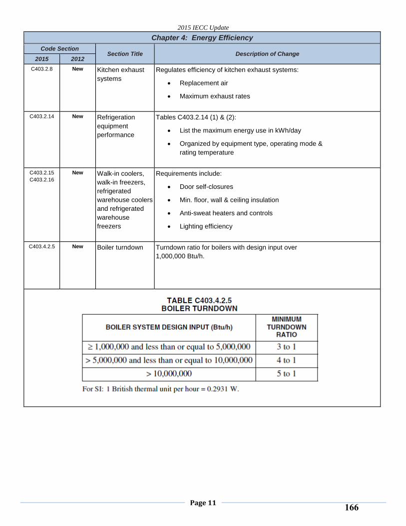
2015 IECC Update
Page 11
Chapter 4: Energy Efficiency
Code Section Section Title Description of Change
2015 2012
C403.2.8 New Kitchen exhaust
systems
Regulates efficiency of kitchen exhaust systems:
Replacement air
Maximum exhaust rates
C403.2.14 New Refrigeration
equipment
performance
Tables C403.2.14 (1) & (2):
List the maximum energy use in kWh/day
Organized by equipment type, operating mode &
rating temperature
C403.2.15
C403.2.16
New Walk-in coolers,
walk-in freezers,
refrigerated
warehouse coolers
and refrigerated
warehouse
freezers
Requirements include:
Door self-closures
Min. floor, wall & ceiling insulation
Anti-sweat heaters and controls
Lighting efficiency
C403.4.2.5 New Boiler turndown Turndown ratio for boilers with design input over
1,000,000 Btu/h.
166
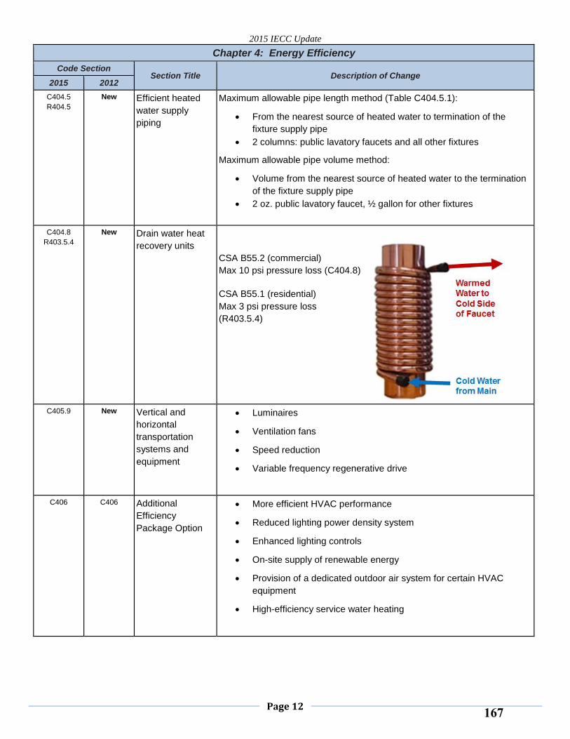
2015 IECC Update
Page 12
Chapter 4: Energy Efficiency
Code Section Section Title Description of Change
2015 2012
C404.5
R404.5
New Efficient heated
water supply
piping
Maximum allowable pipe length method (Table C404.5.1):
From the nearest source of heated water to termination of the
fixture supply pipe
2 columns: public lavatory faucets and all other fixtures
Maximum allowable pipe volume method:
Volume from the nearest source of heated water to the termination
of the fixture supply pipe
2 oz. public lavatory faucet, ½ gallon for other fixtures
C404.8
R403.5.4
New Drain water heat
recovery units
CSA B55.2 (commercial)
Max 10 psi pressure loss (C404.8)
CSA B55.1 (residential)
Max 3 psi pressure loss
(R403.5.4)
C405.9 New Vertical and
horizontal
transportation
systems and
equipment
Luminaires
Ventilation fans
Speed reduction
Variable frequency regenerative drive
C406 C406 Additional
Efficiency
Package Option
More efficient HVAC performance
Reduced lighting power density system
Enhanced lighting controls
On-site supply of renewable energy
Provision of a dedicated outdoor air system for certain HVAC
equipment
High-efficiency service water heating
167
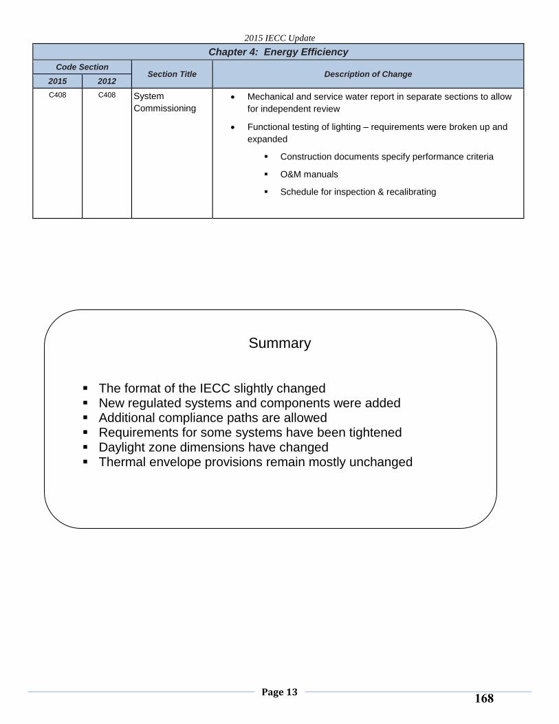
2015 IECC Update
Page 13
Chapter 4: Energy Efficiency
Code Section Section Title Description of Change
2015 2012
C408 C408 System
Commissioning
Mechanical and service water report in separate sections to allow
for independent review
Functional testing of lighting – requirements were broken up and
expanded
Construction documents specify performance criteria
O&M manuals
Schedule for inspection & recalibrating
Summary
The format of the IECC slightly changed New regulated systems and components were added Additional compliance paths are allowed Requirements for some systems have been tightened Daylight zone dimensions have changed Thermal envelope provisions remain mostly unchanged
168
2015 IECC Update ‐ Slide Presentation 9/30/2014
Copyright 2014 International Code Council 1
AccreditationAccreditation
The International Code Council has been accredited as an Authorized Provider by the International Association for Continuing Education and Training (IACET).
As a result of their Authorized Provider accreditation status, ICC is authorized to offer IACET CEUs for its programs that qualify under the ANSI/IACET Standard.
Participants will earn 0.1 CEUs for this webinar
2015 IECC Update 1
2015 International Energy Conservation Code Update
2015 International Energy Conservation Code UpdateBased on the International Energy Conservation Code® (IECC®)
DescriptionDescription
This webinar will discuss the importantchanges from the 2012 to the 2015 IECC.Participants will be presented with thosechanges that most impact their use of thecode when they adopt the 2015 edition.
2015 IECC Update 3
169
2015 IECC Update ‐ Slide Presentation 9/30/2014
Copyright 2014 International Code Council 2
WelcomeWelcome
509.380.5995, direct
2015 IECC Update 4
Andrew Klein, P.E., CEMA S Klein Engineering, PLLC
Questions and AnswersQuestions and Answers
At the end of the presentation, please type your questions into the Q & A portion of Adobe Connect Box.
The facilitator\speaker will respond to your questions at the end of the webinar.
Type your questions into here.
Then hit enter or the send button.
2015 IECC Update 5
Polling Questions
2015 IECC Update 6
170
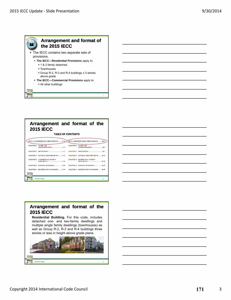
2015 IECC Update ‐ Slide Presentation 9/30/2014
Copyright 2014 International Code Council 3
Arrangement and format of the 2015 IECCArrangement and format of the 2015 IECC
The IECC contains two separate sets of provisions. The IECC—Residential Provisions apply to:
1 & 2 family detached
Townhouses
Group R-2, R-3 and R-4 buildings ≤ 3 stories above grade
The IECC—Commercial Provisions apply to:
All other buildings
7
2015 IECC Update 8
Arrangement and format of the2015 IECCArrangement and format of the2015 IECC
Arrangement and format of the2015 IECCArrangement and format of the2015 IECC
Residential Building. For this code, includesdetached one- and two-family dwellings andmultiple single family dwellings (townhouses) aswell as Group R-2, R-3 and R-4 buildings threestories or less in height above grade plane.
92015 IECC Update
171
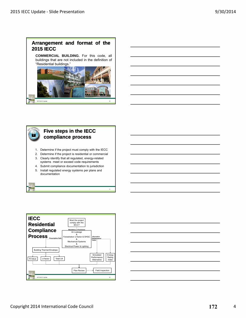
2015 IECC Update ‐ Slide Presentation 9/30/2014
Copyright 2014 International Code Council 4
Arrangement and format of the2015 IECCArrangement and format of the2015 IECC
COMMERCIAL BUILDING. For this code, allbuildings that are not included in the definition of“Residential buildings.”
102015 IECC Update
Five steps in the IECC compliance processFive steps in the IECC compliance process
1. Determine if the project must comply with the IECC
2. Determine if the project is residential or commercial
3. Clearly identify that all regulated, energy-related systems meet or exceed code requirements
4. Submit compliance documentation to jurisdiction
5. Install regulated energy systems per plans and documentation
11
IECCResidential Compliance Process
IECCResidential Compliance Process
122015 IECC Update
Must the project comply with the
IECC?
Air Leakage&
Fenestration U-factor & SHGC&
Mechanical Systems&
Electrical Power & Lighting
Building Thermal Envelope
Simulated Performance AlternativeR-Value U-factor Total UA
Plan Review Field Inspection
Mandatory Provisions
Prescriptive PathAlternativePerformancePaths
Energy Rating Index
172
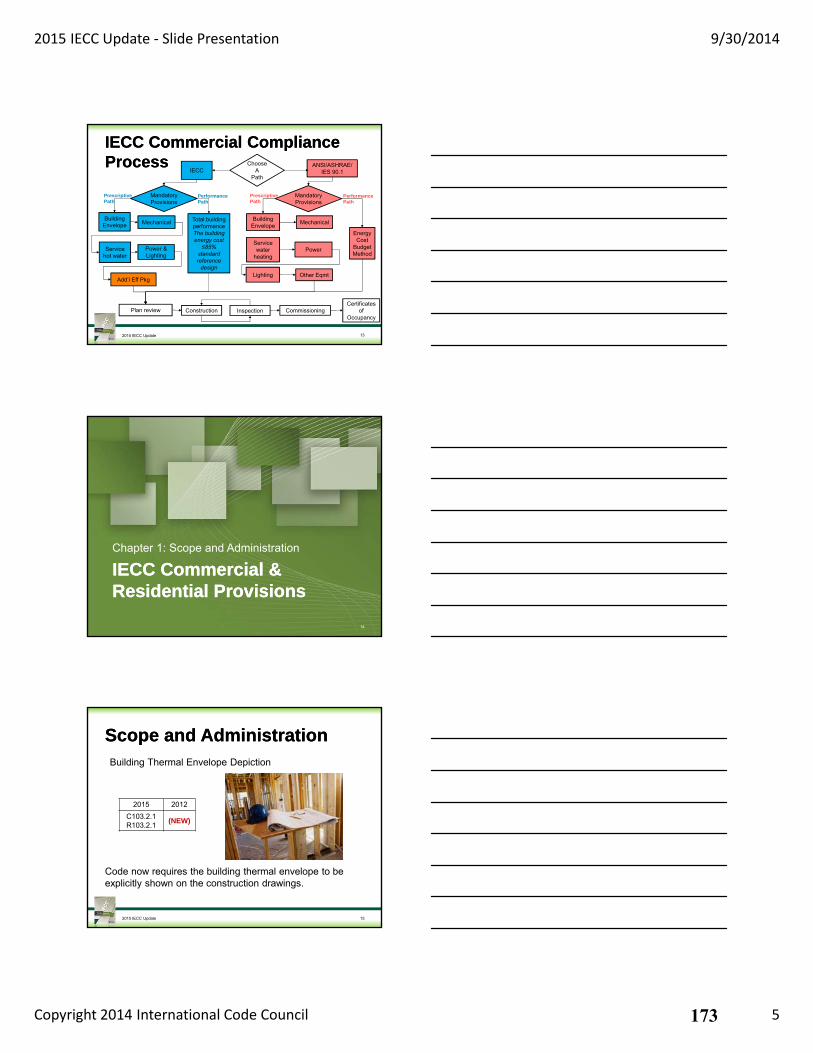
2015 IECC Update ‐ Slide Presentation 9/30/2014
Copyright 2014 International Code Council 5
IECC Commercial Compliance ProcessIECC Commercial Compliance Process
132015 IECC Update
ChooseA
PathIECC
Mandatory Provisions
Mandatory Provisions
ANSI/ASHRAE/IES 90.1
Building Envelope Mechanical
Power & Lighting
Add’l Eff Pkg
Total building performanceThe building energy cost
≤85% standard reference
design
Service hot water
Building Envelope
Mechanical
Lighting Other Eqmt
Service water
heatingPower
Energy Cost
Budget Method
Plan review InspectionCertificates
of Occupancy
CommissioningConstruction
PrescriptivePath
PerformancePath
PrescriptivePath
PerformancePath
IECC Commercial & Residential ProvisionsIECC Commercial & Residential Provisions
Chapter 1: Scope and Administration
14
Scope and AdministrationScope and Administration
2015 2012
C103.2.1 R103.2.1
(NEW)
2015 IECC Update 15
Code now requires the building thermal envelope to be explicitly shown on the construction drawings.
Building Thermal Envelope Depiction
173
2015 IECC Update ‐ Slide Presentation 9/30/2014
Copyright 2014 International Code Council 6
Scope and AdministrationScope and Administration
2015 2012
C104.1 - C104.4R104.1 - R104.4
(NEW)
2015 IECC Update 16
Improved and enhanced details governing inspection of construction. The provisions are more specific and written to relate to the Energy Code.
C/R104.1 Inspections - General C/R104.2 Required inspections C/R104.3 Reinspection C/R104.4 Approved inspection agencies
IECC Commercial & Residential ProvisionsIECC Commercial & Residential Provisions
Chapter 5: Existing Buildings
17
Existing BuildingsExisting Buildings
2015 2012
Chapter 5 (CE)Chapter 5 (RE)
(NEW)
2015 IECC Update 18
Requirements pertaining to existing buildings are consolidated into one chapter.
Additions, alterations, repairs, and changes in occupancy or use
174
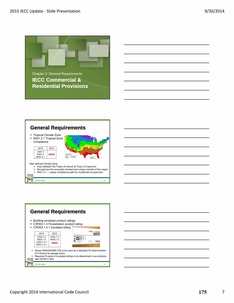
2015 IECC Update ‐ Slide Presentation 9/30/2014
Copyright 2014 International Code Council 7
IECC Commercial & Residential ProvisionsIECC Commercial & Residential Provisions
Chapter 3: General Requirements
19
General RequirementsGeneral Requirements
2015 2012
C301.4R301.4
R401.2.1(NEW)
2015 IECC Update 20
New defined Climate Zone Area between the Tropic of Cancer & Tropic of Capricorn Recognizes the unusually constant and unique climate of this region R401.2.1 – unique compliance path for residential occupancies
Tropical Climate Zone R401.2.1 Tropical Zone
Compliance
General RequirementsGeneral Requirements
2015 2012
C303.1.3R303.1.3
C303.1.4.1R303.1.4.1
C303.1.3R303.1.3
(NEW)
2015 IECC Update 21
Allows ANSI/DASMA 105 to be used as a standard for determination of U-factors for garage doors
Requires R-value of insulated siding to be determined in accordance with ASTM C1363
Building envelope product ratings C/R303.1.3 Fenestration product rating C/R303.1.4.1 Insulated siding
175
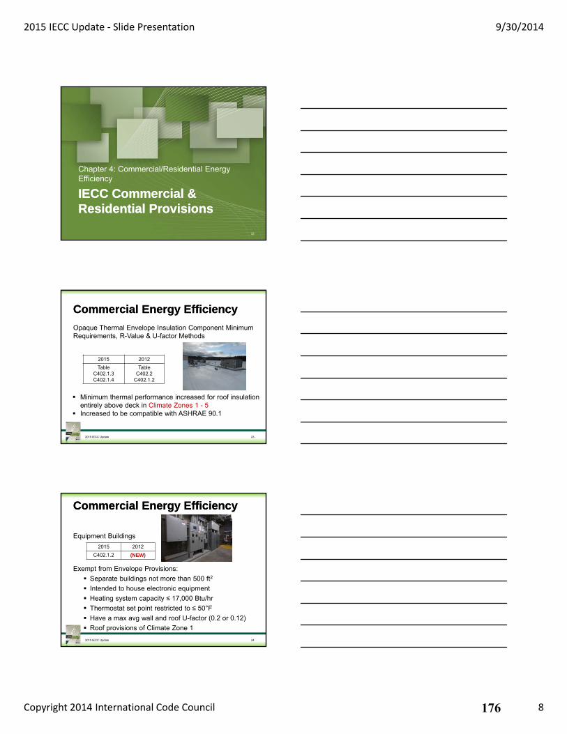
2015 IECC Update ‐ Slide Presentation 9/30/2014
Copyright 2014 International Code Council 8
IECC Commercial & Residential ProvisionsIECC Commercial & Residential Provisions
Chapter 4: Commercial/Residential Energy Efficiency
22
Commercial Energy EfficiencyCommercial Energy Efficiency
2015 2012
TableC402.1.3C402.1.4
Table C402.2
C402.1.2
2015 IECC Update 23
Minimum thermal performance increased for roof insulation entirely above deck in Climate Zones 1 - 5
Increased to be compatible with ASHRAE 90.1
Opaque Thermal Envelope Insulation Component Minimum Requirements, R-Value & U-factor Methods
Commercial Energy EfficiencyCommercial Energy Efficiency
2015 2012
C402.1.2 (NEW)
2015 IECC Update 24
Equipment Buildings
Exempt from Envelope Provisions:
Separate buildings not more than 500 ft2
Intended to house electronic equipment
Heating system capacity ≤ 17,000 Btu/hr
Thermostat set point restricted to ≤ 50°F
Have a max avg wall and roof U-factor (0.2 or 0.12)
Roof provisions of Climate Zone 1
176
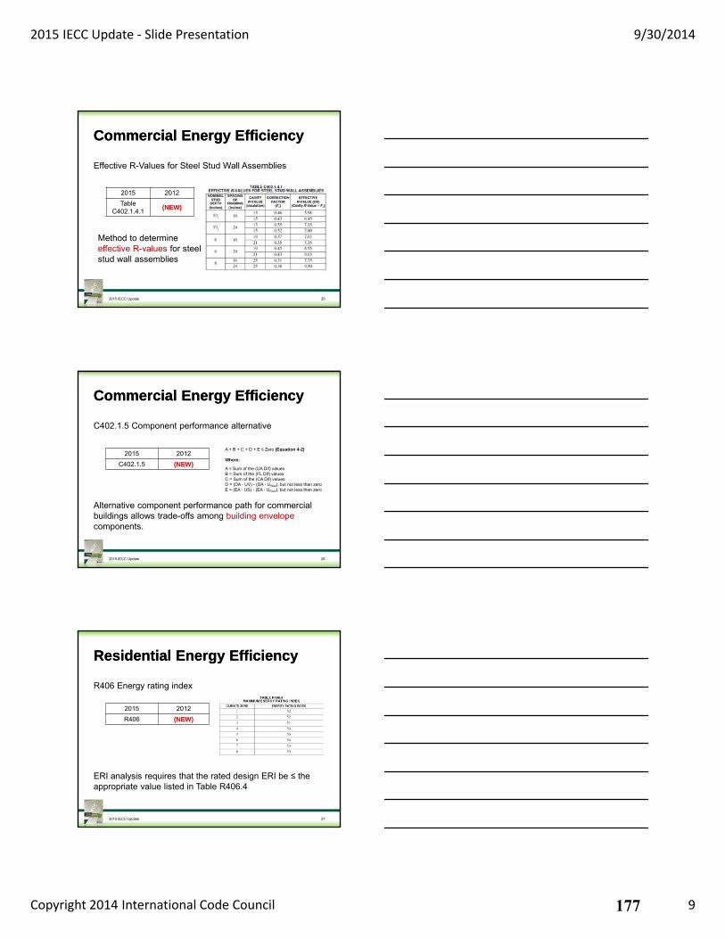
2015 IECC Update ‐ Slide Presentation 9/30/2014
Copyright 2014 International Code Council 9
Commercial Energy EfficiencyCommercial Energy Efficiency
2015 2012
TableC402.1.4.1
(NEW)
2015 IECC Update 25
Method to determine effective R-values for steel stud wall assemblies
Effective R-Values for Steel Stud Wall Assemblies
Commercial Energy EfficiencyCommercial Energy Efficiency
2015 2012
C402.1.5 (NEW)
2015 IECC Update 26
Alternative component performance path for commercial buildings allows trade-offs among building envelope components.
C402.1.5 Component performance alternative
A + B + C + D + E ≤ Zero (Equation 4-2)
Where:
A = Sum of the (UA Dif) valuesB = Sum of the (FL Dif) valuesC = Sum of the (CA Dif) valuesD = (DA · UV) - (DA · UWall), but not less than zeroE = (EA · US) - (EA · URoof), but not less than zero
Residential Energy EfficiencyResidential Energy Efficiency
2015 2012
R406 (NEW)
2015 IECC Update 27
ERI analysis requires that the rated design ERI be ≤ the appropriate value listed in Table R406.4
R406 Energy rating index
177
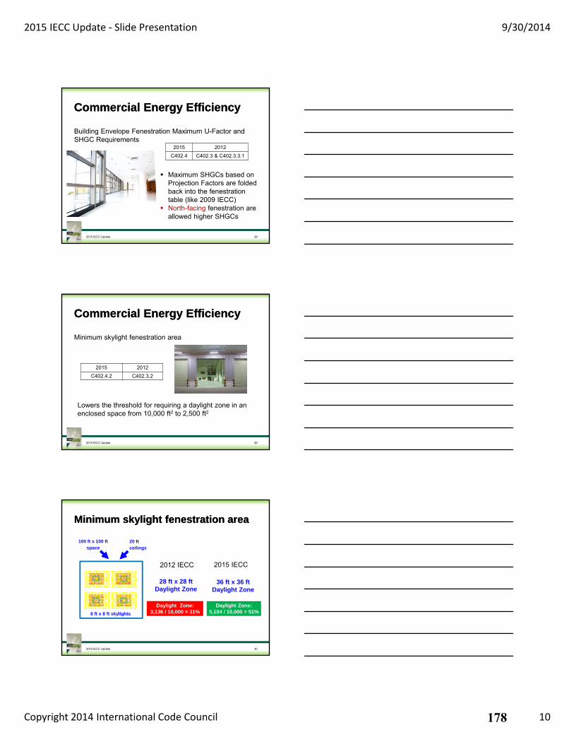
2015 IECC Update ‐ Slide Presentation 9/30/2014
Copyright 2014 International Code Council 10
Commercial Energy EfficiencyCommercial Energy Efficiency
2015 2012
C402.4 C402.3 & C402.3.3.1
2015 IECC Update 28
Maximum SHGCs based on Projection Factors are folded back into the fenestration table (like 2009 IECC)
North-facing fenestration are allowed higher SHGCs
Building Envelope Fenestration Maximum U-Factor and SHGC Requirements
Commercial Energy EfficiencyCommercial Energy Efficiency
2015 2012
C402.4.2 C402.3.2
2015 IECC Update 29
Lowers the threshold for requiring a daylight zone in an enclosed space from 10,000 ft2 to 2,500 ft2
Minimum skylight fenestration area
100 ft x 100 ft
space
2015 IECC Update 30
Daylight Zone:3,136 / 10,000 = 31%
20 ft
ceilings
8 ft x 8 ft skylights
28 ft x 28 ftDaylight Zone
36 ft x 36 ftDaylight Zone
Daylight Zone:5,184 / 10,000 = 51%
Minimum skylight fenestration areaMinimum skylight fenestration area
2012 IECC 2015 IECC
178
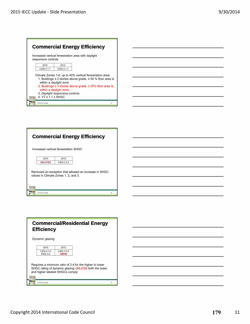
2015 IECC Update ‐ Slide Presentation 9/30/2014
Copyright 2014 International Code Council 11
Commercial Energy EfficiencyCommercial Energy Efficiency
2015 2012
C402.4.1.1 C402.3.1.1
2015 IECC Update 31
Climate Zones 1-6, up to 40% vertical fenestration area:1. Buildings ≤ 2 stories above grade, ≥ 50 % floor area is within a daylight zone.
2. Buildings ≥ 3 stories above grade, ≥ 25% floor area is within a daylight zone.
3. Daylight responsive controls4. VT ≥ 1.1 x SHGC
Increased vertical fenestration area with daylight responsive controls
Commercial Energy EfficiencyCommercial Energy Efficiency
2015 2012
DELETED C402.3.3.2
2015 IECC Update 32
Removed an exception that allowed an increase in SHGC values in Climate Zones 1, 2, and 3.
Increased vertical fenestration SHGC
Commercial/Residential Energy EfficiencyCommercial/Residential Energy Efficiency
2015 2012
C402.4.3.3R402.3.2
C402.3.3.5(NEW)
2015 IECC Update 33
Requires a minimum ratio of 2.4 for the higher to lower SHGC rating of dynamic glazing UNLESS both the lower and higher labeled SHGCs comply
Dynamic glazing
179
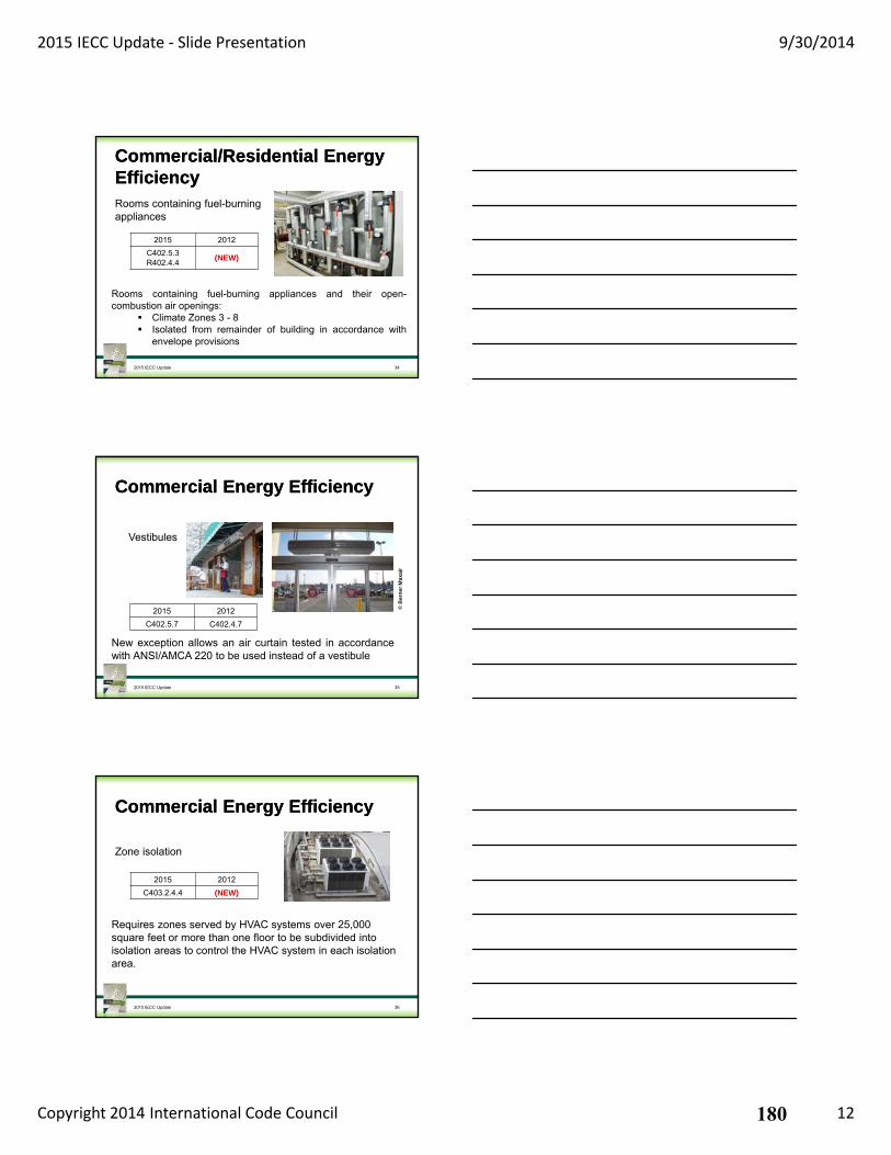
2015 IECC Update ‐ Slide Presentation 9/30/2014
Copyright 2014 International Code Council 12
Commercial/Residential Energy EfficiencyCommercial/Residential Energy Efficiency
2015 2012
C402.5.3R402.4.4
(NEW)
2015 IECC Update 34
Rooms containing fuel-burning appliances and their open-combustion air openings:
Climate Zones 3 - 8 Isolated from remainder of building in accordance with
envelope provisions
Rooms containing fuel-burningappliances
Commercial Energy EfficiencyCommercial Energy Efficiency
2015 2012
C402.5.7 C402.4.7
2015 IECC Update 35
New exception allows an air curtain tested in accordancewith ANSI/AMCA 220 to be used instead of a vestibule
© B
ern
erM
axai
r
Vestibules
Commercial Energy EfficiencyCommercial Energy Efficiency
2015 2012
C403.2.4.4 (NEW)
2015 IECC Update 36
Requires zones served by HVAC systems over 25,000 square feet or more than one floor to be subdivided into isolation areas to control the HVAC system in each isolation area.
Zone isolation
180
2015 IECC Update ‐ Slide Presentation 9/30/2014
Copyright 2014 International Code Council 13
Commercial Energy EfficiencyCommercial Energy Efficiency
2015 2012
C403.2.6.2 (NEW)
2015 IECC Update 37
Ventilation optimization controls to modulate airflow
Enclosed parking garage ventilation controls
Commercial Energy EfficiencyCommercial Energy Efficiency
2015 2012
C403.2.8 (NEW)
2015 IECC Update 38
Regulates efficiency of kitchen exhaust systems Replacement air Maximum exhaust rates
Kitchen exhaust systems
Commercial Energy EfficiencyCommercial Energy Efficiency
2015 2012
C403.2.14 (NEW)
2015 IECC Update 39
Tables C403.2.14 (1) & (2): List the maximum energy use in kWh/day Organized by equipment type, operating mode &
rating temperature
Refrigeration equipmentperformance
181
2015 IECC Update ‐ Slide Presentation 9/30/2014
Copyright 2014 International Code Council 14
Commercial Energy EfficiencyCommercial Energy Efficiency
2015 2012
C403.2.15C403.2.16 (NEW)
2015 IECC Update 40
Requirements include: Door self-closures Min. floor, wall & ceiling insulation Anti-sweat heaters and controls Lighting efficiency
Walk-in coolers, walk-in freezers, refrigerated warehouse coolers and refrigerated warehouse freezers
Commercial Energy EfficiencyCommercial Energy Efficiency
2015 2012
C403.4.2.5 (NEW)
2015 IECC Update 41
Turndown ratio for boilers with design input over 1,000,000 Btu/h.
Boiler turndown
Commercial Energy EfficiencyCommercial Energy Efficiency
2015 2012
C404.5 (NEW)
2015 IECC Update 42
Maximum allowable pipe length method (Table C404.5.1) From the nearest source of heated water to termination of
the fixture supply pipe 2 columns: public lavatory faucets and all other fixturesMaximum allowable pipe volume method Volume from the nearest source of heated water to the
termination of the fixture supply pipe 2 oz. public lavatory faucet, ½ gallon for other fixtures
Efficient heated water supply piping
182
2015 IECC Update ‐ Slide Presentation 9/30/2014
Copyright 2014 International Code Council 15
Commercial/Residential Energy EfficiencyCommercial/Residential Energy Efficiency
2015 2012
C404.8R403.5.4
(NEW)
2015 IECC Update 43
CSA B55.2 (commercial) CSA B55.1 (residential) Max 10 psi pressure loss (C404.8) Max 3 psi pressure loss (R403.5.4)
Drain water heat recovery units
Cold Water from Main
Warmed Water to Cold Side of Faucet
Commercial Energy EfficiencyCommercial Energy Efficiency
2015 2012
C405.9 (NEW)
2015 IECC Update 44
Luminaires Ventilation fans Speed reduction Variable frequency regenerative drive
Vertical and horizontal transportation systems and equipment
Commercial Energy EfficiencyCommercial Energy Efficiency
2015 2012
C406 C406
2015 IECC Update 45
More efficient HVAC performance Reduced lighting power density system Enhanced lighting controls On-site supply of renewable energy Provision of a dedicated outdoor air system for
certain HVAC equipment High-efficiency service water heating
Additional Efficiency Package Option
183
2015 IECC Update ‐ Slide Presentation 9/30/2014
Copyright 2014 International Code Council 16
Commercial Energy EfficiencyCommercial Energy Efficiency
2015 2012
C408 C408
2015 IECC Update 46
Mechanical and service water report in separate sections to allow for independent review
Functional testing of lighting – requirements were broken up and expanded Construction documents specify performance criteria O&M manuals Schedule for inspection & recalibrating
System Commissioning
SummarySummary The format of the IECC slightly changed
New regulated systems and components were added
Additional compliance paths are allowed
Requirements for some systems have been tightened
Daylight zone dimensions have changed
Thermal envelope provisions remain mostly unchanged
2015 IECC Update 47
Questions and AnswersQuestions and Answers
At the end of the presentation, please type your questions into the Q & A portion of Adobe Connect Box.
The facilitator\speaker will respond to your questions at the end of the webinar.
Type your questions into here.
Then hit enter or the send button.
2015 IECC Update 48
184
2015 IECC Update ‐ Slide Presentation 9/30/2014
Copyright 2014 International Code Council 17
CertificatesCertificates
To request a certificate please E-mail:
2015 IECC Update 49
50
Have a code question?Have a code question?
ICC Code OpinionsExt: 338077
Code AlertCode Alert
2015 IECC Update 51
185
2015 IECC Update ‐ Slide Presentation 9/30/2014
Copyright 2014 International Code Council 18
ICC StoreICC Store
2015 IECC Update 52
To Purchase:Visit the ICC Store athttp://shop.iccsafe.org/
Next Feature Topic WebinarsNext Feature Topic Webinars
2015 Update Webinars based on the 2015 I-Codes
Check our LIVE SCHEDULE for more information
www.iccsafe.org/education
2015 IPMCNovember 3, 20141PM CDT
2015 IEBCOctober 8, 20141PM CDT
54
International Code Council is a Registered Provider with The American Institute of Architects Continuing Education Systems. Credit earned on completion of this program will be reported to CES Records for AIA members. Certificates of Completion for non-AIA members are available on request.
This program is registered with the AIA/CES for continuing professional education. As such, it does not include content that may be deemed or construed to be an approval or endorsement by the AIA of any material of construction or any method or manner of handling, using, distributing, or dealing in any material or product. Questions related to specific materials, methods, and services will be addressed at the conclusion of this presentation.
2015 IECC Update
186
2015 IECC Update ‐ Slide Presentation 9/30/2014
Copyright 2014 International Code Council 19
55
Copyright Materials
This presentation is protected by US and International Copyright laws. Reproduction, distribution, display and use of the presentation without written permission of the speaker is
prohibited.
© International Code Council 2014
2015 IECC Update
Thank you for participatingThank you for participating
To schedule a seminar, contact:
The ICC Training & Education Department
1-888-ICC-SAFE (422-7233) Ext. 33818
or
E-mail: [email protected]
2015 IECC Update 56
187

PNNL-24269
Energy and Energy Cost Savings Analysis of the 2015 IECC for Commercial Buildings
June 2015
J Zhang M Rosenberg Y Xie R Hart R Athalye B Liu J Zhuge
188
189
PNNL-24269
Energy and Energy Cost Savings Analysis of the 2015 IECC for Commercial Buildings
J Zhang M Rosenberg Y Xie R Hart R Athalye B Liu J Zhuge June 2015 Prepared for the U.S. Department of Energy under Contract DE-AC05-76RL01830 Pacific Northwest National Laboratory Richland, Washington 99352
190

191
v
Executive Summary
The U.S. Department of Energy (DOE) Building Energy Codes Program supports the development and implementation of building energy codes and standards, which set minimum requirements for energy-efficient design and construction for new and renovated buildings, and impact energy use and greenhouse gas emissions for the life of buildings. As required by federal statute (42 USC 6833), DOE recently issued a determination that ANSI/ASHRAE/IES1 Standard 90.1-2013 would achieve greater energy efficiency in buildings compared to the 2010 edition of the standard. In support of DOE’s determination, Pacific Northwest National Laboratory (PNNL) conducted an energy savings analysis for Standard 90.1-2013 (Halverson et al. 2014). While Standard 90.1 is the national model energy standard for commercial buildings (42 USC 6833), many states have historically adopted the International Energy Conservation Code (IECC) for both residential and commercial buildings.
This report provides an assessment as to whether new buildings constructed to the commercial energy efficiency provisions of the 2015 IECC would save energy and energy costs as compared to the 2012 IECC. PNNL also compared the energy performance of the 2015 IECC with the corresponding Standard 90.1-2013. The purpose of this analysis is to help states and local jurisdictions make informed decisions regarding model code adoption.
The analysis builds on previous work done by PNNL that assessed the energy performance of the 2012 IECC compared to the 2006 and 2009 editions of the IECC (Zhang et al. 2013). For this analysis, PNNL first reviewed all code changes from the 2012 to 2015 IECC and identified those having a quantifiable impact on energy. These changes were then implemented in a suite of 16 prototype building models covering all 15 climate zones in the United States. This results in a total of 480 building models, 240 models each for the 2012 and 2015 editions of the IECC. Prototype models for the 2015 IECC were developed by implementing code changes to the 2012 IECC models. The 16 prototype building models represent more than 80% of the national stock of commercial buildings in the United States.
Whole-building energy simulations were conducted using DOE’s EnergyPlus Version 8.0 (DOE 2013) building simulation software. The resulting energy use from the complete suite of 480 simulation runs was converted to site energy use intensity (EUI, or energy use per unit floor area), and energy cost index (ECI) for each simulation. For each prototype, the resulting EUIs and ECIs in each climate zone were weighted to calculate the aggregate national level EUI and ECI. Weighting factors were developed using commercial construction data and are based on construction floor area of the different building types in each climate zone (Jarnagin and Bandyopadhyay 2010). Finally, the EUIs were aggregated across building types to the national level using the same weighting data.
Overall, the 2015 edition of the IECC results in site energy savings of 11.5% at the aggregate national level compared to the 2012 IECC edition; on a national average basis for all prototypes combined, the 2015 IECC and Standard 90.1-2013 are within 1% for both energy use and energy costs (see Appendix B in this report). Savings from the 2012 to 2015 IECC vary significantly by prototype. This is expected
1 ANSI – American National Standards Institute; ASHRAE – American Society of Heating, Refrigerating, and Air- Conditioning Engineers; IES – Illuminating Engineering Society; IESNA – Illuminating Engineering Society of North America (IESNA rather than IES was identified with Standard 90.1 prior to 90.1-2010)
192
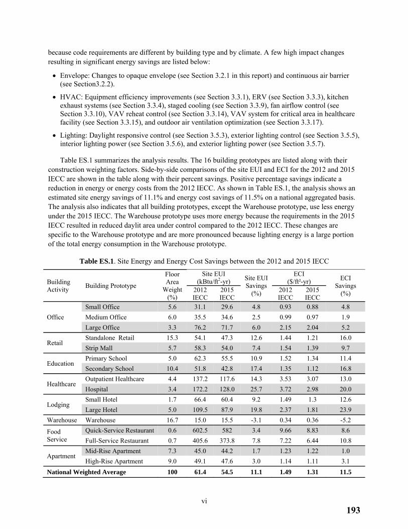
vi
because code requirements are different by building type and by climate. A few high impact changes resulting in significant energy savings are listed below:
Envelope: Changes to opaque envelope (see Section 3.2.1 in this report) and continuous air barrier (see Section3.2.2).
HVAC: Equipment efficiency improvements (see Section 3.3.1), ERV (see Section 3.3.3), kitchen exhaust systems (see Section 3.3.4), staged cooling (see Section 3.3.9), fan airflow control (see Section 3.3.10), VAV reheat control (see Section 3.3.14), VAV system for critical area in healthcare facility (see Section 3.3.15), and outdoor air ventilation optimization (see Section 3.3.17).
Lighting: Daylight responsive control (see Section 3.5.3), exterior lighting control (see Section 3.5.5), interior lighting power (see Section 3.5.6), and exterior lighting power (see Section 3.5.7).
Table ES.1 summarizes the analysis results. The 16 building prototypes are listed along with their construction weighting factors. Side-by-side comparisons of the site EUI and ECI for the 2012 and 2015 IECC are shown in the table along with their percent savings. Positive percentage savings indicate a reduction in energy or energy costs from the 2012 IECC. As shown in Table ES.1, the analysis shows an estimated site energy savings of 11.1% and energy cost savings of 11.5% on a national aggregated basis. The analysis also indicates that all building prototypes, except the Warehouse prototype, use less energy under the 2015 IECC. The Warehouse prototype uses more energy because the requirements in the 2015 IECC resulted in reduced daylit area under control compared to the 2012 IECC. These changes are specific to the Warehouse prototype and are more pronounced because lighting energy is a large portion of the total energy consumption in the Warehouse prototype.
Table ES.1. Site Energy and Energy Cost Savings between the 2012 and 2015 IECC
Building Activity
Building Prototype
Floor Area
Weight (%)
Site EUI (kBtu/ft2-yr) Site EUI
Savings (%)
ECI ($/ft²-yr) ECI
Savings (%) 2012
IECC 2015 IECC
2012 IECC
2015 IECC
Office
Small Office 5.6 31.1 29.6 4.8 0.93 0.88 4.8
Medium Office 6.0 35.5 34.6 2.5 0.99 0.97 1.9
Large Office 3.3 76.2 71.7 6.0 2.15 2.04 5.2
Retail Standalone Retail 15.3 54.1 47.3 12.6 1.44 1.21 16.0
Strip Mall 5.7 58.3 54.0 7.4 1.54 1.39 9.7
Education Primary School 5.0 62.3 55.5 10.9 1.52 1.34 11.4
Secondary School 10.4 51.8 42.8 17.4 1.35 1.12 16.8
Healthcare Outpatient Healthcare 4.4 137.2 117.6 14.3 3.53 3.07 13.0
Hospital 3.4 172.2 128.0 25.7 3.72 2.98 20.0
Lodging Small Hotel 1.7 66.4 60.4 9.2 1.49 1.3 12.6
Large Hotel 5.0 109.5 87.9 19.8 2.37 1.81 23.9
Warehouse Warehouse 16.7 15.0 15.5 -3.1 0.34 0.36 -5.2
Food Service
Quick-Service Restaurant 0.6 602.5 582 3.4 9.66 8.83 8.6
Full-Service Restaurant 0.7 405.6 373.8 7.8 7.22 6.44 10.8
Apartment Mid-Rise Apartment 7.3 45.0 44.2 1.7 1.23 1.22 1.0
High-Rise Apartment 9.0 49.1 47.6 3.0 1.14 1.11 3.1
National Weighted Average 100 61.4 54.5 11.1 1.49 1.31 11.5
193
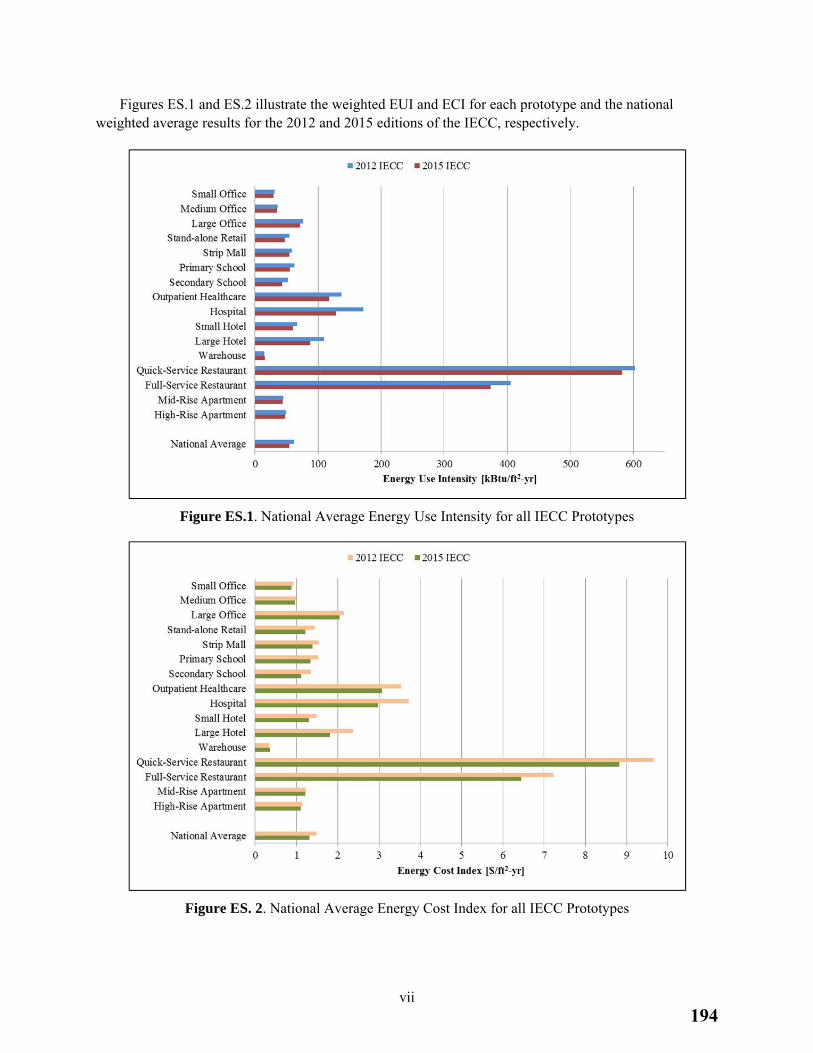
vii
Figures ES.1 and ES.2 illustrate the weighted EUI and ECI for each prototype and the national weighted average results for the 2012 and 2015 editions of the IECC, respectively.
Figure ES.1. National Average Energy Use Intensity for all IECC Prototypes
Figure ES. 2. National Average Energy Cost Index for all IECC Prototypes
194
viii
Acknowledgments
This report was prepared by Pacific Northwest National Laboratory (PNNL) for the U.S. Department of Energy (DOE) Building Energy Codes Program. The authors would like to thank David Cohan and Jeremiah Williams at DOE for providing oversight. The authors also recognize Bing Liu, Manager of the Building Energy Codes Program at PNNL for her thoughtful guidance during the project.
The authors would also like to thank contributors to the Commercial Prototype Building Models, who built a technical foundation for this analysis project. This work was truly a team effort, and the authors would like to express their deep appreciation to everyone from the PNNL codes team who contributed to its completion, including Rosemarie Bartlett, Weimin Wang, Eric Richman, and David Winiarski. Insightful review comments provided by Mark Halverson and Sean McDonald are greatly appreciated.
The authors sincerely thank the external peer reviewers, David Karmol from International Code Council and Eric Lacey from Responsible Energy Codes Alliance, who provided insightful review comments on an earlier draft of this report.
Jian Zhang, Ph.D. Pacific Northwest National Laboratory
195
ix
Acronyms and Abbreviations
AEDG Advanced Energy Design Guide
AIA American Institute of Architects
ANSI American National Standards Institute
AHU air handling unit
ASHRAE American Society of Heating, Refrigerating, and Air-Conditioning Engineers
BECP Building Energy Codes Program
bhp brake horsepower
Btu/h British thermal unit(s) per hour
CBECS Commercial Building Energy Consumption Survey
CFR Code of Federal Regulations
DOE U.S. Department of Energy
DX direct expansion
EC electronically commutated
ECI energy cost index
ECPA Energy Conservation and Production Act
EIA Energy Information Administration
EISA Energy Independence and Security Act
EMS energy management system
EPAct Energy Policy Act
ERV energy recovery ventilator
EUI energy use intensity
ft2 square feet
hp horsepower
HVAC heating, ventilation, and air-conditioning
ICC International Code Council
IECC International Energy Conservation Code
IES Illuminating Engineering Society
IESNA Illuminating Engineering Society of North America
IMC International Mechanical Code
kBtu/ft2-yr thousand British thermal unit(s) per square foot per year
kBtu/h thousand British thermal unit(s) per hour
kWh kilowatt hour(s)
LPD lighting power density
MAT mixed air temperature
NAECA National Appliance Energy Conservation Act
PLR part load ratio
196
x
PNNL Pacific Northwest National Laboratory
SAT supply air temperature
SEER seasonal energy efficiency ratio
SHGC solar heat gain coefficient
SWH service water heating
TMY typical meteorological year
VAV variable air volume
VT visible transmittance
WSHP water source heat pump
WWR window-to-wall ratio
w.c. water column
197
xi
Contents
Executive Summary .............................................................................................................................. v
Acknowledgments ................................................................................................................................. viii
Acronyms and Abbreviations ............................................................................................................... ix
1.0 Introduction .................................................................................................................................. 1.1
2.0 Methodology ................................................................................................................................. 2.1
2.1 Building Prototypes .............................................................................................................. 2.1
2.2 Climate Zones ...................................................................................................................... 2.1
2.3 Comparison Metrics and Construction Weights .................................................................. 2.3
2.4 Enhancements to the 2012 IECC Building Prototypes ........................................................ 2.5
3.0 2015 IECC Building Prototype Development .............................................................................. 3.7
3.1 Review of Code Changes ..................................................................................................... 3.7
3.2 Building Envelope ................................................................................................................ 3.7
3.2.1 Opaque Envelope Performance ................................................................................. 3.7
3.2.2 Continuous Air Barrier .............................................................................................. 3.8
3.3 Building Mechanical Systems .............................................................................................. 3.8
3.3.1 Heating, Ventilating, and Air-Conditioning Equipment Performance Requirements ............................................................................................................. 3.8
3.3.2 Hot Water Boiler Outdoor Temperature Setback Control ......................................... 3.9
3.3.3 Energy Recovery Ventilator ...................................................................................... 3.10
3.3.4 Kitchen Exhaust Systems .......................................................................................... 3.10
3.3.5 Fan Power Limitation Adjustment Credits ................................................................ 3.11
3.3.6 Reach-in Refrigerator and Freezer ............................................................................ 3.11
3.3.7 Manufactured Walk-in Cooler and Freezer ............................................................... 3.12
3.3.8 Economizer................................................................................................................ 3.13
3.3.9 Staged Cooling .......................................................................................................... 3.13
3.3.10 Fan Airflow Control .................................................................................................. 3.14
3.3.11 Part-load Controls for Hydronic Systems ................................................................. 3.14
3.3.12 Boiler Turndown ....................................................................................................... 3.15
3.3.13 Heat Rejection Equipment ........................................................................................ 3.16
3.3.14 VAV Reheat Control ................................................................................................. 3.17
3.3.15 VAV System for Critical Area in Healthcare Facility ............................................... 3.17
3.3.16 Fractional HP Fan Motors ......................................................................................... 3.18
3.3.17 Outdoor Air Ventilation Optimization Control ......................................................... 3.19
3.4 Service Water Heating ......................................................................................................... 3.19
3.4.1 Demand-based Controls for Recirculated Service Water Heating Systems .............. 3.19
3.5 Electrical Power and Lighting Systems ................................................................................ 3.20
3.5.1 Additional Efficiency Package Options .................................................................... 3.20
198
xii
3.5.2 Occupant Sensor Controls ......................................................................................... 3.21
3.5.3 Daylight Responsive Controls and Fenestration Area ............................................... 3.22
3.5.4 Guestroom Lighting Controls .................................................................................... 3.26
3.5.5 Exterior Lighting Automatic Controls ...................................................................... 3.26
3.5.6 Interior Lighting Power ............................................................................................. 3.27
3.5.7 Exterior Lighting Power ............................................................................................ 3.29
3.5.8 Elevator Lighting and Ventilation ............................................................................. 3.29
4.0 Site Energy and Energy Cost Savings Results ............................................................................. 4.1
5.0 References .................................................................................................................................... 5.1
Appendix A Code Changes from the 2012 to 2015 IECC Included in Analysis and their Impact on Building Prototypes ................................................................................................................. A.1
Appendix B Energy and Energy Cost Savings for the 2015 IECC and Corresponding Standard 90.1-2013 ...................................................................................................................................... B.1
199
xiii
List of Figures
ES.1 National Average Energy Use Intensity for all IECC Prototypes ............................................. vii
ES.2 National Average Energy Cost Index for all IECC Prototypes ................................................. vii
2.1 Climate Zone Map .................................................................................................................... 2.2
3.1 Schematic of Skylights in the Warehouse Prototype ................................................................. 3.25
4.1 National Average Energy Use Intensity for all IECC Prototypes ............................................. 4.2
4.2 National Average Energy Cost Index for all IECC Prototypes ................................................. 4.3
B.1 National Average Energy Use Intensity for Standard 90.1 and IECC Prototypes..................... B.3
B.2 National Average Energy Cost Index for Standard 90.1 and IECC Prototypes ........................ B.4
List of Tables
ES.1 Site Energy and Energy Cost Savings between the 2012 and 2015 IECC ................................ vi
2.1 Building Prototypes ................................................................................................................... 2.2
2.2 Construction Area Weights by Building Prototype and Climate Zone ..................................... 2.4
2.3 Site EUI of the 2012 IECC Before and After Enhancements .................................................... 2.6
3.1 Commercial Solid-Door Refrigerators and Freezers in Prototypes ........................................... 3.12
3.2 The 2015 IECC Requirements for Commercial Refrigerators and Freezers in Prototypes ....... 3.12
3.3 Economizer Requirements by Cooling Capacity Thresholds and Climate Zones ..................... 3.13
3.4 Boiler Turndown in Table C403.4.2.5 of the 2015 IECC ......................................................... 3.15
3.5 Prototype Buildings Affected by Section C403.4.4.4 in the 2015 IECC ................................... 3.18
3.6 Percent Energy Savings of the 2015 IECC Controls Attributable to Reductions in Pipe Thermal Losses and Pump Energy Savings .............................................................................. 3.20
3.7 Typical Skylight and Toplight Area in the Building Prototypes ............................................... 3.24
3.8 Area-weighted LPD of General Lighting in the 2012 and 2015 IECC Prototypes ................... 3.28
3.9 Comparison of LPDs in Warehouse Prototype Built to the 2012 and 2015 IECC .................... 3.28
4.1 Site Energy and Energy Cost Savings between the 2012 and 2015 IECC ................................ 4.1
A.1 Changes between the 2012 and 2015 IECC with Quantified Energy Impacts .......................... A.1
B.1 Site Energy and Energy Cost Savings between Standard 90.1-2013 and the 2015 IECC ......... B.3
200
1.1
1.0 Introduction
The U.S. Department of Energy (DOE) Building Energy Codes Program supports the development and implementation of building energy codes and standards, which set minimum requirements for energy-efficient design and construction for new and renovated buildings, and impact energy use and greenhouse gas emissions for the life of buildings.
As required by federal statute (42 USC 6833), DOE recently issued a determination that ANSI/ASHRAE/IES1 Standard 90.1-2013 would achieve greater energy efficiency in buildings subject to the code compared to the 2010 edition of the standard.2 Pacific Northwest National Laboratory (PNNL) conducted an energy savings analysis for Standard 90.1-2013 in support of the determination (Halverson et al. 2014). While Standard 90.1 is the national model energy standard for commercial buildings (42 USC 6833), many states have historically adopted the International Energy Conservation Code (IECC) for both residential and commercial buildings. Of the 47 states with statewide commercial building energy codes currently, 37 use a version of the IECC (BECP 2015). The Commercial Energy Efficiency chapter in the 2015 IECC (International Code Council, ICC 2015a) allows users to either follow the provisions in the IECC or use Standard 90.1-2013 as an alternative compliance path. This report provides an assessment as to whether new buildings constructed to the commercial energy efficiency provisions of the 2015 IECC would save energy and energy costs compared to the 2012 IECC (ICC 2012). Because PNNL used the same methodology for both this 2015 IECC analysis and the previous Standard 90.1-2013 analysis, comparisons between the estimated energy performance of the 2015 IECC and that of its referenced Standard 90.1-2013 are presented in Appendix B of this report. The goal of this analysis is to help states and local jurisdictions make informed decisions regarding model code adoption.
This report documents the approach and results for PNNL’s analysis for energy and energy cost savings of the 2015 IECC for commercial buildings. PNNL first reviewed all code changes from the 2012 to 2015 IECC and identified those having a quantifiable impact. PNNL then used two suites of building prototypes, each suite complying with one edition of the IECC. Each suite consists of 240 building prototypes; a combination of 16 building prototypes in all 15 U.S. climate zones. The 2012 IECC prototypes were taken from PNNL’s previous analysis of the energy performance of the 2012 IECC compared to its previous editions which was documented in Energy and Energy Cost Savings Analysis of the IECC for Commercial Buildings (Zhang et al. 2013), referred to here as Analysis of the 2012 IECC.
The current report is organized as follows: Section 2.0 summarizes the general methodology about the building prototypes, their development, and simulation for their energy use and cost. The same methodology was applied in the previous Analysis of the 2012 IECC and the Standard 90.1-2013 determination (Halverson et al. 2014). Section 3.0 describes how PNNL developed the 2015 IECC prototypes using the 2012 IECC prototypes as a basis. Finally, Section 4.0 summarizes the results of the comparison of the two editions of the IECC. Appendix A summarizes the identified code changes between the 2012 and 2015 IECC (with quantified energy impacts) and identifies which building prototypes are impacted by each change. Appendix B provides energy and energy cost comparisons between Standard 90.1-2013 and the 2015 IECC.
1 ANSI – American National Standards Institute; ASHRAE – American Society of Heating, Refrigerating, and Air- Conditioning Engineers; IES – Illuminating Engineering Society; IESNA – Illuminating Engineering Society of North America (IESNA rather than IES was identified with Standard 90.1 prior to 90.1-2010) 2 For more information on the DOE Determination of energy savings, see http://www.energycodes.gov/regulations/determinations
201
2.1
2.0 Methodology
To support the development and implementation of building energy codes, PNNL researchers have developed building prototypes that comply with various editions of energy codes including both Standard 90.1 and IECC. These building prototypes represent the majority of new commercial building stock and were developed using DOE’s EnergyPlus Version 8.0 building energy simulation software (DOE 2013). The results allow comparison of the national weighted average savings of one code to its earlier edition and the relative performance differences between the codes. This section summarizes the general methodology used for this 2015 IECC analysis, which is consistent with that used for the Analysis of the 2012 IECC.
2.1 Building Prototypes
For this analysis, PNNL used a suite of building prototypes representing the first seven principal building activities in the Commercial Buildings Energy Consumption Survey (CBECS; EIA 2003). These seven principal building activities represent 76% of the building energy usage of commercial buildings. In addition, two multifamily prototypes (Mid-Rise and High-Rise Apartments) which are not included in CBECS were added into the suite of prototypes. These two prototypes were included in the analysis because they are regulated by the commercial provisions of the IECC. Table 2.1 shows the seven principal activities as defined in CBECS and the added apartment activity. These eight building activities were further divided into 16 building prototypes as listed in Table 2.1 along with their floor area, representing 80% of new construction floor area in the United States. Detailed descriptions of these prototypes and enhancements are documented in Thornton et al. (2011) and Goel et al. (2014).
2.2 Climate Zones
The climate zone and moisture regime definitions used by the IECC include eight zones (climate zones 1 through 8) and three moisture regimes (A – moist, B – dry, and C – marine). Each combination of climate zone and moisture regime defines a climate subzone. For this analysis, a specific climate (city) is selected (representing 15 climate subzones covering the entire United States) as shown in Figure 2.1 (Briggs et al. 2003). The term climate zone is used interchangeably with climate subzone in this report.
202
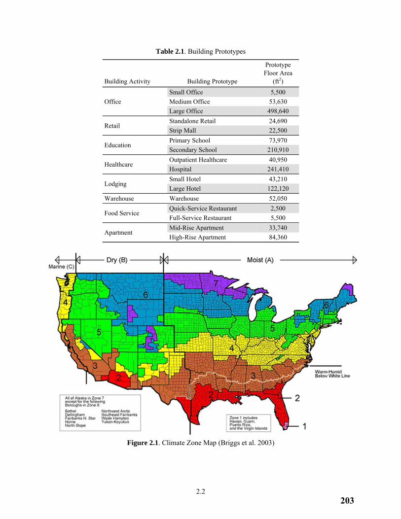
2.2
Table 2.1. Building Prototypes
Building Activity Building Prototype
Prototype Floor Area
(ft2)
Office
Small Office 5,500
Medium Office 53,630
Large Office 498,640
Retail Standalone Retail 24,690
Strip Mall 22,500
Education Primary School 73,970
Secondary School 210,910
Healthcare Outpatient Healthcare 40,950
Hospital 241,410
Lodging Small Hotel 43,210
Large Hotel 122,120
Warehouse Warehouse 52,050
Food Service Quick-Service Restaurant 2,500
Full-Service Restaurant 5,500
Apartment Mid-Rise Apartment 33,740
High-Rise Apartment 84,360
Figure 2.1. Climate Zone Map (Briggs et al. 2003)
203
2.3
The 15 climate locations representing the climate zones are:
1A: Miami, Florida (very hot, humid)
2A: Houston, Texas (hot, humid)
2B: Phoenix, Arizona (hot, dry)
3A: Memphis, Tennessee (warm, humid)
3B: El Paso, Texas (warm, dry)
3C: San Francisco, California (warm, marine)
4A: Baltimore, Maryland (mixed, humid)
4B: Albuquerque, New Mexico (mixed, dry)
4C: Salem, Oregon (mixed, marine)
5A: Chicago, Illinois (cool, humid)
5B: Boise, Idaho (cool, dry)
6A: Burlington, Vermont (cold, humid)
6B: Helena, Montana (cold, dry)
7: Duluth, Minnesota (very cold)
8: Fairbanks, Alaska (subarctic)
2.3 Comparison Metrics and Construction Weights
Annual electricity and natural gas energy use in each building prototype was simulated across 240 buildings, a combination of 16 prototypes in all 15 U.S. climate zones. This simulated energy use is utility electricity and natural gas delivered and used at the building site. The site energy use was converted to site energy use intensity (site EUI, or energy use per unit floor area).
To estimate the energy cost, PNNL used annual national average commercial building energy prices of $0.1029/kWh of electricity and $8.17 per 1000 cubic feet ($0.796/therm) of natural gas. These prices were available from the Energy Information Administration (EIA) and are listed in Table 2, “U.S. Energy Prices,” of the February 2014 Short Term Energy Outlook for commercial sector natural gas and electricity1. The same set of prices was used for all prototypes and in all climate zones. The annual energy costs for each building were calculated for each fuel type (electricity and natural gas) by using the energy prices for all buildings. These costs were converted to energy cost index (ECI, or energy cost per unit floor area) for each building.
The EUI and ECI results of each building are weighted by construction volume for each building prototype and climate zone to calculate the national weighted average EUI and ECI. Weighting factors developed by building type and climate-related geographic areas in the United States were derived from 5 years of recent construction data (Jarnagin and Bandyopadhyay 2010). Table 2.2 lists the weighting factors assigned to each prototype in all 15 U.S. climate zones.
1 EIA Short Term Energy Outlook available at http://www.eia.gov/forecasts/steo/report/.
204
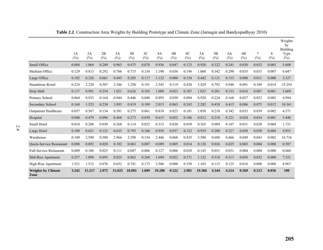
2.4
Table 2.2. Construction Area Weights by Building Prototype and Climate Zone (Jarnagin and Bandyopadhyay 2010)
1A (%)
2A (%)
2B (%)
3A (%)
3B (%)
3C (%)
4A (%)
4B (%)
4C (%)
5A (%)
5B (%)
6A (%)
6B (%)
7 (%)
8 (%)
Weights by
Building Type (%)
Small Office 0.084 1.064 0.289 0.963 0.475 0.078 0.936 0.047 0.123 0.920 0.322 0.241 0.030 0.032 0.005 5.608
Medium Office 0.129 0.813 0.292 0.766 0.715 0.136 1.190 0.036 0.196 1.060 0.342 0.298 0.035 0.033 0.007 6.047
Large Office 0.102 0.326 0.061 0.445 0.285 0.117 1.132 0.000 0.154 0.442 0.121 0.133 0.000 0.011 0.000 3.327
Standalone Retail 0.224 2.220 0.507 2.386 1.250 0.191 2.545 0.119 0.428 3.429 0.792 0.948 0.091 0.109 0.014 15.254
Strip Mall 0.137 0.991 0.254 1.021 0.626 0.103 1.008 0.023 0.107 1.023 0.201 0.153 0.016 0.007 0.001 5.669
Primary School 0.064 0.933 0.164 0.944 0.446 0.048 0.895 0.030 0.094 0.920 0.224 0.168 0.037 0.023 0.003 4.994
Secondary School 0.160 1.523 0.230 1.893 0.819 0.109 2.013 0.063 0.243 2.282 0.438 0.415 0.086 0.075 0.012 10.361
Outpatient Healthcare 0.037 0.567 0.134 0.581 0.275 0.061 0.818 0.023 0.181 1.058 0.218 0.342 0.033 0.039 0.002 4.371
Hospital 0.040 0.479 0.096 0.468 0.273 0.039 0.615 0.022 0.106 0.812 0.218 0.221 0.024 0.034 0.001 3.448
Small Hotel 0.010 0.288 0.030 0.268 0.114 0.022 0.315 0.020 0.039 0.365 0.089 0.107 0.031 0.020 0.004 1.721
Large Hotel 0.109 0.621 0.125 0.635 0.793 0.106 0.958 0.037 0.123 0.919 0.200 0.227 0.058 0.038 0.004 4.951
Warehouse 0.349 2.590 0.580 2.966 2.298 0.154 2.446 0.068 0.435 3.580 0.688 0.466 0.049 0.043 0.002 16.716
Quick-Service Restaurant 0.008 0.092 0.020 0.102 0.063 0.007 0.089 0.005 0.014 0.128 0.026 0.025 0.003 0.004 0.000 0.587
Full-Service Restaurant 0.009 0.106 0.025 0.111 0.047 0.006 0.127 0.006 0.010 0.143 0.031 0.031 0.004 0.004 0.000 0.660
Mid-Rise Apartment 0.257 1.094 0.093 0.825 0.862 0.260 1.694 0.022 0.371 1.122 0.318 0.313 0.056 0.032 0.000 7.321
High-Rise Apartment 1.521 1.512 0.076 0.652 0.741 0.173 2.506 0.000 0.358 1.163 0.115 0.125 0.016 0.008 0.000 8.967
Weights by Climate Zone
3.242 15.217 2.975 15.025 10.081 1.609 19.286 0.522 2.981 19.366 4.344 4.214 0.569 0.513 0.056 100
205
2.5
2.4 Enhancements to the 2012 IECC Building Prototypes
The 2012 IECC prototypes from the Analysis of the 2012 IECC served as a starting point for developing the 2015 IECC prototypes. In this analysis, PNNL made enhancements to the 2012 IECC prototypes for several reasons. The major ones, grouped by reason, include:
1) Improvements to simulation accuracy
a. added multilevel automatic daylighting control to the multipurpose room in Primary School;
b. revised modeling strategy for demand control ventilation in Primary School and Secondary School;
c. revised modeling inputs for pipe heat loss of service water heating (SWH) for all prototypes;
2) Simulation infrastructure updates
a. updated simulation models of the prototypes from DOE EnergyPlus Version 6.0 to 8.0;
b. updated the weather files from typical meteorological year (TMY) 2 to TMY3;
3) Enhancements to provide more detail to capture new requirements
a. added additional infiltration loads to selected guestrooms in Small Hotel and Large Hotel to reflect balcony door opening;
b. revised thermostat setpoints during the morning warmup hours for heating, ventilation, and air-conditioning (HVAC) systems in Small Office, Large Office, Primary School, Secondary School, Quick-Service Restaurant, Full-Service Restaurant, Mid-Rise Apartment, and High-Rise Apartment;
c. revised part-load curves of boilers in Large Office, Primary School, Secondary School, Outpatient Healthcare, Hospital, and High-Rise Apartment;
d. added plug-in lights to Mid-Rise and High-Rise Apartments; and
e. added retail display lighting allowance for Strip Mall.
In addition, there are code changes in the 2015 IECC which reflect changes to DOE’s Appliance and Commercial Equipment Standards for HVAC, SWH, and refrigeration equipment1. These standards were previously developed by DOE or enacted independently through federal legislation. Because the energy savings attributable to these would accrue no matter what edition of the IECC is complied with, they were not considered as code changes contributing to energy savings in this analysis. Therefore, PNNL updated the efficiency of the affected products in the 2012 IECC prototypes to match requirements in the 2015 IECC as follows:
refrigerators, freezers, and walk-in coolers and freezers in Primary School, Secondary School, Hospital, Large Hotel, Quick-Service Restaurant, and Full-Service Restaurant; and
gas-fired boiler with capacity under 300,000 British thermal unit(s) per hour (Btu/h) in Outpatient Healthcare.
1 Energy efficiency standards for appliances and equipment established by DOE are available at the http://energy.gov/eere/buildings/appliance-and-equipment-standards-program
206
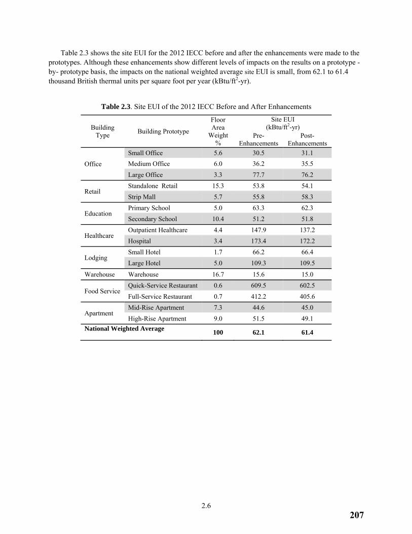
2.6
Table 2.3 shows the site EUI for the 2012 IECC before and after the enhancements were made to the prototypes. Although these enhancements show different levels of impacts on the results on a prototype -by- prototype basis, the impacts on the national weighted average site EUI is small, from 62.1 to 61.4 thousand British thermal units per square foot per year (kBtu/ft2-yr).
Table 2.3. Site EUI of the 2012 IECC Before and After Enhancements
Building Type
Building Prototype
Floor Area
Weight %
Site EUI (kBtu/ft2-yr)
Pre-Enhancements
Post-Enhancements
Office
Small Office 5.6 30.5 31.1
Medium Office 6.0 36.2 35.5
Large Office 3.3 77.7 76.2
Retail Standalone Retail 15.3 53.8 54.1
Strip Mall 5.7 55.8 58.3
Education Primary School 5.0 63.3 62.3
Secondary School 10.4 51.2 51.8
Healthcare Outpatient Healthcare 4.4 147.9 137.2
Hospital 3.4 173.4 172.2
Lodging Small Hotel 1.7 66.2 66.4
Large Hotel 5.0 109.3 109.5
Warehouse Warehouse 16.7 15.6 15.0
Food Service Quick-Service Restaurant 0.6 609.5 602.5
Full-Service Restaurant 0.7 412.2 405.6
Apartment Mid-Rise Apartment 7.3 44.6 45.0
High-Rise Apartment 9.0 51.5 49.1
National Weighted Average
100 62.1 61.4
207
3.7
3.0 2015 IECC Building Prototype Development
The starting point for the 2015 prototypes was the enhanced versions of the 2012 prototypes as described in the preceding section. In this section, PNNL compares code changes in commercial energy efficiency provisions between the 2012 and 2015 IECC and documents how they were implemented in the 2015 IECC prototypes and modeled in EnergyPlus. Where an implementation approach is similar to one described in previous PNNL reports (e.g., Thornton et al. 2011, Zhang et al. 2013, Goel et al. 2014, and Halverson et al. 2014), reference is made to these reports rather than reproducing the text here.
3.1 Review of Code Changes
Chapter 4 Commercial Energy Efficiency of the IECC provides three alternative paths for a new building to show compliance: (1) the mandatory and prescriptive requirements in the IECC; (2) the mandatory and total building performance requirements in the IECC; or (3) the requirements in the referenced Standard 90.1. This analysis looks only at compliance path (1), comparing the energy performance of the 2012 requirements relative to the 2015 requirements.
PNNL classified code changes into three categories, including 1) clarify requirements without changing their efficiency; 2) result in energy efficiency impacts but cannot be quantified using the building prototypes; and 3) result in energy efficiency impacts that can be quantified. Only those in the third category (see Appendix A) were incorporated into the 2015 IECC building prototypes. The most common reason why a change in the second category was not implemented was that the class of equipment or the particular requirements impacted by the change were not represented in the building prototypes. Other reasons were if EnergyPlus was not able to simulate the change or the change applied only to existing buildings instead of new buildings.
3.2 Building Envelope
Section C402 of the 2012 and 2015 IECC specifies requirements for building thermal envelope performance. The code as it relates to the envelope was modified in three areas: opaque envelope performance, fenestration area, and continuous air barrier. Because the fenestration area requirements are related to code changes for daylight responsive controls, these changes are discussed in Section 3.5.3 of this report.
3.2.1 Opaque Envelope Performance
Table C402.1.2 in the 2012 IECC becomes Table C402.1.4 in the 2015 IECC. This table lists opaque thermal envelope assembly requirements using U-factor, C-factor and F-factor-based method. The code changes in the U-factor requirements for roof (insulation entirely above deck type) and exterior wall (mass wall type) are applicable to all building prototypes, except for Small Office, Quick-Service Restaurant, and Full-Service Restaurant. PNNL calculated the R-value of the insulation layer in the wall or roof construction assembly in a prototype by using the changed U-factor requirements. PNNL implemented this R-value in the simulation models of the 2015 IECC prototypes.
208
3.8
3.2.2 Continuous Air Barrier
Section C402.4 of the 2012 IECC addresses the air leakage requirements. A continuous air barrier (CAB) is needed throughout the building envelope except for buildings in climate zones 1 through 3. Three compliance options are provided: (1) materials, (2) assemblies, and (3) whole building air leakage test. In this study, PNNL assumed a prototype has an air leakage rate of 1.8 cfm/ft2 of exterior wall under a pressure differential of 0.30 in. water column (w.c.) if it is exempted from the CAB requirement. We assumed a rate of 1.0 cfm/ft2 when the CAB requirement applied. These values were derived in previous analysis (see Section 5.2.1.1 of Thornton et al 2011).
The 2015 IECC (Section C402.5) only allows climate zone 2B to be exempted from the CAB requirement. To implement the code change, PNNL extended CAB to the 2015 IECC prototypes in climate zones 1A, 2A, 3A, 3B, and 3C by using an air leakage rate of 1.0 cfm/ft2.
3.3 Building Mechanical Systems
Section C403 of the 2012 and 2015 IECC specifies requirements for building mechanical systems. There are several code changes to the Section C403, such as changes to minimum equipment efficiency, controls of HVAC equipment, and extension of the scope to cover more equipment types. Because the building prototypes only cover limited types of equipment and systems with certain capacity ranges, this analysis only estimates the code changes that are applicable to the prototypes.
3.3.1 Heating, Ventilating, and Air-Conditioning Equipment Performance Requirements
Section C403.2.3 of the 2012 IECC specifies minimum efficiency requirements for various HVAC equipment types. The requirements for the following types of equipment were changed from the 2012 to 2015 IECC:
air-cooled unitary air conditioners (single package, size category of <65 thousand British thermal units per hour, or kBtu/h),
air-cooled unitary heat pumps (single package, both heating and cooling modes, size category of <65 kBtu/h),
water-to-air water loop heat pumps (cooling mode, size categories of <17 kBtu/h, 17-65 kBtu/h, and 65-135 kBtu/h),
water-to-air water loop heat pumps (heating mode, size category of <135 kBtu/h),
packaged terminal air conditioners (all sizes),
hot water boilers (gas-fired, size category of <300 kBtu/h),
air-cooled chillers (all sizes),
water-cooled chillers (all sizes), and
axial fan for open-circuit cooling tower (all sizes).
209
3.9
The changed efficiency was modeled in the 2015 IECC prototypes using the same methodology as in the 2012 IECC prototypes. Required equipment efficiency is based on equipment capacity that was calculated for each prototype at each climate zone using a design day sizing simulation in EnergyPlus. PNNL used this capacity to identify the required efficiency in the IECC and then ran an annual simulation using this efficiency. When efficiency values vary by effective dates in the IECC, PNNL used the values with latest dates. For example, Table C403.2.3(1) in the 2015 IECC lists single package air-cooled air conditioners under 65,000 Btu/h to have a minimum efficiency of 13 seasonal energy efficiency ratio (SEER) before January 1, 2016, and 14 SEER as of January 1, 2016. Efficiency of 14 SEER was used in this analysis.
While there is an increase in efficiency requirements for gas-fired hot water boilers with capacity less than 300 kBtu/h from the 2012 to 2015 IECC, this reflects the minimum federally mandated equipment efficiency for this type of boilers. Therefore, the higher boiler efficiency listed in the 2015 IECC was applied to both the 2012 and 2015 IECC building prototypes. Only Outpatient Healthcare has boilers smaller than 300,000 Btu/h.
3.3.2 Hot Water Boiler Outdoor Temperature Setback Control
Section C403.2.5 of the 2015 IECC introduces a new requirement that hot water boilers shall have a control that can automatically lower the boiler water temperature setpoint based on the outdoor air temperature. Section C403.4.2.4 of the 2012 IECC requires that hydronic heating systems have either a temperature reset control or variable flow.
Six building prototypes, i.e., Large Office, Secondary School, Outpatient Healthcare, Hospital, Large Hotel, and High-Rise Apartment, use hot water boilers for heating. Because the 2012 IECC buildings all use variable flow hydronic heating systems, temperature reset control was not implemented.
For the 2015 IECC, PNNL applied outdoor temperature setback control to Large Office, Secondary School, Outpatient Healthcare, Hospital, and Large Hotel. The implemented control is that boiler temperature setpoint is
equal to the design supply temperature if the outdoor temperature is below 20°F,
reset by 25% of the design supply-to-return water temperature difference if the outdoor temperature is above 50°F, and
reset to a value that is linearly interpolated between the two setpoint temperatures above if the outdoor temperature is between 20°F and 50°F.
High-Rise Apartment uses a closed-loop water source heat pump (WSHP) system to provide both heating and cooling to the space. The recirculated water in WSHP serves as heating and cooling source for the water-to-air heat pump in each zone. The water temperature is maintained between two setpoints: 68°F and 86°F by a central fluid cooler and a central boiler. No central heating or cooling is needed if the temperature is within this range. Even when the water temperature is at the lower setpoint of 68°F, the water could serve as both heating and cooling sources for different zones at the same time. Therefore, resetting the setpoint from 68°F to a lower value is not desired. As such, PNNL did not implement this control requirement to High-Rise Apartment for the 2015 IECC. An exception to this hot water boiler outdoor temperature setback control requirement may be added for WSHP systems in the future edition of the IECC.
210
3.10
3.3.3 Energy Recovery Ventilator
Section C403.2.6 of the 2012 IECC specifies the energy recovery ventilator (ERV) requirements by climate zone for different outdoor air fraction and design supply fan size thresholds. These requirements are for systems with outdoor air fractions above 30%. The changes from the 2012 to 2015 IECC, in Table C403.2.7(1) in Section C403.2.7, reduced the fraction threshold to 10% in climate zones 1A, 2A, 3A, 4A, 5A, 6A, 6B, 7, and 8. Additionally, the requirements for climate zones 3B, 3C, 4B, 4C, and 5B for systems with the outdoor air fraction above 70% were removed from the 2012 to 2015 IECC. Finally, Table C403.2.7(2) in the 2015 IECC adds a new set of requirements for ventilation systems operating more than 8,000 hours per year.
Based on the HVAC system sizing information from the EnergyPlus design day simulation, each air handling unit (AHU) of the building prototypes in each climate zone was checked to determine whether an ERV should be required by the 2015 IECC. Hospital and Large Hotel are assumed to operate more than 8,000 hours per year. This code change was implemented in Medium Office, Large Office, Standalone Retail, Strip Mall, Primary School, Secondary School, Outpatient Healthcare, Hospital, and Large Hotel.
AHUs in Mid-Rise Apartment, High-Rise Apartment, and Small Hotel in certain climate zones meet the trigger for the ERV requirements in the 2015 IECC. However, ERVs were not added to these prototypes because ERV products are usually not available for those small AHUs. An exception to this ERV requirement may be added in the future edition of the IECC for systems with very low outdoor air intake.
3.3.4 Kitchen Exhaust Systems
The 2012 IECC does not have requirements for kitchen exhaust hoods and kitchen ventilation systems. Baseline assumptions were made in previous analysis (Zhang et al. 2013) for kitchens in Primary School, Secondary School, Quick-Service Restaurant, Full-Service Restaurant, Large Hotel, and Hospital based on engineering judgment and a review of actual kitchen designs for these building types.
The 2015 IECC introduces new requirements for all kitchen exhaust systems, as listed in Section C403.2.8. The requirements that were implemented to the 2015 IECC prototypes are:
All available transfer air from adjacent spaces shall be used before any other makeup air is introduced to the kitchen for any size hood.
All hoods shall meet maximum net exhaust flow rate requirements listed in Table C403.2.8 if the total kitchen exhaust airflow rate in the kitchen/dining facility is greater than 5,000 cfm.
Kitchen/dining facilities with total kitchen hood exhaust airflow rate larger than 5,000 cfm shall meet one of three options: (a) at least 50% of replacement air from transfer air; (b) cooking-load-based demand control ventilation; and (c) energy recovery devices on exhaust airflow.
Changes to building prototypes for the 2015 IECC include the use of transfer air, reduction of exhaust airflow rate, and the use of demand control ventilation. These changes vary by prototype and by climate zone.
211
3.11
3.3.5 Fan Power Limitation Adjustment Credits
The 2012 IECC specifies maximum allowable fan power limits for HVAC systems at their fan system design conditions. Depending on the devices used in the systems, which affect the system air pressure drop, the IECC allows adjustments (credits) to the allowable limits using Table C403.2.10.1(2).
The 2015 IECC adds new adjustment items (deductions) to the table, Table C403.2.12.1(2). With this code change, systems without a central cooling coil are required to deduct 0.6 in. w.c. from their fan power limits. Systems without a central heating coil are required to deduct 0.3 in. w.c. Finally, systems with a central electric resistance heating element are required to deduct 0.2 in. w.c.
All building prototypes have central cooling coils but none has central electric resistance coils. Therefore, the code changes only affect those without central heating coils. All single-zone HVAC systems in the building prototypes need central heating coils. Hospital, Large Hotel, Large Office, Medium Office, Outpatient Healthcare, Primary School, and Secondary School have multiple-zone variable air volume (VAV) systems. A central heating coil in a VAV system serves to heat the mixed return and outdoor ventilation air from a mixed air temperature (MAT) to a supply air temperature (SAT) setpoint of 55°F. If the MATs never drop below 55°F, the VAV system does not need a central heating coil.
To determine the systems that must take the deduction to their fan power limits, PNNL calculated the lowest MAT for each prototype in each climate zone by using their heating design outdoor air temperature, return air temperature, and design outdoor air fraction. For those systems with the calculated lowest MATs higher or equal to 55°F, PNNL reduced their fan power limits by 0.3 in. w.c. in the 2015 IECC prototypes.
3.3.6 Reach-in Refrigerator and Freezer
The 2012 IECC does not prescribe requirements for commercial refrigerators and freezers. The 2015 IECC expands the scope of the code to add requirements for such equipment in Section C403.2.14. These new requirements reflect changes to national manufacturing standards per 10 Code of Federal Regulations (CFR) part 431, which went into effect on January 1, 2012. Because the energy savings that are attributable to these national manufacturing standards would accrue no matter what edition of the IECC is used, PNNL applied the same efficiency requirements in the 2015 IECC to both the 2012 and 2015 IECC building prototypes.
PNNL assumed that solid-door commercial refrigerators and freezers are used in the kitchens of Quick-Service Restaurant, Full-Service Restaurant, Hospital, Large Hotel, Primary School, and Secondary School. Table 3.1 shows the sizes and numbers of commercial freezers and refrigerators in the building prototypes. The efficiency requirements, in kWh/day, were modelled as a plug load with a constant operation schedule in EnergyPlus. Table 3.2 shows the energy use limits used to calculate the input power of commercial refrigerators and freezers for both the 2012 and 2015 IECC.
212
3.12
Table 3.1. Commercial Solid-Door Refrigerators and Freezers in Prototypes
Building Prototype Number of Freezers
(typical volume V=24 ft3)Number of Refrigerators (typical volume V=48 ft3)
Quick-Service Restaurant 1 2
Full-Service Restaurant 1 2
Hospital 2 3
Large Hotel 1 1
Primary School 2 2
Secondary School 2 2
Table 3.2. The 2015 IECC Requirements for Commercial Refrigerators and Freezers in Prototypes
Equipment Energy Use Limits
(kWh/day)
Reach-in refrigerators with solid doors 0.10V + 2.04
Reach-in freezers with solid doors 0.40V + 1.38
3.3.7 Manufactured Walk-in Cooler and Freezer
The 2012 IECC does not have any requirements for walk-in coolers and freezers. The 2015 IECC expands the scope of the code to add requirements for such equipment as defined in Section C403.2.15. The new requirements have been defined and legislated as the national manufacturing standard and described in 10 CFR 431.306. The requirements are for cover doors, insulation, evaporator fan motor, lighting, anti-sweat heater, condenser fan motor, and their controls.
The code change affects six building prototypes with commercial kitchens: Quick-Service Restaurant, Full-Service Restaurant, Hospital, Large Hotel, Primary School, and Secondary School. PNNL assumed that the walk-in coolers and freezers in these prototypes are manufactured as opposed to site-assembled or site-constructed. We also assumed them to be packaged equipment without remote compressors and condensers.
Navigant (2009) developed characteristics of baseline walk-in coolers and freezers, which show typical efficiency levels of the equipment before the new manufacturing standard. PNNL found that these characteristics either meet or exceed most requirements in the 2015 IECC, except for the evaporator fan motor and the lighting requirements. To capture these new requirements, the evaporator fan motors in the prototypes were assumed to be electronically commutated (EC) motors with an average motor efficiency of 70%, which was determined by surveying typical efficiencies listed in manufacturer catalogs. The efficiency was modelled as the fan power inputs in EnergyPlus models of the prototypes. The impact of the lighting control requirement was modeled as a 10% reduction in the hourly lighting schedule from the baseline models. This simulates the energy saving benefits from an occupancy-sensor-based lighting control. Because the energy savings that are attributable to the national manufacturing standards would
213
3.13
accrue no matter what edition of the IECC is used, PNNL applied the same efficiency requirements to both the 2012 and 2015 IECC building prototypes.
3.3.8 Economizer
There are several changes to the economizer requirements from the 2012 (Section C403.3.1 and C403.4.1) to 2015 IECC (Section C403.3) including capacity threshold increase, water economizer requirements, and combined requirements for simple and complex systems (previously separate in the 2012 IECC). This section describes the implementation for capacity threshold increase; Sections 3.3.9 and 3.3.10 discuss other code changes related to economizers in the prototypes.
To capture the energy impacts of the increased thresholds, first, a sizing simulation was conducted for each prototype with air economizers disabled in EnergyPlus to determine the cooling capacity of each direct expansion (DX) coil in the prototype. Second, the prototype was modified to enable the air economizer if the capacity exceeded the thresholds in the IECC. If the capacity was below the thresholds, the economizer remained disabled. This two-step procedure was followed for both the 2012 and 2015 IECC prototypes, and the differences between them are the thresholds shown in Table 3.3.
Table 3.3. Economizer Requirements by Cooling Capacity Thresholds and Climate Zones
Cooling Capacity Threshold (Btu/hr)
2012 IECC (climate zone)
2015 IECC (climate zone)
No requirement 1A, 1B 1A, 1B
>=33,000 2A, 2B, 3A, 3B, 3C, 4A, 4B, 4C, 5A, 5B, 5C, 6A, 6B, 7, 8
>=54,000 2A, 2B, 3A, 3B, 3C, 4A, 4B, 4C, 5A, 5B, 5C, 6A, 6B, 7, 8
3.3.9 Staged Cooling
Section C403.3.1 in the 2015 IECC introduces a new staged cooling requirement for DX units, which is not contained in the 2012 IECC. According to item 3 under Section C403.3.1, for DX units that control 75,000 Btu/h or greater of rated capacity directly based on occupied space temperature (usually serving a single zone), a minimum of two stages of mechanical cooling capacity are required. Another related new code requirement (see Section 3.3.10 of this report) in Table C403.4.1.1 of the 2015 IECC requires a two-stage fan control for DX units with cooling capacity over 65,000 Btu/h (after January 1, 2016). In practice, a DX unit would either have both staged cooling and staged fan controls together or neither of them. For this reason, PNNL used 65,000 Btu/h as the threshold for the staged cooling requirement instead of 75,000 Btu/h.
Eight building prototypes use packaged single-zone DX cooling units: Standalone Retail, Strip Mall, Quick-Service Restaurant, Full-Service Restaurant, Primary School, Secondary School, Small Hotel, and Warehouse. For the 2012 IECC, these prototypes all use single-stage cooling control. For the 2015 IECC, except for the single-zone units in Small Hotel and Warehouse, the cooling capacities of DX units found in the prototypes are larger than 65,000 Btu/h in most climate zones; therefore, they were modelled with two-stage cooling. For units required to have two-stage cooling, the low-stage capacity was assigned to be half of the full capacity.
214
3.14
Improved economizer integration is a source of energy savings from the new staged cooling requirement in the 2015 IECC. When two-stage cooling and air economizer controls are both required in a 2015 IECC building prototype, economizer operation was modeled to represent increased economizer effectiveness. The fraction of time spent by the system in each mode—full economizer, partial economizer, and full mechanical cooling—was used to calculate an average economizer effectiveness for a given time step. PNNL adjusted the economizer effectiveness by changing the maximum outside air schedule that controls the amount of outside air available at a simulation time step. PNNL implemented this modeling strategy using the EnergyPlus energy management system (EMS) feature. The implementation is described in more detail in Section 5.2.2.6 of the PNNL report (Halverson et al. 2014).
3.3.10 Fan Airflow Control
Fan airflow control is another new requirement introduced in the 2015 IECC. Section C403.4.1.1 and Table C403.4.1.1 require two stages of fan control for DX units (capacity larger than 65,000 Btu/h) that control cooling capacity directly based on space temperature (usually serving a single zone). The requirement states that low or minimum fan speed shall not be greater than 66% of full speed. Section C403.4.1.1 of the 2015 IECC also requires that units with air economizers shall have a minimum of two speeds of fan control during economizer operation.
Six building prototypes, i.e., Standalone Retail, Strip Mall, Quick-Service Restaurant, Full-Service Restaurant, Primary School, and Secondary School, qualify for this requirement because they have packaged single-zone DX cooling units with capacity larger than 65,000 Btu/h. The requirements in the 2015 IECC are identical to those in Standard 90.1-2013 and their implementation in the prototype models has been described in a previous analysis (Halverson et al. 2014). The same modeling strategy applies to the 2012 and 2015 IECC models.
3.3.11 Part-load Controls for Hydronic Systems
Section C403.4.3.4 in the 2012 IECC requires hydronic heating and cooling systems with capacity over 300,000 Btu/h to include either supply-water temperature reset or variable flow controls. The 2015 IECC (Section C403.4.2.4) changes the capacity threshold to 500,000 Btu/h. Additionally, the code is changed from requiring one of these two controls to requiring both of them, plus a variable (or stepped) pumping control.
Six building prototypes, i.e., Large Office, Secondary School, Outpatient Healthcare, Hospital, Large Hotel, and High-Rise Apartment, have variable flow hydronic heating systems with variable flow pumps. Based on engineering judgment, PNNL assumed this type of system to be typical design in these prototypes no matter what edition of the IECC is used.
Four building prototypes, Large Office, Hospital, Secondary School, and Large Hotel, have primary-secondary variable-flow chilled water systems with variable-flow secondary pumps. Based on engineering judgment, PNNL assumed this type of system to be a typical design. Therefore, these prototypes meet the part-load control requirements for hydronic heating and cooling systems in the 2012 IECC.
215
3.15
For the 2015 IECC, the hydronic heating systems in the six prototypes already have the variable flow, variable pumping, and supply-water temperature reset (described in Section 3.3.2). As such, they meet the requirements in 2015 IECC already. For the hydronic cooling systems in the four prototypes, PNNL implemented supply-water temperature setpoint reset using the following reset rule, the setpoint is:
the design supply temperature if the outdoor temperature is below 80°F,
reset by 25% of the design supply-to-return water temperature difference if the outdoor temperature is above 60°F, and
linearly interpolated between the two setpoint temperatures above if the outdoor temperature is between 60°F and 80°F.
The capacities of all hydronic systems in the building prototypes exceed the increased threshold of 500,000 Btu/h in the 2015 IECC. Therefore, the impact of the threshold change was not captured in the simulations.
3.3.12 Boiler Turndown
Section C403.4.2.5 in the 2015 IECC adds a boiler turndown requirement, which does not exist in the 2012 IECC. The new section requires that boiler systems with design input of 1,000,000 Btu/h or more comply with different turndown ratios, as shown in Table 3.4, using multiple single input boilers, one or more modulating boilers, or a combination of single input and modulating boilers.
Table 3.4. Boiler Turndown in Table C403.4.2.5 of the 2015 IECC
Boiler System Design Input (Btu/h) Minimum
Turndown Ratio ≥ 1,000,000 and less than or equal to 5,000,000 3 to 1 > 5,000,000 and less than or equal to 10,000,000 4 to 1 > 10,000,000 5 to 1
The following building prototypes use boilers that may be affected by the turndown requirements: Large Office, Hospital, Primary School, Secondary School, Large Hotel, High-Rise Apartment, and Outpatient Healthcare. PNNL assumed single-stage capacity control to be typical design in the 2012 IECC building prototypes based on a review of the certified boilers in the American Heating and Refrigeration Institute (AHRI) directory1. For the 2015 IECC, PNNL assumed that the prototypes would use modulating boiler capacity control, one of the three compliance options required by the 2015 IECC, if the building’s system capacity was greater than 1,000,000 Btu/h.
EnergyPlus models boiler’s part-load performance with a part-load efficiency (through a part-load curve as function of part load ratio (PLR)), which describes the normalized heating efficiency (as a fraction of nominal thermal efficiency) of the boiler’s burner. PNNL modelled all boilers in the 2012 IECC prototypes using the curve described in Equation 3-1. For the 2015 IECC, PNNL applied Equation 3-1 curve to boilers with input capacity ≤1,000,000 Btu/h and Equation 3-2 curve to those with input
1 AHRI’s Directory of Certified Product Performance database. Last accessed in May 2013 at http://www.ahridirectory.org/ahridirectory/pages/cblr/defaultSearch.aspx
216
3.16
capacity >1,000,000 Btu/h. These curves are based on research by Bertagnolio and Andre (2010). Although these curves were only developed for PLR in the range of minimum turn down load and full load, EnergyPlus could allow a boiler to work at a PLR below the range. PNNL implemented an EnergyPlus EMS algorithm in the simulation models to adjust curve outputs when the PLR was lower than the range.
Curvesingle-stage control = 0.907 + 0.320 * PLR - 0.420 * PLR2 + 0.193 * PLR3 (3-1)
Curvemodulating control = 0.975+0.305 * PLR-0.527 * PLR2+0.249 * PLR3 (3-2)
3.3.13 Heat Rejection Equipment
The 2015 IECC includes two major changes for heat rejection as compared to the 2012 IECC: fan control for multi-cell heat rejection equipment (Section C403.4.3.2.2) and open-circuit cooling tower fan flow turndown (Section C403.4.3.2.1). The second change also requires that the maximum number of fans to operate in multi-cell heat rejection equipment to minimize energy. It is more energy efficient to operate all fans in tandem at the same (lower) fan speed than to have an on/off or sequenced fan operation (operating a select number of cells at full speed to meet load). Using more cells also increases heat transfer area and more heat can be rejected with less airflow and fan speed.
Large Office and Hospital use open-circuit cooling towers. Each prototype has two variable-speed cooling towers. Each tower has one dedicated condenser water pump and two cells. Because the two cooling towers are equally sized, the two condenser water pumps have the same design flow rate. In the 2012 IECC building prototypes, the number of operating cooling towers and condenser water pumps corresponds to the number of operating chillers. When one chiller operates, one cooling tower operates and the corresponding condenser water pump operates. When both chillers are running, both cooling towers and both condenser water pumps are running.
The 2015 IECC requires that the maximum number of fans operate to minimize fan energy. This means that when one chiller is running, all four cell fans in the two cooling towers will be operating unless the fan in one cooling tower already runs at its minimum speed. Running two towers implies that the condenser water flow will be reduced by 50% for each cell in comparison with running one tower.
The strategy for modeling the cooling tower control requirements in the 2015 IECC includes the following:
Change the cell control strategy for variable-speed cooling towers in EnergyPlus from “minimum cells” to “maximum cells.”
For each time step, find the number of operating chillers.
If one chiller is running and the current airflow ratio is greater than the minimum, run the two towers in parallel. Use the EnergyPlus EMS to halve the airflow ratio, which is then used to calculate the fan power according to the cubic power law. The EMS control is necessary because the EnergyPlus native control algorithms cannot run both towers in parallel while delivering the condenser water flow for just one chiller if there are two chillers in the plant.
If two chillers are running or the current airflow is at the minimum when one chiller is running, the EMS algorithm will not override the tower fan curve input and output.
217
3.17
3.3.14 VAV Reheat Control
Section 403.4.5 in the 2012 IECC specifies requirements for zone airflow under multiple zone VAV systems. Thirty percent (30%) of the maximum supply air to each zone is required as the minimum zone supply airflow to reduce VAV reheat at the zone terminals. The 2015 IECC (Section C403.4.4) adds a new exception (item 4) to the 30% minimum; it states that a rate higher than 30% is allowed if it can be demonstrated to reduce overall system annual energy use by offsetting reheat/recool energy losses through a reduction in outdoor air intake for the system. Standard 90.1-2013 has a similar exception and PNNL has established a modeling strategy to determine the minimum zone supply airflow to meet this requirement. The calculation procedure includes four steps: (1) calculate zone ventilation efficiency; (2) calculate system ventilation efficiency; (3) increase the minimum damper fraction (i.e., ratio of minimum to maximum zone supply airflow) from 30% to a new value based on a target value of system ventilation efficiency; and (4) calculate the system design outdoor air intake.
In the 2012 IECC prototypes, only Steps 1, 2, and 4 were applied. For the 2015 IECC, all four steps were followed, which resulted in different minimum damper fractions and system design outdoor airflow rates from those in the 2012 IECC prototypes. The implementation of the four-step methodology is described in detail in Section 5.2.2.21 of Thornton et al. (2011) and Section 2.2.6 of Goel et al. (2014). All prototypes with multiple-zone VAV systems are affected by the code change related to VAV reheat control (i.e., Medium Office, Large Office, Primary School, Secondary School, Outpatient Healthcare, and Hospital).
3.3.15 VAV System for Critical Area in Healthcare Facility
Section C403.4.5 in the 2012 IECC includes Exception (1) to the VAV system requirement for supply air systems serving multiple zones. This exception is for “zones where special pressurization relationships or cross-contamination requirements are such that VAV systems are impractical”. This exception allows designers to use constant volume reheat systems in critical areas of hospitals and similar spaces needing pressure differentials with adjacent areas.
The exception for the VAV requirement is removed in the 2015 IECC (Section C403.4.4). Instead, the 2015 IECC adds an allowance to the airflow rate that can be reheated to achieve reasonable energy savings in these types of spaces, while not compromising health and safety. A new compliance option is to reduce the zone primary air supply to “the airflow rate required to comply with applicable codes or accreditation standards, such as pressure relationships or minimum air change rates”. The code changes mean that if the peak design airflow to any of these spaces is greater than the required minimum air change rate or the minimum rate required maintaining pressure differentials, the system must use VAV, reducing airflow as much as possible before reheat is allowed. Also, if the minimum air change rate is only required during occupied periods (as in operating rooms), the airflow must be reduced during those unoccupied periods before reheat is allowed.
The Hospital and Outpatient Healthcare prototypes include critical spaces that are affected by the changes from the 2012 to 2015 IECC. In the 2012 IECC Hospital and Outpatient Healthcare prototypes, critical spaces, such as operating rooms, patient rooms, intensive care units, and laboratories, were modelled to receive constant airflow with terminal reheat. To capture the impacts of the new requirement, PNNL compared the design airflow to the critical spaces with minimum airflow requirements according to the most commonly used accreditation standard, AIA Guidelines for Design and Construction of
218
3.18
Hospital and Health Care Facilities (American Institute of Architects, AIA 2001). PNNL determined that the operating rooms (during unoccupied periods) and patient rooms should be changed to use VAV systems for the 2015 IECC.
3.3.16 Fractional HP Fan Motors
The 2015 IECC adds a new Section C403.4.4.4 that requires motors from 1/12 horsepower (hp) to under 1 hp to be EC motors or have a minimum efficiency of 70%. The intention is to replace standard permanent-split capacitor (PSC) motors having efficiencies in the range of 15% to 65% with more-efficient EC motors. The intended applications are toilet exhaust fans, small kitchen exhaust fans, series fan-powered VAV boxes, and fan-coil units. The following motors are exempt under the new requirement: motors in an airstream where only heating is provided, motors in packaged equipment, poly-phase small motors, and capacitor-start capacitor-run and capacitor-start induction-run motors that are covered by Table C405.8(3) and Table C405.8(4) in the 2015 IECC.
In the building prototypes, the new requirements apply to fan-coil units, exhaust fans, kitchen exhaust fans, and elevator fans. Table 3.5 provides details on the building prototypes and fans to which the new requirements apply.
Table 3.5. Prototype Buildings Affected by Section C403.4.4.4 in the 2015 IECC
Prototype Building Fan-Coil Unit Exhaust Fan Kitchen Exhaust Fan Elevator Fan High-Rise Apartment Yes Mid-Rise Apartment Yes Hospital Yes Yes Large Hotel Yes Yes Yes Yes Small Hotel Yes
Large Office Yes Medium Office Yes Outpatient Healthcare Yes Yes Quick-Service Restaurant Yes Yes Full-Service Restaurant Yes Yes Primary School Yes Yes Secondary School Yes Yes
To determine the motors whose efficiency must be changed, a set of criteria was established based on motor size. From a review of catalogs, motors in the smallest fans were selected from standard fractional horsepower motor sizes even if the required brake horsepower (bhp) is much lower. Therefore, maximum bhp is set at 90% of 3/4 hp or 560 W (above 90% of 3/4 hp, a 1 hp or larger motor would be used) and minimum bhp is set at 25% of 1/12 hp, or 14 W. Motors between the minimum and maximum bhp are considered to be applicable to the new IECC requirements.
To implement the new requirements, motor efficiency was changed in the prototypes. A motor efficiency of 29% was used in the 2012 IECC prototypes based on an intermediate value between highest potential efficiency and lowest efficiency found through literature review. For the 2015 IECC, the motor efficiency was set to 70%, which is close to the average typical EC motor efficiency.
219
3.19
3.3.17 Outdoor Air Ventilation Optimization Control
The 2015 IECC adds a multiple-zone VAV system ventilation optimization control requirement in Section C403.4.4.6. Under this requirement, multiple-zone VAV systems shall have automatic controls to reduce outdoor air intake flow from the design rates in response to dynamic system ventilation efficiency as defined by the 2015 International Mechanical Code (IMC) (ICC 2015b). According to Exception (2), a system having an ERV, as described in Section 3.3.3, is exempted from this requirement. Without such a requirement, the VAV systems in the 2012 IECC prototypes maintain constant outdoor air intake flowrate at the design level. This is a waste of energy to condition excess outdoor air intake.
To capture the savings of the 2015 IECC requirement, the Controller:MechanicalVentilation object in EnergyPlus was used with the System Outdoor Air field set to ventilation rate procedure. This is the option for meeting ventilation requirements in the 2015 IMC. Under these modeling settings, EnergyPlus implements the multiple-zone calculation per the 2015 IMC at each simulation time step and calculates system efficiency and system outdoor air intake, which is a reduced airflow from the design level. When a system has an ERV, the ventilation optimization control was not implemented; therefore, the system outdoor air intake remains at its design level. The energy savings impacts of the new 2015 IECC requirements were captured in Medium Office, Large Office, Primary School, Secondary School, Outpatient Healthcare, and Hospital.
3.4 Service Water Heating
PNNL reviewed all code changes under Section C404 Service Water Heating and determined that only the new demand-based control requirements for recirculation SWH systems have energy impacts that can be quantified using the building prototypes.
3.4.1 Demand-based Controls for Recirculated Service Water Heating Systems
Section C404.6.1 in the 2015 IECC adds new control requirements for buildings with recirculated SWH systems. The controls shall automatically turn off the circulation pumps when the water temperature in the circulation loop is either at or above the desired setpoint or when there is no hot water demand. These controls are not required in the 2012 IECC.
A recirculated SWH system provides more instant hot water at the water taps but energy losses are greater through pipe thermal losses and pump energy losses than a non-recirculated system. Ten prototypes use recirculated SWH systems. PNNL assumed that the SWH pumps in the 2012 IECC prototypes are always on at constant speed and the SWH temperatures are always maintained at their design setpoint. For each prototype, PNNL estimated the SWH pipe heat loss (kBtu/h) based on the average temperature difference between the water and indoor spaces, total pipe surface area, and pipe insulation. This loss was converted to SWH energy consumption inputs in the EnergyPlus models. Pump power in each prototype was also estimated based on pipe design, flow rate, and SWH system operations. This power was converted to pump pressure head in the EnergyPlus models. Details of the inputs are available in Section 2.1.4 of Goel et al. (2014). To estimate the energy savings impacts of the 2015 IECC requirements, reductions to the pipe heat loss inputs and recirculation pump power inputs were applied to the 2015 IECC building prototypes based on the baseline inputs in the 2012 IECC prototypes, as shown in Table 3.6. PNNL estimated the savings based on assumed SWH demand profiles in these prototypes.
220
3.20
Although Hospital, Small Hotel, and Large Hotel use recirculated SWH systems, PNNL did not quantify the impacts of the new requirements on them because we assumed the occupants in these building always have SWH demand.
Table 3.6. Percent Energy Savings of the 2015 IECC Controls Attributable to Reductions in Pipe Thermal Losses and Pump Energy Savings (as based on the 2012 IECC Building Prototypes)
Building Prototype Energy Savings Attributable to
Reductions in Pipe Thermal Loss Savings Attributable to Pump Energy Savings
Medium Office 57% 89% Large Office 57% 89% Primary School 48% 90% Secondary School 48% 90% Outpatient Healthcare 57% 89% High-Rise Apartment 44% 90%
3.5 Electrical Power and Lighting Systems
Section C405 of the 2012 and 2015 IECC specifies requirements for electrical power and lighting systems. Through review of the code changes, PNNL identified changes in several areas that have energy impacts and can be quantified using the building prototypes. Some of these changes are related to code changes in other areas, e.g., daylight responsive control is related to skylight and window areas and thermal performance of the fenestration components. These are also related to the changes in Section C406 (additional efficiency package options) of the two editions.
3.5.1 Additional Efficiency Package Options
Section C406 of the 2012 IECC requires choosing one from three additional efficiency package options:
1. Efficiency HVAC performance (Section C406.2),
2. Efficient lighting system (Section C406.3), and
3. On-site supply of renewable energy (Section C406.4).
The 2015 IECC modifies these options and adds three more options in Section C406. The six options are:
1. More efficient HVAC performance (Section C406.2),
2. Reduced lighting power density (LPD) system (Section C406.3),
3. Enhanced lighting controls (Section C406.4),
4. On-site supply of renewable energy (Section C406.5),
5. Provision of a dedicated outdoor air system for certain HVAC equipment (Section C406.6), and
6. High-efficiency service water heating (Section C406.7).
221
3.21
In the Analysis for the 2012 IECC, PNNL chose the high-efficiency lighting for the 2012 IECC prototypes because this option is more likely to be chosen for most building designs than the on-site supply of renewable energy option (Section C406.4). The efficient HVAC performance option (Section C406.2) was not chosen because this option would not allow a comparison of the 2012 IECC with its referenced Standard 90.1 with the HVAC equipment at the same minimum efficiencies addressed in the National Appliance Energy Conservation Act (NAECA), Energy Policy Act (EPAct), and the Energy Independence and Security Act (EISA). For the same reason and for keeping consistent choices for this analysis, PNNL chose the corresponding reduced LPD system option (Section C406.3 in the 2015 IECC) for the 2015 IECC prototypes. The impacts of the code changes in the selected option are related to daylight responsive control, skylights and window areas, and thermal performance of the fenestration components in the prototypes, and are discussed in Sections 3.5.3 and 3.5.6.1 in this report.
3.5.2 Occupant Sensor Controls
Section C405.2.2.2 in the 2012 IECC requires occupancy sensors in classrooms, conference/meeting rooms, employee lunch and break rooms, private offices, restrooms, storage rooms, janitorial closets, and other areas less than 300 ft2 enclosed by floor-to-ceiling partitions. The control devices need to turn the lights off within 30 minutes of the occupants leaving the space and can be either manually turned on or automatically controlled to turn the lighting on to no more than 50% power. Full automatic-on controls are allowed in some specified areas.
The 2015 IECC (Section C405.2.1) extends the occupancy sensor control requirements to copy/print rooms, lounges, locker rooms, and warehouses.
An outline of the procedure for determining savings from occupancy sensors is as follows.
Appropriate building areas that fall into the occupancy sensor requirements were identified.
In prototypes like the Small, Medium, and Large Offices and Standalone Retail, where detailed zoning is unavailable, appropriate building areas were determined using the National Commercial Construction Characteristics database.1 This database provides a compilation of the building prototypes and the proportion of common building areas.
Percent lighting energy reduction from the use of occupancy sensors was determined for all qualifying areas based on literature review.
This percentage reduction was applied to the occupied hour values of the lighting schedule used by the specific zone.
Where a separate zone does not exist in the model for a particular space, the reduction factor was calculated as a product of (1) space area as a fraction of whole-building area from the National Commercial Construction Characteristics database, and (2) target lighting energy savings percentage. This reduction was similarly applied to the occupied hours of the whole-building lighting schedule.
1 National Commercial Construction Characteristics Database (NC3), an internal PNNL database of nationwide commercial construction energy-related characteristics.
222
3.22
3.5.3 Daylight Responsive Controls and Fenestration Area
The daylight control requirements in the IECC are related to several other requirements, such as window size, fenestration performance, and lighting power density. The requirements and their implementation in the prototypes are separately discussed in this section for sidelight (daylight through windows) and toplight (daylight through skylights).
3.5.3.1 Sidelighting Area and Control Requirements in the 2012 IECC
The 2012 IECC defines daylight zone adjacent to vertical fenestration in Chapter 2 and specifies control options for sidelight daylight zone in Section C405.2.2.3. However, automatic daylighting controls are not required. However, because the efficient lighting system option was chosen (see Section 3.5.1 and 3.5.6.1), an LPD of 0.9 W/ft2 from Table C406.3 was selected to meet the reduced LPD requirements for the Small Office and Medium Office prototypes. This triggered Footnote (b) of the table to apply. Therefore, two prototypes, which have sidelight daylight zones over 30% of their total conditioned floor area, are required to have automatic daylighting controls. Automatic stepped daylight controls were implemented in the two prototypes for all climate zones for the 2012 IECC.
A window provides a path for daylight entering the space. The 2012 IECC (Section 402.3.1) limits maximum window-to-wall ratio (WWR) of 30%. In climate zones 1 through 6, a maximum WWR of 40% is allowed if 50% of the conditioned floor area is within a daylight zone (including sidelight and toplight areas) and automatic daylighting controls are installed. Through a literature review, PNNL defined typical WWR for each prototype, which is assumed in its design characteristic. Such characteristics remain the same unless certain code provision requires them to be changed. Most prototypes have WWRs of less than 30% as their characteristics. However, four prototypes (Primary School, Secondary School, Medium Office, and Large Office) have typical WWRs between 30% and 40%. PNNL verified that the 40% limit does not apply to these prototypes because they do not have sufficient daylight area. Therefore, their WWRs were reduced from their typical values to 30% for the 2012 IECC prototypes.
In summary, Small Office and Medium Office prototypes were implemented with automatic controls for general lighting in their sidelight daylight zones. In addition, the WWRs of Primary School, Secondary School, Medium Office, and Large Office were set to 30% for the 2012 IECC.
3.5.3.2 Sidelighting Area and Control Requirements in the 2015 IECC
The 2015 IECC (Section C405.2.3) requires automatic daylight responsive controls for sidelight daylight area as opposed to manual controls (an allowed option in the 2012). It specifies 150 Watts of general lighting within sidelight daylight zone as the minimum threshold to apply the control requirement. As such, many sidelight zones in the 2015 prototypes were implemented with automatic daylight controls, such as Small Office, Medium Office, Large Office, Primary School, Secondary School, Outpatient Healthcare, Hospital, Small Hotel, Large Hotel, Warehouse, Quick-Service Restaurant, and Full-Service Restaurant.
In addition, the 2015 IECC specifies control settings for different space types. Where located in offices, classrooms, laboratories and library reading rooms, daylight responsive controls shall dim lights continuously from full light output to 15% of full light output or lower. Daylight responsive controls shall
223
3.23
be capable of a complete shutoff of all controlled lights. For these space types, continuous dimming controls were used and for others, stepped controls were used.
Similar to the 2012 IECC, the 2015 IECC (Section C402.4.1.1) limits the maximum WWR to 30% but allows buildings in climate zones 1 through 6 to use WWR up to 40% if a certain amount of floor area falls under daylight zones. Code changes were made to the criteria for which the 40% limit applies. For buildings with two stories or less, the area in daylight zones must be at least 50% of the net floor area. For buildings with more than two stories, at least 25% of the net floor area must be in a daylight zone. Net floor area excludes corridors, stairwells, bathrooms and mechanical rooms from the conditioned floor area. As mentioned earlier, 30% WWR limit was implemented to Large Office, Medium Office, Primary School, and Secondary School for the 2012 IECC. PNNL checked these prototypes against the changed criteria and compared the ratio of the daylight area (including both sidelight and toplight areas) to the net floor area with the new criteria. It was found that the WWR of Medium Office can be changed to its characteristic size, i.e., WWR of 33%. This was implemented to this prototype in climate zones 1 through 6. In addition, the visible transmittance (VT) of these changed windows was changed to 1.1 times solar heat gain coefficient (SHGC) to meet Section C402.4.1.1 (4) requirement. The WWR remains at 30% in Medium Office (same as the 2012 IECC counterparts) in climate zones 7 and 8.
3.5.3.3 Toplighting Area and Control Requirements in the 2012 IECC
Skylight Area
Section C402.3.2 of the 2012 IECC requires a minimum skylight area in certain spaces larger than 10,000 ft2 to provide toplight daylight area under skylights to be at least 50% of the space area. The skylight area shall not be less than 3% of this daylight area. Buildings in climate zones 6 through 8 are exempted.
Spaces in some of the building prototypes have skylights in their typical design, i.e., skylights are a characteristic of the prototype. Such characteristics remain the same unless certain code provisions require them to be changed. The spaces in these prototypes with skylights are listed in Table 3.7 along with other design characteristics related to daylight area under skylights. As seen in the table, the zones in Primary School and Secondary School meet the minimum skylight area requirements in Section C402.3.2 of the 2012 IECC.
Footnote (c) of Table C406.3 in the efficient light system option, used in the 2012 IECC prototype, as discussed in Section 3.5.6.1, requires 70% of floor area in warehouse and 30% in retail to be in the daylight zone. Because of this requirement, PNNL increased the number of skylights in the 2012 IECC Warehouse and Standalone Retail prototypes.
Daylight Responsive Control in Toplight Daylight Area
Section C402.3.2.1 in the 2012 IECC requires all lighting in the toplight daylight zone to be controlled by multilevel lighting controls except for climate zones 6 through 8. For Warehouse and Standalone Retail prototypes, Footnotes (b) and (c) of Table C406.3 require automatic daylighting control without climate zone exceptions. Therefore, these multilevel lighting controls were implemented to zones
224
3.24
listed in Table 3.7 for Primary School and Secondary School in climate zones 1 through 5. Warehouse and Standalone Retail in all climate zones were modelled with automatic daylighting control.
Thermal Performance of Skylights
Sections C402.3.3.3 in the 2012 IECC allows skylights to have an increased SHGC from the requirements in Table C402.3 in climate zones 1 through 6 where the toplight daylight area under the skylights has automated daylighting controls. Similarly, according to Section C402.3.3.4, these skylights can use increased U-factor in all climate zones. These increased SHGC and U-factor requirements were implemented to the prototypes as they apply.
Table 3.7. Typical Skylight and Toplight Area in the Building Prototypes
Prototype Zone Name Zone Area (ft2)
Skylight Area (ft2)
Toplight Daylight Area (ft2)
Toplight Daylight
Area / Zone Area (%)
Skylight Area / Toplight Daylight Area (%)
Primary School Multipurpose Room 3843 144 3843 100% 4%
Secondary School Gymnasium 21269 864 21269 100% 4%
Auxiliary Gymnasium 13433 576 13433 100% 4%
Warehouse Bulk Storage a, b 34497 160 4876 14% 0%
Fine Storage a, b 15000 0 0 0% 0%
Standalone Retail Core Retail a, b 17227 72 2584 15% 0% a. Daylight areas were increased to 70% (Warehouse) and 30% (Standalone Retail) of the zone area for all climate
zones to meet the requirements of Footnotes (b) and (c) of Table C406.3 in the 2012 IECC. b. Daylight areas were set to 50% to meet the requirements of Section C402.4.2 in the 2015 IECC for climate zones
1-5. They remain as values shown in this table for climate zone 6-8.
3.5.3.4 Toplight in the 2015 IECC
Skylight Area
To save energy from use of daylight responsive control, the requirements of minimum skylight area were modified in the 2015 IECC (Section C402.4.2). The size threshold of a zone, for which the requirements applies, was changed from 10,000 ft2 to 2,500 ft2. As shown in Table 3.7, this new threshold does not affect the Primary School and Secondary School because their skylight areas already exceed the requirements.
The reduced lighting power density system, Section C406.3 used in the 2015 IECC prototype, as discussed in Section 3.5.1 of this report, was changed from specifying requirements for LPD, minimum daylight area, and daylighting controls to LPD only. As such, the minimum skylight area requirements in Section C402.4.2 of the 2015 IECC were implemented to Warehouse and Standalone Retail with respect to their skylight areas. PNNL set the toplight daylight area in the bulk and fine storage zones in Warehouse and core retail zone in Standalone Retail in climate zones 1 through 5 to 50% of the zone area. The skylight areas remain the same as values shown in the Table 3.7 for those building prototypes located in climate zones 6 through 8. PNNL implemented the daylight area by changing the number of skylights
225
3.25
on the roof. As illustrated in Figure 3.1 these changes resulted in a decrease in the number of skylights in Warehouse from the 2012 and the 2015 IECC buildings. The major impacts of these changes on energy performance of the warehouse include envelope thermal performance, daylight responsive control, and HVAC system sizes.
Warehouse for the 2012 IECC in all climate zones
Warehouse for the 2012 IECC in climate zones 1 through 5
Warehouse for the 2015 IECC in climate zones 6 through 8
Figure 3.1. Schematic of Skylights in the Warehouse Prototype
Daylight Responsive Control in Toplight Daylight Area
Section C402.4.2.1 in the 2015 IECC requires all lighting in the toplight daylight zone to be controlled for all climate zones, as opposed to having exceptions in climate zones 6 through 8. Section C405.2.3 also defines a new threshold of 150 watts of general lighting within the zone to qualify daylight responsive control defined in the 2015 IECC.
226
3.26
Section C405.2.3.1 in the 2015 IECC specifies continuously dimming control from full light output for offices, classrooms, laboratories, and library reading rooms. PNNL used a stepped control setting in EnergyPlus to model this requirement for all toplight daylight areas in zones listed in Table 3.7 in all climate zones.
Thermal Performance of Skylights
Similar to the 2012 IECC, the 2015 IECC permits increased SHGC and U-factor from values in Table C402.4 for skylights where located above daylight area with daylight controls. Requirements do not change from the 2012 to 2015. However, toplight daylight controls were not implemented in Primary School and Secondary School located in climate zones 6 through 8 for the 2012 IECC but were implemented for the 2015 IECC. These differences resulted in different U-factor inputs in the simulation models of these two schools between the two editions of the IECC.
3.5.4 Guestroom Lighting Controls
Section C405.2.4 in the 2015 IECC modified the existing requirement in the 2012 IECC (Section C405.2.4) for hotel and motel sleeping units and guest suites. The requirement changed from manual control to automatically switching off all installed luminaires and switched receptacles within 20 minutes after all occupants leave the room.
The new requirement affects Small Hotel and Large Hotel. The implementation assumes 10% reduction in lighting energy in bathroom lighting and that the bathroom lighting contributes 31% of the guestroom lights. Besides lighting control, the new requirement also applies to the switched receptacles in guestrooms. A new schedule for guestroom lighting was calculated using the hourly reduction fraction for guestroom lighting in the advanced case in the Technical Support Document: 50% Energy Savings Design Technology Packages for Highway Lodging Buildings (Jiang et al. 2009). The daily weighted reduction in the lighting power using this schedule is 38%. The hourly reduction fraction for guestroom receptacles in advanced models from Jiang et al. (2009) was used to calculate the 2015 IECC savings. This results in a daily weighted reduction of 17% in equipment energy consumption.
3.5.5 Exterior Lighting Automatic Controls
Section C405.2.4 in the 2012 IECC requires that lighting not designated for dusk-to-dawn operation shall be controlled by either a combination of a photosensor and a time switch, or an astronomical time switch. Lighting designated for dusk-to-dawn operation shall be controlled by an astronomical time switch or photosensor. These requirements mean the exterior lights are off during daytime but do not enforce light power to be reduced at night. The 2015 IECC (Section C405.2.5) requires exterior facade and landscape lighting to be automatically turned off as a function of dawn/dusk and a set business opening and closing time. Exterior lighting not specified as facade or landscape lighting is to be automatically reduced by 30% of its peak power from between no later than midnight to 6 a.m., or from 1 hour after business closing to 1 hour before business opening, or during any period when activity has not been detected for a time longer than 15 minutes.
The code changes have energy savings impacts on all prototypes except for those that are open 24 hours a day, such as Hospital, Outpatient Healthcare, Small Hotel, Large Hotel, Mid-Rise Apartment, and
227
3.27
High-Rise Apartment. Exterior lighting operating schedules were changed to reflect the minimum required power reduction at night. The exterior lighting schedule was separated into a facade schedule with lights off at night and the rest of the exterior lighting schedule with lights reduced by 30% at night.
3.5.6 Interior Lighting Power
The IECC requirements related to the interior lighting power were modified in three areas: general LPD, additional lighting power allowance for retail display lighting, and sleeping unit LPD.
3.5.6.1 Interior Lighting Power Density
The 2012 and 2015 IECC specify total interior lighting power allowance through Section C405. However, the building prototypes need to meet more stringent requirements in Section C406.3 because the efficient lighting system option (Section C406.3 in the 2012 IECC and Section C406.4 in the 2015 IECC) was selected. The reasons for the selection are discussed in Section 3.5.1 of this report.
Section C406.3 in the 2012 IECC specifies LPD allowance using the building area method. The LPDs listed in Table C406.3 were used to model the lighting systems in the prototypes. There are two spaces types, i.e., office and retail, that are each provided with two LPDs in the table. The table allows the higher LPD to be used if daylight zones comprise more than 30% of the total conditioned floor area in the building. It also requires that the daylight zone be controlled by automatic controls. Standalone Retail, Small Office, and Medium Office prototypes have daylight zones comprising 30% or more of the total conditioned floor area in the building. Therefore, the higher LPDs (0.9 W/ft2 for office and 1.4 W/ft2 for retail) were used in these prototypes. The implementation for the daylighting control requirements is described in Section 3.5.3 of this report.
The 2015 IECC has both space-by-space and building area methods to calculate the allowance in Section C406.3. PNNL switched the approach from building area method used in the 2012 IECC prototypes to the space-by-space method to develop the 2015 IECC prototypes for two reasons:
1. the space-by-space method allows use of zone-specific lighting powers, which help better capture the energy impacts of zone-specific lighting control requirements; and
2. the space-by-space method was used for the analysis for Standard 90.1-2013 (Halverson et al. 2014). Using the same method in the analysis for 2015 IECC means that PNNL kept consistent choices between these two analyses.
According to Section C406.3, the LPDs in the 2015 IECC prototypes were calculated by multiplying values from Table C405.4.2(2) by 90%. Table 3.8 shows a side-by-side comparison of the area-weighted prototype building LPD between the 2012 and 2015 IECC building prototypes. In the simulation models for the prototypes, space-specific LPDs were used as inputs and Table 3.8 shows their area-weighted average LPD for each prototype. LPD for dwelling units in Mid-Rise Apartment and High-Rise Apartment, sleeping units in Small Hotel and Large Hotel, and additional display lighting in Strip Mall were not included when calculating the average LPD. As shown in Table 3.8 , there are reductions in average LPD in all prototypes except for Warehouse and the two apartment prototypes. The changes in LPD (including all buildings) are partly because PNNL applied different methods. For the 2012 IECC prototypes, the building area method was used, which is the only method in the 2012 IECC. For the 2015 IECC prototypes, the space-by-space method was used. Table 3.9 shows an example of zone-specific
228
3.28
LPDs in Warehouse. This is a small difference (0.03 w/ft2) in area-weighted average LPD between the two prototypes but the difference by zone is larger; for example, fine storage has an LPD of 0.59 W/ft2 for the 2012 IECC and 0.86 W/ft2 for the 2015 IECC. This can impact the whole- building energy performance when different zone-specific lighting controls are applied to these spaces.
Table 3.8. Area-weighted LPD of General Lighting in the 2012 and 2015 IECC Prototypes
Building Prototype 2012 IECC, LPD
(W/ft2) 2015 IECC, LPD
(W/ft2) Small Office 0.9 0.74 Medium Office 0.9 0.74
Large Office 0.9 0.74
Standalone Retail 1.4 1.30
Strip Mall 1.3 1.22
Primary School 0.99 0.96
Secondary School 0.99 0.85
Outpatient Healthcare 0.87 0.92
Hospital 1.1 0.88
Small Hotel 0.88 0.71
Large Hotel 0.88 0.84
Warehouse 0.6 0.63
Quick-Service Restaurant 0.9 0.84
Full-Service Restaurant 0.89 0.88
Mid-Rise Apartment 0.6 0.68
High-Rise Apartment 0.6 0.64
Table 3.9. Comparison of LPDs in Warehouse Prototype Built to the 2012 and 2015 IECC
Zone Name Area (ft2) 2012 IECC, LPD (W/ft2)
2015 IECC, LPD (W/ft2)
Office 2549 0.74 0.74 Fine Storage 14993 0.59 0.86 Bulk Storage 34484 0.59 0.52
Area-Weighted Average 0.60 0.63
3.5.6.2 Additional Lighting Power Allowance for Retail Display Lighting
The 2012 IECC is not very clear whether the additional lighting power allowance for retail display lighting applies if the efficient lighting system option (Section C406.3 in the 2012 IECC) is selected. In the 2012 IECC prototypes, PNNL did not model the allowed display lighting in Strip Mall, in which some sales areas of certain merchandise qualify for the allowance.
Section C405.4.2.2.1 in the 2015 IECC indicates areas in Strip Mall that are allowed to have additional lighting power for display lighting. This provision applies when the reduced lighting power
229
3.29
density option, Section C406.3, is selected. In addition, the base allowance (Equation 4-10 in the 2015 IECC) is changed from 1000 Watts in the 2012 IECC to 500 Watts.
To capture this code change, PNNL enhanced the Strip Mall prototype built to the 2012 IECC to add the allowance. The code change was captured by applying different display lighting power in the prototypes.
3.5.6.3 Sleeping Unit Lighting Power Density
Sleeping unit lighting in hotels is exempted from the interior LPD requirements in the 2012 IECC according to Exception 1.2 to Section C405.5.1. For the 2012 IECC, PNNL assumed an LPD of 1.1 W/ft2 for guestrooms in Small and Large Hotel based on the early edition of Standard 90.1.
The 2015 IECC modified the provision (Exception 1.2 to Section C405.4.1) that this exemption applies, but 75% of permanently installed light fixtures must be fitted with high-efficacy lamps.
PNNL applied a reduction factor of 0.25 to 75% of the baseline. This factor is based on an assumption that the 60-Watt incandescent lamps in the 2012 IECC prototypes are switched to 15-Watt compact fluorescent lamps to meet the 2015 IECC requirement. Therefore, the LPD in the 2015 IECC hotel guestrooms is 75% x 1.1 W/ft2 x 0.25 + 25% x 1.1 W/ft2 = 0.48 W/ft2.
3.5.7 Exterior Lighting Power
The building façade lighting power allowance in Table C405.6.2(2) of the 2012 IECC is modified in the 2015 IECC (Table C405.5.2(2)) to reduce allowance in lighting zones 2 through 4. The code change applies to all building prototypes. The reduced allowance was implemented using the modelled façade lighting power inputs in EnergyPlus.
3.5.8 Elevator Lighting and Ventilation
The 2012 IECC does not have requirements for elevators. Section C405.9.1 in the 2015 IECC does have such requirements. These include: 1) the cab lighting to have efficacy of not less than 35 lumens per Watt; 2) ventilation fans in elevators without air-conditioning systems shall not consume more than 0.33 watts/cfm at the maximum fan speed; and, 3) the cab lighting and ventilation should be off when the elevator is not used for over 15 minutes.
Medium Office, Large Office, Secondary School, Outpatient Healthcare, Hospital, Small Hotel, Large Hotel, Mid-Rise Apartment, and High-Rise Apartment have elevators. To analyze the energy savings of the code changes, the 2012 IECC baseline assumptions for elevator lights, fans, and their operation schedules are set and then modified lighting power, fan power, and operation schedules reflecting the code changes are used as the 2015 IECC model inputs. The same modeling strategy was used to quantify similar changes from Standard 90.1-2007 to Standard 90.1-2010. Details of the modeling assumptions can be found in Thornton et al. (2011).
230
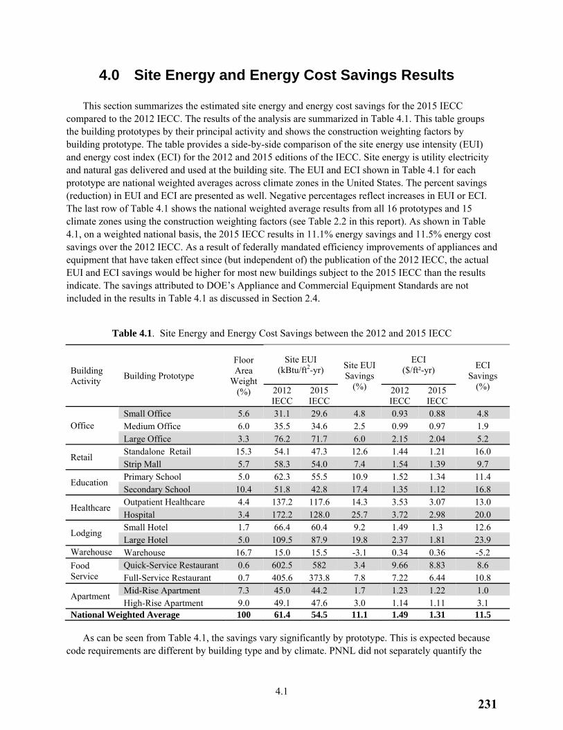
4.1
4.0 Site Energy and Energy Cost Savings Results
This section summarizes the estimated site energy and energy cost savings for the 2015 IECC compared to the 2012 IECC. The results of the analysis are summarized in Table 4.1. This table groups the building prototypes by their principal activity and shows the construction weighting factors by building prototype. The table provides a side-by-side comparison of the site energy use intensity (EUI) and energy cost index (ECI) for the 2012 and 2015 editions of the IECC. Site energy is utility electricity and natural gas delivered and used at the building site. The EUI and ECI shown in Table 4.1 for each prototype are national weighted averages across climate zones in the United States. The percent savings (reduction) in EUI and ECI are presented as well. Negative percentages reflect increases in EUI or ECI. The last row of Table 4.1 shows the national weighted average results from all 16 prototypes and 15 climate zones using the construction weighting factors (see Table 2.2 in this report). As shown in Table 4.1, on a weighted national basis, the 2015 IECC results in 11.1% energy savings and 11.5% energy cost savings over the 2012 IECC. As a result of federally mandated efficiency improvements of appliances and equipment that have taken effect since (but independent of) the publication of the 2012 IECC, the actual EUI and ECI savings would be higher for most new buildings subject to the 2015 IECC than the results indicate. The savings attributed to DOE’s Appliance and Commercial Equipment Standards are not included in the results in Table 4.1 as discussed in Section 2.4.
Table 4.1. Site Energy and Energy Cost Savings between the 2012 and 2015 IECC
Building Activity
Building Prototype
Floor Area
Weight (%)
Site EUI (kBtu/ft2-yr) Site EUI
Savings (%)
ECI ($/ft²-yr) ECI
Savings (%) 2012
IECC 2015 IECC
2012 IECC
2015 IECC
Office Small Office 5.6 31.1 29.6 4.8 0.93 0.88 4.8 Medium Office 6.0 35.5 34.6 2.5 0.99 0.97 1.9 Large Office 3.3 76.2 71.7 6.0 2.15 2.04 5.2
Retail Standalone Retail 15.3 54.1 47.3 12.6 1.44 1.21 16.0 Strip Mall 5.7 58.3 54.0 7.4 1.54 1.39 9.7
Education Primary School 5.0 62.3 55.5 10.9 1.52 1.34 11.4 Secondary School 10.4 51.8 42.8 17.4 1.35 1.12 16.8
Healthcare Outpatient Healthcare 4.4 137.2 117.6 14.3 3.53 3.07 13.0 Hospital 3.4 172.2 128.0 25.7 3.72 2.98 20.0
Lodging Small Hotel 1.7 66.4 60.4 9.2 1.49 1.3 12.6 Large Hotel 5.0 109.5 87.9 19.8 2.37 1.81 23.9
Warehouse Warehouse 16.7 15.0 15.5 -3.1 0.34 0.36 -5.2
Food Service
Quick-Service Restaurant 0.6 602.5 582 3.4 9.66 8.83 8.6 Full-Service Restaurant 0.7 405.6 373.8 7.8 7.22 6.44 10.8
Apartment Mid-Rise Apartment 7.3 45.0 44.2 1.7 1.23 1.22 1.0 High-Rise Apartment 9.0 49.1 47.6 3.0 1.14 1.11 3.1
National Weighted Average 100 61.4 54.5 11.1 1.49 1.31 11.5
As can be seen from Table 4.1, the savings vary significantly by prototype. This is expected because code requirements are different by building type and by climate. PNNL did not separately quantify the
231
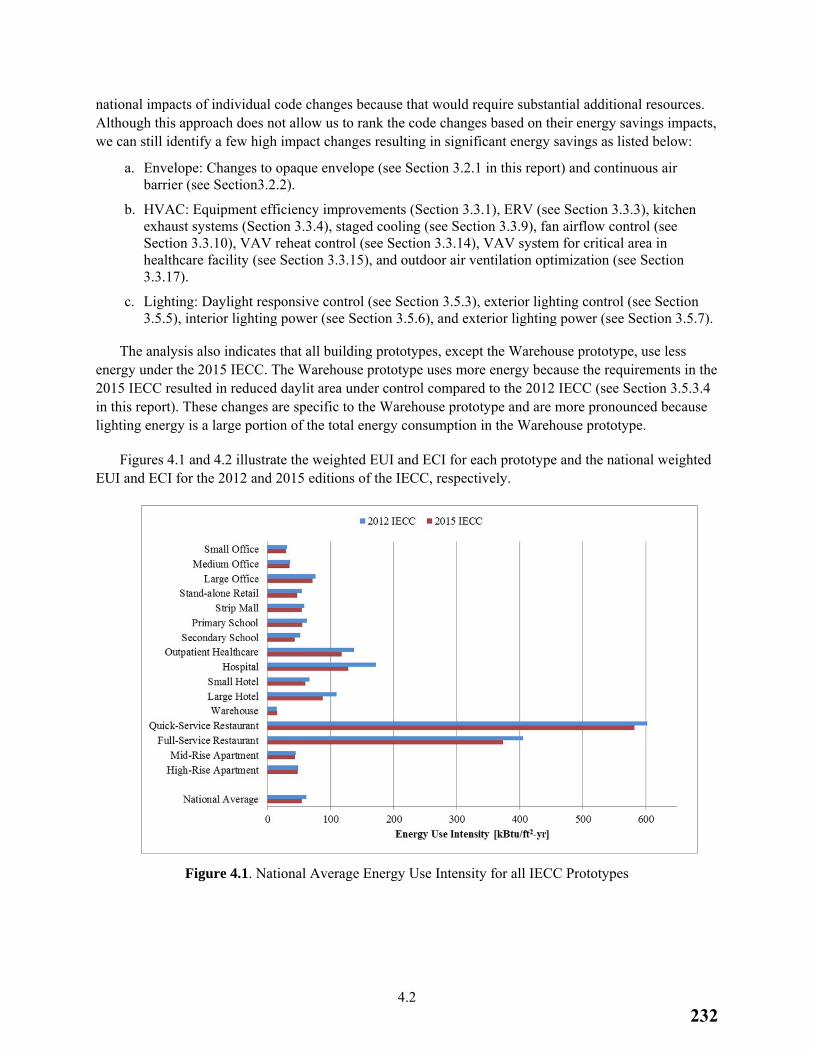
4.2
national impacts of individual code changes because that would require substantial additional resources. Although this approach does not allow us to rank the code changes based on their energy savings impacts, we can still identify a few high impact changes resulting in significant energy savings as listed below:
a. Envelope: Changes to opaque envelope (see Section 3.2.1 in this report) and continuous air barrier (see Section3.2.2).
b. HVAC: Equipment efficiency improvements (Section 3.3.1), ERV (see Section 3.3.3), kitchen exhaust systems (Section 3.3.4), staged cooling (see Section 3.3.9), fan airflow control (see Section 3.3.10), VAV reheat control (see Section 3.3.14), VAV system for critical area in healthcare facility (see Section 3.3.15), and outdoor air ventilation optimization (see Section 3.3.17).
c. Lighting: Daylight responsive control (see Section 3.5.3), exterior lighting control (see Section 3.5.5), interior lighting power (see Section 3.5.6), and exterior lighting power (see Section 3.5.7).
The analysis also indicates that all building prototypes, except the Warehouse prototype, use less energy under the 2015 IECC. The Warehouse prototype uses more energy because the requirements in the 2015 IECC resulted in reduced daylit area under control compared to the 2012 IECC (see Section 3.5.3.4 in this report). These changes are specific to the Warehouse prototype and are more pronounced because lighting energy is a large portion of the total energy consumption in the Warehouse prototype.
Figures 4.1 and 4.2 illustrate the weighted EUI and ECI for each prototype and the national weighted EUI and ECI for the 2012 and 2015 editions of the IECC, respectively.
Figure 4.1. National Average Energy Use Intensity for all IECC Prototypes
232
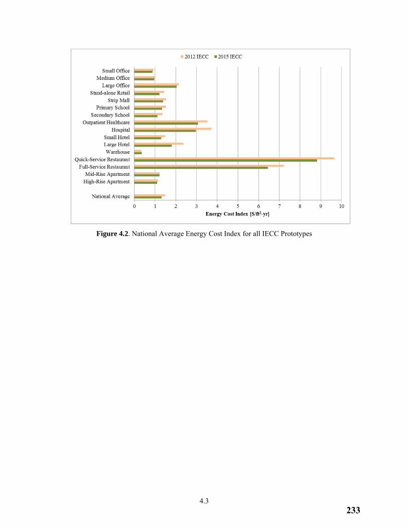
4.3
Figure 4.2. National Average Energy Cost Index for all IECC Prototypes
233
5.1
5.0 References
10 CFR 431. Chapter 10, Code of Federal Regulations, Part 431. Energy Efficiency Program for Certain Commercial and Industrial Equipment. U.S. Department of Energy, Washington, D.C. Assessed April 29, 2015 at http://www.gpo.gov/fdsys/pkg/CFR-2006-title10-vol3/pdf/CFR-2006-title10-vol3-part431.pdf.
42 USC 6833. ECPA, Public Law 94-385, as amended. Assessed April 29, 2015 at http://www.gpo.gov/fdsys/pkg/USCODE-2011-title42/pdf/USCODE-2011-title42-chap81-subchapII.pdf.
AIA. 2001. AIA Guidelines for Design and Construction of Hospital and Health Care Facilities: 2001 Edition. American Institute of Architects, Washington, D.C.
ASHRAE. 2013. ANSI/ASHRAE/IES Standard 90.1-2013. Energy Standard for Buildings Except Low-Rise Residential Buildings. American Society of Heating, Refrigerating, and Air-Conditioning Engineers, Atlanta, Georgia. Assessed April 29, 2015 at https://www.ashrae.org/standards-research--technology/standards--guidelines.
BECP – U.S. Department of Energy, Building Energy Codes Program. 2015. Status of State Energy Code Adoption. Accessed March 19, 2015 at http://www.energycodes.gov/adoption/states.
Bertagnolio S. and P. Andre. 2010. “Development of an Evidence-Based Calibration Methodology Dedicated to Energy Audit of Office Buildings. Part 1: Methodology and Modeling.” In Proceedings of the 10th REHVA World Congress - Clima 2010, Anatalya, Turkey.
Briggs R. L., R. G. Lucas, and Z. T. Taylor. 2003. “Climate Classification for Building Energy Codes and Standards: Part 1—Development Process,” ASHRAE Transactions (1):4610-4611.
DOE. 2013. EnergyPlus Energy Simulation Software, Version 8.0. U.S. Department of Energy, Washington, D.C. Assessed April 29, 2015 at http://apps1.eere.energy.gov/buildings/EnergyPlus/.
ECPA. Energy Conservation and Production Act of 1976. Public Law 94-385. Assessed April 29, 2015 at http://www.gpo.gov/fdsys/pkg/STATUTE-90/pdf/STATUTE-90-Pg1125.pdf.
EIA. 2003. Commercial Buildings Energy Consumption Survey 2003. Energy Information Administration of U.S. Department of Energy, Washington, D.C. Assessed April 29, 2015 at http://www.eia.doe.gov/emeu/cbecs/contents.html.
EISA – Energy Independence and Security Act. 2007. Energy Conservation Standards for Certain Consumer Products and Commercial and Industrial Equipment. Assessed April 29, 2015 at http://www1.eere.energy.gov/buildings/appliance_standards/pdfs/74fr12058.pdf.
EPAct – Energy Policy Act. 1992. Energy Policy Act of 1992. Assessed Oct 31, 2012 at http://uscode.house.gov/download/pls/42C81.txt.
Goel S, R. A. Athalye, W. Wang, J. Zhang, M. I. Rosenberg, Y. L. Xie, P. R. Hart, and V. V. Mendon. 2014. Enhancements to ASHRAE Standard 90.1 Prototype Building Models. PNNL-23269, Pacific
234
5.2
Northwest National Laboratory, Richland, WA. Assessed April 29, 2015 at http://www.pnnl.gov/main/publications/external/technical_reports/PNNL-23269.pdf.
Halverson M. A., R. A. Athalye, M. I. Rosenberg, Y. L. Xie, W. Wang, P. R. Hart, J. Zhang, S. Goel, and V. V. Mendon. 2014. ANSI/ASHRAE/IES Standard 90.1-2013 Determination of Energy Savings: Quantitative Analysis. PNNL-23479, Pacific Northwest National Laboratory, Richland, WA. Assessed April 29, 2015 at http://www.pnnl.gov/main/publications/external/technical_reports/PNNL-23479.pdf.
ICC 2012 – International Code Council. 2012. 2012 International Energy Conservation Code®. Washington D.C.
ICC 2015a – International Code Council. 2015. 2015 International Energy Conservation Code®. Washington D.C.
ICC 2015b – International Code Council. 2015. 2015 International Mechanical Code®. Washington D.C.
Jarnagin R. E. and G. K. Bandyopadhyay. 2010. Weighting Factors for the Commercial Prototype buildings Used in the Development of ANSI/ASHRAE/IENSA Standard 90.1-2010. PNNL-19116, Pacific Northwest National Laboratory, Richland, Washington. Assessed April 29, 2015 at http://www.pnl.gov/main/publications/external/technical_reports/PNNL-19116.pdf.
Jiang W., K. Gowri, M. D. Lane, B. A. Thornton, M. I. Rosenberg, and B. Liu. 2009. Technical Support Document: 50% Energy Savings Design Technology Packages for Highway Lodging Buildings. PNNL-18773. Pacific Northwest National Laboratory, Richland, Washington. Assessed April 29, 2015 at http://www.pnl.gov/main/publications/external/technical_reports/PNNL-18773.pdf.
Navigant. 2009. Energy Savings Potential and R&D Opportunities for Commercial Refrigeration - Final Report. Navigant Consulting, Inc, Washington, District of Columbia. Assessed April 29, 2015 at http://apps1.eere.energy.gov/buildings/publications/pdfs/corporate/commercial_refrig_report_10-09.pdf.
Thornton, B. A., W. Wang, H. Cho, Y. Xie, V. V. Mendon., E. E. Richman, J. Zhang, R. A. Athalye, M. I. Rosenberg, and B. Liu. 2011. Achieving 30% Goal: Energy and Cost Saving Analysis of ASHRAE/IES Standard 90.1-2010. PNNL-20405. Pacific Northwest National Laboratory, Richland, Washington. Assessed April 29, 2015 at http://www.energycodes.gov/publications/research/documents/codes/PNNL-20405.pdf.
Zhang J, R. A. Athalye, P. R. Hart, M. I. Rosenberg, Y. L. Xie, S. Goel, V. V. Mendon, and B. Liu. 2013. Energy and Energy Cost Savings Analysis of the IECC for Commercial Buildings. PNNL-22760, Pacific Northwest National Laboratory, Richland, WA. Assessed April 29, 2015 at http://www.pnnl.gov/main/publications/external/technical_reports/PNNL-22760.pdf.
235
Appendix A
Code Changes from the 2012 to 2015 IECC Included in Analysis and their Impact on Building Prototypes
236
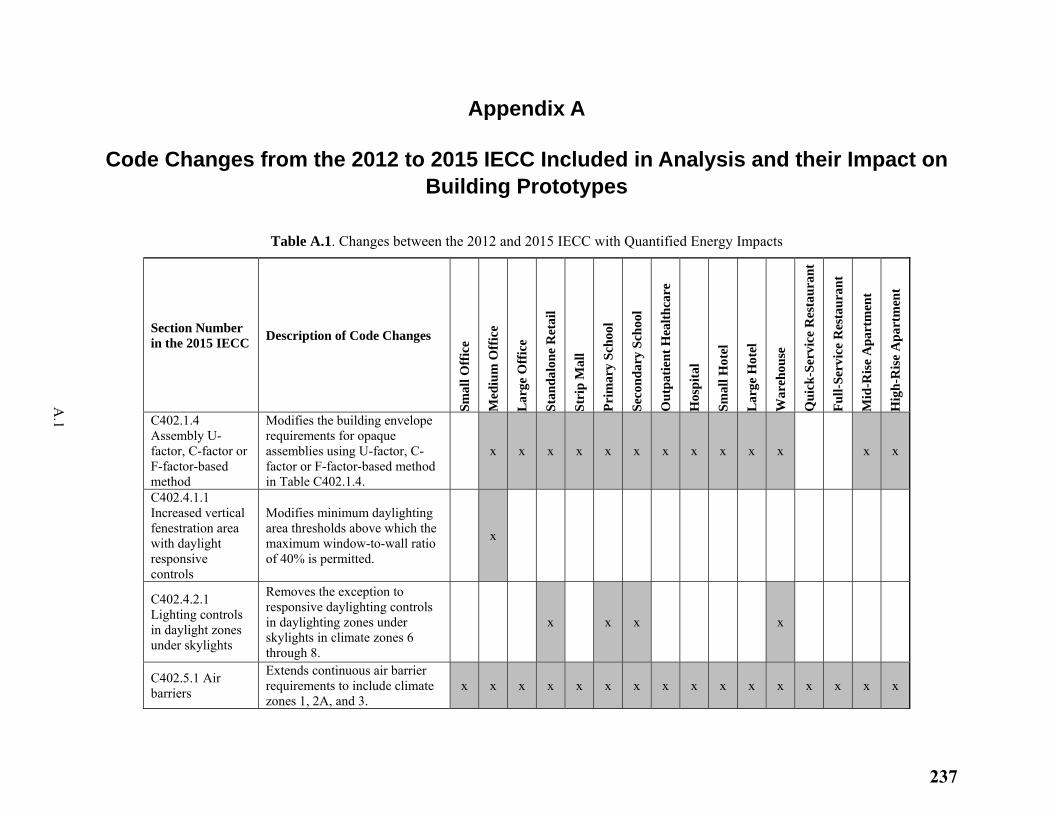
A.1
Appendix A
Code Changes from the 2012 to 2015 IECC Included in Analysis and their Impact on Building Prototypes
Table A.1. Changes between the 2012 and 2015 IECC with Quantified Energy Impacts
Section Number in the 2015 IECC
Description of Code Changes
Sm
all O
ffic
e
Med
ium
Off
ice
Lar
ge O
ffic
e
Sta
nda
lon
e R
etai
l
Str
ip M
all
Pri
mar
y S
choo
l
Sec
ond
ary
Sch
ool
Ou
tpat
ien
t H
ealt
hca
re
Hos
pit
al
Sm
all H
otel
Lar
ge H
otel
War
ehou
se
Qu
ick
-Ser
vice
Res
tau
ran
t
Fu
ll-S
ervi
ce R
esta
ura
nt
Mid
-Ris
e A
part
men
t
Hig
h-R
ise
Apa
rtm
ent
C402.1.4 Assembly U-factor, C-factor or F-factor-based method
Modifies the building envelope requirements for opaque assemblies using U-factor, C-factor or F-factor-based method in Table C402.1.4.
x x x x x x x x x x x x x
C402.4.1.1 Increased vertical fenestration area with daylight responsive controls
Modifies minimum daylighting area thresholds above which the maximum window-to-wall ratio of 40% is permitted.
x
C402.4.2.1 Lighting controls in daylight zones under skylights
Removes the exception to responsive daylighting controls in daylighting zones under skylights in climate zones 6 through 8.
x x x x
C402.5.1 Air barriers
Extends continuous air barrier requirements to include climate zones 1, 2A, and 3.
x x x x x x x x x x x x x x x x
237
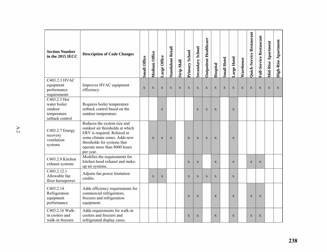
A.2
Section Number in the 2015 IECC
Description of Code Changes
Sm
all O
ffic
e
Med
ium
Off
ice
Lar
ge O
ffic
e
Sta
nda
lon
e R
etai
l
Str
ip M
all
Pri
mar
y S
choo
l
Sec
ond
ary
Sch
ool
Ou
tpat
ien
t H
ealt
hca
re
Hos
pit
al
Sm
all H
otel
Lar
ge H
otel
War
ehou
se
Qu
ick
-Ser
vice
Res
tau
ran
t
Fu
ll-S
ervi
ce R
esta
ura
nt
Mid
-Ris
e A
part
men
t
Hig
h-R
ise
Apa
rtm
ent
C403.2.3 HVAC equipment performance requirements
Improves HVAC equipment efficiency.
x x x x x x x x x x x x x x x x
C403.2.5 Hot water boiler outdoor temperature setback control
Requires boiler temperature setback control based on the outdoor temperature.
x x x x x
C403.2.7 Energy recovery ventilation systems
Reduces the system size and outdoor air thresholds at which ERV is required. Relaxed in some climate zones. Adds new thresholds for systems that operate more than 8000 hours per year.
x x x x x x x x
C403.2.8 Kitchen exhaust systems
Modifies the requirements for kitchen hood exhaust and make-up air systems.
x x x x x x
C403.2.12.1 Allowable fan floor horsepower
Adjusts fan power limitation credits.
x x x x x x x
C403.2.14 Refrigeration equipment performance
Adds efficiency requirements for commercial refrigerators, freezers and refrigeration equipment.
x x x x x x
C403.2.16 Walk-in coolers and walk-in freezers
Adds requirements for walk-in coolers and freezers and refrigerated display cases.
x x x x x x
238
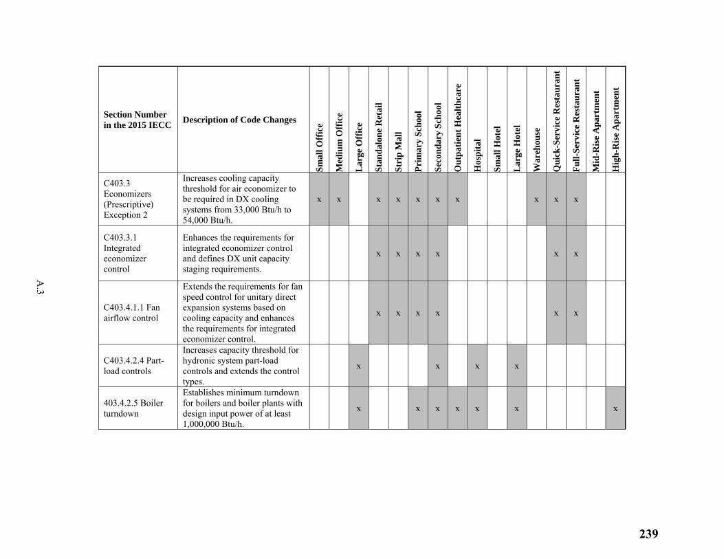
A.3
Section Number in the 2015 IECC
Description of Code Changes
Sm
all O
ffic
e
Med
ium
Off
ice
Lar
ge O
ffic
e
Sta
nda
lon
e R
etai
l
Str
ip M
all
Pri
mar
y S
choo
l
Sec
ond
ary
Sch
ool
Ou
tpat
ien
t H
ealt
hca
re
Hos
pit
al
Sm
all H
otel
Lar
ge H
otel
War
ehou
se
Qu
ick
-Ser
vice
Res
tau
ran
t
Fu
ll-S
ervi
ce R
esta
ura
nt
Mid
-Ris
e A
part
men
t
Hig
h-R
ise
Apa
rtm
ent
C403.3 Economizers (Prescriptive) Exception 2
Increases cooling capacity threshold for air economizer to be required in DX cooling systems from 33,000 Btu/h to 54,000 Btu/h.
x x x x x x x x x x
C403.3.1 Integrated economizer control
Enhances the requirements for integrated economizer control and defines DX unit capacity staging requirements.
x x x x x x
C403.4.1.1 Fan airflow control
Extends the requirements for fan speed control for unitary direct expansion systems based on cooling capacity and enhances the requirements for integrated economizer control.
x x x x x x
C403.4.2.4 Part-load controls
Increases capacity threshold for hydronic system part-load controls and extends the control types.
x x x x
403.4.2.5 Boiler turndown
Establishes minimum turndown for boilers and boiler plants with design input power of at least 1,000,000 Btu/h.
x x x x x x x
239
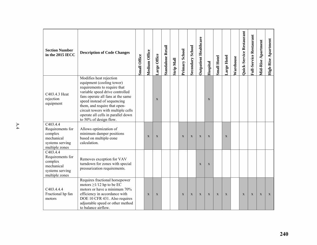
A.4
Section Number in the 2015 IECC
Description of Code Changes
Sm
all O
ffic
e
Med
ium
Off
ice
Lar
ge O
ffic
e
Sta
nda
lon
e R
etai
l
Str
ip M
all
Pri
mar
y S
choo
l
Sec
ond
ary
Sch
ool
Ou
tpat
ien
t H
ealt
hca
re
Hos
pit
al
Sm
all H
otel
Lar
ge H
otel
War
ehou
se
Qu
ick
-Ser
vice
Res
tau
ran
t
Fu
ll-S
ervi
ce R
esta
ura
nt
Mid
-Ris
e A
part
men
t
Hig
h-R
ise
Apa
rtm
ent
C403.4.3 Heat rejection equipment
Modifies heat rejection equipment (cooling tower) requirements to require that variable speed drive controlled fans operate all fans at the same speed instead of sequencing them, and require that open-circuit towers with multiple cells operate all cells in parallel down to 50% of design flow.
x x
C403.4.4 Requirements for complex mechanical systems serving multiple zones
Allows optimization of minimum damper positions based on multiple-zone calculation.
x x x x x x x
C403.4.4 Requirements for complex mechanical systems serving multiple zones
Removes exception for VAV turndown for zones with special pressurization requirements.
x x
C403.4.4.4 Fractional hp fan motors
Requires fractional horsepower motors ≥1/12 hp to be EC motors or have a minimum 70% efficiency in accordance with DOE 10 CFR 431. Also requires adjustable speed or other method to balance airflow.
x x x x x x x x x x x x
240
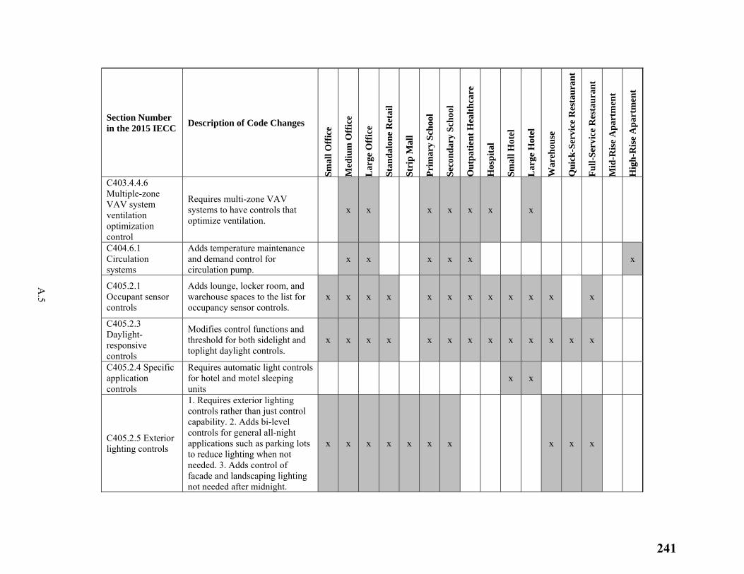
A.5
Section Number in the 2015 IECC
Description of Code Changes
Sm
all O
ffic
e
Med
ium
Off
ice
Lar
ge O
ffic
e
Sta
nda
lon
e R
etai
l
Str
ip M
all
Pri
mar
y S
choo
l
Sec
ond
ary
Sch
ool
Ou
tpat
ien
t H
ealt
hca
re
Hos
pit
al
Sm
all H
otel
Lar
ge H
otel
War
ehou
se
Qu
ick
-Ser
vice
Res
tau
ran
t
Fu
ll-S
ervi
ce R
esta
ura
nt
Mid
-Ris
e A
part
men
t
Hig
h-R
ise
Apa
rtm
ent
C403.4.4.6 Multiple-zone VAV system ventilation optimization control
Requires multi-zone VAV systems to have controls that optimize ventilation.
x x x x x x x
C404.6.1 Circulation systems
Adds temperature maintenance and demand control for circulation pump.
x x x x x x
C405.2.1 Occupant sensor controls
Adds lounge, locker room, and warehouse spaces to the list for occupancy sensor controls.
x x x x x x x x x x x x
C405.2.3 Daylight-responsive controls
Modifies control functions and threshold for both sidelight and toplight daylight controls.
x x x x x x x x x x x x x
C405.2.4 Specific application controls
Requires automatic light controls for hotel and motel sleeping units
x x
C405.2.5 Exterior lighting controls
1. Requires exterior lighting controls rather than just control capability. 2. Adds bi-level controls for general all-night applications such as parking lots to reduce lighting when not needed. 3. Adds control of facade and landscaping lighting not needed after midnight.
x x x x x x x x x x
241
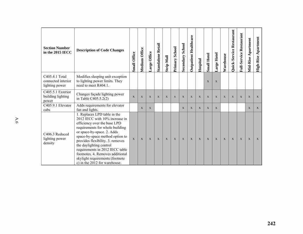
A.6
Section Number in the 2015 IECC
Description of Code Changes
Sm
all O
ffic
e
Med
ium
Off
ice
Lar
ge O
ffic
e
Sta
nda
lon
e R
etai
l
Str
ip M
all
Pri
mar
y S
choo
l
Sec
ond
ary
Sch
ool
Ou
tpat
ien
t H
ealt
hca
re
Hos
pit
al
Sm
all H
otel
Lar
ge H
otel
War
ehou
se
Qu
ick
-Ser
vice
Res
tau
ran
t
Fu
ll-S
ervi
ce R
esta
ura
nt
Mid
-Ris
e A
part
men
t
Hig
h-R
ise
Apa
rtm
ent
C405.4.1 Total connected interior lighting power
Modifies sleeping unit exception to lighting power limits. They need to meet R404.1.
x x
C405.5.1 Exterior building lighting power
Changes façade lighting power in Table C405.5.2(2)
x x x x x x x x x x x x x x x x
C405.9.1 Elevator cabs
Adds requirements for elevator fan and lights.
x x x x x x x x x
C406.3 Reduced lighting power density
1. Replaces LPD table in the 2012 IECC with 10% increase in efficiency over the base LPD requirements for whole building or space-by-space. 2. Adds space-by-space method option to provides flexibility. 3. removes the daylighting control requirements in 2012 IECC table footnotes. 4. Removes additional skylight requirements (footnote c) in the 2012 for warehouse.
x x x x x x x x x x x x x x x x
242
Appendix B
Energy and Energy Cost Savings for the 2015 IECC and Corresponding Standard 90.1-2013
243
B.1
Appendix B
Energy and Energy Cost Savings for the 2015 IECC and Corresponding Standard 90.1-2013
Section 304(b) of the ECPA (Energy Conservation and Production Act), as amended, requires the Secretary of Energy to make a determination each time a revised edition of Standard 90.1 is published with respect to whether the revised standard would improve energy efficiency in commercial buildings. When DOE issues an affirmative determination on Standard 90.1, states are statutorily required to certify within two years that they have reviewed and updated the commercial provisions of their building energy code, with respect to energy efficiency, to meet or exceed the revised standard (42 USC 6833).
In support of DOE’s determination, PNNL conducted an energy savings analysis for Standard 90.1-2013 compared to Standard 90.1-2010 (Halverson et al. 2014). Based on that analysis, DOE issued a determination that Standard 90.1-2013 would achieve greater energy efficiency in buildings compared to the 2010 edition of the standard.
As many states have historically adopted the IECC for both residential and commercial buildings, PNNL has also compared energy performance of Standard 90.1-2013 with the 2015 IECC to help states and local jurisdictions make informed decisions regarding model code adoption. Of the 47 States with statewide commercial building energy codes currently, 37 use a version of the IECC (BECP 2015).
Table B.1 shows side-by-side comparisons of the site EUI and ECI for Standard 90.1-2013 and the 2015 IECC for each of 16 prototype buildings along with the percent difference between the two. The national weighted average of all prototypes combined is also shown. Figures B.1 and B.2 show the same results graphically. Negative percentage differences indicate higher energy or energy costs for buildings designed to the 2015 IECC compared to those designed to Standard 90.1-2013. For most prototypes, both EUIs and ECIs were slightly lower using Standard 90.1-2013. One notable exception is the Warehouse prototype where the 2015 IECC resulted in lower energy use and energy costs. This difference is because Standard 90.1-2013 has a category for semi-heated spaces allowing relaxed levels of insulation, while the 2015 IECC does not.
The comparisons show the combined energy impacts of differences between the 2015 IECC and Standard 90.1-2013. Although the current analysis does not compare or rank the individual differences based on their energy savings, a few high impact differences by category can be identified as follows:
a. Envelope
○ Prescriptive WWR limit: the 2015 IECC allows a WWR up to 30% unless a significant portion of the building is equipped with daylight responsive controls, in which case up to 40% is allowed. Standard 90.1-2013 requires WWR less than 40%.
○ Semi-heated space envelope requirements: the 2015 IECC does not have separate envelope requirements for semi-heated spaces. Semi-heated spaces are required to follow conditioned space requirements. Standard 90.1-2013 has less stringent insulation requirements for semi-heated spaces.
244
B.2
○ Vertical fenestration U-factor independent of frame material: the U-factor requirements for vertical fenestrations in the 2015 IECC are independent of the frame material. Standard 90.1-2013 has higher U-factors for metal-framed fenestrations than for nonmetal-framed fenestrations.
○ SHGC for north-oriented vertical fenestrations: the 2015 IECC sets higher maximum SHGCs for north-oriented fenestrations than those facing other orientations. Standard 90.1-2013 allows a much smaller relaxation of SHGC (SHGC-0.05) for north-oriented fenestrations. The impact of this difference is not captured in the current analysis because the prototype building facades are all facing true east, south, west, or north and the energy impact is negligible for true north-oriented facades. However, both the 2015 IECC and Standard 90.1-2013 define north-oriented fenestration as that which is facing within 45 degrees of true north in the northern hemisphere. For fenestration offset from true north by up to 45 degrees, the relaxation of SHGC may be significant.
○ Vestibule exceptions: the 2015 IECC exempts building entrance doors that open up to a space less than 3,000 sf; Standard 90.1-2013 does not. The 2015 IECC also includes an exception from vestibule requirements if an air curtain is installed instead; Standard 90.1-2013 does not have such an exception.
○ Fenestration orientation: the 2015 IECC does not limit the distribution of fenestration area. Standard 90.1-2013 limits the fenestration area on the east and west façades.
b. Building mechanical systems
○ Shutoff damper controls: the 2015 IECC exempts buildings with less than 3 stories from the motorized damper requirements for ventilation air intakes; Standard 90.1-2013 does not have such an exception.
c. Lighting
○ Dwelling unit (apartment) lighting power: the 2015 IECC requires 75% of all permanently installed luminaires in dwelling units to be high efficacy. Standard 90.1-2013 exempts dwelling units from lighting power requirements.
○ Controls for secondary daylight zone: the 2015 IECC does not require secondary daylight zones to have daylight responsive controls; Standard 90.1-2013 does.
d. Additional efficiency package options
○ The 2015 IECC requires one of the six high efficiency package options to be included; Standard 90.1-2013 does not have such options.
On a national average basis for all prototypes combined, the 2015 IECC and Standard 90.1-2013 are within 1% for both energy use and energy costs. The 2015 IECC has a national weighted EUI of 54.5 kBtu/ft²-yr while the corresponding number for Standard 90.1-2013 is 54.1 kBtu/ft²-yr. Likewise, the ECIs are very close between the 2015 IECC (1.31 $/ft²-yr) and Standard 90.1-2013 (1.30 $/ft²-yr).
245
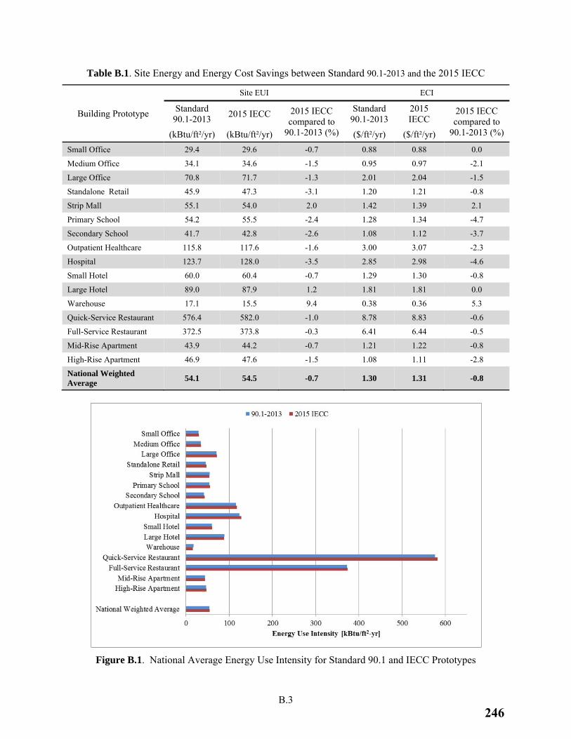
B.3
Table B.1. Site Energy and Energy Cost Savings between Standard 90.1-2013 and the 2015 IECC
Building Prototype
Site EUI ECI
Standard 90.1-2013
2015 IECC 2015 IECC compared to
90.1-2013 (%)
Standard 90.1-2013
2015 IECC
2015 IECC compared to
90.1-2013 (%) (kBtu/ft²/yr) (kBtu/ft²/yr) ($/ft²/yr) ($/ft²/yr)
Small Office 29.4 29.6 -0.7 0.88 0.88 0.0
Medium Office 34.1 34.6 -1.5 0.95 0.97 -2.1
Large Office 70.8 71.7 -1.3 2.01 2.04 -1.5
Standalone Retail 45.9 47.3 -3.1 1.20 1.21 -0.8
Strip Mall 55.1 54.0 2.0 1.42 1.39 2.1
Primary School 54.2 55.5 -2.4 1.28 1.34 -4.7
Secondary School 41.7 42.8 -2.6 1.08 1.12 -3.7
Outpatient Healthcare 115.8 117.6 -1.6 3.00 3.07 -2.3
Hospital 123.7 128.0 -3.5 2.85 2.98 -4.6
Small Hotel 60.0 60.4 -0.7 1.29 1.30 -0.8
Large Hotel 89.0 87.9 1.2 1.81 1.81 0.0
Warehouse 17.1 15.5 9.4 0.38 0.36 5.3
Quick-Service Restaurant 576.4 582.0 -1.0 8.78 8.83 -0.6
Full-Service Restaurant 372.5 373.8 -0.3 6.41 6.44 -0.5
Mid-Rise Apartment 43.9 44.2 -0.7 1.21 1.22 -0.8
High-Rise Apartment 46.9 47.6 -1.5 1.08 1.11 -2.8
National Weighted Average
54.1 54.5 -0.7 1.30 1.31 -0.8
Figure B.1. National Average Energy Use Intensity for Standard 90.1 and IECC Prototypes
246
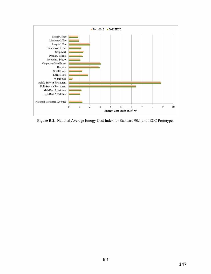
B.4
Figure B.2. National Average Energy Cost Index for Standard 90.1 and IECC Prototypes
247

248
249
Reproduction of this document in whole or in part and in any form for educational or nonprofit purposes may be made without special permission from Bayer MaterialScience, provided acknowledgement of the source is made. Bayer MaterialScience would appreciate receiving a copy of any publication or material that uses this document as a source.
Published by the Communications Department of Bayer MaterialScience.
© Bayer MaterialScience, 2009
Contact: Mr. Jerry Phelan, [email protected]
DISCLAIMER
The authors of this building energy simulation and life cycle study have compiled detailed information provided by internal and external sources, and have conducted engineering calculations and generated market and technical data to the best of their knowledge and belief at the time of this writing. The authors endeavor to improve and expand on the results of this report in subsequent studies. No representation is made or warranty given, either expressly or tacitly, for the completeness or correctness of the information in this study. Neither Bayer MaterialScience nor third parties involved in providing information for this study may be held liable for use or misuse of information provided in this report. This report contains references to non-Bayer MaterialScience companies, services and websites. By providing these references, Bayer MaterialScience is not endorsing or approving their products, services and websites, and cannot confirm the accuracy or completeness of the information or services provided therein. Access and use of these references is at the user's risk. Bayer MaterialScience will not be liable for any harm resulting from the use of non-Bayer MaterialScience products, services or websites. It is the responsibility of the user of non-Bayer MaterialScience products, services and information to comply with all applicable laws and regulations.
ACKNOWLEDGEMENTS
The authors of this study wish to acknowledge and thank Mr. Jeff Mang, of Hogan and Hartson LLP, for his guidance and support in the development of the scope of this study as well as his assistance with the initial market research. We also wish to thank the Center for Environmental Innovation in Roofing’s (CEIR) Mr. Craig Silvertooth, Executive Director, Dr. James Hoff, Research Director, and Mr. Stephen Dobson, graduate student and intern, for providing feedback, practical advice and recommendations.
We also acknowledge the Department of Energy’s Office of Energy Efficiency and Renewable Energy, contributing contractors and the National Laboratories involved in the development and continuing optimization of the EnergyPlus simulation program as well as the Commercial Building Benchmark Models through the “Net Zero Commercial Building Initiative”. These tools provided vital resources on which this study was conducted and will certainly contribute highly to other energy efficiency and environmental based research in the future.
250
TABLE OF CONTENTS Executive Summary
1.0 Background, Purposes and Scope 2.0 Energy Modeling
2.1 EnergyPlus 2.2 Commercial Building Benchmark Models
3.0 Study Simulation Descriptions 3.1 Model Building Types 3.2 Building Locations and Climate Zones 3.3 Characteristics of Existing and Retrofit Building Models 3.4 Roof U-value Calculation Methodology
4.0 Economic Analysis 4.1 Utility Costs 4.2 First Costs
5.0 Simulation Results 5.1 Energy Consumption Characteristics by Building Type 5.2 Energy Consumption Characteristics by Climate Zone 5.3 Energy from Energy Efficient Roof Construction
6.0 Discussion of Energy and Environmental Impact 6.1 Energy Impacts 6.2 GWP Impacts 6.3 Other Environmental Aspects
7.0 Commercial Building Market Analysis 7.1 CBECS 2003 7.2 Building Type and Climate Zone Weighting Methodologies 7.3 The Commercial Roof Replacement Market 7.4 Private Versus Public Existing Commercial Buildings
8.0 Impact Assessment 8.1 Validation of Modeling Results 8.2 Annual Energy Savings – Site 8.3 First Year Energy Cost Savings 8.4 GWP Emissions Prevented 8.5 Cumulative Impact Assessment
9.0 Payback Analysis 9.1 Overall Results 9.2 Market Weighted Findings 9.3 Tax Incentive Impact
10.0 Conclusions
Biographies
2251
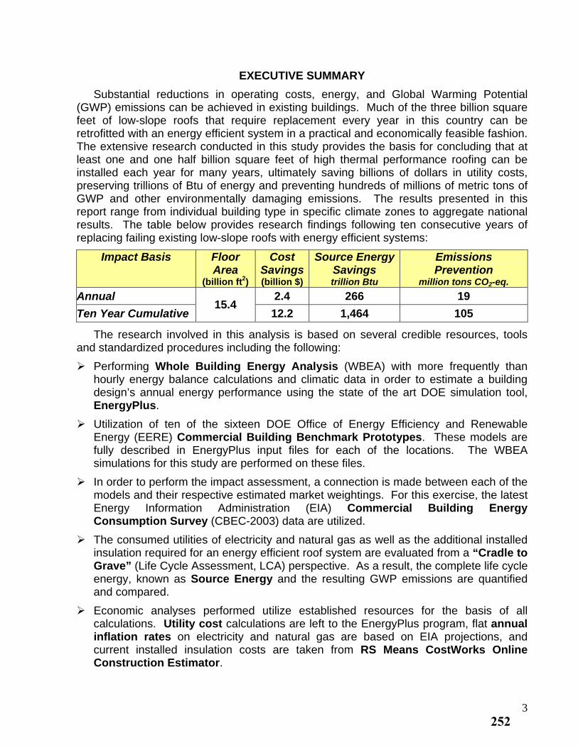
EXECUTIVE SUMMARY
Substantial reductions in operating costs, energy, and Global Warming Potential (GWP) emissions can be achieved in existing buildings. Much of the three billion square feet of low-slope roofs that require replacement every year in this country can be retrofitted with an energy efficient system in a practical and economically feasible fashion. The extensive research conducted in this study provides the basis for concluding that at least one and one half billion square feet of high thermal performance roofing can be installed each year for many years, ultimately saving billions of dollars in utility costs, preserving trillions of Btu of energy and preventing hundreds of millions of metric tons of GWP and other environmentally damaging emissions. The results presented in this report range from individual building type in specific climate zones to aggregate national results. The table below provides research findings following ten consecutive years of replacing failing existing low-slope roofs with energy efficient systems:
Impact Basis Floor Area
(billion ft2)
Cost Savings(billion $)
Source Energy Savings trillion Btu
Emissions Prevention
million tons CO2-eq.
Annual 2.4 266 19
Ten Year Cumulative 15.4
12.2 1,464 105
The research involved in this analysis is based on several credible resources, tools and standardized procedures including the following:
Performing Whole Building Energy Analysis (WBEA) with more frequently than hourly energy balance calculations and climatic data in order to estimate a building design’s annual energy performance using the state of the art DOE simulation tool, EnergyPlus.
Utilization of ten of the sixteen DOE Office of Energy Efficiency and Renewable Energy (EERE) Commercial Building Benchmark Prototypes. These models are fully described in EnergyPlus input files for each of the locations. The WBEA simulations for this study are performed on these files.
In order to perform the impact assessment, a connection is made between each of the models and their respective estimated market weightings. For this exercise, the latest Energy Information Administration (EIA) Commercial Building Energy Consumption Survey (CBEC-2003) data are utilized.
The consumed utilities of electricity and natural gas as well as the additional installed insulation required for an energy efficient roof system are evaluated from a “Cradle to Grave” (Life Cycle Assessment, LCA) perspective. As a result, the complete life cycle energy, known as Source Energy and the resulting GWP emissions are quantified and compared.
Economic analyses performed utilize established resources for the basis of all calculations. Utility cost calculations are left to the EnergyPlus program, flat annual inflation rates on electricity and natural gas are based on EIA projections, and current installed insulation costs are taken from RS Means CostWorks Online Construction Estimator.
3252
1.0 BACKGROUND, PURPOSES AND SCOPE
A rapidly accelerating awareness of the energy and environmental challenges facing us today has spurred enhanced energy efficiency standards, stricter codes and emerging technologies in new construction. As a result, there is confidence that buildings constructed over the coming years will consume less and less energy. Unfortunately, these activities rarely impact the energy consumption levels of the more than 70 billion square feet of existing commercial building floor space in this country.
This study explores one of the most practical and economically feasible opportunities for improving the energy efficiency in existing buildings: Roof replacement of low-slope roofed buildings, i.e. replacement of waterproofing membrane. It is commonly known that a typical building requires three roof replacements during its lifetime or roughly one replacement every twenty years. Thus, routine roof replacement facilitates implementation of the long-proven energy efficiency measure of added levels of insulation.
The current economic crisis has all but stalled the re-roofing market and thus so has also deeply impacted the opportunity to decrease energy consumption in buildings. Initial costs and tight capital cause building owners to resort to patch work in order to extend the life of roofs. This report serves to aid in evaluating the impact of this dilemma and provides support to measures taken to help resolve it.
The Polyisocyanurate Insulation Manufacturers Association (PIMA) and Center for Environmental Innovation in Roofing (CEIR) are proposing that the U.S. Congress implement a tax incentive for the purpose of encouraging the installation of energy efficient roofs on existing buildings. This incentive would be applicable specifically to any existing commercial and high rise (i.e. greater than three stories) residential building with a low-slope roof. The majority of commercial floor space in the United States is in buildings that have low-slope roofs. In order to qualify, the replacement roof would be required to have a minimum insulation R-value of 25, 30 or 35 depending on the climate zone in which the building is located, and would required to be placed in service during 2009 through 2013.
The adoption of a tax incentive requires full vetting of tax revenue impacts weighed against incurred benefits to the public. Here, the benefits would include immediate and long lasting energy cost and resource savings, prevention of substantial global warming emissions, and jobs creation. One of the purposes of this study is to assess the potential impact of a surge of energy efficient roof replacements in terms of cumulative national energy savings, global warming emissions prevention. Therefore, by conducting this analysis, the authors are providing detailed and credible information for legislators so that a sound decision can be made regarding the merits of this proposal.
The scope established for this research is all existing buildings in the United States with low-slope roofs that are in need of roof replacement, or whose owners upgrade their facility in such ways as installing solar equipment or improving energy efficiency. This serves as the boundary for relating the energy modeling performed in this analysis to available commercial building market information. The energy modeling, along with weighting factors developed from market data (Section 7) form the basis for performing the impact assessment (Section 8).
4253
2.0 ENERGY MODELING
Climatic conditions, location and building orientation, envelope characteristics, HVAC and other operating systems, and building use and occupant activities along with the interactions between these components create great complexity in determining the energy consumption of any specific building. Computer-based simulation programs which make thousands of complete energy balance calculations that incorporate all of these variables and their interactions are utilized to perform Whole Building Energy Analysis (WBEA). WBEA is frequently conducted on individual building designs in order to predict energy performance. This analysis is required during the design phase in cases such as qualifying for LEED certification and tax deductions under the Energy Conservation Act of 2005. Appendix G of ASHRAE 90.1, “Performance Rating Method”, includes WBEA as a key component and lists in Section G2 a number of requirements which any simulation tool must satisfy in order to be utilized in this widely accepted energy rating method.
Clearly, the use of a rigorous energy simulation tool is essential in order to closely predict the performance of any specific building design. However, the resources required in order to conduct this type of analysis make it impractical for every project, particularly retrofit jobs such as roof replacement. The authors believe that one can reference specific detailed results from this study to provide an estimate of the benefits realized by completing an energy efficient roof replacement project.
2.1 EnergyPlus
EnergyPlus is a fully integrated building and HVAC simulation software program. It is a product of the Department of Energy (DOE) and was originally developed and is updated twice annually by DOE contractors. The basis for EnergyPlus is BLAST and DOE-2.1E, two earlier DOE programs. The strongest features of these programs were incorporated into EnergyPlus along with additional capabilities.1
The latest version of EnergyPlus, 3.0.0, can be downloaded from the DOE Energy Efficiency and Renewable Energy website free of charge. Along with the program setup and launch, the download provides extensive reference documentation on the engineering basis behind the simulation calculations. The website also provides access to hundreds of hourly weather data files from around the world which can be linked to the specific EnergyPlus simulation file that one is utilizing.
1
U.S. Department of Energy, Energy Efficiency and Renewable Energy, www.eere.energy.gov Programs: Building Technologies.
5254
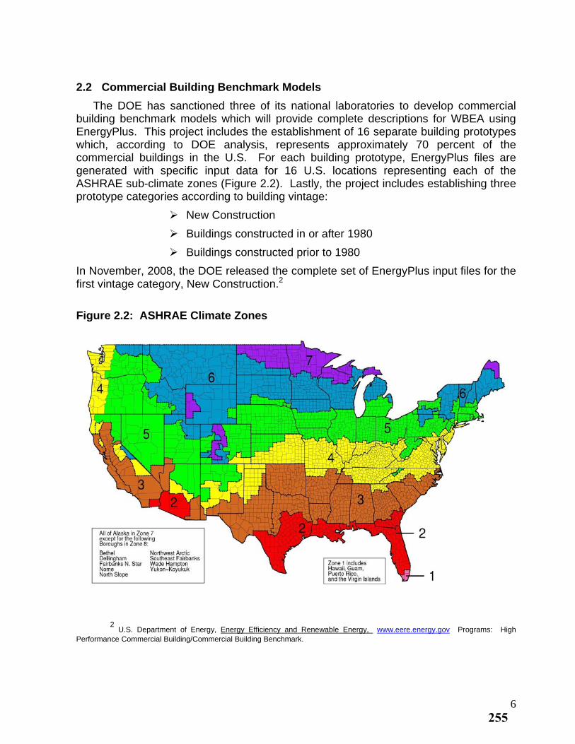
2.2 Commercial Building Benchmark Models
The DOE has sanctioned three of its national laboratories to develop commercial building benchmark models which will provide complete descriptions for WBEA using EnergyPlus. This project includes the establishment of 16 separate building prototypes which, according to DOE analysis, represents approximately 70 percent of the commercial buildings in the U.S. For each building prototype, EnergyPlus files are generated with specific input data for 16 U.S. locations representing each of the ASHRAE sub-climate zones (Figure 2.2). Lastly, the project includes establishing three prototype categories according to building vintage:
New Construction
Buildings constructed in or after 1980
Buildings constructed prior to 1980
In November, 2008, the DOE released the complete set of EnergyPlus input files for the first vintage category, New Construction.2
Figure 2.2: ASHRAE Climate Zones
2
U.S. Department of Energy, Energy Efficiency and Renewable Energy, www.eere.energy.gov Programs: High Performance Commercial Building/Commercial Building Benchmark.
6255
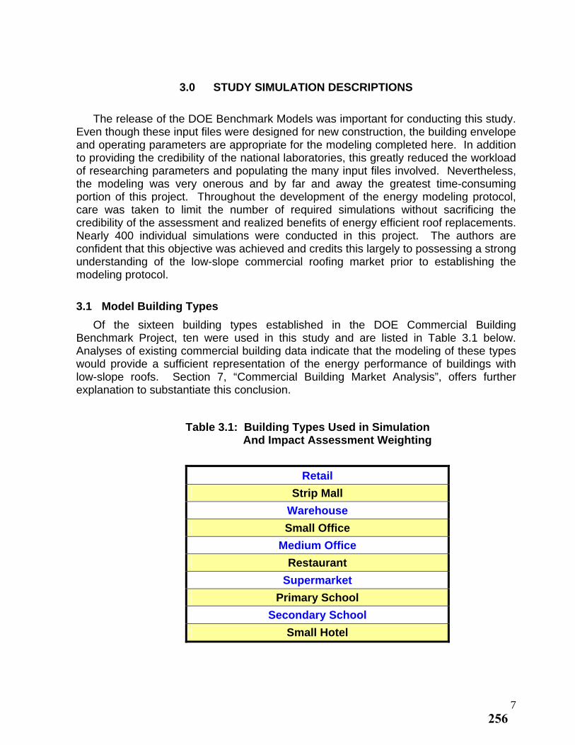
3.0 STUDY SIMULATION DESCRIPTIONS
The release of the DOE Benchmark Models was important for conducting this study. Even though these input files were designed for new construction, the building envelope and operating parameters are appropriate for the modeling completed here. In addition to providing the credibility of the national laboratories, this greatly reduced the workload of researching parameters and populating the many input files involved. Nevertheless, the modeling was very onerous and by far and away the greatest time-consuming portion of this project. Throughout the development of the energy modeling protocol, care was taken to limit the number of required simulations without sacrificing the credibility of the assessment and realized benefits of energy efficient roof replacements. Nearly 400 individual simulations were conducted in this project. The authors are confident that this objective was achieved and credits this largely to possessing a strong understanding of the low-slope commercial roofing market prior to establishing the modeling protocol.
3.1 Model Building Types
Of the sixteen building types established in the DOE Commercial Building Benchmark Project, ten were used in this study and are listed in Table 3.1 below. Analyses of existing commercial building data indicate that the modeling of these types would provide a sufficient representation of the energy performance of buildings with low-slope roofs. Section 7, “Commercial Building Market Analysis”, offers further explanation to substantiate this conclusion.
Table 3.1: Building Types Used in Simulation And Impact Assessment Weighting
Retail
Strip Mall
Warehouse
Small Office
Medium Office
Restaurant
Supermarket
Primary School
Secondary School
Small Hotel
7256
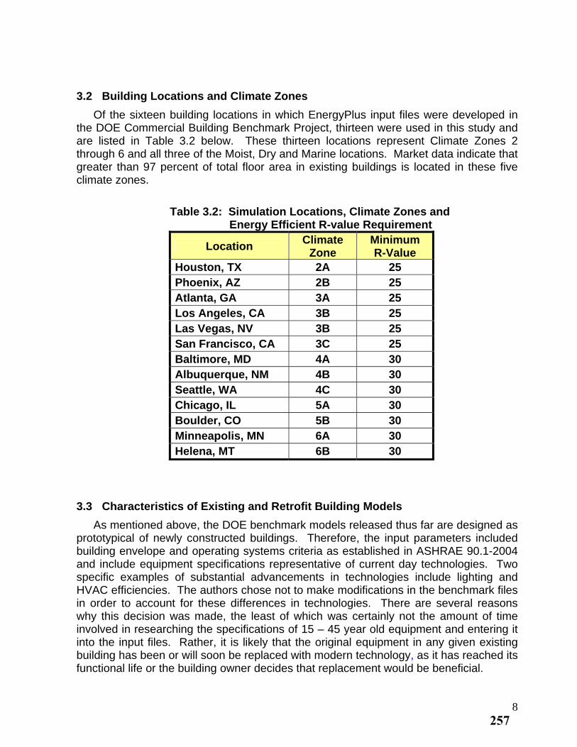
3.2 Building Locations and Climate Zones
Of the sixteen building locations in which EnergyPlus input files were developed in the DOE Commercial Building Benchmark Project, thirteen were used in this study and are listed in Table 3.2 below. These thirteen locations represent Climate Zones 2 through 6 and all three of the Moist, Dry and Marine locations. Market data indicate that greater than 97 percent of total floor area in existing buildings is located in these five climate zones.
Table 3.2: Simulation Locations, Climate Zones and
Energy Efficient R-value Requirement
Location Climate
Zone Minimum R-Value
Houston, TX 2A 25 Phoenix, AZ 2B 25 Atlanta, GA 3A 25 Los Angeles, CA 3B 25 Las Vegas, NV 3B 25 San Francisco, CA 3C 25 Baltimore, MD 4A 30 Albuquerque, NM 4B 30 Seattle, WA 4C 30 Chicago, IL 5A 30 Boulder, CO 5B 30 Minneapolis, MN 6A 30 Helena, MT 6B 30
3.3 Characteristics of Existing and Retrofit Building Models
As mentioned above, the DOE benchmark models released thus far are designed as prototypical of newly constructed buildings. Therefore, the input parameters included building envelope and operating systems criteria as established in ASHRAE 90.1-2004 and include equipment specifications representative of current day technologies. Two specific examples of substantial advancements in technologies include lighting and HVAC efficiencies. The authors chose not to make modifications in the benchmark files in order to account for these differences in technologies. There are several reasons why this decision was made, the least of which was certainly not the amount of time involved in researching the specifications of 15 – 45 year old equipment and entering it into the input files. Rather, it is likely that the original equipment in any given existing building has been or will soon be replaced with modern technology, as it has reached its functional life or the building owner decides that replacement would be beneficial.
8257
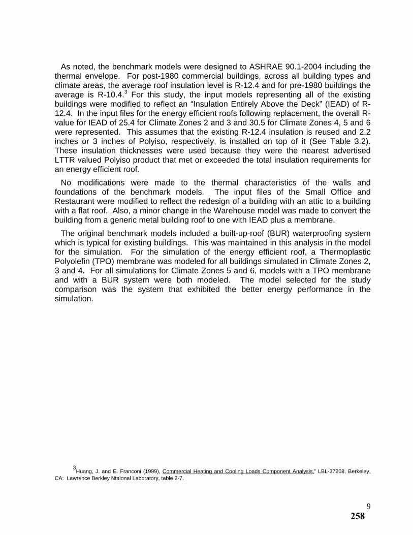
As noted, the benchmark models were designed to ASHRAE 90.1-2004 including the thermal envelope. For post-1980 commercial buildings, across all building types and climate areas, the average roof insulation level is R-12.4 and for pre-1980 buildings the average is R-10.4.3 For this study, the input models representing all of the existing buildings were modified to reflect an “Insulation Entirely Above the Deck” (IEAD) of R-12.4. In the input files for the energy efficient roofs following replacement, the overall R-value for IEAD of 25.4 for Climate Zones 2 and 3 and 30.5 for Climate Zones 4, 5 and 6 were represented. This assumes that the existing R-12.4 insulation is reused and 2.2 inches or 3 inches of Polyiso, respectively, is installed on top of it (See Table 3.2). These insulation thicknesses were used because they were the nearest advertised LTTR valued Polyiso product that met or exceeded the total insulation requirements for an energy efficient roof.
No modifications were made to the thermal characteristics of the walls and foundations of the benchmark models. The input files of the Small Office and Restaurant were modified to reflect the redesign of a building with an attic to a building with a flat roof. Also, a minor change in the Warehouse model was made to convert the building from a generic metal building roof to one with IEAD plus a membrane.
The original benchmark models included a built-up-roof (BUR) waterproofing system which is typical for existing buildings. This was maintained in this analysis in the model for the simulation. For the simulation of the energy efficient roof, a Thermoplastic Polyolefin (TPO) membrane was modeled for all buildings simulated in Climate Zones 2, 3 and 4. For all simulations for Climate Zones 5 and 6, models with a TPO membrane and with a BUR system were both modeled. The model selected for the study comparison was the system that exhibited the better energy performance in the simulation.
3
Huang, J. and E. Franconi (1999), Commercial Heating and Cooling Loads Component Analysis,” LBL-37208, Berkeley, CA: Lawrence Berkley Ntaional Laboratory, table 2-7.
9258
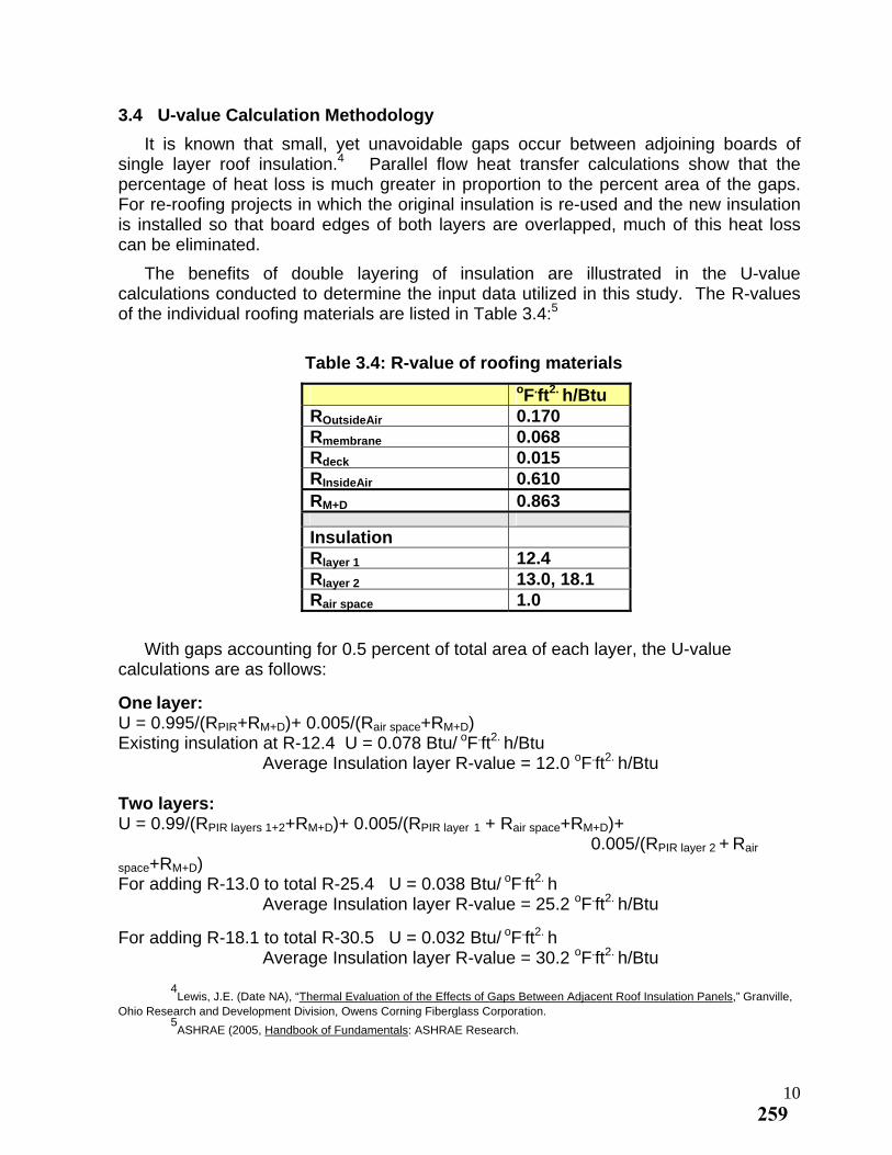
3.4 U-value Calculation Methodology
It is known that small, yet unavoidable gaps occur between adjoining boards of single layer roof insulation.4 Parallel flow heat transfer calculations show that the percentage of heat loss is much greater in proportion to the percent area of the gaps. For re-roofing projects in which the original insulation is re-used and the new insulation is installed so that board edges of both layers are overlapped, much of this heat loss can be eliminated.
The benefits of double layering of insulation are illustrated in the U-value calculations conducted to determine the input data utilized in this study. The R-values of the individual roofing materials are listed in Table 3.4:5
Table 3.4: R-value of roofing materials
oF.ft2. h/Btu ROutsideAir 0.170 Rmembrane 0.068 Rdeck 0.015 RInsideAir 0.610 RM+D 0.863
Insulation
Rlayer 1 12.4
Rlayer 2 13.0, 18.1
Rair space 1.0
With gaps accounting for 0.5 percent of total area of each layer, the U-value calculations are as follows:
One layer: U = 0.995/(RPIR+RM+D)+ 0.005/(Rair space+RM+D)
Existing insulation at R-12.4 U = 0.078 Btu/ oF.ft2. h/Btu Average Insulation layer R-value = 12.0 oF.ft2. h/Btu Two layers: U = 0.99/(RPIR layers 1+2+RM+D)+ 0.005/(RPIR layer 1 + Rair space+RM+D)+
0.005/(RPIR layer 2 + Rair
space+RM+D) For adding R-13.0 to total R-25.4 U = 0.038 Btu/ oF.ft2. h Average Insulation layer R-value = 25.2 oF.ft2. h/Btu
For adding R-18.1 to total R-30.5 U = 0.032 Btu/ oF.ft2. h Average Insulation layer R-value = 30.2 oF.ft2. h/Btu 4
Lewis, J.E. (Date NA), “Thermal Evaluation of the Effects of Gaps Between Adjacent Roof Insulation Panels,” Granville, Ohio Research and Development Division, Owens Corning Fiberglass Corporation.
5ASHRAE (2005, Handbook of Fundamentals: ASHRAE Research.
10259
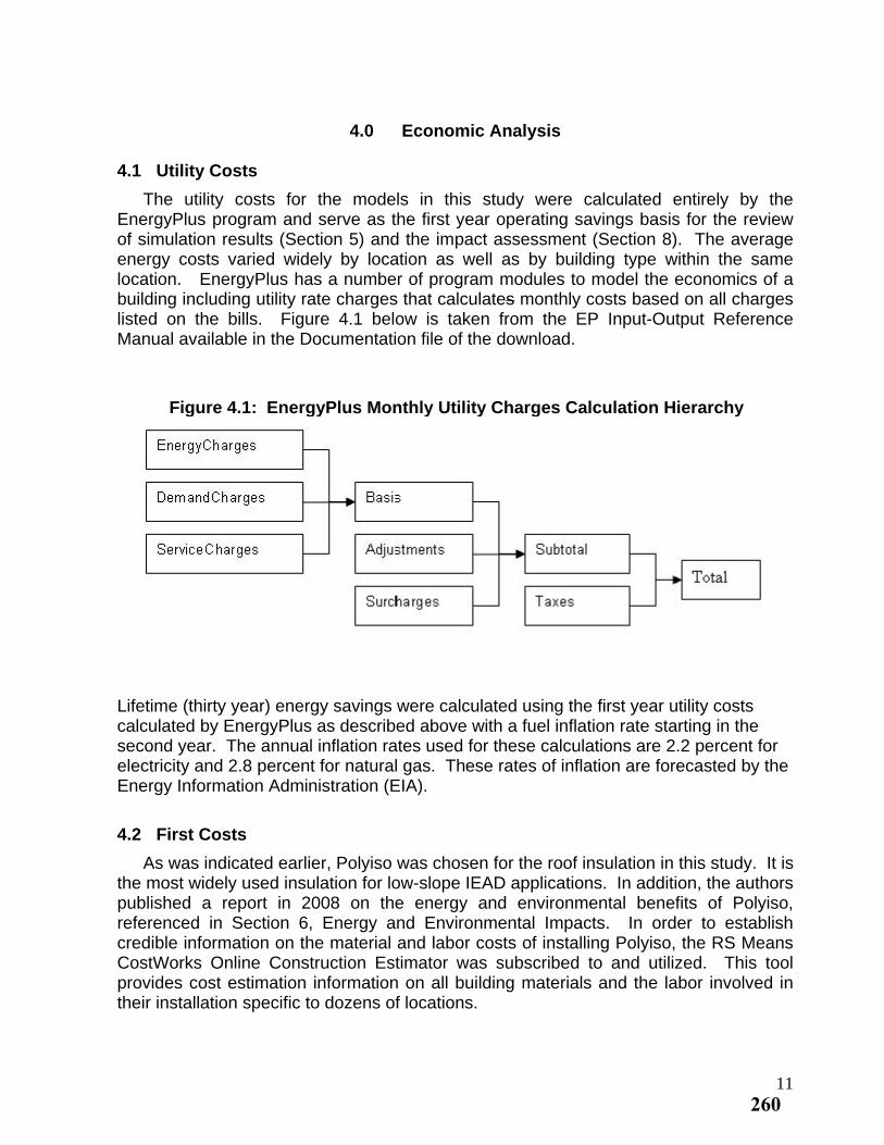
4.0 Economic Analysis
4.1 Utility Costs
The utility costs for the models in this study were calculated entirely by the EnergyPlus program and serve as the first year operating savings basis for the review of simulation results (Section 5) and the impact assessment (Section 8). The average energy costs varied widely by location as well as by building type within the same location. EnergyPlus has a number of program modules to model the economics of a building including utility rate charges that calculates monthly costs based on all charges listed on the bills. Figure 4.1 below is taken from the EP Input-Output Reference Manual available in the Documentation file of the download.
Figure 4.1: EnergyPlus Monthly Utility Charges Calculation Hierarchy
Lifetime (thirty year) energy savings were calculated using the first year utility costs calculated by EnergyPlus as described above with a fuel inflation rate starting in the second year. The annual inflation rates used for these calculations are 2.2 percent for electricity and 2.8 percent for natural gas. These rates of inflation are forecasted by the Energy Information Administration (EIA).
4.2 First Costs
As was indicated earlier, Polyiso was chosen for the roof insulation in this study. It is the most widely used insulation for low-slope IEAD applications. In addition, the authors published a report in 2008 on the energy and environmental benefits of Polyiso, referenced in Section 6, Energy and Environmental Impacts. In order to establish credible information on the material and labor costs of installing Polyiso, the RS Means CostWorks Online Construction Estimator was subscribed to and utilized. This tool provides cost estimation information on all building materials and the labor involved in their installation specific to dozens of locations.
11260
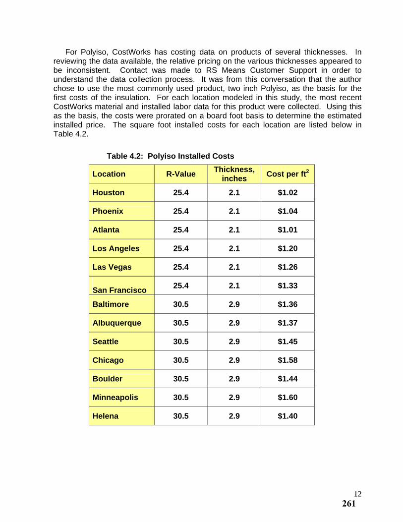
For Polyiso, CostWorks has costing data on products of several thicknesses. In reviewing the data available, the relative pricing on the various thicknesses appeared to be inconsistent. Contact was made to RS Means Customer Support in order to understand the data collection process. It was from this conversation that the author chose to use the most commonly used product, two inch Polyiso, as the basis for the first costs of the insulation. For each location modeled in this study, the most recent CostWorks material and installed labor data for this product were collected. Using this as the basis, the costs were prorated on a board foot basis to determine the estimated installed price. The square foot installed costs for each location are listed below in Table 4.2.
Table 4.2: Polyiso Installed Costs
Location R-Value Thickness,
inches Cost per ft2
Houston 25.4 2.1 $1.02
Phoenix 25.4 2.1 $1.04
Atlanta 25.4 2.1 $1.01
Los Angeles 25.4 2.1 $1.20
Las Vegas 25.4 2.1 $1.26
San Francisco
25.4 2.1 $1.33
Baltimore 30.5 2.9 $1.36
Albuquerque 30.5 2.9 $1.37
Seattle 30.5 2.9 $1.45
Chicago 30.5 2.9 $1.58
Boulder 30.5 2.9 $1.44
Minneapolis 30.5 2.9 $1.60
Helena 30.5 2.9 $1.40
12261
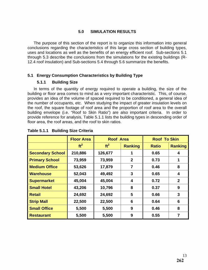
5.0 SIMULATION RESULTS
The purpose of this section of the report is to organize this information into general conclusions regarding the characteristics of this large cross section of building types, uses and locations as well as the benefits of an energy efficient roof. Sub-sections 5.1 through 5.3 describe the conclusions from the simulations for the existing buildings (R-12.4 roof insulation) and Sub-sections 5.4 through 5.6 summarize the benefits.
5.1 Energy Consumption Characteristics by Building Type
5.1.1 Building Size
In terms of the quantity of energy required to operate a building, the size of the building or floor area comes to mind as a very important characteristic. This, of course, provides an idea of the volume of spaced required to be conditioned, a general idea of the number of occupants, etc. When studying the impact of greater insulation levels on the roof, the square footage of roof area and the proportion of roof area to the overall building envelope (i.e. “Roof to Skin Ratio”) are also important criteria. In order to provide reference for analysis, Table 5.1.1 lists the building types in descending order of floor area, the roof areas, and the roof to skin ratios.
Table 5.1.1 Building Size Criteria
Floor Area Roof Area Roof To Skin
ft2 ft2 Ranking Ratio Ranking
Secondary School 210,886 126,677 1 0.65 4
Primary School 73,959 73,959 2 0.73 1
Medium Office 53,626 17,879 7 0.46 8
Warehouse 52,043 49,492 3 0.65 4
Supermarket 45,004 45,004 4 0.72 2
Small Hotel 43,206 10,796 8 0.37 9
Retail 24,692 24,692 5 0.66 3
Strip Mall 22,500 22,500 6 0.64 6
Small Office 5,500 5,500 9 0.46 8
Restaurant 5,500 5,500 9 0.55 7
13262
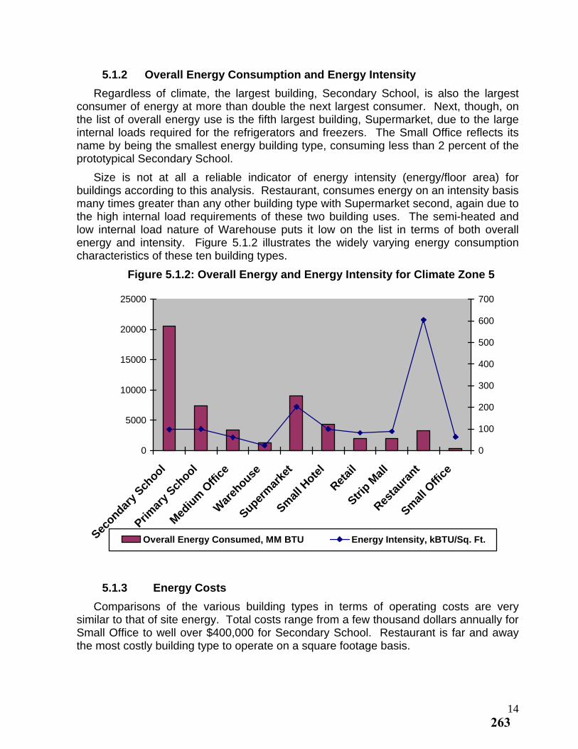
5.1.2 Overall Energy Consumption and Energy Intensity
Regardless of climate, the largest building, Secondary School, is also the largest consumer of energy at more than double the next largest consumer. Next, though, on the list of overall energy use is the fifth largest building, Supermarket, due to the large internal loads required for the refrigerators and freezers. The Small Office reflects its name by being the smallest energy building type, consuming less than 2 percent of the prototypical Secondary School.
Size is not at all a reliable indicator of energy intensity (energy/floor area) for buildings according to this analysis. Restaurant, consumes energy on an intensity basis many times greater than any other building type with Supermarket second, again due to the high internal load requirements of these two building uses. The semi-heated and low internal load nature of Warehouse puts it low on the list in terms of both overall energy and intensity. Figure 5.1.2 illustrates the widely varying energy consumption characteristics of these ten building types.
Figure 5.1.2: Overall Energy and Energy Intensity for Climate Zone 5
0
5000
10000
15000
20000
25000
Secondar
y Sch
ool
Primar
y Sch
ool
Med
ium
Offi
ce
War
ehouse
Superm
arke
t
Smal
l Hote
l
Retai
l
Strip M
all
Resta
urant
Smal
l Offi
ce
0
100
200
300
400
500
600
700
Overall Energy Consumed, MM BTU Energy Intensity, kBTU/Sq. Ft.
5.1.3 Energy Costs
Comparisons of the various building types in terms of operating costs are very similar to that of site energy. Total costs range from a few thousand dollars annually for Small Office to well over $400,000 for Secondary School. Restaurant is far and away the most costly building type to operate on a square footage basis.
14263
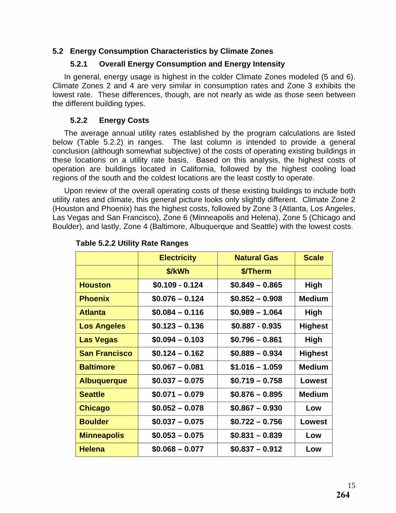
5.2 Energy Consumption Characteristics by Climate Zones
5.2.1 Overall Energy Consumption and Energy Intensity
In general, energy usage is highest in the colder Climate Zones modeled (5 and 6). Climate Zones 2 and 4 are very similar in consumption rates and Zone 3 exhibits the lowest rate. These differences, though, are not nearly as wide as those seen between the different building types.
5.2.2 Energy Costs
The average annual utility rates established by the program calculations are listed below (Table 5.2.2) in ranges. The last column is intended to provide a general conclusion (although somewhat subjective) of the costs of operating existing buildings in these locations on a utility rate basis. Based on this analysis, the highest costs of operation are buildings located in California, followed by the highest cooling load regions of the south and the coldest locations are the least costly to operate.
Upon review of the overall operating costs of these existing buildings to include both utility rates and climate, this general picture looks only slightly different. Climate Zone 2 (Houston and Phoenix) has the highest costs, followed by Zone 3 (Atlanta, Los Angeles, Las Vegas and San Francisco), Zone 6 (Minneapolis and Helena), Zone 5 (Chicago and Boulder), and lastly, Zone 4 (Baltimore, Albuquerque and Seattle) with the lowest costs.
Table 5.2.2 Utility Rate Ranges
Electricity Natural Gas Scale
$/kWh $/Therm
Houston $0.109 - 0.124 $0.849 – 0.865 High
Phoenix $0.076 – 0.124 $0.852 – 0.908 Medium
Atlanta $0.084 – 0.116 $0.989 – 1.064 High
Los Angeles $0.123 – 0.136 $0.887 - 0.935 Highest
Las Vegas $0.094 – 0.103 $0.796 – 0.861 High
San Francisco $0.124 – 0.162 $0.889 – 0.934 Highest
Baltimore $0.067 – 0.081 $1.016 – 1.059 Medium
Albuquerque $0.037 – 0.075 $0.719 – 0.758 Lowest
Seattle $0.071 – 0.079 $0.876 – 0.895 Medium
Chicago $0.052 – 0.078 $0.867 – 0.930 Low
Boulder $0.037 – 0.075 $0.722 – 0.756 Lowest
Minneapolis $0.053 – 0.075 $0.831 – 0.839 Low
Helena $0.068 – 0.077 $0.837 – 0.912 Low
15264
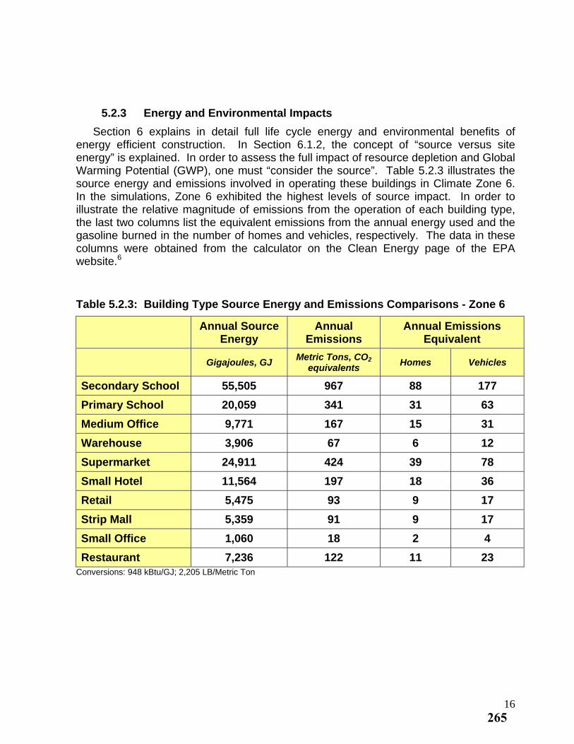
5.2.3 Energy and Environmental Impacts
Section 6 explains in detail full life cycle energy and environmental benefits of energy efficient construction. In Section 6.1.2, the concept of “source versus site energy” is explained. In order to assess the full impact of resource depletion and Global Warming Potential (GWP), one must “consider the source”. Table 5.2.3 illustrates the source energy and emissions involved in operating these buildings in Climate Zone 6. In the simulations, Zone 6 exhibited the highest levels of source impact. In order to illustrate the relative magnitude of emissions from the operation of each building type, the last two columns list the equivalent emissions from the annual energy used and the gasoline burned in the number of homes and vehicles, respectively. The data in these columns were obtained from the calculator on the Clean Energy page of the EPA website.6
Table 5.2.3: Building Type Source Energy and Emissions Comparisons - Zone 6
Annual Source
Energy Annual
Emissions Annual Emissions
Equivalent
Gigajoules, GJ Metric Tons, CO2
equivalents Homes Vehicles
Secondary School 55,505 967 88 177
Primary School 20,059 341 31 63
Medium Office 9,771 167 15 31
Warehouse 3,906 67 6 12
Supermarket 24,911 424 39 78
Small Hotel 11,564 197 18 36
Retail 5,475 93 9 17
Strip Mall 5,359 91 9 17
Small Office 1,060 18 2 4
Restaurant 7,236 122 11 23 Conversions: 948 kBtu/GJ; 2,205 LB/Metric Ton
16265
5.3 Energy Savings from Energy Efficient Roof Construction
This sub-section of the report provides a comprehensive summary of the results of the comparative analysis of the energy performance upon upgrading a typical existing building with an “Energy Efficient Roof”. To review, a twenty to fifty year old building with a low-slope roof likely would have insulation above the roof deck amounting to R-12.4 or less. For this analysis, ten typical buildings with widely varying energy consumption characteristics have been modeled. The definition of the “Energy Efficient Roof” is that of a roof having roof insulation equal to or greater than R-20 for Climate Zone 1, equal to or greater than R-25 for Zones 2, 3, 4 and 5, equal to or greater than R-30 for Zone 6 and equal to or greater than R-35 for Zones 7 and 8. This study includes the comparative analysis of buildings located in Zones 2 – 6. Please note that the simulations were modeled with R-30.5 in Zones 4 and 5 as opposed to R-25. The reason for this is that when the boundaries of this study were established, ASHRAE and the Industry set this minimum level at R-30 for these Zones and have since adjusted to R-25.
6 www.epa.gov/cleanenergy/energy-resouces/calulator.html
17266
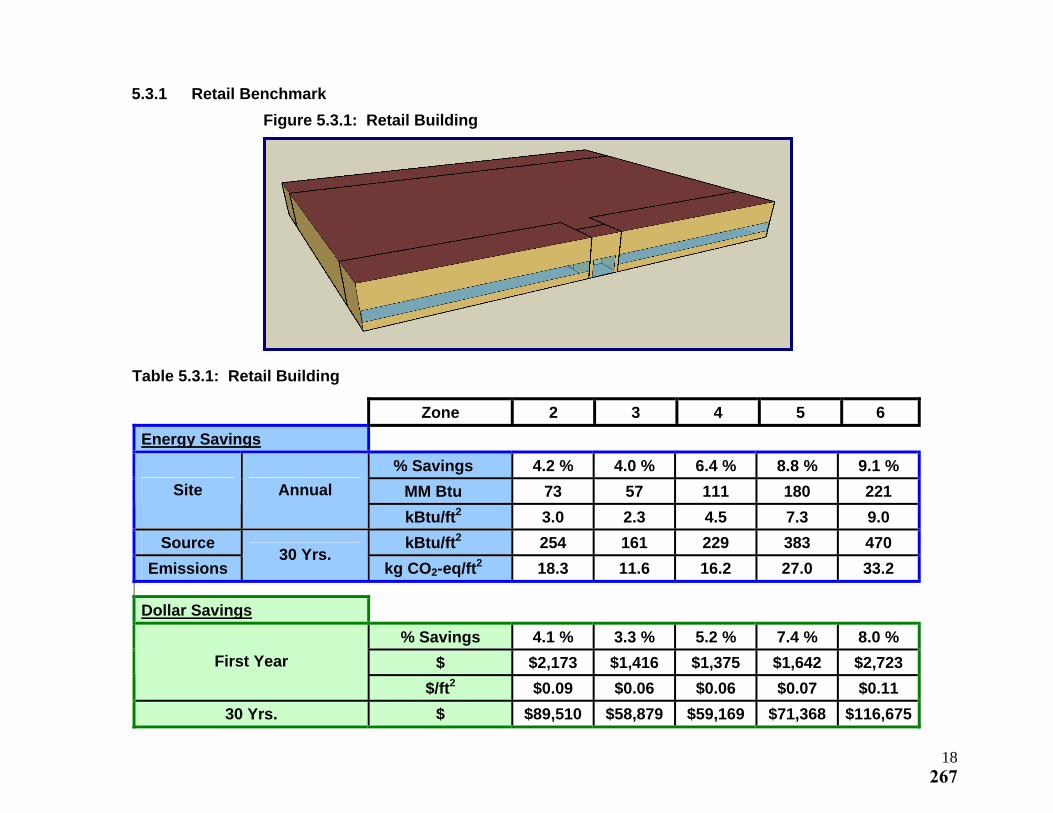
5.3.1 Retail Benchmark
Figure 5.3.1: Retail Building
Table 5.3.1: Retail Building
Zone 2 3 4 5 6
Energy Savings
% Savings 4.2 % 4.0 % 6.4 % 8.8 % 9.1 %
MM Btu 73 57 111 180 221 Site Annual
kBtu/ft2 3.0 2.3 4.5 7.3 9.0
Source kBtu/ft2 254 161 229 383 470
Emissions 30 Yrs.
kg CO2-eq/ft2 18.3 11.6 16.2 27.0 33.2
Dollar Savings
% Savings 4.1 % 3.3 % 5.2 % 7.4 % 8.0 %
$ $2,173 $1,416 $1,375 $1,642 $2,723 First Year
$/ft2 $0.09 $0.06 $0.06 $0.07 $0.11
30 Yrs. $ $89,510 $58,879 $59,169 $71,368 $116,675
18267
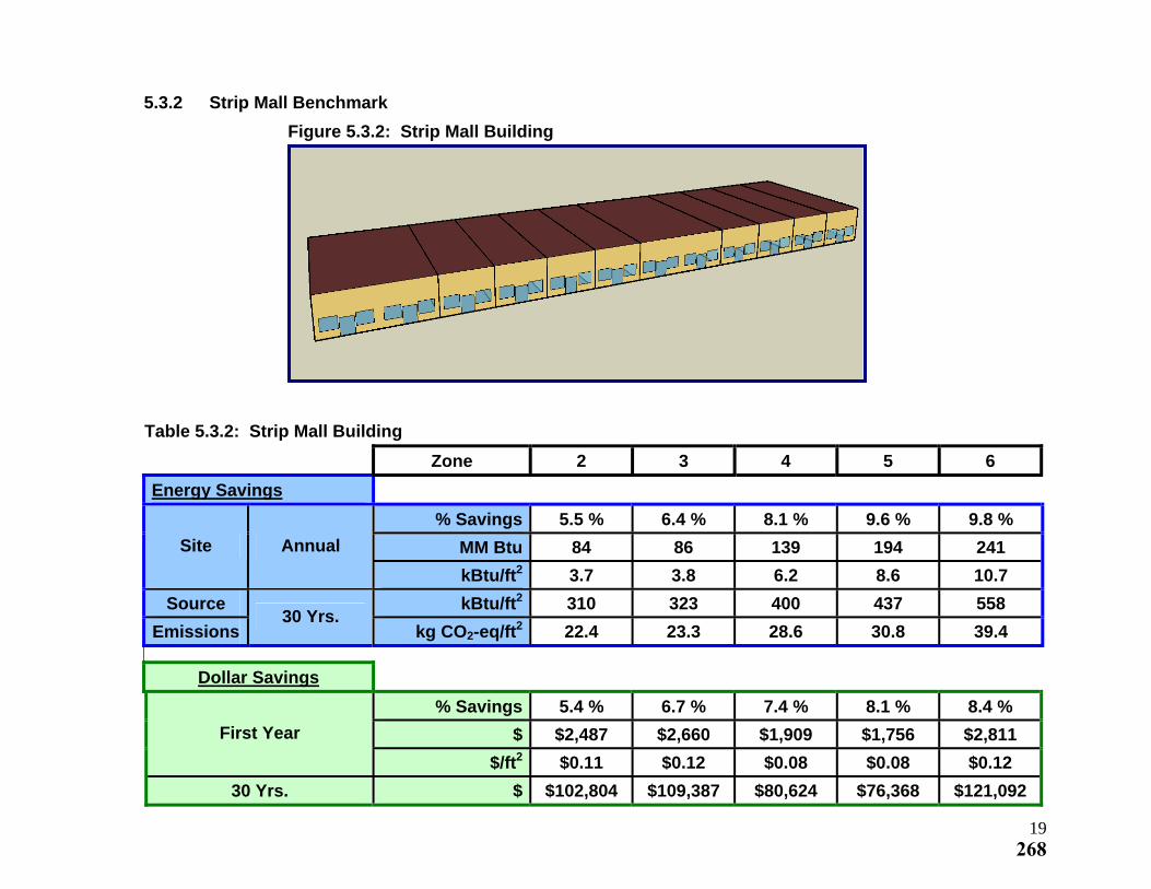
5.3.2 Strip Mall Benchmark
Figure 5.3.2: Strip Mall Building
Table 5.3.2: Strip Mall Building
Zone 2 3 4 5 6
Energy Savings
% Savings 5.5 % 6.4 % 8.1 % 9.6 % 9.8 %
MM Btu 84 86 139 194 241 Site Annual
kBtu/ft2 3.7 3.8 6.2 8.6 10.7
Source kBtu/ft2 310 323 400 437 558
Emissions 30 Yrs.
kg CO2-eq/ft2 22.4 23.3 28.6 30.8 39.4
Dollar Savings
% Savings 5.4 % 6.7 % 7.4 % 8.1 % 8.4 %
$ $2,487 $2,660 $1,909 $1,756 $2,811 First Year
$/ft2 $0.11 $0.12 $0.08 $0.08 $0.12
30 Yrs. $ $102,804 $109,387 $80,624 $76,368 $121,092
19268
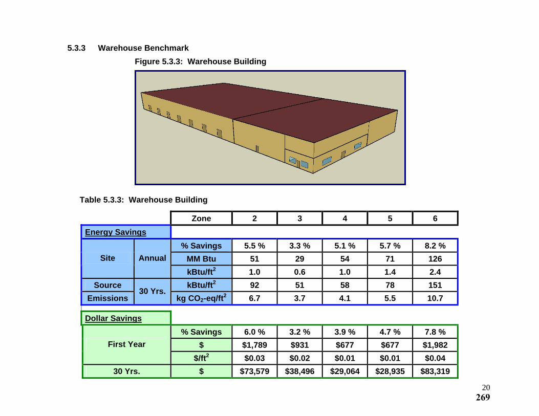
5.3.3 Warehouse Benchmark
Figure 5.3.3: Warehouse Building
Table 5.3.3: Warehouse Building
Zone 2 3 4 5 6
Energy Savings
% Savings 5.5 % 3.3 % 5.1 % 5.7 % 8.2 %
MM Btu 51 29 54 71 126 Site Annual
kBtu/ft2 1.0 0.6 1.0 1.4 2.4
Source kBtu/ft2 92 51 58 78 151
Emissions 30 Yrs.
kg CO2-eq/ft2 6.7 3.7 4.1 5.5 10.7
Dollar Savings
% Savings 6.0 % 3.2 % 3.9 % 4.7 % 7.8 %
$ $1,789 $931 $677 $677 $1,982 First Year
$/ft2 $0.03 $0.02 $0.01 $0.01 $0.04
30 Yrs. $ $73,579 $38,496 $29,064 $28,935 $83,319
20269
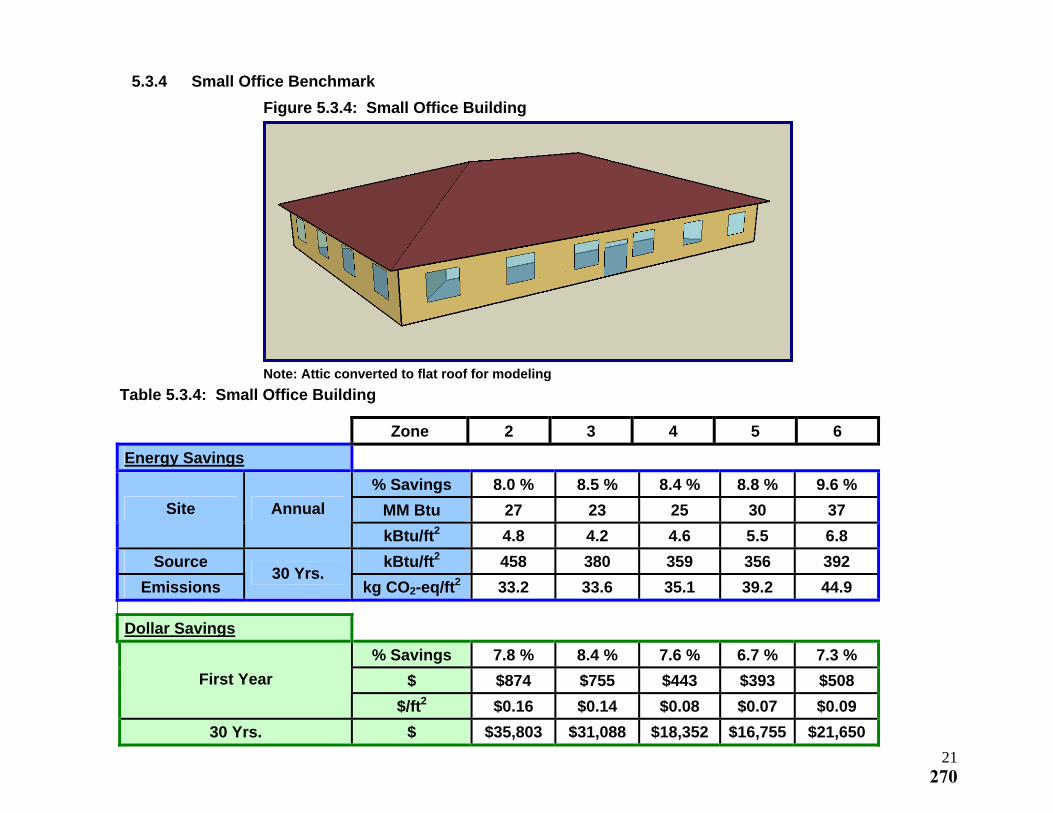
5.3.4 Small Office Benchmark
Figure 5.3.4: Small Office Building
Note: Attic converted to flat roof for modeling
Table 5.3.4: Small Office Building
Zone 2 3 4 5 6
Energy Savings
% Savings 8.0 % 8.5 % 8.4 % 8.8 % 9.6 %
MM Btu 27 23 25 30 37 Site Annual
kBtu/ft2 4.8 4.2 4.6 5.5 6.8
Source kBtu/ft2 458 380 359 356 392
Emissions 30 Yrs.
kg CO2-eq/ft2 33.2 33.6 35.1 39.2 44.9
Dollar Savings
% Savings 7.8 % 8.4 % 7.6 % 6.7 % 7.3 %
$ $874 $755 $443 $393 $508 First Year
$/ft2 $0.16 $0.14 $0.08 $0.07 $0.09
30 Yrs. $ $35,803 $31,088 $18,352 $16,755 $21,650
21270
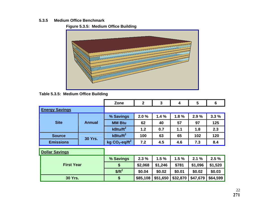
5.3.5 Medium Office Benchmark
Figure 5.3.5: Medium Office Building
Table 5.3.5: Medium Office Building
Zone 2 3 4 5 6
Energy Savings
% Savings 2.0 % 1.4 % 1.8 % 2.9 % 3.3 %
MM Btu 62 40 57 97 125 Site Annual
kBtu/ft2 1.2 0.7 1.1 1.8 2.3
Source kBtu/ft2 100 63 65 102 120
Emissions 30 Yrs.
kg CO2-eq/ft2 7.2 4.5 4.6 7.3 8.4
Dollar Savings
% Savings 2.3 % 1.5 % 1.5 % 2.1 % 2.5 %
$ $2,068 $1,246 $781 $1,096 $1,520 First Year
$/ft2 $0.04 $0.02 $0.01 $0.02 $0.03
30 Yrs. $ $85,108 $51,650 $32,870 $47,679 $64,599
22271
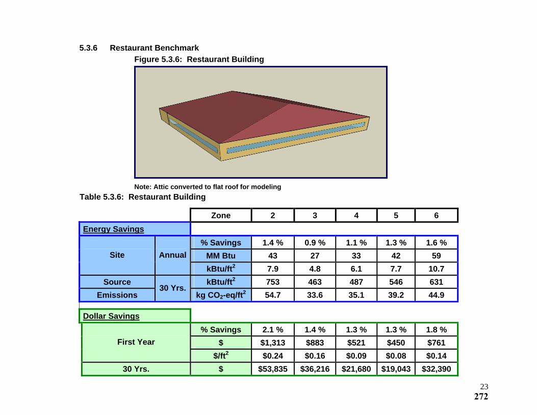
5.3.6 Restaurant Benchmark
Figure 5.3.6: Restaurant Building
Note: Attic converted to flat roof for modeling
Table 5.3.6: Restaurant Building
Zone 2 3 4 5 6
Energy Savings
% Savings 1.4 % 0.9 % 1.1 % 1.3 % 1.6 %
MM Btu 43 27 33 42 59 Site Annual
kBtu/ft2 7.9 4.8 6.1 7.7 10.7
Source kBtu/ft2 753 463 487 546 631
Emissions 30 Yrs.
kg CO2-eq/ft2 54.7 33.6 35.1 39.2 44.9
Dollar Savings
% Savings 2.1 % 1.4 % 1.3 % 1.3 % 1.8 %
$ $1,313 $883 $521 $450 $761 First Year
$/ft2 $0.24 $0.16 $0.09 $0.08 $0.14
30 Yrs. $ $53,835 $36,216 $21,680 $19,043 $32,390
23272
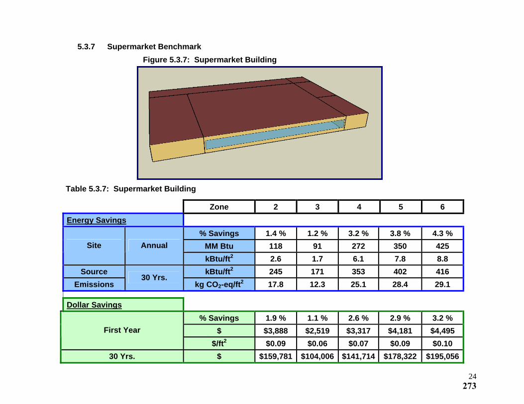
5.3.7 Supermarket Benchmark
Figure 5.3.7: Supermarket Building
Table 5.3.7: Supermarket Building
Zone 2 3 4 5 6
Energy Savings
% Savings 1.4 % 1.2 % 3.2 % 3.8 % 4.3 %
MM Btu 118 91 272 350 425 Site Annual
kBtu/ft2 2.6 1.7 6.1 7.8 8.8
Source kBtu/ft2 245 171 353 402 416
Emissions 30 Yrs.
kg CO2-eq/ft2 17.8 12.3 25.1 28.4 29.1
Dollar Savings
% Savings 1.9 % 1.1 % 2.6 % 2.9 % 3.2 %
$ $3,888 $2,519 $3,317 $4,181 $4,495 First Year
$/ft2 $0.09 $0.06 $0.07 $0.09 $0.10
30 Yrs. $ $159,781 $104,006 $141,714 $178,322 $195,056
24273
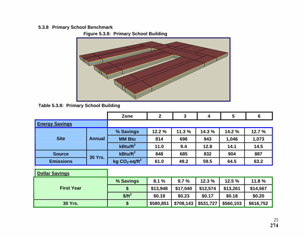
5.3.8 Primary School Benchmark
Figure 5.3.8: Primary School Building
Table 5.3.8: Primary School Building
Zone 2 3 4 5 6
Energy Savings
% Savings 12.2 % 11.3 % 14.3 % 14.2 % 12.7 %
MM Btu 814 696 943 1,046 1,073 Site Annual
kBtu/ft2 11.0 9.4 12.8 14.1 14.5
Source kBtu/ft2 848 685 832 904 887
Emissions 30 Yrs.
kg CO2-eq/ft2 61.0 49.2 59.5 64.5 63.2
Dollar Savings
% Savings 8.1 % 9.7 % 12.3 % 12.5 % 11.8 %
$ $13,948 $17,040 $12,574 $13,261 $14,567 First Year
$/ft2 $0.19 $0.23 $0.17 $0.18 $0.20
30 Yrs. $ $580,851 $708,143 $531,727 $560,103 $616,752
25274
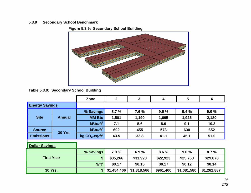
5.3.9 Secondary School Benchmark
Figure 5.3.9: Secondary School Building
Table 5.3.9: Secondary School Building
Zone 2 3 4 5 6
Energy Savings
% Savings 8.7 % 7.6 % 9.5 % 9.4 % 9.0 %
MM Btu 1,501 1,190 1,695 1,925 2,180 Site Annual
kBtu/ft2 7.1 5.6 8.0 9.1 10.3
Source kBtu/ft2 602 455 573 630 652
Emissions 30 Yrs.
kg CO2-eq/ft2 43.5 32.8 41.1 45.1 51.0
Dollar Savings
% Savings 7.9 % 6.9 % 8.6 % 9.0 % 8.7 %
$ $35,266 $31,920 $22,923 $25,763 $29,878 First Year
$/ft2 $0.17 $0.15 $0.17 $0.12 $0.14
30 Yrs. $ $1,454,406 $1,318,566 $961,400 $1,081,580 $1,262,887
26275
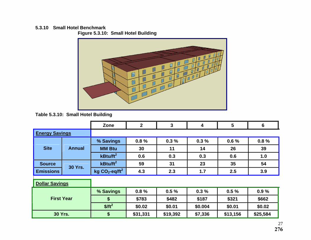
5.3.10 Small Hotel Benchmark Figure 5.3.10: Small Hotel Building
Table 5.3.10: Small Hotel Building
Zone 2 3 4 5 6
Energy Savings
% Savings 0.8 % 0.3 % 0.3 % 0.6 % 0.8 %
MM Btu 30 11 14 26 39 Site Annual
kBtu/ft2 0.6 0.3 0.3 0.6 1.0
Source kBtu/ft2 59 31 23 35 54
Emissions 30 Yrs.
kg CO2-eq/ft2 4.3 2.3 1.7 2.5 3.9
Dollar Savings
% Savings 0.8 % 0.5 % 0.3 % 0.5 % 0.9 %
$ $783 $482 $187 $321 $662 First Year
$/ft2 $0.02 $0.01 $0.004 $0.01 $0.02
30 Yrs. $ $31,331 $19,392 $7,336 $13,156 $25,584
27276
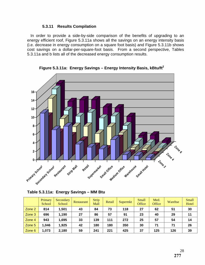
5.3.11 Results Compilation In order to provide a side-by-side comparison of the benefits of upgrading to an energy efficient roof, Figure 5.3.11a shows all the savings on an energy intensity basis (i.e. decrease in energy consumption on a square foot basis) and Figure 5.3.11b shows cost savings on a dollar-per-square-foot basis. From a second perspective, Tables 5.3.11a and b lists all of the decreased energy consumption results. Figure 5.3.11a: Energy Savings – Energy Intensity Basis, kBtu/ft2
0
2
4
6
8
10
12
14
16
Primary
School
Secondary S
chool
Restaura
nt
Strip M
all
Retail
Supermark
et
Small O
ffice
Medium
Offi
ce
Ware
house
Small H
otel
Zone 2
Zone 4
Zone 6
Table 5.3.11a: Energy Savings – MM Btu
Primary School
Secondary School Restaurant Strip
Mall Retail Supermkt Small Office
Med. Office Warehse Small
Hotel Zone 2 814 1,501 43 84 73 118 27 62 51 30
Zone 3 696 1,190 27 86 57 91 23 40 29 11
Zone 4 943 1,695 33 139 111 272 25 57 54 14
Zone 5 1,046 1,925 42 180 180 350 30 71 71 26
Zone 6 1,073 2,180 59 241 221 425 37 125 126 39
28277
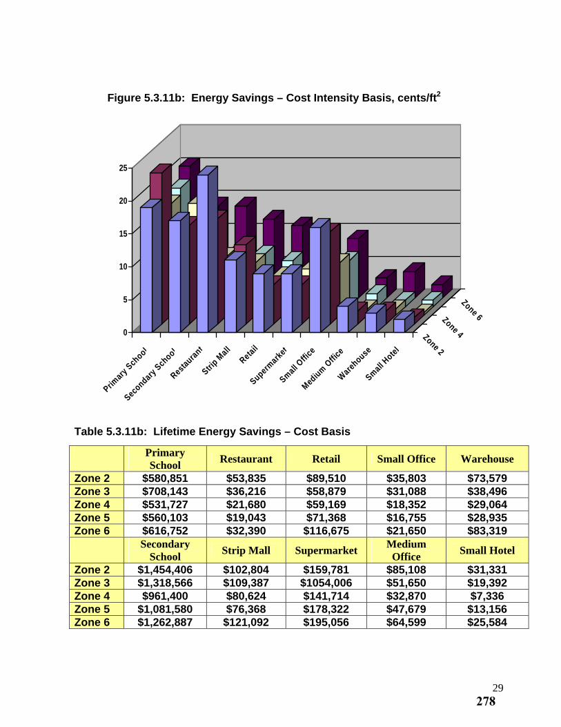
Figure 5.3.11b: Energy Savings – Cost Intensity Basis, cents/ft2
0
5
10
15
20
25
Primary
School
Secondary S
chool
Restaura
nt
Strip M
all
Retail
Supermark
et
Small O
ffice
Medium
Offi
ce
Ware
house
Small H
otel
Zone 2
Zone 4
Zone 6
Table 5.3.11b: Lifetime Energy Savings – Cost Basis
Primary School
Restaurant Retail Small Office Warehouse
Zone 2 $580,851 $53,835 $89,510 $35,803 $73,579 Zone 3 $708,143 $36,216 $58,879 $31,088 $38,496 Zone 4 $531,727 $21,680 $59,169 $18,352 $29,064 Zone 5 $560,103 $19,043 $71,368 $16,755 $28,935 Zone 6 $616,752 $32,390 $116,675 $21,650 $83,319 Secondary
School Strip Mall Supermarket
Medium Office
Small Hotel
Zone 2 $1,454,406 $102,804 $159,781 $85,108 $31,331 Zone 3 $1,318,566 $109,387 $1054,006 $51,650 $19,392 Zone 4 $961,400 $80,624 $141,714 $32,870 $7,336 Zone 5 $1,081,580 $76,368 $178,322 $47,679 $13,156 Zone 6 $1,262,887 $121,092 $195,056 $64,599 $25,584
29278
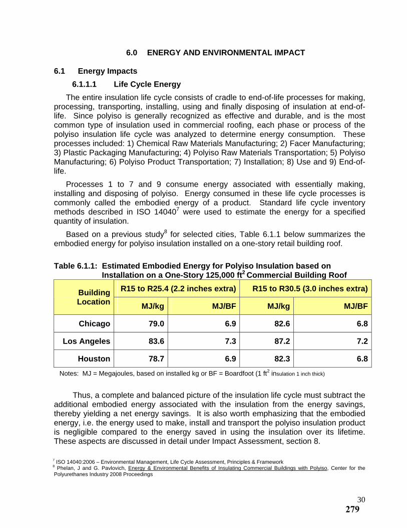
6.0 ENERGY AND ENVIRONMENTAL IMPACT 6.1 Energy Impacts
6.1.1.1 Life Cycle Energy
The entire insulation life cycle consists of cradle to end-of-life processes for making, processing, transporting, installing, using and finally disposing of insulation at end-of-life. Since polyiso is generally recognized as effective and durable, and is the most common type of insulation used in commercial roofing, each phase or process of the polyiso insulation life cycle was analyzed to determine energy consumption. These processes included: 1) Chemical Raw Materials Manufacturing; 2) Facer Manufacturing; 3) Plastic Packaging Manufacturing; 4) Polyiso Raw Materials Transportation; 5) Polyiso Manufacturing; 6) Polyiso Product Transportation; 7) Installation; 8) Use and 9) End-of-life.
Processes 1 to 7 and 9 consume energy associated with essentially making, installing and disposing of polyiso. Energy consumed in these life cycle processes is commonly called the embodied energy of a product. Standard life cycle inventory methods described in ISO 140407 were used to estimate the energy for a specified quantity of insulation.
Based on a previous study8 for selected cities, Table 6.1.1 below summarizes the embodied energy for polyiso insulation installed on a one-story retail building roof.
Table 6.1.1: Estimated Embodied Energy for Polyiso Insulation based on
Installation on a One-Story 125,000 ft2 Commercial Building Roof
R15 to R25.4 (2.2 inches extra) R15 to R30.5 (3.0 inches extra)Building Location MJ/kg MJ/BF MJ/kg MJ/BF
Chicago 79.0 6.9 82.6 6.8
Los Angeles 83.6 7.3 87.2 7.2
Houston 78.7 6.9 82.3 6.8
Notes: MJ = Megajoules, based on installed kg or BF = Boardfoot (1 ft2 insulation 1 inch thick)
Thus, a complete and balanced picture of the insulation life cycle must subtract the additional embodied energy associated with the insulation from the energy savings, thereby yielding a net energy savings. It is also worth emphasizing that the embodied energy, i.e. the energy used to make, install and transport the polyiso insulation product is negligible compared to the energy saved in using the insulation over its lifetime. These aspects are discussed in detail under Impact Assessment, section 8.
7 ISO 14040:2006 – Environmental Management, Life Cycle Assessment, Principles & Framework 8 Phelan, J and G. Pavlovich, Energy & Environmental Benefits of Insulating Commercial Buildings with Polyiso, Center for the Polyurethanes Industry 2008 Proceedings
30279
Embodied energy also includes the total life cycle from energy sources used throughout steps 1 to 7 and 9. This total life cycle from energy sources such as electric power, natural gas, diesel fuel, etc. is often referred to as “source” energy, as discussed below.
6.1.2 Source Energy Versus Site Energy
When estimating energy consumption, it is not sufficient to measure the energy metered at a building or production unit or consumed as transportation fuel. These measurements only include the energy actually measured at a specific location or site, such as a building electricity meter, an orifice meter on a natural gas feed line into a manufacturing unit, or a fuel gauge on a truck using diesel fuel. Actual energy consumption includes the life cycle or “source energy” needed to produce the energy delivered to a specific location or user (i.e. site).
“Source energy” can be thought of as the “energy to make the energy”. Using electrical energy as an example, 3.24 kilowatt hour (kWh) of electricity are needed to generate 1 kWh of electricity delivered to a consumer (based on an average U.S. electric power grid mix). The 3.24 kWh is normally called the “source energy” and the 1 kWh is really the “site energy”. The total source energy of 3.24 kWh per kWh may also be thought of as the life cycle “cradle-to-plug” energy.
In other words, for each kWh of electricity measured at the meter of the building, 3.24 kWh is needed to supply this energy. This energy is required to extract coal, natural gas crude from the earth, refine these fuels as needed, deliver the fuels to the power plant, generate steam in the boilers to drive the turbines and generators, deliver the electricity throughout the grid with transformers, all of which includes efficiency and line losses.
Similarly, based on an average U.S. natural gas mix, 1.156 Mega joules (MJ) of “source energy” are needed for one MJ of natural gas “site energy” delivered to a consumer. The same concept applies to all sources of energy used in embodied energy calculations as well as energy consumed to heat, cool and light a building. Using transportation by a diesel-fueled truck as an example, the energy from combustion (lower heating value) is 128,450 Btu/gallon. However, the total energy associated with the diesel fuel life cycle must include the “pre-combustion energy” (energy for extracting, transporting, refining crude etc), which is 23 percent greater than the combustion energy. Thus, it takes 1.23 MJ of energy to produce one MJ of diesel fuel.
Table 6.1.2(a) shows the source energy factors used to adjust the metered building electricity and natural gas consumption from site energy to source energy in Simulation Results, Section 5. The “metered” values estimated from Whole Building Energy Analysis are multiplied by these source energy factors to obtain the “source” or “total life cycle” energy.
31280
Table 6.1.2(a): Source-Site Ratios for Electricity and Natural Gas9
Type of Energy Source-Site Ratio
US Electric Power Grid Mix (2002) 3.24
US Thermal Energy from Natural Gas (2002) 1.156
Note: Data from GaBi Life Cycle Engineering database (2006), lower heating value
These factors are relatively consistent with the factors published by the Environmental Protection Agency (EPA) on their Energy Star website10, as the US EPA site-source ratio for electricity is 3.34 (3 percent greater than the electricity factor used in this report) and for natural gas the factor is 1.047 (9 percent lower than the natural gas factor used in this report).
The factors in Table 6.1.2(a) were chosen for this study since the authors are familiar with the rigorous life cycle methodology upon which the calculations are based. The methodology considers, for example: 1) The entire “cradle-to-plug” (electricity) or “cradle-to-valve” (natural gas) life cycle, i.e., the data considers the entire supply chain of fuels from exploration to extraction, processing and transport; 2) Life cycle inventory methods in conformance with ISO 14040 and 14044; 3) Cut-off rule coverage for unit processes includes 95 percent of mass and energy for input/output flows and 98% for environmental, with coverage for exploration (crude oil etc) at 90 percent of mass and energy and 95 percent for environmental aspects; 4) Grid mix data based on national US statistics, and power plant models according to US combustion technology mix; 5) All relevant transport processes used in the energy production are included; 6) US-specific boundary conditions and sources for a base year of 2002 (within the 2001 to 2005 averaged range used as the base years for the EPA data).
Table 6.1.2(b) shows source-site energy ratios for common fuels used in the embodied energy calculations, where diesel is used for truck and rail transportation, and lifting equipment such as cranes, and propane is used for fork-lift trucks.
Table 6.1.2(b): Source-Site Ratios for Some Petroleum Refinery Fuels11 Type of Energy Source-Site Ratio
US Diesel from Refinery 1.23
US Propane from Refinery 1.24
Note: Data from GaBi Life Cycle Engineering database (2006), lower heating value
These factors were used, as the EPA site-source ratios for diesel and propane (both 1.01) do not appear to account for the pre-combustion energy required to extract, refine and transport these fuels. Also, similar to the justification provided for the electricity and natural gas, the factors in Table 6.1.2(b) were chosen for this study since the authors are familiar with the rigorous life cycle methodology upon which the calculations are based (ISO 14040/14044 methodology, comprehensive life cycle approach, etc). 9 GaBi 4 Life Cycle Engineering Software and Database (2008), PE International 10 http://www.energystar.gov11 GaBi 4 Life Cycle Engineering Software and Database (2008), PE International
32281
6.2 Global Warming Potential (GWP) Impacts
6.2.1 Life Cycle GWP Emissions
Similar to embodied energy calculations, GWP associated with making, installing and disposing of polyiso was based on a “cradle to end-of-life” analysis that includes all GWP associated with the final polyiso product. The GWP generated during these phases also included GWP associated with pre-combustion and combustion of fuels such as natural gas, diesel, propane, etc. GWP is normally measured in kg CO2-equivalents (kg CO2-eq.), as different types of emissions (e.g. methane, nitrous oxides) have a greater global warming impact than CO2 and must be adjusted to express the emissions on a common basis.
The TRACI model from US EPA was used to estimate the GWP emissions to air from all of the processes used to make polyiso insulation, i.e. processes 1 to 7 and 9 noted in Section 6.1.1. Standard life cycle inventory methods described in ISO 14040 were used to estimate the GWP for a specified quantity of insulation.
Based on a previous study for selected cities, Table 6.1.1 below summarizes the GWP associated with all of the polyiso insulation life cycle phases except for the use phase, when polyiso is installed on a one-story retail building roof.
Table 6.1.1: Estimated GWP Emissions from Increased Polyiso Insulation on a One-Story 125,000 ft2 Commercial Building Roof
R15 to R25.4 (2.2 inches extra) R15 to R30.5 (3.0 inches extra) Building Location kg CO2-eq./kg kg CO2-eq./BF kg CO2-eq./kg kg CO2-eq./BF
Chicago 4.96 0.43 5.18 0.43
Los Angeles 5.35 0.47 5.58 0.46
Houston 4.99 0.43 5.21 0.43
Notes: kg CO2-equivalents = kg CO2-eq., BF = Boardfoot or 1 ft2 insulation 1 inch thick
Thus, a complete and balanced picture of the insulation life cycle must subtract the additional GWP emissions generated from making, installing and transporting the insulation from the GWP emissions prevented in the use phase, thereby yielding a net GWP emissions prevented. It is also worth emphasizing that the GWP emissions generated to make, install, transport etc the polyiso insulation product is negligible compared to GWP prevented when using the insulation over its lifetime. These aspects are discussed in detail under Impact Assessment, Section 8.
33282
6.2.2 GWP Life Cycle Emissions Factors
When estimating GWP emissions, it is not always sufficient to measure the GWP associated with combustion at a building, production unit or from internal combustion engines used for transportation. Actual GWP emissions generated include the life cycle GWP associated with life cycle processes for producing electricity, natural gas and other diesel fuels (extraction, refining, distribution, etc.) as well as GWP emissions generated from combustion of fuels.
Table 6.2.2 shows the GWP life cycle factors used to estimate kg CO2-equivalents associated with electricity and natural gas consumption for the various building types/locations shown in the Simulation Results, Section 5. The metered energy values estimated from Whole Building Energy Analysis are multiplied by these life cycle GWP emissions factors to obtain the “total life cycle” kg CO2-equivalents associated with energy use at the buildings.
Table 6.2.2: Life Cycle GWP Emissions Factors for Electricity and Natural
Gas12 Type of Energy /MJ kg CO2-eq./MJ
US Electric Power Grid Mix (2002) 0.223
US Thermal Energy from Natural Gas (2002) 0.0749 Note: Data from GaBi Life Cycle Engineering database (2006), lower heating value, MJ = Megajoules
These factors differ considerably from the EPA AP42 factors published in the Energy Plus simulation model guidance13, as the EPA factor for electricity is 0.1691 kg CO2-eq./MJ (24 percent lower than the electricity factor used in this report) and for natural gas the factor is 0.0503 kg CO2-eq./MJ (33 percent lower than the natural gas factor used in this report). It appears that these AP42 factors are based mainly on combustion, as it is not clear that GWP emissions associated with life cycle CO2-eq. are considered.
Therefore, the factors in Table 6.2.2 were chosen for this study since the authors are familiar with the rigorous life cycle methodology upon which the calculations are based, as described in Section 6.1.2 (ISO 14040/14044 methodology, comprehensive life cycle approach etc).
Similarly, calculations made for common fuels (diesel for truck and rail transportation, propane for fork-lifts, etc.) in life cycle phases for insulation manufacture, installation, transportation, etc. also include the GWP emissions associated with both the pre-combustion and combustion stages.
12 GaBi 4 Life Cycle Engineering Software and Database (2008), PE International 13 U.S. Department of Energy (2007), EnergyPlus Engineering Reference
34283
6.3 Other Environmental Aspects
Since the scope of this study is energy and cost reductions associated with increased levels of insulation, other environmental benefits have not been quantified with the exception of more commonly discussed GWP emissions.
For example, for every kWh (3.6 Megajoules) of electricity reduced at a building, there is a corresponding 0.803 kg CO2-eq./kWh (0.223 kg CO2-eq./MJ) reduction based on the average U.S. power grid (see Section 6.1.2). In this study, GWP reductions in private and public sector buildings over 30 years total 76,904,634 thousand metric tons of kg CO2-eq., or approximately 77 billion metric tons of kg CO2-eq. (equivalent to 76,904,634,000,000 or almost 77 trillion kg, i.e. 170,000,000,000,000 or 170 trillion pounds of kg CO2-eq.). Since a significant portion of the kg CO2-eq. reduction is associated with electricity generation at power plants, it is apparent from analogy that other environmental aspects associated with electric power generation are also significantly reduced.
Besides the global warming impact measured in kg CO2-eq. (includes green house gases such as methane and nitrous oxide), additional environmental aspects associated with burning fossil/other fuels and electric power plants include, but are not limited to:
• Nitrogen oxides (NOx) emissions, ozone
• Sulfur dioxide (SOx) emissions
• Mercury, other heavy metals and pollutants from burning coal
• Coal mining including strip mining
• Particulate matter emissions
• Water usage
• Wastewater discharges
• Solid waste
The EPA publishes a regularly updated inventory of environmental attributes related to air emissions (greenhouse gases, criteria pollutants) of electric power systems on their “eGRID” webpage15. The data provide an indication of the magnitude of such emissions associated with electric power generation.
Since quantification of these other environmental aspects is beyond the scope of this report, these issues are mentioned to promote awareness that reduction in building energy use from increased insulation has benefits far more extensive than energy and greenhouse gas reductions. Quantification of these other environmental benefits will be the subject of future studies by the authors of this report.
15 www.epa.gov/cleanenergy/energy-resources/egrid
35284
7.0 COMMERCIAL BUILDING MARKET ANALYSIS
The Energy Information Administration’s (EIA) Commercial Building Energy Consumption Survey (CBECS) is generally recognized as providing the most complete data regarding existing commercial buildings. The CBECS Survey is essential for relating the extensive and rigorous energy modeling results performed in this study to commercial building market data. Therefore, data from the most recent available survey, CBECS 2003, were utilized as the basis for the impact assessment (Section 8) of the energy modeling results. The information from the report entitled “DOE Commercial Building Benchmark Models for Energy Simulation” also was very useful in linking the modeling results to the market data.
7.1 CBECS 2003
The CBECS is a national-level sample quadrennial survey of buildings greater than 1,000 square feet in size that devote more than 50 percent of their floor space to commercial activity. The CBECS 2003 reports that the commercial market comprises more than 71.6 billion square feet of floor space in nearly 4.9 million buildings. In addition, it reports that these commercial buildings consume more than 6,500 trillion Btu of energy, with electricity accounting for 55 percent and natural gas 32 percent. Space heating, cooling and ventilation consume more than half of this energy.
7.2 Building Type and Climate Zone Weighting Methodologies
7.2.1 Roof Area Correlation and Weighting by Building Type
As stated in Section 3.1, Model Building Types, the ten DOE benchmark prototype models listed in Table 3.1 are believed to adequately represent the energy performance of buildings with low-slope roofs. This conclusion was established based on CBECS 2003 data and the use of a mapping methodology developed by Crawley and his colleagues.16 This methodology was used to connect the CBECS data, which lists floor area by Principal Building Type (PBT) with the roof area of the DOE benchmark models. The commercial building roofing area was calculated using building floor space and numbers of floors. Table 7.2.1a provides a detailed analysis of the commercial building market by Principal Building Activity (PBA) as well as a correlation to roof area. The selected ten prototypes for this study account for nearly 54 percent and 60 percent of the total floor and roof area, respectively. The individual percentages are prorated in order to calculate the distribution of floor and roof area among the ten prototypes. These are summarized in Table 7.2.1b.
16 “ DOE Commercial Building Benchmark Models for Energy Simulation”, NREL: Michael Deru, Brent Griffith, Kyle Benne, Paul Torcellini; PNNL: Mark Halversion, Dave Winiarski, Bing Liu; LBNL: Joe Huang and Mehry Yazdanian; DOE: Drury Crawley, December, 2008
36285
Table 7.2.1a: Commercial Building Market Analysis
CBECS1 DOE Benchmark Models2,3 Roof Area Distribution4
PBA Floor Area
MM Ft2 Prototypes Distri-bution
Floor Area MM Ft2
No. of Floors
Roof Area MM Ft2
% Roof Area
Large 0.39 4,761 12 397 0.7%
1. Medium 0.41 5,005 3 1,668 3.1% Office 12,208
2. Small 0.20 2,442 1 2,442 4.6%
3. Primary 0.55 5,431 1 5,431 10.2% Education 9,874
4. Secondary 0.45 4,443 2 2,222 4.2%
5. Small 0.36 1,835 4 459 0.9% Lodging 5,096
Large 0.64 3,261 6 544 1.0%
Warehouse 10,078 6. Warehouse 1.0 10,078 1 10,078 18.9%
Hospital 0.6 1,898 5 380 0.7% Health Care 3,163
Outpatient 0.4 1,265 2 633 1.2%
Retail 4,317 7. Retail 1.0 4,317 1 4,317 8.1%
Mall 0.66 4,538 2 2,269 4.3% Malls 6,875
8. Strip Mall 0.34 2,338 1 2,338 4.4%
Food Sales 1,255 9. Supermarket 1.0 1,255 1 1,255 2.4%
Fast Food 0.18 298 1 298 0.6% Food Service
1,654 10. Restaurant 0.82 1,356 1 1,356 2.5%
All Other 17,138 All Other 1.0 17,138 1 17,138 32.2
Total 71,658 71,658 53,222
Ten Model Totals 31,566 59.3%
Table references and notes:
(1) “2003 Commercial Buildings Energy Consumption Survey”, Energy Information Administration (2) “ DOE Commercial Building Benchmark Models for Energy Simulation”, NREL: Michael Deru, Brent
Griffith, Kyle Benne, Paul Torcellini; PNNL: Mark Halversion, Dave Winiarski, Bing Liu; LBNL: Joe Huang and Mehry Yazdanian; DOE: Drury Crawley, December, 2008
(3) Mall: 2 floors; Public Assembly, Public Order and Safety, Religious Worship, Other and Vacant: 1 floor (4) Roofing (MM SF) = Benchmark model floor area (MM SF)/# of Floors
37286
Table 7.2.1b: Weighting Factors for Model Building Type
Building Type Distribution
By Floor Area By Roof Area
0.112 0.137 Retail
0.061 0.074 Strip Mall
0.262 0.304 Warehouse
0.063 0.077 Small Office
0.130 0.053 Medium Office
0.035 0.043 Restaurant
0.033 0.040 Supermarket
0.141 0.172 Primary School
0.115 0.085 Secondary School
0.048 0.015 Small Hotel
Total 1.0 1.0
7.2.2 Climate Zone Weighting Factors
The key assumption in the distribution of the benchmark models by climate zones is that it is the same for both existing and new buildings. The new construction benchmark building weighting factors, the allocation of new construction value by type of construction and the climate zone and square foot cost model (developed by Crawley et al, 2008) are utilized to generate the “New Construction BB Model Climate Zone Distribution”.
The 13 locations included in this study represent every Climate Zone and Sub-zone in the country with the exceptions of 1A (Miami), 7 (northern continental U.S.) and 8 (northern Alaska). These omitted climate zones account for 1.6 percent, 0.6 percent and 0.5% of the total floor area, respectively. Considering these are a minor portion of the overall weighting, they were combined with the results of the nearest climate zone. In other words, the 1.6 percent for 1A is combined with Climate Zone 2 and the 0.6 percent for 7 and the 0.5 percent for 8 are combined with Climate Zone 6. Considering these are the three most extreme climates, the energy savings results can be assumed to be at least as high as the modeled location. The weightings by climate zone used for the impact assessment are compiled in Table 7.2.2.
38287
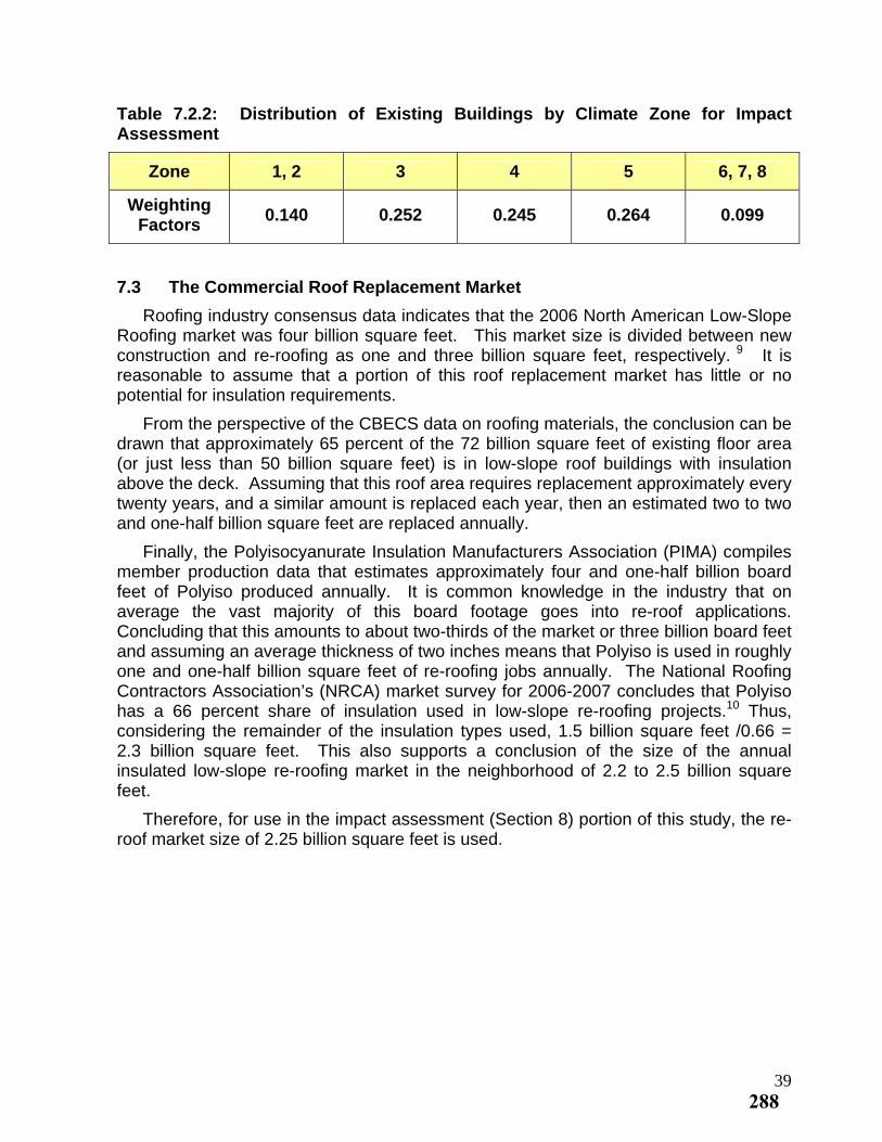
Table 7.2.2: Distribution of Existing Buildings by Climate Zone for Impact Assessment
Zone 1, 2 3 4 5 6, 7, 8
Weighting Factors
0.140 0.252 0.245 0.264 0.099
7.3 The Commercial Roof Replacement Market
Roofing industry consensus data indicates that the 2006 North American Low-Slope Roofing market was four billion square feet. This market size is divided between new construction and re-roofing as one and three billion square feet, respectively. 9 It is reasonable to assume that a portion of this roof replacement market has little or no potential for insulation requirements.
From the perspective of the CBECS data on roofing materials, the conclusion can be drawn that approximately 65 percent of the 72 billion square feet of existing floor area (or just less than 50 billion square feet) is in low-slope roof buildings with insulation above the deck. Assuming that this roof area requires replacement approximately every twenty years, and a similar amount is replaced each year, then an estimated two to two and one-half billion square feet are replaced annually.
Finally, the Polyisocyanurate Insulation Manufacturers Association (PIMA) compiles member production data that estimates approximately four and one-half billion board feet of Polyiso produced annually. It is common knowledge in the industry that on average the vast majority of this board footage goes into re-roof applications. Concluding that this amounts to about two-thirds of the market or three billion board feet and assuming an average thickness of two inches means that Polyiso is used in roughly one and one-half billion square feet of re-roofing jobs annually. The National Roofing Contractors Association’s (NRCA) market survey for 2006-2007 concludes that Polyiso has a 66 percent share of insulation used in low-slope re-roofing projects.10 Thus, considering the remainder of the insulation types used, 1.5 billion square feet /0.66 = 2.3 billion square feet. This also supports a conclusion of the size of the annual insulated low-slope re-roofing market in the neighborhood of 2.2 to 2.5 billion square feet.
Therefore, for use in the impact assessment (Section 8) portion of this study, the re-roof market size of 2.25 billion square feet is used.
39288
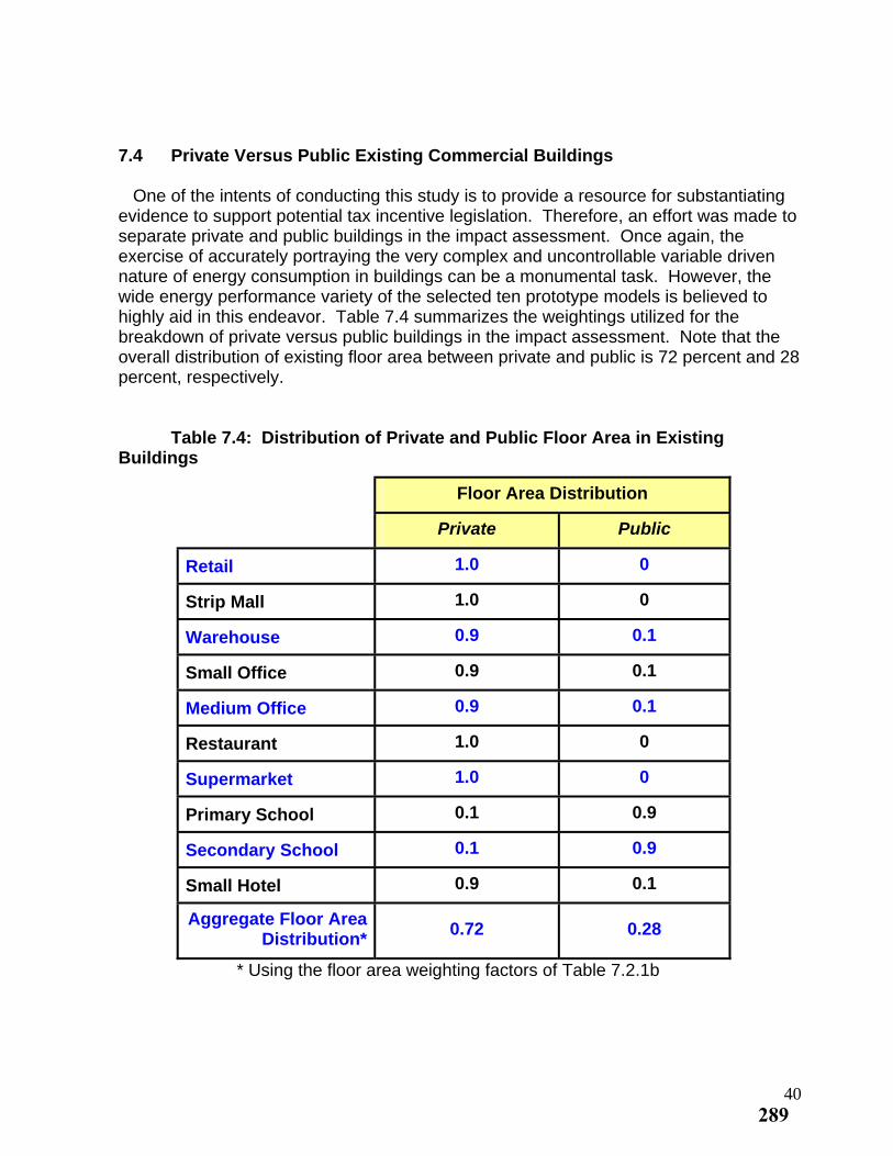
7.4 Private Versus Public Existing Commercial Buildings One of the intents of conducting this study is to provide a resource for substantiating evidence to support potential tax incentive legislation. Therefore, an effort was made to separate private and public buildings in the impact assessment. Once again, the exercise of accurately portraying the very complex and uncontrollable variable driven nature of energy consumption in buildings can be a monumental task. However, the wide energy performance variety of the selected ten prototype models is believed to highly aid in this endeavor. Table 7.4 summarizes the weightings utilized for the breakdown of private versus public buildings in the impact assessment. Note that the overall distribution of existing floor area between private and public is 72 percent and 28 percent, respectively. Table 7.4: Distribution of Private and Public Floor Area in Existing Buildings
Floor Area Distribution
Private Public
1.0 0 Retail
1.0 0 Strip Mall
0.9 0.1 Warehouse
0.9 0.1 Small Office
0.9 0.1 Medium Office
1.0 0 Restaurant
1.0 0 Supermarket
0.1 0.9 Primary School
0.1 0.9 Secondary School
0.9 0.1 Small Hotel
Aggregate Floor Area Distribution*
0.72 0.28
* Using the floor area weighting factors of Table 7.2.1b
40289
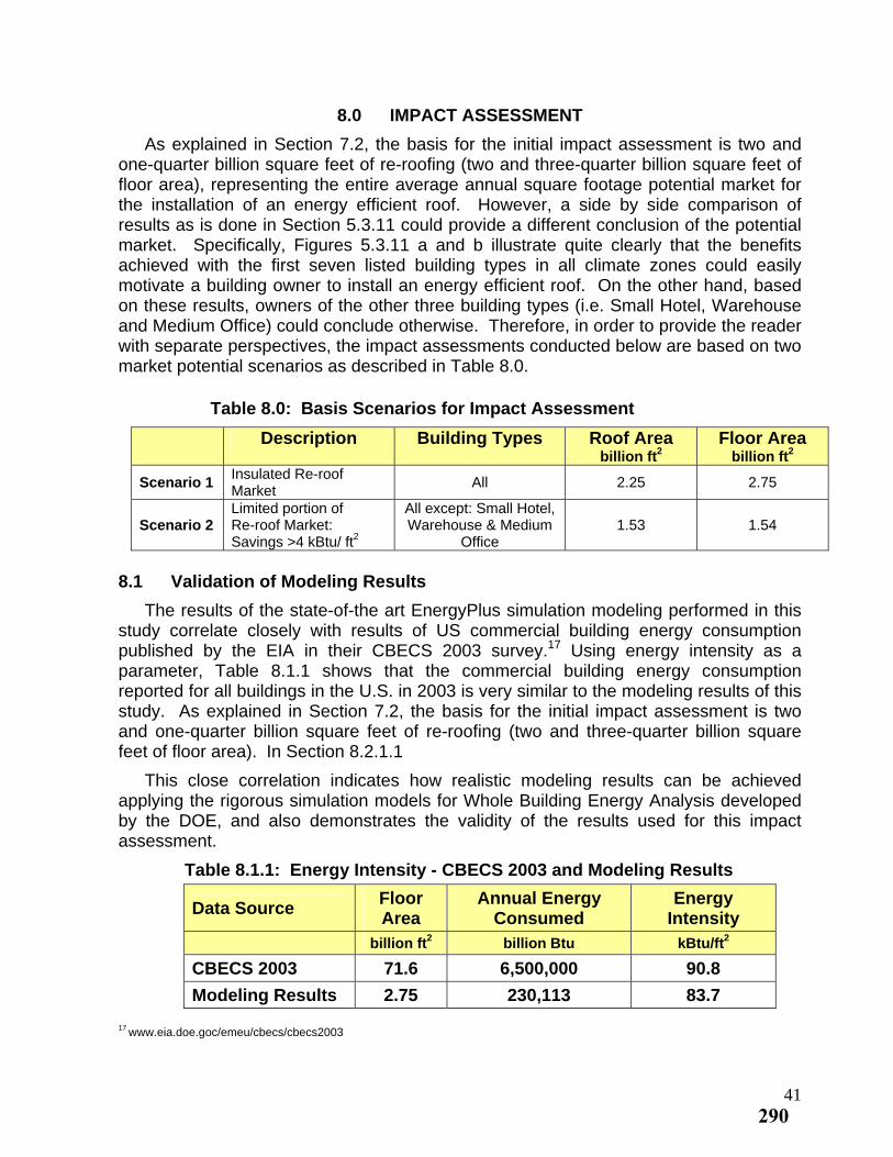
8.0 IMPACT ASSESSMENT
As explained in Section 7.2, the basis for the initial impact assessment is two and one-quarter billion square feet of re-roofing (two and three-quarter billion square feet of floor area), representing the entire average annual square footage potential market for the installation of an energy efficient roof. However, a side by side comparison of results as is done in Section 5.3.11 could provide a different conclusion of the potential market. Specifically, Figures 5.3.11 a and b illustrate quite clearly that the benefits achieved with the first seven listed building types in all climate zones could easily motivate a building owner to install an energy efficient roof. On the other hand, based on these results, owners of the other three building types (i.e. Small Hotel, Warehouse and Medium Office) could conclude otherwise. Therefore, in order to provide the reader with separate perspectives, the impact assessments conducted below are based on two market potential scenarios as described in Table 8.0.
Table 8.0: Basis Scenarios for Impact Assessment
Description Building Types Roof Area Floor Area billion ft2 billion ft2
Insulated Re-roof Market
All 2.25 2.75 Scenario 1
Limited portion of All except: Small Hotel, Warehouse & Medium
Office Re-roof Market: Savings >4 kBtu/ ft
1.53 1.54 Scenario 2 2
8.1 Validation of Modeling Results
The results of the state-of-the art EnergyPlus simulation modeling performed in this study correlate closely with results of US commercial building energy consumption published by the EIA in their CBECS 2003 survey.17 Using energy intensity as a parameter, Table 8.1.1 shows that the commercial building energy consumption reported for all buildings in the U.S. in 2003 is very similar to the modeling results of this study. As explained in Section 7.2, the basis for the initial impact assessment is two and one-quarter billion square feet of re-roofing (two and three-quarter billion square feet of floor area). In Section 8.2.1.1
This close correlation indicates how realistic modeling results can be achieved applying the rigorous simulation models for Whole Building Energy Analysis developed by the DOE, and also demonstrates the validity of the results used for this impact assessment.
Table 8.1.1: Energy Intensity - CBECS 2003 and Modeling Results
Floor Annual Energy Energy Data Source
Area Consumed Intensity billion ft2 billion Btu kBtu/ft2
CBECS 2003 71.6 6,500,000 90.8
Modeling Results 2.75 230,113 83.7
17 www.eia.doe.goc/emeu/cbecs/cbecs2003
41290
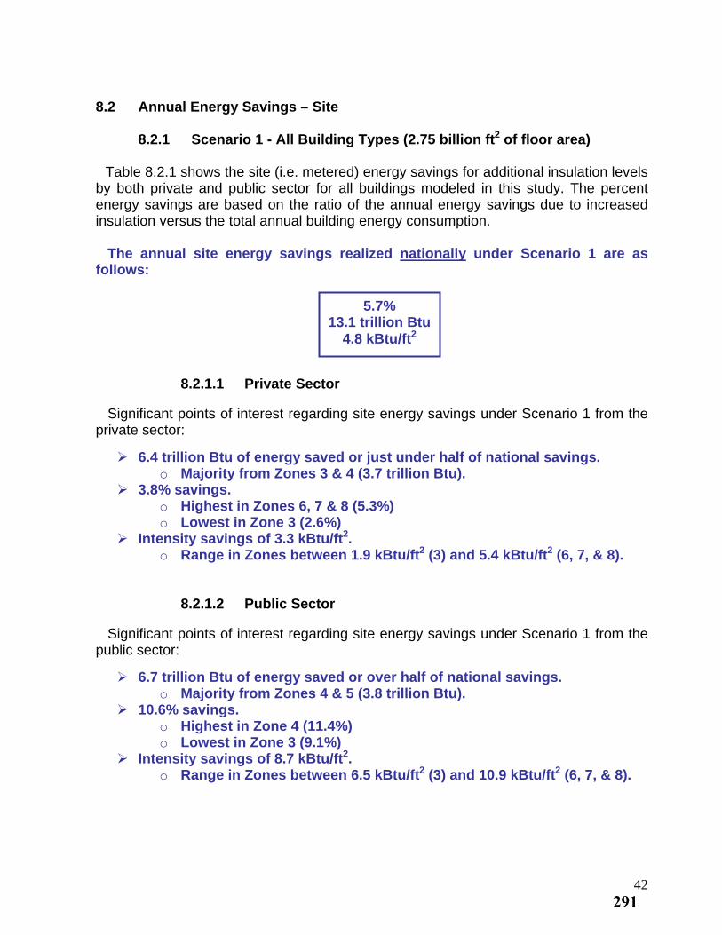
8.2 Annual Energy Savings – Site
8.2.1 Scenario 1 - All Building Types (2.75 billion ft2 of floor area) Table 8.2.1 shows the site (i.e. metered) energy savings for additional insulation levels by both private and public sector for all buildings modeled in this study. The percent energy savings are based on the ratio of the annual energy savings due to increased insulation versus the total annual building energy consumption. The annual site energy savings realized nationally under Scenario 1 are as follows: 5.7%
13.1 trillion Btu 4.8 kBtu/ft2
8.2.1.1 Private Sector Significant points of interest regarding site energy savings under Scenario 1 from the private sector:
6.4 trillion Btu of energy saved or just under half of national savings. o Majority from Zones 3 & 4 (3.7 trillion Btu).
3.8% savings. o Highest in Zones 6, 7 & 8 (5.3%) o Lowest in Zone 3 (2.6%)
Intensity savings of 3.3 kBtu/ft2. o Range in Zones between 1.9 kBtu/ft2 (3) and 5.4 kBtu/ft2 (6, 7, & 8).
8.2.1.2 Public Sector Significant points of interest regarding site energy savings under Scenario 1 from the public sector:
6.7 trillion Btu of energy saved or over half of national savings. o Majority from Zones 4 & 5 (3.8 trillion Btu).
10.6% savings. o Highest in Zone 4 (11.4%) o Lowest in Zone 3 (9.1%)
Intensity savings of 8.7 kBtu/ft2. o Range in Zones between 6.5 kBtu/ft2 (3) and 10.9 kBtu/ft2 (6, 7, & 8).
42291
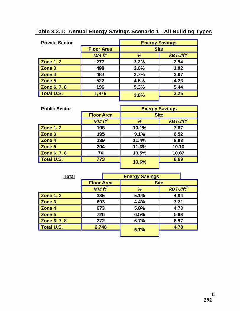
Table 8.2.1: Annual Energy Savings Scenario 1 - All Building Types
Private Sector Energy Savings Floor Area Site
2MM ft % 2kBTU/ftZone 1, 2 277 3.2% 2.54 Zone 3 498 2.6% 1.92 Zone 4 484 3.7% 3.07 Zone 5 522 4.6% 4.23 Zone 6, 7, 8 196 5.3% 5.44 Total U.S. 1,976 3.25 3.8%
Public Sector Energy Savings Floor Area Site
2MM ft % 2kBTU/ftZone 1, 2 108 10.1% 7.87 Zone 3 195 9.1% 6.52 Zone 4 189 11.4% 8.98 Zone 5 204 11.3% 10.10 Zone 6, 7, 8 76 10.5% 10.87 Total U.S. 773 8.69
10.6%
Total Energy Savings Floor Area Site
2MM ft % 2kBTU/ftZone 1, 2 385 5.1% 4.04 Zone 3 693 4.4% 3.21 Zone 4 673 5.8% 4.73 Zone 5 726 6.5% 5.88 Zone 6, 7, 8 272 6.7% 6.97 Total U.S. 2,748 4.78
5.7%
43292
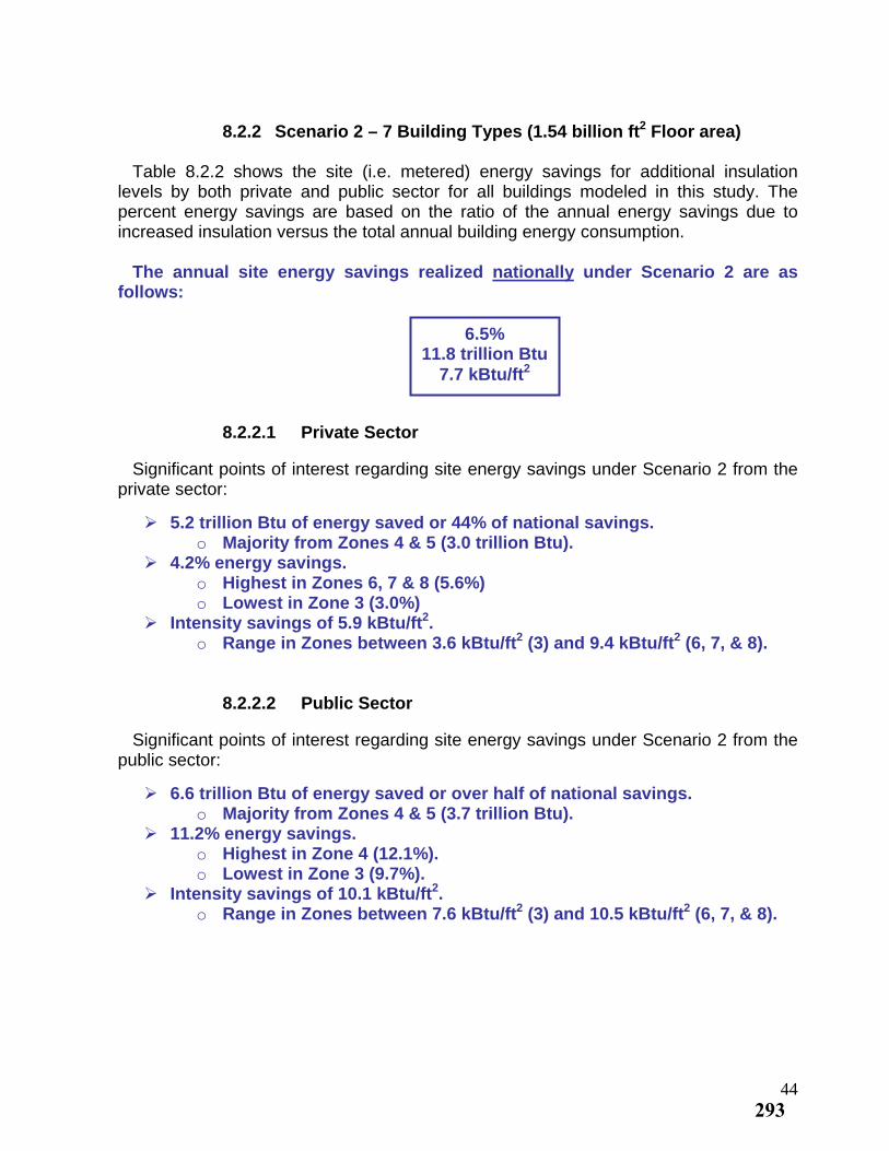
8.2.2 Scenario 2 – 7 Building Types (1.54 billion ft2 Floor area)
Table 8.2.2 shows the site (i.e. metered) energy savings for additional insulation levels by both private and public sector for all buildings modeled in this study. The percent energy savings are based on the ratio of the annual energy savings due to increased insulation versus the total annual building energy consumption. The annual site energy savings realized nationally under Scenario 2 are as follows: 6.5% 11.8 trillion Btu
7.7 kBtu/ft2
8.2.2.1 Private Sector Significant points of interest regarding site energy savings under Scenario 2 from the private sector:
5.2 trillion Btu of energy saved or 44% of national savings. o Majority from Zones 4 & 5 (3.0 trillion Btu).
4.2% energy savings. o Highest in Zones 6, 7 & 8 (5.6%) o Lowest in Zone 3 (3.0%)
Intensity savings of 5.9 kBtu/ft2. o Range in Zones between 3.6 kBtu/ft2 (3) and 9.4 kBtu/ft2 (6, 7, & 8).
8.2.2.2 Public Sector Significant points of interest regarding site energy savings under Scenario 2 from the public sector:
6.6 trillion Btu of energy saved or over half of national savings. o Majority from Zones 4 & 5 (3.7 trillion Btu).
11.2% energy savings. o Highest in Zone 4 (12.1%). o Lowest in Zone 3 (9.7%).
2 Intensity savings of 10.1 kBtu/ft . o Range in Zones between 7.6 kBtu/ft2 (3) and 10.5 kBtu/ft2 (6, 7, & 8).
44293
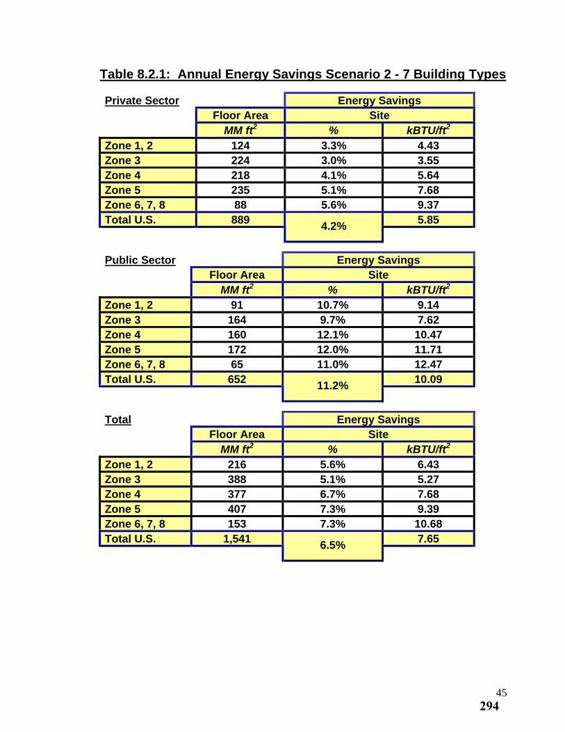
Table 8.2.1: Annual Energy Savings Scenario 2 - 7 Building Types
Private Sector Energy Savings Floor Area Site
2MM ft % 2kBTU/ftZone 1, 2 124 3.3% 4.43 Zone 3 224 3.0% 3.55 Zone 4 218 4.1% 5.64 Zone 5 235 5.1% 7.68 Zone 6, 7, 8 88 5.6% 9.37 Total U.S. 889 5.85
4.2%
Public Sector Energy Savings Floor Area Site
2MM ft % 2kBTU/ftZone 1, 2 91 10.7% 9.14 Zone 3 164 9.7% 7.62 Zone 4 160 12.1% 10.47 Zone 5 172 12.0% 11.71 Zone 6, 7, 8 65 11.0% 12.47 Total U.S. 652 10.09
11.2%
Total Energy Savings Floor Area Site
2MM ft % 2kBTU/ftZone 1, 2 216 5.6% 6.43 Zone 3 388 5.1% 5.27 Zone 4 377 6.7% 7.68 Zone 5 407 7.3% 9.39 Zone 6, 7, 8 153 7.3% 10.68 Total U.S. 1,541 7.65
6.5%
45294
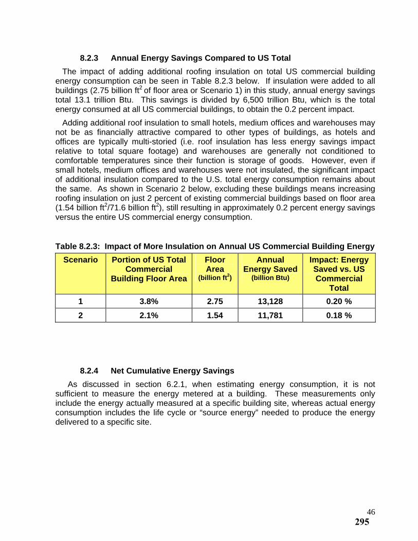
8.2.3 Annual Energy Savings Compared to US Total
The impact of adding additional roofing insulation on total US commercial building energy consumption can be seen in Table 8.2.3 below. If insulation were added to all buildings (2.75 billion ft2 of floor area or Scenario 1) in this study, annual energy savings total 13.1 trillion Btu. This savings is divided by 6,500 trillion Btu, which is the total energy consumed at all US commercial buildings, to obtain the 0.2 percent impact.
Adding additional roof insulation to small hotels, medium offices and warehouses may not be as financially attractive compared to other types of buildings, as hotels and offices are typically multi-storied (i.e. roof insulation has less energy savings impact relative to total square footage) and warehouses are generally not conditioned to comfortable temperatures since their function is storage of goods. However, even if small hotels, medium offices and warehouses were not insulated, the significant impact of additional insulation compared to the U.S. total energy consumption remains about the same. As shown in Scenario 2 below, excluding these buildings means increasing roofing insulation on just 2 percent of existing commercial buildings based on floor area (1.54 billion ft2 2/71.6 billion ft ), still resulting in approximately 0.2 percent energy savings versus the entire US commercial energy consumption.
Table 8.2.3: Impact of More Insulation on Annual US Commercial Building Energy
Scenario Portion of US Total Commercial
Building Floor Area
Floor Area
(billion ft2)
Annual Impact: Energy Energy Saved Saved vs. US
(billion Btu) Commercial Total
1 3.8% 2.75 13,128 0.20 %
2 2.1% 1.54 11,781 0.18 %
8.2.4 Net Cumulative Energy Savings
As discussed in section 6.2.1, when estimating energy consumption, it is not sufficient to measure the energy metered at a building. These measurements only include the energy actually measured at a specific building site, whereas actual energy consumption includes the life cycle or “source energy” needed to produce the energy delivered to a specific site.
46295
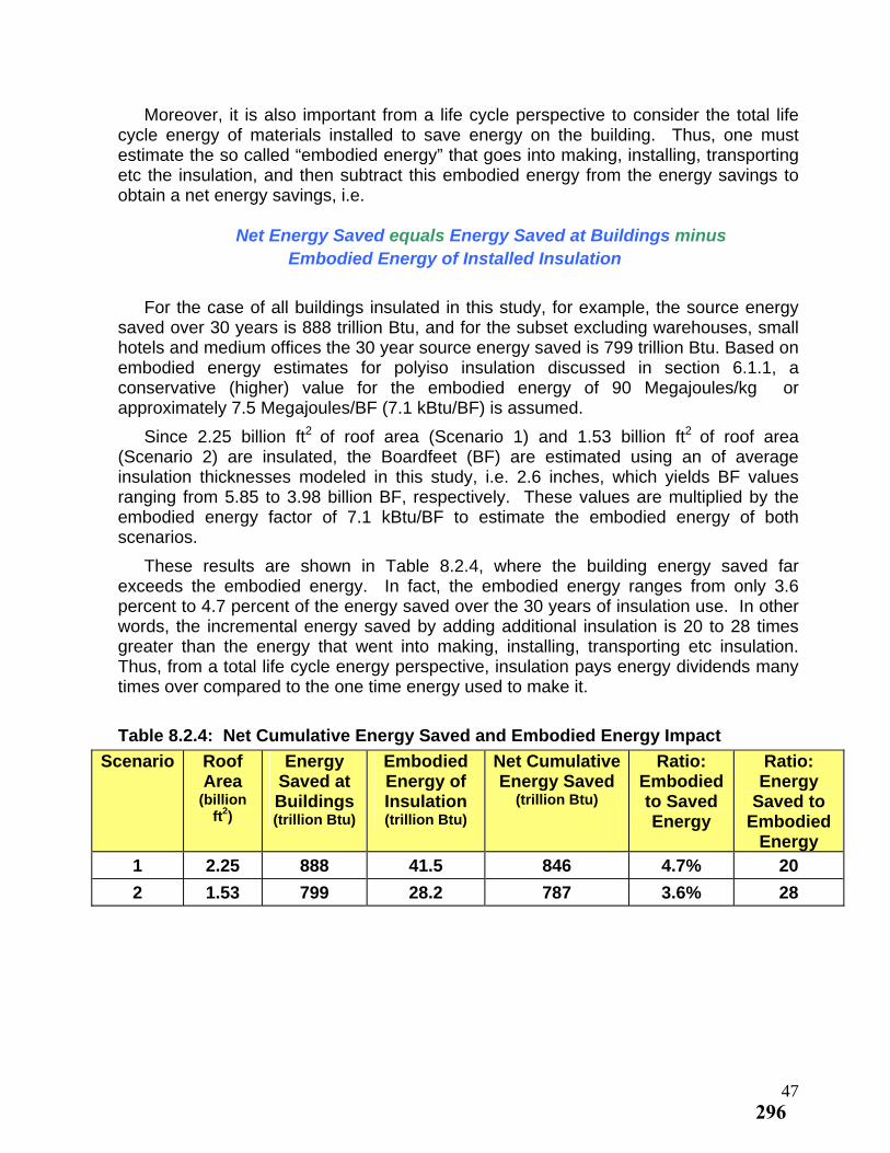
Moreover, it is also important from a life cycle perspective to consider the total life cycle energy of materials installed to save energy on the building. Thus, one must estimate the so called “embodied energy” that goes into making, installing, transporting etc the insulation, and then subtract this embodied energy from the energy savings to obtain a net energy savings, i.e. Net Energy Saved equals Energy Saved at Buildings minus Embodied Energy of Installed Insulation
For the case of all buildings insulated in this study, for example, the source energy saved over 30 years is 888 trillion Btu, and for the subset excluding warehouses, small hotels and medium offices the 30 year source energy saved is 799 trillion Btu. Based on embodied energy estimates for polyiso insulation discussed in section 6.1.1, a conservative (higher) value for the embodied energy of 90 Megajoules/kg or approximately 7.5 Megajoules/BF (7.1 kBtu/BF) is assumed.
2 Since 2.25 billion ft of roof area (Scenario 1) and 1.53 billion ft2 of roof area (Scenario 2) are insulated, the Boardfeet (BF) are estimated using an of average insulation thicknesses modeled in this study, i.e. 2.6 inches, which yields BF values ranging from 5.85 to 3.98 billion BF, respectively. These values are multiplied by the embodied energy factor of 7.1 kBtu/BF to estimate the embodied energy of both scenarios.
These results are shown in Table 8.2.4, where the building energy saved far exceeds the embodied energy. In fact, the embodied energy ranges from only 3.6 percent to 4.7 percent of the energy saved over the 30 years of insulation use. In other words, the incremental energy saved by adding additional insulation is 20 to 28 times greater than the energy that went into making, installing, transporting etc insulation. Thus, from a total life cycle energy perspective, insulation pays energy dividends many times over compared to the one time energy used to make it.
Table 8.2.4: Net Cumulative Energy Saved and Embodied Energy Impact
Scenario Roof Area
(billion ft2)
Energy Saved at Buildings (trillion Btu)
Embodied Energy of Insulation (trillion Btu)
Net Cumulative Energy Saved
(trillion Btu)
Ratio: Ratio: Embodied Energy to Saved Saved to Energy Embodied
Energy 1 2.25 888 41.5 846 4.7% 20
2 1.53 799 28.2 787 3.6% 28
47296
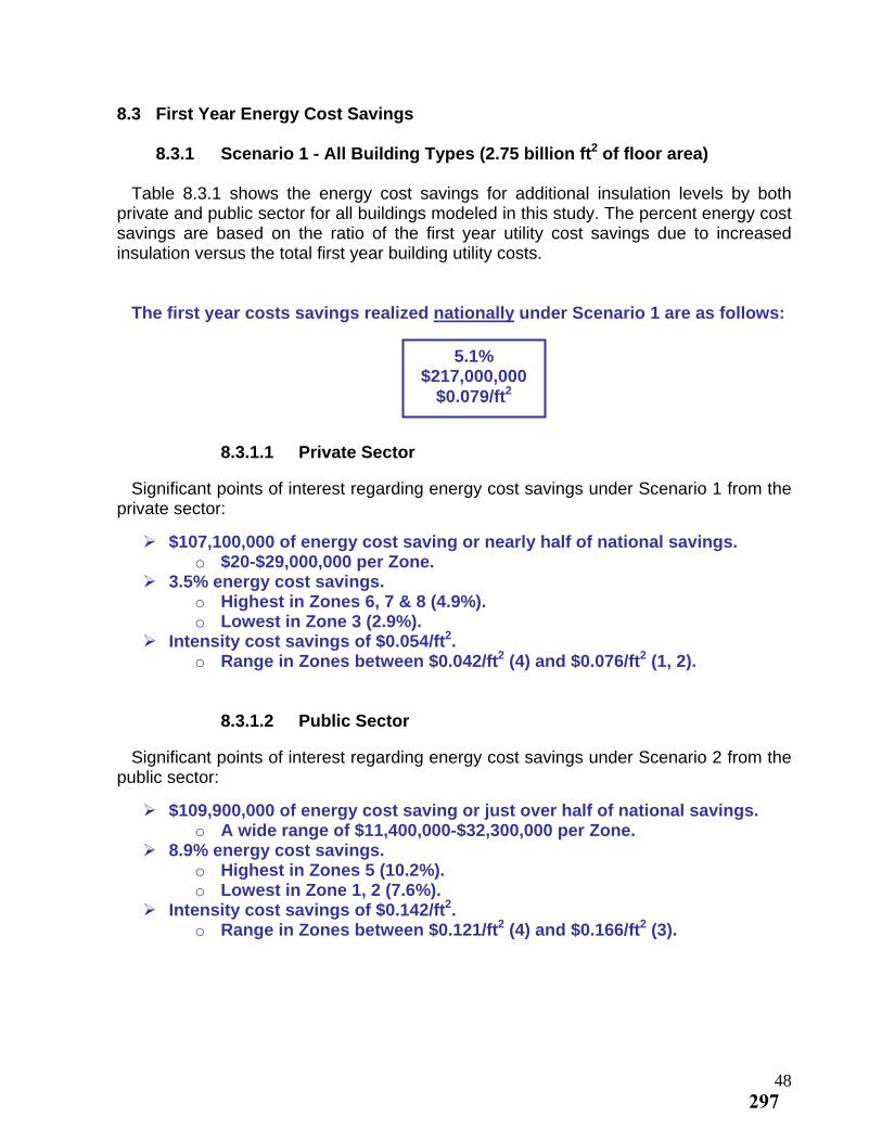
8.3 First Year Energy Cost Savings
8.3.1 Scenario 1 - All Building Types (2.75 billion ft2 of floor area) Table 8.3.1 shows the energy cost savings for additional insulation levels by both private and public sector for all buildings modeled in this study. The percent energy cost savings are based on the ratio of the first year utility cost savings due to increased insulation versus the total first year building utility costs. The first year costs savings realized nationally under Scenario 1 are as follows:
5.1% $217,000,000
$0.079/ft2
8.3.1.1 Private Sector Significant points of interest regarding energy cost savings under Scenario 1 from the private sector:
$107,100,000 of energy cost saving or nearly half of national savings. o $20-$29,000,000 per Zone.
3.5% energy cost savings. o Highest in Zones 6, 7 & 8 (4.9%). o Lowest in Zone 3 (2.9%).
Intensity cost savings of $0.054/ft2. o Range in Zones between $0.042/ft2 (4) and $0.076/ft2 (1, 2).
8.3.1.2 Public Sector Significant points of interest regarding energy cost savings under Scenario 2 from the public sector:
$109,900,000 of energy cost saving or just over half of national savings. o A wide range of $11,400,000-$32,300,000 per Zone.
8.9% energy cost savings. o Highest in Zones 5 (10.2%). o Lowest in Zone 1, 2 (7.6%).
Intensity cost savings of $0.142/ft2. o Range in Zones between $0.121/ft2 (4) and $0.166/ft2 (3).
48297
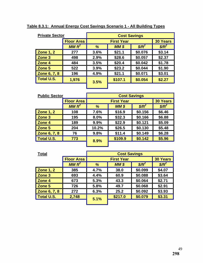
Table 8.3.1: Annual Energy Cost Savings Scenario 1 - All Building Types
Private Sector Cost Savings
Floor Area First Year 30 Years 2MM ft % MM $ $/ft2 $/ft2
Zone 1, 2 277 3.6% $21.1 $0.076 $3.14 Zone 3 498 2.9% $28.6 $0.057 $2.37 Zone 4 484 3.5% $20.4 $0.042 $1.78 Zone 5 522 3.9% $23.2 $0.044 $1.90 Zone 6, 7, 8 196 4.9% $21.1 $0.071 $3.01 Total U.S. 1,976 $107.1 $0.054 $2.27
3.5%
Public Sector Cost Savings Floor Area First Year 30 Years
2MM ft % MM $ $/ft2 $/ft2
Zone 1, 2 108 7.6% $16.9 $0.156 $6.46 Zone 3 195 8.0% $32.3 $0.166 $6.88 Zone 4 189 9.9% $22.9 $0.121 $5.09 Zone 5 204 10.2% $26.5 $0.130 $5.48 Zone 6, 7, 8 76 9.8% $11.4 $0.149 $6.28 Total U.S. 773 $109.9 $0.142 $5.96
8.9%
Total Cost Savings Floor Area First Year 30 Years
2MM ft % MM $ $/ft2 $/ft2
Zone 1, 2 385 4.7% 38.0 $0.099 $4.07 Zone 3 693 4.4% 60.9 $0.088 $3.64 Zone 4 673 5.3% 43.3 $0.064 $2.71 Zone 5 726 5.8% 49.7 $0.068 $2.91 Zone 6, 7, 8 272 6.3% 25.2 $0.092 $3.93 Total U.S. 2,748 $217.0 $0.079 $3.31
5.1%
49298
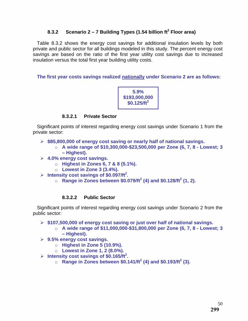
8.3.2 Scenario 2 – 7 Building Types (1.54 billion ft2 Floor area) Table 8.3.2 shows the energy cost savings for additional insulation levels by both private and public sector for all buildings modeled in this study. The percent energy cost savings are based on the ratio of the first year utility cost savings due to increased insulation versus the total first year building utility costs. The first year costs savings realized nationally under Scenario 2 are as follows:
5.9%
$193,000,000
$0.125/ft2
8.3.2.1 Private Sector Significant points of interest regarding energy cost savings under Scenario 1 from the private sector:
$85,800,000 of energy cost saving or nearly half of national savings. o A wide range of $10,300,000-$23,500,000 per Zone (6, 7, 8 - Lowest; 3
– Highest). 4.0% energy cost savings.
o Highest in Zones 6, 7 & 8 (5.1%). o Lowest in Zone 3 (3.4%).
Intensity cost savings of $0.097/ft2. o Range in Zones between $0.079/ft2 (4) and $0.128/ft2 (1, 2).
8.3.2.2 Public Sector Significant points of interest regarding energy cost savings under Scenario 2 from the public sector:
$107,500,000 of energy cost saving or just over half of national savings. o A wide range of $11,000,000-$31,800,000 per Zone (6, 7, 8 - Lowest; 3
– Highest). 9.5% energy cost savings.
o Highest in Zone 5 (10.9%). o Lowest in Zone 1, 2 (8.0%).
Intensity cost savings of $0.165/ft2. o Range in Zones between $0.141/ft2 (4) and $0.193/ft2 (3).
50299
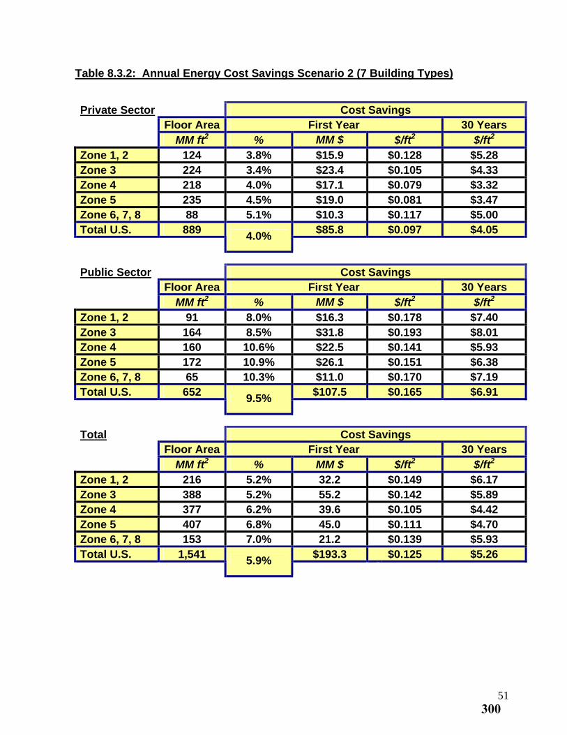
Table 8.3.2: Annual Energy Cost Savings Scenario 2 (7 Building Types)
Private Sector Cost Savings Floor Area First Year 30 Years
2MM ft % MM $ $/ft2 $/ft2
Zone 1, 2 124 3.8% $15.9 $0.128 $5.28 Zone 3 224 3.4% $23.4 $0.105 $4.33 Zone 4 218 4.0% $17.1 $0.079 $3.32 Zone 5 235 4.5% $19.0 $0.081 $3.47 Zone 6, 7, 8 88 5.1% $10.3 $0.117 $5.00 Total U.S. 889 $85.8 $0.097 $4.05
4.0%
Public Sector Cost Savings Floor Area First Year 30 Years
2MM ft % MM $ $/ft2 $/ft2
Zone 1, 2 91 8.0% $16.3 $0.178 $7.40 Zone 3 164 8.5% $31.8 $0.193 $8.01 Zone 4 160 10.6% $22.5 $0.141 $5.93 Zone 5 172 10.9% $26.1 $0.151 $6.38 Zone 6, 7, 8 65 10.3% $11.0 $0.170 $7.19 Total U.S. 652 $107.5 $0.165 $6.91
9.5%
Total Cost Savings Floor Area First Year 30 Years
2MM ft % MM $ $/ft2 $/ft2
Zone 1, 2 216 5.2% 32.2 $0.149 $6.17 Zone 3 388 5.2% 55.2 $0.142 $5.89 Zone 4 377 6.2% 39.6 $0.105 $4.42 Zone 5 407 6.8% 45.0 $0.111 $4.70 Zone 6, 7, 8 153 7.0% 21.2 $0.139 $5.93 Total U.S. 1,541 $193.3 $0.125 $5.26
5.9%
51300
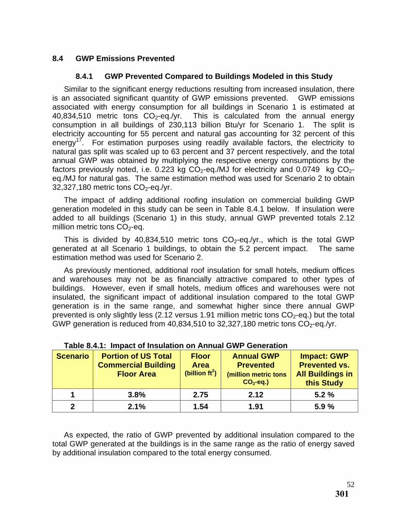
8.4 GWP Emissions Prevented
8.4.1 GWP Prevented Compared to Buildings Modeled in this Study
Similar to the significant energy reductions resulting from increased insulation, there is an associated significant quantity of GWP emissions prevented. GWP emissions associated with energy consumption for all buildings in Scenario 1 is estimated at 40,834,510 metric tons CO2-eq./yr. This is calculated from the annual energy consumption in all buildings of 230,113 billion Btu/yr for Scenario 1. The split is electricity accounting for 55 percent and natural gas accounting for 32 percent of this energy17. For estimation purposes using readily available factors, the electricity to natural gas split was scaled up to 63 percent and 37 percent respectively, and the total annual GWP was obtained by multiplying the respective energy consumptions by the factors previously noted, i.e. 0.223 kg CO -eq./MJ for electricity and 0.0749 kg CO2 2-eq./MJ for natural gas. The same estimation method was used for Scenario 2 to obtain 32,327,180 metric tons CO -eq./yr. 2
The impact of adding additional roofing insulation on commercial building GWP generation modeled in this study can be seen in Table 8.4.1 below. If insulation were added to all buildings (Scenario 1) in this study, annual GWP prevented totals 2.12 million metric tons CO -eq. 2
This is divided by 40,834,510 metric tons CO2-eq./yr., which is the total GWP generated at all Scenario 1 buildings, to obtain the 5.2 percent impact. The same estimation method was used for Scenario 2.
As previously mentioned, additional roof insulation for small hotels, medium offices and warehouses may not be as financially attractive compared to other types of buildings. However, even if small hotels, medium offices and warehouses were not insulated, the significant impact of additional insulation compared to the total GWP generation is in the same range, and somewhat higher since there annual GWP prevented is only slightly less (2.12 versus 1.91 million metric tons CO2-eq.) but the total GWP generation is reduced from 40,834,510 to 32,327,180 metric tons CO -eq./yr. 2
Table 8.4.1: Impact of Insulation on Annual GWP Generation
Scenario Portion of US Total Commercial Building
Floor Area
Floor Area
(billion ft2)
Annual GWP Impact: GWP Prevented Prevented vs.
All Buildings in (million metric tons CO2-eq.) this Study
1 3.8% 2.75 2.12 5.2 %
2 2.1% 1.54 1.91 5.9 %
As expected, the ratio of GWP prevented by additional insulation compared to the total GWP generated at the buildings is in the same range as the ratio of energy saved by additional insulation compared to the total energy consumed.
52301
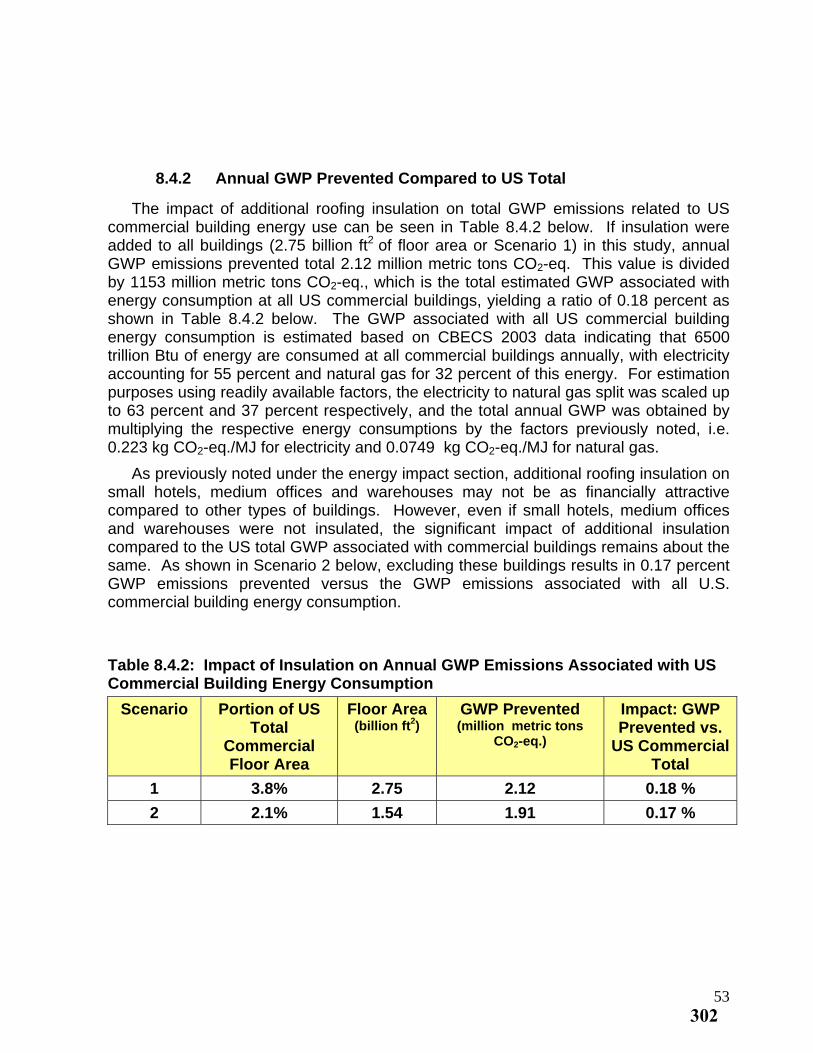
8.4.2 Annual GWP Prevented Compared to US Total
The impact of additional roofing insulation on total GWP emissions related to US commercial building energy use can be seen in Table 8.4.2 below. If insulation were added to all buildings (2.75 billion ft2 of floor area or Scenario 1) in this study, annual GWP emissions prevented total 2.12 million metric tons CO2-eq. This value is divided by 1153 million metric tons CO2-eq., which is the total estimated GWP associated with energy consumption at all US commercial buildings, yielding a ratio of 0.18 percent as shown in Table 8.4.2 below. The GWP associated with all US commercial building energy consumption is estimated based on CBECS 2003 data indicating that 6500 trillion Btu of energy are consumed at all commercial buildings annually, with electricity accounting for 55 percent and natural gas for 32 percent of this energy. For estimation purposes using readily available factors, the electricity to natural gas split was scaled up to 63 percent and 37 percent respectively, and the total annual GWP was obtained by multiplying the respective energy consumptions by the factors previously noted, i.e. 0.223 kg CO -eq./MJ for electricity and 0.0749 kg CO -eq./MJ for natural gas. 2 2
As previously noted under the energy impact section, additional roofing insulation on small hotels, medium offices and warehouses may not be as financially attractive compared to other types of buildings. However, even if small hotels, medium offices and warehouses were not insulated, the significant impact of additional insulation compared to the US total GWP associated with commercial buildings remains about the same. As shown in Scenario 2 below, excluding these buildings results in 0.17 percent GWP emissions prevented versus the GWP emissions associated with all U.S. commercial building energy consumption.
Table 8.4.2: Impact of Insulation on Annual GWP Emissions Associated with US Commercial Building Energy Consumption
Scenario Portion of US Total
Commercial Floor Area
Floor Area (billion ft2)
GWP Prevented Impact: GWP (million metric tons Prevented vs.
CO2-eq.) US Commercial Total
1 3.8% 2.75 2.12 0.18 %
2 2.1% 1.54 1.91 0.17 %
53302
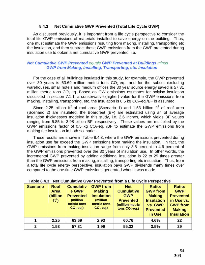
8.4.3 Net Cumulative GWP Prevented (Total Life Cycle GWP)
As discussed previously, it is important from a life cycle perspective to consider the total life GWP emissions of materials installed to save energy on the building. Thus, one must estimate the GWP emissions resulting from making, installing, transporting etc the insulation, and then subtract these GWP emissions from the GWP prevented during insulation use to obtain a net cumulative GWP prevented, i.e.
Net Cumulative GWP Prevented equals GWP Prevented at Buildings minus GWP from Making, Installing, Transporting, etc. Insulation
For the case of all buildings insulated in this study, for example, the GWP prevented over 30 years is 63.69 million metric tons CO2-eq., and for the subset excluding warehouses, small hotels and medium offices the 30 year source energy saved is 57.31 million metric tons CO2-eq. Based on GW emissions estimates for polyiso insulation discussed in section 7.1.1, a conservative (higher) value for the GWP emissions from making, installing, transporting, etc. the insulation is 0.5 kg CO -eq./BF is assumed. 2
2 Since 2.25 billion ft of roof area (Scenario 1) and 1.53 billion ft2 of roof area (Scenario 2) are insulated, the Boardfeet (BF) are estimated using an of average insulation thicknesses modeled in this study, i.e. 2.6 inches, which yields BF values ranging from 5.85 to 3.98 billion BF, respectively. These values are multiplied by the GWP emissions factor of 0.5 kg CO2-eq. /BF to estimate the GWP emissions from making the insulation in both scenarios.
These results are shown in Table 8.4.3, where the GWP emissions prevented during insulation use far exceed the GWP emissions from making the insulation. In fact, the GWP emissions from making insulation range from only 3.5 percent to 4.6 percent of the GWP emissions prevented over the 30 years of insulation use. In other words, the incremental GWP prevented by adding additional insulation is 22 to 29 times greater than the GWP emissions from making, installing, transporting etc insulation. Thus, from a total life cycle energy perspective, insulation pays GWP dividends many times over compared to the one time GWP emissions generated when it was made.
Table 8.4.3: Net Cumulative GWP Prevented from a Life Cycle Perspective
Scenario Roof Area
(billion ft2)
Cumulative GWP
Prevented (million
metric tons CO2-eq.)
GWP from Making
Insulation (million
metric tons CO2-eq.)
Net Ratio: Ratio: Cumulative
GWP Prevented
(million metric tons CO2-eq.)
GWP from GWP Making Prevented
Insulation in Use vs. vs. GWP GWP from
Prevented Making in Use Insulation
1 2.25 63.69 2.93 60.76 4.6% 22
2 1.53 57.31 1.99 55.32 3.5% 29
54303
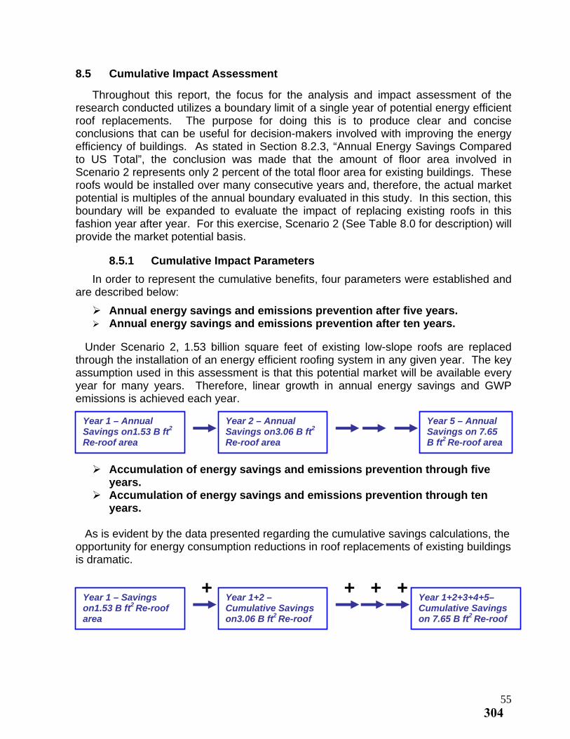
8.5 Cumulative Impact Assessment
Throughout this report, the focus for the analysis and impact assessment of the research conducted utilizes a boundary limit of a single year of potential energy efficient roof replacements. The purpose for doing this is to produce clear and concise conclusions that can be useful for decision-makers involved with improving the energy efficiency of buildings. As stated in Section 8.2.3, “Annual Energy Savings Compared to US Total”, the conclusion was made that the amount of floor area involved in Scenario 2 represents only 2 percent of the total floor area for existing buildings. These roofs would be installed over many consecutive years and, therefore, the actual market potential is multiples of the annual boundary evaluated in this study. In this section, this boundary will be expanded to evaluate the impact of replacing existing roofs in this fashion year after year. For this exercise, Scenario 2 (See Table 8.0 for description) will provide the market potential basis.
8.5.1 Cumulative Impact Parameters
In order to represent the cumulative benefits, four parameters were established and are described below:
Annual energy savings and emissions prevention after five years. Annual energy savings and emissions prevention after ten years.
Under Scenario 2, 1.53 billion square feet of existing low-slope roofs are replaced through the installation of an energy efficient roofing system in any given year. The key assumption used in this assessment is that this potential market will be available every year for many years. Therefore, linear growth in annual energy savings and GWP emissions is achieved each year.
Year 1 – Annual Savings on1.53 B ft
Year 2 – Annual Savings on3.06 B ft
Year 5 – Annual Savings on 7.65 B ft
2 2
2 Re-roof area Re-roof area Re-roof area
Accumulation of energy savings and emissions prevention through five years.
Accumulation of energy savings and emissions prevention through ten years.
As is evident by the data presented regarding the cumulative savings calculations, the opportunity for energy consumption reductions in roof replacements of existing buildings is dramatic.
+ + + +Year 1 – Savings on1.53 B ft
Year 1+2 – Cumulative Savings on3.06 B ft
Year 1+2+3+4+5– Cumulative Savings on 7.65 B ft
2 Re-roof area 2 2 Re-roof Re-roof
55304
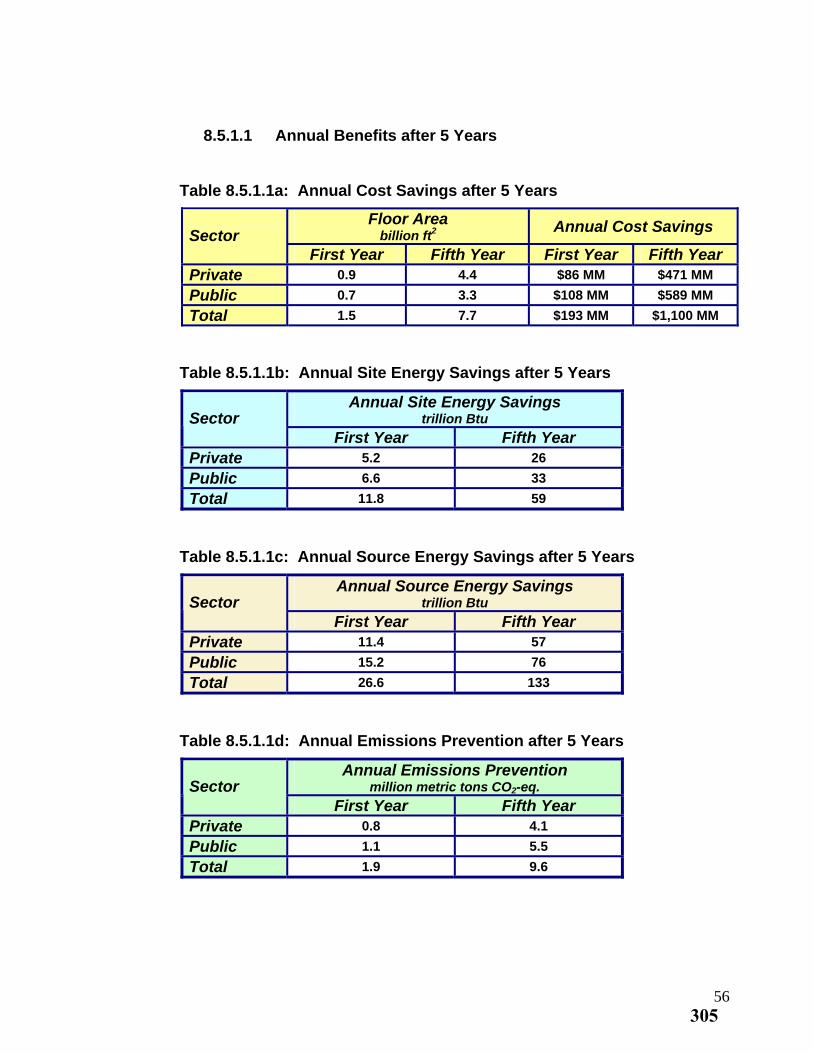
8.5.1.1 Annual Benefits after 5 Years
Table 8.5.1.1a: Annual Cost Savings after 5 Years
Floor Area Annual Cost Savings billion ft2Sector
First Year Fifth Year First Year Fifth Year Private 0.9 4.4 $86 MM $471 MM
Public 0.7 3.3 $108 MM $589 MM
Total 1.5 7.7 $193 MM $1,100 MM
Table 8.5.1.1b: Annual Site Energy Savings after 5 Years
Annual Site Energy Savings trillion Btu Sector
First Year Fifth Year Private 5.2 26
Public 6.6 33
Total 11.8 59
Table 8.5.1.1c: Annual Source Energy Savings after 5 Years
Annual Source Energy Savings trillion Btu Sector
First Year Fifth Year Private 11.4 57
Public 15.2 76
Total 26.6 133
Table 8.5.1.1d: Annual Emissions Prevention after 5 Years
Annual Emissions Prevention million metric tons CO2-eq. Sector
First Year Fifth Year Private 0.8 4.1
Public 1.1 5.5
Total 1.9 9.6
56305
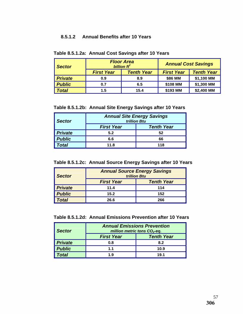
8.5.1.2 Annual Benefits after 10 Years
Table 8.5.1.2a: Annual Cost Savings after 10 Years
Floor Area Annual Cost Savings billion ft2Sector
First Year Tenth Year First Year Tenth Year Private 0.9 8.9 $86 MM $1,100 MM
Public 0.7 6.5 $108 MM $1,300 MM
Total 1.5 15.4 $193 MM $2,400 MM
Table 8.5.1.2b: Annual Site Energy Savings after 10 Years
Annual Site Energy Savings trillion Btu Sector
First Year Tenth Year Private 5.2 52
Public 6.6 66
Total 11.8 118
Table 8.5.1.2c: Annual Source Energy Savings after 10 Years
Annual Source Energy Savings trillion Btu Sector
First Year Tenth Year Private 11.4 114
Public 15.2 152
Total 26.6 266
Table 8.5.1.2d: Annual Emissions Prevention after 10 Years
Annual Emissions Prevention million metric tons CO2-eq. Sector
First Year Tenth Year Private 0.8 8.2
Public 1.1 10.9
Total 1.9 19.1
57306

8.5.1.3 Accumulation of Benefits through 5 Years
Table 8.5.1.3a: Cumulative Cost Savings through 5 Years
Floor Area Cumulative Cost Savings billion ft2Sector
First Year Fifth Year First Year Fifth Year Private 0.9 4.4 $86 MM $1,400 MM
Public 0.7 3.3 $108 MM $1,700 MM
Total 1.5 7.7 $193 MM $3,100 MM
Table 8.5.1.3b: Cumulative Site Energy Savings through 5 Years
Cumulative Site Energy Savings trillion Btu Sector
First Year Fifth Year Private 5.2 78
Public 6.6 99
Total 11.8 177
Table 8.5.1.3c: Cumulative Source Energy Savings through 5 Years
Cumulative Source Energy Savings trillion Btu Sector
First Year Fifth Year Private 11.4 171
Public 15.2 228
Total 26.6 399
Table 8.5.1.3d: Cumulative Emissions Prevention through 5 Years
Cumulative Emissions Prevention million metric tons CO2-eq. Sector
First Year Fifth Year Private 0.8 12.2
Public 1.1 16.4
Total 1.9 28.6
58307
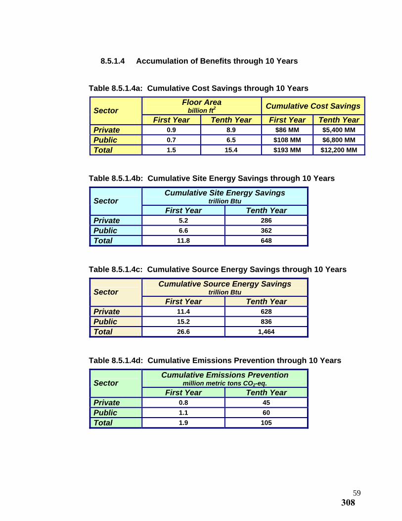
8.5.1.4 Accumulation of Benefits through 10 Years
Table 8.5.1.4a: Cumulative Cost Savings through 10 Years
Floor Area Cumulative Cost Savings billion ft2Sector
First Year Tenth Year First Year Tenth Year Private 0.9 8.9 $86 MM $5,400 MM
Public 0.7 6.5 $108 MM $6,800 MM
Total 1.5 15.4 $193 MM $12,200 MM
Table 8.5.1.4b: Cumulative Site Energy Savings through 10 Years
Cumulative Site Energy Savings trillion Btu Sector
First Year Tenth Year Private 5.2 286
Public 6.6 362
Total 11.8 648
Table 8.5.1.4c: Cumulative Source Energy Savings through 10 Years
Cumulative Source Energy Savings trillion Btu Sector
First Year Tenth Year Private 11.4 628
Public 15.2 836
Total 26.6 1,464
Table 8.5.1.4d: Cumulative Emissions Prevention through 10 Years
Cumulative Emissions Prevention million metric tons CO2-eq. Sector
First Year Tenth Year Private 0.8 45
Public 1.1 60
Total 1.9 105
59308
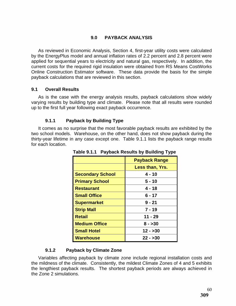
9.0 PAYBACK ANALYSIS
As reviewed in Economic Analysis, Section 4, first-year utility costs were calculated by the EnergyPlus model and annual inflation rates of 2.2 percent and 2.8 percent were applied for sequential years to electricity and natural gas, respectively. In addition, the current costs for the required rigid insulation were obtained from RS Means CostWorks Online Construction Estimator software. These data provide the basis for the simple payback calculations that are reviewed in this section.
9.1 Overall Results
As is the case with the energy analysis results, payback calculations show widely varying results by building type and climate. Please note that all results were rounded up to the first full year following exact payback occurrence.
9.1.1 Payback by Building Type
It comes as no surprise that the most favorable payback results are exhibited by the two school models. Warehouse, on the other hand, does not show payback during the thirty-year lifetime in any case except one. Table 9.1.1 lists the payback range results for each location.
Table 9.1.1 Payback Results by Building Type
Payback Range
Less than, Yrs.
Secondary School 4 - 10
Primary School 5 - 10
Restaurant 4 - 18
Small Office 6 - 17
Supermarket 9 - 21
Strip Mall 7 - 19
Retail 11 - 29
Medium Office 8 - >30
Small Hotel 12 - >30
Warehouse 22 - >30
9.1.2 Payback by Climate Zone
Variables affecting payback by climate zone include regional installation costs and the mildness of the climate. Consistently, the mildest Climate Zones of 4 and 5 exhibits the lengthiest payback results. The shortest payback periods are always achieved in the Zone 2 simulations.
60309
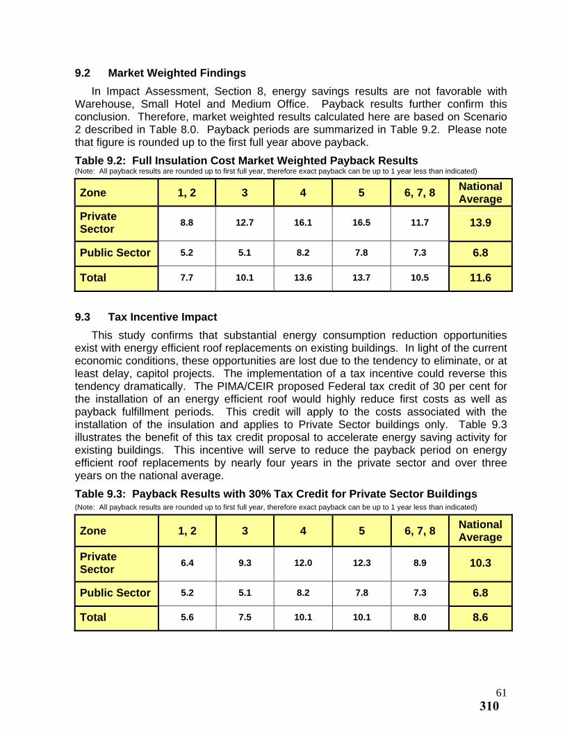
9.2 Market Weighted Findings
In Impact Assessment, Section 8, energy savings results are not favorable with Warehouse, Small Hotel and Medium Office. Payback results further confirm this conclusion. Therefore, market weighted results calculated here are based on Scenario 2 described in Table 8.0. Payback periods are summarized in Table 9.2. Please note that figure is rounded up to the first full year above payback.
Table 9.2: Full Insulation Cost Market Weighted Payback Results (Note: All payback results are rounded up to first full year, therefore exact payback can be up to 1 year less than indicated)
Zone 1, 2 3 4 5 National
6, 7, 8 Average
Private Sector
8.8 12.7 16.1 16.5 11.7 13.9
Public Sector 5.2 5.1 8.2 7.8 7.3 6.8
Total 7.7 10.1 13.6 13.7 10.5 11.6
9.3 Tax Incentive Impact
This study confirms that substantial energy consumption reduction opportunities exist with energy efficient roof replacements on existing buildings. In light of the current economic conditions, these opportunities are lost due to the tendency to eliminate, or at least delay, capitol projects. The implementation of a tax incentive could reverse this tendency dramatically. The PIMA/CEIR proposed Federal tax credit of 30 per cent for the installation of an energy efficient roof would highly reduce first costs as well as payback fulfillment periods. This credit will apply to the costs associated with the installation of the insulation and applies to Private Sector buildings only. Table 9.3 illustrates the benefit of this tax credit proposal to accelerate energy saving activity for existing buildings. This incentive will serve to reduce the payback period on energy efficient roof replacements by nearly four years in the private sector and over three years on the national average.
Table 9.3: Payback Results with 30% Tax Credit for Private Sector Buildings (Note: All payback results are rounded up to first full year, therefore exact payback can be up to 1 year less than indicated)
National Zone 1, 2 3 4 5 6, 7, 8
Average
Private Sector
6.4 9.3 12.0 12.3 8.9 10.3
Public Sector 5.2 5.1 8.2 7.8 7.3 6.8
Total 5.6 7.5 10.1 10.1 8.0 8.6
61310
10.0 CONCLUSIONS
Representing eighteen percent of all U.S. annual energy use at 91 kBtu/ft2 based on
floor area, existing commercial buildings play an important role in the challenge to achieve substantial reductions in consumption of energy and impact on the environment. A key lies in the fact that the vast majority of building stock will require roof replacement over the next fifteen to twenty five years providing a practical opportunity to improve the thermal performance of buildings. From the research conducted and the results presented in this report, the following conclusions have been established:
One and one half billion square feet of existing floor area is a viable annual potential for installation of low-slope energy efficient roofing systems. Clearer and more stringent energy code language as well as increased enforcement specific to re-roofing projects could enhance this potential.
After ten years, fifteen billion square feet or greater than 20 percent of today’s existing floor area will be saving 6.5 percent of total site energy consumption or 118 billion Btu and 266 billion Btu of source energy annually. It is presumed that during this period, a portion of non-retrofitted buildings will be demolished, further contributing to the relative impact of energy efficient roofing systems in lowering the energy intensity level of buildings. Lastly, from a life cycle perspective, the total embodied energy involved in the insulation is recovered in the first year of its use through the energy saved.
The economic impact includes a cumulative savings of $12.2 billion and annual savings of $2.4 billion which, of course, continues throughout the lifetime of the insulation. The total capitol required (installed cost of additional insulation) over this ten year period is approximately $23 billion. Please note that the economic impact in this study is limited to the site utility costs and the installed costs of the insulation. There are other potential economic benefits associated with reductions in energy generation and use as well as reduction in emissions and other environmental impacts that are beyond the scope of this research.
Energy savings realized with energy efficient roof systems vary significantly between climate zones and vary dramatically between building types. Of the ten building types studied, seven exhibit substantial savings in all climate zones with schools reaping the greatest benefits.
With respect to GWP, this practical means of thermal performance improvement prevents nearly 0.2 percent of the total building stock emissions in the first year alone. The compounding impact provides a GWP emissions prevention benefit of greater than 100 million metric tons CO2-equiv. after ten years. Again, comparing this to the life cycle emissions involved in the additional insulation shows that the net zero emissions period is roughly one year.
62311
Biographies Jerry Phelan
Jerry Phelan holds a B. S. degree in Chemical Engineering from the University of Rochester. He has been with Bayer MaterialScience in Pittsburgh for 29 years. For much of that time, Jerry has been, and continues to be, engaged in Bayer’s business with polyurethane and polyisocyanurate insulation in Construction. Jerry has been very active in PIMA (Polyisocyanurate Insulation Manufacturers Association) for the last 14 years, where he is currently serving a third term on the Board of Directors, participates on the Industry Promotion Committee, the ASHRAE Task Force and with colleague Pavlovich, manages PIMA’s Life Cycle Inventory Program. He also actively participates on the Building and Construction Market Team of ACC (American Chemistry Council), participates in CPI (Center for the Polyurethanes Industry) and member of both ASHRAE and NRCA. Alongside many respected colleagues in PIMA and the Polyurethane Industry, Jerry has been deeply involved in and committed to the advancement of polyisocyanurate/polyurethane insulation products for many years. Much of this involvement in recent years has been in the fields of Life Cycle Assessment and Whole Building Energy Analysis.
George Pavlovich
George Pavlovich works for Bayer MaterialScience in Pittsburgh focusing on Life Cycle Assessments. He has worked with chemical processes at Bayer since 1987, implementing pollution prevention programs, conducting environmental impact analyses, and developing global EH&S management systems and Product Stewardship programs. This included several years in Europe and Asia, as well as assignments in China, India, Japan, Belgium, Mexico, Brazil and many plants in the U.S.A. He has an MS in Civil Engineering from Carnegie Mellon University and BS degrees in Chemical Engineering and Biology from the University of Pittsburgh.
Eric Ma
Eric Ma has over 26 years experience in merger and acquisition, sales and marketing, consulting, business development, strategic planning and technology with Bayer MaterialScience. Eric has 11 publications and patents.
63312
313
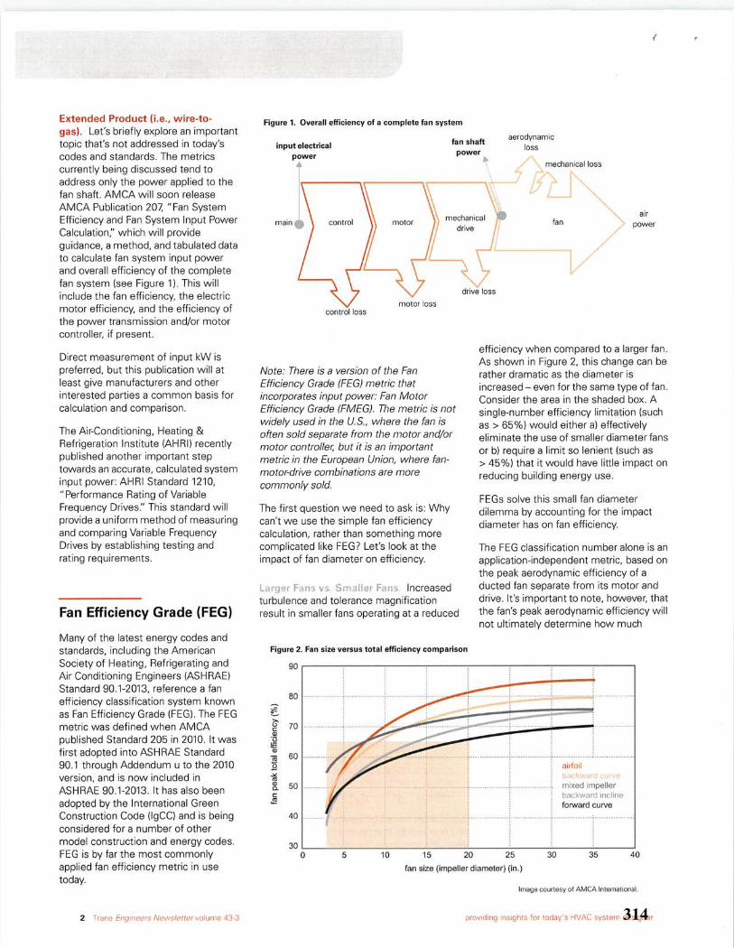
314
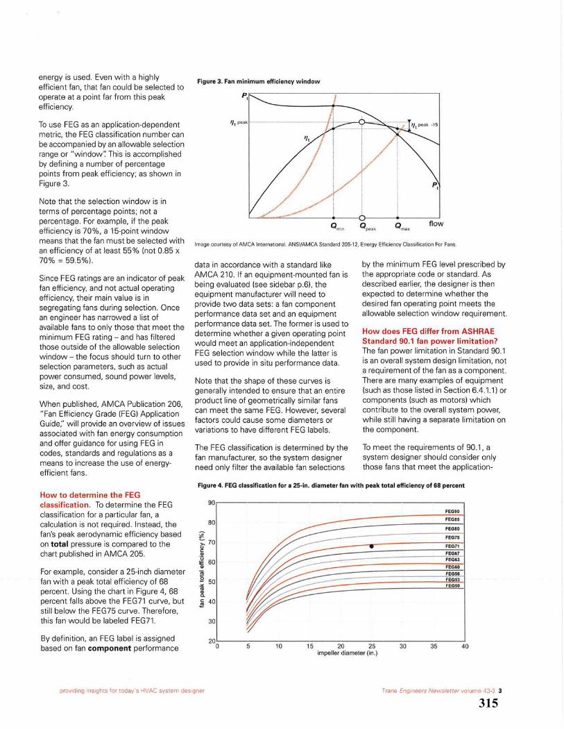
315
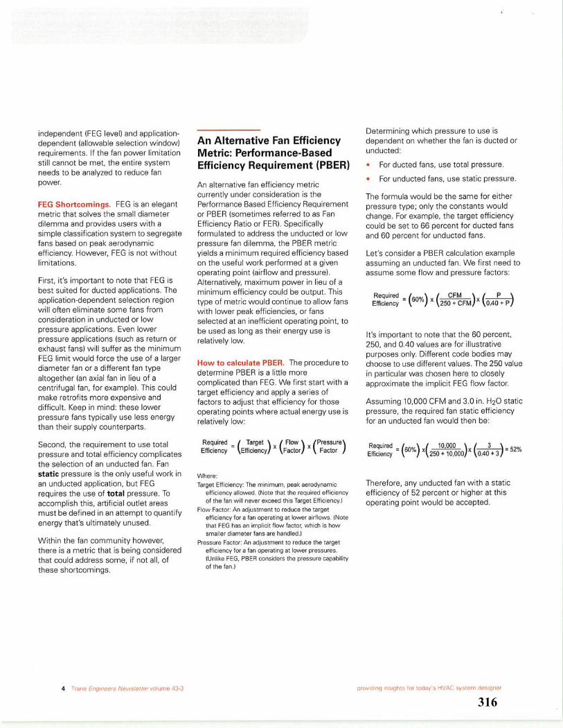
316
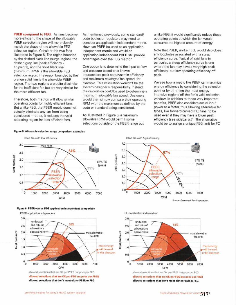
317
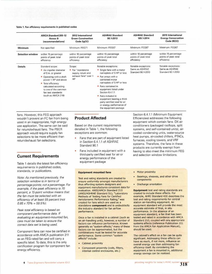
318
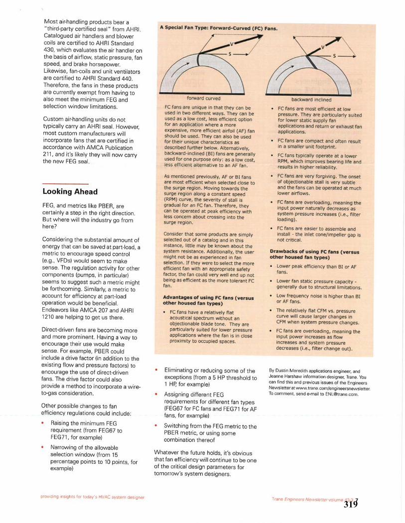
319
320
321
322
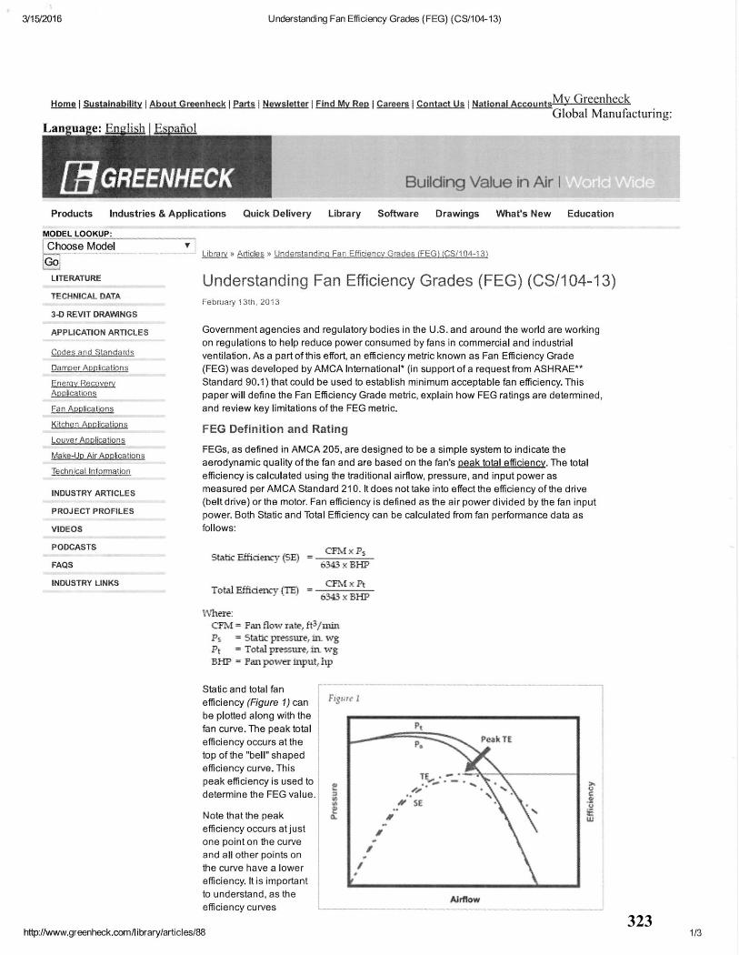
323
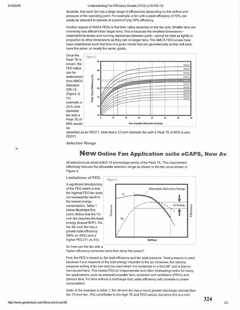
324
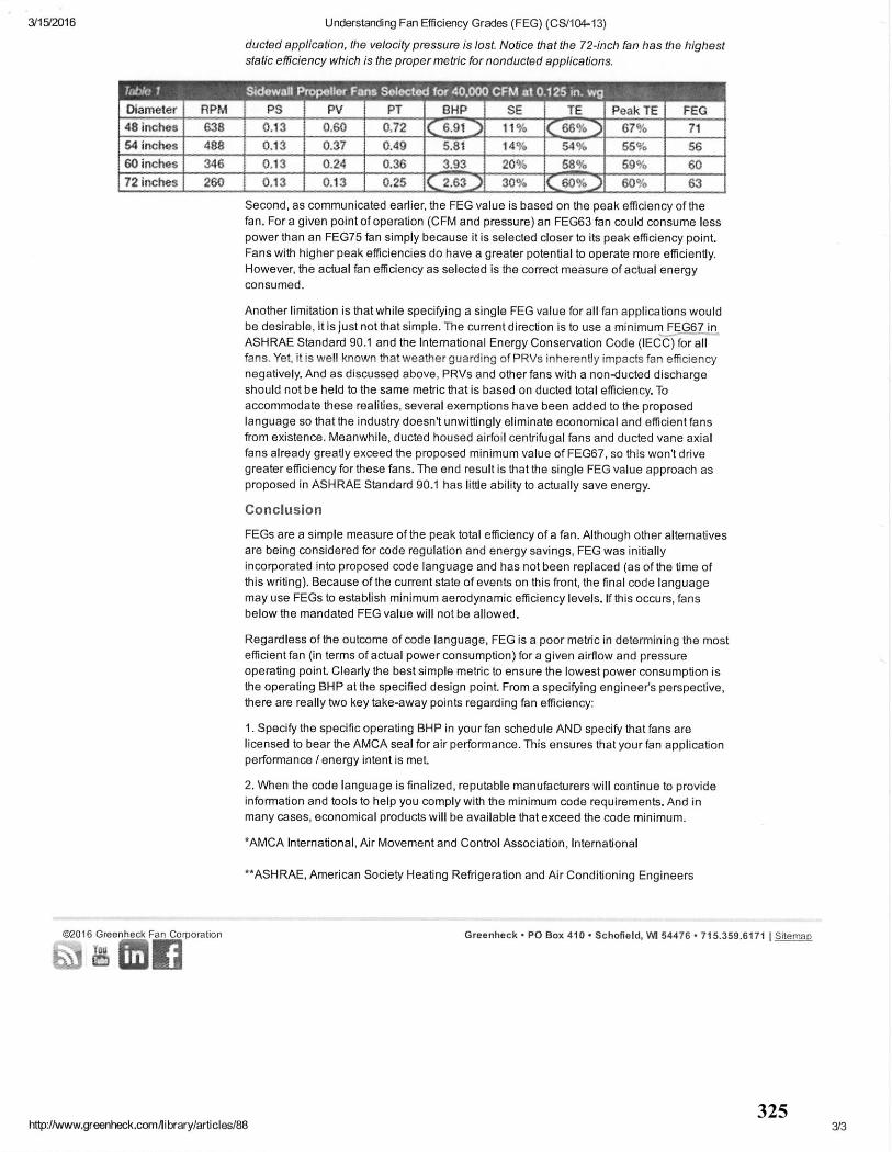
325
326
327
328
329
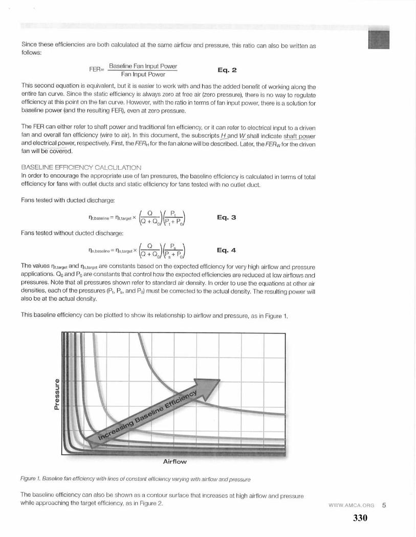
330
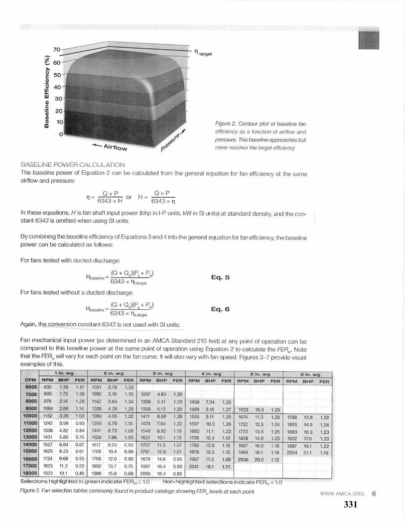
331
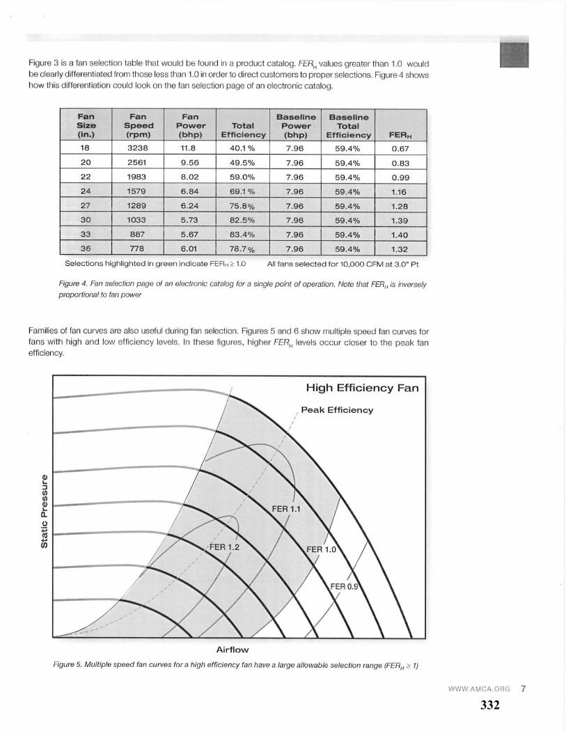
332
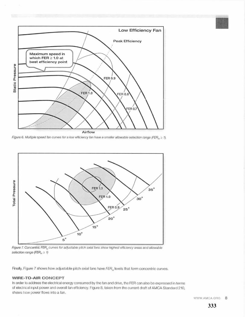
333
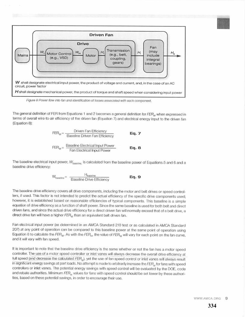
334
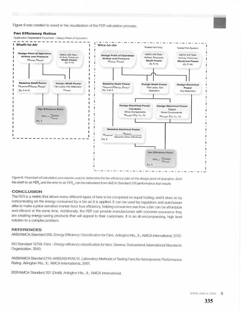
335