Embed Size (px)
Citation preview

Media Tube® HO
INSTALLATION GUIDE
V1.1
Cover:
Media Tube® HO RGBW/RGB/White Direct View
Media Tube® HO RGBW/RGB/White Diffused

www.traxontechnologies.com©2022 TRAXON TECHNOLOGIES - AN OSRAM BUSINESS. ALL RIGHTS RESERVED. TRAXON™, TX CONNECT®, ARE TRADEMARKS OF TRAXON TECHNOLOGIES. U.S. PATENTS, E.U. PATENTS, JAPAN PATENTS, OTHER PATENTS PENDING. SPECIFICATIONS ARE SUBJECT TO CHANGE WITHOUT NOTICE.
Installation Guide 02/22 V1.1 2 of 26
CONTENT
1. INTRODUCTION 3
2. INSTALLATION 6
3. SAFETY AND OPERATION 13
4. SYSTEM CONFIGURATION 14
5. CARE AND MAINTENANCE 20
6. TROUBLESHOOTING 21
7. TECHNICAL SPECIFICATION 22
8. WARRANTY STATEMENT 22
For your own safety and that of the product, please read this installation guide carefully before beginning setup and installation.

www.traxontechnologies.com©2022 TRAXON TECHNOLOGIES - AN OSRAM BUSINESS. ALL RIGHTS RESERVED. TRAXON™, TX CONNECT®, ARE TRADEMARKS OF TRAXON TECHNOLOGIES. U.S. PATENTS, E.U. PATENTS, JAPAN PATENTS, OTHER PATENTS PENDING. SPECIFICATIONS ARE SUBJECT TO CHANGE WITHOUT NOTICE.
Installation Guide 02/22 V1.1 3 of 26
1. INTRODUCTION
1.1 General
MEDIA TUBE® HO RGBW DIRECT VIEW
MEDIA TUBE® HO RGBW DIFFUSED
Length (mm) Maximum number of pixels (PXL)
TU.CS.1112001 TU.DS.1112001 296 12
TU.CS.2124001 TU.DS.2124001 596 24
TU.CS.3136001 TU.DS.3136001 896 36
TU.CS.4148001 TU.DS.4148001 1196 48
TU.CS.5160001 TU.DS.5160001 1496 60
Media Tube® HO is an IP66-rated slim LED tube for any wall or façade media lighting. Available in 296mm, 596mm, 896mm, 1196mm and 1496mm lengths, the simple but robust construction, allows up to 18.3m of tubes to be daisy chained on a single power run. The Media Tube® HO is controllable by DMX512 / e:pix / DVI capable with auto-addressing to the next tube in the daisy chain. The Media Tube® HO is housed in aluminium extrusion with a clear PC cover for direct view or with a diffused PC cover for diffused view.
Features:
• Available lengths: 296mm (12PXL), 596mm (24PXL), 896mm (36PXL), 1196mm (48PXL) and 1496mm (60PXL)
• Direct View or Diffused
• Three color options: RGBW, RGB*, White* (*available upon request)
• DMX512 / e:pix / DVI capable
• Daisy Chain System
• Auto-Addressing
• SMART CHIP™ Technology
• Outdoor Applications (IP66-rated)

www.traxontechnologies.com©2022 TRAXON TECHNOLOGIES - AN OSRAM BUSINESS. ALL RIGHTS RESERVED. TRAXON™, TX CONNECT®, ARE TRADEMARKS OF TRAXON TECHNOLOGIES. U.S. PATENTS, E.U. PATENTS, JAPAN PATENTS, OTHER PATENTS PENDING. SPECIFICATIONS ARE SUBJECT TO CHANGE WITHOUT NOTICE.
Installation Guide 02/22 V1.1 4 of 26
1.2 DimensionsFIG.1: Media Tube® HO Direct View
296mm, 596mm, 896mm, 1196mm, 1496mm / 11.7”, 23.5”, 35.3”, 47.1”, 58.9”
69mm / 2.7” 109mm / 4.3”
23mm / 0.9”
51.5
mm
/ 2
”
24mm / 0.94”
36m
m /
1.4
”
63m
m /
2.5
”
With Mounting Bracket
25mm / 1”
30m
m /
1.2
”
33mm / 1.3”
Quick Lock Input Cable Quick Lock Output Cable
With Mounting Bracket
296mm, 596mm, 896mm, 1196mm, 1496mm / 11.7”, 23.5”, 35.3”, 47.1”, 58.9”
69mm / 2.7” 109mm / 4.3”
23mm / 0.9”
51.5
mm
/ 2
”
24mm / 0.94”36
mm
/ 1
.4”
63m
m /
2.5
”
With Mounting Bracket
25mm / 1”
30m
m /
1.2
”
33mm / 1.3”
Quick Lock Input Cable Quick Lock Output Cable
With Mounting Bracket
FIG.2: Media Tube® HO Diffused
296mm, 596mm, 896mm, 1196mm, 1496mm / 11.7”, 23.5”, 35.3”, 47.1”, 58.9”
69mm / 2.7” 109mm / 4.3”
81m
m /
3.2
”
With Mounting Bracket
25mm / 1”
30m
m /
1.2
”
33mm / 1.3”
Quick Lock Input Cable Quick Lock Output Cable
29mm / 1.14”
With Mounting Bracket
81m
m /
3.2
”
29mm / 1.14”
54m
m /
2.1
”
296mm, 596mm, 896mm, 1196mm, 1496mm / 11.7”, 23.5”, 35.3”, 47.1”, 58.9”
69mm / 2.7” 109mm / 4.3”
81m
m /
3.2
”
With Mounting Bracket
25mm / 1”
30m
m /
1.2
”
33mm / 1.3”
Quick Lock Input Cable Quick Lock Output Cable
29mm / 1.14”
With Mounting Bracket
81m
m /
3.2
”
29mm / 1.14”
54m
m /
2.1
”
Tube-to-Tube Clearance
To maintain consistent LED pitch
See DETAIL A
See DETAIL B
Diffused Tube
M6 x 23mm
USE REAR STUDS FOR ALTERNATIVE MOUNTING
and to allow for thermal expansion.
Connector End Cap
END CAP SEAL ON LAST TUBE
DETAIL A
DETAIL B
69mm / 2.7” 109mm / 4.3”
23mm / 0.9”
51.5
mm
/ 2
”
24mm / 0.94”
36m
m /
1.4
”
296mm, 596mm, 896mm, 1196mm, 1496mm / 11.7”, 23.5”, 35.3”, 47.1”, 58.9”
81m
m /
3.2
”
29mm / 1.14”
Direct View Tube
81m
m /
3.2
”
30m
m /
1.2
”
33mm / 1.3”
29mm / 1.14”63
mm
/ 2
.5”
30m
m /
1.2
”
33mm / 1.3”
182mm / 7.2”
>4mm/0.16”
Lock with screw
54m
m /
2.1
”
Mounting
The light source of this luminaire is not replaceable;When the light source reaches its end of life, thewhole luminaire shall be replaced.
Loosen mounting stud may lead towater ingression.
296mm, 596mm, 896mm, 1196mm, 1496mm / 11.7”, 23.5”, 35.3”, 47.1”, 58.9”
Click!
Without Mounting Bracket
Tube-to-Tube Clearance
To maintain consistent LED pitch
See DETAIL A
See DETAIL B
Diffused Tube
M6 x 23mm
USE REAR STUDS FOR ALTERNATIVE MOUNTING
and to allow for thermal expansion.
Connector End Cap
END CAP SEAL ON LAST TUBE
DETAIL A
DETAIL B
69mm / 2.7” 109mm / 4.3”
23mm / 0.9”
51.5
mm
/ 2
”
24mm / 0.94”
36m
m /
1.4
”
296mm, 596mm, 896mm, 1196mm, 1496mm / 11.7”, 23.5”, 35.3”, 47.1”, 58.9”
81m
m /
3.2
”
29mm / 1.14”
Direct View Tube
81m
m /
3.2
”
30m
m /
1.2
”
33mm / 1.3”
29mm / 1.14”
63m
m /
2.5
”
30m
m /
1.2
”
33mm / 1.3”
182mm / 7.2”
>4mm/0.16”
Lock with screw
54m
m /
2.1
”
Mounting
The light source of this luminaire is not replaceable;When the light source reaches its end of life, thewhole luminaire shall be replaced.
Loosen mounting stud may lead towater ingression.
296mm, 596mm, 896mm, 1196mm, 1496mm / 11.7”, 23.5”, 35.3”, 47.1”, 58.9”
Click!
Without Mounting Bracket

www.traxontechnologies.com©2022 TRAXON TECHNOLOGIES - AN OSRAM BUSINESS. ALL RIGHTS RESERVED. TRAXON™, TX CONNECT®, ARE TRADEMARKS OF TRAXON TECHNOLOGIES. U.S. PATENTS, E.U. PATENTS, JAPAN PATENTS, OTHER PATENTS PENDING. SPECIFICATIONS ARE SUBJECT TO CHANGE WITHOUT NOTICE.
Installation Guide 02/22 V1.1 5 of 26
1.3 Packing ContentsFIG.3: Packing Contents
Media Tube® HO(Direct View or Diffused)
2 x Mounting Bracket(4x screws pre-installed)
2 x Screws 2 x Bolts Assortment of nuts and washers
www.traxontechnologies.com©2022 TRAXON TECHNOLOGIES - AN OSRAM BUSINESS. ALL RIGHTS RESERVED. TRAXON™, TX CONNECT®, ARE TRADEMARKS OF TRAXON TECHNOLOGIES. U.S. PATENTS, E.U. PATENTS, JAPAN PATENTS, OTHER PATENTS PENDING. SPECIFICATIONS ARE SUBJECT TO CHANGE WITHOUT NOTICE.
Installation Guide 02/22 V1.1 6 of 26
2. INSTALLATION
2.1 Points To Consider
Plan your installation before mounting the Media Tubes® HO. The following should be considered for a successful installation.
• Weather conditions and ambient temperature of installation site.
• Appropriate cable lengths (cable gauges described in below diagram). Please consult your local Traxon office or authorized agent for necessary aid.
• The number of Media Tubes® HO and appropriate LED Engines.
• DMX512/e:pix controller to be used to control the Media Tubes® HO.
• Distance between each Tube for thermal expansion and maintaining pixel pitch.
• There are two mounting methods to consider, plan mounting distances accordingly for whichever method is required.
• Proper surge protection.
• Number of standard LED Engines to be used.
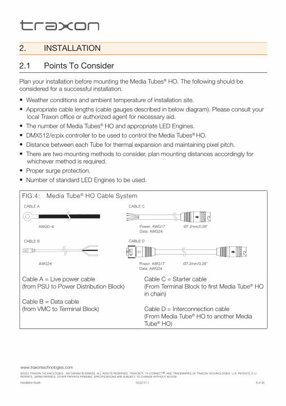
FIG.4: Media Tube® HO Cable System
CABLE A
CABLE B
CABLE C
CABLE D
AWG0~6
AWG24
Power: AWG17 Ø7.2mm/0.28”Data: AWG24
Power: AWG17 Ø7.2mm/0.28”Data: AWG24
Cable A = Live power cable (from PSU to Power Distribution Block)
Cable B = Data cable (from VMC to Terminal Block)
Cable C = Starter cable (From Terminal Block to first Media Tube® HO in chain)
Cable D = Interconnection cable (From Media Tube® HO to another Media Tube® HO)

www.traxontechnologies.com©2022 TRAXON TECHNOLOGIES - AN OSRAM BUSINESS. ALL RIGHTS RESERVED. TRAXON™, TX CONNECT®, ARE TRADEMARKS OF TRAXON TECHNOLOGIES. U.S. PATENTS, E.U. PATENTS, JAPAN PATENTS, OTHER PATENTS PENDING. SPECIFICATIONS ARE SUBJECT TO CHANGE WITHOUT NOTICE.
Installation Guide 02/22 V1.1 7 of 26
2.2 Pre-Installation Checks
2.2.1 Installation Checklist
1. Prepare cables and all necessary accessories (Mounting Brackets, Waterproof Quick Lock End Caps etc).
2. Perform functional check of Media Tubes® HO. Take care not to damage cables/connectors during pre-installation checks.
3. Ensure all pre-installation checks laid out below have been followed.
4. Mount the Media Tubes® HO on-site. If the installation is to be left uncompleted overnight, place all non-connected LED Engines and Media Tubes® HO in an indoor environment.
Ensure all the Interconnection Cables, Media Tubes® HO and LED Engines are initially stored in a dry area to guarantee the complete sealing of the system from water before installation.
2.2.2 Cable Bending
To reduce stress induced on Media Tube® HO lead cables, please adhere to the Minimum Bending Radius of 10mm (0.4”) and the Non-Bendable Length of 20mm near the connector. It is recommended to install lead cables through conduits/trunking.
FIG.5: Minimum Cable Bending and Non-Bendable Length requirement
Minimum Bending Radius10mm/0.4”
Non-Bendable Length20mm/0.79”
NOTE: Water ingress incurred due to cable twisting or excess cable bending will not be under warranty by Traxon Technologies.

www.traxontechnologies.com©2022 TRAXON TECHNOLOGIES - AN OSRAM BUSINESS. ALL RIGHTS RESERVED. TRAXON™, TX CONNECT®, ARE TRADEMARKS OF TRAXON TECHNOLOGIES. U.S. PATENTS, E.U. PATENTS, JAPAN PATENTS, OTHER PATENTS PENDING. SPECIFICATIONS ARE SUBJECT TO CHANGE WITHOUT NOTICE.
Installation Guide 02/22 V1.1 8 of 26
2.2.3 Mounting Bracket
If the Mounting Bracket method of installation is used, it is recommended to fix it to the installation surface before the Media Tube® HO is secured to the bracket
FIG.6: Media Tube® HO Mounting Bracket
30m
m /
1.2
”
33mm / 1.3”
25mm / 1”
2.2.4 Installation Sequence
1. Plan for any possible bending of cables (see Section 2.2.2).
2. Measure the correct distances for Mounting Brackets.
3. Connect Media Tubes® HO with LED Engines in the daisy-chain manner outlined in the System Diagram to form large installations.
4. Perform functional check on all Media Tubes® HO and inspect cables and Mounting Bracket for any damage. Check for any abnormalities with the control signal.
5. Report any functional defect found to your nearest Traxon Technologies office. DO NOT attempt to install Media Tubes® HO with functional defects on-site.

www.traxontechnologies.com©2022 TRAXON TECHNOLOGIES - AN OSRAM BUSINESS. ALL RIGHTS RESERVED. TRAXON™, TX CONNECT®, ARE TRADEMARKS OF TRAXON TECHNOLOGIES. U.S. PATENTS, E.U. PATENTS, JAPAN PATENTS, OTHER PATENTS PENDING. SPECIFICATIONS ARE SUBJECT TO CHANGE WITHOUT NOTICE.
Installation Guide 02/22 V1.1 9 of 26
2.3 On-Site Installation
• DO NOT attempt installation in wet or severe weather conditions.
• DO NOT leave and expose any Media Tubes® HO or LED Engines unconnected under wet/raining or snowing environment.
• IP failure induced by stressed/damaged cables during or after installation will not be under warranty by Traxon Technologies.
• ALWAYS keep the cables protected from sharp objects and ensure no damage is generated on the cable.
Failure to keep Media Tube® HO within the operating temperature range of –30°C to +60°C / –22°F to +140°F and storage temperature range of –40°C to +70°C / –40°F to +158°F will void the product’s warranty.
2.3.1 On-Site Installation
1. Fix Mounting Bracket to installation surface with anchor bolts, if Mounting Bracket method is being used.
2. Attach Media Tube® HO to Mounting Bracket and affix Mounting Plate (see below diagram). If using the Mounting Studs option, simply secure using anchor bolts (see Mounting options for the Tube FIG.10).
FIG.7: Fixing the Mounting Bracket to Installation Surface
Lock with screw driverTightening Torque 1~1.2Nm
1~1.2Nm

www.traxontechnologies.com©2022 TRAXON TECHNOLOGIES - AN OSRAM BUSINESS. ALL RIGHTS RESERVED. TRAXON™, TX CONNECT®, ARE TRADEMARKS OF TRAXON TECHNOLOGIES. U.S. PATENTS, E.U. PATENTS, JAPAN PATENTS, OTHER PATENTS PENDING. SPECIFICATIONS ARE SUBJECT TO CHANGE WITHOUT NOTICE.
Installation Guide 02/22 V1.1 10 of 26
3. The Media Tubes® HO are interconnected using the IN and OUT cables on each end of the tube. Screw the connectors tightly for a water-tight seal. Below diagram shows the Tube connections. Always remember to affix an Quick Lock Waterproof End Cap (sold separately) for the OUT connector of the final Tube in each daisy chain. See System Diagram for details.
FIG.8: Media Tube® HO Connections
End cap for OUTconnector of last tube.
Starter Cable
NOTE: Any water ingress incurred due to improper installation of cable connectors or Waterproof Quick Lock End Caps will not be under warranty by Traxon Technologies.
4. Be sure not to compress the IN/OUT cables (see Requirements Of Cable Bending). NOTE: To keep LED pitch consistent and allow for thermal expansion, be sure to keep a minimum distance of 4mm (0.16”) between consecutive Media Tubes® HO (see below diagram).
FIG.9: Fixing the Mounting Bracket to Installation SurfaceTube-to-Tube Clearance
To maintain consistent LED pitch
See DETAIL A
See DETAIL B
Diffused Tube
M6 x 23mm
USE REAR STUDS FOR ALTERNATIVE MOUNTING
and to allow for thermal expansion.
Connector End Cap
END CAP SEAL ON LAST TUBE
DETAIL A
DETAIL B
69mm / 2.7” 109mm / 4.3”
23mm / 0.9”
51.5
mm
/ 2
”
24mm / 0.94”
36m
m /
1.4
”
296mm, 596mm, 896mm, 1196mm, 1496mm / 11.7”, 23.5”, 35.3”, 47.1”, 58.9”
81m
m /
3.2
”
29mm / 1.14”
Direct View Tube
81m
m /
3.2
”
30m
m /
1.2
”
33mm / 1.3”
29mm / 1.14”
63m
m /
2.5
”
30m
m /
1.2
”
33mm / 1.3”
182mm / 7.2”
>4mm/0.16”
Lock with screw
54m
m /
2.1
”
Mounting
The light source of this luminaire is not replaceable;When the light source reaches its end of life, thewhole luminaire shall be replaced.
Loosen mounting stud may lead towater ingression.
296mm, 596mm, 896mm, 1196mm, 1496mm / 11.7”, 23.5”, 35.3”, 47.1”, 58.9”
Click!

www.traxontechnologies.com©2022 TRAXON TECHNOLOGIES - AN OSRAM BUSINESS. ALL RIGHTS RESERVED. TRAXON™, TX CONNECT®, ARE TRADEMARKS OF TRAXON TECHNOLOGIES. U.S. PATENTS, E.U. PATENTS, JAPAN PATENTS, OTHER PATENTS PENDING. SPECIFICATIONS ARE SUBJECT TO CHANGE WITHOUT NOTICE.
Installation Guide 02/22 V1.1 11 of 26
5. Connect Media Tubes® HO in the daisy-chained manner as detailed in the System Diagram. There are two mounting options.
FIG.10: Mounting options for the tube
M6 x 23mm
Use Rear Studs For Alternative MountingUtiliser les goujons taraudés pour un montage différent
Loosen mounting stud may lead towater ingression into Media Tube.Ne pas desserrer les goujons taraudés sous perte d’étanchéité du Media Tube.81
mm
/ 3
.2”
30m
m /
1.2
”
33mm / 1.3”
29mm / 1.14”
63m
m /
2.5
”
30m
m /
1.2
”
33mm / 1.3”
TAK!
IMPORTANT NOTE: If no “Tak!” sound is heard or connector still not mated well, push both connectors inwards and manually rotate spring head of male connector in the locking direction.
4. 3M Scotch® Rubber Splicing Tape 23* should be applied in successive half-lapped, level-wound layers until desired buildup is reached.
Connect
1. By pushing the cable connectors inwards, quick lock connectors shall be mated and locked automatically.
2. Locking requirement of the quick lock connectors after mated: • “Tak!” sound should be heard • All 3 arrows should be in one straight line • Connector cannot be pull out
TAK! and lock
Wrapping3. Wrap female and male connector as well as end cap with 3M Scotch Rubber Splicing Tape 23 (or other similar self-amalgamating rubber tape) for secondary protection in the direction opposite to the unlocking direction.
Water-proof
*For details, refer to the 3M Scotch® Rubber Splicing Tape 23 Data Sheet.
6. The first tube of the daisy-chain group has to be connected to the control system via
the Quick Lock Starter Cable or the RJ45 / Power Data to Quick Lock Injector Cable Kit (TU.AC.0600400).

www.traxontechnologies.com©2022 TRAXON TECHNOLOGIES - AN OSRAM BUSINESS. ALL RIGHTS RESERVED. TRAXON™, TX CONNECT®, ARE TRADEMARKS OF TRAXON TECHNOLOGIES. U.S. PATENTS, E.U. PATENTS, JAPAN PATENTS, OTHER PATENTS PENDING. SPECIFICATIONS ARE SUBJECT TO CHANGE WITHOUT NOTICE.
Installation Guide 02/22 V1.1 12 of 26
7. Starter cables, Data and Power cables, and video fiber optic cables have to be installed through conduits/trunking.
FIG.11: Bad vs. Good trunking. It is recommended to follow the example on the right.
BAD TRUNKING (WILL VOID WARRANTY) GOOD TRUNKING (RECOMMENDED)
8. Set up the control system indoors as detailed in the System Diagram and connect to the Media Tubes® HO outside. Start up each unit and verify correct function.

www.traxontechnologies.com©2022 TRAXON TECHNOLOGIES - AN OSRAM BUSINESS. ALL RIGHTS RESERVED. TRAXON™, TX CONNECT®, ARE TRADEMARKS OF TRAXON TECHNOLOGIES. U.S. PATENTS, E.U. PATENTS, JAPAN PATENTS, OTHER PATENTS PENDING. SPECIFICATIONS ARE SUBJECT TO CHANGE WITHOUT NOTICE.
Installation Guide 02/22 V1.1 13 of 26
3. SAFETY AND OPERATION• CAUTION - Unplug the power supply from the mains power before connecting any cables
as this can damage the products.
• CAUTION - Avoid looking directly into the LED light source at close range for your own safety.
• Persons installing this product should make sure:
1. The installation complies with all applicable codes, state and local laws,
ordinances, standards and safety regulations.
2. The installation environment is carefully studied and suitable surge protection
measure(s) is taken.
3. He or she is qualified for the handling of electrical equipment.
• Do not attempt to install or use the product until installation instructions and safety labels are fully understood. This product is designed for indoor and outdoor use.
• Ensure product operates within the specified temperature range. (Refer to 7. TECHNICAL SPECIFICATION for more details.)
• Do not attempt to open the product. Not user serviceable.
• Do not use the product if any part of it, or the power cables are damaged.
• Only use product for specified voltage, do not exceed. (Refer to 7. TECHNICAL SPECIFICATION for more details.)
• Always maintain connection to ensure waterproofing.
• If the product has been subjected to drastic temperature variances, for example, following transportation, do not connect the fixture until it has reached room temperature, as moisture condensation may cause electric shock and product damages.
• When installing the products and system power supplies, please ensure they will not be exposed to moisture and extreme heat (and direct sunlight for outdoor products). Besides, keep a clean operating environment for the fixtures and system power supplies.
• Please study this Installation Guide thoroughly and check the latest Technical Specification Sheets available from the Traxon website www.traxontechnologies.com before setup.
• Any non-compliance of the Installation Guide will void the Traxon warranty.

www.traxontechnologies.com©2022 TRAXON TECHNOLOGIES - AN OSRAM BUSINESS. ALL RIGHTS RESERVED. TRAXON™, TX CONNECT®, ARE TRADEMARKS OF TRAXON TECHNOLOGIES. U.S. PATENTS, E.U. PATENTS, JAPAN PATENTS, OTHER PATENTS PENDING. SPECIFICATIONS ARE SUBJECT TO CHANGE WITHOUT NOTICE.
Installation Guide 02/22 V1.1 14 of 26
4. SYSTEM CONFIGURATION
4.1 MEDIA TUBE® HO CONNECTION COMPONENTS
The Media Tube® HO is connected using a daisy chain system with power and data on the same cable. Below diagram shows some typical components for Media Tube® HO system.
FIG.12: Connection Components for Media Tube® HO System
Video Micro Converter (DMX/e:pix)160185
Quick Lock Starter Cable Standard LengthTU.AC.0600100 – Open wire, 5mTU.AC.0600200 – Open wire, 20mTU.AC.0600300 – Open wire, 35mCustom Length also available
Quick Lock Interconnection CableStandard LengthTU.AC.0600500 – 140mmTU.AC.0600600 – 1.5mTU.AC.0600700 – 4mCustom Length also available
LED Engine 1000W 48V - single terminalPS.IE.0011100
PSU Rack for LED Engine 1000W 48V(Houses 3 x PS.IE.0011100)PS.AC.0500100
Quick Lock Connector End CapTU.AC.0600000
LED Engine 320W 48V Outdoor
Quick Lock Power / Data Injector CableTU.AC.0600800
1939460000Weidmüller Terminal BlockTU.AC.0000300
WAGO® Terminal Block Set (6A)TU.AC.0000201
Butler XT2EN.BX.0000001
+–
281-611/281-542WAGO® Part no.
281-656 and 281-512/281-416 (Fuse block)
280-901
(cover plate)280-309
281-335(cover plate)
(cover plate)281-309
RJ45 / Power Data to Quick Lock Injector Cable Kit TU.AC.0600400
WAGO® Terminal Block Set (7A)TU.AC.0602000
WAGO® Part no.281-611/281-542
281-611
280-901
281-309(cover plate)
280-309(cover plate)
Adjacent jumperfor common GND
281-402
LED Engine 240W 48V OutdoorPS.OB.0011002
LED Engine 100W 48V OutdoorPS.CU.0000008

www.traxontechnologies.com©2022 TRAXON TECHNOLOGIES - AN OSRAM BUSINESS. ALL RIGHTS RESERVED. TRAXON™, TX CONNECT®, ARE TRADEMARKS OF TRAXON TECHNOLOGIES. U.S. PATENTS, E.U. PATENTS, JAPAN PATENTS, OTHER PATENTS PENDING. SPECIFICATIONS ARE SUBJECT TO CHANGE WITHOUT NOTICE.
Installation Guide 02/22 V1.1 15 of 26
4.2 LED CONTROL
The LEDs on the Media Tube® HO are controlled by DMX512/e:pix. Each pixel on the Tube uses four (4) channels, for R, G, B and W. Pixel number 1 begin on the IN connector side, and it uses the first four channels.
Pixel 1 Pixel 2
W
BGRRGB
Pixel n Control Channel Number
R +4(n-1) + 1
G +4(n-1) + 2
B +4(n-1) + 3
W +4(n-1) + 4
Where: n is pixel number along the Tube. (Pixel 1 is located near the IN connector.)
NOTE: This is applicable for Media Tube® HO RGBW 4-channel mode only.
For “+White” / “Auto White” feature, please refer to corresponding manual.

www.traxontechnologies.com©2022 TRAXON TECHNOLOGIES - AN OSRAM BUSINESS. ALL RIGHTS RESERVED. TRAXON™, TX CONNECT®, ARE TRADEMARKS OF TRAXON TECHNOLOGIES. U.S. PATENTS, E.U. PATENTS, JAPAN PATENTS, OTHER PATENTS PENDING. SPECIFICATIONS ARE SUBJECT TO CHANGE WITHOUT NOTICE.
Installation Guide 02/22 V1.1 16 of 26
FIG.13: Media Tube® HO RGBW 1000W 7A Fuse Per Daisy Chain System Connection Example
Inte
rcon
nect
ion
Exa
mpl
e:W
AG
O®
term
inal
blo
cks
on 3
5mm
wid
e D
IN r
ail
CA
T5 D
ATA
CA
BLE
(UTP
AW
G24
)
Max
imum
8 o
utpu
tsM
axim
um 1
536
chan
nels
per
out
put
48V
DC
GN
D
DM
X+D
MX–
Pin
3: G
ND
RJ4
5 P
lug
Pin
2: D
MX+
Pin
1: D
MX–
TUB
ES
AR
E D
AIS
Y C
HA
INE
D
TUB
E IN
TER
CO
NN
EC
TIO
N
Star
ter C
able
End
Cap
WA
GO
® P
art n
o.28
1-61
1/28
1-54
2
281-
611
280-
901
Dai
sy-c
hain
ed L
ED
Tub
es M
ax. 7
32 L
ED
clu
ster
s(e
.g. 1
2 x
1.5m
tube
s an
d 1
x 0.
3m tu
be*)
Tota
l 292
8 D
MX5
12 c
hann
els
(4 c
hann
els
/ pi
xel)
Dat
a In
ject
or is
nee
ded
whe
n co
nnec
tion
has
mor
e th
an 1
uni
vers
e.
CA
BLE
A
Pow
er D
istr
ibut
ion
Blo
cks
Pow
er d
istr
ibut
ion
bloc
k to
Wag
o Te
rmin
al B
lock
AW
G12
~14
(1m
max
)
CA
BLE
D
CA
BLE
C
CA
BLE
B
PO
WE
R: A
WG
17D
ATA
: AW
G24
Qui
ck L
ock
Sta
rter
Cab
le
Inte
rcon
nect
ion
cabl
e
This
wiri
ng d
iagr
am s
how
s on
ly ty
pica
l con
nect
ions
. Act
ual w
iring
dep
ends
on
LED
Tub
e co
nfig
urat
ion
and
inst
alla
tion.
*Max
. no.
fixt
ures
is 9
6 fo
r D
MX
sign
al /
32
for
e:pi
x si
gnal
. Act
ual n
o. v
ary
acco
rdin
g to
cab
le le
ngth
s an
d si
gnal
sour
ce. P
leas
e co
nsul
t you
r lo
cal T
raxo
n of
fice
for
aid.
Mea
nwel
l Pow
er S
uppl
y U
nit 3
x 48
V D
C 1
kWLE
D E
ngin
e 10
00W
48V
- s
ingl
e te
rmin
al
PS
U R
ack
for
LED
Eng
ine
1000
W 4
8V(H
ouse
s 3
x LE
D E
ngin
e 10
00W
48V
)B
AC
K
3x 1
kW R
ackm
ount
PS
Uca
n po
wer
up
to 1
46.4
m tu
bes
(18.
3m x
8)
Rin
g co
nnec
tors
to fi
t M5
term
inal
on P
SU
249-
117
(End
sto
pper
)
281-
309
(cov
er p
late
)
Fuse
:7A
Slo
w b
low
x 2
Ø5
x 20
mm
Dai
sy-c
hain
ed V
MC
sM
ax. u
nits
per
cha
in: 8
Use
DV
I spl
itter
for
furt
her
VM
C c
hain
See
VM
C s
peci
ficat
ion
for
mor
e in
form
atio
n
AW
G0~
6
Not
e: C
omm
on th
e G
ND
W
ago®
term
inal
blo
cks
usin
g ad
jaca
nt ju
mpe
rs.
DVI
So
urce
Ethe
rnet
Sour
ce
DVI
IN (D
VI-D
/DVI
-I)
DVI
IN (D
VI-D
/DVI
-I)
DVI
OU
T
DVI
OU
T
Ethe
rnet
Sw
itch Vi
deo
Mic
ro C
onve
rter (
VMC
)
LCE2
fx
GN
DD
MX+
DM
X–
Wag
o® T
erm
inal
blo
ck s
et
Sig
nal
48V
DM
X–D
MX+
Gro
und
Wire
Siz
eA
WG
17
AW
G 2
4A
WG
24
AW
G 1
7
Col
orB
row
nW
hite
Bla
ckB
lueFo
r C
AB
LE C
PO
WE
R IN
JEC
TIO
N
Qui
ck L
ock
Pow
er/D
ata
Inje
ctor
Cab
leTU
.AC
.060
0800
Inje
ctin
g po
wer
for
next
dai
sy c
hain
.
FUSE
FUSE
280-
309
(cov
er p
late
)
281-
402
FUSE
FUSE
FUSE
FUSE
Wag
o® T
erm
inal
blo
ck s
et (7
A)
TU.A
C.0
6020
00

www.traxontechnologies.com©2022 TRAXON TECHNOLOGIES - AN OSRAM BUSINESS. ALL RIGHTS RESERVED. TRAXON™, TX CONNECT®, ARE TRADEMARKS OF TRAXON TECHNOLOGIES. U.S. PATENTS, E.U. PATENTS, JAPAN PATENTS, OTHER PATENTS PENDING. SPECIFICATIONS ARE SUBJECT TO CHANGE WITHOUT NOTICE.
Installation Guide 02/22 V1.1 17 of 26
FIG.14: Media Tube® HO RGBW 1000W 6A Fuse Per Daisy Chain System Connection Example
FUSE
–+
FUSE
FUSE
–+
FUSE
FUSE
–+
FUSE
Inte
rcon
nect
ion
Exam
ple:
WA
GO
® te
rmin
al b
lock
s on
35m
m w
ide
DIN
rail
CA
T5 D
ATA
CA
BLE
(UTP
AW
G24
)
Max
imum
8 o
utpu
tsM
axim
um 1
536
chan
nels
per
out
put
48V
DC
GN
D
DM
X+D
MX–
Pin
3: G
ND
RJ4
5 P
lug
Pin
2: D
MX+
Pin
1: D
MX–
TUB
ES
AR
E D
AIS
Y C
HA
INE
D
TUB
E IN
TER
CO
NN
EC
TIO
N
Star
ter C
able
End
Cap
281-
611/
281-
542
WA
GO
® P
art n
o.
281-
656
and
281-
512/
281-
416
(Fus
e bl
ock)
280-
901
Dai
sy-c
hain
ed L
ED
Tub
es M
ax. 6
36 L
ED
clu
ster
s(e
.g. 1
0 x
1.5m
tube
s an
d 1
x 0.
9m tu
be*)
Tota
l 254
4 D
MX5
12 c
hann
els
(4 c
hann
els
/ pi
xel)
Dat
a In
ject
or is
nee
ded
whe
n co
nnec
tion
has
mor
e th
an 1
uni
vers
e.
CA
BLE
A
Pow
er D
istr
ibut
ion
Blo
cks
Pow
er d
istr
ibut
ion
bloc
k to
Wag
o Te
rmin
al B
lock
AW
G12
~14
(1m
max
)
CA
BLE
D
CA
BLE
C
CA
BLE
B
PO
WE
R: A
WG
17D
ATA
: AW
G24
Qui
ck L
ock
Sta
rter
Cab
le
Inte
rcon
nect
ion
cabl
e
This
wiri
ng d
iagr
am s
how
s on
ly ty
pica
l con
nect
ions
. Act
ual w
iring
dep
ends
on
LED
Tub
e co
nfig
urat
ion
and
inst
alla
tion.
*Max
. no.
fixt
ures
is 9
6 fo
r D
MX
sign
al /
32
for
e:pi
x si
gnal
. Act
ual n
o. v
ary
acco
rdin
g to
cab
le le
ngth
s an
d si
gnal
sour
ce. P
leas
e co
nsul
t you
r lo
cal T
raxo
n of
fice
for
aid.
Mea
nwel
l Pow
er S
uppl
y U
nit 3
x 48
V D
C 1
kWLE
D E
ngin
e 10
00W
48V
- s
ingl
e te
rmin
al
PS
U R
ack
for
LED
Eng
ine
1000
W 4
8V(H
ouse
s 3
x LE
D E
ngin
e 10
00W
48V
)B
AC
K
3x 1
kW R
ackm
ount
PS
Uca
n po
wer
up
to 1
43.1
m tu
bes
(15.
9m x
9)
Rin
g co
nnec
tors
to fi
t M5
term
inal
on P
SU
249-
117
(End
sto
pper
)
(cov
er p
late
)28
0-30
9
281-
335
(cov
er p
late
)
(cov
er p
late
)28
1-30
9
Fuse
:6A
Slo
w b
low
x 2
Ø5
x 20
mm
Dai
sy-c
hain
ed V
MC
sM
ax. u
nits
per
cha
in: 8
Use
DV
I spl
itter
for
furt
her
VM
C c
hain
See
VM
C s
peci
ficat
ion
for
mor
e in
form
atio
n
AW
G0~
6
Not
e: M
arki
ngs
on
Wag
o® te
rmin
al
bloc
ks in
dica
te
pola
rity
of fu
se
bloc
ks.
Con
nect
ion
poin
t ob
scur
ed b
y fu
se b
lock
From
Pow
er/D
ata
sour
ceTo
fixt
ure
+–
DVI
So
urce
Ethe
rnet
Sour
ce
DVI
IN (D
VI-D
/DVI
-I)
DVI
IN (D
VI-D
/DVI
-I)
DVI
OU
T
DVI
OU
T
Ethe
rnet
Sw
itch Vi
deo
Mic
ro C
onve
rter (
VMC
)
LCE2
fx
GN
DD
MX+
DM
X–
Wag
o® T
erm
inal
blo
ck s
et
Sig
nal
48V
DM
X–D
MX+
Gro
und
Wire
Siz
eA
WG
17
AW
G 2
4A
WG
24
AW
G 1
7
Col
orB
row
nW
hite
Bla
ckB
lueFo
r C
AB
LE C
PO
WE
R IN
JEC
TIO
N
Qui
ck L
ock
Pow
er/D
ata
Inje
ctor
Cab
leTU
.AC
.060
0800
Inje
ctin
g po
wer
for
next
dai
sy c
hain
.

www.traxontechnologies.com©2022 TRAXON TECHNOLOGIES - AN OSRAM BUSINESS. ALL RIGHTS RESERVED. TRAXON™, TX CONNECT®, ARE TRADEMARKS OF TRAXON TECHNOLOGIES. U.S. PATENTS, E.U. PATENTS, JAPAN PATENTS, OTHER PATENTS PENDING. SPECIFICATIONS ARE SUBJECT TO CHANGE WITHOUT NOTICE.
Installation Guide 02/22 V1.1 18 of 26
FIG.15: Media Tube® HO RGBW System 320W Outdoor Connection Example
TUB
ES
AR
E D
AIS
Y C
HA
INE
D
IND
OO
RO
UTD
OO
R
Sig
nal
48V
DM
X–
DM
X+
Gro
und
Wire
Siz
e
AW
G 1
7
AW
G 2
4
AW
G 2
4
AW
G 1
7
Col
or
Bro
wn
Whi
te
Bla
ck
Blu
e
DM
X In
300m
m
LED
Eng
ine
320W
48V
PO
WE
R/D
ATA
INJE
CTI
ON
RJ4
5 /
Pow
er to
Qui
ck L
ock
Inje
ctor
Cab
le K
itTU
.AC
.060
0400
AC
In
Dai
sy-c
hain
ed L
ED
Tub
es M
ax. 5
16 L
ED
clu
ster
s(e
.g. 8
x 1
.5m
tube
s an
d 1
x 0.
9m tu
bes*
)To
tal 2
064
DM
X512
cha
nnel
s (4
cha
nnel
s /
pixe
l)D
ata
Inje
ctor
is n
eede
d w
hen
conn
ectio
n ha
s m
ore
than
1 u
nive
rse.
TUB
E IN
TER
CO
NN
EC
TIO
N
Star
ter C
able
End
Cap
This
wiri
ng d
iagr
am s
how
s on
ly ty
pica
l con
nect
ions
. Act
ual w
iring
dep
ends
on
LED
Tub
e co
nfig
urat
ion
and
inst
alla
tion.
*Max
. no.
fixt
ures
is 9
6 fo
r D
MX
sign
al /
32
for
e:pi
x si
gnal
. Act
ual n
o. v
ary
acco
rdin
g to
cab
le le
ngth
s an
d si
gnal
sour
ce. P
leas
e co
nsul
t you
r lo
cal T
raxo
n of
fice
for
aid.
Inst
alla
tion
engi
neer
sho
uld
use
appr
opria
te p
lugs
for
outd
oor
conn
ectio
n.
Qui
ck L
ock
Pow
er/D
ata
Inje
ctor
Cab
leTU
.AC
.060
0800
Inje
ctin
g po
wer
for
next
dai
sy c
hain
.

www.traxontechnologies.com©2022 TRAXON TECHNOLOGIES - AN OSRAM BUSINESS. ALL RIGHTS RESERVED. TRAXON™, TX CONNECT®, ARE TRADEMARKS OF TRAXON TECHNOLOGIES. U.S. PATENTS, E.U. PATENTS, JAPAN PATENTS, OTHER PATENTS PENDING. SPECIFICATIONS ARE SUBJECT TO CHANGE WITHOUT NOTICE.
Installation Guide 02/22 V1.1 19 of 26
FIG.16: Media Tube® HO RGBW System 240W Outdoor Connection Example
TUB
ES
AR
E D
AIS
Y C
HA
INE
D
IND
OO
RO
UTD
OO
R
Sig
nal
48V
DM
X–
DM
X+
Gro
und
Wire
Siz
e
AW
G 1
7
AW
G 2
4
AW
G 2
4
AW
G 1
7
Col
or
Bro
wn
Whi
te
Bla
ck
Blu
e
DM
X In
300m
m
LED
Eng
ine
240W
48V
PS
.OB
.001
1002
PO
WE
R/D
ATA
INJE
CTI
ON
RJ4
5 /
Pow
er to
Qui
ck L
ock
Inje
ctor
Cab
le K
itTU
.AC
.060
0400
AC
In
Dai
sy-c
hain
ed L
ED
Tub
es M
ax. 3
96 L
ED
clu
ster
s(e
.g. 6
x 1
.5m
tube
s an
d 1
x 0.
9m tu
bes*
)To
tal 1
584
DM
X512
cha
nnel
s (4
cha
nnel
s /
pixe
l)D
ata
Inje
ctor
is n
eede
d w
hen
conn
ectio
n ha
s m
ore
than
1 u
nive
rse.
TUB
E IN
TER
CO
NN
EC
TIO
N
Star
ter C
able
End
Cap
This
wiri
ng d
iagr
am s
how
s on
ly ty
pica
l con
nect
ions
. Act
ual w
iring
dep
ends
on
LED
Tub
e co
nfig
urat
ion
and
inst
alla
tion.
*Max
. no.
fixt
ures
is 9
6 fo
r D
MX
sign
al /
32
for
e:pi
x si
gnal
. Act
ual n
o. v
ary
acco
rdin
g to
cab
le le
ngth
s an
d si
gnal
sour
ce. P
leas
e co
nsul
t you
r lo
cal T
raxo
n of
fice
for
aid.
Inst
alla
tion
engi
neer
sho
uld
use
appr
opria
te p
lugs
for
outd
oor
conn
ectio
n.
Qui
ck L
ock
Pow
er/D
ata
Inje
ctor
Cab
leTU
.AC
.060
0800
Inje
ctin
g po
wer
for
next
dai
sy c
hain
.

www.traxontechnologies.com©2022 TRAXON TECHNOLOGIES - AN OSRAM BUSINESS. ALL RIGHTS RESERVED. TRAXON™, TX CONNECT®, ARE TRADEMARKS OF TRAXON TECHNOLOGIES. U.S. PATENTS, E.U. PATENTS, JAPAN PATENTS, OTHER PATENTS PENDING. SPECIFICATIONS ARE SUBJECT TO CHANGE WITHOUT NOTICE.
Installation Guide 02/22 V1.1 20 of 26
FIG.17: Media Tube® HO RGBW System 100W Outdoor Connection Example
TUB
ES
AR
E D
AIS
Y C
HA
INE
D
IND
OO
RO
UTD
OO
R
Sig
nal
48V
DM
X–
DM
X+
Gro
und
Wire
Siz
e
AW
G 1
7
AW
G 2
4
AW
G 2
4
AW
G 1
7
Col
or
Bro
wn
Whi
te
Bla
ck
Blu
e
DM
X In
300m
m
LED
Eng
ine
100W
48V
PS
.CU
.000
0008
PO
WE
R/D
ATA
INJE
CTI
ON
AC
In
Dai
sy-c
hain
ed L
ED
Tub
es M
ax. 1
56 L
ED
clu
ster
s(e
.g. 2
x 1
.5m
tube
s an
d 1
x 0.
9m tu
be*)
Tota
l 624
DM
X512
cha
nnel
s (4
cha
nnel
s /
pixe
l)D
ata
Inje
ctor
is n
eede
d w
hen
conn
ectio
n ha
s m
ore
than
1 u
nive
rse.
TUB
E IN
TER
CO
NN
EC
TIO
N
Star
ter C
able
End
Cap
This
wiri
ng d
iagr
am s
how
s on
ly ty
pica
l con
nect
ions
. Act
ual w
iring
dep
ends
on
LED
Tub
e co
nfig
urat
ion
and
inst
alla
tion.
*Max
. no.
fixt
ures
is 9
6 fo
r D
MX
sign
al /
32
for
e:pi
x si
gnal
. Act
ual n
o. v
ary
acco
rdin
g to
cab
le le
ngth
s an
d si
gnal
sour
ce. P
leas
e co
nsul
t you
r lo
cal T
raxo
n of
fice
for
aid.
Inst
alla
tion
engi
neer
sho
uld
use
appr
opria
te p
lugs
for
outd
oor
conn
ectio
n.
Qui
ck L
ock
Pow
er/D
ata
Inje
ctor
Cab
leTU
.AC
.060
0800
Inje
ctin
g po
wer
for
next
dai
sy c
hain
.
RJ4
5 /
Pow
er to
Qui
ck L
ock
Inje
ctor
Cab
le K
itTU
.AC
.060
0400
www.traxontechnologies.com©2022 TRAXON TECHNOLOGIES - AN OSRAM BUSINESS. ALL RIGHTS RESERVED. TRAXON™, TX CONNECT®, ARE TRADEMARKS OF TRAXON TECHNOLOGIES. U.S. PATENTS, E.U. PATENTS, JAPAN PATENTS, OTHER PATENTS PENDING. SPECIFICATIONS ARE SUBJECT TO CHANGE WITHOUT NOTICE.
Installation Guide 02/22 V1.1 21 of 26
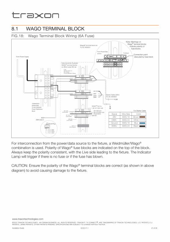
8.1 WAGO TERMINAL BLOCKFIG.18: Wago Terminal Block Wiring (6A Fuse)
FUSE– +
FUSE
FUSE– +
FUSE
FUSE– +
FUSE
Interconnection Example:WAGO® terminal blocks on 35mm wide DIN rail
48V DC
GND
DMX+DMX–
Starter Cable (20m)TU.AC.0000501
281-611/281-542
WAGO® Part no.
281-656 and 281-512/281-416 (Fuse block)
280-901
249-117(End stopper)
(cover plate)280-309
281-335(cover plate)
(cover plate)281-309
Note: Markings on Wago® terminal blocks
indicate polarity of fuse blocks.
Connection point obscured by fuse block
Wago® Terminal block set TU.AC.0000201
From Power/Data source To fixture
+–
From Power Supply
DMX Data In
1939460000(Weidmüller)TU.AC.0000300Power DistributionBlock
Fuse:6A Slow blow x 2Ø5 x 20mm(TU.AC.9900000 100pcs)
Signal
48V
DMX–
Ground
DMX+
Wire Size
AWG 18
AWG 24
AWG 18
AWG 24
Color
Brown
White
Blue
Black
For Starter Cable
Pin 2: DMX+Pin 3: GND
RJ45 Plug
Pin 1: DMX–
For interconnection from the power/data source to the fixture, a Weidmüller/Wago® combination is used. Polarity of Wago® fuse blocks are indicated on the top of the block. Always keep the polarity consistent, with the Live side leading to the fixture. The Indicator Lamp will trigger if there is no fuse or if the fuse has blown.
CAUTION: Ensure the polarity of the Wago® terminal blocks are correct (as shown in above diagram) to avoid causing damage to the fixture.

www.traxontechnologies.com©2022 TRAXON TECHNOLOGIES - AN OSRAM BUSINESS. ALL RIGHTS RESERVED. TRAXON™, TX CONNECT®, ARE TRADEMARKS OF TRAXON TECHNOLOGIES. U.S. PATENTS, E.U. PATENTS, JAPAN PATENTS, OTHER PATENTS PENDING. SPECIFICATIONS ARE SUBJECT TO CHANGE WITHOUT NOTICE.
Installation Guide 02/22 V1.1 22 of 26
FIG.19: Wago Terminal Block Wiring (7A Fuse)
Interconnection Example:WAGO® terminal blocks on 35mm wide DIN rail
48V DC
GND
DMX+DMX–
WAGO® Part no.281-611/281-542281-611
280-901
Power DistributionBlocks
Power distribution block to Wago Terminal Block
AWG12~14(1m max)
POWER: AWG17DATA: AWG24
Quick Lock Starter Cable
From Power Supply
249-117(End stopper)
281-309(cover plate)
Fuse:7A Slow blow x 2Ø5 x 20mm
Note: Common the GND Wago® terminal blocks using adjacant jumpers.
Wago® Terminal block set
Signal48V
DMX–DMX+Ground
Wire SizeAWG 17AWG 24AWG 24AWG 17
ColorBrownWhiteBlackBlue
FUSE
FUSE
280-309(cover plate)
FUSE
FUSE
FUSE
FUSE
281-402
Pin 2: DMX+Pin 3: GND
RJ45 Plug
Pin 1: DMX–
DMX Data In
For interconnection from the power/data source to the fixture, a Weidmüller/Wago® combination is used. Always keep the polarity consistent, with the Live side leading to the fixture. The Indicator Lamp will trigger if there is no fuse or if the fuse has blown.
CAUTION: Ensure the polarity of the Wago® terminal blocks are correct (as shown in above diagram) to avoid causing damage to the fixture.

www.traxontechnologies.com©2022 TRAXON TECHNOLOGIES - AN OSRAM BUSINESS. ALL RIGHTS RESERVED. TRAXON™, TX CONNECT®, ARE TRADEMARKS OF TRAXON TECHNOLOGIES. U.S. PATENTS, E.U. PATENTS, JAPAN PATENTS, OTHER PATENTS PENDING. SPECIFICATIONS ARE SUBJECT TO CHANGE WITHOUT NOTICE.
Installation Guide 02/22 V1.1 23 of 26
5. CARE AND MAINTENANCE
Traxon™ products are of superior design and quality and should be treated with care. The recommendations below will help fulfill any warranty obligations and gain good use and longevity from the products.
• Do not attempt or use the product(s) until you read and understand the installation instructions. Failure to adhere to these instructions could result in serious injury or property damage.
• Do not use product(s) if cables are damaged.
• Do not connect cables and connectors when wet or in wet area. Moisture on bare connectors can cause electric shock and damage to product(s).
• Do not use product(s) in extreme heat environment. Ensure there is sufficient airflow and use cool air circulation if required.
• Do not drop, knock, or shake product(s). Rough handling can damage the electronics and void the warranty.
• Do not use harsh chemicals, cleaning solvents, or strong detergents to clean products. Wipe with a damp cloth on housings and a dry cloth on electronics to remove dirt or dust.
• Do not attempt to service or repair the product(s) unless done by an authorized service personnel. Contact your local Traxon office or distributor for details.
• If the product is not working as specified, please contact your nearest authorized service center or Traxon Technologies office for assistance.

www.traxontechnologies.com©2022 TRAXON TECHNOLOGIES - AN OSRAM BUSINESS. ALL RIGHTS RESERVED. TRAXON™, TX CONNECT®, ARE TRADEMARKS OF TRAXON TECHNOLOGIES. U.S. PATENTS, E.U. PATENTS, JAPAN PATENTS, OTHER PATENTS PENDING. SPECIFICATIONS ARE SUBJECT TO CHANGE WITHOUT NOTICE.
Installation Guide 02/22 V1.1 24 of 26
6. TROUBLESHOOTING
CAUTION: Ensure power supply is OFF when disconnecting / connecting cables.
Problem Cause Possible Solutions
Product does NOT light up after installation
Incorrect power connection
• Check Mains Power
• Check power supply leads and wire connections
• Ensure output wires are connected with proper polarity
• Check Wago terminal block fuse. If Indicator Lamp is on, either the fuse is not present or it is blown.
• Check if LED Engine’s secondary output is working as specified.
Shadowing Light source covered • Check for cables, wires or unwanted debris covering LED light source
Modules are dim Excess products connected
• Ensure the power supplies are not overloaded due to an excess of products connected
Flickering Incorrect power input/Excess products connected
• Ensure the input voltage is correct
• Ensure the power supplies are not overloaded due to an excess of products connected
If problems persist or the product is not working as specified, please contact your nearest authorized service center or Traxon Technologies office for assistance.

www.traxontechnologies.com©2022 TRAXON TECHNOLOGIES - AN OSRAM BUSINESS. ALL RIGHTS RESERVED. TRAXON™, TX CONNECT®, ARE TRADEMARKS OF TRAXON TECHNOLOGIES. U.S. PATENTS, E.U. PATENTS, JAPAN PATENTS, OTHER PATENTS PENDING. SPECIFICATIONS ARE SUBJECT TO CHANGE WITHOUT NOTICE.
Installation Guide 02/22 V1.1 25 of 26
7. TECHNICAL SPECIFICATION
Media Tube® HO RGBWColor Range: 16.7 million additive RGB colors; White CCT 6500K
Light Source: High intensity SMT RGB and White LEDs
Beam Angle: 110° (direct view); 175°(diffused)
Power Input*: 48V DC
Power Consumption (typ).: 4.6W / 8.6W / 12.5W / 16.6W / 20.9W
Weight: 0.36kg / 0.58kg / 0.8kg / 1.02kg / 1.24kg (direct view) 0.4kg / 0.52kg / 0.84kg / 1.06kg / 1.28kg (diffused)
Operating Temperature: –30°C to +60°C / –22°F to +140°F
Storage Temperature: –40°C to +70°C / –40°F to +158°F
*For use with TRAXON LED Engine 1000W 48V Indoor (PS.IE.0011100), LED Engine 320W 48V Outdoor, LED Engine
240W 48V Outdoor (PS.OB.0011002), LED Engine 100W 48V Outdoor (PS.CU.0000008) PSUs.
As with all electronic devices, LED output degrades over time - a term called lumen depreciation. This also explains why it is nearly impossible to expect photometric performances of two LED products with different service life spans to be the same. The rate of LED degradation is a complex function of many factors such as operating efficiency, duration of continuous operation, and operating conditions (e.g. ambient temperature).
Because LEDs are semiconductor devices, their performances are subject to inherent variability commonly found in semiconductor industry. To improve consistency in performance across the same product, LED manufacturers “sort” LEDs into bins according to different preset parameters, such as forward driving voltage, illumination, etc. Whereas binning is a sorting function, it is not a correction process. Inherent variability in the manufacturing process always results in different binning distributions according to different production lots. Traxon uses automatically binned LEDs on its products, thereby minimizing output variations within the model range.
8. WARRANTY STATEMENT
Traxon Technologies warrants its Products against material or workmanship defects for a period of five (5) years from date of purchase, provided that the purchased items are used under the conditions stated in this user manual.
Please refer www.traxontechnologies.com for all warranty terms and conditions.

Please check for the latest updates and changes on the Traxon website.© 2022 TRAXON TECHNOLOGIES ALL RIGHT RESERVED. Information is subject to change without prior notice.www.traxontechnologies.com


