Embed Size (px)
Citation preview

MECHANISMS & MECHANICALDEVICES SOURCEBOOK
Third Edition
NEIL SCLATERNICHOLAS P. CHIRONIS
McGraw-HillNew York • Chicago • San Francisco • Lisbon • London • Madrid
Mexico City • Milan • New Delhi • San Juan • SeoulSingapore • Sydney • Toronto
Sclater FM 5/3/01 9:50 AM Page iii

Library of Congress Cataloging-in-Publication Data
Sclater, Neil.Mechanisms and mechanical devices sourcebook / Neil Sclater, Nicholas P. Chironis.—
3rd ed.p. cm.
Rev. ed of: Mechanisms & mechanical devices sourcebook / [edited by] Nicholas P.Chironis, Neil Sclater. 2nd ed. 1996.ISBN 0-07-136169-31. Mechanical movements. I. Chironis, Nicholas P. II. Mechanisms & mechanical
devices sourcebook. III. Title.
TJ181.S28 2001621.8—dc21 2001030297
Copyright © 2001, 1996, 1991 by The McGraw-Hill Companies, Inc. All rightsreserved, Printed in the United States of America. Except as permitted under the UnitedStates Copyright Act of 1976, no part of this publication may be reproduced or distrib-uted in any form or by any means, or stored in a data base or retrieval system, withoutthe prior written permission of the publisher.
1 2 3 4 5 6 7 8 9 0 KGP/KGP 0 7 6 5 4 3 2 1
ISBN 0-07-136169-3
The sponsoring editor for this book was Larry S. Hager and the production supervisorwas Pamela A. Pelton. It was set in Times Roman by TopDesk Publishers’ Group.
Printed and bound by Quebecor/Kingsport.
McGraw-Hill books are available at special quantity discounts to use as premiums andsales promotions, or for use in corporate training programs. For more information,please write to the Director of Special Sales, Professional Publishing, McGraw-Hill,Two Penn Plaza, New York, NY 10121-2298. Or contact your local bookstore.
This book is printed on acid-free paper.
Information contained in this work has been obtained by The McGraw-HillCompanies, Inc. (“McGraw-Hill”) from sources believed to be reliable. However,neither McGraw-Hil1 nor its authors guarantee the accuracy or completeness of anyinformation published herein and neither McGraw-Hill nor its authors shall beresponsible for any errors, omissions, or damages arising out of use of this informa-tion. This work is published with the understanding that McGraw-Hill and itsauthors are supplying information but are not attempting to render engineering orother professional services. If such services are required, the assistance of an appro-priate professional should be sought.
Sclater FM 5/3/01 9:50 AM Page iv

Neil Sclater began his career as an engineer in the military/aerospace industry and aBoston engineering consulting firm before changing his career path to writing and edit-ing on electronics and electromechanical subjects. He was a staff editor for engineeringpublications in electronic design, instrumentation, and product engineering, includingMcGraw-Hill’s Product Engineering magazine, before starting his own business as aconsultant and contributing editor in technical communication.
For the next 25 years, Mr. Sclater served a diversified list of industrial clients bywriting marketing studies, technical articles, brochures, and new product releases.During this period, he also directly served a wide list of publishers by writing hundredsof by-lined articles for many different magazines and newspapers on various topics inengineering and industrial marketing.
Mr. Sclater holds degrees from Brown University and Northeastern University, andhe has completed graduate courses in industrial management. He is the author or coau-thor of seven books on engineering subjects; six of these were published by McGraw-Hill’s Professional Book Group. He previously revised and edited the Second Edition ofMechanisms and Mechanical Devices Sourcebook after the death of Mr. Chironis.
The late Nicholas P. Chironis developed the concept for Mechanisms and MechanicalDevices Sourcebook, and was the author/editor of the First Edition. He was a mechani-cal engineer and consultant in industry before joining the staff of Product Engineeringmagazine as its mechanical design editor. Later in his career, he was an editor for otherMcGraw-Hill engineering publications. He had previously been a mechanical engineerfor International Business Machines and Mergenthaler Linotype Corporation, and hewas an instructor in product design at the Cooper Union School of Engineering in NewYork City. Mr. Chironis earned both his bachelor’s and master’s degrees in mechanicalengineering from Polytechnic University, Brooklyn, NY.
ABOUT THE EDITORS
Sclater FM 5/3/01 9:50 AM Page v

This author gratefully acknowledges the permission granted by the publisher of NASATech Briefs (Associated Business Publications, New York, NY) for reprinting four of itsrecent articles. They were selected because of their potential applications beyondNASA’s immediate objectives in space science and requirements for specialized equip-ment. The names of the scientist/inventors and the NASA facilities where the work wasperformed have been included. For more information on those subjects, readers canwrite directly to the NASA centers and request technical support packages (TSPs), orthey can contact the scientists directly through the NASA Tech Briefs Web site,www.nasatech.com.
I also wish to thank the following companies and organizations for granting me per-mission to use selected copyrighted illustrations, sending me catalogs, and providingother valuable technical information, all useful in the preparation of this edition:
• Anorad Corporation, Hauppauge, NY• Bayside Motion Group, Port Washington, NY• BEI Industrial Encoder Division, Goleta CA• FANUC Robotics North America, Inc. Rochester Hills, MI• Kollmorgen Motion Technologies Group, Radford, VA• Ledex Actuation Products, TRW Control Systems, Vandalia OH• Sandia National Laboratories, Sandia Corporation, Albuquerque, NM• SolidWorks Corporation, Concord, MA• Stratasys Inc., Eden Prairie, MN• Thomson Industries, Inc., Port Washington, NY
xv
ACKNOWLEDGMENTS
Sclater FM 5/3/01 9:50 AM Page xv
PREFACE xiii
ACKNOWLEDGMENTS xv
CHAPTER 1 MOTION CONTROL SYSTEMS 1
Motion Control Systems Overview 2Glossary of Motion Control Terms 9High-Speed Gearheads Improve Small Servo Performance 10Modular Single-Axis Motion Systems 12Mechanical Components Form Specialized Motion-Control Systems 13Servomotors, Stepper Motors, and Actuators for Motion Control 14Servosystem Feedback Sensors 22Solenoids and Their Applications 29
CHAPTER 2 ROBOT MECHANISMS 33
Industrial Robots 34FANUC Robot Specifications 38Mechanism for Planar Manipulation With Simplified Kinematics 43Tool-Changing Mechanism for Robot 44Piezoelectric Motor in Robot Finger Joint 45Six-Degree-of-Freedom Parallel Minimanipulator 46Self-Reconfigurable, Two-Arm Manipulator With Bracing 47Improved Roller and Gear Drives for Robots and Vehicles 48All-Terrain Vehicle With Self-Righting and Pose Control 49
CHAPTER 3 PARTS-HANDLING MECHANISMS 51
Mechanisms That Sort, Feed, or Weigh 52Cutting Mechanisms 56Flipping Mechanisms 58Vibrating Mechanism 58Seven Basic Parts Selectors 59Eleven Parts-Handling Mechanisms 60Seven Automatic-Feed Mechanisms 62Seven Linkages for Transport Mechanisms 65Conveyor Systems for Production Machines 68Traversing Mechanisms for Winding Machines 73Vacuum Pickup Positions Pills 75Machine Applies Labels from Stacks or Rollers 75High-Speed Machines for Adhesive Applications 76Automatic Stopping Mechanisms for Faulty Machine Operation 82Electrical Automatic Stopping Mechanisms 88Automatic Safety Mechanisms for Operating Machines 90
CHAPTER 4 RECIPROCATING AND GENERAL-PURPOSE MECHANISM 93
Gears and Eccentric Disk Combine in Quick Indexing 94Timung Belts, Four-Bar Linkage Team Up for Smooth Indexing 95Modified Ratchet Drive 96Odd Shapes in Planetary Give Smooth Stop and Go 97Cycloid Gear Mechanism Controls Stroke of Pump 99Converting Rotary-to-Linear Motion 100New Star Wheels Challenge Geneva Drives for Indexing 100
vii
CONTENTS
Sclater FM 5/3/01 9:50 AM Page vii

Geneva Mechanisms 103Modified Geneva Drives 106Indexing and Intermittent Mechanisms 108Rotary-to-Reciprocating Motion and Dwell Mechanisms 116Friction Devices for Intermittent Rotary Motion 122No Teeth on These Ratchets 124Cam-Controlled Planetary Gear System 125
CHAPTER 5 SPECIAL-PURPOSE MECHANISMS 127
Nine Different Ball Slides for Linear Motion 128Ball-Bearing Screws Convert Rotary to Linear Motion 130Three-Point Gear/Leadscrew Positioning 131Unique Linkage Produces Precise Straight-Line Motion 132Twelve Expanding and Contracting Devices 134Five Linkages for Straight-Line Motion 136Linkage Ratios for Straight-Line Mechanisms 138Linkages for Other Motions 139Five Cardan-Gear Mechanisms 140Ten Ways to Change Straight-Line Direction 142Nine More Ways to Change Straight-Line Direction 144Linkages for Accelerating and Decelerating Linear Strokes 146Linkages for Multiplying Short Motions 148Parallel-Link Mechanisms 150Stroke Multiplier 150Force and Stroke Multipliers 152Stroke-Amplifying Mechanisms 154Adjustable-Stroke Mechanisms 155Adjustable-Output Mechanisms 156Reversing Mechanisms 158Computing Mechanisms 159Eighteen Variations of Differential Linkage 163Space Mechanisms 165Seven Popular Types of Three-Dimensional Drives 167Inchworm Actuator 172
CHAPTER 6 SPRING, BELLOW, FLEXURE, SCREW, AND BALL DEVICES 173
Flat Springs in Mechanisms 174Pop-Up Springs Get New Backbone 176Twelve Ways to Put Springs to Work 177Overriding Spring Mechanisms for Low-Torque Drives 179Spring Motors and Typical Associated Mechanisms 181Flexures Accurately Support Pivoting Mechanisms and Instruments 183Taut Bands and Leadscrew Provide Accurate Rotary Motion 185Air Spring Mechanisms 186Obtaining Variable Rates from Springs 188Belleville Springs 189Spring-Type Linkage for Vibration Control 190Twenty Screw Devices 191Ten Ways to Employ Screw Mechanisms 194Seven Special Screw Arrangements 195Fourteen Adjusting Devices 196Linear Roller Bearings Are Suited for High-Load, Heavy-Duty Tasks 197
CHAPTER 7 CAM,TOGGLE, CHAIN, AND BELT MECHANISMS 199
Cam Basics 200Cam-Curve Generating Mechanisms 201
viii
Sclater FM 5/3/01 9:50 AM Page viii
Fifteen Ideas for Cam Mechanisms 207Special-Function Cams 209Cam Drives for Machine Tools 210Toggle Linkage Applications in Different Mechanisms 211Sixteen Latch, Toggle, and Trigger Devices 213Six Snap-Action Mechanisms 215Eight Snap-Action Devices 217Applications of the Differential Winch to Control Systems 219Six Applications for mechanical Power Amplifiers 221Variable-Speed Belt and Chain Drives 224Getting in Step With Hybrid Belts 227Change Center Distance Without Affecting Speed Ratio 231Motor Mount Pivots for Controlled Tension 231Bushed Roller Chains and Their Adaptations 232Six Ingenious Jobs for Roller Chain 234Six More Jobs for Roller Chain 236Mechanisms for Reducing Pulsations in Chain Drives 238Smoother Drive Without Gears 240
CHAPTER 8 GEARED SYSTEMS AND VARIABLE-SPEED MECHANISMS 241
Gears and Gearing 242Nutating-Plate Drive 243Cone Drive Needs No Gears or Pulleys 244Variable-Speed Mechanical Drives 245Unidirectional Drive 253More Variable-Speed Drives 254Variable-Speed Friction Drives 256Variable-Speed Drives and Transmissions 258Precision Ball Bearings Replace Gears in Tiny Speed Reducers 260Multifunction Flywheel Smoothes Friction in Tape Cassette Drive 261Controlled Differential Drives 262Twin-Motor Planetary Gears Provide Safety Plus Dual-Speed 263Harmonic-Drive Speed Reducers 263Flexible Face-Gears Make Efficient High-Reduction Drives 266Compact Rotary Sequencer 267Planetary Gear Systems 268Noncircular Gears 275Sheet-Metal Gears, Sprockets, Worms, and Ratchets 279How to Prevent Reverse Rotation 281Gear-Shift Arrangements 282Shifting Mechanisms for Gears and Clutches 284Fine-Focus Adjustments 286Ratchet-Tooth Speed-Change Drive 287Twinworm Gear Drive 287Compliant Gearing for Redundant Torque Drive 289Lighter, More-Efficient Helicopter Transmissions 290Worm Gear With Hydrostatic Engagement 290Straddle Design of Spiral Bevel and Hypoid Gears 292
CHAPTER 9 COUPLING, CLUTCHING, AND BRAKING DEVICES 293
Coupling of Parallel Shafts 294Novel Linkage Couples Offset Shafts 295Disk-and-Link Coupling Simplifies Transmissions 296Interlocking Space-Frames Flex as They Transmit Shaft Torque 297Off-Center Pins Cancel Misalignment of Shafts 299Hinged Links and Torsion Bushings Give Drives a Soft Start 300
ix
Sclater FM 5/3/01 9:50 AM Page ix

Universal Joint Relays Power 45° at Constant Speeds 301Basic Mechanical Clutches 302Spring-Wrapped Slip Clutches 304Controlled-Slip Concept Adds New Uses for Spring Clutches 306Spring Bands Grip Tightly to Drive Overrunning Clutch 307Slip and Bidirectional Clutches Combine to Control Torque 308Walking Pressure Plate Delivers Constant Torque 309Conical-Rotor Motor Provides Instant Clutching or Braking 310Fast-Reversal Reel Drive 310Seven Overrunning Clutches 311Spring-Loaded Pins aid Sprags in One-Way Clutch 312Roller-Type Clutch 312One-Way Output From Speed Reducers 313Springs, Shuttle Pinion, and Sliding Ball Perform in One-Way Drives 314Details of Overriding Clutches 316Ten Ways to Apply Overrunning Clutches 318Applications for Sprag-Type Clutches 320Small Mechanical Clutches for Precise Service 322Mechanisms for Station Clutches 324Twelve Applications for Electromagnetic Clutches and Brakes 326Trip Roller Clutch 328Geared Electromechanical Rotary Joint 329Ten Universal Shaft Couplings 330Methods for Coupling Rotating Shafts 332Linkages for Band Clutches and Brakes 336Special Coupling Mechanisms 337Link Coupling Mechanisms 338
CHAPTER 10 TORQUE-LIMITING,TENSIONING, AND GOVERNING DEVICES 339
Caliper Brakes Help Maintain Proper Tension in Press Feed 340Sensors Aid Clutch/Brakes 340Warning Device Prevents Overloading of Boom 341Constant Watch on Cable Tension 341Torque-Limiters Protect Light-Duty Drives 342Limiters Prevent Overloading 343Seven Ways to Limit Shaft Rotation 346Mechanical Systems for Controlling Tension and Speed 348Drives for Controlling Tension 352Switch Prevents Overloading of a Hoist 355Mechanical, Geared, and Cammed Limit Switches 356Limit Switches in Machinery 358Automatic Speed Governors 362Centrifugal, Pneumatic, Hydraulic, and Electric Governors 364Speed Control Devices for Mechanisms 366Floating-Pinion Torque Splitter 367
CHAPTER 11 PNEUMATIC AND HYDRAULIC MACHINE AND MECHANISM CONTROL 369
Designs and Operating Principles of Typical Pumps 370Rotary-Pump Mechanisms 374Mechanisms Actuated by Pneumatic or Hydraulic Cylinders 376Foot-Controlled Braking System 378Linkages Actuate Steering in a Tractor 378Fifteen Jobs for Pneumatic Power 379Ten Ways to Use Metal Diaphragms and Capsules 380Differential Transformer Sensing Devices 382High-Speed Counters 384Designing With Permanent Magnets 385
x
Sclater FM 5/3/01 9:50 AM Page x

Permanent Magnet Mechanisms 387Electrically Driven Hammer Mechanisms 390Thermostatic Mechanisms 392Temperature-Regulating Mechanisms 396Photoelectric Controls 398Liquid Level Indicators and Controllers 400Instant Muscle With Pyrotechnic Power 402
CHAPTER 12 FASTENING, LATCHING, CLAMPING, AND CHUCKING DEVICES 405
Remotely Controlled Latch 406Toggle Fastener Inserts, Locks, and Releases Easily 407Grapple Frees Loads Automatically 407Quick-Release Lock Pin Has a Ball Detent 408Automatic Brake Locks Hoist When Driving Torque Ceases 408Lift-Tong Mechanism Firmly Grips Objects 409Perpendicular-Force Latch 409Quick-Release Mechanisms 410Ring Springs Clamp Platform Elevator Into Position 411Quick-Acting Clamps for Machines and Fixtures 412Friction Clamping Devices 414Detents for Stopping Mechanical Movements 416Ten Different Splined Connections 418Fourteen Ways to Fasten Hubs to Shafts 420Clamping Devices for Accurately Aligning Adjustable Parts 422Spring-Loaded Chucks and Holding Fixtures 424Short In-Line Turnbuckle 424Actuator Exerts Tensile or Compressive Axial Load 425Gripping System for Mechanical Testing of Composites 426Passive Capture Joint With Three Degrees of Freedom 427Probe-and-Socket Fasteners for Robotic Assembly 428
CHAPTER 13 KEY EQUATIONS AND CHARTS FOR DESIGNING MECHANISMS 429
Four-Bar Linkages and Typical Industrial Applications 430Designing Geared Five-Bar Mechanisms 432Kinematics of Intermittent Mechanisms—The External Geneva Wheel 436Kinematics of Intermittent Mechanisms—The Internal Geneva Wheel 439Equations for Designing Cycloid Mechanisms 442Designing Crank-and-Rocker Links With Optimum Force Transmission 445Design Curves and Equations for Gear-Slider Mechanisms 448Designing Snap-Action Toggles 452Feeder Mechanisms for Angular Motions 455Feeder Mechanisms for Curvilinear Motions 456Roberts’ Law Helps to Find Alternate Four-Bar Linkages 459Ratchet Layout Analyzed 460Slider-Crank Mechanism 461
CHAPTER 14 NEW DIRECTIONS IN MACHINE DESIGN 463
Software Improvements Expand CAD Capabilities 464New Processes Expand Choices for Rapid Prototyping 468Micromachines Open a New Frontier for Machine Design 475Multilevel Fabrication Permits More Complex and Functional MEMS 478Miniature Multispeed Transmissions for Small Motors 481MEMS Chips Become Integrated Microcontrol Systems 482LIGA: An Alternative Method for Making Microminiature Parts 484
INDEX 487
xi
Sclater FM 5/3/01 9:50 AM Page xi
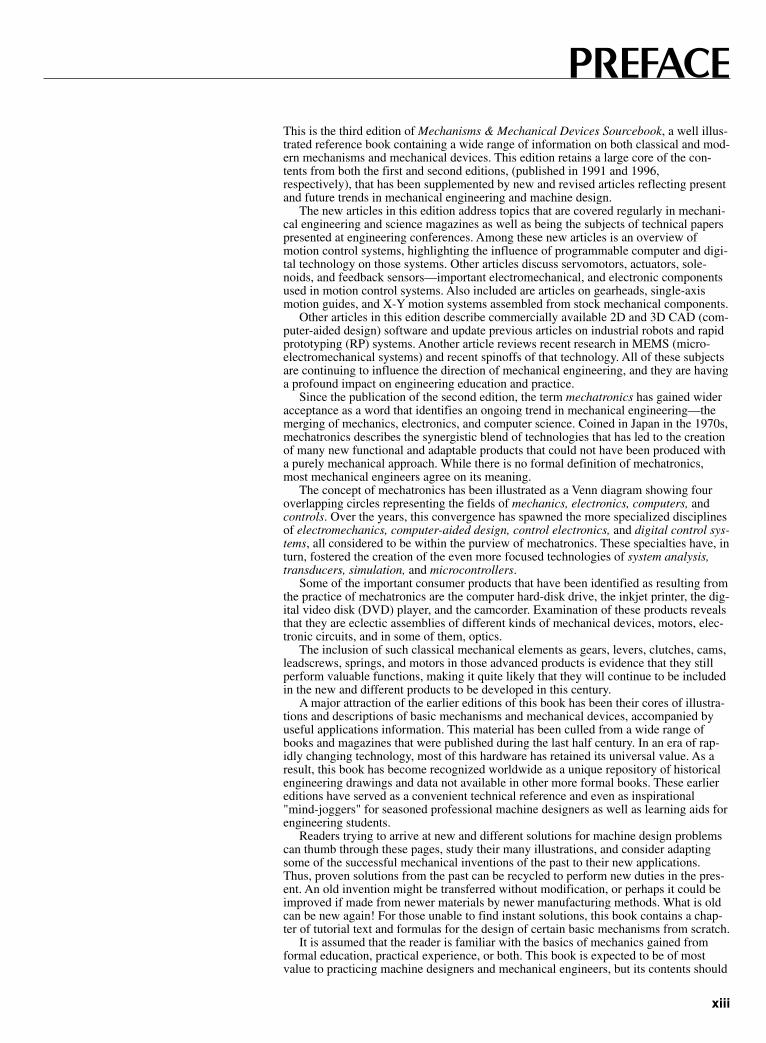
This is the third edition of Mechanisms & Mechanical Devices Sourcebook, a well illus-trated reference book containing a wide range of information on both classical and mod-ern mechanisms and mechanical devices. This edition retains a large core of the con-tents from both the first and second editions, (published in 1991 and 1996,respectively), that has been supplemented by new and revised articles reflecting presentand future trends in mechanical engineering and machine design.
The new articles in this edition address topics that are covered regularly in mechani-cal engineering and science magazines as well as being the subjects of technical paperspresented at engineering conferences. Among these new articles is an overview ofmotion control systems, highlighting the influence of programmable computer and digi-tal technology on those systems. Other articles discuss servomotors, actuators, sole-noids, and feedback sensors—important electromechanical, and electronic componentsused in motion control systems. Also included are articles on gearheads, single-axismotion guides, and X-Y motion systems assembled from stock mechanical components.
Other articles in this edition describe commercially available 2D and 3D CAD (com-puter-aided design) software and update previous articles on industrial robots and rapidprototyping (RP) systems. Another article reviews recent research in MEMS (micro-electromechanical systems) and recent spinoffs of that technology. All of these subjectsare continuing to influence the direction of mechanical engineering, and they are havinga profound impact on engineering education and practice.
Since the publication of the second edition, the term mechatronics has gained wideracceptance as a word that identifies an ongoing trend in mechanical engineering—themerging of mechanics, electronics, and computer science. Coined in Japan in the 1970s,mechatronics describes the synergistic blend of technologies that has led to the creationof many new functional and adaptable products that could not have been produced witha purely mechanical approach. While there is no formal definition of mechatronics,most mechanical engineers agree on its meaning.
The concept of mechatronics has been illustrated as a Venn diagram showing fouroverlapping circles representing the fields of mechanics, electronics, computers, andcontrols. Over the years, this convergence has spawned the more specialized disciplinesof electromechanics, computer-aided design, control electronics, and digital control sys-tems, all considered to be within the purview of mechatronics. These specialties have, inturn, fostered the creation of the even more focused technologies of system analysis,transducers, simulation, and microcontrollers.
Some of the important consumer products that have been identified as resulting fromthe practice of mechatronics are the computer hard-disk drive, the inkjet printer, the dig-ital video disk (DVD) player, and the camcorder. Examination of these products revealsthat they are eclectic assemblies of different kinds of mechanical devices, motors, elec-tronic circuits, and in some of them, optics.
The inclusion of such classical mechanical elements as gears, levers, clutches, cams,leadscrews, springs, and motors in those advanced products is evidence that they stillperform valuable functions, making it quite likely that they will continue to be includedin the new and different products to be developed in this century.
A major attraction of the earlier editions of this book has been their cores of illustra-tions and descriptions of basic mechanisms and mechanical devices, accompanied byuseful applications information. This material has been culled from a wide range ofbooks and magazines that were published during the last half century. In an era of rap-idly changing technology, most of this hardware has retained its universal value. As aresult, this book has become recognized worldwide as a unique repository of historicalengineering drawings and data not available in other more formal books. These earliereditions have served as a convenient technical reference and even as inspirational"mind-joggers" for seasoned professional machine designers as well as learning aids forengineering students.
Readers trying to arrive at new and different solutions for machine design problemscan thumb through these pages, study their many illustrations, and consider adaptingsome of the successful mechanical inventions of the past to their new applications.Thus, proven solutions from the past can be recycled to perform new duties in the pres-ent. An old invention might be transferred without modification, or perhaps it could beimproved if made from newer materials by newer manufacturing methods. What is oldcan be new again! For those unable to find instant solutions, this book contains a chap-ter of tutorial text and formulas for the design of certain basic mechanisms from scratch.
It is assumed that the reader is familiar with the basics of mechanics gained fromformal education, practical experience, or both. This book is expected to be of mostvalue to practicing machine designers and mechanical engineers, but its contents should
xiii
PREFACE
Sclater FM 5/3/01 9:50 AM Page xiii

also be of use to machine design instructors at the college and vocational school level,amateur and professional inventors, and students of all of the engineering disciplinesand physical sciences. Last but not least, it is hoped that the book will be attractive tothose who simply enjoy looking at illustrations of machines and figuring out how theywork.
The drawings in this edition have stood the test of time. Certain material publishedin the previous editions has been deleted because reader feedback suggested that impor-tant design details were missing or unclear. Also, some material considered to be obso-lete and unsuitable for new designs was deleted. For example, clockwork mechanismsfor timing, control, and display have almost universally been replaced in contemporarydesigns by more cost-effective electronic modules that perform the same functions.
References to manufacturers or publications that no longer exist were deleted so thatreaders will not waste time trying to contact them for further information. However, thenames of the inventors, where previously given, have been retained to help the reader whomay want to do further research on any patents now or once held by those individuals.
Many of the mechanisms illustrated in this book were invented by anonymous arti-sans, millwrights, instrument makers, and mechanics over the past centuries. They leftbehind the sketches, formal drawings, and even the working models on which many ofthe illustrations in this book are based. It is also worth noting that many of the mostinfluential machines from the water pump, steam engine, and chronometer, to the cottongin, and airplane were invented by self-trained engineers, scientists, and technicians.
By themselves, many of the mechanisms and devices described in this book are justmechanical curiosities, but when integrated by creative minds with others, they can per-form new and different functions. One need only consider the role of basic mechanismsin the crucial inventions of the past century—the airplane, the helicopter, the jet engine,the programmable robot, and most of our familiar home appliances.
Have you noticed how the size of objects is both increasing and decreasing? There isnow a 142,000-ton cruise ship that can accommodate more than 5000 passengers, andplans have been announced for building jumbo jet aircraft capable of carrying morethan 500 passengers. Moreover, laptop computers now have more computing powerthan mainframe computers that filled a room a quarter century ago. Work is progressingin efforts to combine the functions of computer, cellular telephone, personal digitalassistant (PDA), and Internet-access terminal in a single wireless handheld device.
MEMS are expected to evolve beyond their current prime roles as sensors to becomesecurity locks for computers, optical switches, and practical micromachines.Meanwhile, scientists are studying the feasibility of microminiature, self-propelled cap-sules made with even smaller-scale nanotechnology that could navigate through thehuman body and seek out, diagnose, and treat diseases at their source.
—Neil Sclater
xiv
Sclater FM 5/3/01 9:50 AM Page xiv

CHAPTER 1MOTION CONTROL
SYSTEMS
Sclater Chapter 1 5/3/01 9:52 AM Page 1

Introduction
A modern motion control system typically consists of a motioncontroller, a motor drive or amplifier, an electric motor, and feed-back sensors. The system might also contain other componentssuch as one or more belt-, ballscrew-, or leadscrew-driven linearguides or axis stages. A motion controller today can be a stand-alone programmable controller, a personal computer containing amotion control card, or a programmable logic controller (PLC).
All of the components of a motion control system must worktogether seamlessly to perform their assigned functions. Theirselection must be based on both engineering and economic con-siderations. Figure 1 illustrates a typical multiaxis X-Y-Z motionplatform that includes the three linear axes required to move aload, tool, or end effector precisely through three degrees of free-dom. With additional mechanical or electromechanical compo-nents on each axis, rotation about the three axes can provide upto six degrees of freedom, as shown in Fig. 2.
2
Fig. 2 The right-handed coordinate system showing six degrees offreedom.
MOTION CONTROL SYSTEMSOVERVIEW
Motion control systems today can be found in such diverseapplications as materials handling equipment, machine tool cen-ters, chemical and pharmaceutical process lines, inspection sta-tions, robots, and injection molding machines.
Merits of Electric Systems
Most motion control systems today are powered by electricmotors rather than hydraulic or pneumatic motors or actuatorsbecause of the many benefits they offer:
• More precise load or tool positioning, resulting in fewerproduct or process defects and lower material costs.
• Quicker changeovers for higher flexibility and easier productcustomizing.
• Increased throughput for higher efficiency and capacity.• Simpler system design for easier installation, programming,
and training.• Lower downtime and maintenance costs.• Cleaner, quieter operation without oil or air leakage.
Electric-powered motion control systems do not requirepumps or air compressors, and they do not have hoses or pipingthat can leak hydraulic fluids or air. This discussion of motioncontrol is limited to electric-powered systems.
Motion Control Classification
Motion control systems can be classified as open-loop or closed-loop. An open-loop system does not require that measurementsof any output variables be made to produce error-correcting sig-nals; by contrast, a closed-loop system requires one or morefeedback sensors that measure and respond to errors in outputvariables.
Closed-Loop System
A closed-loop motion control system, as shown in block diagramFig. 3, has one or more feedback loops that continuously com-pare the system’s response with input commands or settings tocorrect errors in motor and/or load speed, load position, or motortorque. Feedback sensors provide the electronic signals for cor-recting deviations from the desired input commands. Closed-loop systems are also called servosystems.
Each motor in a servosystem requires its own feedback sen-sors, typically encoders, resolvers, or tachometers that close
Fig. 1 This multiaxis X-Y-Z motion platform is an example of amotion control system.
Fig. 3 Block diagram of a basic closed-loop control system.
Sclater Chapter 1 5/3/01 9:52 AM Page 2
loops around the motor and load. Variations in velocity, position,and torque are typically caused by variations in load conditions,but changes in ambient temperature and humidity can also affectload conditions.
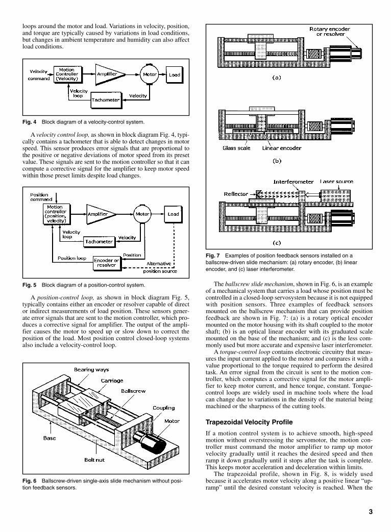
A velocity control loop, as shown in block diagram Fig. 4, typi-cally contains a tachometer that is able to detect changes in motorspeed. This sensor produces error signals that are proportional tothe positive or negative deviations of motor speed from its presetvalue. These signals are sent to the motion controller so that it cancompute a corrective signal for the amplifier to keep motor speedwithin those preset limits despite load changes.
A position-control loop, as shown in block diagram Fig. 5,typically contains either an encoder or resolver capable of director indirect measurements of load position. These sensors gener-ate error signals that are sent to the motion controller, which pro-duces a corrective signal for amplifier. The output of the ampli-fier causes the motor to speed up or slow down to correct theposition of the load. Most position control closed-loop systemsalso include a velocity-control loop.
The ballscrew slide mechanism, shown in Fig. 6, is an exampleof a mechanical system that carries a load whose position must becontrolled in a closed-loop servosystem because it is not equippedwith position sensors. Three examples of feedback sensorsmounted on the ballscrew mechanism that can provide positionfeedback are shown in Fig. 7: (a) is a rotary optical encodermounted on the motor housing with its shaft coupled to the motorshaft; (b) is an optical linear encoder with its graduated scalemounted on the base of the mechanism; and (c) is the less com-monly used but more accurate and expensive laser interferometer.
A torque-control loop contains electronic circuitry that meas-ures the input current applied to the motor and compares it with avalue proportional to the torque required to perform the desiredtask. An error signal from the circuit is sent to the motion con-troller, which computes a corrective signal for the motor ampli-fier to keep motor current, and hence torque, constant. Torque-control loops are widely used in machine tools where the loadcan change due to variations in the density of the material beingmachined or the sharpness of the cutting tools.
Trapezoidal Velocity Profile
If a motion control system is to achieve smooth, high-speedmotion without overstressing the servomotor, the motion con-troller must command the motor amplifier to ramp up motorvelocity gradually until it reaches the desired speed and thenramp it down gradually until it stops after the task is complete.This keeps motor acceleration and deceleration within limits.
The trapezoidal profile, shown in Fig. 8, is widely usedbecause it accelerates motor velocity along a positive linear “up-ramp” until the desired constant velocity is reached. When the
3
Fig. 4 Block diagram of a velocity-control system.
Fig. 5 Block diagram of a position-control system.
Fig. 6 Ballscrew-driven single-axis slide mechanism without posi-tion feedback sensors.
Fig. 7 Examples of position feedback sensors installed on aballscrew-driven slide mechanism: (a) rotary encoder, (b) linearencoder, and (c) laser interferometer.
Sclater Chapter 1 5/3/01 9:52 AM Page 3
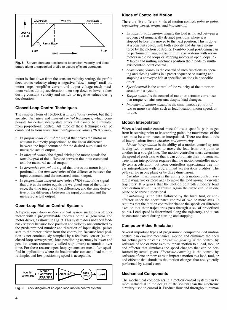
motor is shut down from the constant velocity setting, the profiledecelerates velocity along a negative “down ramp” until themotor stops. Amplifier current and output voltage reach maxi-mum values during acceleration, then step down to lower valuesduring constant velocity and switch to negative values duringdeceleration.
Closed-Loop Control Techniques
The simplest form of feedback is proportional control, but thereare also derivative and integral control techniques, which com-pensate for certain steady-state errors that cannot be eliminatedfrom proportional control. All three of these techniques can becombined to form proportional-integral-derivative (PID) control.
• In proportional control the signal that drives the motor oractuator is directly proportional to the linear differencebetween the input command for the desired output and themeasured actual output.
• In integral control the signal driving the motor equals thetime integral of the difference between the input commandand the measured actual output.
• In derivative control the signal that drives the motor is pro-portional to the time derivative of the difference between theinput command and the measured actual output.
• In proportional-integral-derivative (PID) control the signalthat drives the motor equals the weighted sum of the differ-ence, the time integral of the difference, and the time deriva-tive of the difference between the input command and themeasured actual output.
Open-Loop Motion Control Systems
A typical open-loop motion control system includes a steppermotor with a programmable indexer or pulse generator andmotor driver, as shown in Fig. 9. This system does not need feed-back sensors because load position and velocity are controlled bythe predetermined number and direction of input digital pulsessent to the motor driver from the controller. Because load posi-tion is not continuously sampled by a feedback sensor (as in aclosed-loop servosystem), load positioning accuracy is lower andposition errors (commonly called step errors) accumulate overtime. For these reasons open-loop systems are most often speci-fied in applications where the load remains constant, load motionis simple, and low positioning speed is acceptable.
Fig. 8 Servomotors are accelerated to constant velocity and decel-erated along a trapezoidal profile to assure efficient operation.
Kinds of Controlled Motion
There are five different kinds of motion control: point-to-point,sequencing, speed, torque, and incremental.
• In point-to-point motion control the load is moved between asequence of numerically defined positions where it isstopped before it is moved to the next position. This is doneat a constant speed, with both velocity and distance moni-tored by the motion controller. Point-to-point positioning canbe performed in single-axis or multiaxis systems with servo-motors in closed loops or stepping motors in open loops. X-Y tables and milling machines position their loads by multi-axis point-to-point control.
• Sequencing control is the control of such functions as open-ing and closing valves in a preset sequence or starting andstopping a conveyor belt at specified stations in a specificorder.
• Speed control is the control of the velocity of the motor oractuator in a system.
• Torque control is the control of motor or actuator current sothat torque remains constant despite load changes.
• Incremental motion control is the simultaneous control oftwo or more variables such as load location, motor speed, ortorque.
Motion Interpolation
When a load under control must follow a specific path to getfrom its starting point to its stopping point, the movements of theaxes must be coordinated or interpolated. There are three kindsof interpolation: linear, circular, and contouring.
Linear interpolation is the ability of a motion control systemhaving two or more axes to move the load from one point toanother in a straight line. The motion controller must determinethe speed of each axis so that it can coordinate their movements.True linear interpolation requires that the motion controller mod-ify axis acceleration, but some controllers approximate true lin-ear interpolation with programmed acceleration profiles. Thepath can lie in one plane or be three dimensional.
Circular interpolation is the ability of a motion control sys-tem having two or more axes to move the load around a circulartrajectory. It requires that the motion controller modify loadacceleration while it is in transit. Again the circle can lie in oneplane or be three dimensional.
Contouring is the path followed by the load, tool, or end-effector under the coordinated control of two or more axes. Itrequires that the motion controller change the speeds on differentaxes so that their trajectories pass through a set of predefinedpoints. Load speed is determined along the trajectory, and it canbe constant except during starting and stopping.
Computer-Aided Emulation
Several important types of programmed computer-aided motioncontrol can emulate mechanical motion and eliminate the needfor actual gears or cams. Electronic gearing is the control bysoftware of one or more axes to impart motion to a load, tool, orend effector that simulates the speed changes that can be per-formed by actual gears. Electronic camming is the control bysoftware of one or more axes to impart a motion to a load, tool, orend effector that simulates the motion changes that are typicallyperformed by actual cams.
Mechanical Components
The mechanical components in a motion control system can bemore influential in the design of the system than the electroniccircuitry used to control it. Product flow and throughput, human
4
Fig. 9 Block diagram of an open-loop motion control system.
Sclater Chapter 1 5/3/01 9:52 AM Page 4

mechanical components between the carriage and the positionencoder that can cause deviations between the desired and truepositions. Consequently, this feedback method limits positionaccuracy to ballscrew accuracy, typically ±5 to 10 µm per 300 mm.
Other kinds of single-axis stages include those containingantifriction rolling elements such as recirculating and nonrecircu-lating balls or rollers, sliding (friction contact) units, air-bearingunits, hydrostatic units, and magnetic levitation (Maglev) units.
A single-axis air-bearing guide or stage is shown in Fig. 14.Some models being offered are 3.9 ft (1.2 m) long and include acarriage for mounting loads. When driven by a linear servomo-tors the loads can reach velocities of 9.8 ft/s (3 m/s). As shown inFig. 7, these stages can be equipped with feedback devices such
5
Fig. 10 Leadscrew drive: As the leadscrew rotates, the load istranslated in the axial direction of the screw.
Fig. 11 Ballscrew drive: Ballscrews use recirculating balls to reducefriction and gain higher efficiency than conventional leadscrews.
Fig. 12 Worm-drive systems can provide high speed and high torque.
Fig. 13 Ballscrew-driven single-axis slide mechanism translatesrotary motion into linear motion.
Fig. 14 This single-axis linear guide for load positioning is sup-ported by air bearings as it moves along a granite base.
operator requirements, and maintenance issues help to determinethe mechanics, which in turn influence the motion controller andsoftware requirements.
Mechanical actuators convert a motor’s rotary motion intolinear motion. Mechanical methods for accomplishing thisinclude the use of leadscrews, shown in Fig. 10, ballscrews,shown in Fig. 11, worm-drive gearing, shown in Fig. 12, andbelt, cable, or chain drives. Method selection is based on the rel-ative costs of the alternatives and consideration for the possibleeffects of backlash. All actuators have finite levels of torsionaland axial stiffness that can affect the system’s frequencyresponse characteristics.
Linear guides or stages constrain a translating load to a singledegree of freedom. The linear stage supports the mass of the loadto be actuated and assures smooth, straight-line motion whileminimizing friction. A common example of a linear stage is aballscrew-driven single-axis stage, illustrated in Fig. 13. Themotor turns the ballscrew, and its rotary motion is translated intothe linear motion that moves the carriage and load by the stage’sbolt nut. The bearing ways act as linear guides. As shown in Fig.7, these stages can be equipped with sensors such as a rotary orlinear encoder or a laser interferometer for feedback.
A ballscrew-driven single-axis stage with a rotary encodercoupled to the motor shaft provides an indirect measurement.This method ignores the tolerance, wear, and compliance in the
Sclater Chapter 1 5/3/01 9:52 AM Page 5

Fig. 15 Flexible shaft couplings adjust for and accommodate par-allel misalignment (a) and angular misalignment between rotatingshafts (b).
Fig. 16 Bellows couplings (a) are acceptable for light-duty appli-cations. Misalignments can be 9º angular or 1⁄4 in. parallel. Helicalcouplings (b) prevent backlash and can operate at constant veloc-ity with misalignment and be run at high speed.
as cost-effective linear encoders or ultra-high-resolution laser interferometers.The resolution of this type of stage with anoncontact linear encoder can be as fineas 20 nm and accuracy can be ±1 µm.However, these values can be increasedto 0.3 nm resolution and submicron accu-racy if a laser interferometer is installed.
The pitch, roll, and yaw of air-bearingstages can affect their resolution andaccuracy. Some manufacturers claim ±1arc-s per 100 mm as the limits for each ofthese characteristics. Large air-bearingsurfaces provide excellent stiffness andpermit large load-carrying capability.
The important attributes of all thesestages are their dynamic and static fric-tion, rigidity, stiffness, straightness, flat-ness, smoothness, and load capacity.Also considered is the amount of workneeded to prepare the host machine’smounting surface for their installation.
The structure on which the motioncontrol system is mounted directlyaffects the system’s performance. Aproperly designed base or host machinewill be highly damped and act as a com-pliant barrier to isolate the motion sys-
tem from its environment and minimizethe impact of external disturbances. Thestructure must be stiff enough and suffi-ciently damped to avoid resonance prob-lems. A high static mass to reciprocatingmass ratio can also prevent the motioncontrol system from exciting its hoststructure to harmful resonance.
Any components that move will affecta system’s response by changing theamount of inertia, damping, friction,stiffness, or resonance. For example, aflexible shaft coupling, as shown in Fig.15, will compensate for minor parallel(a) and angular (b) misalignment betweenrotating shafts. Flexible couplings areavailable in other configurations such asbellows and helixes, as shown in Fig. 16.The bellows configuration (a) is accept-able for light-duty applications wheremisalignments can be as great as 9º angu-lar or 1⁄4 in. parallel. By contrast, helicalcouplings (b) prevent backlash at con-stant velocity with some misalignment,and they can also be run at high speed.
Other moving mechanical compo-nents include cable carriers that retainmoving cables, end stops that restrict
travel, shock absorbers to dissipateenergy during a collision, and way cov-ers to keep out dust and dirt.
Electronic System Components
The motion controller is the “brain” ofthe motion control system and performsall of the required computations formotion path planning, servo-loop clo-sure, and sequence execution. It is essen-tially a computer dedicated to motioncontrol that has been programmed by theend user for the performance of assignedtasks. The motion controller produces alow-power motor command signal ineither a digital or analog format for themotor driver or amplifier.
Significant technical developmentshave led to the increased acceptance ofprogrammable motion controllers over thepast five to ten years: These include therapid decrease in the cost of microproces-sors as well as dramatic increases in theircomputing power. Added to that are thedecreasing cost of more advanced semi-conductor and disk memories. During thepast five to ten years, the capability of
6
Sclater Chapter 1 5/3/01 9:52 AM Page 6
these systems to improve product quality, increase throughput, andprovide just-in-time delivery has improved has improved signifi-cantly.
The motion controller is the most critical component in thesystem because of its dependence on software. By contrast, theselection of most motors, drivers, feedback sensors, and associ-ated mechanisms is less critical because they can usually bechanged during the design phase or even later in the field with lessimpact on the characteristics of the intended system. However,making field changes can be costly in terms of lost productivity.
The decision to install any of the three kinds of motion con-trollers should be based on their ability to control both the numberand types of motors required for the application as well as theavailability of the software that will provide the optimum per-formance for the specific application. Also to be considered arethe system’s multitasking capabilities, the number of input/output(I/O) ports required, and the need for such features as linear andcircular interpolation and electronic gearing and camming.
In general, a motion controller receives a set of operatorinstructions from a host or operator interface and it responds withcorresponding command signals for the motor driver or driversthat control the motor or motors driving the load.
Motor Selection
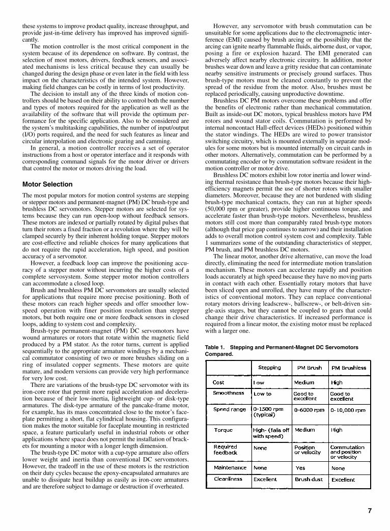
The most popular motors for motion control systems are steppingor stepper motors and permanent-magnet (PM) DC brush-type andbrushless DC servomotors. Stepper motors are selected for sys-tems because they can run open-loop without feedback sensors.These motors are indexed or partially rotated by digital pulses thatturn their rotors a fixed fraction or a revolution where they will beclamped securely by their inherent holding torque. Stepper motorsare cost-effective and reliable choices for many applications thatdo not require the rapid acceleration, high speed, and positionaccuracy of a servomotor.
However, a feedback loop can improve the positioning accu-racy of a stepper motor without incurring the higher costs of acomplete servosystem. Some stepper motor motion controllerscan accommodate a closed loop.
Brush and brushless PM DC servomotors are usually selectedfor applications that require more precise positioning. Both ofthese motors can reach higher speeds and offer smoother low-speed operation with finer position resolution than steppermotors, but both require one or more feedback sensors in closedloops, adding to system cost and complexity.
Brush-type permanent-magnet (PM) DC servomotors havewound armatures or rotors that rotate within the magnetic fieldproduced by a PM stator. As the rotor turns, current is appliedsequentially to the appropriate armature windings by a mechani-cal commutator consisting of two or more brushes sliding on aring of insulated copper segments. These motors are quitemature, and modern versions can provide very high performancefor very low cost.
There are variations of the brush-type DC servomotor with itsiron-core rotor that permit more rapid acceleration and decelera-tion because of their low-inertia, lightweight cup- or disk-typearmatures. The disk-type armature of the pancake-frame motor,for example, has its mass concentrated close to the motor’s face-plate permitting a short, flat cylindrical housing. This configura-tion makes the motor suitable for faceplate mounting in restrictedspace, a feature particularly useful in industrial robots or otherapplications where space does not permit the installation of brack-ets for mounting a motor with a longer length dimension.
The brush-type DC motor with a cup-type armature also offerslower weight and inertia than conventional DC servomotors.However, the tradeoff in the use of these motors is the restrictionon their duty cycles because the epoxy-encapsulated armatures areunable to dissipate heat buildup as easily as iron-core armaturesand are therefore subject to damage or destruction if overheated.
However, any servomotor with brush commutation can beunsuitable for some applications due to the electromagnetic inter-ference (EMI) caused by brush arcing or the possibility that thearcing can ignite nearby flammable fluids, airborne dust, or vapor,posing a fire or explosion hazard. The EMI generated canadversely affect nearby electronic circuitry. In addition, motorbrushes wear down and leave a gritty residue that can contaminatenearby sensitive instruments or precisely ground surfaces. Thusbrush-type motors must be cleaned constantly to prevent thespread of the residue from the motor. Also, brushes must bereplaced periodically, causing unproductive downtime.
Brushless DC PM motors overcome these problems and offerthe benefits of electronic rather than mechanical commutation.Built as inside-out DC motors, typical brushless motors have PMrotors and wound stator coils. Commutation is performed byinternal noncontact Hall-effect devices (HEDs) positioned withinthe stator windings. The HEDs are wired to power transistorswitching circuitry, which is mounted externally in separate mod-ules for some motors but is mounted internally on circuit cards inother motors. Alternatively, commutation can be performed by acommutating encoder or by commutation software resident in themotion controller or motor drive.
Brushless DC motors exhibit low rotor inertia and lower wind-ing thermal resistance than brush-type motors because their high-efficiency magnets permit the use of shorter rotors with smallerdiameters. Moreover, because they are not burdened with slidingbrush-type mechanical contacts, they can run at higher speeds(50,000 rpm or greater), provide higher continuous torque, andaccelerate faster than brush-type motors. Nevertheless, brushlessmotors still cost more than comparably rated brush-type motors(although that price gap continues to narrow) and their installationadds to overall motion control system cost and complexity. Table1 summarizes some of the outstanding characteristics of stepper,PM brush, and PM brushless DC motors.
The linear motor, another drive alternative, can move the loaddirectly, eliminating the need for intermediate motion translationmechanism. These motors can accelerate rapidly and positionloads accurately at high speed because they have no moving partsin contact with each other. Essentially rotary motors that havebeen sliced open and unrolled, they have many of the character-istics of conventional motors. They can replace conventionalrotary motors driving leadscrew-, ballscrew-, or belt-driven sin-gle-axis stages, but they cannot be coupled to gears that couldchange their drive characteristics. If increased performance isrequired from a linear motor, the existing motor must be replacedwith a larger one.
7
Table 1. Stepping and Permanent-Magnet DC ServomotorsCompared.
Sclater Chapter 1 5/3/01 9:52 AM Page 7

Linear motors must operate in closed feedback loops, andthey typically require more costly feedback sensors than rotarymotors. In addition, space must be allowed for the free move-ment of the motor’s power cable as it tracks back and forthalong a linear path. Moreover, their applications are also lim-ited because of their inability to dissipate heat as readily asrotary motors with metal frames and cooling fins, and theexposed magnetic fields of some models can attract loose fer-rous objects, creating a safety hazard.
Motor Drivers (Amplifiers)
Motor drivers or amplifiers must be capable of driving theirassociated motors—stepper, brush, brushless, or linear. A drivecircuit for a stepper motor can be fairly simple because it needsonly several power transistors to sequentially energize themotor phases according to the number of digital step pulsesreceived from the motion controller. However, more advancedstepping motor drivers can control phase current to permit“microstepping,” a technique that allows the motor to positionthe load more precisely.
Servodrive amplifiers for brush and brushless motors typi-cally receive analog voltages of ±10-VDC signals from themotion controller. These signals correspond to current or volt-age commands. When amplified, the signals control both thedirection and magnitude of the current in the motor windings.Two types of amplifiers are generally used in closed-loop ser-vosystems: linear and pulse-width modulated (PWM).
Pulse-width modulated amplifiers predominate because theyare more efficient than linear amplifiers and can provide up to100 W. The transistors in PWM amplifiers (as in PWM powersupplies) are optimized for switchmode operation, and they arecapable of switching amplifier output voltage at frequencies upto 20 kHz. When the power transistors are switched on (onstate), they saturate, but when they are off, no current is drawn.This operating mode reduces transistor power dissipation andboosts amplifier efficiency. Because of their higher operatingfrequencies, the magnetic components in PWM amplifiers canbe smaller and lighter than those in linear amplifiers. Thus theentire drive module can be packaged in a smaller, lighter case.
By contrast, the power transistors in linear amplifiers are con-tinuously in the on state although output power requirements canbe varied. This operating mode wastes power, resulting in loweramplifier efficiency while subjecting the power transistors tothermal stress. However, linear amplifiers permit smoothermotor operation, a requirement for some sensitive motion controlsystems. In addition linear amplifiers are better at driving low-inductance motors. Moreover, these amplifiers generate less EMIthan PWM amplifiers, so they do not require the same degree offiltering. By contrast, linear amplifiers typically have lower maxi-mum power ratings than PWM amplifiers.
8
Feedback Sensors
Position feedback is the most common requirement in closed-loop motion control systems, and the most popular sensor forproviding this information is the rotary optical encoder. The axialshafts of these encoders are mechanically coupled to the driveshafts of the motor. They generate either sine waves or pulsesthat can be counted by the motion controller to determine themotor or load position and direction of travel at any time to per-mit precise positioning. Analog encoders produce sine waves thatmust be conditioned by external circuitry for counting, but digitalencoders include circuitry for translating sine waves into pulses.
Absolute rotary optical encoders produce binary words for themotion controller that provide precise position information. Ifthey are stopped accidentally due to power failure, theseencoders preserve the binary word because the last position ofthe encoder code wheel acts as a memory.
Linear optical encoders, by contrast, produce pulses that areproportional to the actual linear distance of load movement. Theywork on the same principles as the rotary encoders, but the grad-uations are engraved on a stationary glass or metal scale whilethe read head moves along the scale.
Tachometers are generators that provide analog signals thatare directly proportional to motor shaft speed. They are mechan-ically coupled to the motor shaft and can be located within themotor frame. After tachometer output is converted to a digitalformat by the motion controller, a feedback signal is generatedfor the driver to keep motor speed within preset limits.
Other common feedback sensors include resolvers, linearvariable differential transformers (LVDTs), Inductosyns, andpotentiometers. Less common are the more accurate laser inter-ferometers. Feedback sensor selection is based on an evaluationof the sensor’s accuracy, repeatability, ruggedness, temperaturelimits, size, weight, mounting requirements, and cost, with therelative importance of each determined by the application.
Installation and Operation of the System
The design and implementation of a cost-effective motion-control system require a high degree of expertise on the part ofthe person or persons responsible for system integration. It is rarethat a diverse group of components can be removed from theirboxes, installed, and interconnected to form an instantly effectivesystem. Each servosystem (and many stepper systems) must betuned (stabilized) to the load and environmental conditions.However, installation and development time can be minimized ifthe customer’s requirements are accurately defined, optimumcomponents are selected, and the tuning and debugging tools areapplied correctly. Moreover, operators must be properly trainedin formal classes or, at the very least, must have a clear under-standing of the information in the manufacturers’ technical man-uals gained by careful reading.
Sclater Chapter 1 5/3/01 9:52 AM Page 8

Abbe error: A linear error caused by a combination of anunderlying angular error along the line of motion and a dimen-sional offset between the position of the object being measuredand the accuracy-determining element such as a leadscrew orencoder.
acceleration: The change in velocity per unit time.accuracy: (1) absolute accuracy: The motion control system
output compared with the commanded input. It is actually ameasurement of inaccuracy and it is typically measured in mil-limeters. (2) motion accuracy: The maximum expected differ-ence between the actual and the intended position of an object orload for a given input. Its value depends on the method used formeasuring the actual position. (3) on-axis accuracy: The uncer-tainty of load position after all linear errors are eliminated. Theseinclude such factors as inaccuracy of leadscrew pitch, the angulardeviation effect at the measuring point, and thermal expansion ofmaterials.
backlash: The maximum magnitude of an input that producesno measurable output when the direction of motion is reversed. Itcan result from insufficient preloading or poor meshing of gearteeth in a gear-coupled drive train.
error: (1) The difference between the actual result of an inputcommand and the ideal or theoretical result. (2) following error:The instantaneous difference between the actual position asreported by the position feedback loop and the ideal position, ascommanded by the controller. (3) steady-state error: The differ-ence between the actual and commanded position after all cor-rections have been applied by the controller
hysteresis: The difference in the absolute position of the loadfor a commanded input when motion is from opposite directions.
inertia: The measure of a load’s resistance to changes invelocity or speed. It is a function of the load’s mass and shape.
The torque required to accelerate or decelerate the load is propor-tional to inertia.
overshoot: The amount of overcorrection in an underdampedcontrol system.
play: The uncontrolled movement due to the looseness ofmechanical parts. It is typically caused by wear, overloading thesystem, or improper system operation.
precision: See repeatability.repeatability: The ability of a motion control system to
return repeatedly to the commanded position. It is influenced bythe presence of backlash and hysteresis. Consequently, bidirec-tional repeatability, a more precise specification, is the ability ofthe system to achieve the commanded position repeatedlyregardless of the direction from which the intended position isapproached. It is synonymous with precision. However, accuracyand precision are not the same.
resolution: The smallest position increment that the motioncontrol system can detect. It is typically considered to be displayor encoder resolution because it is not necessarily the smallestmotion the system is capable of delivering reliably.
runout: The deviation between ideal linear (straight-line)motion and the actual measured motion.
sensitivity: The minimum input capable of producing outputmotion. It is also the ratio of the output motion to the input drive.This term should not be used in place of resolution.
settling time: The time elapsed between the entry of a com-mand to a system and the instant the system first reaches thecommanded position and maintains that position within the spec-ified error value.
velocity: The change in distance per unit time. Velocity is avector and speed is a scalar, but the terms can be used inter-changeably.
9
GLOSSARY OF MOTION CONTROLTERMS
Sclater Chapter 1 5/3/01 9:52 AM Page 9

The factory-made precision gearheads now available for installa-tion in the latest smaller-sized servosystems can improve theirperformance while eliminating the external gears, belts, and pul-leys commonly used in earlier larger servosystems. The gear-heads can be coupled to the smaller, higher-speed servomotors,resulting in simpler systems with lower power consumption andoperating costs.
Gearheads, now being made in both in-line and right-angleconfigurations, can be mounted directly to the drive motor shafts.They can convert high-speed, low-torque rotary motion to a low-
speed, high-torque output. The latest models are smaller andmore accurate than their predecessors, and they have beendesigned to be compatible with the smaller, more precise servo-motors being offered today.
Gearheads have often been selected for driving long trains ofmechanisms in machines that perform such tasks as feeding wire,wood, or metal for further processing. However, the use of an in-line gearhead adds to the space occupied by these machines, andthis can be a problem where factory floor space is restricted. Oneway to avoid this problem is to choose a right-angle gearhead. It
10
HIGH-SPEED GEARHEADS IMPROVESMALL SERVO PERFORMANCE
This right-angle gearhead is designed for high-performance servo applications. It includes helical planetary output gears, a rigid sun gear, spiralbevel gears, and a balanced input pinion. Courtesy of Bayside Controls Inc.
Sclater Chapter 1 5/3/01 9:52 AM Page 10
can be mounted vertically beneath the host machine or even hor-izontally on the machine bed. Horizontal mounting can savespace because the gearheads and motors can be positionedbehind the machine, away from the operator.
Bevel gears are commonly used in right-angle drives becausethey can provide precise motion. Conically shaped bevel gearswith straight- or spiral-cut teeth allow mating shafts to intersectat 90º angles. Straight-cut bevel gears typically have contactratios of about 1.4, but the simultaneous mating of straight teethalong their entire lengths causes more vibration and noise thanthe mating of spiral-bevel gear teeth. By contrast, spiral-bevelgear teeth engage and disengage gradually and precisely withcontact ratios of 2.0 to 3.0, making little noise. The higher con-tact ratios of spiral-bevel gears permit them to drive loads thatare 20 to 30% greater than those possible with straight bevelgears. Moreover, the spiral-bevel teeth mesh with a rolling actionthat increases their precision and also reduces friction. As aresult, operating efficiencies can exceed 90%.
Simplify the Mounting
The smaller servomotors now available force gearheads to oper-ate at higher speeds, making vibrations more likely. Inadvertentmisalignment between servomotors and gearboxes, which oftenoccurs during installation, is a common source of vibration. Themounting of conventional motors with gearboxes requires sev-eral precise connections. The output shaft of the motor must beattached to the pinion gear that slips into a set of planetary gearsin the end of the gearbox, and an adapter plate must joint themotor to the gearbox. Unfortunately, each of these connectionscan introduce slight alignment errors that accumulate to causeoverall motor/gearbox misalignment.
The pinion is the key to smooth operation because it must bealigned exactly with the motor shaft and gearbox. Until recentlyit has been standard practice to mount pinions in the field whenthe motors were connected to the gearboxes. This procedureoften caused the assembly to vibrate. Engineers realized that theintegration of gearheads into the servomotor package wouldsolve this problem, but the drawback to the integrated unit is thatfailure of either component would require replacement of thewhole unit.
A more practical solution is to make the pinion part of thegearhead assembly because gearheads with built-in pinions areeasier to mount to servomotors than gearheads with field-installedpinions. It is only necessary to insert the motor shaft into the col-lar that extends from the gearhead’s rear housing, tighten theclamp with a wrench, and bolt the motor to the gearhead.
Pinions installed at the factory ensure smooth-running gear-heads because they are balanced before they are mounted. This
procedure permits them to spin at high speed without wobbling.As a result, the balanced pinions minimize friction and thuscause less wear, noise, and vibration than field-installed pinions.
However, the factory-installed pinion requires a floating bear-ing to support the shaft with a pinion on one end. The BaysideMotion Group of Bayside Controls Inc., Port Washington, NewYork, developed a self-aligning bearing for this purpose. Baysidegearheads with these pinions are rated for input speeds up to5000 rpm. A collar on the pinion shaft’s other end mounts to themotor shaft. The bearing holds the pinion in place until it ismounted. At that time a pair of bearings in the servomotor sup-port the coupled shaft. The self-aligning feature of the floatingbearing lets the motor bearing support the shaft afterinstallation.
The pinion and floating bearing help to seal the unit during itsoperation. The pinion rests in a blind hole and seals the rear ofthe gearhead. This seal keeps out dirt while retaining the lubri-cants within the housing. Consequently, light grease and semi-fluid lubricants can replace heavy grease.
Cost-Effective Addition
The installation of gearheads can smooth the operation of ser-vosystems as well as reduce system costs. The addition of a gear-head to the system does not necessarily add to overall operatingcosts because its purchase price can be offset by reductions inoperating costs. Smaller servomotors inherently draw less cur-rent than larger ones, thus reducing operating costs, but thosepower savings are greatest in applications calling for low speedand high torque because direct-drive servomotors must be con-siderably larger than servomotors coupled to gearheads to per-form the same work.
Small direct-drive servomotors assigned to high-speed/low-torque applications might be able to perform the work satisfacto-rily without a gearhead. In those instances servo/gearhead com-binations might not be as cost-effective because powerconsumption will be comparable. Nevertheless, gearheads willstill improve efficiency and, over time, even small decreases inpower consumption due to the use of smaller-sized servos willresult in reduced operating costs.
The decision to purchase a precision gearhead should be eval-uated on a case-by-case basis. The first step is to determine speedand torque requirements. Then keep in mind that although inhigh-speed/low-torque applications a direct-drive system mightbe satisfactory, low-speed/high-torque applications almostalways require gearheads. Then a decision can be made afterweighing the purchase price of the gearhead against anticipatedservosystem operating expenses in either operating mode to esti-mate savings.
11
Sclater Chapter 1 5/3/01 9:52 AM Page 11
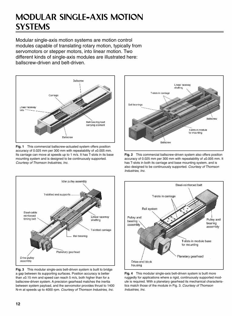
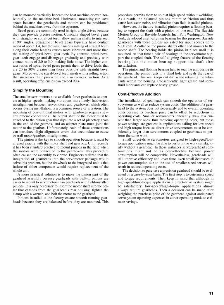
MODULAR SINGLE--AXIS MOTIONSYSTEMSModular single-axis motion systems are motion controlmodules capable of translating rotary motion, typically fromservomotors or stepper motors, into linear motion. Twodifferent kinds of single-axis modules are illustrated here:ballscrew-driven and belt-driven.
12
Fig. 1 This commercial ballscrew-actuated system offers positionaccuracy of 0.025 mm per 300 mm with repeatability of ±0.005 mm.Its carriage can move at speeds up to 1 m/s. It has T-slots in its basemounting system and is designed to be continuously supported.Courtesy of Thomson Industries, Inc.
Fig. 2 This commercial ballscrew-driven system also offers positionaccuracy of 0.025 mm per 300 mm with repeatability of ±0.005 mm. Ithas T-slots in both its carriage and base mounting system, and isalso designed to be continuously supported. Courtesy of ThomsonIndustries, Inc.
Fig. 3 This modular single-axis belt-driven system is built to bridgea gap between its supporting surfaces. Position accuracy is betterthan ±0.15 mm and speed can reach 5 m/s, both higher than for aballscrew-driven system. A precision gearhead matches the inertiabetween system payload, and the servomotor provides thrust to 1400N-m at speeds up to 4000 rpm. Courtesy of Thomson Industries, Inc.
Fig. 4 This modular single-axis belt-driven system is built moreruggedly for applications where a rigid, continuously supported mod-ule is required. With a planetary gearhead its mechanical characteris-tics match those of the module in Fig. 3. Courtesy of ThomsonIndustries, Inc.
Sclater Chapter 1 5/3/01 9:53 AM Page 12
13
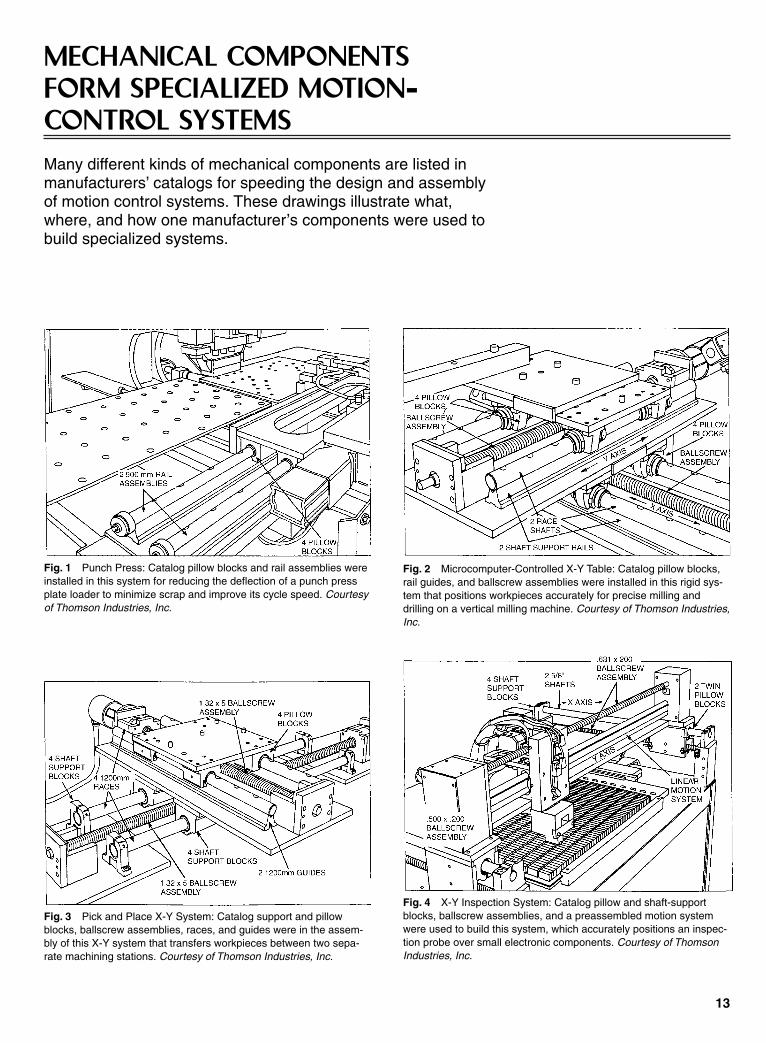
MECHANICAL COMPONENTSFORM SPECIALIZED MOTION--CONTROL SYSTEMSMany different kinds of mechanical components are listed inmanufacturers’ catalogs for speeding the design and assemblyof motion control systems. These drawings illustrate what,where, and how one manufacturer’s components were used tobuild specialized systems.
Fig. 1 Punch Press: Catalog pillow blocks and rail assemblies wereinstalled in this system for reducing the deflection of a punch pressplate loader to minimize scrap and improve its cycle speed. Courtesyof Thomson Industries, Inc.
Fig. 2 Microcomputer-Controlled X-Y Table: Catalog pillow blocks,rail guides, and ballscrew assemblies were installed in this rigid sys-tem that positions workpieces accurately for precise milling anddrilling on a vertical milling machine. Courtesy of Thomson Industries,Inc.
Fig. 3 Pick and Place X-Y System: Catalog support and pillowblocks, ballscrew assemblies, races, and guides were in the assem-bly of this X-Y system that transfers workpieces between two sepa-rate machining stations. Courtesy of Thomson Industries, Inc.
Fig. 4 X-Y Inspection System: Catalog pillow and shaft-supportblocks, ballscrew assemblies, and a preassembled motion systemwere used to build this system, which accurately positions an inspec-tion probe over small electronic components. Courtesy of ThomsonIndustries, Inc.
Sclater Chapter 1 5/3/01 9:53 AM Page 13
Many different kinds of electric motors have been adapted for usein motion control systems because of their linear characteristics.These include both conventional rotary and linear alternating cur-rent (AC) and direct current (DC) motors. These motors can befurther classified into those that must be operated in closed-loopservosystems and those that can be operated open-loop.
The most popular servomotors are permanent magnet (PM)rotary DC servomotors that have been adapted from conven-tional PM DC motors. These servomotors are typically classifiedas brush-type and brushless. The brush-type PM DC servomotorsinclude those with wound rotors and those with lighter weight,lower inertia cup- and disk coil-type armatures. Brushless servo-motors have PM rotors and wound stators.
Some motion control systems are driven by two-part linearservomotors that move along tracks or ways. They are popular inapplications where errors introduced by mechanical couplingbetween the rotary motors and the load can introduce unwantederrors in positioning. Linear motors require closed loops for theiroperation, and provision must be made to accommodate theback-and-forth movement of the attached data and power cable.
Stepper or stepping motors are generally used in less demand-ing motion control systems, where positioning the load by steppermotors is not critical for the application. Increased position accu-racy can be obtained by enclosing the motors in control loops.
Permanent-Magnet DC Servomotors
Permanent-magnet (PM) field DC rotary motors have proven tobe reliable drives for motion control applications where high effi-ciency, high starting torque, and linear speed–torque curves aredesirable characteristics. While they share many of the character-istics of conventional rotary series, shunt, and compound-woundbrush-type DC motors, PM DC servomotors increased in popu-larity with the introduction of stronger ceramic and rare-earthmagnets made from such materials as neodymium–iron–boronand the fact that these motors can be driven easily by micro-processor-based controllers.
The replacement of a wound field with permanent magnetseliminates both the need for separate field excitation and theelectrical losses that occur in those field windings. Because thereare both brush-type and brushless DC servomotors, the term DCmotor implies that it is brush-type or requires mechanical com-mutation unless it is modified by the term brushless. Permanent-magnet DC brush-type servomotors can also have armaturesformed as laminated coils in disk or cup shapes. They are light-weight, low-inertia armatures that permit the motors to acceleratefaster than the heavier conventional wound armatures.
The increased field strength of the ceramic and rare-earthmagnets permitted the construction of DC motors that are bothsmaller and lighter than earlier generation comparably rated DCmotors with alnico (aluminum–nickel–cobalt or AlNiCo) mag-nets. Moreover, integrated circuitry and microprocessors haveincreased the reliability and cost-effectiveness of digital motioncontrollers and motor drivers or amplifiers while permitting themto be packaged in smaller and lighter cases, thus reducing thesize and weight of complete, integrated motion-control systems.
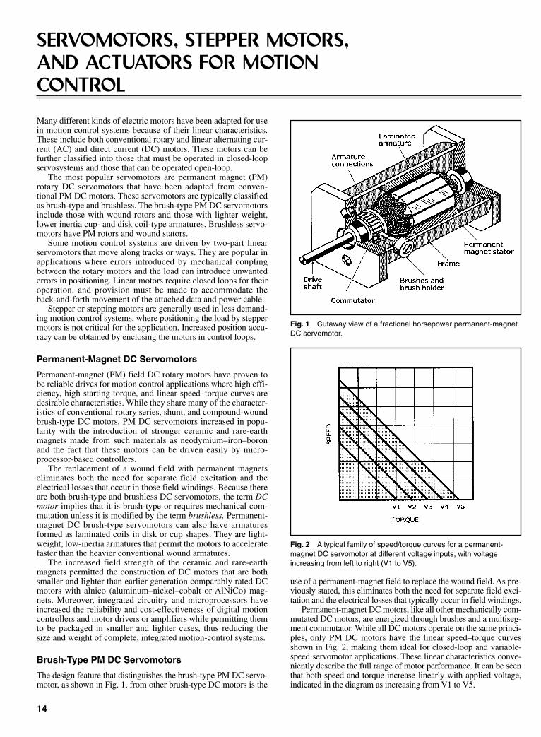
Brush-Type PM DC Servomotors
The design feature that distinguishes the brush-type PM DC servo-motor, as shown in Fig. 1, from other brush-type DC motors is the
use of a permanent-magnet field to replace the wound field. As pre-viously stated, this eliminates both the need for separate field exci-tation and the electrical losses that typically occur in field windings.
Permanent-magnet DC motors, like all other mechanically com-mutated DC motors, are energized through brushes and a multiseg-ment commutator. While all DC motors operate on the same princi-ples, only PM DC motors have the linear speed–torque curvesshown in Fig. 2, making them ideal for closed-loop and variable-speed servomotor applications. These linear characteristics conve-niently describe the full range of motor performance. It can be seenthat both speed and torque increase linearly with applied voltage,indicated in the diagram as increasing from V1 to V5.
14
SERVOMOTORS, STEPPER MOTORS,AND ACTUATORS FOR MOTIONCONTROL
Fig. 1 Cutaway view of a fractional horsepower permanent-magnetDC servomotor.
Fig. 2 A typical family of speed/torque curves for a permanent-magnet DC servomotor at different voltage inputs, with voltageincreasing from left to right (V1 to V5).
Sclater Chapter 1 5/3/01 9:53 AM Page 14

The stators of brush-type PM DC motors are magnetic polepairs. When the motor is powered, the opposite polarities of theenergized windings and the stator magnets attract, and the rotorrotates to align itself with the stator. Just as the rotor reachesalignment, the brushes move across the commutator segmentsand energize the next winding. This sequence continues as longas power is applied, keeping the rotor in continuous motion. Thecommutator is staggered from the rotor poles, and the number ofits segments is directly proportional to the number of windings.If the connections of a PM DC motor are reversed, the motor willchange direction, but it might not operate as efficiently in thereversed direction.
Disk-Type PM DC Motors
The disk-type motor shown exploded view in Fig. 3 has a disk-shaped armature with stamped and laminated windings. Thisnonferrous laminated disk is made as a copper stamping bondedbetween epoxy–glass insulated layers and fastened to an axialshaft. The stator field can either be a ring of many individualceramic magnet cylinders, as shown, or a ring-type ceramic mag-net attached to the dish-shaped end bell, which completes themagnetic circuit. The spring-loaded brushes ride directly onstamped commutator bars.
These motors are also called pancake motors because they arehoused in cases with thin, flat form factors whose diametersexceed their lengths, suggesting pancakes. Earlier generations ofthese motors were called printed-circuit motors because thearmature disks were made by a printed-circuit fabricationprocess that has been superseded. The flat motor case concen-trates the motor’s center of mass close to the mounting plate, per-mitting it to be easily surface mounted. This eliminates the awk-ward motor overhang and the need for supporting braces if aconventional motor frame is to be surface mounted. Their disk-type motor form factor has made these motors popular as axisdrivers for industrial robots where space is limited.
The principal disadvantage of the disk-type motor is the rela-tively fragile construction of its armature and its inability to dis-sipate heat as rapidly as iron-core wound rotors. Consequently,these motors are usually limited to applications where the motorcan be run under controlled conditions and a shorter duty cycleallows enough time for armature heat buildup to be dissipated.
Cup- or Shell-Type PM DC Motors
Cup- or shell-type PM DC motors offer low inertia and lowinductance as well as high acceleration characteristics, making
them useful in many servo applications. They have hollow cylin-drical armatures made as aluminum or copper coils bonded bypolymer resin and fiberglass to form a rigid “ironless cup,”which is fastened to an axial shaft. A cutaway view of this classof servomotor is illustrated in Fig. 4.
Because the armature has no iron core, it, like the disk motor,has extremely low inertia and a very high torque-to-inertia ratio.This permits the motor to accelerate rapidly for the quickresponse required in many motion-control applications. Thearmature rotates in an air gap within very high magnetic fluxdensity. The magnetic field from the stationary magnets is com-pleted through the cup-type armature and a stationary ferrouscylindrical core connected to the motor frame. The shaft rotateswithin the core, which extends into the rotating cup. Spring-brushes commutate these motors.
Another version of a cup-type PM DC motor is shown in theexploded view in Fig. 5. The cup type armature is rigidly fas-tened to the shaft by a disk at the right end of the winding, andthe magnetic field is also returned through a ferrous metal hous-ing. The brush assembly of this motor is built into its end cap orflange, shown at the far right.
The principal disadvantage of this motor is also the inabilityof its bonded armature to dissipate internal heat buildup rapidlybecause of its low thermal conductivity. Without proper coolingand sensitive control circuitry, the armature could be heated todestructive temperatures in seconds.
15
Fig. 3 Exploded view of a permanent-magnet DC servomotor with adisk-type armature.
Fig. 4 Cutaway view of a permanent-magnet DC servomotor with acup-type armature.
Fig. 5 Exploded view of a fractional horsepower brush-type DCservomotor.
Sclater Chapter 1 5/3/01 9:53 AM Page 15

Brushless PM DC Motors
Brushless DC motors exhibit the same linear speed–torque char-acteristics as the brush-type PM DC motors, but they are elec-tronically commutated. The construction of these motors, asshown in Fig. 6, differs from that of a typical brush-type DCmotor in that they are “inside-out.” In other words, they have per-manent magnet rotors instead of stators, and the stators ratherthan the rotors are wound. Although this geometry is required forbrushless DC motors, some manufacturers have adapted thisdesign for brush-type DC motors.
The mechanical brush and bar commutator of the brushlessDC motor is replaced by electronic sensors, typically Hall-effectdevices (HEDs). They are located within the stator windings andwired to solid-state transistor switching circuitry located eitheron circuit cards mounted within the motor housings or in externalpackages. Generally, only fractional horsepower brushlessmotors have switching circuitry within their housings.
The cylindrical magnet rotors of brushless DC motors aremagnetized laterally to form opposing north and south polesacross the rotor’s diameter. These rotors are typically made fromneodymium–iron–boron or samarium–cobalt rare-earth magneticmaterials, which offer higher flux densities than alnico magnets.These materials permit motors offering higher performance to bepackaged in the same frame sizes as earlier motor designs orthose with the same ratings to be packaged in smaller frames than
the earlier designs. Moreover, rare-earth or ceramic magnetrotors can be made with smaller diameters than those earliermodels with alnico magnets, thus reducing their inertia.
A simplified diagram of a DC brushless motor control withone Hall-effect device (HED) for the electronic commutator isshown in Fig. 7. The HED is a Hall-effect sensor integrated withan amplifier in a silicon chip. This IC is capable of sensing thepolarity of the rotor’s magnetic field and then sending appropri-ate signals to power transistors T1 and T2 to cause the motor’srotor to rotate continuously. This is accomplished as follows:
(1) With the rotor motionless, the HED detects the rotor’snorth magnetic pole, causing it to generate a signal that turns ontransistor T2. This causes current to flow, energizing winding W2to form a south-seeking electromagnetic rotor pole. This polethen attracts the rotor’s north pole to drive the rotor in a counter-clockwise (CCW) direction.
(2) The inertia of the rotor causes it to rotate past its neutralposition so that the HED can then sense the rotor’s south mag-netic pole. It then switches on transistor T1, causing current toflow in winding W1, thus forming a north-seeking stator polethat attracts the rotor’s south pole, causing it to continue to rotatein the CCW direction.
The transistors conduct in the proper sequence to ensure thatthe excitation in the stator windings W2 and W1 always leads thePM rotor field to produce the torque necessary keep the rotor inconstant rotation. The windings are energized in a pattern thatrotates around the stator.
There are usually two or three HEDs in practical brushlessmotors that are spaced apart by 90 or 120º around the motor’srotor. They send the signals to the motion controller that actuallytriggers the power transistors, which drive the armature windingsat a specified motor current and voltage level.
The brushless motor in the exploded view Fig. 8 illustrates adesign for a miniature brushless DC motor that includes Hall-effect commutation. The stator is formed as an ironless sleeve ofcopper coils bonded together in polymer resin and fiberglass toform a rigid structure similar to cup-type rotors. However, it isfastened inside the steel laminations within the motor housing.
This method of construction permits a range of values forstarting current and specific speed (rpm/V) depending on wiregauge and the number of turns. Various terminal resistances canbe obtained, permitting the user to select the optimum motor fora specific application. The Hall-effect sensors and a small mag-net disk that is magnetized widthwise are mounted on a disk-shaped partition within the motor housing.
Position Sensing in Brushless Motors
Both magnetic sensors and resolvers can sense rotor position inbrushless motors. The diagram in Fig. 9 shows how three mag-
16
Fig. 6 Cutaway view of a brushless DC motor.
Fig. 7 Simplified diagram of Hall-effect device (HED) commutationof a brushless DC motor.
Fig. 8 Exploded view of a brushless DC motor with Hall-effectdevice (HED) commutation.
Sclater Chapter 1 5/3/01 9:53 AM Page 16

netic sensors can sense rotor position in a three-phase electroni-cally commutated brushless DC motor. In this example the mag-netic sensors are located inside the end-bell of the motor. Thisinexpensive version is adequate for simple controls.
In the alternate design shown in Fig. 10, a resolver on the endcap of the motor is used to sense rotor position when greaterpositioning accuracy is required. The high-resolution signalsfrom the resolver can be used to generate sinusoidal motor cur-rents within the motor controller. The currents through the threemotor windings are position independent and respectively 120ºphase shifted.
Brushless Motor Advantages
Brushless DC motors have at least four distinct advantages overbrush-type DC motors that are attributable to the replacement ofmechanical commutation by electronic commutation.
• There is no need to replace brushes or remove the grittyresidue caused by brush wear from the motor.
• Without brushes to cause electrical arcing, brushless motorsdo not present fire or explosion hazards in an environmentwhere flammable or explosive vapors, dust, or liquids arepresent.
• Electromagnetic interference (EMI) is minimized by replac-ing mechanical commutation, the source of unwanted radiofrequencies, with electronic commutation.
• Brushless motors can run faster and more efficiently withelectronic commutation. Speeds of up to 50,000 rpm can beachieved vs. the upper limit of about 5000 rpm for brush-type DC motors.
Brushless DC Motor Disadvantages
There are at least four disadvantages of brushless DC servo-motors.
• Brushless PM DC servomotors cannot be reversed by simplyreversing the polarity of the power source. The order inwhich the current is fed to the field coil must be reversed.
• Brushless DC servomotors cost more than comparably ratedbrush-type DC servomotors.
• Additional system wiring is required to power the electroniccommutation circuitry.
• The motion controller and driver electronics needed to oper-ate a brushless DC servomotor are more complex and expen-sive than those required for a conventional DC servomotor.
Consequently, the selection of a brushless motor is generallyjustified on a basis of specific application requirements or itshazardous operating environment.
Characteristics of Brushless Rotary Servomotors
It is difficult to generalize about the characteristics of DC rotaryservomotors because of the wide range of products availablecommercially. However, they typically offer continuous torqueratings of 0.62 lb-ft (0.84 N-m) to 5.0 lb-ft (6.8 N-m), peaktorque ratings of 1.9 lb-ft (2.6 N-m) to 14 lb-ft (19 N-m), andcontinuous power ratings of 0.73 hp (0.54 kW) to 2.76 hp (2.06kW). Maximum speeds can vary from 1400 to 7500 rpm, and theweight of these motors can be from 5.0 lb (2.3 kg) to 23 lb (10kg). Feedback typically can be either by resolver or encoder.
Linear Servomotors
A linear motor is essentially a rotary motor that has been openedout into a flat plane, but it operates on the same principles. A per-manent-magnet DC linear motor is similar to a permanent-magnet rotary motor, and an AC induction squirrel cage motor issimilar to an induction linear motor. The same electromagneticforce that produces torque in a rotary motor also produces torquein a linear motor. Linear motors use the same controls and pro-grammable position controllers as rotary motors.
Before the invention of linear motors, the only way to pro-duce linear motion was to use pneumatic or hydraulic cylinders,or to translate rotary motion to linear motion with ballscrews orbelts and pulleys.
A linear motor consists of two mechanical assemblies: coiland magnet, as shown in Fig. 11. Current flowing in a winding ina magnetic flux field produces a force. The copper windings con-duct current (I ), and the assembly generates magnetic flux den-sity (B). When the current and flux density interact, a force (F ) isgenerated in the direction shown in Fig. 11, where F = I × B.
Even a small motor will run efficiently, and large forces canbe created if a large number of turns are wound in the coil and themagnets are powerful rare-earth magnets. The windings are
17
Fig. 9 A magnetic sensor as a rotor position indicator: stationarybrushless motor winding (1), permanent-magnet motor rotor(2), three-phase electronically commutated field (3), three magneticsensors (4), and the electronic circuit board (5).
Fig. 10 A resolver as a rotor position indicator: stationary motorwinding (1), permanent-magnet motor rotor (2), three-phase electron-ically commutated field (3), three magnetic sensors (4), and the elec-tronic circuit board (5).
Sclater Chapter 1 5/3/01 9:53 AM Page 17

phased 120 electrical degrees apart, and they must be continuallyswitched or commutated to sustain motion.
Only brushless linear motors for closed-loop servomotorapplications are discussed here. Two types of these motors areavailable commercially—steel-core (also called iron-core) andepoxy-core (also called ironless). Each of these linear servomo-tors has characteristics and features that are optimal in differentapplications
The coils of steel-core motors are wound on silicon steel tomaximize the generated force available with a single-sided mag-net assembly or way. Figure 12 shows a steel-core brushless lin-ear motor. The steel in these motors focuses the magnetic flux toproduce very high force density. The magnet assembly consistsof rare-earth bar magnets mounted on the upper surface of a steelbase plate arranged to have alternating polarities (i.e., N, S, N, S)
The steel in the cores is attracted to the permanent magnets ina direction that is perpendicular (normal) to the operating motorforce. The magnetic flux density within the air gap of linearmotors is typically several thousand gauss. A constant magneticforce is present whether or not the motor is energized. The nor-mal force of the magnetic attraction can be up to ten times thecontinuous force rating of the motor. This flux rapidly diminishesto a few gauss as the measuring point is moved a few centimetersaway from the magnets.
Cogging is a form of magnetic “detenting” that occurs in bothlinear and rotary motors when the motor coil’s steel laminationscross the alternating poles of the motor’s magnets. Because it canoccur in steel-core motors, manufacturers include features that
Fig. 11 Operating principles of a linear servomotor.
minimize cogging. The high thrust forces attainable with steel-core linear motors permit them to accelerate and move heavymasses while maintaining stiffness during machining or processoperations.
The features of epoxy-core or ironless-core motors differfrom those of the steel-core motors. For example, their coilassemblies are wound and encapsulated within epoxy to form athin plate that is inserted in the air gap between the two perma-nent-magnet strips fastened inside the magnet assembly, asshown in Fig. 13. Because the coil assemblies do not containsteel cores, epoxy-core motors are lighter than steel-core motorsand less subject to cogging.
The strip magnets are separated to form the air gap into whichthe coil assembly is inserted. This design maximizes the gener-ated thrust force and also provides a flux return path for the mag-netic circuit. Consequently, very little magnetic flux exists out-side the motor, thus minimizing residual magnetic attraction.
Epoxy-core motors provide exceptionally smooth motion,making them suitable for applications requiring very low bearingfriction and high acceleration of light loads. They also permitconstant velocity to be maintained, even at very low speeds.
Linear servomotors can achieve accuracies of 0.1 µm. Normalaccelerations are 2 to 3 g, but some motors can reach 15 g.Velocities are limited by the encoder data rate and the amplifiervoltage. Normal peak velocities are from 0.04 in./s (1 mm/s) toabout 6.6 ft/s (2 m/s), but the velocity of some models can exceed26 ft/s (8 m/s).
Ironless linear motors can have continuous force ratings fromabout 5 to 55 lbf (22 to 245 N) and peak force ratings from about25 to 180 lbf (110 to 800 N). By contrast, iron-core linear motorsare available with continuous force ratings of about 30 to 1100lbf (130 to 4900 N) and peak force ratings of about 60 to 1800 lbf(270 to 8000 N).
Commutation
The linear motor windings that are phased 120º apart must becontinually switched or commutated to sustain motion. There aretwo ways to commutate linear motors: sinusoidal and Hall-effectdevice (HED), or trapezoidal. The highest motor efficiency isachieved with sinusoidal commutation, while HED commutationis about 10 to 15% less efficient.
In sinusoidal commutation, the linear encoder that providesposition feedback in the servosystem is also used to commutatethe motor. A process called “phase finding” is required when the
18
Fig. 12 A linear iron-core linear servomotor consists of a magneticway and a mating coil assembly.
Fig. 13 A linear ironless servomotor consists of an ironless mag-netic way and an ironless coil assembly.
Sclater Chapter 1 5/3/01 9:53 AM Page 18
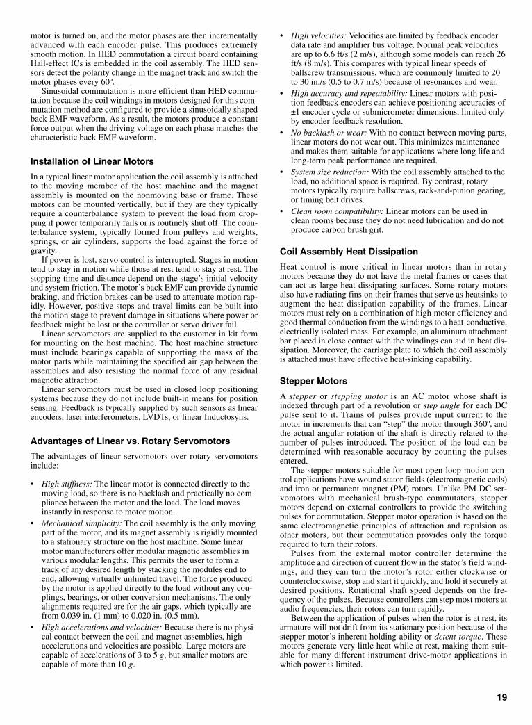
motor is turned on, and the motor phases are then incrementallyadvanced with each encoder pulse. This produces extremelysmooth motion. In HED commutation a circuit board containingHall-effect ICs is embedded in the coil assembly. The HED sen-sors detect the polarity change in the magnet track and switch themotor phases every 60º.
Sinusoidal commutation is more efficient than HED commu-tation because the coil windings in motors designed for this com-mutation method are configured to provide a sinusoidally shapedback EMF waveform. As a result, the motors produce a constantforce output when the driving voltage on each phase matches thecharacteristic back EMF waveform.
Installation of Linear Motors
In a typical linear motor application the coil assembly is attachedto the moving member of the host machine and the magnetassembly is mounted on the nonmoving base or frame. Thesemotors can be mounted vertically, but if they are they typicallyrequire a counterbalance system to prevent the load from drop-ping if power temporarily fails or is routinely shut off. The coun-terbalance system, typically formed from pulleys and weights,springs, or air cylinders, supports the load against the force ofgravity.
If power is lost, servo control is interrupted. Stages in motiontend to stay in motion while those at rest tend to stay at rest. Thestopping time and distance depend on the stage’s initial velocityand system friction. The motor’s back EMF can provide dynamicbraking, and friction brakes can be used to attenuate motion rap-idly. However, positive stops and travel limits can be built intothe motion stage to prevent damage in situations where power orfeedback might be lost or the controller or servo driver fail.
Linear servomotors are supplied to the customer in kit formfor mounting on the host machine. The host machine structuremust include bearings capable of supporting the mass of themotor parts while maintaining the specified air gap between theassemblies and also resisting the normal force of any residualmagnetic attraction.
Linear servomotors must be used in closed loop positioningsystems because they do not include built-in means for positionsensing. Feedback is typically supplied by such sensors as linearencoders, laser interferometers, LVDTs, or linear Inductosyns.
Advantages of Linear vs. Rotary Servomotors
The advantages of linear servomotors over rotary servomotorsinclude:
• High stiffness: The linear motor is connected directly to themoving load, so there is no backlash and practically no com-pliance between the motor and the load. The load movesinstantly in response to motor motion.
• Mechanical simplicity: The coil assembly is the only movingpart of the motor, and its magnet assembly is rigidly mountedto a stationary structure on the host machine. Some linearmotor manufacturers offer modular magnetic assemblies invarious modular lengths. This permits the user to form atrack of any desired length by stacking the modules end toend, allowing virtually unlimited travel. The force producedby the motor is applied directly to the load without any cou-plings, bearings, or other conversion mechanisms. The onlyalignments required are for the air gaps, which typically arefrom 0.039 in. (1 mm) to 0.020 in. (0.5 mm).
• High accelerations and velocities: Because there is no physi-cal contact between the coil and magnet assemblies, highaccelerations and velocities are possible. Large motors arecapable of accelerations of 3 to 5 g, but smaller motors arecapable of more than 10 g.
• High velocities: Velocities are limited by feedback encoderdata rate and amplifier bus voltage. Normal peak velocitiesare up to 6.6 ft/s (2 m/s), although some models can reach 26ft/s (8 m/s). This compares with typical linear speeds ofballscrew transmissions, which are commonly limited to 20to 30 in./s (0.5 to 0.7 m/s) because of resonances and wear.
• High accuracy and repeatability: Linear motors with posi-tion feedback encoders can achieve positioning accuracies of±1 encoder cycle or submicrometer dimensions, limited onlyby encoder feedback resolution.
• No backlash or wear: With no contact between moving parts,linear motors do not wear out. This minimizes maintenanceand makes them suitable for applications where long life andlong-term peak performance are required.
• System size reduction: With the coil assembly attached to theload, no additional space is required. By contrast, rotarymotors typically require ballscrews, rack-and-pinion gearing,or timing belt drives.
• Clean room compatibility: Linear motors can be used inclean rooms because they do not need lubrication and do notproduce carbon brush grit.
Coil Assembly Heat Dissipation
Heat control is more critical in linear motors than in rotarymotors because they do not have the metal frames or cases thatcan act as large heat-dissipating surfaces. Some rotary motorsalso have radiating fins on their frames that serve as heatsinks toaugment the heat dissipation capability of the frames. Linearmotors must rely on a combination of high motor efficiency andgood thermal conduction from the windings to a heat-conductive,electrically isolated mass. For example, an aluminum attachmentbar placed in close contact with the windings can aid in heat dis-sipation. Moreover, the carriage plate to which the coil assemblyis attached must have effective heat-sinking capability.
Stepper Motors
A stepper or stepping motor is an AC motor whose shaft isindexed through part of a revolution or step angle for each DCpulse sent to it. Trains of pulses provide input current to themotor in increments that can “step” the motor through 360º, andthe actual angular rotation of the shaft is directly related to thenumber of pulses introduced. The position of the load can bedetermined with reasonable accuracy by counting the pulsesentered.
The stepper motors suitable for most open-loop motion con-trol applications have wound stator fields (electromagnetic coils)and iron or permanent magnet (PM) rotors. Unlike PM DC ser-vomotors with mechanical brush-type commutators, steppermotors depend on external controllers to provide the switchingpulses for commutation. Stepper motor operation is based on thesame electromagnetic principles of attraction and repulsion asother motors, but their commutation provides only the torquerequired to turn their rotors.
Pulses from the external motor controller determine theamplitude and direction of current flow in the stator’s field wind-ings, and they can turn the motor’s rotor either clockwise orcounterclockwise, stop and start it quickly, and hold it securely atdesired positions. Rotational shaft speed depends on the fre-quency of the pulses. Because controllers can step most motors ataudio frequencies, their rotors can turn rapidly.
Between the application of pulses when the rotor is at rest, itsarmature will not drift from its stationary position because of thestepper motor’s inherent holding ability or detent torque. Thesemotors generate very little heat while at rest, making them suit-able for many different instrument drive-motor applications inwhich power is limited.
19
Sclater Chapter 1 5/3/01 9:53 AM Page 19

The three basic kinds of stepper motors are permanent mag-net, variable reluctance, and hybrid. The same controller circuitcan drive both hybrid and PM stepping motors.
Permanent-Magnet (PM) Stepper Motors
Permanent-magnet stepper motors have smooth armatures andinclude a permanent magnet core that is magnetized widthwiseor perpendicular to its rotation axis. These motors usually havetwo independent windings, with or without center taps. Themost common step angles for PM motors are 45 and 90º, butmotors with step angles as fine as 1.8º per step as well as 7.5, 15,and 30º per step are generally available. Armature rotationoccurs when the stator poles are alternately energized and deen-ergized to create torque. A 90º stepper has four poles and a 45ºstepper has eight poles, and these poles must be energized insequence. Permanent-magnet steppers step at relatively lowrates, but they can produce high torques and they offer verygood damping characteristics.
Variable Reluctance Stepper Motors
Variable reluctance (VR) stepper motors have multitooth arma-tures with each tooth effectively an individual magnet. At restthese magnets align themselves in a natural detent position toprovide larger holding torque than can be obtained with a compa-rably rated PM stepper. Typical VR motor step angles are 15 and30º per step. The 30º angle is obtained with a 4-tooth rotor and a6-pole stator, and the 15º angle is achieved with an 8-tooth rotorand a 12-pole stator. These motors typically have three windingswith a common return, but they are also available with four orfive windings. To obtain continuous rotation, power must beapplied to the windings in a coordinated sequence of alternatelydeenergizing and energizing the poles.
If just one winding of either a PM or VR stepper motor isenergized, the rotor (under no load) will snap to a fixed angle andhold that angle until external torque exceeds the holding torqueof the motor. At that point, the rotor will turn, but it will still tryto hold its new position at each successive equilibrium point.
Hybrid Stepper Motors
The hybrid stepper motor combines the best features of VR andPM stepper motors. A cutaway view of a typical industrial-gradehybrid stepper motor with a multitoothed armature is shown inFig. 14. The armature is built in two sections, with the teeth in the
second section offset from those in the first section. These motorsalso have multitoothed stator poles that are not visible in the fig-ure. Hybrid stepper motors can achieve high stepping rates, andthey offer high detent torque and excellent dynamic and statictorque.
Hybrid steppers typically have two windings on each statorpole so that each pole can become either magnetic north or south,depending on current flow. A cross-sectional view of a hybridstepper motor illustrating the multitoothed poles with dual wind-ings per pole and the multitoothed rotor is illustrated in Fig. 15.The shaft is represented by the central circle in the diagram.
The most popular hybrid steppers have 3- and 5-phase wiring,and step angles of 1.8 and 3.6º per step. These motors can pro-vide more torque from a given frame size than other steppertypes because either all or all but one of the motor windings areenergized at every point in the drive cycle. Some 5-phase motorshave high resolutions of 0.72° per step (500 steps per revolution).With a compatible controller, most PM and hybrid motors can berun in half-steps, and some controllers are designed to providesmaller fractional steps, or microsteps. Hybrid stepper motorscapable of a wide range of torque values are available commer-cially. This range is achieved by scaling length and diameterdimensions. Hybrid stepper motors are available in NEMA size17 to 42 frames, and output power can be as high as 1000 Wpeak.
Stepper Motor Applications
Many different technical and economic factors must be consid-ered in selecting a hybrid stepper motor. For example, the abilityof the stepper motor to repeat the positioning of its multitoothedrotor depends on its geometry. A disadvantage of the hybrid step-per motor operating open-loop is that, if overtorqued, its position“memory” is lost and the system must be reinitialized. Steppermotors can perform precise positioning in simple open-loop con-trol systems if they operate at low acceleration rates with staticloads. However, if higher acceleration values are required fordriving variable loads, the stepper motor must be operated in aclosed loop with a position sensor.
20
Fig. 14 Cutaway view of a 5-phase hybrid stepping motor. A perma-nent magnet is within the rotor assembly, and the rotor segments areoffset from each other by 3.5°.
Fig. 15 Cross-section of a hybrid stepping motor showing the seg-ments of the magnetic-core rotor and stator poles with its wiringdiagram.
Sclater Chapter 1 5/3/01 9:53 AM Page 20

DC and AC Motor Linear Actuators
Actuators for motion control systems are available in many dif-ferent forms, including both linear and rotary versions. One pop-ular configuration is that of a Thomson Saginaw PPA, shown insection view in Fig. 16. It consists of an AC or DC motormounted parallel to either a ballscrew or Acme screw assemblythrough a reduction gear assembly with a slip clutch and integralbrake assembly. Linear actuators of this type can perform a widerange of commercial, industrial, and institutional applications.
One version designed for mobile applications can be poweredby a 12-, 24-, or 36-VDC permanent-magnet motor. Thesemotors are capable of performing such tasks as positioningantenna reflectors, opening and closing security gates, handlingmaterials, and raising and lowering scissors-type lift tables,machine hoods, and light-duty jib crane arms.
Other linear actuators are designed for use in fixed locationswhere either 120- or 220-VAC line power is available. They canhave either AC or DC motors. Those with 120-VAC motors canbe equipped with optional electric brakes that virtually eliminatecoasting, thus permitting point-to-point travel along the stroke.
Where variable speed is desired and 120-VAC power is avail-able, a linear actuator with a 90-VDC motor can be equippedwith a solid-state rectifier/speed controller. Closed-loop feed-back provides speed regulation down to one tenth of the maxi-mum travel rate. This feedback system can maintain its selectedtravel rate despite load changes.
Thomson Saginaw also offers its linear actuators with eitherHall-effect or potentiometer sensors for applications where it isnecessary or desirable to control actuator positioning. With Hall-effect sensing, six pulses are generated with each turn of the out-put shaft during which the stroke travels approximately 1⁄32 in.(0.033 in. or 0.84 mm). These pulses can be counted by a sepa-rate control unit and added or subtracted from the stored pulsecount in the unit’s memory. The actuator can be stopped at any0.033-in. increment of travel along the stroke selected by pro-gramming. A limit switch can be used together with this sensor.
If a 10-turn, 10,000-ohm potentiometer is used as a sensor, itcan be driven by the output shaft through a spur gear. The gearratio is established to change the resistance from 0 to 10,000
21
ohms over the length of the actuator stroke. A separate controlunit measures the resistance (or voltage) across the potentiome-ter, which varies continuously and linearly with stroke travel.The actuator can be stopped at any position along its stroke.
Stepper-Motor Based Linear Actuators
Linear actuators are available with axial integral threaded shaftsand bolt nuts that convert rotary motion to linear motion.Powered by fractional horsepower permanent-magnet steppermotors, these linear actuators are capable of positioning lightloads. Digital pulses fed to the actuator cause the threaded shaftto rotate, advancing or retracting it so that a load coupled to theshaft can be moved backward or forward. The bidirectional digi-tal linear actuator shown in Fig. 17 can provide linear resolutionas fine as 0.001 in. per pulse. Travel per step is determined by thepitch of the leadscrew and step angle of the motor. The maximumlinear force for the model shown is 75 oz.
Fig. 17 This light-duty linear actuator based on a permanent-magnet stepping motor has a shaft that advances or retracts.
Fig. 16 This linear actuator can be powered by either an AC or DC motor. It containsballscrew, reduction gear, clutch, and brake assemblies. Courtesy of Thomson Saginaw.
Sclater Chapter 1 5/3/01 9:53 AM Page 21

SERVOSYSTEM FEEDBACK SENSORS
A servosystem feedback sensor in a motion control system trans-forms a physical variable into an electrical signal for use by themotion controller. Common feedback sensors are encoders,resolvers, and linear variable differential transformers (LVDTs)for motion and position feedback, and tachometers for velocityfeedback. Less common but also in use as feedback devices arepotentiometers, linear velocity transducers (LVTs), angular dis-placement transducers (ADTs), laser interferometers, and poten-tiometers. Generally speaking, the closer the feedback sensor isto the variable being controlled, the more accurate it will be inassisting the system to correct velocity and position errors.
For example, direct measurement of the linear position of thecarriage carrying the load or tool on a single-axis linear guidewill provide more accurate feedback than an indirect measure-ment determined from the angular position of the guide’s lead-screw and knowledge of the drivetrain geometry between thesensor and the carriage. Thus, direct position measurementavoids drivetrain errors caused by backlash, hysteresis, and lead-screw wear that can adversely affect indirect measurement.
Rotary Encoders
Rotary encoders, also called rotary shaft encoders or rotaryshaft-angle encoders, are electromechanical transducers thatconvert shaft rotation into output pulses, which can be counted tomeasure shaft revolutions or shaft angle. They provide rate andpositioning information in servo feedback loops. A rotaryencoder can sense a number of discrete positions per revolution.The number is called points per revolution and is analogous tothe steps per revolution of a stepper motor. The speed of anencoder is in units of counts per second. Rotary encoders canmeasure the motor-shaft or leadscrew angle to report positionindirectly, but they can also measure the response of rotatingmachines directly.
The most popular rotary encoders are incremental opticalshaft-angle encoders and the absolute optical shaft-angleencoders. There are also direct contact or brush-type and mag-netic rotary encoders, but they are not as widely used in motioncontrol systems.
Commercial rotary encoders are available as standard or cata-log units, or they can be custom made for unusual applications orsurvival in extreme environments. Standard rotary encoders arepackaged in cylindrical cases with diameters from 1.5 to 3.5 in.Resolutions range from 50 cycles per shaft revolution to2,304,000 counts per revolution. A variation of the conventionalconfiguration, the hollow-shaft encoder, eliminates problemsassociated with the installation and shaft runout of conventionalmodels. Models with hollow shafts are available for mounting onshafts with diameters of 0.04 to 1.6 in. (1 to 40 mm).
Incremental Encoders
The basic parts of an incremental optical shaft-angle encoder areshown in Fig. 1. A glass or plastic code disk mounted on theencoder shaft rotates between an internal light source, typically alight-emitting diode (LED), on one side and a mask and match-ing photodetector assembly on the other side. The incrementalcode disk contains a pattern of equally spaced opaque and trans-parent segments or spokes that radiate out from its center asshown. The electronic signals that are generated by the encoder’s
electronics board are fed into a motion controller that calculatesposition and velocity information for feedback purposes. Anexploded view of an industrial-grade incremental encoder isshown in Fig. 2.
22
Fig. 1 Basic elements of an incremental optical rotary encoder.
Fig. 2 Exploded view of an incremental optical rotary encodershowing the stationary mask between the code wheel and the pho-todetector assembly.
Sclater Chapter 1 5/3/01 9:53 AM Page 22

Glass code disks containing finer graduations capable of 11-to more than 16-bit resolution are used in high-resolutionencoders, and plastic (Mylar) disks capable of 8- to 10-bit reso-lution are used in the more rugged encoders that are subject toshock and vibration.
The quadrature encoder is the most common type of incre-mental encoder. Light from the LED passing through the rotatingcode disk and mask is “chopped” before it strikes the photodetec-tor assembly. The output signals from the assembly are convertedinto two channels of square pulses (A and B) as shown in Fig. 3.The number of square pulses in each channel is equal to the num-ber of code disk segments that pass the photodetectors as the diskrotates, but the waveforms are 90º out of phase. If, for example,the pulses in channel A lead those in channel B, the disk is rotat-ing in a clockwise direction, but if the pulses in channel A lagthose in channel B lead, the disk is rotating counterclockwise. Bymonitoring both the number of pulses and the relative phases ofsignals A and B, both position and direction of rotation can bedetermined.
Many incremental quadrature encoders also include a thirdoutput Z channel to obtain a zero reference or index signal thatoccurs once per revolution. This channel can be gated to the Aand B quadrature channels and used to trigger certain eventsaccurately within the system. The signal can also be used to alignthe encoder shaft to a mechanical reference.
Absolute Encoders
An absolute shaft-angle optical encoder contains multiple lightsources and photodetectors, and a code disk with up to 20 tracksof segmented patterns arranged as annular rings, as shown inFig. 4. The code disk provides a binary output that uniquelydefines each shaft angle, thus providing an absolute measure-ment. This type of encoder is organized in essentially the sameway as the incremental encoder shown in Fig. 2, but the codedisk rotates between linear arrays of LEDs and photodetectorsarranged radially, and a LED opposes a photodetector for eachtrack or annular ring.
The arc lengths of the opaque and transparent sectors decreasewith respect to the radial distance from the shaft. These disks,also made of glass or plastic, produce either the natural binary orGray code. Shaft position accuracy is proportional to the numberof annular rings or tracks on the disk. When the code disk rotates,light passing through each track or annular ring generates a con-tinuous stream of signals from the detector array. The electronics
board converts that output into a binary word. The value of theoutput code word is read radially from the most significant bit(MSB) on the inner ring of the disk to the least significant bit(LSB) on the outer ring of the disk.
The principal reason for selecting an absolute encoder over anincremental encoder is that its code disk retains the last angularposition of the encoder shaft whenever it stops moving, whetherthe system is shut down deliberately or as a result of power fail-ure. This means that the last readout is preserved, an importantfeature for many applications.
Linear Encoders
Linear encoders can make direct accurate measurements of uni-directional and reciprocating motions of mechanisms with highresolution and repeatability. Figure 5 illustrates the basic parts ofan optical linear encoder. A movable scanning unit contains thelight source, lens, graduated glass scanning reticule, and an arrayof photocells. The scale, typically made as a strip of glass withopaque graduations, is bonded to a supporting structure on thehost machine.
23
Fig. 3 Channels A and B provide bidirectional position sensing. Ifchannel A leads channel B, the direction is clockwise; if channel Bleads channel A, the direction is counterclockwise. Channel Z pro-vides a zero reference for determining the number of disk rotations.
Fig. 4 Binary-code disk for an absolute optical rotary encoder.Opaque sectors represent a binary value of 1, and the transparentsectors represent binary 0. This four-bit binary-code disk can countfrom 1 to 15.
Fig. 5 Optical linear encoders direct light through a moving glassscale with accurately etched graduations to photocells on the oppo-site side for conversion to a distance value.
Sclater Chapter 1 5/3/01 9:53 AM Page 23
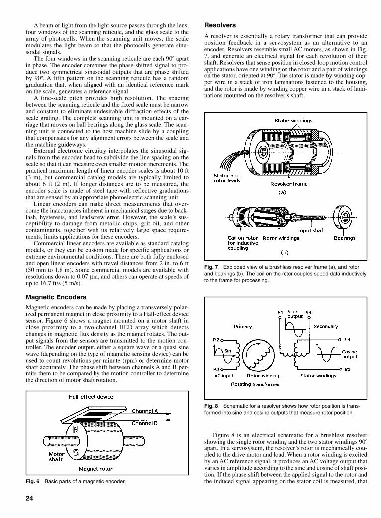
A beam of light from the light source passes through the lens,four windows of the scanning reticule, and the glass scale to thearray of photocells. When the scanning unit moves, the scalemodulates the light beam so that the photocells generate sinu-soidal signals.
The four windows in the scanning reticule are each 90º apartin phase. The encoder combines the phase-shifted signal to pro-duce two symmetrical sinusoidal outputs that are phase shiftedby 90º. A fifth pattern on the scanning reticule has a randomgraduation that, when aligned with an identical reference markon the scale, generates a reference signal.
A fine-scale pitch provides high resolution. The spacingbetween the scanning reticule and the fixed scale must be narrowand constant to eliminate undesirable diffraction effects of thescale grating. The complete scanning unit is mounted on a car-riage that moves on ball bearings along the glass scale. The scan-ning unit is connected to the host machine slide by a couplingthat compensates for any alignment errors between the scale andthe machine guideways.
External electronic circuitry interpolates the sinusoidal sig-nals from the encoder head to subdivide the line spacing on thescale so that it can measure even smaller motion increments. Thepractical maximum length of linear encoder scales is about 10 ft(3 m), but commercial catalog models are typically limited toabout 6 ft (2 m). If longer distances are to be measured, theencoder scale is made of steel tape with reflective graduationsthat are sensed by an appropriate photoelectric scanning unit.
Linear encoders can make direct measurements that over-come the inaccuracies inherent in mechanical stages due to back-lash, hysteresis, and leadscrew error. However, the scale’s sus-ceptibility to damage from metallic chips, grit oil, and othercontaminants, together with its relatively large space require-ments, limits applications for these encoders.
Commercial linear encoders are available as standard catalogmodels, or they can be custom made for specific applications orextreme environmental conditions. There are both fully enclosedand open linear encoders with travel distances from 2 in. to 6 ft(50 mm to 1.8 m). Some commercial models are available withresolutions down to 0.07 µm, and others can operate at speeds ofup to 16.7 ft/s (5 m/s).
Magnetic Encoders
Magnetic encoders can be made by placing a transversely polar-ized permanent magnet in close proximity to a Hall-effect devicesensor. Figure 6 shows a magnet mounted on a motor shaft inclose proximity to a two-channel HED array which detectschanges in magnetic flux density as the magnet rotates. The out-put signals from the sensors are transmitted to the motion con-troller. The encoder output, either a square wave or a quasi sinewave (depending on the type of magnetic sensing device) can beused to count revolutions per minute (rpm) or determine motorshaft accurately. The phase shift between channels A and B per-mits them to be compared by the motion controller to determinethe direction of motor shaft rotation.
Resolvers
A resolver is essentially a rotary transformer that can provideposition feedback in a servosystem as an alternative to anencoder. Resolvers resemble small AC motors, as shown in Fig.7, and generate an electrical signal for each revolution of theirshaft. Resolvers that sense position in closed-loop motion controlapplications have one winding on the rotor and a pair of windingson the stator, oriented at 90º. The stator is made by winding cop-per wire in a stack of iron laminations fastened to the housing,and the rotor is made by winding copper wire in a stack of lami-nations mounted on the resolver’s shaft.
Figure 8 is an electrical schematic for a brushless resolvershowing the single rotor winding and the two stator windings 90ºapart. In a servosystem, the resolver’s rotor is mechanically cou-pled to the drive motor and load. When a rotor winding is excitedby an AC reference signal, it produces an AC voltage output thatvaries in amplitude according to the sine and cosine of shaft posi-tion. If the phase shift between the applied signal to the rotor andthe induced signal appearing on the stator coil is measured, that
24
Fig. 6 Basic parts of a magnetic encoder.
Fig. 7 Exploded view of a brushless resolver frame (a), and rotorand bearings (b). The coil on the rotor couples speed data inductivelyto the frame for processing.
Fig. 8 Schematic for a resolver shows how rotor position is trans-formed into sine and cosine outputs that measure rotor position.
Sclater Chapter 1 5/3/01 9:53 AM Page 24
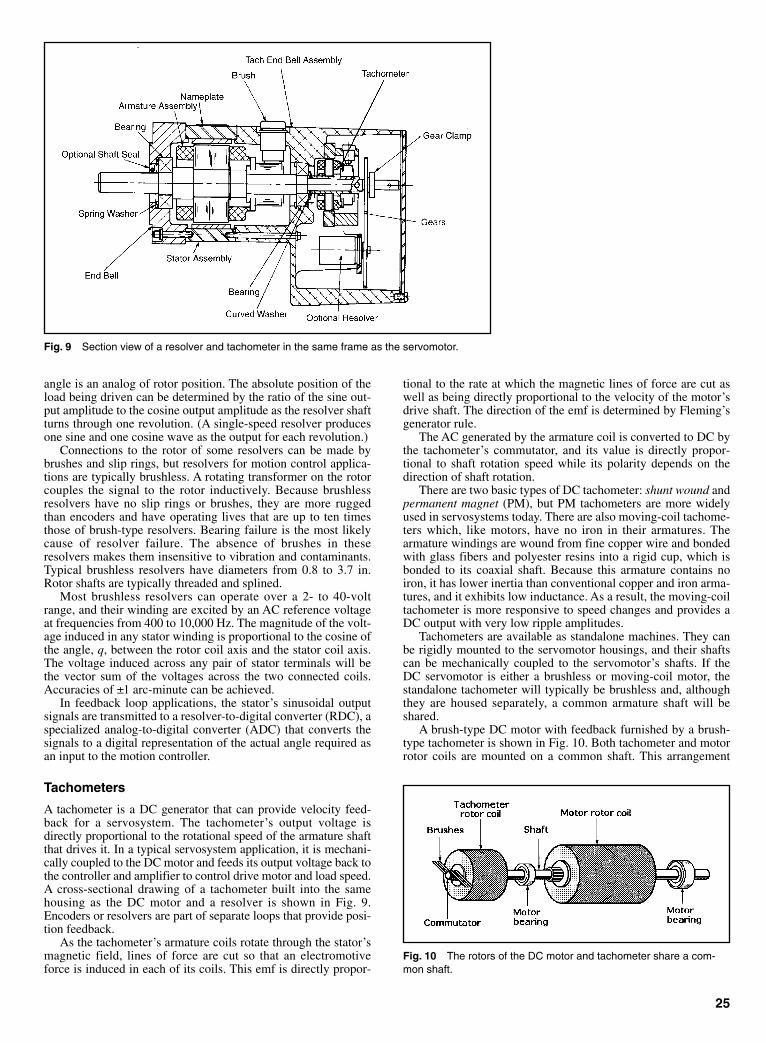
angle is an analog of rotor position. The absolute position of theload being driven can be determined by the ratio of the sine out-put amplitude to the cosine output amplitude as the resolver shaftturns through one revolution. (A single-speed resolver producesone sine and one cosine wave as the output for each revolution.)
Connections to the rotor of some resolvers can be made bybrushes and slip rings, but resolvers for motion control applica-tions are typically brushless. A rotating transformer on the rotorcouples the signal to the rotor inductively. Because brushlessresolvers have no slip rings or brushes, they are more ruggedthan encoders and have operating lives that are up to ten timesthose of brush-type resolvers. Bearing failure is the most likelycause of resolver failure. The absence of brushes in theseresolvers makes them insensitive to vibration and contaminants.Typical brushless resolvers have diameters from 0.8 to 3.7 in.Rotor shafts are typically threaded and splined.
Most brushless resolvers can operate over a 2- to 40-voltrange, and their winding are excited by an AC reference voltageat frequencies from 400 to 10,000 Hz. The magnitude of the volt-age induced in any stator winding is proportional to the cosine ofthe angle, q, between the rotor coil axis and the stator coil axis.The voltage induced across any pair of stator terminals will bethe vector sum of the voltages across the two connected coils.Accuracies of ±1 arc-minute can be achieved.
In feedback loop applications, the stator’s sinusoidal outputsignals are transmitted to a resolver-to-digital converter (RDC), aspecialized analog-to-digital converter (ADC) that converts thesignals to a digital representation of the actual angle required asan input to the motion controller.
Tachometers
A tachometer is a DC generator that can provide velocity feed-back for a servosystem. The tachometer’s output voltage isdirectly proportional to the rotational speed of the armature shaftthat drives it. In a typical servosystem application, it is mechani-cally coupled to the DC motor and feeds its output voltage back tothe controller and amplifier to control drive motor and load speed.A cross-sectional drawing of a tachometer built into the samehousing as the DC motor and a resolver is shown in Fig. 9.Encoders or resolvers are part of separate loops that provide posi-tion feedback.
As the tachometer’s armature coils rotate through the stator’smagnetic field, lines of force are cut so that an electromotiveforce is induced in each of its coils. This emf is directly propor-
tional to the rate at which the magnetic lines of force are cut aswell as being directly proportional to the velocity of the motor’sdrive shaft. The direction of the emf is determined by Fleming’sgenerator rule.
The AC generated by the armature coil is converted to DC bythe tachometer’s commutator, and its value is directly propor-tional to shaft rotation speed while its polarity depends on thedirection of shaft rotation.
There are two basic types of DC tachometer: shunt wound andpermanent magnet (PM), but PM tachometers are more widelyused in servosystems today. There are also moving-coil tachome-ters which, like motors, have no iron in their armatures. Thearmature windings are wound from fine copper wire and bondedwith glass fibers and polyester resins into a rigid cup, which isbonded to its coaxial shaft. Because this armature contains noiron, it has lower inertia than conventional copper and iron arma-tures, and it exhibits low inductance. As a result, the moving-coiltachometer is more responsive to speed changes and provides aDC output with very low ripple amplitudes.
Tachometers are available as standalone machines. They canbe rigidly mounted to the servomotor housings, and their shaftscan be mechanically coupled to the servomotor’s shafts. If theDC servomotor is either a brushless or moving-coil motor, thestandalone tachometer will typically be brushless and, althoughthey are housed separately, a common armature shaft will beshared.
A brush-type DC motor with feedback furnished by a brush-type tachometer is shown in Fig. 10. Both tachometer and motorrotor coils are mounted on a common shaft. This arrangement
25
Fig. 9 Section view of a resolver and tachometer in the same frame as the servomotor.
Fig. 10 The rotors of the DC motor and tachometer share a com-mon shaft.
Sclater Chapter 1 5/3/01 9:53 AM Page 25

provides a high resonance frequency. Moreover, the need for sep-arate tachometer bearings is eliminated.
In applications where precise positioning is required in addi-tion to speed regulation, an incremental encoder can be added onthe same shaft, as shown in Fig. 11.
Linear Variable Differential Transformers (LVDTs)
A linear variable differential transformer (LVDT) is a sensingtransformer consisting of a primary winding, two adjacent sec-ondary windings, and a ferromagnetic core that can be movedaxially within the windings, as shown in the cutaway view Fig.12. LVDTs are capable of measuring position, acceleration,force, or pressure, depending on how they are installed. Inmotion control systems, LVDTs provide position feedback bymeasuring the variation in mutual inductance between their pri-mary and secondary windings caused by the linear movement ofthe ferromagnetic core.
The core is attached to a spring-loaded sensing shaft. Whendepressed, the shaft moves the core axially within the windings,coupling the excitation voltage in the primary (middle) windingP1 to the two adjacent secondary windings S1 and S2.
Figure 13 is a schematic diagram of an LVDT. When the coreis centered between S1 and S2, the voltages induced in S1 and S2have equal amplitudes and are 180º out of phase. With a series-opposed connection, as shown, the net voltage across the second-aries is zero because both voltages cancel. This is called the nullposition of the core.
However, if the core is moved to the left, secondary windingS1 is more strongly coupled to primary winding P1 than second-ary winding S2, and an output sine wave in phase with the pri-mary voltage is induced. Similarly, if the core is moved to theright and winding S2 is more strongly coupled to primary wind-ing P1, an output sine wave that is 180º out-of-phase with theprimary voltage is induced. The amplitudes of the output sinewaves of the LVDT vary symmetrically with core displacement,either to the left or right of the null position.
Linear variable differential transformers require signal condi-tioning circuitry that includes a stable sine wave oscillator toexcite the primary winding P1, a demodulator to convert second-ary AC voltage signals to DC, a low-pass filter, and an amplifierto buffer the DC output signal. The amplitude of the resultingDC voltage output is proportional to the magnitude of coredisplacement, either to the left or right of the null position. Thephase of the DC voltage indicates the position of the core rela-tive to the null (left or right). An LVDT containing an integraloscillator/demodulator is a DC-to-DC LVDT, also known as aDCDT.
Linear variable differential transformers can make linear dis-placement (position) measurements as precise as 0.005 in. (0.127mm). Output voltage linearity is an important LVDT characteris-tic, and it can be plotted as a straight line within a specifiedrange. Linearity is the characteristic that largely determines theLVDT’s absolute accuracy.
Linear Velocity Transducers (LVTs)
A linear velocity transducer (LVT) consists of a magnet posi-tioned axially within a two wire coils. When the magnet ismoved through the coils, it induces a voltage within the coils inaccordance with the Faraday and Lenz laws. The output voltagefrom the coils is directly proportional to the magnet’s fieldstrength and axial velocity over its working range.
When the magnet is functioning as a transducer, both of itsends are within the two adjacent coils, and when it is moved axi-ally, its north pole will induce a voltage in one coil and its southpole will induce a voltage in the other coil. The two coils can beconnected in series or parallel, depending on the application. Inboth configurations the DC output voltage from the coils is pro-portional to magnet velocity. (A single coil would only producezero voltage because the voltage generated by the north polewould be canceled by the voltage generated by the south pole.)
The characteristics of the LVT depend on how the two coilsare connected. If they are connected in series opposition, the out-put is added and maximum sensitivity is obtained. Also, noisegenerated in one coil will be canceled by the noise generated inthe other coil. However, if the coils are connected in parallel,both sensitivity and source impedance are reduced. Reduced sen-sitivity improves high-frequency response for measuring highvelocities, and the lower output impedance improves the LVT’scompatibility with its signal-conditioning electronics.
26
Fig. 11 This coil-type DC motor obtains velocity feedback from atachometer whose rotor coil is mounted on a common shaft and posi-tion feedback from a two-channel photoelectric encoder whose codedisk is also mounted on the same shaft.
Fig. 12 Cutaway view of a linear variable displacement transformer(LVDT).
Fig. 13 Schematic for a linear variable differential transformer(LVDT) showing how the movable core interacts with the primary andsecondary windings.
Sclater Chapter 1 5/3/01 9:53 AM Page 26

Angular Displacement Transducers (ATDs)
An angular displacement transducer is an air-core variable differ-ential capacitor that can sense angular displacement. As shown inexploded view Fig. 14 it has a movable metal rotor sandwichedbetween a single stator plate and segmented stator plates. When ahigh-frequency AC signal from an oscillator is placed across theplates, it is modulated by the change in capacitance value due tothe position of the rotor with respect to the segmented statorplates. The angular displacement of the rotor can then be deter-mined accurately from the demodulated AC signal.
The base is the mounting platform for the transducer assem-bly. It contains the axial ball bearing that supports the shaft towhich the rotor is fastened. The base also supports the transmit-ting board, which contains a metal surface that forms the lowerplate of the differential capacitor. The semicircular metal rotormounted on the shaft is the variable plate or rotor of the capaci-tor. Positioned above the rotor is the receiving board containingtwo separate semicircular metal sectors on its lower surface. Theboard acts as the receiver for the AC signal that has been modu-lated by the capacitance difference between the plates caused byrotor rotation.
An electronics circuit board mounted on top of the assemblycontains the oscillator, demodulator, and filtering circuitry. TheADT is powered by DC, and its output is a DC signal that is pro-portional to angular displacement. The cup-shaped housingencloses the entire assembly, and the base forms a secure cap.
DC voltage is applied to the input terminals of the ADT topower the oscillator, which generates a 400- to 500-kHz voltagethat is applied across the transmitting and receiving stator plates.The receiving plates are at virtual ground, and the rotor is at trueground. The capacitance value between the transmitting andreceiving plates remains constant, but the capacitance betweenthe separate receiving plates varies with rotor position.
A null point is obtained when the rotor is positioned underequal areas of the receiving stator plates. In that position, thecapacitance between the transmitting stator plate and the receiv-ing stator plates will be equal, and there will be no output volt-age. However, as the rotor moves clockwise or counterclock-wise, the capacitance between the transmitting plate and one ofthe receiving plates will be greater than it is between the otherreceiving plate. As a result, after demodulation, the differential
output DC voltage will be proportional to the angular distancethe rotor moved from the null point.
Inductosyns
The Inductosyn is a proprietary AC sensor that generates positionfeedback signals that are similar to those from a resolver. Thereare rotary and linear Inductosyns. Much smaller than a resolver, arotary Inductosyn is an assembly of a scale and slider on insulat-ing substrates in a loop. When the scale is energized with AC, thevoltage couples into the two slider windings and induces volt-ages proportional to the sine and cosine of the slider spacingwithin a cyclic pitch.
An Inductosyn-to-digital (I/D) converter, similar to aresolver-to-digital (R/D) converter, is needed to convert thesesignals into a digital format. A typical rotary Inductosyn with 360cyclic pitches per rotation can resolve a total of 1,474,560 sectorsfor each resolution. This corresponds to an angular rotation ofless than 0.9 arc-s. This angular information in a digital format issent to the motion controller.
Laser Interferometers
Laser interferometers provide the most accurate position feed-back for servosystems. They offer very high resolution (to 1.24nm), noncontact measurement, a high update rate, and intrinsicaccuracies of up to 0.02 ppm. They can be used in servosystemseither as passive position readouts or as active feedback sensorsin a position servo loop. The laser beam path can be preciselyaligned to coincide with the load or a specific point being meas-ured, eliminating or greatly reducing Abbe error.
A single-axis system based on the Michaelson interferometeris illustrated in Fig. 15. It consists of a helium–neon laser, apolarizing beam splitter with a stationary retroreflector, a movingretroreflector that can be mounted on the object whose position isto be measured, and a photodetector, typically a photodiode.
Light from the laser is directed toward the polarizing beamsplitter, which contains a partially reflecting mirror. Part of thelaser beam goes straight through the polarizing beam splitter, andpart of the laser beam is reflected. The part that goes straightthrough the beam splitter reaches the moving reflectometer,which reflects it back to the beam splitter, that passes it on to thephotodetector. The part of the beam that is reflected by the beamsplitter reaches the stationary retroreflector, a fixed distanceaway. The retroreflector reflects it back to the beam splitterbefore it is also reflected into the photodetector.
As a result, the two reflected laser beams strike the photode-tector, which converts the combination of the two light beamsinto an electrical signal. Because of the way laser light beamsinteract, the output of the detector depends on a difference in thedistances traveled by the two laser beams. Because both lightbeams travel the same distance from the laser to the beam splitterand from the beam splitter to the photodetector, these distances
27
Fig. 14 Exploded view of an angular displacement transducer(ADT) based on a differential variable capacitor.
Fig. 15 Diagram of a laser interferometer for position feedback thatcombines high resolution with noncontact sensing, high update rates,and accuracies of 0.02 ppm.
Sclater Chapter 1 5/3/01 9:53 AM Page 27

are not involved in position measurement. The laser interferome-ter measurement depends only on the difference in distancebetween the round trip laser beam travel from the beam splitter tothe moving retroreflector and the fixed round trip distance oflaser beam travel from the beam splitter to the stationary retrore-flector.
If these two distances are exactly the same, the two lightbeams will recombine in phase at the photodetector, which willproduce a high electrical output. This event can be viewed on avideo display as a bright light fringe. However, if the differencebetween the distances is as short as one-quarter of the laser’swavelength, the light beams will combine out-of-phase, interfer-ing with each other so that there will be no electrical output fromthe photodetector and no video output on the display, a conditioncalled a dark fringe.
As the moving retroreflector mounted on the load moves far-ther away from the beam splitter, the laser beam path length willincrease and a pattern of light and dark fringes will repeat uni-formly. This will result in electrical signals that can be countedand converted to a distance measurement to provide an accurateposition of the load. The spacing between the light and darkfringes and the resulting electrical pulse rate is determined by thewavelength of the light from the laser. For example, the wave-length of the light beam emitted by a helium–neon (He–Ne)laser, widely used in laser interferometers, is 0.63 µm, or about0.000025 in.
Thus the accuracy of load position measurement depends pri-marily on the known stabilized wavelength of the laser beam.However, that accuracy can be degraded by changes in humidityand temperature as well as airborne contaminants such as smokeor dust in the air between the beam splitter and the movingretroreflector.
Precision Multiturn Potentiometers
The rotary precision multiturn potentiometer shown in the cut-away in Fig 16 is a simple, low-cost feedback instrument.Originally developed for use in analog computers, precision
potentiometers can provide absolute position data in analog formas a resistance value or voltage. Precise and resettable voltagescorrespond to each setting of the rotary control shaft. If a poten-tiometer is used in a servosystem, the analog data will usually beconverted to digital data by an integrated circuit analog-to-digitalconverter (ADC). Accuracies of 0.05% can be obtained from aninstrument-quality precision multiturn potentiometer, and resolu-tions can exceed 0.005º if the output signal is converted with a16-bit ADC.
Precision multiturn potentiometers have wirewound or hybridresistive elements. Hybrid elements are wirewound elementscoated with resistive plastic to improve their resolution. Toobtain an output from a potentiometer, a conductive wiper mustbe in contact with the resistive element. During its service lifewear on the resistive element caused by the wiper can degradethe precision of the precision potentiometer.
28
Fig. 16 A precision potentiometer is a low-cost, reliable feedbacksensor for servosystems.
Sclater Chapter 1 5/3/01 9:53 AM Page 28

SOLENOIDS AND THEIRAPPLICATIONS
Solenoids: An Economical Choice for Linear orRotary Motion
A solenoid is an electromechanical device that converts electricalenergy into linear or rotary mechanical motion. All solenoidsinclude a coil for conducting current and generating a magneticfield, an iron or steel shell or case to complete the magnetic cir-cuit, and a plunger or armature for translating motion. Solenoidscan be actuated by either direct current (DC) or rectified alternat-ing current (AC).
Solenoids are built with conductive paths that transmit max-imum magnetic flux density with minimum electrical energyinput. The mechanical action performed by the solenoiddepends on the design of the plunger in a linear solenoid or thearmature in a rotary solenoid. Linear solenoid plungers areeither spring-loaded or use external methods to restrain axialmovement caused by the magnetic flux when the coil is ener-gized and restore it to its initial position when the current isswitched off.
Cutaway drawing Fig. 1 illustrates how pull-in and push-outactions are performed by a linear solenoid. When the coil is ener-gized, the plunger pulls in against the spring, and this motion canbe translated into either a “pull-in” or a “push-out” response. Allsolenoids are basically pull-in-type actuators, but the location ofthe plunger extension with respect to the coil and spring deter-mines its function. For example, the plunger extension on the leftend (end A) provides “push-out” motion against the load, while aplunger extension on the right end terminated by a clevis (end B)provides “pull-in” motion. Commercial solenoids perform onlyone of these functions. Figure 2 is a cross-sectional view of a typ-ical pull-in commercial linear solenoid.
Rotary solenoids operate on the same principle as linear sole-noids except that the axial movement of the armature is con-verted into rotary movement by various mechanical devices. One
of these is the use of internal lands or ball bearings and slots orraces that convert a pull-in stroke to rotary or twisting motion.
Motion control and process automation systems use many dif-ferent kinds of solenoids to provide motions ranging from simplyturning an event on or off to the performance of extremely com-plex sequencing. When there are requirements for linear or rotarymotion, solenoids should be considered because of their rela-tively small size and low cost when compared with alternativessuch as motors or actuators. Solenoids are easy to install and use,and they are both versatile and reliable.
Technical Considerations
Important factors to consider when selecting solenoids are theirrated torque/force, duty cycles, estimated working lives, per-formance curves, ambient temperature range, and temperaturerise. The solenoid must have a magnetic return path capable oftransmitting the maximum amount of magnetic flux density withminimum energy input. Magnetic flux lines are transmitted to theplunger or armature through the bobbin and air gap back throughthe iron or steel shell. A ferrous metal path is more efficient thanair, but the air gap is needed to permit plunger or armature move-ment. The force or torque of a solenoid is inversely proportionalto the square of the distance between pole faces. By optimizingthe ferrous path area, the shape of the plunger or armature, andthe magnetic circuit material, the output torque/force can beincreased.
The torque/force characteristic is an important solenoid spec-ification. In most applications the force can be a minimum at thestart of the plunger or armature stroke but must increase at arapid rate to reach the maximum value before the plunger orarmature reaches the backstop.
The magnetizing force of the solenoid is proportional to thenumber of copper wire turns in its coil, the magnitude of the cur-rent, and the permeance of the magnetic circuit. The pull forcerequired by the load must not be greater than the force developedby the solenoid during any portion of its required stroke, or theplunger or armature will not pull in completely. As a result, theload will not be moved the required distance.
Heat buildup in a solenoid is a function of power and thelength of time the power is applied. The permissible temperaturerise limits the magnitude of the input power. If constant voltage
29
Fig. 1 The pull-in and push-out functions of a solenoid are shown.End A of the plunger pushes out when the solenoid is energized whilethe clevis-end B pulls in.
Fig. 2 Cross-section view of a commercial linear pull-type solenoidwith a clevis. The conical end of the plunger increases its efficiency.The solenoid is mounted with its threaded bushing and nut.
Sclater Chapter 1 5/3/01 9:53 AM Page 29
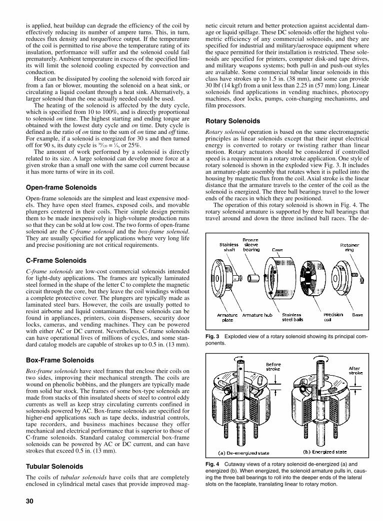
is applied, heat buildup can degrade the efficiency of the coil byeffectively reducing its number of ampere turns. This, in turn,reduces flux density and torque/force output. If the temperatureof the coil is permitted to rise above the temperature rating of itsinsulation, performance will suffer and the solenoid could failprematurely. Ambient temperature in excess of the specified lim-its will limit the solenoid cooling expected by convection andconduction.
Heat can be dissipated by cooling the solenoid with forced airfrom a fan or blower, mounting the solenoid on a heat sink, orcirculating a liquid coolant through a heat sink. Alternatively, alarger solenoid than the one actually needed could be used.
The heating of the solenoid is affected by the duty cycle,which is specified from 10 to 100%, and is directly proportionalto solenoid on time. The highest starting and ending torque areobtained with the lowest duty cycle and on time. Duty cycle isdefined as the ratio of on time to the sum of on time and off time.For example, if a solenoid is energized for 30 s and then turnedoff for 90 s, its duty cycle is 30⁄120 = 1⁄4, or 25%.
The amount of work performed by a solenoid is directlyrelated to its size. A large solenoid can develop more force at agiven stroke than a small one with the same coil current becauseit has more turns of wire in its coil.
Open-frame Solenoids
Open-frame solenoids are the simplest and least expensive mod-els. They have open steel frames, exposed coils, and movableplungers centered in their coils. Their simple design permitsthem to be made inexpensively in high-volume production runsso that they can be sold at low cost. The two forms of open-framesolenoid are the C-frame solenoid and the box-frame solenoid.They are usually specified for applications where very long lifeand precise positioning are not critical requirements.
C-Frame Solenoids
C-frame solenoids are low-cost commercial solenoids intendedfor light-duty applications. The frames are typically laminatedsteel formed in the shape of the letter C to complete the magneticcircuit through the core, but they leave the coil windings withouta complete protective cover. The plungers are typically made aslaminated steel bars. However, the coils are usually potted toresist airborne and liquid contaminants. These solenoids can befound in appliances, printers, coin dispensers, security doorlocks, cameras, and vending machines. They can be poweredwith either AC or DC current. Nevertheless, C-frame solenoidscan have operational lives of millions of cycles, and some stan-dard catalog models are capable of strokes up to 0.5 in. (13 mm).
Box-Frame Solenoids
Box-frame solenoids have steel frames that enclose their coils ontwo sides, improving their mechanical strength. The coils arewound on phenolic bobbins, and the plungers are typically madefrom solid bar stock. The frames of some box-type solenoids aremade from stacks of thin insulated sheets of steel to control eddycurrents as well as keep stray circulating currents confined insolenoids powered by AC. Box-frame solenoids are specified forhigher-end applications such as tape decks, industrial controls,tape recorders, and business machines because they offermechanical and electrical performance that is superior to those ofC-frame solenoids. Standard catalog commercial box-framesolenoids can be powered by AC or DC current, and can havestrokes that exceed 0.5 in. (13 mm).
Tubular Solenoids
The coils of tubular solenoids have coils that are completelyenclosed in cylindrical metal cases that provide improved mag-
netic circuit return and better protection against accidental dam-age or liquid spillage. These DC solenoids offer the highest volu-metric efficiency of any commercial solenoids, and they arespecified for industrial and military/aerospace equipment wherethe space permitted for their installation is restricted. These sole-noids are specified for printers, computer disk-and tape drives,and military weapons systems; both pull-in and push-out stylesare available. Some commercial tubular linear solenoids in thisclass have strokes up to 1.5 in. (38 mm), and some can provide30 lbf (14 kgf) from a unit less than 2.25 in (57 mm) long. Linearsolenoids find applications in vending machines, photocopymachines, door locks, pumps, coin-changing mechanisms, andfilm processors.
Rotary Solenoids
Rotary solenoid operation is based on the same electromagneticprinciples as linear solenoids except that their input electricalenergy is converted to rotary or twisting rather than linearmotion. Rotary actuators should be considered if controlledspeed is a requirement in a rotary stroke application. One style ofrotary solenoid is shown in the exploded view Fig. 3. It includesan armature-plate assembly that rotates when it is pulled into thehousing by magnetic flux from the coil. Axial stroke is the lineardistance that the armature travels to the center of the coil as thesolenoid is energized. The three ball bearings travel to the lowerends of the races in which they are positioned.
The operation of this rotary solenoid is shown in Fig. 4. Therotary solenoid armature is supported by three ball bearings thattravel around and down the three inclined ball races. The de-
30
Fig. 3 Exploded view of a rotary solenoid showing its principal com-ponents.
Fig. 4 Cutaway views of a rotary solenoid de-energized (a) andenergized (b). When energized, the solenoid armature pulls in, caus-ing the three ball bearings to roll into the deeper ends of the lateralslots on the faceplate, translating linear to rotary motion.
Sclater Chapter 1 5/3/01 9:53 AM Page 30
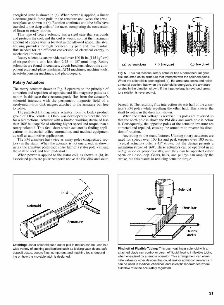
energized state is shown in (a). When power is applied, a linearelectromagnetic force pulls in the armature and twists the arma-ture plate, as shown in (b). Rotation continues until the balls havetraveled to the deep ends of the races, completing the conversionof linear to rotary motion.
This type of rotary solenoid has a steel case that surroundsand protects the coil, and the coil is wound so that the maximumamount of copper wire is located in the allowed space. The steelhousing provides the high permeability path and low residualflux needed for the efficient conversion of electrical energy tomechanical motion.
Rotary solenoids can provide well over 100 lb-in. (115 kgf-cm)of torque from a unit less than 2.25 in. (57 mm) long. Rotarysolenoids are found in counters, circuit breakers, electronic com-ponent pick-and-place machines, ATM machines, machine tools,ticket-dispensing machines, and photocopiers.
Rotary Actuators
The rotary actuator shown in Fig. 5 operates on the principle ofattraction and repulsion of opposite and like magnetic poles as amotor. In this case the electromagnetic flux from the actuator’ssolenoid interacts with the permanent magnetic field of aneodymium–iron disk magnet attached to the armature but freeto rotate.
The patented Ultimag rotary actuator from the Ledex productgroup of TRW, Vandalia, Ohio, was developed to meet the needfor a bidirectional actuator with a limited working stroke of lessthan 360º but capable of offering higher speed and torque than arotary solenoid. This fast, short-stroke actuator is finding appli-cations in industrial, office automation, and medical equipmentas well as automotive applications
The PM armature has twice as many poles (magnetized sec-tors) as the stator. When the actuator is not energized, as shownin (a), the armature poles each share half of a stator pole, causingthe shaft to seek and hold mid-stroke.
When power is applied to the stator coil, as shown in (b), itsassociated poles are polarized north above the PM disk and south
beneath it. The resulting flux interaction attracts half of the arma-ture’s PM poles while repelling the other half. This causes theshaft to rotate in the direction shown.
When the stator voltage is reversed, its poles are reversed sothat the north pole is above the PM disk and south pole is belowit. Consequently, the opposite poles of the actuator armature areattracted and repelled, causing the armature to reverse its direc-tion of rotation.
According to the manufacturer, Ultimag rotary actuators arerated for speeds over 100 Hz and peak torques over 100 oz-in.Typical actuators offer a 45º stroke, but the design permits amaximum stroke of 160º. These actuators can be operated in anon/off mode or proportionally, and they can be operated eitheropen- or closed-loop. Gears, belts, and pulleys can amplify thestroke, but this results in reducing actuator torque.
31
Fig. 5 This bidirectional rotary actuator has a permanent magnetdisk mounted on its armature that interacts with the solenoid poles.When the solenoid is deenergized (a), the armature seeks and holdsa neutral position, but when the solenoid is energized, the armaturerotates in the direction shown. If the input voltage is reversed, arma-ture rotation is reversed (c).
Latching: Linear solenoid push-out or pull-in motion can be used in awide variety of latching applications such as locking vault doors, safedeposit boxes, secure files, computers, and machine tools, depend-ing on how the movable latch is designed.
Pinchoff of Flexible Tubing: This push-out linear solenoid with anattached blade can control or pinch off liquid flowing in flexible tubingwhen energized by a remote operator. This arrangement can elimi-nate valves or other devices that could leak or admit contaminants. Itcan be used in medical, chemical, and scientific laboratories wherefluid flow must be accurately regulated.
Sclater Chapter 1 5/3/01 9:53 AM Page 31

32
Parts or Material Diversion: This diverter arrangement consists of arotary solenoid with a gate attached to its armature. The gate canswing to either of two alternate positions under pushbutton or auto-matic control to regulate the flow of parts or materials moving onbelts or by gravity feed.
Parts Rejection: A push-out linear solenoid can rapidly expel orreject parts that are moving past it into a bin when triggered. An elec-tronic video or proximity sensing system is required to energize thesolenoid at the right time.
Rotary Positioning: A linear push-out solenoid is paired with a multi-station drum containing objects that are indexed by a linear solenoidor actuator. This arrangement would permit the automatic assemblyof parts to those objects or the application of adhesives to them asthe drum is indexed.
Ratcheting Mechanism: A pull-in solenoid with a rack mounted onits plunger becomes a ratcheting mechanism capable of turning agear for the precise positioning of objects under operator or auto-mated control.
Sclater Chapter 1 5/3/01 9:53 AM Page 32

CHAPTER 2ROBOT MECHANISMS
Sclater Chapter 2 5/3/01 10:09 AM Page 33
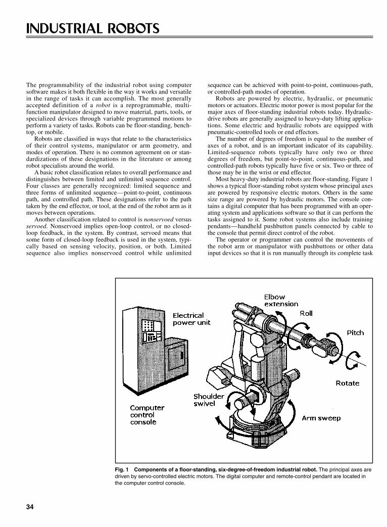
The programmability of the industrial robot using computersoftware makes it both flexible in the way it works and versatilein the range of tasks it can accomplish. The most generallyaccepted definition of a robot is a reprogrammable, multi-function manipulator designed to move material, parts, tools, orspecialized devices through variable programmed motions toperform a variety of tasks. Robots can be floor-standing, bench-top, or mobile.
Robots are classified in ways that relate to the characteristicsof their control systems, manipulator or arm geometry, andmodes of operation. There is no common agreement on or stan-dardizations of these designations in the literature or amongrobot specialists around the world.
A basic robot classification relates to overall performance anddistinguishes between limited and unlimited sequence control.Four classes are generally recognized: limited sequence andthree forms of unlimited sequence—point-to-point, continuouspath, and controlled path. These designations refer to the pathtaken by the end effector, or tool, at the end of the robot arm as itmoves between operations.
Another classification related to control is nonservoed versusservoed. Nonservoed implies open-loop control, or no closed-loop feedback, in the system. By contrast, servoed means thatsome form of closed-loop feedback is used in the system, typi-cally based on sensing velocity, position, or both. Limitedsequence also implies nonservoed control while unlimited
sequence can be achieved with point-to-point, continuous-path,or controlled-path modes of operation.
Robots are powered by electric, hydraulic, or pneumaticmotors or actuators. Electric motor power is most popular for themajor axes of floor-standing industrial robots today. Hydraulic-drive robots are generally assigned to heavy-duty lifting applica-tions. Some electric and hydraulic robots are equipped withpneumatic-controlled tools or end effectors.
The number of degrees of freedom is equal to the number ofaxes of a robot, and is an important indicator of its capability.Limited-sequence robots typically have only two or threedegrees of freedom, but point-to-point, continuous-path, andcontrolled-path robots typically have five or six. Two or three ofthose may be in the wrist or end effector.
Most heavy-duty industrial robots are floor-standing. Figure 1shows a typical floor-standing robot system whose principal axesare powered by responsive electric motors. Others in the samesize range are powered by hydraulic motors. The console con-tains a digital computer that has been programmed with an oper-ating system and applications software so that it can perform thetasks assigned to it. Some robot systems also include trainingpendants—handheld pushbutton panels connected by cable tothe console that permit direct control of the robot.
The operator or programmer can control the movements ofthe robot arm or manipulator with pushbuttons or other datainput devices so that it is run manually through its complete task
34
INDUSTRIAL ROBOTS
Fig. 1 Components of a floor-standing, six-degree-of-freedom industrial robot. The principal axes aredriven by servo-controlled electric motors. The digital computer and remote-control pendant are located inthe computer control console.
Sclater Chapter 2 5/3/01 10:09 AM Page 34
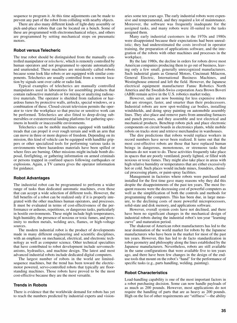
sequence to program it. At this time adjustments can be made toprevent any part of the robot from colliding with nearby objects.
There are also many different kinds of light-duty assembly orpick-and-place robots that can be located on a bench. Some ofthese are programmed with electromechanical relays, and othersare programmed by setting mechanical stops on pneumaticmotors.
Robot versus Telecheric
The true robot should be distinguished from the manually con-trolled manipulator or telecheric, which is remotely controlled byhuman operators and not programmed to operate automaticallyand unattended. These machines are mistakenly called robotsbecause some look like robots or are equipped with similar com-ponents. Telecherics are usually controlled from a remote loca-tion by signals sent over cable or radio link.
Typical examples of telecherics are manually controlledmanipulators used in laboratories for assembling products thatcontain radioactive materials or for mixing or analyzing radioac-tive materials. The operator is shielded from radiation or haz-ardous fumes by protective walls, airlocks, special windows, or acombination of these. Closed-circuit television permits the oper-ator to view the workplace so that precise or sensitive work canbe performed. Telecherics are also fitted to deep-diving sub-mersibles or extraterrestrial landing platforms for gathering spec-imens in hostile or inaccessible environments.
Telecherics can be mobile machines equipped with tankliketreads that can propel it over rough terrain and with an arm thatcan move in three or more degrees of freedom. Depending on itsmission, this kind of vehicle can be equipped with handlike grip-pers or other specialized tools for performing various tasks inenvironments where hazardous materials have been spilled orwhere fires are burning. Other missions might include bomb dis-posal, firefighting, or gathering information on armed criminalsor persons trapped in confined spaces following earthquakes orexplosions. Again, a TV camera gives the operator informationfor guidance.
Robot Advantages
The industrial robot can be programmed to perform a widerrange of tasks than dedicated automatic machines, even thosethat can accept a wide selection of different tools. However, thefull benefits of a robot can be realized only if it is properly inte-grated with the other machines human operators, and processes.It must be evaluated in terms of cost-effectiveness of the per-formance or arduous, repetitious, or dangerous tasks, particularlyin hostile environments. These might include high temperatures,high humidity, the presence of noxious or toxic fumes, and prox-imity to molten metals, welding arcs, flames, or high-voltagesources.
The modern industrial robot is the product of developmentsmade in many different engineering and scientific disciplines,with an emphasis on mechanical, electrical, and electronic tech-nology as well as computer science. Other technical specialtiesthat have contributed to robot development include servomech-anisms, hydraulics, and machine design. The latest and mostadvanced industrial robots include dedicated digital computers.
The largest number of robots in the world are limited-sequence machines, but the trend has been toward the electric-motor powered, servo-controlled robots that typically are floor-standing machines. Those robots have proved to be the mostcost-effective because they are the most versatile.
Trends in Robots
There is evidence that the worldwide demand for robots has yetto reach the numbers predicted by industrial experts and vision-
aries some ten years ago. The early industrial robots were expen-sive and temperamental, and they required a lot of maintenance.Moreover, the software was frequently inadequate for theassigned tasks, and many robots were ill-suited to the tasksassigned them.
Many early industrial customers in the 1970s and 1980swere disappointed because their expectations had been unreal-istic; they had underestimated the costs involved in operatortraining, the preparation of applications software, and the inte-gration of the robots with other machines and processes in theworkplace.
By the late 1980s, the decline in orders for robots drove mostAmerican companies producing them to go out of business, leav-ing only a few small, generally unrecognized manufacturers.Such industrial giants as General Motors, Cincinnati Milacron,General Electric, International Business Machines, andWestinghouse entered and left the field. However, the Japaneseelectrical equipment manufacturer Fanuc Robotics NorthAmerica and the Swedish-Swiss corporation Asea Brown Boveri(ABB) remain active in the U.S. robotics market today.
However, sales are now booming for less expensive robotsthat are stronger, faster, and smarter than their predecessors.Industrial robots are now spot-welding car bodies, installingwindshields, and doing spray painting on automobile assemblylines. They also place and remove parts from annealing furnacesand punch presses, and they assemble and test electrical andmechanical products. Benchtop robots pick and place electroniccomponents on circuit boards in electronics plants, while mobilerobots on tracks store and retrieve merchandise in warehouses.
The dire predictions that robots would replace workers inrecord numbers have never been realized. It turns out that themost cost-effective robots are those that have replaced humanbeings in dangerous, monotonous, or strenuous tasks thathumans do not want to do. These activities frequently take placein spaces that are poorly ventilated, poorly lighted, or filled withnoxious or toxic fumes. They might also take place in areas withhigh relative humidity or temperatures that are either excessivelyhot or cold. Such places would include mines, foundries, chemi-cal processing plants, or paint-spray facilities.
Management in factories where robots were purchased andinstalled for the first time gave many reasons why they did thisdespite the disappointments of the past ten years. The most fre-quent reasons were the decreasing cost of powerful computers aswell as the simplification of both the controls and methods forprogramming the computers. This has been due, in large meas-ure, to the declining costs of more powerful microprocessors,solid-state and disk memory, and applications software.
However, overall system costs have not declined, and therehave been no significant changes in the mechanical design ofindustrial robots during the industrial robot’s ten-year “learningcurve” and maturation period.
The shakeout of American robot manufacturers has led to thenear domination of the world market for robots by the Japanesemanufacturers who have been in the market for most of the pastten years. However, this has led to de facto standardization inrobot geometry and philosophy along the lines established by theJapanese manufacturers. Nevertheless, robots are still availablein the same configurations that were available five to ten yearsago, and there have been few changes in the design of the end-use tools that mount on the robot’s “hand” for the performance ofspecific tasks (e.g., parts handling, welding, painting).
Robot Characteristics
Load-handling capability is one of the most important factors ina robot purchasing decision. Some can now handle payloads ofas much as 200 pounds. However, most applications do notrequire the handling of parts that are as heavy as 200 pounds.High on the list of other requirements are “stiffness”—the ability
35
Sclater Chapter 2 5/3/01 10:09 AM Page 35
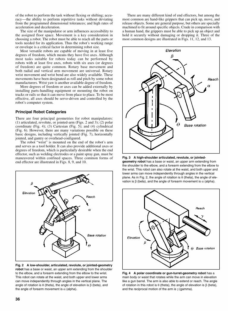
of the robot to perform the task without flexing or shifting; accu-racy—the ability to perform repetitive tasks without deviatingfrom the programmed dimensional tolerances; and high rates ofacceleration and deceleration.
The size of the manipulator or arm influences accessibility tothe assigned floor space. Movement is a key consideration inchoosing a robot. The robot must be able to reach all the parts ortools needed for its application. Thus the robot’s working rangeor envelope is a critical factor in determining robot size.
Most versatile robots are capable of moving in at least fivedegrees of freedom, which means they have five axes. Althoughmost tasks suitable for robots today can be performed byrobots with at least five axes, robots with six axes (or degreesof freedom) are quite common. Rotary base movement andboth radial and vertical arm movement are universal. Rotarywrist movement and wrist bend are also widely available. Thesemovements have been designated as roll and pitch by some robotmanufacturers. Wrist yaw is another available degree of freedom.
More degrees of freedom or axes can be added externally byinstalling parts-handling equipment or mounting the robot ontracks or rails so that it can move from place to place. To be mosteffective, all axes should be servo-driven and controlled by therobot’s computer system.
Principal Robot Categories
There are four principal geometries for robot manipulators:(1) articulated, revolute, or jointed-arm (Figs. 2 and 3); (2) polarcoordinate (Fig. 4); (3) Cartesian (Fig. 5); and (4) cylindrical(Fig. 6). However, there are many variations possible on thesebasic designs, including vertically jointed (Fig. 7), horizontallyjointed, and gantry or overhead-configured.
The robot “wrist” is mounted on the end of the robot’s armand serves as a tool holder. It can also provide additional axes ordegrees of freedom, which is particularly desirable when the endeffector, such as welding electrodes or a paint spray gun, must bemaneuvered within confined spaces. Three common forms ofend effector are illustrated in Figs. 8, 9, and 10.
There are many different kind of end effectors, but among themost common are hand-like grippers that can pick up, move, andrelease objects. Some are general purpose, but others are speciallymachined to fit around specific objects. Crude in comparison witha human hand, the grippers must be able to pick up an object andhold it securely without damaging or dropping it. Three of themost common designs are illustrated in Figs. 11, 12, and 13.
36
Fig. 2 A low-shoulder, articulated, revolute, or jointed-geometryrobot has a base or waist, an upper arm extending from the shoulderto the elbow, and a forearm extending from the elbow to the wrist.This robot can rotate at the waist, and both upper and lower armscan move independently through angles in the vertical plane. Theangle of rotation is θ (theta), the angle of elevation is β (beta), andthe angle of forearm movement is α (alpha).
Fig. 3 A high-shoulder articulated, revolute, or jointed-geometry robot has a base or waist, an upper arm extending fromthe shoulder to the elbow, and a forearm extending from the elbow tothe wrist. This robot can also rotate at the waist, and both upper andlower arms can move independently through angles in the verticalplane. As in Fig. 2, the angle of rotation is θ (theta), the angle of ele-vation is β (beta), and the angle of forearm movement is α (alpha).
Fig. 4 A polar coordinate or gun-turret-geometry robot has amain body or waist that rotates while the arm can move in elevationlike a gun barrel. The arm is also able to extend or reach. The angleof rotation in this robot is θ (theta), the angle of elevation is β (beta),and the reciprocal motion of the arm is γ (gamma).
Sclater Chapter 2 5/3/01 10:09 AM Page 36

37
Fig. 5 The Cartesian-coordinate-geometry robot has three linearaxes, X, Y, and Z. A moving arm mounted on a vertical post movesalong a linear track. The base or X axis is usually the longest; thevertical axis is the Z axis; and the horizontal axis, mounted on thevertical posts, is the Y axis. This geometry is effective for high-speed,low-weight robots.
Fig. 8 A two-degree-of-freedom robot wrist can move a tool onits mounting plate around both pitch and roll axes.
Fig. 9 This two-degree-of-freedom robot wrist can move a toolon its mounting plate around the pitch and two independent roll axes.
Fig. 6 The cylindrical-coordinate-geometry robot can have thesame geometry as the Cartesian-coordinate robot (Fig. 5) except thatits forearm is free to rotate. Alternatively, it can have a rotating waistlike the polar-coordinate robot (Fig. 4) or the revolute-coordinate-geometry robot (Figs. 2 and 3). The Z axis defines vertical movementof the arm, and the Y axis defines traverse motion. Again, the angleof rotation is defined by θ (theta).
Fig. 7 A vertically-jointed robot is similar to an articulated robot,except that the mechanism is turned on its side, and the axes of rota-tion are vertical. The mechanism is then mounted on a vertical postor linear side, as shown. In another variation, the horizontally jointedrobot, the mechanism is turned so that the slide is horizontal.
Sclater Chapter 2 5/3/01 10:09 AM Page 37

38
Fig. 10 A three-degree-of-freedom robot wrist can move a toolon its mounting plate around the pitch, roll, and yaw axes.
Fig. 13 A hydraulic or pneumatic piston opens and closes thejaws of this robot gripper, permitting it to grasp and release objects.
Fig. 11 A reciprocating lever mechanism opens and closes thejaws of this robot gripper, permitting it to grasp and release objects.
Fig. 12 A rack and pinion mechanism opens and closes the jawsof this robot gripper, permitting it to grasp and release objects.
FANUC ROBOT SPECIFICATIONS
The data sheets for three robots from FANUC Robotics NorthAmerica, Inc., Rochester Hills, Michigan, have been reproducedon the following pages to illustrate the range of capabilities ofindustrial robots now in production. These specifications includethe manufacturer’s ratings for the key characteristics: motionrange and speed, wrist load moments and inertias, repeatability,reach, payload, and weight.
S-900iH/i L/i W Robots
There are three robots in the S-900i family: S-900iH, S-900iL,and S-900iW. They are floor-standing, 6-axis, heavy-duty robotswith reaches of between 8 and 10 ft, (2.5 and 3.0 m) and maxi-mum payloads of 441 to 880 lb (200 to 400 kg). S-900i robotscan perform such tasks as materials handling and removal, load-ing and unloading machines, heavy-duty spot welding, and par-ticipation in casting operations.
These high-speed robots are controlled by FANUC R-J3 con-trollers, which provide point-to-point positioning and smoothcontrolled motion. S-900i robots have high-inertia wrists withlarge allowable moments that make them suitable for heavy-dutywork in harsh environments. Their slim J3 outer arms and wristprofiles permit these robots to work in restricted space, and theirsmall footprints and small i-size controllers conserve factoryfloor space. Many attachment points are provided on their wristsfor process-specific tools, and axes J5 and J6 have precision geardrives. All process and application cables are routed through thearm, and there are brakes on all axes.
S-900i robots support standard I/O networks and have stan-dard Ethernet ports. Process-specific software packages areavailable for various applications. Options include B-size con-troller cabinets, additional protection for harsh environments, aprecision baseplate for quick robot exchanges, and integratedauxiliary axes packages.
Sclater Chapter 2 5/3/01 10:09 AM Page 38
39
S-500 Robot
The S-500 is a 6-axis robot with a reach of 9 ft (2.7 m) and a loadcapacity of 33 lb (15 kg). Equipped with high-speed electricservo-drives, the S-500 can perform a wide range of manufactur-ing and processing tasks such as materials handling, loading andunloading machines, welding, waterjet cutting, dispensing, andparts transfer.
The S-500 can be mounted upright, inverted, or on walls with-out modification, and it can operate in harsh uninhabited loca-tions as well as on populated factory floors. Absolute serialencoders eliminate the need for calibration at power-up.Repeatability is ±0.010 in. (±0.25 mm), and axes 3 to 6 can reachspeeds of 320°/s.
Features for increasing reliability include mechanical brakeson all axes and grease fittings on all lubrication points for quickand easy maintenance. RV speed reducers provide smooth motionat all speeds. Bearings and drives are sealed for protection, andcables are routed through hollow joints to eliminate snagging.Brushless AC servo motors minimize motor maintenance.
An optional drive for axis 6 is capable of speeds up to 600°/s.Other options include a 3.5-in. floppy-disk drive for storing dataoff-line and a printer for printing out data and programs. Alsoavailable are an RS-232C communication port and integratedauxiliary axes.
LR Mate 100i Robot
The LR Mate 100i is a 5-axis benchtop robot suitable for per-forming a wide range of tasks in environments ranging fromclean rooms to harsh industrial sites. It has a nominal payloadcapacity of 6.6 to 8.8 lb (3 to 4 kg) and a 24.4-in. (620 mm)reach. Its payload can be increased to 11 lb with a shorter reachof 23.6 in. (600 mm) This modular electric servo-driven robotcan perform such tasks as machine loading and unloading, mate-rials handling and removal, testing and sampling, assembly,welding, dispensing, and parts cleaning.
The 100i robot can be mounted upright or inverted withoutmodification, and its small footprint allows it to be mounted onmachine tools. Repeatability is ±0.002 in. (±0.04 mm), and theaxis 5 speed can reach 272°/s. Two integral double solenoidvalves and the end effector connector are in the wrist. It is able to“double back” on itself for increased access, and axes 2 and 3have fail-safe brakes. Standard software permits 3D palletizingand depalletizing of rows, columns, and layers simply by teach-ing the robot three points.
The FANUC R-J2 Mate i-Controller is easy to install, start up,troubleshoot, and maintain. The controller weighs approximately110 lb (50 kg) and is housed in a small case measuring 14.9 in.wide by 18.5 in. high and 12.6 in. deep (380 × 470 × 320 mm). Itslow-voltage I/O has 20 inputs (8 dedicated), 16 outputs (4 dedi-cated), and 4 inputs at the end-of-arm connector.
Reliability is increased and maintenance is reduced withbrushless AC servo motors and harmonic drives on all axes. Onlytwo types of motors are used to simplify servicing and reducespare parts requirements. Bearings and drives are sealed for pro-tection against harsh factory environments. There are grease fit-tings on all lubrication points for quick and easy maintenance,and easily removable service panels give fast access to therobot’s drive train. A standard IP65 dust and liquid intrusionpackage is included.
As options for the LR Mate 100i, Class 100 cleanroom andhigh-speed versions are offered. The cleanroom version can servein biomedical research labs and high-precision production andtesting facilities. A high-speed version with an axis 5 speed of480°/s and a payload of 6.6 lb (3 kg) is available. Other optionsinclude additional integral valve packages, brakes for axis 1, anda higher-speed CPU to speed up path and cycle times. FANUC’sSensor Interface serial communications software allows the robotto exchange data with third-party equipment such as bar codereaders, vision systems, and personal computers, while its DataTransfer Function serial communications software allows two-way data exchange between the robot and a PC. This permits therobot to be controlled through a VB graphical interface.
Sclater Chapter 2 5/3/01 10:09 AM Page 39

40
Sclater Chapter 2 5/3/01 10:09 AM Page 40
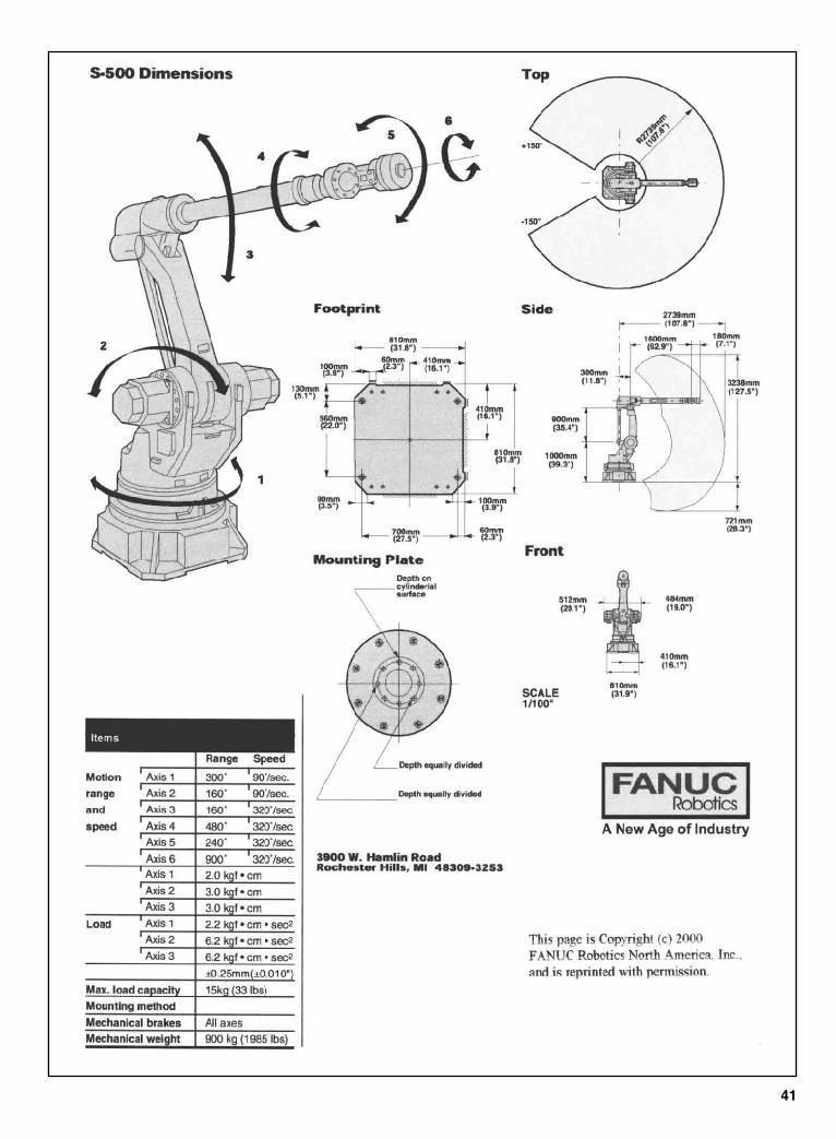
41
Sclater Chapter 2 5/3/01 10:09 AM Page 41
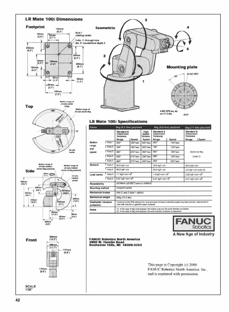
42
Sclater Chapter 2 5/3/01 10:09 AM Page 42
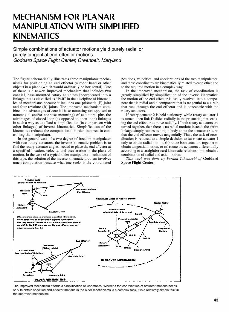
The figure schematically illustrates three manipulator mecha-nisms for positioning an end effector (a robot hand or otherobject) in a plane (which would ordinarily be horizontal). Oneof these is a newer, improved mechanism that includes twocoaxial, base-mounted rotary actuators incorporated into alinkage that is classified as “P4R” in the discipline of kinemat-ics of mechanisms because it includes one prismatic (P) jointand four revolute (R) joints. The improved mechanism com-bines the advantages of coaxial base mounting (as opposed tononcoaxial and/or nonbase mounting) of actuators, plus theadvantages of closed-loop (as opposed to open-loop) linkagesin such a way as to afford a simplification (in comparison withother linkages) of inverse kinematics. Simplification of thekinematics reduces the computational burden incurred in con-trolling the manipulator.
In the general case of a two-degree-of-freedom manipulatorwith two rotary actuators, the inverse kinematic problem is tofind the rotary-actuator angles needed to place the end effector ata specified location, velocity, and acceleration in the plane ofmotion. In the case of a typical older manipulator mechanism ofthis type, the solution of the inverse kinematic problem involvesmuch computation because what one seeks is the coordinated
positions, velocities, and accelerations of the two manipulators,and these coordinates are kinematically related to each other andto the required motion in a complex way.
In the improved mechanism, the task of coordination isgreatly simplified by simplification of the inverse kinematics;the motion of the end effector is easily resolved into a compo-nent that is radial and a component that is tangential to a circlethat runs through the end effector and is concentric with therotary actuators.
If rotary actuator 2 is held stationary, while rotary actuator 1is turned, then link D slides radially in the prismatic joint, caus-ing the end effector to move radially. If both rotary actuators areturned together, then there is no radial motion; instead, the entirelinkage simply rotates as a rigid body about the actuator axis, sothat the end effector moves tangentially. Thus, the task of coor-dination is reduced to a simple decision to (a) rotate actuator 1only to obtain radial motion, (b) rotate both actuators together toobtain tangential motion, or (c) rotate the actuators differentiallyaccording to a straightforward kinematic relationship to obtain acombination of radial and axial motion.
This work was done by Farhad Tahmasebi of GoddardSpace Flight Center.
43
MECHANISM FOR PLANARMANIPULATION WITH SIMPLIFIEDKINEMATICS Simple combinations of actuator motions yield purely radial orpurely tangential end-effector motions. Goddard Space Flight Center, Greenbelt, Maryland
The Improved Mechanism affords a simplification of kinematics: Whereas the coordination of actuator motions neces-sary to obtain specified end-effector motions in the older mechanisms is a complex task, it is a relatively simple task inthe improved mechanism.
Sclater Chapter 2 5/3/01 10:09 AM Page 43
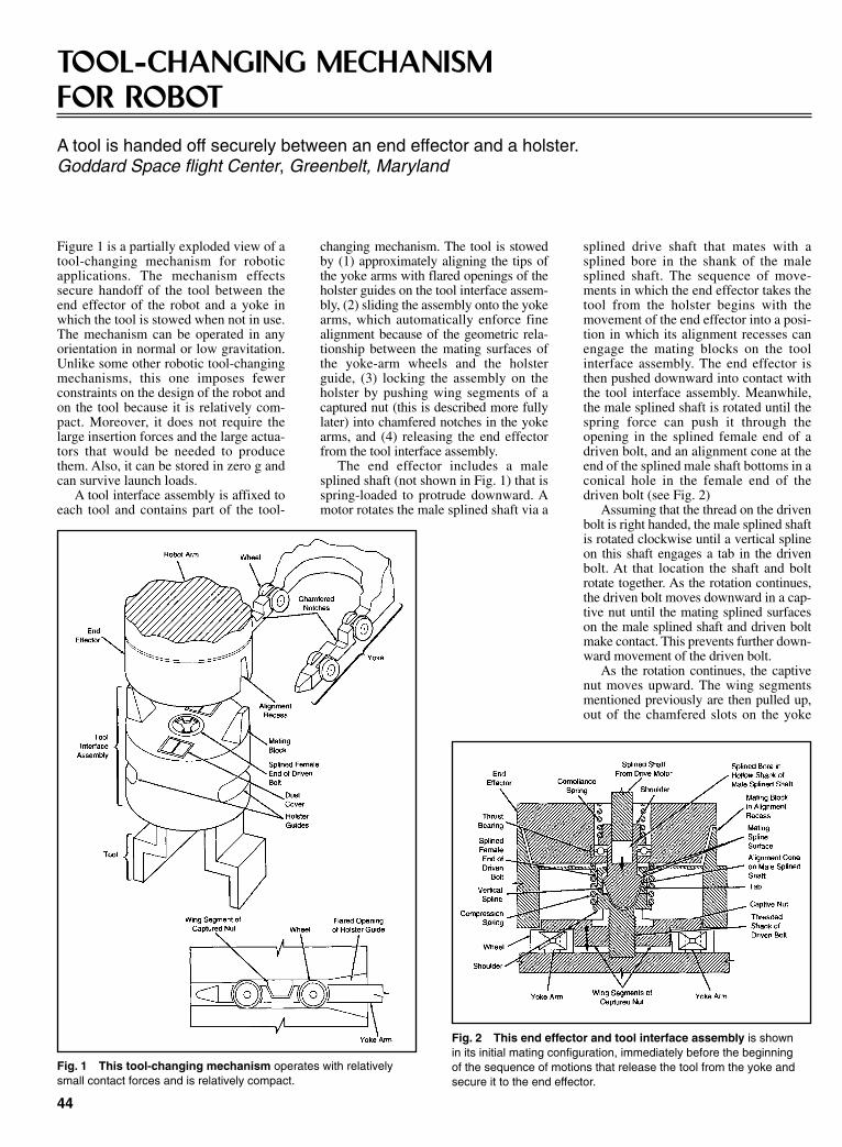
Figure 1 is a partially exploded view of atool-changing mechanism for roboticapplications. The mechanism effectssecure handoff of the tool between theend effector of the robot and a yoke inwhich the tool is stowed when not in use.The mechanism can be operated in anyorientation in normal or low gravitation.Unlike some other robotic tool-changingmechanisms, this one imposes fewerconstraints on the design of the robot andon the tool because it is relatively com-pact. Moreover, it does not require thelarge insertion forces and the large actua-tors that would be needed to producethem. Also, it can be stored in zero g andcan survive launch loads.
A tool interface assembly is affixed toeach tool and contains part of the tool-
changing mechanism. The tool is stowedby (1) approximately aligning the tips ofthe yoke arms with flared openings of theholster guides on the tool interface assem-bly, (2) sliding the assembly onto the yokearms, which automatically enforce finealignment because of the geometric rela-tionship between the mating surfaces ofthe yoke-arm wheels and the holsterguide, (3) locking the assembly on theholster by pushing wing segments of acaptured nut (this is described more fullylater) into chamfered notches in the yokearms, and (4) releasing the end effectorfrom the tool interface assembly.
The end effector includes a malesplined shaft (not shown in Fig. 1) that isspring-loaded to protrude downward. Amotor rotates the male splined shaft via a
splined drive shaft that mates with asplined bore in the shank of the malesplined shaft. The sequence of move-ments in which the end effector takes thetool from the holster begins with themovement of the end effector into a posi-tion in which its alignment recesses canengage the mating blocks on the toolinterface assembly. The end effector isthen pushed downward into contact withthe tool interface assembly. Meanwhile,the male splined shaft is rotated until thespring force can push it through theopening in the splined female end of adriven bolt, and an alignment cone at theend of the splined male shaft bottoms in aconical hole in the female end of thedriven bolt (see Fig. 2)
Assuming that the thread on the drivenbolt is right handed, the male splined shaftis rotated clockwise until a vertical splineon this shaft engages a tab in the drivenbolt. At that location the shaft and boltrotate together. As the rotation continues,the driven bolt moves downward in a cap-tive nut until the mating splined surfaceson the male splined shaft and driven boltmake contact. This prevents further down-ward movement of the driven bolt.
As the rotation continues, the captivenut moves upward. The wing segmentsmentioned previously are then pulled up,out of the chamfered slots on the yoke
44
TOOL-CHANGING MECHANISMFOR ROBOTA tool is handed off securely between an end effector and a holster.Goddard Space flight Center, Greenbelt, Maryland
Fig. 1 This tool-changing mechanism operates with relativelysmall contact forces and is relatively compact.
Fig. 2 This end effector and tool interface assembly is shownin its initial mating configuration, immediately before the beginningof the sequence of motions that release the tool from the yoke andsecure it to the end effector.
Sclater Chapter 2 5/3/01 10:09 AM Page 44
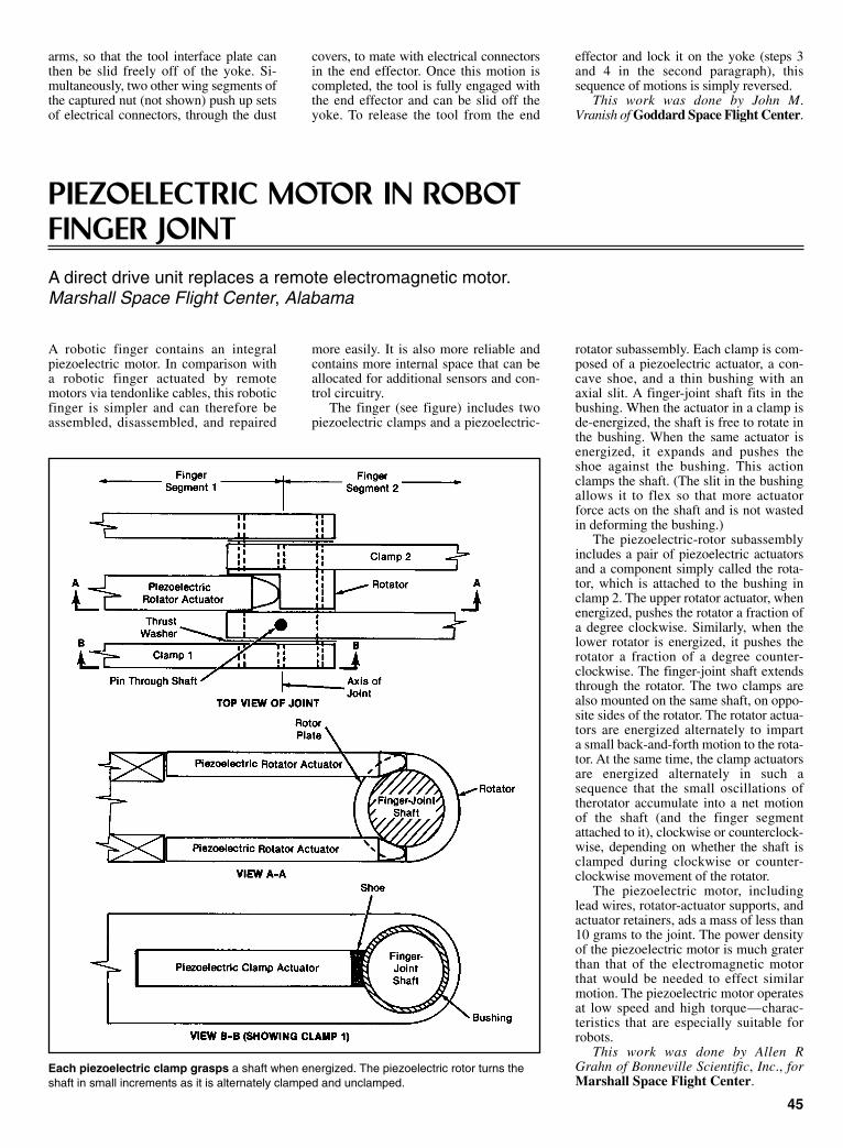
arms, so that the tool interface plate canthen be slid freely off of the yoke. Si-multaneously, two other wing segments ofthe captured nut (not shown) push up setsof electrical connectors, through the dust
covers, to mate with electrical connectorsin the end effector. Once this motion iscompleted, the tool is fully engaged withthe end effector and can be slid off theyoke. To release the tool from the end
effector and lock it on the yoke (steps 3and 4 in the second paragraph), thissequence of motions is simply reversed.
This work was done by John M.Vranish of Goddard Space Flight Center.
45
PIEZOELECTRIC MOTOR IN ROBOTFINGER JOINTA direct drive unit replaces a remote electromagnetic motor.Marshall Space Flight Center, Alabama
A robotic finger contains an integralpiezoelectric motor. In comparison witha robotic finger actuated by remotemotors via tendonlike cables, this roboticfinger is simpler and can therefore beassembled, disassembled, and repaired
more easily. It is also more reliable andcontains more internal space that can beallocated for additional sensors and con-trol circuitry.
The finger (see figure) includes twopiezoelectric clamps and a piezoelectric-
rotator subassembly. Each clamp is com-posed of a piezoelectric actuator, a con-cave shoe, and a thin bushing with anaxial slit. A finger-joint shaft fits in thebushing. When the actuator in a clamp isde-energized, the shaft is free to rotate inthe bushing. When the same actuator isenergized, it expands and pushes theshoe against the bushing. This actionclamps the shaft. (The slit in the bushingallows it to flex so that more actuatorforce acts on the shaft and is not wastedin deforming the bushing.)
The piezoelectric-rotor subassemblyincludes a pair of piezoelectric actuatorsand a component simply called the rota-tor, which is attached to the bushing inclamp 2. The upper rotator actuator, whenenergized, pushes the rotator a fraction ofa degree clockwise. Similarly, when thelower rotator is energized, it pushes therotator a fraction of a degree counter-clockwise. The finger-joint shaft extendsthrough the rotator. The two clamps arealso mounted on the same shaft, on oppo-site sides of the rotator. The rotator actua-tors are energized alternately to imparta small back-and-forth motion to the rota-tor. At the same time, the clamp actuatorsare energized alternately in such asequence that the small oscillations oftherotator accumulate into a net motionof the shaft (and the finger segmentattached to it), clockwise or counterclock-wise, depending on whether the shaft isclamped during clockwise or counter-clockwise movement of the rotator.
The piezoelectric motor, includinglead wires, rotator-actuator supports, andactuator retainers, ads a mass of less than10 grams to the joint. The power densityof the piezoelectric motor is much graterthan that of the electromagnetic motorthat would be needed to effect similarmotion. The piezoelectric motor operatesat low speed and high torque—charac-teristics that are especially suitable forrobots.
This work was done by Allen RGrahn of Bonneville Scientific, Inc., forMarshall Space Flight Center.
Each piezoelectric clamp grasps a shaft when energized. The piezoelectric rotor turns theshaft in small increments as it is alternately clamped and unclamped.
Sclater Chapter 2 5/3/01 10:09 AM Page 45

mechanical advantage; it increases thestiffness and resolution available at themanipulated platform.
This work was done by FarhadTahmasebi and Lung-Web Tsai ofGoddard Space Flight Center.
46
SIX-DEGREE-OF-FREEDOMPARALLEL MINIMANIPULATORAdvantages include greater stiffness and relative simplicity.Goddard Space Flight Center, Greenbelt, Maryland
Fig. 2Three pan-tographs on thebaseplate controlthe positions ofthe universaljoints at C1 andthereby controlthe position andorientation of the manipulatedplatform.
Figure 1 illustrates schematically a six-degree-of-freedom manipulator that pro-duces small, precise motions and thatincludes only three inextensible limbswith universal joints at their ends. Thelimbs have equal lengths and can be saidto act in parallel in that they share the loadon a manipulated platform. The mecha-nism is therefore called a “six-degree-of-freedom parallel minimanipulator.” Theminimanipulator is designed to providehigh resolution and high stiffness (relativeto the other mechanisms) for fine controlof position and force in a hybrid form ofserial/parallel-manipulator system.
Most of the six-degree-of-freedomparallel manipulators that have been pro-posed in the past contain six limbs, andtheir direct kinematic analyses are verycomplicated. In contrast, the equations ofthe direct kinematics of the present mini-manipulator can be solved in closedform. Furthermore, in comparison with atypical six-degree-of-freedom parallelmanipulator, the present minimanipula-tor can be made of fewer parts, the prob-ability of mechanical interferencebetween its limbs is smaller, its payloadcapacity can be made greater, and itsactuators, which are base-mounted, canbe made smaller.
The upper ends of the limbs are con-nected to the manipulated platform byuniversal (two-degree-of-freedom) joints.The lower end of each limb is connectedvia a universal (two-degree-of-freedom)rotary joint to a two-degree-of-freedomdriver. The drivers are mounted directlyon the baseplate, without any interveningpower-transmission devices, like gears orbelts, that could reduce stiffness and pre-cision.
The position and orientation of themanipulated platform is governeduniquely, in all six degrees of freedom,by the positions of the drivers on thebaseplate. Examples of two-degree-of-freedom drivers include bi-directionallinear stepping motors, x-y positioningtables, five-bar linkages driven by rotaryactuators, and pantographs. Figure 2shows an example of a baseplateequipped with pantograph drivers. Theposition of each universal joint Ci(where i = 1, 2, or 3) is controlled by moving either or both of sliders Ai and Biin their respective guide slots. The dis-placement reduction provided by the pantograph linkage and the inextensiblelimbs is equivalent to an increase in
Fig. 1 The six-degree-of-freedom parallel minimanipulator is stiffer and simpler than earliersix-degree-of-freedom manipulators, partly because it includes only three inextensible limbs.
Sclater Chapter 2 5/3/01 10:09 AM Page 46
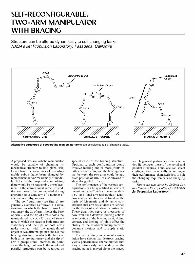
A proposed two-arm robotic manipulatorwould be capable of changing itsmechanical structure to fit a given task.Heretofore, the structures of reconfig-urable robots have been changed byreplacement and/or reassembly of modu-lar links. In the proposed manipulator,there would be no reassembly or replace-ment in the conventional sense: instead,the arms would be commanded duringoperation to assume any of a number ofalternative configurations.
The configurations (see figure) aregenerally classified as follows: (1) serialstructure, in which the base of arm 1 isstationary, the tip of arm 1 holds the baseof arm 2, and the tip of arm 2 holds themanipulated object; (2) parallel struc-ture, in which the bases of both arms arestationary and the tips of both armsmake contact with the manipulatedobject at two different points; and (3) thebracing structure, in which the basis ofboth arms are stationary and the tip ofarm 2 grasps some intermediate pointalong the length of arm 1. the serial andparallel structures can be regarded as
arm. In general, performance characteris-tics lie between those of the serial andparallel structures. Thus, one can selectconfigurations dynamically, according totheir performance characteristics, to suitthe changing requirements of changingtasks.
This work was done by Sukhan Leeand Sungbok Kim of Caltech for NASA’sJet Propulsion Laboratory.
47
SELF-RECONFIGURABLE, TWO-ARM MANIPULATOR WITH BRACINGStructure can be altered dynamically to suit changing tasks.NASA’s Jet Propulsion Laboratory, Pasadena, California
Alternative structures of cooperating manipulator arms can be selected to suit changing tasks.
special cases of the bracing structure.Optionally, each configuration couldinvolve locking one or more joints ofeither or both arms, and the bracing con-tact between the two arms could be at afixed position of arm 1 or else allowed toslide along a link of arm 1.
The performances of the various con-figurations can be quantified in terms ofquantities called “dual-arm manipulabili-ties,” and “dual-arm resistivities.” Dual-arm manipulabilities are defined on thebasis of kinematic and dynamic con-straints; dual-arm resistivities are definedon the basis of static-force constraints.These quantities serve as measures ofhow well such dextrous-bracing actionsas relocation of the bracing point, slidingcontact, and locking of joints affect theability of the dual-arm manipulator togenerate motions and to apply staticforces.
Theoretical study and computer simu-lation have shown that dextrous bracingyields performance characteristics thatvary continuously and widely as thebracing point is moved along the braced
Sclater Chapter 2 5/3/01 10:09 AM Page 47

Two types of gear drives have been devised to improve the per-formances of robotic mechanisms. One type features a dual-input/single-output differential-drive configuration intended toeliminate stick/slip motions; the other type features a single-input/dual-angular-momentum-balanced-output configurationintended to eliminate reaction torques.
Stick/slip motion can degrade the performance of a robotbecause a robotic control system cannot instantaneously correctfor a sudden change between static and dynamic friction.Reaction torque arises in a structure that supports a mechanismcoupled to a conventional gear drive, and can adversely affect thestructure, the mechanism, or other equipment connected to thestructure or mechanism.
In a drive of the differential type, the two input shafts can beturned at different speeds and, if necessary, in opposite directions,to make the output shaft turn in the forward or reverse direction at adesired speed. This is done without stopping rotation of either inputshaft, so that stick/slip does not occur. In a drive of the angular-momentum-balanced type, turning the single input shaft causes thetwo output shafts to rotate at equal speeds in opposite directions.
The figure schematically illustrates one of two drives of thedifferential type and one drive of the angular-momentum-balanced type that have been built and tested. Each of the differ-ential drives is rated at input speeds up to 295 radians per second(2,800 r/min), output torque up to 450 N·m (4,000 lb-in.), andpower up to 5.6 kW (7.5 hp). The maximum ratings of the angu-lar-momentum-balanced drive are input speed of 302 radians persecond (2,880 r/min), dual output torques of 434 N·m (3,840 lb-in.) each, and power of 10.9 kW (14.6 hp).
Each differential drive features either (as explained in the nexttwo sentences) a dual roller-gear or a roller arrangement with asun gear, four first-row planet gears, four second-row planetgears, and a ring gear. One of the differential drives contains aplanetary roller-gear system with a reduction ratio (measuredwith one input driving the output while the other input shaftremains stationary) of 29.23:1. The other differential drive (theone shown in the figure) contains a planetary roller system with areduction ratio of 24:1. The angular-momentum-balanced drivefeatures a planetary roller system with five first- and second-rowplanet gears and a reduction ratio (the input to each of the twooutputs) of 24:1. The three drives were subjected to a broad spec-trum of tests to measure linearity, cogging, friction, and effi-ciency. All three drives operated as expected kinematically,exhibiting efficiencies as high as 95 percent.
Drives of the angular-momentum-balanced type could pro-vide a reaction-free actuation when applied with proper combi-nations of torques and inertias coupled to output shafts. Drives ofthe differential type could provide improvements over presentrobotic transmissions for applications in which there are require-ments for extremely smooth and accurate torque and positioncontrol, without inaccuracies that accompany stick/slip. Drivesof the differential type could also offer viable alternatives to vari-able-ratio transmissions in applications in which output shaftsare required to be driven both forward and in reverse, with anintervening stop. A differential transmission with two input drivemotors could be augmented by a control system to optimize inputspeeds for any requested output speed; such a transmission couldbe useful in an electric car.
This work was done by William J. Anderson and WilliamShipitalo of Nastec, Inc., and Wyatt Newman of Case WesternReserve University for Lewis Research Center.
48
IMPROVED ROLLER AND GEARDRIVES FOR ROBOTS ANDVEHICLESOne type is designed to eliminate stick/slip, another to eliminatereaction torque.Lewis Research Center, Cleveland, Ohio
These Improved Gear Drives offer advantages for control of traction and rotary actuation in robots. In addition,drives of the differential type could be used in variable-speed transmissions in automobiles.
Sclater Chapter 2 5/3/01 10:09 AM Page 48

A small prototype robotic all-terrain vehicle features a uniquedrive and suspension system that affords capabilities for selfrighting, pose control, and enhanced maneuverability for passingover obstacles. The vehicle is designed for exploration of planetsand asteroids, and could just as well be used on Earth to carryscientific instruments to remote, hostile, or otherwise inaccessi-ble locations on the ground. The drive and suspension systemenable the vehicle to perform such diverse maneuvers as flippingitself over, traveling normal side up or upside down, orienting themain vehicle body in a specified direction in all three dimen-sions, or setting the main vehicle body down onto the ground, toname a few. Another maneuver enables the vehicle to overcome acommon weakness of traditional all-terrain vehicles—a limita-tion on traction and drive force that makes it difficult or impossi-ble to push wheels over some obstacles: This vehicle can simplylift a wheel onto the top of an obstacle.
The basic mode of operation of the vehicle can be character-ized as four-wheel drive with skid steering. Each wheel is drivenindividually by a dedicated gearmotor. Each wheel and its gear-motor are mounted at the free end of a strut that pivots about alateral axis through the center of gravity of the vehicle (see fig-ure). Through pulleys or other mechanism attached to theirwheels, both gearmotors on each side of the vehicle drive a sin-gle idler disk or pulley that turns about the pivot axis.
The design of the pivot assembly is crucial to the unique capa-bilities of this system. The idler pulley and the pivot disks of thestruts are made of suitably chosen materials and spring-loadedtogether along the pivot axis in such a way as to resist turningwith a static frictional torque T; in other words, it is necessary toapply a torque of T to rotate the idler pulley or either strut withrespect to each other or the vehicle body.
During ordinary backward or forward motion along theground, both wheels are turned in unison by their gearmotors,
and the belt couplings make the idler pulley turn along with thewheels. In this operational mode, each gearmotor contributes atorque T/2 so that together, both gearmotors provide torque T toovercome the locking friction on the idler pulley. Each strutremains locked at its preset angle because the torque T/2 sup-plied by its motor is not sufficient to overcome its locking friction T.
If it is desired to change the angle between one strut and themain vehicle body, then the gearmotor on that strut only is ener-gized. In general, a gearmotor acts as a brake when not ener-gized. Since the gearmotor on the other strut is not energized andsince it is coupled to the idler pulley, a torque greater than Twould be needed to turn the idler pulley. However, as soon as thegearmotor on the strut that one desires to turn is energized, itdevelops enough torque (T) to begin pivoting the strut withrespect to the vehicle body.
It is also possible to pivot both struts simultaneously in oppo-site directions to change the angle between them. To accomplishthis, one energizes the gearmotors to apply equal and oppositetorques of magnitude T: The net torque on the idler pulley bal-ances out to zero, so that the idler pulley and body remain locked,while the applied torques are just sufficient to turn the strutsagainst locking friction. If it is desired to pivot the struts throughunequal angles, then the gearmotor speeds are adjusted accord-ingly.
The prototype vehicle has performed successfully in tests.Current and future work is focused on designing a simple hubmechanism, which is not sensitive to dust or other contamina-tion, and on active control techniques to allow autonomous plan-etary rovers to take advantage of the flexibility of the mecha-nism.
This work was done by Brian H. Wilcox and Annette K. Nasifof Caltech for NASA’s Jet Propulsion Laboratory.
49
ALL-TERRAIN VEHICLE WITH SELF-RIGHTING AND POSE CONTROL Wheels driven by gearmotors are mounted on pivoting struts. NASA’s Jet Propulsion Laboratory, Pasadena, California
Each wheel Is driven by a dedicated gearmotor and is coupled to the idler pulley. The pivot assembly imposesa constant frictional torque T, so that it is possible to (a) turn both wheels in unison while both struts remainlocked, (b) pivot one strut, or (c) pivot both struts in opposite directions by energizing the gearmotors to applyvarious combinations of torques T/2 or T.
Sclater Chapter 2 5/3/01 10:09 AM Page 49

CHAPTER 3PARTS-HANDLING
MECHANISMS
Sclater Chapter 3 5/3/01 10:19 AM Page 51
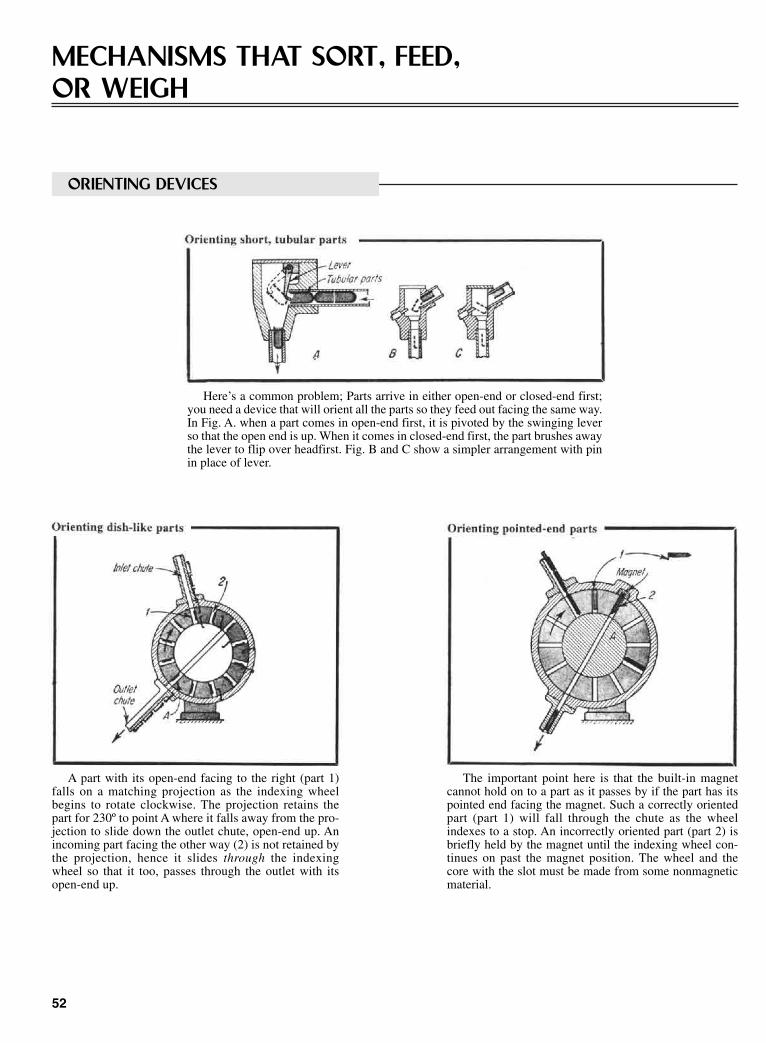
52
MECHANISMS THAT SORT, FEED,OR WEIGH
ORIENTING DEVICES
Here’s a common problem; Parts arrive in either open-end or closed-end first;you need a device that will orient all the parts so they feed out facing the same way.In Fig. A. when a part comes in open-end first, it is pivoted by the swinging leverso that the open end is up. When it comes in closed-end first, the part brushes awaythe lever to flip over headfirst. Fig. B and C show a simpler arrangement with pinin place of lever.
A part with its open-end facing to the right (part 1)falls on a matching projection as the indexing wheelbegins to rotate clockwise. The projection retains thepart for 230º to point A where it falls away from the pro-jection to slide down the outlet chute, open-end up. Anincoming part facing the other way (2) is not retained bythe projection, hence it slides through the indexingwheel so that it too, passes through the outlet with itsopen-end up.
The important point here is that the built-in magnetcannot hold on to a part as it passes by if the part has itspointed end facing the magnet. Such a correctly orientedpart (part 1) will fall through the chute as the wheelindexes to a stop. An incorrectly oriented part (part 2) isbriefly held by the magnet until the indexing wheel con-tinues on past the magnet position. The wheel and thecore with the slot must be made from some nonmagneticmaterial.
Sclater Chapter 3 5/3/01 10:19 AM Page 52
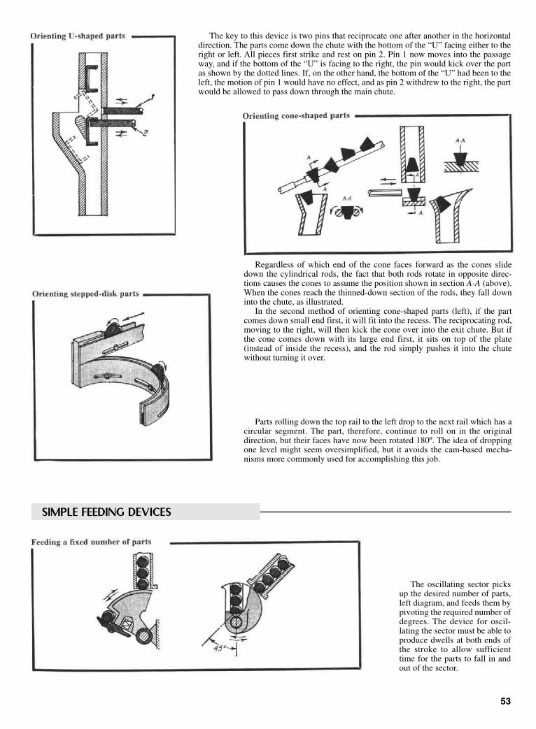
The key to this device is two pins that reciprocate one after another in the horizontaldirection. The parts come down the chute with the bottom of the “U” facing either to theright or left. All pieces first strike and rest on pin 2. Pin 1 now moves into the passageway, and if the bottom of the “U” is facing to the right, the pin would kick over the partas shown by the dotted lines. If, on the other hand, the bottom of the “U” had been to theleft, the motion of pin 1 would have no effect, and as pin 2 withdrew to the right, the partwould be allowed to pass down through the main chute.
53
Regardless of which end of the cone faces forward as the cones slidedown the cylindrical rods, the fact that both rods rotate in opposite direc-tions causes the cones to assume the position shown in section A-A (above).When the cones reach the thinned-down section of the rods, they fall downinto the chute, as illustrated.
In the second method of orienting cone-shaped parts (left), if the partcomes down small end first, it will fit into the recess. The reciprocating rod,moving to the right, will then kick the cone over into the exit chute. But ifthe cone comes down with its large end first, it sits on top of the plate(instead of inside the recess), and the rod simply pushes it into the chutewithout turning it over.
Parts rolling down the top rail to the left drop to the next rail which has acircular segment. The part, therefore, continue to roll on in the originaldirection, but their faces have now been rotated 180º. The idea of droppingone level might seem oversimplified, but it avoids the cam-based mecha-nisms more commonly used for accomplishing this job.
SIMPLE FEEDING DEVICES
The oscillating sector picksup the desired number of parts,left diagram, and feeds them bypivoting the required number ofdegrees. The device for oscil-lating the sector must be able toproduce dwells at both ends ofthe stroke to allow sufficienttime for the parts to fall in andout of the sector.
Sclater Chapter 3 5/3/01 10:19 AM Page 53

The circular parts feed down the chute by grav-ity, and they are separated by the reciprocating rod.The parts first roll to station 3 during the downwardstroke of the reciprocator, then to station 1 duringthe upward stroke; hence the time span betweenparts is almost equivalent to the time it takes for thereciprocator to make one complot oscillation.
The device in Fig. B is similar to the one in Fig.A, except that the reciprocator is replaced by anoscillating member.
54
Two counter rotating wheels form a sim-ple device for alternating the feed of two dif-ferent workpieces.
Each gear in this device is held up by a pivotable cam sector until the gear aheadof it moves forward. Thus, gear 3, rolling down the chute, kicks down its sectorcam but is held up by the previous cam. When gear 1 is picked off (either manually,or mechanically), its sector cam pivots clockwise because of its own weight. Thispermits gear 2 to move into place of gear 1—and frees cam 2 to pivot clockwise.Thus, all gears in the row move forward one station.
SORTING DEVICES
In the simple device (A) theballs run down two inclined andslightly divergent rails. The small-est balls, therefore, will fall intothe left chamber, the medium-sizeones into the middle-size chamber,and the largest ones into the rightchamber.
In the more complicatedarrangement (B), the balls comedown the hopper and must pass agate which also acts as a latch forthe trapdoor. The proper-size ballspass through without touching(actuating) the gate. Larger balls,however, brush against the gatewhich releases the catch on thebottom of the trapdoor, and fallthrough into the special trough forthe rejects.
Sclater Chapter 3 5/3/01 10:19 AM Page 54

The material in the hopper is fed to a con-veyor by the vibration of the reciprocatingslider. The pulsating force of the slider is trans-mitted through the rubber wedge and on to theactuating rod. The amplitude of this force canbe varied by moving the wedge up or down.This is done automatically by making the con-veyor pivot around a central point. As the con-veyor becomes overloaded, it pivots clockwiseto raise the wedge, which reduces the ampli-tude of the force and slows the feed rate of thematerial.
Further adjustments in feed rate can bemade by shifting the adjustable weight or bychanging the speed of the conveyor belt.
55
Workpieces of varying heights are placed on this slowly rotating cross-platform. Bars 1, 2, and 3 have been set at decreasing heights beginning withthe highest bar (bar 1), down to the lowest bar (bar 3). The workpiece istherefore knocked off the platform at either station 1, 2, or 3, depending onits height.
WEIGHT-REGULATING ARRANGEMENTS
The loose material falls down the hopperand is fed to the right by the conveyor systemwhich can pivot about the center point. Theframe of the conveyor system also actuates thehopper gate so that if the amount of materialon the belt exceeds the required amount, theconveyor pivots clockwise and closes the gate.The position of the counterweight on a framedetermines the feed rate of the system.
The indexing table automatically stops atthe feed station. As the material drops into thecontainer, its weight pivots the screen upwardto cut off the light beam to the photocell relay.This in turn shuts the feed gate. The reactua-tion of the indexing table can be automaticafter a time delay or by the cutoff response ofthe electric eye.
Sclater Chapter 3 5/3/01 10:19 AM Page 55
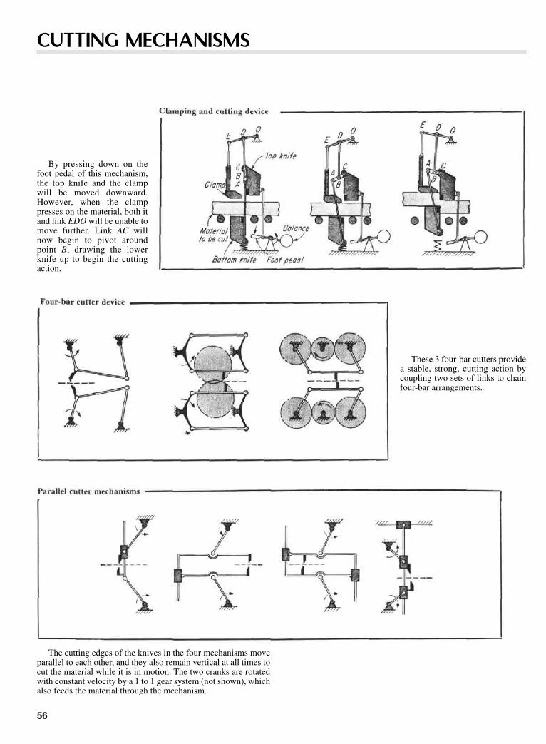
By pressing down on thefoot pedal of this mechanism,the top knife and the clampwill be moved downward.However, when the clamppresses on the material, both itand link EDO will be unable tomove further. Link AC willnow begin to pivot aroundpoint B, drawing the lowerknife up to begin the cuttingaction.
CUTTING MECHANISMS
These 3 four-bar cutters providea stable, strong, cutting action bycoupling two sets of links to chainfour-bar arrangements.
The cutting edges of the knives in the four mechanisms moveparallel to each other, and they also remain vertical at all times tocut the material while it is in motion. The two cranks are rotatedwith constant velocity by a 1 to 1 gear system (not shown), whichalso feeds the material through the mechanism.
56
Sclater Chapter 3 5/3/01 10:19 AM Page 56
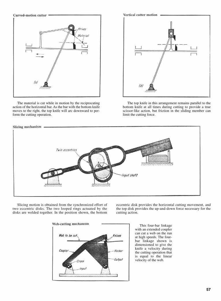
57
The material is cut while in motion by the reciprocatingaction of the horizontal bar. As the bar with the bottom knifemoves to the right, the top knife will arc downward to per-form the cutting operation.
The top knife in this arrangement remains parallel to thebottom knife at all times during cutting to provide a truescissor-like action, but friction in the sliding member canlimit the cutting force.
Slicing motion is obtained from the synchronized effort oftwo eccentric disks. The two looped rings actuated by thedisks are welded together. In the position shown, the bottom
eccentric disk provides the horizontal cutting movement, andthe top disk provides the up-and-down force necessary for thecutting action.
This four-bar linkagewith an extended couplercan cut a web on the runat high speeds. The four-bar linkage shown isdimensioned to give theknife a velocity duringthe cutting operation thatis equal to the linearvelocity of the web.
Sclater Chapter 3 5/3/01 10:19 AM Page 57
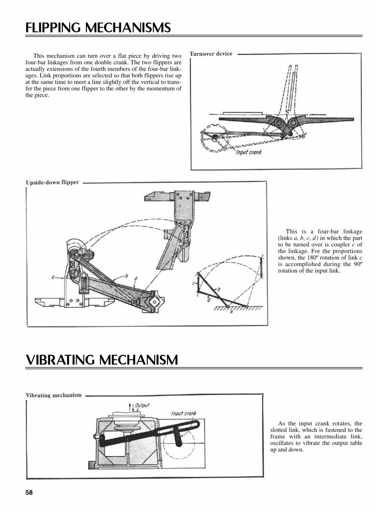
58
FLIPPING MECHANISMS
This mechanism can turn over a flat piece by driving twofour-bar linkages from one double crank. The two flippers areactually extensions of the fourth members of the four-bar link-ages. Link proportions are selected so that both flippers rise upat the same time to meet a line slightly off the vertical to trans-fer the piece from one flipper to the other by the momentum ofthe piece.
This is a four-bar linkage(links a, b, c, d ) in which the partto be turned over is coupler c ofthe linkage. For the proportionsshown, the 180º rotation of link cis accomplished during the 90ºrotation of the input link.
VIBRATING MECHANISM
As the input crank rotates, theslotted link, which is fastened to theframe with an intermediate link,oscillates to vibrate the output tableup and down.
Sclater Chapter 3 5/3/01 10:19 AM Page 58
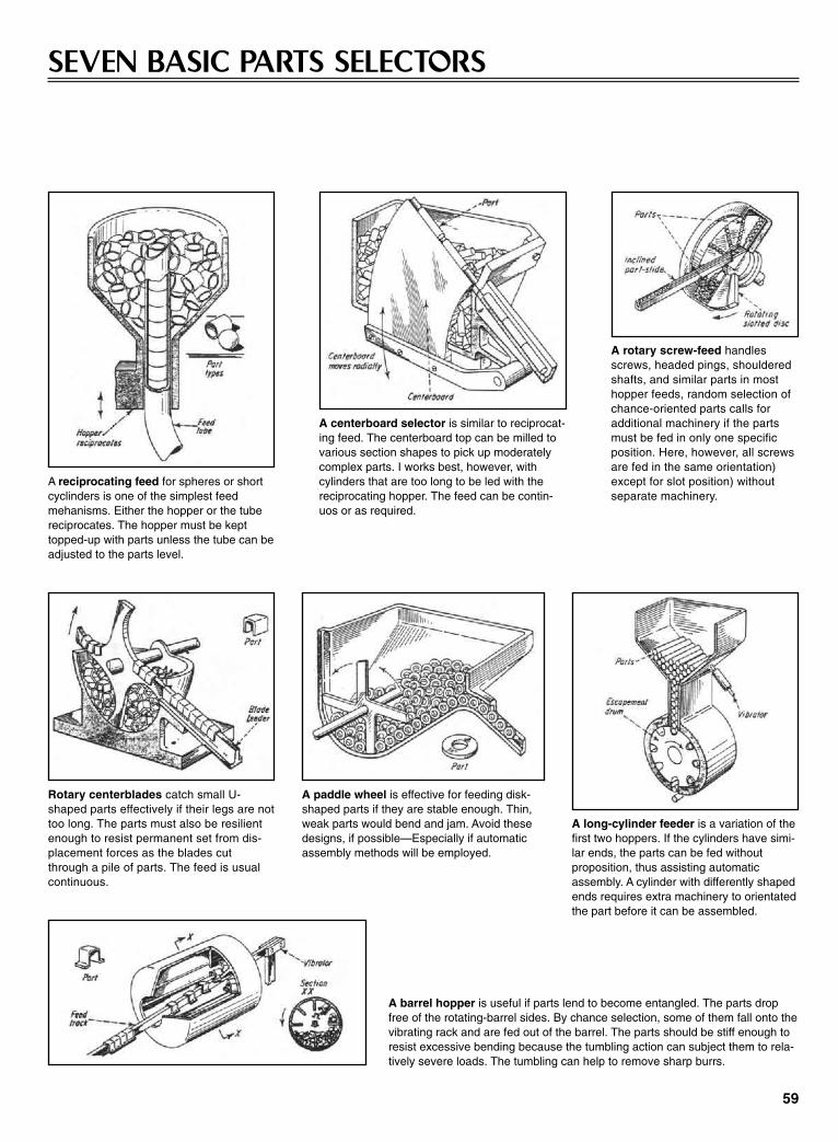
SEVEN BASIC PARTS SELECTORS
A reciprocating feed for spheres or shortcyclinders is one of the simplest feedmehanisms. Either the hopper or the tubereciprocates. The hopper must be kepttopped-up with parts unless the tube can beadjusted to the parts level.
A centerboard selector is similar to reciprocat-ing feed. The centerboard top can be milled tovarious section shapes to pick up moderatelycomplex parts. I works best, however, withcylinders that are too long to be led with thereciprocating hopper. The feed can be contin-uos or as required.
A rotary screw-feed handlesscrews, headed pings, shoulderedshafts, and similar parts in mosthopper feeds, random selection ofchance-oriented parts calls foradditional machinery if the partsmust be fed in only one specificposition. Here, however, all screwsare fed in the same orientation)except for slot position) withoutseparate machinery.
Rotary centerblades catch small U-shaped parts effectively if their legs are nottoo long. The parts must also be resilientenough to resist permanent set from dis-placement forces as the blades cutthrough a pile of parts. The feed is usualcontinuous.
A paddle wheel is effective for feeding disk-shaped parts if they are stable enough. Thin,weak parts would bend and jam. Avoid thesedesigns, if possible—Especially if automaticassembly methods will be employed.
A long-cylinder feeder is a variation of thefirst two hoppers. If the cylinders have simi-lar ends, the parts can be fed withoutproposition, thus assisting automaticassembly. A cylinder with differently shapedends requires extra machinery to orientatedthe part before it can be assembled.
A barrel hopper is useful if parts lend to become entangled. The parts dropfree of the rotating-barrel sides. By chance selection, some of them fall onto thevibrating rack and are fed out of the barrel. The parts should be stiff enough toresist excessive bending because the tumbling action can subject them to rela-tively severe loads. The tumbling can help to remove sharp burrs.
59
Sclater Chapter 3 5/3/01 10:19 AM Page 59
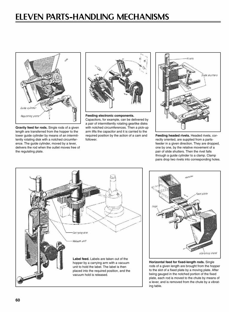
ELEVEN PARTS-HANDLING MECHANISMS
60
Gravity feed for rods. Single rods of a givenlength are transferred from the hopper to thelower guide cylinder by means of an intermit-tently rotating disk with a notched circumfer-ence. The guide cylinder, moved by a lever,delivers the rod when the outlet moves free ofthe regulating plate.
Feeding electronic components.Capacitors, for example, can be delivered bya pair of intermittently rotating gearlike diskswith notched circumferences. Then a pick-uparm lifts the capacitor and it is carried to therequired position by the action of a cam andfollower.
Feeding headed rivets. Headed rivets, cor-rectly oriented, are supplied from a parts-feeder in a given direction. They are dropped,one by one, by the relative movement of apair of slide shutters. Then the rivet fallsthrough a guide cylinder to a clamp. Clamppairs drop two rivets into corresponding holes.
Label feed. Labels are taken out of thehopper by a carrying arm with a vacuumunit to hold the label. The label is thenplaced into the required position, and thevacuum hold is released.
Horizontal feed for fixed-length rods. Singlerods of a given length are brought from the hopperto the slot of a fixed plate by a moving plate. Afterbeing gauged in the notched portion of the fixedplate, each rod is moved to the chute by means ofa lever, and is removed from the chute by a vibrat-ing table.
Sclater Chapter 3 5/3/01 10:19 AM Page 60

61
Pin inserter. Pins, supplied from the parts-feeder, are raised to a ver-tical position by a magnet arm. The pin drops through a guide cylin-der when the electromagnet is turned off.
Cutoff and transfer devices for glass tubes. The upper part of arotating glass tube is held by a chuck (not shown). When the cuttercuts the tube to a given length, the mandrel comes down and aspring member (not shown) drops the tube on the chute.
Vertical feed for wires. Wires of fixed length are stacked vertically,as illustrated. They are removed, one by one, as blocks A and B areslid by a cam and lever (not shown) while the wires are pressed intothe hopper by a spring.
Feeding special-shaped parts. Parts of such special shapes asshown are removed, one by one, in a given direction, and arethen moved individually into the corresponding indents on transferplatforms.
Lateral feed for plain strips. Strips supplied from the parts-feederare put into the required position, one by one, by an arm that is partof a D-drive linkage.
Vertical feed for rods. Rods supplied from the parts-feeder are fedvertically by a direction drum and a pushing bar. The rod is thendrawn away by a chucking lever.
Sclater Chapter 3 5/3/01 10:19 AM Page 61
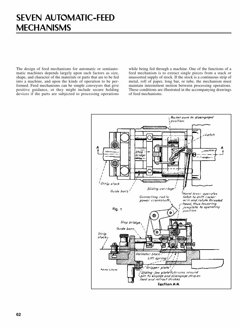
62
SEVEN AUTOMATIC-FEEDMECHANISMS
The design of feed mechanisms for automatic or semiauto-matic machines depends largely upon such factors as size,shape, and character of the materials or parts that are to be fedinto a machine, and upon the kinds of operation to be per-formed. Feed mechanisms can be simple conveyors that givepositive guidance, or they might include secure holdingdevices if the parts are subjected to processing operations
while being fed through a machine. One of the functions of afeed mechanism is to extract single pieces from a stack orunassorted supply of stock. If the stock is a continuous strip ofmetal, roll of paper, long bar, or tube, the mechanism mustmaintain intermittent motion between processing operations.These conditions are illustrated in the accompanying drawingsof feed mechanisms.
Sclater Chapter 3 5/3/01 10:20 AM Page 62
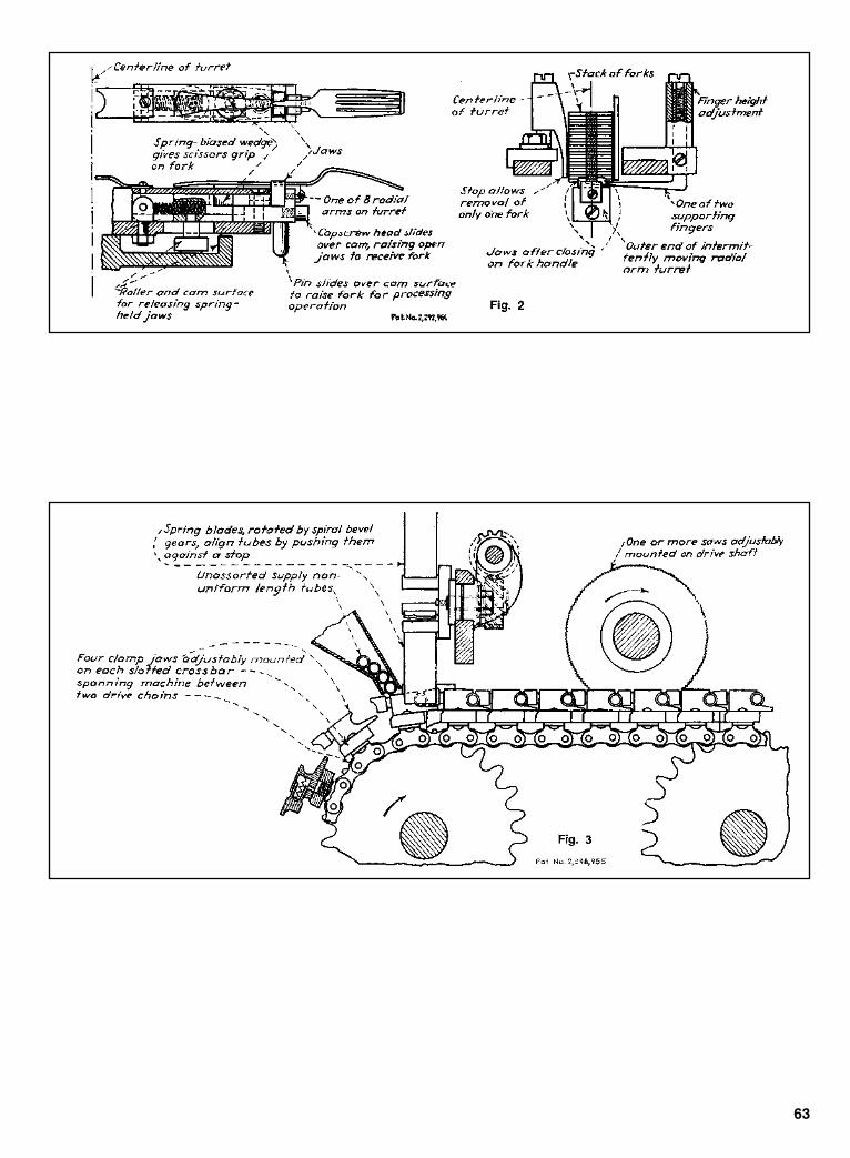
63
Sclater Chapter 3 5/3/01 10:20 AM Page 63
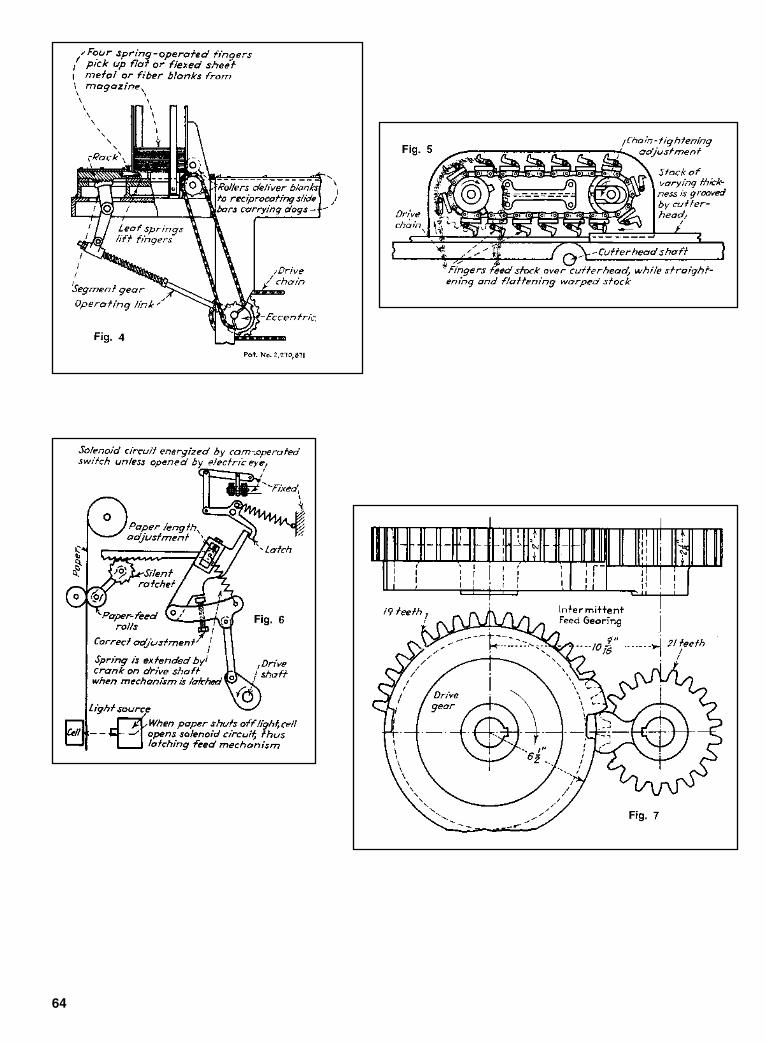
64
Sclater Chapter 3 5/3/01 10:20 AM Page 64
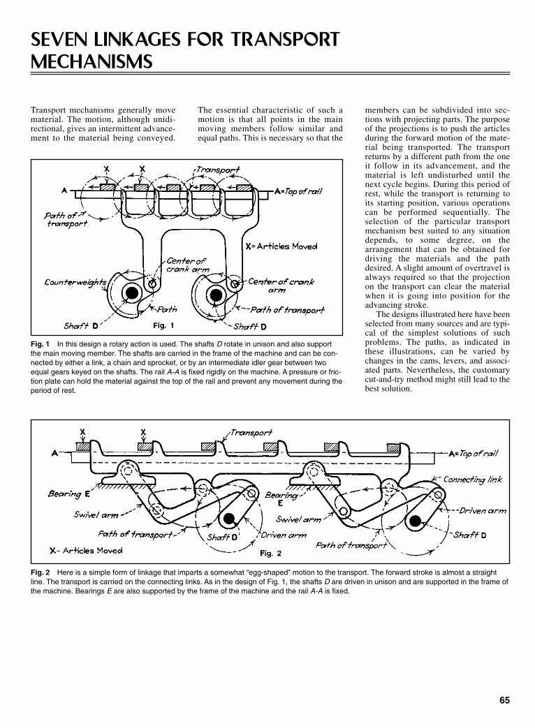
65
SEVEN LINKAGES FOR TRANSPORTMECHANISMS
Fig. 1 In this design a rotary action is used. The shafts D rotate in unison and also supportthe main moving member. The shafts are carried in the frame of the machine and can be con-nected by either a link, a chain and sprocket, or by an intermediate idler gear between twoequal gears keyed on the shafts. The rail A-A is fixed rigidly on the machine. A pressure or fric-tion plate can hold the material against the top of the rail and prevent any movement during theperiod of rest.
members can be subdivided into sec-tions with projecting parts. The purposeof the projections is to push the articlesduring the forward motion of the mate-rial being transported. The transportreturns by a different path from the oneit follow in its advancement, and thematerial is left undisturbed until thenext cycle begins. During this period ofrest, while the transport is returning toits starting position, various operationscan be performed sequentially. Theselection of the particular transportmechanism best suited to any situationdepends, to some degree, on thearrangement that can be obtained fordriving the materials and the pathdesired. A slight amount of overtravel isalways required so that the projectionon the transport can clear the materialwhen it is going into position for theadvancing stroke.
The designs illustrated here have beenselected from many sources and are typi-cal of the simplest solutions of suchproblems. The paths, as indicated inthese illustrations, can be varied bychanges in the cams, levers, and associ-ated parts. Nevertheless, the customarycut-and-try method might still lead to thebest solution.
Fig. 2 Here is a simple form of linkage that imparts a somewhat “egg-shaped” motion to the transport. The forward stroke is almost a straightline. The transport is carried on the connecting links. As in the design of Fig. 1, the shafts D are driven in unison and are supported in the frame ofthe machine. Bearings E are also supported by the frame of the machine and the rail A-A is fixed.
Transport mechanisms generally movematerial. The motion, although unidi-rectional, gives an intermittent advance-ment to the material being conveyed.
The essential characteristic of such amotion is that all points in the mainmoving members follow similar andequal paths. This is necessary so that the
Sclater Chapter 3 5/3/01 10:20 AM Page 65

66
Fig. 3 In another type of action, the forward and return strokes are accomplished by a suitable mechanism, while the raising and lowering isimparted by a friction slide. Thus it can be seen that as the transport supporting slide B starts to move to the left, the friction slide C, which restson the friction rail, tends to remain at rest. As a result, the lifting lever starts to turn in a clockwise direction. This motion raises the transport whichremains in its raised position against stops until the return stroke starts. At that time the reverse action begins. An adjustment should be providedto compensate for the friction between the slide and its rail. It can readily be seen that this motion imparts a long straight path to the transport.
Fig. 4 This drawing illustrates an action in which the forward motion is imparted by an eccen-tric while the raising and lowering of the transport is accomplished by a cam. The shafts, F, E,and D are positioned by the frame of the machine. Special bell cranks support the transportand are interconnected by a tierod.
Fig. 5 This is another form of transport mechanism based on a link motion. The bearings Care supported by the frame as is the driving shaft D.
Sclater Chapter 3 5/3/01 10:20 AM Page 66

67
Fig. 6 An arrangement of interconnected gears with equal diame-ters that will impart a transport motion to a mechanism. The gear andlink mechanism imparts both the forward motion and the raising andlowering motions. The gear shafts are supported in the frame of themachine.
Fig. 7 In this transport mechanism, the forward an return strokesare accomplished by the eccentric arms, while the vertical motion isperformed by the cams.
Sclater Chapter 3 5/3/01 10:20 AM Page 67
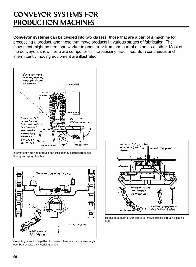
68
CONVEYOR SYSTEMS FORPRODUCTION MACHINES
Conveyor systems can be divided into two classes: those that are a part of a machine forprocessing a product, and those that move products in various stages of fabrication. Themovement might be from one worker to another or from one part of a plant to another. Most ofthe conveyors shown here are components in processing machines. Both continuous andintermittently moving equipment are illustrated.
Intermittently moving grooved bar links convey pasteboard tubesthrough a drying chamber.
Co-acting cams in the paths of follower rollers open and close tongsover bottlenecks by a wedging action.
Hooks on a chain-driven conveyor move articles through a platingbath.
Sclater Chapter 3 5/3/01 10:20 AM Page 68
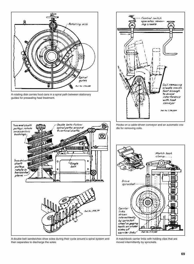
69
A rotating disk carries food cans in a spiral path between stationaryguides for presealing heat treatment.
Hooks on a cable-driven conveyor and an automatic cra-dle for removing coils.
A double belt sandwiches shoe soles during their cycle around a spiral system andthen separates to discharge the soles.
A matchbook carrier links with holding clips that aremoved intermittently by sprockets.
Sclater Chapter 3 5/3/01 10:20 AM Page 69
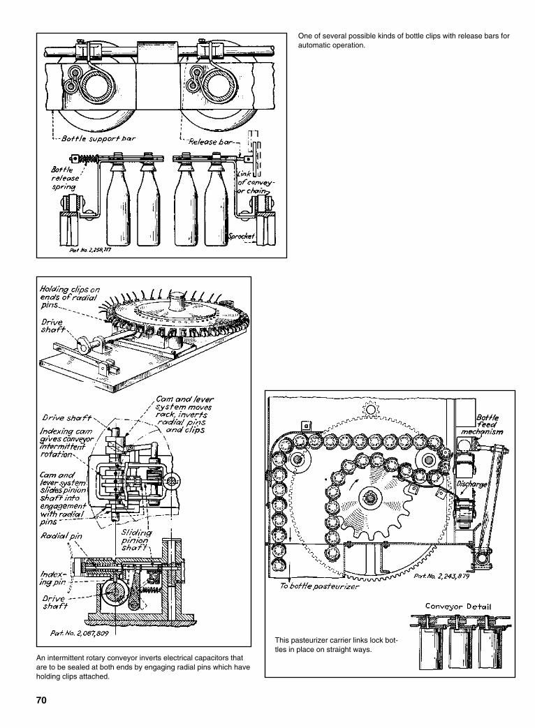
70
One of several possible kinds of bottle clips with release bars forautomatic operation.
An intermittent rotary conveyor inverts electrical capacitors thatare to be sealed at both ends by engaging radial pins which haveholding clips attached.
This pasteurizer carrier links lock bot-tles in place on straight ways.
Sclater Chapter 3 5/3/01 10:20 AM Page 70

71
The wedging action of the side beltsshapes paper sacks for wrapping anpacking.
A reciprocating pusher plate is activated by an eccentric disk and two cams on a drive shaft.
A pusher-type conveyor can have a drive on either side.
Sclater Chapter 3 5/3/01 10:20 AM Page 71

72
A rotary conveyor transfers articles from one belt conveyor to anotherwithout disturbing their relative positions.
Synchronous chains with side arms grasp and move packages.
Sclater Chapter 3 5/3/01 10:20 AM Page 72
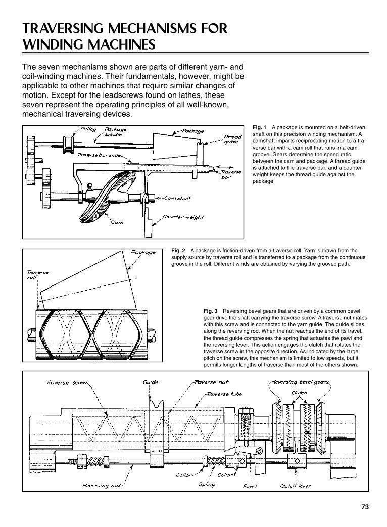
73
TRAVERSING MECHANISMS FORWINDING MACHINESThe seven mechanisms shown are parts of different yarn- andcoil-winding machines. Their fundamentals, however, might beapplicable to other machines that require similar changes ofmotion. Except for the leadscrews found on lathes, theseseven represent the operating principles of all well-known,mechanical traversing devices.
Fig. 1 A package is mounted on a belt-drivenshaft on this precision winding mechanism. Acamshaft imparts reciprocating motion to a tra-verse bar with a cam roll that runs in a camgroove. Gears determine the speed ratiobetween the cam and package. A thread guideis attached to the traverse bar, and a counter-weight keeps the thread guide against thepackage.
Fig. 2 A package is friction-driven from a traverse roll. Yarn is drawn from thesupply source by traverse roll and is transferred to a package from the continuousgroove in the roll. Different winds are obtained by varying the grooved path.
Fig. 3 Reversing bevel gears that are driven by a common bevelgear drive the shaft carrying the traverse screw. A traverse nut mateswith this screw and is connected to the yarn guide. The guide slidesalong the reversing rod. When the nut reaches the end of its travel,the thread guide compresses the spring that actuates the pawl andthe reversing lever. This action engages the clutch that rotates thetraverse screw in the opposite direction. As indicated by the largepitch on the screw, this mechanism is limited to low speeds, but itpermits longer lengths of traverse than most of the others shown.
Sclater Chapter 3 5/3/01 10:20 AM Page 73

74
Fig. 4 A drum drives the package by friction. A pointed camshoe, which pivots in the bottom side of the thread guide assem-bly, rides in cam grooves and produces a reciprocating motion ofthe thread guide assembly on the traverse bar. Plastic cams haveproved to be satisfactory even with fast traverse speeds.Interchangeable cams permit a wide variety of winding methods.
Fig. 5 A roll that rides in a heart-shaped cam groove engages a slot in atraverse bar driver which is attached to the traverse bar. Maximum traverseis obtained when the adjusting guide is perpendicular to the driver. As theangle between the guide and driver is decreased, traverse decreases pro-portionately. Inertia effects limit this mechanism to slow speeds.
Fig. 6 The two cam rolls that engage this heart-shaped cam are attachedto the slide. The slide has a driver roll that engages a slot in the traverse bardriver. Maximum traverse (to the capacity of the cam) occurs when theadjusting disk is set so the slide is parallel to the traverse bar. As the anglebetween the traverse bar and slide increases, traverse decreases. At 90º tra-verse is zero.
Fig. 7 A traverse cam imparts reciprocating motion to a cam fol-lower that drives thread guides on traverse guide rods. The pack-age is friction driven from the drum. Yarn is drawn from the supplysource through a thread guide and transferred to the drum-drivenpackage. The speed of this mechanism is determined by theweight of its reciprocating parts.
Sclater Chapter 3 5/3/01 10:21 AM Page 74

Cores are hopper fed to a rotatingfeeder disk through a tablet duster.This disk is vibrated clockwise undera slotted pick-up ring which rotatescounter-clockwise. Each slot in thepickup ring holds two cores and letsbroken tablets fall through to an areaunder the feeder table. Cores arepicked from ring slots, carried totablet press dies, and deposited in diesby vacuum nozzles fastened to a chaindriven by the press die table. Thischain also drives the pickup ring tosynchronize the motion of ring slotsand pickup nozzles. Coating granula-tion is fed into the dies ahead of andafter the station where a vacuumpickup deposits a core in each die.Compressing rolls are at the left sideof the machine. The principal designobjective here was to develop amachine to apply dry coatings atspeeds that lowered costs below thoseof liquid coating techniques.
75
VACUUM PICKUP POSITIONS PILLSThis pickup carries tablet cores to moving dies, places coresaccurately in coating granulation, and prevents the formation oftablets without cores.
MACHINE APPLIES LABELS FROMSTACKS OR ROLLERS
This labeling machine can perform either conventional glue-label application or it can heat-seal labels in cut or roll form. Themachine labels the front and back of round or odd-shaped con-tainers at speeds of 60 to 160 containers per minute. The contain-ers handled range from 1 in. diameter or thickness to 41⁄4 in. diam-eter by 51⁄2 in. wide. Container height can vary from 2 to 14inches. The unit handles labels ranging from 7⁄8 to 51⁄2 in. wide and
7⁄8 to 61⁄2 in. high. The label hopper is designed for labels that aregenerally rectangular in shape, although it can be modified tohandle irregular shapes. Provision has been made in design of theunit, according to the manufacturer, to allow labels to be placedat varying heights on the containers. The unit’s cut-and-stackedlabel capacity is 4,500. An electric eye is provided for cuttinglabels in web-roll form.
The flow of containers through thislabeler is shown by the top-viewdrawing of the machine. Bottle spac-ers ensure that containers remain 71⁄2in. apart on the conveyor. Dual label-transfer turrets allow for the simulta-neous application of front and backlabels.
Sclater Chapter 3 5/3/01 10:21 AM Page 75
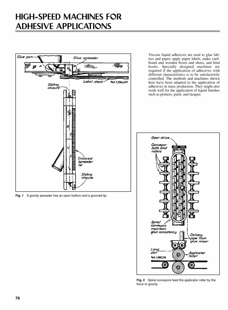
Viscous liquid adhesives are used to glue fab-rics and paper, apply paper labels, make card-board and wooden boxes and shoes, and bindbooks. Specially designed machines arerequired if the application of adhesives withdifferent characteristics is to be satisfactorilycontrolled. The methods and machines shownhere have been adapted to the application ofadhesives in mass production. They might alsowork well for the application of liquid finishessuch as primers, paint, and lacquer.
76
HIGH-SPEED MACHINES FORADHESIVE APPLICATIONS
Fig. 1 A gravity spreader has an open bottom and a grooved lip.
Fig. 2 Spiral conveyors feed the applicator roller by theforce or gravity.
Sclater Chapter 3 5/3/01 10:21 AM Page 76
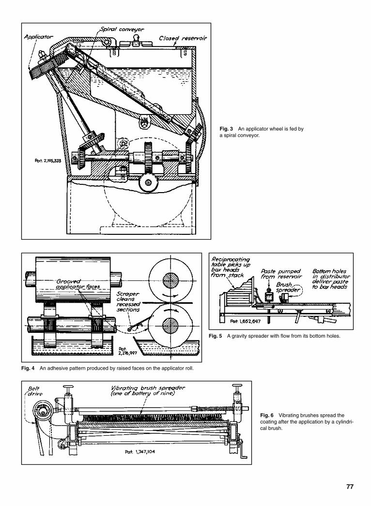
77
Fig. 3 An applicator wheel is fed bya spiral conveyor.
Fig. 4 An adhesive pattern produced by raised faces on the applicator roll.
Fig. 5 A gravity spreader with flow from its bottom holes.
Fig. 6 Vibrating brushes spread thecoating after the application by a cylindri-cal brush.
Sclater Chapter 3 5/3/01 10:21 AM Page 77

78
Fig. 7 This applicator wheel is fed by a transfer disk.
Fig. 8 This applicator surface, consisting of a series of plateedges, is rotated by a Geneva mechanism in the glue pot.
Fig. 9 A rotating applicator disk fed by a trough collector ona transfer drum.
Sclater Chapter 3 5/3/01 10:21 AM Page 78

79
Fig. 10 Cam controlled transfer rollers supply applicator wheelpads with two kinds of adhesive.
Fig. 11 The bottom label is spread with glue bytwo abutting glue-coated picker plates, which sepa-rate during contact with label stack, then carry thelabel to the bottle.
Sclater Chapter 3 5/3/01 10:21 AM Page 79

80
Fig. 12 Measured quantities of cement are forced through perforations in speciallydesigned upper and lower die plates, which are closed hydraulically over zippers. Only thelower die is shown.
Fig. 13 A brush applicator is fed throughpassages between bristle tufts by a spring-operated plunger.
Fig. 14 A shoulder on a valvestem in a glue chamber retainsglue until pressure on the tipopens the bottom valve.
Fig. 15 Glue is applied to envelopes by a spray nozzle.
Fig. 16 A rocker shaft on arack, which is moved verticallyby a sector gear, carries glueon a contact bar from the roll tothe label stack.
Fig. 17 Glue is extruded throughnozzle on work.
Fig. 18 Pin applicators reciprocate vertically, firstimmersing themselves in glue, then contacting the under-sides of carton flaps in a desired pattern.
Sclater Chapter 3 5/3/01 10:21 AM Page 80

81
Fig. 19 A paste belt applicator passes around thepulley in a pastepot and slides over the label stack.
Fig. 20 A dauber assembly is moved horizontally between a gluepot and work by an eccentric pin on a gear. Vertical movements areproduced by a crank-operated bar over the dauber shaft.
Sclater Chapter 3 5/3/01 10:22 AM Page 81

AUTOMATIC STOPPING MECHANISMS FOR FAULTY MACHINE OPERATIONAutomatic stopping mechanisms that prevent machines from damaging themselves or destroying work in process are based on the prin-ciples of mechanics, electricity, hydraulics, and pneumatics.
Fig. 2 The gumming of the suction pickerand label carrier when the label is not pickedup by the suction is prevented by insufficientsuction on a latch-operating cylinder, causedby open suction holes on the picker. When alatch-operating cylinder does not operate,the gum box holding latch returns to its hold-ing position after cyclic removal by the camand roller, thus preventing the gum box androlls from rocking to make contact with thepicker face.
Fig. 1 A repetition of the machine cycle isprevented if a pedal remains depressed. Thelatch carried by the left slide pushes the rightslide downward with a curved shoulder untilthe latch is disengaged by trip member.
Fig. 3 Damage to the milling cutter, work, or fixtures is prevented by the shroud aroundthe cutter. Upon contact with the work, the shroud closes the electric circuit through therelay, thus closing contact A. This causes contact B to close, thus energizing relay C tooperate a stop valve. It also closes a circuit through relay D, thus reversing the selectorvalve by means of a shifter rod so that bed travel will reverse on starting. Simultaneously,relay F opens the circuit of relay E and closes a holding circuit that was broken by theshifter lever at K. Relay G also closes a holding circuit and opens a circuit through relay D.The starting lever, released by pushbutton H, releases contact A and returns the circuit tonormal. If contact is made with the shroud when the bed travel is reversed, interchange thepositions of D and E, with F and G in the sequence of operations.
82
Sclater Chapter 3 5/3/01 10:22 AM Page 82

83
Fig. 4 A high-speed press is stopped when a metal stripadvances improperly. A hole punched in the strip fails to matchwhile the opening in the die block to permit a light beam topass. When the light beam to the photoelectric cell is blocked,the solenoid which withdraws the clutch pin is activated.
Fig. 5 A broken thread allows the contact bar to drop,thereby closing the electronic relay circuit; this stopsthe beamer reeling equipment.
Fig. 6 A nozzle on the packaging machine does not open when the con-tainer is improperly positioned.
Fig. 7 An obstruction under the explorer foot ofa wire-stitching machine raises a vertical plungerwhich releases a latch lever. A rotary cam thenraises a lever that retains the clutch-operatingplunger.
Sclater Chapter 3 5/3/01 10:22 AM Page 83

84
Automatic Stopping Mechanisms (continued )
Sclater Chapter 3 5/3/01 10:22 AM Page 84
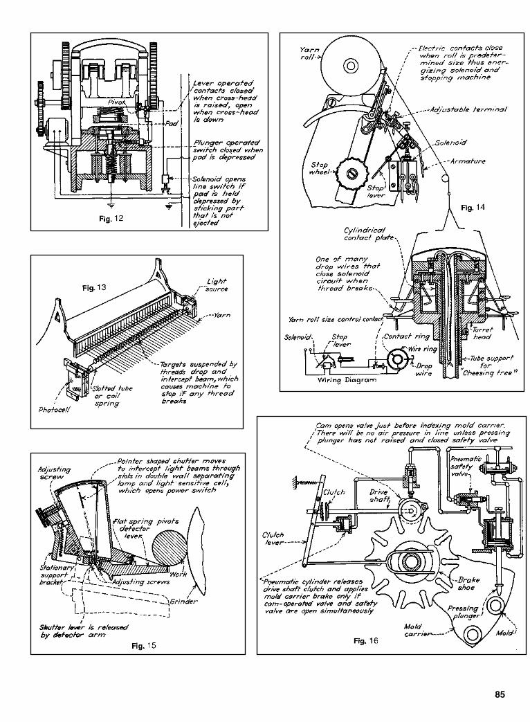
85
Sclater Chapter 3 5/3/01 10:22 AM Page 85

86
Automatic Stopping Mechanisms (continued )
Fig. 17 A mechanism on a spooler. When a thread breaks,the feelers are released and the spiral spring causes thespindle with finger to rotate. The finger throws the stirrup intothe path of the oscillating crank, which on its downwardstroke throws the spool into the position shown dotted. Thestirrup is then thrown out of the path of the oscillating crank.
Fig. 18 A mechanism in use on tubular braiding machines. Whenthe machine is braiding, tension on the wire or thread lifts the idlercarrier which then releases the pawl from the ratchet on the spoolflange and allows the spool to turn and unwind. When the machinestops, the tension on the wire is decreases, allowing the idler car-rier to fall so that the pawl can engage the ratchet. If a wire breakswhile the machine is running, the unsupported idler carrier falls tothe base of the standard, and when the standard arrives at the sta-tion in the raceway adjacent to the cam C, the lug L on the idlercarrier strikes the cam C, rotating it far enough to disengage aclutch on the driving shaft, thereby stopping the machine.
Fig. 19 When thread breaks, the stop drops and intercepts thereciprocating bar. On the next counter-clockwise oscillation of theeccentric arm, the bar B is raised. A feature of this design is that itpermits the arm B to move up or down independently for a limiteddistance.
Fig. 20 A diagram of a mechanism thatcauses a bobbin changer to operate. If thecontact arm does not slip on the bobbin, leverA will rotate to the position shown. But if con-tact with the bobbin center slips, when thebobbin is empty, lever A will not rotate to theposition indicated by the dashed line. This willcause the bobbin changer to operate.
Sclater Chapter 3 5/3/01 10:22 AM Page 86

87
Fig. 21 A simple stop mechanism for limiting the stroke of areciprocating machine member. Arrows indicate the direction ofmovements.
Fig. 22 When the predetermined weight of material has beenpoured on the pan, the movement of the scale beam pushesthe latch out of engagement. This allows the paddle wheel torotate and dump the load. The scale beam drops, therebyreturning the latch to the holding position and stopping thewheel when the next vane hits the latch.
Fig. 23 In this textile machine, any movement that willrotate the stop lever counter-clockwise will move it intothe path of the continuously reciprocating shaft. Thiswill cause the catch lever to be pushed counter-clockwise, freeing the hardened steel stop on theclutch control shaft. A spiral spring then impels theclutch control shaft to rotate clockwise. That movementthrows out the clutch and applies the brake. The initialmovement of the stop lever can be caused by a break-ing thread or a moving dog.
Fig. 24 some package-loading machines have provisions tostop the machine if a package passes the loading station with-out receiving an insert. Pawl finger F has a rocking motionimparted by the crankshaft, timed so that it enters theunsealed packages and is stopped against the contents. If thebox is not filled, the finger enters a long distance. The pawlend at the bottom engages and holds a ratchet wheel on thedriving clutch which disengages the machine-driving shaft.
Sclater Chapter 3 5/3/01 10:22 AM Page 87

ELECTRICAL AUTOMATICSTOPPING MECHANISMS
88
Fig. 1 A safety mechanism on some machines stops themotor when a guard cover is lifted. The circuit is completeonly when the cover is down. In that position a contact lugestablishes a metal-to-metal connection with the contactspring, completing the relay circuit.
Fig. 2 An electrical three-point wedging “warp stop” is shown after a threadhas broken and a drop wire has fallen and tilted to close the circuit. Dotted linesindicate the normal position of the drop wire when it is riding on a thread. Whena thread breaks, the drop wire falls and strikes the top of the terminal blade B,the inclined top of the slot. This causes a wedging action that tilts the drop wireagainst the terminal strip at C and D, reinforcing the circuit-closing action.
Fig. 3 Bobbin changer. When a bobbin isempty, the feeders contact the metal bobbincenter, completing the circuit through a sole-noid which pulls a latch. That causes thebobbin-changing mechanism to operatorand put a new bobbin in the shuttle. As longas the solenoid remains deenergized, thepawl on the lay bar is raised clear of thehook on the bobbin-changing mechanism.
Sclater Chapter 3 5/3/01 10:22 AM Page 88

Fig. 4 Control for the automatic shear. When a seam of two thicknesses of cloth passes between the rolls, the swing roller is moved outwardand closes a sensitive switch which energizes a solenoid. The solenoid pulls in an armature whose outer end is attached to the hinged ringwhere a cam plate is also fastened. The cam plate depresses the pins in a rotating plate. As the plate rotates, the depressed pins lift a hingedcam arm on which two mercury switches are mounted. When tilted, the switches complete circuits in two motor controls. A resetting cam forpushing the depressed pins back to their original position is fastened on the machine frame. The two motors are stopped and reversed until theseam has passed through rollers before they are stopped and reversed again.
Fig. 5 Electric stop for a loom. When a thread breaks or slackens,the drop wire falls and contact A rides on contact C. The drop wire,supported off-center, swings so that contact B is pulled against theinner terminal strip D, completing the solenoid circuit.
Fig. 6 This automatic stop for a folder or yarder machine always stopsthe machine in the same position when a seam in the cloth passesbetween the rolls. A seam passing between the rolls causes the swivel-mounted roll to lift slightly. This motion closes contacts in a sensitiveswitch that opens a relay in the control box. The next time the cam closesthe limit switch, the power of the motor with the integral magnetic brake isshut off. The brake always stops the machine in the same place.
89
Sclater Chapter 3 5/3/01 10:23 AM Page 89

AUTOMATIC SAFETY MECHANISMSFOR OPERATING MACHINES
90
The best automatic safety mechanisms are those that have been designed specificallyfor the machine on which they will be installed. When properly designed, automaticsafety devices (1) do not reduce the operator’s visibility, (2) do not interfere with theoperator’s performance, (3) do not make physical contact with the operator to pre-vent injury (e.g., by knocking his hand out of the way), (4) are fail-safe, (5) are sen-sitive enough to operate instantly, and (6) render the machine inoperative if anyoneattempts to tamper with them or remove them.
Safety mechanisms can range from those that keep both of the operator’s handsoccupied on controls away from the work area to shields that completely enclose thework in progress on the machine and prevent machine operation unless the shield issecurely in place. Many modern safety systems are triggered if any person or objectbreaks a light beam between a photoemitter and photoreceiver.
Sclater Chapter 3 5/3/01 10:23 AM Page 90
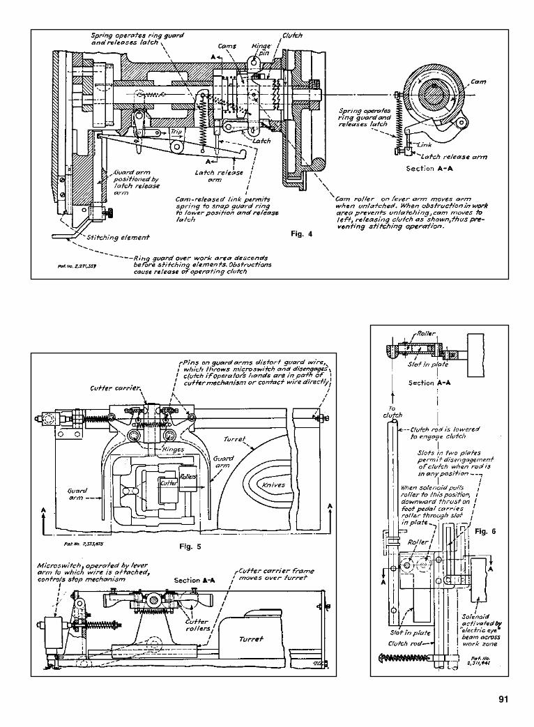
91
Sclater Chapter 3 5/3/01 10:23 AM Page 91

CHAPTER 4RECIPROCATING AND
GENERAL-PURPOSEMECHANISMS
Sclater Chapter 4 5/3/01 10:44 AM Page 93

An ingenious intermittent mechanismwith its multiple gears, gear racks, andlevers provides smoothness and flexibil-ity in converting constant rotary motioninto a start-and-stop type of indexing.
It works equally well for high-speedoperations, as fast as 2 seconds per cycle,including index and dwell, or for slow-speed assembly functions.
The mechanism minimizes shockloads and offers more versatility than theindexing cams and genevas usuallyemployed to convert rotary motion intostart-stop indexing. The number of sta-tions (stops) per revolution of the tablecan easily be changed, as can the periodof dwell during each stop.
Advantages. This flexibility broadensthe scope of such automatic machineoperations as feeding, sorting, packag-ing, and weighing that the rotary tablecan perform. But the design offers otheradvantages, too:
• Gears instead of cams make themechanism cheaper to manufacture,because gears are simpler tomachine.
• The all-mechanical interlocked sys-tem achieves an absolute time rela-tionship between motions.
• Gearing is arranged so that themachine automatically goes into adwell when it is overloaded, prevent-ing damage during jam-ups.
• Its built-in anti-backlash gear systemaverts rebound effects, play, and lostmotion during stops.
How it works. Input from a singlemotor drives an eccentric disk and con-necting rod. In the position shown in thedrawing, the indexing gear and table arelocked by the rack—the planet gear ridesfreely across the index gear withoutimparting any motion to it. Indexing ofthe table to its next position begins whenthe control cam simultaneously releasesthe locking rack from the index gear andcauses the spring control ring gear topivot into mesh with the planet.
This is a planetary gear system con-taining a stationary ring gear, a drivingplanet gear, and a “sun” index gear. Asthe crank keeps moving to the right, itbegins to accelerate the index gear withharmonic motion—a desirable type ofmotion because of its low acceleration-deceleration characteristics—while it isimparting high-speed transfer to thetable.
94
GEARS AND ECCENTRIC DISK COMBINE IN QUICK INDEXING
Sclater Chapter 4 5/3/01 10:44 AM Page 94

Outgrowth from chains. Intermittent-motion mechanisms typically haveingenious shapes and configurations.They have been used in watches and inproduction machines for many years.There has been interest in the chain typeof intermittent mechanism (see drawing),which ingeniously routes a chain aroundfour sprockets to produce a dwell-and-index output.
The input shaft of such a device has asprocket eccentrically fixed to it. The inputalso drives another shaft through one-to-one gearing. This second shaft mounts asimilar eccentric sprocket that is, however,free to rotate. The chain passes first aroundan idler pulley and then around a secondpulley, which is the output.
As the input gear rotates, it also pullsthe chain around with it, producing a
95
At the end of 180º rotation of thecrank, the control cam pivots the ring-gear segment out of mesh and, simulta-neously, engages the locking rack. As theconnecting rod is drawn back, the planetgear rotates freely over the index gear,which is locked in place.
The cam control is so synchronizedthat all toothed elements are in fullengagement briefly when the crank armis in full toggle at both the beginning andend of index. The device can be operatedjust as easily in the other direction.
Overload protection. The ring gearsegment includes a spring-load detentmechanism (simplified in the illustra-tion) that will hold the gearing in fullengagement under normal indexingforces. If rotation of the table is blockedat any point in index, the detent springforce is overcome and the ring gear popsout of engagement with the planet gear.
A detent roller (not shown) will thensnap into a second detent position, whichwill keep the ring gear free during theremainder of the index portion of thecycle. After that, the detent will automat-ically reset itself.
Incomplete indexing is detected by anelectrical system that stops the machineat the end of the index cycle.
Easy change of settings. To changeindexes for a new job setup, the eccentricis simply replaced with one heaving adifferent crank radius, which gives theproper drive stroke for 6, 8, 12, 16, 24,32, or 96 positions per table rotation.
Because indexing occurs during one-half revolution of the eccentric disk, theinput gear must rotate at two or threetimes per cycle to accomplish indexingof 1⁄2, 1⁄4, or 1⁄16 of the total cycle time(which is the equivalent to index-to-dwell cycles of 180/180º, 90/270º or60/300º). To change the cycle time, it isonly necessary to mount a difference setof change gears between input gear andcontrol cam gear.
A class of intermittent mechanisms basedon timing belts, pulleys, and linkages(see drawing) instead of the usualgenevas or cams is capable of cyclicstart-and-stop motions with smoothacceleration and deceleration.
Developed by Eric S. Buhayar andEugene E. Brown of the EngineeringResearch Division, Scott Paper Co.(Philadelphia), the mechanisms areemployed in automatic assembly lines.
These mechanisms, moreover, canfunction as phase adjusters in which therotational position of the input shaft canbe shifted as desired in relation to theoutput shaft. Such phase adjusters havebeen used in the textile and printingindustries to change the “register” of oneroll with that of another, when both rollsare driven by the same input.
TIMING BELTS, FOUR-BAR LINKAGETEAM UP FOR SMOOTH INDEXING
Sclater Chapter 4 5/3/01 10:44 AM Page 95

modulated output rotation. Two spring-loaded shoes, however, must beemployed because the perimeter of thepulleys is not a constant figure, so thedrive has varying slack built into it.
Commercial type. A chain also linksthe elements of a commercial phase-adjuster drive. A handle is moved tochange the phase between the input andoutput shafts. The theoretical chainlength is constant.
In trying to improve this chain device,Scott engineers decided to keep the inputand output pulleys at fixed positions and
MODIFIEDRATCHET DRIVE
96
maintain the two idlers on a swing frame.The variation in wraparound lengthturned out to be surprisingly little,enabling them to install a timing beltwithout spring-loaded tensioners insteadof a chain.
If the swing frame is held in one posi-tion, the intermittent mechanism pro-duces a constant-speed output. Shiftingthe swing frame to a new position auto-matically shifts the phase relationshipbetween the input and output.
Computer consulted. To obtain inter-mittent motion, a four-bar linkage issuperimposed on the mechanism byadding a crank to the input shaft and aconnecting rod to the swing frame. Thedevelopers chose an iterative program ona computer to optimize certain variablesof the four-bar version.
In the design of one two-stop drive, adwell period of approximately 50º isobtained. The output displacementmoves slowly at first, coming to a“pseudo dwell,” in which it is virtuallystationary. The output then picks upspeed smoothly until almost two-thirdsof the input rotation has elapsed (240º).After the input crank completes a full cir-cle of rotation, it continues at a slowerrate and begins to repeat its slow-down—dwell—speed-up cycle.
A ratchet drive was designed to assuremovement, one tooth at a time, in onlyone direction, without overriding. The keyelement is a small stub that moves alongfrom the bottom of one tooth well, acrossthe top of the tooth, and into an adjacenttooth well, while the pawl remains at thebottom of another tooth well.
The locking link, which carries thestub along with the spring, comprises asystem that tends to hold the link andpawl against the outside circumferenceof the wheel and to push the stub andpawl point toward each other and intodifferently spaced wells between theteeth. A biasing element, which might beanother linkage or solenoid, is providedto move the anchor arm from one side tothe other, between the stops, as shown bythe double arrow. The pawl will movefrom one tooth well to the next tooth wellonly when the stub is at the bottom of atooth well and is in a position to preventcounter-rotation.
Sclater Chapter 4 5/3/01 10:44 AM Page 96
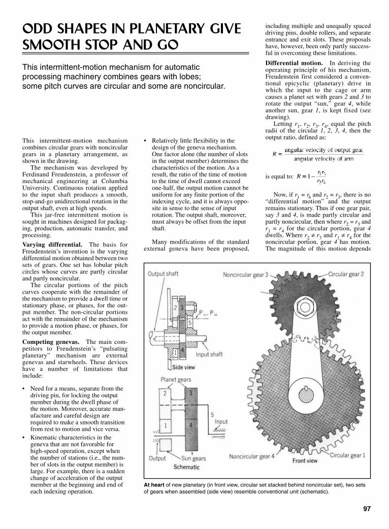
• Relatively little flexibility in thedesign of the geneva mechanism.One factor alone (the number of slotsin the output member) determines thecharacteristics of the motion. As aresult, the ratio of the time of motionto the time of dwell cannot exceedone-half, the output motion cannot beuniform for any finite portion of theindexing cycle, and it is always oppo-site in sense to the sense of inputrotation. The output shaft, moreover,must always be offset from the inputshaft.
Many modifications of the standardexternal geneva have been proposed,
97
ODD SHAPES IN PLANETARY GIVE SMOOTH STOP AND GOThis intermittent-motion mechanism for automatic processing machinery combines gears with lobes; some pitch curves are circular and some are noncircular.
This intermittent-motion mechanismcombines circular gears with noncirculargears in a planetary arrangement, asshown in the drawing.
The mechanism was developed byFerdinand Freudenstein, a professor ofmechanical engineering at ColumbiaUniversity. Continuous rotation appliedto the input shaft produces a smooth,stop-and-go unidirectional rotation in theoutput shaft, even at high speeds.
This jar-free intermittent motion issought in machines designed for packag-ing, production, automatic transfer, andprocessing.
Varying differential. The basis forFreudenstein’s invention is the varyingdifferential motion obtained between twosets of gears. One set has lobular pitchcircles whose curves are partly circularand partly noncircular.
The circular portions of the pitchcurves cooperate with the remainder ofthe mechanism to provide a dwell time orstationary phase, or phases, for the out-put member. The non-circular portionsact with the remainder of the mechanismto provide a motion phase, or phases, forthe output member.
Competing genevas. The main com-petitors to Freudenstein’s “pulsatingplanetary” mechanism are externalgenevas and starwheels. These deviceshave a number of limitations thatinclude:
• Need for a means, separate from thedriving pin, for locking the outputmember during the dwell phase ofthe motion. Moreover, accurate man-ufacture and careful design arerequired to make a smooth transitionfrom rest to motion and vice versa.
• Kinematic characteristics in thegeneva that are not favorable forhigh-speed operation, except whenthe number of stations (i.e., the num-ber of slots in the output member) islarge. For example, there is a suddenchange of acceleration of the outputmember at the beginning and end ofeach indexing operation.
At heart of new planetary (in front view, circular set stacked behind noncircular set), two setsof gears when assembled (side view) resemble conventional unit (schematic).
including multiple and unequally spaceddriving pins, double rollers, and separateentrance and exit slots. These proposalshave, however, been only partly success-ful in overcoming these limitations.
Differential motion. In deriving theoperating principle of his mechanism,Freudenstein first considered a conven-tional epicyclic (planetary) drive inwhich the input to the cage or armcauses a planet set with gears 2 and 3 torotate the output “sun,” gear 4, whileanother sun, gear 1, is kept fixed (seedrawing).
Letting r1, r2, r3, r4, equal the pitchradii of the circular 1, 2, 3, 4, then theoutput ratio, defined as:
is equal to:
Now, if r1 = r4 and r2 = r3, there is no“differential motion” and the outputremains stationary. Thus if one gear pair,say 3 and 4, is made partly circular andpartly noncircular, then where r2 = r3 andr1 = r4 for the circular portion, gear 4dwells. Where r2 ≠ r3 and r1 ≠ r4 for thenoncircular portion, gear 4 has motion.The magnitude of this motion depends
Sclater Chapter 4 5/3/01 10:44 AM Page 97
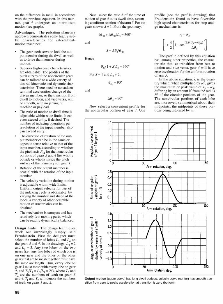
on the difference in radii, in accordancewith the previous equation. In this man-ner, gear 4 undergoes an intermittentmotion (see graph).
Advantages. The pulsating planetaryapproach demonstrates some highly use-ful characteristics for intermittent-motion machines:
• The gear teeth serve to lock the out-put member during the dwell as wellas to drive that member duringmotion.
• Superior high-speed characteristicsare obtainable. The profiles of thepitch curves of the noncircular gearscan be tailored to a wide variety ofdesired kinematic and dynamic char-acteristics. There need be no suddenterminal acceleration change of thedriven member, so the transition fromdwell to motion, and vice versa, willbe smooth, with no jarring ofmachine or payload.
• The ratio of motion to dwell time isadjustable within wide limits. It caneven exceed unity, if desired. Thenumber of indexing operations perrevolution of the input member alsocan exceed unity.
• The direction of rotation of the out-put member can be in the same oropposite sense relative to that of theinput member, according to whetherthe pitch axis P34 for the noncircularportions of gears 3 and 4 lies whollyoutside or wholly inside the pitchsurface of the planetary sun gear 1.
• Rotation of the output member iscoaxial with the rotation of the inputmember.
• The velocity variation during motionis adjustable within wide limits.Uniform output velocity for part ofthe indexing cycle is obtainable; byvarying the number and shape of thelobes, a variety of other desirablemotion characteristics can beobtained.
• The mechanism is compact and hasrelatively few moving parts, whichcan be readily dynamically balanced.
Design hints. The design techniqueswork out surprisingly simply, saidFreudenstein. First the designer mustselect the number of lobes L3 and L4 onthe gears 3 and 4. In the drawings, L3 = 2and L4 = 3. Any two lobes on the twogears (i.e., any two lobes of which one ison one gear and the other on the othergear) that are to mesh together must havethe same arc length. Thus, every lobe ongear 3 must mesh with every lobe on gear4, and T3/T4 = L3/L4 = 2/3, where T3 andT4 are the numbers of teeth on gears 3and 4. T1 and T2 will denote the numbersof teeth on gears 1 and 2.
Next, select the ratio S of the time ofmotion of gear 4 to its dwell time, assum-ing a uniform rotation of the arm 5. For thegears shown, S = 1. From the geometry,
(θ30 + ∆θ30)L3 = 360º
and
S = ∆θ3/θ30
Hence
θ30(1 + S)L3 = 360º
For S = 1 and L3 + 2,
θ30 = 90º
and
∆θ 3 = 90º
Now select a convenient profile forthe noncircular portion of gear 3. One
profile (see the profile drawing) thatFreudenstein found to have favorablehigh-speed characteristics for stop-and-go mechanisms is
r3 = R3
The profile defined by this equationhas, among other properties, the charac-teristic that, at transition from rest tomotion and vice versa, gear 4 will havezero acceleration for the uniform rotationof arm 5.
In the above equation, λ is the quan-tity which, when multiplied by R3, givesthe maximum or peak value of r3 – R3,differing by an amount h′ from the radiusR3 of the circular portions of the gear.The noncircular portions of each lobeare, moreover, symmetrical about theirmidpoints, the midpoints of these por-tions being indicated by m.
12
12 3 30
3+ −
−
λ π θ θθ
cos( )
∆
98
Output motion (upper curve) has long dwell periods; velocity curve (center) has smooth tran-sition from zero to peak; acceleration at transition is zero (bottom).
Sclater Chapter 4 5/3/01 10:44 AM Page 98
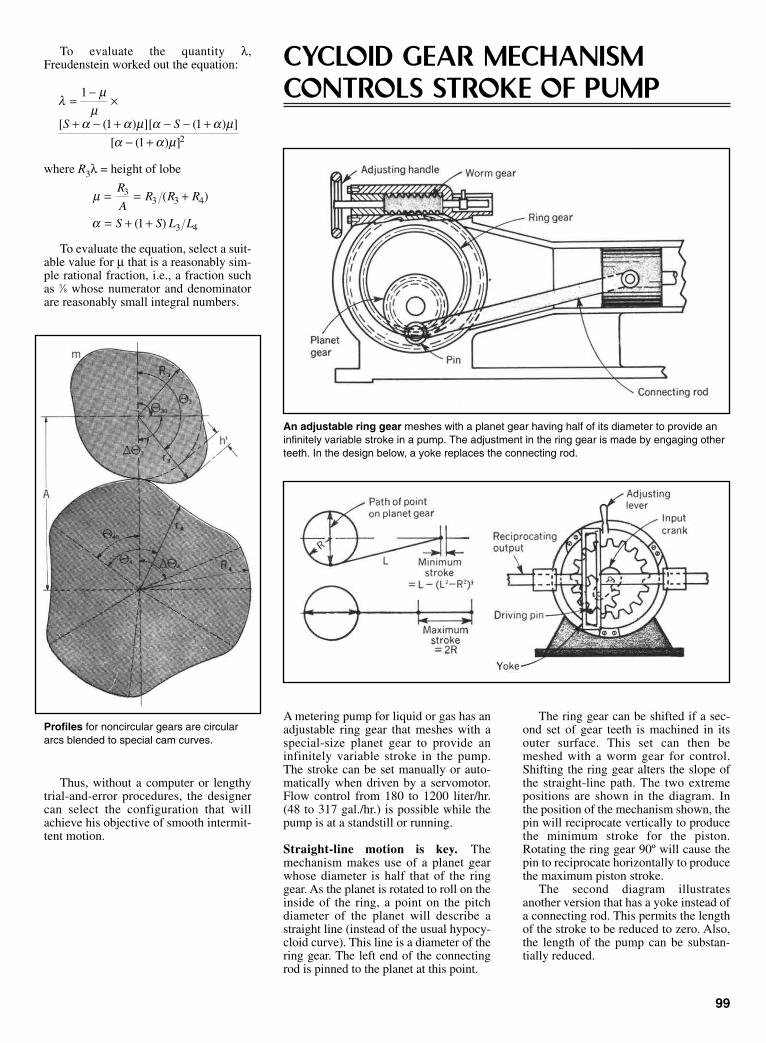
To evaluate the quantity λ,Freudenstein worked out the equation:
where R3λ = height of lobe
To evaluate the equation, select a suit-able value for µ that is a reasonably sim-ple rational fraction, i.e., a fraction suchas 3⁄8 whose numerator and denominatorare reasonably small integral numbers.
Thus, without a computer or lengthytrial-and-error procedures, the designercan select the configuration that willachieve his objective of smooth intermit-tent motion.
µ
α
= = +
= + +
R
AR R R
S S L L
33 3 4
3 41
( )
( )
λµ
µα α µ α α µ
α α µ
=−
×
+ − + − − +− +
1
1 1
1 2
[ ( ) ][ ( ) ]
[ ( ) ]
S S
A metering pump for liquid or gas has anadjustable ring gear that meshes with aspecial-size planet gear to provide aninfinitely variable stroke in the pump.The stroke can be set manually or auto-matically when driven by a servomotor.Flow control from 180 to 1200 liter/hr.(48 to 317 gal./hr.) is possible while thepump is at a standstill or running.
Straight-line motion is key. Themechanism makes use of a planet gearwhose diameter is half that of the ringgear. As the planet is rotated to roll on theinside of the ring, a point on the pitchdiameter of the planet will describe astraight line (instead of the usual hypocy-cloid curve). This line is a diameter of thering gear. The left end of the connectingrod is pinned to the planet at this point.
The ring gear can be shifted if a sec-ond set of gear teeth is machined in itsouter surface. This set can then bemeshed with a worm gear for control.Shifting the ring gear alters the slope ofthe straight-line path. The two extremepositions are shown in the diagram. Inthe position of the mechanism shown, thepin will reciprocate vertically to producethe minimum stroke for the piston.Rotating the ring gear 90º will cause thepin to reciprocate horizontally to producethe maximum piston stroke.
The second diagram illustratesanother version that has a yoke instead ofa connecting rod. This permits the lengthof the stroke to be reduced to zero. Also,the length of the pump can be substan-tially reduced.
99
Profiles for noncircular gears are circulararcs blended to special cam curves.
CYCLOID GEAR MECHANISMCONTROLS STROKE OF PUMP
An adjustable ring gear meshes with a planet gear having half of its diameter to provide aninfinitely variable stroke in a pump. The adjustment in the ring gear is made by engaging otherteeth. In the design below, a yoke replaces the connecting rod.
Sclater Chapter 4 5/3/01 10:44 AM Page 99

CONVERTING ROTARY-TO-LINEAR MOTION
A compact gear system that provides lin-ear motion from a rotating shaft wasdesigned by Allen G. Ford of The JetPropulsion Laboratory in California. Ithas a planetary gear system so that theend of an arm attached to the planet gearalways moves in a linear path (drawing).
The gear system is set in motion by amotor attached to the base plate. Gear A,attached to the motor shaft, turns the caseassembly, causing Gear C to rotate alongGear B, which is fixed. The arm is thesame length as the center distancebetween Gears B and C. Lines betweenthe centers of Gear C, the end of the arm,and the case axle form an isosceles trian-gle, the base of which is always along theplane through the center of rotation. Sothe output motion of the arm attached toGear C will be in a straight line.
When the end of travel is reached, aswitch causes the motor to reverse,returning the arm to its original position.
100
The end of arm moves in a straight line because of the triangle effect (right).
NEW STAR WHEELS CHALLENGEGENEVA DRIVES FOR INDEXINGStar wheels with circular-arc slots can be analyzedmathematically and manufactured easily.
Star Wheels vary in shape, depending on the degree of indexing that must be done during one input revolution.
Sclater Chapter 4 5/3/01 10:44 AM Page 100

A family of star wheels with circularinstead of the usual epicyclic slots (seedrawings) can produce fast start-and-stopindexing with relatively low accelerationforces.
This rapid, jar-free cycling is impor-tant in a wide variety of productionmachines and automatic assembly linesthat move parts from one station toanother for drilling, cutting, milling, andother processes.
The circular-slot star wheels wereinvented by Martin Zugel of Cleveland,Ohio.
The motion of older star wheels withepicyclic slots is difficult to analyze andpredict, and the wheels are hard to make.
The star wheels with their circular-arcslots are easy to fabricate, and becausethe slots are true circular arcs, they canbe visualized for mathematical analysisas four-bar linkages during the entireperiod of pin-slot engagement.
Strong points. With this approach,changes in the radius of the slot can beanalyzed and the acceleration curve var-ied to provide inertia loads below thoseof the genevas for any practical designrequirement.
Another advantage of the star wheelsis that they can index a full 360º in a rel-atively short period (180º). Such one-stop operation is not possible withgenevas. In fact, genevas cannot do two-stop operations, and they have difficultyproducing three stops per index. Mosttwo-stop indexing devices available arecam-operated, which means they requiregreater input angles for indexing.
101
The one-stop index motion of the unit can be designed to take longer to complete itsindexing, thus reducing its index velocity.
Geared star sector indexes smoothly a full 360º during a 180º rotation of thewheel, then it pauses during the other 180º to allow the wheel to catch up.
An accelerating pin brings the output wheel up to speed. Gear sectors mesh to keep the output rotating beyond 180º.
Sclater Chapter 4 5/3/01 10:44 AM Page 101
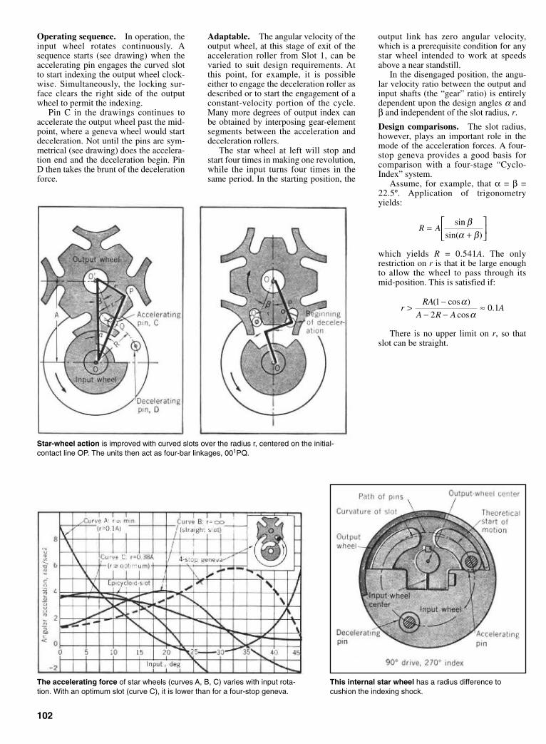
Operating sequence. In operation, theinput wheel rotates continuously. Asequence starts (see drawing) when theaccelerating pin engages the curved slotto start indexing the output wheel clock-wise. Simultaneously, the locking sur-face clears the right side of the outputwheel to permit the indexing.
Pin C in the drawings continues toaccelerate the output wheel past the mid-point, where a geneva wheel would startdeceleration. Not until the pins are sym-metrical (see drawing) does the accelera-tion end and the deceleration begin. PinD then takes the brunt of the decelerationforce.
Adaptable. The angular velocity of theoutput wheel, at this stage of exit of theacceleration roller from Slot 1, can bevaried to suit design requirements. Atthis point, for example, it is possibleeither to engage the deceleration roller asdescribed or to start the engagement of aconstant-velocity portion of the cycle.Many more degrees of output index canbe obtained by interposing gear-elementsegments between the acceleration anddeceleration rollers.
The star wheel at left will stop andstart four times in making one revolution,while the input turns four times in thesame period. In the starting position, the
output link has zero angular velocity,which is a prerequisite condition for anystar wheel intended to work at speedsabove a near standstill.
In the disengaged position, the angu-lar velocity ratio between the output andinput shafts (the “gear” ratio) is entirelydependent upon the design angles α andβ and independent of the slot radius, r.
Design comparisons. The slot radius,however, plays an important role in themode of the acceleration forces. A four-stop geneva provides a good basis forcomparison with a four-stage “Cyclo-Index” system.
Assume, for example, that α = β =22.5º. Application of trigonometryyields:
which yields R = 0.541A. The onlyrestriction on r is that it be large enoughto allow the wheel to pass through itsmid-position. This is satisfied if:
There is no upper limit on r, so thatslot can be straight.
rRA
A R AA>
−− −
≈( cos )
cos.
1
20 1
αα
R A=+
sin
sin( )
βα β
102
The accelerating force of star wheels (curves A, B, C) varies with input rota-tion. With an optimum slot (curve C), it is lower than for a four-stop geneva.
This internal star wheel has a radius difference to cushion the indexing shock.
Star-wheel action is improved with curved slots over the radius r, centered on the initial-contact line OP. The units then act as four-bar linkages, 001PQ.
Sclater Chapter 4 5/3/01 10:44 AM Page 102
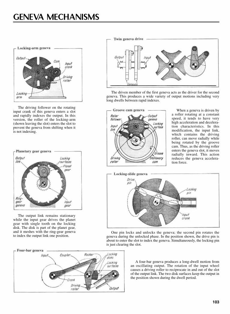
GENEVA MECHANISMS
103
The driving follower on the rotatinginput crank of this geneva enters a slotand rapidly indexes the output. In thisversion, the roller of the locking-arm(shown leaving the slot) enters the slot toprevent the geneva from shifting when itis not indexing.
The output link remains stationarywhile the input gear drives the planetgear with single tooth on the lockingdisk. The disk is part of the planet gear,and it meshes with the ring-gear genevato index the output link one position.
The driven member of the first geneva acts as the driver for the secondgeneva. This produces a wide variety of output motions including verylong dwells between rapid indexes.
When a geneva is driven bya roller rotating at a constantspeed, it tends to have veryhigh acceleration and decelera-tion characteristics. In thismodification, the input link,which contains the drivingroller, can move radially whilebeing rotated by the groovecam. Thus, as the driving rollerenters the geneva slot, it movesradially inward. This actionreduces the geneva accelera-tion force.
One pin locks and unlocks the geneva; the second pin rotates thegeneva during the unlocked phase. In the position shown, the drive pin isabout to enter the slot to index the geneva. Simultaneously, the locking pinis just clearing the slot.
A four-bar geneva produces a long-dwell motion froman oscillating output. The rotation of the input wheelcauses a driving roller to reciprocate in and out of the slotof the output link. The two disk surfaces keep the output inthe position shown during the dwell period.
Sclater Chapter 4 5/3/01 10:44 AM Page 103
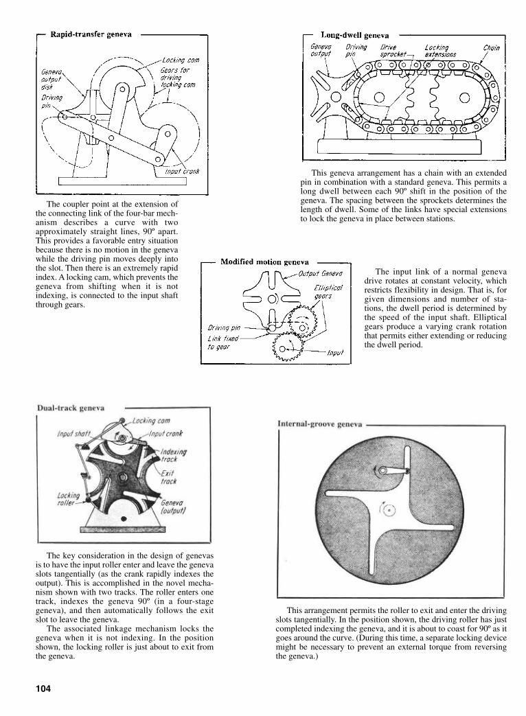
The key consideration in the design of genevasis to have the input roller enter and leave the genevaslots tangentially (as the crank rapidly indexes theoutput). This is accomplished in the novel mecha-nism shown with two tracks. The roller enters onetrack, indexes the geneva 90º (in a four-stagegeneva), and then automatically follows the exitslot to leave the geneva.
The associated linkage mechanism locks thegeneva when it is not indexing. In the positionshown, the locking roller is just about to exit fromthe geneva.
This geneva arrangement has a chain with an extendedpin in combination with a standard geneva. This permits along dwell between each 90º shift in the position of thegeneva. The spacing between the sprockets determines thelength of dwell. Some of the links have special extensionsto lock the geneva in place between stations.
104
The coupler point at the extension ofthe connecting link of the four-bar mech-anism describes a curve with twoapproximately straight lines, 90º apart.This provides a favorable entry situationbecause there is no motion in the genevawhile the driving pin moves deeply intothe slot. Then there is an extremely rapidindex. A locking cam, which prevents thegeneva from shifting when it is notindexing, is connected to the input shaftthrough gears.
The input link of a normal genevadrive rotates at constant velocity, whichrestricts flexibility in design. That is, forgiven dimensions and number of sta-tions, the dwell period is determined bythe speed of the input shaft. Ellipticalgears produce a varying crank rotationthat permits either extending or reducingthe dwell period.
This arrangement permits the roller to exit and enter the drivingslots tangentially. In the position shown, the driving roller has justcompleted indexing the geneva, and it is about to coast for 90º as itgoes around the curve. (During this time, a separate locking devicemight be necessary to prevent an external torque from reversingthe geneva.)
Sclater Chapter 4 5/3/01 10:44 AM Page 104
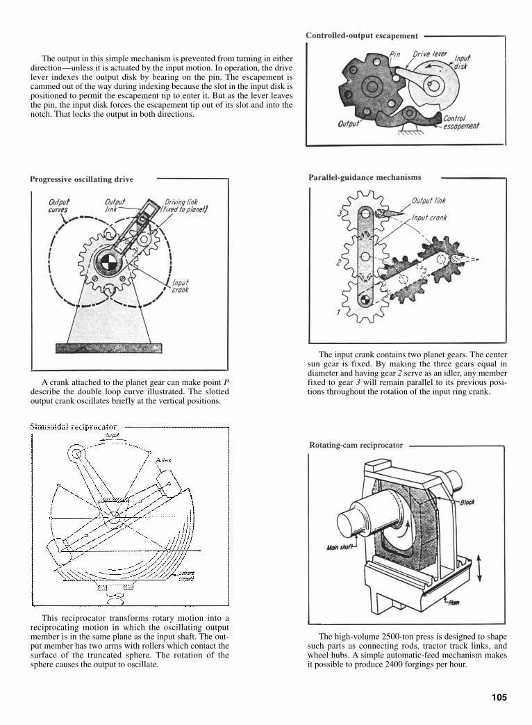
The output in this simple mechanism is prevented from turning in eitherdirection—unless it is actuated by the input motion. In operation, the drivelever indexes the output disk by bearing on the pin. The escapement iscammed out of the way during indexing because the slot in the input disk ispositioned to permit the escapement tip to enter it. But as the lever leavesthe pin, the input disk forces the escapement tip out of its slot and into thenotch. That locks the output in both directions.
A crank attached to the planet gear can make point Pdescribe the double loop curve illustrated. The slottedoutput crank oscillates briefly at the vertical positions.
105
This reciprocator transforms rotary motion into areciprocating motion in which the oscillating outputmember is in the same plane as the input shaft. The out-put member has two arms with rollers which contact thesurface of the truncated sphere. The rotation of thesphere causes the output to oscillate.
The input crank contains two planet gears. The centersun gear is fixed. By making the three gears equal indiameter and having gear 2 serve as an idler, any memberfixed to gear 3 will remain parallel to its previous posi-tions throughout the rotation of the input ring crank.
The high-volume 2500-ton press is designed to shapesuch parts as connecting rods, tractor track links, andwheel hubs. A simple automatic-feed mechanism makesit possible to produce 2400 forgings per hour.
Sclater Chapter 4 5/3/01 10:44 AM Page 105
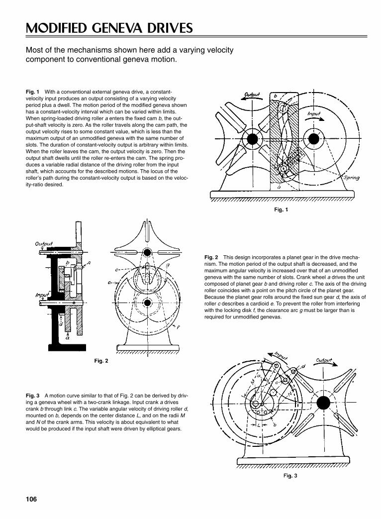
MODIFIED GENEVA DRIVESMost of the mechanisms shown here add a varying velocity component to conventional geneva motion.
Fig. 1 With a conventional external geneva drive, a constant-velocity input produces an output consisting of a varying velocityperiod plus a dwell. The motion period of the modified geneva shownhas a constant-velocity interval which can be varied within limits.When spring-loaded driving roller a enters the fixed cam b, the out-put-shaft velocity is zero. As the roller travels along the cam path, theoutput velocity rises to some constant value, which is less than themaximum output of an unmodified geneva with the same number ofslots. The duration of constant-velocity output is arbitrary within limits.When the roller leaves the cam, the output velocity is zero. Then theoutput shaft dwells until the roller re-enters the cam. The spring pro-duces a variable radial distance of the driving roller from the inputshaft, which accounts for the described motions. The locus of theroller’s path during the constant-velocity output is based on the veloc-ity-ratio desired.
Fig. 2 This design incorporates a planet gear in the drive mecha-nism. The motion period of the output shaft is decreased, and themaximum angular velocity is increased over that of an unmodifiedgeneva with the same number of slots. Crank wheel a drives the unitcomposed of planet gear b and driving roller c. The axis of the drivingroller coincides with a point on the pitch circle of the planet gear.Because the planet gear rolls around the fixed sun gear d, the axis ofroller c describes a cardioid e. To prevent the roller from interferingwith the locking disk f, the clearance arc g must be larger than isrequired for unmodified genevas.
106
Fig. 3 A motion curve similar to that of Fig. 2 can be derived by driv-ing a geneva wheel with a two-crank linkage. Input crank a drivescrank b through link c. The variable angular velocity of driving roller d,mounted on b, depends on the center distance L, and on the radii Mand N of the crank arms. This velocity is about equivalent to whatwould be produced if the input shaft were driven by elliptical gears.
Sclater Chapter 4 5/3/01 10:44 AM Page 106

Fig. 4 The duration of the dwell periods is changed by arranging thedriving rollers unsymmetrically around the input shaft. This does notaffect the duration of the motion periods. If unequal motion periodsand unequal dwell periods are desired, the roller crank-arms must beunequal in length and the star must be suitably modified. This mech-anism is called an irregular geneva drive.
107
Fig. 5 In this intermittent drive, the two rollers drive the output shaftand lock it during dwell periods. For each revolution of the input shaft,the output shaft has two motion periods. The output displacement ϕis determined by the number of teeth. The driving angle, ψ, can bechosen within limits. Gear a is driven intermittently by two drivingrollers mounted on input wheel b, which is bearing-mounted on framec. During the dwell period the rollers circle around the top of a tooth.During the motion period, a roller’s path d, relative to the driven gear,is a straight line inclined towards the output shaft. The tooth profile isa curve parallel to path d. The top land of a tooth becomes the arc ofa circle of radius R, and the arc approximates part of the path of aroller.
Fig. 6 An intermittent drive with a cylindrical lock. Shortly beforeand after the engagement of two teeth with driving pin d at the end ofthe dwell period, the inner cylinder f is unable to cause positive lock-ing of the driven gear. Consequently, a concentric auxiliary cylinder eis added. Only two segments are necessary to obtain positive lock-ing. Their length is determined by the circular pitch of the driven gear.
Sclater Chapter 4 5/3/01 10:44 AM Page 107

INDEXING AND INTERMITTENT MECHANISMS
This mechanism transmits intermittent motion betweentwo skewed shafts. The shafts need not be at right anglesto one another. Angular displacement of the output shaftper revolution of input shaft equals the circular pitch ofthe output gear wheel divided by its pitch radius. Theduration of the motion period depends on the length ofthe angular joint a of the locking disks b.
A “mutilated tooth” intermittent drive. Driver b is acircular disk of width w with a cutout d on its circumfer-ence. It carries a pin c close to the cutout. The drivengear, a, of width 2w has an even number of standard spurgear teeth. They alternately have full and half-width(mutilated) teeth. During the dwell period, two full-widthteeth are in contact with the circumference of the drivingdisk, thus locking it. The mutilated tooth between them isbehind the driver. AT the end of the dwell period, pin ccontacts the mutilated tooth and turns the driven gear onecircular pitch. Then, the full-width tooth engages thecutout d, and the driven gear moves one more pitch. Thenthe dwell period starts again and the cycle is repeated.
An operating cycle of 180º motion and 180º dwell isproduced by this mechanism. The input shaft drives therack, which is engaged with the output shaft gear duringhalf the cycle. When the rack engages, the lock teeth atthe lower end of the coulisse are disengaged and, con-versely, when the rack is disengaged, the coulisse teethare engaged. This action locks the output shaft positively.The changeover points occur at the dead-center posi-tions, so that the motion of the gear is continuously andpositively governed. By varying the radius R and thediameter of the gear, the number of revolutions made bythe output shaft during the operating half of the cycle canbe varied to suit many differing requirements.
108
Sclater Chapter 4 5/3/01 10:45 AM Page 108

109
A cam-driven ratchet.
A six-sided Maltese cross and dou-ble driver give a 3:1 ratio.
A cam operated escapement on a taximeter (a). A solenoid-operated escapement (b).
An escapement on anelectric meter.
A solenoid-operated ratchet with asolenoid-resetting mechanism A slidingwasher engages the teeth.
A plate oscillating across the plane of a ratchet-gearescapement carries stationary and spring-held pawls.
A worm drive, compensated by a cam on a workshaft, produces intermittent motion of the gear.
Sclater Chapter 4 5/3/01 10:45 AM Page 109

110
An intermittent counter mechanism. One revolution of the driveradvances the driven wheel 120º. The driven-wheel rear teeth arelocked on the cam surface during dwell.
Spiral and wheel. One revolution of the spiral advances the drivenwheel one tooth width. The driven-wheel tooth is locked in the drivergroove during dwell.
An internal geneva mechanism. The driver and driven wheel rotatein same direction. The duration of dwell is more than 180º of driverrotation.
A spherical geneva mechanism. The driver and driven wheel areon perpendicular shafts. The duration of dwell is exactly 180º ofdriver rotation.
An external geneva mechanism. The driver grooves lock the drivenwheel pins during dwell. During movement, the driver pin mates withthe driven-wheel slot.
A special planetary gear mechanism. The principle of relativemotion of mating gears illustrated in this method can be applied tospur gears in planetary system. The motion of the central planet gearproduces the motion of the summing gear.
Sclater Chapter 4 5/3/01 10:45 AM Page 110
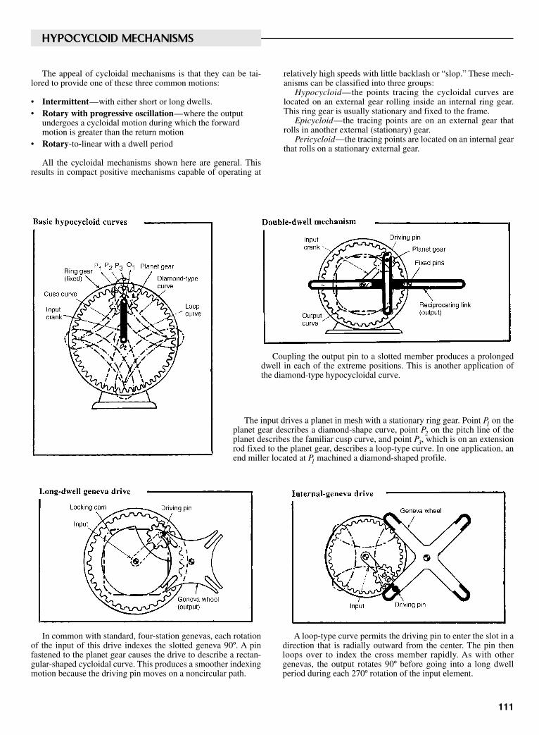
HYPOCYCLOID MECHANISMS
The appeal of cycloidal mechanisms is that they can be tai-lored to provide one of these three common motions:
• Intermittent—with either short or long dwells.• Rotary with progressive oscillation—where the output
undergoes a cycloidal motion during which the forwardmotion is greater than the return motion
• Rotary-to-linear with a dwell period
All the cycloidal mechanisms shown here are general. Thisresults in compact positive mechanisms capable of operating at
relatively high speeds with little backlash or “slop.” These mech-anisms can be classified into three groups:
Hypocycloid—the points tracing the cycloidal curves arelocated on an external gear rolling inside an internal ring gear.This ring gear is usually stationary and fixed to the frame.
Epicycloid—the tracing points are on an external gear thatrolls in another external (stationary) gear.
Pericycloid—the tracing points are located on an internal gearthat rolls on a stationary external gear.
Coupling the output pin to a slotted member produces a prolongeddwell in each of the extreme positions. This is another application ofthe diamond-type hypocycloidal curve.
The input drives a planet in mesh with a stationary ring gear. Point P1 on theplanet gear describes a diamond-shape curve, point P2 on the pitch line of theplanet describes the familiar cusp curve, and point P3, which is on an extensionrod fixed to the planet gear, describes a loop-type curve. In one application, anend miller located at P1 machined a diamond-shaped profile.
In common with standard, four-station genevas, each rotationof the input of this drive indexes the slotted geneva 90º. A pinfastened to the planet gear causes the drive to describe a rectan-gular-shaped cycloidal curve. This produces a smoother indexingmotion because the driving pin moves on a noncircular path.
A loop-type curve permits the driving pin to enter the slot in adirection that is radially outward from the center. The pin thenloops over to index the cross member rapidly. As with othergenevas, the output rotates 90º before going into a long dwellperiod during each 270º rotation of the input element.
111
Sclater Chapter 4 5/3/01 10:45 AM Page 111
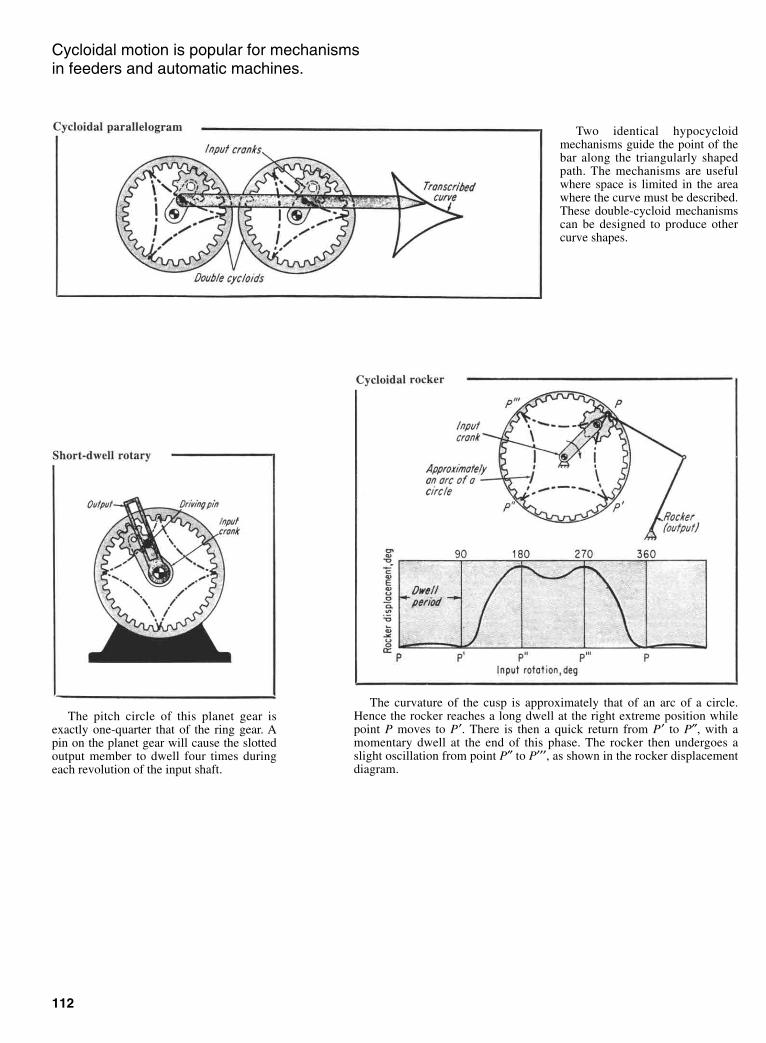
Cycloidal motion is popular for mechanisms in feeders and automatic machines.
The pitch circle of this planet gear isexactly one-quarter that of the ring gear. Apin on the planet gear will cause the slottedoutput member to dwell four times duringeach revolution of the input shaft.
112
Two identical hypocycloidmechanisms guide the point of thebar along the triangularly shapedpath. The mechanisms are usefulwhere space is limited in the areawhere the curve must be described.These double-cycloid mechanismscan be designed to produce othercurve shapes.
The curvature of the cusp is approximately that of an arc of a circle.Hence the rocker reaches a long dwell at the right extreme position whilepoint P moves to P′. There is then a quick return from P′ to P″, with amomentary dwell at the end of this phase. The rocker then undergoes aslight oscillation from point P″ to P′′′, as shown in the rocker displacementdiagram.
Sclater Chapter 4 5/3/01 10:45 AM Page 112
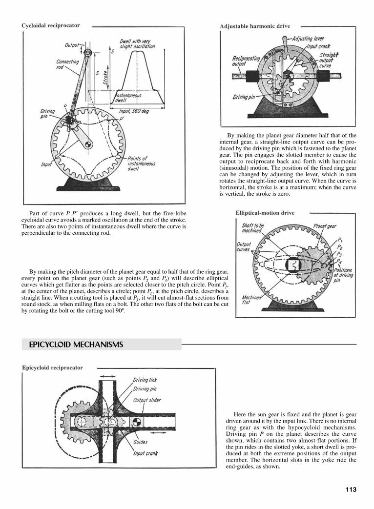
Part of curve P-P′ produces a long dwell, but the five-lobecycloidal curve avoids a marked oscillation at the end of the stroke.There are also two points of instantaneous dwell where the curve isperpendicular to the connecting rod.
By making the planet gear diameter half that of theinternal gear, a straight-line output curve can be pro-duced by the driving pin which is fastened to the planetgear. The pin engages the slotted member to cause theoutput to reciprocate back and forth with harmonic(sinusoidal) motion. The position of the fixed ring gearcan be changed by adjusting the lever, which in turnrotates the straight-line output curve. When the curve ishorizontal, the stroke is at a maximum; when the curveis vertical, the stroke is zero.
113
By making the pitch diameter of the planet gear equal to half that of the ring gear,every point on the planet gear (such as points P2 and P3) will describe ellipticalcurves which get flatter as the points are selected closer to the pitch circle. Point P1,at the center of the planet, describes a circle; point P4 , at the pitch circle, describes astraight line. When a cutting tool is placed at P3 , it will cut almost-flat sections fromround stock, as when milling flats on a bolt. The other two flats of the bolt can be cutby rotating the bolt or the cutting tool 90º.
Here the sun gear is fixed and the planet is geardriven around it by the input link. There is no internalring gear as with the hypocycloid mechanisms.Driving pin P on the planet describes the curveshown, which contains two almost-flat portions. Ifthe pin rides in the slotted yoke, a short dwell is pro-duced at both the extreme positions of the outputmember. The horizontal slots in the yoke ride theend-guides, as shown.
EPICYCLOID MECHANISMS
Sclater Chapter 4 5/3/01 10:45 AM Page 113

Three adjustable output-links provide a wide variety of oscil-lating motions. The input crank oscillates the central memberthat has an adjustable slot to vary the stroke. The oscillation istransferred to the two actuating rollers, which alternately enterthe geneva slots to index it, first in one direction and thenanother. Additional variation in output motion can be obtainedby adjusting the angular positions of the output cranks. The key concept in this indexer is its use of an
input gear that is smaller than the output gear. Thus,it can complete its circuit faster than the output gearwhen both are in mesh. In the left diagram, the actu-ating tooth of the input gear, tooth 1, strikes that ofthe output gear, tooth 2, to roll both gears into mesh.After one circuit of the input (right diagram), tooth 1is now ahead of tooth 2, the gears go out of mesh, andthe output gear stops (it is kept in position by the bot-tom locking detent) for almost 360º of the input gearrotation.
114
Here the output wheel rotates only when the plunger, which is normally kept inthe outer position by its spring, is cammed into the toothed wheel attached to theoutput. Thus, for every revolution of the input disk, the output wheel is drivenapproximately 60º, and then it stops for the remaining 300º.
In a typical scotch yoke, a, the motion of the rotating input crank is translated into the recip-rocating motion of the yoke. But this provides only an instantaneous dwell at each end. Toobtain long dwells, the left slot (in the modified version b) is curved with a radius equal to thatof the input crank radius. This causes a 90º dwell at the let end of the stroke. For the right end,the crank pushes aside the springloaded track swivel as it comes around the bend, and it isshunted into the second track to provide a 90º dwell at the right end as well.
This is a simple way to convert rotarymotion to reciprocating motion. Bothinput and output shafts are in line witheach other. The right half of the device is athree-dimensional reciprocator. Rotatingthe input crank causes its link to oscil-late. A second connecting link then con-verts that oscillation into the desired in-line output motion.
ROTARY-TO-RECIPROCATING DEVICES
Sclater Chapter 4 5/3/01 10:45 AM Page 114

115
VARIABLE SPEED DEVICES
By substituting elliptical gears for the usual circular gears, aplanetary drive is formed. It can provide extra-large variations inthe angular speed output.
This is a normal parallel-gear speed reducer, but it has cam actuation to providea desired variation in the output speed. If the center of the idler shaft were station-ary, the output motion would be uniform. But by attaching a cam to the idler shaft,the shaft has an oscillating motion which varies the final output motion.
ADJUSTABLE-SPEED DRIVES
The output of this novel drivecan be varied infinitely by changingthe distance that the balls will oper-ate from the main shaft line. Thedrive has multiple disks, free torotate on a common shaft, exceptfor the extreme left and right diskswhich are keyed to the input andoutput shafts, respectively. Everyother disk carries three uniformlyspaced balls which can be shiftedcloser to or away from the center bymoving the adjustment lever. Whendisk 1 rotates the first groupof balls, disk 3 will rotate slowerbecause of the different radii, rx1and rx2. Disk 3 will then drive disk5, and disk 5 will drive disk 7, allwith the same speed ratios, thuscompounding the ratios to get thefinal speed reduction.
The effective radii can be calcu-lated from
rx1 = Rx – 1/2 D cos ψ
rx2 = Rx + 1/2 D cos ψ
where Rx is the distance from theshaft center to the ball center, D isthe diameter of the ball, and ψ isone-half the cone angle.
Pulling or pushing the axial con-trol rod of this adjustable-pitch pro-peller linearly twists the propellerblades around on the common axisby moving the rack and geararrangement. A double rack, oneabove and on either side of theother, gives the opposing twistingmotion required for propellerblades.
Sclater Chapter 4 5/3/01 10:45 AM Page 115

ROTARY-TO-RECIPROCATING MOTION AND DWELL MECHANISMS
With proper dimensions, the rotation of the input link can impartan almost-constant velocity motion to the slider within the slot.
The rotary motion of the inputarm is translated into linear motion ofthe linkage end. The linkage is fixedto the smaller sprocket, and the largersprocket is fixed to the frame.
116
The rotation of the input gearcauses the connecting link, attached tothe machine frame, to oscillate. Thisaction produces a large-stroke recipro-cating motion in the output slider.
The rotary motion of the input shaft is translated into an oscil-lating motion of the output gear segment. The rack support andgear sector are pinned at C but the gear itself oscillates around B.
Sclater Chapter 4 5/3/01 10:45 AM Page 116

This linear reciprocator converts arotary motion into a reciprocating motionthat is in line with the input shaft.Rotation of the shaft drives the wormgear which is attached to the machineframe with a rod. Thus input rotationcauses the worm gear to draw itself (andthe worm) to the right—thus providing areciprocating motion. A hardened disk in this drive, riding at an angle to the axis of an input
roller, transforms the rotary motion into linear motion parallel to the axisof the input. The roller is pressed against the input shaft by flat spring F.The feed rate is easily varied by changing the angle of the disk. Thisarrangement can produce an extremely slow feed with a built-in safetyfactor in case of possible jamming.
117
Linear reciprocator Disk and roller drive
Bearing and roller drive
This drive arrangement avoids large Hertzian stresses between the disk androller by including three ball bearings in place of the single disk. The inner racesof the bearings make contact on one side or the other. Hence a gearing arrange-ment is required to alternate the angle of the bearings. This arrangement alsoreduces the bending moment on the shaft.
Reciprocating space crank
The rotary input of this crank causesthe bottom surface of link A to wobblewith respect to the center link. Link B isfree of link A, but it is restrained fromrotating by the slot. This causes the out-put member to reciprocate linearly.
Sclater Chapter 4 5/3/01 10:45 AM Page 117
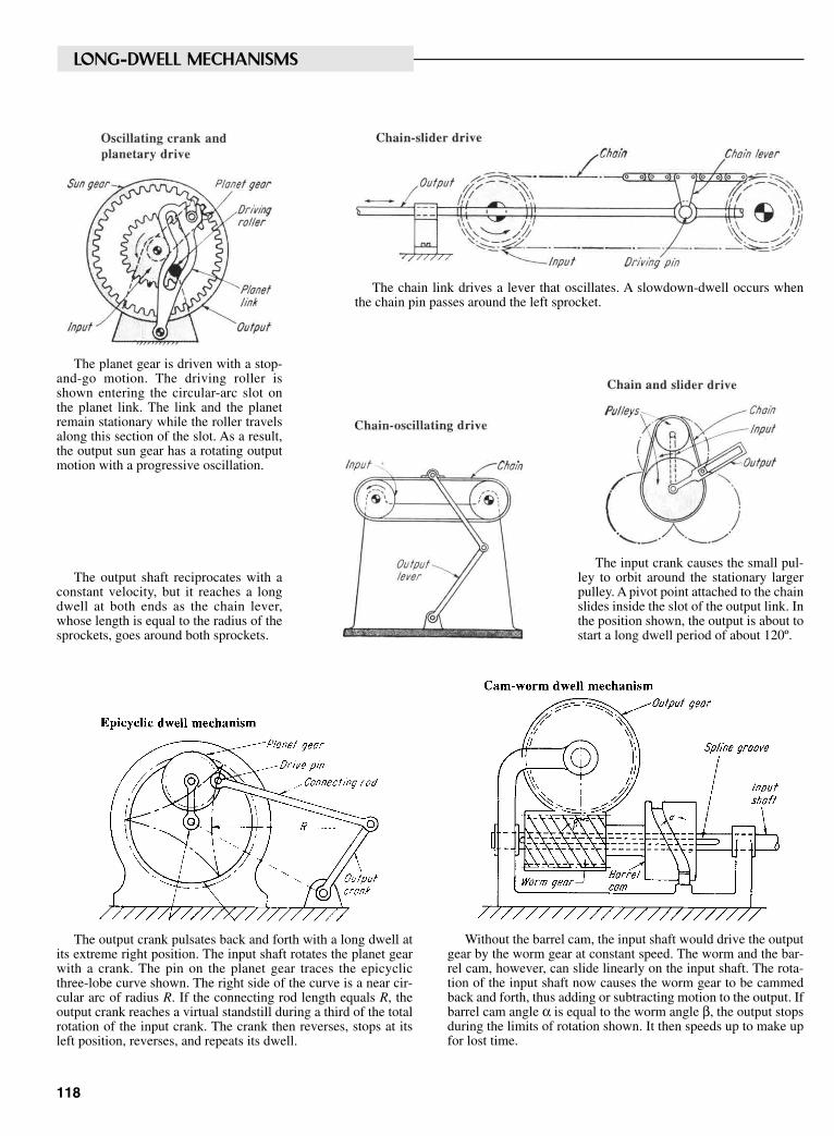
LONG-DWELL MECHANISMS
The planet gear is driven with a stop-and-go motion. The driving roller isshown entering the circular-arc slot onthe planet link. The link and the planetremain stationary while the roller travelsalong this section of the slot. As a result,the output sun gear has a rotating outputmotion with a progressive oscillation.
The chain link drives a lever that oscillates. A slowdown-dwell occurs whenthe chain pin passes around the left sprocket.
The input crank causes the small pul-ley to orbit around the stationary largerpulley. A pivot point attached to the chainslides inside the slot of the output link. Inthe position shown, the output is about tostart a long dwell period of about 120º.
The output shaft reciprocates with aconstant velocity, but it reaches a longdwell at both ends as the chain lever,whose length is equal to the radius of thesprockets, goes around both sprockets.
The output crank pulsates back and forth with a long dwell atits extreme right position. The input shaft rotates the planet gearwith a crank. The pin on the planet gear traces the epicyclicthree-lobe curve shown. The right side of the curve is a near cir-cular arc of radius R. If the connecting rod length equals R, theoutput crank reaches a virtual standstill during a third of the totalrotation of the input crank. The crank then reverses, stops at itsleft position, reverses, and repeats its dwell.
Without the barrel cam, the input shaft would drive the outputgear by the worm gear at constant speed. The worm and the bar-rel cam, however, can slide linearly on the input shaft. The rota-tion of the input shaft now causes the worm gear to be cammedback and forth, thus adding or subtracting motion to the output. Ifbarrel cam angle α is equal to the worm angle β, the output stopsduring the limits of rotation shown. It then speeds up to make upfor lost time.
118
Sclater Chapter 4 5/3/01 10:45 AM Page 118

A steel strip is fed at constant linear velocity in this mechanism. But at the die station(illustrated), it is desired to stop the strip so that the punching operation can be per-formed. The strip passes over movable rollers which, when shifted to the right, cause thestrip to move to the right. Since the strip is normally fed to the left, proper design of thecam can nullify the linear feed rates so that the strip stops, and then speeds to catch up tothe normal rate.
When one helical gear is shifted linearly (but prevented from rotating) it will impartrotary motion to the mating gear because of the helix angle. This principle is applied inthe mechanism illustrated. The rotation of the input shaft causes the intermediate shaft toshift to the left, which in turn adds or subtracts from the rotation of the output shaft.
The rotation of the input crank causesthe output bar to oscillate with a longdwell at its extreme right position. Thisoccurs because point C describes a curvethat is approximately a circular arc (fromC to C ′ with its center at P. The output isalmost stationary during that part of thecurve.
Cam-helical dwell mechanism Six-bar dwell mechanism
Cam-roller dwell mechanism Three-gear drive
This is actually a four-bar linkagecombined with three gears. As the inputcrank rotates, it turns the input gearwhich drives the output gear through theidler. Various output motions are possi-ble. Depending on the relative diametersof the gears, the output gear can pulsate,reach a short dwell, or even reverse itselfbriefly.
Double-crank dwell mechanism
Both cranks are connected to a common shaft which also acts as the input shaft.Thus the cranks always remain a constant distance apart from each other. There areonly two frame points—the center of the input shaft and the guide for the outputslider. As the output slider reaches the end of its stroke (to the right), it remains at avirtual standstill while one crank rotates through angle PP′.
119
Sclater Chapter 4 5/3/01 10:45 AM Page 119
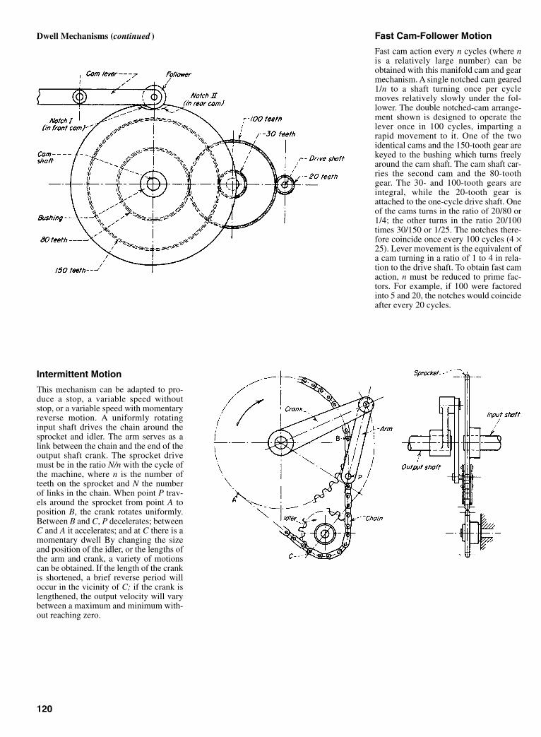
Fast Cam-Follower Motion
Fast cam action every n cycles (where nis a relatively large number) can beobtained with this manifold cam and gearmechanism. A single notched cam geared1/n to a shaft turning once per cyclemoves relatively slowly under the fol-lower. The double notched-cam arrange-ment shown is designed to operate thelever once in 100 cycles, imparting arapid movement to it. One of the twoidentical cams and the 150-tooth gear arekeyed to the bushing which turns freelyaround the cam shaft. The cam shaft car-ries the second cam and the 80-toothgear. The 30- and 100-tooth gears areintegral, while the 20-tooth gear isattached to the one-cycle drive shaft. Oneof the cams turns in the ratio of 20/80 or1/4; the other turns in the ratio 20/100times 30/150 or 1/25. The notches there-fore coincide once every 100 cycles (4 ×25). Lever movement is the equivalent ofa cam turning in a ratio of 1 to 4 in rela-tion to the drive shaft. To obtain fast camaction, n must be reduced to prime fac-tors. For example, if 100 were factoredinto 5 and 20, the notches would coincideafter every 20 cycles.
Intermittent Motion
This mechanism can be adapted to pro-duce a stop, a variable speed withoutstop, or a variable speed with momentaryreverse motion. A uniformly rotatinginput shaft drives the chain around thesprocket and idler. The arm serves as alink between the chain and the end of theoutput shaft crank. The sprocket drivemust be in the ratio N/n with the cycle ofthe machine, where n is the number ofteeth on the sprocket and N the numberof links in the chain. When point P trav-els around the sprocket from point A toposition B, the crank rotates uniformly.Between B and C, P decelerates; betweenC and A it accelerates; and at C there is amomentary dwell By changing the sizeand position of the idler, or the lengths ofthe arm and crank, a variety of motionscan be obtained. If the length of the crankis shortened, a brief reverse period willoccur in the vicinity of C; if the crank islengthened, the output velocity will varybetween a maximum and minimum with-out reaching zero.
120
Dwell Mechanisms (continued )
Sclater Chapter 4 5/3/01 10:45 AM Page 120
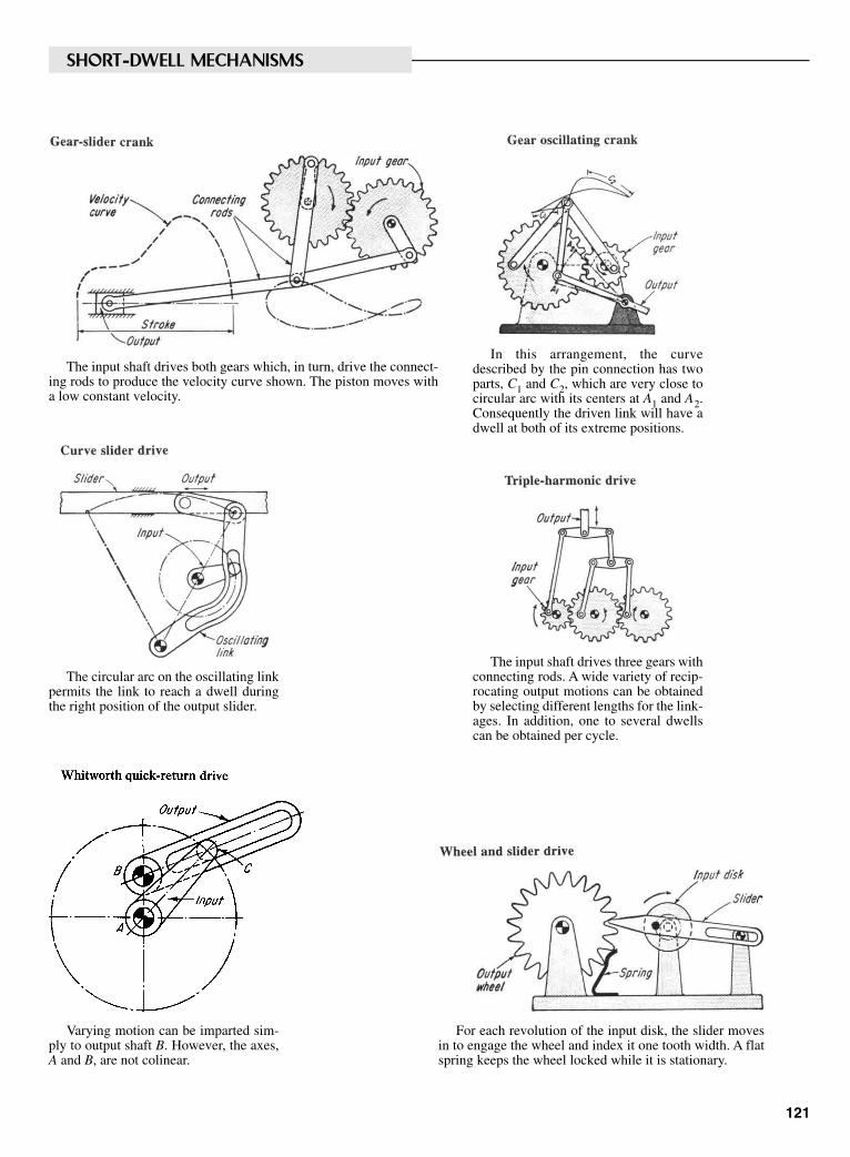
SHORT-DWELL MECHANISMS
The input shaft drives both gears which, in turn, drive the connect-ing rods to produce the velocity curve shown. The piston moves witha low constant velocity.
In this arrangement, the curvedescribed by the pin connection has twoparts, C1 and C2, which are very close tocircular arc with its centers at A1 and A2.Consequently the driven link will have adwell at both of its extreme positions.
The circular arc on the oscillating linkpermits the link to reach a dwell duringthe right position of the output slider.
The input shaft drives three gears withconnecting rods. A wide variety of recip-rocating output motions can be obtainedby selecting different lengths for the link-ages. In addition, one to several dwellscan be obtained per cycle.
Varying motion can be imparted sim-ply to output shaft B. However, the axes,A and B, are not colinear.
For each revolution of the input disk, the slider movesin to engage the wheel and index it one tooth width. A flatspring keeps the wheel locked while it is stationary.
121
Sclater Chapter 4 5/3/01 10:45 AM Page 121
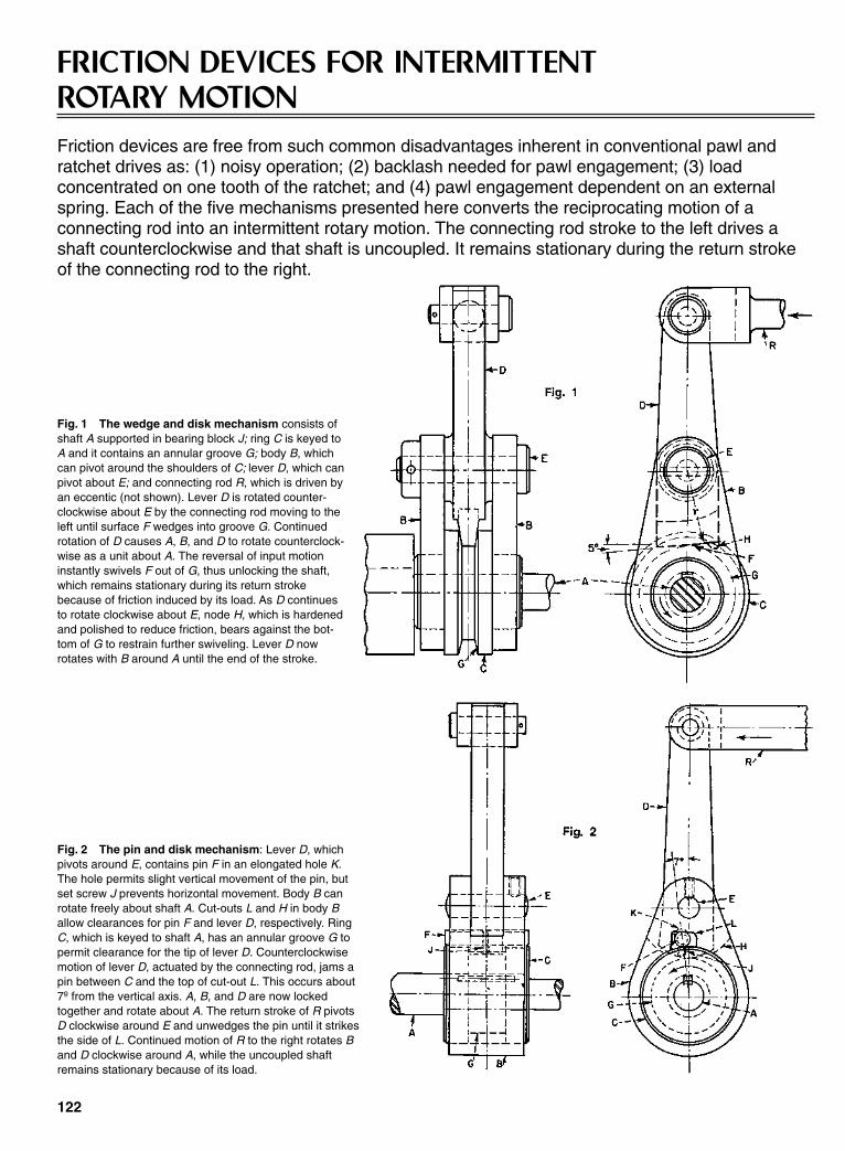
FRICTION DEVICES FOR INTERMITTENT ROTARY MOTIONFriction devices are free from such common disadvantages inherent in conventional pawl andratchet drives as: (1) noisy operation; (2) backlash needed for pawl engagement; (3) loadconcentrated on one tooth of the ratchet; and (4) pawl engagement dependent on an externalspring. Each of the five mechanisms presented here converts the reciprocating motion of aconnecting rod into an intermittent rotary motion. The connecting rod stroke to the left drives ashaft counterclockwise and that shaft is uncoupled. It remains stationary during the return strokeof the connecting rod to the right.
Fig. 1 The wedge and disk mechanism consists ofshaft A supported in bearing block J; ring C is keyed toA and it contains an annular groove G; body B, whichcan pivot around the shoulders of C; lever D, which canpivot about E; and connecting rod R, which is driven byan eccentic (not shown). Lever D is rotated counter-clockwise about E by the connecting rod moving to theleft until surface F wedges into groove G. Continuedrotation of D causes A, B, and D to rotate counterclock-wise as a unit about A. The reversal of input motioninstantly swivels F out of G, thus unlocking the shaft,which remains stationary during its return strokebecause of friction induced by its load. As D continuesto rotate clockwise about E, node H, which is hardenedand polished to reduce friction, bears against the bot-tom of G to restrain further swiveling. Lever D nowrotates with B around A until the end of the stroke.
Fig. 2 The pin and disk mechanism: Lever D, whichpivots around E, contains pin F in an elongated hole K.The hole permits slight vertical movement of the pin, butset screw J prevents horizontal movement. Body B canrotate freely about shaft A. Cut-outs L and H in body Ballow clearances for pin F and lever D, respectively. RingC, which is keyed to shaft A, has an annular groove G topermit clearance for the tip of lever D. Counterclockwisemotion of lever D, actuated by the connecting rod, jams apin between C and the top of cut-out L. This occurs about7º from the vertical axis. A, B, and D are now lockedtogether and rotate about A. The return stroke of R pivotsD clockwise around E and unwedges the pin until it strikesthe side of L. Continued motion of R to the right rotates Band D clockwise around A, while the uncoupled shaftremains stationary because of its load.
122
Sclater Chapter 4 5/3/01 10:45 AM Page 122

Fig. 3 The sliding pin and disk mecha-nism: The counterclockwise movement ofbody B about shaft A draws pin D to theright with respect to body B, aided by springpressure, until the flat bottom F of the pin iswedged against the annular groove E ofring C. The bottom of the pin is inclinedabout 5º for optimum wedging action. RingC is keyed to A, and parts, A, C, D and Bnow rotate counterclockwise as a unit untilthe end of the connecting rod’s stroke. Thereversal of B draws the pin out of engage-ment so that A remains stationary while thebody completes its clockwise rotation.
123
Fig. 4 The toggle link and disk mecha-nism: The input stroke of connecting rod R(to the left) wedges block F in groove G bystraightening toggle links D and E. Body B,toggle links, and ring C, which is keyed toshaft A, rotate counterclockwise togetherabout A until the end of the stroke. Thereversal of connecting rod motion lifts theblock, thus uncoupling the shaft, while bodyB continues clockwise rotation until the endof stroke.
Fig. 5 The rocker arm and disk mecha-nism: Lever D, activated by the reciprocat-ing bar R moving to the left, rotates coun-terclockwise on pivot E, thus wedging blockF into groove G of disk C. Shaft A is keyedto C and rotates counterclockwise as a unitwith body B and lever D. The return strokeof R to the right pivots D clockwise about Eand withdraws the block from the groove sothat shaft is uncoupled while D, strikingadjusting screw H, travels with B about Auntil the completion of stroke. Adjustingscrew J prevents wedging block F fromjamming in the groove.
Sclater Chapter 4 5/3/01 10:45 AM Page 123

NO TEETH ON THESE RATCHETSRatchets with springs, rollers, and other devices keep motion going one way.
Fig. 1 Swinging pawls lock on the rim when the lever swings for-ward, and release on the return stroke. Oversize holes for the sup-porting stud make sure that both the top and bottom surfaces of thepawls make contact.Fig. 2 A helical spring grips the shaft because its inner diameter issmaller than the outer diameter of shaft. During the forward stroke,the spring winds tighter; during the return stroke, it expands.Fig. 3 A V-belt sheave is pushed around when pawl wedges inthe groove. For a snug fit, the bottom of the pawl is tapered like aV-belt.Fig. 4 Eccentric rollers squeeze a disk on its forward stroke. Onthe return stroke, rollers rotate backwards and release their grip.Springs keep the rollers in contact with the disk.
Fig. 5 A rack is wedge-shaped so that it jams between the rollinggear and the disk, pushing the shaft forward. When the driving levermakes its return stroke, it carries along the unattached rack by thecross-piece.Fig. 6 A conical plate moves like a nut back and forth along thethreaded center hub of the lever. The light friction of spring-loadedpins keeps the plate from rotating with the hub.Fig. 7 Flat springs expand against the inside of a drum when alever moves one way, but they drag loosely when the lever turns thedrum in the opposite direction.Fig. 8 An eccentric cam jams against the disk during the motionhalf of a cycle. Elongated holes in the levers allow the cam to wedgeitself more tightly in place.
124
Sclater Chapter 4 5/3/01 10:45 AM Page 124

Construction details of a cam-planetary mechanism used in a film drive.
Do you want more variety in the kinds of output motion given bya planetary gear system? You can have it by controlling theplanet with a grooved cam. The method gives the mechanismthese additional features:
• Intermittent motion, with long dwells and minimum acceler-ation and deceleration.
• Cyclic variations in velocity.• Two levels, or more, of constant speed during each cycle of
the input.
The design is not simple because of need to synchronize theoutput of the planetary system with the cam contour. However,such mechanisms are now at work in film drives and should proveuseful in many automatic machines. Here are equations, tables,and a step-by-step sequence that will make the procedure easier.
How the Mechanism Works
The planet gear need not be cut in full—a gear sector will dobecause the planet is never permitted to make a full revolution.The sun gear is integral with the output gear. The planet arm isfixed to the input shaft, which is coaxial with the output shaft.Attached to the planet is a follower roller which rides in a camgroove. The cam is fixed to the frame.
The planet arm (input) rotates at constant velocity and makesone revolution with each cycle. Sun gear (output) also makes onerevolution during each cycle. Its motion is modified, however, bythe oscillatory motion of the planet gear relative to the planetarm. It is this motion that is controlled by the cam (a constant-radius cam would not affect the output, and the drive would giveonly a constant one-to-one ratio).
Comparison with Other Devices
A main feature of this cam-planetary mechanism is its ability to pro-duce a wide range of nonhomogeneous functions. These functionscan be defined by no less than two mathematical expressions, eachvalid for a discrete portion of the range. This feature is not shared bythe more widely known intermittent mechanisms: the external andinternal genevas, the three-gear drive, and the cardioid drive.
Either three-gear or cardioid can provide a dwell period—butonly for a comparatively short period of the cycle. With the cam-planetary, one can obtain over 180º of dwell during a 360º cycleby employing a 4-to-1 gear ratio between planet and sun.
And what about a cam doing the job by itself? This has thedisadvantage of producing reciprocating motion. In other words,the output will always reverse during the cycle—a conditionunacceptable in many applications.
Design Procedure
The basic equation for an epicyclic gear train is:dθS = d θA – ndθP–A
where: dθS = rotation of sun gear (output), degdθA = rotation of planet arm (input), degdθP–A = rotation of planet gear with respect to arm, degn = ratio of planet to sun gear.
The required output of the system is usually specified in theform of kinematic curves. Design procedure then is to:
• Select the proper planet-sun gear ratio• Develop the equations of the planet motion (which also func-
tions as a cam follower)• Compute the proper cam contour
CAM-CONTROLLED PLANETARY GEAR SYSTEMBy incorporating a grooved cam a novel mechanism can produce a wide variety of output motions.
125
Sclater Chapter 4 5/3/01 10:45 AM Page 125

CHAPTER 5SPECIAL-PURPOSE
MECHANISMS
Sclater Chapter 5 5/3/01 11:45 AM Page 127

128
NINE DIFFERENT BALL SLIDES FOR LINEAR MOTION
Fig. 1 V-grooves and flat surface make a simple horizontal ball slidefor reciprocating motion where no side forces are present and aheavy slide is required to keep the balls in continuous contact. Theball cage ensures the proper spacing of the balls and its contactingsurfaces are hardened and lapped.
Fig. 2 Double V grooves are necessary where the slide is in a verti-cal position or when transverse loads are present. Screw adjustmentor spring force is required to minimize any looseness in the slide.Metal-to-metal contact between the balls and grooves ensure accu-rate motion.
Fig. 3 The ball cartridge has the advantage of unlimited travelbecause the balls are free to recirculate. Cartridges are best suitedfor vertical loads. (A) Where lateral restraint is also required, this typeis used with a side preload. (B) For flat surfaces the cartridge is eas-ily adjusted.
Fig. 4 Commercial ball bearings can be used tomake a reciprocating slide. Adjustments are neces-sary to prevent looseness of the slide. (A) Slide withbeveled ends, (B) Rectangular-shaped slide.
Sclater Chapter 5 5/3/01 11:45 AM Page 128
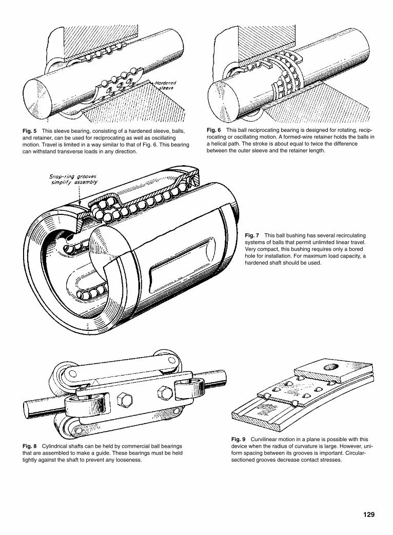
129
Fig. 5 This sleeve bearing, consisting of a hardened sleeve, balls,and retainer, can be used for reciprocating as well as oscillatingmotion. Travel is limited in a way similar to that of Fig. 6. This bearingcan withstand transverse loads in any direction.
Fig. 6 This ball reciprocating bearing is designed for rotating, recip-rocating or oscillating motion. A formed-wire retainer holds the balls ina helical path. The stroke is about equal to twice the differencebetween the outer sleeve and the retainer length.
Fig. 7 This ball bushing has several recirculatingsystems of balls that permit unlimited linear travel.Very compact, this bushing requires only a boredhole for installation. For maximum load capacity, ahardened shaft should be used.
Fig. 8 Cylindrical shafts can be held by commercial ball bearingsthat are assembled to make a guide. These bearings must be heldtightly against the shaft to prevent any looseness.
Fig. 9 Curvilinear motion in a plane is possible with thisdevice when the radius of curvature is large. However, uni-form spacing between its grooves is important. Circular-sectioned grooves decrease contact stresses.
Sclater Chapter 5 5/3/01 11:45 AM Page 129
130
BALL-BEARING SCREWS CONVERT ROTARY TOLINEAR MOTION
This cartridge-operated rotary actuator quicklyretracts the webbing to separate a pilot forciblyfrom his seat as the seat is ejected in emergen-cies. It eliminates the tendency of both pilot andseat to tumble together after ejection, preventingthe opening of the chute. Gas pressure from theejection device fires the cartridge in the actuator toforce the ball-bearing screw to move axially. Thelinear motion of the screw is translated into therotary motion of a ball nut. This motion rapidly rollsup the webbing (stretching it as shown) so that thepilot is snapped out of his seat.
This time-delay switching device integrates a time func-tion with a missile’s linear travel. Its purpose is to arm thewarhead safely. A strict “minimum G-time” system mightarm a slow missile too soon for the adequate protection offriendly forces because a fast missile might arrive beforethe warhead is fused. The weight of the nut plus the inertiaunder acceleration will rotate the ball-bearing screw whichhas a flywheel on its end. The screw pitch is selected sothat the revolutions of the flywheel represent the distancethe missile has traveled.
Fast, easy, and accurate control of fluid flowthrough a valve is obtained by the rotary motionof a screw in the stationary ball nut. The screwproduces linear movement of the gate. The swiveljoint eliminates rotary motion between the screwand the gate.
Sclater Chapter 5 5/3/01 11:45 AM Page 130
three identical pinion gears at the cornersof an equilateral triangle. The centralgear is driven by a hand-cranked ormotor-driven drive gear similar to one ofthe pinion gears.
Each pinion gear is mounted on a hol-low shaft that turns on precise ball bear-ings, and the hollow shaft contains a pre-cise internal thread that mates with oneof the leadscrews. One end of each lead-screw is attached to the movable plate.The meshing of the pinions and the cen-tral gear is set so that the three lead-screws are aligned with each other andthe movable plate is parallel with thefixed plate.
This work was done by Frank S.Calco of Lewis Research Center.
131
THREE-POINT GEAR/LEADSCREW POSITIONINGThe mechanism helps keep the driven plate parallel to a stationary plate.Lewis Research Center, Cleveland, Ohio
A triple-ganged-leadscrew positioningmechanism drives a movable platetoward or away from a fixed plate andkeeps the plates parallel to each other.The mechanism was designed for use intuning a microwave resonant cavity. Theparallel plates are the end walls, and thedistance between is the critical dimen-sion to be adjusted. Other potential appli-cations for this or similar mechanismsinclude adjustable bed plates and can-tilever tail stocks in machine tools,adjustable platforms for optical equip-ment, and lifting platforms.
In the original tunable-microwave-cavity application, the new mechanismreplaces a variety of prior mechanisms.Some of those included single-pointdrives that were subject to backlash (with
consequent slight tilting and uncertaintyin the distance between the plates). Otherprior mechanisms relied on spring load-ing, differential multiple-point drives andother devices to reduce backlash. In pro-viding three-point drive along a trackbetween the movable and fixed plates,the new mechanism ensures the distancebetween, and parallelism of, the twoplates. It is based on the fundamentalgeometric principle that three pointsdetermine a plane.
The moving parts of the mechanismare mounted on a fixed control bracketthat, in turn, is mounted on the same rigidframe that holds the fixed plate and thetrack along which the movable platetravels (see figure). A large central gearturns on precise ball bearings and drives
The Triple-Ganged-Leadscrew Mechanism, shown here greatly simplified, positions the movableplate along the track while keeping the movable plate parallel to the fixed plate.
Sclater Chapter 5 5/3/01 11:45 AM Page 131
• Pick point B on PQ. For greateststraight-line motion, B should be ator near the midpoint of PQ.
• Lay off length PD along FQ from Fto find point E.
• Draw BE and its perpendicular bisec-tor to find point A.
• Pick any point C. Lay off length PCon FQ from F to find point G.
• Draw CG and its perpendicular bisec-tor to find D. The basic mechanism isABCD with PQ as the extension ofBC.
Multilinked versions. A “gang”arrangement (Fig. 8) can be useful forstamping or punching five evenly spacedholes at one time. Two basic linkages arejoined, and the Q points will provideshort, powerful strokes.
An extended dual arrangement (Fig.9) can support the traveling point at bothends and can permit a long stroke with nointerference. A doubled-up parallelarrangement (Fig. 10) provides a rigidsupport and two pivot points to obtainthe straight-line motion of a horizontalbar.
When the traveling point is allowed toclear the pivot support (Fig. 11), the ulti-mate path will curve upward to provide ahandy “kick” action. A short kick isobtained by adding a stop (Fig. 12) toreverse the direction of the frame linkswhile the long coupler continues itsstroke. Daniel suggested that this curvedpath is useful in engaging or releasing anobject on a straight path.
132
UNIQUE LINKAGE PRODUCES PRECISE STRAIGHT-LINE MOTIONA patented family of straight-line mechanisms promises to serve many demands for movement without guideways and with low friction.
A mechanism for producing, withoutguideways, straight-line motion veryclose to true has been invented by JamesA Daniel, Jr., Newton, N.J. A patent hasbeen granted, and the linkage wasapplied to a camera to replace slides andtelescoping devices.
Linkages, with their minimal pivotfriction, serve many useful purposes inmachinery, replacing sliding and rollingparts that need guideways or one type oranother.
James Watt, who developed the firstsuch mechanism in 1784, is said to havebeen prouder of it than of his steamengine. Other well-known linkage inven-tors include Evans, Tchebicheff, Roberts,and Scott-Russell.
Four-bar arrangement. Like othermechanisms that aim at straight-linemotion, the Daniel design is based on thecommon four-bar linkage. Usually it isthe selection of a certain point on thecenter link—the “coupler,” which canextend past its pivot points—and of thelocation and proportions of the links thatis the key to a straight-line device.
According to Daniel, the deviation ofhis mechanism from a straight line is “sosmall it cannot easily be measured.” Also,the linkage has the ability to support aweight from the moving point of interestwith an equal balance as the point movesalong. “This gives the mechanism powersof neutral equilibrium,” said Daniel.
Patented action. The basic version ofDaniel’s mechanism (Fig. 1) consists ofthe four-bar ABCD. The coupler link BC
is extended to P (the proportions of thelinks must be selected according to arule). Rotation of link CD about D (Fig.2) causes BA to rotate about A and pointP to follow approximately a straight lineas it moves to P1. Another point, Q, willmove along a straight path to Q1, alsowithout need for a guide. A weight hungon P would be in equilibrium.
“At first glance,” said Daniel, “theEvans linkage [Fig. 4] may look similarto mine, but link CD, being offset fromthe perpendicular at A, prevents the pathof P from being a straight line.”
Watt’s mechanism EFGD (Fig. 5) isanother four-bar mechanism that willproduce a path of C that is roughly astraight line as EF or GD is rotated.Tchebicheff combined the Watt andEvans mechanisms to create a linkage inwhich point C will move almost perpen-dicularly to the path of P.
Steps in layout. Either end of the cou-pler can be redundant when only onestraight-line movement is required (Fig.6). Relative lengths of the links andplacement of the pivots are critical,although different proportions are easilyobtained for design purposes (Fig. 7).One proportion, for example, allows thepath of P to pass below the lower supportpivot, giving complete clearance to thetraveling member. Any Daniel mecha-nism can be laid out as follows:
• Lay out any desired right trianglePQF (Fig. 3). Best results are withangle A approximately 75 to 80º.
Sclater Chapter 5 5/3/01 11:45 AM Page 132

133
Sclater Chapter 5 5/3/01 11:45 AM Page 133
134
TWELVE EXPANDING AND CONTRACTING DEVICESParallel bars, telescoping slides, and other devices that can spark answers to many design problems.
Fig. 1
Figs. 1 and 2 Expanding grilles are oftenput to work as a safety feature. A single par-allelogram (fig. 1) requires slotted bars; adouble parallelogram (fig. 2) requiresnone—but the middle grille-bar must beheld parallel by some other method.
Fig. 3 Variable motion can be produced with this arrangement.In (A) position, the Y member is moving faster than the X member.In (B), speeds of both members are instantaneously equal. If themotion is continued in the same direction, the speed of X willbecome greater.
Figs. 4, 5, and 6 Multibar barriers such as shutters andgates (fig. 4) can take various forms. Slots (fig. 5) allowfor vertical adjustment. The space between bars can bemade adjustable (fig. 6) by connecting the vertical barswith parallel links.
Fig. 7 Telescoping cylinders are thebasis for many expanding and contractingmechanisms. In the arrangement shown,nested tubes can be sealed and filled with ahighly temperature-responsive mediumsuch as a volatile liquid.
Fig. 2
Sclater Chapter 5 5/3/01 11:45 AM Page 134
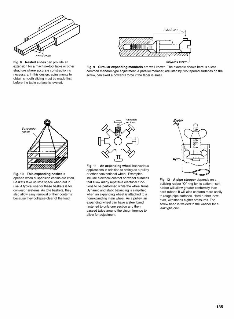
135
Fig. 8 Nested slides can provide anextension for a machine-tool table or otherstructure where accurate construction isnecessary. In this design, adjustments toobtain smooth sliding must be made firstbefore the table surface is leveled.
Fig. 9 Circular expanding mandrels are well-known. The example shown here is a lesscommon mandrel-type adjustment. A parallel member, adjusted by two tapered surfaces on thescrew, can exert a powerful force if the taper is small.
Fig. 10 This expanding basket isopened when suspension chains are lifted.Baskets take up little space when not inuse. A typical use for these baskets is forconveyor systems. As tote baskets, theyalso allow easy removal of their contentsbecause they collapse clear of the load.
Fig. 11 An expanding wheel has variousapplications in addition to acting as a pulleyor other conventional wheel. Examplesinclude electrical contact on wheel surfacesthat allow many repetitive electrical func-tions to be performed while the wheel turns.Dynamic and static balancing is simplifiedwhen an expanding wheel is attached to anonexpanding main wheel. As a pulley, anexpanding wheel can have a steel bandfastened to only one section and thenpassed twice around the circumference toallow for adjustment.
Fig. 12 A pipe stopper depends on abuilding rubber “O” ring for its action—softrubber will allow greater conformity thanhard rubber. It will also conform more easilyto rough pipe surfaces. Hard rubber, how-ever, withstands higher pressures. Thescrew head is welded to the washer for aleaktight joint.
Sclater Chapter 5 5/3/01 11:45 AM Page 135
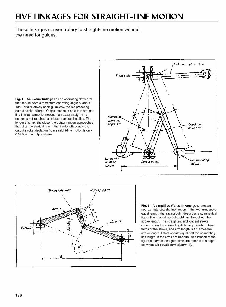
136
FIVE LINKAGES FOR STRAIGHT-LINE MOTIONThese linkages convert rotary to straight-line motion without the need for guides.
Fig. 1 An Evans’ linkage has an oscillating drive-armthat should have a maximum operating angle of about40º. For a relatively short guideway, the reciprocatingoutput stroke is large. Output motion is on a true straightline in true harmonic motion. If an exact straight-linemotion is not required, a link can replace the slide. Thelonger this link, the closer the output motion approachesthat of a true straight line. If the link-length equals theoutput stroke, deviation from straight-line motion is only0.03% of the output stroke.
Fig. 2 A simplified Watt’s linkage generates anapproximate straight-line motion. If the two arms are ofequal length, the tracing point describes a symmetricalfigure 8 with an almost straight line throughout thestroke length. The straightest and longest strokeoccurs when the connecting-link length is about two-thirds of the stroke, and arm length is 1.5 times thestroke length. Offset should equal half the connecting-link length. If the arms are unequal, one branch of thefigure-8 curve is straighter than the other. It is straight-est when a/b equals (arm 2)/(arm 1).
Sclater Chapter 5 5/3/01 11:45 AM Page 136
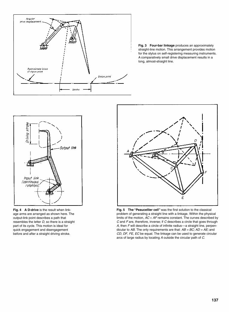
137
Fig. 3 Four-bar linkage produces an approximatelystraight-line motion. This arrangement provides motionfor the stylus on self-registering measuring instruments.A comparatively small drive displacement results in along, almost-straight line.
Fig. 4 A D-drive is the result when link-age arms are arranged as shown here. Theoutput-link point describes a path thatresembles the letter D, so there is a straightpart of its cycle. This motion is ideal forquick engagement and disengagementbefore and after a straight driving stroke.
Fig. 5 The “Peaucellier cell” was the first solution to the classicalproblem of generating a straight line with a linkage. Within the physicallimits of the motion, AC × AF remains constant. The curves described byC and F are, therefore, inverse; if C describes a circle that goes throughA, then F will describe a circle of infinite radius—a straight line, perpen-dicular to AB. The only requirements are that: AB = BC; AD = AE; andCD, DF, FE, EC be equal. The linkage can be used to generate circulararcs of large radius by locating A outside the circular path of C.
Sclater Chapter 5 5/3/01 11:45 AM Page 137

138
LINKAGE RATIOS FOR STRAIGHT-LINE MECHANISMS
Fig. 1 (a), (b), (c), (d),(e)—Isoceles linkages.
Fig. 3 The guide slotis designed to produce straight-linemotion.
Fig. 5 Watt’s linkage.
Fig. 4 (a), (b), (c), (d)—Pantograph linkages.
Fig. 2 Robert’s linkage.
Fig. 6 Tchebicheff combination linkage.
Fig. 7 Tchebicheff’s linkage.
Fig. 8 Walschaertvalve gear.
Sclater Chapter 5 5/3/01 11:45 AM Page 138

139
LINKAGES FOR OTHER MOTIONS
Fig. 2 A slight modification of the mecha-nism in Fig. 1 will produce another type ofuseful motion. If the planet gear has thesame diameter as that of the sun gear, thearm will remain parallel to itself throughoutthe complete cycle. All points on the armwill thereby describe circles of radius R.Here again, the position and diameter of theidler gear have no geometrical importance.This mechanism can be used, for example,to cross-perforate a uniformly moving paperweb. The value for R is chosen so that 2πR,or the circumference of the circle describedby the needle carrier, equals the desireddistance between successive lines of perfo-rations. If the center distance R is madeadjustable, the spacing of perforated linescan be varied as desired.
Fig. 3 To describe a “D” curve, begin atthe straight part of path G, and replace theoval arc of C with a circular arc that will setthe length of link DC.
Fig. 4 This mechanism can act as a film-strip hook that will describe a nearly straight line. Itwill engage and disengage the film perforation in a direction approximately normal to the film.Slight changes in the shape of the guiding slot f permit the shape of the output curve and thevelocity diagram to be varied.
Fig. 1 No linkages or guides are included inthis modified hypocyclic drive which is rela-tively small in relation to the length of its stroke.The sun gear of pitch diameter D is stationary.The drive shaft, which turns the T-shaped arm,is concentric with this gear. The idler andplanet gears, with pitch diameters of D/2, rotatefreely on pivots in the arm extensions. Thepitch diameter of the idler has no geometricalsignificance, although this gear does have animportant mechanical function. It reverses therotation of the planet gear, thus producing truehypocyclic motion with ordinary spur gearsonly. Such an arrangement occupies onlyabout half as much space as does an equiva-lent mechanism containing an internal gear.The center distance R is the sum of D/2, D/4,and an arbitrary distance d, determined by spe-cific applications. Points A and B on the drivenlink, which is fixed to the planet, describestraight-line paths through a stroke of 4R. Allpoints between A and B trace ellipses, whilethe line AB envelopes an astroid.
Sclater Chapter 5 5/3/01 11:45 AM Page 139

140
FIVE CARDAN-GEAR MECHANISMSThese gearing arrangements convert rotary into straight-line motion, without the need for slideways.
Fig. 1 Cardan gearing works on the principle that anypoint on the periphery of a circle rolling on the inside ofanother circle describes, in general, a hypocyloid. Thiscurve degenerates into a true straight line (diameter ofthe larger circle) if the diameters of both circles are in theratio of 1:2. The rotation of the input shaft causes a smallgear to roll around the inside of the fixed gear. A pinlocated on the pitch circle of the small gear describes astraight line. Its linear displacement is proportional to thetheoretically true sine or cosine of the angel throughwhich the input shaft is rotated.
Fig. 2 Cardan gearing and a Scotch yoke incombination provide an adjustable stroke. Theangular position of the outer gear is adjustable.The adjusted stroke equals the projection of thelarge diameter, along which the drive pin travels,on the Scotch-yoke’s centerline. The yoke motionis simple harmonic.
Sclater Chapter 5 5/3/01 11:45 AM Page 140
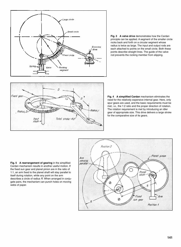
141
Fig. 3 A valve drive demonstrates how the Cardanprinciple can be applied. A segment of the smaller circlerocks back and forth on a circular segment whoseradius is twice as large. The input and output rods areeach attached to points on the small circle. Both thesepoints describe straight lines. The guide of the valverod prevents the rocking member from slipping.
Fig. 4 A simplified Cardan mechanism eliminates theneed for the relatively expensive internal gear. Here, onlyspur gears are used, and the basic requirements must bemet, i.e., the 1:2 ratio and the proper direction of rotation.The rotation requirement is met by introducing an idlergear of appropriate size. This drive delivers a large strokefor the comparative size of its gears.
Fig. 5 A rearrangement of gearing in the simplifiedCardan mechanism results in another useful motion. Ifthe fixed sun gear and planet pinion are in the ratio of1:1, an arm fixed to the planet shaft will stay parallel toitself during rotation, while any point on the armdescribes a circle of radius R. When arranged in conju-gate pairs, the mechanism can punch holes on movingwebs of paper.
Sclater Chapter 5 5/3/01 11:45 AM Page 141
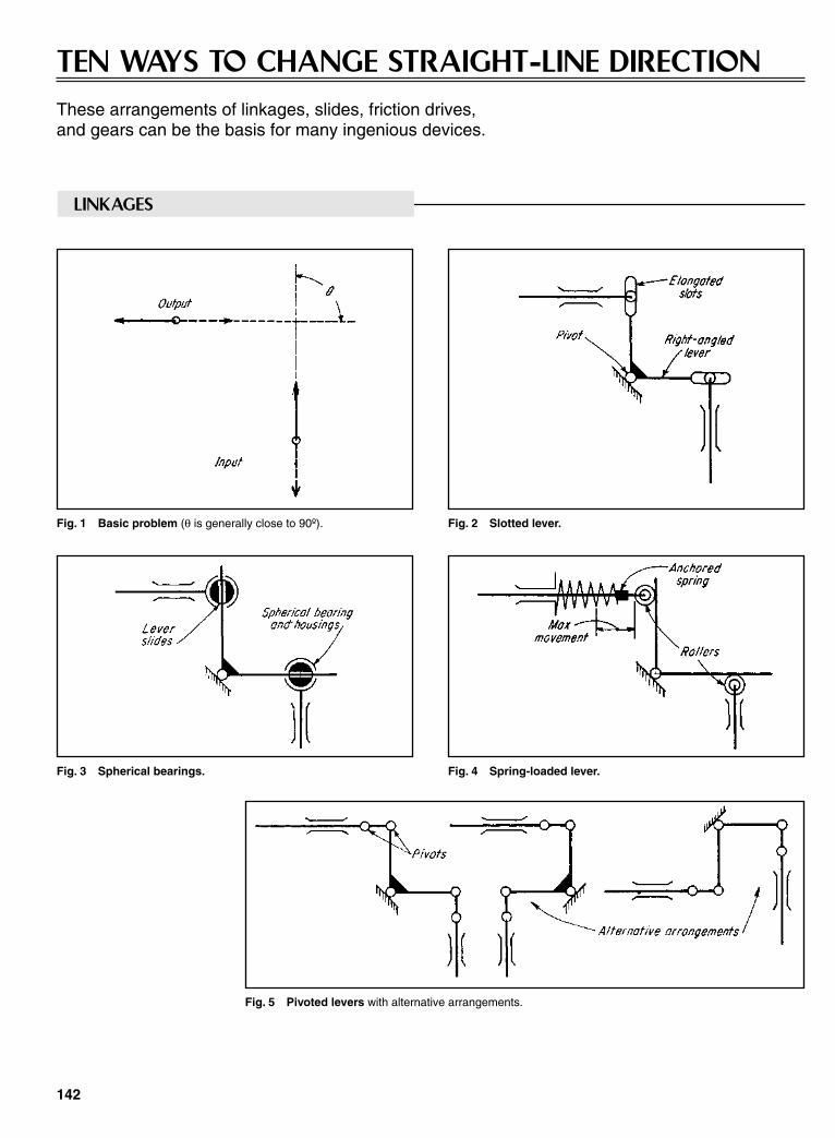
142
TEN WAYS TO CHANGE STRAIGHT-LINE DIRECTIONThese arrangements of linkages, slides, friction drives, and gears can be the basis for many ingenious devices.
LINKAGES
Fig. 1 Basic problem (θ is generally close to 90º). Fig. 2 Slotted lever.
Fig. 3 Spherical bearings. Fig. 4 Spring-loaded lever.
Fig. 5 Pivoted levers with alternative arrangements.
Sclater Chapter 5 5/3/01 11:45 AM Page 142

143
GUIDES
Fig. 6 Single connecting rod (left) is relocated(right) to eliminate the need for extra guides.
FRICTION DRIVES
Fig. 7 Inclined bearing-guide. Fig. 8 A belt, steel band, or rope around the drum is fastened to the drivingand driven members; sprocket-wheels and chain can replace the drum and belt.
Fig. 9 Matching gear-segments.Fig. 10 Racks and coupled pinions (can be substituted as friction surfaces fora low-cost setup).
GEARS
Sclater Chapter 5 5/3/01 11:45 AM Page 143

144
NINE MORE WAYS TO CHANGE STRAIGHT-LINEDIRECTIONThese mechanisms, based on gears, cams, pistons, and solenoids, supplement ten similar arrangements employing linkages, slides, friction drives, and gears.
Fig. 1 An axial screw with a rack-actuated gear (A) and an articulated driving rod (B)are both irreversible movements, i.e., the driver must always drive.
Fig. 2 A rack-actuated gear with associatedbevel gears is reversible.
Fig. 3 An articulated rod on a crank-typegear with a rack driver. Its action is restrictedto comparatively short movements.
Fig. 4 A cam and spring-loaded follower allows an input/output ratio to be varied accordingto cam rise. The movement is usually irreversible.
Sclater Chapter 5 5/3/01 11:45 AM Page 144

145
Fig. 5 An offset driver actuates a driven member by wedge action.Lubrication and materials with a low coefficient of friction permit theoffset to be maximized.
Fig. 6 A sliding wedge is similar to an offset driver but it requiresa spring-loaded follower; also, low friction is less critical with a rollerfollower.
Fig. 7 A fluid coupling allows motion to be transmitted through anyangle. Leak problems and accurate piston-fitting can make thismethod more expensive than it appears to be. Also, although theaction is reversible, it must always be compressive for the bestresults.
Fig. 8 A pneumatic system with a two-way valve is ideal whenonly two extreme positions are required. The action is irreversible.The speed of a driven member can be adjusted by controlling theinput of air to the cylinder.
Fig. 9 Solenoids and a two-way switch are organized asan analogy of a pneumatic system. Contact with the ener-gized solenoid is broken at the end of each stroke. The actionis irreversible.
Sclater Chapter 5 5/3/01 11:45 AM Page 145

146
LINKAGES FOR ACCELERATING AND DECELERATINGLINEAR STROKESWhen ordinary rotary camscannot be convenientlyapplied, the mechanismspresented here, oradaptations of them, offer avariety of interestingpossibilities for obtainingeither acceleration ordeceleration, or both.
Fig. 1 A slide block with a pinion andshaft and a pin for link B reciprocates at aconstant rate. The pinion has a crankpin formounting link D, and it also engages a sta-tionary rack. The pinion can make one com-plete revolution at each forward stroke ofthe slide block and another as the slideblock returns in the opposite direction.However, if the slide block is not movedthrough its normal travel range, the pinionturns only a fraction of a revolution. Themechanism can be made variable by mak-ing the connection link for F adjustablealong the length of the element that con-nects links B and D. Alternatively, thecrankpin for link D can be made adjustablealong the radius of the pinion, or both theconnection link and the crankpin can bemade adjustable.
Fig. 2 A drive rod, reciprocating at a con-stant rate, rocks link BC about a pivot on astationary block. A toggle between arm Band the stationary block contacts an abut-ment. Motion of the drive rod through thetoggle causes deceleration of driven link B.As the drive rod moves toward the right, thetoggle is actuated by encountering the abut-ment. The slotted link BC slides on its pivotwhile turning. This lengthens arm B andshortens arm C of link BC. The result isdeceleration of the driven link. The toggle isreturned by a spring (not shown) on thereturn stroke, and its effect is to acceleratethe driven link on its return stroke.
Sclater Chapter 5 5/3/01 11:46 AM Page 146

Fig. 3 The same direction of travel forboth the drive rod and the drive link is pro-vided by the variation of the Fig. 2 mecha-nism. Here, acceleration is in the directionof the arrows, and deceleration occurs onthe return stroke. The effect of accelerationdecreases as the toggle flattens.
Fig. 4 A bellcrank motion is acceleratedas the rollers are spread apart by a curvedmember on the end of the drive rod,thereby accelerating the motion of the slideblock. The driven elements must bereturned by spring to close the system.
Fig. 5 A constant-speed shaft winds upa thick belt or similar flexible connectingmember, and its effective increase in radiuscauses the slide block to accelerate. It mustbe returned by a spring or weight on itsreversal.
Fig. 6 An auxiliary block that carriessheaves for a cable which runs between thedriving and driven slide block is mounted ontwo synchronized eccentrics. The motion ofthe driven block is equal to the length of thecable paid out over the sheaves, resultingfrom the additive motions of the driving andauxiliary blocks.
Fig. 7 A curved flange on the driving slideblock is straddled by rollers that are piv-otally mounted in a member connected tothe driven slide block. The flange can becurved to give the desired acceleration ordeceleration, and the mechanism returns byitself.
Fig. 8 The stepped acceleration of thedriven block is accomplished as each of thethree reciprocating sheaves progressivelyengages the cable. When the third acceler-ation step is reached, the driven slide blockmoves six times faster than the drive rod.
Fig. 9 A form-turned nut, slotted to travelon a rider, is propelled by reversing itsscrew shaft, thus moving the concave rollerup and down to accelerate or deceleratethe slide block.
147
Sclater Chapter 5 5/3/01 11:46 AM Page 147
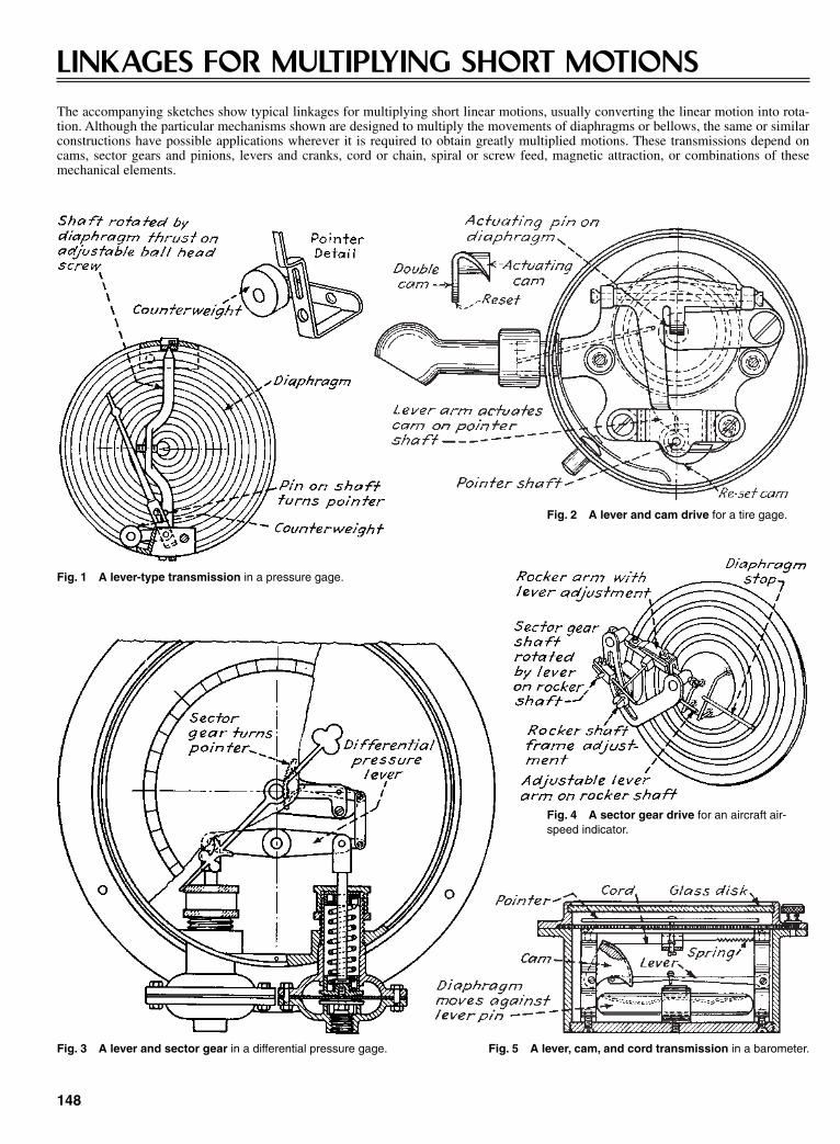
148
LINKAGES FOR MULTIPLYING SHORT MOTIONSThe accompanying sketches show typical linkages for multiplying short linear motions, usually converting the linear motion into rota-tion. Although the particular mechanisms shown are designed to multiply the movements of diaphragms or bellows, the same or similarconstructions have possible applications wherever it is required to obtain greatly multiplied motions. These transmissions depend oncams, sector gears and pinions, levers and cranks, cord or chain, spiral or screw feed, magnetic attraction, or combinations of thesemechanical elements.
Fig. 1 A lever-type transmission in a pressure gage.
Fig. 2 A lever and cam drive for a tire gage.
Fig. 3 A lever and sector gear in a differential pressure gage.
Fig. 4 A sector gear drive for an aircraft air-speed indicator.
Fig. 5 A lever, cam, and cord transmission in a barometer.
Sclater Chapter 5 5/3/01 11:46 AM Page 148
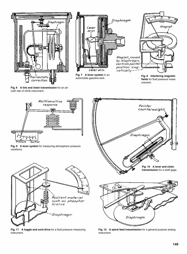
149
Fig. 6 A link and chain transmission for an air-craft rate of climb instrument.
Fig. 7 A lever system in anautomobile gasoline tank.
Fig. 8 Interfering magneticfields for fluid pressure meas-urement.
Fig. 9 A lever system for measuring atmospheric pressurevariations.
Fig. 10 A lever and chaintransmission for a draft gage.
Fig. 11 A toggle and cord drive for a fluid pressure measuringinstrument.
Fig. 12 A spiral feed transmission for a general purpose analoginstrument.
Sclater Chapter 5 5/3/01 11:46 AM Page 149

Turning the adjusting screw spreads or contracts the linkage pairs to raise or lower thetable. Six parallel links are shown, but the mechanism can be build with four, eight, ormore links.
150
PARALLEL-LINK MECHANISMS
Link AB in this arrangement willalways be parallel to EF, and link CDwill always be parallel to AB. Hence CDwill always be parallel to EF. Also, thelinkages are so proportioned that point Cmoves in an approximately straight line.The final result is that the output platewill remain horizontal while movingalmost straight up and down. The weightpermitted this device to function as a dis-appearing platform in a theater stage.
A simple parallel-link mechanism that produces tension in webs, wires, tapes, andstrip steels. Adjusting the weight varies the drag on the material.
Two triangular plates pivot around fixedpoints on a machine frame. The output pointdescribes a circular-arc curve. It can roundout the cutting surfaces of grinding wheels.
STROKE MULTIPLIER
Two gears rolling on a stationary bottomrack drive the movable top rack, which isattached to a printing table. When theinput crank rotates, the table will moveout to a distance of four times the cranklength.
Sclater Chapter 5 5/3/01 11:46 AM Page 150

One of the cranks is the input, and the other follows to keepthe feeding bar horizontal. The feeder can move barrels from sta-tion to station.
All seven short links are kept in a vertical position while rotat-ing. The center link is the driver. This particular machine feedsand opens cartons, but the mechanism will work in many otherapplications.
151
This parallel-link driller powers agroup of shafts. The input crank drivesthe eccentric plate. This, in turn, rotatesthe output cranks that have the samelength at the same speed. Gears wouldoccupy more room between the shafts.
The input and output shafts of thisparallel-plate driver rotate with the sameangular relationship. The positions of theshafts, however, can vary to suit otherrequirements without affecting the input-output relationship between the shafts.
The output link rotates so that itappears to revolve around a point mov-ing in space (P). This avoids the need forhinges at distant or inaccessible spots.The mechanism is suitable for hingingthe hoods of automobiles.
The absence of backlash makes thisparallel-link coupling a precision, low-cost replacement for gear or chain drivesthat can also rotate parallel shafts. Anynumber of shafts greater than two can bedriven from any one of the shafts, pro-vided two conditions are fulfilled: (1) Allcranks must have the same length r; and(2) the two polygons formed by theshafts A and frame pivot centers B mustbe identical. The main disadvantage ofthis mechanism is its dynamic unbalance,which limits the speed of rotation. Tolessen the effect of the vibrations pro-duced, the frame should be made as lightas is consistent with strength require-ments for the intended application.
Sclater Chapter 5 5/3/01 11:46 AM Page 151
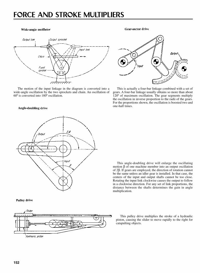
This is actually a four-bar linkage combined with a set ofgears. A four-bar linkage usually obtains so more than about120º of maximum oscillation. The gear segments multiplythe oscillation in inverse proportion to the radii of the gears.For the proportions shown, the oscillation is boosted two andone-half times.
152
FORCE AND STROKE MULTIPLIERS
The motion of the input linkage in the diagram is converted into awide-angle oscillation by the two sprockets and chain. An oscillation of60º is converted into 180º oscillation.
This angle-doubling drive will enlarge the oscillatingmotion β of one machine member into an output oscillationof 2β. If gears are employed, the direction of rotation cannotbe the same unless an idler gear is installed. In that case, thecenters of the input and output shafts cannot be too close.Rotating the input link clockwise causes the output to followin a clockwise direction. For any set of link proportions, thedistance between the shafts determines the gain in anglemultiplication.
This pulley drive multiplies the stroke of a hydraulicpiston, causing the slider to move rapidly to the right forcatapulting objects.
Sclater Chapter 5 5/3/01 11:46 AM Page 152

This drive multiplies the finger force of a type-writer, producing a strong hammer action at the rollerfrom a light touch. There are three pivot pointsattached to the frame. The links are arranged so thatthe type bar can move in free flight after a key hasbeen struck. The mechanism illustrated is actually twofour-bar linkages in series. Some typewriters have asmany as four four-bar linkages in a series.
The first toggle of this puncher keeps point P in the raised positionalthough its weight can exert a strong downward force (as in a heavypunch weight). When the drive crank rotates clockwise (e.g., driven bya reciprocating mechanism), the second toggle begins to straighten so asto create a strong punching force.
This drive mechanism converts the motion of an input crank into a much largerrotation of the output (from 30º to 360º). The crank drives the slider and gear rack,which in turn rotates the output gear.
153
Springs and chains are attached togeared cranks of this drive to operate asprocket output. Depending on the gearratio, the output will produce a desiredoscillation, e.g., two revolutions of out-put in each direction for each 360º ofinput.
Arranging linkages in series on this drive canincrease its angle of oscillation. In the versionillustrated, the oscillating motion of the L-shapedrocker is the input for the second linkage. Thefinal oscillation is 180º.
Sclater Chapter 5 5/3/01 11:46 AM Page 153
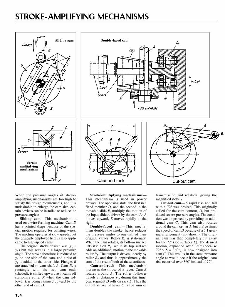
transmission and rotation, giving themagnified stoke y.
Cut-out cam—A rapid rise and fallwithin 72º was desired. This originallycalled for the cam contour, D, but pro-duced severe pressure angles. The condi-tion was improved by providing an addi-tional cam C. This cam also rotatesaround the cam center A, but at five timesthe speed of cam D because of a 5:1 gear-ing arrangement (not shown). The origi-nal cam was then completely cut awayfor the 72º (see surfaces E). The desiredmotion, expanded over 360º (because72º × 5 = 360º ), is now designed intocam C. This results in the same pressureangle as would occur if the original camrise occurred over 360º instead of 72º.
154
STROKE-AMPLIFYING MECHANISMS
When the pressure angles of stroke-amplifying mechanisms are too high tosatisfy the design requirements, and it isundesirable to enlarge the cam size, cer-tain devices can be installed to reduce thepressure angles:
Sliding cam—This mechanism isused on a wire-forming machine. Cam Dhas a pointed shape because of the spe-cial motion required for twisting wires.The machine operates at slow speeds, butthe principle employed here is also appli-cable to high-speed cams.
The original stroke desired was (y1 +y2) but this results in a large pressureangle. The stroke therefore is reduced toy2 on one side of the cam, and a rise ofy1 is added to the other side. Flanges Bare attached to cam shaft A. Cam D, arectangle with the two cam ends(shaded), is shifted upward as it cams offstationary roller R when the cam fol-lower E is being cammed upward by theother end of cam D.
Stroke-multiplying mechanisms—This mechanism is used in powerpresses. The opposing slots, the first in afixed member D, and the second in themovable slide E, multiply the motion ofthe input slide A driven by the cam. As Amoves upward, E moves rapidly to theright.
Double-faced cam—This mecha-nism doubles the stroke, hence reducesthe pressure angles to one-half of theiroriginal values. Roller R1 is stationary.When the cam rotates, its bottom surfacelifts itself on R1, while its top surfaceadds an additional motion to the movableroller R2. The output is driven linearly byroller R2 and thus is approximately thesum of the rise of both of these surfaces.
Cam-and-rack—This mechanismincreases the throw of a lever. Cam Brotates around A. The roller followertravels at distances y1; during this time,gear segment D rolls on rack E. Thus theoutput stroke of lever C is the sum of
Sclater Chapter 5 5/3/01 11:46 AM Page 154
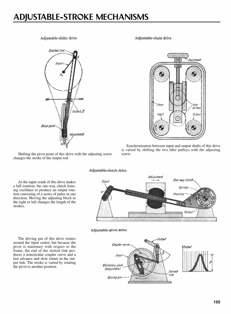
Synchronization between input and output shafts of this driveis varied by shifting the two idler pulleys with the adjustingscrew.
155
ADJUSTABLE-STROKE MECHANISMS
Shifting the pivot point of this drive with the adjusting screwchanges the stroke of the output rod.
As the input crank of this drive makesa full rotation, the one-way clutch hous-ing oscillates to produce an output rota-tion consisting of a series of pulse in onedirection. Moving the adjusting block tothe right or left changes the length of thestrokes.
The driving pin of this drive rotatesaround the input center, but because thepivot is stationary with respect to theframe, the end of the slotted link pro-duces a noncircular coupler curve and afast advance and slow return in the out-put link. The stroke is varied by rotatingthe pivot to another position.
Sclater Chapter 5 5/3/01 11:46 AM Page 155
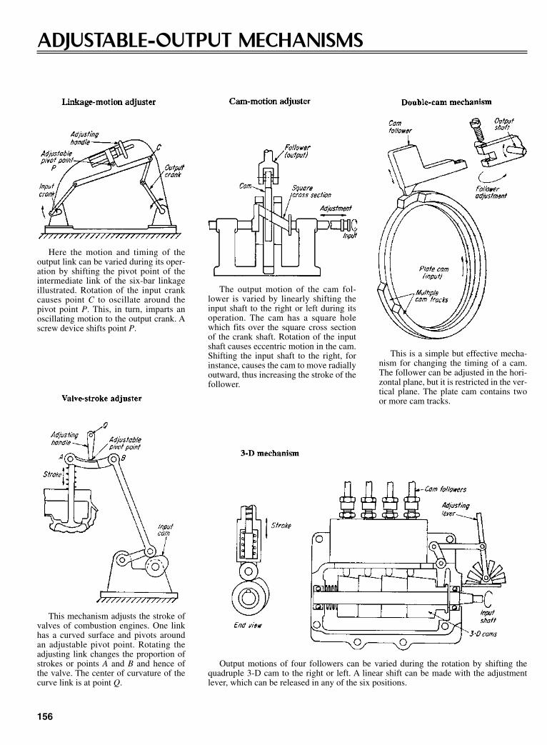
This is a simple but effective mecha-nism for changing the timing of a cam.The follower can be adjusted in the hori-zontal plane, but it is restricted in the ver-tical plane. The plate cam contains twoor more cam tracks.
156
ADJUSTABLE-OUTPUT MECHANISMS
Here the motion and timing of theoutput link can be varied during its oper-ation by shifting the pivot point of theintermediate link of the six-bar linkageillustrated. Rotation of the input crankcauses point C to oscillate around thepivot point P. This, in turn, imparts anoscillating motion to the output crank. Ascrew device shifts point P.
The output motion of the cam fol-lower is varied by linearly shifting theinput shaft to the right or left during itsoperation. The cam has a square holewhich fits over the square cross sectionof the crank shaft. Rotation of the inputshaft causes eccentric motion in the cam.Shifting the input shaft to the right, forinstance, causes the cam to move radiallyoutward, thus increasing the stroke of thefollower.
This mechanism adjusts the stroke ofvalves of combustion engines. One linkhas a curved surface and pivots aroundan adjustable pivot point. Rotating theadjusting link changes the proportion ofstrokes or points A and B and hence ofthe valve. The center of curvature of thecurve link is at point Q.
Output motions of four followers can be varied during the rotation by shifting thequadruple 3-D cam to the right or left. A linear shift can be made with the adjustmentlever, which can be released in any of the six positions.
Sclater Chapter 5 5/3/01 11:46 AM Page 156
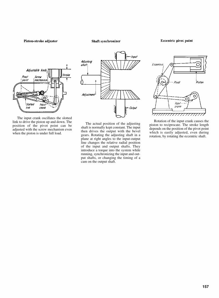
The input crank oscillates the slottedlink to drive the piston up and down. Theposition of the pivot point can beadjusted with the screw mechanism evenwhen the piston is under full load.
The actual position of the adjustingshaft is normally kept constant. The inputthen drives the output with the bevelgears. Rotating the adjusting shaft in aplane at right angles to the input-outputline changes the relative radial positionof the input and output shafts. Theyintroduce a torque into the system whilerunning, synchronizing the input and out-put shafts, or changing the timing of acam on the output shaft.
Rotation of the input crank causes thepiston to reciprocate. The stroke lengthdepends on the position of the pivot pointwhich is easily adjusted, even duringrotation, by rotating the eccentric shaft.
157
Sclater Chapter 5 5/3/01 11:46 AM Page 157

158
REVERSING MECHANISMS
This mechanism automatically reversesthe output drive for every 180º rotationof the input. The input disk has a press-fitpin which strikes link A to drive it clock-wise. Link A in turn drives link B coun-terclockwise with its gear segments (orgears pinned to the links). The outputshaft and the output link (which can bethe working member) are connected tolink B.
After approximately 180º of rotation,the pin slides past link A to strike link Bcoming to meet it—and thus reverses thedirection of link B (and of the output).Then after another 180º rotation the pinslips past link B to strike link A and startsthe cycle over again.
This mechanism also employs a striking pin—but here the pin is on the output mem-ber. The input bevel gear drives two follower bevels which are free to rotate on theircommon shaft. The ratchet clutch, however, is spline-connected to the shaft—althoughfree to slide linearly. As shown, it is the right follower gear that is locked to the driveshaft. Hence the output gear rotates clockwise until the pin strikes the reversing level toshift the toggle to the left. Once past its center, the toggle spring snaps the ratchet to theleft to engage the left follower gear. This instantly reverses the output, which now rotatescounterclockwise until the pin again strikes the reversing level. Thus the mechanismreverses itself for every 360º rotation of the input.
This is a modification of the well-known Watt crank mechanism. The inputcrank causes the planet gear to revolvearound the output gear. But because theplanet gear is fixed to the connecting rod,it causes the output gear to continuallyreverse itself. If the radii of the two gearsare equal, each full rotation of the inputlink will cause the output gear to oscil-late through the same angle as the rod.
Automatically switching from one pivot point to another in midstroke.
Two pivots and the intermediaryflange govern the cutting sequence. Theflange is connected to the press frame atthe upper pivot, and the cutting ram isconnected to the flange at the lowerpivot. In the first part of the cycle, the
ram turns around the lower pivot andshears the plate with the square-cutblade; the motion of the intermediaryflange is restrained by the flange-holdingpiston.
After the shearing cut, the ram stop
bottoms on the flange. This overcomesthe restraining force of the flange-holding piston, and the ram turns aroundthe upper pivot. This brings the bevelingblade into contact with the plate for thebevel cut.
Sclater Chapter 5 5/3/01 11:46 AM Page 158

inputs, and z is the output. The motion of x and y in the same directionperforms addition; in the opposite direction it performs subtraction.
159
COMPUTING MECHANISMS
Fig. 1 Addition and subtraction is usually based on the differentialprinciple; variations depend on whether inputs: (A) rotate shafts, (B)translate links, or (C) angularly displace links. Mechanisms can solvethe equation: z = c (x ± y ), where c is the scale factor, x and y are
Analog computing mechanisms are capable of almost instantaneous response tominute variations in input. Basic units, similar to the examples shown, are combined toform the final mechanism. These mechanisms add, subtract, resolve vectors, or solvespecial or trigonometric functions.
Fig. 2 Functional generators mechanize specific equations. (A) A reciprocal cam converts a number into its reciprocal. This simplifies division by permitting simple multiplication between anumerator and its denominator. The cam is rotated to a position cor-responding to the denominator. The distance between the center ofthe cam to the center of the follower pin corresponds to a reciprocal.
(B) A function-slot cam is ideal for performing complex functionsinvolving one variable. (C) A function is plotted on a large sheetattached to a table. The x lead screw is turned at a constant speedby an analyzer. An operator or photoelectric follower turns the y output to keep the aligning sight on the curve.
Fig. 3 (A) A three-dimensional cam generates functions withtwo variables: z = f (x, y ). A cam is rotated by the y-input; the x-input shifts a follower along a pivot rod. The contour of the camcauses a follower to rotate, giving angular displacement to the z-output gear. (B) A conical cam for squaring positive or negative
inputs: y = c (±x )2. The radius of a cone at any point is proportionalto the length of string to the right of the point; therefore, cylinder rota-tion is proportional to the square of cone rotation. The output is fedthrough a gear differential to convert it to a positive number.
Sclater Chapter 5 5/3/01 11:46 AM Page 159

Fig. 4 Trigonometric functions. (A) A Scotch-yoke mechanism forsine and cosine functions. A crank rotates about fixed point P, gener-ating angle a and giving motion to the arms: y = c sin a; x = c cos a.(B) A tangent-cotangent mechanism generates x = c tan a or
x = c cot β. (C) The eccentric and follower is easily manufactured, butsine and cosine functions are approximate. The maximum error iszero at 90° and 270°; l is the length of the link, and c is the length ofthe crank.
160
Computing Mechanisms (continued )
Fig. 5 Component resolvers determine x and y components ofvectors that are continuously changing in both angle and magnitude.Equations are x = z cos a, y = z sin a, where z is magnitude of vector,and a is vector angle. Mechanisms can also combine components to
obtain a resultant. Inputs in (A) are through bevel gears and leadscrews for z-input, and through spur gears for a-input. Compensatinggear differential (B) prevents the a-input from affecting the z-input.This problem is solved in (C) with constant-lead cams (D) and (E).
Sclater Chapter 5 5/3/01 11:46 AM Page 160

Typical computing mechanisms for performing the mathematicaloperations of multiplication, division, differentiation, and inte-gration of variable functions are presented here.
Fig. 1 The multiplication of two tables, x and y, can usually besolved by either: (A) The similar triangle method, or (B) the logarith-mic method. In (A), lengths x ′ and y ′ are proportional to the rotationof input gears x and y. Distance c is constant. By similar triangles:z/x = y/c or z = xy/c, where z is vertical displacement of output rack.The mechanism can be modified to accept negative variables. In (B),the input variables are fed through logarithmic cams to give lineardisplacements of log x and log y. The functions are then added by adifferential link giving z = log x + log xy (neglecting scale factors). Theresult is fed through the antilog cam so that the motion of the followerrepresents z = xy.
161
Fig. 2 Multiplication of complex functions can be accomplishedby substituting cams in place of input slides and racks of the mecha-nism in Fig. 1. The principle of similar triangles still applies. Themechanism in (A) solves the equation: z = f (y )x 2. The schematic isshown in (B). Division of two variables can be done by feeding one ofthe variables through a reciprocal cam and then multiplying it by theother. The schematic in (C) shows the solution of y = cos θ/x.
Sclater Chapter 5 5/3/01 11:46 AM Page 161
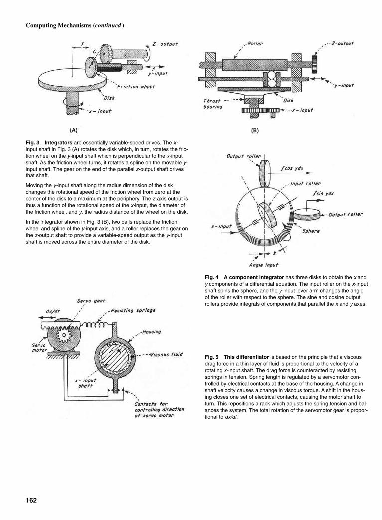
Fig. 3 Integrators are essentially variable-speed drives. The x-input shaft in Fig. 3 (A) rotates the disk which, in turn, rotates the fric-tion wheel on the y-input shaft which is perpendicular to the x-inputshaft. As the friction wheel turns, it rotates a spline on the movable y-input shaft. The gear on the end of the parallel z-output shaft drivesthat shaft.
Moving the y-input shaft along the radius dimension of the diskchanges the rotational speed of the friction wheel from zero at thecenter of the disk to a maximum at the periphery. The z-axis output isthus a function of the rotational speed of the x-input, the diameter ofthe friction wheel, and y, the radius distance of the wheel on the disk,
In the integrator shown in Fig. 3 (B), two balls replace the frictionwheel and spline of the y-input axis, and a roller replaces the gear onthe z-output shaft to provide a variable-speed output as the y-inputshaft is moved across the entire diameter of the disk.
Fig. 4 A component integrator has three disks to obtain the x andy components of a differential equation. The input roller on the x-inputshaft spins the sphere, and the y-input lever arm changes the angleof the roller with respect to the sphere. The sine and cosine outputrollers provide integrals of components that parallel the x and y axes.
162
Computing Mechanisms (continued )
Fig. 5 This differentiator is based on the principle that a viscousdrag force in a thin layer of fluid is proportional to the velocity of arotating x-input shaft. The drag force is counteracted by resistingsprings in tension. Spring length is regulated by a servomotor con-trolled by electrical contacts at the base of the housing. A change inshaft velocity causes a change in viscous torque. A shift in the hous-ing closes one set of electrical contacts, causing the motor shaft toturn. This repositions a rack which adjusts the spring tension and bal-ances the system. The total rotation of the servomotor gear is propor-tional to dx/dt.
Sclater Chapter 5 5/3/01 11:46 AM Page 162

163
EIGHTEEN VARIATIONS OF DIFFERENTIAL LINKAGE
Figure 1 shows the modifications of thedifferential linkage shown in Fig. 2(A).These are based on the variations in thetriple-jointed intermediate link 6. Thelinks are designated as follows: Framelinks: links 2, 3 and 4; two-jointed inter-mediate links: links 5 and 7; three jointedintermediate links: link 6.
The input motions to be added are a and b; their sum s is equal to c1a + c2b, where c1and c2 are scale factors.The links are numbered in the same way as those in Fig. 2(A).
Sclater Chapter 5 5/3/01 11:46 AM Page 163
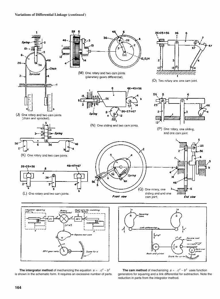
164
Variations of Differential Linkage (continued )
The intergrator method of mechanizing the equation is shown in the schematic form. It requires an excessive number of parts.
a c b2 2= − The cam method of mechanizing uses functiongenerators for squaring and a link differential for subtraction. Note thereduction in parts from the integrator method.
a c b2 2= −
Sclater Chapter 5 5/3/01 11:46 AM Page 164

A virtually unexplored area of mecha-nism research is the vast domain ofthree-dimensional linkage, frequentlycalled space mechanism. Only a compar-atively few kinds have been investigatedor described, and little has been done toclassify those that are known. As a result,many engineers do not know much aboutthem, and applications of space mecha-nisms have not been as widespread asthey could be.
Because a space mechanism can existwith a wide variety of connecting jointsor “pair” combinations, it can be identi-fied by the type and sequence of itsjoints. A listing of all of the physicallyrealizable kinematic pairs has beenestablished, based on the number ofdegrees-of-freedom of a joint. Thesepairs are all the known ways of connect-ing two bodies together for every possi-ble freedom of relative motion betweenthem.
The Practical Nine
The next step was to find the combina-tion of pairs and links that would pro-duce practical mechanisms. Based on the“Kutzbach criterion” (the only knownmobility criterion—it determines thedegree of freedom of a mechanism due tothe constraints imposed by the pairs),417 different kinds of space mechanismshave been identified. Detailed examina-tion showed many of these to be mechan-ically complex and of limited adaptabil-ity. But the four-link mechanisms hadparticular appeal because of theirmechanical simplicity. A total of 138 dif-ferent kinds of four-bar mechanismshave been found. Of these, nine haveparticular merit (Fig. 1).
165
SPACE MECHANISMSThere are potentially hundreds of them, but only a few have been discovered so far. Here are the best of one class—the four-bar space mechanisms.
Fig. 1 The nine chosen mechanisms.
Sclater Chapter 5 5/3/01 11:46 AM Page 165

Fig. 2 The three mavericks.
These nine four-link mechanisms arethe easiest to build because they containonly those joints that have area contactand are self-connecting. In the table,these joints are the five closed, lower pairtypes:
R = Revolute joint, which permitsrotation only
P = Prism joint, which permits slid-ing motion only
H = Helix or screw type of jointC = Cylinder joint, which permits
both rotation and sliding (hencehas two degrees of freedom)
S = Sphere joint, which is the com-mon ball joint permitting rotation in anydirection (three degrees of freedom)
All these mechanisms can producerotary or sliding output motion from arotary input—the most commonmechanical requirements for which link-age mechanisms are designed.
The type letters of the kinematic pairsin the table identify the mechanism byordering the letter symbols consecutivelyaround the closed kinematic chain. Thefirst letter identifies the pair connectingthe input link and the fixed link; the lastletter identifies the output link, or lastlink, with the fixed link. Thus, a mecha-nism labeled R-S-C-R is a double-crankmechanism with a spherical pair betweenthe input crank and the coupler, and acylindrical pair between the coupler andthe output crank.
The Mavericks
The Kutzbach criterion is inadequate forthe job because it cannot predict the exis-tence of such mechanisms as the BennettR-R-R-R mechanism, the double-balljoint R-S-S-R mechanism, and the R-C-C-R mechanism (Fig. 2). These “special”mechanisms require special geometricconditions to have a single degree offreedom. The R-R-R-R mechanismrequires a particular orientation of therevolute axes and a particular ratio oflink lengths to function as a single degreeof freedom space mechanism. The R-S-S-R configuration, when functioning as a
single degree-of-freedom mechanism,will have a passive degree of freedom ofits coupler link. When properly con-structed, the configuration R-C-C-R willalso have a passive degree-of-freedom ofits coupler, and it will function as a sin-gle-degree space mechanism.
Of these three special four-link mecha-nisms, the R-S-S-R mechanism is seen asthe outstanding choice. It is the most ver-satile and practical configuration for meet-ing double-crank motion requirements.
166
Sclater Chapter 5 5/3/01 11:47 AM Page 166
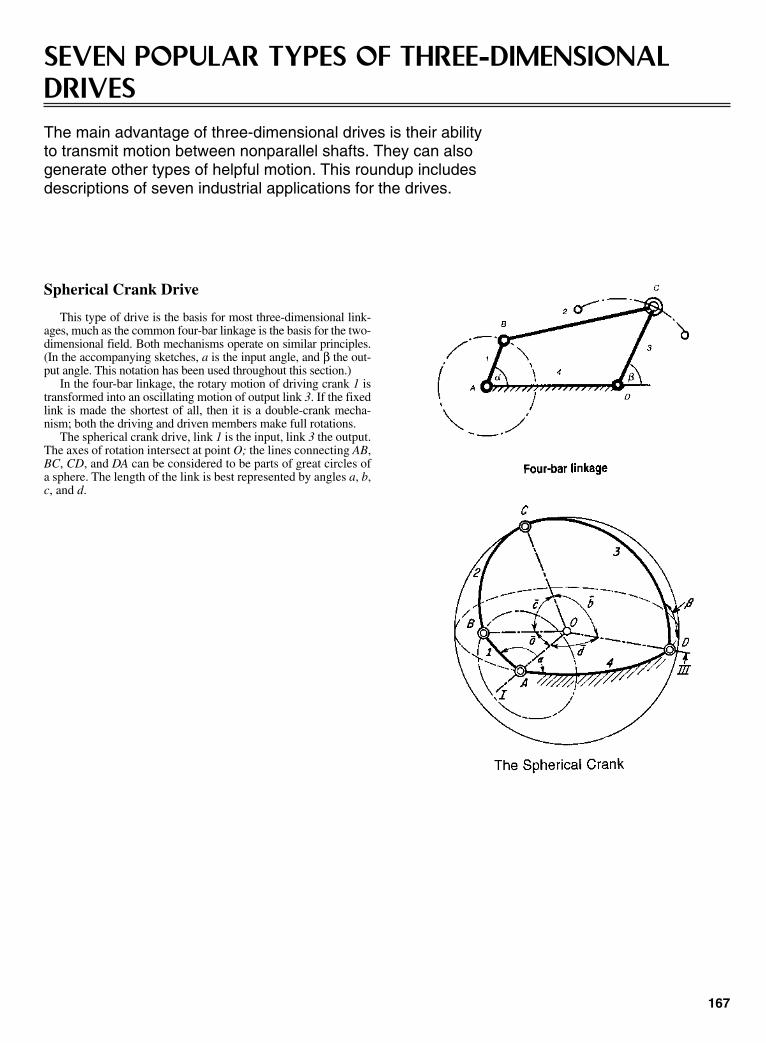
167
SEVEN POPULAR TYPES OF THREE-DIMENSIONALDRIVESThe main advantage of three-dimensional drives is their abilityto transmit motion between nonparallel shafts. They can alsogenerate other types of helpful motion. This roundup includesdescriptions of seven industrial applications for the drives.
Spherical Crank Drive
This type of drive is the basis for most three-dimensional link-ages, much as the common four-bar linkage is the basis for the two-dimensional field. Both mechanisms operate on similar principles.(In the accompanying sketches, a is the input angle, and β the out-put angle. This notation has been used throughout this section.)
In the four-bar linkage, the rotary motion of driving crank 1 istransformed into an oscillating motion of output link 3. If the fixedlink is made the shortest of all, then it is a double-crank mecha-nism; both the driving and driven members make full rotations.
The spherical crank drive, link 1 is the input, link 3 the output.The axes of rotation intersect at point O; the lines connecting AB,BC, CD, and DA can be considered to be parts of great circles ofa sphere. The length of the link is best represented by angles a, b,c, and d.
Sclater Chapter 5 5/3/01 11:47 AM Page 167

Spherical-Slide Oscillator Drive
The two-dimensional slider crank is obtained from a four-barlinkage by making the oscillating arm infinitely long. By makingan analogous change in the spherical crank, the spherical slidercrank is obtained.
The uniform rotation of input shaft I is transferred into anonuniform oscillating or rotating motion of output shaft III.These shafts intersect at an angle δ, corresponding to the framelink 4 of the spherical crank. Angle γ corresponds to the length oflink 1, and axis II is at right angle to axis III.
The output oscillates when γ is smaller than δ, but it rotateswhen γ is larger than δ.
The relation between input angle a and output angle β as des-ignated in the skewed Hooke’s joint is:
tan(tan )(sin )
sin (tan )(cos )(cos )β
γ αδ γ δ α
=+
Skewed Hooke’s Joint Drive
This variation of the spherical crank is specified where analmost linear relation is desired between the input and outputangles for a large part of the motion cycle.
The equation defining the output in terms of the input can beobtained from the skewed Hooke’s joint equation by making δ =90º. Thus, sin δ = 1, cos δ = 0, and
tan β = tan γ sin α
168
Three-Dimensional Drives (continued )
The principle of the skewed Hooke’s joint has been applied tothe drive of a washing machine (see sketch).
Here, the driveshaft drives the worm wheel 1 which has acrank fashioned at an angle γ. The crank rides between two platesand causes the output shaft III to oscillate in accordance with theequation.
The dough-kneading drive is also based on the Hooke’s joint,but it follows the path of link 2 to give a wobbling motion thatkneads dough in the tank.
Sclater Chapter 5 5/3/01 11:47 AM Page 168

monic translation in the direction of itsaxis of rotation. The link performs whatis essentially a twisting motion in eachcycle.
169
The Universal Joint Drive
The universal joint is a variation of the spherical-slide oscilla-tor, but with angle γ = 90º. This drive provides a totally rotatingoutput and can be operated as a pair, as shown in the diagram.
The equation relating input with output for a single universaljoint, where γ is the angle between the connecting link and shaftI, is:
tan β = tan α cos δ
The output motion is pulsating (see curve) unless the jointsare operates as pairs to provide a uniform motion.
The 3-D Crank Slide Drive
The three-dimensional crank slide is avariation of a plane crank slide (seesketch), with a ball point through whichlink g always slides, while a point B onlink g describes a circle. A 3-D crank isobtained from this mechanism by shift-ing output shaft III so that it is not normalto the plane of the circle; another way toaccomplish this is to make shafts I and IIInonparallel.
A practical variation of the 3-D crankslide is the agitator mechanism (seesketch). As input gear I rotates, link gswivels around (and also lifts) shaft III.Hence, the vertical link has both an oscil-lating rotary motion and a sinusoidal har-
Sclater Chapter 5 5/3/01 11:47 AM Page 169
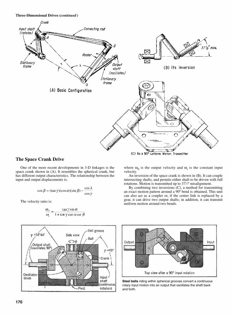
The Space Crank Drive
One of the more recent developments in 3-D linkages is thespace crank shown in (A). It resembles the spherical crank, buthas different output characteristics. The relationship between theinput and output displacements is:
The velocity ratio is:
cos (tan )(cos )(sin )cos
cosβ γ α β
λγ
= −
where ω0 is the output velocity and ωi is the constant inputvelocity.
An inversion of the space crank is shown in (B). It can coupleintersecting shafts, and permits either shaft to be driven with fullrotations. Motion is transmitted up to 371⁄2º misalignment.
By combining two inversions (C), a method for transmittingan exact motion pattern around a 90º bend is obtained. This unitcan also act as a coupler or, if the center link is replaced by agear, it can drive two output shafts; in addition, it can transmituniform motion around two bends.
170
Three-Dimensional Drives (continued )
Steel balls riding within spherical grooves convert a continuousrotary input motion into an output that oscillates the shaft backand forth.
Sclater Chapter 5 5/3/01 11:47 AM Page 170
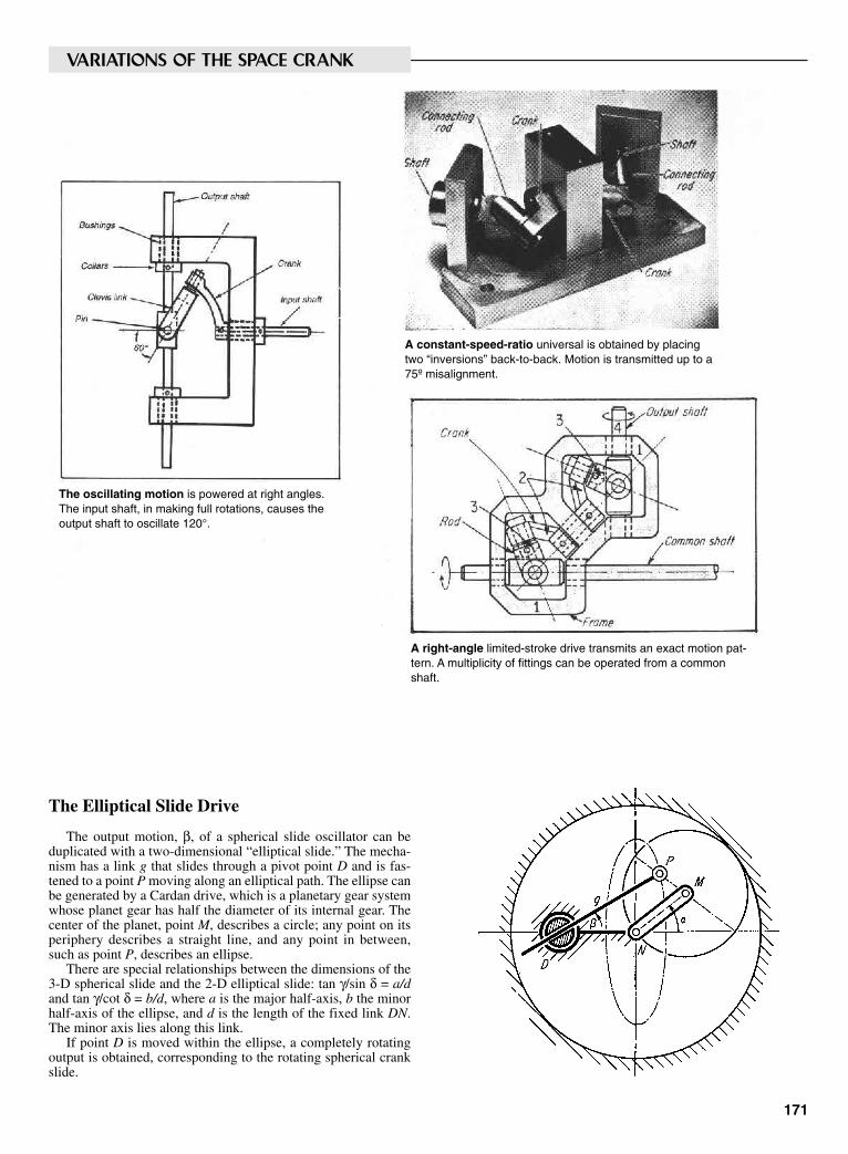
The Elliptical Slide Drive
The output motion, β, of a spherical slide oscillator can beduplicated with a two-dimensional “elliptical slide.” The mecha-nism has a link g that slides through a pivot point D and is fas-tened to a point P moving along an elliptical path. The ellipse canbe generated by a Cardan drive, which is a planetary gear systemwhose planet gear has half the diameter of its internal gear. Thecenter of the planet, point M, describes a circle; any point on itsperiphery describes a straight line, and any point in between,such as point P, describes an ellipse.
There are special relationships between the dimensions of the3-D spherical slide and the 2-D elliptical slide: tan γ/sin δ = a/dand tan γ/cot δ = b/d, where a is the major half-axis, b the minorhalf-axis of the ellipse, and d is the length of the fixed link DN.The minor axis lies along this link.
If point D is moved within the ellipse, a completely rotatingoutput is obtained, corresponding to the rotating spherical crankslide.
171
The oscillating motion is powered at right angles.The input shaft, in making full rotations, causes theoutput shaft to oscillate 120°.
A constant-speed-ratio universal is obtained by placingtwo “inversions” back-to-back. Motion is transmitted up to a75º misalignment.
A right-angle limited-stroke drive transmits an exact motion pat-tern. A multiplicity of fittings can be operated from a commonshaft.
VARIATIONS OF THE SPACE CRANK
Sclater Chapter 5 5/3/01 11:47 AM Page 171
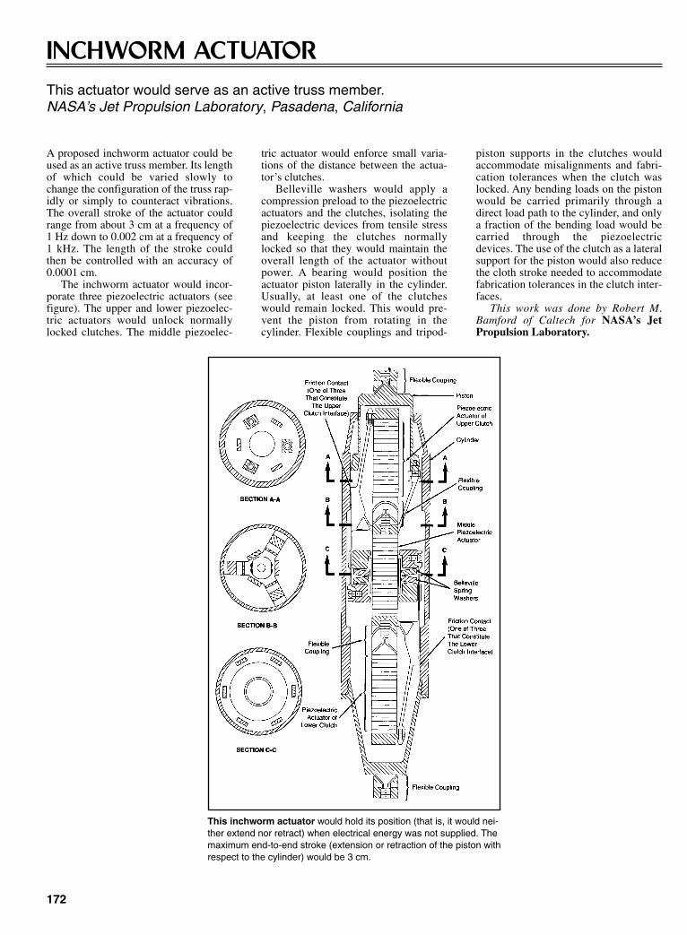
piston supports in the clutches wouldaccommodate misalignments and fabri-cation tolerances when the clutch waslocked. Any bending loads on the pistonwould be carried primarily through adirect load path to the cylinder, and onlya fraction of the bending load would becarried through the piezoelectricdevices. The use of the clutch as a lateralsupport for the piston would also reducethe cloth stroke needed to accommodatefabrication tolerances in the clutch inter-faces.
This work was done by Robert M.Bamford of Caltech for NASA’s JetPropulsion Laboratory.
172
INCHWORM ACTUATORThis actuator would serve as an active truss member.NASA’s Jet Propulsion Laboratory, Pasadena, California
A proposed inchworm actuator could beused as an active truss member. Its lengthof which could be varied slowly tochange the configuration of the truss rap-idly or simply to counteract vibrations.The overall stroke of the actuator couldrange from about 3 cm at a frequency of1 Hz down to 0.002 cm at a frequency of1 kHz. The length of the stroke couldthen be controlled with an accuracy of0.0001 cm.
The inchworm actuator would incor-porate three piezoelectric actuators (seefigure). The upper and lower piezoelec-tric actuators would unlock normallylocked clutches. The middle piezoelec-
tric actuator would enforce small varia-tions of the distance between the actua-tor’s clutches.
Belleville washers would apply acompression preload to the piezoelectricactuators and the clutches, isolating thepiezoelectric devices from tensile stressand keeping the clutches normallylocked so that they would maintain theoverall length of the actuator withoutpower. A bearing would position theactuator piston laterally in the cylinder.Usually, at least one of the clutcheswould remain locked. This would pre-vent the piston from rotating in thecylinder. Flexible couplings and tripod-
This inchworm actuator would hold its position (that is, it would nei-ther extend nor retract) when electrical energy was not supplied. Themaximum end-to-end stroke (extension or retraction of the piston withrespect to the cylinder) would be 3 cm.
Sclater Chapter 5 5/3/01 11:47 AM Page 172

CHAPTER 6SPRING, BELLOW,
FLEXURE, SCREW, ANDBALL DEVICES
Sclater Chapter 6 5/3/01 12:24 PM Page 173
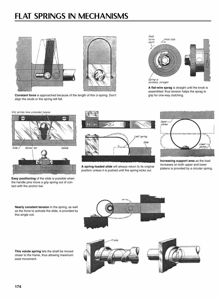
FLAT SPRINGS IN MECHANISMS
174
Constant force is approached because of the length of this U-spring. Don’talign the studs or the spring will fall.
A flat-wire sprag is straight until the knob isassembled: thus tension helps the sprag togrip for one-way clutching.
Easy positioning of the slide is possible whenthe handle pins move a grip spring out of con-tact with the anchor bar.
A spring-loaded slide will always return to its originalposition unless it is pushed until the spring kicks out.
Increasing support area as the loadincreases on both upper and lowerplatens is provided by a circular spring.
Nearly constant tension in the spring, as wellas the force to activate the slide, is provided bythis single coil.
This volute spring lets the shaft be movedcloser to the frame, thus allowing maximumaxial movement.
Sclater Chapter 6 5/3/01 12:24 PM Page 174

These mechanisms rely on a flat spring for their efficient actions.
175
Indexing is accomplished simply,efficiently, and at low cost by flat-spring arrangement shown here.
This cushioning device impartsrapid increase of spring tensionbecause of the small pyramidangle. Its rebound is minimum.
This spring-mounted disk changes its center position as the handle is rotated tomove the friction drive. It also acts as a built-in limit stop.
A return-spring ensures that the oper-ation handle of this two-direction drivewill always return to its neutral position.
This hold-down clamp has itsflat spring assembled with an ini-tial twist to provide a clampingforce for thin material.
Sclater Chapter 6 5/3/01 12:24 PM Page 175

POP-UP SPRINGS GET NEW BACKBONE
An addition to the family of retractablecoil springs, initially popular for use asantennas, holds promise of solving oneproblem in such applications: lack of tor-sional and flexural rigidity whenextended. A pop-up boom that locksitself into a stiffer tube has been made.
In two previous versions—DeHavilland Aircraft’s Stem and HunterSprings’s Helix—rigidity was obtainedby permitting the material to overlap. InMelpar’s design, the strip that unrollsfrom the drum to form the cylindricalmast has tabs and slots that interlock toproduce a strong tube.
Melpar has also added a row of perfo-rations along the center of the strip to aidin accurate control of the spring’s lengthduring extension or contraction. Thisadds to the spring’s attractiveness as apositioning device, besides its estab-lished uses as antennas for spacecraft andportable equipment and as gravity gradi-ent booms and sensing probes.
Curled by heat. Retractable, pre-stressed coil springs have been in thetechnical news for many years, yet mostmanufacturers have been rather close-mouthed about exactly how they covert astrip of beryllium copper or stainlesssteel into such a spring.
In its Helix, Hunter induced the pre-stressing at an angle to the axis of thestrip, so the spring uncoils helically; DeHavilland and Melpar prestress the mate-rial along the axis of the strip.
A prestressing technique was workedout by John J. Park of the NASAGoddard Center. Park found early in hisassignment that technical papers werelacking on just how a metal strip can begiven a new “memory” that makes it curllongitudinally unless restrained.
Starting from scratch, Park ran aseries of experiments using a glass tube,0.65 in. ID, and strips of beryllium cop-per allow, 2 in. wide and 0.002 in. thick.He found it effective to roll the alloystrip lengthwise into the glass tube andthen to heat it in a furnace. Test stripswere then allowed to cool down to roomtemperature.
It was shown that the longer the treat-ment and the hotter the furnace time, themore tightly the strip would curl along itslength, producing a smaller tube. Forexample, a test strip heated at 920° F for5 min would produce a tube thatremained at the 0.65-in. inside diameterof the glass holder; at 770 F, heating foreven 15 min produced a tube that wouldexpand to an 0.68-in. diameter.
By proper correlation of time andtemperature in the furnace, Park sug-gested that a continuous tube-formingprocess could be set up and segments ofthe completed tube could be cut off at thelengths desired.
176
Sclater Chapter 6 5/3/01 12:24 PM Page 176

TWELVE WAYS TO PUT SPRINGS TO WORKVariable-rate arrangements, roller positioning, space saving, and other ingenious ways to get the most from springs.
177
This setup provides a variable rate with a sudden changefrom a light load to a heavy load by limiting the low-rateextension with a spring.
This mechanism provides a three-step rate change at prede-termined positions. The lighter springs will always compressfirst, regardless of their position.
This differential-rate linkage sets the actuatorstroke under light tension at the start, thenallows a gradual transition to heavier tension.
This compressing mechanism has a dual rate for double-action compacting. In one direction pressure is high, but inthe reverse direction pressure is low.
Roller positioning by a tightly woundspring on the shaft is provided by thisassembly. The roller will slide underexcess end thrust.
A short extension of the spring for a longmovement of the slide keeps the tensionchange between maximum and minimum low.
Sclater Chapter 6 5/3/01 12:24 PM Page 177

178
Increased tension for the same movement isgained by providing a movable spring mountand gearing it to the other movable lever.
This pin grip is a spring that holds a pin by frictionagainst end movement or rotation, but lets the pin berepositioned without tools.
A close-wound spring is attached toa hopper, and it will not buckle when itis used as a movable feed-duct fornongranular material.
Toggle action here ensures that the gear-shift lever will not inadvertently be thrownpast its neutral position.
Tension varies at a different rate whenthe brake-applying lever reaches the posi-tion shown. The rate is reduced when thetilting lever tilts.
The spring wheel helps to distribute deflectionover more coils that if the spring rested on the cor-ner. The result is less fatigue and longer life.
Sclater Chapter 6 5/3/01 12:24 PM Page 178
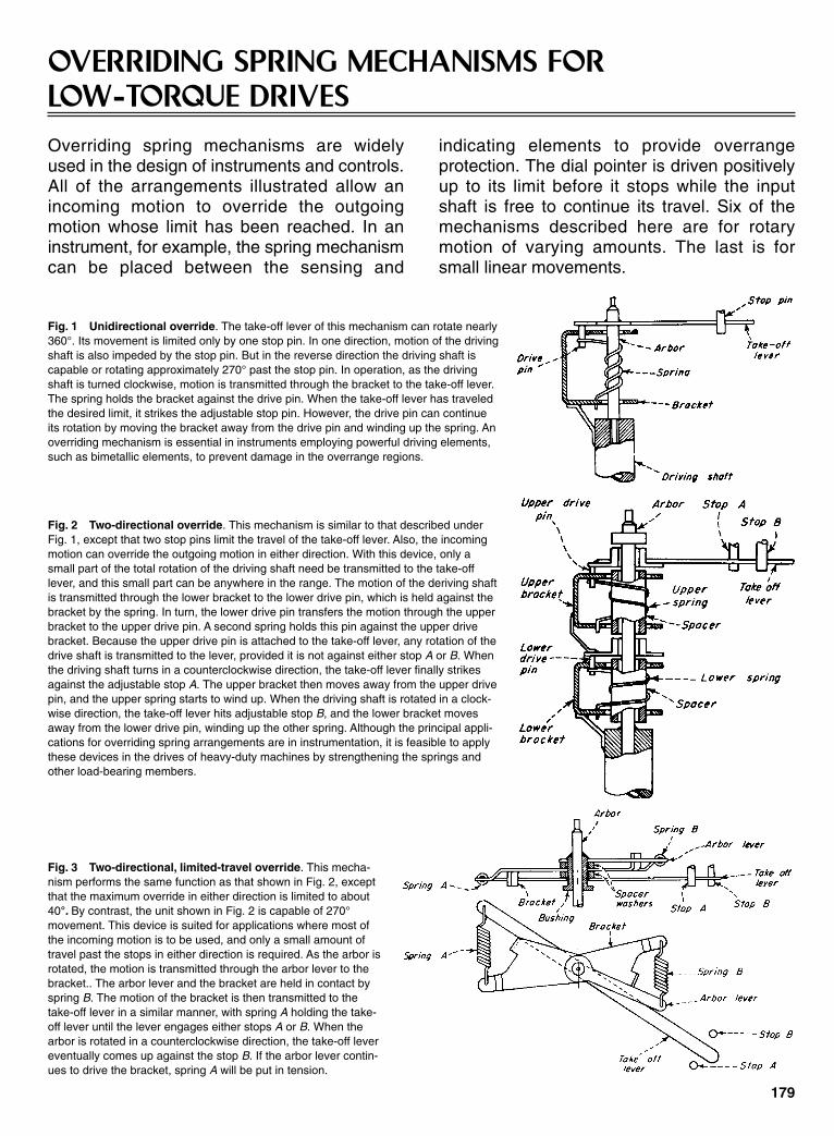
OVERRIDING SPRING MECHANISMS FORLOW-TORQUE DRIVES
Fig. 1 Unidirectional override. The take-off lever of this mechanism can rotate nearly360°. Its movement is limited only by one stop pin. In one direction, motion of the drivingshaft is also impeded by the stop pin. But in the reverse direction the driving shaft iscapable or rotating approximately 270° past the stop pin. In operation, as the drivingshaft is turned clockwise, motion is transmitted through the bracket to the take-off lever.The spring holds the bracket against the drive pin. When the take-off lever has traveledthe desired limit, it strikes the adjustable stop pin. However, the drive pin can continueits rotation by moving the bracket away from the drive pin and winding up the spring. Anoverriding mechanism is essential in instruments employing powerful driving elements,such as bimetallic elements, to prevent damage in the overrange regions.
Fig. 2 Two-directional override. This mechanism is similar to that described underFig. 1, except that two stop pins limit the travel of the take-off lever. Also, the incomingmotion can override the outgoing motion in either direction. With this device, only asmall part of the total rotation of the driving shaft need be transmitted to the take-offlever, and this small part can be anywhere in the range. The motion of the deriving shaftis transmitted through the lower bracket to the lower drive pin, which is held against thebracket by the spring. In turn, the lower drive pin transfers the motion through the upperbracket to the upper drive pin. A second spring holds this pin against the upper drivebracket. Because the upper drive pin is attached to the take-off lever, any rotation of thedrive shaft is transmitted to the lever, provided it is not against either stop A or B. Whenthe driving shaft turns in a counterclockwise direction, the take-off lever finally strikesagainst the adjustable stop A. The upper bracket then moves away from the upper drivepin, and the upper spring starts to wind up. When the driving shaft is rotated in a clock-wise direction, the take-off lever hits adjustable stop B, and the lower bracket movesaway from the lower drive pin, winding up the other spring. Although the principal appli-cations for overriding spring arrangements are in instrumentation, it is feasible to applythese devices in the drives of heavy-duty machines by strengthening the springs andother load-bearing members.
Overriding spring mechanisms are widelyused in the design of instruments and controls.All of the arrangements illustrated allow anincoming motion to override the outgoingmotion whose limit has been reached. In aninstrument, for example, the spring mechanismcan be placed between the sensing and
indicating elements to provide overrangeprotection. The dial pointer is driven positivelyup to its limit before it stops while the inputshaft is free to continue its travel. Six of themechanisms described here are for rotarymotion of varying amounts. The last is forsmall linear movements.
Fig. 3 Two-directional, limited-travel override. This mecha-nism performs the same function as that shown in Fig. 2, exceptthat the maximum override in either direction is limited to about40°. By contrast, the unit shown in Fig. 2 is capable of 270°movement. This device is suited for applications where most ofthe incoming motion is to be used, and only a small amount oftravel past the stops in either direction is required. As the arbor isrotated, the motion is transmitted through the arbor lever to thebracket.. The arbor lever and the bracket are held in contact byspring B. The motion of the bracket is then transmitted to thetake-off lever in a similar manner, with spring A holding the take-off lever until the lever engages either stops A or B. When thearbor is rotated in a counterclockwise direction, the take-off levereventually comes up against the stop B. If the arbor lever contin-ues to drive the bracket, spring A will be put in tension.
179
Sclater Chapter 6 5/3/01 12:24 PM Page 179

Fig. 4 Unidirectional, 90° override. This is a singleoverriding unit that allows a maximum travel of 90°past its stop. The unit, as shown, is arranged forovertravel in a clockwise direction, but it can also bemade for a counterclockwise override. The arborlever, which is secured to the arbor, transmits therotation of the arbor to the take-off lever. The springholds the drive pin against the arbor lever until thetake-off lever hits the adjustable stop. Then, if thearbor lever continues to rotate, the spring will beplaced in tension. In the counterclockwise direction,the drive pin is in direct contact with the arbor leverso that no overriding is possible.
Fig. 5 Two-directional, 90° override. This double-overriding mechanism allows amaximum overtravel of 90° in either direction. As the arbor turns, the motion is carriedfrom the bracket to the arbor lever, then to the take-off lever. Both the bracket and thetake-off lever are held against the arbor lever by spring A and B. When the arbor isrotated counterclockwise, the takeoff lever hits stop A. The arbor lever is held station-ary in contact with the take-off lever. The bracket, which is fastened to the arbor,rotates away from the arbor lever, putting spring A in tension. When the arbor isrotated n a clockwise direction, the take-off lever comes against stop B, and thebracket picks up the arbor lever, putting spring B in tension.
Fig. 6 Unidirectional, 90° override. This mech-anism operates exactly the same as that shown inFig. 4. However, it is equipped with a flat spiralspring in place of the helical coil spring used inthe previous version. The advantage of the flatspiral spring is that it allows for a greater overrideand minimizes the space required. The springholds the take-off lever in contact with the arborlever. When the take-off lever comes in contactwith the stop, the arbor lever can continue torotate and the arbor winds up the spring.
Fig. 7 Two-directional override, linear motion. The previous mechanisms were over-rides for rotary motion. The device in Fig. 7 is primarily a double override for small lineartravel, although it could be used on rotary motion. When a force is applied to the input lever,which pivots about point C, the motion is transmitted directly to the take-off lever through thetwo pivot posts, A and B. The take-off lever is held against these posts by the spring. Whenthe travel causes the take-off lever to hit the adjustable stop A, the take-off lever revolvesabout pivot post A, pulling away from pivot post B, and putting additional tension in thespring. When the force is diminished, the input lever moves in the opposite direction until thetake-off lever contacts the stop B. This causes the take-off lever to rotate about pivot post B,and pivot post A is moved away from the take-off lever.
180
Sclater Chapter 6 5/3/01 12:24 PM Page 180
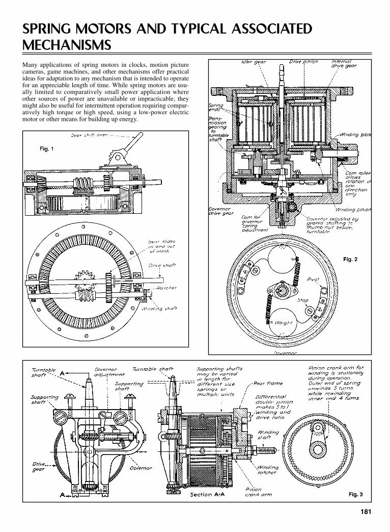
SPRING MOTORS AND TYPICAL ASSOCIATEDMECHANISMSMany applications of spring motors in clocks, motion picturecameras, game machines, and other mechanisms offer practicalideas for adaptation to any mechanism that is intended to operatefor an appreciable length of time. While spring motors are usu-ally limited to comparatively small power application whereother sources of power are unavailable or impracticable, theymight also be useful for intermittent operation requiring compar-atively high torque or high speed, using a low-power electricmotor or other means for building up energy.
181
Sclater Chapter 6 5/3/01 12:24 PM Page 181
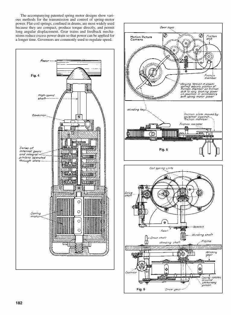
The accompanying patented spring motor designs show vari-ous methods for the transmission and control of spring-motorpower. Flat-coil springs, confined in drums, are most widely usedbecause they are compact, produce torque directly, and permitlong angular displacement. Gear trains and feedback mecha-nisms reduce excess power drain so that power can be applied fora longer time. Governors are commonly used to regulate speed.
182
Sclater Chapter 6 5/3/01 12:24 PM Page 182
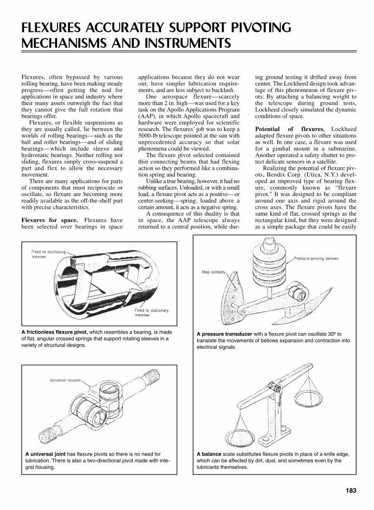
FLEXURES ACCURATELY SUPPORT PIVOTINGMECHANISMS AND INSTRUMENTS
Flexures, often bypassed by variousrolling bearing, have been making steadyprogress—often getting the nod forapplications in space and industry wheretheir many assets outweigh the fact thatthey cannot give the full rotation thatbearings offer.
Flexures, or flexible suspensions asthey are usually called, lie between theworlds of rolling bearings—such as theball and roller bearings—and of slidingbearings—which include sleeve andhydrostatic bearings. Neither rolling norsliding, flexures simply cross-suspend apart and flex to allow the necessarymovement.
There are many applications for partsof components that must reciprocate oroscillate, so flexure are becoming morereadily available as the off-the-shelf partwith precise characteristics.
Flexures for space. Flexures havebeen selected over bearings in space
applications because they do not wearout, have simpler lubrication require-ments, and are less subject to backlash.
One aerospace flexure—scarcelymore than 2 in. high—was used for a keytask on the Apollo Applications Program(AAP), in which Apollo spacecraft andhardware were employed for scientificresearch. The flexures’ job was to keep a5000-lb telescope pointed at the sun withunprecedented accuracy so that solarphenomena could be viewed.
The flexure pivot selected containedthin connecting beams that had flexingaction so they performed like a combina-tion spring and bearing.
Unlike a true bearing, however, it had norubbing surfaces. Unloaded, or with a smallload, a flexure pivot acts as a positive—orcenter-seeking—spring; loaded above acertain amount, it acts as a negative spring.
A consequence of this duality is thatin space, the AAP telescope alwaysreturned to a central position, while dur-
ing ground testing it drifted away fromcenter. The Lockheed design took advan-tage of this phenomenon of flexure piv-ots: By attaching a balancing weight tothe telescope during ground tests,Lockheed closely simulated the dynamicconditions of space.
Potential of flexures. Lockheedadapted flexure pivots to other situationsas well. In one case, a flexure was usedfor a gimbal mount in a submarine.Another operated a safety shutter to pro-tect delicate sensors in a satellite.
Realizing the potential of flexure piv-ots, Bendix Corp. (Utica, N.Y.) devel-oped an improved type of bearing flex-ure, commonly known as “flexurepivot.” It was designed to be compliantaround one axis and rigid around thecross axes. The flexure pivots have thesame kind of flat, crossed springs as therectangular kind, but they were designedas a simple package that could be easily
183
A frictionless flexure pivot, which resembles a bearing, is madeof flat, angular crossed springs that support rotating sleeves in avariety of structural designs.
A universal joint has flexure pivots so there is no need forlubrication. There is also a two-directional pivot made with inte-gral housing.
A pressure transducer with a flexure pivot can oscillate 30º totranslate the movements of bellows expansion and contraction intoelectrical signals.
A balance scale substitutes flexure pivots in place of a knife edge,which can be affected by dirt, dust, and sometimes even by thelubricants themselves.
Sclater Chapter 6 5/3/01 12:24 PM Page 183
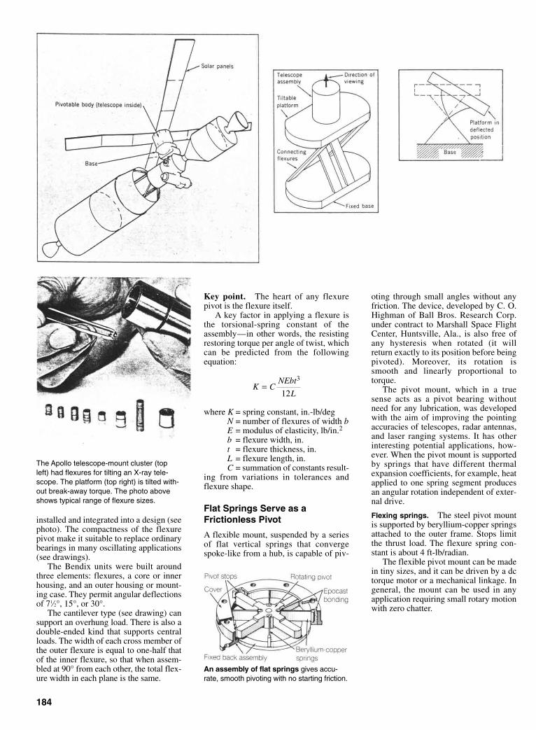
installed and integrated into a design (seephoto). The compactness of the flexurepivot make it suitable to replace ordinarybearings in many oscillating applications(see drawings).
The Bendix units were built aroundthree elements: flexures, a core or innerhousing, and an outer housing or mount-ing case. They permit angular deflectionsof 71⁄2°, 15°, or 30°.
The cantilever type (see drawing) cansupport an overhung load. There is also adouble-ended kind that supports centralloads. The width of each cross member ofthe outer flexure is equal to one-half thatof the inner flexure, so that when assem-bled at 90° from each other, the total flex-ure width in each plane is the same.
184
The Apollo telescope-mount cluster (topleft) had flexures for tilting an X-ray tele-scope. The platform (top right) is tilted with-out break-away torque. The photo aboveshows typical range of flexure sizes.
Key point. The heart of any flexurepivot is the flexure itself.
A key factor in applying a flexure isthe torsional-spring constant of theassembly—in other words, the resistingrestoring torque per angle of twist, whichcan be predicted from the followingequation:
where K = spring constant, in.-lb/degN = number of flexures of width bE = modulus of elasticity, lb/in.2b = flexure width, in.t = flexure thickness, in.L = flexure length, in.C = summation of constants result-
ing from variations in tolerances andflexure shape.
Flat Springs Serve as aFrictionless Pivot
A flexible mount, suspended by a seriesof flat vertical springs that convergespoke-like from a hub, is capable of piv-
K CNEbt
L=
3
12
An assembly of flat springs gives accu-rate, smooth pivoting with no starting friction.
oting through small angles without anyfriction. The device, developed by C. O.Highman of Ball Bros. Research Corp.under contract to Marshall Space FlightCenter, Huntsville, Ala., is also free ofany hysteresis when rotated (it willreturn exactly to its position before beingpivoted). Moreover, its rotation issmooth and linearly proportional totorque.
The pivot mount, which in a truesense acts as a pivot bearing withoutneed for any lubrication, was developedwith the aim of improving the pointingaccuracies of telescopes, radar antennas,and laser ranging systems. It has otherinteresting potential applications, how-ever. When the pivot mount is supportedby springs that have different thermalexpansion coefficients, for example, heatapplied to one spring segment producesan angular rotation independent of exter-nal drive.
Flexing springs. The steel pivot mountis supported by beryllium-copper springsattached to the outer frame. Stops limitthe thrust load. The flexure spring con-stant is about 4 ft-lb/radian.
The flexible pivot mount can be madein tiny sizes, and it can be driven by a dctorque motor or a mechanical linkage. Ingeneral, the mount can be used in anyapplication requiring small rotary motionwith zero chatter.
Sclater Chapter 6 5/3/01 12:24 PM Page 184

A pair of opposed, taut, flexible bands incombination with a leadscrew providesan extremely accurate technique for con-verting rotary motion in one plane torotary motion in another plane. Normally,a worm-gear set would be employed forsuch motion. The technique, however,developed by Kenneth G. Johnson ofJet Propulsion Laboratory, Pasadena,California, under a NASA sponsoredproject, provided repeatable, precise posi-tioning within two seconds of an arc for astar tracker mechanism (drawing, photo).
Crossed bands. In the mechanism, aprecision-finished leadscrew and a fittedmating nut member produce linear trans-latory motion. This motion is then trans-formed to a rotary movement of a pivotalplatform member. The transformation wasachieved by coupling the nut member andthe platform member through a pair ofcrossed flexible phosphor-bronze bands.
The precision leadscrew is journaledat its ends in the two supports.
With the bands drawn taut, the lead-screw is rotated to translate the nut mem-ber. The platform member will be drawn
about its pivot without any lost motion orplay. Because the nut member is accu-rately fitted to the leadscrew, and becauseprecision-ground leadscrews have a mini-mum of lead error, the uniform lineartranslation produced by rotation of thelead screw resulted in a uniform angularrotation of the platform member.
Points on the radial periphery of thesector are governed by the relationship S= RΘ, which means that rotation isdirectly proportional to distance as meas-ured at the circumference. The nut thattranslates on the leadscrew was directlyrelated to the rotary input because theleadscrew was accurately ground andlapped. Also, 360° of rotation of the lead-screw translates the saddle nut a distanceof one thread pitch. This translationresult in rotation of the sector through anangle equal to S/R.
The relationship is true at any pointwithin the operating rang of the instru-ment, provided that R remains constant.Two other necessary conditions formaintaining relationship are that the sad-dle nut be constrained against rotation,
and that there be a zero gap between sec-tor and saddle nut.
Pivots with a Twist
A multipin flexure-type pivot, developedby Smiths Industries in England, com-bined high radial and axial stiffness withthe inherent advantages of a cross-springpivot—which it is.
The pivot provides non-sliding, non-rolling radial and axial support withoutthe need for lubrication. The design com-bines high radial and axial stiffness witha relatively low and controlled angularstiffness. Considerable attention wasgiven to solving the practical problemsof mounting the pivot in a precise andcontrolled way.
The finished pivot is substantially freefrom residual mechanical stress toachieve stability in service. Maragingsteel is used throughout the assembly toavoid any differential expansion due tomaterial mismatch. The blades of theflexure pivot are free from residual brazet o avoid any bimetallic movements whenthe temperature of the pivot changes.
The comparatively open constructionof the pivot made it less susceptible tojamming caused by any loose particles.Furthermore, the simple geometricarrangement of the support pins and flex-ure blade allowed blade anchor points tobe defined with greater accuracy. Theprecision ground integral mountingflanges simplified installation.
Advantages, according to its designer,include frictionless, stictionless and neg-ligible hysteresis characteristics. Thebearing is radiation-resistant and can beused in high vacuum conditions or inenvironments where there is dirt andcontamination.
185
TAUT BANDS AND LEADSCREW PROVIDE ACCURATE ROTARY MOTION
Flexible bands substitute for a worm gear in a precisely repeatable rotarymechanism used as a star tracker. The tracker instrumentation, mounted on theplatform, is rotated by an input motion to the leadscrew.
A flexure pivot boasts high mechanical stability for use in pre-cision instruments.
Sclater Chapter 6 5/3/01 12:24 PM Page 185
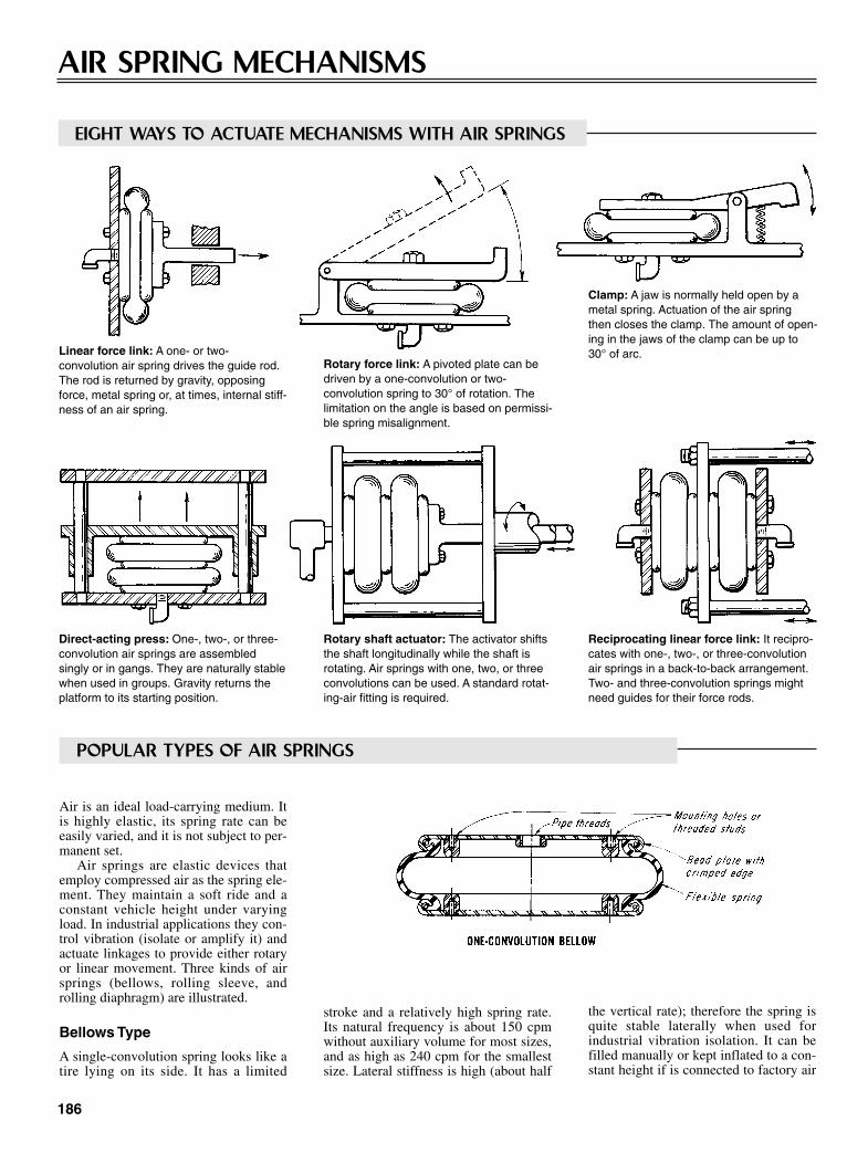
the vertical rate); therefore the spring isquite stable laterally when used forindustrial vibration isolation. It can befilled manually or kept inflated to a con-stant height if is connected to factory air
186
AIR SPRING MECHANISMS
Linear force link: A one- or two-convolution air spring drives the guide rod.The rod is returned by gravity, opposingforce, metal spring or, at times, internal stiff-ness of an air spring.
Clamp: A jaw is normally held open by ametal spring. Actuation of the air springthen closes the clamp. The amount of open-ing in the jaws of the clamp can be up to30° of arc.
Direct-acting press: One-, two-, or three-convolution air springs are assembledsingly or in gangs. They are naturally stablewhen used in groups. Gravity returns theplatform to its starting position.
Rotary shaft actuator: The activator shiftsthe shaft longitudinally while the shaft isrotating. Air springs with one, two, or threeconvolutions can be used. A standard rotat-ing-air fitting is required.
Reciprocating linear force link: It recipro-cates with one-, two-, or three-convolutionair springs in a back-to-back arrangement.Two- and three-convolution springs mightneed guides for their force rods.
stroke and a relatively high spring rate.Its natural frequency is about 150 cpmwithout auxiliary volume for most sizes,and as high as 240 cpm for the smallestsize. Lateral stiffness is high (about half
Rotary force link: A pivoted plate can bedriven by a one-convolution or two-convolution spring to 30° of rotation. Thelimitation on the angle is based on permissi-ble spring misalignment.
EIGHT WAYS TO ACTUATE MECHANISMS WITH AIR SPRINGS
POPULAR TYPES OF AIR SPRINGS
Air is an ideal load-carrying medium. Itis highly elastic, its spring rate can beeasily varied, and it is not subject to per-manent set.
Air springs are elastic devices thatemploy compressed air as the spring ele-ment. They maintain a soft ride and aconstant vehicle height under varyingload. In industrial applications they con-trol vibration (isolate or amplify it) andactuate linkages to provide either rotaryor linear movement. Three kinds of airsprings (bellows, rolling sleeve, androlling diaphragm) are illustrated.
Bellows Type
A single-convolution spring looks like atire lying on its side. It has a limited
Sclater Chapter 6 5/3/01 12:24 PM Page 186

supply through a pressure regulator. Thisspring will also actuate linkages whereshort axial length is desirable. It is sel-dom used in vehicle suspension systems.
Rolling-Sleeve Type
This spring is sometimes called thereversible-sleeve or rolling-lobe type. Ithas a telescoping action—the lobe at thebottom of the air spring rolls up anddown along the piston. The spring isused primarily in vehicle suspensionsbecause lateral stiffness is almost zero.
Rolling-Diaphragm Type
These are laterally stable and can beused as vibration isolators, actuators, orconstant-force spring. But because of
their negative effective-area curve, theirpressure is not generally maintained bypressure regulators.
187
Pivot mechanism: It rotates a rod through145° of rotation. It can accept a 30° mis-alignment because of the circular path of itsconnecting-link pin. A metal spring oropposing force retracts the link.
Reciprocating rotary motion with one-convolution and two-convolution springs. Anarc up to 30° is possible. It can pair a largeair spring with a smaller one or a lengthenlever.
Air suspension on vehicle: A view of normal static conditions—air springs at desired heightand height-control valve closed (a). When a load is added to the vehicle—the valve opens toadmit air to the springs and restore height, but at higher pressure (b). With load removed fromthe vehicle—valve permits bleeding off excess air pressure to atmosphere and restores itsdesign height (c).
Sclater Chapter 6 5/3/01 12:25 PM Page 187

188
OBTAINING VARIABLE RATES FROM SPRINGSHow stops, cams, linkages, and other arrangements can vary the load/deflection ratio during extension or compression
With tapered-pitch springthe number of effective coilschanges with deflection—thecoils “bottom” progressively.
A tapered outside diame-ter and pitch combine toproduce a similar effectexcept that the spring withtapered O.D. will have ashorter solid height.
In dual springs, one springcloses completely before theother.
A cam-and-spring devicecauses the torque relationshipto vary during rotation as themoment arm changes.
Stops can be used with eithercompression or extensionsprings.
Torsion spring combined with avariable-radius pulley gives aconstant force.
Leaf springs can be arranges so that their effec-tive lengths change with deflection.
These linkage-type arrangements are used in instrumentswhere torque control or anti-vibration suspension is required.
With a tapered mandrel and torsionspring the effective number or coilsdecreases with torsional deflection.
A four-bar mechanism in con-junction with a spring has a widevariety of load/deflection charac-teristics.
A molded-rubber springhas deflection characteristicsthat vary with its shape.
An arched leaf-spring gives analmost constant force when it isshaped like the one illustrated.
Sclater Chapter 6 5/3/01 12:25 PM Page 188

Belleville springs are low-profile conicalrings with differing height (h) to thick-ness (t) ratios, as shown in Fig. 1. Fourway to stack them are shown in Fig. 2.
Belleville springs lend themselves toa wide variety; of applications:
For height to spring ratios of about0.4—A linear spring rate and high loadresistance with small deflections.
For height to spring ratios between0.8 and 1.0—An almost linear spring ratefor fasteners and bearing and in stacks.
For rations of around 1.6—A constant(flat) spring rate starting at about 60% ofthe deflection (relative to the fully com-pressed flat position) and proceeding tothe flat position and, if desired, on to theflipped side to a deflection of about140%. In most applications, the flat posi-tion is the limit of travel, and for deflec-tions beyond the flat, the contact elementsmust be allowed unrestricted travel
One application of bellevilles withconstant spring rate is on live spindles onthe tailpiece of a lathe. The work can beloaded on the lathe, and as the piece heatsup and begins to expand, the bellevillewill absorb this change in length withoutadding any appreciable load.
For high height to spring ratiosexceeding about 2.5—The spring is stiff,and as the stability point (high point onthe curve) is passed the spring ratebecomes negative causing resistance todrop rapidly. If allowed, the bellevillewill snap through the flat position. Inother words, it will turn itself inside out.
Working in groups. Belleville wash-ers stacked in the parallel arrangementhave been used successfully in a varietyof applications.
One is a pistol or rifle buffer mecha-nism (Fig. 3) designed to absorbrepeated, high-energy shock loads. Apreload nut predeflects the washers tostiffen their resistance. The stackedwashers are guided by a central shaft, anoutside guide cylinder, guide rings, or acombination of these.
A wind-up starter mechanism fordiesel engines (shown in Fig. 4) replacesa heavy-duty electric starter or auxiliarygas engine. To turn over the engine,energy is manually stored in a stack ofbellevilles compressed by a hand crank.When released, the expanding springpack rotates a pinion meshed with theflywheel ring gear to start the engine.
Figure 5 shows a belleville as a load-ing spring for a clutch.
189
BELLEVILLE SPRINGS
Popular arrangements
Sclater Chapter 6 5/3/01 12:25 PM Page 189

Do you need a buffer between vibratingmachinery and the surrounding struc-ture? These isolators, like capable fight-ers, absorb the light jabs and stand firmagainst the forces that inflict powerfulhaymakers
190
SPRING-TYPE LINKAGE FOR VIBRATION CONTROL
Fig. 1 This basic spring arrangementhas zero stiffness, and is as “soft as acloud” when compression springs are inline, as illustrated in the loaded position.But change the weight or compression-spring alignment, and stiffness increasesgreatly. This support is adequate for vibra-tion isolation because zero stiffness give agreater range or movement than the vibra-tion amplitude generally in the hundredths-of-an-inch range.Arrangements shown here are highlyabsorbent when required, yet provide a firmsupport when large force changes occur. Bycontrast, isolators that depend upon very“soft” springs, such as the sine spring, areunsatisfactory in many applications; theyallow a large movement of the supportedload with any slight weight change or large-amplitude displacing force.
Fig. 2 Alternative arrangements illus-trate adaptability of basic design. Here,instead of the inclined, helical compressionsprings, wither tension or cantilever springscan serve. Similarly, different type ofsprings can replace the axial, tensionspring. Zero torsional stiffness can also beprovided.
Fig. 3 A general-purpose support isbased on basic spring arrangement, exceptthat an axial compression spring is substi-tuted for a tension spring. Inclined compres-sion springs, spaced around a central pillar,carry the component to be isolated. When aload is applied, adjustment might be neces-sary to bring the inclined springs to zeroinclination. Load range that can be sup-ported with zero stiffness on a specific sup-port is determined by the adjustment rangeand physical limitations of the axial spring.
Fig. 4
Fig. 5
Fig. 6
Fig. 7
Various applications of the principle ofvibration isolation show how versatile thedesign is. Coil spring (Fig. 4) as well ascantilever and torsion-bar suspension ofautomobiles can all be reduced in stiffnessby adding an inclined spring; stiffness of thetractor seat (Fig. 5) and, consequently,transmitted shocks can be similarlyreduced. Mechanical tension meter (Fig. 6)provides a sensitive indication of small vari-ations in tension. A weighing scale, forexample, could detect small variations innominally identical objects. A nonlineartorque mete (Fig. 7) provides a sensitiveindication of torque variations about a pre-determined level.
Sclater Chapter 6 5/3/01 12:25 PM Page 190
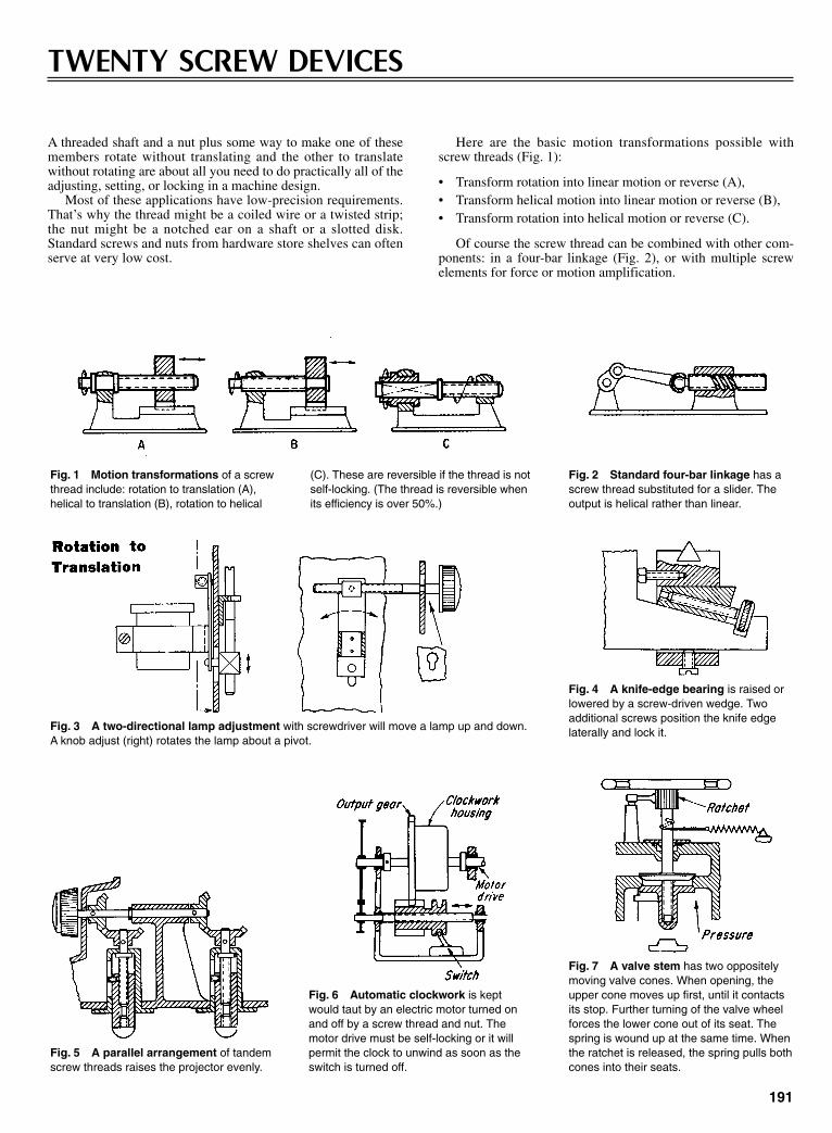
A threaded shaft and a nut plus some way to make one of thesemembers rotate without translating and the other to translatewithout rotating are about all you need to do practically all of theadjusting, setting, or locking in a machine design.
Most of these applications have low-precision requirements.That’s why the thread might be a coiled wire or a twisted strip;the nut might be a notched ear on a shaft or a slotted disk.Standard screws and nuts from hardware store shelves can oftenserve at very low cost.
191
TWENTY SCREW DEVICES
Here are the basic motion transformations possible withscrew threads (Fig. 1):
• Transform rotation into linear motion or reverse (A),• Transform helical motion into linear motion or reverse (B),• Transform rotation into helical motion or reverse (C).
Of course the screw thread can be combined with other com-ponents: in a four-bar linkage (Fig. 2), or with multiple screwelements for force or motion amplification.
Fig. 1 Motion transformations of a screwthread include: rotation to translation (A),helical to translation (B), rotation to helical
(C). These are reversible if the thread is notself-locking. (The thread is reversible whenits efficiency is over 50%.)
Fig. 2 Standard four-bar linkage has ascrew thread substituted for a slider. Theoutput is helical rather than linear.
Fig. 3 A two-directional lamp adjustment with screwdriver will move a lamp up and down.A knob adjust (right) rotates the lamp about a pivot.
Fig. 4 A knife-edge bearing is raised orlowered by a screw-driven wedge. Twoadditional screws position the knife edgelaterally and lock it.
Fig. 5 A parallel arrangement of tandemscrew threads raises the projector evenly.
Fig. 6 Automatic clockwork is keptwould taut by an electric motor turned onand off by a screw thread and nut. Themotor drive must be self-locking or it willpermit the clock to unwind as soon as theswitch is turned off.
Fig. 7 A valve stem has two oppositelymoving valve cones. When opening, theupper cone moves up first, until it contactsits stop. Further turning of the valve wheelforces the lower cone out of its seat. Thespring is wound up at the same time. Whenthe ratchet is released, the spring pulls bothcones into their seats.
Sclater Chapter 6 5/3/01 12:25 PM Page 191

TRANSLATION TO ROTATION
192
Fig. 11 A hairlineadjustment for a tele-scope with two alternativemethods for drive andspring return.
Fig. 8 A metal strip or square rod can betwisted to make a long-lead thread. It is idealfor transforming linear into rotary motion.Here a pushbutton mechanism winds a cam-era. The number of turns or dwell of the out-put gear is easily altered by changing (oreven reversing) the twist of the strip.
Fig. 9 A feeler gage has its motion ampli-fied through a double linkage and thentransformed to rotation for moving a dialneedle.
Fig. 10 The familiar flying propeller-toyis operated by pushing the bushing straightup and off the thread.
SELF-LOCKING
Fig. 12 This screw and nut forma self-locking drive for a complexlinkage.
Fig. 13 Force translation. The threaded handle in(A) drives a coned bushing that thrusts rods outwardlyfor balanced pressure. The screw in (B) retains anddrives a dowel pin for locking purposes. A right- andleft-handed shaft (C) actuates a press.
Sclater Chapter 6 5/3/01 12:25 PM Page 192

193
Fig. 14 Double-threaded screws, whenused as differentials, permit very fineadjustment for precision equipment at rela-tively low cost.
Fig. 15 Differential screws can be madein dozens of forms. Here are two methods:in the upper figure, two opposite-handthreads on a single shaft; in the lower fig-ure, same-hand threads on independentshafts.
Fig. 16 Opposite-hand threads make ahigh-speed centering clamp out of two mov-ing nuts.
Fig. 17 A measuring table rises veryslowly for many turns of the input bevelgear. If the two threads are 11⁄2 to 12 and 3⁄4to 16, in the fine-thread series, the table willrise approximately 0.004 in. per input-gearrevolution.
Fig. 18 A lathe turning tool in a drill rodis adjusted by a differential screw. A specialdouble-pin wrench turns the intermediatenut, advancing the nut and retracting thethreaded tool simultaneously. The tool isthen clamped by a setscrew.
Fig. 19 Any variable-speed motor can bemade to follow a small synchronous motor byconnecting them to the two shafts of this differ-ential screw. Differences in the number of revo-lutions between the two motors appear asmotion of the traveling nut and slide, thus pro-viding electrical speed compensation.
Fig. 20 A wire fork is the nut inthis simple tube-and-screw device.
Fig. 21 A mechanical pencil includes a spring as the screw threadand a notched ear or a bent wire as the nut.
DOUBLE THREADING
Sclater Chapter 6 5/3/01 12:25 PM Page 193
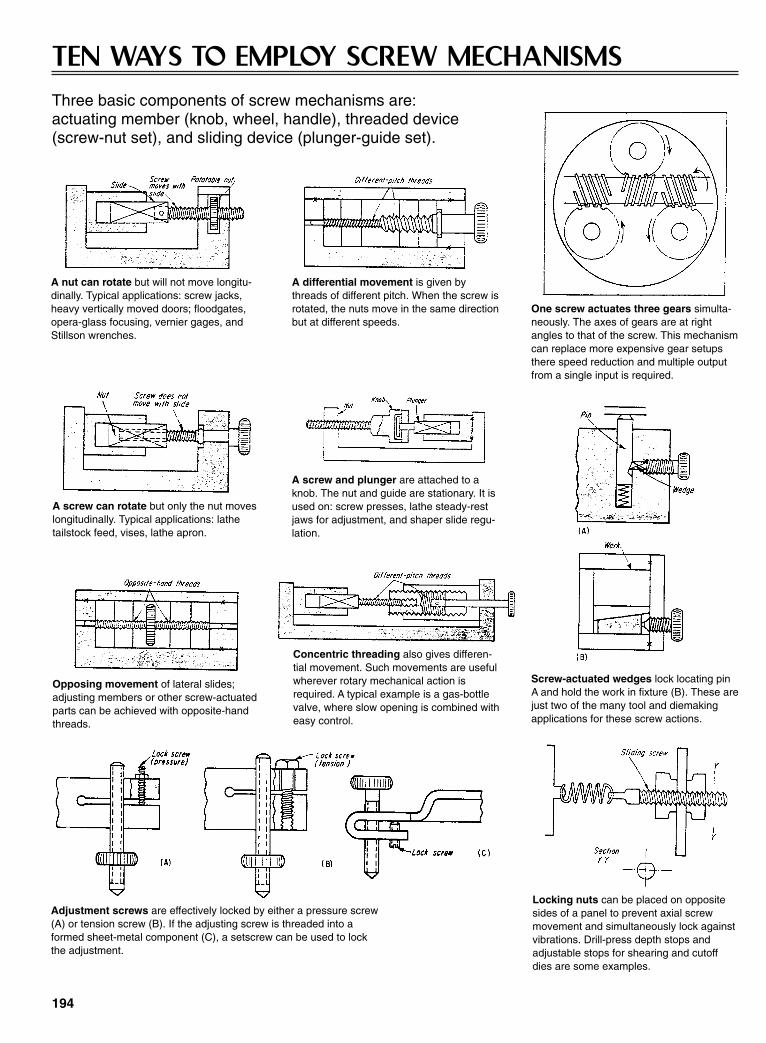
194
A nut can rotate but will not move longitu-dinally. Typical applications: screw jacks,heavy vertically moved doors; floodgates,opera-glass focusing, vernier gages, andStillson wrenches.
A differential movement is given bythreads of different pitch. When the screw isrotated, the nuts move in the same directionbut at different speeds.
One screw actuates three gears simulta-neously. The axes of gears are at rightangles to that of the screw. This mechanismcan replace more expensive gear setupsthere speed reduction and multiple outputfrom a single input is required.
A screw can rotate but only the nut moveslongitudinally. Typical applications: lathetailstock feed, vises, lathe apron.
A screw and plunger are attached to aknob. The nut and guide are stationary. It isused on: screw presses, lathe steady-restjaws for adjustment, and shaper slide regu-lation.
Screw-actuated wedges lock locating pinA and hold the work in fixture (B). These arejust two of the many tool and diemakingapplications for these screw actions.
Opposing movement of lateral slides;adjusting members or other screw-actuatedparts can be achieved with opposite-handthreads.
Concentric threading also gives differen-tial movement. Such movements are usefulwherever rotary mechanical action isrequired. A typical example is a gas-bottlevalve, where slow opening is combined witheasy control.
Adjustment screws are effectively locked by either a pressure screw(A) or tension screw (B). If the adjusting screw is threaded into aformed sheet-metal component (C), a setscrew can be used to lockthe adjustment.
Locking nuts can be placed on oppositesides of a panel to prevent axial screwmovement and simultaneously lock againstvibrations. Drill-press depth stops andadjustable stops for shearing and cutoffdies are some examples.
TEN WAYS TO EMPLOY SCREW MECHANISMSThree basic components of screw mechanisms are: actuating member (knob, wheel, handle), threaded device (screw-nut set), and sliding device (plunger-guide set).
Sclater Chapter 6 5/3/01 12:25 PM Page 194
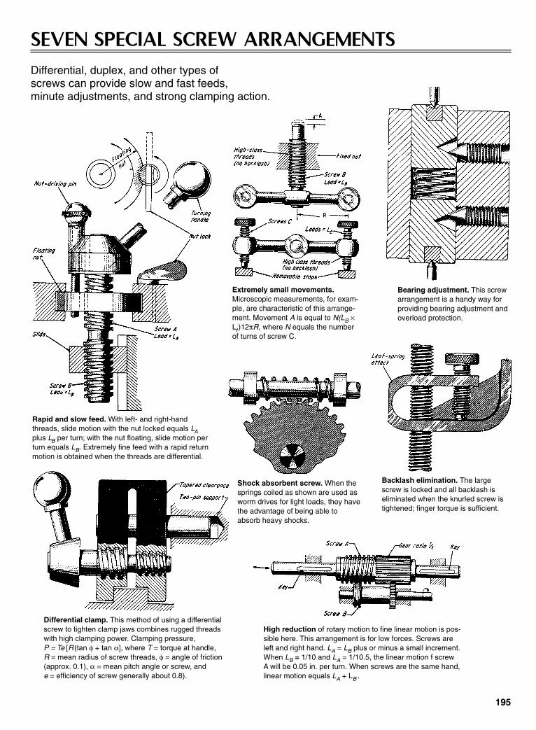
195
SEVEN SPECIAL SCREW ARRANGEMENTSDifferential, duplex, and other types of screws can provide slow and fast feeds, minute adjustments, and strong clamping action.
Rapid and slow feed. With left- and right-handthreads, slide motion with the nut locked equals LAplus LB per turn; with the nut floating, slide motion perturn equals LB. Extremely fine feed with a rapid returnmotion is obtained when the threads are differential.
Extremely small movements.Microscopic measurements, for exam-ple, are characteristic of this arrange-ment. Movement A is equal to N(LB ×Lt)12πR, where N equals the numberof turns of screw C.
Bearing adjustment. This screwarrangement is a handy way forproviding bearing adjustment andoverload protection.
Differential clamp. This method of using a differentialscrew to tighten clamp jaws combines rugged threadswith high clamping power. Clamping pressure, P = Te [R (tan φ + tan α], where T = torque at handle, R = mean radius of screw threads, φ = angle of friction(approx. 0.1), α = mean pitch angle or screw, and e = efficiency of screw generally about 0.8).
Shock absorbent screw. When thesprings coiled as shown are used asworm drives for light loads, they havethe advantage of being able toabsorb heavy shocks.
Backlash elimination. The largescrew is locked and all backlash iseliminated when the knurled screw istightened; finger torque is sufficient.
High reduction of rotary motion to fine linear motion is pos-sible here. This arrangement is for low forces. Screws areleft and right hand. LA = LB plus or minus a small increment.When LB = 1/10 and LA = 1/10.5, the linear motion f screwA will be 0.05 in. per turn. When screws are the same hand,linear motion equals LA + LB .
Sclater Chapter 6 5/3/01 12:25 PM Page 195
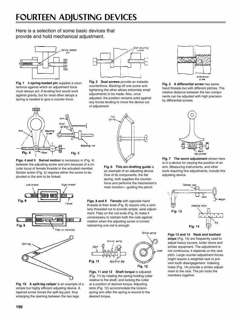
196
FOURTEEN ADJUSTING DEVICESHere is a selection of some basic devices that provide and hold mechanical adjustment.
Fig. 1 A spring-loaded pin supplies a coun-terforce against which an adjustment forcemust always act. A leveling foot would workagainst gravity, but for most other setups aspring is needed to give a counter-force.
Fig. 3 A differential screw has same-hand threads but with different pitches. Therelative distance between the two compo-nents can be adjusted with high precisionby differential screws.
Figs. 4 and 5 Swivel motion is necessary in (Fig. 4)between the adjusting screw and arm because of a cir-cular locus of female threads in the actuated member.Similar action (Fig. 5) requires either the screw to bepivoted or the arm to be forked.
Fig. 6 This arc-drafting guide isan example of an adjusting device.One of its components, the flatspring, both supplies the counter-force and performs the mechanism’smain function—guiding the pencil.
Fig. 7 The worm adjustment shown hereis in a device for varying the position of anarm. Measuring instruments, and othertools requiring fine adjustments, include thisadjusting device.
Fig. 10 A split-leg caliper is an example of asimple but highly efficient adjusting device. Atapered screw forces the split leg part, thusenlarging the opening between the two legs.
Fig. 2 Dual screws provide an inelasticcounterforce. Backing-off one screw andtightening the other allows extremely smalladjustments to be made. Also, onceadjusted, the position remains solid againstany forces tending to move the device outof adjustment.
Figs. 11 and 12 Shaft torque is adjusted(Fig. 11) by rotating the spring-holding collarrelative to the shaft, and locking the collarat a position of desired torque. Adjustingslots (Fig. 12) accommodate the torsion-spring arm after the spring is wound to thedesired torque.
Figs 13 and 14 Rack and toothedstops (Fig. 13) are frequently used toadjust heavy louvers, boiler doors andsimilar equipment. The adjustment isnot continuous; it depends on the rackpitch. Large counter-adjustment forcesmight require a weighted rack to pre-vent tooth disengagement. Indexingholes (Fig. 14) provide a similar adjust-ment to the rack. The pin locks themembers together.
Figs. 8 and 9 Tierods with opposite-handthreads at their ends (Fig. 8) require only a simi-larly threaded nut to provide simple, axial adjust-ment. Flats on the rod ends (Fig. 9) make itunnecessary to restrain both the rods againstrotation when the adjusting screw is turned;restraining one rod is enough.
Sclater Chapter 6 5/3/01 12:25 PM Page 196

The patented Roundway linear roller bearings from ThomsonIndustries, Inc., Port Washington, NY, can carry heavy loads onsupported parallel cylindrical rails where rigidity and stiffness isrequired. The Roundway linear roller bearing consists of acylindrical inner bearing race with rounded-ends that is fastenedto a mounting block by a trunnion pin. It is enclosed by a linkedchain of concave rollers that circulate around the race. Therollers and the inner race are made from hardened and groundhigh-carbon bearing steel, and the mounting block is cast frommalleable iron. The load on the mounting block is transferredthrough the trunnion pin, race, and roller chain assembly to thesupporting rail, which functions as the external raceway.
The height of the bearing can be adjusted with the eccentrictrunnion pin to compensate for variations in the mounting sur-
197
LINEAR ROLLER BEARINGS ARE SUITED FOR HIGH-LOAD, HEAVY-DUTY TASKS
faces. The pin can also be used to preload the bearing by elimi-nating internal bearing clearance. After the trunnion pin hasbeen adjusted, it can be held in place by tightening the lockscrew.
Because a single Roundway linear roller bearing does notresist side loads, a dual version of the Roundway bearing capa-ble of resisting those loads is available. It has two race and rollerassemblies mounted on a wider iron block so that the bearingscontact the raceway support at angles of 45º from the centerline.In typical motion control installation, two single-bearing unitsare mounted in tandem on one of the parallel rails and two dual-bearing units are mounted in tandem on the other rail to with-stand any sideloads.
The concave steel rollers in this linear bearing are linked in a chain assembly as they circulate aroundthe inner race.
Sclater Chapter 6 5/3/01 12:25 PM Page 197

CHAPTER 7CAM, TOGGLE, CHAIN,
AND BELT MECHANISMS
Sclater Chapter 7 5/3/01 12:32 PM Page 199
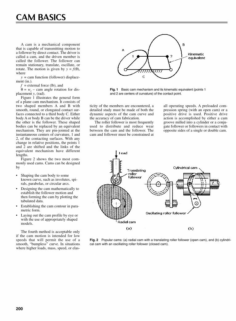
A cam is a mechanical componentthat is capable of transmitting motion toa follower by direct contact. The driver iscalled a cam, and the driven member iscalled the follower. The follower canremain stationary, translate, oscillate, orrotate. The motion is given by y = f(θ),where
y = cam function (follower) displace-ment (in.).
f = external force (lb), andθ = wt – cam angle rotation for dis-
placement y, (rad).Figure 1 illustrates the general form
of a plane cam mechanism. It consists oftwo shaped members A and B withsmooth, round, or elongated contact sur-faces connected to a third body C. Eitherbody A or body B can be the driver whilethe other is the follower. These shapedbodies can be replaced by an equivalentmechanism. They are pin-jointed at theinstantaneous centers of curvature, 1 and2, of the contacting surfaces. With anychange in relative positions, the points 1and 2 are shifted and the links of theequivalent mechanism have differentlengths.
Figure 2 shows the two most com-monly used cams. Cams can be designedby
• Shaping the cam body to someknown curve, such as involutes, spi-rals, parabolas, or circular arcs.
• Designing the cam mathematically toestablish the follower motion andthen forming the cam by plotting thetabulated data.
• Establishing the cam contour in para-metric form.
• Laying out the cam profile by eye orwith the use of appropriately shapedmodels.
The fourth method is acceptable onlyif the cam motion is intended for lowspeeds that will permit the use of asmooth, “bumpless” curve. In situationswhere higher loads, mass, speed, or elas-
200
CAM BASICS
Fig. 1 Basic cam mechanism and its kinematic equivalent (points 1and 2 are centers of curvature) of the contact point.
ticity of the members are encountered, adetailed study must be made of both thedynamic aspects of the cam curve andthe accuracy of cam fabrication.
The roller follower is most frequentlyused to distribute and reduce wearbetween the cam and the follower. Thecam and follower must be constrained at
Fig. 2 Popular cams: (a) radial cam with a translating roller follower (open cam), and (b) cylindri-cal cam with an oscillating roller follower (closed cam).
all operating speeds. A preloaded com-pression spring (with an open cam) or apositive drive is used. Positive driveaction is accomplished by either a camgroove milled into a cylinder or a conju-gate follower or followers in contact withopposite sides of a single or double cam.
Sclater Chapter 7 5/3/01 12:32 PM Page 200
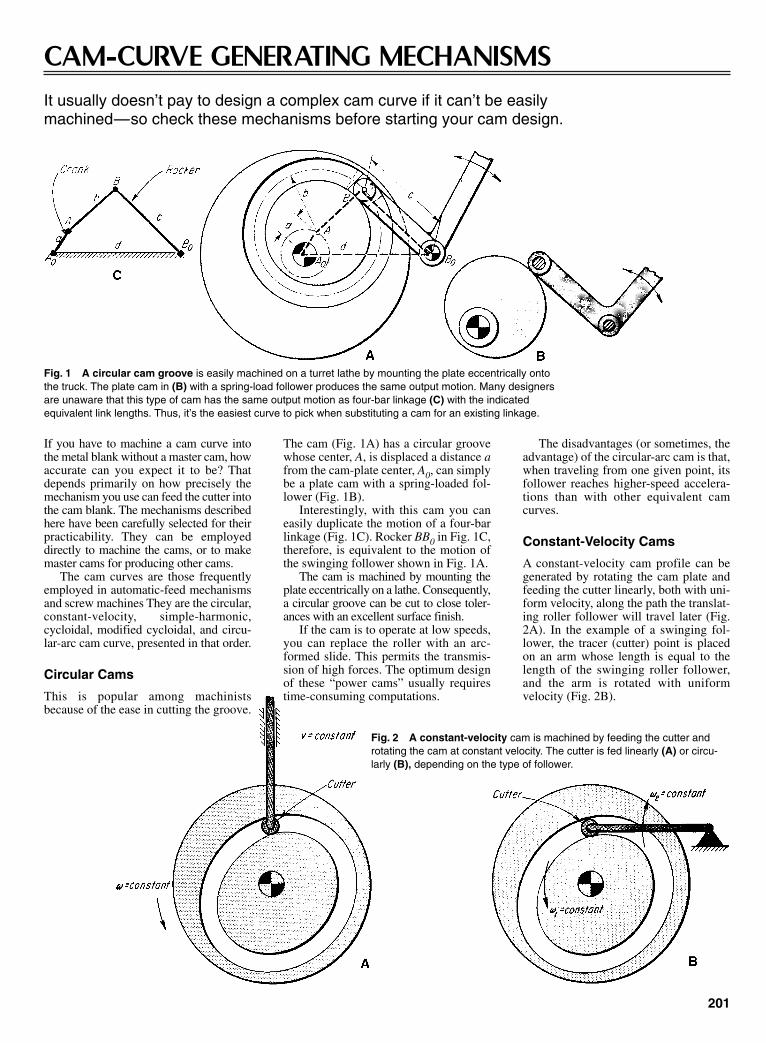
201
CAM-CURVE GENERATING MECHANISMSIt usually doesn’t pay to design a complex cam curve if it can’t be easily machined—so check these mechanisms before starting your cam design.
Fig. 1 A circular cam groove is easily machined on a turret lathe by mounting the plate eccentrically ontothe truck. The plate cam in (B) with a spring-load follower produces the same output motion. Many designersare unaware that this type of cam has the same output motion as four-bar linkage (C) with the indicatedequivalent link lengths. Thus, it’s the easiest curve to pick when substituting a cam for an existing linkage.
Fig. 2 A constant-velocity cam is machined by feeding the cutter androtating the cam at constant velocity. The cutter is fed linearly (A) or circu-larly (B), depending on the type of follower.
The disadvantages (or sometimes, theadvantage) of the circular-arc cam is that,when traveling from one given point, itsfollower reaches higher-speed accelera-tions than with other equivalent camcurves.
Constant-Velocity Cams
A constant-velocity cam profile can begenerated by rotating the cam plate andfeeding the cutter linearly, both with uni-form velocity, along the path the translat-ing roller follower will travel later (Fig.2A). In the example of a swinging fol-lower, the tracer (cutter) point is placedon an arm whose length is equal to thelength of the swinging roller follower,and the arm is rotated with uniformvelocity (Fig. 2B).
If you have to machine a cam curve intothe metal blank without a master cam, howaccurate can you expect it to be? Thatdepends primarily on how precisely themechanism you use can feed the cutter intothe cam blank. The mechanisms describedhere have been carefully selected for theirpracticability. They can be employeddirectly to machine the cams, or to makemaster cams for producing other cams.
The cam curves are those frequentlyemployed in automatic-feed mechanismsand screw machines They are the circular,constant-velocity, simple-harmonic,cycloidal, modified cycloidal, and circu-lar-arc cam curve, presented in that order.
Circular Cams
This is popular among machinistsbecause of the ease in cutting the groove.
The cam (Fig. 1A) has a circular groovewhose center, A, is displaced a distance afrom the cam-plate center, A0, can simplybe a plate cam with a spring-loaded fol-lower (Fig. 1B).
Interestingly, with this cam you caneasily duplicate the motion of a four-barlinkage (Fig. 1C). Rocker BB0 in Fig. 1C,therefore, is equivalent to the motion ofthe swinging follower shown in Fig. 1A.
The cam is machined by mounting theplate eccentrically on a lathe. Consequently,a circular groove can be cut to close toler-ances with an excellent surface finish.
If the cam is to operate at low speeds,you can replace the roller with an arc-formed slide. This permits the transmis-sion of high forces. The optimum designof these “power cams” usually requirestime-consuming computations.
Sclater Chapter 7 5/3/01 12:32 PM Page 201
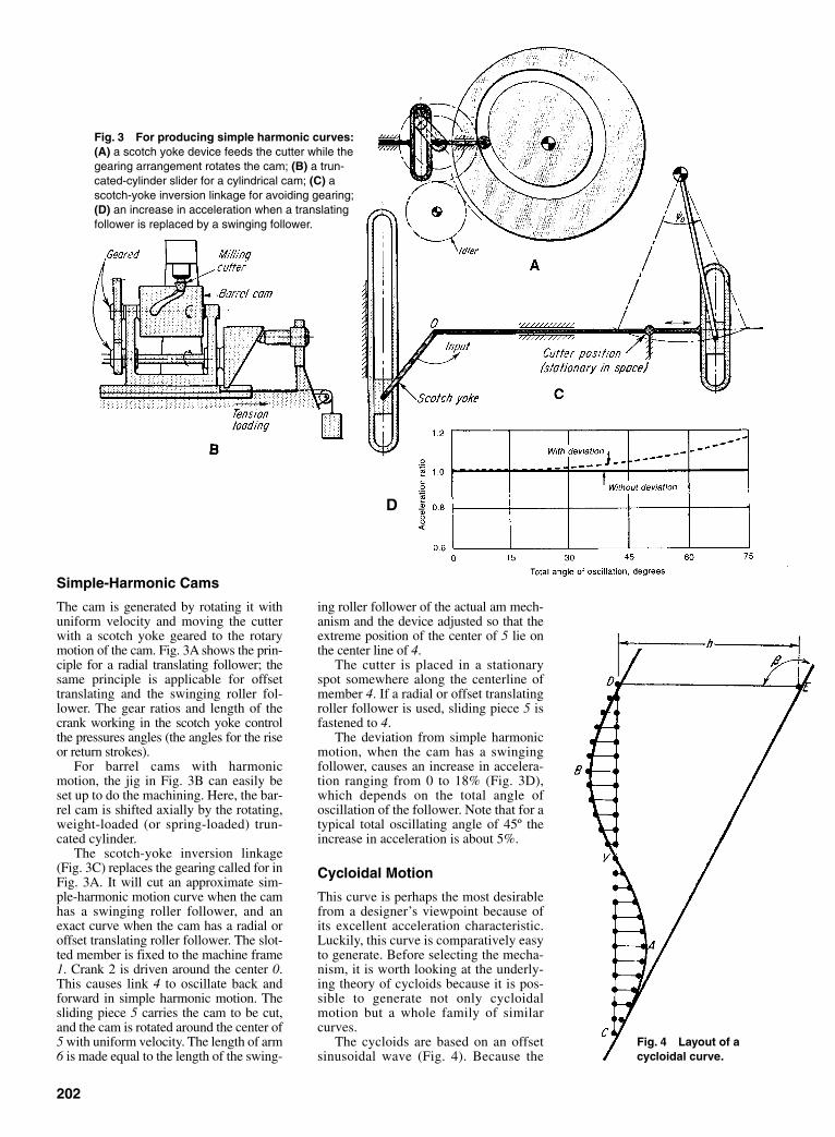
202
ing roller follower of the actual am mech-anism and the device adjusted so that theextreme position of the center of 5 lie onthe center line of 4.
The cutter is placed in a stationaryspot somewhere along the centerline ofmember 4. If a radial or offset translatingroller follower is used, sliding piece 5 isfastened to 4.
The deviation from simple harmonicmotion, when the cam has a swingingfollower, causes an increase in accelera-tion ranging from 0 to 18% (Fig. 3D),which depends on the total angle ofoscillation of the follower. Note that for atypical total oscillating angle of 45º theincrease in acceleration is about 5%.
Cycloidal Motion
This curve is perhaps the most desirablefrom a designer’s viewpoint because ofits excellent acceleration characteristic.Luckily, this curve is comparatively easyto generate. Before selecting the mecha-nism, it is worth looking at the underly-ing theory of cycloids because it is pos-sible to generate not only cycloidalmotion but a whole family of similarcurves.
The cycloids are based on an offsetsinusoidal wave (Fig. 4). Because the
Fig. 3 For producing simple harmonic curves:(A) a scotch yoke device feeds the cutter while thegearing arrangement rotates the cam; (B) a trun-cated-cylinder slider for a cylindrical cam; (C) ascotch-yoke inversion linkage for avoiding gearing;(D) an increase in acceleration when a translatingfollower is replaced by a swinging follower.
Simple-Harmonic Cams
The cam is generated by rotating it withuniform velocity and moving the cutterwith a scotch yoke geared to the rotarymotion of the cam. Fig. 3A shows the prin-ciple for a radial translating follower; thesame principle is applicable for offsettranslating and the swinging roller fol-lower. The gear ratios and length of thecrank working in the scotch yoke controlthe pressures angles (the angles for the riseor return strokes).
For barrel cams with harmonicmotion, the jig in Fig. 3B can easily beset up to do the machining. Here, the bar-rel cam is shifted axially by the rotating,weight-loaded (or spring-loaded) trun-cated cylinder.
The scotch-yoke inversion linkage(Fig. 3C) replaces the gearing called for inFig. 3A. It will cut an approximate sim-ple-harmonic motion curve when the camhas a swinging roller follower, and anexact curve when the cam has a radial oroffset translating roller follower. The slot-ted member is fixed to the machine frame1. Crank 2 is driven around the center 0.This causes link 4 to oscillate back andforward in simple harmonic motion. Thesliding piece 5 carries the cam to be cut,and the cam is rotated around the center of5 with uniform velocity. The length of arm6 is made equal to the length of the swing-
Fig. 4 Layout of acycloidal curve.
D
Sclater Chapter 7 5/3/01 12:32 PM Page 202

radii of curvatures in points C, V, and Dare infinite (the curve is “flat” at thesepoints), if this curve was a cam grooveand moved in the direction of line CVD,a translating roller follower, actuated bythis cam, would have zero acceleration atpoints C, V, and D no matter in whatdirection the follower is pointed.
Now, if the cam is moved in the direc-tion of CE and the direction of motion ofthe translating follower is lined up per-pendicular to CE, the acceleration of thefollower in points, C, V, and D wouldstill be zero. This has now become thebasic cycloidal curve, and it can be con-sidered as a sinusoidal curve of a certainamplitude (with the amplitude measuredperpendicular to the straight line) super-imposed on a straight (constant-velocity)line.
The cycloidal is considered to be thebest standard cam contour because of itslow dynamic loads and low shock andvibration characteristics. One reason forthese outstanding attributes is that sud-den changes in acceleration are avoidedduring the cam cycle. But improved per-formance is obtainable with certain mod-ified cycloidals.
Modified Cycloids
To modify the cycloid, only the directionand magnitude of the amplitude need tobe changed, while keeping the radius ofcurvature infinite at points C, V, and D.
Comparisons are made in Fig. 5 ofsome of the modified curves used inindustry. The true cycloidal is shown inthe cam diagram of Fig. 5A. Note that thesine amplitudes to be added to the con-stant-velocity line are perpendicular tothe base. In the Alt modification shownin Fig. 5B (named after Hermann Alt, aGerman kinematician who first analyzedit), the sine amplitudes are perpendicularto the constant-velocity line. This resultsin improved (lower) velocity characteris-tics (Fig. 5D), but higher accelerationmagnitudes (Fig. 5E).
The Wildt modified cycloidal (afterPaul Wildt) is constructed by selecting apoint w which is 0.57 the distance T/2,and then drawing line wp through ypwhich is midway along OP. The base ofthe sine curve is then constructed perpen-dicular to yw. This modification resultsin a maximum acceleration of 5.88 h/T2.By contrasts, the standard cycloidal
curve has a maximum acceleration of6.28 h/T 2. This is a 6.8 reduction inacceleration.
(It’s a complex task to construct acycloidal curve to go through a particularpoint P—where P might be anywherewithin the limits of the box in Fig. 5C—and with a specific scope at P. There is agrowing demand for this kind ofcycloidal modification.
Generating Modified Cycloidals
One of the few methods capable of gen-erating the family of modified cycloidalsconsists of a double carriage and rackarrangement (Fig. 6A).
The cam blank can pivot around thespindle, which in turn is on the movablecarriage I. The cutter center is stationary.If the carriage is now driven at constantspeed by the leadscrew in the direction ofthe arrow, steel bands 1 and 2 will alsocause the cam blank to rotate. This rota-tion-and-translation motion of the camwill cut a spiral groove.
For the modified cycloidals, a secondmotion must be imposed on the cam tocompensate for the deviations from the
203
Fig. 5 A family of cycloidal curves: (A) A standard cycloidal motion; (B) A modificationaccording to H. Alt; (C) A modification according to P. Wildt; (D) A comparison of velocity char-acteristics; (E) A comparison of acceleration curves.
Sclater Chapter 7 5/3/01 12:32 PM Page 203

true cycloidal. This is done by a secondsteel-band arrangement. As carriage Imoves, bands 3 and 4 cause the eccentricto rotate. Because of the stationaryframe, the slide surrounding the eccentricis actuated horizontally. This slide is partof carriage II. As a result, a sinusoidalmotion is imposed on the cam.
Carriage I can be set at various anglesβ to match angle β in Fig. 5B and C. Themechanism can also be modified to cutcams with swinging followers.
Circular-Arc Cams
In recent years it has become customaryto turn to the cycloidal and other similarcurves even when speeds are low.However, there are still many applica-tions for circular-arc cams. Those camsare composed of circular arcs, or circulararc and straight lines. For comparativelysmall cams, the cutting technique illus-trated in Fig. 7 produces accurate results.
Assume that the contour is composedof circular arc 1-2 with center at 02, arc 3-4 with center at 03 , arc 4-5 with center at01 , arc 5-6 with center at 04 , arc 7-1 withcenter at 01 , and the straight lines 2-3 and6-7. The method calls for a combinationof drilling, lathe turning, and templatefiling.
First, small holes about 0.1 in. indiameter are drilled at 01 , 03 , and 04 .
Then a hole drilled with the center at 02 ,and radius of r2 . Next the cam is fixed ina turret lathe with the center of rotation at01 , and the steel plate is cut until it has adiameter of 2r5 . This completes thelarger convex radius. The straight lines6-7 and 2-3 are then milled on a millingmachine.
Finally, for the smaller convex arcs,hardened pieces are turned with radii r1 ,r3 , and r4 . One such piece is shown inFig. 7. The templates have hubs that fitinto the drilled holes at 01 , 03 , and 04 .Next the arcs 7-1, 3-4, and 5-6 are filedwith the hardened templates as a guide.The final operation is to drill the enlargedhole at 01 to a size that will permit a hubto be fastened to the cam.
This method is usually better thancopying from a drawing or filing thescallops from a cam on which a largenumber of points have been calculated todetermine the cam profile.
Compensating for Dwells
One disadvantage with the previous gen-erating machines is that, with the excep-tion of the circular cam, they cannotinclude a dwell period within the rise-and-fall cam cycle. The mechanismsmust be disengaged at the end of the rise,and the cam must be rotated the exactnumber of degrees to the point where the
204
Fig. 6 Mechanisms for generating(A) modified cycloidal curves, and (B)basic cycloidal curves.
Fig. 7 A technique formachining circular-arccams. Radii r2 and r5 areturned on a lathe; hard-ened templates areadded to r1 , r3 , and r4 forfacilitating hand filing.
Sclater Chapter 7 5/3/01 12:33 PM Page 204

205
Fig. 8 Double genevas with differentials for obtain-ing long dwells. The desired output characteristic (A) ofthe cam is obtained by adding the motion (B) of a four-station geneva to that of (C) an eight-station geneva.The mechanical arrangement of genevas with a differ-ential is shown in (D); the actual device is shown in (E).A wide variety of output dwells (F) are obtained by vary-ing the angle between the driving cranks of thegenevas.
fall cycle begins. This increases the pos-sibility of inaccuracies and slows downproduction.
There are two mechanisms, however,that permit automatic cam machiningthrough a specific dwell period: the dou-ble-geneva drive and the double eccen-tric mechanism.
Double-Genevas withDifferential
Assume that the desired output containsdells (of specific duration) at both therise and fall portions, as shown in Fig.8A. The output of a geneva that is beingrotated clockwise will produce an inter-mittent motion similar to the one shownin Fig. 8B—a rise-dwell-rise-dwellmotion. These rise portions are distortedsimple-harmonic curves, but are suffi-ciently close to the pure harmonic towarrant their use in many applications.
If the motion of another geneva, rotat-ing counterclockwise as shown in (Fig.
8C), is added to that of the clockwisegeneva by a differential (Fig. 8D), thenthe sum will be the desired output shownin (Fig. 8A).
The dwell period of this mechanism isvaried by shifting the relative positionsbetween the two input cranks of thegenevas.
The mechanical arrangement of themechanism is shown in Fig. 8D. The twodriving shafts are driven by gearing (notshown). Input from the four-star genevato the differential is through shaft 3;input from the eight-station geneva isthrough the spider. The output from thedifferential, which adds the two inputs, isthrough shaft 4.
The actual mechanism is shown inFig. 8E. The cutter is fixed in space.Output is from the gear segment thatrides on a fixed rack. The cam is drivenby the motor, which also drives theenclosed genevas. Thus, the entire devicereciprocates back and forth on the slideto feed the cam properly into the cutter.
Sclater Chapter 7 5/3/01 12:33 PM Page 205

206
Fig. 9 A four-bar coupler mechanism for replacing the cranksin genevas to obtain smoother acceleration characteristics.
Fig. 10 A double eccentric drive for automatically cutting cams with dwells. The cam isrotated and oscillated, with dwell periods at extreme ends of oscillation corresponding todesired dwell periods in the cam.
Genevas Driven by Couplers
When a geneva is driven by a constant-speed crank, as shown in Fig. 8D, it has asudden change in acceleration at thebeginning and end of the indexing cycle(as the crank enters or leaves a slot).These abrupt changes can be avoided byemploying a four-bar linkage with a cou-pler in place of the crank. The motion ofthe coupler point C (Fig. 9) permits itssmooth entry into the geneva slot
Double Eccentric Drive
This is another machine for automati-cally cutting cams with dwells. The rota-tion of crank A (Fig. 10) imparts an oscil-lating motion to the rocker C with aprolonged dwell at both extreme posi-tions. The cam, mounted on the rocker, isrotated by the chain drive and then is fedinto the cutter with the proper motion.During the dwells of the rocker, forexample, a dwell is cut into the cam.
Sclater Chapter 7 5/3/01 12:33 PM Page 206
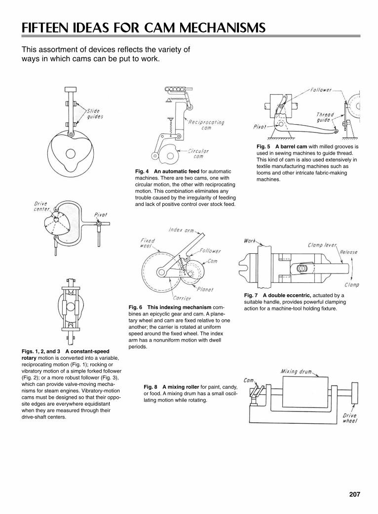
207
FIFTEEN IDEAS FOR CAM MECHANISMSThis assortment of devices reflects the variety of ways in which cams can be put to work.
Figs. 1, 2, and 3 A constant-speedrotary motion is converted into a variable,reciprocating motion (Fig. 1); rocking orvibratory motion of a simple forked follower(Fig. 2); or a more robust follower (Fig. 3),which can provide valve-moving mecha-nisms for steam engines. Vibratory-motioncams must be designed so that their oppo-site edges are everywhere equidistantwhen they are measured through theirdrive-shaft centers.
Fig. 4 An automatic feed for automaticmachines. There are two cams, one withcircular motion, the other with reciprocatingmotion. This combination eliminates anytrouble caused by the irregularity of feedingand lack of positive control over stock feed.
Fig. 5 A barrel cam with milled grooves isused in sewing machines to guide thread.This kind of cam is also used extensively intextile manufacturing machines such aslooms and other intricate fabric-makingmachines.
Fig. 6 This indexing mechanism com-bines an epicyclic gear and cam. A plane-tary wheel and cam are fixed relative to oneanother; the carrier is rotated at uniformspeed around the fixed wheel. The indexarm has a nonuniform motion with dwellperiods.
Fig. 7 A double eccentric, actuated by asuitable handle, provides powerful clampingaction for a machine-tool holding fixture.
Fig. 8 A mixing roller for paint, candy,or food. A mixing drum has a small oscil-lating motion while rotating.
Sclater Chapter 7 5/3/01 12:33 PM Page 207

208
Fig. 9 A slot cam converts the oscillatingmotion of a camshaft to a variable butstraight-line motion of a rod. According toslot shape, rod motion can be made to suitspecific design requirements, such asstraight-line and logarithmic motion.
Fig. 10 The continuous rotary motion ofa shaft is converted into the reciprocatingmotion of a slide. This device is used onsewing machines and printing presses.
Fig. 11 Swash-plate cams are feasiblefor light loads only, such as in a pump. Thecam’s eccentricity produces forces thatcause excessive loads. Multiple followerscan ride on a plate, thereby providingsmooth pumping action for a multipistonpump.
Fig. 12 This steel-ball cam can convertthe high-speed rotary motion of an electricdrill into high-frequency vibrations thatpower the drill core for use as a rotary ham-mer for cutting masonry, and concrete. Thisattachment can also be designed to fit handdrills.
Fig. 13 This tilting device can be designed so that a leverremains in a tilted position when the cylinder rod is withdrawn,or it can be spring-loaded to return with a cylinder rod.
Fig. 14 This sliding cam in a remote con-trol can shift gears in a position that is oth-erwise inaccessible on most machines.
Fig. 15 A groove and oval follower forma device that requires two revolutions of acam for one complete follower cycle.
Sclater Chapter 7 5/3/01 12:33 PM Page 208

209
SPECIAL-FUNCTION CAMS
Fig. 1—A quick drop of the follower isobtained by permitting the cam to bepushed out of the way by the followeritself as it reaches the edge of the cam.Lugs C and C′ are fixed to the camshaft.The cam is free to turn (float) on thecamshaft, limited by lug C and theadjusting screw. With the cam rotatingclockwise, lug C drives the cam throughlug B. At the position shown, the rollerwill drop off the edge of the cam, whichis then accelerated clockwise until itscam lug B strikes the adjusting screw oflug C′.
Fig. 2—Instantaneous drop isobtained by the use of two integral camsand followers. The roller follower rideson cam 1. Continued rotation will trans-fer contact to the flat-faced follower,which drops suddenly off the edge ofcam 2. After the desired dwell, the fol-lower is restored to its initial position bycam 1.
Fig. 3—The dwell period of the camcan be varied by changing the distancebetween the two rollers in the slot.
Fig. 4—A reciprocating pin (notshown) causes the barrel cam to rotateintermittently. The cam is stationarywhile a pin moves from 1 to 2. Groove 2-3 is at a lower level; thus, as the pinretracts, it cams the barrel cam; then itclimbs the incline from 2 to the new posi-tion of 1.
Fig. 5—A double-groove cam makestwo revolutions for one complete move-ment of the follower. The cam has mov-able switches, A and B, which direct thefollower alternately in each groove. Atthe instant shown, B is ready to guide theroller follower from slot 1 to slot 2.
Figs. 6 and 7—Increased stroke isobtained by permitting the cam to shifton the input shaft. Total displacement ofthe follower is therefore the sum of thecam displacement on the fixed roller plusthe follower displacement relative to thecam.
Fig. 2 A quick-actingdwell cams.
Fig. 3 An adjustable-dwell cam.
Fig. 1 A quick-acting floatingcam.
Fig. 5 A double-revolution cam. Fig. 6 An increased-stroke barrel cam. Fig. 7 An increased-stroke plate cam.
Fig. 4 An indexing cam.
Sclater Chapter 7 5/3/01 12:33 PM Page 209

Fig. 8—The stroke of the follower isadjusted by turning the screw handlewhich changes distance AB.
Fig. 9—The pivot point of the con-necting link to the follower is changedfrom point D to point C by adjusting thescrew.
Fig. 10—Adjustable dwell is obtainedby having the main cam, with lug A,pinned to the revolving shaft. Lug Aforces the plunger up into the positionshown, and allows the latch to hook overthe catch, thus holding the plunger in theup position. The plunger is unlatched bylug B. The circular slots in the cam platepermit the shifting of lug B, therebyvarying the time that the plunger is heldin the latched position.
REFERENCE: Rothbart, H. A. Cams—Design, Dynamics, and Accuracy, JohnWiley and Sons, Inc., New York.
Fig. 8 An adjustable roller-position cam.
Fig. 9 An adjustable pivot-point cam.
Fig. 10 An adjustable lugcam.
CAM DRIVES FOR MACHINE TOOLS
ADJUSTABLE-DWELL CAMS
This two-directional rack-and-gear drivefor a main tool slide combines accurate,uniform movement and minimum idle time.The mechanism makes a full double strokeeach cycle. It approaches fast, shifts
smoothly into feed, and returns fast. Itspoint-of-shift is controlled by an adjustabledog on a calibrated gear. Automatic brakingaction assures a smooth shift fromapproach to feed.
210
A cam drive for a tool-slide mechanismreplaces a rack feed when a short stroke isrequired to get a fast machining cycle on auto-matic machines. The cams and rollers areshown with the slide in its retracted position.
Sclater Chapter 7 5/3/01 12:33 PM Page 210

211
TOGGLE LINKAGE APPLICATIONS IN DIFFERENTMECHANISMS
Fig. 1 Many mechanical linkages are based on the simple toggle that con-sists of two links which tend to line up in a straight line at one point in theirmotion. The mechanical advantage is the velocity ratio of the input point A withrespect to the outpoint point B: or VA/VB . As the angle α approaches 90º, thelinks come into toggle, and the mechanical advantage and velocity ratio bothapproach infinity. However, frictional effects reduce the forces to much les thaninfinity, although they are still quite high.
Fig. 2 Forces can be applied through otherlinks, and need not be perpendicular to each other.(A) One toggle link can be attached to another linkrather than to a fixed point or slider. (B) Two togglelinks can come into toggle by lining up on top ofeach other rather than as an extension of eachother. The resisting force can be a spring.
HIGH MECHANICAL ADVANTAGE
Fig. 3 In punch presses, large forces areneeded at the lower end of the work stroke.However, little force is required during theremainder of the stroke. The crank and con-necting rod come into toggle at the lowerend of the punch stroke, giving a highmechanical advantage at exactly the time itis most needed.
Fig. 5 Locking latches produce a high mechanical advantage when inthe toggle portion of the stroke. A simple latch exerts a large force in thelocked position (Fig. 5A). For positive locking, the closed position oflatch is slightly beyond the toggle position. A small unlatching forceopens the linkage (Fig. 5B).
Fig. 4 A cold-heading rivetmachine is designed to giveeach rivet two successiveblows. Following the first blow(point 2) the hammer movesupward a short distance (topoint 3). Following the secondblow (at point 4), the hammerthen moves upward a longerdistance (to point 1) to provideclearance for moving the work-piece. Both strokes are pro-duced by one revolution of thecrank, and at the lowest pointof each stroke (points 2 and 4)the links are in toggle.
Fig. 6 A stone crusher has two toggle linkages in series to obtain ahigh mechanical advantage. When the vertical link I reaches the topof its stroke, it comes into toggle with the driving crank II; at the sametime, link III comes into toggle and link IV. This multiplication results ina very large crushing force.
Fig. 7 A friction ratchet is mounted on a wheel; a light springkeeps the friction shoes in contact with the flange. This device per-mits clockwise motion of the arm I. However, reverse rotationcauses friction to force link II into toggle with the shoes. This actiongreatly increases the locking pressure.
Sclater Chapter 7 5/3/01 12:33 PM Page 211
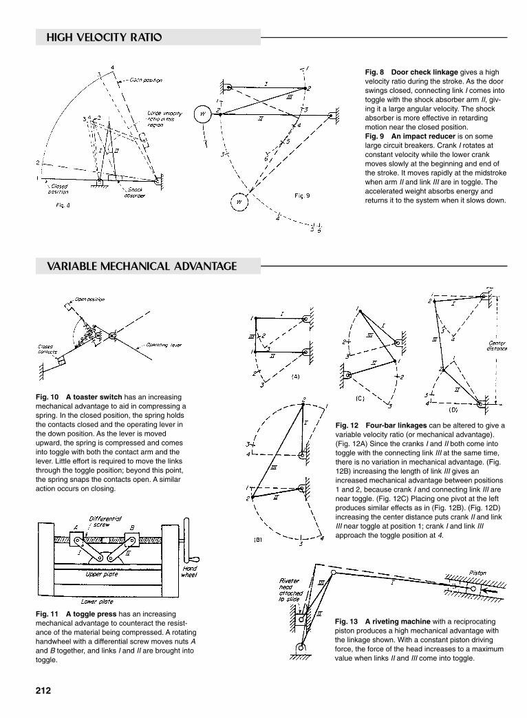
HIGH VELOCITY RATIO
Fig. 8 Door check linkage gives a highvelocity ratio during the stroke. As the doorswings closed, connecting link I comes intotoggle with the shock absorber arm II, giv-ing it a large angular velocity. The shockabsorber is more effective in retardingmotion near the closed position.Fig. 9 An impact reducer is on somelarge circuit breakers. Crank I rotates atconstant velocity while the lower crankmoves slowly at the beginning and end ofthe stroke. It moves rapidly at the midstrokewhen arm II and link III are in toggle. Theaccelerated weight absorbs energy andreturns it to the system when it slows down.
212
VARIABLE MECHANICAL ADVANTAGE
Fig. 10 A toaster switch has an increasingmechanical advantage to aid in compressing aspring. In the closed position, the spring holdsthe contacts closed and the operating lever inthe down position. As the lever is movedupward, the spring is compressed and comesinto toggle with both the contact arm and thelever. Little effort is required to move the linksthrough the toggle position; beyond this point,the spring snaps the contacts open. A similaraction occurs on closing.
Fig. 12 Four-bar linkages can be altered to give avariable velocity ratio (or mechanical advantage).(Fig. 12A) Since the cranks I and II both come intotoggle with the connecting link III at the same time,there is no variation in mechanical advantage. (Fig.12B) increasing the length of link III gives anincreased mechanical advantage between positions1 and 2, because crank I and connecting link III arenear toggle. (Fig. 12C) Placing one pivot at the leftproduces similar effects as in (Fig. 12B). (Fig. 12D)increasing the center distance puts crank II and linkIII near toggle at position 1; crank I and link IIIapproach the toggle position at 4.
Fig. 11 A toggle press has an increasingmechanical advantage to counteract the resist-ance of the material being compressed. A rotatinghandwheel with a differential screw moves nuts Aand B together, and links I and II are brought intotoggle.
Fig. 13 A riveting machine with a reciprocatingpiston produces a high mechanical advantage withthe linkage shown. With a constant piston drivingforce, the force of the head increases to a maximumvalue when links II and III come into toggle.
Sclater Chapter 7 5/3/01 12:33 PM Page 212
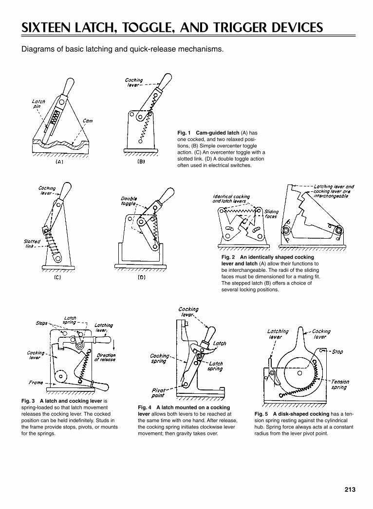
213
SIXTEEN LATCH, TOGGLE, AND TRIGGER DEVICESDiagrams of basic latching and quick-release mechanisms.
Fig. 1 Cam-guided latch (A) hasone cocked, and two relaxed posi-tions, (B) Simple overcenter toggleaction. (C) An overcenter toggle with aslotted link. (D) A double toggle actionoften used in electrical switches.
Fig. 2 An identically shaped cockinglever and latch (A) allow their functions tobe interchangeable. The radii of the slidingfaces must be dimensioned for a mating fit.The stepped latch (B) offers a choice ofseveral locking positions.
Fig. 3 A latch and cocking lever isspring-loaded so that latch movementreleases the cocking lever. The cockedposition can be held indefinitely. Studs inthe frame provide stops, pivots, or mountsfor the springs.
Fig. 4 A latch mounted on a cockinglever allows both levers to be reached atthe same time with one hand. After release,the cocking spring initiates clockwise levermovement; then gravity takes over.
Fig. 5 A disk-shaped cocking has a ten-sion spring resting against the cylindricalhub. Spring force always acts at a constantradius from the lever pivot point.
Sclater Chapter 7 5/3/01 12:33 PM Page 213
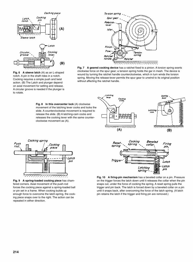
214
Fig. 6 A sleeve latch (A) as an L-shapednotch. A pin in the shaft rides in a notch.Cocking requires a simple push and twistaction. (B) The Latch and plunger dependon axial movement for setting and release.A circular groove is needed if the plunger isto rotate.
Fig. 7 A geared cocking device has a ratchet fixed to a pinion. A torsion spring exertsclockwise force on the spur gear; a tension spring holds the gar in mesh. The device iswound by turning the ratchet handle counterclockwise, which in turn winds the torsionspring. Moving the release-lever permits the spur gear to unwind to its original positionwithout affecting the ratchet handle.
Fig. 8 In this overcenter lock (A) clockwisemovement of the latching lever cocks and locks theslide. A counterclockwise movement is required torelease the slide. (B) A latching-cam cocks andreleases the cocking lever with the same counter-clockwise movement as (A).
Fig. 9 A spring-loaded cocking piece has cham-fered corners. Axial movement of the push-rodforces the cocking piece against a spring-loaded ballor pin set in a frame. When cocking builds upenough force to overcome the latch-spring, the cock-ing piece snaps over to the right. The action can berepeated in either direction.
Fig. 10 A firing-pin mechanism has a beveled collar on a pin. Pressureon the trigger forces the latch down until it releases the collar when the pinsnaps out, under the force of cocking the spring. A reset spring pulls thetrigger and pin back. The latch is forced down by a beveled collar on a pinuntil it snaps back, after overcoming the force of the latch spring. (A latchpin retains the latch if the trigger and firing pin are removed.)
Sclater Chapter 7 5/3/01 12:33 PM Page 214

215
SIX SNAP-ACTION MECHANISMSThese diagrams show six basic ways to produce mechanicalsnap action.
Mechanical snap action results when a force is applied to a device over a period of time;buildup of this force to a critical level causes a sudden motion to occur. The ideal snapdevice would have no motion until the force reached a critical level. This, however, is notpossible, and the way in which the mechanism approaches this ideal is a measure of itsefficiency as a snap device. Some of the designs shown here approach the ideal closely;others do not, but they have other compensating good features.
Fig. 1 A dished disk is a simple, common method for producing snap action. A snap leafmade from spring material can have various-shaped impressions stamped at the point wherethe overcentering action occurs. A “Frog clacker” is, of course, a typical applications. A bimetalelement made in this way will reverse itself at a predetermined temperature.
Fig. 2 Friction override can hold againstan increasing load until friction is suddenlyovercome. This is a useful action for smallsensitive devices where large forces andmovements are undesirable. This is the waywe snap our fingers. That action is probablythe original snap mechanism.
Fig. 3 A ratchet-and-pawl combination is probably the most widely used form of snap mech-anism. Its many variations are an essential feature in practically every complicated mechanicaldevice. By definition, however, this movement is not true snap-action.
Sclater Chapter 7 5/3/01 12:33 PM Page 215
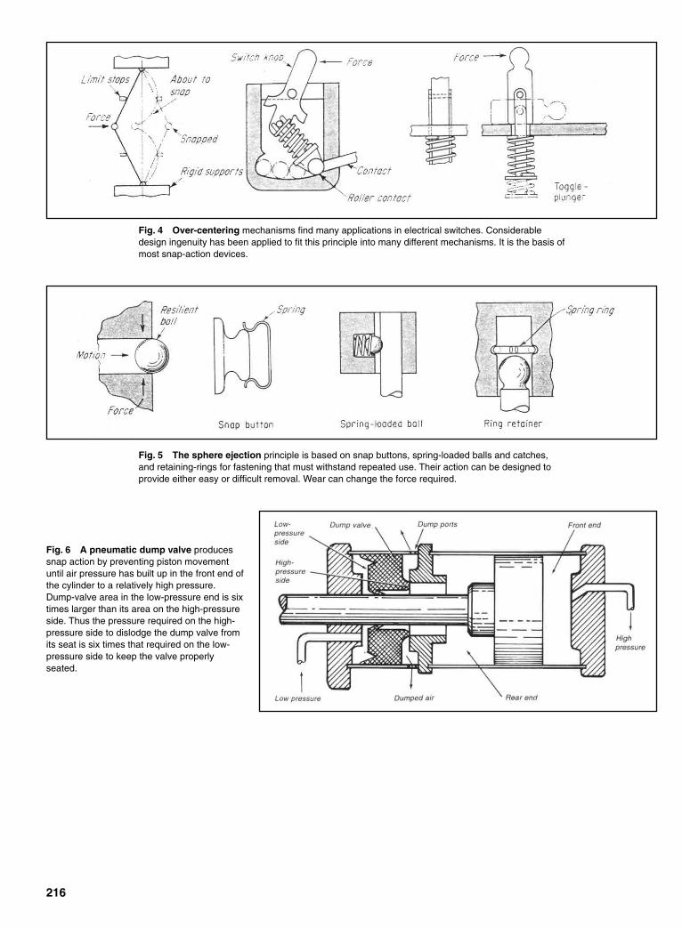
216
Fig. 4 Over-centering mechanisms find many applications in electrical switches. Considerabledesign ingenuity has been applied to fit this principle into many different mechanisms. It is the basis ofmost snap-action devices.
Fig. 5 The sphere ejection principle is based on snap buttons, spring-loaded balls and catches,and retaining-rings for fastening that must withstand repeated use. Their action can be designed toprovide either easy or difficult removal. Wear can change the force required.
Fig. 6 A pneumatic dump valve producessnap action by preventing piston movementuntil air pressure has built up in the front end ofthe cylinder to a relatively high pressure.Dump-valve area in the low-pressure end is sixtimes larger than its area on the high-pressureside. Thus the pressure required on the high-pressure side to dislodge the dump valve fromits seat is six times that required on the low-pressure side to keep the valve properlyseated.
Sclater Chapter 7 5/3/01 12:33 PM Page 216

217
EIGHT SNAP-ACTION DEVICESAnother selection of basic devices for obtaining sudden motion after a gradual buildup of force.
Fig. 1 A torsion ribbon bent as shown will turn “inside out” at Awith a snap action when twisted at B. Design factors are ribbonwidth, thickness, and bend angle.
Fig. 2 A collapsing cylinder has elastic walls that can be deformedgradually until their stress changes from compressive to bending, with theresulting collapse of the cylinder.
Fig. 3 A bowed spring will collapse into a new shape when it isloaded as shown A. A “push-pull” steel measuring tape illustratesthis action; the curved material stiffens the tape so that it can beheld out as a cantilever until excessive weight causes it to col-lapse suddenly.
Fig. 4 A flap vane cuts off air or liquid flow at a limiting velocity. With aregulating valve, the vane will snap shut (because of increased velocity)when pressure is reduced below a design value.
Sclater Chapter 7 5/3/01 12:33 PM Page 217

218
Fig. 5 A sacrificing link is useful where high temperature orcorrosive chemicals would be hazardous. If the temperaturebecomes too high, or atmosphere too corrosive, the link will yieldat design conditions. The device usually is required to act onlyonce, although a device like the lower one can be quickly reset.However, it is restricted to temperature control.
Fig. 6 Gravity-tips, although slower acting than most snapmechanisms, can be called snap mechanisms because theyrequire an accumulation of energy to trigger an automatic release.A tripping trough that spreads sewerage is one example. Asshown in A, it is ready to trip. When overbalanced, it trips rapidly,as in B.
Fig. 7 An overcentering tension spring combined with a piv-oted contact-strip is one arrangement used in switches. Theexample shown here is unusual because the actuating forcebears on the spring itself.
Fig. 8 An overcentering leaf-spring action is also the basis formany ingenious snap-action switches for electrical control.Sometimes spring action is combined with the thermostatic actionof a bimetal strip to make the switch respond to heat or cold,either for control purposes or as a safety feature.
Sclater Chapter 7 5/3/01 12:33 PM Page 218
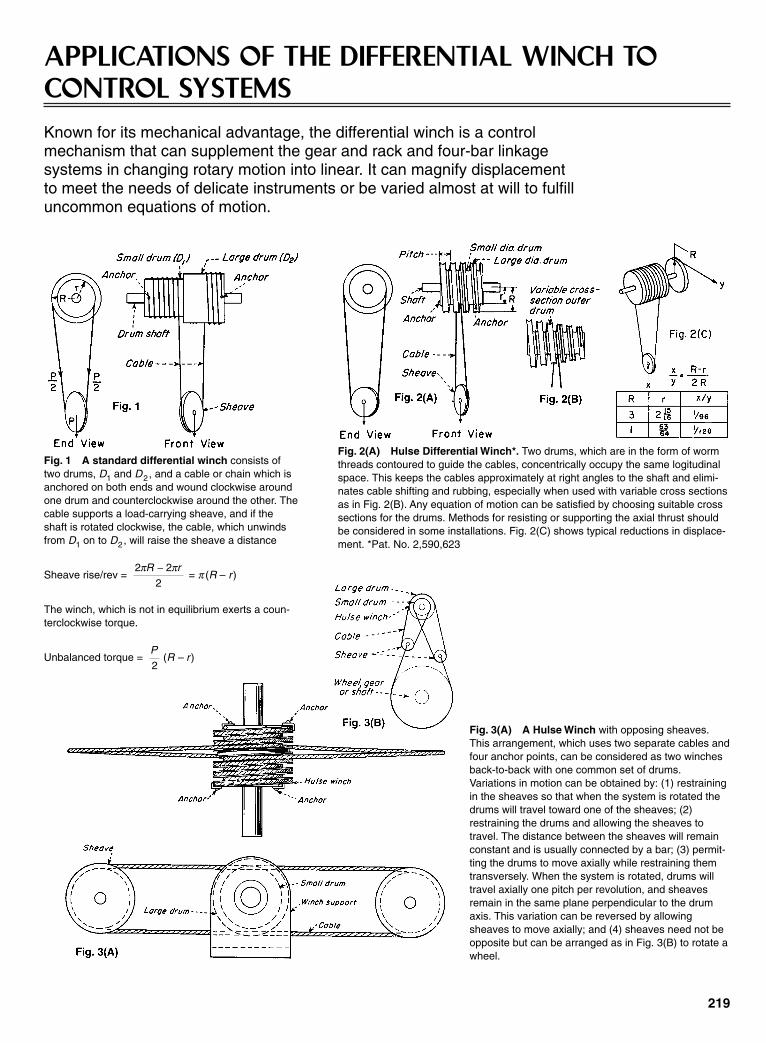
219
APPLICATIONS OF THE DIFFERENTIAL WINCH TOCONTROL SYSTEMSKnown for its mechanical advantage, the differential winch is a control mechanism that can supplement the gear and rack and four-bar linkage systems in changing rotary motion into linear. It can magnify displacement to meet the needs of delicate instruments or be varied almost at will to fulfilluncommon equations of motion.
Fig. 2(A) Hulse Differential Winch*. Two drums, which are in the form of wormthreads contoured to guide the cables, concentrically occupy the same logitudinalspace. This keeps the cables approximately at right angles to the shaft and elimi-nates cable shifting and rubbing, especially when used with variable cross sectionsas in Fig. 2(B). Any equation of motion can be satisfied by choosing suitable crosssections for the drums. Methods for resisting or supporting the axial thrust shouldbe considered in some installations. Fig. 2(C) shows typical reductions in displace-ment. *Pat. No. 2,590,623
Fig. 3(A) A Hulse Winch with opposing sheaves.This arrangement, which uses two separate cables andfour anchor points, can be considered as two winchesback-to-back with one common set of drums.Variations in motion can be obtained by: (1) restrainingin the sheaves so that when the system is rotated thedrums will travel toward one of the sheaves; (2)restraining the drums and allowing the sheaves totravel. The distance between the sheaves will remainconstant and is usually connected by a bar; (3) permit-ting the drums to move axially while restraining themtransversely. When the system is rotated, drums willtravel axially one pitch per revolution, and sheavesremain in the same plane perpendicular to the drumaxis. This variation can be reversed by allowingsheaves to move axially; and (4) sheaves need not beopposite but can be arranged as in Fig. 3(B) to rotate awheel.
Fig. 1 A standard differential winch consists oftwo drums, D1 and D2, and a cable or chain which isanchored on both ends and wound clockwise aroundone drum and counterclockwise around the other. Thecable supports a load-carrying sheave, and if theshaft is rotated clockwise, the cable, which unwindsfrom D1 on to D2, will raise the sheave a distance
Sheave rise/rev = = π (R – r)
The winch, which is not in equilibrium exerts a coun-terclockwise torque.
Unbalanced torque = (R – r)P
2
2 2
2
π πR r−
Sclater Chapter 7 5/3/01 12:33 PM Page 219
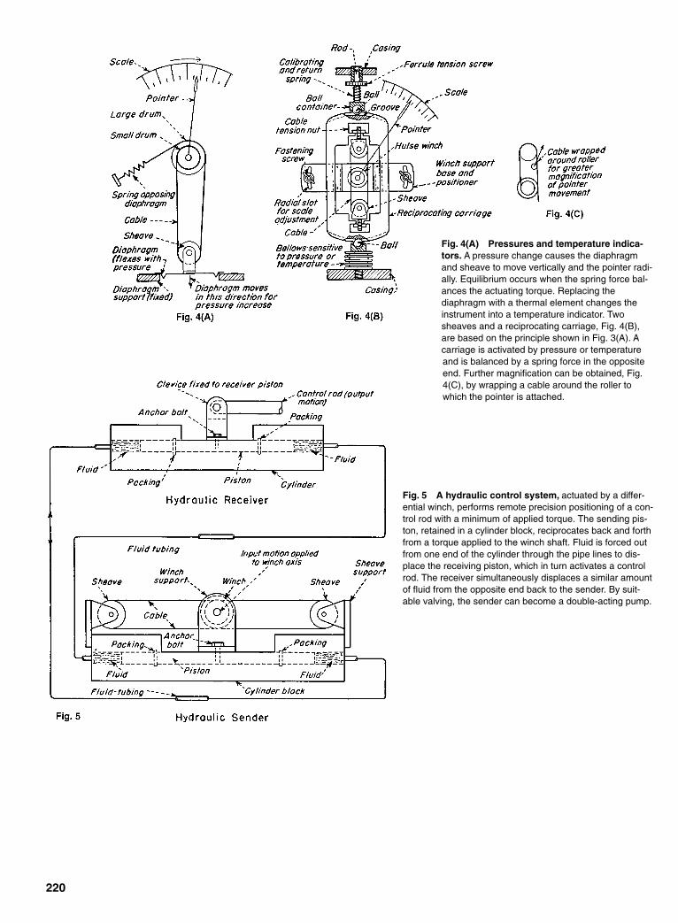
220
Fig. 4(A) Pressures and temperature indica-tors. A pressure change causes the diaphragmand sheave to move vertically and the pointer radi-ally. Equilibrium occurs when the spring force bal-ances the actuating torque. Replacing thediaphragm with a thermal element changes theinstrument into a temperature indicator. Twosheaves and a reciprocating carriage, Fig. 4(B),are based on the principle shown in Fig. 3(A). Acarriage is activated by pressure or temperatureand is balanced by a spring force in the oppositeend. Further magnification can be obtained, Fig.4(C), by wrapping a cable around the roller towhich the pointer is attached.
Fig. 5 A hydraulic control system, actuated by a differ-ential winch, performs remote precision positioning of a con-trol rod with a minimum of applied torque. The sending pis-ton, retained in a cylinder block, reciprocates back and forthfrom a torque applied to the winch shaft. Fluid is forced outfrom one end of the cylinder through the pipe lines to dis-place the receiving piston, which in turn activates a controlrod. The receiver simultaneously displaces a similar amountof fluid from the opposite end back to the sender. By suit-able valving, the sender can become a double-acting pump.
Sclater Chapter 7 5/3/01 12:33 PM Page 220

221
SIX APPLICATIONS FORMECHANICAL POWER AMPLIFIERSPrecise positioning and movement of heavy loads are twobasic jobs for this all-mechanical torque booster.
This mechanical power amplifier has a fast response. Power fromits continuously rotating drums is instantaneously available.When used for position-control applications, pneumatic,hydraulic, and electrical systems—even those with continuouslyrunning power sources—require transducers to change signalsfrom one energy form to another. The mechanical power ampli-fier, on the other hand, permits direct sensing of the controlledmotion.
Four major advantages of this all-mechanical device are:1. Kinetic energy of the power source is continuously avail-
able for rapid response.2. Motion can be duplicated and power amplified without
converting energy forms.3. Position and rate feedback are inherent design characteristics.4. Zero slip between input and output eliminates the possibil-
ity of cumulative error.One other important advantage is the ease with which this
device can be adapted to perform special functions—jobs forwhich other types of systems would require the addition of morecostly and perhaps less reliable components. The six applicationswhich follow illustrate how those advantages have been put towork in solving widely divergent problems.
The capstan principle is the basis for the mechanical power ampli-fier described here that combines two counterrotating drums. Thedrums are continuously rotating but only transmit torque when theinput shaft is rotated to tighten the band on drum A. Overrun of outputis stopped by drum B, when overrun tightens the band on this drum.
A capstan is a simple mechanical amplifier—rope wound on a motor-driven drumslips until slack is taken up on the free end. The force needed on the free end to lift theload depends on the coefficient of friction and the number of turns of rope. By con-necting bands A and B to an input shaft and arm, the power amplifier provides an out-put in both directions, plus accurate angular positioning. When the input shaft is turnedclockwise, the input arm takes up the slack on band A, locking it to its drum. Becausethe load end of locked band A is connected to the output arm, it transmits the CWmotion of the driven drum on which it is wound to the output shaft. Band B thereforeslacks off and slips on its drum. When the CW motion of the input shaft stops, tensionon band A is released and it slips on its own drum. If the output shaft tries to overrun,the output arm will apply tension to band B, causing it to tighten on the CCW rotatingrum and stop the shaft.
Sclater Chapter 7 5/3/01 12:33 PM Page 221
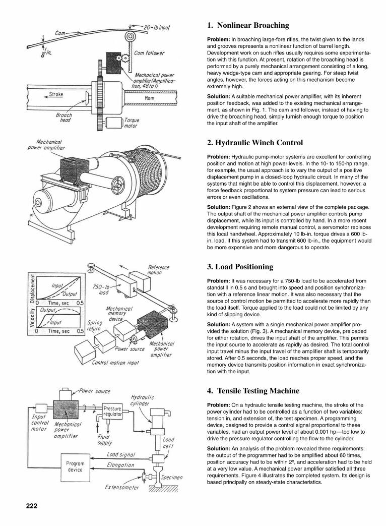
222
1. Nonlinear Broaching
Problem: In broaching large-fore rifles, the twist given to the landsand grooves represents a nonlinear function of barrel length.Development work on such rifles usually requires some experimenta-tion with this function. At present, rotation of the broaching head isperformed by a purely mechanical arrangement consisting of a long,heavy wedge-type cam and appropriate gearing. For steep twistangles, however, the forces acting on this mechanism becomeextremely high.
Solution: A suitable mechanical power amplifier, with its inherentposition feedback, was added to the existing mechanical arrange-ment, as shown in Fig. 1. The cam and follower, instead of having todrive the broaching head, simply furnish enough torque to positionthe input shaft of the amplifier.
2. Hydraulic Winch Control
Problem: Hydraulic pump-motor systems are excellent for controllingposition and motion at high power levels. In the 10- to 150-hp range,for example, the usual approach is to vary the output of a positivedisplacement pump in a closed-loop hydraulic circuit. In many of thesystems that might be able to control this displacement, however, aforce feedback proportional to system pressure can lead to seriouserrors or even oscillations.
Solution: Figure 2 shows an external view of the complete package.The output shaft of the mechanical power amplifier controls pumpdisplacement, while its input is controlled by hand. In a more recentdevelopment requiring remote manual control, a servomotor replacesthis local handwheel. Approximately 10 lb-in. torque drives a 600 lb-in. load. If this system had to transmit 600 lb-in., the equipment wouldbe more expensive and more dangerous to operate.
3. Load Positioning
Problem: It was necessary for a 750-lb load to be accelerated fromstandstill in 0.5 s and brought into speed and position synchroniza-tion with a reference linear motion. It was also necessary that thesource of control motion be permitted to accelerate more rapidly thanthe load itself. Torque applied to the load could not be limited by anykind of slipping device.
Solution: A system with a single mechanical power amplifier pro-vided the solution (Fig. 3). A mechanical memory device, preloadedfor either rotation, drives the input shaft of the amplifier. This permitsthe input source to accelerate as rapidly as desired. The total controlinput travel minus the input travel of the amplifier shaft is temporarilystored. After 0.5 seconds, the load reaches proper speed, and thememory device transmits position information in exact synchroniza-tion with the input.
4. Tensile Testing Machine
Problem: On a hydraulic tensile testing machine, the stroke of thepower cylinder had to be controlled as a function of two variables:tension in, and extension of, the test specimen. A programmingdevice, designed to provide a control signal proportional to thesevariables, had an output power level of about 0.001 hp—too low todrive the pressure regulator controlling the flow to the cylinder.
Solution: An analysis of the problem revealed three requirements:the output of the programmer had to be amplified about 60 times,position accuracy had to be within 2º, and acceleration had to be heldat a very low value. A mechanical power amplifier satisfied all threerequirements. Figure 4 illustrates the completed system. Its design isbased principally on steady-state characteristics.
Sclater Chapter 7 5/3/01 12:33 PM Page 222
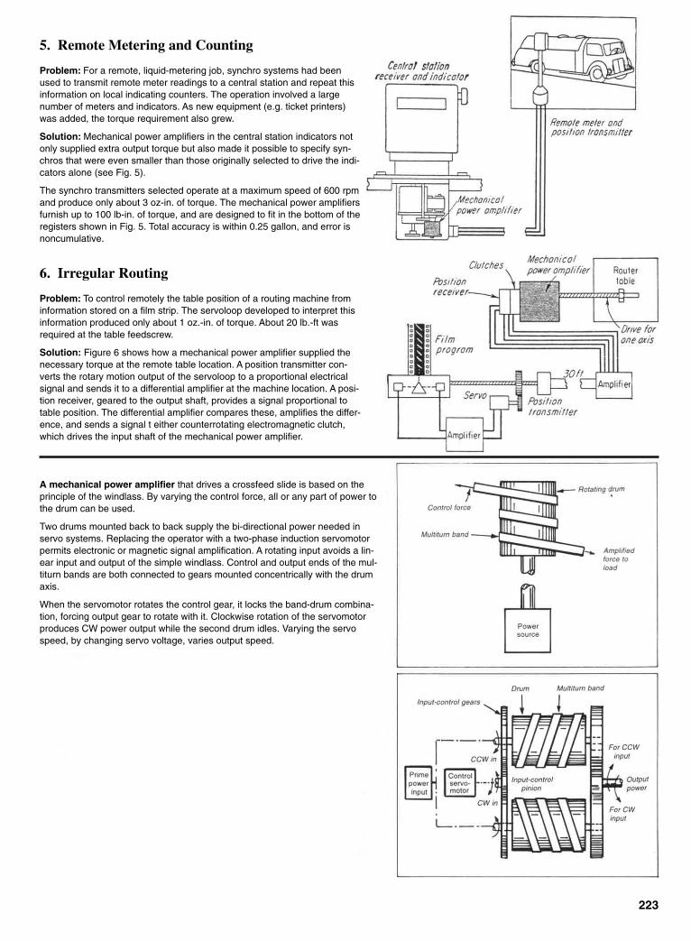
223
5. Remote Metering and Counting
Problem: For a remote, liquid-metering job, synchro systems had beenused to transmit remote meter readings to a central station and repeat thisinformation on local indicating counters. The operation involved a largenumber of meters and indicators. As new equipment (e.g. ticket printers)was added, the torque requirement also grew.
Solution: Mechanical power amplifiers in the central station indicators notonly supplied extra output torque but also made it possible to specify syn-chros that were even smaller than those originally selected to drive the indi-cators alone (see Fig. 5).
The synchro transmitters selected operate at a maximum speed of 600 rpmand produce only about 3 oz-in. of torque. The mechanical power amplifiersfurnish up to 100 lb-in. of torque, and are designed to fit in the bottom of theregisters shown in Fig. 5. Total accuracy is within 0.25 gallon, and error isnoncumulative.
6. Irregular Routing
Problem: To control remotely the table position of a routing machine frominformation stored on a film strip. The servoloop developed to interpret thisinformation produced only about 1 oz.-in. of torque. About 20 lb.-ft wasrequired at the table feedscrew.
Solution: Figure 6 shows how a mechanical power amplifier supplied thenecessary torque at the remote table location. A position transmitter con-verts the rotary motion output of the servoloop to a proportional electricalsignal and sends it to a differential amplifier at the machine location. A posi-tion receiver, geared to the output shaft, provides a signal proportional totable position. The differential amplifier compares these, amplifies the differ-ence, and sends a signal t either counterrotating electromagnetic clutch,which drives the input shaft of the mechanical power amplifier.
A mechanical power amplifier that drives a crossfeed slide is based on theprinciple of the windlass. By varying the control force, all or any part of power tothe drum can be used.
Two drums mounted back to back supply the bi-directional power needed inservo systems. Replacing the operator with a two-phase induction servomotorpermits electronic or magnetic signal amplification. A rotating input avoids a lin-ear input and output of the simple windlass. Control and output ends of the mul-titurn bands are both connected to gears mounted concentrically with the drumaxis.
When the servomotor rotates the control gear, it locks the band-drum combina-tion, forcing output gear to rotate with it. Clockwise rotation of the servomotorproduces CW power output while the second drum idles. Varying the servospeed, by changing servo voltage, varies output speed.
Sclater Chapter 7 5/3/01 12:33 PM Page 223
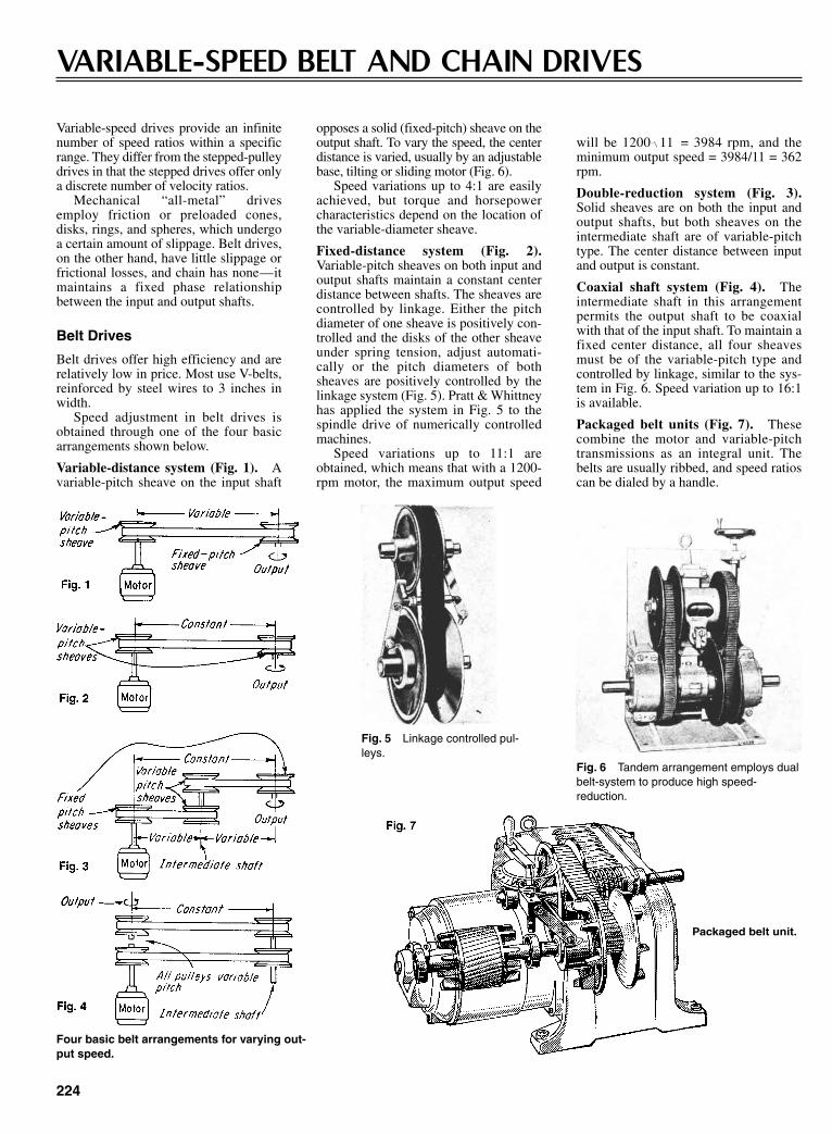
224
VARIABLE-SPEED BELT AND CHAIN DRIVES
Variable-speed drives provide an infinitenumber of speed ratios within a specificrange. They differ from the stepped-pulleydrives in that the stepped drives offer onlya discrete number of velocity ratios.
Mechanical “all-metal” drivesemploy friction or preloaded cones,disks, rings, and spheres, which undergoa certain amount of slippage. Belt drives,on the other hand, have little slippage orfrictional losses, and chain has none—itmaintains a fixed phase relationshipbetween the input and output shafts.
Belt Drives
Belt drives offer high efficiency and arerelatively low in price. Most use V-belts,reinforced by steel wires to 3 inches inwidth.
Speed adjustment in belt drives isobtained through one of the four basicarrangements shown below.
Variable-distance system (Fig. 1). Avariable-pitch sheave on the input shaft
opposes a solid (fixed-pitch) sheave on theoutput shaft. To vary the speed, the centerdistance is varied, usually by an adjustablebase, tilting or sliding motor (Fig. 6).
Speed variations up to 4:1 are easilyachieved, but torque and horsepowercharacteristics depend on the location ofthe variable-diameter sheave.
Fixed-distance system (Fig. 2).Variable-pitch sheaves on both input andoutput shafts maintain a constant centerdistance between shafts. The sheaves arecontrolled by linkage. Either the pitchdiameter of one sheave is positively con-trolled and the disks of the other sheaveunder spring tension, adjust automati-cally or the pitch diameters of bothsheaves are positively controlled by thelinkage system (Fig. 5). Pratt & Whittneyhas applied the system in Fig. 5 to thespindle drive of numerically controlledmachines.
Speed variations up to 11:1 areobtained, which means that with a 1200-rpm motor, the maximum output speed
will be 1200 = 3984 rpm, and theminimum output speed = 3984/11 = 362rpm.
Double-reduction system (Fig. 3).Solid sheaves are on both the input andoutput shafts, but both sheaves on theintermediate shaft are of variable-pitchtype. The center distance between inputand output is constant.
Coaxial shaft system (Fig. 4). Theintermediate shaft in this arrangementpermits the output shaft to be coaxialwith that of the input shaft. To maintain afixed center distance, all four sheavesmust be of the variable-pitch type andcontrolled by linkage, similar to the sys-tem in Fig. 6. Speed variation up to 16:1is available.
Packaged belt units (Fig. 7). Thesecombine the motor and variable-pitchtransmissions as an integral unit. Thebelts are usually ribbed, and speed ratioscan be dialed by a handle.
11
Four basic belt arrangements for varying out-put speed.
Fig. 5 Linkage controlled pul-leys.
Fig. 6 Tandem arrangement employs dualbelt-system to produce high speed-reduction.
Packaged belt unit.
Sclater Chapter 7 5/3/01 12:33 PM Page 224
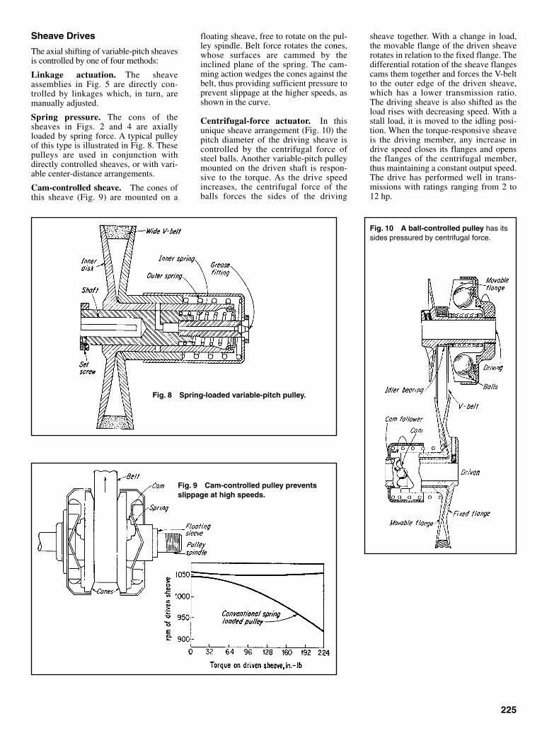
Sheave Drives
The axial shifting of variable-pitch sheavesis controlled by one of four methods:
Linkage actuation. The sheaveassemblies in Fig. 5 are directly con-trolled by linkages which, in turn, aremanually adjusted.
Spring pressure. The cons of thesheaves in Figs. 2 and 4 are axiallyloaded by spring force. A typical pulleyof this type is illustrated in Fig. 8. Thesepulleys are used in conjunction withdirectly controlled sheaves, or with vari-able center-distance arrangements.
Cam-controlled sheave. The cones ofthis sheave (Fig. 9) are mounted on a
floating sheave, free to rotate on the pul-ley spindle. Belt force rotates the cones,whose surfaces are cammed by theinclined plane of the spring. The cam-ming action wedges the cones against thebelt, thus providing sufficient pressure toprevent slippage at the higher speeds, asshown in the curve.
Centrifugal-force actuator. In thisunique sheave arrangement (Fig. 10) thepitch diameter of the driving sheave iscontrolled by the centrifugal force ofsteel balls. Another variable-pitch pulleymounted on the driven shaft is respon-sive to the torque. As the drive speedincreases, the centrifugal force of theballs forces the sides of the driving
sheave together. With a change in load,the movable flange of the driven sheaverotates in relation to the fixed flange. Thedifferential rotation of the sheave flangescams them together and forces the V-beltto the outer edge of the driven sheave,which has a lower transmission ratio.The driving sheave is also shifted as theload rises with decreasing speed. With astall load, it is moved to the idling posi-tion. When the torque-responsive sheaveis the driving member, any increase indrive speed closes its flanges and opensthe flanges of the centrifugal member,thus maintaining a constant output speed.The drive has performed well in trans-missions with ratings ranging from 2 to12 hp.
225
Fig. 10 A ball-controlled pulley has itssides pressured by centrifugal force.
Fig. 8 Spring-loaded variable-pitch pulley.
Fig. 9 Cam-controlled pulley preventsslippage at high speeds.
Sclater Chapter 7 5/3/01 12:34 PM Page 225

Chain Drives
PIV drive (Fig. 11). This chain drive(positive, infinitely variable) eliminatesany slippage between the self-forminglaminated chain teeth and the chainsheaves. The individual laminations arefree to slide laterally to take up the fullwidth of the sheave. The chain runs inradially grooved faces of conical sur-face sheaves which are located on theinput and output shafts. The faces are
not straight cones, but have a slightconvex curve to maintain proper chaintension at all positions. The pitch diam-eters of both sheaves are positivelycontrolled by the linkage. Booth actionis positive throughout operating range.It is rated to 25 hp with speed variationof 6:1.
Double-roller chain drive (Fig. 12).This specially developed chain is builtfor capacities to 22 hp. The hardened
226
Fig. 11 A PIV drive chain grips radially grooved faces of avariable-pitch sheave to prevent slippage.
Fig. 12 A double-roller chain drive combines strengthwith ease in changing speed.
Fig. 13 A single-roller chain drivefor high horse-power applications.
rollers are wedged between the hardenedconical sides of the variable-pitchsheaves. Radial rolling friction results insmooth chain engagement.
Single-roller chain drive (Fig. 13).The double strand of this chain booststhe capacity to 50 hp. The scissor-levercontrol system maintains the proper pro-portion of forces at each pair of sheavefaces throughout the range.
Sclater Chapter 7 5/3/01 12:34 PM Page 226

227
GETTING IN STEP WITH HYBRID BELTSImaginative fusions of belts, cables, gears and chains areexpanding the horizons for light-duty synchronous drives
Belts have long been used for the transferof mechanical power. Today’s familiarflat belts and V-belts are relatively light,quiet, inexpensive, and tolerant of align-ment errors. They transmit power solelythrough frictional contacts. However,they function best at moderate speeds(4000 to 6000 fpm) under static loads.Their efficiencies drop slightly at lowspeeds, and centrifugal effects limit theircapacities at high speeds. Moreover, theyare inclined to sip under shock loads orwhen starting and braking. Even underconstant rotation, standard belts tend tocreep. Thus, these drives must be keptunder tension to function properly,increasing loads on pulley shaft bearings.
Gears and chains, on the other hand,transmit power through bearing forcesbetween positively engaged surfaces.They do not slip or creep, as measured bythe relative motions of the driving anddriven shafts. But the contacts them-selves can slip significantly as the chainrollers and gear teeth move in and out ofmesh.
Positive drives are also very sensitiveto the geometries of the mating surfaces.A gear’s load is borne by one or twoteeth, thus magnifying small tooth-to-tooth errors. A chain’s load is morewidely distributed, but chordal variationsin the driving wheel’s effective radiusproduce small oscillations in the chain’svelocity.
To withstand these stresses, chainsand gears must be carefully made fromhard materials and must then be lubri-
Fig. 1 Conventional timing belts have fiberglass or polyester tension members, bodies ofneoprene or polyurethane, and trapezoidal tooth profiles.
Fig. 2 NASA metal timing belts exploit stainless steel’s strength and flexibility, and arecoated with sound-and friction-reducing plastic.
Sclater Chapter 7 5/3/01 12:34 PM Page 227
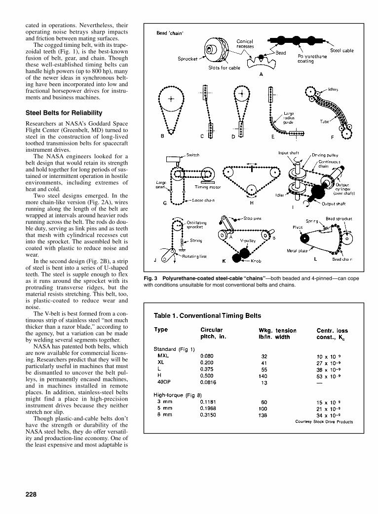
cated in operations. Nevertheless, theiroperating noise betrays sharp impactsand friction between mating surfaces.
The cogged timing belt, with its trape-zoidal teeth (Fig. 1), is the best-knownfusion of belt, gear, and chain. Thoughthese well-established timing belts canhandle high powers (up to 800 hp), manyof the newer ideas in synchronous belt-ing have been incorporated into low andfractional horsepower drives for instru-ments and business machines.
Steel Belts for Reliability
Researchers at NASA’s Goddard SpaceFlight Center (Greenbelt, MD) turned tosteel in the construction of long-livedtoothed transmission belts for spacecraftinstrument drives.
The NASA engineers looked for abelt design that would retain its strengthand hold together for long periods of sus-tained or intermittent operation in hostileenvironments, including extremes ofheat and cold.
Two steel designs emerged. In themore chain-like version (Fig. 2A), wiresrunning along the length of the belt arewrapped at intervals around heavier rodsrunning across the belt. The rods do dou-ble duty, serving as link pins and as teeththat mesh with cylindrical recesses cutinto the sprocket. The assembled belt iscoated with plastic to reduce noise andwear.
In the second design (Fig. 2B), a stripof steel is bent into a series of U-shapedteeth. The steel is supple enough to flexas it runs around the sprocket with itsprotruding transverse ridges, but thematerial resists stretching. This belt, too,is plastic-coated to reduce wear andnoise.
The V-belt is best formed from a con-tinuous strip of stainless steel “not muchthicker than a razor blade,” according tothe agency, but a variation can be madeby welding several segments together.
NASA has patented both belts, whichare now available for commercial licens-ing. Researchers predict that they will beparticularly useful in machines that mustbe dismantled to uncover the belt pul-leys, in permanently encased machines,and in machines installed in remoteplaces. In addition, stainless-steel beltsmight find a place in high-precisioninstrument drives because they neitherstretch nor slip.
Though plastic-and-cable belts don’thave the strength or durability of theNASA steel belts, they do offer versatil-ity and production-line economy. One ofthe least expensive and most adaptable is
228
Fig. 3 Polyurethane-coated steel-cable “chains”—both beaded and 4-pinned—can copewith conditions unsuitable for most conventional belts and chains.
Sclater Chapter 7 5/3/01 12:34 PM Page 228
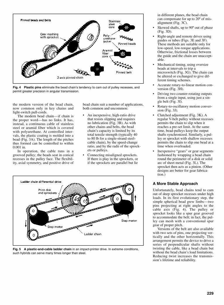
the modern version of the bead chain,now common only in key chains andlight-switch pull-cords.
The modern bead chain—if chain isthe proper word—has no links. It has,instead, a continuous cable of stainlesssteel or aramid fiber which is coveredwith polyurethane. At controlled inter-vals, the plastic coating is molded into abead (Fig. 3A). The length of the pitchesthus formed can be controlled to within0.001 in.
In operation, the cable runs in agrooved pulley; the beads seat in conicalrecesses in the pulley face. The flexibil-ity, axial symmetry, and positive drive of
bead chain suit a number of applications,both common and uncommon:
• An inexpensive, high-ratio drivethat resists slipping and requiresno lubrication (Fig. 3B). As withother chains and belts, the beadchain’s capacity is limited by itstotal tensile strength (typically 40to 80 lb for a single-strand steel-cable chain), by the speed-changeratio, and by the radii of the sprock-ets or pulleys.
• Connecting misaligned sprockets.If there is play in the sprockets, orif the sprockets are parallel but lie
in different planes, the bead chaincan compensate for up to 20º of mis-alignment (Fig. 3C).
• Skewed shafts, up to 90º out of phase(Fig. 3D).
• Right-angle and remote drives usingguides or tubes (Figs. 3E and 3F).These methods are suitable only forlow-speed, low-torque applications.Otherwise, frictional losses betweenthe guide and the chain are unaccept-able.
• Mechanical timing, using oversizebeads at intervals to trip amicroswitch (Fig. 3G). The chain canbe altered or exchanged to give dif-ferent timing schemes.
• Accurate rotary-to-linear motion con-version (Fig. 3H).
• Driving two counter-rotating outputsfrom a single input, using just a sin-gle belt (Fig. 3I).
• Rotary-to-oscillatory motion conver-sion (Fig. 3J).
• Clutched adjustment (Fig. 3K). Aregular V-belt pulley without recessespermits the chain to slip when itreaches a pre-set limit. At the sametime, bead-pulleys keep the outputshafts synchronized. Similarly, a pul-ley or sprocket with shallow recessespermits the chain to slip one bead at atime when overloaded.
• Inexpensive “gears” or gear segmentsfashioned by wrapping a bead chainround the perimeter of a disk or solidarc of sheet metal (Fig. 3L). Thesprocket then acts as a pinion. (Otherdesigns are better for gear fabrica-tion.)
A More Stable Approach
Unfortunately, bead chains tend to camout of deep sprocket recesses under highloads. In its first evolutionary step, thesimple spherical bead grew limbs—twopins projecting at right angles to thecable axis (Fig. 4). The pulley orsprocket looks like a spur gear groovedto accommodate the belt; in fact, the pul-ley can mesh with a conventional spurgear of proper pitch.
Versions of the belt are also availablewith two sets of pins, one projecting ver-tically and the other horizontally. Thisarrangement permits the device to drive aseries of perpendicular shafts withouttwisting the cable, like a bead chain butwithout the bead chain’s load limitations.Reducing twist increases the transmis-sion’s lifetime and reliability.
229
Fig. 4 Plastic pins eliminate the bead chain’s tendency to cam out of pulley recesses, andpermit greater precision in angular transmission.
Fig. 5 A plastic-and-cable ladder chain in an impact-printer drive. In extreme conditions,such hybrids can serve many times longer than steel.
Sclater Chapter 7 5/3/01 12:34 PM Page 229
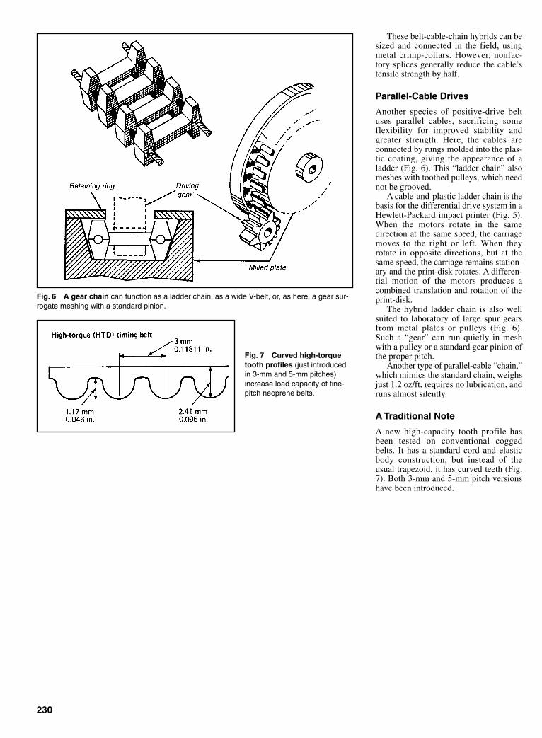
These belt-cable-chain hybrids can besized and connected in the field, usingmetal crimp-collars. However, nonfac-tory splices generally reduce the cable’stensile strength by half.
Parallel-Cable Drives
Another species of positive-drive beltuses parallel cables, sacrificing someflexibility for improved stability andgreater strength. Here, the cables areconnected by rungs molded into the plas-tic coating, giving the appearance of aladder (Fig. 6). This “ladder chain” alsomeshes with toothed pulleys, which neednot be grooved.
A cable-and-plastic ladder chain is thebasis for the differential drive system in aHewlett-Packard impact printer (Fig. 5).When the motors rotate in the samedirection at the same speed, the carriagemoves to the right or left. When theyrotate in opposite directions, but at thesame speed, the carriage remains station-ary and the print-disk rotates. A differen-tial motion of the motors produces acombined translation and rotation of theprint-disk.
The hybrid ladder chain is also wellsuited to laboratory of large spur gearsfrom metal plates or pulleys (Fig. 6).Such a “gear” can run quietly in meshwith a pulley or a standard gear pinion ofthe proper pitch.
Another type of parallel-cable “chain,”which mimics the standard chain, weighsjust 1.2 oz/ft, requires no lubrication, andruns almost silently.
A Traditional Note
A new high-capacity tooth profile hasbeen tested on conventional coggedbelts. It has a standard cord and elasticbody construction, but instead of theusual trapezoid, it has curved teeth (Fig.7). Both 3-mm and 5-mm pitch versionshave been introduced.
230
Fig. 6 A gear chain can function as a ladder chain, as a wide V-belt, or, as here, a gear sur-rogate meshing with a standard pinion.
Fig. 7 Curved high-torquetooth profiles (just introducedin 3-mm and 5-mm pitches)increase load capacity of fine-pitch neoprene belts.
Sclater Chapter 7 5/3/01 12:34 PM Page 230

231
Increasing the gap between the roller andknife changes chain lengths from F to E.Because the idler moves with the rollersprocket, length G changes to H. Thechanges in chain length are similar invalue but opposite in direction. Chainlengths E minus F closely approximate Gminus H. Variations in required chainlength occur because the chains do notrun parallel. Sprocket offset is requiredto avoid interference. Slack produced istoo minute to affect the drive because itis proportional to changes in the cosineof a small angle (2º to 5º). For the 72-in.chain, variation is 0.020 in.
site roller bottoms in the left-hand slot.The motor now swings out untilrestrained by the V-belt, which drives thepump and basket.
The motor, momentarily at zero rpm,develops maximum torque and begins toaccelerate the load of basket, water, and
wash. The motor pivots (B) about the leftroller increasing belt tension in propor-tion to the output torque. When the bas-ket reaches maximum speed, the load isreduced and belt tension relaxes. Theagitation cycle produces an identicalreaction in the reverse direction.
MOTOR MOUNT PIVOTS FOR CONTROLLED TENSIONBelt tensioning proportional to load
When the agitation cycle is completed,the motor is momentarily idle with theright roller bottomed in the right-handslot. When spin-dry starts, (A) the start-ing torque produces a reaction at the sta-tor, pivoting the motor on the bottomedroller. The motor pivots until the oppo-
CHANGE CENTER DISTANCE WITHOUT AFFECTING SPEED RATIO
Sclater Chapter 7 5/3/01 12:34 PM Page 231
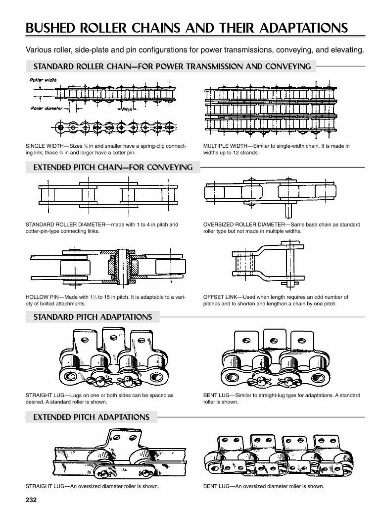
232
BUSHED ROLLER CHAINS AND THEIR ADAPTATIONSVarious roller, side-plate and pin configurations for power transmissions, conveying, and elevating.
STANDARD ROLLER CHAIN—FOR POWER TRANSMISSION AND CONVEYING
SINGLE WIDTH—Sizes 5⁄8 in and smaller have a spring-clip connect-ing link; those 3⁄4 in and larger have a cotter pin.
MULTIPLE WIDTH—Similar to single-width chain. It is made inwidths up to 12 strands.
STANDARD ROLLER DIAMETER—made with 1 to 4 in pitch andcotter-pin-type connecting links.
OVERSIZED ROLLER DIAMETER—Same base chain as standardroller type but not made in multiple widths.
HOLLOW PIN—Made with 11⁄4 to 15 in pitch. It is adaptable to a vari-ety of bolted attachments.
OFFSET LINK—Used when length requires an odd number ofpitches and to shorten and lengthen a chain by one pitch.
STRAIGHT LUG—Lugs on one or both sides can be spaced asdesired. A standard roller is shown.
BENT LUG—Similar to straight-lug type for adaptations. A standardroller is shown.
STRAIGHT LUG—An oversized diameter roller is shown. BENT LUG—An oversized diameter roller is shown.
EXTENDED PITCH CHAIN—FOR CONVEYING
STANDARD PITCH ADAPTATIONS
EXTENDED PITCH ADAPTATIONS
Sclater Chapter 7 5/3/01 12:34 PM Page 232

233
HOLLOW PIN
STRAIGHT LUG—Lugs are detachable for field adaptation. BENT LUG—Similar to straight lug type for adaptations.
EXTENDED PIN CHAINS
SPECIAL ADAPTATIONS
STANDARD PITCH—Pins can be extended on either side. EXTENDED PITCH—Similar to standard for adaptations.
HOLLOW PIN—Pins are designed for field adaptation. CROSS ROD—The rod can be removed from the hollow pins.
Used for holding conveyed objects. Used to keep conveyed object on the center-line of the chain.
Used when flexing is desired in one direction only. Used for supporting concentrated loads.
Sclater Chapter 7 5/3/01 12:34 PM Page 233

234
Fig. 1 This low-cost rack-and-pinion deviceis easily assembled from standard parts.
Fig. 2 An extension of the rack-and-pinion principle—This is a soldering fix-ture for noncircular shells. Positive-actioncams can be similarly designed. Standardangle brackets attach the chain to a cam orfixture plate.
Fig. 3 This control-cable dirction-changeris extensively used in aircraft.
SIX INGENIOUS JOBS FOR ROLLER CHAINThis low-cost industrial chain can be applied in a variety ofways to perform tasks other than simply transmitting power.
Sclater Chapter 7 5/3/01 12:34 PM Page 234

235
Fig. 4 The transmission of tipping or rocking motion can becombined with the previous example (Fig. 3) to transmit this kind ofmotion to a remote location and around obstructions. The tippingangle should not exceed 40º.
Fig. 5 This lifting device is simplified by roller chain.
Fig. 6 Two examples of indexing and feeding applications of roller chain are shown here.This setup feeds plywood strips into a machine. The advantages of roller chain as used here areits flexibility and long feed.
Sclater Chapter 7 5/3/01 12:34 PM Page 235
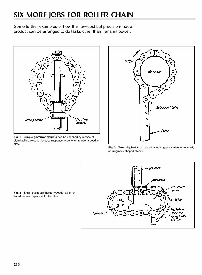
236
SIX MORE JOBS FOR ROLLER CHAINSome further examples of how this low-cost but precision-madeproduct can be arranged to do tasks other than transmit power.
Fig. 1 Simple governor weights can be attached by means ofstandard brackets to increase response force when rotation speed isslow.
Fig. 2 Wrench pivot A can be adjusted to grip a variety of regularlyor irregularly shaped objects.
Fig. 3 Small parts can be conveyed, fed, or ori-ented between spaces of roller chain.
Sclater Chapter 7 5/3/01 12:34 PM Page 236

237
Fig. 4 Clamp toggle action is supplied bytwo chains, thus clearing pin at fulcrum.
Fig. 5 Light-duty trolley conveyors canbe made by combining standard roller-chaincomponents with standard curtain-trackcomponents. Small gearmotors are used todrive the conveyor.
Fig. 6 Slatted belt, made by attachingwood, plastic, or metal slats, can serve asadjustable safety guard, conveyor belt, fast-acting security-wicket window.
Sclater Chapter 7 5/3/01 12:34 PM Page 237

238
MECHANISMS FOR REDUCING PULSATIONS IN CHAIN DRIVESPulsations in chain motion created by the chordal action of chain andsprockets can be minimized or avoided by introducing acompensating cyclic motion in the driving sprocket. Mechanisms forreducing fluctuating dynamic loads in chain drives and the pulsationsresulting from them include noncircular gears, eccentric gears, andcam-activated intermediate shafts.
Sclater Chapter 7 5/3/01 12:34 PM Page 238

Fig. 1 The large cast-tooth, noncircular gear, mounted on thechain sprocket shaft, has a wavy outline in which the number ofwaves equals the number of teeth on a sprocket. The pinion has acorresponding noncircular shape. Although requiring special-shapedgears, the drive completely equalizes the chain pulsations.
Fig. 2 This drive has two eccentrically mounted spur pinions (1 and2). Input power is through the belt pulley keyed to the same shaft aspinion 1. Pinion 3 (not shown), keyed to the shaft of pinion 2, drivesthe large gear and sprocket. However, the mechanism does not com-pletely equalize chain velocity unless the pitch lines of pinions 1 and2 are noncircular instead of eccentric.
Fig. 3 An additional sprocket 2 drives the noncircular sprocket 3through a fine-pitch chain 1.This imparts pulsating velocity to shaft 6and to the long-pitch conveyor sprocket 5 through pinion 7 and gear4. The ratio of the gear pair is made the same as the number of teethof sprocket 5. Spring-actuated lever and rollers 8 take up the slack.Conveyor motion is equalized, but the mechanism has limited powercapacity because the pitch of chain 1 must be kept small. Capacitycan be increased by using multiple strands of fine-pitch chain.
Fig. 4 Power is transmitted from shaft 2 to sprocket 6 throughchain 4, thus imparting a variable velocity to shaft 3, and through it, tothe conveyor sprocket 7. Because chain 4 has a small pitch andsprocket 5 is relatively large, the velocity of 4 is almost constant. Thisinduces an almost constant conveyor velocity. The mechanismrequires the rollers to tighten the slack side of the chain, and it haslimited power capacity.
Fig. 5 Variable motion to the sprocket is produced by disk 3. Itsupports pin and roller 4, as well as disk 5, which has a radial slotand is eccentrically mounted on shaft 2. The ratio of rpm of shaft 2 tothe sprocket equals the number of teeth in the sprocket. Chain veloc-ity is not completely equalized.
Fig. 6 The integrated “planetary gear” system (gears 4, 5, 6and 7) is activated by cam 10, and it transmits a variable velocity tothe sprocket synchronized with chain pulsations through shaft 2,thus completely equalizing chain velocity. Cam 10 rides on a circu-lar idler roller 11. Because of the equilibrium of the forces, the cammaintains positive contact with the roller. The unit has standardgears, acts simultaneously as a speed reducer, and can transmithigh horsepower.
239
Sclater Chapter 7 5/3/01 12:34 PM Page 239
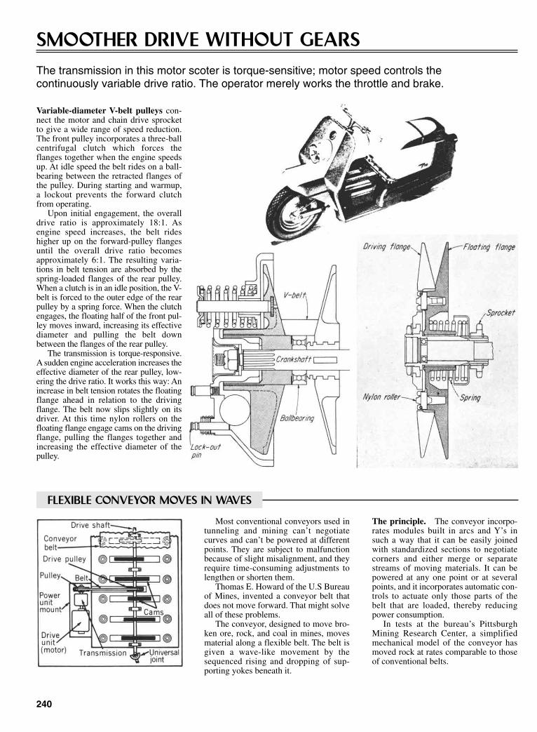
240
SMOOTHER DRIVE WITHOUT GEARSThe transmission in this motor scoter is torque-sensitive; motor speed controls the continuously variable drive ratio. The operator merely works the throttle and brake.
Variable-diameter V-belt pulleys con-nect the motor and chain drive sprocketto give a wide range of speed reduction.The front pulley incorporates a three-ballcentrifugal clutch which forces theflanges together when the engine speedsup. At idle speed the belt rides on a ball-bearing between the retracted flanges ofthe pulley. During starting and warmup,a lockout prevents the forward clutchfrom operating.
Upon initial engagement, the overalldrive ratio is approximately 18:1. Asengine speed increases, the belt rideshigher up on the forward-pulley flangesuntil the overall drive ratio becomesapproximately 6:1. The resulting varia-tions in belt tension are absorbed by thespring-loaded flanges of the rear pulley.When a clutch is in an idle position, the V-belt is forced to the outer edge of the rearpulley by a spring force. When the clutchengages, the floating half of the front pul-ley moves inward, increasing its effectivediameter and pulling the belt downbetween the flanges of the rear pulley.
The transmission is torque-responsive.A sudden engine acceleration increases theeffective diameter of the rear pulley, low-ering the drive ratio. It works this way: Anincrease in belt tension rotates the floatingflange ahead in relation to the drivingflange. The belt now slips slightly on itsdriver. At this time nylon rollers on thefloating flange engage cams on the drivingflange, pulling the flanges together andincreasing the effective diameter of thepulley.
FLEXIBLE CONVEYOR MOVES IN WAVES
Most conventional conveyors used intunneling and mining can’t negotiatecurves and can’t be powered at differentpoints. They are subject to malfunctionbecause of slight misalignment, and theyrequire time-consuming adjustments tolengthen or shorten them.
Thomas E. Howard of the U.S Bureauof Mines, invented a conveyor belt thatdoes not move forward. That might solveall of these problems.
The conveyor, designed to move bro-ken ore, rock, and coal in mines, movesmaterial along a flexible belt. The belt isgiven a wave-like movement by thesequenced rising and dropping of sup-porting yokes beneath it.
The principle. The conveyor incorpo-rates modules built in arcs and Y’s insuch a way that it can be easily joinedwith standardized sections to negotiatecorners and either merge or separatestreams of moving materials. It can bepowered at any one point or at severalpoints, and it incorporates automatic con-trols to actuate only those parts of thebelt that are loaded, thereby reducingpower consumption.
In tests at the bureau’s PittsburghMining Research Center, a simplifiedmechanical model of the conveyor hasmoved rock at rates comparable to thoseof conventional belts.
Sclater Chapter 7 5/3/01 12:34 PM Page 240
CHAPTER 8GEARED SYSTEMS AND
VARIABLE-SPEEDMECHANISMS
Sclater Chapter 8 5/3/01 12:42 PM Page 241
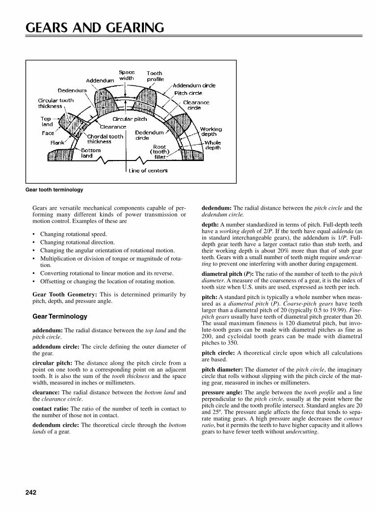
Gears are versatile mechanical components capable of per-forming many different kinds of power transmission ormotion control. Examples of these are
• Changing rotational speed.• Changing rotational direction.• Changing the angular orientation of rotational motion.• Multiplication or division of torque or magnitude of rota-
tion.• Converting rotational to linear motion and its reverse.• Offsetting or changing the location of rotating motion.
Gear Tooth Geometry: This is determined primarily bypitch, depth, and pressure angle.
Gear Terminology
addendum: The radial distance between the top land and thepitch circle.
addendum circle: The circle defining the outer diameter ofthe gear.
circular pitch: The distance along the pitch circle from apoint on one tooth to a corresponding point on an adjacenttooth. It is also the sum of the tooth thickness and the spacewidth, measured in inches or millimeters.
clearance: The radial distance between the bottom land andthe clearance circle.
contact ratio: The ratio of the number of teeth in contact tothe number of those not in contact.
dedendum circle: The theoretical circle through the bottomlands of a gear.
dedendum: The radial distance between the pitch circle and thededendum circle.
depth: A number standardized in terms of pitch. Full-depth teethhave a working depth of 2/P. If the teeth have equal addenda (asin standard interchangeable gears), the addendum is 1/P. Full-depth gear teeth have a larger contact ratio than stub teeth, andtheir working depth is about 20% more than that of stub gearteeth. Gears with a small number of teeth might require undercut-ting to prevent one interfering with another during engagement.
diametral pitch (P): The ratio of the number of teeth to the pitchdiameter. A measure of the coarseness of a gear, it is the index oftooth size when U.S. units are used, expressed as teeth per inch.
pitch: A standard pitch is typically a whole number when meas-ured as a diametral pitch (P). Coarse-pitch gears have teethlarger than a diametral pitch of 20 (typically 0.5 to 19.99). Fine-pitch gears usually have teeth of diametral pitch greater than 20.The usual maximum fineness is 120 diametral pitch, but invo-lute-tooth gears can be made with diametral pitches as fine as200, and cycloidal tooth gears can be made with diametralpitches to 350.
pitch circle: A theoretical circle upon which all calculationsare based.
pitch diameter: The diameter of the pitch circle, the imaginarycircle that rolls without slipping with the pitch circle of the mat-ing gear, measured in inches or millimeters.
pressure angle: The angle between the tooth profile and a lineperpendicular to the pitch circle, usually at the point where thepitch circle and the tooth profile intersect. Standard angles are 20and 25º. The pressure angle affects the force that tends to sepa-rate mating gears. A high pressure angle decreases the contactratio, but it permits the teeth to have higher capacity and it allowsgears to have fewer teeth without undercutting.
242
GEARS AND GEARING
Gear tooth terminology
Sclater Chapter 8 5/3/01 12:42 PM Page 242
Gear Dynamics Terminology
backlash: The amount by which the width of a tooth spaceexceeds the thickness of the engaging tooth measured on thepitch circle. It is the shortest distance between the noncontactingsurfaces of adjacent teeth.
gear efficiency: The ratio of output power to input power, takinginto consideration power losses in the gears and bearings andfrom windage and churning of lubricant.
gear power: A gear’s load and speed capacity, determined bygear dimensions and type. Helical and helical-type gears havecapacities to approximately 30,000 hp, spiral bevel gears toabout 5000 hp, and worm gears to about 750 hp.
gear ratio: The number of teeth in the gear (larger of a pair)divided by the number of teeth in the pinion (smaller of a pair).Also, the ratio of the speed of the pinion to the speed of the gear.In reduction gears, the ratio of input to output speeds.
gear speed: A value determined by a specific pitchline velocity.It can be increased by improving the accuracy of the gear teethand the balance of rotating parts.
undercutting: Recessing in the bases of gear tooth flanks toimprove clearance.
Gear Classification
External gears have teeth on the outside surface of a disk orwheel.
Internal gears have teeth on the inside surface of a cylinder.
Spur gears are cylindrical gears with teeth that are straight andparallel to the axis of rotation. They are used to transmit motionbetween parallel shafts.
Rack gears have teeth on a flat rather than a curved surface thatprovide straight-line rather than rotary motion.
Helical gears have a cylindrical shape, but their teeth are set at anangle to the axis. They are capable of smoother and quieter actionthan spur gears. When their axes are parallel, they are called par-
243
allel helical gears, and when they are at right angles they arecalled helical gears. Herringbone and worm gears are based onhelical gear geometry.
Herringbone gears are double helical gears with both right-handand left-hand helix angles side by side across the face of the gear.This geometry neutralizes axial thrust from helical teeth.
Worm gears are crossed-axis helical gears in which the helixangle of one of the gears (the worm) has a high helix angle,resembling a screw.
Pinions are the smaller of two mating gears; the larger one iscalled the gear or wheel.
Bevel gears have teeth on a conical surface that mate on axes thatintersect, typically at right angles. They are used in applicationswhere there are right angles between input and output shafts.This class of gears includes the most common straight and spiralbevel as well as the miter and hypoid.
Straight bevel gears are the simplest bevel gears. Their straightteeth produce instantaneous line contact when they mate. Thesegears provide moderate torque transmission, but they are not assmooth running or quiet as spiral bevel gears because thestraight teeth engage with full-line contact. They permitmedium load capacity.
Spiral bevel gears have curved oblique teeth. The spiral angleof curvature with respect to the gear axis permits substantialtooth overlap. Consequently, teeth engage gradually and at leasttwo teeth are in contact at the same time. These gears havelower tooth loading than straight bevel gears, and they can turnup to eight times faster. They permit high load capacity.
Miter gears are mating bevel gears with equal numbers of teethand with their axes at right angles.
Hypoid gears are spiral bevel gears with offset intersecting axes.
Face gears have straight tooth surfaces, but their axes lie inplanes perpendicular to shaft axes. They are designed to matewith instantaneous point contact. These gears are used in right-angle drives, but they have low load capacities.
NUTATING-PLATE DRIVE
The Nutation Drive* is a mechanically positive, gearless powertransmission that offers high single-stage speed ratios at highefficiencies. A nutating member carries camrollers on its periph-ery and causes differential rotation between the three majorcomponents of the drive: stator, nutator, and rotor. Correctlydesigned cams on the stator and rotor assure a low-noiseengagement and mathematically pure rolling contact betweencamrollers and cams.
The drive’s characteristics include compactness, high speedratio, and efficiency. Its unique design guarantees rolling contactbetween the power-transmitting members and even distribution
of the load among a large number of these members. Both factorscontribute to the drive’s inherent low noise level and long, main-tenance-free life. The drive has a small number of moving parts;furthermore, commercial grease and solid lubrication provideadequate lubrication for many applications.
Kinetics of the Nutation Drive
Basic components. The three basic components of theNutation Drive are the stator, nutator, and rotor, as shown inFig. 1. The nutator carries radially mounted conical camrollers
Sclater Chapter 8 5/3/01 12:42 PM Page 243

244
Fig. 1 An exploded view of the Nutation Drive.
CONE DRIVE NEEDS NO GEARS OR PULLEYS
Cone drive operates without lubrication.
nutator. Each nutation cycle advances the rotor by an angleequivalent to the angular spacing of the rotor cams. During nuta-tion the nutator is held from rotating by the stator, which trans-mits the reaction forces to the housing.
* Four U.S. patents (3,094,880, 3,139,771, 3,139,772, and 3,590,659)have been issued to A. M. Maroth.
A variable-speed-transmission cone drive operates without gearsor pulleys. The drive unit has its own limited slip differential andclutch.
As the drawing shows, two cones made of brake lining mate-rial are mounted on a shaft directly connected to the engine.These drive two larger steel conical disks mounted on the outputshaft. The outer disks are mounted on pivoting frames that can bemoved by a simple control rod.
To center the frames and to provide some resistance when theouter disks are moved, two torsion bars attached to the mainframe connect and support the disk-support frames. By alteringthe position of the frames relative to the driving cones, the direc-tion of rotation and speed can be varied.
The unit was invented by Marion H. Davis of Indiana.
that engage between cams on the rotor and stator. Cam surfacesand camrollers have a common vanishing point—the center ofthe nutator. Therefore, line-contact rolling is assured between therollers and the cams.
Nutation is imparted to the nutator through the center supportbearing by the fixed angle of its mounting on the input shaft. Onerotation of the input shaft causes one complete nutation of the
Sclater Chapter 8 5/3/01 12:42 PM Page 244
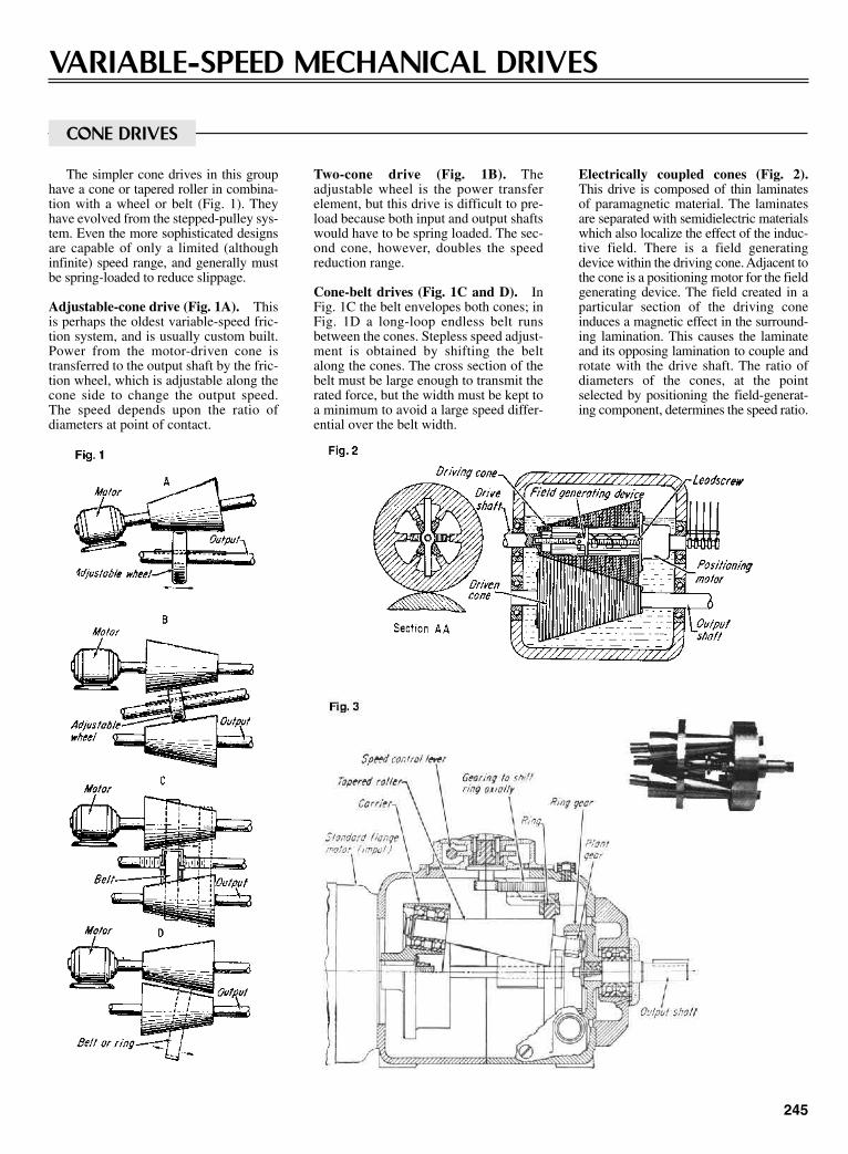
245
VARIABLE-SPEED MECHANICAL DRIVES
CONE DRIVES
Electrically coupled cones (Fig. 2).This drive is composed of thin laminatesof paramagnetic material. The laminatesare separated with semidielectric materialswhich also localize the effect of the induc-tive field. There is a field generatingdevice within the driving cone. Adjacent tothe cone is a positioning motor for the fieldgenerating device. The field created in aparticular section of the driving coneinduces a magnetic effect in the surround-ing lamination. This causes the laminateand its opposing lamination to couple androtate with the drive shaft. The ratio ofdiameters of the cones, at the pointselected by positioning the field-generat-ing component, determines the speed ratio.
Two-cone drive (Fig. 1B). Theadjustable wheel is the power transferelement, but this drive is difficult to pre-load because both input and output shaftswould have to be spring loaded. The sec-ond cone, however, doubles the speedreduction range.
Cone-belt drives (Fig. 1C and D). InFig. 1C the belt envelopes both cones; inFig. 1D a long-loop endless belt runsbetween the cones. Stepless speed adjust-ment is obtained by shifting the beltalong the cones. The cross section of thebelt must be large enough to transmit therated force, but the width must be kept toa minimum to avoid a large speed differ-ential over the belt width.
The simpler cone drives in this grouphave a cone or tapered roller in combina-tion with a wheel or belt (Fig. 1). Theyhave evolved from the stepped-pulley sys-tem. Even the more sophisticated designsare capable of only a limited (althoughinfinite) speed range, and generally mustbe spring-loaded to reduce slippage.
Adjustable-cone drive (Fig. 1A). Thisis perhaps the oldest variable-speed fric-tion system, and is usually custom built.Power from the motor-driven cone istransferred to the output shaft by the fric-tion wheel, which is adjustable along thecone side to change the output speed.The speed depends upon the ratio ofdiameters at point of contact.
Sclater Chapter 8 5/3/01 12:42 PM Page 245

Graham drive (Fig. 3). This commer-cial unit combines a planetary-gear setand three tapered rollers (only one ofwhich is shown). The ring is positionedaxially by a cam and gear arrangement.The drive shaft rotates the carrier withthe tapered rollers, which are inclined atan angle equal to their taper so that theirouter edges are parallel to the centerlineof the assembly. Traction pressurebetween the rollers and ring is created bycentrifugal force, or spring loading of therollers. At the end of each roller a pinionmeshes with a ring gear. The ring gear ispart of the planetary gear system and iscoupled to the output shaft.
The speed ratio depends on the ratioof the diameter of the fixed ring to theeffective diameter of the roller at the
point of contact, and is set by the axialposition of the ring. The output speed,even at its maximum, is always reducedto about one-third of input speed becauseof the differential feature. When theangular speed of the driving motorequals the angular speed of the centers ofthe tapered rollers around their mutualcenterline (which is set by the axial posi-tion of the nonrotating friction ring), theoutput speed is zero. This drive is manu-factured in ratings up to 3 hp; efficiencyreaches 85%.
Cone-and-ring drive (Fig. 4). Here,two cones are encircled by a preloadedring. Shifting the ring axially varies theoutput speed. This principle is similar tothat of the cone-and-belt drive (Fig. 1C).
In this case, however, the contact pres-sure between ring and cones increaseswith load to limit slippage.
Planetary-cone drive (Fig. 5). This isbasically a planetary gear system butwith cones in place of gears. The planetcones are rotated by the sun cone which,in turn, is driven by the motor. The planetcones are pressed between an outer non-rotating rind and the planet hold. Axialadjustment of the ring varies the rota-tional speed of the cones around theirmutual axis. This varies the speed of theplanet holder and the output shaft. Thus,the mechanism resembles that of theGraham drive (Fig. 3).
The speed adjustment range of the unitillustrated if from 4:1 to 24:1. The systemis built in Japan in ratings up to 2 hp.
246
Sclater Chapter 8 5/3/01 12:42 PM Page 246
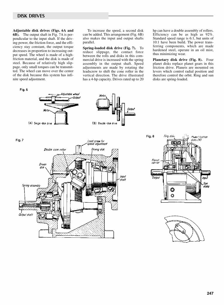
247
Adjustable disk drives (Figs. 6A and6B). The output shaft in Fig. 7A is per-pendicular to the input shaft. If the driv-ing power, the friction force, and the effi-ciency stay constant, the output torquedecreases in proportion to increasing out-put speed. The wheel is made of a high-friction material, and the disk is made ofsteel. Because of relatively high slip-page, only small torques can be transmit-ted. The wheel can move over the centerof the disk because this system has infi-nite speed adjustment.
To increase the speed, a second diskcan be added. This arrangement (Fig. 6B)also makes the input and output shaftsparallel.
Spring-loaded disk drive (Fig. 7). Toreduce slippage, the contact forcebetween the rolls and disks in this com-mercial drive is increased with the springassembly in the output shaft. Speedadjustments are made by rotating theleadscrew to shift the cone roller in thevertical direction. The drive illustratedhas a 4-hp capacity. Drives rated up to 20
hp can have a double assembly of rollers.Efficiency can be as high as 92%.Standard speed range is 6:1, but units of10:1 have been build. The power trans-ferring components, which are madehardened steel, operate in an oil mist,thus minimizing wear.
Planetary disk drive (Fig. 8). Fourplanet disks replace planet gears in thisfriction drive. Planets are mounted onlevers which control radial position andtherefore control the orbit. Ring and sundisks are spring-loaded.
DISK DRIVES
Sclater Chapter 8 5/3/01 12:42 PM Page 247

248
Ring-and-pulley drive (Fig. 9). Athick steel ring in this drive encircles twovariable-pitch (actually variable-width)pulleys. A novel gear-and-linkage systemsimultaneously changes the width ofboth pulleys (see Fig. 9B). For example,when the top pulley opens, the sides ofthe bottom pulley close up. This reducesthe effective pitch diameter of the toppulley and increases that of the bottompulley, thus varying the output speed.
Normally, the ring engages the pul-leys at points A and B. However, underload, the driven pulley resists rotation
and the contact point moves from B to Dbecause of the very small elastic defor-mation of the ring. The original circularshape of the ring is changed to a slightlyoval form, and the distance betweenpoints of contact decreases. This wedgesthe ring between the pulley cones andincreases the contact pressure betweenring and pulleys in proportion to the loadapplied, so that constant horsepower atall speeds is obtained. The drive canhave up to 3-hp capacity; speed varia-tions can be 16:1, with a practical rangeof about 8:1.
Some manufacturers install rings withunusual cross sections (Fig. 10) formedby inverting one of the sets of sheaves.
Double-ring drive (Fig. 11). Powertransmission is through two steel tractionrings that engage two sets of disks mountedon separate shafts. This drive requires thatthe outer disks be under a compressionload by a spring system (not illustrated).The rings are hardened and convex-groundto reduce wear. Speed is changed by tiltingthe ring support cage, forcing the rings tomove to the desired position.
RING DRIVES
Sclater Chapter 8 5/3/01 12:42 PM Page 248
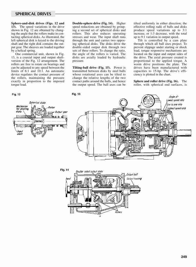
249
Sphere-and-disk drives (Figs. 12 and13). The speed variations in the driveshown in Fig. 12 are obtained by chang-ing the angle that the rollers make in con-tacting spherical disks. As illustrated, theleft spherical disk is keyed to the drivingshaft and the right disk contains the out-put gear. The sheaves are loaded togetherby a helical spring.
One commercial unit, shown in Fig.13, is a coaxial input and output shaft-version of the Fig. 12 arrangement. Therollers are free to rotate on bearings andcan be adjusted to any speed between thelimits of 6:1 and 10:1. An automaticdevice regulates the contact pressure ofthe rollers, maintaining the pressureexactly in proportion to the imposedtorque load.
Double-sphere drive (Fig. 14). Higherspeed reductions are obtained by group-ing a second set of spherical disks androllers. This also reduces operatingstresses and wear. The input shaft runsthrough the unit and carries two oppos-ing spherical disks. The disks drive thedouble-sided output disk through twosets of three rollers. To change the ratio,the angle of the rollers is varied. Thedisks are axially loaded by hydraulicpressure.
Tilting-ball drive (Fig. 15). Power istransmitted between disks by steel ballswhose rotational axes can be tilted tochange the relative lengths of the twocontact paths around the balls, and hencethe output speed. The ball axes can be
tilted uniformly in either direction; theeffective rolling radii of balls and disksproduce speed variations up to 3:1increase, or 1:3 decrease, with the totalup to 9:1 variation in output speed.
Tilt is controlled by a cam platethrough which all ball axes project. Toprevent slippage under starting or shockload, torque responsive mechanisms arelocated on the input and output sides ofthe drive. The axial pressure created isproportional to the applied torque. Aworm drive positions the plate. Thedrives have been manufactured withcapacities to 15-hp. The drive’s effi-ciency is plotted in the chart.
Sphere and roller drive (Fig. 16). Theroller, with spherical end surfaces, is
SPHERICAL DRIVES
Sclater Chapter 8 5/3/01 12:43 PM Page 249
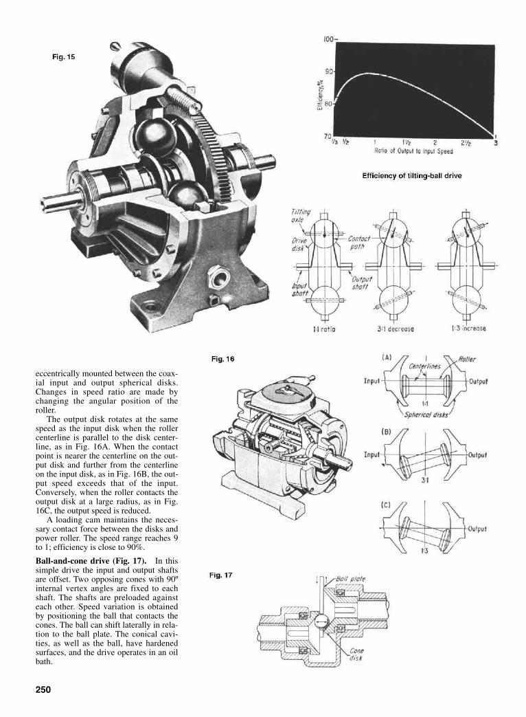
eccentrically mounted between the coax-ial input and output spherical disks.Changes in speed ratio are made bychanging the angular position of theroller.
The output disk rotates at the samespeed as the input disk when the rollercenterline is parallel to the disk center-line, as in Fig. 16A. When the contactpoint is nearer the centerline on the out-put disk and further from the centerlineon the input disk, as in Fig. 16B, the out-put speed exceeds that of the input.Conversely, when the roller contacts theoutput disk at a large radius, as in Fig.16C, the output speed is reduced.
A loading cam maintains the neces-sary contact force between the disks andpower roller. The speed range reaches 9to 1; efficiency is close to 90%.
Ball-and-cone drive (Fig. 17). In thissimple drive the input and output shaftsare offset. Two opposing cones with 90ºinternal vertex angles are fixed to eachshaft. The shafts are preloaded againsteach other. Speed variation is obtainedby positioning the ball that contacts thecones. The ball can shift laterally in rela-tion to the ball plate. The conical cavi-ties, as well as the ball, have hardenedsurfaces, and the drive operates in an oilbath.
250
Sclater Chapter 8 5/3/01 12:43 PM Page 250

251
Ball-and-disk drive (Fig. 18). Frictiondisks are mounted on splined shafts toallow axial movement. The steel ballscarried by swing arms rotate on guiderollers, and are in contact with drivingand driven disks. Belleville springs pro-vide the loading force between the ballsand the disks. The position of the ballscontrols the ratio of contact radii, andthus the speed.
Only one pair of disks is required toprovide the desired speed ratio; the mul-tiple disks increase the torque capacity. Ifthe load changes, a centrifugal loadingdevice increases or decreases the axialpressure in proportion to the speed. Thehelical gears permit the output shaft to be
coaxial with respect to the input shaft.Output to input speed ratios are from 1 to1 to 1 to 5, and the drive’s efficiency canreach 92%. Small ball and disk drives arerated to 9 hp, and large ball and diskdrives are rated to 38 hp.
Oil-coated disks (Fig. 19). Power istransmitted without metal-to-metal con-tact at 85% efficiency. The interleaveddisk sets are coated with oil when operat-ing. At their points of contact, axial pres-sure applied by the rim disks compressesthe oil film, increasing its viscosity. Thecone disks transmit motion to the rimdisks by shearing the molecules of thehigh-viscosity oil film.
Three stacks of cone disks (only onestack is shown) surround the central rimstack. Speed is changed by moving thecones radially toward the rim disks (out-put speed increases) or away from therim disks (output speed decreases). Aspring and cam on the output shaftmaintain the pressure of the disks at alltimes.
Drives with ratings in excess of 60 hphave been built. The small drives arecooled, but water cooling is required forthe larger units.
Under normal conditions, the drivecan transmit its rated power with a 1%slip at high speeds and 3% slip at lowspeeds.
MULTIPLE DISK DRIVES
Sclater Chapter 8 5/3/01 12:43 PM Page 251
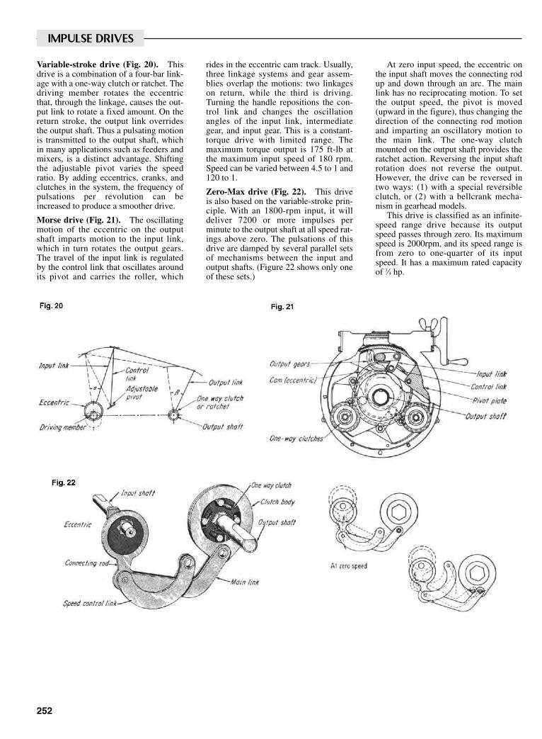
252
Variable-stroke drive (Fig. 20). Thisdrive is a combination of a four-bar link-age with a one-way clutch or ratchet. Thedriving member rotates the eccentricthat, through the linkage, causes the out-put link to rotate a fixed amount. On thereturn stroke, the output link overridesthe output shaft. Thus a pulsating motionis transmitted to the output shaft, whichin many applications such as feeders andmixers, is a distinct advantage. Shiftingthe adjustable pivot varies the speedratio. By adding eccentrics, cranks, andclutches in the system, the frequency ofpulsations per revolution can beincreased to produce a smoother drive.
Morse drive (Fig. 21). The oscillatingmotion of the eccentric on the outputshaft imparts motion to the input link,which in turn rotates the output gears.The travel of the input link is regulatedby the control link that oscillates aroundits pivot and carries the roller, which
rides in the eccentric cam track. Usually,three linkage systems and gear assem-blies overlap the motions: two linkageson return, while the third is driving.Turning the handle repositions the con-trol link and changes the oscillationangles of the input link, intermediategear, and input gear. This is a constant-torque drive with limited range. Themaximum torque output is 175 ft-lb atthe maximum input speed of 180 rpm.Speed can be varied between 4.5 to 1 and120 to 1.
Zero-Max drive (Fig. 22). This driveis also based on the variable-stroke prin-ciple. With an 1800-rpm input, it willdeliver 7200 or more impulses perminute to the output shaft at all speed rat-ings above zero. The pulsations of thisdrive are damped by several parallel setsof mechanisms between the input andoutput shafts. (Figure 22 shows only oneof these sets.)
At zero input speed, the eccentric onthe input shaft moves the connecting rodup and down through an arc. The mainlink has no reciprocating motion. To setthe output speed, the pivot is moved(upward in the figure), thus changing thedirection of the connecting rod motionand imparting an oscillatory motion tothe main link. The one-way clutchmounted on the output shaft provides theratchet action. Reversing the input shaftrotation does not reverse the output.However, the drive can be reversed intwo ways: (1) with a special reversibleclutch, or (2) with a bellcrank mecha-nism in gearhead models.
This drive is classified as an infinite-speed range drive because its outputspeed passes through zero. Its maximumspeed is 2000rpm, and its speed range isfrom zero to one-quarter of its inputspeed. It has a maximum rated capacityof 3⁄4 hp.
IMPULSE DRIVES
Sclater Chapter 8 5/3/01 12:43 PM Page 252
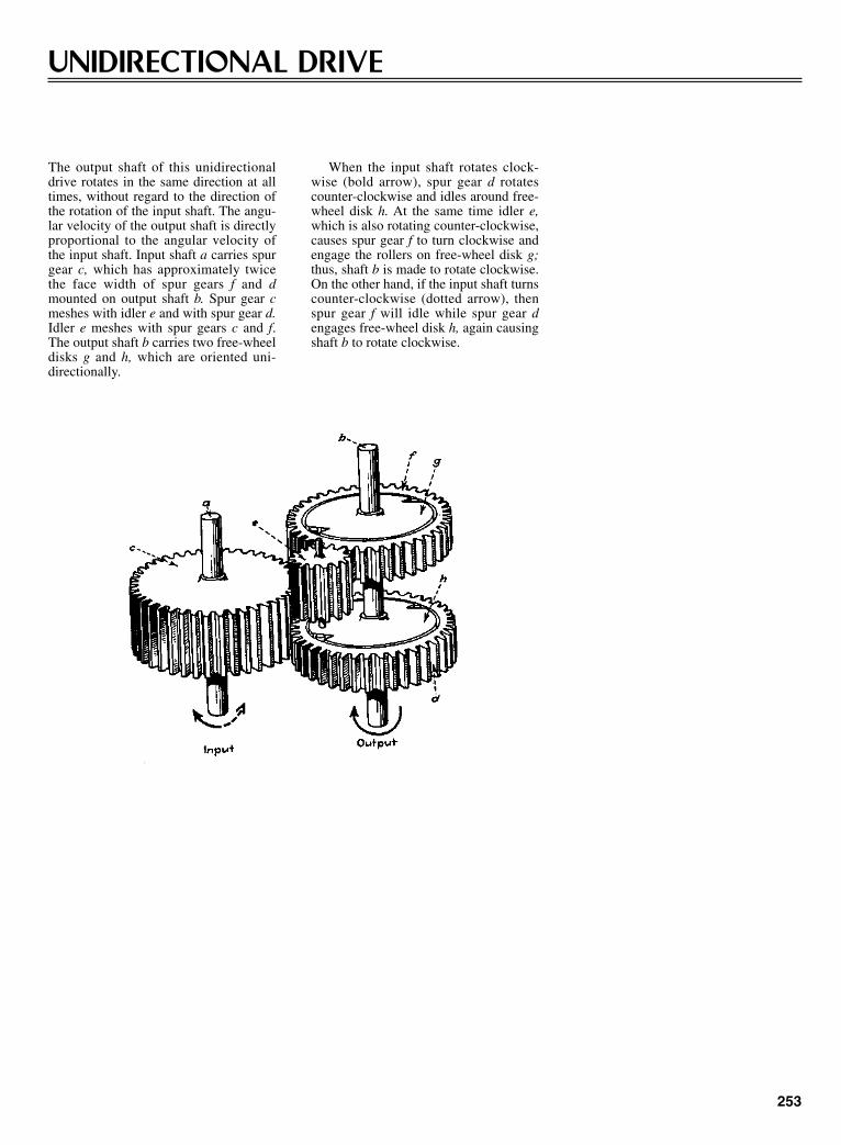
253
UNIDIRECTIONAL DRIVE
The output shaft of this unidirectionaldrive rotates in the same direction at alltimes, without regard to the direction ofthe rotation of the input shaft. The angu-lar velocity of the output shaft is directlyproportional to the angular velocity ofthe input shaft. Input shaft a carries spurgear c, which has approximately twicethe face width of spur gears f and dmounted on output shaft b. Spur gear cmeshes with idler e and with spur gear d.Idler e meshes with spur gears c and f.The output shaft b carries two free-wheeldisks g and h, which are oriented uni-directionally.
When the input shaft rotates clock-wise (bold arrow), spur gear d rotatescounter-clockwise and idles around free-wheel disk h. At the same time idler e,which is also rotating counter-clockwise,causes spur gear f to turn clockwise andengage the rollers on free-wheel disk g;thus, shaft b is made to rotate clockwise.On the other hand, if the input shaft turnscounter-clockwise (dotted arrow), thenspur gear f will idle while spur gear dengages free-wheel disk h, again causingshaft b to rotate clockwise.
Sclater Chapter 8 5/3/01 12:43 PM Page 253
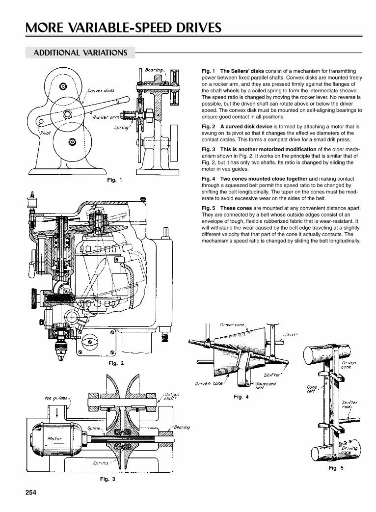
254
MORE VARIABLE-SPEED DRIVES
Fig. 1 The Sellers’ disks consist of a mechanism for transmittingpower between fixed parallel shafts. Convex disks are mounted freelyon a rocker arm, and they are pressed firmly against the flanges ofthe shaft wheels by a coiled spring to form the intermediate sheave.The speed ratio is changed by moving the rocker lever. No reverse ispossible, but the driven shaft can rotate above or below the driverspeed. The convex disk must be mounted on self-aligning bearings toensure good contact in all positions.
Fig. 2 A curved disk device is formed by attaching a motor that isswung on its pivot so that it changes the effective diameters of thecontact circles. This forms a compact drive for a small drill press.
Fig. 3 This is another motorized modification of the older mech-anism shown in Fig. 2. It works on the principle that is similar that ofFig. 2, but it has only two shafts. Its ratio is changed by sliding themotor in vee guides.
Fig. 4 Two cones mounted close together and making contactthrough a squeezed belt permit the speed ratio to be changed byshifting the belt longitudinally. The taper on the cones must be mod-erate to avoid excessive wear on the sides of the belt.
Fig. 5 These cones are mounted at any convenient distance apart.They are connected by a belt whose outside edges consist of anenvelope of tough, flexible rubberized fabric that is wear-resistant. Itwill withstand the wear caused by the belt edge traveling at a slightlydifferent velocity that that part of the cone it actually contacts. Themechanism’s speed ratio is changed by sliding the belt longitudinally.
ADDITIONAL VARIATIONS
Sclater Chapter 8 5/3/01 12:43 PM Page 254
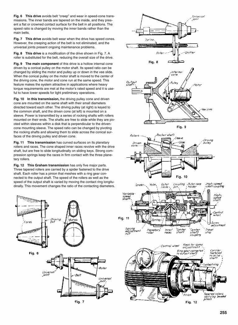
Fig. 6 This drive avoids belt “creep” and wear in speed-cone trans-missions. The inner bands are tapered on the inside, and they pres-ent a flat or crowned contact surface for the belt in all positions. Thespeed ratio is changed by moving the inner bands rather than themain belts.
Fig. 7 This drive avoids belt wear when the drive has speed cones.However, the creeping action of the belt is not eliminated, and theuniversal joints present ongoing maintenance problems.
Fig. 8 This drive is a modification of the drive shown in Fig. 7. Aroller is substituted for the belt, reducing the overall size of the drive.
Fig. 9 The main component of this drive is a hollow internal conedriven by a conical pulley on the motor shaft. Its speed ratio can bechanged by sliding the motor and pulley up or down in the vee slide.When the conical pulley on the motor shaft is moved to the center ofthe driving cone, the motor and cone run at the same speed. Thisfeature makes the system attractive in applications where heavytorque requirements are met at the motor’s rated speed and it is use-ful to have lower speeds for light preliminary operations.
Fig. 10 In this transmission, the driving pulley cone and drivencone are mounted on the same shaft with their small diametersdirected toward each other. The driving pulley (at right) is keyed tothe common shaft, and the driven cone (at left) is mounted on asleeve. Power is transmitted by a series of rocking shafts with rollersmounted on their ends. The shafts are free to slide while they are piv-oted within sleeves within a disk that is perpendicular to the driven-cone mounting sleeve. The speed ratio can be changed by pivotingthe rocking shafts and allowing them to slide across the conical sur-faces of the driving pulley and driven cone.
Fig. 11 This transmission has curved surfaces on its planetaryrollers and races. The cone shaped inner races revolve with the driveshaft, but are free to slide longitudinally on sliding keys. Strong com-pression springs keep the races in firm contact with the three plane-tary rollers.
Fig. 12 This Graham transmission has only five major parts.Three tapered rollers are carried by a spider fastened to the driveshaft. Each roller has a pinion that meshes with a ring gear con-nected to the output shaft. The speed of the rollers as well as thespeed of the output shaft is varied by moving the contact ring longitu-dinally. This movement changes the ratio of the contacting diameters.
255
Sclater Chapter 8 5/3/01 12:43 PM Page 255
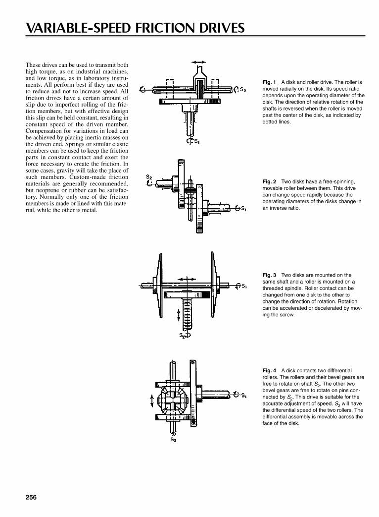
256
VARIABLE-SPEED FRICTION DRIVES
Fig. 2 Two disks have a free-spinning,movable roller between them. This drivecan change speed rapidly because theoperating diameters of the disks change inan inverse ratio.
Fig. 3 Two disks are mounted on thesame shaft and a roller is mounted on athreaded spindle. Roller contact can bechanged from one disk to the other tochange the direction of rotation. Rotationcan be accelerated or decelerated by mov-ing the screw.
These drives can be used to transmit bothhigh torque, as on industrial machines,and low torque, as in laboratory instru-ments. All perform best if they are usedto reduce and not to increase speed. Allfriction drives have a certain amount ofslip due to imperfect rolling of the fric-tion members, but with effective designthis slip can be held constant, resulting inconstant speed of the driven member.Compensation for variations in load canbe achieved by placing inertia masses onthe driven end. Springs or similar elasticmembers can be used to keep the frictionparts in constant contact and exert theforce necessary to create the friction. Insome cases, gravity will take the place ofsuch members. Custom-made frictionmaterials are generally recommended,but neoprene or rubber can be satisfac-tory. Normally only one of the frictionmembers is made or lined with this mate-rial, while the other is metal.
Fig. 1 A disk and roller drive. The roller ismoved radially on the disk. Its speed ratiodepends upon the operating diameter of thedisk. The direction of relative rotation of theshafts is reversed when the roller is movedpast the center of the disk, as indicated bydotted lines.
Fig. 4 A disk contacts two differentialrollers. The rollers and their bevel gears arefree to rotate on shaft S2. The other twobevel gears are free to rotate on pins con-nected by S2. This drive is suitable for theaccurate adjustment of speed. S2 will havethe differential speed of the two rollers. Thedifferential assembly is movable across theface of the disk.
Sclater Chapter 8 5/3/01 12:43 PM Page 256
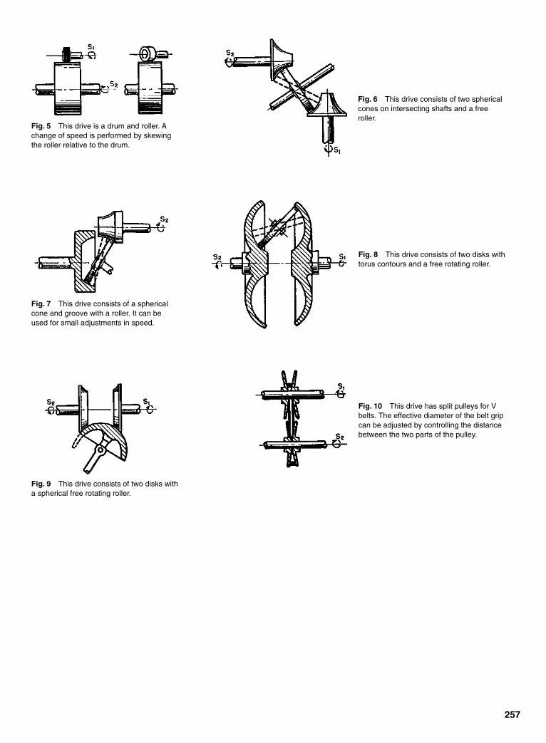
257
Fig. 5 This drive is a drum and roller. Achange of speed is performed by skewingthe roller relative to the drum.
Fig. 6 This drive consists of two sphericalcones on intersecting shafts and a freeroller.
Fig. 7 This drive consists of a sphericalcone and groove with a roller. It can beused for small adjustments in speed.
Fig. 8 This drive consists of two disks withtorus contours and a free rotating roller.
Fig. 9 This drive consists of two disks witha spherical free rotating roller.
Fig. 10 This drive has split pulleys for Vbelts. The effective diameter of the belt gripcan be adjusted by controlling the distancebetween the two parts of the pulley.
Sclater Chapter 8 5/3/01 12:43 PM Page 257

Fig. 1 This variable-speed drive is suitable only for very light dutyin a laboratory or for experimental work. The drive rod receivesmotion from the drive shaft and it rocks the lever. A friction clutch isformed in a lathe by winding wire around a drill rod whose diameter isslightly larger than the diameter of the driven shaft. The speed ratiocan be changed when the drive is stationary by varying the length ofthe rods or the throw of the eccentric.
Fig. 2 This Torrington lubricator drive illustrates the general prin-ciples of ratchet transmission drives. Reciprocating motion from aconvenient sliding part, or from an eccentric, rocks the ratchet lever.That motion gives the variable-speed shaft an intermittent unidirec-tional motion. The speed ratio can be changed only when the unit isstationary. The throw of the ratchet lever can be varied by placing afork of the driving rod in a different hole.
Fig. 3 This drive is an extension of the principle illustrated in Fig. 2.The Lenney transmission replaces the ratchet with an over-runningclutch. The speed of the driven shaft can be varied while the unit is inmotion by changing the position of the connecting-lever fulcrum.
Fig. 4 This transmission is based on the principle shown in Fig. 3.The crank disk imparts motion to the connecting rod. The crossheadmoves toggle levers which, in turn, give unidirectional motion to theclutch wheel when the friction pawls engage in a groove. The speedratio is changed by varying the throw of the crank with the aid of arack and pinion.
Fig. 5 This is a variable speed transmission for gasoline-powered railroad section cars. The connecting rod from the crank,mounted on a constant-speed shaft, rocks the oscillating lever andactuates the over-running clutch. This gives intermittent but unidirec-tional motion to the variable-speed shaft. The toggle link keeps theoscillating lever within the prescribed path. The speed ratio ischanged by swinging the bell crank toward the position shown in thedotted lines, around the pivot attached to the frame. This varies themovement of the over-running clutch. Several units must be out-of-phase with each other for continuous shaft motion.
258
VARIABLE-SPEED DRIVES AND TRANSMISSIONSThese ratchet and inertial drives providevariable-speed driving of heavy and lightloads.
Sclater Chapter 8 5/3/01 12:43 PM Page 258

Fig. 6 This Thomas transmission is an integral part of an automo-bile engine whose piston motion is transferred by a conventional con-necting rod to the long arm of the bellcrank lever oscillating about afixed fulcrum. A horizontal connecting rod, which rotates the crank-shaft, is attached to the short arm of the bellcrank. Crankshaft motionis steadily and continuously maintained by a flywheel. However, nopower other than that required to drive auxiliaries is taken from thisshaft. The main power output is transferred from the bellcrank leverto the over-running clutch by a third connecting rod. The speed ratiois changed by sliding the top end of the third connecting rod withinthe bellcrank lever with a crosshead and guide mechanism. The high-est ratio is obtained when the crosshead is farthest from the fulcrum,and movement of the crosshead toward the fulcrum reduces the ratiountil a “neutral” position is reached. That occurs when the center lineof the connecting rod coincides with the fulcrum.
Fig. 7 This Constantino torque converter is another automotivetransmission system designed and built as part of the engine. It fea-tures an inherently automatic change of speed ratio that tracks thespeed and load on the engine. The constant-speed shaft rotates acrank which, in turn, drives two oscillating levers with inertia weightsat their ends. The other ends are attached by links to the rockinglevers. These rocking levers include over-running clutches. At lowengine speeds, the inertia weights oscillate through a wide angle. Asa result, the reaction of the inertia force on the other end of the leveris very slight, and the link imparts no motion to the rocker lever.Engine speed increases cause the inertia weight reaction to increase.This rocks the small end of the oscillating lever as the crank rotates.The resulting motion rocks the rocking lever through the link, and thevariable shaft is driven in one direction.
Fig. 8 This transmission has a differential gear with an adjustableescapement. This arrangement bypasses a variable portion of thedrive-shaft revolutions. A constant-speed shaft rotates a freelymounted worm wheel that carries two pinion shafts. The firmly fixedpinions on these shafts, in turn, rotate the sun gear that meshes withother planetary gears. This mechanism rotates the small worm gearattached to the variable-speed output shaft.
Fig. 9 This Morse transmission has an eccentric cam integral withits constant-speed input shaft. It rocks three ratchet clutches througha series of linkage systems containing three rollers that run in a circu-lar groove cut in the cam face. Unidirectional motion is transmitted tothe output shaft from the clutches by planetary gearing. The speedratio is changed by rotating an anchor ring containing a fulcrum oflinks, thus varying the stroke of the levers.
259
Sclater Chapter 8 5/3/01 12:43 PM Page 259
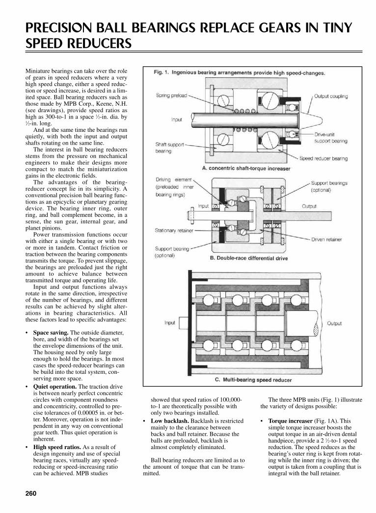
260
PRECISION BALL BEARINGS REPLACE GEARS IN TINYSPEED REDUCERS
Miniature bearings can take over the roleof gears in speed reducers where a veryhigh speed change, either a speed reduc-tion or speed increase, is desired in a lim-ited space. Ball bearing reducers such asthose made by MPB Corp., Keene, N.H.(see drawings), provide speed ratios ashigh as 300-to-1 in a space 1⁄2-in. dia. by1⁄2-in. long.
And at the same time the bearings runquietly, with both the input and outputshafts rotating on the same line.
The interest in ball bearing reducersstems from the pressure on mechanicalengineers to make their designs morecompact to match the miniaturizationgains in the electronic fields.
The advantages of the bearing-reducer concept lie in its simplicity. Aconventional precision ball bearing func-tions as an epicyclic or planetary gearingdevice. The bearing inner ring, outerring, and ball complement become, in asense, the sun gear, internal gear, andplanet pinions.
Power transmission functions occurwith either a single bearing or with twoor more in tandem. Contact friction ortraction between the bearing componentstransmits the torque. To prevent slippage,the bearings are preloaded just the rightamount to achieve balance betweentransmitted torque and operating life.
Input and output functions alwaysrotate in the same direction, irrespectiveof the number of bearings, and differentresults can be achieved by slight alter-ations in bearing characteristics. Allthese factors lead to specific advantages:
• Space saving. The outside diameter,bore, and width of the bearings setthe envelope dimensions of the unit.The housing need by only largeenough to hold the bearings. In mostcases the speed-reducer bearings canbe build into the total system, con-serving more space.
• Quiet operation. The traction driveis between nearly perfect concentriccircles with component roundnessand concentricity, controlled to pre-cise tolerances of 0.00005 in. or bet-ter. Moreover, operation is not inde-pendent in any way on conventionalgear teeth. Thus quiet operation isinherent.
• High speed ratios. As a result ofdesign ingenuity and use of specialbearing races, virtually any speed-reducing or speed-increasing ratiocan be achieved. MPB studies
showed that speed ratios of 100,000-to-1 are theoretically possible withonly two bearings installed.
• Low backlash. Backlash is restrictedmainly to the clearance betweenbacks and ball retainer. Because theballs are preloaded, backlash isalmost completely eliminated.
Ball bearing reducers are limited as tothe amount of torque that can be trans-mitted.
The three MPB units (Fig. 1) illustratethe variety of designs possible:
• Torque increaser (Fig. 1A). Thissimple torque increaser boosts theoutput torque in an air-driven dentalhandpiece, provide a 2 1⁄2-to-1 speedreduction. The speed reduces as thebearing’s outer ring is kept from rotat-ing while the inner ring is driven; theoutput is taken from a coupling that isintegral with the ball retainer.
Sclater Chapter 8 5/3/01 12:43 PM Page 260
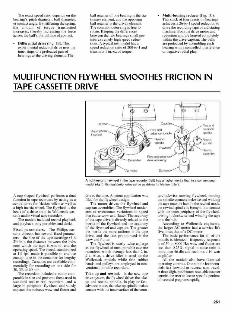
The exact speed ratio depends on thebearing’s pitch diameter, ball diameter,or contact angle. By stiffening the spring,the amount of torque transmittedincreases, thereby increasing the forceacross the ball’s normal line of contact.
• Differential drive (Fig. 1B). Thisexperimental reduction drive uses theinner rings of a preloaded pair ofbearings as the driving element. The
ball retainer of one bearing is the sta-tionary element, and the opposingball retainer is the driven element.The common outer ring is free torotate. Keeping the differencesbetween the two bearings small per-mits extremely high speed reduc-tions. A typical test model has aspeed reduction ratio of 200-to-1 andtransmits 1 in.-oz of torque.
• Multi-bearing reducer (Fig. 1C).This stack of four precision bearingsachieves a 26-to-1 speed reduction todrive the recording tape of a dictatingmachine. Both the drive motor andreduction unit are housed completelywithin the drive capstan. The ballsare preloaded by assembling eachbearing with a controlled interferenceor negative radial play.
261
MULTIFUNCTION FLYWHEEL SMOOTHES FRICTION INTAPE CASSETTE DRIVE
A cup-shaped flywheel performs a dualfunction in tape recorders by acting as acentral drive for friction rollers as well asa high inertia wheel. The flywheel is theheart of a drive train in Wollensak cas-sette audio-visual tape recorders.
The models included record-playbackand playback-only portables and decks.
Fixed parameters. The Philips cas-sette concept has several fixed parame-ters—the size of the tape cartridge (4 ×21⁄2 in.), the distance between the hubsonto which the tape is wound, and theoperating speed. The speed, standardizedat 17⁄8 ips, made it possible to encloseenough tape in the container for lengthyrecordings. Cassettes are available com-mercially for recording on one side for30, 35, or 60 min.
The recorders included a motor com-parable in size and power to those used instandard reel-to-reel recorders, and alarge bi-peripheral flywheel and sturdycapstan that reduces wow and flutter and
drives the tape. A patent application wasfiled for the flywheel design.
The motor drives the flywheel andcapstan assemblies. The flywheel moder-ates or overcomes variations in speedthat cause wow and flutter. The accuracyof the tape drive is directly related to theinertia of the flywheel and the accuracyof the flywheel and capstan. The greaterthe inertia the more uniform is the tapedrive, and the less pronounced is thewow and flutter.
The flywheel is nearly twice as largeas the flywheel of most portable cassetterecorders, which average less than 2 in.dia. Also, a drive idler is used on theWollensak models while thin rubberbands and pulleys are employed in con-ventional portable recorders.
Take-up and rewind. In the new tapedrive system, the flywheel drives the take-up and rewind spindle. In play or fast-advance mode, the take-up spindle makescontact with the inner surface of the coun-
terclockwise moving flywheel, movingthe spindle counterclockwise and windingthe tape onto the hub. In the rewind mode,the rewind spindle is brought into contactwith the outer periphery of the flywheel,driving it clockwise and winding the tapeonto the hub.
According to Wollensak engineers,the larger AC motor had a service lifefive times that of a DC motor.
The basic performance for all of themodels is identical: frequency responseis of 50 to 8000 Hz; wow and flutter areless than 0.25%; signal-to-noise ratio ismore than 46 db; and each has a 10-wattamplifier.
All the models also have identicaloperating controls. One simple lever con-trols fast forward or reverse tape travel.A three-digit, pushbutton-resettable counterpermits the user to locate specific portionsof recorded programs rapidly.
A lightweight flywheel in the tape recorder (left) has a higher inertia than in a conventionalmodel (right). Its dual peripheries serve as drives for friction rollers.
Sclater Chapter 8 5/3/01 12:43 PM Page 261
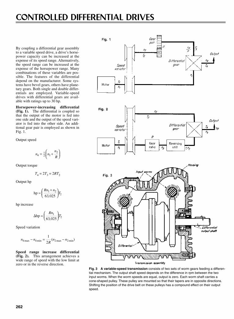
262
CONTROLLED DIFFERENTIAL DRIVES
By coupling a differential gear assemblyto a variable speed drive, a drive’s horse-power capacity can be increased at theexpense of its speed range. Alternatively,the speed range can be increased at theexpense of the horsepower range. Manycombinations of these variables are pos-sible. The features of the differentialdepend on the manufacturer. Some sys-tems have bevel gears, others have plane-tary gears. Both single and double differ-entials are employed. Variable-speeddrives with differential gears are avail-able with ratings up to 30 hp.
Horsepower-increasing differential(Fig. 1). The differential is coupled sothat the output of the motor is fed intoone side and the output of the speed vari-ator is fed into the other side. An addi-tional gear pair is employed as shown inFig. 1.
Output speed
Output torque
T4 = 2T3 = 2RT2
Output hp
hp increase
Speed variation
Speed range increase differential(Fig. 2). This arrangement achieves awide range of speed with the low limit atzero or in the reverse direction.
n nR
n n4 4 2 21
2max min max min( )− = −
�hp =
RnT1
263 025,
hp =+
Rn nT1 2
263 025,
n nn
R412 1
2= +
Fig. 3 A variable-speed transmission consists of two sets of worm gears feeding a differen-tial mechanism. The output shaft speed depends on the difference in rpm between the twoinput worms. When the worm speeds are equal, output is zero. Each worm shaft carries acone-shaped pulley. These pulley are mounted so that their tapers are in opposite directions.Shifting the position of the drive belt on these pulleys has a compound effect on their outputspeed.
Sclater Chapter 8 5/3/01 12:43 PM Page 262

263
TWIN-MOTOR PLANETARY GEARS PROVIDE SAFETYPLUS DUAL-SPEED
Many operators and owners of hoists andcranes fear the possible catastrophicdamage that can occur if the drivingmotor of a unit should fail for any reason.One solution to this problem is to feedthe power of two motors of equal ratinginto a planetary gear drive.
Power supply. Each of the motors isselected to supply half the required out-put power to the hoisting gear (see dia-gram). One motor drives the ring gear,which has both external and internalteeth. The second motor drives the sungear directly.
Both the ring gear and sun gear rotatein the same direction. If both gears rotateat the same speed, the planetary cage,which is coupled to the output, will alsorevolve at the same speed (and in thesame direction). It is as if the entire innerworks of the planetary were fusedtogether. There would be no relativemotion. Then, if one motor fails, the cagewill revolve at half its original speed, andthe other motor can still lift with undi-minished capacity. The same principleholds true when the ring gear rotatesmore slowly than the sun gear.
No need to shift gears. Anotheradvantage is that two working speedsare available as a result of a simpleswitching arrangement. This makes is
unnecessary to shift gears to obtaineither speed.
The diagram shows an installation fora steel mill crane.
Power flow from two motors combine in a planetary that drives the cable drum.
HARMONIC-DRIVE SPEED REDUCERS
Fig. 1 Exploded view of a typical harmonic drive showing itsprincipal parts. The flexspline has a smaller outside diameter thanthe inside diameter of the circular spline, so the elliptical wave gen-erator distorts the flexspline so that its teeth, 180º apart, mesh.
The harmonic-drive speed reducer was invented in the 1950s at theHarmonic Drive Division of the United Shoe MachineryCorporation, Beverly, Massachusetts. These drives have been speci-fied in many high-performance motion-control applications.Although the Harmonic Drive Division no longer exists, the manu-facturing rights to the drive have been sold to several Japanese man-ufacturers, so they are still made and sold. Most recently, the driveshave been installed in industrial robots, semiconductor manufactur-ing equipment, and motion controllers in military and aerospaceequipment.
The history of speed-reducing drives dates back more than 2000years. The first record of reducing gears appeared in the writings ofthe Roman engineer Vitruvius in the first century B.C. He describedwooden-tooth gears that coupled the power of water wheel to mill-stones for grinding corn. Those gears offered about a 5 to 1 reduction.In about 300 B.C., Aristotle, the Greek philosopher and mathemati-cian, wrote about toothed gears made from bronze.
In 1556, the Saxon physician, Agricola, described geared, horse-drawn windlasses for hauling heavy loads out of mines in Bohemia.Heavy-duty cast-iron gear wheels were first introduced in the mid-eighteenth century, but before that time gears made from brass andother metals were included in small machines, clocks, and militaryequipment.
Sclater Chapter 8 5/3/01 12:43 PM Page 263
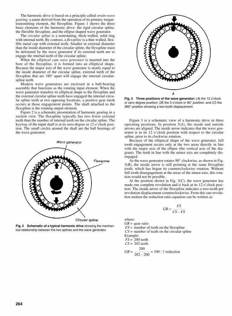
The harmonic drive is based on a principle called strain-wavegearing, a name derived from the operation of its primary torque-transmitting element, the flexspline. Figure 1 shows the threebasic elements of the harmonic drive: the rigid circular spline,the fliexible flexspline, and the ellipse-shaped wave generator.
The circular spline is a nonrotating, thick-walled, solid ringwith internal teeth. By contrast, a flexspline is a thin-walled, flex-ible metal cup with external teeth. Smaller in external diameterthan the inside diameter of the circular spline, the flexspline mustbe deformed by the wave generator if its external teeth are toengage the internal teeth of the circular spline.
When the elliptical cam wave generator is inserted into thebore of the flexspline, it is formed into an elliptical shape.Because the major axis of the wave generator is nearly equal tothe inside diameter of the circular spline, external teeth of theflexspline that are 180° apart will engage the internal circular-spline teeth.
Modern wave generators are enclosed in a ball-bearingassembly that functions as the rotating input element. When thewave generator transfers its elliptical shape to the flexspline andthe external circular spline teeth have engaged the internal circu-lar spline teeth at two opposing locations, a positive gear meshoccurs at those engagement points. The shaft attached to theflexspline is the rotating output element.
Figure 2 is a schematic presentation of harmonic gearing in asection view. The flexspline typically has two fewer externalteeth than the number of internal teeth on the circular spline. Thekeyway of the input shaft is at its zero-degree or 12 o’clock posi-tion. The small circles around the shaft are the ball bearings ofthe wave generator.
264
Fig. 2 Schematic of a typical harmonic drive showing the mechan-ical relationship between the two splines and the wave generator.
Fig. 3 Three positions of the wave generator: (A) the 12 o’clockor zero degree position; (B) the 3 o’clock or 90° position; and (C) the360° position showing a two-tooth displacement.
Figure 3 is a schematic view of a harmonic drive in threeoperating positions. In position 3(A), the inside and outsidearrows are aligned. The inside arrow indicates that the wave gen-erator is in its 12 o’clock position with respect to the circularspline, prior to its clockwise rotation.
Because of the elliptical shape of the wave generator, fulltooth engagement occurs only at the two areas directly in linewith the major axis of the ellipse (the vertical axis of the dia-gram). The teeth in line with the minor axis are completely dis-engaged.
As the wave generator rotates 90° clockwise, as shown in Fig.3(B), the inside arrow is still pointing at the same flexsplinetooth, which has begun its counterclockwise rotation. Withoutfull tooth disengagement at the areas of the minor axis, this rota-tion would not be possible.
At the position shown in Fig. 3(C), the wave generator hasmade one complete revolution and is back at its 12 o’clock posi-tion. The inside arrow of the flexspline indicates a two-tooth perrevolution displacement counterclockwise. From this one revolu-tion motion the reduction ratio equation can be written as:
where:GR = gear ratioFS = number of teeth on the flexsplineCS = number of teeth on the circular splineExample:FS = 200 teethCS = 202 teeth
GR = = 100 : 1 reduction200
202 200−
GRFS
CS FS=
−
Sclater Chapter 8 5/3/01 12:43 PM Page 264

As the wave generator rotates and flexes the thin-walledspline, the teeth move in and out of engagement in a rotatingwave motion. As might be expected, any mechanical componentthat is flexed, such as the flexspline, is subject to stress andstrain.
Advantages and Disadvantages
The harmonic drive was accepted as a high-performance speedreducer because of its ability to position moving elements pre-cisely. Moreover, there is no backlash in a harmonic drivereducer. Therefore, when positioning inertial loads, repeatabilityand resolution are excellent (one arc-minute or less).
Because the harmonic drive has a concentric shaft arrange-ment, the input and output shafts have the same centerline. Thisgeometry contributes to its compact form factor. The ability ofthe drive to provide high reduction ratios in a single pass withhigh torque capacity recommends it for many machine designs.The benefits of high mechanical efficiency are high torquecapacity per pound and unit of volume, both attractive perform-ance features.
One disadvantage of the harmonic drive reducer has been itswind-up or torsional spring rate. The design of the drive’s tooth
265
form necessary for the proper meshing of the flexspline and thecircular spline permits only one tooth to be completely engagedat each end of the major elliptical axis of the generator. Thisdesign condition is met only when there is no torsional load.However, as torsional load increases, the teeth bend slightly andthe flexspline also distorts slightly, permitting adjacent teeth toengage.
Paradoxically, what could be a disadvantage is turned into anadvantage because more teeth share the load. Consequently, withmany more teeth engaged, torque capacity is higher, and there isstill no backlash. However, this bending and flexing causes tor-sional wind-up, the major contributor to positional error in har-monic-drive reducers.
At least one manufacturer claims to have overcome this prob-lem with redesigned gear teeth. In a new design, one companyreplaced the original involute teeth on the flexspline and circularspline with noninvolute teeth. The new design is said to reducestress concentration, double the fatigue limit, and increase thepermissible torque rating.
The new tooth design is a composite of convex and concavearcs that match the loci of engagement points. The new toothwidth is less than the width of the tooth space and, as a result ofthese dimensions and proportions, the root fillet radius is larger.
Sclater Chapter 8 5/3/01 12:43 PM Page 265

266
FLEXIBLE FACE-GEARS MAKE EFFICIENT HIGH-REDUCTION DRIVES
A system of flexible face-gearing pro-vides designers with a means for obtain-ing high-ratio speed reductions in com-pact trains with concentric input andoutput shafts.
With this approach, reduction ratiosrange from 10:1 to 200:1 for single-stagereducers, whereas ratios of millions toone are possible for multi-stage trains.Patents on the flexible face-gear reducerswere held by Clarence Slaughter ofGrand Rapids, Michigan.
Building blocks. Single-stage gearreducers consist of three basic parts: aflexible face-gear made of plastic or thinmetal; a solid, non-flexing face-gear; anda wave former with one or more slidersand rollers to force the flexible gear intomesh with the solid gear at points wherethe teeth are in phase.
The high-speed input to the systemusually drives the wave former. Low-speed output can be derived from eitherthe flexible or the solid face gear; thegear not connected to the output is fixedto the housing.
Teeth make the difference. Motionbetween the two gears depends on aslight difference in their number of teeth(usually one or two teeth). But driveswith gears that have up to a difference of10 teeth have been devised.
On each revolution of the wave for-mer, there is a relative motion between
the two gears that equals the difference intheir numbers of teeth. The reductionratio equals the number of teeth in theoutput gear divided by the difference intheir numbers of teeth.
Two-stage and four-stage gear reduc-ers are made by combining flexible and
solid gears with multiple rows of teethand driving the flexible gears with acommon wave former.
Hermetic sealing is accomplished bymaking the flexible gear serve as a fullseal and by taking output rotation fromthe solid gear.
A flexible face-gear is flexed by a rotating wave former into contact with a solid gear at pointof mesh. The two gears have slightly different numbers of teeth.
A two-stage speed reducer is driven by a common-wave formeroperating against an integral flexible gear for both stages.
A four-stage speed reducer can, theoretically, attain reductions ofmillions to one. The train is both compact and simple.
Sclater Chapter 8 5/3/01 12:43 PM Page 266

267
COMPACT ROTARY SEQUENCERTwo coaxial rotations, one clockwise and one counterclockwise, are derived from a single clockwise rotation.
A proposed rotary sequencer is assem-bled from a conventional planetary dif-ferential gearset and a latching mecha-nism. Its single output and two rotaryoutputs (one clockwise and one counter-clockwise) are coaxial, and the outputtorque is constant over the entire cycle.Housed in a lightweight, compact, cylin-drical package, the sequencer requires nobulky ratchets, friction clutches, or cam-and-track followers. Among its possibleapplications are sequencing in automatedproduction-line equipment, in homeappliances, and in vehicles.
The sequencer is shown in Figure 1. Asun gear connects with four planetarygears that engage a ring gear. With thering gear held stationary, clockwise rota-tion of the sun gear causes the entireplanetary-gear carrier also to rotateclockwise. If the planetary-gear carrier isheld fixed, the ring gear will rotate coun-terclockwise when the sun gear rotatesclockwise.
Figure 2 shows the latch. It consists ofa hook (the carrier hook) that is rigidlyattached to the planetary-gear carrier, arind that is rigidly attached to the ringgear, and a latch pivot arm with a pair oflatch rollers attached to one end. Theother end of the pivot arm rotates about ashort shaft that extends from the fixedwall of the housing.
The sequencer cycle starts with thering latch roller resting in a slot in thering. This locks the ring and causes theplanetary-gear carrier to rotate clockwise
with the input shaft (Fig. 2a). When thecarrier hook has rotated approximatelythree-quarters of a complete cycle, itbegins to engage the planet-carrier latchroller (Fig. 2b), causing the latch pivotarm to rotate and the ring latch roller toslip out of its slot (Fig. 2c). This frees thering and ring gear for counterclockwisemotion, while locking the carrier. After ashort interval of concurrent motion, theplanetary-gear output shaft ceases itsclockwise motion, and the ring-gear out-put shaft continues its clockwise motion.
When the ring reaches the position inFig. 2d, the cycle is complete, and theinput shaft is stopped. If required, the
input can then be rotated counterclock-wise, and the sequence will be reverseduntil the starting position (Fig. 2a) isreached again.
In a modified version of thesequencer, the latch pivot arm is short-ened until its length equals the radii ofthe rollers. This does away with the shortoverlap of output rotations when both arein motion. For this design, the carriermotion ceases before the ring begins itsrotation.
This work was done by Walter T.Appleberry of Rockwell InternationalCorp. for Johnson Space Center,Houston, Texas.
Fig. 1 The Rotary Sequencer has a ring-gear output (in color) that is coaxial with a plane-tary-gear output (in gray). Clockwise rotation of the input is converted to clockwise rotation ofthe planetary-gear output followed by counterclockwise rotation of the ring-gear output. Thesequence is controlled by the latch action described in Fig. 2.
Fig. 2 The Latch Sequence is shown in four steps: (a) The input shaft rotates the carrier clockwisewhile the ring latch roller holds the ring gear stationary; (b) the carrier hook begins to engage the car-rier latch roller; (c) the ring latch roller begins to move out of its slot, and the carrier motion ceaseswhile the ring begins to move; and (d) the sequence has ended with the ring in its final position.
Sclater Chapter 8 5/3/01 12:43 PM Page 267

268
PLANETARY GEAR SYSTEMSDesigners keep finding new and useful planetaries. Forty-eight popular types are given here with their speed-ratio equations.
Symbols
C = carrier (also called “spider”)—a non-gear member of a geartrain whose rotation affects gear ratio
N = number of teethR = overall speed reduction ratio
1, 2, 3, etc. = gears in a train (corresponding to labels onschematic diagram)
MISSILE SILO COVER DRIVE
DOUBLE-ECCENTRIC DRIVE
Input is through double-throw crank (carrier). Gear 1
Sclater Chapter 8 5/3/01 12:43 PM Page 268
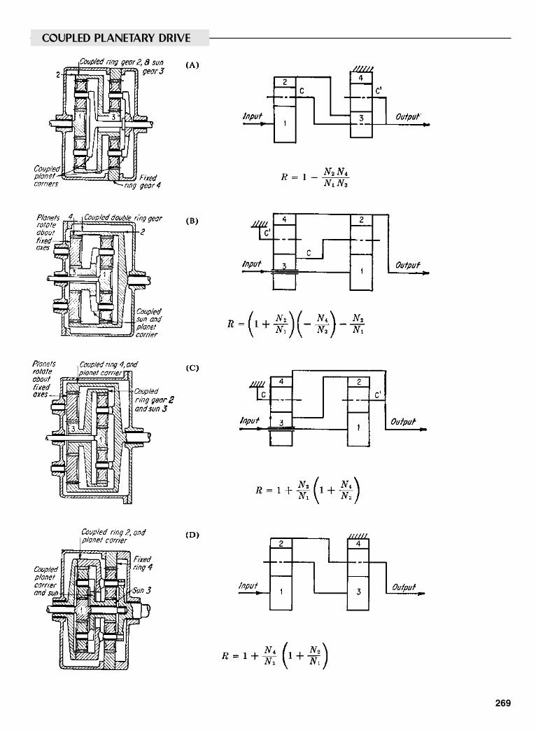
269
COUPLED PLANETARY DRIVE
Sclater Chapter 8 5/3/01 12:43 PM Page 269

FIXED-DIFFERENTIAL DRIVES
270
Output is differencebetween speeds oftwo parts leading tohigh reductionratios
Sclater Chapter 8 5/3/01 12:43 PM Page 270
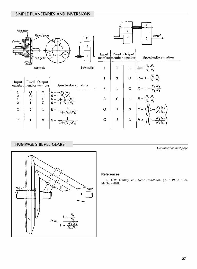
271
SIMPLE PLANETARIES AND INVERSIONS
HUMPAGE’S BEVEL GEARSContinued on next page
References
1. D. W. Dudley, ed., Gear Handbook, pp. 3-19 to 3-25,McGraw-Hill.
Sclater Chapter 8 5/3/01 12:43 PM Page 271

272
TWO-SPEED FORDOMATIC (Ford Motor Co.)
CRUISE-O-MATIC 3-SPEED TRANSMISSION (Ford Motor Co.)
HYDRAMATIC 3-SPEED TRANSMISSION (General Motors)
TRIPLE PLANETARY DRIVES
Sclater Chapter 8 5/3/01 12:43 PM Page 272
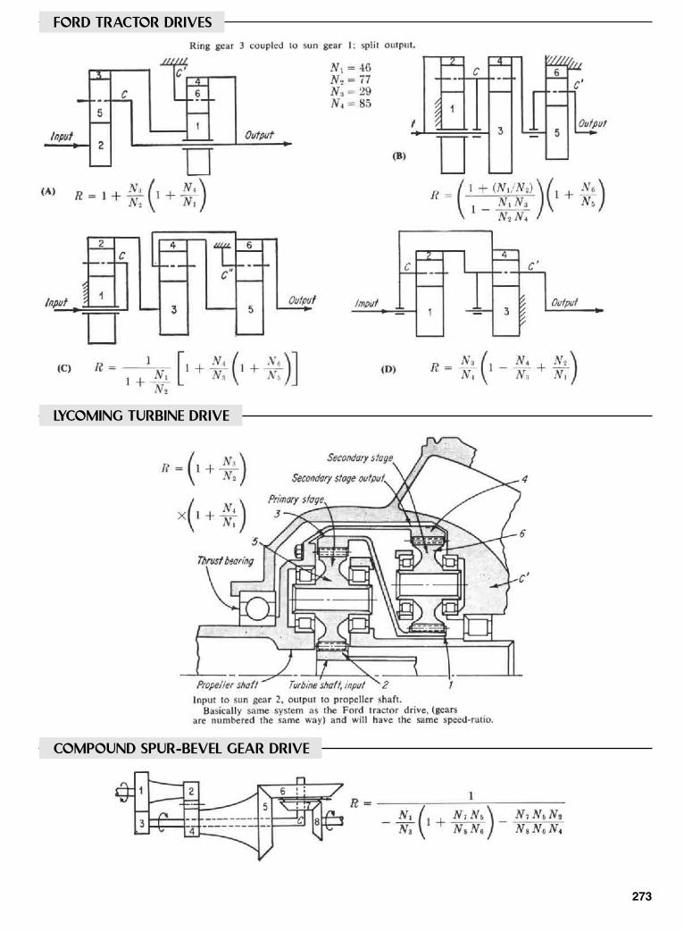
273
FORD TRACTOR DRIVES
LYCOMING TURBINE DRIVE
COMPOUND SPUR-BEVEL GEAR DRIVE
Sclater Chapter 8 5/3/01 12:44 PM Page 273

274
TWO-GEAR PLANETARY DRIVES
PLANOCENTRIC DRIVE
WOBBLE-GEAR DRIVE
Sclater Chapter 8 5/3/01 12:44 PM Page 274
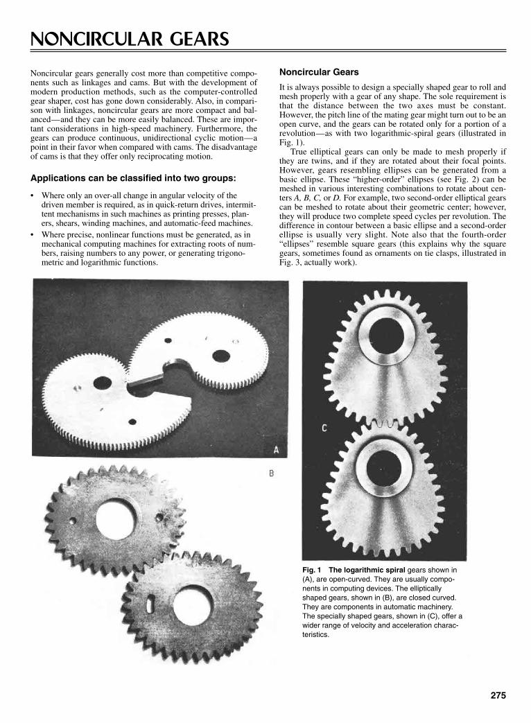
275
NONCIRCULAR GEARS
Noncircular gears generally cost more than competitive compo-nents such as linkages and cams. But with the development ofmodern production methods, such as the computer-controlledgear shaper, cost has gone down considerably. Also, in compari-son with linkages, noncircular gears are more compact and bal-anced—and they can be more easily balanced. These are impor-tant considerations in high-speed machinery. Furthermore, thegears can produce continuous, unidirectional cyclic motion—apoint in their favor when compared with cams. The disadvantageof cams is that they offer only reciprocating motion.
Applications can be classified into two groups:
• Where only an over-all change in angular velocity of thedriven member is required, as in quick-return drives, intermit-tent mechanisms in such machines as printing presses, plan-ers, shears, winding machines, and automatic-feed machines.
• Where precise, nonlinear functions must be generated, as inmechanical computing machines for extracting roots of num-bers, raising numbers to any power, or generating trigono-metric and logarithmic functions.
Noncircular Gears
It is always possible to design a specially shaped gear to roll andmesh properly with a gear of any shape. The sole requirement isthat the distance between the two axes must be constant.However, the pitch line of the mating gear might turn out to be anopen curve, and the gears can be rotated only for a portion of arevolution—as with two logarithmic-spiral gears (illustrated inFig. 1).
True elliptical gears can only be made to mesh properly ifthey are twins, and if they are rotated about their focal points.However, gears resembling ellipses can be generated from abasic ellipse. These “higher-order” ellipses (see Fig. 2) can bemeshed in various interesting combinations to rotate about cen-ters A, B, C, or D. For example, two second-order elliptical gearscan be meshed to rotate about their geometric center; however,they will produce two complete speed cycles per revolution. Thedifference in contour between a basic ellipse and a second-orderellipse is usually very slight. Note also that the fourth-order“ellipses” resemble square gears (this explains why the squaregears, sometimes found as ornaments on tie clasps, illustrated inFig. 3, actually work).
Fig. 1 The logarithmic spiral gears shown in(A), are open-curved. They are usually compo-nents in computing devices. The ellipticallyshaped gears, shown in (B), are closed curved.They are components in automatic machinery.The specially shaped gears, shown in (C), offer awider range of velocity and acceleration charac-teristics.
Sclater Chapter 8 5/3/01 12:44 PM Page 275

A circular gear, mounted eccentrically, can roll properlyonly with specially derived curves (shown in Fig. 4). One of thecurves, however, closely resembles an ellipse. For proper mesh,it must have twice as many teeth as the eccentric gear. Whenthe radiis r, and eccentricity, e, are known, the major semiaxisof the elliptically shaped gear becomes 2r + e, and the minor2r – e. Note also that one of the gears in this group must haveinternal teeth to roll with the eccentric gear. Actually, it is pos-sible to generate internal-tooth shapes to rotate with noncirculargears of any shape (but, again, the curves can be of the opentype).
Noncircular gears can also be designed to roll with speciallyshaped racks (shown in Fig. 5). Combinations include: an ellipti-
276
cal gear and a sinusoid-like rack. A third-order ellipse is illus-trated, but any of the elliptical rolling curves can be used in itsplace. The main advantage of those curves is that when theellipse rolls, its axis of rotation moves along a straight line; othercombinations include a logarithmic spiral and straight rack. Therack, however, must be inclined to its direction of motion by theangle of the spiral.
DESIGN EQUATIONS
Equations for noncircular gears are given here in functional formfor three common design requirements. They are valid for anynoncircular gear pair. Symbols are defined in the box.
Noncircular Gears (continued )
Fig. 2 Basic and High-Order Elliptical Gear Combinations.
Fig. 3 Square gears seem to defy basic kinematiclaws, but they are a takeoff on a pair of fourth-orderellipses.
Fig. 4 An eccentric spur gear rotating about point A, willmesh properly with any of the three gears shown whosecenters are at points B, C and D.
Sclater Chapter 8 5/3/01 12:44 PM Page 276
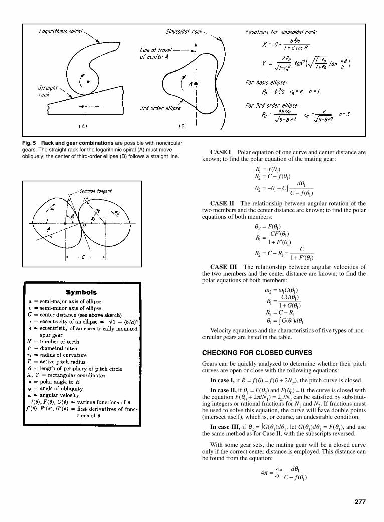
277
CASE I Polar equation of one curve and center distance areknown; to find the polar equation of the mating gear:
CASE II The relationship between angular rotation of thetwo members and the center distance are known; to find the polarequations of both members:
CASE III The relationship between angular velocities ofthe two members and the center distance are known; to find thepolar equations of both members:
Velocity equations and the characteristics of five types of non-circular gears are listed in the table.
CHECKING FOR CLOSED CURVES
Gears can be quickly analyzed to determine whether their pitchcurves are open or close with the following equations:
In case I, if R = f (θ) = f (θ + 2Nπ), the pitch curve is closed.
In case II, if θ1 = F(θ2) and F(θ0) = 0, the curve is closed withthe equation F(θ0 + 2π/N1) = 2π /N2 can be satisfied by substitut-ing integers or rational fractions for N1 and N2. If fractions mustbe used to solve this equation, the curve will have double points(intersect itself), which is, or course, an undesirable condition.
In case III, if θ2 = ∫G(θ1)dθ1, let G(θ1)dθ1 = F(θ1), and usethe same method as for Case II, with the subscripts reversed.
With some gear sets, the mating gear will be a closed curveonly if the correct center distance is employed. This distance canbe found from the equation:
4 1
102π θ
θπ=
−∫d
C f ( )
ω ω θθθ
θ θ θ
2 1 1
11
1
2 1
1 1 1
1
=
=+
= −= ∫
G
RCG
GR C R
G d
( )( )( )
( )
θ θθθ
θ
2 =
= ′+ ′
= − =+ ′
F
RCF
F
R C RCF
( )( )( )
( )
1
11
1
2 11
1
1
R fR C f
Cd
C f
1 1
2 1
2 11
1
== −
= − +−∫
( )( )
( )
θθ
θ θθ
θ
Fig. 5 Rack and gear combinations are possible with noncirculargears. The straight rack for the logarithmic spiral (A) must moveobliquely; the center of third-order ellipse (B) follows a straight line.
Sclater Chapter 8 5/3/01 12:44 PM Page 277
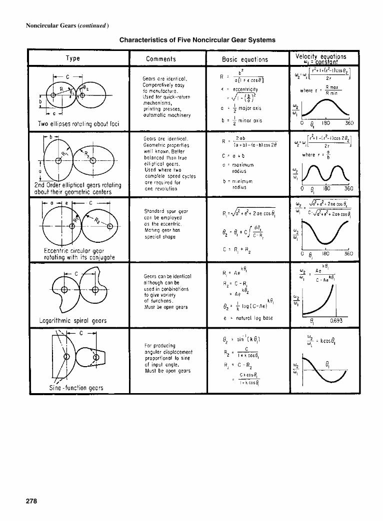
Noncircular Gears (continued )
Characteristics of Five Noncircular Gear Systems
278
Sclater Chapter 8 5/3/01 12:44 PM Page 278

279
SHEET-METAL GEARS, SPROCKETS, WORMS, AND RATCHETS
When a specified motion must be transmitted at intervals ratherthan continuously, and the loads are light, these mechanisms areideal because of their low cost and adaptability to mass produc-
tion. Although not generally considered precision parts, ratchetsand gears can be stamped to tolerances of ±0.007 in, and if nec-essary, shaved to close dimensions.
Fig. 1 The pinion is a sheet metal cup with rectangular holes serv-ing as teeth. The meshing gear is sheet metal, blanked with speciallyformed teeth. The pinion can be attached to another sheet metalwheel by prongs, as shown, to form a gear train.
Fig. 2 The sheet-metal wheel gear meshes with a wide-face pinion,which is either extruded or machined. The wheel is blanked withteeth of conventional form.
Fig. 3 The pinion mates with round pinson a circular disk made of metal, plastic orwood. The pins can be attached by stakingor with threaded fasteners.
Fig. 4 Two blanked gears, conically formed after blanking, becomebevel gears meshing on a parallel axis. Both have specially formedteeth.
Fig. 5 The horizontal wheel with waves on its out rim replacingteeth, meshes with either one or two sheet-metal pinions. They havespecially formed teeth and are mounted on intersecting axes.
Fig. 6 Two bevel-type gears, with specially formed teeth, aremounted on 90° intersecting axes. They can be attached by stakingthem to hubs.
Fig. 7 The blanked and formed bevel-type gear meshes with amachined or extruded pinion. Conventional teeth can be used onboth the gear and pinion.
Fig. 8 The blanked, cup-shaped wheel meshes with a solid pinionon 90° intersecting axes.
Fig. 9 Backlash can be eliminated from stamped gears by stackingtwo identical gears and displacing them by one tooth. The spring thenbears one projection on each gear, taking up lost motion.
Sclater Chapter 8 5/3/01 12:44 PM Page 279
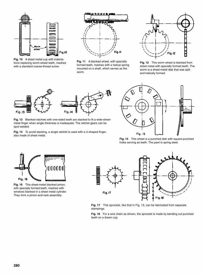
280
Fig. 10 A sheet metal cup with indenta-tions replacing worm-wheel teeth, mesheswith a standard coarse-thread screw.
Fig. 11 A blanked wheel, with speciallyformed teeth, meshes with a helical springmounted on a shaft, which serves as theworm.
Fig. 12 This worm wheel is blanked fromsheet metal with specially formed teeth. Theworm is a sheet-metal disk that was splitand helically formed.
Fig. 13 Blanked ratchets with one-sided teeth are stacked to fit a wide-sheet-metal finger when single thickness is inadequate. The ratchet gears can bespot-welded.
Fig. 14 To avoid stacking, a single ratchet is used with a U-shaped finger,also made of sheet metal.
Fig. 15 This wheel is a punched disk with square-punchedholes serving as teeth. The pawl is spring steel.
Fig. 16 This sheet-metal blanked pinion,with specially formed teeth, meshes withwindows blanked in a sheet metal cylinder.They form a pinion-and-rack assembly.
Fig. 17 This sprocket, like that in Fig. 13, can be fabricated from separatestampings.
Fig. 18 For a wire chain as shown, the sprocket is made by bending out punchedteeth on a drawn cup.
Sclater Chapter 8 5/3/01 12:44 PM Page 280
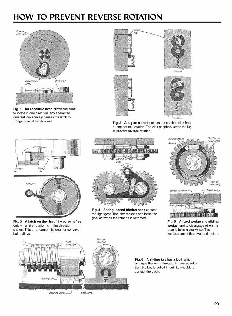
281
HOW TO PREVENT REVERSE ROTATION
Fig. 1 An eccentric latch allows the shaftto rotate in one direction; any attemptedreversal immediately causes the latch towedge against the disk wall. Fig. 2 A lug on a shaft pushes the notched disk free
during normal rotation. The disk periphery stops the lugto prevent reverse rotation.
Fig. 3 A latch on the rim of the pulley is freeonly when the rotation is in the directionshown. This arrangement is ideal for conveyor-belt pulleys.
Fig. 4 Spring-loaded friction pads contactthe right gear. The idler meshes and locks thegear set when the rotation is reversed.
Fig. 5 A fixed wedge and slidingwedge tend to disengage when thegear is turning clockwise. Thewedges jam in the reverse direction.
Fig. 6 A sliding key has a tooth whichengages the worm threads. In reverse rota-tion, the key is pulled in until its shoulderscontact the block.
Sclater Chapter 8 5/3/01 12:44 PM Page 281

282
GEAR-SHIFT ARRANGEMENTS13 ways of arranging gears and clutches to obtain changes in speed ratios
Fig. 1 The schematic symbols used in the followingillustrations to represent gears and clutches.
Fig. 2 Double-clutch drive.Two pairs of gears are perma-nently in mesh. Pair I or II trans-mits motion to the output shaftdepending on the position of thecoupling; the other pair idles.The coupling is shown in a neu-tral position with both gear pairsidle. Herring-bone gears are rec-ommended for quieter running.
Fig. 3 Sliding-change drive. Gears aremeshed by lateral sliding. Up to threegears can be mounted on a sliding sleeve.Only one pair is in mesh in any operatingposition. This drive is simpler, cheaper,and more extensively used than the driveof Fig. 2. Chamfering the sides of the teetheases their engagement.
Fig. 4 Swivel-gear drive.Output gears are fastened tothe shaft. A handle is pusheddown, then shifted laterally toobtain transmission through anyoutput gear. This drive is notsuitable for the transmission oflarge torques because theswivel gear tends to vibrate. Itsoverall ratio should not exceed1:3.
Fig. 5 Slide-key drive. Aspring-loaded slide key ridesinside a hollow output shaft. Theslide key snaps out of the shaftwhen it is in position to lock aspecific change gear to the out-put shaft. No central position isshown.
Fig. 6 This is a combination cou-pling and slide gears. It has threeratios: a direct mesh for ratios I and II;a third ratio is transmitted throughgears II and III, which couple together.
Fig. 7 Double-shift drive. One shift must always be ina neutral position. That might require both levers to beshifted when making a change. However, only twoshafts are used to achieve four ratios.
Sclater Chapter 8 5/3/01 12:44 PM Page 282

283
Fig. 8 A triple shaft drive gives four ratios. (A) The output of the first drive serves as the input forthe second. The presence of an intermediate shaft eliminates the requirement for ensuring that oneshift is always in the neutral position. A wrong shift-lever position cannot cause damage. (B) A space-saving modification; the coupling is on shaft A instead of the intermediate shaft. (C) Still more spaceis saved if one gear replaces a pair on the intermediate shaft. Ratios can be calculated to allow this.
Fig. 9 Six ratios are available with twocouplings and (A) ten gears, (B) eightgears. Up to six gears can be in perma-nent mesh. It is not necessary to ensurethat one shift is in neutral.
Fig. 10 This eight-ratio drive has twoslide gears and a coupling. This arrange-ment reduces the number of parts andmeshes. The position of shifts I and II areinterdependent. One shift must be in neutralif the other is in mesh.
Fig. 11 This drive has eightratios; a coupled gear driveand slide-key drive are inseries. Comparatively lowstrength of the slide key limitsthe drive to small torque.
Sclater Chapter 8 5/3/01 12:44 PM Page 283
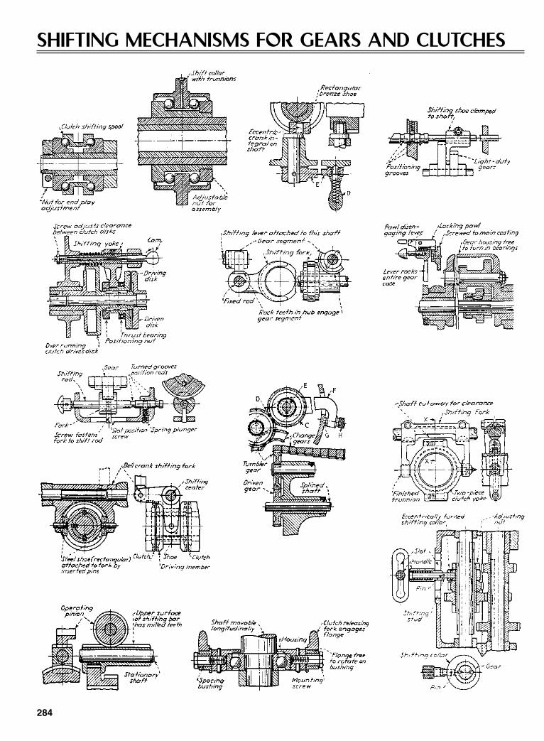
SHIFTING MECHANISMS FOR GEARS AND CLUTCHES
284
Sclater Chapter 8 5/3/01 12:44 PM Page 284

Spiderless differential
If you’ve ever been unable to drive yourcar out of a ditch because one wheel spunuselessly while the other sat torquelessand immobile, you’ll thank the inventors(Seliger and Hegar) of the limited-slipdifferential shown here.
In straight running, it performs as adrive axle, driven by the driveshaft pin-ion through the ring gear. The differentialaction occurs only when one wheel losestraction, travels along a different arc, orotherwise attempts to turn at a speed thatis different from that of the other. Thenthe wedge-type, two-way, over-runningclutch (second figure) disengages, free-ing the wheel to spin without drag.
Variations. Each clutch has three posi-tions: forward drive, idle, and reversedrive. Thus, there are many combina-tions of drive-idle, depending on roadconditions and turn direction. US Patent3,124,972 describes a few:
• For left turns, the left wheel is driv-ing, and the right wheel is forced toturn faster—thus over-running anddisengaging the clutch. A frictionring built into each clutch assemblydoes the shifting. Wear is negligible.
• If power should be removed from thedriveshaft during the left turn, thefriction rings will shift each clutchand cause the left wheel to run free
and the right wheel to drag in fullcoupling with the car’s driveshaft.
• If your car is on the straightaway,under power and one wheel is liftedout of contact with the road, the otherimmediately transmits full torque.(The conventional spider differentialperforms in the opposite manner.)
On or off. Note one limitation, how-ever: There is no gradual division ofpower. A wheel is either clutched in andturning at exactly the same speed as itsopposite, or it is clutched out. It is not thesame kind of mechanism as the conven-tional spider differential, which dividesthe driving load variably at any ratio ofspeeds.
285
Sclater Chapter 8 5/3/01 12:44 PM Page 285
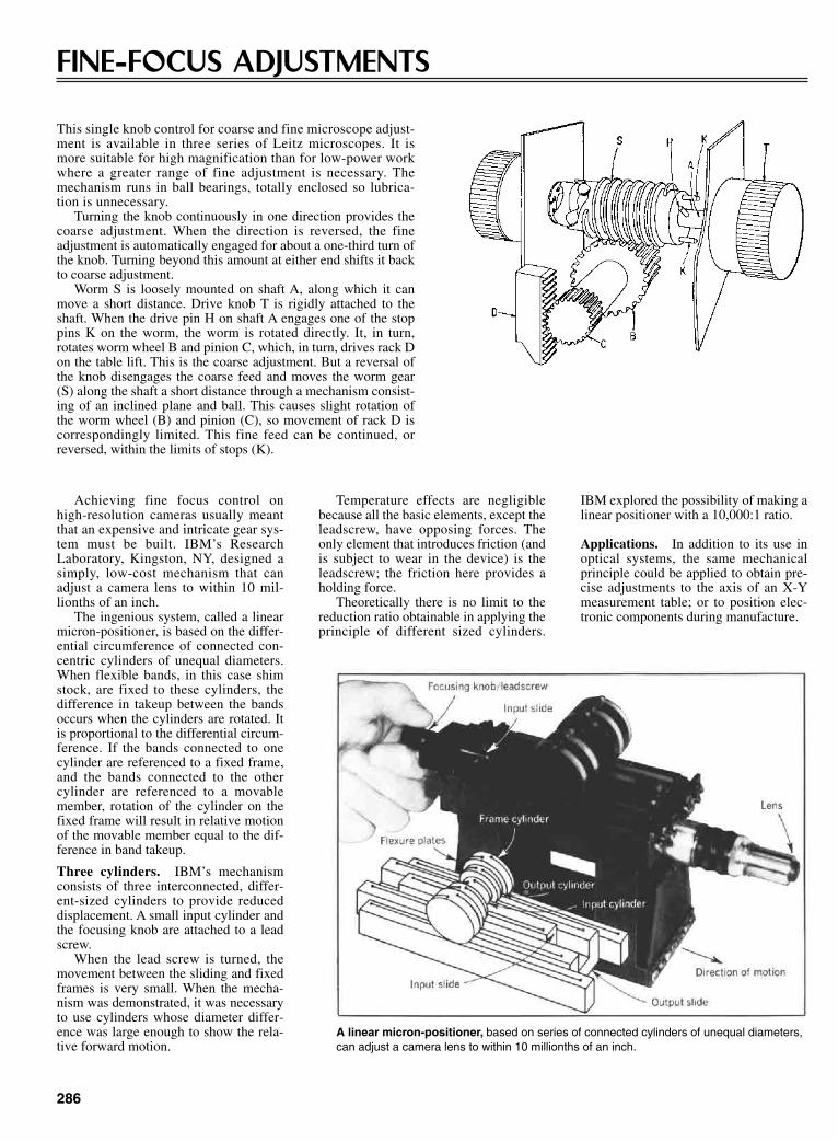
286
FINE-FOCUS ADJUSTMENTS
This single knob control for coarse and fine microscope adjust-ment is available in three series of Leitz microscopes. It ismore suitable for high magnification than for low-power workwhere a greater range of fine adjustment is necessary. Themechanism runs in ball bearings, totally enclosed so lubrica-tion is unnecessary.
Turning the knob continuously in one direction provides thecoarse adjustment. When the direction is reversed, the fineadjustment is automatically engaged for about a one-third turn ofthe knob. Turning beyond this amount at either end shifts it backto coarse adjustment.
Worm S is loosely mounted on shaft A, along which it canmove a short distance. Drive knob T is rigidly attached to theshaft. When the drive pin H on shaft A engages one of the stoppins K on the worm, the worm is rotated directly. It, in turn,rotates worm wheel B and pinion C, which, in turn, drives rack Don the table lift. This is the coarse adjustment. But a reversal ofthe knob disengages the coarse feed and moves the worm gear(S) along the shaft a short distance through a mechanism consist-ing of an inclined plane and ball. This causes slight rotation ofthe worm wheel (B) and pinion (C), so movement of rack D iscorrespondingly limited. This fine feed can be continued, orreversed, within the limits of stops (K).
Temperature effects are negligiblebecause all the basic elements, except theleadscrew, have opposing forces. Theonly element that introduces friction (andis subject to wear in the device) is theleadscrew; the friction here provides aholding force.
Theoretically there is no limit to thereduction ratio obtainable in applying theprinciple of different sized cylinders.
IBM explored the possibility of making alinear positioner with a 10,000:1 ratio.
Applications. In addition to its use inoptical systems, the same mechanicalprinciple could be applied to obtain pre-cise adjustments to the axis of an X-Ymeasurement table; or to position elec-tronic components during manufacture.
Achieving fine focus control onhigh-resolution cameras usually meantthat an expensive and intricate gear sys-tem must be built. IBM’s ResearchLaboratory, Kingston, NY, designed asimply, low-cost mechanism that canadjust a camera lens to within 10 mil-lionths of an inch.
The ingenious system, called a linearmicron-positioner, is based on the differ-ential circumference of connected con-centric cylinders of unequal diameters.When flexible bands, in this case shimstock, are fixed to these cylinders, thedifference in takeup between the bandsoccurs when the cylinders are rotated. Itis proportional to the differential circum-ference. If the bands connected to onecylinder are referenced to a fixed frame,and the bands connected to the othercylinder are referenced to a movablemember, rotation of the cylinder on thefixed frame will result in relative motionof the movable member equal to the dif-ference in band takeup.
Three cylinders. IBM’s mechanismconsists of three interconnected, differ-ent-sized cylinders to provide reduceddisplacement. A small input cylinder andthe focusing knob are attached to a leadscrew.
When the lead screw is turned, themovement between the sliding and fixedframes is very small. When the mecha-nism was demonstrated, it was necessaryto use cylinders whose diameter differ-ence was large enough to show the rela-tive forward motion.
A linear micron-positioner, based on series of connected cylinders of unequal diameters,can adjust a camera lens to within 10 millionths of an inch.
Sclater Chapter 8 5/3/01 12:44 PM Page 286

287
RATCHET-TOOTH SPEED-CHANGE DRIVE
An in-line shaft drive, with reduction ratios of 1:1 and 1:16 or1:28, combined in a single element, was designed by Telefunkenof Germany. It consists basically of friction wheels that drip eachother elastically.
Crown wheel with a gear ratio of 1:1 provide the coarseadjustment, and friction spur gearing, with a ratio of 1:16 or 1:28,provides the fine or vernier adjustment.
A spring (see diagram) applies pressure to the fine-adjustmentpinion, preventing backlash while the coarse adjustment is inuse. It uncouples the coarse adjustment when the vernier isbrought into play by forward movement of the front shaft. Thespring also ensures that the front shaft is always in gear.
TWINWORM GEAR DRIVE
The term “self-locking” as applied to gear systems denotes adrive that gives the input gear freedom to rotate the output gear ineither direction. But the output gear locks with the input when anoutside torque attempts to rotate the output in either direction.This characteristic is often sought by designers who want to besure that loads on the output side of the system cannot affect theposition of the gears. Worm gears are one of the few gear systemsthat can be made self-locking, but at the expense of efficiency. Itseldom exceeds 40% when the gears are self-locking.
An Israeli engineer, B. Popper, invented a simple dual-wormgear system that not only provided self-locking with over 90%efficiency, but exhibited a phenomenon which the inventor calls“deceleration-locking.”
The “Twinworm” drive has been employed in Israel-designedcounters and computers for years with marked success.
The Twinworm drive is simply constructed. Two threadedrods, or “worm” screws, are meshed together. Each worm iswound in a different direction and has a different pitch angle. Forproper mesh, the worm axes are not parallel, but slightly skewed.(If both worms had the same pitch angle, a normal, reversibledrive would result—similar to helical gears.) But y selectingproper, and different, pitch angles, the drive will exhibit eitherself-locking, or a combination of self-locking and deceleration-locking characteristics, as desired. Deceleration-locking is acompletely new property best described in this way.
When the input gear decelerates (for example, when thepower source is shut off, or when an outside force is applied tothe output gear in a direction that tends to help the output gear),
Sclater Chapter 8 5/3/01 12:44 PM Page 287

the entire transmission immediately locks up and comes to anabrupt stop, moderated only by any elastic “stretch” in the sys-tem.
Almost any type of thread will work with the new drive—standard threads, 60º screw threads, Acme threads, or any arbi-trary shallow-profile thread. Hence, the worms can be manufac-tured on standard machine-shop equipment.
JOBS FOR THE NEW DRIVE
Applications for Twinworm can be divided into two groups:(1) Those employing self-locking characteristics to prevent
the load from affecting the system.(2) Those employing deceleration-locking characteristics to
brake the system to an abrupt stop if the input decelerates.Self-locking occurs as soon as tan φ1 is equal to or smaller
than µ, or when
Angles φ1 and φ2 represent the respective pitch angles of the twoworms, and φ2 – φ1 is the angle between the two worm shafts(angle of misalignment). Angle φ1 is quite small (usually in theorder of 2º to 5º).
Here, S1 represents a “safety factor” (selected by thedesigner). It must be somewhat greater than one to make sure
tanφ µ1
1=
S
288
that self-locking is maintained, even if µ should fall below anassumed value. Neither φ2 nor the angle (φ2 – φ1) affects the self-locking characteristic.
Deceleration-locking occurs as soon as tan φ2 is also equal to orsmaller than µ; or, if a second safety factor S2 is employed(where S2 > 1), when
For the equations to hold true, φ2 must always be madegreater than φ1. Also, µ refers to the idealized case where theworm threads are square. If the threads are inclined (as withAcme-threads or V-threads) then a modified value of µ must beemployed, where
A relationship between the input and output forces duringrotation is:
Efficiency is determined from the equation:
η µ φµ φ
= ++
11
2
1
/ tan/ tan
PP
1
2
1 1
2 2= +
+sin cossin cos
φ µ φφ µ φ
µ µθmodified
true=cos
tanφ µ2
2=
S
Sclater Chapter 8 5/3/01 12:44 PM Page 288
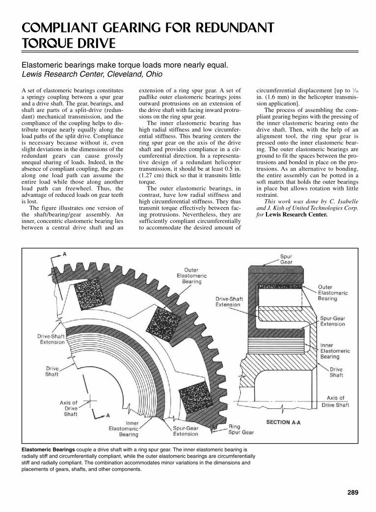
289
COMPLIANT GEARING FOR REDUNDANT TORQUE DRIVEElastomeric bearings make torque loads more nearly equal.Lewis Research Center, Cleveland, Ohio
A set of elastomeric bearings constitutesa springy coupling between a spur gearand a drive shaft. The gear, bearings, andshaft are parts of a split-drive (redun-dant) mechanical transmission, and thecompliance of the coupling helps to dis-tribute torque nearly equally along theload paths of the split drive. Complianceis necessary because without it, evenslight deviations in the dimensions of theredundant gears can cause grosslyunequal sharing of loads. Indeed, in theabsence of compliant coupling, the gearsalong one load path can assume theentire load while those along anotherload path can freewheel. Thus, theadvantage of reduced loads on gear teethis lost.
The figure illustrates one version ofthe shaft/bearing/gear assembly. Aninner, concentric elastomeric bearing liesbetween a central drive shaft and an
extension of a ring spur gear. A set ofpadlike outer elastomeric bearings joinsoutward protrusions on an extension ofthe drive shaft with facing inward protru-sions on the ring spur gear.
The inner elastomeric bearing hashigh radial stiffness and low circumfer-ential stiffness. This bearing centers thering spur gear on the axis of the driveshaft and provides compliance in a cir-cumferential direction. In a representa-tive design of a redundant helicoptertransmission, it should be at least 0.5 in.(1.27 cm) thick so that it transmits littletorque.
The outer elastomeric bearings, incontrast, have low radial stiffness andhigh circumferential stiffness. They thustransmit torque effectively between fac-ing protrusions. Nevertheless, they aresufficiently compliant circumferentiallyto accommodate the desired amount of
circumferential displacement [up to 1⁄16
in. (1.6 mm) in the helicopter transmis-sion application].
The process of assembling the com-pliant gearing begins with the pressing ofthe inner elastomeric bearing onto thedrive shaft. Then, with the help of analignment tool, the ring spur gear ispressed onto the inner elastomeric bear-ing. The outer elastomeric bearings areground to fit the spaces between the pro-trusions and bonded in place on the pro-trusions. As an alternative to bonding,the entire assembly can be potted in asoft matrix that holds the outer bearingsin place but allows rotation with littlerestraint.
This work was done by C. Isabelleand J. Kish of United Technologies Corp.for Lewis Research Center.
Elastomeric Bearings couple a drive shaft with a ring spur gear. The inner elastomeric bearing isradially stiff and circumferentially compliant, while the outer elastomeric bearings are circumferentiallystiff and radially compliant. The combination accommodates minor variations in the dimensions andplacements of gears, shafts, and other components.
Sclater Chapter 8 5/3/01 12:44 PM Page 289

290
LIGHTER, MORE-EFFICIENT HELICOPTERTRANSMISSIONSRedundant gearing transmits torque through an angle or angles.Lewis Research Center, Cleveland, Ohio
An improved gear system intended pri-marily for use in a helicopter transmitstorque from the horizontal or nearly hori-zontal shafts of two engines to the verti-cal output shaft that supports the rotor.The system apportions torques equallyalong multiple, redundant drive paths,thereby reducing the stresses on individ-ual gear teeth, and it enables one engineto continue to turn the rotor when theother engine fails. The underlying designconcept could also be applied to coupletwo airplane engines to a set of pro-pellers in such a way that both propellersturn as long as at least one engine oper-ates.
The system exploits the specialadvantages of the geometry of the mesh-ing of a spur-gear-type pinion with a facegear. In comparison with other geargeometries that have been used in heli-copter transmissions, this one is muchmore forgiving of (1) errors in manufac-turing and alignment and (2) thermal andvibrational changes in the sizes and posi-tions of the meshing components. One ofthe benefits is a reduction of gear-tooth-contact noise and vibration. Another ben-efit is the possibility of achieving a high(> 4) speed-reduction ratio in a single,efficient mesh, and the consequent possi-bility of reducing the number of parts,the size, the cost, and the weight of thegear system. Of course, the reduction ofthe number of parts confers yet anotherbenefit by increasing the reliability of thesystem.
The system is shown schematically inthe figure. The output of each engine iscoupled by a pinion shaft to a spur-gear-type pinion. Each pinion engages anupper and a lower face gear, and eachface gear is coupled by a face-gear shaftto an upper spur gear. The upper spurgears feed torque into a large combininggear. The pinion end of each pinion shaftis lightly spring-loaded in a nominal lat-
eral position and is free to shift laterallythrough a small distance to take up slack,compensate for misalignments, andapportion torques equally to the two facegears with which it is engaged.
The combining gear is splined to ashaft that flares outwardly to a sun gear.The sun gear operates in conjunction
with planetary gears and a stationaryouter ring gear. The torque is coupledfrom the sun gear through the planetarygears to the planet-carrier ring, which ismounted on the output shaft.
This work was done by Robert B.Bossler, Jr., of Lucas Western, Inc., forLewis Research Center.
Torque from each engine is split and transmitted to the combining gear along two redundantpaths. Should one engine fail, the other engine could still turn the output shaft.
WORM GEAR WITH HYDROSTATIC ENGAGEMENTFriction would be reduced greatly.Lewis Research Center, Cleveland, Ohio
In a proposed worm-gear transmission,oil would be pumped at high pressurethrough the meshes between the teeth of
the gear and the worm coil (see Figure1). The pressure in the oil would separatethe meshing surfaces slightly, and the oil
would reduce the friction between thesesurfaces. Each of the separating forces inthe several meshes would contribute to
Sclater Chapter 8 5/3/01 12:44 PM Page 290

the torque on the gear and to an axialforce on the worm. To counteract thisaxial force and to reduce the friction thatit would otherwise cause, oil would alsobe pumped under pressure into a counter-force hydrostatic bearing at one end ofthe worm shaft.
This type of worm-gear transmissionwas conceived for use in the drive trainbetween the gas-turbine engine and therotor of a helicopter and might be usefulin other applications in which weight iscritical. Worm gear is attractive for suchweight-critical applications because (1) itcan transmit torque from a horizontalengine (or other input) shaft to a verticalrotor (or other perpendicular output)shaft, reducing the speed by the desiredratio in one stage, and (2) in principle, aone-stage design can be implemented ina gearbox that weighs less than does aconventional helicopter gearbox.
Heretofore, the high sliding frictionbetween the worm coils and the gearteeth of worm-gear transmissions hasreduced efficiency so much that suchtransmissions could not be used in heli-copters. The efficiency of the proposedworm-gear transmission with hydrostaticengagement would depend partly on theremaining friction in the hydrostaticmeshes and on the power required topump the oil. Preliminary calculationsshow that the efficiency of the proposedtransmission could be the same as that ofa conventional helicopter gear train.
Figure 2 shows an apparatus that isbeing used to gather experimental datapertaining to the efficiency of a wormgear with hydrostatic engagement. Twostationary disk sectors with oil pocketsrepresent the gear teeth and are installedin a caliper frame. A disk that representsthe worm coil is placed between the disksectors in the caliper and is rotated rap-idly by a motor and gearbox. Oil ispumped at high pressure through theclearances between the rotating disk andthe stationary disk sectors. The apparatusis instrumented to measure the frictionalforce of meshing and the load force.
The stationary disk sectors can beinstalled with various clearances and atvarious angles to the rotating disk. Thestationary disk sectors can be made invarious shapes and with oil pockets atvarious positions. A flowmeter and pres-sure gauge will measure the pump power.Oils of various viscosities can be used.The results of the tests are expected toshow the experimental dependences ofthe efficiency of transmission on thesefactors.
It has been estimated that futureresearch and development will make itpossible to make worm-gear helicoptertransmission that weigh half as much asconventional helicopter transmissionsdo. In addition, the new hydrostaticmeshes would offer longer service lifeand less noise. It might even be possible
to make the meshing worms and gears, orat least parts of them, out of such light-weight materials as titanium, aluminum,and composites.
This work was done by Lev. I. Chalkoof the U.S. Army Propulsion Directorate(AVSCOM) for Lewis Research Center.
291
Fig. 1 Oil would be injected at high pressure to reduce friction in critical areas of contact.
Fig. 2 This test apparatus simulates and measures some of the loading conditions of theproposed worm gear with hydrostatic engagement. The test data will be used to design effi-cient worm-gear transmissions.
Sclater Chapter 8 5/3/01 12:44 PM Page 291
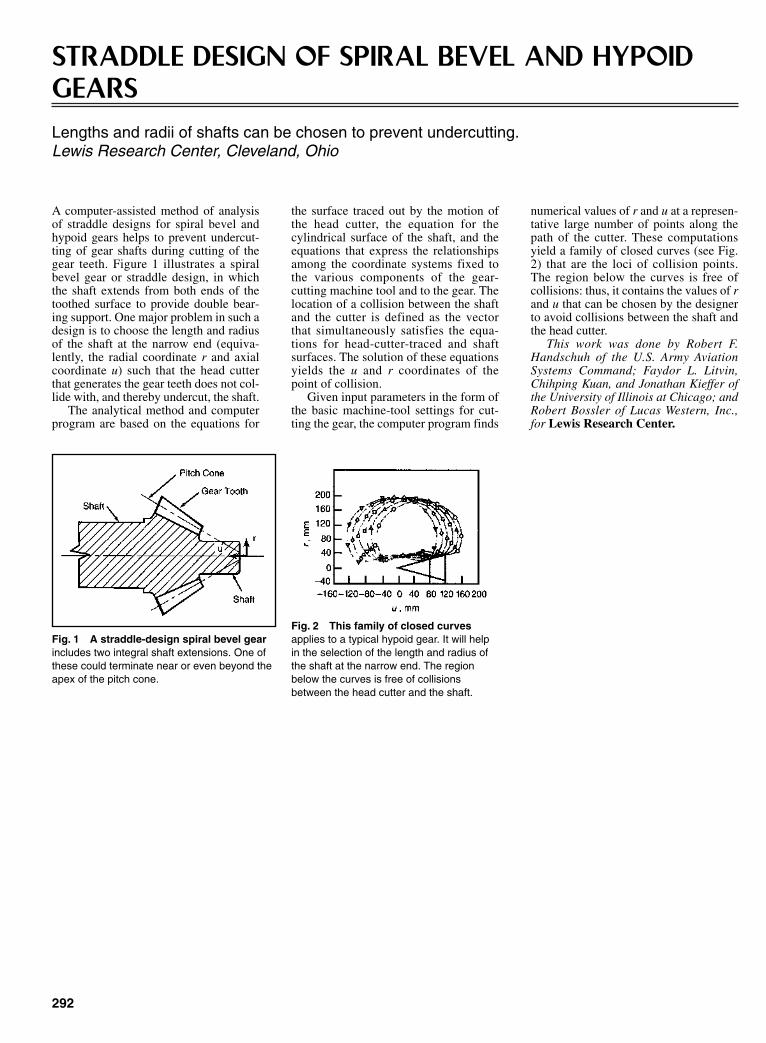
292
STRADDLE DESIGN OF SPIRAL BEVEL AND HYPOIDGEARSLengths and radii of shafts can be chosen to prevent undercutting.Lewis Research Center, Cleveland, Ohio
A computer-assisted method of analysisof straddle designs for spiral bevel andhypoid gears helps to prevent undercut-ting of gear shafts during cutting of thegear teeth. Figure 1 illustrates a spiralbevel gear or straddle design, in whichthe shaft extends from both ends of thetoothed surface to provide double bear-ing support. One major problem in such adesign is to choose the length and radiusof the shaft at the narrow end (equiva-lently, the radial coordinate r and axialcoordinate u) such that the head cutterthat generates the gear teeth does not col-lide with, and thereby undercut, the shaft.
The analytical method and computerprogram are based on the equations for
the surface traced out by the motion ofthe head cutter, the equation for thecylindrical surface of the shaft, and theequations that express the relationshipsamong the coordinate systems fixed tothe various components of the gear-cutting machine tool and to the gear. Thelocation of a collision between the shaftand the cutter is defined as the vectorthat simultaneously satisfies the equa-tions for head-cutter-traced and shaftsurfaces. The solution of these equationsyields the u and r coordinates of thepoint of collision.
Given input parameters in the form ofthe basic machine-tool settings for cut-ting the gear, the computer program finds
numerical values of r and u at a represen-tative large number of points along thepath of the cutter. These computationsyield a family of closed curves (see Fig.2) that are the loci of collision points.The region below the curves is free ofcollisions: thus, it contains the values of rand u that can be chosen by the designerto avoid collisions between the shaft andthe head cutter.
This work was done by Robert F.Handschuh of the U.S. Army AviationSystems Command; Faydor L. Litvin,Chihping Kuan, and Jonathan Kieffer ofthe University of Illinois at Chicago; andRobert Bossler of Lucas Western, Inc.,for Lewis Research Center.
Fig. 1 A straddle-design spiral bevel gearincludes two integral shaft extensions. One ofthese could terminate near or even beyond theapex of the pitch cone.
Fig. 2 This family of closed curvesapplies to a typical hypoid gear. It will helpin the selection of the length and radius ofthe shaft at the narrow end. The regionbelow the curves is free of collisionsbetween the head cutter and the shaft.
Sclater Chapter 8 5/3/01 12:44 PM Page 292

CHAPTER 9COUPLING, CLUTCHING,AND BRAKING DEVICES
Sclater Chapter 9 5/3/01 12:56 PM Page 293

294
COUPLING OF PARALLEL SHAFTS
Fig. 1 One method of coupling shafts makes use of gears thatcan replace chains, pulleys, and friction drives. Its major limitationis the need for adequate center distance. However, an idler can beused for close centers, as shown. This can be a plain pinion or aninternal gear. Transmission is at a constant velocity and there isaxial freedom.
Fig. 2 This coupling consists of two universal joints and a shortshaft. Velocity transmission is constant between the input and outputshafts if the shafts remain parallel and if the end yokes are arrangedsymmetrically. The velocity of the central shaft fluctuates during rota-tion, but high speed and wide angles can cause vibration. The shaftoffset can be varied, but axial freedom requires that one shaft bespline mounted.
Fig. 3 This crossed-axis yoke coupling is a variation of the mecha-nism shown in Fig. 2. Each shaft has a yoke connected so that it canslide along the arms of a rigid cross member. Transmission is at aconstant velocity, but the shafts must remain parallel, although theoffset can vary. There is no axial freedom. The central cross memberdescribes a circle and is thus subjected to centrifugal loads.
Fig. 4 This Oldham coupling provides motion at a constant velocityas its central member describes a circle. The shaft offset can vary,but the shafts must remain parallel. A small amount of axial freedomis possible. A tilt in the central member can occur because of the off-set of the slots. This can be eliminated by enlarging its diameter andmilling the slots in the same transverse plane.
Sclater Chapter 9 5/3/01 12:56 PM Page 294

295
NOVEL LINKAGE COUPLES OFFSET SHAFTS
An unorthodox yet remarkably simplearrangement of links and disks forms thebasis of a versatile parallel-shaft cou-pling. This coupling—essentially threedisks rotating in unison and intercon-nected in series by six links (se draw-ing)—can adapt to wide variations inaxial displacement while it is runningunder load.
Changes in radial displacement do notaffect the constant-velocity relationshipbetween the input and output shafts, nordo they affect initial radial reactionforces that might cause imbalance in thesystem. Those features open up unusualapplications for it in automotive, marine,machine-tool, and rolling-mill machin-ery (see drawings).
How it works. The inventor of thecoupling, Richard Schmidt of Madison,Alabama, said that a similar link arrange-ment had been known to some Germanengineers for years. But those engineerswere discouraged from applying the the-ory because they erroneously assumedthat the center disk had to be retained byits own bearing. Actually, Schmidt foundthat the center disk is free to assume itsown center of rotation. In operation, allthree disks rotate with equal velocity.
The bearing-mounted connections oflinks to disks are equally spaced at 120ºon pitch circles of the same diameter.The distance between shafts can be var-ied steplessly between zero (when theshafts are in line) and a maximum that istwice the length of the links (see draw-ings.) There is no phase shift betweenshafts while the coupling is undulating.
Parallel-link connections between disks(see upper drawing) exactly duplicate themotion between the input and outputshafts—the basis of this principle in cou-pling. The lower diagrams show threepositions of the links as one shaft isshifted with respect to the other shaft inthe system.
Torque transmitted by three links in thegroup adds up to a constant value, regard-less of the angle of rotation.
Sclater Chapter 9 5/3/01 12:56 PM Page 295
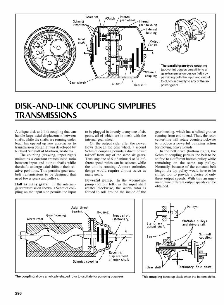
DISK-AND-LINK COUPLING SIMPLIFIESTRANSMISSIONS
296
The parallelgram-type coupling(above) introduces versatility to agear-transmission design (left ) bypermitting both the input and outputto clutch in directly to any of the sixpower gears.
A unique disk-and-link coupling that canhandle large axial displacement betweenshafts, while the shafts are running underload, has opened up new approaches totransmission design. It was developed byRichard Schmidt of Madison, Alabama.
The coupling (drawing, upper right)maintains a constant transmission ratiobetween input and output shafts whilethe shafts undergo axial shifts in their rel-ative positions. This permits gear-and-belt transmissions to be designed thatneed fewer gears and pulleys.
Half as many gears. In the internal-gear transmission shown, a Schmidt cou-pling on the input side permits the input
to be plugged in directly to any one of sixgears, all of which are in mesh with theinternal gear wheel.
On the output side, after the powerflows through the gear wheel, a secondSchmidt coupling permits a direct powertakeoff from any of the same six gears.Thus, any one of 6 × 6 minus 5 or 31 dif-ferent speed ratios can be selected whilethe unit is running. A more orthodoxdesign would require almost twice asmany gears.
Powerful pump. In the worm-typepump (bottom left), as the input shaftrotates clockwise, the worm rotor isforced to roll around the inside of the
gear housing, which has a helical grooverunning from end to end. Thus, the rotorcenter-line will rotate counterclockwiseto produce a powerful pumping actionfor moving heavy liquids.
In the belt drive (bottom right), theSchmidt coupling permits the belt to beshifted to a different bottom pulley whileremaining on the same top pulley.Normally, because of the constant beltlength, the top pulley would have to beshifted too, to provide a choice of onlythree output speeds. With this arrange-ment, nine different output speeds can beobtained.
The coupling allows a helically-shaped rotor to oscillate for pumping purposes. This coupling takes up slack when the bottom shifts.
Sclater Chapter 9 5/3/01 12:56 PM Page 296
297
INTERLOCKING SPACE-FRAMES FLEX AS THEYTRANSMIT SHAFT TORQUEThis coupling tolerates unusually high degrees of misalignment, with no variation in the high torque that’s being taken from the shaft.
A concept in flexible drive-shaft cou-plings permits unusually large degrees ofmisalignment and axial motion duringthe transmission of high amounts oftorque. Moreover, the rotational velocityof the driven member remains constantduring transmission at angular misalign-ments; in other words, cyclic pulsationsare not induced as they would be if, say, auniversal coupling or a Hooke’s jointwere employed.
The coupling consists essentially of aseries of square space-frames, each bentto provide offsets at the diagonals andeach bolted to adjacent members at alter-nate diagonals. The concept was inventedby Robert B. Bossler, Jr. He was grantedU.S. Patent No. 3,177,684.
Couplings accommodate the inevitablemisalignments between rotating shafts in adriven train. These misalignments arecaused by imperfect parts, dimensionalvariations, temperature changes, anddeflections of the supporting structures.The couplings accommodate misalignmenteither with moving contacts or by flexing.
Most couplings, however, have partswith moving contacts that require lubri-cation and maintenance. The rubbingparts also absorb power. Moreover, thelubricant and the seals limit the couplingenvironment and coupling life. Partswear out, and the coupling can develop alarge resistance to movement as the partsdeteriorate. Then, too, in many designs,the coupling does not provide true con-stant velocity.
For flexibility. Bossler studied the var-ious types of couplings n the market andfirst developed a new one with a movingcontact. After exhaustive tests, hebecame convinced that if there were tobe the improvements he wanted, he hadto design a coupling that flexed withoutany sliding or rubbing.
Flexible-coupling behavior, however,is not without design problems. Any flex-
ible coupling can be proportioned withstrong, thick, stiff members that easilytransmit a design torque and provide thestiffness to operate at design speed.However, misalignment requires flexingof these members. The flexing producesalternating stresses that can limit cou-pling life. The greater the strength andstiffness of a member, the higher thealternating stress from a given misalign-ment. Therefore, strength and stiffnessprovisions that transmit torque at speedwill be detrimental to misalignmentaccommodation capability.
The design problem is to proportionthe flexible coupling to accomplishtorque transmission and overcome mis-alignment for the lowest system cost.Bossler looked at a drive shaft, a goodexample of power transmission—andwondered how he could convert it intoone with flexibility.
He began to evolve it by followingbasic principles. How does a drive shafttransmit torque? By tension and com-pression. He began paring it down to theimportant struts that could transmittorque and found that they are curvedbeams. But a curved beam in tension andcompression is not as strong as a straightbeam. He ended up with the beamsstraight in a square space-frame withwhat might be called a double helixarrangement. One helix contained ele-ments in compression; the other helixcontained elements in tension.
Flattening the helix. The total numberof plates should be an even number toobtain constant velocity characteristicsduring misalignment. But even with anodd number, the cyclic speed variationsare minute, not nearly the magnitude ofthose in a Hooke’s joint.
Although the analysis and resultingequations developed by Bossler arebased on a square-shaped unit, he con-cluded that the perfect square is not the
ideal for the coupling, because of theposition of the mounting holes. The flat-ter the helix—in other words the smallerthe distance S—the more misalignmentthe coupling will tolerate.
Hence, Bossler began making thespace-frames slightly rectangular insteadof square. In this design, the bolt-headsthat fasten the plates together are offsetfrom adjoining pairs, providing enoughclearance for the design of a “flatter”helix. The difference in stresses betweena coupling with square-shaped plates andone with slightly rectangular plates is soinsignificant that the square-shape equa-tions can be employed with confidence.
Design equations. By making a fewkey assumptions and approximations,Bossler boiled the complex analyticalrelationships down to a series of straight-forward design equations and charts. Thederivation of the equations and theresulting verification from tests are givenin the NASA report The BosslerCoupling, CR-1241.
Torque capacity. The ultimate torquecapacity of the coupling before bucklingthat might occur in one of the space-frame struts under compression is givenby Eq. 1. The designer usually knows orestablishes the maximum continuoustorque that the coupling must transmit.Then he must allow for possible shockloads and overloads. Thus, the clutchshould be designed to have an ultimatetorque capacity that is at least twice asmuch, and perhaps three times as much,as the expected continuous torque,according to Bossler.
Induced stress. At first glance, Eq. 1seems to allow a lot of leeway in select-ing the clutch size. The torque capacity iseasily boosted, for example, by picking asmaller bolt-circle diameter, d, which
Sclater Chapter 9 5/3/01 12:56 PM Page 297

298
Design equations for the Bossler coupling
Ultimate torque capacity
(1) T = 11.62
Maximum stress per degree of misalignment.(2) σmax = 0.0276 Et/L
Minimum thickness to meet required torque strength
(3) t = 0.4415 n0.3
Weight of coupling with minimum-thickness plates
(4) W = 1.249w d4/3 b2/3 n1.3
Maximum permissible misalignment
(5) θmax = 54.7 σc n0.7
Maximum permissible misalignment (simplified)
(6) θ/d = 10.9
Maximum permissible offset-angle
(7) β = 54.7
where:
Maximum permissible offset-angle (simplified)
(8) β/d = 10 9. C
T n1/3 0.3
x=1
x=n
lx
S
S∑ − −
1 12
( )
bd
TE
C
n
2
2e0.3
1 3/
σ
n
T
0.7
1/3
bd
TE
2
2
1 3/
T
E
1 3/
dT
bE
1 3/
Ebt
dn
3
0 9.
Critical speed frequency
(9) f =
where: k = and (El)e = 0.886Ebt3S/L
List of symbols
b = Width of an elementd = Diameter at the bold circleE = Modulus of elasticityf = First critical speed, rpml = Flatwise moment of inertia of an element = bt3/12
k = Spring constant for single degree of freedomL = Effective length of an element. This concept is required
because joint details tend to stiffen the ends of the elements.L = 0.667 d is recommended
M = Mass of center shaft plus mass of one coupling with fastenersn = Number of plates in each couplingS = Offset distance by which a plate is out of planet = Thickness of an element
T = Torque applied to coupling, useful ultimate, usually taken aslowest critical buckling torque
w = Weight per unit volumeW = Total weight of plates in a coupling
(El)e = Flexural stiffness, the moment that causes one radian of flex-ural angle change per unit length of coupling
β = Equivalent angle change at each coupling during parallel off-set misalignment, deg
ϑ = Total angular misalignment, degσc = Characteristic that limits stress for the material: yield stress for
static performance, endurance limit stress for fatigue perform-ance
24(El)
nS)e
3(
60
2
1 2
πk
M
/
Sclater Chapter 9 5/3/01 12:56 PM Page 298

makes the clutch smaller, or by makingthe plates thicker. But either solutionwould also make the clutch stiffer, hencewould restrict the misalignment permit-ted before the clutch becomes over-stressed. The stress-misalignment rela-tionship is given in Eq. 2, which showsthe maximum flat-wise bending stressproduced when a plate is misaligned 1ºand is then rotated to transmit torque.
Plate thickness. For optimum misalign-ment capability, the plates should beselected with the least thickness that willprovide the required torque strength. Todetermine the minimum thickness,Bossler found it expedient to rearrangeEq. 1 into the form shown in Eq. 3. Theweight of any coupling designed inaccordance to the minimum-thicknessequation can be determined from Eq. 4.
Maximum misalignment. Angularmisalignment occurs when the center-lines of the input and output shafts inter-sect at some angle—the angle of mis-alignment. When the characteristic
limiting stress is known for the materialselected—and for the coupling’s dimen-sions—the maximum allowable angleof misalignment can be computed fromEq. 5.
If this allowance is not satisfactory,the designer might have to juggle the sizefactors by, say, adding more plates to theunit. To simplify eq. 5, Bossler madesome assumptions in the ratio ofendurance limit to modulus and in theratio of dsb to obtain Eq. 6.
Parallel offset. This condition existswhen the input and output shafts remainparallel but are displaced laterally. Aswith Eq. 6, Eq. 7 is a performance equa-tion and can be reduced to design curves.Bossler obtained Eq. 8 by making thesame assumptions as in the previouscase.
Critical speed. Because of the noncir-cular configurations of the coupling, it isimportant that the operating speed of theunit be higher than its critical speed. Itshould not only be higher but also shouldavoid an integer relationship.
Bossler worked out a handy relation-ship for critical speed (Eq. 9) thatemploys a somewhat idealized value forthe spring constant k.
Bossler also made other recommen-dations where weight reduction is vital:
• Size of plates. Use the largest d con-sistent with envelope and centrifugalforce loading. Usually, centrifugalforce loading will not be a problembelow 300 ft/s tip speed.
• Number of plates. Pick the least nconsistent with the required perform-ance.
• Thickness of plates. Select thesmallest t consistent with the requiredultimate torque.
• Joint details. Be conservative; usehigh-strength tension fasteners withhigh preload. Provide fretting protec-tion. Make element centerlines andbolt centerlines intersect at a point.
• Offset distance. Use the smallest Sconsistent with clearance.
299
OFF-CENTER PINS CANCEL MISALIGNMENT OF SHAFTS
Two Hungarian engineers developed anall-metal coupling (see drawing) for con-necting shafts where alignment is notexact—that is, where the degree of mis-alignment does not exceed the magnitudeof the shaft radius.
The coupling is applied to shafts thatare being connected for either high-torque or high-speed operation and thatmust operate at maximum efficiency.Knuckle joints are too expensive, andthey have too much play; elastic jointsare too vulnerable to the influences ofhigh loads and vibrations.
How it’s made. In essence, the cou-pling consists of two disks, each keyed to
a splined shaft. One disk bears fourfixed-mounted steel studs at equal spac-ing; the other disk has large-diameterholes drilled at points facing the studs.
Each large hole is fitted with a bear-ing that rotates freely inside it on rollersor needles. The bore of the bearings,however, is off-center. The amount ofeccentricity of the bearing bore is identi-cal to the deviation of the two shaft cen-ter lines.
In operation, input and output shaftscan be misaligned, yet they still rotatewith the same angular relationship theywould have if perfectly aligned.
Eccentrically bored bearings rotate tomake up for misalignment between shafts.
Sclater Chapter 9 5/3/01 12:56 PM Page 299
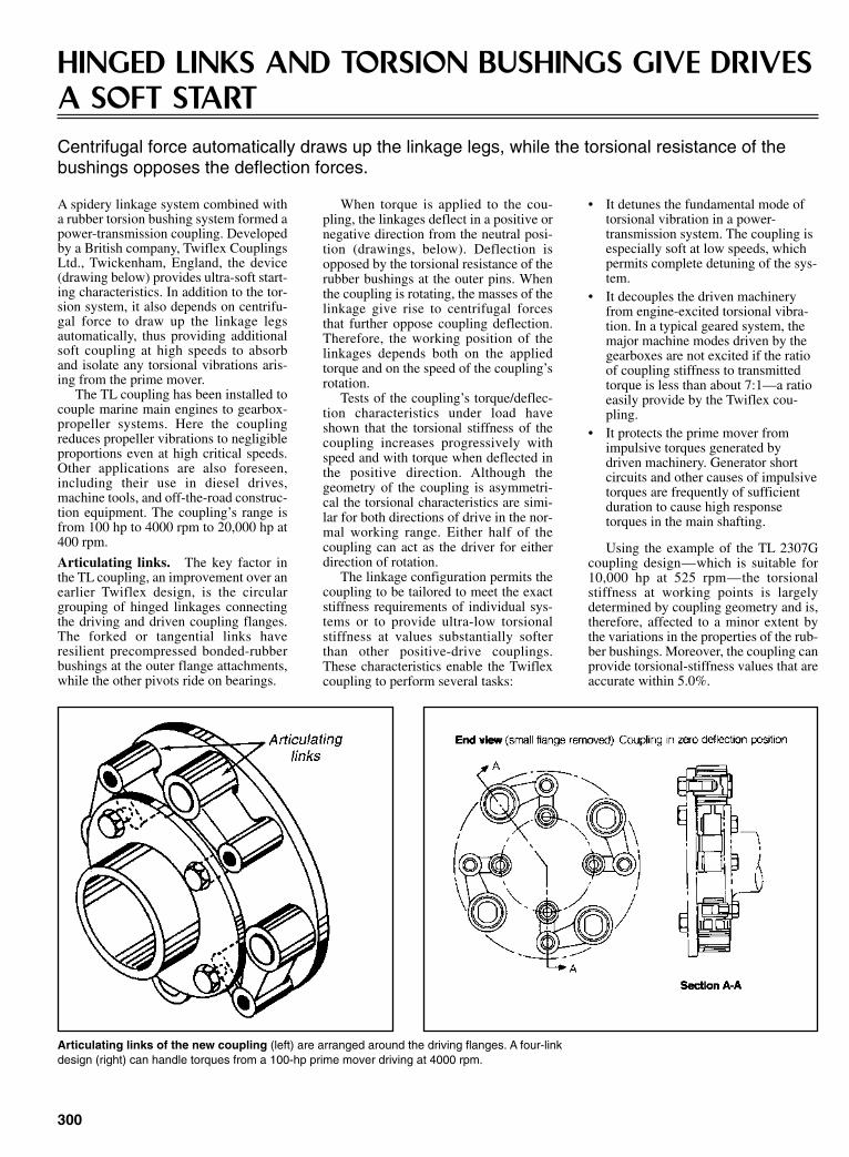
300
HINGED LINKS AND TORSION BUSHINGS GIVE DRIVESA SOFT STARTCentrifugal force automatically draws up the linkage legs, while the torsional resistance of thebushings opposes the deflection forces.
A spidery linkage system combined witha rubber torsion bushing system formed apower-transmission coupling. Developedby a British company, Twiflex CouplingsLtd., Twickenham, England, the device(drawing below) provides ultra-soft start-ing characteristics. In addition to the tor-sion system, it also depends on centrifu-gal force to draw up the linkage legsautomatically, thus providing additionalsoft coupling at high speeds to absorband isolate any torsional vibrations aris-ing from the prime mover.
The TL coupling has been installed tocouple marine main engines to gearbox-propeller systems. Here the couplingreduces propeller vibrations to negligibleproportions even at high critical speeds.Other applications are also foreseen,including their use in diesel drives,machine tools, and off-the-road construc-tion equipment. The coupling’s range isfrom 100 hp to 4000 rpm to 20,000 hp at400 rpm.
Articulating links. The key factor inthe TL coupling, an improvement over anearlier Twiflex design, is the circulargrouping of hinged linkages connectingthe driving and driven coupling flanges.The forked or tangential links haveresilient precompressed bonded-rubberbushings at the outer flange attachments,while the other pivots ride on bearings.
When torque is applied to the cou-pling, the linkages deflect in a positive ornegative direction from the neutral posi-tion (drawings, below). Deflection isopposed by the torsional resistance of therubber bushings at the outer pins. Whenthe coupling is rotating, the masses of thelinkage give rise to centrifugal forcesthat further oppose coupling deflection.Therefore, the working position of thelinkages depends both on the appliedtorque and on the speed of the coupling’srotation.
Tests of the coupling’s torque/deflec-tion characteristics under load haveshown that the torsional stiffness of thecoupling increases progressively withspeed and with torque when deflected inthe positive direction. Although thegeometry of the coupling is asymmetri-cal the torsional characteristics are simi-lar for both directions of drive in the nor-mal working range. Either half of thecoupling can act as the driver for eitherdirection of rotation.
The linkage configuration permits thecoupling to be tailored to meet the exactstiffness requirements of individual sys-tems or to provide ultra-low torsionalstiffness at values substantially softerthan other positive-drive couplings.These characteristics enable the Twiflexcoupling to perform several tasks:
• It detunes the fundamental mode oftorsional vibration in a power-transmission system. The coupling isespecially soft at low speeds, whichpermits complete detuning of the sys-tem.
• It decouples the driven machineryfrom engine-excited torsional vibra-tion. In a typical geared system, themajor machine modes driven by thegearboxes are not excited if the ratioof coupling stiffness to transmittedtorque is less than about 7:1—a ratioeasily provide by the Twiflex cou-pling.
• It protects the prime mover fromimpulsive torques generated bydriven machinery. Generator shortcircuits and other causes of impulsivetorques are frequently of sufficientduration to cause high responsetorques in the main shafting.
Using the example of the TL 2307Gcoupling design—which is suitable for10,000 hp at 525 rpm—the torsionalstiffness at working points is largelydetermined by coupling geometry and is,therefore, affected to a minor extent bythe variations in the properties of the rub-ber bushings. Moreover, the coupling canprovide torsional-stiffness values that areaccurate within 5.0%.
Articulating links of the new coupling (left) are arranged around the driving flanges. A four-linkdesign (right) can handle torques from a 100-hp prime mover driving at 4000 rpm.
Sclater Chapter 9 5/3/01 12:56 PM Page 300

301
UNIVERSAL JOINT RELAYS POWER 45° ATCONSTANT SPEEDS
A universal joint that transmits power atconstant speeds through angles up to 45ºwas designed by Malton Miller ofMinnesota.
Models of the true-speed drive thatcan transmit up to 20 hp have beendeveloped.
It had not been possible to transmitpower at constant speeds with only oneuniversal joint. Engineers had to specifyan intermediate shaft between twoHooke’s joints or use a Rzappa-type jointto get the desired effect.
Ball-and-socket. Basically, the True-Speed joint is a system of ball-and-socket connections with large contactareas (low unit pressure) to transmit tor-sional forces across the joint. Thisarrangement minimizes problems whenhigh bearing pressures build up againstrunning surfaces. The low-friction bear-ings also increase efficiency. The joint isbalanced to keep vibration at high speedsto a minimum.
The joint consists of driving anddriven halves. Each half has a couplingsleeve at its end of the driveshaft, a pairof driving arms opposite each other and
pivoted on a cross pin that extendsthrough the coupling sleeve, and a ball-and-socket coupling at the end of eachdriving arm.
As the joint rotates, angular flexure inone plane of the joint is accommodatedby the swiveling of the all-and-socketcouplings and, in the 90º plane, by theoscillation of the driving arms about thetransverse pin. As rotation occurs, tor-sion is transmitted from one half of thejoint to the other half through the swivel-ing ball-and-socket couplings and theoscillating driving arms.
Balancing. Each half of the joint, ineffect, rotates about its own center shaft,so each half is considered separate forbalancing. The center ball-and-socketcoupling serves only to align and securethe intersection point of the two shafts. Itdoes not transmit any forces to the entiredrive unit.
Balancing for rotation is achieved byequalizing the weight of the two drivingarms of each half of the joint. Balancingthe acceleration forces due to the oscilla-tion of the ball-and-socket couplings,which are offset from their swiveling
axes, is achieved by the use of counter-weights extending from the opposite sideof each driving arm.
The outer ball-and-socket couplingswork in two planes of motion, swivelingwidely in the plane perpendicular to themain shaft and swiveling slightly aboutthe transverse pin in the plane parallel tothe main shaft. In this coupling configu-ration, the angular displacement of thedriving shaft is exactly duplicated in thedriven shaft, providing constant rota-tional velocity and constant torque at allshaft intersection angles.
Bearings. The only bearing parts arethe ball-and-socket couplings and thedriving arms on the transverse pins.Needle bearings support the driving armson the transverse pin, which is hardenedand ground. A high-pressure grease lubri-cant coats the bearing surfaces of theball-and-socket couplings. Under maxi-mum rated loadings of 600 psi on theball-and-socket surfaces, there is noappreciable heating or power loss due tofriction.
Capabilities. Units have been labora-tory-tested at all rated angles of driveunder dynamometer loadings. Althoughthe first available units were for smallercapacities, a unit designed for 20 hp at550 rpm, suitable for tractor power take-off drive, has been tested.
Similar couplings have been designedas pump couplings. But the True-Speeddrive differs in that the speed and transferelements are positive. With the pumpcoupling, on the other hand, the speedmight fluctuate because of springbounce.
A novel arrangement of pivots and ball-socket joints transmits uniform motion.
An earlier version for angled shaftsrequired spring-loaded sliding rods.
Sclater Chapter 9 5/3/01 12:56 PM Page 301
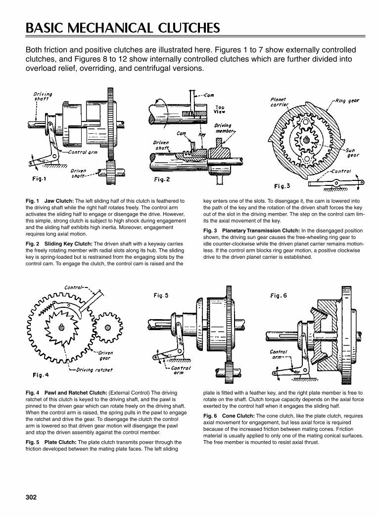
302
BASIC MECHANICAL CLUTCHESBoth friction and positive clutches are illustrated here. Figures 1 to 7 show externally controlledclutches, and Figures 8 to 12 show internally controlled clutches which are further divided intooverload relief, overriding, and centrifugal versions.
Fig. 1 Jaw Clutch: The left sliding half of this clutch is feathered tothe driving shaft while the right half rotates freely. The control armactivates the sliding half to engage or disengage the drive. However,this simple, strong clutch is subject to high shock during engagementand the sliding half exhibits high inertia. Moreover, engagementrequires long axial motion.
Fig. 2 Sliding Key Clutch: The driven shaft with a keyway carriesthe freely rotating member with radial slots along its hub. The slidingkey is spring-loaded but is restrained from the engaging slots by thecontrol cam. To engage the clutch, the control cam is raised and the
key enters one of the slots. To disengage it, the cam is lowered intothe path of the key and the rotation of the driven shaft forces the keyout of the slot in the driving member. The step on the control cam lim-its the axial movement of the key.
Fig. 3 Planetary Transmission Clutch: In the disengaged positionshown, the driving sun gear causes the free-wheeling ring gear toidle counter-clockwise while the driven planet carrier remains motion-less. If the control arm blocks ring gear motion, a positive clockwisedrive to the driven planet carrier is established.
Fig. 4 Pawl and Ratchet Clutch: (External Control) The drivingratchet of this clutch is keyed to the driving shaft, and the pawl ispinned to the driven gear which can rotate freely on the driving shaft.When the control arm is raised, the spring pulls in the pawl to engagethe ratchet and drive the gear. To disengage the clutch the controlarm is lowered so that driven gear motion will disengage the pawland stop the driven assembly against the control member.
Fig. 5 Plate Clutch: The plate clutch transmits power through thefriction developed between the mating plate faces. The left sliding
plate is fitted with a feather key, and the right plate member is free torotate on the shaft. Clutch torque capacity depends on the axial forceexerted by the control half when it engages the sliding half.
Fig. 6 Cone Clutch: The cone clutch, like the plate clutch, requiresaxial movement for engagement, but less axial force is requiredbecause of the increased friction between mating cones. Frictionmaterial is usually applied to only one of the mating conical surfaces.The free member is mounted to resist axial thrust.
Sclater Chapter 9 5/3/01 12:56 PM Page 302

Fig. 7 Expanding Shoe Clutch: This clutch is engaged by themotion of the control arm. It operates linkages that force the frictionshoes radially outwards so that they contact the inside surface of thedrum.
Fig. 8 Spring and Ball Radial Detent Clutch: This clutch will holdthe driving gear and driven gear in a set timing relationship until thetorque becomes excessive. At that time the balls will be forced inwardagainst their springs and out of engagement with the holes in thehub. As a result the driving gear will continue rotating while the driveshaft is stationary.
Fig. 10 Wrapped Spring Clutch: This simple unidirectional clutchconsists of two rotating hubs connected by a coil spring that is press-fit over both hubs. In the driving direction the spring tightens aroundthe hubs increasing the friction grip, but if driven in the oppositedirection the spring unwinds causing the clutch to slip.
Fig. 11 Expanding Shoe Centrifugal Clutch: This clutch performsin a similar manner to the clutch shown in Fig. 7 except that there isno external control. Two friction shoes, attached to the driving mem-ber, are held inward by springs until they reach the “clutch-in” speed.
At that speed centrifugal force drives the shoes outward into contactwith the drum. As the drive shaft rotates faster, pressure between theshoes against the drum increases, thus increasing clutch torque.
Fig. 12 Mercury Gland Clutch: This clutch contains two frictionplates and a mercury-filled rubber bladder. At rest, mercury fills aring-shaped cavity around the shaft, but when rotated at a sufficientlyhigh speed, the mercury is forced outward by centrifugal force. Themercury then spreads the rubber bladder axially, forcing the frictionplates into contact with the opposing faces of the housing to drive it.
303
Fig. 9 Cam and Roller Clutch: This over-running clutch is bettersuited for higher-speed free-wheeling than a pawl-and-ratchet clutch.The inner driving member has cam surfaces on its outer rim that holdlight springs that force the rollers to wedge between the cam surfacesand the inner cylindrical face of the driven member. While driving,friction rather than springs force the rollers to wedge tightly betweenthe members to provide positive clockwise drive. The springs ensurefast clutching action. If the driven member should begin to run aheadof the driver, friction will force the rollers out of their tightly wedgedpositions and the clutch will slip.
Sclater Chapter 9 5/3/01 12:56 PM Page 303
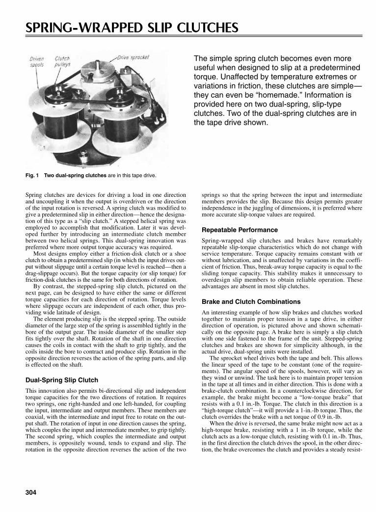
304
SPRING-WRAPPED SLIP CLUTCHES
The simple spring clutch becomes even moreuseful when designed to slip at a predeterminedtorque. Unaffected by temperature extremes orvariations in friction, these clutches are simple—they can even be “homemade.” Information isprovided here on two dual-spring, slip-typeclutches. Two of the dual-spring clutches are inthe tape drive shown.
Spring clutches are devices for driving a load in one directionand uncoupling it when the output is overdriven or the directionof the input rotation is reversed. A spring clutch was modified togive a predetermined slip in either direction—hence the designa-tion of this type as a “slip clutch.” A stepped helical spring wasemployed to accomplish that modification. Later it was devel-oped further by introducing an intermediate clutch memberbetween two helical springs. This dual-spring innovation waspreferred where more output torque accuracy was required.
Most designs employ either a friction-disk clutch or a shoeclutch to obtain a predetermined slip (in which the input drives out-put without slippage until a certain torque level is reached—then adrag-slippage occurs). But the torque capacity (or slip torque) forfriction-disk clutches is the same for both directions of rotation.
By contrast, the stepped-spring slip clutch, pictured on thenext page, can be designed to have either the same or differenttorque capacities for each direction of rotation. Torque levelswhere slippage occurs are independent of each other, thus pro-viding wide latitude of design.
The element producing slip is the stepped spring. The outsidediameter of the large step of the spring is assembled tightly in thebore of the output gear. The inside diameter of the smaller stepfits tightly over the shaft. Rotation of the shaft in one directioncauses the coils in contact with the shaft to grip tightly, and thecoils inside the bore to contract and produce slip. Rotation in theopposite direction reverses the action of the spring parts, and slipis effected on the shaft.
Dual-Spring Slip Clutch
This innovation also permits bi-directional slip and independenttorque capacities for the two directions of rotation. It requirestwo springs, one right-handed and one left-handed, for couplingthe input, intermediate and output members. These members arecoaxial, with the intermediate and input free to rotate on the out-put shaft. The rotation of input in one direction causes the spring,which couples the input and intermediate member, to grip tightly.The second spring, which couples the intermediate and outputmembers, is oppositely wound, tends to expand and slip. Therotation in the opposite direction reverses the action of the two
springs so that the spring between the input and intermediatemembers provides the slip. Because this design permits greaterindependence in the juggling of dimensions, it is preferred wheremore accurate slip-torque values are required.
Repeatable Performance
Spring-wrapped slip clutches and brakes have remarkablyrepeatable slip-torque characteristics which do not change withservice temperature. Torque capacity remains constant with orwithout lubrication, and is unaffected by variations in the coeffi-cient of friction. Thus, break-away torque capacity is equal to thesliding torque capacity. This stability makes it unnecessary tooverdesign slip members to obtain reliable operation. Theseadvantages are absent in most slip clutches.
Brake and Clutch Combinations
An interesting example of how slip brakes and clutches workedtogether to maintain proper tension in a tape drive, in eitherdirection of operation, is pictured above and shown schemati-cally on the opposite page. A brake here is simply a slip clutchwith one side fastened to the frame of the unit. Stepped-springclutches and brakes are shown for simplicity although, in theactual drive, dual-spring units were installed.
The sprocket wheel drives both the tape and belt. This allowsthe linear speed of the tape to be constant (one of the require-ments). The angular speed of the spools, however, will vary asthey wind or unwind. The task here is to maintain proper tensionin the tape at all times and in either direction. This is done with abrake-clutch combination. In a counterclockwise direction, forexample, the brake might become a “low-torque brake” thatresists with a 0.1 in.-lb. Torque. The clutch in this direction is a“high-torque clutch”—it will provide a 1-in.-lb torque. Thus, theclutch overrides the brake with a net torque of 0.9 in.-lb.
When the drive is reversed, the same brake might now act as ahigh-torque brake, resisting with a 1 in.-lb torque, while theclutch acts as a low-torque clutch, resisting with 0.1 in.-lb. Thus,in the first direction the clutch drives the spool, in the other direc-tion, the brake overcomes the clutch and provides a steady resist-
Fig. 1 Two dual-spring clutches are in this tape drive.
Sclater Chapter 9 5/3/01 12:56 PM Page 304
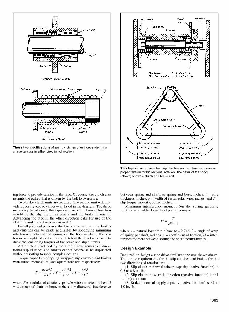
ing force to provide tension in the tape. Of course, the clutch alsopermits the pulley that is driven by the belt to overdrive.
Two brake-clutch units are required. The second unit will pro-vide opposing torque values—as listed in the diagram. The drivenecessary to advance the tape only in a clockwise directionwould be the slip clutch in unit 2 and the brake in unit 1.Advancing the tape in the other direction calls for use of theclutch in unit 1 and the brake in unit 2.
For all practical purposes, the low torque values in the brakesand clutches can be made negligible by specifying minimuminterference between the spring and the bore or shaft. The lowtorque is amplified in the spring clutch at the level necessary todrive the tensioning torques of the brake and slip clutches.
Action thus produced by the simple arrangement of direc-tional slip clutches and brakes cannot otherwise be duplicatedwithout resorting to more complex designs.
Torque capacities of spring-wrapped slip clutches and brakeswith round, rectangular, and square wire are, respectively:
where E = modules of elasticity, psi; d = wire diameter, inches; D= diameter of shaft or bore, inches; ε = diametral interference
TEd
DT
EbtD
TEt
D= = =π δ δ δ4
2
3
2
4
232 6 6; ;
305
between spring and shaft, or spring and bore, inches; t = wirethickness, inches; b = width of rectangular wire, inches; and T =slip torque capacity, pound-inches.
Minimum interference moment (on the spring grippinglightly) required to drive the slipping spring is:
where e = natural logarithmic base (e = 2.716; θ = angle of wrapof spring per shaft, radians, µ = coefficient of friction, M = inter-ference moment between spring and shaft, pound-inches.
Design Example
Required: to design a tape drive similar to the one shown above.The torque requirements for the slip clutches and brakes for thetwo directions of rotation are:
(1) Slip clutch in normal takeup capacity (active function) is0.5 to 0.8 in.-lb.
(2) Slip clutch in override direction (passive function) is 0.1in.-lb (maximum
(3) Brake in normal supply capacity (active function) is 0.7 to1.0 in.-lb.
MT
e=
−µθ 1
These two modifications of spring clutches offer independent slipcharacteristics in either direction of rotation.
This tape drive requires two slip clutches and two brakes to ensureproper tension for bidirectional rotation. The detail of the spool(above) shows a clutch and brake unit.
Sclater Chapter 9 5/3/01 12:56 PM Page 305

(4) Brake in override direction (passive function) is 0.1 in.-lb(maximum).
Assume that the dual-spring design shown previously is toinclude 0.750-in. drum diameters. Also available is an axiallength for each spring, equivalent to 12 coils which are dividedequally between the bridged shafts. Assuming round wire, calcu-late the wire diameter of the springs if 0.025 in. is maximumdiametral interference desired for the active functions. For thepassive functions use round wire that produces a spring index notmore than 25.Slip clutch, active spring:
The minimum diametral interference is (0.025) (0.5)/0.8 =0.016 in. Consequently, the ID of the spring will vary from 0.725to 0.734 in.Slip clutch, passive spring:
Wire dia. =drum dia.
spring index in.= =0 750
250 030
..
Diametral interference:
Assuming a minimum coefficient of friction of 0.1, determinethe minimum diametral interference for a spring clutch that willdrive the maximum slip clutch torque of 0.8 lb-in.
Minimum diametral interference:
ID of the spring is therefore 0.727 to 0.745 in.
Brake springs
By similar computations the wire diameter of the active brakespring is 0.053 in., with an ID that varies from 0.725 and 0.733in.; wire diameter of the passive brake spring is 0.030 in., with itsID varying from 0.727 to 0.744 in.
min ..
..= × =0 023
0 0190 1
0 0044 in.
MT
e e=
−=
−µθ π10 8
10 1 6.
( . )( )
δπ π
= =×
=32 32 0 750 0 130 10 0 030
0 0232
4
2
6 4D TEd
( )( . )( . )( )( . )
. in.
306
CONTROLLED-SLIP CONCEPT ADDS NEW USES FORSPRING CLUTCHES
A remarkably simple change in springclutches is solving a persistent problemin tape and film drives—how to keepdrag tension on the tape constant, as itsspool winds or unwinds. Shaft torquehas to be varied directly with the tapediameter so many designers resort toadding electrical control systems, butthat calls for additional components; anextra motor makes this an expensivesolution. The self-adjusting spring brake(Fig. 1) developed by Joseph Kaplan,Farmingdale, NY, gives a constant dragtorque (“slip” torque) that is easily andautomatically varied by a simple lever
arrangement actuated by the tape spooldiameter (Fig. 2). The new brake is alsobeing employed to test the output ofmotors and solenoids by providing levelsof accurate slip torque.
Kaplan used his “controlled-slip” con-cept in two other products. In the con-trolled-torque screwdriver (Fig. 3) astepped spring provides a 11⁄4-in.-lb slipwhen turned in either direction. It avoidsovertightening machine screws in delicateinstrument assemblies. A stepped spring isalso the basis for the go/no-go torque gagethat permits production inspection of out-put torques to within 1%.
Interfering spring. The three productswere the latest in a series of slip clutches,drag brakes, and slip couplings devel-oped by Kaplan for instrument brakedrives. All are actually outgrowths of thespring clutch. The spring in this clutch isnormally prevented from gripping theshaft by a detent response. Upon releaseof the detent, the spring will grip theshaft. If the shaft is turning in the properdirection, it is self-energizing. In theother direction, the spring simply over-rides. Thus, the spring clutch is a “one-way” clutch.
Fig. 1 Variable-torque drag brake . . . Fig. 2 . . . holds tension constant on tape Fig. 3 Constant-torque screwdriver
Sclater Chapter 9 5/3/01 12:56 PM Page 306

307
SPRING BANDS GRIP TIGHTLY TO DRIVEOVERRUNNING CLUTCH
An overrunning clutch that takes up onlyhalf the space of most clutches has aseries of spiral-wound bands instead ofconventional rollers or sprags to transmithigh torques. The design (see drawing)also simplifies the assembly, cuttingcosts as much as 40% by eliminatingmore than half the parts in conventionalclutches.
The key to the savings in cost andspace is the clutches’ freedom from theneed for a hardened outer race. Rollersand sprags must have hardened racesbecause they transmit power by a wedg-ing action between the inner and outerraces.
Role of spring bands. Overrunningclutches, including the spiral-band type,slip and overrun when reversed (seedrawing). This occurs when the outermember is rotated clockwise and theinner ring is the driven member.
The clutch, developed by NationalStandard Co., Niles, Michigan, containsa set of high-carbon spring-steel bands(six in the design illustrated) that grip theinner member when the clutch is driving.
The outer member simply serves toretain the spring anchors and to play apart in actuating the clutch. Because itisn’t subject to wedging action, it can bemade of almost any material, and thisaccounts for much of the cost saving. Forexample, in the automotive torque con-verter in the drawing at right, the bandsfit into the aluminum die-cast reactor.
Reduced wear. The bands are spring-loaded over the inner member of theclutch, but they are held and rotated bythe outer member. The centrifugal forceon the bands then releases much of theforce on the inner member and consider-ably decreases the overrunning torque.Wear is consequently greatly reduced.
The inner portion of the bands fitsinto a V-groove in the inner member.When the outer member is reversed, thebands wrap, creating a wedging action inthis V-groove. This action is similarto that of a spring clutch with a helical-coil spring, but the spiral-band type hasvery little unwind before it overruns,compared with the coil type. Thus, itresponds faster.
Edges of the clutch bands carry theentire load, and there is also a compoundaction of one band upon another. As thetorque builds up, each band pushes downon the band beneath it, so each tip isforced more firmly into the V-groove.The bands are rated for torque capacitiesfrom 85 to 400 ft.-lb. Applicationsinclude their use in auto transmissions,starters, and industrial machinery.
Spiral clutch bands can be purchasedseparately to fit the user’s assembly.
Spiral bands direct the force inward as an outer ring drives counterclockwise. The rollers and sprags direct the force outward.
Sclater Chapter 9 5/3/01 12:56 PM Page 307

308
SLIP AND BIDIRECTIONAL CLUTCHES COMBINE TOCONTROL TORQUE
A torque-limiting knob includes a dualset of miniature clutches—a detent slipclutch in series with a novel bi-directional-locking clutch—to preventthe driven member from backturning theknob. The bi-directional clutch in theknob locks the shaft from backlashtorque originating within the panel, andthe slip clutch limits the torque transmit-ted from outside the panel. The clutchwas invented by Ted Chanoux, ofMedford, N.Y.
The clutch (see drawing) is the resultof an attempt to solve a problem thatoften plagues design engineers. A mecha-nism behind a panel such as a precisionpotentiometer or switch must be operatedby a shaft that protrudes from the panel.The mechanism, however, must not beable to turn the shaft. Only the operatorin front of the knob can turn the shaft,and he must limit the amount of torquehe applies.
Solving design problem. This prob-lem showed up in the design of a naviga-tional system for aircraft.
The counter gave a longitudinal or lat-itudinal readout. When the aircraft wasready to take off, the navigator or pilotset a counter to some nominal figure,depending on the location of his startingpoint, and he energized the system. Thecomputer then accepts the directionalinformation from the gyro, the air speed
from instruments in the wings, plus otherdata, and feeds a readout at the counter.
The entire mechanism was subjectedto vibration, acceleration and decelera-tion, shock, and other high-torque loads,all of which could feed back through thesystem and might move the counter. Thenew knob device positively locks themechanism shaft against the vibration,shock loads, and accidental turning, andit also limits the input torque to the sys-tem to a preset value.
Operation. To turn the shaft, the oper-ator depresses the knob 1⁄16 in. and turns itin the desired direction. When it isreleased, the knob retracts, and the shaftimmediately and automatically locks tothe panel or frame with zero backlash.Should the shaft torque exceed the presetvalue because of hitting a mechanicalstop after several turns, or should theknob turn in the retracted position, theknob will slip to protect the systemmechanism.
Internally, pushing in the knob turnsboth the detent clutch and the bidirec-tional-clutch release cage via the key-way. The fingers of the cage extendbetween the clutch rollers so that therotation of the cage cams out the rollers,which are usually kept jammed betweenthe clutch cam and the outer race with theroller springs. This action permits rota-tion of the cam and instrument shaft both
clockwise and counterclockwise, but itlocks the shaft securely against insidetorque up to 30 oz.-in.
Applications. The detent clutch can beadjusted to limit the input torque to thedesired values without removing theknob from the shaft. The outside diame-ter of the shaft is only 0.900 in., and thetotal length is 0.940 in. The exteriormaterial of the knob is anodized alu-minum, black or gray, and all other partsare stainless steel. The device is designedto meet the military requirements ofMIL-E-5400, class 3 and MILK-3926specifications.
Applications were seen in counter andreset switches and controls for machinesand machine tools, radar systems, andprecision potentiometers.
Eight-Joint Coupler
A novel coupler combines two parallellinkage systems in a three-dimensionalarrangement to provide wide angular andlateral off-set movements in pipe joints.By including a bellows between the con-necting pipes, the connector can joinhigh-pressure and high-temperature pip-ing such as is found in refineries, steamplants, and stationary power plants.
The key components in the couplerare four pivot levers (drawing) mounted
in two planes. Each pivot lever has provi-sions for a ball joint at each end.“Twisted” tie rods, with holes in differentplanes, connect the pivot levers to com-plete the system. The arrangement per-mits each pipe face to twist through anappreciable arc and also to shift orthogo-nally with respect to the other.
Longer tie rods can be formed byjoining several bellows together withcenter tubes.
The connector was developedby Ralph Kuhm Jr. of El Segundo,California.
Miniature knob is easily operated from outside the panel by pushing it in and turning it in thedesired direction. When released, the bi-directional clutch automatically locks the shaft againstall conditions of shock and vibration.
Sclater Chapter 9 5/3/01 12:56 PM Page 308

309
WALKING PRESSURE PLATEDELIVERS CONSTANT TORQUE
This automatic clutch causes the drivingplate to move around the surface of thedriven plate to prevent the clutch platesfrom overheating if the load gets toohigh. The “walking” action enables theclutch to transmit full engine torque forhours without serious damage to theclutch plates or the engine.
The automatic centrifugal clutch,manufactured by K-M Clutch Co., VanNuys, California, combines the princi-ples of a governor and a wedge to trans-mit torque from the engine to the driveshaft (see drawing).
How it works. As the engine builds upspeed, the weights attached to the levershave a tendency to move towards the rimof the clutch plate, but they are stoppedby retaining springs. When the shaftspeed reaches 1600 rpm, however, cen-trifugal force overcomes the resistance ofthe springs, and the weights move out-ward. Simultaneously, the tapered end ofthe lever wedges itself in a slot in pin E,which is attached to the driving clutchplate. The wedging action forces both thepin and the clutch plate to move into con-tact with the driven plate.
A pulse of energy is transmitted to theclutch each time a cylinder fires. Withevery pulse, the lever arm moves out-ward, and there is an increase in pressurebetween the faces of the clutch. Beforethe next cylinder fires, both the lever armand the driving plate return to their origi-nal positions. This pressure fluctuationbetween the two faces is repeatedthroughout the firing sequence of theengine.
Plate walks. If the load torque exceedsthe engine torque, the clutch immediatelyslips, but full torque transfer is main-tained without serious overheating. Thepressure plate then momentarily disen-gages from the driven plate. However, asthe plate rotates and builds up torque, itagain comes in contact with the drivenplate. In effect, the pressure plate
“walks” around the contact surface of thedriven plate, enabling the clutch to con-tinuously transmit full engine torque.
Applications. The clutch has undergonehundreds of hours of development test-ing on 4-stroke engines that ranged from5 to 9 hp. According to the K-M ClutchCo., the clutch enables designers to usesmaller motors than they previouslycould because of its no-load startingcharacteristics.
The clutch also acts as a brake to holdengine speeds within safe limits. Forexample, if the throttle accidentallyopens when the driving wheels or drivenmechanisms are locked, the clutch willstop.
The clutch can be fitted with sprock-ets, sheaves, or a stub shaft. It operates inany position, and can be driven in bothdirections. The clutch could be installedin ships so that the applied torque wouldcome from the direction of the drivenplate.
The pressure plate was made of castiron, and the driven-plate casting wasmade of magnesium. To prevent toomuch wear, the steel fly weights and flylevers were pre-hardened.
A driving plate moves to plate D, closingthe gap, when speed reaches 1600 rpm.
When a centrifugal force overcomes theresistance of the spring force, the leveraction forces the plates together.
Sclater Chapter 9 5/3/01 12:57 PM Page 309

310
CONICAL-ROTOR MOTORPROVIDES INSTANT CLUTCHING OR BRAKING
By reshaping the rotor of an ac electricmotor, engineers at Demag BrakeMotors, Wyandotte, Michigan, foundthat the axial component of the magneticforces can be used to act on a clutch or abrake. Moreover, the motors can bearranged in tandem to obtain fast or slowspeeds with instant clutching or braking.
As a result, this motor was used inmany applications where instant brakingis essential—for example, in an elevatorwhen the power supply fails. The princi-pal can also be applied to obtain a verniereffect, which is useful in machine-tooloperations.
Operating principles. The Demagbrake motor operates on a sliding-rotorprinciple. When no power is beingapplied, the rotor is pushed slightlyaway from the stator in an axial direc-tion by a spring. However, with powerthe axial vector of the magnetic forcesovercomes the spring pressure andcauses the rotor to slide forward almostfull into the stator. The maximum dis-
tance in an axial direction is 0.18 in.This effect permits that a combined fanand clutch, mounted on the rotor shaft,to engage with a brake drum whenpower is stopped, and disengage whenpower is applied.
In Europe, the conical-rotored motoris used where rapid braking is essentialto overcome time consuming overruns,or where accurate braking and preciseangular positioning are critical—such asin packaging machines.
Novel arrangement. For instance, iftwo motors are installed, one running at900 rpm and the other at 3600 rpm, theunit can reduce travel at a precisemoment from a fats speed to an inchingspeed. This is achieved in the followingway: When the main motor (running at3600 rpm, and driving a conveyor tableat fat speed) is stopped, the rotor slidesback, and the clutch plate engages withthe other rotating clutch plate, which isbeing driven through a reduction gearsystem by the slower running motor.
Because the second motor is running at900 rpm and the reduction through thegear and belts is 125:1, the speed isgreatly reduced.
FAST-REVERSAL REEL DRIVE
A fast-reversal drive for both forward movement and rewind isshifted by the rotary switch; it also controls a lamp and drive motor. Ashort lever on the switch shaft is linked to an overcenter mechanismon which the drive wheel is mounted. During the shift from forward torewind, the drive pulley crosses its pivot point so that the spring ten-
sion of the drive belt maintains pressure on the driven wheel. Thedrive from the shutter pulley is 1:1 by the spring belt to the drive pul-ley and through a reduction when the forward pulley is engaged.When rewind is engaged, the reduction is eliminated and the filmrewinds at several times forward speed.
Sclater Chapter 9 5/3/01 12:57 PM Page 310
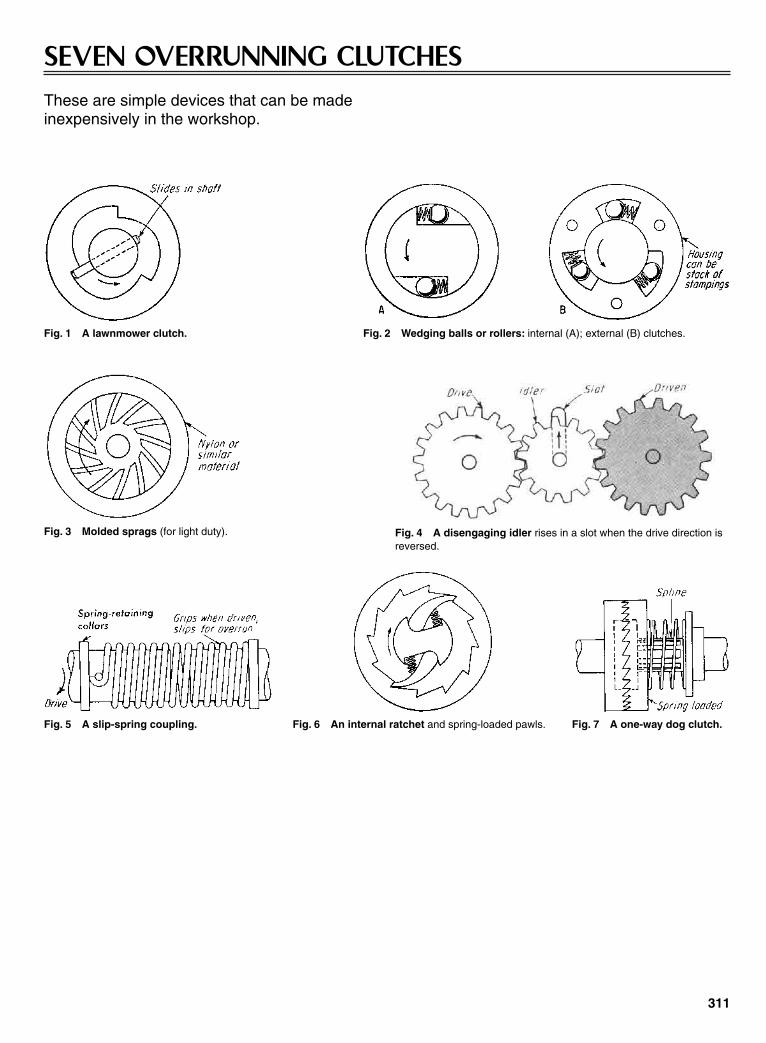
311
SEVEN OVERRUNNING CLUTCHESThese are simple devices that can be made inexpensively in the workshop.
Fig. 1 A lawnmower clutch. Fig. 2 Wedging balls or rollers: internal (A); external (B) clutches.
Fig. 3 Molded sprags (for light duty). Fig. 4 A disengaging idler rises in a slot when the drive direction isreversed.
Fig. 5 A slip-spring coupling. Fig. 6 An internal ratchet and spring-loaded pawls. Fig. 7 A one-way dog clutch.
Sclater Chapter 9 5/3/01 12:57 PM Page 311

312
SPRING-LOADED PINS AID SPRAGS IN ONE-WAY CLUTCHSprags combined with cylindrical rollersin a bearing assembly can provide a sim-ple, low-cost method for meeting thetorque and bearing requirements of mostmachine applications. Designed and builtby Est. Nicot of Paris, this unit gives one-direction-only torque transmission in anoverrunning clutch. In addition, it alsoserves as a roller bearing.
The torque rating of the clutchdepends on the number of sprags. A min-imum of three, equally spaced around thecircumference of the races, is generallynecessary to get acceptable distributionof tangential forces on the races.
This clutch can be adapted for either electrical or mechanical actu-ation, and will control 1⁄2 hp at 1500 rpm with only 7 W of power in thesolenoid. The rollers are positioned by a cage (integral with thetoothed control wheel —see diagram) between the ID of the drivinghousing and the cammed hub (integral with the output gear).
When the pawl is disengaged, the drag of the housing on the fric-tion spring rotates the cage and wedges the rollers into engagement.This permits the housing to drive the gear through the cam.
When the pawl engages the control wheel while the housing isrotating, the friction spring slips inside the housing and the rollers arekicked back, out of engagement. Power is therefore interrupted.
According to the manufacturer, Tiltman Langley Ltd, Surrey,England, the unit operated over the full temperature range of –40º to200ºF.
Races are concentric; a locking ramp is provided by the sprag profile, which is composed oftwo nonconcentric curves of different radius. A spring-loaded pin holds the sprag in the lockedposition until the torque is applied in the running direction. A stock roller bearing cannot be con-verted because the hard-steel races of the bearing are too brittle to handle the locking impactof the sprag. The sprags and rollers can be mixed to give any desired torque value.
ROLLER-TYPE CLUTCH
Two-speed operation is provided by the new cam clutch
This clutch consists of two rotary members (see dia-grams), arranged so that the outer (follower) member acts onits pulley only when the inner member is driving. When theouter member is driving, the inner member idles. One appli-cation was in a dry-cleaning machine. The clutch functionsas an intermediary between an ordinary and a high-speedmotor to provide two output speeds that are used alternately.
A positive drive is provided by this British rollerclutch.
Sclater Chapter 9 5/3/01 12:57 PM Page 312
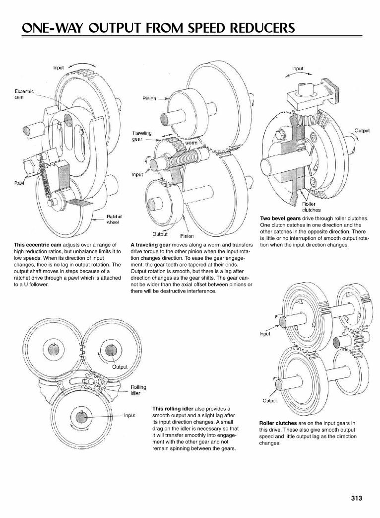
313
ONE-WAY OUTPUT FROM SPEED REDUCERS
This eccentric cam adjusts over a range ofhigh reduction ratios, but unbalance limits it tolow speeds. When its direction of inputchanges, thee is no lag in output rotation. Theoutput shaft moves in steps because of aratchet drive through a pawl which is attachedto a U follower.
A traveling gear moves along a worm and transfersdrive torque to the other pinion when the input rota-tion changes direction. To ease the gear engage-ment, the gear teeth are tapered at their ends.Output rotation is smooth, but there is a lag afterdirection changes as the gear shifts. The gear can-not be wider than the axial offset between pinions orthere will be destructive interference.
Two bevel gears drive through roller clutches.One clutch catches in one direction and theother catches in the opposite direction. Thereis little or no interruption of smooth output rota-tion when the input direction changes.
This rolling idler also provides asmooth output and a slight lag afterits input direction changes. A smalldrag on the idler is necessary so thatit will transfer smoothly into engage-ment with the other gear and notremain spinning between the gears.
Roller clutches are on the input gears inthis drive. These also give smooth outputspeed and little output lag as the directionchanges.
Sclater Chapter 9 5/3/01 12:57 PM Page 313
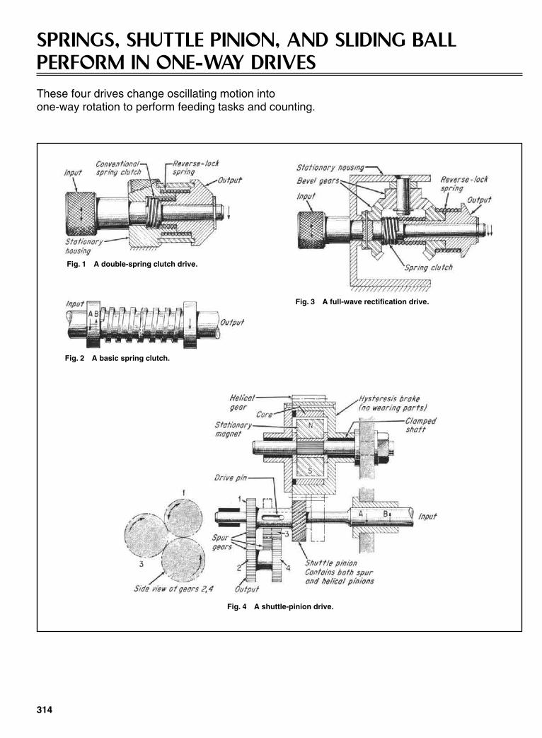
SPRINGS, SHUTTLE PINION, AND SLIDING BALLPERFORM IN ONE-WAY DRIVESThese four drives change oscillating motion into one-way rotation to perform feeding tasks and counting.
314
Fig. 1 A double-spring clutch drive.
Fig. 2 A basic spring clutch.
Fig. 3 A full-wave rectification drive.
Fig. 4 A shuttle-pinion drive.
Sclater Chapter 9 5/3/01 12:57 PM Page 314

The one-way drive, shown in Fig. 1,was invented as a byproduct of thedesign of a money-order imprinter.
The task was to convert the oscillat-ing motion of the input crank (20º in thiscase) into a one-way motion to advancean inking ribbon. One of the simplestknown devices was used to obtain theone-way drive—a spring clutch which isa helical spring joining two co-linearbutting shafts (Fig. 2). The spring is usu-ally made of square or rectangular cross-section wire.
This clutch transmits torque in onedirection only because it overrides whenit is reversed. The helical spring, whichbridges both shafts, need not be fastenedat either end; a slight interference fit isacceptable. Rotating the input shaft in thedirection tending to wind the spring(direction A in Fig. 2) causes the springto grip both shafts and then transmitmotion from the input to the output shaft.Reversing the input unwinds the spring,and it overrides the output shaft with adrag—but this drag, slight as it was,caused a problem in operation.
Double-Clutch Drive
The spring clutch (Fig. 2) did not provideenough friction in the tape drive to allowthe spring clutch to slip on the shafts onthe return stroke. Thus the output movedin sympathy with the input, and thedesired one-way drive was not achieved.
At first, an attempt was made to addfriction artificially to the output, but thisresulted in an awkward design. Finallythe problem was elegantly solved (Fig. 1)by installing a second helical spring,slightly larger than the first that servedexactly the same purpose: transmissionof motion in one direction only. Thisspring, however joined the output shaft
and a stationary cylinder. In this way,with the two springs of the same hand,the undesirable return motion of the rib-bon drive was immediately arrested, anda positive one-way drive was obtainedquite simply.
This compact drive can be consideredto be a mechanical half-wave rectifier inthat it transmits motion in one directiononly while it suppresses motion in thereverse direction.
Full-Wave Rectifier
The principles described will also pro-duce a mechanical full-wave rectifier byintroducing some reversing gears, Fig. 3.In this application the input drive in onedirection is directly transmitted to theoutput, as before, but on the reversestroke the input is passed through revers-ing gears so that the output appears in theopposite sense. In other words, the origi-nal sense of the output is maintained.Thus, the output moves forward twice foreach back-and-forth movement of theinput.
Shuttle-Gear Drive
Earlier, a one-way drive was developedthat harnessed the axial thrust of a pair ofhelical gears to shift a pinion, Fig. 4.Although at first glance, it might looksomewhat complicated, the drive is inex-pensive to make and has been operatingsuccessfully with little wear.
When the input rotates in direction A,it drives the output through spur gears 1and 2. The shuttle pinion is also drivingthe helical gear whose rotation is resistedby the magnetic flux built up between thestationary permanent magnet and therotating core. This magnet-core arrange-ment is actually a hysteresis brake, and
its constant resisting torque produces anaxial thrust in mesh of the helical pinionacting to the left. Reversing the inputreverses the direction of thrust, whichshifts the shuttle pinion to the right. Thedrive then operates through gears 1, 3,and 4, which nullifies the reversion toproduce output in the same direction.
Reciprocating-Ball Drive
When the input rotates in direction A,Fig. 5, the drive ball trails to the right,and its upper half engages one of theradial projections in the right ring gear todrive it in the same direction as the input.The slot for the ball is milled at 45º to theshaft axes and extends to the flanges oneach side.
When the input is reversed, the ballextends to the flanges on each side, trailsto the left and deflects to permit the ballto ride over to the left ring gear, andengage its radial projection to drive thegear in the direction of the input.
Each gear, however, is constantly inmesh with a pinion, which in turn is inmesh with the other gear. Thus, regard-less of the direction the input is turned,the ball positions itself under one oranother ring gear, and the gears willmaintain their respective sense of rota-tion (the rotation shown in Fig. 5).Hence, an output gear in mesh with oneof the ring gears will rotate in one direc-tion only.
315
Fig. 5 A reciprocating-ball drive.
Sclater Chapter 9 5/3/01 12:57 PM Page 315

316
DETAILS OF OVERRIDING CLUTCHES
Fig. 1 Elementary overriding clutches: (A) A ratchet and pawlmechanism converts reciprocating or oscillating movement to inter-mittent rotary motion. This motion is positive but limited to a multipleof the tooth pitch. (B) A friction-type clutch is quieter, but it requires a
spring device to keep the eccentric pawl in constant engagement. (C)Balls or rollers replace the pawls in this device. Motion of the outerrace wedges the rollers against the inclined surfaces of the ratchetwheel.
Fig. 2 A commercial overriding clutch has springs that hold the rollers in continu-ous contact between the cam surfaces and the outer race; thus, there is no backlash orlost motion. This simple design is positive and quiet. For operation in the oppositedirection, the roller mechanism can easily be reversed in the housing.
Fig. 3 A centrifugal force can hold therollers in contact with the cam and outer race.A force is exerted on the lugs of the cage thatcontrols the position of the rollers.
Fig. 4 With cylindrical inner and outer races, sprags can transmittorque. Energizing springs serve as a cage to hold the sprags. (A)Compared to rollers, the shape of a sprag permits a greater numberwithin a limited space; thus higher torque loads are possible. Special
cam surfaces are not required, so this version can be installed insidegear or wheel hubs. (B) Rolling action wedges the sprags tightlybetween the driving and driven members. A relatively large wedgingangle ensures positive engagement.
Sclater Chapter 9 5/3/01 12:57 PM Page 316
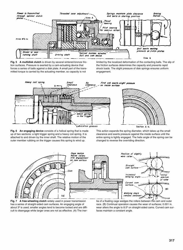
317
Fig. 5 A multidisk clutch is driven by several sintered-bronze fric-tion surfaces. Pressure is exerted by a cam-actuating device thatforces a series of balls against a disk plate. A small part of the trans-mitted torque is carried by the actuating member, so capacity is not
limited by the localized deformation of the contacting balls. The slip ofthe friction surfaces determines the capacity and prevents rapidshock loads. The slight pressure of disk springs ensures uniformengagement.
Fig. 6 An engaging device consists of a helical spring that is madeup of two sections: a light trigger spring and a heavy coil spring. It isattached to and driven by the inner shaft. The relative motion of theouter member rubbing on the trigger causes this spring to wind up.
This action expands the spring diameter, which takes up the smallclearance and exerts pressure against the inside surface until theentire spring is tightly engaged. The helix angle of the spring can bechanged to reverse the overriding direction.
Fig. 7 A free-wheeling clutch widely used in power transmissionhas a series of straight-sided cam surfaces. An engaging angle ofabout 3º is used; smaller angles tend to become locked and are diffi-cult to disengage while larger ones are not as effective. (A) The iner-
tia of a floating cage wedges the rollers between the cam and outerrace. (B) Continual operation causes the wear of surfaces; 0.001 in.wear alters the angle to 8.5º on straight-sided cams. Curved cam sur-faces maintain a constant angle.
Sclater Chapter 9 5/3/01 12:57 PM Page 317
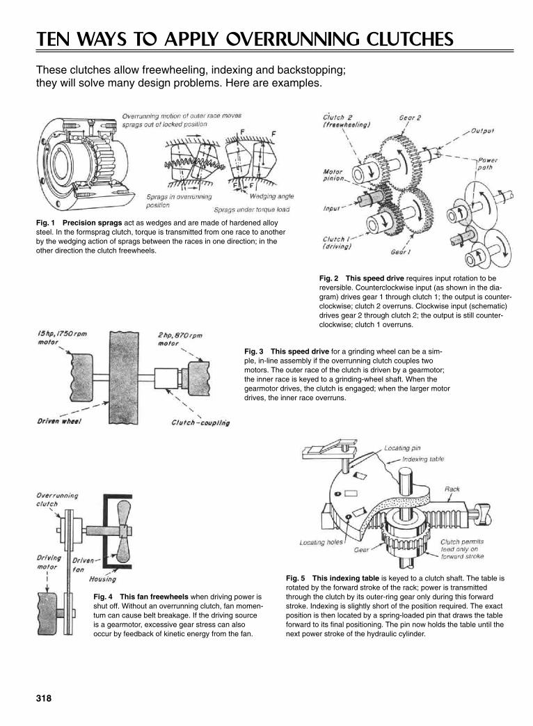
318
TEN WAYS TO APPLY OVERRUNNING CLUTCHESThese clutches allow freewheeling, indexing and backstopping; they will solve many design problems. Here are examples.
Fig. 1 Precision sprags act as wedges and are made of hardened alloysteel. In the formsprag clutch, torque is transmitted from one race to anotherby the wedging action of sprags between the races in one direction; in theother direction the clutch freewheels.
Fig. 2 This speed drive requires input rotation to bereversible. Counterclockwise input (as shown in the dia-gram) drives gear 1 through clutch 1; the output is counter-clockwise; clutch 2 overruns. Clockwise input (schematic)drives gear 2 through clutch 2; the output is still counter-clockwise; clutch 1 overruns.
Fig. 3 This speed drive for a grinding wheel can be a sim-ple, in-line assembly if the overrunning clutch couples twomotors. The outer race of the clutch is driven by a gearmotor;the inner race is keyed to a grinding-wheel shaft. When thegearmotor drives, the clutch is engaged; when the larger motordrives, the inner race overruns.
Fig. 4 This fan freewheels when driving power isshut off. Without an overrunning clutch, fan momen-tum can cause belt breakage. If the driving sourceis a gearmotor, excessive gear stress can alsooccur by feedback of kinetic energy from the fan.
Fig. 5 This indexing table is keyed to a clutch shaft. The table isrotated by the forward stroke of the rack; power is transmittedthrough the clutch by its outer-ring gear only during this forwardstroke. Indexing is slightly short of the position required. The exactposition is then located by a spring-loaded pin that draws the tableforward to its final positioning. The pin now holds the table until thenext power stroke of the hydraulic cylinder.
Sclater Chapter 9 5/3/01 12:57 PM Page 318

319
Fig. 6 This punch press feedis arranged so that the strip isstationary on the downstroke ofthe punch (clutch freewheels);feed occurs during the upstrokewhen the clutch transmitstorque. The feed mechanismcan easily be adjusted to varythe feed amount. Fig. 7 Indexing and backstopping is done with two
clutches arranged so that one drives while the otherfreewheels. The application shown here is for a cap-suling machine; gelatin is fed by the roll and stoppedintermittently so the blade can precisely shear thematerial to form capsules.
Fig. 8 The intermittent motion of a candymachine is adjustable. The clutch ratchets the feedrolls around. This keeps the material in the hopperagitated.
Fig. 9 This double-impulse drive has double eccentrics and drive clutches.Each clutch is indexed 180° out of phase with the other. One revolution of theeccentric produces two drive strokes. Stroke length, and thus the output rotation,can be adjusted from zero to maximum by the control link.
Fig. 10 This anti-backlash device depends on overrunning clutches toensure that no backlash is left in the unit. Gear A drives B and shaft II withthe gear mesh and backlash, as shown in (A). The overrunning clutch ingear C permits gear D (driven by shaft II) to drive gear C and results inthe mesh and backlash shown in (B). The overrunning clutches neveractually overrun. They provide flexible connections (something like splitand sprung gears) between shaft I and gears A and C to allow absorptionof all backlash.
Sclater Chapter 9 5/3/01 12:57 PM Page 319

320
APPLICATIONS FOR SPRAG-TYPE CLUTCHESOverrunning sprag clutches transmit torque in one direction and reduce speed, rest, hold, or free-wheel in the reverse direction. Applications include overrunning, backstopping, and indexing. Their selection—similar to other mechanical devices—requires a review of the torque to be transmitted, overrunning speed, type of lubrication, mounting characteristics, environmental conditions, and shock conditions that might be encountered.
Fig. 1 Overrunning permits torque transmission inone direction and free wheels or overruns in the oppo-site direction. For example, the gar motor drives theload by transmitting torque through the overrunningclutch and the high-speed shaft. Energizing the high-speed motor causes the inner member to rotate at therpm of the high-speed motor. The gear motor contin-ues to drive the inner member, but the clutch is free-wheeling.
Fig. 2 Backstopping permits rotation in one direc-tion only. The clutch serves as a counter-rotation hold-ing device. An example is a clutch mounted on theheadshaft of a conveyor. The outer race is restrainedby torque-arming the stationary frame of the conveyor.If, for any reason, power to the conveyor is inter-rupted, the back-stopping clutch will prevent the buck-ets from running backwards and dumping the load.
Fig. 4 Unidirectional drives with reverse mechanism incorporate twooverrunning clutches into the gears, sheaves, or sprockets. Here, a 1:1ratio right-angle drive is shown with a reversing input shaft. The outputshaft rotates clockwise, regardless of the input shaft direction. By chang-ing gear sizes, combinations of continuous or intermittent unidirectionaloutput relative to the input can be obtained.
Fig. 3 Indexing is the transmission of intermittentrotary motion in one direction; an example is the feedrolls of a punch press. On each stroke of the presscrankshaft, a feed stroke on the feed roll is accom-plished by the rack-and-pinion system. The systemfeeds the material into the dies of the punch press.
Sclater Chapter 9 5/3/01 12:57 PM Page 320

321
Fig. 5 Two-speed unidirectional output is made possible by using spur gears and reversing the direction of the inputshaft. The rotation of shaft A transfers the power of gears B, D, and E to the output. Counterclockwise rotation engagesthe lower clutch, freewheeling the upper clutch because gear C is traveling at a faster rate than the shaft. This is causedby the reduction between gears B and E. Clockwise rotation of A engages the upper clutch, while the lower clutch free-wheels because of the speed increase between gears D and E.
Fig. 6 A speed-differential or compensation is required where adifferent speed range for a function is desired, while retaining thesame basic speed for all other functions. A series of individuallydriven power rolls can have different surface speeds because of driveor diameter variations of the rolls. An overrunning clutch permits therolls with slower peripheral speed to overspeed and adjust to thematerial speed.
Fig. 7 A speed differential application permits the operationof engine accessories within a narrow speed range while theengine operates over a wide range. Pulley No. 2 contains theoverrunning clutch. When the friction or electric clutch is disen-gaged, the driver pulley drives pulley No. 2 through the overrun-ning clutch, rotating the driven shaft. The engagement of thefriction or electric clutch causes high-speed driven shaft rotation.This causes an overrun condition in the clutch at pulley No. 2.
Fig. 8 High inertia dissipation avoids driving back through a powersystem. In machines with high resistances, it prevents power train dam-age. If the engine is shut down while the generator is under a no-loadcondition, it would have a tendency to twist off the generator shaft. Theoverrunning clutch allows generator deceleration at a slower rate thanthe engine deceleration.
Sclater Chapter 9 5/3/01 12:57 PM Page 321
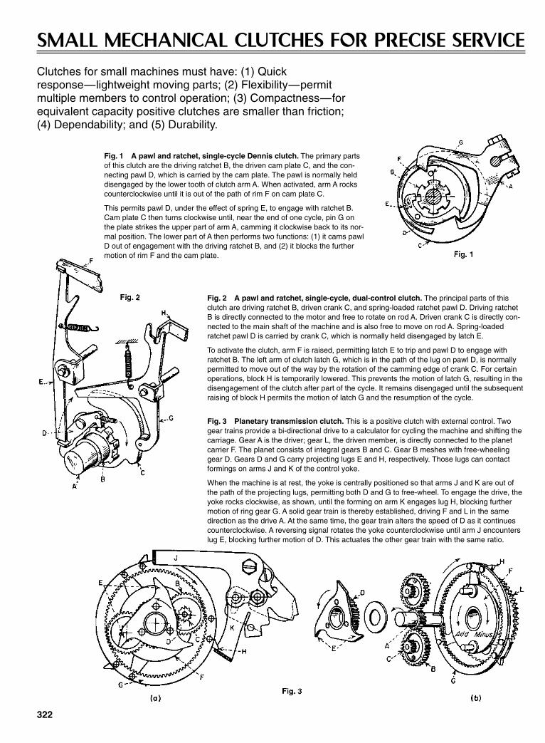
322
SMALL MECHANICAL CLUTCHES FOR PRECISE SERVICEClutches for small machines must have: (1) Quick response—lightweight moving parts; (2) Flexibility—permit multiple members to control operation; (3) Compactness—for equivalent capacity positive clutches are smaller than friction; (4) Dependability; and (5) Durability.
Fig. 2 A pawl and ratchet, single-cycle, dual-control clutch. The principal parts of thisclutch are driving ratchet B, driven crank C, and spring-loaded ratchet pawl D. Driving ratchetB is directly connected to the motor and free to rotate on rod A. Driven crank C is directly con-nected to the main shaft of the machine and is also free to move on rod A. Spring-loadedratchet pawl D is carried by crank C, which is normally held disengaged by latch E.
To activate the clutch, arm F is raised, permitting latch E to trip and pawl D to engage withratchet B. The left arm of clutch latch G, which is in the path of the lug on pawl D, is normallypermitted to move out of the way by the rotation of the camming edge of crank C. For certainoperations, block H is temporarily lowered. This prevents the motion of latch G, resulting in thedisengagement of the clutch after part of the cycle. It remains disengaged until the subsequentraising of block H permits the motion of latch G and the resumption of the cycle.
Fig. 1 A pawl and ratchet, single-cycle Dennis clutch. The primary partsof this clutch are the driving ratchet B, the driven cam plate C, and the con-necting pawl D, which is carried by the cam plate. The pawl is normally helddisengaged by the lower tooth of clutch arm A. When activated, arm A rockscounterclockwise until it is out of the path of rim F on cam plate C.
This permits pawl D, under the effect of spring E, to engage with ratchet B.Cam plate C then turns clockwise until, near the end of one cycle, pin G onthe plate strikes the upper part of arm A, camming it clockwise back to its nor-mal position. The lower part of A then performs two functions: (1) it cams pawlD out of engagement with the driving ratchet B, and (2) it blocks the furthermotion of rim F and the cam plate.
Fig. 3 Planetary transmission clutch. This is a positive clutch with external control. Twogear trains provide a bi-directional drive to a calculator for cycling the machine and shifting thecarriage. Gear A is the driver; gear L, the driven member, is directly connected to the planetcarrier F. The planet consists of integral gears B and C. Gear B meshes with free-wheelinggear D. Gears D and G carry projecting lugs E and H, respectively. Those lugs can contactformings on arms J and K of the control yoke.
When the machine is at rest, the yoke is centrally positioned so that arms J and K are out ofthe path of the projecting lugs, permitting both D and G to free-wheel. To engage the drive, theyoke rocks clockwise, as shown, until the forming on arm K engages lug H, blocking furthermotion of ring gear G. A solid gear train is thereby established, driving F and L in the samedirection as the drive A. At the same time, the gear train alters the speed of D as it continuescounterclockwise. A reversing signal rotates the yoke counterclockwise until arm J encounterslug E, blocking further motion of D. This actuates the other gear train with the same ratio.
Sclater Chapter 9 5/3/01 12:57 PM Page 322

323
Fig. 4 A multiple-disk friction clutch. Two multiple-diskfriction clutches are combined in a single, two-position unitthat is shown shifted to the left. A stepped cylindrical hous-ing, C, encloses both clutches. Internal self-lubricated bear-ings support the housing on coaxial shaft J that is driven bytransmission gear H, meshing with housing gear teeth K. Atthe other end, the housing carries multiple metal disks Qthat engage keyways V and can make frictional contact withphenolic laminate disks N. They, in turn, can contact a setof metal disks P that have slotted openings for couplingswith flats located on sleeves B and W.
In the position shown, pressure is exerted through rollers L,forcing the housing to the left, making the left clutch com-press against adjusting nuts R. Those nuts drive gear Athrough sleeve B, which is connected to jack shaft J by pinU. When the carriage is to be shifted, rollers L force thehousing to the right. However, it first relieves the pressurebetween the adjoining disks on the left clutch. Then theypass through a neutral position in which both clutches aredisengaged, and they finally compress the right clutchagainst thrust bearing F. That action drives gear G throughsleeve W, which rotates freely on the jack shaft.
Fig. 5 A single-plate friction clutch. The basic parts ofthis clutch are the phenolic laminate clutch disk A, steel diskB, and drum C. They are normally kept separated by springwasher G. To engage the drive, the left end of a control armis raised, causing ears F, which are located in slots in platesH, to rock clockwise. This action spreads the plates axiallyalong sleeve P. Sleeves E and P and plate B are keyed tothe drive shaft; all other members can rotate freely.
The axial motion loads the assembly to the right through thethrust ball bearings K against plate L and adjusting nut M. Italso loads them to the left through friction surfaces on A, B,and C to thrust washer S, sleeve E, and against a shoulderon shaft D. This response then permits phemolic laminatedisk A to drive drum C.
Fig. 6 An overload relief clutch. This is a simple, double-plate, friction coupling with springloading. Shaft G drives collar E, which drives slotted plates C and D faced with phenolic lami-nate disks B. Spring H is held in compression by the two adjusting nuts on the threaded end ofcollar E. These maintain the unit under axial pressure against the shoulder at the left end of thecollar.
This enables the phenolic laminate disks B to drive through friction against both faces of thegar, which is free to turn o the collar. This motion of the gear causes output pinion J to rotate. Ifthe machine to which the clutch is attached should jam and pinion J is prevented from turning,the motor can continue to run without overloading. However, slippage can occur between thephenolic laminate clutch plates B and the large gear.
Sclater Chapter 9 5/3/01 12:57 PM Page 323

324
MECHANISMS FORSTATION CLUTCHESInnumerable variations of these stationclutches can be designed for starting andstopping machines at selected points in theiroperation cycles.
Fig. 1(a) The driver andclutch body move in uni-son with the connector justcoming in contact with theextractor. In Fig. 1(b)continued movement with-draws the connector.
Fig. 2 A two-station clutch whose stations are 180º apart. Because it has only one extractorarm, this mechanism can function as a one-station clutch.
Fig. 3 A modification of the cam extrac-tor shown in Fig. 2.
Fig. 6 The end and longitudinal sectionof a station clutch with internal drivingrecesses.
Fig. 4 A single extractor two-station clutch with the sta-tions that are 180º apart. Only one extractor is requiredbecause the connector has two cams.
Fig. 5 This one- or two-station clutch with a dual extractoris compact because there are no parts projecting beyond itsbody.
Sclater Chapter 9 5/3/01 12:57 PM Page 324
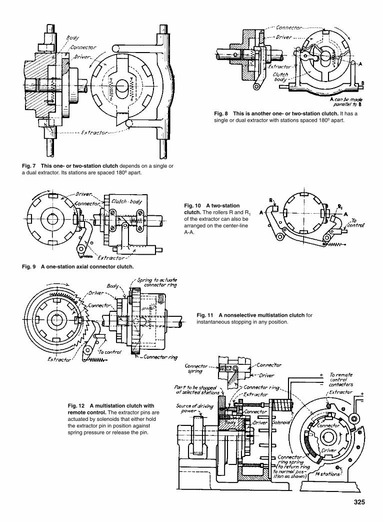
325
Fig. 7 This one- or two-station clutch depends on a single ora dual extractor. Its stations are spaced 180º apart.
Fig. 8 This is another one- or two-station clutch. It has asingle or dual extractor with stations spaced 180º apart.
Fig. 9 A one-station axial connector clutch.
Fig. 10 A two-stationclutch. The rollers R and R1of the extractor can also bearranged on the center-lineA-A.
Fig. 11 A nonselective multistation clutch forinstantaneous stopping in any position.
Fig. 12 A multistation clutch withremote control. The extractor pins areactuated by solenoids that either holdthe extractor pin in position againstspring pressure or release the pin.
Sclater Chapter 9 5/3/01 12:57 PM Page 325

326
TWELVE APPLICATIONS FOR ELECTROMAGNETICCLUTCHES AND BRAKES
Magnetic Friction Clutches
The simplest and most adaptable electromagnetic control clutch isthe magnetic friction clutch. It works on the same principle as asimple solenoid-operated electric relay with a spring return to nor-mal. Like the relay, it is a straightforward automatic switch for con-trolling the flow of power (in this cases, torque) through a circuit.
Rotating or Fixed Field?
This is a question primarily of magnetic design. Rotating-fieldclutches include a rotating coil, energized through brushes andslip rings. Fixed-field units have a stationary coil. Rotating-fieldunits are still more common, but there has been a marked trendtoward the fixed-field versions.
Generally speaking, a rotating-field clutch is a two-memberunit, with the coil carried in the driving (input) member. It can bemounted directly on a motor or speed-reducer shaft without load-ing down the driving motor. In the smaller sizes, it offers a betterratio of size to rated output than the fixed-field type, although therotating coil increases inertia in the larger models.
A fixed-field clutch, on the other hand, is a three-member unit
with rotating input and output members and a stationary coilhousing. It eliminates the need for brushes and slip rings, but itdemands additional bearing supports, and it can require close tol-erances in mounting.
Purely Magnetic Clutches
Probably less familiar than the friction types are hysteresis andeddy-current clutches. They operate on straight magnetic princi-ples and do not depend on mechanical contact between theirmembers. The two styles are almost identical in construction, butthe magnetic segments of the hysteresis clutch are electricallyisolated, and those of the eddy-current clutch are interconnected.The magnetic analogy of both styles is similar in that the flux ispassed between the two clutch members.
Hysteresis Clutches
The hysteresis clutch is a proportional-torque control device. Asits name implies, it exploits the hysteresis effect in a permanent-magnet rotor ring to produce a substantially constant torque thatis almost completely independent of speed (except for slight,
Fig. 1 Coupling or uncoupling power or sensing device.
Fig. 2 Calibration protection (energize to adjust).
Figs. 3 & 4 Simple servomotor brakes.
Fig. 5 Adding or subtracting two inputs.Fig. 6 Controlling output from a differential.
Sclater Chapter 9 5/3/01 12:57 PM Page 326
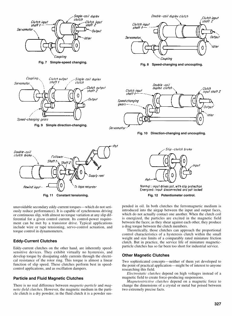
unavoidable secondary eddy-current torques—which do not seri-ously reduce performance). It is capable of synchronous drivingor continuous slip, with almost no torque variation at any slip dif-ferential for a given control current. Its control-power require-ment can be met by a transistor drive. Typical applicationsinclude wire or tape tensioning, servo-control actuation, andtorque control in dynamometers.
Eddy-Current Clutches
Eddy-current clutches on the other hand, are inherently speed-sensitive devices. They exhibit virtually no hysteresis, anddevelop torque by dissipating eddy currents through the electri-cal resistance of the rotor ring. This torque is almost a linearfunction of slip speed. These clutches perform best in speed-control applications, and as oscillation dampers.
Particle and Fluid Magnetic Clutches
There is no real difference between magnetic-particle and mag-netic-field clutches. However, the magnetic medium in the parti-cle clutch is a dry powder; in the fluid clutch it is a powder sus-
327
pended in oil. In both clutches the ferromagnetic medium isintroduced into the airgap between the input and output faces,which do not actually contact one another. When the clutch coilis energized, the particles are excited in the magnetic fieldbetween the faces; as they shear against each other, they producea drag torque between the clutch members.
Theoretically, those clutches can approach the proportionalcontrol characteristics of a hysteresis clutch within the smallweight and size limits of a comparably rated miniature frictionclutch. But in practice, the service life of miniature magnetic-particle clutches has so far been too short for industrial service.
Other Magnetic Clutches
Two sophisticated concepts—neither of them yet developed tothe point of practical application—might be of interest to anyoneresearching this field.
Electrostatic clutches depend on high voltages instead of amagnetic field to create force-producing suspensions.
Magnetostrictive clutches depend on a magnetic force tochange the dimensions of a crystal or metal bar poised betweentwo extremely precise facts.
Fig. 7 Simple-speed changing.Fig. 8 Speed-changing and uncoupling.
Fig. 9 Simple direction-changing.
Fig. 10 Direction-changing and uncoupling.
Fig. 11 Constant tensioning. Fig. 12 Potentiometer control.
Sclater Chapter 9 5/3/01 12:57 PM Page 327
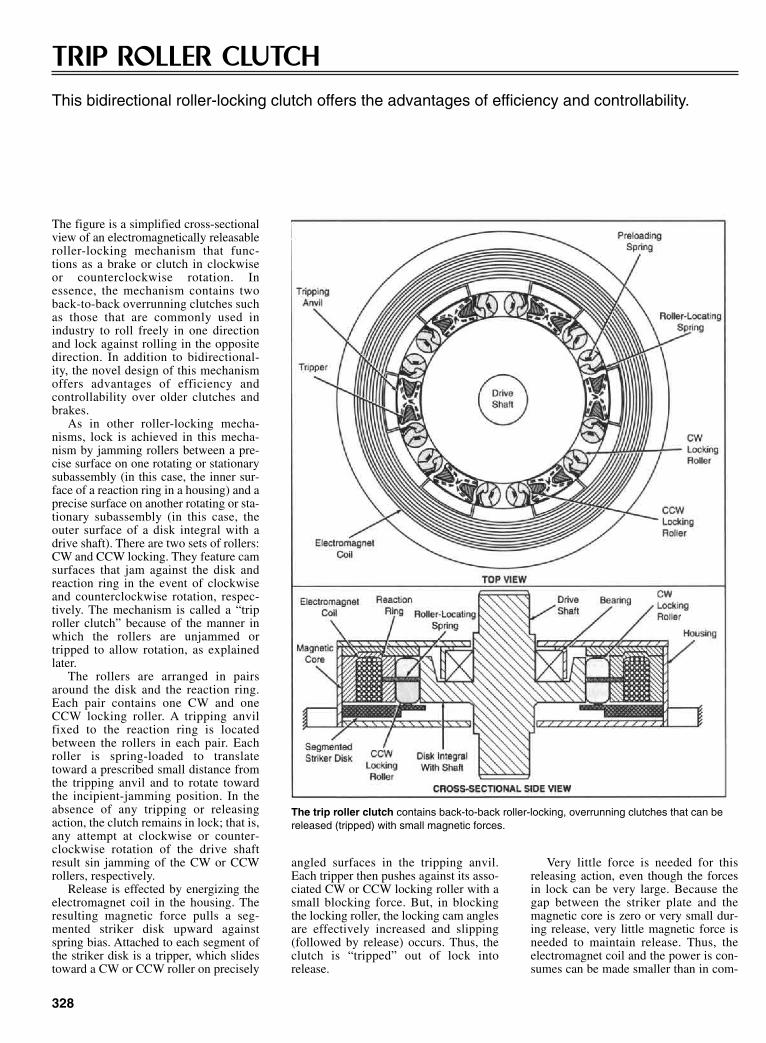
328
TRIP ROLLER CLUTCHThis bidirectional roller-locking clutch offers the advantages of efficiency and controllability.
The figure is a simplified cross-sectionalview of an electromagnetically releasableroller-locking mechanism that func-tions as a brake or clutch in clockwiseor counterclockwise rotation. Inessence, the mechanism contains twoback-to-back overrunning clutches suchas those that are commonly used inindustry to roll freely in one directionand lock against rolling in the oppositedirection. In addition to bidirectional-ity, the novel design of this mechanismoffers advantages of efficiency andcontrollability over older clutches andbrakes.
As in other roller-locking mecha-nisms, lock is achieved in this mecha-nism by jamming rollers between a pre-cise surface on one rotating or stationarysubassembly (in this case, the inner sur-face of a reaction ring in a housing) and aprecise surface on another rotating or sta-tionary subassembly (in this case, theouter surface of a disk integral with adrive shaft). There are two sets of rollers:CW and CCW locking. They feature camsurfaces that jam against the disk andreaction ring in the event of clockwiseand counterclockwise rotation, respec-tively. The mechanism is called a “triproller clutch” because of the manner inwhich the rollers are unjammed ortripped to allow rotation, as explainedlater.
The rollers are arranged in pairsaround the disk and the reaction ring.Each pair contains one CW and oneCCW locking roller. A tripping anvilfixed to the reaction ring is locatedbetween the rollers in each pair. Eachroller is spring-loaded to translatetoward a prescribed small distance fromthe tripping anvil and to rotate towardthe incipient-jamming position. In theabsence of any tripping or releasingaction, the clutch remains in lock; that is,any attempt at clockwise or counter-clockwise rotation of the drive shaftresult sin jamming of the CW or CCWrollers, respectively.
Release is effected by energizing theelectromagnet coil in the housing. Theresulting magnetic force pulls a seg-mented striker disk upward againstspring bias. Attached to each segment ofthe striker disk is a tripper, which slidestoward a CW or CCW roller on precisely
angled surfaces in the tripping anvil.Each tripper then pushes against its asso-ciated CW or CCW locking roller with asmall blocking force. But, in blockingthe locking roller, the locking cam anglesare effectively increased and slipping(followed by release) occurs. Thus, theclutch is “tripped” out of lock intorelease.
Very little force is needed for thisreleasing action, even though the forcesin lock can be very large. Because thegap between the striker plate and themagnetic core is zero or very small dur-ing release, very little magnetic force isneeded to maintain release. Thus, theelectromagnet coil and the power is con-sumes can be made smaller than in com-
The trip roller clutch contains back-to-back roller-locking, overrunning clutches that can bereleased (tripped) with small magnetic forces.
Sclater Chapter 9 5/3/01 12:57 PM Page 328
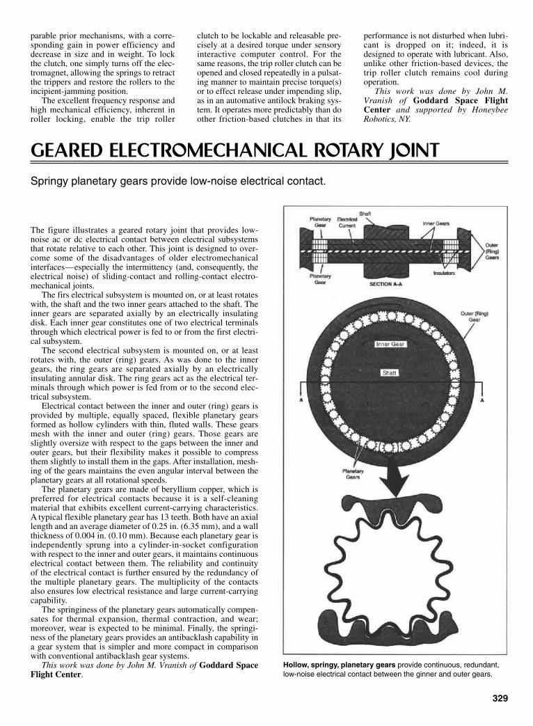
parable prior mechanisms, with a corre-sponding gain in power efficiency anddecrease in size and in weight. To lockthe clutch, one simply turns off the elec-tromagnet, allowing the springs to retractthe trippers and restore the rollers to theincipient-jamming position.
The excellent frequency response andhigh mechanical efficiency, inherent inroller locking, enable the trip roller
clutch to be lockable and releasable pre-cisely at a desired torque under sensoryinteractive computer control. For thesame reasons, the trip roller clutch can beopened and closed repeatedly in a pulsat-ing manner to maintain precise torque(s)or to effect release under impending slip,as in an automative antilock braking sys-tem. It operates more predictably than doother friction-based clutches in that its
performance is not disturbed when lubri-cant is dropped on it; indeed, it isdesigned to operate with lubricant. Also,unlike other friction-based devices, thetrip roller clutch remains cool duringoperation.
This work was done by John M.Vranish of Goddard Space FlightCenter and supported by HoneybeeRobotics, NY.
329
GEARED ELECTROMECHANICAL ROTARY JOINTSpringy planetary gears provide low-noise electrical contact.
The figure illustrates a geared rotary joint that provides low-noise ac or dc electrical contact between electrical subsystemsthat rotate relative to each other. This joint is designed to over-come some of the disadvantages of older electromechanicalinterfaces—especially the intermittency (and, consequently, theelectrical noise) of sliding-contact and rolling-contact electro-mechanical joints.
The firs electrical subsystem is mounted on, or at least rotateswith, the shaft and the two inner gears attached to the shaft. Theinner gears are separated axially by an electrically insulatingdisk. Each inner gear constitutes one of two electrical terminalsthrough which electrical power is fed to or from the first electri-cal subsystem.
The second electrical subsystem is mounted on, or at leastrotates with, the outer (ring) gears. As was done to the innergears, the ring gears are separated axially by an electricallyinsulating annular disk. The ring gears act as the electrical ter-minals through which power is fed from or to the second elec-trical subsystem.
Electrical contact between the inner and outer (ring) gears isprovided by multiple, equally spaced, flexible planetary gearsformed as hollow cylinders with thin, fluted walls. These gearsmesh with the inner and outer (ring) gears. Those gears areslightly oversize with respect to the gaps between the inner andouter gears, but their flexibility makes it possible to compressthem slightly to install them in the gaps. After installation, mesh-ing of the gears maintains the even angular interval between theplanetary gears at all rotational speeds.
The planetary gears are made of beryllium copper, which ispreferred for electrical contacts because it is a self-cleaningmaterial that exhibits excellent current-carrying characteristics.A typical flexible planetary gear has 13 teeth. Both have an axiallength and an average diameter of 0.25 in. (6.35 mm), and a wallthickness of 0.004 in. (0.10 mm). Because each planetary gear isindependently sprung into a cylinder-in-socket configurationwith respect to the inner and outer gears, it maintains continuouselectrical contact between them. The reliability and continuityof the electrical contact is further ensured by the redundancy ofthe multiple planetary gears. The multiplicity of the contactsalso ensures low electrical resistance and large current-carryingcapability.
The springiness of the planetary gears automatically compen-sates for thermal expansion, thermal contraction, and wear;moreover, wear is expected to be minimal. Finally, the springi-ness of the planetary gears provides an antibacklash capability ina gear system that is simpler and more compact in comparisonwith conventional antibacklash gear systems.
This work was done by John M. Vranish of Goddard SpaceFlight Center.
Hollow, springy, planetary gears provide continuous, redundant,low-noise electrical contact between the ginner and outer gears.
Sclater Chapter 9 5/3/01 12:57 PM Page 329
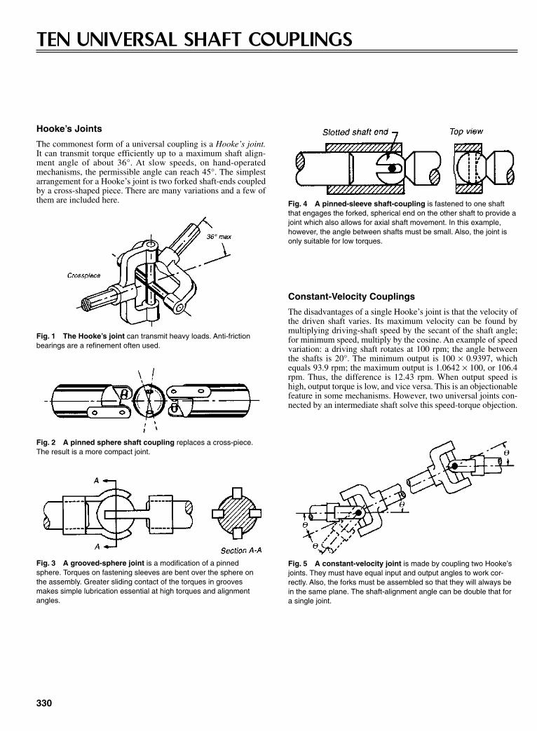
330
TEN UNIVERSAL SHAFT COUPLINGS
Hooke’s Joints
The commonest form of a universal coupling is a Hooke’s joint.It can transmit torque efficiently up to a maximum shaft align-ment angle of about 36°. At slow speeds, on hand-operatedmechanisms, the permissible angle can reach 45°. The simplestarrangement for a Hooke’s joint is two forked shaft-ends coupledby a cross-shaped piece. There are many variations and a few ofthem are included here.
Constant-Velocity Couplings
The disadvantages of a single Hooke’s joint is that the velocity ofthe driven shaft varies. Its maximum velocity can be found bymultiplying driving-shaft speed by the secant of the shaft angle;for minimum speed, multiply by the cosine. An example of speedvariation: a driving shaft rotates at 100 rpm; the angle betweenthe shafts is 20°. The minimum output is 100 × 0.9397, whichequals 93.9 rpm; the maximum output is 1.0642 × 100, or 106.4rpm. Thus, the difference is 12.43 rpm. When output speed ishigh, output torque is low, and vice versa. This is an objectionablefeature in some mechanisms. However, two universal joints con-nected by an intermediate shaft solve this speed-torque objection.
Fig. 1 The Hooke’s joint can transmit heavy loads. Anti-frictionbearings are a refinement often used.
Fig. 2 A pinned sphere shaft coupling replaces a cross-piece.The result is a more compact joint.
Fig. 3 A grooved-sphere joint is a modification of a pinnedsphere. Torques on fastening sleeves are bent over the sphere onthe assembly. Greater sliding contact of the torques in groovesmakes simple lubrication essential at high torques and alignmentangles.
Fig. 4 A pinned-sleeve shaft-coupling is fastened to one shaftthat engages the forked, spherical end on the other shaft to provide ajoint which also allows for axial shaft movement. In this example,however, the angle between shafts must be small. Also, the joint isonly suitable for low torques.
Fig. 5 A constant-velocity joint is made by coupling two Hooke’sjoints. They must have equal input and output angles to work cor-rectly. Also, the forks must be assembled so that they will always bein the same plane. The shaft-alignment angle can be double that fora single joint.
Sclater Chapter 9 5/3/01 12:57 PM Page 330
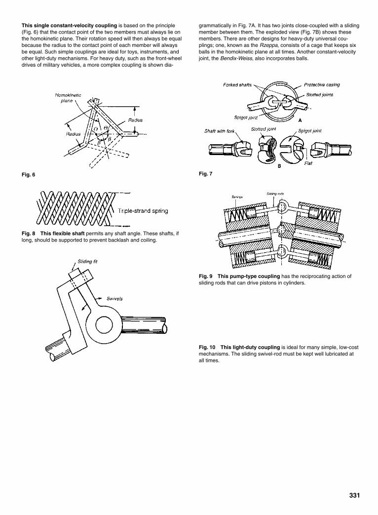
This single constant-velocity coupling is based on the principle(Fig. 6) that the contact point of the two members must always lie onthe homokinetic plane. Their rotation speed will then always be equalbecause the radius to the contact point of each member will alwaysbe equal. Such simple couplings are ideal for toys, instruments, andother light-duty mechanisms. For heavy duty, such as the front-wheeldrives of military vehicles, a more complex coupling is shown dia-
331
grammatically in Fig. 7A. It has two joints close-coupled with a slidingmember between them. The exploded view (Fig. 7B) shows thesemembers. There are other designs for heavy-duty universal cou-plings; one, known as the Rzeppa, consists of a cage that keeps sixballs in the homokinetic plane at all times. Another constant-velocityjoint, the Bendix-Weiss, also incorporates balls.
Fig. 6 Fig. 7
Fig. 8 This flexible shaft permits any shaft angle. These shafts, iflong, should be supported to prevent backlash and coiling.
Fig. 9 This pump-type coupling has the reciprocating action ofsliding rods that can drive pistons in cylinders.
Fig. 10 This light-duty coupling is ideal for many simple, low-costmechanisms. The sliding swivel-rod must be kept well lubricated atall times.
Sclater Chapter 9 5/3/01 12:57 PM Page 331
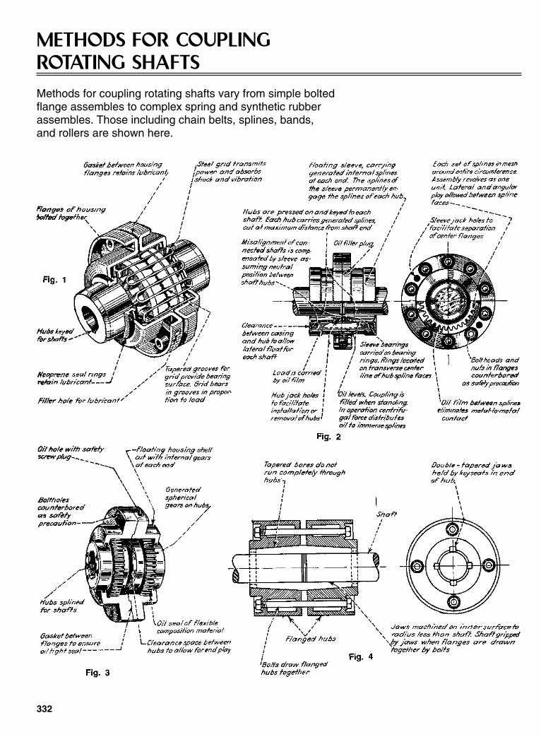
332
METHODS FOR COUPLING ROTATING SHAFTSMethods for coupling rotating shafts vary from simple bolted flange assembles to complex spring and synthetic rubber assembles. Those including chain belts, splines, bands, and rollers are shown here.
Sclater Chapter 9 5/3/01 12:58 PM Page 332

333
Sclater Chapter 9 5/3/01 12:58 PM Page 333

334
Typical Methods of Coupling Rotating Shafts (continued )
Sclater Chapter 9 5/3/01 12:58 PM Page 334

335
Shaft couplings that include internal and external gears,balls, pins, and nonmetallic parts to transmit torque areshown here.
Sclater Chapter 9 5/3/01 12:58 PM Page 335

336
LINKAGES FOR BAND CLUTCHES AND BRAKES
Fig. 1 An outside bandclutch operated by a rollerand cone.
Fig. 2 An outside bandclutch made as two halfwrap bands with an interme-diate equalizer.
Fig. 3 An outside band clutchmade as two full wrap bands withan intermediate equalizer.
Fig. 4 An inside bandclutch operated by ayoke having movementalong the shaft.
Fig. 5 A two-way acting band brake oper-ated hydraulically.
Sclater Chapter 9 5/3/01 12:58 PM Page 336

Fig. 6 A hoist-drumband brake operated by afoot pedal.
Fig. 7 A band brake witha single toggle action. Fig. 8 A crawler-drive band brake operated by
a ratchet lever.
SPECIAL COUPLING MECHANISMS
Fig. 1 Six links and three disks can synchro-nize the motion between adjacent, parallel shafts.
Fig. 3 As the input rotates, the five bent pins will move inand out of the drilled holes to impart a constant velocity rota-tion to the right angle-output shaft. The device can transmitconstant velocity at angles other than 90°, as shown.
337
Fig. 2 An arrangement to syn-chronize shafts without the needfor links.
Sclater Chapter 9 5/3/01 12:58 PM Page 337
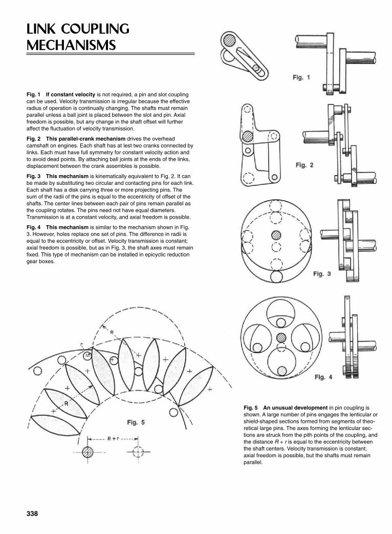
Fig. 1 If constant velocity is not required, a pin and slot couplingcan be used. Velocity transmission is irregular because the effectiveradius of operation is continually changing. The shafts must remainparallel unless a ball joint is placed between the slot and pin. Axialfreedom is possible, but any change in the shaft offset will furtheraffect the fluctuation of velocity transmission.
Fig. 2 This parallel-crank mechanism drives the overheadcamshaft on engines. Each shaft has at lest two cranks connected bylinks. Each must have full symmetry for constant velocity action andto avoid dead points. By attaching ball joints at the ends of the links,displacement between the crank assembles is possible.
Fig. 3 This mechanism is kinematically equivalent to Fig. 2. It canbe made by substituting two circular and contacting pins for each link.Each shaft has a disk carrying three or more projecting pins. Thesum of the radii of the pins is equal to the eccentricity of offset of theshafts. The center lines between each pair of pins remain parallel asthe coupling rotates. The pins need not have equal diameters.Transmission is at a constant velocity, and axial freedom is possible.
Fig. 4 This mechanism is similar to the mechanism shown in Fig.3. However, holes replace one set of pins. The difference in radii isequal to the eccentricity or offset. Velocity transmission is constant;axial freedom is possible, but as in Fig. 3, the shaft axes must remainfixed. This type of mechanism can be installed in epicyclic reductiongear boxes.
338
LINK COUPLINGMECHANISMS
Fig. 5 An unusual development in pin coupling isshown. A large number of pins engages the lenticular orshield-shaped sections formed from segments of theo-retical large pins. The axes forming the lenticular sec-tions are struck from the pith points of the coupling, andthe distance R + r is equal to the eccentricity betweenthe shaft centers. Velocity transmission is constant;axial freedom is possible, but the shafts must remainparallel.
Sclater Chapter 9 5/3/01 12:58 PM Page 338

CHAPTER 10TORQUE-LIMITING,TENSIONING, AND
GOVERNING DEVICES
Sclater Chapter 10 5/3/01 1:07 PM Page 339
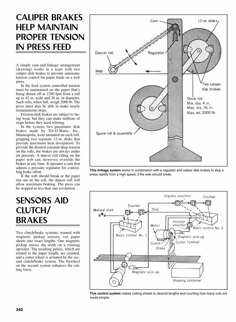
340
CALIPER BRAKESHELP MAINTAINPROPER TENSIONIN PRESS FEED
A simple cam-and-linkage arrangement(drawing) works in a team with twocaliper disk brakes to provide automatictension control for paper feeds on a webpress.
In the feed system controlled tensionmust be maintained on the paper that’sbeing drawn off at 1200 fpm from a rollup to 42 in. wide and 36 in. in diameter.Such rolls, when full, weigh 2000 lb. Thepress must also be able to make nearlyinstantaneous stops.
Friction-disk brakes are subject to lin-ing wear, but they can make millions ofstops before they need relining.
In the system, two pneumatic diskbrakes made by Tol-O-Matic, Inc.,Minneapolis, were mounted on each roll,gripping two separate 12-in. disks thatprovide maximum heat dissipation. Toprovide the desired constant-drag tensionon the rolls, the brakes are always underair pressure. A dancer roll riding on thepaper web can, however, override thebrakes at any time. It operates a cam thatadjusts a pressure regulator for control-ling brake effort.
If the web should break or the paperrun out on the roll, the dancer roll willallow maximum braking. The press canbe stopped in less than one revolution.
SENSORS AIDCLUTCH/BRAKESTwo clutch/brake systems, teamed withmagnetic pickup sensors, cut papersheets into exact lengths. One magneticpickup senses the teeth on a rotatingsprocket. The resulting pulses, which arerelated to the paper length, are counted,and a cutter wheel is actuated by the sec-ond clutch/brake system. The flywheelon the second system enhances the cut-ting force.
This linkage system works in combination with a regulator and caliper disk brakes to stop apress rapidly from a high speed, if the web should break.
This control system makes cutting sheets to desired lengths and counting how many cuts aremade simpler.
Sclater Chapter 10 5/3/01 1:07 PM Page 340
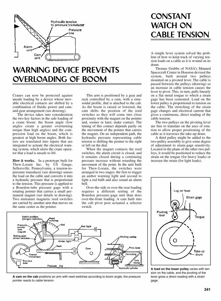
341
WARNING DEVICE PREVENTSOVERLOADING OF BOOM
Cranes can now be protected againstunsafe loading by a device whose mov-able electrical contacts are shifted by acombination of fluidic power and cam-and-gear arrangement (see drawing).
The device takes into considerationthe two key factors in the safe loading ofa crane boom: the boom angle (lowangles create a greater overturningtorque than high angles) and the com-pression load on the boom, which isgreatest at high boom angles. Both fac-tors are translated into inputs that areintegrated to actuate the electrical warn-ing system, which alerts the crane opera-tor that a load is unsafe to lift.
How it works. In a prototype built forThew-Lorain Inc. by US Gauge,Sellersville, Pennsylvania, a tension-to-pressure transducer (see drawing) sensesthe load on the cable and converts it intoa hydraulic pressure that is proportionalto the tension. This pressure is applied toa Bourdon-tube pressure gage with arotating pointer that carries a small per-manent magnet (see details in drawing).Two miniature magnetic reed switchesare carried by another arm that moves onthe same center as the pointer.
This arm is positioned by a gear andrack controlled by a cam, with a sinu-soidal profile, that is attached to the cab.As the boom is raised or lowered, thecam shifts the position of the reedswitches so they will come into closeproximity with the magnet on the pointerand, sooner or later, make contact. Thetiming of this contact depends partly onthe movement of the pointer that carriesthe magnet. On an independent path, thehydraulic pressure representing cabletension is shifting the pointer to the rightor left on the dial.
When the magnet contacts the reedswitches, the alarm circuit is closed, andit remains closed during a continuingpressure increase without retarding themovement of the point. In the unit builtfor Thew-Lorain, the switches werearranged in two stages: the first to triggeran amber warning light and second tolight a red bulb and also sound an alarmbell.
Over-the-side or over-the-rear loadingrequires a different setting of theBourdon pressure-gage unit than doesover-the-front loading. A cam built intothe cab pivot post actuated a selectorswitch.
A cam on the cab positions an arm with reed switches according to boom angle; the pressurepointer reacts to cable tension.
CONSTANTWATCH ONCABLE TENSION
A simple lever system solved the prob-lem of how to keep track of varying ten-sion loads on a cable as it is wound on itsdrum.
Thomas Grubbs of NASA’s MannedSpacecraft Center in Houston devised thesystem, built around two pulleysmounted on a pivoted lever. The cable ispassed between the pulleys (drawing) soan increase in cable tension causes thelever to pivot. This, in turn, pulls linearlyon a flat metal tongue to which a straingage has been cemented. Load on thelower pulley is proportional to tension onthe cable. The stretching of the straingage changes and electrical current thatgives a continuous, direct reading of thecable tension.
The two pulleys on the pivoting leverare free to translate on the axes of rota-tion to allow proper positioning of thecable as it traverses the take-up drum.
A third pulley might be added to thetwo-pulley assembly to give some degreeof adjustment to strain-gage sensitivity.Located in the plane of the other two pul-leys, it would be positioned to reduce thestrain on the tongue (for heavy loads) orincrease the strain (for light loads).
A load on the lower pulley varies with ten-sion on the cable, and the pivoting of thelever gives a direct reading with a straingage.
Sclater Chapter 10 5/3/01 1:07 PM Page 341

342
TORQUE-LIMITERS PROTECT LIGHT-DUTY DRIVESLight-duty drives break down when they are overloaded. These eight devices disconnect them from dangerous torque surges.
Fig. 1 Permanent magnets transmit torque in accordance with their numbers and size around the cir-cumference of the clutch plate. Control of the drive inplace is limited to removing magnets to reduce thedrive’s torque capacity.
Fig. 2 Arms hold rollers in the slots thatare cut across the disks mounted on theends of butting shafts. Springs keep theroller in the slots, but excessive torqueforces them out.
Fig. 3 A cone clutch is formed by matinga taper on the shaft to a beveled centralhole in the gear. Increasing compression onthe spring by tightening the nut increasesthe drive’s torque capacity.
Fig. 4 A flexible belt wrapped aroundfour pins transmits only the lightest loads.The outer pins are smaller than the innerpins to ensure contact.
Fig. 5 Springs inside the block grip theshaft because they are distorted when thegear is mounted to the box on the shaft.
Sclater Chapter 10 5/3/01 1:07 PM Page 342
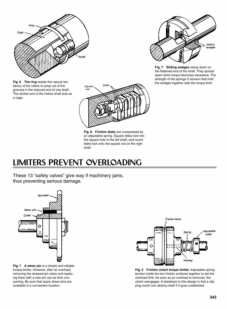
LIMITERS PREVENT OVERLOADINGThese 13 “safety valves” give way if machinery jams, thus preventing serious damage.
343
Fig. 6 The ring resists the natural ten-dency of the rollers to jump out of thegrooves in the reduced end of one shaft.The slotted end of the hollow shaft acts asa cage.
Fig. 7 Sliding wedges clamp down onthe flattened end of the shaft. They spreadapart when torque becomes excessive. Thestrength of the springs in tension that holdthe wedges together sets the torque limit.
Fig. 8 Friction disks are compressed byan adjustable spring. Square disks lock intothe square hole in the left shaft, and rounddisks lock onto the square rod on the rightshaft.
Fig. 1 A shear pin is a simple and reliabletorque limiter. However, after an overload,removing the sheared pin stubs and replac-ing them with a new pin can be time con-suming. Be sure that spare shear pins areavailable in a convenient location.
Fig. 2 Friction clutch torque limiter. Adjustable springtension holds the two friction surfaces together to set theoverload limit. As soon as an overload is removed, theclutch reengages. A drawback to this design is that a slip-ping clutch can destroy itself if it goes undetected.
Sclater Chapter 10 5/3/01 1:07 PM Page 343

344
Fig. 3 Mechanical keys. A spring holds a ball in a dim-ple in the opposite face of this torque limiter until an over-load forces it out. Once a slip begins, clutch face wearcan be rapid. Thus, this limiter is not recommended formachines where overload is common.
Fig. 4 A cylinder cut at an angle forms a torque limiter. A spring clamps theopposing-angled cylinder faces together, and they separate from angular align-ment under overload conditions. The spring tension sets the load limit.
Fig. 5 A retracting key limits the torque in this clutch. The ramped sidesof the keyway force the key outward against an adjustable spring. As thekey moves outward, a rubber pad or another spring forces the key into aslot in the sheave. This holds the key out of engagement and preventswear. To reset the mechanism, the key is pushed out of the slot with a toolin the reset hole of the sheave.
Fig. 6 Disengaging gears. The axial forces of aspring and driving arm are in balance in this torquelimiter. An overload condition overcomes the force ofthe spring to slide the gears out of engagement.After the overload condition is removed, the gearsmust be held apart to prevent them from beingstripped. With the driver off, the gears can safely bereset.
Fig. 7 A cammed sleeve connects the input and output shafts of thistorque limiter. A driven pin pushes the sleeve to the right against thespring. When an overload occurs, the driving pin drops into the slot tokeep the shaft disengaged. The limiter is reset by turning the output shaftbackwards.
Sclater Chapter 10 5/3/01 1:07 PM Page 344
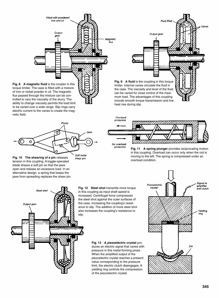
345
Fig. 8 A magnetic fluid is the coupler in thistorque limiter. The case is filled with a mixtureof iron or nickel powder in oil. The magneticflux passed through the mixture can be con-trolled to vary the viscosity of the slurry. Theability to change viscosity permits the load limitto be varied over a wide range. Slip rings carryelectric current to the vanes to create the mag-netic field.
Fig. 9 A fluid is the coupling in this torquelimiter. Internal vanes circulate the fluid inthe case. The viscosity and level of the fluidcan be varied for close control of the maxi-mum load. The advantages of this couplinginclude smooth torque transmission and lowheat rise during slip.
Fig. 10 The shearing of a pin releasestension in this coupling. A toggle-operatedblade shears a soft pin so that the jawsopen and release an excessive load. In analternative design, a spring that keeps thejaws from spreading replaces the shear pin.
Fig. 11 A spring plunger provides reciprocating motionin this coupling. Overload can occur only when the rod ismoving to the left. The spring is compressed under anoverload condition.
Fig. 12 Steel shot transmits more torquein this coupling as input shaft speed isincreased. Centrifugal force compressesthe steel shot against the outer surfaces ofthe case, increasing the coupling’s resist-ance to slip. The addition of more steel shotalso increases the coupling’s resistance toslip.
Fig. 13 A piezoelectric crystal pro-duces an electric signal that varies withpressure in this metal-forming press.When the amplified output of thepiezoelectric crystal reaches a presentvalue corresponding to the pressurelimit, the electric clutch disengages. Ayielding ring controls the compressionof the piezoelectric crystal.
Sclater Chapter 10 5/3/01 1:07 PM Page 345

346
SEVEN WAYS TO LIMIT SHAFT ROTATIONTraveling nuts, clutch plates, gear fingers, and pinned members form the basis of these ingenious mechanisms.
Mechanical stops are often required in automatic machinery and servomechanisms tolimit shaft rotation to a given number of turns. Protection must be provided againstexcessive forces caused by abrupt stops and large torque requirements when machinerotation is reversed after being stopped.
Fig. 1 A traveling nut moves along the threaded shaft until theframe prevents further rotation. This is a simple device, but the travel-ing nut can jam so tightly that a large torque is required to move theshaft from its stopped position. This fault is overcome at the expenseof increased device length by providing a stop pin in the traveling nut.
Fig. 2 The engagement between the pin and the rotating fingermust be shorter than the thread pitch so the pin can clear the fingeron the first reverse-turn. The rubber ring and grommet lessen theimpact and provide a sliding surface. The grommet can be oil-impregnated metal.
Fig. 3 Clutch plates tighten and stop their rotationas the rotating shaft moves the nut against thewasher. When rotation is reversed, the clutch platescan turn with the shaft from A to B. During thismovement, comparatively low torque is required tofree the nut from the clutch plates. Thereafter, sub-sequent movement is free of clutch friction until theaction is repeated at the other end of the shaft. Thedevice is recommended for large torques becausethe clutch plates absorb energy well.
Sclater Chapter 10 5/3/01 1:07 PM Page 346

347
Fig. 4 A shaft finger on the output shaft hits theresilient stop after making less than one revolu-tion. The force on the stop depends upon the gearratio. The device is, therefore, limited to low ratiosand few turns, unless a worm-gear setup is used.
Fig. 5 Two fingers butt together at the initial and final positions to prevent rotationbeyond these limits. A rubber shock-mount absorbs the impact load. A gear ratio ofalmost 1:1 ensures that the fingers will be out-of-phase with one another until theymeet on the final turn. Example: Gears with 30 to 32 teeth limit shaft rotation to 25turns. Space is saved here, but these gears are expensive.
Fig. 6 A large gear ratio limits the idler gear to less than one turn.Stop fingers can be added to the existing gears in a train, making thisdesign the simplest of all. The input gear, however, is limited to maxi-mum of about five turns.
Fig. 7 Pinned fingers limit shaft turns to approximately N + 1 revo-lutions in either direction. Resilient pin-bushings would help reducethe impact force.
Sclater Chapter 10 5/3/01 1:07 PM Page 347
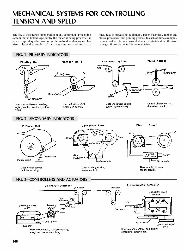
348
MECHANICAL SYSTEMS FOR CONTROLLING TENSION AND SPEED
The key to the successful operation of any continuous-processingsystem that is linked together by the material being processed ispositive speed synchronization of the individual driving mecha-nisms. Typical examples of such a system are steel mill strip
lines, textile processing equipment, paper machines, rubber andplastic processers, and printing presses. In each of these examples,the material will become wrinkled, marred, stretched or otherwisedamaged if precise control is not maintained.
FIG. 1—PRIMARY INDICATORS
FIG. 2—SECONDARY INDICATORS
FIG. 3—CONTROLLERS AND ACTUATORS
Sclater Chapter 10 5/3/01 1:07 PM Page 348
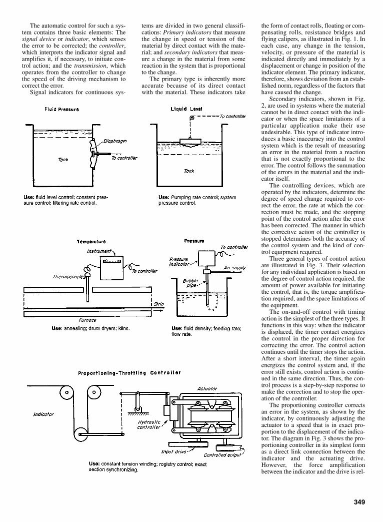
The automatic control for such a sys-tem contains three basic elements: Thesignal device or indicator, which sensesthe error to be corrected; the controller,which interprets the indicator signal andamplifies it, if necessary, to initiate con-trol action; and the transmission, whichoperates from the controller to changethe speed of the driving mechanism tocorrect the error.
Signal indicators for continuous sys-
tems are divided in two general classifi-cations: Primary indicators that measurethe change in speed or tension of thematerial by direct contact with the mate-rial; and secondary indicators that meas-ure a change in the material from somereaction in the system that is proportionalto the change.
The primary type is inherently moreaccurate because of its direct contactwith the material. These indicators take
the form of contact rolls, floating or com-pensating rolls, resistance bridges andflying calipers, as illustrated in Fig. 1. Ineach case, any change in the tension,velocity, or pressure of the material isindicated directly and immediately by adisplacement or change in position of theindicator element. The primary indicator,therefore, shows deviation from an estab-lished norm, regardless of the factors thathave caused the change.
Secondary indicators, shown in Fig.2, are used in systems where the materialcannot be in direct contact with the indi-cator or when the space limitations of aparticular application make their useundesirable. This type of indicator intro-duces a basic inaccuracy into the controlsystem which is the result of measuringan error in the material from a reactionthat is not exactly proportional to theerror. The control follows the summationof the errors in the material and the indi-cator itself.
The controlling devices, which areoperated by the indicators, determine thedegree of speed change required to cor-rect the error, the rate at which the cor-rection must be made, and the stoppingpoint of the control action after the errorhas been corrected. The manner in whichthe corrective action of the controller isstopped determines both the accuracy ofthe control system and the kind of con-trol equipment required.
Three general types of control actionare illustrated in Fig. 3. Their selectionfor any individual application is based onthe degree of control action required, theamount of power available for initiatingthe control, that is, the torque amplifica-tion required, and the space limitations ofthe equipment.
The on-and-off control with timingaction is the simplest of the three types. Itfunctions in this way: when the indicatoris displaced, the timer contact energizesthe control in the proper direction forcorrecting the error. The control actioncontinues until the timer stops the action.After a short interval, the timer againenergizes the control system and, if theerror still exists, control action is contin-ued in the same direction. Thus, the con-trol process is a step-by-step response tomake the correction and to stop the oper-ation of the controller.
The proportioning controller correctsan error in the system, as shown by theindicator, by continuously adjusting theactuator to a speed that is in exact pro-portion to the displacement of the indica-tor. The diagram in Fig. 3 shows the pro-portioning controller in its simplest formas a direct link connection between theindicator and the actuating drive.However, the force amplificationbetween the indicator and the drive is rel-
349
Sclater Chapter 10 5/3/01 1:07 PM Page 349
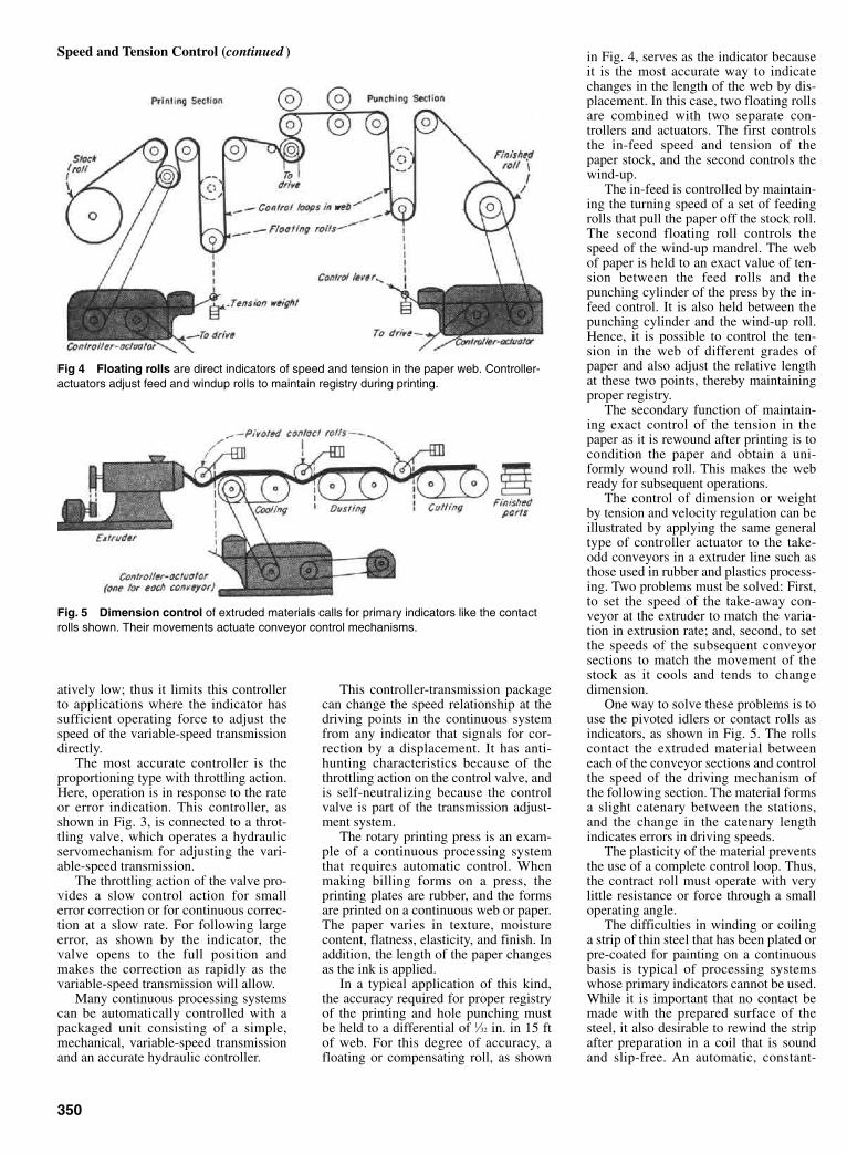
atively low; thus it limits this controllerto applications where the indicator hassufficient operating force to adjust thespeed of the variable-speed transmissiondirectly.
The most accurate controller is theproportioning type with throttling action.Here, operation is in response to the rateor error indication. This controller, asshown in Fig. 3, is connected to a throt-tling valve, which operates a hydraulicservomechanism for adjusting the vari-able-speed transmission.
The throttling action of the valve pro-vides a slow control action for smallerror correction or for continuous correc-tion at a slow rate. For following largeerror, as shown by the indicator, thevalve opens to the full position andmakes the correction as rapidly as thevariable-speed transmission will allow.
Many continuous processing systemscan be automatically controlled with apackaged unit consisting of a simple,mechanical, variable-speed transmissionand an accurate hydraulic controller.
This controller-transmission packagecan change the speed relationship at thedriving points in the continuous systemfrom any indicator that signals for cor-rection by a displacement. It has anti-hunting characteristics because of thethrottling action on the control valve, andis self-neutralizing because the controlvalve is part of the transmission adjust-ment system.
The rotary printing press is an exam-ple of a continuous processing systemthat requires automatic control. Whenmaking billing forms on a press, theprinting plates are rubber, and the formsare printed on a continuous web or paper.The paper varies in texture, moisturecontent, flatness, elasticity, and finish. Inaddition, the length of the paper changesas the ink is applied.
In a typical application of this kind,the accuracy required for proper registryof the printing and hole punching mustbe held to a differential of 1⁄32 in. in 15 ftof web. For this degree of accuracy, afloating or compensating roll, as shown
in Fig. 4, serves as the indicator becauseit is the most accurate way to indicatechanges in the length of the web by dis-placement. In this case, two floating rollsare combined with two separate con-trollers and actuators. The first controlsthe in-feed speed and tension of thepaper stock, and the second controls thewind-up.
The in-feed is controlled by maintain-ing the turning speed of a set of feedingrolls that pull the paper off the stock roll.The second floating roll controls thespeed of the wind-up mandrel. The webof paper is held to an exact value of ten-sion between the feed rolls and thepunching cylinder of the press by the in-feed control. It is also held between thepunching cylinder and the wind-up roll.Hence, it is possible to control the ten-sion in the web of different grades ofpaper and also adjust the relative lengthat these two points, thereby maintainingproper registry.
The secondary function of maintain-ing exact control of the tension in thepaper as it is rewound after printing is tocondition the paper and obtain a uni-formly wound roll. This makes the webready for subsequent operations.
The control of dimension or weightby tension and velocity regulation can beillustrated by applying the same generaltype of controller actuator to the take-odd conveyors in a extruder line such asthose used in rubber and plastics process-ing. Two problems must be solved: First,to set the speed of the take-away con-veyor at the extruder to match the varia-tion in extrusion rate; and, second, to setthe speeds of the subsequent conveyorsections to match the movement of thestock as it cools and tends to changedimension.
One way to solve these problems is touse the pivoted idlers or contact rolls asindicators, as shown in Fig. 5. The rollscontact the extruded material betweeneach of the conveyor sections and controlthe speed of the driving mechanism ofthe following section. The material formsa slight catenary between the stations,and the change in the catenary lengthindicates errors in driving speeds.
The plasticity of the material preventsthe use of a complete control loop. Thus,the contract roll must operate with verylittle resistance or force through a smalloperating angle.
The difficulties in winding or coilinga strip of thin steel that has been plated orpre-coated for painting on a continuousbasis is typical of processing systemswhose primary indicators cannot be used.While it is important that no contact bemade with the prepared surface of thesteel, it also desirable to rewind the stripafter preparation in a coil that is soundand slip-free. An automatic, constant-
350
Speed and Tension Control (continued )
Fig 4 Floating rolls are direct indicators of speed and tension in the paper web. Controller-actuators adjust feed and windup rolls to maintain registry during printing.
Fig. 5 Dimension control of extruded materials calls for primary indicators like the contactrolls shown. Their movements actuate conveyor control mechanisms.
Sclater Chapter 10 5/3/01 1:07 PM Page 350

tension winding control and a secondaryindicator initiate the control action.
The control system shown in Fig. 6 isused in winding coils from 16 in. corediameter to 48 in. maximum diameter.The power to wind the coil is the con-trolling medium because, by maintain-ing constant winding power as the coilbuilds up, a constant value of strip ten-sion can be held within the limitsrequired. Actually, this method is soinaccurate that the losses in the drivingequipment (which are a factor in thepower being measured) are not constant;hence the strip tension changes slightly.This same factor enters into any controlsystem that uses winding power as anindex of control.
A torque-measuring belt that operatesa differential controller measures thepower of the winder. Then, in turn, thecontroller adjusts the variable-speedtransmission. The change in speedbetween the source of power and thetransmission is measured by the three-shaft gear differential, which is driven intandem with the control belt. Any changein load across the control belt produces achange in speed between the driving anddriven ends of the belt. The differentialacts as the controller, because any changein speed between the two outside shaftsof the differential results in a rotation ordisplacement of the center or controlshaft. By connecting the control shaft ofthe differential directly to a screw-controlled variable-speed transmission, itis possible to adjust the transmission tocorrect any change in speed and powerdelivered by the belt.
This system is made completely auto-matic by establishing a neutralizingspeed between the two input shaft of thedifferential (within the creep value of thebelt). When there is no tension in thestrip (e.g., when it is cut), the input speedto the actuator side of the differential ishigher on the driven side than it is on thedriving side of the differential. Thisunbalance reverses the rotation of thecontrol shaft of the differential, which inturn resets the transmission to high speedrequired for starting the next coil on therewinding mandrel.
In operation, any element in the sys-tem that tends to change strip tensioncauses a change in winding power. Thischange, in turn, is immediately compen-sated by the rotation (or tendency torotate) of the controlling shaft in the dif-ferential. Hence, the winding mandrelspeed is continuously and automaticallycorrected to maintain constant tension inthe strip.
When the correct speed relationshipsare established in the controller, the sys-tem operates automatically for all condi-tions of operation. In addition, tension inthe strip can be adjusted to any value by
moving the tension idler on the controlbelt to increase or decrease the loadcapacity of the belt to match a desiredstrip tension.
There are many continuous process-ing systems that require constant velocityof the material during processing, yet donot require accurate control of the ten-sion in the material. An example of thisprocess is the annealing of wire that ispulled off stock reels through an anneal-ing furnace and then rewound on a wind-up block.
The wire must be passed through thefurnace at a constant rate so that theannealing time is maintained at a fixedvalue. Because the wire is pulled throughthe furnace by the wind-up blocks,shown in Fig. 7, its rate of movementthrough the furnace would increase asthe wire builds up on the reels unless acontrol slows down the reels.
A constant-velocity control thatmakes use of the wire as a direct indica-tor measures the speed of the wire to ini-tiate a control action for adjusting the
speed of the wind-up reel. In this case,the wire can be contacted directly, and aprimary indicator in the form of a contactroll can register any change in speed. Thecontact roll drives one input shaft of thedifferential controller. The second inputshaft is connected to the driving shaft ofthe variable-speed transmission to pro-vide a reference speed. The third, or con-trol, shaft will then rotate when any dif-ference in speed exists between the twoinput shafts. Thus, if the control shaft isconnected to a screw-regulated actuator,an adjustment is obtained for slowingdown the wind-up blocks as the coilsbuild up and the wire progresses throughthe furnace at a constant speed.
351
Fig. 6 The differential controller has a third shaft that signals the remote actuator when ten-sion in sheet material changes. Coiler power is a secondary-control index.
Fig. 7 The movement of wire through the annealing furnace is regulated at constant velocityby continuously retarding the speed of the windup reels to allow for wire build-up.
Sclater Chapter 10 5/3/01 1:07 PM Page 351

352
DRIVES FOR CONTROLLING TENSIONMechanical, electrical, and hydraulic methods for obtaining controlled tension on winding reels and similar drives, or for driving independent parts of a machine in synchronism.
the difference between the coefficient offriction at the start and the coefficient ofsliding friction. Sliding friction will beaffected by moisture, foreign matter, andwear of the surfaces.
Capacity is limited by the heat radiat-ing capacity of the brake at the maximumpermissible running temperature.
Differential drives can take many dif-ferent forms, e.g., epicycle spur gears,bevel gear differentials, or worm geardifferentials.
The braking device on the ring gear orspider could be a band brake, a fan, animpeller, an electric generator, or an elec-tric drag element such as a copper diskrotating in a powerful magnetic field. Abrake will give a drag or tension that is
MECHANICAL DRIVES
reasonably constant over a wide speedrange. The other braking devices men-tioned here will exert a torque that willvary widely with speed, but will be defi-nite for any given speed of the ring gearor spider.
A definite advantage of any differen-tial drive is that maximum driving torquecan never exceed the torque developedby the braking device.
Differential gearing can be used tocontrol a variable-speed transmission. Ifthe ring gear and sun gear are to bedriven in opposite directions from theirrespective shafts which are to be held insynchronism, the gear train can bedesigned so that the spider on which the
planetary gears are mounted will notrotate when the shafts are running at thedesired relative speeds. If one or theother of the shafts speeds ahead, the spi-der rotates correspondingly. The spiderrotation changes the ratio of the variable-speed transmission unit.
ELECTRICAL DRIVES
The shunt-field rheostat in a DCmotor drive can be used to synchronizedrives. When connected to a machine forprocessing paper, cloth, or other sheetmaterial that is passing around a take-uproll, the movement of the take-up rollmoves a control arm which is connectedto the rheostat. This kind of drive is notsuitable for wide changes of speed thatexceed about a 2.5 to 1 ratio.
For wide ranges of speed, the rheostatis put in the shunt field of a DC generatorthat is driven by another motor. The volt-age developed by the generator is con-trolled from zero to full voltage. Thegenerator furnishes the current to thedriving motor armature, and the fields ofthe driving motor are separately excited.Thus, the motor speed is controlled fromzero to maximum.
A band brake is used on coil winders,insulation winders, and similar machineswhere maintaining the tension withinclose limits is not required.
It is simple and economical, but ten-sion will vary considerably. Friction dragat start-up might be several times thatwhich occurs during running because of
Sclater Chapter 10 5/3/01 1:08 PM Page 352
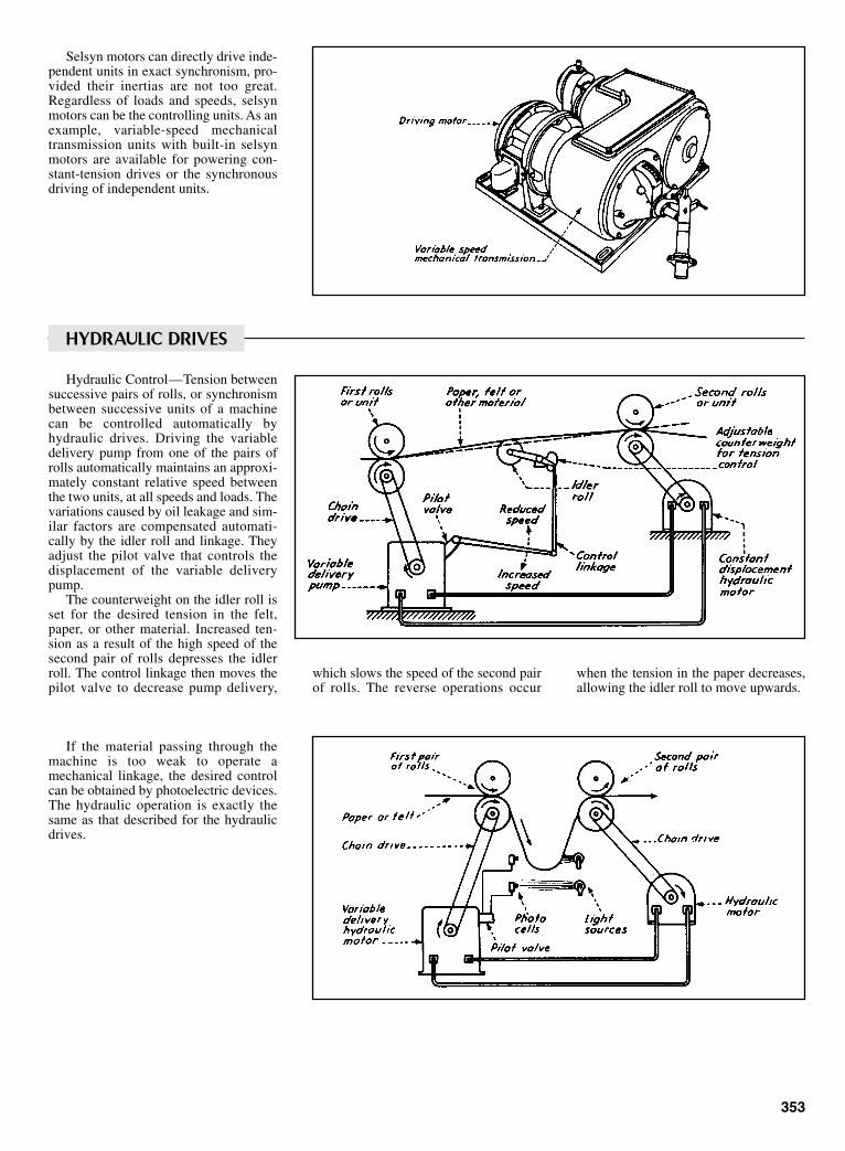
Selsyn motors can directly drive inde-pendent units in exact synchronism, pro-vided their inertias are not too great.Regardless of loads and speeds, selsynmotors can be the controlling units. As anexample, variable-speed mechanicaltransmission units with built-in selsynmotors are available for powering con-stant-tension drives or the synchronousdriving of independent units.
Hydraulic Control—Tension betweensuccessive pairs of rolls, or synchronismbetween successive units of a machinecan be controlled automatically byhydraulic drives. Driving the variabledelivery pump from one of the pairs ofrolls automatically maintains an approxi-mately constant relative speed betweenthe two units, at all speeds and loads. Thevariations caused by oil leakage and sim-ilar factors are compensated automati-cally by the idler roll and linkage. Theyadjust the pilot valve that controls thedisplacement of the variable deliverypump.
The counterweight on the idler roll isset for the desired tension in the felt,paper, or other material. Increased ten-sion as a result of the high speed of thesecond pair of rolls depresses the idlerroll. The control linkage then moves thepilot valve to decrease pump delivery,
which slows the speed of the second pairof rolls. The reverse operations occur
353
HYDRAULIC DRIVES
when the tension in the paper decreases,allowing the idler roll to move upwards.
If the material passing through themachine is too weak to operate amechanical linkage, the desired controlcan be obtained by photoelectric devices.The hydraulic operation is exactly thesame as that described for the hydraulicdrives.
Sclater Chapter 10 5/3/01 1:08 PM Page 353
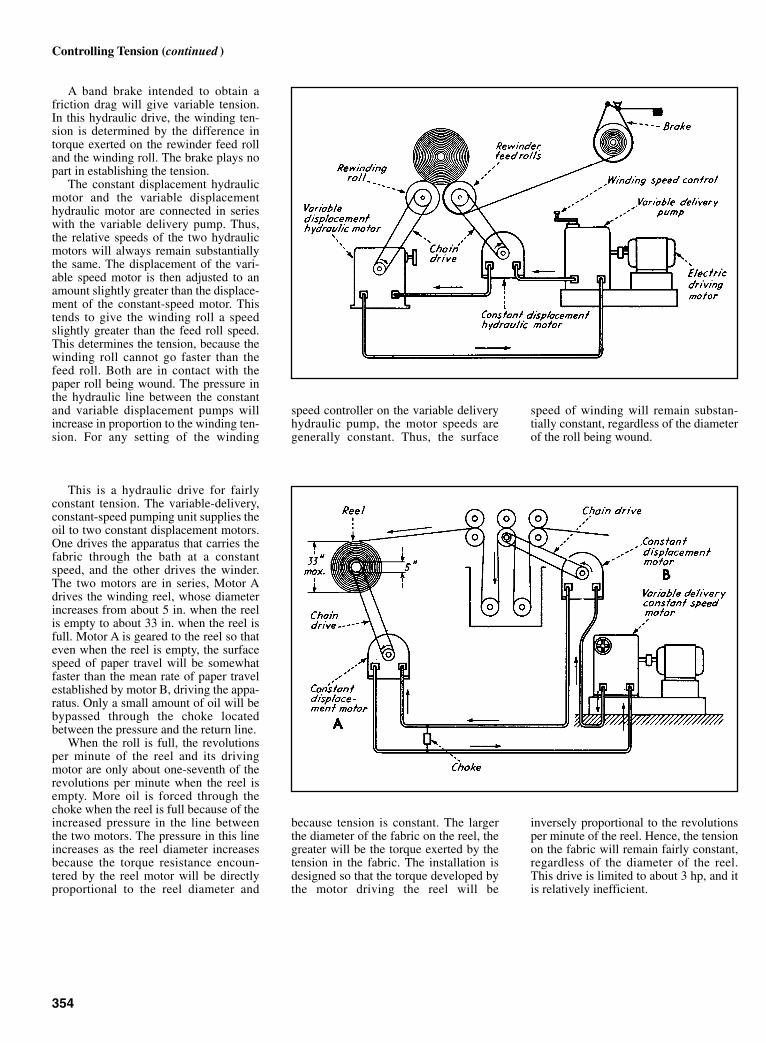
A band brake intended to obtain afriction drag will give variable tension.In this hydraulic drive, the winding ten-sion is determined by the difference intorque exerted on the rewinder feed rolland the winding roll. The brake plays nopart in establishing the tension.
The constant displacement hydraulicmotor and the variable displacementhydraulic motor are connected in serieswith the variable delivery pump. Thus,the relative speeds of the two hydraulicmotors will always remain substantiallythe same. The displacement of the vari-able speed motor is then adjusted to anamount slightly greater than the displace-ment of the constant-speed motor. Thistends to give the winding roll a speedslightly greater than the feed roll speed.This determines the tension, because thewinding roll cannot go faster than thefeed roll. Both are in contact with thepaper roll being wound. The pressure inthe hydraulic line between the constantand variable displacement pumps willincrease in proportion to the winding ten-sion. For any setting of the winding
speed controller on the variable deliveryhydraulic pump, the motor speeds aregenerally constant. Thus, the surface
speed of winding will remain substan-tially constant, regardless of the diameterof the roll being wound.
354
Controlling Tension (continued )
This is a hydraulic drive for fairlyconstant tension. The variable-delivery,constant-speed pumping unit supplies theoil to two constant displacement motors.One drives the apparatus that carries thefabric through the bath at a constantspeed, and the other drives the winder.The two motors are in series, Motor Adrives the winding reel, whose diameterincreases from about 5 in. when the reelis empty to about 33 in. when the reel isfull. Motor A is geared to the reel so thateven when the reel is empty, the surfacespeed of paper travel will be somewhatfaster than the mean rate of paper travelestablished by motor B, driving the appa-ratus. Only a small amount of oil will bebypassed through the choke locatedbetween the pressure and the return line.
When the roll is full, the revolutionsper minute of the reel and its drivingmotor are only about one-seventh of therevolutions per minute when the reel isempty. More oil is forced through thechoke when the reel is full because of theincreased pressure in the line betweenthe two motors. The pressure in this lineincreases as the reel diameter increasesbecause the torque resistance encoun-tered by the reel motor will be directlyproportional to the reel diameter and
because tension is constant. The largerthe diameter of the fabric on the reel, thegreater will be the torque exerted by thetension in the fabric. The installation isdesigned so that the torque developed bythe motor driving the reel will be
inversely proportional to the revolutionsper minute of the reel. Hence, the tensionon the fabric will remain fairly constant,regardless of the diameter of the reel.This drive is limited to about 3 hp, and itis relatively inefficient.
Sclater Chapter 10 5/3/01 1:08 PM Page 354

355
SWITCH PREVENTS OVERLOADING OF A HOISTA fail-safe switch deactivates a lifting circuit if the load exceeds apreset value. Split coupling permits quick attachment of the cable.
A load plunger is inserted through the bellevillesprings, which are supported on a swivelingcrosshead. The crosshead is mounted on the hoistframe and retained by two S-hooks and bolts. Underload, the belleville springs deflect and permit theload plunger to move axially. The end of the loadplunger is connected to a normally closed switch.When the springs deflect beyond a preset value, theload plunger trips the switch, opening the raising-coilcircuit of the magnetic hoist-controller. The raisingcircuit becomes inoperative, but the lowering circuitis not affected. A second contact, normally open, isincluded in the switch to permit the inclusion ofvisual or audible overload signal devices.
The load plunger and the swaged-on cable termina-tion have ball-and-socket seat sections to permitmaximum free cable movement, reducing the possi-bility of fatigue failure. A split-coupling and sleevepermits quick attachment of the cable-ball terminalto the load plunger.
Ball-Type Transmission Is Self-Governing
The Gerritsen transmission, developed in England at the TiltmanLangley Laboratories Ltd., Redhill Aerodrome, Surrey, governsits own output speed within limits of ±1%. The usual difficultiesof speed governing—lack of sensitivity, lag, and hunting—asso-ciated with separate governor units are completely eliminatedbecause regulation is effected directly by the driving membersthrough their own centrifugal force. The driving members areprecision bearing-steel balls that roll on four hardened-steel,cone-shaped rings. These members can be organized for differentratio arrangements.
The transmission can be used in three different ways: as afixed “gear,” as an externally controlled variable-speed unit, oras a self-governing drive that produces a constant output speedform varying input speeds.
The self-governing action of the transmission is derived from thecentrifugal forces of the balls as they rotate. When the balls moveoutward radially, the input-output ration changes. By properly arrang-ing the rings and springs, the gear ration can be controlled by themovement of the balls to maintain a constant value of output speed.
Sclater Chapter 10 5/3/01 1:08 PM Page 355

356
MECHANICAL, GEARED, AND CAMMEDLIMIT SWITCHES
Limit switches are electric currentswitching devices that are operated bysome form or mechanical motion. Limitswitches are usually installed in auto-matic machinery to control a completeoperating cycle automatically by closing
and opening electrical circuits in theproper sequence.
In addition to interlocking control cir-cuits, limit switches have many otheruses. For example, they are important assafety devices to stop a machine, sound a
warning signal, or illuminate a warninglight when a dangerous operating condi-tion develops. Thus, properly appliedswitches can both control highly efficientautomatic electric machinery and protectit and its operator.
Actuators Linear mechanical switches
Sclater Chapter 10 5/3/01 1:08 PM Page 356
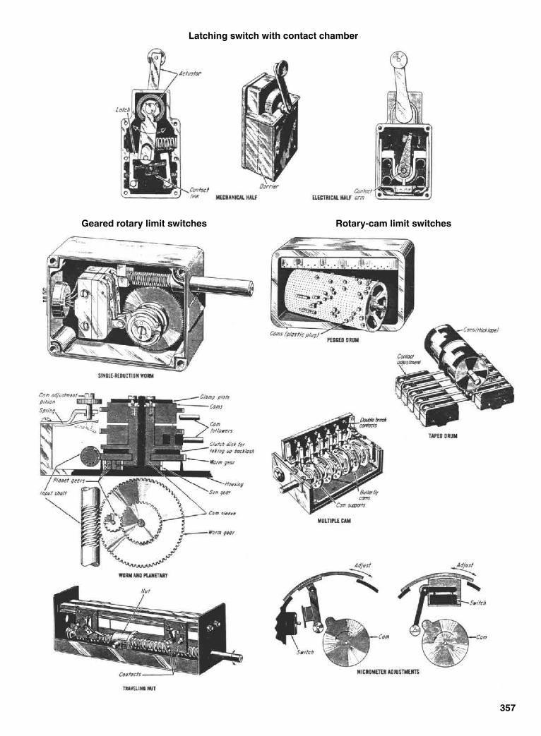
357
Latching switch with contact chamber
Geared rotary limit switches Rotary-cam limit switches
Sclater Chapter 10 5/3/01 1:08 PM Page 357

LIMIT SWITCHES IN MACHINERYLimit switches, which confine or restrain the travel or rotation of moving parts within certain predetermined points, are actuated by varying methods. Some of these, such as cams, rollers, push-rods, and traveling nuts, are described and illustrated.
358
Sclater Chapter 10 5/3/01 1:08 PM Page 358
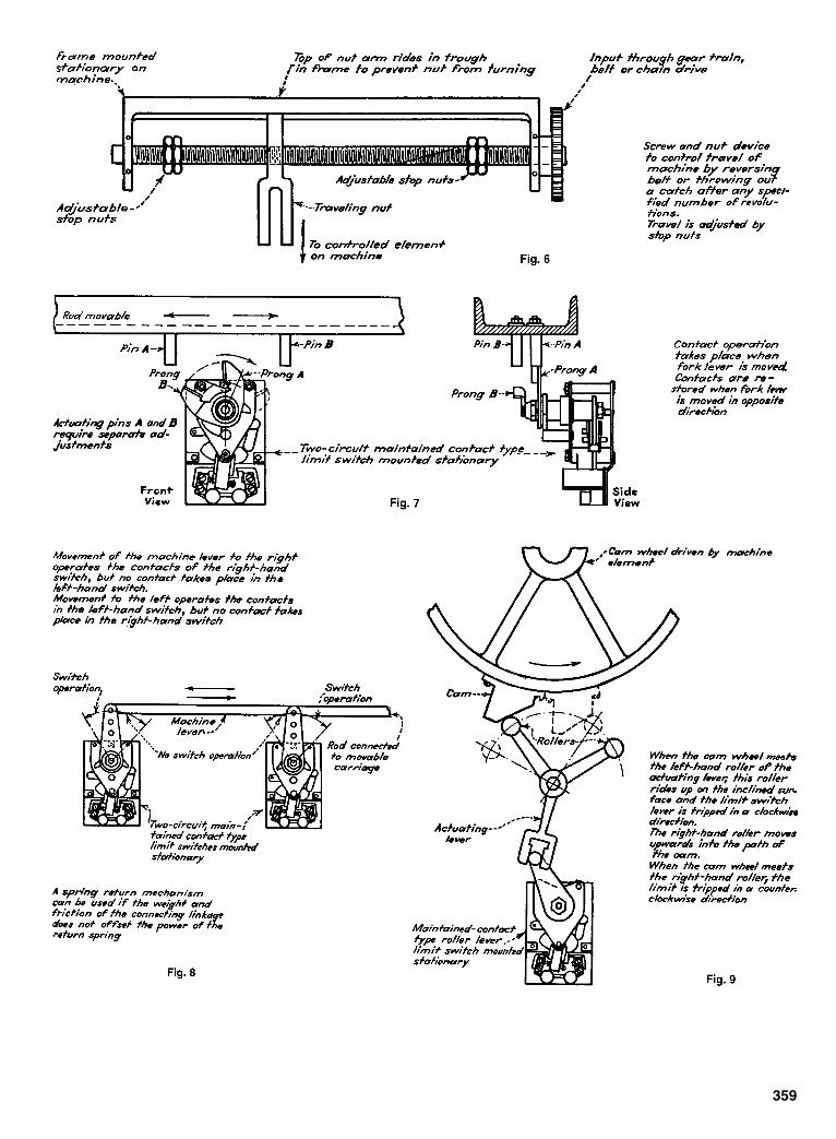
359
Sclater Chapter 10 5/3/01 1:08 PM Page 359
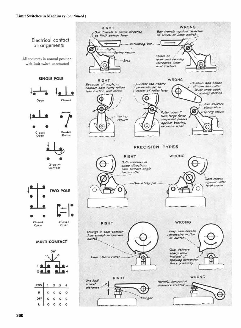
360
Limit Switches in Machinery (continued )
Sclater Chapter 10 5/3/01 1:08 PM Page 360

361
Sclater Chapter 10 5/3/01 1:08 PM Page 361

AUTOMATIC SPEED GOVERNORSSpeed governors, designed to maintain the speeds of machines within reasonably constant limits, regardless of loads, depend for their action upon centrifugal force or cam linkages. Other governors depend on pressure differentials and fluid velocities for their actuation.
362
Fig. 1 Auxiliary piston governor.
Fig. 2 Hit-and-miss governor.Fig. 3 Force-compensatedregulator.
Sclater Chapter 10 5/3/01 1:08 PM Page 362

363
Fig. 4 Pressure-actuated governor.
Fig. 5 Varying differential governor.
Fig. 6 Centrifugal governor.
Fig. 7 Constant-volume governor.
Fig. 8 Velocity-type governor (coil spring). Fig. 9 Velocity-type governor (cantilever spring).
Sclater Chapter 10 5/3/01 1:08 PM Page 363

364
CENTRIFUGAL, PNEUMATIC, HYDRAULIC, ANDELECTRIC GOVERNORSCentrifugal governors are the most com-mon—they are simple and sensitive andhave high output force. There is morepublished information on centrifugal gov-ernors than on all other types combined.
In operation, centrifugal flyweightsdevelop a force proportional to thesquare of the speed, modified by link-ages, as required. In small engines theflyweight movement can actuate the fuelthrottle directly. Larger engines requireamplifiers or relays. This has lead toinnumerable combinations of pilot pis-tons, linear actuators, dashpots, compen-sators, and gear boxes.
Pneumatic sensors are the most inex-pensive and also the most inaccurate ofall speed-measuring and governing com-ponents. Nevertheless, they are entirelyadequate for many applications. Thepressure or velocity of cooling or com-bustion air is used to measure and governthe speed of the engine.
Sclater Chapter 10 5/3/01 1:08 PM Page 364
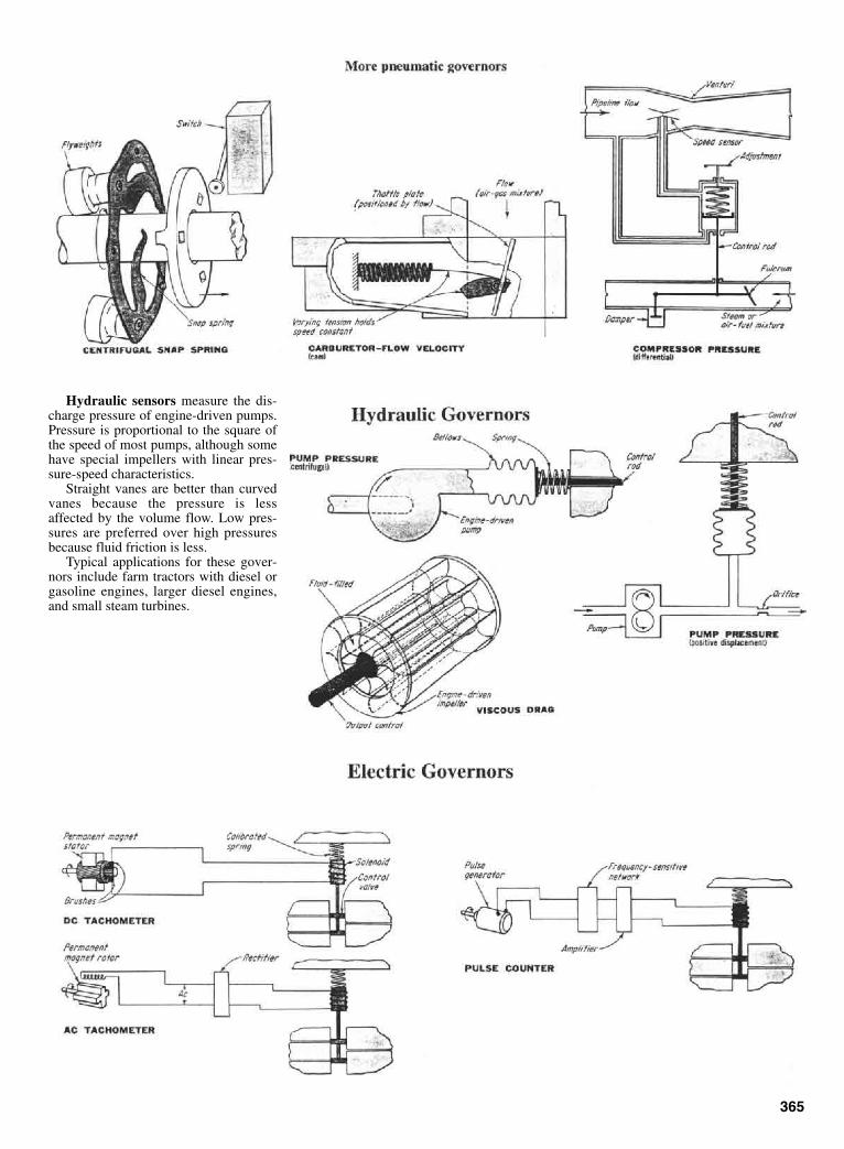
Hydraulic sensors measure the dis-charge pressure of engine-driven pumps.Pressure is proportional to the square ofthe speed of most pumps, although somehave special impellers with linear pres-sure-speed characteristics.
Straight vanes are better than curvedvanes because the pressure is lessaffected by the volume flow. Low pres-sures are preferred over high pressuresbecause fluid friction is less.
Typical applications for these gover-nors include farm tractors with diesel orgasoline engines, larger diesel engines,and small steam turbines.
365
Sclater Chapter 10 5/3/01 1:08 PM Page 365
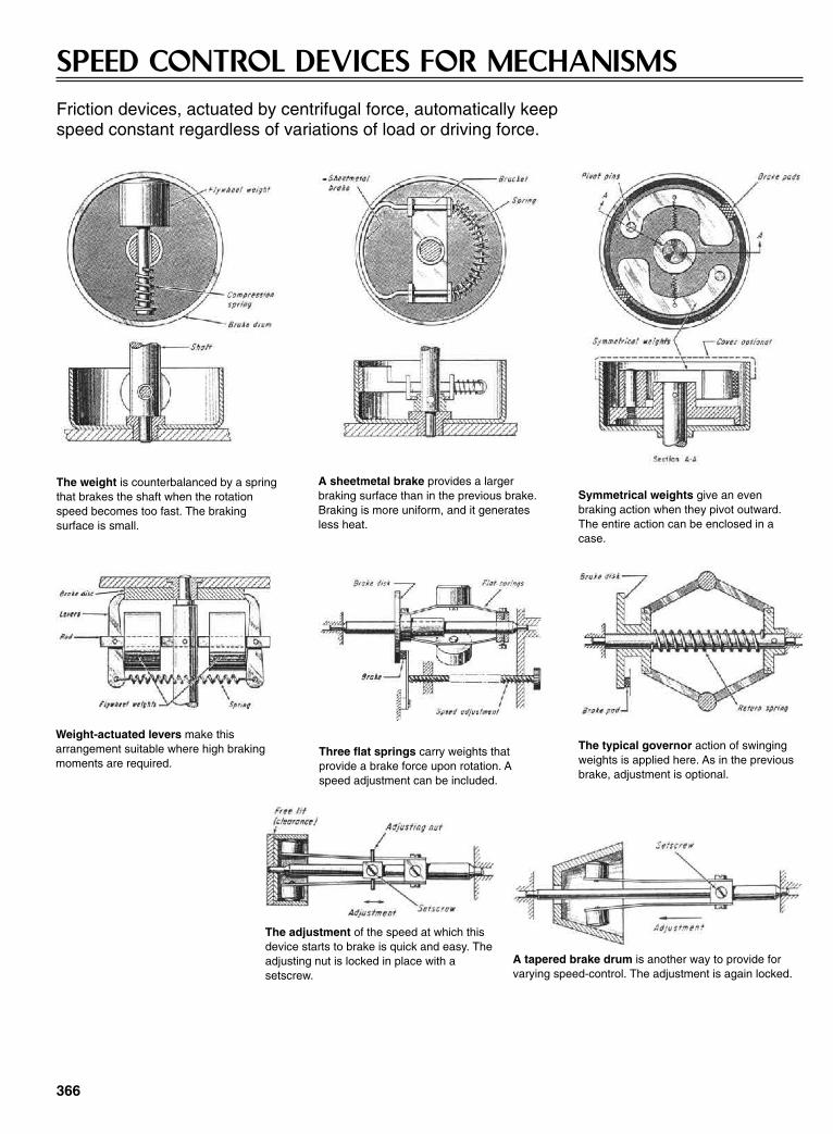
366
SPEED CONTROL DEVICES FOR MECHANISMSFriction devices, actuated by centrifugal force, automatically keep speed constant regardless of variations of load or driving force.
The weight is counterbalanced by a springthat brakes the shaft when the rotationspeed becomes too fast. The braking surface is small.
A sheetmetal brake provides a larger braking surface than in the previous brake.Braking is more uniform, and it generatesless heat.
Symmetrical weights give an even braking action when they pivot outward.The entire action can be enclosed in acase.
Weight-actuated levers make thisarrangement suitable where high brakingmoments are required.
Three flat springs carry weights that provide a brake force upon rotation. Aspeed adjustment can be included.
The typical governor action of swingingweights is applied here. As in the previousbrake, adjustment is optional.
The adjustment of the speed at which thisdevice starts to brake is quick and easy. Theadjusting nut is locked in place with asetscrew.
A tapered brake drum is another way to provide forvarying speed-control. The adjustment is again locked.
Sclater Chapter 10 5/3/01 1:08 PM Page 366

A gear-drive mechanism helps to appor-tion torques nearly equally along twoparallel drive paths from an input bevelgear to an output bull gear. A mechanismof this type could be used, for example,as part of a redundant drive train betweenthe engine and the rotor of a helicopter.The principal advantage of this torque-splitting mechanism is that it weighs lessthan comparably rated existing torque-splitting mechanisms.
The input torque is supplied to a bevelgear (see figure) from a bevel pinion (notshown) connected to the engine or othersource. Overall, the torque is transmittedfrom the bevel gear through a torque-splitting pinion to two torque-splittinggears, then from the two torque-splitting
gears through the associated two bullpinions to the bull gear, then to the outputshaft. The purpose of the torque-splittingfeature is to distribute the loads as nearlyequally as possible to all gear teeth in thetwo parallel load paths to keep the loadon each tooth as nearly equal as possible,thereby prolonging the life of the geartrain.
In a redundant drive mechanism ofthe same basic configuration but withoutexplicit provision for torque splitting, theslightest deviation from precision inmachining could cause the entire load tobe transmitted along one of the two pathswhile the gear and pinion in the otherpath rotate freely. To provide explicitlyfor torque splitting components made to
manufacturing tolerances, elastic defor-mations, and other deviations from thenominal precise gearing geometry, it isnecessary to incorporate a low-springrate member at one or more critical loca-tions in the mechanism.
In this mechanism, the resultant loadon the torque-splitting pinion is zerowhen the torque is identical on the leftand right members. If there is a differ-ence in torque, the resultant load will dis-place the torque-splitting pinion until theloads are again in balance, thereby ensur-ing equal loads in each path.
This work was done by Harold W.Melles of United Technologies Corp. forLewis Research Center.
367
FLOATING-PINION TORQUE SPLITTERDesigned-in looseness at the right locations helps to distribute torques more evenly.Lewis Research Center, Cleveland, Ohio
Splined connections permit small angular excursions of a shaft, the bevel gear on its upper end, andthe torque-splitting pinion on its lower end. These small excursions are essential for equalization oftorques in the presence of machining tolerances and other geometric imperfection of the drive train.
Sclater Chapter 10 5/3/01 1:08 PM Page 367

CHAPTER 11PNEUMATIC AND
HYDRAULIC MACHINEAND MECHANISM
CONTROL
Sclater Chapter 11 5/3/01 1:15 PM Page 369

370
DESIGNS AND OPERATING PRINCIPLES OF TYPICAL PUMPSThese pumps are used to transfer liquids and supply hydraulic power.
1. WITH BUT TWO MOVING PARTS, the rotors that turn in the same direction, thisrotary pump has reduced friction to a minimum. The rotors rotate against flexible syn-thetic rubber cushions that allow sand, grit and other abrasives to flow freely through thepump without damage. It is a positive displacement pump that develops a constant pres-sure and will deliver a uniform flow at any given speed. The pump is reversible and canbe driven by a gasoline engine or electric motor. The rubber cushions withstand theaction of oil, kerosene, and gasoline, and the pump operates at any angle. It has been usedin circulating water systems, cutting tool coolant oil systems and general applications.
2. PUMPING ACTION is produced bythe meshing of the idler and rotor teeth inthis rotary pump. The idler is pin-mounted to the head and the rotor oper-ates in either direction. This pump willnot splash, foam, churn or cause pound-ing. Liquids of any viscosity that do notcontain grit can be transferred by thispump which is made of iron and bronze.
3. BASED on the swinging vane princi-ple, this pump maintains its volumetricefficiency automatically. The action ofthe buckets, fitted loosely into recesses inthe rotor, compensates for wear. In oper-ation, the tip of the bucket is in light con-tact with the casing wall. Liquids aremoved by sucking and pushing actionsand are not churned or foamed.
4. HIGH-PRESSURE, high-volume pumps of the axial piston, constant displace-ment type are rated at 3,500 psi for continuous duty operation; higher pressure is per-missible for intermittent operation. A pressure-balanced piston shoe lubricates thecam plate and prevents direct contact between the shoe and cam plate. The use of thepressure balanced system removes the need for thrust bearings. The two-piece shaftabsorbs deflection and minimizes bearing wear. The pump and electric driving motorare connected by a flexible coupling. The revolving cylinder barrel causes the axialreciprocation of the pumping pistons. These pumps only pump hydraulic fluids.
Sclater Chapter 11 5/3/01 1:15 PM Page 370
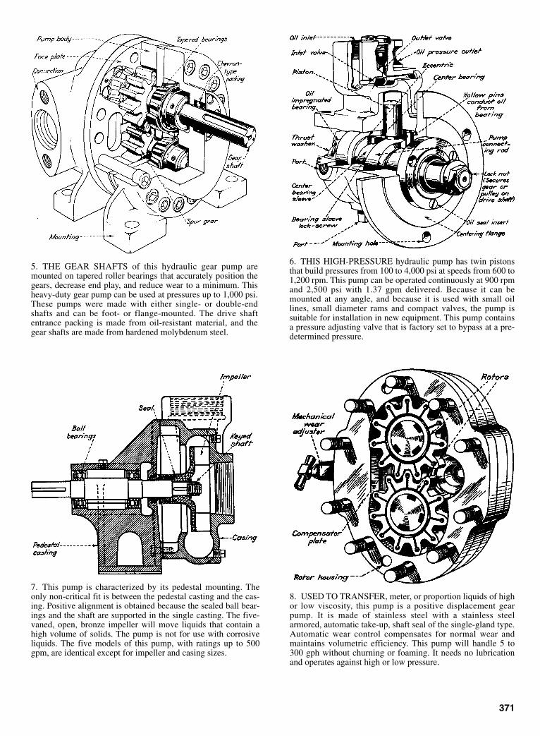
5. THE GEAR SHAFTS of this hydraulic gear pump aremounted on tapered roller bearings that accurately position thegears, decrease end play, and reduce wear to a minimum. Thisheavy-duty gear pump can be used at pressures up to 1,000 psi.These pumps were made with either single- or double-endshafts and can be foot- or flange-mounted. The drive shaftentrance packing is made from oil-resistant material, and thegear shafts are made from hardened molybdenum steel.
6. THIS HIGH-PRESSURE hydraulic pump has twin pistonsthat build pressures from 100 to 4,000 psi at speeds from 600 to1,200 rpm. This pump can be operated continuously at 900 rpmand 2,500 psi with 1.37 gpm delivered. Because it can bemounted at any angle, and because it is used with small oillines, small diameter rams and compact valves, the pump issuitable for installation in new equipment. This pump containsa pressure adjusting valve that is factory set to bypass at a pre-determined pressure.
8. USED TO TRANSFER, meter, or proportion liquids of highor low viscosity, this pump is a positive displacement gearpump. It is made of stainless steel with a stainless steelarmored, automatic take-up, shaft seal of the single-gland type.Automatic wear control compensates for normal wear andmaintains volumetric efficiency. This pump will handle 5 to300 gph without churning or foaming. It needs no lubricationand operates against high or low pressure.
371
7. This pump is characterized by its pedestal mounting. Theonly non-critical fit is between the pedestal casting and the cas-ing. Positive alignment is obtained because the sealed ball bear-ings and the shaft are supported in the single casting. The five-vaned, open, bronze impeller will move liquids that contain ahigh volume of solids. The pump is not for use with corrosiveliquids. The five models of this pump, with ratings up to 500gpm, are identical except for impeller and casing sizes.
Sclater Chapter 11 5/3/01 1:15 PM Page 371
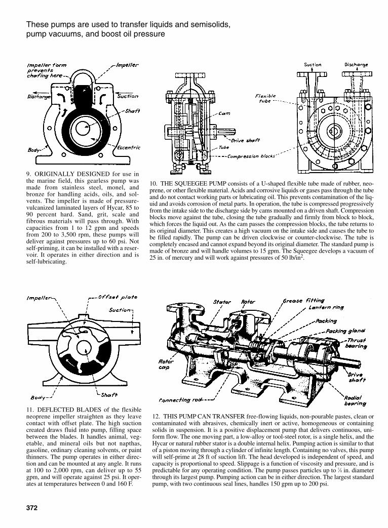
372
These pumps are used to transfer liquids and semisolids, pump vacuums, and boost oil pressure
9. ORIGINALLY DESIGNED for use inthe marine field, this gearless pump wasmade from stainless steel, monel, andbronze for handling acids, oils, and sol-vents. The impeller is made of pressure-vulcanized laminated layers of Hycar, 85 to90 percent hard. Sand, grit, scale andfibrous materials will pass through. Withcapacities from 1 to 12 gpm and speedsfrom 200 to 3,500 rpm, these pumps willdeliver against pressures up to 60 psi. Notself-priming, it can be installed with a reser-voir. It operates in either direction and isself-lubricating.
10. THE SQUEEGEE PUMP consists of a U-shaped flexible tube made of rubber, neo-prene, or other flexible material. Acids and corrosive liquids or gases pass through the tubeand do not contact working parts or lubricating oil. This prevents contamination of the liq-uid and avoids corrosion of metal parts. In operation, the tube is compressed progressivelyfrom the intake side to the discharge side by cams mounted on a driven shaft. Compressionblocks move against the tube, closing the tube gradually and firmly from block to block,which forces the liquid out. As the cam passes the compression blocks, the tube returns toits original diameter. This creates a high vacuum on the intake side and causes the tube tobe filled rapidly. The pump can be driven clockwise or counter-clockwise. The tube iscompletely encased and cannot expand beyond its original diameter. The standard pump ismade of bronze and will handle volumes to 15 gpm. The Squeegee develops a vacuum of25 in. of mercury and will work against pressures of 50 lb/in2.
12. THIS PUMP CAN TRANSFER free-flowing liquids, non-pourable pastes, clean orcontaminated with abrasives, chemically inert or active, homogeneous or containingsolids in suspension. It is a positive displacement pump that delivers continuous, uni-form flow. The one moving part, a low-alloy or tool-steel rotor, is a single helix, and theHycar or natural rubber stator is a double internal helix. Pumping action is similar to thatof a piston moving through a cylinder of infinite length. Containing no valves, this pumpwill self-prime at 28 ft of suction lift. The head developed is independent of speed, andcapacity is proportional to speed. Slippage is a function of viscosity and pressure, and ispredictable for any operating condition. The pump passes particles up to 7⁄8 in. diameterthrough its largest pump. Pumping action can be in either direction. The largest standardpump, with two continuous seal lines, handles 150 gpm up to 200 psi.
11. DEFLECTED BLADES of the flexibleneoprene impeller straighten as they leavecontact with offset plate. The high suctioncreated draws fluid into pump, filling spacebetween the blades. It handles animal, veg-etable, and mineral oils but not napthas,gasoline, ordinary cleaning solvents, or paintthinners. The pump operates in either direc-tion and can be mounted at any angle. It runsat 100 to 2,000 rpm, can deliver up to 55gpm, and will operate against 25 psi. It oper-ates at temperatures between 0 and 160 F.
Sclater Chapter 11 5/3/01 1:15 PM Page 372

13. HIGH-VACUUM PUMPS operate withthe rotating plunger action of liquid pumps.Sealing oil lubricates the three moving parts.Parts are accessible without disturbing con-nected piping. These pumps are used torough pump a vacuum before connecting adiffusion pump; to evacute light bulbs andelectronic tubes, and to vacuum dry and dis-till. Single pumps draw vacuums from 2 to 5microns; in series to 0.5 micron, and com-pound pumps draw to 0.1 micron. They canbe run in reverse for transferring liquids.Diagonal cored slots, closed by a slide pin,form the passageway and inlet valve. Popperor feature outlet valves are used.
14. A COMPACT MULTI-PLUNGER INTENSIFIER, this hydraulic booster isdesigned to convert low pressure to high pressure in any oil-hydraulic circuit. Noadditional pumps are required. Because of its six plungers, the pressure flow fromthe booster is both smooth and uninterrupted. High-pressure pumps are notrequired, and no operating valves are needed to control the high-pressure system.Small cylinder and ram assemblies can be used on operating equipment because thepressure is high. Operating costs can be low because of the efficient use of con-nected horsepower. The inertia effects of the small operating rams are low, so highspeed operations can be attained. These boosters were built in two standard sizes,each of which was available in two pressure ranges: 2 to 1 and 3 to 1. Volumetricoutput is in inverse proportion to the pressure ratio. All units have a maximum7,500 psi discharge pressure. Pistons are double-acting, and the central valveadmits oil to pistons in sequence and is always hydraulically balanced.
373
15. THIS SELF-PRIMING PUMP gives arapid and smooth transition from primingcycle to centrifugal pumping. The pumpstarts with its priming chamber full. Liquid isrecirculated through the impeller until thepump is primed. As priming liquid circu-lates, air is drawn through impeller andexpelled through the discharge. When all airis evacuated, discharge velocity closes thepriming valve completely. These pumps canhave open or closed impellers. Solids up to 1in. can be passed through a 3 in. size pumpwith an open impeller.
16. INTERNAL SCREW PUMPS can easily transfer high-viscosity petroleumproducts. They can be used as boiler fuel pumps because they deliver a pulselessflow of oil. For marine or stationary systems, the characteristic low vibration ofscrew pumps has allowed them to be mounted on light foundations. The absenceof vibration and pulsing flow reduces strain on pipes, hose and fittings. Thepumping screws are mounted on shafts and take in liquid at both ends of the pumpbody and move it to the center for discharge. This balanced pumping actionmakes it unnecessary to use thrust bearings except in installations where thepump is mounted at a high angle. The pumps can be used at any angle up to verti-cal. Where thrust bearings are needed, antifriction bearings capable of supportingthe load of the shaft and screws are used. The intermeshing pumping screws aretimed by a pair of precision-cut herringbone gears. These are self-centering, anddo not allow the side wear of the screws while they are pumping. The pump ismost efficient when driven less than 1,200 rpm by an electric motor and 1,300rpm by a steam turbine.
Sclater Chapter 11 5/3/01 1:15 PM Page 373

374
ROTARY-PUMP MECHANISMS
Fig. 1 (A) A Ramelli pump with spring-loaded vanes to ensure con-tact with the wall; vane ends are rounded for line contact. (B) Twovanes pivot in the housing and are driven by an eccentricallymounted disk; vanes slide in glands and are always radial to the
housing, thus providing surface contact. (C) A housing with a cardioidcurve allows the use of a single vane because opposing points on thehousing in line with the disk center are equidistant.
Fig. 2 Flexible vanes on an eccentric rub-ber rotor displace liquid as in sliding-vanepumps. Instead of the vanes sliding in andout, they bend against the casing to per-form pumping. Fig. 3 A disk mounted eccentrically on
the drive shaft displaces liquid in continu-ous flow. A spring-loaded gland separatesthe inlet from the outlet except when thedisk is at the top of stroke.
Fig. 4 A rotary compressor pump has alink separating its suction and compressionsides. The link is hinged to a ring whichoscillates while it is driven by the disk.Oscillating action pumps the liquid in a con-tinuous flow.
Fig. 5 A gear pump transports liquidbetween the tooth spaces and the housingwall. A circular tooth shape ha sonly one toothmaking contact, and it is more efficient than aninvolute shape which might enclose a pocketbetween two adjoining teeth, recirculating partof the liquid. The pump has helical teeth.
Fig. 6 A Roots compressor has twoidentical impellers with specially shapedteeth. The shafts are connected by externalgearing to ensure constant contact betweenthe impellers.
Fig. 7 A three-screw pump drivesliquid between the screw threads alongthe axis of the screws. The idle rotorsare driven by fluid pressure, not bymetallic contact with the power rotor.
Sclater Chapter 11 5/3/01 1:15 PM Page 374

375
Fig. 8 The housing of the Hele-Shaw-Beachum pump rotates theround-cranked shaft. Connectingrods attached to the crank ringcause the pistons to oscillate as thehousing rotates. No valves are nec-essary because the fixed hollowshaft, divided by a wall, has suctionand compression sides that arealways in correct register with theinlet and outlet ports.
Fig. 9 A disk drives the oscillating arm whichacts as piston. The velocity of the arm variesbecause of its quick-return mechanism. Liquid isslowly drawn in and expelled during the clockwiserotation of the arm; the return stroke transfers theliquid rapidly.
Fig. 10 A rotating cylinder block is mounted concentricallyin a housing. Connecting-rod ends slide around an eccentricguide as the cylinders rotate and cause the pistons to recipro-cate. The housing is divided into suction and compressioncompartments.
Fig. 11 A rotary-reciprocating pump that is normally operatedmanually to pump high-viscosity liquids such as oil.
OFFSET PLANETARY GEARS INDUCE ROTARY-PUMP ACTION
Two planetary gears are driven by an offset sun gear to provide the pumping action in this positive-displacement pump. A successively increasing/decreasing (suction/compression) is formed on either side of the sun and planet gears.
Sclater Chapter 11 5/3/01 1:15 PM Page 375
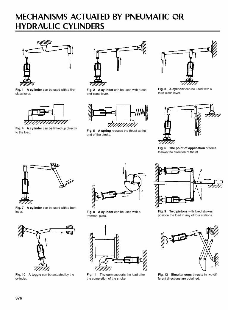
376
MECHANISMS ACTUATED BY PNEUMATIC ORHYDRAULIC CYLINDERS
Fig. 1 A cylinder can be used with a first-class lever.
Fig. 2 A cylinder can be used with a sec-ond-class lever.
Fig. 3 A cylinder can be used with athird-class lever.
Fig. 4 A cylinder can be linked up directlyto the load. Fig. 5 A spring reduces the thrust at the
end of the stroke.
Fig. 6 The point of application of forcefollows the direction of thrust.
Fig. 7 A cylinder can be used with a bentlever. Fig. 8 A cylinder can be used with a
trammel plate.Fig. 9 Two pistons with fixed strokesposition the load in any of four stations.
Fig. 10 A toggle can be actuated by thecylinder.
Fig. 11 The cam supports the load afterthe completion of the stroke.
Fig. 12 Simultaneous thrusts in two dif-ferent directions are obtained.
Sclater Chapter 11 5/3/01 1:16 PM Page 376

377
(Note: In place of cylinders, electrically powered thrust units orsolenoids can be used.)
Fig. 13 A force is transmitted by a cable. Fig. 14 A force can be modified by a sys-tem of pulleys. Fig. 15 A force can be modified by
wedges.
Fig. 16 A gear sector moves the rackperpendicular to the piston stroke.
Fig. 17 A rack turns the gear sector.Fig. 18 The motion of a movable rack istwice that of the piston.
Fig. 19 A torque applied to the shaft canbe transmitted to a distant point.
Fig. 20 A torque can also be applied to ashaft by a belt and pulley. Fig. 21 A motion is transmitted to a dis-
tant point in the plane of motion.
Fig. 22 A steep screw nut produces arotation of the shaft.
Fig. 23 A single-sprocket wheel pro-duces rotation in the plane of motion.
Fig. 24 A double-sprocket wheel makesthe rotation more nearly continuous.
Sclater Chapter 11 5/3/01 1:16 PM Page 377
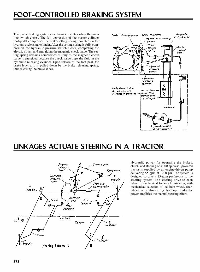
378
FOOT-CONTROLLED BRAKING SYSTEM
This crane braking system (see figure) operates when the mainline switch closes. The full depression of the master-cylinderfoot-pedal compresses the brake-setting spring mounted on thehydraulic releasing cylinder. After the setting spring is fully com-pressed, the hydraulic pressure switch closes, completing theelectric circuit and energizing the magnetic check valve. The set-ting spring remains compressed as long as the magnetic checkvalve is energized because the check valve traps the fluid in thehydraulic-releasing cylinder. Upon release of the foot peal, thebrake lever arm is pulled down by the brake releasing spring,thus releasing the brake shoes.
LINKAGES ACTUATE STEERING IN A TRACTOR
Hydraulic power for operating the brakes,clutch, and steering of a 300 hp diesel-poweredtractor is supplied by an engine-driven pumpdelivering 55 gpm at 1200 psi. The system isdesigned to give a 15-gpm preference to thesteering system. The steering drive to eachwheel is mechanical for synchronization, withmechanical selection of the front-wheel, four-wheel or crab-steering hookup; hydraulicpower amplifies the manual steering effort.
Sclater Chapter 11 5/3/01 1:16 PM Page 378
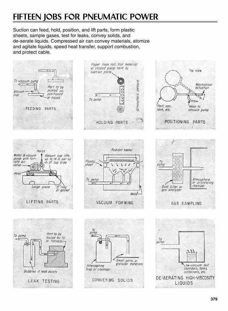
379
FIFTEEN JOBS FOR PNEUMATIC POWERSuction can feed, hold, position, and lift parts, form plastic sheets, sample gases, test for leaks, convey solids, and de-aerate liquids. Compressed air can convey materials, atomize and agitate liquids, speed heat transfer, support combustion, and protect cable.
Sclater Chapter 11 5/3/01 1:16 PM Page 379

15 Jobs for Pneumatic Power (continued )
TEN WAYS TO USE METAL DIAPHRAGMS ANDCAPSULES
380
A metal diaphragm is usually corrugated (Fig. 1) or formed to some irregular profile. It can beused as a flexible seal for an actuating rod. The capsule (Fig. 2) is an assembly of twodiaphragms sealed together at their outer edges, usually by soldering, brazing, or welding. Twoor more capsules assembled together are known as a capsular element (Fig. 3). End fittingsfor the capsules vary according to their function; the “fixed end” is fixed to the equipment. The“free end” moves the related components and linkages. The nested capsule (Fig. 4) requiresless space and can be designed to withstand large external overpressures without damage.
Sclater Chapter 11 5/3/01 1:16 PM Page 380
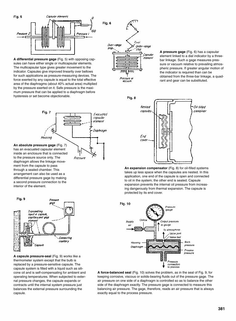
381
A differential pressure gage (Fig. 5) with opposing cap-sules can have either single or multicapsular elements.The multicapsular type gives greater movement to theindicator. Capsules give improved linearity over bellowsfor such applications as pressure-measuring devices. Theforce exerted by any capsule is equal to the total effectivearea of the diaphragms (about 40% actual area) multipliedby the pressure exerted on it. Safe pressure is the maxi-mum pressure that can be applied to a diaphragm beforehysteresis or set become objectionable.
A pressure gage (Fig. 6) has a capsularelement linked to a dial indicator by a three-bar linkage. Such a gage measures pres-sure or vacuum relative to prevailing atmos-pheric pressure. If greater angular motion ofthe indicator is required than can beobtained from the three-bar linkage, a quad-rant and gear can be substituted.
An absolute pressure gage (Fig. 7)has an evacuated capsular elementinside an enclosure that is connectedto the pressure source only. Thediaphragm allows the linkage move-ment from the capsule to passthrough a sealed chamber. Thisarrangement can also be used as adifferential pressure gage by makinga second pressure connection to theinterior of the element.
An expansion compensator (Fig. 8) for oil-filled systemstakes up less space when the capsules are nested. In thisapplication, one end of the capsule is open and connectedto oil in the system; the other end is sealed. Capsuleexpansion prevents the internal oil pressure from increas-ing dangerously from thermal expansion. The capsule isprotected by its end cover.
A capsule pressure-seal (Fig. 9) works like athermometer system except that the bulb isreplaced by a pressure-sensitive capsule. Thecapsule system is filled with a liquid such as sili-cone oil and is self-compensating for ambient andoperating temperatures. When subjected to exter-nal pressure changes, the capsule expands orcontracts until the internal system pressure justbalances the external pressure surrounding thecapsule.
A force-balanced seal (Fig. 10) solves the problem, as in the seal of Fig. 9, forkeeping corrosive, viscous or solids-bearing fluids out of the pressure gage. Theair pressure on one side of a diaphragm is controlled so as to balance the otherside of the diaphragm exactly. The pressure gage is connected to measure thisbalancing air pressure. The gage, therefore, reads an air pressure that is alwaysexactly equal to the process pressure.
Sclater Chapter 11 5/3/01 1:16 PM Page 381
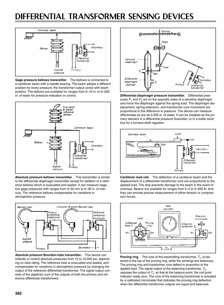
382
DIFFERENTIAL TRANSFORMER SENSING DEVICES
Gage pressure bellows transmitter. The bellows is connected toa cantilever beam with a needle bearing. The beam adopts a differentposition for every pressure; the transformer output varies with beamposition. The bellows are available for ranges from 0–10 in. to 0–200in. of water for pressure indication or control. Differential diaphragm pressure transmitter. Differential pres-
sures P1 and P2 act on the opposite sides of a sensitive diaphragmand move the diaphragm against the spring load. The diaphragm dis-placement, spring extension, and transformer core movement areproportional to the difference in pressure. The device can measuredifferentials as low as 0.005 in. of water. It can be installed as the pri-mary element in a differential pressure flowmeter, or in a boiler wind-box for a furnace-draft regulator.
Absolute pressure bellows transmitter. This transmitter is similarto the differential diaphragm transmitter except for addition of a refer-ence bellows which is evacuated and sealed. It can measure nega-tive gage pressures with ranges from 0–50 mm to 0–30 in. of mer-cury. The reference bellows compensates for variations inatmospheric pressure.
Cantilever load cell. The deflection of a cantilever beam and thedisplacement of a differential transformer core are proportional to theapplied load. The stop prevents damage to the beam in the event ofoverload. Beams are available for ranges from 0–5 to 0–500 lb. Andthey can provide precise measurement of either tension or compres-sion forces.
Absolute pressure Bourdon-tube transmitter. This device canindicate or control absolute pressures from 15 to 10,000 psi, depend-ing on tube rating. The reference tube is evacuated and sealed, andcompensates for variations in atmospheric pressure by changing theoutput of the reference differential transformer. The signal output con-sists of the algebraic sum of the outputs of both the primary and ref-erence differential transformers.
Proving ring. The core of the transmitting transformer, T1, is fas-tened to the top of the proving ring, while the windings are stationary.The proving ring and transformer core deflect in proportion to theapplied load. The signal output of the balancing transformer, T2,opposes the output of T1, so that at the balance point, the null pointindicator reads zero. The core of the balancing transformer is actuatedby a calibrated micrometer that indicates the proving ring deflectionwhen the differential transformer outputs are equal and balanced.
Sclater Chapter 11 5/3/01 1:16 PM Page 382
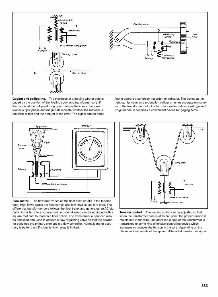
383
Gaging and callipering. The thickness of a moving wire or strip isgaged by the position of the floating spool and transformer core. Ifthe core is at the null point for proper material thickness, the trans-former output phase and magnitude indicate whether the material istoo thick or thin and the amount of the error. The signal can be ampli-
fied to operate a controller, recorder, or indicator. The device at theright can function as a production caliper or as an accurate microme-ter. If the transformer output is fed into a meter indicator with go andno-go bands, it becomes a convenient device for gaging items.
Flow meter. The flow area varies as the float rises or falls in the taperedtube. High flows cause the float to rise, and low flows cause it to drop. Thedifferential transformer core follows the float travel and generates an AC sig-nal which is fed into a square-root recorder. A servo can be equipped with asquare root cam to read on a linear chart. The transformer output can alsobe amplified and used to actuate a flow regulating valve so that the flowme-ter becomes the primary element in a flow controller. Normally meter accu-racy is better than 2%, but its flow range is limited.
Tension control. The loading spring can be adjusted so thatwhen the transformer core is at its null point, the proper tension ismaintained in the wire. The amplified output of the transformer istransmitted to some kind of tension-controlling device whichincreases or reduces the tension in the wire, depending on thephase and magnitude of the applied differential transformer signal.
Sclater Chapter 11 5/3/01 1:16 PM Page 383
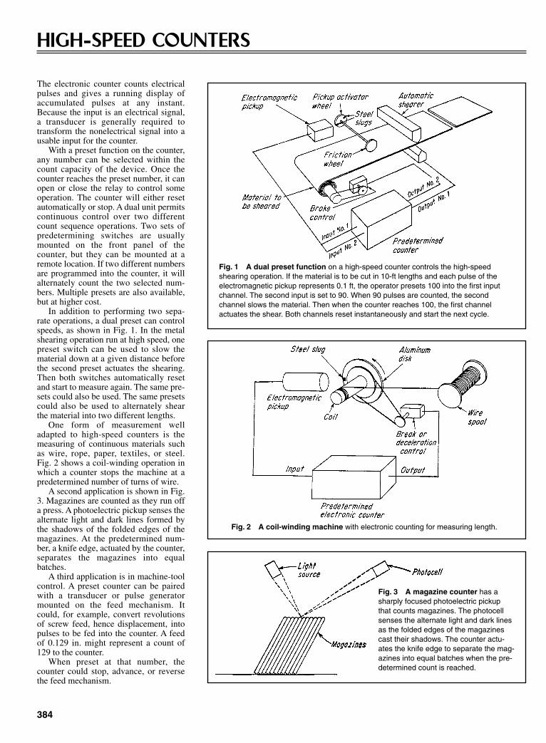
384
HIGH-SPEED COUNTERS
The electronic counter counts electricalpulses and gives a running display ofaccumulated pulses at any instant.Because the input is an electrical signal,a transducer is generally required totransform the nonelectrical signal into ausable input for the counter.
With a preset function on the counter,any number can be selected within thecount capacity of the device. Once thecounter reaches the preset number, it canopen or close the relay to control someoperation. The counter will either resetautomatically or stop. A dual unit permitscontinuous control over two differentcount sequence operations. Two sets ofpredetermining switches are usuallymounted on the front panel of thecounter, but they can be mounted at aremote location. If two different numbersare programmed into the counter, it willalternately count the two selected num-bers. Multiple presets are also available,but at higher cost.
In addition to performing two sepa-rate operations, a dual preset can controlspeeds, as shown in Fig. 1. In the metalshearing operation run at high speed, onepreset switch can be used to slow thematerial down at a given distance beforethe second preset actuates the shearing.Then both switches automatically resetand start to measure again. The same pre-sets could also be used. The same presetscould also be used to alternately shearthe material into two different lengths.
One form of measurement welladapted to high-speed counters is themeasuring of continuous materials suchas wire, rope, paper, textiles, or steel.Fig. 2 shows a coil-winding operation inwhich a counter stops the machine at apredetermined number of turns of wire.
A second application is shown in Fig.3. Magazines are counted as they run offa press. A photoelectric pickup senses thealternate light and dark lines formed bythe shadows of the folded edges of themagazines. At the predetermined num-ber, a knife edge, actuated by the counter,separates the magazines into equalbatches.
A third application is in machine-toolcontrol. A preset counter can be pairedwith a transducer or pulse generatormounted on the feed mechanism. Itcould, for example, convert revolutionsof screw feed, hence displacement, intopulses to be fed into the counter. A feedof 0.129 in. might represent a count of129 to the counter.
When preset at that number, thecounter could stop, advance, or reversethe feed mechanism.
Fig. 1 A dual preset function on a high-speed counter controls the high-speed shearing operation. If the material is to be cut in 10-ft lengths and each pulse of theelectromagnetic pickup represents 0.1 ft, the operator presets 100 into the first inputchannel. The second input is set to 90. When 90 pulses are counted, the second channel slows the material. Then when the counter reaches 100, the first channel actuates the shear. Both channels reset instantaneously and start the next cycle.
Fig. 2 A coil-winding machine with electronic counting for measuring length.
Fig. 3 A magazine counter has asharply focused photoelectric pickupthat counts magazines. The photocellsenses the alternate light and dark linesas the folded edges of the magazinescast their shadows. The counter actu-ates the knife edge to separate the mag-azines into equal batches when the pre-determined count is reached.
Sclater Chapter 11 5/3/01 1:16 PM Page 384
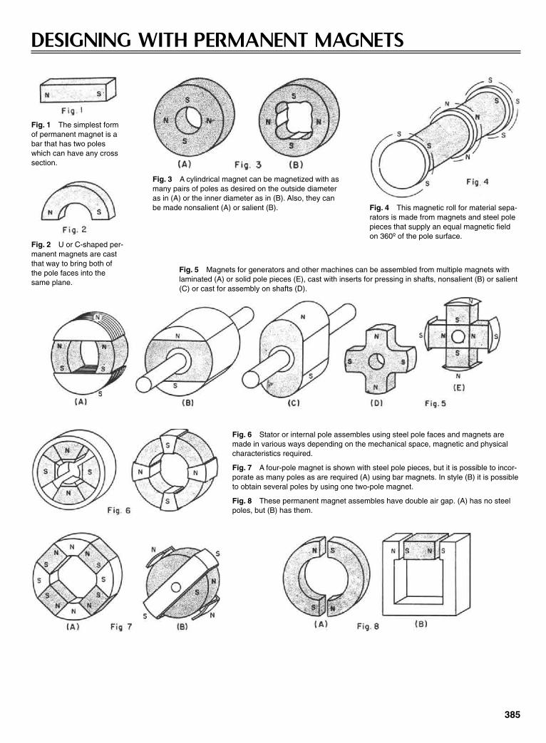
385
DESIGNING WITH PERMANENT MAGNETS
Fig. 1 The simplest formof permanent magnet is abar that has two poleswhich can have any crosssection.
Fig. 3 A cylindrical magnet can be magnetized with asmany pairs of poles as desired on the outside diameteras in (A) or the inner diameter as in (B). Also, they canbe made nonsalient (A) or salient (B). Fig. 4 This magnetic roll for material sepa-
rators is made from magnets and steel polepieces that supply an equal magnetic fieldon 360º of the pole surface.
Fig. 5 Magnets for generators and other machines can be assembled from multiple magnets withlaminated (A) or solid pole pieces (E), cast with inserts for pressing in shafts, nonsalient (B) or salient(C) or cast for assembly on shafts (D).
Fig. 2 U or C-shaped per-manent magnets are castthat way to bring both ofthe pole faces into thesame plane.
Fig. 6 Stator or internal pole assembles using steel pole faces and magnets aremade in various ways depending on the mechanical space, magnetic and physicalcharacteristics required.
Fig. 7 A four-pole magnet is shown with steel pole pieces, but it is possible to incor-porate as many poles as are required (A) using bar magnets. In style (B) it is possibleto obtain several poles by using one two-pole magnet.
Fig. 8 These permanent magnet assembles have double air gap. (A) has no steelpoles, but (B) has them.
Sclater Chapter 11 5/3/01 1:16 PM Page 385
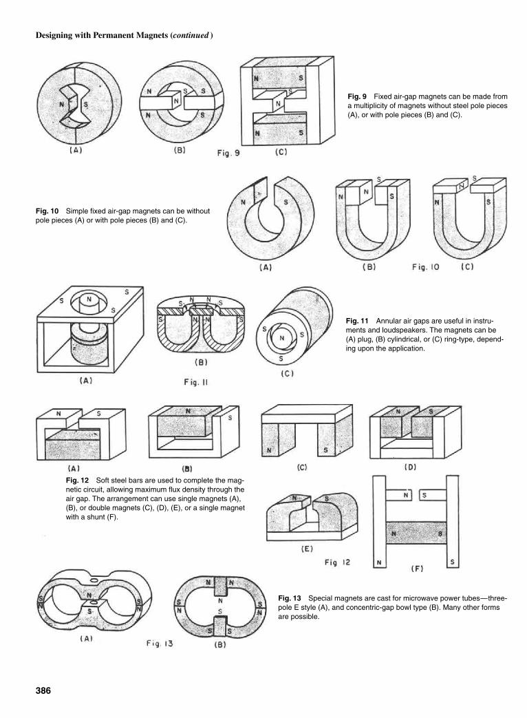
Fig. 9 Fixed air-gap magnets can be made froma multiplicity of magnets without steel pole pieces(A), or with pole pieces (B) and (C).
Fig. 10 Simple fixed air-gap magnets can be withoutpole pieces (A) or with pole pieces (B) and (C).
Fig. 11 Annular air gaps are useful in instru-ments and loudspeakers. The magnets can be(A) plug, (B) cylindrical, or (C) ring-type, depend-ing upon the application.
Fig. 13 Special magnets are cast for microwave power tubes—three-pole E style (A), and concentric-gap bowl type (B). Many other formsare possible.
386
Designing with Permanent Magnets (continued )
Fig. 12 Soft steel bars are used to complete the mag-netic circuit, allowing maximum flux density through theair gap. The arrangement can use single magnets (A),(B), or double magnets (C), (D), (E), or a single magnetwith a shunt (F).
Sclater Chapter 11 5/3/01 1:16 PM Page 386
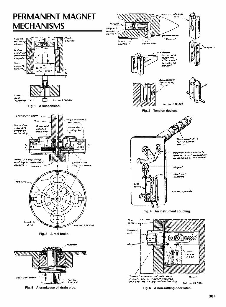
387
PERMANENT MAGNETMECHANISMS
Fig. 1 A suspension.
Fig. 3 A reel brake.
Fig. 4 An instrument coupling.
Fig. 5 A crankcase oil drain plug. Fig. 6 A non-rattling door latch.
Fig. 2 Tension devices.
Sclater Chapter 11 5/3/01 1:16 PM Page 387
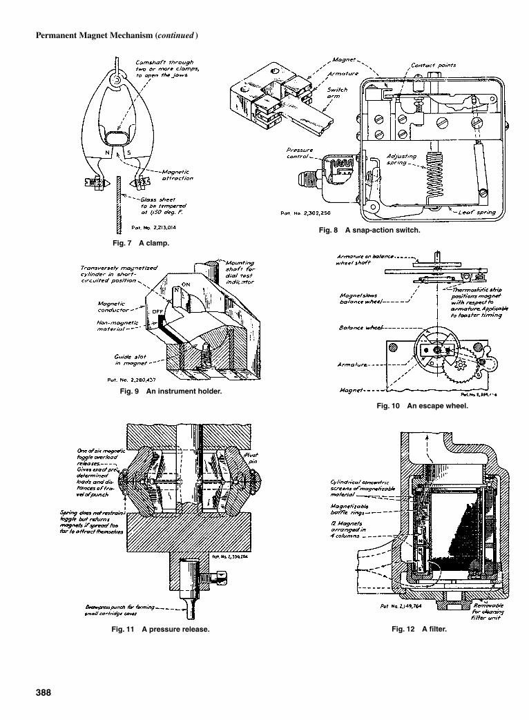
388
Permanent Magnet Mechanism (continued )
Fig. 7 A clamp.
Fig. 8 A snap-action switch.
Fig. 9 An instrument holder.
Fig. 10 An escape wheel.
Fig. 11 A pressure release. Fig. 12 A filter.
Sclater Chapter 11 5/3/01 1:16 PM Page 388
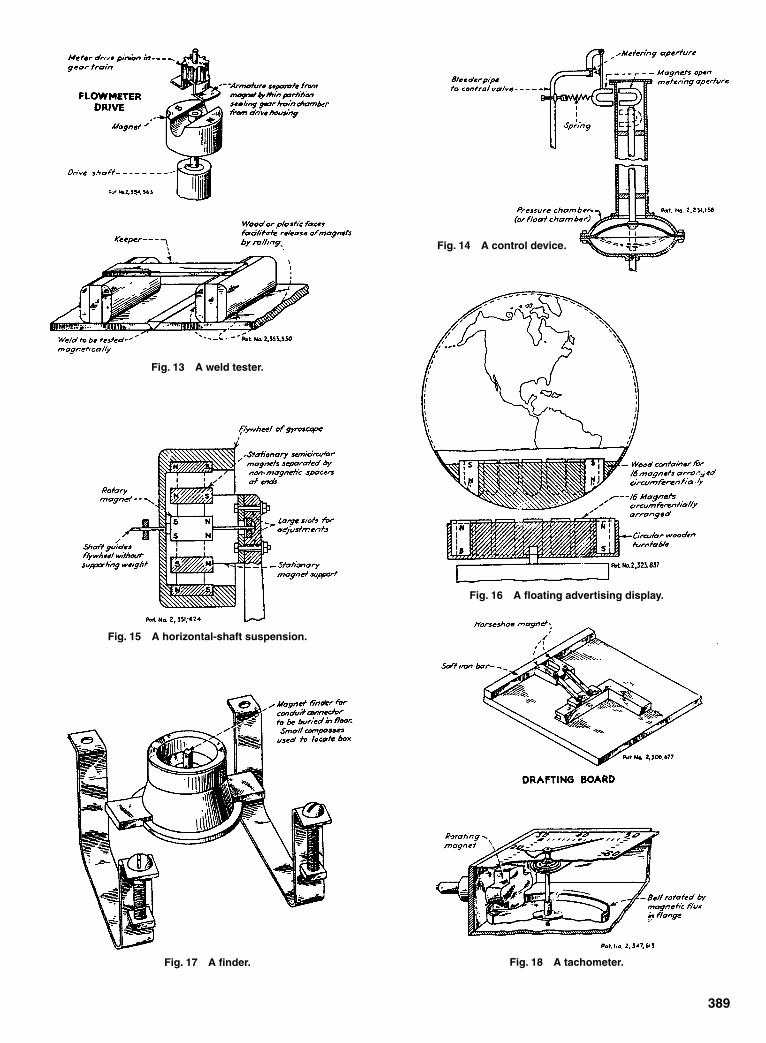
389
Fig. 13 A weld tester.
Fig. 14 A control device.
Fig. 15 A horizontal-shaft suspension.
Fig. 17 A finder. Fig. 18 A tachometer.
Fig. 16 A floating advertising display.
Sclater Chapter 11 5/3/01 1:16 PM Page 389

390
ELECTRICALLY DRIVEN HAMMER MECHANISMS
The application of controlled impact forces can be as prac-tical in specialized stationary machinery as in the portableelectric hammers shown here. These mechanisms have beenemployed in vibrating concrete forms, nailing machines,and other special machinery. In portable hammers they areefficient in drilling, chiseling, digging, chipping, tamping,
Fig. 1 A free-driving throw of the cam-slotted striker is produced bythe eccentric stud roller during contact between points A and B of theslot. This accelerates the striker beyond the tangential speed of theroller for an instant before the striker is picked up for the return stroke.
Fig. 3 The striker has no mechanical connection with thereciprocating drive in this hammer.
Fig. 2 The centrifugal force of two oppositely rotating weights throws thestriker assembly of this hammer. The power connection is maintained by asliding-splined shaft. The guide, not shown, prevents the rotation of the strikerassembly. Fig. 4 This combination of mechanical, pneumatic, and
spring action is included in this hammer.
Sclater Chapter 11 5/3/01 1:16 PM Page 390

391
riveting, and similar operations where quick, concentratedblows are required. The striker mechanisms illustrated areoperated by springs, cams, magnetic force, air and vacuumchambers, and centrifugal force. The drawings show only thestriking mechanisms.
Fig. 5 Two electromagnets operate this hammer. The weight ofthe blows can be controlled by varying the electric current in thecoils or timing the current reversals by an air-gap adjustment ofthe contacts.
Fig. 7 This spring-operated hammer includes a shaft rotating in afemale cam to return the striker.
Fig. 6 This spring-operated hammer with a cam and rocker forthe return stroke has a screw for adjusting the blow to beimparted.
Fig. 8 This spring-operated hammer has two fixed rotating-barrelcams. They return the striker by means of two rollers on the oppositesides of the striker sleeve. Auxiliary springs prevent the striker fromhitting the retaining cylinder. A means of rotating the tool, not shown,is also included in this hammer.
Fig. 9 Two steel balls rotated in a divided cylinder and steeredby an edge cam develop centrifugal force to strike blows againstthe tool holder. The collar is held clear of the hammer by a com-pression spring when no tool is in the holder. A second springcushions the blows when the motor is running, but the tool is notheld against the work.
Sclater Chapter 11 5/3/01 1:16 PM Page 391

Sensitivity or change in deflection for a given temperaturechange depends upon the combination of meals selected and thedimensions of the bimetal element. Sensitivity increases withthe square of the length and inversely with the thickness. Theforce developed for a given temperature change also depends
on the type of bimetal. However, the allowable working loadfor the thermostatic strip increases with the width and thesquare of the thickness. Thus, the design of bimetal elementsdepends upon the relative importance of sensitivity and work-ing load.
392
THERMOSTATIC MECHANISMS
Fig. 1 This recording thermometer has a pen that is moved verti-cally across a revolving chart by a brass-invar bimetal element. Toobtain sensitivity, the long movement of the pen requires a long stripof bimetal, which is coiled into a helix to save space. For accuracy, arelatively large cross section gives stiffness, although the large thick-ness requires increased length to obtain the desired sensitivity.
Fig. 2 Room temperatures in summer and winter are controlledover a wide range by a single, large-diameter coil of brass-invar inthis thermometer. To prevent chattering, a small permanent magnet ismounted on each side of the steel contact blade. The magneticattraction on the blade, which increases inversely with the square ofthe distance from the magnet, gives a snap action to the contacts.
Fig. 3 This overload relay for large motors passes some of themotor current through a heating coil within the relay. Heat from thecoil raises the temperature of a bimetal spiral which rotates a shaftcarrying an electrical contact. To withstand the operating tempera-tures, it includes a heat-resistant bimetal spiral. It is coiled into thespiral form for compactness. Because of the large deflection needed,the spiral is long and thin, whereas the width is made large to providethe required contact pressure.
Heat barriers between the bimetal spiral and the heating coil makethe temperature rise of the bimetal spiral closely follow the increasein temperature within the motor. Thus, momentary overloads do notcause sufficient heating to close the contacts. However, a continuedoverload will, in time, cause the bimetal spiral to rotate the contactarm around to the adjustable stationary contact, causing a relay toshut down the motor.
Sclater Chapter 11 5/3/01 1:16 PM Page 392

393
Fig. 4 Carburetor control. When the engine is cold, a vane in theexhaust passage to the “hot spot” is held open by a bimetal springagainst the force of a small counterweight. When the thermostaticspiral is heated by the outside air or by the warm air stream from theradiator, the spring coils up and allows the weight to close the vane.Because high accuracy is not needed, a thin, flexible cross sectionwith a long length provides the desired sensitivity.
Fig. 5 Thermostatic relay. A constant current through an electricalheating coil around a straight bimetal strip gives a time-delay action.Because the temperature range is relatively large, high sensitivity isnot necessary. Thus, a short, straight strip of bimetal is suitable.Because of its relatively heavy thickness, the strip is sufficiently stiffto close the contact firmly without chattering.
Fig. 6 The bimetal element in this time-delay relay protects mer-cury-vapor rectifiers. This relay closes the voltage circuit to the mer-cury tube only after the filament has had time to reach its normaloperating temperature. To eliminate the effect of changes in roomtemperature on the length of the contact gap (and therefore the timeinterval) the stationary contact is carried by a second bimetal strip,similar to the heated element. Barriers of laminated plastic on bothsides of the active bimetal strip shield the compensating strip andprevent air currents from affecting the heating rate. The relativelyhigh temperature range allows the use of a straight, thick strip, butthe addition of the compensating strip makes accurate timing possi-ble with a short travel.
Fig. 7 Oil pressure, engine temperature, and gasoline level areindicated electrically on automobile dashboard instruments whosebimetal element is both the sender and receiver. A grounded contactat the sender completes an electric circuit through heaters aroundtwo similar bimetal strips. Because the same current flows around thetwo bimetal elements, their deflections are the same. But the senderelement, when heated, will bend away from the grounded contactuntil the circuit is broken Upon cooling, the bimetal element againmakes contact and the cycle continues. This allows the bimetal ele-ment to follow the movement of the grounded contact. For the oil-pressure gage, the grounded contact is attached to a diaphragm; forthe temperature indicator, the contact is carried by another thermo-static bimetal strip; in the gasoline-level device, the contact is shiftedby a cam on a shaft rotated by a float. Deflections on the receivingbimetal element are amplified through a linkage that operates apointer over the scale of the receiving instrument. Because only smalldeflections are needed, the bimetal element is in the form of a short,stiff strip.
Fig. 8 Oil dashpots in heavy-capacity scales have a thermostaticcontrol to compensate for changes in oil viscosity with temperature. Arectangular orifice in the plunger is covered by a swaged projectionon the bimetal element. With a decrease in oil temperature, the oilviscosity increases, tending to increase the damping effect. But thebimetal element deflects upward, enlarging the orifice enough tokeep the damping force constant. A wide bimetal strip provides suffi-cient stiffness so that the orifice will not be altered by the force of theflowing oil.
Sclater Chapter 11 5/3/01 1:17 PM Page 393

394
Thermostatic Mechanisms (continued )
Fig. 9 Automobile cooling-water temperature is controlled by aself-contained bellows in the thermostat. As in the radiator air valve,the bellows itself is subjected to the temperature to be controlled. Asthe temperature of the water increases to about 140°F. the valvestarts to open; at approximately 180°F., free flow is permitted. Atintermediate temperatures, the valve opening is in proportion to thetemperature. Fig. 10 A throttling circulating-water control valve for refrigera-
tion plants has its valve opening vary with the pressure on the bel-lows. This valve controls the rate of flow of the cooling water throughthe condenser. A greater amount of water is required when the tem-perature, and therefore the pressure, increases. The pressure in thecondenser is transmitted through a pipe to the valve bellows, therebyadjusting the flow of cooling water. The bronze bellows is protectedfrom contact with the water by a rubber diaphragm.
Fig. 11 An automatic gas-range control has a sealed thermosta-tic element consisting of a bulb, capillary tube, and bellows. As foodis often placed near the bulb, a nontoxic liquid, chlorinated diphenyl,is in the liquid expansion system. The liquid is also non-flammableand has no corrosive effect on the phosphor-bronze bellows. By plac-ing the liquid outside instead of inside the bellows, the workingstresses are maximum at normal temperatures when the bellows bot-toms on the cup. At elevated working temperatures, the expansion ofthe liquid compresses the bellows against the action of the extendedspring. This, in turn, is adjusted by the knob. Changes in calibrationcaused by variations in ambient temperature are compensated bymaking the rocker arm of a bimetal suitable for high-temperatureservice.
Fig. 12 For electric ranges, this thermostat has the same bellowsunit as the gas-type control. But, instead of a throttling action, thethermostat opens and closes the electrical contacts with a snapaction. To obtain sufficient force for the snap action, the controlrequires a temperature difference between on and off positions. For acontrol range from room temperature to 550°F., the differential in thisinstrument is ±10°F. With a smaller control range, the differential isproportionately less. The snap-action switch is made of berylliumcopper, giving it high strength, better snap action, and longer life thanis obtainable with phosphor bronze. Because of its corrosion resist-ance, the beryllium-copper blade requires no protective finish.
Sclater Chapter 11 5/3/01 1:17 PM Page 394

395
Fig. 13 For heavy-duty room-temperature controls, this thermo-stat has a bellows mechanism that develops a high force with smallchanges in temperature. The bellows is partly filled with liquid butane.At room temperatures this gas exhibits a large change in vapor pres-sure for small temperature differentials. Snap action of the electricalcontact is obtained from a small permanent magnet that pulls thesteel contact blade into firm contact when the bellows cools. Becauseof the firm contact, the device is rated at 20 A for noninductive loads.To avoid chattering or bounce under the impact delivered by the rapidmagnetic closing action, small auxiliary contacts are carried on lightspring blades. With the large force developed by the bellows, a tem-perature differential of only 2°F. is obtained.
Fig. 14 Snap action in this refrigerator control is obtained from abowed flat spring. The silver contacts carried on an extended end ofthe spring open or close rapidly when movement of the bellows actu-ates the spring. With this snap action, the contacts can control analternating-current motor as large as 11⁄2 hp without auxiliary relays.Temperature differential is adjusted by changing the spacing betweentwo collars on the bellows shaft passing through the contact spring.For the temperatures needed to freeze ice, the bellows system ispartly filled with butane.
Fig. 15 In this refrigerator control, the necessary snap action isobtained from a toggle spring supported from a long arm moved bythe bellows. With this form of toggle action, the contact pressure is ata maximum at the instant the contacts start to open. Thermostaticaction is obtained from a vapor-filled system. Sulfur dioxide is the fillfor typical refrigerating service or methyl chloride where lower tem-peratures are required. To reduce friction, the bellows makes point-contact with the bellows cup. Operating temperature is adjusted bychanging the initial compression in the bellows spring. For resistanceto corrosion, levers and blades are made from stainless steel withbronze pin bearings.
Fig. 16 Two bellows units in this thermostatic expansion valve controllarge refrigeration systems. A removable power bellows unit is operatedby vapor pressure in a bulb attached to the evaporator output line. Thesecond bellows serves as a flexible, gastight seal for the gas valve. Astainless-steel spring holds the valve closed until opened by pressuretransmitted from the thermostatic bellows through a molded push pin.
Sclater Chapter 11 5/3/01 1:17 PM Page 395

396
TEMPERATURE-REGULATING MECHANISMSTemperature regulators are either on-off or throttling. The characteristics of the processdetermine which should be used. Within each group, selection of a regulator is governed by the accuracy required, space limitations, simplicity, and cost.
Fig. 1 A bimetallic sensor is simple, compact, and precise.Contacts mounted on low-expansion struts determine slow make-and-break action. A shell contracts or expands with temperaturechanges, opening or closing the electrical circuit that controls a heat-ing or cooling unit. It is adjustable and resistant to shock and vibra-tion. Its range is 100 to 1500°F, and it responds to a temperaturechanges of less than 0.5°F. Fig. 2 This enclosed, disk-type, snap-action control has a fixed
operating temperature. It is suitable for unit and space heaters, smallhot water heaters, clothes dryers, and other applications requiringnon-adjustable temperature control. It is useful where dirt, dust, oil, orcorrosive atmospheres are present. It is available with various tem-perature differentials and with a manual reset. Depending on themodel, its temperature setting range is from –10° to 550°F and itsminimum differential can be 10, 20, 30, 40 or 50°F.
Fig. 3 This bimetallic unit has a rod with a low coefficient ofexpansion and a shell with a high coefficient of expansion. Amicroswitch gives snap action to the electrical control circuit. The cur-rent can be large enough to operate a solenoid valve or relay directly.The set point is adjusted by a knob which moves the pivot point ofthe lever. Its range is –20° to 175°F, and its accuracy is 0.25 to 0.50°.
Fig. 4 This is a bimetallic-actuated, air-piloted control. Theexpansion of the rod causes an air signal (3 to 15 psi) to be transmit-ted to a heating or cooling pneumatic valve. The position of the pneu-matic valve depends on the amount of air bled through the pilot valveof the control. This produces a throttling type of temperature controlas contrasted to the on-off characteristic that is obtained with thethree units described previously. Its range is 32 to 600°F, and itsaccuracy is ±1 to ±3°F, depending on the range.
Fig. 5 This self-contained regulator is actuated by the expansionor contraction of liquid or gas in a temperature-sensitive bulb that isimmersed in the medium being controlled. The signal is transmittedfrom the bulb to a sealed expansion element which opens or closesthe ball valve. Its range is 20 to 270°F, and its accuracy is ±1°F. Themaximum pressure rating is 100 psi for dead-end service and 200 psifor continuous flow.
Sclater Chapter 11 5/3/01 1:17 PM Page 396

397
Fig. 6 This remote bulb, nonindicating regulator has a bellows assem-bly that operates a flapper. This allows air pressure in the control system tobuild up or bleed, depending on the position of the changeover link. The unitcan be direct- or reverse-acting. A control knob adjusts the setting, and thethrottling range adjustment determines the percentages of the control rangein which full output pressure (3–15 psi) is obtained. Its range is 0 to 700°F,and its accuracy is about ±0.5% of full scale, depending on the way it isinstalled.
Fig. 7 This lever-type pilot valve is actuated by a tempera-ture-sensitive bulb. The motion of the lever causes the wateror steam being controlled to exert pressure on a diaphragmwhich opens or closes the main valve. Its temperature rangeis 20 to 270°F, and its accuracy is ±1 to 4°F. It is rated for 5 to125 psi of steam and 5 to 175 psi of water.
Fig. 8 These two recording and controlling instru-ments have adjustable proportional ranges. In both, airsupply is divided by a relay valve. A small part goesthrough a nozzle and flapper assembly. The main partgoes to the control valve. Unit B has an extra bellows forautomatic resetting. It was designed for systems with con-tinuously changing control points, and it can be usedwhere both heating and cooling are required in oneprocess. Both A and B are easily changed from direct toreverse acting. Its accuracy is 1% of its temperaturerange of –40 to 800°F.
Sclater Chapter 11 5/3/01 1:17 PM Page 397

Fig. 1 Automatic weighing and filling. The task is to fill each boxwith an exact quantity of products, such as screws. An electric feedervibrates parts through a chute and into a box on a small balance. Thephotoelectric control is mounted at the rear of the scale. The lightbeam is restricted to very small dimensions by an optical slit. Thecontrol is positioned so that the light is interrupted by a balanced can-tilever arm attached to the scale when the proper box weight isreached. The photoelectric control then stops the flow of parts bydeenergizing the feeder. Simultaneously, an indexing mechanism isactivated to remove the filled box and replace it with an empty one.The completion of indexing reenergizes the feeder, which starts theflow of screws.
398
PHOTOELECTRIC CONTROLSTypical applications are presented for reducing production costs and increasing operator safeguards by precisely and automatically controlling the feed, transfer, or inspection of products from one process stage to another.
Fig. 2 Operator safeguard. Most pressures are operated by a footpedal that leaves the operator’s hands free for loading and unload-ing. This creates a safety hazard. The use of mechanical gate sys-tems reduces the speed of production. With photoelectric controls, acurtain of light is set up by a multiple series of photoelectric scannersand light sources. When a light beam is broken at any point by theoperator’s hand, the control energizes a locking mechanism that pre-vents the punch-press drive from being energized. A circuit or powerfailure causes the control to function as if the light beam were broken.In addition, the light beam frequently becomes the actuating controlbecause the clutch is released as soon as the operator removes hishand from the die on the press table.
Fig. 3 This apparatus sorts cartons of three different kinds ofobjects. Because the cartons containing objects differ widely in size,it is not feasible to sort by carton size and shape. A small strip ofreflecting tape is put on the cartons by a packer during assembly. Onone type of object, the strip is located along one edge of the bottom,and it extends almost to the middle. For the second type, the strip islocated along the same edge, but from the middle to the oppositeside. No tape is placed on the third type. Cartons are placed on theconveyor so that the tape is at right angles to the direction of travel.Photoelectric controls shown in A “see” the reflecting tape and oper-ate a pusher-bar mechanism shown in B. This pushes the cartononto the proper distribution conveyor. Cartons without tape pass.
Sclater Chapter 11 5/3/01 1:17 PM Page 398

Fig. 4 This cut-off machine has a photoelectric control for stripmaterials that lack sufficient mass to operate a mechanical limitswitch satisfactorily. The forward end of the strip breaks the lightbeam, thus actuating the cut-off operation. The light source and thecontrol are mounted on an adjustable stand at the end of themachine to vary the length of the finished stock.
399
Fig. 5 This heat-treating conveyor has an electronic timer pairedwith a photoelectric control to carry parts emerging from a furnace at2300°F. The conveyor must operate only when a part is placed on itand only for the distance required to reach the next process stage.Parts are ejected onto the conveyor at varying rates. High tempera-tures caused failures when the mechanical switches were used.Glowing white-hot parts radiate infrared rays that actuate the photo-electric control as soon as a part comes in view. The control operatesthe conveyor that carries the parts away from the furnace and simul-taneously starts the timer. The conveyor is kept running by a timer forthe predetermined length of time required to position the part for thenext operation.
Fig. 6 Jam detector. Cartons jamming on the conveyor causelosses in production and damage to cartons, products, and convey-ors. Detection is accomplished with a photoelectric control that has atimer, as shown in (A). Each time a carton passes the light source,the control beam is broken. That starts the timing interval in the timer.The timing circuit is reset without relay action each time the beam isrestored before the preset timing interval has elapsed. If a jamoccurs, causing cartons to butt against each other, the light beamcannot reach the control. The timing circuit will then time-out, openingthe load circuit. This stops the conveyor motor. By locating the lightsource at an angle with respect to the conveyor, as shown in (B), thepower conveyor can be delayed if cartons are too close to each otherbut not butting each other.
Fig. 7 Automatic inspection. As steel caps are conveyed to finalassembly, they pass an intermediate stage where an assemblerinserts an insulation liner into a cap. The inspection point for themissing liners has a reflection-type photoelectric scanner which incor-porates both a light source and photosensor with a common lens sys-tem to recognize the difference in reflection between the dark linerand the light steel cap instantly. When it detects a cap without a liner,a relay operates an airjet ejector that is controlled by a solenoidvalve. The start and duration of the air blast is accurately controlledby a timer so that no other caps are displaced.
Sclater Chapter 11 5/3/01 1:17 PM Page 399
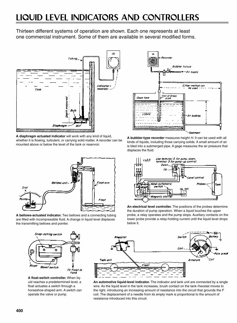
400
LIQUID LEVEL INDICATORS AND CONTROLLERSThirteen different systems of operation are shown. Each one represents at least one commercial instrument. Some of them are available in several modified forms.
A diaphragm actuated indicator will work with any kind of liquid,whether it is flowing, turbulent, or carrying solid matter. A recorder can bemounted above or below the level of the tank or reservoir.
A bubbler-type recorder measures height H. It can be used with allkinds of liquids, including those carrying solids. A small amount of airis bled into a submerged pipe. A gage measures the air pressure thatdisplaces the fluid.
A bellows-actuated indicator. Two bellows and a connecting tubingare filled with incompressible fluid. A change in liquid level displacesthe transmitting bellows and pointer.
An electrical level controller. The positions of the probes determinethe duration of pump operation. When a liquid touches the upperprobe, a relay operates and the pump stops. Auxiliary contacts on thelower probe provide a relay-holding current until the liquid level dropsbelow it.
A float-switch controller. When liq-uid reaches a predetermined level, afloat actuates a switch through ahorseshoe-shaped arm. A switch canoperate the valve or pump.
An automotive liquid-level indicator. The indicator and tank unit are connected by a singlewire. As the liquid level in the tank increases, brush contact on the tank rheostat moves tothe right, introducing an increasing amount of resistance into the circuit that grounds the Fcoil. The displacement of a needle from its empty mark is proportional to the amount ofresistance introduced into this circuit.
Sclater Chapter 11 5/3/01 1:17 PM Page 400
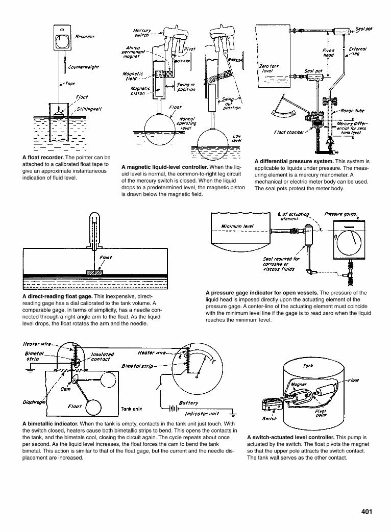
401
A float recorder. The pointer can beattached to a calibrated float tape togive an approximate instantaneousindication of fluid level.
A magnetic liquid-level controller. When the liq-uid level is normal, the common-to-right leg circuitof the mercury switch is closed. When the liquiddrops to a predetermined level, the magnetic pistonis drawn below the magnetic field.
A differential pressure system. This system isapplicable to liquids under pressure. The meas-uring element is a mercury manometer. Amechanical or electric meter body can be used.The seal pots protest the meter body.
A direct-reading float gage. This inexpensive, direct-reading gage has a dial calibrated to the tank volume. Acomparable gage, in terms of simplicity, has a needle con-nected through a right-angle arm to the float. As the liquidlevel drops, the float rotates the arm and the needle.
A pressure gage indicator for open vessels. The pressure of theliquid head is imposed directly upon the actuating element of thepressure gage. A center-line of the actuating element must coincidewith the minimum level line if the gage is to read zero when the liquidreaches the minimum level.
A bimetallic indicator. When the tank is empty, contacts in the tank unit just touch. Withthe switch closed, heaters cause both bimetallic strips to bend. This opens the contacts inthe tank, and the bimetals cool, closing the circuit again. The cycle repeats about onceper second. As the liquid level increases, the float forces the cam to bend the tankbimetal. This action is similar to that of the float gage, but the current and the needle dis-placement are increased.
A switch-actuated level controller. This pump isactuated by the switch. The float pivots the magnetso that the upper pole attracts the switch contact.The tank wall serves as the other contact.
Sclater Chapter 11 5/3/01 1:17 PM Page 401

402
INSTANT MUSCLE WITH PYROTECHNIC POWERCartridge-actuated devices generate a punch that cuts cable and pipe, shears bolts for fast release, and provides emergency thrust.
Sclater Chapter 11 5/3/01 1:17 PM Page 402
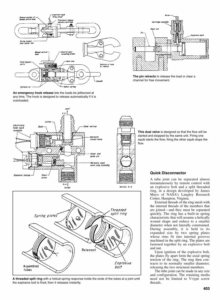
Quick Disconnector
A tube joint can be separated almostinstantaneously by remote control withan explosive bolt and a split threadedring, in a design developed by JamesMayo of NASA’s Langley ResearchCenter, Hampton, Virginia.
External threads of the ring mesh withthe internal threads of the members thatare joined—and they must be separatedquickly. The ring has a built-in springcharacteristic that will assume a helicallywound shape and reduce to a smallerdiameter when not laterally constrained.During assembly, it is held to itsexpanded size by two spring plateswhose rims fit into internal groovesmachined in the split ring. The plates arefastened together by an explosive boltand nut.
Upon ignition of the explosive bolt,the plates fly apart form the axial springtension of the ring. The ring then con-tracts to its normally smaller diameter,releasing the two structural members.
The tube joint can be made in any sizeand configuration. The retaining medianeed not be limited to V-type screwthreads.
403
The pin retracts to release the load or clear achannel for free movement.
An emergency hook release lets the loads be jettisoned atany time. The hook is designed to release automatically if it isoverloaded.
This dual valve is designed so that the flow will bestarted and stopped by the same unit. Firing onesquib starts the flow; firing the other squib stops theflow.
A threaded split ring with a helical-spring response holds the ends of the tubes at a joint untilthe explosive bolt is fired; then it releases instantly.
Sclater Chapter 11 5/3/01 1:17 PM Page 403

CHAPTER 12FASTENING, LATCHING,
CLAMPING, ANDCHUCKING DEVICES
Sclater Chapter 12 5/3/01 1:24 PM Page 405

406
REMOTELY CONTROLLED LATCHThis simple mechanism engages and disengages parallel plates carrying couplings and connectors.
A new latch mates two parallel plates inone continuous motion (see Fig. 1). Onthe Space Shuttle, the latch connects (anddisconnects) plates carrying 20 fluid cou-plings and electrical connectors. (Thecoupling/connector receptacles are oneplate, and mating plugs are on the otherplate). Designed to lock items in placefor handling, storage, or processingunder remote control, the mechanism
also has a fail-safe feature: It does notallow the plates to separate completelyunless both are supported. Thus, platescannot fall apart and injure people ordamage equipment.
The mechanism employs fourcam/gear assemblies, one at each cornerof the lower plate. The gears on each sideof the plate face inward to balance theloading and help align the plates. Worm
gears on the cam-gear assemblies areconnected to a common drive motor.
Figure 1 illustrates the sequence ofmovements as a pair of plates is latchedand unlatched. Initially, the hook isextended and tilted out. The two platesare brought together, and when they are4.7 in. (11.9 cm) apart, the drive motor isstarted (a). The worm gear rotates thehook until it closes on a pin on the oppo-
Fig. 1 The latch operation sequence is shown for locking in steps (a) through (c) and forunlocking in steps (d) through (f).
Sclater Chapter 12 5/3/01 1:24 PM Page 406

site plate (b). Further rotation of theworm gear shortens the hook extensionand raises the lower plate (c). At thatpoint, the couplings and connectors onthe two plates are fully engaged andlocked.
To disconnect the plates, the worm
gear is turned in the opposite direction.This motion lowers the bottom plate andpulls the couplings apart (d). However, ifthe bottom plate is unsupported, the latchsafety feature operates. The hook cannotclear the pin if the lower plate hangsfreely (e). If the bottom plate is sup-
ported, the hook extension lifts the hookclear of the pin (f) so that the plates arecompletely separated.
This work was done by Clifford J.Barnett, Paul Castiglione, and Leo R.Coda of Rockwell International Corp. forJohnson Space Center.
407
TOGGLE FASTENER INSERTS,LOCKS, AND RELEASES EASILY
A pin-type toggle fastener, invented byC.C. Kubokawa at NASA’s AmesResearch Center, can be used to fastenplates together, fasten things to walls ordecks, or fasten units with surfaces ofdifferent curvatured, such as a concaveshape to a convex surface.
With actuator pin. The cylindricalbody of the fastener has a tapered end foreasy entry into the hole; the head isthreaded to receive a winged locknutand, if desired, a ring for pulling the fas-tener out again after release. Slots in thebody hold two or more toggle wings thatrespond to an actuator pin. These wingsare extended except when the spring-loaded pin is depressed.
For installation, the actuator pin isdepressed, retracting the toggle wings.When the fastener is in place, the pin isreleased, and the unit is then tightened byscrewing the locknut down firmly. Thisexerts a compressive force on the now-expanded toggle wings. For removal, thelocknut is loosened and the pin is againdepressed to retract the toggle wings.Meanwhile, the threaded outer end of thecylindrical body functions as a stud towhich a suitable pull ring can be screwedto facilitate removal of the fastener.
This invention has been patented byNASA (U.S. Patent No. 3,534,650).
A fastener with controllable toggles can beinserted and locked from only one side.
GRAPPLE FREES LOADSAUTOMATICALLY
A simple grapple mechanism, designedat Argonne National Laboratory inIllinois, engages and releases loads fromoverhead cranes automatically. This self-releasing mechanism was developed toremove fuel rods from nuclear reactors.It can perform tasks where human inter-vention is hazardous or inefficient, suchas lowering and releasing loads from hel-icopters.
The mechanism (see drawing) con-sists of two pieces: a lift knob secured tothe load and a grapple member attachedto the crane. The sliding latch-releasecollar under the lift knob is the design’skey feature.
Spring magic. The grapple housing,which has a cylindrical inner surface,contains a machined groove fitted with agarter spring and three metal latches.When the grapple is lowered over the lift
knob, these latches recede into the grooveas their edges come into contact with theknob. After passing the knob, they springforward again, locking the grapple to theknob. Now the load can be lifted.
When the load is lowered to theground again, gravity pull or pressurefrom above forces the grapple housingdown until the latches come into contactwith a double cone-shaped release collar.The latches move back into the groove asthey pass over the upper cone’s surfaceand move forward again when they slideover the lower cone.
The grapple is then lifted so that therelease collar moves up the cylindricalrod until it is housed in a recess in the liftknob. Because the collar can move nofarther, the latches are forced by theupward pull to recede again into thegroove—allowing the grapple to belifted free.
A sliding release collar is a key feature ofthis automatic grapple.
Sclater Chapter 12 5/3/01 1:24 PM Page 407
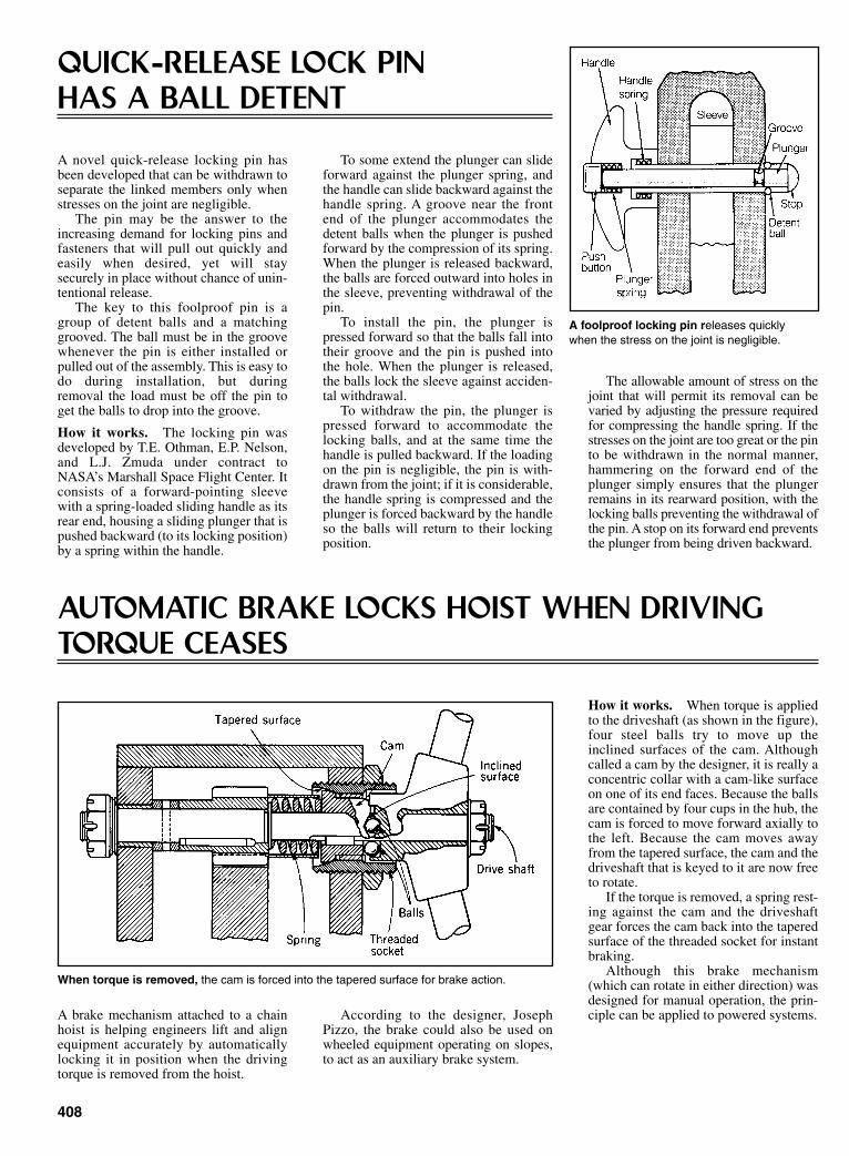
408
QUICK-RELEASE LOCK PIN HAS A BALL DETENT
A novel quick-release locking pin hasbeen developed that can be withdrawn toseparate the linked members only whenstresses on the joint are negligible.
The pin may be the answer to theincreasing demand for locking pins andfasteners that will pull out quickly andeasily when desired, yet will staysecurely in place without chance of unin-tentional release.
The key to this foolproof pin is agroup of detent balls and a matchinggrooved. The ball must be in the groovewhenever the pin is either installed orpulled out of the assembly. This is easy todo during installation, but duringremoval the load must be off the pin toget the balls to drop into the groove.
How it works. The locking pin wasdeveloped by T.E. Othman, E.P. Nelson,and L.J. Zmuda under contract toNASA’s Marshall Space Flight Center. Itconsists of a forward-pointing sleevewith a spring-loaded sliding handle as itsrear end, housing a sliding plunger that ispushed backward (to its locking position)by a spring within the handle.
To some extend the plunger can slideforward against the plunger spring, andthe handle can slide backward against thehandle spring. A groove near the frontend of the plunger accommodates thedetent balls when the plunger is pushedforward by the compression of its spring.When the plunger is released backward,the balls are forced outward into holes inthe sleeve, preventing withdrawal of thepin.
To install the pin, the plunger ispressed forward so that the balls fall intotheir groove and the pin is pushed intothe hole. When the plunger is released,the balls lock the sleeve against acciden-tal withdrawal.
To withdraw the pin, the plunger ispressed forward to accommodate thelocking balls, and at the same time thehandle is pulled backward. If the loadingon the pin is negligible, the pin is with-drawn from the joint; if it is considerable,the handle spring is compressed and theplunger is forced backward by the handleso the balls will return to their lockingposition.
The allowable amount of stress on thejoint that will permit its removal can bevaried by adjusting the pressure requiredfor compressing the handle spring. If thestresses on the joint are too great or the pinto be withdrawn in the normal manner,hammering on the forward end of theplunger simply ensures that the plungerremains in its rearward position, with thelocking balls preventing the withdrawal ofthe pin. A stop on its forward end preventsthe plunger from being driven backward.
A foolproof locking pin releases quicklywhen the stress on the joint is negligible.
AUTOMATIC BRAKE LOCKS HOIST WHEN DRIVINGTORQUE CEASES
A brake mechanism attached to a chainhoist is helping engineers lift and alignequipment accurately by automaticallylocking it in position when the drivingtorque is removed from the hoist.
When torque is removed, the cam is forced into the tapered surface for brake action.
According to the designer, JosephPizzo, the brake could also be used onwheeled equipment operating on slopes,to act as an auxiliary brake system.
How it works. When torque is appliedto the driveshaft (as shown in the figure),four steel balls try to move up theinclined surfaces of the cam. Althoughcalled a cam by the designer, it is really aconcentric collar with a cam-like surfaceon one of its end faces. Because the ballsare contained by four cups in the hub, thecam is forced to move forward axially tothe left. Because the cam moves awayfrom the tapered surface, the cam and thedriveshaft that is keyed to it are now freeto rotate.
If the torque is removed, a spring rest-ing against the cam and the driveshaftgear forces the cam back into the taperedsurface of the threaded socket for instantbraking.
Although this brake mechanism(which can rotate in either direction) wasdesigned for manual operation, the prin-ciple can be applied to powered systems.
Sclater Chapter 12 5/3/01 1:24 PM Page 408
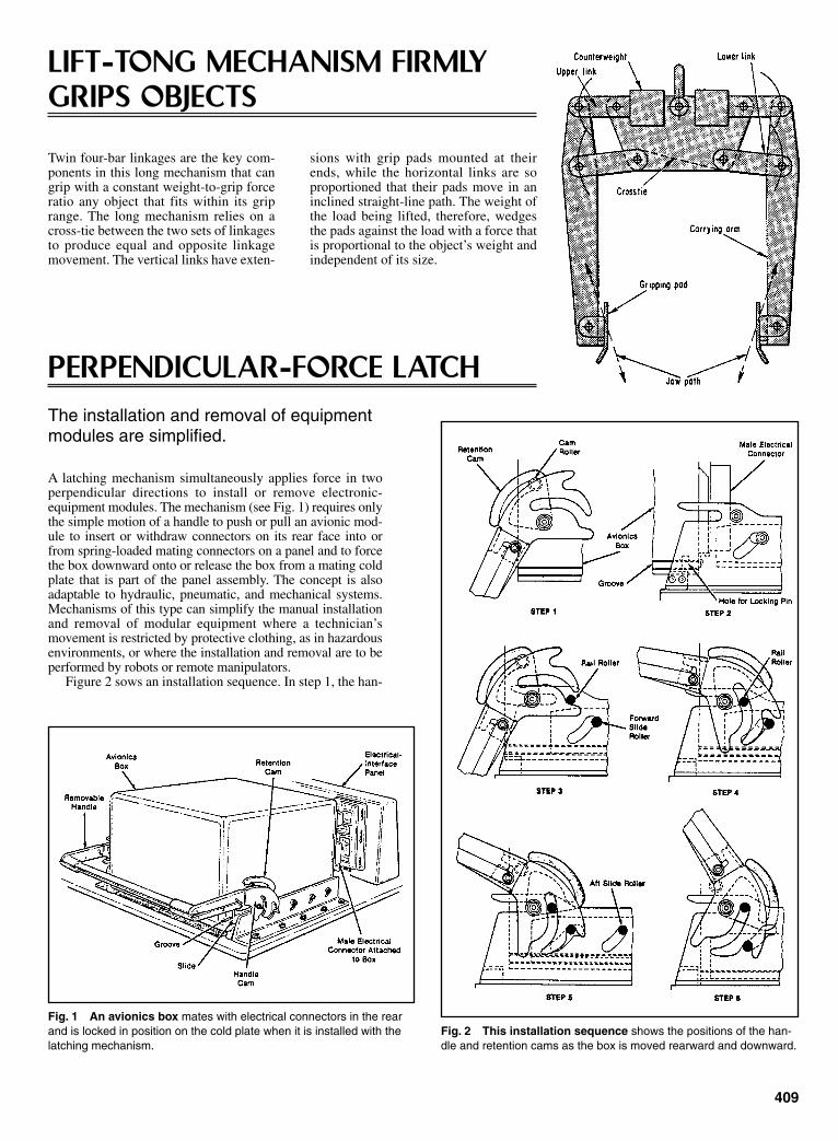
409
LIFT-TONG MECHANISM FIRMLYGRIPS OBJECTS
Twin four-bar linkages are the key com-ponents in this long mechanism that cangrip with a constant weight-to-grip forceratio any object that fits within its griprange. The long mechanism relies on across-tie between the two sets of linkagesto produce equal and opposite linkagemovement. The vertical links have exten-
sions with grip pads mounted at theirends, while the horizontal links are soproportioned that their pads move in aninclined straight-line path. The weight ofthe load being lifted, therefore, wedgesthe pads against the load with a force thatis proportional to the object’s weight andindependent of its size.
PERPENDICULAR-FORCE LATCHThe installation and removal of equipment modules are simplified.
A latching mechanism simultaneously applies force in twoperpendicular directions to install or remove electronic-equipment modules. The mechanism (see Fig. 1) requires onlythe simple motion of a handle to push or pull an avionic mod-ule to insert or withdraw connectors on its rear face into orfrom spring-loaded mating connectors on a panel and to forcethe box downward onto or release the box from a mating coldplate that is part of the panel assembly. The concept is alsoadaptable to hydraulic, pneumatic, and mechanical systems.Mechanisms of this type can simplify the manual installationand removal of modular equipment where a technician’smovement is restricted by protective clothing, as in hazardousenvironments, or where the installation and removal are to beperformed by robots or remote manipulators.
Figure 2 sows an installation sequence. In step 1, the han-
Fig. 1 An avionics box mates with electrical connectors in the rearand is locked in position on the cold plate when it is installed with thelatching mechanism.
Fig. 2 This installation sequence shows the positions of the han-dle and retention cams as the box is moved rearward and downward.
Sclater Chapter 12 5/3/01 1:24 PM Page 409
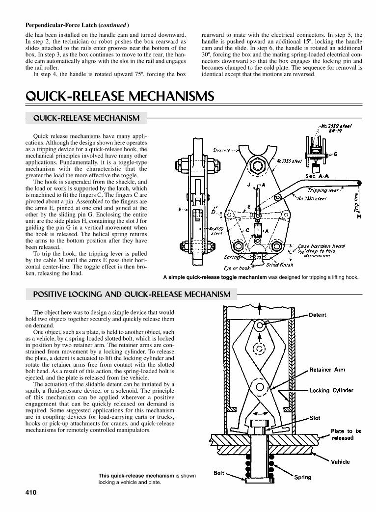
dle has been installed on the handle cam and turned downward.In step 2, the technician or robot pushes the box rearward asslides attached to the rails enter grooves near the bottom of thebox. In step 3, as the box continues to move to the rear, the han-dle cam automatically aligns with the slot in the rail and engagesthe rail roller.
In step 4, the handle is rotated upward 75º, forcing the box
410
rearward to mate with the electrical connectors. In step 5, thehandle is pushed upward an additional 15º, locking the handlecam and the slide. In step 6, the handle is rotated an additional30º, forcing the box and the mating spring-loaded electrical con-nectors downward so that the box engages the locking pin andbecomes clamped to the cold plate. The sequence for removal isidentical except that the motions are reversed.
Perpendicular-Force Latch (continued )
QUICK-RELEASE MECHANISMSQUICK-RELEASE MECHANISM
Quick release mechanisms have many appli-cations. Although the design shown here operatesas a tripping device for a quick-release hook, themechanical principles involved have many otherapplications. Fundamentally, it is a toggle-typemechanism with the characteristic that thegreater the load the more effective the toggle.
The hook is suspended from the shackle, andthe load or work is supported by the latch, whichis machined to fit the fingers C. The fingers C arepivoted about a pin. Assembled to the fingers arethe arms E, pinned at one end and joined at theother by the sliding pin G. Enclosing the entireunit are the side plates H, containing the slot J forguiding the pin G in a vertical movement whenthe hook is released. The helical spring returnsthe arms to the bottom position after they havebeen released.
To trip the hook, the tripping lever is pulledby the cable M until the arms E pass their hori-zontal center-line. The toggle effect is then bro-ken, releasing the load.
A simple quick-release toggle mechanism was designed for tripping a lifting hook.
This quick-release mechanism is shownlocking a vehicle and plate.
POSITIVE LOCKING AND QUICK-RELEASE MECHANISM
The object here was to design a simple device that wouldhold two objects together securely and quickly release themon demand.
One object, such as a plate, is held to another object, suchas a vehicle, by a spring-loaded slotted bolt, which is lockedin position by two retainer arm. The retainer arms are con-strained from movement by a locking cylinder. To releasethe plate, a detent is actuated to lift the locking cylinder androtate the retainer arms free from contact with the slottedbolt head. As a result of this action, the spring-loaded bolt isejected, and the plate is released from the vehicle.
The actuation of the slidable detent can be initiated by asquib, a fluid-pressure device, or a solenoid. The principleof this mechanism can be applied wherever a positiveengagement that can be quickly released on demand isrequired. Some suggested applications for this mechanismare in coupling devices for load-carrying carts or trucks,hooks or pick-up attachments for cranes, and quick-releasemechanisms for remotely controlled manipulators.
Sclater Chapter 12 5/3/01 1:24 PM Page 410

411
RING SPRINGS CLAMP PLATFORMELEVATOR INTO POSITION
A simple yet effective technique keeps aplatform elevator locked safely in posi-tion without an external clamping force.The platform (see drawing) contains spe-cial ring assemblies that grip the fourcolumn-shafts with a strong force by thesimple physical interaction of twotapered rings.
Thus, unlike conventional platformelevators, no outside power supply isrequired to hold the platform in position.Conventional jacking power isemployed, however, in raising the plat-form from one position to another.
How the rings work. The ring assem-blies are larger versions of the ringsprings sometimes installed for shockabsorption. In this version, the assemblyis made up of an inner nonmetallic ring
tapering upward and an outer steel ringtapered downward (see drawing).
The outside ring is linked to the plat-form, and the inside ring is positionedagainst the circumference of the columnshaft. When the platform is raised to thedesigned height, the jack force isremoved, and the full weight of the plat-form bears downward on the outside ringwith a force that, through a wedgingaction, is transferred into a horizontalinward force of the inside ring.
Thus, the column shaft is grippedtightly by the inside ring; the heavier theplatform the larger the gripping forceproduced.
The advantage of the technique is thatthe shafts do not need notches or threads,and cost is reduced. Moreover, the shaftscan be made of reinforced concrete.
Ring springs unclamp the column as theplatform is raised (upper). As soon as thejack power is removed (lower), the columnis gripped by the inner ring.
CAMMED JAWS IN HYDRAULICCYLINDER GRIP SHEETS
A single, double-acting hydraulic cylin-der in each work holder clamps andunclamps the work and retracts oradvances the jaws as required. With thepiston rod fully withdrawn into thehydraulic cylinder (A), the jaws of theholder are retracted and open. When thecontrol valve atop the work holder isactuated, the piston rod moves forward atotal of 12 in. The first 10 in. of move-ment (B) brings the sheet-locaterbumper into contact with the work. Thecammed surface on the rod extensionstarts to move the trip block upward, andthe locking pin starts to drop into posi-tion. The next 3⁄4 in. of piston-rod travel(C) fully engages the work-holder lock-ing pin and brings the lower jaw of theclamp up to the bottom of the work. Thework holder slide is now locked betweenthe forward stop and the locking pin.The last 11⁄4 in. of piston travel (D)clamps the workpiece between the jawswith a pressure of 2500 lbs. No adjust-ment for work thickness is necessary. Ajaws-open limit switch clamps the workholder in position (C) for loading andunloading operations.
Sclater Chapter 12 5/3/01 1:25 PM Page 411
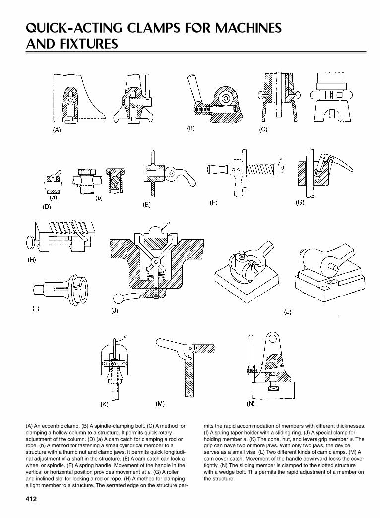
412
QUICK-ACTING CLAMPS FOR MACHINES AND FIXTURES
(A) An eccentric clamp. (B) A spindle-clamping bolt. (C) A method forclamping a hollow column to a structure. It permits quick rotaryadjustment of the column. (D) (a) A cam catch for clamping a rod orrope. (b) A method for fastening a small cylindrical member to astructure with a thumb nut and clamp jaws. It permits quick longitudi-nal adjustment of a shaft in the structure. (E) A cam catch can lock awheel or spindle. (F) A spring handle. Movement of the handle in thevertical or horizontal position provides movement at a. (G) A rollerand inclined slot for locking a rod or rope. (H) A method for clampinga light member to a structure. The serrated edge on the structure per-
mits the rapid accommodation of members with different thicknesses.(I) A spring taper holder with a sliding ring. (J) A special clamp forholding member a. (K) The cone, nut, and levers grip member a. Thegrip can have two or more jaws. With only two jaws, the deviceserves as a small vise. (L) Two different kinds of cam clamps. (M) Acam cover catch. Movement of the handle downward locks the covertightly. (N) The sliding member is clamped to the slotted structurewith a wedge bolt. This permits the rapid adjustment of a member onthe structure.
Sclater Chapter 12 5/3/01 1:25 PM Page 412

413
From Handbook of Fastening and Joining of Metal Parts,McGraw-Hill, Inc.
(A) A method for fastening capacitor plates to a structure with a circu-lar wedge. Rotation of the plates in a clockwise direction locks theplates to the structure. (B) A method for clamping member a with aspecial clamp. Detail b pivots on pin c. (C) A method for clamping twomovable parts so that they can be held in any angular position with aclamping screw. (D) A cam clamp for clamping member a. (E) Twomethods for clamping a cylindrical member. (F) Two methods forclamping member a with a special clamp. (G) A special clampingdevice that permits the parallel clamping of five parts by the tighten-
ing of one bolt. (H) A method for securing a structure with a bolt and amovable detail that provides a quick method for fastening the cover.(I) A method for quickly securing, adjusting, or releasing the centermember. (J) A method for securing a bushing in a structure with aclamp screw and thumb nut. (K) A method for securing an attachmentto a structure with a bolt and hand lever used as a nut. (L) A methodfor fastening a member to a structure with a wedge. (M) Two meth-ods for fastening two members to a structure with a spring and onescrew. The members can be removed without loosening the screw.
Sclater Chapter 12 5/3/01 1:25 PM Page 413

414
FRICTION CLAMPING DEVICES
Many different devices for gaining mechanical advantage havebeen used in the design of friction clamps. These clamps can gripmoderately large loads with comparatively small smooth sur-faces, and the loads can be tightened or released with simple con-trols. The clamps illustrated here can be tightened or releasedwith screws, levers, toggles, wedges, and combinations of them.
Sclater Chapter 12 5/3/01 1:25 PM Page 414
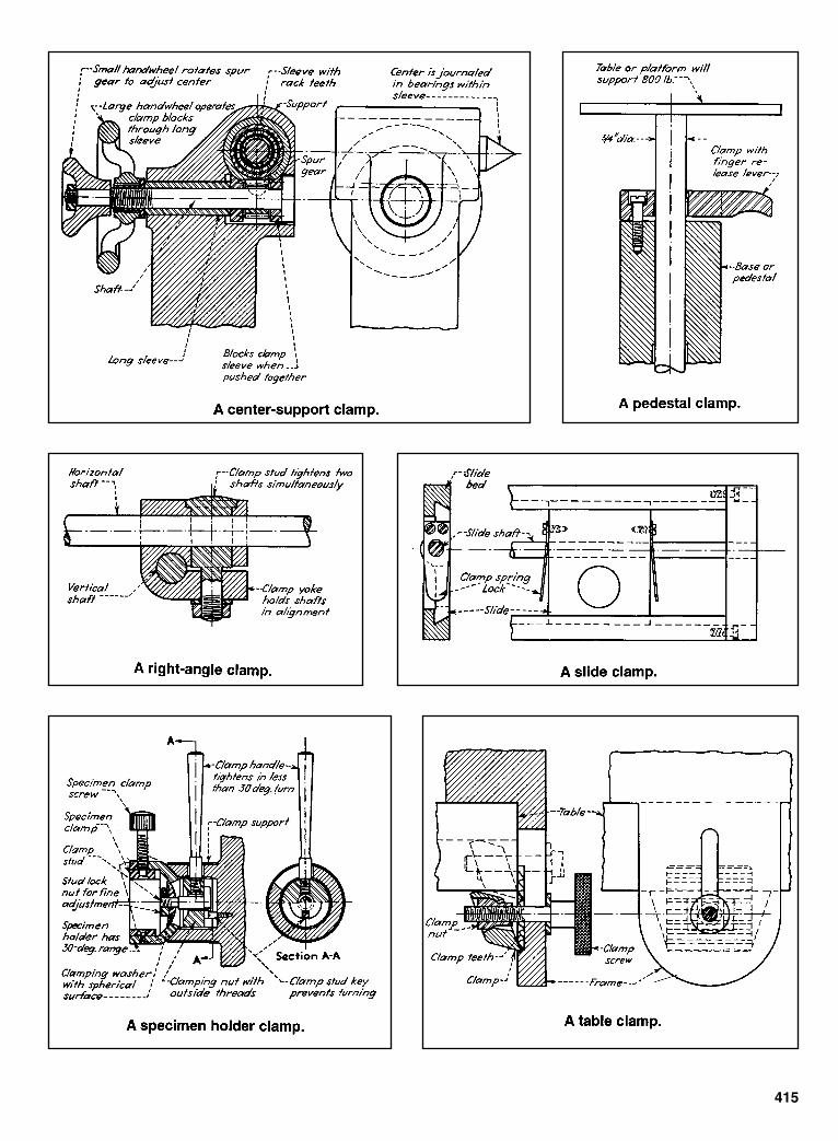
415
Sclater Chapter 12 5/3/01 1:25 PM Page 415

416
DETENTS FOR STOPPING MECHANICAL MOVEMENTSSome of the more robust and practical devices for stopping mechanical movements are illustrated here.
Fixed holding power is constant in bothdirections.
A domed plunger has long life. The screw provides adjustable holding.
Wedge action locks the movement in thedirection of the arrow.
Friction results in holding force. A notch shape dictates the direction of rodmotion.
A leaf spring provides limited holdingpower.
A leaf-spring detent can be removedquickly.
A conical or wedge-ended detent.
A positive detent has a manual release. .A leaf spring for holding flat pieces.
An automatic release occurs in one direc-tion; manual release is needed in the otherdirection.
Sclater Chapter 12 5/3/01 1:25 PM Page 416
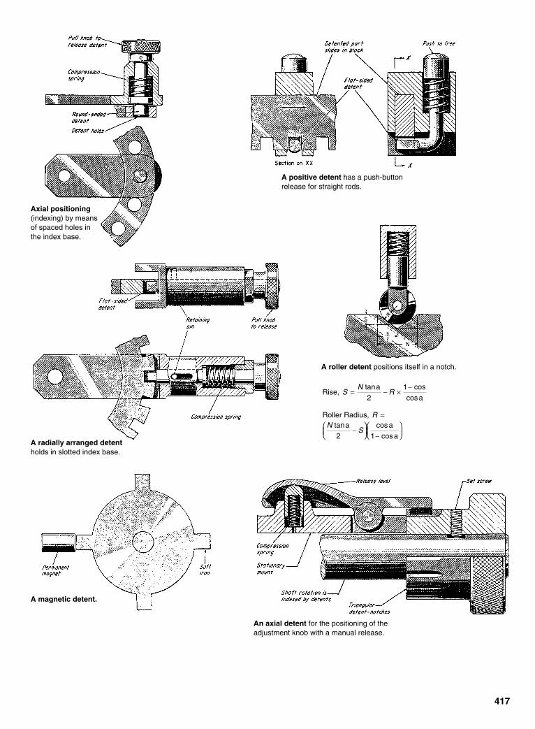
417
Axial positioning(indexing) by meansof spaced holes inthe index base.
A positive detent has a push-buttonrelease for straight rods.
A radially arranged detentholds in slotted index base.
A roller detent positions itself in a notch.
Rise, a
2 a
Roller Radius, a
2
a
a
SN
R
RN
S
= − ×−
=
−
−
tan cos
cos
tan cos
cos
1
1
A magnetic detent.
An axial detent for the positioning of theadjustment knob with a manual release.
Sclater Chapter 12 5/3/01 1:25 PM Page 417
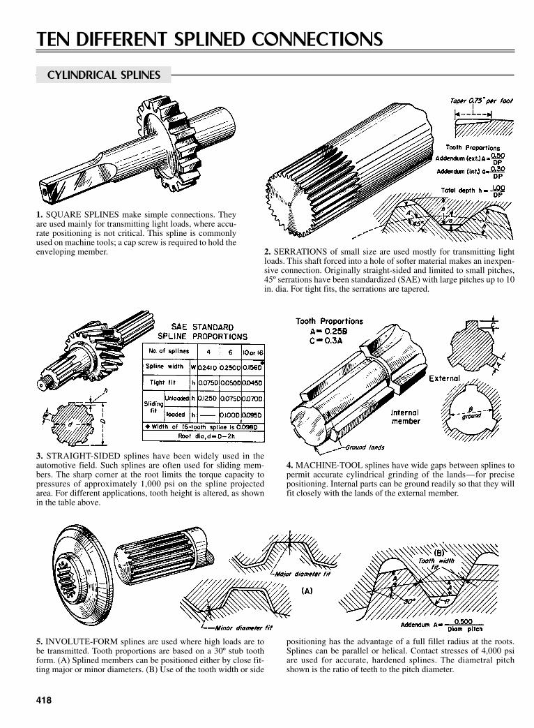
418
TEN DIFFERENT SPLINED CONNECTIONS
CYLINDRICAL SPLINES
1. SQUARE SPLINES make simple connections. Theyare used mainly for transmitting light loads, where accu-rate positioning is not critical. This spline is commonlyused on machine tools; a cap screw is required to hold theenveloping member. 2. SERRATIONS of small size are used mostly for transmitting light
loads. This shaft forced into a hole of softer material makes an inexpen-sive connection. Originally straight-sided and limited to small pitches,45º serrations have been standardized (SAE) with large pitches up to 10in. dia. For tight fits, the serrations are tapered.
3. STRAIGHT-SIDED splines have been widely used in theautomotive field. Such splines are often used for sliding mem-bers. The sharp corner at the root limits the torque capacity topressures of approximately 1,000 psi on the spline projectedarea. For different applications, tooth height is altered, as shownin the table above.
4. MACHINE-TOOL splines have wide gaps between splines topermit accurate cylindrical grinding of the lands—for precisepositioning. Internal parts can be ground readily so that they willfit closely with the lands of the external member.
5. INVOLUTE-FORM splines are used where high loads are tobe transmitted. Tooth proportions are based on a 30º stub toothform. (A) Splined members can be positioned either by close fit-ting major or minor diameters. (B) Use of the tooth width or side
positioning has the advantage of a full fillet radius at the roots.Splines can be parallel or helical. Contact stresses of 4,000 psiare used for accurate, hardened splines. The diametral pitchshown is the ratio of teeth to the pitch diameter.
Sclater Chapter 12 5/3/01 1:25 PM Page 418

419
6. SPECIAL INVOLUTE splines are made by using gear toothproportions. With full depth teeth, greater contact area is possi-ble. A compound pinion is shown made by cropping the smallerpinion teeth and internally splining the larger pinion.
7. TAPER-ROOT splines are for drivers that require positivepositioning. This method holds mating parts securely. With a 30ºinvolute stub tooth, this type is stronger than parallel root splinesand can be hobbed with a range of tapers.
FACE SPLINES
8. MILLED SLOTS in hubs or shafts make inexpensive connec-tions. This spline is limited to moderate loads and requires alocking device to maintain positive engagement. A pin and sleevemethod is used for light torques and where accurate positioningis not required.
9. RADIAL SERRATIONS made by milling or shaping the teethform simple connections. (A) Tooth proportions decrease radi-ally. (B) Teeth can be straight-sided (castellated) or inclined; a90º angle is common.
10. CURVIC COUPLING teeth are machined by a face-mill cut-ter. When hardened parts are used that require accurate position-ing, the teeth can be ground. (A) This process produces teethwith uniform depth. They can be cut at any pressure angle,
although 30º is most common. (B) Due to the cutting action, theshape of the teeth will be concave (hour-glass) on one memberand convex on the other—the member with which it will beassembled.
Sclater Chapter 12 5/3/01 1:25 PM Page 419
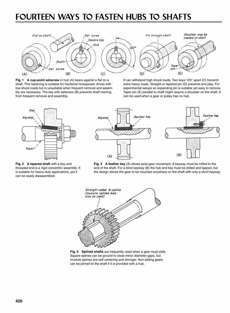
420
FOURTEEN WAYS TO FASTEN HUBS TO SHAFTS
Fig. 1 A cup-point setscrew in hub (A) bears against a flat on ashaft. This fastening is suitable for fractional horsepower drives withlow shock loads but is unsuitable when frequent removal and assem-bly are necessary. The key with setscrew (B) prevents shaft marringfrom frequent removal and assembly.
It can withstand high shock loads. Two keys 120° apart (C) transmitextra heavy loads. Straight or tapered pin (D) prevents end play. Forexperimental setups an expanding pin is suitable yet easy to remove.Taper pin (E) parallel to shaft might require a shoulder on the shaft. Itcan be used when a gear or pulley has no hub.
Fig. 2 A tapered shaft with a key andthreaded end is a rigid concentric assembly. Itis suitable for heavy-duty applications, yet itcan be easily disassembled.
Fig. 3 A feather key (A) allows axial gear movement. A keyway must be milled to theend of the shaft. For a blind keyway (B) the hub and key must be drilled and tapped, butthe design allows the gear to be mounted anywhere on the shaft with only a short keyway.
Fig. 4 Splined shafts are frequently used when a gear must slide.Square splines can be ground to close minor diameter gaps, butinvolute splines are self-centering and stronger. Non-sliding gearscan be pinned to the shaft if it is provided with a hub.
Sclater Chapter 12 5/3/01 1:25 PM Page 420

421
Fig. 5 A retaining ring allows quick gear removal in light-loadapplications. A shoulder on the shaft is necessary. A shear pin cansecure the gear to the shaft if protection against an excessive load isrequired.
Fig. 6 A stamped gear and formed wire shaftcan be used in light-duty application. Lugsstamped on both legs of the wire prevent disas-sembly. The bend radii of the shaft should be smallenough to allow the gear to seat.
Fig. 7 Interlocking tapered rings hold the hub tightly to the shaft when the nut is tight-ened. Coarse machining of the hub and shaft does not affect concentricity as in pinned andkeyed assemblies. A shoulder is required (A) for end-of-shaft mounting. End plates and fourbolts (B) allow the hub to be mounted anywhere on the shaft.
Fig. 8 This split bushing has a tapered outer diameter. Split holesin the bushing align with split holes in the hub. For tightening, the hubhalf of the hole is tapped, and the bushing half is un-tapped. A screwpulls the bushing into the hub as it is tightened, and it is removed byreversing the procedure.
Fig. 9 The split hub of a stock precision gear is clamped onto ashaft with a separate hub clamp. Manufacturers list correctly dimen-sioned hubs and clamps so that they can be efficiently fastened to aprecision-ground shaft.
Sclater Chapter 12 5/3/01 1:25 PM Page 421

422
CLAMPING DEVICES FOR ACCURATELY ALIGNINGADJUSTABLE PARTSMethods for clamping parts that must be readily movable are as numerous and as varied as therequirements. In many instances, a clamp of any design is satisfactory, provided it has sufficientstrength to hold the parts immovable when tightened. However, it is sometimes necessary thatthe movable part be clamped to maintain accurate alignment with some fixed part. Examples ofthese clamps are described and illustrated.
FIG. 1 When a nut is tightened, the flange on the edge ofthe movable part is drawn against the machined edge ofthe stationary part. This method is effective, but theremoval of the clamped part can be difficult if it is heavy orunbalanced.
FIG. 2 The lower edged of the bolt head contacts the angular side of locatinggroove, causing the keys to be held tightly against the opposite side of thegroove. This design permits easy removal of the clamped part, but it is effectiveonly if the working pressure is directly downward or in a direction against theperpendicular side of the slot.
FIG. 4 One side of the bolt is machined at an angle to form a side of thedovetail, which tightens in the groove as the nut is drawn tight. The part mustbe slid the entire length of the slot for removal.
FIG. 3 The movable part is held against one side of the groovewhile the T-nut is forced against the other side. The removal ofthe screw permits easy removal of the clamped part. Heavypressure toward the side of the key out of contact with the slotcan permit slight movement due to the springing of the screw.
FIG. 5 The angular surface of the nut contacts the angular side of thekey, and causes it to move outward against the side of the groove. Thisexerts a downward pull on the clamped part due to the friction of the nutagainst the side of a groove as the nut is drawn upward by the screw.
Sclater Chapter 12 5/3/01 1:25 PM Page 422
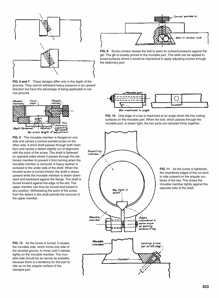
423
FIG. 6 and 7 These designs differ only in the depth of thegrooves. They cannot withstand heavy pressure in an upwarddirection but have the advantage of being applicable to nar-row grooves.
FIG. 8 Screw contact causes the ball to exert an outward pressure against thegib. The gib is loosely pinned to the movable part. This slide can be applied tobroad surfaces where it would be impractical to apply adjusting screws throughthe stationary part.
FIG. 9 The movable member is flanged on oneside and carries a conical pointed screw on theother side. A short shaft passes through both mem-bers and carries a detent slightly out of alignmentwith the point of the screw. This shaft is flattenedon opposite sides where it passes through the sta-tionary member to prevent it from turning when themovable member is removed. A heavy washer isscrewed to the under side of the shaft. When theknurled screw is turned inward, the shaft is drawnupward while the movable member is drawn down-ward and backward against the flange. The shaft isforced forward against the edge of the slot. Theupper member can thus be moved and locked inany position. Withdrawing the point of the screwfrom the detent in the shaft permits the removal ofthe upper member.
FIG. 10 One edge of a bar is machined at an angle which fits into matingsurfaces on the movable part. When the bolt, which passes through themovable part, is drawn tight, the two parts are clamped firmly together.
FIG. 11 As the screw is tightened,the chamfered edges of the cut tendto ride outward on the angular sur-faces of the key. This draws themovable member tightly against theopposite side of the shaft.
FIG. 12 As the screw is turned, it causesthe movable side, which forms one side ofthe dovetail groove, to move until it clampstightly on the movable member. The mov-able side should be as narrow as possible,because there is a tendency for this part toride up on the angular surface of theclamped part.
Sclater Chapter 12 5/3/01 1:25 PM Page 423
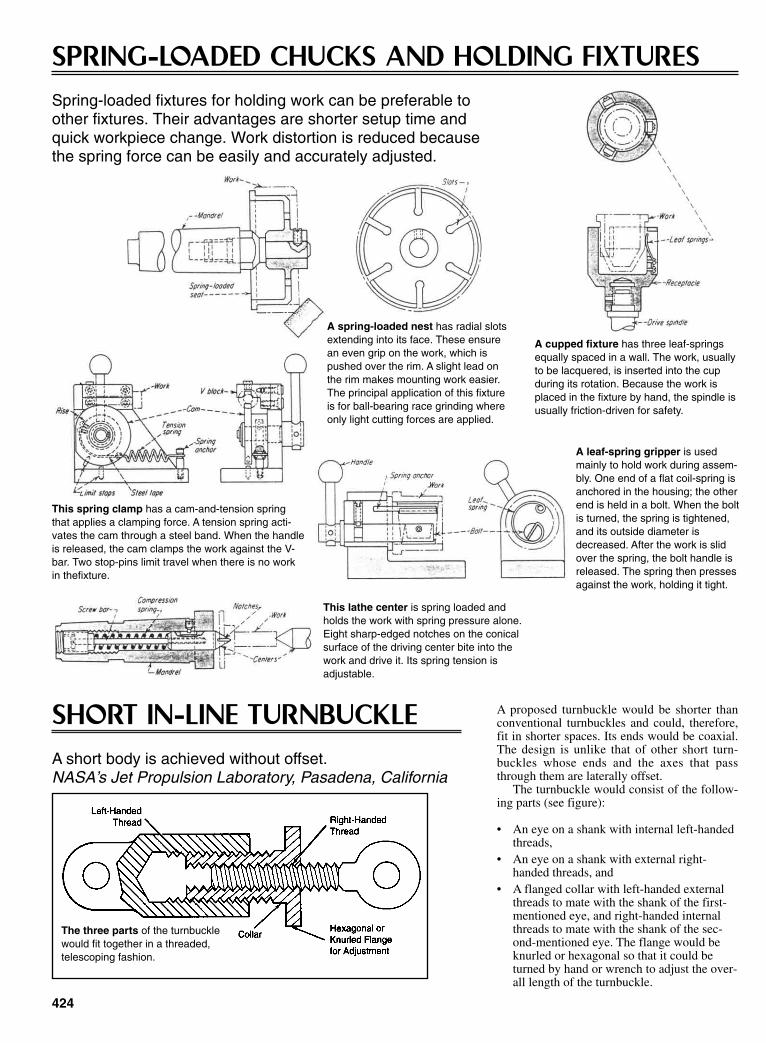
424
A cupped fixture has three leaf-springsequally spaced in a wall. The work, usuallyto be lacquered, is inserted into the cupduring its rotation. Because the work isplaced in the fixture by hand, the spindle isusually friction-driven for safety.
A spring-loaded nest has radial slotsextending into its face. These ensurean even grip on the work, which ispushed over the rim. A slight lead onthe rim makes mounting work easier.The principal application of this fixtureis for ball-bearing race grinding whereonly light cutting forces are applied.
This spring clamp has a cam-and-tension springthat applies a clamping force. A tension spring acti-vates the cam through a steel band. When the handleis released, the cam clamps the work against the V-bar. Two stop-pins limit travel when there is no workin thefixture.
A leaf-spring gripper is usedmainly to hold work during assem-bly. One end of a flat coil-spring isanchored in the housing; the otherend is held in a bolt. When the boltis turned, the spring is tightened,and its outside diameter isdecreased. After the work is slidover the spring, the bolt handle isreleased. The spring then pressesagainst the work, holding it tight.
This lathe center is spring loaded andholds the work with spring pressure alone.Eight sharp-edged notches on the conicalsurface of the driving center bite into thework and drive it. Its spring tension isadjustable.
SPRING-LOADED CHUCKS AND HOLDING FIXTURESSpring-loaded fixtures for holding work can be preferable to other fixtures. Their advantages are shorter setup time and quick workpiece change. Work distortion is reduced because the spring force can be easily and accurately adjusted.
SHORT IN-LINE TURNBUCKLEA short body is achieved without offset.NASA’s Jet Propulsion Laboratory, Pasadena, California
A proposed turnbuckle would be shorter thanconventional turnbuckles and could, therefore,fit in shorter spaces. Its ends would be coaxial.The design is unlike that of other short turn-buckles whose ends and the axes that passthrough them are laterally offset.
The turnbuckle would consist of the follow-ing parts (see figure):
• An eye on a shank with internal left-handedthreads,
• An eye on a shank with external right-handed threads, and
• A flanged collar with left-handed externalthreads to mate with the shank of the first-mentioned eye, and right-handed internalthreads to mate with the shank of the sec-ond-mentioned eye. The flange would beknurled or hexagonal so that it could beturned by hand or wrench to adjust the over-all length of the turnbuckle.
The three parts of the turnbucklewould fit together in a threaded,telescoping fashion.
Sclater Chapter 12 5/3/01 1:25 PM Page 424
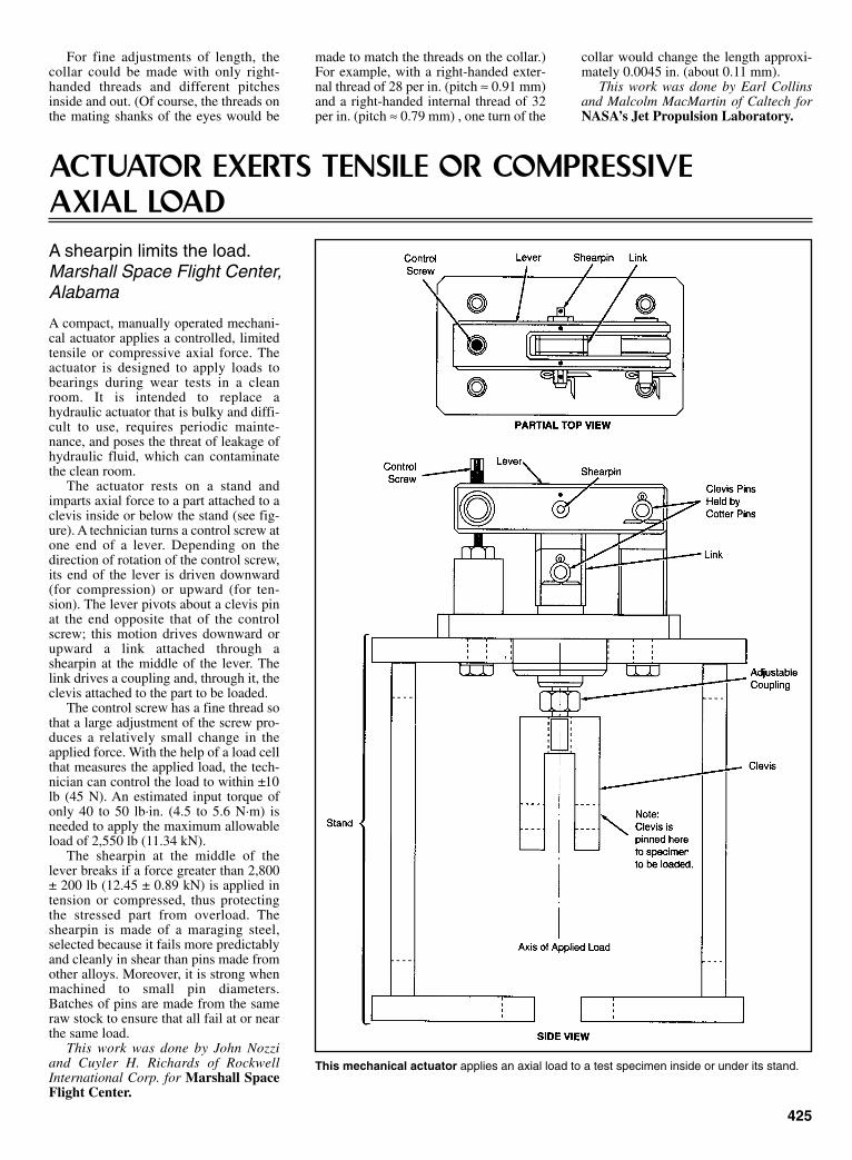
For fine adjustments of length, thecollar could be made with only right-handed threads and different pitchesinside and out. (Of course, the threads onthe mating shanks of the eyes would be
made to match the threads on the collar.)For example, with a right-handed exter-nal thread of 28 per in. (pitch ≈ 0.91 mm)and a right-handed internal thread of 32per in. (pitch ≈ 0.79 mm) , one turn of the
collar would change the length approxi-mately 0.0045 in. (about 0.11 mm).
This work was done by Earl Collinsand Malcolm MacMartin of Caltech forNASA’s Jet Propulsion Laboratory.
ACTUATOR EXERTS TENSILE OR COMPRESSIVE AXIAL LOADA shearpin limits the load.Marshall Space Flight Center, Alabama
A compact, manually operated mechani-cal actuator applies a controlled, limitedtensile or compressive axial force. Theactuator is designed to apply loads tobearings during wear tests in a cleanroom. It is intended to replace ahydraulic actuator that is bulky and diffi-cult to use, requires periodic mainte-nance, and poses the threat of leakage ofhydraulic fluid, which can contaminatethe clean room.
The actuator rests on a stand andimparts axial force to a part attached to aclevis inside or below the stand (see fig-ure). A technician turns a control screw atone end of a lever. Depending on thedirection of rotation of the control screw,its end of the lever is driven downward(for compression) or upward (for ten-sion). The lever pivots about a clevis pinat the end opposite that of the controlscrew; this motion drives downward orupward a link attached through ashearpin at the middle of the lever. Thelink drives a coupling and, through it, theclevis attached to the part to be loaded.
The control screw has a fine thread sothat a large adjustment of the screw pro-duces a relatively small change in theapplied force. With the help of a load cellthat measures the applied load, the tech-nician can control the load to within ±10lb (45 N). An estimated input torque ofonly 40 to 50 lb·in. (4.5 to 5.6 N·m) isneeded to apply the maximum allowableload of 2,550 lb (11.34 kN).
The shearpin at the middle of thelever breaks if a force greater than 2,800± 200 lb (12.45 ± 0.89 kN) is applied intension or compressed, thus protectingthe stressed part from overload. Theshearpin is made of a maraging steel,selected because it fails more predictablyand cleanly in shear than pins made fromother alloys. Moreover, it is strong whenmachined to small pin diameters.Batches of pins are made from the sameraw stock to ensure that all fail at or nearthe same load.
This work was done by John Nozziand Cuyler H. Richards of RockwellInternational Corp. for Marshall SpaceFlight Center.
This mechanical actuator applies an axial load to a test specimen inside or under its stand.
425
Sclater Chapter 12 5/3/01 1:25 PM Page 425

426
GRIPPING SYSTEM FOR MECHANICAL TESTING OF COMPOSITESSpecimens can be held without slippage, even at high temperatures.Lewis Research Center, Cleveland, Ohio
An improved gripping system has beendesigned to hold the ends of a specimenof a composite material securely during acreep or tensile test. The grips functionover a wide range of applied stress [3 to100 kpsi (about 21 to about 690 Mpa)]and temperature [up to 1,800ºF (about980ºC)].
Each grip includes a pair of wedgesthat have sharply corrugated (sawtooth-profile) gripping surfaces. The wedgesare held between two plates that containcavities which are sloped to accommo-date the wedges (see figure). Two suchgrips—one for each end of the speci-men—hold a specimen in a furnacewhich is connected to a tensile testmachine for creep measurements.
In preparation for a test, the specimenis assembled with the grips in a fixturethat maintains all parts in precise align-ment: this step is necessary to ensurethat the load applied during the test willcoincide with the axis of the specimen.Unlike some older wedge grips, thespecimen can be gripped in a delicatemanner during assembly and alignment.While the assembled parts are still in thealignment fixture, hexagonal nuts andbolts on the grip can be tightened evenlywith a torque wrench to 120 lb-in. (≈13.6 N-m).
During a test, the grips apply therequired tensile stress to the specimenwithout slippage at high temperaturesand, therefore, without loss of alignment.
In contrast, some older plate grips tendedto sip at high temperatures when appliedtensile stresses rose above 20 kpsi (≈ 140Mpa), while older hydraulically actuatedgrips could not be allowed inside the
testing furnaces, which introduced tem-perature gradients in the specimens.
This work was done by Rebecca A.MacKay and Michael V. Nathal of LewisResearch Center.
A pair of sawtooth wedges clamped between a pair of plates holds one end of a specimen. Amirror image of this grip is attached at the other end of the specimen. An alignment fixture (notshown) holds the grips and specimen during assembly.
Sclater Chapter 12 5/3/01 1:25 PM Page 426

PASSIVE CAPTURE JOINT WITH THREE DEGREES OF FREEDOMNew joint allows quick connection between any two structural elements where rotation in all three axis is desired.Marshall Space Flight Center, Alabama
427
The three-degrees-of-freedom capability of the Passive Capture Joint provides for quick connectand disconnect operations.
A new joint, proposed for use on anattachable debris shield for theInternational Space Station ServiceModule, has potential for commercialuse in situations where hardware must beassembled and disassembled on a regularbasis.
This joint can be useful in a variety ofapplications, including replacing thejoints commonly used on trailer-hitchtongues and temporary structures, suchas crane booms and rigging. Other usesfor this joint include assembly of struc-tures where simple rapid deployment isessential, such as in space, undersea, andin military structures.
This new joint allows for quick con-nection between any two structural ele-ments where it is desirable to have rota-tion in all three axes. The joint can befastened by moving the two halves intoposition. The joint is then connected byinserting the ball into the bore of thebase. When the joint ball is fully inserted,the joint will lock with full strength.Release of this joint involves only a sim-ple movement and rotation of one part.The joint can then be easily separated.
Most passive capture devices allowonly axial rotation when fastened—ifany movement is allowed at all.Manually- or power-actuated active
joints require an additional action, orpower and control signal, as well as amore complex mechanism.
The design for this new joint is rela-tively simple. It consists of two halves, aball mounted on a stem (such as those ona common trailer-hitch ball) and asocket. The socket contains all the mov-ing parts and is the important part of thisinvention. The socket also has a base,which contains a large central cylindricalbore ending in a spherical cup.
This work was done by BruceWeddendorf and Richard A. Cloyd of theMarshall Space Flight Center.
Sclater Chapter 12 5/3/01 1:25 PM Page 427
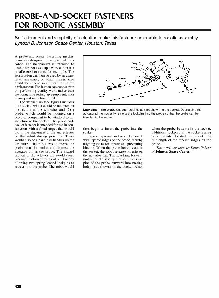
428
PROBE-AND-SOCKET FASTENERS FOR ROBOTIC ASSEMBLYSelf-alignment and simplicity of actuation make this fastener amenable to robotic assembly.Lyndon B. Johnson Space Center, Houston, Texas
A probe-and-socket fastening mecha-nism was designed to be operated by arobot. The mechanism is intended toenable a robot to set up a workstation in ahostile environment, for example. Theworkstation can then be used by an astro-naut, aquanaut, or other human whocould then spend minimum time in theenvironment. The human can concentrateon performing quality work rather thanspending time setting up equipment, withconsequent reduction of risk.
The mechanism (see figure) includes(1) a socket, which would be mounted ona structure at the worksite, and (2) aprobe, which would be mounted on apiece of equipment to be attached to thestructure at the socket. The probe-and-socket fastener is intended for use in con-junction with a fixed target that wouldaid in the placement of the end effectorof the robot during grasping. Therewould also be a handle or handles on thestructure. The robot would move theprobe near the socket and depress theactuator pin in the probe. The inwardmotion of the actuator pin would causerearward motion of the axial pin, therebyallowing two spring-loaded lockpins toretract into the probe. The robot would
Lockpins in the probe engage radial holes (not shown) in the socket. Depressing the actuator pin temporarily retracts the lockpins into the probe so that the probe can be inserted in the socket.
then begin to insert the probe into thesocket.
Tapered grooves in the socket meshwith tapered ridges on the probe, therebyaligning the fastener parts and preventingbinding. When the probe bottoms out inthe socket, the robot releases its grip onthe actuator pin. The resulting forwardmotion of the axial pin pushes the lock-pins of the probe outward into matingholes (not shown) in the socket. Also,
when the probe bottoms in the socket,additional lockpins in the socket springinto detents located at about themidlength of the tapered ridges on theprobe.
This work was done by Karen Nybergof Johnson Space Center.
Sclater Chapter 12 5/3/01 1:25 PM Page 428

CHAPTER 13KEY EQUATIONS AND
CHARTS FOR DESIGNINGMECHANISMS
Sclater Chapter 13 5/3/01 1:31 PM Page 429
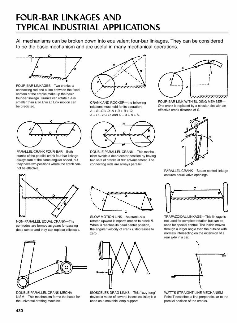
430
FOUR-BAR LINKAGES AND TYPICAL INDUSTRIAL APPLICATIONSAll mechanisms can be broken down into equivalent four-bar linkages. They can be consideredto be the basic mechanism and are useful in many mechanical operations.
FOUR-BAR LINKAGES—Two cranks, aconnecting rod and a line between the fixedcenters of the cranks make up the basicfour-bar linkage. Cranks can rotate if A issmaller than B or C or D. Link motion canbe predicted.
FOUR-BAR LINK WITH SLIDING MEMBER—One crank is replaced by a circular slot with aneffective crank distance of B.
PARALLEL CRANK—Steam control linkageassures equal valve openings.
SLOW MOTION LINK—As crank A isrotated upward it imparts motion to crank B.When A reaches its dead center position,the angular velocity of crank B decreases tozero.
TRAPAZOIDAL LINKAGE—This linkage isnot used for complete rotation but can beused for special control. The inside movesthrough a larger angle than the outside withnormals intersecting on the extension of arear axle in a car.
CRANK AND ROCKER—the followingrelations must hold for its operation: A + B +C > D; A + D + B > C;A + C – B < D, and C – A + B > D.
NON-PARALLEL EQUAL CRANK—Thecentrodes are formed as gears for passingdead center and they can replace ellipticals.
DOUBLE PARALLEL CRANK MECHA-NISM—This mechanism forms the basis forthe universal drafting machine.
ISOSCELES DRAG LINKS—This “lazy-tong”device is made of several isosceles links; it isused as a movable lamp support.
WATT’S STRAIGHT-LINE MECHANISM—Point T describes a line perpendicular to theparallel position of the cranks.
PARALLEL CRANK FOUR-BAR—Bothcranks of the parallel crank four-bar linkagealways turn at the same angular speed, butthey have two positions where the crank can-not be effective.
DOUBLE PARALLEL CRANK—This mecha-nism avoids a dead center position by havingtwo sets of cranks at 90° advancement. Theconnecting rods are always parallel.
Sclater Chapter 13 5/3/01 1:31 PM Page 430
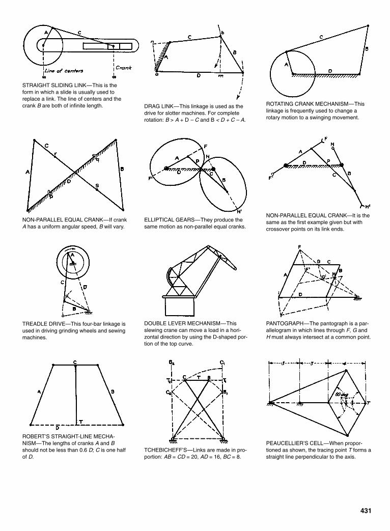
431
STRAIGHT SLIDING LINK—This is theform in which a slide is usually used toreplace a link. The line of centers and thecrank B are both of infinite length. DRAG LINK—This linkage is used as the
drive for slotter machines. For completerotation: B > A + D – C and B < D + C – A.
ROTATING CRANK MECHANISM—Thislinkage is frequently used to change arotary motion to a swinging movement.
NON-PARALLEL EQUAL CRANK—If crankA has a uniform angular speed, B will vary.
ELLIPTICAL GEARS—They produce thesame motion as non-parallel equal cranks.
NON-PARALLEL EQUAL CRANK—It is thesame as the first example given but withcrossover points on its link ends.
TREADLE DRIVE—This four-bar linkage isused in driving grinding wheels and sewingmachines.
DOUBLE LEVER MECHANISM—Thisslewing crane can move a load in a hori-zontal direction by using the D-shaped por-tion of the top curve.
PANTOGRAPH—The pantograph is a par-allelogram in which lines through F, G andH must always intersect at a common point.
ROBERT’S STRAIGHT-LINE MECHA-NISM—The lengths of cranks A and Bshould not be less than 0.6 D; C is one halfof D.
TCHEBICHEFF’S—Links are made in pro-portion: AB = CD = 20, AD = 16, BC = 8.
PEAUCELLIER’S CELL—When propor-tioned as shown, the tracing point T forms astraight line perpendicular to the axis.
Sclater Chapter 13 5/3/01 1:31 PM Page 431

432
DESIGNING GEARED FIVE-BAR MECHANISMSGeared five-bar mechanisms offer excellent force-transmission characteristics and can producemore complex output motions—including dwells—than conventional four-bar mechanisms.
It is often necessary to design a mecha-nism that will convert uniform inputrotational motion into nonuniform outputrotation or reciprocation. Mechanismsdesigned for such purposes are usuallybased on four-bar linkages. Those link-ages produce a sinusoidal output that canbe modified to yield a variety of motions.
Four-bar linkages have their limita-tions, however. Because they cannot pro-duce dwells of useful duration, thedesigner might have to include a camwhen a dwell is desired, and he mighthave to accept the inherent speed restric-tions and vibration associated with cams.A further limitation of four-bar linkagesis that only a few kinds have efficientforce-transmission capabilities.
One way to increase the variety ofoutput motions of a four-bar linkage, andobtain longer dwells and better forcetransmissions, is to add a link. The result-ing five-bar linkage would becomeimpractical, however, because it wouldthen have only two degrees of freedomand would, consequently, require twoinputs to control the output.
Simply constraining two adjacentlinks would not solve the problem. Thefive-bar chain would then function effec-tively only as a four-bar linkage. If, onthe other hand, any two nonadjacentlinks are constrained so as to removeonly one degree of freedom, the five-barchain becomes a functionally usefulmechanism.
Gearing provides solution. There areseveral ways to constrain two non-adjacent links in a five-bar chain. Somepossibilities include the use of gears,slot-and-pin joints, or nonlinear bandmechanisms. Of these three possibilities,gearing is the most attractive. Some prac-tical gearing systems (Fig. 1) includedpaired external gears, planet gearsrevolving within an external ring gear,and planet gears driving slotted cranks.
In one successful system (Fig. 1A)each of the two external gears has a fixedcrank that is connected to a crossbar by arod. The system has been successful inhigh-speed machines where it transformsrotary motion into high-impact linearmotion. The Stirling engine includes asimilar system (Fig. 1B).
In a different system (Fig. 1C) a pinon a planet gear traces an epicyclic,three-lobe curve to drive an output crankback and forth with a long dwell at the
Fig. 1 Five-bar mechanism designs can be based on paired external gears or planetarygears. They convert simple input motions into complex outputs.
Sclater Chapter 13 5/3/01 1:31 PM Page 432

extreme right-hand position. A slottedoutput crank (Fig. 1D) will provide asimilar output.
Two professors of mechanical engi-neering, Daniel H. Suchora of YoungstownState University, Youngstown, Ohio, andMichael Savage of the University ofAkron, Akron, Ohio, studied a variation ofthis mechanism in detail.
Five kinematic inversions of this form(Fig. 2) were established by the tworesearchers. As an aid in distinguishingbetween the five, each type is namedaccording to the link which acts as thefixed link. The study showed that theType 5 mechanism would have the great-est practical value.
In the Type 5 mechanism (Fig. 3A),the gear that is stationary acts as a sungear. The input shaft at Point E drives theinput crank which, in turn, causes theplanet gear to revolve around the sungear. Link a2, fixed to the planet, thendrives the output crank, Link a4, bymeans of the connecting link, Link a3. Atany input position, the third and fourthlinks can be assembled in either of twodistinct positions or “phases” (Fig. 3B).
Variety of outputs. The different kindsof output motions that can be obtainedfrom a Type 5 mechanism are based onthe different epicyclic curves traced bylink joint B. The variables that control theshape of a “B-curve” are the gear ratioGR (GR = N2/N5), the link ratio a2/a1 andthe initial position of the gear set, defined by the initial positions of θ1 andθ2, designated as θ10 and θ20, respectively.
Typical B-curve shapes (Fig. 4)include ovals, cusps, and loops. Whenthe B-curve is oval (Fig. 4B) or semioval(Fig. 4C), the resulting B-curve is similarto the true-circle B-curve produced by afour-bar linkage. The resulting outputmotion of Link a4 will be a sinusoidaltype of oscillation, similar to that pro-duced by a four-bar linkage.
When the B-curve is cusped (Fig.4A), dwells are obtained. When the B-curve is looped (Figs. 4D and 4E), a dou-ble oscillation is obtained.
In the case of the cusped B-curve(Fig. 4A), dwells are obtained. When theB-curve is looped (Figs. 4D and 4E), adouble oscillation is obtained.
In the case of the cusped B-curve(Fig. 4A), by selecting a2 to be equal tothe pitch radius of the planet gear r2, linkjoint B becomes located at the pitch cir-cle of the planet gear. The gear ratio in allthe cases illustrated is unity (GR = 1).
Professors Suchora and Savage ana-lyzed the different output motions pro-duced by the geared five-bar mecha-nisms by plotting the angular position θ4of the output link a4 of the output link a4against the angular position of the inputlink θ1 for a variety of mechanism con-figurations (Fig. 5).
433
Fig. 2 Five types of geared five-bar mechanisms. A different link acts as the fixed link ineach example. Type 5 might be the most useful for machine design.
Fig. 3 A detailed design of a Type-5 mechanism. The input crank causes the planet gear torevolve around the sun gear, which is always stationary.
Sclater Chapter 13 5/3/01 1:32 PM Page 433
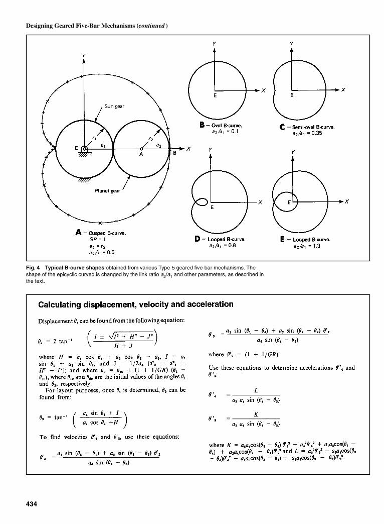
434
Designing Geared Five-Bar Mechanisms (continued )
Fig. 4 Typical B-curve shapes obtained from various Type-5 geared five-bar mechanisms. Theshape of the epicyclic curved is changed by the link ratio a2/a1 and other parameters, as described inthe text.
Sclater Chapter 13 5/3/01 1:32 PM Page 434
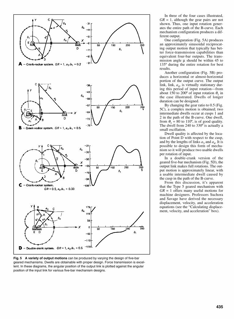
In three of the four cases illustrated,GR = 1, although the gear pairs are notshown. Thus, one input rotation gener-ates the entire path of the B-curve. Eachmechanism configuration produces a dif-ferent output.
One configuration (Fig. 5A) producesan approximately sinusoidal reciprocat-ing output motion that typically has bet-ter force-transmission capabilities thanequivalent four-bar outputs. The trans-mission angle µ should be within 45 to135º during the entire rotation for bestresults.
Another configuration (Fig. 5B) pro-duces a horizontal or almost-horizontalportion of the output curve. The outputlink, link, a4, is virtually stationary dur-ing this period of input rotation—fromabout 150 to 200º of input rotation θ1 inthe case illustrated. Dwells of longerduration can be designed.
By changing the gear ratio to 0.5 (Fig.5C), a complex motion is obtained; twointermediate dwells occur at cusps 1 and2 in the path of the B-curve. One dwell,from θ1 = 80 to 110º, is of good quality.The dwell from 240 to 330º is actually asmall oscillation.
Dwell quality is affected by the loca-tion of Point D with respect to the cusp,and by the lengths of links a3 and a4. It ispossible to design this form of mecha-nism so it will produce two usable dwellsper rotation of input.
In a double-crank version of thegeared five-bar mechanism (Fig. 5D), theoutput link makes full rotations. The out-put motion is approximately linear, witha usable intermediate dwell caused bythe cusp in the path of the B-curve.
From this discussion, it’s apparentthat the Type 5 geared mechanism withGR = 1 offers many useful motions formachine designers. Professors Suchoraand Savage have derived the necessarydisplacement, velocity, and accelerationequations (see the “Calculating displace-ment, velocity, and acceleration” box).
435
Fig. 5 A variety of output motions can be produced by varying the design of five-bargeared mechanisms. Dwells are obtainable with proper design. Force transmission is excel-lent. In these diagrams, the angular position of the output link is plotted against the angularposition of the input link for various five-bar mechanism designs.
Sclater Chapter 13 5/3/01 1:32 PM Page 435

KINEMATICS OF INTERMITTENT MECHANISMS—THE EXTERNAL GENEVA WHEEL
436
One of the most commonly appliedmechanisms for producing intermittentrotary motion from a uniform inputspeed is the external geneva wheel.
The driven member, or star wheel,contains many slots into which the rollerof the driving crank fits. The number ofslots determines the ratio between dwelland motion period of the driven shaft.The lowest possible number of slots isthree, while the highest number is theo-retically unlimited. In practice, the three-slot geneva is seldom used because of theextremely high acceleration valuesencountered. Genevas with more than 18slots are also infrequently used becausethey require wheels with comparativelylarge diameters.
In external genevas of any number ofslots, the dwell period always exceedsthe motion period. The opposite is true ofthe internal geneva. However, for thespherical geneva, both dwell and motionperiods are 180º.
For the proper operation of the exter-nal geneva, the roller must enter the slottangentially. In other words, the center-line of the slot and the line connectingthe roller center and crank rotation centermust form a right angle when the rollerenters or leaves the slot.
The calculations given here are basedon the conditions stated here.
Fig. 1 A basic outline drawing for the external geneva wheel. Thesymbols are identified for application in the basic equations.
Fig. 2 A schematic drawing of a six-slot geneva wheel. Rollerdiameter, dr, must be considered when determining D.
Sclater Chapter 13 5/3/01 1:32 PM Page 436

Consider an external geneva wheel,shown in Fig. 1, in which
n = number of slotsa = crank radius
From
Fig. 1, b = center distance =
Let
Then b = am
It will simplify the development ofthe equations of motion to designate theconnecting line of the wheel and crankcenters as the zero line. This is contraryto the practice of assigning the zero valueof α, representing the angular position ofthe driving crank, to that position of thecrank where the roller enters the slot.
Thus, from Fig. 1, the driven crankradius f at any angle is:
(1)
f am a
m m
= − +
= + −
( cos ) sin
cos
α α α
α α
2 2 2
21 2
1180
sinn
m=
a
nsin
180
437
Fig. 3 A four-slot geneva (A) and aneight-slot geneva (B). Both have lockingdevices.
Fig. 5 Chart for determining the angular velocity of the driven member.
Fig. 4 Chart for determining the angular displacement of the driven member.
Sclater Chapter 13 5/3/01 1:32 PM Page 437

Kinematics of Intermittent Mechanisms (continued )
and the angular displacement β can befound from:
(2)
A six-slot geneva is shown schemati-cally in Fig. 2. The outside diameter D ofthe wheel (when accounting for the effectof the roller diameter d) is found to be:
(3)
Differentiating Eq. (2) and dividingby the differential of time, dt, the angularvelocity of the driven member is:
(4)
where ω represents the constant angularvelocity of the crank.
By differentiation of Eq. (4) the accel-eration of the driven member is found tobe:
(5)
All notations and principal formulasare given in Table I for easy reference.Table II contains all the data of principalinterest for external geneva wheels havingfrom 3 to 18 slots. All other data can beread from the charts: Fig. 4 for angularposition, Fig. 5 for angular velocity, andFig. 6 for angular acceleration.
ddt
m mm m
2
22
2
2 21
1 2β ω α
α= −
+ −
sin ( )( cos )
ddt
mm m
β αα
= −+ −
ω cos
cos1
1 22
Dd
an
r= +24
18022 2cot
coscos
cosβ
α= −
+ −m am m1 22
Fig. 6 Chart for determining the angular acceleration of the driven member.
438
Sclater Chapter 13 5/3/01 1:32 PM Page 438
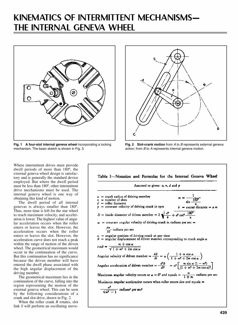
KINEMATICS OF INTERMITTENT MECHANISMS—THE INTERNAL GENEVA WHEEL
Where intermittent drives must providedwell periods of more than 180º, theexternal geneva wheel design is satisfac-tory and is generally the standard deviceemployed. But where the dwell periodmust be less than 180º, other intermittentdrive mechanisms must be used. Theinternal geneva wheel is one way ofobtaining this kind of motion.
The dwell period of all internalgenevas is always smaller than 180º.Thus, more time is left for the star wheelto reach maximum velocity, and acceler-ation is lower. The highest value of angu-lar acceleration occurs when the rollerenters or leaves the slot. However, theacceleration occurs when the rollerenters or leaves the slot. However, theacceleration curve does not reach a peakwithin the range of motion of the drivenwheel. The geometrical maximum wouldoccur in the continuation of the curve.But this continuation has no significancebecause the driven member will haveentered the dwell phase associated withthe high angular displacement of thedriving member.
The geometrical maximum lies in thecontinuation of the curve, falling into theregion representing the motion of theexternal geneva wheel. This can be seenby the following considerations of acrank and slot drive, drawn in Fig. 2.
When the roller crank R rotates, slotlink S will perform an oscillating move-
Fig. 1 A four-slot internal geneva wheel incorporating a lockingmechanism. The basic sketch is shown in Fig. 3.
Fig. 2 Slot-crank motion from A to B represents external genevaaction; from B to A represents internal geneva motion.
439
Sclater Chapter 13 5/3/01 1:32 PM Page 439

ment, for which the displacement, angu-lar velocity, and acceleration can begiven in continuous curves.
When the crank R rotates from A to B,then the slot link S will move from C toD, exactly reproducing all moving condi-tions of an external geneva of equal slotangle. When crank R continues its move-ment from B back to A, then the slot linkS will move from D back to C, this timereproducing exactly (though in a mirrorpicture with the direction of motionbeing reversed) the moving conditions ofan internal geneva.
Therefore, the characteristic curves ofthis motion contain both the external andinternal geneva wheel conditions; theregion of the external geneva liesbetween A and B, the region of the inter-nal geneva lies between B and A.
The geometrical maxima of the accel-eration curves lie only in the regionbetween A and B, representing that por-tion of the curves which belongs to theexternal geneva.
The principal advantage of the internalgeneva, other than its smooth operation, isit sharply defined dwell period. A disad-vantage is the relatively large size of thedriven member, which increases the forceresisting acceleration. Another feature,which is sometimes a disadvantage, is thecantilever arrangement of the roller crankshaft. This shaft cannot be a through shaftbecause the crank must be fastened to theoverhanging end of the input shaft.
To simplify the equations, the con-necting line of the wheel and crank cen-ters is taken as the zero line. The angular
440
Kinematics of Intermittent Mechanisms (continued )
Fig. 3 A basic outline for developing the equations of the internalgeneva wheel, based on the notations shown.
Fig. 4 A drawing of a six-slot internal geneva wheel. The sym-bols are identified, and the motion equations are given in Table I.
Fig. 5 Angular displacement of the driven member can be determined from this chart.
Sclater Chapter 13 5/3/01 1:32 PM Page 440

position of the driving crank α is zerowhen it is on this line. Then the follow-ing relations are developed, based onFig. 3.
n = number of slotsa = crank radiusb = center distance =
Let
then; b = amTo find the angular displacement β of
the driven member, the driven crankradius f is first calculated from:
(1)
and because
it follows:
(2)
From this formula, β, the angular dis-placement, can be calculated for anyangle α, the angle of the mechanism’sdriving member.
The first derivative of Eq. (2) givesthe angular velocity as:
(3)
where ω designates the uniform speed ofthe driving crank shaft, namely:
if p equals its number of revolutions perminute.
Differentiating Eq. (3) once moredevelops the equation for the angularacceleration:
(4)
The maximum angular velocityoccurs, obviously, at α = 0º. Its value isfound by substituting 0º for α in Eq. (3).It is:
(5)
ddt m
β ωmax
=+1
ddt
m mm m
2
22
2
2 21
1 2β ω α
α= −
+ +
sin ( )( cos )
ω π= p30
ddt
mm m
β ω αα
= ++ +
11 22
coscos
coscos
cosβ α
α= +
+ +mm m1 22
coscosβ α= +mf
f a am a
m m
= + +
= + +
2 2 2
21 2
sin ( cos )
cos
α α
α α
1180
sinº ,
n
m=
a
nsin
º180
441
Fig. 6 Angular velocity of the driven member can be determined from this chart.
Fig. 7 Angular acceleration of the driven member can be determined from this chart.
Sclater Chapter 13 5/3/01 1:32 PM Page 441

Kinematics of Intermittent Mechanisms (continued )
The highest value of the accelerationis found by substituting 180/n + 980 forα in Eq. (4):
(6)d
dt m
2
2
2
2 1β ω
max=
−
A layout drawing for a six-slot inter-nal geneva wheel is shown in Fig. 4. Allthe symbols in this drawing and through-out the text are compiled in Table I foreasy reference.
Table II contains all the data of princi-
pal interest on the performance of inter-nal geneva wheels that have from 3 to 18slots. Other data can be read from thecharts: Fig. 5 for angular position, Fig. 6for angular velocity, and Fig. 7 for angu-lar acceleration.
442
EQUATIONS FOR DESIGNING CYCLOID MECHANISMS
Angular displacement
tan( )sin sin( )( )cos cos( )
( )
( )cos
cos
( )
β θ θ γθ θ γ
ωθ
θ
= + − ++ − +
=+
+− +
+
++
−
+
R r bR r b
V
br R r
r Rr
bR r
Rr
bR r
bR r
Rr
A
1
12
12
2
2
2
Angular velocity
Angular acceleration
==−
+
+
++
−+
ωθ
θ
2
2
2
2
2
2
2
2
1
12
3
bR r
Rr
bR r
Rr
bR r
bR r
Rr
( )sin
( )cos
( )
The equations for angular displacement,velocity, and acceleration for a basicepicyclic drive are given below.
Sclater Chapter 13 5/3/01 1:32 PM Page 442
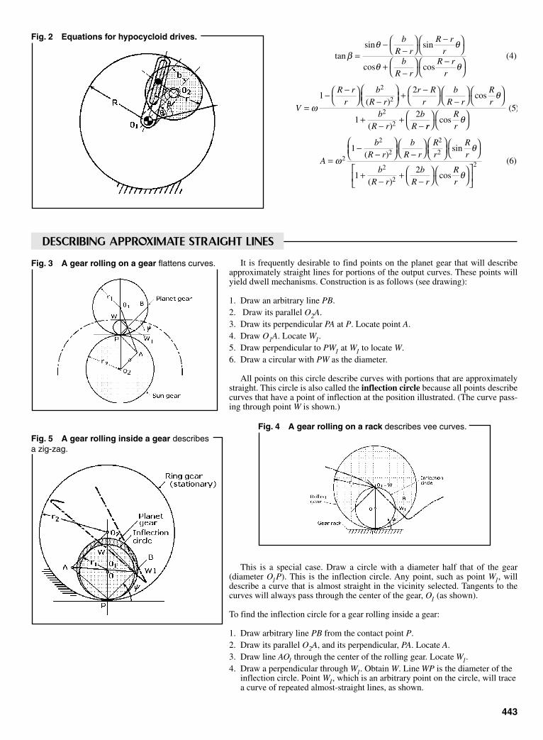
It is frequently desirable to find points on the planet gear that will describeapproximately straight lines for portions of the output curves. These points willyield dwell mechanisms. Construction is as follows (see drawing):
1. Draw an arbitrary line PB.2. Draw its parallel O2A.3. Draw its perpendicular PA at P. Locate point A.4. Draw O1A. Locate W1.5. Draw perpendicular to PW1 at W1 to locate W.6. Draw a circular with PW as the diameter.
All points on this circle describe curves with portions that are approximatelystraight. This circle is also called the inflection circle because all points describecurves that have a point of inflection at the position illustrated. (The curve pass-ing through point W is shown.)
This is a special case. Draw a circle with a diameter half that of the gear(diameter O1P). This is the inflection circle. Any point, such as point W1, willdescribe a curve that is almost straight in the vicinity selected. Tangents to thecurves will always pass through the center of the gear, O1 (as shown).
To find the inflection circle for a gear rolling inside a gear:
1. Draw arbitrary line PB from the contact point P.2. Draw its parallel O2A, and its perpendicular, PA. Locate A.3. Draw line AO1 through the center of the rolling gear. Locate W1.4. Draw a perpendicular through W1. Obtain W. Line WP is the diameter of the
inflection circle. Point W1, which is an arbitrary point on the circle, will tracea curve of repeated almost-straight lines, as shown.
443
Fig. 2 Equations for hypocycloid drives.
tansin sin
cos cos( )
( )cos
( )
βθ θ
θ θ
ωθ
=−
−
−
+−
−
=− −
−
+ −
−
+−
+−
bR r
R rr
bR r
R rr
V
R rr
bR r
r Rr
bR r
Rr
bR r
bR
4
12
12
2
2
2
2 rrRr
A
bR r
bR r
Rr
Rr
bR r
bR r
Rr
=−
−
−
+−
+−
cos( )
( )sin
( )cos
( )
θ
ωθ
θ
5
1
12
62
2
2
2
2
2
2
2
DESCRIBING APPROXIMATE STRAIGHT LINES
Fig. 3 A gear rolling on a gear flattens curves.
Fig. 4 A gear rolling on a rack describes vee curves.Fig. 5 A gear rolling inside a gear describesa zig-zag.
Sclater Chapter 13 5/3/01 1:32 PM Page 443

By locating the centers of curvature at various points, one candetermine the length of the rocking or reciprocating arm to providelong dwells.
1. Draw a line through points C and P.2. Draw a line through points C and O1.3. Draw a perpendicular to CP at P. This locates point A.4. Draw line AO2, to locate C0, the center of curvature.
1. Draw extensions of CP and CO1.2. Draw a perpendicular of PC at P to locate A.3. Draw AO2 to locate C0 .
444
Equations for Designing Cycloid Mechanisms (continued )
Fig. 6 The center of curvature: a gear rollingon gear.
DESIGNING FOR DWELLS
Fig. 7 The center of curvature:a gear rolling on a rack
Construction is similar to that of the previous case.
1. Draw an extension of line CP.2. Draw a perpendicular at P to locate A.3. Draw a perpendicular from A to the straight surface to locate C.
Fig. 8 The center of curvature: a gear rolling iside a gear.
Fig. 9 Analytical solutions.
The center of curvature of a gearrolling on an external gear can be com-puted directly from the Euler-Savaryequation:
where angle ψ and r locate the positionof C.
By applying this equation twice,specifically to point O1 and O2, which
1 17
r rc−
=sin ( )ψ constant
have their own centers of rotation, thefollowing equation is obtained:
or
This is the final design equation. Allfactors except rc are known; hence, solv-ing for rc leads to the location of C0.
1 1 1 1
2 1r r r rc+ = +
sinψ
1 190
1 1
2 1r r r rc−
= +
sin º sinψ
For a gear rolling inside an internalgear, the Euler-Savary equation is:
which leads to:
1 1 1 1
2 1r r r rc− = −
sinψ
1 1r rc
+
=sinψ constant
Sclater Chapter 13 5/3/01 1:32 PM Page 444

445
DESIGNING CRANK-AND-ROCKER LINKS WITH OPTIMUM FORCE TRANSMISSIONFour-bar linkages can be designed with a minimum of trial and error by a combination of tabularand iteration techniques.
The determination of optimum crank-and-rocker linkages has most effectivelybeen performed on a computer becauseof the complexity of the equations andcalculations involved. Thanks to thework done at Columbia University’sDepartment of Mechanical and NuclearEngineering, all you need now is a calcu-lator and the computer-generated tablespresented here. The computations weredone by Mr. Meng-Sang Chew, at theuniversity.
A crank-and-rocker linkage, ABCD, isshown in the first figure. The twoextreme positions of the rocker areshown schematically in the second fig-ure. Here ψ denotes the rocker swingangle and φ denotes the correspondingcrank rotation, both measured counter-clockwise from the extended dead-centerposition, AB1C1D.
The problem is to find the proportionsof the crank-and-rocker linkage for agiven rocker swing angle, ψ, a prescribedcorresponding crank rotation, φ, andoptimum force transmission. The latter isusually defined in terms of the transmis-sion angle, m, the angle µ between cou-pler BC extended and rocker CD.
Considering static forces only, thecloser the transmission angle is to 90º,the greater is the ratio of the driving com-ponent of the force exerted on the rockerto the component exerting bearing pres-sure on the rocker. The control of trans-mission-angle variation becomes espe-cially important at high speeds and inheavy-duty applications.
How to find the optimum. The stepsin the determination of crank-and-rockerproportions for a given rocker swingangle, corresponding crank rotation, andoptimum transmission, are:
• Select (ψ, φ) within the followingrange:0º < ψ < 180º(90º + 1/2 ψ) < φ < (270º + 1/2 ψ)
• Calculate: t = tan 1/2 φu = tan 1/2(φ – ψ)v = tan 1/2 ψ
The optimum solution for the classic four-bar crank-and-rocker mechanism problem can nowbe obtained with only the accompanying table and a calculator.
An example in this knee-joint tester designed and built by following the design and calculat-ing procedures outlined in this article.
Sclater Chapter 13 5/3/01 1:32 PM Page 445

• Using the table, find the ratio λopt ofcoupler to crank length that mini-mizes the transmission-angle devia-tion from 90º. The most practicalcombinations of (ψ, φ) are includedin the table. If the (ψ, φ) combinationis not included, or if φ = 180º, go tonext steps (a,b,c):
• (a) If φ ≠ 180º and (ψ, φ) fall outsidethe range given in the table, deter-mine the arbitrary intermediate valueQ from the equation:Q3 + 2Q2 – t2Q – (t2/u2)(1 + t2) = 0where (1/u2 < Q < t2).
This is conveniently accomplished bynumerical iteration:
Set Q tu1
12
22
1= +
Calculate Q2, Q3, . . . from the recursionequation:
Iterate until the ratio [(Qi + 1 – Qi)/Qi ] issufficiently small, so that you obtain thedesired number of significant figures.Then:
λopt = t2/Q
(b) If φ ≠ 180º and the determination ofλopt requires interpolation between twoentries in the table, let Q1 = t2λ2, where λcorresponds to the nearest entry in thetable, and continue as in (a) above todetermine Q and λopt. Usually one or twoiterations will suffice.
(c) φ = 180º. In this case, a2+ b2 = c2 +d2; ψ = 2 sin–1 (b/d); and the maximum
QQ Q t u t
Q Q tii i
i i+ = + + +
+ −1
2 2 2 2
22 1 1
3 4( ) ( / )( )
( )
deviation, ∆, of the transmission anglefrom 90º is equal to sin–1 (ab/cd).
• Determine linkage proportions as fol-lows:
Then: a = ka′; b = kb′; c = kc′; d = kd′where k is a scale factor, such that thelength of any one link, usually the crank,is equal to a design value. The max devi-
446
Designing Crank-and-Rocker Links (continued )
Sclater Chapter 13 5/3/01 1:32 PM Page 446
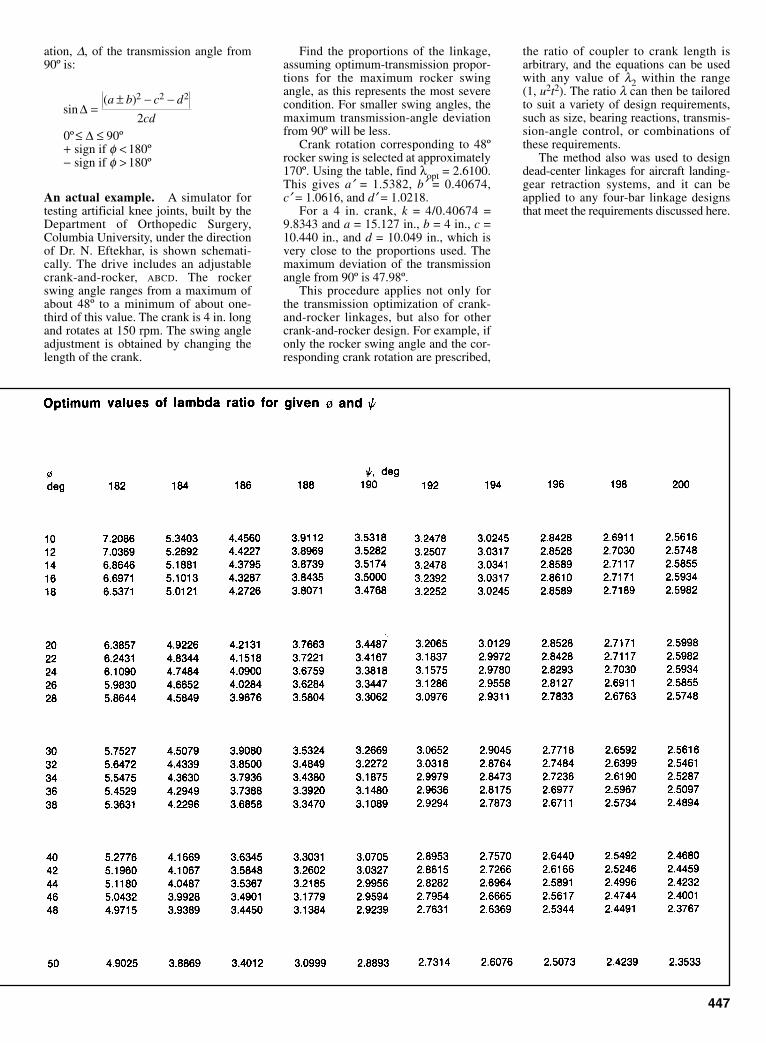
ation, ∆, of the transmission angle from90º is:
An actual example. A simulator fortesting artificial knee joints, built by theDepartment of Orthopedic Surgery,Columbia University, under the directionof Dr. N. Eftekhar, is shown schemati-cally. The drive includes an adjustablecrank-and-rocker, ABCD. The rockerswing angle ranges from a maximum ofabout 48º to a minimum of about one-third of this value. The crank is 4 in. longand rotates at 150 rpm. The swing angleadjustment is obtained by changing thelength of the crank.
sin( )
º ººº
∆
∆
=± − −
≤ ≤+ <− >
a b c d
cd
2 2 2
20 90
180180
sign if sign if
φφ
Find the proportions of the linkage,assuming optimum-transmission propor-tions for the maximum rocker swingangle, as this represents the most severecondition. For smaller swing angles, themaximum transmission-angle deviationfrom 90º will be less.
Crank rotation corresponding to 48ºrocker swing is selected at approximately170º. Using the table, find λopt = 2.6100.This gives a′ = 1.5382, b′ = 0.40674, c′ = 1.0616, and d′ = 1.0218.
For a 4 in. crank, k = 4/0.40674 =9.8343 and a = 15.127 in., b = 4 in., c =10.440 in., and d = 10.049 in., which isvery close to the proportions used. Themaximum deviation of the transmissionangle from 90º is 47.98º.
This procedure applies not only forthe transmission optimization of crank-and-rocker linkages, but also for othercrank-and-rocker design. For example, ifonly the rocker swing angle and the cor-responding crank rotation are prescribed,
the ratio of coupler to crank length isarbitrary, and the equations can be usedwith any value of λ2 within the range(1, u2t2). The ratio λ can then be tailoredto suit a variety of design requirements,such as size, bearing reactions, transmis-sion-angle control, or combinations ofthese requirements.
The method also was used to designdead-center linkages for aircraft landing-gear retraction systems, and it can beapplied to any four-bar linkage designsthat meet the requirements discussed here.
447
Sclater Chapter 13 5/3/01 1:32 PM Page 447

448
DESIGN CURVES AND EQUATIONS FOR GEAR-SLIDER MECHANISMS
What is a gear-slider mechanism? It islittle more than a crank-and-slider withtwo gears meshed in line with the crank(Fig. 1). But, because one of the gears(planet gear, 3) is prevented from rotat-ing because it is attached to the connect-ing rod, the output is taken from the sungear, not the slider. This produces a vari-ety of cyclic output motions, dependingon the proportions of the members.
In his investigation of the capabilitiesof the mechanism, Professor PrebenJensen of Bridgeport, Connecticutderived the equations defining its motionand acceleration characteristics. He thendevised some variations of his own (Figs.5 through 8). These, he believes, willoutperform the parent type. Jensen illus-trated how the output of one of the newmechanisms, Fig. 8, can come to dead
stop during each cycle, or progressivelyoscillate to new positions around theclock. A machine designer, therefore, canobtain a wide variety of intermittentmotions from the arrangement and, bycombining two of these units, he can tai-lor the dwell period of the mechanism tofit the automatic feed requirements of amachine.
Fig. 1 A basic gear-slider mechanism. It differs from the better known three-gear drive because a slider restricts the motion of the planet gear. The output istaken from the gear, which is concentric with the input shaft, and not from theslider.
Symbols
L = Length of connecting rod, in.r3 = radius of gear fixed to connecting rod,
in.r4 = radius of output gear, in.R = length of crank, in.α = angular acceleration of the input
crank, rad/sec2
β = connecting rod displacement, degγ = output rotation, degθ = input rotation, deg
θo = crank angle rotation during which theoutput gear reverses its motion, deg
φ = angle through which the output gearrotates back
ω = angular velocity of input crank, rad/sec
A single prime mark denotes angular veloc-ity, rad/sec; double prime marks denoteangular acceleration, rad/sec2.
Sclater Chapter 13 5/3/01 1:32 PM Page 448

The Basic Form
The input motion is to crank 1, and theoutput motion is from gear 4. As thecrank rotates, say counterclockwise, itcauses planet gear 3 to oscillate whilefollowing a satellite path around gear 4.This imparts a varying output motion togear 4, which rotates twice in the coun-terclockwise direction (when r3 = r4) forevery revolution of the input.
Jensen’s equations for angular dis-placement, velocity, and acceleration ofgear 4, when driven at a speed of ω bycrank 1, are as follows:
Angular Displacement
(1)
where β is computed from the followingrelationship (see the list of symbols inthis article):
(2)
Angular Velocity
(3)
where
(4)
Angular Acceleration
(5)
where
(6)
For a constant angular velocity, Eq. 5becomes
(7)
Design Charts
The equations were solved by ProfessorJensen for various L/R ratios and posi-tions of the crank angle θ to obtain thedesign charts in Figs. 2, 3, and 4. Thus,for a mechanism with
L = 12 in. r3 = 2.5R = 4 in. r4 = 1.5ω = 1000 per second
= radians per second
′′ = ′′γ βrr3
4
′′ =
−
−
βω
θ
θ2
2
22
3 2
1
1
RL
RL
RL
sin
sin
/
′′ = + + ′′γ α α βrr3
4( )
′ =
−
βω
θ
θ
RL R
L
cos
sin
/
12
2
1 2
′ = + + ′γ ω ω βrr3
4( )
sin sinβ θ= RL
γ θ θ β= + +rr3
4( )
449
Fig. 2 Angular displacement diagram for the connecting rod.
Fig. 3 Angular velocity curves for various crank angles.
Fig. 4 Angular acceleration curves for various crank angles.
Sclater Chapter 13 5/3/01 1:32 PM Page 449

the output velocity at crank angle θ = 60ºcan be computed as follows:
L/R = 12/4 = 3
From Fig. 3 β′/ω = 0.175
β′ = 0.175(1000) = 175 radians per second
From Eq. 3
γ = 2960 radians per second
Three-Gear Variation
One interesting variation, shown in Fig.5, is obtained by adding idler gear 5 tothe drive. If gears 3 and 4 are then madeequal in side, output gear 4 will thenoscillate with exactly the same motion asconnecting rod 2.
One use for this linkage, Jensen said,is in machinery where a sleeve is to rideconcentrically over an input shaft, andyet must oscillate to provide a reciprocat-
450
Gear-Slider Mechanisms (continued )
Fig. 5 Modified gear-slider mechanism.
Fig. 6 A ring-gear and slider mechanism. The ring gear isthe output and it replaces the center gear in Fig. 1.
Fig. 7 A more practical ring-gear and slider arrangement.The output is now from the smaller gear.
Fig. 8 Jensen’s model of the ring-gear and slider mecha-nism shown in Fig. 7. A progressive oscillation motion isobtained by making r4 greater than L-R.
ing motion. The shaft can drive thesleeve with this mechanism by makingthe sleeve part of the output gear.
Internal-Gear Variations
By replacing one of the external gears ofFig. 1 with an internal one, two mecha-nisms are obtained (Figs. 6 and 7) whichhave wider variable output abilities. Butit is the mechanism in Fig. 7 that inter-ested Jensen. This could be proportionedto give either a dwell or a progressiveoscillation, that is, one in which the out-put rotates forward, say 360º, turns backto 30º, moves forward 30º, and then pro-ceeds to repeat the cycle by moving for-ward again for 360º.
In this mechanism, the crank drivesthe large ring gear 3 which is fixed to theconnecting rod 2. Output is from gear 4.Jensen derived the following equations:
Output Motion
(8)
When r4 = L – R, then ω4 = 0 fromEq. 8, and the mechanism is propor-tioned to give instantaneous dwell. Toobtain a progressive oscillation, r4 must
ω ω44
41= − − −
L R rLr
R
Sclater Chapter 13 5/3/01 1:32 PM Page 450

be greater than L – R, as shown inJensen’s model (Fig. 8).
If gear 4 turns back and then startsmoving forward again, there must be twopositions where the motion of gear 4 iszero. Those two mechanisms are sym-metrical with respect to A0B. If θ0 equalsthe crank-angle rotation (of input), dur-ing which the output gear reverses itsmotion, and φ equals the angle throughwhich gear 4 rotates back, then
(9)
and
(10)
where
(11)
Chart for Proportioning
The chart in Fig. 9 helps proportion themechanism of Fig. 8 to provide a specifickind of progressive oscillation. It is set
sin sinβ θ0
0
2= R
L
γ = − −θ θ β03
40 0
rr
( )
cos( )
/θ0
2 2
4 4
1 2
2 2= −
+
L Rr R r
up for R equals 1 in. For other values ofR, convert the chart values for r4 propor-tionally, as shown below.
For example, assume that the outputgear, during each cycle, is to rotate back9.2º. Thus φ = 9.2º. Also given is R =0.75 in. and L = 1.5 in. Thus L/R = 2.
From the right side of the chart, go tothe φ-curve for L = 2, then upward to theθ0-curve for L = 2 in. Read θ0 = 82º at theleft ordinate.
Now return to the second intersectionpoint and proceed upward to read on theabscissa scale for L = 2, a value of r4 =1.5. Since R = 0.75 in., and the chart isfor R 1, convert r4 as follows: r4 = 0.75(1.5) = 1.13 in.
Thus, if the mechanism is built with anoutput gear of radius r4 = 1.13 in., thenduring 82º rotation of the crank, the out-put gear 4 will go back 9.2º. Of course,during the next 83º, gear 4 will havereversed back to its initial position—andthen will keep going forward for theremaining 194º of the crank rotation.
Future Modifications
The mechanism in Fig. 8 is designed topermit changing the output motion easilyfrom progressive oscillation to instanta-neous dwell or nonuniform CW or CCW
rotation. This is accomplished by shiftingthe position of the pin which acts as thesliding piece of the centric slider crank. Itis also possible to use an eccentric slidercrank, a four-bar linkage, or a sliding-block linkage as the basic mechanism.
Two mechanisms in series will givean output with either a prolonged dwellor two separate dwells. The anglebetween the separated dwells can beadjusted during its operation by interpos-ing a gear differential so that the positionof the output shaft of the first mechanismcan be changed relative to the position ofthe input shaft of the second mechanism.
The mechanism can also be improvedby introducing an additional link, B-B0,to guide pin B along a circular arc insteadof a linear track. This would result in aslight improvement in the performanceof the mechanism.
451
Fig. 9 A chart for proportioning a ring-gear and slider mechanism.
Sclater Chapter 13 5/3/01 1:33 PM Page 451

452
DESIGNING SNAP-ACTION TOGGLESTheory, formulas, and design charts are presented for determining toggle dimensions to maximize snap-action.
Over-centering toggle mechanisms, asshown in Fig. 1, are widely used inmechanical and electrical switches, latchmechanisms and mechanical overloadcontrols. These toggles also serve as:(1) detents (for holding other parts inselected position); (2) overload devicesin mechanical linkages (they shift to theopposite position when sufficientlyloaded); and (3) energy-storage devices.
Two applications, shown in Fig. 2,illustrate the snap-action of a toggle. Asthe toggle passes dead center, it issnapped ahead of the actuating force bythe toggle spring. In most applications,the objective is to obtain maximum snap-action.
Snap-action is a function of the elon-gation per length of the toggle spring as itmoves over dead center. Elongation atdead center is equal to:
J = K – H (1)
The elongation e in percent of length isequal to:
e = (100)J/S (2)
Because the resisting force of thespring increases with elongation butdecreases with an increase in length, theratio J/S should be as large as possiblewithin the capacity of the spring for thebest snap-action performance.
The ratio J/S as a function of angle θcan be derived as follows:
H = S – S cos ϕ (3)
and
K = A – A cos θ (4)
Substituting Eqs. (3) and (4) into Eq. (1),
J = A(1 – cos θ )– S(1 – cos ϕ) (5)
or
J/S = (A/S)(1 – cos θ)– (1 – cos ϕ) (6)
The relationship between θ and φ is:
L = A sin θ = S sin ϕor
sin ϕ = (A/S)(sin θ) (7)
By trigonometric identity,
sin θ = (1 – cos2 θ)1/2 (8)
Substituting Eq. (8) into Eq. (7) andsquaring both sides,
sin ϕ = (A/S)2(1 – cos2 θ) (9)
By trigonometric identity,
cos ϕ = (1 – sin2 ϕ)1/2 (10)
Substituting Eq. (9) into Eq. (10),
cos ϕ = [1 – (A/S)2
+(A/S)2 cos2 θ]1/2 (11)
and Eq. (11) into Eq. (6),
J/S = (A/S)(1 – cos θ) – 1+[1 – (A/S)(1 – cos θ) – 1–(A/S)2 cos1/2 (12)
Eq. (12) can be considered to haveonly three variables: (1) the spring elon-gation ratio J/S; (2) the toggle arm tospring length ratio, A/S; and (3) the tog-gle arm angle θ.
A series of curves are plotted fromEq. (12) showing the relationshipbetween J/S and A/S for various angles ofθ. The curves are illustrated in Fig. 3; forgreater accuracy each chart has a differ-ent vertical scale.
Maximum Snap-Action
Maximum snap-action for a particularangle occurs when J/S is a maximum.This can be determined by setting thefirst derivative of Eq. (12) equal to zeroand solving for A/S.
Differentiating Eq. (12),
(13)
Setting Eq. (13) Equal to zero and rear-ranging terms,
(14)
Cross-multiplying, squaring, and simpli-fying,
(S/A)2 – 1 + cos2 θ =cos2 θ + 2 cos θ + 1
Reducing,
(S/A)2 = 2 cos θ + 2
and finally simplifying to the followingequation is A/S when J/S is a maximum:
A/S = [2(cos θ + 1)]–1/2 (15)
coscos
/( / )[( / ) cos ] /
θθ
θ
−−
=
− +
11
1
2
2 2 1 2A S
A S S A
d J Sd A S
A S A SA S A S
( / )( / )
cos
[ ( / ) ( / )(cos )][ ( / ) ( / ) cos ] /
= − +
− +− +
1
2 22 1
2
2 2 2 1 2
θ
θθ
The maximum value of J/S can bedetermined by substituting Eq. (15) intoEq. (12):
(16)
which is simplified into the followingexpression:
(17)
The locus of points of J/Smax is astraight line function as shown in Fig. 3.It can be seen from Eq. (15) that thevalue of A/S at J/Smax varies from 0.500when θ = 0 to 0.707 when θ = 90º. Thisrelatively small range gives a quick rule-of-thumb to check if a mechanism hasbeen designed close to the maximumsnap-action point.
Elongation of the spring, Eq. (2), isbased on the assumption that the springis installed in its free length S with no ini-tial elongation. For a spring with a freelength E smaller than S, the total elonga-tion in percent when extended to thedead center position is:
e = 100[(S/E)(1 + J/S) – 1] (18)
The relationship between φ and θ atthe point of maximum snap-action forany value of θ is:
θ = 2ϕ (19)
This can be proved by substituting Eqs. (9)and (11) into the trigonometric identity:
cos 2ϕ = cos2 ϕ – sin2 ϕ (20)
and comparing the resulting equationwith one obtained by solving for cos θ inEq. (15). This relationship between theangles is another way to evaluate a tog-gle mechanism quickly.
Design Procedure
A toggle is usually designed to operatewithin certain space limitations. Whenthe dimensions X and W, as shown in Fig.4, are known, the angle θ resulting inmaximum snap-action can be determinedas follows:
A sin θ = S sin ϕ = W/2 (21)
Substituting Eq. (19) into Eq. (21),
A sin θ = S sin (θ /2) = W/2 (22)
J S/[ (cos )]
[ (cos )]max
/
/= − ++
2 2 12 1
1 2
1 2θ
θ
J S/cos
[ (cos )]
(cos )cos
(cos )
max /
/
= −+
− +
−+
++
12 1
1
11
2 1 2 1
1 2
2 1 2
θθ
θθ
θ
Sclater Chapter 13 5/3/01 1:33 PM Page 452
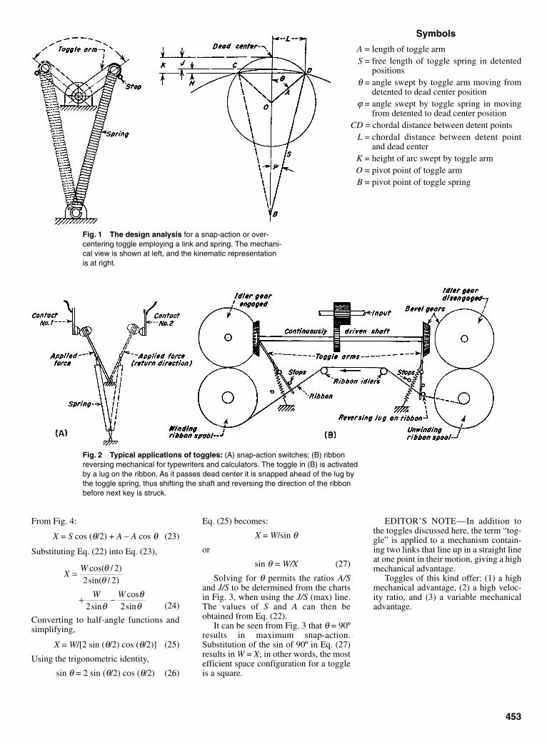
From Fig. 4:
X = S cos (θ/2) + A – A cos θ (23)
Substituting Eq. (22) into Eq. (23),
(24)
Converting to half-angle functions andsimplifying,
X = W/[2 sin (θ/2) cos (θ/2)] (25)
Using the trigonometric identity,
sin θ = 2 sin (θ/2) cos (θ/2) (26)
XW
W W
=
+ −
cos( / )sin( / )
sincossin
θθ
θθ
θ
22 2
2 2
Eq. (25) becomes:
X = W/sin θor
sin θ = W/X (27)
Solving for θ permits the ratios A/Sand J/S to be determined from the chartsin Fig. 3, when using the J/S (max) line.The values of S and A can then beobtained from Eq. (22).
It can be seen from Fig. 3 that θ = 90ºresults in maximum snap-action.Substitution of the sin of 90º in Eq. (27)results in W = X; in other words, the mostefficient space configuration for a toggleis a square.
EDITOR’S NOTE—In addition tothe toggles discussed here, the term “tog-gle” is applied to a mechanism contain-ing two links that line up in a straight lineat one point in their motion, giving a highmechanical advantage.
Toggles of this kind offer: (1) a highmechanical advantage, (2) a high veloc-ity ratio, and (3) a variable mechanicaladvantage.
453
Fig. 1 The design analysis for a snap-action or over-centering toggle employing a link and spring. The mechani-cal view is shown at left, and the kinematic representationis at right.
Symbols
A = length of toggle armS = free length of toggle spring in detented
positionsθ = angle swept by toggle arm moving from
detented to dead center positionϕ = angle swept by toggle spring in moving
from detented to dead center positionCD = chordal distance between detent points
L = chordal distance between detent pointand dead center
K = height of arc swept by toggle armO = pivot point of toggle armB = pivot point of toggle spring
Fig. 2 Typical applications of toggles: (A) snap-action switches; (B) ribbonreversing mechanical for typewriters and calculators. The toggle in (B) is activatedby a lug on the ribbon. As it passes dead center it is snapped ahead of the lug bythe toggle spring, thus shifting the shaft and reversing the direction of the ribbonbefore next key is struck.
Sclater Chapter 13 5/3/01 1:33 PM Page 453

454
Snap-Action Toggles (continued )
Fig. 3 Design charts for evaluat-ing toggle arm and spring length formaximum spring elongation. Chart(B) is an extension of chart (A).
Fig. 4 Designing a toggle to lie withinspace boundaries W and X. It can beshown that for maximum snap-action, sin θ= X/W.
Sclater Chapter 13 5/3/01 1:33 PM Page 454

455
FEEDER MECHANISMS FOR ANGULAR MOTIONSHow to use four-bar linkages to generate continuous or intermittent angular motions required by feeder mechanisms
In putting feeder mechanisms to work, it is often necessary tosynchronize two sets of angular motions. A four-bar linkageoffers one way. For example, in Fig. 1 two angular motions, φ12and φ13, must be synchronized with two others, ψ12 and ψ13,about the given pivot points A0 and B0 and the given crank lengthA0A. This means that crank length B0B. must be long enough sothat the resulting four-bar linkage will coordinate angularmotions φ12 and φ13 with ψ12 and ψ13. The procedure is:
1. Obtain point A′2 by revolving A2 about B0 through angle –ψ12but in the opposite direction.
2. Obtain point A′3 similarly by revolving A3 about B0 throughangle –ψ13.
3. Draw lines A1A′2 and A1A′3 and the perpendicular bisectors ofthe lines which intersect at desired point B1.
4. The quadrilateral A0A1B1B0 represents the four-bar linkagethat will produce the required relationship between theangles φ12, φ13, and ψ12, ψ13.
Three angles with four relative positions can be synchronizedin a similar way. Figure 2 shows how to synchronize angles ψ12,ψ13,ψ14 with corresponding angles ψ12, ψ13, and ψ14, usingfreely chosen pivot points A0 and B0. In this case, crank lengthA0A as well as B0B is to be determined, and the procedure is:
1. Locate pivot points A0 and B0 on a line those bisects angleA3A0A4, the length A0B0 being arbitrary.
2. Measure off 1⁄2 of angle B3B0B4 and with this angle drawB0A4 which establishes crank length A0A at intersection ofA0A4. This also establishes points A3, A2 and A1.
3. WithB0 as center and B0B4 as radius mark off angles –ψ14,–ψ13, –ψ12, the negative sign indicating they are in oppositesense to ψ14, ψ13 and ψ12. This establishes points A′2, A′3 andA′4, but here A′3 and A′4 coincide because of symmetry of A3and A4 about A0B0.
4. Draw lines A1A′2 and A1A′4, and the perpendicular bisectorsof these lines, which intersect at the desired point B1.
5. The quadrilateral A0A1B0B1 represents the four-bar linkagethat will produce the required relationship between theangles φ12, φ13, φ14, and ψ12, ψ13, ψ14.
The illustrations show how these angles must be coordinatedwithin the given space. In Fig. 3A, input angles of the crank mustbe coordinated with the output angles of the forked escapement.In Fig. 3B, input angles of the crank are coordinated with the out-put angles of the tilting hopper. In Fig. 3C, the input angles of thecrank are coordinated with the output angles of the segment. InFig. 3D, a box on a conveyor is tilted 90º by an output crank,which is actuated by an input crank through a coupler. Othermechanisms shown can also coordinate the input and outputangles; some have dwell periods between the cycles, others givea linear output with dwell periods.
Fig. 1 Four-bar linkage synchronizes two angular movements, φ12and φ13, with ψ12, and ψ14.
Fig. 2 Three angular positions, φ12, φ13, φ14, are synchronized byfour-bar linkage here with ψ12, ψ13, and ψ14.
Sclater Chapter 13 5/3/01 1:33 PM Page 455
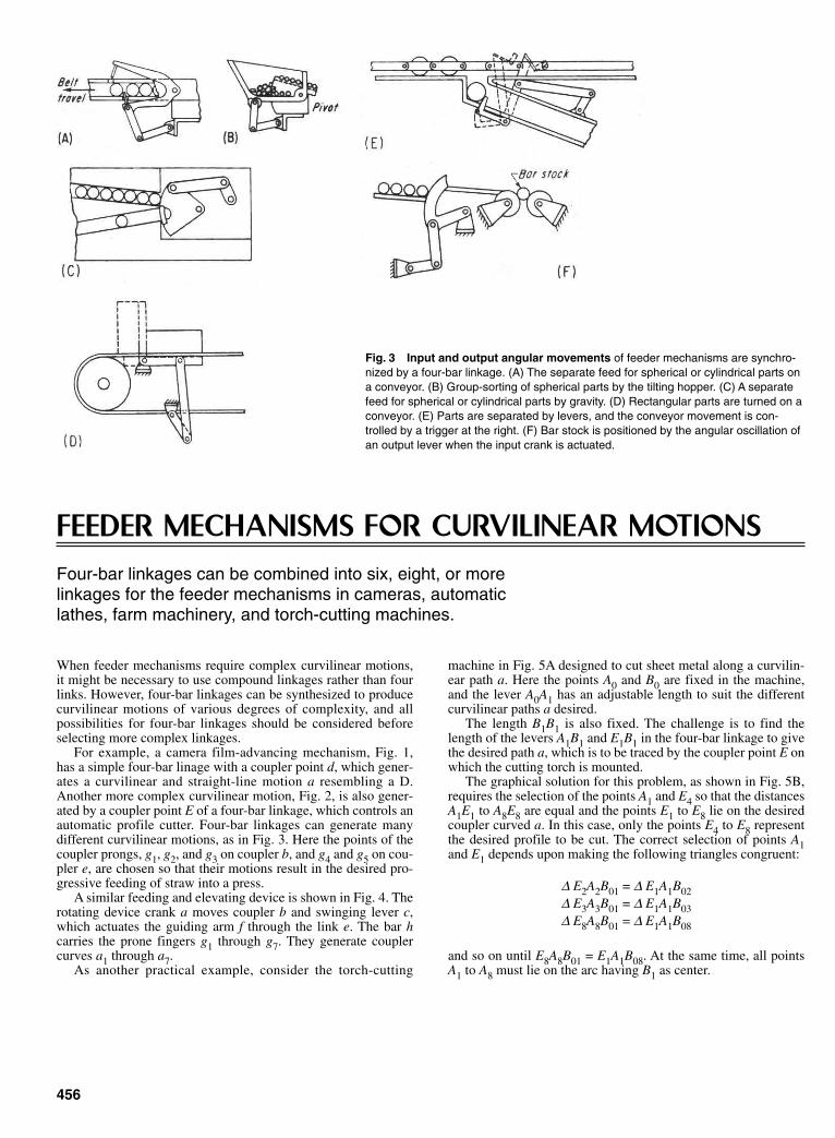
FEEDER MECHANISMS FOR CURVILINEAR MOTIONSFour-bar linkages can be combined into six, eight, or more linkages for the feeder mechanisms in cameras, automatic lathes, farm machinery, and torch-cutting machines.
When feeder mechanisms require complex curvilinear motions,it might be necessary to use compound linkages rather than fourlinks. However, four-bar linkages can be synthesized to producecurvilinear motions of various degrees of complexity, and allpossibilities for four-bar linkages should be considered beforeselecting more complex linkages.
For example, a camera film-advancing mechanism, Fig. 1,has a simple four-bar linage with a coupler point d, which gener-ates a curvilinear and straight-line motion a resembling a D.Another more complex curvilinear motion, Fig. 2, is also gener-ated by a coupler point E of a four-bar linkage, which controls anautomatic profile cutter. Four-bar linkages can generate manydifferent curvilinear motions, as in Fig. 3. Here the points of thecoupler prongs, g1, g2, and g3 on coupler b, and g4 and g5 on cou-pler e, are chosen so that their motions result in the desired pro-gressive feeding of straw into a press.
A similar feeding and elevating device is shown in Fig. 4. Therotating device crank a moves coupler b and swinging lever c,which actuates the guiding arm f through the link e. The bar hcarries the prone fingers g1 through g7. They generate couplercurves a1 through a7.
As another practical example, consider the torch-cutting
machine in Fig. 5A designed to cut sheet metal along a curvilin-ear path a. Here the points A0 and B0 are fixed in the machine,and the lever A0A1 has an adjustable length to suit the differentcurvilinear paths a desired.
The length B1B1 is also fixed. The challenge is to find thelength of the levers A1B1 and E1B1 in the four-bar linkage to givethe desired path a, which is to be traced by the coupler point E onwhich the cutting torch is mounted.
The graphical solution for this problem, as shown in Fig. 5B,requires the selection of the points A1 and E4 so that the distancesA1E1 to A8E8 are equal and the points E1 to E8 lie on the desiredcoupler curved a. In this case, only the points E4 to E8 representthe desired profile to be cut. The correct selection of points A1and E1 depends upon making the following triangles congruent:
∆ E2A2B01 = ∆ E1A1B02∆ E3A3B01 = ∆ E1A1B03∆ E8A8B01 = ∆ E1A1B08
and so on until E8A8B01 = E1A1B08. At the same time, all pointsA1 to A8 must lie on the arc having B1 as center.
456
Fig. 3 Input and output angular movements of feeder mechanisms are synchro-nized by a four-bar linkage. (A) The separate feed for spherical or cylindrical parts ona conveyor. (B) Group-sorting of spherical parts by the tilting hopper. (C) A separatefeed for spherical or cylindrical parts by gravity. (D) Rectangular parts are turned on aconveyor. (E) Parts are separated by levers, and the conveyor movement is con-trolled by a trigger at the right. (F) Bar stock is positioned by the angular oscillation ofan output lever when the input crank is actuated.
Sclater Chapter 13 5/3/01 1:33 PM Page 456
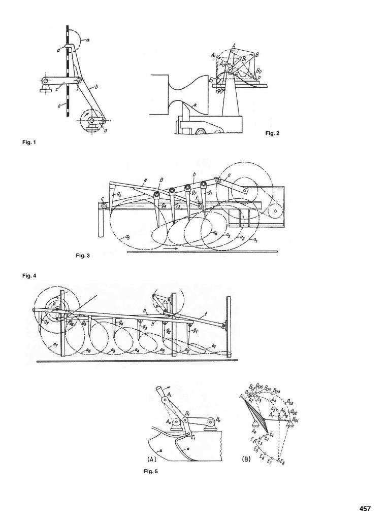
457
Fig. 1
Fig. 2
Fig. 3
Fig. 4
Fig. 5
Sclater Chapter 13 5/3/01 1:33 PM Page 457
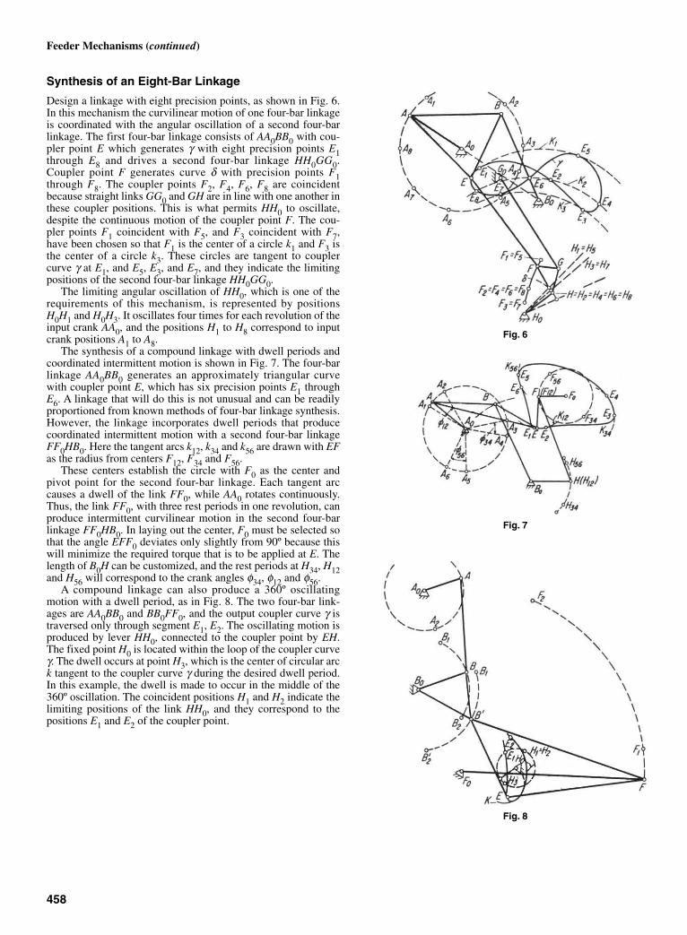
Synthesis of an Eight-Bar Linkage
Design a linkage with eight precision points, as shown in Fig. 6.In this mechanism the curvilinear motion of one four-bar linkageis coordinated with the angular oscillation of a second four-barlinkage. The first four-bar linkage consists of AA0BB0 with cou-pler point E which generates γ with eight precision points E1through E8 and drives a second four-bar linkage HH0GG0.Coupler point F generates curve δ with precision points F1through F8. The coupler points F2, F4, F6, F8 are coincidentbecause straight links GG0 and GH are in line with one another inthese coupler positions. This is what permits HH0 to oscillate,despite the continuous motion of the coupler point F. The cou-pler points F1 coincident with F5, and F3 coincident with F7,have been chosen so that F1 is the center of a circle k1 and F3 isthe center of a circle k3. These circles are tangent to couplercurve γ at E1, and E5, E3, and E7, and they indicate the limitingpositions of the second four-bar linkage HH0GG0.
The limiting angular oscillation of HH0, which is one of therequirements of this mechanism, is represented by positionsH0H1 and H0H3. It oscillates four times for each revolution of theinput crank AA0, and the positions H1 to H8 correspond to inputcrank positions A1 to A8.
The synthesis of a compound linkage with dwell periods andcoordinated intermittent motion is shown in Fig. 7. The four-barlinkage AA0BB0 generates an approximately triangular curvewith coupler point E, which has six precision points E1 throughE6. A linkage that will do this is not unusual and can be readilyproportioned from known methods of four-bar linkage synthesis.However, the linkage incorporates dwell periods that producecoordinated intermittent motion with a second four-bar linkageFF0HB0. Here the tangent arcs k12, k34 and k56 are drawn with EFas the radius from centers F12, F34 and F56.
These centers establish the circle with F0 as the center andpivot point for the second four-bar linkage. Each tangent arccauses a dwell of the link FF0, while AA0 rotates continuously.Thus, the link FF0, with three rest periods in one revolution, canproduce intermittent curvilinear motion in the second four-barlinkage FF0HB0. In laying out the center, F0 must be selected sothat the angle EFF0 deviates only slightly from 90º because thiswill minimize the required torque that is to be applied at E. Thelength of B0H can be customized, and the rest periods at H34, H12and H56 will correspond to the crank angles φ34, φ12 and φ56.
A compound linkage can also produce a 360º oscillatingmotion with a dwell period, as in Fig. 8. The two four-bar link-ages are AA0BB0 and BB0FF0, and the output coupler curve γ istraversed only through segment E1, E2. The oscillating motion isproduced by lever HH0, connected to the coupler point by EH.The fixed point H0 is located within the loop of the coupler curveγ. The dwell occurs at point H3, which is the center of circular arck tangent to the coupler curve γ during the desired dwell period.In this example, the dwell is made to occur in the middle of the360º oscillation. The coincident positions H1 and H2 indicate thelimiting positions of the link HH0, and they correspond to thepositions E1 and E2 of the coupler point.
458
Feeder Mechanisms (continued)
Fig. 6
Fig. 7
Fig. 8
Sclater Chapter 13 5/3/01 1:33 PM Page 458

459
ROBERTS’ LAW HELPS TO FIND ALTERNATE FOUR-BAR LINKAGESThe three linkage examples
When a four-bar linkage has been designed or selected from acatalog to produce a desired coupler curve, it is often found thatone of the pivot points is inconveniently located or that the trans-mission angles are not suitable. (A coupler curve is produced bya point on the connecting rod joining the two cranks of the four-bar linkage). According to Roberts’ Law there are at least twoother four-bar linkages that will generate the same coupler curve.One of these linkages might be more suitable for the application.
Robert’s Law states that the two alternate linkages are relatedto the first by a series of similar triangles. This leads to graphicalsolutions; three examples are shown. The first involves similartriangles, the second is a more convenient step-by-step method,and the third illustrates the solution of a special case where thecoupler point lies along the connecting rod.
Method of Similar Triangles
Four-bar linkage ABCD in Fig. 1 uses point P, which is actuallyan extension of the connecting rod BC, to produce desired curve.Point E is found by constructing EP parallel to AB, and EA paral-lel to PB. Then triangle EFP is constructed similar to triangleBPC. This calls for laying out angles a and β.
Point H is found in a similar way, and point G is located bydrawing GH parallel to FP and GF parallel to HP.
The two alternate linkages to ABCD are GFEA and GHID. Alluse point P to produce the desired curve, and given any one ofthe three, the other two can be determined.
The Step-by-Step Method
With the similar-triangle method just described, slight errors inconstructing the proper angles lead to large errors in link dimen-sions. The construction of angles can be avoided by laying off thelink lengths along a straight line.
Thus, linkage ABCD in Fig. 2 is laid off as a straight line fromA to Din Fig. 3. Included in the transfers is point P. PointsEFGHI are quickly found by either extending the original linesor constructing parallel lines. Fig. 3, which now has all the cor-rect dimensions of all the links, is placed under a sheet of tracingpaper and, with the aid of a compass, links AB and CD are rotated(see Fig. 4) so that linkage ABCD is identical to that in Fig. 2.Links PEF and PHI are rotated parallel to AB and CD, respec-
tively. Completion of the parallelogram gives the two alternatelinkages, AEFG and GHID.
Special Case
It is not uncommon for the coupler point P to lie on a linethrough BC, as in Fig. 5. Links EA, EP and ID can be foundquickly by constructing the appropriate parallel lines. Point G islocated by using the proportion: CB:BP = DA:AG. Points H and Fare then located by drawing lines parallel to AB and CD.
Fig. 1 The method of similartriangles.
Fig. 2, 3, 4 A step-by-stepmethod.
Fig. 5 This special caseshows the simplicity of applyingRoberts’ Law.
Sclater Chapter 13 5/3/01 1:33 PM Page 459
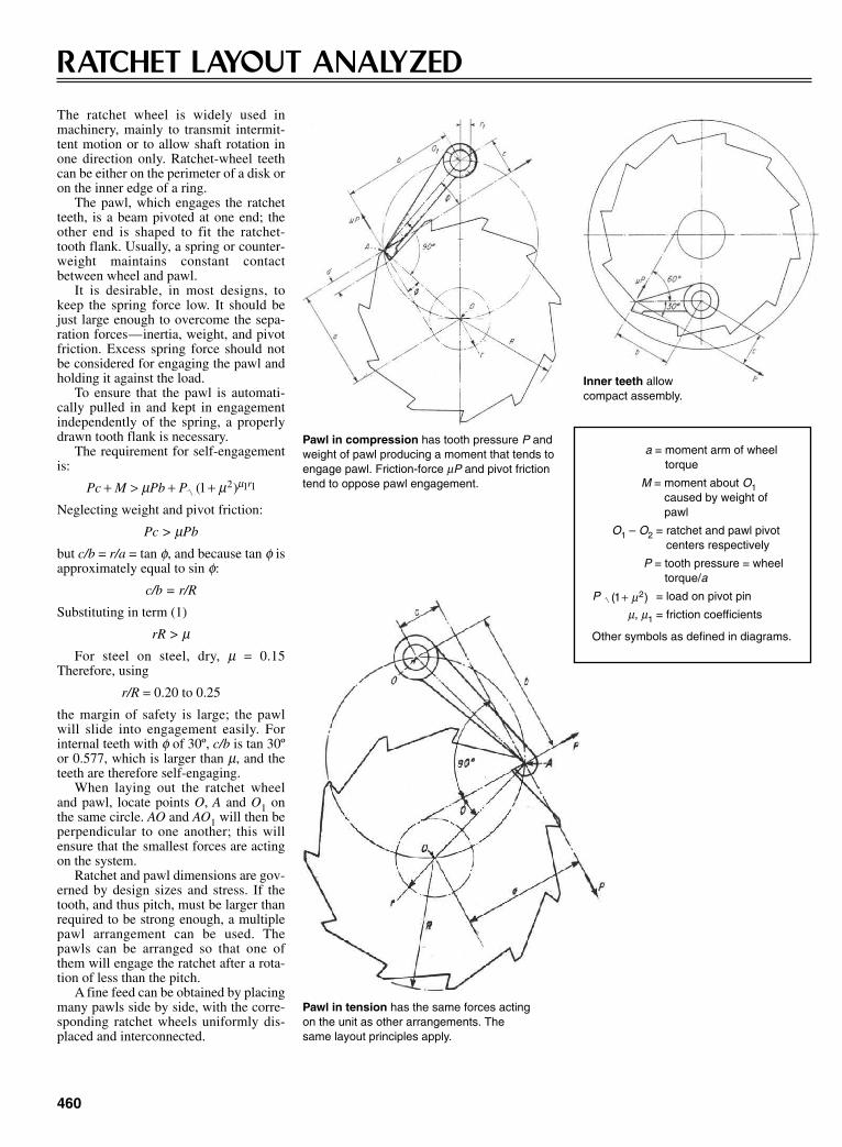
460
RATCHET LAYOUT ANALYZED
The ratchet wheel is widely used inmachinery, mainly to transmit intermit-tent motion or to allow shaft rotation inone direction only. Ratchet-wheel teethcan be either on the perimeter of a disk oron the inner edge of a ring.
The pawl, which engages the ratchetteeth, is a beam pivoted at one end; theother end is shaped to fit the ratchet-tooth flank. Usually, a spring or counter-weight maintains constant contactbetween wheel and pawl.
It is desirable, in most designs, tokeep the spring force low. It should bejust large enough to overcome the sepa-ration forces—inertia, weight, and pivotfriction. Excess spring force should notbe considered for engaging the pawl andholding it against the load.
To ensure that the pawl is automati-cally pulled in and kept in engagementindependently of the spring, a properlydrawn tooth flank is necessary.
The requirement for self-engagementis:
Neglecting weight and pivot friction:
Pc > µPb
but c/b = r/a = tan φ, and because tan φ isapproximately equal to sin φ:
c/b = r/R
Substituting in term (1)
rR > µFor steel on steel, dry, µ = 0.15
Therefore, using
r/R = 0.20 to 0.25
the margin of safety is large; the pawlwill slide into engagement easily. Forinternal teeth with φ of 30º, c/b is tan 30ºor 0.577, which is larger than µ, and theteeth are therefore self-engaging.
When laying out the ratchet wheeland pawl, locate points O, A and O1 onthe same circle. AO and AO1 will then beperpendicular to one another; this willensure that the smallest forces are actingon the system.
Ratchet and pawl dimensions are gov-erned by design sizes and stress. If thetooth, and thus pitch, must be larger thanrequired to be strong enough, a multiplepawl arrangement can be used. Thepawls can be arranged so that one ofthem will engage the ratchet after a rota-tion of less than the pitch.
A fine feed can be obtained by placingmany pawls side by side, with the corre-sponding ratchet wheels uniformly dis-placed and interconnected.
Pc M Pb P r+ > + +µ µ µ( )1 2 1 1
Pawl in compression has tooth pressure P andweight of pawl producing a moment that tends toengage pawl. Friction-force µP and pivot frictiontend to oppose pawl engagement.
Inner teeth allowcompact assembly.
Pawl in tension has the same forces actingon the unit as other arrangements. Thesame layout principles apply.
a = moment arm of wheeltorque
M = moment about O1caused by weight ofpawl
O1 – O2 = ratchet and pawl pivotcenters respectively
P = tooth pressure = wheeltorque/a
P = load on pivot pin
µ, µ1 = friction coefficients
Other symbols as defined in diagrams.
( )1 2+ µ
Sclater Chapter 13 5/3/01 1:33 PM Page 460

461
SLIDER-CRANK MECHANISM
The slider crank, an efficient mechanismfor changing reciprocating motion torotary motion, is widely used in engines,pumps, automatic machinery, andmachine tools.
The equations developed here forfinding these factors are in a more sim-plified form than is generally found intext books.
SYMBOLSL = length of connecting rodR = crank length; radius of crank circlex = distance from center of crankshaft A
to wrist pin Cx′ = slider velocity (linear velocity of
point C)x″ = slider accelerationθ = crank angle measured from dead cen-
ter (when slider is fully extended)φ = angular position of connecting rod; φ
= 0 when θ = 0φ′ = connecting-rod angular velocity =
dφ/dtφ″ = connecting-rod angular acceleration
= d2φ/dl2
ω = constant crank angle velocity
Displacement of sliderx = L cos φ + R cos φ
Also:
Angular velocity of the connecting rod
Linear velocity of the piston
Angular acceleration of the connecting rod
cos sin
( / )cos[ ( / ) sin ]
sin
( / )sin [( / )
/
/
φ θ
φ = ω θθ
ω φω
θ
φ ω θ
= −
′−
′ = − + ′
′′ = −
1
1
1
1
22
1 2
2 2 1 2
2 2
RL
R LR L
xL
RL
R L R L ]][ ( / ) sin ]
cos sin cos
/1 2 2 3 2
22
−
′′ = −
+ ′′ + ′
R L
xL
RL
θ
ω θ φω
θ φω
θ
Slider acceleration
Sclater Chapter 13 5/3/01 1:33 PM Page 461

CHAPTER 14NEW DIRECTIONS IN
MACHINE DESIGN
Sclater Chapter 14 5/3/01 1:44 PM Page 463

464
SOFTWARE IMPROVEMENTS EXPAND CAD CAPABILITIES
Computer Aided Design (CAD) is a computer-based technologythat allows a designer to draw and label the engineering details ofa product or project electronically on a computer screen whilerelegating drawing reproduction to a printer or X-Y plotter. Italso permits designers in different locations to collaborate in thedesign process via a computer network and permits the drawingto be stored digitally in computer memory for ready reference.CAD has done for engineering graphics what the word processordid for writing. The introduction of CAD in the late 1960schanged the traditional method of drafting forever by relievingthe designer of the tedious and time-consuming tasks of manualdrawing from scratch, inking, and dimensioning on a conven-tional drawing board.
While CAD offers many benefits to designers or engineersnever before possible, it does not relieve them of the requirementfor extensive technical training and wide background knowledgeof drawing standards and practice if professional work is to beaccomplished. Moreover, in making the transition from the draw-ing board to the CAD workstation, the designer must spend thetime and make the effort to master the complexities of the spe-cific CAD software systems in use, particularly how to make themost effective use of the icons that appear on the screen.
The discovery of the principles of 3D isometric and perspec-tive drawing in the Middle Ages resulted in a more realistic andaccurate portrayal of objects than 2D drawings, and they con-veyed at a glance more information about that object, but makinga 3D drawing manually was then and is still more difficult andtime-consuming, calling for a higher level of drawing skill.Another transition is required for the designer moving up from2D to 3D drawing, contouring, and shading.
The D in CAD stands for design, but CAD in its present stateis still essentially “computer-aided drawing” because the user,not the computer, must do the designing. Most commercial CADprograms permit lettering, callouts, and the entry of notes andparts lists, and some even offer the capability for calculating suchphysical properties as volume, weight, and center of gravity if thedrawing meets certain baseline criteria. Meanwhile, CAD soft-ware developers are busy adding more automated features totheir systems to move them closer to being true design programsand more user-friendly. For example, CAD techniques nowavailable can perform analysis and simulation of the design aswell as generate manufacturing instructions. These features arebeing integrated with the code for modeling the form and struc-ture of the design.
In its early days, CAD required at least the computing powerof a minicomputer and the available CAD software was largelyapplication specific and limited in capability. CAD systems wereneither practical nor affordable for most design offices and inde-pendent consultants. As custom software became more sophisti-cated and costly, even more powerful workstations were requiredto support them, raising the cost of entry into CAD even higher.Fortunately, with the rapid increases in the speed and power ofmicroprocessors and memories, desktop personal computers rap-idly began to close the gap with workstations even as their pricesfell. Before long, high-end PCs become acceptable low-costCAD platforms. When commercial CAD software producersaddressed that market sector with lower-cost but highly effectivesoftware packages, their sales surged.
PCs that include high-speed microprocessors, Windows oper-ating systems, and sufficient RAM and hard-drive capacity cannow run software that rivals the most advanced custom Unix-based products of a few years ago. Now both 2D and 3D CAD
software packages provide professional results when run on off-the-shelf personal computers. The many options available incommercial CAD software include
• 2D drafting• 3D wireframe and surface modeling• 3D solid modeling• 3D feature-based solid modeling• 3D hybrid surface and solid modeling
Two-Dimensional Drafting
Two-dimensional drafting software for mechanical design isfocused on drawing and dimensioning traditional engineeringdrawings. This CAD software was readily accepted by engineers,designers, and draftspersons with many years of experience.They felt comfortable with it because it automated their custom-ary design changes, provided a way to make design changesquickly, and also permitted them to reuse their CAD data for newlayouts.
A typical 2D CAD software package includes a completelibrary of geometric entities. It can also support curves, splines,and polylines as well as define hatching patterns and place hatch-ing within complex boundaries. Other features include the abilityto perform associative hatching and provide complete dimen-sioning. Some 2D packages can also generate bills of materials.2D drawing and detailing software packages are based on ANSI,ISO, DIN, and JIS drafting standards.
In a 2D CAD drawing, an object must be described by multi-ple 2D views, generally three or more, to reveal profile and inter-nal geometry from specific viewpoints. Each view of the objectis created independently from other views. However, 2D viewstypically contain many visible and hidden lines, dimensions, andother detailing features. Unless careful checks of the finisheddrawing are made, mistakes in drawing or dimensioning intricatedetails can be overlooked. These can lead to costly problemsdownstream in the product design cycle. Also, when a change is
A three-dimensional “wireframe” drawing of two meshed gearsmade on a personal computer using software that cost less than$500. (Courtesy of American Small Business Computers, Inc.)
Sclater Chapter 14 5/3/01 1:44 PM Page 464

made, each view must be individually updated. One way to avoidthis problem (or lessen the probability that errors will go unde-tected) is to migrate upward to a 3D CAD system
Three-Dimensional Wireframe and Surface Modeling
A 3D drawing provides more visual impact than a 2D drawingbecause it portrays the subject more realistically and its valuedoes not depend on the viewer’s ability to read and interpret themultiple drawings in a 2D layout. Of more importance to thedesigner or engineer, the 3D presentation consolidates importantinformation about a design, making it easier and faster to detectdesign flaws. Typically a 3D CAD model can be created withfewer steps than are required to produce a 2D CAD layout.Moreover, the data generated in producing a 3D model can beused to generate a 2D CAD layout, and this information can bepreserved throughout the product design cycle. In addition, 3Dmodels can be created in the orthographic or perspective modesand rotated to any position in 3D space.
The wireframe model, the simplest of the 3D presentations, isuseful for most mechanical design work and might be all that isneeded for many applications where 3D solid modeling is notrequired. It is the easiest 3D system to migrate to when makingthe transition from 2D to 3D drawing. A wireframe model is ade-quate for illustrating new concepts, and it can also be used tobuild on existing wireframe designs to create models of workingassemblies.
Wireframe models can be quickly edited during the conceptphase of the design without having to maintain complex solid-face relationships or parametric constraints. In wireframe model-ing only edge information is stored, so data files can be signifi-cantly smaller than for other 3D modeling techniques. This canincrease productivity and conserve available computer memory.
465
The unification of multiple 2D views into a single 3D viewfor modeling a complex machine design with many componentspermits the data for the entire machine to be stored and managedin a single wireframe file rather than many separate files. Also,model properties such as color, line style, and line width can becontrolled independently to make component parts more visuallydistinctive.
The construction of a wireframe structure is the first step inthe preparation of a 3D surface model. Many commercial CADsoftware packages include surface modeling with wireframecapability. The designer can then use available surface-modelingtools to apply a “skin” over the wire framework to convert it to asurface model whose exterior shape depends on the geometry ofthe wireframe.
One major advantage of surface modeling is its ability to pro-vide the user with visual feedback. A wireframe model does notreadily show any gaps, protrusions, and other defects. By makinguse of dynamic rotation features as well as shading, the designeris better able to evaluate the model. Accurate 2D views can alsobe generated from the surface model data for detailing purposes.Surface models can also be used to generate tool paths fornumerically controlled (NC) machining. Computer-aided manu-facturing (CAM) applications require accurate surface geometryfor the manufacture of mechanical products.
Yet another application for surface modeling is its use in thepreparation of photorealistic graphics of the end product. Thiscapability is especially valued in consumer product design,where graphics stress the aesthetics of the model rather than itsprecision.
Some wireframe software also includes data translators,libraries of machine design elements and icons, and 2D draftingand detailing capability, which support design collaboration andcompatibility among CAD, CAM, and computer-aided engineer-ing (CAE) applications. Designers and engineers can store anduse data accumulated during the design process. This data per-
A three-dimensional “wireframe” drawing of a single-drawing model airplane engine showing theprincipal contours of both propeller and engine. This also was drawn on a personal computer usingsoftware that cost less than $500. (Courtesy of American Small Business Computers, Inc.)
Sclater Chapter 14 5/3/01 1:44 PM Page 465

3D illustration of an indexing wheel drawn with3D solid modeling software. Courtesy ofSolidWorks Corporation
3D illustration of the ski suspension mechanismof a bobsled drawn with 3D modeling software.Courtesy of SolidWorks Corporation
mits product manufacturers with compatible software to receive2D and 3D wireframe data from other CAD systems.
Among the features being offered in commercial wireframesoftware are:
• Basic dimensioning, dual dimensioning, balloon notes,datums, and section lines.
• Automated geometric dimensioning and tolerancing(GD&T).
• Symbol creation, including those for weld and surface finish,with real-time edit or move capability and leaders.
• A library of symbols for sheet metal, welding, electrical pip-ing, fluid power, and flow chart applications.
Data translators provide an effective and efficient means fortransferring information from the source CAD design station tooutside contract design offices, manufacturing plants, or engi-neering analysis consultants, job shops, and product develop-ment services. These include IGES, DXF, DWG, STL, CADL,and VRML.
Three-Dimensional Solid Modeling
CAD solid-modeling programs can perform many more func-tions than simple 3D wireframe modelers. These programs areused to form models that are solid objects rather than simple 3Dline drawings. Because these models are represented as solids,
they are the source of data that permits the physical properties ofthe parts to be calculated.
Some solid-modeling software packages provide fundamentalanalysis features. With the assignment of density values for avariety of materials to the solid model, such vital statistics asstrength and weight can be determined. Mass properties such asarea, volume, moment of inertia, and center of gravity can be cal-culated for regularly and irregularly shaped parts. Finite elementanalysis software permits the designer to investigate stress, kine-matics, and other factors useful in optimizing a part or compo-nent in an assembly. Also, solid models can provide the basicdata needed for rapid prototyping using stereolithography, andcan be useful in CAM software programs.
Most CAD solid-model software includes a library of primi-tive 3D shapes such as rectangular prisms, spheres, cylinders,and cones. Using Boolean operations for forming unions, sub-tractions, and intersections, these components can be added, sub-tracted, intersected, and sectioned to form complex 3D assem-blies. Shading can be used to make the solid model easier for theviewers to comprehend. Precise 2D standard, isometric, and aux-iliary views as well as cross sections can be extracted from thesolid modeling data, and the cross sections can be cross-hatched.
Three-Dimensional Feature-Based Solid Modeling
3D feature-based solid modeling starts with one or more wire-frame profiles. It creates a solid model by extruding, sweeping,revolving, or skinning these profiles. Boolean operations can
466
Sclater Chapter 14 5/3/01 1:44 PM Page 466

also be used on the profiles as well as the solids generated fromthese profiles. Solids can also be created by combining surfaces,including those with complex shapes. For example, this tech-nique can be used to model streamlined shapes such as those of aship’s hull, racing-car’s body, or aircraft.
3D feature-based solid modeling allows the designer to createsuch features as holes, fillets, chamfers, bosses, and pockets, andcombine them with specific edges and faces of the model. If adesign change causes the edges or faces to move, the features canbe regenerated so that they move with the changes to keep theiroriginal relationships.
However, to use this system effectively, the designer mustmake the right dimensioning choices when developing these mod-els, because if the features are not correctly referenced, they couldend up the wrong location when the model is regenerated. Forexample, a feature that is positioned from the edge of an objectrather than from its center might no longer be centered when themodel is regenerated. The way to avoid this is to add constraintsto the model that will keep the feature at the center of the face.
The key benefit of the parametric feature of solid modeling isthat it provides a method for facilitating change. It imposesdimensional constraints on the model that permit the design tomeet specific requirements for size and shape. This software per-mits the use of constraint equations that govern relationshipsbetween parameters. If some parameters remain constant or aspecific parameter depends on the values of others, these rela-tionships will be maintained throughout the design process. Thisform of modeling is useful if the design is restricted by spaceallowed for the end product or if its parts such as pipes or wiringmust mate precisely with existing pipes or conduits.
Thus, in a parametric model, each entity, such as a line or arcin a wireframe, or fillet, is constrained by dimensional parame-ters. For example, in the model of a rectangular object, theseparameters can control its geometric properties such as thelength, width, and height. The parametric feature allows thedesigner to make changes as required to create the desired model.This software uses stored historical records that have recordedthe steps in producing the model so that if the parameters of themodel are changed, the software refers to the stored history andrepeats the sequence of operations to create a new model forregeneration. Parametric modeling can also be used in trial-and-error operations to determine the optimum size of a componentbest suited for an application, either from an engineering or aes-thetic viewpoint, simply by adjusting the parameters and regen-erating a new model.
Parametric modeling features will also allow other methodsof relating entities. Design features can, for example, be locatedat the origin of curves, at the end of lines or arcs, at vertices, or atthe midpoints of lines and faces, and they can also be located at aspecified distance or at the end of a vector from these points.When the model is regenerated, these relationships will be main-tained. Some software systems also allow geometric constraintsbetween features. These can mandate that the features be parallel,tangent, or perpendicular.
Some parametric modeling features of software combinefreeform solid modeling, parametric solid modeling, surfacemodeling, and wireframe modeling to produce true hybrid mod-els. Its features typically include hidden line removal, associativelayouts, photorealistic rendering, attribute masking, and levelmanagement.
Three-Dimensional Hybrid Surface and SolidModelingSome modeling techniques are more efficient that others. Forexample, some are better for surfacing the more complex shapes aswell as organic and freeform shapes. Consequently, commercialsoftware producers offer 3D hybrid surface and solid-modelingsuites that integrate 2D drafting and 3D wireframe with 3D surfaceand 3D solid modeling into a single CAD package. Included in
these packages might also be software for photorealistic renderingand data translators to transport all types of data from the compo-nent parts of the package to other CAD or CAM software.
Glossary of Commonly Used CAD Terms
absolute coordinates: Distances measured from a fixed refer-ence point, such as the origin, on the computer screen.
ANSI: An abbreviation for the American National StandardsInstitute.
associative dimensions: A method of dimensioning in CADsoftware that automatically updates dimension values whendimension size is changed.
Boolean modeling: A CAD 3D modeling technique that permitsthe user to add or subtract 3D shapes from one model toanother.
Cartesian coordinates: A rectangular system for locating pointsin a drawing area in which the origin point is the 0,0 locationand X represents length, Y width, and Z height. The surfacesbetween them can be designated as the X–Z, X–Y, and Y–Zplanes.
composite drawing: A drawing containing multiple drawings inthe form of CAD layers.
DXF: An abbreviation for Data Exchange Format, a standardformat or translator for transferring data describing CADdrawings between different CAD programs.
FEM: An acronym for Finite Element Method for CAD struc-tural design.
FTD: An abbreviation for File Transfer Protocol for upload anddownload of files to the Internet.
function: A task in a CAD program that can be completed byissuing a set of commands.
GD&T: An automated geometric, dimensioning, and tolerancingfeature of CAD software.
GIS: An abbreviation for Geographic Information System.IGES: An abbreviation for International Graphics Exchange
Specification, a standard format or translator for transferringCAD data between different programs.
ISO: An abbreviation for International Standards Organization.linear extrusion: A 3D technique that projects 2D into 3D
shapes along a linear path.MCAD: An abbreviation for mechanical CAD.menu: A set of modeling functions or commands that are dis-
played on the computer screen. Options can be selected fromthe menu by a pointing device such as a mouse.
object snaps: A method for indicating point locations on existingdrawings as references.
origin point: The 0,0 location in the coordinate system.parametric modeling: CAD software that links the 3D drawing
on the computer screen with data that sets dimensional andpositional constraints.
polar coordinates: A coordinate system that locates points withan angle and radial distance from the origin, considered to bethe center of a sphere.
polyline: A string of lines that can contain many connected linesegments.
primitives: The basic elements of a graphics display such aspoints, lines, curves, polygons, and alphanumeric characters.
prototype drawing: A master drawing or template that includespreset computer defaults so that it can be reused in otherapplications.
radial extrusion: A 3D technique for projecting 2D into 3Dshapes along a circular path.
spline: A flexible curve that can be drawn to connect a series ofpoints in a smooth shape.
STL: An abbreviation for Solid Transfer Language, files createdby a CAD system for use in rapid prototyping (RP).
tangent: A line in contact with the circumference of a circle thatis at right angles to a line drawn between the contact point andthe center of the circle.
467
Sclater Chapter 14 5/3/01 1:44 PM Page 467

468
NEW PROCESSES EXPAND CHOICES FOR RAPID PROTOTYPING
New concepts in rapid prototyping (RP)have made it possible to build many dif-ferent kinds of 3D prototype modelsfaster and cheaper than by traditionalmethods. The 3D models are fashionedautomatically from such materials asplastic or paper, and they can be full sizeor scaled-down versions of largerobjects. Rapid-prototyping techniquesmake use of computer programs derivedfrom computer-aided design (CAD)drawings of the object. The completedmodels, like those made by machines andmanual wood carving, make it easier forpeople to visualize a new or redesignedproduct. They can be passed around aconference table and will be especiallyvaluable during discussions among prod-uct design team members, manufacturingmanagers, prospective suppliers, andcustomers.
At least nine different RP techniquesare now available commercially, and oth-ers are still in the development stage.Rapid prototyping models can be madeby the owners of proprietary equipment,or the work can be contracted out to vari-ous RP centers, some of which are ownedby the RP equipment manufacturers. Theselection of the most appropriate RPmethod for any given modeling applica-tion usually depends on the urgency ofthe design project, the relative costs ofeach RP process, and the anticipated timeand cost savings RP will offer over con-ventional model-making practice. Newand improved RP methods are beingintroduced regularly, so the RP field is ina state of change, expanding the range ofdesigner choices.
Three-dimensional models can bemade accurately enough by RP methodsto evaluate the design process and elimi-nate interference fits or dimensioningerrors before production tooling isordered. If design flaws or omissions arediscovered, changes can be made in thesource CAD program and a replacementmodel can be produced quickly to verifythat the corrections or improvementshave been made. Finished models areuseful in evaluations of the form, fit, andfunction of the product design and fororganizing the necessary tooling, manu-facturing, or even casting processes.
Most of the RP technologies are addi-tive; that is, the model is made automati-cally by building up contoured lamina-tions sequentially from materials such asphotopolymers, extruded or beaded plas-tic, and even paper until they reach thedesired height. These processes can be
used to form internal cavities, overhangs,and complex convoluted geometries aswell as simple planar or curved shapes.By contrast, a subtractive RP processinvolves milling the model from a blockof soft material, typically plastic or alu-minum, on a computer-controlled millingmachine with commands from a CAD-derived program.
In the additive RP processes, pho-topolymer systems are based on succes-sively depositing thin layers of a liquidresin, which are then solidified by expo-sure to a specific wavelengths of light.Thermoplastic systems are based on pro-cedures for successively melting and fus-ing solid filaments or beads of wax orplastic in layers, which harden in the airto form the finished object. Some sys-tems form layers by applying adhesivesor binders to materials such as paper,plastic powder, or coated ceramic beadsto bond them.
The first commercial RP processintroduced was stereolithography in1987, followed by a succession of others.Most of the commercial RP processes arenow available in Europe and Japan aswell as the United States. They havebecome multinational businesses throughbranch offices, affiliates, and franchises.
Each of the RP processes focuses onspecific market segments, taking intoaccount their requirements for modelsize, durability, fabrication speed, andfinish in the light of anticipated eco-nomic benefits and cost. Some processesare not effective in making large models,and each process results in a model witha different finish. This introduces an eco-nomic tradeoff of higher price forsmoother surfaces versus additional costand labor of manual or machine finishingby sanding or polishing.
Rapid prototyping is now also seen asan integral part of the even larger but notwell defined rapid tooling (RT) market.Concept modeling addresses the earlystages of the design process, whereas RTconcentrates on production tooling ormold making.
Some concept modeling equipment,also called 3D or office printers, areself-contained desktop or benchtopmanufacturing units small enough andinexpensive enough to permit proto-type fabrication to be done in an officeenvironment. These units include pro-vision for the containment or ventingof any smoke or noxious chemicalvapors that will be released during themodel’s fabrication.
Computer-Aided DesignPreparation
The RP process begins when the object isdrawn on the screen of a CAD worksta-tion or personal computer to provide thedigital data base. Then, in a post-designdata processing step, computer softwareslices the object mathematically into afinite number of horizontal layers ingenerating an STL (Solid TransferLanguage) file. The thickness of the“slices” can range from 0.0025 to 0.5 in.(0.06 to 13 mm) depending on the RPprocess selected. The STL file is thenconverted to a file that is compatible withthe specific 3D “printer” or processorthat will construct the model.
The digitized data then guides a laser,X-Y table, optics, or other apparatus thatactually builds the model in a processcomparable to building a high-rise build-ing one story at a time. Slice thicknessmight have to be modified in some RPprocesses during model building to com-pensate for material shrinkage.
Prototyping Choices
All of the commercial RP methodsdepend on computers, but four of themdepend on laser beams to cut or fuse eachlamination, or provide enough heat tosinter or melt certain kinds of materials.The four processes that make use oflasers are Directed-Light Fabrication(DLF), Laminated-Object Manufacturing(LOM), Selective Laser Sintering (SLS),and Stereolithography (SL); the fiveprocesses that do not require lasers areBallistic Particle Manufacturing (BPM),Direct-Shell Production Casting (DSPC),Fused-Deposition Modeling (FDM),Solid-Ground Curing (SGC), and 3DPrinting (3DP).
Stereolithography (SL)
The stereolithographic (SL) process isperformed on the equipment shown inFig. 1. The movable platform on whichthe 3D model is formed is initiallyimmersed in a vat of liquid photopoly-mer resin to a level just below its surfaceso that a thin layer of the resin covers it.The SL equipment is located in a sealedchamber to prevent the escape of fumesfrom the resin vat.
The resin changes from a liquid to asolid when exposed to the ultraviolet(UV) light from a low-power, highlyfocused laser. The UV laser beam is
Sclater Chapter 14 5/3/01 1:44 PM Page 468

focused on an X-Y mirror in a computer-controlled beam-shaping and scanningsystem so that it draws the outline of thelowest cross-section layer of the objectbeing built on the film of photopolymerresin.
After the first layer is completelytraced, the laser is then directed to scanthe traced areas of resin to solidify themodel’s first cross section. The laserbeam can harden the layer down to adepth of 0.0025 to 0.0300 in. (0.06 to 0.8mm). The laser beam scans at speeds upto 350 in./s (890 cm/s). The photopoly-mer not scanned by the laser beamremains a liquid. In general, the thinnerthe resin film (slice thickness), the higherthe resolution or more refined the finishof the completed model. When modelsurface finish is important, layer thick-nesses are set for 0.0050 in. (0.13 mm) orless.
The table is then submerged undercomputer control to the specified depthso that the next layer of liquid polymerflows over the first hardened layer. Thetracing, hardening, and recoating stepsare repeated, layer-by-layer, until thecomplete 3D model is built on the plat-form within the resin vat.
Because the photopolymer used in theSL process tends to curl or sag as it cures,models with overhangs or unsupportedhorizontal sections must be reinforcedwith supporting structures: walls, gus-sets, or columns. Without support, partsof the model can sag or break off beforethe polymer has fully set. Provision forforming these supports is included in the
digitized fabrication data. Each scan ofthe laser forms support layers where nec-essary while forming the layers of themodel.
When model fabrication is complete,it is raised from the polymer vat and resinis allowed to drain off; any excess can beremoved manually from the model’s sur-faces. The SL process leaves the modelonly partially polymerized, with onlyabout half of its fully cured strength. Themodel is then finally cured by exposing itto intense UV light in the enclosed cham-ber of post-curing apparatus (PCA). TheUV completes the hardening or curing ofthe liquid polymer by linking its mole-cules in chainlike formations. As a finalstep, any supports that were required areremoved, and the model’s surfaces aresanded or polished. Polymers such asurethane acrylate resins can be milled,drilled, bored, and tapped, and their outersurfaces can be polished, painted, orcoated with sprayed-on metal.
The liquid SL photopolymers are sim-ilar to the photosensitive UV-curablepolymers used to form masks on semi-conductor wafers for etching and platingfeatures on integrated circuits. Resinscan be formulated to solidify under eitherUV or visible light.
The SL process was the first to gaincommercial acceptance, and it stillaccounts for the largest base of installedRP systems. 3D Systems of Valencia,California, is a company that manufac-tures stereolithography equipment for itsproprietary SLA process. It offers theThermoJet Solid Object Printer. The
SLA process can build a model within avolume measuring 10 × 7.5 × 8 in. (25 ×19 × 20 cm). It also offers the SLA 7000system, which can form objects within avolume of 20 × 20 × 23.62 in. (51 × 51 ×60 cm). Aaroflex, Inc. of Fairfax,Virginia, manufactures the Aacura 22solid-state SL system and operates AIM,an RP manufacturing service.
Solid Ground Curing (SGC)
Solid ground curing (SGC) (or the“solider process”) is a multistep in-lineprocess that is diagrammed in Fig. 2. Itbegins when a photomask for the firstlayer of the 3D model is generated by theequipment shown at the far left. An elec-tron gun writes a charge pattern of thephotomask on a clear glass plate, andopaque toner is transferred electrostati-cally to the plate to form the photolitho-graphic pattern in a xerographic process.The photomask is then moved to theexposure station, where it is aligned overa work platform and under a collimatedUV lamp.
Model building begins when the workplatform is moved to the right to a resinapplication station where a thin layer ofphotopolymer resin is applied to the topsurface of the work platform and wipedto the desired thickness. The platform isthen moved left to the exposure station,where the UV lamp is then turned on anda shutter is opened for a few seconds toexpose the resin layer to the mask pat-tern. Because the UV light is so intense,
469
Fig. 1 Stereolithography (SL): A computer-controlledneon–helium ultraviolet light (UV)–emitting laser outlines eachlayer of a 3D model in a thin liquid film of UV-curable photopoly-mer on a platform submerged a vat of the resin. The laser thenscans the outlined area to solidify the layer, or “slice.” The plat-form is then lowered into the liquid to a depth equal to layerthickness, and the process is repeated for each layer until the3D model is complete. Photopolymer not exposed to UVremains liquid. The model is them removed for finishing.
Fig. 2 Solid Ground Curing (SGC): First, a photomask isgenerated on a glass plate by a xerographic process. Liquidphotopolymer is applied to the work platform to form a layer,and the platform is moved under the photomask and a strongUV source that defines and hardens the layer. The platformthen moves to a station for excess polymer removal before waxis applied over the hardened layer to fill in margins and spaces.After the wax is cooled, excess polymer and wax are milled offto form the first “slice.” The first photomask is erased, and asecond mask is formed on the same glass plate. Masking andlayer formation are repeated with the platform being loweredand moved back and forth under the stations until the 3Dmodel is complete. The wax is then removed by heating orimmersion in a hot water bath to release the prototype.
Sclater Chapter 14 5/3/01 1:44 PM Page 469

the layer is fully cured and no secondarycuring is needed.
The platform is then moved back tothe right to the wiper station, where all ofresin that was not exposed to UV isremoved and discarded. The platformthen moves right again to the wax appli-cation station, where melted wax isapplied and spread into the cavities leftby the removal of the uncured resin. Thewax is hardened at the next station bypressing it against a cooling plate. Afterthat, the platform is moved right again tothe milling station, where the resin andwax layer are milled to a precise thick-ness. The platform piece is then returnedto the resin application station, where itis lowered a depth equal to the thicknessof the next layer and more resin isapplied.
Meanwhile, the opaque toner hasbeen removed from the glass mask and anew mask for the next layer is generatedon the same plate. The complete cycle isrepeated, and this will continue until the3D model encased in the wax matrix iscompleted. This matrix supports anyoverhangs or undercuts, so extra supportstructures are not needed.
After the prototype is removed fromthe process equipment, the wax is eithermelted away or dissolved in a washingchamber similar to a dishwasher. Thesurface of the 3D model is then sanded orpolished by other methods.
The SGC process is similar to dropon demand inkjet plotting, a method thatrelies on a dual inkjet subsystem thattravels on a precision X-Y drive car-riage and deposits both thermoplasticand wax materials onto the build plat-form under CAD program control. Thedrive carriage also energizes a flatbedmilling subsystem for obtaining the pre-cise vertical height of each layer and theoverall object by milling off the excessmaterial.
Cubital America Inc., Troy, Michigan,offers the Solider 4600/5600 equipmentfor building prototypes with the SGCprocess.
Selective Laser Sintering (SLS)
Selective laser sintering (SLS) is anotherRP process similar to stereolithography(SL). It creates 3D models from plastic,metal, or ceramic powders with heat gen-erated by a carbon dioxide infrared(IR)–emitting laser, as shown in Fig. 3.The prototype is fabricated in a cylinderwith a piston, which acts as a movingplatform, and it is positioned next to acylinder filled with preheated powder. Apiston within the powder delivery systemrises to eject powder, which is spread bya roller over the top of the build cylinder.Just before it is applied, the powder isheated further until its temperature is justbelow its melting point
When the laser beam scans the thinlayer of powder under the control of theoptical scanner system, it raises the tem-perature of the powder even further untilit melts or sinters and flows together toform a solid layer in a pattern obtainedfrom the CAD data.
As in other RP processes, the pistonor supporting platform is lowered uponcompletion of each layer and the rollerspreads the next layer of powder over thepreviously deposited layer. The processis repeated, with each layer being fusedto the underlying layer, until the 3D pro-totype is completed.
The unsintered powder is brushedaway and the part removed. No final cur-ing is required, but because the objectsare sintered they are porous. Wax, forexample, can be applied to the inner andouter porous surfaces, and it can besmoothed by various manual or machinegrinding or melting processes. No sup-ports are required in SLS because over-hangs and undercuts are supported by thecompressed unfused powder within thebuild cylinder.
Many different powdered materialshave been used in the SLS process,including polycarbonate, nylon, andinvestment casting wax. Polymer-coatedmetal powder is also being studied as analternative. One advantage of the SLSprocess is that materials such as polycar-bonate and nylon are strong and stableenough to permit the model to be used inlimited functional and environmentaltesting. The prototypes can also serve asmolds or patterns for casting parts.
SLS process equipment is enclosed ina nitrogen-filled chamber that is sealedand maintained at a temperature justbelow the melting point of the powder.
The nitrogen prevents an explosion thatcould be caused by the rapid oxidation ofthe powder.
The SLS process was developed atthe University of Texas at Austin, and ithas been licensed by the DTMCorporation of Austin, Texas. The com-pany makes a Sinterstation 2500plus.Another company participating in SLS isEOS GmbH of Germany.
Laminated-Object Manufacturing(LOM)
The Laminated-Object Manufacturing(LOM) process, diagrammed in Fig. 4,forms 3D models by cutting, stacking,and bonding successive layers of papercoated with heat-activated adhesive. Thecarbon-dioxide laser beam, directed byan optical system under CAD data con-trol, cuts cross-sectional outlines of theprototype in the layers of paper, whichare bonded to previous layers to becomethe prototype.
The paper that forms the bottom layeris unwound from a supply roll and pulledacross the movable platform. The laserbeam cuts the outline of each laminationand cross-hatches the waste materialwithin and around the lamination tomake it easier to remove after the proto-type is completed. The outer waste mate-rial web from each lamination is continu-ously removed by a take-up roll. Finally,a heated roller applies pressure to bondthe adhesive coating on each layer cutfrom the paper to the previous layer.
A new layer of paper is then pulledfrom a roll into position over the previ-ous layer, and the cutting, cross hatching,web removal, and bonding procedure isrepeated until the model is completed.
470
Fig. 3 Selective Laser Sintering (SLS): Loose plastic powder from a reservoir is distributedby roller over the surface of piston in a build cylinder positioned at a depth below the tableequal to the thickness of a single layer. The powder layer is then scanned by a computer-controlled carbon dioxide infrared laser that defines the layer and melts the powder to solidifyit. The cylinder is again lowered, more powder is added, and the process is repeated so thateach new layer bonds to the previous one until the 3D model is completed. It is then removedand finished. All unbonded plastic powder can be reused.
Sclater Chapter 14 5/3/01 1:44 PM Page 470

When all the layers have been cut andbonded, the excess cross-hatched mate-rial in the form of stacked segments isremoved to reveal the finished 3D model.The models made by the LOM havewoodlike finishes that can be sanded orpolished before being sealed and painted.
Using inexpensive, solid-sheet mate-rials makes the 3D LOM models moreresistant to deformity and less expensiveto produce than models made by otherprocesses, its developers say. These mod-els can be used directly as patterns forinvestment and sand casting, and asforms for silicone molds. The objectsmade by LOM can be larger than thosemade by most other RP processes—up to30 × 20 × 20 in. (75 × 50 × 50 cm).
The LOM process is limited by theability of the laser to cut through the gen-erally thicker lamination materials andthe additional work that must be done toseal and finish the model’s inner andouter surfaces. Moreover, the laser cut-ting process burns the paper, formingsmoke that must be removed from theequipment and room where the LOMprocess is performed.
Helysys Corporation, Torrance,California, manufactures the LOM-2030H LOM equipment. Alternatives topaper including sheet plastic and ceramicand metal-powder-coated tapes havebeen developed.
Other companies offering equipmentfor building prototypes from paper lami-nations are the Schroff DevelopmentCorporation, Mission, Kansas, andCAM-LEM, Inc. Schroff manufacturesthe JP System 5 to permit desktop rapidprototyping.
Fused Deposition Modeling(FDM)
The Fused Deposition Modeling (FDM)process, diagrammed in Fig. 5, formsprototypes from melted thermoplastic fil-ament. This filament, with a diameter of0.070 in. (1.78 mm), is fed into a temper-ature-controlled FDM extrusion headwhere it is heated to a semi-liquid state.It is then extruded and deposited in ultra-thin, precise layers on a fixtureless plat-form under X-Y computer control.Successive laminations ranging in thick-ness from 0.002 to 0.030 in. (0.05 to 0.76mm) with wall thicknesses of 0.010 to0.125 in. (0.25 to 3.1 mm) adhere to eachby thermal fusion to form the 3D model.
Structures needed to support over-hanging or fragile structures in FDMmodeling must be designed into the CADdata file and fabricated as part of themodel. These supports can easily beremoved in a later secondary operation.
All components of FDM systems arecontained within temperature-controlledenclosures. Four different kinds of inert,nontoxic filament materials are being
used in FDM: ABS polymer (acryloni-trile butadiene styrene), high-impact-strength ABS (ABSi), investment castingwax, and elastomer. These materials meltat temperatures between 180 and 220ºF(82 and 104ºC).
FDM is a proprietary process developedby Stratasys, Eden Prairie, Minnesota. Thecompany offers four different systems.Its Genisys benchtop 3D printer has abuild volume as large as 8 × 8 × 8 in. (20× 20 × 20 cm), and it prints models fromsquare polyester wafers that are stackedin cassettes. The material is heated andextruded through a 0.01-in. (0.25-mm)–diameter hole at a controlled rate.The models are built on a metallic sub-strate that rests on a table. Stratasys alsooffers four systems that use spooledmaterial. The FDM2000, another bench-top system, builds parts up to 10 in3 (164
cm3) while the FDM3000, a floor-standing system, builds parts up to 10 ×10 × 16 in. (26 × 26 × 41 cm).
Two other floor-standing systems arethe FDM 8000, which builds models upto 18 × 18 × 24 in. (46 × 46 × 61 cm), andthe FDM Quantum system, which buildsmodels up to 24 × 20 × 24 in. (61 × 51 ×61 cm). All of these systems can be usedin an office environment.
Stratasys offers two options for form-ing and removing supports: a breakawaysupport system and a water-soluble sup-port system. The water-soluble supportsare formed by a separate extrusion head,and they can be washed away after themodel is complete.
471
Fig. 4 Laminated Object Manufacturing (LOM): Adhesive-backed paper is fed across anelevator platform and a computer-controlled carbon dioxide infrared-emitting laser cuts the out-line of a layer of the 3D model and cross-hatches the unused paper. As more paper is fedacross the first layer, the laser cuts the outline and a heated roller bonds the adhesive of thesecond layer to the first layer. When all the layers have been cut and bonded, the cross-hatched material is removed to expose the finished model. The complete model can then besealed and finished.
Fig. 5 Fused Deposition Modeling (FDM): Filaments of thermoplastic are unwound from aspool, passed through a heated extrusion nozzle mounted on a computer-controlled X-Y table,and deposited on the fixtureless platform. The 3D model is formed as the nozzle extruding theheated filament is moved over the platform. The hot filament bonds to the layer below it andhardens. This laserless process can be used to form thin-walled, contoured objects for use asconcept models or molds for investment casting. The completed object is removed andsmoothed to improve its finish.
Sclater Chapter 14 5/3/01 1:44 PM Page 471
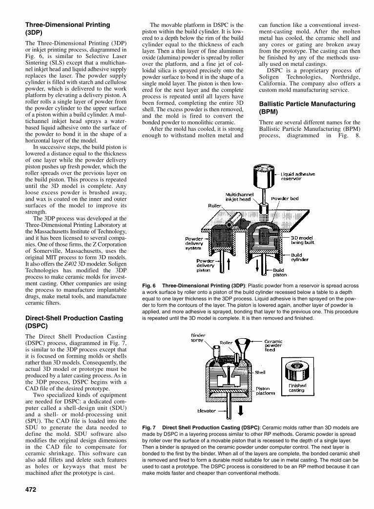
Three-Dimensional Printing(3DP)
The Three-Dimensional Printing (3DP)or inkjet printing process, diagrammed inFig. 6, is similar to Selective LaserSintering (SLS) except that a multichan-nel inkjet head and liquid adhesive supplyreplaces the laser. The powder supplycylinder is filled with starch and cellulosepowder, which is delivered to the workplatform by elevating a delivery piston. Aroller rolls a single layer of powder fromthe powder cylinder to the upper surfaceof a piston within a build cylinder. A mul-tichannel inkjet head sprays a water-based liquid adhesive onto the surface ofthe powder to bond it in the shape of ahorizontal layer of the model.
In successive steps, the build piston islowered a distance equal to the thicknessof one layer while the powder deliverypiston pushes up fresh powder, which theroller spreads over the previous layer onthe build piston. This process is repeateduntil the 3D model is complete. Anyloose excess powder is brushed away,and wax is coated on the inner and outersurfaces of the model to improve itsstrength.
The 3DP process was developed at theThree-Dimensional Printing Laboratory atthe Massachusetts Institute of Technology,and it has been licensed to several compa-nies. One of those firms, the Z Corporationof Somerville, Massachusetts, uses theoriginal MIT process to form 3D models.It also offers the Z402 3D modeler. SoligenTechnologies has modified the 3DPprocess to make ceramic molds for invest-ment casting. Other companies are usingthe process to manufacture implantabledrugs, make metal tools, and manufactureceramic filters.
Direct-Shell Production Casting(DSPC)
The Direct Shell Production Casting(DSPC) process, diagrammed in Fig. 7,is similar to the 3DP process except thatit is focused on forming molds or shellsrather than 3D models. Consequently, theactual 3D model or prototype must beproduced by a later casting process. As inthe 3DP process, DSPC begins with aCAD file of the desired prototype.
Two specialized kinds of equipmentare needed for DSPC: a dedicated com-puter called a shell-design unit (SDU)and a shell- or mold-processing unit(SPU). The CAD file is loaded into theSDU to generate the data needed todefine the mold. SDU software alsomodifies the original design dimensionsin the CAD file to compensate forceramic shrinkage. This software canalso add fillets and delete such featuresas holes or keyways that must bemachined after the prototype is cast.
The movable platform in DSPC is thepiston within the build cylinder. It is low-ered to a depth below the rim of the buildcylinder equal to the thickness of eachlayer. Then a thin layer of fine aluminumoxide (alumina) powder is spread by rollerover the platform, and a fine jet of col-loidal silica is sprayed precisely onto thepowder surface to bond it in the shape of asingle mold layer. The piston is then low-ered for the next layer and the completeprocess is repeated until all layers havebeen formed, completing the entire 3Dshell. The excess powder is then removed,and the mold is fired to convert thebonded powder to monolithic ceramic.
After the mold has cooled, it is strongenough to withstand molten metal and
can function like a conventional invest-ment-casting mold. After the moltenmetal has cooled, the ceramic shell andany cores or gating are broken awayfrom the prototype. The casting can thenbe finished by any of the methods usu-ally used on metal castings.
DSPC is a proprietary process ofSoligen Technologies, Northridge,California. The company also offers acustom mold manufacturing service.
Ballistic Particle Manufacturing(BPM)
There are several different names for theBallistic Particle Manufacturing (BPM)process, diagrammed in Fig. 8.
472
Fig. 6 Three-Dimensional Printing (3DP): Plastic powder from a reservoir is spread acrossa work surface by roller onto a piston of the build cylinder recessed below a table to a depthequal to one layer thickness in the 3DP process. Liquid adhesive is then sprayed on the pow-der to form the contours of the layer. The piston is lowered again, another layer of powder isapplied, and more adhesive is sprayed, bonding that layer to the previous one. This procedureis repeated until the 3D model is complete. It is then removed and finished.
Fig. 7 Direct Shell Production Casting (DSPC): Ceramic molds rather than 3D models aremade by DSPC in a layering process similar to other RP methods. Ceramic powder is spreadby roller over the surface of a movable piston that is recessed to the depth of a single layer.Then a binder is sprayed on the ceramic powder under computer control. The next layer isbonded to the first by the binder. When all of the layers are complete, the bonded ceramic shellis removed and fired to form a durable mold suitable for use in metal casting. The mold can beused to cast a prototype. The DSPC process is considered to be an RP method because it canmake molds faster and cheaper than conventional methods.
Sclater Chapter 14 5/3/01 1:44 PM Page 472
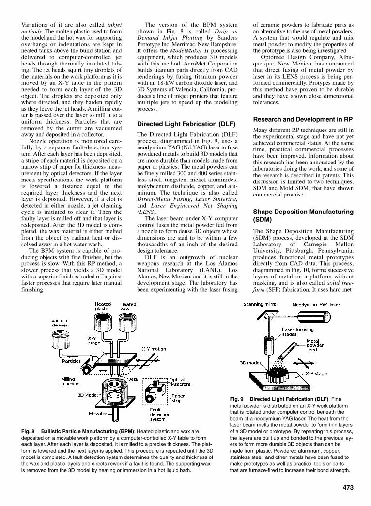
Variations of it are also called inkjetmethods. The molten plastic used to formthe model and the hot wax for supportingoverhangs or indentations are kept inheated tanks above the build station anddelivered to computer-controlled jetheads through thermally insulated tub-ing. The jet heads squirt tiny droplets ofthe materials on the work platform as it ismoved by an X-Y table in the patternneeded to form each layer of the 3Dobject. The droplets are deposited onlywhere directed, and they harden rapidlyas they leave the jet heads. A milling cut-ter is passed over the layer to mill it to auniform thickness. Particles that areremoved by the cutter are vacuumedaway and deposited in a collector.
Nozzle operation is monitored care-fully by a separate fault-detection sys-tem. After each layer has been deposited,a stripe of each material is deposited on anarrow strip of paper for thickness meas-urement by optical detectors. If the layermeets specifications, the work platformis lowered a distance equal to therequired layer thickness and the nextlayer is deposited. However, if a clot isdetected in either nozzle, a jet cleaningcycle is initiated to clear it. Then thefaulty layer is milled off and that layer isredeposited. After the 3D model is com-pleted, the wax material is either meltedfrom the object by radiant heat or dis-solved away in a hot water wash.
The BPM system is capable of pro-ducing objects with fine finishes, but theprocess is slow. With this RP method, aslower process that yields a 3D modelwith a superior finish is traded off againstfaster processes that require later manualfinishing.
The version of the BPM systemshown in Fig. 8 is called Drop onDemand Inkjet Plotting by SandersPrototype Inc, Merrimac, New Hampshire.It offers the ModelMaker II processingequipment, which produces 3D modelswith this method. AeroMet Corporationbuilds titanium parts directly from CADrenderings by fusing titanium powderwith an 18-kW carbon dioxide laser, and3D Systems of Valencia, California, pro-duces a line of inkjet printers that featuremultiple jets to speed up the modelingprocess.
Directed Light Fabrication (DLF)
The Directed Light Fabrication (DLF)process, diagrammed in Fig. 9, uses aneodymium YAG (Nd:YAG) laser to fusepowdered metals to build 3D models thatare more durable than models made frompaper or plastics. The metal powders canbe finely milled 300 and 400 series stain-less steel, tungsten, nickel aluminides,molybdenum disilicide, copper, and alu-minum. The technique is also calledDirect-Metal Fusing, Laser Sintering,and Laser Engineered Net Shaping(LENS).
The laser beam under X-Y computercontrol fuses the metal powder fed froma nozzle to form dense 3D objects whosedimensions are said to be within a fewthousandths of an inch of the desireddesign tolerance.
DLF is an outgrowth of nuclearweapons research at the Los AlamosNational Laboratory (LANL), LosAlamos, New Mexico, and it is still in thedevelopment stage. The laboratory hasbeen experimenting with the laser fusing
473
Fig. 8 Ballistic Particle Manufacturing (BPM): Heated plastic and wax aredeposited on a movable work platform by a computer-controlled X-Y table to formeach layer. After each layer is deposited, it is milled to a precise thickness. The plat-form is lowered and the next layer is applied. This procedure is repeated until the 3Dmodel is completed. A fault detection system determines the quality and thickness ofthe wax and plastic layers and directs rework if a fault is found. The supporting waxis removed from the 3D model by heating or immersion in a hot liquid bath.
Fig. 9 Directed Light Fabrication (DLF): Finemetal powder is distributed on an X-Y work platformthat is rotated under computer control beneath thebeam of a neodymium YAG laser. The heat from thelaser beam melts the metal powder to form thin layersof a 3D model or prototype. By repeating this process,the layers are built up and bonded to the previous lay-ers to form more durable 3D objects than can bemade from plastic. Powdered aluminum, copper,stainless steel, and other metals have been fused tomake prototypes as well as practical tools or partsthat are furnace-fired to increase their bond strength.
of ceramic powders to fabricate parts asan alternative to the use of metal powders.A system that would regulate and mixmetal powder to modify the properties ofthe prototype is also being investigated.
Optomec Design Company, Albu-querque, New Mexico, has announcedthat direct fusing of metal powder bylaser in its LENS process is being per-formed commercially. Protypes made bythis method have proven to be durableand they have shown close dimensionaltolerances.
Research and Development in RP
Many different RP techniques are still inthe experimental stage and have not yetachieved commercial status. At the sametime, practical commercial processeshave been improved. Information aboutthis research has been announced by thelaboratories doing the work, and some ofthe research is described in patents. Thisdiscussion is limited to two techniques,SDM and Mold SDM, that have showncommercial promise.
Shape Deposition Manufacturing(SDM)
The Shape Deposition Manufacturing(SDM) process, developed at the SDMLaboratory of Carnegie MellonUniversity, Pittsburgh, Pennsylvania,produces functional metal prototypesdirectly from CAD data. This process,diagrammed in Fig. 10, forms successivelayers of metal on a platform withoutmasking, and is also called solid free-form (SFF) fabrication. It uses hard met-
Sclater Chapter 14 5/3/01 1:44 PM Page 473
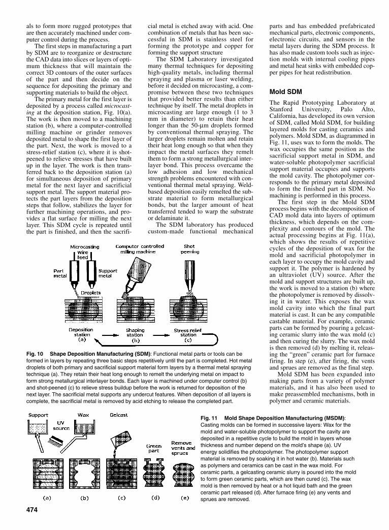
parts and has embedded prefabricatedmechanical parts, electronic components,electronic circuits, and sensors in themetal layers during the SDM process. Ithas also made custom tools such as injec-tion molds with internal cooling pipesand metal heat sinks with embedded cop-per pipes for heat redistribution.
Mold SDM
The Rapid Prototyping Laboratory atStanford University, Palo Alto,California, has developed its own versionof SDM, called Mold SDM, for buildinglayered molds for casting ceramics andpolymers. Mold SDM, as diagrammed inFig. 11, uses wax to form the molds. Thewax occupies the same position as thesacrificial support metal in SDM, andwater-soluble photopolymer sacrificialsupport material occupies and supportsthe mold cavity. The photopolymer cor-responds to the primary metal depositedto form the finished part in SDM. Nomachining is performed in this process.
The first step in the Mold SDMprocess begins with the decomposition ofCAD mold data into layers of optimumthickness, which depends on the com-plexity and contours of the mold. Theactual processing begins at Fig. 11(a),which shows the results of repetitivecycles of the deposition of wax for themold and sacrificial photopolymer ineach layer to occupy the mold cavity andsupport it. The polymer is hardened byan ultraviolet (UV) source. After themold and support structures are built up,the work is moved to a station (b) wherethe photopolymer is removed by dissolv-ing it in water. This exposes the waxmold cavity into which the final partmaterial is cast. It can be any compatiblecastable material. For example, ceramicparts can be formed by pouring a gelcast-ing ceramic slurry into the wax mold (c)and then curing the slurry. The wax moldis then removed (d) by melting it, releas-ing the “green” ceramic part for furnacefiring. In step (e), after firing, the ventsand sprues are removed as the final step.
Mold SDM has been expanded intomaking parts from a variety of polymermaterials, and it has also been used tomake preassembled mechanisms, both inpolymer and ceramic materials.
474
Fig. 10 Shape Deposition Manufacturing (SDM): Functional metal parts or tools can beformed in layers by repeating three basic steps repetitively until the part is completed. Hot metaldroplets of both primary and sacrificial support material form layers by a thermal metal sprayingtechnique (a). They retain their heat long enough to remelt the underlying metal on impact toform strong metallurgical interlayer bonds. Each layer is machined under computer control (b)and shot-peened (c) to relieve stress buildup before the work is returned for deposition of thenext layer. The sacrificial metal supports any undercut features. When deposition of all layers iscomplete, the sacrificial metal is removed by acid etching to release the completed part.
Fig. 11 Mold Shape Deposition Manufacturing (MSDM):Casting molds can be formed in successive layers: Wax for themold and water-soluble photopolymer to support the cavity aredeposited in a repetitive cycle to build the mold in layers whosethickness and number depend on the mold’s shape (a). UVenergy solidifies the photopolymer. The photopolymer supportmaterial is removed by soaking it in hot water (b). Materials suchas polymers and ceramics can be cast in the wax mold. Forceramic parts, a gelcasting ceramic slurry is poured into the moldto form green ceramic parts, which are then cured (c). The waxmold is then removed by heat or a hot liquid bath and the greenceramic part released (d). After furnace firing (e) any vents andsprues are removed.
als to form more rugged prototypes thatare then accurately machined under com-puter control during the process.
The first steps in manufacturing a partby SDM are to reorganize or destructurethe CAD data into slices or layers of opti-mum thickness that will maintain thecorrect 3D contours of the outer surfacesof the part and then decide on thesequence for depositing the primary andsupporting materials to build the object.
The primary metal for the first layer isdeposited by a process called microcast-ing at the deposition station, Fig. 10(a).The work is then moved to a machiningstation (b), where a computer-controlledmilling machine or grinder removesdeposited metal to shape the first layer ofthe part. Next, the work is moved to astress-relief station (c), where it is shot-peened to relieve stresses that have builtup in the layer. The work is then trans-ferred back to the deposition station (a)for simultaneous deposition of primarymetal for the next layer and sacrificialsupport metal. The support material pro-tects the part layers from the depositionsteps that follow, stabilizes the layer forfurther machining operations, and pro-vides a flat surface for milling the nextlayer. This SDM cycle is repeated untilthe part is finished, and then the sacrifi-
cial metal is etched away with acid. Onecombination of metals that has been suc-cessful in SDM is stainless steel forforming the prototype and copper forforming the support structure
The SDM Laboratory investigatedmany thermal techniques for depositinghigh-quality metals, including thermalspraying and plasma or laser welding,before it decided on microcasting, a com-promise between these two techniquesthat provided better results than eithertechnique by itself. The metal droplets inmicrocasting are large enough (1 to 3mm in diameter) to retain their heatlonger than the 50-µm droplets formedby conventional thermal spraying. Thelarger droplets remain molten and retaintheir heat long enough so that when theyimpact the metal surfaces they remeltthem to form a strong metallurgical inter-layer bond. This process overcame thelow adhesion and low mechanicalstrength problems encountered with con-ventional thermal metal spraying. Weld-based deposition easily remelted the sub-strate material to form metallurgicalbonds, but the larger amount of heattransferred tended to warp the substrateor delaminate it.
The SDM laboratory has producedcustom-made functional mechanical
Sclater Chapter 14 5/3/01 1:44 PM Page 474
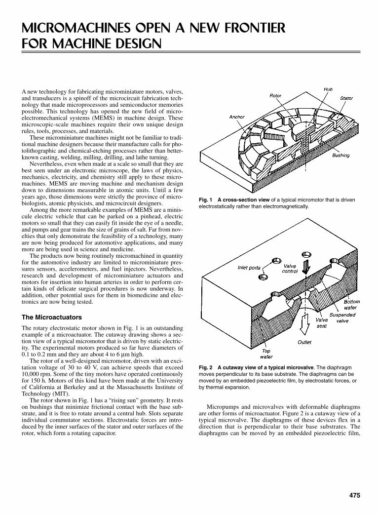
A new technology for fabricating microminiature motors, valves,and transducers is a spinoff of the microcircuit fabrication tech-nology that made microprocessors and semiconductor memoriespossible. This technology has opened the new field of micro-electromechanical systems (MEMS) in machine design. Thesemicroscopic-scale machines require their own unique designrules, tools, processes, and materials.
These microminiature machines might not be familiar to tradi-tional machine designers because their manufacture calls for pho-tolithographic and chemical-etching processes rather than better-known casting, welding, milling, drilling, and lathe turning.
Nevertheless, even when made at a scale so small that they arebest seen under an electronic microscope, the laws of physics,mechanics, electricity, and chemistry still apply to these micro-machines. MEMS are moving machine and mechanism designdown to dimensions measurable in atomic units. Until a fewyears ago, those dimensions were strictly the province of micro-biologists, atomic physicists, and microcircuit designers.
Among the more remarkable examples of MEMS are a minis-cule electric vehicle that can be parked on a pinhead, electricmotors so small that they can easily fit inside the eye of a needle,and pumps and gear trains the size of grains of salt. Far from nov-elties that only demonstrate the feasibility of a technology, manyare now being produced for automotive applications, and manymore are being used in science and medicine.
The products now being routinely micromachined in quantityfor the automotive industry are limited to microminiature pres-sures sensors, accelerometers, and fuel injectors. Nevertheless,research and development of microminiature actuators andmotors for insertion into human arteries in order to perform cer-tain kinds of delicate surgical procedures is now underway. Inaddition, other potential uses for them in biomedicine and elec-tronics are now being tested.
The Microactuators
The rotary electrostatic motor shown in Fig. 1 is an outstandingexample of a microactuator. The cutaway drawing shows a sec-tion view of a typical micromotor that is driven by static electric-ity. The experimental motors produced so far have diameters of0.1 to 0.2 mm and they are about 4 to 6 µm high.
The rotor of a well-designed micromotor, driven with an exci-tation voltage of 30 to 40 V, can achieve speeds that exceed10,000 rpm. Some of the tiny motors have operated continuouslyfor 150 h. Motors of this kind have been made at the Universityof California at Berkeley and at the Massachusetts Institute ofTechnology (MIT).
The rotor shown in Fig. 1 has a “rising sun” geometry. It restson bushings that minimize frictional contact with the base sub-strate, and it is free to rotate around a central hub. Slots separateindividual commutator sections. Electrostatic forces are intro-duced by the inner surfaces of the stator and outer surfaces of therotor, which form a rotating capacitor.
475
MICROMACHINES OPEN A NEW FRONTIER FOR MACHINE DESIGN
Micropumps and microvalves with deformable diaphragmsare other forms of microactuator. Figure 2 is a cutaway view of atypical microvalve. The diaphragms of these devices flex in adirection that is perpendicular to their base substrates. Thediaphragms can be moved by an embedded piezoelectric film,
Fig. 1 A cross-section view of a typical micromotor that is drivenelectrostatically rather than electromagnetically.
Fig. 2 A cutaway view of a typical microvalve. The diaphragmmoves perpendicular to its base substrate. The diaphragms can bemoved by an embedded piezoelectric film, by electrostatic forces, orby thermal expansion.
Sclater Chapter 14 5/3/01 1:44 PM Page 475

electrostatic forces, or thermal expansion. Applications are seenfor the microminiature pumps and valves in biomedicine becausethey are orders of magnitude smaller than conventional biomed-ical pumps and valves.
Actuators have also been made in the form of vibratingmicrostructures with flexible suspensions. Figure 3 is a drawingof a linear resonator consisting of two identical folded beams ofan interdigital electrostatic “comb” drive. The folded beams aresupported by anchors grown on the semiconductor substrate, andthe comb drive is supported by a pedestal grown on the same sil-icon substrate.
The folded beams are dimensioned to have a specific resonantfrequency, and they are driven by electrostatic charges placed onthe comb-drive digits, which act as capacitors. Both beam struc-tures vibrate simultaneously but only in the X direction becauselateral or Y-direction motion is constrained by the geometrics ofthe folded beams.
Materials
Currently, the most popular material for fabricating all of thesemicromachines is silicon, the material from which most micro-circuit chips and discrete transistors are made. The silicon can bein either of several different forms. However, micromachineshave also included parts made of aluminum and diamonds. Thesuccessful design and manufacture of billions of integrated cir-cuits over the past 35 years have left an extensive database andbody of knowledge about silicon—how to grow it, alter its struc-ture chemically, mill it chemically, and bond slices of it togetherpermanently.
Silicon is a very strong material with a modulus of elasticitythat closely matches steel. Its lack of mechanical hysteresismakes it an almost perfect material for fabricating sensors andtransducers. Silicon exceeds stainless steel in yield strength andaluminum in strength-to-weight ratio. It also exhibits high ther-mal conductivity and a low thermal expansion coefficient.Because silicon is sensitive to stress, strain, and temperature, sil-icon sensors can easily communicate with electronic circuitry forthe transmission of electrical signals.
In the fabrication of micromachines, silicon is chemicallyetched into a wide variety of shapes rather than being machinedwith traditional cutting tools. Silicon, as well as such associatedmaterials as polysilicon, silicon nitride, and aluminum, can bemicromachined in batches into many different shapes and con-tours. In micromachining, mechanical structures are sculptedfrom a silicon wafer by selectively etching away sacrificial sup-porting layers or structures.
The etching process is complemented by such standard inte-grated circuit processes as photolithography for producing therequired masks at the various stages of the process. Diffusion canalter the chemical makeup of the material by introducing“dopants.” Epitaxy is a process for growing new material on thebasic substrate, and deposition is a process for the “plating” ofone type of material on another.
The bulk micromachining process is widely used for fabricatingsilicon accelerometers, but has also been applied to the fabrica-tion of flow sensors, inkjet nozzles, microvalves, and motors.The etching process can be controlled by dispersing differentdoping materials within the silicon or by concentrating electricalcurrent in specific regions.
Powering Micromachines
Micromachines can be actuated by the piezoelectric effect, ther-mal expansion, electrostatic force, or magnetic force. The choiceof actuation method is influenced by the nature of the device andits specific application requirements. However, the microscopicdimensions of the devices generally rule out current-inducedmagnetic forces such as those that drive conventional electric
476
motors and solenoids because those forces are too weak whenscaled to the small sizes required to power the devices.
The high power consumption required to concentrate enoughheat in a small local area to move parts by the thermal expansionof unlike materials is unacceptable for many applications.Therefore, the two most commonly used microactuation drivemethods are the piezoelectric effect and electrostatic force.
Electrostatic Forces
Electrostatic forces are used to drive micromachines because,unlike magnetic forces, induced electrostatic forces can be scaleddown favorably with size. Electrostatic force is induced by set-ting up equivalent parallel-plate capacitors between adjacentmechanical elements. There must be two conductive surfacesthat act as opposing capacitor plates. The electrostatic force isdirectly proportional to the product of the square of the voltageacross the plates and plate area, and it is inversely proportional tothe square of the distance between the plates.
A surface-micromachined motor is shown in Fig. 1. The endsurfaces of the rotor spokes and segmented inner walls of theinsulated stator electrodes effectively form capacitors, which areseparated by a small air gap. The rotor is the spoked wheel free torotate around a central post. To drive the motor, the opposinginsulated stator segments are energized in a rotating pattern androtor spokes are attracted to the stator segments as they moveinto position near the stators to keep the rotor turning, makingone revolution for many polarity changes in the stator elements.It can be seen that the spacing between the spokes and stator seg-ments change with respect to time as the rotor turns. As a result,the electrostatic force varies with time or is a nonlinear functionof the applied voltage.
Problems can arise if the rotor spokes are not uniform inradius dimensions, the bearing surfaces are not smooth, or therotor does not rotate concentrically. Any of these mechanicaldefects could cause the rotor to stick in one position.
The handicap for surface micromachined motors is their smallvertical dimensions, making it difficult for them to obtain largeenough changes in capacitance when the rotor is in motion.Somewhat larger motors with thicker, taller stators and rotor seg-ments have been made by LIGA techniques to overcome thisdrawback. (The abbreviation LIGA stands for the German wordsfor lithography, electroplating, and molding-—Lithographie,Galvanoformung, Abformung.)
Another kind of electrostatic actuator, the electrostatic-combdrive shown in Fig. 3, was developed to maximize the capaci-tance effects in electrostatic micromachines by taking advantage
Fig. 3 This linear resonator consists of a pair of folded beams thatare set in vibrational motion in the X direction by an electrostaticallydriven comb structure. Lateral or Y-direction motion is restrained bythe geometry of the folded beams.
Sclater Chapter 14 5/3/01 1:44 PM Page 476

477
piezoelectric film. Figure 4 is a diagram of a beam with a centralpiezoelectric layer of insulated polycrystalline zinc oxide (ZnO)up to several micrometers thick. The layer is then insulated onboth sides and sandwiched between two conductive electrodes toform the rigid structure.
When voltage is applied to the two electrodes, the piezoelec-trically induced stress in the ZnO film causes the structure todeflect. The converse of the piezoelectric effect can be obtainedin applications where it is desirable to convert the strain on thebeam or diaphragm into electrical signals that are proportional tostrain.
Bulk Micromachining
The development of micromachines, sensors, and actuators overthe past decade has been driven by advancements in siliconmicrocircuits. Micromachining by the chemical etching of crys-talline silicon wafers has been an important fabrication tech-nique. Strong alkalines etch single-crystal silicon at a rate thatdepends on the crystal orientation, its dopant concentration, andan externally applied electric field.
The etching is controlled by photolithographic etch masksthat are applied over silicon which has been coated with a pho-toresist. The photoresist can be chemically removed from thoseareas of the silicon that have been exposed to ultraviolet lightthrough the transparent parts of the mask. When the silicon isexposed, it can be etched, plated, or diffused with dopants.
This bulk micromachining process has been combined withmethods for fusion-bonding silicon substrates to form precisethree-dimensional structures such as micropumps andmicrovalves. Two or more etched wafers can be bonded by press-ing them together and annealing the structure, making the three-dimensional microstructure permanent. This approach permitsinternal or re-entrant cavities to be formed.
Surface Micromachining
Deposited thin films of such materials as polysilicon, siliconoxide (SiO2), silicon nitride (Si3N4), and phosphosilicate glass(PSG) have been surface micromachined by both dry ionic andwet chemical etching to define those films. Freestanding struc-tures have been formed by the removal of underlying sacrificiallayers (typically of SiO2 or PSG). The film is removed by ahighly selective chemical etchant such as hydrofluoric acidafter the structure layer, usually polysilicon, is deposited andpatterned.
The electrostatic motor shown in Fig. 1 is made by a succes-sion of deposition and masking steps in which alternate layers ofpermanent silicon material and sacrificial material are depositeduntil the structure of the motor—stator, rotor, and central hub—is completed. Then the sacrificial material is chemicallyremoved, effectively sculpting the permanent silicon structure sothat the rotor is free to move on the hub. At the same time, anelectrostatic shield and interconnections are formed.
Fig. 4 A microminiature piezoelectric transducer is made asan insulated layer of polycrystalline zinc oxide (ZnO) sandwichedbetween two conductive electrodes to form a rigid bimetallicstructure.
of the classical parallel plate capacitor formula because onlyattractive forces can be generated.
Where E is the energy stored,C is the capacitance, andV is the voltage across the capacitor.
Surface micromachined comb drives consist of many inter-digitated fingers, as shown in Fig. 3. When a voltage is applied,an attractive force is developed between the fingers, which movetogether. The increase in capacitance is proportional to the num-ber of fingers.
This means that large numbers of fingers are required to gen-erate large forces. Because the direction of motion of the electro-static comb drive is parallel with the length of the comb-fingerelectrodes, the effective plate area with respect to spacingbetween the plates remains constant.
Consequently, capacitance with respect to the direction ofmotion is linear, and the induced force in the X direction isdirectly proportional to the square of the voltage applied acrossthe plates. Comb-drive structures have been driven to deflect byas much as one quarter of the comb finger length with DC volt-ages of 20 to 40 V.
A disadvantage of the comb drive is that if the lateral gapsbetween the fingers are not equal on the sides or if the fingers arenot parallel, it is possible for the fingers to move at right angles tothe intended direction of motion and adhere together until thevoltage is turned off. They could remain stuck permanently.
Piezoelectric Films
Microminiature transducers have been made in the form of rigidbeams and diaphragms with a core of polycrystalline zinc-oxide
ECV=
2
2
Sclater Chapter 14 5/3/01 1:44 PM Page 477

478
MULTILEVEL FABRICATION PERMITS MORE COMPLEXAND FUNCTIONAL MEMS
Researchers at Sandia National Laboratories, Albuquerque, NewMexico, have developed two surface micromachining processesfor fabricating multilevel MEMS (microelectromechanical sys-tems) from polysilicon that are more complex and functionalthan those made from two- and three-level processes. Theprocesses are SUMMiT Technology, a four-level process inwhich one ground or electrical interconnect plane and threemechanical layers can be micromachined, and SUMMiT VTechnology, a similar five-level process except that four mechan-ical layers can be micromachined. Sandia offers this technologyunder license agreement to qualified commercial IC producers.
According to Sandia researchers, polycrystalline silicon (alsocalled polysilicon or poly) is an ideal material for making themicroscopic mechanical systems. It is stronger than steel, with astrength of 2 to 3 GPa (assuming no surface flaws), whereas steelhas a strength of 200 MPa to 1 GPa (depending on how it isprocessed). Also, polysilicon is extremely flexible, with a maxi-mum strain before fracture of approximately 0.5%, and it doesnot readily fatigue.
Years of experience in working with polysilicon have beengained by commercial manufacturers of large-scale CMOS inte-grated circuits chips because it is used to form the gate structuresof most CMOS transistors. Consequently, MEMS can be pro-duced in large volumes at low cost in IC manufacturing facilitieswith standard production equipment and tools. The Sandiaresearchers report that because of these advantages, polysiliconsurface micromachining is being pursued by many MEMS fabri-cation facilities.
The complexity of MEMS devices made from polysilicon islimited by the number of mechanical layers that can bedeposited. For example, the simplest actuating comb drives can
be made with one ground or electrical plane and one mechanicallayer in a two-level process, but a three-level process with twomechanical layers permits micromachining mechanisms such asgears that rotate on hubs or movable optical mirror arrays. Afour-level process such as SUMMiT permits mechanical linkagesto be formed that connect actuator drives to gear trains. As aresult, it is expected that entirely new kinds of complex andsophisticated micromachines will be fabricated with the five-level process.
According to the Sandia scientists, the primary difficultiesencountered in forming the extra polysilicon layers for surfacemicromachining the more complex devices are residual filmstress and device topography. The film stress can cause themechanical layers to bow from the required flatness. This cancause the mechanism to function poorly or even prevent it fromworking. The scientists report that this has even been a problemin the fabrication of MEMS with only two mechanical layers.
To surmount the bowing problem, Sandia has developed aproprietary process for holding stress levels to values typicallyless than 5 MPa, thus permitting the successful fabrication andoperation of two meshing gears, whose diameters are as large as2000 µm.
The intricacies of device topography that make it difficult topattern and etch successive polysilicon layers restrict the com-plexities of the devices that can be built successfully. Sandia hasminimized that problem by developing a proprietary chemical-mechanical polishing (CMP) process called “planarizing” forforming truly flat top layers on the polysilicon. Because CMP isnow so widely used in integrated circuit chip manufacture, it willallow MEMS to be batch fabricated by the SUMMiT processesusing standard commercial IC fabrication equipment.
Fig. 1 Wedge Stepping Motor: Thisindexing motor can precisely index otherMEMS components such as microgeartrains. It can also position gears and indexone gear tooth at a time at speeds of morethan 200 teeth/s or less than 5 ms/step. Aninput of two simple input pulse signals willoperate it. This motor can index gears inMEMS such as locking devices, counters,and odometers. It was built with Sandia’sfour-layer SUMMiT technology. Torque andindexing precision increase as the device isscaled up in size.
GALLERY OF MEMS ELECTRON-MICROSCOPE IMAGESThe Sandia National Laboratories, Albuquerque, New Mexico,have developed a wide range of microelectromechanical systems(MEMS). The scanning electron microscope (SEM) micrographs
presented here show the range of these devices, and the captionsdescribe their applications.
Sclater Chapter 14 5/3/01 1:44 PM Page 478

479
Fig. 2 Wedge Stepping Motor: A close-up view of one of the teethof the indexing motor shown in Fig. 1.
Fig. 3 Torque Converter: This modular transmission unit has anoverall gear reduction ratio of 12 to 1. It consists of two multilevelgears, one with a gear reduction ratio of 3 to 1 and the other with aratio of 4 to 1. A coupling gear within the unit permits cascading.
Fig. 4 Torque Converter: By cascading six stages of the modular12-to-1 transmission units shown in Fig. 3, a 2,985,894-to-1 gearreduction ratio is obtained in a die area of less than 1 mm2. The con-verter can step up or step down.
Fig. 5 Dual-Mass Oscillator: This oscillator uses parallel plateactuation and system dynamics to amplify motion. The 10-mm-longparallel plate actuators on the driving mass produce an amplifiedmotion on the second mass when it is driven by a signal. The actu-ated mass remains nearly motionless, while the moving mass hasan amplitude of approximately 4 µm when driven by a 4-V signal. Itwas designed to be part of a vibrating gyroscope.
Sclater Chapter 14 5/3/01 1:44 PM Page 479

480
Fig. 6 Rotary Motor: This close-up shows part of a rotary motor thatoffers advantages over other MEMS actuators. Its operates on linear-comb drive principles, but the combs are bent in a circle to permitunlimited travel. The combs are embedded inside the rotor so that othermicromachines can be powered directly from the rotor’s perimeter. Builtby Sandia’s four-level SUMMiT technology, the motor is powered by alower voltage and produces higher output torque than other MEMSactuators, but it still occupies a very small footprint. It can also operateas a stepper motor for precise positioning applications.
Fig. 7 Comb Drive Actuation: Two sets of comb-drive actuators(not shown) drive a set of linkages (upper right) to a set of rotary gears.The comb-drive actuators drive the linkages 90° out of phase with eachother to rotate the small 19-tooth gear at rotational speeds in excess of300,000 rpm. The operational lifetime of these small devices canexceed 8 × 10⁹ revolutions. The smaller gear drives a larger 57-tooth(1.6-mm-diameter) gear that has been driven as fast as 4800 rpm.
Fig. 8 Micro Transmission: This transmission has sets of small andlarge gears mounted on the same shaft so that they interlock with othersets of gears to transfer power while providing torque multiplication andspeed reduction. Its output gear is coupled to a double-level gear train.
Fig. 9 Microtransmission and Gear Reduction Unit: This mecha-nism is the same as that in Fig. 8 except that it performs a gear-reduc-tion function. The microengine pinion gear, labeled A in the figure,meshes directly with the large 57-tooth gear, labeled B. A smaller 19-tooth gear, C, is positioned on top of gear B and is linked to B’s hub.Because the gears are joined, both make the same number of turnsper minute. The small gear essentially transmits the power of the largergear over a shorter distance to turn the larger 61-tooth gear D. Two ofthe gear pairs (B and C, D and E) provide 12 times the torque of theengine. A linear rack F, capable of driving an external load, has beenadded to the final 17-tooth output gear E to provide a speedreduction/torque multiplication ratio of 9.6 to 1.
Gallery of MEMS (continued )
Sclater Chapter 14 5/3/01 1:44 PM Page 480

481
MINIATURE MULTISPEED TRANSMISSIONS FOR SMALL MOTORS Transmissions would be batch-fabricated using micromachining technologies. NASA’s Jet Propulsion Laboratory, Pasadena, California
Fig. 10 Gear-Reduction Units: This micrograph shows the threelower-level gears (A, B, and E) as well as the rack (F) of the systemshown in Fig. 9. The large flat area on the lower gear provides a planarsurface for the fabrication of the large, upper-level 61-tooth gear (D).
Fig. 11 Microsteam Engine: This is the world’s smallest multipistonmicrosteam engine. Water inside the three compression cylinders isheated by electric current, and when it vaporizes, it pushes the pistonsout. Capillary forces then retract the piston once current is removed.
A design has been developed for manufacturing multispeedtransmissions that are small enough to be used with minimo-tors—electromagnetic motors with power ratings of less than 1W. Like similar, larger systems, such as those in automobiles, theproposed mechanism could be used to satisfy a wider dynamicrange than could be achieved with fixed-ratio gearing. However,whereas typical transmission components are machined individ-ually and then assembled, this device would be made using sili-con batch-fabrication techniques, similar to those used to manu-facture integrated circuits and sensors.
Until now, only fixed-ratio gear trains have been available forminimotors, affording no opportunity to change gears in opera-tion to optimize for varying external conditions, or varyingspeed, torque, and power requirements. This is because conven-tional multispeed gear-train geometries and actuation techniquesdo not lend themselves to cost-effective miniaturization. In
Fig. 1 Simple epicyclic gear train. Compound epicyclic gears intraditional automatic transmissions usually consist of simple epicyclicswhich are stacked one on top of the other along a radial axis.
Fig. 2 Evolutionary stages in converting conventional gears to axi-ally flattened gears.
recent years, the advent of microelectromechanical systems(MEMS) and of micromachining techniques for making smallactuators and gears has created the potential for economical massproduction of multispeed transmissions for minimotors. In addi-tion, it should be possible to integrate these mechanisms withsensors, such as tachometers and load cells, as well as circuits, tocreate integrated silicon systems, which could perform closed-loop speed or torque control under a variety of conditions. Incomparison with a conventional motor/transmission assembly,such a package would be smaller and lighter, contain fewer parts,
Sclater Chapter 14 5/3/01 1:44 PM Page 481
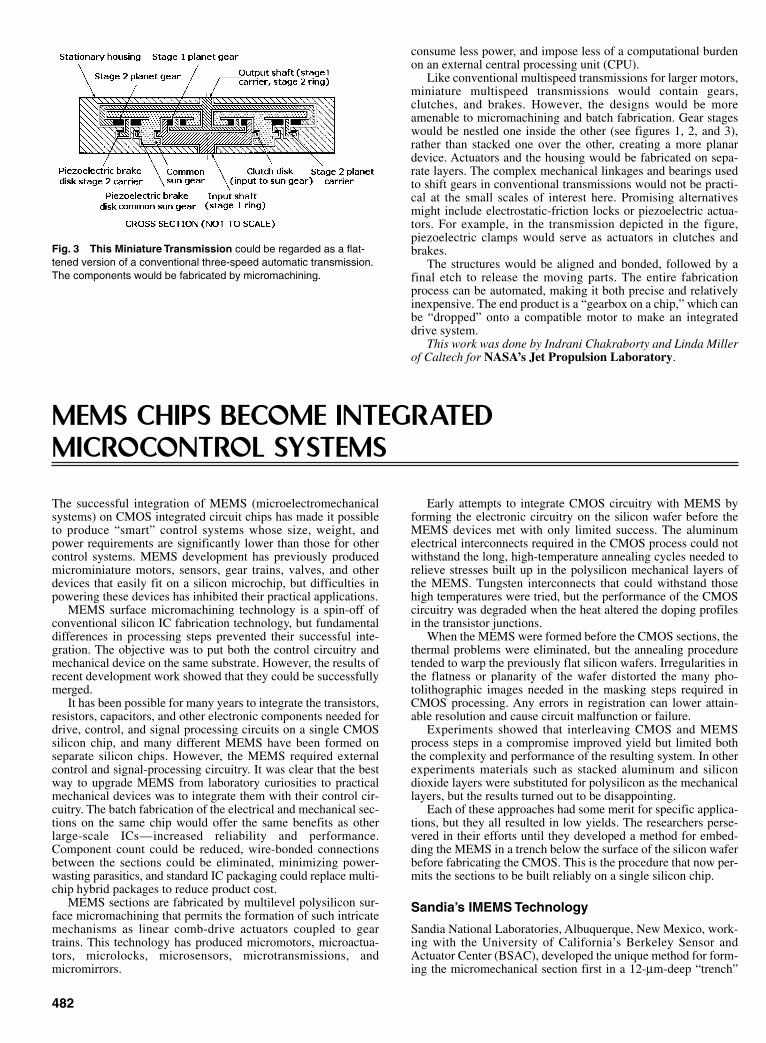
482
consume less power, and impose less of a computational burdenon an external central processing unit (CPU).
Like conventional multispeed transmissions for larger motors,miniature multispeed transmissions would contain gears,clutches, and brakes. However, the designs would be moreamenable to micromachining and batch fabrication. Gear stageswould be nestled one inside the other (see figures 1, 2, and 3),rather than stacked one over the other, creating a more planardevice. Actuators and the housing would be fabricated on sepa-rate layers. The complex mechanical linkages and bearings usedto shift gears in conventional transmissions would not be practi-cal at the small scales of interest here. Promising alternativesmight include electrostatic-friction locks or piezoelectric actua-tors. For example, in the transmission depicted in the figure,piezoelectric clamps would serve as actuators in clutches andbrakes.
The structures would be aligned and bonded, followed by afinal etch to release the moving parts. The entire fabricationprocess can be automated, making it both precise and relativelyinexpensive. The end product is a “gearbox on a chip,” which canbe “dropped” onto a compatible motor to make an integrateddrive system.
This work was done by Indrani Chakraborty and Linda Millerof Caltech for NASA’s Jet Propulsion Laboratory.
Fig. 3 This Miniature Transmission could be regarded as a flat-tened version of a conventional three-speed automatic transmission.The components would be fabricated by micromachining.
MEMS CHIPS BECOME INTEGRATED MICROCONTROL SYSTEMS
The successful integration of MEMS (microelectromechanicalsystems) on CMOS integrated circuit chips has made it possibleto produce “smart” control systems whose size, weight, andpower requirements are significantly lower than those for othercontrol systems. MEMS development has previously producedmicrominiature motors, sensors, gear trains, valves, and otherdevices that easily fit on a silicon microchip, but difficulties inpowering these devices has inhibited their practical applications.
MEMS surface micromachining technology is a spin-off ofconventional silicon IC fabrication technology, but fundamentaldifferences in processing steps prevented their successful inte-gration. The objective was to put both the control circuitry andmechanical device on the same substrate. However, the results ofrecent development work showed that they could be successfullymerged.
It has been possible for many years to integrate the transistors,resistors, capacitors, and other electronic components needed fordrive, control, and signal processing circuits on a single CMOSsilicon chip, and many different MEMS have been formed onseparate silicon chips. However, the MEMS required externalcontrol and signal-processing circuitry. It was clear that the bestway to upgrade MEMS from laboratory curiosities to practicalmechanical devices was to integrate them with their control cir-cuitry. The batch fabrication of the electrical and mechanical sec-tions on the same chip would offer the same benefits as otherlarge-scale ICs—increased reliability and performance.Component count could be reduced, wire-bonded connectionsbetween the sections could be eliminated, minimizing power-wasting parasitics, and standard IC packaging could replace multi-chip hybrid packages to reduce product cost.
MEMS sections are fabricated by multilevel polysilicon sur-face micromachining that permits the formation of such intricatemechanisms as linear comb-drive actuators coupled to geartrains. This technology has produced micromotors, microactua-tors, microlocks, microsensors, microtransmissions, andmicromirrors.
Early attempts to integrate CMOS circuitry with MEMS byforming the electronic circuitry on the silicon wafer before theMEMS devices met with only limited success. The aluminumelectrical interconnects required in the CMOS process could notwithstand the long, high-temperature annealing cycles needed torelieve stresses built up in the polysilicon mechanical layers ofthe MEMS. Tungsten interconnects that could withstand thosehigh temperatures were tried, but the performance of the CMOScircuitry was degraded when the heat altered the doping profilesin the transistor junctions.
When the MEMS were formed before the CMOS sections, thethermal problems were eliminated, but the annealing proceduretended to warp the previously flat silicon wafers. Irregularities inthe flatness or planarity of the wafer distorted the many pho-tolithographic images needed in the masking steps required inCMOS processing. Any errors in registration can lower attain-able resolution and cause circuit malfunction or failure.
Experiments showed that interleaving CMOS and MEMSprocess steps in a compromise improved yield but limited boththe complexity and performance of the resulting system. In otherexperiments materials such as stacked aluminum and silicondioxide layers were substituted for polysilicon as the mechanicallayers, but the results turned out to be disappointing.
Each of these approaches had some merit for specific applica-tions, but they all resulted in low yields. The researchers perse-vered in their efforts until they developed a method for embed-ding the MEMS in a trench below the surface of the silicon waferbefore fabricating the CMOS. This is the procedure that now per-mits the sections to be built reliably on a single silicon chip.
Sandia’s IMEMS Technology
Sandia National Laboratories, Albuquerque, New Mexico, work-ing with the University of California’s Berkeley Sensor andActuator Center (BSAC), developed the unique method for form-ing the micromechanical section first in a 12-µm-deep “trench”
Sclater Chapter 14 5/3/01 1:44 PM Page 482
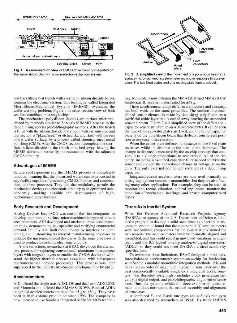
and backfilling that trench with sacrificial silicon dioxide beforeforming the electronic section. This technique, called IntegratedMicroElectroMechanical Systems (IMEMS), overcame thewafer-warping problem. Figure 1 is cross-section view of bothsections combined on a single chip.
The mechanical polysilicon devices are surface microma-chined by methods similar to Sandia’s SUMMiT process in thetrench, using special photolithography methods. After the trenchis filled with the silicon dioxide, the silicon wafer is annealed andthat section is “planarized,” or etched flat and flush with the restof the wafer surface, by a process called chemical-mechanicalpolishing (CMP). After the CMOS section is complete, the sacri-ficial silicon dioxide in the trench is etched away, leaving theMEMS devices electrically interconnected with the adjacentCMOS circuitry.
Advantages of IMEMS
Sandia spokespersons say the IMEMS process is completelymodular, meaning that the planarized wafers can be processed inany facility capable of processing CMOS, bipolar, and combina-tions of these processes. They add that modularity permits themechanical devices and electronic circuitry to be optimized inde-pendently, making possible the development of high-performance microsystems.
Early Research and Development
Analog Devices Inc. (ADI) was one of the first companies todevelop commercial surface-micromachined integrated-circuitaccelerometers. ADI developed and marketed these accelerome-ter chips, demonstrating its capability and verifying commercialdemand. Initially ADI built these devices by interleaving, com-bining, and customizing its internal manufacturing processes toproduce the micromechanical devices with the same processes itused to produce monolithic electronic circuitry.
At the same time, researchers at BSAC developed the alterna-tive process for replacing conventional aluminum interconnectlayers with tungsten layers to enable the CMOS device to with-stand the higher thermal stresses associated with subsequentmicromechanical device processing. This process was latersuperseded by the joint BSAC–Sandia development of IMEMS.
Accelerometers
ADI offered the single-axis ADXL150 and dual-axis ADXL250,and Motorola Inc. offered the XMMAS40GWB. Both of ADI’sintegrated accelerometers are rated for ±5 g to ±50 g. They havebeen in high-volume production since 1993. The company isnow licensed to use Sandia’s integrated MEMS/CMOS technol-
483
ogy. Motorola is now offering the MMA1201P and MMA2200Wsingle-axis IC accelerometers rated for ±38 g.
These accelerometer chips differ in architecture and circuitry,but both work on the same principles. The surface microma-chined sensor element is made by depositing polysilicon on asacrificial oxide layer that is etched away, leaving the suspendedsensor element. Figure 2 is a simplified view of the differential-capacitor sensor structure in an ADI accelerometer. It can be seenthat two of the capacitor plates are fixed, and the center capacitorplate is on the polysilicon beam that deflects from its rest posi-tion in response to acceleration.
When the center plate deflects, its distance to one fixed plateincreases while its distance to the other plate decreases. Thechange in distance is measured by the on-chip circuitry that con-verts it to a voltage proportional to acceleration. All of the cir-cuitry, including a switched-capacitor filter needed to drive thesensor and convert the capacitance change to voltage, is on thechip. The only external component required is a decouplingcapacitor.
Integrated-circuit accelerometers are now used primarily asairbag-deployment sensors in automobiles, but they are also find-ing many other applications. For example, they can be used tomonitor and record vibration, control appliances, monitor thecondition of mechanical bearings, and protect computer harddrives.
Three-Axis Inertial System
When the Defense Advanced Research Projects Agency(DARPA), an agency of the U.S. Department of Defense, initi-ated a program to develop a solid-state three-axis inertial meas-urement system, it found that the commercial IC accelerometerswere not suitable components for the system it envisioned fortwo reasons: the accelerometers must be manually aligned andassembled, and this could result in unwanted variations in align-ment, and the ICs lacked on-chip analog-to-digital converters(ADCs), so they could not meet DARPA’s critical sensitivityspecifications.
To overcome these limitations, BSAC designed a three-axis,force-balanced accelerometer system-on-a-chip for fabricationwith Sandia’s modular monolithic integration methods. It is saidto exhibit an order of magnitude increase in sensitivity over thebest commercially available single-axis integrated accelerome-ters. The Berkeley system also includes clock generation cir-cuitry, a digital output, and photolithographic alignment of senseaxes. Thus, the system provides full three-axis inertial measure-ment, and does not require the manual assembly and alignmentof sense axes.
A combined X- and Y-axis rate gyro and a Z-axis rate gyrowas also designed by researchers at BSAC. By using IMEMS
Fig. 1 A cross-section view of CMOS drive circuitry integrated onthe same silicon chip with a microelectromechanical system. Fig. 2 A simplified view of the movement of a polysilicon beam in a
surface-micromachined accelerometer moving in response to acceler-ation. The two fixed plates and one moving plate form a unit cell.
Sclater Chapter 14 5/3/01 1:44 PM Page 483
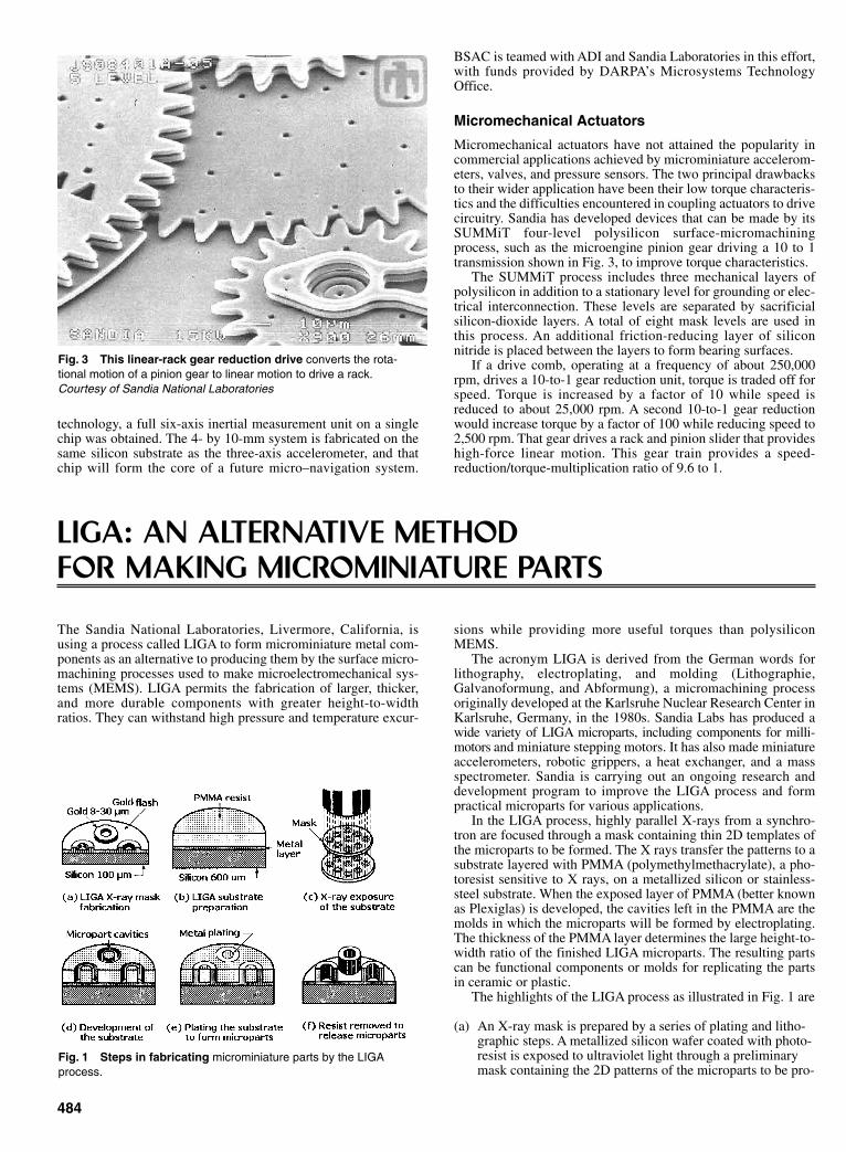
technology, a full six-axis inertial measurement unit on a singlechip was obtained. The 4- by 10-mm system is fabricated on thesame silicon substrate as the three-axis accelerometer, and thatchip will form the core of a future micro–navigation system.
484
BSAC is teamed with ADI and Sandia Laboratories in this effort,with funds provided by DARPA’s Microsystems TechnologyOffice.
Micromechanical Actuators
Micromechanical actuators have not attained the popularity incommercial applications achieved by microminiature accelerom-eters, valves, and pressure sensors. The two principal drawbacksto their wider application have been their low torque characteris-tics and the difficulties encountered in coupling actuators to drivecircuitry. Sandia has developed devices that can be made by itsSUMMiT four-level polysilicon surface-micromachiningprocess, such as the microengine pinion gear driving a 10 to 1transmission shown in Fig. 3, to improve torque characteristics.
The SUMMiT process includes three mechanical layers ofpolysilicon in addition to a stationary level for grounding or elec-trical interconnection. These levels are separated by sacrificialsilicon-dioxide layers. A total of eight mask levels are used inthis process. An additional friction-reducing layer of siliconnitride is placed between the layers to form bearing surfaces.
If a drive comb, operating at a frequency of about 250,000rpm, drives a 10-to-1 gear reduction unit, torque is traded off forspeed. Torque is increased by a factor of 10 while speed isreduced to about 25,000 rpm. A second 10-to-1 gear reductionwould increase torque by a factor of 100 while reducing speed to2,500 rpm. That gear drives a rack and pinion slider that provideshigh-force linear motion. This gear train provides a speed-reduction/torque-multiplication ratio of 9.6 to 1.
Fig. 3 This linear-rack gear reduction drive converts the rota-tional motion of a pinion gear to linear motion to drive a rack.Courtesy of Sandia National Laboratories
LIGA: AN ALTERNATIVE METHOD FOR MAKING MICROMINIATURE PARTS
sions while providing more useful torques than polysiliconMEMS.
The acronym LIGA is derived from the German words forlithography, electroplating, and molding (Lithographie,Galvanoformung, and Abformung), a micromachining processoriginally developed at the Karlsruhe Nuclear Research Center inKarlsruhe, Germany, in the 1980s. Sandia Labs has produced awide variety of LIGA microparts, including components for milli-motors and miniature stepping motors. It has also made miniatureaccelerometers, robotic grippers, a heat exchanger, and a massspectrometer. Sandia is carrying out an ongoing research anddevelopment program to improve the LIGA process and formpractical microparts for various applications.
In the LIGA process, highly parallel X-rays from a synchro-tron are focused through a mask containing thin 2D templates ofthe microparts to be formed. The X rays transfer the patterns to asubstrate layered with PMMA (polymethylmethacrylate), a pho-toresist sensitive to X rays, on a metallized silicon or stainless-steel substrate. When the exposed layer of PMMA (better knownas Plexiglas) is developed, the cavities left in the PMMA are themolds in which the microparts will be formed by electroplating.The thickness of the PMMA layer determines the large height-to-width ratio of the finished LIGA microparts. The resulting partscan be functional components or molds for replicating the partsin ceramic or plastic.
The highlights of the LIGA process as illustrated in Fig. 1 are
(a) An X-ray mask is prepared by a series of plating and litho-graphic steps. A metallized silicon wafer coated with photo-resist is exposed to ultraviolet light through a preliminarymask containing the 2D patterns of the microparts to be pro-
Fig. 1 Steps in fabricating microminiature parts by the LIGAprocess.
The Sandia National Laboratories, Livermore, California, isusing a process called LIGA to form microminiature metal com-ponents as an alternative to producing them by the surface micro-machining processes used to make microelectromechanical sys-tems (MEMS). LIGA permits the fabrication of larger, thicker,and more durable components with greater height-to-widthratios. They can withstand high pressure and temperature excur-
Sclater Chapter 14 5/3/01 1:44 PM Page 484

duced. Development of the photoresist dissolves the resistfrom the plated surface of the wafer, forming the micropartpattern, which is plated in gold to a thickness of 8 to 30 µm.The remaining photoresist is then dissolved to finish themask.
(b) Target substrate for forming microparts is prepared by sol-vent-bonding a layer of PMMA to a metallized-silicon orstainless-steel substrate.
(c) PMMA-coated substrate is then exposed to highly colli-mated parallel X rays from a synchrotron through the mask.
(d) PMMA is then chemically developed to dissolve theexposed areas down to the metallized substrate, etchingdeep cavities for forming microparts.
(e) Substrate is then electroplated to fill the cavities with metal,forming the microparts. The surface of the substrate is thenlapped to finish the exposed surfaces of the microparts tothe required height within ±5µm.
(f) Remaining PMMA is dissolved, exposing the 3Dmicroparts, which can be separated from the metallized sub-strate or allowed to remain attached, depending on theirapplication.
The penetrating power of the X rays from the synchrotronallows structures to be formed that have sharp, well-defined verti-cal surfaces or sidewalls. The minimum feature size is 20 µm, andmicroparts can be fabricated with thickness of 100 µm to 3 mm.The sidewall slope is about 1µm/mm. In addition to gold,microparts have been made from nickel, copper, nickel–iron,nickel–cobalt, and bronze.
An example of a miniature machine assembled from parts
485
fabricated by LIGA is an electromagnetically actuated millimo-tor. With an 8-mm diameter and a height of 3 mm, it includes 20LIGA parts as well as an EDM-machined permanent magnet andwound coils. The millimotor has run at speeds up to 1600 rpm,and it can provide torque in excess of 1 mN-m. Another exampleof a miniature machine built from LIGA parts is a size 5 steppermotor able to step in 1.8-deg increments. Both its rotor and statorwere made from stacks of 50 laminations, each 1-mm thick.
According to Sandia researchers, the LIGA process is versa-tile enough to be an alternative to such precision machiningmethods as wire EDM for making miniature parts. The featuredefinition, radius, and sidewall texture produced by LIGA aresaid to be superior to those obtained by any precision metal cut-ting technique.
In an effort to form LIGA parts with higher aspect ratios,researchers at the University of Wisconsin in Madison teamedwith the Brookhaven National Laboratory on Long Island to usethe laboratory’s 20,000-eV photon source to produce muchhigher levels of X-ray radiation than are used in other LIGAprocesses. The higher-energy X rays penetrate into the photore-sist to depths of 1 cm or more, and they also pass more easilythrough the mask. This permitted the Wisconsin team to usethicker and stronger materials to make 4-in.-square masks ratherthan the standard 1- × 6-cm masks used in standard LIGA.Working with Honeywell, the team developed LIGA opticalmicroswitches
The primary disadvantage to LIGA is its requirement for asynchrotron or other high-energy sources to image parallel X-rays on the PMMA covered substrate. In addition to their limitedavailability, these sources are expensive to build, install, andoperate. Their use adds significantly to the cost of producingLIGA microstructures, especially for commercial applications.
Sclater Chapter 14 5/3/01 1:44 PM Page 485

Index Terms Links Accelerometers, microminiature 475 Actuators
centrifugal force 225 for control of tension and speed 348 inchworm (piezoelectric) 172 linear, AC and DC 21 mechanical 5 425 microactuators 475 rotary 31 rotary, cartridge-operator 130
shaft, air-spring 186 solenoid-type 31
stepper motor-based 21 Adjusters
cam-motion 156 linkage-motion 156 valve-stroke 156
Adjusting devices 196 Adjustments, fine-focus 286 Air springs
bellows-type 186 rolling-diaphragm type 187 vehicle-suspension type 187
Amplifiers impulse 340 mechanical power
applications 221 capstan-type 221 windlass 223
motor, (servomotor), electronic linear 8 pulse-width modulated (PWM) 8
Arrangements cam-and-gear, for warning 341 cam-and-linkage 340 contact, switch, relay, electrical 360 gear-shift 282 weight-regulating 55
Ball bushing 129 cartridge 128 screws 2 12 slides 2 128
Ballistic particle manufacturing (BPM), (SeeRapid Prototyping) Bands
spiral clutch 307 spring 307 taut 185
Bearings air 5 ball 260

Index Terms Links Bearing, cont.
commercial 10 129 eccentrically bored 299 elastometric 289 linear roller 197 reciprocating, ball 129 sleeve 129
Bellcrank 147 Bellows
general 6 308 pressure sensing 183 365 382 394 397 temperature sensing 394 395
Belts bead chain 228 229 cable-chain hybrid 230 flat 227 flexible 342 hybrid 227 ladder chain, cable and plastic 230 tensioning 231 timing 227 228 230 with four-bar linkage 95 variable speed with chain 224 V- 227 wound helix wire 55
Bimetal elements and sensors 392 396 Bolt nut 5 Brakes
automatic hoist 408 band 336 caliper (disk) 340 clutches/brake systems 304 326 336 340 clutch, double-coil 327 electromagnetic with clutches with 326 foot-controlled system 378 reel, permanent magnet 387 slip 304 327 variable-torque drag 306
Bushings, torsion 300 Cams
basics 200 barrel 202 207 209 circular 201 circular-arc 204 205 computer emulation of 4 conical 159 constant-velocity 201 control 94 cut-out 154 cycloid, cycloidal motion in 203 cylindrical 200 double-faced 154

Index Terms Links Cams cont.
double-revolution 209 drives, for machine tools 210 dwell
adjustable 209 compensating for 204 quick-acting 209
eccentric 313 floating, quick-acting 209 general use 319 341 generating curves for 201 groove 125 indexing 209 jaws, in hydraulic cylinder 411 locking 104 lug, adjustable 210 mechanisms 207 pivot-point, adjustable 210 plate, increased-stroke 209 radial 200 reciprocal, (reciprocating) 159 207 roller position, adjustable 210 simple harmonic 202 sliding 154 208 slot 208 special-function 209 steel ball 208 straight-sided 317 swash-plate 208 three-dimensional 159 vibratory motion 207
Capstan 221 Cells
load 382 Peaucelliers’s 431 photo 384
Chains bead 229 drives (See Drives) gears, with 227 length changes 231 positive, infinitely variable (PIV) drive 226 roller
bushed 232 double 226 single 226
Chemical mechanical polishing (CMP) 478 483 Chucks, spring-loaded 424 Clamps
air spring 186 center-support 415 differential 195 double, for spindle head 414

Index Terms Links Clamps con t.
hold-down 175 friction 414 magnetic, permanent 388 piezoelectric 45 pedestal 415 quick-acting 412 right-angle 415 slide 414 specimen holder 415 spring 424 table 415 turntable 414
Clutches adjustable 155 backstopping 320 band
inside 336 outside 336 new-spiral 307
bidirectional 308 cam and roller 303 centrifugal 309 364 cone 302 342 design of 305 detent 308 dog, one-way 311 dual-spring slip 304 duplex, single- and double-coil 327 driving 321 eddy current 326 electrostatic 327 expanding-shoe 303 expanding shoe, centrifugal 303 fixed-field 326 free-wheeling 317 friction
general 302 magnetic 326 multiple-disk 323 single-plate 323
hysterisis 326 inchworm actuator 172 jaw 302 lawnmower 311 magnetic 326
friction 326 particle-and-fluid 327
magnetostrictive 327 mechanical
basic 302 small, for precise service 322
mercury-gland 303

Index Terms Links Clutches cont.
multidisk 317 multistation 325 one-way 312 overload relief 323 overriding 316 overrunning 285 311 318 320 pawl and ratchet
general 302 single-cycle, Dennis 322 single-cycle, dual control 322
planetary transmission 302 322 plates 302 346 roller
general 307 312 locking, bidirectional 328 trip 328
rotating-field 326 shifting mechanism for 284 286 sprag-type 307 311 312 320 spring
basic 314 controlled 306 dual 304 slip 304 spring-wrapped 303 stepped 305
spring and ball radial detent 303 station, one and/or two 324 325 wedging ball or roller
external 311 internal 311
Commutation (See Motor commutation) Computer-aided design (CAD)
drafting, 2D software 464 glossary of terms 467 modeling, 3D software
feature-based solid 466 hybrid surface and solid 467 solid 466 wireframe and surface 465
preparation for rapid prototyping 468 software improvements 464
Computer-aided engineering (CAE) 465 Computer-aided manufacturing (CAM) 465 Connections
parallel-link 295 splined 367 418
Controls automatic weighing and filling 398 carton sorting 398 closed-loop 2 34 43

Index Terms Links Controls cont.
fine-focus 286 gas range 394 hydraulic winch 222 inspection, photoelectric 399 motion 2 open-loop 2 4 photoelectric 64 84 398 position-loop 2 refrigerator 395 room-temperature, heavy-duty 395 sequencing sheet-cutting 340 techniques
derivative 4 intregral 4 proportional 4 proportional-integral derivative (PID) 4
tension 352 speed, and 348 383
thermostatic 393 torque-loop 2 velocity ( speed) loop 2
Controllers actuators with 348 351 400 differential 351 float-switch 400 indicators, with 400 level-controller, switch-actuated 401 liquid level
electrical 400 magnetic 401
motion 2 4 6 8 on-and-off 348 programmable logic, (PLC) 2 proportioning 348 proportioning-throttling 349
Coordinate system, six-degree-of-freedom 2 Conversion (Converters)
rotary-to-linear motion 100 130 229 rotary-to-oscillatory 229 torque
Constantino 259 MEMS 479
Conveyors 68 237 240 320 399 Coordinate system, six degree of freedom 2 Coulisse 108 Counters
electronic, high-speed 384 magazine 384 pulse 365
Couplings (couplers) bellows 6

Index Terms Links Couplings (couplers) cont.
Bendix-Weiss 331 bent-pin 337 Bossler, design of 298 constant-velocity joint 331 crossed-axis yoke 294 disk-and link 295 drive-shaft, flexible 297 eight-joint 308 flexible shaft 331 fluid 145 345 four-bar 206 four-link 300 grooved-sphere joint 330 Hooke’s joint 297 304 330 instrument, PM 387 light-duty 331 mechanisms, special for 337 misalignment cancelling 299 offset shaft 295 Oldham 294 parallel link 151 295 308 337 parallel shaft 295 pin-and-slot 338 pinned-sleeve 330 pinned-sphere shaft 330 pipe-joint 308 power transmission 300 pump-type 331 rotating shafts, methods for 332 Rzeppa 331 Schmidt 296 six-disk 337 slip-spring 311 space-frame 297 spring-plunger 345 square-plate 298 steel-shot 345 three-plate rectangular 298 Twiflex 300 universal 297
Cranks double parallel 430 fixed 432 gear-oscillating 116 gear-slider 116 input 432 nonparallel 430 output 432 parallel, four bar 430 reciprocating-space 117 rotating 431 slide, 3D 169

Index Terms Links Cranks cont.
space 170 spherical 167
Detectors, jam 399 Detents
axial 417 magnetic 417 Detents cont. positive 416 417 radial 417 stopping movement for 94 416 roller 417
Devices adjustable
pitch 115 speed 115 spacecrank 115
adjusting 196 anti-backlash 319 cartridge-actuated 402 clamping 56 414 422 clamping and cutting 56 cushioning 175 differential transformer sensing 382 elliptical-gear planetary 115 expanding and contracting 134 four-bar cutter 56 friction for intermediate rotary motion 122 123 gaging and calipering 383 geared cocking 214 latch, toggle and trigger 213 orienting
cone-shaped parts 53 dish-like parts 52 pointed-end parts 52 short, tubular parts 52 stepped-disk parts 53 U-shaped parts 53
pyrotechnic, power 402 rack-and-pinion 234 rotary-to-reciprocating 92 114
in-line reciprocator 114 track-switching scotch yoke 114
rotation-to-translation 191 scotch-yoke 202 screw 191 self-locking 192 simple feeding 53 snap-action 217 sorting 54 speed control for mechanisms 366 tension control 383 387

Index Terms Links Devices cont.
tilting 208 time-delay switching 130 toggle 213 translation-to-rotation 192 variable-speed 115 weight-regulating 55 warning, boom overload 341
Diaphragms capsules, with, applications of 380 differential pressure 382
Differentials bevel-gear 159 planetary-gear 163 rotating-link 159 sliding-link 159 spiderless 285
Diffusion 476 Directed-light fabrication (DLF) (See Rapid Prototyping) Direction changes, straight-line 142 Direct-shell production casting (DSPC) (See Rapid Prototyping) Disconnector, quick 403 Disks
friction 343 encoder 22
absolute 23 incremental 22 Sellers’ 254
spring-mounted 175 Drawings, 3D 464 Driller, parallel-link 151 Drives (drivers)
adjustable chain 155 clutch 155 cone 245 harmonic 113 pivot 155 slider 155
angle-doubling 152 angular-momentum-balanced, robot 48 ball-and-cone 250 ball-and-disk, and 251 ball-and-screw 5 12 bearings and roller 117 belt 12 224 257 belt-and-chain, variable speed 224 cam for machine tools 210
for tool-slide mechanism 210 two-directional rack-and-gear 210

Index Terms Links Drives (drivers) cont.
chain adjustable 155 double-roller 226 general 153 226 234 353 ladder, differential 229 oscillating 118 for reducing pulsations in 238 single-roller 226 slider 118 with chain 118
clutch adjustable 155 double-spring 282 314 spring, double 314 comb,electrostatic 476 484
cone adjustable 245 ball, and 250 belt 245 general 244 254 257 Graham 246 electrically-coupled 245 planetary 246 ring, and 246 roller, and 257 two 245 curve-slider 121
differential fixed 270 general 352 robot 48
disk adjustable 247 and roller 117 256 ball, and 251 general 247 256 planetary 247 spring-loaded 247
double clutch 282 eccentric 206 impulse 319 ring 248 shift 282 sphere 249 spring clutch 314 toggle-puncher 153
drum and roller 257 electrical 352 electrostatic comb 476 epicycloids, (cycloid)
equations for 442

Index Terms Links Drives (drivers), epicycloids, (cycloid) cont
reciprocator 113 elliptical-motion 113 elliptical-slide 171 fast-reversal reel 310 flowmeter 389 Ford tractor 273 friction 142 143 256 full-wave rectifier 314 gear
compound spur-bevel 273 oscillating crank 121 rack 153 robot 48 sector 152 slider crank 121 wobble 274
geneva, modified 106 Graham 246 harmonic
adjustable 113 speed-reducer 263 triple 121
Hooke’s joint, skewed 168 hydraulic 353 hypocycloid, (cycloid), equations for 443 impulse 252 319
double 319 Morse 252 variable-stroke 252 zero-max 252
intermittent, “mutilated tooth” 108 leadscrew drive 5 lever and cam 148 light-duty 342 linear reciprocator 117 linkage chain 153 low-torque 179 lubricator, Torrington 258 Lycoming turbine 273 Maltese cross, double, six-sided 109 mechanical 352 missle silo cover 268 Morse 252 motor (See Amplifiers) motor scooter 240 multicone 115 multiple disk 251
ball-and-disk 251 oil-coated 251
multiple ratio 283 nutating-plate (nutation) 243 offset 145

Index Terms Links Drives (drivers ) cont.
one-way 314 oscillating
crank and planetary 118 progressive 105
parallel cable 230 link coupling 151
plate 151 pitch 115 pivot, adjustable 155 planet, planetary 106
coupled 269 triple 272 two-gear 274 simple with inversions 271
planocentric 274 pulley 152 rack and gear, two-directional 210 ratchet, modified 96 ratios, four, six, and eight 283 reciprocating-ball 315 reciprocating-table 150 redundant torque 289 ring, double 248 ring with pulley 248 rod 146 shaft, in-line 287 shift, double 282 shuttle-gear 315 shuttle-pinion 314 slide, elliptical 171 slide-key 282 slider, adjustable 155 sliding change 282 space crank 170 space crank, adjustable 115 speed change, ratchet-tooth 287 sphere
disk, and 249 double 249 roller, and 249
speed 318 spherical 249
ball-and-cone 250 crank 167 disk, with 249 slide oscillator 168 tilting-ball 249
swivel-gear 282 tension controlling 352 three-dimensional 167 three-dimensional crank-slide 169

Index Terms Links Drives (drivers) cont.
three gear 119 toggle-and-cord 149 triple -shaft 283 Twinworm, gear 287 typewriter 153 unidirectional 253 320 universal, joint 169 valve 141 variable-speed, mechanical
belt-and-chain 224 friction 256 general 224 245 254 256 258 and transmissions 258
variable-stroke 252 wheel and slider 121 Whitworth quick-return 121 worm 5 109 zero-max 252
Electromagnetic force 476 Electromagnets 391 Electron microscope, scanning, (SEM) 478 Electron microscope, scanning, (SEM), MEMS, images from 478 Electrostatic force 475 476 Emulation, electronic 7 Encoders, (See Sensors, feedback) End-effector (See Robots, industrial) Epicycloid, (epicyclic) 111 113 481 Epitaxy 476 Escapement
cam-operated 109 controlled output 105 meter 109 ratchet-gear 109 solenoid-operated 109
Fan 318 Fasteners
hub-to-shaft 421 probe-and-socket 428 toggle 407
Feeders (feeds) centerboard selector 19 chutes and tubes 8 19 21 long cylinder 19 paddle wheel 19 parallel-link 151 reciprocating 19 rotary centerblade 19 rotary screw 19 vibratory bowl 25

Index Terms Links Filter, PM 388 Fixtures, holding 424 Fingers, for stopping 347 Flexspine 264 Flexures 183 Flowmeter 291 383 Flywheel, malfunction 261 Focus adjustments 286 Function generators 159 Fused deposition modeling (FDM)
(See Rapid prototyping)
Gages float 401 pressure 148 381
absolute 381 Bourdon 341 differential 381
strain 335 341 Gearheads 10
right-angle 10 straight 10 11
Gearmotors 49 Gears (gearing)
bevel 10 11 144 159 243 313 367Humpage’s 271 spiral 10 292 straddle-design of 292
Cardan 140 141 circular 97 classification 242 combining 290 compliant 289 computer emulation of 4 cycloid 99 design of spiral beval and hypoid 292 differential 364 direction changing 143 eccentric 278 elliptical 97 115 275 278 431 epicyclic 481 external 243 face 243 290 flexible face 266 harmonic 263 helical 119 243 287 314 herringbone 243 hypoid 243 292 hypoid, straddle-design of 292 idler 311 313 indexer, for indexing 94 114 indexer with eccentric disk 94 internal 243

Index Terms Links Gears (gearing) cont.
lever and sector 148 miter 243 noncircular 275 pinions 243 pinions
balanced 10 coupled and racks 143 planet 141 sheet-metal cup 279 spur-gear type 290 torque-splitting 367
planet (planetary) elliptical 115 general 99 106 112 239 263 general, cont. 268 290 329 357 432 442 geneva 103 104 helical 10 mechanism 110 odd-shapes 97 offset 375 oscillating 94 segments, matching 143 simp le 271 systems
cam-controlled 125 external 432 general 239 268 internal 432 rack-and-pinion 143
ratio 347 ring 94 99 112 263 267 289 ring, cont. 352 432 443 rolling 443 444 sheet-metal 279 shift arrangements 282 shifting, (gears and clutched) 284 sine-function 278 spiral, logarithmic 278 spur 276 289 321 square 276 straight-line direction change, for 143 strain-wave 264 sun 97 113 141 263 289 sun cont. 432 442 terminology tooth 242
dynamics 243 torque-splitting 367 train, epicyclic 481 traveling 313 Twinworm 287

Index Terms Links Gears (gearing) cont.
wooden-tooth 263 worm 99 109 244 279 357 worm with hydrostatic engagement, with 290
Generators DC 352 elliptical cam wave 264 function 159 164
Genevas coupler-driven 207 double with differentials 205 drives
conventional 82 84 double-eccentric 206 intermittent 107 modified 106 twin 103
dual-track 104 eight-station 205 external wheel
charts for angular acceleration 438 position 437 velocity 437
eight-slot 437 formulas for 436 five-slot 103 four-slot 103 104 106 437 kinematics data for 436 six-slot 103 436
four-bar 103 four-station 205 groove cam 103 internal wheel
charts for angular acceleration 438 displacement 440 velocity 441 eight-slot 437 formulas for 439 four-slot 104 409 439 kinematics data for 439 six-slot 440 slot-crank motion 439
locking-arm 103 locking-slide 103 long-dwell 104 modified drives 106 modified-motion 104 noncircular 97 oscillating output 92 planetary-gear 81 rapid-transfer 104

Index Terms Links Genevas cont.
ring-gear 103 spherical 110 wheels 97 436
Governors auxiliary piston 362 centrifugal 363 364 constant-volume 363 differential, varying 363 electrical 365 force-compensated 362 hit-and-miss 362 hydraulic 365 pneumatic 364 pressure-actuated 363 speed, automatic 362 366 velocity-type 363
Grapple, automatic 407 Gripper, leaf-spring 424 Gripping System formechanical testing 426 Guides, general 143 Guides, linear, single -axis
air-bearing 5 ballscrew-driven, (actuated) 2 3 12 belt-driven 2 12 direction change, for 143 hydrostatic 5 leadscrew-driven 2 magnetic levitation (Maglev) 5 nested 135 rolling elements, circulating or
noncirculating 5 sliding, friction contact 5
Hall-effect Device (HED) (See Motors commutation)
Hammers, electrically driven 390 Hammers, spring-operated 391 Hoist 355 408 Holder, instrument 388 Holding fixtures, spring-loaded 424 Hook release, emergency 403 Hoppers 19 21 23 Hydraulics
control system 220 353 cylinders 318 336 341 376 378 drives 353 intensifier, multi-plunger motors 353 pumps, feed 82 353 receiver 220 robot drive, receiver 22 sender 220

Index Terms Links Hydraulics cont.
sensors 365 switch, pressure 378 valves 82 winch control 222
Hydrostatic engagement 290 Hypocycloid 89 91 111 112 140 Indexing (Indexers)
belts, timing and four-bar linkage for 95 gears and eccentric disk for 94 general 175 plunger-actuated 114 quick 94 single-tooth 92 114 smooth 95 star wheel 100
Indicators automotive, dashboard 393 400 bellows-actuated 400 bimetallic 401 diaphragm-actiuated 400 liquid level, automotive 400 liquid level with controller 400 motion 348 power 348 pressure 220 349 401 primary 348 secondary 348 speed and tension 350 temperature 220 349
Inductosysns (See sensors feedback) Input/output (I/O)ports 7 Instruments, recording and controlling 397 Integrated circuits, CMOS 482 Integrated microelectromechanical
systems (IMEMS) 482 Interference, electromagnetic, (EMI) 7 Jaws, cam-locked 411 Jaws, robot 38 Joints
ball 308 ball-and-socket 301 Bendix-Weiss 331 cam 163 captive, passive 427 constant-velocity 330 cylinder 166 cylinder-plane 166 grooved-sphere 330 helix 166 Hooke’s, skewed 168 301 330
Index Terms Links Joints cont.
plane 166 prism 166 revolute 166 robot 43 rotary 163 rotary, geared, electromechanical 329 Rzeppa 301 331 sliding 163 sphere
groove 166 grooved helix 166 plane 166 slotted cylinder 166 slotted helix 166
torus 166 torus, helix 166 True-speed 301 universal 183 169 294 301
constant-speed 301
Keys 344 420 Kinematics
external geneva wheel 436 internal geneva wheel 439 for planar manipulation 43
Knee-joint tester 445 Laminated-object manufacturing (LOM)
(See Rapid Prototyping) Lasers
carbon dioxide IR emitting 470 471 helium-neon UV emitting 468 interferometer, for closed-loop feedback 6 8 22 27 neodymium YAG 473
Latches cam-guided 213 cocking with lever for 213 locking 211 perpendicular-force 409 remotely controlled 406 sleeve 213
Leadscrew positioning 131 Lever systems 149 LIGA process (techniques) 476 484 Limiters
friction-clutch torque 343 overloading prevention, for 343 shear pin 343 torque, protection 342 shaft rotation 346
Linear guides (See Guides single-axis) Linear resonator 476

Index Terms Links Linear variable differential transformers
(LVDTs) (See Sensors feedback) Linkage, links
accelerating /decelerating linear strokes 146 articulating 300 closed-loop 43 crank and rocker 430 445 Daniel’s 133 D-curve 139 D-drive 137 differential 163 door-check 212 drag 431 eight-bar 150 Evans’ 133 136 five-bar 432 four-bar
general 95 137 167 212 430 general cont. 432 445 456 industrial applications of 430 parallel crank 430 sliding member, with 430
hinged 300 hypocyclic-drive inventors of
Daniel 132 Evans 132 Isoceles 138 Peaucellier 137 Roberts 132 Scott-Russell 132 Tchebicheff 132 Walschaert 138 Watt, James 132
Isosceles 138 430 linear force 186 linear strokes, accelerating and
decelerating, for 146 long-kick 133 motions for
direction change 142 430 multiplying short 148 other 139 sliding 431 slow 430 straight-line, for 132 136
nonparallel equal crank 430 offset shaft 295 pantograph 138 parallel-link feeder 151 parallelogram 151 Peaucellier’s 137 431 ratios for straight-line mechanisms 138

Index Terms Links Linkage, links cont.
reciprocating linear force, air spring 186 Roberts’ 138 rotary force, air spring 186 rotating crank 431 sacrificing 218 scotch-yoke inversion 202 short-kick 133 spring-type 190 steering actuation for a tractor 378 Tchebicheff’s 138 431 toggle, in different applications for 123 211 215 transport mechanisms, for 65 trapezoidal 430 Walschaert’s 138 Watt’s 136 138 430 Watt-Evans’ 133
Lock pin, quick-release 408 Machines
adhesive applications 76 automatic shear 89 coil-winding 384 cut-off 399 folder or yarder 89 label application 75 loom 89 riveting 211 212 routing 223 stone-crushing 211 tensile testing 222 winding 73
Magnets, magnetic alnico 14 ceramic 14 clutches 327 designing with permanent 385 detent 417 mechanisms 387 permanent, (PM) 342 rare-earth 14
Manipulators (see Robots industrial) Maltese cross, six-sided 109 Mechanisms
adjustable output 156 adjustable stroke 155 adjuster
cam-motion 156 linkage-motion 156 piston-stroke 157 valve stroke 156
agitator 153 air-spring 186

Index Terms Links Mechanisms cont.
angular motion 455 automatic
feed 62 safety for operating machines 90 stopping, electrical 88 stopping, for faulty machines 82
bobbin changer 86 cam
cut-out 154 double 156 double-faced 154 follower motion, fast 120 function generator 164 ideas for 207 sliding 154
cam-and-rack 153 Cardan-gear 140 chain
adjustable 155 oscillating 118 slider, and 118
clutch adjustable 155 one-station 324 scribing 151 two-station 324
computing 159 counting (counter) 110 340 coupler (coupling)
four-bar 206 link 329 338 special 337
crank double-parallel 430 gear, oscillating 121 gear, slider 121 nonparallel equal 431 parallel 338 reciprocating space 117 rotating 431
crank and rocker, four-bar, design of 445 curved-motion cutter 57 curve generating 201 cutting (cutter) 56
clamping and 56 curved-motion 57 four-bar 56 parallel 56 slicing 57 vertical 57 web 57

Index Terms Links Mechanisms cont.
cycloid, cycloidal curves, family of 203 equations for the design of 442 gear 99 modified 203 generating 203 motion 202 parallelogram 112 reciprocator 113 rocker 112
differential bevel-gear 159 general 159 planetary-gear 163 rotating-link 159 sliding-link 159
differentiator 162 direction-changing 142 dwell
cam-helical 119 cam-roller 119 cam-worm 118 double-crank 119 double, hypocycloid 111 epicyclic 118 long 118 rotary, short 112 short 121 six-bar 119
drive bearing-and-roller 117 disk-and-roller 117 three-gear 119 long 118 triple harmonic 121 Whitworth quick-return 121 wheel-and-slider 121 worm 109
eccentric pivot point 157 elliptical-motion drive 113 epicycloid
oscillating-output geneva 114 plunger-actuated indexer 114 reciprocator 113 single-tooth indexer 114
escapement, electric meter 109 external geneva 110 fast-cam follower motion 120 feed 52 feeder for curvilinear motions 456 firing-pin 214 flipping 58

Index Terms Links Mechanisms cont.
gear (geared) Cardan 140 five-bar, designing 432 Jensen’s ring and slider 450 planetary 88 ring and slider 450 slider 448
generator, function 159 164 geneva
external 110 general 103 internal 110 long-dwell, drive (slotted) 111 spherical 110
guidance, parallel 83 hammer, electrically driven 390 handling, part 26 harmonic drive, adjustable 113 hypocycloid 89 111 140 hydraulic cylinder actuated 376 indexing (indexer) 72 86 94 indexing and intermittent 108 integrator 162 164 intermittent motion 97 120 intermittent counter 110 internal geneva 110 leadscrew positioning, triple-ganged 131 lever, double 431 lift-tong 409 link-coupling 338 long-dwell 118 long-kick 133 magnet, permanent (PM) 387 motor, spring 181 oscillating
chain 116 118 crank and planetary 118 output geneva 114
over-centering 216 overriding spring for low-torque drives
two-directional override 179 unidirectional override 179
parallel crank 338 cutter 56 guidance 105 link 150
parallelogram, cycloidal 112 parts handling 52 pericycloid 111 permanent magnet 387 pin-and-disk 122

Index Terms Links Mechanisms cont.
pin-and-disk, sliding 123 piston-stroke adjuster 157 pivoting 138 pivot, point-eccentric 157 planar manipulation 43 planetary gear 110 pneumatic-cylinder actuated 145 376 press, toggle 212 pump, rotary 374 pulsating planetary, Frudensteins’s 97 pulse reduction in chain drives, for 238 quick-release 410 quick-release and positive locking 410 rack-and-gear sector 116 rack-and-pinion 38 reciprocator, reciprocating
cycloidal 113 in-line 114 lever 38 linear 117 rotary to 114 track-switching, scotch yoke 114
reversing 158 ring gear and slider 450 ring and slider, Jenson’s 450 robot 34 rocker arm and disk 123 roller-dwell 119 rotary, short-dwell 112 rotary-to-reciprocating motion and dwell 116 rotary pump 374 rotating crank 431 screw 194 screw, double-handed 150 sector, rack-and-gear 116 Sellers’ disk 254 Shifting, for gears and clutches 284 short-dwell 121 short-kick 133 six-bar dwell 119 slicing 57 slide, slider
adjustable 155 ballscrew-driven 3 crank 461
sliding pin and disk 123 snap-action 215 sort 52 sort, feed or weigh 52 sorting 8 20 space, four bar 165 spherical geneva 110

Index Terms Links Mechanisms cont.
spiral and wheel 110 springs, flat, in 174 stop, simple 61 straight-line, linkage ratios for 138 straight-line, Watt’s 430 straight-line 132
Roberts’ 431 stroke-amplifying 154 stroke-multiplying 154 synchronizer, shaft 157 temperature regulating 396 tensioning 150 tensioning, arm and disk 123 tensioning, cycloidal 112 thermostatic 392
cam 154 chain 118 four-bar 116 single-axis (See Guides, single-axis)
three-dimensional, (3D) 156 165 three-gear drive 119 toggle
link and disk 123 press 212 quick-release 410
tool changing, robot 44 transport 65 transversing, for winding machines 73 triple pivot 150 vibrating 58 washing machine 168 web cutting 57 wedge and disk 122 weigh 52 weight-regulating 55
Microaccelerometers 475 483 Microactuators 475 482 484 Microcontrol systems, integrated (MEMS) 482 Microcontrol systems , three-axis inertial
measurement 483 Microelectromechanical systems (MEMS) 475 Microelectromechanical systems (MEMS)
Images, gallery of 478 Micrographs, scanning-electron microscope
(SEM) 478 484 Micro-inertial systems, three-axis 483 484 Micromachines 475 484 Micromachining (fabrication)
bulk 477 multilevel 478 surface 476 477 483
Micromechanical actuators 484

Index Terms Links Microminiature, (micro-)
flow sensors 476 fuel injectors 475 gear-reduction drive 481 484 inertial systems, three-axis 483 484 inkjet nozzle 476 locks 482 motors 475 484 motors for microtransmissions 481 optical mirror arrays 478 positioner 286 pressure sensors 475 pumps 475 steam engine 481 transducers 475 transducers, piezoelectric 477 transmissions
with gear reduction 480 multispeed, for small motors 481
valves 475 476 Mold shape deposition manufacturing
(MSDM) (See Rapid Prototyping) Motion control
incremental 4 motors for (See Motors) point-to-point 4 Motion control cont. sequencing 4 speed (velocity) 4 torque 4
Motion controller, (See Controller, motion) Motion control systems 2
card for 2 classification of
closed-loop 2 3 8 derivative 4 integral 4 position 4 PID 4 proportional 4 open-loop 2 4
computer-aided emulation in 4 electric powered 2 electronic components for 6 feedback sensors for (see Sensors, feedback) glossary of terms for 9 installation and operation 8 interpolation
circular 4 contouring 4 linear 4 7
mechanical components form 4 13 microcomputer-controlled X-Y table 13

Index Terms Links Motion control systems cont.
pick and place X-Y 13 punch press 13 X-Y inspection 13
Motors AC, rotary 14 21 commutation
Hall-effect (HED) 7 16 18 linear servomotor 18 magnetic 17 mechanical (brush-type) 7 14 sinusoidal 18
comparison of stepping and servo 7 conical-rotor for bra king or clutching 310 drivers (See Amplifiers) DC servomotors, rotary, PM 11 14 15 19
brushless 7 14 16 brush-type 7 14 15 coil-type armature 14 15 cup or shell-type armature 14 15 disk-type armature 14 15 wound armature 14
electric 2 14 34 hydraulic 34 353 linear, servomotors 7 14 17
advantages of 19 coil assembly 19 iron-core 18 ironless 18 installation of 19 hydraulic 34 353
microminiature 475 476 479 motion control, for 7 14 mount, pivoting 231 piezoelectric 45 pneumatic 34 selection of 7 selsyn 353 spring 181 stepper (stepping) 7 14 19 68
applications for 20 hybrid 20 permanent-magnet (PM) 20 variable reluctance (VR) 20 wedge, MEMS 478 479
Multipliers force and stroke 152 stroke 150 three-gear stroke 116
Oscillators dual-mass, MEMS 479 wide-angle 152

Index Terms Links Pantograph 431 Pericycloid 111 Photosensors 398 Piezoelectric
actuator 45 172 actuator clamp 45 actuator rotator 45 crystal 345 effect 476 films 475 477 motors (see Motors, piezoelectric) transducer 477
Pinions (see Gears) Pivots, frictionless-flexure 183 Pivots, point-eccentric 157 Platform, motion, X-Y-Z 2 Plunger, spring 345 Pneumatic
cylinder 145 376 direction changer 145 dump valve 216 power applications 379
Positioner, linear micron 286 Positioning, leadscrew with three-point gear 131 Potentiometer (See Sensors, feedback) Press
direct-acting air 186 punch 211 319 safeguards for 398 toggle 212
Pressure plate, walking 309 Profile, trapezoidal velocity 3 Prototyping (See Rapid prototyping (RP)) Pulleys
ball-controlled 225 cam-controlled 225 general 229 341 spring-loaded variable pitch 225
Pumps design and operating principles of 370 eccentric disk 374 flexible-vane 370 374 gear 374 gearless 372 Hele -Shaw-Beacham 375 high pressure 370 high vacuum 373 high volume 370 hydraulic 371 intensifier, multi-plunger 373 internal screw 373 oscillating-arm 375 Rameli 374

Index Terms Links Pumps cont.
rotary, rotating compressor 374 cylinder block 375 general 370 offset planetary gears in 375 positive-displacement 375 reciprocating 375
Rootes compressor 374 self-priming 373 squeegee 372 stroke control 99 three-screw 374 worm-type 296
Puncher, double-toggle 153 Rack, locking 94 Rapid Prototyping, (RP)
ballistic particle manufacturing (BPM) 468 472 CAD preparation for 468 474 directed light fabrication (DLF) 468 473 direct-shell production casting (DSPC) 468 472 fused deposition modeling (FDM) 468 471 general 468 laminated-object manufacturing (LOM) 468 470 mold SDM, (MSDM) 474 research and development in 473 selective laser sintering (SLS) 468 470 Rapid Prototyping, (RP) cont. shape deposition manufacturing (SDM) 473 solid ground curing (SGC) 468 469 stereolithography (SL) 468 three-dimensional printing (3DP) 468 472
Ratchets cam-driven 109 drive 96 109 211 215 322 friction 211 general 124 internal 311 layout 460 sheet-metal 279 solenoid-operated 109 toothless 124
Reciprocators cycloidal 113 epicycloid 113 in-line 114 linear 117 rotating-cam 105 sinusoidal 105 track-switching scotch yoke 114
Recorders bubbler type 400

Index Terms Links Recorders cont.
float 401 general 383
Regulator, nonindicating 397 Relays
overload 392 thermostatic 393 time-delay 393
Release emergency hook 403 Pressure, PM 388
Reducers impact 212 ball-bearing 260 cammed-gear 115 four-stage 266 harmonic -drive 263 one-way output 313 two-stage 266
Resolvers, electromechanical (See also Sensors, feedback)
Resonator, linear 476 Reversers
double-link 158 toggle-link 158 Watts’ modified 158
Rheostat, shunt-field 346 Roberts’ Law 459 Robots, industrial 34
advantages of 35 all-terrain vehicle 49 axes 36 characteristics of 35 definition of 34 categories 36
articulated, revolute or jointed arm 36 cartesian 36 cylindrical 36 polar coordinate, (gun-turret) 36 vertically jointed 37
continuous-path 34 controlled-path 34 degrees-of-freedom 34 drives, roller and gear for 48 end effectors 36 43 electric -powered 34 floor-standing 34 gantry, (overhead configured) 36 end effectors 44 finger joints for 45 floor-standing 34 grippers, hand-like 36 38 hydraulic-powered 34

Index Terms Links Robots, industrial cont.
jaws piston-operated 38 rack and pinion 38 reciprocating 38
manipulators general 34 36 43 six-degree-of freedom 34 46 two-arm, self reconfigurable 47
mechanisms for planar manipulation with simplified
kinematics 43 tool-changing 44
nonservoed 34 pendants 34 pick-and-place 34 point-to-point 34 self-configurable, two-arm 47 servoed 34 specifications for Fanuc robots 38 tool changing for a 44 tools 34 trends 35 unlimited sequence 34 wrists
general 34 36 three-degree-of-freedom 38 two-degree-of-freedom 37
Rollers 342 Rollers, ring latch 257 Scotch yoke 114 140 Screws
arrangements, special 195 ball bearing 130 devices 191 differential 193 196 double-threading/threaded 193 mechanisms, applications 194 motion translation/transformation 191
Seals, force-balanced 381 Seals, pressure 381 Selective laser sintering. (SLS)
(See Rapid Prototyping) Selectors, parts 59 Sensors, feedback
encoders, rotary, optical 3 8 22 absolute 8 22 23 brush-type 22 hollow-shaft 22 incremental 8 22 linear, optical 3 6 8 22 23 rotary, magnetic 22 24
Index Terms Links Sensors, feedback, encoders cont.
rotary, optical 8 22 Inductosyns 8 27 laser interferometers 3 6 8 22 27 magnetic 17 24 potentiometers, precision multiturn 8 22 28 resolvers 8 17 22 24 servosystem 22 tachometers 8 22 25 365 389 transducers, angular displacement, (ADTs) 22 26 transducers, linear velocity, (LVTs) 22 26 transformers, linear variable displacement
(LVDTs) 8 22 26 Sensors, pickup, magnetic 340 Sequencer, compact rotary 267 Servomotors (See Motors) Servosystems, feedback sensors for 22 Shape deposition manufacturing (SDM)
(See Rapid Prototyping) Shafts, splined 420 Shafts, tapered 420 Sheaves, cam-controlled 225 Sheaves, design of 225 Sleeve, cammed 344 Sleeve, splined 344 Slides, ball for linear motion 128 129 Slides, linear, single -axis (See Guides,
Linear, single-axis) Slideblocks 146 Solenoids
applications for 31 box-frame 30 C-frame 30 general 29 59 62 123 145 365 open-frame 30 tubular 29 30 rotary 30
Solid ground curing (SGC) (See Rapid Prototyping)
Space frames 297 Splines
circular 264 cylindrical 418 face 419 flex 264 involute-form 418 419 machine-tool 418 square 418 straight-sided 418 taper-root 419
Sprags 174 307 311 316 318 320 Springs
air 186 187

Index Terms Links Springs cont.
applications for 174 axial compression 190 belleville 189 355 bowed 217 cantilever 190 coil 188 190 317 342 363 compression 190 flat, in mechanisms 174 184 helix, Hunter’s 176 leaf 188 218 motors 181 overriding mechanisms 179 pop-up 176 ring 411 return, in mechanisms 175 rubber, molded 188 stem, DeHaviland’s 176 tapered-pitch 188 tension 190 218 torque 190 torsion 188 190 variable rate from 188 vibration control/isolation 190 volute, in mechanisms 173
Sprockets 228 Sprockets, driving and driven 227 Sprockets, sheet-metal 279 Stages, linear (see Guides) Stereolithography, (SL) (See Rapid Prototyping) Sterling engine 432 SUMMiT process 478 484 Switches
limit actuators 356 fail safe 355 latching 357 linear mechanical 356 machinery, in 358 rotary cam 357 rotary geared 357
mercury 84 89 microswitch 91 229 reed 341 snap-action 388 snap-action, toggle 453 toaster 212 two-way 145
Systems ballscrew driven, single -axis motion modular 12 belt-driven
coaxial-shaft 224 double-reduction 224
Index Terms Links Systems, belt-driven cont.
fixed-distance 224 variable-distance 224
braking, foot-controlled 378 carburetor 393 clutch-brake 340 control (See Control systems) closed-loop (See Motion control) electric, for motion control 2 hydraulic control 220 mechanical, for tension and speed control 348 microcontrol systems, integrated (MEMS) 482 microcontrol systems, three-axis inertial
measurement 483 motion control (See Motion control systems) open-loop (See Motion control) planetary gear 239 268 servo (See Motion control) single-axis motion, modular 12 Sterling engine 432 X-Y
inspection 13 pick-and-place 13 table, microcomputer-controlled 13
Table, indexing 318 Tachometers,(see Sensors, feedback) Telecheric 35 Thermal expansion 475 476 Thermometer, recording 392 Thermostats
automobile cooling water 394 automatic gas range 394 electric range 394
Three-dimensional printing (3DP) (See Rapid Prototyping)
Toggles linkage 123 180 211 213 216 snap-action, (over-centering), design of 452 typical applications for 453
Torque control (see Control systems) converter, Constantio 259 limiters 342 splitter, floating pinion 367
Transducers (See also, Sensors, feedback) pressure 183 tension-to pressure 341
Transformers (See Sensors, feedback) Transmissions
ball-type 355 belt, for motor scooter 240 Constantino torque converter 259

Index Terms Links Transmissions cont.
Cruise-O-Matic, 3-speed 272 Fordomatic, 2-speed 272 general 296 Graham 255 helicopter 290 Hydramatic, 3 speed 272 lever
cam, and cord 148 chain 149 type 148
Morse 259 spiral-feed 149 Thomas 259 variable-speed 258 353 worm-gear 290
Transmitters, pressure bellows, gage 382 Bourdon-tube, absolute 382 diaphragm, differential 382
Turnbuckle, short, in-line 424 Vacuum pickup 75 Valves
circulating water control 394 dual flow 403 pilot, lever-type 397
Variator, cammed gear speed 115 Vehicle, all terrain 49 Velocity profile, trapezoidal, motor V-grooves 128 Washers, belleville 172 Wedges, sawtooth 426 Wedges, sliding 145 343 345 Wheels, star 100 Winch, differential, standard 219 Winch, Hulse 219 Worms, sheet-metal 279


