Embed Size (px)
Citation preview
Mechanical and thermal stability of hard nitride coatings
Yu-Hsiang Chen
ADVERTIMENT La consulta d’aquesta tesi queda condicionada a l’acceptació de les següents condicions d'ús: La difusió d’aquesta tesi per mitjà del r e p o s i t o r i i n s t i t u c i o n a l UPCommons (http://upcommons.upc.edu/tesis) i el repositori cooperatiu TDX ( h t t p : / / w w w . t d x . c a t / ) ha estat autoritzada pels titulars dels drets de propietat intel·lectual únicament per a usos privats emmarcats en activitats d’investigació i docència. No s’autoritza la seva reproducció amb finalitats de lucre ni la seva difusió i posada a disposició des d’un lloc aliè al servei UPCommons o TDX. No s’autoritza la presentació del seu contingut en una finestra o marc aliè a UPCommons (framing). Aquesta reserva de drets afecta tant al resum de presentació de la tesi com als seus continguts. En la utilització o cita de parts de la tesi és obligat indicar el nom de la persona autora.
ADVERTENCIA La consulta de esta tesis queda condicionada a la aceptación de las siguientes condiciones de uso: La difusión de esta tesis por medio del repositorio institucional UPCommons (http://upcommons.upc.edu/tesis) y el repositorio cooperativo TDR (http://www.tdx.cat/?locale- attribute=es) ha sido autorizada por los titulares de los derechos de propiedad intelectual únicamente para usos privados enmarcados en actividades de investigación y docencia. No se autoriza su reproducción con finalidades de lucro ni su difusión y puesta a disposición desde un sitio ajeno al servicio UPCommons No se autoriza la presentación de su contenido en una ventana o marco ajeno a UPCommons (framing). Esta reserva de derechos afecta tanto al resumen de presentación de la tesis como a sus contenidos. En la utilización o cita de partes de la tesis es obligado indicar el nombre de la persona autora.
WARNING On having consulted this thesis you’re accepting the following use conditions: Spreading this thesis by the i n s t i t u t i o n a l r e p o s i t o r y UPCommons (http://upcommons.upc.edu/tesis) and the cooperative repository TDX (http://www.tdx.cat/?locale- attribute=en) has been authorized by the titular of the intellectual property rights only for private uses placed in investigation and teaching activities. Reproduction with lucrative aims is not authorized neither its spreading nor availability from a site foreign to the UPCommons service. Introducing its content in a window or frame foreign to the UPCommons service is not authorized (framing). These rights affect to the presentation summary of the thesis as well as to its contents. In the using or citation of parts of the thesis it’s obliged to indicate the name of the author.
Linköping Studies in Science and TechnologyDissertation No. 1930
Mechanical and thermal stability ofhard nitride coatings
Yu-Hsiang Chen
Nanostructured Materials DivisionDepartment of Physics, Chemistry, and Biology (IFM)Linköping University, SE-581 83 Linköping, Sweden
Part ofthe Joint European Doctoral Programme in Material Science and Engineering (DocMASE)
in collaboration with
Department of Materials Science and Metallurgical EngineeringUniversitat Politècnica de Catalunya
Campus Diagonal Besòs-EEBE, 08019 Barcelona, Spain
Supervisors:Prof. Marc AngladaProf. Magnus OdénDr. Joan Josep Roa
2018
The cover image is the cross-sectional scanning electron micrograph of a mechani-cally damaged coating, showing the crack propagation in the multilayered coating.
© Yu-Hsiang ChenISBN 978-91-7685-325-2ISSN 0345-7524
Printed by LiU-Tryck 2018

Abstract
Hard coating’s thermal stability is essential due to the high temperature envi-ronment of high-speed cutting applications, while the phase and microstructureevolution induced by exposing the coating to high temperature affects the me-chanical properties. In this thesis, the mechanical stability of arc-evaporated,hard, transition metal nitride coatings annealed at high temperature is analyzedand related to the phase and microstructure evolution. In addition to hardness,fracture toughness is evaluated by surface and cross-sectional investigations byscanning/transmission electron microscopy of damage events following mechanicaltests.
The crack resistance of Ti1−xAlxN with a range of Al content (x = 0.23-0.82)was studied by contact fatigue tests, where the differences in the microstructurewere found to play a major role. Superior mechanical properties were foundin Ti0.63Al0.37N; in the as-deposited state as a result of a favorable grain size,and after annealing at 900 ◦C due to the microstructure formed during spinodaldecomposition.
The mechanical and high-temperature properties of hard coatings can beenhanced by alloying or multi-layering. Within this work, quaternary Ti-Al-X-N(X = Cr, Nb and V) alloys were studied and superior toughness was found forTiAl(Nb)N in both the as-deposited and annealed (1100 ◦C) states. Further, thehexagonal (h-)AlN formation in TixAl0.37Cr1−0.37−xN (x = 0.03 and 0.16) wasanalyzed by in-situ x-ray scattering during annealing. The kinetic energy forh-AlN formation was found to be dependent on the microstructure evolution duringannealing, which varies with the coating composition.
High Al content h-ZrAlN/cubic (c-)TiN and h-ZrAlN/c-ZrN multilayers wereinvestigated through scratch tests followed by focused ion-beam analysis of thecrack propagation. A c-Ti(Zr)N phase forms in h-ZrAlN/c-TiN multilayers at hightemperatures and that contributes to enhanced hardness and fracture toughnessby keeping the semi-coherent sub-interfaces.
Finally, an in-situ analysis of coatings by x-ray scattering during a turning
iii

iv
process was carried out. It demonstrates the possibility of observation of stressevolution and thermal expansion of the coatings or the work piece material duringmachining. This experiment provides real-time information on the coating behaviorduring cutting.
Populärvetenskaplig sammanfattning
Material spelar en stor roll i det vardagliga livet och den materialutveckling somsker gör att människor kan åtnjuta prylar och utrustning av allt högre kvalitet. Tillexempel har, under bara ungefär 70 års utveckling, datorer minskat i storlek frånatt uppta ett helt rum till en mobiltelefon stor som en hand och som nästan allahar råd att äga. Det har skett som en följd av utvecklingen av halvledarmaterial,där transistorer kan göras mindre och mindre så att ett chip kan fyllas med flertransistorer som kan utföra fler operationer på mindre yta. Ytskikt kan förbättraprodukters prestanda inom många tillämpningar. Till exempel gör keramiskaytskikt på turbinbladen i en jetmotor att bladen kan motstå högre temperaturerutan att smälta. Det gör att motorn kan köras med högre hastighet och därigenomminska bränsleförbrukningen.
Metallbearbetning som svarvning, fräsning och borrning är en viktig del avmånga tillverkningsindustrier, till exempel bilindustrin som måste kunna bearbetastål med hög precision. Ett skärverktyg som används vid metallbearbetning utsättsför höga temperaturer och tryck. Genom att lägga ett tunt lager (med en tjockleksom är ungefär 1/20 av ett hårstrås tjocklek) av ett hårt material på verktyget kanverktygets livslängd ökas väsentligt. Ytskiktet gör skärprocessen mer energieffektiveftersom färre skärverktyg behöver användas då verktygen håller längre, mindreeffekt krävs för processen och mindre kylvätska behövs.
TiAlN ytskikt är vanliga på verktyg för skärande bearbetning. Den intressantaegenskapen hos TiAlN är att dess hårdhet ökar då den utsätts för höga temperaturer.Ytskikten tillverkas genom arcförångning, en teknik där Ti och Al joner bildasfrån ett fast material och sedan får reagera med kvävgas och bilda ett metastabiltTiAlN skikt på ett substrat. När ytskiktet sedan utsätts för höga temperaturer vidmetallbearbetning så sönderfaller det till de mer stabila TiN och AlN faserna och denmikrostruktur som bildas resulterar i en härdning av ytskiktet. Hårdheten ökar dockinte kontinuerligt med ökande temperatur. En anledning är den fastransformationav AlN som sker, från en kubiskt ordnad struktur till en hexagonalt ordnad struktur.Den mjukare hexagonala fasen gör att ytskiktets hårdhet minskar vid temperaturer
v
vi
över 1000 ◦C.I den här avhandlingen har ytskiktens seghet studerats genom reptester eller
utmattningstester. Elektronmikroskopistudier av utmattningsprovade ytskikt visaratt fortplantningen av sprickor i TiAlN skikt beror på Ti/Al förhållandet och korn-storleken. Om kornstorleken är alltför liten eller alltför stor så kommer sprickornaatt fortplantas rakt igenom skiktet medan om kornstorleken har ett optimalt värdeså böjs sprickorna av där korngränserna korsas. Skillnaden påverkar livstiden för ettverktyg eftersom enklare fortplantning av sprickor gör att ytskiktet slits snabbare.Den här studien relaterar ytskiktens fassammansättning och mikrostruktur tillskiktens mekaniska egenskaper.
Hårda, kvävebaserade ytskikt kan förbättras till exempel genom att legera TiAlNmed ett fjärde grundämne. I den här avhandlingen har högtemperaturstabilitetenhos kvarternära legeringar undersökts eftersom fasutvecklingen är viktig för hur demekaniska egenskaperna utvecklas vid höga temperaturer. TiAlNbN skikt fannsha de bästa mekaniska egenskaperna efter att de utsatts för höga temperaturervilket beror av att den hexagonala AlN fasen bildas senare i dessa skikt jämförtmed de andra studerade legeringarna. Var i strukturen hexagonala AlN korn bildasberor på ytskiktets kemiska sammansättning. Den energi som krävs för att bildahexagonal AlN har uppmätts för två TiAlCrN skikt med olika sammansättningoch resultaten visar att den beror av var i skikten som den hexagonala fasen bildas.Den här kunskapen kan användas för att designa nästa generations hårda ytskiktmed förbättrad högtemperaturstabilitet och bättre mekaniska egenskaper.
Ytskikt som har en multilagerstruktur kan också ha förbättrade mekaniskaegenskaper. Genom att omväxlande växa lager av två olika material med entjocklek som är en bråkdel av en procent av skiktets totala tjocklek syntetiseras enmultilagerstruktur. Högtemperaturegenskaperna och de mekaniska egenskapernahos ZrAlN/TiN och ZrAlN/ZrN multilager studerades i den här avhandlingen. Ensekundär fas av Ti(Zr)N bildades i ZrAlN/TiN skiktet vid värmebehandling vilketresulterade i bibehållna töjningar samt koherens mellan ZrAlN- och TiN-lagren.Det resulterade i bättre seghet i ZrAlN/TiN skiktet jämfört med ZrAlN/ZrN skiktetdär en liknande sekundär fas saknades.
Slutligen har en svarv i liten skala byggts vilken kan placeras vid en synkrotron-ljuskälla för fasanalys in situ under svarvning. Genom att använda röntgenstrålningmed hög intensitet samt noggrann precision vid linjering av skärverktyget i rönt-genstrålen kan fasutvecklingen i ytskiktet följas i realtid vid skärande bearbetning.Dessutom kan information om verktygets temperatur och töjningstillstånd extra-heras. Studien demonstrerar potentialen för djupgående undersökningar av ytskiktvid metallbearbetning.

Resumen
La estabilidad térmica del recubrimiento es esencial debido a que estos recubrimien-tos durante su aplicación son utilizados a elevada temperatura y a alta velocidad.Durante dicho proceso, la evolución microestructural afecta a las propiedadesmecánicas. En dicha tesis, la estabilidad mecánica de los recubimientos duros basenitruro producidos mediante arco y recocidos a elevada temperatura son analizadosy se correlacionado con su transformación de fase. La dureza, la resistencia a lafractura son evaluados mediante la observación tanto superficial como transversalmediante microscopia electrónica de barrido. La resistencia a la propagación degrieta de Ti1−xAlxN con un contenido en Al que fluctúa entre 0.23-0.82 se estudiamediante ensayos de fatiga por contacto, donde la diferencia microstructural juegaun papel importante. Las mejores propiedades mecánicas se encentran en lasmuestras con un 0.63 de Ti donde se ha realizado un proceso de recocido a 900 ◦Cdebido a la descomposición espinoidal.
Las características mecánicas y de alta temperatura de recubrimientos durospueden ser mejoradas si tenemos un recubrimiento multicapa. Aleaciones cua-ternarias de Ti-Al-X-N (X = Cr, Nb y V) son estudiada, y una mejor tenacidadde fractura se encuentra para la muestra TiAl(Nb)N sin tratamiento de recocidocomo recocida a 1000ºC. La formación del AlN con una estructura hexagonal en lamuestra TixAl0.37Cr1−0.37−xN (x = 0.03 y 0.16) son analizadas mediante ensayosin-situ de difracción de rayos X durante el proceso de recocido. Cabe mencionarque la energía cinética para la formación de la AlN con una estructura hexagonaldepende del proceso de recocido, la cual hace variar la composición química delrecubrimiento. Multicapas de h (hexagonal)-ZrAlN/c (cúbica)-TiN con un elevadocontenido de Al son estudiadas mediante ensayos de rayado y la generación dedaño es observado mediante la técnica del haz de iones focalizados.
Las formas de la fase de c-Ti(Zr)N en las multicapas de (h)-ZrAlN/c-TiNformadas a elevadas temperaturas contribuyen a mejorar la dureza y la tenacidadde fractura manteniendo la semicoherencia en las intercaras entre cada capa.
Finalmente, se realiza un análisis in-situ de los diferentes recubrimientos me-
vii

viii
diante dispersión de rayos X durante un proceso de torneado. En este caso, sedemuestra la posibilidad de observar la evolución de las tensiones residuales yde la expansión térmica durante el proceso de conformado. Dicho experimentosproporciona información en tiempo real sobre el comportamiento del recubrimientoen condiciones de servicio.
Preface
This thesis is a collection of results from my doctoral studies in the Nanostructuredmaterials group at Linköping university and Department of Materials Scienceand Metallurgical Engineering at Universitat Politècnica de Catalunya between2013 and 2018, with the support by the EU’s Erasmus-Mundus graduate schoolin Material Science and Engineering (DocMASE). The experimental work hasalso been performed at Seco Tools AB in Fagersta and Petra III in Hamburg.The work has also been financially supported by Swedish Research Council VR,Swedish Government Strategic Research Area grant AFM - SFO MatLiU, and thecompetence center FunMat-II.
ix

List of publications and my contribution
[I] Effects of decomposition route and microstructure on h-AlN forma-tion rate in TiCrAlN alloysY.H. Chen, L. Rogström, D. Ostach, N. Ghafoor, M.P. Johansson-Jõesaar, N.Schell, J. Birch and M. OdénJournal of Alloys and Compounds 691 (2017) 1024-1032
I participated in the growth of the coatings and synchrotron measurements, carriedout the analysis of the results and wrote the manuscript.
[II] Thermal and mechanical stability of wurtzite-ZrAlN/cubic-TiN andwurtzite-ZrAlN/cubic-ZrN multilayersY.H. Chen, L. Rogström, J.J. Roa, J.Q. Zhu, I.C. Schramm,L.J.S. Johnson, N.Schell, F. Mücklich, M.J. Anglada and M. OdénSurface & Coatings Technology 324 (2017) 328–337
I carried out the GIXRD and mechanical tests, analyzed the results, and wrote themanuscript.
[III] Enhanced thermal stability and fracture toughness of TiAlN coat-ings by Cr, Nb and V-alloyingY.H. Chen, J.J. Roa, C. H. Yu, M.P. Johansson-Jõesaar, J. M. Andersson, M.J.Anglada, M. Odén and L. RogströmSurface & Coatings Technology 342 (2018) 85–93
I planned the study, carried out the characterization, analyzed the data and wrotethe manuscript.
xi
xii
[IV] Toughness of arc deposited Ti1−xAlxN (x = 0.23-0.82) coatingsevaluated by contact fatigue testingY.H. Chen, J.J. Roa, M.P. Johansson-Jõesaar, R. D. Boyd, J. M. Andersson, M.J.Anglada, M. Odén and L. RogströmIn manuscript
I planned the study, carried out the characterization, analyzed the data and wrotethe manuscript.
[V] A small-scale lathe for in situ studies of the turning process usinghigh-energy x-ray scatteringL. Rogström, Y.H. Chen, J. Eriksson, M. Fallqvist, M. P. Johansson Jõesaar, J.Andersson, N. Schell, M. Odén and J. BirchIn manuscript
I participated in the planning and measurements of the study; assisted in dataanalysis and paper writing.
Symbols and abbreviations
a Lattice constantA Area
APT Atom probe tomographyBF Bright-fieldc- Cubic structure
CSM Continuous stiffness measurementd Plane spacingd∗ Strain-free plane spacingdψ Plane spacing measured at a tilt angleD Grain sizeDF Dark-fieldDFT Density functional theoryEDS Energy-dispersive x-ray spectroscopyEhkl Elastic modulus in the hkl directionFD Flow directionFFT Fast Fourier transformFIB Focused ion beamG Total free energyGs Surface energyGv Crystal free energyGD Growth directionGI Grazing incidenceGIS Gas injection systemhc Contact depthhs Surface displacement
HAADF high-angle annular dark-fieldh- Hexagonal structureHR High-resolutionhkl Miller index
xiii
xiv
I IntensityIP In-planeIR Infraredk1 Stress constantLc Critical loadMe Transition metalND Normal directionPVD Physical vapor depositionPmax Maximum indenter loadS Contact stiffness
SAED Selective-area electron diffractionSEM Scanning electron microscopySTEM Scanning transmission electron microscopyTEC Thermal expansion coefficientTEM Transmission electron microscopyTD Transverse directionXRD X-ray diffractionλ Wavelength2θ Scattering angleψ Tilt angleνhkl Poisson’s ratio in the hkl directionε Strainε Indenter constantσy Yield stressσ0 Stress in crystals without grain boundaries
Acknowledgements
I am grateful to all the people that helped me during my PhD studying, so thatthis thesis can be accomplished. I specially want to thank
Magnus Odén for the full support on my research, and guidances on the studyingdirection that are self-proven to be accurate eventually
Lina Rogström for teaching me how to transform experimental results to a"readable" manuscript. And of course all the long driving to Hamburg
Marc Anglada (Universitat Politècnica de Catalunya) for the kind assistance ofplanning my studies at UPC
Joan Josep (Universitat Politècnica de Catalunya) for all the great help on thetribology studies, along with your infinite ideas and passion for our works
Mats Johansson (SECO Tools AB) for always being positive and efficient forhelping me with coating depositions
Jens Birch for the brainstorming ideas during the synchrotron experiments, andrecording our works with professional pictures
Robert Boyd and Jun Lu for being the light of hope when I get lost in the darkworld of TEM and FIB
my colleagues in the Nanostructured materials group for all the valuablediscussions, and fun moments we had playing mini-golf and curling
my colleagues in the Thin film, Theoretical physics and Plasma group forassistance in the lab and badminton exercise at the gym
Family, especially my parents for the patience on my study; my wife, Sarah, foryour loving accompany through the toughest time of my PhD
xv

Contents
1 Introduction 1
2 Material systems 32.1 Ti-Al-N . . . . . . . . . . . . . . . . . . . . . . . . . . . . . . . . . 3
2.1.1 Spinodal decomposition . . . . . . . . . . . . . . . . . . . . 42.1.2 Formation and growth of h-AlN . . . . . . . . . . . . . . . . 4
2.2 Ti-Al-X-N (X = Cr, Nb and V) . . . . . . . . . . . . . . . . . . . . 62.3 (Ti)-Zr-Al-N . . . . . . . . . . . . . . . . . . . . . . . . . . . . . . 6
3 Coating deposition and growth 93.1 Cathodic arc evaporation . . . . . . . . . . . . . . . . . . . . . . . 93.2 Microstructure of deposited coatings . . . . . . . . . . . . . . . . . 103.3 Residual stress . . . . . . . . . . . . . . . . . . . . . . . . . . . . . 11
4 Characterization techniques 134.1 X-ray diffraction . . . . . . . . . . . . . . . . . . . . . . . . . . . . 13
4.1.1 Grazing incidence x-ray diffraction . . . . . . . . . . . . . . 154.1.2 In-situ x-ray scattering during high temperature annealing . 154.1.3 Stress measurements . . . . . . . . . . . . . . . . . . . . . . 16
4.2 Electron microscopy . . . . . . . . . . . . . . . . . . . . . . . . . . 184.2.1 Scanning electron microscopy . . . . . . . . . . . . . . . . . 184.2.2 Transmission electron microscopy . . . . . . . . . . . . . . . 194.2.3 Energy-dispersive x-ray spectroscopy . . . . . . . . . . . . . 21
4.3 Focused ion beam . . . . . . . . . . . . . . . . . . . . . . . . . . . . 214.4 Atom Probe Tomography . . . . . . . . . . . . . . . . . . . . . . . 22
5 Mechanical properties of hard coatings 255.1 Hardness . . . . . . . . . . . . . . . . . . . . . . . . . . . . . . . . 255.2 Fracture toughness . . . . . . . . . . . . . . . . . . . . . . . . . . . 27
xvii
xviii Contents
5.2.1 Scratch testing . . . . . . . . . . . . . . . . . . . . . . . . . 285.2.2 Contact fatigue testing . . . . . . . . . . . . . . . . . . . . . 29
5.3 Engineering the mechanical properties by tuning microstructure . . 30
6 Real-time analysis during a turning process 336.1 Design of the lathe and facing challenges . . . . . . . . . . . . . . . 336.2 Stress/temperature distribution . . . . . . . . . . . . . . . . . . . . 366.3 Study of the chips produced during a turning process . . . . . . . . 36
7 Summary of the results 397.1 Kinetics of the h-AlN formation in TiAlCrN . . . . . . . . . . . . . 397.2 Thermal stability of multilayers and quaternary alloys . . . . . . . 407.3 Fracture behavior in hard coatings . . . . . . . . . . . . . . . . . . 407.4 In-situ analysis during a turning process . . . . . . . . . . . . . . . 41
Bibliography 43
Paper I 57
Paper II 69
Paper III 81
Paper IV 93
Paper V 123
CHAPTER 1
Introduction
Coatings are commonly applied in our daily life. Applications include wood sprayingcoatings for furniture finishing; decoration or protection for delicate luxuries ordurable parts in cars. Hard coatings are used to substantially prolong the lifetimeof cutting tools, where they have wide application areas such as turning, shapingand drilling. Since the nitride coatings exhibit a superior hardness ∼ 30 GPa,they successfully decrease the abrasive wear that tools undergo during the cuttingprocess [1, 2].
The enhanced mechanical properties of TiAlN due to age hardening whenexposed to high temperature (> 1000 ◦C) makes it widely applied in the cuttingindustry. The phase evolution of TiAlN in the high temperature environment thatis generated during high-speed cutting process has been extensively studied becauseof the strong relation with its hardness. Spinodal decomposition contributes tothe age hardening of TiAlN, while further annealing results in degradation of itshardness due to hexagonal (h-)AlN formation.
Therefore, approaches to improve coating’s mechanical properties at hightemperatures by enhancing its thermal stability are needed. By varying Ti/Alratio of TiAlN, the phase contents are changed that affects the phase evolutionat high temperatures [3, 4]. Accompanied with different coating microstructure,hardness in both as-deposited and annealed coatings is varied with its composition.Nevertheless, not only hardness is an essential property of coatings, but goodfracture toughness is also required [5] to prevent from failures due to crackingduring machining process. Thus, studies on the fracture behavior in TiAlN relatedwith its coating composition are essential.
Further, alloying the TiAlN with a fourth transition metal (Me) is theoreticallyestimated to alter its thermal stability and toughness [6]. The comparison betweenTiAl(Me)N alloys’ mechanical properties can lead to the design of superior coatingthat has high temperature properties. On the other hand, h-AlN formation has
1
2 Introduction
been found critical to coating’s mechanical strength, as it breaks the coherencybetween domains in the microstructure when growing in larger grain size [7, 8].Thus, the kinetics of h-AlN forms during annealing are interesting to study, fordiscovering its dependence on the coating composition and microstructure. Inaddition to multi-component coatings, multi-layering structures can also contributeto enhanced thermal and mechanical properties [9–11]. One of the advantages fromthe multilayer structures is that cracks can be deflected by the sub-interfaces orpropagated differently with compressive stress in sub-layers [12].
There are differences between annealing environment with the one during areal turning process, such as high pressure applied on the coatings. However, adirection observation of phase evolution during a turning process is lack of due tothe complexity of measurement for the in-situ information.
In this thesis, mechanical property focusing on fracture toughness is studiedfor TiAlN coatings with varied Ti/Al ratio, TiAl(Me)N coatings with Me = Cr,Nb and V, and ZrAlN/TiN (or ZrN) multilayers. The results are further relatedwith their thermal stability, and kinetic energy for h-AlN formation is furtherextracted in TiAlCrN. Finally, a phase analysis of hard coatings during a turningprocess is carried out, with the aid of a small-scale of turning rig integrated with asynchrotron radiation source.
CHAPTER 2
Material systems
TiN coatings are widely applied in cutting applications, with its superior mechan-ical properties in terms of hardness. However, since improved high temperaturemechanical properties are needed for high speed cutting applications, ternary andquaternary alloys are extensively studied instead of focusing only on binary alloyssuch as TiN.
2.1 Ti-Al-NTi1−xAlxN alloys have been demonstrated to exhibit superior mechanical proper-ties compared to TiN, including high hardness after high temperature annealing[13]. Better oxidation resistance is also one of the superior properties than TiN[14], when introducing Al to form Ti1−xAlxN coatings. However, Ti1−xAlxN isthermodynamically unstable, so that physical vapor deposition (PVD) techniquessuch as arc evaporation needs to be employed for forming metastable solid-solutions.Further, different crystal structures and mechanical properties are obtained whenvarying the Ti/Al ratio in the metastable Ti-Al-N coatings [15]. In general, singlephase cubic NaCl-structure Ti1−xAlxN is obtained with x < 0.6, a dual-phasestructure including h-Ti1−xAlxN is formed when x is between 0.6 to 0.7. Singlephase h-Ti1−xAlxN is formed at even higher Al content, due to its relatively higherstability than the cubic phase at the coating composition [3, 4, 16].
As cubic (c-)Ti1−xAlxN exhibits higher hardness than h-Ti1−xAlxN, c-Ti1−xAlxNare commonly applied in cutting industry and its mechanical properties have beenstudied with great interest and were found to be tunable with the Ti/Al ratio [3, 15].The hardness increases with some addition of Al (x < 0.6) into TiN, which can beexplained by solid solution hardening (alloy hardening) [13] and by the increase ofthe bulk modulus due to decrease of interatomic spacing (lattice parameters of AlN
3
4 Material systems
is smaller than TiN) [3]. With high Al content (x > 0.6), when a hexagonal phaseis present, a decrease in hardness of Ti1−xAlxN has been found in various studies[3, 13, 15]. The relation between the composition of Ti1−xAlxN and its mechanicalproperties is again different with varied deposition conditions. Nevertheless, thedependence of the mechanical properties on its microstructure remains consistent.
When exposed to high temperature, the metastable Ti1−xAlxN tend to de-compose into thermodynamically stable phases. The decomposition process inhard coatings can enhance or deteriorate mechanical properties depending on thecorresponding phase and microstructure evolution. Spinodal decomposition ofc-TiAlN during annealing results into age hardening [17, 18]; on the contrary,further annealing forming h-AlN would degrade the mechanical properties [10, 19].Thermal stability of Ti1−xAlxN is closely related with the chemical composition;thus, studies of Ti-Al-N coatings with various Ti/Al ratio are important for op-timization of these coatings. Therefore, studies of phases, thermal stability andmechanical properties of as-deposited and annealed Ti1−xAlxN alloy’s with variousTi/Al ratio are carried out in Paper IV.
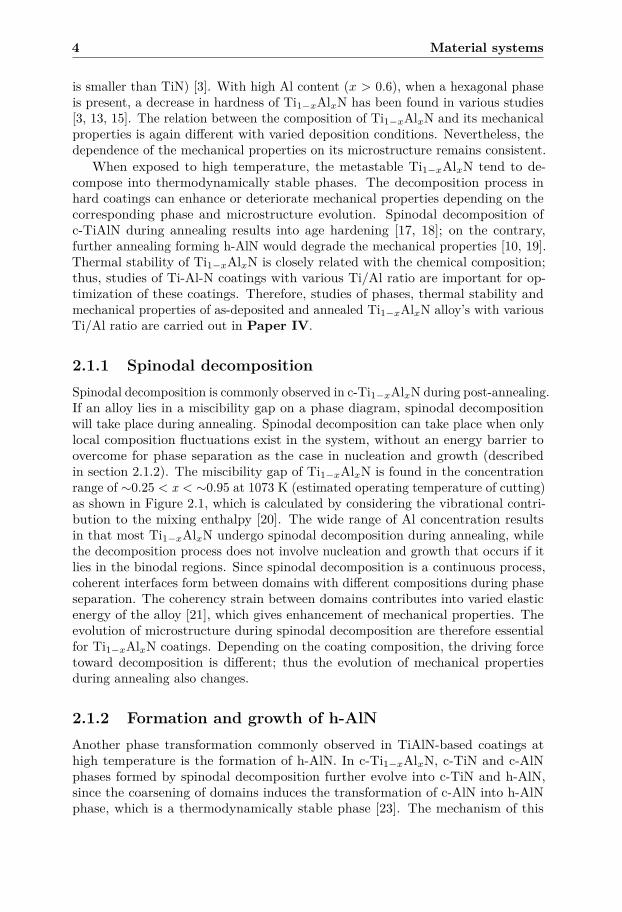
2.1.1 Spinodal decompositionSpinodal decomposition is commonly observed in c-Ti1−xAlxN during post-annealing.If an alloy lies in a miscibility gap on a phase diagram, spinodal decompositionwill take place during annealing. Spinodal decomposition can take place when onlylocal composition fluctuations exist in the system, without an energy barrier toovercome for phase separation as the case in nucleation and growth (describedin section 2.1.2). The miscibility gap of Ti1−xAlxN is found in the concentrationrange of ∼0.25 < x < ∼0.95 at 1073 K (estimated operating temperature of cutting)as shown in Figure 2.1, which is calculated by considering the vibrational contri-bution to the mixing enthalpy [20]. The wide range of Al concentration resultsin that most Ti1−xAlxN undergo spinodal decomposition during annealing, whilethe decomposition process does not involve nucleation and growth that occurs if itlies in the binodal regions. Since spinodal decomposition is a continuous process,coherent interfaces form between domains with different compositions during phaseseparation. The coherency strain between domains contributes into varied elasticenergy of the alloy [21], which gives enhancement of mechanical properties. Theevolution of microstructure during spinodal decomposition are therefore essentialfor Ti1−xAlxN coatings. Depending on the coating composition, the driving forcetoward decomposition is different; thus the evolution of mechanical propertiesduring annealing also changes.
2.1.2 Formation and growth of h-AlNAnother phase transformation commonly observed in TiAlN-based coatings athigh temperature is the formation of h-AlN. In c-Ti1−xAlxN, c-TiN and c-AlNphases formed by spinodal decomposition further evolve into c-TiN and h-AlN,since the coarsening of domains induces the transformation of c-AlN into h-AlNphase, which is a thermodynamically stable phase [23]. The mechanism of this
2.1 Ti-Al-N 5
Figure 2.1. Phase diagrams of Ti1−xAlxN calculated by [20] indicating the spinodaland binodal regions [22].
phase transformation is nucleation and growth, which starts with nuclei formationcontrolled by the total free energy. The total free energy (∆G) of a nucleusincludes its surface energy (∆Gs) and the crystal free energy (∆Gv), where the twocontributions are dominant for different nucleus size. Thus, the critical nucleus sizeis determined when the total free energy, that is, the sum of ∆Gs and ∆Gv reachesa maximum value. The critical nucleus size means the minimum size of a stableformed nucleus that will grow in size, since the ∆G decreases with increasing nucleussize [24]. For nuclei larger than the critical nucleus size, coarsening begins in orderto minimize the total free energy. Nucleation modes are classified to continuousnucleation with a constant nucleation rate, and the site-saturated nucleation withpre-existing nuclei [25].
The h-AlN formation is a nucleation and growth process [26, 27]; therefore,an activation energy barrier is governing the formation process. Such activationenergy has been studied in TiAlN with different coating compositions [28], whilethe activation energy is found not the determining factor for the formation rate ofh-AlN; instead, the interconnection of h-AlN domains in the microstructure is. Onthe other hand, in Paper I, deviation in microstructure evolution of TiAlCrN thataffects the h-AlN formation can be revealed by the differences in such activationenergy, which is further discussed in section 2.2.
The formation of h-AlN has been found to alter the coating’s mechanicalproperties. At the inital h-AlN formation, coherency strains form due to coherentinterfaces between cubic and hexagonal domains/grains and this enhances the wearand toughness properties [29–31]. Further growth of this phase leads to degradationof mechanical properties due to the loss of coherent interfaces [19].
6 Material systems
2.2 Ti-Al-X-N (X = Cr, Nb and V)One of the methods for enhancing a coating’s thermal stability is to introduce afourth element into the Ti-Al-N system. Theoretical studies predict that Ti-Al-Me-N (Me : transition metal) systems exhibit superior thermal stability, which delaysthe spinodal decomposition and results in superior hardness at higher temperaturesthan Ti-Al-N alloys [32–36]. The thermal stability and mechanical properties ofquaternary alloys are studied in this thesis, which are further discussed below.
Studies on Ti-Al-Cr-N system has shown that it exhibits enhanced thermalstability, oxidation resistance [37, 38] and cutting performance [39–42]. Thedriving force for decomposition is depending on the chemical composition ofTi1−x−yAlxCryN [43], where Lind et al has predicted by theoretical calculations thatthe decomposition routes would vary with different composition of Ti1−x−yAlxCryN.Understanding the phase transformations at high temperature is essential fordesigning coatings with the desired mechanical properties. One of the essentialfactors is the h-AlN formation, which is strongly related to the coating’s mechanicalproperties including hardness as further described in section 2.1.2. Forsén etal found that h-AlN forms semi-coherent or incoherent interfaces with c-TiCrNdomains depending on its domain size [37, 44]. In quaternary alloy Ti-Al-X-Nsystems, the h-AlN phase forms from the Al-rich domains generated during phaseevolution. In Ti1−x−yAlxCryN, such domains are CrAlN [38, 45, 46]. Thus, themechanism forming the CrAlN phase, which is relate to the thermal stabilityof the coating is essential for the h-AlN formation. In Paper I, the activationenergy for h-AlN formation was studied for TixAl0.37Cr1−0.37−xN alloys, and thedecomposition routes, where CrAlN phase formed differently in the microstructures,determine the h-AlN formation rate.
Similar to the Ti-Al-Cr-N system, Ti-Al-X-N (X = Nb and V) systems arealso among the interesting quaternary alloys with improved thermal stability byaltering the mixing free energy [6, 43]. Though few experimental studies on thermalstability of Ti-Al-X-N (X = Nb and V) have been carried out [47], enhancedductility of these quaternary alloys is estimated by theoretically calculations [6, 48],and superior properties for cutting applications are also deomonstrated [14, 49, 50].Since brittleness is a common drawback of ceramic coatings [51, 52], enhancementof fracture toughness is essential for improvements of hard coating’s wear or crackresistance. Experimental results also prove the enhanced toughness properties ofTi1−x−yAlyNbxN [53], and the improved tribological properties are also found inTi1−x−yAlyVxN [54]. In Paper III, the evolution of mechanical properties underhigh temperatures is studied to be related with both spinodal decomposition andh-AlN formation, which is varied with the thermal stability of Ti-Al-X-N alloys.
2.3 (Ti)-Zr-Al-NZr1−xAlxN alloys exhibit similar structural and thermodynamic characteristics asTi1−xAlxN. With larger miscibility gap and higher mixing energy than Ti1−xAlxN[55, 56], it has a higher driving force for decomposition of its solid solution. In fact,only Zr1−xAlxN with Al content lower than ∼ 0.3 forms with the cubic structure
2.3 (Ti)-Zr-Al-N 7
[56, 57]. The c-Zr1−xAlxN shows promising mechanical properties along with goodoxidation resistance at high temperatures [58–61]. With high Al content (x> ∼ 70%), a h-Zr1−xAlxN solid soultion is formed [55, 62], which even displays superiorwear behavior during cutting than the c-Zr1−xAlxN coatings due to its high thermalstability [63].
Multilayered structures can further enhance thermal stability and mechanicalproperties [9–11] of the coatings. In the Zr-Al-N material system, c-Zr0.65Al0.35N/TiNmultilayers have been to have superior thermal stability, as hardness enhancementis retained at annealing temperature up to 1100 ◦C [64]. The secondary phaseTiZr(Al)N is formed during annealing, which contributes to the improved mechani-cal properties, while such phase does not exist for c-Zr0.65Al0.35N/ZrN multilayers.Therefore, it is interesting to study how a multilayer system of h-Zr1−xAlxN andc-TiN (or ZrN) perform in thermal and mechanical properties, as was done inPaper II. The secondary phase Ti(Zr)N forms in h-Zr1−xAlxN/TiN and keeps thesemi-coherency at sub-interfaces at 1100 ◦C annealing. Such phase is also foundto be able to sustain the compressive stress in the c-TiN phase so that enhancedfracture toughness is resulted; on the contrary, the stress relaxation to tensile stressin h-Zr1−xAlxN/ZrN, where no secondary phase present.

8 Material systems
CHAPTER 3
Coating deposition and growth
3.1 Cathodic arc evaporationThe deposition of hard coatings in this work is performed by cathodic arc evapora-tion, which is widely applied for large-scale production in the cutting industry [65].The process is started when applying high current, low voltage arc discharge on themetallic cathodes, resulting in cathode spots of high power density (∼ 1013 W/m2)on the cathode surface. With extremely high local temperature, the material istransformed from solid phase into fully ionized plasma [66]. The high density ofion flux brings high kinetic energy to the substrate with the aid of a negativesubstrate bias. The high kinetic energy of the ionized plasma allows the possibil-ity of depositing coatings at low (∼ 300-500 ◦C) temperatures and for formingmetastable compounds [4]. The high plasma density also provides the advantageof high deposition rate.
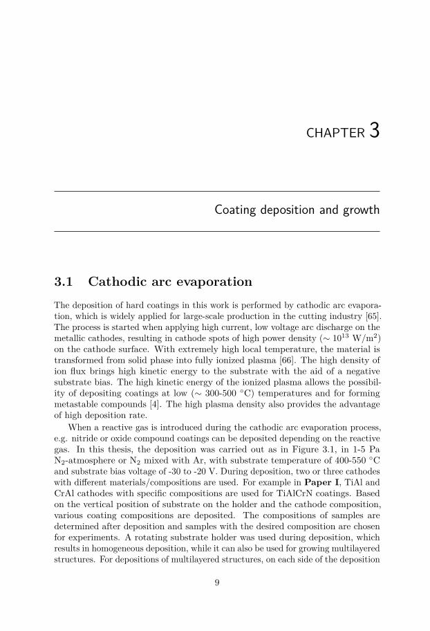
When a reactive gas is introduced during the cathodic arc evaporation process,e.g. nitride or oxide compound coatings can be deposited depending on the reactivegas. In this thesis, the deposition was carried out as in Figure 3.1, in 1-5 PaN2-atmosphere or N2 mixed with Ar, with substrate temperature of 400-550 ◦Cand substrate bias voltage of -30 to -20 V. During deposition, two or three cathodeswith different materials/compositions are used. For example in Paper I, TiAl andCrAl cathodes with specific compositions are used for TiAlCrN coatings. Basedon the vertical position of substrate on the holder and the cathode composition,various coating compositions are deposited. The compositions of samples aredetermined after deposition and samples with the desired composition are chosenfor experiments. A rotating substrate holder was used during deposition, whichresults in homogeneous deposition, while it can also be used for growing multilayeredstructures. For depositions of multilayered structures, on each side of the deposition
9
10 Coating deposition and growth
chamber a certain set of cathodes for the desired material of the sub-layers inthe multilayered samples is mounted. In Paper II, the ZrAlN/TiN (or ZrN)multilayers were deposited by placing a ZrAl cathode and a Ti or Zr cathode onthe opposite side in the chamber.
Figure 3.1. A schematic illustration of cathodic arc evaporation.
The substrates are usually cemented carbide (WC-Co) with 12 wt% Co. Thedepositions were also done on iron foils for preparation of free-standing coatingpowder, to prevent chemical reactions between coating and substrate materialsduring in-situ annealing experiments at ∼1100 ◦C (Paper I). Powder sampleswere prepared by dissolving the iron substrates in hydrochloric acid, a procedurethat completely removes the Fe while retaining the coating structure [67].
3.2 Microstructure of deposited coatingsThe microstructure of coatings deposited by arc evaporation is affected by depositionparameters such as cathode composition, bias voltage [68] and substrate temperature[69]. In general, columnar microstructures of arc deposited films are formed due tointense ion bombardment [70].
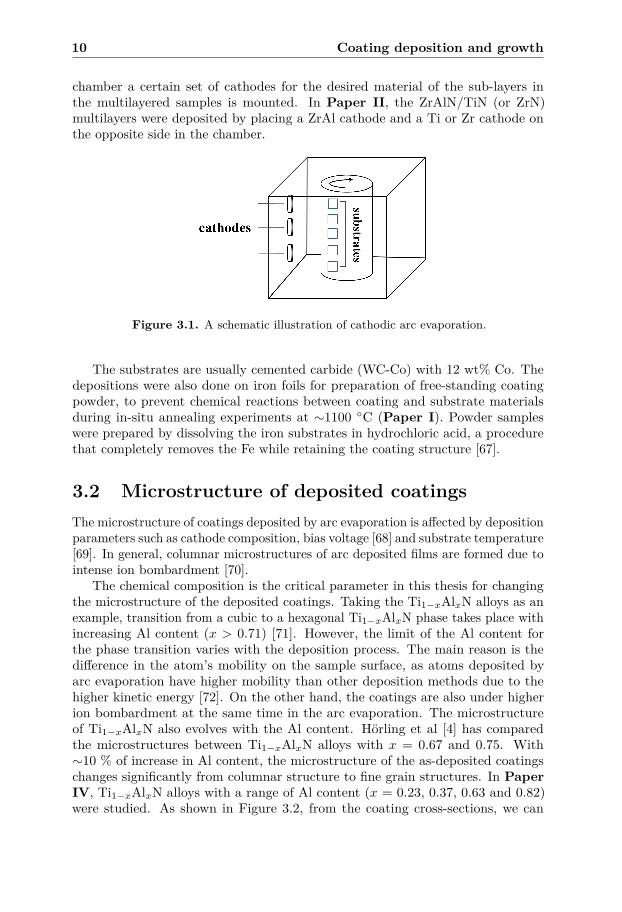
The chemical composition is the critical parameter in this thesis for changingthe microstructure of the deposited coatings. Taking the Ti1−xAlxN alloys as anexample, transition from a cubic to a hexagonal Ti1−xAlxN phase takes place withincreasing Al content (x > 0.71) [71]. However, the limit of the Al content forthe phase transition varies with the deposition process. The main reason is thedifference in the atom’s mobility on the sample surface, as atoms deposited byarc evaporation have higher mobility than other deposition methods due to thehigher kinetic energy [72]. On the other hand, the coatings are also under higherion bombardment at the same time in the arc evaporation. The microstructureof Ti1−xAlxN also evolves with the Al content. Hörling et al [4] has comparedthe microstructures between Ti1−xAlxN alloys with x = 0.67 and 0.75. With∼10 % of increase in Al content, the microstructure of the as-deposited coatingschanges significantly from columnar structure to fine grain structures. In PaperIV, Ti1−xAlxN alloys with a range of Al content (x = 0.23, 0.37, 0.63 and 0.82)were studied. As shown in Figure 3.2, from the coating cross-sections, we can
3.3 Residual stress 11
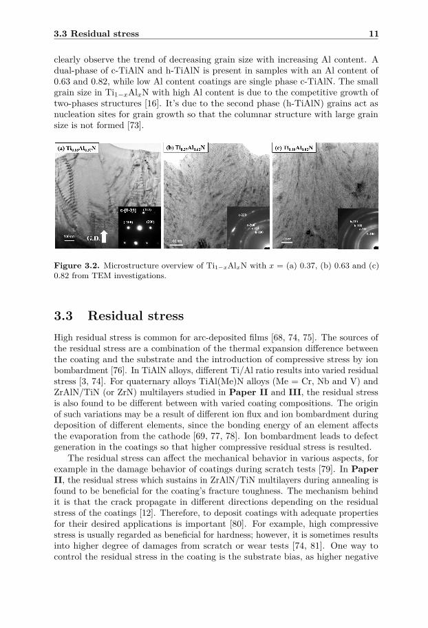
clearly observe the trend of decreasing grain size with increasing Al content. Adual-phase of c-TiAlN and h-TiAlN is present in samples with an Al content of0.63 and 0.82, while low Al content coatings are single phase c-TiAlN. The smallgrain size in Ti1−xAlxN with high Al content is due to the competitive growth oftwo-phases structures [16]. It’s due to the second phase (h-TiAlN) grains act asnucleation sites for grain growth so that the columnar structure with large grainsize is not formed [73].
Figure 3.2. Microstructure overview of Ti1−xAlxN with x = (a) 0.37, (b) 0.63 and (c)0.82 from TEM investigations.
3.3 Residual stressHigh residual stress is common for arc-deposited films [68, 74, 75]. The sources ofthe residual stress are a combination of the thermal expansion difference betweenthe coating and the substrate and the introduction of compressive stress by ionbombardment [76]. In TiAlN alloys, different Ti/Al ratio results into varied residualstress [3, 74]. For quaternary alloys TiAl(Me)N alloys (Me = Cr, Nb and V) andZrAlN/TiN (or ZrN) multilayers studied in Paper II and III, the residual stressis also found to be different between with varied coating compositions. The originof such variations may be a result of different ion flux and ion bombardment duringdeposition of different elements, since the bonding energy of an element affectsthe evaporation from the cathode [69, 77, 78]. Ion bombardment leads to defectgeneration in the coatings so that higher compressive residual stress is resulted.
The residual stress can affect the mechanical behavior in various aspects, forexample in the damage behavior of coatings during scratch tests [79]. In PaperII, the residual stress which sustains in ZrAlN/TiN multilayers during annealing isfound to be beneficial for the coating’s fracture toughness. The mechanism behindit is that the crack propagate in different directions depending on the residualstress of the coatings [12]. Therefore, to deposit coatings with adequate propertiesfor their desired applications is important [80]. For example, high compressivestress is usually regarded as beneficial for hardness; however, it is sometimes resultsinto higher degree of damages from scratch or wear tests [74, 81]. One way tocontrol the residual stress in the coating is the substrate bias, as higher negative

12 Coating deposition and growth
bias results in higher kinetic energy of the ions for bombardment. Thus, highercompressive stress is found with higher substrate bias [74].
CHAPTER 4
Characterization techniques
The phase content and microstructure of hard coatings is essential for their mechan-ical properties and cutting performance, especially at high temperature becausethe temperature in high-speed cutting processes may exceed 1000 ◦C [82]. In thisthesis, the following characterization techniques are used.
4.1 X-ray diffractionX-ray diffraction (XRD) is a quick and non-destructive method for structuralanalysis. As shown in Figure 4.1, the path difference of x-rays with a specificwavelength (λ) scattering on atomic planes in a crystalline structure with a planespacing (d) can be described as
∆1 + ∆2 = 2d cos(90◦ − θ) = 2d sin θ. (4.1)
Constructive interference takes place when the path difference equals to an integral(n) multiply with the wavelength as described by Bragg’s law, which can beexpressed as,
nλ = 2d sin θ . (4.2)
When constructive interference takes place, maximum scattering intensity isachieved.
For lab-source XRD experiments, a constant x-ray wavelength is usually used,which is Cu Kα = 1.54 Å in this thesis. In a "θ − 2θ" measurement, the incidentangle (θ) is kept as half of the 2θ, where 2θ is the angle between incident x-raybeam and the detector, i.e. the scattering angle. Then, when the incident angle(θ) fulfill the Bragg’s condition, a diffraction "peak" is resulted due to constructiveinterference, where the d value can be obtained from Eq. 4.2. Further, the obtained
13
14 Characterization techniques
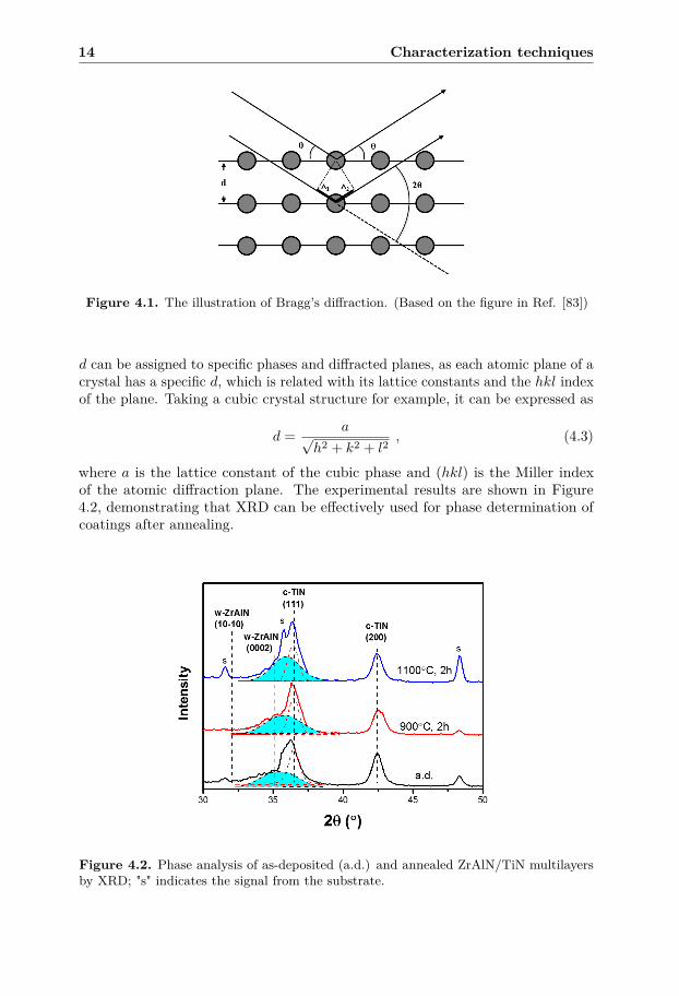
Figure 4.1. The illustration of Bragg’s diffraction. (Based on the figure in Ref. [83])
d can be assigned to specific phases and diffracted planes, as each atomic plane of acrystal has a specific d, which is related with its lattice constants and the hkl indexof the plane. Taking a cubic crystal structure for example, it can be expressed as
d = a√h2 + k2 + l2
, (4.3)
where a is the lattice constant of the cubic phase and (hkl) is the Miller indexof the atomic diffraction plane. The experimental results are shown in Figure4.2, demonstrating that XRD can be effectively used for phase determination ofcoatings after annealing.
Figure 4.2. Phase analysis of as-deposited (a.d.) and annealed ZrAlN/TiN multilayersby XRD; "s" indicates the signal from the substrate.
4.1 X-ray diffraction 15
4.1.1 Grazing incidence x-ray diffractionWhen keeping the incident angle to a low value (∼ 2-5 ◦) but above the totalreflection angle, the grazing incidence (GI) XRD experiments are performed. Theadvantage of the GIXRD technique is especially observed for thin films, when thesubstrate’s diffraction signal is much stronger than the film. With higher incidenceangle, the penetration depth of x-ray into the sample increases [84], resulting intomore diffraction signal from substrate instead of the film. Therefore, the advantageof using grazing incidence angle is to increase the signal from the film by keepingthe penetration depth low to avoid substrate signal.
Poly-crystalline films consists of grains with various directions, where the plansare not always parallel to surface normal. Therefore, with a fixed θ, Bragg’scondition can still be fulfilled with various 2θ values for poly-crystalline films, sincethe diffraction planes are not only originated from the planes that are perpendicularto the surface normal (as indicated in Figure 4.1). In Paper II, coating signals aresuccessfully investigated by GIXRD without strong interference from the substrate,as shown in Figure 4.2.
4.1.2 In-situ x-ray scattering during high temperature an-nealing
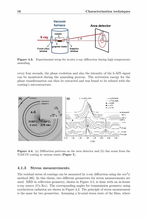
Compared with lab-source x-ray instruments, synchrotron x-ray sources have theadvantages of high brightness, high photon energy and the capability of integrationwith desired experimental equipment for in-situ measurements. For studies of phaseevolution which need high time resolution, a synchrotron source is an essentialtool. Due to high photon flux from synchrotron source, rapid diffraction scans canbe done with faster rate than an in-house x-ray equipment. High energy x-rays(∼ 80 keV) also has the advantage of penetrating samples, since the absorption islow. The in-situ measurements during high temperature annealing are done bythe integration of a furnace in the beamline, which can heat samples to ∼1000◦C , shown in Figure 4.3. The x-ray beam is aligned with the sample and passesthrough the glass windows located on each side of the furnace and the openingson the graphite heater tube. The furnace is under vacuum of around 10−5 torr toprevent oxidation of films during annealing.
Equipped with a two-dimensional area detector as in this thesis, diffractionsignals in a wide range of scattering angles can be captured within a single exposure.By image processing, a line scan of d can be extracted, by converting the 2θ angle,which is the angle between the incident beam and the diffracted signal, by Eq. 4.2.Line scans can be obtained in various directions between the growth direction (GD)and the in-plane (IP) direction by choosing a tilt angle (ψ). Such results are veryuseful for stress measurements (section 4.1.3) and texture analysis.
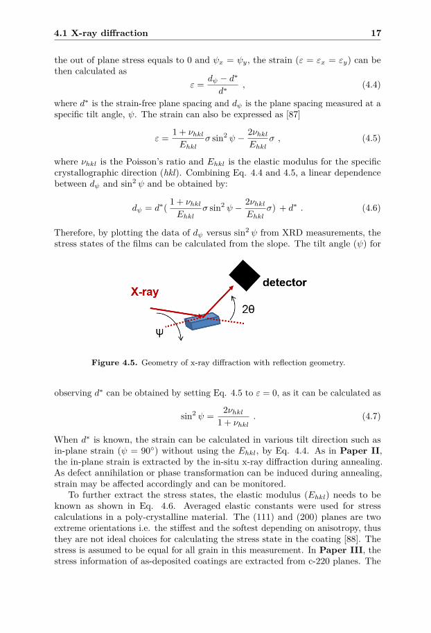
In Paper I, the formation of h-AlN was investigated by in-sit x-ray diffractionanalysis during annealing, since the h-AlN phase has dominant effects on coating’smechanical properties [29, 30, 85]. As shown in Figure 4.4, the phase transformationcan be observed from the changes in the diffraction pattern, while the exact phasescan be identified from the extracted line scans. With an image exposure taken
16 Characterization techniques
Figure 4.3. Experimental setup for in-situ x-ray diffraction during high temperatureannealing.
every four seconds, the phase evolution and also the intensity of the h-AlN signalcan be monitored during the annealing process. The activation energy for thephase transformation can then be extracted and was found to be related with thecoating’s microstructure.
Figure 4.4. (a) Diffraction patterns on the area detector and (b) line scans from theTiAlCrN coating in various states (Paper I).
4.1.3 Stress measurementsThe residual stress of coatings can be measured by x-ray diffraction using the sin2ψmethod [86]. In this thesis, two different geometries for stress measurements areused. XRD in reflection geometry, shown in Figure 4.5, is done with an in-housex-ray source (Cu Kα). The corresponding angles for transmission geometry usingsynchrotron radiation are shown in Figure 4.3. The principle of stress measurementis the same for two geometries. Assuming a bi-axial stress state of the films, where
4.1 X-ray diffraction 17
the out of plane stress equals to 0 and ψx = ψy, the strain (ε = εx = εy) can bethen calculated as
ε = dψ − d∗
d∗, (4.4)
where d∗ is the strain-free plane spacing and dψ is the plane spacing measured at aspecific tilt angle, ψ. The strain can also be expressed as [87]
ε = 1 + νhklEhkl
σ sin2 ψ − 2νhklEhkl
σ , (4.5)
where νhkl is the Poisson’s ratio and Ehkl is the elastic modulus for the specificcrystallographic direction (hkl). Combining Eq. 4.4 and 4.5, a linear dependencebetween dψ and sin2 ψ and be obtained by:
dψ = d∗( 1 + νhklEhkl
σ sin2 ψ − 2νhklEhkl
σ) + d∗ . (4.6)
Therefore, by plotting the data of dψ versus sin2 ψ from XRD measurements, thestress states of the films can be calculated from the slope. The tilt angle (ψ) for
Figure 4.5. Geometry of x-ray diffraction with reflection geometry.
observing d∗ can be obtained by setting Eq. 4.5 to ε = 0, as it can be calculated as
sin2 ψ = 2νhkl1 + νhkl
. (4.7)
When d∗ is known, the strain can be calculated in various tilt direction such asin-plane strain (ψ = 90◦) without using the Ehkl, by Eq. 4.4. As in Paper II,the in-plane strain is extracted by the in-situ x-ray diffraction during annealing.As defect annihilation or phase transformation can be induced during annealing,strain may be affected accordingly and can be monitored.
To further extract the stress states, the elastic modulus (Ehkl) needs to beknown as shown in Eq. 4.6. Averaged elastic constants were used for stresscalculations in a poly-crystalline material. The (111) and (200) planes are twoextreme orientations i.e. the stiffest and the softest depending on anisotropy, thusthey are not ideal choices for calculating the stress state in the coating [88]. Thestress is assumed to be equal for all grain in this measurement. In Paper III, thestress information of as-deposited coatings are extracted from c-220 planes. The
18 Characterization techniques
used elastic modulus is estimated from theoretical calculations as TiAlN (E = 432GPa); TiAl(Nb)N (E = 420 GPa); TiAl(V)N (E = 429 GPa) with Hill’s averagecombining the Voigt and Reuss model [89].
4.2 Electron microscopyElectron microscopy utilizes the interaction between incident electrons and theinvestigated sample for imaging and identification of phases and microstructure.In general, electron microscopy provides visual images for direct comparison ordetermination of grain sizes existed in the films, and investigations of surface topog-raphy for as-deposited or damaged coatings by mechanical tests. The microscopytechniques used in this thesis are the following.
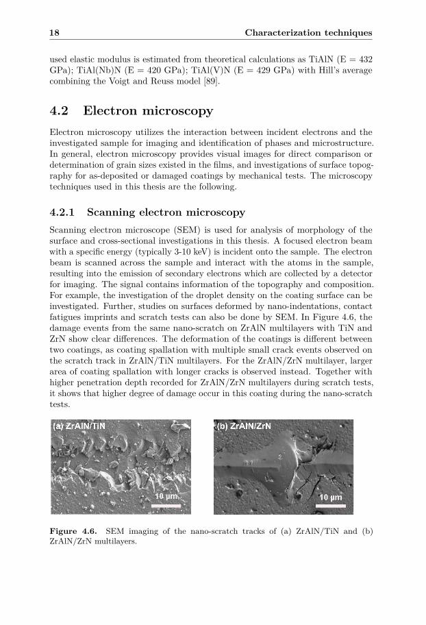
4.2.1 Scanning electron microscopyScanning electron microscope (SEM) is used for analysis of morphology of thesurface and cross-sectional investigations in this thesis. A focused electron beamwith a specific energy (typically 3-10 keV) is incident onto the sample. The electronbeam is scanned across the sample and interact with the atoms in the sample,resulting into the emission of secondary electrons which are collected by a detectorfor imaging. The signal contains information of the topography and composition.For example, the investigation of the droplet density on the coating surface can beinvestigated. Further, studies on surfaces deformed by nano-indentations, contactfatigues imprints and scratch tests can also be done by SEM. In Figure 4.6, thedamage events from the same nano-scratch on ZrAlN multilayers with TiN andZrN show clear differences. The deformation of the coatings is different betweentwo coatings, as coating spallation with multiple small crack events observed onthe scratch track in ZrAlN/TiN multilayers. For the ZrAlN/ZrN multilayer, largerarea of coating spallation with longer cracks is observed instead. Together withhigher penetration depth recorded for ZrAlN/ZrN multilayers during scratch tests,it shows that higher degree of damage occur in this coating during the nano-scratchtests.
Figure 4.6. SEM imaging of the nano-scratch tracks of (a) ZrAlN/TiN and (b)ZrAlN/ZrN multilayers.
4.2 Electron microscopy 19
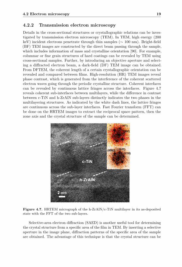
4.2.2 Transmission electron microscopyDetails in the cross-sectional structures or crystallographic relations can be inves-tigated by transmission electron microscopy (TEM). In TEM, high energy (200keV) incident electrons penetrate through thin samples (∼ 100 nm). Bright-field(BF) TEM images are constructed by the direct beam passing through the sample,which includes information of mass and crystalline orientation [90]. For example,columnar or fine grain structures of hard coatings can be revealed by TEM usingcross-sectional samples. Further, by introducing an objective aperture and select-ing a diffracted electron beam, a dark-field (DF) TEM image can be obtained.From DFTEM, the coherent length of a certain crystallographic orientation can berevealed and compared between films. High-resolution (HR) TEM images revealphase contrast, which is generated from the interference of the coherent scatteredelectron waves going through the periodic crystalline structure. Coherent interfacescan be revealed by continuous lattice fringes across the interfaces. Figure 4.7reveals coherent sub-interfaces between multilayers, while the difference in contrastbetween c-TiN and h-ZrAlN sub-layers distinctly indicates the two phases in themultilayering structures. As indicated by the white dash lines, the lattice fringesare continuous across the sub-layer interfaces. Fast Fourier transform (FFT) canbe done on the HRTEM images to extract the reciprocal space pattern, then thezone axis and the crystal structure of the sample can be determined.
Figure 4.7. HRTEM micrograph of the h-ZrAlN/c-TiN multilayer in its as-depositedstate with the FFT of the two sub-layers.
Selective-area electron diffraction (SAED) is another useful tool for determiningthe crystal structure from a specific area of the film in TEM. By inserting a selectiveaperture in the image plane, diffraction patterns of the specific area of the sampleare obtained. The advantage of this technique is that the crystal structure can be
20 Characterization techniques
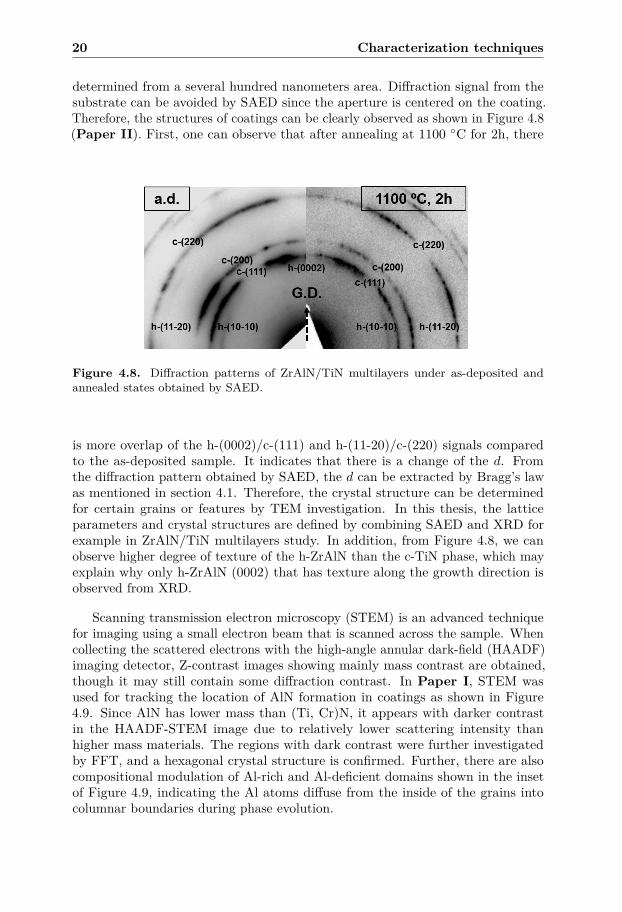
determined from a several hundred nanometers area. Diffraction signal from thesubstrate can be avoided by SAED since the aperture is centered on the coating.Therefore, the structures of coatings can be clearly observed as shown in Figure 4.8(Paper II). First, one can observe that after annealing at 1100 ◦C for 2h, there
Figure 4.8. Diffraction patterns of ZrAlN/TiN multilayers under as-deposited andannealed states obtained by SAED.
is more overlap of the h-(0002)/c-(111) and h-(11-20)/c-(220) signals comparedto the as-deposited sample. It indicates that there is a change of the d. Fromthe diffraction pattern obtained by SAED, the d can be extracted by Bragg’s lawas mentioned in section 4.1. Therefore, the crystal structure can be determinedfor certain grains or features by TEM investigation. In this thesis, the latticeparameters and crystal structures are defined by combining SAED and XRD forexample in ZrAlN/TiN multilayers study. In addition, from Figure 4.8, we canobserve higher degree of texture of the h-ZrAlN than the c-TiN phase, which mayexplain why only h-ZrAlN (0002) that has texture along the growth direction isobserved from XRD.
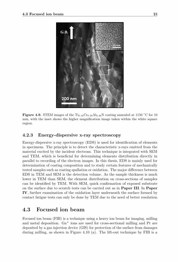
Scanning transmission electron microscopy (STEM) is an advanced techniquefor imaging using a small electron beam that is scanned across the sample. Whencollecting the scattered electrons with the high-angle annular dark-field (HAADF)imaging detector, Z-contrast images showing mainly mass contrast are obtained,though it may still contain some diffraction contrast. In Paper I, STEM wasused for tracking the location of AlN formation in coatings as shown in Figure4.9. Since AlN has lower mass than (Ti, Cr)N, it appears with darker contrastin the HAADF-STEM image due to relatively lower scattering intensity thanhigher mass materials. The regions with dark contrast were further investigatedby FFT, and a hexagonal crystal structure is confirmed. Further, there are alsocompositional modulation of Al-rich and Al-deficient domains shown in the insetof Figure 4.9, indicating the Al atoms diffuse from the inside of the grains intocolumnar boundaries during phase evolution.
4.3 Focused ion beam 21
Figure 4.9. STEM images of the Ti0.16Cr0.36Al0.48N coating annealed at 1150 ◦C for 10min, with the inset shows the higher magnification image taken within the white squareregion.
4.2.3 Energy-dispersive x-ray spectroscopyEnergy-dispersive x-ray spectroscopy (EDS) is used for identification of elementsin specimens. The principle is to detect the characteristic x-rays emitted from thematerial excited by the incident electrons. This technique is integrated with SEMand TEM, which is beneficial for determining elements distribution directly inparallel to recording of the electron images. In this thesis, EDS is mainly used fordetermination of coating composition and to study certain features of mechanicallytested samples such as coating spallation or oxidation. The major difference betweenEDS in TEM and SEM is the detection volume. As the sample thickness is muchlower in TEM than SEM, the element distribution on cross-sections of samplescan be identified by TEM. With SEM, quick confirmation of exposed substrateon the surface due to scratch tests can be carried out as in Paper III. In PaperIV, further examination of the oxidation layer underneath the surface formed bycontact fatigue tests can only be done by TEM due to the need of better resolution.
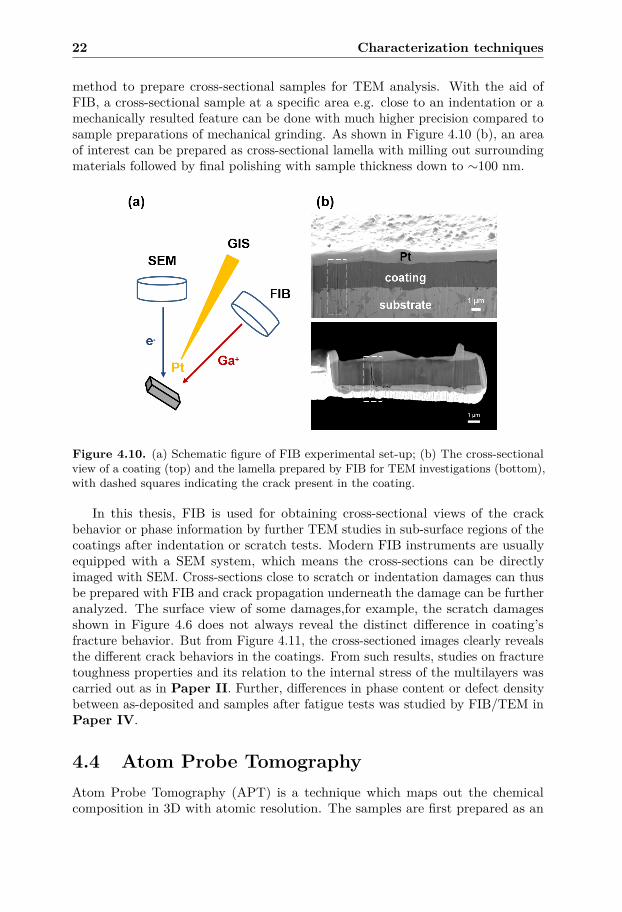
4.3 Focused ion beamFocused ion beam (FIB) is a technique using a heavy ion beam for imaging, millingand metal deposition. Ga+ ions are used for cross-sectional milling and Pt aredeposited by a gas injection device (GIS) for protection of the surface from damagesduring milling, as shown in Figure 4.10 (a). The lift-out technique by FIB is a
22 Characterization techniques
method to prepare cross-sectional samples for TEM analysis. With the aid ofFIB, a cross-sectional sample at a specific area e.g. close to an indentation or amechanically resulted feature can be done with much higher precision compared tosample preparations of mechanical grinding. As shown in Figure 4.10 (b), an areaof interest can be prepared as cross-sectional lamella with milling out surroundingmaterials followed by final polishing with sample thickness down to ∼100 nm.
Figure 4.10. (a) Schematic figure of FIB experimental set-up; (b) The cross-sectionalview of a coating (top) and the lamella prepared by FIB for TEM investigations (bottom),with dashed squares indicating the crack present in the coating.
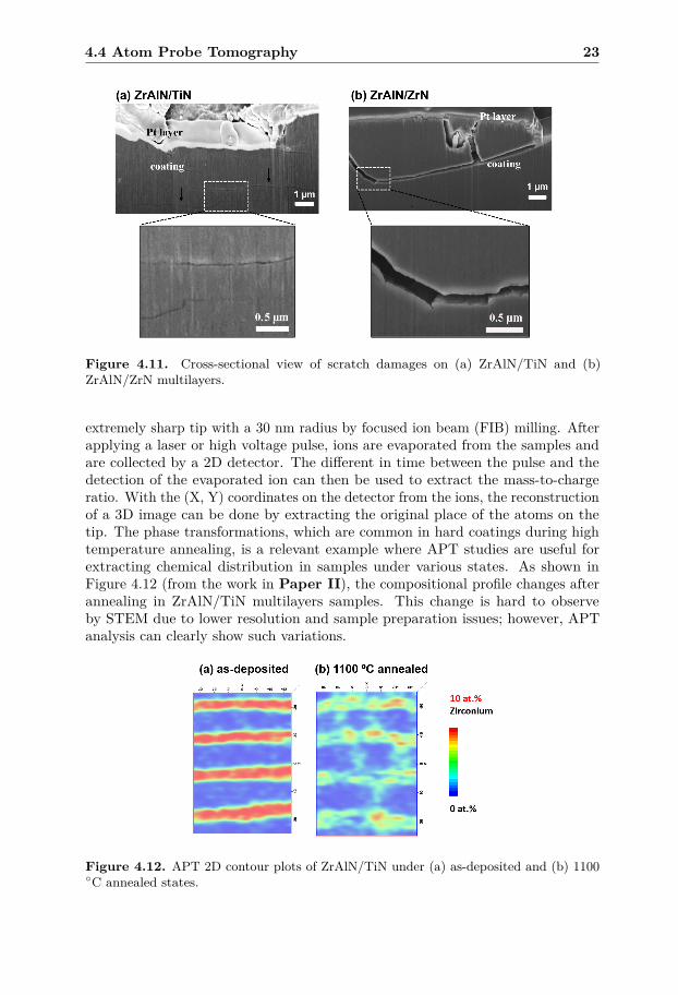
In this thesis, FIB is used for obtaining cross-sectional views of the crackbehavior or phase information by further TEM studies in sub-surface regions of thecoatings after indentation or scratch tests. Modern FIB instruments are usuallyequipped with a SEM system, which means the cross-sections can be directlyimaged with SEM. Cross-sections close to scratch or indentation damages can thusbe prepared with FIB and crack propagation underneath the damage can be furtheranalyzed. The surface view of some damages,for example, the scratch damagesshown in Figure 4.6 does not always reveal the distinct difference in coating’sfracture behavior. But from Figure 4.11, the cross-sectioned images clearly revealsthe different crack behaviors in the coatings. From such results, studies on fracturetoughness properties and its relation to the internal stress of the multilayers wascarried out as in Paper II. Further, differences in phase content or defect densitybetween as-deposited and samples after fatigue tests was studied by FIB/TEM inPaper IV.
4.4 Atom Probe TomographyAtom Probe Tomography (APT) is a technique which maps out the chemicalcomposition in 3D with atomic resolution. The samples are first prepared as an
4.4 Atom Probe Tomography 23
Figure 4.11. Cross-sectional view of scratch damages on (a) ZrAlN/TiN and (b)ZrAlN/ZrN multilayers.
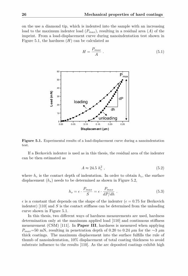
extremely sharp tip with a 30 nm radius by focused ion beam (FIB) milling. Afterapplying a laser or high voltage pulse, ions are evaporated from the samples andare collected by a 2D detector. The different in time between the pulse and thedetection of the evaporated ion can then be used to extract the mass-to-chargeratio. With the (X, Y) coordinates on the detector from the ions, the reconstructionof a 3D image can be done by extracting the original place of the atoms on thetip. The phase transformations, which are common in hard coatings during hightemperature annealing, is a relevant example where APT studies are useful forextracting chemical distribution in samples under various states. As shown inFigure 4.12 (from the work in Paper II), the compositional profile changes afterannealing in ZrAlN/TiN multilayers samples. This change is hard to observeby STEM due to lower resolution and sample preparation issues; however, APTanalysis can clearly show such variations.
Figure 4.12. APT 2D contour plots of ZrAlN/TiN under (a) as-deposited and (b) 1100◦C annealed states.

24 Characterization techniques
CHAPTER 5
Mechanical properties of hard coatings
Mechanical properties of materials are related with various aspects, such as hardnessor fracture toughness. While high hardness of ceramic coatings leads to improvedtool life due to low wear rate, poor toughness is usually found [51, 91], whichleads to high degree of crack propagations and further failure of coatings [92, 93].Therefore, toughening hard coatings is essential for coating development, and hasbeen approached by various methods such as alloying TiAlN [33, 42, 48, 94], whereab initio density functional theory (DFT) can predict with elements choice foravoiding brittleness of coatings [89]. Simulation results of toughness properties canfurther explain the different behavior of hard coatings in mechanical tests [95, 96].
However, most studies are focusing on the hardness or wear rate of the coatings;thus, the evaluation of toughness properties has not been fully developed. Al-though scratch and contact fatigue tests have been used to analyze the tribologicalproperties of coatings [75, 97–99], most studies are limited to surface damagessuch as shape of damage features or critical load resulting in failure [100, 101].Detailed studies of how cracks travel in the coatings are important for resolvingtoughness properties [102–105], which also simulates how coatings behave duringcutting processes. The knowledge can be used for designing of next-generation hardcoatings. The following are the main analysis techniques for mechanical propertiesin this thesis.
5.1 HardnessHardness is one of the most frequently used properties for evaluation of coatings.High hardness can result in low wear rate in abrasive wear processes [1, 106], whichhas been demonstrated with improved life time and performance of tools [107–109].In this thesis, the hardness is measured by nanoindentation. The technique is based
25
26 Mechanical properties of hard coatings
on the use a diamond tip, which is indented into the sample with an increasingload to the maximum indenter load (Pmax), resulting in a residual area (A) of theimprint. From a load-displacement curve during nanoindentation test shown inFigure 5.1, the hardness (H) can be calculated as
H = PmaxA
. (5.1)
Figure 5.1. Experimental results of a load-displacement curve during a nanoindentationtest.
If a Berkovich indenter is used as in this thesis, the residual area of the indentercan be then estimated as
A ≈ 24.5 h2c , (5.2)
where hc is the contact depth of indentation. In order to obtain hc, the surfacedisplacement (hs) needs to be determined as shown in Figure 5.2,
hs = ε · PmaxS
= ε · PmaxdP/dh
. (5.3)
ε is a constant that depends on the shape of the indenter (ε = 0.75 for Berkovichindenter) [110] and S is the contact stiffness can be determined from the unloadingcurve shown in Figure 5.1.
In this thesis, two different ways of hardness measurements are used, hardnessdetermination only at the maximum applied load [110] and continuous stiffnessmeasurement (CSM) [111]. In Paper III, hardness is measured when applyingPmax=50 mN, resulting in penetration depth of 0.20 to 0.24 µm for the ∼3 µmthick coatings. The maximum displacement into the surface fulfills the rule ofthumb of nanoindentation, 10% displacement of total coating thickness to avoidsubstrate influence to the results [110]. As the arc deposited coatings exhibit high

5.2 Fracture toughness 27
Figure 5.2. A schematic figure of a cross-section during indentation. (Based on thefigure in [110])
surface roughness from macro-particles, 20-30 indents were done on the polishedtapered cross-sections and an average hardness value was calculated.
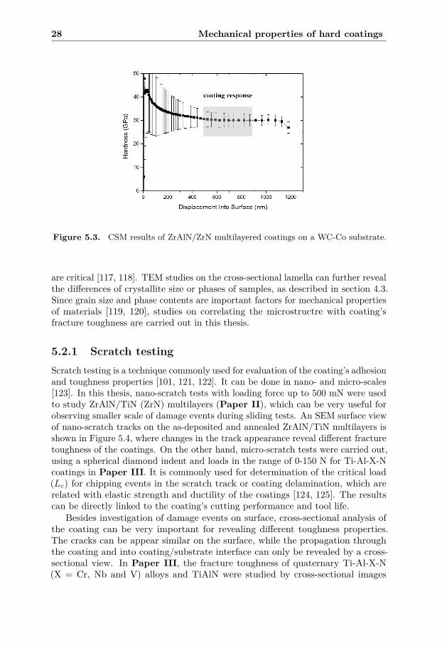
CSM, which was used in Paper II and IV, is done by applying a smalloscillation of applied force during indentation and measuring the correspondingdisplacement during each oscillation. The advantage of CSM is that hardnessinformation is obtained continuously with the increasing penetration depth. Asshown in Figure 5.3, the hardness changes with displacement into the sampleare observed from samples resulting in three regions. For displacements lowerthan ∼ 400 nm, the large variation of hardness and high scattering are due tomacro-particles on the coating surface. Hardness values become stable and are lessscattered between displacement of 500 and 900 nm, where the values correspondto coating’s hardness. As the coating thickness is around 6 µm in the ZrAlN/ZrNmultilayered coatings shown here, we find that the 10 % rule is not totally valid.The 10 % rule is an empirical rule and studies show that the critical indentationdepth for correct coating information varies for different coating systems [112, 113].With higher indentation depth, the hardness starts to decrease, due to the influenceof the substrate (WC-Co), exhibiting hardness of 15-20 GPa [114].
5.2 Fracture toughnessThe wear behavior during applications of hard coatings is usually complicated,and hardness is not the only factor affecting it. While transition metal nitridecoatings exhibit high hardness, they are also well known of their brittleness. Sincecracking can lead to subsequent failure or spallation of coatings, the crack behavioressentially affects the tool life time for machining applications [115, 116]. However,methods evaluating fracture toughness of thin coatings are not yet fully established.
Scratch tests and contact fatigue tests are the techniques used in this thesis forstudying fracture toughness of hard coatings. Combined with FIB/SEM analysisof the damaged coatings, differences in spallation or crack propagation can berevealed. As fracture toughness is related to the amount of energy needed for crackpropagation [80] in the coating, investigations of crack lengths of a damage event
28 Mechanical properties of hard coatings
Figure 5.3. CSM results of ZrAlN/ZrN multilayered coatings on a WC-Co substrate.
are critical [117, 118]. TEM studies on the cross-sectional lamella can further revealthe differences of crystallite size or phases of samples, as described in section 4.3.Since grain size and phase contents are important factors for mechanical propertiesof materials [119, 120], studies on correlating the microstructre with coating’sfracture toughness are carried out in this thesis.
5.2.1 Scratch testingScratch testing is a technique commonly used for evaluation of the coating’s adhesionand toughness properties [101, 121, 122]. It can be done in nano- and micro-scales[123]. In this thesis, nano-scratch tests with loading force up to 500 mN were usedto study ZrAlN/TiN (ZrN) multilayers (Paper II), which can be very useful forobserving smaller scale of damage events during sliding tests. An SEM surface viewof nano-scratch tracks on the as-deposited and annealed ZrAlN/TiN multilayers isshown in Figure 5.4, where changes in the track appearance reveal different fracturetoughness of the coatings. On the other hand, micro-scratch tests were carried out,using a spherical diamond indent and loads in the range of 0-150 N for Ti-Al-X-Ncoatings in Paper III. It is commonly used for determination of the critical load(Lc) for chipping events in the scratch track or coating delamination, which arerelated with elastic strength and ductility of the coatings [124, 125]. The resultscan be directly linked to the coating’s cutting performance and tool life.
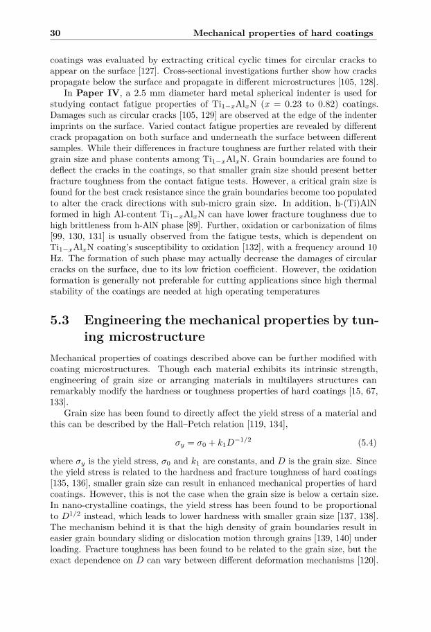
Besides investigation of damage events on surface, cross-sectional analysis ofthe coating can be very important for revealing different toughness properties.The cracks can be appear similar on the surface, while the propagation throughthe coating and into coating/substrate interface can only be revealed by a cross-sectional view. In Paper III, the fracture toughness of quaternary Ti-Al-X-N(X = Cr, Nb and V) alloys and TiAlN were studied by cross-sectional images
5.2 Fracture toughness 29
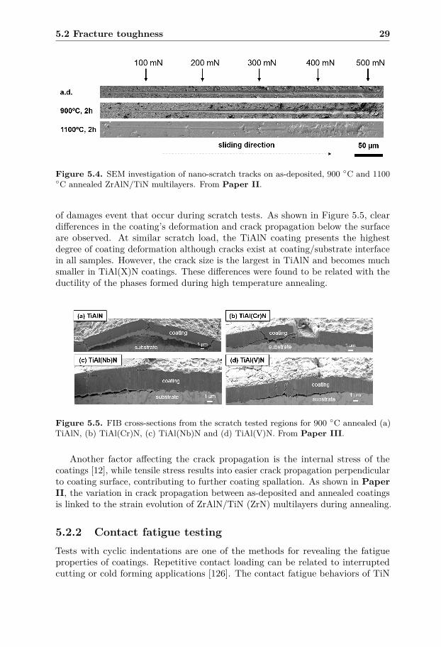
Figure 5.4. SEM investigation of nano-scratch tracks on as-deposited, 900 ◦C and 1100◦C annealed ZrAlN/TiN multilayers. From Paper II.
of damages event that occur during scratch tests. As shown in Figure 5.5, cleardifferences in the coating’s deformation and crack propagation below the surfaceare observed. At similar scratch load, the TiAlN coating presents the highestdegree of coating deformation although cracks exist at coating/substrate interfacein all samples. However, the crack size is the largest in TiAlN and becomes muchsmaller in TiAl(X)N coatings. These differences were found to be related with theductility of the phases formed during high temperature annealing.
Figure 5.5. FIB cross-sections from the scratch tested regions for 900 ◦C annealed (a)TiAlN, (b) TiAl(Cr)N, (c) TiAl(Nb)N and (d) TiAl(V)N. From Paper III.
Another factor affecting the crack propagation is the internal stress of thecoatings [12], while tensile stress results into easier crack propagation perpendicularto coating surface, contributing to further coating spallation. As shown in PaperII, the variation in crack propagation between as-deposited and annealed coatingsis linked to the strain evolution of ZrAlN/TiN (ZrN) multilayers during annealing.
5.2.2 Contact fatigue testingTests with cyclic indentations are one of the methods for revealing the fatigueproperties of coatings. Repetitive contact loading can be related to interruptedcutting or cold forming applications [126]. The contact fatigue behaviors of TiN
30 Mechanical properties of hard coatings
coatings was evaluated by extracting critical cyclic times for circular cracks toappear on the surface [127]. Cross-sectional investigations further show how crackspropagate below the surface and propagate in different microstructures [105, 128].
In Paper IV, a 2.5 mm diameter hard metal spherical indenter is used forstudying contact fatigue properties of Ti1−xAlxN (x = 0.23 to 0.82) coatings.Damages such as circular cracks [105, 129] are observed at the edge of the indenterimprints on the surface. Varied contact fatigue properties are revealed by differentcrack propagation on both surface and underneath the surface between differentsamples. While their differences in fracture toughness are further related with theirgrain size and phase contents among Ti1−xAlxN. Grain boundaries are found todeflect the cracks in the coatings, so that smaller grain size should present betterfracture toughness from the contact fatigue tests. However, a critical grain size isfound for the best crack resistance since the grain boundaries become too populatedto alter the crack directions with sub-micro grain size. In addition, h-(Ti)AlNformed in high Al-content Ti1−xAlxN can have lower fracture toughness due tohigh brittleness from h-AlN phase [89]. Further, oxidation or carbonization of films[99, 130, 131] is usually observed from the fatigue tests, which is dependent onTi1−xAlxN coating’s susceptibility to oxidation [132], with a frequency around 10Hz. The formation of such phase may actually decrease the damages of circularcracks on the surface, due to its low friction coefficient. However, the oxidationformation is generally not preferable for cutting applications since high thermalstability of the coatings are needed at high operating temperatures
5.3 Engineering the mechanical properties by tun-ing microstructure
Mechanical properties of coatings described above can be further modified withcoating microstructures. Though each material exhibits its intrinsic strength,engineering of grain size or arranging materials in multilayers structures canremarkably modify the hardness or toughness properties of hard coatings [15, 67,133].
Grain size has been found to directly affect the yield stress of a material andthis can be described by the Hall–Petch relation [119, 134],
σy = σ0 + k1D−1/2 (5.4)
where σy is the yield stress, σ0 and k1 are constants, and D is the grain size. Sincethe yield stress is related to the hardness and fracture toughness of hard coatings[135, 136], smaller grain size can result in enhanced mechanical properties of hardcoatings. However, this is not the case when the grain size is below a certain size.In nano-crystalline coatings, the yield stress has been found to be proportionalto D1/2 instead, which leads to lower hardness with smaller grain size [137, 138].The mechanism behind it is that the high density of grain boundaries result ineasier grain boundary sliding or dislocation motion through grains [139, 140] underloading. Fracture toughness has been found to be related to the grain size, but theexact dependence on D can vary between different deformation mechanisms [120].
5.3 Engineering the mechanical properties by tuning microstructure 31
In Paper IV, a demonstration of different contact fatigue properties of coatingswith varied grain size is carried out. The knowledge of how the microstructureaffects the fracture toughness is essential for design of wear-resistant coatings.
The design of multilayer architecture in hard coatings has been shown to resultin greater thermal stability [9, 141] and better mechanical properties [64, 75, 142].The enhancement can be explained by the microstructures modification, includingconfinement of dislocation movement by the sub-layer interfaces [143], or residualstress in the coatings changing the direction of the crack propagation [12]. InPaper II it was found that the coherent interfaces between sub-interfaces andthe secondary phase c-Ti(Zr)N contributes to the superior fracture resistance ofZrAlN/TiN than ZrAlN/ZrN multilayers, as previously shown in Figure 4.11.

32 Mechanical properties of hard coatings
CHAPTER 6
Real-time analysis during a turning process
Previously mentioned in-situ measurements at high temperature (section 4.1.2) canonly provide a simulation of how coatings behave during the cutting process (∼1000 ◦C). Studies at high temperature and high pressure simulating the cuttingprocess conditions for hard coatings have extensively improved the understandingof thermal stability and decomposition [82, 144]. Further, investigations of therelation between the cutting properties of hard coatings and their phase evolutionhave also drawn much research interest [145–147]. Considering the importance ofthe relation between microstructure, phase content and mechanical properties ofhard coatings, a preferable way to link these two properties would be monitoringthe phase and microstructure evolution during a real time turning process.
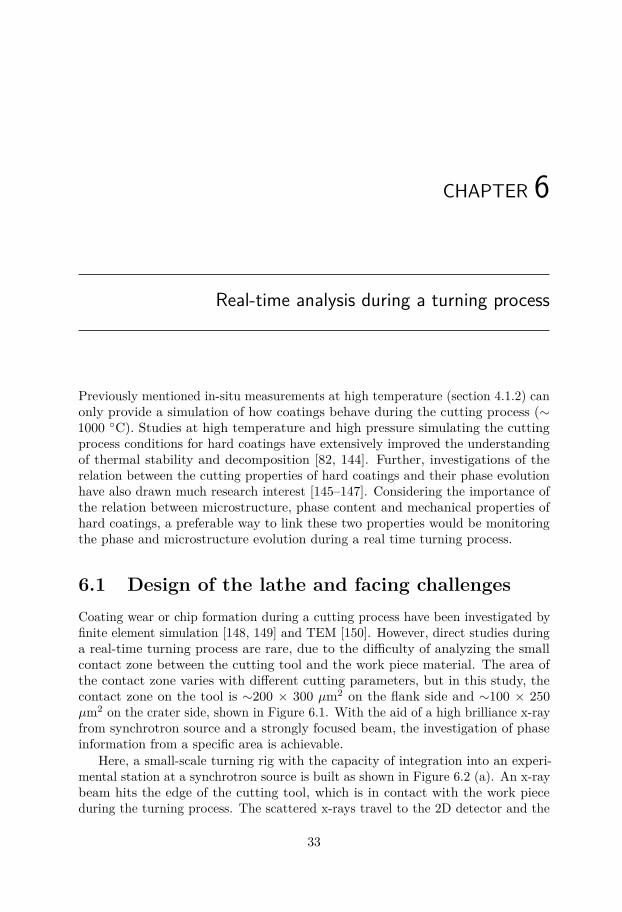
6.1 Design of the lathe and facing challengesCoating wear or chip formation during a cutting process have been investigated byfinite element simulation [148, 149] and TEM [150]. However, direct studies duringa real-time turning process are rare, due to the difficulty of analyzing the smallcontact zone between the cutting tool and the work piece material. The area ofthe contact zone varies with different cutting parameters, but in this study, thecontact zone on the tool is ∼200 × 300 µm2 on the flank side and ∼100 × 250µm2 on the crater side, shown in Figure 6.1. With the aid of a high brilliance x-rayfrom synchrotron source and a strongly focused beam, the investigation of phaseinformation from a specific area is achievable.
Here, a small-scale turning rig with the capacity of integration into an experi-mental station at a synchrotron source is built as shown in Figure 6.2 (a). An x-raybeam hits the edge of the cutting tool, which is in contact with the work pieceduring the turning process. The scattered x-rays travel to the 2D detector and the
33
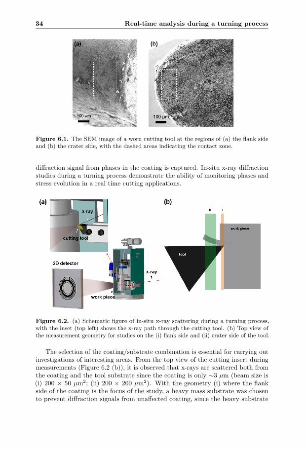
34 Real-time analysis during a turning process
Figure 6.1. The SEM image of a worn cutting tool at the regions of (a) the flank sideand (b) the crater side, with the dashed areas indicating the contact zone.
diffraction signal from phases in the coating is captured. In-situ x-ray diffractionstudies during a turning process demonstrate the ability of monitoring phases andstress evolution in a real time cutting applications.
Figure 6.2. (a) Schematic figure of in-situ x-ray scattering during a turning process,with the inset (top left) shows the x-ray path through the cutting tool. (b) Top view ofthe measurement geometry for studies on the (i) flank side and (ii) crater side of the tool.
The selection of the coating/substrate combination is essential for carrying outinvestigations of interesting areas. From the top view of the cutting insert duringmeasurements (Figure 6.2 (b)), it is observed that x-rays are scattered both fromthe coating and the tool substrate since the coating is only ∼3 µm (beam size is(i) 200 × 50 µm2; (ii) 200 × 200 µm2). With the geometry (i) where the flankside of the coating is the focus of the study, a heavy mass substrate was chosento prevent diffraction signals from unaffected coating, since the heavy substrate
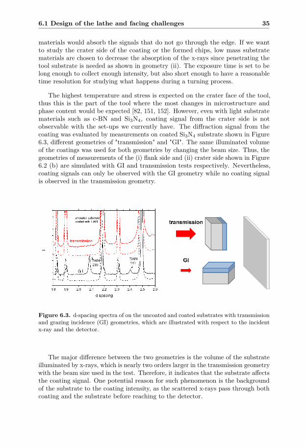
6.1 Design of the lathe and facing challenges 35
materials would absorb the signals that do not go through the edge. If we wantto study the crater side of the coating or the formed chips, low mass substratematerials are chosen to decrease the absorption of the x-rays since penetrating thetool substrate is needed as shown in geometry (ii). The exposure time is set to belong enough to collect enough intensity, but also short enough to have a reasonabletime resolution for studying what happens during a turning process.
The highest temperature and stress is expected on the crater face of the tool,thus this is the part of the tool where the most changes in microstructure andphase content would be expected [82, 151, 152]. However, even with light substratematerials such as c-BN and Si3N4, coating signal from the crater side is notobservable with the set-ups we currently have. The diffraction signal from thecoating was evaluated by measurements on coated Si3N4 substrate shown in Figure6.3, different geometries of "transmission" and "GI". The same illuminated volumeof the coatings was used for both geometries by changing the beam size. Thus, thegeometries of measurements of the (i) flank side and (ii) crater side shown in Figure6.2 (b) are simulated with GI and transmission tests respectively. Nevertheless,coating signals can only be observed with the GI geometry while no coating signalis observed in the transmission geometry.
Figure 6.3. d-spacing spectra of on the uncoated and coated substrates with transmissionand grazing incidence (GI) geometries, which are illustrated with respect to the incidentx-ray and the detector.
The major difference between the two geometries is the volume of the substrateilluminated by x-rays, which is nearly two orders larger in the transmission geometrywith the beam size used in the test. Therefore, it indicates that the substrate affectsthe coating signal. One potential reason for such phenomenon is the backgroundof the substrate to the coating intensity, as the scattered x-rays pass through bothcoating and the substrate before reaching to the detector.
36 Real-time analysis during a turning process
6.2 Stress/temperature distributionThe high pressure and high temperature environment that hard coatings experiencesduring a turning process remains as an interest topic as it substantially influencesthe properties of hard coatings. Studies of these parameters are difficult to becarried out due to the complexity of turning process that involves cutting tool,work piece and chips. With the aid of analytical model, the distribution of thenormal stress along the cutting edge of the tool has been measured and shown tohave its maximum stress at the tool edge, which is around 2 GPa and is similar forcutting speed from 100 m/min to 400 m/min[82].
Temperatures of cutting tool during the turning process has been studiesusing various methods such as thermocouples/pyrometer [151] or depositing atemperature sensor coating on the tool [153, 154]. Norrby et al [82] used an infrared(IR) CCD camera to map out the temperature distribution on the cutting insertand found that it becomes higher with higher cutting speed [155]. The maximumtemperature was at a cutting speed of 400 m/min and is around 1000 ◦C. However,the temperature distribution can also be affected by the cutting feed and thedepth-of-cut so that a turning process with different parameters can have variedtemperature environment on the cutting tool.
Flank wear of a cutting tool is a general phenomenon during metal cuttingand limits the tool lifetime [156], and influences the surface finish of the workpiece material [157]. Stress evolution or phase transition in the coatings during theturning process would strongly affect its hardness, which is strongly related with theabrasive wear resistance. In this thesis, the geometry of the flank side measurementis shown in Figure 6.2 (a) with the beam (indicated as (i)), positioned at the edgeof the cutting tool. As shown in Figure 6.4, the in-plane strain and the strain-freed spacing (d∗) of a TiAlNbN coating is measured during three contacts of turning,with the method mentioned in section 4.1.2 and 4.1.3. For the as-deposited coating,a compressive strain is measured while there is a higher strain during contact. Thisbehavior can be explained by the compressive stress from mechanical load duringcutting [158]. Further, from the d∗ values of TiAlNbN, the coating temperaturescan be estimated to ∼350 ◦C for both 230 and 320 m/min cutting speed. This isfound much lower than the expected operating temperatures, which can be a resultof that a relatively larger volume of the coatings is measured than the real contactarea on the edge of the tool. Since the thickness of the tool (along the flank side)is around 4 mm and the width of the contact zone at the same direction is only∼200 µm, much volume of the coatings are not heated by the turning process.
6.3 Study of the chips produced during a turningprocess
Chips generated from work piece play an essential role for a turning process. Theformation of the chips and the stress distribution on the built-up edge [159, 160]at the chip formation zone are important to study for optimization of the cuttingparameters. For example, the prediction of the chip flow direction has been studied
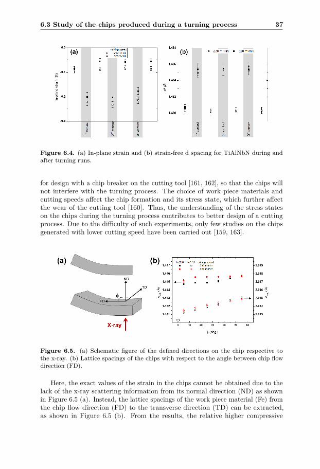
6.3 Study of the chips produced during a turning process 37
Figure 6.4. (a) In-plane strain and (b) strain-free d spacing for TiAlNbN during andafter turning runs.
for design with a chip breaker on the cutting tool [161, 162], so that the chips willnot interfere with the turning process. The choice of work piece materials andcutting speeds affect the chip formation and its stress state, which further affectthe wear of the cutting tool [160]. Thus, the understanding of the stress stateson the chips during the turning process contributes to better design of a cuttingprocess. Due to the difficulty of such experiments, only few studies on the chipsgenerated with lower cutting speed have been carried out [159, 163].
Figure 6.5. (a) Schematic figure of the defined directions on the chip respective tothe x-ray. (b) Lattice spacings of the chips with respect to the angle between chip flowdirection (FD).
Here, the exact values of the strain in the chips cannot be obtained due to thelack of the x-ray scattering information from its normal direction (ND) as shownin Figure 6.5 (a). Instead, the lattice spacings of the work piece material (Fe) fromthe chip flow direction (FD) to the transverse direction (TD) can be extracted,as shown in Figure 6.5 (b). From the results, the relative higher compressive
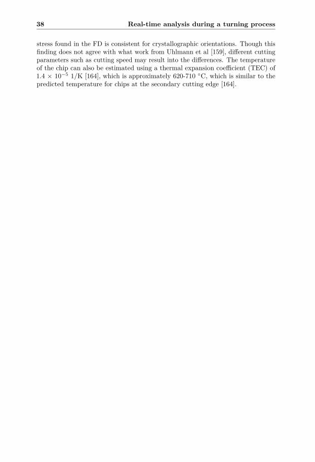
38 Real-time analysis during a turning process
stress found in the FD is consistent for crystallographic orientations. Though thisfinding does not agree with what work from Uhlmann et al [159], different cuttingparameters such as cutting speed may result into the differences. The temperatureof the chip can also be estimated using a thermal expansion coefficient (TEC) of1.4 × 10−5 1/K [164], which is approximately 620-710 ◦C, which is similar to thepredicted temperature for chips at the secondary cutting edge [164].
CHAPTER 7
Summary of the results
7.1 Kinetics of the h-AlN formation in TiAlCrN
h-AlN formation is essential for cubic TiAlN-based coating’s evolution of mechanicalproperties at high temperatures [19, 29–31], as large grains of this phase degradesthe coating hardness. The formation rate of h-AlN is therefore an important aspectwhen designing coatings with enhanced thermal stability.
InPaper I, the formation of h-AlN in Ti0.03Al0.59Cr0.38N and Ti0.16Al0.48Cr0.36Ncoatings was investigated during isothermal annealing experiments. The decom-position route is different in these coatings, while spinodal decomposition takesplace for Ti0.16Al0.48Cr0.36N, nucleation and growth of h-AlN, c-TiN and c-CrAlNoccurs in Ti0.03Al0.59Cr0.38N. This difference results in faster formation rate ofh-AlN in Ti0.03Al0.59Cr0.38N, which corresponds to a lower activation energy (88± 36 kJ/mol) for h-AlN formation than in Ti0.16Al0.48Cr0.36N (304 ± 7 kJ/mol).Since h-AlN is formed from CrAlN phase for both coatings, the location and size ofCrAlN domains determine its varied thermal stability. By spinodal decomposition,the CrAlN phase is stabilized in a coherent structure with the TiCrN phase inTi0.16Al0.48Cr0.36N. By contrast, larger size of CrAlN domains are formed in theTi0.03Al0.59Cr0.38N by nucleation and growth. In addition, the extremely lowactivation energy in Ti0.03Al0.59Cr0.38N is a result of direct precipitation of h-AlNat grain boundaries.
39
40 Summary of the results
7.2 Thermal stability of multilayers and quater-nary alloys
To improve the thermal stability of hard coatings at high temperatures, multi-layered structures (Paper II) and multi-component alloys (Paper III) weregrown and studied. The low Al content c-Zr0.65Al0.35N/TiN multilayer withsuperior thermal stability studied in Ref. [64] inspired the work on h-Zr0.25Al0.75Nmultilayers with TiN or ZrN that was investigated in Paper II. A secondaryTi(Zr)N phase is formed during annealing, and this phase assists to sustain thecompressive stress in the coatings and the coherency at the sub-interfaces partiallyremains after annealing. The retained strain and coherency leads to better fractureresistance in the h-Zr0.25Al0.75N/TiN multilayer. On the contrary, this behaviordoes not exist for h-Zr0.25Al0.75N/ZrN multilayer.
For TiAlN-based coatings alloyed with Nb, Cr or V element, the phase evolutionat high temperatures was studied in Paper III. Different thermal stability wasrevealed by varied initial temperatures for spinodal decomposition and h-AlN for-mation, which is affected by the difference in the mixing free energy of coatings [6,43]. Since spinodal decomposition and h-AlN formation are the main mechanismstaking place at high temperatures [23], the contribution of these phase transforma-tions to the coating’s mechanical properties is different. In sum, TiAlNbN exhibitsthe highest thermal stability in terms of the highest annealing temperature forinitiating the h-AlN formation, which further reflects on its superior mechanicalproperties at 1100 ◦C, especially on the fracture toughness.
7.3 Fracture behavior in hard coatingsFracture toughness is an essential property for wear resistant coatings, as thebrittleness of hard transition metal nitride coatings leads to easy failure of thecoatings during cutting [115, 116]. The crack behavior in hard coatings was studiedby indentations, scratch tests or contact fatigue analysis followed by characterizationof the different toughness properties. Multilayers of ZrAlN/TiN and ZrAlN/ZrNwere studied using nano-scratch and cube-corner indents, and clear differences incracks propagation and critical load for crack initiation were found (Paper II).Despite similar critical load for coating spallation from scratch tests, higher crackresistance is found from sub-surface studies for ZrAlN/TiN multilayers annealedup to 1100 ◦C, along with its higher hardness than ZrAlN/ZrN multilayers. Thesuperior mechanical properties after annealing at high temperatures are relatedwith the secondary phase, Ti(Zr)N that forms at the sub-interfaces.
Quaternary alloys of TiAlN alloying with Cr, Nb or V were compared to areference alloy TiAlN by micro-scratch tests in Paper III. Though the damage onthe surface reveals little difference between the samples, sub-surface investigationsby FIB cross-sections show clear variations in the mechanism of coating failures.Cracks tend to propagate differently in the coatings, which is found to be relatedwith the ductility of coatings estimated by the theoretical calculations [6].
In Paper IV, the fracture toughness of Ti1−xAlxN with x = 0.23 to 0.82 was
7.4 In-situ analysis during a turning process 41
studied using contact fatigue tests. Rings cracks were found around the imprintsonly for certain samples, revealing their difference in fracture toughness. Cross-sections on the ring cracks around the fatigue imprints were investigated, andvaried crack propagation was found between Ti1−xAlxN coatings. The differencesare related to the grain size. The Ti0.63Al0.37N coating exhibits the highest degreeof crack deflection by grain boundaries, due to its smaller grain size (i.e. higherdensity of grain boundaries) compared to Ti0.77Al0.23N. Ti1−xAlxN with higher Alcontent than 0.37 has too small grain size (nanometer range) so that the densityof grain boundaries is too high for crack deflection to take place. In addition, anoxide layer forms on the Ti0.18Al0.82N and prevents crack formation in the coating.Such oxidation may lead to easier coating failure during machining process and isabsent for the rest coatings.
7.4 In-situ analysis during a turning processA cutting process is different from a high temperature annealing for the hardcoatings. For instance, high pressure is an important factor affecting the coatingsduring cutting [82, 144]. Therefore, more information that is related with a turningprocess is obtained if one can directly observe the phase and microstructure duringmachining.
Paper V demonstrates the in-situ x-ray scattering analysis of tool coatings orthe chips from the work piece during a turning process. With the aid of a small scaleturning rig that can be placed in a synchrotron radiation facility, determination ofthe temperature and stress during a turning process were performed. PVD grownTiAlNbN and CVD grown Al2O3 coatings were tested and the strain and the strain-free d spacing (d∗) were investigated during the turning process. For all coatings,higher compressive strain is found during contact in the turning process, with theestimated operating temperatures as 350-430 ◦C. The obtained temperature canbe influenced by diffraction signal from coating outside the contact zone. A studyon the formed chips was also carried out, showing higher compressive strain inthe chip flow direction. The estimated chip temperature was around 720-820 ◦C,revealing that the measured area is in the chip formation zone.

42 Summary of the results
Bibliography
[1] M. M. Khruschov, “Principles of abrasive wear”, Wear 28, 69–88 (1974).[2] D. H. Jeong, U. Erb, K. T. Aust, and G. Palumbo, “The relationship
between hardness and abrasive wear resistance of electrodeposited nanocrys-talline Ni–P coatings”, Scripta Materialia, ViewPoint Set No. 29 "PhaseTransformations and Deformations in Magnesium Alloys" 48, 1067–1072(2003).
[3] M. Zhou, Y. Makino, M. Nose, and K. Nogi, “Phase transition and propertiesof Ti–Al–N thin films prepared by r.f.-plasma assisted magnetron sputtering”,Thin Solid Films 339, 203–208 (1999).
[4] A. Hörling, L. Hultman, M. Odén, J. Sjölén, and L. Karlsson, “Thermalstability of arc evaporated high aluminum-content Ti1-xAlxN thin films”,Journal of Vacuum Science & Technology A: Vacuum, Surfaces, and Films20, 1815–1823 (2002).
[5] M. E. Launey, and R. O. Ritchie, “On the Fracture Toughness of AdvancedMaterials”, Advanced Materials 21, 2103–2110 (2009).
[6] F. Wang, D. Holec, M. Odén, F. Mücklich, I. A. Abrikosov, and F. Tasnádi,“Systematic ab initio investigation of the elastic modulus in quaternary tran-sition metal nitride alloys and their coherent multilayers”, Acta Materialia127, 124–132 (2017).
[7] M. Odén, L. Rogström, A. Knutsson, M. R. Terner, P. Hedström, J. Almer,and J. Ilavsky, “In situ small-angle x-ray scattering study of nanostructureevolution during decomposition of arc evaporated TiAlN coatings”, AppliedPhysics Letters 94, 053114 (2009).
[8] L. Rogström, J. Ullbrand, J. Almer, L. Hultman, B. Jansson, and M. Odén,“Strain evolution during spinodal decomposition of TiAlN thin films”, ThinSolid Films 520, 5542–5549 (2012).
43
44 BIBLIOGRAPHY
[9] A. Knutsson, M. P. Johansson, P. O. A. Persson, L. Hultman, and M.Odén, “Thermal decomposition products in arc evaporated TiAlN/TiNmultilayers”, Applied Physics Letters 93 (2008).
[10] I. A. Abrikosov, A. Knutsson, B. Alling, F. Tasnádi, H. Lind, L. Hultman,and M. Odén, “Phase Stability and Elasticity of TiAlN”, Materials 4, 1599–1618 (2011).
[11] L. Rogström, L. J. S. Johnson, M. P. Johansson, M. Ahlgren, L. Hultman,and M. Odén, “Thermal stability and mechanical properties of arc evaporatedZrN/ZrAlN multilayers”, Thin Solid Films 519, 694–699 (2010).
[12] C. Mendibide, P. Steyer, J. Fontaine, and P. Goudeau, “Improvement of thetribological behaviour of PVD nanostratified TiN/CrN coatings - An explana-tion”, English, Surface & Coatings Technology 201, WOS:000243149700056,4119–4124 (2006).
[13] A. Hörling, L. Hultman, M. Odén, J. Sjölén, and L. Karlsson, “Mechanicalproperties and machining performance of Ti1=xAlxN-coated cutting tools”,Surface and Coatings Technology 191, 384–392 (2005).
[14] K.-D. Bouzakis, N. Michailidis, G. Skordaris, E. Bouzakis, D. Biermann, andR. M’Saoubi, “Cutting with coated tools: Coating technologies, characteri-zation methods and performance optimization”, CIRP Annals 61, 703–723(2012).
[15] S. PalDey, and S. C. Deevi, “Single layer and multilayer wear resistantcoatings of (Ti,Al)N: a review”, Materials Science and Engineering: A 342,58–79 (2003).
[16] U. Wahlström, L. Hultman, J. .-.-E. Sundgren, F. Adibi, I. Petrov, and J. E.Greene, “Crystal growth and microstructure of polycrystalline Ti1=xAlxNalloy films deposited by ultra-high-vacuum dual-target magnetron sputter-ing”, Thin Solid Films 235, 62–70 (1993).
[17] P. H. Mayrhofer, C. Mitterer, L. Hultman, and H. Clemens, “Microstructuraldesign of hard coatings”, Progress in Materials Science 51, 1032–1114 (2006).
[18] P. H. Mayrhofer, M. Stoiber, and C. Mitterer, “Age hardening of PACVDTiBN thin films”, Scripta Materialia 53, 241–245 (2005).
[19] R. Rachbauer, S. Massl, E. Stergar, D. Holec, D. Kiener, J. Keckes, J.Patscheider, M. Stiefel, H. Leitner, and P. H. Mayrhofer, “Decompositionpathways in age hardening of Ti-Al-N films”, Journal of Applied Physics110, 023515 (2011).
[20] N. Shulumba, O. Hellman, Z. Raza, B. Alling, J. Barrirero, F. Mücklich, I. A.Abrikosov, and M. Odén, “Lattice Vibrations Change the Solid Solubilityof an Alloy at High Temperatures”, Physical Review Letters 117, 205502(2016).
[21] D. J. Seol, S. Y. Hu, Y. L. Li, J. Shen, K. H. Oh, and L. Q. Chen, “Computersimulation of spinodal decomposition in constrained films”, Acta Materialia51, 5173–5185 (2003).
BIBLIOGRAPHY 45
[22] S. Benítez, and I. Citlalli, “Defect-engineered (Ti,Al)N thin films” (2017).[23] P. H. Mayrhofer, A. Hörling, L. Karlsson, J. Sjölén, T. Larsson, C. Mitterer,
and L. Hultman, “Self-organized nanostructures in the Ti–Al–N system”,Applied Physics Letters 83, 2049 (2003).
[24] N. T. K. Thanh, N. Maclean, and S. Mahiddine, “Mechanisms of Nucleationand Growth of Nanoparticles in Solution”, Chemical Reviews 114, 7610–7630 (2014).
[25] E. A. Jägle, and E. J. Mittemeijer, “The kinetics of grain-boundary nucleatedphase transformations: Simulations and modelling”, Acta Materialia 59,5775–5786 (2011).
[26] L. Hultman, “Thermal stability of nitride thin films”, Vacuum 57, 1–30(2000).
[27] L. Hultman, “Transmission Electron Microscopy of Metastable Materials”,EN, Key Engineering Materials 103, 181–194 (1995).
[28] N. Norrby, L. Rogström, M. P. Johansson-Jõesaar, N. Schell, and M. Odén,“In situ X-ray scattering study of the cubic to hexagonal transformation ofAlN in Ti1=xAlxN”, Acta Materialia 73, 205–214 (2014).
[29] D. Rafaja, C. Wuestefeld, C. Baehtz, V. Klemm, M. Dopita, M. Motylenko,C. Michotte, and M. Kathrein, “Effect of Internal Interfaces on Hardness andThermal Stability of Nanocrystalline Ti0.5Al0.5N Coatings”, English, Met-allurgical and Materials Transactions a-Physical Metallurgy and MaterialsScience 42A, WOS:000286834700006, 559–569 (2011).
[30] R. Forsén, I. C. Schramm, P. O. A. Persson, F. Muecklich, M. Oden, andN. Ghafoor, “Nanostructuring and coherency strain in multicomponent hardcoatings”, English, Apl Materials 2, WOS:000345638800023, 116104 (2014).
[31] I. N. Mastorakos, H. M. Zbib, and D. F. Bahr, “Deformation mechanismsand strength in nanoscale multilayer metallic composites with coherent andincoherent interfaces”, English, Applied Physics Letters 94 (2009).
[32] D. Holec, L. Zhou, R. Rachbauer, and P. H. Mayrhofer, “Alloying-relatedtrends from first principles: An application to the Ti–Al–X–N system”,Journal of Applied Physics 113, 113510 (2013).
[33] R. Rachbauer, D. Holec, M. Lattemann, L. Hultman, and P. H. Mayrhofer,“Electronic origin of structure and mechanical properties in Y and Nballoyed Ti–Al–N thin films”, International Journal of Materials Research102, 735–742 (2011).
[34] H. W. Hugosson, H. Högberg, M. Algren, M. Rodmar, and T. I. Selinder,“Theory of the effects of substitutions on the phase stabilities of Ti1=xAlxN”,Journal of Applied Physics 93, 4505–4511 (2003).
[35] L. Chen, D. Holec, Y. Du, and P. H. Mayrhofer, “Influence of Zr on structure,mechanical and thermal properties of Ti–Al–N”, Thin Solid Films 519, 5503–5510 (2011).
46 BIBLIOGRAPHY
[36] K. Kutschej, N. Fateh, P. H. Mayrhofer, M. Kathrein, P. Polcik, and C.Mitterer, “Comparative study of Ti1=xAlxN coatings alloyed with Hf, Nb,and B”, Surface and Coatings Technology, PSE 2004 200, 113–117 (2005).
[37] R. Forsén, M. P. Johansson, M. Odén, and N. Ghafoor, “Effects of Tialloying of AlCrN coatings on thermal stability and oxidation resistance”,Thin Solid Films 534, 394–402 (2013).
[38] R. Forsén, M. Johansson, M. Odén, and N. Ghafoor, “Decomposition andphase transformation in TiCrAlN thin coatings”, Journal of Vacuum Science& Technology A: Vacuum, Surfaces, and Films 30, 061506 (2012).
[39] A. I. Kovalev, D. L. Wainstein, A. Y. Rashkovskiy, G. S. Fox-Rabinovich,K. Yamamoto, S. Veldhuis, M. Aguirre, and B. D. Beake, “Impact of Aland Cr alloying in TiN-based PVD coatings on cutting performance duringmachining of hard to cut materials”, Vacuum 84, 184–187 (2009).
[40] L. Bai, X. Zhu, J. Xiao, and J. He, “Study on thermal stability of CrTiAlNcoating for dry drilling”, Surface and Coatings Technology, Proceedingsof the Fifth Asian-European International Conference on Plasma SurfaceEngineering 201, 5257–5260 (2007).
[41] S. G. Harris, E. D. Doyle, A. C. Vlasveld, J. Audy, J. M. Long, and D.Quick, “Influence of chromium content on the dry machining performanceof cathodic arc evaporated TiAlN coatings”, Wear 254, 185–194 (2003).
[42] E. Pflüger, A. Schröer, P. Voumard, L. Donohue, and W.-D. Münz, “Influenceof incorporation of Cr and Y on the wear performance of TiAlN coatingsat elevated temperatures”, Surface and Coatings Technology 115, 17–23(1999).
[43] H. Lind, R. Forsén, B. Alling, N. Ghafoor, F. Tasnádi, M. P. Johansson,I. A. Abrikosov, and M. Odén, “Improving thermal stability of hard coatingfilms via a concept of multicomponent alloying”, Applied Physics Letters99, 091903 (2011).
[44] R. Forsén, N. Ghafoor, and M. Odèn, “Coherency strain engineered de-composition of unstable multilayer alloys for improved thermal stability”,Journal of Applied Physics 114, 244303 (2013).
[45] H. Willimann, P. H. Mayrhofer, L. Hultman, and C. Mitterer, “Hardnessevolution of Al-Cr-N coatings under thermal load”, Journal of MaterialsResearch 23, 2880–2885 (2008).
[46] P. H. Mayrhofer, H. Willmann, and A. E. Reiter, “Structure and phaseevolution of Cr–Al–N coatings during annealing”, Surface and CoatingsTechnology 202, 4935–4938 (2008).
[47] P. H. Mayrhofer, R. Rachbauer, and D. Holec, “Influence of Nb on the phasestability of Ti–Al–N”, Scripta Materialia 63, 807–810 (2010).
[48] D. G. Sangiovanni, V. Chirita, and L. Hultman, “Toughness enhancement inTiAlN-based quarternary alloys”, Thin Solid Films 520, 4080–4088 (2012).
BIBLIOGRAPHY 47
[49] F. Rovere, D. Music, S. Ershov, M. to Baben, H.-G. Fuss, P. H. Mayrhofer,and J. M. Schneider, “Experimental and computational study on the phasestability of Al-containing cubic transition metal nitrides”, Journal of PhysicsD: Applied Physics 43, 035302 (2010).
[50] M. Kathrein, C. Michotte, M. Penoy, P. Polcik, and C. Mitterer, “Multi-functional multi-component PVD coatings for cutting tools”, Surface andCoatings Technology, ICMCTF 2005 200, 1867–1871 (2005).
[51] W. J. Clegg, “Controlling Cracks in Ceramics”, Science 286, 1097 (1999).[52] S. M. Wiederhorn, “Brittle-Fracture and Toughening Mechanisms in Ce-
ramics”, Annual Review of Materials Science 14, 373–403 (1984).[53] M. Mikula, D. Plašienka, D. G. Sangiovanni, M. Sahul, T. Roch, M. Truchlý,
M. Gregor, L. Čaplovič, A. Plecenik, and P. Kúš, “Toughness enhancementin highly NbN-alloyed Ti-Al-N hard coatings”, Acta Materialia 121, 59–67(2016).
[54] R. Franz, and C. Mitterer, “Vanadium containing self-adaptive low-frictionhard coatings for high-temperature applications: A review”, Surface andCoatings Technology 228, 1–13 (2013).
[55] D. Holec, R. Rachbauer, L. Chen, L. Wang, D. Luef, and P. H. Mayrhofer,“Phase stability and alloy-related trends in Ti–Al–N, Zr–Al–N and Hf–Al–Nsystems from first principles”, Surface and Coatings Technology, Proceedingsof the 38th International Conference on Metallurgical Coatings and ThinFilms (ICMCTF) 206, 1698–1704 (2011).
[56] N. Shulumba, “Vibrations in solids : From first principles lattice dynamics tohigh temperature phase stability”, English, DOI: 10.3384/diss.diva-122949,PhD thesis (Linköping University Electronic Press, Linköping, 2015).
[57] L. Rogström, M. P. Johansson, N. Ghafoor, L. Hultman, and M. Odén, “In-fluence of chemical composition and deposition conditions on microstructureevolution during annealing of arc evaporated ZrAlN thin films”, Journal ofVacuum Science & Technology A: Vacuum, Surfaces, and Films 30, 031504(2012).
[58] L. Rogström, M. Ahlgren, J. Almer, L. Hultman, and M. Odén, “Phasetransformations in nanocomposite ZrAlN thin films during annealing”,Journal of Materials Research 27, 1716–1724 (2012).
[59] R. Sanjinés, C. S. Sandu, R. Lamni, and F. Lévy, “Thermal decompositionof Zr1=xAlxN thin films deposited by magnetron sputtering”, Surface andCoatings Technology 200, 6308–6312 (2006).
[60] P. H. Mayrhofer, D. Sonnleitner, M. Bartosik, and D. Holec, “Structural andmechanical evolution of reactively and non-reactively sputtered Zr–Al–Nthin films during annealing”, Surface and Coatings Technology 244, 52–56(2014).
[61] R. Franz, M. Lechthaler, C. Polzer, and C. Mitterer, “Oxidation behaviourand tribological properties of arc-evaporated ZrAlN hard coatings”, Surfaceand Coatings Technology 206, 2337–2345 (2012).
48 BIBLIOGRAPHY
[62] L. Rogström, N. Ghafoor, J. Schroeder, N. Schell, J. Birch, M. Ahlgren,and M. Odén, “Thermal stability of wurtzite Zr1-xAlxN coatings studiedby in situ high-energy x-ray diffraction during annealing”, English, Journalof Applied Physics 118 (2015) 10.1063/1.4927156.
[63] L. Rogström, M. P. Johansson-Jõesaar, L. Landälv, M. Ahlgren, and M.Odén, “Wear behavior of ZrAlN coated cutting tools during turning”, Surfaceand Coatings Technology 282, 180–187 (2015).
[64] L. Rogström, N. Ghafoor, M. Ahlgren, and M. Odén, “Auto-organizingZrAlN/ZrAlTiN/TiN multilayers”, Thin Solid Films 520, 6451–6454 (2012).
[65] A. Anders, “A brief modern history of cathodic arc coating”, The Societyof Vacuum Coaters 50th Anniversary Book (2007).
[66] D. M. Sanders, and A. Anders, “Review of cathodic arc deposition technologyat the start of the new millennium”, Surface and Coatings Technology 133,78–90 (2000).
[67] A. Knutsson, M. P. Johansson, L. Karlsson, and M. Odén, “Thermallyenhanced mechanical properties of arc evaporated Ti0.34Al0.66N/TiN mul-tilayer coatings”, Journal of Applied Physics 108, 044312 (2010).
[68] M. Odén, C. Ericsson, G. Håkansson, and H. Ljungcrantz, “Microstructureand mechanical behavior of arc-evaporated Cr–N coatings”, Surface andCoatings Technology 114, 39–51 (1999).
[69] A. Anders, “A structure zone diagram including plasma-based depositionand ion etching”, Thin Solid Films 518, 4087–4090 (2010).
[70] A. E. Reiter, V. H. Derflinger, B. Hanselmann, T. Bachmann, and B. Sartory,“Investigation of the properties of Al1-xCrxN coatings prepared by cathodicarc evaporation”, Surface and Coatings Technology 200, 2114–2122 (2005).
[71] B. Alling, M. Odén, L. Hultman, and I. A. Abrikosov, “Pressure enhancementof the isostructural cubic decomposition in Ti1=xAlxN”, Applied PhysicsLetters 95, 181906 (2009).
[72] L. Chen, K. K. Chang, Y. Du, J. R. Li, and M. J. Wu, “A comparativeresearch on magnetron sputtering and arc evaporation deposition of Ti–Al–Ncoatings”, Thin Solid Films 519, 3762–3767 (2011).
[73] D. J. Srolovitz, G. S. Grest, M. P. Anderson, and A. D. Rollett, “Computersimulation of recrystallization—II. Heterogeneous nucleation and growth”,Acta Metallurgica 36, 2115–2128 (1988).
[74] N. Norrby, M. P. Johansson-Jõesaar, and M. Odén, “Improved metal cuttingperformance with bias-modulated textured Ti0.50Al0.50N multilayers”,Surface and Coatings Technology, 25 years of TiAlN hard coatings inresearch and industry 257, 102–107 (2014).
[75] M. Nordin, M. Larsson, and S. Hogmark, “Mechanical and tribologicalproperties of multilayered PVD TiN/CrN”, Wear 232, 221–225 (1999).
[76] C. A. Davis, “A simple model for the formation of compressive stress inthin films by ion bombardment”, Thin Solid Films 226, 30–34 (1993).
BIBLIOGRAPHY 49
[77] I. Petrov, P. Losbichler, D. Bergstrom, J. E. Greene, W. .-.-D. Münz, T.Hurkmans, and T. Trinh, “Ion-assisted growth of Ti1=xAlxN/Ti1=yNbyNmultilayers by combined cathodic-arc/magnetron-sputter deposition”, ThinSolid Films 302, 179–192 (1997).
[78] A. Anders, “Macroparticles”, in Cathodic Arcs: From Fractal Spots toEnergetic Condensation (Springer New York, New York, NY, 2008), pp. 1–34.
[79] A. Laukkanen, K. Holmberg, J. Koskinen, H. Ronkainen, K. Wallin, andS. Varjus, “Tribological contact analysis of a rigid ball sliding on a hardcoated surface, Part III: Fracture toughness calculation and influence ofresidual stresses”, Surface and Coatings Technology 200, 3824–3844 (2006).
[80] S. Zhang, D. Sun, Y. Fu, and H. Du, “Toughening of hard nanostructuralthin films: a critical review”, Surface and Coatings Technology 198, 2–8(2005).
[81] D. S. Rickerby, and S. J. Bull, “Engineering with surface coatings: The roleof coating microstructure”, Surface and Coatings Technology 39, 315–328(1989).
[82] N. Norrby, M. P. Johansson, R. M’Saoubi, and M. Odén, “Pressure andtemperature effects on the decomposition of arc evaporated Ti0.6Al0.4Ncoatings in continuous turning”, Surface and Coatings Technology 209,203–207 (2012).
[83] M. Birkholz, “Principles of X-ray Diffraction”, in Thin Film Analysis byX-Ray Scattering (Wiley-VCH Verlag GmbH & Co. KGaA, 2005), pp. 1–40.
[84] M. Bouroushian, and T. Kosanovic, “Characterization of Thin Films by LowIncidence X-Ray Diffraction”, en, Crystal Structure Theory and Applications01, 35 (2012).
[85] D. Rafaja, A. Poklad, V. Klemm, G. Schreiber, D. Heger, M. Šíma, andM. Dopita, “Some consequences of the partial crystallographic coherencebetween nanocrystalline domains in Ti–Al–N and Ti–Al–Si–N coatings”,Thin Solid Films 514, 240–249 (2006).
[86] J. Almer, U. Lienert, R. L. Peng, C. Schlauer, and M. Odén, “Strain andtexture analysis of coatings using high-energy x-rays”, Journal of AppliedPhysics 94, 697–702 (2003).
[87] I. C. Noyan, and J. B. Cohen, Residual Stress: Measurement by Diffractionand Interpretation, Materials Research and Engineering (Springer-Verlag,New York, 1987).
[88] L. Rogström, “High temperature behavior of arc evaporated ZrAlN andTiAlN thin films”, eng, (2012).
[89] F. Wang, D. Holec, M. Odén, F. Mücklich, I. A. Abrikosov, and F. Tasnádi,“Systematic ab initio investigation of the elastic modulus in quaternary tran-sition metal nitride alloys and their coherent multilayers”, Acta Materialia127, 124–132 (2017).
50 BIBLIOGRAPHY
[90] D. B. Williams, and C. B. Carter, Transmission Electron Microscopy(Springer US, Boston, MA, 2009).
[91] Y. X. Wang, and S. Zhang, “Toward hard yet tough ceramic coatings”,Surface and Coatings Technology 258, 1–16 (2014).
[92] P. F. Liu, and J. Y. Zheng, “Recent developments on damage modelingand finite element analysis for composite laminates: A review”, Materials &Design 31, 3825–3834 (2010).
[93] C. Baudin, A. Sayir, and M. H. Berger, “Mechanical behaviour of direction-ally solidified alumina/aluminium titanate ceramics”, Acta Materialia 54,3835–3841 (2006).
[94] L. Chen, D. Holec, Y. Du, and P. H. Mayrhofer, “Influence of Zr on structure,mechanical and thermal properties of Ti–Al–N”, Thin Solid Films 519, 5503–5510 (2011).
[95] H. Kindlund, D. G. Sangiovanni, L. Martínez-de-Olcoz, J. Lu, J. Jensen,J. Birch, I. Petrov, J. E. Greene, V. Chirita, and L. Hultman, “Toughnessenhancement in hard ceramic thin films by alloy design”, APL Materials 1,042104 (2013).
[96] M. Mikula, D. Plašienka, D. G. Sangiovanni, M. Sahul, T. Roch, M. Truchlý,M. Gregor, L. Čaplovič, A. Plecenik, and P. Kúš, “Toughness enhancementin highly NbN-alloyed Ti-Al-N hard coatings”, Acta Materialia 121, 59–67(2016).
[97] S. Hogmark, S. Jacobson, and M. Larsson, “Design and evaluation of tribo-logical coatings”, Wear 246, 20–33 (2000).
[98] S. Zhang, and X. Zhang, “Toughness evaluation of hard coatings and thinfilms”, Thin Solid Films 520, 2375–2389 (2012).
[99] G. Ramírez, A. Mestra, B. Casas, I. Valls, R. Martínez, R. Bueno, A.Góez, A. Mateo, and L. Llanes, “Influence of substrate microstructure onthe contact fatigue strength of coated cold-work tool steels”, Surface andCoatings Technology 206, 3069–3081 (2012).
[100] S. J. Bull, “Failure mode maps in the thin film scratch adhesion test”,Tribology International 30, 491–498 (1997).
[101] A. J. Perry, “Scratch adhesion testing of hard coatings”, Thin Solid Films107, 167–180 (1983).
[102] K. H. Nam, I. H. Park, and S. H. Ko, “Patterning by controlled cracking”,en, Nature 485, 221–224 (2012).
[103] J. J. Roa, E. Jiménez-Piqué, R. Martínez, G. Ramírez, J. M. Tarragó, R.Rodríguez, and L. Llanes, “Contact damage and fracture micromechanismsof multilayered TiN/CrN coatings at micro- and nano-length scales”, ThinSolid Films 571, 308–315 (2014).
BIBLIOGRAPHY 51
[104] P. H. Mayrhofer, D. Sonnleitner, M. Bartosik, and D. Holec, “Structural andmechanical evolution of reactively and non-reactively sputtered Zr–Al–Nthin films during annealing”, Surface and Coatings Technology 244, 52–56(2014).
[105] L. Llanes, E. Tarrés, G. Ramírez, C. A. Botero, and E. Jiménez-Piqué,“Fatigue susceptibility under contact loading of hardmetals coated withceramic films”, Procedia Engineering 2, 299–308 (2010).
[106] M. A. Moore, “The relationship between the abrasive wear resistance,hardness and microstructure of ferritic materials”, Wear 28, 59–68 (1974).
[107] W. Münz, “Titanium aluminum nitride films: A new alternative to TiNcoatings”, Journal of Vacuum Science & Technology A: Vacuum, Surfaces,and Films 4, 2717–2725 (1986).
[108] D. Heim, and R. Hochreiter, “TiAlN and TiAlCN deposition in an industrialPaCVD-plant”, Surface and Coatings Technology, Papers presented at theFifth International Conference on Plasma Surface Engineering 98, 1553–1556 (1998).
[109] O. Knotek, W. D. Münz, and T. Leyendecker, “Industrial deposition ofbinary, ternary, and quaternary nitrides of titanium, zirconium, and alu-minum”, en, Journal of Vacuum Science & Technology A: Vacuum, Surfaces,and Films 5, 2173–2179 (1987).
[110] W. C. Oliver, and G. M. Pharr, “An improved technique for determininghardness and elastic modulus using load and displacement sensing indenta-tion experiments”, Journal of Materials Research 7, 1564–1583 (1992).
[111] W. C. Oliver, and G. M. Pharr, “Measurement of hardness and elasticmodulus by instrumented indentation: Advances in understanding andrefinements to methodology”, Journal of Materials Research 19, 3–20 (2004).
[112] J. Chen, and S. J. Bull, “On the factors affecting the critical indenterpenetration for measurement of coating hardness”, Vacuum 83, 911–920(2009).
[113] Z. Chen, X. Wang, V. Bhakhri, F. Giuliani, and A. Atkinson, “Nanoin-dentation of porous bulk and thin films of La0.6Sr0.4Co0.2Fe0.8O3”, ActaMaterialia 61, 5720–5734 (2013).
[114] R. W. Armstrong, “The Hardness and Strength Properties of WC-CoComposites”, Materials 4, 1287–1308 (2011).
[115] W. F. Sales, A. E. Diniz, and Á. R. Machado, “Application of cutting fluidsin machining processes”, Journal of the Brazilian Society of MechanicalSciences 23, 227–240 (2001).
[116] R. Sekhar, and T. P. Singh, “Mechanisms in turning of metal matrix com-posites: a review”, Journal of Materials Research and Technology 4, 197–207(2015).
[117] G. M. Pharr, “Measurement of mechanical properties by ultra-low loadindentation”, Materials Science and Engineering: A 253, 151–159 (1998).
52 BIBLIOGRAPHY
[118] G. R. Anstis, P. Chantikul, B. R. Lawn, and D. B. Marshall, “A CriticalEvaluation of Indentation Techniques for Measuring Fracture Toughness: I,Direct Crack Measurements”, en, Journal of the American Ceramic Society64, 533–538 (1981).
[119] E. O. Hall, “The Deformation and Ageing of Mild Steel: III Discussion ofResults”, en, Proceedings of the Physical Society. Section B 64, 747 (1951).
[120] Z. Fan, “The grain size dependence of ductile fracture toughness of poly-crystalline metals and alloys”, Materials Science and Engineering: A 191,73–83 (1995).
[121] S. J. Bull, D. S. Rickerby, A. Matthews, A. Leyland, A. R. Pace, andJ. Valli, “The use of scratch adhesion testing for the determination ofinterfacial adhesion: The importance of frictional drag”, Surface and CoatingsTechnology 36, 503–517 (1988).
[122] S. J. Bull, and E. G. Berasetegui, “An overview of the potential of quantita-tive coating adhesion measurement by scratch testing”, Tribology Interna-tional, 180 Years of Scratch Testing 39, 99–114 (2006).
[123] B. D. Beake, A. J. Harris, and T. W. Liskiewicz, “Review of recent progressin nanoscratch testing”, Tribology - Materials, Surfaces & Interfaces 7, 87–96(2013).
[124] J. von Stebut, R. Rezakhanlou, K. Anoun, H. Michel, and M. Gantois, “Majordamage mechanisms during scratch and wear testing of hard coatings onhard substrates”, Thin Solid Films 181, 555–564 (1989).
[125] K. Holmberg, A. Laukkanen, H. Ronkainen, K. Wallin, S. Varjus, and J.Koskinen, “Tribological contact analysis of a rigid ball sliding on a hardcoated surface Part II: Material deformations, influence of coating thicknessand Young’s modulus”, English, Surface & Coatings Technology 200, 3810–3823 (2006).
[126] R. Bantle, and A. Matthews, “Investigation into the impact wear behaviourof ceramic coatings”, Surface and Coatings Technology, Fourth InternationalConference on Plasma Surface Engineering Part 2 74-75, 857–868 (1995).
[127] E. Tarrés, G. Ramírez, Y. Gaillard, E. Jiménez-Piqué, and L. Llanes, “Con-tact fatigue behavior of PVD-coated hardmetals”, International Journalof Refractory Metals and Hard Materials, International Conference on theScience of Hard Materials - 9 27, 323–331 (2009).
[128] G. Ramírez, E. Jiménez-Piqué, A. Mestra, M. Vilaseca, D. Casellas, and L.Llanes, “A comparative study of the contact fatigue behavior and associateddamage micromechanisms of TiN- and WC:H-coated cold-work tool steel”,Tribology International 88, 263–270 (2015).
[129] B. Lawn, “Indentation of ceramics with spheres: A century after Hertz”,Journal of the American Ceramic Society 81, 1977–1994 (1998).
BIBLIOGRAPHY 53
[130] M. F. C. Ordoñez, J. S. R. Paruma, F. S. Osorio, and M. C. M. Farias,“The Effect of Counterpart Material on the Sliding Wear of TiAlN CoatingsDeposited by Reactive Cathodic Pulverization”, en, Scientia cum Industria3, 59–66 (2015).
[131] L. C. Agudelo-Morimitsu, J. De La Roche, A. Ruden, D. Escobar, and E.Restrepo-Parra, “Effect of substrate temperature on the mechanical andtribological properties of W/WC produced by DC magnetron sputtering”,Ceramics International 40, 7037–7042 (2014).
[132] F. Vaz, L. Rebouta, M. Andritschky, M. F. da Silva, and J. C. Soares,“Thermal oxidation of Ti1 = xAlxN coatings in air”, Journal of the EuropeanCeramic Society, International Symposium on Nitrides Journees d’Etudessur les Nitures 17, 1971–1977 (1997).
[133] Y.-W. Kim, M. Mitomo, and H. Hirotsuru, “Grain Growth and FractureToughness of Fine-Grained Silicon Carbide Ceramics”, en, Journal of theAmerican Ceramic Society 78, 3145–3148 (1995).
[134] N. Hansen, “Hall–Petch relation and boundary strengthening”, ScriptaMaterialia, Viewpoint set no. 35. Metals and alloys with a structural scalefrom the micrometer to the atomic dimensions 51, 801–806 (2004).
[135] H. Gleiter, “Nanocrystalline materials”, Progress in Materials Science 33,223–315 (1989).
[136] C. Xiao, R. A. Mirshams, S. H. Whang, and W. M. Yin, “Tensile behaviorand fracture in nickel and carbon doped nanocrystalline nickel”, MaterialsScience and Engineering: A 301, 35–43 (2001).
[137] G. J. Fan, H. Choo, P. K. Liaw, and E. J. Lavernia, “A model for the inverseHall–Petch relation of nanocrystalline materials”, Materials Science andEngineering: A, Micromechanics of Advanced Materials II 409, 243–248(2005).
[138] T. G. Nieh, and J. Wadsworth, “Hall-petch relation in nanocrystallinesolids”, Scripta Metallurgica et Materialia 25, 955–958 (1991).
[139] R. Masumura, P. Hazzledine, and C. Pande, “Yield stress of fine grainedmaterials”, Acta Materialia 46, 4527–4534 (1998).
[140] J. Schiøtz, F. D. D. Tolla, and K. W. Jacobsen, “Softening of nanocrystallinemetals at very small grain sizes”, Nature 391, 561 (1998).
[141] R. Forsén, N. Ghafoor, and M. Odén, “Coherency strain engineered de-composition of unstable multilayer alloys for improved thermal stability”,Journal of Applied Physics 114, 244303 (2013).
[142] A. Knutsson, M. P. Johansson, L. Karlsson, and M. Odén, “Thermallyenhanced mechanical properties of arc evaporated Ti0.34al0.66n/TiN multi-layer coatings”, Journal of Applied Physics 108, 044312 (2010).
[143] P. C. Yashar, and W. D. Sproul, “Nanometer scale multilayered hardcoatings”, Vacuum 55, 179–190 (1999).
54 BIBLIOGRAPHY
[144] N. Norrby, H. Lind, G. Parakhonskiy, M. P. Johansson, F. Tasnádi, L. S.Dubrovinsky, N. Dubrovinskaia, I. A. Abrikosov, and M. Odén, “Highpressure and high temperature stabilization of cubic AlN in Ti0.60al0.40n”,Journal of Applied Physics 113, 053515 (2013).
[145] K. D. Bouzakis, N. Michailidis, G. Skordaris, E. Bouzakis, D. Biermann,and R. M’Saoubi, “Cutting with coated tools: Coating technologies, charac-terization methods and performance optimization”, English, Cirp Annals-Manufacturing Technology 61, 703–723 (2012).
[146] M. Sokovic, J. Mikula, L. A. Dobrzanski, J. Kopac, L. Kosec, P. Panjan,J. Madejski, and A. Piech, “Cutting properties of the Al2O3+SiC(w) basedtool ceramic reinforced with the PVD and CVD wear resistant coatings”,English, Journal of Materials Processing Technology 164, 924–929 (2005).
[147] S. Ruppi, and M. Halvarsson, “TEM investigation of wear mechanismsduring metal machining”, English, Thin Solid Films 353, 182–188 (1999).
[148] E. Uhlmann, S. Henze, K. Brömmelhoff, and W. Reimers, “Cutting Sim-ulation with Consideration of the Material Hardening in the Shear Zoneof AISI1045”, Procedia CIRP, 16th CIRP Conference on Modelling ofMachining Operations (16th CIRP CMMO) 58, 91–96 (2017).
[149] A. G. Mamalis, M. Horváth, A. S. Branis, and D. E. Manolakos, “Finiteelement simulation of chip formation in orthogonal metal cutting”, Journalof Materials Processing Technology 110, 19–27 (2001).
[150] S. Ruppi, and M. Halvarsson, “TEM investigation of wear mechanismsduring metal machining”, Thin Solid Films 353, 182–188 (1999).
[151] J. Hou, W. Zhou, H. Duan, G. Yang, H. Xu, and N. Zhao, “Influenceof cutting speed on cutting force, flank temperature, and tool wear inend milling of Ti-6al-4v alloy”, en, The International Journal of AdvancedManufacturing Technology 70, 1835–1845 (2014).
[152] N. S. Kumar, and T. Tamizharasan, “Impact of Interface Temperature overFlank Wear in Hard Turning Using Carbide Inserts”, Procedia Engineering,INTERNATIONAL CONFERENCE ON MODELLING OPTIMIZATIONAND COMPUTING 38, 613–621 (2012).
[153] W. Tillmann, E. Vogli, J. Herper, D. Biermann, and K. Pantke, “Devel-opment of temperature sensor thin films to monitor turning processes”,Journal of Materials Processing Technology 210, 819–823 (2010).
[154] D. Biermann, M. Kirschner, K. Pantke, W. Tillmann, and J. Herper, “Newcoating systems for temperature monitoring in turning processes”, Surfaceand Coatings Technology, Proceedings of the 39th International Conferenceon Metallurgical Coatings and Thin Films (ICMCTF) 215, 376–380 (2013).
[155] N. Norrby, “Microstructural evolution of TiAlN hard coatings at elevatedpressures and temperatures”, eng, PhD thesis (2014).
[156] X. Luo, K. Cheng, R. Holt, and X. Liu, “Modeling flank wear of carbidetool insert in metal cutting”, Wear, 15th International Conference on Wearof Materials 259, 1235–1240 (2005).
BIBLIOGRAPHY 55
[157] T. G. Dawson, D. Thomas, R. Kurfess, T. G. Dawson, and T. R. Kurfess,Wear trends of pcbn cutting tools in hard turning.
[158] H. K. Tönshoff, C. Arendt, and R. B. Amor, “Cutting of Hardened Steel”,CIRP Annals 49, 547–566 (2000).
[159] E. Uhlmann, R. Gerstenberger, S. Herter, T. Hoghé, W. Reimers, B. Camin,R. V. Martins, A. Schreyer, and T. Fischer, “In situ strain measurementin the chip formation zone during orthogonal cutting”, en, ProductionEngineering 5, 1–8 (2011).
[160] E. Uhlmann, S. Henze, and K. Brömmelhoff, “Influence of the Built-upEdge on the Stress State in the Chip Formation Zone During OrthogonalCutting of AISI1045”, Procedia CIRP, 15th CIRP Conference on Modellingof Machining Operations (15th CMMO) 31, 310–315 (2015).
[161] A. D′Acunto, G. Le Coz, A. Moufki, and D. Dudzinski, “Effect of CuttingEdge Geometry on Chip Flow Direction – Analytical Modelling and Experi-mental Validation”, Procedia CIRP, 16th CIRP Conference on Modelling ofMachining Operations (16th CIRP CMMO) 58, 353–357 (2017).
[162] J. A. Arsecularatne, R. F. Fowle, and P. Mathew, “Prediction of ChipFlow Direction, Cutting Forces and Surface Roughness in Finish Turning”,Journal of Manufacturing Science and Engineering 120, 1–12 (1998).
[163] K. Brömmelhoff, S. Henze, R. Gerstenberger, T. Fischer, N. Schell, E.Uhlmann, and W. Reimers, “Space resolved microstructural characteristicsin the chip formation zone of orthogonal cut C45e steel samples characterizedby diffraction experiments”, Journal of Materials Processing Technology213, 2211–2216 (2013).
[164] T. Özel, and T. Altan, “Process simulation using finite element method —prediction of cutting forces, tool stresses and temperatures in high-speedflat end milling”, International Journal of Machine Tools and Manufacture40, 713–738 (2000).

56 BIBLIOGRAPHY
I
Paper I
Effects of decomposition route and microstructureon h-AlN formation rate in TiCrAlN alloys
Y. H. ChenL. Rogström
D. OstachN. Ghafoor
M.P.Johansson-JõesaarN.Schell
J.BirchM.Odén
Journal of Alloys and Compounds , 691, 1024-1032 (2017)
Reprinted with permission. ©2017 Elsevier

Effects of decomposition route and microstructure on h-AlN formationrate in TiCrAlN alloys
Y.H. Chen a, *, L. Rogstr€om a, D. Ostach b, N. Ghafoor a, M.P. Johansson-J~oesaar a, c,N. Schell b, J. Birch d, M. Ode
n a
a Nanostructured Materials, Department of Physics, Chemistry and Biology (IFM), Link€oping University, SE-581 83 Link€oping, Swedenb Helmholtz-Zentrum Geesthacht (HZG), Max-Planck-Str. 1, D-21502 Geesthacht, Germanyc R&D Material and Technology Development, SECO Tools AB, SE-737 82 Fagersta, Swedend Thin Film Physics, Department of Physics, Chemistry and Biology (IFM), Link€oping University, SE-581 83 Link€oping, Sweden
a r t i c l e i n f o
Article history:Received 3 June 2016Received in revised form21 August 2016Accepted 28 August 2016Available online 30 August 2016
Keywords:Coating materialsPhase transitionsKineticsSynchrotron radiation
a b s t r a c t
The phase evolution of cubic (c), solid solution TixCr~0.37Al1�0.37�xN alloys with x ¼ 0.03 and 0.16, and thekinetics of the hexagonal (h)-AlN formation are studied via in situ wide angle x-ray scattering experi-ments during high temperature (1000e1150 �C) annealing. Spinodal decomposition was observed inTi0.16Cr0.36Al0.48N while Ti0.03Cr0.38Al0.59N decomposes through nucleation and growth of h-AlN, c-TiNand c-CrAlN. h-AlN is formed from c-CrAlN domains in both cases and the formation rate of h-AlN de-pends on the stability of the c-CrAlN domains. In Ti0.16Cr0.36Al0.48N, the c-CrAlN domains are stabilized bycrystallographic coherency with the surrounding c-TiCrN in a microstructure originating from spinodaldecomposition. This results in lower formation rates of h-AlN for this composition. These differences arereflected in higher activation energy for h-AlN formation in Ti0.16Cr0.36Al0.48N compared toTi0.03Cr0.38Al0.59N. It also points out different stabilities of the intermediate phase c-CrAlN during phasedecomposition of TiCrAlN alloys. Additional contributions to the low activation energy for formation ofh-AlN in Ti0.03Cr0.38Al0.59N stems from precipitation at grain boundaries.
© 2016 Elsevier B.V. All rights reserved.
1. Introduction
Wear resistant coatings are used to improve the properties ofhard metal cutting tool inserts. Among a wide range of transitionmetal nitrides, cubic c-Ti1�xAlxN coatings are extensively used inthis product segment triggered by its superior mechanical prop-erties [1]. The high hardness after exposing the coating to hightemperatures is related to spinodal decomposition [2,3] resulting inc-TiN and c-AlN rich domains where the variations in elasticproperties and the strain between domains gives rise to age hard-ening. However, the subsequent transformation of c-AlN to hex-agonal (h)-AlN following the spinodal decomposition [3] degradesthe mechanical properties of the alloy due to loss of coherencybetween c-TiN and c-AlN domains [4,5].
For high-speed cutting tools the temperatures may reach above1000 �C at the cutting zone [6]. Coating materials with improvedthermal stability are needed in order for the tool to survive
extended time periods or even higher temperatures. Enhancedthermal stability, in terms of suppressing the h-AlN formationduring decomposition, has been demonstrated by multilayeringTiAlN [7,8] or alloying metal elements (Me) in TiMeAlN [9e12].Specifically, the addition of Cr in TiCrAlN-alloys has shown to yieldsuperior mechanical properties after high temperature annealingand wear resistance compared to TiAlN [13e15]. Despite a lesspronounced age hardening in TiCrAlN because of lower coherencystrains betweenTi- and Al-rich domains when introducing Cr [7,16],the detrimental effect on the mechanical properties by h-AlN for-mation is also less severe due to formation of semi-coherent in-terfaces between h-AlN and c-TiCrN domains [8,16e18].Nevertheless, the formation of h-AlN still limits the high temper-ature properties and the details regarding its transformation arelacking. There is a critical domain size for when the interfaces relaxfrom semi-coherent to incoherent during formation of h-AlN,which is Cr-content dependent [16]. In order to further improve thedesign of these coatings, a better understanding of the formationmechanisms of h-AlN is needed.
The decomposition path of TiCrAlN is known to be dependent* Corresponding author.E-mail address: [email protected] (Y.H. Chen).
Contents lists available at ScienceDirect
Journal of Alloys and Compounds
journal homepage: http: / /www.elsevier .com/locate/ ja lcom
http://dx.doi.org/10.1016/j.jallcom.2016.08.2990925-8388/© 2016 Elsevier B.V. All rights reserved.
Journal of Alloys and Compounds 691 (2017) 1024e1032
Paper I 59
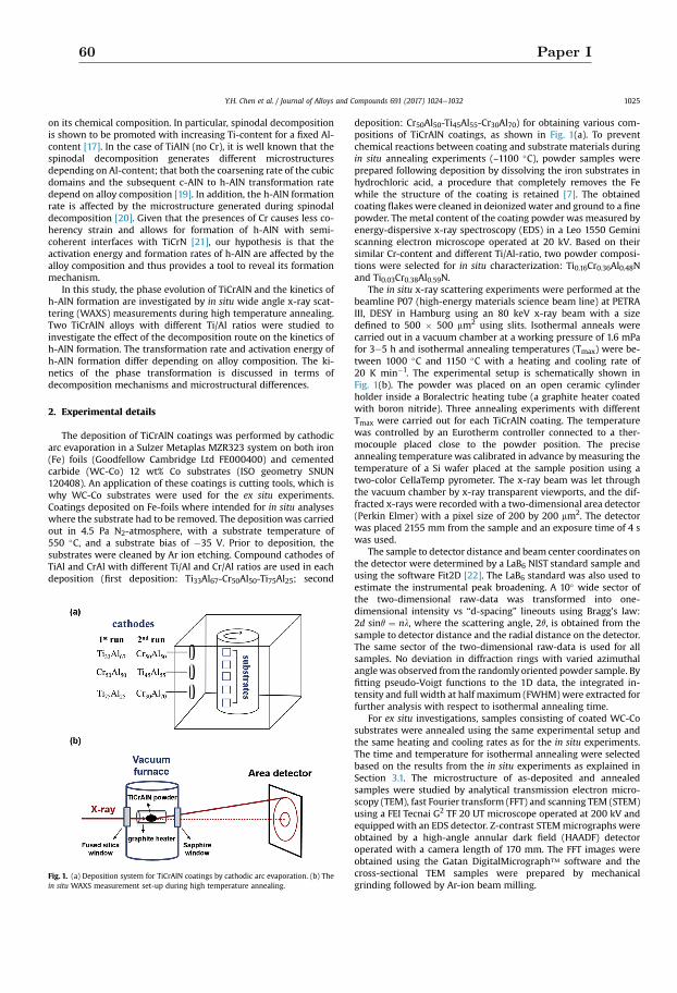
on its chemical composition. In particular, spinodal decompositionis shown to be promoted with increasing Ti-content for a fixed Al-content [17]. In the case of TiAlN (no Cr), it is well known that thespinodal decomposition generates different microstructuresdepending on Al-content; that both the coarsening rate of the cubicdomains and the subsequent c-AlN to h-AlN transformation ratedepend on alloy composition [19]. In addition, the h-AlN formationrate is affected by the microstructure generated during spinodaldecomposition [20]. Given that the presences of Cr causes less co-herency strain and allows for formation of h-AlN with semi-coherent interfaces with TiCrN [21], our hypothesis is that theactivation energy and formation rates of h-AlN are affected by thealloy composition and thus provides a tool to reveal its formationmechanism.
In this study, the phase evolution of TiCrAlN and the kinetics ofh-AlN formation are investigated by in situ wide angle x-ray scat-tering (WAXS) measurements during high temperature annealing.Two TiCrAlN alloys with different Ti/Al ratios were studied toinvestigate the effect of the decomposition route on the kinetics ofh-AlN formation. The transformation rate and activation energy ofh-AlN formation differ depending on alloy composition. The ki-netics of the phase transformation is discussed in terms ofdecomposition mechanisms and microstructural differences.
2. Experimental details
The deposition of TiCrAlN coatings was performed by cathodicarc evaporation in a Sulzer Metaplas MZR323 system on both iron(Fe) foils (Goodfellow Cambridge Ltd FE000400) and cementedcarbide (WC-Co) 12 wt% Co substrates (ISO geometry SNUN120408). An application of these coatings is cutting tools, which iswhy WC-Co substrates were used for the ex situ experiments.Coatings deposited on Fe-foils where intended for in situ analyseswhere the substrate had to be removed. The depositionwas carriedout in 4.5 Pa N2-atmosphere, with a substrate temperature of550 �C, and a substrate bias of �35 V. Prior to deposition, thesubstrates were cleaned by Ar ion etching. Compound cathodes ofTiAl and CrAl with different Ti/Al and Cr/Al ratios are used in eachdeposition (first deposition: Ti33Al67-Cr50Al50-Ti75Al25; second
deposition: Cr50Al50-Ti45Al55-Cr30Al70) for obtaining various com-positions of TiCrAlN coatings, as shown in Fig. 1(a). To preventchemical reactions between coating and substrate materials duringin situ annealing experiments (~1100 �C), powder samples wereprepared following deposition by dissolving the iron substrates inhydrochloric acid, a procedure that completely removes the Fewhile the structure of the coating is retained [7]. The obtainedcoating flakes were cleaned in deionized water and ground to a finepowder. The metal content of the coating powder was measured byenergy-dispersive x-ray spectroscopy (EDS) in a Leo 1550 Geminiscanning electron microscope operated at 20 kV. Based on theirsimilar Cr-content and different Ti/Al-ratio, two powder composi-tions were selected for in situ characterization: Ti0.16Cr0.36Al0.48Nand Ti0.03Cr0.38Al0.59N.
The in situ x-ray scattering experiments were performed at thebeamline P07 (high-energy materials science beam line) at PETRAIII, DESY in Hamburg using an 80 keV x-ray beam with a sizedefined to 500 � 500 mm2 using slits. Isothermal anneals werecarried out in a vacuum chamber at a working pressure of 1.6 mPafor 3e5 h and isothermal annealing temperatures (Tmax) were be-tween 1000 �C and 1150 �C with a heating and cooling rate of20 K min�1. The experimental setup is schematically shown inFig. 1(b). The powder was placed on an open ceramic cylinderholder inside a Boralectric heating tube (a graphite heater coatedwith boron nitride). Three annealing experiments with differentTmax were carried out for each TiCrAlN coating. The temperaturewas controlled by an Eurotherm controller connected to a ther-mocouple placed close to the powder position. The preciseannealing temperature was calibrated in advance by measuring thetemperature of a Si wafer placed at the sample position using atwo-color CellaTemp pyrometer. The x-ray beam was let throughthe vacuum chamber by x-ray transparent viewports, and the dif-fracted x-rays were recorded with a two-dimensional area detector(Perkin Elmer) with a pixel size of 200 by 200 mm2. The detectorwas placed 2155 mm from the sample and an exposure time of 4 swas used.
The sample to detector distance and beam center coordinates onthe detector were determined by a LaB6 NIST standard sample andusing the software Fit2D [22]. The LaB6 standard was also used toestimate the instrumental peak broadening. A 10� wide sector ofthe two-dimensional raw-data was transformed into one-dimensional intensity vs “d-spacing” lineouts using Bragg's law:2d sinq ¼ nl, where the scattering angle, 2q, is obtained from thesample to detector distance and the radial distance on the detector.The same sector of the two-dimensional raw-data is used for allsamples. No deviation in diffraction rings with varied azimuthalanglewas observed from the randomly oriented powder sample. Byfitting pseudo-Voigt functions to the 1D data, the integrated in-tensity and full width at half maximum (FWHM) were extracted forfurther analysis with respect to isothermal annealing time.
For ex situ investigations, samples consisting of coated WC-Cosubstrates were annealed using the same experimental setup andthe same heating and cooling rates as for the in situ experiments.The time and temperature for isothermal annealing were selectedbased on the results from the in situ experiments as explained inSection 3.1. The microstructure of as-deposited and annealedsamples were studied by analytical transmission electron micro-scopy (TEM), fast Fourier transform (FFT) and scanning TEM (STEM)using a FEI Tecnai G2 TF 20 UT microscope operated at 200 kV andequipped with an EDS detector. Z-contrast STEMmicrographs wereobtained by a high-angle annular dark field (HAADF) detectoroperated with a camera length of 170 mm. The FFT images wereobtained using the Gatan DigitalMicrograph™ software and thecross-sectional TEM samples were prepared by mechanicalgrinding followed by Ar-ion beam milling.
Fig. 1. (a) Deposition system for TiCrAlN coatings by cathodic arc evaporation. (b) Thein situ WAXS measurement set-up during high temperature annealing.
Y.H. Chen et al. / Journal of Alloys and Compounds 691 (2017) 1024e1032 1025
60 Paper I
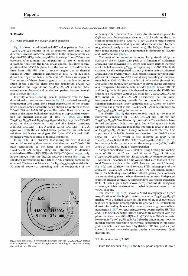
3. Results
3.1. Phase evolution of c-TiCrAlN during annealing
Fig. 2 shows two-dimensional diffraction patterns from theTi0.16Cr0.36Al0.48N coating in its as-deposited state and at twodifferent stages of isothermal annealing. In the exposure of the as-deposited TiCrAlN powder, only diffraction rings from c-TiCrAlN areobserved. After ramping the temperature to 1150 �C, additionaldiffraction rings from the h-AlN phase appear, indicating decom-position of the c-TiCrAlN phase. Also, the positions of the diffractionrings from c-TiCrAlN shift to smaller angles due to thermalexpansion. After isothermal annealing at 1150 �C for 278 min,diffraction rings from h-AlN, c-TiN and c-Cr phases are apparent.The presence of these phases suggests that a complete decompo-sition of the c-TiCrAlN phase into the equilibrium phases hasoccurred at this stage. As for Ti0.03Cr0.38Al0.59N, a similar phaseevolution was observed and detailed comparison between two al-loys is shown in Fig. 3.
Intensity versus d-spacing lineouts generated from the two-dimensional exposures are shown in Fig. 3 for selected annealingtemperatures and times. For a better presentation of the decom-posed phases, only a part of the data is shown, i.e. centered at the c-TiCrAlN 220 and h-AlN 100 peaks. The dashed lines mark the po-sition of the binary bulk phases including an approximate correc-tion for thermal expansion at 1150 �C [20,23e25]. BothTi0.16Cr0.36Al0.48N and Ti0.03Cr0.38Al0.59N display only the c-TiCrAlNphase in the as-deposited state and the lattice constants,a(Ti0.16Cr0.36Al0.48N) ¼ 4.12 Å and a(Ti0.03Cr0.38Al0.59N) ¼ 4.10 Å,agree well with the estimated lattice parameters for such solidsolutions [26]. During ramping to 1150 �C, the c-TiCrAlN peaks shiftto higher d values because of thermal expansion.
In Fig. 3 (a), it is observed that during the first 30 min ofisothermal annealing there are two shoulders on the c-TiCrAlN 220peak contributing to the large peak broadening for theTi0.16Cr0.36Al0.48N sample. They are interpreted as domainsenriched in c-AlN (c-(Ti)CrAlN) and c-TiN (c-TiCr(Al)N) respectively.In the lineouts from the Ti0.03Cr0.38Al0.59N sample (Fig. 3(c)), noshoulders corresponding to c-TiN or c-AlN enriched domains areobserved. The two shoulders seen for Ti0.16Cr0.36Al0.48N vanish after30 min of isothermal annealing and the composition of the
remaining cubic phase is close to c-Cr. An intermediate phase h-Cr2N was also observed (most clear at d ~ 2.12 Å) during the earlystage of decomposition (~1000 �Ce1150 �C), and N release duringannealing was corroborated by a mass decrease observed by ther-mogravimetric analysis (not shown here). The h-Cr2N phase hasbeen found during c-Cr phase formation in decomposed TiCrAlNand CrAlN coatings [16,27].
The onset of decomposition is more clearly visualized by theFWHM of the c-TiCrAlN 220 peak as a function of isothermalannealing time shown in Fig. 4, where peak width starts to increaseat ~7 min before reaching Tmax, corresponding to ~1000 �C for bothcoatings. For the as-deposited coatings (~50 min before isothermalannealing), the FWHM value (~1.05 mrad) is similar for both sam-ples and it decreases to ~0.75 mrad during annealing at tempera-tures below 1000 �C. This is an effect of point defect (interstitialsand vacancies) annihilation commonly observed during annealingof arc evaporated transition metal nitrides [28,29]. Above 1000 �Cand during the initial part of isothermal annealing the FWHM in-creases to a maximum value of 1.17 mrad for Ti0.16Cr0.36Al0.48N and0.76 mrad for Ti0.03Cr0.38Al0.59N. Considering that the sameinstrumental broadening prevails for both samples, a smallercoherent domain size, larger compositional variations, or highermicrostrain is present in the Ti0.16Cr0.36Al0.48N alloy compared toTi0.03Cr0.38Al0.59N during decomposition.
The FWHM (Fig. 4) decreases to 0.42 mrad at ~20 min ofisothermal annealing for Ti0.03Cr0.38Al0.59N and ~60 min forTi0.16Cr0.36Al0.48N. Simultaneously, pure c-Cr, c-TiN and h-AlN haveformed and grown. Diffraction signal from c-TiN appears in bothsamples during annealing though the intensity is small in the caseof Ti0.03Cr0.38Al0.59N since it only contains 3 at.% TiN. The firstappearance of the h-AlN phase is best seen from the 100 diffractionsignal (d ~ 2.7 Å) which is first observed at 1000 �C inTi0.03Cr0.38Al0.59N and at 1150 �C for Ti0.16Cr0.36Al0.48N (Fig. 3 (b, d)).In summary, both coatings contain the same phases (c-TiN, h-AlNand c-Cr) at the final stage of decomposition.
Samples annealed at Tmax ¼ 1150 �C, using heating and coolingrates of 20 K min�1 and hold times at Tmax of 10 min(Ti0.16Cr0.36Al0.48N) and 0 min (Ti0.03Cr0.38Al0.59N) where chosen forTEM studies. The annealing time was selected such that 50% of thetotal Al-content exists in the h-AlN phase (see section 3.2 below).Fig. 5 (a) and (b) shows the Z-contrast STEM micrographs of theannealed Ti0.16Cr0.36Al0.48N and Ti0.03Cr0.38Al0.59N sample, respec-tively. For both alloys, well-defined Al-rich grains (dark contrast)are accumulating along the boundary regions between Al-depletedgrains of brighter contrast. A corresponding fast Fourier transform(FFT) of such a grain (not shown here) confirms its hexagonalstructure, which is consistent with the h-AlN phase observed in theWAXS lineouts.
The inset of Fig. 5 (a) shows a STEM micrograph at highermagnification of the bright contrast grains in Ti0.16Cr0.36Al0.48Nmarked with a dashed square. In this type of grain characteristicfeatures of spinodal decomposition are observed, i.e. isostructuraldomains formed by chemical fluctuations over a length scale of fewnanometers [19]. The crystal structure was determined by HR-TEMand FFT to be cubic and the formed domains are consistent with thephases indicated as c-TiCr(Al)N and c-(Ti)CrAlN in WAXS lineouts.However, in Ti0.03Cr0.38Al0.59N (Fig. 5 (b)) the bright grains show nointernal contrast suggesting no chemical segregation within thesegrains, which is also confirmed by flat-line EDS line profiles (notshown). Instead these cubic grains display a homogeneous Cr-Aldistribution.
3.2. Formation rate of h-AlN
From the lineouts in Fig. 3, the h-AlN phase appears at lower
Fig. 2. Two-dimensional x-ray diffraction patterns from the Ti0.16Cr0.36Al0.48N coatingin its as-deposited (a.d.) state and during isothermal annealing at 1150 �C with holdingtime of 0 min and 278 min.
Y.H. Chen et al. / Journal of Alloys and Compounds 691 (2017) 1024e10321026
Paper I 61
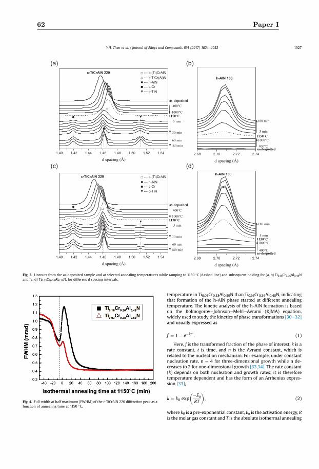
temperature in Ti0.03Cr0.38Al0.59N than Ti0.16Cr0.36Al0.48N, indicatingthat formation of the h-AlN phase started at different annealingtemperature. The kinetic analysis of the h-AlN formation is basedon the KolmogoroveJohnsoneMehleAvrami (KJMA) equation,widely used to study the kinetics of phase transformations [30e32]and usually expressed as
f ¼ 1� e�ktn : (1)
Here, f is the transformed fraction of the phase of interest, k is arate constant, t is time, and n is the Avrami constant, which isrelated to the nucleation mechanism. For example, under constantnucleation rate, n ¼ 4 for three-dimensional growth while n de-creases to 2 for one-dimensional growth [33,34]. The rate constant(k) depends on both nucleation and growth rates; it is thereforetemperature dependent and has the form of an Arrhenius expres-sion [33],
k ¼ k0 exp��Ea
RT
�; (2)
where k0 is a pre-exponential constant, Ea is the activation energy, Ris themolar gas constant and T is the absolute isothermal annealing
Fig. 3. Lineouts from the as-deposited sample and at selected annealing temperatures while ramping to 1150 �C (dashed line) and subsequent holding for (a, b) Ti0.16Cr0.36Al0.48Nand (c, d) Ti0.03Cr0.38Al0.59N, for different d spacing intervals.
Fig. 4. Full-width at half maximum (FWHM) of the c-TiCrAlN 220 diffraction peak as afunction of annealing time at 1150 �C.
Y.H. Chen et al. / Journal of Alloys and Compounds 691 (2017) 1024e1032 1027
62 Paper I
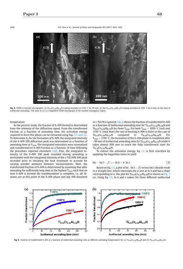
temperature.In the present study, the fraction of h-AlN formed is determined
from the intensity of the diffraction signal. From the transformedfraction as a function of annealing time, the activation energyrequired to form this phase can be extracted using Eqs. (1) and (2).To determine Ea for the formation of h-AlN, the integrated intensityof the h-AlN 100 diffraction peak was determined as a function ofannealing time at Tmax. The integrated intensities were normalizedand transformed to h-AlN fraction as a function of time followingthe procedure reported elsewhere [20]. First, the integrated in-tensity of the h-AlN 100 peak recorded during annealing isnormalized with the integrated intensity of the c-TiCrAlN 200 peakrecorded prior to initiating the heat treatment to account forvarying powder amounts between measurements. Next, thetransformed fraction of h-AlN is determined by assuming that afterannealing for sufficiently long time at the highest Tmax such that nonew h-AlN is formed the transformation is complete, i.e. all Al-atoms are at this point in the h-AlN phase and any AlN dissolved
in c-TiCrN is ignored. Fig. 6 shows the fraction of transformed h-AlNas a function of isothermal annealing time for Ti0.16Cr0.36Al0.48N andTi0.03Cr0.38Al0.59N for three Tmax. For both Tmax ¼ 1050 �C (red) and1150 �C (dark blue) the rate of forming h-AlN is faster in the case ofTi0.03Cr0.38Al0.59N compared to Ti0.16Cr0.36Al0.48N. ForTmax ¼ 1150 �C, the formation of the h-AlN phase is completed after~50 min of isothermal annealing time for Ti0.03Cr0.38Al0.59N while ittakes almost 200 min to reach the fully transformed state forTi0.16Cr0.36Al0.48N.
To extract the activation energy, Eq. (1) is first rewritten byapplying the logarithm twice to yield
lnð � lnð1� f Þ Þ ¼ ln kþ n$ln t: (3)
Based on Eq. (3), a plot of ln(�ln(1� f)) versus ln(t) should resultin a straight line, which intercepts the y-axis at ln k and has a slopecorresponding to n. The plot for Ti0.16Cr0.36Al0.48N is shown in Fig. 7(a). Using Eq. (3), ln k and n values for three different isothermal
Fig. 5. STEM z-contrast micrographs: (a) Ti0.16Cr0.36Al0.48N coating annealed at 1150 �C for 10 min; (b) the Ti0.03Cr0.38Al0.59N coating annealed at 1150 �C for 0 min (at the start ofisothermal annealing). The inset in (a) is a magnified STEM micrograph of the marked rectangular region.
Fig. 6. Fraction of transformed h-AlN as a function of isothermal annealing time at different annealing temperatures for (a) Ti0.16Cr0.36Al0.48N and (b) Ti0.03Cr0.38Al0.59N.
Y.H. Chen et al. / Journal of Alloys and Compounds 691 (2017) 1024e10321028
Paper I 63
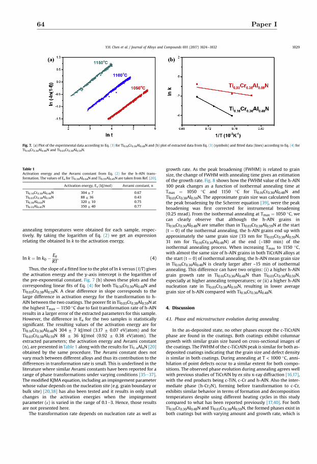
annealing temperatures were obtained for each sample, respec-tively. By taking the logarithm of Eq. (2) we get an expressionrelating the obtained ln k to the activation energy,
ln k ¼ ln k0 �EaRT
: (4)
Thus, the slope of a fitted line to the plot of ln k versus (1/T) givesthe activation energy and the y-axis intercept is the logarithm ofthe pre-exponential constant. Fig. 7 (b) shows these plots and thecorresponding linear fits of Eq. (4) for both Ti0.16Cr0.36Al0.48N andTi0.03Cr0.38Al0.59N. A clear difference in slope corresponds to thelarge difference in activation energy for the transformation to h-AlN between the two coatings. The poorer fit in Ti0.03Cr0.38Al0.59N atthe highest Tmax ¼ 1150 �C due to fast transformation rate of h-AlNresults in a larger error of the extracted parameters for this sample.However, the difference in Ea for the two samples is statisticallysignificant. The resulting values of the activation energy are forTi0.16Cr0.36Al0.48N 304 ± 7 kJ/mol (3.17 ± 0.07 eV/atom) and forTi0.03Cr0.38Al0.59N 88 ± 36 kJ/mol (0.92 ± 0.38 eV/atom). Theextracted parameters; the activation energy and Avrami constant(n), are presented in Table 1 alongwith the results for Ti1-xAlxN [20]obtained by the same procedure. The Avrami constant does notvary much between different alloys and thus its contribution to thedifferences in transformation rate is small. This is underlined in theliterature where similar Avrami constants have been reported for arange of phase transformations under varying conditions [35e37].The modified KJMA equation, including an impingement parameterwhose value depends on the nucleation site (e.g. grain boundary orbulk site) [20,38] has also been tested and it results in only smallchanges in the activation energies when the impingementparameter (ε) is varied in the range of 0.1e3. Hence, those resultsare not presented here.
The transformation rate depends on nucleation rate as well as
growth rate. As the peak broadening (FWHM) is related to grainsize, the change of FWHM with annealing time gives an estimationof the growth rate. Fig. 8 shows how the FWHM value of the h-AlN100 peak changes as a function of isothermal annealing time atTmax ¼ 1050 �C and 1150 �C for Ti0.16Cr0.36Al0.48N andTi0.03Cr0.38Al0.59N. The approximate grain size was calculated fromthe peak broadening by the Scherrer equation [39], were the peakbroadening was first corrected for instrumental broadening(0.25 mrad). From the isothermal annealing at Tmax ¼ 1050 �C, wecan clearly observe that although the h-AlN grains inTi0.16Cr0.36Al0.48N are smaller than in Ti0.03Cr0.38Al0.59N at the start(t ¼ 0) of the isothermal annealing, the h-AlN grains end up withapproximately the same grain size (33 nm for Ti0.03Cr0.38Al0.59N,31 nm for Ti0.16Cr0.36Al0.48N) at the end (~180 min) of theisothermal annealing process. When increasing Tmax to 1150 �C,with almost the same size of h-AlN grains in both TiCrAlN alloys atthe start (t ¼ 0) of isothermal annealing, the h-AlN mean grain sizein Ti0.16Cr0.36Al0.48N is clearly larger after ~15 min of isothermalannealing. This difference can have two origins: (i) a higher h-AlNgrain growth rate in Ti0.16Cr0.36Al0.48N than Ti0.03Cr0.38Al0.59N,especially at higher annealing temperatures; or (ii) a higher h-AlNnucleation rate in Ti0.03Cr0.38Al0.59N, resulting in lower averagegrain size of h-AlN compared with Ti0.16Cr0.36Al0.48N.
4. Discussion
4.1. Phase and microstructure evolution during annealing
In the as-deposited state, no other phases except the c-TiCrAlNphase are found in the coatings. Both coatings exhibit columnargrowth with similar grain size based on cross-sectional images ofthe coatings. The FWHMof the c-TiCrAlN peak is similar for both as-deposited coatings indicating that the grain size and defect densityis similar in both coatings. During annealing at T < 1000 �C, anni-hilation of point defects occur to a similar extent for both compo-sitions. The observed phase evolution during annealing agrees wellwith previous studies of TiCrAlN by ex situ x-ray diffraction [16,17],with the end products being c-TiN, c-Cr and h-AlN. Also the inter-mediate phase (h-Cr2N), forming before transformation to c-Cr,exhibits similar behavior in terms of formation and decompositiontemperatures despite using different heating cycles in this studycompared to what has been reported previously [17,40]. For bothTi0.16Cr0.36Al0.48N and Ti0.03Cr0.38Al0.59N, the formed phases exist inboth coatings but with varying amount and growth rate, which is
Fig. 7. (a) Plot of the experimental data according to Eq. (3) for Ti0.16Cr0.36Al0.48N and (b) plot of extracted data from Eq. (3) (symbols) and fitted data (lines) according to Eq. (4) forTi0.16Cr0.36Al0.48N and Ti0.03Cr0.38Al0.59N.
Table 1Activation energy and the Avrami constant from Eq. (2) for the h-AlN trans-formation. The values of Ea for Ti0.36Al0.64N and Ti0.55Al0.45N are taken from Ref. [20].
Activation energy, Ea (kJ/mol) Avrami constant, n
Ti0.16Cr0.36Al0.48N 304 ± 7 0.67Ti0.03Cr0.38Al0.59N 88 ± 36 0.43Ti0.36Al0.64N 320 ± 10 0.75Ti0.55Al0.45N 350 ± 40 0.77
Y.H. Chen et al. / Journal of Alloys and Compounds 691 (2017) 1024e1032 1029
64 Paper I
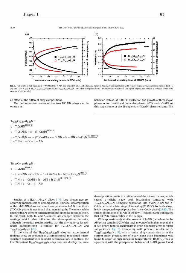
an effect of the different alloy compositions.The decomposition routes of the two TiCrAlN alloys can be
written as
Studies of c-TixCr1-xAl0.61N alloys [17], have shown two co-occurring mechanisms of decomposition: spinodal decompositionof the c-TiCrAlN phase and direct precipitation of h-AlN from the c-(Ti)CrAlN phase. It was found that increasing the Ti-content whilekeeping the Al-content constant promotes spinodal decomposition.In this work, both Ti- and Al-content are changed between thecoatings which also influence the decomposition behavior,although theoretical studies predict that the driving force for spi-nodal decomposition is similar for Ti0.03Cr0.38Al0.59N andTi0.16Cr0.36Al0.48N [26].
In the case of the Ti0.16Cr0.36Al0.48N alloy our experimentalfindings show an evolution of a compositional modulated micro-structure consistent with spinodal decomposition. In contrast, thelow Ti-content Ti0.03Cr0.38Al0.59N alloy does not display the same
behavior. Instead, at 1000 �C, nucleation and growth of three majorphases occur: h-AlN and two cubic phases, c-TiN and c-CrAlN. Atthis stage, some of the Ti-depleted c-TiCrAlN phase remains. The
decomposition results in a refinement of the microstructure, whichcauses a slight x-ray peak broadening compared withTi0.16Cr0.36Al0.48N. Complete separation into h-AlN, c-TiN and c-CrAlN occurs at a later stage of annealing (1150 �C). For both alloys,h-AlN is expected to precipitate from the c-CrAlN phase [27,40]. Theearlier observation of h-AlN in the low Ti-content sample indicatesthat c-CrAlN forms earlier in this sample.
With approximately similar amount of h-AlN (i.e. when the h-AlN phase contains 50% of the total amount of Al in the sample), theh-AlN grains tend to accumulate in grain boundary areas for bothsamples (see Fig. 5). Comparing with previous results for c-Ti0.11Cr0.28Al0.61N [17], with a similar alloy composition as in thecurrent study, precipitation of h-AlN along grain boundaries wasfound to occur for high annealing temperatures (1000 �C), thus inagreement with the precipitation behavior of h-AlN grains found
Fig. 8. Full-width at half maximum (FWHM) of the h-AlN 100 peak (left axis) and estimated mean h-AlN grain size (right axis) with respect to isothermal annealing time at 1050 �C(a) and 1150 �C (b) in Ti0.16Cr0.36Al0.48N (black) and Ti0.03Cr0.38Al0.59N (red). (For interpretation of the references to color in this figure legend, the reader is referred to the webversion of this article.)
Ti0:16Cr0:36Al0:48N :
c� TiCrAlN ��!1000 �C
c� TiCrðAlÞNþ c� ðTiÞCrAlN ��!1150 �C
c� TiCrðAlÞNþ c� ðTiÞCrAlNþ c� CrAlNþ h� AlNþ hCr2N ����!4h; 1150 �C
c� TiNþ c� Crþ h� AlN
Ti0:03Cr0:38Al0:59N :
c� TiCrAlN ��!1000 �C
c� ðTiÞCrAlNþ c� TiNþ c� CrAlNþ h� AlNþ hCr2N ��!1150 �C
c� TiNþ c� CrAlNþ h� AlNþ hCr2N ����!4h; 1150 �C
c� TiNþ c� Crþ h� AlN
Y.H. Chen et al. / Journal of Alloys and Compounds 691 (2017) 1024e10321030
Paper I 65
here. Though at an earlier stage of decomposition (annealing at900 �C) the segregation of Al to grain boundaries was less obvious[17]. This suggests that h-AlN precipitates mainly at grain bound-aries despite the preceding spinodal decomposition in the alloy,which is actually similar to TiAlN [2].
The size of h-AlN grains in the Ti0.03Cr0.38Al0.59N sampleannealed at 1050 �C estimated from the STEM micrograph is30e50 nm, which is slightly larger than the 28 nm grain sizedetermined by x-ray peak broadening analysis. For theTi0.16Cr0.36Al0.48N sample at the same temperature, the h-AlN grainsize is estimated to 50e75 nm from STEM and 35 nm from x-raypeak broadening analysis. These differences suggest subgrain for-mation in the h-AlN, perhaps due to entrapped Cr and Ti atoms orcoalescence of slightly misaligned h-AlN grains. The subgrain for-mation is more pronounced in the Ti0.16Cr0.36Al0.48N sample.
4.2. Kinetics of h-AlN formation
The large difference in formation rate of h-AlN between the twoalloys suggests that the formation rate depends on the decompo-sition route, where the occurrence of spinodal decomposition inone of the alloys affects the transformation rate. And since the h-AlN phase forms from CrAlN for both alloys, formation of CrAlNthen limits the h-AlN transformation rate.
In the Ti0.03Cr0.38Al0.59N coating, the c-CrAlN grain size isalready in the order of 50e100 nm after ramping to 1150 �Cwithouthold period. In contrast, the c-(Ti)CrAlN domains formed duringspinodal decomposition of Ti0.16Cr0.36Al0.48N remain small forlonger annealing times. After 10 min at 1150 �C their size is still justa few nm. Further, Fors�en et al. [8] have shown that better latticematching can be achieved between the two cubic phases in thepresence of Cr causing a reduced coherency strain and therebyincreasing the stability. The domains can then grow larger whilestill remaining coherent [41]. This delays the transformation to h-AlN, resulting in lower transformation rates compared to TiAlN[20]. Comparing the two TiCrAlN alloys, the Cr containing domainswe observe here with coherent interfaces in Ti0.16Cr0.36Al0.48N havea lower driving force for Al migration to the grain boundaries whereh-AlN is formed. The net result is that the CrAlN domains within thefine microstructure caused by spinodal decomposition are morestable than the larger CrAlN grains in Ti0.03Cr0.38Al0.59N.
The formation of h-AlN occurs by nucleation and growth, whileboth nucleation and growth rates affect the overall transformationrate. Despite a slower transformation rate to h-AlN of theTi0.16Cr0.36Al0.48N, it displays larger h-AlN grains. It leads us toconclude that the h-AlN nucleation rate is higher forTi0.03Cr0.38Al0.59N than Ti0.16Cr0.36Al0.48N. The lower nucleation ratefor Ti0.16Cr0.36Al0.48N is likely caused by the relativelymore stable c-CrAlN domains surrounded by c-TiCrN, compared to c-CrAlN withsmall amounts of dissolved Ti in Ti0.03Cr0.38Al0.59N. Hence, themigration of Al is shifted to higher temperatures, which giveshigher mobility and enlarges the critical radius of an h-AlN nucleus,promoting growth over nucleation.
The two different samples have different activation energy forthe formation of h-AlN. The value for the Ti0.16Cr0.36Al0.48N (304 kJ/mol) is comparable to what has been reported for TiAlN-alloyswithout Cr. In contrast, the activation energy recorded forTi0.03Cr0.38Al0.59N is more than a factor of three lower, i.e. 88 kJ/mol.While there is a lower certainty for the activation energy value forTi0.03Cr0.38Al0.59N, it is significantly lower than the value forTi0.16Cr0.36Al0.48N and for TiAlN. It adds to the argument that theCrAlN phase is stabilized by the coherency strain imposed by thesurrounding c-TiCrN phase.
The similar value of the activation energy for Ti0.16Cr0.36Al0.48Nand the two TiAlN alloys (see Table 1) is surprising as the phase
transformation is different in the case of TiCrAlN and TiAlN. InTiAlN, pure c-AlN domains transform to h-AlN while in TiCrAlN h-AlN precipitates from the c-CrAlN domains. On the other hand, theactivation energy for Ti0.16Cr0.36Al0.48N and for TiAlN is in the sameorder as the activation energy for diffusion in TiAlN alloys [3,19],which implies that the h-AlN formation rate may be diffusioncontrolled in both cases. Formation of h-AlN from c-CrAlN [8,17,41]or c-AlN [5,42,43] involves migrating Al atoms that must overcomesimilar energy barriers in the decomposed cubic matrix, whichlikely explains the small difference in activation energy. While thestructure of Al-rich domains is similar for TiAlN andTi0.16Cr0.36Al0.48N, the c-CrAlN grains in Ti0.03Cr0.38Al0.59N are notconfined in a nanoscale compositionally modulated structure. Thedifferent microstructure yields another diffusion path, which isresponsible for the deviating activation energy found for thissample.
The activation energy for lattice diffusion and grain boundarydiffusion can differ by up to three times as was found for Al thinfilms [44] and metal diffusions in nitride films [45,46], where theactivation energy for grain boundary diffusion (30e115 kJ/mol) is inthe range of what is found here for formation of h-AlN inTi0.03Cr0.38Al0.59N. As evident from the STEM micrographs in Fig. 5,h-AlN precipitates at grain boundaries for both TiCrAlN alloys. Thesupply of Al to the grain boundaries is likely dependent on thelocation of AlN-rich domains, which for Ti0.03Cr0.38Al0.59N, the c-CrAlN grains are in direct connection to the grain boundaries, whilein Ti0.16Cr0.36Al0.48N they are located within the nanoscale micro-structure originating from spinodal decomposition. Thus, pre-cipitations of h-AlN at grain boundaries take place inTi0.03Cr0.38Al0.59N while lattice diffusion limits the formation rate ofh-AlN in Ti0.16Cr0.36Al0.48N, which determines the large differencein the activation energy.
In summary, the rate of h-AlN formation in TiCrAlN alloys isrelated to the stability of the c-CrAlN phase, which primarily isgoverned by the surrounding microstructure. It results in differenttransformation kinetics where coherency strain confines the c-CrAlNdomains generated during spinodal decomposition and decreasesthe transformation rate in comparison to precipitation from largerincoherent c-CrAlN grains. Further, precipitations of h-AlN from c-CrAlN grains at grain boundaries results in high transformation ratesdue to the low activation energy for diffusion of Al atoms.
5. Conclusion
The decomposition mechanism and the kinetics of the decom-position process in TixCr~0.35Al1�xN alloys with varying Ti contentwere investigated by in situ x-ray scattering during annealing. Thesame phases form during annealing in both samples, while thedecomposition route depends on the Ti-content. For high Ti-content Ti0.16Cr0.36Al0.48N, spinodal decomposition occurs that re-sults in nanoscale, coherent domains of c-(Ti)CrAlN and c-TiCr(Al)N. In low Ti-content Ti0.03Cr0.38Al0.59N, c-CrAlN, c-TiN and h-AlNforms through nucleation and growth.
The formation rate of h-AlN is determined by the formation andthe stability of c-CrAlN domains. With low Ti-content, nucleationand growth results in large, pure c-CrAlN grains forming in an earlystage of decomposition. Also, h-AlN precipitates from such c-CrAlNgrains with a high rate due to high diffusivity along grain bound-aries. In contrast, the CrAlN domains forming during spinodaldecomposition in the high Ti-content coating are stabilized bylattice coherency with the surrounding c-TiCrN domains. The for-mation of h-AlN is limited by bulk diffusion of Al to grain bound-aries where h-AlN forms. Combining these variations duringdecomposition, higher activation energy for h-AlN formation isfound for the high Ti-content TiCrAlN alloy.
Y.H. Chen et al. / Journal of Alloys and Compounds 691 (2017) 1024e1032 1031
66 Paper I
Acknowledgment
We acknowledge the financial support from EU's Erasmus-Mundus graduate school in Material Science and Engineering(DocMASE), the Swedish Research Council VR (621- 2012-4401)and R€ontgen-Ångstr€om Cluster grant (VR 2011-6505) that includesaccess to Petra III, Swedish Foundation for Strategic Research, SSF(RMA08-0069), Swedish government strategic research area grantAFM e SFO MatLiU (2009-00971), and VINNOVA (M e Era.netproject 2013-02355). We also thank Dr. Jeremy Schroeder forassistance with synchrotron equipment set-ups and data collectionand Dr. Jianqiang Zhu for (S)TEM investigations.
References
[1] A. H€orling, L. Hultman, M. Od�en, J. Sj€ol�en, L. Karlsson, Mechanical propertiesand machining performance of Ti1-xAlxN-coated cutting tools, Surf. Coat.Technol. 191 (2005) 384e392.
[2] R. Rachbauer, S. Massl, E. Stergar, D. Holec, D. Kiener, J. Keckes, J. Patscheider,M. Stiefel, H. Leitner, P.H. Mayrhofer, Decomposition pathways in age hard-ening of Ti-Al-N films, J. Appl. Phys. 110 (2011) 023515.
[3] P.H. Mayrhofer, A. H€orling, L. Karlsson, J. Sj€ole
n, T. Larsson, C. Mitterer,L. Hultman, Self-organized nanostructures in the TieAleN system, Appl. Phys.Lett. 83 (2003) 2049.
[4] M. Ode
n, L. Rogstr€om, A. Knutsson, M.R. Terner, P. Hedstr€om, J. Almer,J. Ilavsky, In situ small-angle x-ray scattering study of nanostructure evolutionduring decomposition of arc evaporated TiAlN coatings, Appl. Phys. Lett. 94(2009) 053114.
[5] L. Rogstr€om, J. Ullbrand, J. Almer, L. Hultman, B. Jansson, M. Od�en, Strainevolution during spinodal decomposition of TiAlN thin films, Thin Solid Films520 (2012) 5542e5549.
[6] M.A. Davies, T. Ueda, R. M'Saoubi, B. Mullany, A.L. Cooke, On the measurementof temperature in material removal processes, CIRP Ann. Manuf. Technol. 56(2007) 581e604.
[7] A. Knutsson, M.P. Johansson, L. Karlsson, M. Ode
n, Thermally enhanced me-chanical properties of arc evaporated Ti0.34Al0.66N/TiN multilayer coatings,J. Appl. Phys. 108 (2010) 044312.
[8] R. Fors�en, N. Ghafoor, M. Od�en, Coherency strain engineered decomposition ofunstable multilayer alloys for improved thermal stability, J. Appl. Phys. 114(2013) 244303.
[9] K. Kutschej, N. Fateh, P.H. Mayrhofer, M. Kathrein, P. Polcik, C. Mitterer,Comparative study of Ti1-xAlxN coatings alloyed with Hf, Nb, and B, Surf.Coat. Technol. 200 (2005) 113e117.
[10] L. Chen, D. Holec, Y. Du, P.H. Mayrhofer, Influence of Zr on structure, me-chanical and thermal properties of TieAleN, Thin Solid Films 519 (2011)5503e5510.
[11] D. Holec, L. Zhou, R. Rachbauer, P.H. Mayrhofer, Alloying-related trends fromfirst principles: an application to the TieAleXeN system, J. Appl. Phys. 113(2013) 113510.
[12] H.W. Hugosson, H. H€ogberg, M. Algren, M. Rodmar, T.I. Selinder, Theory of theeffects of substitutions on the phase stabilities of Ti1�xAlxN, J. Appl. Phys. 93(2003) 4505e4511.
[13] S.G. Harris, E.D. Doyle, A.C. Vlasveld, J. Audy, J.M. Long, D. Quick, Influence ofchromium content on the dry machining performance of cathodic arc evap-orated TiAlN coatings, Wear 254 (2003) 185e194.
[14] Z.F. Zhou, P.L. Tam, P.W. Shum, K.Y. Li, High temperature oxidation of CrTiAlNhard coatings prepared by unbalanced magnetron sputtering, Thin Solid Films517 (2009) 5243e5247.
[15] A.I. Kovalev, D.L. Wainstein, A.Y. Rashkovskiy, G.S. Fox-Rabinovich,K. Yamamoto, S. Veldhuis, M. Aguirre, B.D. Beake, Impact of Al and Cr alloyingin TiN-based PVD coatings on cutting performance during machining of hardto cut materials, Vacuum 84 (2009) 184e187.
[16] R. Forsen, M. Johansson, M. Oden, N. Ghafoor, Decomposition and phasetransformation in TiCrAlN thin coatings, J. Vac. Sci. Technol. A Vac. Surf., Films30 (2012) 061506.
[17] R. Fors�en, M.P. Johansson, M. Od�en, N. Ghafoor, Effects of Ti alloying of AlCrNcoatings on thermal stability and oxidation resistance, Thin Solid Films 534(2013) 394e402.
[18] B. Alling, T. Marten, I.A. Abrikosov, A. Karimi, Comparison of thermodynamicproperties of cubic Cr1-xAlxN and Ti1-xAlxN from first-principles
calculations, J. Appl. Phys. 102 (2007).[19] A. Knutsson, J. Ullbrand, L. Rogstr€om, N. Norrby, L.J.S. Johnson, L. Hultman,
J. Almer, M.P. Johansson J€oesaar, B. Jansson, M. Ode
n, Microstructure evolutionduring the isostructural decomposition of TiAlNdA combined in-situ smallangle x-ray scattering and phase field study, J. Appl. Phys. 113 (2013) 213518.
[20] N. Norrby, L. Rogstr€om, M.P. Johansson-J~oesaar, N. Schell, M. Od�en, In situ X-ray scattering study of the cubic to hexagonal transformation of AlN inTi1�xAlxN, Acta Mater. 73 (2014) 205e214.
[21] R. Fors�en, I.C. Schramm, P.O.A. Persson, F. Mucklich, M. Od�en, N. Ghafoor,Nanostructuring and coherency strain in multicomponent hard coatings, APLMater. 2 (2014) 116104.
[22] A.P. Hammersley, FIT2D: an Introduction and Overview, ESRF Internal Report,ESRF97HA02T, 1997.
[23] Joint Committee of Powder Diffraction Standards (JCPDS)dInternationalCentre for Diffraction Data, 1998, Card No. 25e1133.
[24] Joint Committee of Powder Diffraction Standards (JCPDS)dInternationalCentre for Diffraction Data, 1998, Card No. 38e1420.
[25] Joint Committee of Powder Diffraction Standards (JCPDS)dInternationalCentre for Diffraction Data, 1998, Card No. 89e4055.
[26] H. Lind, R. Fors�en, B. Alling, N. Ghafoor, F. Tasnadi, M.P. Johansson,I.A. Abrikosov, M. Ode
n, Improving thermal stability of hard coating films via aconcept of multicomponent alloying, Appl. Phys. Lett. 99 (2011) 5090.
[27] P.H. Mayrhofer, H. Willmann, A.E. Reiter, Structure and phase evolution ofCreAleN coatings during annealing, Surf. Coat. Technol. 202 (2008)4935e4938.
[28] M. Od�en, J. Almer, G. Håkansson, M. Olsson, Microstructureeproperty re-lationships in arc-evaporated CreN coatings, Thin Solid Films 377e378 (2000)407e412.
[29] K. Gr€onhagen, J. Ågren, M. Od�en, Phase-field modelling of spinodal decom-position in TiAlN including the effect of metal vacancies, Scr. Mater. 95 (2015)42e45.
[30] M. Avrami, Kinetics of phase change. I general theory, J. Chem. Phys. 7 (1939)1103.
[31] M. Avrami, Kinetics of phase change. II transformation-time relations forrandom distribution of nuclei, J. Chem. Phys. 8 (1940) 212.
[32] M. Avrami, Granulation, Phase change, and microstructure kinetics of phasechange. III, J. Chem. Phys. 9 (1941) 177.
[33] D.A. Porter, K.E. Easterling, Phase Transformations in Metals and Alloys, thirded., Taylor & Francis, 1992 (Revised Reprint).
[34] T. Pradell, D. Crespo, N. Clavaguera, M.T. Clavaguera-Mora, Diffusioncontrolled grain growth in primary crystallization: Avrami exponents revis-ited, J. Phys. Condens. Mat. 10 (1998) 3833e3844.
[35] E.J. Mittemeijer, I.A. Wierszyllowski, The isothermal and nonisothermal ki-netics of tempering iron-carbon and iron-nitrogen martensites and austen-ites, Z. Met. 82 (1991) 419e429.
[36] E.J. Mittemeijer, Analysis of the kinetics of phase-transformations, J. Mater.Sci. 27 (1992) 3977e3987.
[37] A. Khatibi, J. Lu, J. Jensen, P. Eklund, L. Hultman, Phase transformations in facecentered cubic (Al0.32Cr0.68)2O3 thin films, Surf. Coat. Technol. 206 (2012)3216e3222.
[38] E.A. J€agle, E.J. Mittemeijer, The kinetics of grain-boundary nucleated phasetransformations: simulations and modelling, Acta Mater. 59 (2011)5775e5786.
[39] U.t.G.t. K€onigliche Gesellschaft der Wissenschaften zu G€ottingen, Nachrichtenvon der K€onigl, Gesellschaft der Wissenschaften und der G.A. Universit€at zuG€ottingen, Dieterichschen Buchhandlung, G€ottingen, 1845.
[40] H. Willmann, P.H. Mayrhofer, P.O.Å. Persson, A.E. Reiter, L. Hultman,C. Mitterer, Thermal stability of AleCreN hard coatings, Scr. Mater. 54 (2006)1847e1851.
[41] H. Willimann, P.H. Mayrhofer, L. Hultman, C. Mitterer, Hardness evolution ofAl-Cr-N coatings under thermal load, J. Mater. Res. 23 (2008) 2880e2885.
[42] I.A. Abrikosov, A. Knutsson, B. Alling, F. Tasnadi, H. Lind, L. Hultman, M. Od�en,Phase stability and elasticity of TiAlN, Materials 4 (2011) 1599e1618.
[43] A. H€orling, L. Hultman, M. Od�en, J. Sj€ol�en, L. Karlsson, Thermal stability of arcevaporated high aluminum-content Ti1�xAlxN thin films, J. Vac. Sci. Technol.A 20 (2002) 1815e1823.
[44] A. Jankowski, J. Ferreira, J. Hayes, Activation energies of grain growth mech-anisms in aluminum coatings, Thin Solid Films 491 (2005) 61e65.
[45] C. Engstrom, J. Birch, L. Hultman, C. Lavoie, C. Cabral, J.L. Jordan-Sweet,J.R.A. Carlsson, Interdiffusion studies of single crystal TiN/NbN superlatticethin films, J. Vac. Sci. Technol. A 17 (1999) 2920e2927.
[46] G.I. Grigorov, K.G. Grigorov, M. Stoyanova, J.L. Vignes, J.P. Langeron,P. Denjean, Aluminum diffusion in titanium nitride films - efficiency of tinbarrier layers, Appl. Phys. A Mater. 57 (1993) 195e197.
Y.H. Chen et al. / Journal of Alloys and Compounds 691 (2017) 1024e10321032
Paper I 67

68 Paper I
IIPaper II
Thermal and mechanical stability ofwurtzite-ZrAlN/cubic-TiN and
wurtzite-ZrAlN/cubic-ZrN multilayers
Y. H. ChenL. Rogström
J.J.RoaJ.Q.Zhu
I.C.SchrammL.J.S.Johnson
N.SchellF.Mücklich
M.J.AngladaM.Odén
Surface and Coatings Technology, 324, 328–337 (2017)
Reprinted with permission. ©2017 Elsevier

Thermal and mechanical stability of wurtzite-ZrAlN/cubic-TiN andwurtzite-ZrAlN/cubic-ZrN multilayers
Y.H. Chen a,⁎, L. Rogström a, J.J. Roa b, J.Q. Zhu a, I.C. Schramm a,c, L.J.S. Johnson d, N. Schell e, F. Mücklich c,M.J. Anglada b, M. Odén a
a Nanostructured Materials, Department of Physics, Chemistry and Biology (IFM), Linköping University, SE-581 83 Linköping, Swedenb Departament de Ciència dels Materials i Enginyería Metal·lúrgica, Universitat Politècnica de Catalunya, EEBE-Campus Diagonal Besòs, 08019 Barcelona, Spainc Functional Materials, Department of Materials Science, Campus D3.3, Saarland University, D 66123 Saarbrücken, Germanyd Sandvik Coromant, SE-126 80 Stockholm, Swedene Helmholtz-Zentrum Geesthacht (HZG), Max-Planck-Str. 1, D-21502 Geesthacht, Germany
a b s t r a c ta r t i c l e i n f o
Article history:Received 10 March 2017Revised 18 May 2017Accepted in revised form 20 May 2017Available online 25 May 2017
The phase stability and mechanical properties of wurtzite (w)-Zr0.25Al0.75N/cubic (c)-TiN and w-Zr0.25Al0.75N/c-ZrN multilayers grown by arc evaporation are studied. Coherent interfaces with an orientation relation of c-TiN(111)[1-10]ǀǀw-ZrAlN (0001)[11-20] form between ZrAlN and TiN sublayers during growth of the w-ZrAlN/c-TiN multilayer. During annealing at 1100 °C a c-Ti(Zr)N phase forms at interfaces between ZrAlN and TiN,which reduces the lattice mismatch so that the coherency and the compressive strain are partially retained,resulting in an increased hardness (32 GPa) after annealing. For thew-ZrAlN/c-ZrNmultilayer, there is no coher-ency between sublayers leading to strain relaxation during annealing causing the hardness to drop. The retainedcoherency between layers and the compressive strain in thew-ZrAlN/c-TiNmultilayer results in superior fracturetoughness compared to the w-ZrAlN/c-ZrN multilayer as revealed by cross-sectional investigations of damageevents under scratch and indentation tests.
© 2017 Elsevier B.V. All rights reserved.
Keywords:MultilayersZrAlN coatingsScratch testFracture toughnessArc evaporation
1. Introduction
Wear resistance of protective coatings at high temperature is criticalfor cutting and machining tools [1], where the operating temperaturemay exceed 1000 °C [2]. One way to achieve high thermal stabilityand good mechanical properties is to design an alloy that decomposesat high temperature into a nanocomposite and exhibits age hardening[3,4]. The archetype for this approach is the metastable cubic (c-)Ti1 − xAlxN solid solution, which forms nm-sized domains by spinodaldecomposition when exposed to high temperatures (around 900 °C)[5–8]. At even higher temperatures this alloy further decomposes intoits thermodynamically stable phases c-TiN and wurtzite (w-) AlN[9] that deteriorates the mechanical properties [10,11]. The relatedZr1 − xAlxN alloys display characteristics similar to Ti1 − xAlxN with amiscibility gap for cubic solid solutions and a higher driving force fordecomposition compared to Ti1 − xAlxN [12,13] resulting in promisingmechanical properties [14–18] at high temperature. In addition tocubic solid solutions, wurtzite structured Zr1 − xAlxN solid solutionshave high thermal stability when the Al content is higher than ~70%[13]. It has also been shown to exhibit spinodal decomposition at high
temperature [19] resulting in good wear behavior during cutting appli-cations [20].
Multilayered structures incorporating hard coating materials can bedesigned to improve the thermal stability [21–23], mechanical proper-ties [24,25] andwear behavior [26,27]. For example, when sandwichingZrAlN and TiN during very high temperature (900 °C) growth condi-tions, the multilayer architecture allows for growth of c-AlN in a c-ZrNmatrix in the ZrAlN sublayers where c-AlN further transforms to w-AlN when exposed to mechanical stress [28]. The transformation is as-sociated with a volume expansion that promotes crack closure andyields an enhanced fracture toughness of the coatings [27,29]. Promis-ing data has also been reported for low Al content c-ZrAlN/TiN multi-layers grown at more moderate temperatures (400 °C) displayingsuperior hardness at 1100 °C compared with ZrAlN and TiAlN singlelayers; ZrAlN/ZrN and TiAlN/TiN multilayers [30]. The enhanced hard-ness is suggested to be an effect of the secondary phase, c-ZrTi(Al)N,formed during annealing. In addition, tribological tests of cohesion/ad-hesion and wear resistance have demonstrated the enhancement ofsuch properties from multilayered structures [26,27,31].
In this study, we use themultilayer design and combine highAl-con-tent (~75%)w-ZrAlNwith high thermal stabilitywith a stable c-TiN or c-ZrN phase.We groww-ZrAlN/c-TiN andw-ZrAlN/c-ZrNmultilayer coat-ings by cathodic arc evaporation and report their microstructure
Surface & Coatings Technology 324 (2017) 328–337
⁎ Corresponding author.E-mail address: [email protected] (Y.H. Chen).
http://dx.doi.org/10.1016/j.surfcoat.2017.05.0550257-8972/© 2017 Elsevier B.V. All rights reserved.
Contents lists available at ScienceDirect
Surface & Coatings Technology
j ourna l homepage: www.e lsev ie r .com/ locate /sur fcoat
Paper II 71
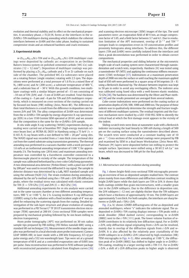
evolution and thermal stability and its effect on themechanical proper-ties. A secondary phase, c-Ti(Zr)N, forms at the interfaces in the w-ZrAlN/c-TiN multilayers during annealing which stabilizes the coherentinterfaces between w-ZrAlN and the cubic phase, leading to sustainedcompressive strain and an enhanced hardness and crack resistance.
2. Experimental details
w-Zr0.25Al0.75N/c-TiN and w-Zr0.25Al0.75N/c-ZrN multilayer coat-ings were deposited by cathodic arc evaporation in an OerlikonBalzers Innova system on polished cemented carbide (WC-Co) sub-strates (12 × 12 mm2). Deposition of multilayer coatings was per-formed by placing a Zr17Al83 cathode and a Ti or Zr cathode on eachside of the chamber. The polished WC-Co substrates were placedon a rotating fixture (single rotation) rotating with 2.5 rpm. The depo-sitions were performed at a total pressure of 1.6 Pa in a mixed flow ofN2 (400 sccm) and Ar (200 sccm), a substrate temperature of 400 °C,and a substrate bias of −30 V. With this growth condition, two multi-layer coatings with a similar bilayer period of ~15 nm consisting of~10 nm of TiN (ZrN) and ~5 nm of ZrAlN are resulted. Total thicknessof the coating is ~5 μm and ~6 μm for TiN and ZrN multilayers respec-tively, which is measured on cross-sections of the coating carried outby focused ion beam (FIB) milling (Zeiss, Neon 40). The difference intheir total thickness is a result from the difference in deposition rate be-tween ZrN and TiN. The alloy composition of ZrAlN was determinedfrom thew-ZrAlN/c-TiN sample by energy-dispersive X-ray spectrosco-py (EDS) in a Leo 1550 Gemini SEM operated at 20 kV, and we assumethat the composition is the same for the w-ZrAlN/c-ZrN sample.
In situ wide angle X-ray scattering (WAXS) experiments during an-nealing were carried out at beamline P07 (high-energy materials sci-ence beam line) at PETRA III, DESY in Hamburg using a 75 keV (λ =0.165 Å) X-ray beam with a size defined to 500 × 20 μm2 using slits.The WAXS signal was recorded from a 1 mm thick cross-sectional slicecut from the coated substrate using transmission geometry. The thermalannealingwas performed in a vacuum chamberwith awork pressure of1.6 mPa at an isothermal annealing temperature of 1100 °C for approx-imately 2 h. The heating rate (20 K/min) andmaximum annealing tem-perature was controlled by a Eurotherm controller connected to athermocouple placed in vicinity of the sample. The temperature of thesamplewas calibrated beforehandby a two-color CellaTemppyrometer.A two-dimensional area detector (Perkin Elmer) with a pixel size of 200by 200 μm2was used to record the diffracted X-ray signal. The sample todetector distance was determined by a LaB6 NIST standard sample andusing the software Fit2D [32]. The strain evolution during annealing isobtained by the sin2ψmethod using the c-TiN and c-ZrN 200 diffractionpeaks, where the residual stress was calculated with elastic constantsfor TiN (E = 570 GPa) [33] and ZrN (E = 462 GPa) [34].
Additional annealing experiments for ex situ analysis were carriedout in the same vacuum chamber at two different annealing tempera-tures, 900 °C or 1100 °C, for 2 h. Grazing incidence X-ray diffraction(GIXRD) using Cu Kα radiation with a fixed incident angle of 4° was ap-plied for enhancing the scattering signals from the coating. Detailed in-vestigation of the sub-layer structure and phase evolution of coatingswas performed in a FEI Tecnai G2 TF 20 UT transmission electronmicro-scope (TEM) operated at 200 kV. Cross-sectional TEM-samples wereprepared by mechanical grinding followed by Ar-ion beam milling toelectron transparency.
Atom probe tomography (APT) was performed on 30 nm radiussample tips prepared by FIB milling (FEI Helios nanolab 600) using astandard lift out technique [35]. Measurement of the needle shape sam-pleswas performed in a local electrode atomprobe instrument (CamecaLEAP 3000X-HR) in laser mode with a 200 kHz frequency, 0.5 nJ perpulse energy and a 532 nmwavelength laser. Tips were set at a groundtemperature of 60 K and at a controlled evaporation rate of 0.005 ionsper pulse. Data reconstruction was performed in IVAS software packagewith reconstructed parameters calculated from Kingham curves [36]
and scanning electron microscope (SEM) images of the tips. The usedparameters were: an evaporation field of 40 V/nm, an image compres-sion factor of 1.65, and a field factor between 3.7 and 4.1. Due to resolu-tion limitation of the APT instrument, overlap of Zr+3 and TiN+2
isotopes leads to composition errors in 1D concentration profiles andproximity histograms along interfaces. To address this, the differentlayers (TiN and ZrAlN) were carefully isolated from the interfaces andthen a peak deconvolution was performed in order to obtain correctcompositions.
The mechanical properties and sliding behavior at the micrometriclength scale of each coating system were characterized through nanoin-dentation and scratch tests, respectively. Hardness (H) was tested usinga nanoindenter XP (MTS) and applying the continuous stiffnessmeasure-ment (CSM) technique [37]. Indentations at a maximum penetrationdepth of 2000nm into the surface or until reaching themaximumappliedload of 650 mN were performed in a square array of 64 imprints (8 × 8)using a Berkovich diamond tip. The distance between imprints was keptto 50 μm in order to avoid any overlapping effects. The indenter areawas calibrated using fused silica with a well-known elastic modulus,72 GPa [38]. The hardnesswas determined by the Oliver and Pharrmeth-od [38] and the results presented are averaged from several indents.
Cube-corner indentations were performed on the coating surface atpenetration depths of 250, 500, 1000 and 2000nm. The purpose of theseindents was to qualitatively determine the strength and fracture tough-ness of different multilayer systems. The residual imprints and the frac-ture mechanism were studied by a LEO 1550 FEG SEM to identify thecritical load at which the first damage event appears in the vicinity ofthe indent.
Sliding-scratch tests were done at nanometer scale with a Berkovichindenter increasing the load linearly to 500 mN during a length of 500μm on the coating surface using the nanoindenter described above.The scratch tests were conducted at a constant loading rate of 10μm·s−1. Cross-sections of the scratched coatings were prepared by FIBand examined by SEM in a dual beam Workstation (Zeiss Neon 40).Platinum (Pt) layers were deposited before ion milling to protect thesample surface. Specimens were milled using a 30 kV/2 nA Ga+ ionbeam, which was decreased to 500 pA for the final polish.
3. Results
3.1. Microstructure and strain evolution during annealing
Fig. 1 shows bright-field cross-sectional TEM micrographs present-ing an overview of two as-deposited samples studied here. The contrastarisesmainly frommass differences and diffraction contrast resulting inbright ZrAlN layers while the dark layers are TiN or ZrN. It shows thatboth coatings exhibit fine-grain microstructures, with a smaller grainsize in the ZrAlN sublayers. Due to the difference in deposition rate,the ZrN sublayers (~12 nm) are slightly thicker than the TiN sublayerswhich have a thickness of approximately 10 nm. The ZrAlN layers areapproximately 5 nm thick. For both samples, the interfaces are sharp be-tween w-ZrAlN and c-TiN/c-ZrN.
Fig. 2(a, b) shows GIXRD diffractograms of the as-deposited andannealed multilayers, where “s” indicates the substrate signal. The as-deposited w-ZrAlN/c-TiN coating displays intense c-TiN peaks with aweak shoulder (filled dashed curves) corresponding to w-ZrAlN(0002) next to the c-TiN (111) peak. The lower volume fraction of w-ZrAlN contributes to its relatively low diffraction signal. For w-ZrAlN/c-ZrN, only diffraction signal originating from c-ZrN can be resolved,mainly due to overlap of the diffraction signals from c-ZrN and w-ZrAlN. It is also affected by the relatively poor crystallinity of theZrAlN sublayers in w-ZrAlN/c-ZrN (observed by high-resolution (HR)TEM micrographs in Figs. 4–5). After annealing at 1100 °C, the diffrac-tion peak of w-ZrAlN (0002) has shifted to higher angle in w-ZrAlN/c-TiN coating, resulting in a larger overlap with c-TiN 111. For w-ZrAlN/c-ZrN, a shift of c-ZrN diffraction peaks to higher angle is observed
329Y.H. Chen et al. / Surface & Coatings Technology 324 (2017) 328–337
72 Paper II
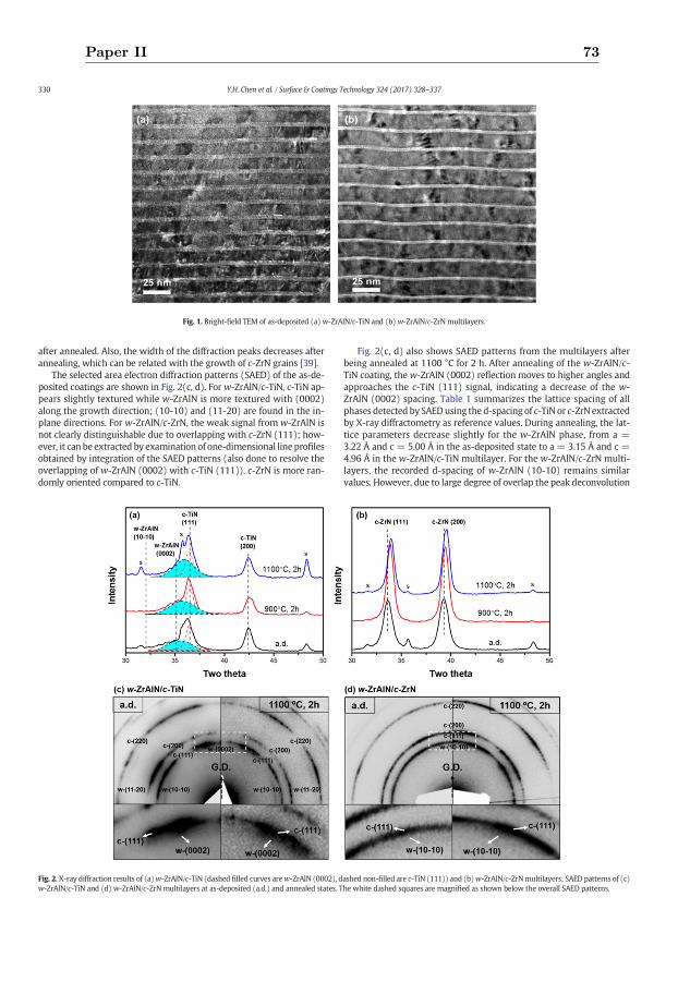
after annealed. Also, the width of the diffraction peaks decreases afterannealing, which can be related with the growth of c-ZrN grains [39].
The selected area electron diffraction patterns (SAED) of the as-de-posited coatings are shown in Fig. 2(c, d). For w-ZrAlN/c-TiN, c-TiN ap-pears slightly textured while w-ZrAlN is more textured with (0002)along the growth direction; (10-10) and (11-20) are found in the in-plane directions. For w-ZrAlN/c-ZrN, the weak signal from w-ZrAlN isnot clearly distinguishable due to overlapping with c-ZrN (111); how-ever, it can be extracted by examination of one-dimensional line profilesobtained by integration of the SAED patterns (also done to resolve theoverlapping of w-ZrAlN (0002) with c-TiN (111)). c-ZrN is more ran-domly oriented compared to c-TiN.
Fig. 2(c, d) also shows SAED patterns from the multilayers afterbeing annealed at 1100 °C for 2 h. After annealing of the w-ZrAlN/c-TiN coating, the w-ZrAlN (0002) reflection moves to higher angles andapproaches the c-TiN (111) signal, indicating a decrease of the w-ZrAlN (0002) spacing. Table 1 summarizes the lattice spacing of allphases detected by SAEDusing the d-spacing of c-TiN or c-ZrN extractedby X-ray diffractometry as reference values. During annealing, the lat-tice parameters decrease slightly for the w-ZrAlN phase, from a =3.22 Å and c = 5.00 Å in the as-deposited state to a = 3.15 Å and c =4.96 Å in the w-ZrAlN/c-TiN multilayer. For the w-ZrAlN/c-ZrN multi-layers, the recorded d-spacing of w-ZrAlN (10-10) remains similarvalues. However, due to large degree of overlap the peak deconvolution
Fig. 1. Bright-field TEM of as-deposited (a) w-ZrAlN/c-TiN and (b) w-ZrAlN/c-ZrN multilayers.
Fig. 2. X-ray diffraction results of (a)w-ZrAlN/c-TiN (dashed filled curves arew-ZrAlN (0002), dashed non-filled are c-TiN (111)) and (b)w-ZrAlN/c-ZrNmultilayers; SAED patterns of (c)w-ZrAlN/c-TiN and (d) w-ZrAlN/c-ZrN multilayers at as-deposited (a.d.) and annealed states. The white dashed squares are magnified as shown below the overall SAED patterns.
330 Y.H. Chen et al. / Surface & Coatings Technology 324 (2017) 328–337
Paper II 73
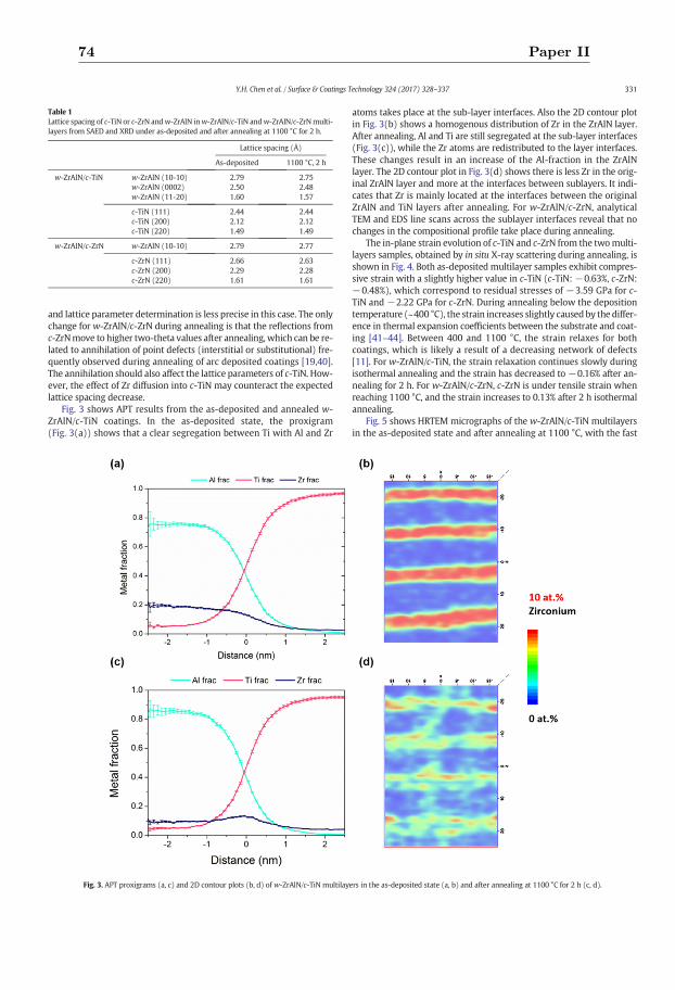
and lattice parameter determination is less precise in this case. The onlychange for w-ZrAlN/c-ZrN during annealing is that the reflections fromc-ZrNmove to higher two-theta values after annealing, which can be re-lated to annihilation of point defects (interstitial or substitutional) fre-quently observed during annealing of arc deposited coatings [19,40].The annihilation should also affect the lattice parameters of c-TiN. How-ever, the effect of Zr diffusion into c-TiN may counteract the expectedlattice spacing decrease.
Fig. 3 shows APT results from the as-deposited and annealed w-ZrAlN/c-TiN coatings. In the as-deposited state, the proxigram(Fig. 3(a)) shows that a clear segregation between Ti with Al and Zr
atoms takes place at the sub-layer interfaces. Also the 2D contour plotin Fig. 3(b) shows a homogenous distribution of Zr in the ZrAlN layer.After annealing, Al and Ti are still segregated at the sub-layer interfaces(Fig. 3(c)), while the Zr atoms are redistributed to the layer interfaces.These changes result in an increase of the Al-fraction in the ZrAlNlayer. The 2D contour plot in Fig. 3(d) shows there is less Zr in the orig-inal ZrAlN layer and more at the interfaces between sublayers. It indi-cates that Zr is mainly located at the interfaces between the originalZrAlN and TiN layers after annealing. For w-ZrAlN/c-ZrN, analyticalTEM and EDS line scans across the sublayer interfaces reveal that nochanges in the compositional profile take place during annealing.
The in-plane strain evolution of c-TiN and c-ZrN from the twomulti-layers samples, obtained by in situ X-ray scattering during annealing, isshown in Fig. 4. Both as-deposited multilayer samples exhibit compres-sive strain with a slightly higher value in c-TiN (c-TiN: −0.63%, c-ZrN:−0.48%), which correspond to residual stresses of −3.59 GPa for c-TiN and −2.22 GPa for c-ZrN. During annealing below the depositiontemperature (~400 °C), the strain increases slightly causedby the differ-ence in thermal expansion coefficients between the substrate and coat-ing [41–44]. Between 400 and 1100 °C, the strain relaxes for bothcoatings, which is likely a result of a decreasing network of defects[11]. For w-ZrAlN/c-TiN, the strain relaxation continues slowly duringisothermal annealing and the strain has decreased to −0.16% after an-nealing for 2 h. For w-ZrAlN/c-ZrN, c-ZrN is under tensile strain whenreaching 1100 °C, and the strain increases to 0.13% after 2 h isothermalannealing.
Fig. 5 shows HRTEM micrographs of the w-ZrAlN/c-TiN multilayersin the as-deposited state and after annealing at 1100 °C, with the fast
Table 1Lattice spacing of c-TiN or c-ZrN andw-ZrAlN inw-ZrAlN/c-TiN andw-ZrAlN/c-ZrNmulti-layers from SAED and XRD under as-deposited and after annealing at 1100 °C for 2 h.
Lattice spacing (Å)
As-deposited 1100 °C, 2 h
w-ZrAlN/c-TiN w-ZrAlN (10-10) 2.79 2.75w-ZrAlN (0002) 2.50 2.48w-ZrAlN (11-20) 1.60 1.57
c-TiN (111) 2.44 2.44c-TiN (200) 2.12 2.12c-TiN (220) 1.49 1.49
w-ZrAlN/c-ZrN w-ZrAlN (10-10) 2.79 2.77
c-ZrN (111) 2.66 2.63c-ZrN (200) 2.29 2.28c-ZrN (220) 1.61 1.61
Fig. 3. APT proxigrams (a, c) and 2D contour plots (b, d) of w-ZrAlN/c-TiN multilayers in the as-deposited state (a, b) and after annealing at 1100 °C for 2 h (c, d).
331Y.H. Chen et al. / Surface & Coatings Technology 324 (2017) 328–337
74 Paper II
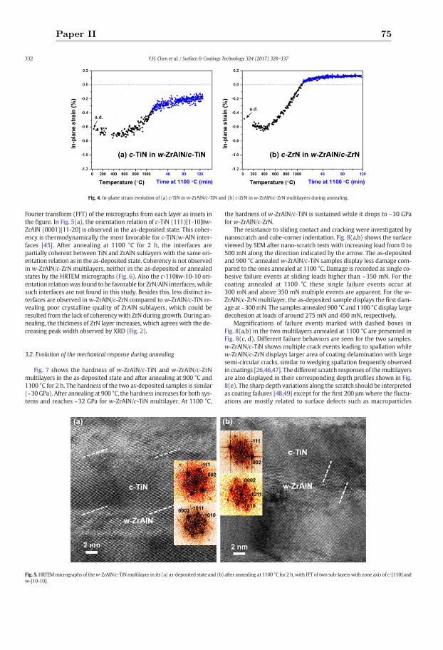
Fourier transform (FFT) of the micrographs from each layer as insets inthe figure. In Fig. 5(a), the orientation relation of c-TiN (111)[1-10]ǀǀw-ZrAlN (0001)[11-20] is observed in the as-deposited state. This coher-ency is thermodynamically the most favorable for c-TiN/w-AlN inter-faces [45]. After annealing at 1100 °C for 2 h, the interfaces arepartially coherent between TiN and ZrAlN sublayers with the same ori-entation relation as in the as-deposited state. Coherency is not observedin w-ZrAlN/c-ZrN multilayers, neither in the as-deposited or annealedstates by the HRTEM micrographs (Fig. 6). Also the c-110ǀǀw-10-10 ori-entation relationwas found to be favorable for ZrN/AlN interfaces,whilesuch interfaces are not found in this study. Besides this, less distinct in-terfaces are observed inw-ZrAlN/c-ZrN compared to w-ZrAlN/c-TiN re-vealing poor crystalline quality of ZrAlN sublayers, which could beresulted from the lack of coherencywith ZrN during growth. During an-nealing, the thickness of ZrN layer increases, which agrees with the de-creasing peak width observed by XRD (Fig. 2).
3.2. Evolution of the mechanical response during annealing
Fig. 7 shows the hardness of w-ZrAlN/c-TiN and w-ZrAlN/c-ZrNmultilayers in the as-deposited state and after annealing at 900 °C and1100 °C for 2 h. The hardness of the two as-deposited samples is similar(~30 GPa). After annealing at 900 °C, the hardness increases for both sys-tems and reaches ~32 GPa for w-ZrAlN/c-TiN multilayer. At 1100 °C,
the hardness of w-ZrAlN/c-TiN is sustained while it drops to ~30 GPafor w-ZrAlN/c-ZrN.
The resistance to sliding contact and cracking were investigated bynanoscratch and cube-corner indentation. Fig. 8(a,b) shows the surfaceviewed by SEM after nano-scratch tests with increasing load from 0 to500 mN along the direction indicated by the arrow. The as-depositedand 900 °C annealed w-ZrAlN/c-TiN samples display less damage com-pared to the ones annealed at 1100 °C. Damage is recorded as single co-hesive failure events at sliding loads higher than ~350 mN. For thecoating annealed at 1100 °C these single failure events occur at300 mN and above 350 mN multiple events are apparent. For the w-ZrAlN/c-ZrNmultilayer, the as-deposited sample displays the first dam-age at ~300mN. The samples annealed 900 °C and 1100 °C display largedecohesion at loads of around 275 mN and 450 mN, respectively.
Magnifications of failure events marked with dashed boxes inFig. 8(a,b) in the two multilayers annealed at 1100 °C are presented inFig. 8(c, d). Different failure behaviors are seen for the two samples.w-ZrAlN/c-TiN shows multiple crack events leading to spallation whilew-ZrAlN/c-ZrN displays larger area of coating delamination with largesemi-circular cracks, similar to wedging spallation frequently observedin coatings [26,46,47]. The different scratch responses of themultilayersare also displayed in their corresponding depth profiles shown in Fig.8(e). The sharp depth variations along the scratch should be interpretedas coating failures [48,49] except for the first 200 μm where the fluctu-ations are mostly related to surface defects such as macroparticles
Fig. 4. In-plane strain evolution of (a) c-TiN in w-ZrAlN/c-TiN and (b) c-ZrN inw-ZrAlN/c-ZrN multilayers during annealing.
Fig. 5.HRTEMmicrographs of thew-ZrAlN/c-TiNmultilayer in its (a) as-deposited state and (b) after annealing at 1100 °C for 2 h, with FFT of two sub-layers with zone axis of c-[110] andw-[10-10].
332 Y.H. Chen et al. / Surface & Coatings Technology 324 (2017) 328–337
Paper II 75
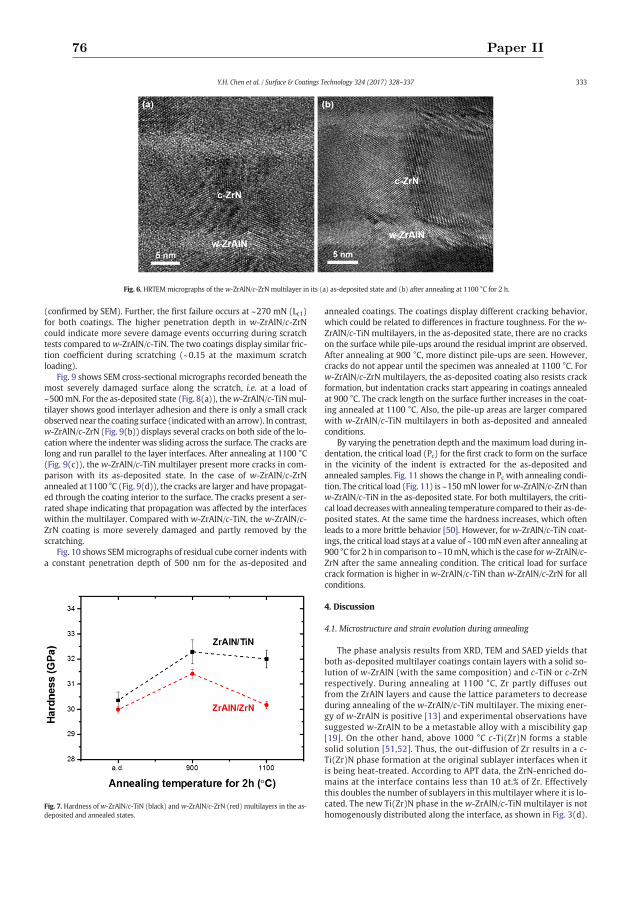
(confirmed by SEM). Further, the first failure occurs at ~270 mN (Lc1)for both coatings. The higher penetration depth in w-ZrAlN/c-ZrNcould indicate more severe damage events occurring during scratchtests compared to w-ZrAlN/c-TiN. The two coatings display similar fric-tion coefficient during scratching (~0.15 at the maximum scratchloading).
Fig. 9 shows SEM cross-sectional micrographs recorded beneath themost severely damaged surface along the scratch, i.e. at a load of~500mN. For the as-deposited state (Fig. 8(a)), thew-ZrAlN/c-TiNmul-tilayer shows good interlayer adhesion and there is only a small crackobserved near the coating surface (indicatedwith an arrow). In contrast,w-ZrAlN/c-ZrN (Fig. 9(b)) displays several cracks on both side of the lo-cation where the indenter was sliding across the surface. The cracks arelong and run parallel to the layer interfaces. After annealing at 1100 °C(Fig. 9(c)), the w-ZrAlN/c-TiN multilayer present more cracks in com-parison with its as-deposited state. In the case of w-ZrAlN/c-ZrNannealed at 1100 °C (Fig. 9(d)), the cracks are larger and have propagat-ed through the coating interior to the surface. The cracks present a ser-rated shape indicating that propagation was affected by the interfaceswithin the multilayer. Compared with w-ZrAlN/c-TiN, the w-ZrAlN/c-ZrN coating is more severely damaged and partly removed by thescratching.
Fig. 10 shows SEMmicrographs of residual cube corner indents witha constant penetration depth of 500 nm for the as-deposited and
annealed coatings. The coatings display different cracking behavior,which could be related to differences in fracture toughness. For the w-ZrAlN/c-TiN multilayers, in the as-deposited state, there are no crackson the surface while pile-ups around the residual imprint are observed.After annealing at 900 °C, more distinct pile-ups are seen. However,cracks do not appear until the specimen was annealed at 1100 °C. Forw-ZrAlN/c-ZrN multilayers, the as-deposited coating also resists crackformation, but indentation cracks start appearing in coatings annealedat 900 °C. The crack length on the surface further increases in the coat-ing annealed at 1100 °C. Also, the pile-up areas are larger comparedwith w-ZrAlN/c-TiN multilayers in both as-deposited and annealedconditions.
By varying the penetration depth and the maximum load during in-dentation, the critical load (Pc) for the first crack to form on the surfacein the vicinity of the indent is extracted for the as-deposited andannealed samples. Fig. 11 shows the change in Pc with annealing condi-tion. The critical load (Fig. 11) is ~150mN lower forw-ZrAlN/c-ZrN thanw-ZrAlN/c-TiN in the as-deposited state. For both multilayers, the criti-cal load decreaseswith annealing temperature compared to their as-de-posited states. At the same time the hardness increases, which oftenleads to a more brittle behavior [50]. However, for w-ZrAlN/c-TiN coat-ings, the critical load stays at a value of ~100mN even after annealing at900 °C for 2 h in comparison to ~10mN,which is the case forw-ZrAlN/c-ZrN after the same annealing condition. The critical load for surfacecrack formation is higher in w-ZrAlN/c-TiN than w-ZrAlN/c-ZrN for allconditions.
4. Discussion
4.1. Microstructure and strain evolution during annealing
The phase analysis results from XRD, TEM and SAED yields thatboth as-deposited multilayer coatings contain layers with a solid so-lution of w-ZrAlN (with the same composition) and c-TiN or c-ZrNrespectively. During annealing at 1100 °C, Zr partly diffuses outfrom the ZrAlN layers and cause the lattice parameters to decreaseduring annealing of the w-ZrAlN/c-TiN multilayer. The mixing ener-gy of w-ZrAlN is positive [13] and experimental observations havesuggested w-ZrAlN to be a metastable alloy with a miscibility gap[19]. On the other hand, above 1000 °C c-Ti(Zr)N forms a stablesolid solution [51,52]. Thus, the out-diffusion of Zr results in a c-Ti(Zr)N phase formation at the original sublayer interfaces when itis being heat-treated. According to APT data, the ZrN-enriched do-mains at the interface contains less than 10 at.% of Zr. Effectivelythis doubles the number of sublayers in this multilayer where it is lo-cated. The new Ti(Zr)N phase in the w-ZrAlN/c-TiN multilayer is nothomogenously distributed along the interface, as shown in Fig. 3(d).
Fig. 6. HRTEMmicrographs of the w-ZrAlN/c-ZrN multilayer in its (a) as-deposited state and (b) after annealing at 1100 °C for 2 h.
Fig. 7. Hardness ofw-ZrAlN/c-TiN (black) and w-ZrAlN/c-ZrN (red) multilayers in the as-deposited and annealed states.
333Y.H. Chen et al. / Surface & Coatings Technology 324 (2017) 328–337
76 Paper II
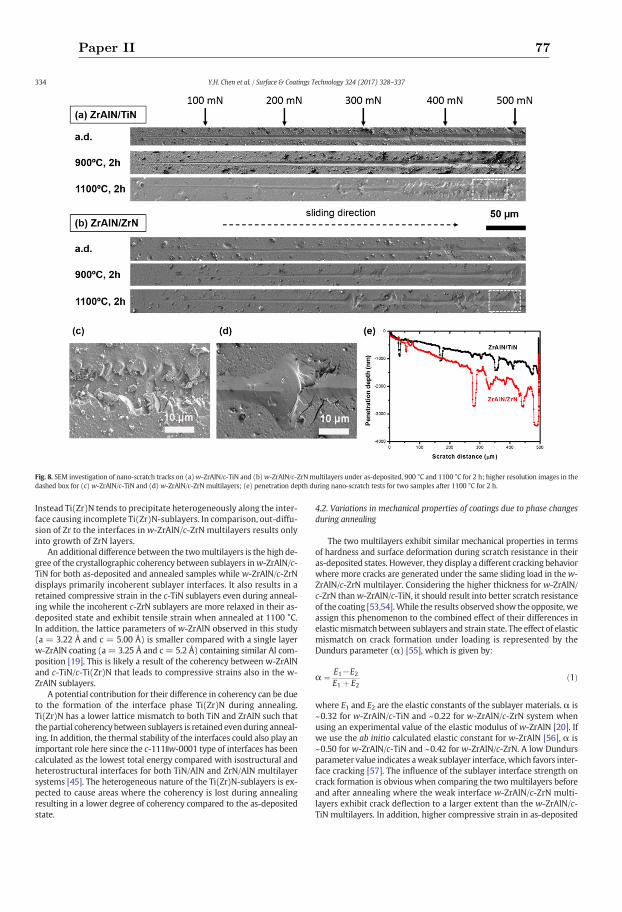
Instead Ti(Zr)N tends to precipitate heterogeneously along the inter-face causing incomplete Ti(Zr)N-sublayers. In comparison, out-diffu-sion of Zr to the interfaces in w-ZrAlN/c-ZrN multilayers results onlyinto growth of ZrN layers.
An additional difference between the twomultilayers is the high de-gree of the crystallographic coherency between sublayers inw-ZrAlN/c-TiN for both as-deposited and annealed samples while w-ZrAlN/c-ZrNdisplays primarily incoherent sublayer interfaces. It also results in aretained compressive strain in the c-TiN sublayers even during anneal-ing while the incoherent c-ZrN sublayers are more relaxed in their as-deposited state and exhibit tensile strain when annealed at 1100 °C.In addition, the lattice parameters of w-ZrAlN observed in this study(a = 3.22 Å and c = 5.00 Å) is smaller compared with a single layerw-ZrAlN coating (a= 3.25 Å and c = 5.2 Å) containing similar Al com-position [19]. This is likely a result of the coherency between w-ZrAlNand c-TiN/c-Ti(Zr)N that leads to compressive strains also in the w-ZrAlN sublayers.
A potential contribution for their difference in coherency can be dueto the formation of the interface phase Ti(Zr)N during annealing.Ti(Zr)N has a lower lattice mismatch to both TiN and ZrAlN such thatthepartial coherencybetween sublayers is retained evenduring anneal-ing. In addition, the thermal stability of the interfaces could also play animportant role here since the c-111ǀǀw-0001 type of interfaces has beencalculated as the lowest total energy compared with isostructural andheterostructural interfaces for both TiN/AlN and ZrN/AlN multilayersystems [45]. The heterogeneous nature of the Ti(Zr)N-sublayers is ex-pected to cause areas where the coherency is lost during annealingresulting in a lower degree of coherency compared to the as-depositedstate.
4.2. Variations in mechanical properties of coatings due to phase changesduring annealing
The two multilayers exhibit similar mechanical properties in termsof hardness and surface deformation during scratch resistance in theiras-deposited states. However, they display a different cracking behaviorwhere more cracks are generated under the same sliding load in thew-ZrAlN/c-ZrN multilayer. Considering the higher thickness for w-ZrAlN/c-ZrN thanw-ZrAlN/c-TiN, it should result into better scratch resistanceof the coating [53,54].While the results observed show the opposite, weassign this phenomenon to the combined effect of their differences inelasticmismatch between sublayers and strain state. The effect of elasticmismatch on crack formation under loading is represented by theDundurs parameter (α) [55], which is given by:
α ¼ E1−E2E1 þ E2
ð1Þ
where E1 and E2 are the elastic constants of the sublayer materials. α is~0.32 for w-ZrAlN/c-TiN and ~0.22 for w-ZrAlN/c-ZrN system whenusing an experimental value of the elastic modulus of w-ZrAlN [20]. Ifwe use the ab initio calculated elastic constant for w-ZrAlN [56], α is~0.50 for w-ZrAlN/c-TiN and ~0.42 for w-ZrAlN/c-ZrN. A low Dundursparameter value indicates aweak sublayer interface, which favors inter-face cracking [57]. The influence of the sublayer interface strength oncrack formation is obvious when comparing the two multilayers beforeand after annealing where the weak interface w-ZrAlN/c-ZrN multi-layers exhibit crack deflection to a larger extent than the w-ZrAlN/c-TiN multilayers. In addition, higher compressive strain in as-deposited
Fig. 8. SEM investigation of nano-scratch tracks on (a)w-ZrAlN/c-TiN and (b)w-ZrAlN/c-ZrNmultilayers under as-deposited, 900 °C and 1100 °C for 2 h; higher resolution images in thedashed box for (c) w-ZrAlN/c-TiN and (d) w-ZrAlN/c-ZrN multilayers; (e) penetration depth during nano-scratch tests for two samples after 1100 °C for 2 h.
334 Y.H. Chen et al. / Surface & Coatings Technology 324 (2017) 328–337
Paper II 77
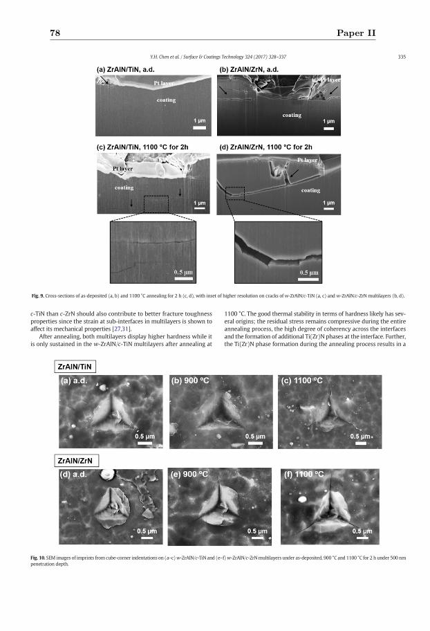
c-TiN than c-ZrN should also contribute to better fracture toughnessproperties since the strain at sub-interfaces in multilayers is shown toaffect its mechanical properties [27,31].
After annealing, both multilayers display higher hardness while itis only sustained in the w-ZrAlN/c-TiN multilayers after annealing at
1100 °C. The good thermal stability in terms of hardness likely has sev-eral origins; the residual stress remains compressive during the entireannealing process, the high degree of coherency across the interfacesand the formation of additional Ti(Zr)N phases at the interface. Further,the Ti(Zr)N phase formation during the annealing process results in a
Fig. 9. Cross-sections of as-deposited (a, b) and 1100 °C annealing for 2 h (c, d), with inset of higher resolution on cracks of w-ZrAlN/c-TiN (a, c) and w-ZrAlN/c-ZrN multilayers (b, d).
Fig. 10. SEM images of imprints from cube-corner indentations on (a–c)w-ZrAlN/c-TiN and (e–f)w-ZrAlN/c-ZrNmultilayers under as-deposited, 900 °C and 1100 °C for 2 h under 500 nmpenetration depth.
335Y.H. Chen et al. / Surface & Coatings Technology 324 (2017) 328–337
78 Paper II
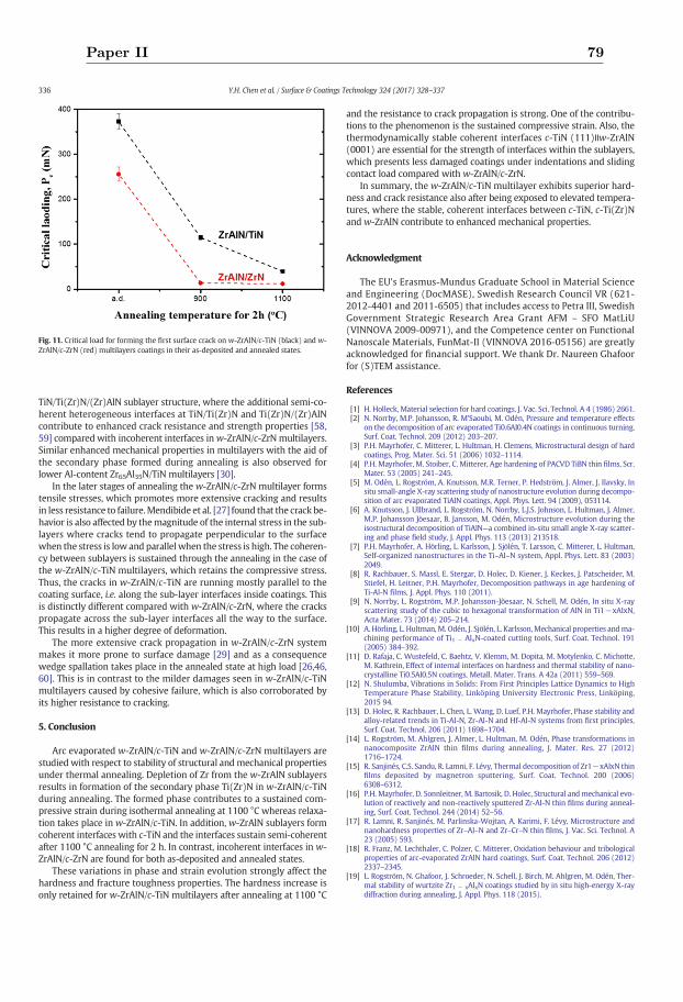
TiN/Ti(Zr)N/(Zr)AlN sublayer structure, where the additional semi-co-herent heterogeneous interfaces at TiN/Ti(Zr)N and Ti(Zr)N/(Zr)AlNcontribute to enhanced crack resistance and strength properties [58,59] compared with incoherent interfaces inw-ZrAlN/c-ZrN multilayers.Similar enhanced mechanical properties in multilayers with the aid ofthe secondary phase formed during annealing is also observed forlower Al-content Zr65Al35N/TiN multilayers [30].
In the later stages of annealing the w-ZrAlN/c-ZrN multilayer formstensile stresses, which promotes more extensive cracking and resultsin less resistance to failure.Mendibide et al. [27] found that the crack be-havior is also affected by themagnitude of the internal stress in the sub-layers where cracks tend to propagate perpendicular to the surfacewhen the stress is low and parallel when the stress is high. The coheren-cy between sublayers is sustained through the annealing in the case ofthe w-ZrAlN/c-TiN multilayers, which retains the compressive stress.Thus, the cracks in w-ZrAlN/c-TiN are running mostly parallel to thecoating surface, i.e. along the sub-layer interfaces inside coatings. Thisis distinctly different compared with w-ZrAlN/c-ZrN, where the crackspropagate across the sub-layer interfaces all the way to the surface.This results in a higher degree of deformation.
The more extensive crack propagation in w-ZrAlN/c-ZrN systemmakes it more prone to surface damage [29] and as a consequencewedge spallation takes place in the annealed state at high load [26,46,60]. This is in contrast to the milder damages seen in w-ZrAlN/c-TiNmultilayers caused by cohesive failure, which is also corroborated byits higher resistance to cracking.
5. Conclusion
Arc evaporated w-ZrAlN/c-TiN and w-ZrAlN/c-ZrN multilayers arestudied with respect to stability of structural andmechanical propertiesunder thermal annealing. Depletion of Zr from the w-ZrAlN sublayersresults in formation of the secondary phase Ti(Zr)N in w-ZrAlN/c-TiNduring annealing. The formed phase contributes to a sustained com-pressive strain during isothermal annealing at 1100 °C whereas relaxa-tion takes place in w-ZrAlN/c-TiN. In addition, w-ZrAlN sublayers formcoherent interfaces with c-TiN and the interfaces sustain semi-coherentafter 1100 °C annealing for 2 h. In contrast, incoherent interfaces in w-ZrAlN/c-ZrN are found for both as-deposited and annealed states.
These variations in phase and strain evolution strongly affect thehardness and fracture toughness properties. The hardness increase isonly retained for w-ZrAlN/c-TiN multilayers after annealing at 1100 °C
and the resistance to crack propagation is strong. One of the contribu-tions to the phenomenon is the sustained compressive strain. Also, thethermodynamically stable coherent interfaces c-TiN (111)ǀǀw-ZrAlN(0001) are essential for the strength of interfaces within the sublayers,which presents less damaged coatings under indentations and slidingcontact load compared with w-ZrAlN/c-ZrN.
In summary, the w-ZrAlN/c-TiN multilayer exhibits superior hard-ness and crack resistance also after being exposed to elevated tempera-tures, where the stable, coherent interfaces between c-TiN, c-Ti(Zr)Nand w-ZrAlN contribute to enhanced mechanical properties.
Acknowledgment
The EU's Erasmus-Mundus Graduate School in Material Scienceand Engineering (DocMASE), Swedish Research Council VR (621-2012-4401 and 2011-6505) that includes access to Petra III, SwedishGovernment Strategic Research Area Grant AFM – SFO MatLiU(VINNOVA 2009-00971), and the Competence center on FunctionalNanoscale Materials, FunMat-II (VINNOVA 2016-05156) are greatlyacknowledged for financial support. We thank Dr. Naureen Ghafoorfor (S)TEM assistance.
References
[1] H. Holleck, Material selection for hard coatings, J. Vac. Sci. Technol. A 4 (1986) 2661.[2] N. Norrby, M.P. Johansson, R. M'Saoubi, M. Odén, Pressure and temperature effects
on the decomposition of arc evaporated Ti0.6Al0.4N coatings in continuous turning,Surf. Coat. Technol. 209 (2012) 203–207.
[3] P.H. Mayrhofer, C. Mitterer, L. Hultman, H. Clemens, Microstructural design of hardcoatings, Prog. Mater. Sci. 51 (2006) 1032–1114.
[4] P.H. Mayrhofer, M. Stoiber, C. Mitterer, Age hardening of PACVD TiBN thin films, Scr.Mater. 53 (2005) 241–245.
[5] M. Odén, L. Rogström, A. Knutsson, M.R. Terner, P. Hedström, J. Almer, J. Ilavsky, Insitu small-angle X-ray scattering study of nanostructure evolution during decompo-sition of arc evaporated TiAlN coatings, Appl. Phys. Lett. 94 (2009), 053114.
[6] A. Knutsson, J. Ullbrand, L. Rogström, N. Norrby, L.J.S. Johnson, L. Hultman, J. Almer,M.P. Johansson Jöesaar, B. Jansson, M. Odén, Microstructure evolution during theisostructural decomposition of TiAlN—a combined in-situ small angle X-ray scatter-ing and phase field study, J. Appl. Phys. 113 (2013) 213518.
[7] P.H. Mayrhofer, A. Hörling, L. Karlsson, J. Sjölén, T. Larsson, C. Mitterer, L. Hultman,Self-organized nanostructures in the Ti–Al–N system, Appl. Phys. Lett. 83 (2003)2049.
[8] R. Rachbauer, S. Massl, E. Stergar, D. Holec, D. Kiener, J. Keckes, J. Patscheider, M.Stiefel, H. Leitner, P.H. Mayrhofer, Decomposition pathways in age hardening ofTi-Al-N films, J. Appl. Phys. 110 (2011).
[9] N. Norrby, L. Rogström, M.P. Johansson-Jõesaar, N. Schell, M. Odén, In situ X-rayscattering study of the cubic to hexagonal transformation of AlN in Ti1−xAlxN,Acta Mater. 73 (2014) 205–214.
[10] A. Hörling, L. Hultman, M. Odén, J. Sjölén, L. Karlsson, Mechanical properties andma-chining performance of Ti1 − AlxN-coated cutting tools, Surf. Coat. Technol. 191(2005) 384–392.
[11] D. Rafaja, C. Wustefeld, C. Baehtz, V. Klemm, M. Dopita, M. Motylenko, C. Michotte,M. Kathrein, Effect of internal interfaces on hardness and thermal stability of nano-crystalline Ti0.5Al0.5N coatings, Metall. Mater. Trans. A 42a (2011) 559–569.
[12] N. Shulumba, Vibrations in Solids: From First Principles Lattice Dynamics to HighTemperature Phase Stability, Linköping University Electronic Press, Linköping,2015 94.
[13] D. Holec, R. Rachbauer, L. Chen, L. Wang, D. Luef, P.H. Mayrhofer, Phase stability andalloy-related trends in Ti-Al-N, Zr-Al-N and Hf-Al-N systems from first principles,Surf. Coat. Technol. 206 (2011) 1698–1704.
[14] L. Rogström, M. Ahlgren, J. Almer, L. Hultman, M. Odén, Phase transformations innanocomposite ZrAlN thin films during annealing, J. Mater. Res. 27 (2012)1716–1724.
[15] R. Sanjinés, C.S. Sandu, R. Lamni, F. Lévy, Thermal decomposition of Zr1−xAlxN thinfilms deposited by magnetron sputtering, Surf. Coat. Technol. 200 (2006)6308–6312.
[16] P.H. Mayrhofer, D. Sonnleitner, M. Bartosik, D. Holec, Structural andmechanical evo-lution of reactively and non-reactively sputtered Zr-Al-N thin films during anneal-ing, Surf. Coat. Technol. 244 (2014) 52–56.
[17] R. Lamni, R. Sanjinés, M. Parlinska-Wojtan, A. Karimi, F. Lévy, Microstructure andnanohardness properties of Zr–Al–N and Zr–Cr–N thin films, J. Vac. Sci. Technol. A23 (2005) 593.
[18] R. Franz, M. Lechthaler, C. Polzer, C. Mitterer, Oxidation behaviour and tribologicalproperties of arc-evaporated ZrAlN hard coatings, Surf. Coat. Technol. 206 (2012)2337–2345.
[19] L. Rogström, N. Ghafoor, J. Schroeder, N. Schell, J. Birch, M. Ahlgren, M. Odén, Ther-mal stability of wurtzite Zr1 − xAlxN coatings studied by in situ high-energy X-raydiffraction during annealing, J. Appl. Phys. 118 (2015).
Fig. 11. Critical load for forming the first surface crack on w-ZrAlN/c-TiN (black) and w-ZrAlN/c-ZrN (red) multilayers coatings in their as-deposited and annealed states.
336 Y.H. Chen et al. / Surface & Coatings Technology 324 (2017) 328–337
Paper II 79
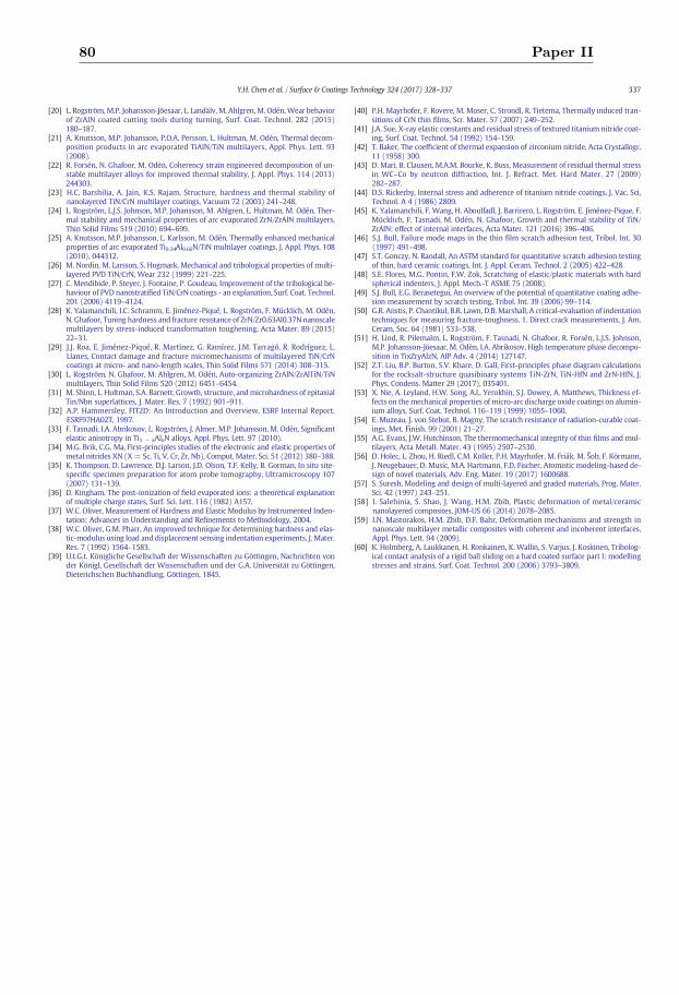
[20] L. Rogström,M.P. Johansson-Jõesaar, L. Landälv,M. Ahlgren,M. Odén,Wear behaviorof ZrAlN coated cutting tools during turning, Surf. Coat. Technol. 282 (2015)180–187.
[21] A. Knutsson, M.P. Johansson, P.O.A. Persson, L. Hultman, M. Odén, Thermal decom-position products in arc evaporated TiAlN/TiN multilayers, Appl. Phys. Lett. 93(2008).
[22] R. Forsén, N. Ghafoor, M. Odèn, Coherency strain engineered decomposition of un-stable multilayer alloys for improved thermal stability, J. Appl. Phys. 114 (2013)244303.
[23] H.C. Barshilia, A. Jain, K.S. Rajam, Structure, hardness and thermal stability ofnanolayered TiN/CrN multilayer coatings, Vacuum 72 (2003) 241–248.
[24] L. Rogström, L.J.S. Johnson, M.P. Johansson, M. Ahlgren, L. Hultman, M. Odén, Ther-mal stability and mechanical properties of arc evaporated ZrN/ZrAlN multilayers,Thin Solid Films 519 (2010) 694–699.
[25] A. Knutsson, M.P. Johansson, L. Karlsson, M. Odén, Thermally enhanced mechanicalproperties of arc evaporated Ti0.34Al0.66N/TiN multilayer coatings, J. Appl. Phys. 108(2010), 044312.
[26] M. Nordin, M. Larsson, S. Hogmark, Mechanical and tribological properties of multi-layered PVD TiN/CrN, Wear 232 (1999) 221–225.
[27] C. Mendibide, P. Steyer, J. Fontaine, P. Goudeau, Improvement of the tribological be-haviour of PVD nanostratified TiN/CrN coatings - an explanation, Surf. Coat. Technol.201 (2006) 4119–4124.
[28] K. Yalamanchili, I.C. Schramm, E. Jiménez-Piqué, L. Rogström, F. Mücklich, M. Odén,N. Ghafoor, Tuning hardness and fracture resistance of ZrN/Zr0.63Al0.37N nanoscalemultilayers by stress-induced transformation toughening, Acta Mater. 89 (2015)22–31.
[29] J.J. Roa, E. Jiménez-Piqué, R. Martínez, G. Ramírez, J.M. Tarragó, R. Rodríguez, L.Llanes, Contact damage and fracture micromechanisms of multilayered TiN/CrNcoatings at micro- and nano-length scales, Thin Solid Films 571 (2014) 308–315.
[30] L. Rogström, N. Ghafoor, M. Ahlgren, M. Odén, Auto-organizing ZrAlN/ZrAlTiN/TiNmultilayers, Thin Solid Films 520 (2012) 6451–6454.
[31] M. Shinn, L. Hultman, S.A. Barnett, Growth, structure, andmicrohardness of epitaxialTin/Nbn superlattices, J. Mater. Res. 7 (1992) 901–911.
[32] A.P. Hammersley, FIT2D: An Introduction and Overview, ESRF Internal Report,ESRF97HA02T, 1997.
[33] F. Tasnadi, I.A. Abrikosov, L. Rogström, J. Almer, M.P. Johansson, M. Odén, Significantelastic anisotropy in Ti1 − xAlxN alloys, Appl. Phys. Lett. 97 (2010).
[34] M.G. Brik, C.G. Ma, First-principles studies of the electronic and elastic properties ofmetal nitrides XN (X= Sc, Ti, V, Cr, Zr, Nb), Comput. Mater. Sci. 51 (2012) 380–388.
[35] K. Thompson, D. Lawrence, D.J. Larson, J.D. Olson, T.F. Kelly, B. Gorman, In situ site-specific specimen preparation for atom probe tomography, Ultramicroscopy 107(2007) 131–139.
[36] D. Kingham, The post-ionization of field evaporated ions: a theoretical explanationof multiple charge states, Surf. Sci. Lett. 116 (1982) A157.
[37] W.C. Oliver, Measurement of Hardness and Elastic Modulus by Instrumented Inden-tation: Advances in Understanding and Refinements to Methodology, 2004.
[38] W.C. Oliver, G.M. Pharr, An improved technique for determining hardness and elas-tic-modulus using load and displacement sensing indentation experiments, J. Mater.Res. 7 (1992) 1564–1583.
[39] U.t.G.t. Königliche Gesellschaft der Wissenschaften zu Göttingen, Nachrichten vonder Königl, Gesellschaft der Wissenschaften und der G.A. Universität zu Göttingen,Dieterichschen Buchhandlung, Göttingen, 1845.
[40] P.H. Mayrhofer, F. Rovere, M. Moser, C. Strondl, R. Tietema, Thermally induced tran-sitions of CrN thin films, Scr. Mater. 57 (2007) 249–252.
[41] J.A. Sue, X-ray elastic constants and residual stress of textured titanium nitride coat-ing, Surf. Coat. Technol. 54 (1992) 154–159.
[42] T. Baker, The coefficient of thermal expansion of zirconium nitride, Acta Crystallogr.11 (1958) 300.
[43] D. Mari, B. Clausen, M.A.M. Bourke, K. Buss, Measurement of residual thermal stressin WC–Co by neutron diffraction, Int. J. Refract. Met. Hard Mater. 27 (2009)282–287.
[44] D.S. Rickerby, Internal stress and adherence of titanium nitride coatings, J. Vac. Sci.Technol. A 4 (1986) 2809.
[45] K. Yalamanchili, F. Wang, H. Aboulfadl, J. Barrirero, L. Rogström, E. Jiménez-Pique, F.Mücklich, F. Tasnadi, M. Odén, N. Ghafoor, Growth and thermal stability of TiN/ZrAlN: effect of internal interfaces, Acta Mater. 121 (2016) 396–406.
[46] S.J. Bull, Failure mode maps in the thin film scratch adhesion test, Tribol. Int. 30(1997) 491–498.
[47] S.T. Gonczy, N. Randall, An ASTM standard for quantitative scratch adhesion testingof thin, hard ceramic coatings, Int. J. Appl. Ceram. Technol. 2 (2005) 422–428.
[48] S.E. Flores, M.G. Pontin, F.W. Zok, Scratching of elastic/plastic materials with hardspherical indenters, J. Appl. Mech.-T ASME 75 (2008).
[49] S.J. Bull, E.G. Berasetegui, An overview of the potential of quantitative coating adhe-sion measurement by scratch testing, Tribol. Int. 39 (2006) 99–114.
[50] G.R. Anstis, P. Chantikul, B.R. Lawn, D.B.Marshall, A critical-evaluation of indentationtechniques for measuring fracture-toughness. 1. Direct crack measurements, J. Am.Ceram. Soc. 64 (1981) 533–538.
[51] H. Lind, R. Pilemalm, L. Rogström, F. Tasnadi, N. Ghafoor, R. Forsén, L.J.S. Johnson,M.P. Johansson-Jöesaar, M. Odèn, I.A. Abrikosov, High temperature phase decompo-sition in TixZryAlzN, AIP Adv. 4 (2014) 127147.
[52] Z.T. Liu, B.P. Burton, S.V. Khare, D. Gall, First-principles phase diagram calculationsfor the rocksalt-structure quasibinary systems TiN-ZrN, TiN-HfN and ZrN-HfN, J.Phys. Condens. Matter 29 (2017), 035401.
[53] X. Nie, A. Leyland, H.W. Song, A.L. Yerokhin, S.J. Dowey, A. Matthews, Thickness ef-fects on themechanical properties of micro-arc discharge oxide coatings on alumin-ium alloys, Surf. Coat. Technol. 116–119 (1999) 1055–1060.
[54] E. Muzeau, J. von Stebut, B. Magny, The scratch resistance of radiation-curable coat-ings, Met. Finish. 99 (2001) 21–27.
[55] A.G. Evans, J.W. Hutchinson, The thermomechanical integrity of thin films and mul-tilayers, Acta Metall. Mater. 43 (1995) 2507–2530.
[56] D. Holec, L. Zhou, H. Riedl, C.M. Koller, P.H. Mayrhofer, M. Friák, M. Šob, F. Körmann,J. Neugebauer, D. Music, M.A. Hartmann, F.D. Fischer, Atomistic modeling-based de-sign of novel materials, Adv. Eng. Mater. 19 (2017) 1600688.
[57] S. Suresh, Modeling and design of multi-layered and graded materials, Prog. Mater.Sci. 42 (1997) 243–251.
[58] I. Salehinia, S. Shao, J. Wang, H.M. Zbib, Plastic deformation of metal/ceramicnanolayered composites, JOM-US 66 (2014) 2078–2085.
[59] I.N. Mastorakos, H.M. Zbib, D.F. Bahr, Deformation mechanisms and strength innanoscale multilayer metallic composites with coherent and incoherent interfaces,Appl. Phys. Lett. 94 (2009).
[60] K. Holmberg, A. Laukkanen, H. Ronkainen, K. Wallin, S. Varjus, J. Koskinen, Tribolog-ical contact analysis of a rigid ball sliding on a hard coated surface part I: modellingstresses and strains, Surf. Coat. Technol. 200 (2006) 3793–3809.
337Y.H. Chen et al. / Surface & Coatings Technology 324 (2017) 328–337
80 Paper II
III
Paper III
Enhanced thermal stability and fracturetoughness of TiAlN coatings by Cr, Nb and
V-alloying
Y. H. ChenJ.J.Roa
C. H. YuM.P.Johansson-Jõesaar
J. M. AnderssonM.J.Anglada
M.OdénL. Rogström
Surface and Coatings Technology, 342, 85–93 (2018)
Reprinted with permission. ©2018 Elsevier

Contents lists available at ScienceDirect
Surface & Coatings Technology
journal homepage: www.elsevier.com/locate/surfcoat
Enhanced thermal stability and fracture toughness of TiAlN coatings by Cr,Nb and V-alloying
Y.H. Chena,⁎, J.J. Roab,c, C.H. Yua, M.P. Johansson-Jõesaara,d, J.M. Anderssond, M.J. Angladab,c,M. Odéna, L. Rogströma
aNanostructured Materials, Department of Physics, Chemistry and Biology (IFM), Linköping University, SE-581 83 Linköping, SwedenbDepartment of Materials Science and Metallurgical Engineering, Universitat Politècnica de Catalunya, Campus Diagonal Besòs-EEBE, 08019 Barcelona, Spainc Centre for Research in Multiscale Engineering of Barcelona, Universitat Politècnica de Catalunya, Campus Diagonal Besòs-EEBE, 08019 Barcelona, Spaind R&D Material and Technology Development, SECO Tools AB, SE-737 82 Fagersta, Sweden
A R T I C L E I N F O
Keywords:Thermal stabilityQuaternary transition metal nitridesScratch testFracture toughnessArc evaporation
A B S T R A C T
The effect of metal alloying on mechanical properties including hardness and fracture toughness were in-vestigated in three alloys, Ti~0.33Al0.50(Me)~0.17N (Me=Cr, Nb and V), and compared to Ti0.50Al0.50N, in the as-deposited state and after annealing. All studied alloys display similar as-deposited hardness while the hardnessevolution during annealing is found to be connected to phase transformations, related to the alloy's thermalstability. The most pronounced hardening was observed in Ti0.50Al0.50N, while all the coatings with additionalmetal elements sustain their hardness better and they are harder than Ti0.50Al0.50N after annealing at 1100 °C.Fracture toughness properties were extracted from scratch tests. In all tested conditions, as-deposited and an-nealed at 900 and 1100 °C, Ti0.33Al0.50Nb0.17N show the least surface and sub-surface damage when scratcheddespite the differences in decomposition behavior and h-AlN formation. Theoretically estimated ductility ofphases existing in the coatings correlates well with their crack resistance. In summary, Ti0.33Al0.50Nb0.17N is thetoughest alloy in both as-deposited and post-annealed states.
1. Introduction
Superior mechanical properties in terms of wear-resistance are es-sential for coatings used for high-speed cutting tools, where the oper-ating temperatures can be above 900 °C [1]. As a result, thermal sta-bility of coatings with enhanced mechanical properties is desired. Cubic(c-) Ti1−xAlxN coatings have been extensively studied and used due toits enhanced hardness (H) that is related to a spinodal decomposition athigh temperature [2]. While the formation of coherently strained c-TiNand c-AlN rich domains gives rise to age hardening during high tem-perature heat treatment, further annealing induces hexagonal h-AlNphase transformation, which degrades the coating's mechanical prop-erties [3,4].
It has been shown that the thermal stability and hardness can beimproved by alloying Ti1−xAlxN with an additional transition metal(Me) [5–9]. For example, Ti1−x−yAlx(Cr)yN has shown enhancedhardness after annealing above 1000 °C [7,10]. Still, brittleness remainsas a drawback of ceramic coatings [11,12]. Theoretical studies predictthat quaternary Ti1−x−yAlx(Me)yN alloys may have higher toughnessand ductility than TiAlN [13–15]. Experimentally, the fracture
toughness of Ti1−x−yAlx(Nb)yN has been found to enhance with theaddition of Nb [16]. With theoretical predictions based on the valenceelectron concentrations (VEC), the toughness of Ti1−x−yAlx(V)yN alsoincreases by V alloying [13,17]. In addition, V in Ti1−x−yAlx(V)yN hasalso been observed to improve lubrication and wear-resistance prop-erties [18].
Experimental studies of the fracture toughness of hard coatings aresparse, mainly due to the lack of established test methods for thin films.Tribological tests such as scratch or wear tests effectively evaluate thecoating's mechanical strength and adhesion properties by analyzing thefailure events [19–23]. However, the focus of these studies is limited tothe damage events occurring on the surface. A more detailed under-standing can be achieved by studying the fracture behavior of thecoating. Here we use a focused ion beam (FIB) to make cross sectionalinvestigations of the damage events that enable observation of differ-ences in crack resistance between coatings. We also report the fracturebehavior of post-annealed samples and correlate the results to me-chanical properties such as hardness and ductility. The alloying ele-ments affect the microstructure and phase evolution during annealingthat impact the coating's ductility, e.g. the formation of h-AlN is
https://doi.org/10.1016/j.surfcoat.2018.02.059Received 4 November 2017; Received in revised form 18 January 2018; Accepted 16 February 2018
⁎ Corresponding author.E-mail address: [email protected] (Y.H. Chen).
Surface & Coatings Technology 342 (2018) 85–93
Available online 17 February 20180257-8972/ © 2018 Elsevier B.V. All rights reserved.
T
Paper III 83
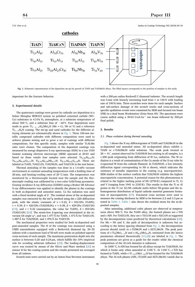
important for the fracture behavior.
2. Experimental details
The quaternary coatings were grown by cathodic arc deposition in aSulzer Metaplas MZR323 system on polished cemented carbide (WC-Co) substrates in 4.5 Pa N2 atmosphere, at a substrate temperature ofabout 550 °C, and a substrate bias of −60 V. Four depositions weremade to grow Ti1−x−yAlx(Me)yN (Me=Cr, Nb or V) and a referenceTi1−xAlxN coating. The set-up and used cathodes for the different al-loying elements are schematically shown in Fig. 1. Three 100mm me-tallic compound cathodes with different composition were used toachieve plasma mixing and to grow a set of coatings with differentcompositions. For this specific study, samples with similar Ti:Al:Meratio were chosen. The composition of the deposited coatings wasmeasured by energy-dispersive X-ray spectroscopy (EDS) in a Leo 1550Gemini scanning electron microscope (SEM) operated at 20 kV andbased on these results four samples were selected: Ti0.49Al0.51N;Ti0.33Al0.50Cr0.17N; Ti0.33Al0.50Nb0.17N; Ti0.37Al0.45V0.18N. These arelabeled as TiAlN, TiAl(Cr)N, TiAl(Nb)N, and TiAl(V)N in the text below.
Thermal annealing of the samples was done in a 1.6mPa vacuumenvironment at constant annealing temperatures with a holding time of20min, and heating/cooling rates of 20 °C/min. The temperature wasmonitored by a thermocouple located near the sample and the ther-mocouple reading was calibrated by a two-color CellaTemp pyrometer.Grazing incidence X-ray diffraction (GIXRD) using a Bruker D8 AdvanceX-ray diffractometer was applied to identify the phases in the coatingsin both as-deposited and annealed states. Cu Kα radiation was usedwith a fixed incident angle of 2°. The residual stress of the as-depositedsamples was extracted by the sin2ψ method using the c-220 diffractionpeak, with the elastic constants of v=0.22, E= 432 GPa (TiAlN);v=0.39, E= 420 GPa (TiAl(Nb)N); v=0.38, E= 429 GPa (TiAl(V)N)[15], and v=0.22 (assumption, the value for TiAlN), E= 454 GPa(TiAl(Cr)N) [24]. The strain-free d-spacing was determined at the in-variant tilt angle ψ*, and was 1.477 Å for TiAlN, 1.473 Å for TiAl(Cr)N,1.487 Å for TiAl(Nb)N, and 1.476 Å for TiAl(V)N.
The mechanical properties were studied for both as-deposited andpost-annealed samples. The H of the coatings was measured using aUMIS nanoindenter equipped with a Berkovich diamond tip. 20–30indents with a maximum load of 50mN were made on polished taperedcross-sections of each sample. The maximum penetration depth into thesurface is between 0.20 and 0.24 μm, which fulfills the 10% empiricalrule for avoiding substrate influence [25]. The loading-displacementcurve was treated by means of the Oliver and Pharr method [26] toextract H for the coating system and the results presented are averagedfrom all indents.
Scratch tests were carried out by an Anton Paar Revetest instrument
with a 200 μm radius Rockwell C diamond indenter. The scratch lengthwas 5mm with linearly increasing load from 1 to 150 N with loadingrate of 100 N/min. Three scratches were done for each sample. Surfaceand sub-surface damage of the scratch tracks and cross-sections ofspecific spallation events were examined by SEM and focused ion beam(FIB) in a dual beam Workstation (Zeiss Neon 40). The specimens werecoarse milled using a 30 kV/2 nA Ga+ ion beam followed by 500 pAfinal polish.
3. Results
3.1. Phase evolution during thermal annealing
Fig. 2 shows the X-ray diffractograms of TiAlN and TiAl(Me)N in theas-deposited and annealed states. All as-deposited alloys exhibit c-TiAlN or c-TiAl(Me)N solid solutions. The weak peak located at2θ≈ 41°, easiest observed for TiAl(Nb)N but existing in all samples, is ac-200 peak originating from diffraction of W Lα1 radiation. The W ra-diation is a result of contamination of the Cu anode of the X-ray tube byevaporated W from the cathode filament. In TiAl(Nb)N, a low intensitydiffraction signal corresponding to Nb is shown, which indicates theexistence of metallic impurities in the coating (e.g. macroparticles).SEM studies of the surface confirm that TiAl(Nb)N exhibits the highestmacroparticle concentration. A potential reason for this phenomenon isrelated to the higher melting point of Nb (2750 K) compared to Ti, Crand V (ranging from 1941 to 2183 K). This results in that the Ti or Algrains in the Ti (or Al)-Nb cathode melts before Nb-grains and the in-homogeneous distribution of liquid cathode material generates forma-tion of macroparticles [27]. Fractured cross sections were used tomeasure the coating thickness by SEM to be between 2.2 and 3.3 μm asnoted in Table 1. Table 1 also shows the residual stress for the as-de-posited samples.
After annealing, additional cubic phases are observed at tempera-tures above 900 °C. For the TiAlN alloy, the formed phases are c-TiNand c-AlN. For TiAl(Cr)N, they are c-Ti(Cr)N and c-Al(Cr)N as suggestedby the decomposition route predicted by theoretical calculations [28].For Me=Nb and V, the path of decomposition is unknown but ac-cording to the lattice spacing obtained from Fig. 2, the decompositionprocess should result in c-Ti(Me)N and c-Al(Ti,Me)N. The peak posi-tions of c-Tix(Me)1−xN and c-Al0.5(Me)0.5N, estimated from the latticeparameters obtained theoretically [15,28] are labeled in Fig. 2. Thepeak positions are given as a guide for the reader while the chemicalcomposition of the Al-rich domains is unknown.
At 1000 °C, h-AlN has formed for all alloys except for TiAl(Nb)N, forwhich it forms only when annealed at 1100 °C. At 1100 °C, c-TiN hasformed in TiAlN, while c-Ti~0.7(Me)~0.3N has formed for the TiAl(Me)Nalloys. The Al-rich phases (AlN, (Ti)AlN and Al(Ti,Me)N) vanish due to
Fig. 1. Schematic representation of the deposition set-up for growth of TiAlN and TiAl(Me)N alloys. The filled square corresponds to the position of samples in this study.
Y.H. Chen et al. Surface & Coatings Technology 342 (2018) 85–93
86
84 Paper III
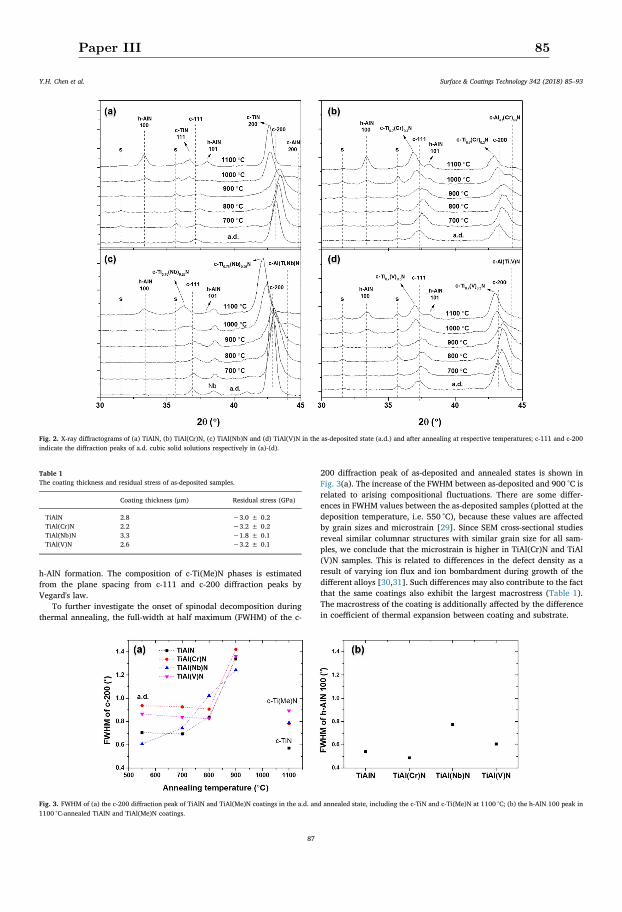
h-AlN formation. The composition of c-Ti(Me)N phases is estimatedfrom the plane spacing from c-111 and c-200 diffraction peaks byVegard's law.
To further investigate the onset of spinodal decomposition duringthermal annealing, the full-width at half maximum (FWHM) of the c-
200 diffraction peak of as-deposited and annealed states is shown inFig. 3(a). The increase of the FWHM between as-deposited and 900 °C isrelated to arising compositional fluctuations. There are some differ-ences in FWHM values between the as-deposited samples (plotted at thedeposition temperature, i.e. 550 °C), because these values are affectedby grain sizes and microstrain [29]. Since SEM cross-sectional studiesreveal similar columnar structures with similar grain size for all sam-ples, we conclude that the microstrain is higher in TiAl(Cr)N and TiAl(V)N samples. This is related to differences in the defect density as aresult of varying ion flux and ion bombardment during growth of thedifferent alloys [30,31]. Such differences may also contribute to the factthat the same coatings also exhibit the largest macrostress (Table 1).The macrostress of the coating is additionally affected by the differencein coefficient of thermal expansion between coating and substrate.
Fig. 2. X-ray diffractograms of (a) TiAlN, (b) TiAl(Cr)N, (c) TiAl(Nb)N and (d) TiAl(V)N in the as-deposited state (a.d.) and after annealing at respective temperatures; c-111 and c-200indicate the diffraction peaks of a.d. cubic solid solutions respectively in (a)-(d).
Table 1The coating thickness and residual stress of as-deposited samples.
Coating thickness (μm) Residual stress (GPa)
TiAlN 2.8 −3.0 ± 0.2TiAl(Cr)N 2.2 −3.2 ± 0.2TiAl(Nb)N 3.3 −1.8 ± 0.1TiAl(V)N 2.6 −3.2 ± 0.1
Fig. 3. FWHM of (a) the c-200 diffraction peak of TiAlN and TiAl(Me)N coatings in the a.d. and annealed state, including the c-TiN and c-Ti(Me)N at 1100 °C; (b) the h-AlN 100 peak in1100 °C-annealed TiAlN and TiAl(Me)N coatings.
Y.H. Chen et al. Surface & Coatings Technology 342 (2018) 85–93
87
Paper III 85
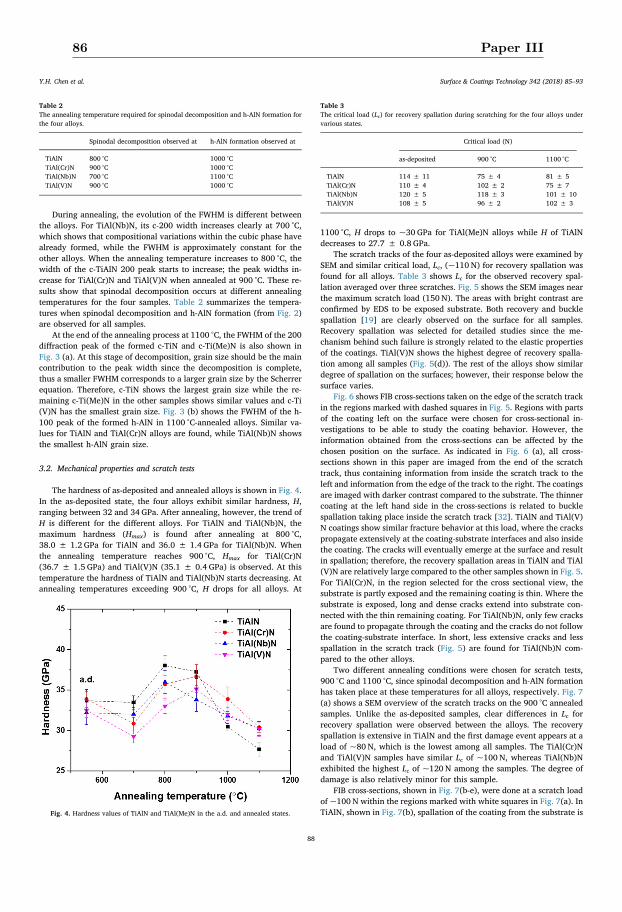
During annealing, the evolution of the FWHM is different betweenthe alloys. For TiAl(Nb)N, its c-200 width increases clearly at 700 °C,which shows that compositional variations within the cubic phase havealready formed, while the FWHM is approximately constant for theother alloys. When the annealing temperature increases to 800 °C, thewidth of the c-TiAlN 200 peak starts to increase; the peak widths in-crease for TiAl(Cr)N and TiAl(V)N when annealed at 900 °C. These re-sults show that spinodal decomposition occurs at different annealingtemperatures for the four samples. Table 2 summarizes the tempera-tures when spinodal decomposition and h-AlN formation (from Fig. 2)are observed for all samples.
At the end of the annealing process at 1100 °C, the FWHM of the 200diffraction peak of the formed c-TiN and c-Ti(Me)N is also shown inFig. 3 (a). At this stage of decomposition, grain size should be the maincontribution to the peak width since the decomposition is complete,thus a smaller FWHM corresponds to a larger grain size by the Scherrerequation. Therefore, c-TiN shows the largest grain size while the re-maining c-Ti(Me)N in the other samples shows similar values and c-Ti(V)N has the smallest grain size. Fig. 3 (b) shows the FWHM of the h-100 peak of the formed h-AlN in 1100 °C-annealed alloys. Similar va-lues for TiAlN and TiAl(Cr)N alloys are found, while TiAl(Nb)N showsthe smallest h-AlN grain size.
3.2. Mechanical properties and scratch tests
The hardness of as-deposited and annealed alloys is shown in Fig. 4.In the as-deposited state, the four alloys exhibit similar hardness, H,ranging between 32 and 34 GPa. After annealing, however, the trend ofH is different for the different alloys. For TiAlN and TiAl(Nb)N, themaximum hardness (Hmax) is found after annealing at 800 °C,38.0 ± 1.2 GPa for TiAlN and 36.0 ± 1.4 GPa for TiAl(Nb)N. Whenthe annealing temperature reaches 900 °C, Hmax for TiAl(Cr)N(36.7 ± 1.5 GPa) and TiAl(V)N (35.1 ± 0.4 GPa) is observed. At thistemperature the hardness of TiAlN and TiAl(Nb)N starts decreasing. Atannealing temperatures exceeding 900 °C, H drops for all alloys. At
1100 °C, H drops to ~30 GPa for TiAl(Me)N alloys while H of TiAlNdecreases to 27.7 ± 0.8 GPa.
The scratch tracks of the four as-deposited alloys were examined bySEM and similar critical load, Lc, (~110 N) for recovery spallation wasfound for all alloys. Table 3 shows Lc for the observed recovery spal-lation averaged over three scratches. Fig. 5 shows the SEM images nearthe maximum scratch load (150 N). The areas with bright contrast areconfirmed by EDS to be exposed substrate. Both recovery and bucklespallation [19] are clearly observed on the surface for all samples.Recovery spallation was selected for detailed studies since the me-chanism behind such failure is strongly related to the elastic propertiesof the coatings. TiAl(V)N shows the highest degree of recovery spalla-tion among all samples (Fig. 5(d)). The rest of the alloys show similardegree of spallation on the surfaces; however, their response below thesurface varies.
Fig. 6 shows FIB cross-sections taken on the edge of the scratch trackin the regions marked with dashed squares in Fig. 5. Regions with partsof the coating left on the surface were chosen for cross-sectional in-vestigations to be able to study the coating behavior. However, theinformation obtained from the cross-sections can be affected by thechosen position on the surface. As indicated in Fig. 6 (a), all cross-sections shown in this paper are imaged from the end of the scratchtrack, thus containing information from inside the scratch track to theleft and information from the edge of the track to the right. The coatingsare imaged with darker contrast compared to the substrate. The thinnercoating at the left hand side in the cross-sections is related to bucklespallation taking place inside the scratch track [32]. TiAlN and TiAl(V)N coatings show similar fracture behavior at this load, where the crackspropagate extensively at the coating-substrate interfaces and also insidethe coating. The cracks will eventually emerge at the surface and resultin spallation; therefore, the recovery spallation areas in TiAlN and TiAl(V)N are relatively large compared to the other samples shown in Fig. 5.For TiAl(Cr)N, in the region selected for the cross sectional view, thesubstrate is partly exposed and the remaining coating is thin. Where thesubstrate is exposed, long and dense cracks extend into substrate con-nected with the thin remaining coating. For TiAl(Nb)N, only few cracksare found to propagate through the coating and the cracks do not followthe coating-substrate interface. In short, less extensive cracks and lessspallation in the scratch track (Fig. 5) are found for TiAl(Nb)N com-pared to the other alloys.
Two different annealing conditions were chosen for scratch tests,900 °C and 1100 °C, since spinodal decomposition and h-AlN formationhas taken place at these temperatures for all alloys, respectively. Fig. 7(a) shows a SEM overview of the scratch tracks on the 900 °C annealedsamples. Unlike the as-deposited samples, clear differences in Lc forrecovery spallation were observed between the alloys. The recoveryspallation is extensive in TiAlN and the first damage event appears at aload of ~80 N, which is the lowest among all samples. The TiAl(Cr)Nand TiAl(V)N samples have similar Lc of ~100 N, whereas TiAl(Nb)Nexhibited the highest Lc of ~120 N among the samples. The degree ofdamage is also relatively minor for this sample.
FIB cross-sections, shown in Fig. 7(b-e), were done at a scratch loadof ~100 N within the regions marked with white squares in Fig. 7(a). InTiAlN, shown in Fig. 7(b), spallation of the coating from the substrate is
Table 2The annealing temperature required for spinodal decomposition and h-AlN formation forthe four alloys.
Spinodal decomposition observed at h-AlN formation observed at
TiAlN 800 °C 1000 °CTiAl(Cr)N 900 °C 1000 °CTiAl(Nb)N 700 °C 1100 °CTiAl(V)N 900 °C 1000 °C
Fig. 4. Hardness values of TiAlN and TiAl(Me)N in the a.d. and annealed states.
Table 3The critical load (Lc) for recovery spallation during scratching for the four alloys undervarious states.
Critical load (N)
as-deposited 900 °C 1100 °C
TiAlN 114 ± 11 75 ± 4 81 ± 5TiAl(Cr)N 110 ± 4 102 ± 2 75 ± 7TiAl(Nb)N 120 ± 5 118 ± 3 101 ± 10TiAl(V)N 108 ± 5 96 ± 2 102 ± 3
Y.H. Chen et al. Surface & Coatings Technology 342 (2018) 85–93
88
86 Paper III
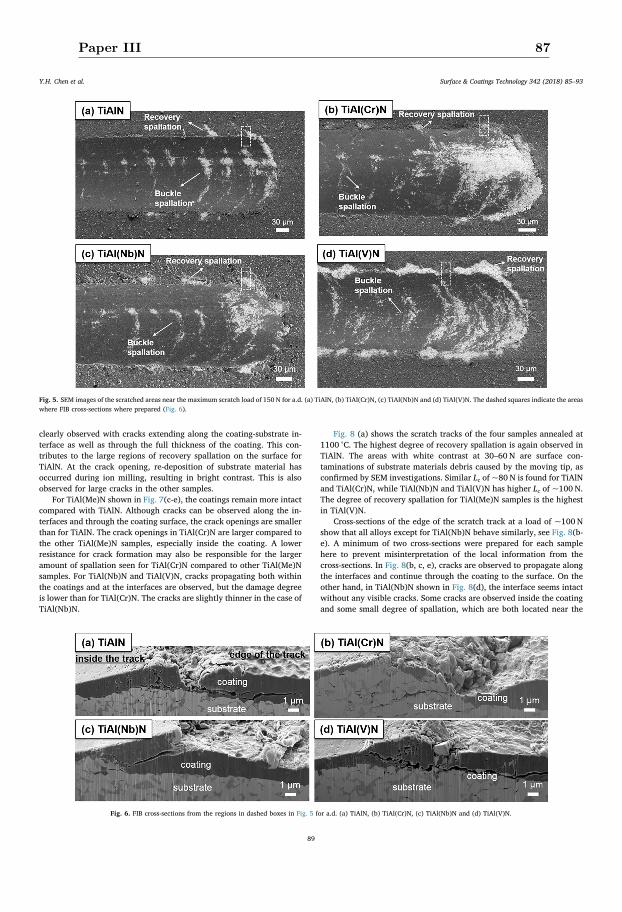
clearly observed with cracks extending along the coating-substrate in-terface as well as through the full thickness of the coating. This con-tributes to the large regions of recovery spallation on the surface forTiAlN. At the crack opening, re-deposition of substrate material hasoccurred during ion milling, resulting in bright contrast. This is alsoobserved for large cracks in the other samples.
For TiAl(Me)N shown in Fig. 7(c-e), the coatings remain more intactcompared with TiAlN. Although cracks can be observed along the in-terfaces and through the coating surface, the crack openings are smallerthan for TiAlN. The crack openings in TiAl(Cr)N are larger compared tothe other TiAl(Me)N samples, especially inside the coating. A lowerresistance for crack formation may also be responsible for the largeramount of spallation seen for TiAl(Cr)N compared to other TiAl(Me)Nsamples. For TiAl(Nb)N and TiAl(V)N, cracks propagating both withinthe coatings and at the interfaces are observed, but the damage degreeis lower than for TiAl(Cr)N. The cracks are slightly thinner in the case ofTiAl(Nb)N.
Fig. 8 (a) shows the scratch tracks of the four samples annealed at1100 °C. The highest degree of recovery spallation is again observed inTiAlN. The areas with white contrast at 30–60 N are surface con-taminations of substrate materials debris caused by the moving tip, asconfirmed by SEM investigations. Similar Lc of ~80 N is found for TiAlNand TiAl(Cr)N, while TiAl(Nb)N and TiAl(V)N has higher Lc of ~100 N.The degree of recovery spallation for TiAl(Me)N samples is the highestin TiAl(V)N.
Cross-sections of the edge of the scratch track at a load of ~100 Nshow that all alloys except for TiAl(Nb)N behave similarly, see Fig. 8(b-e). A minimum of two cross-sections were prepared for each samplehere to prevent misinterpretation of the local information from thecross-sections. In Fig. 8(b, c, e), cracks are observed to propagate alongthe interfaces and continue through the coating to the surface. On theother hand, in TiAl(Nb)N shown in Fig. 8(d), the interface seems intactwithout any visible cracks. Some cracks are observed inside the coatingand some small degree of spallation, which are both located near the
Fig. 5. SEM images of the scratched areas near the maximum scratch load of 150 N for a.d. (a) TiAlN, (b) TiAl(Cr)N, (c) TiAl(Nb)N and (d) TiAl(V)N. The dashed squares indicate the areaswhere FIB cross-sections where prepared (Fig. 6).
Fig. 6. FIB cross-sections from the regions in dashed boxes in Fig. 5 for a.d. (a) TiAlN, (b) TiAl(Cr)N, (c) TiAl(Nb)N and (d) TiAl(V)N.
Y.H. Chen et al. Surface & Coatings Technology 342 (2018) 85–93
89
Paper III 87
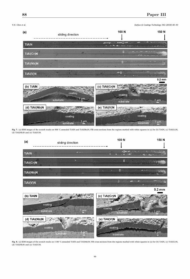
Fig. 7. (a) SEM images of the scratch tracks on 900 °C-annealed TiAlN and TiAl(Me)N; FIB cross-sections from the regions marked with white squares in (a) for (b) TiAlN, (c) TiAl(Cr)N,(d) TiAl(Nb)N and (e) TiAl(V)N.
Fig. 8. (a) SEM images of the scratch tracks on 1100 °C-annealed TiAlN and TiAl(Me)N; FIB cross-sections from the regions marked with white squares in (a) for (b) TiAlN, (c) TiAl(Cr)N,(d) TiAl(Nb)N and (e) TiAl(V)N.
Y.H. Chen et al. Surface & Coatings Technology 342 (2018) 85–93
90
88 Paper III
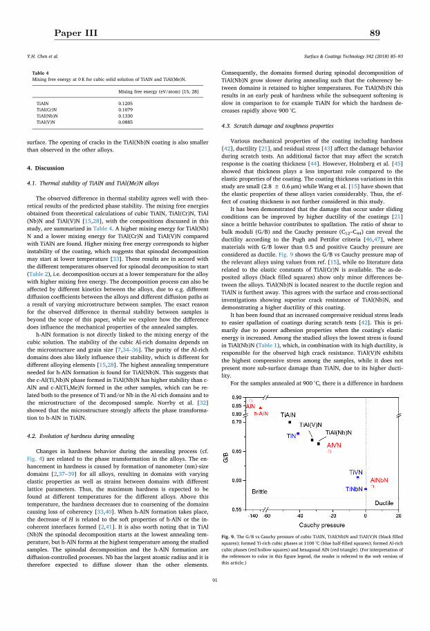
surface. The opening of cracks in the TiAl(Nb)N coating is also smallerthan observed in the other alloys.
4. Discussion
4.1. Thermal stability of TiAlN and TiAl(Me)N alloys
The observed difference in thermal stability agrees well with theo-retical results of the predicted phase stability. The mixing free energiesobtained from theoretical calculations of cubic TiAlN, TiAl(Cr)N, TiAl(Nb)N and TiAl(V)N [15,28], with the compositions discussed in thisstudy, are summarized in Table 4. A higher mixing energy for TiAl(Nb)N and a lower mixing energy for TiAl(Cr)N and TiAl(V)N comparedwith TiAlN are found. Higher mixing free energy corresponds to higherinstability of the coating, which suggests that spinodal decompositionmay start at lower temperature [33]. These results are in accord withthe different temperatures observed for spinodal decomposition to start(Table 2), i.e. decomposition occurs at a lower temperature for the alloywith higher mixing free energy. The decomposition process can also beaffected by different kinetics between the alloys, due to e.g. differentdiffusion coefficients between the alloys and different diffusion paths asa result of varying microstructure between samples. The exact reasonfor the observed difference in thermal stability between samples isbeyond the scope of this paper, while we explore how the differencedoes influence the mechanical properties of the annealed samples.
h-AlN formation is not directly linked to the mixing energy of thecubic solution. The stability of the cubic Al-rich domains depends onthe microstructure and grain size [7,34–36]. The purity of the Al-richdomains does also likely influence their stability, which is different fordifferent alloying elements [15,28]. The highest annealing temperatureneeded for h-AlN formation is found for TiAl(Nb)N. This suggests thatthe c-Al(Ti,Nb)N phase formed in TiAl(Nb)N has higher stability than c-AlN and c-Al(Ti,Me)N formed in the other samples, which can be re-lated both to the presence of Ti and/or Nb in the Al-rich domains and tothe microstructure of the decomposed sample. Norrby et al. [32]showed that the microstructure strongly affects the phase transforma-tion to h-AlN in TiAlN.
4.2. Evolution of hardness during annealing
Changes in hardness behavior during the annealing process (cf.Fig. 4) are related to the phase transformation in the alloys. The en-hancement in hardness is caused by formation of nanometer (nm)-sizedomains [2,37–39] for all alloys, resulting in domains with varyingelastic properties as well as strains between domains with differentlattice parameters. Thus, the maximum hardness is expected to befound at different temperatures for the different alloys. Above thistemperature, the hardness decreases due to coarsening of the domainscausing loss of coherency [33,40]. When h-AlN formation takes place,the decrease of H is related to the soft properties of h-AlN or the in-coherent interfaces formed [2,41]. It is also worth noting that in TiAl(Nb)N the spinodal decomposition starts at the lowest annealing tem-perature, but h-AlN forms at the highest temperature among the studiedsamples. The spinodal decomposition and the h-AlN formation arediffusion-controlled processes. Nb has the largest atomic radius and it istherefore expected to diffuse slower than the other elements.
Consequently, the domains formed during spinodal decomposition ofTiAl(Nb)N grow slower during annealing such that the coherency be-tween domains is retained to higher temperatures. For TiAl(Nb)N thisresults in an early peak of hardness while the subsequent softening isslow in comparison to for example TiAlN for which the hardness de-creases rapidly above 900 °C.
4.3. Scratch damage and toughness properties
Various mechanical properties of the coating including hardness[42], ductility [21], and residual stress [43] affect the damage behaviorduring scratch tests. An additional factor that may affect the scratchresponse is the coating thickness [44]. However, Holmberg et al. [45]showed that thickness plays a less important role compared to theelastic properties of the coating. The coating thickness variations in thisstudy are small (2.8 ± 0.6 μm) while Wang et al. [15] have shown thatthe elastic properties of these alloys varies considerably. Thus, the ef-fect of coating thickness is not further considered in this study.
It has been demonstrated that the damage that occur under slidingconditions can be improved by higher ductility of the coatings [21]since a brittle behavior contributes to spallation. The ratio of shear tobulk moduli (G/B) and the Cauchy pressure (C12–C44) can reveal theductility according to the Pugh and Pettifor criteria [46,47], wherematerials with G/B lower than 0.5 and positive Cauchy pressure areconsidered as ductile. Fig. 9 shows the G/B vs Cauchy pressure map ofthe relevant alloys using values from ref. [15], while no literature datarelated to the elastic constants of TiAl(Cr)N is available. The as-de-posited alloys (black filled squares) show only minor differences be-tween the alloys. TiAl(Nb)N is located nearest to the ductile region andTiAlN is furthest away. This agrees with the surface and cross-sectionalinvestigations showing superior crack resistance of TiAl(Nb)N, anddemonstrating a higher ductility of this coating.
It has been found that an increased compressive residual stress leadsto easier spallation of coatings during scratch tests [42]. This is pri-marily due to poorer adhesion properties when the coating's elasticenergy is increased. Among the studied alloys the lowest stress is foundin TiAl(Nb)N (Table 1), which, in combination with its high ductility, isresponsible for the observed high crack resistance. TiAl(V)N exhibitsthe highest compressive stress among the samples, while it does notpresent more sub-surface damage than TiAlN, due to its higher ducti-lity.
For the samples annealed at 900 °C, there is a difference in hardness
Table 4Mixing free energy at 0 K for cubic solid solution of TiAlN and TiAl(Me)N.
Mixing free energy (eV/atom) [15, 28]
TiAlN 0.1205TiAl(Cr)N 0.1079TiAl(Nb)N 0.1330TiAl(V)N 0.0885
Fig. 9. The G/B vs Cauchy pressure of cubic TiAlN, TiAl(Nb)N and TiAl(V)N (black filledsquares); formed Ti-rich cubic phases at 1100 °C (blue half-filled squares); formed Al-richcubic phases (red hollow squares) and hexagonal AlN (red triangle). (For interpretation ofthe references to color in this figure legend, the reader is referred to the web version ofthis article.)
Y.H. Chen et al. Surface & Coatings Technology 342 (2018) 85–93
91
Paper III 89
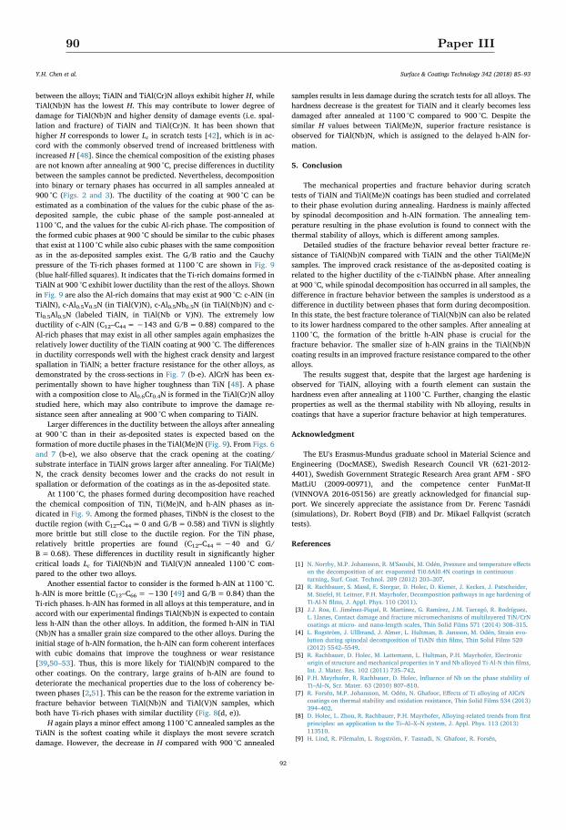
between the alloys; TiAlN and TiAl(Cr)N alloys exhibit higher H, whileTiAl(Nb)N has the lowest H. This may contribute to lower degree ofdamage for TiAl(Nb)N and higher density of damage events (i.e. spal-lation and fracture) of TiAlN and TiAl(Cr)N. It has been shown thathigher H corresponds to lower Lc in scratch tests [42], which is in ac-cord with the commonly observed trend of increased brittleness withincreased H [48]. Since the chemical composition of the existing phasesare not known after annealing at 900 °C, precise differences in ductilitybetween the samples cannot be predicted. Nevertheless, decompositioninto binary or ternary phases has occurred in all samples annealed at900 °C (Figs. 2 and 3). The ductility of the coating at 900 °C can beestimated as a combination of the values for the cubic phase of the as-deposited sample, the cubic phase of the sample post-annealed at1100 °C, and the values for the cubic Al-rich phase. The composition ofthe formed cubic phases at 900 °C should be similar to the cubic phasesthat exist at 1100 °C while also cubic phases with the same compositionas in the as-deposited samples exist. The G/B ratio and the Cauchypressure of the Ti-rich phases formed at 1100 °C are shown in Fig. 9(blue half-filled squares). It indicates that the Ti-rich domains formed inTiAlN at 900 °C exhibit lower ductility than the rest of the alloys. Shownin Fig. 9 are also the Al-rich domains that may exist at 900 °C: c-AlN (inTiAlN), c-Al0.5V0.5N (in TiAl(V)N), c-Al0.5Nb0.5N (in TiAl(Nb)N) and c-Ti0.5Al0.5N (labeled TiAlN, in TiAl(Nb or V)N). The extremely lowductility of c-AlN (C12–C44=−143 and G/B=0.88) compared to theAl-rich phases that may exist in all other samples again emphasizes therelatively lower ductility of the TiAlN coating at 900 °C. The differencesin ductility corresponds well with the highest crack density and largestspallation in TiAlN; a better fracture resistance for the other alloys, asdemonstrated by the cross-sections in Fig. 7 (b-e). AlCrN has been ex-perimentally shown to have higher toughness than TiN [48]. A phasewith a composition close to Al0.6Cr0.4N is formed in the TiAl(Cr)N alloystudied here, which may also contribute to improve the damage re-sistance seen after annealing at 900 °C when comparing to TiAlN.
Larger differences in the ductility between the alloys after annealingat 900 °C than in their as-deposited states is expected based on theformation of more ductile phases in the TiAl(Me)N (Fig. 9). From Figs. 6and 7 (b-e), we also observe that the crack opening at the coating/substrate interface in TiAlN grows larger after annealing. For TiAl(Me)N, the crack density becomes lower and the cracks do not result inspallation or deformation of the coatings as in the as-deposited state.
At 1100 °C, the phases formed during decomposition have reachedthe chemical composition of TiN, Ti(Me)N, and h-AlN phases as in-dicated in Fig. 9. Among the formed phases, TiNbN is the closest to theductile region (with C12–C44= 0 and G/B=0.58) and TiVN is slightlymore brittle but still close to the ductile region. For the TiN phase,relatively brittle properties are found (C12–C44=−40 and G/B=0.68). These differences in ductility result in significantly highercritical loads Lc for TiAl(Nb)N and TiAl(V)N annealed 1100 °C com-pared to the other two alloys.
Another essential factor to consider is the formed h-AlN at 1100 °C.h-AlN is more brittle (C12–C66=−130 [49] and G/B=0.84) than theTi-rich phases. h-AlN has formed in all alloys at this temperature, and inaccord with our experimental findings TiAl(Nb)N is expected to containless h-AlN than the other alloys. In addition, the formed h-AlN in TiAl(Nb)N has a smaller grain size compared to the other alloys. During theinitial stage of h-AlN formation, the h-AlN can form coherent interfaceswith cubic domains that improve the toughness or wear resistance[39,50–53]. Thus, this is more likely for TiAl(Nb)N compared to theother coatings. On the contrary, large grains of h-AlN are found todeteriorate the mechanical properties due to the loss of coherency be-tween phases [2,51]. This can be the reason for the extreme variation infracture behavior between TiAl(Nb)N and TiAl(V)N samples, whichboth have Ti-rich phases with similar ductility (Fig. 8(d, e)).
H again plays a minor effect among 1100 °C annealed samples as theTiAlN is the softest coating while it displays the most severe scratchdamage. However, the decrease in H compared with 900 °C annealed
samples results in less damage during the scratch tests for all alloys. Thehardness decrease is the greatest for TiAlN and it clearly becomes lessdamaged after annealed at 1100 °C compared to 900 °C. Despite thesimilar H values between TiAl(Me)N, superior fracture resistance isobserved for TiAl(Nb)N, which is assigned to the delayed h-AlN for-mation.
5. Conclusion
The mechanical properties and fracture behavior during scratchtests of TiAlN and TiAl(Me)N coatings has been studied and correlatedto their phase evolution during annealing. Hardness is mainly affectedby spinodal decomposition and h-AlN formation. The annealing tem-perature resulting in the phase evolution is found to connect with thethermal stability of alloys, which is different among samples.
Detailed studies of the fracture behavior reveal better fracture re-sistance of TiAl(Nb)N compared with TiAlN and the other TiAl(Me)Nsamples. The improved crack resistance of the as-deposited coating isrelated to the higher ductility of the c-TiAlNbN phase. After annealingat 900 °C, while spinodal decomposition has occurred in all samples, thedifference in fracture behavior between the samples is understood as adifference in ductility between phases that form during decomposition.In this state, the best fracture tolerance of TiAl(Nb)N can also be relatedto its lower hardness compared to the other samples. After annealing at1100 °C, the formation of the brittle h-AlN phase is crucial for thefracture behavior. The smaller size of h-AlN grains in the TiAl(Nb)Ncoating results in an improved fracture resistance compared to the otheralloys.
The results suggest that, despite that the largest age hardening isobserved for TiAlN, alloying with a fourth element can sustain thehardness even after annealing at 1100 °C. Further, changing the elasticproperties as well as the thermal stability with Nb alloying, results incoatings that have a superior fracture behavior at high temperatures.
Acknowledgment
The EU's Erasmus-Mundus graduate school in Material Science andEngineering (DocMASE), Swedish Research Council VR (621-2012-4401), Swedish Government Strategic Research Area grant AFM - SFOMatLiU (2009-00971), and the competence center FunMat-II(VINNOVA 2016-05156) are greatly acknowledged for financial sup-port. We sincerely appreciate the assistance from Dr. Ferenc Tasnádi(simulations), Dr. Robert Boyd (FIB) and Dr. Mikael Fallqvist (scratchtests).
References
[1] N. Norrby, M.P. Johansson, R. M'Saoubi, M. Odén, Pressure and temperature effectson the decomposition of arc evaporated Ti0.6Al0.4N coatings in continuousturning, Surf. Coat. Technol. 209 (2012) 203–207.
[2] R. Rachbauer, S. Massl, E. Stergar, D. Holec, D. Kiener, J. Keckes, J. Patscheider,M. Stiefel, H. Leitner, P.H. Mayrhofer, Decomposition pathways in age hardening ofTi-Al-N films, J. Appl. Phys. 110 (2011).
[3] J.J. Roa, E. Jiménez-Piqué, R. Martínez, G. Ramírez, J.M. Tarragó, R. Rodríguez,L. Llanes, Contact damage and fracture micromechanisms of multilayered TiN/CrNcoatings at micro- and nano-length scales, Thin Solid Films 571 (2014) 308–315.
[4] L. Rogström, J. Ullbrand, J. Almer, L. Hultman, B. Jansson, M. Odén, Strain evo-lution during spinodal decomposition of TiAlN thin films, Thin Solid Films 520(2012) 5542–5549.
[5] R. Rachbauer, D. Holec, M. Lattemann, L. Hultman, P.H. Mayrhofer, Electronicorigin of structure and mechanical properties in Y and Nb alloyed Ti-Al-N thin films,Int. J. Mater. Res. 102 (2011) 735–742.
[6] P.H. Mayrhofer, R. Rachbauer, D. Holec, Influence of Nb on the phase stability ofTi–Al–N, Scr. Mater. 63 (2010) 807–810.
[7] R. Forsén, M.P. Johansson, M. Odén, N. Ghafoor, Effects of Ti alloying of AlCrNcoatings on thermal stability and oxidation resistance, Thin Solid Films 534 (2013)394–402.
[8] D. Holec, L. Zhou, R. Rachbauer, P.H. Mayrhofer, Alloying-related trends from firstprinciples: an application to the Ti–Al–X–N system, J. Appl. Phys. 113 (2013)113510.
[9] H. Lind, R. Pilemalm, L. Rogström, F. Tasnadi, N. Ghafoor, R. Forsén,
Y.H. Chen et al. Surface & Coatings Technology 342 (2018) 85–93
92
90 Paper III
L.J.S. Johnson, M.P. Johansson-Jöesaar, M. Odèn, I.A. Abrikosov, High temperaturephase decomposition in TixZryAlzN, AIP Adv. 4 (2014) 127147.
[10] Y.X. Xu, H. Riedl, D. Holec, L. Chen, Y. Du, P.H. Mayrhofer, Thermal stability andoxidation resistance of sputtered TiAlCrN hard coatings, Surf. Coat. Technol. 324(2017) 48–56.
[11] W.J. Clegg, Controlling cracks in ceramics, Science 286 (1999) 1097.[12] S.M. Wiederhorn, Brittle-fracture and toughening mechanisms in ceramics, Annu.
Rev. Mater. Sci. 14 (1984) 373–403.[13] D.G. Sangiovanni, V. Chirita, L. Hultman, Toughness enhancement in TiAlN-based
quarternary alloys, Thin Solid Films 520 (2012) 4080–4088.[14] D. Holec, L.C. Zhou, R. Rachbauer, P.H. Mayrhofer, Alloying-related trends from
first principles: an application to the Ti-Al-X-N system, J. Appl. Phys. 113 (2013).[15] F. Wang, D. Holec, M. Odén, F. Mücklich, I.A. Abrikosov, F. Tasnádi, Systematic ab
initio investigation of the elastic modulus in quaternary transition metal nitridealloys and their coherent multilayers, Acta Mater. 127 (2017) 124–132.
[16] M. Mikula, D. Plasienka, D.G. Sangiovanni, M. Sahul, T. Roch, M. Truchly,M. Gregor, L. Caplovic, A. Plecenik, P. Kus, Toughness enhancement in highly NbN-alloyed Ti-Al-N hard coatings, Acta Mater. 121 (2016) 59–67.
[17] D.G. Sangiovanni, L. Hultman, V. Chirita, Supertoughening in B1 transition metalnitride alloys by increased valence electron concentration, Acta Mater. 59 (2011)2121–2134.
[18] R. Franz, C. Mitterer, Vanadium containing self-adaptive low-friction hard coatingsfor high-temperature applications: a review, Surf. Coat. Technol. 228 (2013) 1–13.
[19] S.J. Bull, Failure mode maps in the thin film scratch adhesion test, Tribol. Int. 30(1997) 491–498.
[20] S. Sveen, J.M. Andersson, R. M'Saoubi, M. Olsson, Scratch adhesion characteristicsof PVD TiAlN deposited on high speed steel, cemented carbide and PCBN substrates,Wear 308 (2013) 133–141.
[21] J. von Stebut, R. Rezakhanlou, K. Anoun, H. Michel, M. Gantois, Major damagemechanisms during scratch and wear testing of hard coatings on hard substrates,Thin Solid Films 181 (1989) 555–564.
[22] P. Hedenqvist, M. Olsson, S. Jacobson, S. Söderberg, Failure mode analysis of TiN-coated high speed steel: in situ scratch adhesion testing in the scanning electronmicroscope, Surf. Coat. Technol. 41 (1990) 31–49.
[23] K. Holmberg, A. Laukkanen, H. Ronkainen, K. Wallin, S. Varjus, A model forstresses, crack generation and fracture toughness calculation in scratched TiN-coated steel surfaces, Wear 254 (2003) 278–291.
[24] N. Vattanaprateep, N. Panich, S. Surinphong, S. Tungasmita, P. Wangyao, Structuraland mechanical properties of nanostructured TiAlCrN thin films deposited byCathodic arc deposition, High Temp Mat Pr-Isr, vol. 32, 2013, pp. 107–111.
[25] J. Chen, S.J. Bull, On the factors affecting the critical indenter penetration formeasurement of coating hardness, Vacuum 83 (2009) 911–920.
[26] W.C. Oliver, G.M. Pharr, An improved technique for determining hardness andelastic-modulus using load and displacement sensing indentation experiments, J.Mater. Res. 7 (1992) 1564–1583.
[27] A. Anders, Macroparticles, in: A. Anders (Ed.), Cathodic Arcs: From Fractal Spots toEnergetic Condensation, Springer New York, New York, NY, 2008, pp. 1–34.
[28] H. Lind, R. Forsén, B. Alling, N. Ghafoor, F. Tasnadi, M.P. Johansson,I.A. Abrikosov, M. Odén, Improving thermal stability of hard coating films via aconcept of multicomponent alloying, Appl. Phys. Lett. 99 (2011) 5090.
[29] M. Birkholz, Line profile analysis, Thin Film Analysis by X-ray Scattering, Wiley-VCH Verlag GmbH & Co.–KGaA, 2006, pp. 85–-141.
[30] I. Petrov, P. Losbichler, D. Bergstrom, J.E. Greene, W.D. Münz, T. Hurkmans,T. Trinh, Ion-assisted growth of Ti1−xAlxN/Ti1−yNbyN multilayers by combinedcathodic-arc/magnetron-sputter deposition, Thin Solid Films 302 (1997) 179–192.
[31] A. Anders, A structure zone diagram including plasma-based deposition and ionetching, Thin Solid Films 518 (2010) 4087–4090.
[32] S.J. Bull, Failure modes in scratch adhesion testing, Surf. Coat. Technol. 50 (1991)25–32.
[33] A. Knutsson, J. Ullbrand, L. Rogström, N. Norrby, L.J.S. Johnson, L. Hultman,J. Almer, M.P. Johansson Jöesaar, B. Jansson, M. Odén, Microstructure evolutionduring the isostructural decomposition of TiAlN—a combined in-situ small angle X-
ray scattering and phase field study, J. Appl. Phys. 113 (2013) 213518.[34] N. Norrby, L. Rogström, M.P. Johansson-Jõesaar, N. Schell, M. Odén, In situ X-ray
scattering study of the cubic to hexagonal transformation of AlN in Ti1−xAlxN,Acta Mater. 73 (2014) 205–214.
[35] Y.H. Chen, L. Rogström, D. Ostach, N. Ghafoor, M.P. Johansson-Jõesaar, N. Schell,J. Birch, M. Odén, Effects of decomposition route and microstructure on h-AlNformation rate in TiCrAlN alloys, J. Alloys Compd. 691 (2017) 1024–1032.
[36] R. Rachbauer, S. Massl, E. Stergar, D. Holec, D. Kiener, J. Keckes, J. Patscheider,M. Stiefel, H. Leitner, P.H. Mayrhofer, Decomposition pathways in age hardening ofTi-Al-N films, J. Appl. Phys. 110 (2011) 023515.
[37] P.H. Mayrhofer, C. Mitterer, L. Hultman, H. Clemens, Microstructural design of hardcoatings, Prog. Mater. Sci. 51 (2006) 1032–1114.
[38] M. Odén, L. Rogström, A. Knutsson, M.R. Terner, P. Hedström, J. Almer, J. Ilavsky,In situ small-angle x-ray scattering study of nanostructure evolution during de-composition of arc evaporated TiAlN coatings, Appl. Phys. Lett. 94 (2009) 053114.
[39] R. Forsén, I.C. Schramm, P.O.A. Persson, F. Mucklich, M. Odén, N. Ghafoor,Nanostructuring and coherency strain in multicomponent hard coatings, Apl Mater2 (2014) 116104.
[40] A. Hörling, L. Hultman, M. Odén, J. Sjölén, L. Karlsson, Thermal stability of arcevaporated high aluminum-content Ti[sub 1−x]Al[sub x]N thin films, J. Vac. Sci.Technol. A 20 (2002) 1815.
[41] P.H. Mayrhofer, A. Hörling, L. Karlsson, J. Sjölén, T. Larsson, C. Mitterer,L. Hultman, Self-organized nanostructures in the Ti–Al–N system, Appl. Phys. Lett.83 (2003) 2049.
[42] D.S. Rickerby, S.J. Bull, Engineering with surface coatings: the role of coating mi-crostructure, Surf. Coat. Technol. 39 (1989) 315–328.
[43] A. Laukkanen, K. Holmberg, J. Koskinen, H. Ronkainen, K. Wallin, S. Varjus,Tribological contact analysis of a rigid ball sliding on a hard coated surface, part III:fracture toughness calculation and influence of residual stresses, Surf. Coat.Technol. 200 (2006) 3824–3844.
[44] X. Nie, A. Leyland, H.W. Song, A.L. Yerokhin, S.J. Dowey, A. Matthews, Thicknesseffects on the mechanical properties of micro-arc discharge oxide coatings on alu-minium alloys, Surf. Coat. Technol. 116–119 (1999) 1055–1060.
[45] K. Holmberg, A. Laukkanen, H. Ronkainen, K. Wallin, S. Varjus, J. Koskinen,Tribological contact analysis of a rigid ball sliding on a hard coated surface Part II:Material deformations, influence of coating thickness and Young's modulus, Surface& Coatings Technology 200 (2006) 3810–3823.
[46] S.F. Pugh, XCII. Relations between the elastic moduli and the plastic properties ofpolycrystalline pure metals, The London, Edinburgh, and Dublin PhilosophicalMagazine and Journal of Science 45 (1954) 823–843.
[47] D.G. Pettifor, Theoretical predictions of structure and related properties of inter-metallics, Mater Sci Tech-Lond 8 (1992) 345–349.
[48] G.R. Anstis, P. Chantikul, B.R. Lawn, D.B. Marshall, A critical evaluation of in-dentation techniques for measuring fracture toughness: I, direct crack measure-ments, J. Am. Ceram. Soc. 64 (1981) 533–538.
[49] D. Nguyen-Manh, D.G. Pettifor, D.J.H. Cockayne, M. Mrovec, S. Znam, V. Vitek,Environmentally dependent bond-order potentials: new developments and appli-cations, B Mater Sci 26 (2003) 43–51.
[50] I.N. Mastorakos, H.M. Zbib, D.F. Bahr, Deformation mechanisms and strength innanoscale multilayer metallic composites with coherent and incoherent interfaces,Appl. Phys. Lett. 94 (2009).
[51] D. Rafaja, C. Wustefeld, C. Baehtz, V. Klemm, M. Dopita, M. Motylenko,C. Michotte, M. Kathrein, Effect of internal interfaces on hardness and thermalstability of nanocrystalline Ti0.5Al0.5N coatings, Metall Mater Trans A 42a (2011)559–569.
[52] D. Rafaja, A. Poklad, V. Klemm, G. Schreiber, D. Heger, M. Šíma, M. Dopita, Someconsequences of the partial crystallographic coherence between nanocrystallinedomains in Ti–Al–N and Ti–Al–Si–N coatings, Thin Solid Films 514 (2006) 240–249.
[53] K. Yalamanchili, F. Wang, H. Aboulfadl, J. Barrirero, L. Rogström, E. Jiménez-Pique, F. Mücklich, F. Tasnadi, M. Odén, N. Ghafoor, Growth and thermal stabilityof TiN/ZrAlN: effect of internal interfaces, Acta Mater. 121 (2016) 396–406.
Y.H. Chen et al. Surface & Coatings Technology 342 (2018) 85–93
93
Paper III 91

92 Paper III
IV
Paper IV
Toughness of arc deposited Ti1−xAlxN (x =0.23-0.82) coatings evaluated by contact fatigue
testing
Y. H. ChenJ.J.Roa
M.P.Johansson-JõesaarR. D. Boyd
J. M. AnderssonM.J.Anglada
M.OdénL. Rogström
In manuscript

1
Toughness of arc deposited Ti1-xAl xN (x = 0.23-0.82) coatings evaluated by contact fatigue testing
Y.H. Chen1,*, J.J. Roa2,3, M.P. Johansson-Jõesaar1,4, R.D. Boyd1,5, J. M. Andersson4, M.J. Anglada2,3, M. Odén1, and L. Rogström1
1 Nanostructured Materials, Department of Physics, Chemistry and Biology (IFM), Linköping University, SE-581 83 Linköping, Sweden
2 Department of Materials Science and Metallurgical Engineering, Universitat Politècnica de Catalunya, Campus Diagonal Besòs-EEBE, 08019 Barcelona, Spain
3 Centre for Research in Multiscale Engineering of Barcelona, Universitat Politècnica de Catalunya, Campus Diagonal Besòs-EEBE, 08019 Barcelona, Spain
4 R&D Material and Technology Development, SECO Tools AB, SE-737 82 Fagersta, Sweden
5 Plasma and Coatings Physics Division, Department of Physics, Chemistry and Biology, Linköping University, SE-58183, Linköping, Sweden
* Corresponding author: [email protected]
Abstract
Contact fatigue properties of Ti1-xAl xN (x = 0.23 to 0.82) coatings grown by arc deposition are investigated.
Rings cracks formed on the surface in the vicinity of the contact imprints are observed on all as-deposited
coatings except for the Ti0.18Al0.82N onto which surface oxides formed. The grain size of the coating was
found to decrease with increasing Al-content, resulting in a change of the apparent deformation mechanism,
from dislocation movements (coarse grain) to grain boundary sliding (fine grain). In this way, a critical grain
size for the highest hardness is resulted, as the closet grain size to such critical value observed in this study
lies in Ti0.37Al0.63N. By contact fatigue tests, the best fracture toughness is found in Ti0.63Al0.37N with its
optimal grain boundary density for crack deflection. Even after annealing at 900 °C, the highest hardness
and fracture toughness are still found in Ti0.63Al0.37N due to the coherent domains formed during spinodal
decomposition. Growth of hexagonal (Ti)AlN in Ti0.37Al0.63N and Ti0.18Al 0.82N during annealing degrades
the mechanical properties of the coatings. For the fine-grained Ti0.37Al0.63N, grain growth and reorientation
occur during fatigue tests, which confirms the grain boundary sliding mechanism during deformation.
Paper IV 95
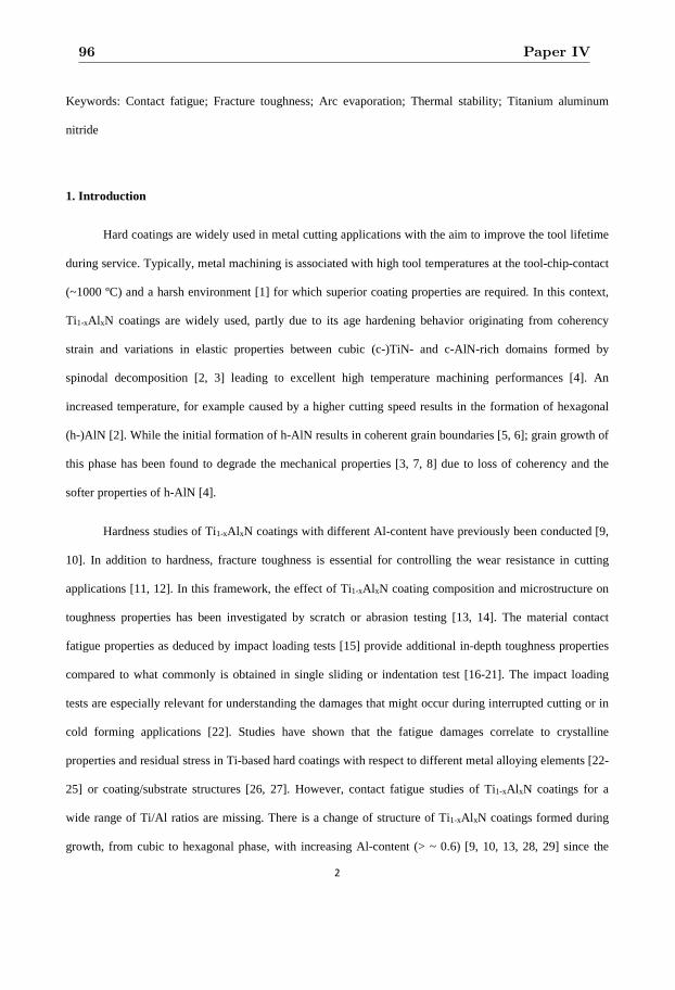
2
Keywords: Contact fatigue; Fracture toughness; Arc evaporation; Thermal stability; Titanium aluminum
nitride
1. Introduction
Hard coatings are widely used in metal cutting applications with the aim to improve the tool lifetime
during service. Typically, metal machining is associated with high tool temperatures at the tool-chip-contact
(~1000 ºC) and a harsh environment [1] for which superior coating properties are required. In this context,
Ti1-xAl xN coatings are widely used, partly due to its age hardening behavior originating from coherency
strain and variations in elastic properties between cubic (c-)TiN- and c-AlN-rich domains formed by
spinodal decomposition [2, 3] leading to excellent high temperature machining performances [4]. An
increased temperature, for example caused by a higher cutting speed results in the formation of hexagonal
(h-)AlN [2]. While the initial formation of h-AlN results in coherent grain boundaries [5, 6]; grain growth of
this phase has been found to degrade the mechanical properties [3, 7, 8] due to loss of coherency and the
softer properties of h-AlN [4].
Hardness studies of Ti1-xAl xN coatings with different Al-content have previously been conducted [9,
10]. In addition to hardness, fracture toughness is essential for controlling the wear resistance in cutting
applications [11, 12]. In this framework, the effect of Ti1-xAl xN coating composition and microstructure on
toughness properties has been investigated by scratch or abrasion testing [13, 14]. The material contact
fatigue properties as deduced by impact loading tests [15] provide additional in-depth toughness properties
compared to what commonly is obtained in single sliding or indentation test [16-21]. The impact loading
tests are especially relevant for understanding the damages that might occur during interrupted cutting or in
cold forming applications [22]. Studies have shown that the fatigue damages correlate to crystalline
properties and residual stress in Ti-based hard coatings with respect to different metal alloying elements [22-
25] or coating/substrate structures [26, 27]. However, contact fatigue studies of Ti1-xAl xN coatings for a
wide range of Ti/Al ratios are missing. There is a change of structure of Ti1-xAl xN coatings formed during
growth, from cubic to hexagonal phase, with increasing Al-content (> ~ 0.6) [9, 10, 13, 28, 29] since the
96 Paper IV
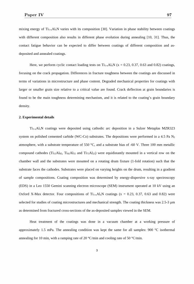
3
mixing energy of Ti1-xAlxN varies with its composition [30]. Variation in phase stability between coatings
with different composition also results in different phase evolution during annealing [10, 31]. Thus, the
contact fatigue behavior can be expected to differ between coatings of different composition and as-
deposited and annealed coatings.
Here, we perform cyclic contact loading tests on Ti1-xAl xN (x = 0.23, 0.37, 0.63 and 0.82) coatings,
focusing on the crack propagation. Differences in fracture toughness between the coatings are discussed in
terms of variations in microstructure and phase content. Degraded mechanical properties for coatings with
larger or smaller grain size relative to a critical value are found. Crack deflection at grain boundaries is
found to be the main toughness determining mechanism, and it is related to the coating’s grain boundary
density.
2. Experimental details
Ti1-xAl xN coatings were deposited using cathodic arc deposition in a Sulzer Metaplas MZR323
system on polished cemented carbide (WC-Co) substrates. The depositions were performed in a 4.5 Pa N2
atmosphere, with a substrate temperature of 550 °C, and a substrate bias of -60 V. Three 100 mm metallic
compound cathodes (Ti15Al 85, Ti45Al55 and Ti75Al25) were equidistantly mounted in a vertical row on the
chamber wall and the substrates were mounted on a rotating drum fixture (1-fold rotation) such that the
substrate faces the cathodes. Substrates were placed on varying heights on the drum, resulting in a gradient
of sample compositions. Coating composition was determined by energy-dispersive x-ray spectroscopy
(EDS) in a Leo 1550 Gemini scanning electron microscope (SEM) instrument operated at 10 kV using an
Oxford X-Max detector. Four compositions of Ti1-xAl xN coatings (x = 0.23, 0.37, 0.63 and 0.82) were
selected for studies of coating microstructures and mechanical strength. The coating thickness was 2.5-3 µm
as determined from fractured cross-sections of the as-deposited samples viewed in the SEM.
Heat treatment of the coatings was done in a vacuum chamber at a working pressure of
approximately 1.5 mPa. The annealing condition was kept the same for all samples: 900 °C isothermal
annealing for 10 min, with a ramping rate of 20 °C/min and cooling rate of 50 °C/min.
Paper IV 97
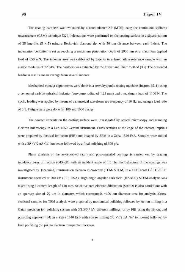
4
The coating hardness was evaluated by a nanoindenter XP (MTS) using the continuous stiffness
measurement (CSM) technique [32]. Indentations were performed on the coating surface in a square pattern
of 25 imprints (5 × 5) using a Berkovich diamond tip, with 50 µm distance between each indent. The
indentation condition is set as reaching a maximum penetration depth of 2000 nm or a maximum applied
load of 650 mN. The indenter area was calibrated by indents in a fused silica reference sample with an
elastic modulus of 72 GPa. The hardness was extracted by the Oliver and Pharr method [33]. The presented
hardness results are an average from several indents.
Mechanical contact experiments were done in a servohydraulic testing machine (Instron 8511) using
a cemented carbide spherical indenter (curvature radius of 1.25 mm) and a maximum load of 1100 N. The
cyclic loading was applied by means of a sinusoidal waveform at a frequency of 10 Hz and using a load ratio
of 0.1. Fatigue tests were done for 100 and 1000 cycles.
The contact imprints on the coating surface were investigated by optical microscopy and scanning
electron microscopy in a Leo 1550 Gemini instrument. Cross-sections at the edge of the contact imprints
were prepared by focused ion beam (FIB) and imaged by SEM in a Zeiss 1540 EsB. Samples were milled
with a 30 kV/2 nA Ga+ ion beam followed by a final polishing of 500 pA.
Phase analysis of the as-deposited (a.d.) and post-annealed coatings is carried out by grazing
incidence x-ray diffraction (GIXRD) with an incident angle of 1°. The microstructure of the coatings was
investigated by (scanning) transmission electron microscopy (TEM/ STEM) in a FEI Tecnai G2 TF 20 UT
instrument operated at 200 kV (FEI, USA). High angle angular dark field (HAADF) STEM analysis was
taken using a camera length of 140 mm. Selective area electron diffraction (SAED) is also carried out with
an aperture size of 20 µm in diameter, which corresponds ~100 nm diameter area for analysis. Cross-
sectional samples for TEM analysis were prepared by mechanical polishing followed by Ar-ion milling in a
Gatan precision ion polishing system with 3/1.5/0.7 kV different millings, or by FIB using the lift-out and
polishing approach [34] in a Zeiss 1540 EsB with coarse milling (30 kV/2 nA Ga+ ion beam) followed by
final polishing (50 pA) to electron transparent thickness.
98 Paper IV
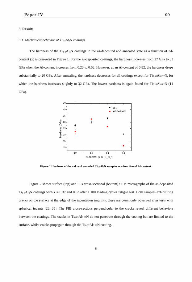
5
3. Results
3.1 Mechanical behavior of Ti1-xAlxN coatings
The hardness of the Ti1-xAl xN coatings in the as-deposited and annealed state as a function of Al-
content (x) is presented in Figure 1. For the as-deposited coatings, the hardness increases from 27 GPa to 33
GPa when the Al-content increases from 0.23 to 0.63. However, at an Al-content of 0.82, the hardness drops
substantially to 20 GPa. After annealing, the hardness decreases for all coatings except for Ti0.63Al0.37N, for
which the hardness increases slightly to 32 GPa. The lowest hardness is again found for Ti0.18Al0.82N (11
GPa).
Figure 1 Hardness of the a.d. and annealed Ti1-xAl xN samples as a function of Al-content.
Figure 2 shows surface (top) and FIB cross-sectional (bottom) SEM micrographs of the as-deposited
Ti1-xAl xN coatings with x = 0.37 and 0.63 after a 100 loading cycles fatigue test. Both samples exhibit ring
cracks on the surface at the edge of the indentation imprints, these are commonly observed after tests with
spherical indents [23, 35]. The FIB cross-sections perpendicular to the cracks reveal different behaviors
between the coatings. The cracks in Ti0.63Al0.37N do not penetrate through the coating but are limited to the
surface, whilst cracks propagate through the Ti0.37Al0.63N coating.
Paper IV 99
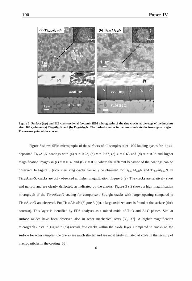
6
Figure 2 Surface (top) and FIB cross-sectional (bottom) SEM micrographs of the ring cracks at the edge of the imprints after 100 cycles on (a) Ti0.63Al0.37N and (b) Ti0.37Al 0.63N. The dashed squares in the insets indicate the investigated region. The arrows point at the cracks.
Figure 3 shows SEM micrographs of the surfaces of all samples after 1000 loading cycles for the as-
deposited Ti1-xAl xN coatings with (a) x = 0.23, (b) x = 0.37, (c) x = 0.63 and (d) x = 0.82 and higher
magnification images in (e) x = 0.37 and (f) x = 0.63 where the different behavior of the coatings can be
observed. In Figure 3 (a-d), clear ring cracks can only be observed for Ti0.77Al0.23N and Ti0.37Al0.63N. In
Ti0.63Al0.37N, cracks are only observed at higher magnification, Figure 3 (e). The cracks are relatively short
and narrow and are clearly deflected, as indicated by the arrows. Figure 3 (f) shows a high magnification
micrograph of the Ti0.37Al 0.63N coating for comparison. Straight cracks with larger opening compared to
Ti0.63Al0.37N are observed. For Ti0.18Al0.82N (Figure 3 (d)), a large oxidized area is found at the surface (dark
contrast). This layer is identified by EDS analyses as a mixed oxide of Ti-O and Al-O phases. Similar
surface oxides have been observed also in other mechanical tests [36, 37]. A higher magnification
micrograph (inset in Figure 3 (d)) reveals few cracks within the oxide layer. Compared to cracks on the
surface for other samples, the cracks are much shorter and are most likely initiated at voids in the vicinity of
macroparticles in the coating [38].
100 Paper IV
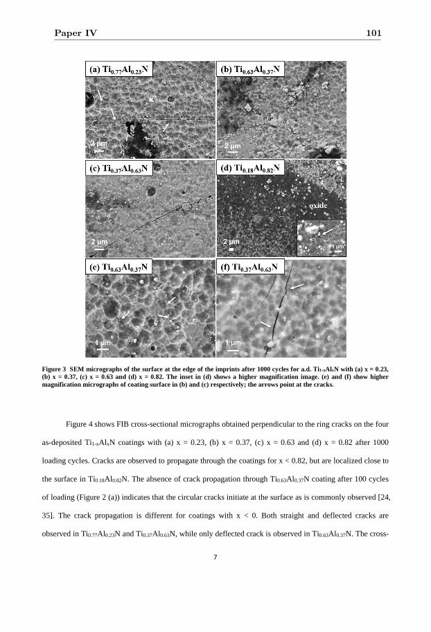
7
Figure 3 SEM micrographs of the surface at the edge of the imprints after 1000 cycles for a.d. Ti1-xAl xN with (a) x = 0.23, (b) x = 0.37, (c) x = 0.63 and (d) x = 0.82. The inset in (d) shows a higher magnification image. (e) and (f) show higher magnification micrographs of coating surface in (b) and (c) respectively; the arrows point at the cracks.
Figure 4 shows FIB cross-sectional micrographs obtained perpendicular to the ring cracks on the four
as-deposited Ti1-xAl xN coatings with (a) x = 0.23, (b) x = 0.37, (c) x = 0.63 and (d) x = 0.82 after 1000
loading cycles. Cracks are observed to propagate through the coatings for x < 0.82, but are localized close to
the surface in Ti0.18Al0.82N. The absence of crack propagation through Ti0.63Al 0.37N coating after 100 cycles
of loading (Figure 2 (a)) indicates that the circular cracks initiate at the surface as is commonly observed [24,
35]. The crack propagation is different for coatings with x < 0. Both straight and deflected cracks are
observed in Ti0.77Al0.23N and Ti0.37Al0.63N, while only deflected crack is observed in Ti0.63Al0.37N. The cross-
Paper IV 101
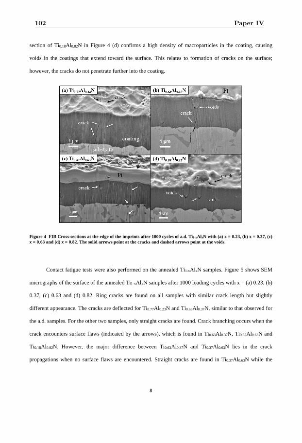
8
section of Ti0.18Al0.82N in Figure 4 (d) confirms a high density of macroparticles in the coating, causing
voids in the coatings that extend toward the surface. This relates to formation of cracks on the surface;
however, the cracks do not penetrate further into the coating.
Figure 4 FIB Cross-sections at the edge of the imprints after 1000 cycles of a.d. Ti1-xAl xN with (a) x = 0.23, (b) x = 0.37, (c) x = 0.63 and (d) x = 0.82. The solid arrows point at the cracks and dashed arrows point at the voids.
Contact fatigue tests were also performed on the annealed Ti1-xAlxN samples. Figure 5 shows SEM
micrographs of the surface of the annealed Ti1-xAl xN samples after 1000 loading cycles with x = (a) 0.23, (b)
0.37, (c) 0.63 and (d) 0.82. Ring cracks are found on all samples with similar crack length but slightly
different appearance. The cracks are deflected for Ti0.77Al0.23N and Ti0.63Al0.37N, similar to that observed for
the a.d. samples. For the other two samples, only straight cracks are found. Crack branching occurs when the
crack encounters surface flaws (indicated by the arrows), which is found in Ti0.63Al 0.37N, Ti0.37Al0.63N and
Ti0.18Al0.82N. However, the major difference between Ti0.63Al0.37N and Ti0.37Al0.63N lies in the crack
propagations when no surface flaws are encountered. Straight cracks are found in Ti0.37Al0.63N while the
102 Paper IV
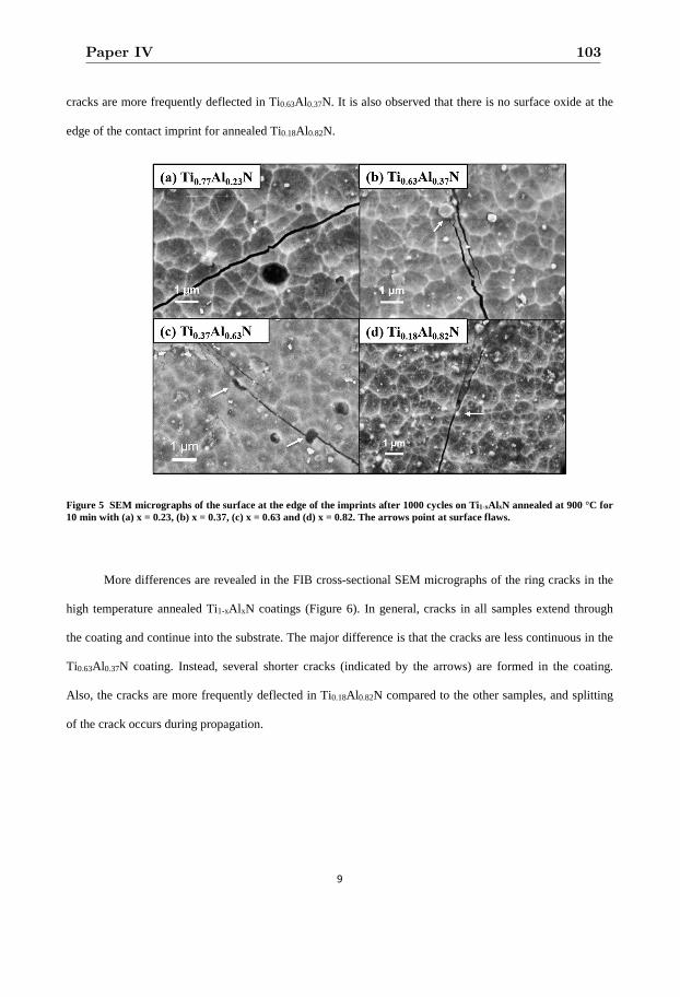
9
cracks are more frequently deflected in Ti0.63Al0.37N. It is also observed that there is no surface oxide at the
edge of the contact imprint for annealed Ti0.18Al0.82N.
Figure 5 SEM micrographs of the surface at the edge of the imprints after 1000 cycles on Ti1-xAl xN annealed at 900 °C for 10 min with (a) x = 0.23, (b) x = 0.37, (c) x = 0.63 and (d) x = 0.82. The arrows point at surface flaws.
More differences are revealed in the FIB cross-sectional SEM micrographs of the ring cracks in the
high temperature annealed Ti1-xAl xN coatings (Figure 6). In general, cracks in all samples extend through
the coating and continue into the substrate. The major difference is that the cracks are less continuous in the
Ti0.63Al0.37N coating. Instead, several shorter cracks (indicated by the arrows) are formed in the coating.
Also, the cracks are more frequently deflected in Ti0.18Al0.82N compared to the other samples, and splitting
of the crack occurs during propagation.
Paper IV 103
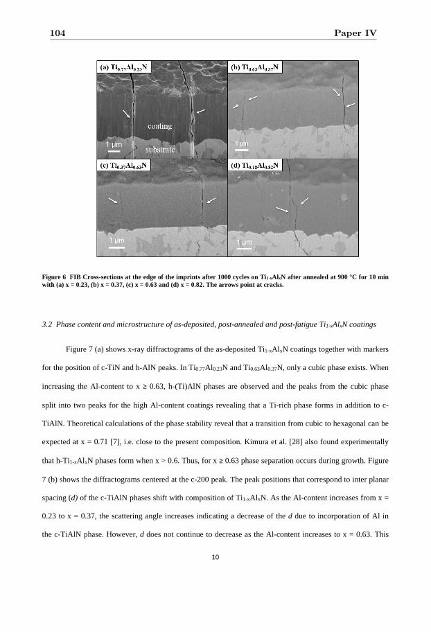
10
Figure 6 FIB Cross-sections at the edge of the imprints after 1000 cycles on Ti1-xAl xN after annealed at 900 °C for 10 min with (a) x = 0.23, (b) x = 0.37, (c) x = 0.63 and (d) x = 0.82. The arrows point at cracks.
3.2 Phase content and microstructure of as-deposited, post-annealed and post-fatigue Ti1-xAlxN coatings
Figure 7 (a) shows x-ray diffractograms of the as-deposited Ti1-xAl xN coatings together with markers
for the position of c-TiN and h-AlN peaks. In Ti0.77Al0.23N and Ti0.63Al 0.37N, only a cubic phase exists. When
increasing the Al-content to x ≥ 0.63, h-(Ti)AlN phases are observed and the peaks from the cubic phase
split into two peaks for the high Al-content coatings revealing that a Ti-rich phase forms in addition to c-
TiAlN. Theoretical calculations of the phase stability reveal that a transition from cubic to hexagonal can be
expected at x = 0.71 [7], i.e. close to the present composition. Kimura et al. [28] also found experimentally
that h-Ti1-xAl xN phases form when x > 0.6. Thus, for x ≥ 0.63 phase separation occurs during growth. Figure
7 (b) shows the diffractograms centered at the c-200 peak. The peak positions that correspond to inter planar
spacing (d) of the c-TiAlN phases shift with composition of Ti1-xAl xN. As the Al-content increases from x =
0.23 to x = 0.37, the scattering angle increases indicating a decrease of the d due to incorporation of Al in
the c-TiAlN phase. However, d does not continue to decrease as the Al-content increases to x = 0.63. This
104 Paper IV
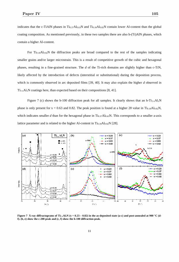
11
indicates that the c-TiAlN phases in Ti0.37Al0.63N and Ti0.18Al0.82N contain lower Al-content than the global
coating composition. As mentioned previously, in these two samples there are also h-(Ti)AlN phases, which
contain a higher Al-content.
For Ti0.18Al 0.82N the diffraction peaks are broad compared to the rest of the samples indicating
smaller grains and/or larger microstrain. This is a result of competitive growth of the cubic and hexagonal
phases, resulting in a fine-grained structure. The d of the Ti-rich domains are slightly higher than c-TiN,
likely affected by the introduction of defects (interstitial or substitutional) during the deposition process,
which is commonly observed in arc deposited films [39, 40]. It may also explain the higher d observed in
Ti1-xAl xN coatings here, than expected based on their compositions [8, 41].
Figure 7 (c) shows the h-100 diffraction peak for all samples. It clearly shows that an h-Ti1-xAl xN
phase is only present for x = 0.63 and 0.82. The peak position is found at a higher 2θ value in Ti0.18Al0.82N,
which indicates smaller d than for the hexagonal phase in Ti0.37Al0.63N. This corresponds to a smaller a-axis
lattice parameter and is related to the higher Al-content in Ti0.18Al0.82N [28].
Figure 7 X-ray diffractograms of Ti1-xAl xN (x = 0.23 – 0.82) in the as-deposited state (a-c) and post-annealed at 900 °C (d-f). (b, e) show the c-200 peak and (c, f) show the h-100 diffraction peak.
Paper IV 105
12
Figure 7 (d) shows the diffractograms of the samples annealed at 900 °C for 10 min. There is no
major difference in terms of phase composition in the coatings. Nevertheless, changes in peak position and
shape take place during annealing. The changes are better seen in Figure 7 (e). For x = 0.23 to 0.63, there is
a weak shoulder appearing at higher 2θ value (lower d), indicating that cubic, Al-rich domains are forming.
Also for the coating with x = 0.82, the peak of the c-TiAlN phase broadens during annealing. The decrease
of d in c-Ti0.77Al0.23N is assigned to defect annihilation taking place during annealing [1, 39]. However, the d
in c-Ti0.63Al0.37N does not change but can be affected by the formation of Ti- and Al-rich domains by
spinodal decomposition. Although spinodal decomposition takes place in Ti0.77Al0.23N confirmed by the
observation of the cubic Al-rich domains, the driving force for decomposition should be lower in this
coating compared with higher Al-content Ti1-xAl xN [8, 42]. Thus, the small change of the Al-content
explains that d in c-Ti0.77Al0.23N changes little, while defect annihilation dominates during annealing.
For the hexagonal phase in Ti0.37Al0.63N and Ti0.18Al0.82N, the position of the h-100 peak shifts to a
higher angle after annealing (Figure 7 (f)). The decrease of the a-axis lattice parameter is a result of a
decrease of the Ti content in h-Ti1-xAl xN during annealing [28]. The change of lattice parameter of the h-
(Ti)AlN phase is largest in Ti0.37Al0.63N, for which the phase stability is the lowest [7]. The out-diffusion of
Ti from the h-(Ti)AlN phase results in formation of c-TiN in the coating and thus results in the increase of
the overall lattice parameter of the cubic phase.
Figure 8 (a-c) shows bright-field transmission electron micrographs (BFTEM) of the as-deposited
Ti1-xAl xN with x = 0.37, 0.63 and 0.82. The largest crystallite size is present in Ti0.63Al0.37N (Figure 8 (a)),
which is also revealed by the SAED showing a diffraction pattern along the c-[0-31] zone axis. In
Ti0.37Al0.63N and Ti0.18Al0.82N, the micrographs reveal a fine-grained structure resulting in ring-shaped
diffraction patterns corresponding to a random orientation of both cubic and hexagonal grains. The HAADF
STEM in the inset of Figure 8 (c) shows a Ti-rich macroparticle, with voids around the particle. There is
also a porous structure above the particle, observed with dark contrast in the STEM micrograph and with
bright contrast in BFTEM micrographs of Ti0.37Al0.63N and Ti0.18Al0.82N, indicated by the dashed arrows.
The high density of macroparticles in these two coatings is due to that these samples are located close to the
106 Paper IV
13
higher Al-content cathodes during deposition process, as the much lower melting point of Al than Ti results
in more macroparticles generated from the molten pool on the cathode surface [43].
Figure 8 (d) shows the full-width at half maximum (FWHM) of the c-200 diffraction peak for Ti1-
xAl xN (presented in Figure 7 (b)). For x = 0.63 and 0.82, which contain two cubic phases, the width is
extracted from the phase with higher Al-content. Although microstrain can contribute to the width of a
diffraction peak, TEM investigations (Figure 8 (a-c)) show a strong dependence of grain size with Al-
content. Therefore, the FWHM is mainly affected by grain size here: smaller grain size results in the peak
broadening. Thus in general, higher Al-content of Ti1-xAl xN leads to finer grain size. Changes from a coarse-
grained columnar microstructure to fine grain sizes have also been previously found in Ti1-xAl xN with x =
0.66 to 0.74 [31].
Figure 9 (a, b) show BF-TEM micrographs of Ti1-xAl xN with x = 0.37 and 0.82 after annealing. Like
the as-deposited coatings, Ti0.63Al0.37N exhibits a larger grain size than Ti0.18Al0.82N. For Ti0.63Al 0.37N, larger
grain size at the in-plane direction (~ 200-400 nm) compared to the as-deposited sample (~ 100-200 nm)
(Figure 8 (a)) can be observed after annealing. Defect annihilation has occurred and the dislocations are
concentrated to grain boundaries, as indicated by the location of dark contrast features in Figure 9 (a).
For Ti0.18Al0.82N, the microstructure is still fine-grained, with a high density of voids (indicated by
the dashed area). The SAED pattern shows strong signal contribution from the hexagonal phase, while the
signal from the cubic phase is weaker. The grain size and texture is similar to the as deposited coating.
Paper IV 107
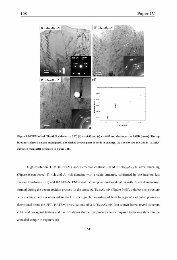
14
Figure 8 BFTEM of a.d. Ti1-xAl xN with (a) x = 0.37, (b) x = 0.63 and (c) x = 0.82 and the respective SAED (insets). The top
inset in (c) show a STEM micrograph. The dashed arrows point at voids in coatings. (d) The FWHM of c-200 in Ti1-xAl xN
extracted from XRD presented in Figure 7 (b).
High-resolution TEM (HRTEM) and elemental contrast STEM of Ti0.63Al0.37N after annealing
(Figure 9 (c)) reveal Ti-rich and Al-rich domains with a cubic structure, confirmed by the inserted fast
Fourier transform (FFT) and HAADF-STEM reveal the compositional modulation with ~5 nm domain size,
formed during the decomposition process. In the annealed Ti0.18Al0.82N (Figure 9 (d)), a defect-rich structure
with stacking faults is observed in the HR micrograph, consisting of both hexagonal and cubic phases as
determined from the FFT. HRTEM investigations of a.d. Ti0.18Al0.82N (not shown here), reveal coherent
cubic and hexagonal lattices and the FFT shows sharper reciprocal pattern compared to the one shown in the
annealed sample in Figure 9 (d).
108 Paper IV
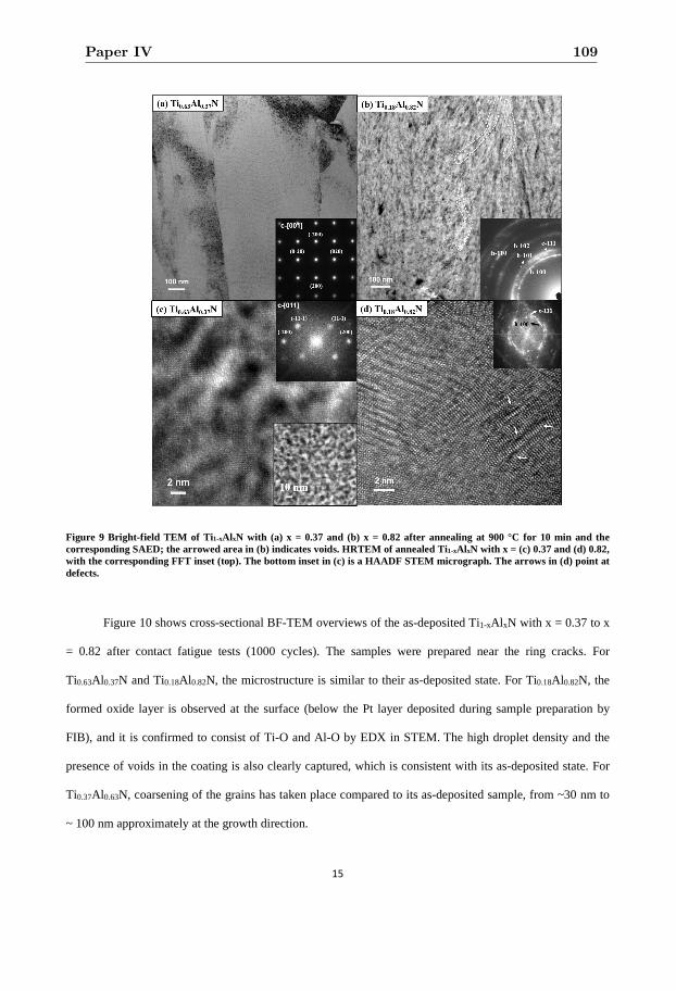
15
Figure 9 Bright-field TEM of Ti 1-xAl xN with (a) x = 0.37 and (b) x = 0.82 after annealing at 900 °C for 10 min and the corresponding SAED; the arrowed area in (b) indicates voids. HRTEM of annealed Ti1-xAl xN with x = (c) 0.37 and (d) 0.82, with the corresponding FFT inset (top). The bottom inset in (c) is a HAADF STEM micrograph. The arrows in (d) point at defects.
Figure 10 shows cross-sectional BF-TEM overviews of the as-deposited Ti1-xAl xN with x = 0.37 to x
= 0.82 after contact fatigue tests (1000 cycles). The samples were prepared near the ring cracks. For
Ti0.63Al0.37N and Ti0.18Al0.82N, the microstructure is similar to their as-deposited state. For Ti0.18Al0.82N, the
formed oxide layer is observed at the surface (below the Pt layer deposited during sample preparation by
FIB), and it is confirmed to consist of Ti-O and Al-O by EDX in STEM. The high droplet density and the
presence of voids in the coating is also clearly captured, which is consistent with its as-deposited state. For
Ti0.37Al0.63N, coarsening of the grains has taken place compared to its as-deposited sample, from ~30 nm to
~ 100 nm approximately at the growth direction.
Paper IV 109
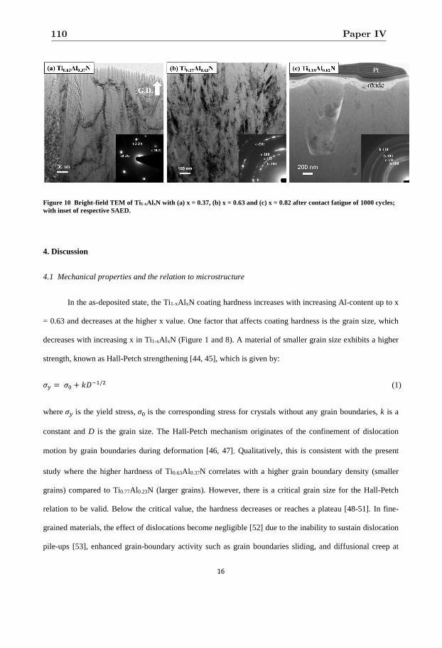
16
Figure 10 Bright-field TEM of Ti 1-xAl xN with (a) x = 0.37, (b) x = 0.63 and (c) x = 0.82 after contact fatigue of 1000 cycles; with inset of respective SAED.
4. Discussion
4.1 Mechanical properties and the relation to microstructure
In the as-deposited state, the Ti1-xAl xN coating hardness increases with increasing Al-content up to x
= 0.63 and decreases at the higher x value. One factor that affects coating hardness is the grain size, which
decreases with increasing x in Ti1-xAl xN (Figure 1 and 8). A material of smaller grain size exhibits a higher
strength, known as Hall-Petch strengthening [44, 45], which is given by:
�� � �� � ��/� (1)
where �� is the yield stress, �� is the corresponding stress for crystals without any grain boundaries, k is a
constant and D is the grain size. The Hall-Petch mechanism originates of the confinement of dislocation
motion by grain boundaries during deformation [46, 47]. Qualitatively, this is consistent with the present
study where the higher hardness of Ti0.63Al0.37N correlates with a higher grain boundary density (smaller
grains) compared to Ti0.77Al0.23N (larger grains). However, there is a critical grain size for the Hall-Petch
relation to be valid. Below the critical value, the hardness decreases or reaches a plateau [48-51]. In fine-
grained materials, the effect of dislocations become negligible [52] due to the inability to sustain dislocation
pile-ups [53], enhanced grain-boundary activity such as grain boundaries sliding, and diffusional creep at
110 Paper IV
17
grain boundaries [54-57]. In the present work, the decreased hardness for x = 0.82 thus indicate that the
grain size for this composition is smaller than the critical value.
In addition, precipitation of h-AlN in high Al-content Ti1-xAl xN coatings has been found to decrease
its hardness [4] alike to other studies of dual-phase Ti1-xAl xN coatings [9, 10, 58]. A similar effect on the
hardness may hence be expected due to the onset of the h-(Ti)AlN phase in Ti1-xAl xN with x = 0.63 and 0.82.
However, despite the presence of h-(Ti)AlN in the coating with x = 0.63 (Figure 7) it exhibits the highest
hardness (Figure 1) of all coatings in this study. The reason for this behavior is likely due to the positive
effect of the small grain size on the hardness as explained above, which has a larger effect on the hardness
than the presence of a hexagonal phase. A similar phenomenon is observed by Kutschej et al [10] for a
Ti0.33Al0.67N coating. On the other hand, in the single-phase c-Ti1-xAl xN (x = 0.23 and 0.37) samples, the
increase of hardness can also be a result of solid solution hardening (alloy hardening) [4] and the increase of
its bulk moduli by smaller distance between neighboring atoms [9, 59].
Contact fatigue behavior of coatings can be altered by their microstructure [16, 18, 35]. Lawn [35]
found that the fatigue damages are related to the grain size, such that a degradation of lifetime is found with
increasing grain size [16]. Similar findings of enhancements in wear resistance with finer grain size are
found in ceramics too compared to relatively coarse grains [60], which are related to the fracture toughness
of the materials. For grain sizes of micrometer scales, as found in Ti0.77Al0.23N and Ti0.63Al0.37N, grain
boundaries are effective in deflecting the cracks [61] and the effect of this phenomenon increases with
smaller grain size due to higher density of grain boundaries.
However, the enhancement of damage resistance with decreasing grain size has previously only been
studied with grain sizes ranging from 1-50 µm [35], which is significantly larger compared to the Ti1-xAl xN
coatings with high Al-content (x = 0.63 and 0.82). At submicrometer grain size, the grain boundary density
is so high that the crack defection at grain boundaries does not cause substantial energy dissipation and the
cracks appear to propagate straight through the coating. Thus, decreasing the grain size to the nanometer
range actually results in easier crack propagation. Similar crack behavior has also been found in
nanocomposite nitride coatings [62].
Paper IV 111
18
The relation between crack deflection and grain size mentioned above is valid under the assumption
that cracks propagate through grain boundaries for all samples. This is a reasonable assumption since grain
boundaries are concentrated with dislocations or slip bands that may fail under stress [63, 64]. In Figure 3
and 5, cracks are observed to propagate through the columns while the grain size observed by TEM is much
smaller than the column size, thus it is likely that the cracks propagate through grain boundaries. These
observations suggest that the highest fracture toughness for the TiAlN coatings of this study corresponds to a
critical grain size between ~30 and ~100 nm.
The onset of an oxide layer on the Ti0.18Al0.82N surface during contact fatigue (Figure 10) can
seriously affect its fracture behavior. Similar surface oxide layers have been observed on TiAlN coatings in
other mechanical tests such as sliding and wear tests [10, 36]. The oxide layers act as a protection layer due
to its low friction coefficient, resulting in lower shear stress on the coating during sliding or wear tests.
Considering the fact that shear stress is induced during contact fatigue tests with spherical indentations [35],
the oxidation layer formed on TiAlN coating should have the effects of protecting the same from further
damage. Contact fatigue tests on TiN reveals the formation of a surface oxide layer around the indentation
imprint at fatigue cycles of 105 or more [24]. Since oxidation may contribute to coating spallation at high
service temperatures for example during metal cutting [65], oxidation of the Ti0.18Al0.82N coating is not
desirable. The existence of an oxide layer in Ti0.18Al 0.82N rather than in the rest of the coatings is related to
the low oxidation resistance in high Al-content Ti1-xAl xN coatings. Although introducing Al into TiN
coatings increases the oxidation resistance [66], Vaz et al. [67] found a critical amount of Al-content for the
highest oxidation resistance, and in their study Ti0.19Al0.81N shows the worst resistance among Ti1-xAl xN
coatings. In addition, the low hardness of Ti0.18Al 0.82N can also result in less extensive propagation of cracks
since in some cases lower hardness leads to better toughness [68, 69]. For the rest of the samples, hardness is
similar so such difference is not resulted.
After annealing, the trend of hardness evolution is different between Ti1-xAl xN coatings. For the
Ti0.77Al0.23N coating, the decrease in hardness with annealing temperature is related to defect annihilation
and stress relaxation [70, 71], which is also observed as a decrease in interplanar d-spacing (Figure 7). For
112 Paper IV
19
Ti0.63Al0.37N, spinodal decomposition takes place resulting in a strong age-hardening effect [2, 3]. The
smaller hardening effect for the Ti0.77Al0.23N coating is due to the less variation of elastic property between
columns or different shape of domains formed during decomposition [72]. For x = 0.63 and x = 0.82, the
hardness decreases after annealing. This degradation is a result of larger grain size and/or higher amount of
h-(Ti)AlN in the post-annealed coatings, as observed from the sharper diffraction with higher intensity from
XRD (Figure 7) and SAED (Figure 9 (b)). In addition, spinodal decomposition of the cubic phase may
enhance the hardness via coherency strain so that its hardness is stabilized even with the growth of h-
(Ti)AlN. Such effect is likely larger in Ti0.37Al0.63N compared to Ti0.18Al 0.82N because of the higher content
of cubic phase [73]. Further, the loss of coherency strain [2, 3] between cubic and hexagonal domains found
in Ti0.18Al0.82N, due to the incomplete formation of h-AlN and c-TiN phases via diffusion during annealing
may seriously degrade the fracture toughness since the coherency between domains can enhance the crack
resistance of the coatings [74, 75]. A similar phenomenon may also appear in Ti0.37Al0.63N and possibly to
an even higher extent, since the change of h-(Ti)AlN in lattice parameters, which is caused by out-diffusion
of Ti from the h-(Ti)AlN phase for higher thermal stability [30], is even larger than in Ti0.18Al0.82N. A non-
coherent structure should result in straighter crack propagation as observed in Ti0.37Al0.63N (Figure 6).
A lower crack resistance is observed for all Ti1-xAl xN coatings after annealing, but from due to
varied origins. For Ti0.82Al0.18N and Ti0.63Al0.37N, the reason for a degraded toughness is the increase of
grain size, which decreases the density of grain boundaries. As for Ti0.37Al0.63N and Ti0.18Al0.82N, the
contributing mechanism is due to the growth of h-(Ti)AlN phase, which exhibits higher brittleness than c-
Ti1-xAl xN [76]. On the other hand, the coherency strain between domains of different composition resulting
from the spinodal decomposition can also enhance the crack resistance [77-79]. From other contact fatigue
studies, heterogeneous microstructures have been observed to display higher fracture resistance [18, 35]. As
a result, the annealed Ti0.63Al0.37N exhibits better crack fracture properties than the other annealed coatings,
since spinodal decomposition is the most pronounced in this coating. The cracks still propagate through the
coating but the cracks are discontinuous, revealing that more energy is needed for cracks to fully extend
through the coatings compared to the other samples.
Paper IV 113
20
A similar behavior of crack propagation for the as-deposited samples is found, with crack deflection
is apparent for the Ti1-xAl xN coatings with x = 0.23 and 0.37, while straight cracks are observed in the other
coatings (Figure 5). This behavior has probably the same origin as for the as deposited samples, i.e., smaller
grain size in high Al-content samples. Another contribution for straight crack propagations may be the
coarsening of the h-(Ti)AlN phase, as observed in Ti0.18Al0.82N. Since h-(Ti)AlN exhibits much higher
brittleness [80] than c-Ti1-xAl xN [76] based on theoretical calculations, growth in size and increased purity
of the h-AlN phase will certainly degrade the fracture toughness. The sub-surface crack splitting in
Ti0.18Al0.82N may be resulted from its heterogeneous structure consisting of c-Ti(Al)N and h-(Ti)AlN phases.
Though such structure already presents in as-deposited state and in Ti0.37Al0.63N, the h-(Ti)AlN phase may
only be substantially enough for resulting in crack branching in annealed Ti0.18Al0.82N.
For Ti0.18Al0.82N, the major difference between the as-deposited and annealed sample is the
substantial reduction of the oxide layer resulting in cracks that propagate through the coating. The reason for
the difference in oxidation behavior in such coating after annealing is the changes in its microstructure.
Lower Al-content Ti1-xAl xN can exhibit better oxidation resistance since x = 0.81 was found to have the
lowest oxidation resistance [67]. The decomposition of h-(Ti)AlN and c-TiAlN results in c-Ti(Al)N with
higher Ti content , i.e. better oxidation resistance. Although the decomposition also results in formation of h-
(Ti)AlN with a composition close to h-AlN with similar oxidation resistance, a heterogeneous structures
consisting of cubic Ti-rich and hexagonal Al-rich domains may result in interrupted oxidation formation.
4.2 Changes in the microstructure after contact fatigue tests
Grain coarsening and reorientation after contact fatigue tests, here seen in Ti0.37Al0.63N, has been
found in other films during deformation [81-83]. Goswami et al. observed a stronger texture at the area of
fatigue deformation [81], which results in enhanced crack propagation due to the lattice rotation [84]. This
indicates that grain boundaries migration or sliding take place in Ti0.37Al0.63N under the fatigue tests, which
is commonly observed in materials with fine-grained microstructures [57, 85]. An enhanced crystallographic
texture induced during fatigue tests can therefore results in relatively straight and extended crack
propagation in the Ti0.37Al 0.63N than the Ti0.63Al0.37N.
114 Paper IV
21
The reason why such behavior only takes place in Ti0.37Al0.63N is because dislocation movement is
more pronounced in Ti1-xAl xN with larger grain size (x = 0.23 and 0.37). As a result, there are no clear
changes in the Ti0.63Al0.37N between as-deposited and post-fatigued samples. The absence of such
microstructural changes in the fine-grained Ti0.18Al0.82N during contact fatigue tests is due to the formed
oxide layer on the surface and its protective effects. This is also consistent with less damage the surface of
Ti0.18Al0.82N after the contact fatigue tests.
5. Conclusion
Contact fatigue tests and nanoindentation were used to investigate the toughness and hardness of Ti1-
xAl xN (x = 0.23-0.82), and they are affected by the microstructure. For as-deposited coatings, hardness and
fracture toughness are related to the grain size. The dependence of grain size on hardness changes when the
deformation mechanism evolves from dislocation pile-ups evolve to grain boundary activities as grain size
decreases. For toughness revealed by crack propagation, a critical grain boundary density is found for
deflecting cracks, while the critical grain size for the best toughness is different from the one for the highest
hardness. For Al-contents of 0.63 and above, a hexagonal (Ti)AlN phase co-exists with the cubic phase in
the as-deposited coatings resulting in a fine-grained structure due to competitive growth of the two phases.
The existence of h-(Ti)AlN degrades the coating’s fracture toughness. In addition, severe oxidation is also
found on the surface of post-fatigue Ti0.18Al0.82N, which affects with the fatigue damage in this coating. For
the fine-grained Ti0.37Al0.63N coating, grain coarsening and reorientation occurs during fatigue tests due to
grain boundary motion.
After annealing at 900 °C, the hardness is the highest for Ti0.63Al0.37N due to spinodal decomposition
occurring for this composition. For fine-grained, dual-phase, high Al-content coatings, growth of h-(Ti)AlN
phase results in worse mechanical properties after annealing. In sum, the best fracture toughness in both the
as-deposited and annealed state is found for Ti0.63Al0.37N due to a single-phase structure, an optimal grain
size and a favorable spinodal decomposition occurring during annealing.
Paper IV 115
22
Acknowledgment
The EU’s Erasmus-Mundus graduate school in Material Science and Engineering (DocMASE), Swedish
Research Council VR (621- 2012-4401), Swedish government strategic research area grant AFM – SFO
MatLiU (2009-00971), and the competence center FunMat-II that is financially supported by Vinnova (grant
no 2016-05156) are greatly acknowledged for financial support. We gratefully appreciate the assistance
from Dr. F.García Marro with contact fatigue tests.
References
[1] N. Norrby, M.P. Johansson, R. M'Saoubi, M. Odén, Pressure and temperature effects on the decomposition of arc evaporated Ti0.6Al0.4N coatings in continuous turning, Surface and Coatings Technology, 209 (2012) 203-207.
[2] P.H. Mayrhofer, A. Hörling, L. Karlsson, J. Sjölén, T. Larsson, C. Mitterer, L. Hultman, Self-organized nanostructures in the Ti–Al–N system, Applied Physics Letters, 83 (2003) 2049.
[3] R. Rachbauer, S. Massl, E. Stergar, D. Holec, D. Kiener, J. Keckes, J. Patscheider, M. Stiefel, H. Leitner, P.H. Mayrhofer, Decomposition pathways in age hardening of Ti-Al-N films, Journal of Applied Physics, 110 (2011) 023515.
[4] A. Hörling, L. Hultman, M. Odén, J. Sjölén, L. Karlsson, Mechanical properties and machining performance of Ti1-xAlxN-coated cutting tools, Surface & coatings technology, 191 (2005) 384-392.
[5] R. Forsén, I.C. Schramm, P.O.A. Persson, F. Mucklich, M. Odén, N. Ghafoor, Nanostructuring and coherency strain in multicomponent hard coatings, Apl Mater, 2 (2014) 116104.
[6] R. Forsén, N. Ghafoor, M. Odén, Coherency strain engineered decomposition of unstable multilayer alloys for improved thermal stability, Journal of Applied Physics, 114 (2013) 244303
[7] I.A. Abrikosov, A. Knutsson, B. Alling, F. Tasnadi, H. Lind, L. Hultman, M. Odén, Phase Stability and Elasticity of TiAlN, Materials, 4 (2011) 1599-1618.
[8] L. Rogström, J. Ullbrand, J. Almer, L. Hultman, B. Jansson, M. Odén, Strain evolution during spinodal decomposition of TiAlN thin films, Thin Solid Films, 520 (2012) 5542-5549.
[9] M. Zhou, Y. Makino, M. Nose, K. Nogi, Phase transition and properties of Ti–Al–N thin films prepared by r.f.-plasma assisted magnetron sputtering, Thin Solid Films, 339 (1999) 203-208.
[10] K. Kutschej, P.H. Mayrhofer, M. Kathrein, P. Polcik, R. Tessadri, C. Mitterer, Structure, mechanical and tribological properties of sputtered Ti1–xAlxN coatings with 0.5≤x≤0.75, Surface and Coatings Technology, 200 (2005) 2358-2365.
[11] R. Sekhar, T.P. Singh, Mechanisms in turning of metal matrix composites: a review, Journal of Materials Research and Technology, 4 (2015) 197-207.
116 Paper IV
23
[12] S. Veprek, M.J.G. Veprek-Heijman, Industrial applications of superhard nanocomposite coatings, Surface and Coatings Technology, 202 (2008) 5063-5073.
[13] S.P. Pemmasani, K. Valleti, R.C. Gundakaram, K.V. Rajulapati, R. Mantripragada, S. Koppoju, S.V. Joshi, Effect of microstructure and phase constitution on mechanical properties of Ti1−xAlxN coaLngs, Appl Surf Sci, 313 (2014) 936-946.
[14] X.-z. Ding, C.T. Bui, X.T. Zeng, Abrasive wear resistance of Ti1−xAlxN hard coaLngs deposited by a vacuum arc system with lateral rotating cathodes, Surface and Coatings Technology, 203 (2008) 680-684.
[15] O. Knotek, B. Bosserhoff, A. Schrey, T. Leyendecker, O. Lemmer, S. Esser, A new technique for testing the impact load of thin films: the coating impact test, Surface and Coatings Technology, 54-55 (1992) 102-107.
[16] J.-G. Yeo, K.S. Lee, B.R. Lawn, Role of Microstructure in Dynamic Fatigue of Glass-Ceramics after Contact with Spheres, J Am Ceram Soc, 83 (2000) 1545-1547.
[17] J.O. Peters, R.O. Ritchie, Foreign-object damage and high-cycle fatigue: role of microstructure in Ti–6Al–4V, Int J Fatigue, 23 (2001) 413-421.
[18] N.P. Padture, B.R. Lawn, Contact Fatigue of a Silicon Carbide with a Heterogeneous Grain Structure, J Am Ceram Soc, 78 (1995) 1431-1438.
[19] D.K. Kim, Y.G. Jung, I.M. Peterson, B.R. Lawn, Cyclic fatigue of intrinsically brittle ceramics in contact with spheres, Acta Materialia, 47 (1999) 4711-4725.
[20] Y.G. Jung, I.M. Peterson, D.K. Kim, B.R. Lawn, Lifetime-limiting Strength Degradation from Contact Fatigue in Dental Ceramics, J Dent Res, 79 (2000) 722-731.
[21] F.B. Abudaia, J.T. Evans, B.A. Shaw, Spherical indentation fatigue cracking, Materials Science and Engineering: A, 391 (2005) 181-187.
[22] R. Bantle, A. Matthews, Investigation into the impact wear behaviour of ceramic coatings, Surface and Coatings Technology, 74-75 (1995) 857-868.
[23] L. Llanes, E. Tarrés, G. Ramírez, C.A. Botero, E. Jiménez-Piqué, Fatigue susceptibility under contact loading of hardmetals coated with ceramic films, Procedia Engineering, 2 (2010) 299-308.
[24] E. Tarrés, G. Ramírez, Y. Gaillard, E. Jiménez-Piqué, L. Llanes, Contact fatigue behavior of PVD-coated hardmetals, International Journal of Refractory Metals and Hard Materials, 27 (2009) 323-331.
[25] M. Stoiber, M. Panzenböck, C. Mitterer, C. Lugmair, Fatigue properties of Ti-based hard coatings deposited onto tool steels, Surface and Coatings Technology, 142-144 (2001) 117-124.
[26] C. Mendibide, P. Steyer, J. Fontaine, P. Goudeau, Improvement of the tribological behaviour of PVD nanostratified TiN/CrN coatings - An explanation, Surface & coatings technology, 201 (2006) 4119-4124.
[27] J. Yang, F.G. Marro, T. Trifonov, M. Oden, M.P. Johansson-Joesaar, L. Llanes, Contact damage resistance of TiN-coated hardmetals: Beneficial effects associated with substrate grinding, Surface & coatings technology, 275 (2015) 133-141.
[28] A. Kimura, M. Kawate, H. Hasegawa, T. Suzuki, Anisotropic lattice expansion and shrinkage of hexagonal TiAlN and CrAlN films, Surface and Coatings Technology, 169-170 (2003) 367-370.
Paper IV 117
24
[29] U. Wahlström, L. Hultman, J.E. Sundgren, F. Adibi, I. Petrov, J.E. Greene, Crystal growth and microstructure of polycrystalline Ti1−xAlxN alloy films deposited by ultra-high-vacuum dual-target magnetron sputtering, Thin Solid Films, 235 (1993) 62-70.
[30] B. Alling, A. Ruban, A. Karimi, O. Peil, S. Simak, L. Hultman, I. Abrikosov, Mixing and decomposition thermodynamics of c-Ti1−xAlxN from first-principles calculations, Physical Review B, 75 (2007).
[31] A. Hörling, L. Hultman, M. Odén, J. Sjölén, L. Karlsson, Thermal stability of arc evaporated high aluminum-content Ti1−xAlxN thin films, Journal of Vacuum Science & Technology A, 20 (2002) 1815-1823.
[32] W.C. Oliver, Measurement of hardness and elastic modulus by instrumented indentation: Advances in understanding and refinements to methodology, DOI (2004).
[33] W.C. Oliver, G.M. Pharr, An Improved Technique for Determining Hardness and Elastic-Modulus Using Load and Displacement Sensing Indentation Experiments, Journal of Materials Research, 7 (1992) 1564-1583.
[34] R.M. Langford, A.K. Petford-Long, Preparation of transmission electron microscopy cross-section specimens using focused ion beam milling, Journal of Vacuum Science & Technology A: Vacuum, Surfaces, and Films, 19 (2001) 2186-2193.
[35] B.R. Lawn, Indentation of ceramics with spheres: A century after Hertz, J Am Ceram Soc, 81 (1998) 1977-1994.
[36] M.F.C. Ordoñez, J.S.R. Paruma, F.S. Osorio, M.C.M. Farias, The Effect of Counterpart Material on the Sliding Wear of TiAlN Coatings Deposited by Reactive Cathodic Pulverization, Scientia cum Industria, 3 (2015) 59-66.
[37] L.C. Agudelo-Morimitsu, J. De La Roche, A. Ruden, D. Escobar, E. Restrepo-Parra, Effect of substrate temperature on the mechanical and tribological properties of W/WC produced by DC magnetron sputtering, Ceram Int, 40 (2014) 7037-7042.
[38] G.D. Quinn, R. Morrell, Design Data for Engineering Ceramics: A Review of the Flexure Test, J Am Ceram Soc, 74 (1991) 2037-2066.
[39] P.H. Mayrhofer, F. Rovere, M. Moser, C. Strondl, R. Tietema, Thermally induced transitions of CrN thin films, Scripta Materialia, 57 (2007) 249-252.
[40] L. Rogström, N. Ghafoor, J. Schroeder, N. Schell, J. Birch, M. Ahlgren, M. Odén, Thermal stability of wurtzite Zr1-xAlxN coatings studied by in situ high-energy x-ray diffraction during annealing, Journal of Applied Physics, 118 (2015).
[41] B. Alling, A. Karimi, I.A. Abrikosov, Electronic origin of the isostructural decomposition in cubic M1−xAlxN (M=Ti, Cr, Sc, Hf): A first-principles study, Surface and Coatings Technology, 203 (2008) 883-886.
[42] A. Knutsson, J. Ullbrand, L. Rogström, N. Norrby, L.J.S. Johnson, L. Hultman, J. Almer, M.P. Johansson Jöesaar, B. Jansson, M. Odén, Microstructure evolution during the isostructural decomposition of TiAlN—A combined in-situ small angle x-ray scattering and phase field study, Journal of Applied Physics, 113 (2013) 213518.
[43] A. Anders, Macroparticles, Cathodic Arcs: From Fractal Spots to Energetic Condensation, Springer New York, New York, NY, 2008, pp. 1-34.
[44] E.O. Hall, The Deformation and Ageing of Mild Steel: III Discussion of Results, Proc. Phys. Soc. B, 64 (1951) 747-753.
[45] N.J. Petch, The Cleavage Strength of Polycrystals, The Journal of the Iron and Steel Institute, 173 (1953) 25-28.
118 Paper IV
25
[46] A.M. Minor, E.A. Stach, J.W. Morris, I. Petrov, In-situ nanoindentation of epitaxial TiN/MgO (001) in a transmission electron microscope, J Electron Mater, 32 (2003) 1023-1027.
[47] N. Hansen, Hall–Petch relation and boundary strengthening, Scripta Materialia, 51 (2004) 801-806.
[48] Z. Fan, The grain size dependence of ductile fracture toughness of polycrystalline metals and alloys, Materials Science and Engineering: A, 191 (1995) 73-83.
[49] M.A. Meyers, A. Mishra, D.J. Benson, Mechanical properties of nanocrystalline materials, Prog Mater Sci, 51 (2006) 427-556.
[50] G.J. Fan, H. Choo, P.K. Liaw, E.J. Lavernia, A model for the inverse Hall–Petch relation of nanocrystalline materials, Materials Science and Engineering: A, 409 (2005) 243-248.
[51] T.G. Nieh, J. Wadsworth, Hall-petch relation in nanocrystalline solids, Scripta Metallurgica et Materialia, 25 (1991) 955-958.
[52] R.Z. Valiev, N.A. Krasilnikov, N.K. Tsenev, Plastic deformation of alloys with submicron-grained structure, Materials Science and Engineering: A, 137 (1991) 35-40.
[53] C.E. Carlton, P.J. Ferreira, What is behind the inverse Hall–Petch effect in nanocrystalline materials?, Acta Materialia, 55 (2007) 3749-3756.
[54] R.A. Masumura, P.M. Hazzledine, C.S. Pande, Yield stress of fine grained materials, Acta Materialia, 46 (1998) 4527-4534.
[55] J. Schiotz, F.D. Di Tolla, K.W. Jacobsen, Softening of nanocrystalline metals at very small grain sizes, Nature, 391 (1998) 561-563.
[56] A.H. Chokshi, A. Rosen, J. Karch, H. Gleiter, On the validity of the hall-petch relationship in nanocrystalline materials, Scripta Metallurgica, 23 (1989) 1679-1683.
[57] H. Hahn, P. Mondal, K.A. Padmanabhan, Plastic deformation of nanocrystalline materials, Nanostruct Mater, 9 (1997) 603-606.
[58] S. PalDey, S.C. Deevi, Single layer and multilayer wear resistant coatings of (Ti,Al)N: a review, Materials Science and Engineering: A, 342 (2003) 58-79.
[59] M.L. Cohen, Calculation of bulk moduli of diamond and zinc-blende solids, Physical Review B, 32 (1985) 7988-7991.
[60] S.-J. Cho, B.J. Hockey, B.R. Lawn, S.J. Bennison, Grain-Size and R-Curve Effects in the Abrasive Wear of Alumina, J Am Ceram Soc, 72 (1989) 1249-1252.
[61] R. Daniel, M. Meindlhumer, W. Baumegger, J. Zalesak, B. Sartory, M. Burghammer, C. Mitterer, J. Keckes, Grain boundary design of thin films: Using tilted brittle interfaces for multiple crack deflection toughening, Acta Materialia, 122 (2017) 130-137.
[62] K. Yalamanchili, R. Forsén, E. Jiménez-Piqué, M.P. Johansson Jöesaar, J.J. Roa, N. Ghafoor, M. Odén, Structure, deformation and fracture of arc evaporated Zr–Si–N hard films, Surface and Coatings Technology, 258 (2014) 1100-1107.
[63] M.D. Sangid, H.J. Maier, H. Sehitoglu, The role of grain boundaries on fatigue crack initiation – An energy approach, Int J Plasticity, 27 (2011) 801-821.
Paper IV 119
26
[64] V.Y. Gertsman, S.M. Bruemmer, Study of grain boundary character along intergranular stress corrosion crack paths in austenitic alloys, Acta Materialia, 49 (2001) 1589-1598.
[65] D. McIntyre, J.E. Greene, G. Håkansson, J.E. Sundgren, W.D. Münz, Oxidation of metastable single-phase polycrystalline Ti0.5Al0.5N films: Kinetics and mechanisms, Journal of Applied Physics, 67 (1990) 1542-1553.
[66] M. Kawate, A. Kimura Hashimoto, T. Suzuki, Oxidation resistance of Cr1−XAlXN and Ti1−XAlXN films, Surface and Coatings Technology, 165 (2003) 163-167.
[67] F. Vaz, L. Rebouta, M. Andritschky, M.F. da Silva, J.C. Soares, Thermal oxidation of Ti1 − xAlxN coaLngs in air, J Eur Ceram Soc, 17 (1997) 1971-1977.
[68] G.R. Anstis, P. Chantikul, B.R. Lawn, D.B. Marshall, A Critical Evaluation of Indentation Techniques for Measuring Fracture Toughness: I, Direct Crack Measurements, J Am Ceram Soc, 64 (1981) 533-538.
[69] V. Martinez, R. Palma, J.J. Urcola, The relation of hardness to toughness and retained austenite content in N2-H2-CH4 sintered T6, T15 and T42 high-speed steels, J Mater Sci, 25 (1990) 3359-3367.
[70] K. Grönhagen, J. Ågren, M. Odén, Phase-field modelling of spinodal decomposition in TiAlN including the effect of metal vacancies, Scripta Materialia, 95 (2015) 42-45.
[71] M. Odén, J. Almer, G. Håkansson, M. Olsson, Microstructure–property relationships in arc-evaporated Cr–N coatings, Thin Solid Films, 377–378 (2000) 407-412.
[72] M.P. Johansson Jõesaar, N. Norrby, J. Ullbrand, R. M'Saoubi, M. Odén, Anisotropy effects on microstructure and properties in decomposed arc evaporated Ti1-xAlxN coatings during metal cutting, Surface and Coatings Technology, 235 (2013) 181-185.
[73] H. Lind, R. Forsén, B. Alling, N. Ghafoor, F. Tasnadi, M.P. Johansson, I.A. Abrikosov, M. Odén, Improving thermal stability of hard coating films via a concept of multicomponent alloying, Applied Physics Letters, 99 (2011) 5090.
[74] D. Rafaja, C. Wustefeld, C. Baehtz, V. Klemm, M. Dopita, M. Motylenko, C. Michotte, M. Kathrein, Effect of Internal Interfaces on Hardness and Thermal Stability of Nanocrystalline Ti0.5Al0.5N Coatings, Metall Mater Trans A, 42a (2011) 559-569.
[75] D. Rafaja, A. Poklad, V. Klemm, G. Schreiber, D. Heger, M. Šíma, M. Dopita, Some consequences of the partial crystallographic coherence between nanocrystalline domains in Ti–Al–N and Ti–Al–Si–N coatings, Thin Solid Films, 514 (2006) 240-249.
[76] F. Wang, D. Holec, M. Odén, F. Mücklich, I.A. Abrikosov, F. Tasnádi, Systematic ab initio investigation of the elastic modulus in quaternary transition metal nitride alloys and their coherent multilayers, Acta Materialia, 127 (2017) 124-132.
[77] A. Knutsson, M.P. Johansson, P.O.A. Persson, L. Hultman, M. Odén, Thermal decomposition products in arc evaporated TiAlN/TiN multilayers, Applied Physics Letters, 93 (2008).
[78] I. Salehinia, S. Shao, J. Wang, H.M. Zbib, Plastic Deformation of Metal/Ceramic Nanolayered Composites, Jom-Us, 66 (2014) 2078-2085.
[79] I.N. Mastorakos, H.M. Zbib, D.F. Bahr, Deformation mechanisms and strength in nanoscale multilayer metallic composites with coherent and incoherent interfaces, Applied Physics Letters, 94 (2009).
[80] D. Nguyen-Manh, D.G. Pettifor, D.J.H. Cockayne, M. Mrovec, S. Znam, V. Vitek, Environmentally dependent bond-order potentials: New developments and applications, B Mater Sci, 26 (2003) 43-51.
120 Paper IV
27
[81] R. Goswami, C.R. Feng, S.B. Qadri, C.S. Pande, Fatigue-Assisted Grain Growth in Al Alloys, Sci Rep-Uk, 7 (2017) 10179.
[82] R.A. Meirom, D.H. Alsem, A.L. Romasco, T. Clark, R.G. Polcawich, J.S. Pulskamp, M. Dubey, R.O. Ritchie, C.L. Muhlstein, Fatigue-induced grain coarsening in nanocrystalline platinum films, Acta Materialia, 59 (2011) 1141-1149.
[83] M. Jin, A.M. Minor, J.W. Morris, Strain-induced coarsening in nano-grained films, Thin Solid Films, 515 (2007) 3202-3207.
[84] R. Goswami, S.B. Qadri, C.S. Pande, Fatigue mediated lattice rotation in Al alloys, Acta Materialia, 129 (2017) 33-40.
[85] H. Conrad, J. Narayan, K. Jung, Grain size softening in nanocrystalline TiN, International Journal of Refractory Metals and Hard Materials, 23 (2005) 301-305.
Paper IV 121

122 Paper IV
V
Paper V
A small-scale lathe for in situ studies of theturning process using high-energy x-ray
scattering
L. RogströmY. H. ChenJ Eriksson
M. FallqvistM.P.Johansson-Jõesaar
J. AnderssonN. Schell
M.OdénJ. Birch
In manuscript

A small-scale lathe for in situ studies of the turning process using high-energy x-ray scattering
L. Rogström1, Y.H. Chen1, J. Eriksson2, M. Fallqvist2, M. P. Johansson Jõesaar2, J. M. Andersson2, N.
Schell3, M. Odén1, J. Birch4
1Nanostructured Materials, Department of Physics, Chemistry and Biology (IFM), Linköping
University, 581 83 Linköping, Sweden
2Seco Tools AB, 737 82 Fagersta, Sweden
3Helmholtz-Zentrum Geesthacht (HZG), Max-Planck Str. 1, 21502, Geesthacht, Germany
4Thin Film Physics, Department of Physics, Chemistry and Biology (IFM), Linköping University, 581 83
Linköping, Sweden
Abstract
We present a small-scale lathe designed for in situ studies of the tool and workpiece using high-energy
x-ray scattering. The lathe allows for industrially relevant cutting parameters as cutting speed (≤ 400
m/min) and feed (≤ 0.25 mm/rev). We present results of the strain and temperature of the tool coating
and the chip from initial tests of the lathe at the high-energy material science beamline P07 at Petra
III, DESY, Hamburg. We find that by the right choice of combination of substrate and coating material,
we can record diffraction patterns from both the flank face and from the chip at the rake side of the
tool during machining.
Paper V 125
1. Introduction
Metal machining is one of the most important processes in manufacturing industries. Ensuring high
precision machining and high production rates requires high performance cutting tools. The tool
inserts are exposed to demanding conditions including high temperature and pressure [1] together
with abrasive wear from hard particles in the work piece material, thus placing high demands on both
the tool material and its design. Optimizing the tools requires knowledge of both the conditions the
tool experiences during machining and how the tool materials behave under these conditions.
Today, the knowledge of the machining process is largely based on modelling of the stress and
temperature distribution [2-5] and studies of worn tools [6, 7] and the machined surfaces [8, 9]. A few
measurement of tool temperature and stresses and temperature can be found [1, 10, 11]. Direct
observation of conditions and changes in the tool through for example in situ experiments are rare.
This can be understood by the lack of line-of-sight into the contact zone between the tool and the work
piece material.
High-energy x-ray radiation have the advantage that it can penetrate both substrate and work piece
material. X-ray diffraction gives information on phase content as well as strain and stress state and the
full diffraction ring can be recorded within the order of seconds by the use of a two-dimensional
detector, thus enabling time-resolved studies. High-energy x-ray scattering has been shown to be a
valuable tool for investigating strains and stresses in ceramic tools during both thermomechanical
loads and in friction testing [12, 13]. It has also been used to study the chip formation and the stress
state in situ during low-speed (3 mm/m) cutting and the stress state of the chip during cutting [14, 15].
Tool inserts are commonly coated by a thin (~1-10 µm), hard coating, which dramatically improves the
wear resistance of the tool. Coating materials are selected to hold good mechanical properties,
oxidation resistance and chemical inertness at the operation temperature of the tool. TiAlN is one of
the most common coating materials due to its’ beneficial age hardening behavior at high temperature,
combined with good oxidation resistance. The age hardening is caused by spinodal composition of
cubic structured TiAlN into TiN- and AlN-enriched domains [16], resulting in varying elastic properties
[17] and coherency strains within the coating. Model studies and theoretical work have shown that
the decomposition is affected by factors such as temperature and pressure [1, 18, 19] but since the
exact temperature and pressure in the contact zone are not known the dependence of the
decomposition behavior on the cutting parameters remains unknown. Thus, the optimizing of the
coating properties requires local analysis of the coating in the cutting zone, which size is in the order
of 1 mm2 and within which both temperature and pressure vary dramatically. The size of the x-ray
beam can be controlled by slits or by focusing optics to beam sizes in the order of 10 x 10 µm2, thus
allowing specific areas of interest to be selected for analysis. In addition, high-energy x-ray scattering
has been shown to be a useful tool for studying phase transformations and strains in hard coatings
[19-23].
We present a small-scale lathe, designed to allow for x-ray scattering studies during longitudinal
turning, while using industrial scale cutting parameters. In particular, the high cutting speeds now
made possible are needed to reach the high temperature range for relevant studies of the materials
involved in the cutting process. We show the first in situ results from a turning operation, recorded at
the high-energy materials science beamline P07 at Petra III and including simultaneous measurements
of substrate, coating, as well as the chips formed during machining at high cutting speed.
2. Design of small-scale lathe and material choice
126 Paper V
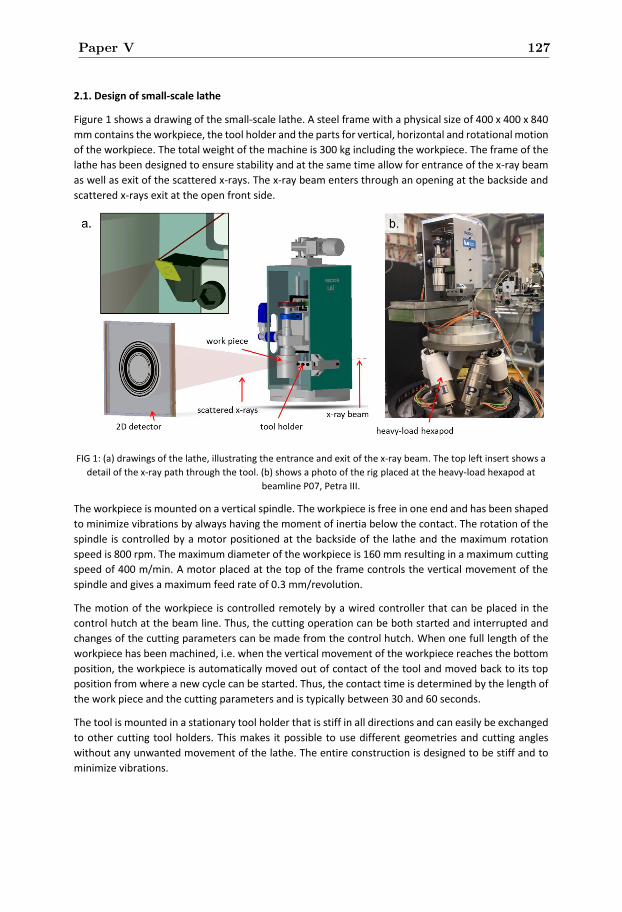
2.1. Design of small-scale lathe
Figure 1 shows a drawing of the small-scale lathe. A steel frame with a physical size of 400 x 400 x 840
mm contains the workpiece, the tool holder and the parts for vertical, horizontal and rotational motion
of the workpiece. The total weight of the machine is 300 kg including the workpiece. The frame of the
lathe has been designed to ensure stability and at the same time allow for entrance of the x-ray beam
as well as exit of the scattered x-rays. The x-ray beam enters through an opening at the backside and
scattered x-rays exit at the open front side.
FIG 1: (a) drawings of the lathe, illustrating the entrance and exit of the x-ray beam. The top left insert shows a
detail of the x-ray path through the tool. (b) shows a photo of the rig placed at the heavy-load hexapod at
beamline P07, Petra III.
The workpiece is mounted on a vertical spindle. The workpiece is free in one end and has been shaped
to minimize vibrations by always having the moment of inertia below the contact. The rotation of the
spindle is controlled by a motor positioned at the backside of the lathe and the maximum rotation
speed is 800 rpm. The maximum diameter of the workpiece is 160 mm resulting in a maximum cutting
speed of 400 m/min. A motor placed at the top of the frame controls the vertical movement of the
spindle and gives a maximum feed rate of 0.3 mm/revolution.
The motion of the workpiece is controlled remotely by a wired controller that can be placed in the
control hutch at the beam line. Thus, the cutting operation can be both started and interrupted and
changes of the cutting parameters can be made from the control hutch. When one full length of the
workpiece has been machined, i.e. when the vertical movement of the workpiece reaches the bottom
position, the workpiece is automatically moved out of contact of the tool and moved back to its top
position from where a new cycle can be started. Thus, the contact time is determined by the length of
the work piece and the cutting parameters and is typically between 30 and 60 seconds.
The tool is mounted in a stationary tool holder that is stiff in all directions and can easily be exchanged
to other cutting tool holders. This makes it possible to use different geometries and cutting angles
without any unwanted movement of the lathe. The entire construction is designed to be stiff and to
minimize vibrations.
Paper V 127
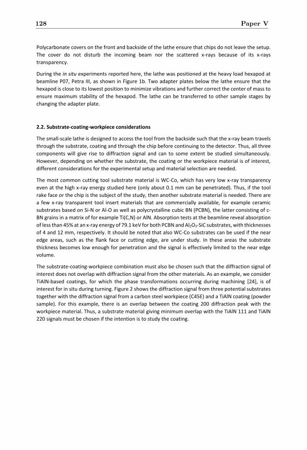
Polycarbonate covers on the front and backside of the lathe ensure that chips do not leave the setup.
The cover do not disturb the incoming beam nor the scattered x-rays because of its x-rays
transparency.
During the in situ experiments reported here, the lathe was positioned at the heavy load hexapod at
beamline P07, Petra III, as shown in Figure 1b. Two adapter plates below the lathe ensure that the
hexapod is close to its lowest position to minimize vibrations and further correct the center of mass to
ensure maximum stability of the hexapod. The lathe can be transferred to other sample stages by
changing the adapter plate.
2.2. Substrate-coating-workpiece considerations
The small-scale lathe is designed to access the tool from the backside such that the x-ray beam travels
through the substrate, coating and through the chip before continuing to the detector. Thus, all three
components will give rise to diffraction signal and can to some extent be studied simultaneously.
However, depending on whether the substrate, the coating or the workpiece material is of interest,
different considerations for the experimental setup and material selection are needed.
The most common cutting tool substrate material is WC-Co, which has very low x-ray transparency
even at the high x-ray energy studied here (only about 0.1 mm can be penetrated). Thus, if the tool
rake face or the chip is the subject of the study, then another substrate material is needed. There are
a few x-ray transparent tool insert materials that are commercially available, for example ceramic
substrates based on Si-N or Al-O as well as polycrystalline cubic BN (PCBN), the latter consisting of c-
BN grains in a matrix of for example Ti(C,N) or AlN. Absorption tests at the beamline reveal absorption
of less than 45% at an x-ray energy of 79.1 keV for both PCBN and Al2O3-SiC substrates, with thicknesses
of 4 and 12 mm, respectively. It should be noted that also WC-Co substrates can be used if the near
edge areas, such as the flank face or cutting edge, are under study. In these areas the substrate
thickness becomes low enough for penetration and the signal is effectively limited to the near edge
volume.
The substrate-coating-workpiece combination must also be chosen such that the diffraction signal of
interest does not overlap with diffraction signal from the other materials. As an example, we consider
TiAlN-based coatings, for which the phase transformations occurring during machining [24], is of
interest for in situ during turning. Figure 2 shows the diffraction signal from three potential substrates
together with the diffraction signal from a carbon steel workpiece (C45E) and a TiAlN coating (powder
sample). For this example, there is an overlap between the coating 200 diffraction peak with the
workpiece material. Thus, a substrate material giving minimum overlap with the TiAlN 111 and TiAlN
220 signals must be chosen if the intention is to study the coating.
128 Paper V
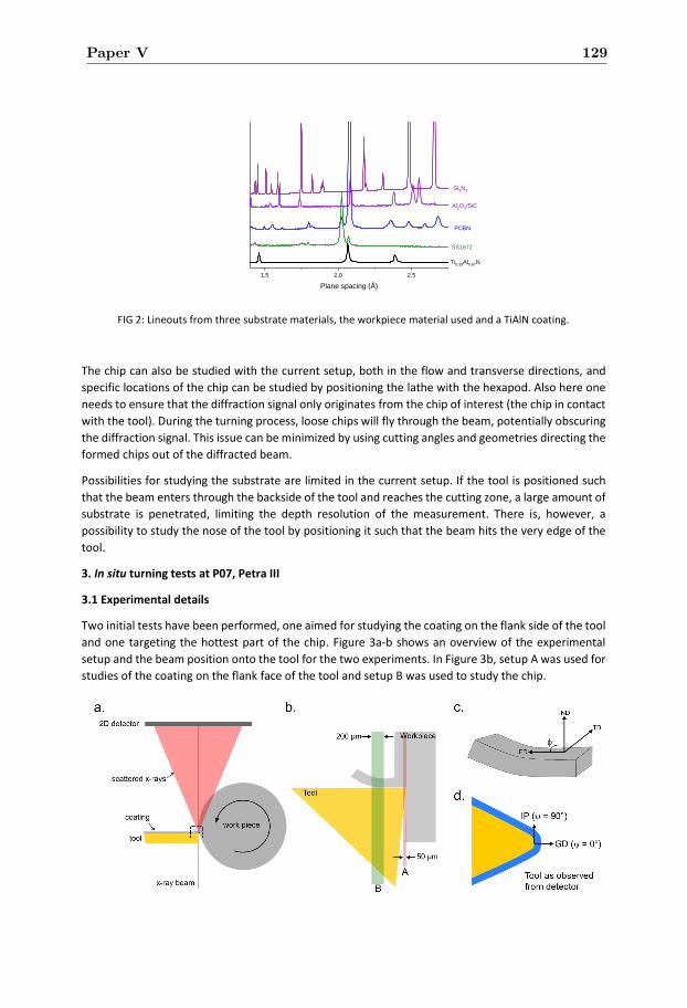
FIG 2: Lineouts from three substrate materials, the workpiece material used and a TiAlN coating.
The chip can also be studied with the current setup, both in the flow and transverse directions, and
specific locations of the chip can be studied by positioning the lathe with the hexapod. Also here one
needs to ensure that the diffraction signal only originates from the chip of interest (the chip in contact
with the tool). During the turning process, loose chips will fly through the beam, potentially obscuring
the diffraction signal. This issue can be minimized by using cutting angles and geometries directing the
formed chips out of the diffracted beam.
Possibilities for studying the substrate are limited in the current setup. If the tool is positioned such
that the beam enters through the backside of the tool and reaches the cutting zone, a large amount of
substrate is penetrated, limiting the depth resolution of the measurement. There is, however, a
possibility to study the nose of the tool by positioning it such that the beam hits the very edge of the
tool.
3. In situ turning tests at P07, Petra III
3.1 Experimental details
Two initial tests have been performed, one aimed for studying the coating on the flank side of the tool
and one targeting the hottest part of the chip. Figure 3a-b shows an overview of the experimental
setup and the beam position onto the tool for the two experiments. In Figure 3b, setup A was used for
studies of the coating on the flank face of the tool and setup B was used to study the chip.
1.5 2.0 2.5
Si3N4
Al2O3/SiC
SS1672
PCBN
Plane spacing (Å)
Ti0.33Al0.67N
Paper V 129
FIG 3: (a,b) Schematic top-view of the tool an workpiece showing the beam position for the two experiments
and (c,d) definition of directions and angles for the two experiments.
Turning experiments were performed at two different cutting speeds, 230 m/min and 320 m/min. The
feed was set to 0.15 mm/rev and the depth of cut was 0.2 mm for all runs. The workpiece material was
C45E carbon engineering steel. Cutting one length of the work piece takes approximately 50 s for the
lower cutting speed and 30 s for the higher cutting speed. For each insert, a minimum of three lengths
were cut.
For studies of the flank face of the tool, coated WC-Co tools were used. Since the absorption of x-rays
is large in WC-Co, the choice of this substrate material ensure that only diffraction signal from the flank
face, close to the nose of the tool, reaches the detector. Two types of coatings were used, PVD grown
TiNbAlN and CVD grown Al2O3/Ti(C,N). TiNbAlN coatings were grown by cathodic arc evaporation to a
thickness of 3 µm using Ti-Nb-Al alloy cathodes in a 4.5 Pa N2 atmosphere. Before deposition, the
substrates were sputter cleaned with Ar ions. The growth temperature was 500 °C and a negative
substrate bias of 30 V was used. The CVD Ti(C,N) layers were deposited at a temperature of 860 °C
from a gas mixture of CH3CN-TiCl4-H2-N2 and the α-Al2O3 layers were subsequently deposited from the
AlCl3-CO2-CO-H2S-H2 system at 1000 °C. After deposition, the coating was removed from the backside
of the insert, in order to ensure that the diffracted signal originates from the cutting zone.
For studies of the chip, PCBN tools were used due to the low absorption of x-rays by PCBN. The tools
were coated by a CVD grown Al2O3/Ti(C,N) using the growth conditions described above.
The experiments were performed at beamline P07, Petra III, using an x-ray energy of 78-79.5 keV
(wavelength of 0.159-0.156 Å). The size of the beam was defined by slits to 200 x 50 µm for setup A
and 200 x 200 µm for setup B. The diffracted x-rays were detected by a two-dimensional Perkin-Elmer
detector with a pixel size of 200 x 200 µm2 and 2048 x 2048 pixels, positioned approximately 3.3 m
from the sample. The exact detector position was determined by measurements of a NIST LaB6
standard sample placed at the position of the tool. Each image consisted of 40-60 summed 1 s long
exposures, thus one image were recorded per length of cut.
The two-dimensional data was integrated in 5° wide bins and the resulting one-dimensional data was
analyzed by fitting of Gaussian curves to the diffraction signal from the coating, substrate and chip to
extract peak position and peak width (FWHM). The strain and stress were calculated by the sin2ψ
method. Figure 3d shows the definition of the in-plane (IP) and growth direction (GD) and the tilt angle
ψ. For TiAlNbN, the 220 diffraction signal and elastic constants for TiNbAlN (v= 0.38, E = 429 GPa) [25]
were used. For WC, the 101 (setup A) or 100 (setup B) diffraction signal and an elastic modulus of 620
GPa and a Poisson ratio of 0.185 were used [26]. For Al2O3, the 104 diffraction signal and elastic
constants of E=416 and ν=0.23 were used [27]. For TiCN, the 200 diffraction signal and elastic constants
for TiN were used, E=450 GPa and ν=0.22 [28].
For the chip, only data in the range φ = [0°:60°], see definition of angles in Fig. 3c, was analyzed.
Between φ = 60° and φ = 90°, diffraction signal from loose chips reaches the detector and interfere
with the desired diffraction signal (from the chip-tool contact) while at φ < 60°, the tool holder blocks
diffraction signal from the loose chips.
Worn inserts were studied by scanning electron microscopy (SEM, Leo 1550 Gemini) using 5-15 kV
acceleration voltage.
130 Paper V
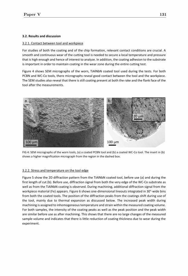
3.2. Results and discussion
3.2.1. Contact between tool and workpiece
For studies of both the coating and of the chip formation, relevant contact conditions are crucial. A
smooth and continuous wear of the cutting tool is needed to secure a local temperature and pressure
that is high enough and hence of interest to analyze. In addition, the coating adhesion to the substrate
is important in order to maintain coating in the wear zone during the entire cutting test.
Figure 4 shows SEM micrographs of the worn, TiAlNbN coated tool used during the tests. For both
PCBN and WC-Co tools, there micrographs reveal good contact between the tool and the workpiece.
The SEM studies also reveal that there is still coating present at both the rake and the flank face of the
tool after the measurements.
FIG 4: SEM micrographs of the worn tools, (a) a coated PCBN tool and (b) a coated WC-Co tool. The insert in (b)
shows a higher magnification micrograph from the region in the dashed box.
3.2.2. Stress and temperature on the tool edge
Figure 5 show the 2D diffraction pattern from the TiAlNbN coated tool, before use (a) and during the
first length of cut (b). Before use, diffraction signal from both the very edge of the WC-Co substrate as
well as from the TiAlNbN coating is observed. During machining, additional diffraction signal from the
workpiece material (Fe) appears. Figure 6 shows one-dimensional lineouts integrated in 30°-wide bins
from both the coated tools. The position of the diffraction peaks from the coatings shift during use of
the tool, mainly due to thermal expansion as discussed below. The increased peak width during
machining is assigned to inhomogeneous temperature and strain within the measured coating volume.
For both samples, the intensity of the coating peaks as well as the peak position and the peak width
are similar before use as after machining. This shows that there are no large changes of the measured
sample volume and indicates that there is little reduction of coating thickness due to wear during the
experiment.
Paper V 131
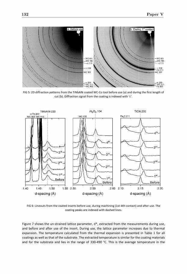
FIG 5: 2D diffraction patterns from the TiNbAlN coated WC-Co tool before use (a) and during the first length of
cut (b). Diffraction signal from the coating is indexed with ‘c’.
FIG 6: Lineouts from the coated inserts before use, during machining (1st-4th contact) and after use. The
coating peaks are indexed with dashed lines.
Figure 7 shows the un-strained lattice parameter, d*, extracted from the measurements during use,
and before and after use of the insert. During use, the lattice parameter increases due to thermal
expansion. The temperature calculated from the thermal expansion is presented in Table 1 for all
coatings as well as that of the substrate. The extracted temperature is similar for the coating materials
and for the substrate and lies in the range of 330-490 °C. This is the average temperature in the
132 Paper V
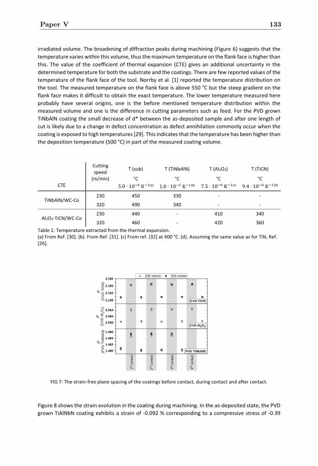
irradiated volume. The broadening of diffraction peaks during machining (Figure 6) suggests that the
temperature varies within this volume, thus the maximum temperature on the flank face is higher than
this. The value of the coefficient of thermal expansion (CTE) gives an additional uncertainty in the
determined temperature for both the substrate and the coatings. There are few reported values of the
temperature of the flank face of the tool. Norrby et al. [1] reported the temperature distribution on
the tool. The measured temperature on the flank face is above 550 °C but the steep gradient on the
flank face makes it difficult to obtain the exact temperature. The lower temperature measured here
probably have several origins, one is the before mentioned temperature distribution within the
measured volume and one is the difference in cutting parameters such as feed. For the PVD grown
TiNbAlN coating the small decrease of d* between the as-deposited sample and after one length of
cut is likely due to a change in defect concentration as defect annihilation commonly occur when the
coating is exposed to high temperatures [29]. This indicates that the temperature has been higher than
the deposition temperature (500 °C) in part of the measured coating volume.
Cutting speed
T (sub) T (TiNbAlN) T (Al2O3) T (TiCN)
(m/min) °C °C °C °C CTE 5.0 ∙ 10−6 K−1(a) 1.0 ∙ 10−5 K−1(b) 7.5 ∙ 10−6 K−1(c) 9.4 ∙ 10−6 K−1(d)
TiNbAlN/WC-Co 230 450 330 - -
320 490 340 - -
Al2O3-TiCN/WC-Co 230 440 - 410 340
320 460 - 420 360
Table 1: Temperature extracted from the thermal expansion. (a) From Ref. [30]. (b). From Ref. [31]. (c) From ref. [32] at 400 °C. (d). Assuming the same value as for TiN, Ref. [26].
FIG 7: The strain-free plane spacing of the coatings before contact, during contact and after contact.
Figure 8 shows the strain evolution in the coating during machining. In the as-deposited state, the PVD
grown TiAlNbN coating exhibits a strain of -0.092 % corresponding to a compressive stress of -0.39
1.480
1.482
1.484
1.486
3rd
co
nta
ct
4th
co
nta
ct
230 m/min 320 m/min
d*
(PV
D T
iAlN
bN
)
2n
d c
onta
ct
1st c
onta
ct
PVD TiNbAlN
CVD Al2O3
CVD TiCN
2.556
2.560
2.564
d*
(CV
D A
l 2O
3)
2.148
2.152
2.156
2.160
d*
(CV
D T
iCN
)
Paper V 133
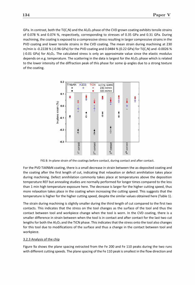
GPa. In contrast, both the Ti(C,N) and the Al2O3 phase of the CVD grown coating exhibits tensile strains
of 0.078 % and 0.074 %, respectively, corresponding to stresses of 0.35 GPa and 0.31 GPa. During
machining, the coating is exposed to a compressive stress resulting in larger compressive strains in the
PVD coating and lower tensile strains in the CVD coating. The mean strain during machining at 230
m/min is -0.2228 % (-0.96 GPa) for the PVD coating and 0.0484 % (0.22 GPa) for Ti(C,N) and -0.0026 %
(-0.01 GPa) for Al2O3. The calculated stress is only an approximate value since the elastic modulus
depends on e.g. temperature. The scattering in the data is largest for the Al2O3 phase which is related
to the lower intensity of the diffraction peak of this phase for some ψ-angles due to a strong texture
of the coating.
FIG 8: In-plane strain of the coatings before contact, during contact and after contact.
For the PVD TiAlNbN coating, there is a small decrease in strain between the as-deposited coating and
the coating after the first length of cut, indicating that relaxation or defect annihilation takes place
during machining. Defect annihilation commonly takes place at temperatures above the deposition
temperature REF but annealing studies are normally performed for longer times compared to the less
than 1 min high temperature exposure here. The decrease is larger for the higher cutting speed, thus
more relaxation takes place in the coating when increasing the cutting speed. This suggests that the
temperature is higher for the higher cutting speed, despite the similar values obtained here (Table 1).
The strain during machining is slightly smaller during the third length of cut compared to the first two
contacts. This indicates that the stress on the tool changes as the surface of the tool and thus the
contact between tool and workpiece change when the tool is worn. In the CVD coating, there is a
smaller difference in strain between when the tool is in contact and after contact for the last two cut
lengths for both the Al2O3 and the TiCN phase. This indicates that the stress onto the tool also changes
for this tool due to modifications of the surface and thus a change in the contact between tool and
workpiece.
3.2.3 Analysis of the chip
Figure 9a shows the plane spacing extracted from the Fe 200 and Fe 110 peaks during the two runs
with different cutting speeds. The plane spacing of the Fe 110 peak is smallest in the flow direction and
134 Paper V
increases with φ. For the 200 peak, the trend is similar for the run at 230 m/min while the behavior is
slightly different for the run at 320 m/min while the smallest d200 value is, however, still found in the
flow direction. The smaller plane spacing in the chip flow direction is likely related to compressive
strain in this direction. The exact strain and stress of the chip cannot be determined due to the lack of
data in the normal direction (ND) with the current experimental setup. Uhlmann et al. determined the
stress state of the chip during low-speed orthogonal cutting [14]. They found a larger compressive
stress in the transverse direction compared to the flow direction, thus contrary to what the results
presented here suggest. Uhlmann et al. could not measure the stress in the transverse direction (TD)
directly in their experimental setup, while FEM simulations revealed good consistency with the
measured stress values. In both our and their experiments, there is an uncertainty introduced by the
averaging of data across the chip thickness. In addition, the results presented here are obtained from
a hot chip during high-speed machining, thus the strain can differ between the two measurements.
There is also a difference in cutting geometry where Uhlmann uses orthogonal turning while we use
longitudinal turning resulting in differences in the chip formation. Figure 8b shows the change of the
Fe 110 plane spacing (d110) as a function of lengths cut with one tool. The plane spacing is slightly larger
during the 8th length compared to the first length. The trend of d110 vs φ does not change suggesting a
similar stress state, thus this is likely a change of thermal expansion due to a higher temperature in the
chip-tool contact zone with a worn tool.
Paper V 135
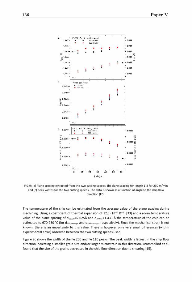
FIG 9: (a) Plane spacing extracted from the two cutting speeds, (b) plane spacing for length 1-8 for 230 m/min
and (c) peak widths for the two cutting speeds. The data is shown as a function of angle to the chip flow
direction (FD).
The temperature of the chip can be estimated from the average value of the plane spacing during
machining. Using a coefficient of thermal expansion of 12,8 ∙ 10−6 K−1 [33] and a room temperature
value of the plane spacing of d110,RT=2.025Å and d200,RT=1.433 Å the temperature of the chip can be
estimated to 670-730 °C (for d110,average and d200,average, respectively). Since the mechanical strain is not
known, there is an uncertainty to this value. There is however only very small differences (within
experimental error) observed between the two cutting speeds used.
Figure 9c shows the width of the Fe 200 and Fe 110 peaks. The peak width is largest in the chip flow
direction indicating a smaller grain size and/or larger microstrain in this direction. Brömmelhof et al.
found that the size of the grains decreased in the chip flow direction due to shearing [15].
136 Paper V
4. Summary
We have successfully designed a small-scale lathe that enables industrially relevant cutting parameters
and offers the stability required to study the tool insert in situ during machining using high energy x-
ray scattering. By careful selection of substrate material, we can study the wear resistant coating and
the chip on both the rake and the flank face.
The initial results indicate that as the tool become worn the temperature of the chip increases. A worn
tool also results in a change in stress state on the flank face of the tool.
References
[1] N. Norrby, M.P. Johansson, R. M'Saoubi, M. Odén. Pressure and temperature effects on the decomposition of arc evaporated Ti0.6Al0.4N coatings in continuous turning, Surf. Coat. Technol. 209 (2012) 203-207. [2] H.O. Gekonde, S.V. Subramanian. Tribology of tool–chip interface and tool wear mechanisms, Surf. Coat. Technol. 149 (2002) 151-160. [3] T. MacGinley, J. Monaghan. Modelling the orthogonal machining process using coated cemented carbide cutting tools, Journal of Materials Processing Technology 118 (2001) 293-300. [4] W. Grzesik, M. Bartoszuk, P. Nieslony. Finite element modelling of temperature distribution in the cutting zone in turning processes with differently coated tools, Journal of Materials Processing Technology 164-165 (2005) 1204-1211. [5] L.J. Xie, J. Schmidt, C. Schmidt, F. Biesinger. 2D FEM estimate of tool wear in turning operation, Wear 258 (2005) 1479-1490. [6] J. Angseryd, E. Coronel, M. Elfwing, E. Olsson, H.O. Andrén. The microstructure of the affected zone of a worn PCBN cutting tool characterised with SEM and TEM, Wear 267 (2009) 1031-1040. [7] A. Flink, R. M'Saoubi, F. Giuliani, J. Sjölén, T. Larsson, P.O.Å. Persson, M.P. Johansson, L. Hultman. Microstructural characterization of the tool-chip interface enabled by focused ion beam and analytical electron microscopy, Wear 266 (2009) 1237-1240. [8] Y.K. Chou, C.J. Evans. White layers and thermal modeling of hard turned surfaces, International Journal of Machine Tools and Manufacture 39 (1999) 1863-1881. [9] H. Gürbüz, U. Şeker, F. Kafkas. Investigation of effects of cutting insert rake face forms on surface integrity, International Journal of Advanced Manufacturing Technology 90 (2017) 3507-3522. [10] R. M'Saoubi, H. Chandrasekaran. Investigation of the effects of tool micro-geometry and coating on tool temperature during orthogonal turning of quenched and tempered steel, Int. J. Mach. Tool. Manuf. 44 (2004) 213-224. [11] H. Chandrasekaran, A. Thuvander. Modeling tool stresses and temperature evaluation in turning using finite element method, Machining Science and Technology 2 (1998) 355-367. [12] C. Eichenseer, I. Wittmann, C. Hartig, G.A. Schneider, N. Schell, W. Hintze. In situ measurement of lattice strains in mixed ceramic cutting tools under thermal and mechanical loads using synchrotron radiation, Production Engineering (2012) 1-7. [13] C. Eichenseer, C. Hartig, N. Schell, W. Hintze. In situ determination of internal stresses in mixed ceramic cutting tools during friction testing using synchrotron radiation, Production Engineering 8 (2014) 513-519.
Paper V 137
[14] E. Uhlmann, R. Gerstenberger, S. Herter, T. Hoghé, W. Reimers, B. Camin, R. Martins, A. Schreyer, T. Fischer. In situ strain measurement in the chip formation zone during orthogonal cutting, Production Engineering 5 (2011) 1-8. [15] K. Brömmelhoff, S. Henze, R. Gerstenberger, T. Fischer, N. Schell, E. Uhlmann, W. Reimers. Space resolved microstructural characteristics in the chip formation zone of orthogonal cut C45E steel samples characterized by diffraction experiments, J. Mater. Proc. Technol. 213 (2013) 2211-2216. [16] A. Knutsson, M.P. Johansson, P.O.Å. Persson, L. Hultman, M. Odén. Thermal decomposition products in arc evaporated TiAlN/TiN multilayers, Appl. Phys. Lett. 93 (2008) 143110. [17] F. Tasnádi, I.A. Abrikosov, L. Rogström, J. Almer, M.P. Johansson, M. Odén. Significant elastic anisotropy in Ti1-xAlxN alloys, Appl. Phys. Lett. 97 (2010) 231902. [18] B. Alling, M. Oden, L. Hultman, I.A. Abrikosov. Pressure enhancement of the isostructural cubic decomposition in Ti[sub 1 - x]Al[sub x]N, Appl. Phys. Lett. 95 (2009) 181906-181903. [19] A. Knutsson, J. Ullbrand, L. Rogström, N. Norrby, L.J.S. Johnson, L. Hultman, J. Almer, M.P.J. Jöesaar, B. Jansson, M. Odén. Microstructure evolution during the isostructural decomposition of TiAlN - A combined in-situ small angle x-ray scattering and phase field study, J. Appl. Phys. 113 (2013) 213518. [20] L. Rogström, J. Ullbrand, J. Almer, L. Hultman, B. Jansson, M. Odén. Strain evolution during spinodal decomposition of TiAlN thin films, Thin Solid Films 520 (2012) 5542-5549. [21] N. Norrby, L. Rogström, M.P. Johansson-Jõesaar, N. Schell, M. Odén. In situ X-ray scattering study of the cubic to hexagonal transformation of AlN in Ti1−xAlxN, Acta Materialia 73 (2014) 205-214. [22] Y.H. Chen, L. Rogström, D. Ostach, N. Ghafoor, M.P. Johansson-Jõesaar, N. Schell, J. Birch, M. Odén. Effects of decomposition route and microstructure on h-AlN formation rate in TiCrAlN alloys, J Alloy Compd 691 (2017) 1024-1032. [23] L. Rogström, N. Ghafoor, J. Schroeder, N. Schell, J. Birch, M. Ahlgren, M. Odén. Thermal stability of wurtzite Zr1−xAlxN coatings studied by in situ high-energy x-ray diffraction during annealing, Journal of Applied Physics 118 (2015) 035309. [24] M.P. Johansson Jõesaar, N. Norrby, J. Ullbrand, R. M'Saoubi, M. Odén. Anisotropy effects on microstructure and properties in decomposed arc evaporated Ti1-xAlxN coatings during metal cutting, Surface and Coatings technology 235 (2013) 181-185. [25] F. Wang, D. Holec, M. Odén, F. Mücklich, I.A. Abrikosov, F. Tasnádi. Systematic ab initio investigation of the elastic modulus in quaternary transition metal nitride alloys and their coherent multilayers, Acta Materialia 127 (2017) 124-132. [26] L.E. Toth. Transition Metal Carbides and Nitrides, Academic Press, New York and London, 1971. [27] R.G. Munro. Evaluated properties for a sintered alpha-alumina, J. Am. Cer. Soc. 80 (1997) 1919-1928. [28] J.A. Sue. X-ray elastic constants and residual stress of textured titanium nitride coating, Surf. Coat. Technol. 54-55 (1992) 154-159. [29] L. Karlsson, A. Hörling, M.P. Johansson, L. Hultman, G. Ramanath. The influence of thermal annealing on residual stresses and mechanical properties of arc-evaporated TiCxN1-x (x=0, 0.15 and 0.45) thin films Acta Mater. 50 (2002) 5103-5114. [30] B. Uhrenius. Evaluation of molar volumes in the Co-W-C system and calculation of volume fractions of phases in cemented carbides, Int. J. Refr. Metal. Hard Mat. 12 (1994) 121-127. [31] F. Tasnádi, F. Wang, M. Odén, I. A. Abrikosov. Thermal expansion of quaternary nitride coatings, Journal of Physics: Condensed Matter 30 (2018) 135901. [32] B. Winkler, D.J. Wilson, S.C. Vogel, D.W. Brown, T.A. Sisneros, V. Milman. In situ observation of the formation of TiC from the elements by neutron diffraction, Journal of Alloys and Compounds 441 (2007) 374-380. [33] M. Spittel, T. Spittel. 4.5 Thermal expansion of steel: Datasheet from Landolt-Börnstein - Group VIII Advanced Materials and Technologies · Volume 2C1: "Metal Forming Data of Ferrous Alloys
138 Paper V

- deformation behaviour" in SpringerMaterials (https://dx.doi.org/10.1007/978-3-540-44760-3_9). In: Warlimont H, (Ed.): Springer-Verlag Berlin Heidelberg.
Paper V 139


