Embed Size (px)
Citation preview
JINAN MEIDE CASTING CO., LTD.
Malleable Iron Pipe Fittings
Pipe NipplesJINAN MEIDE CASTING CO., LTD.
Ductile Iron Pipe FittingsCast Iron Pipe Fittings JINAN MEIDE CASTING CO., LTD.
Ductile Iron Grooved Fittings and Couplings
JINAN MEIDE CASTING CO., LTD.
Electrical Power Fittings JINAN MEIDE CASTING CO., LTD.
ValvesJINAN MEIDE CASTING CO., LTD.
Cast Bronze Fittings JINAN MEIDE CASTING CO., LTD.
Malleable Iron Pipe Clamps JINAN MEIDE CASTING CO., LTD.
MECH FLOW SUPPLIES
UPDATED 02/2016
JINAN MEIDE CASTING CO., LTD.Address: Pingyin Industrial Park, Meigui Zone, Jinan Meide Technopark, Jinan, China 250400Phone: (86)531 87885036 87879384Fax: (86)531 87879387Email: [email protected]: //www.meide-casting.com
ValvesJINAN MEIDE CASTING CO., LTD.
American Standard

More than 50 years of Foundry Experience

Company Profile
Jinan Meide Casting Co. Ltd. was established in 1962.
In the past decades, Jinan Meide has seized each
opportunity to consolidate its strength, and has finally
developed into what it is today, a large-scale enterprise
group with advanced technology, equipment and
strong comprehensive strength, known for its complete
range of products, large producing capacity, high
quality and strong R&D strength. The company owns
altogether one main factory, three branch factories,
two independent accounting steel pipe companys, and
a science & technology park.
The company is the largest manufacturer in the fitting
industry with the most complete range of products,
supplying malleable iron fittings, grooved fittings,
grooved couplings, valves, cast iron fittings, ductile iron
fittings, steel pipe nipples and couplings, stainless steel
nipples, brass pipe nipples, cast bronze fittings, steel
pipes, pipe hangers and supports, electric fittings, etc.
Over 50 years, Jinan Meide has been a trusted name
in piping solutions by offering high-quality products,
service and support to the PVF industry continuously.
We provide expertise and product solutions for a wide
range of applications, plumbing, mechanical, industrial,
air-conditioning and refrigeration, mining, oil, gas, fire
protection, equipment and power system. Many of the
company’s application technology are advanced in the
world, with more than 20 patents registered each year,
and the company has presided over and participated in
the drafting of many important national standards of
the industry.
We organize the whole production process in
accordance with ISO 9001 and ISO 14001. It has also
the most complete certificates in the PVF industry,
including UL/FM/NSF of US, CRN/cUL of Canada,
DVGW/TUV/CE/VdS of Germany, BSI/LPCB of UK, SII of
Israel, JIS of Japan, ABNT of Brazil, GOST-R of Russia,
CNBOP of Poland, KS of South Korea, TSE of Turkey, PSB
of Singapore, SIRIM of Malaysia, SABS of South Africa
etc. The products are well distributed in more than 130
countries and regions.
As an industry leader and key high-tech enterprise of
the national torch plan, the company attaches great
importance to environmental protection, energy-
saving and emission-reduction. US-EEC recognizes
MECH brand malleable iron pipe fittings as “the
product to promote for the technology exchange of
environmental protection”. Protecting the environment
is the duty of the company.
Customer satisfaction has always been the company’s
top objective, and we constantly stick to the principle:
to provide customers with a value-added solution
rather than simply delivering products.
American Valves 01
Ma
llea
ble
Iron Pip
e Fitting
s
Ca
st Iron Fitting
s
Co
nduit Bo
dy
Self Exp
ort, D
eve
lop
ed
US and
Euro
pe
an M
arke
t
Stee
l Pipe
Nip
ple
sRe
d Bra
ss Pipe
Nip
ple
s19
60
1961
1962
1963
1964
1965
1966
1967
1968
1969
1970
1971
1972
1973
1974
1975
1976
1977
1978
1979
1980
1981
1982
1983
1984
1985
1986
1987
1988
1989
1990
1991
1992
1993
1994
1995
1996
1997
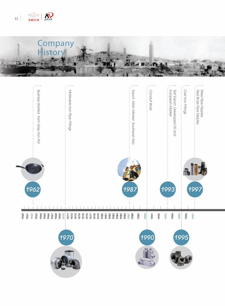
1970
19971993
Expo
rt, Ma
in Ma
rket: So
uthea
st Asia
1987Busine
ss Starte
d fro
m G
rey Iro
n Pot
1962
1990 1995
CompanyHistory
02
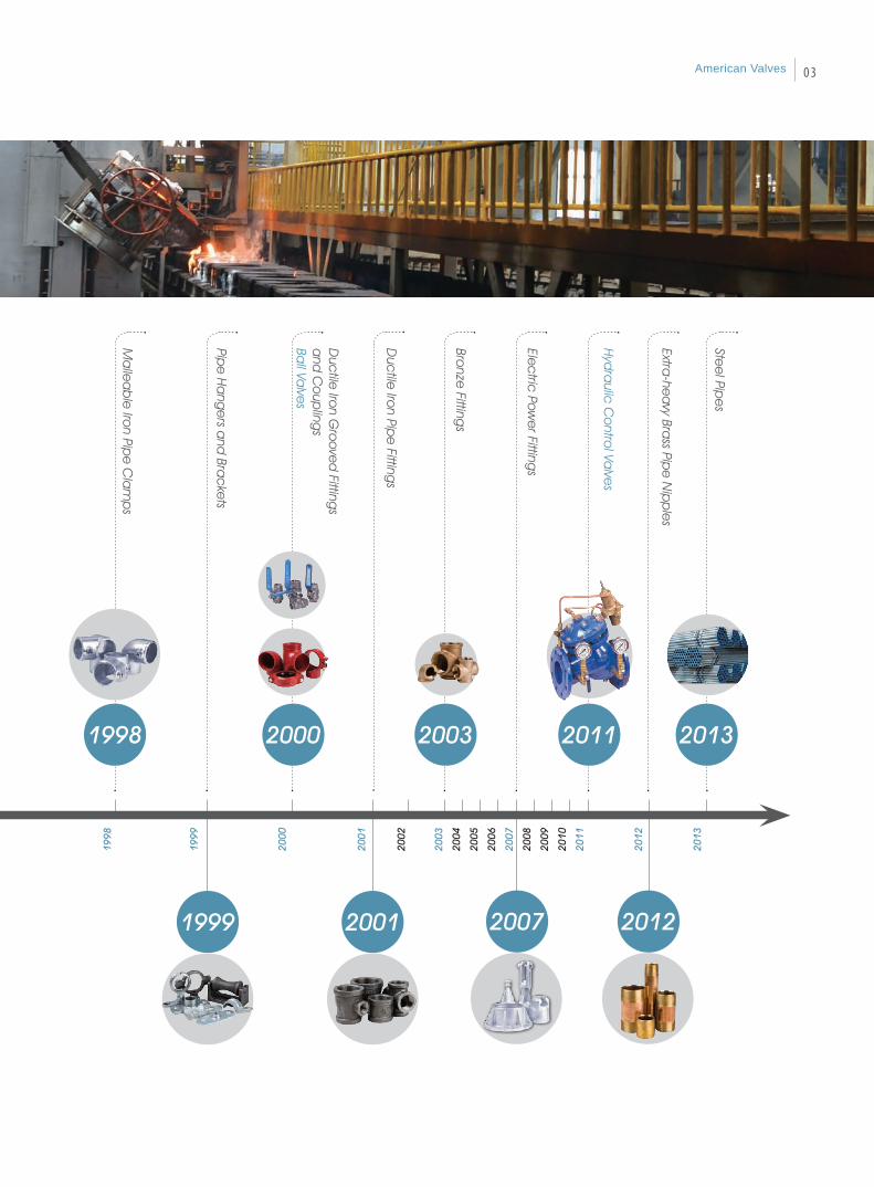
Pipe
Ha
nge
rs and
Brac
kets
Duc
tile Iro
n Gro
ove
d Fitting
s a
nd C
oup
lings
Ball Va
lves
Bronze
Fittings
Hyd
raulic
Co
ntrol Va
lves
Extra-he
avy Bra
ss Pipe
Nip
ple
s
Stee
l Pipe
s
Elec
tric Po
we
r Fittings
1998
1999
200
0
200
1
2002
2003
2004
2005
2006
2007
2008
2009
2010
2011
2012
201
3
2007 2012
2000 2003 2011 2013M
alle
ab
le Iro
n Pipe
Cla
mp
s 1998
Duc
tile Iro
n Pipe
Fittings
20011999
American Valves 03

High precision equipment is quality assurance.
Jinan Meide’s 8 factories are all equipped with the
most advanced facilities and equipment in the
industry. The main production facilities include Sinto
automatic molding line, Tokyu automatic molding
line, Chinese 416 automatic vertical molding line,
automatic molding sand mixers, cupola furnaces,
electric furnaces, water-cooled longevous cupola
furnaces, CNC vertical machining centers, CNC
machines, NC vertical lathes, radial drills, Jinan
Meide proprietary automatic machines, hot-dipped
galvanization line, automatic box sealing line,
stereoscopic warehouse and so on.
Tokyu AMF-111055
Pouring
State ofthe Art Equipment
Pattern
04
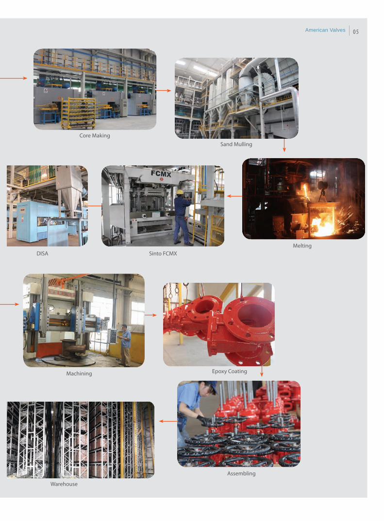
Core MakingSand Mulling
MeltingSinto FCMX
Epoxy CoatingMachining
Assembling
Warehouse
DISA
American Valves 05

Reliable Quality Assurance
Jinan Meide is honored as the National enterprise
technical center and is capable and qualified to
conduct full series of tests and inspections including
chemical checking, etc.
Inspection facilities include: spectrometer, carbon
sulfur analyzer, metallurgical microscope, tensile
strength testing equipment, pressure testing
equipment, adhesive force testing equipment, CMM,
hardness tester, etc.
From incoming inspection to finished product,
quality is checked and monitored in the whole
process. Each step of the manufacturing process is
carefully documented, regularly reviewed for revision
control and updating standard. Quality procedures
are constantly monitored and updated to assure
that only the highest and most consistent quality
products are supplied to our valued customers.
R & D
Spec t romete r
Meta l lu rg ica l M ic roscope
06

CMM Pro jec to r
Va lve Pressure Tes t ing Mach ine (Hor i zon ta l )Endurance Tes t Mach ineVa lve Pressure Tes t ing Mach ine (Ver t i ca l )
Va lve Pressure Tes t ing Mach ine (Hor i zon ta l )
American Valves 07
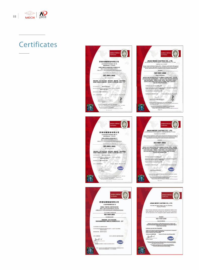
Certificates
08

American Valves 09
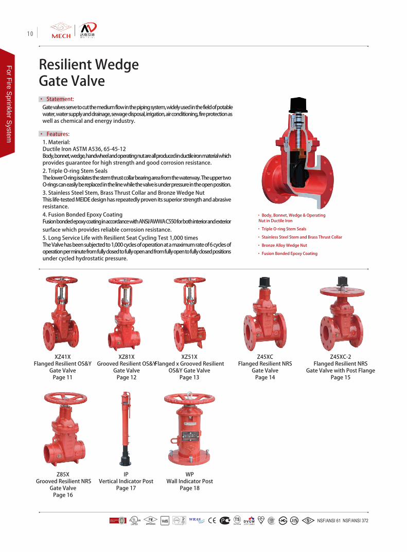
Resilient Wedge Gate Valve• Statement:
Gate valves serve to cut the medium flow in the piping system, widely used in the field of potable water, water supply and drainage, sewage disposal, irrigation, air conditioning, fire protection as well as chemical and energy industry.
• Features: 1. Material: Ductile Iron ASTM A536, 65-45-12Body, bonnet, wedge, handwheel and operating nut are all produced in ductile iron material which provides guarantee for high strength and good corrosion resistance.2. Triple O-ring Stem SealsThe lower O-ring isolates the stem thrust collar bearing area from the waterway. The upper two O-rings can easily be replaced in the line while the valve is under pressure in the open position.3. Stainless Steel Stem, Brass Thrust Collar and Bronze Wedge NutThis life-tested MEIDE design has repeatedly proven its superior strength and abrasive resistance.4. Fusion Bonded Epoxy CoatingFusion bonded epoxy coating in accordance with ANSI/AWWA C550 for both interior and exterior surface which provides reliable corrosion resistance.5. Long Service Life with Resilient Seat Cycling Test 1,000 timesThe Valve has been subjected to 1,000 cycles of operation at a maximum rate of 6 cycles of operation per minute from fully closed to fully open and from fully open to fully closed positions under cycled hydrostatic pressure.
• Body, Bonnet, Wedge & Operating Nut in Ductile Iron
• Triple O-ring Stem Seals
• Stainless Steel Stem and Brass Thrust Collar
• Bronze Alloy Wedge Nut
• Fusion Bonded Epoxy Coating
Z45XCFlanged Resilient NRS
Gate ValvePage 14
XZ41XFlanged Resilient OS&Y
Gate ValvePage 11
Z45XC-2Flanged Resilient NRS
Gate Valve with Post FlangePage 15
XZ81XGrooved Resilient OS&Y
Gate ValvePage 12
XZ51XFlanged x Grooved Resilient
OS&Y Gate ValvePage 13
Z85X Grooved Resilient NRS
Gate ValvePage 16
WPWall Indicator Post
Page 18
IPVertical Indicator Post
Page 17
10
For Fire Sprinkler S
ystem
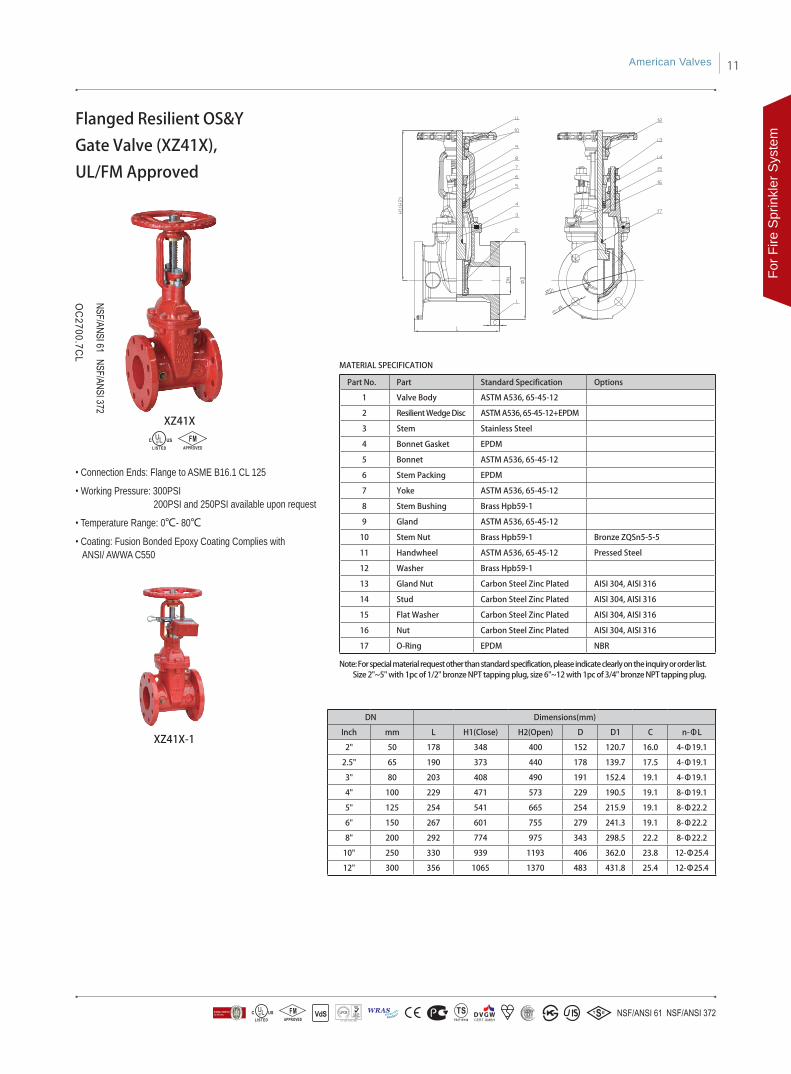
Part No. Part Standard Specification Options
1 Valve Body ASTM A536, 65-45-12
2 Resilient Wedge Disc ASTM A536, 65-45-12+EPDM
3 Stem Stainless Steel
4 Bonnet Gasket EPDM
5 Bonnet ASTM A536, 65-45-12
6 Stem Packing EPDM
7 Yoke ASTM A536, 65-45-12
8 Stem Bushing Brass Hpb59-1
9 Gland ASTM A536, 65-45-12
10 Stem Nut Brass Hpb59-1 Bronze ZQSn5-5-5
11 Handwheel ASTM A536, 65-45-12 Pressed Steel
12 Washer Brass Hpb59-1
13 Gland Nut Carbon Steel Zinc Plated AISI 304, AISI 316
14 Stud Carbon Steel Zinc Plated AISI 304, AISI 316
15 Flat Washer Carbon Steel Zinc Plated AISI 304, AISI 316
16 Nut Carbon Steel Zinc Plated AISI 304, AISI 316
17 O-Ring EPDM NBR
• Connection Ends: Flange to ASME B16.1 CL 125
• Working Pressure: 300PSI 200PSI and 250PSI available upon request
• Temperature Range: 0℃- 80℃
• Coating: Fusion Bonded Epoxy Coating Complies with ANSI/ AWWA C550
DN Dimensions(mm)
Inch mm L H1(Close) H2(Open) D D1 C n-ΦL
2" 50 178 348 400 152 120.7 16.0 4-Φ19.1
2.5" 65 190 373 440 178 139.7 17.5 4-Φ19.1
3" 80 203 408 490 191 152.4 19.1 4-Φ19.1
4" 100 229 471 573 229 190.5 19.1 8-Φ19.1
5" 125 254 541 665 254 215.9 19.1 8-Φ22.2
6" 150 267 601 755 279 241.3 19.1 8-Φ22.2
8" 200 292 774 975 343 298.5 22.2 8-Φ22.2
10" 250 330 939 1193 406 362.0 23.8 12-Φ25.4
12" 300 356 1065 1370 483 431.8 25.4 12-Φ25.4
MATERIAL SPECIFICATION
XZ41X
XZ41X-1
Flanged Resilient OS&Y
Gate Valve (XZ41X),
UL/FM Approved
Note: For special material request other than standard specification, please indicate clearly on the inquiry or order list. Size 2"~5" with 1pc of 1/2" bronze NPT tapping plug, size 6"~12 with 1pc of 3/4" bronze NPT tapping plug.
American Valves 11
For F
ire S
prin
kler
Sys
tem
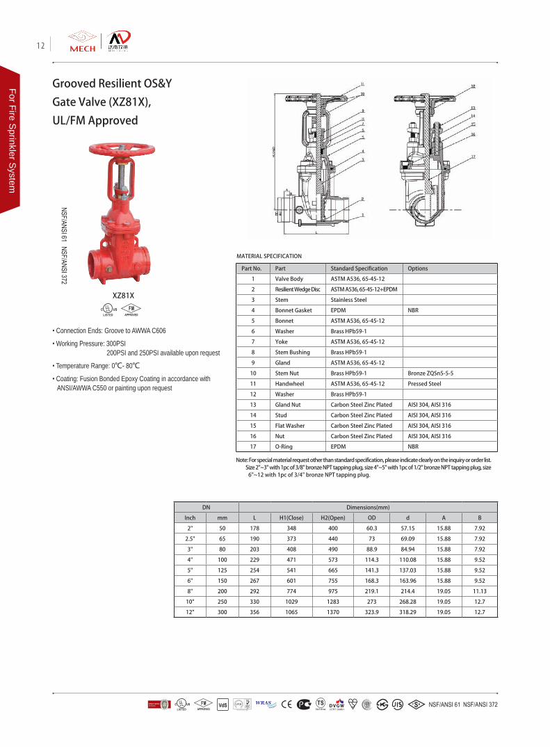
Grooved Resilient OS&Y
Gate Valve (XZ81X),
UL/FM Approved
Part No. Part Standard Specification Options
1 Valve Body ASTM A536, 65-45-12
2 Resilient Wedge Disc ASTM A536, 65-45-12+EPDM
3 Stem Stainless Steel
4 Bonnet Gasket EPDM NBR
5 Bonnet ASTM A536, 65-45-12
6 Washer Brass HPb59-1
7 Yoke ASTM A536, 65-45-12
8 Stem Bushing Brass HPb59-1
9 Gland ASTM A536, 65-45-12
10 Stem Nut Brass HPb59-1 Bronze ZQSn5-5-5
11 Handwheel ASTM A536, 65-45-12 Pressed Steel
12 Washer Brass HPb59-1
13 Gland Nut Carbon Steel Zinc Plated AISI 304, AISI 316
14 Stud Carbon Steel Zinc Plated AISI 304, AISI 316
15 Flat Washer Carbon Steel Zinc Plated AISI 304, AISI 316
16 Nut Carbon Steel Zinc Plated AISI 304, AISI 316
17 O-Ring EPDM NBR
DN Dimensions(mm)
Inch mm L H1(Close) H2(Open) OD d A B
2" 50 178 348 400 60.3 57.15 15.88 7.92
2.5" 65 190 373 440 73 69.09 15.88 7.92
3" 80 203 408 490 88.9 84.94 15.88 7.92
4" 100 229 471 573 114.3 110.08 15.88 9.52
5" 125 254 541 665 141.3 137.03 15.88 9.52
6" 150 267 601 755 168.3 163.96 15.88 9.52
8" 200 292 774 975 219.1 214.4 19.05 11.13
10" 250 330 1029 1283 273 268.28 19.05 12.7
12" 300 356 1065 1370 323.9 318.29 19.05 12.7
• Connection Ends: Groove to AWWA C606
• Working Pressure: 300PSI 200PSI and 250PSI available upon request
• Temperature Range: 0℃- 80℃
• Coating: Fusion Bonded Epoxy Coating in accordance with ANSI/AWWA C550 or painting upon request
MATERIAL SPECIFICATION
XZ81X
Note: For special material request other than standard specification, please indicate clearly on the inquiry or order list. Size 2"~3" with 1pc of 3/8" bronze NPT tapping plug, size 4"~5" with 1pc of 1/2" bronze NPT tapping plug, size 6"~12 with 1pc of 3/4" bronze NPT tapping plug.
12
For Fire Sprinkler S
ystem
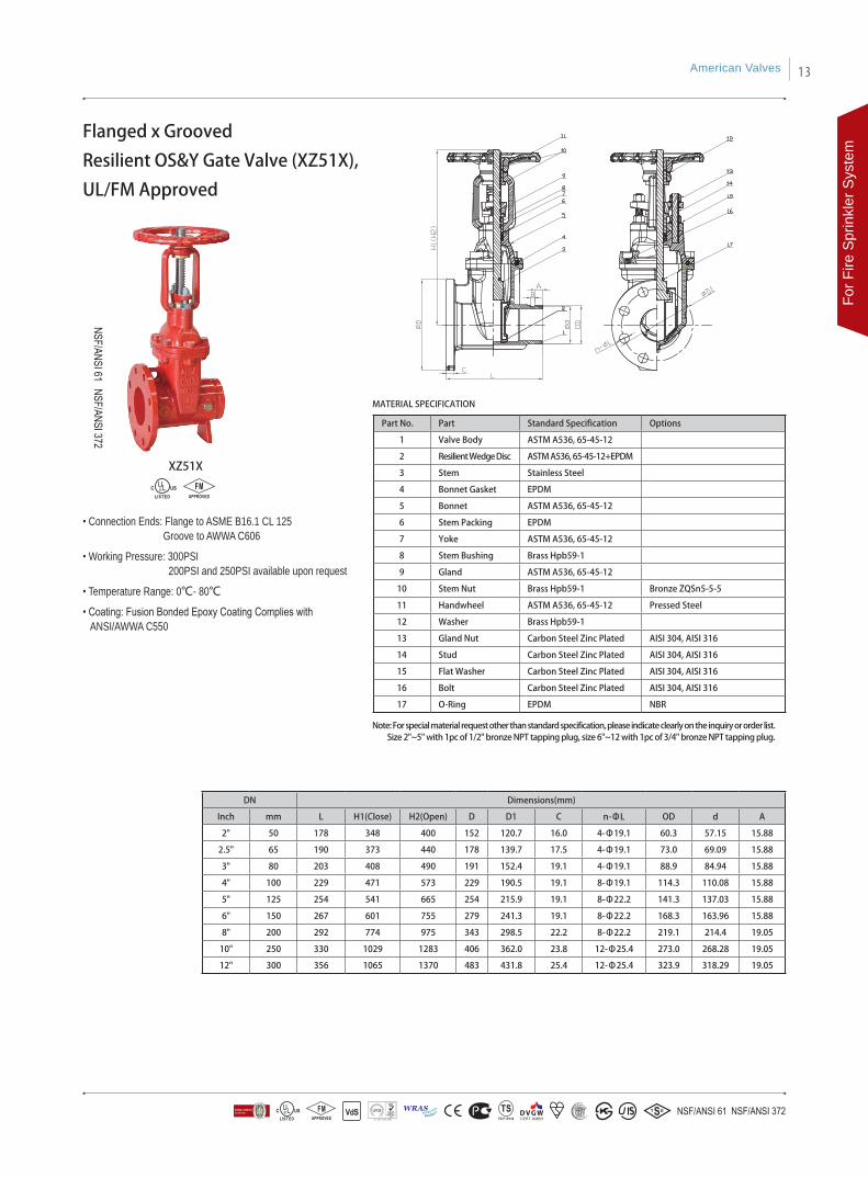
Part No. Part Standard Specification Options
1 Valve Body ASTM A536, 65-45-12
2 Resilient Wedge Disc ASTM A536, 65-45-12+EPDM
3 Stem Stainless Steel
4 Bonnet Gasket EPDM
5 Bonnet ASTM A536, 65-45-12
6 Stem Packing EPDM
7 Yoke ASTM A536, 65-45-12
8 Stem Bushing Brass Hpb59-1
9 Gland ASTM A536, 65-45-12
10 Stem Nut Brass Hpb59-1 Bronze ZQSn5-5-5
11 Handwheel ASTM A536, 65-45-12 Pressed Steel
12 Washer Brass Hpb59-1
13 Gland Nut Carbon Steel Zinc Plated AISI 304, AISI 316
14 Stud Carbon Steel Zinc Plated AISI 304, AISI 316
15 Flat Washer Carbon Steel Zinc Plated AISI 304, AISI 316
16 Bolt Carbon Steel Zinc Plated AISI 304, AISI 316
17 O-Ring EPDM NBR
MATERIAL SPECIFICATION
Flanged x Grooved
Resilient OS&Y Gate Valve (XZ51X),
UL/FM Approved
• Connection Ends: Flange to ASME B16.1 CL 125 Groove to AWWA C606
• Working Pressure: 300PSI 200PSI and 250PSI available upon request
• Temperature Range: 0℃- 80℃
• Coating: Fusion Bonded Epoxy Coating Complies with ANSI/AWWA C550
XZ51X
DN Dimensions(mm)
Inch mm L H1(Close) H2(Open) D D1 C n-ΦL OD d A
2" 50 178 348 400 152 120.7 16.0 4-Φ19.1 60.3 57.15 15.88
2.5" 65 190 373 440 178 139.7 17.5 4-Φ19.1 73.0 69.09 15.88
3" 80 203 408 490 191 152.4 19.1 4-Φ19.1 88.9 84.94 15.88
4" 100 229 471 573 229 190.5 19.1 8-Φ19.1 114.3 110.08 15.88
5" 125 254 541 665 254 215.9 19.1 8-Φ22.2 141.3 137.03 15.88
6" 150 267 601 755 279 241.3 19.1 8-Φ22.2 168.3 163.96 15.88
8" 200 292 774 975 343 298.5 22.2 8-Φ22.2 219.1 214.4 19.05
10" 250 330 1029 1283 406 362.0 23.8 12-Φ25.4 273.0 268.28 19.05
12" 300 356 1065 1370 483 431.8 25.4 12-Φ25.4 323.9 318.29 19.05
Note: For special material request other than standard specification, please indicate clearly on the inquiry or order list. Size 2"~5" with 1pc of 1/2" bronze NPT tapping plug, size 6"~12 with 1pc of 3/4" bronze NPT tapping plug.
American Valves 13
For F
ire S
prin
kler
Sys
tem
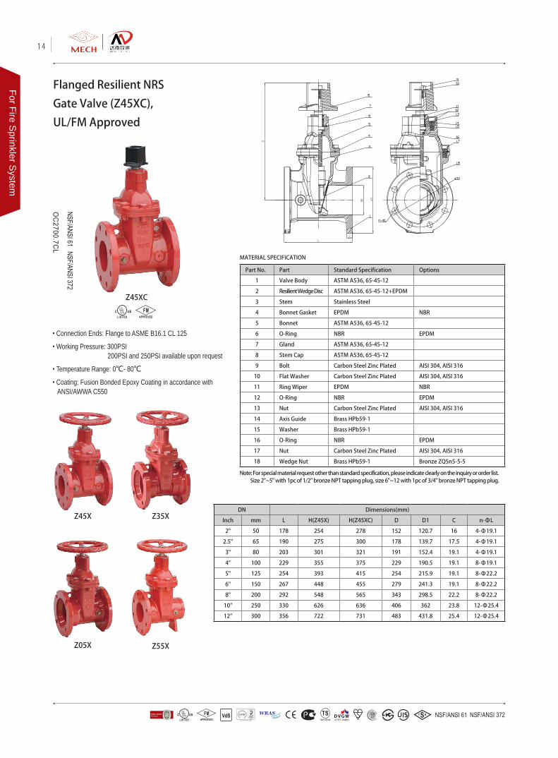
• Connection Ends: Flange to ASME B16.1 CL 125
• Working Pressure: 300PSI 200PSI and 250PSI available upon request
• Temperature Range: 0℃- 80℃
• Coating: Fusion Bonded Epoxy Coating in accordance with ANSI/AWWA C550
Flanged Resilient NRS
Gate Valve (Z45XC),
UL/FM Approved
Part No. Part Standard Specification Options
1 Valve Body ASTM A536, 65-45-12
2 Resilient Wedge Disc ASTM A536, 65-45-12+EPDM
3 Stem Stainless Steel
4 Bonnet Gasket EPDM NBR
5 Bonnet ASTM A536, 65-45-12
6 O-Ring NBR EPDM
7 Gland ASTM A536, 65-45-12
8 Stem Cap ASTM A536, 65-45-12
9 Bolt Carbon Steel Zinc Plated AISI 304, AISI 316
10 Flat Washer Carbon Steel Zinc Plated AISI 304, AISI 316
11 Ring Wiper EPDM NBR
12 O-Ring NBR EPDM
13 Nut Carbon Steel Zinc Plated AISI 304, AISI 316
14 Axis Guide Brass HPb59-1
15 Washer Brass HPb59-1
16 O-Ring NBR EPDM
17 Nut Carbon Steel Zinc Plated AISI 304, AISI 316
18 Wedge Nut Brass HPb59-1 Bronze ZQSn5-5-5
DN Dimensions(mm)
Inch mm L H(Z45X) H(Z45XC) D D1 C n-ΦL
2" 50 178 254 278 152 120.7 16 4-Φ19.1
2.5" 65 190 275 300 178 139.7 17.5 4-Φ19.1
3" 80 203 301 321 191 152.4 19.1 4-Φ19.1
4" 100 229 355 375 229 190.5 19.1 8-Φ19.1
5" 125 254 393 415 254 215.9 19.1 8-Φ22.2
6" 150 267 448 455 279 241.3 19.1 8-Φ22.2
8" 200 292 548 565 343 298.5 22.2 8-Φ22.2
10" 250 330 626 636 406 362 23.8 12-Φ25.4
12" 300 356 722 731 483 431.8 25.4 12-Φ25.4
Z45XC
Z45X
Z05X
Z35X
Z55X
MATERIAL SPECIFICATION
Note: For special material request other than standard specification, please indicate clearly on the inquiry or order list. Size 2"~5" with 1pc of 1/2" bronze NPT tapping plug, size 6"~12 with 1pc of 3/4" bronze NPT tapping plug.
14
For Fire Sprinkler S
ystem
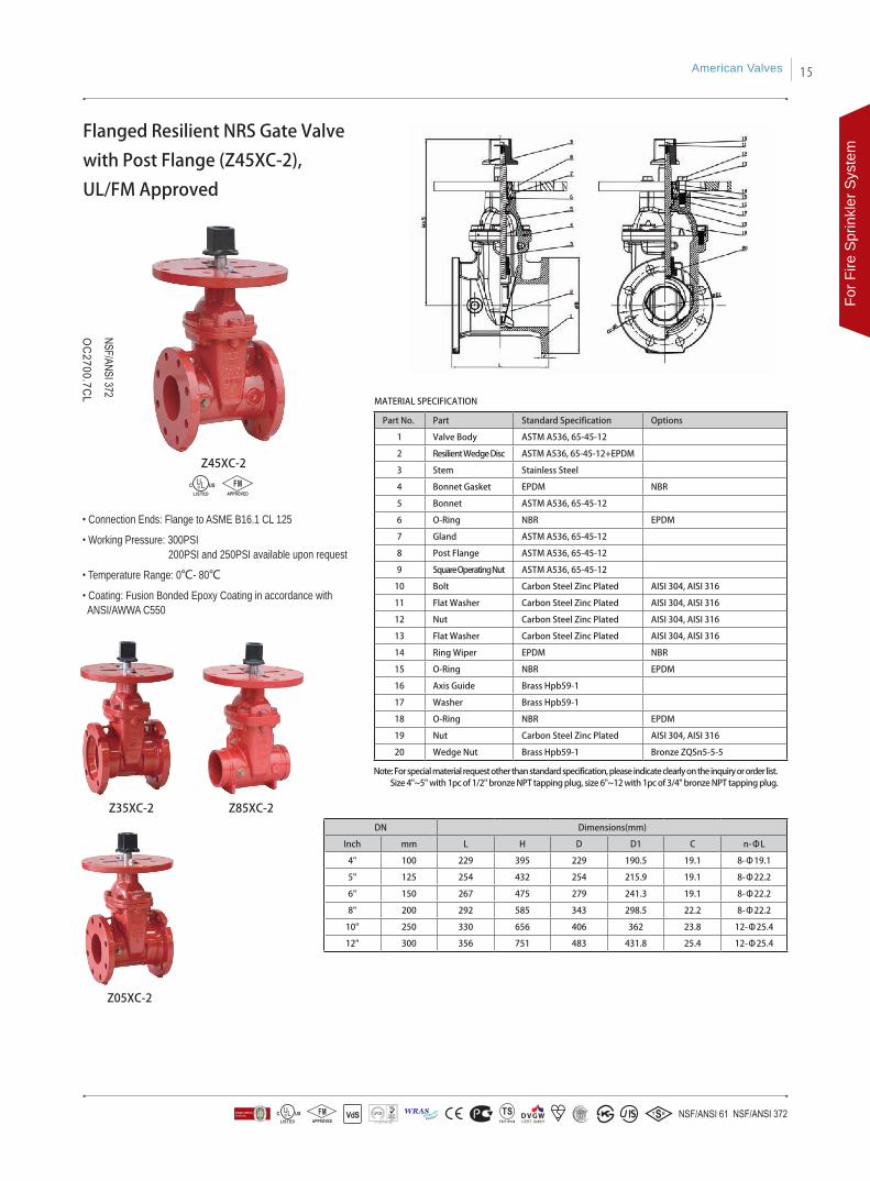
• Connection Ends: Flange to ASME B16.1 CL 125
• Working Pressure: 300PSI 200PSI and 250PSI available upon request
• Temperature Range: 0℃- 80℃
• Coating: Fusion Bonded Epoxy Coating in accordance with ANSI/AWWA C550
Part No. Part Standard Specification Options
1 Valve Body ASTM A536, 65-45-12
2 Resilient Wedge Disc ASTM A536, 65-45-12+EPDM
3 Stem Stainless Steel
4 Bonnet Gasket EPDM NBR
5 Bonnet ASTM A536, 65-45-12
6 O-Ring NBR EPDM
7 Gland ASTM A536, 65-45-12
8 Post Flange ASTM A536, 65-45-12
9 Square Operating Nut ASTM A536, 65-45-12
10 Bolt Carbon Steel Zinc Plated AISI 304, AISI 316
11 Flat Washer Carbon Steel Zinc Plated AISI 304, AISI 316
12 Nut Carbon Steel Zinc Plated AISI 304, AISI 316
13 Flat Washer Carbon Steel Zinc Plated AISI 304, AISI 316
14 Ring Wiper EPDM NBR
15 O-Ring NBR EPDM
16 Axis Guide Brass Hpb59-1
17 Washer Brass Hpb59-1
18 O-Ring NBR EPDM
19 Nut Carbon Steel Zinc Plated AISI 304, AISI 316
20 Wedge Nut Brass Hpb59-1 Bronze ZQSn5-5-5
DN Dimensions(mm)
Inch mm L H D D1 C n-ΦL
4" 100 229 395 229 190.5 19.1 8-Φ19.1
5" 125 254 432 254 215.9 19.1 8-Φ22.2
6" 150 267 475 279 241.3 19.1 8-Φ22.2
8" 200 292 585 343 298.5 22.2 8-Φ22.2
10" 250 330 656 406 362 23.8 12-Φ25.4
12" 300 356 751 483 431.8 25.4 12-Φ25.4
Flanged Resilient NRS Gate Valve
with Post Flange (Z45XC-2),
UL/FM Approved
MATERIAL SPECIFICATION
Z45XC-2
Note: For special material request other than standard specification, please indicate clearly on the inquiry or order list. Size 4"~5" with 1pc of 1/2" bronze NPT tapping plug, size 6"~12 with 1pc of 3/4" bronze NPT tapping plug.
Z85XC-2
Z05XC-2
Z35XC-2
American Valves 15
For F
ire S
prin
kler
Sys
tem

• Connection Ends: Groove to AWWA C606
• Working Pressure: 300PSI 200PSI and 250PSI available upon request
• Temperature Range: 0℃- 80℃
• Coating: Fusion Bonded Epoxy Coating in accordance with ANSI/AWWA C550 or painting upon request
DN Dimensions(mm)
Inch mm L H OD d A B
2" 50 178 254 60.3 57.15 15.88 7.92
2.5" 65 190 275 73 69.09 15.88 7.92
3" 80 203 301 88.9 84.94 15.88 7.92
4" 100 229 355 114.3 110.08 15.88 9.52
5" 125 254 393 141.3 137.03 15.88 9.52
6" 150 267 448 168.3 163.96 15.88 9.52
8" 200 292 548 219.1 214.4 19.05 11.13
10" 250 330 626 273 268.28 19.05 12.7
12" 300 356 722 323.9 318.29 19.05 12.7
Grooved Resilient NRS
Gate Valve (Z85X),
UL/FM Approved
Part No. Part Standard Specification Options
1 Valve Body ASTM A536, 65-45-12
2 Resilient Wedge Disc ASTM A536, 65-45-12+EPDM
3 Stem Stainless Steel
4 Bonnet Gasket EPDM NBR
5 Bonnet ASTM A536,65-45-12
6 O-Ring NBR EPDM
7 Gland ASTM A536,65-45-12
8 Handwheel ASTM A536,65-45-12 Pressed Steel
9 Bolt Carbon Steel Zinc Plated AISI 304, AISI 316
10 Flat Washer Carbon Steel Zinc Plated AISI 304, AISI 316
11 Ring Wiper EPDM NBR
12 O-Ring NBR EPDM
13 Nut Carbon Steel Zinc Plated AISI 304, AISI 316
14 Axis Guide Brass HPb59-1
15 Washer Brass HPb59-1
16 O-Ring NBR EPDM
17 Nut Carbon Steel Zinc Plated AISI 304, AISI 316
18 Wedge Nut Brass HPb59-1 Bronze ZQSn5-5-5
MATERIAL SPECIFICATION
Z85X
Note: For special material request other than standard specification, please indicate clearly on the inquiry or order list. Size 2"~3" with 1pc of 3/8" bronze NPT tapping plug, size 4"~5" with 1pc of 1/2" bronze NPT tapping plug, size 6"~12 with 1pc of 3/4" bronze NPT tapping plug.
16
For Fire Sprinkler S
ystem
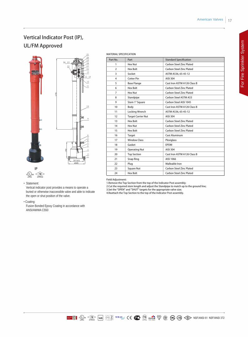
• Statement: Vertical indicator post provides a means to operate a buried or otherwise inaccessible valve and able to indicate the open or shut position of the valve.
• Coating:Fusion Bonded Epoxy Coating in accordance with ANSI/AWWA C550
Part No. Part Standard Specification
1 Hex Nut Carbon Steel Zinc Plated
2 Hex Bolt Carbon Steel Zinc Plated
3 Socket ASTM A536, 65-45-12
4 Cotter Pin AISI 304
5 Base Flange Cast Iron ASTM A126 Class B
6 Hex Bolt Carbon Steel Zinc Plated
7 Hex Nut Carbon Steel Zinc Plated
8 Standpipe Carbon Steel ASTM A53
9 Stem 1" Square Carbon Steel AISI 1045
10 Body Cast Iron ASTM A126 Class B
11 Locking Wrench ASTM A536, 65-45-12
12 Target Carrier Nut AISI 304
13 Hex Bolt Carbon Steel Zinc Plated
14 Hex Nut Carbon Steel Zinc Plated
15 Hex Bolt Carbon Steel Zinc Plated
16 Target Cast Aluminum
17 Window Class Plexiglass
18 Gasket EPDM
19 Operating Nut AISI 304
20 Top Section Cast Iron ASTM A126 Class B
21 Snap Ring AISI 1066
22 Plug Malleable Iron
23 Square Nut Carbon Steel Zinc Plated
24 Hex Bolt Carbon Steel Zinc Plated
Field Adjustment:1.Remove the Top Section from the top of the Indicator Post assembly;2.Cut the required stem length and adjust the Standpipe to match up to the ground line;3.Set the "OPEN" and "SHUT" targets for the appropriate valve size;4.Reattach the Top Section to the top of the Indicator Post assembly.
MATERIAL SPECIFICATION
IP
Vertical Indicator Post (IP),
UL/FM Approved
American Valves 17
For F
ire S
prin
kler
Sys
tem

• Statement: Wall indicator post provides a means to operate a valve installed behind a wall and able to indicate the open or shut position of the valve.
• Coating:Fusion Bonded Epoxy Coating in accordance with ANSI/AWWA C550
Part No. Part Standard Specification
1 Body Cast Iron ASTM A126 Class B
2 Plug Malleable Iron
3 Square Nut Carbon Steel Zinc Plated
4 Hex Bolt Carbon Steel Zinc Plated
5 Cover Cast Iron ASTM A126 Class B
6 Hand wheel ASTM A536, 65-45-12
7 Eye Bolt Carbon Steel Zinc Plated
8 Gasket Carbon Steel Zinc Plated
9 Snap Ring AISI 1066
10 Operating NUT AISI 304
11 Gasket EPDM
12 Window Class Plexiglass
13 Target Cast Aluminum
14 Hex Bolt Carbon Steel Zinc Plated
15 Hex Bolt Carbon Steel Zinc Plated
16 Hex Nut Carbon Steel Zinc Plated
17 Target Carrier Nut AISI 304
18 Hex Nut Carbon Steel Zinc Plated
19 Hex Bolt Carbon Steel Zinc Plated
20 Stem 1" Square Carbon Steel AISI 1045
21 Cotter Pin AISI 304
22 Socket ASTM A536, 65-45-12
Note: For special material request other than standard specification, please indicate clearly on the inquiry or order list;
MATERIAL SPECIFICATION
WP
Wall Indicator Post (WP),
UL/FM Approved
18
For Fire Sprinkler S
ystem
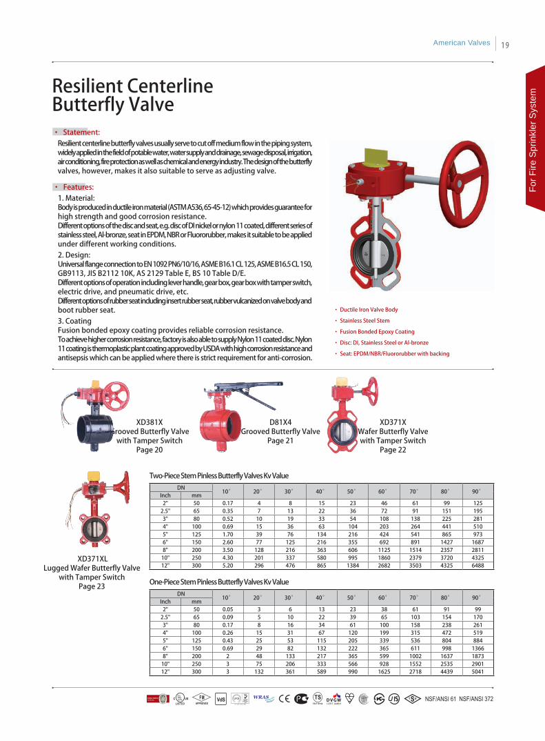
Resilient Centerline Butterfly Valve
• Statement: Resilient centerline butterfly valves usually serve to cut off medium flow in the piping system, widely applied in the field of potable water, water supply and drainage, sewage disposal, irrigation, air conditioning, fire protection as well as chemical and energy industry. The design of the butterfly valves, however, makes it also suitable to serve as adjusting valve.
• Features:1. Material: Body is produced in ductile iron material (ASTM A536, 65-45-12) which provides guarantee for high strength and good corrosion resistance.Different options of the disc and seat, e.g. disc of DI nickel or nylon 11 coated, different series of stainless steel, Al-bronze, seat in EPDM, NBR or Fluororubber, makes it suitable to be applied under different working conditions.2. Design: Universal flange connection to EN 1092 PN6/10/16, ASME B16.1 CL 125, ASME B16.5 CL 150, GB9113, JIS B2112 10K, AS 2129 Table E, BS 10 Table D/E. Different options of operation including lever handle, gear box, gear box with tamper switch, electric drive, and pneumatic drive, etc.Different options of rubber seat including insert rubber seat, rubber vulcanized on valve body and boot rubber seat. 3. CoatingFusion bonded epoxy coating provides reliable corrosion resistance.To achieve higher corrosion resistance, factory is also able to supply Nylon 11 coated disc. Nylon 11 coating is thermoplastic plant coating approved by USDA with high corrosion resistance and antisepsis which can be applied where there is strict requirement for anti-corrosion.
• Ductile Iron Valve Body
• Stainless Steel Stem
• Fusion Bonded Epoxy Coating
• Disc: DI, Stainless Steel or Al-bronze
• Seat: EPDM/NBR/Fluororubber with backing
XD371XWafer Butterfly Valvewith Tamper Switch
Page 22
XD381XGrooved Butterfly Valve
with Tamper SwitchPage 20
DN10° 20° 30° 40° 50° 60° 70° 80° 90°
Inch mm2" 50 0.17 4 8 15 23 46 61 99 125
2.5" 65 0.35 7 13 22 36 72 91 151 195 3" 80 0.52 10 19 33 54 108 138 225 281 4" 100 0.69 15 36 63 104 203 264 441 510 5" 125 1.70 39 76 134 216 424 541 865 973 6" 150 2.60 77 125 216 355 692 891 1427 1687 8" 200 3.50 128 216 363 606 1125 1514 2357 2811
10" 250 4.30 201 337 580 995 1860 2379 3720 4325 12" 300 5.20 296 476 865 1384 2682 3503 4325 6488
DN10° 20° 30° 40° 50° 60° 70° 80° 90°
Inch mm2" 50 0.05 3 6 13 23 38 61 91 99
2.5" 65 0.09 5 10 22 39 65 103 154 170 3" 80 0.17 8 16 34 61 100 158 238 261 4" 100 0.26 15 31 67 120 199 315 472 519 5" 125 0.43 25 53 115 205 339 536 804 884 6" 150 0.69 29 82 132 222 365 611 998 1366 8" 200 2 48 133 217 365 599 1002 1637 1873
10" 250 3 75 206 333 566 928 1552 2535 2901 12" 300 3 132 361 589 990 1625 2718 4439 5041
D81X4Grooved Butterfly Valve
Page 21
Two-Piece Stem Pinless Butterfly Valves Kv Value
One-Piece Stem Pinless Butterfly Valves Kv Value
XD371XLLugged Wafer Butterfly Valve
with Tamper SwitchPage 23
American Valves 19
For F
ire S
prin
kler
Sys
tem
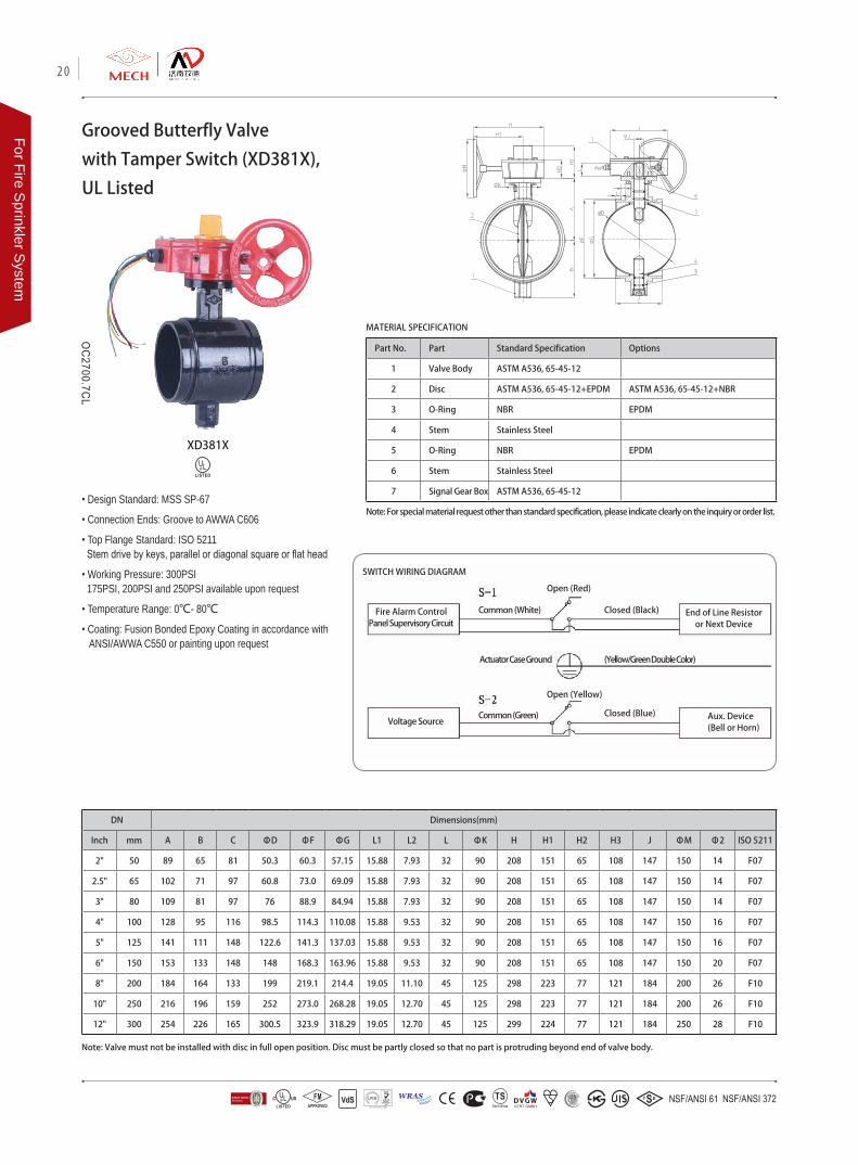
Grooved Butterfly Valve
with Tamper Switch (XD381X),
UL Listed
Part No. Part Standard Specification Options
1 Valve Body ASTM A536, 65-45-12
2 Disc ASTM A536, 65-45-12+EPDM ASTM A536, 65-45-12+NBR
3 O-Ring NBR EPDM
4 Stem Stainless Steel
5 O-Ring NBR EPDM
6 Stem Stainless Steel
7 Signal Gear Box ASTM A536, 65-45-12• Design Standard: MSS SP-67
• Connection Ends: Groove to AWWA C606
• Top Flange Standard: ISO 5211 Stem drive by keys, parallel or diagonal square or flat head
• Working Pressure: 300PSI 175PSI, 200PSI and 250PSI available upon request
• Temperature Range: 0℃- 80℃
• Coating: Fusion Bonded Epoxy Coating in accordance with ANSI/AWWA C550 or painting upon request
Note: Valve must not be installed with disc in full open position. Disc must be partly closed so that no part is protruding beyond end of valve body.
XD381X
MATERIAL SPECIFICATION
Note: For special material request other than standard specification, please indicate clearly on the inquiry or order list.
SWITCH WIRING DIAGRAM
Fire Alarm Control Panel Supervisory Circuit
Common (White)
Open (Red)
Closed (Black) End of Line Resistor or Next Device
Actuator Case Ground (Yellow/Green Double Color)
Voltage SourceCommon (Green)
Open (Yellow)
Closed (Blue) Aux. Device(Bell or Horn)
DN Dimensions(mm)
Inch mm A B C ΦD ΦF ΦG L1 L2 L ΦK H H1 H2 H3 J ΦM Φ2 ISO 5211
2" 50 89 65 81 50.3 60.3 57.15 15.88 7.93 32 90 208 151 65 108 147 150 14 F07
2.5" 65 102 71 97 60.8 73.0 69.09 15.88 7.93 32 90 208 151 65 108 147 150 14 F07
3" 80 109 81 97 76 88.9 84.94 15.88 7.93 32 90 208 151 65 108 147 150 14 F07
4" 100 128 95 116 98.5 114.3 110.08 15.88 9.53 32 90 208 151 65 108 147 150 16 F07
5" 125 141 111 148 122.6 141.3 137.03 15.88 9.53 32 90 208 151 65 108 147 150 16 F07
6" 150 153 133 148 148 168.3 163.96 15.88 9.53 32 90 208 151 65 108 147 150 20 F07
8" 200 184 164 133 199 219.1 214.4 19.05 11.10 45 125 298 223 77 121 184 200 26 F10
10" 250 216 196 159 252 273.0 268.28 19.05 12.70 45 125 298 223 77 121 184 200 26 F10
12" 300 254 226 165 300.5 323.9 318.29 19.05 12.70 45 125 299 224 77 121 184 250 28 F10
20
For Fire Sprinkler S
ystem
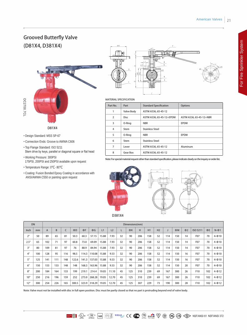
Grooved Butterfly Valve
(D81X4, D381X4)
Part No. Part Standard Specification Options
1 Valve Body ASTM A536, 65-45-12
2 Disc ASTM A536, 65-45-12+EPDM ASTM A536, 65-45-12+NBR
3 O-Ring NBR EPDM
4 Stem Stainless Steel
5 O-Ring NBR EPDM
6 Stem Stainless Steel
7 Lever ASTM A536, 65-45-12 Aluminum
8 Gear Box ASTM A536, 65-45-12
• Design Standard: MSS SP-67
• Connection Ends: Groove to AWWA C606
• Top Flange Standard: ISO 5211 Stem drive by keys, parallel or diagonal square or flat head
• Working Pressure: 300PSI 175PSI, 200PSI and 250PSI available upon request
• Temperature Range: 0℃- 80℃
• Coating: Fusion Bonded Epoxy Coating in accordance with ANSI/AWWA C550 or painting upon request
Note: Valve must not be installed with disc in full open position. Disc must be partly closed so that no part is protruding beyond end of valve body.
D381X4
D81X4
MATERIAL SPECIFICATION
DN Dimensions(mm)
Inch mm A B C ΦD ΦF ΦG L1 L2 L ΦK H H1 H2 J ΦM Φ2 ISO 5211 ΦE N-Φ1
2" 50 89 65 81 50.3 60.3 57.15 15.88 7.93 32 90 206 158 52 114 150 14 F07 70 4-Φ10
2.5" 65 102 71 97 60.8 73.0 69.09 15.88 7.93 32 90 206 158 52 114 150 14 F07 70 4-Φ10
3" 80 109 81 97 76 88.9 84.94 15.88 7.93 32 90 206 158 52 114 150 14 F07 70 4-Φ10
4" 100 128 95 116 98.5 114.3 110.08 15.88 9.53 32 90 206 158 52 114 150 16 F07 70 4-Φ10
5" 125 141 111 148 122.6 141.3 137.03 15.88 9.53 32 90 206 158 52 114 150 16 F07 70 4-Φ10
6" 150 153 133 148 148 168.3 163.96 15.88 9.53 32 90 206 158 52 114 150 20 F07 70 4-Φ10
8" 200 184 164 133 199 219.1 214.4 19.05 11.10 45 125 310 239 69 167 300 26 F10 102 4-Φ12
10" 250 216 196 159 252 273.0 268.28 19.05 12.70 45 125 310 239 69 167 300 26 F10 102 4-Φ12
12" 300 254 226 165 300.5 323.9 318.29 19.05 12.70 45 125 307 229 73 190 300 28 F10 102 4-Φ12
Note: For special material request other than standard specification, please indicate clearly on the inquiry or order list.
American Valves 21
For F
ire S
prin
kler
Sys
tem
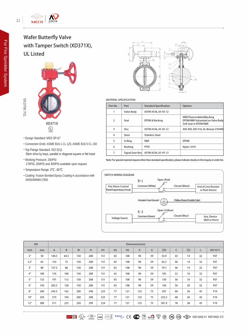
Wafer Butterfly Valve
with Tamper Switch (XD371X),
UL Listed
Part No. Part Standard Specification Options
1 Valve Body ASTM A536, 65-45-12
2 Seat EPDM & BackingNBR/Fluororubber&BackingEPDM/NBR Vulcanized on Valve BodySoft Seat in EPDM/NBR
3 Disc ASTM A536, 65-45-12 AISI 304, AISI 316, AL-Bronze C95400
4 Stem Stainless Steel
5 O-Ring NBR EPDM
6 Bushing PTFE Nylon 1010
7 Signal Gear Box ASTM A536, 65-45-12
• Design Standard: MSS SP-67
• Connection Ends: ASME B16.1 CL 125, ASME B16.5 CL 150
• Top Flange Standard: ISO 5211 Stem drive by keys, parallel or diagonal square or flat head
• Working Pressure: 250PSI 175PSI, 200PSI and 300PSI available upon request
• Temperature Range: 0℃- 80℃
• Coating: Fusion Bonded Epoxy Coating in accordance with ANSI/AWWA C550
MATERIAL SPECIFICATION
XD371X
Note: For special material request other than standard specification, please indicate clearly on the inquiry or order list.
DN Dimensions(mm)
Inch mm A B M H H1 H2 H3 K G ØD C Ø2 L ISO 5211
2" 50 140.5 64.5 150 208 151 65 108 90 59 53.9 43 14 32 F07
2.5" 65 153 72 150 208 151 65 108 90 59 65.2 46 14 32 F07
3" 80 157.5 86 150 208 151 65 108 90 59 79.7 46 14 32 F07
4" 100 176 100 150 208 151 65 108 90 59 105 52 16 32 F07
5" 125 191 112 150 208 151 65 108 90 59 130 56 16 32 F07
6" 150 202.5 128 150 208 151 65 108 90 59 156 56 20 32 F07
8" 200 243.5 162 200 298 223 77 121 125 75 207 60 26 45 F10
10" 250 273 194 200 298 223 77 121 125 75 253.3 68 26 45 F10
12" 300 311 223 250 299 224 77 121 125 75 301.9 78 28 45 F10
SWITCH WIRING DIAGRAM
Fire Alarm Control Panel Supervisory Circuit
Common (White)
Open (Red)
Closed (Black) End of Line Resistor or Next Device
Actuator Case Ground (Yellow/Green Double Color)
Voltage SourceCommon (Green)
Open (Yellow)
Closed (Blue) Aux. Device(Bell or Horn)
22
For Fire Sprinkler S
ystem
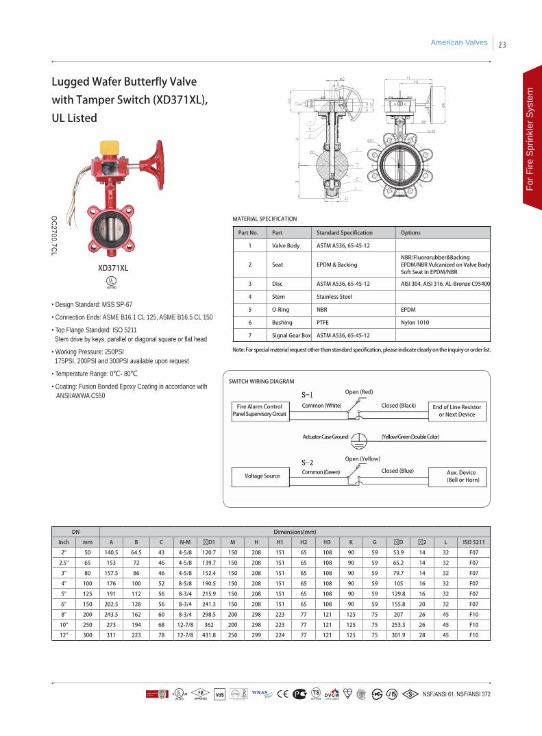
Lugged Wafer Butterfly Valve
with Tamper Switch (XD371XL),
UL Listed
Part No. Part Standard Specification Options
1 Valve Body ASTM A536, 65-45-12
2 Seat EPDM & BackingNBR/Fluororubber&BackingEPDM/NBR Vulcanized on Valve BodySoft Seat in EPDM/NBR
3 Disc ASTM A536, 65-45-12 AISI 304, AISI 316, AL-Bronze C95400
4 Stem Stainless Steel
5 O-Ring NBR EPDM
6 Bushing PTFE Nylon 1010
7 Signal Gear Box ASTM A536, 65-45-12
Note: For special material request other than standard specification, please indicate clearly on the inquiry or order list.
MATERIAL SPECIFICATION
DN Dimensions(mm)
Inch mm A B C N-M ØD1 M H H1 H2 H3 K G ØD Ø2 L ISO 5211
2" 50 140.5 64.5 43 4-5/8 120.7 150 208 151 65 108 90 59 53.9 14 32 F07
2.5" 65 153 72 46 4-5/8 139.7 150 208 151 65 108 90 59 65.2 14 32 F07
3" 80 157.5 86 46 4-5/8 152.4 150 208 151 65 108 90 59 79.7 14 32 F07
4" 100 176 100 52 8-5/8 190.5 150 208 151 65 108 90 59 105 16 32 F07
5" 125 191 112 56 8-3/4 215.9 150 208 151 65 108 90 59 129.8 16 32 F07
6" 150 202.5 128 56 8-3/4 241.3 150 208 151 65 108 90 59 155.8 20 32 F07
8" 200 243.5 162 60 8-3/4 298.5 200 298 223 77 121 125 75 207 26 45 F10
10" 250 273 194 68 12-7/8 362 200 298 223 77 121 125 75 253.3 26 45 F10
12" 300 311 223 78 12-7/8 431.8 250 299 224 77 121 125 75 301.9 28 45 F10
C
• Design Standard: MSS SP-67
• Connection Ends: ASME B16.1 CL 125, ASME B16.5 CL 150
• Top Flange Standard: ISO 5211 Stem drive by keys, parallel or diagonal square or flat head
• Working Pressure: 250PSI 175PSI, 200PSI and 300PSI available upon request
• Temperature Range: 0℃- 80℃
• Coating: Fusion Bonded Epoxy Coating in accordance with ANSI/AWWA C550
SWITCH WIRING DIAGRAM
Fire Alarm Control Panel Supervisory Circuit
Common (White)
Open (Red)
Closed (Black) End of Line Resistor or Next Device
Actuator Case Ground (Yellow/Green Double Color)
Voltage SourceCommon (Green)
Open (Yellow)
Closed (Blue) Aux. Device(Bell or Horn)
XD371XL
American Valves 23
For F
ire S
prin
kler
Sys
tem
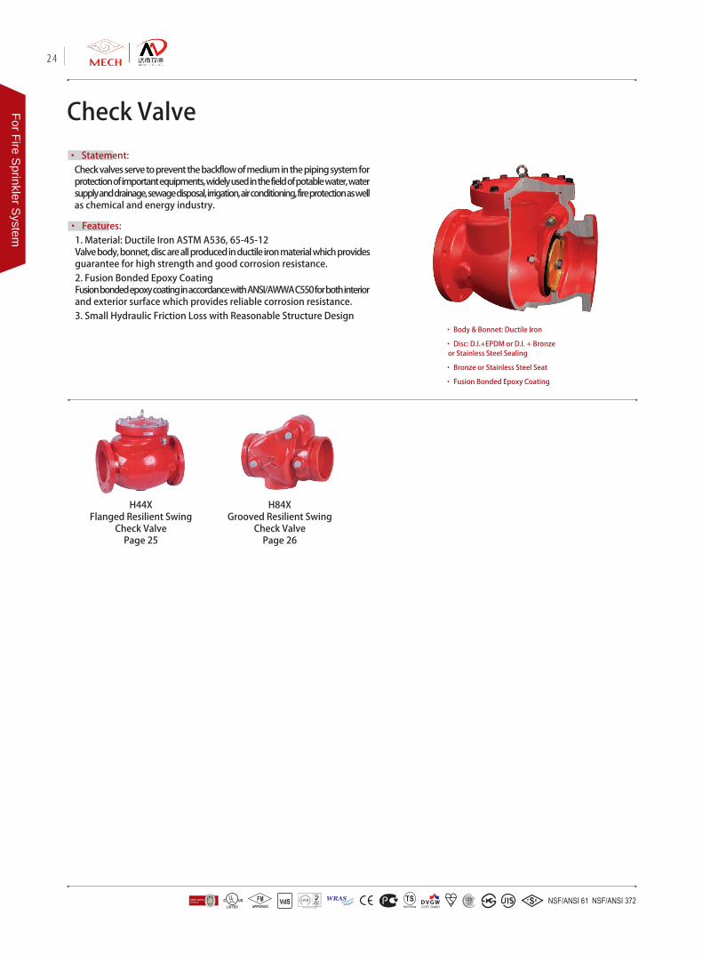
Check Valve
• Statement: Check valves serve to prevent the backflow of medium in the piping system for protection of important equipments, widely used in the field of potable water, water supply and drainage, sewage disposal, irrigation, air conditioning, fire protection as well as chemical and energy industry.
• Features: 1. Material: Ductile Iron ASTM A536, 65-45-12Valve body, bonnet, disc are all produced in ductile iron material which provides guarantee for high strength and good corrosion resistance.2. Fusion Bonded Epoxy CoatingFusion bonded epoxy coating in accordance with ANSI/AWWA C550 for both interior and exterior surface which provides reliable corrosion resistance.3. Small Hydraulic Friction Loss with Reasonable Structure Design
• Body & Bonnet: Ductile Iron
• Disc: D.I.+EPDM or D.I. + Bronze or Stainless Steel Sealing
• Bronze or Stainless Steel Seat
• Fusion Bonded Epoxy Coating
H44XFlanged Resilient Swing
Check ValvePage 25
H84XGrooved Resilient Swing
Check ValvePage 26
24
For Fire Sprinkler S
ystem
DN Dimensions(mm)
Inch mm L D D1 b n-Φd H
2" 50 203 152 120.5 16 4-Φ19.1 133
2.5" 65 254 178 139.5 17.5 4-Φ19.1 150
3" 80 278 191 152.5 19 4-Φ19.1 150
4" 100 330 229 190.5 24 8-Φ19.1 218
6" 150 406 279 241.5 25.5 8-Φ22.2 290
8" 200 495 343 298.5 28.5 8-Φ22.2 330
10" 250 622 406 362 30.5 12-Φ25.4 350
12" 300 660 483 432 32 12-Φ25.4 376
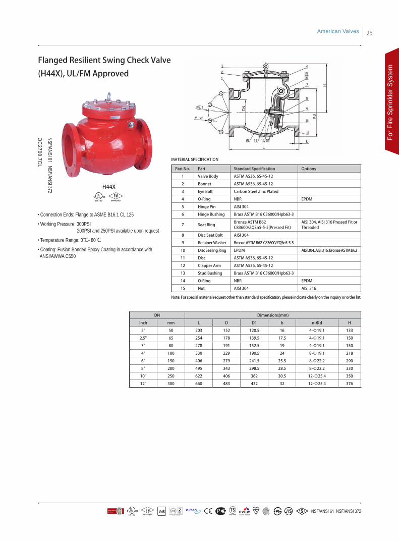
Flanged Resilient Swing Check Valve
(H44X), UL/FM Approved
Part No. Part Standard Specification Options
1 Valve Body ASTM A536, 65-45-12
2 Bonnet ASTM A536, 65-45-12
3 Eye Bolt Carbon Steel Zinc Plated
4 O-Ring NBR EPDM
5 Hinge Pin AISI 304
6 Hinge Bushing Brass ASTM B16 C36000/Hpb63-3
7 Seat RingBronze ASTM B62C83600/ZQSn5-5-5(Pressed Fit)
AISI 304, AISI 316 Pressed Fit or Threaded
8 Disc Seat Bolt AISI 304
9 Retainer Washer Bronze ASTM B62 C83600/ZQSn5-5-5
10 Disc Sealing Ring EPDM AISI 304, AISI 316, Bronze ASTM B62
11 Disc ASTM A536, 65-45-12
12 Clapper Arm ASTM A536, 65-45-12
13 Stud Bushing Brass ASTM B16 C36000/Hpb63-3
14 O-Ring NBR EPDM
15 Nut AISI 304 AISI 316
• Connection Ends: Flange to ASME B16.1 CL 125
• Working Pressure: 300PSI 200PSI and 250PSI available upon request
• Temperature Range: 0℃- 80℃
• Coating: Fusion Bonded Epoxy Coating in accordance with ANSI/AWWA C550
H44X
MATERIAL SPECIFICATION
Note: For special material request other than standard specification, please indicate clearly on the inquiry or order list.
American Valves 25
For F
ire S
prin
kler
Sys
tem
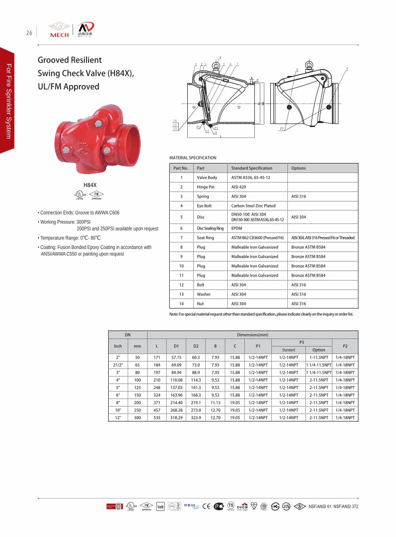
Part No. Part Standard Specification Options
1 Valve Body ASTM A536, 65-45-12
2 Hinge Pin AISI 420
3 Spring AISI 304 AISI 316
4 Eye Bolt Carbon Steel Zinc Plated
5 DiscDN50-100 AISI 304DN150-300 ASTM A536, 65-45-12
AISI 304
6 Disc Sealing Ring EPDM
7 Seat Ring ASTM B62 C83600 (Pressed Fit) AISI 304, AISI 316 Pressed Fit or Threaded
8 Plug Malleable Iron Galvanized Bronze ASTM B584
9 Plug Malleable Iron Galvanized Bronze ASTM B584
10 Plug Malleable Iron Galvanized Bronze ASTM B584
11 Plug Malleable Iron Galvanized Bronze ASTM B584
12 Bolt AISI 304 AISI 316
13 Washer AISI 304 AISI 316
14 Nut AISI 304 AISI 316
DN Dimensions(mm)
Inch mm L D1 D2 B C P1P3
P2Standard Option
2" 50 171 57.15 60.3 7.93 15.88 1/2-14NPT 1/2-14NPT 1-11.5NPT 1/4-18NPT
21/2" 65 184 69.09 73.0 7.93 15.88 1/2-14NPT 1/2-14NPT 1 1/4-11.5NPT 1/4-18NPT
3" 80 197 84.94 88.9 7.93 15.88 1/2-14NPT 1/2-14NPT 1 1/4-11.5NPT 1/4-18NPT
4" 100 210 110.08 114.3 9.53 15.88 1/2-14NPT 1/2-14NPT 2-11.5NPT 1/4-18NPT
5" 125 248 137.03 141.3 9.53 15.88 1/2-14NPT 1/2-14NPT 2-11.5NPT 1/4-18NPT
6" 150 324 163.96 168.3 9.53 15.88 1/2-14NPT 1/2-14NPT 2-11.5NPT 1/4-18NPT
8" 200 371 214.40 219.1 11.13 19.05 1/2-14NPT 1/2-14NPT 2-11.5NPT 1/4-18NPT
10" 250 457 268.28 273.0 12.70 19.05 1/2-14NPT 1/2-14NPT 2-11.5NPT 1/4-18NPT
12" 300 535 318.29 323.9 12.70 19.05 1/2-14NPT 1/2-14NPT 2-11.5NPT 1/4-18NPT
Grooved Resilient
Swing Check Valve (H84X),
UL/FM Approved
• Connection Ends: Groove to AWWA C606
• Working Pressure: 300PSI 200PSI and 250PSI available upon request
• Temperature Range: 0℃- 80℃
• Coating: Fusion Bonded Epoxy Coating in accordance with ANSI/AWWA C550 or painting upon request
H84X
MATERIAL SPECIFICATION
Note: For special material request other than standard specification, please indicate clearly on the inquiry or order list.
26
For Fire Sprinkler S
ystem
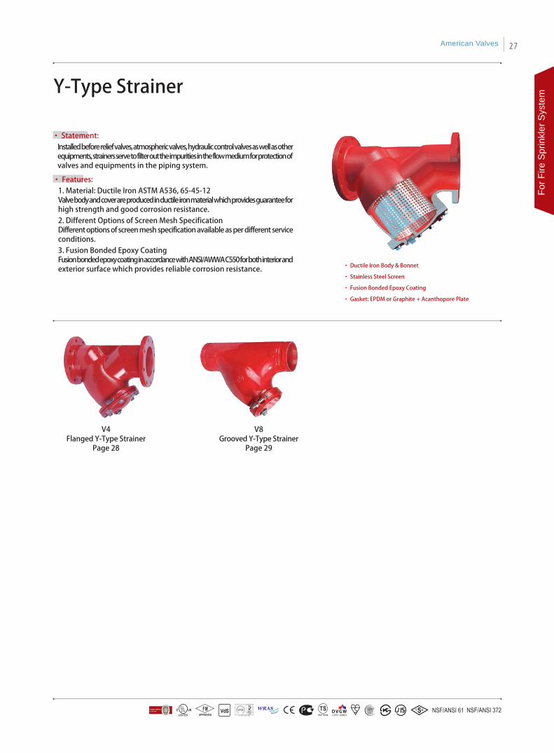
• Statement: Installed before relief valves, atmospheric valves, hydraulic control valves as well as other equipments, strainers serve to filter out the impurities in the flow medium for protection of valves and equipments in the piping system.
Y-Type Strainer
• Features: 1. Material: Ductile Iron ASTM A536, 65-45-12Valve body and cover are produced in ductile iron material which provides guarantee for high strength and good corrosion resistance.2. Different Options of Screen Mesh SpecificationDifferent options of screen mesh specification available as per different service conditions. 3. Fusion Bonded Epoxy Coating Fusion bonded epoxy coating in accordance with ANSI/AWWA C550 for both interior and exterior surface which provides reliable corrosion resistance. • Ductile Iron Body & Bonnet
• Stainless Steel Screen
• Fusion Bonded Epoxy Coating
• Gasket: EPDM or Graphite + Acanthopore Plate
V4Flanged Y-Type Strainer
Page 28
V8Grooved Y-Type Strainer
Page 29
American Valves 27
For F
ire S
prin
kler
Sys
tem
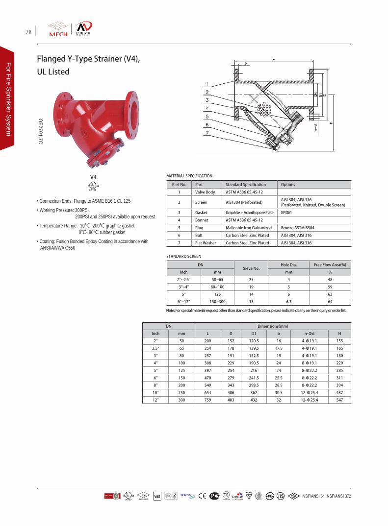
Part No. Part Standard Specification Options
1 Valve Body ASTM A536 65-45-12
2 Screen AISI 304 (Perforated)AISI 304, AISI 316 (Perforated, Knitted, Double Screen)
3 Gasket Graphite + Acanthopore Plate EPDM
4 Bonnet ASTM A536 65-45-12
5 Plug Malleable Iron Galvanized Bronze ASTM B584
6 Bolt Carbon Steel Zinc Plated AISI 304, AISI 316
7 Flat Washer Carbon Steel Zinc Plated AISI 304, AISI 316
DN Dimensions(mm)
Inch mm L D D1 b n-Φd H
2" 50 200 152 120.5 16 4-Φ19.1 155
2.5" 65 254 178 139.5 17.5 4-Φ19.1 165
3" 80 257 191 152.5 19 4-Φ19.1 180
4" 100 308 229 190.5 24 8-Φ19.1 229
5" 125 397 254 216 24 8-Φ22.2 285
6" 150 470 279 241.5 25.5 8-Φ22.2 311
8" 200 549 343 298.5 28.5 8-Φ22.2 394
10" 250 654 406 362 30.5 12-Φ25.4 487
12" 300 759 483 432 32 12-Φ25.4 547
Flanged Y-Type Strainer (V4),
UL Listed
• Connection Ends: Flange to ASME B16.1 CL 125
• Working Pressure: 300PSI 200PSI and 250PSI available upon request
• Temperature Range: -10℃- 200℃ graphite gasket 0℃- 80℃ rubber gasket
• Coating: Fusion Bonded Epoxy Coating in accordance with ANSI/AWWA C550
V4 MATERIAL SPECIFICATION
Note: For special material request other than standard specification, please indicate clearly on the inquiry or order list.
STANDARD SCREEN
DNSieve No.
Hole Dia. Free Flow Area(%)
Inch mm mm %
2"~2.5" 50~65 25 4 48
3"~4" 80~100 19 5 59
5" 125 14 6 63
6"~12" 150~300 13 6.3 64
28
For Fire Sprinkler S
ystem
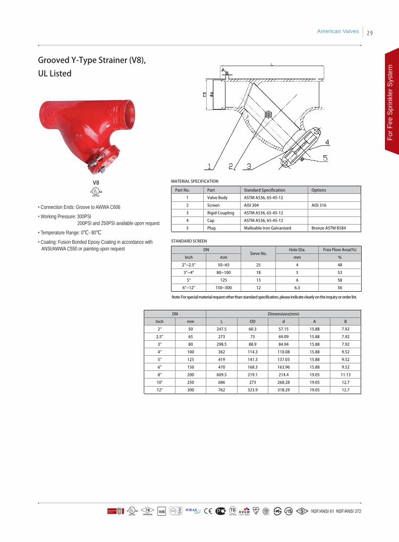
Grooved Y-Type Strainer (V8),
UL Listed
• Connection Ends: Groove to AWWA C606
• Working Pressure: 300PSI 200PSI and 250PSI available upon request
• Temperature Range: 0℃- 80℃
• Coating: Fusion Bonded Epoxy Coating in accordance with ANSI/AWWA C550 or painting upon request
Part No. Part Standard Specification Options
1 Valve Body ASTM A536, 65-45-12
2 Screen AISI 304 AISI 316
3 Rigid Coupling ASTM A536, 65-45-12
4 Cap ASTM A536, 65-45-12
5 Plug Malleable Iron Galvanized Bronze ASTM B584
DN Dimensions(mm)
Inch mm L OD d A B
2" 50 247.5 60.3 57.15 15.88 7.92
2.5" 65 273 73 69.09 15.88 7.92
3" 80 298.5 88.9 84.94 15.88 7.92
4" 100 362 114.3 110.08 15.88 9.52
5" 125 419 141.3 137.03 15.88 9.52
6" 150 470 168.3 163.96 15.88 9.52
8" 200 609.5 219.1 214.4 19.05 11.13
10" 250 686 273 268.28 19.05 12.7
12" 300 762 323.9 318.29 19.05 12.7
MATERIAL SPECIFICATION
STANDARD SCREEN
DNSieve No.
Hole Dia. Free Flow Area(%)
Inch mm mm %
2"~2.5" 50~65 25 4 48
3"~4" 80~100 18 5 53
5" 125 13 6 58
6"~12" 150~300 12 6.3 56
V8
Note: For special material request other than standard specification, please indicate clearly on the inquiry or order list.
American Valves 29
For F
ire S
prin
kler
Sys
tem
MATERIAL SPECIFICATION
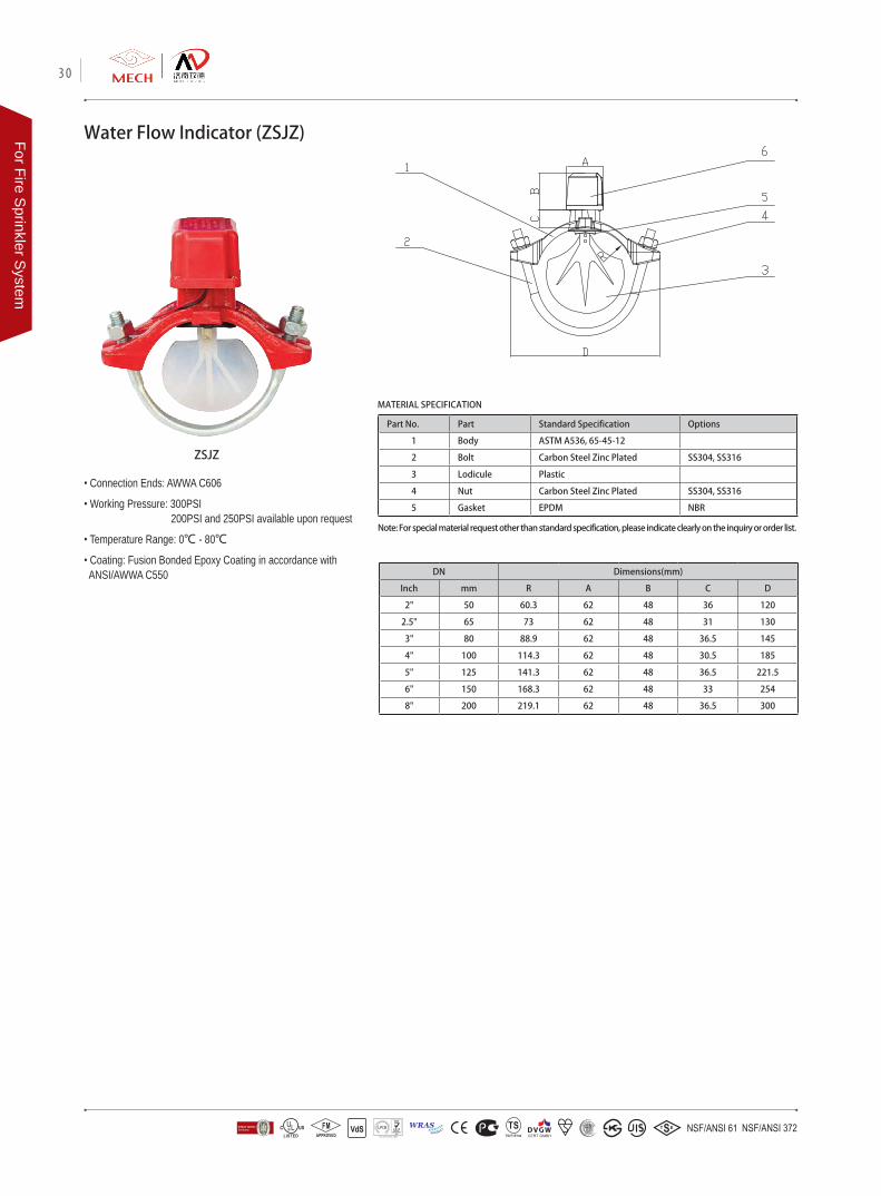
Water Flow Indicator (ZSJZ)
ZSJZ
Note: For special material request other than standard specification, please indicate clearly on the inquiry or order list.
Part No. Part Standard Specification Options
1 Body ASTM A536, 65-45-12
2 Bolt Carbon Steel Zinc Plated SS304, SS316
3 Lodicule Plastic
4 Nut Carbon Steel Zinc Plated SS304, SS316
5 Gasket EPDM NBR
• Connection Ends: AWWA C606
• Working Pressure: 300PSI 200PSI and 250PSI available upon request
• Temperature Range: 0℃ - 80℃
• Coating: Fusion Bonded Epoxy Coating in accordance with ANSI/AWWA C550 DN Dimensions(mm)
Inch mm R A B C D
2" 50 60.3 62 48 36 120
2.5" 65 73 62 48 31 130
3" 80 88.9 62 48 36.5 145
4" 100 114.3 62 48 30.5 185
5" 125 141.3 62 48 36.5 221.5
6" 150 168.3 62 48 33 254
8" 200 219.1 62 48 36.5 300
30
For Fire Sprinkler S
ystem
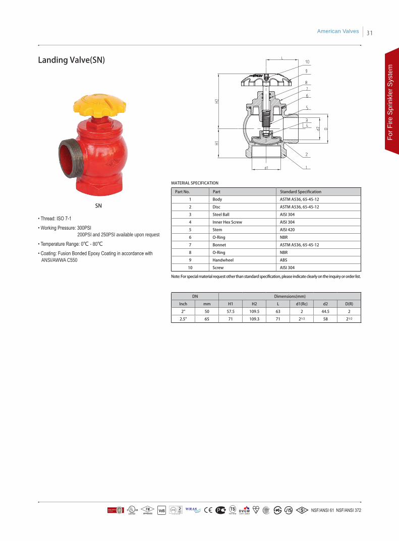
Landing Valve(SN)
• Thread: ISO 7-1
• Working Pressure: 300PSI 200PSI and 250PSI available upon request
• Temperature Range: 0℃ - 80℃
• Coating: Fusion Bonded Epoxy Coating in accordance with ANSI/AWWA C550
MATERIAL SPECIFICATION
Part No. Part Standard Specification
1 Body ASTM A536, 65-45-12
2 Disc ASTM A536, 65-45-12
3 Steel Ball AISI 304
4 Inner Hex Screw AISI 304
5 Stem AISI 420
6 O-Ring NBR
7 Bonnet ASTM A536, 65-45-12
8 O-Ring NBR
9 Handwheel ABS
10 Screw AISI 304
DN Dimensions(mm)
Inch mm H1 H2 L d1(Rc) d2 D(R)
2" 50 57.5 109.5 63 2 44.5 2
2.5" 65 71 109.3 71 21/2 58 21/2
SN
Note: For special material request other than standard specification, please indicate clearly on the inquiry or order list.
American Valves 31
For F
ire S
prin
kler
Sys
tem
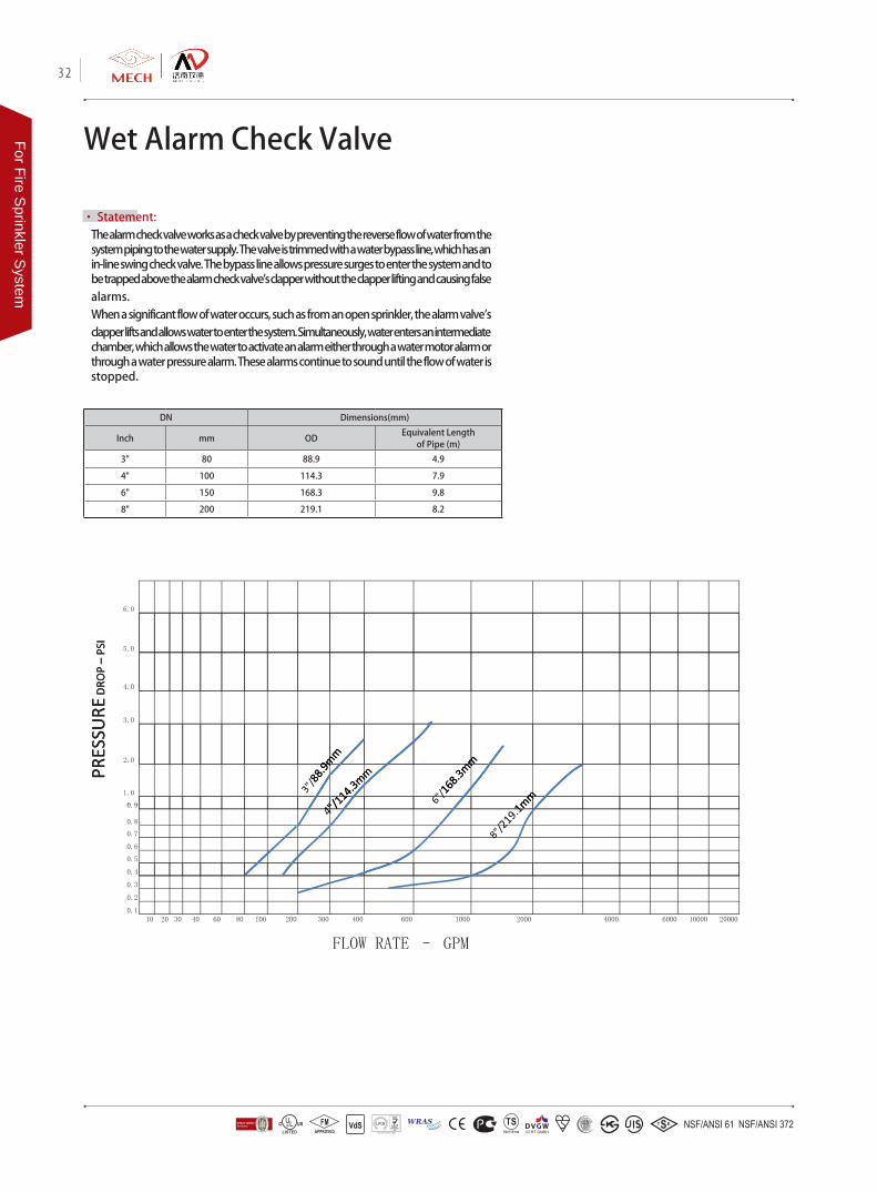
• Statement: The alarm check valve works as a check valve by preventing the reverse flow of water from the system piping to the water supply. The valve is trimmed with a water bypass line, which has an in-line swing check valve. The bypass line allows pressure surges to enter the system and to be trapped above the alarm check valve's clapper without the clapper lifting and causing false alarms.When a significant flow of water occurs, such as from an open sprinkler, the alarm valve's clapper lifts and allows water to enter the system. Simultaneously, water enters an intermediate chamber, which allows the water to activate an alarm either through a water motor alarm or through a water pressure alarm. These alarms continue to sound until the flow of water is stopped.
Wet Alarm Check Valve
6.0
5.0
4 0DRO
P –
PSI
4.0
3.0
RESS
URE
DRO
P –
PSI
2.0
1.0
0 9
PRES
SURE
D
0.9
0.8
0.7
0.6
0.5
PR
0.4
0.3
0.2
0.110 20 30 40 60 80 100 200 300 400 600 1000 2000 4000 6000 10000 20000
FLOW RATE – GPM
DN Dimensions(mm)
Inch mm ODEquivalent Length
of Pipe (m)
3" 80 88.9 4.9
4" 100 114.3 7.9
6" 150 168.3 9.8
8" 200 219.1 8.2
32
For Fire Sprinkler S
ystem
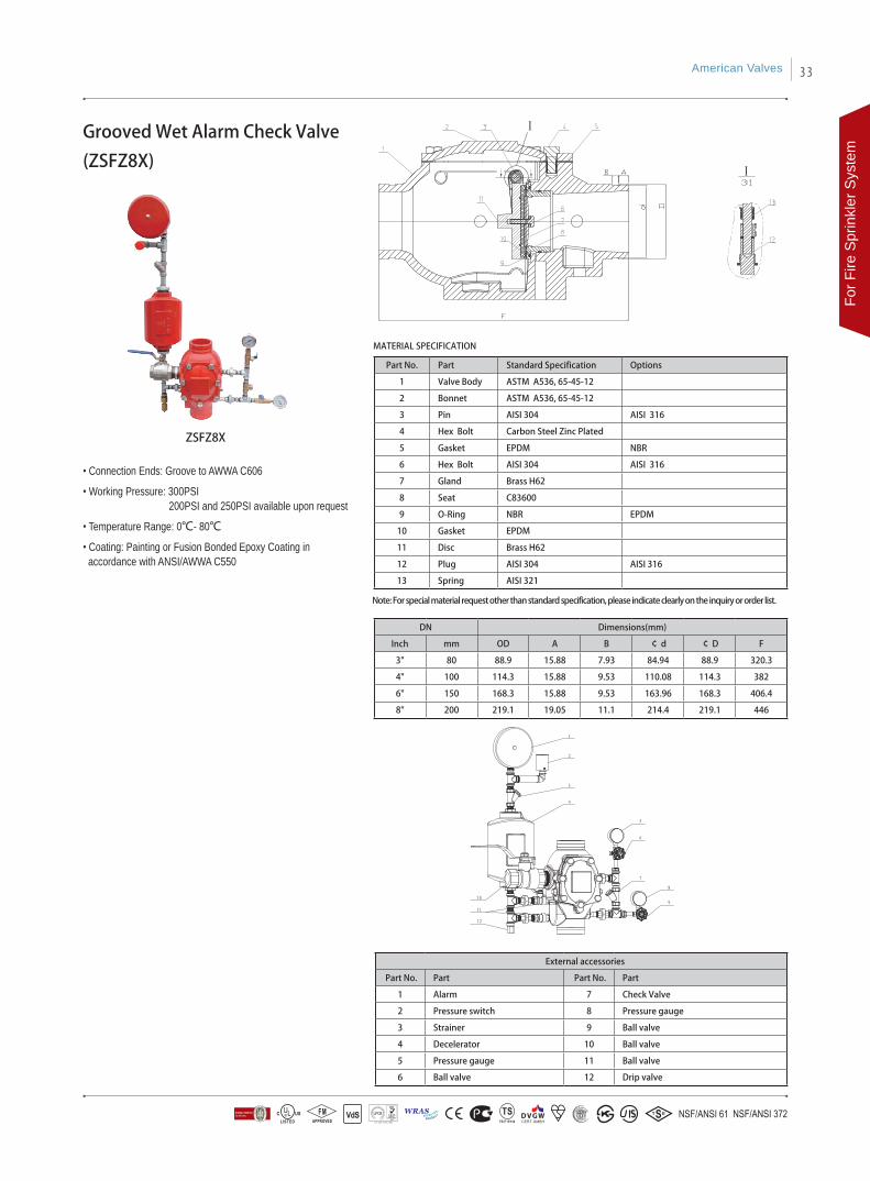
Part No. Part Standard Specification Options
1 Valve Body ASTM A536, 65-45-12
2 Bonnet ASTM A536, 65-45-12
3 Pin AISI 304 AISI 316
4 Hex Bolt Carbon Steel Zinc Plated
5 Gasket EPDM NBR
6 Hex Bolt AISI 304 AISI 316
7 Gland Brass H62
8 Seat C83600
9 O-Ring NBR EPDM
10 Gasket EPDM
11 Disc Brass H62
12 Plug AISI 304 AISI 316
13 Spring AISI 321
DN Dimensions(mm)
Inch mm OD A B ¢ d ¢ D F
3" 80 88.9 15.88 7.93 84.94 88.9 320.3
4" 100 114.3 15.88 9.53 110.08 114.3 382
6" 150 168.3 15.88 9.53 163.96 168.3 406.4
8" 200 219.1 19.05 11.1 214.4 219.1 446
Grooved Wet Alarm Check Valve
(ZSFZ8X)
• Connection Ends: Groove to AWWA C606
• Working Pressure: 300PSI 200PSI and 250PSI available upon request
• Temperature Range: 0℃- 80℃
• Coating: Painting or Fusion Bonded Epoxy Coating in accordance with ANSI/AWWA C550
ZSFZ8X
MATERIAL SPECIFICATION
Note: For special material request other than standard specification, please indicate clearly on the inquiry or order list.
External accessories
Part No. Part Part No. Part
1 Alarm 7 Check Valve
2 Pressure switch 8 Pressure gauge
3 Strainer 9 Ball valve
4 Decelerator 10 Ball valve
5 Pressure gauge 11 Ball valve
6 Ball valve 12 Drip valve
American Valves 33
For F
ire S
prin
kler
Sys
tem
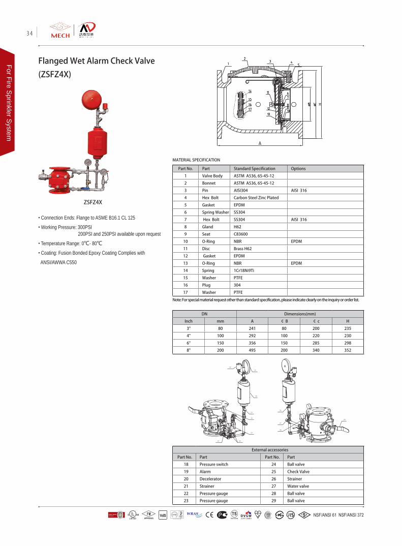
Part No. Part Standard Specification Options
1 Valve Body ASTM A536, 65-45-12
2 Bonnet ASTM A536, 65-45-12
3 Pin AISI304 AISI 316
4 Hex Bolt Carbon Steel Zinc Plated
5 Gasket EPDM
6 Spring Washer SS304
7 Hex Bolt SS304 AISI 316
8 Gland H62
9 Seat C83600
10 O-Ring NBR EPDM
11 Disc Brass H62
12 Gasket EPDM
13 O-Ring NBR EPDM
14 Spring 1Cr18Ni9Ti
15 Washer PTFE
16 Plug 304
17 Washer PTFE
Flanged Wet Alarm Check Valve
(ZSFZ4X)
• Connection Ends: Flange to ASME B16.1 CL 125
• Working Pressure: 300PSI 200PSI and 250PSI available upon request
• Temperature Range: 0℃- 80℃
• Coating: Fusion Bonded Epoxy Coating Complies with
ANSI/AWWA C550
ZSFZ4X
MATERIAL SPECIFICATION
Note: For special material request other than standard specification, please indicate clearly on the inquiry or order list.
DN Dimensions(mm)
Inch mm A ¢ B ¢ c H
3" 80 241 80 200 235
4" 100 292 100 220 230
6" 150 356 150 285 298
8" 200 495 200 340 352
External accessories
Part No. Part Part No. Part
18 Pressure switch 24 Ball valve
19 Alarm 25 Check Valve
20 Decelerator 26 Strainer
21 Strainer 27 Water valve
22 Pressure gauge 28 Ball valve
23 Pressure gauge 29 Ball valve
34
For Fire Sprinkler S
ystem

Electric Inspector's Test Connection
(ZSPM-80-DX)
Manual Inspector's Test Connection
(ZSPM-80-SA)
ZSPM-80-DX
ZSPM-80-SA
MATERIAL SPECIFICATION
Part No. Part Standard Specification
1 Test nozzle AISI 304
2 Outside Hex Bushing Malleable Iron Galvanized
3 Reducing Tee Malleable Iron Galvanized
4 Pressure Switch
5 Nexagon Nipple,Equal Malleable Iron Galvanized
6 Reducing Tee Malleable Iron Galvanized
7 Solenoid Valves Brass
8 Pressure Gauge
9 Connector Brass
10 Ball Valve AISI 304
11 90° Elbow Malleable Iron Galvanized
12 Union With Brass Seat Malleable Iron Galvanized
Note: 1.For special material request other than standard specification, please indicate clearly on the inquiry or oder list. 2.Threads connection options available includes: ASME B1.20.1, ISO 7-1
Part No. Part Standard Specification
1 Test nozzle AISI 304
2 Outside Hex Bushing Malleable Iron Galvanized
3 Ball Valve AISI 304
4 Nexagon Nipple,Equal Malleable Iron Galvanized
5 Reducing Tee Malleable Iron Galvanized
6 Connector Brass
7 Pressure Gauge
MATERIAL SPECIFICATION
Note: 1.For special material request other than standard specification, please indicate clearly on the inquiry or oder list. 2.Threads connection options available includes: ASME B1.20.1, ISO 7-1
American Valves 35
For F
ire S
prin
kler
Sys
tem

36
For Fire Sprinkler S
ystem

DN Dimensions(mm)
Inch mm L H D D1 b n-ΦL
2" 50 206 170 152 120.5 16 4-Φ19.1
2.5" 65 211 195 178 139.5 17.5 4-Φ19.1
3" 80 249 215 191 152.5 19 4-Φ19.1
4" 100 320 255 229 190.5 24 8-Φ19.1
6" 150 414 360 279 241.5 25.5 8-Φ22.2
8" 200 500 450 343 298.5 28.5 8-Φ22.2
10" 250 605 550 406 362 30.5 12-Φ25.4
12" 300 724 645 483 432 32 12-Φ25.4
14" 350 734 700 533 476 35 12-Φ28.5
16" 400 991 790 597 540 36.5 16-Φ28.5
Water Head Loss (psi)Flow
Rate (gpm)
DN50DN65
DN80
DN100
DN125
DN150
DN200
DN250
DN300DN350
DN400DN450DN500DN600
Hydraulic Control Valve
• StatementThe hydraulic control valve was initially originated in Holand, Israel and Denmark, used for agricultural irrigation. Later the product was introduced into the United Sates, Canada and Asian countries. It was from the 1990s when the product first entered China, and ever since its entrance it gets rapidly developped and widely applied in different industrie aside from irrigation.
The hydraulic control valve produced by Jinan Meide is new style that absorbed the essence of other well-known brands which makes it better in energy saving, consumption reducing and accurate adjusting achieving. The MECH brand hydraulic control valves have been widely used in China, Europe and South East Asian countries in pipe system of irrigation, water supplying, fire protection and air conditioning which has medium of water under 80℃ or other medium with similar physical and chemical property as water.
• SpecificationsBasic Valve: Y-Type Direct-flowConnection Ends: Flange to ASME B16.1 CL 125Temperature Range: 0℃- 80℃Working Pressure: 300PSITesting Standard: API 598
• Flow Diagram of Basic Valve
Bottom Gland (ASTM A536,65-45-12)
Up Gland (ASTM A536,65-45-12)
Cap Plug (Brass H62)
Up Bonnet (ASTM A536,65-45-12)
Bushing (Brass H62)
Middle Bonnet (ASTM A536,65-45-12)
Stem (AISI 304)
Bolt (AISI 304)
Spring ( Stainless Steel 4Cr13)
Main Disc (ASTM A536,65-45-12)
Main Gasket (EPDM)Gland of Main Disc (ASTM A536,65-45-12)
Seat (AISI 304)
Valve Body (ASTM A536,65-45-12)
Diaphragm (EPDM)
DN 50 65 80 100 125 150 200 250 300 350 400 450 500 600
Kv 41 53 105 175 285 402 730 1160 1400 1770 3010 3225 3395 4272
American Valves 37
For F
ire S
prin
kler
Sys
tem
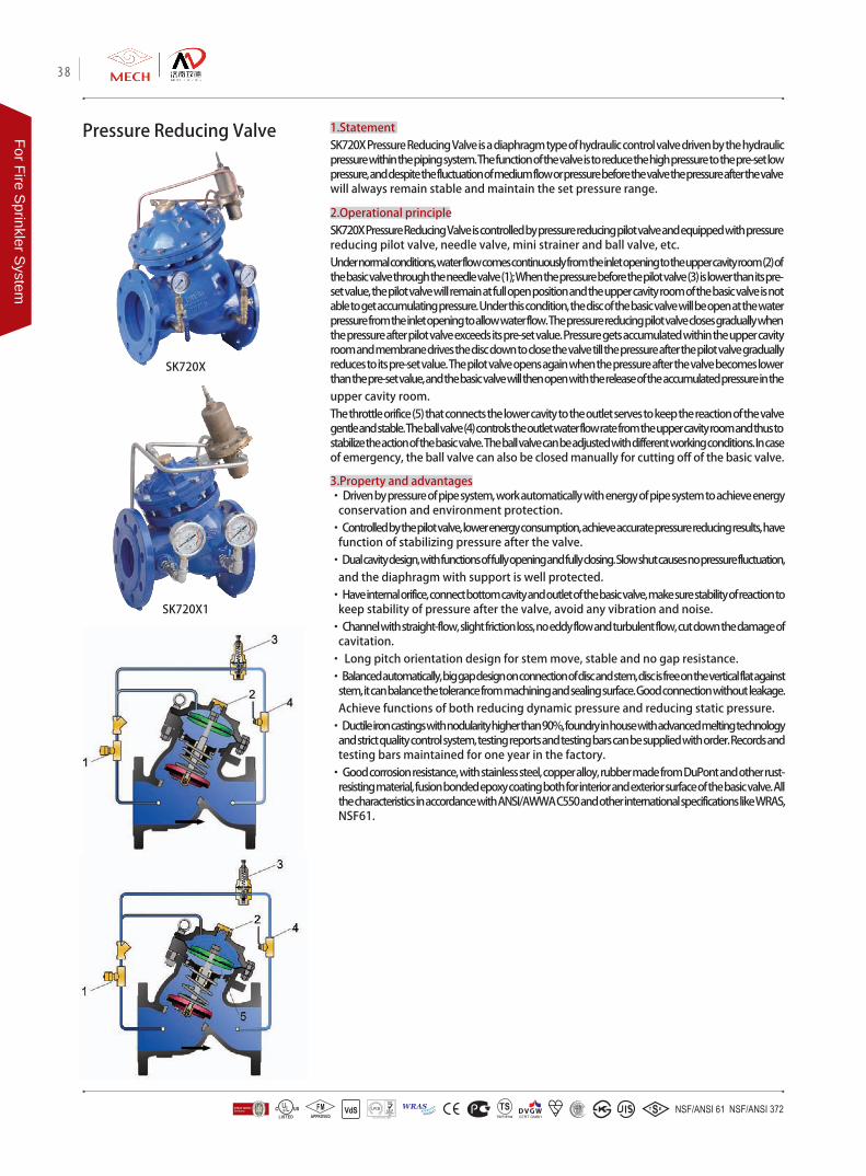
Pressure Reducing Valve 1.StatementSK720X Pressure Reducing Valve is a diaphragm type of hydraulic control valve driven by the hydraulic pressure within the piping system. The function of the valve is to reduce the high pressure to the pre-set low pressure, and despite the fluctuation of medium flow or pressure before the valve the pressure after the valve will always remain stable and maintain the set pressure range.
2.Operational principleSK720X Pressure Reducing Valve is controlled by pressure reducing pilot valve and equipped with pressure reducing pilot valve, needle valve, mini strainer and ball valve, etc.Under normal conditions, water flow comes continuously from the inlet opening to the upper cavity room (2) of the basic valve through the needle valve (1); When the pressure before the pilot valve (3) is lower than its pre-set value, the pilot valve will remain at full open position and the upper cavity room of the basic valve is not able to get accumulating pressure. Under this condition, the disc of the basic valve will be open at the water pressure from the inlet opening to allow water flow. The pressure reducing pilot valve closes gradually when the pressure after pilot valve exceeds its pre-set value. Pressure gets accumulated within the upper cavity room and membrane drives the disc down to close the valve till the pressure after the pilot valve gradually reduces to its pre-set value. The pilot valve opens again when the pressure after the valve becomes lower than the pre-set value, and the basic valve will then open with the release of the accumulated pressure in the upper cavity room. The throttle orifice (5) that connects the lower cavity to the outlet serves to keep the reaction of the valve gentle and stable. The ball valve (4) controls the outlet water flow rate from the upper cavity room and thus to stabilize the action of the basic valve. The ball valve can be adjusted with different working conditions. In case of emergency, the ball valve can also be closed manually for cutting off of the basic valve.
3.Property and advantages• Driven by pressure of pipe system, work automatically with energy of pipe system to achieve energy
conservation and environment protection.• Controlled by the pilot valve, lower energy consumption, achieve accurate pressure reducing results, have
function of stabilizing pressure after the valve. • Dual cavity design, with functions of fully opening and fully closing. Slow shut causes no pressure fluctuation,
and the diaphragm with support is well protected.• Have internal orifice, connect bottom cavity and outlet of the basic valve, make sure stability of reaction to
keep stability of pressure after the valve, avoid any vibration and noise. • Channel with straight-flow, slight friction loss, no eddy flow and turbulent flow, cut down the damage of
cavitation. • Long pitch orientation design for stem move, stable and no gap resistance.• Balanced automatically, big gap design on connection of disc and stem, disc is free on the vertical flat against
stem, it can balance the tolerance from machining and sealing surface. Good connection without leakage. Achieve functions of both reducing dynamic pressure and reducing static pressure.
• Ductile iron castings with nodularity higher than 90%, foundry in house with advanced melting technology and strict quality control system, testing reports and testing bars can be supplied with order. Records and testing bars maintained for one year in the factory.
• Good corrosion resistance, with stainless steel, copper alloy, rubber made from DuPont and other rust-resisting material, fusion bonded epoxy coating both for interior and exterior surface of the basic valve. All the characteristics in accordance with ANSI/AWWA C550 and other international specifications like WRAS, NSF61.
SK720X
SK720X1
38
For Fire Sprinkler S
ystem
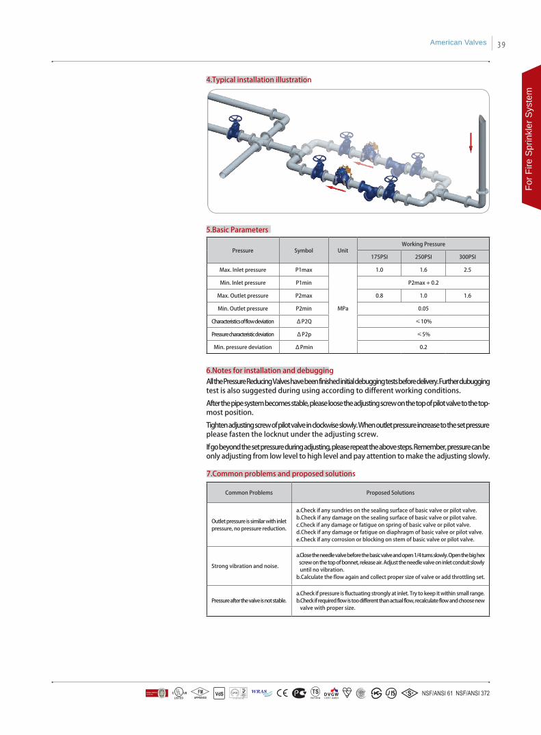
4.Typical installation illustration
5.Basic Parameters
Pressure Symbol UnitWorking Pressure
175PSI 250PSI 300PSI
Max. Inlet pressure P1max
MPa
1.0 1.6 2.5
Min. Inlet pressure P1min P2max + 0.2
Max. Outlet pressure P2max 0.8 1.0 1.6
Min. Outlet pressure P2min 0.05
Characteristics of flow deviation ΔP2Q ≤10%
Pressure characteristic deviation ΔP2p ≤5%
Min. pressure deviation ΔPmin 0.2
6.Notes for installation and debuggingAll the Pressure Reducing Valves have been finished initial debugging tests before delivery. Further dubugging test is also suggested during using according to different working conditions.
After the pipe system becomes stable, please loose the adjusting screw on the top of pilot valve to the top-most position.
Tighten adjusting screw of pilot valve in clockwise slowly. When outlet pressure increase to the set pressure please fasten the locknut under the adjusting screw.
If go beyond the set pressure during adjusting, please repeat the above steps. Remember, pressure can be only adjusting from low level to high level and pay attention to make the adjusting slowly.
Common Problems Proposed Solutions
Outlet pressure is similar with inlet pressure, no pressure reduction.
a.Check if any sundries on the sealing surface of basic valve or pilot valve. b.Check if any damage on the sealing surface of basic valve or pilot valve.c.Check if any damage or fatigue on spring of basic valve or pilot valve. d.Check if any damage or fatigue on diaphragm of basic valve or pilot valve.e.Check if any corrosion or blocking on stem of basic valve or pilot valve.
Strong vibration and noise.
a.Close the needle valve before the basic valve and open 1/4 turns slowly. Open the big hex screw on the top of bonnet, release air. Adjust the needle valve on inlet conduit slowly until no vibration. b.Calculate the flow again and collect proper size of valve or add throttling set.
Pressure after the valve is not stable. a.Check if pressure is fluctuating strongly at inlet. Try to keep it within small range. b.Check if required flow is too different than actual flow, recalculate flow and choose new valve with proper size.
7.Common problems and proposed solutions
American Valves 39
For F
ire S
prin
kler
Sys
tem
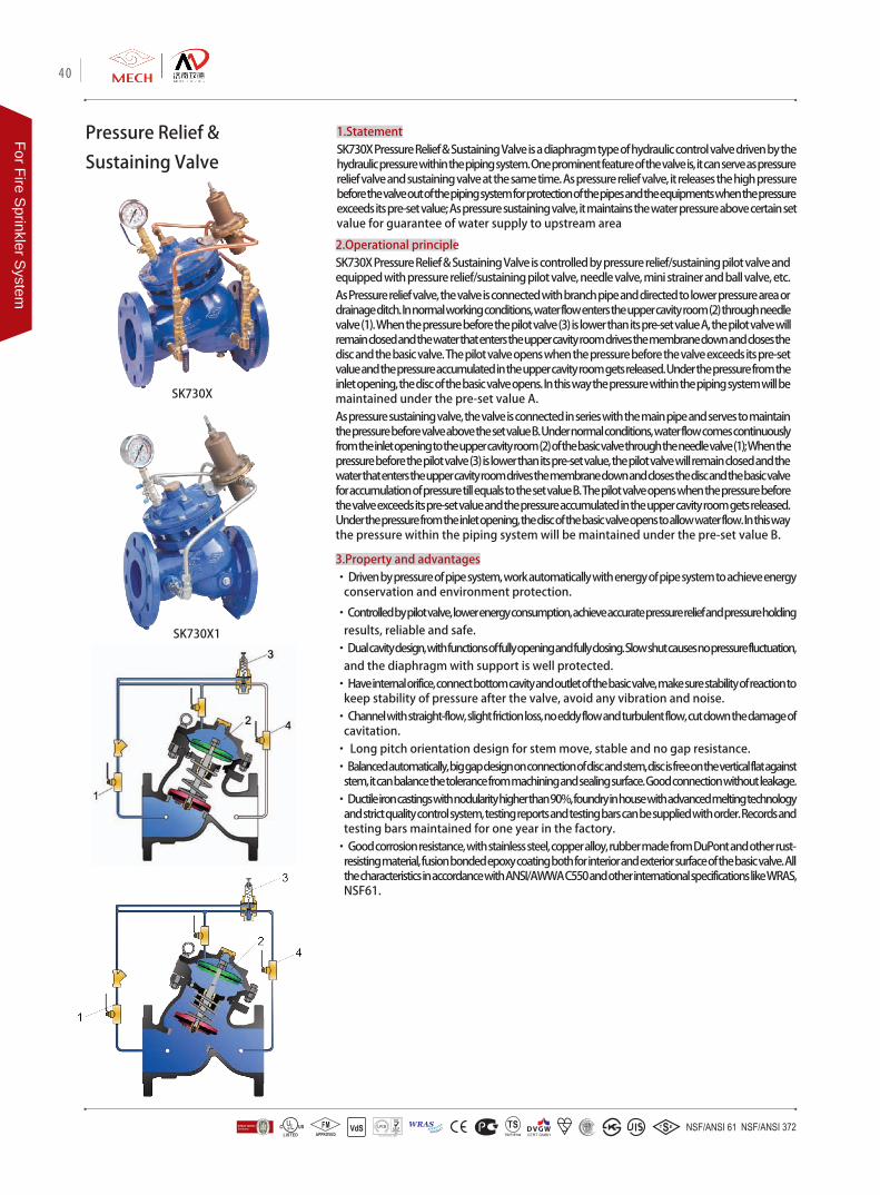
Pressure Relief &
Sustaining Valve
1.StatementSK730X Pressure Relief & Sustaining Valve is a diaphragm type of hydraulic control valve driven by the hydraulic pressure within the piping system. One prominent feature of the valve is, it can serve as pressure relief valve and sustaining valve at the same time. As pressure relief valve, it releases the high pressure before the valve out of the piping system for protection of the pipes and the equipments when the pressure exceeds its pre-set value; As pressure sustaining valve, it maintains the water pressure above certain set value for guarantee of water supply to upstream area
2.Operational principleSK730X Pressure Relief & Sustaining Valve is controlled by pressure relief/sustaining pilot valve and equipped with pressure relief/sustaining pilot valve, needle valve, mini strainer and ball valve, etc.As Pressure relief valve, the valve is connected with branch pipe and directed to lower pressure area or drainage ditch. In normal working conditions, water flow enters the upper cavity room (2) through needle valve (1). When the pressure before the pilot valve (3) is lower than its pre-set value A, the pilot valve will remain closed and the water that enters the upper cavity room drives the membrane down and closes the disc and the basic valve. The pilot valve opens when the pressure before the valve exceeds its pre-set value and the pressure accumulated in the upper cavity room gets released. Under the pressure from the inlet opening, the disc of the basic valve opens. In this way the pressure within the piping system will be maintained under the pre-set value A. As pressure sustaining valve, the valve is connected in series with the main pipe and serves to maintain the pressure before valve above the set value B. Under normal conditions, water flow comes continuously from the inlet opening to the upper cavity room (2) of the basic valve through the needle valve (1); When the pressure before the pilot valve (3) is lower than its pre-set value, the pilot valve will remain closed and the water that enters the upper cavity room drives the membrane down and closes the disc and the basic valve for accumulation of pressure till equals to the set value B. The pilot valve opens when the pressure before the valve exceeds its pre-set value and the pressure accumulated in the upper cavity room gets released. Under the pressure from the inlet opening, the disc of the basic valve opens to allow water flow. In this way the pressure within the piping system will be maintained under the pre-set value B.
3.Property and advantages• Driven by pressure of pipe system, work automatically with energy of pipe system to achieve energy
conservation and environment protection.
• Controlled by pilot valve, lower energy consumption, achieve accurate pressure relief and pressure holding results, reliable and safe.
• Dual cavity design, with functions of fully opening and fully closing. Slow shut causes no pressure fluctuation, and the diaphragm with support is well protected.
• Have internal orifice, connect bottom cavity and outlet of the basic valve, make sure stability of reaction to keep stability of pressure after the valve, avoid any vibration and noise.
• Channel with straight-flow, slight friction loss, no eddy flow and turbulent flow, cut down the damage of cavitation.
• Long pitch orientation design for stem move, stable and no gap resistance.• Balanced automatically, big gap design on connection of disc and stem, disc is free on the vertical flat against
stem, it can balance the tolerance from machining and sealing surface. Good connection without leakage. • Ductile iron castings with nodularity higher than 90%, foundry in house with advanced melting technology
and strict quality control system, testing reports and testing bars can be supplied with order. Records and testing bars maintained for one year in the factory.
• Good corrosion resistance, with stainless steel, copper alloy, rubber made from DuPont and other rust-resisting material, fusion bonded epoxy coating both for interior and exterior surface of the basic valve. All the characteristics in accordance with ANSI/AWWA C550 and other international specifications like WRAS, NSF61.
SK730X
SK730X1
40
For Fire Sprinkler S
ystem
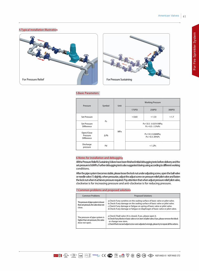
4.Typical installation illustration
6.Notes for installation and debuggingAll the Pressure Relief & Sustaining Valves have been finished initial debugging tests before delivery and the set-pressure is 0.6MPa. Further debugging test is also suggested during using according to different working conditions.
After the pipe system becomes stable, please loose the lock nut under adjusting screw, open the ball valve or needle valve (1) slightly, when pressurize, adjust the adjust screw on pressure relief pilot valve and fasten the lock nut when it achieves pressure required. Pay attention that when adjust pressure relief pilot valve, clockwise is for increasing pressure and anti-clockwise is for reducing pressure.
7.Common problems and proposed solutions
5.Basic Parameters
Pressure Symbol Unit
Working Pressure
175PSI 250PSI 300PSI
Set Pressure
Ps
MPa
≤0.83 ≤1.33 ≤1.7
Set PressureDifference
Ps<0.5: ±0.014 MPa;Ps≥0.5: ±3%Ps
Open/ClosePressure
DifferenceΔPb
Ps<0.3: 0.06MPa;Ps≥0.3: 20%Ps
Dischargepressure
Pd ≤1.2Ps
Common Problems Proposed Solutions
The pressure of pipe system is lower than set-pressure, the valve dose not close.
a.Check if any sundries on the sealing surface of basic valve or pilot valve. b.Check if any damage on the sealing surface of basic valve or pilot valve.c.Check if any damage or fatigue on spring of basic valve or pilot valve. d.Check if any damage or fatigue on diaphragm of basic valve or pilot valve.
The pressure of pipe system is higher than set-pressure, the valve dose not open.
a.Check if ball valve (4) is closed, if yes, please open it.b.Check if any blocks in basic valve or on stem of pilot valve, if yes, please remove the block or change new stem.c.Check if lock nut and adjust screw were adjusted wrongly, please try to repeat all the actions.
For Pressure Relief For Pressure Sustaining
American Valves 41
For F
ire S
prin
kler
Sys
tem

Deluge Alarm Valve 1.StatementSK790X Deluge Alarm Valve is a diaphragm type of hydraulic control valve driven by the hydraulic pressure within the piping system, functioning as flow control and alarming device in the sprinkler and pre-action system, i.e. to start the sprinkler system for quenching of the fire and send out fire alarm through the fire bell when there is fire detected.
2.Operational principleSK790X Deluge Alarm Valve is equipped with solenoid, anti-reset controller, mini strainer, ball valve and pressure gauge, etc.. For deluge valve there is set condition and work condition. When the valve is under set condition, ball valve (3) is open, ball valve (7), solenoid (8) and remote ball valve (9) are closed, the anti-reset controller is connected, and pressure gauge (1) and pressure gauge (6) shows the same value. When ball valve (11) is open, pressure gauge (10) shows 0. When ball valve (12) and (14) are open, (13) & (15) closed, there is no hydraulic pressure for pressure switch (17) , and alarm (18) does not work. Under set condition, you can operate as following if you want to test the pressure switch alarm device (17) and water motor alarm (18): close ball valve (14) and open (15), and then close (15) and open (14) after testing.In case there is fire detected, the following 3 methods will set the deluge valve into work condition immediately, A: Opening solenoid valve (8) B: Opening ball valve (7) C: Opening remote ball valve (9). Any of the above 3 methods can get the pressure within the control room of the basic valve released rapidly to open the valve and set it into working condition. At this time the sealing ball of anti-reset controller makes controller in a shutdown state, water will pass through the main valve, ball valve (12), (4), pressure switch (17), fire bell (18), the pressure switch bell sends out signal alarms. After fire fighting, close ball valve (7), solenoid valve (8), remote valve (9), press the anti-reset controller handle till the pressure gauge (6) and pressure gauge (1) shows the same value. The deluge alarm valves returns to set condition.Ball valve (2), (5) & (11) are normally open unless need to change the pressure gauge.
3.Property and advantages• Driven by pressure of pipe system, work automatically with energy of pipe system to achieve energy
conservation and environment protection.• Dual cavity design, with functions of fully opening and fully closing. Slow shut causes no pressure fluctuation,
and the diaphragm with support is well protected.• Triple insurance, there're three opening types used for different situation of firing. Anyone can make the valve
into working condition. • Anti-reset controller, hydraulic pressure type, compact design, tight sealing, operating by hand to make sure
all the parts including basic valve, ball valves and conduits are all in good condition after out-fire. • Channel with straight-flow, slight friction loss, no eddy flow and turbulent flow, cut down the damage of
cavitation. • Long pitch orientation design for stem move, stable and no gap resistance.• Balanced automatically, big gap design on connection of disc and stem, disc is free on the vertical flat
against stem, it can balance the tolerance from machining and sealing surface. Good connection without leakage. Achieve functions of both reducing dynamic pressure and reducing static pressure.
• Ductile iron castings with nodularity higher than 90%, foundry in house with advanced melting technology and strict quality control system, testing reports and testing bars can be supplied with order. Records and testing bars maintained for one year in the factory.
• Good corrosion resistance, with stainless steel, copper alloy, rubber made from DuPont and other rust-resisting material, fusion bonded epoxy coating both for interior and exterior surface of the basic valve. All the characteristics in accordance with ANSI/AWWA C550 and other international specifications like WRAS, NSF61.
SK790X
42
For Fire Sprinkler S
ystem

6.Common problems and proposed solutions
5.Notes for installation and debuggingPlease check if pressure switch and alarm bell are in good condition before installation. Make sure water can not leak to system from water supplying system or there's equipment to discharge the leaked water. Please adjust all the ball valves to make sure the basic valve be in set condition.Make sure anti-reset controller is in good condition and seal well before installation. If there's water with pressure in front of the valve, please closed ball valve (7), (9) and electromagnetic valve when it's in empty state behind the basic valve, press the anti-reset controller, when up cavity of basic valve is full of water please check if there's any leakage behind the valve. If no leakage, it said anti-reset controller is in good condition.
Common Problems Proposed Solutions
Press anti-reset controller after fire-out, there's still water coming out behind the valve.
a.Check if any sundries or damage on the sealing surface of basic valve or anti-reset controller.b.Check if any damage on diaphragm. c.Check if controlling valve (7), (8) and (9) were closed completely. Close them or replace with new ones.
When open controlling valve (7), (8) and (9) no water comes out from the basic valve.
a.Check if controlling valve (7), (8) and (9) were opened. Close them or replace with new ones.b.Check if there's block on stem of basic valve, repair it.
4.Typical installation illustration
American Valves 43
For F
ire S
prin
kler
Sys
tem
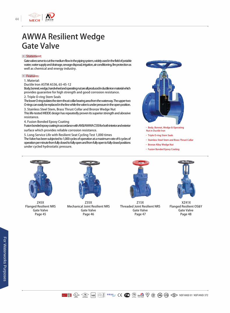
AWWA Resilient Wedge Gate Valve• Statement:
Gate valves serve to cut the medium flow in the piping system, widely used in the field of potable water, water supply and drainage, sewage disposal, irrigation, air conditioning, fire protection as well as chemical and energy industry.
• Features: 1. Material: Ductile Iron ASTM A536, 65-45-12Body, bonnet, wedge, handwheel and operating nut are all produced in ductile iron material which provides guarantee for high strength and good corrosion resistance.2. Triple O-ring Stem SealsThe lower O-ring isolates the stem thrust collar bearing area from the waterway. The upper two O-rings can easily be replaced in the line while the valve is under pressure in the open position.3. Stainless Steel Stem, Brass Thrust Collar and Bronze Wedge NutThis life-tested MEIDE design has repeatedly proven its superior strength and abrasive resistance.4. Fusion Bonded Epoxy CoatingFusion bonded epoxy coating in accordance with ANSI/AWWA C550 for both interior and exterior surface which provides reliable corrosion resistance.5. Long Service Life with Resilient Seat Cycling Test 1,000 timesThe Valve has been subjected to 1,000 cycles of operation at a maximum rate of 6 cycles of operation per minute from fully closed to fully open and from fully open to fully closed positions under cycled hydrostatic pressure.
• Body, Bonnet, Wedge & Operating Nut in Ductile Iron
• Triple O-ring Stem Seals
• Stainless Steel Stem and Brass Thrust Collar
• Bronze Alloy Wedge Nut
• Fusion Bonded Epoxy Coating
XZ41XFlanged Resilient OS&Y
Gate ValvePage 48
Z15XThreaded Joint Resilient NRS
Gate Valve Page 47
Z45XFlanged Resilient NRS
Gate ValvePage 45
Z35XMechanical Joint Resilient NRS
Gate ValvePage 46
44
For Waterw
orks Purposes
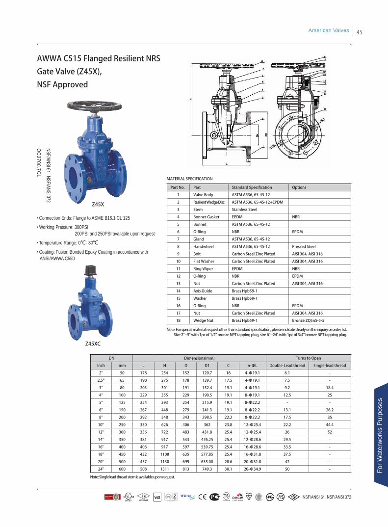
• Connection Ends: Flange to ASME B16.1 CL 125
• Working Pressure: 300PSI 200PSI and 250PSI available upon request
• Temperature Range: 0℃- 80℃
• Coating: Fusion Bonded Epoxy Coating in accordance with ANSI/AWWA C550
AWWA C515 Flanged Resilient NRS
Gate Valve (Z45X),
NSF Approved
Part No. Part Standard Specification Options
1 Valve Body ASTM A536, 65-45-12
2 Resilient Wedge Disc ASTM A536, 65-45-12+EPDM
3 Stem Stainless Steel
4 Bonnet Gasket EPDM NBR
5 Bonnet ASTM A536, 65-45-12
6 O-Ring NBR EPDM
7 Gland ASTM A536, 65-45-12
8 Handwheel ASTM A536, 65-45-12 Pressed Steel
9 Bolt Carbon Steel Zinc Plated AISI 304, AISI 316
10 Flat Washer Carbon Steel Zinc Plated AISI 304, AISI 316
11 Ring Wiper EPDM NBR
12 O-Ring NBR EPDM
13 Nut Carbon Steel Zinc Plated AISI 304, AISI 316
14 Axis Guide Brass Hpb59-1
15 Washer Brass Hpb59-1
16 O-Ring NBR EPDM
17 Nut Carbon Steel Zinc Plated AISI 304, AISI 316
18 Wedge Nut Brass Hpb59-1 Bronze ZQSn5-5-5
DN Dimensions(mm) Turns to Open
Inch mm L H D D1 C n-ΦL Double-Lead thread Single-lead thread
2" 50 178 254 152 120.7 16 4-Φ19.1 6.1 -
2.5" 65 190 275 178 139.7 17.5 4-Φ19.1 7.5 -
3" 80 203 301 191 152.4 19.1 4-Φ19.1 9.2 18.4
4" 100 229 355 229 190.5 19.1 8-Φ19.1 12.5 25
5" 125 254 393 254 215.9 19.1 8-Φ22.2 - -
6" 150 267 448 279 241.3 19.1 8-Φ22.2 13.1 26.2
8" 200 292 548 343 298.5 22.2 8-Φ22.2 17.5 35
10" 250 330 626 406 362 23.8 12-Φ25.4 22.2 44.4
12" 300 356 722 483 431.8 25.4 12-Φ25.4 26 52
14" 350 381 917 533 476.25 25.4 12-Φ28.6 29.5 -
16" 400 406 917 597 539.75 25.4 16-Φ28.6 33.5 -
18" 450 432 1108 635 577.85 25.4 16-Φ31.8 37.5 -
20" 500 457 1130 699 635.00 28.6 20-Φ31.8 42 -
24" 600 508 1311 813 749.3 30.1 20-Φ34.9 50 -
Z45X
Z45XC
MATERIAL SPECIFICATION
Note: For special material request other than standard specification, please indicate clearly on the inquiry or order list. Size 2"~5" with 1pc of 1/2" bronze NPT tapping plug, size 6"~24" with 1pc of 3/4" bronze NPT tapping plug.
Note: Single lead thread stem is available upon request.
American Valves 45
For W
ater
wor
ks P
urpo
ses
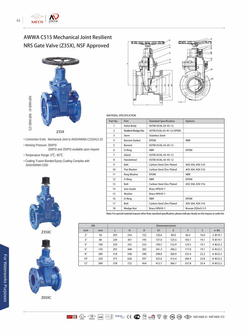
• Connection Ends: Mechanical Joint to ANSI/AWWA C153/A21.53
• Working Pressure: 300PSI 200PSI and 250PSI available upon request
• Temperature Range: 0℃- 80℃
• Coating: Fusion Bonded Epoxy Coating Complies with ANSI/AWWA C550
Part No. Part Standard Specification Options
1 Valve Body ASTM A536, 65-45-12
2 Resilient Wedge Disc ASTM A536, 65-45-12+EPDM
3 Stem Stainless Steel
4 Bonnet Gasket EPDM NBR
5 Bonnet ASTM A536, 65-45-12
6 O-Ring NBR EPDM
7 Gland ASTM A536, 65-45-12
8 Handwheel ASTM A536, 65-45-12
9 Bolt Carbon Steel Zinc Plated AISI 304, AISI 316
10 Flat Washer Carbon Steel Zinc Plated AISI 304, AISI 316
11 Ring Washer EPDM NBR
12 O-Ring NBR EPDM
13 Bolt Carbon Steel Zinc Plated AISI 304, AISI 316
14 Axis Guide Brass HPb59-1
15 Washer Brass HPb59-1
16 O-Ring NBR EPDM
17 Bolt Carbon Steel Zinc Plated AISI 304, AISI 316
18 Wedge Nut Brass HPb59-1 Bronze ZQSn5-5-5
Z35X
MATERIAL SPECIFICATION
AWWA C515 Mechanical Joint Resilient
NRS Gate Valve (Z35X), NSF Approved
DN Dimensions(mm)
Inch mm L H D D1 E F C n-ΦL
2" 50 203 254 152 120.6 89.0 66.3 16.0 2-Φ19.1
3" 80 229 301 195 157.0 125.5 103.1 19.1 4-Φ19.1
4" 100 229 355 232 190.5 152.9 124.5 19.1 4-Φ22.2
6" 150 292 448 282 241.3 206.2 177.8 19.1 6-Φ22.2
8" 200 318 548 340 298.0 260.9 232.4 22.2 6-Φ22.2
10" 250 375 626 397 355.6 313.4 284.4 23.8 8-Φ22.2
12" 300 378 722 454 412.7 366.7 337.8 25.4 8-Φ22.2
Note: For special material request other than standard specification, please indicate clearly on the inquiry or order list.
Z35XC
Z05XC
46
For Waterw
orks Purposes
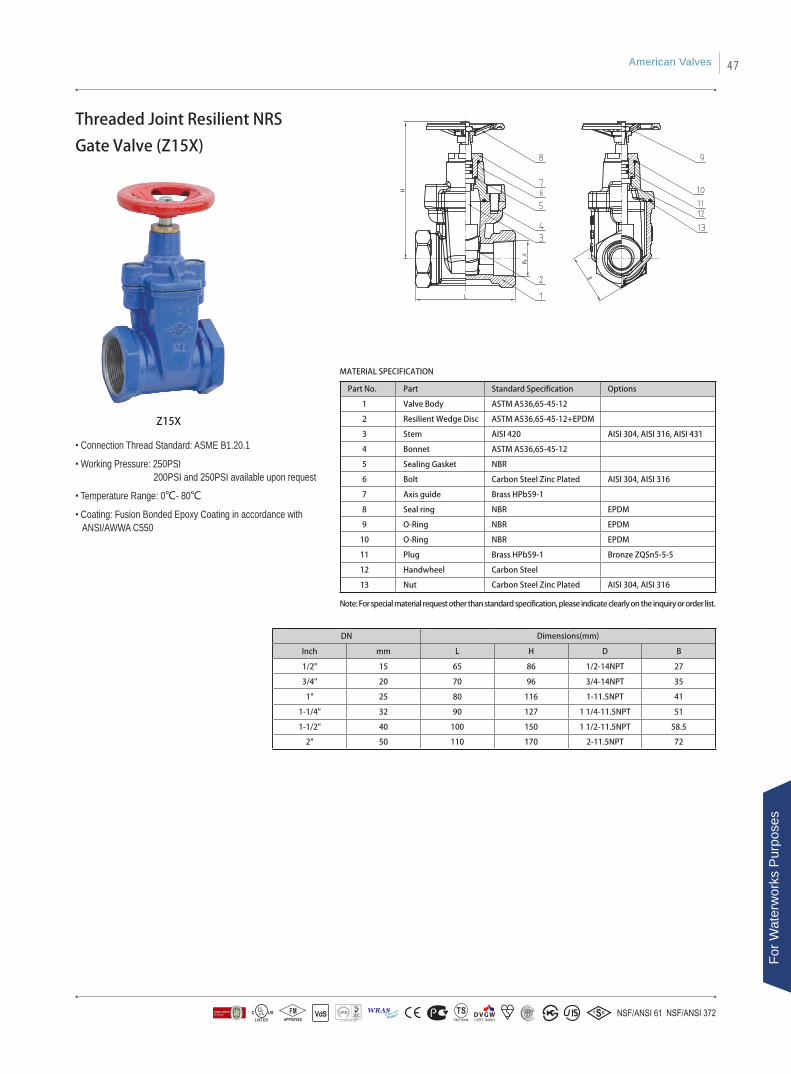
Threaded Joint Resilient NRS
Gate Valve (Z15X)
• Connection Thread Standard: ASME B1.20.1
• Working Pressure: 250PSI 200PSI and 250PSI available upon request
• Temperature Range: 0℃- 80℃
• Coating: Fusion Bonded Epoxy Coating in accordance with ANSI/AWWA C550
MATERIAL SPECIFICATION
Note: For special material request other than standard specification, please indicate clearly on the inquiry or order list.
DN Dimensions(mm)
Inch mm L H D B
1/2" 15 65 86 1/2-14NPT 27
3/4" 20 70 96 3/4-14NPT 35
1" 25 80 116 1-11.5NPT 41
1-1/4" 32 90 127 1 1/4-11.5NPT 51
1-1/2" 40 100 150 1 1/2-11.5NPT 58.5
2" 50 110 170 2-11.5NPT 72
Z15X
Part No. Part Standard Specification Options
1 Valve Body ASTM A536,65-45-12
2 Resilient Wedge Disc ASTM A536,65-45-12+EPDM
3 Stem AISI 420 AISI 304, AISI 316, AISI 431
4 Bonnet ASTM A536,65-45-12
5 Sealing Gasket NBR
6 Bolt Carbon Steel Zinc Plated AISI 304, AISI 316
7 Axis guide Brass HPb59-1
8 Seal ring NBR EPDM
9 O-Ring NBR EPDM
10 O-Ring NBR EPDM
11 Plug Brass HPb59-1 Bronze ZQSn5-5-5
12 Handwheel Carbon Steel
13 Nut Carbon Steel Zinc Plated AISI 304, AISI 316
American Valves 47
For W
ater
wor
ks P
urpo
ses

AWWA C515 Flanged Resilient OS&Y
Gate Valve (XZ41X),
NSF Approved
Part No. Part Standard Specification Options
1 Valve Body ASTM A536, 65-45-12
2 Resilient Wedge Disc ASTM A536, 65-45-12+EPDM
3 Stem Stainless Steel
4 Bonnet Gasket EPDM NBR
5 Bonnet ASTM A536, 65-45-12
6 Washer Brass Hpb59-1
7 Yoke ASTM A536, 65-45-12
8 Stem Bushing Brass Hpb59-1
9 Gland ASTM A536, 65-45-12
10 Stem Nut Brass Hpb59-1 Bronze ZQSn5-5-5
11 Handwheel ASTM A536, 65-45-12 Pressed Steel
12 Washer Brass Hpb59-1
13 Gland Nut Carbon Steel Zinc Plated AISI 304, AISI 316
14 Stud Carbon Steel Zinc Plated AISI 304, AISI 316
15 Flat Washer Carbon Steel Zinc Plated AISI 304, AISI 316
16 Nut Carbon Steel Zinc Plated AISI 304, AISI 316
17 O-Ring EPDM NBR
• Connection Ends: Flange to ASME B16.1 CL 125
• Working Pressure: 300PSI 200PSI and 250PSI available upon request
• Temperature Range: 0℃- 80℃
• Coating: Fusion Bonded Epoxy Coating in accordance with ANSI/AWWA C550
DN Dimensions(mm) Turns to Open Double-Lead threadInch mm L H1(Close) H2(Open) D D1 C n-ΦL
2" 50 178 348 400 152 120.7 16 4-Φ19.1 6.5 6.5
2.5" 65 190 373 440 178 139.7 17.5 4-Φ19.1 7.5 7.5
3" 80 203 408 490 191 152.4 19.1 4-Φ19.1 8.8 8.8
4" 100 229 471 573 229 190.5 19.1 8-Φ19.1 10.5 10.5
5" 125 254 541 665 254 215.9 19.1 8-Φ22.2
6" 150 267 601 755 279 241.3 19.1 8-Φ22.2 13.3 13.3
8" 200 292 774 975 343 298.5 22.2 8-Φ22.2 17.7 17.7
10" 250 330 939 1193 406 362 23.8 12-Φ25.4 22.5 22.5
12" 300 356 1065 1370 483 431.8 25.4 12-Φ25.4 26 26
14" 350 381 1210 1560 533 476.3 25.4 12-Φ28.6 29.5 29.5
16" 400 406 1280 1680 597 539.8 25.4 16-Φ28.6 33.5 33.5
18" 450 432 1760 2210 635 577.9 25.4 16-Φ31.8 37.5 37.5
20" 500 457 1780 2280 699 635.0 28.6 20-Φ31.8 42 42
24" 600 508 1950 2550 813 749.3 30.1 20-Φ34.9 50 50
MATERIAL SPECIFICATION
XZ41X
Note: For special material request other than standard specification, please indicate clearly on the inquiry or order list. Size 2"~5" with 1pc of 1/2" bronze NPT tapping plug, size 6"~24" with 1pc of 3/4" bronze NPT tapping plug.
48
For Waterw
orks Purposes
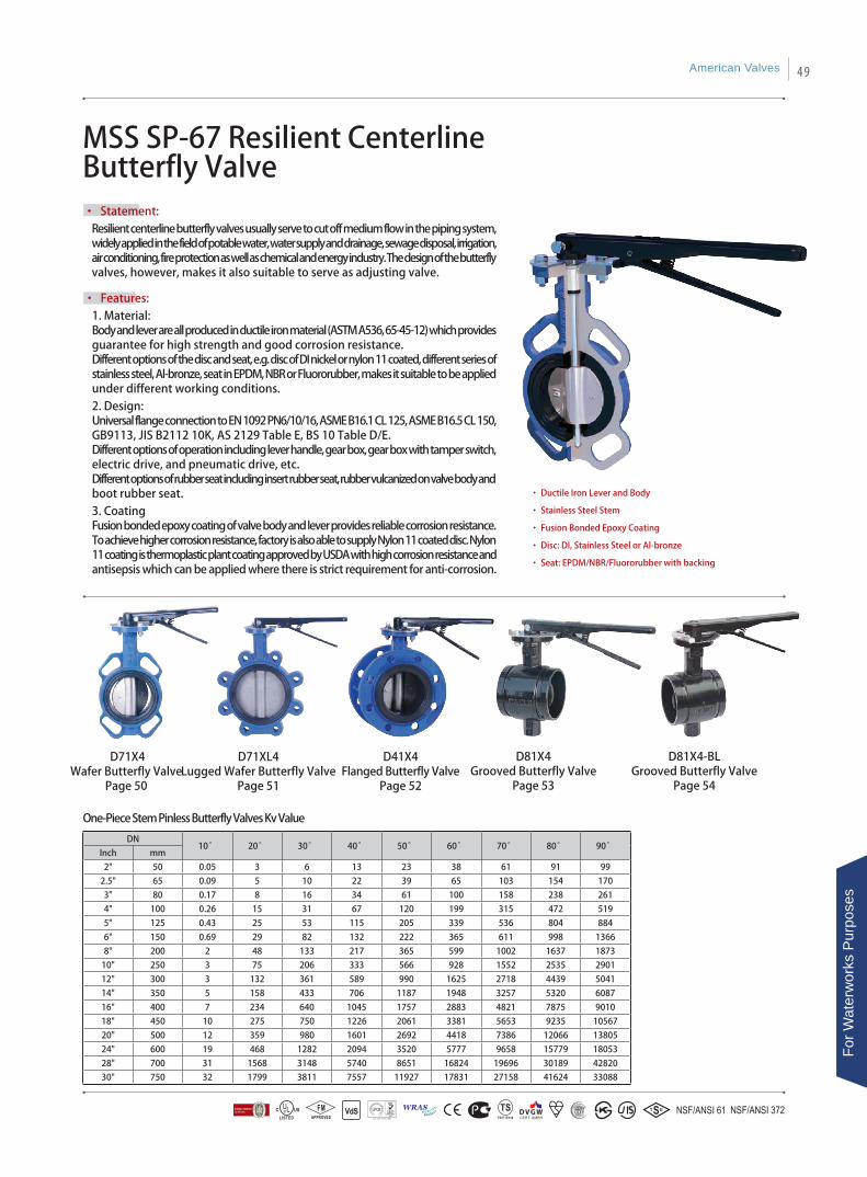
MSS SP-67 Resilient Centerline Butterfly Valve
• Statement: Resilient centerline butterfly valves usually serve to cut off medium flow in the piping system, widely applied in the field of potable water, water supply and drainage, sewage disposal, irrigation, air conditioning, fire protection as well as chemical and energy industry. The design of the butterfly valves, however, makes it also suitable to serve as adjusting valve.
• Features:1. Material: Body and lever are all produced in ductile iron material (ASTM A536, 65-45-12) which provides guarantee for high strength and good corrosion resistance.Different options of the disc and seat, e.g. disc of DI nickel or nylon 11 coated, different series of stainless steel, Al-bronze, seat in EPDM, NBR or Fluororubber, makes it suitable to be applied under different working conditions.2. Design: Universal flange connection to EN 1092 PN6/10/16, ASME B16.1 CL 125, ASME B16.5 CL 150, GB9113, JIS B2112 10K, AS 2129 Table E, BS 10 Table D/E. Different options of operation including lever handle, gear box, gear box with tamper switch, electric drive, and pneumatic drive, etc.Different options of rubber seat including insert rubber seat, rubber vulcanized on valve body and boot rubber seat. 3. CoatingFusion bonded epoxy coating of valve body and lever provides reliable corrosion resistance.To achieve higher corrosion resistance, factory is also able to supply Nylon 11 coated disc. Nylon 11 coating is thermoplastic plant coating approved by USDA with high corrosion resistance and antisepsis which can be applied where there is strict requirement for anti-corrosion.
• Ductile Iron Lever and Body
• Stainless Steel Stem
• Fusion Bonded Epoxy Coating
• Disc: DI, Stainless Steel or Al-bronze
• Seat: EPDM/NBR/Fluororubber with backing
D71XL4Lugged Wafer Butterfly Valve
Page 51
D41X4Flanged Butterfly Valve
Page 52
D71X4Wafer Butterfly Valve
Page 50
DN10° 20° 30° 40° 50° 60° 70° 80° 90°
Inch mm
2" 50 0.05 3 6 13 23 38 61 91 99
2.5" 65 0.09 5 10 22 39 65 103 154 170
3" 80 0.17 8 16 34 61 100 158 238 261
4" 100 0.26 15 31 67 120 199 315 472 519
5" 125 0.43 25 53 115 205 339 536 804 884
6" 150 0.69 29 82 132 222 365 611 998 1366
8" 200 2 48 133 217 365 599 1002 1637 1873
10" 250 3 75 206 333 566 928 1552 2535 2901
12" 300 3 132 361 589 990 1625 2718 4439 5041
14" 350 5 158 433 706 1187 1948 3257 5320 6087
16" 400 7 234 640 1045 1757 2883 4821 7875 9010
18" 450 10 275 750 1226 2061 3381 5653 9235 10567
20" 500 12 359 980 1601 2692 4418 7386 12066 13805
24" 600 19 468 1282 2094 3520 5777 9658 15779 18053
28" 700 31 1568 3148 5740 8651 16824 19696 30189 42820
30" 750 32 1799 3811 7557 11927 17831 27158 41624 33088
One-Piece Stem Pinless Butterfly Valves Kv Value
D81X4-BLGrooved Butterfly Valve
Page 54
D81X4Grooved Butterfly Valve
Page 53
American Valves 49
For W
ater
wor
ks P
urpo
ses
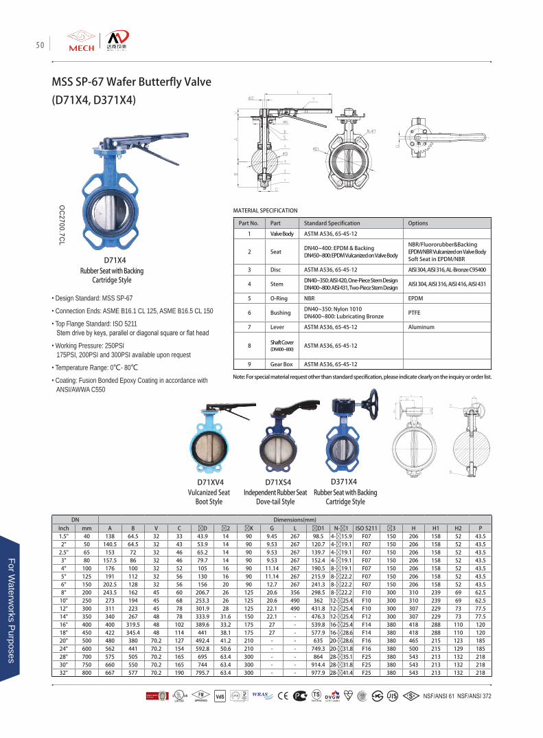
MSS SP-67 Wafer Butterfly Valve
(D71X4, D371X4)
Part No. Part Standard Specification Options
1 Valve Body ASTM A536, 65-45-12
2 SeatDN40~400: EPDM & BackingDN450~800: EPDM Vulcanized on Valve Body
NBR/Fluororubber&BackingEPDM/NBR Vulcanized on Valve BodySoft Seat in EPDM/NBR
3 Disc ASTM A536, 65-45-12 AISI 304, AISI 316, AL-Bronze C95400
4 StemDN40~350: AISI 420, One-Piece Stem DesignDN400~800: AISI 431, Two-Piece Stem Design
AISI 304, AISI 316, AISI 416, AISI 431
5 O-Ring NBR EPDM
6 BushingDN40~350: Nylon 1010 DN400~800: Lubricating Bronze
PTFE
7 Lever ASTM A536, 65-45-12 Aluminum
8 Shaft Cover (DN400~800)
ASTM A536, 65-45-12
9 Gear Box ASTM A536, 65-45-12
• Design Standard: MSS SP-67
• Connection Ends: ASME B16.1 CL 125, ASME B16.5 CL 150
• Top Flange Standard: ISO 5211 Stem drive by keys, parallel or diagonal square or flat head
• Working Pressure: 250PSI 175PSI, 200PSI and 300PSI available upon request
• Temperature Range: 0℃- 80℃
• Coating: Fusion Bonded Epoxy Coating in accordance with ANSI/AWWA C550
MATERIAL SPECIFICATION
D71X4
D371X4
DN Dimensions(mm)Inch mm A B V C ØD Ø2 ØK G L ØD1 N-Ø1 ISO 5211 Ø3 H H1 H2 P1.5" 40 138 64.5 32 33 43.9 14 90 9.45 267 98.5 4-Ø15.9 F07 150 206 158 52 43.52" 50 140.5 64.5 32 43 53.9 14 90 9.53 267 120.7 4-Ø19.1 F07 150 206 158 52 43.5
2.5" 65 153 72 32 46 65.2 14 90 9.53 267 139.7 4-Ø19.1 F07 150 206 158 52 43.53" 80 157.5 86 32 46 79.7 14 90 9.53 267 152.4 4-Ø19.1 F07 150 206 158 52 43.54" 100 176 100 32 52 105 16 90 11.14 267 190.5 8-Ø19.1 F07 150 206 158 52 43.55" 125 191 112 32 56 130 16 90 11.14 267 215.9 8-Ø22.2 F07 150 206 158 52 43.56" 150 202.5 128 32 56 156 20 90 12.7 267 241.3 8-Ø22.2 F07 150 206 158 52 43.58" 200 243.5 162 45 60 206.7 26 125 20.6 356 298.5 8-Ø22.2 F10 300 310 239 69 62.5
10" 250 273 194 45 68 253.3 26 125 20.6 490 362 12-Ø25.4 F10 300 310 239 69 62.512" 300 311 223 45 78 301.9 28 125 22.1 490 431.8 12-Ø25.4 F10 300 307 229 73 77.514" 350 340 267 48 78 333.9 31.6 150 22.1 - 476.3 12-Ø25.4 F12 300 307 229 73 77.516" 400 400 319.5 48 102 389.6 33.2 175 27 - 539.8 16-Ø25.4 F14 380 418 288 110 12018" 450 422 345.4 48 114 441 38.1 175 27 - 577.9 16-Ø28.6 F14 380 418 288 110 12020" 500 480 380 70.2 127 492.4 41.2 210 - - 635 20-Ø28.6 F16 380 465 215 123 18524" 600 562 441 70.2 154 592.8 50.6 210 - - 749.3 20-Ø31.8 F16 380 500 215 129 18528" 700 575 505 70.2 165 695 63.4 300 - - 864 28-Ø35.1 F25 380 543 213 132 21830" 750 660 550 70.2 165 744 63.4 300 - - 914.4 28-Ø31.8 F25 380 543 213 132 21832" 800 667 577 70.2 190 795.7 63.4 300 - - 977.9 28-Ø41.4 F25 380 543 213 132 218
Note: For special material request other than standard specification, please indicate clearly on the inquiry or order list.
D71XS4 D71XV4Vulcanized Seat
Boot StyleIndependent Rubber Seat
Dove-tail StyleRubber Seat with Backing
Cartridge Style
Rubber Seat with BackingCartridge Style
50
For Waterw
orks Purposes

Part No. Part Standard Specification Options
1 Valve Body ASTM A536, 65-45-12
2 SeatDN40~150: EPDM & BackingDN200~800: EPDM Vulcanized on Valve Body
NBR/Fluororubber&BackingEPDM/NBR Vulcanized on Valve BodySoft Seat in EPDM/NBR
3 Disc ASTM A536, 65-45-12 AISI 304, AISI 316, AL-Bronze C95400
4 StemDN40~350: AISI 420, One-Piece Stem DesignDN400~800: AISI 431, Two-Piece Stem Design
AISI 304, AISI 316, AISI 416, AISI 431
5 O-Ring NBR EPDM
6 BushingDN40~350: Nylon 1010 DN400~800: Lubricating Bronze
PTFE
7 Lever ASTM A536, 65-45-12 Aluminum
8 Shaft Cover (DN400~800)
ASTM A536, 65-45-12
9 Gear Box ASTM A536, 65-45-12
MSS SP-67 Lugged Wafer
Butterfly Valve (D71XL4, D371XL4)
• Design Standard: MSS SP-67
• Connection Ends: ASME B16.1 CL 125, ASME B16.5 CL 150
• Top Flange Standard: ISO 5211 Stem drive by keys, parallel or diagonal square or flat head
• Working Pressure: 250PSI 175PSI, 200PSI and 300PSI available upon request
• Temperature Range: 0℃- 80℃
• Coating: Fusion Bonded Epoxy Coating in accordance with ANSI/AWWA C550
D71XL4
D371XL4
MATERIAL SPECIFICATION
DN Dimensions(mm)
Inch mm A B V C ØD Ø2 ØK G L ØD1 N-M ISO 5211 Ø3 H H1 H2 P
1.5" 40 138 64.5 32 33 43.9 14 90 9.45 267 98.5 4-1/2 F07 150 206 158 52 43.5
2" 50 140.5 64.5 32 43 53.9 14 90 9.53 267 120.7 4-5/8 F07 150 206 158 52 43.5
2.5" 65 153 72 32 46 65.2 14 90 9.53 267 139.7 4-5/8 F07 150 206 158 52 43.5
3" 80 157.5 86 32 46 79.7 14 90 9.53 267 152.4 4-5/8 F07 150 206 158 52 43.5
4" 100 176 100 32 52 105 16 90 11.14 267 190.5 8-5/8 F07 150 206 158 52 43.5
5" 125 191 112 32 56 130 16 90 11.14 267 215.9 8-3/4 F07 150 206 158 52 43.5
6" 150 202.5 128 32 56 156 20 90 12.7 267 241.3 8-3/4 F07 150 206 158 52 43.5
8" 200 243.5 162 45 60 206.7 26 125 20.6 356 298.5 8-3/4 F10 300 310 239 69 62.5
10" 250 273 194 45 68 253.3 26 125 20.6 490 362 12-7/8 F10 300 310 239 69 62.5
12" 300 311 223 45 78 301.9 28 125 22.1 490 431.8 12-7/8 F10 300 307 229 73 77.5
14" 350 340 267 48 78 333.9 31.6 150 22.1 - 476.3 12-1 F12 300 307 229 73 77.5
16" 400 400 319.5 48 102 389.6 33.2 175 27 - 539.8 16-1 F14 380 418 288 110 120
18" 450 422 345.4 48 114 441 38.1 175 27 - 577.9 16-1 1/8 F14 380 418 288 110 120
20" 500 480 380 70.2 127 492.4 41.2 210 - - 635 20-1 1/8 F16 380 465 215 123 185
24" 600 562 441 70.2 154 592.8 50.6 210 - - 749.3 20-1 1/4 F16 380 500 215 129 185
28" 700 575 505 70.2 165 695 63.4 300 - - 863.6 28-1 1/4 F25 380 543 213 132 218
30" 750 660 550 70.2 165 744 63.4 300 - - 914.4 28-1 1/4 F25 380 543 213 132 218
32" 800 667 577 70.2 190 795.7 63.4 300 - - 977.9 28-1 1/2 F25 380 543 213 132 218
Note: For special material request other than standard specification, please indicate clearly on the inquiry or order list.
American Valves 51
For W
ater
wor
ks P
urpo
ses
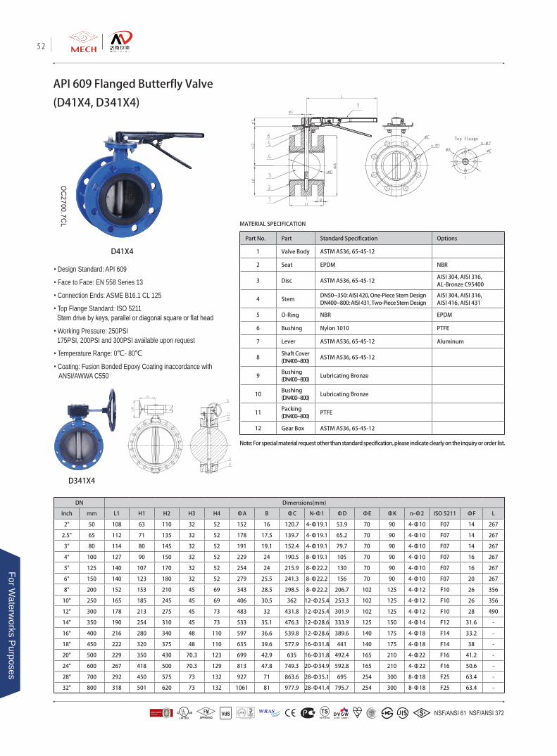
API 609 Flanged Butterfly Valve
(D41X4, D341X4)
Part No. Part Standard Specification Options
1 Valve Body ASTM A536, 65-45-12
2 Seat EPDM NBR
3 Disc ASTM A536, 65-45-12AISI 304, AISI 316, AL-Bronze C95400
4 StemDN50~350: AISI 420, One-Piece Stem DesignDN400~800: AISI 431, Two-Piece Stem Design
AISI 304, AISI 316,AISI 416, AISI 431
5 O-Ring NBR EPDM
6 Bushing Nylon 1010 PTFE
7 Lever ASTM A536, 65-45-12 Aluminum
8Shaft Cover (DN400~800)
ASTM A536, 65-45-12
9Bushing (DN400~800)
Lubricating Bronze
10Bushing (DN400~800)
Lubricating Bronze
11Packing (DN400~800)
PTFE
12 Gear Box ASTM A536, 65-45-12
• Design Standard: API 609
• Face to Face: EN 558 Series 13
• Connection Ends: ASME B16.1 CL 125
• Top Flange Standard: ISO 5211 Stem drive by keys, parallel or diagonal square or flat head
• Working Pressure: 250PSI 175PSI, 200PSI and 300PSI available upon request
• Temperature Range: 0℃- 80℃
• Coating: Fusion Bonded Epoxy Coating inaccordance with ANSI/AWWA C550
D41X4
D341X4
MATERIAL SPECIFICATION
Note: For special material request other than standard specification, please indicate clearly on the inquiry or order list.
DN Dimensions(mm)
Inch mm L1 H1 H2 H3 H4 ΦA B ΦC N-Φ1 ΦD ΦE ΦK n-Φ2 ISO 5211 ΦF L
2" 50 108 63 110 32 52 152 16 120.7 4-Φ19.1 53.9 70 90 4-Φ10 F07 14 267
2.5" 65 112 71 135 32 52 178 17.5 139.7 4-Φ19.1 65.2 70 90 4-Φ10 F07 14 267
3" 80 114 80 145 32 52 191 19.1 152.4 4-Φ19.1 79.7 70 90 4-Φ10 F07 14 267
4" 100 127 90 150 32 52 229 24 190.5 8-Φ19.1 105 70 90 4-Φ10 F07 16 267
5" 125 140 107 170 32 52 254 24 215.9 8-Φ22.2 130 70 90 4-Φ10 F07 16 267
6" 150 140 123 180 32 52 279 25.5 241.3 8-Φ22.2 156 70 90 4-Φ10 F07 20 267
8" 200 152 153 210 45 69 343 28.5 298.5 8-Φ22.2 206.7 102 125 4-Φ12 F10 26 356
10" 250 165 185 245 45 69 406 30.5 362 12-Φ25.4 253.3 102 125 4-Φ12 F10 26 356
12" 300 178 213 275 45 73 483 32 431.8 12-Φ25.4 301.9 102 125 4-Φ12 F10 28 490
14" 350 190 254 310 45 73 533 35.1 476.3 12-Φ28.6 333.9 125 150 4-Φ14 F12 31.6 -
16" 400 216 280 340 48 110 597 36.6 539.8 12-Φ28.6 389.6 140 175 4-Φ18 F14 33.2 -
18" 450 222 320 375 48 110 635 39.6 577.9 16-Φ31.8 441 140 175 4-Φ18 F14 38 -
20" 500 229 350 430 70.3 123 699 42.9 635 16-Φ31.8 492.4 165 210 4-Φ22 F16 41.2 -
24" 600 267 418 500 70.3 129 813 47.8 749.3 20-Φ34.9 592.8 165 210 4-Φ22 F16 50.6 -
28" 700 292 450 575 73 132 927 71 863.6 28-Φ35.1 695 254 300 8-Φ18 F25 63.4 -
32" 800 318 501 620 73 132 1061 81 977.9 28-Φ41.4 795.7 254 300 8-Φ18 F25 63.4 -
52
For Waterw
orks Purposes
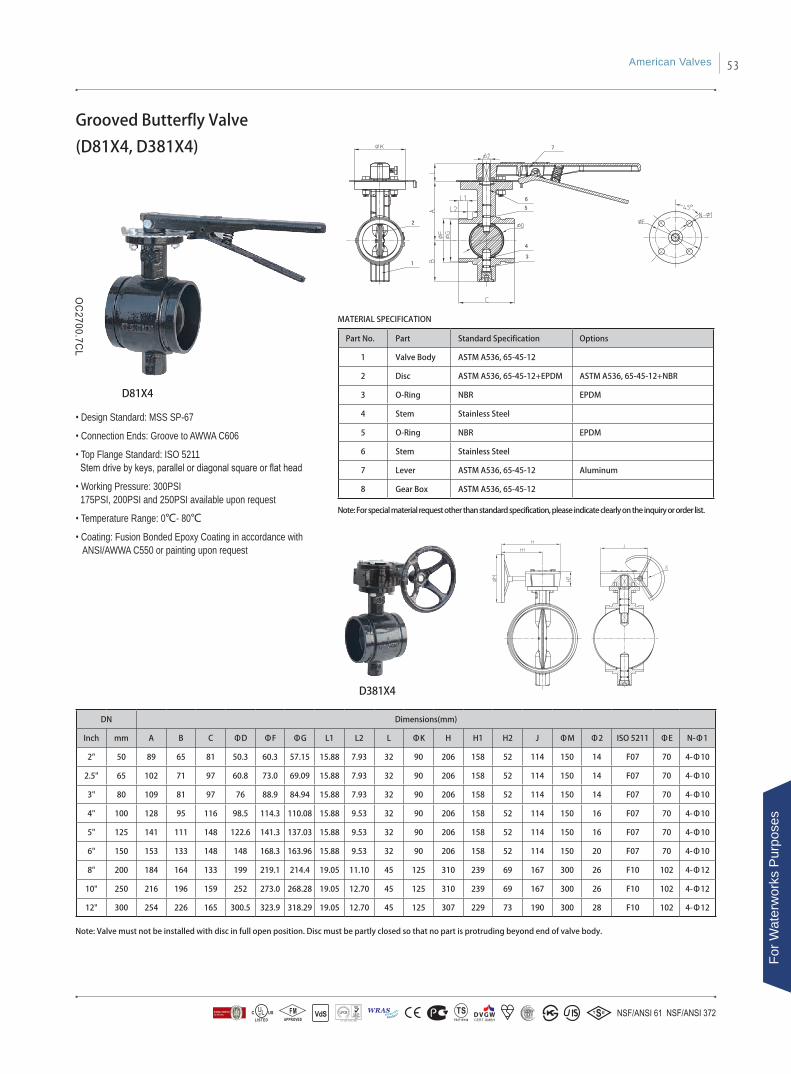
Grooved Butterfly Valve
(D81X4, D381X4)
Part No. Part Standard Specification Options
1 Valve Body ASTM A536, 65-45-12
2 Disc ASTM A536, 65-45-12+EPDM ASTM A536, 65-45-12+NBR
3 O-Ring NBR EPDM
4 Stem Stainless Steel
5 O-Ring NBR EPDM
6 Stem Stainless Steel
7 Lever ASTM A536, 65-45-12 Aluminum
8 Gear Box ASTM A536, 65-45-12
• Design Standard: MSS SP-67
• Connection Ends: Groove to AWWA C606
• Top Flange Standard: ISO 5211 Stem drive by keys, parallel or diagonal square or flat head
• Working Pressure: 300PSI 175PSI, 200PSI and 250PSI available upon request
• Temperature Range: 0℃- 80℃
• Coating: Fusion Bonded Epoxy Coating in accordance with ANSI/AWWA C550 or painting upon request
Note: Valve must not be installed with disc in full open position. Disc must be partly closed so that no part is protruding beyond end of valve body.
D381X4
D81X4
MATERIAL SPECIFICATION
DN Dimensions(mm)
Inch mm A B C ΦD ΦF ΦG L1 L2 L ΦK H H1 H2 J ΦM Φ2 ISO 5211 ΦE N-Φ1
2" 50 89 65 81 50.3 60.3 57.15 15.88 7.93 32 90 206 158 52 114 150 14 F07 70 4-Φ10
2.5" 65 102 71 97 60.8 73.0 69.09 15.88 7.93 32 90 206 158 52 114 150 14 F07 70 4-Φ10
3" 80 109 81 97 76 88.9 84.94 15.88 7.93 32 90 206 158 52 114 150 14 F07 70 4-Φ10
4" 100 128 95 116 98.5 114.3 110.08 15.88 9.53 32 90 206 158 52 114 150 16 F07 70 4-Φ10
5" 125 141 111 148 122.6 141.3 137.03 15.88 9.53 32 90 206 158 52 114 150 16 F07 70 4-Φ10
6" 150 153 133 148 148 168.3 163.96 15.88 9.53 32 90 206 158 52 114 150 20 F07 70 4-Φ10
8" 200 184 164 133 199 219.1 214.4 19.05 11.10 45 125 310 239 69 167 300 26 F10 102 4-Φ12
10" 250 216 196 159 252 273.0 268.28 19.05 12.70 45 125 310 239 69 167 300 26 F10 102 4-Φ12
12" 300 254 226 165 300.5 323.9 318.29 19.05 12.70 45 125 307 229 73 190 300 28 F10 102 4-Φ12
Note: For special material request other than standard specification, please indicate clearly on the inquiry or order list.
American Valves 53
For W
ater
wor
ks P
urpo
ses
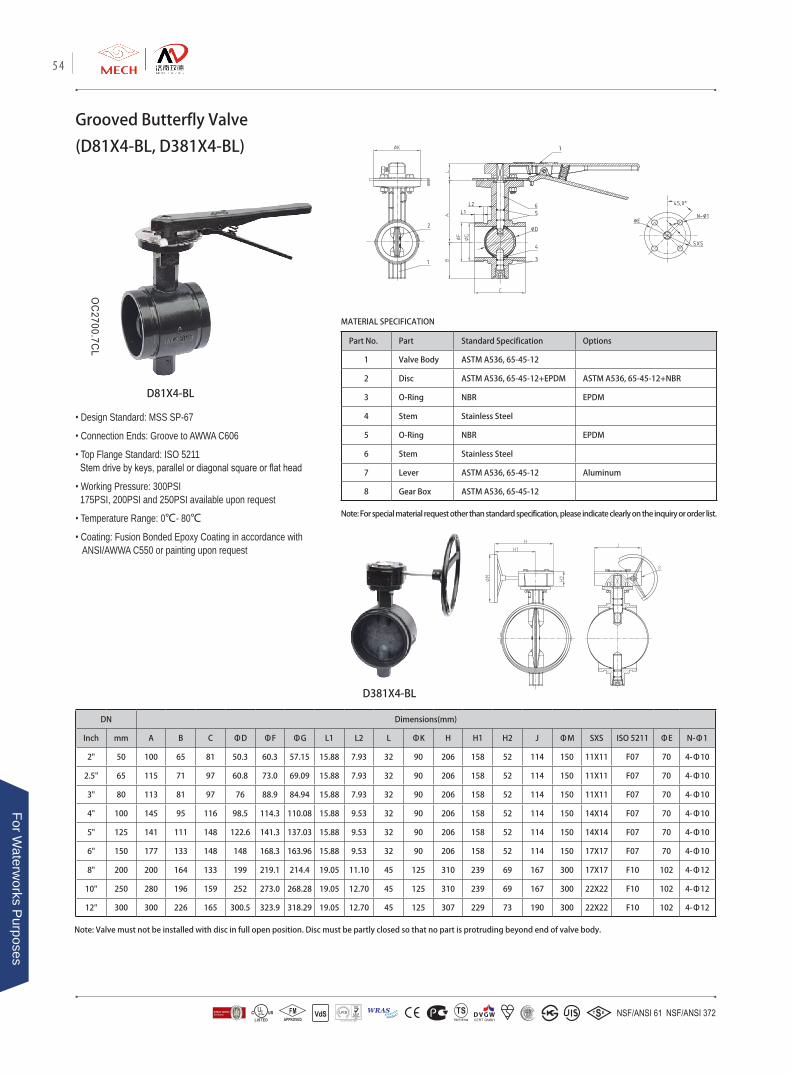
DN Dimensions(mm)
Inch mm A B C ΦD ΦF ΦG L1 L2 L ΦK H H1 H2 J ΦM SXS ISO 5211 ΦE N-Φ1
2" 50 100 65 81 50.3 60.3 57.15 15.88 7.93 32 90 206 158 52 114 150 11X11 F07 70 4-Φ10
2.5" 65 115 71 97 60.8 73.0 69.09 15.88 7.93 32 90 206 158 52 114 150 11X11 F07 70 4-Φ10
3" 80 113 81 97 76 88.9 84.94 15.88 7.93 32 90 206 158 52 114 150 11X11 F07 70 4-Φ10
4" 100 145 95 116 98.5 114.3 110.08 15.88 9.53 32 90 206 158 52 114 150 14X14 F07 70 4-Φ10
5" 125 141 111 148 122.6 141.3 137.03 15.88 9.53 32 90 206 158 52 114 150 14X14 F07 70 4-Φ10
6" 150 177 133 148 148 168.3 163.96 15.88 9.53 32 90 206 158 52 114 150 17X17 F07 70 4-Φ10
8" 200 200 164 133 199 219.1 214.4 19.05 11.10 45 125 310 239 69 167 300 17X17 F10 102 4-Φ12
10" 250 280 196 159 252 273.0 268.28 19.05 12.70 45 125 310 239 69 167 300 22X22 F10 102 4-Φ12
12" 300 300 226 165 300.5 323.9 318.29 19.05 12.70 45 125 307 229 73 190 300 22X22 F10 102 4-Φ12
Part No. Part Standard Specification Options
1 Valve Body ASTM A536, 65-45-12
2 Disc ASTM A536, 65-45-12+EPDM ASTM A536, 65-45-12+NBR
3 O-Ring NBR EPDM
4 Stem Stainless Steel
5 O-Ring NBR EPDM
6 Stem Stainless Steel
7 Lever ASTM A536, 65-45-12 Aluminum
8 Gear Box ASTM A536, 65-45-12
Grooved Butterfly Valve
(D81X4-BL, D381X4-BL)
Note: Valve must not be installed with disc in full open position. Disc must be partly closed so that no part is protruding beyond end of valve body.
D381X4-BL
D81X4-BL
MATERIAL SPECIFICATION
Note: For special material request other than standard specification, please indicate clearly on the inquiry or order list.
• Design Standard: MSS SP-67
• Connection Ends: Groove to AWWA C606
• Top Flange Standard: ISO 5211 Stem drive by keys, parallel or diagonal square or flat head
• Working Pressure: 300PSI 175PSI, 200PSI and 250PSI available upon request
• Temperature Range: 0℃- 80℃
• Coating: Fusion Bonded Epoxy Coating in accordance with ANSI/AWWA C550 or painting upon request
54
For Waterw
orks Purposes
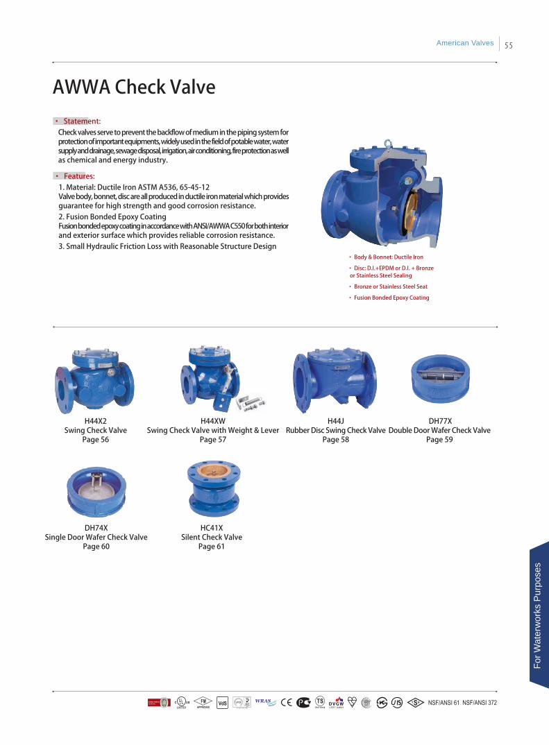
AWWA Check Valve
• Statement: Check valves serve to prevent the backflow of medium in the piping system for protection of important equipments, widely used in the field of potable water, water supply and drainage, sewage disposal, irrigation, air conditioning, fire protection as well as chemical and energy industry.
• Features: 1. Material: Ductile Iron ASTM A536, 65-45-12Valve body, bonnet, disc are all produced in ductile iron material which provides guarantee for high strength and good corrosion resistance.2. Fusion Bonded Epoxy CoatingFusion bonded epoxy coating in accordance with ANSI/AWWA C550 for both interior and exterior surface which provides reliable corrosion resistance.3. Small Hydraulic Friction Loss with Reasonable Structure Design
• Body & Bonnet: Ductile Iron
• Disc: D.I.+EPDM or D.I. + Bronze or Stainless Steel Sealing
• Bronze or Stainless Steel Seat
• Fusion Bonded Epoxy Coating
H44X2Swing Check Valve
Page 56
H44JRubber Disc Swing Check Valve
Page 58
HC41XSilent Check Valve
Page 61
DH77XDouble Door Wafer Check Valve
Page 59
H44XWSwing Check Valve with Weight & Lever
Page 57
DH74XSingle Door Wafer Check Valve
Page 60
American Valves 55
For W
ater
wor
ks P
urpo
ses
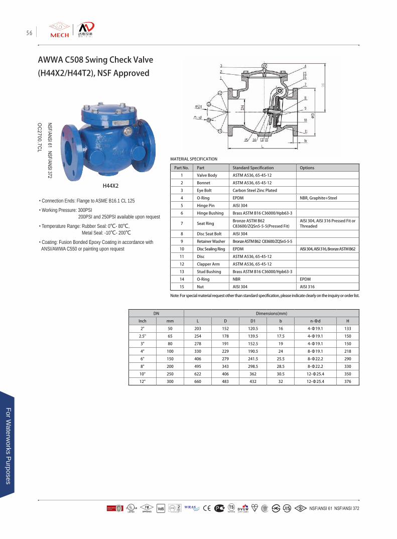
AWWA C508 Swing Check Valve
(H44X2/H44T2), NSF Approved
• Connection Ends: Flange to ASME B16.1 CL 125
• Working Pressure: 300PSI 200PSI and 250PSI available upon request
• Temperature Range: Rubber Seal: 0℃- 80℃, Metal Seal: -10℃- 200℃
• Coating: Fusion Bonded Epoxy Coating in accordance with ANSI/AWWA C550 or painting upon request
DN Dimensions(mm)
Inch mm L D D1 b n-Φd H
2" 50 203 152 120.5 16 4-Φ19.1 133
2.5" 65 254 178 139.5 17.5 4-Φ19.1 150
3" 80 278 191 152.5 19 4-Φ19.1 150
4" 100 330 229 190.5 24 8-Φ19.1 218
6" 150 406 279 241.5 25.5 8-Φ22.2 290
8" 200 495 343 298.5 28.5 8-Φ22.2 330
10" 250 622 406 362 30.5 12-Φ25.4 350
12" 300 660 483 432 32 12-Φ25.4 376
Part No. Part Standard Specification Options
1 Valve Body ASTM A536, 65-45-12
2 Bonnet ASTM A536, 65-45-12
3 Eye Bolt Carbon Steel Zinc Plated
4 O-Ring EPDM NBR, Graphite+Steel
5 Hinge Pin AISI 304
6 Hinge Bushing Brass ASTM B16 C36000/Hpb63-3
7 Seat RingBronze ASTM B62C83600/ZQSn5-5-5(Pressed Fit)
AISI 304, AISI 316 Pressed Fit or Threaded
8 Disc Seat Bolt AISI 304
9 Retainer Washer Bronze ASTM B62 C83600/ZQSn5-5-5
10 Disc Sealing Ring EPDM AISI 304, AISI 316, Bronze ASTM B62
11 Disc ASTM A536, 65-45-12
12 Clapper Arm ASTM A536, 65-45-12
13 Stud Bushing Brass ASTM B16 C36000/Hpb63-3
14 O-Ring NBR EPDM
15 Nut AISI 304 AISI 316
H44X2
MATERIAL SPECIFICATION
Note: For special material request other than standard specification, please indicate clearly on the inquiry or order list.
56
For Waterw
orks Purposes
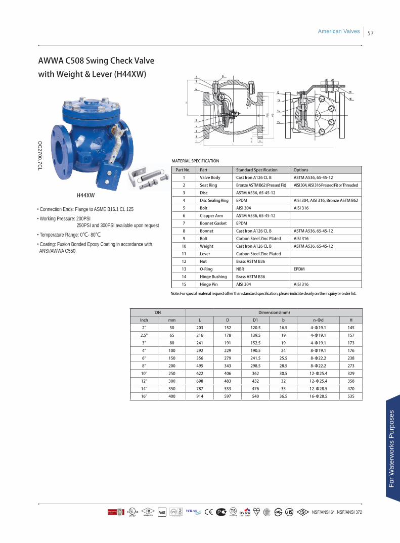
Part No. Part Standard Specification Options
1 Valve Body Cast Iron A126 CL B ASTM A536, 65-45-12
2 Seat Ring Bronze ASTM B62 (Pressed Fit) AISI 304, AISI 316 Pressed Fit or Threaded
3 Disc ASTM A536, 65-45-12
4 Disc Sealing Ring EPDM AISI 304, AISI 316, Bronze ASTM B62
5 Bolt AISI 304 AISI 316
6 Clapper Arm ASTM A536, 65-45-12
7 Bonnet Gasket EPDM
8 Bonnet Cast Iron A126 CL B ASTM A536, 65-45-12
9 Bolt Carbon Steel Zinc Plated AISI 316
10 Weight Cast Iron A126 CL B ASTM A536, 65-45-12
11 Lever Carbon Steel Zinc Plated
12 Nut Brass ASTM B36
13 O-Ring NBR EPDM
14 Hinge Bushing Brass ASTM B36
15 Hinge Pin AISI 304 AISI 316
DN Dimensions(mm)
Inch mm L D D1 b n-Φd H
2" 50 203 152 120.5 16.5 4-Φ19.1 145
2.5" 65 216 178 139.5 19 4-Φ19.1 157
3" 80 241 191 152.5 19 4-Φ19.1 173
4" 100 292 229 190.5 24 8-Φ19.1 176
6" 150 356 279 241.5 25.5 8-Φ22.2 238
8" 200 495 343 298.5 28.5 8-Φ22.2 273
10" 250 622 406 362 30.5 12-Φ25.4 329
12" 300 698 483 432 32 12-Φ25.4 358
14" 350 787 533 476 35 12-Φ28.5 470
16" 400 914 597 540 36.5 16-Φ28.5 535
AWWA C508 Swing Check Valve
with Weight & Lever (H44XW)
• Connection Ends: Flange to ASME B16.1 CL 125
• Working Pressure: 200PSI 250PSI and 300PSI available upon request
• Temperature Range: 0℃- 80℃
• Coating: Fusion Bonded Epoxy Coating in accordance with ANSI/AWWA C550
MATERIAL SPECIFICATION
H44XW
Note: For special material request other than standard specification, please indicate clearly on the inquiry or order list.
American Valves 57
For W
ater
wor
ks P
urpo
ses
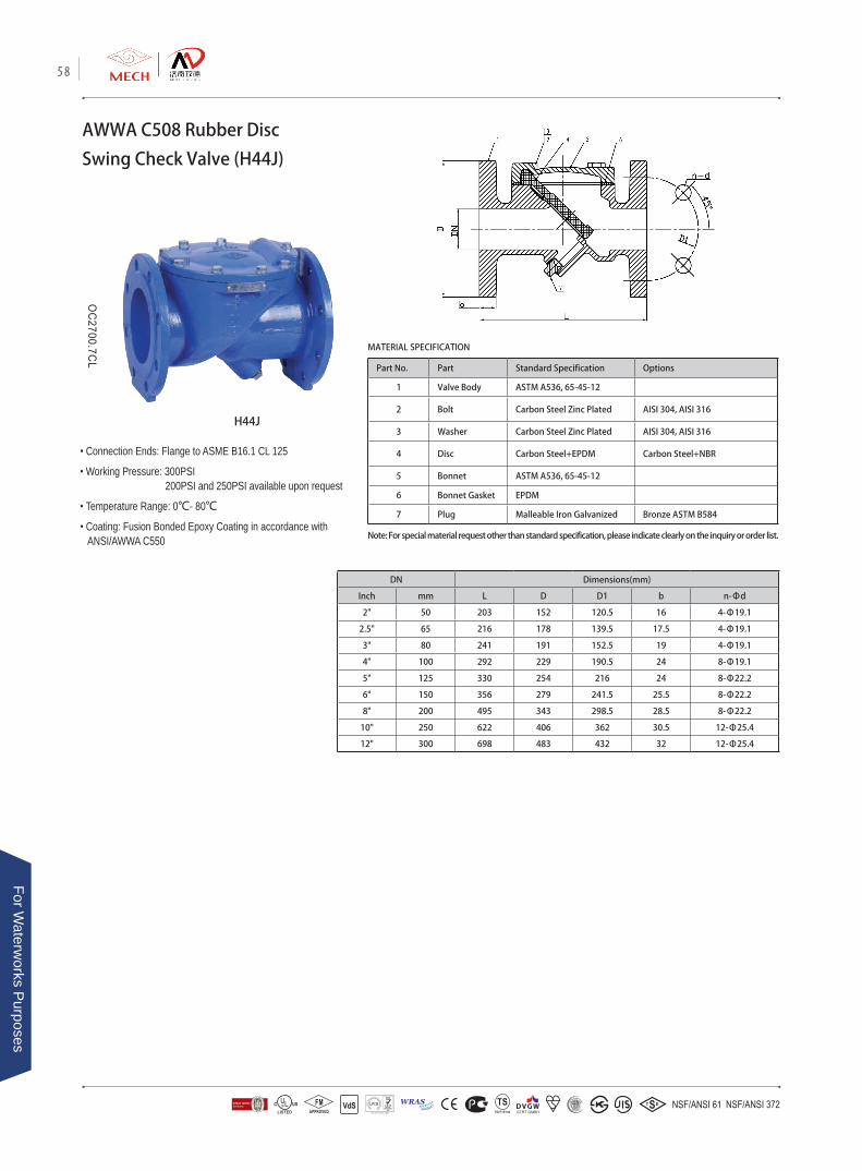
Part No. Part Standard Specification Options
1 Valve Body ASTM A536, 65-45-12
2 Bolt Carbon Steel Zinc Plated AISI 304, AISI 316
3 Washer Carbon Steel Zinc Plated AISI 304, AISI 316
4 Disc Carbon Steel+EPDM Carbon Steel+NBR
5 Bonnet ASTM A536, 65-45-12
6 Bonnet Gasket EPDM
7 Plug Malleable Iron Galvanized Bronze ASTM B584
DN Dimensions(mm)
Inch mm L D D1 b n-Φd
2" 50 203 152 120.5 16 4-Φ19.1
2.5" 65 216 178 139.5 17.5 4-Φ19.1
3" 80 241 191 152.5 19 4-Φ19.1
4" 100 292 229 190.5 24 8-Φ19.1
5" 125 330 254 216 24 8-Φ22.2
6" 150 356 279 241.5 25.5 8-Φ22.2
8" 200 495 343 298.5 28.5 8-Φ22.2
10" 250 622 406 362 30.5 12-Φ25.4
12" 300 698 483 432 32 12-Φ25.4
AWWA C508 Rubber Disc
Swing Check Valve (H44J)
• Connection Ends: Flange to ASME B16.1 CL 125
• Working Pressure: 300PSI 200PSI and 250PSI available upon request
• Temperature Range: 0℃- 80℃
• Coating: Fusion Bonded Epoxy Coating in accordance with ANSI/AWWA C550
H44J
MATERIAL SPECIFICATION
Note: For special material request other than standard specification, please indicate clearly on the inquiry or order list.
58
For Waterw
orks Purposes

Part No. Part Standard Specification Options
1 Valve Body ASTM A536, 65-45-12
2 Disc ASTM A536, 65-45-12 AISI 304, AISI 316, AL-Bronze UNC 95400
3 Stem AISI 420 AISI 304, AISI 316, AISI 416
4 Spring AISI 304 AISI 316
5 Rubber Seat EPDM NBR
API 594 Double Door Wafer
Check Valve (DH77X)
• Connection Ends: ASME B16.1 CL 125, ASME B16.5 CL 150
• Working Pressure: 300PSI 200PSI and 250PSI available upon request
• Temperature Range: 0℃- 80℃
• Coating: Fusion Bonded Epoxy Coating in accordance with ANSI/AWWA C550
DH77XMATERIAL SPECIFICATION
DN Dimensions(mm)
Inch mm L D D1 D2
2" 50 54 102 64 46
2.5" 65 54 121 78 60
3" 80 57 134 94 70
4" 100 64 162 117 84
5" 125 70 192 145 115
6" 150 76 218 170 134
8" 200 95 273 224 184
10" 250 108 328 265 220
12" 300 143 408 310 260
14" 350 184 449 360 302
16" 400 191 512 410 350
Note: For special material request other than standard specification, please indicate clearly on the inquiry or order list.
American Valves 59
For W
ater
wor
ks P
urpo
ses
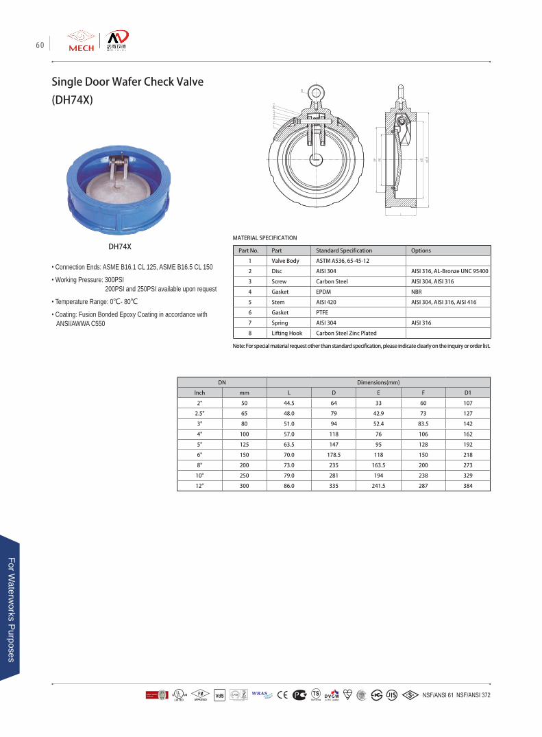
Part No. Part Standard Specification Options
1 Valve Body ASTM A536, 65-45-12
2 Disc AISI 304 AISI 316, AL-Bronze UNC 95400
3 Screw Carbon Steel AISI 304, AISI 316
4 Gasket EPDM NBR
5 Stem AISI 420 AISI 304, AISI 316, AISI 416
6 Gasket PTFE
7 Spring AISI 304 AISI 316
8 Lifting Hook Carbon Steel Zinc Plated
MATERIAL SPECIFICATION
Single Door Wafer Check Valve
(DH74X)
DH74X
• Connection Ends: ASME B16.1 CL 125, ASME B16.5 CL 150
• Working Pressure: 300PSI 200PSI and 250PSI available upon request
• Temperature Range: 0℃- 80℃
• Coating: Fusion Bonded Epoxy Coating in accordance with ANSI/AWWA C550
Note: For special material request other than standard specification, please indicate clearly on the inquiry or order list.
DN Dimensions(mm)
Inch mm L D E F D1
2" 50 44.5 64 33 60 107
2.5" 65 48.0 79 42.9 73 127
3" 80 51.0 94 52.4 83.5 142
4" 100 57.0 118 76 106 162
5" 125 63.5 147 95 128 192
6" 150 70.0 178.5 118 150 218
8" 200 73.0 235 163.5 200 273
10" 250 79.0 281 194 238 329
12" 300 86.0 335 241.5 287 384
60
For Waterw
orks Purposes
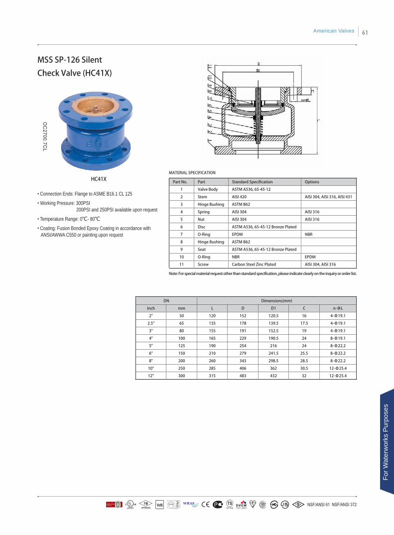
Part No. Part Standard Specification Options
1 Valve Body ASTM A536, 65-45-12
2 Stem AISI 420 AISI 304, AISI 316, AISI 431
3 Hinge Bushing ASTM B62
4 Spring AISI 304 AISI 316
5 Nut AISI 304 AISI 316
6 Disc ASTM A536, 65-45-12 Bronze Plated
7 O-Ring EPDM NBR
8 Hinge Bushing ASTM B62
9 Seat ASTM A536, 65-45-12 Bronze Plated
10 O-Ring NBR EPDM
11 Screw Carbon Steel Zinc Plated AISI 304, AISI 316
DN Dimensions(mm)
Inch mm L D D1 C n-ΦL
2" 50 120 152 120.5 16 4-Φ19.1
2.5" 65 135 178 139.5 17.5 4-Φ19.1
3" 80 155 191 152.5 19 4-Φ19.1
4" 100 165 229 190.5 24 8-Φ19.1
5" 125 190 254 216 24 8-Φ22.2
6" 150 210 279 241.5 25.5 8-Φ22.2
8" 200 260 343 298.5 28.5 8-Φ22.2
10" 250 285 406 362 30.5 12-Φ25.4
12" 300 315 483 432 32 12-Φ25.4
MSS SP-126 Silent
Check Valve (HC41X)
• Connection Ends: Flange to ASME B16.1 CL 125
• Working Pressure: 300PSI 200PSI and 250PSI available upon request
• Temperature Range: 0℃- 80℃
• Coating: Fusion Bonded Epoxy Coating in accordance with ANSI/AWWA C550 or painting upon request
HC41XMATERIAL SPECIFICATION
Note: For special material request other than standard specification, please indicate clearly on the inquiry or order list.
American Valves 61
For W
ater
wor
ks P
urpo
ses
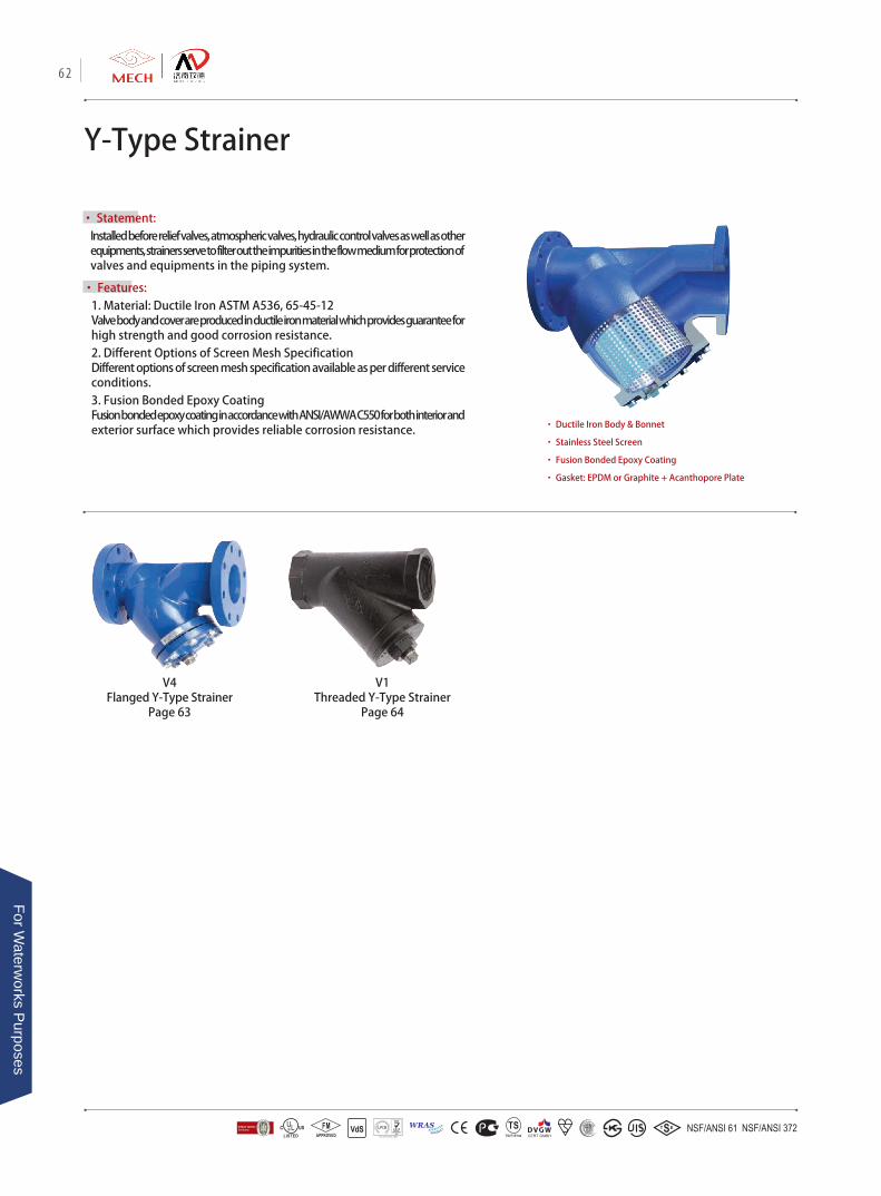
• Statement: Installed before relief valves, atmospheric valves, hydraulic control valves as well as other equipments, strainers serve to filter out the impurities in the flow medium for protection of valves and equipments in the piping system.
Y-Type Strainer
• Features: 1. Material: Ductile Iron ASTM A536, 65-45-12Valve body and cover are produced in ductile iron material which provides guarantee for high strength and good corrosion resistance.2. Different Options of Screen Mesh SpecificationDifferent options of screen mesh specification available as per different service conditions. 3. Fusion Bonded Epoxy Coating Fusion bonded epoxy coating in accordance with ANSI/AWWA C550 for both interior and exterior surface which provides reliable corrosion resistance. • Ductile Iron Body & Bonnet
• Stainless Steel Screen
• Fusion Bonded Epoxy Coating
• Gasket: EPDM or Graphite + Acanthopore Plate
V4Flanged Y-Type Strainer
Page 63
V1Threaded Y-Type Strainer
Page 64
62
For Waterw
orks Purposes
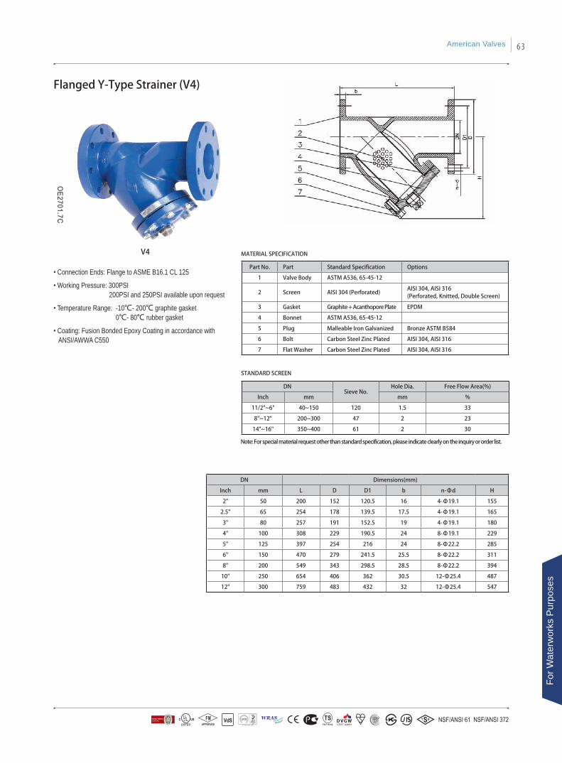
Part No. Part Standard Specification Options
1 Valve Body ASTM A536, 65-45-12
2 Screen AISI 304 (Perforated)AISI 304, AISI 316 (Perforated, Knitted, Double Screen)
3 Gasket Graphite + Acanthopore Plate EPDM
4 Bonnet ASTM A536, 65-45-12
5 Plug Malleable Iron Galvanized Bronze ASTM B584
6 Bolt Carbon Steel Zinc Plated AISI 304, AISI 316
7 Flat Washer Carbon Steel Zinc Plated AISI 304, AISI 316
DN Dimensions(mm)
Inch mm L D D1 b n-Φd H
2" 50 200 152 120.5 16 4-Φ19.1 155
2.5" 65 254 178 139.5 17.5 4-Φ19.1 165
3" 80 257 191 152.5 19 4-Φ19.1 180
4" 100 308 229 190.5 24 8-Φ19.1 229
5" 125 397 254 216 24 8-Φ22.2 285
6" 150 470 279 241.5 25.5 8-Φ22.2 311
8" 200 549 343 298.5 28.5 8-Φ22.2 394
10" 250 654 406 362 30.5 12-Φ25.4 487
12" 300 759 483 432 32 12-Φ25.4 547
Flanged Y-Type Strainer (V4)
• Connection Ends: Flange to ASME B16.1 CL 125
• Working Pressure: 300PSI 200PSI and 250PSI available upon request
• Temperature Range: -10℃- 200℃ graphite gasket 0℃- 80℃ rubber gasket
• Coating: Fusion Bonded Epoxy Coating in accordance with ANSI/AWWA C550
V4 MATERIAL SPECIFICATION
STANDARD SCREEN
Note: For special material request other than standard specification, please indicate clearly on the inquiry or order list.
DNSieve No.
Hole Dia. Free Flow Area(%)
Inch mm mm %
11/2"~6" 40~150 120 1.5 33
8"~12" 200~300 47 2 23
14"~16" 350~400 61 2 30
American Valves 63
For W
ater
wor
ks P
urpo
ses
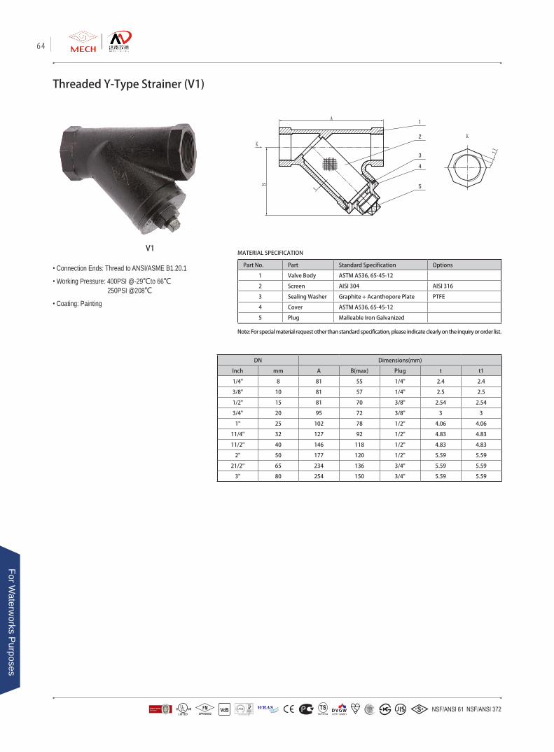
V1
• Connection Ends: Thread to ANSI/ASME B1.20.1
• Working Pressure: 400PSI @-29℃to 66℃ 250PSI @208℃
• Coating: Painting
Part No. Part Standard Specification Options
1 Valve Body ASTM A536, 65-45-12
2 Screen AISI 304 AISI 316
3 Sealing Washer Graphite + Acanthopore Plate PTFE
4 Cover ASTM A536, 65-45-12
5 Plug Malleable Iron Galvanized
MATERIAL SPECIFICATION
Threaded Y-Type Strainer (V1)
DN Dimensions(mm)
Inch mm A B(max) Plug t t1
1/4" 8 81 55 1/4" 2.4 2.4
3/8" 10 81 57 1/4" 2.5 2.5
1/2" 15 81 70 3/8" 2.54 2.54
3/4" 20 95 72 3/8" 3 3
1" 25 102 78 1/2" 4.06 4.06
11/4" 32 127 92 1/2" 4.83 4.83
11/2" 40 146 118 1/2" 4.83 4.83
2" 50 177 120 1/2" 5.59 5.59
21/2" 65 234 136 3/4" 5.59 5.59
3" 80 254 150 3/4" 5.59 5.59
Note: For special material request other than standard specification, please indicate clearly on the inquiry or order list.
64
For Waterw
orks Purposes
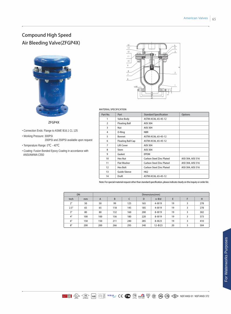
Compound High Speed
Air Bleeding Valve(ZFGP4X)
Part No. Part Standard Specification Options
1 Valve Body ASTM A536, 65-45-12
2 Floating Ball AISI 304
3 Nut AISI 304
4 O-Ring NBR
5 Bonnet ASTM A536, 65-45-12
6 Floating Ball Cap ASTM A536, 65-45-12
7 Lift Cover AISI 304
8 Stem AISI 304
9 Gasket EPDM
10 Hex Nut Carbon Steel Zinc Plated AISI 304, AISI 316
11 Flat Washer Carbon Steel Zinc Plated AISI 304, AISI 316
12 Hex Bolt Carbon Steel Zinc Plated AISI 304, AISI 316
13 Guide Sleeve H62
14 Draft ASTM A536, 65-45-12
MATERIAL SPECIFICATION
Note: For special material request other than standard specification, please indicate clearly on the inquiry or order list.
DN Dimensions(mm)
Inch mm A B C D n-Φd E F H
2" 50 50 99 125 165 4-Φ19 19 3 278
2.5" 65 65 118 145 185 4-Φ19 19 3 278
3" 80 80 132 160 200 8-Φ19 19 3 302
4" 100 100 156 180 220 8-Φ19 19 3 373
6" 150 150 211 240 285 8-Φ23 19 3 410
8" 200 200 266 295 340 12-Φ23 20 3 504
ZFGP4X
• Connection Ends: Flange to ASME B16.1 CL 125
• Working Pressure: 300PSI 200PSI and 250PSI available upon request
• Temperature Range: 0℃ - 40℃
• Coating: Fusion Bonded Epoxy Coating in accordance with ANSI/AWWA C550
American Valves 65
For W
ater
wor
ks P
urpo
ses
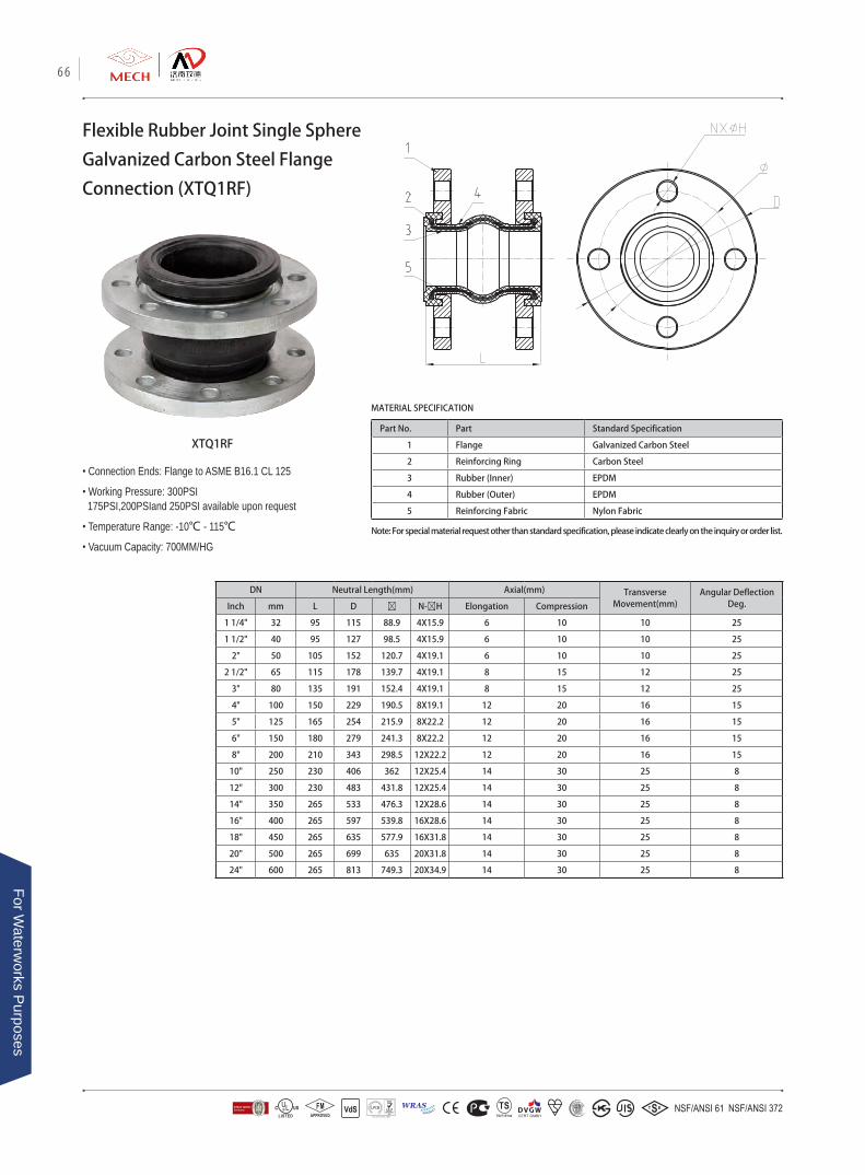
MATERIAL SPECIFICATION
Flexible Rubber Joint Single Sphere
Galvanized Carbon Steel Flange
Connection (XTQ1RF)
XTQ1RF
Note: For special material request other than standard specification, please indicate clearly on the inquiry or order list.
• Connection Ends: Flange to ASME B16.1 CL 125
• Working Pressure: 300PSI 175PSI,200PSIand 250PSI available upon request
• Temperature Range: -10℃ - 115℃
• Vacuum Capacity: 700MM/HG
DN Neutral Length(mm) Axial(mm) Transverse Movement(mm)
Angular Deflection Deg.Inch mm L D Ø N-ØH Elongation Compression
1 1/4" 32 95 115 88.9 4X15.9 6 10 10 25
1 1/2" 40 95 127 98.5 4X15.9 6 10 10 25
2" 50 105 152 120.7 4X19.1 6 10 10 25
2 1/2" 65 115 178 139.7 4X19.1 8 15 12 25
3" 80 135 191 152.4 4X19.1 8 15 12 25
4" 100 150 229 190.5 8X19.1 12 20 16 15
5" 125 165 254 215.9 8X22.2 12 20 16 15
6" 150 180 279 241.3 8X22.2 12 20 16 15
8" 200 210 343 298.5 12X22.2 12 20 16 15
10" 250 230 406 362 12X25.4 14 30 25 8
12" 300 230 483 431.8 12X25.4 14 30 25 8
14" 350 265 533 476.3 12X28.6 14 30 25 8
16" 400 265 597 539.8 16X28.6 14 30 25 8
18" 450 265 635 577.9 16X31.8 14 30 25 8
20" 500 265 699 635 20X31.8 14 30 25 8
24" 600 265 813 749.3 20X34.9 14 30 25 8
Part No. Part Standard Specification
1 Flange Galvanized Carbon Steel
2 Reinforcing Ring Carbon Steel
3 Rubber (Inner) EPDM
4 Rubber (Outer) EPDM
5 Reinforcing Fabric Nylon Fabric
66
For Waterw
orks Purposes
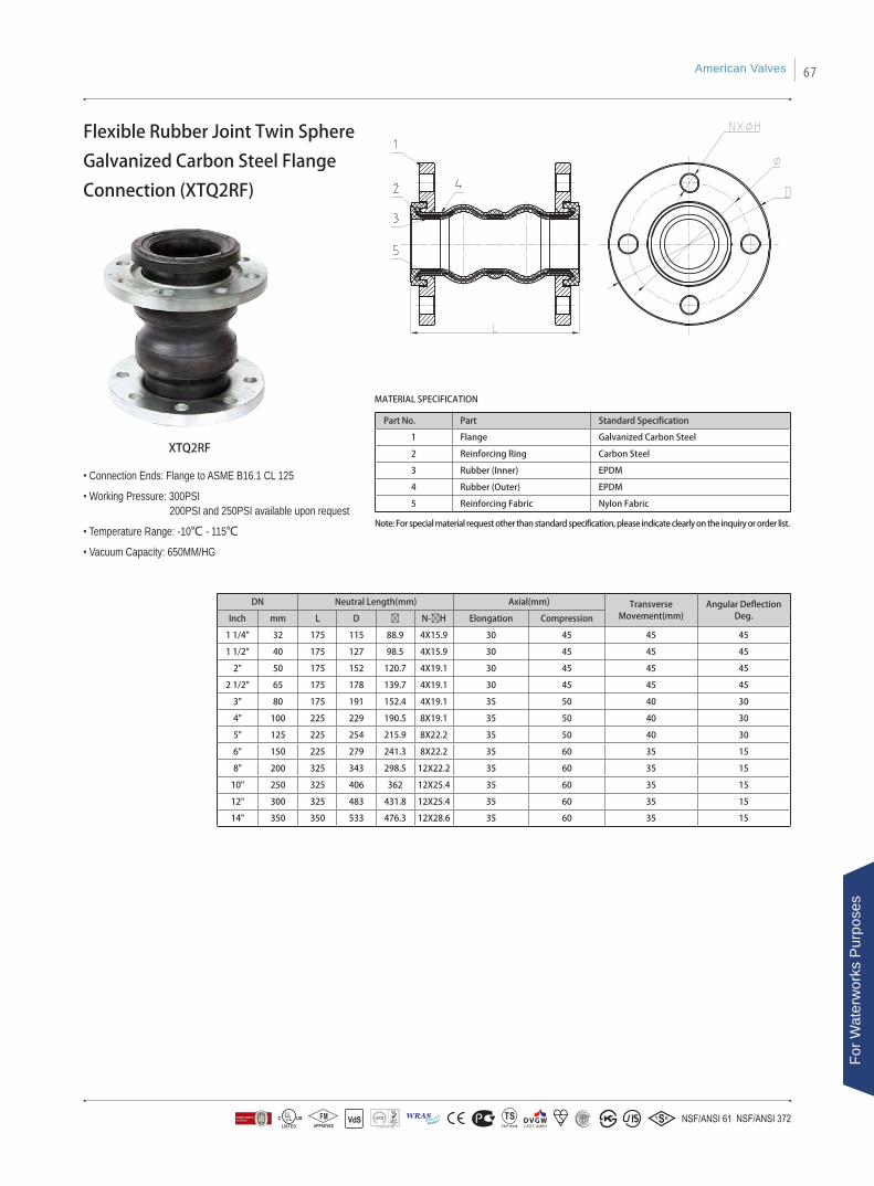
MATERIAL SPECIFICATION
Flexible Rubber Joint Twin Sphere
Galvanized Carbon Steel Flange
Connection (XTQ2RF)
XTQ2RF
Note: For special material request other than standard specification, please indicate clearly on the inquiry or order list.
• Connection Ends: Flange to ASME B16.1 CL 125
• Working Pressure: 300PSI 200PSI and 250PSI available upon request
• Temperature Range: -10℃ - 115℃
• Vacuum Capacity: 650MM/HG
Part No. Part Standard Specification
1 Flange Galvanized Carbon Steel
2 Reinforcing Ring Carbon Steel
3 Rubber (Inner) EPDM
4 Rubber (Outer) EPDM
5 Reinforcing Fabric Nylon Fabric
DN Neutral Length(mm) Axial(mm) Transverse Movement(mm)
Angular Deflection Deg.Inch mm L D Ø N-ØH Elongation Compression
1 1/4" 32 175 115 88.9 4X15.9 30 45 45 45
1 1/2" 40 175 127 98.5 4X15.9 30 45 45 45
2" 50 175 152 120.7 4X19.1 30 45 45 45
2 1/2" 65 175 178 139.7 4X19.1 30 45 45 45
3" 80 175 191 152.4 4X19.1 35 50 40 30
4" 100 225 229 190.5 8X19.1 35 50 40 30
5" 125 225 254 215.9 8X22.2 35 50 40 30
6" 150 225 279 241.3 8X22.2 35 60 35 15
8" 200 325 343 298.5 12X22.2 35 60 35 15
10" 250 325 406 362 12X25.4 35 60 35 15
12" 300 325 483 431.8 12X25.4 35 60 35 15
14" 350 350 533 476.3 12X28.6 35 60 35 15
American Valves 67
For W
ater
wor
ks P
urpo
ses

MATERIAL SPECIFICATION
Flexible Rubber Joint Twin Sphere
Union-Screw End Connection(XTQ2L)
XTQ2L
• Thread: ISO 7-1
• Working Pressure: 300PSI 200PSI and 250PSI available upon request
• Temperature Range: -10℃ -115℃
• Vacuum Capacity: 500MM/HG
Note: For special material request other than standard specification, please indicate clearly on the inquiry or order list.
Part No. Part Standard Specification
1 Union Malleable iron
2 Rubber (Outer) EPDM
3 Reinforcing Fabric Nylon Fabric
4 Rubber (Inner) EPDM
DNNeutral
Length(mm)Thread Axial(mm) Transverse
Movement(mm)Angular Deflection
Deg.Inch mm L X NPT Elongation Compression
1/2" 15 200 1/2-14 6 22 22 40
3/4" 20 200 3/4-14 6 22 22 40
1" 25 200 1-11.5 6 22 22 40
1 1/4" 32 200 1 1/4-11.5 6 22 22 40
1 1/2" 40 200 1 1/2-11.5 6 22 22 40
2" 50 200 2-11.5 6 22 22 40
2 1/2" 65 240 2 1/2-8 6 22 22 40
3" 80 240 3-8 6 22 22 40
68
For Waterw
orks Purposes
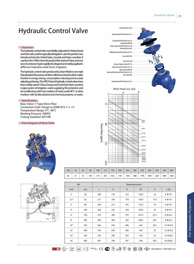
Water Head Loss (psi)Flow
Rate (gpm)
DN50DN65
DN80
DN100
DN125
DN150
DN200
DN250
DN300DN350
DN400DN450DN500DN600
Hydraulic Control Valve
• StatementThe hydraulic control valve was initially originated in Holand, Israel and Denmark, used for agricultural irrigation. Later the product was introduced into the United Sates, Canada and Asian countries. It was from the 1990s when the product first entered China, and ever since its entrance it gets rapidly developped and widely applied in different industrie aside from irrigation.
The hydraulic control valve produced by Jinan Meide is new style that absorbed the essence of other well-known brands which makes it better in energy saving, consumption reducing and accurate adjusting achieving. The MECH brand hydraulic control valves have been widely used in China, Europe and South East Asian countries in pipe system of irrigation, water supplying, fire protection and air conditioning which has medium of water under 80℃ or other medium with similar physical and chemical property as water.
• SpecificationsBasic Valve: Y-Type Direct-flowConnection Ends: Flange to ASME B16.1 CL 125Temperature Range: 0℃- 80℃Working Pressure: 300PSITesting Standard: API 598
• Flow Diagram of Basic Valve
Bottom Gland (ASTM A536,65-45-12)
Up Gland (ASTM A536,65-45-12)
Cap Plug (Brass H62)
Up Bonnet (ASTM A536,65-45-12)
Bushing (Brass H62)
Middle Bonnet (ASTM A536,65-45-12)
Stem (AISI 304)
Bolt (AISI 304)
Spring ( Stainless Steel 4Cr13)
Main Disc (ASTM A536,65-45-12)
Main Gasket (EPDM)Gland of Main Disc (ASTM A536,65-45-12)
Seat (AISI 304)
Valve Body (ASTM A536,65-45-12)
Diaphragm (EPDM)
DN 50 65 80 100 125 150 200 250 300 350 400 450 500 600
Kv 41 53 105 175 285 402 730 1160 1400 1770 3010 3225 3395 4272
DN Dimensions(mm)
Inch mm L H D D1 b n-ΦL
2" 50 206 170 152 120.5 16 4-Φ19.1
2.5" 65 211 195 178 139.5 17.5 4-Φ19.1
3" 80 249 215 191 152.5 19 4-Φ19.1
4" 100 320 255 229 190.5 24 8-Φ19.1
6" 150 414 360 279 241.5 25.5 8-Φ22.2
8" 200 500 450 343 298.5 28.5 8-Φ22.2
10" 250 605 550 406 362 30.5 12-Φ25.4
12" 300 724 645 483 432 32 12-Φ25.4
14" 350 734 700 533 476 35 12-Φ28.5
16" 400 991 790 597 540 36.5 16-Φ28.5
American Valves 69
For W
ater
wor
ks P
urpo
ses

1.StatementSK710X Electromagnetic Control Valve is a diaphragm type of hydraulic control valve driven by the hydraulic pressure within the piping system. This type of valve is widely applied in the field of piping system optimization, pressure division, water reservoir (tank) backup, change of industrial valves, etc., with its closing and opening remotely controlled by electric signal.
Electromagnetic
Control Valve
2.Operational principleSK710X Electromagnetic Control Valve is controlled by solenoid valve and equipped with normally open (or normally closed) two positions two ways or two positions three ways solenoid pilot valve, needle valve, mini strainer and ball valve, etc.When the normally open solenoid valve is applied, the main valve in most cases will be in open position. When there is pressure coming from the flow direction, Pressure P1 enters the upper cavity room of the valve through the guide tube and then comes to the low pressure area through the normally open solenoid valve. In this way the upper cavity room is not able to form confined space and the disc of the main valve will be opened at the pressure of P1. When the normally open solenoid valve is closed, pressure P1 will be accumulated inside the upper cavity which will gradually push the membrane to close the disc and the valve.For normally closed solenoid valve, the main valve will be in most cases closed and operation principle same as stated above. The application of the solenoid valve depends on the working environment.In case the water inside the piping system are highly corrosive or with high deposits, user can choose also to control the valve with medium from outside. It's up to the option of the client, depending on different working conditions.
3.Property and advantages• Driven by pressure of pipe system, work automatically without any power-generating. It saves installation
and repairing space. • Controlled by solenoid valve, save energy and wiring costs, can be used for large range of pressure and
voltage. • Series of mode of execution can be changed to hand control, normally closed solenoid valve control or
normally open solenoid valve control, etc. • Dual cavity design, with functions of fully opening and fully closing. Slow shut causes no pressure fluctuation,
and the diaphragm with support is well protected. • Channel with straight-flow, slight friction loss, no eddy flow and turbulent flow. • Long pitch orientation design for stem move, stable and no gap resistance. • Balanced automatically, big gap design on connection of disc and stem, disc is free on the vertical flat against
stem, it can balance the tolerance from machining and sealing surface. Good connection without leakage. • Ductile iron castings with nodularity higher than 90%, foundry in house with advanced melting technology
and strict quality control system, testing reports and testing bars can be supplied with order. Records and testing bars maintained for one year in the factory.
• Good corrosion resistance, with stainless steel, copper alloy, rubber made from DuPont and other rust-resisting material, fusion bonded epoxy coating both for interior and exterior surface of the basic valve. All the characteristics in accordance with ANSI/AWWA C550 and other international specifications like WRAS, NSF61.
SK710X
SK710X1
70
For Waterw
orks Purposes
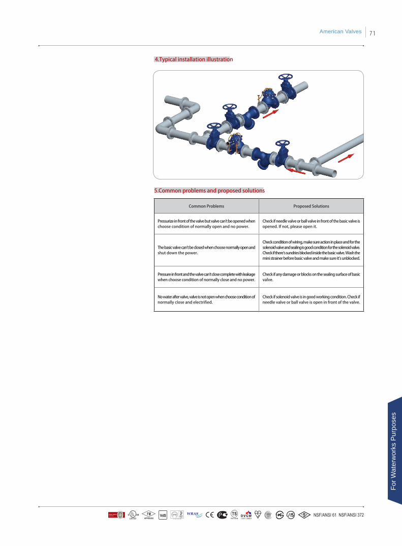
4.Typical installation illustration
5.Common problems and proposed solutions
Common Problems Proposed Solutions
Pressurize in front of the valve but valve can't be opened when choose condition of normally open and no power.
Check if needle valve or ball valve in front of the basic valve is opened. If not, please open it.
The basic valve can't be closed when choose normally open and shut down the power.
Check condition of wiring, make sure action in place and for the solenoid valve and sealing is good condition for the solenoid valve. Check if there's sundries blocked inside the basic valve. Wash the mini strainer before basic valve and make sure it's unblocked.
Pressure in front and the valve can't close complete with leakage when choose condition of normally close and no power.
Check if any damage or blocks on the sealing surface of basic valve.
No water after valve, valve is not open when choose condition of normally close and electrified.
Check if solenoid valve is in good working condition. Check if needle valve or ball valve is open in front of the valve.
American Valves 71
For W
ater
wor
ks P
urpo
ses
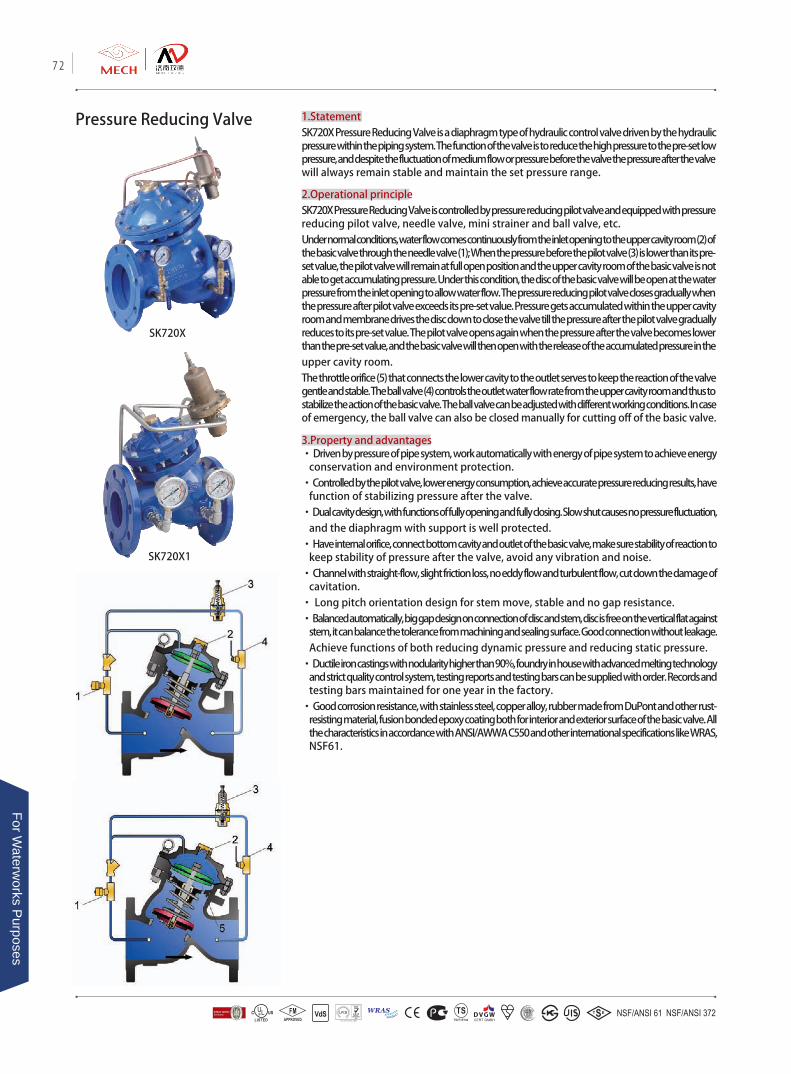
Pressure Reducing Valve 1.StatementSK720X Pressure Reducing Valve is a diaphragm type of hydraulic control valve driven by the hydraulic pressure within the piping system. The function of the valve is to reduce the high pressure to the pre-set low pressure, and despite the fluctuation of medium flow or pressure before the valve the pressure after the valve will always remain stable and maintain the set pressure range.
2.Operational principleSK720X Pressure Reducing Valve is controlled by pressure reducing pilot valve and equipped with pressure reducing pilot valve, needle valve, mini strainer and ball valve, etc.Under normal conditions, water flow comes continuously from the inlet opening to the upper cavity room (2) of the basic valve through the needle valve (1); When the pressure before the pilot valve (3) is lower than its pre-set value, the pilot valve will remain at full open position and the upper cavity room of the basic valve is not able to get accumulating pressure. Under this condition, the disc of the basic valve will be open at the water pressure from the inlet opening to allow water flow. The pressure reducing pilot valve closes gradually when the pressure after pilot valve exceeds its pre-set value. Pressure gets accumulated within the upper cavity room and membrane drives the disc down to close the valve till the pressure after the pilot valve gradually reduces to its pre-set value. The pilot valve opens again when the pressure after the valve becomes lower than the pre-set value, and the basic valve will then open with the release of the accumulated pressure in the upper cavity room. The throttle orifice (5) that connects the lower cavity to the outlet serves to keep the reaction of the valve gentle and stable. The ball valve (4) controls the outlet water flow rate from the upper cavity room and thus to stabilize the action of the basic valve. The ball valve can be adjusted with different working conditions. In case of emergency, the ball valve can also be closed manually for cutting off of the basic valve.
3.Property and advantages• Driven by pressure of pipe system, work automatically with energy of pipe system to achieve energy
conservation and environment protection.• Controlled by the pilot valve, lower energy consumption, achieve accurate pressure reducing results, have
function of stabilizing pressure after the valve. • Dual cavity design, with functions of fully opening and fully closing. Slow shut causes no pressure fluctuation,
and the diaphragm with support is well protected.• Have internal orifice, connect bottom cavity and outlet of the basic valve, make sure stability of reaction to
keep stability of pressure after the valve, avoid any vibration and noise. • Channel with straight-flow, slight friction loss, no eddy flow and turbulent flow, cut down the damage of
cavitation. • Long pitch orientation design for stem move, stable and no gap resistance.• Balanced automatically, big gap design on connection of disc and stem, disc is free on the vertical flat against
stem, it can balance the tolerance from machining and sealing surface. Good connection without leakage. Achieve functions of both reducing dynamic pressure and reducing static pressure.
• Ductile iron castings with nodularity higher than 90%, foundry in house with advanced melting technology and strict quality control system, testing reports and testing bars can be supplied with order. Records and testing bars maintained for one year in the factory.
• Good corrosion resistance, with stainless steel, copper alloy, rubber made from DuPont and other rust-resisting material, fusion bonded epoxy coating both for interior and exterior surface of the basic valve. All the characteristics in accordance with ANSI/AWWA C550 and other international specifications like WRAS, NSF61.
SK720X
SK720X1
72
For Waterw
orks Purposes
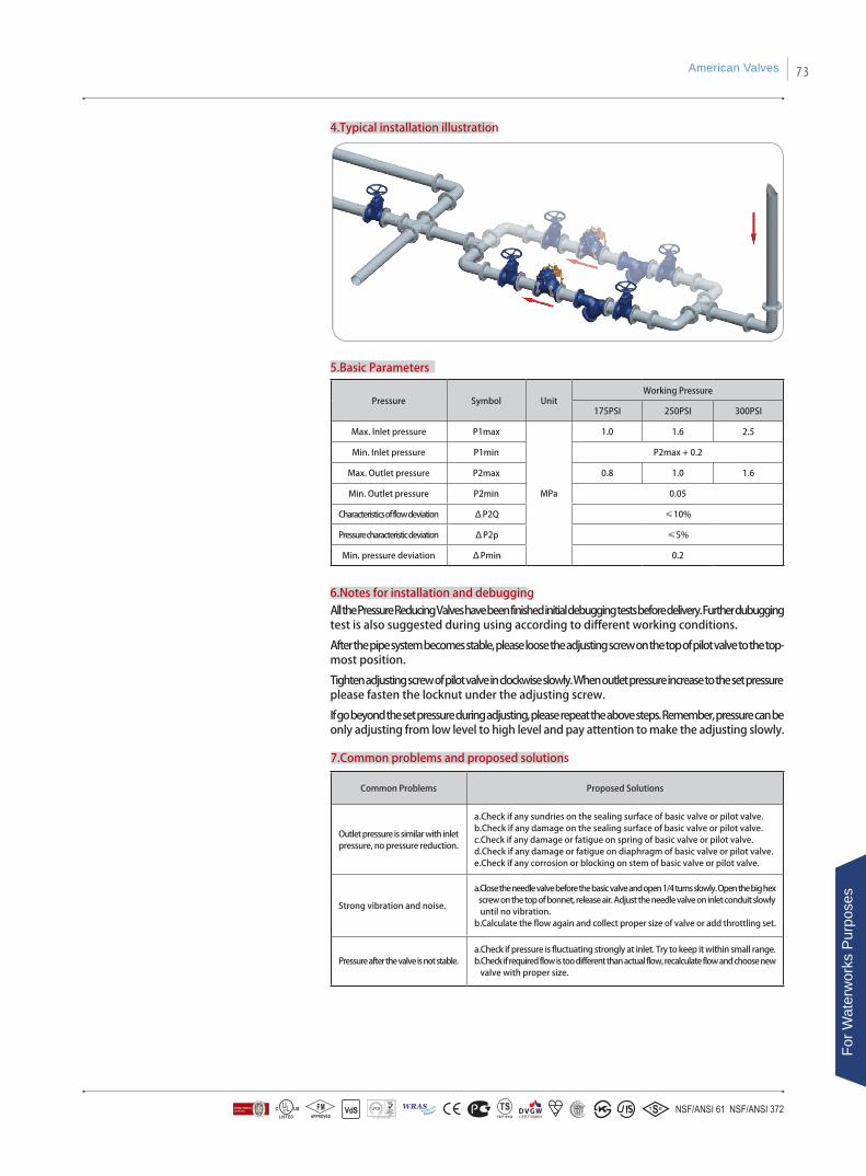
4.Typical installation illustration
5.Basic Parameters
Pressure Symbol UnitWorking Pressure
175PSI 250PSI 300PSI
Max. Inlet pressure P1max
MPa
1.0 1.6 2.5
Min. Inlet pressure P1min P2max + 0.2
Max. Outlet pressure P2max 0.8 1.0 1.6
Min. Outlet pressure P2min 0.05
Characteristics of flow deviation ΔP2Q ≤10%
Pressure characteristic deviation ΔP2p ≤5%
Min. pressure deviation ΔPmin 0.2
6.Notes for installation and debuggingAll the Pressure Reducing Valves have been finished initial debugging tests before delivery. Further dubugging test is also suggested during using according to different working conditions.
After the pipe system becomes stable, please loose the adjusting screw on the top of pilot valve to the top-most position.
Tighten adjusting screw of pilot valve in clockwise slowly. When outlet pressure increase to the set pressure please fasten the locknut under the adjusting screw.
If go beyond the set pressure during adjusting, please repeat the above steps. Remember, pressure can be only adjusting from low level to high level and pay attention to make the adjusting slowly.
Common Problems Proposed Solutions
Outlet pressure is similar with inlet pressure, no pressure reduction.
a.Check if any sundries on the sealing surface of basic valve or pilot valve. b.Check if any damage on the sealing surface of basic valve or pilot valve.c.Check if any damage or fatigue on spring of basic valve or pilot valve. d.Check if any damage or fatigue on diaphragm of basic valve or pilot valve.e.Check if any corrosion or blocking on stem of basic valve or pilot valve.
Strong vibration and noise.
a.Close the needle valve before the basic valve and open 1/4 turns slowly. Open the big hex screw on the top of bonnet, release air. Adjust the needle valve on inlet conduit slowly until no vibration. b.Calculate the flow again and collect proper size of valve or add throttling set.
Pressure after the valve is not stable. a.Check if pressure is fluctuating strongly at inlet. Try to keep it within small range. b.Check if required flow is too different than actual flow, recalculate flow and choose new valve with proper size.
7.Common problems and proposed solutions
American Valves 73
For W
ater
wor
ks P
urpo
ses
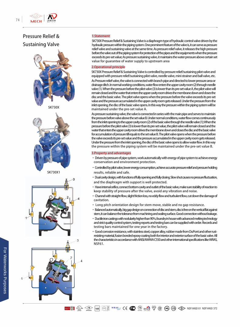
Pressure Relief &
Sustaining Valve
1.StatementSK730X Pressure Relief & Sustaining Valve is a diaphragm type of hydraulic control valve driven by the hydraulic pressure within the piping system. One prominent feature of the valve is, it can serve as pressure relief valve and sustaining valve at the same time. As pressure relief valve, it releases the high pressure before the valve out of the piping system for protection of the pipes and the equipments when the pressure exceeds its pre-set value; As pressure sustaining valve, it maintains the water pressure above certain set value for guarantee of water supply to upstream area
2.Operational principleSK730X Pressure Relief & Sustaining Valve is controlled by pressure relief/sustaining pilot valve and equipped with pressure relief/sustaining pilot valve, needle valve, mini strainer and ball valve, etc.As Pressure relief valve, the valve is connected with branch pipe and directed to lower pressure area or drainage ditch. In normal working conditions, water flow enters the upper cavity room (2) through needle valve (1). When the pressure before the pilot valve (3) is lower than its pre-set value A, the pilot valve will remain closed and the water that enters the upper cavity room drives the membrane down and closes the disc and the basic valve. The pilot valve opens when the pressure before the valve exceeds its pre-set value and the pressure accumulated in the upper cavity room gets released. Under the pressure from the inlet opening, the disc of the basic valve opens. In this way the pressure within the piping system will be maintained under the pre-set value A. As pressure sustaining valve, the valve is connected in series with the main pipe and serves to maintain the pressure before valve above the set value B. Under normal conditions, water flow comes continuously from the inlet opening to the upper cavity room (2) of the basic valve through the needle valve (1); When the pressure before the pilot valve (3) is lower than its pre-set value, the pilot valve will remain closed and the water that enters the upper cavity room drives the membrane down and closes the disc and the basic valve for accumulation of pressure till equals to the set value B. The pilot valve opens when the pressure before the valve exceeds its pre-set value and the pressure accumulated in the upper cavity room gets released. Under the pressure from the inlet opening, the disc of the basic valve opens to allow water flow. In this way the pressure within the piping system will be maintained under the pre-set value B.
3.Property and advantages• Driven by pressure of pipe system, work automatically with energy of pipe system to achieve energy
conservation and environment protection.
• Controlled by pilot valve, lower energy consumption, achieve accurate pressure relief and pressure holding results, reliable and safe.
• Dual cavity design, with functions of fully opening and fully closing. Slow shut causes no pressure fluctuation, and the diaphragm with support is well protected.
• Have internal orifice, connect bottom cavity and outlet of the basic valve, make sure stability of reaction to keep stability of pressure after the valve, avoid any vibration and noise.
• Channel with straight-flow, slight friction loss, no eddy flow and turbulent flow, cut down the damage of cavitation.
• Long pitch orientation design for stem move, stable and no gap resistance.• Balanced automatically, big gap design on connection of disc and stem, disc is free on the vertical flat against
stem, it can balance the tolerance from machining and sealing surface. Good connection without leakage. • Ductile iron castings with nodularity higher than 90%, foundry in house with advanced melting technology
and strict quality control system, testing reports and testing bars can be supplied with order. Records and testing bars maintained for one year in the factory.
• Good corrosion resistance, with stainless steel, copper alloy, rubber made from DuPont and other rust-resisting material, fusion bonded epoxy coating both for interior and exterior surface of the basic valve. All the characteristics in accordance with ANSI/AWWA C550 and other international specifications like WRAS, NSF61.
SK730X
SK730X1
74
For Waterw
orks Purposes

4.Typical installation illustration
6.Notes for installation and debuggingAll the Pressure Relief & Sustaining Valves have been finished initial debugging tests before delivery and the set-pressure is 0.6MPa. Further debugging test is also suggested during using according to different working conditions.
After the pipe system becomes stable, please loose the lock nut under adjusting screw, open the ball valve or needle valve (1) slightly, when pressurize, adjust the adjust screw on pressure relief pilot valve and fasten the lock nut when it achieves pressure required. Pay attention that when adjust pressure relief pilot valve, clockwise is for increasing pressure and anti-clockwise is for reducing pressure.
7.Common problems and proposed solutions
5.Basic Parameters
Pressure Symbol Unit
Working Pressure
175PSI 250PSI 300PSI
Set Pressure
Ps
MPa
≤0.83 ≤1.33 ≤1.7
Set PressureDifference
Ps<0.5: ±0.014 MPa;Ps≥0.5: ±3%Ps
Open/ClosePressure
DifferenceΔPb
Ps<0.3: 0.06MPa;Ps≥0.3: 20%Ps
Dischargepressure
Pd ≤1.2Ps
Common Problems Proposed Solutions
The pressure of pipe system is lower than set-pressure, the valve dose not close.
a.Check if any sundries on the sealing surface of basic valve or pilot valve. b.Check if any damage on the sealing surface of basic valve or pilot valve.c.Check if any damage or fatigue on spring of basic valve or pilot valve. d.Check if any damage or fatigue on diaphragm of basic valve or pilot valve.
The pressure of pipe system is higher than set-pressure, the valve dose not open.
a.Check if ball valve (4) is closed, if yes, please open it.b.Check if any blocks in basic valve or on stem of pilot valve, if yes, please remove the block or change new stem.c.Check if lock nut and adjust screw were adjusted wrongly, please try to repeat all the actions.
For Pressure Relief For Pressure Sustaining
American Valves 75
For W
ater
wor
ks P
urpo
ses

1.StatementSK735X Surge Anticipating Valve is a diaphragm type of hydraulic control valve driven by the hydraulic pressure within the piping system. The valve dissipates surges caused by power failure to pumps. The valve anticipates the surge by opening on low line pressure associated with sudden stopping of pumps. This assures that the valve is open when the return high pressure surge arrives.
2.Operational principleThe valve is closed when the line pressure is between the set points of the two pilots. The valve opens when the line pressure drops below the setting of Low Surge Pilot. The valve also opens when the line pressure exceeds the setting of High Surge Pilot.Main Valve is normally open when pressure is applied to the valve inlet. When this same pressure is applied to the bonnet, the Main Valve closes tight because the area of the diaphragm is greater than the area of the seat. Pressure above the diaphragm determines the position of the Main Valve.Bonnet pressure is controlled with a pilot circuit consisting primarily of the following items:1. A pilot line from the header to the bonnet including parts composed of Strainer etc.2. Two pilot lines from the Main Valve bonnet through the outlet of the Main Valve. Pressure from the header is directed to the bonnet of the Closing Speed Control, keeping the main valve closed if there is no flow through the two pilot valves. When one of the pilot valves opens and there is more flow out of the bonnet than is coming in, the main valve opens. Pressure from the header is directed to the bonnet of the Closing Speed Control, keeping the main valve closed if there is no flow through the two pilot valves. When one of the pilot valves opens and there is more flow out of the bonnet than is coming in, the main valve opens.
3.Property and advantages• Driven by pressure of pipe system, work automatically with energy of pipe system to achieve energy
conservation and environment protection.• Controlled by pressure reducing pilot valve, lower energy consumption, achieve accurate pressure reducing
and able to stabilize the pressure after the valve.• Controlled by pressure relief and sustaining pilot valve, lower energy consumption, achieve accurate
pressure relief and pressure holding results, reliable and safe.• Dual cavity design, with functions of fully opening and fully closing. Slow shut causes no pressure
fluctuation, and the diaphragm with support is well protected.• Channel with straight-flow, slight friction loss, no eddy flow and turbulent flow, cut down the damage of
cavitation. • Long pitch orientation design for stem move, stable and no gap resistance.• Balanced automatically, big gap design on connection of disc and stem, disc is free on the vertical flat
against stem, it can balance the tolerance from machining and sealing surface. Good connection without leakage. Achieve functions of both reducing dynamic pressure and reducing static pressure.
• Ductile iron castings with nodularity higher than 90%, foundry in house with advanced melting technology and strict quality control system, testing reports and testing bars can be supplied with order. Records and testing bars maintained for one year in the factory.
• Good corrosion resistance, with stainless steel, copper alloy, rubber made from DuPont and other rust-resisting material, fusion bonded epoxy coating both for interior and exterior surface of the basic valve. All the characteristics in accordance with GB/T 17219-2001 and other international specifications like WRAS, NSF61.
Surge Anticipating Valve
SK735X
76
For Waterw
orks Purposes
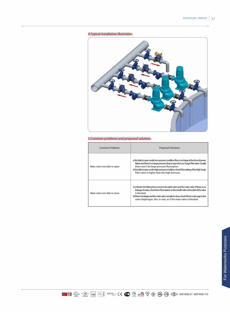
4.Typical installation illustration
5.Common problems and proposed solutions
Common Problems Proposed Solutions
Main valve not able to open
a.Not able to open under low pressure condition: flow is not large at the time of power failure and there is no large pressure drop to open the Low Surge Pilot valve. Usually there won't be large pressure fluctuation.
b.Not able to open under high pressure condition: check if the setting of the High Surge Pilot valve is higher than the high pressure.
Main valve not able to close
a.Unfasten the fitting that connects the pilot valve and the main valve. If there is no leakage of water, check then if the strainer or the needle valve at the inlet of the valve is blocked.
b.If there is leakage and the main valve not able to close, check if there is damage to the valve diaphragm, disc or seat, or if the main valve is blocked.
American Valves 77
For W
ater
wor
ks P
urpo
ses
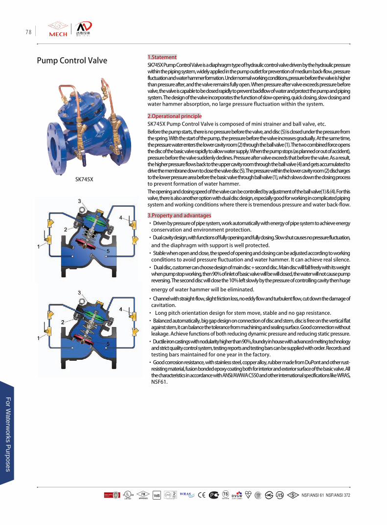
Pump Control Valve 1.StatementSK745X Pump Control Valve is a diaphragm type of hydraulic control valve driven by the hydraulic pressure within the piping system, widely applied in the pump outlet for prevention of medium back-flow, pressure fluctuation and water hammer formation. Under normal working conditions, pressure before the valve is higher than pressure after, and the valve remains fully open. When pressure after valve exceeds pressure before valve, the valve is capable to be closed rapidly to prevent backflow of water and protect the pump and piping system. The design of the valve incorporates the function of slow-opening, quick closing, slow closing and water hammer absorption, no large pressure fluctuation within the system.
2.Operational principleSK745X Pump Control Valve is composed of mini strainer and ball valve, etc.Before the pump starts, there is no pressure before the valve, and disc (5) is closed under the pressure from the spring. With the start of the pump, the pressure before the valve increases gradually. At the same time, the pressure water enters the lower cavity room (2) through the ball valve (1). The two combined force opens the disc of the basic valve rapidly to allow water supply. When the pump stops (as planned or out of accident), pressure before the valve suddenly declines. Pressure after valve exceeds that before the valve. As a result, the higher pressure flows back to the upper cavity room through the ball valve (4) and gets accumulated to drive the membrane down to close the valve disc (5). The pressure within the lower cavity room (2) discharges to the lower pressure area before the basic valve through ball valve (1), which slows down the closing process to prevent formation of water hammer. The opening and closing speed of the valve can be controlled by adjustment of the ball valve(1) & (4). For this valve, there is also another option with dual disc design, especially good for working in complicated piping system and working conditions where there is tremendous pressure and water back-flow.
3.Property and advantages• Driven by pressure of pipe system, work automatically with energy of pipe system to achieve energy
conservation and environment protection.• Dual cavity design, with functions of fully opening and fully closing. Slow shut causes no pressure fluctuation,
and the diaphragm with support is well protected.• Stable when open and close, the speed of opening and closing can be adjusted according to working
conditions to avoid pressure fluctuation and water hammer. It can achieve real silence. • Dual disc, customer can choose design of main disc + second disc. Main disc will fall freely with its weight
when pump stop working, then 90% of inlet of basic valve will be will closed, the water will not cause pump reversing. The second disc will close the 10% left slowly by the pressure of controlling cavity then huge
energy of water hammer will be eliminated.
• Channel with straight-flow, slight friction loss, no eddy flow and turbulent flow, cut down the damage of cavitation.
• Long pitch orientation design for stem move, stable and no gap resistance.• Balanced automatically, big gap design on connection of disc and stem, disc is free on the vertical flat
against stem, it can balance the tolerance from machining and sealing surface. Good connection without leakage. Achieve functions of both reducing dynamic pressure and reducing static pressure.
• Ductile iron castings with nodularity higher than 90%, foundry in house with advanced melting technology and strict quality control system, testing reports and testing bars can be supplied with order. Records and testing bars maintained for one year in the factory.
• Good corrosion resistance, with stainless steel, copper alloy, rubber made from DuPont and other rust-resisting material, fusion bonded epoxy coating both for interior and exterior surface of the basic valve. All the characteristics in accordance with ANSI/AWWA C550 and other international specifications like WRAS, NSF61.
SK745X
78
For Waterw
orks Purposes
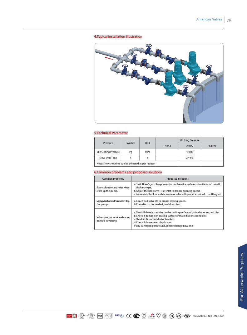
4.Typical installation illustration
6.Common problems and proposed solutions
5.Technical Parameter
Common Problems Proposed Solutions
Strong vibration and noise when start-up the pump.
a.Check if there's gas in the upper cavity room. Loose the hex brass nut on the top of bonnet to discharge gas. b.Adjust the ball valve (1) at inlet to proper opening speed.c.Recalculate the flow and choose new valve with proper size or add throttling set.
Strong vibration and noise when stop the pump.
a.Adjust ball valve (4) to proper closing speed.b.Consider to choose design of dual discs.
Valve does not work and cause pump's reversing.
a.Check if there's sundries on the sealing surface of main disc or second disc.b.Check if damage on sealing surface of main disc or second disc.c.Check if stem corroded or blocked. d.Check if damage on diaphragm. If any damaged parts found, please change new one.
Pressure Symbol UnitWorking Pressure
175PSI 250PSI 300PSI
Min Closing Pressure Pg MPa ≤0.05
Slow-shut Time t s 2~60
Note: Slow-shut time can be adjusted as per request
American Valves 79
For W
ater
wor
ks P
urpo
ses
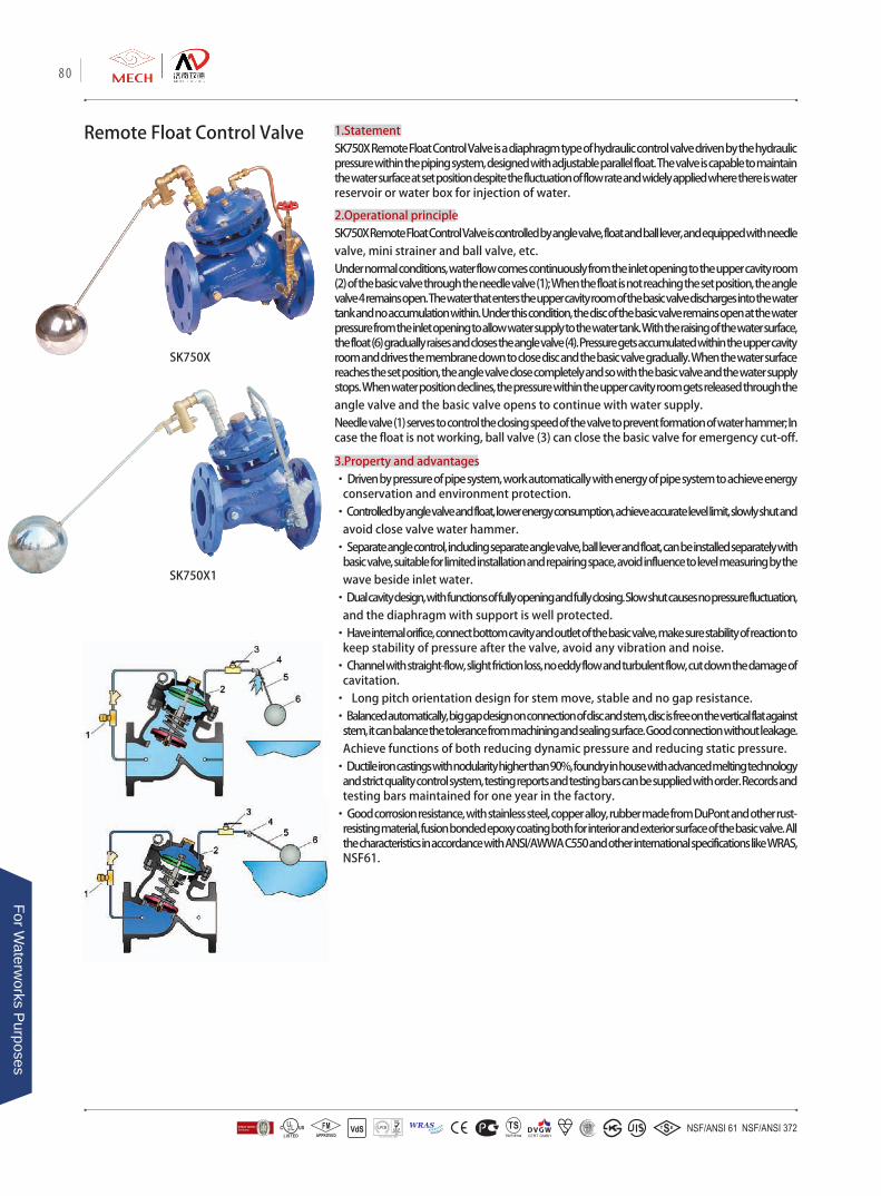
Remote Float Control Valve 1.StatementSK750X Remote Float Control Valve is a diaphragm type of hydraulic control valve driven by the hydraulic pressure within the piping system, designed with adjustable parallel float. The valve is capable to maintain the water surface at set position despite the fluctuation of flow rate and widely applied where there is water reservoir or water box for injection of water.
2.Operational principleSK750X Remote Float Control Valve is controlled by angle valve, float and ball lever, and equipped with needle valve, mini strainer and ball valve, etc.Under normal conditions, water flow comes continuously from the inlet opening to the upper cavity room (2) of the basic valve through the needle valve (1); When the float is not reaching the set position, the angle valve 4 remains open. The water that enters the upper cavity room of the basic valve discharges into the water tank and no accumulation within. Under this condition, the disc of the basic valve remains open at the water pressure from the inlet opening to allow water supply to the water tank. With the raising of the water surface, the float (6) gradually raises and closes the angle valve (4). Pressure gets accumulated within the upper cavity room and drives the membrane down to close disc and the basic valve gradually. When the water surface reaches the set position, the angle valve close completely and so with the basic valve and the water supply stops. When water position declines, the pressure within the upper cavity room gets released through the angle valve and the basic valve opens to continue with water supply.Needle valve (1) serves to control the closing speed of the valve to prevent formation of water hammer; In case the float is not working, ball valve (3) can close the basic valve for emergency cut-off.
3.Property and advantages• Driven by pressure of pipe system, work automatically with energy of pipe system to achieve energy
conservation and environment protection.• Controlled by angle valve and float, lower energy consumption, achieve accurate level limit, slowly shut and
avoid close valve water hammer. • Separate angle control, including separate angle valve, ball lever and float, can be installed separately with
basic valve, suitable for limited installation and repairing space, avoid influence to level measuring by the wave beside inlet water.
• Dual cavity design, with functions of fully opening and fully closing. Slow shut causes no pressure fluctuation, and the diaphragm with support is well protected.
• Have internal orifice, connect bottom cavity and outlet of the basic valve, make sure stability of reaction to keep stability of pressure after the valve, avoid any vibration and noise.
• Channel with straight-flow, slight friction loss, no eddy flow and turbulent flow, cut down the damage of cavitation.
• Long pitch orientation design for stem move, stable and no gap resistance.• Balanced automatically, big gap design on connection of disc and stem, disc is free on the vertical flat against
stem, it can balance the tolerance from machining and sealing surface. Good connection without leakage. Achieve functions of both reducing dynamic pressure and reducing static pressure.
• Ductile iron castings with nodularity higher than 90%, foundry in house with advanced melting technology and strict quality control system, testing reports and testing bars can be supplied with order. Records and testing bars maintained for one year in the factory.
• Good corrosion resistance, with stainless steel, copper alloy, rubber made from DuPont and other rust-resisting material, fusion bonded epoxy coating both for interior and exterior surface of the basic valve. All the characteristics in accordance with ANSI/AWWA C550 and other international specifications like WRAS, NSF61.
SK750X
SK750X1
80
For Waterw
orks Purposes
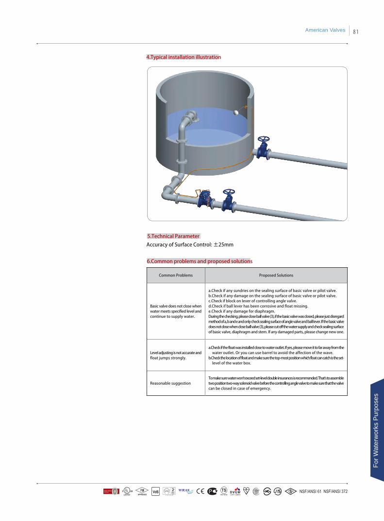
6.Common problems and proposed solutions
5.Technical Parameter
Common Problems Proposed Solutions
Basic valve does not close when water meets specified level and continue to supply water.
a.Check if any sundries on the sealing surface of basic valve or pilot valve. b.Check if any damage on the sealing surface of basic valve or pilot valve.c.Check if block on lever of controlling angle valve.d.Check if ball lever has been corrosive and float missing. e.Check if any damage for diaphragm.During the checking, please close ball valve (3), if the basic valve was closed, please just disregard method of a, b and e and only check sealing surface of angle valve and ball lever. If the basic valve does not close when close ball valve (3), please cut off the water supply and check sealing surface of basic valve, diaphragm and stem. If any damaged parts, please change new one.
Level adjusting is not accurate and float jumps strongly.
a.Check if the float was installed close to water outlet. If yes, please move it to far away from the water outlet. Or you can use barrel to avoid the affection of the wave.
b.Check the location of float and make sure the top-most position which float can catch is the set-level of the water box.
Reasonable suggestionTo make sure water won't exceed set-level double insurances is recommended. That's to assemble two position two-way solenoid valve before the controlling angle valve to make sure that the valve can be closed in case of emergency.
4.Typical installation illustration
Accuracy of Surface Control: ±25mm
American Valves 81
For W
ater
wor
ks P
urpo
ses
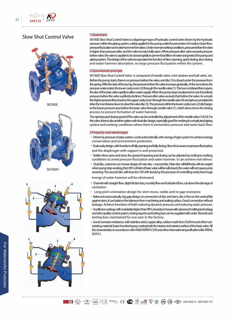
Slow Shut Control Valve 1.StatementSK760X Slow Shut Control Valve is a diaphragm type of hydraulic control valve driven by the hydraulic pressure within the piping system, widely applied in the pump outlet for prevention of medium back-flow, pressure fluctuation and water hammer formation. Under normal working conditions, pressure before the valve is higher than pressure after, and the valve remains fully open. When pressure after valve exceeds pressure before valve, the valve is capable to be closed rapidly to prevent backflow of water and protect the pump and piping system. The design of the valve incorporates the function of slow-opening, quick closing, slow closing and water hammer absorption, no large pressure fluctuation within the system.
2.Operational principleSK760X Slow Shut Control Valve is composed of needle valve, mini strainer and ball valve, etc.Before the pump starts, there is no pressure before the valve, and disc (5) is closed under the pressure from the spring. With the start of the pump, the pressure before the valve increases gradually. At the same time, the pressure water enters the lower cavity room (2) through the needle valve (1). The two combined force opens the disc of the basic valve rapidly to allow water supply. When the pump stops (as planned or out of accident), pressure before the valve suddenly declines. Pressure after valve exceeds that before the valve. As a result, the higher pressure flows back to the upper cavity room through the needle valve (4) and gets accumulated to drive the membrane down to close the valve disc (5). The pressure within the lower cavity room (2) discharges to the lower pressure area before the basic valve through needle valve (1), which slows down the closing process to prevent formation of water hammer. The opening and closing speed of the valve can be controlled by adjustment of the needle valve (1) & (4). For this valve, there is also another option with dual disc design, especially good for working in complicated piping system and working conditions where there is tremendous pressure and water back-flow.
3.Property and advantages• Driven by pressure of pipe system, work automatically with energy of pipe system to achieve energy
conservation and environment protection.• Dual cavity design, with functions of fully opening and fully closing. Slow shut causes no pressure fluctuation,
and the diaphragm with support is well protected.• Stable when open and close, the speed of opening and closing can be adjusted according to working
conditions to avoid pressure fluctuation and water hammer. It can achieve real silence. • Dual disc, customer can choose design of main disc + second disc. Main disc will fall freely with its weight
when pump stop working, then 90% of inlet of basic valve will be will closed, the water will not cause pump reversing. The second disc will close the 10% left slowly by the pressure of controlling cavity then huge
energy of water hammer will be eliminated.
• Channel with straight-flow, slight friction loss, no eddy flow and turbulent flow, cut down the damage of cavitation.
• Long pitch orientation design for stem move, stable and no gap resistance.• Balanced automatically, big gap design on connection of disc and stem, disc is free on the vertical flat
against stem, it can balance the tolerance from machining and sealing surface. Good connection without leakage. Achieve functions of both reducing dynamic pressure and reducing static pressure.
• Ductile iron castings with nodularity higher than 90%, foundry in house with advanced melting technology and strict quality control system, testing reports and testing bars can be supplied with order. Records and testing bars maintained for one year in the factory.
• Good corrosion resistance, with stainless steel, copper alloy, rubber made from DuPont and other rust-resisting material, fusion bonded epoxy coating both for interior and exterior surface of the basic valve. All the characteristics in accordance with ANSI/AWWA C550 and other international specifications like WRAS, NSF61.
5
SK760X
SK760X1
82
For Waterw
orks Purposes
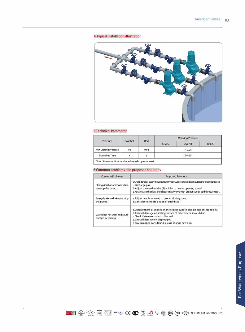
4.Typical installation illustration
6.Common problems and proposed solutions
5.Technical Parameter
Common Problems Proposed Solutions
Strong vibration and noise when start-up the pump.
a.Check if there's gas in the upper cavity room. Loose the hex brass nut on the top of bonnet to discharge gas. b.Adjust the needle valve (1) at inlet to proper opening speed.c.Recalculate the flow and choose new valve with proper size or add throttling set.
Strong vibration and noise when stop the pump.
a.Adjust needle valve (4) to proper closing speed.b.Consider to choose design of dual discs.
Valve does not work and cause pump's reversing.
a.Check if there's sundries on the sealing surface of main disc or second disc.b.Check if damage on sealing surface of main disc or second disc.c.Check if stem corroded or blocked. d.Check if damage on diaphragm. If any damaged parts found, please change new one.
Pressure Symbol UnitWorking Pressure
175PSI 250PSI 300PSI
Min Closing Pressure Pg MPa ≤0.05
Slow-shut Time t s 2~60
Note: Slow-shut time can be adjusted as per request
American Valves 83
For W
ater
wor
ks P
urpo
ses

Pressure Differential
By-pass Balancing Valve
1.StatementSK780X Pressure Differential By-pass Balancing Valve is a diaphragm type of hydraulic control valve driven by the hydraulic pressure within the piping system, widely applied in HVAC system for guarantee of flow stability in the air conditioning, refrigeration and heating system and pump working. The valve prevents the effect on the other pipe branches when there is fluctuation on one branch by balancing of pressure in the radiant and distribution water manifold, thus to protect the efficient and safe working of the refrigeration set or heating set.
2.Operational principleSK780X Pressure Differential By-pass Balancing Valve is composed of pressure balancing pilot valve, needle valve (or ball valve), mini strainer and ball valve, etc.SK780X Pressure Differential By-pass Balancing Valve is installed between radiant and distribution water manifold (water supply and water return). Water flow enters continuously from water supply duct to the valve inlet and then to the upper cavity room (2) through needle valve (1) (or ball valve). Pilot valve (3) is connected to the water supply duct and return duct by guide tube (4) and (5) to sensing of the pressure difference and adjustment of the opening position of the pilot valve accordingly. When the pressure difference is large, pilot valve opens broadly, the pressure inside upper cavity room (2) declines and the basic valve opens broadly. As result the water flow between the supply and return duct increase and the entire system gets balanced. When the pressure difference is small, pilot valve (3) turns to close at the pressure of the spring, the pressure inside upper cavity room (2) increase and the basic valve turns to close. As result the water flow between the supply and return duct decreases and the entire system also gets balanced.
3.Property and advantages• Driven by pressure of pipe system, work automatically with energy of pipe system to achieve energy
conservation and environment protection.• Dual cavity design, with functions of fully opening and fully closing. Slow shut causes no pressure fluctuation,
and the diaphragm with support is well protected.• Antenna type of conduit, See No.4 and 5 conduit, connect with water knockout drum and water collector
(supplying pipe and return pipe), can achieve accurate and reliable adjusting. • Have internal orifice, connect bottom cavity and outlet of the basic valve, make sure stability of reaction to
keep stability of pressure after the valve, avoid any vibration and noise. • Channel with straight-flow, slight friction loss, no eddy flow and turbulent flow, cut down the damage of
cavitation. • Long pitch orientation design for stem move, stable and no gap resistance.• Balanced automatically, big gap design on connection of disc and stem, disc is free on the vertical flat
against stem, it can balance the tolerance from machining and sealing surface. Good connection without leakage. Achieve functions of both reducing dynamic pressure and reducing static pressure.
• Ductile iron castings with nodularity higher than 90%, foundry in house with advanced melting technology and strict quality control system, testing reports and testing bars can be supplied with order. Records and testing bars maintained for one year in the factory.
• Good corrosion resistance, with stainless steel, copper alloy, rubber made from DuPont and other rust-resisting material, fusion bonded epoxy coating both for interior and exterior surface of the basic valve. All the characteristics in accordance with ANSI/AWWA C550 and other international specifications like WRAS, NSF61.
SK780X
SK780X1
84
For Waterw
orks Purposes
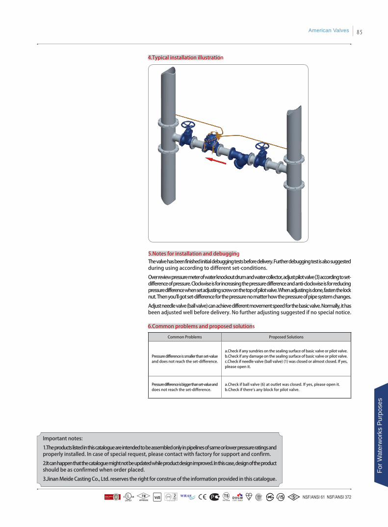
4.Typical installation illustration
6.Common problems and proposed solutions
Common Problems Proposed Solutions
Pressure difference is smaller than set-value and does not reach the set-difference.
a.Check if any sundries on the sealing surface of basic valve or pilot valve. b.Check if any damage on the sealing surface of basic valve or pilot valve.c.Check if needle valve (ball valve) (1) was closed or almost closed. If yes, please open it.
Pressure difference is bigger than set-value and does not reach the set-difference.
a.Check if ball valve (6) at outlet was closed. If yes, please open it.b.Check if there's any block for pilot valve.
5.Notes for installation and debuggingThe valve has been finished initial debugging tests before delivery. Further debugging test is also suggested during using according to different set-conditions.
Over review pressure meter of water knockout drum and water collector, adjust pilot valve (3) according to set-difference of pressure. Clockwise is for increasing the pressure difference and anti-clockwise is for reducing pressure difference when set adjusting screw on the top of pilot valve. When adjusting is done, fasten the lock nut. Then you'll got set-difference for the pressure no matter how the pressure of pipe system changes.
Adjust needle valve (ball valve) can achieve different movement speed for the basic valve. Normally, it has been adjusted well before delivery. No further adjusting suggested if no special notice.
Important notes:
1.The products listed in this catalogue are intended to be assembled only in pipelines of same or lower pressure ratings and properly installed. In case of special request, please contact with factory for support and confirm.
2.It can happen that the catalogue might not be updated while product design improved. In this case, design of the product should be as confirmed when order placed.
3.Jinan Meide Casting Co., Ltd. reserves the right for construe of the information provided in this catalogue.
American Valves 85
For W
ater
wor
ks P
urpo
ses
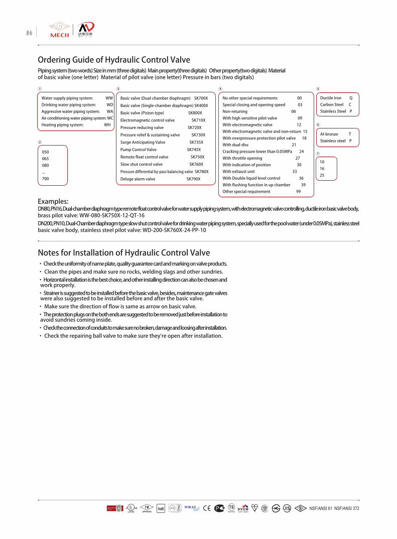
Notes for Installation of Hydraulic Control Valve
Ordering Guide of Hydraulic Control ValvePiping system (two words) Size in mm (three digitals) Main property(three digitals) Other property(two digitals) Material of basic valve (one letter) Material of pilot valve (one letter) Pressure in bars (two digitals)
050
065
080
...
700
Ductile Iron Q
Carbon Steel C
Stainless Steel P
Al-bronze T
Stainless steel P
10
16
25
Basic valve (Dual-chamber diaphragm) SK700X
Basic valve (Single-chamber diaphragm) SK400X
Basic valve (Piston type) SK800X
Electromagnetic control valve SK710X
Pressure reducing valve SK720X
Pressure relief & sustaining valve SK730X
Surge Anticipating Valve SK735X
Pump Control Valve SK745X
Remote float control valve SK750X
Slow shut control valve SK760X
Pressure differential by-pass balancing valve SK780X
Deluge alarm valve SK790X
No other special requirements 00
Special closing and opening speed 03
Non-retuning 06
With high sensitive pilot valve 09
With electromagnetic valve 12
With electromagnetic valve and non-return 15
With overpressure protection pilot valve 18
With dual-disc 21
Cracking pressure lower than 0.05MPa 24
With throttle opening 27
With indication of position 30
With exhaust unit 33
With Double liquid level control 36
With flushing function in up chamber 39
Other special requirement 99
Water supply piping system: WW
Drinking water piping system: WD
Aggressive water piping system: WA
Air conditioning water piping system: WC
Heating piping system: WH
Examples: DN80, PN16, Dual-chamber diaphragm type remote float control valve for water supply piping system, with electromagnetic valve controlling, ductile iron basic valve body, brass pilot valve: WW-080-SK750X-12-QT-16DN200, PN10, Dual-Chamber diaphragm type slow shut control valve for drinking water piping system, specially used for the pool water (under 0.05MPa), stainless steel basic valve body, stainless steel pilot valve: WD-200-SK760X-24-PP-10
• Check the uniformity of name plate, quality guarantee card and marking on valve products. • Clean the pipes and make sure no rocks, welding slags and other sundries.• Horizontal installation is the best choice, and other installing direction can also be chosen and work properly. • Strainer is suggested to be installed before the basic valve, besides, maintenance gate valves were also suggested to be installed before and after the basic valve. • Make sure the direction of flow is same as arrow on basic valve. • The protection plugs on the both ends are suggested to be removed just before installation to avoid sundries coming inside. • Check the connection of conduits to make sure no broken, damage and loosing after installation. • Check the repairing ball valve to make sure they're open after installation.
⑦
①
②
③ ④ ⑤
⑥
86
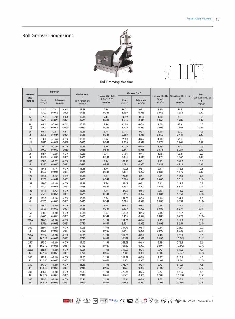
Roll Groove Dimensions
Nominal Size
mm/in
Pipe ODGasket seat
A±0.76/±0.03
mm/in
Groove Width B±0.76/±0.03
mm/in
Groove Dia CGroove Depth
D(ref)mm/in
MaxAllow Flare Dia F
mm/in
Min.Allow wall thickness
Tmm/in
Basicmm/in
Tolerencemm/in
Basicmm/in
Tolerencemm/in
251
33.71.327
+0.41+0.016
-0.68-0.026
15.880.625
7.140.281
30.231.190
-0.38-0.015
1.600.063
34.51.358
1.80.071
321Ø
42.41.669
+0.50+0.020
-0.60-0.023
15.880.625
7.140.281
38.991.535
-0.38-0.015
1.600.063
43.31.705
1.80.071
401Ø
48.31.900
+0.44+0.017
-0.52-0.020
15.880.625
7.140.281
45.091.779
-0.38-0.015
1.600.063
49.41.945
1.80.071
502
60.32.375
+0.61+0.024
-0.61-0.024
15.880.625
8.740.344
57.152.250
-0.38-0.015
1.600.063
62.22.449
1.80.071
652Ø
73.02.875
+0.74+0.029
-0.74-0.029
15.880.625
8.740.344
69.092.720
-0.46-0.018
1.980.078
75.22.961
2.30.091
652Ø
76.13.000
+0.76+0.030
-0.76-0.030
15.880.625
8.740.344
72.262.845
-0.46-0.018
1.990.078
77.73.059
2.30.091
803
88.93.500
+0.89+0.035
-0.79-0.031
15.880.625
8.740.344
84.943.344
-0.46-0.018
1.980.078
90.63.567
2.30.091
1004
108.04.250
+1.07+0.042
-0.79-0.031
15.880.625
8.740.344
103.734.084
-0.51-0.020
2.110.083
109.74.319
2.30.091
1004
114.34.500
+1.14+0.045
-0.79-0.031
15.880.625
8.740.344
110.084.334
-0.51-0.020
2.110.083
116.24.575
2.30.091
1255
133.05.250
+1.32+0.052
-0.79-0.031
15.880.625
8.740.344
129.135.084
-0.51-0.020
2.110.083
134.95.311
2.90.114
1255
139.75.500
+1.40+0.055
-0.79-0.031
15.880.625
8.740.344
135.485.334
-0.51-0.020
2.110.083
141.75.579
2.90.114
1255
141.35.563
+1.42+0.056
-0.79-0.031
15.880.625
8.740.344
137.035.395
-0.56-0.022
2.130.084
143.55.650
2.90.114
1506
159.06.250
+1.60+0.063
-0.79-0.031
15.880.625
8.740.344
154.506.083
-0.56-0.022
2.160.085
161.06.339
2.90.114
1506
165.16.500
+1.60+0.063
-0.79-0.031
15.880.625
8.740.344
160.86.330
-0.56-0.022
2.160.085
167.16.579
2.90.114
1506
168.36.625
+1.60+0.063
-0.79-0.031
15.880.625
8.740.344
163.966.455
-0.56-0.022
2.160.085
170.76.720
2.90.114
200A8
216.38.516
+1.60+0.063
-0.79-0.031
19.050.750
11.910.469
211.608.331
-0.64-0.025
2.350.093
219.88.653
2.90.114
2008
219.18.625
+1.60+0.063
-0.79-0.031
19.050.750
11.910.469
214.408.441
-0.64-0.025
2.340.092
221.58.720
2.90.114
250A10
267.410.528
+1.60+0.063
-0.79-0.031
19.050.750
11.910.469
262.6010.339
-0.69-0.027
2.400.095
270.910.665
3.60.142
25010
273.010.750
+1.60+0.063
-0.79-0.031
19.050.750
11.910.469
268.2810.562
-0.69-0.027
2.390.094
275.410.842
3.60.142
300A12
318.512.539
+1.60+0.063
-0.79-0.031
19.050.750
11.910.469
312.9012.319
-0.76-0.030
2.770.109
322.012.677
4.00.158
30012
323.912.750
+1.60+0.063
-0.79-0.031
19.050.750
11.910.469
318.2912.531
-0.76-0.030
2.770.109
326.212.842
4.00.158
35014
377.014.842
+1.60+0.063
-0.79-0.031
23.830.938
11.910.469
371.4414.623
-0.76-0.030
2.770.109
379.514.941
4.50.177
40016
426.016.772
+1.60+0.063
-0.79-0.031
23.830.938
11.910.469
420.4616.553
-0.76-0.030
2.770.109
428.516.870
4.50.177
50020
529.020.827
+1.60+0.063
-0.79-0.031
25.401.000
11.910.469
523.4620.608
-0.76-0.030
2.770.109
533.020.984
5.00.197
Roll Grooving Machine
American Valves 87

Class 125 Flange and Bolting Dimensions
NPS
Flanges Hub Blind Flanges Bolt Holes Bolting
Diameter of Flange,
O
Thickness of Flange,
Min.,Q
[Note(1)]
Diameter Min.,
X
Length of Hub
and Threads,
Min.,Y
[Note(2)]
Diameter of Port,
I[Note(3)]
Wallthickness,
V[Note(4)]
Diameter of Bolt Circle
Diameter of Bolt Holes
[Notes(5)and(6)]
Number of Bolts
Diameter of Bolts
[Notes(7)anf(8)]
Length of Bolts
[Notes(7)and(8)]
Length of Bolt
Stud With Two Nuts[Note(7)]
1 110 11.1 49 18 25 9.6 79 5/8 4 1/2 45 …
11/4 115 12.7 59 21 32 11.1 89 5/8 4 1/2 51 …
11/2 125 14.3 65 22 38 12.7 98 5/8 4 1/2 51 …
2 150 15.9 78 25 51 14.3 121 3/4 4 5/8 57 …
21/2 180 17.5 91 29 64 15.9 140 3/4 4 5/8 64 …
3 190 19.0 108 30 76 17.5 152 3/4 4 5/8 64 …
31/2 215 20.6 122 32 89 19.0 178 3/4 8 5/8 70 …
4 230 23.8 135 33 102 22.2 191 3/4 8 5/8 76 …
5 255 23.8 164 37 127 22.2 216 7/8 8 3/4 76 …
6 280 25.4 192 40 152 23.8 241 7/8 8 3/4 83 …
8 345 28.6 246 45 203 27.0 299 7/8 8 3/4 89 …
10 405 30.2 303 49 254 28.6 362 1 12 7/8 95 …
12 485 31.8 357 56 305 20.6 432 1 12 7/8 95 …
14 535 32.4 391 57 356 22.2 476 1 1/8 12 1 108 …
16 595 36.5 445 64 406 25.4 540 1 1/8 16 1 114 …
18 635 39.7 499 68 457 27.0 578 1 1/4 16 1 1/8 121 …
20 700 42.9 553 73 508 28.6 635 1 1/4 20 1 1/8 127 …
24 815 47.6 660 83 610 31.8 749 1 3/8 20 1 1/4 140 …
30 985 54.0 … … 762 36.6 914 1 3/8 28 1 1/4 159 …
36 1170 60.3 … … 914 41.3 1086 1 5/8 32 1 1/2 178 222
42 1345 66.7 … … 1066 46.0 1257 1 5/8 36 1 1/2 191 235
48 1510 69.9 … … 1219 50.8 1422 1 5/8 44 1 1/2 197 242
54(9) 1685 76.2 … … … … 1594 2 44 1 3/8 216 267
60(9) 1855 79.4 … … … … 1759 2 52 1 3/8 222 273
72(9) 2195 88.9 … … … … 2096 2 60 1 3/8 241 292
84(9) 2535 98.4 … … … … 2426 2 1/4 64 2 267 324
96(9) 2875 108.0 … … … … 2756 2 1/2 68 2 1/4 292 356
General Note: Dimensions are in millimeters. Notes: (1) For facing see para.7.2.(a) (2) For thread of threaded flanges, see paras.7.5.1 and 7.5.2. (3) All blind flange NPS 12 and larger must be dished with inside radius equal to the port diameter. (4) For wall thickness tolerance, see para.7.1. (5) For flange bolt holes, see para.7.6. (6) For spot facing, see para.7.7. (7) For bolts and nuts, see para.8.1.1. (8) Bolt lengths to be compensated for when bolting steel to gray iron flanges. (9) NPS 54 through 96 are included for convenience. Pressure-temperature ratings are the user's responsibility.
88


![arXiv:2107.10728v1 [cond-mat.stat-mech] 22 Jul 2021](https://img.dokumen.tips/doc/110x75/6321f8e2aa6c954bc7077e0a/arxiv210710728v1-cond-matstat-mech-22-jul-2021.jpg)


![arXiv:1602.05855v2 [cond-mat.stat-mech] 13 May 2016](https://img.dokumen.tips/doc/110x75/63325aee3108fad7760e9589/arxiv160205855v2-cond-matstat-mech-13-may-2016.jpg)


![arXiv:2111.09926v3 [cond-mat.stat-mech] 2 Apr 2022](https://img.dokumen.tips/doc/110x75/6327ec416d480576770d8480/arxiv211109926v3-cond-matstat-mech-2-apr-2022.jpg)
![arXiv:0705.1951v1 [cond-mat.stat-mech] 14 May 2007](https://img.dokumen.tips/doc/110x75/6327a86b051fac18490e5ac5/arxiv07051951v1-cond-matstat-mech-14-may-2007.jpg)


![arXiv:1204.1427v1 [cond-mat.stat-mech] 6 Apr 2012](https://img.dokumen.tips/doc/110x75/632315ea117b4414ec0c2b4b/arxiv12041427v1-cond-matstat-mech-6-apr-2012.jpg)


