Embed Size (px)
Citation preview

MEASUREMENTS
For
ELECTRICAL ENGINEERING INSTRUMENTATION ENGINEERING

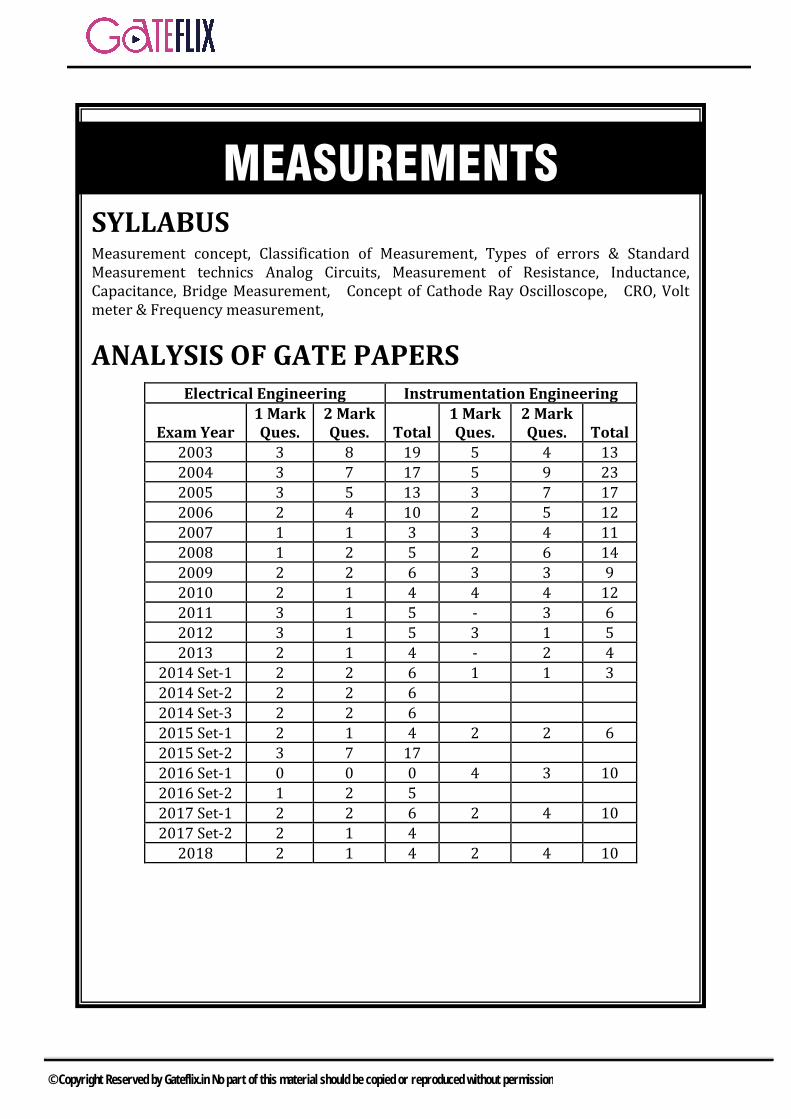
SYLLABUS Measurement concept, Classification of Measurement, Types of errors & Standard Measurement technics Analog Circuits, Measurement of Resistance, Inductance, Capacitance, Bridge Measurement, Concept of Cathode Ray Oscilloscope, CRO, Volt meter & Frequency measurement,
ANALYSIS OF GATE PAPERS
Electrical Engineering Instrumentation Engineering
Exam Year 1 Mark Ques.
2 Mark Ques. Total
1 Mark Ques.
2 Mark Ques. Total
2003 3 8 19 5 4 13
2004 3 7 17 5 9 23
2005 3 5 13 3 7 17
2006 2 4 10 2 5 12
2007 1 1 3 3 4 11
2008 1 2 5 2 6 14
2009 2 2 6 3 3 9
2010 2 1 4 4 4 12
2011 3 1 5 - 3 6
2012 3 1 5 3 1 5
2013 2 1 4 - 2 4
2014 Set-1 2 2 6 1 1 3
2014 Set-2 2 2 6
2014 Set-3 2 2 6
2015 Set-1 2 1 4 2 2 6
2015 Set-2 3 7 17
2016 Set-1 0 0 0 4 3 10
2016 Set-2 1 2 5
2017 Set-1 2 2 6 2 4 10
2017 Set-2 2 1 4
2018 2 1 4 2 4 10
MEASUREMENTS
© Copyright Reserved by Gateflix.in No part of this material should be copied or reproduced without permission
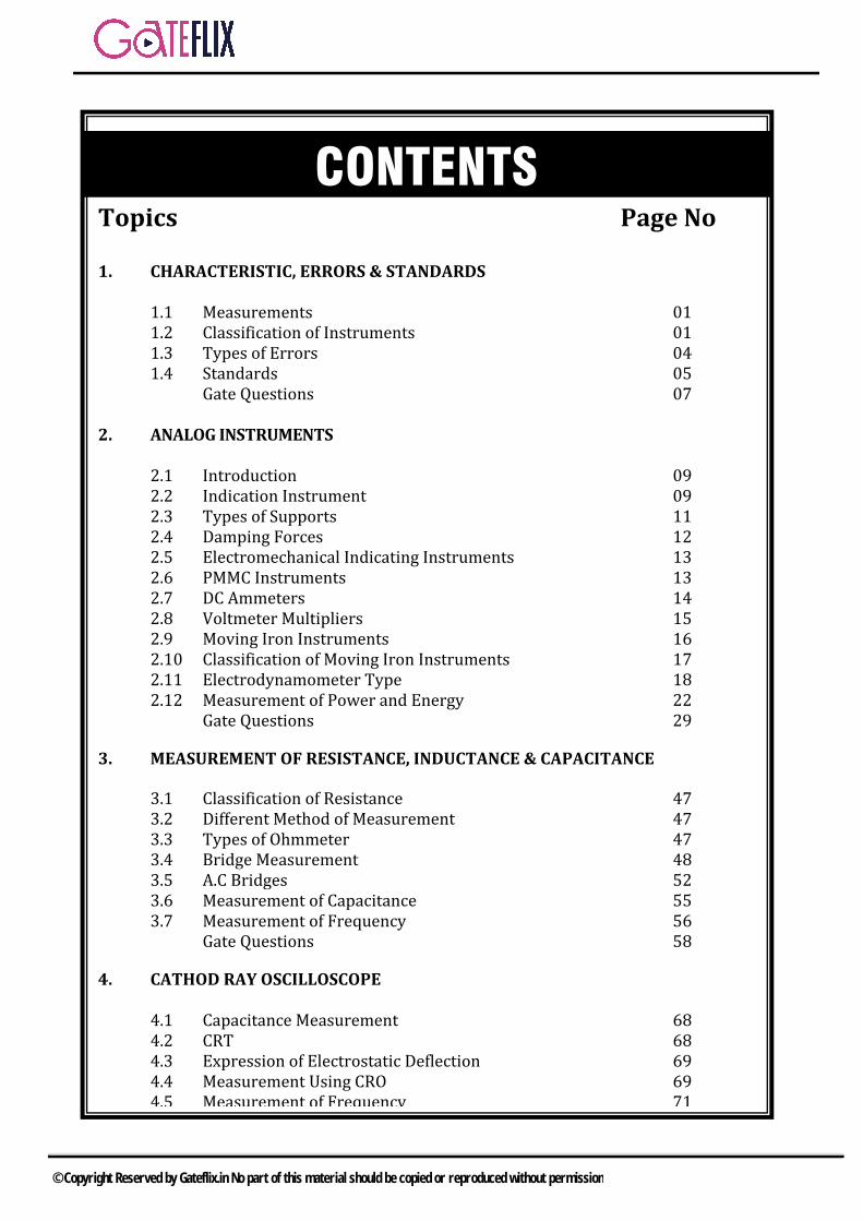
Topics Page No 1. CHARACTERISTIC, ERRORS & STANDARDS
1.1 Measurements 01 1.2 Classification of Instruments 01 1.3 Types of Errors 04 1.4 Standards 05 Gate Questions 07
2. ANALOG INSTRUMENTS 2.1 Introduction 09 2.2 Indication Instrument 09 2.3 Types of Supports 11 2.4 Damping Forces 12 2.5 Electromechanical Indicating Instruments 13 2.6 PMMC Instruments 13 2.7 DC Ammeters 14 2.8 Voltmeter Multipliers 15 2.9 Moving Iron Instruments 16 2.10 Classification of Moving Iron Instruments 17 2.11 Electrodynamometer Type 18 2.12 Measurement of Power and Energy 22 Gate Questions 29
3. MEASUREMENT OF RESISTANCE, INDUCTANCE & CAPACITANCE
3.1 Classification of Resistance 47 3.2 Different Method of Measurement 47 3.3 Types of Ohmmeter 47 3.4 Bridge Measurement 48 3.5 A.C Bridges 52 3.6 Measurement of Capacitance 55 3.7 Measurement of Frequency 56 Gate Questions 58
4. CATHOD RAY OSCILLOSCOPE 4.1 Capacitance Measurement 68 4.2 CRT 68 4.3 Expression of Electrostatic Deflection 69 4.4 Measurement Using CRO 69 4.5 Measurement of Frequency 71
CONTENTS
© Copyright Reserved by Gateflix.in No part of this material should be copied or reproduced without permission
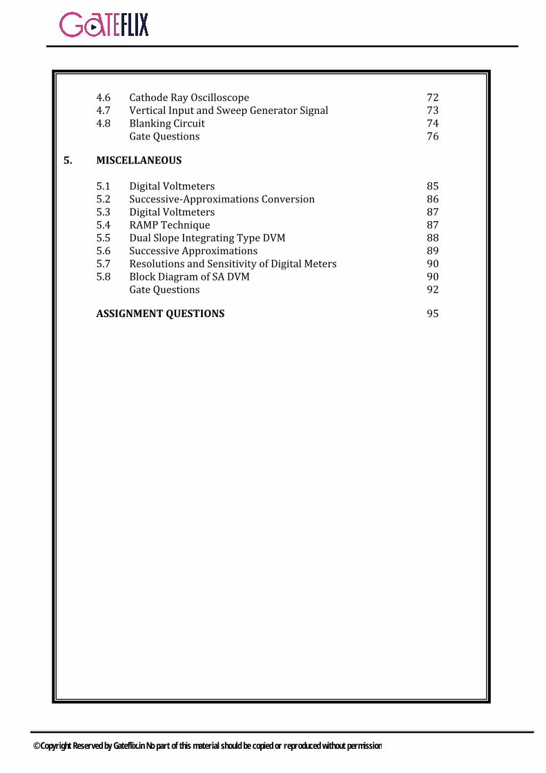
4.6 Cathode Ray Oscilloscope 72
4.7 Vertical Input and Sweep Generator Signal 73 4.8 Blanking Circuit 74 Gate Questions 76
5. MISCELLANEOUS 5.1 Digital Voltmeters 85 5.2 Successive-Approximations Conversion 86 5.3 Digital Voltmeters 87 5.4 RAMP Technique 87 5.5 Dual Slope Integrating Type DVM 88 5.6 Successive Approximations 89 5.7 Resolutions and Sensitivity of Digital Meters 90 5.8 Block Diagram of SA DVM 90 Gate Questions 92
ASSIGNMENT QUESTIONS 95
© Copyright Reserved by Gateflix.in No part of this material should be copied or reproduced without permission
1.1 MEASUREMENTS
The measurement of a given quantity is essentially an act or the result of comparison between the quantity and a predefined standard. Since two quantities are compared, the result is expressed in numerical values.
1.1.1 METHODS OF MEASUREMENTS.
i) Direct Methods andii) Indirect Methods
Direct Methods:- In these methods, the unknown quantity is directly compared against a standard. The result is expressed as a numerical number and a unit Direct methods are quite common for the measurement of physical quantities like length, mass and time.
Indirect Methods:- Measurement by direct methods are not always possible, feasible and practicable. Then measurement is done by measuring Instruments.
Instruments and Measurement Systems:- Measurements involve the use of instruments as a physical means of determining quantities or variables. The earliest scientific instruments used the same three essential elements as our modern instruments do. These elements are: i) a detectorii) an intermediate transfer deviceiii) an indicator, recorder or a storage
device.The history of development of instruments encompasses three phases of instruments, vis.: i) mechanical instrumentsii) electrical instrumentsiii) electronic instruments.
Summarizing, it may be stated that in general electronic instruments have i) a higher sensitivityii) a faster responseiii) a greater flexibilityiv) lower weightv) lower power consumptionvi) a higher degree of reliability than their
mechanical or purely electricalcounterparts.
1.2 CLASSIFICATION OF INSTRUMENTS
i) Absolute Instrumentsii) Secondary Instruments.
1. Absolute Instruments. Theseinstruments give the magnitude of thequantity under measurement in termsof physical constants of the instrument.The examples of this class ofinstruments are Tangent Galvanometerand Rayleigh’s Current Balance.
2. Secondary Instruments. Theseinstruments are so constructed that thequantity being measured can only bemeasured by observing the outputindicated by the instrument. Theseinstruments are calibrated bycomparison with an absolute instrumentor another secondary instrument whichhas already been calibrated against anabsolute instrument.
1.2.1 DEFLECTION AND NULL TYPE INSTRUMENTS.
Deflection Type:- The instruments of this type, the deflection of the instrument provides a basis for determining the quantity under measurement. The measured quantity produces some physical effect with deflects or produces a mechanical displacement of the moving system of the instrument.
1 CHARACTERISTIC, ERRORS & STANDARDS
© Copyright Reserved by Gateflix.in No part of this material should be copied or reproduced without permission
NULL TYPE:- In a null type of instrument, a zero or null indication leads to determination of the magnitude of measured quantity. The null condition is dependent upon some other known conditions.
Comparison of Deflection and Null Type Instruments
i) Null type of instruments are moreaccurate than deflection typeinstruments.
ii) Null type instruments can be highlysensitive as compared with deflectiontype instruments
iii) Deflection type of instruments are moresuited for measurements underdynamic conditions than null type ofinstruments whose intrinsic response isslower.
Applications of Measurement systems.
i) Monitoring of processes and operations,ii) Control of processes and operations, andiii) Experimental Engineering analysis.
Elements of a Generalized Measurement System. 1. Primary sensing element,2. Variable conversion element,3. Data presentation element.
Primary Sensing Element: A transducer is defined as a device which converts a physical quantity into an electrical quantity.
Variable Conversion Element: The output of the primary sensing element may be electrical signal of any form. It may be necessary to convert this output to some other suitable form while preserving the information content of the original signal.
Data Presentation Element: The information about the quantity under measurement has to be conveyed to the
personnel handling the instrument or the system for monitoring, control, or analysis purposes. The information conveyed must be in a form intelligible to the personnel or to the intelligent instrumentation system. Characteristics of Instruments and Measurement Systems (i) Static characteristics, and (ii) Dynamic characteristics.
Static Characteristics. The main static characteristics discussed here are: i) Accuracyii) Sensitivityiii) Reproducibilityiv) Driftv) Static errorvi) Dead Zone
The qualities (i), (ii) and (iii) are desirable, while qualities (iv), (v) and (vi) are undesirable.
Static Error: The most important characteristic of an instrument of measurement system is its accuracy, the accuracy of an instrument is measured in terms of its error. Static error is defined as the difference between the measured value and the true value of the quantity. Then: A = Am -At
the ratio of absolute static error A to At, the true value of the quantity under measurement. Therefore, the relative static errorr, is given by:
r=absoluteerror
truevalue=
tA
A=
tA
0
At = Am (1-r)
Accuracy: It is the closeness with which an instrument reading approaches the true value of the quantity being measured. Thus accuracy of a measurement means conformity to truth.
Precision: It is a measure of the reproducibility of the measurements, the
© Copyright Reserved by Gateflix.in No part of this material should be copied or reproduced without permission
term ‘Precise’ means clearly or sharply defined. A Wheatstone bridge requires a change of 7
in the unknown arm of the bridge to produce a change in deflection of 3mm of the galvanometer.
Sensitivity= magnitudeof output response
magnitudeof input
= 3mm
7 = 0.429 mm/
Inverse sensitivity or scale factor = magnitudeof input
magnitudeof output response=7
3mm
= 2.33
/mm
Linearity: One of the best characteristics of an instrument or a measurement system is considered to be linearity, that is, the output is linearly proportional to the input.
Dead Time: Dead time is defined as the time required by a measurement system to begin to respond to a change in the measured.
Dead Zone: It is defined as the largest change of input quantity for which there is no output of the instrument
Resolution or Discrimination: If the input is slowly increased from some arbitrary input value, it will again be found that output does not change at all until a certain increment is exceeded. This increment is called resolution or discrimination of the instrument. So resolution defines the smallest measurable input change.
Example A moving coil voltmeter has a uniform scale with 100 divisions, the full scale reading is 200 V and 1/10 of a scale division can be estimated with a fair degree of certainty. Determine the resolution of the instrument in volt. Solution 1 scale division = 200/100 = 2V
Resolution = 10
1scale division =
10
12
=0.2 V
Example A digital voltmeter has a read-out range from 0 to 9,999 counts. Determine the resolution of the instrument in volt when the full scale reading is 9.999 V. Solution. The resolution of this instrument is 1 or 1 count in 9,999.
Resolution = 9999
1count =
9999
1
9.999 volt = 10-3 V = 1 mV.
Loading Effects: The ideal situation in a measurement system is that when an element used for any purpose may be for signal sensing, conditioning, transmission or detection is introduced into the system, the original signal should remain un-distorted. This means that the original signal should not be distorted in any form by introduction of any element in the measurement system. However, under practical conditions in extraction of energy from the system thereby distorting the original signal. This distortion may take the form of attenuation waveform distortion, phase shift and many a time all these undesirable features put together. Errors in Measurements and Their Statistical Analysis
Actual value of quantity Aa = As A
Relative limiting error r =s
A
A
= rAs
r = actual value nomin al value
nomin al value
Combination of Quantities with Limiting Errors. i) Sum of two quantities. X = x1 +x2
1 2 1 1 2 2
1 2
dx dx x dx x dxdx
X X X X x X x
X
X
= 1 1 2 2
1 2
x x x x
X x X x
ii) Difference of two quantities.X = x1 –x2
© Copyright Reserved by Gateflix.in No part of this material should be copied or reproduced without permission
X
X
= 1dx
X- 2dx
X,
dX
X=dX
X
1
1
dx
x- 2x
X
2
2
dx
x,
X
X
=
1 1 2 2
1 2
x x x x. .
X x X x
iii) Sum of difference of more than twoquantities.X= x1 x2 x3. then the relativelimiting error in X is given by:
X
X
=
3 31 1 2 2
1 2 3
x xx x x x. . .
X x X x X x
iv) Product of two Components,X = x1x2.,loge X = loge x1 +loge x2.1
X=
1
1
x. 1dx
dX+
2
1
x. 2dx
dX,
dX
X= 1
1
dx
x+ 2
2
dx
x,
X
X
=
1 2
1 2
x x
x x
v) Quotient
X = 1
2
x
x,
loge X = loge x1 -loge x2. 1
X=
1
1
x. 1dx
dX-
2
1
x. 2dx
dX,
dX
X= 1
1
dx
x- 2
2
dx
x,
X
X
=
1 2
1 2
x x
x x
vi) Product or quotient of more than twoquantities
X
X
=
31 2
1 2 3
xx x
x x x
vii)Composite factorsX = x1n.x2m,loge X = n loge x1 + m loge x2
1 2
1 2
dx dx1 n m. . ,
X x dX x dX
1 2
1 2
dx dxdXn m ,
X x x
X
X
= 1 2
1 2
x xn mx x
1.3 TYPES OF ERRORS
1. Gross Errors,2. Systematic Error.3. Random Errors.
Gross Errors. This class of errors mainly covers human mistakes in reading instruments and recording and calculation measurement results. 1. Great care should be taken in reading
and recording the data.2. Two, three or even more reading should
be taken for the quantity undermeasurement.
Systematic Errors. 1. Instrumental Errors.2. Environmental Errors.3. Observational Errors.
1. Instrumental Errors.i) Due to inherent shortcomings in the
instrument,ii) Due to misuse of the instruments,
andiii) Due to loading effects of
instruments
Environmental Errors. Observational Errors. Random Errors. Statistical Treatment of Data.
i) Multi-sample test andii) Single-sample test.
Arithmetic Mean.
X = 1 2 3 4 nx x x x ......... x
n
=
x
n
d1 = x1-X
© Copyright Reserved by Gateflix.in No part of this material should be copied or reproduced without permission
d2 = x2- X………….
dn = xn - X
X = n n(x d )
n
Average Deviation.
1 2 3 nd d d .... dD
n
=
d
n
Standard Deviation (S.D.)
S.D. = = 2 2 2
1 2 nd d .... d
n
=
2d
n
When the number of observations is greater than 20, S.D. is denoted by symbol while if the number of observation is less than 20, the symbol used is s.
s =2 2 2 2
1 2 3 nd d d .... d
n 1
2d
n 1
Variance. The variance is the mean square deviation, V = (Standard Deviation)2 = (S.D.)2 = 2
= 2 2 2 2
1 2 3 nd d d .... d
n
=2d
n
,V = s2 =
2d
n 1
1.4 STANDARDS
i) International standardsii) Primary standardsiii) Secondary standardsiv) Working standards
(i) International standards : Not available to everyone.
(ii) Pri. standards: National standards (iii)Sec. standards: used in industrial labs. (iv) Working standards: Used in general labs.
Standards of EMF:
'Weston' cell is used for primary and secondary standards of emf.
Pri. Standard Weston cell: saturated, normal, Weston cell is used asthe pri standard of emf.. The potential of saturated weston cell. E
= 1.01864 volts. It contains CdSO4 crystal, Hg2SO4, (Cd +
Hg) (Amalgum).Note : CdSO4 crystal is used in saturated Weston cell only.
Variation in emf with temperature –40v/°C
Variation in potential with time. -1 V/Year The max. current from saturated weston
cell is 100 A. Internal resistance of sat. weston cell.
600-800
Sec. Standard
Unsaturated weston cell is used as sec.standards.
The potential of unsaturated weston cellE=l.0180 to 1.0194V.
It does not have CdSO4 crystal. Porous plug is used to hold electrode in
place. Variation in potential is -30V to -
50V/year.
Laboratory standard of emf
The zener diode circuit is used forlaboratorystandard.
Standards of Resistance
Magnine is used for the standard resistance. Contents of Magnine: Ni 4% Cu 84% Mn 12%
Characteristics of Magnine
High resistivity
© Copyright Reserved by Gateflix.in No part of this material should be copied or reproduced without permission
low temp. coefff. low thermal expansion with copper.
Errors in resistance standards Skin effect. stray inductances, and capacitances. there can be contact resistances.
Bifilar winding
The bifilar winding is used to reduce the inductive effect of resistance.
Campbell type
is used as the primary standard. It consists of marble cylinders with screw threads carrying a coils of bare copper, Bare copper (without any insulation) wound under tension.
Sec, standards of mutual inductance
It consists of two coils wound on bobbin of marble and coils are separated by a flange. Cu is used as a conductor.
Pri. standards of self inductance
It is same as that of mutual inductance. (i.e. Campbell type).
Sec. standards of self inductance.
Silk covered copper wire wound on marble former.
Pri. standards of time Atomic clock is used as primary standard.
Pri._standards of freq.
a) CAESIUM (Ce) beam is used as pri-standard
b) Hydrogen maser.
Sec. standards of freq.
a) rubidium crystalb) Quartz crystal
© Copyright Reserved by Gateflix.in No part of this material should be copied or reproduced without permission
Q.1 Resistance R1 and R2 have respectively, nominal value of 10Ω and 5Ω and tolerances of 5% and
10% . The range of values for the parallel combination of 1R and 2R is
a) 3.077Ω to3.616Ωb) 2.805Ω to3.371Ωc) 3.237Ω to3.678Ωd) 3.192Ω to3.435Ω
[GATE-2001]
Q.2 A variable w is related to three other variables x, y, z as w=xy/z. The variables are measured with meters of accuracy 0.5% reading, 1% of full scale value and 1.5% reading. The actual readings of the three meters are 80, 20 and 50 with 100 being the full scale value for all three. The maximum uncertainty in the measurement of w will be a) 0.5%rdg b) 5.5%rdg
c) 6.7%rdg d) 7.0%rdg
[GATE-2006]
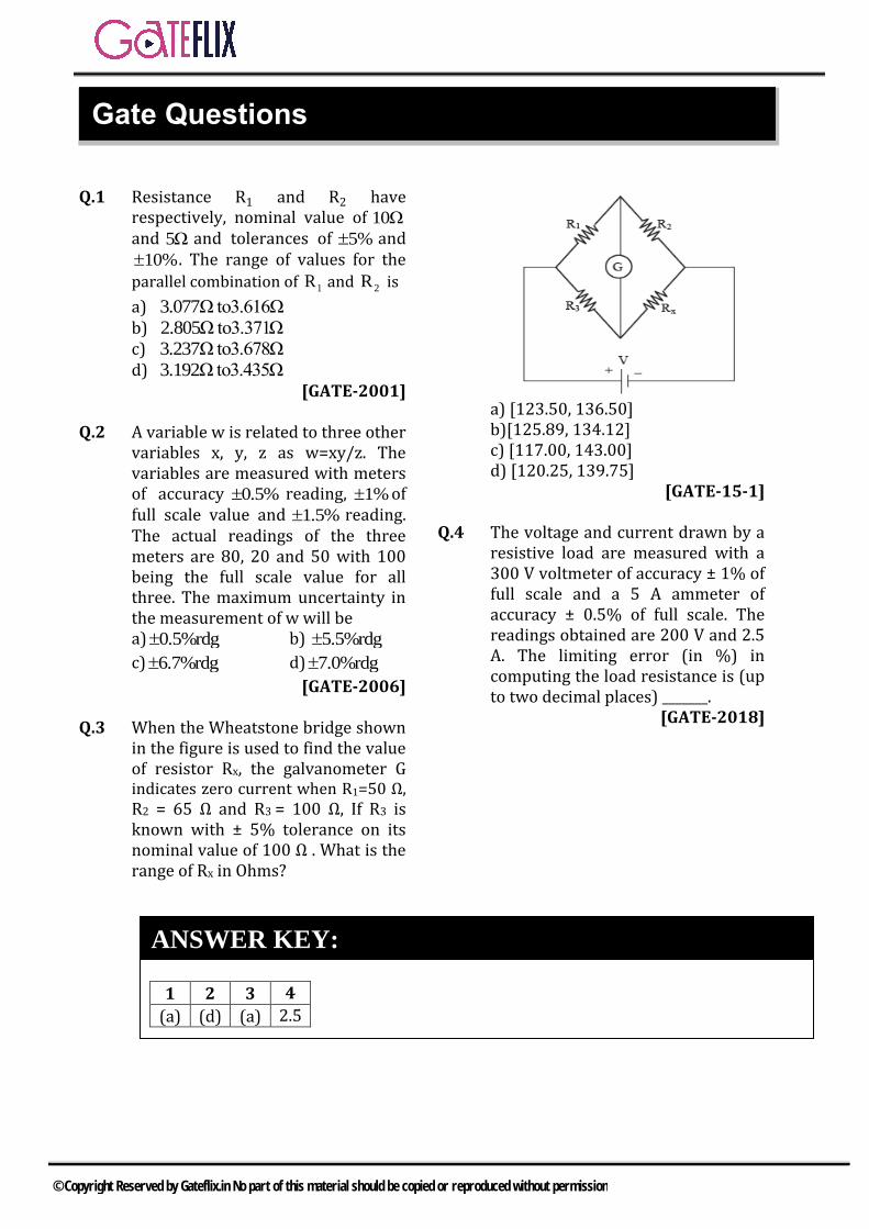
Q.3 When the Wheatstone bridge shown in the figure is used to find the value of resistor Rx, the galvanometer G indicates zero current when R1=50 Ω, R2 = 65 Ω and R3 = 100 Ω, If R3 is known with ± 5% tolerance on its nominal value of 100 Ω . What is the range of Rx in Ohms?
a) [123.50, 136.50]b)[125.89, 134.12] c) [117.00, 143.00]d) [120.25, 139.75]
[GATE-15-1]
Q.4 The voltage and current drawn by a resistive load are measured with a 300 V voltmeter of accuracy ± 1% of full scale and a 5 A ammeter of accuracy ± 0.5% of full scale. The readings obtained are 200 V and 2.5 A. The limiting error (in %) in computing the load resistance is (up to two decimal places) _______.
[GATE-2018]
1 2 3 4
(a) (d) (a) 2.5
ANSWER KEY:
Gate Questions
© Copyright Reserved by Gateflix.in No part of this material should be copied or reproduced without permission
Q.1 (a)
Range of 1
5R 10 10
100
9.5Ω to10.5Ω Range of
2
10R 5 5 4.5Ω to5.5Ω
100
1 2p
1 2
R RR
R R
p
9.5 4.5 10.5 5.5Range of R to
9.5 4.5 10.5 5.5
3.05Ω to3.61Ω
Q.2 (d) Full scale reading of all three =100 Readings of x=80 Readings of y=20 Readings of z=50
0.5 80δx 0.5% of reading 0.4
100
1 100δy 1% of full reading
100
1.5 501δz 1.5% of reading
100
0.75
Given xy
ωz
Taking log, we get logω logx logy logz
Differenting wrt ω we get δω δx δy δz
ω x y z
For maximum uncertainty
0.4 1 0.75100 7%
80 20 100
δω
ω
Q.3 (a) Weinbridge is balanced, R1, Rx = R2R3 50×Rx = 65×100 Rx = 130Ω
Now R3 = 100 ± 100×0.05 = 100 ± 5 = 95/105 Ω
2 3x
1
R R 65×105R = = =136.5Ω
R 50
x
65×95R = =123.5Ω
50Range of R is123.5 Ω to136.5 Ω
Q.4 2.5
Given : Voltmeter V 300 1% and
Ammeter A 5 0.5%
For V= 200, I = 2.5A
300%limiting error V 1 1.5%
200
5%limiting error A 0.5 1 %
2.5
V%limiting error R 1.5 1 2.5 %
I
EXPLANATIONS
© Copyright Reserved by Gateflix.in No part of this material should be copied or reproduced without permission
2.1 INTRODUCTION
A galvanometer is an instrument used for detecting presence of small currents or voltages in a circuit or for measuring their magnitudes. Galvanometers find their principal application in bridge and potentiometer measurements where their function is to indicate zero current. Therefore, a galvanometer in addition to being sensitive should have a stable zero a short periodic time and nearly critical damping.
2.1.1 D’ARSONVAL GALVANOMETER
The instruments are very commonly used in various methods of resistance measurement and also in d.c. potentiometer work. A sensitive galvanometer is one which produces a large deflection for a small current. We have current sensitivity, Si = G/500 K.
2.1.2 BALLISTIC GALVANOMETER
A ballistic galvanometer is used for measurement of quantity of electricity (charge) passed through it. In magnetic measurements, this quantity of electricity is due to an instantaneous emf induced in a search coil connected across the ballistic galvanometer. The instantaneous emf is induced in the search coil when the flux linking with the search coil is changed. The quantity of electricity passing through the galvanometer is proportional to the emf induced and hence to the change in flux linking with the search coil. The galvanometer can therefore be calibrated to read the charge directly. It does not show a steady deflection it oscillates with decreasing amplitude, the amplitude of the first deflection or swing or throw being proportional to the charge passing.
The construction of a ballistic galvanometer is similar to a d’Arsonval type galvanometer.
2.1.3 FLUX METER
The flux meter is a special type of ballistic galvanometer in which the controlling torque is very small and the electromagnetic damping is heavy. The construction of a flux meter is general the construction is similar to that of a moving coil milli-ammeter. A coil of small cross-section is suspended from a spring support by means of a single silk thread. The coil moves in the narrow gap of a permanent magnet. There are no control springs.
2.1.4 VIBRATION GALVANOMETERS
These galvanometers are of d’Arsonval type having a moving coil suspended between the pieces of a permanent magnet. When an alternating current is passed through the moving coil, an alternating deflecting torque is produced which makes the coil vibrate with a frequency equal to the frequency of the current passing. On account of inertia of the moving parts, the amplitude of vibrations is small. However, if the natural frequency of the moving system is made equal to the frequency of the current, mechanical resonance is obtained and the moving system vibrates with a large amplitude. Vibration galvanometers are suitable for use at power and low audio frequencies, but they are mainly used at power frequencies.
2.2 INDICATING INSTRUMENT
i)
ii)
2 ANALOG INSTRUMENTS
© Copyright Reserved by Gateflix.in No part of this material should be copied or reproduced without permission
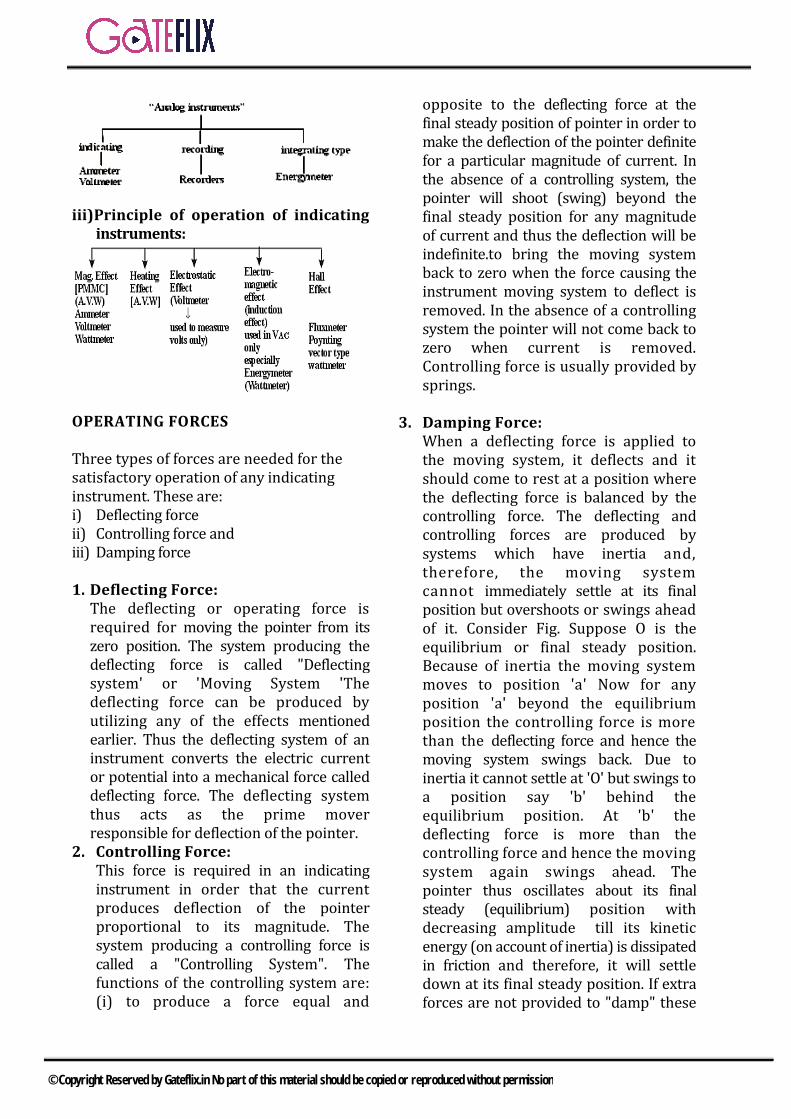
iii)Principle of operation of indicatinginstruments:
OPERATING FORCES
Three types of forces are needed for the satisfactory operation of any indicating instrument. These are: i) Deflecting forceii) Controlling force andiii) Damping force
1. Deflecting Force:The deflecting or operating force isrequired for moving the pointer from itszero position. The system producing thedeflecting force is called "Deflectingsystem' or 'Moving System 'Thedeflecting force can be produced byutilizing any of the effects mentionedearlier. Thus the deflecting system of aninstrument converts the electric currentor potential into a mechanical force calleddeflecting force. The deflecting systemthus acts as the prime moverresponsible for deflection of the pointer.
2. Controlling Force:This force is required in an indicatinginstrument in order that the currentproduces deflection of the pointerproportional to its magnitude. Thesystem producing a controlling force iscalled a "Controlling System". Thefunctions of the controlling system are:(i) to produce a force equal and
opposite to the deflecting force at the final steady position of pointer in order to make the deflection of the pointer definite for a particular magnitude of current. In the absence of a controlling system, the pointer will shoot (swing) beyond the final steady position for any magnitude of current and thus the deflection will be indefinite.to bring the moving system back to zero when the force causing the instrument moving system to deflect is removed. In the absence of a controlling system the pointer will not come back to zero when current is removed. Controlling force is usually provided by springs.
3. Damping Force:When a deflecting force is applied tothe moving system, it deflects and itshould come to rest at a position wherethe deflecting force is balanced by thecontrolling force. The deflecting andcontrolling forces are produced bysystems which have inertia and,therefore, the moving systemcannot immediately settle at its finalposition but overshoots or swings aheadof it. Consider Fig. Suppose O is theequilibrium or final steady position.Because of inertia the moving systemmoves to position 'a' Now for anyposition 'a' beyond the equilibriumposition the controlling force is morethan the deflecting force and hence themoving system swings back. Due toinertia it cannot settle at 'O' but swings toa position say 'b' behind theequilibrium position. At 'b' thedeflecting force is more than thecontrolling force and hence the movingsystem again swings ahead. Thepointer thus oscillates about its finalsteady (equilibrium) position withdecreasing amplitude till its kineticenergy (on account of inertia) is dissipatedin friction and therefore, it will settledown at its final steady position. If extraforces are not provided to "damp" these
© Copyright Reserved by Gateflix.in No part of this material should be copied or reproduced without permission
oscillations. the moving system will take a considerable time to settle to the final position and hence lime consumed in taking readings will be very large. Therefore damping forces are necessary so that the moving system comes to its equilibrium position rapidly and smoothly without any oscillations.
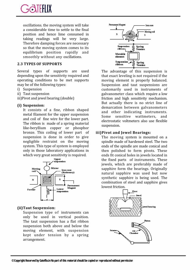
2.3 TYPES OF SUPPORTS
Several types of supports are used depending upon the sensitivity required and operating conditions to be met supports may be of the following types: i) Suspensionii) Taut suspensioniii)Pivot and jewel bearing (double)
(i) Suspension: It consists of a fine, ribbon shaped metal filament for the upper suspension and coil of fine wire for the lower part. The ribbon is made of a spring material like-beryllium copper or phosphor bronze. This coiling of lower part of suspension is done in order to give negligible restraint on the moving system. This type of system is employed only in those laboratory applications in which very great sensitivity is required.
(ii) Taut Suspension: Suspension type o f instruments can only be used in vertical position. The taut suspension has a flat ribbon suspension both above and below the moving element, with suspension kept under tension by a spring arrangement.
The advantage of this suspension is that exact leveling is not required if the moving element is properly balanced. Suspension and taut suspensions are customarily used in instruments of galvanometer class which require a low friction and high sensitivity mechanism. But actually there is no strict line of demarcation between galvanometers and other indicating instruments. Some sensitive wattmeters, and electrostatic voltmeters also use flexible suspension.
iii)Pivot and Jewel Bearings:The moving system is mounted on aspindle made of hardened steel. The twoends of the spindle are made conical andthen polished to form pivots. Theseends fit conical holes in jewels located inthe fixed parts of instruments. Thesejewels, which are preferably made ofsapphire form the bearings. Originallynatural sapphire was used but nowsynthetic sapphire is being used. Thecombination of steel and sapphire giveslowest friction.
© Copyright Reserved by Gateflix.in No part of this material should be copied or reproduced without permission
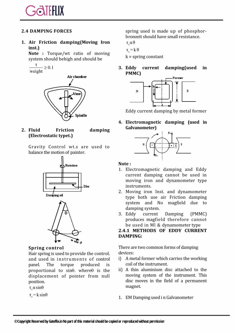
2.4 DAMPING FORCES
1. Air Friction damping(Moving Ironinst.)Note : Torque/wt ratio of movingsystem should behigh and should be
τ0.1
weight
2. Fluid Friction damping (Electrostatic typet.)
Gravity Control wt.s are used to balance the motion of painter.
Spring control Hair spring is used to provide the control. and used in i n st rume n t s of control panel. The torque produced is proportional to sin. where is the displacement of pointer from null position.
c
c
τ αsinθ
τ =k sinθ
spring used is made up of phosphor-bronzeit should have small resistance.
c
c
τ αθ
τ = kθ
k = spring constant
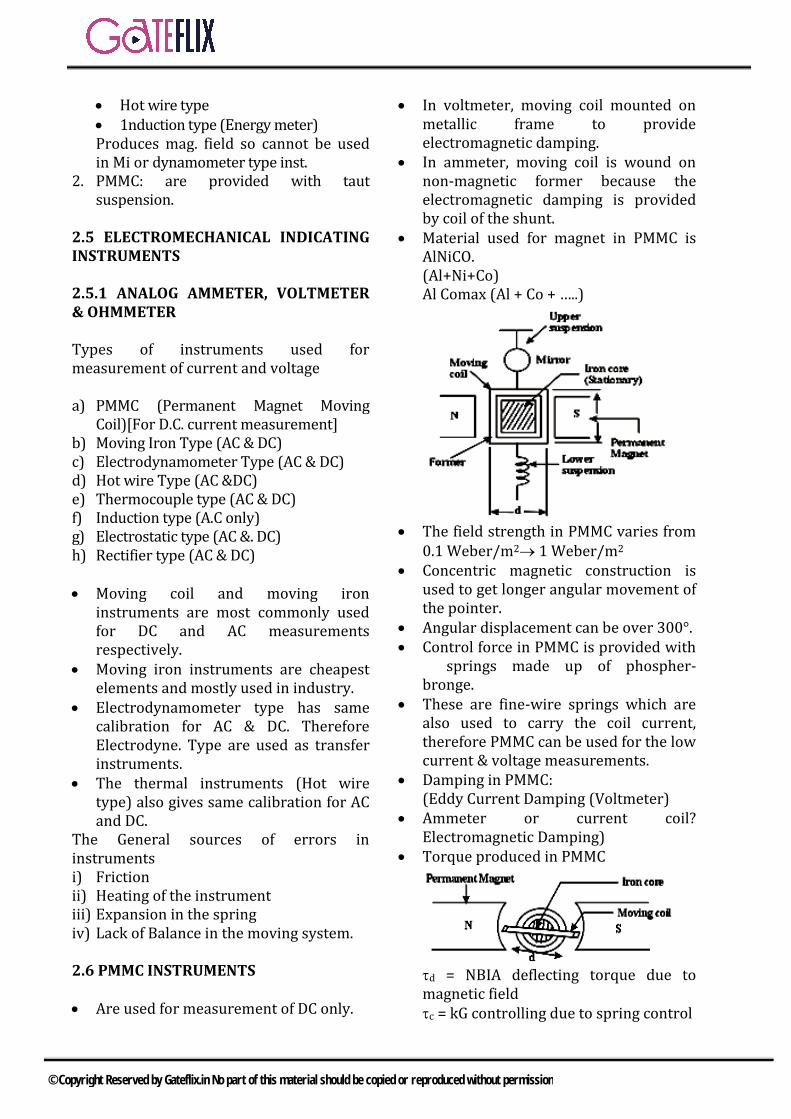
3. Eddy current damping(used inPMMC)
Eddy current damping by metal former
4. Electromagnetic damping (used inGalvanometer)
Note : 1. Electromagnetic damping and Eddy
current damping cannot be used inmoving iron and dynamometer typeinstruments.
2. Moving iron Inst. and dynamometertype both use air Friction dampingsystem and No magfield due todamping system.
3. Eddy current Damping (PMMC)produces magfield therefore cannotbe used in Ml & dynamometer type
2.4.1 METHODS OF EDDY CURRENT DAMPING:
There are two common forms of damping devices: i) A metal former which carries the working
coil of the instrument.ii) A thin aluminium disc attached to the
moving system of the instrument. Thisdisc moves in the field of a permanentmagnet.
1. EM Damping used i n Galvanometer
© Copyright Reserved by Gateflix.in No part of this material should be copied or reproduced without permission
Hot wire type 1nduction type (Energy meter)Produces mag. field so cannot be used in Mi or dynamometer type inst.
2. PMMC: are provided with tautsuspension.
2.5 ELECTROMECHANICAL INDICATING INSTRUMENTS
2.5.1 ANALOG AMMETER, VOLTMETER & OHMMETER
Types of instruments used for measurement of current and voltage
a) PMMC (Permanent Magnet MovingCoil)[For D.C. current measurement]
b) Moving Iron Type (AC & DC)c) Electrodynamometer Type (AC & DC)d) Hot wire Type (AC &DC)e) Thermocouple type (AC & DC)f) Induction type (A.C only)g) Electrostatic type (AC &. DC)h) Rectifier type (AC & DC)
Moving coil and moving ironinstruments are most commonly usedfor DC and AC measurementsrespectively.
Moving iron instruments are cheapestelements and mostly used in industry.
Electrodynamometer type has samecalibration for AC & DC. ThereforeElectrodyne. Type are used as transferinstruments.
The thermal instruments (Hot wiretype) also gives same calibration for ACand DC.
The General sources of errors in instruments i) Frictionii) Heating of the instrumentiii) Expansion in the springiv) Lack of Balance in the moving system.
2.6 PMMC INSTRUMENTS
Are used for measurement of DC only.
In voltmeter, moving coil mounted onmetallic frame to provideelectromagnetic damping.
In ammeter, moving coil is wound onnon-magnetic former because theelectromagnetic damping is providedby coil of the shunt.
Material used for magnet in PMMC isAlNiCO.(Al+Ni+Co)Al Comax (Al + Co + …..)
The field strength in PMMC varies from0.1 Weber/m2 1 Weber/m2
Concentric magnetic construction isused to get longer angular movement ofthe pointer.
Angular displacement can be over 300°. Control force in PMMC is provided with
springs made up of phospher- bronge.
These are fine-wire springs which arealso used to carry the coil current,therefore PMMC can be used for the lowcurrent & voltage measurements.
Damping in PMMC:(Eddy Current Damping (Voltmeter)
Ammeter or current coil? Electromagnetic Damping)
Torque produced in PMMC
d = NBIA deflecting torque due to magnetic field c = kG controlling due to spring control
© Copyright Reserved by Gateflix.in No part of this material should be copied or reproduced without permission
At balance NBIA - k = G l TC = Td KQ = NBIA deflection produced in the instrument
Gθ= I
k
θαI
were G = NBA (Hence the scale in PMMC is Linear)
Iθα
k
Hence with the ageing effect of springthe reading will be more.
Also
θαB
θαN
θαA
Hence with the decreasing mag. field ofmagnets. reading will be less.
Note: If control force in the any type of
instrument is absent then pointer willbe moving beyond
The full scale. If damping force is absent the pointer
will oscillate around the mean position.
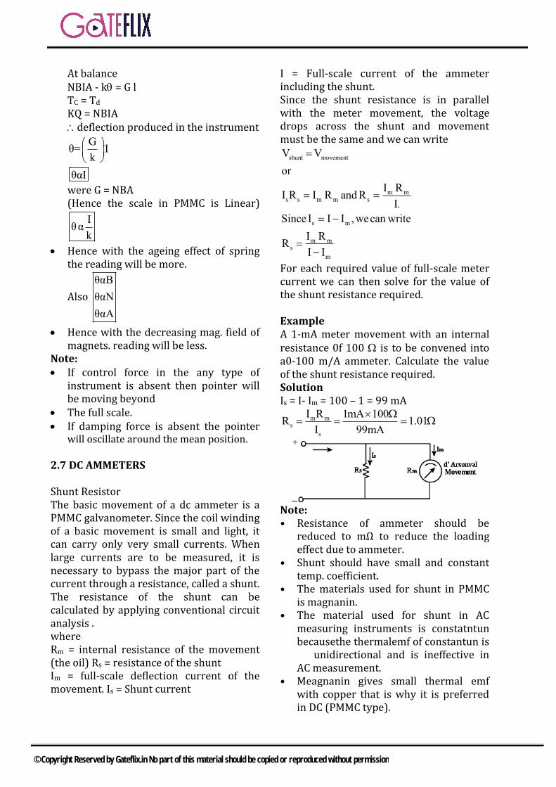
2.7 DC AMMETERS
Shunt Resistor The basic movement of a dc ammeter is a PMMC galvanometer. Since the coil winding of a basic movement is small and light, it can carry only very small currents. When large currents are to be measured, it is necessary to bypass the major part of the current through a resistance, called a shunt. The resistance of the shunt can be calculated by applying conventional circuit analysis . where Rm = internal resistance of the movement (the oil) Rs = resistance of the shunt Im = full-scale deflection current of the movement. Is = Shunt current
I = Full-scale current of the ammeter including the shunt. Since the shunt resistance is in parallel with the meter movement, the voltage drops across the shunt and movement must be the same and we can write
shunt movement
m ms s m m s
s m
m ms
m
V V
or
I RI R I R and R
I.
Since I I I , wecan write
I RR
I I
For each required value of full-scale meter current we can then solve for the value of the shunt resistance required.
Example A 1-mA meter movement with an internal resistance 0f 100 is to be convened into a0-100 m/A ammeter. Calculate the value of the shunt resistance required. Solution Is = I- Im = 100 – 1 = 99 mA
m ms
s
I R 1mA 100R 1.01
I 99mA
Note: • Resistance of ammeter should be
reduced to mΩ to reduce the loadingeffect due to ammeter.
• Shunt should have small and constanttemp. coefficient.
• The materials used for shunt in PMMCis magnanin.
• The material used for shunt in ACmeasuring instruments is constatntunbecausethe thermalemf of constantun is unidirectional and is ineffective in AC measurement.
• Meagnanin gives small thermal emfwith copper that is why it is preferredin DC (PMMC type).
© Copyright Reserved by Gateflix.in No part of this material should be copied or reproduced without permission

Effect of temperature change in ammeter reading: As temp. increases the resistance of copper increase and this result into change of reading of instrument because coil is made up of copper and shunt is made up of magnanin which has different temp coeff. To reduce the effect of temp, a resistance having very small temp, coeff. made up of magnanin is connected in series with the coil. And this coil is called “Swamping Resistance”
2.7.1 MULTI RANGE AMMETERS
There are two methods to achieve multirange of the ammeter. i) By using a no. of shunts.
m 1Sh1 1
1 m
R IR m
m 1 I
m 2Sh2 2
2 m
R IR m
m 1 I
ii) By using universal shunt or Ayrtonshunt- for dc only
mI
I
m 12
2
RR
m I
R RR
m
2.8 VOLTMETER MULTIPLIERS
V = ifs (Rs + 4)
Rs = fs
VG
i
Rs= (m – 1)Rm
m = fs
V
V
Vfs Voltage Across coil at full scale deflection m multiplying factor Sensitivity of Voltmeter:
v
fs
1S unit / v
I
Note: If range 0 - 100 V. Sv = 100 /v. then(Rs + Rm) = 100 x 100 = 10 k = RT
s m
fs
VR R
I
s v mR VS R
Rs – Multiplier resistance
2.8.1 MULTIRANGE DC VOLTMETERS:
Multirange of dc voltmeters can be obtained by individual multipliers. i) Using individual multipliersii)Using potential dividers.
(i) Using individual multipliers
1s1 1 m 1
VR (m 1)R m
v
2s2 2 m 2
VR (m 1)R m
v
ii) Using pot. Divider
1 1 m 1 1R (m 1)R m V / v
© Copyright Reserved by Gateflix.in No part of this material should be copied or reproduced without permission
2 2 1 m 2 2R (m m )R m V / v
3 3 2 m 1 3R (m m )R m V / v
Note: 1. Current range of multirange ammeter
is1-50 A.2. Vol. range far multirange voltmeter is
moderate.3. The loading effect reduces the
reading of instruments.
2.8.2 SOURCES OF ERRORS IN PMMC
i) Magnet ageing and temperature.ii) Spring ageing and temperatureiii) Change in resistance of coil with
temperature2I dL
2k d
2I
2.8.3 ADVANTAGES &DISADVANTAGES OF PMMC
1. Torque to wt. ratio is high2. Sensitivity is high.3. Losses arc low (25 - 200 w)4. Accuracy is high.5. Single instrument can be used for
different range.6. They have uniform scale.
Disadvantages 1. Their cost is high2. They are used for measurement of
DC.
2.9 MOVING IRON INSTRUMENTS (MI)
In the moving iron instruments vane made upon soft iron and high
permeability steel forms a moving element of the system. It is so situated that it can move in the magnetic field of a stationary coil carrying the current. The iron vane always try to adjust alone the path of minimum reluctance.
2.9.1 EXPRESSION FOR TORQUE:
Torque produced in the moving part2
d
I dLT
2 d
deflection of pointerL inductance of coil
2.9.2 CONTROL FORCE :
is provided by the spring
Tc= K where k = Control spring const. = deflection, rad. At balance
deflection is proportional to square of current and hence the scale of moving iron instruments is nonlinear. For Linear Scale:
22 I dL
2k d
for scale to be linear
dLcons tan t
d
Note: Control force for panel type instruments is provided with gravity control and control force for laboratory type instrument is provided with spring. Damping Air Friction damping is used.
Note: i) The Mag. field if the coil is very small.
(0.006 - 0.007wb/m2)ii) Therefore eddy current damping cannot
be used in moving iron typeinstruments because field of eddycurrents may distort the field of coils.
© Copyright Reserved by Gateflix.in No part of this material should be copied or reproduced without permission
2.10 CLASSIFICATION OF MOVING IRON INSTRUMENTS
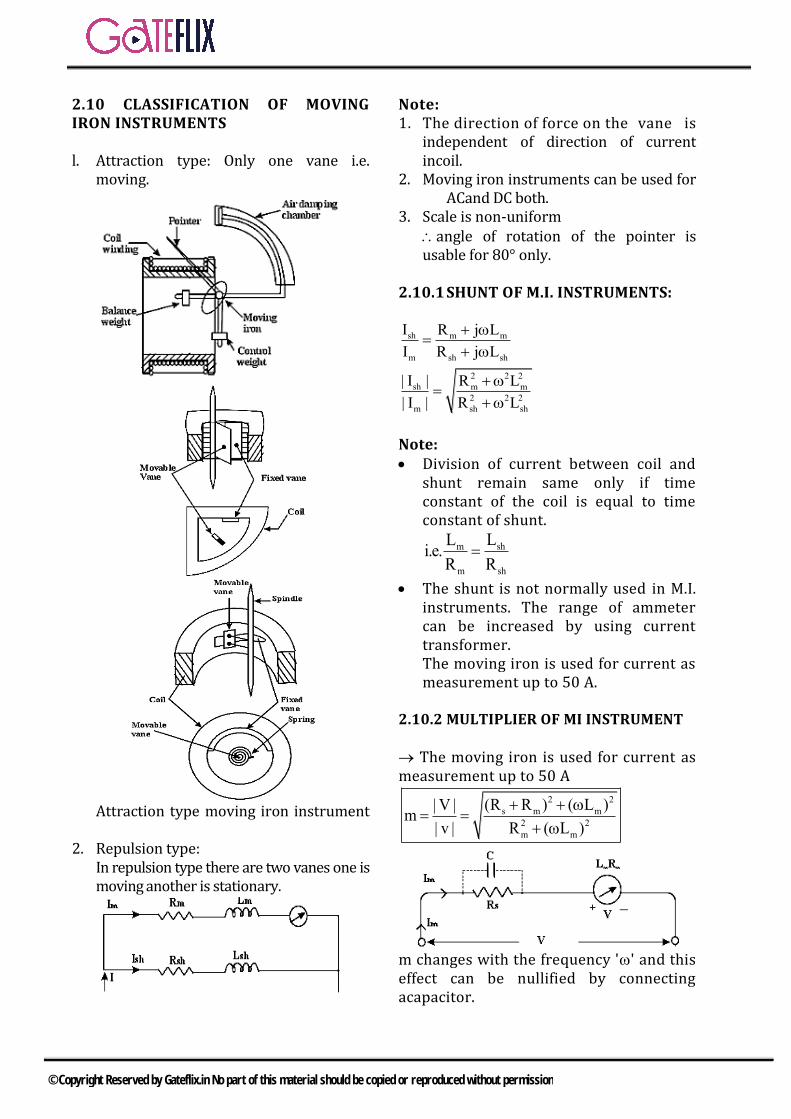
l. Attraction type: Only one vane i.e.moving.
Attraction type moving iron instrument
2. Repulsion type:In repulsion type there are two vanes one ismoving another is stationary.
Note: 1. The direction of force on the vane is
independent of direction of currentincoil.
2. Moving iron instruments can be used forACand DC both.
3. Scale is non-uniformangle of rotation of the pointer isusable for 80° only.
2.10.1 SHUNT OF M.I. INSTRUMENTS:
sh m m
m sh sh
2 2 2
sh m m
2 2 2
m sh sh
I R j L
I R j L
| I | R L
| I | R L
Note: Division of current between coil and
shunt remain same only if timeconstant of the coil is equal to timeconstant of shunt.
shm
m sh
LLi.e.
R R
The shunt is not normally used in M.I.instruments. The range of ammetercan be increased by using currenttransformer.The moving iron is used for current asmeasurement up to 50 A.
2.10.2 MULTIPLIER OF MI INSTRUMENT
The moving iron is used for current as measurement up to 50 A
2 2
s m m
2 2
m m
(R R ) ( L )| V |m
| v | R ( L )
m changes with the frequency '' and this effect can be nullified by connecting acapacitor.
© Copyright Reserved by Gateflix.in No part of this material should be copied or reproduced without permission
RS multiplier resistance.
Note: • Inductance of attraction type is less
than repulsion type.• Scale of repulsion type can be made
almost linear.
2.10.3 ERRORS IN MOVING IRON INSTRUMENTS:
i) Hysteresis: The reading of the metercan be different for the different cyclesof the current of the coil due tohysteresis effect of iron vane
ii) Frequency Error:
m2 2
m s m
VI
(R R ) ( L )
as frequency increases Im decreases
and2
mI will decrease for same
voltage. The effect can be nullified by using a capacitor.
2
s
LC 0.41 farad
R
iii) Eddy current error:Eddy currents in moving ironinstruments are ineffective from d.c. to125 Hz. therefore M.I instrument areused only upto 125Hz.
Note: Moving iron instruments are mostly used in industry and they require different Calibration of A.C. and D.C.
2.10.4 ADVANTAGES AND DISADVANTAGES OF M.I. INSTRUMENTS
• Less Friction Errors• Cheapness• Robustness• Accuracy: The initial accuracy of high
grade instruments is stated to be 0.75
percent for frequencies between 25 to 125 Hz and they may be expected to be accurate within 0.2% to 0.3% a 50 Hz if carefully designed.
• Scale: The scale of moving ironinstruments is no uniform and iscramped at the lower end andtherefore accurate readings are notpossible at this end
• Errors: These instruments aresubjected to serious errors due tohysteresis, frequency changes andstray magnetic fields.
• Waveform errors
Note: 1. The moving coil instruments are used
in aircraft and aerospace industriesbecause They provide self-shielding tomagnetic fields.
2. Sensitivity of MI instruments issmaller than PMMC.
3. Accuracy of MI instruments is lessthan PMMC.
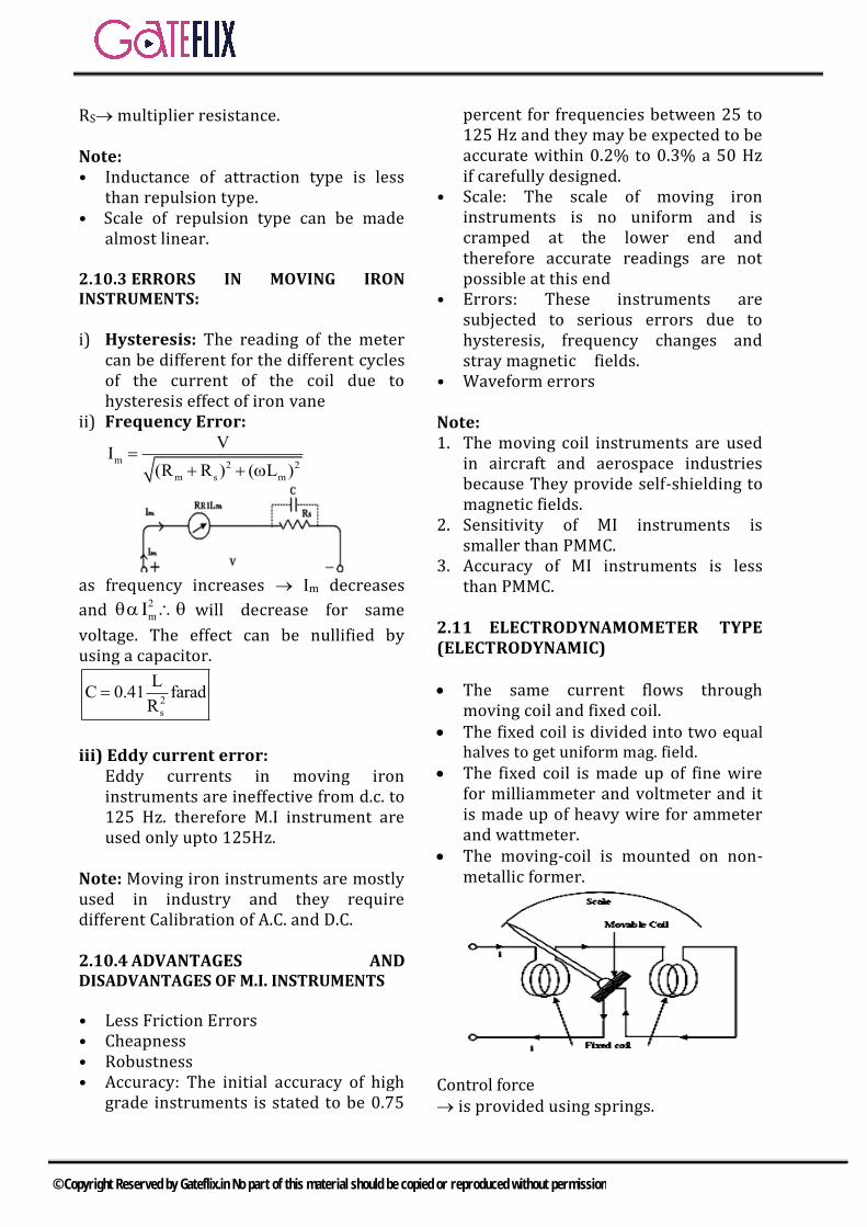
2.11 ELECTRODYNAMOMETER TYPE (ELECTRODYNAMIC)
The same current flows throughmoving coil and fixed coil.
The fixed coil is divided into two equalhalves to get uniform mag. field.
The fixed coil is made up of fine wirefor milliammeter and voltmeter and itis made up of heavy wire for ammeterand wattmeter.
The moving-coil is mounted on non-metallic former.
Control force is provided using springs.
© Copyright Reserved by Gateflix.in No part of this material should be copied or reproduced without permission
Damping force air friction damping is used. Eddy current damping cannot be used because that can distort the magnetic field of the coil. The magnetic field of the coil is very small. (0.005 - 0.006) wb/m2 same as in case of MI instruments Note: The instrument is provided with shielding with high permeability alloy against the external magnetic field.
2.11.1 EXPRESSION OF TORQUE
Circuit representation of Electrodynamometer Instrument For DC
1 2
dMT I I
d
but I1=I2
2 dMT I
d
where M is mutual inductance between the coils.
For AC 1 2
dMT I I cos
d
but I1 = I2 , = 0
2 dMT I
d
Now Torque in control spring TC = K At balance
K = I2dM
d2
2I dMI
K d
hence scale of electro dynamometer type is non-linear.
Electro dynamometer typeinstruments give same deflection forAC and DC these devices can be calibrated byusing DC and can be used for ACmeasurement.
These instruments are also calledtransfer instrument.
These instruments are mostly used inlabs.
Their sensitivity is smaller thansensitivity of PMMC and also smallerthan MI instruments.
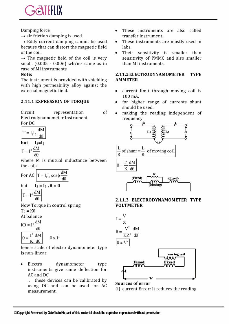
2.11.2 ELECTRODYNAMOMETER TYPE AMMETER
current limit through moving coil is100 mA.
for higher range of currents shuntshould be used.
making the reading independent offrequency.
L Lof shunt = of moving coi1
R R
2I dM
K d
2.11.3 ELECTRODYNAMOMETER TYPE VOLTMETER
VI
Z
2
2
V dM
KZ d
2V
Sources of error (i) current Error: It reduces the reading
© Copyright Reserved by Gateflix.in No part of this material should be copied or reproduced without permission
(ii) Frequency error: As , Z men in case of voltmeter, reading is reduced
2
1as
z
2.11.4 ADVANTAGE & DISADVANTAGE
i) Accuracy of electrodynamometer typeis very high.
ii) A.C. electro dynamometer typevoltmeter is most accurate.
iii) the effect of external magnetic field onelectro dynamometer type instrumentcan be reduced by using “AstaticSystem”.
iv) Frequency range forelectrodynamometer type instrumentis d.c.-125 Hz but it can be 15 Hz - 1000Hz for low grade instruments and it canbe even up to 10 KHz with astaticsystem
v) The electrodynamometer typeinstruments follows the square lawonly for 0 varying.-45° to + 45°C or 45° to 135°cM = Mmax cos sin
2I sin
iv) Sensitivity of electrodynamometertype inst. Is low. (10-30/v)Errors in Electrodynamometer Wattmeters
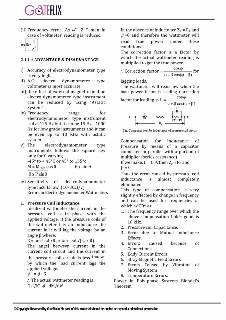
1. Pressure Coil InductanceIdealized wattmeter the current in thepressure coil is in phase with theapplied voltage. If the pressure coils ofthe wattmeter has an inductance thecurrent in it will lag the voltage by anangle β where:β = tan-1 ωL/Rp = tan-1 ωL/(rp + R)The angel between current in thecurrent coil circuit and the current in
the pressure coil circuit is less than ,
by which the load current lags theapplied voltage. ` = - β
The actual wattmeter reading is :
(IPI/K) ` dM/d
In the absence of inductance Zp = Rp and =0 and therefore the wattmeter will
read true power under these conditions. The correction factor is a factor by which the actual wattmeter reading is multiplied to get the true power.
Correction factor cos
cos cos( )
for
lagging loads. The wattmeter will read low when the load power factor is leading Correction
factor for leading p.f. cos
cos cos( )
Compensation for Inductance of Pressure by means of a capacitor connected in parallel with a portion of multiplier (series resistance) If we make, L = Cr2, then ZpRP and
0
Thus the error caused by pressure coil inductance is almost completely eliminated. This type of compensation is very slightly effected by change in frequency and can be used for frequencies at which ω2C2r2<< 1. The frequency range over which the
above compensation holds good is10 kHz.
2. Pressure coil Capacitance.3. Error due to Mutual Inductance
Effects.4. Errors caused because of
Connections.5. Eddy Current Errors6. Stray Magnetic Field Errors7. Errors Caused by Vibration of
Moving System8. Temperature Errors.
Power in Poly-phase Systems Blondel’s Theorem.
© Copyright Reserved by Gateflix.in No part of this material should be copied or reproduced without permission
If a network is supplied through n conductors, the total power is measured by summing the readings of n wattmeter’s so arranged that a current element of a wattmeter is in each line and the corresponding. If the common point is located on one of the lines, then the power may be measured by n – 1 wattmeter’s. Energy is the total power delivered or consumed over a time interval, that is, Energy = power × time.
W = t
0
vi dt
Unit of energy is joule or wall second which is 1 watt over an interval of one second. Larger unit is used – then kilowatt hour.
2.11.5 ENERGY METERS FOR A.C. CIRCUITS
Induction type of energy meters are universally used for measurement of energy in domestic and industrial a.c. circuit. Induction type of meters possess lower friction and higher torque/weight ratio. Also induction type meters are inexpensive and accurate and retain their accuracy over a wide range of loads and temperature conditions.
2.11.6 THEORY OF INDUCTION TYPE METERS
In all induction instruments we have two fluxes produced by current flowing in the windings of the instrument. These fluxes are alternating in nature and so they produce emfs in a metallic disc or a drum provided for the purpose. These emfs in turn circulate eddy currents in the metallic disc or the drum. Flux 1, induced emf and this induced emf
will prudence an eddy current i. Similarly flux 2 will produce an eddy current i2.
Total torque is the sum of these two torques. Theory and Operation of Single Phase Energy Meters
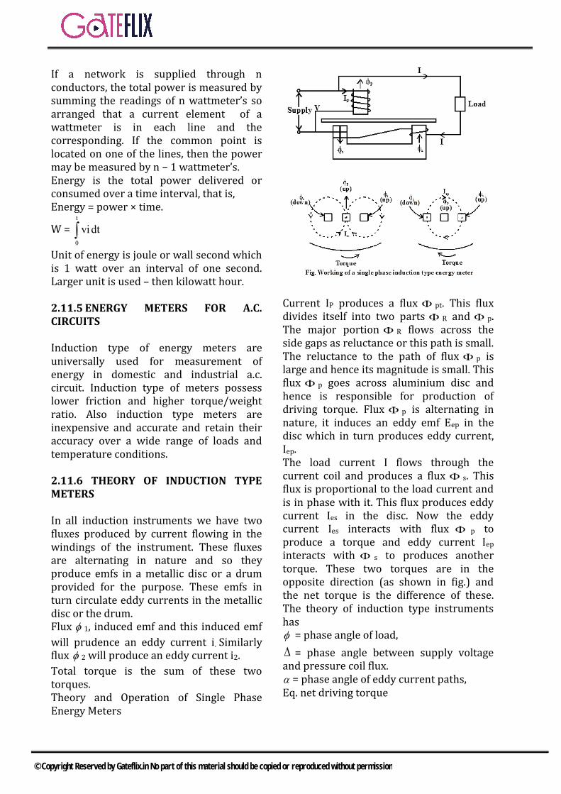
Current IP produces a flux pt. This flux divides itself into two parts R and p. The major portion R flows across the side gaps as reluctance or this path is small. The reluctance to the path of flux p is large and hence its magnitude is small. This flux p goes across aluminium disc and hence is responsible for production of driving torque. Flux p is alternating in nature, it induces an eddy emf Eep in the disc which in turn produces eddy current, Iep. The load current I flows through the current coil and produces a flux s. This flux is proportional to the load current and is in phase with it. This flux produces eddy current Ies in the disc. Now the eddy current Ies interacts with flux p to produce a torque and eddy current Iep interacts with s to produces another torque. These two torques are in the opposite direction (as shown in fig.) and the net torque is the difference of these. The theory of induction type instruments has = phase angle of load,
= phase angle between supply voltage and pressure coil flux. = phase angle of eddy current paths, Eq. net driving torque
© Copyright Reserved by Gateflix.in No part of this material should be copied or reproduced without permission
Td 1 2f
Zsin cos = K1 1 2
f
Zsin
cos
=phase angle between fluxes p and s
= ( )
If f, Z and are constant, T4 = K3VI sin ( )
Speed, N = KVI sin (900 - ) = KVI cos
= K (power) Thus in order that the speed of rotation is
proportional to power, angle should be equal to 900. Hence the flux p, must be made to lag the supply voltage by exactly 900. Total number of revolution
N dt K VI sin ( )dt K (VI cos )dt K (power)dt K (energy)
2.11.7 LAG ADJUSTMENT DEVICE
The meter will register true energy only if
the angle is made equal to 900 The shunt magnet flux p can be brought exact quadrature with applied voltage V. This adjustment is known as “lag adjustment”. Sometimes it is referred to as “power factor”, “quadrature” or “inductive load adjustment” Compensation • Light Load or Friction Compensation• Over – Load Compensation• Voltage Compensation• Temperature Compensation• Errors in Single Phase Energy Meters
Adjustments in Single Phase Energy Meters 1. Preliminary Light Load Adjustment2. Full Load Unity Factor Adjustment3. Lag Adjustment (Low Power Factor
Adjustment)4. Unit p.f. and low p.f. adjustments5. Light Load Adjustment6. Full load – unity power factor and light
load adjustments7. The performance is rechecked at 0.5 p.f.
lagging.
8. Creep Adjustment
2.11.8 TESTING OF ENERGY METERS PHANTOM LOADING
When the current rating of a meter under test is high a test with actual loading arrangements would involve a considerable waste of power. In order to avoid this “Phantom” or “Fictitious” loading is done. Phantom loading consists of supplying the pressure circuit from a circuit of required normal voltage, and the current circuit from a separate low voltage supply. It is possible to circulate the rated current through the current circuit with a low voltage supply as the impedance of this circuit is very low.
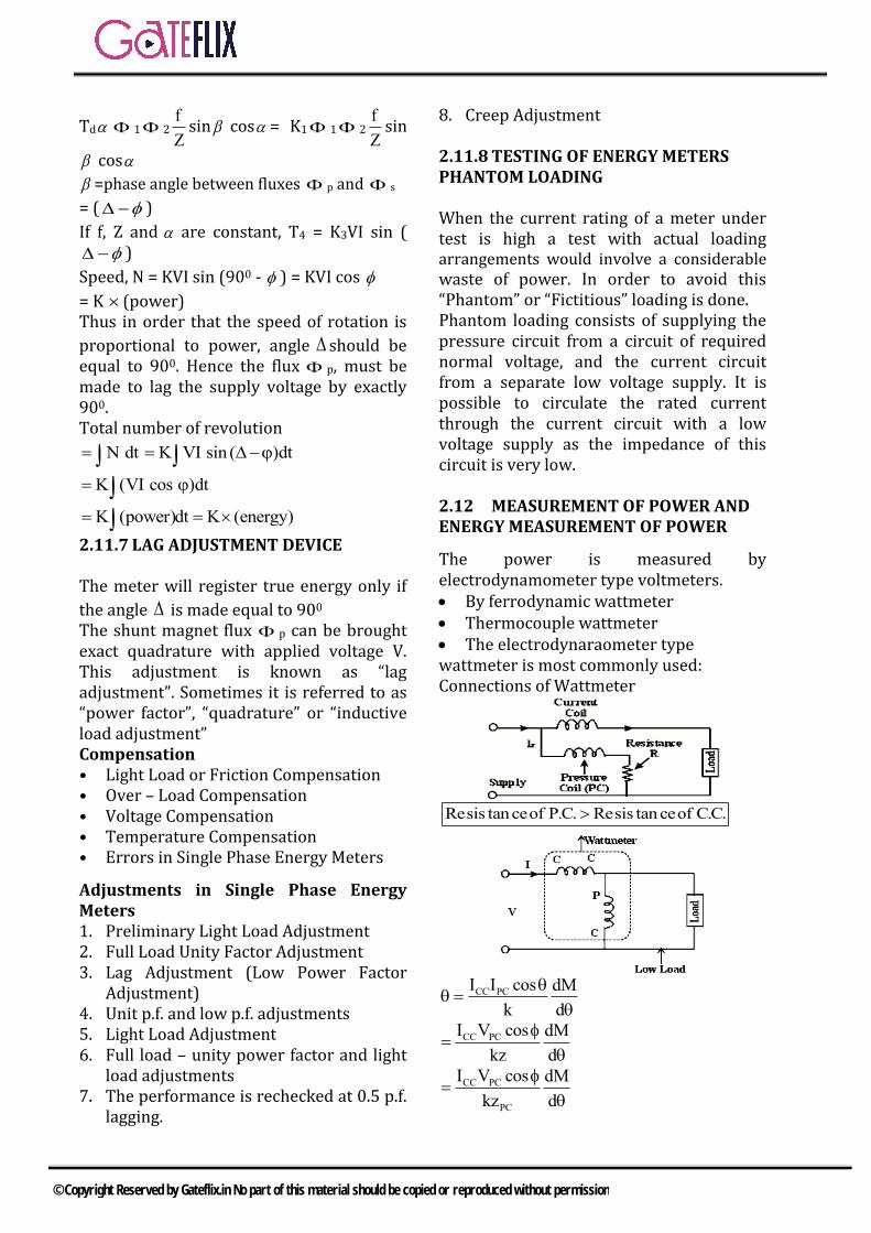
2.12 MEASUREMENT OF POWER AND ENERGY MEASUREMENT OF POWER
The power is measured by electrodynamometer type voltmeters. By ferrodynamic wattmeter Thermocouple wattmeter The electrodynaraometer typewattmeter is most commonly used: Connections of Wattmeter
Resis tan ceof P.C. Resis tan ceof C.C.
CC PCI I cos dM
k d
CC PCI V cos dM
kz d
CC PC
PC
I V cos dM
kz d
© Copyright Reserved by Gateflix.in No part of this material should be copied or reproduced without permission
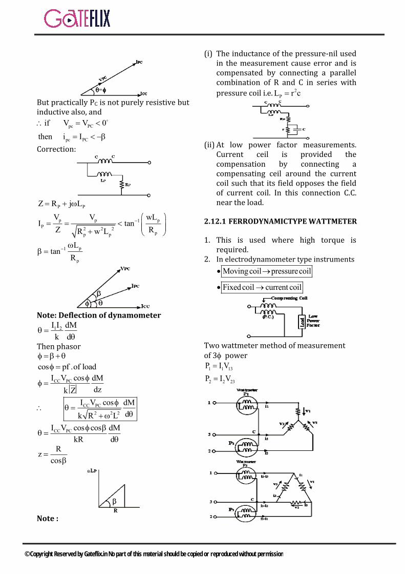
But practically PC is not purely resistive but inductive also, and
pc PC
pc PC
if V V 0
then i I
Correction:
P PZ R j L
p p p1
P2 2 2
pp p
V V wLI tan
Z RR w L
p1
p
Ltan
R
Note: Deflection of dynamometer
1 2I I dM
k d
Then phasor
cos pf .of load
CC PCI V cos dM
dzk Z
CC PC
2 2 2
I V cos dM
dk R L
CC PCI V cos cos dM
kR d
Rz
cos
Note :
(i) The inductance of the pressure-nil used in the measurement cause error and is compensated by connecting a parallel combination of R and C in series with
pressure coil i.e. 2
PL r c
(ii) At low power factor measurements. Current ceil is provided the compensation by connecting a compensating ceil around the current coil such that its field opposes the field of current coil. In this connection C.C. near the load.
2.12.1 FERRODYNAMICTYPE WATTMETER
1. This is used where high torque isrequired.
2. In electrodynamometer type instruments
Moving coil pressurecoil
Fixed coil current coil
Two wattmeter method of measurement of 3 power
1 1 13
2 2 23
P I V
P I V
© Copyright Reserved by Gateflix.in No part of this material should be copied or reproduced without permission
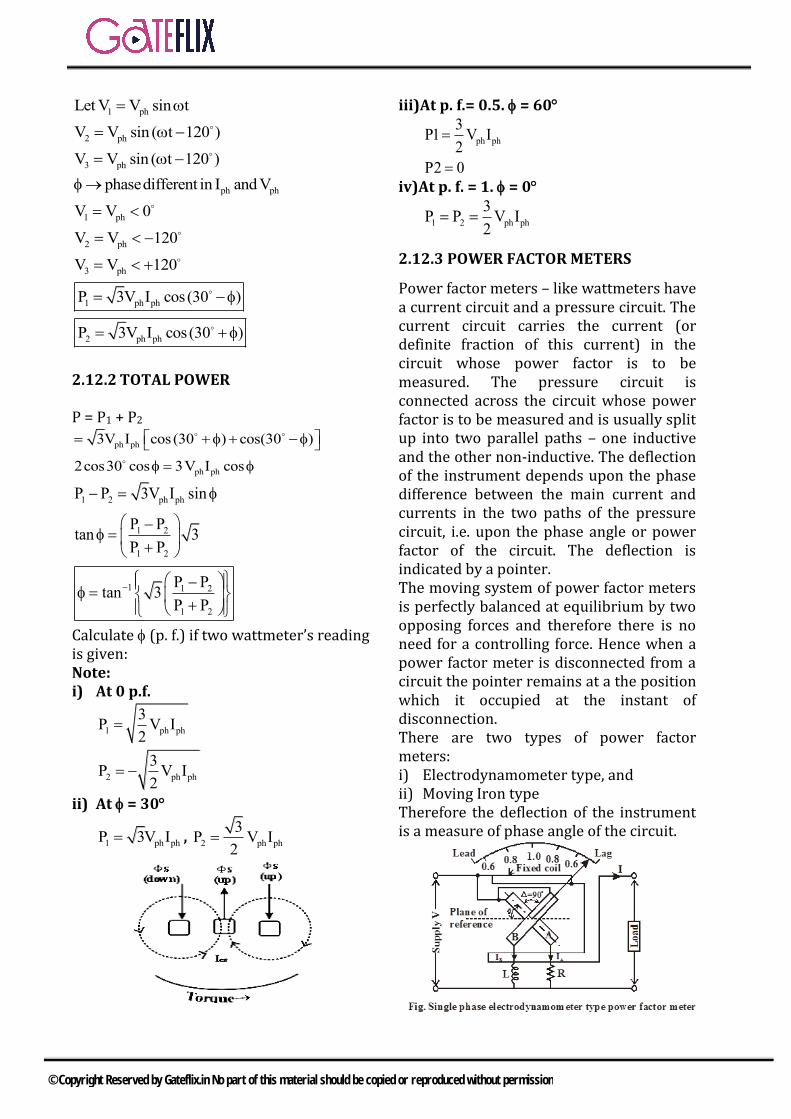
1 phLet V V sin t
2 phV V sin ( t 120 )
3 phV V sin ( t 120 )
ph phphasedifferent in I and V
1 phV V 0
2 phV V 120
3 phV V 120
1 ph phP 3V I cos(30 )
2 ph phP 3V I cos(30 )
2.12.2 TOTAL POWER
P = P1 + P2
ph ph
ph ph
3V I cos (30 ) cos(30 )
2cos30 cos 3V I cos
1 2 ph ph
1 2
1 2
1 1 2
1 2
P P 3V I sin
P Ptan 3
P P
P Ptan 3
P P
Calculate (p. f.) if two wattmeter’s reading is given: Note: i) At 0 p.f.
1 ph ph
3P V I
2
2 ph ph
3P V I
2
ii) At = 30
1 ph phP 3V I , 2 ph ph
3P V I
2
iii)At p. f.= 0.5. = 60
ph ph
3P1 V I
2
P2 0
iv)At p. f. = 1. = 0
1 2 ph ph
3P P V I
2
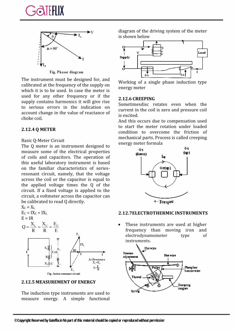
2.12.3 POWER FACTOR METERS
Power factor meters – like wattmeters have a current circuit and a pressure circuit. The current circuit carries the current (or definite fraction of this current) in the circuit whose power factor is to be measured. The pressure circuit is connected across the circuit whose power factor is to be measured and is usually split up into two parallel paths – one inductive and the other non-inductive. The deflection of the instrument depends upon the phase difference between the main current and currents in the two paths of the pressure circuit, i.e. upon the phase angle or power factor of the circuit. The deflection is indicated by a pointer. The moving system of power factor meters is perfectly balanced at equilibrium by two opposing forces and therefore there is no need for a controlling force. Hence when a power factor meter is disconnected from a circuit the pointer remains at a the position which it occupied at the instant of disconnection. There are two types of power factor meters: i) Electrodynamometer type, andii) Moving Iron typeTherefore the deflection of the instrument is a measure of phase angle of the circuit.
© Copyright Reserved by Gateflix.in No part of this material should be copied or reproduced without permission
The instrument must be designed for, and calibrated at the frequency of the supply on which it is to be used. In case the meter is used for any other frequency or if the supply contains harmonics it will give rise to serious errors in the indication on account change in the value of reactance of choke coil.
2.12.4 Q METER
Basic Q-Meter Circuit The Q meter is an instrument designed to measure some of the electrical properties of coils and capacitors. The operation of this useful laboratory instrument is based on the familiar characteristics of series-resonant circuit, namely, that the voltage across the coil or the capacitor is equal to the applied voltage times the Q of the circuit. If a fixed voltage is applied to the circuit, a voltmeter across the capacitor can be calibrated to read Q directly. XC = XL EC = IXC = IXL E = IR
C CLX EX
QR R E
2.12.5 MEASUREMENT OF ENERGY
The induction type instruments are used to measure energy. A simple functional
diagram of the driving system of the meter is shown below
Working of a single phase induction type energy meter
2.12.6 CREEPING Sometimesdisc rotates even when the current in the coil is zero and pressure coil is excited. And this occurs due to compensation used to start the meter rotation under loaded condition to overcome the friction of mechanical parts. Process is called creeping energy meter formula
2.12.7ELECTROTHERMIC INSTRUMENTS
These instruments are used at higherfrequency than moving iron andelectrodynamometer type ofinstruments.
© Copyright Reserved by Gateflix.in No part of this material should be copied or reproduced without permission
2.12.8 CLASSIFICATION OF ELECTROTHERMIC INSTRUMENTS
Hot wire: expansion of heated wire Thermocouple: Emf at heated junction.
Bolometer: change in resistance due to heating, heating is due to the current through the devices.
2.12.9 HOT WIRE
Thermoelectric element used in hot wire type instruments is made up of platinum indium. sensitivity of electrothermic instruments is higher than electrodynamometer type instruments. Advantages and disadvantages (i) Not affected by magnetic field, (ii) Not affected by frequency hence can
be used at higher frequency (more than 50 MHz)
(iii)can be used for A.C. and D.C. measurements,
(iv)measurement in electrothermic instruments is RMS, which is independent of waveform.
2.12.10 THERMOCOUPLE TYPE INSTRUMENTS
These instruments are generally used upto 500 v and at frequency more than 50 MHz. At frequencies more than 50 MHz the skin effect is dominant and can cause an error. But this can be minimised by using. Tubular Conductor This is preferable for current.
Tubular conductor Skin effect lessened. The thermoelective instruments give same call for A.C and D.C. therefore these instruments can be calibrated by D.C. current and can be used for A.C. measurement that is why these instruments are also called transfer instruments. At low frequencies (voltmeter) act as
precision instrument. (Hot wire instruments measure Irms
and Vrms) (In thermocouple type instruments
PMMC is used for detection ofthermocouple emf. But its scale iscalibrated to measure RMS value).
⦁ Disadvantage ⦁ These instruments have very small
loading effect.
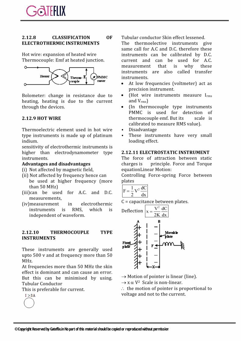
2.12.11 ELECTROSTATIC INSTRUMENT The force of attraction between static charges is principle. Force and Torque equationLinear Motion: Controlling Force-spring Force between plates
21 dCF V
2 dx
C = capacitance between plates.
Deflection 2V dC
x2K dx
Motion of pointer is linear (line). x V2 Scale is non-linear. the motion of pointer is proportional to voltage and not to the current.
© Copyright Reserved by Gateflix.in No part of this material should be copied or reproduced without permission
electrostatic type instruments are used for measurement of voltages only (H. V) around 20kV. Torque equation:
21 dcT V
2 d
21 V dc
T2 K d
2V
motion of point er circular
Scale non linear
Note: electrostatic instruments are mostly used in lab. for measurement of voltage. Advantages of electrostatic instruments: • low power required.• no. frequency error.• No effect of stray magnetic field.• Can be used for HV (KV) measurement• Can be used for AC and DC both.
Disadvantage: • Expensive and costly• Suitable for high voltage measurement
only• non-uniform scale• operating force is small.
2.12.12RECTIFIER TYPE INSTRUMENTS
1. They employ a rectifier for therectification and PMMC for detection.these instruments use PMMC fordisplay and measure r.m.s. value bycalibrating the scale of instruments.
2. Rectifier type instruments are mostlyused in communication or lowcurrents application with maximumcurrent approximately 1 mA.
3. Sensitivity = 1000 /V to 2000 /V incase of PMMC - highest sensitivity.
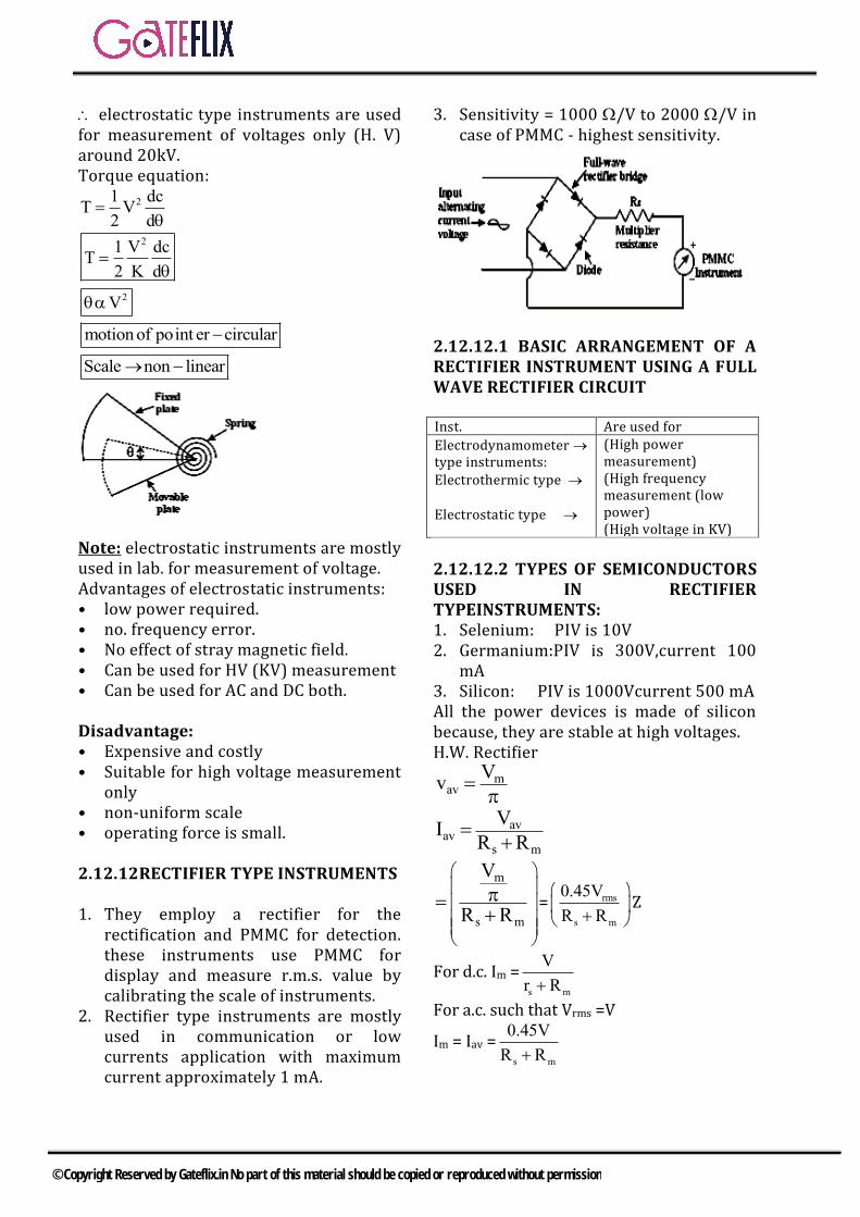
2.12.12.1 BASIC ARRANGEMENT OF A RECTIFIER INSTRUMENT USING A FULL WAVE RECTIFIER CIRCUIT
Inst. Are used for
Electrodynamometer type instruments: Electrothermic type
Electrostatic type
(High power measurement) (High frequency measurement (low power) (High voltage in KV)
2.12.12.2 TYPES OF SEMICONDUCTORS USED IN RECTIFIER TYPEINSTRUMENTS: 1. Selenium: PIV is 10V2. Germanium:PIV is 300V,current 100
mA3. Silicon: PIV is 1000Vcurrent 500 mAAll the power devices is made of silicon because, they are stable at high voltages. H.W. Rectifier
mav
Vv
avav
s m
VI
R R
m
s m
V
R R
= rms
s m
0.45V
R R
Z
For d.c. Im =s m
V
r R
For a.c. such that Vrms =V
Im = Iav =s m
0.45V
R R
© Copyright Reserved by Gateflix.in No part of this material should be copied or reproduced without permission
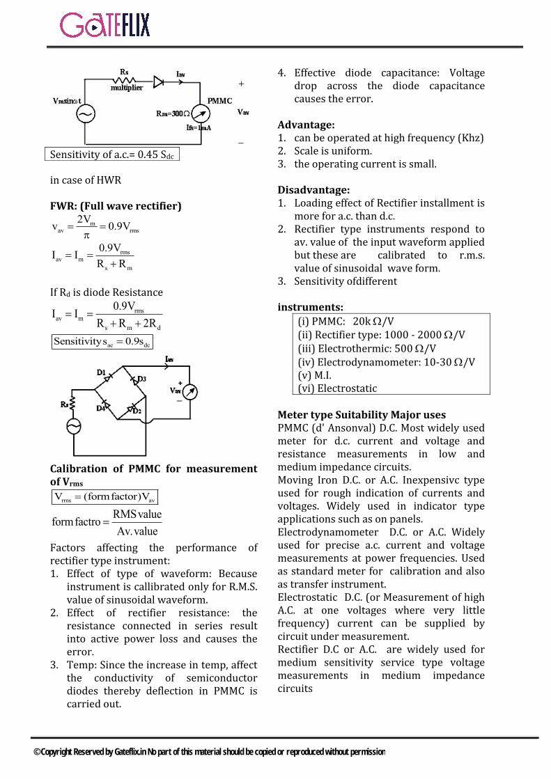
in case of HWR
FWR: (Full wave rectifier)
mav rms
2Vv 0.9V
rmsav m
s m
0.9VI I
R R
If Rd is diode Resistance
rmsav m
s m d
0.9VI I
R R 2R
ac dcSensitivitys 0.9s
Calibration of PMMC for measurement of Vrms
rms avV (formfactor)V
RMSvalueformfactro
Av.value
Factors affecting the performance of rectifier type instrument: 1. Effect of type of waveform: Because
instrument is callibrated only for R.M.S.value of sinusoidal waveform.
2. Effect of rectifier resistance: theresistance connected in series resultinto active power loss and causes theerror.
3. Temp: Since the increase in temp, affectthe conductivity of semiconductordiodes thereby deflection in PMMC iscarried out.
4. Effective diode capacitance: Voltagedrop across the diode capacitancecauses the error.
Advantage: 1. can be operated at high frequency (Khz)2. Scale is uniform.3. the operating current is small.
Disadvantage: 1. Loading effect of Rectifier installment is
more for a.c. than d.c.2. Rectifier type instruments respond to
av. value of the input waveform appliedbut these are calibrated to r.m.s.value of sinusoidal wave form.
3. Sensitivity ofdifferent
instruments:
(i) PMMC: 20k /V (ii) Rectifier type: 1000 - 2000 /V (iii) Electrothermic: 500 /V (iv) Electrodynamometer: 10-30 /V (v) M.I. (vi) Electrostatic
Meter type Suitability Major uses PMMC (d' Ansonval) D.C. Most widely used meter for d.c. current and voltage and resistance measurements in low and medium impedance circuits. Moving Iron D.C. or A.C. Inexpensivc type used for rough indication of currents and voltages. Widely used in indicator type applications such as on panels. Electrodynamometer D.C. or A.C. Widely used for precise a.c. current and voltage measurements at power frequencies. Used as standard meter for calibration and also as transfer instrument. Electrostatic D.C. (or Measurement of high A.C. at one voltages where very little frequency) current can be supplied by circuit under measurement. Rectifier D.C or A.C. are widely used for medium sensitivity service type voltage measurements in medium impedance circuits
Sensitivity of a.c.= 0.45 Sdc
© Copyright Reserved by Gateflix.in No part of this material should be copied or reproduced without permission
Q.1 A 100μA ammeter has an internal
resistance of 100 Ω . For extending its range to measure 500μA the
shunt resistance required is of a) 20.0Ω b) 22.22 Ωc) 25.0 Ω d) 50.0 Ω
[GATE-2001]
Q.2 A Manganin swap resistance is connected in series with a moving coil ammeter consisting of a milli –ammeter and a suitable shunt in order to a) minimize the effect of
temperature variationb) obtain large deflecting torquec) reduce the size of the meterd) minimize the effect of stray
magnetic fields[GATE-2003]
Q.3 A rectifier type ac voltmeter consists of a series resistance Rs an ideal full- wave rectifier bridge and a PMMC instrument as shown in figure. The internal resistance of the instrument is 100Ω and a full scale deflection is produced by a dc current of 1mA. The value of Rs required to obtain full scale deflection with an ac voltage of 100V (rms) applied to the input terminals is
a) 63.56Ω b) 69.93Ωc) 89.93Ω d) 141.3Ω
[GATE-2003]
Q.4 The inductance of a certain moving –iron ammeter is expressed as
2L 10 3θ (θ / 4)μH Where θ is
the deflection in radians form the zero position. The control spring
torque in 625 10 Nm/ radian .the deflection of the pointer in radian when the meter carries a current of 5A, is a) 2.4 b) 2.0c) 1.32 d) 10
[GATE-2003]
Q.5 A galvanometer with a full scale current of 10mA has a resistance of1000Ω . The multiplying power (the ratio of measured current to galvanometer current) of 100Ω shunt with this galvanometer is a) 110 b) 100c) 11 d) 10
[GATE-2004]
Q.6 A moving coil of a meter has 100turns, and a length and depth of 10mm and 20mm respectively .It is positioned in uniform radial flux density of 200mT. The coil caries a current of 50 mA. The torque on the coil is a) 200μNm b) 100 μNmc) 2μNm d) 1μNm
[GATE-2004]
Q.7 A moving iron ammeter produces a full scale torque of 240μNm with a
deflection of 120° a current of 10A. The rate of change of self inductance μH/radian of the instrument at full scale is a) 2.0μH/ radian b) 4.8μH/ radian
c)12.0μH/ radian d)114.6μH/ radian
[GATE-2004]
Q.8 A PMMC voltmeter is connected across a series combination of a DC
GATE QUESTIONS (Galvanometer, Voltmeter & Ammeter
© Copyright Reserved by Gateflix.in No part of this material should be copied or reproduced without permission
voltage source 1V 2V and and AC
voltage source 2V (t) 3sin(4t)V
The meter reads a) 2V b) 5V
c) (2 3 / 2)V d) 17 / 2 V
[GATE-2005]
Q.9 A 1000V DC supply has two 1-core cables as its positive and negative lead: their insulation resistances to earth are 4MΩ and 6MΩ respectively, as shown in the figure. A voltmeter with resistance 50kΩ is used to measure the insulation of the cable. When connected between the positive core and earth, then voltmeter reads
a) 8V b) 16Vc) 24V d) 40V
[GATE-2005]
Q.10 A current of 8 6 2sin(ωt 30°) A
is passed through three meters. They are a centre zero PMMC meters, a true rms meter and moving iron instrument. The respective reading (in A) will be a) 8,6,10 b) 8,6,8c) -8,10,10 d)-8,2,2
[GATE-2006]
Q.11 An ammeter has a current range of 0-5A, and its internal resistance is 0.2Ω In order to change the rage to 0-25 A, we need to add a resistance of a) 0.8Ω in series with the meterb) 1.0 Ω in series with the meterc) 0.04 Ω in parallel with the meterd) 0.05Ω in parallel with the meter
[GATE-2010]
Q.12 A periodic voltage waveform observed on an oscilloscope across a load is shown. A permanent magnet moving coil (PMMC) meter connected across the same load reads
a) 4V b) 5Vc) 8V d) 10V
[GATE-2012]
Q.13 An analog voltmeter uses external multiplier setting. With a multiplier setting of 20kΩ it reads 440V and with a multiplier setting of 80kΩ it reads 352 V. For a multiplier setting of 40kΩ the voltmeter reads a) 371V b) 383Vc) 394V d) 480V
[GATE-2012]
Q.14 The input impedance of the permanent magnet moving coil (PMMC) voltmeter is infinite. Assuming that the diode shown in the figure below is ideal, the reading of the voltmeter in Volts is
a) 4.46 b) 3.15c) 2.23 d) 0
[GATE-2013]
Q.15 The dc current flowing in a circuit is measured by two ammeters, one PMMC and another electrodynamo- meter type, connected in series. The PMMC meter contains 100 turns in the coil, the flux density in the air gap is 0.2 Wb/m2, and the area of the coil is 80 mm2. The
© Copyright Reserved by Gateflix.in No part of this material should be copied or reproduced without permission

electrodynamometer ammeter has a change in mutual inductance with respect to deflection of 0.5 mH/deg. The spring constants of both the meters are equal. The value of current, at which the deflections of the two meters are same, is
[GATE-14-1]
Q.16 The saw-tooth voltage wave form shown in the figure is fed to a moving iron voltmeter. Its reading would be close to
[GATE-14-2]
Q.17 Two ammeters X and Y have resistances of 1.2Ω and 1.5 Ω respectively and they give full scale deflection with 150 mA and 250 mA respectively. The ranges have been extended by connecting shunts so as to give full scale deflection with 15 A. The ammeters along with shunts are connected in parallel and then placed in a circuit in which the total current flowing is 15A. The current in amperes indicated in ammeter X is
[GATE-14-2]
Q.18 A periodic waveform observed across a load is represented by
1 sinsin t0 t 6
V t1 sinsin t6 t 12
The measured value, using moving iron voltmeter connected across the load, is
a) 3
2b)
2
3
c)3
2d)
2
3[GATE-14-3]
Q.19 A (0-50A) moving coil ammeter has a voltage drop of 0.1 V across its terminals at full scale deflection. The external shunt resistance (in milliohms) needed to extend its range to (0-500A) is
[GATE-15-1]
Q.20 Match the following: Instrument Type Used for P. Permanent magnet moving coil 1. DC only Q. Moving iron connected through current transformer 2. AC only R. Rectifier 3.AC and DC S. ElectrodynamometerP —1 P —1 P —1 P —3 a) Q — 2b) Q −3c) Q — 2d) Q —1 R —1 R —1 R —3 R — 2
S —3 S — 2 S — 3 S —1[GATE-15-2]
Q.21 A capacitive voltage divider is used to measure the bus voltage Vb, in a high-voltage 50 Hz AC system as shown in the figure. The measurement capacitor C1 and C2 have tolerances of ±10% on their normal capacitance values. If the bus voltage V bus is 100 kV rms, the maximum rms output voltage\Tout (in kV), considering the capacitor tolerance, is
[GATE-15-2]
Q.22 Consider the ammeter-voltmeter method of determining the value of the resistance R using the circuit shown in the figure. The maximum possible errors of the voltmeter and ammeter are known to be 1% and 2% of their readings, respectively. Neglecting the effects of meter resistances, the maximum possible percentage error in the value of R determined from the measurements, is ___ %.
© Copyright Reserved by Gateflix.in No part of this material should be copied or reproduced without permission
[GATE-15]
Q.23 A voltage V1 is measured 100 times and its average and standard deviation are 100 V and 1.5 V respectively. A second voltage V2, which is independent of V1, is measured 200 times and its average and standard deviation are 150 V and 2 V respectively. V3 is computed as: V3 = V1 + V2. Then the standard deviation of V3 in volt is____.
[GATE-16]
Q.24 A 3 ½ digit DMM has an accuracy specification of ± 1% of full scale (accuracy class 1). A reading of 100.0 mA is obtained on its 200 mA full scale range. The worst case error in the reading in milliampere is ± ______ .
[GATE-16]
Q.25 A 200 mV full scale dual-slope 1
2
digit DMM has a reference voltage of 100 mV and a first integration time of 100 ms. For an input of [100 + 10
Cos 100 t ] mV, the conversion
time (without taking the auto-zero phase time into consideration) in millisecond is______.
[GATE-16]
Q.26 A current waveform, i(t), shown in the figure, is passed through a Permanent Magnet Moving coil (PMMC) type ammeter. The reading of the ammeter up to two decimal places is
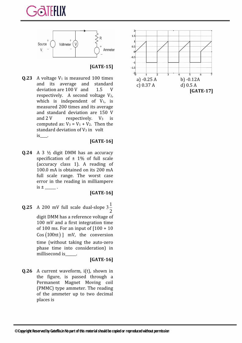
a) -0.25 A b) -0.12Ac) 0.37 A d) 0.5 A
[GATE-17]
© Copyright Reserved by Gateflix.in No part of this material should be copied or reproduced without permission
Q.1 (c)
ash
R 100R
500m 11
100
25.0Ω
Q.2 (a)
Coil is made of copper. A swamping resistance (RSW) of manganin (which has a negligible temperature coefficient) having a resistance 20to 30 times the coil resistance is connected in series with the coil and a shunt of manganin is connected across the is combination. Since copper forms a small fraction of the series currents would divided between the meter and the shunt would not change appreciably with the change in temperature.
Q.3 (c)
(FS)l Current required to produce full scale
deflection d.c. sensitivity is ,
dc
(FS)
1S
I 31
10 Ω / V1mA
For full wave rectifier a. c. sensitivity
ac dcS 0.9S 900Ω / V
Resistance of multiplier,
s dc m dR S V R 2R
Since diodes are ideal dR 0
then, sR 900 100 100
89.9kΩ
Q.4 (c) Deflecting torque in moving –iron ammeter
2
d
1 dLT l
2 dθ
Inductance 2θ
L 10 3θ μH4
Rate of change of inductance with deflection
2dL d θ10 3θ
dθ dθ 4
θ3 μH / rad
2
Current l=5A
1 2 3 4 5 6 7 8 9 10 11 12 13 14
(c) (a) (c) (c) (c) (a) (b) (a) (a) (c) (d) (a) (d) (a)
15 16 17 18 19 20 21 22 23 24 25 26
3.2 57.7 10.15 1 0.22 c 12 3 2.5 2.1 200 (a)
ANSWER KEY:
EXPLANATIONS
© Copyright Reserved by Gateflix.in No part of this material should be copied or reproduced without permission
Deflecting torque
2
d
1 dLT l
2 dθ
2 6
d
1 θT 5 3 10
2 2
625 θ3 10 Nm
2 2
Controlling torque 6
cT kθ 25 10 θ
At equilibrium
c dT T
6 625 θ25 10 θ 3 10
2 2
5θ3
2
θ 1.2rad
Q.5 (c)
Full scale current of galvanometer
mI 10mA Resistance of meter
mR 1000Ω
Resistance of shunt
shR 100Ω
shm
sh m
IRI
R R
Multiplying power
sh m
m m
R RI
I R
100 100011
100
Q.6 (a) T=Torque on the coil =NBAI Where N=No f turns =100 B=Flux density
3200mT 200 10 T A Area of the coil length depth
3 310 10 200 10
6 2200 10 m
l curent through the coil 350mA 50 10
T=NBAI
3 6 3100 200 10 200 10 50 10
42 10 N m 200μN m
Q.7 (b) Torque produced
21 dLT l
2 dθ
Where l 10A and T 240μN m
6240 10 N m
21 dLT l
2 dθ
6 21 dL240 10 10
2 dθ
Rate of change of self inductance
6dL4.8 10 H / radian
dθ
dL4.8μH / radian
dθ
Q.8 (a) Total voltage across PMMC
T 1 2V V V
2 3sin 4t V
PMMC reads average value Average value of 1V 2V
Average value of 2V 0
Average value of TV 2V
So PMMC reads =2V
Q.9 (a)
Resistance of voltmeter (Rv) appears parallel to 4MΩ
© Copyright Reserved by Gateflix.in No part of this material should be copied or reproduced without permission
Effective resistance between A& B
AB vR R || 4MΩ
vR 50kΩ 0.05MΩ
ABR 0.05 || 4MΩ 0.05MΩ
AC AB BCR R R
0.05 6 6.05MΩ
AC
1000 1000I μA
R 6.05
Voltmeter reads
6 6
AB
1000IR 10 0.05 10 8V
6.05
Q.10 (c)
1 2l 8 6 2 sin(ωt 30°)l 8A andl
6 2 sin(ωt 30°)
Average value of l1 = −8A Average value of l2 = 0 So average value of l = −8A PMMC reads only average value of current. Therefore PMMC reads = −8A (Since it is centre zero type)
2
2 6 2RMSvalueofl 8 10A
2
RMS meter and moving iron meter both reads RMS value of the current So, both m2 and m3read 10 A
Q.11 (d) To extend the range of the ammeter, a resistance shR is connected across
the meter
mI a Full scale deflection current
=5A
I 25A Multiplying power
m
I 25m 5
I 5
shm
sh m
IRI
R R
sh m
m sh
R RI
I R
m
sh
Rm 1
R
msh
RR
m 1
0.20.05
5 1
Q.12 (a) As PMMC meter reads only DC value or average value and average value is equal to
avg
Area under the curveV
Total time
avg
110 10 5 2 (5 8)
2V
20
Q.13 (d)
When
1SR 20kΩ,v 440V
m
440V 20 440
R ….(1)
When 2SR 80kΩ,v 352V
m
352V 80 352
R …(2)
m
352 80 440 20R
88
mR 220kΩ,V 480V
© Copyright Reserved by Gateflix.in No part of this material should be copied or reproduced without permission
Q.14 (a) In the half cycle, D is ON
0V 0V
In negative half cycle, D id OFF, < PMMC voltmeter measures average value of V0
In case of half wave rectification,
o avg
14.14 100V
π 101 4.456V
Q.15 (3.2) → Given pmmc and electro
dynamometer type meters are connected in series.
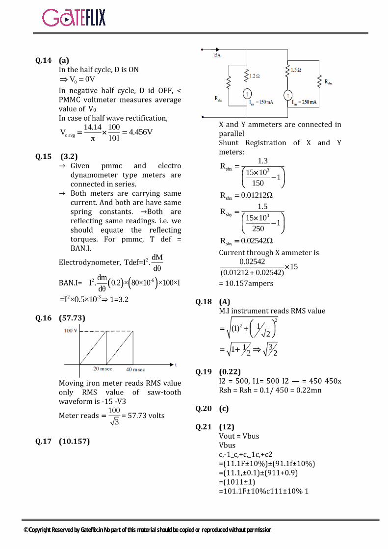
→ Both meters are carrying same current. And both are have same spring constants. →Both are reflecting same readings. i.e. we should equate the reflecting torques. For pmmc, T def = BAN.I.
Electrodynometer, 2 dMTdef=I .
dθ
BAN.I= 2 -6dmI . 0.2 × 80×10 ×100×I
dθ2 -3=I ×0.5×10 ⇒ 1=3.2
Q.16 (57.73)
Moving iron meter reads RMS value only RMS value of saw-tooth waveform is -15 -V3
Meter reads 100
3 = 57.73 volts
Q.17 (10.157)
X and Y ammeters are connected in parallel Shunt Registration of X and Y meters:
shx 3
1.3R
15 101
150
shxR 0.01212Ω
shy 3
1.5R
15 101
250
shyR 0.02542Ω
Current through X ammeter is 0.02542
15(0.01212 0.02542)
= 10.157ampers
Q.18 (A) M.I instrument reads RMS value
2
2 1(1)2
3112 2
Q.19 (0.22) I2 = 500, I1= 500 I2 — = 450 450x Rsh = Rsh = 0.1/ 450 = 0.22mn
Q.20 (c)
Q.21 (12) Vout = Vbus Vbus c,-1_c,+c,_1c,+c2 =(11.1F±10%)±(91.1f±10%) =(11.1,±0.1)±(911+0.9) =(1011±1) =101.1F±10%c111±10% 1
© Copyright Reserved by Gateflix.in No part of this material should be copied or reproduced without permission
= 0.1± 20% c, + c, 101.1 ± 10% ∴ Vout =100x 103(0.1± 20%) =10 kV ± 20% =10k + 2k (or)10k - 2k =12k or 8k
Q.22 (3)
V 2%R R 3%
V I 1%x x
x x
I x
V
Q.23 (2.5) Given V1 = 100 V Standard deviation of V1
= 1.5 V
V2 = 150 V Standard deviation of V2
= 2V
V3 = V1 + V2 Standard deviation of V3
2 2
2 1.5
= 2.5 Volt So, the standard deviation of V3 is 2.5 Volts.
Q.24 2.1
From given data, we have 1
32
digit
DMM, Accuracy specification = ± 1% of full scale (Accuracy class 1) Reading = 100 mA on its 200 mA full scale 100mV reading on the 200mV full scale is 1 0 0 .0 mV 1 count on this 200mV full scale is 000.1 mV % error in reading =
1200mA
100
2
Therefore, error can be calculated as Error = ± (2% of reading +1 class)
2100.0mV+1 000.1mV
100
= ± [2 mV + 0.1 mV] = ± 2.1 mV So, the worst case error in the reading is ± 2.1 m volts
Q.25 200 From the given data
For 200 mV full scale range, 1
32
digit
DMM Reference voltage (Vref) = 100 mV, First integration time (T1) = 100 ms Input voltage (Vin)
100 10cos 100 t mV
Conversion time (Tconv) = ? We know Vin T1 = Vref T2 100 mV 100 ms = 100 mV T2 T2 = 100 ms Tconv = T1 + T2 = 100 ms + 100 ms = 200 ms So, the conversion time is 200 ms.
Q.26 (a)
Consider the PMMC as zero centered meter Average value of the above signal is
1 2
0 1
22
1
1tdt 1dt
T
11 1 1t 1 0.25 Amps
02 2 2 2
t
© Copyright Reserved by Gateflix.in No part of this material should be copied or reproduced without permission
Q.1 The minimum number of wattmeter (s) required to measure 3-phase, 3-wire balanced or unbalanced power is a) 1 b) 2c) 3 d) 4
[GATE-2001]
Q.2 The line to line input voltage to the 3-phase 50Hz, ac circuit shown in figure is 100V rms assuming that the phase sequence is RYB the wattmeter would read.
a) 1 2W 886W andW 896W
b) 1 2W 500W andW 500W
c) 1 2W 0W andW 1000W
d) 1 2W 250W andW 750W
[GATE-2002]
Q.3 A wattmeter reads 400W when its current coil is connected in the R phase and its pressure coil is connected between this phase and the natural of a symmetrical 3-phase system supplying a balanced star connected 0.8p.f. Inductive load. The phase sequence is RYB. What will be the reading of this wattmeter if its pressure coil alone is reconnected between the B and Y phases all other connections remaining as before? a)400.0 b)519.6 c) 300.0 d)692.8
[GATE-2003]
Q.4 The voltage –flux adjustment of a
certain 1-phase 220V induction watt- hour meter is altered so that the phase angle between the applied voltage and the flux due to it is 85° (instead of 90° ). The errors introduced in the reading of this meter when the current is 5A at power factors of unity and 0.5 lagging are respectively a) 3.8mW, 77.4mWb)-3.8mW,-77.4mW C)-4.2W,-85.1W d) 4.2W, 85.1W
[GATE-2003]
Q.5 The circuit in figure is used to measure the power consumed by the load. The current coil and the voltage coil of the wattmeter have0.02Ω and 1000Ω resistances respectively .The measured power compared to the load power will be
a) 0.4%less b) 0.2%lessc) 0.2%more d) 0.4%more
[GATE-2004]
Q.6 A dc A-h meter is rated for 15A, 250V.The meter constant is 14.4A sec/rev. The meter constant at rated voltage may be expressed as a) 3750rev/kWh b) 3600 rev/kWhc) 1000rev/kWh d) 960rev/kWh
[GATE-2004]
Q.7 A single –phase load is connected between R and Y terminals of a 415V, symmetrical 3-phase, 4wire system with phase sequence RYB. A wattmeter is connected in the
GATE QUESTIONS(IN)
GATE QUESTIONS (Measurement of Energy & Power)
© Copyright Reserved by Gateflix.in No part of this material should be copied or reproduced without permission
system as shown in figure. The power factor of the load is 0.8 lagging .The wattmeter will read
a) -795W b) -597Wc) +597W d) +795W
[GATE-2004]
Q.8 Two wattmeter, which are connected measure the total power on a three- phase system supplying a balanced load, read 10.5kW and -2.5kW, respectively. The total power and the power factor respectively, are a) 13.0kW, o.334 b) 13.0 kW,0.684c) 8.0kW, 0.52 d) 8.0kW,0.334
[GATE-2005]
Q.9 A sampling wattmeter (that computes power from simultaneously sampled values of voltage and current) is used to measure the average power of a load. The peak to peak voltage of the square wave is 10V and the current is a triangular wave of 5A p-p as shown in the figure. The period is 20ms. The reading in W will be
a)0W b)25W c)50W d)100W
[GATE-2006]
Q.10 The pressure coil of a dynamometer type wattmeter is a) highly inductiveb) highly resistivec) purely resistived) purely inductive
[GATE-2009]
Q.11 The Figure shows a three –phase delta connected load supplied from a 400V 50 Hz, 3-phase balanced source. The pressure coil (PC) and current coil (CC) of a wattmeter are connected to the load as shown, with the coil polarities suitably selected to ensure a positive deflection. The wattmeter reading will be
a) 800 Wattt b) 1600Wattc) 0 d) 400Watt
[GATE-2009]
Q.12 A Wattmeter is connected as shown in the figure. The wattmeter reads
a) Zero alwaysb) Total power consumed by
1 2Z andZ
c) Power consumed by 1Z
d) Power consumed by 2Z
[GATE-2010]
Q.13 Consider the following statements: i) The compensating coil of a low
power factor wattmetercompensates the effect of theimpedance of the current coil.
ii) The compensating coil of a lowpower factor wattmetercompensates the effect of theimpedance of the voltage coilcircuit
a) (i) is true but (ii) is falseb) (i) is false but (ii) is true
© Copyright Reserved by Gateflix.in No part of this material should be copied or reproduced without permission
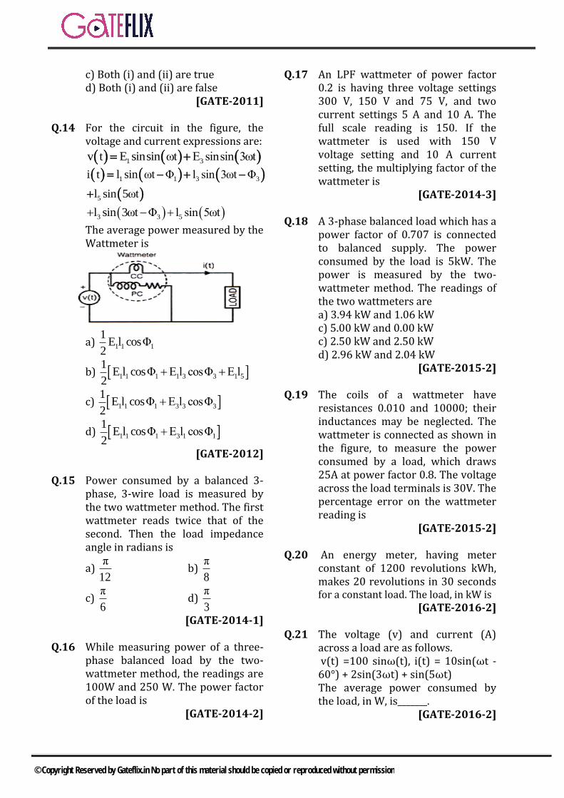
c) Both (i) and (ii) are trued) Both (i) and (ii) are false
[GATE-2011]
Q.14 For the circuit in the figure, the voltage and current expressions are:
1 3v t E sinsin ωt E sinsin 3ωt
1 1 3 3
5
i t l sin ωt Φ l sin 3ωt Φ
l sin 5ωt
3 3 5l sin 3ωt Φ l sin 5ωt
The average power measured by the Wattmeter is
a) 1 1 1
1E l cosΦ
2
b) 1 1 1 1 3 3 1 5
1E l cosΦ E l cosΦ E l
2
c) 1 1 1 3 3 3
1E l cosΦ E l cosΦ
2
d) 1 1 1 3 1 1
1E l cosΦ E l cosΦ
2
[GATE-2012]
Q.15 Power consumed by a balanced 3-phase, 3-wire load is measured by the two wattmeter method. The first wattmeter reads twice that of the second. Then the load impedance angle in radians is
a) π
12b)
π
8
c) π
6d)
π
3[GATE-2014-1]
Q.16 While measuring power of a three-phase balanced load by the two-wattmeter method, the readings are 100W and 250 W. The power factor of the load is
[GATE-2014-2]
Q.17 An LPF wattmeter of power factor 0.2 is having three voltage settings 300 V, 150 V and 75 V, and two current settings 5 A and 10 A. The full scale reading is 150. If the wattmeter is used with 150 V voltage setting and 10 A current setting, the multiplying factor of the wattmeter is
[GATE-2014-3]
Q.18 A 3-phase balanced load which has a power factor of 0.707 is connected to balanced supply. The power consumed by the load is 5kW. The power is measured by the two-wattmeter method. The readings of the two wattmeters are a) 3.94 kW and 1.06 kWc) 5.00 kW and 0.00 kWc) 2.50 kW and 2.50 kWd) 2.96 kW and 2.04 kW
[GATE-2015-2]
Q.19 The coils of a wattmeter have resistances 0.010 and 10000; their inductances may be neglected. The wattmeter is connected as shown in the figure, to measure the power consumed by a load, which draws 25A at power factor 0.8. The voltage across the load terminals is 30V. The percentage error on the wattmeter reading is
[GATE-2015-2]
Q.20 An energy meter, having meter constant of 1200 revolutions kWh, makes 20 revolutions in 30 seconds for a constant load. The load, in kW is
[GATE-2016-2]
Q.21 The voltage (v) and current (A) across a load are as follows. v(t) =100 sinω(t), i(t) = 10sin(ωt - 60°) + 2sin(3ωt) + sin(5ωt) The average power consumed by the load, in W, is_______.
[GATE-2016-2]
© Copyright Reserved by Gateflix.in No part of this material should be copied or reproduced without permission
Q.22 A symmetrical three-phase three- wire RYB system is connected to a
balanced delta-connected load. The RMS values of the line current and line-to-line voltage are 10 A and 400 V respectively. The power in the system is measured using the two wattmeter method. The first wattmeter connected between R-
line and Y-line reads zero. The reading of the second wattmeter (connected between B-line and Y-
line) in watt is ______ . [GATE-2016]
Q.23 Identify the instrument that does not exist: a) Dynamometer-type ammeterb) Dynamometer-type wattmeterc) Moving-iron voltmeterd) Moving-iron wattmeter
[GATE-2016]
Q.24 A 300 V, 5 A, 0.2 pf low power factor wattmeter is used to measure the power consumed by a load. The wattmeter scale has 150 divisions and the pointer is on the 100th division. The power consumed by the load (in Watts) is _________.
[GATE-2018]
© Copyright Reserved by Gateflix.in No part of this material should be copied or reproduced without permission
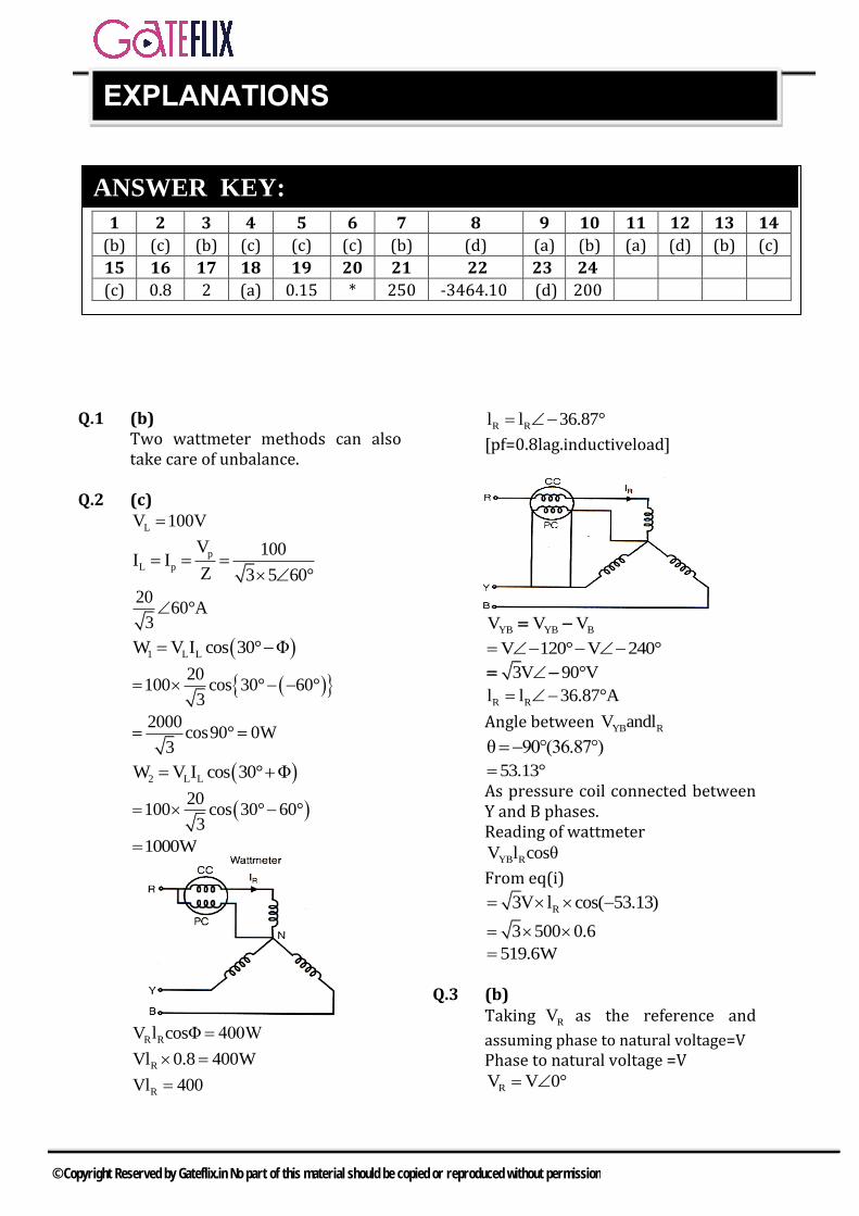
Q.1 (b) Two wattmeter methods can also take care of unbalance.
Q.2 (c)
LV 100V
p
L p
V 100I I
Z 3 5 60°
2060°A
3
1 L LW V I cos 30° Φ
20
100 cos 30° 60°3
2000cos90° 0W
3
2 L LW V I cos 30° Φ
20
100 cos 30° 60°3
1000W
R RV l cosΦ 400W
RVl 0.8 400W
RVl 400
R Rl l 36.87°
[pf=0.8lag.inductiveload]
YB YB BV V V
V 120° V 240°
3V 90°V
R Rl l 36.87°A
Angle between YB RV andl
θ 90°(36.87°)
53.13° As pressure coil connected between Y and B phases. Reading of wattmeter
YB RV l cosθ
From eq(i)
R3V l cos( 53.13)
3 500 0.6
519.6W
Q.3 (b) Taking RV as the reference and
assuming phase to natural voltage=V Phase to natural voltage =V
RV V 0°
1 2 3 4 5 6 7 8 9 10 11 12 13 14
(b) (c) (b) (c) (c) (c) (b) (d) (a) (b) (a) (d) (b) (c)
15 16 17 18 19 20 21 22 23 24
(c) 0.8 2 (a) 0.15 * 250 -3464.10 (d) 200
ANSWER KEY:
EXPLANATIONS
© Copyright Reserved by Gateflix.in No part of this material should be copied or reproduced without permission
yV V 120°
And BV V 240°
Q.4 (c) Measured value VIsin( Φ)
Where Phase angle between voltage and flux cosΦ powerfactor
True value VIcosΦ Error =Measured value –True value Case-I
85°,pf cosΦ 1,Φ 0°
V 220V,l 5A
Error VIsin Φ VIcosΦ
220 5sin 85 0° 220 1 1
4.2W Case-II
85°,pf cosΦ 0.5, Φ 60°
V 220V,l 5A
Error VIsin Φ VIcosΦ
220 5sin 85 60° 220 5 0.5
85.1W
Q.5 (c) Load power (true power ) VIcosΦ
200 20 1 4000W Resistance of current coil
CCR 0.02
Current through CCC l 20A
Power consumed by current coil 2
c CCl R220 0.02 8W
Measured power = power consumed by load + power consumed by current coil Measured power =4000+8=4008W%error
Measured power True power100
True power
4008 4000100
4000
0.2%(more)
Q.6 (c) Meter constant m =14.4A sec/rev To express meter constant in the unit rev/ kWh Meter constant
' 1 1 revM
M 14.4 A sec
' 31 rev 1 3600secM 10
14.4 A sec 250V 1hr
33600 10
rev / kWh14.4 250
1000rev / kWh
Q.7 (b) Line of line voltage =450V
Phase to natural voltage 415
V3
Taking RV as the reference,
RN
415V 0°V
3
YN
415V 120°V
3
And BN
415V 240°V
3
RY RN YNV V V
415 4150°V 120°V
3 3
415 30°V Load current
RYL
V 415 30°l
z 100 36.87
4.15 6.87°A
Current through current coil
CC Ll l 4.15 6.87°A
Voltage across pressure coil
BN
415V 240°V
3
Phase angle between BN CCV andl
Φ 240° 6.87°
233.13°
Wattmeter reading BN LV l cosΦ
4154.15 cos233.13 597W
3
© Copyright Reserved by Gateflix.in No part of this material should be copied or reproduced without permission
Q.8 (d)
1 2P 10.5kWandP 2.5kW
Total power 1 2P P 10.5 2.5
8kW Power factor
1 1 2
1 2
P PcosΦ cos tan 3
P P
1 10.5 ( 2.5)cos tan 3
10.5 ( 2.5)
=0.334
Q.9 (a)
Positive power= negative power So average power=0W
Q.10 (b) It is difficult to have purely resistive pressure coil. The pressure coil has a small value of inductance. Due to which error occurs in wattmeter readings.
Q.11 (a) Assuming phase sequence abc Line to line voltage l lV 400V
Taking abV as the reference
ab l lV V 0° 400 0°V
bcV 400 120°V
Current through current coil
caCC
2
V 400 240°Vl
Z 100 j0
4 240°V Voltage across pressure coil
pc bcV V
400 120°V Φ = angle betweenlCCand Vpc
120 240° 120°
Wattmeter reading
pc ccV l cosΦ
400 4 cos 120°
800W
Q.12 (d)
Potential coil draws negligible current, so Current through 1 2Z andZ is same
Current through current coil
ccI I
Voltage across potential coil pcV
Voltage across 2 pcZ V V
Wattmeter reads power consumed by 2Z as voltage across
Potential coil =Voltage across 2Z
Current through current coil =current through 2Z
Q.13 (b)
The current coil caries a current of
pl l and produces a filed
corresponding to this current. The compensating coil is connected in series with the pressure coil circuit and is made as nearly as possible identical and coincident with the current coil. It is so connected that it opposes the field of the current coil. The compensating coil carries a current
pl and produces a field
corresponding to this current. This
© Copyright Reserved by Gateflix.in No part of this material should be copied or reproduced without permission
field acts in opposition to the current coil field. Thus the resultant field is due to current I only. Hence the error caused by the pressure coil current flowing in the current coil is neutralized
Q.14 (c)
1 3v t E sinωt E sin3ωt
1 1 3i t l sin ωt Φ l
3 5sin 3ωt Φ l sin5ωt
Average power 2π
avg
0
1P vi d(ωt)
2π
The products of different frequency terms have zero average value
avg 1 1 1 3 3 3
1 1P E l cosΦ E l cosΦ
2 2
Q.15 (C)
When load impedance is 6
π
radians. The first wattmeter reads twice that if the second wattmeter.
Q.16 (0.802) In two-wattmeter method, The readings are 100 W & 250 W Power factor = cos ϕ
1 21
1 2
3cos tan
ω ω
ω ω
1 3(150)cos tan
350
=0.8029
Q.17 (2) In LPF wattmeter, Td on the moving system is small owing to low power factor even when the current and potential coils are fully excited. Also the errors introduced due to inductance of pressure coil tend to be large at low power factors. So for calculating multiplying factor for a low p.f. wattmeter, p.f. mentioned on
the wattmeter should be taken into account. Therefore, Multiplying Factor = (Current range used*Voltage range used*p.f) / Power at FSD Given, Power at Full scale reading = 150 dini‘b Current Range used = 100A - Voltage Range used r=150 VI ring Success Power Factor 1=0.2 ONNE MEM NENE 10x150x 0.2 Therefore, m = _2 150
Q.18 (a)
Q.19 (0.15) P load = 30x25x08 = 600W Wattmeter measures loss in pressure coil circuit Load 2 2 V loss in P = -30 = 0.9W Rp 1000 9 error = 0.x100 = 0.15% 600
Q.20 K =1200rev/kwh = 20revolutions I I 1. "" 3600 jhrm. (30 1P = 2kW 91
Q.21 (250) The instantaneous power of load is p(t) = V(∈)i(t) [(100sinωt)(10sin(ωt - 60)] + [(100sinωt) (2sin3ωt)]+[(100 sinωt,)(5sin5ωt)]
→ since, T
avg
0
P P t dt in the above
expression Only 1st term will result non zero answer Remaining 2 terms wiII be 0. → so directly consider [P(t) = 100sinωt] [10(sinωt-60)]
P t 100sinωt 10(sinωt 60)
avg rms rms v 1
100 10P V I cos θ θ
2 2
1000 1cos(60) 250watt
2 2
Q.22 -3464.10 From given question, using formula
© Copyright Reserved by Gateflix.in No part of this material should be copied or reproduced without permission

2 1
2 1
W Wtan 3
W W
(Since W1 = reading of the first Wattmeter = 0, W2 = reading of the Second Wattmeter)
2
2
1 o
T 2 1 2
L L
W3 3
W
tan 3 60
TotalPower P W W W
3 V I cos
3 400 10 0.5
3464.10 Watt
The wattmeter connected between B-line and Y-line it read negative, so PT = – 3464.10 W
Q.23 (d) To Measure power we require to coils (C.C & P.C) Dynamo meter will consist two coils. So it can measure power. Dynamo meter can also measure current and voltage, if we connect C.C & P.C in series. Moving Iron meter will have only one coil, so it can measure current and voltage but not power. Note: Moving Iron wattmeter doesn’t exist.
Q.24 200 Given : 300 V, 5 A, 0.2 pf low power factor wattmeter Wattmeter scale has 150 division and the pointer is on the 100th division.
th
Power P 300 5 W
300For 100 division P 100 200 W
150
© Copyright Reserved by Gateflix.in No part of this material should be copied or reproduced without permission
3.1 CLASSIFICATION OF RESISTANCE
a) low resistance less than 1b) medium resistance between '1'
and 0.1M.c) High resistance Above 0.l M
3.1.1 MEASUREMENT OF LOW RESISTANCE
a) Ammeter-Voltmeter methodb) Kelvin's Rouble bridge methodc) Potentiometer methodNote: 1. Low resistances have four terminals
two current terminalstwo voltageterminals. This is done to avoid contactresistance effect
2. The range of resistance measured byKelvin double bridge is from 0.1 to 1.
3. Measurement of medium resistances.(i) Ammeter-Voltmeter method(ii) Substitution method(iii)Wheatstone Bridge,(iv)Ohmmeter method.
3.1.2MEASUREMENT OF HIGH RESISTANCES
different categories: (i) insulation resistance of m/c and cable (ii) leakage resistance of the capacitor (iii)leakage resistance of vacuum tube (iv)surface resistance.
3.1.3 DIFFICULTIES IN MEASUREMENT OF HIGH RESISTANCES
(i) leakage resistance (ii) Electrostatic effect. (iii)Capacitance of the specimen under
measurement. Note: Guard Ckt. is used to eliminate the errors due to leakage current.
3.2 DIFFERENT METHODS OF MEASUREMENT
1. direct deflection method (like ohmmeter method) de'Arsenol Galvanometer is used-for deflection.
2. Loss of charge method3. Mega Ohm Bridge method4. Meggar (used in measurement of earth
resistance).Ohm-meter It is a device which gives direct reading
for the measurement of a resistance. This instrument has low degree of
accuracy. It is generally used for the
measurement of hetero resistance offield winding of m/cs, Measurement ofresistances used in electrotronics lab.
Cheking of diodes.
3.3 TYPES OF OHMMETER
1. Series type2. shunt type
3.3.1 L SERIES TYPE
Rse current limiting resistance. Rsh used to adjust the meter current for full scaledeflection. E internal battery of meter. Rx = 0 Give full scale def. Rx = Give null def.
3 MEASUREMENT OF RESISTANCE, INDUCTANCE & CAPACITANCE
© Copyright Reserved by Gateflix.in No part of this material should be copied or reproduced without permission
The value of resistance Rx for mid scale deflection. Rx = Rh = internal resistance of meter gives half scale deflection
m shh se
m sh
R RR R (i)
R R
Current supplied by battery at half scale deflection
sc h
h
EI I
2R
sh se fsI I I
sh fs
h
EI I
R
The voltage across Rsh = voltage across meter.
sh sh fs mI ,R I R
fs m fs msh
sh h fs
I R I RR
I E / R I
fs m h
h fs
I R RRsh
E R I
(ii)
Note: for 10% drop in battery emf. Rsh is given by:(E 0.9 E)
fs m hsh
h fs
I R RR
0.9E R I
Note: Mag. shunt is used across pole pieces. Polepieces of PMMC (magnets of PMMC) to reduce the effect of change in battery of emf. with changing the ckt elements.
3.3.2 SHUNT TYPE
Rx = 0. Gives null deflection. Rx = gives full scale deflection.
At Full scale deflection
xR
m fs
1 m
EI I
R R
(i)
1 m
fs
ER R
I (ii)
At any intermediate deflection:
xm
m x m x1
m x
REI
R R R RR
R R
xm
1 m x m x
ERI
R (R R ) R R
Note: Shunt type ohmmeter is particularly suitedfor measurement of low resistances. Megger: It is an instrument used for the measurement of insulation resistance & earth resistances. Scale : scale is compressed near pt. 'o' and expands wards ' ' resistance. The test voltage is generated by hand driven generator.
3.4 BRIDGE MEASUREMENTS
3.4.1 A.C. BRIDGES
i) used to measure self inductance, mutualinductance capacitance, and frequency.
ii) Types of sources for low frequency: power line
supply can be used, for high frequency: electronic
oscillator is used.iii) Types of detectors:
Head phones (250 Hz to 3/4 KHz)
© Copyright Reserved by Gateflix.in No part of this material should be copied or reproduced without permission
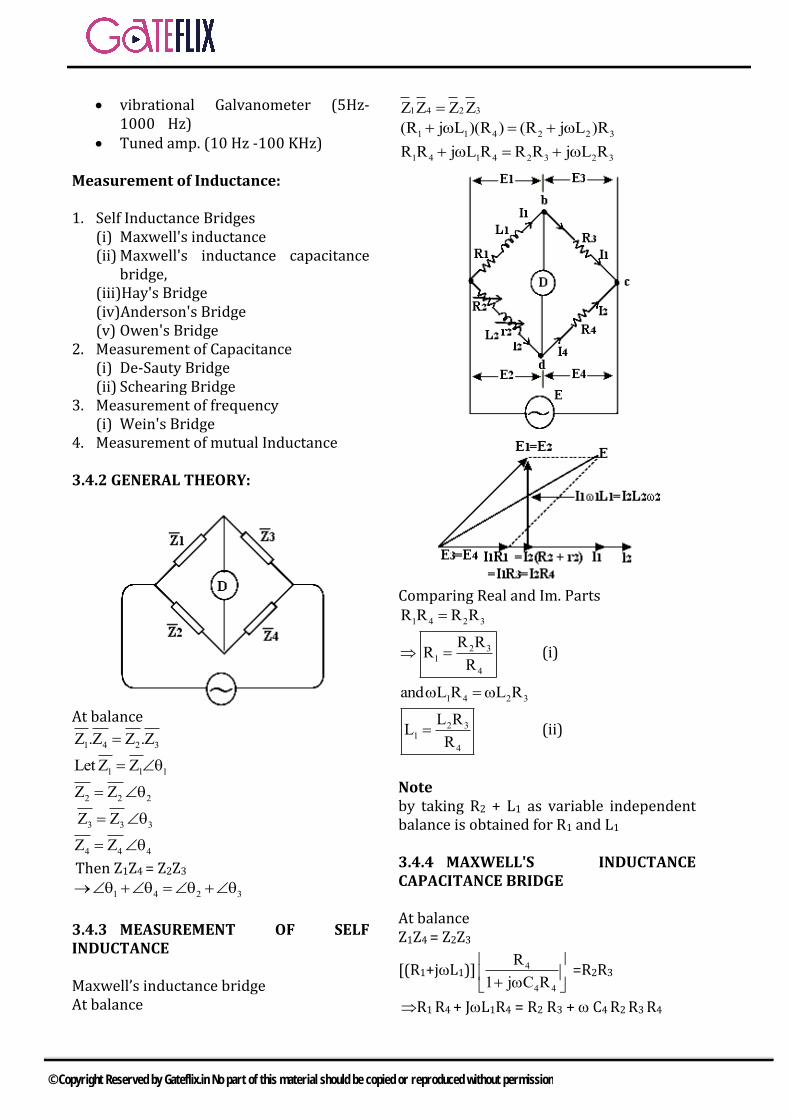
vibrational Galvanometer (5Hz-1000 Hz)
Tuned amp. (10 Hz -100 KHz)
Measurement of Inductance:
1. Self Inductance Bridges(i) Maxwell's inductance(ii) Maxwell's inductance capacitance
bridge, (iii)Hay's Bridge (iv)Anderson's Bridge (v) Owen's Bridge
2. Measurement of Capacitance(i) De-Sauty Bridge(ii) Schearing Bridge
3. Measurement of frequency(i) Wein's Bridge
4. Measurement of mutual Inductance
3.4.2 GENERAL THEORY:
At balance
1 4 2 3Z .Z Z .Z
1 1 1Let Z Z
2 2 2Z Z
3 3 3Z Z
4 4 4Z Z
Then Z1Z4 = Z2Z3
1 4 2 3
3.4.3 MEASUREMENT OF SELF INDUCTANCE
Maxwell’s inductance bridge At balance
1 4 2 3Z Z Z Z
1 1 4 2 2 3(R j L )(R ) (R j L )R
1 4 1 4 2 3 2 3R R j L R R R j L R
Comparing Real and Im. Parts
1 4 2 3R R R R
2 31
4
R RR
R (i)
1 4 2 3and L R L R
2 31
4
L RL
R (ii)
Note by taking R2 + L1 as variable independent balance is obtained for R1 and L1
3.4.4 MAXWELL'S INDUCTANCE CAPACITANCE BRIDGE
At balance Z1Z4 = Z2Z3
[(R1+jL1)] 4
4 4
R
1 j C R
=R2R3
R1 R4 + JL1R4 = R2 R3 + C4 R2 R3 R4
© Copyright Reserved by Gateflix.in No part of this material should be copied or reproduced without permission
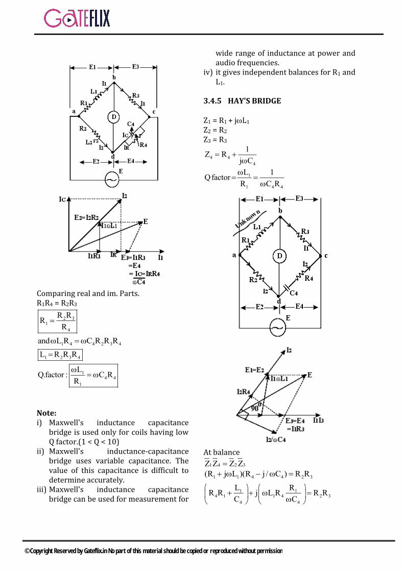
Comparing real and im. Parts. R1R4 = R2R3
2 31
4
R RR
R
1 4 4 2 3 4and L R C R R R
1 2 3 4L R R R
14 4
1
LQ.factor : C R
R
Note: i) Maxwell's inductance capacitance
bridge is used only for coils having lowQ factor.(1 < Q < 10)
ii) Maxwell's inductance-capacitancebridge uses variable capacitance. Thevalue of this capacitance is difficult todetermine accurately.
iii) Maxwell's inductance capacitancebridge can be used for measurement for
wide range of inductance at power and audio frequencies.
iv) it gives independent balances for R1 andL1.
3.4.5 HAY’S BRIDGE
Z1 = R1 + jL1
Z2 = R2 Z3 = R3
4 4
4
1Z R
j C
1
1 4 4
L 1Qfactor
R C R
At balance
1 4 2 3Z Z Z Z
1 1 4 4 2 3(R j L )(R j / C ) R R
1 14 1 1 4 2 3
4 4
L RR R j L R R R
C C
© Copyright Reserved by Gateflix.in No part of this material should be copied or reproduced without permission
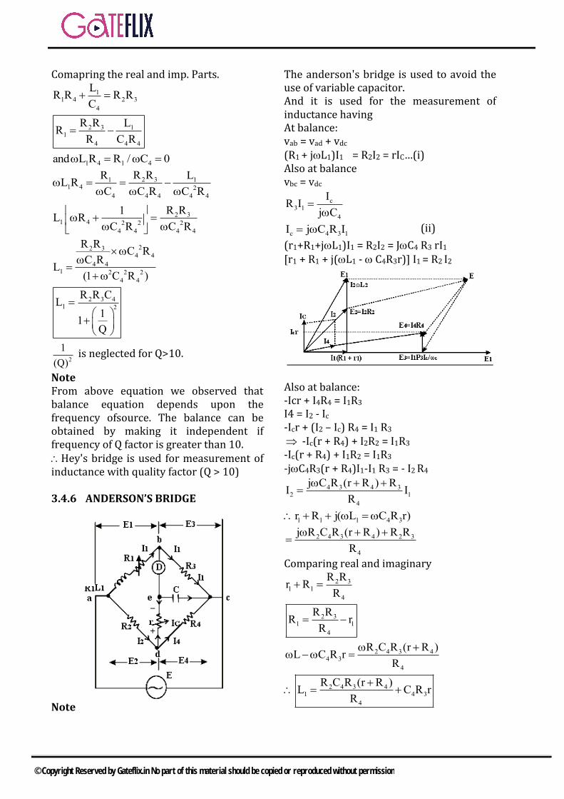
Comapring the real and imp. Parts.
11 4 2 3
4
LR R R R
C
2 3 11
4 4 4
R R LR
R C R
1 4 1 4and L R R / C 0
2 31 11 4 2
4 4 4 4 4
R RR LL R
C C R C R
2 31 4 2 2 2
4 4 4 4
R R1L R
C R C R
22 34 4
4 41 2 2 2
4 4
R RC R
C RL
(1 C R )
2 3 41 2
R R CL
11
Q
2
1
(Q) is neglected for Q>10.
Note From above equation we observed that balance equation depends upon the frequency ofsource. The balance can be obtained by making it independent if frequency of Q factor is greater than 10. Hey's bridge is used for measurement of inductance with quality factor (Q > 10)
3.4.6 ANDERSON’S BRIDGE
Note
The anderson's bridge is used to avoid the use of variable capacitor. And it is used for the measurement of inductance having At balance: vab = vad + vdc
(R1 + jL1)I1 = R2I2 = rIC…(i) Also at balance vbc = vdc
c3 1
4
IR I
j C
c 4 3 1I j C R I (ii)
(r1+R1+jL1)I1 = R2I2 = JC4 R3 rI1 [r1 + R1 + j(L1 - C4R3r)] I1 = R2 I2
Also at balance: -Icr + I4R4 = I1R3 I4 = I2 - Ic -Icr + (I2 – Ic) R4 = I1 R3
-Ic(r + R4) + I2R2 = I1R3 -Ic(r + R4) + I1R2 = I1R3
-jC4R3(r + R4)I1-I1 R3 = - I2 R4
4 3 4 32 1
4
j C R (r R ) RI I
R
1 1 1 4 3r R j( L C R r)
2 4 3 4 2 3
4
j R C R (r R ) R R
R
Comparing real and imaginary
2 31 1
4
R Rr R
R
2 31 1
4
R RR r
R
2 4 3 44 3
4
R C R (r R )L C R r
R
2 4 3 41 4 3
4
R C R (r R )L C R r
R
© Copyright Reserved by Gateflix.in No part of this material should be copied or reproduced without permission
3.4.7 OWEN’S BRIDGE
At balance Z1Z4 = Z2Z3
3.4.8 WIEN’S BRIDGE
(1) freq. measurement (2) harmonic distortion analyzer (3) notch filter (4) audio and HF oscillator
1 4
3
R R
R= 1 1
2
2
C RR
C
+ j 1 1 2
2
1C R R
c
Comparing both sides
1 4 1 12
3 2
R R C RR
R C …(i)
And
1 1 2
2
1C R R
C
1 2 1 2
1
C C R R
1 2 1 2
1f .2 C C R R
…(ii)
From Equation (i)
4 2 1
3 1 2
R R C
R R C
1 2 1 2whenC C ,R R
4 3R 2R
1and f
2 RC
Note: 1. Wein's bridge is used for measurement
of frequency from 100 Hz to 100 KHzAudio AndHF frequency range.
2. Wein's bridge can be used as Notchfiller in Harmonic distortion analyser.
3. Harmonics in supply can disturb thebalance. It is very sensitive towardsharmonics in supply.
4. Wein's bridge can also be used formeasurement of capacitance.
3.5 A.C. BRIDGES
3.5.1 INTRODUCTION
Alternating current bridge methods are of outstanding importance for measurement of electrical quantities. Measurement of inductance, capacitance, storage factor, loss factor may be made
3.5.2 SOURCES AND DETECTORS
For measurement at low frequencies, the power line may act as the source of supply to the bridge circuit. For higher frequencies electronics oscillators are universally used as bridge source supplies. These oscillators have the advantage that the frequency is constant, easily adjustable, and determinable with accuracy. The waveform is very close to a sine wave, and their power output is sufficient for most bridge measurement. A typical oscillator has a frequency range of 40 Hz to 125 kHz with a power output of 7 W. The detectors commonly used for a.c. bridges are (i) Head phones, (ii) Vibration galvanometers, and (iii) Tuneable amplifier detectors. Head phones are widely used as detectors at frequencies of 250 Hz and over upto 3 or 4 kHz. They are most sensitive detectors for this frequency range. Vibration galvanometers are extremely useful for power and low audio frequency ranges. Vibration galvanometers are manufactured to work at various frequencies ranging from 5 Hz to 1000 Hz but are most commonly used below 200 Hz as below this frequency they are more sensitive than the head phones. Tuneable amplifier detectors are the most versatile of the detectors. This detector can be used, over a frequency range of 10 Hz to 100 kHz.
© Copyright Reserved by Gateflix.in No part of this material should be copied or reproduced without permission
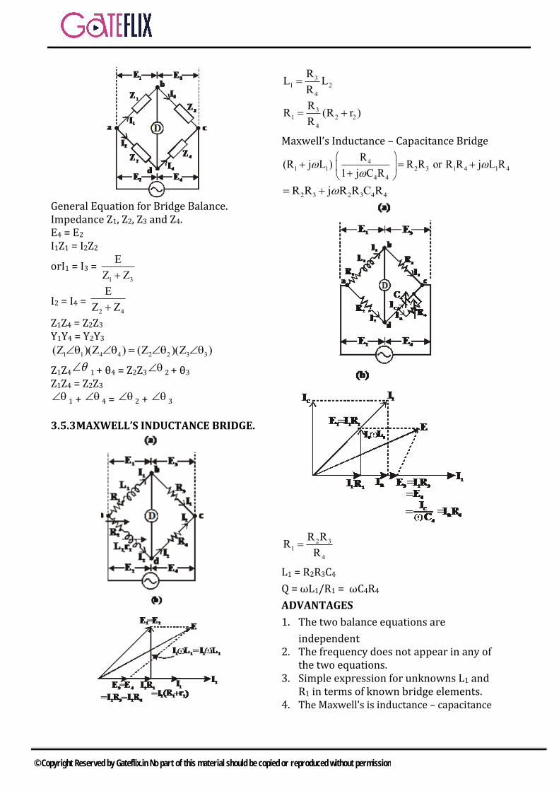
General Equation for Bridge Balance. Impedance Z1, Z2, Z3 and Z4. E4 = E2 I1Z1 = I2Z2
orI1 = I3 = 1 3
E
Z Z
I2 = I4 = 2 4
E
Z Z
Z1Z4 = Z2Z3 Y1Y4 = Y2Y3
1 1 4 4 2 2 3 3(Z )(Z ) (Z )(Z )
Z1Z4
1 + θ4 = Z2Z3 2 + θ3
Z1Z4 = Z2Z3 1 + 4 = 2 + 3
3.5.3 MAXWELL’S INDUCTANCE BRIDGE.
31 2
4
RL L
R
31 2 2
4
RR (R r )
R
Maxwell’s Inductance – Capacitance Bridge
41 1 2 3 1 4 1 4
4 4
R(R j L ) R R or R R j L R
1 j C R
2 3 2 3 4 4R R j R R C R
2 31
4
R RR
R
L1 = R2R3C4
Q = ωL1/R1 = ωC4R4
ADVANTAGES
1. The two balance equations are
independent2. The frequency does not appear in any of
the two equations.3. Simple expression for unknowns L1 and
R1 in terms of known bridge elements.4. The Maxwell’s is inductance – capacitance
© Copyright Reserved by Gateflix.in No part of this material should be copied or reproduced without permission
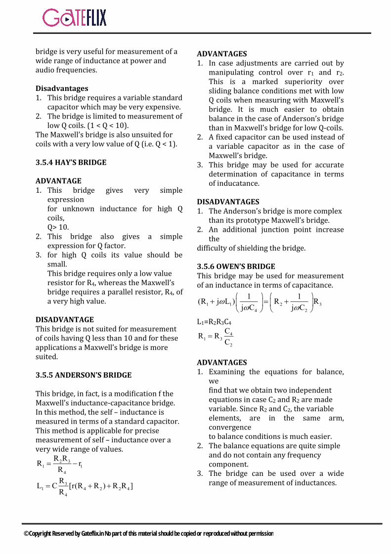
bridge is very useful for measurement of a wide range of inductance at power and audio frequencies.
Disadvantages 1. This bridge requires a variable standard
capacitor which may be very expensive.2. The bridge is limited to measurement of
low Q coils. (1 < Q < 10).The Maxwell’s bridge is also unsuited for coils with a very low value of Q (i.e. Q < 1).
3.5.4 HAY’S BRIDGE
ADVANTAGE 1. This bridge gives very simple
expressionfor unknown inductance for high Qcoils,Q> 10.
2. This bridge also gives a simpleexpression for Q factor.
3. for high Q coils its value should besmall.This bridge requires only a low valueresistor for R4, whereas the Maxwell’sbridge requires a parallel resistor, R4, ofa very high value.
DISADVANTAGE This bridge is not suited for measurement of coils having Q less than 10 and for these applications a Maxwell’s bridge is more suited.
3.5.5 ANDERSON’S BRIDGE
This bridge, in fact, is a modification f the Maxwell’s inductance-capacitance bridge. In this method, the self – inductance is measured in terms of a standard capacitor. This method is applicable for precise measurement of self – inductance over a very wide range of values.
2 31 1
4
R RR r
R
31 4 2 2 4
4
RL C [r(R R ) R R ]
R
ADVANTAGES1. In case adjustments are carried out by
manipulating control over r1 and r2.This is a marked superiority oversliding balance conditions met with lowQ coils when measuring with Maxwell’sbridge. It is much easier to obtainbalance in the case of Anderson’s bridgethan in Maxwell’s bridge for low Q-coils.
2. A fixed capacitor can be used instead ofa variable capacitor as in the case ofMaxwell’s bridge.
3. This bridge may be used for accuratedetermination of capacitance in termsof inducatance.
DISADVANTAGES 1. The Anderson’s bridge is more complex
than its prototype Maxwell’s bridge.2. An additional junction point increase
thedifficulty of shielding the bridge.
3.5.6 OWEN’S BRIDGE This bridge may be used for measurement of an inductance in terms of capacitance.
1 1 2 3
4 2
1 1(R j L ) R R
j C j C
L1=R2R3C4
41 3
2
CR R
C
ADVANTAGES 1. Examining the equations for balance,
wefind that we obtain two independentequations in case C2 and R2 are madevariable. Since R2 and C2, the variableelements, are in the same arm,convergenceto balance conditions is much easier.
2. The balance equations are quite simpleand do not contain any frequencycomponent.
3. The bridge can be used over a widerange of measurement of inductances.
© Copyright Reserved by Gateflix.in No part of this material should be copied or reproduced without permission
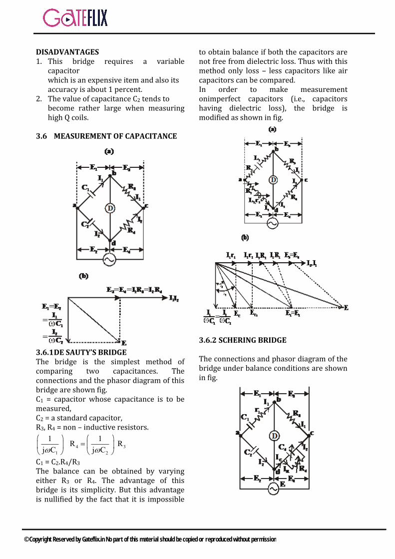
DISADVANTAGES 1. This bridge requires a variable
capacitorwhich is an expensive item and also itsaccuracy is about 1 percent.
2. The value of capacitance C2 tends tobecome rather large when measuringhigh Q coils.
3.6 MEASUREMENT OF CAPACITANCE
3.6.1 DE SAUTY’S BRIDGE The bridge is the simplest method of comparing two capacitances. The connections and the phasor diagram of this bridge are shown fig. C1 = capacitor whose capacitance is to be measured, C2 = a standard capacitor, R3, R4 = non – inductive resistors.
4 3
1 2
1 1R R
j C j C
C1 = C2.R4/R3 The balance can be obtained by varying either R3 or R4. The advantage of this bridge is its simplicity. But this advantage is nullified by the fact that it is impossible
to obtain balance if both the capacitors are not free from dielectric loss. Thus with this method only loss – less capacitors like air capacitors can be compared. In order to make measurement onimperfect capacitors (i.e., capacitors having dielectric loss), the bridge is modified as shown in fig.
3.6.2 SCHERING BRIDGE
The connections and phasor diagram of the bridge under balance conditions are shown in fig.
© Copyright Reserved by Gateflix.in No part of this material should be copied or reproduced without permission
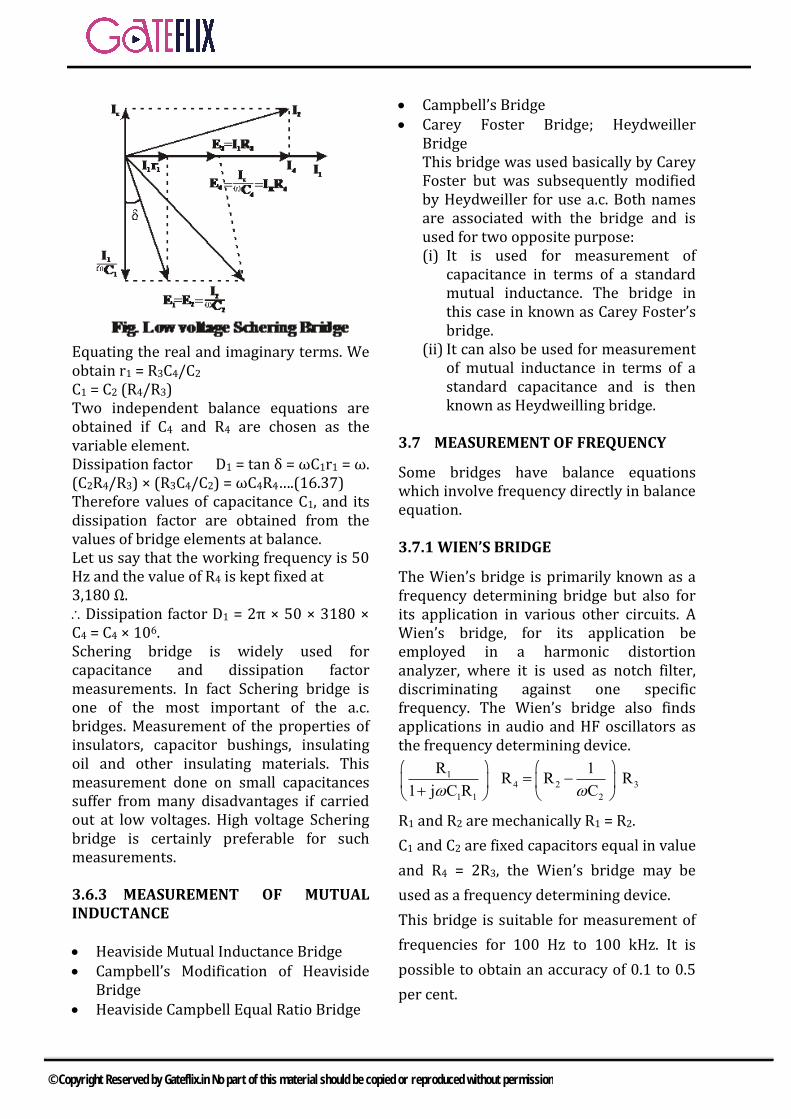
Equating the real and imaginary terms. We obtain r1 = R3C4/C2 C1 = C2 (R4/R3) Two independent balance equations are obtained if C4 and R4 are chosen as the variable element. Dissipation factor D1 = tan δ = ωC1r1 = ω. (C2R4/R3) × (R3C4/C2) = ωC4R4….(16.37) Therefore values of capacitance C1, and its dissipation factor are obtained from the values of bridge elements at balance. Let us say that the working frequency is 50 Hz and the value of R4 is kept fixed at 3,180 Ω. Dissipation factor D1 = 2π × 50 × 3180 × C4 = C4 × 106. Schering bridge is widely used for capacitance and dissipation factor measurements. In fact Schering bridge is one of the most important of the a.c. bridges. Measurement of the properties of insulators, capacitor bushings, insulating oil and other insulating materials. This measurement done on small capacitances suffer from many disadvantages if carried out at low voltages. High voltage Schering bridge is certainly preferable for such measurements.
3.6.3 MEASUREMENT OF MUTUAL INDUCTANCE
Heaviside Mutual Inductance Bridge Campbell’s Modification of Heaviside
Bridge Heaviside Campbell Equal Ratio Bridge
Campbell’s Bridge Carey Foster Bridge; Heydweiller
BridgeThis bridge was used basically by CareyFoster but was subsequently modifiedby Heydweiller for use a.c. Both namesare associated with the bridge and isused for two opposite purpose:(i) It is used for measurement of
capacitance in terms of a standard mutual inductance. The bridge in this case in known as Carey Foster’s bridge.
(ii) It can also be used for measurement of mutual inductance in terms of a standard capacitance and is then known as Heydweilling bridge.
3.7 MEASUREMENT OF FREQUENCY
Some bridges have balance equations which involve frequency directly in balance equation.
3.7.1 WIEN’S BRIDGE
The Wien’s bridge is primarily known as a frequency determining bridge but also for its application in various other circuits. A Wien’s bridge, for its application be employed in a harmonic distortion analyzer, where it is used as notch filter, discriminating against one specific frequency. The Wien’s bridge also finds applications in audio and HF oscillators as the frequency determining device.
14 2 3
1 1 2
R 1R R R
1 j C R C
R1 and R2 are mechanically R1 = R2.
C1 and C2 are fixed capacitors equal in value
and R4 = 2R3, the Wien’s bridge may be
used as a frequency determining device.
This bridge is suitable for measurement of
frequencies for 100 Hz to 100 kHz. It is
possible to obtain an accuracy of 0.1 to 0.5
per cent.
© Copyright Reserved by Gateflix.in No part of this material should be copied or reproduced without permission
The bridge is not balanced for any harmonics present in the applied voltage. The difficulty can be overcome by connecting a filter in series with the null detector. A Wien’s bridge may be used for measurement of capacitance also.
3.7.2 UNIVERSAL IMPEDANCE BRIDGE
One of the most useful and versatile laboratory bridges is the Universal Impedance Bridge. This instrument is capable of measuring both d.c. and a.c. resistance, inductance and storage factor Q factor of an inductor, capacitance and dissipation factor D of a capacitor. The universal bridge consists of four basic bridge circuits. It has suitable a.c. and d.c. sources, a.c. and d.c. null detectors, and impedance standards. The Wheatstone bridge is used for both d.c. and a.c. resistance measurements.
3.7.3 WAGNER EARTHING DEVICE
very high accuracy in measurement is made possible by the additional of a Wagner earthing device. This device removes all the earth capacitances from the bridge network.
Fig : Wagner Earthing Devise
© Copyright Reserved by Gateflix.in No part of this material should be copied or reproduced without permission
Q.1 Kelvin double bridge is best suited for the measurement of a) Resistance of very low valueb) Low value capacitancec) Resistance of very high valued) High value capacitance
[GATE-2002]
Q.2 A dc potentiometer is designed to measure up to about 2V with a slide wire of 800mm. A standard cell of emf 1.18V obtains balance at 600mm. A test cell is seen to obtain balance at 680mm. The emf of the test cell is a)1.00V b)1.34V c)1.50V d)1.70V
[GATE-2004]
Q.3 The set-up in the figure is used to measure resistance R. The ammeter and voltmeter resistance are 0.01Ω
and2000Ω , respectively Their
reading are 2A and 180V, giving a measured resistance of 90Ω .The percentage error in the measurement is
a)2.25% b)2.35% c) 4.5% d)4.71%
[GATE-2005]
Q.4 1R and 4R are the opposite arms of
a Wheatstone bridge as are and 2R .
The source voltage is applied across
1R and 3R .Under balanced
conditions which one of the following is true?
a) 1 3 4 2R R R / R
b) 1 2 3 4R R R / R
c) 1 2 4 3R R R / R
d) 1 2 3 4R R R R
[GATE-2006]
Q.5 Suppose that resistors R1 and R2 are connected in parallel to give an equivalent resistor R. If resistors R1 and R2 have tolerance of 1% each, the equivalent resistor R for resistors R1 = 300Ωand R2 = 200Ω will have tolerance of a) 0.5% b) 1%c) 1.2% d) 2%
[GATE-2014-2]
Q.6 An unbalanced DC Wheatstone bridge is shown in the figure. At what value of p will the magnitude of Vo be maximum? Ai‘ir1 Engineering SI
[GATE-2015-1]
Q.7 The bridge most suited for measurement of a four-terminal resistance in the range of 0.001 to 0.1 is
a) Wien’s bridgeb) Kelvin double bridgec) Maxwell’s bridged) Schering bridge
[GATE-2015]
Q.8 A dc potentiometer, shown in figure below, is made by connecting fifteen 10 resistors and a 10 slide wire of length 1000 mm in series. The potentiometer is standardized with the current Ip = 10.0000 mA. Balance for an unknown voltage is obtained when the dial is in position 11 (11 numbers of the fixed 10
GATE QUESTIONS (AC Bridge)
© Copyright Reserved by Gateflix.in No part of this material should be copied or reproduced without permission
resistor are included) and the slide wire is on the 234th mm position. The unknown voltage (up to four decimal places) in volt is _______ .
[GATE-2016]
Q.9 When the voltage across a battery is measured using a d.c. potentiometer, the reading shows 1.08V. But when the same voltage is measured using a Permanent Magnet Moving Coil (PMMC) voltmeter, the voltmeter reading shows 0.99V. If the resistance of the voltmeter is 1100 , the internal resistance of the battery, in , is _________.
[GATE-2017]
1 2 3 4 5 6 7 8 9
(a) (b) (c) (b) (b) (a) (b) 1.1234 100
ANSWER KEY:
© Copyright Reserved by Gateflix.in No part of this material should be copied or reproduced without permission
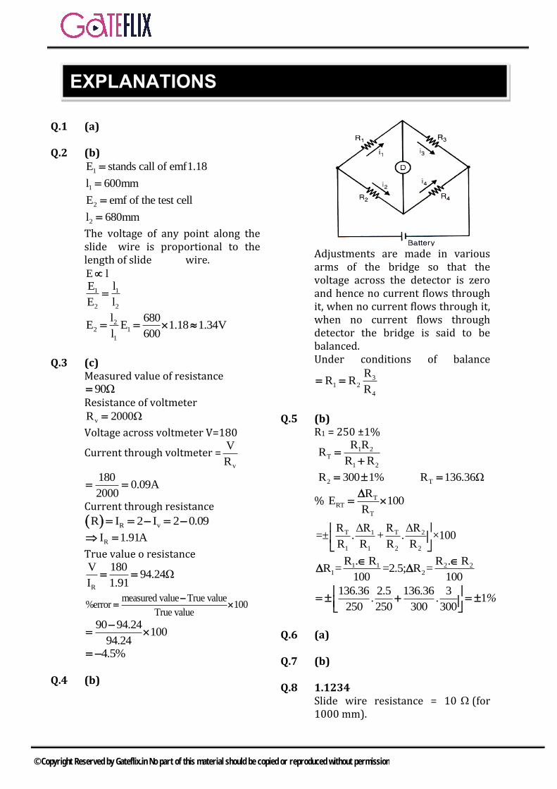
Q.1 (a)
Q.2 (b)
1E stands call of emf1.18
1l 600mm
2E emf of the test cell
2l 680mm
The voltage of any point along the slide wire is proportional to the length of slide wire. E l
1 1
2 2
E l
E l
22 1
1
l 680E E 1.18 1.34V
l 600
Q.3 (c) Measured value of resistance
90Ω Resistance of voltmeter
vR 2000Ω
Voltage across voltmeter V=180
Current through voltmeter =v
V
R
1800.09A
2000
Current through resistance
R vR I 2 I 2 0.09
RI 1.91A
True value o resistance
R
V 18094.24Ω
I 1.91
measured value True value%error 100
True value
90 94.24100
94.24
4.5%
Q.4 (b)
Adjustments are made in various arms of the bridge so that the voltage across the detector is zero and hence no current flows through it, when no current flows through it, when no current flows through detector the bridge is said to be balanced. Under conditions of balance
31 2
4
RR R
R
Q.5 (b) R1 = 250 ±1%
1 2T
1 2
R RR
R R
2R 300 1% TR 136.36Ω
% TRT
T
RE 100
R
T 1 T 2
1 1 2 2
R ΔR R ΔR=± . + . ×100
R R R R
1 1 2 21 2
R . R R . RR = =2.5; R =
100 100
136.36 2.5 136.36 31
250 250 300 300. . %
Q.6 (a)
Q.7 (b)
Q.8 1.1234 Slide wire resistance = 10 (for 1000 mm).
EXPLANATIONS
© Copyright Reserved by Gateflix.in No part of this material should be copied or reproduced without permission
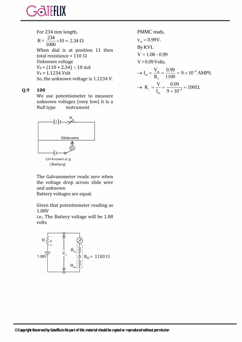
For 234 mm length, 234
R = 10 2.341000
When dial is at position 11 then total resistance = 110 Unknown voltage VX = (110 + 2.34) 10 mA VX = 1.1234 Volt So, the unknown voltage is 1.1234 V.
Q.9 100 We use potentiometer to measure unknown voltages (very low) it is a Null type instrument
The Galvanometer reads zero when the voltage drop across slide wire and unknown Battery voltages are equal.
Given that potentiometer reading as 1.08V i.e., The Battery voltage will be 1.08volts
m
4mm
v
i 4
m
PMMC reads,
v 0.99V.
ByKVL
V = 1.08 0.99
V=0.09Volts.
V 0.99I 9 10 AMPS.
R 1100
V 0.09R 100
I 9 10
© Copyright Reserved by Gateflix.in No part of this material should be copied or reproduced without permission
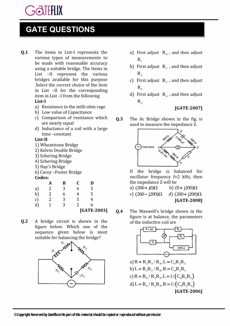
Q.1 The items in List-I represents the various types of measurements to be made with reasonable accuracy using a suitable bridge. The items in List –II represent the various bridges available for this purpose .Select the correct choice of the item in List –II for the corresponding item in List –I from the following List-I a) Resistance in the milli-ohm rageb) Low value of Capacitancec) Comparison of resistance which
are nearly equald) Inductance of a coil with a large
time –constantList-II 1) Wheatstone Bridge2) Kelvin Double Bridge3) Schering Bridge4) Schering Bridge5) Hay’s Bridge6) Carey –Foster BridgeCodes:
A B C D a) 2 3 6 5 b) 2 6 4 5 c) 2 3 5 4 d) 1 3 2 6
[GATE-2003]
Q.2 A bridge circuit is shown in the figure below. Which one of the sequence given below is most suitable for balancing the bridge?
a) First adjust 4R , and then adjust
1R
b) First adjust 2R , and then adjust
3R
c) First adjust 2R , and then adjust
4R
d) First adjust 4R , and then adjust
2R
[GATE-2007]
Q.3 The Ac Bridge shown in the fig. is used to measure the impedance Z.
If the bridge is balanced for oscillator frequency f=2 kHz, then the impedance Z will be a) (260 j0)Ω b) (0 j200)Ω
c) (260 j200)Ω d) (260 j200)Ω
[GATE-2008]
Q.4 The Maxwell’s bridge shown in the figure is at balance, the parameters of the inductive coil are
a) 2 3 4 4 2 3R R R / R ,L C R R
b) 2 3 4 4 2 3L R R / R ,R C R R
c) 4 2 3 4 2 3R R / R R ,L 1/ C R R
d) 4 2 3 4 2 3L R / R R ,R 1/ C R R
[GATE-2006]
GATE QUESTIONS
© Copyright Reserved by Gateflix.in No part of this material should be copied or reproduced without permission
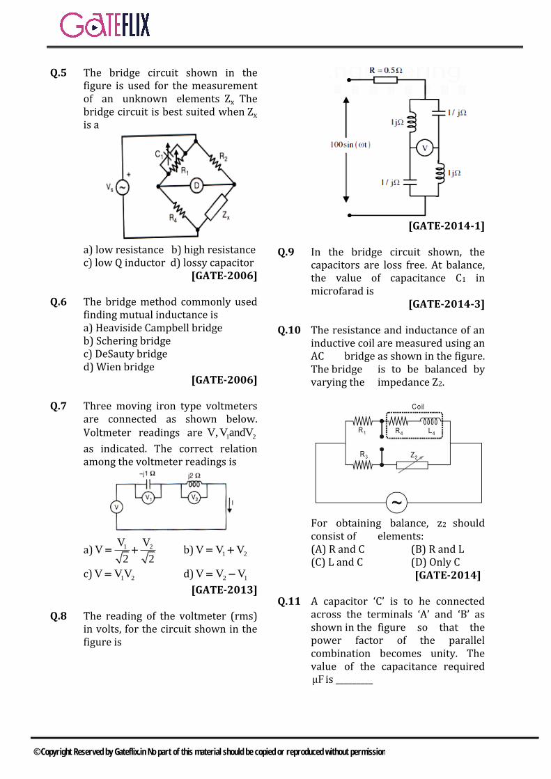
Q.5 The bridge circuit shown in the figure is used for the measurement of an unknown elements Zx The bridge circuit is best suited when Zx is a
a) low resistance b) high resistancec) low Q inductor d) lossy capacitor
[GATE-2006]
Q.6 The bridge method commonly used finding mutual inductance is a) Heaviside Campbell bridgeb) Schering bridgec) DeSauty bridged) Wien bridge
[GATE-2006]
Q.7 Three moving iron type voltmeters are connected as shown below. Voltmeter readings are 1 2V,VandV
as indicated. The correct relation among the voltmeter readings is
a) 1 2V VV
2 2 b) 1 2V V V
c) 1 2V VV d) 2 1V V V
[GATE-2013]
Q.8 The reading of the voltmeter (rms) in volts, for the circuit shown in the figure is
[GATE-2014-1]
Q.9 In the bridge circuit shown, the capacitors are loss free. At balance, the value of capacitance C1 in microfarad is
[GATE-2014-3]
Q.10 The resistance and inductance of an inductive coil are measured using an AC bridge as shown in the figure. The bridge is to be balanced by varying the impedance Z2.
For obtaining balance, z2 should consist of elements: (A) R and C (B) R and L (C) L and C (D) Only C
[GATE-2014]
Q.11 A capacitor ‘C’ is to he connected across the terminals ‘A’ and ‘B’ as shown in the figure so that the power factor of the parallel combination becomes unity. The value of the capacitance required μF is _________
© Copyright Reserved by Gateflix.in No part of this material should be copied or reproduced without permission
[GATE-2014]
Q.12 The inductance of a coil is measured using the bridge shown in the figure. Balance (D = 0) is obtained with
1 1 2 41nF, R 2.2M R 22.2k R 10 kC
The value of the inductance Lx (in mH) is ___.
[GATE-2014]
Q.13 A high Q coil having distributed (self) capacitance is tested with a Q-
meter. First resonance at 6
1 10
rad/s is obtained with a capacitance of 990 pF. The second resonance at
6
2 2 10 rad/s is obtained with a
240 pF capacitance. The value of the inductance (in mH) of the coil is (up to one decimal place) ________.
[GATE-2018]
1 2 3 4 5 6 7 8 9
(a) (c) (a) (a) (c) (a) (d) 142 0.3
10 11 12 13
(b) 187 222 1
ANSWER KEY:
© Copyright Reserved by Gateflix.in No part of this material should be copied or reproduced without permission
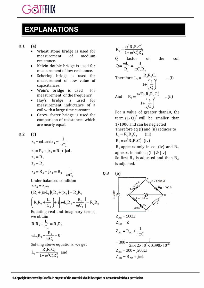
Q.1 (a) Wheat stone bridge is used for
measurement of mediumresistance.
Kelvin double bridge is used formeasurement of low resistance.
Schering bridge is used formeasurement of low value ofcapacitances.
Wein’s bridge is used for measurement of the frequency
Hay’s bridge is used formeasurement inductance of acoil with a large time constant.
Carey- foster bridge is used forcomparison of resistances whichare nearly equal.
Q.2 (c)
1 1 4
4
1x ωL andx
ωC
1 1 1 1 1z R jx R jωL
2 2z R
3 3z R
4 4 4z R jx 4
4
1R
ωC
Under balanced condition
1 4 2 3z z z z
1 1 4 4 2 3R jωL R jx R R
1 11 4 1 4 2 3
4 4
L RR R j ωL R R R
C ωC
Equating real and imaginary terms, we obtain
11 4 2 3
4
LR R R R
C
11 4
4
RωL R 0
ωC
Solving above equations, we get
2 3 41 2 2 2
4 4
R R CL
1 ω C R
and
2 2
2 3 42 2 2 2
4 4
ω R R CR
1 ω C R
Q factor of the coil
1
1 4 4
ωL 1Q
R ωC R
Therefore 2 3 41 2
R R CL
11
Q
….(i)
And 2 2
2 3 4 41 2
ω R R R CR
11
Q
…(ii)
For a value of greater than10, the
term 2
1/ Q will be smaller than
1/1000 and can be neglected Therefore eq (i) and (ii) reduces to
1 2 3 4L R R C (iii) 2 2
1 2 3 4R ω R R C (iv)
4R appears only in eq. (iv) and 2R
appears in both eq (iii) & (iv) So first 2R is adjusted and then 4R
is adjusted.
Q.3 (a)
ABZ 500Ω
CDZ Z
BC BC
1Z R
jωC
3 6
j300
2π 2 10 0.398 10
BCZ 300 j200Ω
AD ADZ R jωL
EXPLANATIONS
© Copyright Reserved by Gateflix.in No part of this material should be copied or reproduced without permission
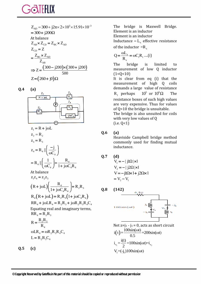
3 3
ADZ 300 j2π 2 10 15.91 10
300 j200Ω
At balance
AB CD BC ADZ Z Z Z
CDZ Z
BC AD
AB
Z Z
Z
300 j200 300 j200Z
500
Z 260 j0 Ω
Q.4 (a)
1z R jωL
2 2z R
3 3z R
4 4
4
jz R
ωC||
44
4 4 4
R1R
ωC 1 jωC R||
At balance
1 4 2 3z z z z
42 3
4 4
RR jωL R R
1 jωC R
4 2 3 4 4R R jωL R R 1 jωC R
4 4 2 3 2 3 4 4RR jωLR R R jωR R R C
Equating real and imaginary terms,
4 2 3RR R R
2 3
4
R RR
R
4 2 3 4 4ωLR ωR R R C
2 3 4L R R C
Q.5 (c)
The bridge is Maxwell Bridge. Element is an inductor Element is an inductor Inductance xL effective resistance
of the inductor x=R
x1 1
x
ωLQ ωC R
R ….(i)
The bridge is limited to measurement of low Q inductor (1<Q<10) It is clear from eq (i) that the measurement of high Q coils demands a large value of resistance
1R perhaps 510 or 610 Ω The
resistance boxes of such high values are very expensive. Thus for values of Q>10 the bridge is unsuitable. The bridge is also unsuited for coils with very low values of Q (i.e. Q<1)
Q.6 (a) Heaviside Campbell bridge method commonly used for finding mutual inductance.
Q.7 (d)
1V | j1Ω| l
2V | j2Ω| l
V j1Ω l j2Ω l
2 1V V
Q.8 (142)
Net z=j1 - j1 = 0, acts as short circuit
100sin(ωt)
i t = =200sin(ωt)0.5
1 2v v
i(t)i = =100sin(ωt)=i
2
1 1V =(-j )100sin(ωt)
© Copyright Reserved by Gateflix.in No part of this material should be copied or reproduced without permission
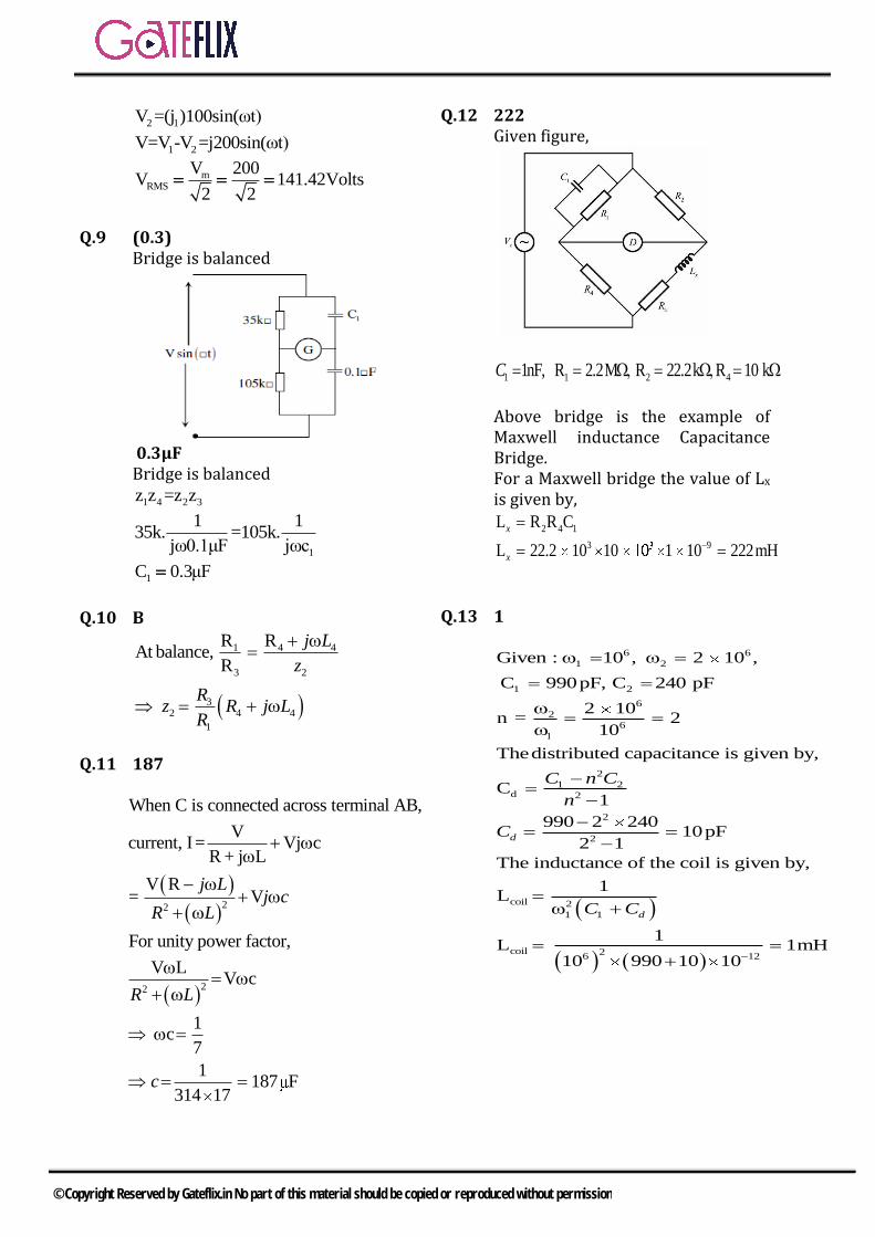
2 1V =(j )100sin(ωt)
1 2V=V -V =j200sin(ωt)
mRMS
V 200V 141.42Volts
2 2
Q.9 (0.3) Bridge is balanced
0.3μF Bridge is balanced
1 4 2 3z z =z z
1
1 135k. =105k.
jω0.1μF jωc
1C 0.3μF
Q.10 B
1 4 4
3 2
32 4 4
1
R RAt balance,
R
j L
z
Rz R j L
R
Q.11 187
22
22
When C is connected across terminal AB,
Vcurrent, I= Vj c
R + j L
V R= V
For unity power factor,
V LV c
1c
7
1187 F
314 17
j Lj c
R L
R L
c
Q.12 222 Given figure,
1 1 2 41nF, R 2.2M R 22.2k R 10 kC
Above bridge is the example of Maxwell inductance Capacitance Bridge. For a Maxwell bridge the value of Lx is given by,
2 4 1
3 9
L R R C
L 22.2 10 10 1 10 222mH
x
x
Q.13 1
6 6
1 2
1 2
6
2
6
2
1 2d 2
2
2
coil 2
1 1
coil 26
Given : 10 , 2 10 ,
C 990pF, C 240 pF
2 10n = 2
10
Thedistributed capacitance is given by,
C1
990 2 24010pF
2 1
The inductance of the coil is given by,
1L
1L
10 990
d
d
C n C
n
C
C C
12
1mH10 10
© Copyright Reserved by Gateflix.in No part of this material should be copied or reproduced without permission
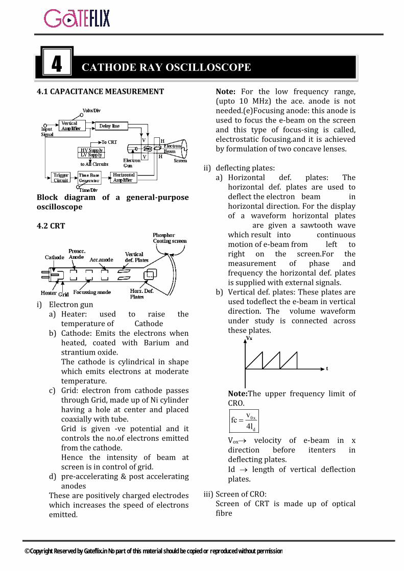
4.1 CAPACITANCE MEASUREMENT
Block diagram of a general-purpose oscilloscope
4.2 CRT
i) Electron guna) Heater: used to raise the
temperature of Cathode b) Cathode: Emits the electrons when
heated, coated with Barium andstrantium oxide.The cathode is cylindrical in shapewhich emits electrons at moderatetemperature.
c) Grid: electron from cathode passesthrough Grid, made up of Ni cylinderhaving a hole at center and placedcoaxially with tube.Grid is given -ve potential and itcontrols the no.of electrons emittedfrom the cathode.Hence the intensity of beam atscreen is in control of grid.
d) pre-accelerating & post acceleratinganodes
These are positively charged electrodes which increases the speed of electrons emitted.
Note: For the low frequency range, (upto 10 MHz) the ace. anode is not needed.(e)Focusing anode: this anode is used to focus the e-beam on the screen and this type of focus-sing is called, electrostatic focusing.and it is achieved by formulation of two concave lenses.
ii) deflecting plates:a) Horizontal def. plates: The
horizontal def. plates are used todeflect the electron beam inhorizontal direction. For the displayof a waveform horizontal plates
are given a sawtooth wave which result into continuous motion of e-beam from left to right on the screen.For the measurement of phase and frequency the horizontal def. plates is supplied with external signals.
b) Vertical def. plates: These plates areused todeflect the e-beam in verticaldirection. The volume waveformunder study is connected acrossthese plates.
Note:The upper frequency limit of CRO.
0x
d
vfc
4l
Vox velocity of e-beam in x direction before itenters in deflecting plates. Id length of vertical deflection plates.
iii) Screen of CRO:Screen of CRT is made up of opticalfibre
4 CATHODE RAY OSCILLOSCOPE
© Copyright Reserved by Gateflix.in No part of this material should be copied or reproduced without permission
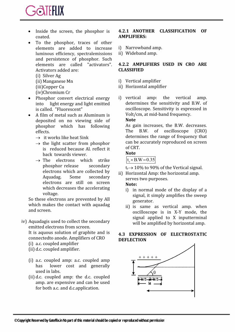
Inside the screen, the phosphor iscoated.
To the phosphor, traces of otherelements are added to increaseluminous efficiency, spectralemissionsand persistence of phosphor. Suchelements are called "activators".Activators added are:(i) Silver Ag(ii) Manganese Mn(iii)Copper Cu(iv)Chromium Cr
Phosphor convert electrical energyinto light energy and light emittedis called. "Fluorescent"
A film of metal such as Aluminum isdeposited on no viewing side ofphosphor which has followingeffects. it works like heat Sink the light scatter from phosphor
is reduced because Al. reflect it back towards viewer.
The electrons which strike phosphor release secondary electrons which are collected by Aquadag. Some secondary electrons are still on screen which decreases the accelerating voltage.
So these electrons are prevented by All which makes the contact with aquadag and screen.
iv) Aquadagis used to collect the secondaryemitted electrons from screen.It is aquous solution of graphite and isconnectedto anode. Amplifiers of CRO(i) a.c. coupled amplifier(ii) d.c. coupled amplifier.
(i) a.c. coupled amp: a.c. coupled amp has lower cost and generally used in labs.
(ii) d.c. coupled amp: the d.c. coupled amp. are expensive and can be used for both a.c. and d.c.application.
4.2.1 ANOTHER CLASSIFICATION OF AMPLIFIERS:
i) Narrowband amp.ii) Wideband amp.
4.2.2 AMPLIFIERS USED IN CRO ARE CLASSIFIED
i) Vertical amplifierii) Horizontal amplifier
i) vertical amp: the vertical amp.determines the sensitivity and B.W. ofoscilloscope. Sensitivity is expressed inVolt/cm, at mid-band frequency.NoteAs gain increases, the B.W. decreases.The B.W. of oscilloscope (CRO)determines the range of frequency thatcan be accurately reproduced on screenof CRT.Note
rt B.W 0.35
tr 10% to 90% of the Vertical signal. ii) Horizontal Amp: the horizontal amp.
serves two purposes.Note:i) in normal mode of the display of a
signal, it simply amplifies the sweepgenerator.
ii) is same as vertical amp. whenoscilloscope is in X-Y mode, thesignal applied to X inputterminalwill be amplified by horizontal amp.
4.3 EXPRESSION OF ELECTROSTATIC DEFLECTION
© Copyright Reserved by Gateflix.in No part of this material should be copied or reproduced without permission
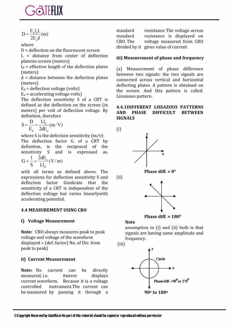
d d
a
E l LD (m)
2E d
where D = deflection on the fluorescent screen L = distance from center of deflection platesto screen (meters) Id = effective length «f the deflection plates (meters) d = distance between the deflection plates (meters) Ed = deflection voltage (volts) Ea = accelerating voltage volts) The deflection sensitivity S of a CRT is defined as the deflection on the screen (in meters) per volt of deflection voltage. By definition, therefore
d
d a
LlDS (m /V)
E 2dE
where S is the defection sensitivity (m/v)- The deflection factor G. of a CRT by definition, is the reciprocal of the sensitivity S and is expressed as.
a
d
2dE1G (V /m)
S Ll
with all terms as defined above. The expressions for deflection sensitivity S and deflection factor Gindicate that the sensitivity of a CRT is independent of the deflection voltage but varies linearlywith accelerating potential.
4.4 MEASUREMENT USING CRO
I) Voltage Measurement
Note: CRO always measures peak to peak voltage and voltage of the waveform displayed = (def. factor) No. of Div. from peak to peak)
ii) Current Measurement
Note: No current can be directly measured, i.e. itnever displays current waveform. Because it is a voltage controlled instrument.The current can be measured by passing it through a
standard resistance The voltage across standard resistance is displayed on CRO. The voltage measured from CRO divided by it gives value of current
iii) Measurement of phase and frequency
(a) Measurement of phase difference between two signals: the two signals are connected across vertical and horizontal deflecting plates. A pattern is obtained on the screen. And this pattern is called. Lissazous pattern.
4.4.1DIFFERENT LISSAZOUS PATTERNS AND PHASE DIFFICULT BETWEEN SIGNALS
(i)
Phase diff. = 0 (ii)
Phase diff. = 180 Note assumption in (i) and (ii) both is that signals are having same amplitude and frequency.
(iii)
90o to 180o
© Copyright Reserved by Gateflix.in No part of this material should be copied or reproduced without permission
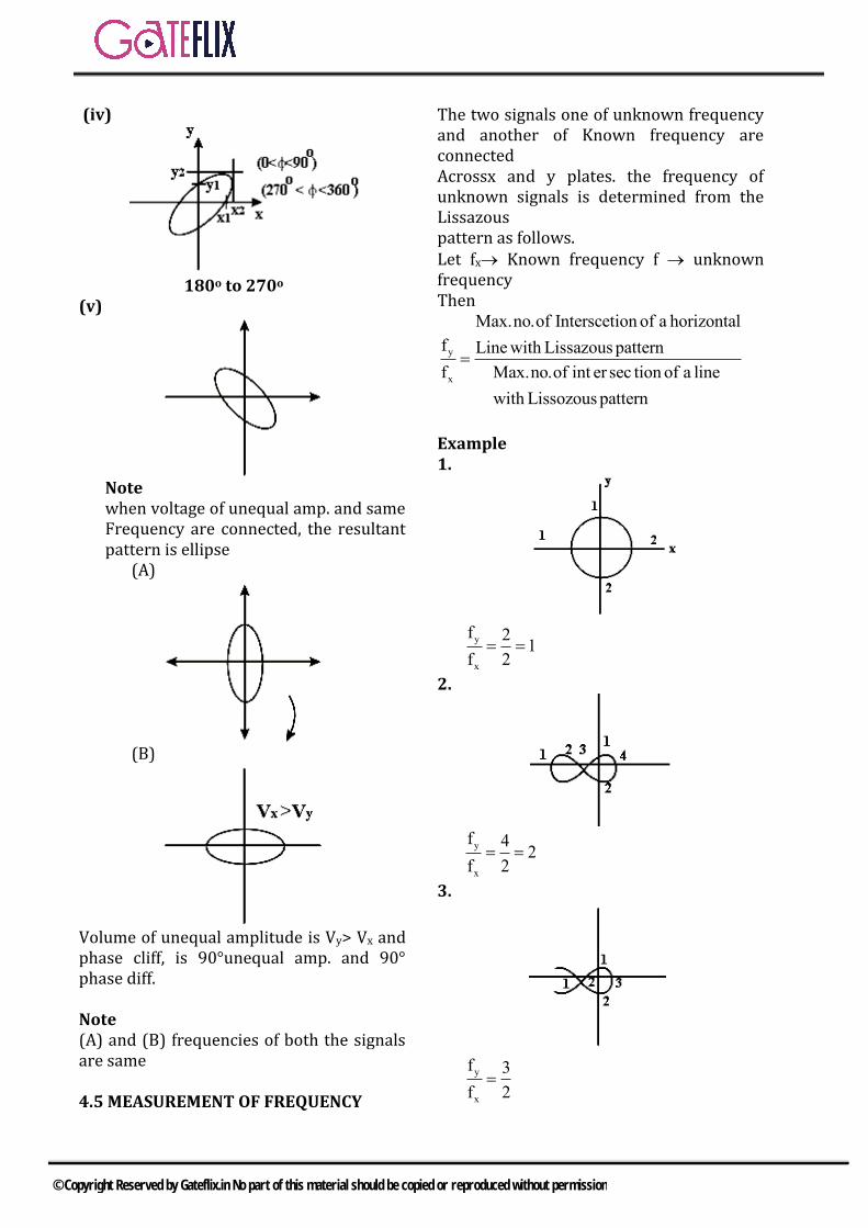
(iv)
180o to 270o (v)
Note when voltage of unequal amp. and same Frequency are connected, the resultant pattern is ellipse
(A)
(B)
Volume of unequal amplitude is Vy> Vx and phase cliff, is 90°unequal amp. and 90° phase diff.
Note (A) and (B) frequencies of both the signals are same
4.5 MEASUREMENT OF FREQUENCY
The two signals one of unknown frequency and another of Known frequency are connected Acrossx and y plates. the frequency of unknown signals is determined from the Lissazous pattern as follows. Let fx Known frequency f unknown frequency Then
y
x
Max.no.of Interscetion of a horizontal
f Linewith Lissazouspattern
f Max.no.of int er sec tion of a line
with Lissozouspattern
Example 1.
y
x
f 21
f 2
2.
y
x
f 42
f 2
3.
y
x
f 3
f 2
© Copyright Reserved by Gateflix.in No part of this material should be copied or reproduced without permission

4.
6 3
4 2
5.
y
x
f 6
f 2
4.5.1 SPECIAL OSCILLOSCOPES
In the conventional CRT the persistence of the phosphor ranges from a few milliseconds to several seconds, so that an event that occurs only once will disappear from the screen after a relatively short period of time. A storage CRT can retain the display much longer, up to several hours after the image was first written on the phosphor.
4.6 CATHODE RAY OSCILLOSCOP (CRO)
4.6.1 INTRODUCTION
The cathode ray oscilloscope (CRO) is a very useful and versatile laboratory instrument used for display, measurement and analysis of waveforms and other phenomena in electrical and electronic circuits. CROs are in fact very fast X – Y plotters, displaying an input signal versus time. The “stylus” of this “plotter” is a luminous spot which moves over the display area in response to an input voltage. The luminous spot is produced by a beam of electrons striking a fluorescent screen.
The normal form of a CRO uses a horizontal input voltage which is an internally generated ramp voltage called “Time Base”. CROs operate on voltages. However, it is possible to convert current, strain acceleration, pressure and other physical quantities into voltages with the help of transducers and thus to present visual representations of a wide variety of dynamic phenomena on CROs. CROs are also used to investigate waveforms, transient phenomena, and other time varying quantities from a very low frequency range to the radio frequencies. Oscilloscopes have been evolved continuously, and they are now available which can measure frequencies upto 1 GHz, and observer events as small as 20 Hz in duration. Storage oscilloscopes can be used for capturing transient signals. The digital storage oscilloscope first converts the analog signal to a digital form and stores it in digital memory. The signal can ten be recalled for display as and when required.
4.6.2 CATHODE RAY TUBE (CRT)
A cathode ray oscilloscope consists of a cathode ray tube (CRT), which is the heart of the tube, and some additional circuitry to operate the CRT. The main parts of a CRT are: (i) Electron gun assembly, (ii) Deflection plate assembly, (iii)Fluorescent screen, (iv) Glass envelope, (v) Base, through which connections are
made to various parts.
d d d d
a a
LeE l Ll EmD .
md 2eE 2dE
d
DDeflectionsensitivityS
E
d
a
Llm / V
2dE
© Copyright Reserved by Gateflix.in No part of this material should be copied or reproduced without permission
The Deflection Factor of a CRT is defined as the reciprocal of sensitivity
1Deflection factorG
S
a
d
2dEV / m
Ll
c
1
1Upper limiting frequencyf
4t
oxV
4l
4.6.3 AQUADAG
The bombarding electrons, striking the screen, release secondary emission electrons. These secondary electrons are collected by an aqueous solution of graphite called ‘Aquadag’ which is connected to the second anode, collection of secondary electrons is necessary to keep the CRT screen in a state of electrical equilibrium.
4.6.4 TIME BASE GENERATORS
Oscilloscopes are generally used to display a waveform that varies as a function of time. If the waveform is to be accurately reproduced, the beam must have a constant horizontal velocity. Since the beam velocity is a function of the deflecting voltage, the deflecting voltage must increase linearly with time. A voltage with this characteristic is called a ramp voltage. If the voltage decreases rapidly to zero with the waveform repeatedly reproduced, as shown in Fig. the pattern is generally called a saw tooth waveform.
4.7 VERTICAL INPUT AND SWEEP GENERATOR SIGNAL
4.7.1 SYNCHRONIZATION
Most waveforms that we will have occasion to observe with an oscilloscope will be
changing at a rate faster than the eye can follow, If we are to be able to observe such rapid changes, the beam must retrace the same pattern repeatedly. If the pattern is retraced in such a manner that the pattern always occupies the same location on the screen, the eye will see a stationary display. The beam will retrace the same pattern at a rapid rate if the vertical input signal and the sweep generator signal are synchronized, which means that the frequency of vertical input signal must be equal to or an exact multiple of, the sweep generator signal frequency. (i) Free Running Sweep (ii) Triggered Sweep
4.7.2 TYPES OF SWEEPS
There are four basic types of sweeps (i) Free Running or Recurrent Sweep
In the free or recurrent sweep, the sawthooth waveform is repetitive. A new sweep is started immediately after the previous sweep is terminated and the circuit is not initiated by any external signal.
(ii) Triggered Sweep A waveform to be observed on the CRO may not be periodic but may perhaps occur at irregular intervals. The triggered sweep is used for examination of transients or one time signals and the waveform is photographed for record. The trigger can be obtained from the signal under investigation or by an external source.
(iii)Driven Sweep In most cases, a driven sweep is used where the sweep is recurrent but triggered by the signal under test.
(iv)Non Saw Tooth Sweep For some applications like comparison of two frequencies or for finding phase shift between two voltages, non sawtooth voltages are utilized for the
© Copyright Reserved by Gateflix.in No part of this material should be copied or reproduced without permission
sweep circuit. Sweep frequencies vary with the type os oscilloscope. A laboratory oscilloscope may have sweep frequencies upto several MHz; a simple oscilloscope for audiowork has an upper limit of 100 kHz. Most TV services require a sweep voltage frequency upto 1 MHz.
4.7.3 SYNCHRONIZATION
Whatever type of sweep is used, it must be synchronized with the signal being measured. Synchronization has to be done to obtain a stationary pattern. This requires that the time base be operated at a sub multiple frequency of the signal under measurement (applied to Y plates).
4.7.4 SOURCES OF SYNCHRONIZATION
(i) Internal: In this type of synchronization, the trigger is obtained from the signal being measured through the vertical amplifier.
(ii) External: In this method, an external trigger source is also used to trigger or initiate the signal being measured. Line: In this case, the trigger is obtained from the power supply to the CRO (say 230 V, 50 Hz).
4.8 BLANKING CIRCUIT
4.8.1 ASTIGMATISM
In most modern oscilloscopes there is an additional focusing control marked Astigmatism. The spot is then made as sharp as possible by successive adjustment of focus and astigmatism controls. Measurement of Phase and Frequency (LissajousPatterns)
4.8.2 FREQUENCY MEASUREMENT
y
x
f number of times tangent touches topor bottom
f number of time tangent toucheseither side
number of horizontal tangencies
number of vertical tangencies
Where fy = frequency of signal applied to Y plates, Fx = frequency of signal applied to X plates
y
x
f number of intersectionsof thehorizontal linewith thecurve
f number of intersectionsof thevertical linewith thecurve
The applications of this rule to fig. gives a
frequency ratio y
x
f 5
f 2
y
x
f number of horizontal tangencies
f number of vertical tangencies
2 1/ 2 5
1 2
4.8.3 ACCESSORIES OF CATHODE RAY OSCILLOSCOPES
The cathode-ray oscilloscope is one of the most useful instruments in the electronic industry. The usefulness of the oscilloscope is further extended by provision of accessories or auxiliary equipment. Some of the accessories are described below.
4.8.4 CALIBRATORS
Many oscilloscopes have a built-in reference source of voltage which has usually a square waveform with a frequency of 1kHz.
4.8.5 PROBES
The probe performs the very important function of connecting the test circuit to the oscilloscope without altering, loading, or otherwise the test circuit. The probes are of three different types: 1. Direct Probe: This probe is simplest of
all the probes and uses a shielded co-axial cable. It avoids stray pick-upswhich may create problems when lowlevel signals are being measured. It is
© Copyright Reserved by Gateflix.in No part of this material should be copied or reproduced without permission
usually used for low frequency or low impedance circuits. External high impedance probes are used to increase the input resistance and reduce the effective input capacitance of an oscilloscope. Supposing, it is intended to attenuate the signal by a factor of 10 R1 = R2 (k -1) = (1 × 10⁶) (10 – 1) = 9 MΩ C1 = C2j(k – 1) = 30 × 10-12/(10 – 1) = 3.33pF. Ri = R1 + R2 = 10 MΩ
1 2i
1 2
C CC 3pF
C C
Probe capacitance is adjusted to the wrong value, the oscilloscope will exhibit a factor frequency response. The adjustment of probe is usually checked by displaying a square wave on the CRT screen. If the probe is not properly compensated, the display of square waveform will be adversely affected as shown in Fig. If the value of C1 is too small, the leading edge of the square wave is rounded off but if value of C1 is too large, the leading edge of square wave overshoots.
2. Isolation Probe: Isolation probe is usedin order to avoid the undesirable circuitloading effects of the shielded probe.The isolation of the probe, which is usedalong with a capacitive voltage divider,decreases the input capacitance andincreases the input resistance of theoscilloscope. This way the loadingeffects are drastically reduced.
3. Detector Probe: When analyzing theresponse to modulated signals used incommunication equipment like AM, andTV receivers, the detector probefunctions to separate the low frequencymodulation component from the highfrequency carrier. This permits anoscilloscope capable of audio-frequencyresponse to perform signal tracing testson communication signals in the rangeof hundreds of MHz, a range, which isbeyond the capabilities of all
oscilloscopes except the highly specialized ones.
4.8.6 FREQUENCY METERS
The different types of frequency meters are: 1. Mechanical resonance type2 Electrical resonance type 3. Electrodynamometer type4. Weston type5. Ratiometer type6. Saturable core typeThe frequency can also be measured and compared by other arrangement like electronic counters, frequency bridges, stroboscopic methods and cathode ray oscilloscope.
© Copyright Reserved by Gateflix.in No part of this material should be copied or reproduced without permission
Q.1 Two in phase 50Hz sinusoidal wave forms of unit amplitude are fed into channel -1 and channel -2 respectively of an oscilloscope Assuming that the voltage scale, time scale and other setting are exactly the same for both the channels. What would be observed if the oscilloscope is operated in x-y mode? a) A circle of unit radiusb) An ellipsec) A parabolad) A straight line inclined at 45°
with respect to the x-axis[GATE-2002]
Q.2 A reading of 120 is obtained when standard inductor was connected. The circuit of a Q- mater and the variable capacitor is adjusted to a value of 300 pF .A lossless capacitor of unknown value xC is then
connected in parallel with the variable capacitor and the same reading was obtained when the variable capacitor is readjusted to a value of 200pF. The value of xC in pF is
a) 100 b) 200c) 300 d) 500
[GATE-2003]
Q.3 The simplified block diagram of a 10-bit A/D converter of duel slop integrator type is shown in figure. The 10-bit counter at the output is clocked by a 1MHz clock. Assuming negligible timing overhead for the control logic that can be converted using this A/D converter is approximately
a)2kHz b)1kHz c)500Hz d)250Hz
[GATE-2003]
Q.4 List-I represents the figures obtained on a CRO screen when the voltage signals
x xm y ymV V sinωtandV V sin(ωt Φ)
are given to its X and Y plates respectively and Φ is changed. Choose the correct value of Φ is changed. Choose the correct value of Φ from list-I to match corresponding figure of List –II List-I A. Φ=0 B. Φ = π/2 C. π< Φ<3π/2 D. Φ = 3π/2 List –II 1.
2.
3.
4.
5.
GATE QUESTIONS
© Copyright Reserved by Gateflix.in No part of this material should be copied or reproduced without permission

6.
Codes : A B C D
a) 1 3 6 5 b) 2 6 4 5 c) 2 3 5 4 d) 1 5 6 4
[GATE-2004]
Q.5 A CRO probe has an impedance of 500kΩ in parallel with a capacitance of 10pF .The probe is used to
measure the voltage between P and Q as shown in figure. The measured voltage will be
a)3.53V b)4.37V c)4.54V d)5.00V
[GATE-2004]
Q.6 The Q-meter works on the principle of a)mutual inductanceb) self inductancec) series resonanced)parallel resonance
[GATE-2005]
Q.7 A digital –to –analog converter with a full scale output voltage of 3.5V has a resolution close to 14m. V its bit size is a) 4 b) 8c) 16 d) 32
[GATE-2005]
Q.8 The simultaneous application of signals x (t) and y (t) to the horizontal and vertical plates respectively, of an oscilloscope, produces vertical figure –of -8 displays. If P and Q are constants and x (t) =P sin (4t+30), then y(t) is equal to a) Qsin(4t 30) b) Qsin(2t 15)
c) Qsin(8t 60) d) Qsin(4t 30)
[GATE-2005]
Q.9 The time /div and voltage /div axes of an oscilloscope have been erased. A student connects a 1 kHz 5V p-p square wave calibration pulse to channel 1 of the scope and observes the screen to be as shown in the upper trace of the figure. An unknown signal is connected to channel 2 (lower trace) of the scope. It the time /div and V/div on both channels are the same, the amplitude (p-p) and period of the unknown signal are respectively
a) 5V,1ms b) 5V, 2msc) 7.5V, 2ms d) 10V, 1ms
[GATE-2006]
Q.10 The probes of a nonisolated, two channel oscilloscope are clipped to points A, B and C in the circuit of the adjacent figure. inV is a square wave
of a suitable low frequency. The display on 1Ch and 2Ch are as
shown on the right. Then the “Signal” and “Ground “probes
1 1 2 2 2S ,G andS G andCh respectively
are connected to points:
© Copyright Reserved by Gateflix.in No part of this material should be copied or reproduced without permission
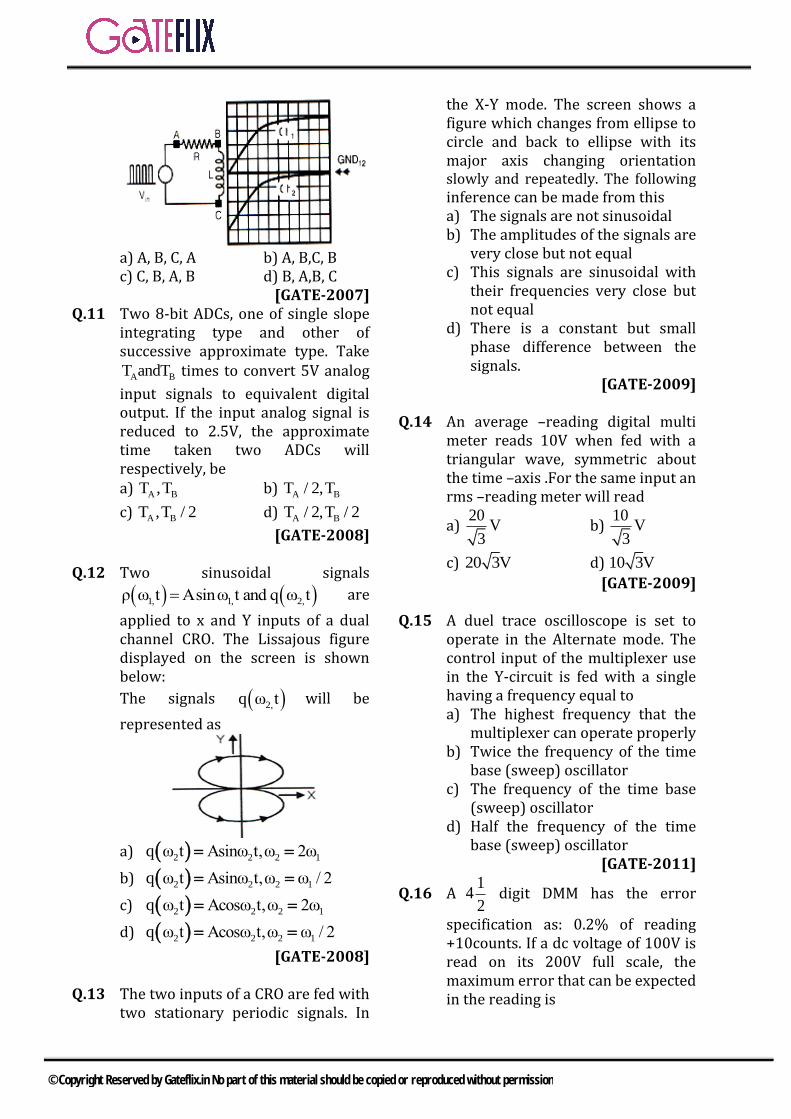
a) A, B, C, A b) A, B,C, Bc) C, B, A, B d) B, A,B, C
[GATE-2007] Q.11 Two 8-bit ADCs, one of single slope
integrating type and other of successive approximate type. Take
A BT andT times to convert 5V analog
input signals to equivalent digital output. If the input analog signal is reduced to 2.5V, the approximate time taken two ADCs will respectively, be a) A BT ,T b) A BT / 2,T
c) A BT ,T / 2 d) A BT / 2,T / 2
[GATE-2008]
Q.12 Two sinusoidal signals
1, 1, 2,ρ ω t Asinω t and q ω t are
applied to x and Y inputs of a dual channel CRO. The Lissajous figure displayed on the screen is shown below:
The signals 2,q ω t will be
represented as
a) 2 2 2 1q ω t Asinω t,ω 2ω
b) 2 2 2 1q ω t Asinω t,ω ω / 2
c) 2 2 2 1q ω t Acosω t,ω 2ω
d) 2 2 2 1q ω t Acosω t,ω ω / 2
[GATE-2008]
Q.13 The two inputs of a CRO are fed with two stationary periodic signals. In
the X-Y mode. The screen shows a figure which changes from ellipse to circle and back to ellipse with its major axis changing orientation slowly and repeatedly. The following inference can be made from this a) The signals are not sinusoidalb) The amplitudes of the signals are
very close but not equalc) This signals are sinusoidal with
their frequencies very close butnot equal
d) There is a constant but smallphase difference between thesignals.
[GATE-2009]
Q.14 An average –reading digital multi meter reads 10V when fed with a triangular wave, symmetric about the time –axis .For the same input an rms –reading meter will read
a) 20
V3
b) 10
V3
c) 20 3V d) 10 3V
[GATE-2009]
Q.15 A duel trace oscilloscope is set to operate in the Alternate mode. The control input of the multiplexer use in the Y-circuit is fed with a single having a frequency equal to a) The highest frequency that the
multiplexer can operate properlyb) Twice the frequency of the time
base (sweep) oscillatorc) The frequency of the time base
(sweep) oscillatord) Half the frequency of the time
base (sweep) oscillator[GATE-2011]
Q.16 A1
42
digit DMM has the error
specification as: 0.2% of reading +10counts. If a dc voltage of 100V is read on its 200V full scale, the maximum error that can be expected in the reading is
© Copyright Reserved by Gateflix.in No part of this material should be copied or reproduced without permission
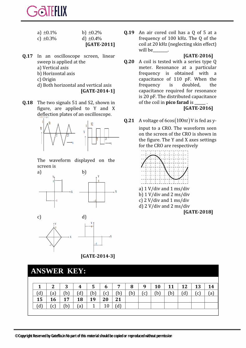
a) 0.1% b) 0.2%
c) 0.3% d) 0.4%
[GATE-2011]
Q.17 In an oscilloscope screen, linear sweep is applied at the a) Vertical axisb) Horizontal axisc) Origind) Both horizontal and vertical axis
[GATE-2014-1]
Q.18 The two signals 51 and S2, shown in figure, are applied to Y and X deflection plates of an oscilloscope.
The waveform displayed on the screen is a) b)
c) d)
[GATE-2014-3]
Q.19 An air cored coil has a Q of 5 at a frequency of 100 kHz. The Q of the coil at 20 kHz (neglecting skin effect) will be________.
[GATE-2016] Q.20 A coil is tested with a series type Q
meter. Resonance at a particular frequency is obtained with a capacitance of 110 pF. When the frequency is doubled, the capacitance required for resonance is 20 pF. The distributed capacitance of the coil in pico farad is ______ .
[GATE-2016]
Q.21 A voltage of 6cos 100 t V is fed as y-
input to a CRO. The waveform seen on the screen of the CRO is shown in the figure. The Y and X axes settings for the CRO are respectively
a) 1 V/div and 1 ms/divb) 1 V/div and 2 ms/divc) 2 V/div and 1 ms/divd) 2 V/div and 2 ms/div
[GATE-2018]
1 2 3 4 5 6 7 8 9 10 11 12 13 14
(d) (a) (b) (d) (b) (c) (b) (b) (c) (b) (b) (d) (c) (a)
15 16 17 18 19 20 21
(d) (c) (b) (a) 1 10 (d)
ANSWER KEY:
© Copyright Reserved by Gateflix.in No part of this material should be copied or reproduced without permission
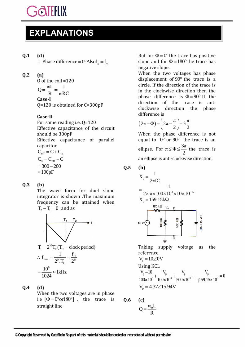
Q.1 (d) Phase difference
x y0°Alsof f
Q.2 (a) Q of the coil =120
ωL 1Q
R ωRC
Case-I Q=120 is obtained for C=300pF
Case-II For same reading i.e. Q=120 Effective capacitance of the circuit should be 300pF Effective capacitance of parallel capacitor
eff xC C C
x effC C C
300 200 100pF
Q.3 (b) The wave form for duel slope integrator is shown .The maximum frequency can be attained when
2 1T T 0 and as
N
1 C CT 2 T (T clock period)
Cmax N N
C
f1f
2 .T 2
6101kHz
1024
Q.4 (d) When the two voltages are in phase i.e [Φ 0°or180°] , the trace is
straight line
But for Φ 0° the trace has positive slope and for Φ 180° the trace has negative slope. When the two voltages has phase displacement of 90° the trace is a circle. If the direction of the trace is in the clockwise direction then the phase difference is Φ 90° If the direction of the trace is anti clockwise direction the phase difference is
π π
2π Φ 2π 32 2
When the phase difference is not equal to 0° or 90° the trace is an
ellipse. For 3π
π Φ2
the trace is
an ellipse is anti-clockwise direction.
Q.5 (b)
c
1X
2πfC
3 12
1
2 π 100 10 10 10
cX 159.15kΩ
Taking supply voltage as the reference.
sV 10 0V
Using KCL
p p p p
3 3 3 3
V 10 V V V0
100 10 100 10 500 10 j159.15 10
pV 4.37 15.94V
Q.6 (c)
0ω LQ
R
EXPLANATIONS
© Copyright Reserved by Gateflix.in No part of this material should be copied or reproduced without permission
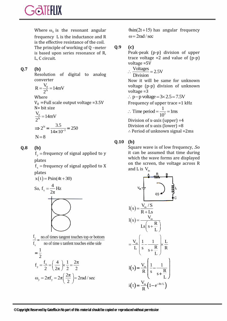
Where 0ω is the resonant angular
frequency L is the inductance and R is the effective resistance of the coil. The principle of working of Q –meter is based upon series resonance of R, L, C circuit.
Q.7 (b) Resolution of digital to analog converter
0
N
VR 14mV
2
Where V0 =Full scale output voltage =3.5V N= bit size
0
N
V14mV
2
N
3
3.52 250
14 10
N 8
Q.8 (b)
yf frequency of signal applied to y
plates
xf frequency of signal applied to X
plates
x t Psin(4t 30)
So, x
4f Hz
2π
y
x
f no.of times tangent touches top or bottom
f no of time s tanfent touches eithe side
1
2
xy
f 4 1 2πf
2 2π 2 2
y y
2πω 2πf 2π 2rad / sec
2
θsin(2t 15) has angular frequency
ω 2rad / sec
Q.9 (c) Peak-peak (p-p) division of upper trace voltage =2 and value of (p-p) voltage =5V
Voltages2.5V
Division
Now it will be same for unknown voltage (p-p) division of unknown voltage =3
p p voltage 3 2.5 7.5V
Frequency of upper trace =1 kHz
3
1Time period 1ms
10
Division of x-axis (upper) =4 Division of x-axis (lower) =8 ∴ Period of unknown signal =2ms
Q.10 (b) Square wave is of low frequency, .So it can be assumed that time during which the wave forms are displayed on the screen, the voltage across R and L is inV
inV / Sl s
R Ls
inVl s
RLs s
L
inV 1 1 L
RL s Rs
L
inV 1 1l s
RR ss
L
Rt/LinVi t 1 e
R
© Copyright Reserved by Gateflix.in No part of this material should be copied or reproduced without permission
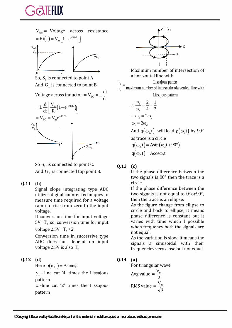
ABV Voltage across resistance
Rt/L
inRi t V 1 e
So, 1S is connected to point A
And 1G is connected to point B
Voltage across inductor BC
diV L
dt
Rt/LinVdL 1 e
dt R
Rt/L
BC inV V e
So 2S is connected to point C.
And 2G is connected top point B.
Q.11 (b) Signal slope integrating type ADC utilizes digital counter techniques to measure time required for a voltage ramp to rise from zero to the input voltage. If conversion time for input voltage 5V= AT so, conversion time for input
voltage 2.5V= AT / 2
Conversion time in successive type ADC does not depend on input voltage 2.5V is also BT
Q.12 (d)
Here 1 1ρ ω t Asinω t
1y line cut ‘4’ times the Lissajous
pattern
1x -line cut ‘2’ times the Lissajous
pattern
Maximum number of intersection of a horizontal line with
y
x
ω Lissajous patten
maximum number of intersectin ofa vertical line withω
Lissajous pattern
y
x
ω 2 1
ω 4 2
x yω 2ω
1 2ω 2ω
And 2,q ω t will lead 1,ρ ω t by 90°
as trace is a circle
2, 2q ω t Asin ω t 90°
2, 2q ω t Acosω t
Q.13 (c) If the phase difference between the two signals is 90° then the trace is a circle. If the phase difference between the two signals is not equal to 0°or90° , then the trace is an ellipse. As the figure change from ellipse to circle and back to ellipse, it means phase difference is constant but it varies with time which I possible when frequency both the signals are not equal. As the variation is slow, it means the signals a sinusoidal with their frequencies very close but not equal.
Q.14 (a) For triangular wave
Avg value mV
2
RMS value mV
3
© Copyright Reserved by Gateflix.in No part of this material should be copied or reproduced without permission
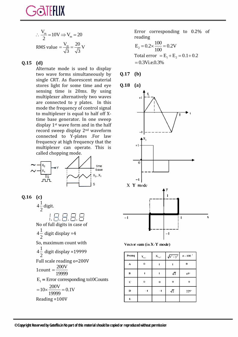
mm
V10V V 20
2
RMS value mV 20V
3 3
Q.15 (d) Alternate mode is used to display two wave forms simultaneously by single CRT. As fluorescent material stores light for some time and eye sensing time is 20ms. By using multiplexer alternatively two waves are connected to y plates. In this mode the frequency of control signal to multiplexer is equal to half off X-time base generator. In one sweep display 1st wave form and in the half record sweep display 2nd waveform connected to Y-plates .For law frequency at high frequency that the multiplexer can operate. This is called chopping mode.
Q.16 (c) 1
42
digit.
No of full digits in case of 1
42
digit display =4
So, maximum count with 1
42
digit display =19999
Full scale reading o=200V
1count 200V
19999
1E Error corresponding to10Counts
200V10 0.1V
19999
Reading =100V
Error corresponding to 0.2% of reading
2
100E 0.2 0.2V
100
Total error 1 2E E 0.1 0.2
0.3Vi.e.0.3%
Q.17 (b)
Q.18 (a)
© Copyright Reserved by Gateflix.in No part of this material should be copied or reproduced without permission
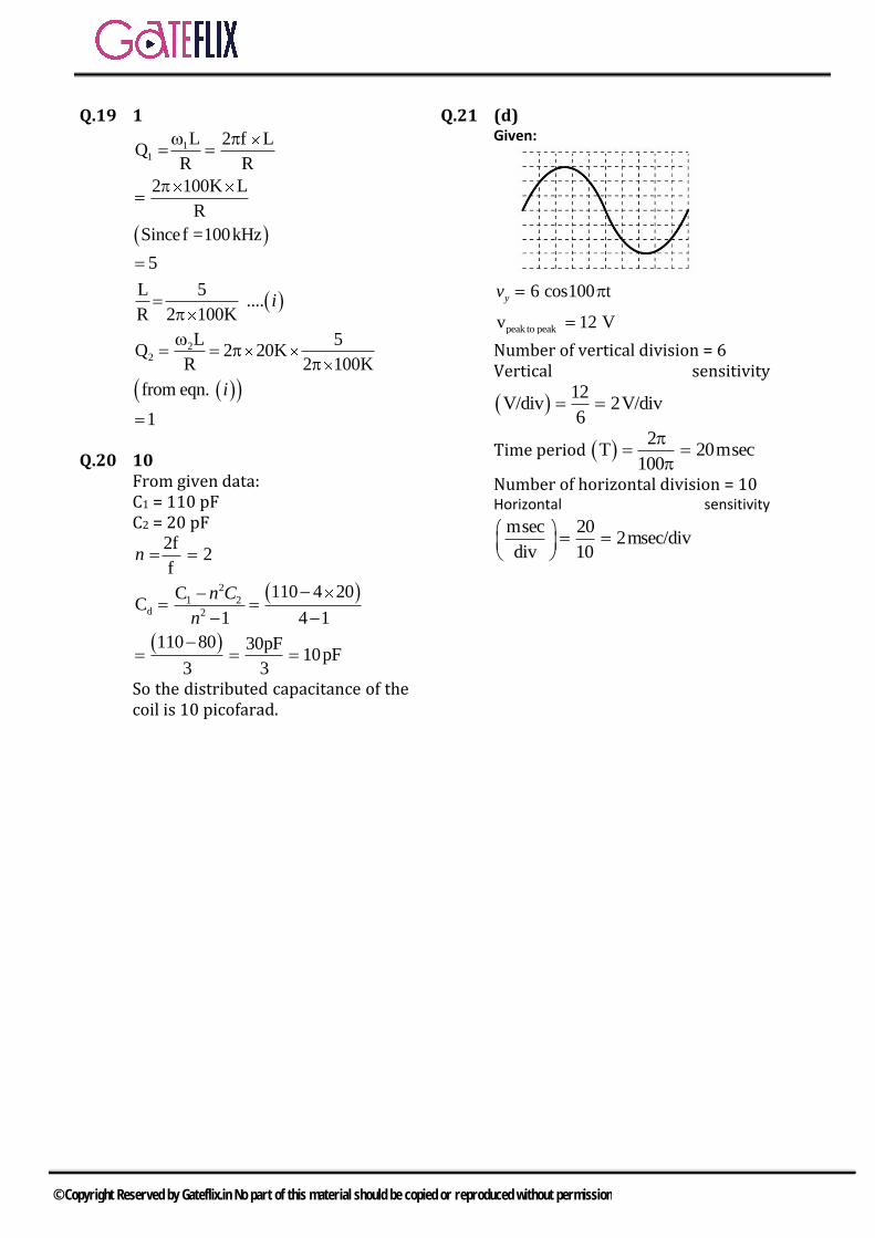
Q.19 1
11
22
L 2 f LQ
R R
2 100K L
R
Sincef =100kHz
5
L 5....
R 2 100K
L 5Q 2 20K
R 2 100K
from eqn.
1
i
i
Q.20 10 From given data: C1 = 110 pF C2 = 20 pF
2
1 2d 2
2f2
f
110 4 20CC
1 4 1
110 80 30pF10pF
3 3
n
n C
n
So the distributed capacitance of the coil is 10 picofarad.
Q.21 (d) Given:
peak to peak
6 cos100 t
v 12 V
yv
Number of vertical division = 6 Vertical sensitivity
12
V/div 2V/div6
Time period 2
T 20msec100
Number of horizontal division = 10 Horizontal sensitivity
msec 202msec/div
div 10
© Copyright Reserved by Gateflix.in No part of this material should be copied or reproduced without permission
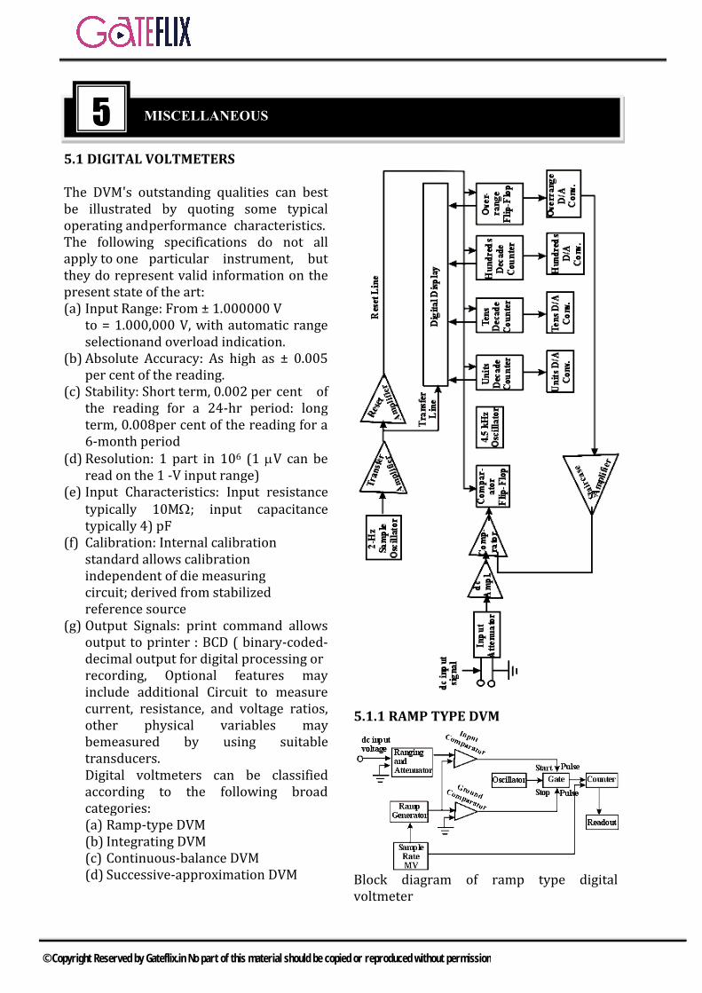
5.1 DIGITAL VOLTMETERS
The DVM's outstanding qualities can best be illustrated by quoting some typical operating and performance characteristics. The following specifications do not all apply to one particular instrument, but they do represent valid information on the present state of the art: (a) Input Range: From ± 1.000000 V
to = 1.000,000 V, with automatic range selectionand overload indication.
(b) Absolute Accuracy: As high as ± 0.005 per cent of the reading.
(c) Stability: Short term, 0.002 per cent of the reading for a 24-hr period: long term, 0.008per cent of the reading for a 6-month period
(d) Resolution: 1 part in 106 (1 V can be read on the 1 -V input range)
(e) Input Characteristics: Input resistance typically 10M; input capacitance typically 4) pF
(f) Calibration: Internal calibration standard allows calibration independent of die measuring circuit; derived from stabilized reference source
(g) Output Signals: print command allows output to printer : BCD ( binary-coded-decimal output for digital processing or recording, Optional features may include additional Circuit to measure current, resistance, and voltage ratios, other physical variables may bemeasured by using suitable transducers. Digital voltmeters can be classified according to the following broad categories: (a) Ramp-type DVM (b) Integrating DVM (c) Continuous-balance DVM (d) Successive-approximation DVM
5.1.1 RAMP TYPE DVM
Block diagram of ramp type digital voltmeter
5 MISCELLANEOUS
© Copyright Reserved by Gateflix.in No part of this material should be copied or reproduced without permission
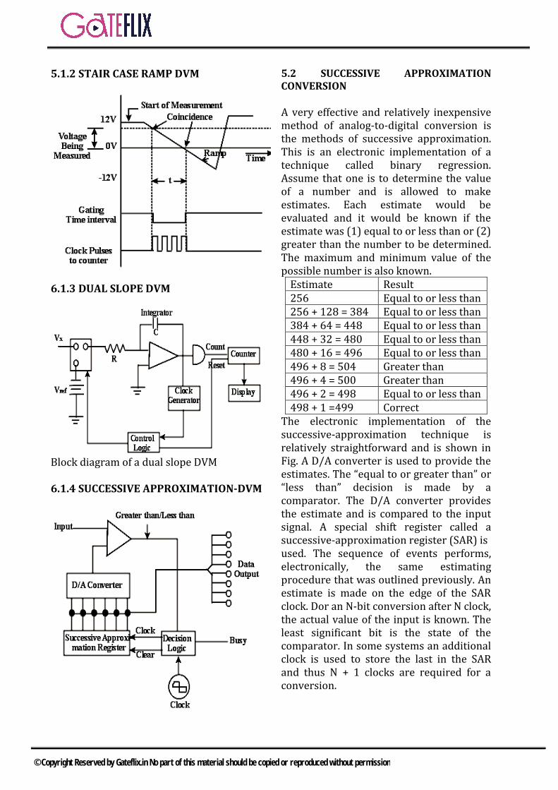
5.1.2 STAIR CASE RAMP DVM
6.1.3 DUAL SLOPE DVM
Block diagram of a dual slope DVM
6.1.4 SUCCESSIVE APPROXIMATION-DVM
SUCCESSIVE APPROXIMATION 5.2CONVERSION
A very effective and relatively inexpensive method of analog-to-digital conversion is the methods of successive approximation. This is an electronic implementation of a technique called binary regression. Assume that one is to determine the value of a number and is allowed to make estimates. Each estimate would be evaluated and it would be known if the estimate was (1) equal to or less than or (2) greater than the number to be determined. The maximum and minimum value of the possible number is also known.
Estimate Result 256 Equal to or less than 256 + 128 = 384 Equal to or less than 384 + 64 = 448 Equal to or less than 448 + 32 = 480 Equal to or less than 480 + 16 = 496 Equal to or less than 496 + 8 = 504 Greater than 496 + 4 = 500 Greater than 496 + 2 = 498 Equal to or less than 498 + 1 =499 Correct
The electronic implementation of the successive-approximation technique is relatively straightforward and is shown in Fig. A D/A converter is used to provide the estimates. The “equal to or greater than” or “less than” decision is made by a comparator. The D/A converter provides the estimate and is compared to the input signal. A special shift register called a successive-approximation register (SAR) is used. The sequence of events performs, electronically, the same estimating procedure that was outlined previously. An estimate is made on the edge of the SAR clock. Dor an N-bit conversion after N clock, the actual value of the input is known. The least significant bit is the state of the comparator. In some systems an additional clock is used to store the last in the SAR and thus N + 1 clocks are required for a conversion.
© Copyright Reserved by Gateflix.in No part of this material should be copied or reproduced without permission
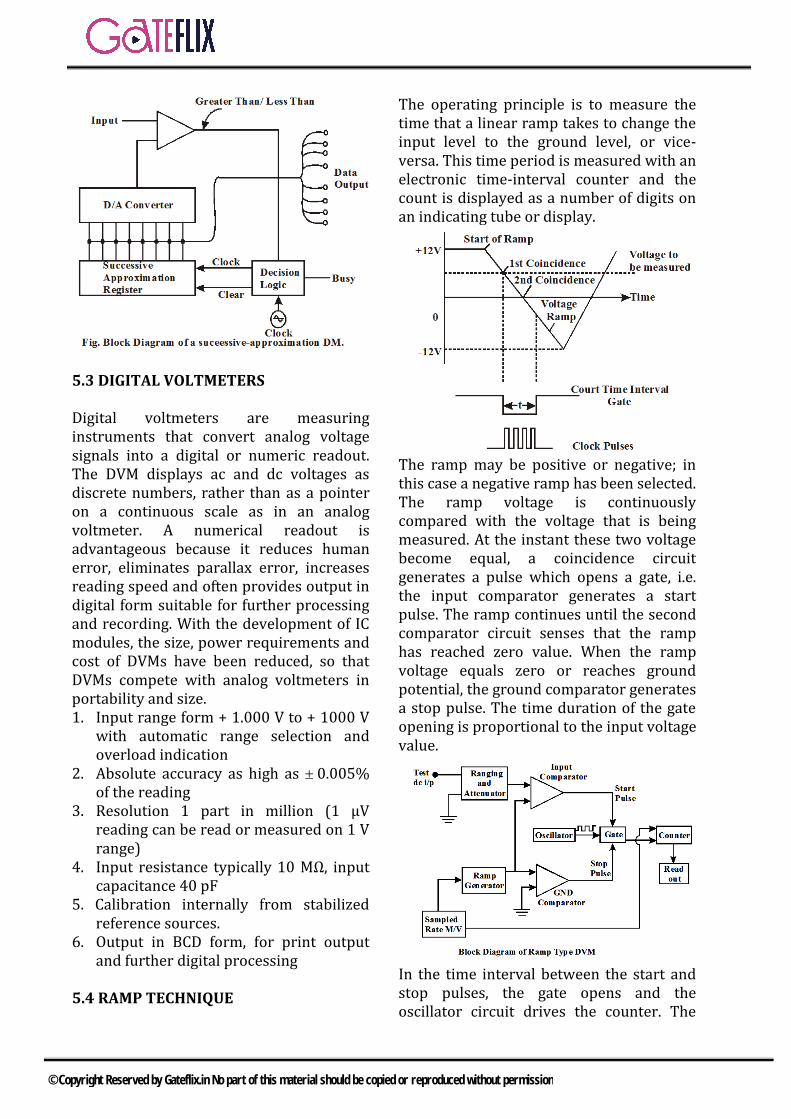
5.3 DIGITAL VOLTMETERS
Digital voltmeters are measuring instruments that convert analog voltage signals into a digital or numeric readout. The DVM displays ac and dc voltages as discrete numbers, rather than as a pointer on a continuous scale as in an analog voltmeter. A numerical readout is advantageous because it reduces human error, eliminates parallax error, increases reading speed and often provides output in digital form suitable for further processing and recording. With the development of IC modules, the size, power requirements and cost of DVMs have been reduced, so that DVMs compete with analog voltmeters in portability and size. 1. Input range form + 1.000 V to + 1000 V
with automatic range selection andoverload indication
2. Absolute accuracy as high as 0.005%of the reading
3. Resolution 1 part in million (1 μVreading can be read or measured on 1 Vrange)
4. Input resistance typically 10 MΩ, inputcapacitance 40 pF
5. Calibration internally from stabilizedreference sources.
6. Output in BCD form, for print outputand further digital processing
5.4 RAMP TECHNIQUE
The operating principle is to measure the time that a linear ramp takes to change the input level to the ground level, or vice-versa. This time period is measured with an electronic time-interval counter and the count is displayed as a number of digits on an indicating tube or display.
The ramp may be positive or negative; in this case a negative ramp has been selected. The ramp voltage is continuously compared with the voltage that is being measured. At the instant these two voltage become equal, a coincidence circuit generates a pulse which opens a gate, i.e. the input comparator generates a start pulse. The ramp continues until the second comparator circuit senses that the ramp has reached zero value. When the ramp voltage equals zero or reaches ground potential, the ground comparator generates a stop pulse. The time duration of the gate opening is proportional to the input voltage value.
In the time interval between the start and stop pulses, the gate opens and the oscillator circuit drives the counter. The
© Copyright Reserved by Gateflix.in No part of this material should be copied or reproduced without permission
magnitude of the count indicates the magnitude of the input voltage, which is displayed by the readout. Therefore, the voltage is converted into time and the time count represents the magnitude of the voltage.
5.4.1 ADVANTAGES & DISADVANTAGES
The ramp technique circuit is easy to design and its cost is low. Also, the output pulse can be transmitted over long feeder lines. However, the single ramp requires excellent characteristics regarding linearity of the ramp and time measurement. Large errors are possible when noise is superimposed on the input signal. Input filters are usually required with this type of converter.
5.5 DUAL SLOPE INTEGRATINGTYPE DVM(VOLTAGE TO TIME CONVERSION) In ramp techniques, superimposed noise can cause large error. In the dual ramp technique, noise is averaged out by the positive and negative ramps using the process of integration.
5.5.1 PRINCIPLE OF DUAL SLOPETYPE DVM
As illustrated in fig, the input voltage ‘ei’ is integrated, with the slope of the integrator output proportional to the test input voltage. After a fixed time, equal to t1, the input voltage is disconnected and the integrator input is connected to a negative voltage –er. The integrator output will have a negative slope which is constant and proportional to the magnitude of the input voltage. At the start a pulse resets the counter and the F/F output to logic level ‘0’. Si the capacitor begins to charge. As soon as the integrator output exceeds zero, the comparator output voltage changes state, which opens the gate so that the oscillator clock pulses are fed to the counter.
The discharge time t2 is now proportional to the input voltage. The counter indicates the count during time t2. When the negative slope of the integrator reaches zero, the comparator switches to state 0 and the gate closes, i.e. the capacitor C is now discharged with a constant slope. As soon as the comparator input (zero detector) finds that ea is zero, the counter is stopped. The pulses counted by the counter thus have a direct relation with the input voltage.
During charging 1t
i 10 i
0
1 e te e dt
RC RC
During discharging 2t
r 20 r
0
1 e te e dt
RC RC
2i r
1
te e
t
5.5.2 INTEGRATING TYPE DVM(VOLTAGETO FREQUENCYCONVERSION)
© Copyright Reserved by Gateflix.in No part of this material should be copied or reproduced without permission
The principle of operation of an integrating type DVM is illustrated in fig. A constant input voltage is integrated and the slope of the output ramp is proportional to the input voltage. When the output reaches a certain value, it is discharged to 0 and another cycle begins.
5.5.3 MOST COMMONLY USEDPRINCIPLES OF ADC (ANALOG TO DIGITALCONVERSION)
Direct Compensation
The Staircase Ramp
The basic principle is that the input signal Vi is compared with an internal staircase voltage, Vc, generated by a series circuit consisting of a pulse generator (clock), a counter counting the pulses and a digital to analog converter, converting the counter output input a dc signal. As soon as Vc is equal to Vi, the input comparator closes a gate between the clock and the counter, the counter stops and its output is shown on the display. (DAC) is also 0. If Vi is not equal to zero, the input comparator applies an output voltage that opens the gate so that clock pulses are passed on to the counter through the gate. Starts counting and the DAC starts to produce an output voltage increasing by one small step at each count of the counter. This process continues until the staircase voltage is equal to or slightly greater than the input voltage Vi. At that instant t2, the output voltage of the input comparator changes state or polarity, so that the gate closes and the counter is stopped.
The advantages of a staircase type DVM are as follows. 1. Input impedance of the DAC is high
when the compensation is reached.2. The accuracy depends only on the
stability and accuracy of the voltage andDAC. The clock has no effect on theaccuracy.
The disadvantages are the following. 1. The system measures the instantaneous
value of the input signal at the momentcompensation is reached. This meansthe reading the rather unstable, i.e. theinput signal is not a pure dc voltage.
2. Until the full compensation is reached,the input impedance is low, which caninfluence the accuracy.
5.6 SUCCESSIVE APPROXIMATIONS
The successive approximation principle can be easily understood using a simple example;
5.6.1 3 – 1/2 DIGIT
The number of digit positions used in a digital meter determines the resolution. Hence a 3 digit display on a DVM for a 0 – 1 V range will indicate values from 0 – 999 mV with a smallest increment of 1 mV.
© Copyright Reserved by Gateflix.in No part of this material should be copied or reproduced without permission
Normally, a fourth digit capable of indicating 0 or 1 (hence called a Half Digit) is placed to the left. This permits the digital meter to read values above 999 up to 1999, to give overlap between ranges for convenience, a process called over – ranging. This type of display is called a 3½ digit display, shown in fig.
5.7 RESOLUTION AND SENSITIVITYOF DIGITAL METERS
Resolution If n = number of full digits, then resolution (R) is 1/10n.
If n = 3, R = %1.0001.010
1
10
13
orn
Sensitivity of Digital Meters Sensitivity is the smallest change in input which a digital meter is able to detect. Hence, it is the full scale value of the lowest voltage range multiplied by the meter’s resolution. Sensitivity S = (fs)min × R Where (fs)min= lowest full scale of the meter R= resolution expressed as decimal
Example What is the resolution of a 3½ digit display on 1V and 10V ranges? Solution Number of full digits is 3. Therefore resolution is 1/10n
where n = 3. Resolution R = 1/103= 1/1000 = 0.001 Hence the meter cannot distinguish between values that differ from each other by less than 0.001 of full scale. For full scale range reading of 1V, the resolution is 1 × 0.001 = 0.001 V. For full scale reading of 10V range, the resolution is 10V × 0.001 = 0.01 V. Hence on 10 V scale, the meter cannot distinguish between readings that differ by less than 0.01 V.
Example
A 4½ digit voltmeter is used for voltage measurements (i) Find its resolution (ii) How would 12.98 V be displayed on a
10 V range? (iii)How would 0.6973 be displayed o 1 V
and 10 V ranges. Solution (i) Resolution = 1/10n = 1/104 = 0.0001 Where the number of full digits is n = 4 (ii) There are 5 digit places in 4½ digits,
therefore 12.98 would be displayed as 12.980. Resolution on 1 V range is 1 V ×0.0001 = 0.0001 Any reading up to the 4th decimal can be displayed. Hence 0.6973 will be displayed as 0.6973.
(iii)Resolution on 10 V range = 10V × 0.0001 = 0.001V Hence decimals up to the 3rd decimal place can be displayed. Therefore on a 10 V range, the reading will be 0.697 instead of 0.6973.
5.8 BLOCK DIAGRAM OF SA DVM
5.8.1 BASIC Q METER CIRCUIT
5.8.2 SERIES CONNECTION
© Copyright Reserved by Gateflix.in No part of this material should be copied or reproduced without permission
Q meter measurement of a Low Impedance component in series connection Series connection: Low impedance components, such a low-value resistors, small coils and large capacitors, are measured in series with the measuring circuit. The above figure shows the connection. The component to be measured, here indicated by [Z] is placed in series with a stable work coil across the test terminals. (The work coil is usually supplied with the instrument). Two measurements are made: In the First measurement the unknown is short-circuited by a small shorting strap and the circuit is resonated, establishing reference condition. The values of the tuning capacitor (C1) and the indicated Q (Q1) are noted. In the second measurement the shorting strap is removed and the circuit is returned, giving a no value for the tuning capacitor (C2) and a change in the Q value from Q1, to Q2.
1 2 1 2
s
1 1 2 2
C C Q QQ
C Q C Q
1s
2
C CC
C C
The Q of the capacitor may be found by using above equation
5.8.3 PARALLEL CONNECTION:
High-impedance components, such as high-value resistors, certain inductors, and small capacitors, are measured by connecting them in parallel with the measuring circuit. Figure shows the connections. Before the unknown is connected, the circuit is
resonated, by using a suitable work coil, to establish reference values for Q and C(Q1 and C1).Then when the component under test is connected to the circuit, the capacitor is readjusted for resonance, and a new value for the tuning capacitance (C2) is obtained and a change in the value of circuit Q(Q) from Q1 to Q2.
© Copyright Reserved by Gateflix.in No part of this material should be copied or reproduced without permission
Q.1 A 500A/5A, 50Hz current transformer has a bar primary. The secondary burden is a pure resistance of 1Ω and it draws a current of 5A if the magnetic core requires 250 AT for magnetization, the percentage ratio error is a)10.56 b)-10.56 c) 11.80 d)-11.80
[GATE-2003]
Q.2 A 50 Hz, bar primary CT has a secondary with 500 turns. The secondary supplies 5 A current into a purely resistive burden of 1Ω The magnetizing ampere –turns is 200. The phase angel between the primary and secondary current is a) 4.6° b) 85.4°
c) 94.6° d) 175.4°
[GATE-2004]
Q.3 The core flux in the CT of Prob, under the given operating conditions a) 0 b) 45.0μWbc)22.5mWb d)100.0mWb
[GATE-2004]
Q.4 A 200/1 Current transformer (CT) is wound with 200 turns on the secondary on a toroid core. When it carries a current of 160A on the primary, the ratio and phase errors of the CT are found to be-0.5% and 30 minutes respectively. If the number of secondary turns is reduced by 1 the new ratio error (%) and phase error (min) will be respectively
a) 0,0,30 b)-0.5, 35 c) -1.0, 030 d)-1.0, 25
[GATE-2006]
Q.5 The power delivered to a single phase inductive load is measured with a dynamometer type wattmeter using a potential transformer (PT) of turns ratio 200:1 and the current transformer (CT) of turns ratio 1:5. Assume both the transformers to be ideal. The power factor of the load is 0.8. If the wattmeter reading is 200W, then the apparent power of the load in kVA is _________.
[GATE-2016]
Q.6 A 3 ½ digit DMM has an accuracy specification of ±1% of full scale (accuracy class 1). A reading of 100.0 mA is obtained on its 200 mA full scale range. The worst case error in the reading in milliampere is ± ____________.
Q.7 A 200 mV full scale dual-slope 1
32
digit DMM has a reference voltage of 100 mV and a first integration time of 100 ms. For an input of [100+10cos(100πt)]mV, the conversion time (without taking the auto-zero phase time into consideration) in millisecond is _______ .
1 2 3 4 5 6 7
(b) (a) (b) (a) 250 2 200
ANSWER KEY:
GATE QUESTIONS
© Copyright Reserved by Gateflix.in No part of this material should be copied or reproduced without permission
Q.1 (b)
Nominal ratio 500
1005
Number of turn in primary N=1 (primary bar) Magnetizing current
m
mmfl
no.ofturns
250250
1
Secondary current
sl 5A
500n 100
5
Primary current
2 2
p s ml nl l
2 2
100 5 250
pl 559.017A
Actual ratio
pl 559.017
5 5
111.803 Ratio error
Nomial Ratio Actual ratio100
Actual ratio
100 111.803100 10.56%
111.803
Q.2 (a) Phase angle between primary and secondary current
m
s
l180θ degree
π nl
No. of turns in primary pN 1
No. of turns in secondary sN 500
N=turn ratio s
p
N500
N
sl Secondary widing current =5A
Magnetizing ampere turn =200
m
p
Magnetizing ampere turnl
N
200200A
1
180 200θ
π 500 5
4.6°
Q.3 (b)
sZ Burden 1Ω
Voltage induced in the secondary,
s s sE l Z 5 1 5V
s m sE 4.44fΦ N
sm
s
EΦ
4.4fN
5
4.44 50 500
45μWb
Q.4 (a)
Nominal ratio n
200k 200
1
Primary current pl 160A
Actual ratio e1 1
p
lR n 1
l
…(i)
% ratio error n 1
1
k R100 0.5
R
1
1
200 R100
R
Actual ratio 1R 201
1n turn ratio 200
e1
p
lR 200 1
l
…(ii)
When no. of secondary is reduced by 1
sn 199
2n 199
EXPLANATIONS
© Copyright Reserved by Gateflix.in No part of this material should be copied or reproduced without permission
e2 2
p
lR n 1
l
e
p
l199 1
l
…(iii)
Dividing eq.(ii) and (iii)
1
2
R 200
R 199
2 1
199R R
200
199201
200
199.995 200 % ratio Error
n 2
2
k R100
R
200 200100 0
200
Phase angle error m
p
l1800
π l
Reduction of one or two turns of the secondary winding, no doubt, reduces the ratio error but is has no effect on the phase angle error.
Q.5 250
1 2
2 1
12 1
2
12
2 2
1 1
12
2
I NExp:
I N
NI I
N
II
5
V N
V N
VV
200
I through C.C I
2V/g crossP.C V
Power measured by w/m will be
2 2200 = V I cos
1 1
3
1 1
V I200 = 0.8
200 5
200V I = 10 =250 kVA
0.8
Q.6 2 Since all information are given n in
mA unit assume the scale in mA unit.
→ Since it is given that error is ±1%
of full scale So, error =±1%of
200mA=±2mA.
→So if it measures 100mA then the
reading will be in the range (100 ±
2)mA
→ The worst source error is ±2mA.
Q.7 200 In dual slope converter total
conversion time
T= 1st integration period
+ 2nd integration period
= T1 + T2 = 100 msec T2
To obtain T2 we can use
Vin T1 = Vref T2
⟹ 100mv × 100msec = 100mv × T2
⟹ T2 = 100msec
⟹ T = 100 + 100 = 200 msec
© Copyright Reserved by Gateflix.in No part of this material should be copied or reproduced without permission
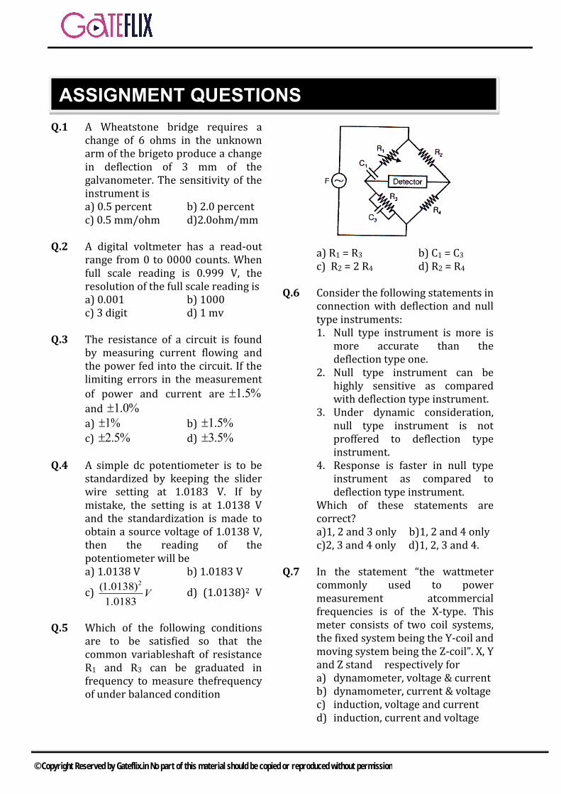
Q.1 A Wheatstone bridge requires a change of 6 ohms in the unknown arm of the brigeto produce a change in deflection of 3 mm of the galvanometer. The sensitivity of the instrument is a) 0.5 percent b) 2.0 percentc) 0.5 mm/ohm d)2.0ohm/mm
Q.2 A digital voltmeter has a read-out range from 0 to 0000 counts. When full scale reading is 0.999 V, the resolution of the full scale reading is a) 0.001 b) 1000c) 3 digit d) 1 mv
Q.3 The resistance of a circuit is found by measuring current flowing and the power fed into the circuit. If the limiting errors in the measurement
of power and current are 1.5%
and 1.0%
a) 1% b) 1.5%
c) 2.5% d) 3.5%
Q.4 A simple dc potentiometer is to be standardized by keeping the slider wire setting at 1.0183 V. If by mistake, the setting is at 1.0138 V and the standardization is made to obtain a source voltage of 1.0138 V, then the reading of the potentiometer will be a) 1.0138 V b) 1.0183 V
c) 2(1.0138)
1.0183V d) (1.0138)2 V
Q.5 Which of the following conditions are to be satisfied so that the common variableshaft of resistance R1 and R3 can be graduated in frequency to measure thefrequency of under balanced condition
a) R1 = R3 b) C1 = C3
c) R2 = 2 R4 d) R2 = R4
Q.6 Consider the following statements in connection with deflection and null type instruments: 1. Null type instrument is more is
more accurate than thedeflection type one.
2. Null type instrument can behighly sensitive as comparedwith deflection type instrument.
3. Under dynamic consideration,null type instrument is notproffered to deflection typeinstrument.
4. Response is faster in null typeinstrument as compared todeflection type instrument.
Which of these statements are correct? a)1, 2 and 3 only b)1, 2 and 4 only c)2, 3 and 4 only d)1, 2, 3 and 4.
Q.7 In the statement “the wattmeter commonly used to power measurement atcommercial frequencies is of the X-type. This meter consists of two coil systems, the fixed system being the Y-coil and moving system being the Z-coil”. X, Y and Z stand respectively for a) dynamometer, voltage & currentb) dynamometer, current & voltagec) induction, voltage and currentd) induction, current and voltage
ASSIGNMENT QUESTIONS
© Copyright Reserved by Gateflix.in No part of this material should be copied or reproduced without permission
Q.8 Two-wattmeter method is employed to measure power in a 3-phase balanced system with the current coils connected in the A and C lines. The phase sequence is ABC. If the wattmeter with its current coil in A-phase line reads zero, then the power factor of the 3-phase load will be a) zerolaggin b) zero leadingc) 0.5 lagging d) 0.5 leading
Q.9 In a particular form of frequency meter, a 1 mF capacitor is connected across a symmetrical square wave signal of 1 volt peak value. If the average value of the current taken by the capacitor, after full wave rectification is measured as 2 mA, then the frequency of the signal will be a) 1000/pHz b) 500 Hzc) 1000 Hz d) 1000 pHz
Q.10 The meter constant of a single-phase 240 V induction watt-hour meter is 400revolutions per kWh. The speed of the meter disc for a current of 10 amperes at 0.8 p.f, lagging will be a) 12.8 rpm b) 16.02 rpmc) 18.2 rpm d) 21.1 rpm
Q.11 A digital voltmeter uses a 10 MHz clock and has a voltage controlled generator which provides a width of 10 m sec per volt of unit signal. 10 volt of input signal would correspond to a pulse count of a) 500 b) 750c) 1000 d) 1500
Q.12 When reading is taken at half scale in the instrument, the error is a) exactly equal to half of full –
scale error.b) equal to full – scale error.c) less than full – scale error.d) more than full – scale error.
Q.13 A Lissajous pattern on an oscilloscope has 5 horizontal tangencies and 2 vertical tangencies. The frequency of the horizontal input is 100 Hz. What is the frequency of the vertical inout? a) 400 Hz b) 2500 Hzc) 4000 Hz d) 5000 Hz
Q.14 The resistance of a thermistor is 5000 Ω at 20° C and its resistance temperature coefficient is 0,04/° C. A measurement with a lead resistance of 10 Ω will cause an error of a) 0.05° C b) 0.1° Cc) 0.4° C d) 0.8° C
Q.15 In a digital voltmeter, the oscillator frequency is 400 kHz and the ramp voltage falls from 8 V to 0 V in 20 m sec. The number of pulses counted by the counter is a) 800 b) 2000c) 400 d) 8000
Q.16 A zero to 300 V voltmeter has an error of ±2% of the full-scale deflection. If the true voltage is 30 V, then the range of readings on this voltmeter would be a) 20 V to 40 Vb) 24 V to 36 Vc) 29.4 V to 30.6 Vd) 29.94 V to 30.06 V
Q.17 If Qeis the effective Q of the coil, C is the resonance capacitance and Cd is the distributed capacitance, then the true Q in a Q.meter will be a) Qe[(C + Cd)/C)]b) Qe[C/(C + Cd))]c) Qe[(Cd/(C + Cd)]d) Qe[(C + Cd)/Cd)]
Q.18 A first order instrument is characterized by a) time constant only.
© Copyright Reserved by Gateflix.in No part of this material should be copied or reproduced without permission
b) static sensitivity and timeconstant.
c) static sensitivity and dampingcoefficient.
d) static sensitivity, dampingcoefficient and natural frequencyof oscillations.
Q.19 The voltmeter of choice for measuring the emf of a 100 V dc source would be a) 100 V, 1 mAb) 100 V, 2 mAc) 100 V, 10 kW/Vd) 100 V, 100 W/V
Q.20 A piezoelectric transducer has the following parameters values Crystal capacitance = 10-9 F Cable capacitance = 2 × 10⁻¹⁰ F Charge sensitivity = 4 × 10⁻⁶ F Columb/cm If the oscilloscope used for read-out has an input resistance of 1 MΩ in parallel with C = 4 × 10⁻¹⁰ F, then the voltage sensitivity constant will be a) 2500 V/cm b) 3334 V/cmc) 4000 V/cm d) 4500 V/cm
Q.21 A high frequency a.c. signal is applied to a PMMC instrument. If the rms value of the a.c. signal is 2 V, then the reading of the instrument will be a) zero b) 2 V
c) 2 2V d) 4 2V
Q.22 In the circuit shown in the figure, if the ammeter indicates 1 A and the voltmeter having an internal resistance of 1 kΩ indicated 100 V, then the value of R would be
a) 111.11 Ω b) 105.2 Ωc) 100 Ω d) 90.9 Ω
Q.23 A current i = (10 + 10 sin t) amperes is passed through an ideal moving iron type ammeter. Its reading will be a) zero b) 10 A
c) 150A d) 10 2A
Q.24 An indicating instrument is more sensitive if its torque to weight ratio is a) much larger than unity.b) of the order of unityc) much less the unity.d) made deflection dependent.
Q.25 In PMMC instrument, the central spring stiffness and the strength of the magnet decrease by 0.04% and 0.02% respectively due to a rise in temperature by 1°C. With a rise in temperature of 10° C, the instrument reading wil a) increase by 0.2%b) decrease by 0.2%c) increase by 0.6%d) decrease by 0.7%
Q.26 Standard call a) Will have precise and accurate
constant voltage when currentdrawn from it is fewmicroamperes only.
b) Will have precise and accurateconstant voltage when fewmicroamperes are drawn from it.
c) Will continue to have constantvoltage irrespective of loadingconditions.
d) Can supply voltages up to 10 V
Q.27 In a Q.meter, an inductor tunes to 2 MHz with 450 pF and to 4 MHz with 90 pF. Thedistributed capacitance of the inductor is a) 30 pF b) 45 pFc) 90 pF d) 360 pF
© Copyright Reserved by Gateflix.in No part of this material should be copied or reproduced without permission
Q.28 If the reading of the two wattmeters are equal and positive in two-wattmeter method, the load pf in a balanced 3-phase 3-wire circuit will be a) zero b) 0.5c) 0.866 d) unity
Q.29 The disc of a house service energy meter of 230 V, 50 Hz, 5 A, 2400 rev per kWh creeps at a 1 rev. Per min. The creep error (in percent) of full load unity pF is
a) 60
1002400
b) 60
1002400
c) 60
1001.15 2400
d) 60
1001.15 2400
Q.30 which one of the following decided the time of response of an indicating instrument? a) deflecting system.b) controlling system.c) Damping system..d) pivot and jewel bearings.
Q.31 A wattmeter has a range of 100 W with an error of ±1% of full scale deflection. If the true power passed through it is 100 W, then the relative error would be a) ±10% b) ±5%c) ±1% d) ±0.5%
Q.32 A resistance strain guage is fastened to a beam subjected to a stain of 1 × 10⁻⁶yielding a resistance change of 240 μΩ. If the original resistance of the strain guageis 120 Ω, the guage factor would be a) 5 b) 2c) 1 d) 0.2
Q.33 A voltage of
200 2 sin314t 6 2 sin(942i 30 )
8 2 cos(1570t 30 ) V is given to a
harmonic distortion meter. The meter will indicate a total harmonic distortion of approximately a) 4.55% b) 6.5%c) 7.5% d) 8.5%
Q.34 Ana.c. voltmeter using full-wave rectification and having a sinusoidal input has an a.c. sensitivity equal to a) 1.414 times dc sensitivityb) dc sensitivityc) 0.90 times dc sensitivityd) 0.707 times dc sensitivity
Q.35 A spring controlled moving iron voltmeter draws a current of 1 mA for full scale value of 100 V. If it draws a current of 0.5 mA. The meter reading is a) 25 V b) 50 Vc) 100 V d) 200 V
Q.36 The difference between the indicated value and the true value of a quantity is a) gross errorb) absolute error.c) dynamic error.d) relative error.
Q.37 In the measurement of power on balanced load by two-wattmeter method in a 3- phase circuit, the readings of the wattmeter are 3 kW and 1 kW respectively. The letter being obtained after reversing the connections to the current coil. The power factor of the load is a) 0.277 b) 0.554c) 0.625 d) 0.866
Q.38 A first order instrument of power on balanced Od by two-Wattmeter method in a 3-phase circuit, the readings of the Wattmeter’s are 3
© Copyright Reserved by Gateflix.in No part of this material should be copied or reproduced without permission
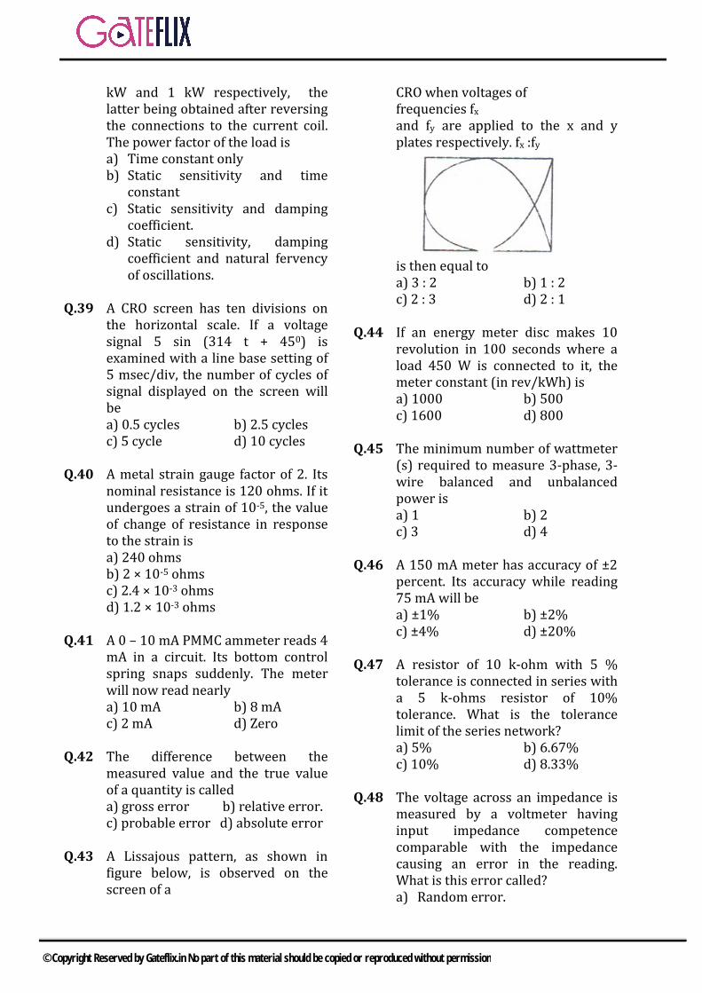
kW and 1 kW respectively, the latter being obtained after reversing the connections to the current coil. The power factor of the load is a) Time constant onlyb) Static sensitivity and time
constantc) Static sensitivity and damping
coefficient.d) Static sensitivity, damping
coefficient and natural fervencyof oscillations.
Q.39 A CRO screen has ten divisions on the horizontal scale. If a voltage signal 5 sin (314 t + 450) is examined with a line base setting of 5 msec/div, the number of cycles of signal displayed on the screen will be a) 0.5 cycles b) 2.5 cyclesc) 5 cycle d) 10 cycles
Q.40 A metal strain gauge factor of 2. Its nominal resistance is 120 ohms. If it undergoes a strain of 10-5, the value of change of resistance in response to the strain is a) 240 ohmsb) 2 × 10⁻⁵ ohmsc) 2.4 × 10⁻³ ohmsd) 1.2 × 10⁻³ ohms
Q.41 A 0 – 10 mA PMMC ammeter reads 4 mA in a circuit. Its bottom control spring snaps suddenly. The meter will now read nearly a) 10 mA b) 8 mAc) 2 mA d) Zero
Q.42 The difference between the measured value and the true value of a quantity is called a) gross error b) relative error.c) probable error d) absolute error
Q.43 A Lissajous pattern, as shown in figure below, is observed on the screen of a
CRO when voltages of frequencies fx and fy are applied to the x and y plates respectively. fx :fy
is then equal to a) 3 : 2 b) 1 : 2c) 2 : 3 d) 2 : 1
Q.44 If an energy meter disc makes 10 revolution in 100 seconds where a load 450 W is connected to it, the meter constant (in rev/kWh) is a) 1000 b) 500c) 1600 d) 800
Q.45 The minimum number of wattmeter (s) required to measure 3-phase, 3-wire balanced and unbalanced power is a) 1 b) 2c) 3 d) 4
Q.46 A 150 mA meter has accuracy of ±2 percent. Its accuracy while reading 75 mA will be a) ±1% b) ±2%c) ±4% d) ±20%
Q.47 A resistor of 10 k-ohm with 5 % tolerance is connected in series with a 5 k-ohms resistor of 10% tolerance. What is the tolerance limit of the series network? a) 5% b) 6.67%c) 10% d) 8.33%
Q.48 The voltage across an impedance is measured by a voltmeter having input impedance competence comparable with the impedance causing an error in the reading. What is this error called? a) Random error.
© Copyright Reserved by Gateflix.in No part of this material should be copied or reproduced without permission
b) gross error.c) Systematic error.d) Loading effect error.
Q.49 Two voltmeter have the same range 400 V. The internal impedances are 30,000 ohms and 20,000 ohms. If they are connected in series and 600 V be applied across them the readings are a) 360 V and 240 Vb) 300 V and 300 Vc) 400 V and 200 Vd) None of these
Q.50 A meter has a full-scale angle of 900 at a current of 1 A. This meter has perfect square-law response. What has perfect square-law response. What is the current when the deflection angle is 450? a) 0.5 A b) 0.65 Ac) 0.707 A d) 0.87 A
Q.51 Which of the following electronic instruments (or equipment) can be used to measure correctly the fundamental frequency components of a waveform and its higher harmonics? 1. Cathode ray oscilloscope2. Vacuum tube voltmeter3. Spectrum analyser4. Distortion factor meterSelect the correct answer using the codes given below a) 1 and 2 b) 2 and 3c) 3 and 4 d) 1 and 4
Q.52 Match List-I with List-II and select the correct answer using the codes given below the lists: List – I A. Precision B. Accuracy C. Resolution D. Static List – II
1. The smallest change in the inputquantity which can be detectedwith its certainty
2. Closeness of the reading with itstrue value
3. Measure of reproducibility of themeasurements.
4. Ratio of infinitesimal changesensitivity in output toinfinitesimal change sensitivityin output to infinitesimal changein input
Codes: A B C D
a) 3 2 1 4 b) 2 3 1 4 c) 2 3 4 1 d) 3 2 4 1
Q.53 Match List-I (Error parameters) with List-II (Values) and select the correct answer using the codes given below the lists (σ is the standard deviation of Gaussian error) List – I A. Precision index B. Probable error C. Error limit D. Peak probability density of error List – II 1. 0.67 σ2. 3 σ3. 0.39/ σ4. 0.71/ σCodes:
A B C D a) 4 2 1 3 b) 4 1 2 3 c) 3 1 2 4 d) 3 2 1 4
Q.54 The error introduce by an instrument fall in which category? (a) Systematic error. (b) random error. (c) Gross Error. (d) Environment errors.
© Copyright Reserved by Gateflix.in No part of this material should be copied or reproduced without permission
Q.55 A dc circuit can be represented by an internal voltage source of 50 V with an output resistance of 100 kΩ. In order to achieve accuracy better than 99% for voltage measurement across its terminals, the voltage measuring device should have a resistance of at least a) 10 MΩ b) 1 kΩc) 10 kΩ d) 1 kΩ
Q.56 An analogue voltage signal whose highest significant frequency is 1 kHz is to be coded with a resolution of 0.01 percent for a voltage range of 0 – 10 V. The minimum number of bits should respectively be a) 1 kHz and 12 b) 1 kHz and 14c) 2 kHz and 12 d) 2 kHz and 14
Q.57 Two meters X and Y require 40 mA and 50 mA, respectively, to give full-scale deflection, then a) sensitivity cannot be judged with
given informationb) both are equally sensitivec) X is more sensitived) Y is more sensitive
Q.58 What is the correct sequence of the following types of ammeters and voltmeters with increasing accuracy? 1. Moving iron2. Moving-coil permanent magnet3. InductionSelect the correct answer using the codes given below a) 1, 3, 2 b) 1, 2, 3c) 3, 1, 2 d) 2, 1, 3
Q.59 The total current l = l1 + l2 in a circuit is measured as l1 = 150 ± 1 A, l2 = 250 ± 2 A, where the limits of error are given as standard deviations. l is measured as a)(400 ± 3) A b)(400 ± 2.24) A c)(400 ± 1/5) A d)(400 ± 1) A
Q.60 A 300 V full – scale deflection voltmeter has an accuracy of ±2%,
when it reads 222 V. The actual voltage a) lies between 217.56 V and
226.44 Vb) lies between 217.4 V and 226.6 Vc) lies between 216 V and 228 Vd) is exactly 222 V.
Q.61 A spring controlled moving iron voltmeter draws a current of 1 mA for full scale value of 100 V. If it draws a current of 0.5 mA, the meter reading is a) 25 V b) 50 Vc) 100 V d) 200 V
Q.62 Sensitivity of potentiometer can be increased by a) Decreasing the length of
potentiometer wireb) Increasing the length of
potentiometer wirec) Decreasing the current in
potentiometer wired) Decreasing the resistance in the
rheostat in series with thebattery.
Q.63 Match List-I (Instrument) with List-II (Measurand) and select the correct answer using the codes given below the lists List – I A. McLeod gauge B. Turbine meter C. Pyrometer D. Synchros List – II 1. Temperature2. Pressure3. Flow4. DisplacementCodes:
A B C D a) 1 4 2 3 b) 2 3 1 4 c) 1 3 2 4 d) 2 4 1 3
© Copyright Reserved by Gateflix.in No part of this material should be copied or reproduced without permission
Q.64 In a stroboscopic method of rotational speed measurement of a machine shaft, N = the machine shaft speed of rotation of the shaft in revolutions/min n = No. of points on the circuit pattern F = No. of flash per min. The speed of rotation N will be a) N = F + n b) N = F - nc) N = F/n d) N = F.n
Q.65 To reduce the effect of noise level, 100 sets of data are averaged. The averaged data set will have a noise level reduced by a factor of
a) 10 b) 10 2
c) 50 2 d) 100
Q.66 The “accuracy” of a measuring instrument is determined by the a) closeness of the value indicated
by it to the correct value of themeasured.
b) repeatability of the measuredvalue.
c) speed with which theinstrument’s reading approachesthe final value.
d) last change in the value of themeasured that could be detectedby the instrument.
Q.67 A 1 cm piezoelectric transducer having a g-coefficient of 58 V/kg/m2 is subjected to a constant pressure of 10-3 kg/m2 for about 15 minutes. The piezoelectric voltage developed by the transducer will be a) 116 mV b) 58 mVc) 29 mV d) 0 mV
Q.68 The output of a piezoelectric crystal has a) low amplitude & low impedanceb) high amplitude & high impedancec) low amplitude & high impedanced) high amplitude & low impedance
Q.69 In digit voltmeter ‘over ranging’ implies that a) next 4 digit are switched ONb) ½ digit is switched OFFc) ½ digit is switched ONd) an indicator short growing
Q.70 A C.R.O. is operated with X and Y settings of 0.5 mV/cm and 100 mV/cm. The screen of the C.R.O is 10 cm × 8 cm (X and Y). A sine wave of frequency 200 Hz and r.m.s. amplitude of 300 mV is applied to the Y-input. The screen will show a) One cycle of the undistorted sine
waveb) Two cycles of the undistorted
sine wavec) One cycle of the sine wave with
clipped amplituded) Two cycle of the sine wave with
clipped amplitude
Q.71 A Wien-bridge is used is used to measure the frequency of the input signal. However, the input signal has 10% third harmonic distortion. Specifically the signal is 2 sin 400 πt + 0.2 sin 1200 πt (with t in sec.). With this input the balance will a) Lead to a null indication and
setting will correspond to afrequency of 200 Hz
b) Lead to a null indication andsetting will correspond to 260Hz
c) Lead to a null indication andsetting will correspond to 400Hz
d) not lead to null indication
Q.72 Accuracy is defined as the a) measured of the consistency or
reproducibility of themeasurement.
b) closeness with which aninstrument reading approachesthe true value of the quantitybeing measured.
© Copyright Reserved by Gateflix.in No part of this material should be copied or reproduced without permission
c) smallest measurable input change.
d) ratio of the change in outputsignal of an instrument to achange in the input.
Q.73Match List-I (Parameter) with List-II (Transducer) and select the correct answer using the codes given below the lists List – I A. Pressure B. Temperature C. Displacement D. Stress List – II 1. Thermistor2. Piezoelectric crystal3. Capacitance transducer4. Resistance strain gauge5. Ultrasonic wavesCodes:
A B C D a) 1 2 5 3 b) 2 1 4 3 c) 1 2 5 4 d) 2 1 3 4
Q.74 Measurement of flow, thermal conductivity and liquid level using thermistors make use of a) Resistance decrease with
temperatureb) Resistance increase with
temperaturec) Self-heating phenomenond) Solar cell, LVDT
Q.75 Pair of active transducers is a) Thermistor, Solar cellb) Thermocouple, Thermistorc) Thermocouple, Solar celld) Solar cell, LVDT
Q.76 Match List-I (Accuracy) with List-II (Type of the standard) and select the correct answer using the codes given below the lists List – I
A. Least accurate B. More accurate C. Much more accurate D. Highest possible accurate List – II 1. Primary2. Secondary3. Working4. InternationalCodes:
A B C D a) 3 4 1 2 b) 1 4 3 2 c) 3 2 1 4 d) 1 2 3 4
Q.77 Measurement of an unknown voltage with a d.c. Potentiometer loses its advantage of open circuit measurement when a) primary circuit battery is
changedb) standardisation has to be done
again to compensate for drifts.c) Voltage larger than the range of
the potentiometer are measured.d) range reduction by a factor of 10
is employed in the potentiometer to improve resolution.
Q.78 considered the following statement regarding a moving coil instrument. 1. The sensitivity of a moving coil
voltmeter is specified in terms ofohms per volt.
2. A higher range moving coilvoltmeter has higher sensitivity.
3. Higher sensitivity meter givemore reliable result.
Which of the statement are correct? a) 1, 2 and 3. b) 1, 3 and 4.c) 1, 2 and 4. d) 2, 3 and 4.
Q.79 Match List-I (instruments) with List-II (application) and select the correct answer using the codes given below the lists List – I
© Copyright Reserved by Gateflix.in No part of this material should be copied or reproduced without permission
A. Dynamometer instrument B. Thermocouple based instrument C. Ramp generator D. Weston Standard Cell List – II 1. True r.m.s. value meter2. Transfer instrument between a.c
and d.c3. Time based of CRO4. Standard of Electromotive
force(Emf)Codes:
A B C D a) 4 1 3 2 b) 4 3 1 2 c) 2 1 3 4 d) 2 3 1 4
Q.80 A set of independent current measurements taken by four observes was recorded as: 117.02 mA, 117.11 mA, 117.08 mA and 117.03 mA. What is the range of error? a) ±0.045 b) ±0.054c) ±0.065 d) ±0.056
Q.81 Which of the following bridges can be used for inductance measurement? 1. Maxwell’s bridge2. Schering bridge3. Wein-bridge4. Hay’s bridge5. Wheatstone bridgeSelect the correct answer using the codes given below a) 1 and 2 b) 2 and 3c) 3, 4 and 5 d) 1 and 4
Q.82 Match List-I (frequency) with List-II (Detector) and select the correct answer using the codes given below the lists List – I A. Zero frequency B. 50 Hz C. 1200 Hz D. 10 KHz
List – II 1. Head phone2. D’Arsonval galvanometer3. Cathode ray oscilloscope4. Vibration galvanometer5. Ballistic galvanometerCodes:
A B C D a) 2 1 5 3 b) 3 4 1 2 c) 2 4 1 3 d) 3 1 5 2
Q.83 The secondary winding of a current transformer is open when current is following in the primary then. a) there will be high current in
primary.b) there will be very high secondary
voltage. c) the transformer will burn out
immediately.d) the meter will burn out.
Q.84 which one of the following statements is not correct? a) It is not possible to have precise
measurement which are notaccurate.
b) Correctness in measurementsrequires both accuracy andprecision.
c) Reproducibility and consistencyare expressions that bestdescribe precision inmeasurements.
d) An instrument with 2% accuracyis better than another with 5%accuracy.
Q.85 A 12 bit A/D convert has a range 0-10V. What is the approximate resolution of the converter? a) 1 mV b) 2.5 mVc) 2.5 μV d) 12 m V
Q.86 In ananalog data acquisition unit, what is correct sequence of the blocks starting from the unit?
© Copyright Reserved by Gateflix.in No part of this material should be copied or reproduced without permission
a) Transducer-Recorder-Signal condition
b) Transducer-Signal condition-Recorder
c) Signal condition-Transducer-Recorder
d) Signal condition-Recorder-Transducer
Q.87 Which one of the following digital
voltmeters is most suitable to eliminate the effect of period noise? a) Ramp type digital voltage b) Integrating type digital
voltmeter c) Successive approximation type
digital voltmeter d) Servo type digital voltmeter
Q.88 A moving-coil instrument gives full-
scale deflection for 1 mA and has a resistance of 5Ω. If a resistance of 0.55Ω is connected in parallel to the instrument, what is the maximum value of current it can measure?
a) 5 mA b) 10 mA c) 50 mA d) 100 mA Q.89 A signal slide wire is used for the
measurement of current in a circuit. The voltage drop across a standard resistance of 1.0Ω is balanced at 70 cm. What is the magnitude of the current, if the standard cell having is balanced at 50 cm?
a) 3.09 A b) 2.65 A c) 2.03 A d) 1.45 A Q.90 A resistance of 105 ohms is
specified using significant figure as indicated below: 1. 105 ohms 2. 105.0 ohms 3. 0.000105 ohms Among these a) 1 represent greater precision
than 2 and 3 b) 2 represent greater precision but
1 & 3 represent same precision.
b) 2 & 3 represent greater precision than 1.
d) 1, 2 & 3 represent the same precision
Q.91 Match List-I (Parameter to be measured) with List-II (Instrument to be Used) and select the correct answer using the codes given below the lists
List – I A. Average value of current B. RMS value of current C. Frequency of a wave D. Strain gauge resistance
List – II 1. Self-balancing bridge 2. Wien Bridge 3. PMMC ammeter 4. Moving-iron ammeter
Codes: A B C D a) 3 4 2 1 b) 2 1 3 4 c) 3 1 2 4 d) 2 4 3 1
Q.92 Match List-I with List-II and select the correct answer using the codes given below the lists
List – I A. Digital Counter B. Schering Bridge C. Megger D. Spectrum Analyser List – II 1. Measurement of harmonics 2. Measurement of frequency 3. Measurement of dielectric loss 4. Measurement of insulation
resistance Codes: A B C D a) 1 3 4 2 b) 2 4 3 1 c) 1 4 3 2 d) 2 3 4 1 Q.93 Match List-I (Instrument) with List-
II (Error) and select the correct
© Copyright Reserved by Gateflix.in No part of this material should be copied or reproduced without permission
answer using the codes given below the lists List – I A. PMMC voltmeter B. AC ammeter C. Current transformer D. Energy meter List – II 1. Eddy current error2. Phase angle error3. Braking system error4. Temperature errorCodes:
A B C D a) 2 3 4 1 b) 4 1 2 3 c) 2 1 4 3 d) 4 3 2 1
Q.94 What is the series resistance required to extend the 0-100V range of a 20000 Ω/V meter to 0-1000V? a) 10 MΩ b) 16 MΩc) 18 MΩ d) 20 MΩ
Q.95 which of the following can be used/ modified for measurement of angular speed? 1. LVDT2. Magnetic pick-up3. Tacho-generator4. Strain gaugeSelect the correct answer using the code given below a) Only 1 and 2 b) Only 2 and 3c) Only 3 d) Only 2, 3 and 4
Q.96 A resistance of 108 Ω is specified using significant figure as indicated below: 1. 108 Ω2. 108.0 Ω3. 0.000108 MΩ
Among thesea) 1 represent greater precision
than 2 and 3b) 1 represent greater precision
than 1 and 3 represent sameprecision.
b) 2 and 3 represent greaterprecision than 1.
d) 1, 2 and 3 represent the sameprecision
Q.97 The meter constant a signal phase 240 V induction wattmeter meter is 400 revolution per KWh. The speed of the meter disc for a current of 10 Amps of 0.8 p.f. lagging will be a) 12.8 rpm b) 16.02 rpmc) 18.2 rpm d) 21.1 rpm
Q.98 A force with which the plates of a parallel plate capacitor having charge Q and area of each plate A, attract each other is 1. Directly proportional to Q2. Directly proportional to Q2
3. Inversely proportional to Aa) 1 and 2 only b) 2 and 3 onlyc) 1 and 3 only d) 1, 2 and 3
Q.99 A 10 bit A/D converter is used to digities an analog signal in the 0 and 5 range. The maximum peak to peak ripple voltage that can be allowed in the D.C. voltage is a) nearly 100 mV b) nearly 50 mVc) nearly 25 mV d) nearly 0.5 mV
Q.100 The sensitivity of voltmeter using 0 to 5 mA meter movement is a) 50 Ω/volt b) 100 Ω/voltc) 200 Ω/volt d) 500 Ω/volt
Q.101 Twomillimetres, with a full scale current of 1 mA and 10 mA are connected in parallel and they read 0.5 mA and 2.5 mA respectively. Their internal resistance are in the radio of a) 1 : 10 b) 10 : 1c) 1 : 5 d) 5 : 1
Q.102 Which one of the following statement is correct? The application of the instrument in wrong manner in the procedure of measurement result in a/an
© Copyright Reserved by Gateflix.in No part of this material should be copied or reproduced without permission
a) systematic error.b) random error.c) gross error.d) instrument error
Q.103 The relation which related the gauge factor ‘K’ to Poisson ratio ‘μ’ is given as a) μ = 1 + 2 K b) μ = 1 – 2 Kc) K = 1 – 2 μ d) K = 1 + 2 μ
Q.104 A Wien Bridge oscillator has a) two feedback paths, both
positiveb) two feedback paths, both
negativec) one positive and one negative
feedback, positive greater thannegative feedback
d) one positive and one negativefeedback, positive less thannegative feedback
Q.105 The full scale deflection current of a meter is 1 mA and its internal resistance is 100Ω. This meter is to have full deflection when 100 V is measured. What is the volume of series resistor to be used? a) 99.99 kΩ b) 100 kΩc) 99.99 Ω d) 100 Ω
Q.106 A bridge type rectification meter and a thermocouple meter employ moving coil movement for indication. Both are calibrated on a 100 Hz sinusoidal wave from, if a 100 Hz rectangular waveform is applied to each, the ratio of their readings will be a) 2 : 1 b) 1.11 : 1c) 1.41 : 1 d) 1.21 : 1
Q.107 Pulses from the clock of frequency 100 KHz pass through the counter of digital multi meter during a gate period 5.75 m sec. The number of pulses counted by the counter will be
a) 57500 pulses b) 5750 pulsesc) 575 pulses d) 57.5 pulses
Q.108 What are the causes of gross error in the instruments? 1. Misreading of instrument2. Incorrect adjustment of
instrument3. Error due to defective
instrument4. Error due to effect environment
on the instrument
Q.109 In a CRT, 3 × 10¹⁷ electrons are accelerated through a potential difference of 10,000 V over a distance of 40mm per minute. Calculate the average power supplied to the beam of electrons. a) 2 W b) 4 Wc) 6 W d) 8 W
Q.110 Calculate the maximum velocity of the beam of electrons in a CRT having a cathode anode voltage of 1000 V. Assume the electrons to leave the cathode with zero velocity. Charge of electron = 1.6 × 10⁻¹⁹ C and mass of electron = 1.9 × 10⁻¹³ kg. a) 0.1875 × 10⁶ m/sb) 0.1875 × 10⁷ m/sc) 0.1875 × 10⁸ m/sd) 0.1875 × 10⁹ m/s
Q.111 A zero to 300 V voltmeter has a guaranteed accuracy of 1% full scale reading. The voltage measured by the instrument is 83 V. The percent limiting error i a) 0.95 b) 1.81c) 3.62 d) 4.85
Q.112 A utility type voltmeter with an accuracy of ±3% of full scale (at 250C) is used on 300 V scale to measure 230 V. (a) What is the possible percentage error? (b) What range will the actual voltage fall
© Copyright Reserved by Gateflix.in No part of this material should be copied or reproduced without permission
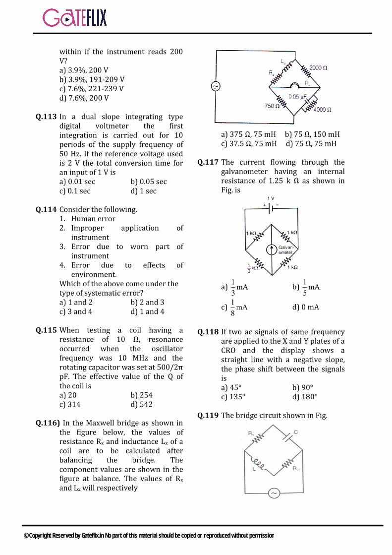
within if the instrument reads 200 V? a) 3.9%, 200 Vb) 3.9%, 191-209 Vc) 7.6%, 221-239 Vd) 7.6%, 200 V
Q.113 In a dual slope integrating type digital voltmeter the first integration is carried out for 10 periods of the supply frequency of 50 Hz. If the reference voltage used is 2 V the total conversion time for an input of 1 V is a) 0.01 sec b) 0.05 secc) 0.1 sec d) 1 sec
Q.114 Consider the following. 1. Human error2. Improper application of
instrument3. Error due to worn part of
instrument4. Error due to effects of
environment.Which of the above come under the type of systematic error? a) 1 and 2 b) 2 and 3c) 3 and 4 d) 1 and 4
Q.115 When testing a coil having a resistance of 10 Ω, resonance occurred when the oscillator frequency was 10 MHz and the rotating capacitor was set at 500/2π pF. The effective value of the Q of the coil is a) 20 b) 254c) 314 d) 542
Q.116) In the Maxwell bridge as shown in the figure below, the values of resistance Rx and inductance Lx of a coil are to be calculated after balancing the bridge. The component values are shown in the figure at balance. The values of Rx and Lx will respectively
a) 375 Ω, 75 mH b) 75 Ω, 150 mHc) 37.5 Ω, 75 mH d) 75 Ω, 75 mH
Q.117 The current flowing through the galvanometer having an internal resistance of 1.25 k Ω as shown in Fig. is
a) 1mA3
b) 1mA5
c) 1mA8
d) 0 mA
Q.118 If two ac signals of same frequency are applied to the X and Y plates of a CRO and the display shows a straight line with a negative slope, the phase shift between the signals is a) 45° b) 90°c) 135° d) 180°
Q.119 The bridge circuit shown in Fig.
© Copyright Reserved by Gateflix.in No part of this material should be copied or reproduced without permission
a) cannot be balancedb) can be balanced but the
frequency of excitation must beknown
c) can be balanced for only onefrequency
d) can be balanced at anyfrequency.
Q.120 Which one of the following type of error come under systematic error? 1. Irregular spring tension.2. Improper readings of an
instrument.3. Loading effects.4. Error due to the presence of
electric filed or magnetic fielda) 1 and 2 b) 2 and 3c) 3 and 1 d) 4 and 1
1 2 3 4 5 6 7 8 9 10 11 12 13 14
(c) (d) (d) (a) (d) (a) (b) (c) (a) (a) (c) (c) (d) (a)
15 16 17 18 19 20 21 22 23 24 25 26 27 28
(d) (b) (b) (b) (c) (a) (a) (a) (c) (a) (a) (a) (a) (d)
29 30 31 32 33 34 35 36 37 38 39 40 41 42
(d) (c) (a) (b) (a) (c) (a) (b) (a) (b) (b) (c) (a) (d)
43 44 45 46 47 48 49 50 51 52 53 54 55 56
(c) (d) (b) (c) (b) (b) (a) (c) (c) (a) (b) (a) (a) (d)
57 58 59 60 61 62 63 64 65 66 67 68 69 70
(c) (c) (b) (c) (a) (b) (b) (c) (d) (a) (b) (c) (c) (a)
71 72 73 74 75 76 77 78 79 80 81 82 83 84
(d) (a) (d) (a) (c) (c) (c) (c) (c) (a) (d) (c) (b) (a)
85 86 87 88 89 90 91 92 93 94 95 96 97 98
(b) (b) (d) (b) (c) (b) (a) (d) (b) (c) (b) (b) (a) (b)
99 100 101 102 103 104 105 106 107 108 109 110 111 112
(d) (c) (d) (c) (d) (c) (a) (b) (c) (a) (d) (c) (c) (b)
113 114 115 116 117 118 119 120
(c) (c) (a) (a) (b) (d) (d) (c)
ANSWER KEY:
© Copyright Reserved by Gateflix.in No part of this material should be copied or reproduced without permission
Q.1 (c)
Sensitivity = 3
6mm/ohm
Q.2 (d)
Resolution = 9.999
9999 = 1mV
Q.3 (d) P = l2R
R = 2
P
I
δR δP 2δI ±
R P I
= ±1.5×(2×1) δR
= ± 3.5%R
Q.4 (a)
Q.5 (d)
Q.6 (a)
Q.7 (b) In dynamometer type wattmeter, the fixed coil is current coil and moving coil us voltage coil or pressure coil.
Q.8 (c) When power factor cos = 0.5 then
one wattmeter reads zero. The load is lagging in this case.
Q.9 (a)
Q.10 (a) Meter constt.=400 revolution parkwh
= 240 10 0.8
4001000
revolutions per
hour = 768 revolution per hour
= 768
60 rpm = 12.8 rpm
Q.11 (c)
Q.12 (c)
Q.13 (b) fy
fx=
No.of horizontal tangent
No.of vertical tangle
fy
1000=
5
2
fy = 2500 Hz
Q.14 (a)
Q.15 (d)
Q.16 (b) δV
V = 2%
δV =2
300100
= 6 V
So range of reading = 30 ± 6 = 24 V to 36
Q.17 (b)
Q.18 (b)
Q.19 (c)
Q.20 (a)
Q.21 (a) Because PMMC reads only d.c. value or average value.
Q.22 (a)
EXPLANATIONS
© Copyright Reserved by Gateflix.in No part of this material should be copied or reproduced without permission
V = I1R
But I1 = 3
3
10.
10I
R
I = 1 A and V = 100 V
100 =3
3
10.
10R
R
∴ R = 111.11
Q.23 (c) Moving iron type ammeter reads average value
∴ Reading = 2
2 1010
2
Reading = 150 A
Q.24 (a)
Q.25 (a) For 10 spring stiffness K’ = K-0.4% of K K’ = 0.996 K For 10 New B’ = B-0.2% of B = 0.998 B Kθ
K'θ' =
NBAI
NB'AI
'
=
.999K B
K 0.998B
Θ’ = 1.002 Θ So the instrument reading increase by 0.2%
Q.26 (a) The makers specify the maximum value as 100 μA. This means that the current drawn from the cell should be less than 100 μA and this current should flow momentarily.
Q.27 (a)
Q.28 (d)
Q.29 (d)
Q.30 (c)
Q.31 (a)
Q.32 (b)
Gauze factor =
R
RL
L
= 6
6
240 10
120 10
Gauze factor = 2
Q.33 (a) Total harmonic distortion
Totalharmonics100
Total rms
2 2
2 2 2
6 8100
6 8 200
T.H.D. = 4.55%
Q.34 (c)
Q.35 (a) In Moving iron voltmeter deflection α I2
2
1
100 1
V 0.5
V1 = 25 V Q.36 (b)
Q.37 (a)
tanθ = 1 2
1 2
P P3
P P
P1= 3 kW P2= -1 kW
tanθ = 4
32
tanθ = 2 3
θ = 73.89 Power factor =cos θ = 0.277
Q.38 (b)
Q.39 (b) Line base setting = 5 m sec./div. for 10 division = 50 m sec. ω = 314 2πf = 314
© Copyright Reserved by Gateflix.in No part of this material should be copied or reproduced without permission
f = 50Hz ∴ No. of cycles = 50×10-3×50 = 2.5 cycles
Q.40 (c)
Gauze factor =
R
RL
L
2 = 5
R
120
10
∆R = 2.4×10⁻³
Q.41 (a) When control spring snaps it given full scale deflection. Because there is no controlling torque present.
Q.42 (d)
Q.43 (c) fy
fx=
No.of horizontal tangent
No.of vertical tangle
fy
fx=
1
1.5
fy
fx=
2
3
Q.44 (d) Revolution per kW =
4
3
10 10
450 10 450
Revolution per kWh = 410 3600
450 100
= 800
Q.45 (b) Two wattmeter method will be used to measure 3-phase, 3 wire balanced and unbalanced power.
Q.46 (c) Error while reading 150mA
= 2
150100
= 3 mA
∴ Accuracy while reading 72 mA
= 3
100 4%75
Q.47 (b) Tolerance for 10 k
= 5
10K 0.5K100
Tolerance for 5 k = 10
5K 0.5K100
Total tolerance = 0.5 + 0.5 = 1 K Total resistance in series = 10 + 5 = 15 K ∴ Tolerance limit = 1
100 6.67%15
Q.48 (b)
Q.49 (a) Total impedance = 30000+20000 = 50000 ∴ Current through them
= 600
.012A50000
Voltage across 1st voltmeter = .012 × 30000 = 360 V Voltage across IInd voltmeter = 0.012×20000 = 240 V
Q.50 (c) ∝ I2
2
1 1
2
2 2
I
I
2
2
2
12
I
4
∴ I2= 0.707
Q.51 (c) Both spectrum analyzer and distortion factor meter are single analyzers. A spectrum analyzer
© Copyright Reserved by Gateflix.in No part of this material should be copied or reproduced without permission
sweeps the single frequency band and displays a plot of amplitude versus frequency. Distortion factor metcs.er tunes out the fundamental signal and gives an indication of the harmonics.
Q.52 (a)
Q.53 (b)
Q.54 (a)
Q.55 (a)
LL
0
L
E 49.5 1Z 10M
100KE 501
Z
Q.56 (d) Minimum sampling frequency = Nyquist Sampling Rate = 2kHz and resolution = 0.01
= n
1100
2 1
n ≈ 14
Q.57 (c) Refer static sensitivity.
Q.58 (c) Induction principle is more generally used for Watt-hour meter than for ammeter and voltmeter owing to their comparatively high cost and inaccuracy of induction instruments of the latter types.
Q.59 (b)
1 2
2 2
2 2
1 I I
1 2
I I
I I
1 2
I I1
I I
∴ 2 2 2 2
1 (1) (1) (1) (2) 2.24A
∴ I = (400±2.24)A
Q.60 (c)
Q.61 (a)
∝ I2
2100 1
0.5
25 V
Q.62 (b)
Q.63 (b)
Q.64 (c)
Q.65 (d)
Q.66 (a)
Q.67 (b) V =g.p V = 58×10-3 = 58 mV
Q.68 (c)
Q.69 (c)
Q.70 (a)
Q.71 (d)
Q.72 (a)
Q.73 (d)
Q.74 (a) Thermistors have negative resistance temperature coefficients.
Q.75 (c)
Q.76 (c)
Q.77 (c)
Q.78 (c)
Q.79 (c)
© Copyright Reserved by Gateflix.in No part of this material should be copied or reproduced without permission
Q.80 (a) Average current,
= 117.02 117.08 117.11 117.03
4
= 117.06mA as Imax = 117.11 mA &Imin = 117.02 mA ∴ range of error
= ± max av av minI I I I
2
= ±0.05 0.04
2
= ±0.045 mA
Q.81 (d)
Q.82 (c)
Q.83 (b)
Q.84 (a)
Q.85 (b) Approximate resolution
= 12
102.5
2 1
mV
Q.86 (b)
Q.87 (d) Refer potentiometric type digital voltmeter
Q.88 (b) V = 5 × 1 = 5 mV
New resistance = 5 .55 55
5.55 111
∴ Imax = 5 111
1055
mA
Q.89 (c) Voltage drop per unit length = 1.45/50 = 0.029 V/cm Voltage drop across 70 cm. length = 0.029 × 70 = 2.03 V
∴ Current through resistor = 2.03
1
= 2.03 A
Q.90 (b)
Q.91 (a)
Q.92 (d)
Q.93 (b)
Q.94 (c) Initial resistance = 20000 × 100 = 2M Final resistance = 20000 × 100 = 20M ∴ Series resistance = 20 – 2 = 18 M
Q.95 (b) LVDT and strain gauge measure linear displacement.
Q.96 (b)
Q.97 (a) 400 rev → 1 kw
Rpm speed = 400 20
60 3
Power is =240 10 0.8
1000
= 1.92 kw
required speed = 20
3× 1.92
= 12.8 rpm
Q.98 (b)
Q.99 (d) The smallest incremental change is
= 10
1 1
2 1024
For 5 V, 5
1024= nearly 5 mV.
Q.100 (c)
Sensitivity (I) = 1
200 N5mA
© Copyright Reserved by Gateflix.in No part of this material should be copied or reproduced without permission

Q.101 (d)
1∝ 1
R
∴ 1 2
2 1
R I 2.5 5
R I 0.5 1
Q.102 (c) Q.103 (d) Q.104 (c) Q.105 (a)
Series resister
= 1
100K 1 K100
= 99.99 K
Q.106 (b) In bridge type rectifier meter Reading =Vms = 1.11 Vav
In Thermocouple meter for square wave
Reading =Vms = Vav
∴ Ratio = 1.11 : 1 Q.107 (c)
No. of pulses = 5.75 × 100 = 575 pulses
Q.108 (a) Q.109 (d)
Total energy supplied by the source in one minute.
W = 3 × 1017 × 10-19 × 10000 = 4.8 × 10² J = 480 J
∴ Average power supplied to the beam
= 480/60 = 8 W Q.110 (c) Work done by the electric field = eV
Kinetic energy =1
2 mv2 = eV
V =2eV
m
= 19
31
2 1.6 10 1000
9.1 10
= 0.1875108 m/s Q.111 (c)
1 % accuracy means that a
maximum possible error of 300 1
100
= 3 may be present in any reading. Since the deflection is 83 V the
present limiting error is 3
10083
=
3.62. Q.112 (b)
Error = 3
300100
= 9V
(a) Possible % error to measure 230 V
= 9
100230
= 3.9%
(b) Range = 230 ± 9 = 191 – 209 V Q.113 (c)
In a dual slope integrating type digital voltmeter
∴ Vin =Vref (t2/t1) Where t1 is the first integration time t1 = 10 × 1/50 = 0.2 sec Vm = 1 V Vref= 2
t2 = Vin × 1
ref
t
V
= 0.2
12
= 0.1 sec
Q.114 (c) Q.115 (a)
Q = 0
0
L 1
R C R
= 12 7
1
500 / 2 10 2 10 10
= 410 10000
20500 500
© Copyright Reserved by Gateflix.in No part of this material should be copied or reproduced without permission
Q.116 (a)
R1 = 32
4
R 750R 2000 375
R 4000 W
L1 = R2R3C4 = 2000×750×0.05×10-5 = 75 mH
Q.117 (b)
Q.118 (d)
Q.119 (d)
Q.120 (c)
© Copyright Reserved by Gateflix.in No part of this material should be copied or reproduced without permission