Embed Size (px)
Citation preview
Airfield Radio and Landing Systems Factory Short Cuts * Induction Heating
3 Tube Tests * Television * BerylliumMAY 1944
Caldwotl-Ciemonfe, Inc.
(□‘e
»Ai
ibration and pressure. They are particu
INDIANAPOLIS 6, INDIANAP. R. MALLORY & CO
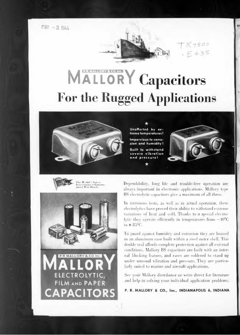
cases are soldered to standnal blocking feature.under unus
temperatures from —40°C
larl\ suited to marine and aircraft application
See your Mallory distributor or write direct for literature and help in solving your individual application problems.
In strenuous tests, as well as in actual operation, these electrolytics ha\e proved their ability to withstand extreme variations of heat and cold. Thanks to a special electro-
Dependability, long life and trouble-free operation are always important in electronic applications. Mallory type BS electrolytic capacitors give a maximum of all three.
The If crhis Safest Invest meni — »verri- ment 19 ar Hands
MÄLLOrY Capacitors For the Rugged Applications
lytic thev operate efficien to + 85°C.
To guard against humidity and corrosion thev are housed in an aluminum case built within a steel outer shell. This double seal affords complete protection against all external conditions. Mallory BS capacitors are built with an inter-
Unaffected by extreme temperatures!
Impervious to corrosion and humidity !
Built to withstand severe vibration and pressure!
MallorYELECTROLYTIC, FILM and PAPER
CAPACITORS
313 572® a is]Ì1SB373ÌI33I ■ c I ■ d I n g INDUSTRIAL ELECTRONICS
MAX, 1944
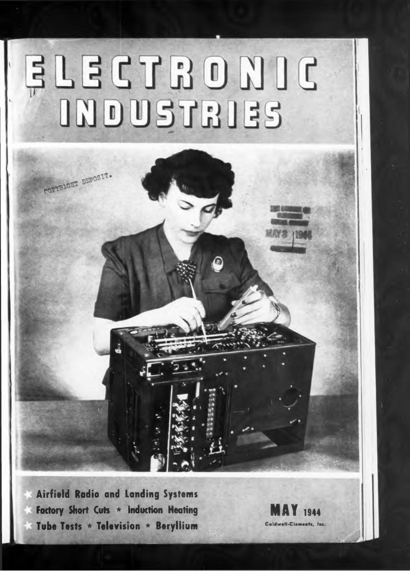
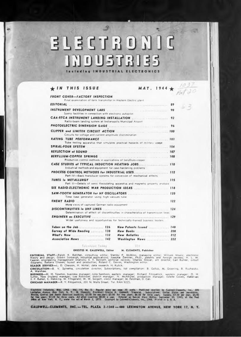
FRONT COVER—FACTORY INSPECTIONFinal examination of tank transmitter in Western Electric plant
EDITORIAL ...........................................................................................
INSTRUMENT DEVELOPMENT LABS ...........................................Sperry facilities in connection with electronic autopilot
CAA-RTCA INSTRUMENT LANDING INSTALLATION ............Radio-beam landing system at Indianapolis Municipal Airport
PHOTOELECTRIC DIMENSION GAGE.........................................
CLIPPER and LIMITER CIRCUIT ACTION ........................................................Circuits for voltage and current amplitude discrimination
RATING TUBE PERFORMANCE ...........................................................................Tube testing apparatus that simulates practical hazards of military usage
SPIRAL-FOUR SYSTEM .............................................................................................
89
90
92
96JOO
103
104REFLECTION of SOUND.................................................................................................BERYLLIUM-COPPER SPRINGS ...................................................................................
Production control methods in applications of beryllium copper
CASE STUDIES of TYPICAL INDUCTION HEATING JOBSIndustrial methods and equipment for case-hardening problems
PROCESS CONTROL METHODS for INDUSTRIAL USES Part IV—Basic transducer systems for conversion of mechanical effects
TUBES in METALLURGY .............................................................................................. Part II—Details of sonic flocculating apparatus and magnetic property analysis
SIX RADIO-ELECTRONIC WAR PRODUCTION IDEAS .......................................
107108
HO
112
SAW-TOOTH GENERATOR for HF OSCILLATORS................................................Time base generator using high vacuum tube
ENEMY RADIO ................................................................................................................Moro views of captured German radio equipment
DISCONTINUITIES in UHF LINES ...............................................................................Determination of effect of discontinuities in characteristics of transmission lines
ENGINEER os EXECUTIVE.......................Wider usefulness and opportunities for technically-trained business leaders
Tubes on fhe Job............. Survey of Wide Reeding What's New ................... Association Nows..........
115
118
120
122
124
129
140208212222
126130132142
New Patents IssuedNew Beeks .......New Bulletins .... Washington News
ORESTES H. CALDWELL, Editor M. CLEMENTS, Publisher
EDITORIAL STAFF—Ralph R. Batcher consulting editor; Stanley F McMinn, managing editor; William Moulic, electronic theory and design; Gilbert Sonbergh, industrial applications; Josepha Zentner, Ph.D., p-itents and foreign reviews; H. L. M. Capron, engineering management relations; E. T Bennett, editorial records; Charles Dreyer, art director; Carl Buhrer, circuit diagrams; Barbara Chasen, layout and production; Roland C. Davies, Washington editor.READER SERVICE—1 D. Chesson, H. Mirtei; data research. H Kulick.CIRCULATION—B. V. Spinetta, circulation director. Subscriptions; list compilation : B. Gollub, M Groening, B. Ruchaisky, A. Warshaw.BUSINESS—M. H Newton, business manager, John Samborn, eastern manager; Richard Fitzpatrick, western manager; O. H. Sutter, New England manager; Lee Robinson, district manager; N. McAllister, production manager; Estelle Coven make-up, E. P. Butler, E Hekking, M. Fitzgerald; W W. Sw>gert, credit manager; M. Feldman, D. Cali.CHICAGO MANAGER—R. Y. Fitzpatrick, 201 N. Wells Street. Tel. RAN 9225.
Elitlrwnic Industrtu. May 1944. Vai HI, 8* $ Rugular ana pts espy 35 ante. Publish» monthly by Carawell-ClMients, Inc . 480 Lexington Annuo, Row York, N. Y. M Clements, President; Orestes H. Caldwell, Treasurer. Subscriptions: United States and posse Muns, Mexico, Central and South American countries, $3.00 for one wear $5.00 for two yean; $6.50 for three years Canada, $3-30 wr year; $5.50 for two years'- $715 fot three years. All ether countrin $5 00 e year Enterea as Secci.’ Class Matter, September 20, 1943 at the rn OMce at Nm York. M. Y. under the act of Mort?: 2. 1879. Copyright by Coldwell Clements, Im 1944 Print» in U S. A
CALDWELL*CLEMiNTSt INC.—TEL PLAZA 3-1340—480 LEXINGTON AVENUE. NEW YORK 17. N. Y
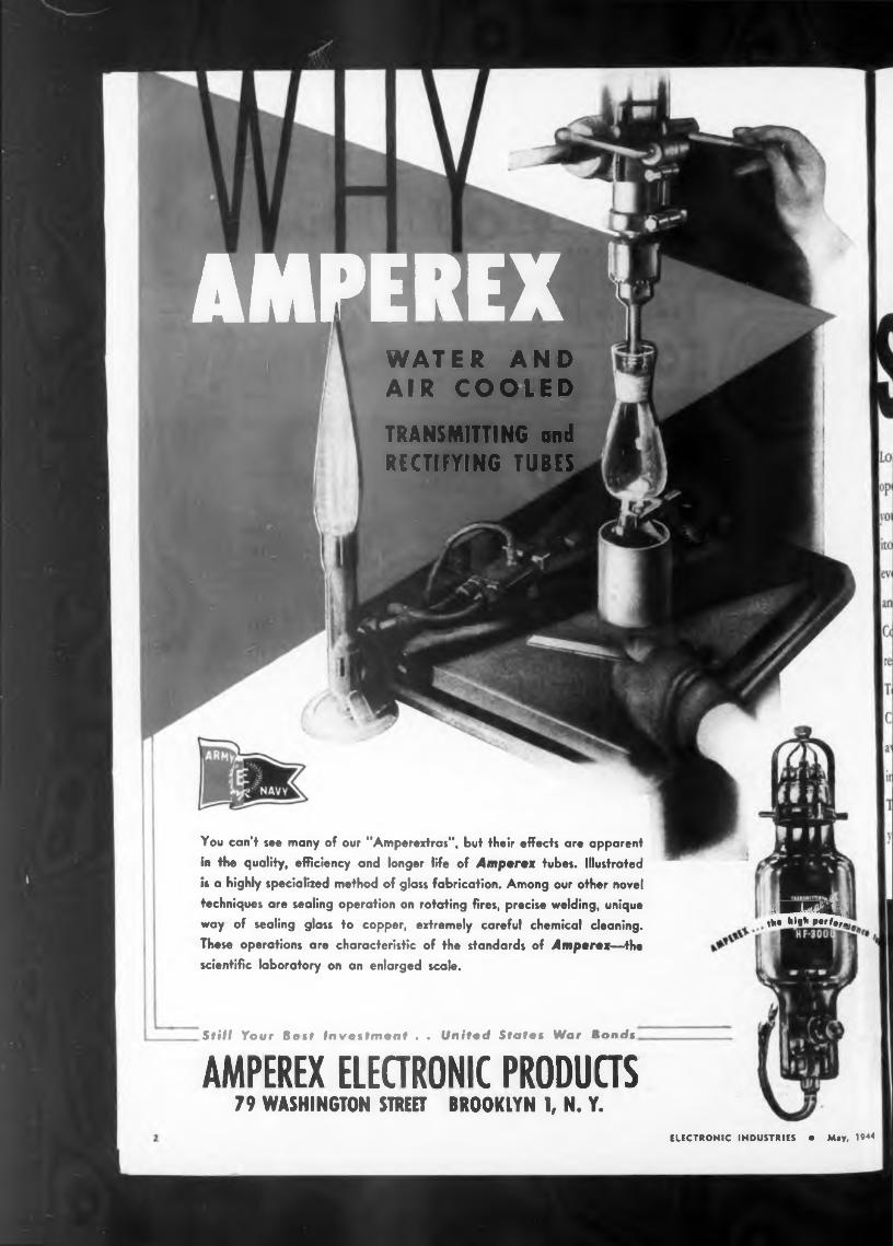
AMPEREXWATER AND AIR COOLEDTRANSMITTING andRECTIFYING TUBES
You can’t see many of our "Amperextras”, but their effects are apparent
in the quality, efficiency and longer life of Amperes tubes. Illustrated is a highly specialized method of glass fabrication. Among our other novel techniques are sealing operation on rotating fires, precise welding, unique
way of sealing glass to copper, extremely careful chemical cleaning.
These operations are characteristic of the standards of Amperes—the scientific laboratory on an enlarged scale.
1 ■Matej tM high Ptrfer.
Still Your Best Investment . . United States War lands
AMPEREX ELECTRONIC PRODUCTS79 WASHINGTON STREET BROOKLYN 1, N. Y.
ELECTRONIC INDUSTRIES • May, 1944
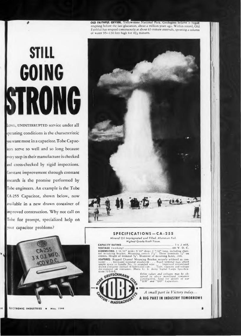
OLD FAITHFUL GEYSER, Yellowstone National Park. Geologists believ^Hvegaw erupting before the last glaciation, about a million years ago. Within record. Old Faithful has erupted continuously at about 65-minute intervals, spouting a column of water 95—130 feet high for 41/2 minutes.
STILLGOING
MKLong, uninterrupted service under all
operating conditions is the characteristic
vou want most in a capacitor. Tobe Capac
itors serve so well and so long because
every step in their manufacture is checked
and cross-checked by rigid inspections.
Constant improvement through constant
research is the promise performed by
Tobe engineers. An example is the Tobe
CA-2 5 5 Capacitor, shown below, now
available in a new drawn container of
improved construction. Why not call on
Tobe for prompt, specialized help oft
your capacitor problems?
CAPACITY RATINGVOLTAGE (working).
SPECIFICATIONS-CA-255Mineral Oil Impregnated and Filled. Aluminum Foil.
Highest Grade Kraft Tissue.... 3 x .1 mfd. 400 V. D. C.
DIMENSIONS: 1 H/16* wide: 9/16" deep: 2 7/16" long, including channel mounting bracket. Mounting centers 2%". Three terminals Vi" on centers. Height of terminal Diameter of mounting holes, .144.FEATURES: Rugged Channel Mounting Bracket securely soldered to container . . . Increased terminal insulation . . . Rigid terminal lugs afford ample space to handle No. 14 stranded wire . . . Improved streamlined drawn container instead of fabricated can . . . Type, capacity and voltage die-stamped on container. Meets (J. S. Army Signal Corps Specifications 71-516-E.
&Other values and voltages may be obtained in above mentioned container construction. Send for details of our “ONI” and "OD” Capacitors.
¿Cj A small part in Victory today...A BIG PART IN INDUSTRY TOMORROW I
ELECTRONIC INDUSTRIES • May, 1944
LETTERS
.expected potentialout. They found
IT TAKEShave any information bearing
RockefellerNew York City
to build an Amplifier such as this
it reflects the
Did Two-Filament LampFirst Reveal Edison Effect
gineering cou]
Terry Ramsaye, EditorMotion Picture Herald
Plaza
Percival PentodeAlgiers APO, Afrique
Editor, Electronic IndustriesA good many years ago, it
ELECTRONIC INDUSTRIES • May, 1944
chance to on it.
skill, to insure the most in quality at the lowest possible cost.
It is not alone the trim looks and compact convenience of this amplifier which caused it to attain such popularity. Like all Thordarson products,
Thordarson Model T3OW2O is a 20-Watt amplifier embodying all of the latest improvements and conveniences which make it adaptable for <1 wide variety of uses.
spondence with IF. K. L. Dickson, who i n a member of the Edison staff for a h ng time, prior to his dismissal in 1895, he gave me the explanation that “the Edi >n Effect” had been discovered incidental to experiments with double-filament lamp:
He said that they tried making lamps with a second or spare filament to cut i .ro the circuit when the first filament burred
“Nothing is impossible," Thomas A. Edison used to say. “IFe merely dont kn u yet how to do it. AU that is necessary to overcome an obstacle is to find the right man."
in this idle second filament, according to Dickson; and he said that it was part oj his assignment, prior to his motion-pict re work, to make galvanometer tests of the effect.
Since my interests through many years of contact with Mr. Edison were principally pertaining to the motion picture, I never got around to discussing this with him, and I am wondering now if any of your readers
right combination of inspired en- ipled with the highest productive
Scarem Harem—or Video Amid the HouriEditor, Electronic Industries:
Romantic Pasha here in North Africa has progressive ideas. Talking to Maj. Andre Baruch, former CBS announcer now in Africa, he inquired about the possibilities of a closed-circuit radio set-up in his harem so that he could broadcast whenever he wished. He already has an intercommunication system that allows him to push a button and contact any room in the harem...
But pay-off came in his final remark to the radio officer, when he asked, "And how is television progressing in your country, major?”
Apparently our German enemies ha-e developed a crewless radio-controlled mi' i- ature airplane capable of being direct'd by the crew of a bomber, and carrying a lethal load of destruction. IT ell, we had a radio-controlled bomb as far back as 1934, but it was figured that “straigl ’ bombing on a wholesale scale would e more effective. It is.
Says Charles F. Kettering—“I expect 'o spend the rest of my life in the future .-o I want to be reasonably sure of what kind of future it's going to be—my reason ' ir planning.”
THORDARSON ELECTRIC MFC CO 500 WEST HURON ST . CHICAGO, III
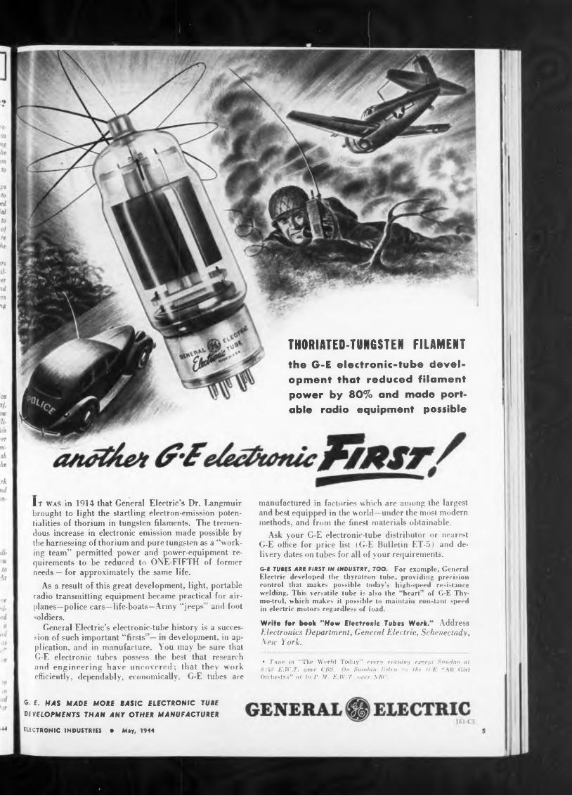
THORIATED-TUNGSTEN FILAMENT
high-speed resistanceheart’
development, in ap
of G-E Thy- nstant speed
control that makes possible today’s 1 welding. This versatile tube is also themo-trol, which makes it possible to maintain in electric motors regardless of load.
G-E TUBES ARE FIRST IN INDUSTRY, TOO For example. General Electric developed the thyratron tube, providing precision
sion of such important “firsts'
ELECTRONIC INDUSTRIES • May, 1944
manufactured in factories which are among the largest and best equipped in the world—under the most modern methods, and from the finest materials obtainable.
It was in 1914 that General Electric's Dr. Langmuir brought to light the startling electron-emission potentialities of thorium in tungsten filaments. The tremendous increase in electronic emission made possible by the harnessing of thorium and pure tungsten as a “working team’’ permitted power and power-equipment requirements to be reduced to ONE-FIFTH of former needs — for approximately the same life.
Write tor book "How Electronic Tubes Work." Address Electronics Department, General Electric, Schenectady, New York.
Ask your G-E electronic-tube distributor or nearest G-E office for price list (G-E Bulletin ET-5) and delivery dates on tubes for all of your requirements.
As a result of this great development, light, portable radio transmitting equipment became practical for airplanes—police cars—life-boats—Army “jeeps" and foot soldiers.
General Electric’s electronic-tube history is a succes-
• Tune in “The World Today” every ereniny except Sunday at E.W.T. over CBS. On Sunday listen to the G-E “All Girl
Orchestra” at 10 P. M. E.W.T. over NBC.
G E. HAS MADE MORE BASIC ELECTRONIC TUBE DEVELOPMENTS THAN ANY OTHER MANUFACTURER
the G-E electronic-tube development that reduced filament power by 80% and made portable radio equipment possible
plication, and in manufacture. You may be sure that G-E electronic tubes possess the best that research and engineering have uncovered; that they work efficiently, dependably, economically. G-E tubes are
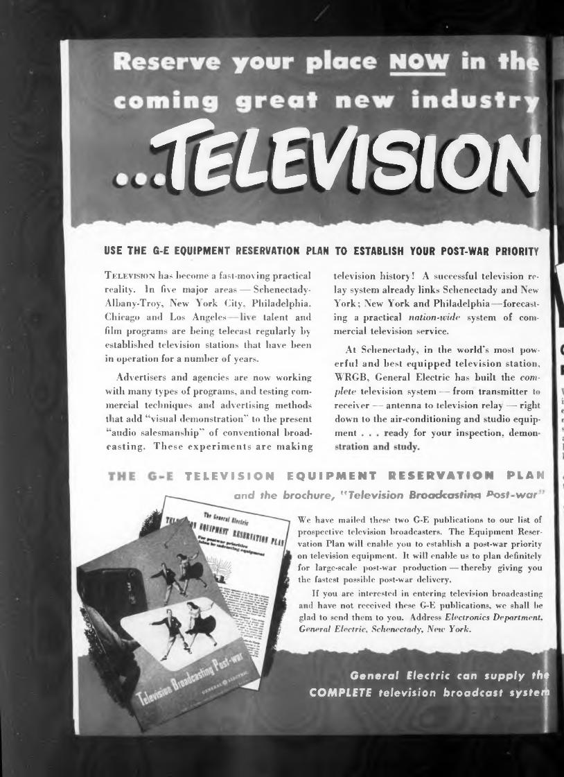
USE THE G-E EQUIPMENT RESERVATION PLAN TO ESTABLISH YOUR POST-WAR PRIORITY
Chicago ami Los Angeles talent ami
ady for your inspection, demonment
film programs are being telecast regularly by established television stations that have been in operation for a number of years.
Advertisers and agencies are now working with many types of programs, and testing commercial techniques ami advertising methods that add “visual demonstration4* to the present “audio salesmanship" of conventional broadcasting. These experiments are making
television history ! A successful television relay system already links Schenectady and New York; New York and Philadelphia—forecasting a practical nation-wide system of commercial television service.
We have mailed these two G-E publications to our list of prospective television broadcasters. The Equipment Reservation Plan will enable you to establish a post-war priority on television equipment. It will enable us to plan definitely for large-scale post-war production — thereby giving you the fastest possible post-war delivery.
If you are interested in entering television broadcasting and have not received these G-E publications, we shall be glad to send them to you. Address Electronics Department. General Electric, Schenectady, New York.
At Schenectady, in the world’s most powerful and best equipped television station, WRGB, General Electric has built the com
plete television system — from transmitter to receiver — antenna to television relay — right down to the air-conditioning and studio equip-
TELEVISION EQUIPMENT RESERVATION PLAN
and the brochure, "Television Broadcasting ^ost-war '
Television has become a fast-moving practical reality. In five major areas — Schenectady- Albany-Troy, New \ ork City, Philadelphia,
TELEVISION
General Electric can supply the COMPLETE television broadcast s y sieri
500 P'
se«0O°®
Here, G.E. has gained vastequipment and programs.
vstem. Here, G.E. has established the technical standcomplete televisionexperience in the perfection of the
General Electric believes that the strongest contribution we can make to this teamwork is television research
STATION AND STUDIO EQUIPMENT • TRANSMITTERS ANTENNAS • ELECTRONIC TUBES • RECEIVERS
We do not pretend to know all the answers involved in the business of operating television stations, tving them together as networks, and making them pay. That is a job for those whose business is broadcasting — and Me are sure that they can and will do that job.
Ml of this research, equipment, and “know how,” covering over twenty years of television experience, is at the service of prospective television broadcasters.
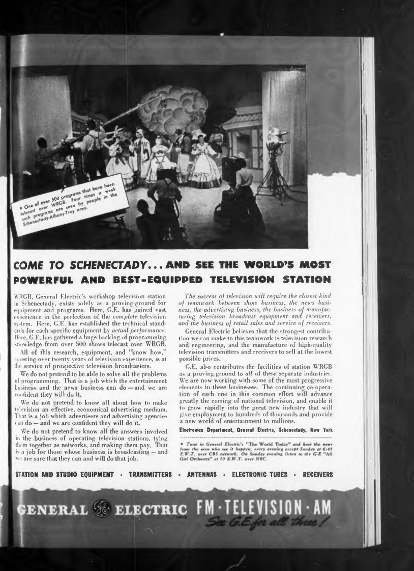
WRGB. General Electric’s workshop television station in Schenectady, exists solely as a proving-ground for
b««n v,e«k
greatly the coming of national television, and enable it to grow rapidly into the great new industry that will give employment to hundreds of thousands and provide a new world of entertainment to millions.Electronics Department, General Electric, Schenectady, New York
ards for each specific equipment by actual performance. Here, G.E. has gathered a huge backlog of programming knowledge from over 500 shows telecast over WRGB.
The success of television will require the closest kind of teamwork between show business, the news business, the advertising business, the business of manufacturing television broadcast equipment and receivers, and the business of retail sales and service of receivers.
and engineering, and the manufacture of high-quality television transmitters and receivers to sell at the lowest possible prices.
G.E. also contributes the facilities of station WRGB as a proving-ground to ail of these separate industries. We are now working with some of the most progressive elements in these businesses. The continuing co-operation of each one in this common effort will advance
We do not pretend to be able to solve all the problems of programming. That is a job which the entertainment business and the news business can do — and we are confident they will do it.
We do not pretend to know all about how to make television an effective, economical advertising medium. That is a job which advertisers and advertising agencies can do — and we are confident they will do it.
COME TO SCHENECTADY... AND SEE THE WORLD’S MOST POWERFUL AND BEST-EQUIPPED TELEVISION STATION
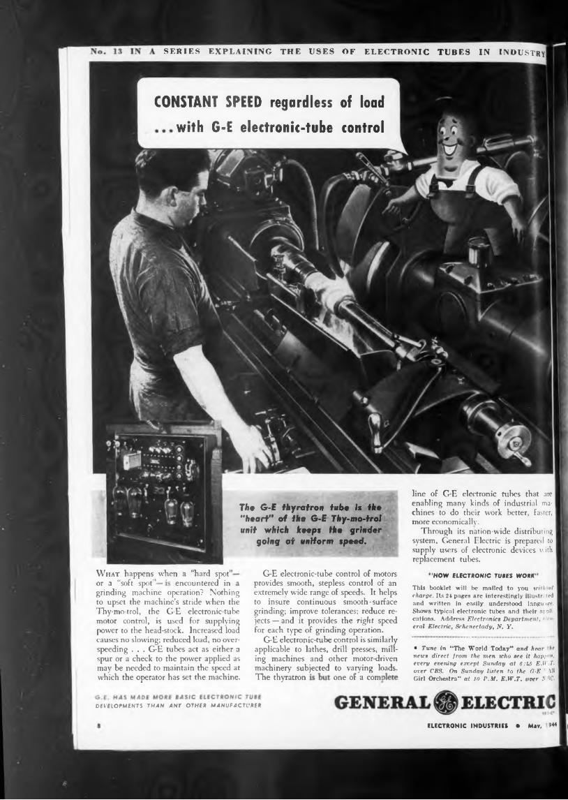
CONSTANT SPEED regardless of loadwith G-E electronic-tube control
'HOW ELECTRONIC TUBES WORK'
The thyratron
DEVELOPMENTS THAN ANY OTHER MANUFACTURER
This booklet will be mailed to you wilt >xf charge. Its 21 pages are interestingly illustr. । ted and written in easily understood language. Shows typical electronic tubes and their applications. Address Electronica Department, ' ■ »■ eral Electric, Schenectady, N, F.
• Tune in “The World Today” and hear he news direct from the men who tee it hapi », every evening except Sunday at 6:k5 E.U T. over CBS. On Sunday listen to the G-E AU Girl Orchestra” at 10 P.M. E.W.T. over b 1C.
What happens when a “hard spot’encountered in a
SERIES EXPLAINING THE USES OF ELECTRONIC TUBES IN INDUSTRY
G-E electronic-tube control of motors provides smooth, stepless control of an extremely wide range of speeds. It helps to insure continuous smooth-surface grinding; improve tolerances; reduce rejects — and it provides the right speed for each type of grinding operation.
G-E electronic-tube control is similarly applicable to lathes, drill presses, milling machines and other motor-driven machinery subjected to varying loads.
line of G-E electronic tubes that are enabling many kinds of industrial machines to do their work better, faster, more economically.
Through its nation-wide distributing system, General Electric is prepared to supply users of electronic devices with replacement tubes.
The G-E thyratron tube Is the "heart" of the G-E Thy-mo-trol unit which keeps the grinder
going at uniform speed.
one or a com]
or a “soft spot’grinding machine operation? Nothing to upset the machine’s stride when the Thy-mo-trol, the G-E electronic-tube motor control, is used for supplying power to the head-stock. Increased load causes no slowing; reduced load, no overspeeding . . . G-E tubes act as either a spur or a check to the power applied as may be needed to maintain the speed at which the operator has set the machine.
ELECTRONIC INDUSTRIES • May, »44
Wake Ho u r llcxt
ELECTRONIC INDUSTRIES May, 1944
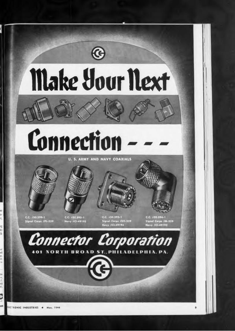
U. S. ARMY AND NAVY COAXIALS
C.C. *50.193-1
Novy ‘CI-49195
QC. #50.392-1
Signal Corp« ‘SO-239
Nayy ‘CI-49194
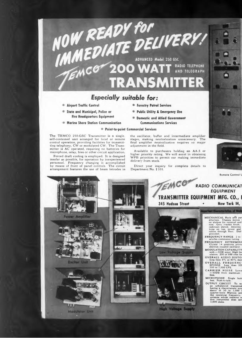
Airport Traffic Control Forestry Patrol ServicesPublic Utility & Emergency Use
• Domestic and Allied Government• Marine Shore Station Communication Communications Services
• Point-to-point Commercial ServicesThe TEMCO 250-GSC Transmitter single,
Available to purchasers holding AA-5
arrangement features the use of beam tetrodes inRemole Control U
RADIO
TRANSMITTER EQUIPMENT MFG. CO., IHew York 14, I345 Hudsu Sheet
Low Voltage Supply
Modulator Unit
higher priority rating. We will assist in obtaining WPB priorities to permit our making immediate delivery from stock.
Direct your inquiry for complete details to Department No. I 101.
self-contained unit arranged for local or remote control operation, providing facilities for transmitting telephony, CW or modulated CW. The Transmitter is AC operated, requiring no batteries for microphone, relay, bias or other circuit application.
Forced draft cooling is employed. It is designed insofar as possible, for operation by inexperienced personnel. Frequency changing is accomplished by means of front of panel controls. The circuit
the oscillator, buffer and intermediate amplifier stages, making neutralization unnecessary. The final amplifier neutralization requires no major adjustment in the field.
State and Municipal, Police or Fire Headquarters Equipment
MICROPHONE Single butt, bon. Push-to-talk.
OUTPUT CIRCUIT To wc an unbalanced transmits! having * characteristic surg dance of 30 to 1,000 c quarter-wave Marconi anti the operating frequency, antenna whose resistive hi tive component does not 1,000 ohms.
MECHANICAL Rack arfd pan struction. Chassis moves I on shelves for removal and tion Grey crackle finish cadmium plated Antenna tions on top: power and cables through floor Dial provided.
FREQUENCY RANGE 2 to 1 acydes continuous tuning.
FREQUENCY DETERMINA Crystal (4 positions provid electron coupled oscillator.
MODULATION CAPABILITY with — 5DB input. High lev ulation 200 or 600 ohm lin
OVERALL AUDIO DISTOf Less than 5% at 80% mod
OVERALL FREQUENCE SPONSE Less than 2D1 200 to 7,500 CPS.
CARRIER NOISE Lowe —50DB from maximum
COMM UN IC AT EQUIPMENT
g *ADVANCED Model 250 G5C
AAA lAf ATT RADIO TELEPHONEWAI I AND TELEGRAPH
TRANSMITTER
GOVERNMENT ISSUE
>ntrol Unit
ICATION
from
thanmodula-
ELECTRONIC INDUSTRIES May, 1944
and control Dial damps
, 2 to 16 inn lining.RMINAT10N a provided ) ■ illatorBILITY im ligh level mod- ohm line input. JISTORTION •% modulationJENCY lan 2DB
0., INCi 14, N.f.
itic surge impe I 1,000 ohms, •
capacity NOW!
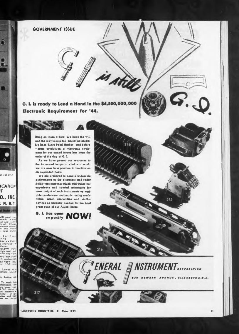
Bring on those orders! We have the will and the way to help roll 'em oH the assembly lines. Since Pearl Harbor—and before —mass production ot electronic equipment for our armed forces has been the order oi the doty at G. I.
As we have geared our resources to the increased tempo oi vital war work, we are now in a position to function on an expanded basis.
We are prepared Io handle widescale assignments in the electronic and radar helds - assignments which will utilise our experience and special techniques for mass output of such instruments as variable condensers, automatic tuning mechanism, wired assemblies and similar devices so urgently needed for the final great push of our Allied forces.
ail’d panel rm move* forward val and inspec finish. Chassis
uency, or w stive and I>ei not exceed
ENERAL NSTRUMENT.. . . . .
316
316
1368
MATERIAL H.H.C.RS.
Send for This BookletIE cut metal stampingssmall lots
accurallow as 25 produced <
quantities as pieces can be Maximum Thickness,
Maximum Blank Size, 22" x 22
Maximum Blanking Pressure, 350 tons.
DAYTON2851 12th Avenue South MINNEAPOLIS 7, MINNESOTA
quotation will immediately.
Average Die Life, 8000 to 10,000 duplicate blanks.
No matter how small your quantity requirements are or how intricate your work may be, we can show you a definite saving.
See example illustrated on this page. Data on other representative jobs will be sent to you on request.
Send us your blueprint or sample and state quantities required. Our
ELECTRONIC INDUSTRIES • May, 1944
New booklet “Metal Stamping in Small Lots” gives valuable information for Designing Engineers and Production Executives. Tells how small-lot metal stampings can be furnished at surprisingly low costs. Ask for copy on your letterhead.
permanent dies at a cost of 15% to 20% of conventional type permanent tools.This service was originated by the Dayton Rogers Manufacturing Company approximately 20 years ago. It eliminates costly permanent dies on your small lot stamping requirements. These small lot jobs can be die cut and produced to a close working tolerance with duplication assured throughout the entire lot.Stampings of any size and shape according to your special custom made requirements can be blanked, pierced, and formed from practically any sheet metal.
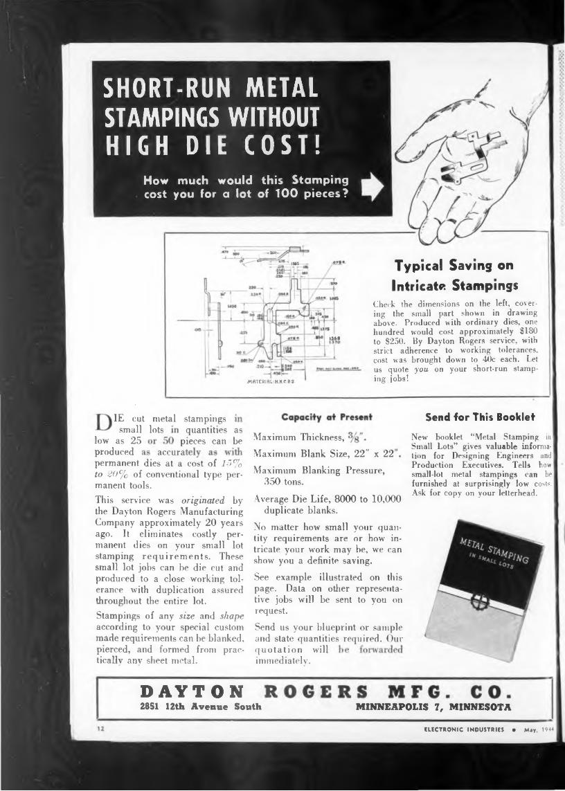
Typical Savins onIntricate Stampings
Check the dimensions on the left, covering the small part shown in drawing above. Produced with ordinary dies, one hundred would cost approximately $180 to $250. By Dayton Rogers service, with strict adherence to working tolerances, cost was brought down to 40c each. Let us quote you on your short-run stamping jobs!
SHORT-RUN METAL STAMPINGS WITHOUT HIGH DIE COST!
How much would this Stamping cost you for a lot of 100 pieces?
ow
ironic applications with no prejudices, no preconcep
CHICAGO 47, 1917 NO. SPRINGFIELD AVE. 101 KAZU STRICT, PATERSON, M. J.
ELECTRONIC INDUSTRIES1944
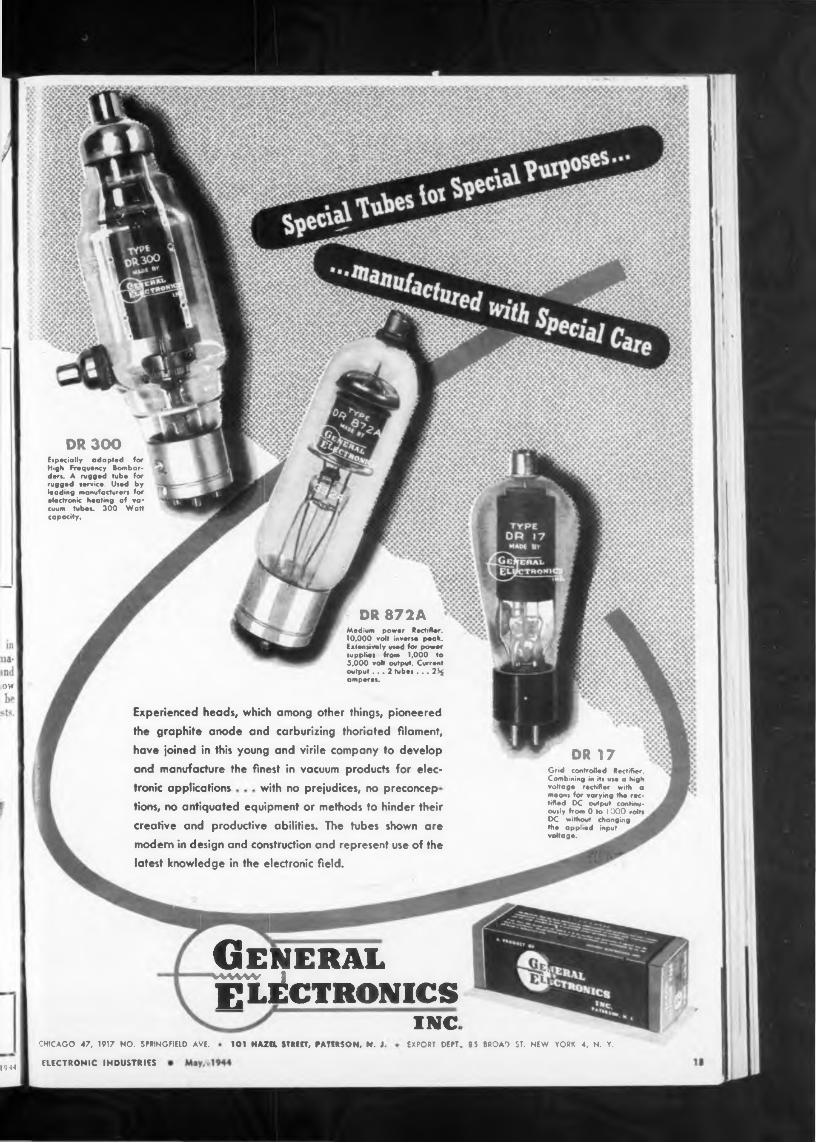
Experienced heads, which among other things, pioneered
the graphite anode and carburizing thoriated filament, have joined in this young and virile company to develop
and manufacture the finest in vacuum products for elec*
EXPORT DEPT, 9 5 BROAO ST. NEW TORK 4, N. Y.
tions, no antiquated equipment or methods to hinder their creative and productive abilities. The tubes shown are
modem in design and construction and represent use of the
latest knowledge in the electronic field.
DR 17Grid controlled Rectifier. Combining in it* use a high voltage rectifier with a means for varying the rectified DC output continuously from 0 to I 000 volts DC without changing the applied input voltage.
DR 872AMedium power Rectifier. 10,000 volt inverse peak. Extensively used for power supplies from 1,000 to 5,000 volt output. Current output ... 2 tubes ... 21$ amperes.
GeneralWWW I
ELECTRONICSINC.
DR 300Especially adapted for High Frequency Bomborders. A rugged tube for rugged service. Used by leading manufacturers for electronic heating of vacuum tubes. 300 Watt capacity.
Du MONT
19" h
ELECTRONIC INDUSTRIES
ing handles. 14' 130 lbs.
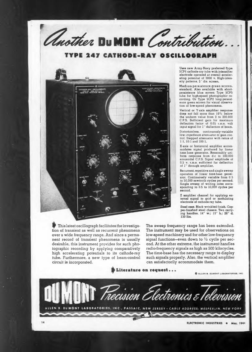
J This latest oscillograph facilitates the investigation of transient as well as recurrent phenomena over a wide frequency range. And since a permanent record of transient phenomena is usually desirable, this instrument provides for such photographic recording by applying comparatively high accelerating potentials io its cathode-ray tube. Furthermore, a new type of beam-control circuit is incorporated.
The sweep frequency range has been extended. The instrument may be used for observations on low-speed machinery and for other low-frequency signal functions—even down io 14 cycle per second. At the other extreme, the instrument handles radio-frequency signals as high as 500 kilocycles. The time-base has the necessary range io display such signals properly. Also, the vertical amplifier can satisfactorily accommodate them.
Uses new Army-Navy preferred Type 5CP1 cathode ray tube with intensifier electrode operated at overall accelerating potential of 3000 v. High-intensity patterns. 5" dia. screen.Medium-persistence green screen, standard. Also available with short* persistence blue screen Type 5CP5 tube for high speed photographic recording. Or Type 5CP2 long-persistence green screen for visual observation of low-speed phenomena.Vertical or Y-axis amplifier response does not fall more than 10% below the uniform value from 2 to 200.000 C.P.S. Sufficient gain for maximum deflection factor ol 0.05 r.m.s. volt input signal for 1" deflection of beam.Distortionless, continuously-variable low-impedance attenuator or gain control. Stepped attenuator with ratios of 1:1, 10:1 and 100:1.X-axis or horizontal amplifier accom modates signal produced by linear time-base generator. Reasonably uniform response from d-c to 100.000 sinusoidal C.P.S. Signal amplitude of U.5 v. r.m.s. sufficient for deflection of 1" through amplifier.Recurrent, repetitive and single-sweep operation of linear time-base generator. Continuously variable from 0.5 to 50,000 sawtooth cycles per second Single sweep of writing rates corresponding to 0.5 to 10,00^ cycles per second.Z amplifier channel for applying external signal to grid or modulating electrode of cathode-ray tube.Steel case. Black wrinkled finish. Copper-finished steel chassis. Two carry-
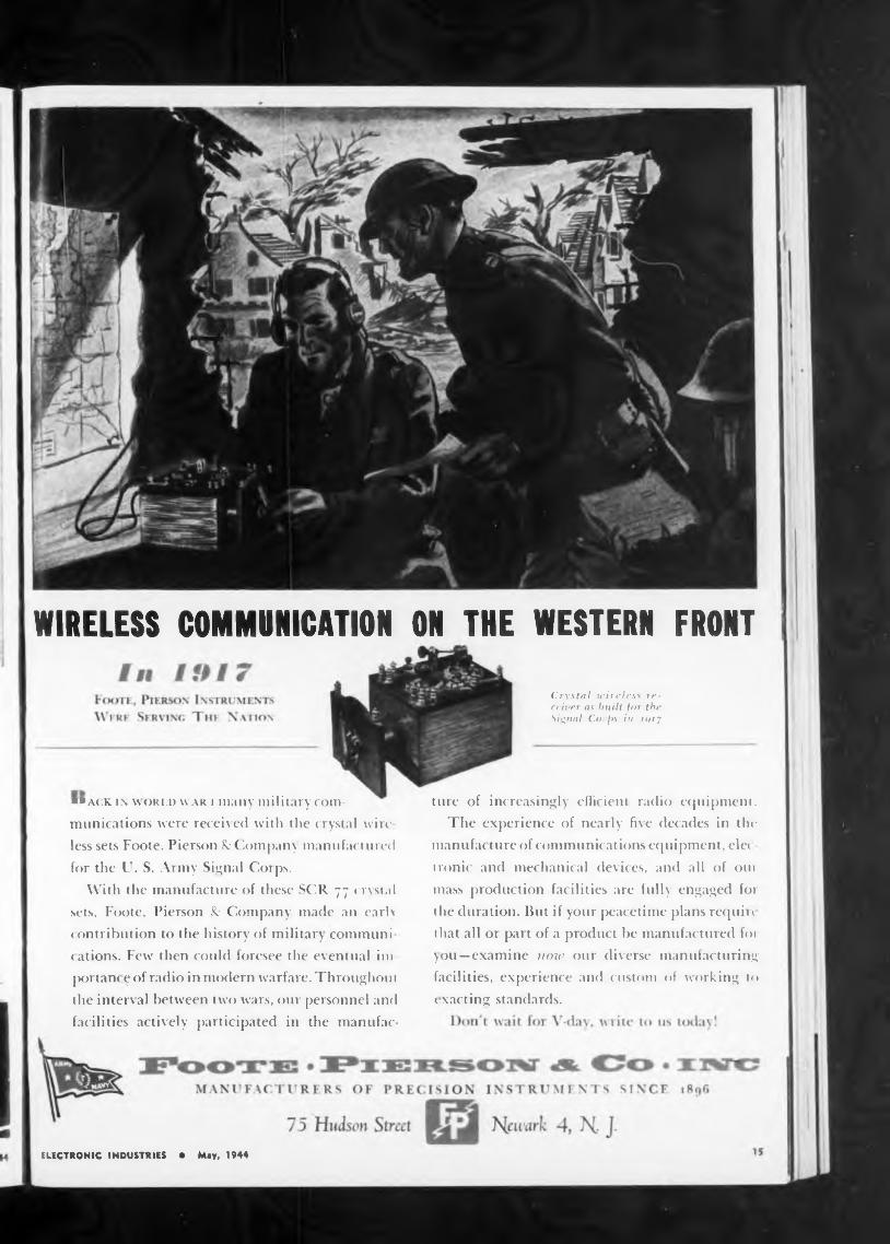
ON THE WESTERN FRONTWIRELESS COMMUNICATION
■»ack ix wori.d war i many military communications were received with the crystal wire less sets Foote. Pierson & (Company manufactured for the U. S. Army Signal Corps.
With the manufacture of these SCR 77 crystal sets, Foote, Pierson R: Company made an early c ontribution to the history of military communi cations. Few then cotdd foresee the eventual ini ¡Hirtanc e of radio in modern warfare. Throughout the interval between two wars, our personnel and facilities actively participated in the manufac-
Crystal wireless receiver as built for the Signal Corps in iqij
ELECTRONIC INDUSTRIES • May, 1944
ture of increasingly efficient radio equipment.The experience of nearly five decades in the
manufat ture of communications equipment, elec ironic and mechanical devices, and all of our mass production facilities are fully engaged for the duration. But if your peacetime plans require that all or part of a product be manufactured for you—examine now our diverse manufacturing facilities, experience and custom of working to e xacting standards.
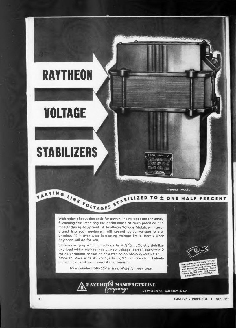
RAYTHEON
VOLTAGE
STABILIZERS
ELECTRONIC INDUSTRIES • May, 1944
With today's heavy demands for power, line voltages are constantly fluctuating thus impairing the performance of much precision and manufacturing equipment. A Raytheon Voltage Stabilizer incorporated into such equipment will control output voltage to plus or minus L So over wide fluctuating voltage limits. Here's what Raytheon will do for you.Stabilize varying AC input voltage to *2 %... Quickly stabilize any load within their ratings... Input voltage is stabilized within 2 cycles, variations cannot be observed on an ordinary volt meter... Stabilizes over wide AC voltage limits, 95 to 135 volts... Entirely automatic operation, connect it and forget it.
New Bulletin DL48-537 is free. Write for your copy.
»01TA6E stauium
ENDBELl MODEL
RAYTHEON MANUFACTURING190 WILLOW ST, WALTHAM, MASS
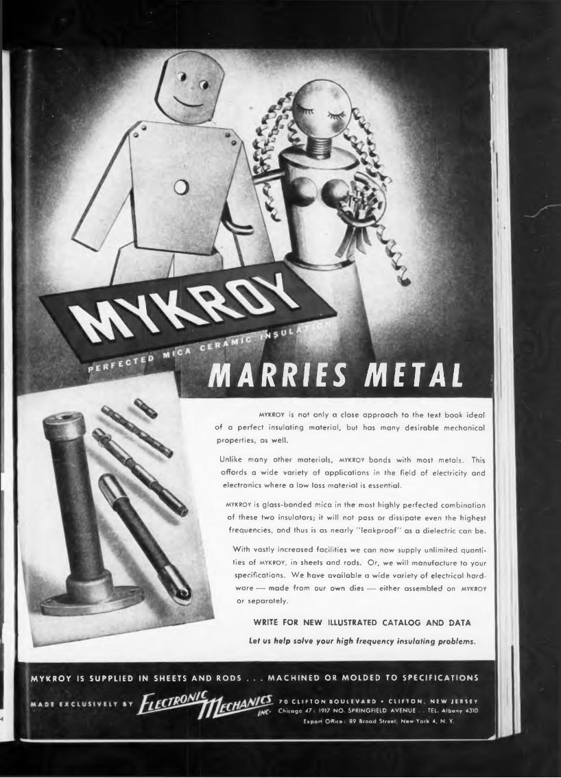
IN SHEETS ANDMYKROY IS SUPPLIED
WRITE FOR NEW ILLUSTRATED CATALOG AND DATA
Let us help solve your high frequency insulating problems.
mykroy is not only a close approach to the text book ideal
of a perfect insulating material, but has many desirable mechanical
properties, as well.
Unlike many other materials, mykroy bonds with most metals. This
affords a wide variety of applications in the field of electricity and
electronics where a low loss material is essential.
mykroy is glass-bonded mica in the most highly perfected combination
of these two insulators; it will not pass or dissipate even the highest
frequencies, and thus is as nearly "leakproof" as a dielectric can be.
With vastly increased facilities we can now supply unlimited quanti
ties of mykroy, in sheets and rods. Or, we will manufacture to your
specifications. We have available a wide variety of electrical hard
ware — made from our own dies — either assembled on mykroy
or separately.
MARRIES METAL
RODS . . . MACHINED OR MOLDED TO SPECIFICATIONS
70 CLIFTON BOULEVARD • CLIFTON, NEW JERSEY Chicago 47 1917 NO SPRINGFIELD AVENUE . TEL Albany 4310
Export OWica 89 Broad Slreat. Naw York 4, N. Y.
R roadcasting
clll ommercial
iathertny
Kectric .
Welding
F—■ Um-Sound
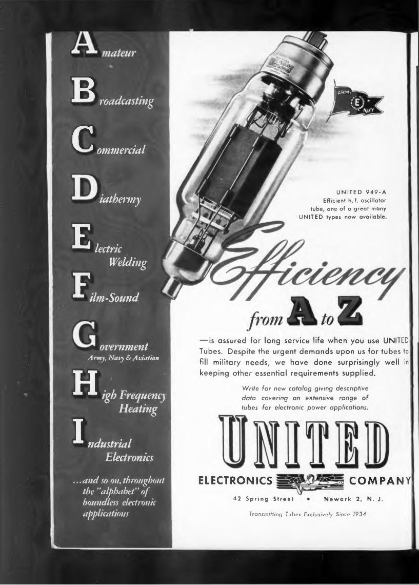
UNITED 949-A Efficient h. f. oscillator
tube, one of a great many UNITED types now available.
ovemmentArmy, Navy & Aviation
H* * igb FrequencyHeating
rLM ndustrial Electronics
... and so on, throughout the "alphabet ” of boundless electronic applications
— is assured for long service life when you use UNITED Tubes. Despite the urgent demands upon us for tubes to fill military needs, we have done surprisingly well in keeping other essential requirements supplied.
Write for new catalog giving descriptive data covering an extensive range of tubes for electronic power applications.
ELECTRONICS
42 Spring Street
COMPANY
Newark 2, N. J.
Transmitting Tubes Exclusively Since 1934
in
ONSOLIDATED RADIO
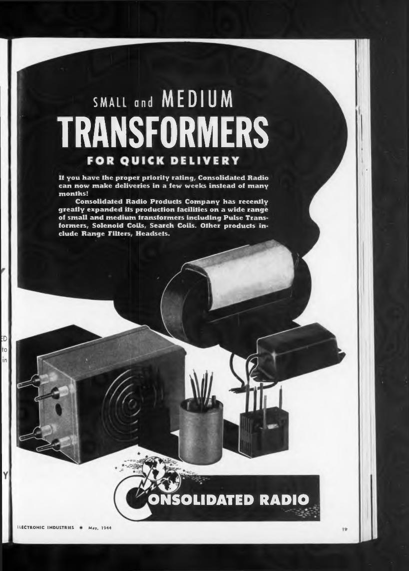
SMALL and MEDIUMTRANSFORMERSIf you have the proper priority rating, Consolidated Radio can now make deliveries in a few weeks instead of many months!
Consolidated Radio Products Company has recently greatly expanded its production facilities on a wide range of small and medium transformers including Pulse Trans formers, Solenoid Coils, Search Coils. Other products in elude Range Pilfers, Headsets.
:D to
ELECTRONIC INDUSTRIES May, 1944
produce a varied line ofsheet metal, Karp craftsmenfrom a chassis small enough to be handled by two fingers
ARTISANS »124 30th STREET
HELP SHOR THE WAR BUY MORE WAR BONDS
special existing conditions house long motor shafts.
BROOKLYN 31, N. Y.
Artisans products
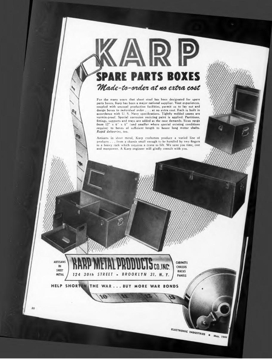
For the many years that sheet steel has been designated for spare parts boxes, Karp has been a major national supplier. Vast experiences, coupled with unusual production facilities, permit us to lay out and design boxes to individual order ... at no extra cost. Each is built in accordance with U. S. Navy specifications. Tightly welded seams are vermin-proof. Special corrosion resisting paint is applied. Partitions, fittings, supports and trays are added as the case demands. Sizes range
to a heavy rack which requires a crane to lift. We save you time, cost and manpower. A Karp engineer will gladly consult with you.
from 12" x 6" x 6" (and smaller where require) to boxes of sufficient length to Rapid deliveries, too.
SHEETMETAL
CABINETS CHASSIS RACKS PANELS
SPARE PARTS BOXESTKade-to-ondei at »ta extna coat


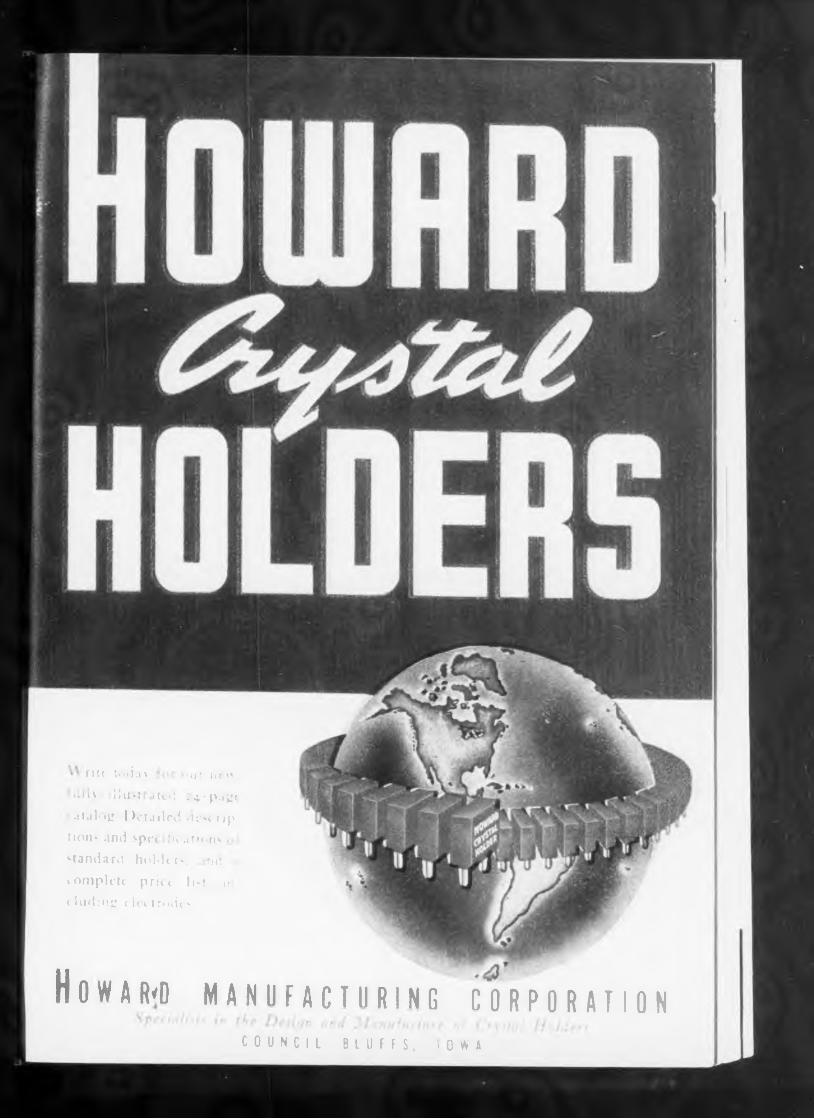
rile b'd.is »«m nt" i»li\ : 11 ii -1 itol •4'P-i^t atalog Detailed d^c rip
lions and spei fu ation< - standard holders, me ? complete price I nt h
< hiding elei trodc««
H 0 W A R<D MANUFACTURING CORPORATIONCOUNCIL BLUFFS. IOWA
EL C 0 j
>
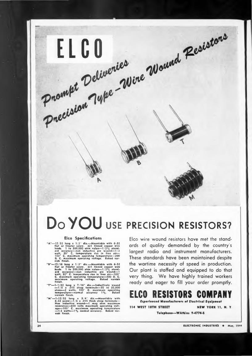
Do you USE PRECISION RESISTORS?Elco Specifications
"A"—15/32 long x 1/2" dia—Mountable with 6-32 flat or f Hester «craw. #21 tinned copper wire leads. 1 to 300,000 ohm value—1/2% standard accuracy—non inductive pie wound—1 /2 watt, 30° C temperature rise in free air— 100° C. maximum operating temperature—200 D C. maximum operating voltage. Baked varnish finish.
B"—15/16 long a 1/2" die.—Mountable with 6-32 flat or filester screw. #21 tinned copper wire leads. 1 to 500,000 ohm value—1/2% standard accuracy—non inductive pie wound—1 watt, 30* C. temperature rise in free air—100* C. maximum operating temperature—300 D C. maximum operating voltage. Baked varnish finish.
"T*—1-1/32 long x 7/16" dia.—inductively wound —1/8 x .015 strap terminals—35 to 35,000 ohm»—2 watts, 100” C. maximum operating temperature—normal accuracy 1%. Baked varnish finish.
"M"—1-13/32 long x 3/4" dia.—Mountable with 6-32 screw—1/8 x .015 thick strap terminals— Non inductive wound—1 meg ohm maximum resistance—600 volts maximum operating voltage—100” C. maximum operating temperature —1.5 wefts—1% normal accuracy. Baked varnish finish.
Elco wire wound resistors have met the standards of quality demanded by the country's largest radio and instrument manufacturers. These standards have been maintained despite the wartime necessity of speed in production. Our plant is staffed and equipped to do that very thing. We have highly trained workers ready and eager to fill your order promptly.
ELCO RESISTORS COMPANYExperienced Manufacturers of Electrical Equipment
114 WEST 1STH STREET NEW YORK 11, N. Y,
Tolophoue—WAtkius 9-4774-5
ELECTRONIC INDUSTRIES May, 1944
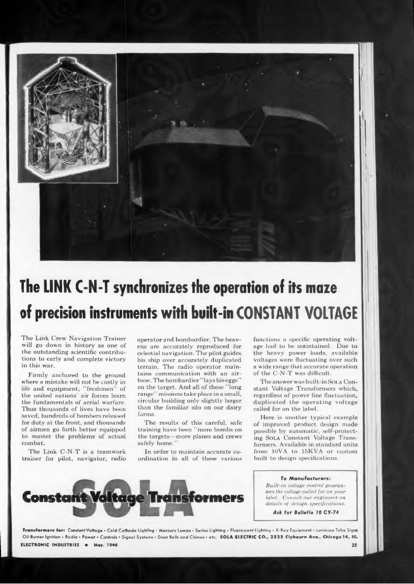
of precision instruments with built-in CONSTANT VOLTAGE
Constai «mers
The LINK C-N-T synchronizes the operation of its maze
To Manufacturars:Built-in voltage control guarantees the voltage called for on your label. Consult our engineers on details of design specifications.
Ask for Bulletin 10 CV-74
functions a specific operating voltage had to be maintained. Due to the heavy power loads, available voltages were fluctuating over such a wide range that accurate operation of the C-N-T was difficult.
The answer was built-in Sola Constant Voltage Transformers which, regardless of power line fluctuation, duplicated the operating voltage called for on the label.
Here is another typical example of improved product design made possible by automatic, self-protecting Sola Constant Voltage Transformers. Available in standard units from 10VA to 15KVA or custom built to design specifications.
operator and bombardier. The heavens are accurately reproduced for celestial navigation. The pilot guides his ship over accurately duplicated terrain. The radio operator maintains communication with an airbase. The bombardier "lays his eggs” on the target. And all of these "long range” missions take place in a small, circular building only slightly larger than the familiar silo on our dairy farms.
The results of this careful, safe training have been "more bombs on the targets—more planes and crews safely home.”
In order to maintain accurate coordination in all of these various
Transformers for: Constant Voltage • Cold Cathod* Lighting ■ Mercury lamps • Series Lighting • Fluorescent Lighting • X-Ray Equipment • Luminous Tube Signs Oil Burner Ignition • Radio • Power • Controls • Signal Systems * Door Bells and Chimes • etc. SOLA ELECTRIC CO., 2525 Clybourn Ave.- Chicago 14, HL
ELECTRONIC INDUSTRIES O May. 1944 25
The Link Crew Navigation Trainer will go down in history as one of the outstanding scientific contributions to early and complete victory in this war.
Firmly anchored to the ground where a mistake will not be costly in life and equipment, "freshmen” of the united nations’ air forces learn the fundamentals of aerial warfare. Thus thousands of lives have been saved, hundreds of bombers released for duty at the front, and thousands of airmen go forth better equipped to master the problems of actual combat.
The Link C-N-T is a teamwork trainer for pilot, navigator, radio
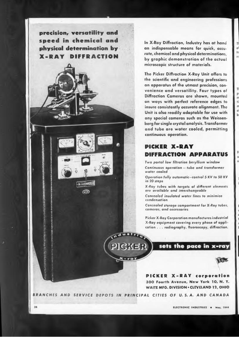
The Picker Diffraction X-Ray Unit offers to the scientific and engineering professions an apparatus of the utmost precision, convenience and versatility. Four types of Diffraction Cameras are shown, mounted on ways with perfect reference edges to insure consistently accurate alignment. The Unit is also readily adaptable for use with any special cameras such as the Weissenberg for single crystal analysis. Transformer and tube are water cooled, permitting continuous operation.
Two portal low filtration beryllium window
Continuous operation — tube and transformer water cooledOperation fully automatic-control 5 KV to 50 KV in 20 steps
X-Ray tubes with targets of different elements are available and interchangeableConcealed insulated water lines to minimize condensationConcealed storage compartment for X-Ray tubes, cameras, and accessories
In X-Ray Diffraction, Industry has at hand an indispensable means for quick, accurate, chemical and physical determinations, by graphic demonstration of the actual microscopic structure of materials.
ELECTRONIC INDUSTRIES • May, 1944
PICKER X-RAY corporation300 Fourth Avenue, New York 10, N. Y. WAITE MFG. DIVISION • CLEVELAND 12, OHIO
Picker X-Ray Corporation manufactures industrial X-Ray equipment covering every phase of application . . . radiography, fluoroscopy, diffraction.
PICKER X-RAY DIFFRACTION APPARATUS
precision, versatility and speed in chemical and physical determination by X-RAY DIFFRACTION
Diffraction Pattern
precise measurement of lattice and the determination of alloy
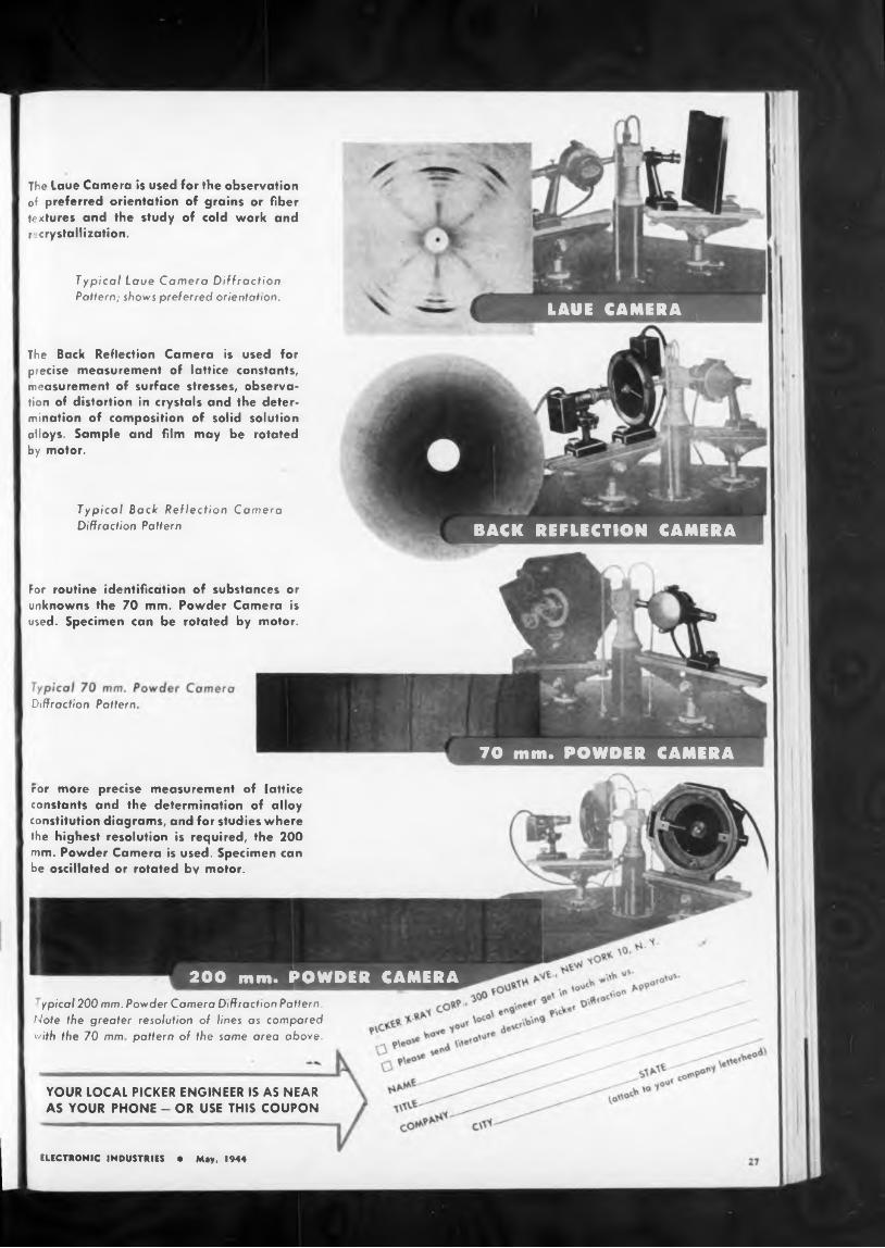
The Laue Camera is used for the observation of preferred orientation of grains or fiber textures and the study of cold work and recrystallization.
ror more constants
YOUR LOCAL PICKER ENGINEER IS AS NEAR AS YOUR PHONE - OR USE THIS COUPON
Typical Back Reflection Camera Diffraction Pattern
For routine identification of substances or unknowns the 70 mm. Powder Camera is used. Specimen can be rotated by motor.
Typical Laue Camera Diffraction Pattern; shows preferred orientation.
The Back Reflection Camera is used for precise measurement of lattice constants, measurement of surface stresses, observation of distortion in crystals and the determination of composition of solid solution alloys. Sample and film may be rotated by motor.
ypical 200 mm. Powder Camera Diffraction Pattern. Note the greater resolution of lines as compared with the 70 mm pattern of the same area above.
constitution diagrams, and for studies where the highest resolution is required, the 200 mm. Powder Camera is used. Specimen can be oscillated or rotated by motor.
ELECTRONIC INDUSTRIES • May, 1944
CAMERALAUE
BACK REFLECTION CAMERA
200 mm. POWDER CAMERA
70 mm. POWDER CAMERA
COMPANY, ATTLEBORO, MASSSPENCER THERMOSTAT
ELECTRONIC INDUSTRIES ♦ May, 1944
Type ri» (NAFA 13
Circuit breaker
Tvpe EK
i' <*<S I Se”r1’Tvpf 5,, w arming,
„ r.2HSl SeriesTyPe„„hinu Controls
Used as Rot^^Sl OvensOn Outer Crystas
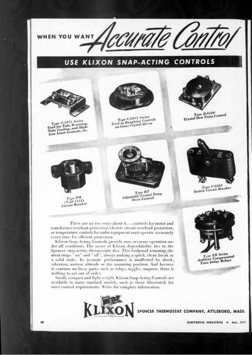
There are no two ways about if... controls for motor and transformer overheat protection, electric circuit overload protection, or temperature controls for radio equipment must operate accurately every time for efficient protection.
Klixon Snap-Acting Controls provide sure, accurate operation under all conditions. The secret of Klixon dependability lies in the Spencer snap-acting thermostatic disc. This foolproof actuating element snaps "on” and "off”, always making a quick, clean break or a solid make. Its accurate performance is unaffected by shock, vibration, motion, altitude or the mounting position. And because it contains no fussy parts, such a- relays, toggles, magnets, there is nothing to get out of order.
Small, compact and light weight. Klixon Snap-Acting Controls are available in many standard models, such as those illustrated, for most control requirements. Write for complete information.
USE KLIXON SNAP-ACTING CONTROLS
To cope with these sudden problems we calledCREATIVE PLASTICS and the re
CREATIVE" insulating grommets
968 KENT AVENUE BROOKLYN 5. N. Y,
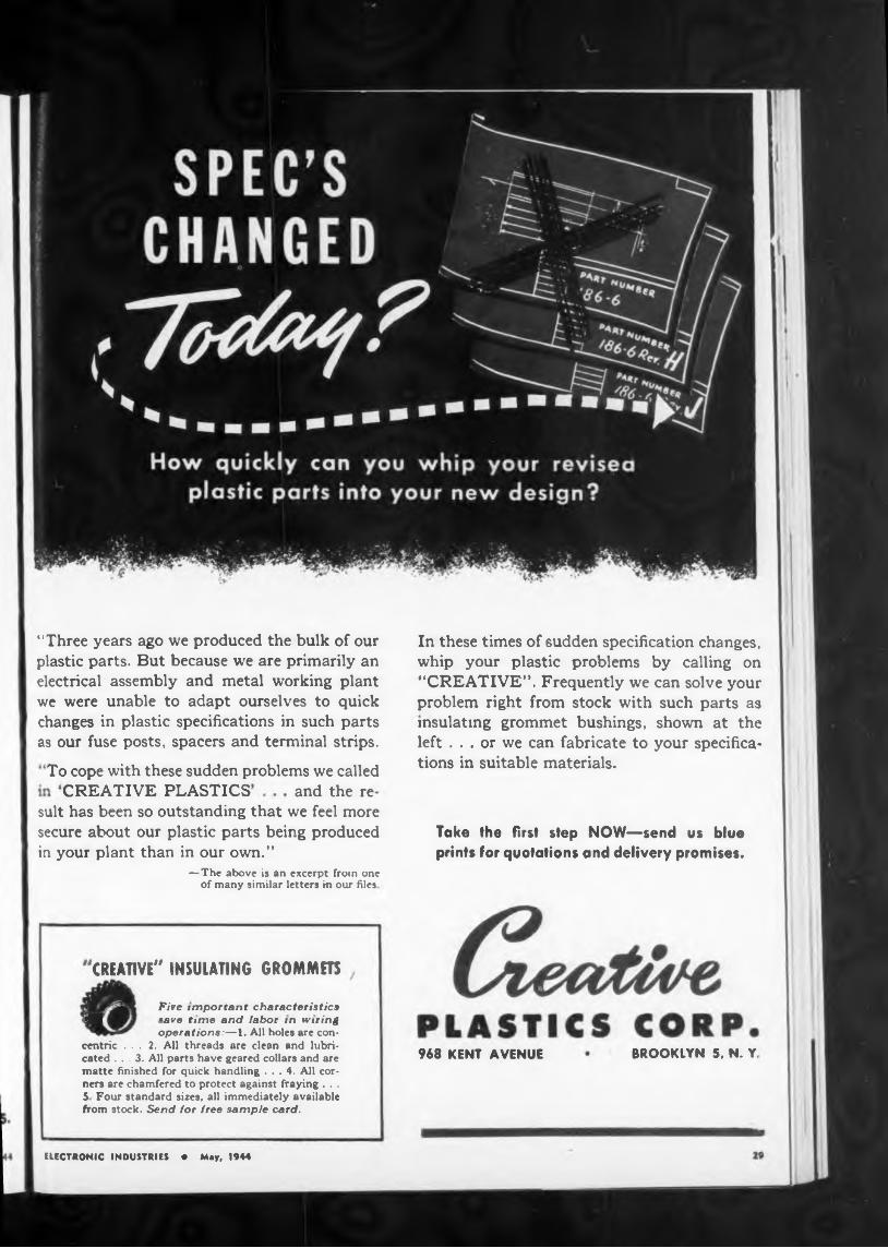
“Three years ago we produced the bulk of our plastic parts. But because we are primarily an electrical assembly and metal working plant we were unable to adapt ourselves to quick changes in plastic specifications in such parts as our fuse posts, spacers and terminal strips.
Take the first step NOW—send us blue prints for quotations and delivery promises.
In these times of sudden specification changes, whip your plastic problems by calling on “CREATIVE”. Frequently we can solve your problem right from stock with such parts as insulating grommet bushings, shown at the left ... or we can fabricate to your specifications in suitable materials.
ELECTRONIC INDUSTRIES « May, 1944
suit has been so outstanding that we feel more secure about our plastic parts being produced in your plant than in our own.”
— The above is an excerpt from one of many similar letters in our files
Five important characteristics 41 ‘ave time and labor in wiring
operations:—1. All holes are concentric ... 2. All threads are clean and lubricated ... 3. All parts have geared collars and are matte finished for quick handling ... 4. All corners are chamfered to protect against fraying . . . 5 Four standard sizes, all immediately available from stock. Send for free sample card.
*•* LINES
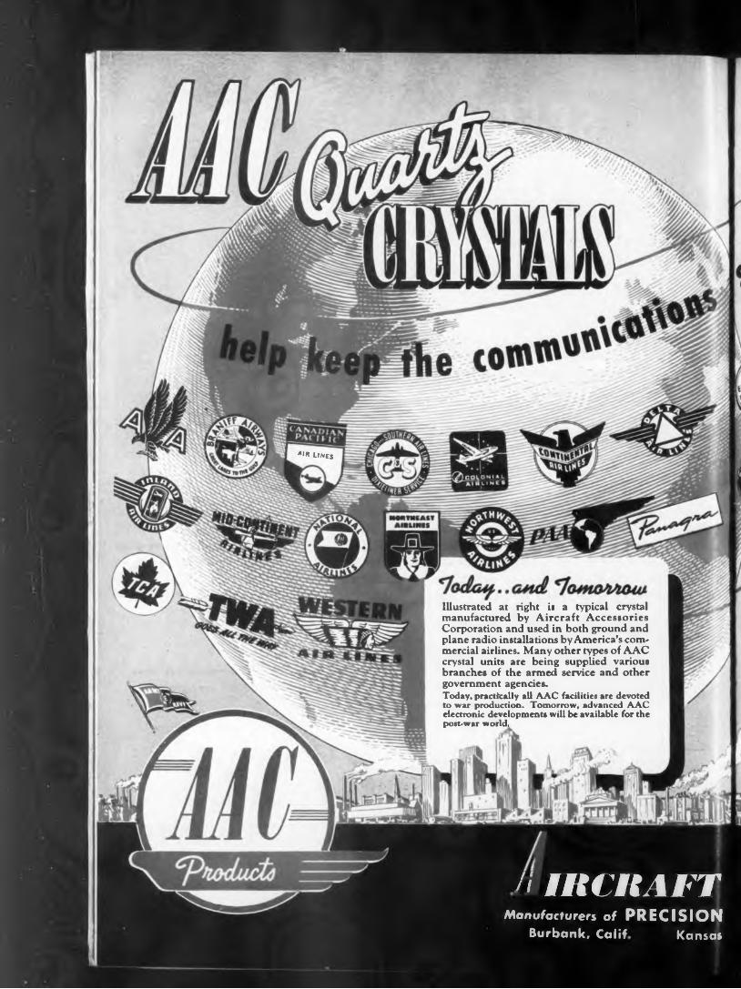
Illustrated at right is a typical crystal manufactured by Aircraft Accessories Corporation and used in both ground and plane radio installations by America’s commercial airlines. Many other types of AAC crystal units are being supplied various branches of the armed service and other government agencies.Today, practically all AAC facilities are devoted to war production. Tomorrow, advanced AAC electronic developments will be available for the post-war world.
Burbank, Calif Kansas
// men AFTManufacturers of PRECISION
PROMPT DELIVERY
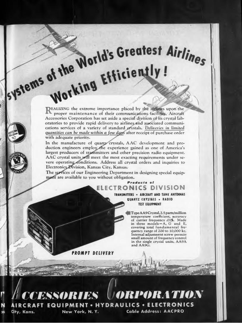
temperature coefficient, accuracy of carrier frequency .01%. Made in three models —A, G and E, covering total fundamental frequency range of 200 to 10,000 kc. Internal adjustment screw permits small amount of frequency control in the single crystal units, AA9A and AA9G.
REALIZING the extreme importance placed by the ai^ties upon the proper maintenance of their communication^facilities, Aircraft
Accessories Corporation has set aside a special division of Its crystal laboratories to provide rapid delivery to airlines and associated communications services of a variety of standard crystals. Deliveries in limited
quantities can be made within a few dgys after receipt of purchase order with adequate priority.In the manufacture of quarté'crystals, AAC development and production engineers emplov/tne experience gained as one of America’s largest producers of transmitters and other precision radio equipment. AAC crystal units will meet the most exacting requirements under severe operatingxonditions. Address all crystal orders and inquiries to Electronic§^ivision, Kansas City, Kansas.The services of our Engineering Department in designing special equipment are available to you without obligation.
Product» of
^^^^ELECTRONICS DIVISIONTRANSMITTERS • AIRCRAFT AND TANK ANTENNAS
QUARTZ CRYSTALS • RADIOSL " O' > f W EQUIPMENT
I ORPORA HO\< CCENNORIESNew York, N. Y Cable Address: AACPRO
TO MEN WHO ARE THINKING ABOUT
INDU
THE WORLD OF TOMORROW
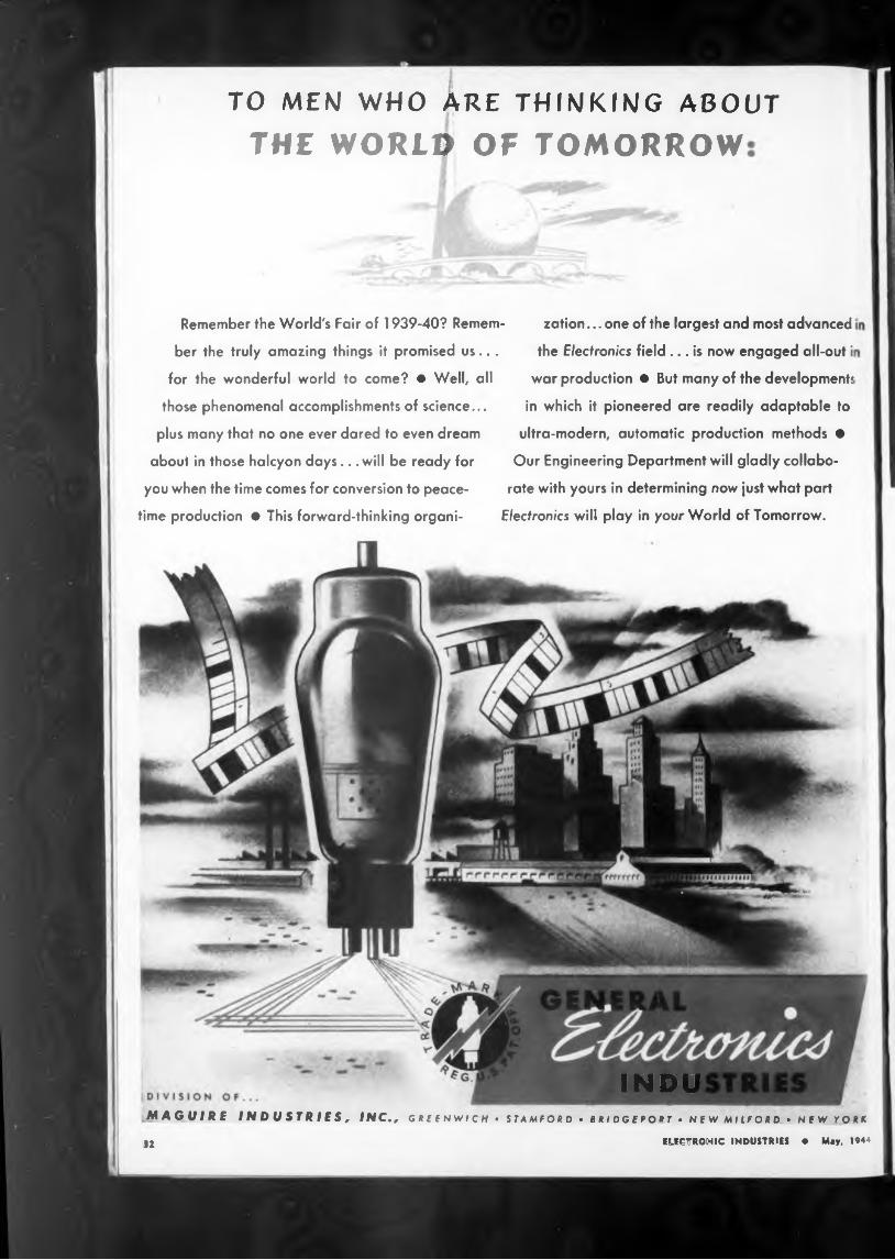
Remember the World's Fair of 1939-40? Remem' ber the truly amazing things it promised us...
for the wonderful world to come? ♦ Well, all those phenomenal accomplishments of science...
plus many that no one ever dared to even dream
about in those halcyon days.. .will be ready for you when the time comes for conversion to peace
time production ♦ This forward-thinking organi-
- zation... one of the largest and most advancedthe Electronics field... is now engaged all-out i
war production • But many of the developments
in which it pioneered are readily adaptable to ultra-modern, automatic production methods •
Our Engineering Department will gladly collaborate with yours in determining now just what part
Electronics will play in your World of Tomorrow.
MAGUIRE INDUSTRIES, INC., g « e e nwi c h • sta mfor d • s ri dg e po pt . n e w mi lfor d • n f w yq ru
12 ELECTRONIC INDUSTRIES • May. 1944
Hyperbolics,
Address
State
"•“•“I Niisi MwtanaMt-wz. , Phony, Radio. -^ireTele-
fu.Bessel Functions.
mrTIAL TABEE °F CONTE(i
» ’ ‘ ‘5VI
Logarithms Functions, Ural Lopari
Ctmral Enimttnnt Tables. Conversion. Fractions of Inch, Copper and Copperweld Wire, Machine Screw Dau.
logarithms, Nat- Functions,
••»tbiwaficg Tablesural Tricon,
Publication Department, Federal Telephone and Radio Corporation 67 Broad Street, New York 4, N. Y.I enclose dollars for which send me copies of“Reference Data for Radio Engineers” ( $1.00 per single copy. In quantities of 12 or more, for bulk shipment. 75e per copy).
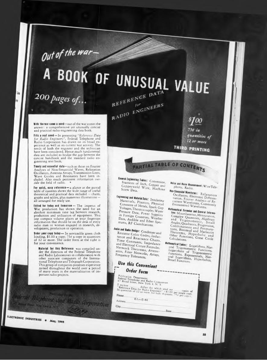
With th* war cane a nail—out of the war comes the answer: a comprehensive yet unusually concise and practical radio engineering dau book.Fills a real Hied— In presenting “Reference Data for Radio Engineers”, Federal Telephone and Radio Corporation has drawn on its broad experience as well as its current war activity. The needs of both the engineer and the technician have been considered. Hence much fundamental dau are included to bridge the gap between the concise handbook and the standard radio engineering text book.Tillly and essential data—such as those on Fourier Analyses of Non-Sinusoidal Waves, Relaxation Oscillators, Antenna Arrays, Transmission Lines, Wave Guides and Resonators have been included. Also much pertinent information outside the field of radio. •Fer quck, easy reference—a glance at the partial uble of contents shows the wide range of useful theoretical and practical dau included — charts, graphs and ubles, plus numerous illustrations — all arranged for ready use.Edited fer teday aid tomorrow — The impetus of War production has shown the need for an absolute minimum time lag between research, production and utilization of equipment. This one compact volume places at your fingertips information that should be on the desk of every radio man or woman engaged in research, development, production or operation.Order yiir copy today— In serviceable green cloth binding, $1.00 a copy; 750 copy in quantities of 12 or more. The order form at the right is for your convenience.
Matirial for this Rifirinci was compiled under the direction of the Federal Telephone and Radio Laboratories in collaboration with other associate companies of the International Telephone and Telegraph Corporation. This group of companies possesses experience gained throughout the world over a period of many years in the materialization of important radio projects.
——« wnuorws: Relaxation Oscillators, Electronic Differentiation, Fourier Analysis of Recurrent Waveforms, Commonly Encountered Waveforms.
Mithenatical Formdas aid Central Infima- tili: Miscellaneous,Mensuration, Complex Quantities, Algebraic and Trigonometric, Small Angles, Quadratics, Progression, Combinations and Permutations, Binomial and Maclaurin Theorems, Hyperbolic and Other Functions, Great Circle Calculations.
EnfiMtriRi and Matinal Data: Insulating Materials, Plastics, Physical Constants of Metals, Spark Gap Voltages.Thermocouples, Water Pressure Data, Power Supplies in Foreign Countries, Weather Data, Audible and Ether Spectrums, RF Classifications.
Aidil and Radii Disigi. Condenser and Resistor Color Codes, Inductance and Reactance Charts, Time Constants, Impedance and Electrical Circuit Formulas, Network Theorems, Attenuators, Filter Networks, Arrays, Frequency Tolerances.
Use this ConvenientOrder Form■J
A BOOK OF UNUSUAL VALUE
quantities oj ^2 or more
1 PRINTING
KNIFE-DISCONNECTSPLICING TERMINAL
ONLY 2 PARTSBOTH IDENTICAL
STAY TOGETHER UNTIL INTENTIONALLY TAKER APART
ANDjlOW AN AsMlP’"KNIFE-DISCONNECT
SPLICING SYSTEM
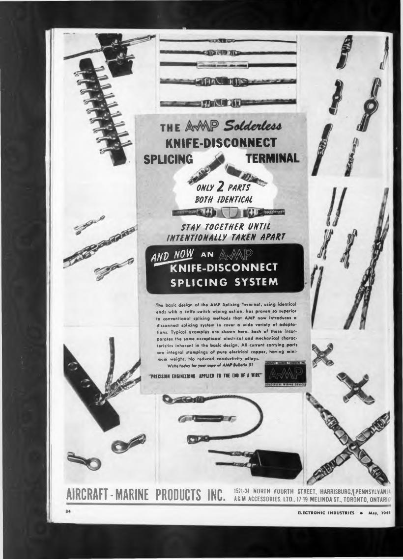
The basic design of the AMP Splicing Terminal, using identical ends with a knife-switch wiping action, has proven so superior to conventional splicing methods that AMP now introduces a
disconnect splicing system to cover a wide variety of adaptations. Typical examples are shown here. Each of these incorporates the same exceptional electrical and mechanical characteristics inherent in the basic design. All current carrying parts are integral stampings of pure electrical copper, having mini
mum weight. No reduced conductivity alloys.Writ» today hr yew cepy of AMP MMin 31
“PIECiSIM ENGINEERING APPLI9 TI TIE »1 IF A Witt”
AIRCRAFT MARINE DDnnilPTC IMP IHb3< N0RTH F0URTH street, harrisburg,ipennsyivanh Hinuimil - mHninL riUJUUUIO mb. ASM accessories, ltd,wu melinda st, Toronto, Ontario
ELECTRONIC INDUSTRIES e Mey, 1944
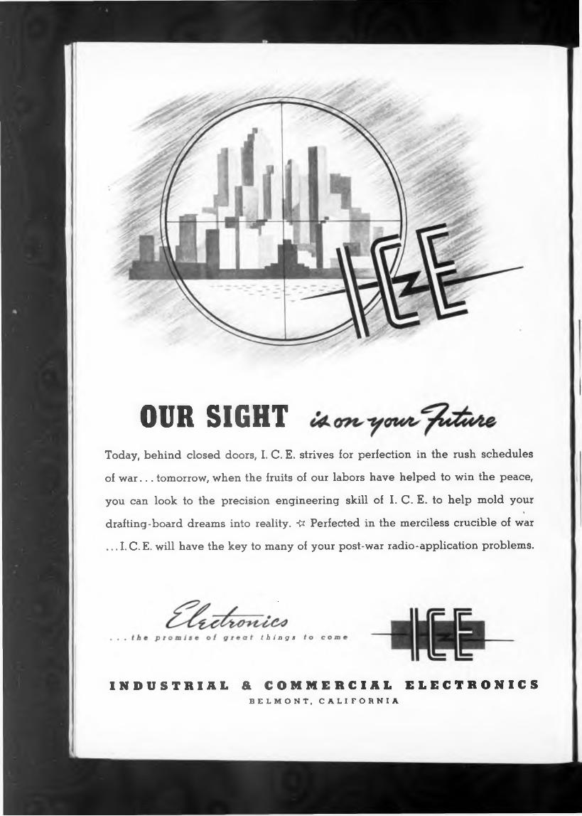
OUR SIGHTToday, behind closed doors, I. C. E. strives for perfection in the rush schedules
of war... tomorrow, when the fruits of our labors have helped to win the peace,
you can look to the precision engineering skill of I. C. E. to help mold your<
drafting-board dreams into reality. 4* Perfected in the merciless crucible of war
... I. C. E. will have the key to many of your post-war radio-application problems.
things
INDUSTRIAL & COMMERCIAL ELECTRONICS BELMONT, CALIFORNIA
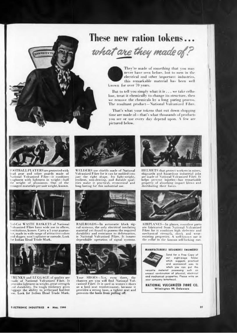
These new ration tokens
take celluwe
had remarkableprevent
RAILROADS automatic block
the col the famous self-locking nut.
MANUFACTURERS! DESIGNERS! ENGINEERS!
prevents
E.ECTRONIC INDUSTRIES
property of absorbing impact blows ami distributing their forces.
But to tell you simply what it
nal systems, the only electrical insulating material yet found to possess the required durability and resistance to deformation, is National Vulcanized Fibre. It insures dependable operation of signal systems.
HELMETS that protect workers in mines, shipyards and hazardous industrial jobs are made of National A ulcanized Fibre. It
AIRPLANES—In planes, countless parts are fabricated from National Vulcanized Fibre for it combines high dielectric and mechanical strength, shock and wearresisting properties. 4 well-known use is
\ >d-Cot UASTE BASKETS of National \ ulcanized 1 ibre have wide use in offices, institutions, homes. Carry a 5 year guarantee, made in wide range of attractive colors and shapes; won't splinter or corrode. Look, for Indian Head Trade Mark.
WELDERS use shields made of National V ulcanized Fibre for it can be molded into just the right shape. Its light-weight, resilient, non-denting, and durable qualities make it practical, economical and long-lasting for this industrial use.
That’s what your tokens that cut down shopping time are made of—that’s what thousands of products you see or use every day depend upon. A few are pictured below.
I • M )TB ALL PLAYERS are protected w ith bead gear and other guards made of National Vulcanized Fibre—it combines toughness with lightness in weight—half the weight of aluminum. One of the strongest materials per unit weight, known.
industries, been well
lose, treat it chemically to change its structure, then we remove the chemicals by a long puring process. The resultant product—National Vulcanized Fibre.
Your SHOES—Yes, even there, the chances are you will find National Vulcanized Fibre. It is used in women's shoes as a heel seat reinforcement, because it provides a strong base, a tighter seat and
RUNKS and LUGGAGE of quality are lade of National Vulcanized Fibre. It
provides lightness in weight, great strength Mid durability. Its tough resiliency gives luggage the ability to withstand hardest use. Look for Indian Head Trude Mark.
riiev’re made of something that you may never have seen before, hut to men in the
• irh ul .Hid ulh< r • 11.j-ri i11! this remarkable material has
know n for over 70 years.
Send for a Free Copy of , J out eight-page folder
which suggests practical and economical uses to which you can put this
versatile material possessing such on unusual combination of physical, electrical ind mechanical properties. Please write on
your company letterhead.
NATIONAL VULCANIZED FIBRE CO.Wilmington 99, Delaware
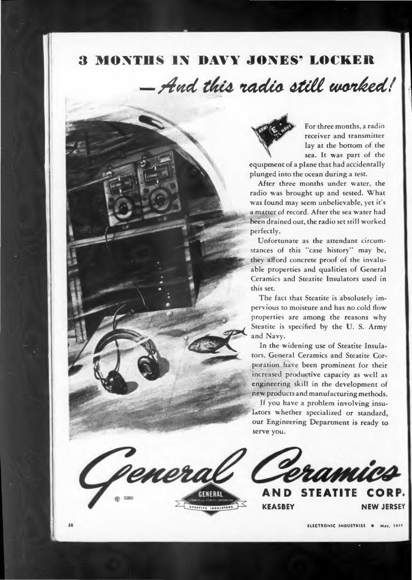
3 MONTHS IN DAVY JONES’ LOCKER
—¿fad nadto táM w&diccti/ ’ i
May, 1944ELECTRONIC INDUSTRIES
For three months, a radio receiver and transmitter lay at the bottom of . the sea. It was part of the
equipment of a plane that had accidentally plunged into the ocean during a test.
After three months under water, the radio was brought up and tested. What was found may seem unbelievable, yet it’s a matter of record. After the sea water had been drained out, the radio set still worked perfectly.
Unfortunate as the attendant circumstances of this "case history” may be, they afford concrete proof of the invaluable properties and qualities of General Ceramics and Steatite Insulators used in this set.
The fact that Steatite is absolutely impervious to moisture and has no cold flow properties are among the reasons why Steatite is specified by the U. S. Army and Navy.
In the widening use of Steatite Insulators, General Ceramics and Steatite Corporation have been prominent for their increased productive capacity as well as engineering skill in the development of new products and manufacturing methods.
If you have a problem involving insulators whether specialized or standard, our Engineering Department is ready to serve you.
AND STEATITE CORP.KEASBEY NEW JERSEY

Let's BeS together
ANACONDA WIRE & CABLE COMPANY
uous metallurgical experience.
Electronic industries * Mey, 1944
ANACONDA WIRE & CABLE COMPANY General Offices: 2? Broadway .New York 4
Chicago Office: 20 N.Wacker Drive 6 Subsidiary of Anact>nda Copper Mining Co.
Sales Offices in Principal Cities
As a matter of fact, perhaps we can get together now, but if it happens we can’t, remember we have a date in and for the future. When we both can keep it, you can again take advantage of Anaconda service and the benefits derived from the single product control "from mine to consumer" backed by years of contin-
Thii familiar trade-mark symbolizes the best efforts of modern research
and production.
If you believe in the future of America as we do, then we’re asking for an appointment immediately after the victory has been won . . . when a bright new era awaits us all.
Perhaps we can talk about a coil problem . . . how thoroughly we’re organized to help you on such a problem only military censorship forbids telling now. Or it may be that you manufacture your own coils and will be interested in discussing magnet wire—any shape —any insulation that your operations require.
AnacondAFrofn mi sumsK

Smooth Power Control Constant Output VoltageAT THE TURN OF A KNOB FROM VARYING INPUT
BUY WAH BONDS
Smtu
ELECTRONIC INDUSTRIES
VARIABLE-VOLTAGE AUTOTRANSFORMER used for smooth control of uninterrupted voltage and small amounts of power. Mechanically strong, compact, and light in weight, designed for panel or bench mounting. Operates on low input power and low exciting current, with high efficiency and excellent regulation throughout entire range from zero to full load. Made in three capacities. Bulletin GEA-3635A.
AUTOMATIC VOLTAGE STABILIZER used in conjunction with equipment requiring closely regulated input voltage. Provides practically instantaneous correction of voltage changes caused by either a changing input voltage or variation in magnitude of the load. Has no moving parts, requires no adjustments. Bulletin GEA-3634A.
"■"Wors, * ^tnic0 Noto,.
' »»net
tSSS^c
^9 . * ^the
•‘•«t «• ^••neiley othe.
CHIEVE THE “IMPOSSIBLE
laths for sound travel. The
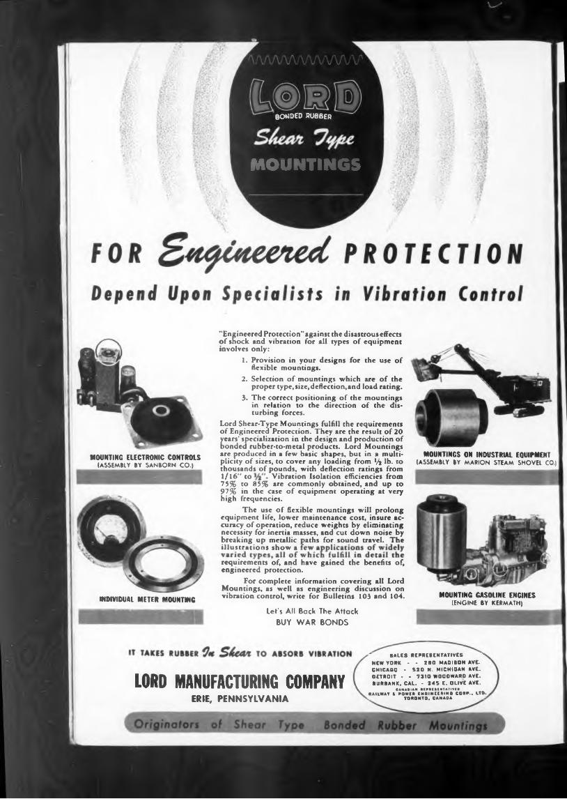
INDIVIDUAL METER MOUNTING
MOUNTING ELECTRONIC CONTROLS (ASSEMBLY BY SANBORN CO.)
MOUNTINGS ON INDUSTRIAL EQUIPMENT (ASSEMBLY BY MARION STEAM SHOVEL CO.)
Let's All Back The Attack BUY WAR BONDS
MOUNTING GASOLINE ENGINES (ENGINE BY KERMATH)
_ The use of flexible mountings will prolong equipment life, lower maintenance cost, insure accuracy of operation, reduce weights by eliminating necessity for inertia masses, and cut down noise by breaking up metallic * * illustrations show a
"Engineered Protection" against the disastrous effects of shock and vibration for all types of equipment involves only:
1. Provision in your designs for the use of flexible mountings.
2. Selection of mountings which are of the proper type, size, deflection, and load racing.
3. The correct positioning of the mountings in relation to the direction of the disturbing forces.
Lord Shear-Type Mountings fulfill the requirements of Engineered Protection. They are the result of 20 years’ specialization in the design and production of bonded rubber-to-metal products. Lord Mountings are produced in a few basic shapes, but in a multiplicity of sizes, to cover any loading from V? lb. to thousands of pounds, with deflection ratings from 1/16" to Vibration Isolation efficiencies from 75% to 85% are commonly obtained, and up to 97% in the case of equipment operating at very high frequencies.
LORD MANUFACTURING COMPANY ERIE, PENNSYLVANIA
requirements of, and have gained the benefits of, engineered protection.
For complete information covering all Lord Mountings, as well as engineering discussion on vibration control, write for Bulletins 103 and 104.
•" SALES REPRESENTATIVES ’ NEW YORK - - 280 MADISON AVE. CHICAliG • S20 N. MICHIGAN AVE. DETROIT - - 7310 WOODWARD AVE. BURBANK, CAL. - 245 E. OLIVE AVE.
CAMAOIAP •trRtSCHTATIVtaRAILWAY A POWER ENOINEERINO CORP . LTO . TORONTO.CANADA >
bonded RUBBER
MOUNTINGS

WEBSTER PRODUCTSand VOLTAGE REGULATION
VOLTAGE REGULATORS
buy moke
HOVf
PRODUCTSWEBSTERS)3825 W. ARMITAGE AVE. LU J CHICAGO 47, ILLINOIS
Webster Carbon Pile Voltage Regulators are sturdy, compact, reliable—withstanding vibration, shock, moisture and salt spray. Maximum pile resistances from approximately 14 ohm to 100 ohms are available. Compensation for wide temperature ranges is provided. Typical performance of two models under specific operating conditions is indicated in the tables at left. Our engineers will be glad to study your application to see if a Webster Regulator will do the job best. Please include complete circuit data and operating specifications with your inquiry.
ELECTRONIC INDUSTRIES • May, 1944
...with outstanding performance advantages The Webster dynamotors listed here are our standard large- scale production models. The outstanding performance records they have set reflect the care with which parts are machined and inspected before assembly to assure good balance, minimum vibration and maximum durability. You can have more complete details than space permits giving here by just writing for them.
LOOK TO WEBSTER PRODUCTS
TODAYDynamotors and
Voltage RegulatorsTOMORROW World-Acclaimed Record Changers
MD
VI AR ' BONUS
‘Ratings shown are for continuous duty with temperature rise and secondary ripple voltage well within the limit* of Government Specification*. Model* listed are also available with mounting brackets or filter* when required.
Watt- ■ge
Webster Model
Number
Input Output* Net Wt. Lbs.
Dimensions
Volts Max. Amp. Volts Amp. A B
10 to IS
MD-1020 14 2 4 250 .060 24 4’4 24MD-1021 28 1.15 250 .060 2’» 4'4 24MD-1022 28 1.15 250 .060 4'4 4'4 24MD-1024 27 1.15 250 .060 2’a 4'4 24
IS to20
KD 1000 14 2.8 220 .080 S 54 34KD-1001 12 3.8 220 .100 5'4 SH 3’ i«KD-1002 13.8 2.5 230 .070 44 54 3’aKD-1004 27.9 1.25 230 .070 44 54 3’a
20 to30
LD-lObi 12.2 3.3 230 .090 54 5’4 34LD-1011 28 1.6 230 .100 5 5’’» 3’aLD 1012 9 6.4 450 .060 5’4 64 34LD 1013 18 3.3 450 .060 5’4 64 34LD-1014 18.5 3.3 400 .08u 5’4 6’w 34
150 FD-1060 28 10.5High 300 Metí ISO Low 14 5
.260
.0104.9
21 11’4 S'4
Input Voltage
Pile Drop
Pile Current
Pile Resistance
(Ohms)
Regulated Output Voltage
Max. Loa-l (Ampere*)
Wt. (Lb*.)
O.D. (Inche*)
Height (Inche*)
21.0 2.2 V. 45 A .49 18.85.0 2 Ji 2 »4 4’4
30.0 11.0 V 2.4 A. 4.68 19.0
Input Voltage
Pile Drop
Pile Current
Pile Resistance
(Ohms)
Regu Fi
Volt.
ating tld
Amp.
Regulated Wt O.D. (Inches)
Height (Inches)
21.6 68 V 1.4 A 4.85 14.8 1.2 13.1 24 2'4 4429.0 25 0 V. .34 A. 73.5 4.0 1.2 13.2
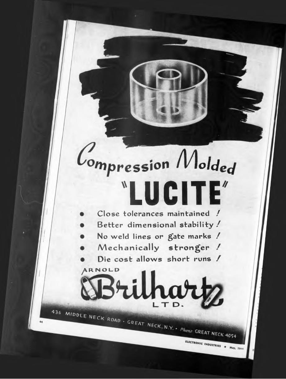
short runs
toldi
LUCITEClose tolerances maintained / Better dimensional stability / No weld lines or gate marks /
4054
4^6 Midd
R0AD • CDc.
^reat
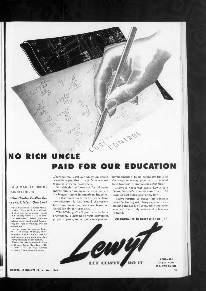
NO RICH UNCLE
LEWYT CORPORATION, tl BROADWAY, B'KLYN II, N.Y.
REMEMBER 3 BUY MORE L WAR BONDS
developments? Some recent graduate of the easy-come-easy-go school, or one of long training in production economies?
Lewyt is not u war baby. Lewyt is a “manufacturer’s manufacturer” with 56 years of cost-conscious “know-how”.
Lewyt returns to peace-time contract manufacturing with long experience in meeting the needs of production engineers who will have only costs and efficiency in mind.
Where we really got our education was in peace-time practice . . . not from a short course in wartime production.
Our shingle has been out for 56 years and we number among our clients many of the biggest names in American Industry.
“C-Day”—conversion to peace-time manufacture — is just ’round the corner. More and more materials are being released for civilian products.
Which “shingle” will you turn to for a professional diagnosis of your conversion program, parts production or new product
ELECTRONIC INDUSTRIES • May, 1944
SE A MANUFACTURER’SMANUFACTURER..........0MC
L'iOftiiiiUly—One (?OAt
Ipwyt’s business is Contract Munu- f during. We s[>ecialize in electric and electronic instruments, chassis and housings; mechanical and electrical assemblies; highest precision machine work; sheet metal fabricat ons; all types of welding, product li wishing, etc.
Our advanced engineering facili- < es for the design, re-design, or de- \ dopment of your product may intprest the man upon whom you place t he responsibility of production
That's the man who should have ur 4A-page lxv»k. ' I*t Lewyt Do
It” Write for it on your business ’tationerv There is iwi obligation.
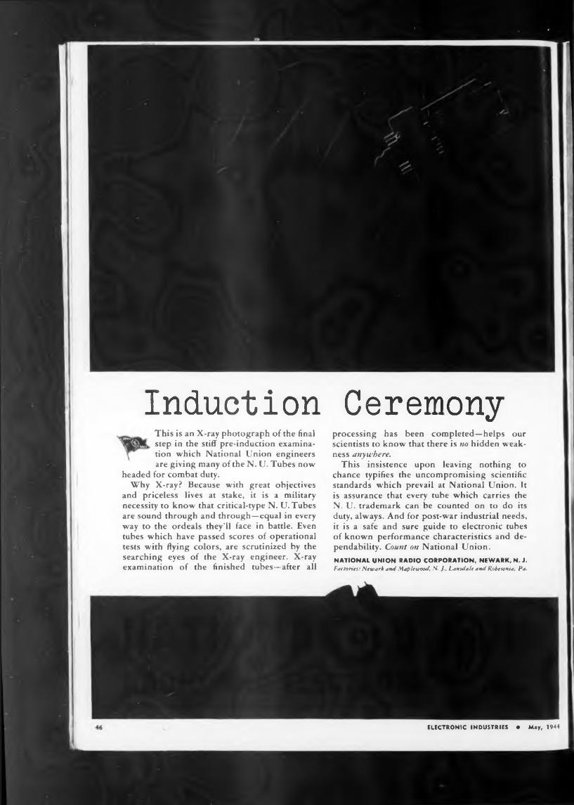
Induction Ceremony_ This is an X-ray photograph of the final
step in the stiff pre-induction examination which National Union engineers are giving many of the N. U. Tubes now
headed for combat duty.Why X-ray? Because with great objectives
and priceless lives at stake, it is a military necessity to know that critical-type N. U. Tubes are sound through and through—equal in every way to the ordeals they’ll face in battle. Even tubes which have passed scores of operational tests with flying colors, are scrutinized by the searching eyes of the X-ray engineer. X-ray examination of the finished tubes—after all
processing has been completed—helps our scientists to know that there is no hidden weakness anywhere.
This insistence upon leaving nothing to chance typifies the uncompromising scientific standards which prevail at National Union. It is assurance that every tube which carries the N. U. trademark can be counted on to do its duty, always. And for post-war industrial needs, it is a safe and sure guide to electronic tubes of known performance characteristics and dependability. Count on National Union.NATIONAL UNION RADIO CORPORATION, NEWARK,N.J. Factories: Newark and Maplewood, N. J., Lansdale and Robesonia, Pa.
ELECTRONIC INDUSTRIES * May, 1944
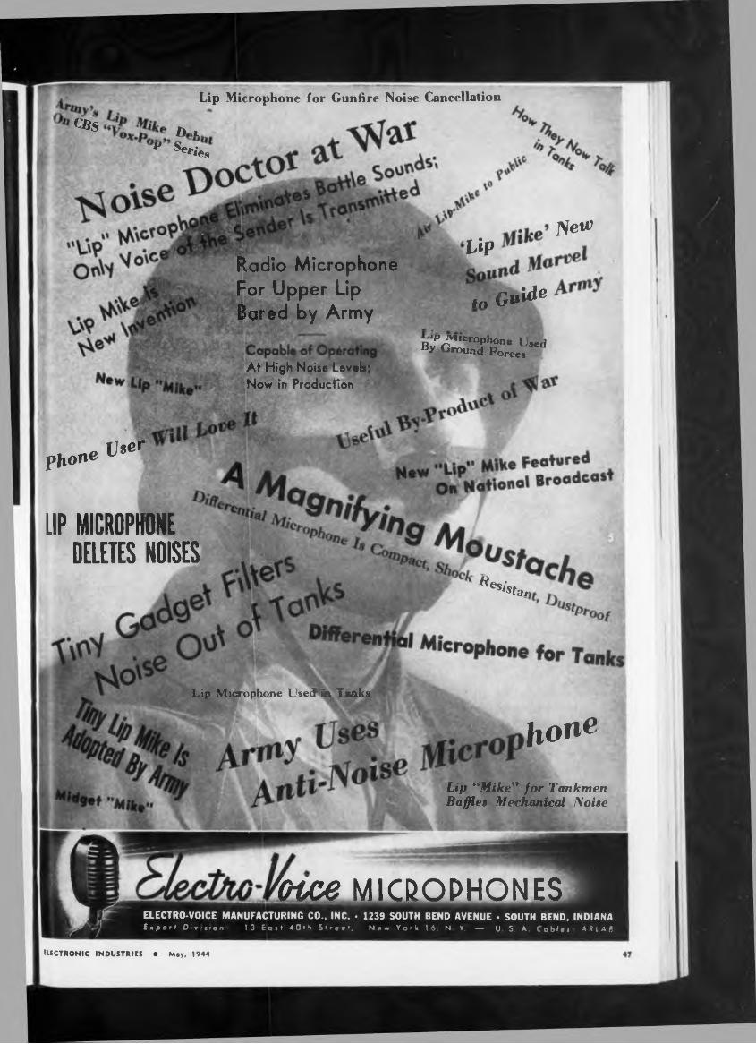
Nei#
hone
face MICROPHONES
Radio Microphone
For Upper Lip
Bared by Army
At High Noise Levels; Now in Production
lip
i„ G»^
^tar
Lip Microphone Used in Tanks
„„ User phon^
UP MICROPHONE DELETES NOISES
B^^^Phone Ijaed y Ground Forces
Lip Microphone for Gunfire Noise Cancellation
Lip “Mike” for Tankmen Baffles Mechanical Noise
ELECTRONIC INDUSTRIES • May, 1944
<*S D i
P S^ies
ELECTRO-VOICE MANUFACTURING CO., INC. * 1239 SOUTH BEND AVENUE * SOUTH BEND, INDIANA fspsrt Diviiiom 13 East 40«h Street, New York 16, N Y. — U. S. A. Cablet AilAB
REPLACED
THIS
BULLETIN
BULLETIN
Copies will
DIVISION
MOLDED RESISTORS FLEXIBLE SHAFT TOOLS
S. S. WHITEFLEXIBLE SHAFT ANDCASING COMBINATION
remote control.
S. S. White Power Drive and Remote Control Flexible
information:
1238—Power Drive Flexible Shafts
38-42—Remote Contro* Flexible Shafts.
And once the details of the flexible shaft unit have been
be mailed to you on request. Write for yours today
DEFT.B, 10 EAST 40th ST., NEW YORK 16, N. Y.FLEXIBLE SHAFTS AIRCRAFT ACCESSORIES
MOLDED FLASTiCS
May, 1944ELECTRONIC INDUSTRIES
MITE n”c INDUSTRIALTHE S. S. WHITE DENTAL MFG. CO
emir iMiNwt ntxY SAYS-
LOW costs
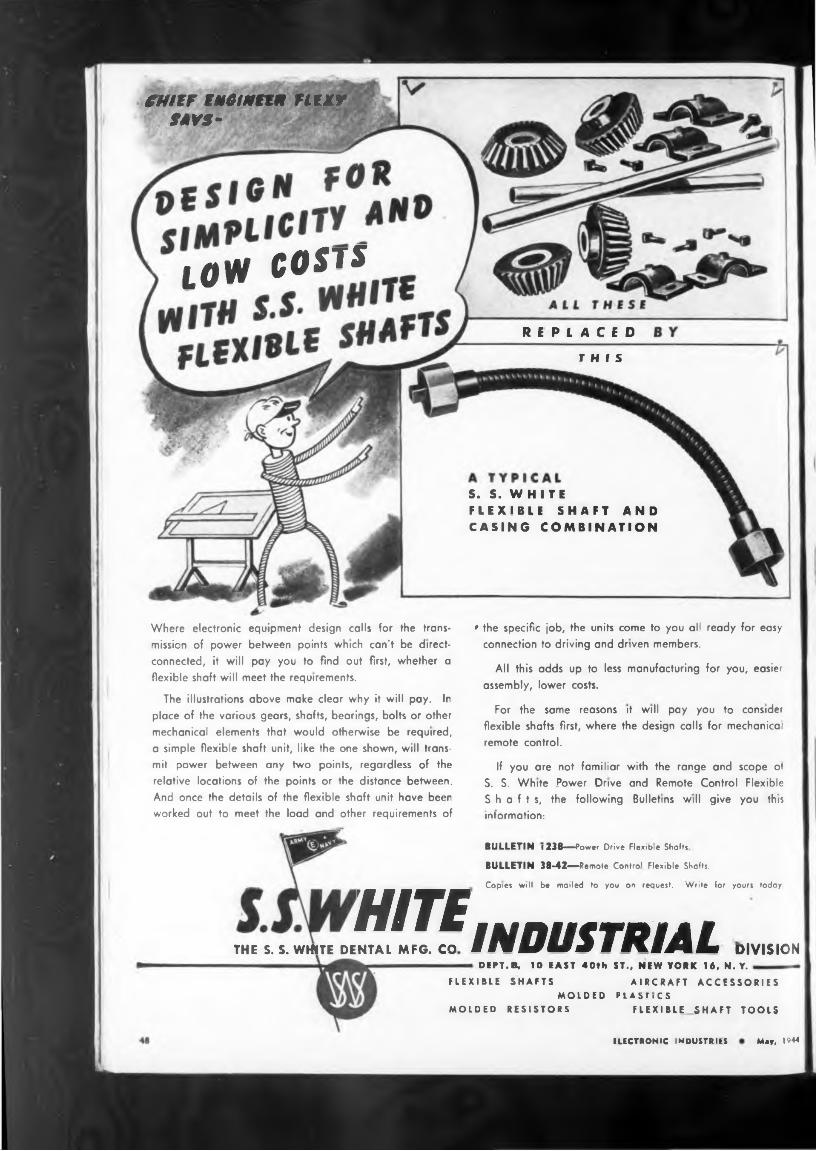
Where electronic equipment design calls for the transmission of power between points which can’t be direct-connected, it will pay you to find out first, whether aflexible shaft will meet the requirements.
The illustrations above make clear why it will pay. Inplace of the various gears, shafts, bearings, bolts or othermechanical elements that would otherwise be required,a simple flexible shaft unit, like the one shown, will trans-mit power between any two points, regardless of therelative locations of the points or the distance between.
worked out to meet the load and other requirements of
• the specific job, the units come to you all ready for easyconnection to driving and driven members.
All this adds up to less manufacturing for you, easierassembly, lower costs.
For the same reasons it will pay you to considerflexible shafts first, where the design calls for medianica1
If you are not familiar with the range and scope of
Shafts, the following Bulletins will give you this
4«
N
Yesterday« h d
TODAY
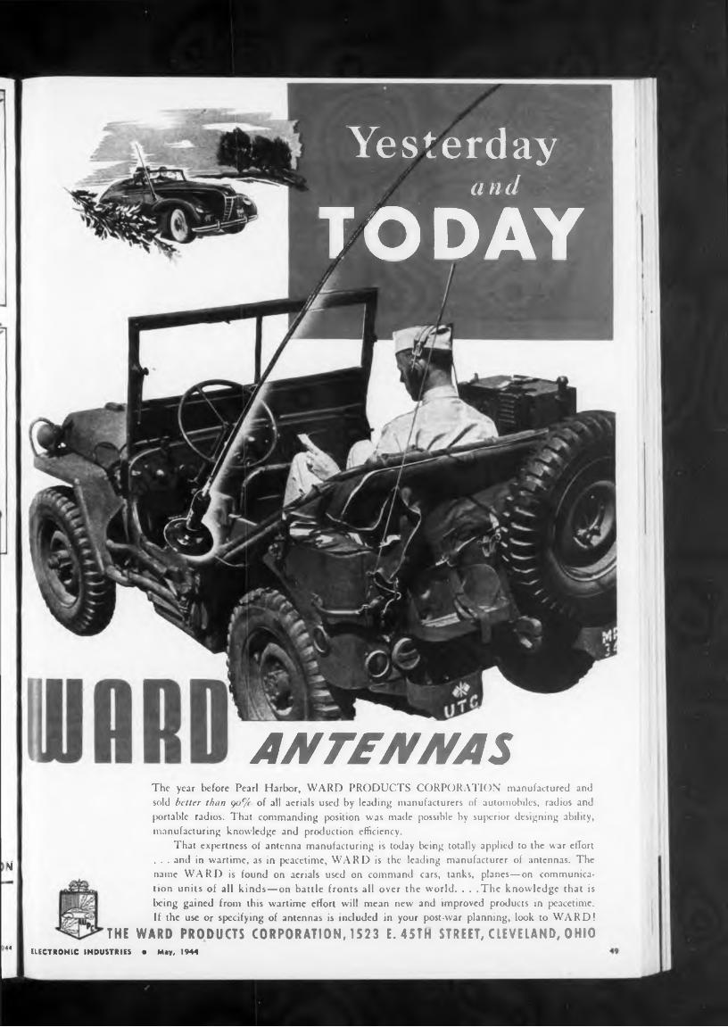
ANTEAfAfA SThe year before Pearl Harbor, WARD PRODUCTS CORPORATION manufactured and sold better than 90% of all aerials used by leading manufacturers of automobiles, radios and portable radios. That commanding position was made possible by superior designing ability, manufacturing knowledge and production efficiency.
That expertness of antenna manufacturing is today being totally applied to the war effort . . . and in wartime, as in peacetime, WARD is the leading manufacturer of antennas. The name WARD is found on aerials used on command cars, tanks, planes—on communication units of all kinds—on battle fronts all over the world. . . .The knowledge that is being gained from this wartime effort will mean new and improved products in peacetime. If the use or specifying of antennas is included in your post-war planning, look to WARD!
THE WARD PRODUCTS CORPORATION, 1523 E. 45TH STREET, CLEVELAND, OHIOELECTRONIC INDUSTRIES • M.S, IMS
Use KOVAR
Kovar IS the answer to lermanentvacuum or
FOR GREAT ACHIEVEMENT-
All Hack The Attack
EXTRA War Bond»
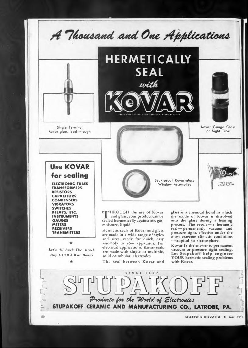
Leak-proof Kovar-glass Window AssembliesELECTRONIC TUBES
TRANSFORMERS RESISTORS CAPACITORS CONDENSERS VIBRATORS SWITCHES RELAYS, ETC. INSTRUMENTS GAUGES METERS RECEIVERS TRANSMITTERS
Kovar Gauge Glass or Sight Tube
Single Terminal Kovar-glass lead-through
Ptodtreta tke “Wontd Sleetn&tiMSTUPAKOFF CERAMIC AND MANUFACTURING CO., LATROBE, PA.
glass is a chemical bond in which the oxide of Kovar is dissolved into the glass during a heating process. The result — a hermetic seal—permanently vacuum and pressure tight, effective under the most extreme climatic conditions —tropical to stratosphere.
ELECTRONIC INDUSTRIES • May, 1944
THROUGH the use of Kovar and glass, your product can be
sealed hermetically against air, gas, moisture, liquid.Hermetic seals of Kovar and glass are made in a wide range of styles and sizes, ready for quick, easy assembly to your apparatus. For electrical applications, Kovar seals are made with single or multiple, solid or tubular, electrodes.The seal between Kovar and
NAM*
HERMETICALLY SEAL
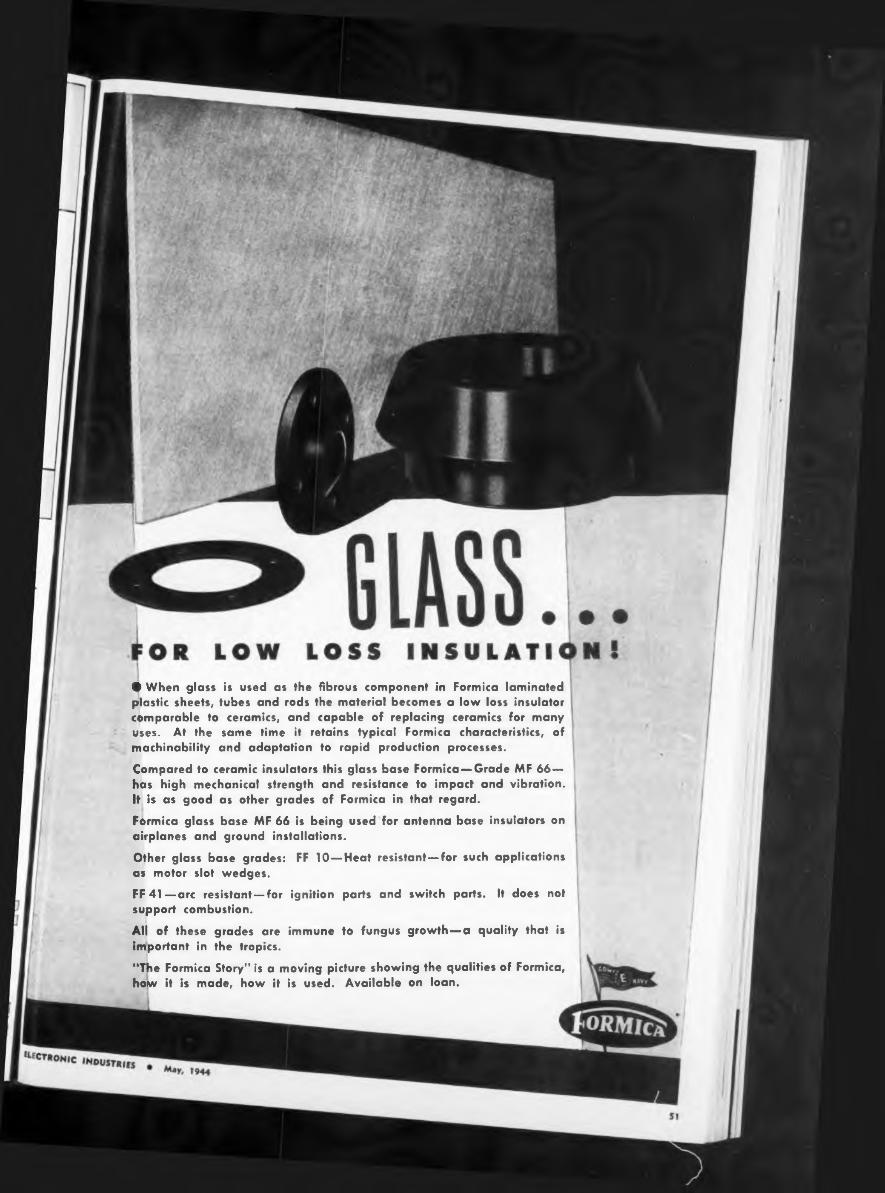
• When glass is used as the fibrous component in Formica laminated plastic sheets, tubes and rods the material becomes a low loss insulator comparable to ceramics, and capable of replacing ceramics for many uses. At the same time it retains typical Formica characteristics, of machinability and adaptation to rapid production processes.
Compared to ceramic insulators this glass base Formica —Grade MF 66— has high mechanical strength and resistance to impact and vibration. It is as good as other grades of Formica in that regard.
Formica glass base MF 66 is being used for antenna base insulators on airplanes and ground installations.Other glass base grades: FF 10—Heat resistant—for such applications as motor slot wedges.FF 41—arc resistant — for ignition parts and switch parts. It does not support combustion.
All of these grades are immune to fungus growth—a quality that is important in the tropics.“The Formica Story’’ is a moving picture showing the qualities of Formica, how it is made, how it is used. Available on loan.
There is an apparent discrepancy at this point.
The pages are either missing or the pagination is incorrect.
The filming is recorded as the book is found in the collections
■■■
unoi»-'“s'HfPC*^Xo*< c*1
Die : encloseILMAN HYDRAULIclTURNING MACHINE
• ** ’
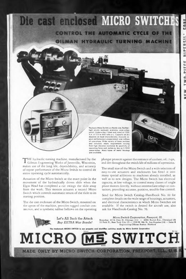
The basic Micro Switch is a thumb-size, featherlight plastic enclosed, precision, snap-action switch. Underwriters’ listed and rated at 1200 V.A. at 125 to 460 volts a-c. Capacity on d-c depends on load characteristics. Accurate repeat performance is experienced uver millions of operations. Wide variety of basic switches and c ctuators meets requirements varying from high vibration resistance to sensitivity of operating force and motion as low as 2/1000 ounce inches. Many types of metal housings are available.
MICRO switch:
THE hydraulic turning machine, manufactured by the Gilman Engineering Works of Janesville, Wisconsin,
makes use of the long life, dependability, and accuracy of repeat performance of the Micro Switch to control its entire operating cycle automatically.
Actuation of the Micro Switch at the exact point in the movement of the hydraulically driven slide when the Elgin Head has completed a cut swings the slide away from the work. This motion actuates a second Micro Switch which controls automatic return of the slide to its starting position.
The die cast enclosure of the Micro Switch, mounted on the apron of the machine, provides rugged conduit connection, and a synthetic rubber bellows on the operating
Let's All Back the Attack Buy EXTRA War Bonds!
MICRO EThe trademark MICRO SWITCH it aw property and identifies twitches made by Miou Switch Corporation
Oti«SWITCH
plunger protects against the entrance of coolant, oil, chips, and dirt throughout the switch life of millions of operations.
The small size of the Micro Switch and a wide selection of easy-to-use actuators and enclosures has fitted it into many special additions to machines already installed, as well as to new designs. The Micro Switch has electrical capacity, at line voltage, to control many classes of single phase motors directly, without intermediate relays or contactors, providing accurate, positive, trouble-free control.
Send for Micro Switch Catalog-Handbook No. 60 for complete details on the wide range of housings, actuators, and electrical characteristics in which Micro Switches are available. If the switch is desired for aircraft use, also ask for Handbook-Catalog No. 70.
Micro Switch Corporation, Freeport, Ill.Branches: 43 E Ohio St., Chicago (11) • 4900 Fuclid Ave., Cleveland (3) 11 Park Pl., New York City (7) • 1709 W 8th St. Los Angeles (14) • Sales 4
Engineering Offices: Boston - Hartford
MADE ONLY BY MICRO SWITCH CORPORATION, FREEPORT ILL
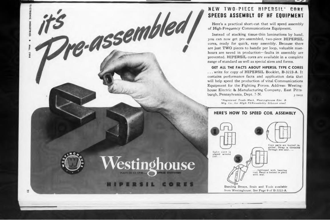
i!ed/NEW TWO-PIECE HIPERSIL* CORF SPEEDS ASSEMBLY OF HF EQUIPMENT
Here’s a practical short-cut that will speed assembly of High-Frequency Communications Equipment.
Instead of stacking tissue-thin laminations by hand, you can now get pre-assembled, two-piece HIPERSIL cores, ready for quick, easy assembly. Because there are just TWO pieces to handle per loop, valuable manhours are saved in production—faults in assembly are prevented. HIPERSIL cores are available in a complete range of standard as well as special sizes and forms.
GET ALL THE FACTS ABOUT HIPERSIL TYPE C CORES . . . write for copy of HIPERSIL Booklet, B 3223-A. It contains performance facts and application data that will help speed the production of vital Communications Equipment for the Fighting Forces. Address: Westinghouse Electric & Manufacturing Company, East Pittsburgh, Pennsylvania, Dept. 7-N. j.70422
* Registered Trade-Mark, Westinghouse Elec. & Mfg Co., for High PERmeability SIL. icon steel.
HERE’S HOW TO SPEED COIL ASSEMBLY
Westinghouse«LAN's n 2a one
Split core is placed around coil.. .
Core putts ur* hutted to- gether. Strap is threaded through seal and ...
. . . tightened with banding tool Band it locked in place with seal.
Banding Straps, Seals and Tools availablefrom Westinghouse. See Page 9 of B-3223-A.
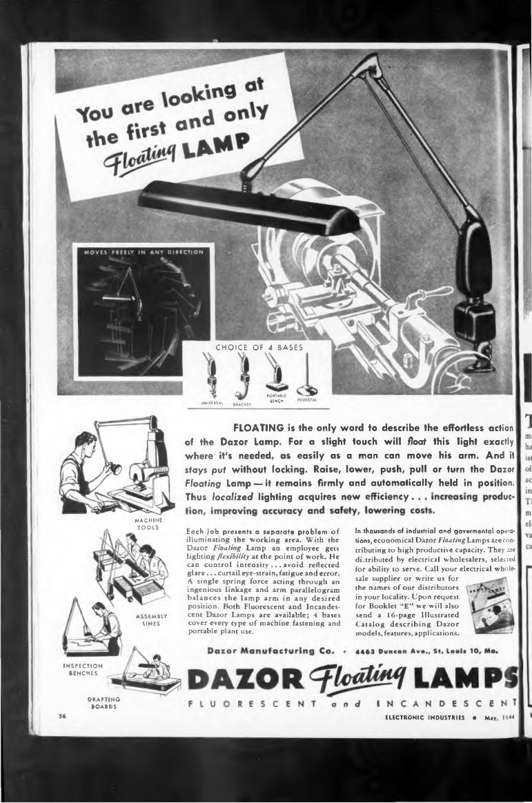
CHOICE OF 4 BASES
UNOUNIVERSAL
where it's needed,
Thus localized lighting acquires new efficiency
INSPECTION BENCHES
DRAFTING BOARDS
MACHINE TOOLS
ASSEMBLY LINES
stays put without locking. Raise, lower, push, pull or turn the Dazor Floating Lamp —it remains firmly and automatically held in position.
FLOATING is the only word to describe the effortless action of the Dazor Lamp. For a slight touch will float this light exactly
In thousands of industrial and govermental opera« tions, economical Dazor Floating Lamps are contributing to high productive capacity. They are distributed by electrical wholesalers, selected for ability to serve. Call your electrical wholesale supplier or write us for the names of our distributors \ \ ’in your locality. Upon request ' / for Booklet “E” we will also Jsend a 16-page Illustrated , Catalog describing Dazor models, features, applications. J
Each job presents a separate problem of illuminating the working area. With the Dazor Floating Lamp an employee gets lighting flexibility at the point of work. He can control intensity ... avoid reflected glare... curtail eye-strain, fatigue and error. A single spring force acting through an ingenious linkage and arm parallelogram balances the lamp arm in any desired position. Both Fluorescent and Incandescent Dazor Lamps are available; 4 bases cover every type of machine fastening and portable plant use.
ELECTRONIC INDUSTRIES • May, 1944
easily as a man can move his arm. And it
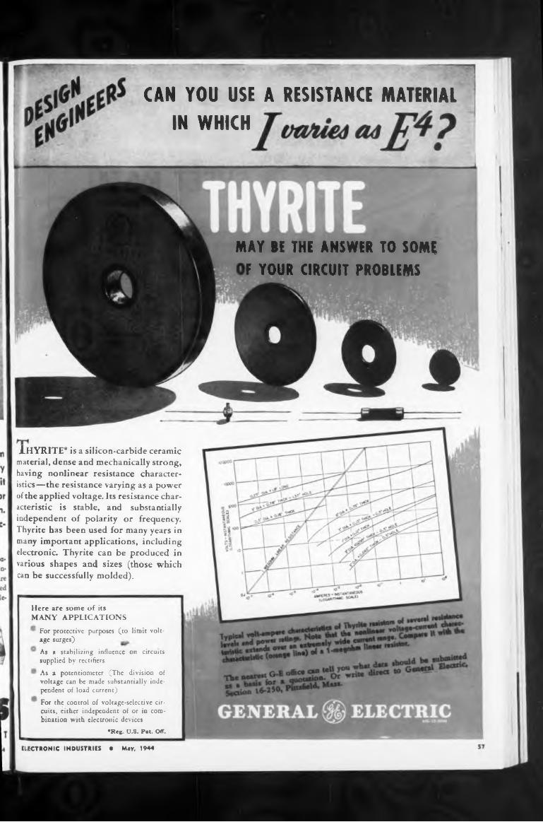
CAN YOU USE A RESISTANCE MATERIALIN WHICH
MAY BE THE ANSWER TO SOMEF YOUR CIRCUIT PROBLEMS
Here are some of itsMANY APPLICATIONS
1 For protective purposes (to limit voltage surges)
As a stabilizing influence on circuits supplied by rectifiersAs a potentiometer (The division of voltage can be made substantially independent of load current)For the control of voltage-selective circuits, either independent of or in combination with electronic devices
•Reg. U.S. Pat. Off.
ELECTRONIC INDUSTRIES « May, 1944
iHYRTTE* is a silicon-carbide ceramic material, dense and mechanically strong, having nonlinear resistance characteristics—the resistance varying as a power of the applied voltage. Its resistance characteristic is stable, and substantially independent of polarity or frequency. Thyrite has been used for many years in many important applications, including electronic. Thyrite can be produced in various shapes and sizes (those which can be successfully molded).
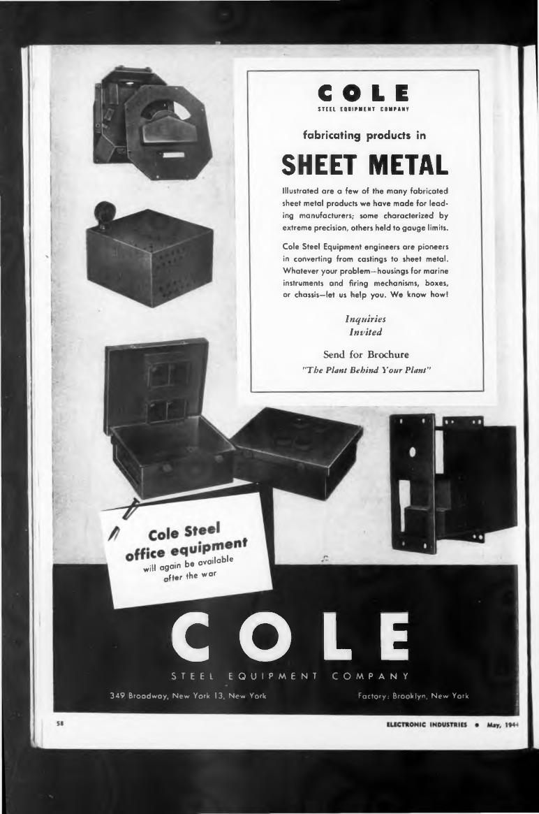
COLESTEEL EQUIPMENT COMPANY
fabricating products in
SHEET METALIllustrated are a few of the many fabricated sheet metal products we have made for leading manufacturers; some characterized by extreme precision, others held to gauge limits.
Cole Steel Equipment engineers are pioneers in converting from castings to sheet metal. Whatever your problem—housings for marine instruments and firing mechanisms, boxes, or chassis—let us help you. We know howl
Inquiries
Invited
Send for Brochure
"The Plant Behind Your Plant”
/be available will again be av
«Her the war
COLESTEEL EQUIPMENT COMPANY
349 Broadway, New York 13, New York Factory: Brooklyn, New York
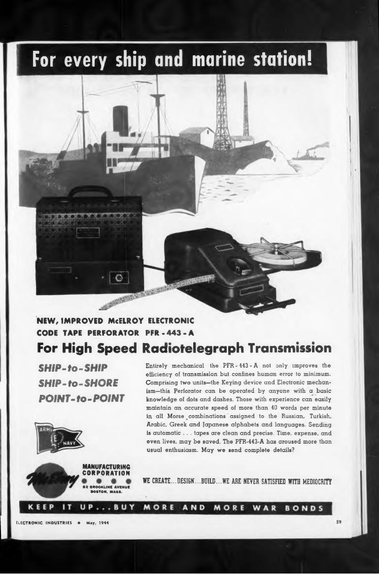
For High Speed Radiotelegraph TransmissionSHIP-to-SHIPSHIP-to-SHOREPOINT-to-POINT
WE CREATE...DESIGN...BUILD...WE ARE NEVER SATISFIED WITH MEDIOCRITY
MANUFACTURING CORPORATION
BS BROOKUNK AVCNUK BOSTON. MASS
NEW, IMPROVED McELROY ELECTRONIC
CODE TAPE PERFORATOR PFR-443-A
Entirely mechanical the PFR - 443 - A not only improves the efficiency of transmission but confines human error to minimum. Comprising two units—the Keying device and Electronic mechanism—this Perforator can be operated by anyone with a basic knowledge of dots and dashes. Those with experience can easily maintain an accurate speed of more than 40 words per minute in all Morse combinations assigned to the Russian, Turkish, Arabic, Greek and Japanese alphabets and languages Sending is automatic . . . tapes are clean and precise. Time, expense, and even lives, may be saved. The PFR-443-A has aroused more than usual enthusiasm. May we send complete details?
ELECTRONIC INDUSTRIES • May, 1944
For every ship and marine station!
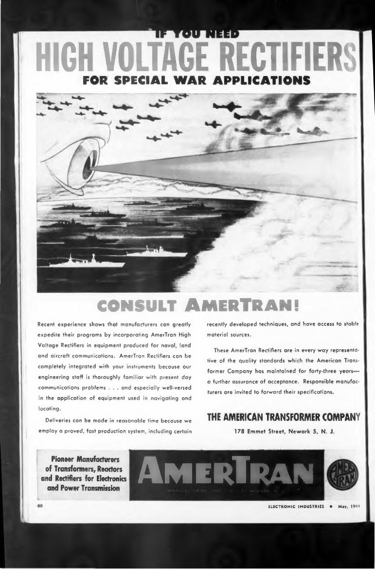
CONSULT AMERTRAN!
THE AMERICAN TRANSFORMER COMPANY178 Emmet Street, Newark 5, N. J
Pioneer Manufacturers of Transformers, Reactors
and Rectifiers for Electronics and Power Transmission
These AmerTran Rectifiers are in every way representa
tive of the quality standards which the American Trans
former Company has maintained for forty-three years—
a further assurance of acceptance. Responsible manufac
turers are invited to forward their specifications.
Deliveries can be made in reasonable time because we
employ a proved, fast production system, including certain
recently developed techniques, and have access to stable
material sources.
Recent experience shows that manufacturers can greatly
expedite their programs by incorporating AmerTran High
Voltage Rectifiers in equipment produced for naval, land
and aircraft communications. AmerTran Rectifiers can be
completely integrated with your instruments because our
engineering staff is thoroughly familiar with present day
communications problems . . . and especially well-versed
in the application of equipment used in navigating and
locating.
ELECTRONIC INDUSTRIES • May, 1944
HIGH VOLTAGE RECTIFIERSFOR SPECIAL WAR APPLICATIONS
AmerTran
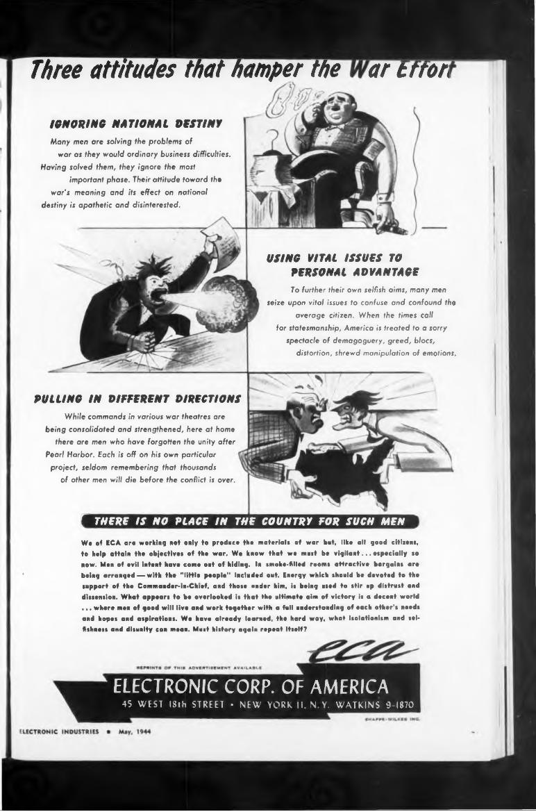
Three attitudes that hamper the ar trrar
IGNORING NATIONAL DESTINY
/ THERE IS NO PLACE IN THE COUNTRY FOR SUCH MEN
Many men ore solving the problems of war os they would ordinary business difficulties.
Having solved them, they ignore the most important phase. Their attitude toward the
war's meaning and its effect on national destiny is apathetic and disinterested.
PULLING IN DIFFERENT DIRECTIONSWhile commands in various war theatres are
being consolidated and strengthened, here at home there are men who have forgotten the unity after
Pearl Harbor. Each is off on his own particular project, seldom remembering that thousands
of other men will die before the conflict is over.
USING VITAL ISSUES TOPERSONAL ADVANTAGETo further their own selfish aims, many men
seize upon vital issues to confuse and confound the
average citizen. When the times call
for statesmanship, America is treated to a sorry
spectacle of demagoguery, greed, blocs, distortion, shrewd manipulation of emotions.
We of ECA ore working not only to produce the material* of war bat, like all good citizens, to help attain the objective* of the war. We know that we must be vigilant... especially so now. Men of evil Intent have come out of hiding. In smoke-filled rooms attractive bargains are being arranged — with the "little people" included out. Energy which should be devoted to the support of the Commander-In-Chief, and those under him, is being used to stir up distrust and dissension. What appears to bo overlooked Is that the ultimate aim of victory is a decent world ... where men of good will live and work together with a full understanding of each other's needs and hopes and aspirations. We have already learned, the hard way, what Isolationism and sei» fishness and disunity can mean. Must history again repeat itself?
ELECTRONIC CORP. OF AMERICA45 WEST 18th STREET • NEW YORK II. N.Y. WATKINS 9 1870
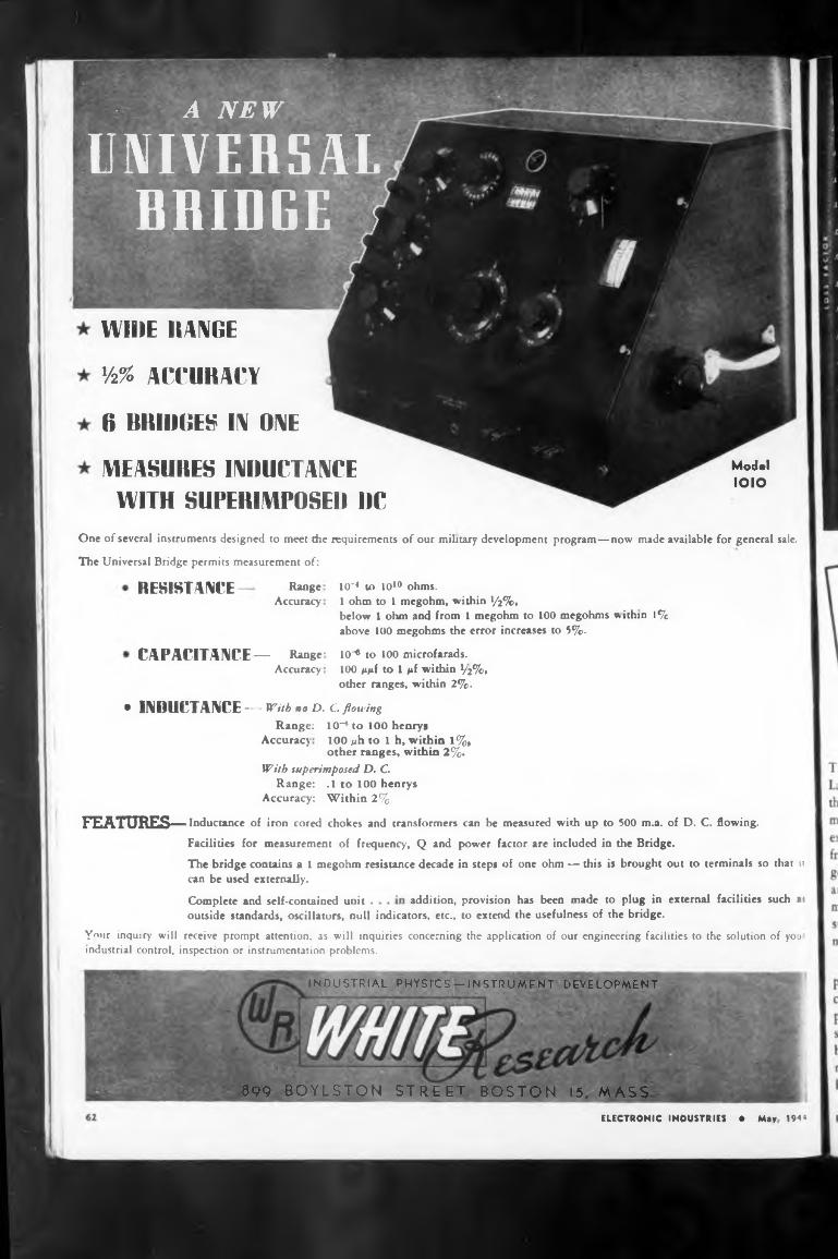
WIDE RANGE
%% ACCURACY
6 BRIDGES IN ONE
MEASURES INIIUCTANCEWITH SUPERIMPOSE!) RC
RESISTANCE
addition, provision has been made to plug in external facilities such aiComplete and self-contained unit
899 BOYLSTON STREET. BOSTON 15. MASS.
Model IOIO
Range Accuracy
Range: Accuracy
10-* to 100 henrys 100 juh to 1 h, within 1%, other ranges, within 2%.
10*4 to 1010 ohms.1 ohm to I megohm, within V2%» below 1 ohm and from 1 megohm to 100 megohms within 1% above 100 megohms the error increases to 5%.
10^ to 100 microfarads.100 ggf to 1 pt within V2%> other ranges, within 2%.
INDUSTRIAL PHYSICS —INSTRUMENT DEVELOPMENT
With superimposed D. C.Range: .1 to 100 henrys
Accuracy: Within 2%
FEATURES— Inductance of iron cored chokes and transformers can be measured with up to 500 m.a. of D, C. flowing.
Facilities for measurement of frequency, Q and power factor are included in the Bridge.
The bridge contains a 1 megohm resistance decade in steps of one ohm — this is brought out to terminals so that ii can be used externally.
• INDUCTANCE--- With HO D. C. flowing
outside standards, oscillators, null indicators, etc., to extend the usefulness of the bridge.
Your inquiry will receive prompt attention, as will inquiries concerning the application of our engineering facilities to the solution of you industrial control, inspection or instrumentation problems.
One of several instruments designed to meet the requirements of our military development program—now made available for general sale.
The Universal Bridge permits measurement of:
ELECTRONIC INDUSTRIES * May 1944
CAPACITANCE— RangeAccuracy
■ A NEW
UNIVERSAL nmnrr r DiillJbE f
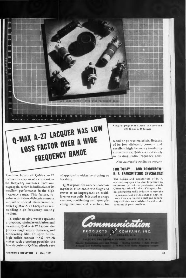
IACQDER
RANGÉ
■■■■■■I■■■■■■I
»■■■I llllll UMM
ft ■■fui»’
IneMmi kiBIHMI
The design and manufacture of H. F. transmitting specialties has long been an important part of the production which Communication Products Company, Inc. has offered the radio industry to meet the requirements of a wide range of applica* tions. Our engineering staff and laboratory facilities are available for aid in the solution of your problem.
MEMEBB !■■■■■■■
UECTRONIC INDUSTRIES • May, 1944
A typical group of H, F. radio coils insulated
with Q-Max A-27 Lacquer
FOR TODAY... AND TOMORROW: H. F. TRANSMITTING SPECIALTIES
wood or porous materials. Because of its low dielectric constant and excellent high frequency insulating characteristics, Q-Max is used widely in treating radio frequency coils.
New descriptive booklet on request.
HRS LOIN
of application either by dipping or brushing.
Q-Max provides an excellent coating for R. F. solenoid windings and serves as an imprégnant on multilayer or star coils. It is used as a tape saturant, a stiffening and strengthening medium, and a surfacer for
The loss factor of Q-Max A-27 Lacquer is very nearly constant as the frequency increases from one megacycle, which is indicative of its excellent performance in the high frequency range. This feature, together with its low dielectric constant and other special characteristics, makes Q-Max A-27 Lacquer an outstanding high frequency coating medium.
In order to give water-repellent protection, minimize oxidation and c >rrosion, Q-Max A-27 Lacquer deposits a tough, uniformly heavy, and self-leveling film. In spite of the high solids content—45%—which nakes such a coating possible, the low viscosity of Q-Max affords ease
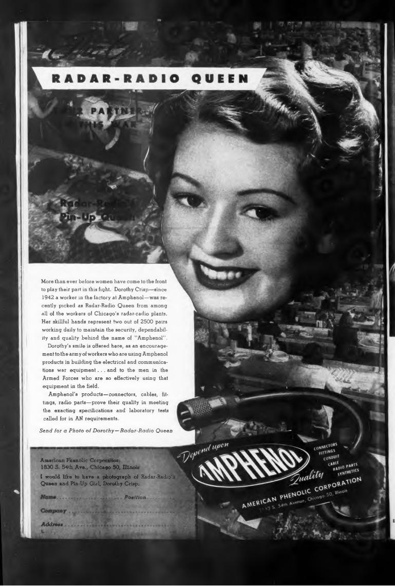
since
Send for a Photo of Dorothy—Radar-Radio Queen
Patltioo
Addrm
Amenoax knenolic Corpe»»»^» 1830 S. 54th Ave., Chicago 50, Clinou
I would like to have a photograph ci Radar-Radio'i Queer and Pin-Up Girl, Dorothy Crisp.
to play their part in this fight Dorothy Crisp- 1942 a worker in the factory at Amphenol—
More than ever before women have come to the front
cently picked as Radar-Radio Queen from among all of the workers of Chicago's radar-radio plants. Her skillful hands represent two out of 2500 pairs working daily to maintain the security, dependability and quality behind the name of "Amphenol".
Dorothy's smile is offered here, as an encouragement to the army of workers who are using Amphenol products in building the electrical and communications war equipment... and to the men in the Armed Forces who are so effectively using that equipment in the field.
Amphenol's products—connectors, cables, fittings, radio parts—prove their quality in meeting the exacting specifications and laboratory tests called for in AN requirements
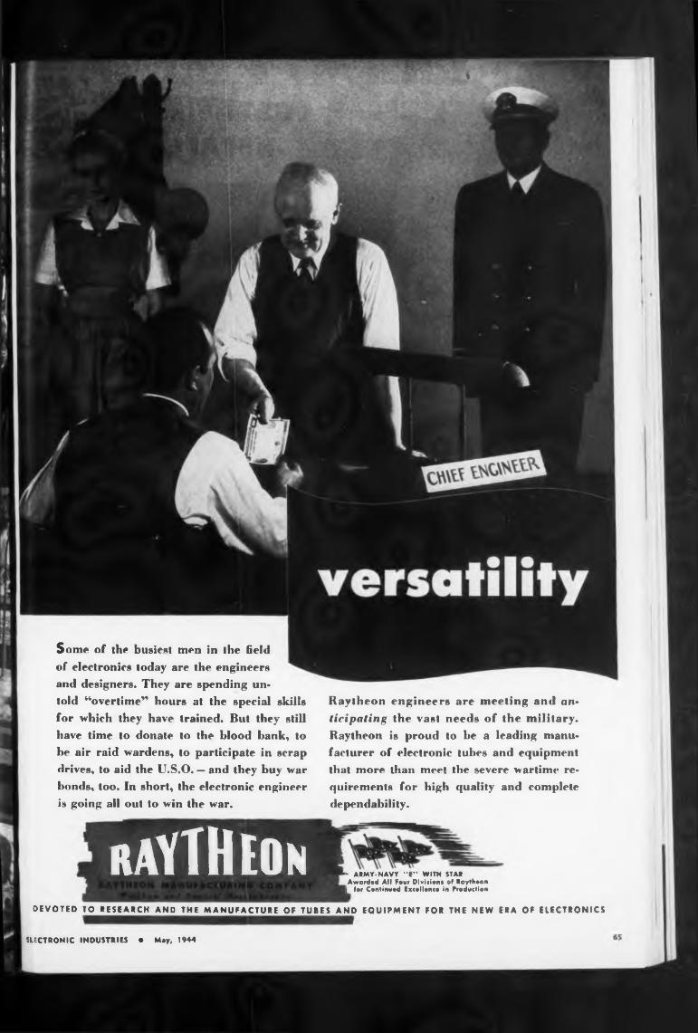
U ECT R ON IC INDUSTRIES • May, 1944
AND EQUIPMENT FOR THE NEW ERA OF ELECTRONICS
* ARMY-NAVY "E” WITH STAR Awarded All Four Divisions of Raytheon
[ for Continued Excellence in Production
DEVOTED TO RESEARCH AND THE MANUFACTURE OF TUBES
RAYTHEON
Some of the busiest men in the field
of electronics today are the engineers
and designers. They are spending un«
told “overtime” hours at the special skills
for which they have trained. But they still
have time to donate to the blood bank, to
be air raid wardens, to participate in scrap
drives, to aid the U.S.O. — and they buy war
bonds, too. In short, the electronic engineer
is going all out to win the war.
Raytheon engineers are meeting and anticipating the vast needs of the military.
Raytheon is proud to be a leading manu
facturer of electronic tubes and equipment
that more than meet the severe wartime re*
quirements for high quality and complete
dependability.
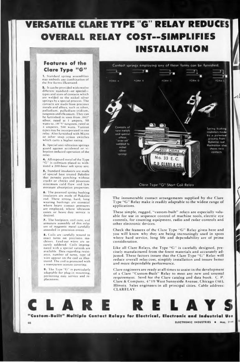
VERSATILE CLARE TYPE "G" RELAY REDUCESOVERALL RELAY COST—SIMPLIFIES
INSTALLATION
It can he provided with twelvedifferent standard
ampere,
8. Coils are carefully wound toprecision
May, 1944ELECTRONIC INDUSTRIES
The innumerable contact arrangements supplied by the Clare Type “G” Relay make it readily adaptable to the widest range of applications.
types and sizes of contacts which are welded to the nickel silver springs hy a special process. The contacts are made from precious metals and alloys, such as silver, palladium, palladium-iridium, tungsten and elkonium. They can he furnished in sizes from .062'
9. The Type “G” is particularly adaptable for plug-in mounting, permitting easy service and replacement.
1. Standard spring assemblies may embody any combination of the five forms illustrated.
Check the features of the Clare Type “G” Relay given here and you will know why they are being increasingly used in spots where hard service, long life and dependability are of prime consideration.
These simple, rugged, “custom-built” relays are especially valuable for use in sequence control of machine tools, electric eye controls, for counting equipment, radio and radar controls and other electronic devices.
Clare engineers are ready at all times to assist in the development of ,i Clare “Custom-Built” Relay to meet any new and unusual requirement. Send for the Clare catalog and data book. C. P. Clare & Company, 4719 West Sunnyside Avenue, Chicago (30), Illinois. Sales engineers in all principal cities. Cable address*. CLARELAY.
Like all Clare Relays, the Type “G” is carefully designed, precisely manufactured from the finest materials and accurately adjusted. These factors insure that the Clare Type “G” Relay will reduce overall relay cost, simplify installation and insure better and more dependable performance.
chines. Lead-out wires are securely soldered. Coils impregnated with a special varnish are available. Data regarding resistance, number of turns, type of wire appear on the coil as illustrated. The coil is protected with a transparent acetate covering.
watts to .1875' tungsten, rated at 4 amperes, 500 watts. Various types may be incorporated in one relay. Also furnished with Micro or other snap-action switches which carry a higher rating.3. Special anti-vihration springs guard against accidental or vibration-induced operation of the relay.4. All exposed metal of the Type “G” is cadmium plated to withstand a 200-hour salt spray test.5. Standard insulators are made of special heat treated Bakelite that permits punching without cracks or checks and possesses minimum cold flow and low moisture absorption properties.6- The patented spring bushing insulators are made of Bakelite rod. These strong, hard, long wearing bushings are essential where heavy contact pressures are employed, where vibration exists or heavy duty service is desired.7. The heelpiece, coil core, and armature assembly of this relay are of magnetic metal carefully annealed in precision ovens.
FORM C FORM D FORM EFORM B
spring'
Clare Type ”G” Short Coil Relay
Contacts of rare metals and special
alloys, "over-all" welded to
nickel
Spring bushing insulators made by a patented process from Bakelite rod.
Illustration also shows twin contacts.
Contact springs employing any of these forms can be furnished
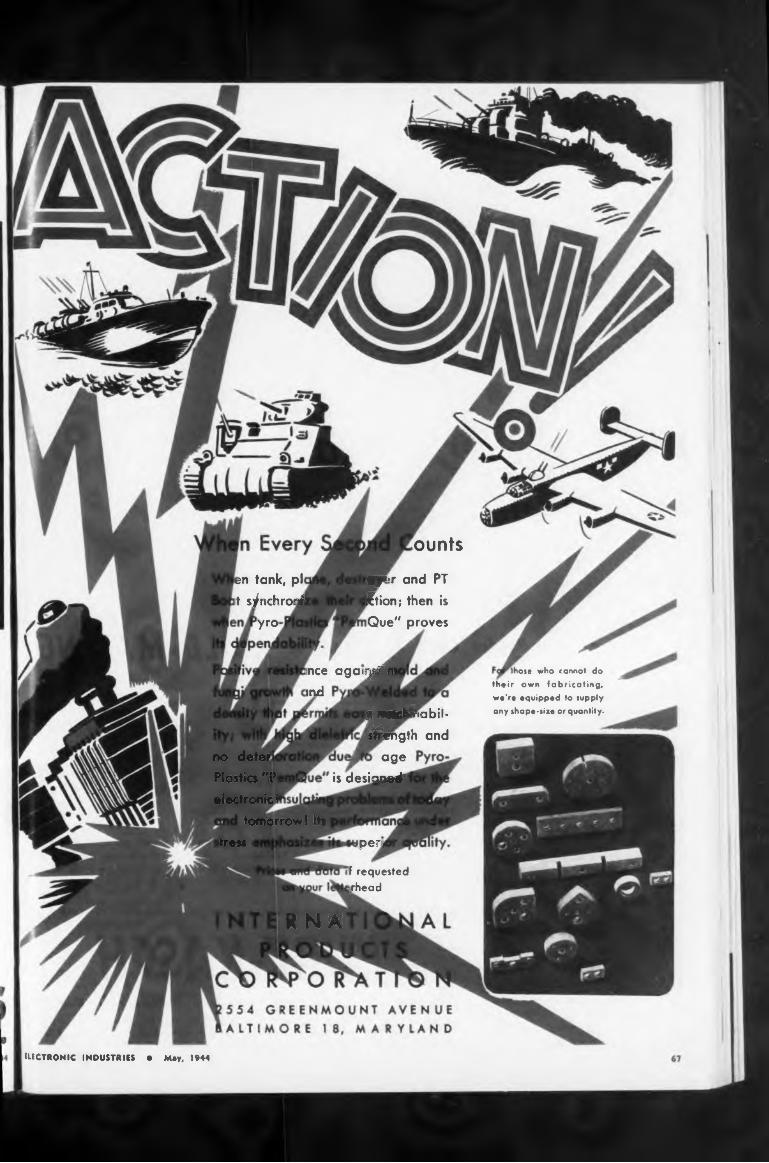
ounts
yro
tomorrow! Itstress peri
R N A
en tank, pl it s/nchronl
F requested /head
wytjr and PT Ftion; then is Que" proves
'hose who cannot do their own fabricating, we're equipped to supply any shape-size or quantity.
no deter Plastics MP< electronic I
ince agati^M ind
ELECTRONIC INDUSTRIES • Mey, 1944
ageis desiaiMÉ«
y Màcina bil*Hmgth and
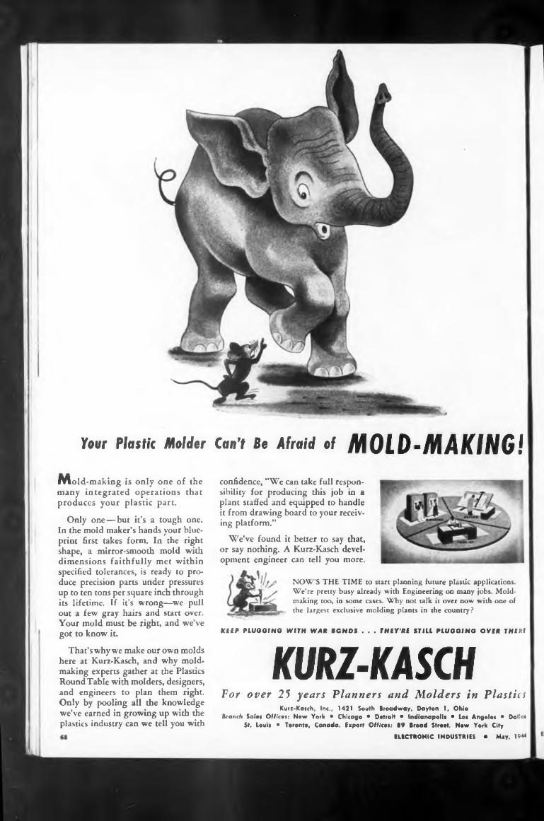
Can’t Be Afraid of MOLD-MAKING!Your Plastic Molder
KURZ-KASCH
Mold-making is only one of the many integrated operations that produces your plastic part.
For over 25 years Planners and Molders in Plastics
KEEP PLUGGING WITH WAR BONDS . . . THEY'RE STILL PLUGGING OVER THERE
ELECTRONIC INDUSTRIES • May. 1944
That’s why we make our own molds here at Kurz-Kasch, and why moldmaking experts gather at the Plastics Round Table with molders, designers, and engineers to plan them right. Only by pooling all the knowledge we’ve earned in growing up with the plastics industry can we tell you with
NOW’S THE TIME to start planning future plastic applications. We’re pretty busy already with Engineering on many jobs. Moldmaking too, in some cases. Why not talk it over now with one of the largest exclusive molding plants in the country?
Kurz-Kasch, Inc., 1421 South Broadway, Dayton 1, Ohio Branch Salos Offices: New York • Chicago • Dotroit • Indianapolis • Los Angeles • Dalias
St. Louis • Toronto, Canada. Export Office»: 89 Broad Street, New York City
Only one—but it’s a tough one. In the mold maker’s hands your blueprint first takes form. In the right shape, a mirror-smooth mold with dimensions faithfully met within specified tolerances, is ready to produce precision parts under pressures up to ten tons per square inch through its lifetime. If it’s wrong—we pull out a few gray hairs and start over. Your mold must be right, and we’ve got to know it.
confidence, "We can take full responsibility for producing this |ob in a plant staffed and equipped to handle it from drawing board to your receiving platform.”
We’ve found it better to say that, or say nothing. A Kurz-Kasch development engineer can tell you more.
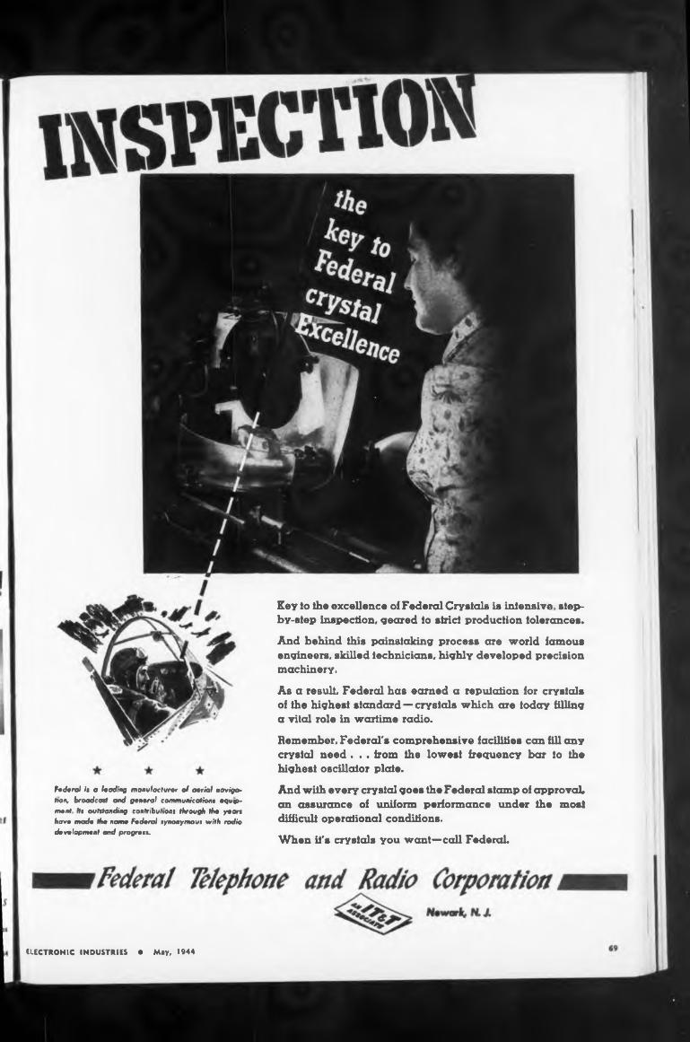
Key to the excellence of Federal Crystals is intensive, step- by-step inspection, geared to strict production tolerances.
Federal is a leading manufacturer cf aerial navigation, broadcast ond general communications equipment Hr outstanding contributions through the yean have made the name Federal synonymous with radio development and progress.
And with every crystal goes the Federal stamp of approval» an assurance of uniform performance under the most difficult operational conditions.
And behind this painstaking process are world famous engineers, skilled technicians, highly developed precision machinery.
When it's crystals you want—call Federal.
As a result Federal has earned a reputation for crystals of the highest standard—crystals which are today filling a vital role in wartime radio.Remember. Federal's comprehensive facilities can fill any crystal need. . . from the lowest frequency bar to the highest oscillator plate.
ELECTRONIC INDUSTRIES • May, 1944
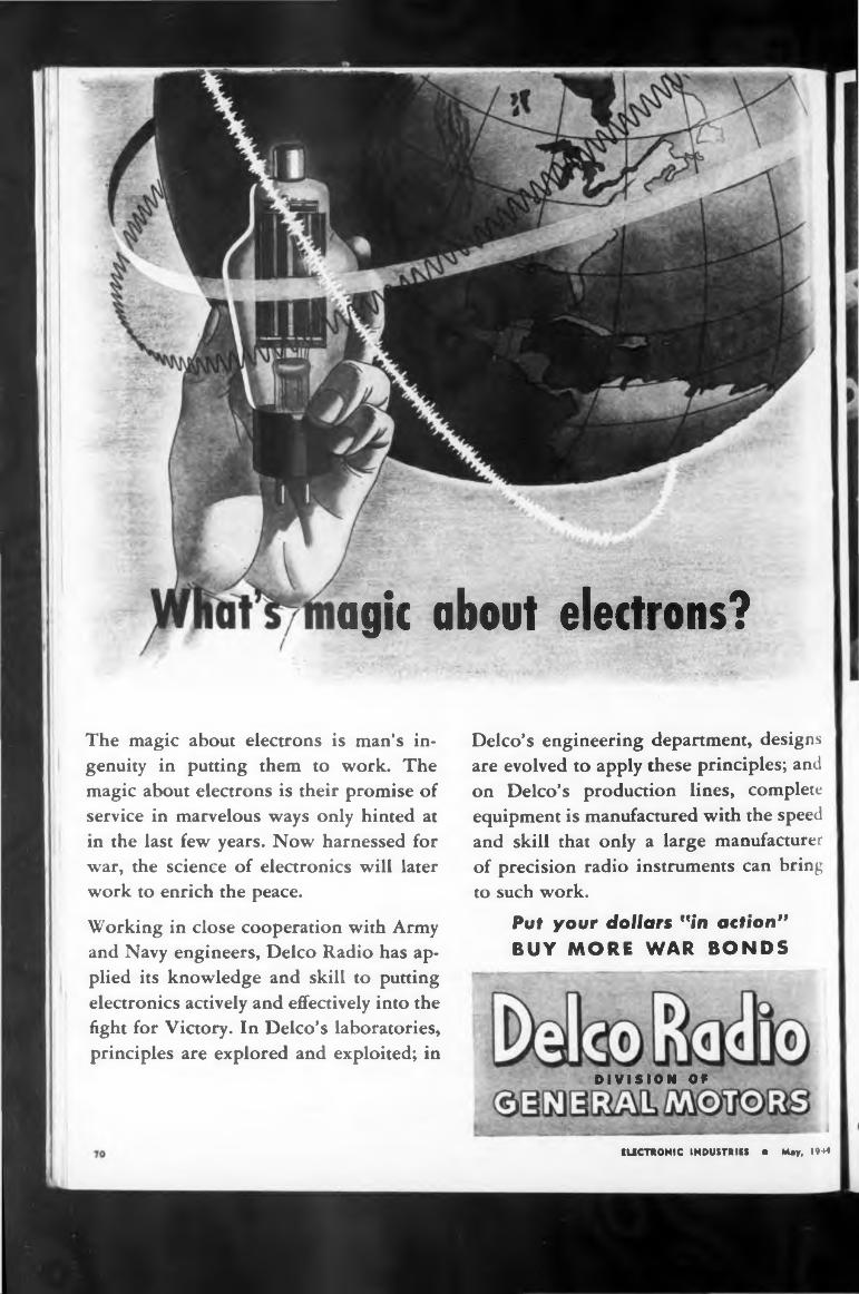
agit about electrons?
The magic about electrons is man’s ingenuity in putting them to work. The magic about electrons is their promise of service in marvelous ways only hinted at in the last few years. Now harnessed for war, the science of electronics will later work to enrich the peace.
Working in close cooperation with Army and Navy engineers, Delco Radio has applied its knowledge and skill to putting electronics actively and effectively into the fight for Victory. In Delco’s laboratories, principles are explored and exploited; in
Delco’s engineering department, designs are evolved to apply these principles; and on Delco’s production lines, complete equipment is manufactured with the speed and skill that only a large manufacturer of precision radio instruments can bring to such work.
Put your dollars "in action” BUY MORE WAR BONDS
DIVISION OF
KUCTRONIC INDUSTRIES • May, 1944
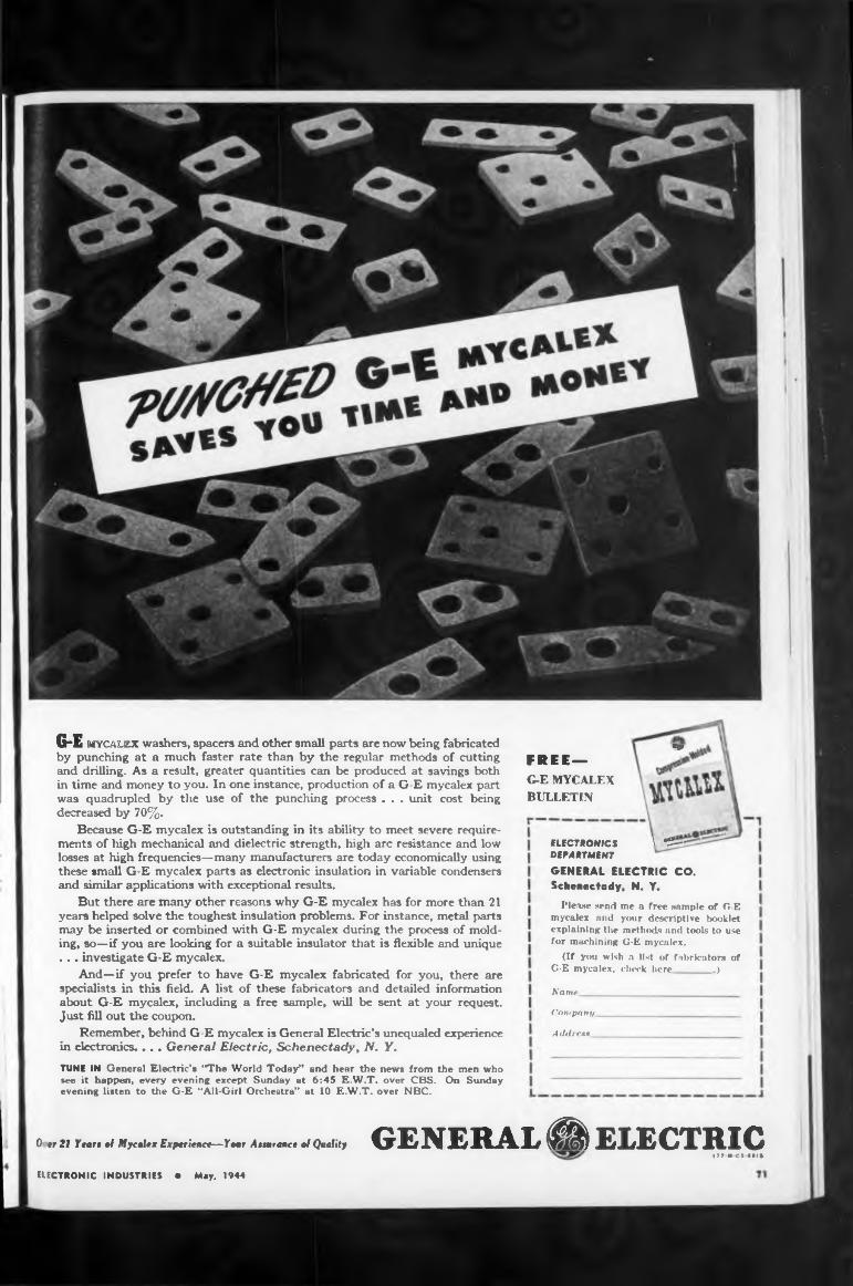
G-E MYCALEX washers, spacers and other small parts are now being fabricated by punching at a much faster rate than by the regular methods of cutting and drilling. As a result, greater quantities can be produced at savings both in time and money to you. In one instance, production of a G-E mycalex part was quadrupled by the use of the punching process . . . unit cost being decreased by 70%.
Because G-E mycalex is outstanding in its ability to meet severe requirements of high mechanical and dielectric strength, high arc resistance and low losses at high frequencies—many manufacturers are today economically using these small G-E mycalex parts as electronic insulation in variable condensers and similar applications with exceptional results.
But there are many other reasons why G-E mycalex has for more than 21 years helped solve the toughest insulation problems. For instance, metal parts may be inserted or combined with G-E mycalex during the process of molding, so—if you are looking for a suitable insulator that is flexible and unique ... investigate G-E mycalex.
And—if you prefer to have G-E mycalex fabricated for you, there are specialists in this field. A list of these fabricators and detailed information about G-E mycalex, including a free sample, will be sent at your request. Just fill out the coupon.
Remember, behind G-E mycalex is General Electric’s unequaled experience in electronics... . Genera/ Electric, Schenectady, N. Y.
TUNE IN General Electric’s "The World Today” and hear the news from the men who see it happen, every evening except Sunday at 6:45 E.W.T. over CBS. On Sunday evening listen to the G-E “All-Girl Orchestra” at 10 EW.T. over NBC.
FREE—G-E MYCALEX BULLETIN
** I
ELECTRONICS 1 «S— DEPARTMENTGENERAL ELECTRIC CO.Schenectady, N. Y.
Please send me a free sample of G-E mycalex and your descriptive booklet explaining the methods and tools to use for machining G-E mycalex.
(If you wish a list of fabricators of G-E mycalex, check here.)
Name
Company
A Adrea*
0 rr 21 Y tari of Mycalax Experience—Year Ainrancr of Quality GENERAL Ä ELECTRICI77-MC3 •»!»
ELECTRONIC INDUSTRIES • May, 1944
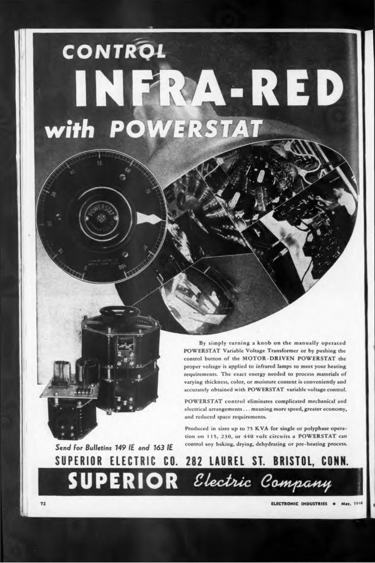
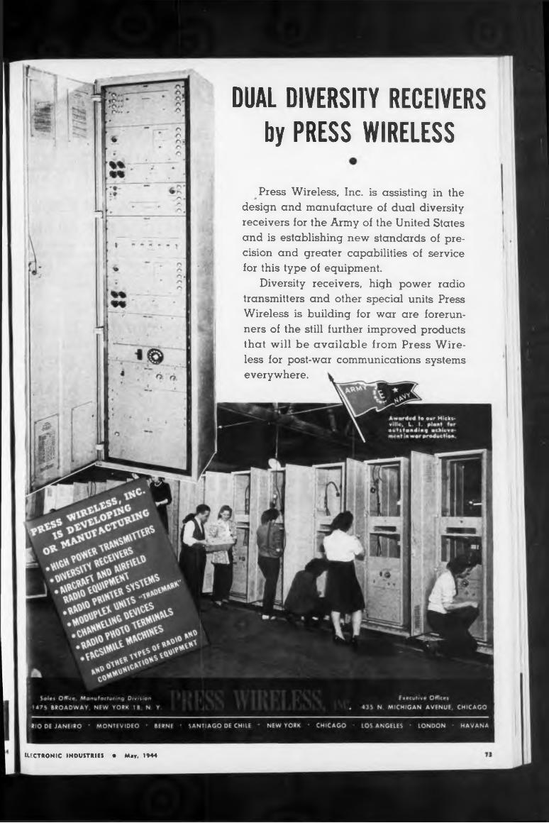
DUAL DIVERSITY RECEIVERSby PRESS WIRELESS
Press Wireless, Inc. is assisting in the design and manufacture of dual diversity receivers for the Army of the United States and is establishing new standards of precision and greater capabilities of service for this type of equipment.
Diversity receivers, high power radio transmitters and other special units Press Wireless is building for war are forerunners of the still further improved products that will be available from Press Wireless for post-war communications systems everywhere.
ELECTRONIC INDUSTRIES • May, 1944
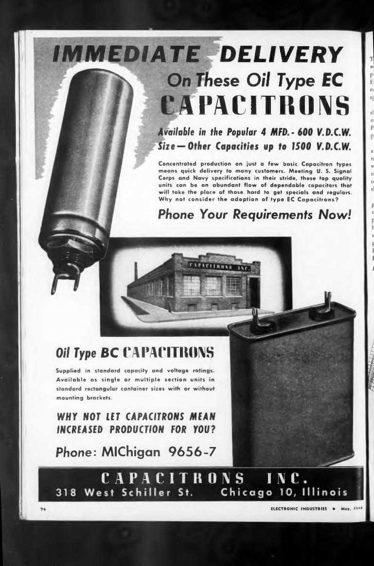
IMMEDIA TErDELIVERY
vailable in the Popular 4 MFD.
Oil Type BC CAPACITRONS
Phone: Michigan 9656-7
WHY NOT LET CAPACITRONS MEAN INCREASED PRODUCTION FOR YOU?
•Ifl-s
On These Oil Type ECCAPACITRONS
Concentrated production on just a few basic Capacitron types means quick delivery to many customers. Meeting U. S. Signal Corps and Navy specifications in their stride, these top quality units can be an abundant flow of dependable capacitors that will take the place of those hard to get specials and regulars. Why not consider the adoption of type EC Capacitrons?
Phone Your Requirements Now!
Supplied in standard capacity and voltage ratings. Available as single or multiple section units in standard rectangular container sizes with or without mounting brackets.
ELECTRONIC INDUSTRIES • May. 1944
CAPACITRONS INC
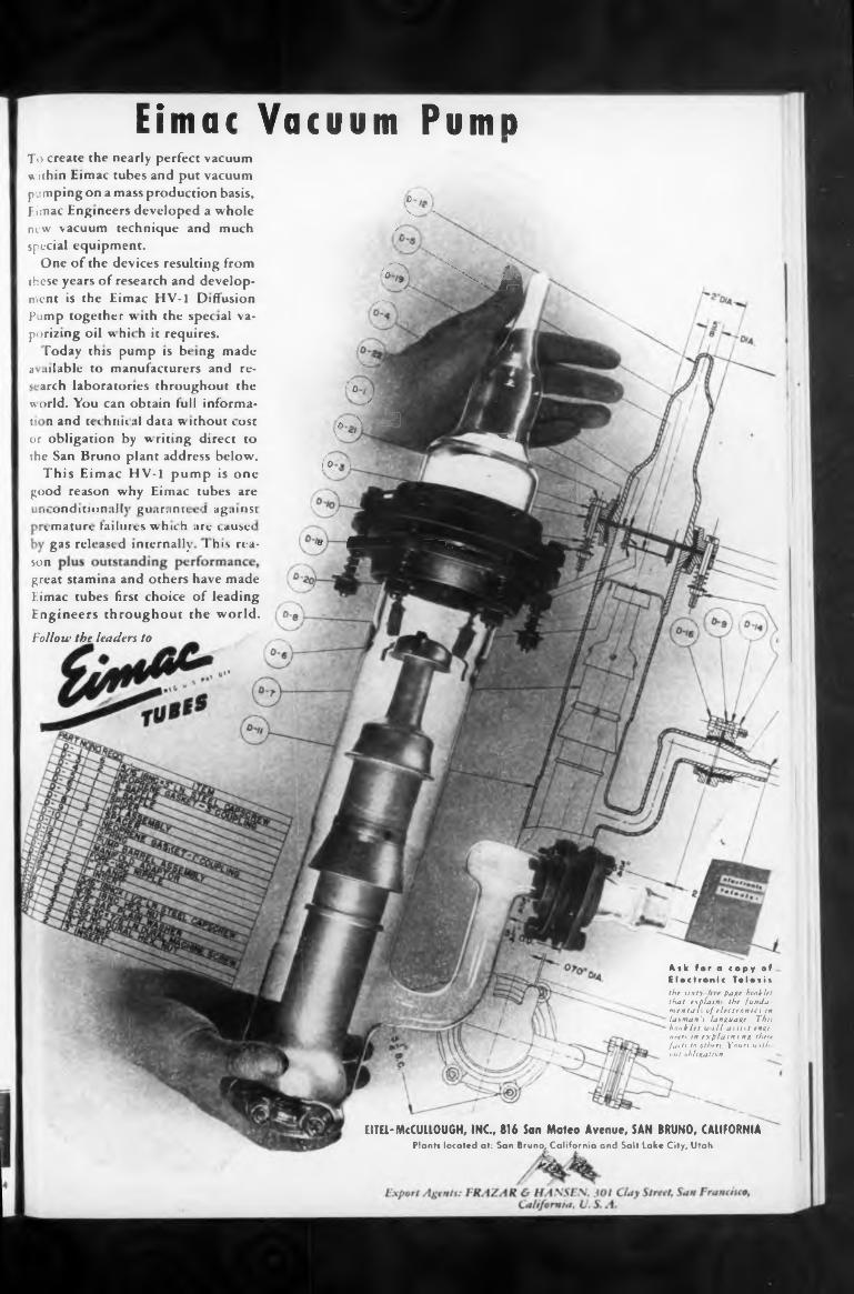
son
EITEL-McCULLOUGH, INC, 816 San Mateo Avenue, SAN BRUNO, CALIFORNIA Plants located at: San Bruno, California and Salt Lake City, Utah
Ask for a copy of Electronic Telesisthe sixty hie pa»t beoklet that explains the fundamentals of electronics in layman's language. This booklet u ill assist engineers tn explaining these facts to others. Yours with out obligation.
great stamina and others have made Eimac tubes first choice of leading Engineers throughout the world.
Follow the leaders to
Eimac Vacuum PumpTo create the nearly perfect vacuum within Eimac tubes and put vacuum pumping on a mass production basis, cEimac Engineers developed a whole < * -new vacuum technique and much /special equipment.
One of the devices resulting from z —x \ ,these years of research and develop- °"XX JMmcnt is the Eimac HV-I Diffusion _ |Pump together with the special vaporizing oil which it requires.
Today this pump is bring made i .nlable to manufacturers and re- '* arch laboratories throughout the ' 0
world. You can obtain lull informa- z ;t n and uchriic ,il data w ithouc i ost A \ ‘wPor obligation by writing direct to ' ^* 4the San Bruno plant address below. foiW
This Eimac HV-1 pump is one good reason why Eimac cubes are
n wndition.dh gti.ir.mn s •! ag.n»»H tmatur». Lnhirvs w hu. h .hv«juw< gas released internal!;. ! his nu- a 1E " "***_
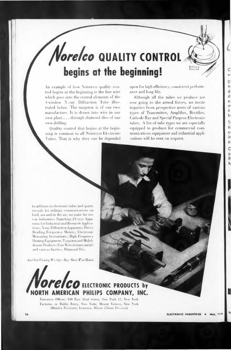
Coreico QUALITY CONTROL
begins at the beginning!Drilling a Diamond
An example of how Norelco quality control begins at the beginning is the fine wire which goes into the central elements of the 4-window X-ray Diffraction Tube illustrated below. The tungsten is of our own manufacture. It is drawn into wire in our own plant . . . through diamond dies of our own drilling.
Quality control that begins at the beginning is common to all Norelco Electronic Tubes. That is why they can be depended
upon for high efficiency, consistent performance and long life.
Although all the tubes we produce are now going to the armed forces, we invite inquiries from prospective users of various types of Transmitter, Amplifier, Rectifier, Cathode Ray and Special Purpose Electronic tubes. A list of tube types we are especially equipped to produce for commercial communications equipment and industrial applications will be sent on request.
In addition to electronic tubes and quartz crystals for military communications on land, sea and in the air, we make for our war industries: Searchray (X-ray) Apparatus for Industrial and Research Applications; X-ray Diffraction Apparatus; Direct Reading Frequency Meters; Electronic Measuring Instruments; High Frequency Heating Equipment; Tungsten and Molybdenum Products: Fine Wire in many metak and various finishes; Diamond Dies.
Ind For Victory H e Say: Buy More H ar Bonds
norelco ELECTRONIC PRODUCTS by NORTH AMERICAN PHILIPS COMPANY, INC.
Executive Offices: 100 East 42nd Street, New York 17, New YorkFactories in Dobbs Ferry, New York; Mount Vernon, New York
(Metalix Division); Lewiston, Maine (Elmet Division)
ELECTRONIC INDUSTRIES • Mey, 19*4
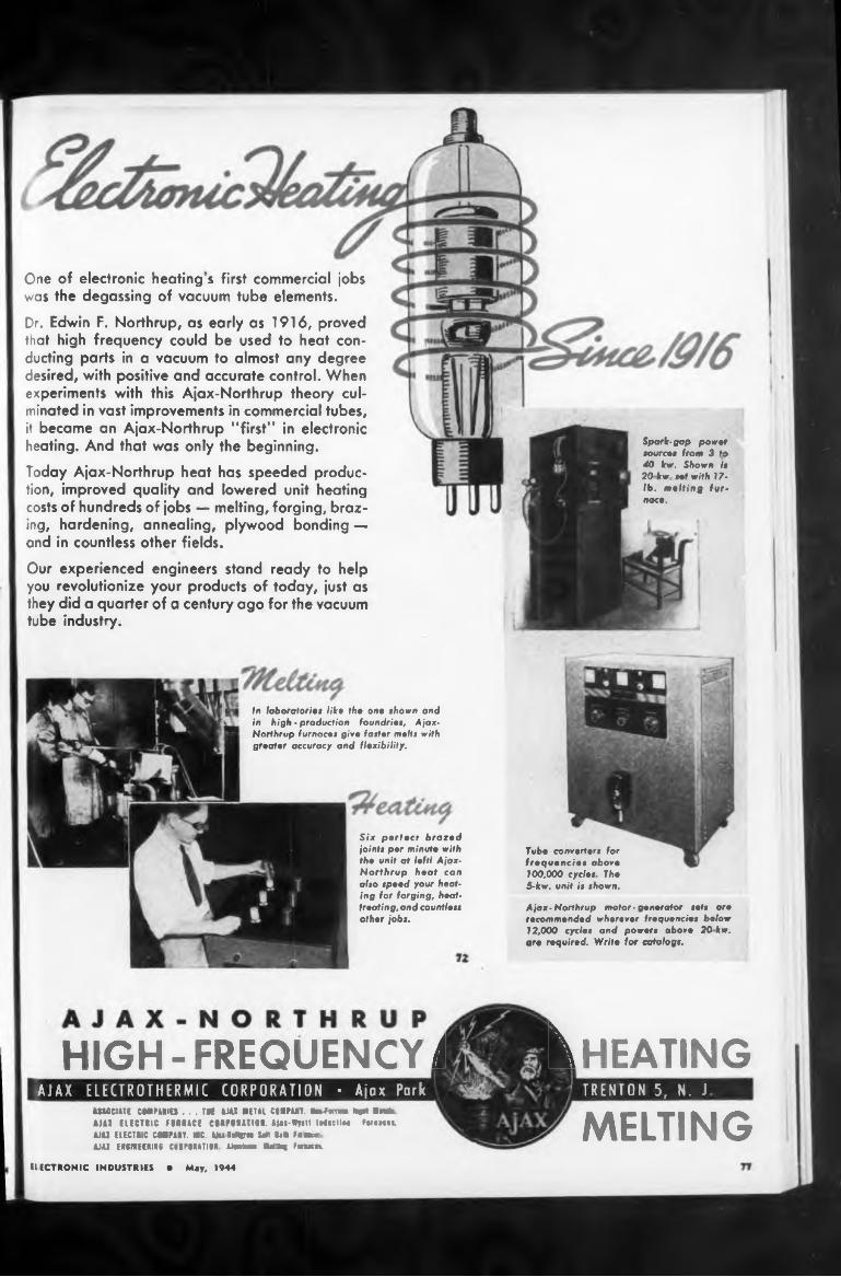
CheatingHIGH- FREQUENCY J
MELTING
One of electronic heating s first commercial jobs was the degassing of vacuum tube elements.
Our experienced engineers stand ready to help you revolutionize your products of today, just as they did a quarter of a century ago for the vacuum tube industry.
Six perfect brazed joints per minute with tho unit at left! Ajax- Northrup heat can also speed your heating for forging, heattreating, and countless other jobs.
Ajax-Northrup motor-generator sets are recommended wherever frequencies below 12,000 cycles and powers above 20 kw. are required. Write for catalogs.
Tube converters for frequencies above 100,000 cycles The 5-kw. unit is shown.
ELECTRONIC INDUSTRIES • May. 1944
ASSOCIATE COMPARIES ... TEE ULI METAL COMPART. MMwm* Rpt «rata AMI ELECTRIC FIRRACE CMmillOL Mu-Wyttt IMicUm FwmtL MU ELECTRIC CAMPAIT. MC. Aju MiHim Salt Bat» FflUrr AMI EI6MEERIIG CCAPDAATI OR AMwa MalU«| Fnam.
Spark-gap power sources from 3 to 40 kw. Shown is 20 kw set with 17lb. melting furnace.
In laboratories like the one shown and in high - production foundries, Ajax- Northrup furnaces give faster melts with greater accuracy and flexibility.
Dr. Edwin F. Northrup, as early as 1916, proved that high frequency could be used to heat conducting parts in a vacuum to almost any degree desired, with positive and accurate control. When experiments with this Ajax-Northrup theory culminated in vast improvements in commercial tubes, it became an Ajax-Northrup “first” in electronic heating. And that was only the beginning.Today Ajax-Northrup heat has speeded production, improved quality and lowered unit heating costs of hundreds of jobs — melting, forging, brazing, hardening, annealing, plywood bonding — and in countless other fields.
TRENTON 5, N. JAJAX E L E CTR 0 T H ER MIC CORPORATION • Ajax Pork
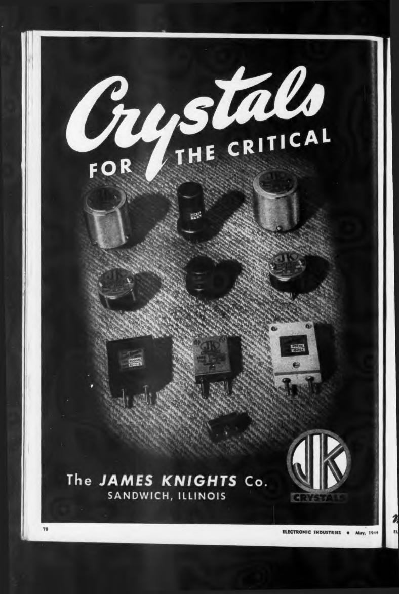
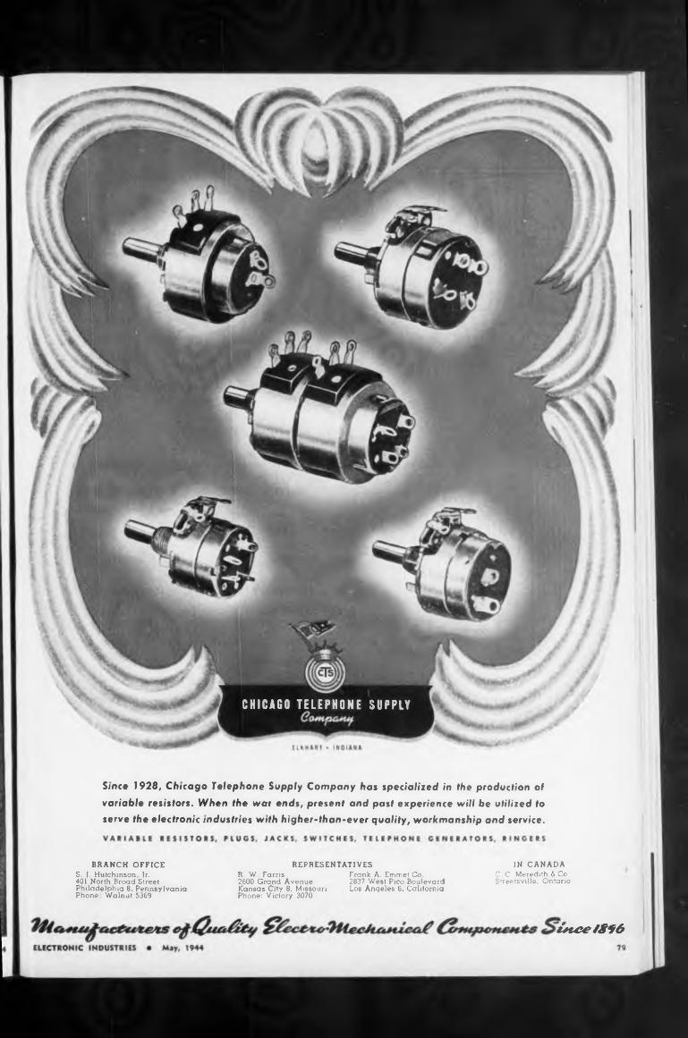
REPRESENTATIVES
' ¿nee 18f6
R. W. Farris 2600 Grand Avenue Kansas City 8, Missouri Phone: Victory 3070
Frank A. Emmet Co.2837 West Pico Boulevard Los Angeles 6, California
IN CANADAC. C. Meredith & Co. Streetsville, Ontario
BRANCH OFFICES. J. Hutchinson, Jr.401 North Broad Street Philadelphia 8, Pennsylvania Phone: Walnut 5369
Since 1928, Chicago Telephone Supply Company has specialized in the production of
variable resistors. When the war ends, present and past experience will be utilized to serve the electronic industries with higher-than-ever quality, workmanship and service.
CHICAGO TELEPHONE SÜPPLY
1. Make the best product possible.
2. Buy only the finest in raw materials.
3.
4.
NEW YORK 37 W 65 St J3
Use a polymerization vacuum*varnish impregnation process combined with pressure.
Guarantee unconditionally every unit manufactured.
I oday, when you have a Langevin Transformer, you have all these plus rigid manufacturing control and inspection. Your inquiries for quality transformer products are solicited. Capacity to 5 KVA.
When our transformer plant was organized 22 months ago, four MUST rules were laid down. In order, they were:—
SAN FRANCISCO1050 Howard St 3
LOS ANGELES 1000 N Seward St 38
The Langevin CompanyINCORPORATED # A-X
SOUND REINFORCEMENT AND REPRODUCTION ENGINEERING
JillSFORMERSof Quality...
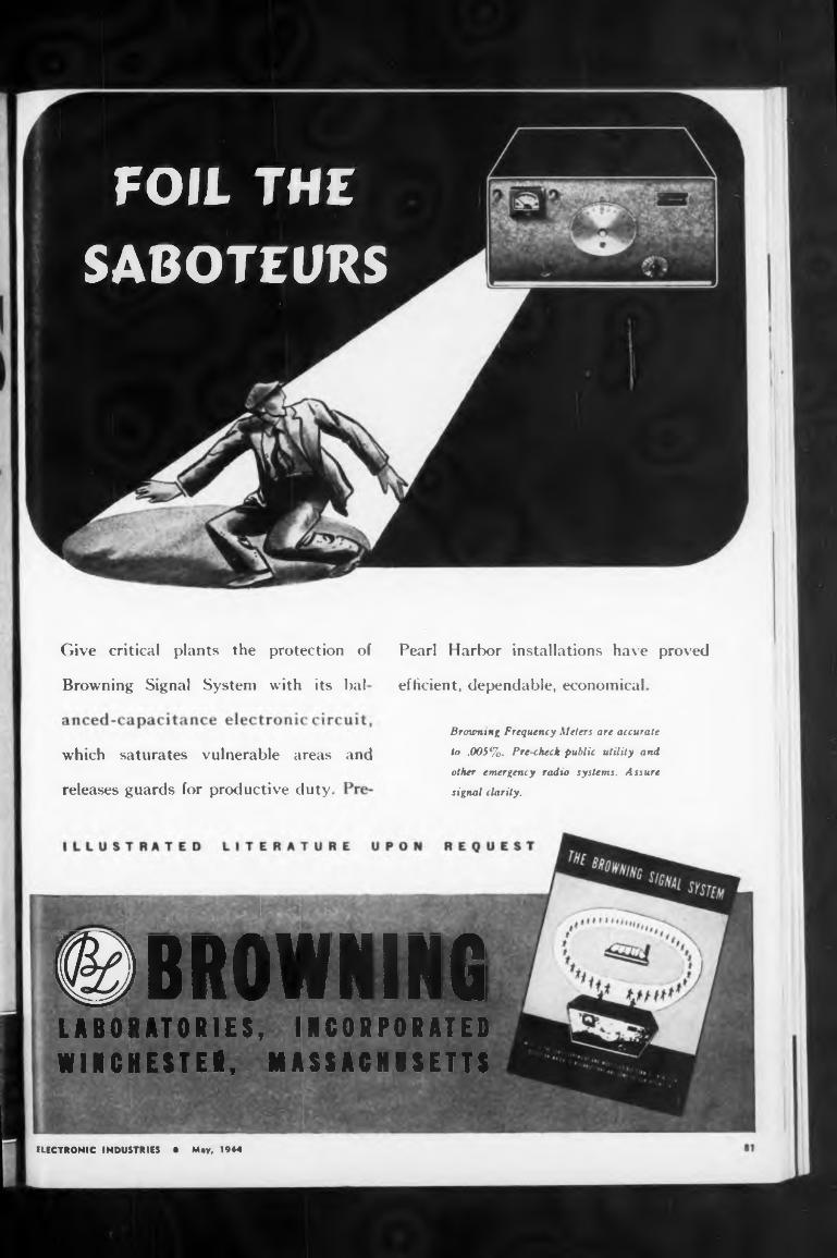
Pearl Harbor installations have proved
Browning Signal System with its bai efficient, dependable, economical
and
releases guards for productive duty
Brimming Frequency Meters are accurate
to .005%. Pre-check public utility and
other emergency radio systems. Assure
signal clarity.
Give critical plants the protection of
which saturates vulnerable areas
ELECTRONIC INDUSTRIES • May, 1944
©BROWNINGLABORATORIES, INCORPORATED WINCHESTER, MASSACHUSETTS
FOIL THE SABOTEURS
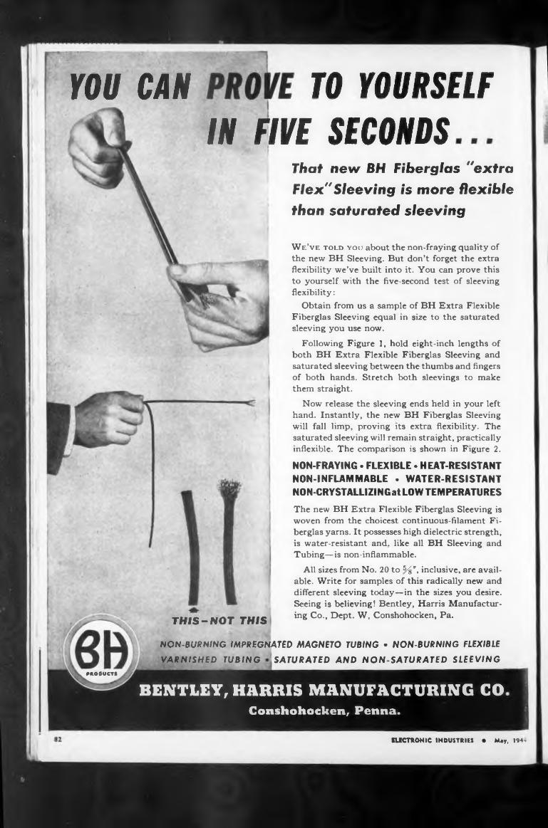
TO YOURSELFYOU CANIN FIVE SECONDS
THIS-NOT THIS
VARNISHED TUBING SATURATED AND NON-SATURATED SLEEVINGPHO0UCTS
NON-BURNING IMPREGNATED MAGNETO TUBING • NON-BURNING FLEXIBLE
The new BH Extra Flexible Fiberglas Sleeving is woven from the choicest continuous-filament Fiberglas yams. It possesses high dielectric strength, is water-resistant and. like all BH Sleeving and Tubing—is non-inflammable.
All sizes from No. 20 to 5^", inclusive, are available. Write for samples of this radically new and different sleeving today—in the sizes you desire. Seeing is believing! Bentley, Harris Manufacturing Co., Dept. W, Conshohocken, Pa.
That new BH Fiberglas "extra
Flex"Sleeving is more flexible
than saturated sleeving
We’ve told you about the non-fraying quality of the new BH Sleeving. But don’t forget the extra flexibility we’ve built into it. You can prove this to yourself with the five-second test of sleeving flexibility:
Obtain from us a sample of BH Extra Flexible Fiberglas Sleeving equal in size to the saturated sleeving you use now.
Following Figure I, hold eight-inch lengths of both BH Extra Flexible Fiberglas Sleeving and saturated sleeving between the thumbs and fingers of both hands. Stretch both sleevings to make them straight.
Now release the sleeving ends held in your left hand. Instantly, the new BH Fiberglas Sleeving will fall limp, proving its extra flexibility. The saturated sleeving will remain straight, practically inflexible. The comparison is shown in Figure 2.
NON-FRAYING • FLEXIBLE • HEAT-RESISTANT NON-INFLAMMABLE • WATER-RESISTANT NON-CRYSTALLIZINGat LOW TEMPERATURES
ELECTRONIC INDUSTRIES • May, 194-
BENTLEY, HARRIS MANUFACTURING CO Conshohocken, Penna.
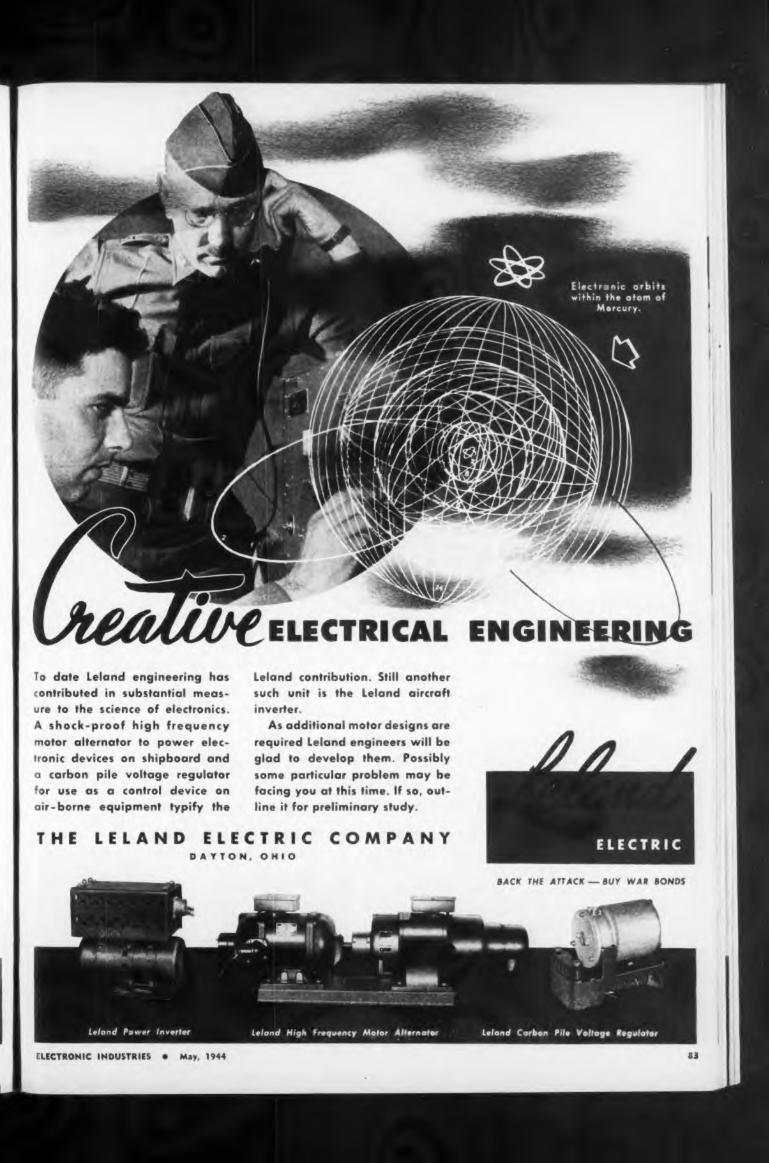
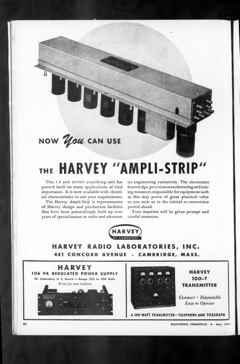
NOW
HARVEY
TRANSMITTER
A 100 WATT TRANSMITTER—TELEPHONE AND TELEGRAPH
HARVEY RADIO LABORATORIES, INC
ics engineering exclusively. The electronics knowledge, precision manufacturing and testing resources responsible for equipment such as this may prove of great practical value to you now or in the critical re-conversion period ahead.
Your inquiries will be given prompt and careful attention.
Compact • Dependable Easy to Operate
the HARVEY "AMPLI-STRIP
ELECTRONIC INDUSTRIES • May. 1944
This I-F and AUDIO amplifying unit has proved itself on many applications of vital importance. It is now available with electrical characteristics to suit your requirements.
The Harvey Ampli-Strip is representative of Harvey design and production facilities that have been painstakingly built up over years of specialization in radio and electron-
HARVEY 1OO-T
HARVEY 106 PA REGULATED POWER SUPPLY
for Laboratory D. C. Source — Range 200 to 300 Volts
Write for new bulletin
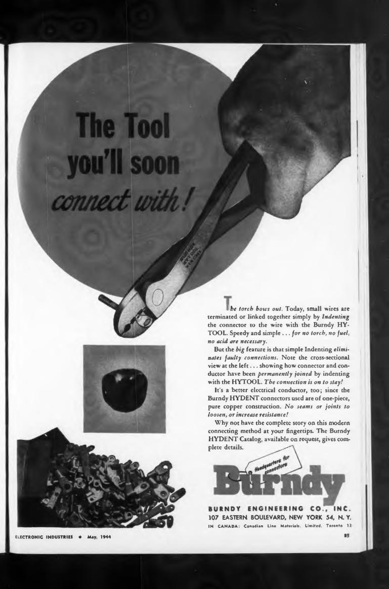
I be torch hows out, Today, small wires are terminated or linked together simply by Indenting the connector to the wire with the Burndy HY- TOOL. Speedy and simple ... for no torch, no fuel, no acid are necessary.
But the big feature is that simple Indenting eltmi' nates faulty connections. Note the cross-sectional view at the left... showing how connector and conductor have been permanently joined by indenting with the HYTOOL. The connection is on to stay!
It’s a better electrical conductor, too; since the Burndy HYDENT connectors used are of one-piece, pure copper construction. No seams or joints to loosen, or increase resistance!
Why not have the complete story on this modern connecting method at your fingertips. The Burndy HYDENT Catalog, available on request, gives complete details. ... - '
ELECTRONIC INDUSTRIES • May, 1944
107 EASTERN BOULEVARD, NEW YORK 54, N. Y.IN CANADA: Canadian Line Materials, Limited, Toronto 13
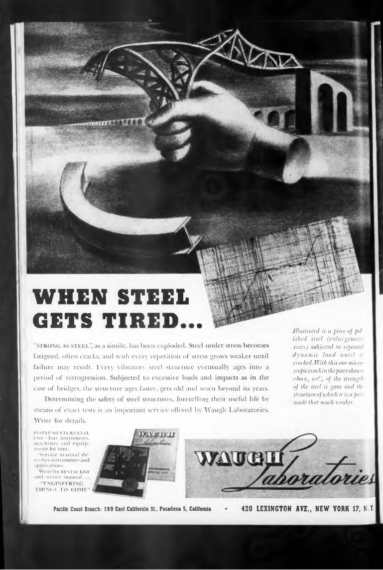
WHEN STEELGETS TIRED
the structure ages faster
Pacific Coast Branch: 180 East California St, Pasadena 5, California
MN Ml ItST
period of reti case of bridge:
420 LEXINGTON AVE., NEW YORK 17, NY
ts old and worn beyond its years, cs, foretelling their useful life by
fatigued, often cracks, and with every repetition of stress grows weaker until failure may result. Every vibratory steel structure eventually ages into a
Illustrated is a piece of polished steel (enlargement lozx) subjected to repeated dynamic load until it cracked. With this one micro scopiccrackin the pieceshown above, 50% °f I he strength of the steel is gone and the structure of which it is a pa i' made that much weaker.
means of exact tests is an important service offered by Waugh Laboratories Write for details.
ISsTRl MENTS RENTAL list—lists instruments, machines and equipments for rent.
Service manual describes instruments and applications.
Write for RENTAL LIST and service manual ...
ENGINEERINGTHINGS TO COME”
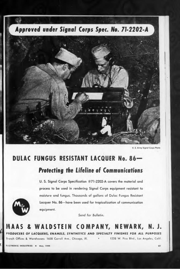
DULAC FUNGUS RESISTANT LACQUER No. 86
moisture and fungus. Thousands of gallons of Dulac Fungus Resistant
equipment.Send for Bulletin
MAAS & WALDSTEIN COMPANYPRODUCERS OF LACQUERS, ENAMELS, SYNTHETICS AND SPECIALTY FINISHES FOR ALL PURPOSES
Branch Offices & Warehouses: 1658 Carroll Ave., Chicago, III 1228 W. Pico Blvd., Los Angeles, Calif.
ELECTRONIC INDUSTRIES * May, 1944
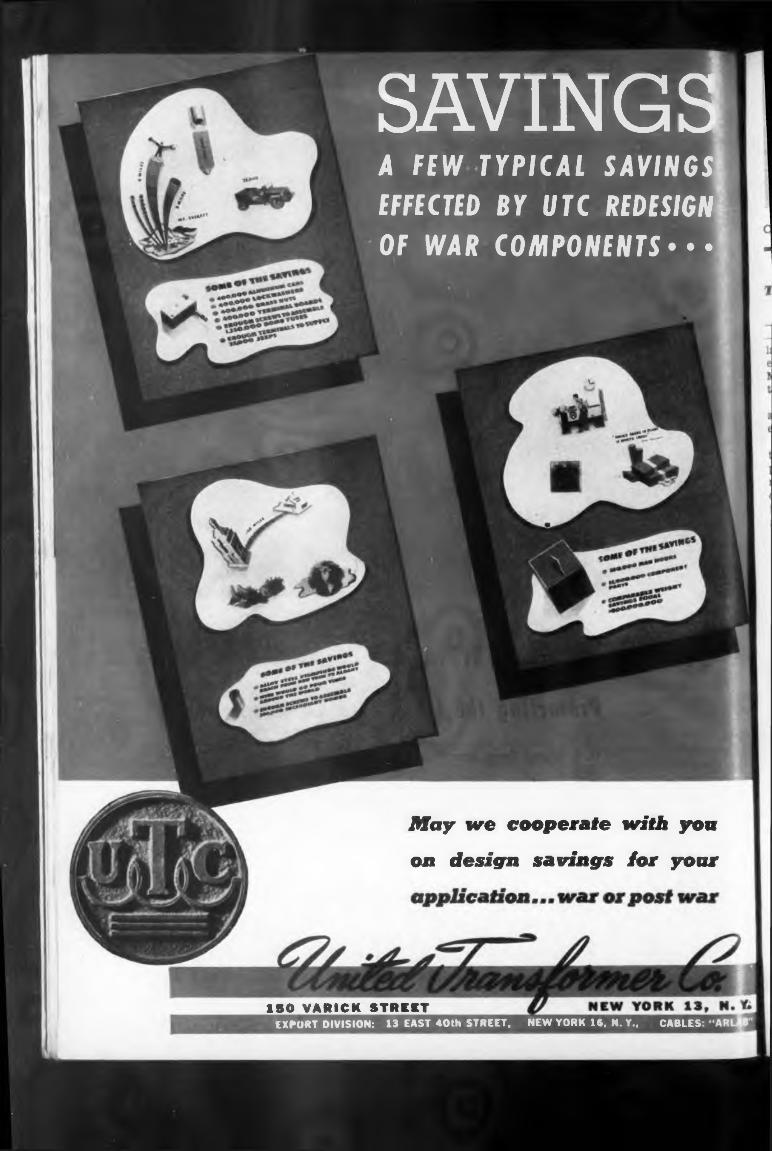
ISO VARICK STREET
May we cooperate with yon on design savings for your
SAVINGSA FEW TYPICAL SAVINGS EFFECTED BY UTC REDESIGN OF WAR COMPONENTS •• •
EXPORT DIVISION: 13 EAST 40th STREET, NEW YORK 16, N. Y., CABLES
O. H CALDWELL, EDITOR M. CLEMENTS, PUBLISHER
Tube* us Instruments of Precision
T* acqaaia* oar readers generally, with the electronic development which I* now tahlng place in varioas sections of the United States, the editors plan to present in coming fanes a series of reports on electronic production facilities, products, and operations in principal U.S. electronic centers.
learn a lot) he can occasionally carry back into research, design, and development—to the benefit of all concerned
480 LEXINGTON AVE., NEW YORK (17), N Y
First of sock regional studios will be our Callforsia Issue, scheduled for next month, June. This number will afford a complete survey of the electronic development, resources, output and personnel of the Golden State.
NEXT MONTH-REPORTING CALIFORNIA!
Regarding tubes, there are two things to remember: (1) A tube is one of the cheapest Instruments of precision that can be found, for its development costs have been spread over a sale of many millions.
(2) A tube will generally function to make a less precise and more bulky mechanism do the work of some delicate mechanism that was formerly a problem even to a watchmaker.
Electronic-tube engineers are learning the details of industrial instrumentation and control, and production men no longer become scared by even the thought of a “fragile vacuum tube” in a device. When this interchange of thinking-methods is more complete, both may have the same motto: When some unusual effect has to be provided, find out some way to make an electron tube do it. 4
LLtCTRONIC INDUSTRI» • May, 1944
Wider Executive Usefulness for EngineersMore and more, as the electronic arts expand, the
engineer is needed broadly in Industrial management, —all the way through production, distribution and application, as charted on a following page. Engineering leadership in all the functions of management, will pay big dividends to the engineer, to his Individual firm, and to society in general
Too often has the engineer “built a wonderland" and then let others run it. They have not always run it well. The engineer must lend a hand in tomorrow’s steering. What he learns in the process (and he will
The Stuff Stands Up!The American high command in the Pacific theater
—Admirals Nimitz and Halsey and General MacArthur —have never had their operations delayed through the lack of adequate and efficient communications-radio equipment! This was the word brought back by Major General Harry C. Ingles. Chief Signal Officer of the Army.
General Ingles declared he found no critical shortages of any types of communications-radio-electronic equipment to exist in the Pacific combat zones
The radio apparatus takes an awful beating from the jungles, he related, and only through the waterproofing and fungi-pro tec tive measures does the equipment stand up. Dry-cell batteries have to be kept in cold storage. In unloading in nets into barges and in standing on the beaches in rain for days, the radio sets are given the toughest treatment, but they come through.
The blanketing effect of wet jungles cuts down the range of the mobile radio apparatus, especially walkie- talkies. It often reduces the distance by one-half.
Feet on the Ground, Everybody!It may be a surprise to some of our industrial read
ers that one of our objectives is to acquaint tube- minded engineers with the fact that there are actually other ways of doing certain jobs than by using tubes! Actually in many places tube men have of late made use of air-operated, or magnetic, or motor-driven devices, instead of tubes. And on the other hand, industrial control engineers are becoming used to tubes.
Efficiency and reliability are expensively-purchased components in any design of industrial control, especially when an intricate and precise mechanism is needed.
ELECTRONIC INDUSTRIES
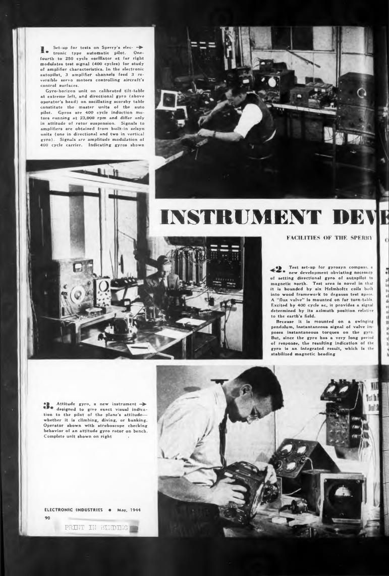
■ Set-up for tests on Sperry's elec- -► ■ * tronic type automatic pilot. Onefourth to 250 cycle oscillator at far right modulates test signal (400 cycles) for study of amplifier characteristics. In the electronic autopilot, 3 amplifier channels feed 3 reversible servo motors controlling aircraft’s control surfaces.
Gyro-horizon unit on calibrated tilt-table at extreme left, and directional gyro (above operator’s head) on oscillating scorsby table constitute the master units of the auto pilot. Gyros are 400 cycle induction motors running at 23,000 rpm and differ only in attitude of rotor suspension. Signals to amplifiers are obtained from built-in selsyn units (one in directional and two in vertical gyro). Signals are amplitude modulation of 400 cycle carrier. Indicating gyros shown
INSTRUMENT DEVFACILITIES OF THE SPERM
•> Attitude gyro, a new instrument —► designed to give exact visual indica
tion to the pilot of the plane’s attitude— whether it is climbing, diving, or banking. Operator shown with stroboscope checking behavior of an attitude gyro rotor on bench. Complete unit shown on right •
ELECTRONIC INDUSTRIES • May, 1944
90
PRUIT III BINDING ■
0^ Test set-up for gyrosyn compass, a • new development obviating necessity
of setting directional gyro of autopilot to magnetic north. Test area is novel in that it is bounded by six Helmholtz coils built into wood framework to degauss test space. A “flux valve*’ is mounted on far turn-table. Excited by 400 cycle ac, it provides a signal determined by its azimuth position relative to the earth’s field.
Because it is mounted on a swinging pendulum, instantaneous signal of valve imposes instantaneous torques on the gyro. But, since the gyro has a very long period of response, the resulting indication of the gyro is an integrated result, which is the stabilized magnetic heading
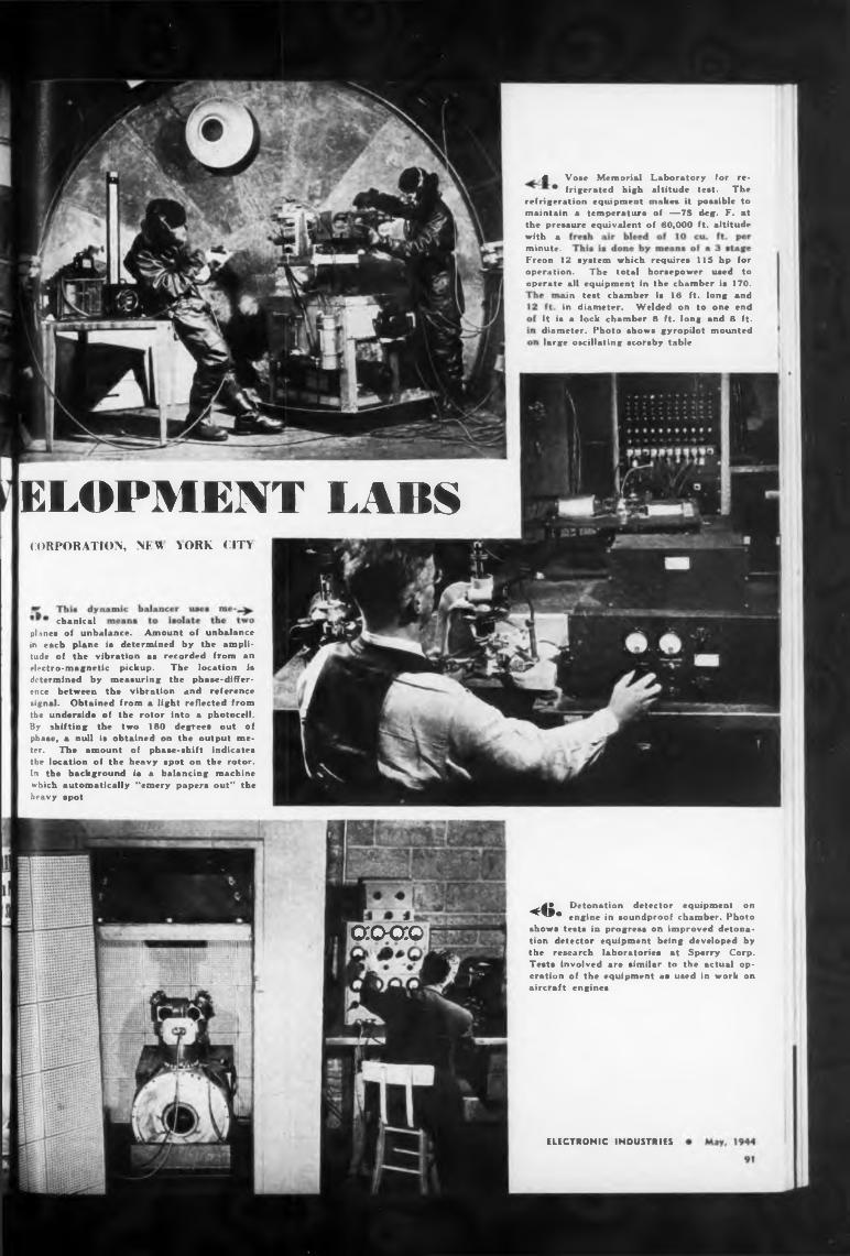
ELOPMENT LABS
chanical
acxxo
ELECTRONIC INDUSTRIES
it is a lock chamber 8 ft. long and 8 ft. diameter. Photo shows gyropilot mounted large oscillating scorsby table
CORPORATION, NFU YORK CITY
ain test chamber is 16 ft. long and in diameter. Welded on to one end
with a minute.
4 Vose Memorial Laboratory for re- • frigerated high altitude test. The
refrigeration equipment makes it possible to maintain a temperature of —75 deg. F. at the pressure equivalent of 60,000 ft. altitude
Freon 12 system which requires 115 bp for operation. The total horsepower used to operate all equipment in the chamber is 170.
<6. Detonation detector equipment on engine in soundproof chamber. Photo
shows tests in progress on improved detonation detector equipment being developed by the research laboratories at Sperry Corp. Tests involved are similar to the actual operation of the equipment as used in work on aircraft engines
planes of unbalance. Amount of unbalance in each plane ia determined by the amplitude of the vibration as recorded from an electro-magnetic pickup. The location is determined by measuring the phase-difference between the vibration and reference signal. Obtained from a light reflected from the underside of the rotor into a photocell. By shifting the two 180 degrees out of phase, a null is obtained on the output meter. The amount of phase-shift indicates the location of the heavy spot on the rotor. In the background ia a balancing machine which automatically “emery papers out" the heavy spot
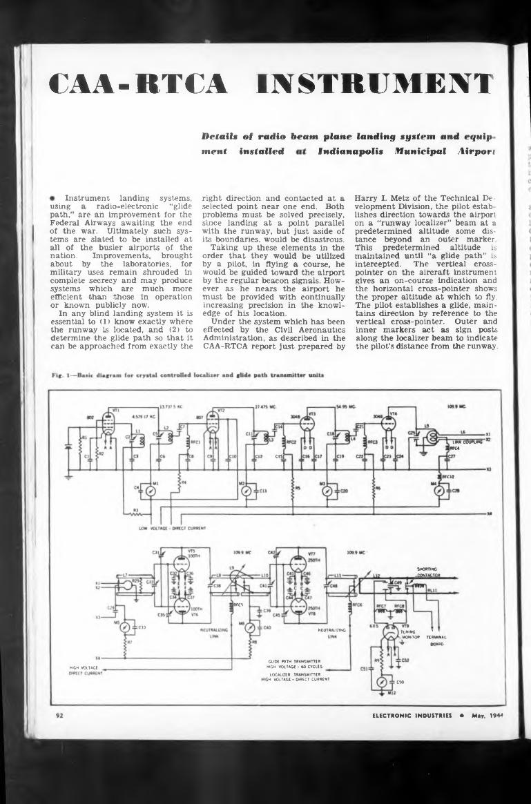
INSTRUMENTCAA-RTCADetails of radio beam plane landing system and equip
Indianapolis Municipal Airport
radio-electronicare an improvement for the
CIS]
weit
RFCS
C30NEUTRALIZING
HIGH VOLTAGE
C50
airport he continually the knowl-
using path/
Under the system which has been effected by the Civil Aeronautics Administration, as described in the CAA-RTCA report just prepared by
systems, “glide
ever as he nears the must be provided with increasing precision in edge of his location.
Instrument landing
ment installed
right direction and contacted at a selected point near one end. Both problems must be solved precisely, since landing at a point parallel with the runway, but just aside of its boundaries, would be disastrous.
Taking up these elements in the order that they would be utilized by a pilot, in flying a course, he would be guided toward the airport by the regular beacon signals. How-
SHORTING-factor
LMK COWFUNGIRFC*
Harry I. Metz of the Technical Development Division, the pilot estab lishes direction towards the airport on a “runway localizer” beam at a predetermined altitude some distance beyond an outer marker This predetermined altitude is maintained until “a glide path” is intercepted. The vertical crosspointer on the aircraft instrument gives an on-course indication and the horizontal cross-pointer shows the proper altitude at which to fly. The pilot establishes a glide, maintains direction by reference to the vertical cross-pointer. Outer and inner markers act as sign posts along the localizer beam to indicate the pilot’s distance from the runway
ELECTRONIC INDUSTRIES • M«y, 194*
Federal Airways awaiting the end of the war. Ultimately such systems are slated to be installed at all of the busier airports of the nation. Improvements, brought about by the laboratories, for military uses remain shrouded in complete secrecy and may produce systems which are much more efficient than those in operation or known publicly now.
In any blind landing system it is essential to (1) know exactly where the runway is located, and (2) to determine the glide path so that it can be approached from exactly the
TUNING '.MONITOR TERMINAI + KARO
GLIDE PATH TRANSMITTERHIGH VOLTAGE - 60 CYCLES
LOCALIZER TRANSMITTER ¡H VOLTAGE - DIRECT CURRENT
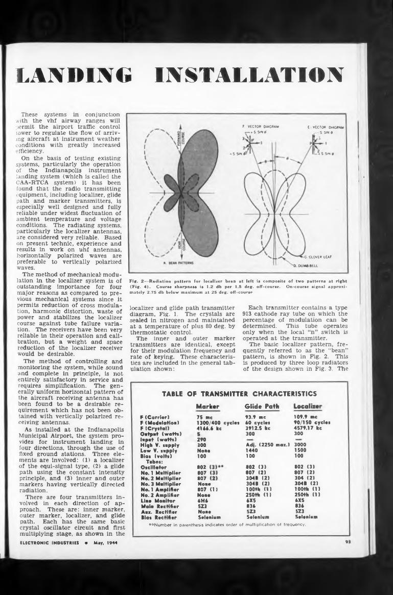
LANDING INSTALLATIONconjunction
♦ S Sin dS SINS
•c. CLOVER LEAF
D DUMBBELL
switch isonly when the local
OF TRANSMITTER CHARACTERISTICSTABLE
Glide PathMarker
»«Number in parenthesis indicates order of multiplication of frequency.
3000 1500100
These systems
75 me 1300/400 cycles 4166.6 kc
Adj. (2250 mai.) 1440 100
802807807
109.9 me 90/150 cycle* 4579.17 kc 300
Nome 807 <13 Nome 6H6 5Z3 None Selenium
802 (3) 807 (2) 3048 (21 3048 (2) 100th (1) 250th (1) 6X5 836 5Z3 Selenium
93.9 me 60 eyelet 3912.5 kc 300
Each transmitter contains a type 913 cathode ray tube on which the percentage of modulation can be determined. This tube operates
F (Carrier) F (Modulation) F (Crystal) Output (watts) Input (watts) High V. supply Low V. supply Blas (volts)
Tubes: Oscillator No. 1 Multiplier No. 2 Multiplier No. 3 Multiplier No. 1 Amplifier No. 2 Amplifier Line Monitor Main Rectifier Aux. Rectifier Bias Rectifier
802 (3) 807 (2) 304 (2) 304B (2) 100th (1) 250th (1) 6X5 836 5Z3 Selenium
localizer and glide path transmitter diagram, Fig. 1. The crystals are sealed in nitrogen and maintained at a temperature of plus 80 deg. by thermostatic control.
The inner and outer marker transmitters are identical, except for their modulation frequency and rate of keying. These characteristics are included in the general tabulation shown:
290 300 Nona 100
F. VECTOR DIAGRAM r— +S SINS'
Fig. 2—Radiation pattern for localizer bean at left is composite of two patterns at right (Fig. 4). Course sharpness is 1.2 db per 1.5 deg. off-course. On-course signal approximately 2.75 db below maximum at 25 deg. off-course
operated at the transmitter.The basic localizer pattern, fre
quently referred to as the “bean” pattern, is shown in Fig. 2. This is produced by three loop radiators of the design shown in Fig. 3. The
ELECTRONIC INDUSTRIES • May, 1944
E VECTOR DIAGRAM r--S SIN 0
with the vhf airway ranges will permit the airport traffic control tower to regulate the flow of arriving aircraft at instrument weather conditions with greatly increased >fficiency.
On the basis of testing existing systems, particularly the operation of the Indianapolis instrument landing system (which is called the CAA-RTCA system) it has been found that the radio transmitting equipment, including localizer, glide path and marker transmitters, is especially well designed and fully reliable under widest fluctuation of ambient temperature and voltage conditions. The radiating systems, particularly the localizer antennas, are considered very reliable. Based on present technic, experience and results in work on uhf antennas, horizontally polarized waves are preferable to vertically polarized waves.
The method of mechanical modulation in the localizer system is of outstanding importance for four major reasons as compared to previous mechanical systems since it permits reduction of cross modulation, harmonic distortion, waste of power and stabilizes the localizer course against tube failure variation. The receivers have been very reliable in their operation and calibration, but a weight and space reduction of the localizer receiver would be desirable.
The method of controlling and monitoring the system, while sound and complete in principle, is not entirely satisfactory in service and requires simplification. The generally uniform horizontal pattern of the aircraft receiving antenna has been found to be a desirable requirement which has not been obtained with vertically polarized receiving antennas.
As installed at the Indianapolis Municipal Airport, the system provides for instrument landing in four directions, through the use of fixed ground stations. Three elements are involved: (1) a localizer of the equi-signal type, (2) a glide path using the constant intensity principle, and (3) inner and outer markers having vertically directed radiation.
There are four transmitters involved in each direction of approach. These are: inner marker, outer marker, localizer, and glide path. Each has the same basic crystal oscillator circuit and first multiplying stage, as shown in the
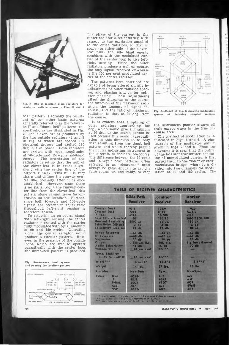
a spacing of
thereferred toalways be great enough to avoid a false course or, preferably, to keep
outer radiators approaching 180 deg., which would give a minimum at 90 deg. to the course, cannot be used because this would cause radiation in this direction to be only that resulting from the dumb-bell pattern and would thereby permit the course indicating instrument in the aircraft to indicate on-course. The difference between the 90-cycle and 150-cycle bean patterns, often
of maximum90 deg. from
‘clearance,” mustenergy. The orientation
bean pattern is actually the resultant of two other basic patterns generally referred to as the “cloverleaf” and “dumb-bell” patterns, respectively, as are illustrated in Fig.2. The clover-leaf is produced by the two outside radiators (2 and 3 in Fig. 5) which are spaced 165 electrical degrees and excited 180 deg. out of phase. Both radiators are excited with equal amplitudes of 90-cycle and 150-cycle sideband
Fig. 3—One of localizer beam radiator« for producing pattern shown in Figs. 2 and 4
ELECTRONIC INDUSTRIES e May, 1944
the instrument pointer always off scale except when in the true on- course area.
The method of modulation is illustrated in Figs. 5 and 6. A photograph of the modulator unit is given in Figs. 7 and 8. From the diagrams it is seen that the output of the localizer transmitter, consisting of unmodulated carrier, is first passed through the “lower or crossmodulation bridge” where it is divided into two channels for modulation at 90 and 150 cycles. The
radiators is set so that the null of the clover-leaf is in exact alignment with the center line of the airport runway. This null is very sharp and defines the runway center line precisely after it is once established. However, since there is no signal along the runway center line from the clover-leaf, this pattern alone cannot serve for operation as the localizer. Further, since both 90-cycle and 150-cycle signals are present in equal ratio throughout, left-right sensing is therefore absent.
To establish an on-course signal with left-right sensing, the center radiator is excited with the carrier fully modulated with equal amounts of 90 and 150 cycles. Operating alone, the center radiator would produce a circular pattern. However, in the presence of the outside loops, which are free to operate parasitically with the center loop, the dumb-bell pattern is produced.
The phase of the current in the center radiator is set at 90 deg. with respect to the excitation supplied to the outer radiators, so that in space (to either side of the cloverleaf null) the side band energy combines with the modulated carrier of the center loop to give leftright sensing. Since the outer radiators produce a null on-course, the only signal received on-course is the 100 per cent modulated carrier of the center radiator.
The patterns here described are capable of being altered slightly by adjustment of outer radiator spacing and phasing and center radiator phasing. These adjustments affect the sharpness of the course, the direction of the maximum radiation, the amount of signal on-course, and the ratio radiation to that at the course.
It is evident that
Fig. 5—Antenna feed system and phasing for localizer pattern
Audio selectivity value at freq. 25 per cent below resonance.Localiser vertical pointer movement in degrees.Std aircraft length and height is 19-7/16 x 7-11/16 in.
TABLE OF RECEIVER CHARACTERISTICS
Olid« Path Receiver
LocaliserReceiver
Marker Receiver
Carrier (Me) 93.9 109.9 75.0Crystal (he) 7298 8325 7430.5IF (kc) 4325 10.000 4325Fa»« Filters (cycle* 1 Nominal Sensitivity Selectivity (40 kc)
«0 110/90 3000/1300/4002500 m*. 50 M*- 150 M*.
3 db 3 db 4 dbSelectivity (300 kel 40 db 40 db 40 dbImage Response —40 db —40 db —40 dbIF Response - 4b —40 db —40 dbSig./noise 30 db 30 db 30 dbOutput 0-400 fsa, d.e. Bal. d.e. Sig. lamp It auralAudio Selectivity* 15 db 15 db 20 dbVoltage Stability +10 per cent 0.5°**Temp. Stability
(—40 to -f-40°Cl +10 per cent 3.5°**Widtb*** 5-3/14" 10-3/8" 5-3/14"Weight 14 lbs. 27 Ibs. 15 lbs.V’brator Non-Syne. Sync. Non-Syae.Tubes: Mod. 6C4G 4J7 4J7
IF. 4SJ7 4SK7 4J72nDet. 4SQ7 4SQ7 4Ç7And. 4R7 4J5 4V4GOSC. 4C4G 4N7 ‘H’
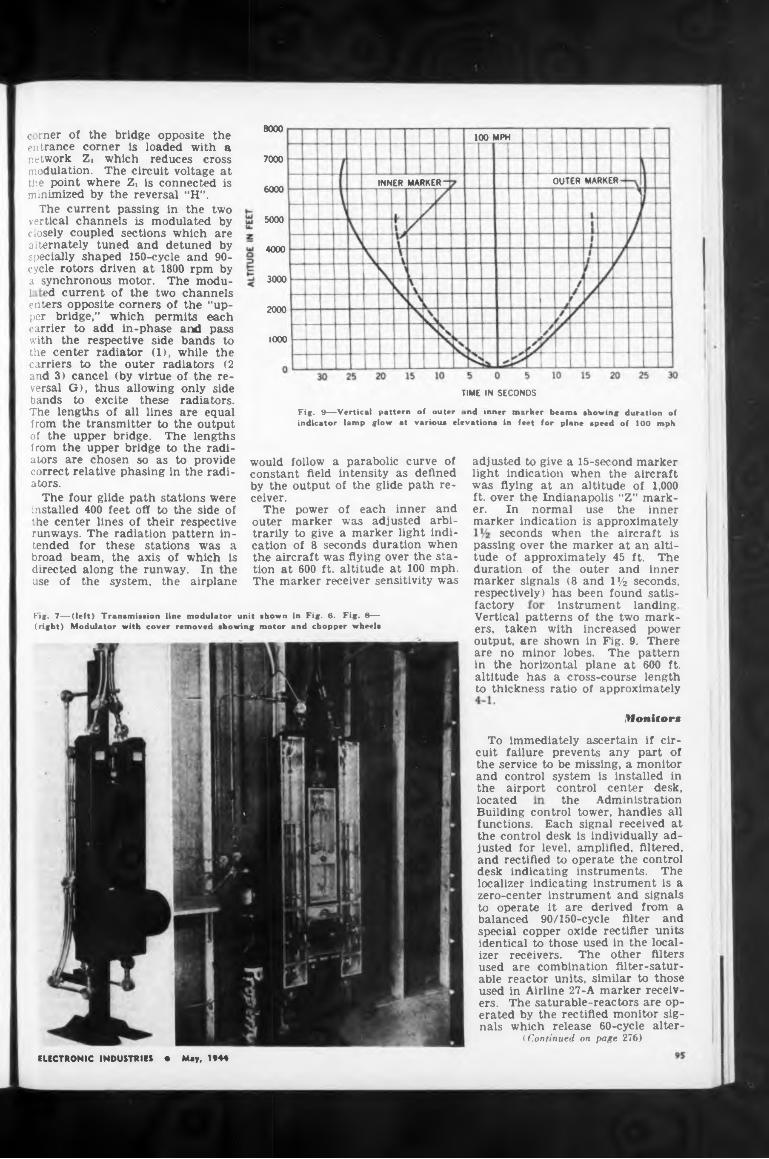
8000100 MPH
7000
OUTER MARKERINNER MARKER6000
5000
4000
3000
2000
1000
TIME IN SECONDS
factory instrument landing
Monitor*
located
To immediately ascertain if circuit failure prevents any part of the service to be missing, a monitor and control system is installed in the airport control center desk,
the Administration
Fig. 7—(left) Transmission line modulator unit shown in Fig. 6. Fig. 8— (right) Modulator with cover removed showing motor and chopper wheels
would follow a parabolic curve of constant field intensity as defined by the output of the glide path receiver.
The power of each inner and outer marker was adjusted arbitrarily to give a marker light indication of 8 seconds duration when the aircraft was flying over the station at 600 ft. altitude at 100 mph. The marker receiver sensitivity was
Vertical patterns of the two markers, taken with increased power output, are shown in Fig. 9. There are no minor lobes. The pattern in the horizontal plane at 600 ft. altitude has a cross-course length to thickness ratio of approximately
ELECTRONIC INDUSTRIES • May, 1944
adjusted to give a 15-second marker light indication when the aircraft was flying at an altitude of 1,000 ft. over the Indianapolis “Z” marker. In normal use the inner marker indication is approximately
seconds when the aircraft is passing over the marker at an altitude of approximately 45 ft. The duration of the outer and inner marker signals (8 and iy2 seconds, respectively) has been found satis-
Building control tower, handles all functions. Each signal received at the control desk is individually adjusted for level, amplified, filtered, and rectified to operate the control desk indicating instruments. The localizer indicating instrument is a zero-center instrument and signals to operate it are derived from a balanced 90/150-cycle filter and special copper oxide rectifier units identical to those used in the localizer receivers. The other filters used are combination filter-saturable reactor units, similar to those used in Airline 27-A marker receivers. The saturable-reactors are operated by the rectified monitor signals which release 60-cycle alter-
(Continued on page 276)
c rner of the bridge opposite the entrance corner is loaded with a rutwork Zi which reduces cross modulation. The circuit voltage at the point where Zi is connected is minimized by the reversal “H”.
The current passing in the two vertical channels is modulated by mosely coupled sections which are jiternately tuned and detuned by specially shaped 150-cycle and 90- cycle rotors driven at 1800 rpm by a synchronous motor. The modu- 1 ed current of the two channels enters opposite comers of the “upper bridge,” which permits each carrier to add in-phase and pass with the respective side bands to the center radiator (1), while the carriers to the outer radiators (2 and 3) cancel (by virtue of the reversal G), thus allowing only side bands to excite these radiators. The lengths of all lines are equal from the transmitter to the output of the upper bridge. The lengths from the upper bridge to the radiators are chosen so as to provide correct relative phasing in the radiators.
The four glide path stations were installed 400 feet off to the side of the center lines of their respective runways. The radiation pattern intended for these stations was a broad beam, the axis of which is directed along the runway. In the use of the system, the airplane
Fig. 9—Vertical pattern of outer ind inner marker beam* showing duration of indicator lamp glow at various elevations in feet for plane speed of 100 mph
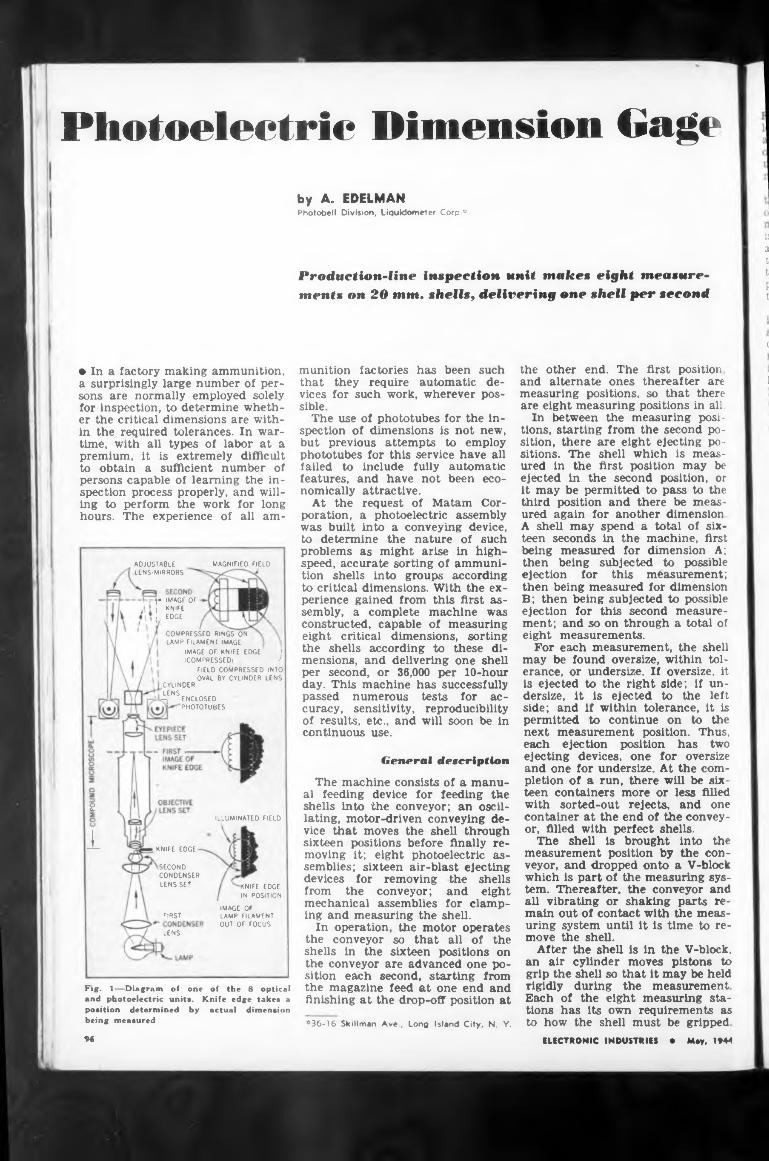
Photoelectric Dimension Gageby A. EDELMANPhotobell Division, Liquidometer Corp *
Production-line inspection unit makes eight measurements on 20 mm. shells, delivering one shell per second
if a t tP t
c
• In a factory making ammunition, a surprisingly large number of persons are normally employed solely for inspection, to determine whether the critical dimensions are within the required tolerances. In wartime, with all types of labor at a premium, it is extremely difficult to obtain a sufficient number of persons capable of learning the inspection process properly, and willing to perform the work for long hours. The experience of all am-
j* IMAGE OF I KNIFE , EDGE
adjustable magnified field LENS-MIRRORS
COMPRESSED RINGS ON LAMP FILAMENT IMAGE
IMAGE OF KNIFE EDGE I(COMPRESSED) /
FIELD COMPRESSED INTO OVAL BY CYLINDER LENS
CYLINDER LENS -j ENCLOSED
PHOTOTUBES
2ILLUMINATED FIELD
1 KNIFE EDGE
SECOND CONDENSER LENS SET
FIRST
KNIFE EDGE IN POSITION
IMAGE OF LAMP FILAMENT OUT OF FOCUS
LENS
Fig. 1—Diagram of one of the 8 optical and photoelectric unit*. Knife edge take* a position determined by actual dimension being measured
9<
munition factories has been such that they require automatic devices for such work, wherever possible.
The use of phototubes for the inspection of dimensions is not new, but previous attempts to employ phototubes for this service have all failed to include fully automatic features, and have not been eco- nomically
At the poration, was built
attractive.request of Matam Cora photoelectric assembly into a conveying device,
to determine the nature of such problems as might arise in highspeed, accurate sorting of ammunition shells into groups according to critical dimensions. With the experience gained from this first assembly, a complete machine was constructed, capable of measuring eight critical dimensions, sorting the shells according to these dimensions, and delivering one shell per second, or 36,000 per 10-hour day. This machine has successfully passed numerous curacy, sensitivity, of results, etc., and continuous use.
tests for ac- reproducibility
will soon be in
General description
The machine consists of a manual feeding device for feeding the shells into the conveyor; an oscillating, motor-driven conveying device that moves the shell through sixteen positions before finally removing it; eight photoelectric assemblies; sixteen air-blast ejecting devices for removing the shells from the conveyor; and eight mechanical assemblies for clamping and measuring the shell.
In operation, the motor operates the conveyor so that all of the shells in the sixteen positions on the conveyor are advanced one position each second, starting from the magazine feed at one end and finishing at the drop-off position at
*36-16 Skillman Ave., Long Island City, N. Y.
the other end. The first position and alternate ones thereafter are measuring positions, so that there are eight measuring positions in all.
In between the measuring positions, starting from the second position, there are eight ejecting positions. The shell which is measured in the first position may be ejected in the second position, or it may be permitted to pass to the third position and there be measured again for another dimension A shell may spend a total of sixteen seconds in the machine, first being measured for dimension A; then being subjected to possible ejection for this measurement; then being measured for dimension B; then being subjected to possible ejection for this second measurement; and so on through a total of eight measurements.
For each measurement, the shell may be found oversize, within tolerance, or undersize. If oversize, it is ejected to the right side; if undersize, it is ejected to the left side; and if within tolerance, it is permitted to continue on to the next measurement position. Thus, each ejection position has two ejecting devices, one for oversize and one for undersize. At the completion of a run, there will be sixteen containers more or less filled with sorted-out rejects, and one container at the end of the conveyor, filled with perfect shells.
The shell is brought into the measurement position by the conveyor, and dropped onto a V-block which is part of the measuring system. Thereafter, the conveyor and all vibrating or shaking parts remain out of contact with the measuring system until it is time to remove the shell.
After the shell is in the V-block, an air cylinder moves pistons to grip the shell so that it may be held rigidly during the measurement Each of the eight measuring stations has its own requirements as to how the shell must be gripped
ELECTRONIC INDUSTRIES • May, 1944
1
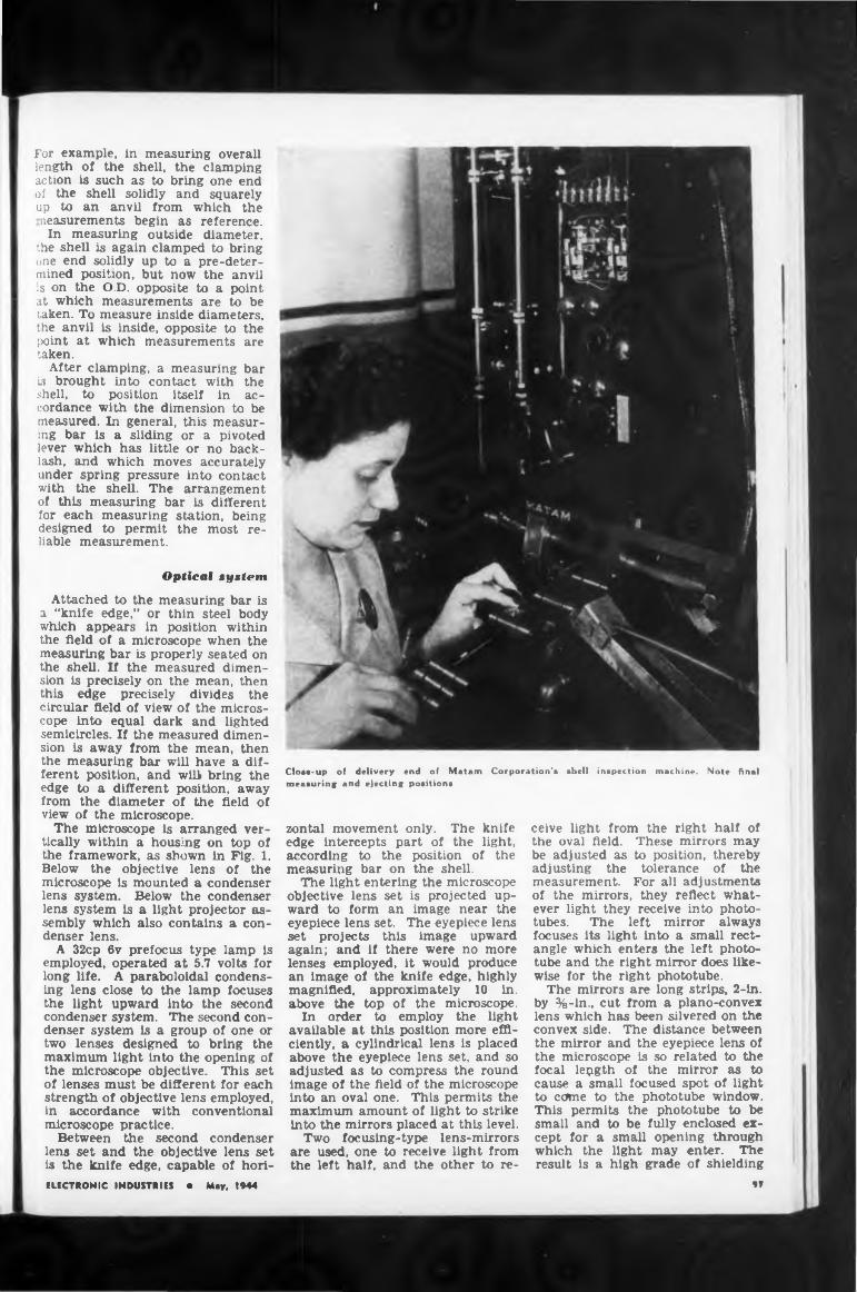
For example, in measuring overall length of the shell, the clamping action is such as to bring one end of the shell solidly and squarely up to an anvil from which the neasurements begin as reference.
In measuring outside diameter, the shell is again clamped to bring one end solidly up to a pre-deter- mined position, but now the anvil is on the O.D. opposite to a point at which measurements are to be taken. To measure inside diameters, the anvil is inside, opposite to the point at which measurements are taken.
After clamping, a measuring bar is brought into contact with the shell, to position itself in accordance with the dimension to be measured. In general, this measuring bar is a sliding or a pivoted lever which has little or no backlash, and which moves accurately under spring pressure into contact with the shell. The arrangement of this measuring bar is different for each measuring station, being designed to permit the most reliable measurement.
Optical system
Attached to the measuring bar is a “knife edge,” or thin steel body which appears in position within the field of a microscope when the measuring bar is properly seated on the shell. If the measured dimension is precisely on the mean, then this edge precisely divides the circular field of view of the microscope into equal dark and lighted semicircles. If the measured dimension is away from the mean, then the measuring bar will have a different position, and will bring the edge to a different position, away from the diameter of the field of view of the microscope.
The microscope is arranged vertically within a housing on top of the framework, as shown in Fig. 1. Below the objective lens of the microscope is mounted a condenser lens system. Below the condenser lens system is a light projector assembly which also contains a condenser lens.
A 32cp 6v prefocus type lamp is employed, operated at 5.7 volts for long life. A paraboloidal condensing lens close to the lamp focuses the light upward into the second condenser system. The second condenser system is a group of one or two lenses designed to bring the maximum light into the opening of the microscope objective. This set of lenses must be different for each strength of objective lens employed, in accordance with conventional microscope practice.
Between the second condenser lens set and the objective lens set is the knife edge, capable of hori-ELECTRONIC INDUSTRIES • May, 1944
Clos«-up of delivery end of Matam Corporation’s shell inspection machine. Note final measuring and ejecting positions
zontal movement only. The knife edge intercepts part of the light, according to the position of the measuring bar on the shell.
The light entering the microscope objective lens set is projected upward to form an image near the eyepiece lens set. The eyepiece lens set projects this image upward again; and if there were no more lenses employed, it would produce an image of the knife edge, highly magnified, approximately 10 in. above the top of the microscope.
In order to employ the light available at this position more efficiently, a cylindrical lens is placed above the eyepiece lens set, and so adjusted as to compress the round image of the field of the microscope into an oval one. This permits the maximum amount of light to strike into the mirrors placed at this level.
Two focusing-type lens-mirrors are used, one to receive light from the left half, and the other to re
ceive light from the right half of the oval field. These mirrors may be adjusted as to position, thereby adjusting the tolerance of the measurement. For all adjustments of the mirrors, they reflect whatever light they receive into phototubes. The left mirror always focuses its light into a small rectangle which enters the left phototube and the right mirror does likewise for the right phototube.
The mirrors are long strips, 2-in. by %-ln., cut from a plano-convex lens which has been silvered on the convex side. The distance between the mirror and the eyepiece lens of the microscope is so related to the focal lepgth of the mirror as to cause a small focused spot of light to come to the phototube window. This permits the phototube to be small and to be fully enclosed except for a small opening through which the light may enter. The result is a high grade of shielding
9T
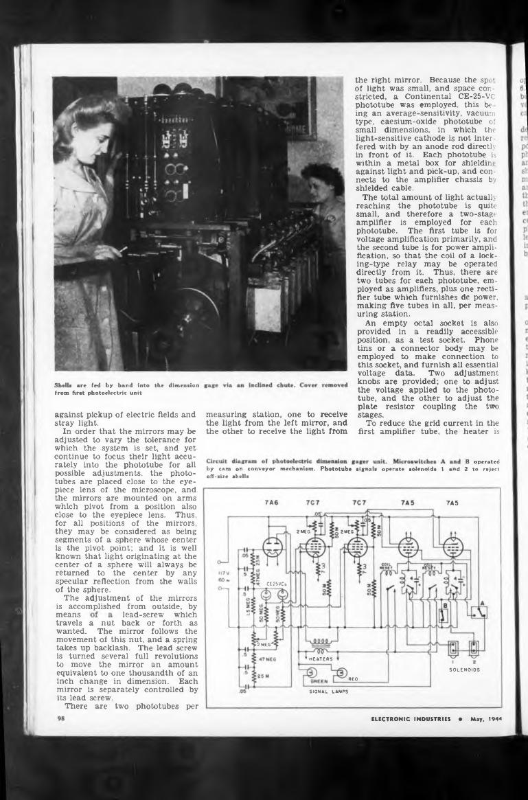
first amplifier tube, the heater is
7A5
2 MEG 2 MEG
CE25VC
of the mirrorsis accomplished from outside, bymeans
2 MEG'
HEATERS
SOLENOIDS
REO
SIGNAL LAMPS
measuring station, one to receive the light from the left mirror, and the other to receive the light from
center by any from the walls
by cam on conveyor mechanism. Phototube signals operate solenoids 1 and off-size shells
lead-screw which
B operated 2 tv reject
against pickup of electric fields and stray light.
In order that the mirrors may be adjusted to vary the tolerance for which the system is set, and yet continue to focus their light accurately into the phototube for all possible adjustments, the phototubes are placed close to the eyepiece lens of the microscope, and the mirrors are mounted on arms which pivot from a position also close to the eyepiece lens. Thus, for all positions of the mirrors, they may be considered as being segments of a sphere whose center is the pivot point; and it is well known that light originating at the center of a sphere will always bereturned to the specular reflection of the sphere.
The adjustment
travels a nut back or forth as wanted. The mirror follows the movement of this nut, and a spring takes up backlash. The lead screw is turned several full revolutions to move the mirror an amount equivalent to one thousandth of an inch change in dimension. Each mirror is separately controlled by its lead screw.
There are two phototubes per
Shelia are fed by hand into the dimension from first photoelectric unit
ELECTRONIC INDUSTRIES • May, 1944
the right mirror. Because the sp< ’ of light was small, and space constricted, a Continental CE-25-VC phototube was employed, this be ing an average-sensitivity, vacuum type, caesium-oxide phototube of small dimensions, in which the light-sensitive cathode is not interfered with by an anode rod directly in front of it. Each phototube is within a metal box for shieldin p against light and pick-up, and connects to the amplifier chassis by shielded cable.
The total amount of light actually reaching the phototube is quite small, and therefore a two-stage amplifier is employed for each phototube. The first tube is for voltage amplification primarily, and the second tube is for power amplification, so that the coil of a locking-type relay may be operated directly from it. Thus, there are two tubes for each phototube, employed as amplifiers, plus one rectifier tube which furnishes de power, making five tubes in all, per measuring station.
An empty octal socket is also provided in a readily accessible position, as a test socket. Phone tins or a connector body may be employed to make connection to this socket, and furnish all essential voltage data. Two adjustment knobs are provided; one to adjust the voltage applied to the phototube, and the other to adjust the plate resistor coupling the two stages.
To reduce the grid current in the
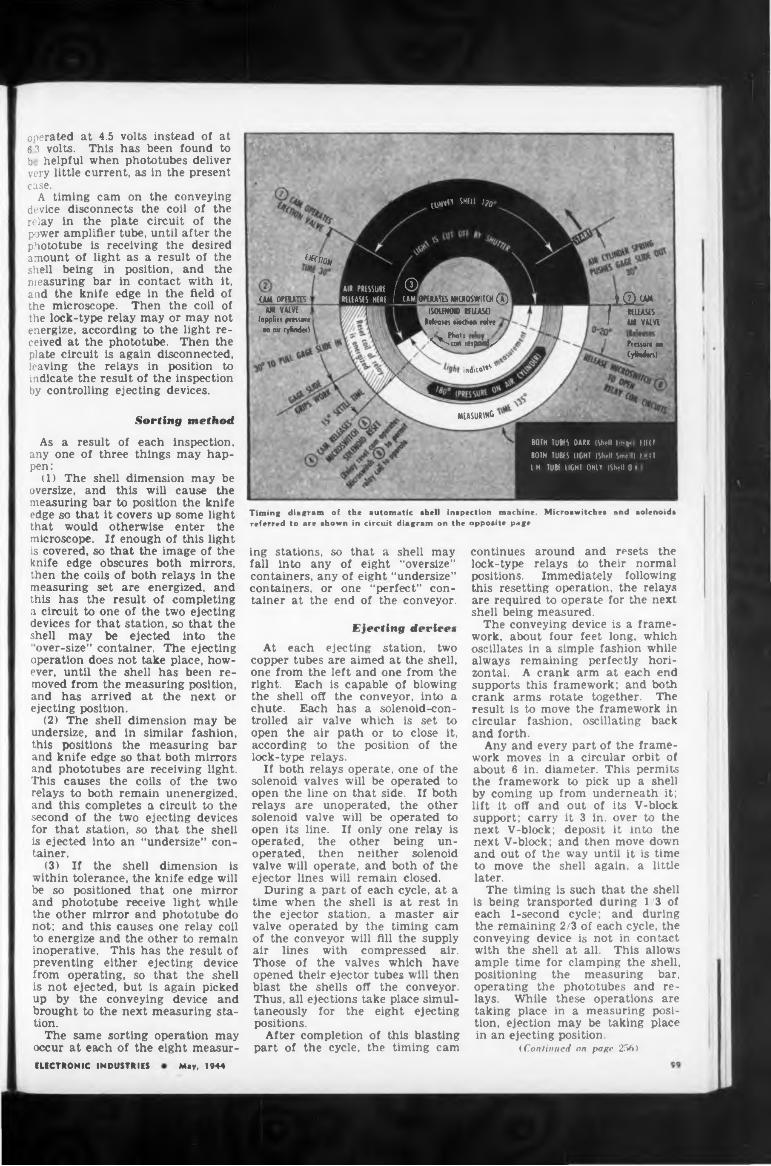
operated at 4.5 volts instead of at 6 3 volts. This has been found to b helpful when phototubes deliver very little current, as in the present case.
A timing cam on the conveying device disconnects the coil of the relay in the plate circuit of the power amplifier tube, until after the phototube is receiving the desired amount of light as a result of the shell being in position, and the measuring bar in contact with it, and the knife edge in the field of the microscope. Then the coil of the lock-type relay may or may not energize, according to the light received at the phototube. Then the plate circuit is again disconnected, leaving the relays in position to indicate the result of the inspection by controlling ejecting devices.
Sorting method
As a result of each inspection, any one of three things may happen:
(1) The shell dimension may be oversize, and this will cause the measuring bar to position the knife edge so that it covers up some light that would otherwise enter the microscope. If enough of this light is covered, so that the image of the knife edge obscures both mirrors, then the coils of both relays in the measuring set are energized, and this has the result of completing a circuit to one of the two ejecting devices for that station, so that the shell may be ejected into the
“over-size” container. The ejecting operation does not take place, however, until the shell has been removed from the measuring position, and has arrived at the next or ejecting position.
(2) The shell dimension may be undersize, and in similar fashion, this positions the measuring bar and knife edge so that both mirrors and phototubes are receiving light. This causes the coils of the two relays to both remain unenergized, and this completes a circuit to the second of the two ejecting devices for that station, so that the shell is ejected into an “undersize” container.
(3) If the shell dimension is within tolerance, the knife edge will be so positioned that one mirror and phototube receive light while the other mirror and phototube do not; and this causes one relay coil to energize and the other to remain inoperative. This has the result of preventing either ejecting device from operating, so that the shell is not ejected, but is again picked up by the conveying device and brought to the next measuring station.
The same sorting operation may occur at each of the eight measur
^TlO*
OPERATES MICEOSWIUH (A)
ind»co'*s
Pr«$w< m CyMtni
ÌSOtfNOIO RELEASE)Ideas« Median yohe
' <% ^,0X^con respond^
MEASURE
CAM OPERATIS i AIR VALVE ,
(applies pressate ' M air cylinder)
I® UM
f «LEASES
I UH VALVE
Timing diagram of the automatic shell inspection machine. Microswitches and solenoids referred to are shown in circuit diagram on the opposite page
BOTH TUBES DARK (Shell Icq. OKI
BOTH TUBES LIGHT (Shell Smell) KU
I H TUB! (IGHT ONLY (Shell 0»
UjHNri SHill i?0
AIR PRESSURE / CD
RELEASES HERE I (AM,
ing stations, so that a shell may fall into any of eight “oversize” containers, any of eight “undersize” containers, or one “perfect” container at the end of the conveyor.
Ejecting devices
At each ejecting station, two copper tubes are aimed at the shell, one from the left and one from the right. Each is capable of blowing the shell off the conveyor, into a chute. Each has a solenoid-controlled air valve which is set to open the air path or to close it, according to the position of the lock-type relays.
If both relays operate, one of the solenoid valves will be operated to open the line on that side. If both relays are unoperated, the other solenoid valve will be operated to open its line. If only one relay is operated, the other being un- operated, then neither solenoid valve will operate, and both of the ejector lines will remain closed.
During a part of each cycle, at a time when the shell is at rest in the ejector station, a master air valve operated by the timing cam of the conveyor will fill the supply air lines with compressed air. Those of the valves which have opened their ejector tubes will then blast the shells off the conveyor. Thus, all ejections take place simultaneously for the eight ejecting positions.
After completion of this blasting part of the cycle, the timing cam
continues around and resets the lock-type relays to their normal positions. Immediately following this resetting operation, the relays are required to operate for the next shell being measured.
The conveying device is a framework, about four feet long, which oscillates in a simple fashion while always remaining perfectly horizontal. A crank arm at each end supports this framework; and both crank arms rotate together. The result is to move the framework in circular fashion, oscillating back and forth.
Any and every part of the framework moves in a circular orbit of about 6 in. diameter. This permits the framework to pick up a shell by coming up from underneath it; lift it off and out of its V-block support; carry it 3 in. over to the next V-block; deposit it into the next V-block; and then move down and out of the way until it is time to move the shell again, a little later.
The timing is such that the shell is being transported during 1/3 of each 1-second cycle; and during the remaining 2/3 of each cycle, the conveying device is not in contact with the shell at all. This allows ample time for clamping the shell, positioning the measuring bar, operating the phototubes and relays. While these operations are taking place in a measuring position, ejection may be taking place in an ejecting position.
(Continued on page 256)
ELECTRONIC INDUSTRIES May, 1944
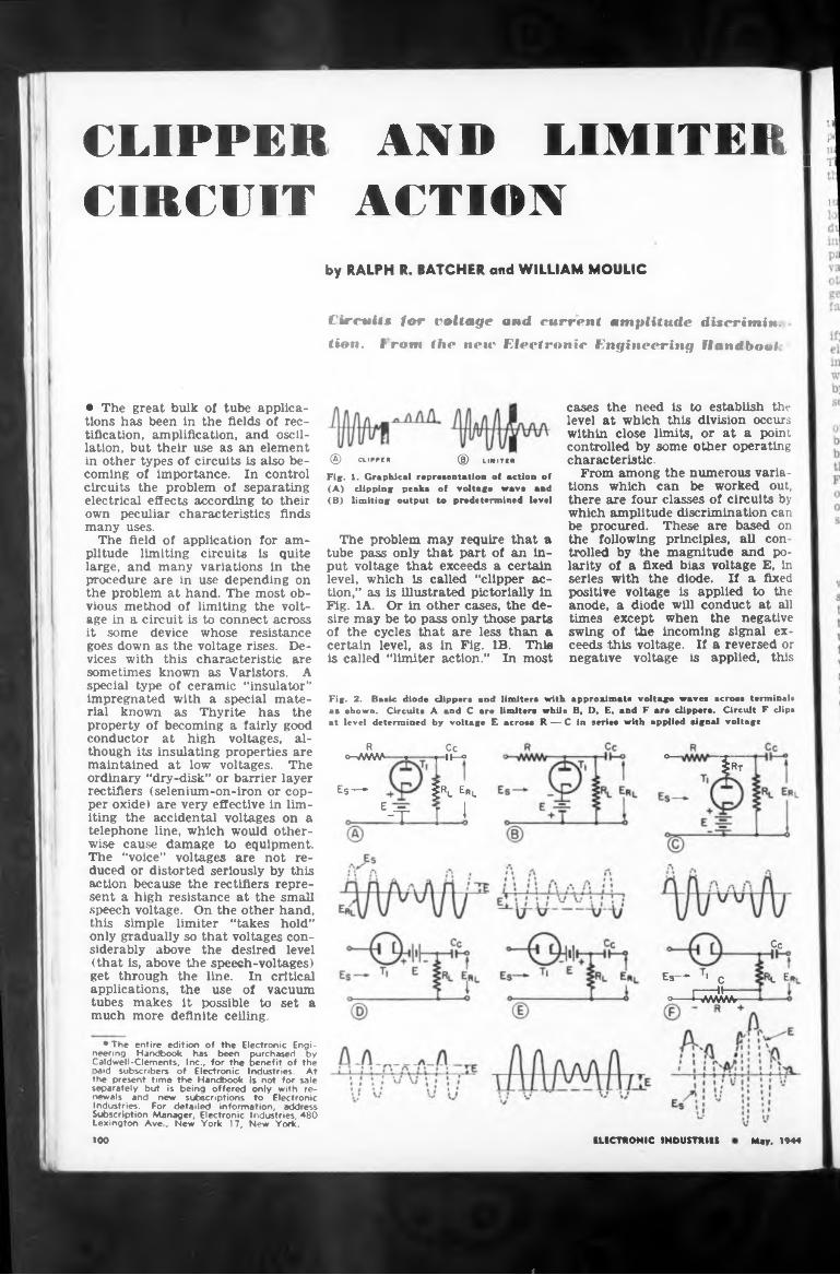
CLIPPER AND LIMITER ?I TI
CIRCUIT ACTION •by RALPH R. BATCHER and WILLIAM MOULIC
Circuits for voltage and current amplitude dUcrimin. tion. f rom the new Electronic Engineering Handball
• The great bulk of tube applications has been in the fields of rectification, amplification, and oscillation, but their use as an element in other types of circuits is also becoming of importance. In control circuits the problem of separating electrical effects according to their own peculiar characteristics finds many uses.
The field of application for amplitude limiting circuits is quite large, and many variations in the procedure are in use depending on the problem at hand. The most obvious method of limiting the voltage in a circuit is to connect across it some device whose resistance goes down as the voltage rises. Devices with this characteristic are sometimes known as Varistors. A special type of ceramic “insulator” impregnated with a special material known as Thyrite has the property of becoming a fairly good conductor at high voltages, although its insulating properties are maintained at low voltages. The ordinary “dry-disk” or barrier layer rectifiers (selenium-on-iron or copper oxide) are very effective in limiting the accidental voltages on a telephone line, which would otherwise cause damage to equipment. The “voice” voltages are not reduced or distorted seriously by this action because the rectifiers represent a high resistance at the small speech voltage. On the other hand, this simple limiter “takes hold” only gradually so that voltages considerably above the desired level (that is, above the speech-voltages) get through the line. In critical applications, the use of vacuum tubes makes It possible to set a much more definite ceiling.
® CLIPPER ® LIMITERFig. 1. Graphical representation of action of (A) clipping peaks of voltage wave and (B) limiting output to predetermined level
The problem may require that a tube pass only that part of an input voltage that exceeds a certain level, which Is called “clipper action,” as is illustrated pictorially in Fig. 1A. Or in other cases, the desire may be to pass only those parts of the cycles that are less than a certain level, as in Fig. IB. Thia Is called “limiter action.” In most
Fig. 2. Basic diode clippers and limiters with approximate voltage waves across terminal* as shown. Circuits A and C are limiters while B, 1), F.. and F are clippers. Circuit F clips at level determined by voltage E across R — C in series with applied signal voltage
R Cc°-/AAAA * j II—°
ES— f% Erl
e-T T 1
cases the need is to establish the level at which this division occurs within close limits, or at a point controlled by some other operating characteristic.
From among the numerous variations which can be worked out, there are four classes of circuits by which amplitude discrimination can be procured. These are based on the following principles, all controlled by the magnitude and polarity of a fixed bias voltage E, in series with the diode. If a fixed positive voltage is applied to the anode, a diode will conduct at all times except when the negative swing of the incoming signal exceeds this voltage. If a reversed or negative voltage is applied, this
°—X — $Rt
Es-* r> c r------ II—
°----hWiWr
Cc
k Er
* The entire edition of the Electronic Engineering Handbook has been purchased by Caldwell-Clements, Inc., for the benefit of the oaid subscribers of Electronic Industries. At the present time the Handbook is not for sale separately but is being offered only with renewals and new subscriptions to Electronic Industries. For detailed information, address Subscription Manager, Electronic Industries, 480 Lexington Ave , New York 17, New York.
100 ELECTRONIC INDUSTRIES May. 1944
a
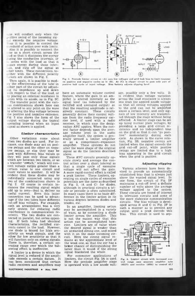
Fig. 3. Pentode limiter circuit at
Input
101
UW
INPUT CUTOFF
tube will conduct only when the positive swing of the incoming signal exceeds the negative voltage. Thus it is possible to control the threshold of action over wide limits.
Also it is possible to connect the tube as a short circuit across the load so that it dissipates the energy during the conductive intervals, or m series with the load so that it passes energy during those intervals, and cuts off the signal at other times. These connections, together with the different polarity factors are shown in Fig. 2.
Then again, it is possible to modify the effectiveness of the tube in either part of the circuit by adjusting its impedance up and down with respect to that of the load, or by placing an external resistance in series with its anode, as in Fig. 2C.
The transfer point with the various combinations shown here can be altered to any point on the wave by altering the bias voltage between the positive and negative extremes. Fig. 2 also shows the form of the output voltage during the typical operating interval when an input signal as shown is applied.
Litniter characteristics
Other variations come about when two diodes are used. For instance, one diode may act on positive swings and the other on negative swings, or else they may be used with different bias values so they will pass only those signals which are between two limits, or as a transfer “svMtch,” which will connect voltage surges greater than a certain value to one circuit and lesser values to another. It will be evident that these diodes may be individually connected using any two of the combinations shown in Fig. 2. Of course in certain instances the resulting signal might add up to zero—that is, deliver no useful current. Even this latter connection can be used to advantage if the two tubes have different cut-off bias voltages. For example, such an arrangement was a very early system for reducing radio interference in communication receivers. The two diodes are connected in parallel, but series opposing. If both tubes had identical characteristics, the rectified currents cancel in the load. However, one diode is biased for high sensitivity on weak signals, and the other for low sensitivity so that it will function only on strong signals. There is, therefore, a certain operating range over which the balancing effect is ineffective.
A limiter is a device In which the signal level is reduced if the amplitude exceeds a certain datum. It has been mentioned that certain radio receivers and amplifiers mayELECTRONIC INDUSTRIES • May, 1944
OUTPUT WAVE
¿OA O
HIIM
(A) use* low voltage* and grid leak bia* to limit reaponaeon poaitive and negative cycle* a* in (B). At (C) i* clipper circuit to paas only part of poaitive half cycle of input voltage. Bia* battery adjust* clipping level
have an automatic volume control feature, where the gain in an amplifier is altered inversely as the signal level (as indicated by the rectified and averaged output) so that the resulting amplitude is relatively constant. These circuits generally derive their control voltage from the radio frequency carrier level, if used with a radio receiver, in which case the designation AVC applies. When the control factor depends upon the average volume level in the audio amplifier itself, the system is generally termed a limiter amplifier or as a compression-expansion amplifier. These systems do not alter the wave shape of the original signal as do the limiters described above.
These AVC circuits generally operate slowly and average the control action over a short interval so that a single cycle of excessive voltage will not affect the gain. A more rapid control effect is called a peak limiter. These limiters, operating on single cycles of excessive potentials are the same as described in Fig. 2, (A and C) for diodes, although in practical circuits a triode or pentode is often substituted. In many cases there is no basic difference in the limiter action in its various degrees between diodes and triodes, etc.
In an amplifier, limiting action may be accomplished in a variety of ways, as by connecting a diode limiter across the amplifier. This is not the easiest way that this action can be accomplished however. Limiters are of value when the desired signal is weaker than an unwanted strong one, and mixed with it on the same incoming circuit. Here the strong signal remains at the approximate level of the weak one, so that the ear has a better chance of distinguishing the latter than it would if the strong signal blanketed the whole.
For commoner applications of limiters, the circuit Fig. 3A is used. Here the pentode amplifier stage is operated with a low anode volt
age, possibly only a few volts. It is evident that voltage variation across the load resistance is always less than the applied anode voltage so that all strong voltages applied to the grid can not be amplified above a certain level, and only signals of low intensity are transmitted through the stage without being affected. A limiter stage can be set up using normal plate voltages, by providing a large grid circuit resistance and no independent bias on the grid so that it can “go positive” momentarily during each cycle. As shown in the curve relation, Fig. 3B, negative swings are limited when the signal exceeds the grid cut-off point, while positive swings are limited due to a high bias appearing in the grid circuit when the grid is positive.
Adjusting clipping
Various schemes have been devised to provide an automatically established bias that is always just above the wanted signal level. In one form, the circuit of Fig. 2F maintains a cut-off level a definite number of volts above the average voltage applied to the system. These circuits are found of interest in television circuits and some of the more elaborate communication circuits. The bias voltage is developed across R and C in Fig. 2F in such a manner as to prevent any output until a peak exceeds this bias. This circuit is used to sep-
+ 50V.
Fig. 4. Limiter circuit with increased control range use* separate amplifier tube (6SJ7) and rectifier (6H6) to control 6L7
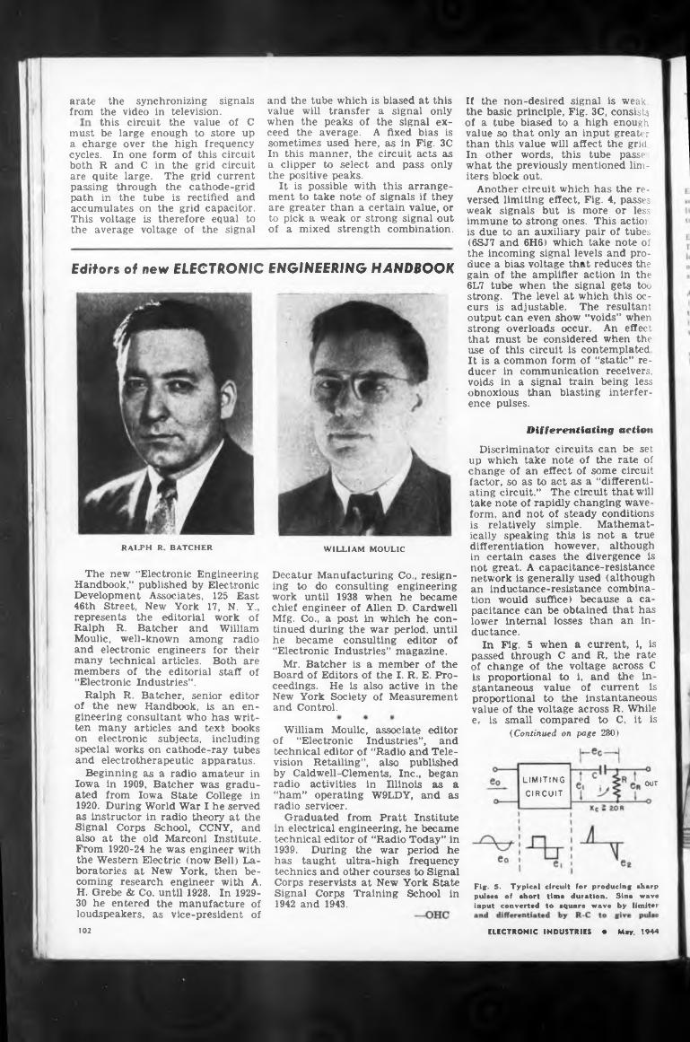
must
Editors of new ELECTRONIC ENGINEERING HANDBOOK
Differentiating action
RALPH R BATCHER WILLIAM MOULIC
OUT
102
arate from
and the tube which is biased at this value will transfer a signal only when the peaks of the signal exceed the average. A fixed bias is sometimes used here, as in Fig. 3C In this manner, the circuit acts as a clipper to select and pass only the positive peaks.
It is possible with this arrangement to take note of signals if they are greater than a certain value, or to pick a weak or strong signal out of a mixed strength combination.
Fi«. 5. Typical pulirà of short input converted
a charge over the high frequency cycles. In one form of this circuit both R and C in the grid circuit are quite large. The grid current passing through the cathode-grid path in the tube is rectified and accumulates on the grid capacitor. This voltage is therefore equal to the average voltage of the signal
the synchronizing signals the video in television.this circuit the value of C be large enough to store up
Decatur Manufacturing Co., resigning to do consulting engineering work until 1938 when he became chief engineer of Allen D. Cardwell Mfg. Co., a post in which he continued during the war period, until he became consulting editor of “Electronic Industries” magazine.
Mr. Batcher is a member of the Board of Editors of the I. R. E. Proceedings. He is also active in the New York Society of Measurement and Control.
circuit for producing »harp time duration. Sina wave to square wave by limitei
William Moulic, associate editor of “Electronic Industries”, and technical editor of “Radio and Television Retailing”, also published by Caldwell-Clements, Inc., began radio activities in Illinois as a “ham” operating W9LDY, and as radio servicer.
Graduated from Pratt Institute in electrical engineering, he became technical editor of “Radio Today” in 1939. During the war period he has taught ultra-high frequency technics and other courses to Signal Corps reservists at New York State Signal Corps Training School in 1942 and 1943.
ELECTRONIC INDUSTRIES • May, 1944
If the non-desired signal is weak, the basic principle, Fig. 3C, consists of a tube biased to a high enough value so that only an input greater than this value will affect the grid In other words, this tube passe:; what the previously mentioned limiters block out.
Another circuit which has the reversed limiting effect, Fig. 4, passes weak signals but is more or less immune to strong ones. This actior. is due to an auxiliary pair of tubes (6SJ7 and 6H6) which take note of the incoming signal levels and produce a bias voltage that reduces the gain of the amplifier action in the 6L7 tube when the signal gets too strong. The level at which this occurs is adjustable. The resultant output can even show “voids” when strong overloads occur. An effect that must be considered when the use of this circuit is contemplated It is a common form of “static” reducer in communication receivers, voids in a signal train being less obnoxious than blasting interference pulses.
The new “Electronic Engineering Handbook,” published by Electronic Development Associates, 125 East 46th Street, New York 17, N. Y., represents the editorial work of Ralph R. Batcher and William Moulic, well-known among radio and electronic engineers for their many technical articles. Both are members of the editorial staff of “Electronic Industries”.
Ralph R. Batcher, senior editor of the newr Handbook, is an engineering consultant who has written many articles and text books on electronic subjects, including special works on cathode-ray tubes and electrotherapeutic apparatus.
Beginning as a radio amateur in Iowa in 1909, Batcher was graduated from Iowa State College in 1920. During World War I he served as instructor in radio theory at the Signal Corps School, CCNY, and also at the old Marconi Institute. From 1920-24 he was engineer with the Western Electric (now Bell) Laboratories at New York, then becoming research engineer with A. H. Grebe & Co. until 1928. In 192930 he entered the manufacture of loudspeakers, as vice-president of
Discriminator circuits can be set up which take note of the rate of change of an effect of some circuit factor, so as to act as a “differentiating circuit.” The circuit that will take note of rapidly changing waveform, and not of steady conditions is relatively simple. Mathematically speaking this is not a true differentiation however, although in certain cases the divergence is not great. A capacitance-resistance network is generally used (although an inductance-resistance combination would suffice) because a capacitance can be obtained that has lower internal losses than an inductance.
In Fig. 5 when a current, i, is passed through C and R, the rate of change of the voltage across C is proportional to 1, and the instantaneous value of current is proportional to the instantaneous value of the voltage across R. While ec is small compared to C, it is
(Continued on page 2801
LIMITING
CIRCUIT
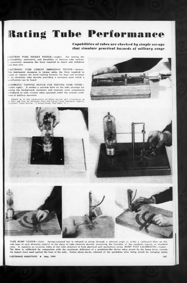
Rating Tube Performance
automatic tapping device for testing tube NOISE
Details as to the construction of these devices and information as
ELECTRONIC INDUSTRIES >03
It accurately tube base pins
Capabilities of tubes are checked by simple set-ups that simulate practical hazards of military usage
envelope which a
to their use may be obtained from the Signal Corps Standards Agency, Electronic Tubes Section, 12 Broad Street, Red Bank, N. J.
tube envelope for noise components the critical condi-
> LECTRON1C TUBE CEMENT IMMERSION TESTER—(below)
ELECTRON TUBE SOCKET TESTER— (right). For testing the-rviceability, uniformity, and durability of electron tube sockets.
ibelow right). It strikes a uniform blow on the testing the background, harmonic and resonant introduced in tube circuits when operated under ti -ns of military operation
loosen or rupture the bond existing between the base und oi an electronic tube thereby providing a standard upon specification can be based
TUBE BUMP TESTER—(left). Spring-actuated bar is released to swing through a selected angle to strike a calibrated blow on the tube base in each direction relative to the plane of tube elements thereby measuring the intensity of the resultant impact, in standard units. It registers an accurate index of the tube structure in both electrical and mechanical terms. BUMP TEST CALIBRATOR—(right).
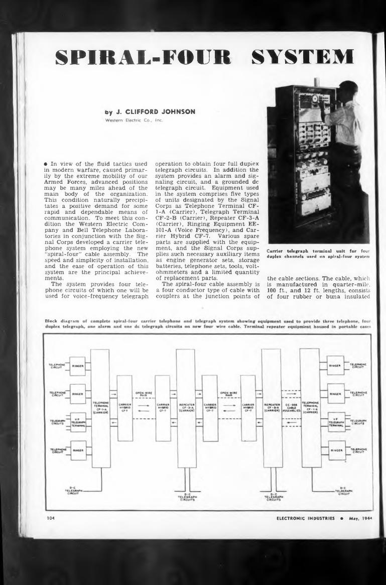
SYSTEMSPIRAL-FOUR
by J. CLIFFORD JOHNSON
Block diagrai
104
body of the organization, condition naturally precipi- a positive demand for some and dependable means of
Carrier telegraph terminal unit for four duplex channels used on spiral-four system
• In view of the fluid tactics used in modern warfare, caused primarily by the extreme mobility of our Armed Forces, advanced positions may be many miles ahead of the
the cable sections. The cable, which is manufactured in quarter-mile, 100 ft., and 12 ft. lengths, consists of four rubber or buna insulated
main This ta tes rapidcommunication. To meet this condition the Western Electric Company and Bell Telephone Laboratories in conjunction with the Signal Corps developed a carrier telephone system employing the new “spiral-four” cable assembly. The speed and simplicity of installation, and the ease of operation of this system are the principal achievements.
The system provides four telephone circuits of which one will be used for voice-frequency telegraph
ELECTRONIC INDUSTRIES • May, 194*
operation to obtain four full duplex telegraph circuits. In addition the system provides an alarm and signaling circuit, and a grounded de telegraph circuit. Equipment used in the system comprises five types of units designated by the Signal Corps as Telephone Terminal CF- 1-A (Carrier), Telegraph Terminal CF-2-B (Carrier), Repeater CF-3-A (Carrier), Ringing Equipment EE- 101-A (Voice Frequency), and Carrier Hybrid CF-7. Various spare parts are supplied with the equipment, and the Signal Corps supplies such necessary auxiliary items as engine generator sets, storage batteries, telephone sets, tools, voltohmmeters and a limited quantity of replacement parts.
The spiral-four cable assembly is a four conductor type of cable with couplers at the junction points of
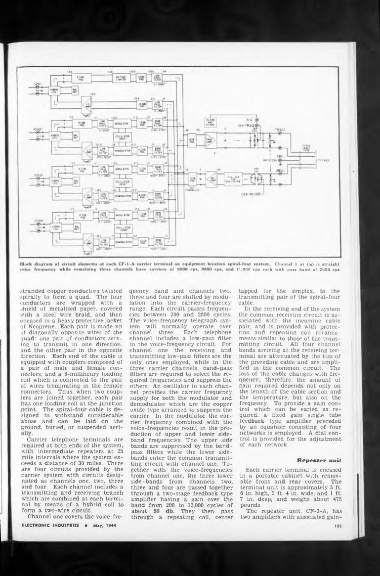
(CHI)
(TRSG)
(SH)
. ÎQviyZt»
(CH4)
11,800 epa each
tapped for the simplex the
Repeater unit
about They thenthrough a repeating coil,
105
pass center
Channel 1 at top is straight with pass band of 2600 cps
Each carrier terminal is encased in a portable cabinet with removable front and rear covers. The terminal unit is approximately 5 ft. 6 in. high, 2 ft. 4 in. wide, and 1 ft. 7 in. deep, and weighs about 475 pounds.
The repeater unit, CF-3-A, has two amplifiers with associated gain
transmitting pair of the spiral-four cable.
In the receiving end of the system the common receiving circuit is associated with the incoming cable pair, and is provided with protection and repeating coil arrangements similar to those of the transmitting circuit. All four channel bands arriving at the receiving terminal are attenuated by the loss of the preceding cable and are amplified in the common circuit. The loss of the cable changes with frequency; therefore, the amount of gain required depends not only on the length of the cable section and the temperature, but also on the frequency. To provide a gain control which can be varied as required, a fixed gain single tube feedback type amplifier preceded by an equalizer consisting of four networks is employed. A dial control is provided for the adjustment of each network.
stranded copper conductors twisted spirally to form a quad. The four conductors are wrapped with a shield of metalized paper, covered with a steel wire braid, and then encased in a heavy protective jacket of Neoprene. Each pair is made up of diagonally opposite wires of the quad: one pair of conductors serving to transmit in one direction, and the other pair in the opposite direction. Each end of the cable is equipped with couplers composed of a pair of male and female connectors, and a 6-millihenry loading coil which is connected to the pair of wires terminating in the female connectors. Thus, when two couplers are joined together, each pair has one loading coil at the junction point. The spiral-four cable is designed to withstand considerable abuse and can be laid on the ground, buried, or suspended aeri-
quency band and channels two, three and four are shifted by modulation into the carrier-frequency range. Each circuit passes frequencies between 200 and 2800 cycles. The voice-frequency telegraph system will normally operate over channel three. Each telephone channel includes a low-pass filter in the voice-frequency circuit. For channel one the receiving and transmitting low-pass filters are the only ones employed, while in the three carrier channels, band-pass filters are required to select the required frequencies and suppress the others. An oscillator in each channel provides the carrier frequency supply for both the modulator and demodulator which are the copper oxide type arranged to suppress the carrier. In the modulator the carrier frequency combined with the voice-frequencies result in the production of upper and lower sideband frequencies. The upper side bands are suppressed by the bandpass filters while the lower sidebands enter the common transmitting circuit with channel one. Together with the voice-frequencies from channel one, the three lower side-bands from channels two, three and four are passed together through a two-stage feedback type amplifier having a gain over the band from 200 to 12,000 cycles of
(SIC) I (SX-TRSC)
Carrier telephone terminals are required at both ends of the system, with intermediate repeaters at 25 mile intervals where the system exceeds a distance of 30 miles. There are four circuits provided by the carrier system with circuits designated as channels one, two, three and four. Each channel includes a transmitting and receiving branch which are combined at each terminal by means of a hybrid coil to form a two-wire circuit.
Channel one covers the voice-fre-ELECTRONIC INDUSTRIES • May, 1944
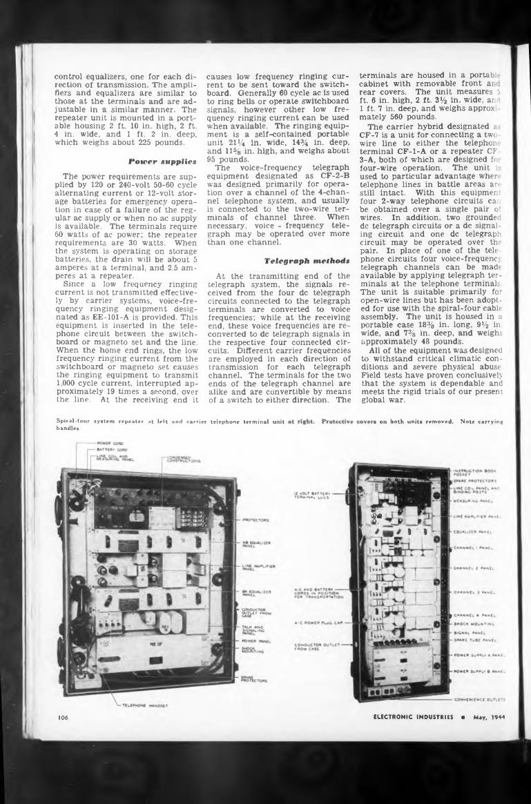
Power »applies
Telegraph method»
sa
106
on both units removed. Note carrying
The power requirements are supplied by 120 or 240-volt 50-60 cycle alternating current or 12-volt storage batteries for emergency operation in case of a failure of the regular ac supply or when no ac supply is available. The terminals require 60 watts of ac power; the repeater requirements are 30 watts. When the system is operating on storage batteries, the drain will be about 5 amperes at a terminal, and 2.5 amperes at a repeater.
Since a low frequency ringing current is not transmitted effectively by carrier systems, voice-frequency ringing equipment designated as EE-101-A is provided. This equipment is inserted in the telephone circuit between the switchboard or magneto set and the line. When the home end rings, the low frequency ringing current from the switchboard or magneto set causes the ringing equipment to transmit 1,000 cycle current, interrupted approximately 19 times a second, over the line. At the receiving end it
At the transmitting end of the telegraph system, the signals received from the four de telegraph circuits connected to the telegraph terminals are converted to voice frequencies; while at the receiving end, these voice frequencies are reconverted to de telegraph signals in the respective four connected circuits. Different carrier frequencies are employed in each direction of transmission for each telegraph channel. The terminals for the two ends of the telegraph channel are alike and are convertible by means of a switch to either direction. The
control equalizers, one for each direction of transmission. The amplifiers and equalizers are similar to those at the terminals and are adjustable in a similar manner. The repeater unit is mounted in a portable housing 2 ft. 10 in. high, 2 ft. 4 in. wide, and 1 ft. 2 in. deep, which weighs about 225 pounds.
terminals are housed in a portab cabinet with removable front a: rear covers. The unit measures 5 ft. 6 in. high, 2 ft. 3Va in. wide, and 1 ft. 7 in. deep, and weighs approx mately 560 pounds.
The carrier hybrid designated ; CF-7 is a unit for connecting a tw< - wire line to either the telephor terminal CF-l-A or a repeater CF 3-A, both of which are designed fo four-wire operation. The unit used to particular advantage wher telephone lines in battle areas an still intact. With this equipment four 2-way telephone circuits can be obtained over a single pair of wires. In addition, two grounded de telegraph circuits or a de signaling circuit and one de telegraph circuit may be operated over the pair. In place of one of the telephone circuits four voice-frequency telegraph channels can be made available by applying telegraph terminals at the telephone terminals The unit is suitable primarily for open-wire lines but has been adopted for use with the spiral-four cable assembly. The unit is housed in a portable case 18% in. long, 9% in wide, and 7% in. deep, and weighs approximately 48 pounds.
All of the equipment was designed to withstand critical climatic conditions and severe physical abuse Field tests have proven conclusively that the system is dependable and meets the rigid trials of our present global war.
ELECTRONIC INDUSTRIES • May, 1944
Spiral-four system repeater at left and carrier telephone terminal unit handles
causes low frequency ringing current to be sent toward the switchboard. Generally 60 cycle ac is used to ring bells or operate switchboard signals, however other low frequency ringing current can be used when available. The ringing equipment is a self-contained portable unit 21% in. wide, 14% in. deep, and 11% in. high, and weighs about 95 pounds.
The voice-frequency telegraph equipment designated as CF-2-B was designed primarily for operation over a channel of the 4-chan- nel telephone system, and usually is connected to the two-wire terminals of channel three. When necessary, voice - frequency telegraph may be operated over more than one channel.
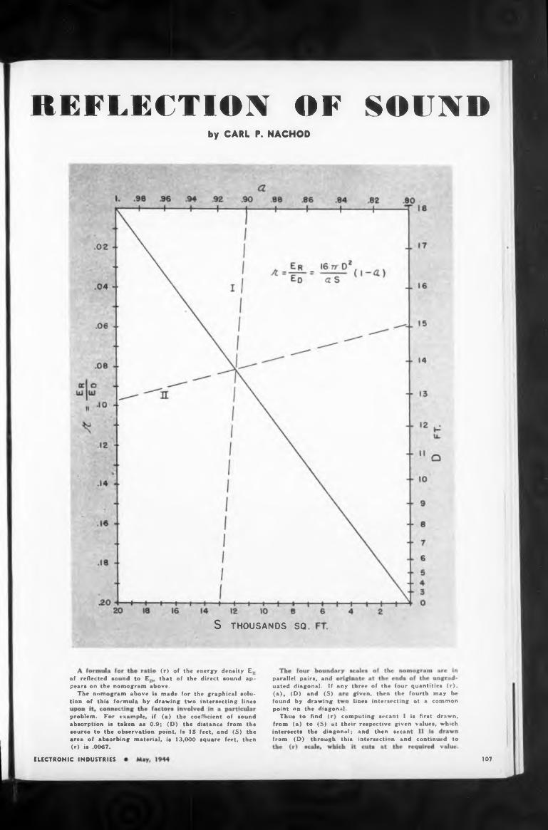
REFLECTION OF SOUNDby CARL P. NACHOD
S THOUSANDS SQ
of reflected sound to Eany
from (D) through this intersection and continued to
107ELECTRONIC INDUSTRIES
(r) of the energy density E that of the direct sound ap-
three of the four quantities (r), given, then the fourth may be lines intersecting at a common
pears on the nomogram above.The nomogram above is made for the graphical solu
tion of this formula by drawing two intersecting lines
problem. For example, if (a) the coefficient of sound absorption is taken as 0.9; (D) the distance from the source to the observation point, is 15 feet, and (S) the area of absorbing material, is 13,000 square feet, then (r) is .0967.
parallel pairs, and uated diagonal. If (a), (D) and (S) found by drawingpoint nn the diagonal.
Thus to find (r) computing secant 1 is first drawn, from (a) to (S) at their respective given values, whichintersects the diagonal; and then secant
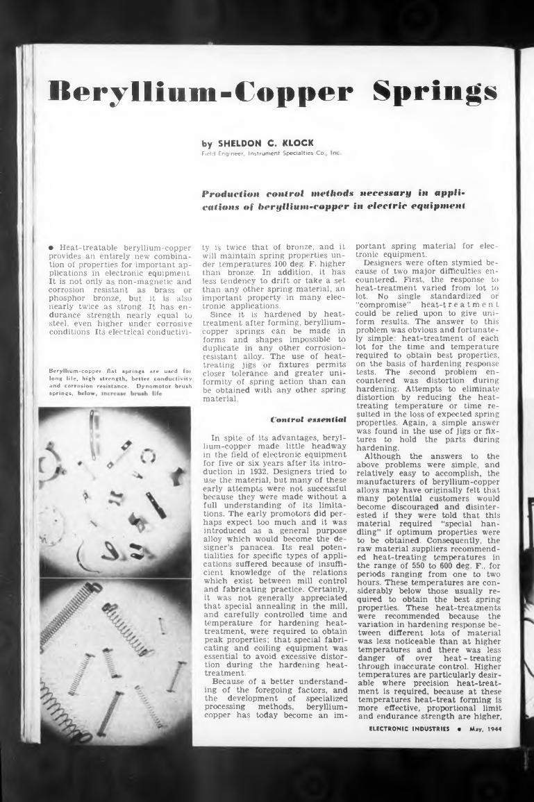
Beryllium-Copper Springs
brassalso
springs,
Control essential
danger
♦ Heat-treatable beryllium-copper provides an entirely new combination of properties for important applications in electronic equipment. It is not only as non-magnetic and
its advantages, beryl- made little headway
through inaccurate control. Higher temperatures are particularly desirable where precision heat-treatment is required, because at these temperatures heat-treat forming is more effective, proportional limit and endurance strength are higher,
In spite of lium-copper
by SHELDON C. KLOCKField Engineer, Instrument Specialties Co
phosphor bronze, but itnearly twice as strong. It has endurance strength nearly equal to steel, even higher under corrosive conditions. Its electrical conductivi-
corrosion resistant
over heat - treating
ty is twice that of bronze, and it will maintain spring properties under temperatures 100 deg. F. higher than bronze. In addition, it has less tendency to drift or take a set than any other spring material, an important property in many electronic applications.
Since it is hardened by heattreatment after forming, berylliumcopper springs can be made in forms and shapes impossible to duplicate in any other corrosionresistant alloy. The use of heattreating jigs or fixtures permits closer tolerance and greater uniformity of spring action than can be obtained with any other spring material.
in the field of electronic equipment for five or six years after its introduction in 1932. Designers tried to use the material, but many of these early attempts were not successful because they were made without a full understanding of its limitations. The early promoters did perhaps expect too much and it was introduced as a general purpose alloy which would become the designer’s panacea. Its real potentialities for specific types of applications suffered because of insufficient knowledge of the relations which exist between mill control and fabricating practice. Certainly, it was not generally appreciated that special annealing in the mill, and carefully controlled time and temperature for hardening heattreatment, were required to obtain peak properties; that special fabricating and coiling equipment was essential to avoid excessive distortion during the hardening heattreatment.
Because of a better understanding of the foregoing factors, and the development of specialized processing methods, berylliumcopper has today become an im-
ELECTRONIC INDUSTRIES • May, 1944
Beryllium-copper flat springs are used for long life, high strength, better conductivity and corrosion resistance. Dynomotor brush
portant spring material for electronic equipment.
Designers were often stymied because of two major difficulties encountered. First, the response to heat-treatment varied from lot to lot. No single standardized or “compromise” heat-t reatment could be relied upon to give uniform results. The answer to this problem was obvious and fortunately simple: heat-treatment of each lot for the time and temperature required to obtain best properties, on the basis of hardening response tests. The second problem encountered was distortion during hardening. Attempts to eliminate distortion by reducing the heattreating temperature or time resulted in the loss of expected spring properties. Again, a simple answer was found in the use of jigs or fixtures to hold the parts during hardening.
Although the answers to the above problems were simple, and relatively easy to accomplish, the manufacturers of beryllium-copper alloys may have originally felt that many potential customers would become discouraged and disinterested if they were told that this material required “special handling” if optimum properties were to be obtained. Consequently, the raw material suppliers recommended heat-treating temperatures in the range of 550 to 600 deg. F., for periods ranging from one to two hours. These temperatures are considerably below those usually required to obtain the best spring properties. These heat-treatments were recommended because the variation in hardening response between different lots of material was less noticeable than at higher temperatures and there was less
Produetion control methods necessary in applications of beryllium-copper in electric equipment
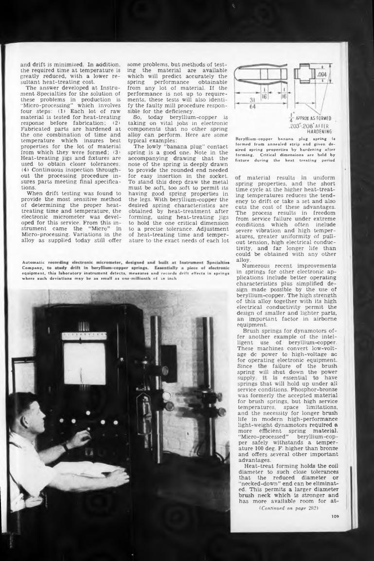
uniform
MicroMicro-processing. Variations in thealloy as supplied today still offer
beryllium-copper,
failureSincespring will shut down the power
essential havesupply,
and
109
spring properties, and the short time cycle at the higher heat-treating temperatures reduces the tendency to drift or take a set and also cuts the cost of these advantages.
the brush
These machines convert low-voltage de power to high-voltage ac for operating electronic equipment.
material results
out tension, high electrical conductivity, and far longer life than could be obtained with any other alloy.
Numerous recent improvements in springs for other electronic applications include better operating characteristics plus simplified design made possible by the use of beryllium-copper. The high strength of this alloy together with its high electrical conductivity permit the design of smaller and lighter parts, an important factor in airborne equipment.
Brush springs for dynamotors offer another example of the intel-
strument came
freedom extreme include
tempered pull-
equipment, this laboratory instrument detects, measures and records drift effects in springs where such deviations msy be as email as one-millionth nf tn inch
ligent use
Automatic Company,
The process results in from service failure under conditions which often severe vibration and high atures, greater uniformity
some problems, but methods of testing the material are available which will predict accurately the spring performance obtainable from any lot of material. If the performance is not up to requirements, these tests will also identify the faulty mill procedure responsible for the deficiency.
So, today beryllium-copper is taking on vital jobs in electronic components that no other spring alloy can perform. Here are some typical examples:
The lowly “banana plug” contact spring is a good one. Note in the accompanying drawing that the nose of the spring is deeply drawn to provide the rounded end needed for easy insertion in the socket. To stand this deep draw the metal must be soft, too soft to permit its having good spring properties in the legs. With beryllium-copper the desired spring characteristics are obtained by heat-treatment after forming, using heat-treating jigs to hold the one critical dimension to a precise tolerance. Adjustment of heat-treating time and temperature to the exact needs of each lot
springs that will hold up under all service conditions. Phosphor-bronze was formerly the accepted material for brush springs, but high service temperatures, space limitations, and the necessity for longer brush life in modern high-performance light-weight dynamotors required a more efficient spring material. “Micro-processed” beryllium-copper safely withstands a temperature 100 deg. F. higher than bronze and offers several other important advantages.
Heat-treat forming holds the coil diameter to such close tolerances that the reduced diameter or “necked-down” end can be eliminated. This permits a larger diameter
and drift is minimized. In addition, the required time at temperature is greatly reduced, with a lower resultant heat-treating cost.
The answer developed at Instrument Specialties for the solution of these problems in production is “Micro-processing” which involves four steps: (1) Each lot of raw material is tested for heat-treating response before fabrication; (2) Fabricated parts are hardened at the one combination of time and temperature which insures best properties for the lot of material from which they were formed; (3» Heat-treating jigs and fixtures are used to obtain closer tolerances; (4) Continuous inspection throughout the processing procedure insures parts meeting final specifications.
When drift testing was found to provide the most sensitive method of determining the proper heattreating time and temperature, the electronic micrometer was developed for this service. From this in-
Beryllium-copper banana plug spring ia formed from annealed atrip and given desired spring properties by hardening after forming. Critical dimensions are held by fixture during the heat treating period
4 APPROX. AS FORMED 203-.208’AFTER
HARDENING
brush neck which is stronger has more available room for
(Continued on page 282)
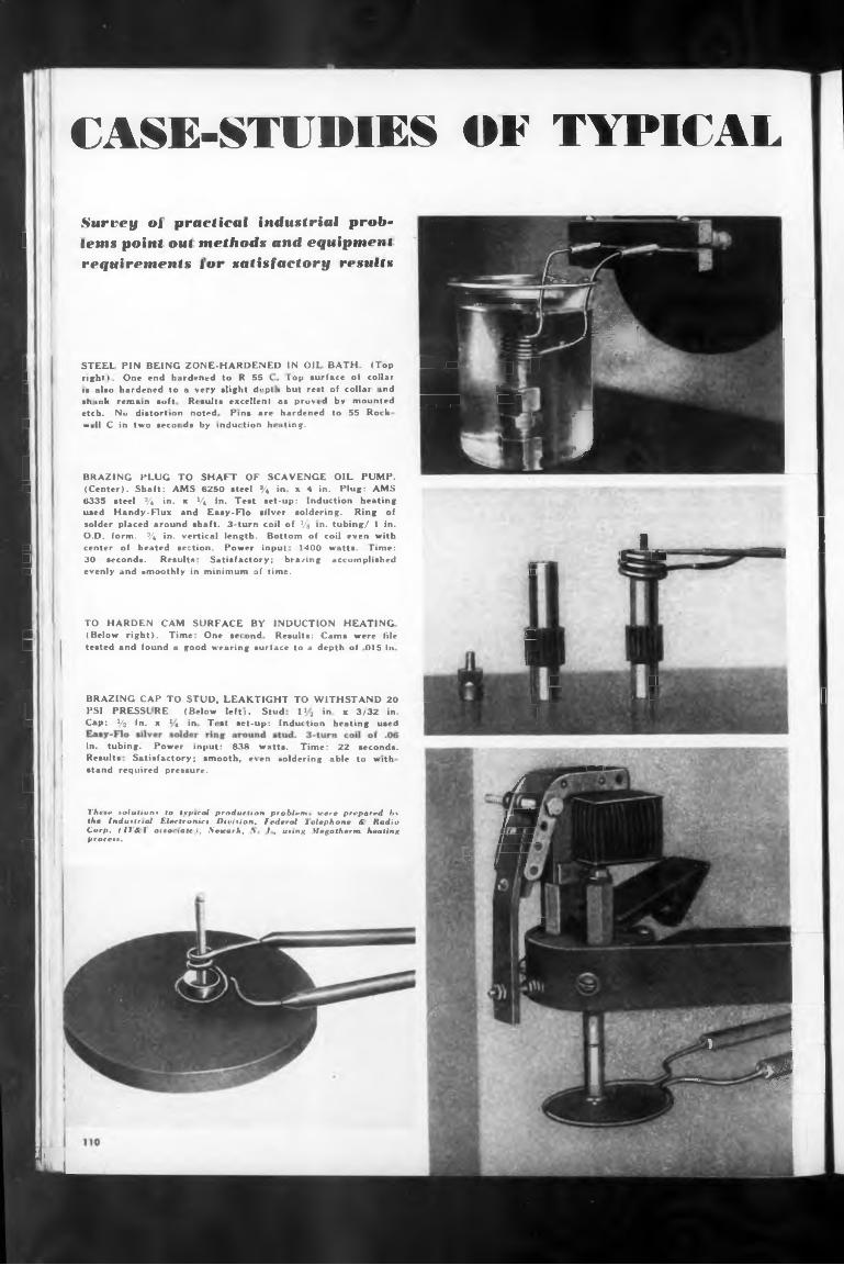
CASE-STUDIES OF TYPICALsol. Ok .Surrey oi practical industrial prob* • .
1 Irins point oat methods and equipment -requirements lor satisfactory rrxwlts
&ui■PRHmkhmi
1 STEEL PIN BEING ZONE-HARDENED IN Oil BATH (lop H .W J £1 right 1 . One end hardened to R 55 < Top surface of collarI i» also hardened to a very slight d<‘pt i but rest of collar ind .hffL
■Sink remain soft Results excellent as proved bv mounted ^B^^B Mt"etch. No distortion noted Pins are hardened to 55 Rock 4f
H —»(I C in two securds by induction hi ating.
1 BRAZING PLUG TO SHAFT OF SCAVENGE OIL PUMP.
• j!^ ■I 1
■ (Center). Shaft: AMS 6250 steel % in x 4 in. Plug: AMS6335 steel % in. x V« in. Test set-up: Induction heating used Handy-Flux and Easy-Flo silver soldering. Ring of solder placed around shaft. 3-turn coil of Vs >n. tubing/ 1 in. O.D. form. % in. vertical length. Bottom of coil even with
■ center of heated section. Power input 1400 watt*. Time:,.. 1^ —-, 1
H 30 seconds. Result» Satisfactory; brazing accomplished „■ evenly and smoothly in minimum of time. M
TO HARDEN CAM SURFACE BY INDUCTION HEATINGH, (Below right). Time One second Results: Cams were file 'B|H tested and found a good wearing surlace to a depth ot 015 in |H
J BRAZING CAP TO STUD, LEAKT1GHT TO WITHSTAND 20 %] PSI PRESSLRE. (Below lefti. Stud T 2 in. x 3/32 in. H t ('■ Cap: V2 in. x 1« in Test set-up: Induction heating used >
V IIW 1 * I
in. tubing. Power input: 838 watts. Time: 22 seconds. ' Results Satisfactory; smooth, even soldering able to Hith
stand required pressure.1 /fl
These solutions to tvpical production problem. were prepared by ) qUthe Industrial Electronic! Division, federal Telephone A iladio jjd£SCorp, (11 A. 1 aiuhiatrl, \emrk, \ 1, using Megatherm heating
. process. /MB.■r । •1 (flf ■
. - -M. ■ - _
1 •'.. . .............■
™l
1
' ' 1$ — H^l
1
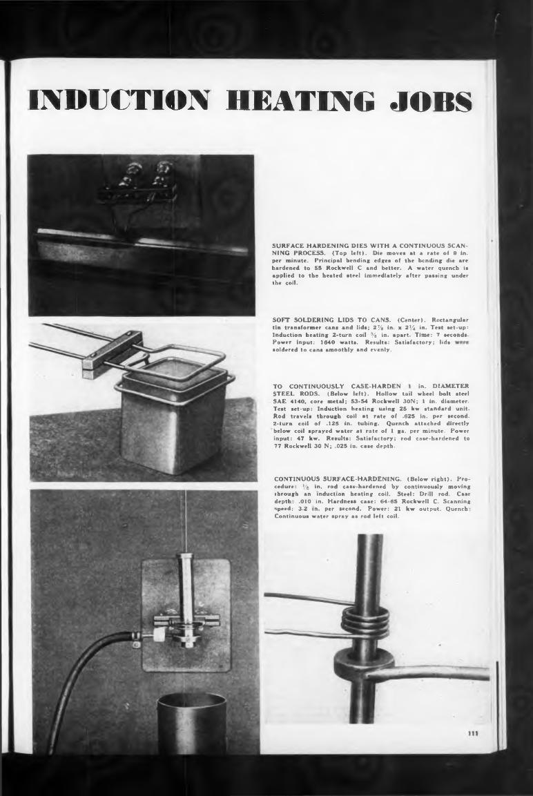
through an induction heating coil. Steel: Drill rod. Casedepth. .010 in. Hardness case: 64-65 Rockwell C. Scanningipeed; 3.2 in. per second. Power: 21 kw output. QuenchContinuous water spray as rod left coil.
INDUCTION HEATING JOBS
SURFACE HARDENING DIES WITH A CONTINUOUS SCANNING PROCESS. (Top left). Die moves at a rate of 9 in. per minute. Principal bending edges of the bending die are hardened to 55 Rockwell C and better. A water quench is applied to the heated steel immediately after passing under the coil.
SOFT SOLDERING LIDS TO CANS. (Center). Rectangular tin transformer cans and lids; 2% in. x 2*4 in. Test set-up: Induction heating 2-turn coil % in. apart. Time: 7 seconds. Power input: 1640 watts. Results: Satisfactory; lids soldered tn cans smoothly and evenly.
TO CONTINUOUSLY STEEL RODS. (Below SAE 4140, core metal; Test set-up: Induction
CASE-HARDEN in. DIAMETERleft). Hollow tail wheel bolt steel
53-54 Rockwell 30N; I in. diameter, heating using 25 kw standard unit.
Rod travels through coil at rate of .625 in. per second. 2-turn coil of .125 in. tubing. Quench attached directly below coil sprayed water at rate of 1 ga. per minute. Power input: 47 kw. Results: Satisfactory; rod case-hardened to 77 Rockwell 30 N; .025 in. case depth.
CONTINUOUS SURFACE-HARDENING. (Below right). Procedure: */■> in. rod case-hardened by continuously moving
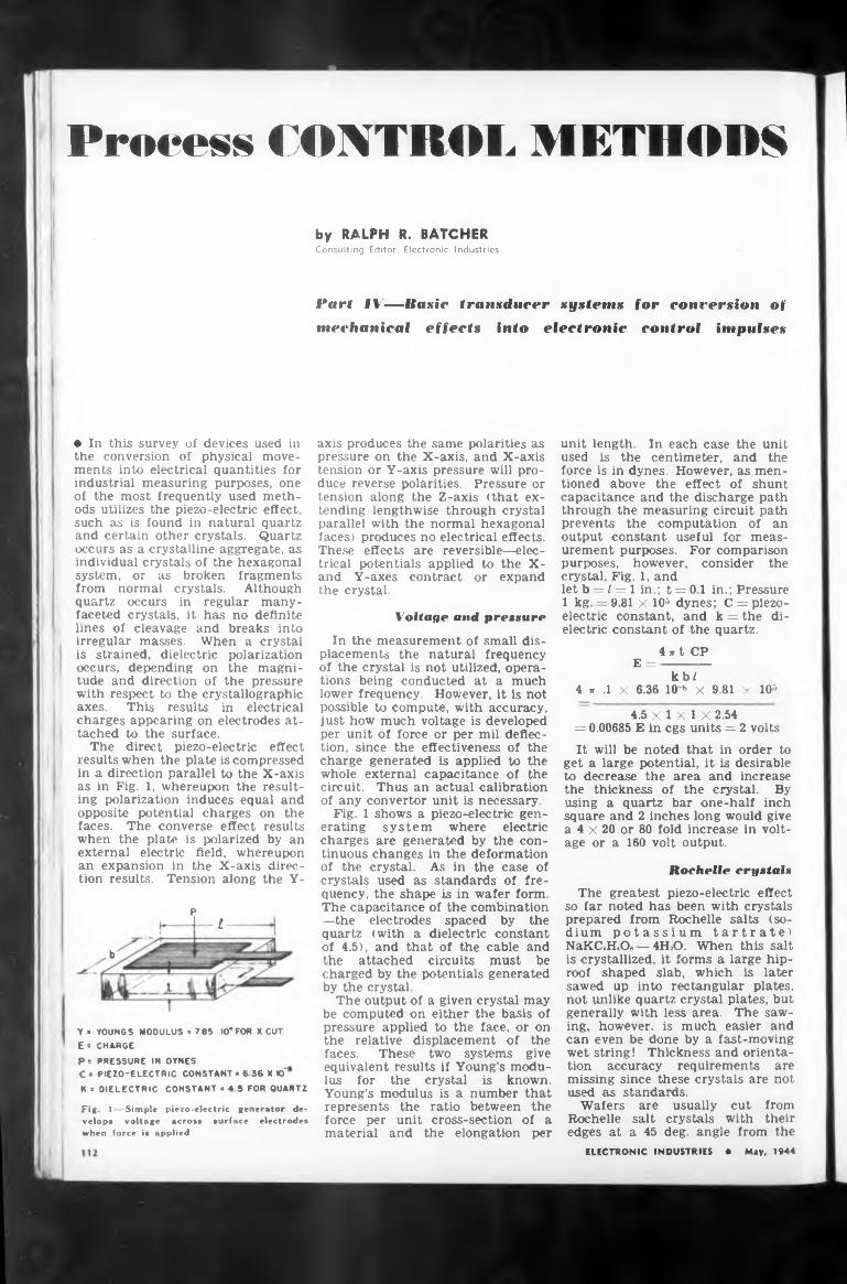
Process CONTROL METHODSby RALPH R. BATCHERConsulting Editor, Electronic Industries
Part IV—Basic transducer systems for conversion of mechanical effects into electronic control impulses
♦ In this survey of devices used in the conversion of physical movements into electrical quantities for industrial measuring purposes, one of the most frequently used methods utilizes the piezo-electric effect, such as is found in natural quartz and certain other crystals. Quartz occurs as a crystalline aggregate, as individual crystals of the hexagonal system, or as broken fragments from normal crystals. Although quartz occurs in regular manyfaceted crystals, it has no definite lines of cleavage and breaks into irregular masses. When a crystal is strained, dielectric polarization occurs, depending on the magnitude and direction of the pressure with respect to the crystallographic axes. This results in electrical charges appearing on electrodes attached to the surface.
The direct piezo-electric effect results when the plate is compressed in a direction parallel to the X-axis as in Fig. 1, whereupon the resulting polarization induces equal and opposite potential charges on the faces. The converse effect results when the plate is polarized by an external electric field, whereupon an expansion in the X-axis direction results. Tension along the Y-
P
I I
b
Y « YOUNGS MODULUS • 765 10*FOR X CUT.E = CHARGEP* PRESSURE in OYNESC= PIEZO-ELECTRIC CONSTANT • 63G X »'K » DIELECTRIC CONSTANT *45 FOR QUARTZ
Fig 1—Simple velops voltage
piezo-electric generator deaero»» surface electrodes
when force is applied
axis produces the same polarities as pressure on the X-axis, and X-axis tension or Y-axis pressure will produce reverse polarities. Pressure or tension along the Z-axis (that extending lengthwise through crystal parallel with the normal hexagonal faces) produces no electrical effects. These effects are reversible—electrical potentials applied to the X- and Y-axes contract or expand the crystal.
Voltage and pressure
In the measurement of small displacements the natural frequency of the crystal is not utilized, operations being conducted at a much lower frequency. However, it Is not possible to compute, with accuracy, just how much voltage is developed per unit of force or per mil deflection, since the effectiveness of the charge generated is applied to the whole external capacitance of the circuit. Thus an actual calibration of any convertor unit is necessary.
Fig. 1 shows a piezo-electric generating system where electric charges are generated by the continuous changes in the deformation of the crystal. As in the case of crystals used as standards of frequency, the shape is in wafer form The capacitance of the combination —the electrodes spaced by the quartz (with a dielectric constant of 4.5), and that of the cable and the attached circuits must be charged by the potentials generated by the crystal.
The output of a given crystal may be computed on either the basis of pressure applied to the face, or on the relative displacement of the faces. These two systems give equivalent results if Young’s modulus for the crystal is known. Young’s modulus is a number that represents the ratio between the force per unit cross-section of a material and the elongation per
unit length In each case the unit used is the centimeter, and the force is in dynes. However, as mentioned above the effect of shunt capacitance and the discharge path through the measuring circuit path prevents the computation of an output constant useful for measurement purposes. For comparison purposes, however, consider the crystal, Fig. 1, andlet b = / = 1 in.; t = 0 1 in.; Pressure 1 kg. — 9.81 X 10⁵ dynes; C = piezoelectric constant, and k = the dielectric constant of the quartz.
4 ir t CP E =-----------
kb/4 r .1 X 6.36 IO » x 9.81 x 10*
4.5 X 1 X 1 X 2.54= 0.00685 E in cgs units = 2 voltsIt will be noted that in order to
get a large potential, It is desirable to decrease the area and increase the thickness of the crystal. By using a quartz bar one-half inch square and 2 inches long would give a 4 x 20 or 80 fold increase in voltage or a 160 volt output.
Rochelle crystals
The greatest piezo-electric effect so far noted has been with crystals prepared from Rochelle salts (sodium potassium tartrate) NaKCJLO. — 4H2O. When this salt is crystallized, it forms a large hiproof shaped slab, which is later sawed up into rectangular plates, not unlike quartz crystal plates, but generally with less area. The sawing, however, is much easier and can even be done by a fast-moving wet string! Thickness and orientation accuracy requirements are missing since these crystals are not used as standards.
Wafers are usually cut from Rochelle salt crystals with their edges at a 45 deg. angle from the
ELECTRONIC INDUSTRIES • May, 1944
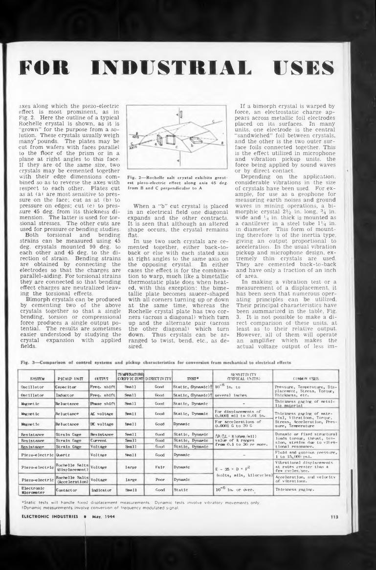
INDUSTRIALFOR USES
AXIS
crystal remains
the opposing crystal. either
utilizedating principles can
the other diagonal) which turn
crystals are ce either back-to
Their principal characteristics have been summarized in the table, Fig. 3. It is not possible to make a direct comparison of these units, at least as to their relative output.
back or else with each stated axis at right angles to the same axis on
When a “b” cut crystal is placed in an electrical field one diagonal expands and the other contracts. It is seen that although an alteredshape occurs, the flat.
In use two such mented together,
will operate makes the of less im-
If a bimorph crystal is warped by force, an electrostatic charge appears across metallic foil electrodes placed on its surfaces. In many units, one electrode is the central “sandwiched” foil between crystals, and the other is the two outer surface foils connected together. This is the effect utilized in microphone and vibration pickup units, the force being applied by sound waves or by direct contact.
Depending on the application, considerable vibrations in the size of crystals have been used. For example, for use as a geophone for measuring earth noises and ground waves in mining operations, a bimorphic crystal 2*/2 in. long, % in. wide and % in. thick is mounted as a cantilever in a steel tube 1*4 in. in diameter. This form of mounting therefore is of the inertia type, giving an output proportional to acceleration. In the usual vibration pickup and microphone design, extremely thin crystals are used. They are cemented back-to-back and have only a fraction of an inch of area.
In making a vibration test or a measurement of a displacement, it has been seen that numerous oper-
axes along which the piezo-electric effect is most prominent, as in Fig. 2. Here the outline of a typical Rochelle crystal is shown, as it is “grown” for the purpose from a solution. These crystals usually weigh many* pounds. The plates may be cut from wafers with faces parallel to the floor of the prism or in a plane at right angles to this face. If they are of the same size, two crystals may be cemented together with their edge dimensions combined so as to reverse the axes with respect to each other. Plates cut as at (a) are most sensitive to pressure on the face; cut as at (b) to pressure on edges; cut (c) to pressure 45 deg. from its thickness dimension. The latter is used for torsional stresses. The other cuts are used for pressure or bending studies.
Both torsional and bending strains can be measured using 45 deg. crystals mounted 90 deg. to each other and 45 deg. to the direction of strain. Bending strains are obtained by connecting the electrodes so that the charges are parallel-aiding. For torsional strains they are connected so that bending effect charges are neutralized leaving the torsional effects.
Bimorph crystals can be produced by cementing two of the above crystals together so that a single bending, torsion or compressional force produces a single output potential. The results are sometimes easier understood by studying the crystal expansion with applied fields
However, all of them an amplifier which actual voltage output
cases the effect is for the combination to warp, much like a bimetallic thermostatic plate does when heated, with this exception: the bimetallic plate becomes saucer-shaped with all corners turning up or down at the same time, whereas the Rochelle crystal plate has two corners (across a diagonal) which turn up and the alternate pair (across
down. Thus crystals can be ar ranged to twist, bend, etc., as de sired.
Fig 2—Rochelle salt crystal exhibits greatest piezo-electric effect along axis 45 deg. from B and C perpendicular to A
’Static tests will handle fixed displacement measurements. Dynamic tests involve vibratory movements only. tDynamic measurements involve conversion of frequency modulated signal.
SYSTEM PICKUP UNIT (WTPiln-MwuruRE CiFTFICIEVT DIRECTIVITY TEXT*
SENSITIVITY CTYPICAL UNITS) COMION USES
Oscillator Cater It or Freq, shift Small Good Static,(Dynamic )f IO-** In. to
several Inches
Pressure, Temperature, Displacement, Stress, Torque, Thickness, etc.Oscillator Inductor Freq, shift Snell l«x>! Static,(Dynamic)!
Wig twt Ic Reluctance Hvt.se shift Shall Good Static, Dynamic - Thickness gaging of metallic material
Magnet Ic Reluctance AC voltage Steell fxx«l Static, Dynamic For displacements of O.OOO1 mil to 0.01 In. Thickness gaging of mate
rial, Vibrations, Torque, Stress, Acceleration, Pressure, TemperatureMagnet le Reluctance DC voltage Srial 1 Good Dvnamlc For accelerations of
0.0001 G to 70 G
Resistance Strain Gage Resistance Small Good Static, Dynamic AR/ÄL= K (ohms/mil) value of k ranges from 0.1 (n 30 nr more.
Dynamic or fixed structural loads torque, thrust, tension, strains due to vibrational resonance.
Resistance Strain Gage Current Small Good Static, DynamicResistance Strain Gage Voltage Small Good Static, Dynamic
Piezo-electric Quartz Voltage Snell Good Dynamic - Fluid and gaseous pressure, 1 to 15,000 psi.
Piezo-electric Rochelle Salts (displacement) Voltage large Fair Dynamic E - 35 * D x F2
(volts, mils, kilocycles)
Vibrational displacements at rates greater than a few eye les/sec.
Piezo-electric Rochelle Salts (Acceleration) Voltage large Pnor Dynamic Acceleration, and velocity
of vibrations.Electronic Klcrometir Contactor Indicator Snell Good Static IO“® In. or wer, Thickness gaging.
ELECTRONIC INDUSTRIES • May, 1944
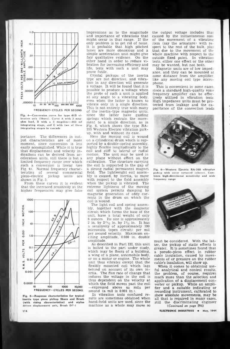
Fig. 4—Conversion curve for type 61B vibration unit (Shure). Curve A with 3 megohm load, B with a 3 megohm—.003 mf integrating stage, and C with two of these integrating stages in cascade
portance. The differences in output characteristics are of more moment, since conversion is less easily accomplished. While it is true that displacement and velocity indications can be derived from acceleration units, still there is but a limited frequency range over which such a conversion is linear (see Fig. 4). Normal frequency characteristics of several commercial piezo-electric pickup units are shown in Fig. 5.
From these curves it is evident that the increased sensitivity at the higher frequencies may give false
displacement unit. Brush DP-1driven
impressions as to the magnitude and importance of vibrations that might occur in that range. If the only problem is to get rid of noise, it is probable that high pitched tones are more obnoxious and a simple acceleration unit might give fair qualitative evidence. On the other hand in order to reduce vibration for increasing efficiency and life, tests with such a unit may prove futile.
Crystal pickups of the inertia type are not directive, and vibration in any direction will generate a voltage. It will be found that it is possible to produce a voltage when the probe of such a unit is applied at any angle to a vibrating body, even when the latter is known to vibrate only in a single direction. This is not entirely true with many of the inertia-type magnetic units, since the latter have guiding springs which restrain the movement to a single direction, as in Fig. 6, which shows the type RA- 355 Western Electric vibration pickup, with and without its case.
Here the moving coil is wound on a cylindrical drum which is supported by a double-spring assembly, highly flexible longitudinally to the coil and stiff to lateral or radial motion. The unit may be used in any plane without effect on the calibration. The structure carrying the coil Is supported in the gap of a strong radial permanent magnet field. The lightweight coil assembly is caused, by inertia, to move with respect to the field assembly when the pickup is vibrated. The extreme lightness of the moving coil system permits damping by magnetic generation of eddy currents in the drum on which the coil is wound.
The light coil and spring assembly, together with the magnetic circuit which forms the base of the unit, have a total weight of only 6 ounces. Its size is approximately 2 in. by 2J%2 in. by 1%2 in. It has a sensitivity of approximately 100 microvolts (open circuit) per mil per second velocity. Maximum exciting amplitude, 0.080 in. double amplitude.
As described in Part III, this unit is bolted to the part under study, which may be floors of a building, a wing of a plane, automobile body, or on a motor or engine. The whole unit thus vibrates except that the flexibly mounted coil which lags behind on account of its own inertia. The flux rate of change that induces the voltage in the coil is thus dependent on the velocity at which the field moves past the coil —expressed above as mils per second (a mil is 0.001 in.).
In vibration tests confused results are sometimes obtained when hand-held units are used, since the machine as a whole may move so
the output voltage includes that caused by the instantaneous sum of the movement of a vibrating item (say the armature) with respect to the rest of the bulk, plus that due to the movement of the whole machine with respect to the outside fixed point. In vibration tests, either one effect or the other may be wanted, but not both.
Magnetic units are of low impedance, and they can be mounted at some distance from the amplifier, like any moving coil type microphone.
This is convenient in some cases, since a standard high-quality voice frequency amplifier can be effectively utilized in vibration tests. High impedance units must be protected from leakage and the capacitance of the connection leads
■
KM
Fig. 6—Western Electric RA-355 vibration pickup with cover removed (above). Com bines high-directional sensitivity and wide frequency range
> *
must be considered. With the latter, the pickup of static effects is greater. It is sometimes found that a pseudo-piezo effect in rubber cable insulation, caused by movements of or pressure on the rubber cable’s insulation, will show up.
When it comes to obtaining useful analytical and control results, the problem, of course, requires much more than the selection and application of a displacement converter or pickup. While an amplifier and a suitable Indicating or recording Instrument, calibrated to show absolute movements, may be all that is required in many cases, still the discriminating engineer
(Continued on page 294)ELECTRONIC INDUSTRIES • May, 1944114
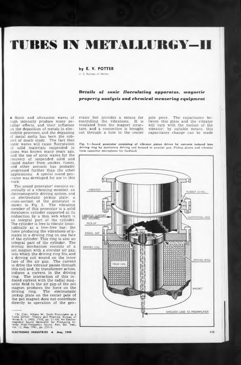
TUBES IN METALLUBGY—II
Detailsproperty analysis and chemical measuring equipment
-Sound
VIBRATORRUBBER SHIMS
The vibratingshown in Fig.
SUPPORTING WEP
RADIAL GAP
DRIVING COIL
DRIVING RING
FIELD COIL
MAGNET
SHIELDED LEAD TO PREAMPLIFIER
Inst
connection is brought a hole in the center
ture, and a out through
of sonic flocculating apparatus, magnetic
tense High-Frequency Sound, Rev Vol. 12, May 1941, pp. 250-6.
pole piece. The capacitance between this plate and the vibrator will vary with the motion of the vibrator; by suitable means, this capacitance change can be made
member of this generator is a solid duralumin cylinder supported at its midsection by a thin web which is an integral part of the cylinder. The cylinder is free to vibrate longitudinally as a free-free bar; the force producing the vibrations originates in a driving ring on one face of the cylinder. This ring is also an integral part of the cylinder. The driving mechanism consists of a pot magnet with a circular air gap, into which the driving ring fits, and a driving coil wound on the inner face of the air gap. The current to drive the vibrator passes through this coil and, by transformer action, induces a current in the driving ring. The interaction of this induced current with the radial magnetic field in the air gap of the pot magnet produces the force on the driving ring. The electrostatic pickup plate on the center pole of the pot magnet does not contribute directly to operation of the gen
erator but provides a means for controlling the vibrations. It is insulated from the magnet struc-
driving ring by stationary driving coil located in annular gap. Pickup plates and vibrator form capacitor microphone for feedback
ELECTRONIC INDUSTRIES • May, 1944
by E. V.U. S. Bureau
• Sonic and ultrasonic waves of high intensity produce many peculiar effects, and their influence on the deposition of metals in electrolytic processes, and the degassing of metal melts has been the subject of much study. The fact that sonic waves will cause flocculation of solid materials suspended in gases was known many years ago, and the use of sonic waves for the recovery of suspended solid and liquid matter from smokes, fumes, and other aerosols has probably progressed further than the other applications. A special sound generator was developed for use in this work.
The sound generator1 consists essentially of a vibrating member, an electromagnetic driving system, and an electrostatic pickup plate; a cross-section of the generator is
lSt. Clair, Hillary W.( Sonic Flocculator as a Fume Settler: Theory and Practice, bureau of Mines R I 3400, 1938, pp. 51-64; An Electromagnetic Sound Generator for Producing In-
POTTERof Mines
VIBRATOR SUPPORT AND HOUSING
PICKUP
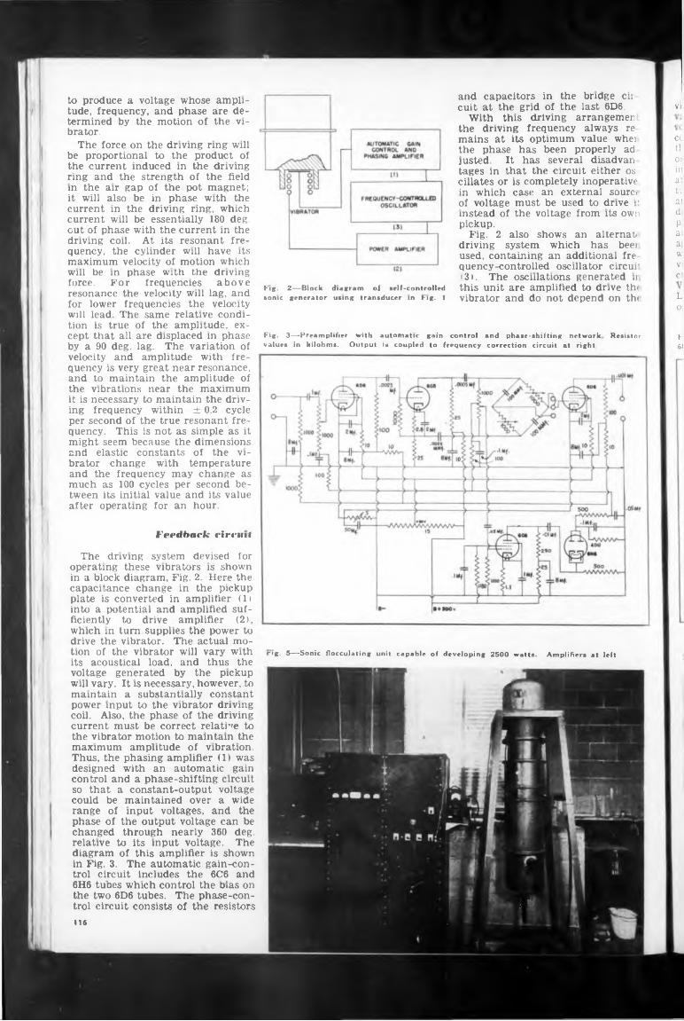
VI
2—Block diagram of •elf-controlledFig.sonic generator using transducer in Fig. 1
Fig. 3—Preamplifier with automatic gain
Feedhack circuit
116
Ì*
L o¡
F 61
The driving system devised for
drive the vibrator. The actual mo-tion of the vibrator will vary with
current must be correct relative tothe vibrator motion to maintain themaximum amplitude of vibration.
could be maintained over a widerange of input voltages, and the
trol circuit includes the 6C6 and6H6 tunes which control the bias onthe two 6D6 tubes. The phase-control circuit consists of the resistors
control and phase-shifting network Resistor
It has several disadvanjusted.
in which case an external sourctof voltage must be used to drive it
pickup.
to produce a voltage whose ampli-
brator.
At its resonant fre-
aboveforce. frequenciesForresonance the velocity will lag, and
will lead The same relative condi-tion is true of the amplitude, ex-
the vibrations near the maximum
and elastic constants of the vi-brator change with temperature
tween its initial value and its valueafter operating for an hour.
values in kilohms. Output is coupled to frequency correction circuit at right
rig. 5—Sonic flocculating unit capable of developing 2500 watts. Amplifiers at left
driving coil.
will be in phase with the driving
for lower frequencies the velocity
cept that all are displaced in phase by a 90 deg. lag. The variation of velocity and amplitude with frequency is very great near resonance, and to maintain the amplitude of
it is necessary to maintain the driving frequency within ± 0.2 cycle per second of the true resonant frequency. This is not as simple as it might seem because the dimensions
and the frequency may change as much as 100 cycles per second be
operating these vibrators is shown in a block diagram, Fig. 2. Here the capacitance change in the pickup plate is converted in amplifier (1 ) into a potential and amplified sufficiently to drive amplifier (2), which in turn supplies the power to
its acoustical load, and thus the voltage generated by the pickup will vary. It is necessary, however, to maintain a substantially constant power input to the vibrator driving coil. Also, the phase of the driving
Thus, the phasing amplifier (1) was designed with an automatic gain control and a phase-shifting circuit so that a constant-output voltage
phase of the output voltage can be changed through nearly 360 deg.relative to its input voltage. The diagram of this amplifier is shown in Fig. 3. The automatic gain-con
tude, frequency, and phase are de-termined by the motion of the vi-
The force on the driving ring willbe proportional to the product ofthe current induced in the drivingring and the strength of the fieldin the air gap of the pot magnet;it will also be in phase with thecurrent in the driving ring, whichcurrent will be essentially 180 deg.cut of phase with the current in the
quency, the cylinder will have itsmaximum velocity of motion which
cuit at the grid of the last 6D6.
the driving frequency always remains at its optimum value wheithe phase has been properly ad
tages in that the circuit either oscillâtes or is completely inoperative
instead of the voltage from its owl
Fig. 2 also shows an alternaidriving system which has beeiused, containing an additional frequency-controlled oscillator circuit
and capacitors in the bridge cir
With this driving arrangemen
131. The osculations generated n
CL t!: Oí in a: U ai d) p: ai ai w VI Cl
this unit are amplified to drive thi vibrator and do not depend on the
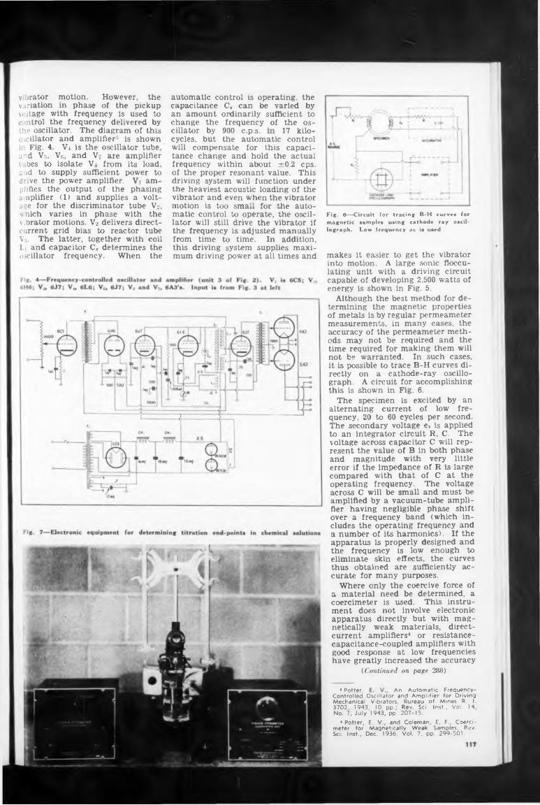
automatic control is operating, the
900 c.p.s, 17 kilothe automatic control
V4 is the oscillator tubeVg, and V-
t. bes to isolate Va'id to supply sufficient power tod ive the power amplifier. am
616
1®
An Automatic Frequency• Potter,
are amplifier from its load.
1 Fig. 4 a nd Vr„
C, can be varied by ordinarily sufficient to frequency of the os-
plifies the output of the phasing amplifier (1) and supplies a voltage for the discriminator tube V2, which varies in phase with the vibrator motions. V2 delivers direct- current grid bias to reactor tube V;. The latter, together with coil
the the
capacitance an amount change the cillator by cycles, butwill compensate for this capacitance change and hold the actual frequency within about ±0.2 cps. of the proper resonant value. This driving system will function under the heaviest acoustic loading of the vibrator and even when the vibrator motion is too small for the automatic control to operate, the oscillator will still drive the vibrator if the frequency is adjusted manually from time to time. In addition, this driving system supplies maximum driving power at all times and
Li and capacitor CK determines oscillator frequency. When
Fig. 6—Circuit for tracing B-H curve* for magnetic sample* using cathode ray oscillograph. Low frequency ac is used
makes it easier to get the vibrator into motion. A large sonic flocculating unit with a driving circuit capable of developing 2,500 watts of energy is shown in Fig. 5.
Although the best method for determining the magnetic properties of metals is by regular permeameter measurements, in many cases, the accuracy of the permeameter methods may not be required and the time required for making them will not be warranted. In such cases, it is possible to trace B-H curves di-
v »rator motion. However, the variation in phase of the pickup v Itage with frequency is used to c itrol the frequency delivered by the oscillator. The diagram of this oscillator and amplifier3 is shown
on a cathode-ray oscillo- A circuit for accomplishing
shown in Fig. 6.specimen is excited by an
rectly graph, this is
Thealternating current of low frequency, 20 to 60 cycles per second. The secondary voltage e« is applied to an integrator circuit R, C. The voltage across capacitor C will represent the value of B in both phase and magnitude with very little error if the impedance of R is large compared with that of C at the operating frequency. The voltage across C will be small and must be amplified by a vacuum-tube amplifier having negligible phase shift over a frequency band (which includes the operating frequency and a number of its harmonics). If the apparatus is properly designed and the frequency is low enough to eliminate skin effects, the curves thus obtained are sufficiently accurate for many purposes.
Where only the coercive force of a material need be determined, a coercimeter is used. This instrument does not involve electronic apparatus directly but with magnetically weak materials, direct- current amplifiers4 or resistancecapacitance-coupled amplifiers with good response at low frequencies have greatly increased the accuracy
(Continued on page 288)
Controlled Oscillator and Amplifier for Driving Mechanical Vibrators, Bureau of Mines R. I. 3702, 1943, 10 pp.; Rev. Sci. Inst., Vol. 14 No. 7, July 1943, pp. 207-15.
‘ Potter, E. V., and Coleman, E. F., Coercimeter for Magnetically Weak Samples, Rev. Sci. Inst., Dec. 1936, Vol. 7, pp 299-501.
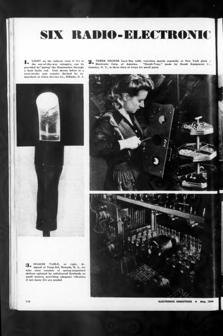
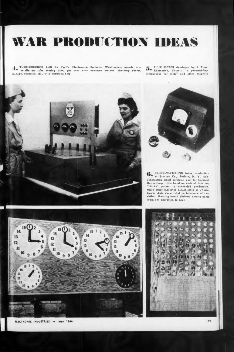
Spokane, Washington, speeds pre- one-man method, checking shorts,
g TUBE-CHECKER built by Pacific Electronics, ■ * installation tube testing 3000 per cent over
leakage, emission, etc., with unskilled help
• FLUX METER developed by J. Thos. Rhamstine, Detroit, is permeability
comparator for meter and other magnets
119ELECTRONIC INDUSTRIES • May, 1944
? $
el . J 91- t
U4*
CLOCK-WATCHING helps production* at Strauss Co., Buffalo, N. Y., sub
contracting small precision part for Colonia! Radio Corp. One hand on each of four top “clocks” points to scheduled production, while other indicates actual state of affairs. Lower dials show total performance of two shifts. Routing board (below) carries parts from one operation to next
/'“'V Í ’
WAR PRODUCTION IDEAS
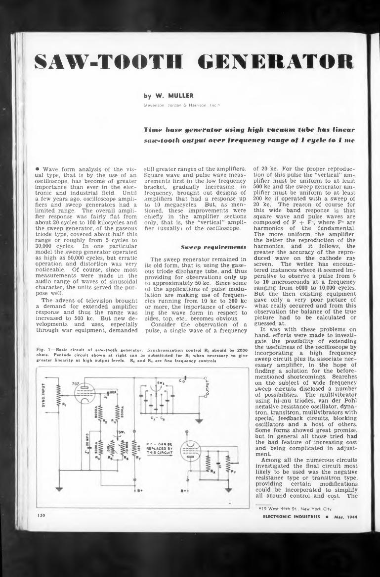
SAW-TOOTH GENERATORby W. MULLERStevenson, Jordan & Harrison, Inc.*
Time base generator using high vacuum tube has linear saw-tooth output over frequency range of f cycle to I me
• Wave form analysis of the visual type, that is by the use of an oscilloscope, has become of greater Importance than ever in the electronic and industrial field. Until a few years ago, oscilloscope amplifiers and sweep generators had a limited range. The overall amplifier response was fairly flat from about 20 cycles to 100 kilocycles and the sweep generator, of the gaseous triode type, covered about half this range or roughly from 5 cycles to 30,000 cycles. In one particular model the sweep generator operated as high as 50,000 cycles, but erratic operation and distortion was very noticeable. Of course, since most measurements were made in the audio range of waves of sinusoidal character, the units served the purpose well.
The advent of television brought a demand for extended amplifier response and thus the range was increased to 500 kc. But new developments and uses, especially through war equipment, demanded
Fig. 1—Basic circuit of saw-tooth generator.ohm». Pentode circuit shown at right can be substituted for R when necessary to give greatei linearity at high output levels. R, and R. are fine frequency controls
[00^ c?
gw, R.
SW|
Cl«i
still greater ranges of the amplifiers. Square wave and pulse wave measurements first in the low frequency bracket, gradually increasing in frequency, brought out designs of amplifiers that had a response up to 10 megacycles. But, as mentioned, these improvements were chiefly in the amplifier sections only, that is, the “vertical” amplifier (usually) of the oscilloscope.
Sweep requiremimtK
The sweep generator remained in its old form, that is, using the gaseous triode discharge tube, and thus providing for observations only up to approximately 50 kc. Since some of the applications of pulse modulation are making use of frequencies running from 10 kc to 200 kc or more, the importance of observing the wave form in respect to sides, top, etc., becomes obvious.
Consider the observation of a pulse, a single wave of a frequency
Synchronization control R should be 2000
swt c,°-O
â
c.- c,
ft? - CAN BE REPLACED BY THIS CIRCUIT
Rv
.4
of 20 kc. For the proper reproduction of this pulse the “vertical” amplifier must be uniform to at least 500 kc and the sweep generator amplifier must be uniform to at least 200 kc if operated with a sweep of 20 kc. The reason of course for this wide band response is that square wave and pulse waves are composed of F 4- Fn, where Fn are
of the fundamental.harmonicsThe more uniform the amplifier, the better the reproduction of the harmonics, and it greater the accuracy duced wave on the screen. The writer
follows, the of the reprocathode ray has encoun-
tered instances where it seemed imperative to observe a pulse from 5 to 10 microseconds at a frequency ranging from 5000 to 10,000 cycles. But the then existing equipment gave only a very poor picture of what really occurred and from this observation the balance of the true picture had to be calculated or guessed at.
It was with these problems on hand, efforts were made to investigate the possibility of extending the usefulness of the oscilloscope by incorporating a high frequency sweep circuit plus its associate necessary amplifier, in the hope of finding a solution for the beforementioned shortcomings. Searches on the subject of wide frequency sweep circuits disclosed a number of possibilities. The multivibrator using hi-mu triodes, van der Pohl negative resistance oscillator, dynatron, transitron, multivibrators with special feedback circuits, blocking oscillators and a host of others. Some forms showed great promise, but in general all those tried had the bad feature of increasing cost and being complicated in adjustment.
Among all the numerous circuits investigated the final circuit most likely to be used was the negative resistance type or transitron type, providing certain modifications could be incorporated to simplify all around control and cost. The
120
*19 West 44th St., New York City
ELECTRONIC INDUSTRIES « May, 1944
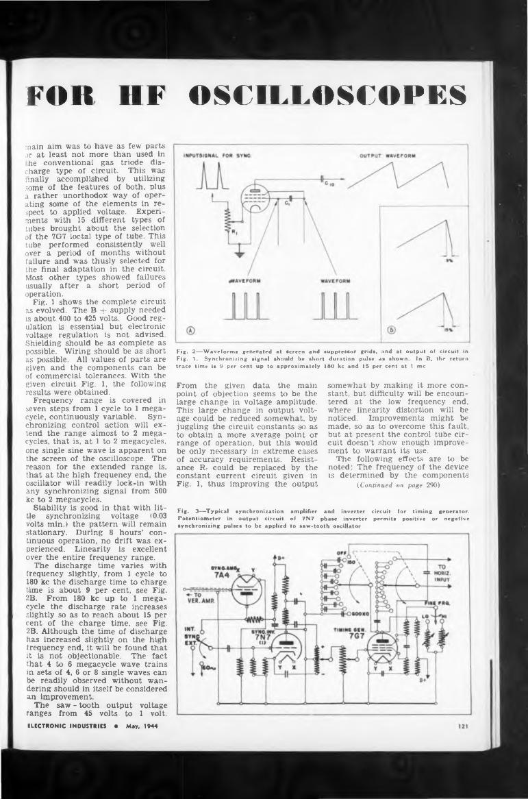
FOR HF
somewhat by making it more con-
isoutput
amplifier andof 7N7 phaseto saw-tooth oscillator
Fig. 3—Typical synchronization Potentiometer in output circuit synchronizing pulses to be applied
determined by the components (Continued on page 290)
main aim was to have as few parts or at least not more than used in he conventional gas triode dis
charge type of circuit. This was anally accomplished by utilizing some of the features of both, plus a rather unorthodox way of operating some of the elements in respect to applied voltage. Experiments with 15 different types of tubes brought about the selection of the 7G7 loctal type of tube. This tube performed consistently well over a period of months without failure and was thusly selected for the final adaptation in the circuit. Most other types showed failures usually after a short period of operation.
Fig. 1 shows the complete circuit as evolved. The B 4- supply needed is about 400 to 425 volts. Good regulation is essential but electronic voltage regulation is not advised. Shielding should be as complete as possible. Wiring should be as short as possible. All values of parts are given and the components can be of commercial tolerances. With the given circuit Fig. 1, the following results were obtained.
Frequency range is covered in seven steps from 1 cycle to 1 megacycle, continuously variable. Synchronizing control action will extend the range almost to 2 megacycles, that is, at 1 to 2 megacycles, one single sine wave is apparent on the screen of the oscilloscope. The reason for the extended range is, that at the high frequency end, the oscillator will readily lock-in with any synchronizing signal from 500 kc to 2 megacycles.
Stability is good in that with little synchronizing voltage (0.03 volts min.) the pattern will remain stationary. During 8 hours’ continuous operation, no drift was experienced. Linearity is excellent over the entire frequency range.
The discharge time varies with frequency slightly, from 1 cycle to 180 kc the discharge time to charge time is about 9 per cent, see Fig. 2B. From 180 kc up to 1 megacycle the discharge rate increases slightly so as to reach about 15 per cent of the charge time, see Fig. 2B. Although the time of discharge has increased slightly on the high frequency end, it will be found that it is not objectionable. The fact that 4 to 6 megacycle wave trains in sets of 4, 6 or 8 single waves can be readily observed without wandering should in itself be considered an improvement.
The saw - tooth output voltage ranges from 45 volts to 1 volt.ELECTRONIC INDUSTRIES • May, 1944
OSCILLOSCOPES
Fig. 2—Waveforms generated at screen and suppressor grids, and at output of circuit in
180 kc and 15 per cent at 1trace time is 9 per cent up to approximatelyIn B, the return me
Fig. 1. Synchronizing signal should be short duration pulse as shown.
From the given data the main point of objection seems to be the large change in voltage amplitude. This large change in output voltage could be reduced somewhat, by juggling the circuit constants so as to obtain a more average point or range of operation, but this would be only necessary in extreme cases of accuracy requirements. Resistance Rt could be replaced by the constant current circuit given inFig. 1, thus improving the
stant, but difficulty will be encountered at the low frequency end, where linearity distortion will be noticed. Improvements might be made, so as to overcome this fault, but at present the control tube circuit doesn’t show enough improvement to warrant its use.
The following effects are to be noted: The frequency of the device
inverter circuit for timing generator, inverter permits positive or negative
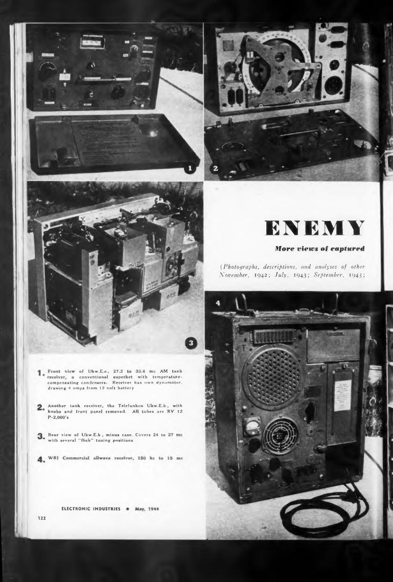
ENEMYHore views of captured
27.2•uperhet with
WRI
ELECTRONIC INDUSTRIES
122
compensating condensers drawing 4 amps from 12
of Ukw.E.c, conventional
Rear with
Receiver has ><wn dynamotor, olt battery
re AM tank temperature-
view of Ukw.E.h-, minus case. Covers 24 to several “flick” tuning positions
Another tank receiver, the Telefunken Ukw.E.h knobs and front panel removed. All tubes are P-2,000’*
., with RV 12
(Photographs, descriptions, and analyses of othe November, 1942; July, 1943; September, 1943
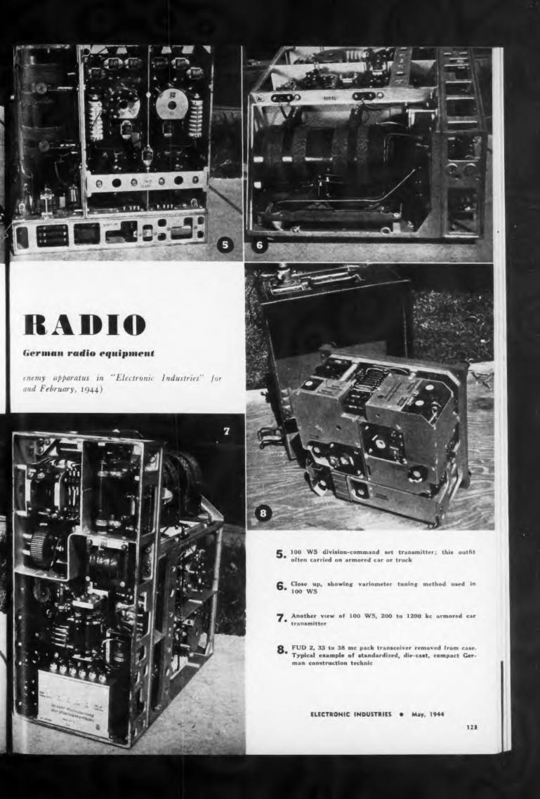
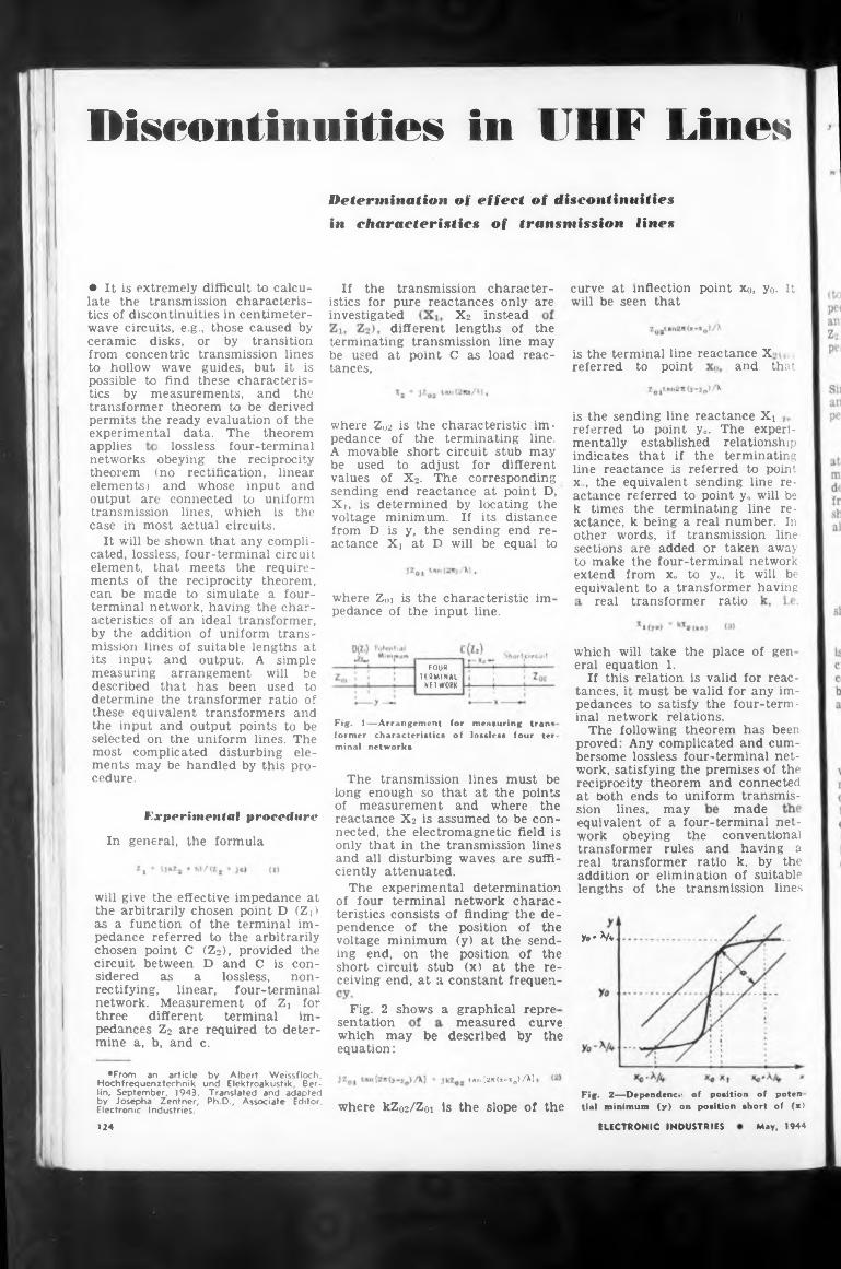
Discontinuities in CHF LinesDetermination of effect of discontinuities
investigated X2 insteaddifferent lengths of the
is the terminal line reactance X
applies
ratio
which will take the place of gen
madeExperimental procedure
In general, the formula
>0* V*
sentationthe
where kZ02/Z0i is the slope of theMay. 1944ELECTRONIC INDUSTRIES
transmission line may point C as load reac-
FOUR TERMINAL
NETWORK
which may be described by equation :
curve at inflection point x0, yo. It will be seen that
and that
real transformer
lossless four-terminalcharacteristic im- terminating line.
voltage from D ac tance
referred to point
eral equation 1.If this relation is valid for reac
tances, it must be valid for any impedances to satisfy the four-terminal network relations.
The following theorem has been proved: Any complicated and cumbersome lossless four-terminal network, satisfying the premises of the reciprocity theorem and connected at noth ends to uniform transmis-
terminating be used at tances,
in characteristics of transmission lines
A movable short circuit stub may be used to adjust for different values of X2. The corresponding sending end reactance at point D, Xi, is determined by locating the
tan [2k(x-xo)/X1
where Z02 is the pedance of the
measured curve
equivalent of a four-terminal network obeying the conventional transformer rules and having a real transformer ratio k. by the addition or elimination of suitable lengths of the transmission lines
Fig. 1—Arrangement for measuring tran< former characteristics of lossless four ter. minal networks
sion lines, may
ceramic disks, from concentric to hollow wave possible to find
where Z01 is the characteristic im pedance of the input line.
is the sending line reactance Xi referred to point y«. The experimentally established relationship indicates that if the terminating line reactance is referred to point x„, the equivalent sending line reactance referred to point y» will be k times the terminating line reactance, k being a real number. In other words, if transmission line sections are added or taken away to make the four-terminal network extend from xo to y», it will be equivalent to a transformer having
or by transition transmission lines guides, but it is
these characteris-
• It is extremely difficult to calculate the transmission characteristics of discontinuities in centimeterwave circuits, e.g., those caused by
minimum. If its distance is y, the sending end reXi at D will be equal to
If the transmission characteristics for pure reactances only are
The transmission lines must be long enough so that at the points of measurement and where the reactance X2 is assumed to be connected, the electromagnetic field is only that in the transmission lines and all disturbing waves are sufficiently attenuated.
The experimental determination of four terminal network characteristics consists of finding the dependence of the position of the voltage minimum (y) at the sending end, on the position of the short circuit stub (x) at the receiving end, at a constant frequen-
tics by measurements, and the transformer theorem to be derived permits the ready evaluation of the experimental data. The theorem
will give the effective impedance at the arbitrarily chosen point D (Zj) as a function of the terminal impedance referred to the arbitrarily chosen point C (Z2), provided the circuit between D and C is considered as a lossless, nonrectifying, linear, four-terminal network. Measurement of Zi for three different terminal impedances Z2 are required to determine a, b, and c.
networks obeying the reciprocity theorem (no rectification, linear elements) and whose input and output are connected to uniform transmission lines, which is the case in most actual circuits.
It will be shown that any complicated, lossless, four-terminal circuit element, that meets the requirements of the reciprocity theorem, can be made to simulate a four- terminal network, having the characteristics of an ideal transformer, by the addition of uniform transmission lines of suitable lengths at its input and output. A simple measuring arrangement will be described that has been used to determine the transformer ratio of these equivalent transformers and the input and output points to be selected on the uniform lines. The most complicated disturbing elements may be handled by this procedure.
♦From an article by Albert Weissfloch, Hochfrequenztechnik und Elektroakustik, Berlin, September, 1943. Translated and adapted by Josepha Zentner, Ph.D., Associate Editor, Electronic Industries.
124
Fig. 2 shows a graphical repre
Fig. 2—Dependent.' of position of poten tial minimum (y) on position short of (x>
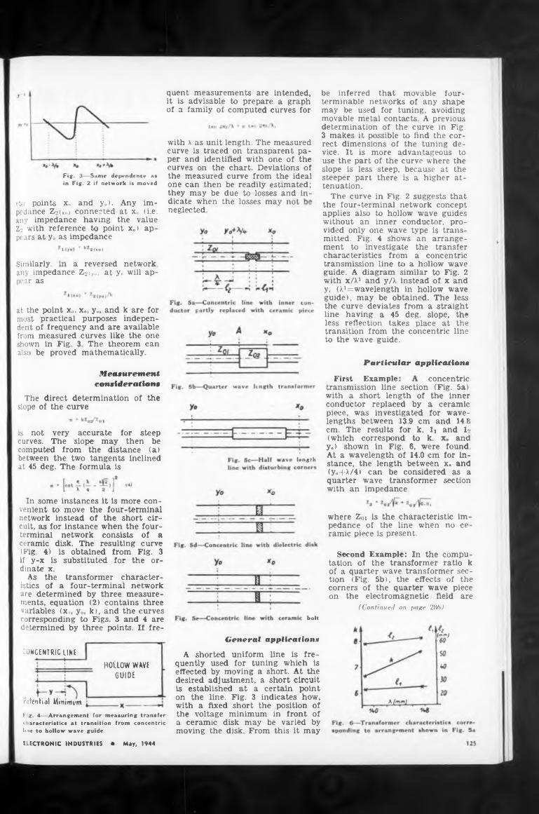
in Fig. 2 suggests thatthe losses may not
a reversed network,Similarly,
Particular application«
concentric
(which correspond to k. and
length
no ce
on
variables (x k), and the curvesbolt
(mm)General applications
CONCENTRIC LINE
ntential Minimum
corresponding to Figs. 3 and 4 are determined by three points. If fre-
steep, because at the there is a higher at-
compu- ratio k
Second Example: In the tation of the transformer
quent measurements are intended, it is advisable to prepare a graph of a family of computed curves for
y.) shown in Fig. 6, were found. At a wavelength of 14.0 cm for instance, the length between x«, and (y.4-l/4> can be considered as a quarter wave transformer section with an impedance
pedance of the line when ramie piece is present.
dicate when neglected
A shorted uniform line is frequently used for tuning which is effected by moving a short. At the desired adjustment, a short circuit is established at a certain point on the line. Fig. 3 indicates how, with a fixed short the position of the voltage minimum in front of a ceramic disk may be varied by moving the disk. From this it may
The direct determination of the slope of the curve
First Example
of a quarter wave transformer section (Fig. 5b), the effects of the corners of the quarter wave piece
Fig. 3—Same dependence a* in Fig. 2 if network is moved
where Zoi is the characteristic im
F g. 4—Arrangement for measuring transfer c aracteristics at transition fiom concentric line to hollow wave guide
with x as unit length. The measured curve is traced on transparent paper and identified with one of the curves on the chart. Deviations of the measured curve from the ideal one can then be readily estimated; they may be due to losses and in-
transmission line section (Fig. 5a) with a short length of the inner conductor replaced by a ceramic piece, was investigated for wavelengths between 13.9 cm and 14.8 cm. The results for k, h and 1*
at the point xo. x„, y„ and k are for most practical purposes independent of frequency and are available from measured curves like the one shown in Fig. 3 The theorem can also be proved mathematically.
any impedance Z^<>) at y0 will ap pear as
the four-terminal network concept applies also to hollow wave guides without an inner conductor, provided only one wave type is transmitted. Fig. 4 shows an arrangement to investigate the transfer characteristics from a concentric transmission line to a hollow wave guide. A diagram similar to Fig. 2 with x/M and y/X instead of x and y, (M= wavelength in hollow wave guide), may be obtained. The less the curve deviates from a straight line having a 45 deg. slope, the less reflection takes place at the transition from the concentric line to the wave guide.
be inferred that movable four- terminable networks of any shape may be used for tuning, avoiding movable metal contacts. A previous determination of the curve in Fig. 3 makes it possible to find the correct dimensions of the tuning device. It is more advantageous to use the part of the curve where the
H01L0W WAVE GUIDE
ELECTRONIC INDUSTRIES • May, 1944
(to points Xo and yo). Any impedance Z2(xo) connected at x (i.e. any impedance having the value Z2 with reference to point xo) appears at yo as impedance
Measurement consideration*
In some instances it is more convenient to move the four-terminal network instead of the short circuit, as for instance when the four- terminal network consists of a ceramic disk. The resulting curve (Fig. 4) is obtained from Fig. 3 if y-x is substituted for the ordinate x.
As the transformer characteristics of a four-terminal network are determined by three measurements, equation (2) contains three
slope is less steeper part tenuation.
The curve
the electromagnetic field are (Continued on page 286)
is not very accurate for steep curves. The slope may then be computed from the distance (a) between the two tangents inclined at 45 deg. The formula is
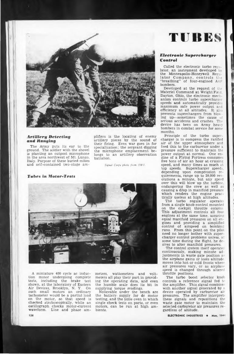
Artillery Detecting and Ranging
The Army puts its ear to the ground. The soldier with the shovel is planting an outpost microphone in the area northwest of Mt. Lungo, Italy. Purpose of these buried mikes and self-contained two-stage am-
Tubes in Motor-Tests
A miniature 400 cycle ac induction motor undergoing complete tests, including the brake test shown, at the laboratory of Eastern Air Devices, Brooklyn, N. Y. On such small motors an ordinary tachometer would be a partial load on the motor, so that speed is checked stroboscopically, while an oscillograph checks motor-current waveform. Line and phase am
plifiers is the locating of enemy artillery pieces by the sound of their firing. Even war goes in for specialization; the sergeant digging the microphone emplacement belongs to an artillery observation battalion.
Signal Corps photo from OWI.
meters, wattometers and voltmeters all play their part in providing the operating data, and even the humble scale does its bit in supplying torque readings.
Noticeable under the bench are the battery- supply for de motor testing, and the little oven in which single check tests on parts, or even motors, can be run at high ambients.
TUBESElectronic Supercharger Control
Called the electronic turbo reg i- | lator, an instrument developed by the Minneapolis-Honeywell Regulator Company, controls the “breathing” of four-engined AAF bombers.
Developed at the request of the Materiel Command at Wright Field, Dayton, Ohio, the electronic mechanism controls turbo supercharger speeds and automatically provides maximum safe power output and efficiency at all altitudes. It also prevents superchargers from blowing up—sometimes the cause of serious accidents and crashes. The device has been on Army heavy bombers in combat service for some months.
Principle of the turbo supercharger is to compress the rarified air of the upper atmosphere and feed this to the carburetor under a pressure sufficient to maintain the power output at normal. One engine of a Flying Fortress consumes five tons of air an hour at cruising speed, and many times as much at top speeds. Supercharger speeds, depending upon compression requirements, range up to 28,000 revolutions a minute, but any speed over this will blow up the turbine, endangering the crew as well as causing a drop in manifold pressure which renders the engine practically useless at high altitudes.
The turbo regulator operates from a single knob control mounted on the cockpit throttle column. This adjustment controls all four engines at the same time, assuring equal manifold pressures on all engines and providing a simplified control of airspeed on bombing runs. From this point on the pilot need no longer bother with supercharger control problems unless, at some time during the flight, he desires to alter manifold pressures.
The control system itself operates continuously, making minute adjustments in waste gate position as the airplane gains or loses altitude, moves into hot or cold fronts where air pressures vary, or as airplane speed is changed through altered throttle positions.
The turbo boost selector knob controls a reference signal fed to the amplifier. This signal combines with another signal generated by a device operated by carburetor air pressures. The amplifier interprets these signals and repositions the waste gate motor to maintain th< selected carburetor air pressures re gardless of altitude.
126 ELECTRONIC INDUSTRIES Miy, 1944
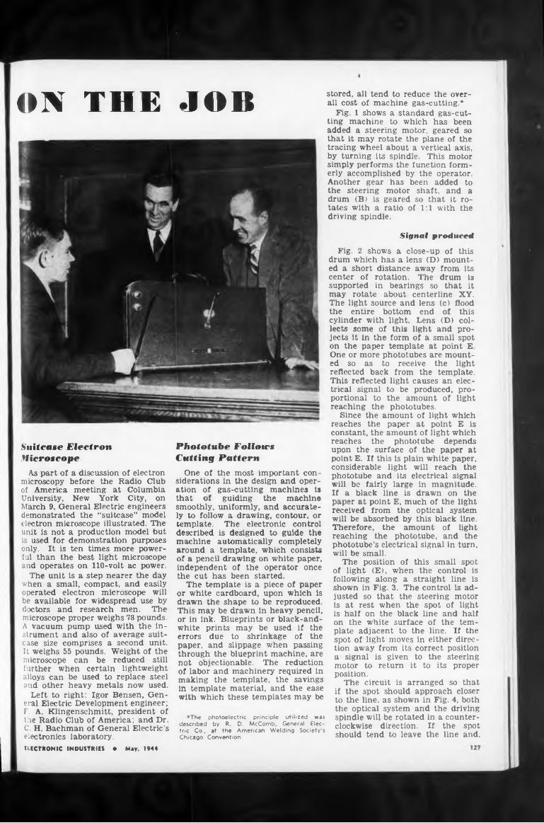
ON THE JOB
Signal produced
this
that
This reflected light causes an trical signal to be produced, portional to the amount of reaching the phototubes.
the entire bottom end
guiding the machine
stored, all tend to reduce the overall cost of machine gas-cutting.*
Fig. 1 shows a standard gas-cutting machine to which has been added a steering motor, geared so that it may rotate the plane of the tracing wheel about a vertical axis, by turning its spindle. This motor simply performs the function formerly accomplished by the operator. Another gear has been added to the steering motor shaft, and a drum (B) is geared so that it rotates with a ratio of 1:1 with the driving spindle.
smoothly, uniformly, and accurately to follow a drawing, contour, or template. The electronic control described is designed to guide the machine automatically completely around a template, which consists of a pencil drawing on white paper, independent of the operator once the cut has been started.
The template is a piece of paper or white cardboard, upon which is drawn the shape to be reproduced. This may be drawn in heavy pencil, or in ink. Blueprints or black-and- white prints may be used if the errors due to shrinkage of the paper, and slippage when passing through the blueprint machine, are not objectionable. The reduction of labor and machinery required in making the template, the savings in template material, and the ease with which these templates may be
Fig. 2 shows a close-up of this drum which has a lens (D) mounted a short distance away from its center of rotation. The drum is supported in bearings so that it may rotate about centerline XY. The light source and lens (c) flood
Since the amount of light which reaches the paper at point E is constant, the amount of light which reaches the phototube depends upon the surface of the paper at point E. If this is plain white paper, considerable light will reach the phototube and its electrical signal will be fairly large in magnitude. If a black line is drawn on the paper at point E, much of the light received from the optical system will be absorbed by this black line. Therefore, the amount of light reaching the phototube, and the phototube’s electrical signal in turn, will be small.
The position of this small spot of light (E), when the control is following along a straight line is shown in Fig. 3. The control is adjusted so that the steering motor is at rest when the spot of light is half on the black line and half on the white surface of the template adjacent to the line. If the spot of light moves in either direction away from its correct position a signal is given to the steering motor to return it to its proper position.
The circuit is arranged so that if the spot should approach closer to the line, as shown in Fig. 4, both the optical system and the driving spindle will be rotated in a counterclockwise direction. If the spot should tend to leave the line and,
ELECTRONIC INDUSTRIES • May, 1944
cylinder with light. Lens (D) collects some of this light and projects it in the form of a small spot on the paper template at point E One or more phototubes are mounted so as to receive the light reflected back from the template.
*The photoelectric principle utilized was described by R. D. McComb, General Electric Co., at the American Welding Society's Chicago Convention.
elec- prolight
Suitcase Electron Microscope
As part of a discussion of electron microscopy before the Radio Club of America meeting at Columbia University, New York City, on March 9. General Electric engineers demonstrated the “suitcase” model electron microscope illustrated. The unit is not a production model but is used for demonstration purposes only. It is ten times more powerful than the best light microscope and operates on 110-volt ac power.
The unit is a step nearer the day when a small, compact, and easily operated electron microscope will be available for widespread use by doctors and research men. The microscope proper weighs 78 pounds. A vacuum pump used with the instrument and also of average suitcase size comprises a second unit. It weighs 55 pounds. Weight of the microscope can be reduced still further when certain lightweight alloys can be used to replace steel and other heavy metals now used.
Left to right: Igor Bensen, General Electric Development engineer; F. A. Klingenschmitt, president of the Radio Club of America; and Dr C. H. Bachman of General Electric’s electronics laboratory.
Phototube FollowsCutting Pattern
One of the most important considerations in the design and operation of gas-cutting machines is
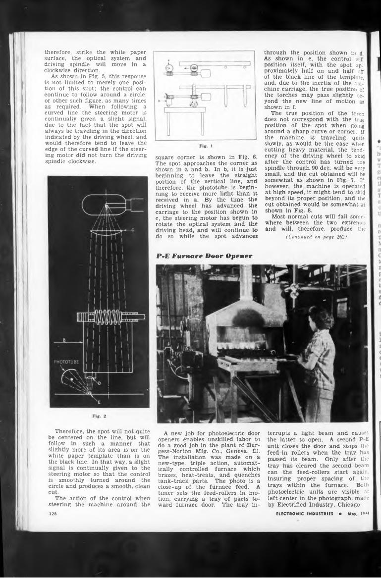
of motion
By the time thereceived in
P-E Furnace Door Opener
followA new job for photoelectric door
openers enables unskilled labor to do a good job in the plant of Bur-
Therefore, the spot will not quite be centered on the line, but will
of the torch with the true
gess-Norton Mfg. The installation new-type, triple ically controlled
driving wheel has advanced the carriage to the position shown in c, the steering motor has begun to rotate the optical system and the driving head, and will continue to do so while the spot advances
As shown in Fig. 5, this response is not limited to merely one position of this spot; the control can continue to follow around a circle, or other such figure, as many times as required. When following a curved line the steering motor is continually given a slight signal, due to the fact that the spot will always be traveling in the direction indicated by the driving wheel, and would therefore tend to leave the edge of the curved line if the steering motor did not turn the driving spindle clockwise. square corner is shown in Fig. 6
The spot approaches the corner as shown in a and b. In b, it is just beginning to leave the straight portion of the vertical line, and therefore, the phototube is beginning to receive more light than it
through the position shown in d As shown in e, the control will position itself, with the spot approximately half on and half off of the black line of the tempi, te, and, due to the inertia of the machine carriage, the true position of the torches may pass slightly oe-
brazes, heat-treats, and quenches tank-track parts. The photo is a close-up of the furnace feed. A timer sets the feed-rollers in motion, carrying a tray of parts toward furnace door. The tray in-
yond the new line shown in f.
The true position does not correspond
white paper system and move in a
Co., Geneva, Ill. was made on a action, automat
furnace which
ELECTRONIC INDUSTRIES • May, 1944
such a manner that
therefore, strike the surface, the optical driving spindle will clockwise direction.
terrupts a light beam and causes the latter to open. A second P E unit closes the door and stops the feed-in rollers when the tray h is passed its beam. Only after the tray has cleared the second beam can the feed-rollers start again, insuring proper spacing of the trays within the furnace. Both photoelectric units are visible at left center in the photograph, made by Electrified Industry. Chicago.
position of the spot when going around a sharp curve or corner. If the machine is traveling quite slowly, as would be the case when cutting heavy material, the tendency of the driving wheel to skid after the control has turned the spindle through 90 deg. will be very small, and the cut obtained will be somewhat as shown in Fig. 7. If, however, the machine is operated at high speed, it might tend to skid beyond its proper position, and the cut obtained would be somewhat us shown in Fig. 8.
Most normal cuts will fall somewhere between the two extremes and will, therefore, produce the
(Continued on page 262)
slightly more of its area is on the white paper template than is on the black line. In that way, a slight signal is continually given to the steering motor so that the control is smoothly turned around the circle and produces a smooth, clean cut.
The action of the control when steering the machine around the128
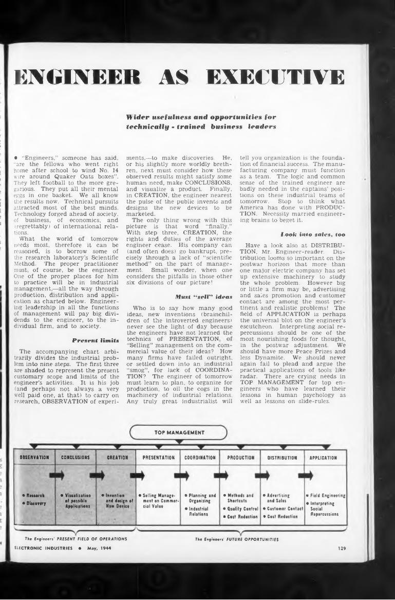
ENGINEER AS EXECUTIVE
Look into sales, tooworld tomorrow
on the
PRESENTATIONtechnicsPresent limits
Th* Engineers' PRESENT FIELD OF OPERATIONS The Engineers' FUTURE OPPORTUNITIES
129
The only picture is With step rights and
to plan, to organize for to oil the cogs in the of industrial relations, great industrialist will
considers the pitfalls in those other six divisions of our picture!
must learn production, machinery Any truly
method’ ment.
Must “sell” ideas
The accompanying chart arbitrarily divides the industrial problem into nine steps. The first three are shaded to represent the present customary scope and limits of the engineer’s activities. It is his job (and perhaps not always a very well paid one, at that) to carry on research, OBSERVATION of experi-
engmeer cease, (and often does) cisely through a
Small wonder, when one
• “Engineers,” someone has said, “are the fellows who went right home after school to wind No. 14 wire around Quaker Oats boxes”. They left football to the more gregarious. They put all their mental eggs in one basket. We all know the results now. Technical pursuits attracted most of the best minds. Technology forged ahead of society.
His company can go bankrupt, prelack of “scientific part of manage-Method. The proper practitioner
must, of course, be the engineer. One of the proper places for him to practice will be in industrial management,—all the way through production, distribution and application as charted below. Engineering leadership in all the functions of management will pay big dividends to the engineer, to the individual firm, and to society.
Who is to say how many good ideas, new’ inventions (brainchildren of the introverted engineers) never see the light of day because the engineers have not learned the
tell you organization is the foundation of financial success. The manufacturing company must function as a team. The logic and common sense of the trained engineer are badly needed in the captains’ positions on these industrial teams of tomorrow. Stop to think what America has done with PRODUCTION. Necessity married engineering brains to beget it.
Have a look also at DISTRIBUTION, Mr. Engineer-reader. Distribution looms so important on the postwar horizon that more than one major electric company has set up extensive machinery to study the whole problem. However big or little a firm may be, advertising and sales promotion and customer contact are among the most pertinent and realistic problems! The field of APPLICATION is perhaps the universal blot on the engineer’s escutcheon. Interpreting social repercussions should be one of the most nourishing foods for thought, in the postwar adjustment. We should have more Peace Prizes and less Dynamite. We should never again fail to plead and argue the practical applications of tools like radar. There are crying needs in TOP MANAGEMENT for top engineers who have learned their lessons in human psychology as well as lessons on slide-rules.
of economics, and of international rela-
UECTRONIC INDUSTRIES • May, 1944
Wider usefulness and opportunities for technically - trained business leaders
thing wrong with this that word “finally.”
three, CREATION, the duties of the average
therefore it can be to borrow some of
laboratory’s Scientific
rnents,—to make discoveries. He, or his slightly more worldly brethren, next must consider how these observed results might satisfy some human need, make CONCLUSIONS, and visualize a product. Finally, in CREATION, the engineer nearest the pulse of the public invents and designs the new devices to be marketed.
“Selling” management on the commercial value of their ideas? How many firms have failed outright, or settled down into an industrial “smog”, for lack of COORDINATION? The engineer of tomorrow
of business, (regrettably) tions.
What the needs most, reasoned, is the research
TOP MANAGEMENT
OBSERVATION CONCLUSIONS CREATION PRESENTATION COORDINATION PRODUCTION DISTRIBUTION APPLICATION
• Research
• Oise every
• Visualization •I possible Applications
• Invention ani design ef New Device
• Selling Manacement on Commercial Value
• Planning and Organizing
• Industrial Relatiens
• Methods and Shortcuts
♦ Quality Control
• Cost Reduction
• Advertising and Sales
• Customer Contact
• Cost Reduction
• Field Engineering
• Interpreting Social Repercussions
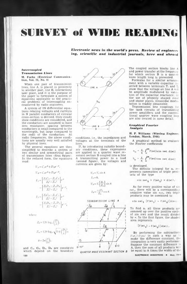
SURVEY of WIRE READING
ing, scientific and industrial Journals, here and abroad
UNE A
LINE B
and
Cue^-^-D bc sin 9,
sin 9,
cos 9
TRANSMISSION LINE A
120 log
120
9^0'are constantsand C.which depend on the boundary QUARTER WAVE RESONANT SECTION B
By performing the subtraction > f(wtx )-f(wtJ in such a way as to make the difference constant, th integration is very easily performed Suppose the constant difference A, then the sum of all products will be equal to A times the width of th
Graphical Fourier Analysis
is developed.The definite integral for an re
presents summation of triple prod ucts of the type
The coupled section blocks line A and power transfer at the frequency for which section B is a quarer wave length long is prevented.
Formulas for a similar arrangement with a variable capacitor inserted between terminals Ti and T. show that the voltage on line A will be amplitude modulated by variation of the capacitor reactance; by the use of properly shaped rotor and stator plates, sinusoidal modulation is readily obtainable.
Transmission line couplings for the tank circuits of transmitting power amplifiers and the conventional quarter wave coupling loop are also treated in some detail.
(second figure), the voltages currents are given by:
IntercoupledTransmission Lines
Electronic news in the world's press. Review of engine?
conditions, i.e., the impedances and voltages at the terminals of the lines.
If, by introducing suitable boundary conditions, these expressions are applied to a quarter wave resonant section B coupled into a line A transmitting power to a load
As for every positive value of sin there will be a corresponding
negative value sin nut,, two triple products may be combined to
To find an all these products are summed up over the positive cycles of sin nwt and the result divided by jt. In the first figure, the shaded area represents
ELECTRONIC INDUSTRIES • May, 1944
II. P. Williams (Wireless Engineer, London. March. 1944)
A graphical method to evaluate the Fourier coefficients
M. Fuchs (Electrical Communication, Vol. 21. No. 4)
When one pair of transmission lines, line A, is placed in proximity to another pair, line B, interactions take place, and it is the purpose of the paper to formulate a system of equations applicable to the practical problems of intercoupling encountered by radio engineers.
A system of 2N differential equations relating voltages and currents in N parallel conductors of circular cross-section is derived. Only steady state conditions are considered, and the conductors are assumed to have zero resistance; spacing between conductors is small compared to the wavelength, but large compared to the radii of the conductors. At radio frequencies, the above conditions are usually very well satisfied by physical lines.
The general equations are then simplified to describe a system of two similar and symmetrical pairs of transmission lines (first figure). In the reduced form, the equations read:
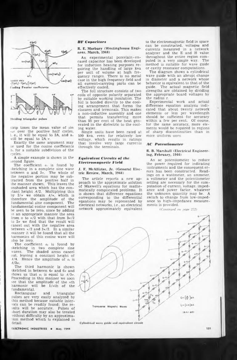
BF Capacitorsd(wt)
d(orf)
it will be equal to 2A,
sketching in
the amplitude of a3 is
harmonicsketched in between 4*- and
1/nth
strip times the mean nwt over the positive
shows us that as is equal Proceeding in this manner see that the amplitude of
analyzer and the E and H throughout the entire region puted in a very simple way. method is suitable for wave
The third
value half
two complete sine shaded areas cancel
a constant height of
Equivalent Circuits of the Electromagnetic Field
of sin cycles, and an
shown6*- and
jnnvkl' »Ht» 'I
Finding Fourier coefficient*
harmonic will fundamental.
Rectangular pulses are very
or cavity resonator computations.The diagram shows a cylindrical
wave guide with an abrupt change in diameter and a network whose behavior is equivalent to that of the guide. The actual magnetic field strengths are obtained by dividing the appropriate board voltages by the radius r.
Experimental work and actual difference equation analysis indicated that about twenty network elements or less per wavelength should be sufficient for accuracy within a few per cent. Of course, for the same accuracy, more elements would be required in regions of sharp discontinuities than in more uniform ones.
this method because suitable intervals can be readily found; the results will be accurate. Pulses of short duration may also be treated without difficulty by an approximation method which is explained in detail.
to the electromagnetic field in space can be constructed, voltages and currents measured in a network
waves. The out, leaving 4/4. Hence
and triangular easily analyzed by
to A/3ir. we soon the nth of the
will be equal to 2A/*-.Exactly the same argument may
be used for the cosine coefficients bn for a suitable subdivision of the cycles.
A simple example is shown in the second figure.
The coefficient a, is found by sketching in a complete sine wave between o and 2*\ The whole of the negative portion may be subtracted from the positive half in the manner shown. This leaves the unshaded area which has the constant height .4/2. Multiplying this by 2/r we obtain A/k, which is therefore the amplitude of the fundamental sine component. The fundamental cosine component will be seen to be zero, since by adding in an appropriate manner the area from o to *72 with that from 3*72 to 2*- we find that the result will cancel out with the negative area between *72 and 3*72. In a similar manner it will be found that all the harmonics of this cosine wave will also be zero.
The coefficient a* is found by
ELECTRONIC INDUSTRIES • May, 1944
value com-
The guide
R. E. Morbury (Westinghouse Engineer. March, 1944)
An experimental porcelain - encased capacitor has been developed for induction heating purposes requiring the handling of large kva per unit of volume at high frequency ranges. There is no metal case in the high frequency field and all current-carrying parts can be effectively cooled.
The foil structure consists of two coils of opposite polarity separated by suitable working insulation. The foil is bonded directly to the cooling arrangement that forms the closures and terminals. This makes a non-inductive assembly and one that permits transferring more than 95 per cent of the heat generated in the dielectric to the cooling water.
Single units have been rated at 500 kva, even for relatively low voltage, which results in ratings that involve very large currents through the terminals.
R. B. Marshall (Electrical Engineering, February, 1944)
An ac potentiometer to reduce the power required for indicating instruments and the consequent errors has been constructed. Readings on a wattmeter, an ammeter, a voltmeter and the potentiometer setting are necessary for the computation of current, voltage, impedance and power factor, whatever the unknown quantity may be. A switch to change from low-impedance to high-impedance measurements is provided.
(Continued on page 272)
J. F. McAllister, Jr. (General Electric Review, March, 1944)
The article reports a new approach to the approximate solution of Maxwell’s equations for mathematically complicated problems. It is shown that difference equations corresponding to the differential equations may be represented by electrical networks, i.e., an electrical network approximately equivalent
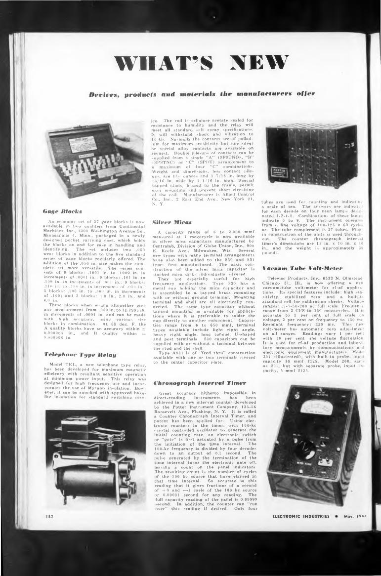
WHAT’S NEWDevices, products and materials the manufacturers oiler
Gage Blocks
An economy Het of 87 gage blocks is now available in two qualities from Continental Machines, Inc., 1301 Washington Avenue So., Minneapolis 4, Minn., packaged in u newly designed pocket carrying case, which holds the blocks on end for ease in handling and identifying. The set includes two .050 wear blocks in addition to the five standard series of gage blocks regularly offered. The addition of the .050 in. size makes the complete set more versatile. The series consists of 9 blocks: .1001 in. to .1009 in. in increments of .0001 in.; 9 blocks: .101 in. to .109 in. in increments of .<><11 in.; 9 blocks: .110 in. to .190 in. in increments of .010 in.; 5 blocks: .100 in. to .500 in. in increments of .100; and 3 blocks: 1.0 in., 2.0 in., and 4.0 in.
These blocks when wrung altogether give any measurement from .050 in. to 11.7995 in. in increments of .0001 in. and can be made with high accuracy, using various size blocks in combination. At 68 deg. F. the A quality blocks have an accuracy within Zb 0.000004 in., and II quality within ztz 0.000008 in.
Telephone Type Belay
Model TKL, a new telephone type relay, has been developed for maximum magnetic efficiency with resultant sensitive operation at minimum power input. This relay was designed for high frequency use and incorporates the use of Mycalex insulation. However, it can be supplied with approved bakelite insulation for standard switching serv-
ice. The coil is cellulose acetate sealed for resistance to humidity and the relay will meet all standard salt spray specifications. It will withstand shock and vibration to 10 Gs. Normally the contacts are of palladium for maximum sensitivity but fine silver or special alloy contacts are available on request. Double pile-ups of contacts can be supplied from a single “A” (SPSTNO), "B” (SPSTNC) or “C” (SPDT) arrangement to * maximum of four “C” combinations. Weight and dimensions, less contact pileups. are 1 l2 ounces and 1 7/16 in. long by 15/16 in. wide by 1 1/16 in. high. Special tapped studs, brazed to the frame, permit easy mounting and prevent short circuiting of the coil. Manufacturer is Allied Control Co., Inc., 2 East End Ave., New York 21, N. Y.
Silver Micas
A capacity range of 6 to 2,000 mmf measured at 1 megacycle is now available in silver mica capacitors manufactured by Centralab, Division of Globe Union, Inc., 900 E. Keefe Ave., Milwaukee, Wis. Several new types with many terminal arrangements have also been added to the 830 and 831 types first manufactured. The basic construction of the silver mica capacitor is stacked mica disks individually silvered.
They are especially useful for high frequency applications. Type 830 has a metal cup holding the mica capacitor and is assembled to a tapped brass mounting with or without ground terminal. Mounting terminal and shell are all electrically connected. The same type capacitor without tapped mounting is available for applications where it is preferable to solder the cup directly to another component. Capacities range from 6 to 650 mmf, terminal types available include light right angle, heavy right angle, long tongue, U-shaped and post terminals. 830 capacitors can be supplied with or without a terminal between the stud and the shell.
Type A831 is of “feed thru” construction available with one or two terminals riveted to the center capacitor plate.
Chronograph Interrai Timer
Great accuracy hitherto impossible in direct-reading instruments has been achieved in a new interval counter developed by the Potter Instrument Company, 135-56 Roosevelt Ave., Flushing, N. Y. It is called a Counter Chronograph Interval Timer, and patent has been applied for. Using electronic counters in the timer, with 100-kc crystal controlled oscillator to generate the initial counting rate, an electronic switch or "gate” is first actuated by a pulse from the initiation of the time interval. The 100-kc frequency is divided by four decades down to an output of 0.1 second. The pulse generated by the termination of the time interval turns the electronic gate off, leaving a count on the panel indicators. The resulting count is the number of cycles of the 100 kc source that have elapsed in that time interval. So accurate is this reading that it gives fractions of a second of -f-0 and —1 cycle of the 100 kc source or 0.00001 second for any reading. The full capacity reading of the panel is 0.09999 second. In addition, the counter can “run over” this reading if desired. Only four
tubes are used for counting and indicating a scale of ten. The answers are indicated for each decade on four neon lamps desi nated 1-2-4-8. Combinations of these lam; indicate 0 to 9. The instrument operate from a line voltage of 100-125 v 60 cycle ac. The tube complement is 27 tubes. Plugin construction of the units is used throughout. The counter chronograph interval timer’s dimensions are 15 in. x 10 in. x 10 in., and the weight is approximately 3‘J pounds.
Vacuum Tube Volt-Meter
Televiso Products, Inc., 6533 N. Olmstead, Chicago 31, III., is now offering u new vacuum-tube volt-meter for rf-af applications. Its special features include: high sensitivity. stabilized zero, and a built-in standard cell for calibration checks. Voltage ranges: .5-5-50-200 ac full scale. Frequency range from 2 CPS to 150 megacycles. It i accurate to 2 per cent of full scale on voltage, 2 per cent on frequency to 150 nu . Resonant frequency: 350 me. This new volt-meter has automatic zero adjustment on all ranges. Readings vary 1 per cent with 10 per cent ane voltage fluctuation. It is used for rf-af production and laboratory measurements by communications and electronic equipment manufacturers. Model 201 (illustrated), with built-in probe, input capacity 10 mmf $125. Model 200, same as 201, but with separate probe, input ca parity, 5 mmf $135.
132 ELECTRONIC INDUSTRIES May, 1944
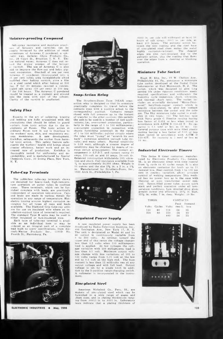
Uoixliire-pnwfing Compound
thedrying
Miniature Tube Socket
Laboratories at Fort Monmouth,designed to
life under rigorous conditions,Snap-Action Relay
Clarity of the varnish
heavily silver-platedSafety Flux
of transfer to the other position
cations overcurrent protection, particularly in the range of 1 to 100 milliamperes
‘hunts furnishing potentialsof 1 to 100 millivolts; pulsing circuits where
‘scratch its ownmembranes. development. less at
Industrial Electronic Timers
Tube-Cap Terminals
loss
ture operation on power tubes confined
and leads are made metals for
TIMER CONTACTS
Peak»¡stance for all types
Regulated Power Supplyable
output
content is less than 12 millivolts rmu at anyoutput voltage and with full load,voltage is set by single knobtion to the 3-position range-changing switch.
in the instru-
Zinc-plated Steel
furnished in
tests indicate that plating thickness of
ELECTRONIC INDUSTRIES
operation in any range of temperature. Hot- electro tinning assures highest corrosion re
Output i addi-
A voltmeter is incorporated ment.
Demand, kva
The long
meets
transformer power power tubes assure operation under all
when tested
connection with
with part
continuously variable from
demand cent in control ' od has rheostat
overcurrent protection
.0003 hoursleast tween
lacquer is also
or may be a complete
s, from Air- 1591 D No.
locket, which
tard the or varnish.
the range
caps and leads
wide range
ike natural waxes, Acrawax C does not re-
ordered as an integral part of lead built to users’ specification! craft-Marine Products Inc., Fourth St., Harrisburg, Pa.
individual item A new regulated power supply has been developed by Radio-Television Institute. Inc., 480 Lexington Ave., New York 17, N. Y. The unit is designated ns Model 44 and its
quick tern- gives high.
of the solvent, unaffected.
no power or auto
available The Diamond Grip tube-cap units are for use on insulated wire where an insulation-support type of terminal is required. The standard Type B units may be used in either insulated or n«n-insulated wire.
Each type of tube-cap terminal is avail-
The solderless tube-cap terminals shown are designed for heavy-load, high-tempera-
Salt-spray resistance and moisture proof- ss of lacquers and varnishes can bi
small syn-
variation with 100 milliamperes load is than 0.1 volt. Maximum output voltchange with line variations of 105 to volts varies from 0.15 volt at the low to 0.5 volt at the high end. The hum
deep. Weight: 30 lbs.
reatly increased by the addition of ercentages of Acrawax C powdered, i
■ hetic wax. declares Glyco Product, Inc., 26 Court St., Brooklyn 2, N. Y.
the relay must "pump' accordance with ASTM D
perature conditions. Low internal drop greater power and efficiency. 20 in.
less age 125 end
American Nickeloid Co., makers of zinc-plated steel
areas. These terminals, which can be furnished complete with leads, are practically independent of operation temperature. Caps
0 to 300 volts. At settings toward the upper end of this range the voltage changes less than 0.2 volts when 100 milliamperes load is applied. At low voltages the volt-
kva Heat control, from 1 to 100 per stepless variation, allows accurate
of welding temperature. This meth-
Hugh H. Eby, Inc., 18 W. Chelton Ave., Philadelphia 44, Pa„ announces a miniature tube socket developed at the Signal Corps
Experts in the art of soldering, brazing and welding are fully acquainted with the precautions that should be taken to guard workers from toxic action due to the ingredients of fluxes. The toxic action in ordinary fluxes now in use is injurious to the workers’ eyes, skin, and respiratory mu-
Kwikflux, safeguards the worker from harmful toxic action. This safety feature safeguards the workers’ health and brings about greater efficiency, better work and an increased rate of production. Kwikflux is thoroughly tested for uniformity and dependability, and is manufactured by Special Chemicals Corp., 30 Irving Place, New York,
in. per side will withstand at least 50 of salt spray ; .0005 in. per side, at
100 hours. The galvanic action bethe zinc coating and the steel base
trol. Xenon-filled start and perfect
The Struthers-Dunn Type 79XAX snapaction relay is designed so that its armature practically completes its travel before the contacts snap with ■ positive action to the corresponding position. Contacts remain closed with full pressure up to the instant
Volts110220
150-42T. Its capacity is 5 mmf 10 me.
Volts110220440
back”; numerous sensitive vacuum tube circuits ; and many others. Normal sensitivity is 0.01 watt, although a greater degree of sensitivity may be obtained by means of various circuit arrangements. The contact arrangement is S.P.D.T. and contact rating 10 amps. 110-volt ae and 10 amps. 24-volt de. Balanced construction withstands 10G vibration and shock. Coil resistance available from % to approximately 30,000 ohms. Weight is 10 ounces and the size 2% in. i 3 in. z 1% in. Manufactured by Struthers-Dunn, Inc., 1321 Arch St., Philadelphia 7, Pa.
Peru, Ill., are which can be of guge* and
-aid to improve the flow-out and helps pigment suspension. One-half of one per cent Acrawax C powdered, incorporated into a 28 per cent solids urea formaldehyde alkyd modified clear baking varnish, gave a film on a steel panel which after baking at 300 ■ leg. F for 30 minutes resisted a concentrated salt spray (20 per cent) at 100 deg. F for 144 hours. The Acrawax C powdered should be treated as a pigment and ground
This Series II timer contactor, manufactured by Electronic Products Co., Geneva. Ill., is an electronic timer with time control from cycle to 45 cycles range. It is also an electronic contactor for loads up to 15
required specifications and withstands the humidity cycle immersion, shock, vibration, and thermal shock tests. The socket includes an especially designed "Micro-Processed” beryllium-copper contact which is
sheet sizes, and in plating thicknesses ranging from .00015 in. to .0005 in. Laboratory
of zinc-plated steel sheet makes the metal highly corrosion-resistant. The sheared edges are also rust-resistant due to the galvanic action, plus the coating that flows over the edges from a shearing or blanking operation.
resistance between the socket and the tube pin. The Eby miniature tube socket is available tn two types: (1) The low-loss type with Navy grade G Steatite casting having loss factor of 0.016 or less when tested in accordance with ASTM D 150-42 T. Its ca parity is 1.5 mmf or less at 10 me. (2) General purpose type with mica filled plastic casting having a loss factor of 0.05 or less
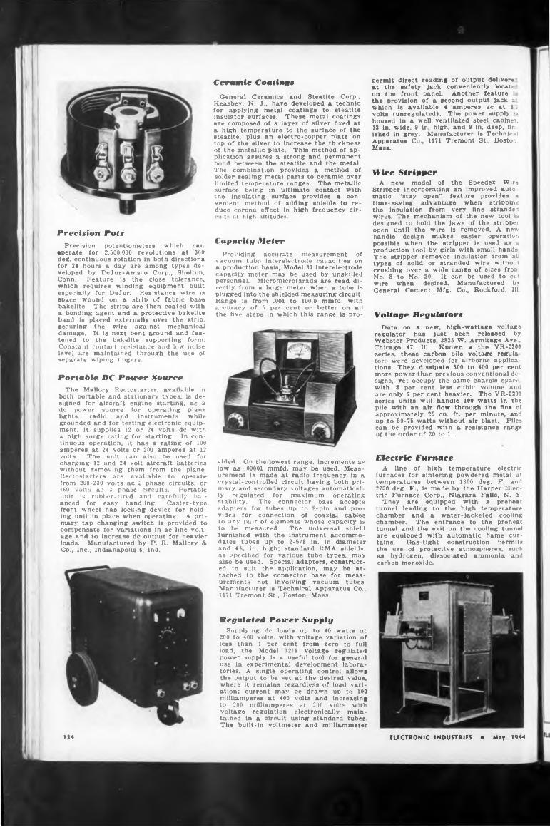
Precision PotsPrecision potentiometers which can
eperate for 2,500,000 revolutions at 360 deg. continuous rotation in both directions for 24 hours a day are among types developed by DeJur-Amsco Corp., Shelton, Conn. Feature is the close tolerance, which requires winding equipment built especially for DeJur. Resistance wire is space wound on a strip of fabric base bakelite. The strips are then coated with a bonding agent and a protective bakelite band is placed externally over the strip, securing the wire against mechanical damage. It is next bent around and fastened to the bakelite supporting form. Constant contact resistance and low noise level are maintained through the use of separate wiping fingers.
Portable DC Power SourceThe Mallory Rectostarter, available in
both portable and stationary types, is designed for aircraft engine starting, as a de power source for operating plane lights, radio and instruments while grounded and for testing electronic equipment. It supplies 12 or 24 volts de with a high surge rating for starting. In continuous operation, it has a rating of 100 amperes at 24 volts or 200 amperes at 12 volts. The unit can also be used for charging 12 and 24 volt aircraft batteries without removing them from the plane. Rectostarters are available to operate from 208-230 volts ac 3 phase circuits, or 460 volts ac 3 phase circuits. Portable unit is rubber-tired and carefully balanced for easy handling. Caster-type front wheel has locking device for holding unit in place when operating. A primary tap changing switch is provided to compensate for variations in ac line voltage and to increase de output for heavier loads. Manufactured by P. R. Mallory & Co., Inc., Indianapolis 6, Ind.
Ceramic Coatings
General Ceramics and Steatite Corp., Keasbey, N. J., have developed a technic for applying metal coatings to steatite insulator surfaces. These metal coatings are composed of a layer of silver flxed at a high temperature to the surface of the steatite, plus an electro-copper plate on top of the silver to increase the thickness of the metallic plate. This method of application assures a strong and permanent bond between the steatite and the metal. The combination provides a method of solder sealing metal parts to ceramic over limited temperature ranges. The metallic surface being in ultimate contact with the insulating surface provides a convenient method of adding shields to reduce corona effect in high frequency circuits at high altitudes.
Capacity Meter
Providing accurate measurement of vacuum tube interelectrode capacities on a production basis, Model 37 interelectrode capacity meter may be used by unskilled personnel. Micromicrofarads are read directly from a large meter when a tube is plugged into the shielded measuring circuit. Range is from .001 to 100.0 mmfd. with accuracy of 5 per cent or better on all the five steps in which this range is pro-
vided. On the lowest range, Increments as low as .00001 mmfd. may be used. Measurement is made at radio frequency in a crystal-controlled circuit having both primary and secondary voltages automatically regulated for maximum operating stability. The connector base accepts adapters for tubes up to 8-pin and provides for connection of coaxial cables to any pair of elements whose capacity is to be measured. The universal shield furnished with the instrument accommodates tubes up to 2-5/8 in. in diameter and 4% in. high; standard RMA shields, as specified for various tube types, may also be used. Special adapters, constructed to suit the application, may be attached to the connector base for measurements not involving vacuum tubes. Manufacturer is Technical Apparatus Co., 1171 Tremont St., Boston, Mass.
Regulated Power SupplySupplying de loads up to 40 watts at
200 to 400 volts, with voltage variation of less than 1 per cent from zero to full load, the Model 1218 voltage regulated power supply is a useful tool for general use in experimental development laboratories. A single operating control allows the output to be set at the desired value, where it remains regardless of load variation; current may be drawn up to 100 milliamperes at 400 volts and increasing to 200 milliamperes at 200 volts with voltage regulation electronically maintained in a circuit using standard tubes. The built-in voltmeter and milliammeter
permit direct reading of output deliver» at the safety jack conveniently locate, on the front panel. Another feature the provision of a second output jack a which is available 4 amperes ac at 8 ; volts (unregulated). The power supply •« housed in a well ventilated steel cabinet, 13 in. wide, 9 in. high, and 9 in. deep, fin ished In grey. Manufacturer is Technics! Apparatus Co., 1171 Tremont St., Boston. Mass.
Wire StripperA new model of the Speedex Wire
Stripper incorporating an improved auto matic "stay open” feature provides a time-saving advantage when stripping the insulation from very fine stranded wires. The mechanism of the new tool is designed to hold the jaws of the stripper open until the wire is removed. A new handle design makes easier operation possible when the stripper is used as a production tool by girls with small hands The stripper removes insulation from al types of solid or stranded wire without crushing over a wide range of sizes from No. 8 to No. 30. It can be used to cut wire when desired. Manufactured by General Cement Mfg. Co., Rockford, Ill.
Voltage RegulatorsData on a new, high-wattage voltage
regulator has just been released by Webster Products, 3825 W. Armitage Ave., Chicago 47, Ill. Known a the VR-2200 series, these carbon pile voltage regula tors were developed for airborne applications. They dissipate 300 to 400 per eent more power than previous conventional designs, yet occupy the same chassis spac». with 8 per cent less cubic volume and are only 6 per cent heavier. The VR-2200 series units will handle 100 watts in the pile with an air flow through the fins of approximately 25 cu. ft. per minute, and up to 50-75 watts without air blast. Piles can be provided with a resistance range of the order of 20 to 1.
Electric FurnaceA line of high temperature electric
furnaces for sintering powdered metal at temperatures between 1800 deg. F. and 2750 deg. F., is made by the Harper Electric Furnace Corp., Niagara Falls, N. Y.
They are equipped with a preheat tunnel leading to the high temperature chamber and a water-jacketed cooling chamber. The entrance to the preheat tunnel and the exit on the cooling tunnel are equipped with automatic flame curtains. Gas-tight construction permits the use of protective atmospheres, such as hydrogen, dissociated ammonia and carbon monoxide.
134 ELECTRONIC INDUSTRIES e May, 1944
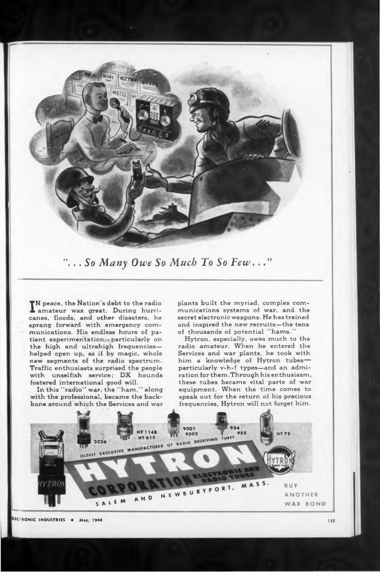
"... So Many Owe So Much To So Few..
IN peace, the Nation’s debt to the radio amateur was great. During hurri
canes, floods, and other disasters, he sprang forward with emergency communications. His endless hours of patient experimentation—particularly on the high and ultrahigh frequencies— helped open up, as if by magic, whole new segments of the radio spectrum. Traffic enthusiasts surprised the people with unselfish service; DX hounds fostered international good will.
In this “radio” war, the “ham,” along with the professional, became the backbone around which the Services and war
plants built the myriad, complex communications systems of war, and the secret electronic weapons. He has trained and inspired the new recruits—the tens of thousands of potential “hams.”
Hytron, especially, owes much to the radio amateur. When he entered the Services and war plants, he took with him a knowledge of Hytron tubes— particularly v-h-f types—and an admiration for them.Through his enthusiasm, these tubes became vital parts of war equipment. When the time comes to speak out for the return of his precious frequencies, Hytron will not forget him.
2C26
M HY114B fT HY415
9001 ÏH 9002
of .«.o
” 95«955
tube*HY75
0,01«
S ALe M
buyM - NtWBU ANOTHER
A N w WAR BOND
ELECTRONIC INDUSTRIES • May, 1944 135
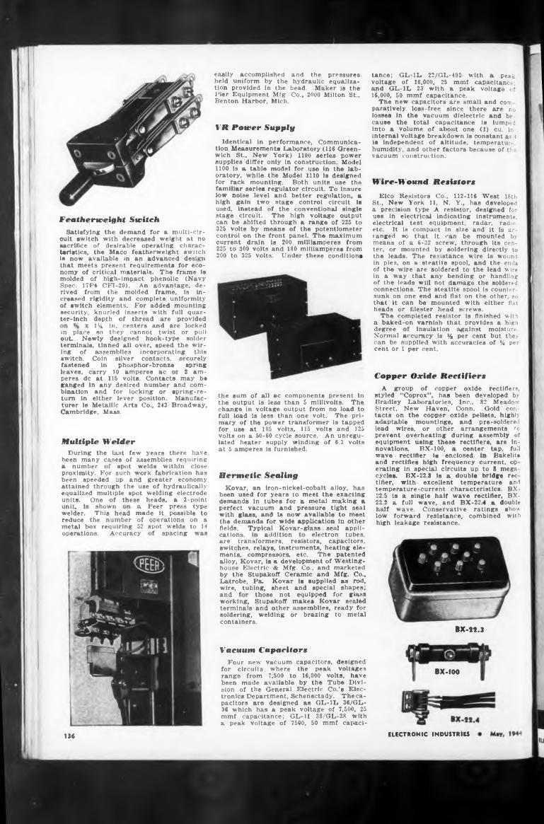
Peak
VR Power Supply
Hire-Wound Resistors
Featherweight Switch
degreein place
Copper Oxide Rectifiersrectifier!
has been developed by
Bakelitenumber
Hermetic Sealing BX-22.3 is a double bridge recKovar, an iron-nickel-cobalt alloy, has temperature-current characteristics.
This head
Typical Kovar-glass seal appi!spacing addition
tubing, sheet and special shapes
containers.BX-32.3
Vacuum Capacitors
BX-1OC
ELECTRONIC INDUSTRIES136
been used for years to meet the exacting demands in tubes for a metal making a perfect vacuum and pressure tight seal with glass, and is now available to meet the demands for wide application in other
those not equipped for glass Stupakoff makes Kovar sealed and other assemblies, ready for welding or brazing to metal
and rectifies high frequency current, op erating in special circuits up to 8 mega
security, ter-inch
securely spring
• 2 am-
cycles, tlfier.
Normal accuracy is % per cent can be supplied with accuracies cent or 1 per cent.
One of shown
switch.fastened
a Peer press type made it possible to of operations on a52 spot welds to 14
and BX-
wire, andworking, terminals soldering,
fields, cations,
reduce the number metal box requiring
half low high
moisture, but they of % per
electron tubes,
insulation against
spot welds within close
with excellent temperature
copper oxideA group of styled “Coprox1
22.5 is a single half wave rectifier, BX-22.2 a full wave, and BX-22.4 a doublethese heads, a 3-point
center tap, full
proximity. For such work fabrication has been speeded up and greater economy attained through the use of hydraulically equalized multiple spot welding electrode
knurled inserts with full quar- depth of thread are provided 1%, in. centers and are locked so they cannot twist or pul)
wave rectifier is enclosed
units, unit, i welder.
novations. BX-100,
Identical in performance, Communication Measurements Laboratory (116 Greenwich St., New York) 1100 series power supplies differ only in construction. Model 1100 is a table model for use In the laboratory, while the Model 1110 Is designed for rack mounting. Both units use the familiar series regulator circuit. To insure low noise level and better regulation, a high gain two stage control circuit is used, instead of the conventional single stage circuit. The high voltage output can be shifted through a range of 225 to 325 volts by means of the potentiometer control on the front panel. The maximum current drain is 200 milliamperes from 225 to 300 volts and 180 milliamperes from 300 to 325 volts. Under these conditions
leaves, carry 10 amperes ac
tance; GL-1L 22/GL-492 with
the sum of all ac components present in the output is less than 5 millivolts. The change in voltage output from no load to full load is less than one volt. The primary of the power transformer is tapped for use at 105 volts, 115 volts and 125 volts on a 50-60 cycle source. An unregulated heater supply winding of 6.3 volts at 5 amperes is furnished.
Four new vacuum capacitors, designed for circuits where the peak voltages range from 7,500 to 16,000 volts, have been made available by the Tube Division of the General Electric Co.’s Electronics Department, Schenectady. The capacitors are designed as GL-IL 36/GL- .16 which has a peak voltage of 7,500, 25 mmf capacitance; GL-H 38/GL-38 with a peak voltage of 7590, 50 mmf capaci-
are transformers, resistors, capacitors, switches, relays, Instruments, heating elements, compressors, etc. The patented alloy, Kovar, is a development of Westinghouse Electric & Mfg. Co., and marketed by the Stupakoff Ceramic and Mfg. Co., Latrobe, Pa. Kovar Is supplied as rod,
operations. Accuracy
peres de at 115 volts. Contacts may be ganged in any desired number and combination and for locking or spring-return in either lever position. Manufacturer is Metallic Arts Co., 243 Broadway, Cambridge, Mass.
voltage of 16,000, 25 mmf capacitanc*; and GL-1L 23 with a peak voltage < ’ 16,000, 50 mmf capacitance.
The new capacitors are small and corr paratively loss-free since there are no losses in the vacuum dielectric and because the total capacitance is lumped into a volume of about one (1) cu. in. internal voltage breakdown is constant ar. d is independent of altitude, temperatur, humidity, and other factors because of tb vacuum construction.
easily accomplished and the pressures held uniform by the hydraulic equalization provided in the head. Maker is the Pier Equipment Mfg. Co., 2000 Milton St., Benton Harbor, Mich.
Coin silver contacts, in phosphor-bronze
Satisfying the demand for a multi-circuit switch with decreased weight at no sacrifice of desirable operating characteristics, the Maco featherweight switch is now available in an advanced design that meets present requirements for economy of critical materials. The frame is molded of high-impact phenolic (Navy Spec. 17P4 CFI-20). An advantage, derived from the molded frame, is increased rigidity and complete uniformity of switch elements. For added mounting
wave. Conservative ratings show forward resistance, combined with leakage resistance.
out. Newly designed hook-type solder terminals, tinned all over, speed the wiring of assemblies incorporating this
Elco Resistors Co., 112-116 West 18th St., New York 11, N. Y., has developed a precision type A resistor, designed for use in electrical indicating instruments, electrical test equipment, radar, radio, etc. It is compact in size and it is arranged »o that it can be mounted by means of a 6-32 screw, through its center, or mounted by soldering directly to the leads. The resistance wire is wound in pies, on a steatite spool, and the ends of the wire are soldered to the lead wire in a way that any bending or handling of the leads will not damage the soldered connections. The steatite spool is countersunk on one end and flat on the other, so that it can be mounted with either flat heads or filester head screws.
The completed resistor is finished with a baked-on varnish that provides a high
Bradley Laboratories, Inc., 82 Meadow Street, New Haven, Oonn. Gold contacts on the copper oxide pellets, highly adaptable mountings, and pre-soldered lead wires, or other arrangements to prevent overheating during assembly of equipment using these rectifiers, are in-Multiple Welder
During the last few years there have been many cases of assemblies requiring
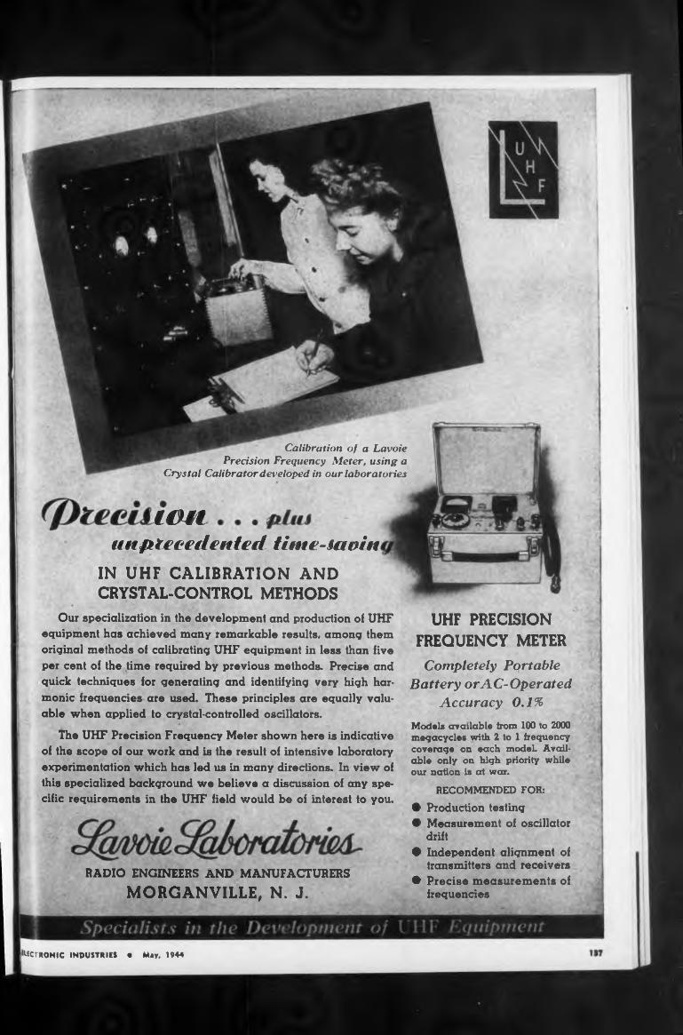
IMlunprecedented tinte-iaoin
IN UHF CALIBRATION AND CRYSTAL-CONTROL METHODS
UHF PRECISION FREQUENCY METER
Our specialization in the development and production oi UHF equipment has achieved many remarkable results, among them original methods of calibrating UHF equipment in less than five per cent of the time required by previous methods. Precise and quick techniques for generating and identifying very high harmonic frequencies are used. These principles are equally valuable when applied to crystal-controlled oscillators.
The UHF Precision Frequency Meter shown here is indicative of the scope of our work and is the result of intensive laboratory experimentation which has led us in many directions. In view of this specialized background we believe a discussion of any specific requirements in the UHF field would be of interest to you.
Models available from 100 tc 2000 megacycles with 2 to 1 frequency coverage on each model. Available only on high priority while our nation is at war.
RECOMMENDED FOR:
• Production testing• Measurement of oscillator drift• Independent alignment of transmitters and receivers• Precise measurements of frequencies
Calibration of a Lavoie Precision Frequency Meter, using a
Crystal Calibrator developed in our laboratories
Completely Portable Battery or AC-Operated
Accuracy 0,1%
[^TRONIC INDUSTRIES • May, 1944
RADIO ENGINEERS AND MANUFACTURERS
MORGANVILLE, N. J.
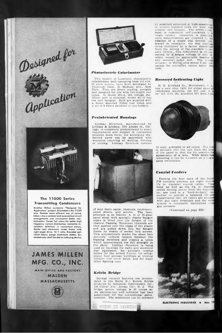
completely self-contained in
Photoelectric Colorimeter
Recessed Indicating Light
Prefabricated Housings
Coaxial Feeders
JAMES MILLENMFG. CO INC
MAIN OFFICE AND FACTORY Kelvin BridgeMALDEN
MASSACHUSETTS
bridge source voltage 60 cycles ac.
ELECTRONIC INDUSTRIESPRINT IN BINDING
unusual features are incorpo- the Model K-l Kelvin Bridge by Industrial Instruments, Inc.,
Two models of Lumetron photoelectric colorimeters, both operating from 110 volt.
Several rated in produced
formed parts assembled with
have been developed by 95 Madison Ave., New direct reading, portable use with full-length test400-A, the voltage sta-
An electron-ray null indicator has been substituted for the conventional galvanometer. The Instrument can be operated
wrenches requiring no welding, riveting or cutting. Lindsay Structure consists
60 cycle source, Photovolt Corp., York. They are and designed for tubes. In model
Lindsay Structure, manufactured by Lindsay & Lindsay, 2225 Adams St., Chicago, is completely prefabricated to exact requirements and shipped in convenient knocked down form; the accurately die-
bilizer unit is external; model 400-G has the unit integral. Both are supplied with a dozen matched Pyrex test tubes and a set of 6 filters mounted in two holders.
156 Culver Ave., Jersey City, N. J. The
10 watt, available in all colors. The bult is recessed into the unit from the front of the panel so that the tip assumes thi appearance of a lens. With single-holi mounting it can be mounted on a singlegang switchplate.
by unskilled personnel at high-speeds—up to several hundred tests per hour with suitable test fixtures. The entire equip.
single cabinet. Operation is simplified, since measurements are obtained by the rotation of a single dial directly all- brated in resistance, the dial readings being multiplied by a factor determined from the setting of the .standard resistance switch- -The instrument Is cha rac- terized by a sot^-ce voltage of onlj 05. which means no appreciable heating of any resistor^ undpr test. The overall accuracy is within'plus-minus 2 per cent except for resistance values below ohm.
H. R. Kirkland Co., Morristown, N. J, has a new pilot light for either panel or switchplate mounting, the Sil unit. It H for use with the standard Sil lamp bulb,
of four basic parts: channels, tensioners, panel sheets, and screws. The basic principle lx as follows: A 24 or 26-gage panel sheet with specially drawn flanged edges 13 fitted over the flanges of the channel framing. Tensioner channels are then applied over the edges of the sheets and are pulled down into the flanged frame by means of socket lock screws. This automatically draws the sheet into minutely uniform tension between the framing members and creates a union which approximates the full strength in the sheet. Lindsay Structure is being used a* housings for radio and electrical war equipment, for auxiliary combat bodies for the Armed Forces, for refrigerator food storage buildings at tropical militarv and naval bases, and for many other fighting uses.
Feeding the four bays of the Zeniti FM turnstile antenna are eight Andrew 1% in. diameter coaxial cables. The» lines, as well as the 414 in. diametd cables feeding power from the transmit! ter, are used in a "back-to-back” coni nection to provide a balanced 140 ohd transmission line. All cables are equipped with gas tight terminals and the entiij system is constantly maintained unde gas pressure.
(Continued on page 200)
The 11OOO Series Transmitting Condensers
Anottim Millen exclusive "Designed for Application" product Illustrated Is the 11039 size. Permits more efficient use el newer tubes—moio compact and symmetrical circuit arrangements and consequent better neutralization. Confer fed rotors for better high frequency current distribution isolantite insulation; terminals in convenient places. Sturdy cast aluminum center frame with right angle drive, 16 1 ratio Rounded polished heavy gauge aluminum plates. Extended rotor shaft (or dial or indexing device.
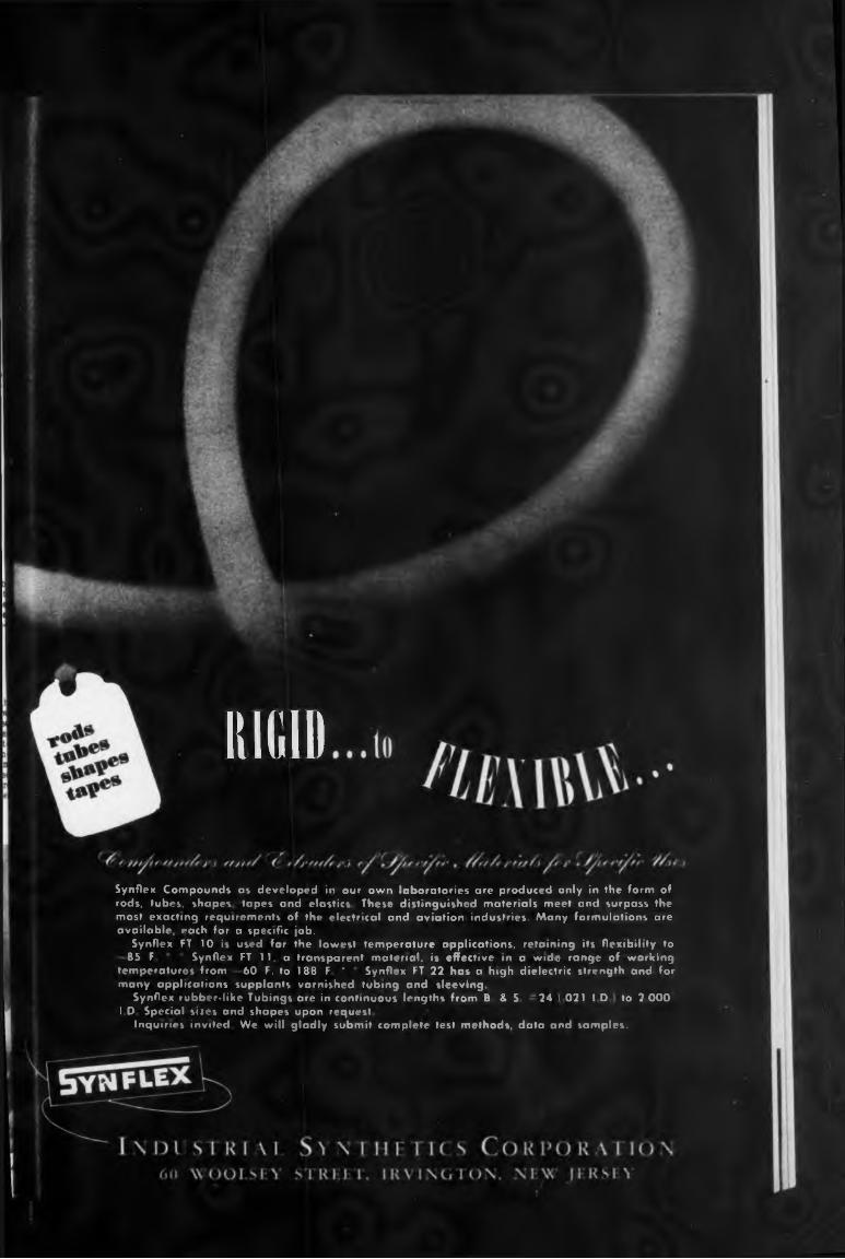
HIUI1
Synflex Compounds as developed in our own laboratories are produced only in the form of rods, tubes, shapes tapes and elastics These distinguished materials meet and surpass the most exacting requirements of the electrical and aviation industries. Many formulations are available, each for a specific job.
Synflex FT 10 is used for the lowest temperature applications, retaining its flexibility to 85 F Synflex FT 11, a transparent material, is effective in a wide range of working
temperatures from 60 F. to 188 F ' Synflex FT 22 has a high dielectric strength and for many applications supplants varnished tubing and sleeving.
Synflex rubber.like Tubings are in continuous lengths from B & S 24 I 021 ID to 2 000I D Special sizes and shapes upon request
Inquiries invited We will gladly submit complete test methods, data and samples.
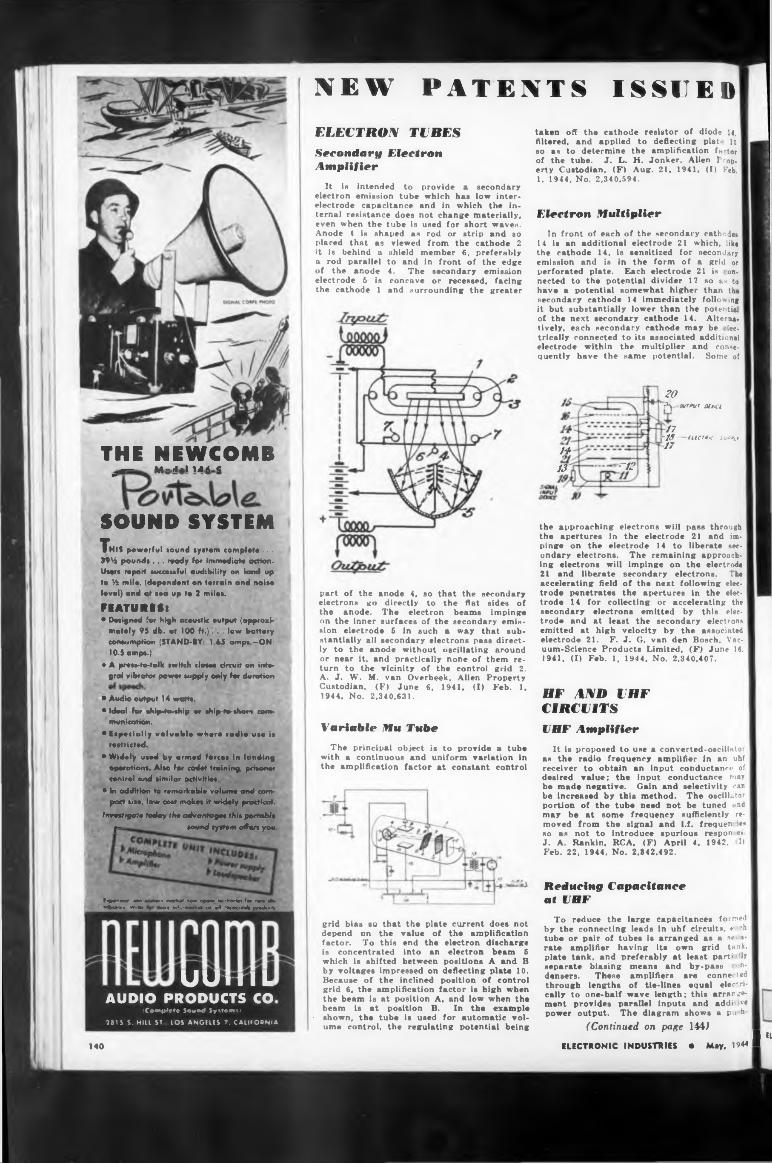
THE NEWCOMB_t— M-r-m« «
SOUND SYSTEM
UU iti L
This powerful sound system complete ...
3916 pounds ... ready for immediate action. Users report successful audibility on land up to 16 mile, (dependent on terrain and noise level) and at sea up to 3 miles.
FEATURES:• Designed for high acoustic output (approxi
mately 95 db. at 100 ft.)... low battery consumption (STAND-BY: 1.65 amps —ON: 10.5 amps.)
e A press-to-tolk switch closet circuit on integral vibrator power supply only far duration
• Audio output 14 watts.• Ideal for thip4o-thip or ship-fa-share com*
munication.• Especially valuable where radio use is
restricted.* Widely used by armed forces in landing
operations. Also for cadet training, prisoner central and similar activities.
• in addition to remarkable volume and compact sire, lew cost makes tt widely practical.
Investigate today the advantages thit portabit ।— sound system offers you
feqMmtfcwi iirto eartorn work»* now opo»» hwrHortot for now sb* Mbutorx W*We mor« miormation on oil Newcomb product*.
AUDIO PRODUCTS CO iCoMftPete Sovmd Systems।
2815 5. HILL ST LOS ANGELES 7, CALIFORNIA
NEW PATENTS ISSUEDELECTRON TUBESSecondary Electron Amplifier
It is intended to provide a secondary electron emission tube which has low interelectrode capacitance and in which the internal resistance does not change materially, even when the tube is used for short waves. Anode 4 is shaped as rod or strip and so placed that as viewed from the cathode 2
taken off the cathode resistor of diode U, Altered, and applied to deflecting plat. lo so as to determine the amplification factor of the tube. J. L. H. Jonker. Alien Prop, erty Custodian, (F) Aug. 21, 1941, (I) Feb. 1. 1944, No. 2.340.594.
Electron Multiplier
it is behind a a rod parallel of the anode electrode 5 is the cathode 1
shield member 6, preferably to and in front of the edge 4. The secondary emission concave or recessed, facing and surrounding the greater
In front of each of the secondary cathodes 14 Is an additional electrode 21 which, like the cathode 14. is sensitized for secondary emission and is in the form of a grid or perforated plate. Each electrode 21 is on. nected to the potential divider 17 so as to have a potential somewhat higher than th* secondary cathode 14 immediately following it but substantially lower than the potential of the next secondary cathode 14. Alternatively, each secondary cathode may be ■ lec- trically connected to its associated additional electrode within the multiplier and const- quently have the same potential. Some of
20Sy MW Ottici
14
13 ^12
part of the anode 4, so that electrons go directly to the
the secondary flat sides of
the anode. The electron beams impinge on the inner surfaces of the secondary emission electrode 6 in such a way that substantially all secondary electrons pass directly to the anode without oscillating around or near it. and practically none of them return to the vicinity of the control grid 2. A. J. W. M. van Overbeek, Alien Property Custodian, (F) June 6, 1941, (I) Feb. 1. 1944, No. 2,340,631.
Variable Mu TubeThe principal object is to provide a tube
with a continuous and uniform variation in the amplification factor at constant control
grid bias so that the plate current does not depend on the value of the amplification factor. To this end the electron discharge is concentrated into an electron beam 5 which is shifted between positions A and B by voltages impressed on deflecting plate 10. Because of the inclined position of control grid 6, the amplification factor is high when the beam is at position A, and low when the beam is at position B. In the example
■ shown, the tube is used for automatic volume control, the regulating potential being
17~19-------Ultras sup»l117
the approaching electrons will pass through the apertures in the electrode 21 and impinge on the electrode 14 to liberate secondary electrons. The remaining approaching electrons will impinge on the electrode 21 and liberate secondary electrons. The accelerating field of the next following electrode penetrates the apertures in the electrode 14 for collecting or accelerating the secondary electrons emitted by this electrode and at least the secondary electrons emitted at high velocity by the associated electrode 21. F. J. G. van den Bosch, Vacuum-Science Products Limited, (F) June IS. 1941, (I) Feb. 1, 1944, No. 2.340,407.
HF A^D UHF CIRCUITSVHF Amplifier
It is proposed to use a converted-oscilUtor as the radio frequency amplifier in an uhf receiver to obtain an input conductance of desired value; the input conductance may be made negative. Gain and selectivity can be increased by this method. The oscillator portion of the tube need not be tuned and may be at some frequency sufficiently removed from the signal and i.f. frequen ies so an not to introduce spurious respon e» J. A. Rankin, RCA. (F) April 4. 1942. I) Feb. 22, 1944, No. 2,342,492.
Reducing Capacitance at VHF
To reduce the large capacitances formed by the connecting leads in uhf circuits, e ’h tube or pair of tubes is arranged as a sr a- rate amplifier having its own grid tank, plate tank, and preferably at least parti 'If separate biasing means and by-pass - n- densers. These amplifiers are connected through lengths of tie-lines equal elec'ideally to one-half wave length; this arrangement provides parallel Inputs and addi' ve power output. The diagram shows a pu h-
(Continued on page 144)
140■ u
ELECTRONIC INDUSTRIES • May, 1944 ■
Quality"FOR GREAT
ACHIEVEMENT'
STUPAKOFF CERAMIC AND MANUFACTURING CO., LATROBE, PA
Let'» All Baek The Attack—Buy EXTRA Kar Bond»
UECTRONIC INDUSTRIES • May, 1944
STUPAKOFF quality is assured by the constant research of its engineering staff... by
rigid inspection of its alert "quality-trained” workers ... by modern manufacturing facilities . . . by wide technical and engineering knowledge gained through years of experience in producing every type of ceramic used by the electronic industry.
Quality is the result . . . quality that assures unfailing performance wherever Stupakoff ceramics are used.
Variable Pitch CoilEasily and inexpensively made
by the Stupakoff process
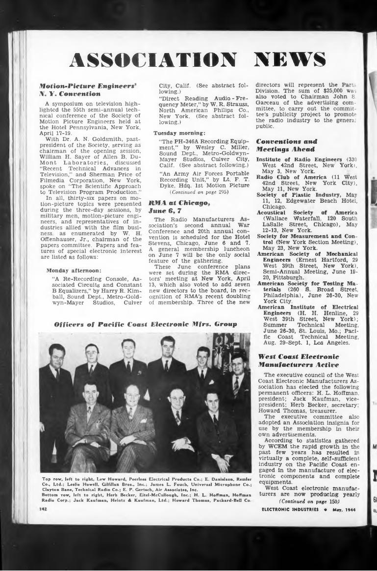
NEWSASSOCIATION
ment,
enumerated by W.ness,
social
Officers of Pacific Coast Electronic Mfrs, Group Summer
plans direc-
tors’ meeting at New York, April 13, which also voted to add seven new directors to the board, in recognition of RMA’s recent doubling of membership. Three of the new
Broad Street,
directors will represent the Parts Division. The sum of $25,000 was also voted to Chairman John S. Garceau of the advertising committee, to carry out the committee’s publicity project to promote the radio industry to the general public.
tenais (260
by Wesley C. Miller,
America) South
Motion-Picture Engineers'N. Y. Convention
Offenhauser, Jr., chairman of the papers committee. Papers and features of special electronic interest are listed as follows:
RM A at Chicago. June 69 7
Technical Meeting,
LaSalle Street, Chicago), May 12-13, New York.
Society for Measurement and Control (New York Section Meeting), May 23, New York.
American Society of Mechanical Engineers (Ernest Hartford, 29 West 39th Street, New York), Semi-Annual Meeting, June 1920, Pittsburgh.
American Society for Testing Ma-
June 26-30, St. Louis, Mo.; Pacific Coast Technical Meeting, Aug. 29-Sept. 1, Los Angeles.
City, Calif. (See abstract following.)“Direct Reading Audio - Frequency Meter,” by W. R. Strauss, North American Philips Co., New York. (See abstract following.)
vention is scheduled for the Hotel Stevens, Chicago, June 6 and 7. A general membership luncheon
The Radio Manufacturers sociation’s second annual Conference and 20th annual
on June 7 will be the only feature of the gathering.
These June conference were set during the RMA
Chicago.Acoustical Society
(Wallace Waterfall,
The executive council of the West Coast Electronic Manufacturers Association has elected the following permanent officers: H. L. Hoffman, president; Jack Kaufman, vicepresident; Herb Becker, secretary. Howard Thomas, treasurer.
The executive committee also adopted an Association insignia for use by the membership in their own advertisements.
According to statistics gathered by WCEM the rapid growth in the past few years has resulted in virtually a complete, self-sufficient industry on the Pacific Coast engaged in the manufacture of electronic components and complete equipments.
West Coast electronic manufacturers are now producing yearly
(Continued on page 1501
Top row, left to right Lew Howard, Peerless Electrical Products Co.; E. Danielson, Rentier Co., Ltd.; Leslie Howell, Gilfillan Bros., Inc.; James L. Fouch, Universal Microphone Co.; Clayton Bane, Technical Radio Co.; E. P. Gertsch, Air Associates, Inc.Bottom row, left to right, Herb Becker, Eitel-McCullough, Inc.; H. L. Hoffman, Hoffman Radio Corp.; Jack Kaufman, Heintz 4k Kaufman, Ltd.; Howard Thomas, Packard-Bell Co.
“An Army Air Forces Portable Recording Unit,” by Lt. F. T. Dyke, Hdq. 1st Motion Picture
(Continued on page 295)
ELECTRONIC INDUSTRIES • Mey, 1944
West Coast Electronic Manufacturers Active
War con-
A symposium on television highlighted the 55th semi-annual technical conference of the Society of Motion Picture Engineers held at the Hotel Pennsylvania, New York, April 17-19.
With Dr. A. N. Goldsmith, pastpresident of the Society, serving as chairman of the opening session, William H. Sayer of Allen B. DuMont Laboratories, discussed “Recent Technical Advances in Television,” and Sherman Price of Filmedia Corporation, New York, spoke on “The Scientific Approach to Television Program Production.”
In all, thirty-six papers on motion-picture topics were presented during the three-day sessions, by military men, motion-picture engineers, and representatives of industries allied with the film busi-
Philadelphia), June 26-30, New York City.
American Institute of Electrical Engineers (H. H. Henline, 29 West 39th Street, New York);
Tuesday morning:“The PH-346A Recording Equip
Monday afternoon:“A Re-Recording Console, Associated Circuits and Constant B Equalizers,” by Harry R. Kimball, Sound Dept., Metro-Goldwyn-Mayer Studios, Culver
Conventions andMeetings AheadInstitute of Radio Engineers (330
West 42nd Street, New York), May 3. New’ York.
Radio Club of America (11 West 42nd Street, New York City), May 11, New York.
Society of Plastic Industry, May 11, 12, Edgewater Beach Hotel,
Sound Dept., Metro-Goldwyn- Mayer Studios, Culver City, Calif. (See abstract following.)
AMERICAMYCALEX CORPORATION
THERE IS ONLY ONE MYCALEX
In any number of military and industrial applications any weather andthe unique properties of Leadless MYCALEX have been tried andclimate
Remember MYCALEX is not the name of a class of materials, but the reg
60 CLIFTON BOULEVARD CLIFTON, NEW JERSEY143
Keep Buying More and More
War Bonds
istered trade-name for low-loss insulation manufactured in the WESTERN HEMISPHERE by the Mycalex Corporation of America.
This building houses MYCALEX which, in the opinion of reputable engineers, is . the most nearly perfect electrical insulator known today". Developed and perfected more than twenty-five years ago, MYCALEX has been improved to such an extent that it now possesses advantages which make it superior to other types of glass bound mica insulation.
tod**
tested, and found more than satisfactory. A few desirable properties are high dielectric strength combined with mechanical strength, heat and arc resistance, low moisture absorption, low power factor and low loss. Furthermore, MYCALEX meets all standards for close tolerances. Leadless MYCALEX is adaptable, too . . .
UECTRONIC INDUSTRIES • May, 1944
Mycalex Corporation of AmericaExclusive Licensee under all patents of MYCALEX (PARENT) CO., Ltd.
it can be cut, tapped, machined, drilled, ground, polished ... or moulded.* And in any of these assignments it will prove to be extremely dependable. Sheets and rods are immediately available for fabrication by us or in your own plant.
Ml'
W
jz
pull amplifier connected according to the invention. A system of two push-pull units, four tubes, may be arranged as a modulator by symmetrically applying the modulation frequency to the tank circuits of the units, and by transposing either tie-lines 44,4 5 or 50,52 so that the two units operate in phase opposition. The modulation is of the carrier-suppressed type giving only side bands. C. B. Watte, Jr., Federal Telephone and Radio Corp., (F) May 18, 1942, (I) Feb. 1, 1944, No. 2.340,352.
Electrical Laboratory Testing Board Built to Order
AMPLIFIER CIRCUITSAudiphone Amplifier
NOW AVAILABLE!AT NEWLY EQUIPPED WEST WARREN FACTORY
ELECTRICAL CONTROL BOARDS-SWITCHES-FUSESPrecision-built for your needs
Fifty years of highly skilled manufacturing for commercial industry, as well as for the Navy, Army and Maritime Commission. With our electrical lighting and power distributing equipment serving on over 500 of this nation s fighting ships, our schedule now permits handling of important civilian orders.
Variable negative feedback is introduced so that for the lower sensitivities the feedback is greater and better quality of reproduction is obtained for those who have only slightly impaired hearing and who are more likely to appreciate the better quality. Further, a positive feedback proportional to the internal resistance of the battery is provided so that the gain of the amplifier is substantially independent of the inter* nal resistance of the battery which incre. es as the battery becomes discharged. According to another feature of the invention, the pickup microphone is connected to the amplifier through an adjustable network which gives the user a choice of several low frequency characteristics. In noisy locations, this network may be set to give a large amount of low frequency attenuation, thereby discriminating against low pitched noises and the lower sound frequencies of the voice which contribute but little to intelligibility. This procedure permits of greater amplification of the higher frequencies without overloading. C. H Rumpel. Bell Telephone Labs.. (F) Dec. 24, 1940, (I) Feb. 29. 1944. No. 2.342.822.
Wide Range Amplifier
Several design features to compensate for distortion and provide constant gain in wide range amplifiers are described.
We Invite Your Inquiries
Trade Mark
METROPOLITAN ELECTRIC MFG. CO.Factories: Long Island City, N. Y. and West Warren, Mass.
144
By placing two volume control 36 trolytic condenser balance conditions
amplifier stages after and by using an elec- 35, constant harmonic are maintained. Fur-
ther, the impedance of resistance 18 in series with inductance 19 rises with frequency, compensating partially the shunting effect of the plate capacity of tube 1- The signal voltage applied to grid 25 isresonated frequency 22 which with theresonance
at the high end of the desired band by means of inductance forms a series resonant circuit
input capacity of tube 2. ' his lifts the upper end of the fre-
quency response an much as ten times in a practical case. The resulting response peak may be too sharp to com plc-
ELECTRONIC INDUSTRIES • May, 1944
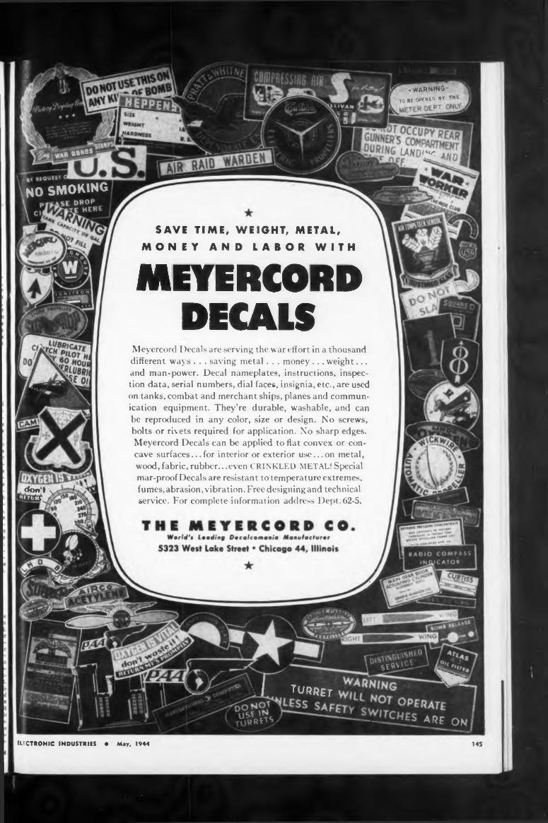
t
MEYERCORDDECALS
145
LAND/“< A uÁ i
Meyercord Decals are serving the war effort in a thousand different ways . . . saving metal . . . money ... weight... and man-power. Decal nameplates, instructions, inspection data, serial numbers, dial faces, insignia, etc., are used on tanks, combat and merchant ships, planes and communication equipment. They’re durable, washable, and can be reproduced in any color, size or design. No screws, bolts or rivets required for application. No sharp edges. Meyercord Decals can be applied to flat convex or concave surfaces... for interior or exterior use... on metal, wood, fabric, rubber...even CRINKLED METAL! Special mar-proof Decals are resistant to temperature extremes, fumes, abrasion, vibration. Free designing and technical service. For complete information address Dept. 62-5.
electronic industries • May, 1944
-WARNING*
[ to » 0««° W
SAVE TIME, WEIGHT, METAL,
MONEY AND LABOR WITH
don't□Hr
¿EPPEN
BUMO5
SE«V
A ’"»«r *
íros,/ — 4 RE on
NO SMOKING
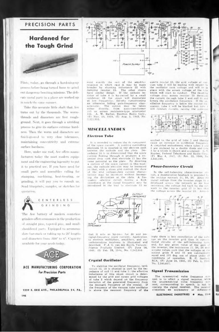
Hardened for
HO
shunting inductanceother phase with the screen voltage of the tube
out dangerous Immbing cathode which will start to conduct.voltage drop resistor
condenser thelow frequencies,
MISCELLANEOUSElectron Tubefinish-ground 1
Phase-Inverter Circuit
charac-
the resistor network 21 Since thesignal voltage from the inverter stage Iti i
quotation
andthat
available for your needs today F. J. G. van den Bosch, Vacuum-the inverter, the resistances 21,assume values such that the voltages at the1944output grids and substantiallyequal and 180 deg. out of phase under .11
Sanford,Crystal Oscillator 1944.
ACESignal Transmission
to speech,
asymmetry1239 comprises
May 1944ELECTRONIC INDUSTRIES
voltage of v with respect and will be
OUTPUT IMPEDANCE
signal voice
INPUT IMPEDANCE
component controlling
The If the
In the self-balancing phase-inverter cuit, a degenerative feedback is provided by
described.Science '
105 or106. A.(F) Nov.2,325,933
i, is not to The receiver
• differential
quartz crystal 20, the grid uum tube 3 will be leading the oscillator tank voltage
Products Limited,
with stages
by-pass for
coil 15 andIf the os-
crystal f rebut tube I
conditions of operation.
E. ERIE AVE., PHILADELPHIA 2 4, PA
frequency response, frequency
To stabilize the oscillator frequency, tank circuit 12, 13 is shunted in part by the impedance of coil 15 and tube 2; the effective inductance of this shunt circuit is determined by the grid and screen grid voltages of tube 2 which depend on the frequency deviation of the generated frequency from the resonant frequency of the crystal. If the frequency of the vacuum tube oscillator is above the resonant frequency of the
the lead to electrode
RCA, (F) June 28, 1941, (I) Feb. 1 No. 2,340,617.
the current through tube 2 and lowers the oscillation frequency, cillation frequency is below the quency, tube 3 will be blocked
damping resistor 2: have similar design, sistor of tube I is
1941, (I) Feb.f) June 2,342,986.
electrode 15 is inserted in the electron path between the cathode and the plate. Impedance 16 is so dimensioned that the space current flowing through it produces a potential drop such that electrode 15 has the same potential as the plate. By diverting a portion of the space current in this manner, the cathode emission may be increased so that, with a given grid control, the slope
signal-frequency space currents. Application to electron multipliers, amplifiers, and superheterodyne receivers is illustrated and
otherwise falling gain-frequency char-
applied to the grid of tube 2 and thereby cause an increase in oscillation frequency. A simplified embodiment where tubes 3 and 4 are replaced by a double diode and tube 3 by a triode is shown and explained. G 1 Royden, Federal Telephone and Radio Corp .
will conduct current, raising the potential
The resulting23 decreases
1942, (I) Feb.
It is intended to reduce the de of the space current. A positive
acteristic. The either directly.
by-passed by a small stage will degenerate thereby compensating
Radio Corp.3, 1943, No
ingly there is less cancellation of the vol.- age on the inverter grid than in conventional circuits of the self-balancing tyi and, for any given value of the gain of
output may be taken from auto-transformer
resistance-type attenuator
ment exactly response in ■ broader by
The symmetrical rent is to effect a the unsymmetrical rent, corresponding operate the signal
network as its load fed back by the net- grid 17 is less than resistor 28. Accord-
A fre- a high may be developed across the
resistance, the voltage work to the inverter the voltage across the
; t he rest which case
of the grid voltage-plate current teristic may be increased without ing the dissipation at the plate, quency selective circuit having impedance at the signal frequency
Barber, Boonton 1939, (I) Aug.
the amplifier may be made
of straight pins, tapered pins, shouldered parts. Equipped todate bar-stock or tubing up to 20' lengths
and diameters from .030" to 6". Capacity
MANUFACTURING CORPORATIONFor Precision Parts
Pilots, today, go through a hardening-up
process before being turned loose to grind
cate metal parts in a plan
in much tin- same manner

for V.H.F. CIRCUITS
ERIE STAND-OFF CERAMICONMaximum Capacity
temperature coefficient17 MMF
Minimum Capacity, 2 MMF.
TORONTO, CANADALONDON, ENGLAND
75 MMF—750 P/M/°C
ERIE RESISTOR CORP., ERIE, PA
30 MMF.—330 P/M/CC
UECTRONIC INDUSTRIES « May, 1944
ACTUAL SIZE
Developed for Important War Application—Ideal for Peacetime EM. and TelevisionHIGH Frequency applications have a way
of throwing existing component designs into the discard. Short, heavy leads, low series inductance, and other design factors assume greater importance.
Erie Resistor had already had considerable experience in designing tubular and disc ceramic capacitors, and button type silver mica condensers for V.H.F. and U.H.F. equipment. Thus, when engineers from one of the country's foremost research and development laboratories came to Erie Resistor with a new capacitor design problem, the answer was quickly forthcoming, in the form of a basically new style of Erie Ceramicon, pictured above. Approximately 60 days later, finished units were being delivered for the extremely urgent communications equipment for which they were designed.
This compact, stand-off Ceramicon has mechanical advantages that permit it to be rigidly mounted, and support other circuit elements. Electrically, this Erie stand-off Ceramicon has a high resonant frequency, and short electrical path to both silvered plates. The stability and retrace characteristics of Erie temperature compensating Ceramicons are inherent in this new unit.
Is there a place for this new component in your designs for war or peacetime communications equipment? Or if you have any other design problems involving resistors or condensers, our engineers will be glad to discuss them with you.
Minimum Capacity Tolerance ±0.5 MMF. Available Temperature Coefficients +100 to —750 P/M/°C.
.002
.520
Let's All Back The Attack EXTRA War Bonds
APPROX.DIMENSIONS
TWICE SIZE
3-4fl THD.
symmetrical signal current
Oct.1942, 1943.
Phase Modulation Receiver
Gerlach,
663 BROADWAY NEW YORK 12, N. Y
4mpb4<r«
ELECTRONIC INDUSTRIES148
For Bogen distributors, we’re working steadily to catch up with the demand for Bogen catalog equipment. It’s equipment that’s doing a mighty important war job, too. Delivery dates are being kept more regularly. What’s more, they are going to be better.
Logan, 1April 23, 2,332,494
For the Army and Navy, the David Bogen Company is intensifying production of vital intercommunication, detection and specialized sound distribution equipment/
David Bogen Co. Inc
Recognizing acts of heroism at the time of the Western Electric tubeshop explosion in New York City, the Vail Medal in bronze has been awarded to Louis G. DeLyon (post-
Bell Telephone
We illustrate the Bogen Model E75, unquestionably one of the finest High Power Amplifiers ever manufactured to commercial specifications. Under wraps, as a matter of military secrecy, are the many wartime Bogen developments in sound equipment. These developments will be released after Victory for incorporation in great new Bogen equipment which will spell profit and prestige to our distributors—and a better life for a world at peace.
for about 0.02 se jnd.
Heroism in Tube Laboratory
quency persists S. M. Babcock,
humously ), Alfred
Horton, and M Labs., Inc..
Alexander Mikolasy, William Mohr-1 hoff and Louis J. Rom.
At fifteen minutes past midnight on the morning of November 30th, 1943, an explosion rocked the Western Electric Vacuum Tube Shop at I 395 Hudson St., New York City, j Heavy steel doors were ripped from their fastenings, walls were crushed, and broken glass and de- j bris littered the streets for blocks around. Gas leaking from hydro-1 gen tanks on a ground-floor loading platform had ignited and caused the disaster.
Mr. DeLyon, supervisor of the hydrogen equipment, with three fellow employes, Messrs. Gerlach, Mohrhoff and Rom, entered the gas room immediately upon learning of the initial trouble. Again and again the escaping gas drove them out. But with full knowledge of the extreme hazard involved they persisted in an attempt to avert the tragedy. All were injured by the resulting explosion and Mr. DeLyon lost his life.
Mr. Mikolasy, hearing the blast and guessing its probable location, proceeded from the third floor >f the building to the scene where he
Similar frequency dividers 1' and 2 are inserted in the paths of the carrier and of the modulated carrier to reduce the relative phase shift to 90 deg. or less, which limit is required for the satisfactory operation of the automatic frequency control circuit The undesirable phase shift is introduced by the carrier filter and is a function of the frequency deviation from the mid-band frequency. It is also proposed to provide two demodulators, one including frequency dividers and feeding the automatic frequency control reactance tube, the other without the frequency dividers and providing the audio signal. R E. Schock, RCA, (F) May 23, 1942, (I) Feb. 1, 1944, No. 2,340.432.
detector which prevents the closing signal detector circuit upon receptici of asymmetrical currents. Further a telay network is included which permits cl sing of the signal detector circuit only i
FROM GREENLAND'S ICY MOUNTAINS
ponen isabnormal vibration
INDIANAPOLIS 6, INDIANAP. R. MALLORY & CO
VIBRATORS
special mechanical designs
Hermetically-sealed vibrators and other com
The Vibrapack meets these conditions unfail- ingk in its use with our armed forces. Militari restrictions prevent our shoeing the latest V ibrapack units, but here are some of their features:
Mallory
3tapack
extremes of atmospheric pressure and moisture-laden air, Mallory hermetically-sealed vibrators operate under ideal conditions for economy and long life.
input and/or output voltages, including independent bias supplies and XC or DC filament power in addition to plate and screen potential.
With ihese and other Mallori improvements, the X ibrapack carries tremendous implications for new-born products of today and tomorrow. If you are looking for a method of obtaining high voltage DC current from a low voltage source, we shall be glad to send i ou further information.• I ibrapack is the registered trademark ofP. R. MaUors & ('o.. for vibrator potver supplies.
EFFi Hermetically-SealedMALLOR Y V ibrators
V Ì our Be«t Bur f oday and Every Pay Day : Government Uar Bond*
tlECTRONIC INDUSTRIES • May, 1944
and mountings, including duplicate mountings for replacement of other equipment ... wide band and special band Kt "hash" filtering . . . multiple
Modern war, with its rigorous demands on communications equipment, requires vibrator power supplies that can operate under great extremes of heat, cold and humidity, and are able to withstand terrific jolts and jars.
MallorY
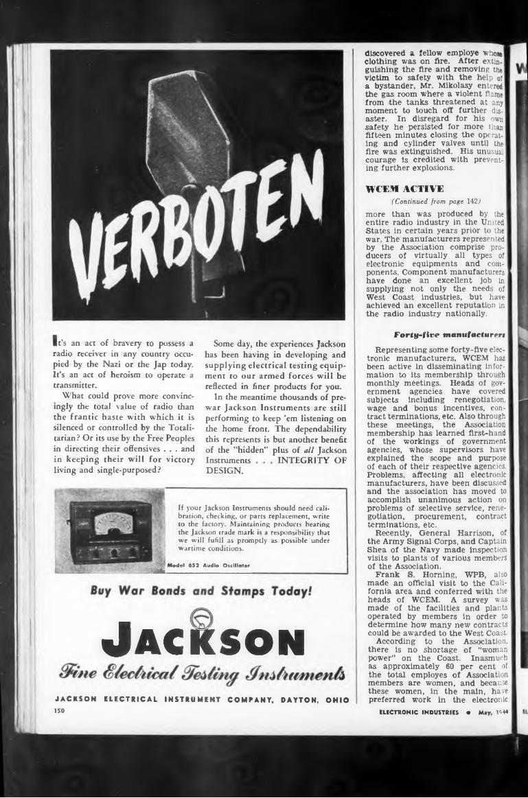
WCEM ACTIVE
Forty-five manufacturer»
INTEGRITY OF
Frank
Jackson
If your Jackson Instruments should need calibration, checking, or parts replacement, write to the factory. Maintaining products hearing the Jackson trade mark is a responsibility that we will fufill as promptly as possible under wartime conditions.
Horning, WPB, also
discovered a fellow employe whose clothing was on fire. After extin. guishing the fire and removing the victim to safety with the help of a bystander, Mr. Mikolasy entered the gas room where a violent flame from the tanks threatened at any moment to touch off further disaster. In disregard for his own safety he persisted for more than fifteen minutes closing the operating and cylinder valves until the fire was extinguished. His unusual courage Is credited with preventing further explosions.
wage and bonus incentives, contract terminations, etc. Also through these meetings, the Association membership has learned first-hand of the workings of government agencies, whose supervisors have explained the scope and purpose of each of their respective agencies. Problems, affecting all electronic manufacturers, have been discussed and the association has moved to accomplish unanimous action on problems of selective service, renegotiation, procurement, contract terminations, etc.
Recently, General Harrison, of the Army Signal Corps, and Captain Shea of the Navy made inspection visits to plants of various members of the Association.
made an official visit to the California area and conferred with the heads of WCEM. A survey was made of the facilities and plants operated by members in order to determine how many new contracts could be awarded to the West Coast.
According to the Association, there is no shortage of “woman power” on the Coast. Inasmuch as approximately 60 per cent of the total employes of Association members are women, and because these women, in the main, have preferred work in the electronic
Heads of gov- have covered renegotiation,
Representing some forty-five electronic manufacturers, WCEM has been active in disseminating information to its membership throughmonthly meetings, eminent agencies subjects including
ELECTRONIC INDUSTRIES • May, 1944
What could prove more convincingly the total value of radio than the frantic haste with which it is silenced or controlled by the Totalitarian? Or its use by the Free Peoples in directing their offensives . . . and in keeping their will for victory living and single-purposed?
Model 652 Audio Oscillator■BH___________________
Instruments DESIGN.
It’s an act of bravery to possess a radio receiver in any country occupied by the Nazi or the Jap today. It’s an act of heroism to operate a transmitter.
Some day, the experiences Jackson has been having in developing and supplying electrical testing equipment to our armed forces will be reflected in finer products for you.
In the meantime thousands of prewar Jackson Instruments are still performing to keep ’em listening on the home front. The dependability this represents is but another benefit of the "hidden” plus of all Jackson
(Continued, from page 142?more than was produced by the entire radio industry in the United States in certain years prior to the war. The manufacturers represented by the Association comprise producers of virtually all types of electronic equipments and components. Component manufacturers have done an excellent job in supplying not only the needs of West Coast industries, but have achieved an excellent reputation in the radio industry nationally.
JACKSON ELECTRICAL INSTRUMENT COMPANY, DAYTON, OHIO ISO
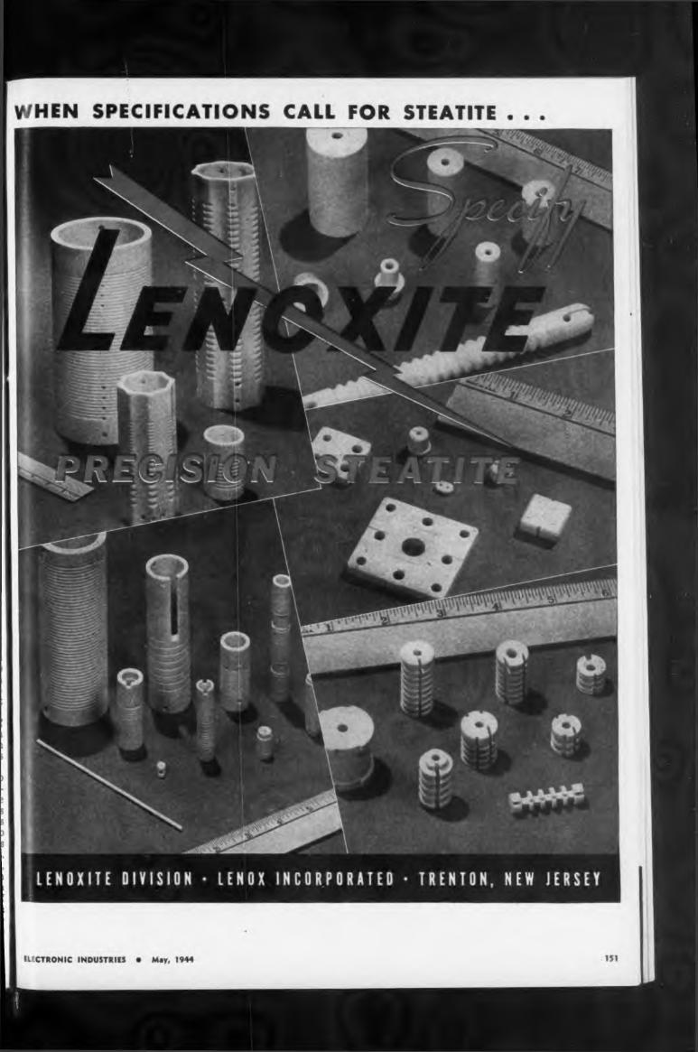
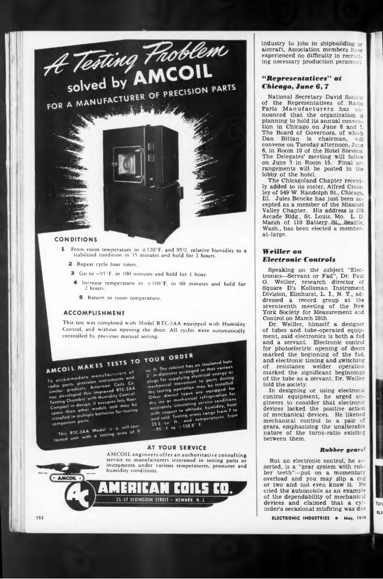
CONDITIONSFrom room
2 Repeat cycle four times
Rubber gears.mg
152
industry to jobs in shipbuilding or aircraft, Association members h ive experienced no difficulty in recruiting necessary production person ?1.
5 Return to room temperature
3 Go to —95°F. in 100 minutes and hold for 1 hour
Dan Bittan
4 Increase temperature to +160'F in 60 minutes and hold for 2 hours.
chairman, will
But an electronic control, he asserted, is a “gear system with rubber teeth”—put on a momentary overload and you may slip a cog or two and not even know it. He cited the automobile as an example of the dependability of mechanical devices and claimed that a cylinder’s occasional misfiring was due
service to manufacturers interested in testing parts or instruments under various temperatures, pressures and humidity conditions.
convene on Tuesday afternoon, June 6, in Room 10 of the Hotel Stevens. The Delegates’ meeting will follow on June 7 in Room 15. Final arrangements will be posted in the lobby of the hotel.
The Chicagoland Chapter recently added to its roster, Alfred Crossley of 549 W. Randolph St., Chicago, Ill. Jules Bencke has just been accepted as a member of the Missouri Valley Chapter. His address is 578 Arcade Bldg., St. Louis, Mo. L D. Marsh of 110 Battery SU Seattle, Wash., has been elected a member- at-large.
Speaking on the subject “Electronics—Servant or Fad”, Dr. Paul O. Weiller, research director of Square D’s Kollsman Instrument Division, Elmhurst, L. I., N. Y., addressed a record group at the seventeenth meeting of the New York Society for Measurement and Control on March 28th.
Dr. Weiller, himself a designer of tubes and tube-operated equipment, said electronics is both a fad and a servant. Electronic control for photoelectric opening of doors marked the beginning of the fad, and electronic timing and switching of resistance welder operation marked the significant beginnings of the tube as a servant, Dr. Weiller told the society.
In designing or using electronic control equipment, he urged engineers to consider that electronic devices lacked the positive action of mechanical devices. He likened mechanical control to a pair of gears, emphasizing the unalterable nature of the tums-ratio existing between them.
ELECTRONIC INDUSTRIES • May, 19-4
temperature to + 120°F. and 95% relative humidity to stabilized condition >n 35 minutes and hold for 2 hours.
AT YOUR SERVICEAMCOIL engineers offer an authoritative consult1
Weiller on Electronic Controls
ACCOMPLISHMENTThis test was completed with Model RTC-3AA equipped with Humidity Control, and without opening the door. All cycles were automatically controlled by previous manual setting.
“Representatives" at Chicago, June 6, 7
National Secretary David Sonkin of the Representatives of Radio Parts Manufacturers has announced that the organization is planning to hold its annual convention in Chicago on June 6 and 7. The Board of Governors, of which
ho» °n
AMERICAN COILS CO
drvqn > other °"
ho» «e" testing
RTC-3A* und wd
suloied ho*»hat vario“
25-27 LEXINGTON STREET • NEWARK, N J.
31 5 «« r T »«Model - °
ra»«W humidi*y.r«»ped ’° °' ± ronge Tron» 7 io
^„hon— " ,on may « ,the leUing ’P' ore *«4“^ * Other ^^il^col refrié”’" "L .ce or h»«*«"“0’ * * tondifon*
* d RTC-3AA nproveo Humidity Control occupy"°
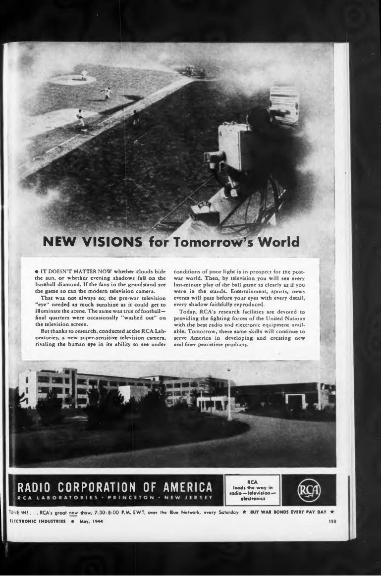
NEW VISIONS for Tomorrow’s World
RCA lead* the way In
radio—tale vision - electronici
TUNE IN! . . . RCA’* great new show, 7;30-8:00 P.M, EWT, over the Blue Network, every Saturday ★ BUY WAR BONDS EVERY PAY DAY dr
• IT DOESN’T MATTER NOW whether clouds hide the sun, or whether evening shadows fall on the baseball diamond. If the fans in the grandstand see the game so can the modern television camera.
That was not always so; the pre-war television ”eye” needed as much sunshine as it could get to illuminate the scene. The same was true of footballfinal quarters were occasionally "washed out” on the television screen.
But thanks to research, conducted at the RCA Laboratories, a new super-sensitive television camera, rivaling the human eye in its ability to see under
ELECTRONIC INDUSTRIES • May, 1944
conditions of poor light is in prospect for the postwar world. Then, by television you will see every last-minute play of the ball game as clearly as if you were in the stands. Entertainment, sports, news events will pass before your eyes with every detail, every shadow faithfully reproduced.
Today, RCA’s research facilities are devoted to providing the fighting forces of the United Nations with the best radio and electronic equipment available. Tomorrow, these same skills will continue to serve America in developing and creating new and finer peacetime products.
RADIO CORPORATION OF AMERICA
If you have requirements for such applications in your particular company or field, we invite your inquiries. We believe our staff of engineers and our production facilities can project your requirements into practical, workable design and equipment.
ELECTROCON CORPORATION219 West Sunrise Highway, Freeport, New York
to unreliability of the sparky phenomenon in the realm of electronics. Dr. Weiller pointed out that to be dependable, electronic control instruments must be designed with components rated for large factors of safety,—quite unlike the $9.95 commercial radio set.
The talk was followed by discussion and demonstration of a number of electronic control and research devices designed and constructed at the Kollsman laboratory.
Dr. Weiller is a metallurgical engineer graduated at Charlottenburg, Berlin, in 1908, and has had long experience in steel mills, copper smelters, and in explosives. From designing vacuum tubes and tubemaking machinery for Westinghouse after World War I, he turned to the manufacture of welding and other electronic controls in 1928.
A NEW WORLD for TOMORROWWe are busy, as you are, with present
activities in the fields of electronic, electromotive and electromechanical applications for industry and, of course, for the War Effort.
Maintaining Electronic Heat Equipment
Special installation and maintenance requirements for electronic heat-processing equipment were outlined by S. Walden Shaw, RCA field engineer, at the March meeting of the Electrical Maintenance Engineers Association of Philadelphia. Members of the Power Maintenance Association of South Jersey also met.
While installation of electronic power generators is relatively simple, Shaw said, the high voltages and high frequencies employed must be taken into account in selecting equipment and installing coupling circuits and applicator assemblies.
One factor is that high-frequency currents travel only on the surface of a conductor, he pointed out. Coupling circuits, therefore, must be made from tubing or pipe with a relatively large surface area. The surface of a pipe 2y2 in. in diameter might be required, for example, to carry high-frequency currents of an amperage which, at low frequency, could be carried by a ^-inch solid conductor.
Avoid sharp edges
Another consideration Is the avoidance of points or sharp edgesin the design of electrodes, in orderto minimize the tendency of high voltages (often from 10 to 20 thousand volts) to form an arc from the edge of one electrode to the other. To avoid such short-circuiting of the material which has been plac d between the electrodes for heatirg, voltages must be limited by the thickness of the load assembly.
Once installation Is completed, Shaw said, the most serious responsibility of the plant maintenance man is to see that dust accumula-
ELECTRONIC INDUSTRIES • May, 1944154
New Federal Development Revolutionizes the Metal Rectifier!
Federal battery chargers and power »upplic powered by Selenium Rectifiers, have wide appli-
cation in the fields ol radio, telephone, telegraph, aviation, railway signaling and wherever direct
current h required from an AC source.
By the use of a simple CENTER CONTACT Federal has achieved another "first" in
Selenium Rectifier development.The result — remarkable new corrosion
resistance and weather stamina added to the important advantages already inherent in Federal Selenium Rectifiers. v
Outstanding among these advantages are fahigh efficiency over a wide range of load; '*138 yL
small size and light weight; adaptability to wide ranges of temperatures, humidities and
atmospheric pressures—plus maintenance- free operation.
CENTER CONTACT is available only in Federal Selenium Rectifiers, first in the field
and standard for industry.
0IUU6 that historic day in 1899 when an electric
impulse was transmitted from the Marconi
apparatus aboard an English lightship, miracles
have been performed in, and with radio com
munication. Contemporary with that development
and—indispensable to it—was the power regu
lating component—the transformer.
In recent development Stancor Transformers have played a noteworthy role, and this experience multiplied a hundred-fold by the intimate association with wartime electronic units, will be a rich source of appeal when industry asks for improved safety and control.
STANCOR STANDARD TRANSFORMER CORPORATION 1500 NORTH HALSTED STREET - CHICAGO
tions are prevented by periodic cleaning of all parts of the set-uj. and to cheek meter readings for any substantial deviation from standard.
Oust trouble
Dust containing either metallic particles or moisture may cause arcing if permitted to accumulate, he explained, while off-standard readings appearing on any of the meters on the generator may indicate the need for suspending operation of the equipment until adjustments are made.
The excitation, filament voltage and high-frequency output power control settings are normally determined at the time of installation, he said, and there is little occasion to employ others except when setting up for an entirely different work load. Efficient operation, he pointed out, demands that the best control settings be determined for each new load.
Newspaper Men Study FM
Manufacturers of quality transformers, reactors, power paths and allied products for the
SEND FORNEW
COMPLETE CATALOG
-,
Growing interest among newspaper publishers in the development of frequency modulation broadcasting prompted the Amer-1 lean Newspaper Publishers Associa-1 tion to set aside an entire session I of its annual membership meeting in New York April 27 to a discus-1 sion of the subject.
Dr. W. R. G Baker, chairman RTPB, and Walter J. Damm, president of FM Broadcasters, Inc., and vice-president of the Journal Company, Milwaukee, Wis., accepted in-1 vitations to address the session of the convention. An FM educational film was also scheduled to be shown and a part of the session was to be devoted to general question-and- answer discussion.
Newspapers have taken an active part in the development of FM to date. After the establishment of some fifty stations—many by newspapers—the war virtually stopped new construction. Nowr 125 applications for permission to build new stations are pending before the FCC. More than half of these have been filed by newspapers or companies having newspaper affiliation.
Noise Abatement WeekThe first week of May has been
set aside as Noise Abatement Week by the National Noise Abatement Council, 9 Rockefeller Plaza, New York, N. Y. Many cities are cooperating to reduce needless noise as a means of speeding up workers’ efficiency and the war effort.
Prof. H. E. Reilley, of McGill University, Montreal, declares the cam-
ELECTRONIC INDUSTRIES • May, 1944156
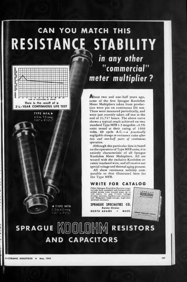
m-YEAR CONTINUOUS LIFE TEST
practically
WRITE FOR CATALOG
SPRAGUE SPECIALTIES CORethtor Divinen
NORTH ADAMS
ELECTRONIC INDUSTRIES • May, 1944
About two and one*half years ago, some of the first Sprague Koolohm Meter Multipliers taken from production were put on continuous life test. These were measured periodically, and were just recently taken off test at the end of 21,747 hours. The above curve shows a typical result achieved on two standard Type MFB 1.5 megohm ±0.5% units tested at their rating of 1500
negligible change in resistance value after two and one-half years of continuous operation.
Although this particular data is based on the operation of Type MFB units, it is entirely characteristic of all Sprague Koolohm Meter Multipliers. All are wound with the exclusive Koolohm ceramic insulated w'ire, and all receive our special voltage and thermal aging process.
All show resistance stability comparable to that illustrated here for the Type MFB.
Other Sprague Koolohm Resistor types include t>otn standard and hermetically sealed power wire wound types up to 120 watts; 10- and 15-watt voltage divider sections; bobbin-type resistors; and Megomax high voltage, high-temperature resistors.
TIMI IN THOUSANDS 0» N0UM
Here is the result of a
CAN YOU MATCH THIS
RESISTORSSPRAGUEAND CAPACITORS
TYPE MFA ►4.0 to 7.5 meg.
"commerciar meter multiplier
◄ TYPE MFB 0.5 to 4.0 meg1 /-" X 5 V';/"
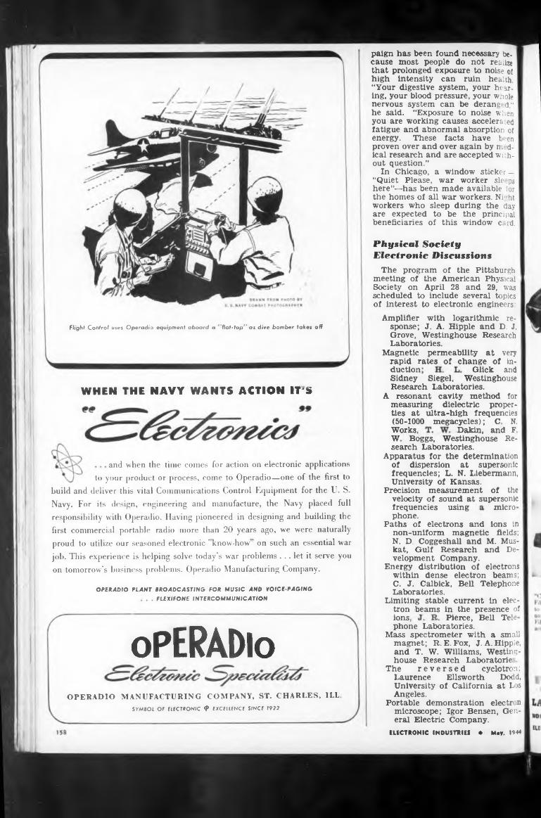
duction
WHEN THE NAVY WANTS ACTION IT'S
Works,
and when the time comes for action on electronic applications
micro
OPERADIO PLANT BROADCASTING FOR MUSIC AND VOICE-PAGING
FLEXIFONE INTERCOMMUNICATION
ions,
oPERADloOPERADIO MANUFACTURING COMPANY, ST. CHARLES, ILL,
SYMBOL OF ELECTRONIC 4* EXCELLENCE S/NCE 1922
Pierce, Bell Tele
Dakin, and F
Glick and
frequencies using phone.
Physical Society Electronic Discussions
paign has been found necessary because most people do not realize that prolonged exposure to noise oi high Intensity can ruin health. “Your digestive system, your hearing, your blood pressure, your whole nervous system can be derang'd," he said. “Exposure to noise when you are working causes accelerated fatigue and abnormal absorption of energy. These facts have been proven over and over again by m dical research and are accepted without question.”
In Chicago, a window7 sticker — “Quiet Please, war worker sle ps here”—has been made available for the homes of all war workers. Nr ht workers who sleep during the day are expected to be the principal beneficiaries of this window card.
Flight Control uses Operadio equipment aboard a 'flat-top ' as dive bomber takes off
phone Laboratories.Mass spectrometer with a small
magnet; R. E. Fox, J. A. Hippie, and T. W. Williams, Westinghouse Research Laboratorie
The reversed cyclotron ;Laurence Ellsworth Dodd, University of California at Los Angeles.
Portable demonstration electr n microscope; Igor Bensen, General Electric Company.
Sidney Siegel, Westinghouse Research Laboratories.
A resonant cavity method for measuring dielectric properties at ultra-high frequencies (50-1000 megacycles) ; C N.
W Boggs, Westinghouse Research Laboratories.
Apparatus for the determination of dispersion at supersonic frequencies; L. N. Liebermann, University of Kansas.
Precision measurement of the velocity of sound at supersonic
Paths of electrons and ions in non-uniform magnetic fields; N. D. Coggeshall and M. Muskat, Gulf Research and Development Company.
Energy distribution of electrons within dense electron beams; C. J. Calbick, Bell Telephone Laboratories.
Limiting stable current in electron beams in the presence of
ELECTRONIC INDUSTRIEI • May. 1944
The program of the Pittsburgh meeting of the American Physical Society on April 28 and 29, was scheduled to include several topics of interest to electronic engineers:
Amplifier with logarithmic response; J. A. Hippie and D. J. Grove, Westinghouse Research Laboratories.
Magnetic permeability at very rapid rates of change of in-
job. This experience is helping solve today's war problems ... let it serve you
on tomorrow's business problems. Operadio Manufacturing Company.
first commercial portable radio more than 20 years ago, we were naturally
proud to utilize our seasoned electronic ' know-how ' on such an essential war
to your product or process, come to Operadio—one of the first to
build and deliver this vital Communications Control Equipment for the U. S. Navy. For its design, engineering and manufacture, the Navy placed full responsibility with Operadio. Having pioneered in designing and building the
While there well as ours, is to pro-
of such products, Taylor Fibre
LAMINATED PLASTICS: VULCANIZED FIBRE • PHENOL FIBRE • Sheets, Rods, Tubes, and Fabricated Parts
159
our maximum attention and
NORRISTOWN, PENNSYLVANIA * OFFICES IN PRINCIPAL CITIES • PACIFIC COAST HEADQUARTERS: 544 S. SAN PEDRO ST.. LOS ANOELES
your principal concern.
raw materials to finished product,is unsurpassed, thanks to Taylor’s Verifibre Process
a war to be won.
in which quality is controlled step by step, from the industry’s most modern plant.
ELECTRONIC INDUSTRIES • May, 1944
Now—before the curtain goes up on a bright, new world, discuss your post-war plans with our engineers. Now is the time to Take it to Taylor.
duce products that will speed victory. We are all giving production-capacity to that vitally important objective.
Figuring prominently in manv a profitable, peace-time venture will be the intelligent use of Vulcanized Fibre and Phenol Fibre. In the design, application, and production
But even the most pessimistic will agree that it is not too soon to plan and think for the post-war reconstruction period. Peace will dawn with the suddenness of a raised curtain and only those who are prepared for it will be able to swing into profitable, peace-time production with the minimum delay.
“• '.at’s head.” they call it. The core is Phenol F bre — to eliminate moisture absorption and U> increase dielectric strength. But because an electric arc will not carbonize Vulcanized Fibre, the front and back of the Cat’s head a ■ made of Vulcanized Fibre.
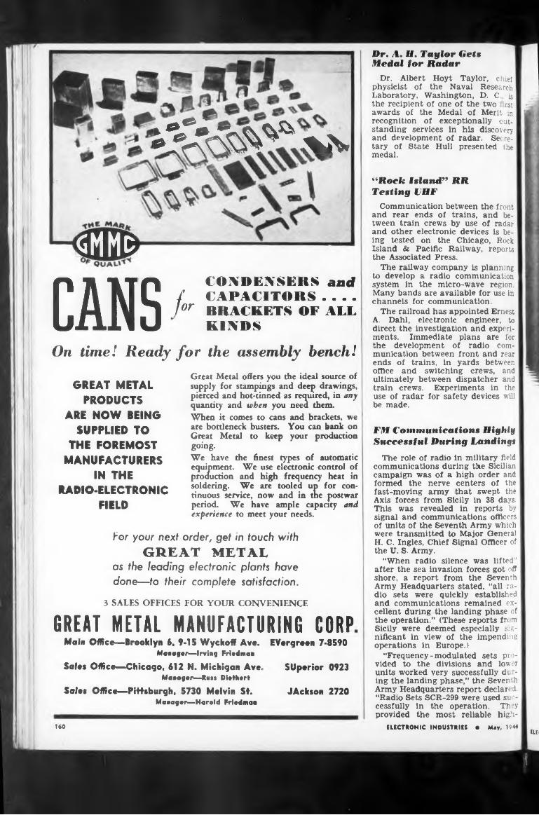
Dr. A. H. Taylor Gets Medal for Radar
SMMg
ft®*«.Dr. Albert Hoyt Taylor, chief
physicist of the Naval Research Laboratory, Washington, D. C is the recipient of one of the two rst awards of the Medal of Merit in recognition of exceptionally outstanding services in his discovery and development of radar. Secretary of State Hull presented the medal.
-
CANS *orCONDENSERS and CAPACITORS . . . . BRACKETS OF ALL KINDS
On time! Ready for the assembly bench!
GREAT METAL PRODUCTS
ARE NOW BEING SUPPLIED TO
THE FOREMOST MANUFACTURERS
IN THE RADIO-ELECTRONIC
FIELD
Great Metal offers you the ideal source of supply for stampings and deep drawings, pierced and hot-tinned as required, in any quantity and when you need them.When it comes to cans and brackets, we are bottleneck busters. You can bank on Great Metal to keep your production going.We have the finest types of automatic equipment. We use electronic control of production and high frequency heat in soldering. We are tooled up for continuous service, now and in the postwar period. We have ample capacity and experience to meet your needs.
“Rock island" RRTesting VHF
Communication between the front and rear ends of trains, and between train crews by use of radar and other electronic devices is being tested on the Chicago, Rock Island & Pacific Railway, reports the Associated Press.
The railway company is planning to develop a radio communication system in the micro-wave region. Many bands are available for use in channels for communication.
The railroad has appointed Ernest A. Dahl, electronic engineer, to direct the investigation and experiments. Immediate plans are for the development of radio communication between front and rear ends of trains, in yards between office and switching crews, and ultimately between dispatcher and train crews. Experiments in the use of radar for safety devices will be made.
For your next order, get in touch with GREAT METAL
as the leading electronic plants have done—to their complete satisfaction.
3 SALES OFFICES FOR YOUR CONVENIENCE
GREAT METAL MANUFACTURING CORPMals Office—Brooklyn 6, 9-15 Wyckoff Av«.
Manager—Irving Friedman
Sales Office—Chicago, 612 N. Michigan Ave. Managar—Rn«« Diethert
Sales Office—Pittsburgh, 5730 Melvin St. Manager—Harold Friedman
Evergreen 7-8590
Superior 0923
JAckson 2720
FM Communications Highly Successful During Landings
The role of radio in military field communications during the Sicilian campaign was of a high order and formed the nerve centers of the fast-moving army that swept the Axis forces from Sicily in 38 days. This was revealed in reports by signal and communications officers of units of the Seventh Army which were transmitted to Major General H. C. Ingles, Chief Signal Officer of the U. S. Army.
“When radio silence was lifted” after the sea invasion forces got off shore, a report from the Seventh Army Headquarters stated, “all radio sets were quickly established and communications remained excellent during the landing phase of the operation.” (These reports fre m Sicily were deemed especially significant in view of the impending operations in Europe.)
“Frequency-modulated sets provided to the divisions and lowr units worked very successfully du - ing the landing phase,” the Seven (h Army’ Headquarters report declan d. “Radio Sets SCR-299 were used successfully in the operation. They provided the most reliable high-
ELECTRONIC INDUSTRIES • May, 1944ELE;
160
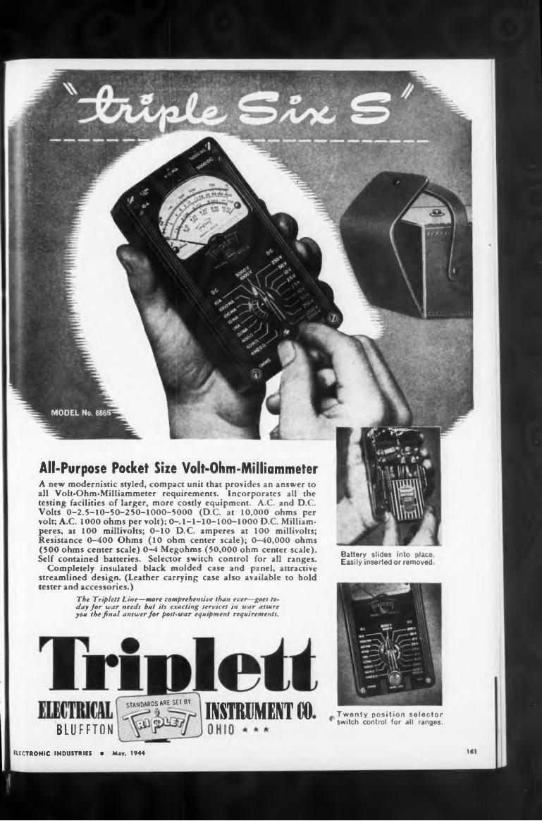
All-Purpose Pocket Size Volt-Ohm-Milliammeter
STANDARDS ARE SET BY imMEKT tOBLUFFTON
1ST
Battery slides into place. Easily inserted or removed
Twenty position selector switch control for all ranges.
ELECTRONIC INDUSTRIES • May, 1944
The Triplett Line—more comprehensive than ever—goes today Jor war needs hut its exacting services in war assure you the final answer Jor post-u ar equipment requirements.
A new modernistic styled, compact unit that provides an answer to all Volt-Ohm-Milliammeter requirements. Incorporates all the testing facilities of larger, more costly equipment. A.C. and D.C. Volts O-2.5-1O-5O-25O-1OOO-5OOO (D.C. at 10,000 ohms per volt; A.C. 1000 ohms per volt); 0-.1-1-10-100-1000 D.C. Milliamperes, ar 100 millivolts; 0-10 D.C. amperes at 100 millivolts; Resistance 0-400 Ohms (10 ohm center scale); 0-40,000 ohms (500 ohms center scale) 0-4 Megohms (50,000 ohm center scale). Self contained batteries. Selector switch control for all ranges.
Completely insulated black molded case and panel, attractive streamlined design. (Leather carrying case also available to hold tester and accessories.)
MODEL No. 666!
Interference required ( U
Amphibious equipment
ShallcrossSELECTOR SWITCHES
Ayrton Universal Shunta
radio set SCR-193told how
1944162
powered radio communications”The report contained other de
tails as follows:
used wasland. The SCR-193.”
ELECTRONIC INDUSTRIES • May.
“Amphibious envelopments by a battalion landing team were executed at San Agata and Brole," said a report from a Division Commander. “Radio contact with these | landing forces was maintained on shipboard and established and maintained ashore within one hour after landing. Two SCR-193’s in quarter-ton trucks served admirably for this purpose. They were able to follow the battalion from the beach to its objectives on high ground where larger vehicles could not go. On one occasion when the Infantry operated at a hill position where no vehicle could follow, the officer and operator with the set displayed extraordinary courage in continuing to operate the set from an exposed position on the flat ground outside the main lines.”
The commanding officer of a Signal Company, reporting the activities during the middle of August.
mounted in a quarter-ton jeep and a radio set SCR-284 were assigned to a unit operating in mountaino us terrain where it was necessary to hand-carry the SCR-284 to some points where vehicular transport was an impossibility. In these instances radio communications were maintained by relay through the SCR-193 located somewhere in the rear.”
WRITE FOR CATALOGAlthough Shallcross Selector Switches are produced in an almost infinite number of types, you'll find our data sheets a worthwhile guide. Ask for Switch Bulletin C-l, and C-2.
For quality selector switches—try Shallcross!Dozens of standard designs are available
—and each of these is subject to many variations to suit individual requirements.
Shallcross Selector Switches are the logical outgrowth of our own need for dependable, high-quality units for exacting Shallcross electrical measuring devices and other equipment. You'll find them unexcelled for use wherever the call is for switches of assured better performance.
“The Division Commander’s net utilized an SCR-188 and SCR-193’s in quarter-ton trucks. This net linked up the Division Commander, the Deputy Commanders, the Assistant Commander for staff intelligence officers, and. three Régi-1 mental Commanders. These vehiclemounted sets were all landed without loss of a single set. Although this net was maintained for personal voice contact between the I Division Commanders and for staff officers, radio interference conditions made it necessary to operate on cw (continuous wave) most of the time.”
In describing another phase of the use of radio, a Signal officer of the Seventh Army declared in his report that “High-powered radios in amphibious vehicles were tried and used successfully in this operation. They provided the most reliable early communications that we had. The most useful vehicle we have found equipped with radio has been the quarter-ton truck on
---- OTHER------ SHALLCROSS PRECISION PRODUCTS
Ratio BoxerWheatstone BridgesKelvin-Wheatstone
BridgesLow-Resistance
Test SelvMi’li ■ohm-meters
Decade Resistance Boxes
Megohmmetersand many more
OHALLCROSS MFG. CO.ENGINEERING • DESIGNING • MANUFACTURING
A Third CITATIONFOR THE INSTRUMENT LEADER
D...FOR MERITORIOUS WA R PRO T I O N
This third citation for meritorious war production . . climaxing a long record of war service ... is a source of justifiable pride to the men and women of Weston.
The record began back in the earliest days of our defense period, when a large segment of Westons’ capacity was assigned to the production of instruments vital to military needs. Thus, when we finally were forced into this world struggle, Weston was ready for full-scale war production.
This new star which adorns our “E" pennant marks the third time Weston has been first in this highly specialized field to receive each successive war citation. Weston Electrical Instrument Corporation, Newark 5, New Jersey.
laboratory Standards . Precision DC and AC Portables . . Instrument Transfomers
. . Sensitive Relays . . DC, AC, and
Thermo Switchboard and Panel Instruments, WESTON•: ... . .
Specialized Test Equipment . . . llpM Measurement and Central Devices , . Exposure Meters...Aircraft Instruments... Electric Tachome<ers...Dial Thermometers.
FOR OVER YEARS LEADERS IN ELECTRICAL MEASURING INSTRUMENTS
ELECTRONIC INDUSTRIES 4 Mey, 1944 141
MEASUREMENTS CORPORATION
3OONTON.NEW JERSEY
Standord Signai
Generators
Square Wave
Generators
Vacuum Tube
Voltmeters
Pulse
Generators
Moisture
Meters
U.H.F.Noisemeters
“Conveyor-Belt” Radio System
Government radio engineers continue to launch “trial balloons” from Washington to get public reactions on their proposal for a “radio trunk line” or “radio conveyor belt” for international communication. The system w'ould be made up of eight powerful relay stations girdling the globe at a latitude about 20 degrees north of the equator. This would be theoretically far enough from the equator to get away from the tropical dampness which raises hob with electrical equipment, yet far enough south to avoid polar magnetic disturbances, the bane of radio transmission. (See also page 192, our January, 1944, issue.)
Tentative station locations are: San Juan, Puerto Rico; Tenerife, Canary Islands; Alexandria, Egypt; Bombay, India; Hong Kong, China; Guam; Honolulu, H. I, and Mexico City, Mexico.
How it would work
Overseas phone calls and radiograms from the eastern sections of the U.S. and Canada for London or Paris would go via high-powered stations in New York, Miami, or New Orleans, through Puerto Rico and the Canaries to destination. Calls from the western sections would be beamed via San Francisco to Mexico City, or via New Orleans to Puerto Rico; calls from Santiago, Chile, would go via Mexico City; those from Rio de Janiero, via the Canaries; calls for Berlin or Moscow would go via Egypt.
Experts of the FCC declare the plan to be technically possible in the present state of the radio art. Still to be heard from are the International diplomats and financiers whose services would have to be called upon before the “conveyor belt” system could become a postwar actuality.
Sees Peril inNazi Radio Bombs
John Hays Hammond, Jr., internationally known inventor and holder of patents on radio-controlled bombs similar to those being used by the Germans, was quoted recently as saying in Boston he believed the Nazis have only been practicing with the projectiles and that their full force would be felt later, the AP reports.
“My feeling is,” he said, “that perfection of this device by Germany would imperil the British fleet. The fleet versus glider bombs could be the next phase of this war —it could be glider bombs against the combined Allied fleets.
“No shipping will be safe if the Germans perfect this type of war
fare, excepting those ships which can stay out of reach.”
Hammond’s prediction was described in London as “visionary and exaggerated out of all proportions’’, by one British expert.
Vse of Quartz Crystals Relaxed
The number of permitted use. of quartz crystals, previously only available in the manufacture of radio oscillators and filters for var purposes and a few other military items, has been increased by the War Production Board through an amendment to General Conservation Order M-146 as the result of an easier supply-demand situation.
The new permitted uses are the utilization of quartz crystals for manufacture of radio oscillators and filters for governmental activities, directly connected with defense, public health, welfare or security and for commercial broadcasting stations and other commercial communication systems. The production of radio oscillators and filters for governmental activities will permit the police, forestry services and similar activities in which radio plays an important communications role to get the quartz radio parts they need. The manufacture of optical or electrical parts using quartz crystals for use in research of production instruments manufactured to fill orders rated AA-2X or better, also is permitted.
Made its Japan!Mr. Tojo and his children are
certainly proving the greatest imitators in the world.
This is a story brought back from the Southwest Pacific by Major General Ingles, Chief Signal Officer. The American troops were Incensed at one time when they captured a Japanese radio station with tubes having the RCA trademark. But the tubes and the entire set, they soon found, had actually been made in Japan.
The little Nipponese were not merely content with copying the American design. They even reproduced the RCA markings.
Electron Micrographs of Mine Bust
Drilling and blasting operation produce silica dust in the air of a mine. If this dust is breathed into the lungs over a long period of time, the condition known as sih- cosis, which is a serious disease among miners, is set up. The driving dust appears to be more harmful In its effect than the blasting
ELECTRONIC INDUSTRIES • May 1944164
1
Are You Keeping Up-to-DateON LOW-VOLTAGE RECTIFIERS?1. Name the three most commonly used types of low-voltage rectifiers.
2. In what respects do they differ?
3. What is the best way to decide which type to use for a specific job?
4. Name the only designer-manufacturer of all three types.5. What engineering-service benefit does the rectifier user get when he consults a company that offers him all three types of rectifiers?
(Turn to page 313 <oz the answers.
GENERAL ELECTRICELECTRONIC INDUSTRIES e May, 1944 145
First commercial service
spri
Four bands
age-breakdown materials
Write for Literature
When the War Manpower CommiMion hailed Meriden, Conn.
WM
166
applied for. Actual frequency group to be finally used is not yet determined, but will be fixed by experiments made with the several bands. Carrier power is specified as 2 watts for each transmitter. Highly directional radiating and receiving antenna systems will make this low power practical.
components. Used in the laboratory or out in the plant. Can be operated by usual factory personnel:
each group are
“Connecticut Tel." Host to Celebrities
dust, but no significant difference between the two could be discovered by ordinary methods.
In the November, 1943, issue of the Canadian Journal of Research, John H. L. Watson reports electron microscopic investigation of the particle size in mine dust. The distribution of particle sizes in the two types of dust was studied and from electron micrographs it could be concluded that the percentage of particles with diameters less than 0.20m is much greater in the drilling than in the blasting dust.
• A simple, positive, safe and quick means of testing D.C. volt-
The new system will be operated by radio relays of a type which was under development by the Bell Telephone Laboratories prior to he war This system applies to communication by radio many of the techniques which have played an important part in the developm it of long-distance wire telephone circuits. Directed radio beams at ultra-high frequencies will operite simultaneously in both directions and these will be relayed at stations spaced at an average of about 30 miles throughout the route. It is hoped that, ultimately, each radio beam will carry up to 100 telephone communications channels.
Typical of the large and growing line of Industrial Instruments—instrumentation for everyday work about laboratory or production line —practical, dependable, moderate in cost.
ELECTRONIC INDUSTRIES • May. 1944
community” thia group visited the Meriden plant of Connecticut Telephone A Electric Division of Great American Industries, producers of radio and electronic devices for the armed forces. Left to right: Gov. Raymond Baldwin of Connecticut; WMC Chairma« Paul V. McNutt; Luise Rainer, film star; Francia T. Maloney, U. S. Senator from Connecticut; Harold W. Harwell, president of Great American Industrie«. and Walter F. Skill % vice-president. Probable cauae of broad smiles—antics by radio comedian Jimmie Duranta who accompanied party
This is the first plan for a system of this type to handle regular commercial long-distance telephone messages over land within the United States and it is believed that it will be the first to handle commercial communications services anywhere in the world.
This project also represents another step in the march of radio telephony to utilize shorter and shorter wave lengths. Overseas commercial radio telephony to England was initiated by the Bell System in 1927 using very long waves. Soon afterward “short waves” were developed for transocean telephony and today, except for the war, it is possible to talk from any telephone in the United
fou you
• Plug* into standard A.C. outlet. Rectifier provides 1 to 4000 (Type P-1) or 1 to 10,000 (Type P-3) volts D.C., continuously variable.
♦ Red panel light indicates "On" or “live." Variac knob is rotated until meter reads desired test voltage.
• Second panel light indicates when breakdown occurs, and meter gives the breakdown voltage.
♦ Current-limiting resistors keep current to approximately 5 milliamperes on P-L 40 milliamperes on P-3, over full range.
• A standard test equipment, now available for prompt delivery.
AT&T to Try VHF Repeater Links
Plans for experimental operation of a series of ultra-high-frequency radio relay links between New York and Boston, for conveying both television programs and multiple telephone conversations, are revealed in applications just made by AT&T to FCC for the necessary frequencies.
Three groups of frequencies are requested: 2000 megacycles; 4000 megacycles, and 15,000 megacycles.
156 CULVER AVENUE,
JERSEY CITY, N. J.
VOLTAGEBREAKDOWN
Industrial B KWTC1SW PLANT and OFFICES
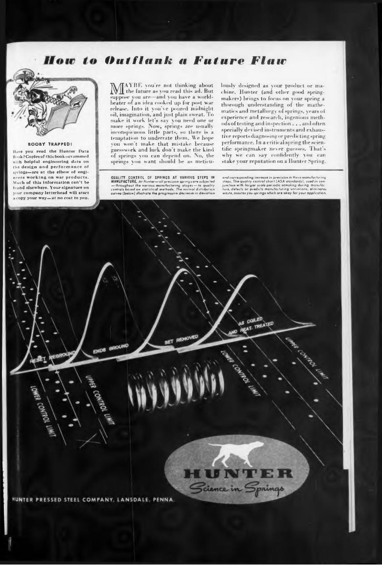
Outflank a Future Flute
more springs. springs are usually
QUALITY CONTROL OF SPRINGS AT VARIOUS STEPS IN MANUFACTURE. At Hunter—all precision springs ore sub|«cfed — throughout th. various manufacturing stages — to qualify controls based on statistical methods. The normal dis'ribuficn curves (below) illustrate the progressive decrease in deviation
and corresponding increase in precision in theie manufacturing steps. The quality control chart (ASA ttandardi), used in son- junction with larger scale periodic sampling during manufacture. detects or pradkti manufacturing variations, eliminates waste, assures you springs which o'* okay far your application.
BOOBY TRAPPED!
Have you read the Hunter Data Bi >ok? Copies of this book—crammed with helpful engineering data on the design and performance of springs—are at the elbow of engineers working on war products. Much of this information can’t be found elsew here. Your signature on your company letterhead will start a copy your way—at no cost to you.
inconspicuous little parts, so there is a temptation to underrate them. We hope vou won't make that mistake because guesswork and luck don’t make the kind of springs you can depend on. IXo, the springs you want should be as meticu-
MAT BE you're not thinking about the future as you read this ad. But
suppose you are—and you have a world- beater of an idea cooked up for post war release. Into it you've poured midnight oil, imagination, and just plain sweat. I o make it work let’s say vou need one or
lously designed as your product or machine. Hunter (and other good springmakers) brings to focus on your spring a thorough understanding of the mathematics and metallurgy of springs, years of experience and researcli, ingenious methods of testing and inspection. . .and often specially dev ised instruments and exhaustive reports diagnosing or predicting spring performance. Ina critical spring the scientific springmaker never guesses. That's why we can say confidently you can stake your reputation on a Hunter Spring.
FOR EUERVIHIRG Radio r«. coaxial
items
Call Allied
OVER 10,000 ITEMS
168
save time and work First. Thousands do.
Tube* Condenser* Capacitors Resistors Rheostats Coils Sockets Photo Cells Batteries Charger*
States to more than 70 foreign countries and to any of more than 95 per cent of all the telephones in the world
Using still shorter waves, only two or three meters long, which do not travel much beyond the horizon, radiotelephone service was established just before the war across Chesapeake Bay between Norfolk and Cape Charles, across Massachusetts Bay between Boston and Provincetown, and between the mainland and Smith and Tangier Islands in Chesapeake Bay.
The new project proposes to use microwaves which are shorter than have heretofore been used for commercial telephony.
Wright Succeeds Thomson At Western Electric
Transformer* Relay* Switch«* Rectifier* Wire A Cable Crystal* Speaker* Receivers Training Kits Code Equip-
Philip L. Thomson, director of public relations of the Western Electric Company, retired under the Company’s pension plan on April 1, after 41 years of service. He is succeeded by Fred B. Wright, an executive of the company’s nationwide distributing organization.
Mr. Thomson joined Western Electric in 1903 after receiving degrees from Union College and from Harvard. He rose through the ranks, becoming manager of the company’s distributing house at Pittsburgh in 1905 and, in 1911, advertising manager at New York head-
NEW Rapid R-F Resonance and Coil Winding Calculator New, dual-purpose Calculator devised by Allied for fast and accurate determination of resonance factors and coil winding data. Simple, easy to use. Send for it now. No. 37-955. Price net, only....................................... 25c
FREEToday's Most
Complete Helpful
IÌUYING GUIDE
ELECTRONIC INDUSTRIES • May, 1944
The principal purpose of the trial is to determine by practical opera- | tion in commercial service the relative advantages and disadvantages of radio relays in the transmission of long-distance messages and television programs, compared with transmission by the familiar wires and cables and coaxial cables 1 Relative costs represent only one of the factors to be determined; others include the relative quality of transmission, flexibility under actual operating conditions, and dependability.
Postwar plans were recently announced for a country-wide extension by the Bell System, by about 7,000 miles, of its coaxial cables suitable for telephone service and the transmission of television programs. According to telephone officials, it is hoped that the new radio system will prove to be valuable as an additional means of meeting the nation’s telephone and television communications requirements. Plans will be worked out to tie together the new Boston- New York radio system, with the New York-Washington coaxialcable line, to give a continuous wide-band channel for television from Washington to Boston.
One call to Allied . . . and your procurement job is done! There’s no lost time — no waste motion. Today’s largest and most complete stocks are concentrated here under one roof... Over 10,000 electronic and radio
the Armed Forces, Government, Industry and Research Laboratories.What’s more . . . close contact with all leading manufacturers enables us to simplify and speed procurement of many diversified needs. You deal with one source, instead of many. You send one order for everything. Whether you need one item or a hundred . . .
ClECTROnics 1
—such as:Microphones Neodphonns Public Address Meters Test Equip. Intercom.Power Supplies Converters Generators Tools
IFrite, IFire, or Phone Haymarket 6800
ALLIED RADIO CORP.833 W. JACKSON BLVD., Dept. 32-E-4, Chicago 7, III.
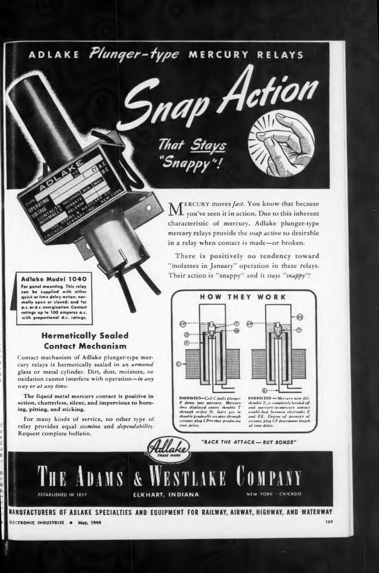
There
ENERGIZED—Coti Cpulh plunger
MANUFACTURERS OF ADLAKE SPECIALTIES AND EQUIPMENT FOR RAILWAY, AIRWAY, HIGHWAY, AHD WATERWAY
169ELECTRONIC INDUSTRIES
thus displaced enters thimble T through orifice O. Inert gas in thimble gradually escapes through ceramic plug CP—thus producing time delay.
BACK THE ATTACK-BUY BONDS
ENERGIZED — Mercury now fills thimble T, is completely lest led off and mercury-to mercury contact established between electrodes E and EE. Degree of porosity of ceramic plug CP determines length of time delay.
Hermetically Sealed Contact Mechanism
Adlake Model 1040 Far panel mounting. This relay can be «applied with either quick or time delay action; nor* molly open or closed, and tor a.e. or d.c. energisation. Contact ratings up to 100 amperes a.c. with proportional d.c. ratings.
"molasses in January” operation in these relays. Their action is “snappy” and it stays "snappy"!
MERCURY moves fast. You know that because you’ve seen it in action. Due to this inherent
characteristic of mercury, Adlake plunger-type mercury relays provide the snap action so desirable in a relay when contact is made—or broken.
Contact mechanism of Adlake plunger-type mercury relays is hermetically sealed in an armored glass or metal cylinder. Dirt, dust, moisture, or oxidation cannot interfere with operation—in any way or at any time.
The liquid metal mercury contact is positive in action, chatterlesn, silent, and impervious to burning, pitting, and sticking.
For many kinds of service, no other type of relay provides equal stamina and dependability. Request complete bulletin.
Tin: Adams & Westlake ComparìfSIABLlSHtD IN IBS7 ELKHART, INDIANA NEW YORK CHICAGO
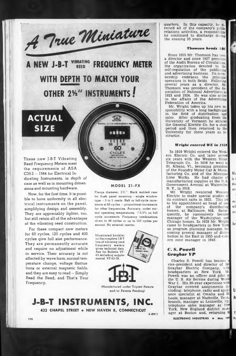
Thomson head« Bf
WITH DEPTH TO MATCH YOUR
INSTRUMENTSOTHER TA
Wright entered WE in 1910
CYGUES
MODEL 21-FXan<
ma
am
J-B-T INSTRUMENTS, INC
Illustrated booklet on the complete J-B-T line of vibrating reed frequency meters gives technical data. Ask for Bulletin VF- 43. including supplemental VF-43-1B.
quarters. In this capacity, he di-' reeled all of the company’s public relations activities, a responsibility he continued to discharge during the ensuing 33 years.
Since 1925 Mr. Thomson has been I a director and since 1927 president! of the Audit Bureau of Circulations I the organization devoted to the I self-regulation of the publishing! and advertising business. Its mem. I bership embraces the principal operators in both fields. Following several years as a director, Mr Thomson was president of the Association of National Advertisers in 1923 and 1924. He was also active in the affairs of the Advertising Federation of America.
Mr. Wright takes up his new re sponsibility with a long background in the field of distribution and sales. After graduating from the University of Vermont he entered the General Electric Co. for a short period and then returned to the University for three years as instructor.
(Manufactured under Triplett Patents and/or Patenta Pending)
In 1910 Wright entered the West I ern Electric Co. and later served! six years with the Western Union I Telegraph Co. In 1916 he went to] St. Albans, Vt., becoming president! of the Foundry Motor Car & Manu | facturing Co. and of the Missiquoi] Lime Works. He had charge of I manufacturing supplies at the U SI Government Arensal at Watervlietl N. Y., in 1918.
Mr. Wright reentered Western! Electric to make special studies of its contract sales in 1922. This led to his appointment as head of one of the company’s distributing houses, at Baltimore, Md. Subsequently, he successively became manager of the Washington and Chicago houses. In 1928 Mr. Wright came to headquarters in New York as program planning manager, becoming general manager of distribution in the East in 1935 and eastern zone manager in 1942.
FREQUENCY METER
ELECTRONIC INDUSTRIES • May. 1
Flanqe diameter, 2’1". Black molded case for flush panel mounting — single window type — 3 to 5 reeds. Half or full-cycle increments at 60 cycles — proportional increments for other frequencies Accuracy, under normal operating temperatures. ± 0.3% on full cycle increments. Frequency combinations down to 40 cycles or up to 550 cycles per second. No external reactor.
433 CHAPEL STREET • NEW HAVEN 8, CONNECTICUT5 JBT-2
These new J-B-T Vibrating Reed Frequency Meters meet the requirements of ASA C39.2 — 1944 for Electrical Indicating Instruments, in depth oi case as well as in mounting dimensions and mounting hardware.
Now, for the first time, it is possible to have uniformity in all electrical instruments on the panel, simplifying design and assembly. They are appreciably lighter, too, but still retain all of the advantages of the vibrating reed construction.
For these compact new meters for 60 cycles, 120 cycles and 400 cycles give full size performance. They are permanently accurate and require no adjustment while in service. Their accuracy is not affected by wave form, normal temperature change, voltage fluctuations or external magnetic fields, and they are easy to read — Simply Read the Reed, and That's Your Frequency.
C. S. PowellGraybar VP
Charles S. Powell has become al vice-president and director of th Graybar Electric Company, withl headquarters at New York. Mr. Powell was an officer and pilot in the U. S. Air Service during W rid War I. His 30-year experience v ithl Graybar covered assignments including: telephone, radio and applH ance specialist at Omaha and St. Louis, manager at Nashville, Tenn branch, manager at Louisville, Kj telephone sales manager at New York. New England district mani ager at Boston and. returning
■ •11«
ACTUAL SIZE
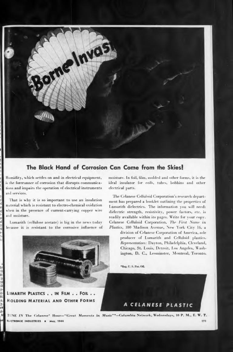
Lumarith Plastics Foilin Film
Molding Material and Other forms
Music***—Columbia Network. WedneMlays, 10 P. M., E. W. T.
moisture. In foil, film, molded and other forms, it is the ideal insulator for coils, tubes, bobbins and other electrical parts.
Humidity, which settles on and in electrical equipment, is the forerunner of corrosion that disrupts communications and impairs the operation of electrical instruments and services.
That is why it is so important to use an insulation material which is resistant to electro-chemical oxidation when in the presence of current-carrying copper wire and moisture.
Î' NE IN The Olanewe* Hour—“Great Moments tUCTRONIC INDUSTRIES ■ May, 1944
Lumarith (cellulose acetate) is big in the news today because it is resistant to the corrosive influence of
The Celanese Celluloid Corporation’s research department has prepared a booklet outlining the properties of Lumarith dielectrics. The information you will need: dielectric strength, resistivity, power factors, etc. is readily available within its pages. Write for your copy. Celanese Celluloid Corporation, The First Name in Plastics, 180 Madison Avenue, New York City 16, a
division of Celanese Corporation of America, sole producer of Lumarith and Celluloid plastics. Representatives: Day ton, Philadelphia. Cleveland, Chicago, St. Louis, Detroit, Los Angeles, Washington, D. C., Leominster, Montreal, Toronto.
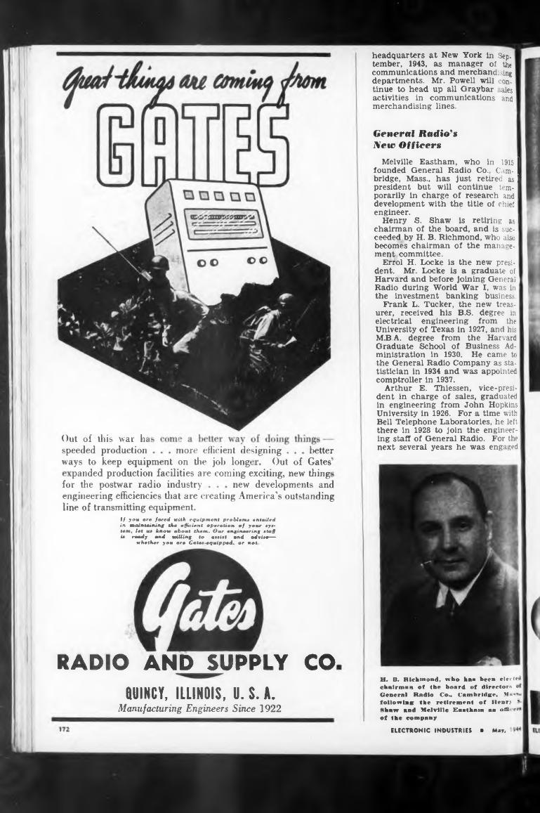
betterOut of Gates'
for the postwar radio industry
RADIO AND SUPPLY CO
panded production facilities are coming exciting, new thing!
more efficient designingways to keep equipment on the job long<
new developments and
headquarters at New York in Sep. tember, 1943, as manager ot the communications and merchandising departments. Mr. Powell will continue to head up all Graybar iaies activities in communications and merchandising lines
QUINCY, ILLINOIS, U. S. A.Manufacturing Engineers Since 1922
Melville Eastham, who in 1915 I founded General Radio Co.. Cam- I bridge, Mass., has just retiree as I president but will continue tem- I porarily in charge of research and I development with the title of chief engineer.
Henry S. Shaw is retiring as I chairman of the board, and is sue- ceeded by H. B. Richmond, who also I becomes chairman of the management committee.
Errol H. Locke is the new presi-1 dent. Mr. Locke is a graduate of Harvard and before joining General Radio during World War I, was in the investment banking business.
Frank L. Tucker, the new treasurer, received his B.S. degree in electrical engineering from the University of Texas in 1927, and his M.B.A. degree from the Harvard Graduate School of Business Administration in 1930. He came to the General Radio Company as statistician in 1934 and was appointed comptroller in 1937.
Arthur E. Thiessen, vice-president in charge of sales, graduated in engineering from John Hopkins University in 1926. For a time with Bell Telephone Laboratories, he left there in 1928 to join the engineering staff of General Radio. For the next several years he was engaged
ELECTRONIC INDUSTRIES ■ May,
engineering efficiencies that are creating America’s outstanding line of transmitting equipment.
H. It. Hichinond, who boa been electK cknlrmnn of the board of directors o General llndlo Co., CambrldKC. M««" follow Ink the retirement of Henr> * Mhnw and Melville Eanthmn na olU<-rr ot the company
General Radio9» New Officers
Out of this war hi speeded production
If you aro fared with equipment problem* .mailed in maintaining tho efficient operation of your tyt- tom, let ut know about them. Our engineering »taU it ready and willing to «Milt and adrite—
whether you aro Calat-equipped. or not.
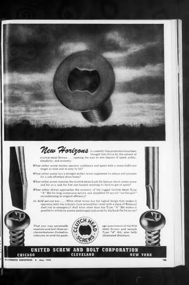
Type Bit; also fullyillustrated Brochure.
age assortment of CLUTCH HEAD Screws and sample
That you may personally examine and test these exclusivefeatures, United invites you to send lor pack-
ELECTRONIC INDUSTRIES • May, 1944
J m assembly line production have beenif brought into focus by the advent of
clutch head Screws . . . opening the way to new degrees of speed, safety, simplicity, and economy.
What other screw invites operator confidence and speed with a recess bull’s-eye target so wide and so easy to hit?
What other screw has a straight-walled recess engineered to reduce end pressure for a safe effortless drive home?
What other screw matches the CLUTCH head Lock-On feature which unites screw and bit as a unit for free one-handed reaching to hard-to-get-at spots?
What other driver approaches the economy of the rugged CLUTCH HEAD Type “A” Bit for long continuous service and simplified 60-second “on-the-spot” reconditioning to original efficiency?
In field service too . . . What other recess has the logical design that makes it operative with the ordinary type screwdriver: even with a piece of flattened steel rod in emergency? And what other than the Type “A” Bit makes it possible to withdraw screws undamaged and saved by the Lock-On for re-use?
UNITED SCREW AND BOLT CORPORATIONCLEVELAND NEW YORKCHICAGO
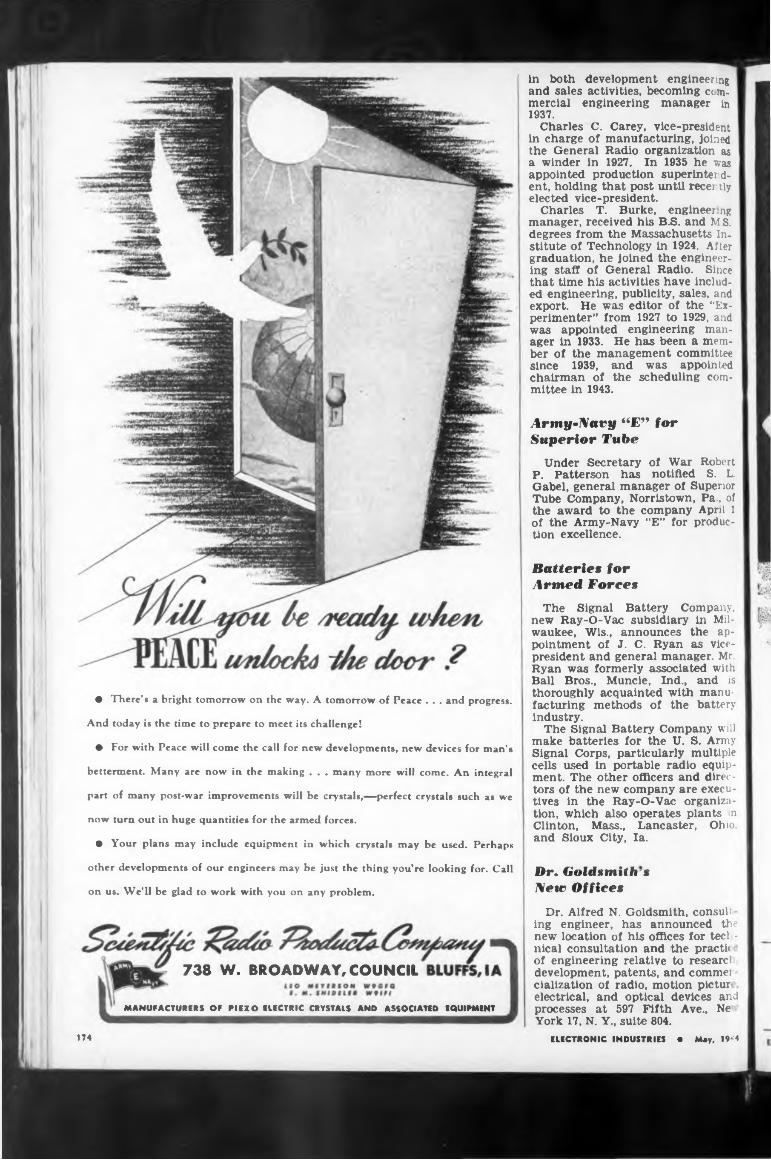
• There’s a bright tomorrow on the way. A tomorrow of Peace . . . and progress.
And today is the time to prepare to meet its challenge!
♦ For with Peace will come the call for new developments, new devices for man’s
betterment. Many are now in the making . . . many more will come. An integral
part of many post-war improvements will be crystals,—perfect crystals such as we
now turn out in huge quantities for the armed forces.
• Your plans may include equipment in which crystals may be used. Perhaps
other developments of our engineers may be just the thing you’re looking for. Call
on us. We’ll be glad to work with you on any problem.
in both development engineering and sales activities, becoming cc m- mercial engineering manager in 1937.
Charles C. Carey, vice-president in charge of manufacturing, joined the General Radio organization as a winder in 1927, In 1935 he was appointed production superintendent, holding that post until recently elected vice-president.
Charles T. Burke, engineer ng manager, received his B.S. and M.S. degrees from the Massachusetts Institute of Technology in 1924. After graduation, he joined the engineering staff of General Radio. Since that time his activities have included engineering, publicity, sales, and export. He was editor of the “Experimenter” from 1927 to 1929, and was appointed engineering manager in 1933. He has been a member of the management committee since 1939, and was appointed chairman of the scheduling committee in 1943.
Army-Navy “E” for Superior Tube
Under Secretary of War Robert P. Patterson has notified S. L. Gabel, general manager of Superior Tube Company, Norristown, Pa., of the award to the company April 1 of the Army-Navy “E” for production excellence.
Batteries for Armed Forces
The Signal Battery Company, new Ray-O-Vac subsidiary in Milwaukee, Wis., announces the appointment of J. C. Ryan as vice- president and general manager. Mr. Ryan was formerly associated with Ball Bros., Muncie, Ind., and is thoroughly acquainted with manufacturing methods of the battery industry.
The Signal Battery Company will make batteries for the U. S. Army Signal Corps, particularly multiple cells used in portable radio equipment. The other officers and directors of the new company are executives in the Ray-O-Vac organization, which also operates plants in Clinton, Mass., Lancaster, Ohio, and Sioux City, la.
Dr. Goldsmith's New Offices
738 W. BROADWAY, COUNCIL
MANUFACTURERS OF PIEZO ELECTRIC CRYSTALS AND ASSOCIATED EQUIPMENT
Dr. Alfred N. Goldsmith, consul: ing engineer, has announced th^ new location of his offices for tech - nical consultation and the practic of engineering relative to researci development, patents, and comma cialization of radio, motion pictur electrical, and optical devices and processes at 597 Fifth Ave., Ne York 17, N. Y., suite 804.
ELECTRONIC INDUSTRIES • May, 19*4174
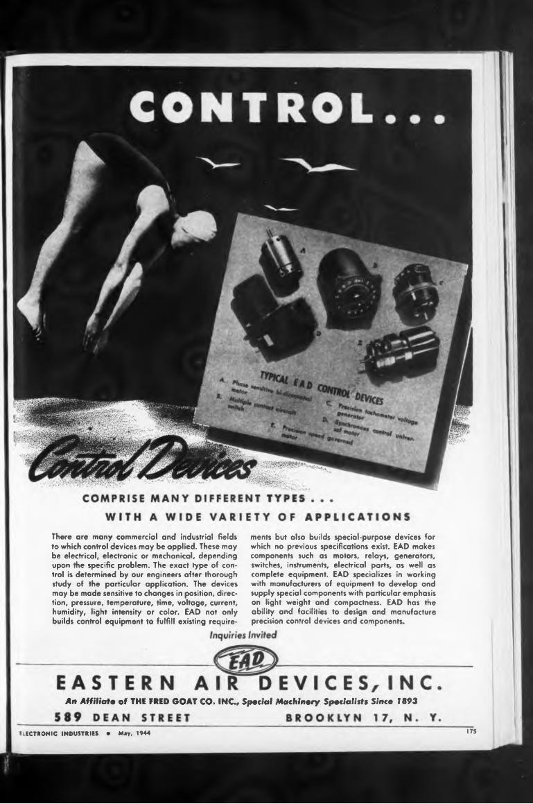
An Affiliate of THE FRED GOAT CO. INC., Special Machinery Specialists Since 1893
175ELECTRONIC INDUSTRIES • May, 1944
There are many commercial and industrial fields to which control devices may be applied. These may be electrical, electronic or mechanical, depending upon the specific problem. The exact type of control is determined by our engineers after thorough study of the particular application. The devices may be made sensitive to changes in position, direction, pressure, temperature, time, voltage, current, humidity, light intensity or color. EAD not only builds control equipment to fulfill existing require-
ments but also builds special-purpose devices for which no previous specifications exist. EAD makes components such as motors, relays, generators, switches, instruments, electrical parts, as well as complete equipment. EAD specializes in working with manufacturers of equipment to develop and supply special components with particular emphasis on light weight and compactness. EAD has the ability and facilities to design and manufacture precision control devices and components.
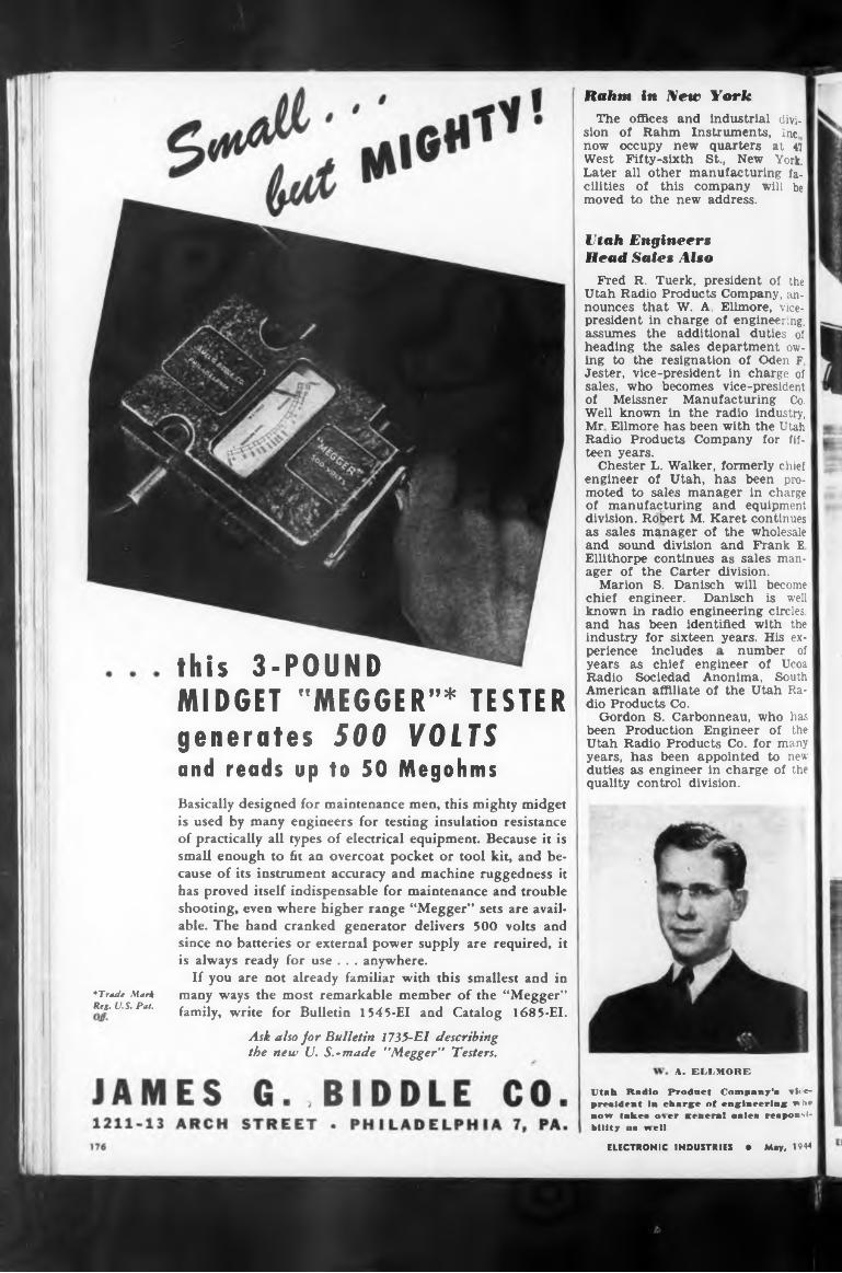
Rahm in New York
number ofthis 3-POUND
A. BELMORE
Utah Engineers Head Sales Also
*Tnu/t Mari Reg. U.S. Pat.
perience includes
Fred R. Tuerk, president of the Utah Radio Products Company, announces that W. A. Ellmore, vicepresident in charge of engineering, assumes the additional duties of heading the sales department owing to the resignation of Oden F Jester, vice-president in charge of sales, who becomes vice-president of Meissner Manufacturing Co. Well known in the radio industry, Mr Ellmore has been with the Utah Radio Products Company for fifteen years.
Chester L. Walker, formerly chief engineer of Utah, has been promoted to sales manager in charge of manufacturing and equipment division. Robert M. Karet continues as sales manager of the wholesale and sound division and Frank E Ellithorpe continues as sales manager of the Carter division.
Marion S. Danisch will become chief engineer. Danisch is well known in radio engineering circles, and has been identified with the industry for sixteen years. His ex-
MIDGET "MEGGER”* TESTER
The offices and industrial division of Rahm Instruments, Inc. now occupy new quarters at 47 West Fifty-sixth St., New York. Later all other manufacturing facilities of this company will be moved to the new address.
years as chief engineer of Ucoa Radio Sociedad Anonima, South American affiliate of the Utah Radio Products Co.
Gordon S. Carbonneau, who has been Production Engineer of the Utah Radio Products Co. for many years, has been appointed to new duties as engineer in charge of the quality control division.
Ask also for Bulletin 1735-El describing the new U. S.-made ''Megger” Testers.
generates 500 VOLTS and reads up to 50 MegohmsBasically designed for maintenance men, this mighty midget is used by many engineers for testing insulation resistance of practically all types of electrical equipment. Because it is small enough to fit an overcoat pocket or tool kit, and because of its instrument accuracy and machine ruggedness it has proved itself indispensable for maintenance and trouble shooting, even where higher range “Megger” sets are available. The hand cranked generator delivers 500 volts and since no batteries or external power supply are required, it is always ready for use . . . anywhere.
If you are not already familiar with this smallest and in many ways the most remarkable member of the “Megger” family, write for Bulletin 1545-EI and Catalog 1685-EI.
Utah Radio Product Company'« xi<e- preaident in charge ot engineering who now taken o» er Kmeral aalen rewponsl- hlllty as well
ELECTRONIC INDUSTRIES • May, 1944
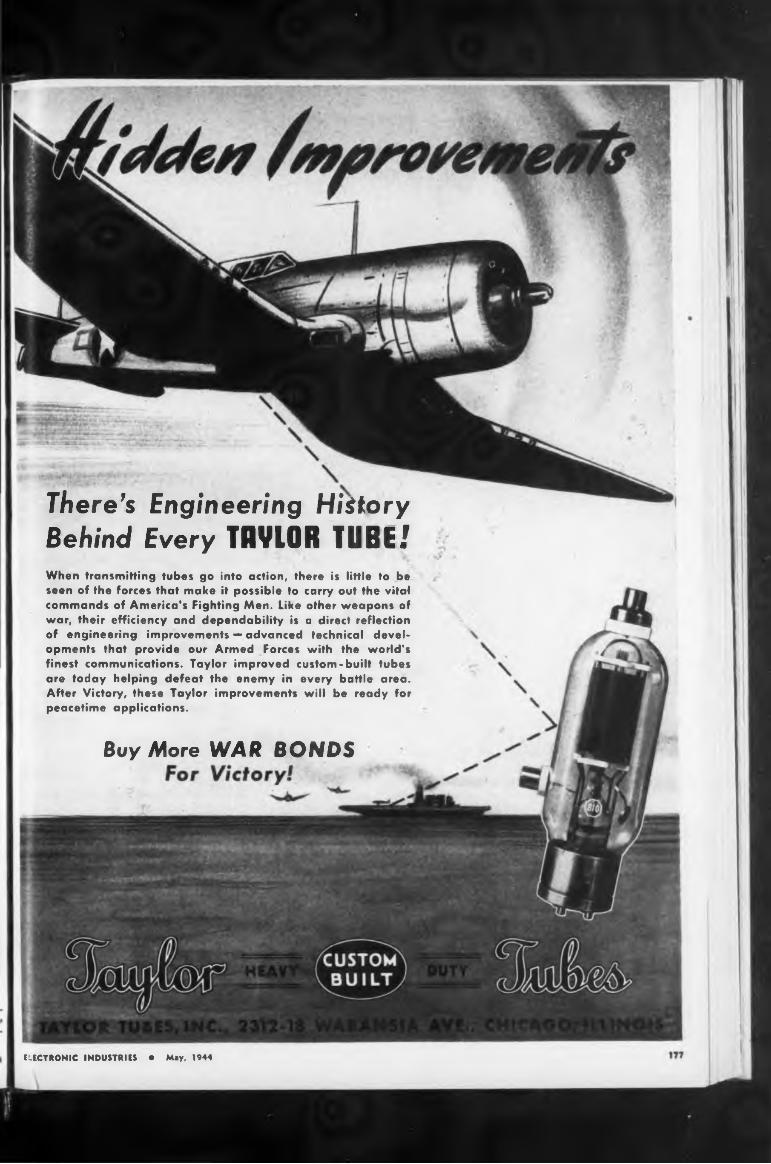
There’s Engineering HistoryBehind Every TOVLOR TUBE.'When transmitting tubes go into action, there is little to be seen of the forces that make it possible to carry out the vital commands of America’s Fighting Men. Like other weapons of war, their efficiency and dependability is a direct reflection of engineering improvements — advanced technical developments that provide our Armed Forces with the world’s finest communications. Taylor improved custom-built tubes are today helping defeat the enemy in every battle area. After Victory, these Taylor improvements will be ready for peacetime applications.
Buy More WAR BONDS
ELECTRONIC INDUSTRIES • May, 1944
Trirohuh Efficiency
TRADE FLUX
i
After Victory, Permoflux Acoustical Developments which today
f provide superior intelligibility to America’s fighting voices, will give improved fidelity to millions of entertainment instruments. There will be Permoflux Engineered Devices for all sound transmission requirements.
ermoflùx engineering leans Faithful Speech
eproduction............
BUY WAR BONDS FOR VICTORY'
Meek Plant Radio Receivers
Following design and development work on postwar radio receivers, John Meek Industries, Plymouth, Ind., has recently been issued an RCA license to manufacture the sets, according to a state ment from Mr. Meek. For the past several months, an internationally famous firm of industrial designing engineers has been working closely with Meek draftsmen in the preparation of streamlined models with popular eye-appeal for modern tastes.
Ralph Glover, Contulting Engineer
Ralph P. Glover has announced his resignation from Webster Products Co., Chicago, where he was in charge of engineering-sales coordination, as well as manager of the voltage-regulator division, to devote himself to consulting engineering, with offices at 1024 Superior St., Oak Park, Hl. He will specialize in product development and product management counsel in the electronic, electroacoustic and radio fields.
Upon graduation from the electrical engineering course at the University of Cincinnati, he joined Crosley Radio Corp. He was active tn the formation of the Cincinnati Section of the I.R.E. and served as its secretary. Later he became assistant chief engineer of SilverMarshall, Inc., and was placed In charge of public-address and parts development and manufacturing. From 1933 to 1935 he managed engineering and sales for the E. F Johnson Co., manufacturers of transmitter components and antenna devices. From 1933 to 1940 he served as chief engineer of Shure Brothers, manufacturers of microphones and acoustic devices. He then joined the Jensen Radio
PERMOFLUX CORPORATION4916-22 W. Grand Ave., Chicago 39, III.
PIONEER MANUFACTURERS Of FIRMAMENT MAGNET DYNAMIC TRANSDUCERS RALPH GLOVERELECTRONIC INDUSTRIES • May, 194- I El
178

DESCRIPTIVE BULLETINS AVAILABLE ON REQUEST
ADD STILL ANOTHER CML 1420 GENERATOR: This gives you 250 watts at any three frequencies in the range, or 750 watts of three-phase power with two phases adjustable through 360° with respect to the third phase. With either Delta or "Wye” output corrections.
ADD ONE CML 1420 GENERATOR. This gives you 250 watts at any two frequencies in the range, or 500 watts of two-phase power with the phase relationship adjustable through 360°.
TAKE ONE CML 1420-A GENERATOR: This gives you 250 watts of power through a frequency range of 50 — 6,000 cycles at 80-120-135- 270 volts. 3% regulation no load to full load; maximum distortion, 6%.
Elmer Crane to Lear Atria
headquarters
Write today. Your inquiry will receive prompt attention.
IbO
Elmer P. Crane, former head of the products and facilities branch of WPB’s Radio and Radar Division, has been appointed general manager of radio for Lear Avia. Inc., manufacturer of radio and aircraft equipment of Piqua, O., and Grand Rapids, Mich. Mr. Crane, who previously had been with Western Electric for 18 years, will make his
John Smith to P. R, Mallory
where the Lear Avia organization’s radio production is being centralized.
Mfg. Co., makers of loud speaker» and sound-reproducing equipment to coordinate engineering and ;al& activities on new products.
Mr. Glover is a member of the Acoustical Society of America, Institute of Radio Engineers, and the Radio Engineers Club of Chicago and is the author of a number of published technical papers.
Grand Rapids,
If your post-war product incorporates a tube, singly or in combination with an electrical control, or other electronic or electrical unit, we are prepared to make specific recommendations to bring it to maximum efficiency.
★ No need to crystal gaze into the
future of electronics. For, as we at
National Scientific Products Company
engage in secret wartime electronic
developments, many peacetime appli
cations of these very same electronic
principles are revealed daily.
New, cost-saving electronic designs which are applicable to post-war products ranging from radios, lighting units, thermal devices, timing and measuring instruments, electrical-therapy machines and door openers, to a host of other peacetime items, are everyday occurrences in National laboratories.
NATIONAL SCIENTIFIC PRODUCTS COMPANYDesigners and Manufacturers of Electrical and Mechanical Devices
5011-25 NORTH KEDZIE AVE., CHICAGO 25, ILLINOIS
Army-Navy “E” AwardsAircraft Accessories Corp., Power
Controls Division, Burbank, Cid (white star added).
Electro Motive Mfg. Co., William- tic, Conn, (white star added).
National Union Radio Corp., Newark & Maplewood. N J. (white star added).
Rola Company, Inc., 2530 SuperiorAve., Cleveland, Ohio, (star added).
Superior Tube Co., Norristown, PaThe Thomas & Betts Co., Elizabeth,
N. J (second star added).
John M Smith, who has been gener d manager oi manufacturing for RCA Victor, Camden, N. J., has joined P. R. Mallory & Co., Inc., Indianapolis, Ind., as vice-pm- ident in charge ot manufacturing
ELECTRONIC INDUSTRIES ■ May. 1944
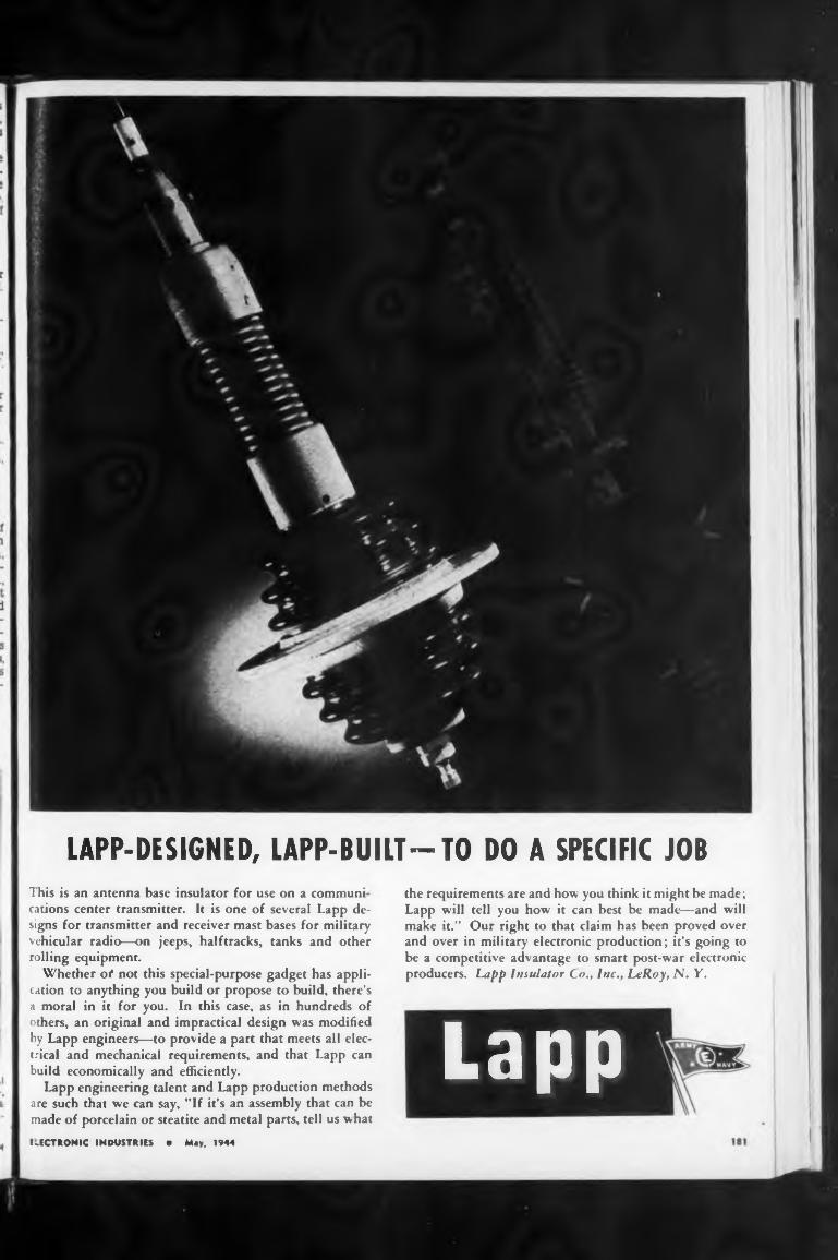
This is an antenna base insulator for use on a communi
LAPP-DESIGNED, LAPP-BUILT— TO DO A SPECIFIC JOB
ELECTRONIC INDUSTRIES • May. 1944
the requirements are and how you think it might be made ; Lapp will tell you how it can best be made—and will make it.” Our right to that claim has been proved over and over in military electronic production; it’s going to be a competitive advantage to smart post-war electronicproducers. Lapp Insulator Co., Inc., Le Roy, N. Y.
cations center transmitter. It is one of several Lapp designs for transmitter and receiver mast bases for military vehicular radio—on jeeps, halftracks, tanks and other rolling equipment.
Whether ot not this special-purpose gadget has application to anything you build or propose to build, there’s a moral in it for you. In this case, as in hundreds of others, an original and impractical design was modified by Lapp engineers—to provide a part that meets all electrical and mechanical requirements, and that Lapp can build economically and efficiently.
Lapp engineering talent and Lapp production methods are such that we can say, "If it’s an assembly that can be made of porcelain or steatite and metal parts, tell us what
Lapp
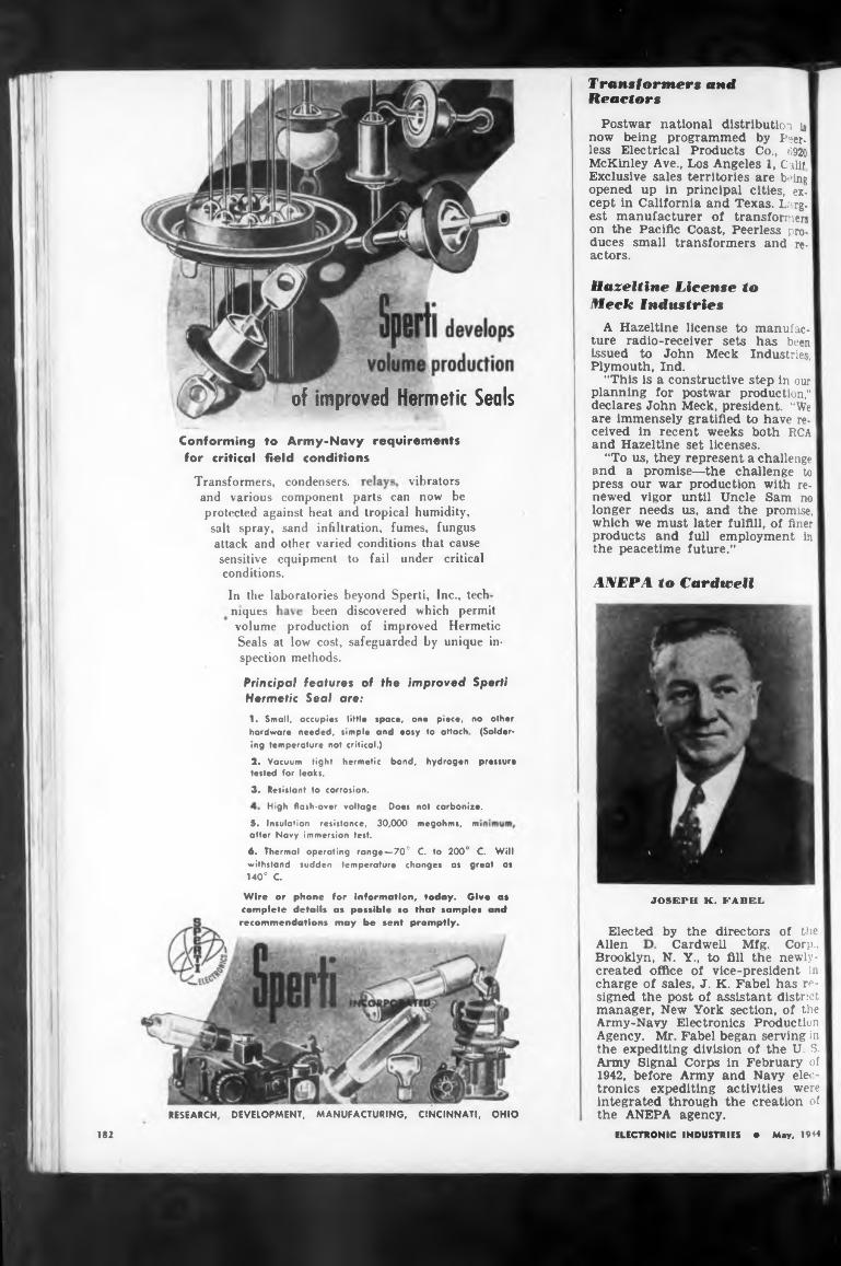
of improved Hermetic Seals
vibrators
AN EPA to Cardwell
been discovered which permitniques
JOSEPH K. FABEL
Elected by the directorsAllen
182
Brooklyn, N. Y., to fill the
of the Corp.,
newly-
Tr ans formers and Reactors
High flash-over voltage. Doe«
Cardwell Mfg.
Principal features of the improved Sperti Hermetic Seal are:
Transformers, condensers,
A Hazeltine license to manufacture radio-receiver sets has been ' issued to John Meek Industries, Plymouth, Ind.
“This is a constructive step in our planning for postwar production," declares John Meek, president. “We are immensely gratified to have received in recent weeks both RCA and Hazeltine set licenses.
“To us, they represent a challenge and a promise—the challenge to press our war production with renewed vigor until Uncle Sam no longer needs us, and the promise, which we must later fulfill, of finer products and full employment in the peacetime future.”
Postwar national distribution u now being programmed by Peerless Electrical Products Co., 6920 McKinley Ave., Los Angeles 1, Calif Exclusive sales territories are being opened up in principal cities, except in California and Texas. Largest manufacturer of transformers on the Pacific Coast, Peerless produces small transformers and reactors.
RESEARCH, DEVELOPMENT, MANUFACTURING, CINCINNATI, OHIO
Conforming for critical
to Army-Navy requirements field conditions
Wire or phone for information, today. Give a* complete details as possible so that samples and recommendations may be sent promptly.
volume production of improved Hermetic Seals at low cost, safeguarded by unique inspection methods.
withstand sudden temperature changes as great as 140° G
Hazeltine License to fleck Industries
C. to 200° C. Will
5. Insulation resistance, 30,000 after Navy immersion test.
6. Thermal operating range—70°
not carbonize,
megohms, mi
and various component parts can now be protected against heat and tropical humidity, salt spray, sand infiltration, fumes, fungus attack and other varied conditions that cause sensitive equipment to fail under critical conditions.
In the laboratories beyond Sperti, Inc., tech
1. Small, occupies little space, one piece, no other hardware needed, simple and easy to attach (Soldering temperature not critical.)
2. Vacuum tight hermetic bond, hydrogen pressure tested for leaks.
3. Resistant to corrosion.
created office of vice-president in charge of sales, J. K. Fabel has resigned the post of assistant district manager, New York section, of the Army-Navy Electronics Production Agency. Mr. Fabel began serving in the expediting division of the U. S. Army Signal Corps in February of 1942, before Army and Navy electronics expediting activities were integrated through the creation of the ANEPA agency.
ELECTRONIC INDUSTRIES • May, 1944
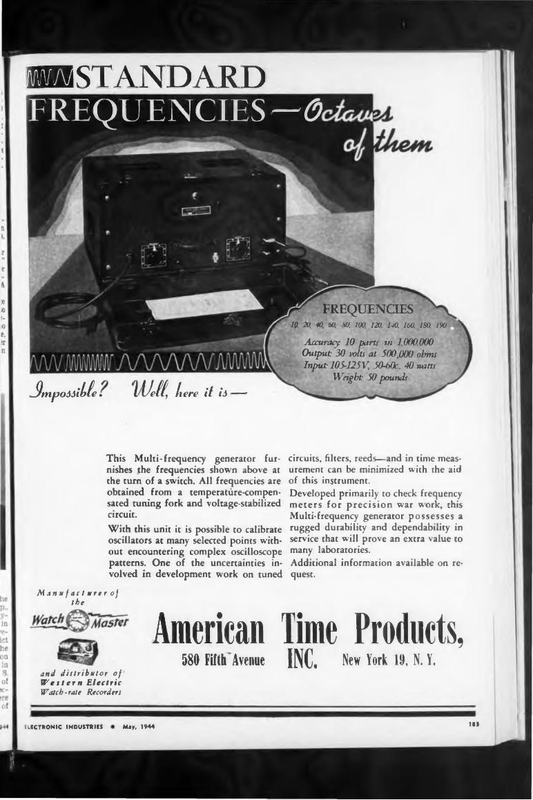
»STANDARD
FREQUENCIES10. 20 SO, 60. SO 100, 120. 110 160 ISO 190
^tnpoóôihte » ïUetf, here it h—’
Accuracy 10 parts in 1,000,000 Output: 30 volts at 500,000 ohms Input: 105-125V, 50-bOr, 40 watts
Weight: 50 pounds
FREQUENCIES— 6
This Multi-frequency generator furnishes the frequencies shown above at the turn of a switch. All frequencies are obtained from a temperatùre-compen- sated tuning fork and voltage-stabilized circuit.With this unit it is possible to calibrate oscillators at many selected points without encountering complex oscilloscope patterns. One of the uncertainties involved in development work on tuned
circuits, filters, reeds—and in time measurement can be minimized with the aid of this instrument.Developed primarily to check frequency meters for precision war work, this Multi-frequency generator possesses a rugged durability and dependability in service that will prove an extra value to many laboratories.Additional information available on request.
Man u f ac t urer of the
and distributor of Western Electric Watch-rate Recorders
American Time Products,580 Fifth Avenue INC. New York 19, N. ï.
ELECTRONIC INDUSTRIES May, 1944 183
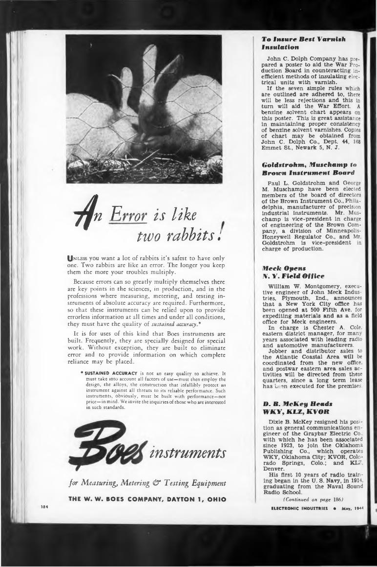
7/» Error is Uh
two rabbits I(Jnless you want a lot of rabbits it’s safest to have only one. Two rabbits are like an error. The longer you keep them the more your troubles multiply.
Because errors can so greatly multiply themselves there are key points in the sciences, in production, and in the professions where measuring, metering, and testing instruments of absolute accuracy are required. Furthermore, so that these instruments can be relied upon to provide errorless information at all times and under all conditions, they must have the quality of sustained accuracy*
It is for uses of this kind that Boes instruments are built. Frequently, they are specially designed for special work. Without exception, they are built to eliminate error and to provide information on which complete reliance may be placed.
* SUSTAINED ACCURACY is not an easy quality to achieve. It must take into account all factors of use—must then employ the design, the alloys, the construction that infallibly protect an instrument against all threats to its reliable performance. Such instruments, obviously, must be built with performance—not price—in mind. We invite the inquiries of those who are interested in such standards.
instruments
for Measuring, Metering & Testing Equipment
THE W. W. BOES COMPANY, DAYTON 1, OHIO
To Insure Best Varnish Insulation
John C. Dolph Company has prepared a poster to aid the War Production Board in counteracting inefficient methods of insulating electrical units with varnish.
If the seven simple rules which are outlined are adhered to, there will be less rejections and this in turn will aid the War Effort. A benzine solvent chart appears on this poster. This is great assistance in maintaining proper consistency of benzine solvent varnishes. Copies of chart may be obtained from John C. Dolph Co., Dept. 44, 168 Emmet St., Newark 5, N. J.
Goldstrohm, Muschamp to Brown Instrument Board
Paul L. Goldstrohm and George M. Muschamp have been elected members of the board of directors of the Brown Instrument Co., Philadelphia, manufacturer of precision industrial instruments. Mr. Muschamp is vice-president in charge of engineering of the Brown Company, a division of Minneapolis- Honeywell Regulator Co., and Mr. Goldstrohm is vice-president in charge of production.
Heck OpensN. Y. Field Office
William W. Montgomery, executive engineer of John Meek Industries, Plymouth, Ind., announces that a New York City office has been opened at 500 Fifth Ave. for expediting materials and as a field office for Meek engineers.
In charge is Chester A. Cole, eastern district manager, for many years associated with leading radio and automotive manufacturers.
Jobber and distributor sales to the Atlantic Coastal Area will be coordinated from the new office, and postwar eastern area sales activities will be directed from these quarters, since a long term lease has L ?n executed for the premises.
D. B. McKey HeadsWKY, KLZ, KVOR
Dixie B. McKey resigned his position as general communications engineer of the Graybar Electric Co., with which he has been associated since 1923, to join the Oklahoma Publishing Co., which operates WKY, Oklahoma City; KVOR, Colorado Springs, Colo.; and KLZ, Denver.
His first 10 years of radio training began in the U. S. Navy, in 1914, graduating from the Naval Sound Radio School.
(Continued on page 186)ELECTRONIC INDUSTRIES • May, 1944184
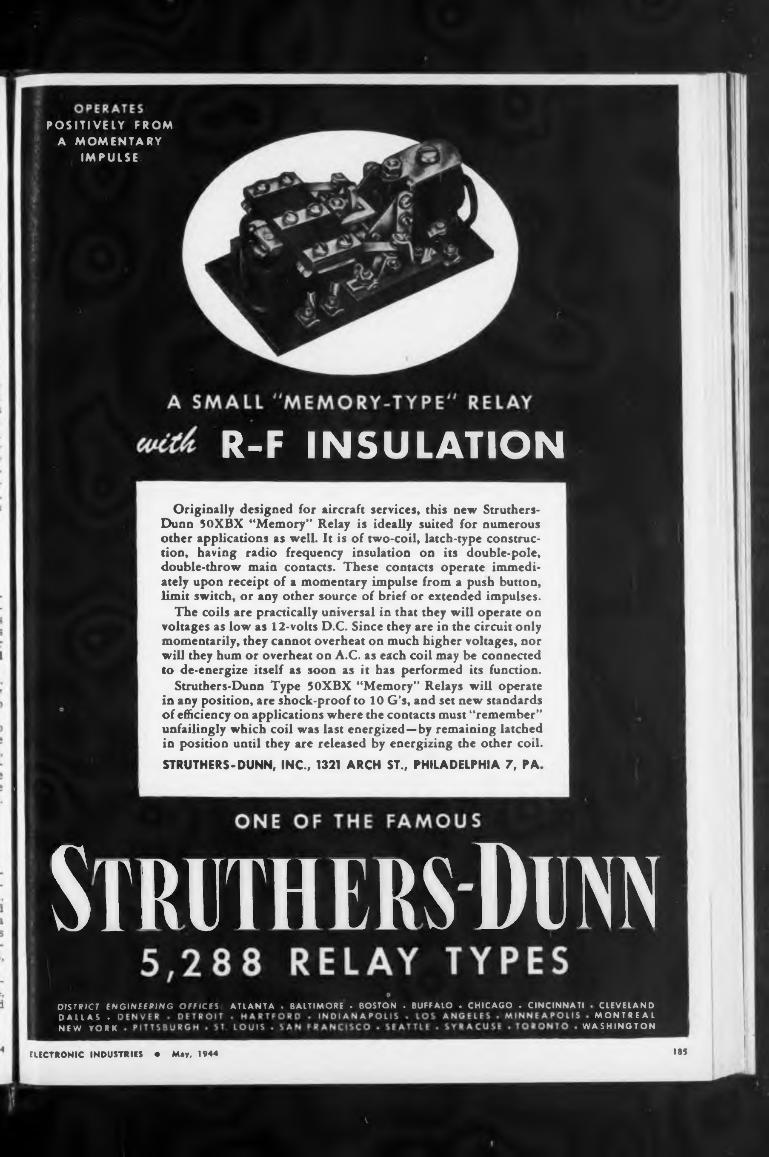
185
STRUTHERS-DUNN, INC., 1321 ARCH ST., PHILADELPHIA 7, PA
ELECTRONIC INDUSTRIES • May. 1944
Originally designed for aircraft services, this new Struthers- Dunn 50XBX “Memory” Relay is ideally suited for numerous other applications as well. It is of two-coil, latch-type construction, having radio frequency insulation on its double-pole, double-throw main contacts. These contacts operate immediately upon receipt of a momentary impulse from a push button, limit switch, or any other source of brief or extended impulses.
The coils are practically universal in that they will operate on voltages as low as 12-volts D.C. Since they are in the circuit only momentarily, they cannot overheat on much higher voltages, nor will they hum or overheat on A.C. as each coil may be connected to de-energize itself as soon as it has performed its function.
Struthers-Dunn Type 50XBX “Memory” Relays will operate in any position, are shock-proof to 10 G's, and set new standards of efficiency on applications where the contacts must “remember” unfailingly which coil was last energized—by remaining latched in position until they are released by energizing the other coil.
POSITIVELY FROMA MOMENTARY
IMPULSE
R-F INSULATION
Struthers-DennWASHINGTON
CLEVELAND MONTREALDALLAS . I
NEW YORK
DISTRICT ENGINEERING OFFICES ATLANTA . BALTIMORE - BOSTON . BUFFALO . CHICAGO . CINCINNATI
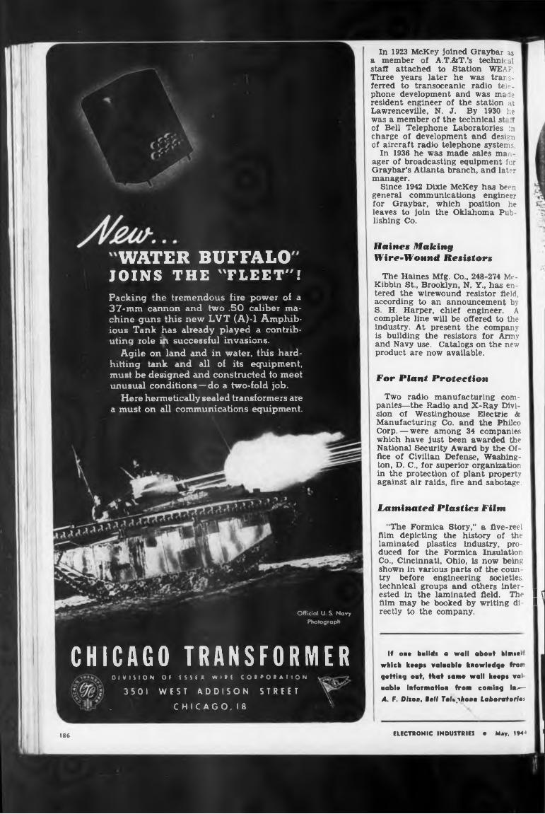
Official U S, Navy Photograph
CHICAGO TRANSFORMERo DIVISION Of ESSEX WISE C Û I F O I A I I O N
35OI WEST ADDISON STREET. C H I C A G O, I 8_______________ X
WATER BUFFALOJOINS THE "FLEET"!Packing the tremendous fire power of a 37-mm cannon and two .50 caliber machine guns this new LVT (A)-l Amphibious Tank has already played a contributing role in successful invasions.
Agile on land and in water, this hardhitting tank and all of its equipment, must be designed and constructed to meet unusual conditions — do a two-fold job.
Here hermetically sealed transformers are a must on all communications equipment.
In 1923 McKey joined Graybar as a member of A.T.&T.’s technical staff attached to Station WEAR Three years later he was transferred to transoceanic radio telephone development and was male resident engineer of the station at Lawrenceville, N. J. By 1930 he was a member of the technical st if of Bell Telephone Laboratories in charge of development and design of aircraft radio telephone systems.
In 1936 he was made sales manager of broadcasting equipment for Graybar’s Atlanta branch, and later manager.
Since 1942 Dixie McKey has been general communications engineer for Graybar, which position he leaves to join the Oklahoma Publishing Co.
Haines Making Wire-Wound Resistors
The Haines Mfg. Co., 248-274 Mc- Kibbin St., Brooklyn, N. Y., has entered the wirewound resistor field, according to an announcement by S. H. Harper, chief engineer. A complete line will be offered to the industry. At present the company is building the resistors for Army and Navy use. Catalogs on the new product are now available.
For Plant Protection
Two radio manufacturing companies—the Radio and X-Ray Division of Westinghouse Electric & Manufacturing Co. and the Philco Corp. — were among 34 companies which have just been awarded the National Security Award by the Office of Civilian Defense, Washington, D. C., for superior organization in the protection of plant property against air raids, fire and sabotage.
Laminated Plastics Film
“The Formica Story,” a five-reel film depicting the history of the laminated plastics industry, produced for the Formica Insulation Co., Cincinnati, Ohio, is now being shown in various parts of the coun try before engineering societies.technical groups and others inter-ested In the laminated field. The I f film may be booked by writing di- I ’rectly to the company.
If on* build« a wall about himiei which hoops valaabla knowledge from getting ont, that same wall keeps val noble Information from coming in.— 4. F. Dixon, Boll Tok^hono Loboratorios
186 ELECTRONIC INDUSTRIES e May, 1944
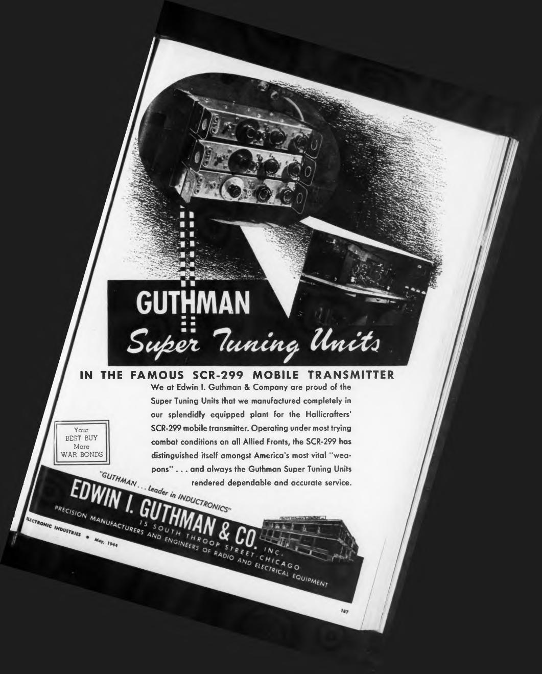
IN THE
Your BEST BUY
More WAR BONDS
FAMOUS SCR-299 MOBILE TRANSMITTERWe at Edwin I. Guthman & Company are proud of the Super Tuning Units that we manufactured completely in our splendidly equipped plant for the Hallicrafters' SCR-299 mobile transmitter. Operating under most trying combat conditions on all Allied Fronts, the SCR-299 has distinguished itself amongst America’s most vital "weapons" ... and always the Guthman Super Tuning Units
Ay rendered dependable and accurate service.
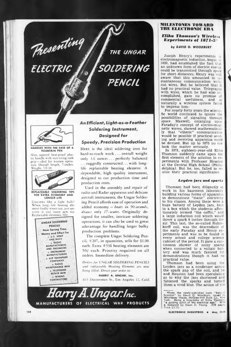
by DAVID O. WOODBURY
Leyden jars and sparks
pages
188
MILESTONES TOWARD THE ELECTRONIC ERAElihu Thomson's Wireless Experiment* of 1871-3
as to why the jars shortened and fattened the sparks and turned them a vivid blue. The action of the
practical value.Thomson had
Leyden jars as a the spark gap of and Houston had
Thomson had been diligently at work in his basement laboratory building various forms of apparatus to demonstrate “static” electricity to his classes. Among these were a huge battery of Leyden jars, kept in a box which the students affectionately termed “the coffin,” and a large induction coil which would throw a spark 6 inches through the air. This last, the so-called Ruhm- korff coil, was the descendant of the early Faraday and Henry experiments and was to be found in every school and college science cabinet of the period. It gave a continuous shower of noisy sparks when connected to a voltaic battery and was much favored for demonstrations though it had no
been using the condenser across the coil, and he been speculating
“a guiding spirit of the electrical a foreword by Owen D. Young. Price $3.50.
Joseph Henry’s experiments in electromagnetic induction, begun in 1832, had established the fact t tat an unknown form of electric energy could be transmitted through sp ice for short distances. Henry was well aware that this amounted to instantaneous communication without wires. But he believed that it had no practical value. Telegraphy with wires, which he had also accomplished, gave no promise of commercial usefulness, and so naturally a wireless system failed to impress him.
For nearly forty years the scientific world continued to ignore the possibilities of signaling through space. Maxwell, enlarging upon Faraday’s concept of electro-magnetic waves, showed mathematically that “etheric” communication would be possible if practical sending and receiving apparatus could be devised. But up to 1875 no one took the matter seriously.
In 1871, eighteen-year-old Elihu Thomson suddenly came upon the first element of the solution in experiments with Professor Houston at the Central High School (Philadelphia]. But he, too, failed to realize their practical significance.
ELECTRONIC INDUSTRIES • May, 1944
HANDLES WITH THE EASE OF A FOUNTAIN PEN
Slim, tapered, heat-proof plastic handle with non-tiring cork grip — ideal for women operators. Overall length, 7-inches. Weight, 3-6 oz._____________
UNGAR SOLDERING
PENCILS Now Saving Time,
Money and Effort for . U.S. ARMY
AND NAVY• RADIO
manufacturers and ENGINEERS. INSTRUMENT
manufacturers . AIR TRANSPORT
COMPANIES• RADIO
MAINTENANCE men . telephone repair men. WIRING
CONTRACTORS
REPLACEABLE SOLDERING TIPS FOR EXTRA ECONOMY AND
LONGER LIFEUnscrews like a light bulb! When long - life heating element finally wears out, just unscrew it and insert new tip. Replaceable elements, 50c1.
An Efficient, Light-as-a-Feather Soldering Instrument,
Designed for Speedy, Precision Production Here is the ideal soldering iron for hard-to-reach work . . . overall weight only 3.6 ounces . . . perfectly balanced ... ruggedly constructed... with longlife replaceable heating element. A dependable, high quality instrument, designed to cut production time and production costs.
Used in the assembly and repair of radio and Radar apparatus and delicate aircraft instruments, the Ungar Soldering Pencil affords ease of operation and added economy — beats tn 90-seconds, draws only 17-watts. Originally designed for smaller, intricate soldering operations, it can also be used to great adavantage for handling larger bulky production problems.
The complete Ungar Soldering Pencil, #207, in quantities, sells for $1.00 each. Extra #536 heating elements are 500 each. Priority required on all orders. Immediate delivery.
•From the newly-published book "Beloved Scientist" by David O. Woodbury, issued by Whittlesey House McGraw-Hill Book Co., New York. Being a biography of Elihu Thoms n,
Orders jor UNGAR SOLDERING PENCILS and replaceable Heating Elements are now being filled. Direct your order to:
HARRY A. UNGAR, Inc.
615 Ducommun St., Los Angeles 12, Calif.
THE UNGAR
ELECTRIC SOLDERING PENCIL
Harry A. Ungar Inc.MANUFACTURERS OF ELECTRICAL WAR PRODUCTS
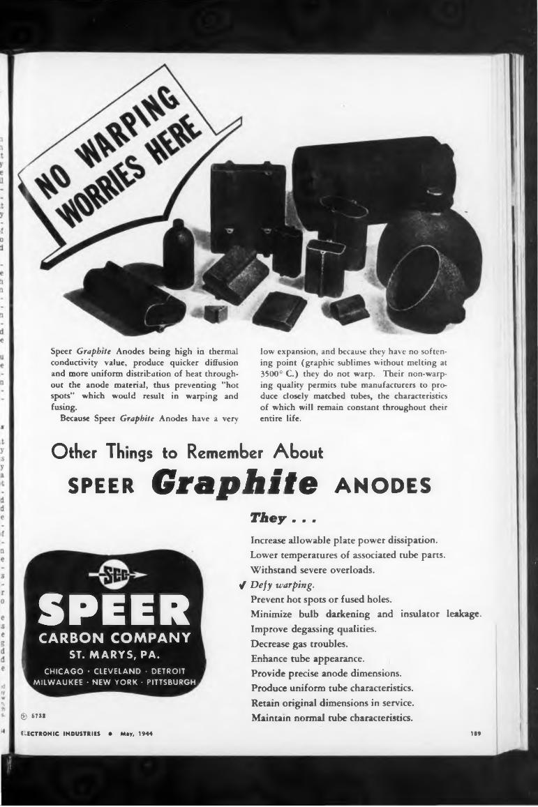
Speer Graphite Anodes being high in thermal conductivity value, produce quicker diffusion and more uniform distribution of heat throughout the anode material, thus preventing "hot spots” which would result in warping and fusing.
Because Speer Graphite Anodes have a very
low expansion, and because they have no softening point (graphic sublimes without melting at 3500° C.) they do not warp. Their non-warping quality permits tube manufacturers to produce closely matched tubes, the characteristics of which will remain constant throughout their entire life.
Other Things to Remember About
Speer Graphite anodesThey - . .
CHICAGO • CLEVELAND • DETROIT MILWAUKEE • NEW YORK ■ PITTSBURGH
SPEERCARBON COMPANY
ST. MARYS, PA.
Increase allowable plate power dissipation.Lower temperatures of associated tube parts.Withstand severe overloads.
/ Defy warping.Prevent hot spots or fused holes.Minimize bulb darkening and insulator leakage.Improve degassing qualities.Decrease gas troubles.Enhance tube appearance.Provide precise anode dimensions.Produce uniform tube characteristics.
Retain original dimensions in service.
Maintain normal tube characteristics.189
® 5738
ELECTRONIC INDUSTRIES • May, 1944
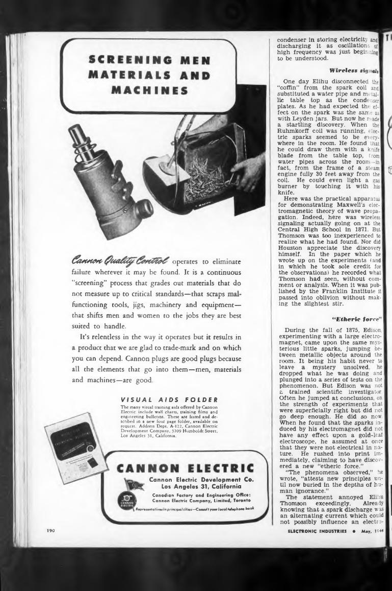
Wireless sig alt
“Etheric force
leave
190
During the fall of 1875, Edison, experimenting with a large electromagnet, came upon the same mysterious little sparks, jumping between metallic objects around the room. It. being his habit never to
condenser in storing electricity and' discharging It as oscillations oi high frequency was just beginning to be understood.
mystery unsolved.
and machines—are good.
One day Elihu disconnected the! “coffin” from the spark coil and I substituted a water pipe and me tai-1 lie table top as the conde iser I plates. As he had expected thf ef I feet on the spark was the same as I with Leyden jars. But now he made I a startling discovery. When the I Ruhmkorff coll was running, elec-1 trie sparks seemed to be every-1 where in the room. He found had he could draw them with a knife! blade from the table top, from! water pipes across the room -in I fact, from the frame of a steam engine fully 30 feet away from the coil. He could even light a gas burner by touching it with his knife.
Here was the practical apparatus for demonstrating Maxwell’s electromagnetic theory of wave propagation. Indeed, here was wireless signaling actually going on at the | Central High School in 1871. But! Thomson was too inexperienced to realize what he had found Nor did Houston appreciate the discovery himself. In the paper which he wrote up on the experiments (and in which he took sole credit for the observations) he recorded what Thomson had seen, without comment or analysis. When it was published by the Franklin Institute it passed into oblivion without making the slightest stir.
dropped what he was doing and plunged into a series of tests on the1 phenomenon. But Edison was not a trained scientific investigator. Often he jumped at conclusions, on the strength of experiments that were superficially right but did not go deep enough. He did so now. When he found that the sparks induced by his electromagnet did not have any effect upon a gold-leaf electroscope, he assumed at once that they were not electrical in nature. He rushed into print immediately, claiming to have discovered a new “etheric force.”
“The phenomena observed,” he wrote, “attests new principles until now burled in the depths of human ignorance.”
The statement annoyed Elihu Thomson exceedingly. Already knowing that a spark discharge was an alternating current which coi ld not possibly influence an electro-
not measure up to critical standards—that scraps
ELECTRONIC INDUSTRIES • May, 1944
functioning tools, jigs, machinery and equipment— that shifts men and women to the jobs they are best suited to handle.
CatCtt&C' operates to eliminatefailure wherever it may be found. It is a continuous "screening” process that grades out materials that do
Cannon Electric Development Co. K Los Angeles 31, California
Canadian Factory and Engineering Office: I Cannon Electric Company, Limited, Toronto
Rcpr»»ntativ», i n principal allei —Comal I your local telephone book
you can depend. Cannon plugs are good plugs because all the elements that go into them—men, materials
VISUAL AIDS FOLDERThe many visual training aids offered by Cannon Electric include wall charts, training films and engineering bulletins. These are listed and described in a new four page folder, available on request. Address Dept A 122. Cannon Electric De velopment Company, 3209 Humboldt Street, Los Angeles 31, California.
It’s relentless in the way it operates but it results in product that we are glad to trade-mark and on which
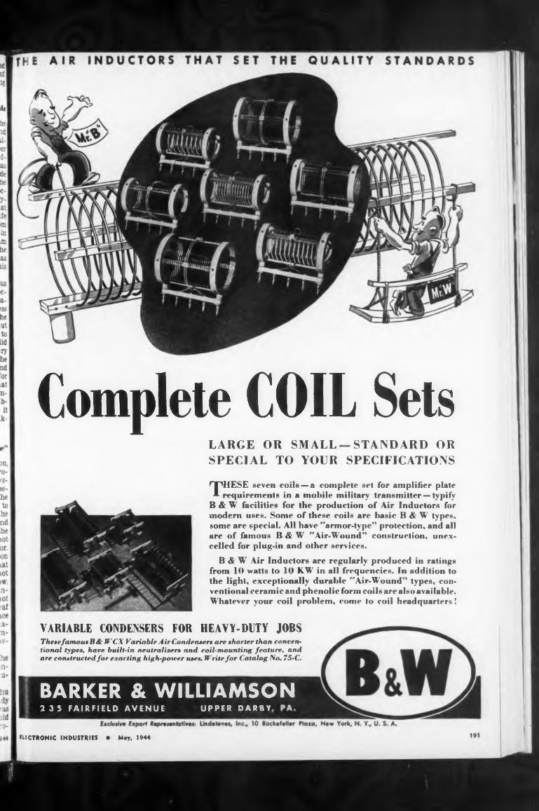
Complete COIL SetsLARGE OR SMALL STANDARD ORSPECIAL TO YOUR SPECIFICATIONS
HEAVY-DUTY JOBSVARIABLE CONDENSERS FOR
IUCTRONIC INDUSTRIES • May, 1944
Thesefamous R& JF’CX Variable Air Condenaera are shorter than conventional types, have built-in neutralizers and coil-mounting feature, and are constructed for exacting high-potver uses. Write for Catalog No. 75-C.
B & W Air Inductor« are regularly produced in ratings from 10 watts to 10 KW in all frequencies. In addition to the light, exceptionally durable “Air-Wound” types, conventional ceramic and phenolic form coils are also available. Whatever your coil problem, come to coil headquarters!
THESE seven coils — a complete set for amplifier plate requirements in a mobile military transmitter — typify
B & W facilities for the production of Air Inductors for modern uses. Some of these coils are basic B & W types, some are special. All have "armor-type” protection, and all are of famous B & W "Air-Wound” construction, unexcelled for plug-in and other services.
BARKER & WILLIAMSON2 3 5 FAIRFIELD AVENUE UPPER DARBY
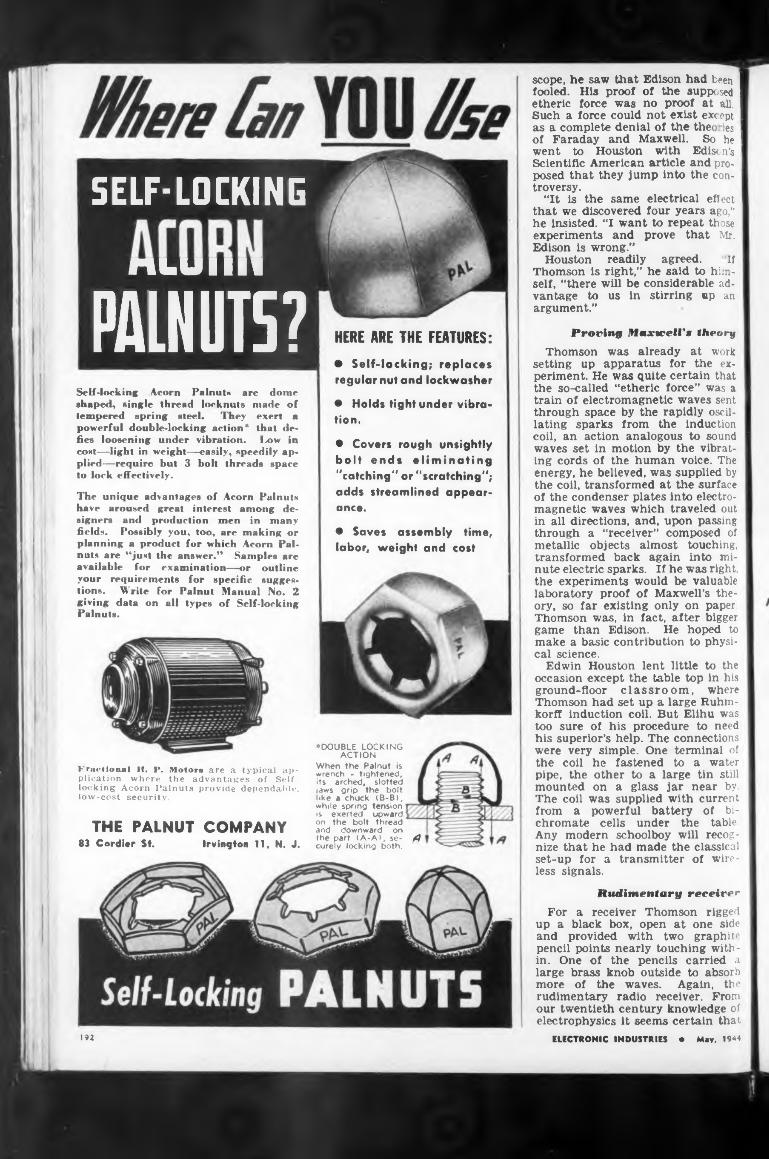
SELF-LOCKING
niaUllll
PALNUT5?Self-locking Acorn Palnut- are dome shaped, single thread locknuts made of tempered spring steel. They exert a powerful double-locking action* that defies loosening under vibration. Low in cost—light in weight—easily, speedily applied—require but 3 bolt threads space to lock effectively.
The unique advantages of Acorn Palnuts have aroused great interest among designers and production men in many fields. Possibly you, too, are making or planning a product for which Acorn Pal- nuts are “just the answer.” Samples are available for examination—or outline your requirements for specific suggestions. Write for Palnut Manual No. 2 giving data on all types of Self-locking Palnuts.
Fractional H. P. Motors are a typical application where the advantages of Selflocking Acorn Palnuts provide dependable, low-cost security.
THE PALNUT COMPANY83 Cordier St. Irvington 11, N. J.
HERE ARE THE FEATURES:
• Self-locking; replaces regular nut and lockwasher
• Holds tight under vibration.
♦ Covers rough unsightly bolt ends eliminating ‘'catching“ or “scratching"; adds streamlined appearance.
• Saves assembly time, labor, weight and cost
»DOUBLE LOCKING ACTION
When the Palnut is trench - tightened, its arched, slotted jaws grip the bolt like a chuck (B-B), while spring tension is exerted upward on the bolt thread and downward onthe part (A-A), se- x? curely locking both.
scope, he saw that Edison had been I fooled. His proof of the supposed I etheric force was no proof at all. I Such a force could not exist exc ept I as a complete denial of the thet les of Faraday and Maxwell. So he I went to Houston with Edison’s Scientific American article and pro- j posed that they jump into the controversy.
“It is the same electrical effect that we discovered four years ago," | he insisted. “I want to repeat those | experiments and prove that Mr. I Edison is wrong.”
Houston readily agreed. If Thomson is right,” he said to himself, “there will be considerable advantage to us in stirring up an argument."
Proring Maxwell's theory
Thomson was already at work setting up apparatus for the experiment. He was quite certain that the so-called “etheric force” was a train of electromagnetic waves sent through space by the rapidly oscillating sparks from the induction coil, an action analogous to sound waves set in motion by the vibrating cords of the human voice. The energy, he believed, was supplied by the coil, transformed at the surface of the condenser plates into electromagnetic waves which traveled out in all directions, and, upon passing through a “receiver” composed of metallic objects almost touching, transformed back again into minute electric sparks. If he was right, the experiments would be valuable laboratory proof of Maxwell’s theory, so far existing only on paper. Thomson was, in fact, after bigger game than Edison. He hoped to make a basic contribution to physical science.
Edwin Houston lent little to the occasion except the table top in his ground-floor classroom, where Thomson had set up a large Ruhm- korff induction coil. But Elihu was too sure of his procedure to need his superior’s help. The connections were very simple. One terminal of the coil he fastened to a water pipe, the other to a large tin still mounted on a glass jar near by. The coil was supplied with current from a powerful battery of bichromate cells under the table. Any modern schoolboy will recognize that he had made the classical set-up for a transmitter of wireless signals.
Rudimentary receiver
For a receiver Thomson rigged up a black box, open at one side and provided with two graphite pencil points nearly touching within. One of the pencils carried a large brass knob outside to absorb more of the waves. Again, the rudimentary radio receiver. From our twentieth century knowledge of electrophysics it seems certain that
ELECTRONIC INDUSTRIES • May. 1944192
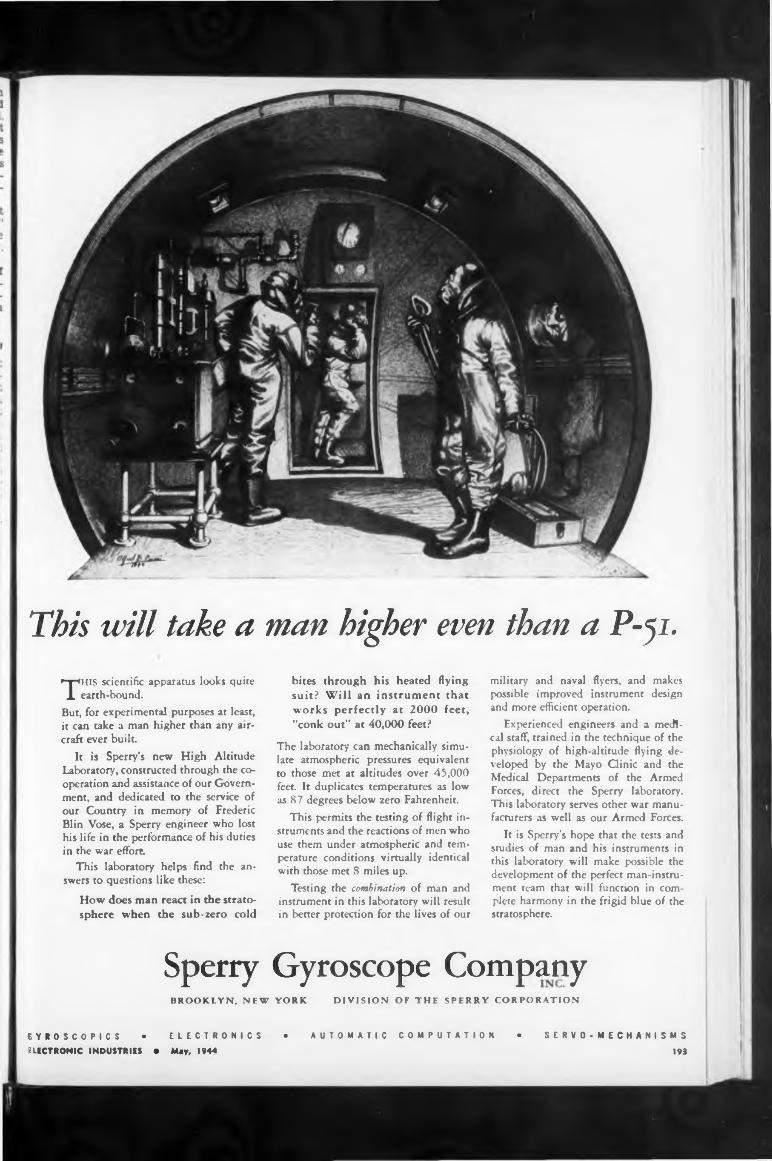
This will take a man higher even than a P-ji.
THIS scientific apparatus looks quite earth-bound.
But, for experimental purposes at least, it can take a man higher than any aircraft ever built
It is Sperry’s new High Altitude Laboratory, constructed through the cooperation and assistance of our Government, and dedicated to the service of our Country in memory of Frederic Blin Vbse, a Sperry engineer who lost his life in the performance of his duties in the war effort.
This laboratory helps find the answers to questions like these:
How does man react in the stratosphere when the sub-zero cold
bites through his heated flying suit? Will an instrument that works perfectly at 2000 feet, "conk out” at 40,000 feet?
The laboratory can mechanically simulate atmospheric pressures equivalent to those met at altitudes over 45,000 feet. It duplicates temperatures as low as 87 degrees below zero Fahrenheit.
This permits the testing of flight instruments and the reactions of men who use them under atmospheric and temperature conditions virtually identical with those met S miles up.
Testing the combination of man and instrument in this laboratory will result in better proteaion for the lives of our
military and naval flyers, and makes possible improved instrument design and more efficient operation.
Experienced engineers and a medical staff, trained in the technique of the physiology of high-altitude flying developed by the Mayo Qinic and the Medical Departments of the Armed Forces, direct the Sperry laboratory. This laboratory serves other war manufacturers as well as our Armed Forces.
It is Sperry's hope that the tests and studies of man and his instruments in this laboratory will make possible the development of the perfect man-instrument team that will function in complete harmony in the frigid blue of the stratosphere.
Sperry Gyroscope CompanyBROOKLYN, NEW YORK DIVISION OF THE SPERRY CORPORATION
GYROSCOPICS • ELECTRONICS • AUTOMATIC COMPUTATION • SERVO-MECHANISMS
UECTRONIC INDUSTRIES • May, 1944 193
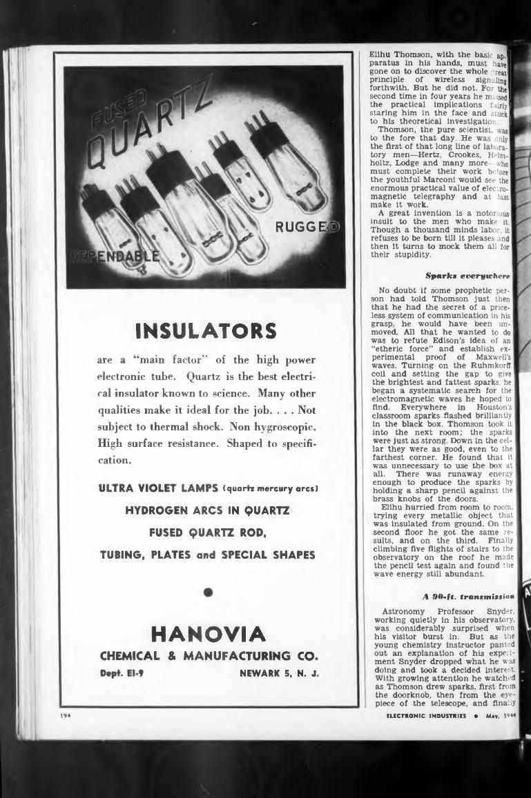
RUGGER
Spark» everywhere
INSULATORSMaxwell’sare
Houston’sNot
cation
ULTRA VIOLET LAMPS (quartz mercury arcs)
HYDROGEN ARCS IN QUARTZ
FUSED QUARTZ ROD
TUBING. PLATES and SPECIAL SHAPES
A HO-ft. transmi/uioH
HANOVIACHEMICAL & MANUFACTURING CO
NEWARK 5, N. J.
194
waves. Turning on the Ruhmkorfl coll and setting the gap to give the brightest and fattest sparks, he began a systematic search for the electromagnetic waves he hoped to
It turns to mock them all for stupidity.
perimental proof
then their
qualities make it ideal for the job
main factor’* of the high power
find. Everywhere
Astronomy Professor Snyder, working quietly in his observatory, was considerably surprised when his visitor burst in. But as the young chemistry instructor panted out an explanation of his experiment Snyder dropped what he was doing and took a decided interest. With growing attention he watched as Thomson drew sparks, first from the doorknob, then from the eyepiece of the telescope, and finally
classroom sparks flashed brilliantly I in the black box. Thomson took it into the next room; the sparks were just as strong. Down in the cellar they were as good, even to the farthest corner. He found that it was unnecessary to use the box at all. There was runaway energy enough to produce the sparks by holding a sharp pencil against the brass knobs of the doors.
Elihu hurried from room to room, trying every metallic object that was insulated from ground. On the second floor he got the same results, and on the third. Finally climbing five flights of stairs to the observatory on the roof he made the pencil test again and found the wave energy still abundant.
No doubt if some prophetic person had told Thomson just then that he had the secret of a priceless system of communication in his grasp, he would have been unmoved All that he wanted to do was to refute Edison’s idea of an “etheric force” and establish ex-
ELECTRONIC INDUSTRIES • May, 1944
Elihu Thomson, with the basic ap.| paratus in his hands, must have! gone on to discover the whole great! principle of wireless signaling! forthwith. But he did not. For the! second time in four years he missed I the practical implications fairly! staring him in the face and stuck to his theoretical Investigatio: I
Thomson, the pure scientist was to the fore that day. He was only the first of that long line of lab >ra- tory men—Hertz, Crookes, H Ina- holtz, Lodge and many more—who must complete their work before the youthful Marconi would see the enormous practical value of electromagnetic telegraphy and at last make it work.
A great invention is a notorious insult to the men who make it. Though a thousand minds labor, it refuses to be born till it pleases and
subject to thermal shock. Non hygroscopic High surface resistance. Shaped to specifi
electronic tube. Quartz is the best electrical insulator known to science. Many other
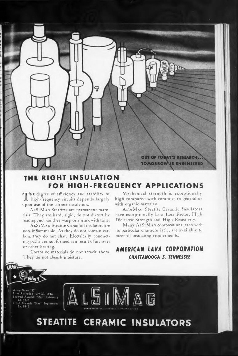
OUT OF TO1 TOMORRO
Y'S RESEARCH. .> \IS ENGINEERED
have exceptiona
AMERICAN LAVA CORPORATION CH AU ANOOGA 5, TENNESSEE
THE RIGHT INSULATION FOR HIGH-FREQUENCY APPLICATIONS
,ow Loss Factor, HighDielectric Strength and High Resistivity.
Many Ai.SiMag compositions, each with its particular characteristic, are available to meet all insulating requirements.
The degree of efficiency and stability of high-frequency circuits depends largely
upon use of the correct insulation.AlSiMag Steatites are permanent mate
rials. They are hard, rigid, do not distort by loading, nor do they warp or shrink, with time.
AlSiMag Steatite Ceramic Insulators are non-inflammable. As they do not contain carbon, they do not char. Electrically conducting paths are not formed as a result of arc over or other heating.
Corrosive materials do not attack them. They do not absorb moisture.
Mechanical strength is exceptionally h compared with ceramics in general or i organic materials.AlSiMag Steatite Ceramic Insulators
Septembi
STEATITE CERAMIC INSULATORS
1942 Februa
Fi st Awarded )u»y 2' Second Award. Star
13. ’.943Ihi.d Awards "Star"
25. 1943
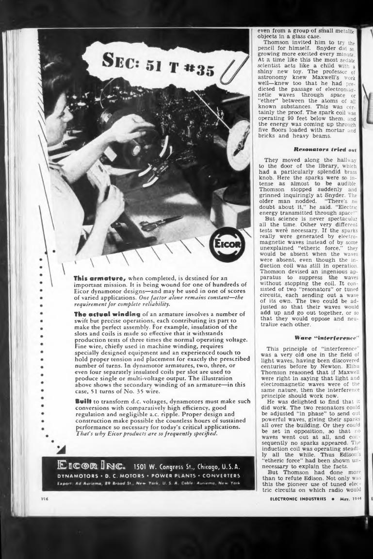
Rexonatorx tried out
almost audibletense
ÊICOR]
waves
196
They moved along the hallway to the door of the library, which had a particularly splendid brass knob Here the sparks were n in-
Warp “interference"
paratus to suppress
This principle of “interference was a very old one in the field of light waves, having been discovered centuries before by Newton. Elihu Thomson reasoned that if Maxwell were right in saying that light and electromagnetic waves were of the same nature, then the interference principle should work now.
He was delighted to find that it did w'ork. The two resonators could be adjusted “in phase” to send out powerful waves, giving their sparks all over the building. Or they could be set in opposition, so that no waves went out at all, and consequently no sparks appeared. The induction coil was operating stead - ly all the while. Thus Edison s “etheric force” had been shown ui - necessary to explain the facts.
But Thomson had done more than to refute Edison. Not only was this the pioneer use of tuned electric circuits on which radio would
without stopping the coil. It consisted of two “resonators” or tuned circuits, each sending out a wave of its own. The two could be adjusted so that their waves would add up and go out together, or so that they would oppose and neutralize each other.
Thomson stopped suddenly and grinned inquiringly at Snyder The older man nodded. “There’s no doubt about it,” he said. “Electric energy transmitted through space!"
But science is never spectacular all the time. Other very different tests were necessary. If the sparks really were generated by electromagnetic waves instead of by some unexplained “etheric force,” they would be absent when the waves were absent, even though the induction coil was still in operation. Thomson devised an ingenious ap-
ELECTRONIC INDUSTRIES • Mjv. 1944
even from a group of small metallic! objects in a glass case.
Thomson invited him to try the pencil for himself. Snyder did so. growing more excited every minute At a time like this the most sedate scientist acts like a child with a shiny new toy. The professor of astronomy knew Maxwell’s work well—knew too that he had predicted the passage of electromag. netic waves through space or “ether” between the atoms of all known substances. This was certainly the proof. The spark coil was operating 90 feet below them, and the energy was coming up through five floors loaded with mortar and bricks and heavy beams.
Thit armature# when completed, is destined for an important mission. It is being wound for one of hundreds of Eicor dynamotor designs—and may be used in one of scores of varied applications. One factor alone remains constant—the requirement for complete reliability.The actual winding of an armature involves a number of swift but precise operations, each contributing its part to make the perfect assembly. For example, insulation of the slots and coils is made so effective that it withstands production tests of three times the normal operating voltage. Fine wire, chiefly used in machine winding, requires specially designed equipment and an experienced touch to hold proper tension and placement for exactly the prescribed number of turns. In dynamotor armatures, two, three, or even four separately insulated coils per slot are used to produce single or multi-voltage output. The illustration above shows the secondary winding of an armature—in this case, 51 turns of No. 35 wire.Built to transform d.c. voltages, dynamotors must make such conversions with comparatively high efficiency, good regulation and negligible a.c. ripple. Proper design and construction make possible the countless hours of sustained performance so necessary for today’s critical applications. That's why Eicor products are so frequently specified.
En®@ra Orjc. 1501 W. Congress St., Chicogo, U.S.A.DYNAMOTORS • D. C. MOTORS • POWER PLANTS • CONVERTERS
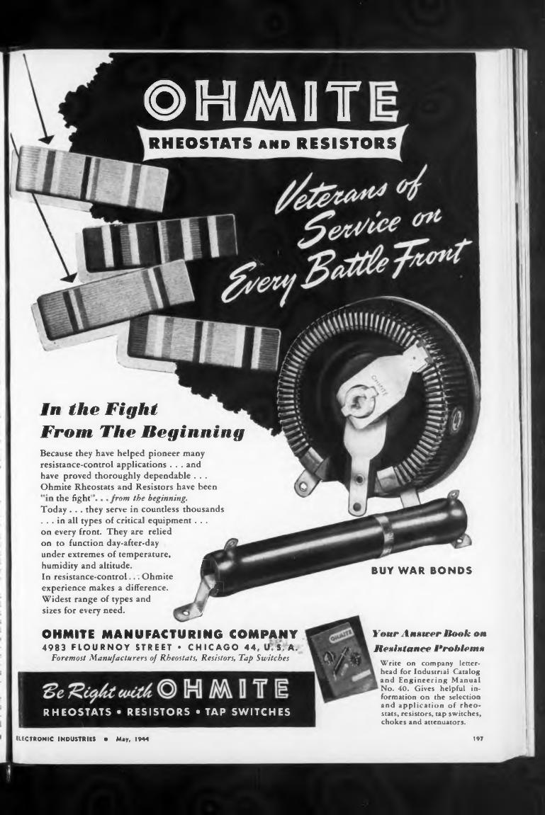
RHEOSTATS and RESISTORS
the fight'
BUY WAR BONDS
197
Your Answer Book on Resistance Problems
in the Fight From The Beginning
Write on company letterhead for Industrial Catalog and Engineering Manual No. 40. Gives helpful information on the selection and application of rheostats, resistors, tap switches, chokes and attenuators.
rrom the beginning.
OHMITE MANUFACTURING COMPANY4983 FLOURNOY STREET • CHICAGO 44, S. A.
Foremost Manufacturers of Rheostats, Resistors, Tap Switches
Because they have helped pioneer many resistance-control applications . . . and have proved thoroughly dependable . . . Ohmite Rheostats and Resistors have been
ELECTRONIC INDUSTRIES • May, 1944
Today . . . they serve in countless thousands . . . in all types of critical equipment . . . on every front. They are relied on to function day-after-day under extremes of temperature, humidity and altitude. MIn resistance-control... Ohmite experience makes a difference. mHWidest range of types and sizes for every need. J
©HMOT
RHEOSTATS • RESISTORS • TAP SWITCHES
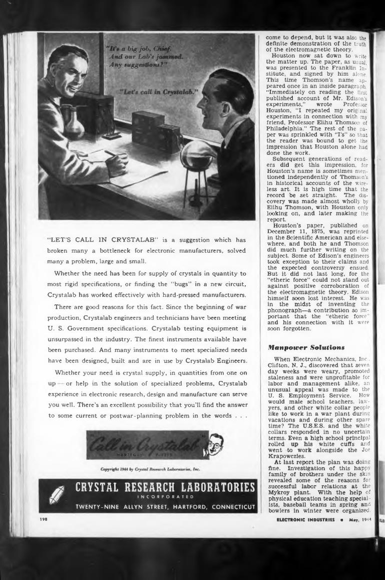
Manpower Solations
Whether your need is crystal supply, in quantities from one on
rolledHARTFORD
198
white cuffs and
LET’S CALL IN CRYSTALAB” is a suggestion which has
went to work alongside the Joe Krapowczies.
At last report the plan was doing fine. Investigation of this happy family of brothers under the skin revealed some of the reasons for successful labor relations at the Mykroy plant. With the help of physical education teaching specialists, baseball teams in spring and bowlers in winter were organized.
or help in the solution of specialized problems, Crystalab
a big job, Ctiief. And our Lab's jamn Any suggestions?”
come to depend, but it was also the I definite demonstration of the truth of the electromagnetic theory.
Houston now sat down to write the matter up. The paper, as usual, I was presented to the Franklin In- 1 stitute, and signed by him alone. This time Thomson’s name appeared once in an inside paragr ph. “Immediately on reading the rst published account of Mr. Edison’s experiments,” wrote Professor Houston, “I repeated my orig.nal experiments in connection with my friend, Professor Elihu Thomson of Philadelphia.” The rest of the paper was sprinkled with ‘Ts” so that the reader was bound to get the impression that Houston alone had done the work.
Subsequent generations of readers did get this impression, for Houston’s name is sometimes mentioned independently of Thomson’s in historical accounts of the wireless art. It is high time that the record be set straight. The discovery was made almost wholly by Elihu Thomson, with Houston only looking on, and later making the report.
Houston’s paper, published on December 11, 1875, was reprinted in the Scientific American and elsewhere, and both he and Thomson did much further writing on the subject. Some of Edison’s engineers took exception to their claims and the expected controversy ensued. But it did not last long, for the “etheric force” could not stand out against positive corroboration of the electromagnetic theory. Edison himself soon lost interest. He was in the midst of inventing the phonograph—a contribution so important that the “etheric force” and his connection with it were soon forgotten.
EUCTRONIC INDUSTRIES « May, 1944
When Electronic Mechanics, Inc.. Clifton, N. J., discovered that seven day weeks were weary, promoted staleness and were unprofitable for labor and management alike, an unusual appeal was made to the U. S. Employment Service. How would male school teachers, lawyers, and other white collar people like to work in a war plant during vacations and during other spare time? The UJS.E.S. and the white collars responded in no uncertain terms. Even a high school principal
There are good reasons for this fact. Since the beginning of war
production, Crystalab engineers and technicians have been meeting
U. S. Government specifications. Crystalab testing equipment is
unsurpassed in the industry. The finest instruments available have
been purchased. And many instruments to meet specialized needs
have been designed, built and are in use by Crystalab Engineers.
broken many a bottleneck for electronic manufacturers, solved
many a problem, large and small.
experience in electronic research, design and manufacture can serve
you well. There’s an excellent possibility that you’ll find the answer
to some current or postwar-planning problem in the words . . .
Whether the need has been for supply of crystals in quantity to
most rigid specifications, or finding the “bugs” in a new circuit,
Crystalab has worked effectively with hard-pressed manufacturers.
TWENTY-NINE ALLYN STREET, HARTFORD, CONNECTICUT
CRYSTAL RESEARCH LABORATORIESINCORPORATED
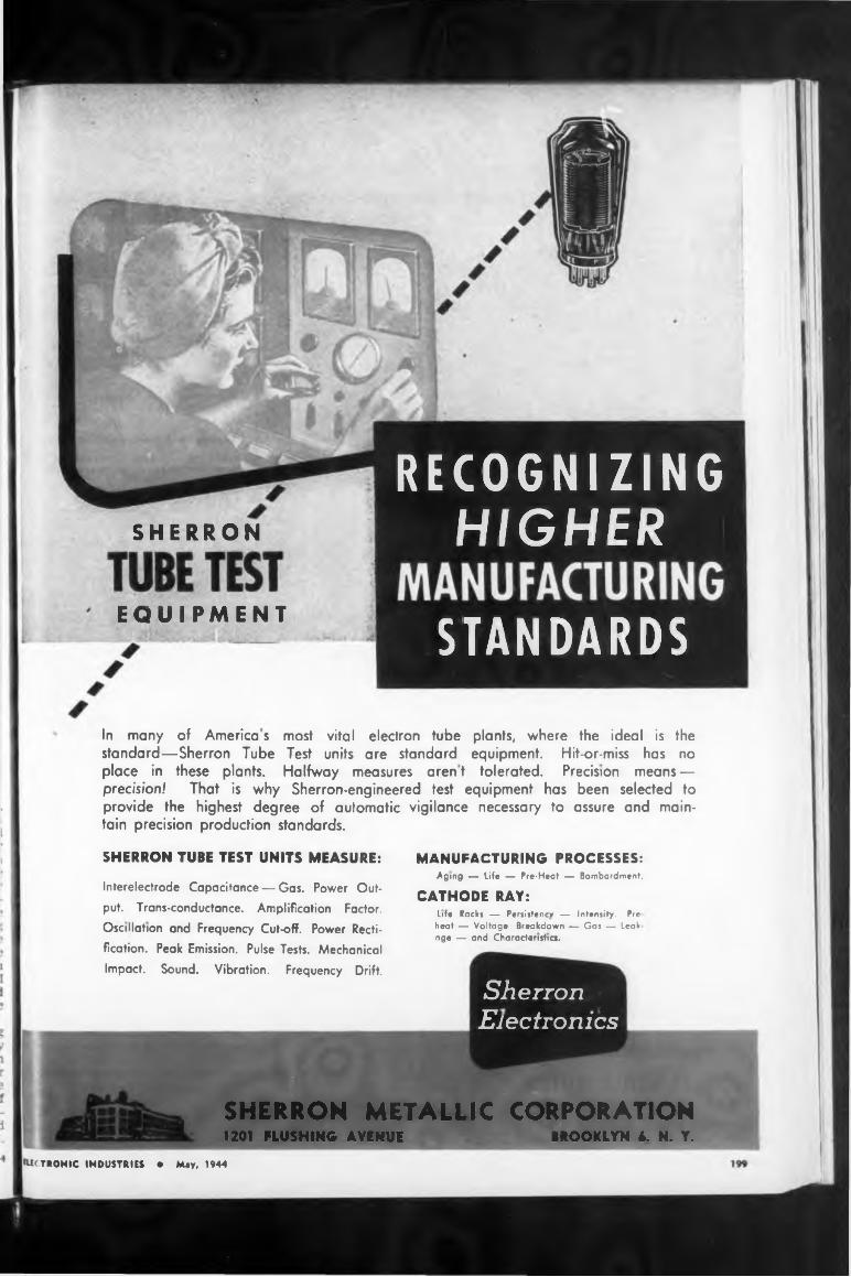
SHERRON
SHERRON TUBE TEST UNITS MEASURE:
1201 FLUSHING AVENUE BROOKLYN L N. Y.
RECOGNIZING
STANDARDS
SherronElectronics
MANUFACTURING PROCESSES:Aging — life — Pre-Heat — Bombardment.
CATHODE RAY:Life Racks — Persistency — Intensity. Preheat — Voltage Breakdown — Gas — Leakage — and Characteristics.
EQUIPMENT
HIGHER
In many of America s most vital electron tube plants, where the ideal is thestandard—Sherron Tube Test units are standard equipment. Hit-or-miss has noplace in these plants. Halfway measures arent tolerated. Precision means —precision! That is why Sherron-engineered test equipment has been selected to provide the highest degree of automatic vigilance necessary to assure and maintain precision production standards.
Interelectrode Capacitance — Gas. Power Output. Trans-conductance. Amplification Factor.Oscillation and Frequency Cut-off. Power Rectification. Peak Emission. Pulse Tests. Mechanical
Impact. Sound. Vibration. Frequency Drift.
SHERRON METALLIC CORPORATIONEIECTRONIC INDUSTRIES • May, 1944
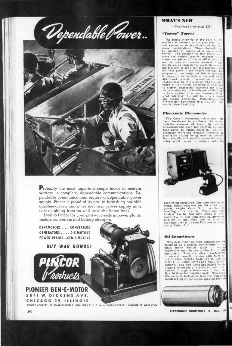
WHAT’S NEW(Continued from page 138)
Temeo" Turret
well
Hud
Electronic Micrometer
touch making
Oil Capacitron«
BUY WAR BONDS!
PIONEER GEN-E-MOTOR
ELECTRONIC INDUSTRIES200
The Carson electronic micrometer ha« been developed to eliminate the unpre-dlctable element
POWER PLANTS...GEN-E-MOTORS
open all parallel resonant circuits
Transmitter Equipment Mfg. Co. son St., New York City.
Probably the most important single factor in modern warfare is complete, dependable communications. Dependable communications require a dependable power supply. Pincor is proud of its part in furnishing portable gasoline-driven and other electrical power supply units to the fighting front as well as to the home front.
Look to Pincor for your postwar needs in power plants, motors, converters and battery chargers.
measurements, such for example as > uiin tube parts, to within OOoOB in. The micrometer functions without pressur* an electronic circuit being used to indl ate both visually and audibly, when the n as- urlng point comes in contact with the
not in use so that, in the event the operating frequencies are close, self resonance will not take place in the unused channel The purpose of the design of this rf assembly is primarily to maintain a low and evenly distributed capacity, irrespective of which channel may be in operation. The frequency range of this turret assembly is from two to sixteen megacycles, although not necea- sarily continuous. All coils are of the plugin type so that, if a new frequency desired, adapting this unit to it Ie a simple and speedy operation. Manufactured by
EXPORT ADDRESS: 25 WARREN STREET, NEW YORK 7, U. S. A. • CABLE ADDRESS: SIMONTRICE, NEW YORK
The new ••EC” oil type capacitrons are designed as standard components to replace many similar types of special] capacitors used in the production of war equipment. They are being manufact red in several capacity ranges with de working voltage ratings from 600 to 1,500 to meet U. S. Signal Corps and Navy sp> 'locations. The new units are locked on the chassis by means of a solid nut and M- washer through n single hole to clear the
x 16 threaded bakelite neck. The bakelite neck is lock-spun Into the extru ed insulated metal container, making pos? ble
The turret assembly of the 1000 A< ■ u transmitter consists of six pre-tuned iian- nels employing six individual coil ano on. denser combinations. These channel ma be selected by means of a motor- ¡ver switch. The function of this switch to place the desired parallel resonant cult across the plates of the amplifier tubes, as
part being measured. The complete equipment, which operates on 110 v. 60 cycle power, weighs about 20 lb„ requires no levelling or calibration. There are three models: 4% in. dial with .00005 in. divisions; 3% in. dial with .(»<101 In. divisions; and 2% In. dial with .0001 In. divisions. Manufacturer Is Carson Micrometer Corp, Little Falls, N. J.DYNAMOTORS
GENERATORSCONVERTERS D C MOTORS
PINCOR
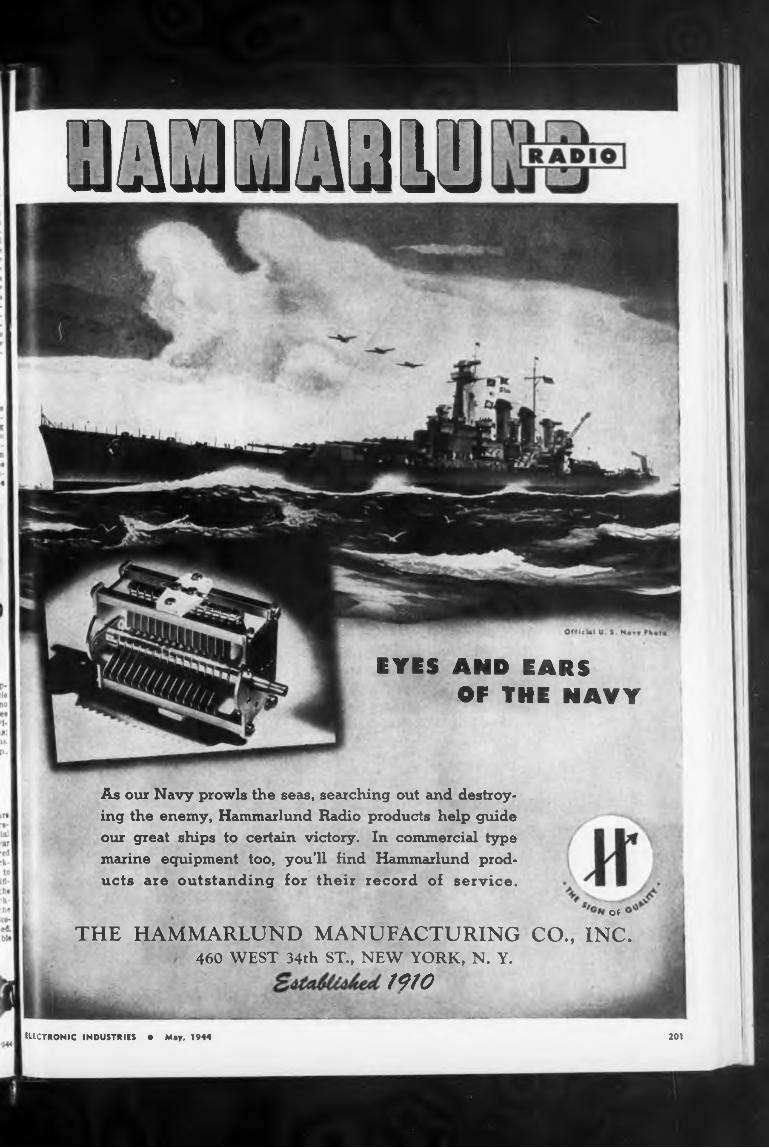
™ ma la
EYES AND EARSOF THE NAVY
201
THE HAMMARLUND MANUFACTURING460 WEST 34th ST., NEW YORK, N. Y.
1910
As our Navy prowls the seas, searching out and destroying the enemy, Hammarlund Radio products help guide our great ships to certain victory. In commercial type marine equipment too, you’ll find Hammarlund products are outstanding for their record of service.
ELECTRONIC INDUSTRIES ♦ May, 1944
OF
CO., INC.
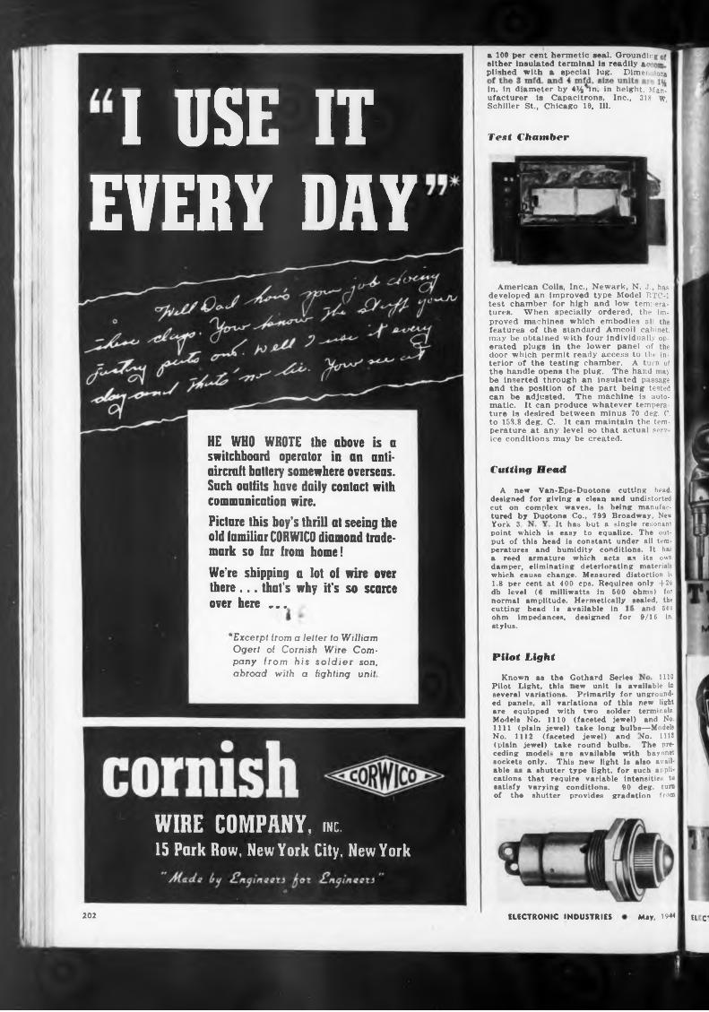
Tent Chamber
Cutting Head
It has but a single resonantYork 3,
cutting head is available in
Pilot Light
inoGothard Series
1111 (plain jewel) take long bulbs-
202 May. 1944ELECTRONIC INDUSTRIES Il Cl
perature at any level »o that actual serv ice conditions may be created.
can be matic. ture is to 158.8
ew unit is available in Primarily for unground-
and 5009/16 in
sockets able as cations satisfy of the
Known as the Pilot Light, this several variations.
available with bayonet new light is also avail-
designed for
jewel) and round bulbs.
a 100 per cent hermetic seal. Grounding either insulated terminal is readily ac plished with a special lug. Dimen «long
adjusted. The machine is auto- It can produce whatever temperadesired between minus 70 deg. C. deg. C. It can maintain the tem-
only. This
Picture this boy’s thrill at seeing the old familiar CORWICO diamond trademark so far from home!
ohm impedances, stylus.
a shutter type light, for such anpli- that require variable intensities to varying conditions. 90 deg. turn shutter provides gradation from
HE WHO WROTE the above is a switchboard operator in an antiaircraft battery somewhere overseas. Sach outfits have daily contact with communication wire.
American Coils, Inc., Newark, N. J., has developed an improved type Model RTC-1 test chamber for high and low temperatures. When specially ordered, the improved machines which embodies all the features of the standard Amcoil cabinet, may be obtained with four individually operated plugs in the lower panel of the door which permit ready access to the interior of the testing chamber. A turn of the handle opens the plug. The hand may be Inserted through an insulated passage and the position of the part being tested
ed panels, all variations of this new light are equipped with two solder terminals. Models No. 1110 (faceted jewel) and No.
In. In diameter by 4% un. in height. Manufacturer Is Capacitrons, Inc., 118 w Schiller St., Chicago 10, Ill.
point which is easy to equalize. The output of this head is constant under nil temperatures and humidity conditions. It has a reed armature which acts as its own damper, eliminating deteriorating materials which cause change. Measured distortion is 1.8 per cent at 400 cps. Requires only 4-20 db level (6 milliwatts in 500 ohms) for normal amplitude. Hermetically sealed, the
’Excerpt from a fetter to William Ogert of Cornish Wire Company from his soldier son, abroad with a fighting unit
A new Van-Eps-Duotone cutting head, designed for giving a clean and undistorted cut on complex waves, is being manufactured by Duotone Co., 799 Broadway, New
i—Models No. UH The pre
No. 1112 (faceted (plain jewel) take ceding model- a re
We’re shipping a lot of wire over there... that's why it’s so scarce over here ...
I USE ITEVERY DAY
WIRE COMPANY, me.15 Park Row, New York City, New York
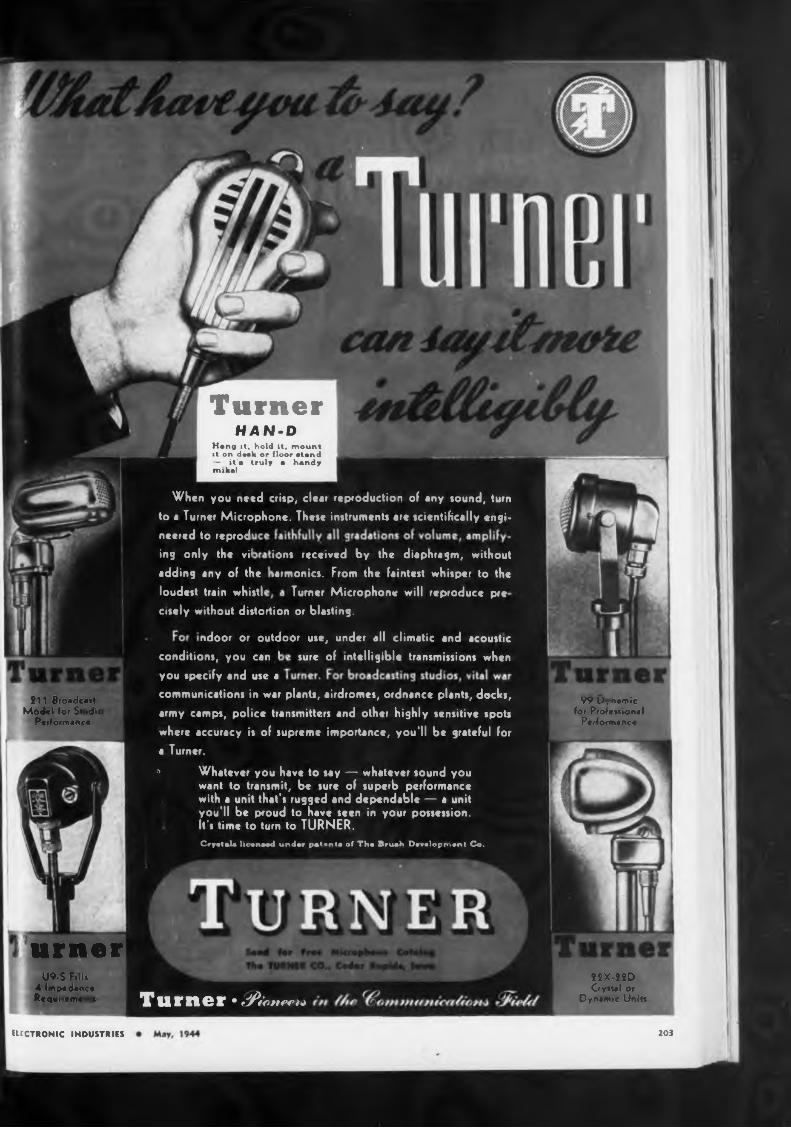
Turner
urner
ELECTRONIC INDUSTRIES 203
U9-S Fills 4 Impadanca Requi.rmai
2ÎX-22D Gystal or
Dynamic Units
S11 Broadcast Model for St tdfc
Performance
99 r.namic for Professional
Performance
HAN-DHang it. hold it. mount it on desk or floor stand — it'a truly a handy mika!
sure
neered to reprod
ing only the vil
cisely without distortion
adding any of the
loudest train whistl
, under all climatic and acoustic
of intelligible transmissions whenconditions, you can I you specify and use a
ndoor or outdoor use
When you need crisp, clear reproduction of any sound, turn
to a Turner Microphone. These instruments are scientifically engi-
ions received by the diaphragm, without harmonics. From the faintest whisper to the
Turner Microphone will reproduce pre
or blasting.
communications in war plants, airdromes, ordnance plants, docks, army camps, police transmitters and other highly sensitive spots
where accuracy is of supreme importance, you'll be grateful for a Turner.
9 Whatever you have to say — whatever sound you want to transmit, be sure of superb performance with a unit that's rugged and dependable — a unit you'll be proud to have seen in your possession, h's time to turn to TURNER.Cryatala licanoed under patonta of Tha Bruah Daaalopmant Co.
Turner • dflfonma
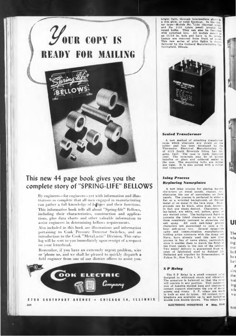
rural hedwith polarised lens. All models mount
OUR COPY ISREADY FOR MAILING
Sealed Transformer
seal compound.
A new Inlay process for placing durable
engmee
Bellow
out
and we shall be pleased to quickly dispatch
arc
ELECTRONIC INDUSTRIES204
bakelite c the case, gas tight.
compact relay and vibration, that the relay Unit construe- and stationary
welded rubber
The mounting bolts are It is also potted with a
contact support eliminates screws and rivets. S. P. in both ac and de types, binations are available up double pole double throws.
the use of many relays are male All contact com- to and Including The relays havs
field engineer from one of our district offices to assist you.
salt spray, characters
This new 44 page book gives you the
complete story of "SPRING-LIFE’’ BELLOWS
bright light, through intermediate gios a dim glow, or total blackout. In the shutter type—Models No. *1114 (faceted j el> and No. 1115 (plain jewel) provid, for
11 such new-inlay process guaranteed to pass a 50-
The S P Relay is a small designed to withstand shock The armature is balanced so will operate in any position, tion of bakelite molded base
hour salt-spray test. Several large-scale radio and communication manufacturers, holding prime contracts with the Army and Navy, have already used this new inlay process in lieu of name plates, particularly since it enable- them to match the finish of the front panels to the rest of the cabinet. Two weeks’ delivery is guaranteed from receipt of fabricated steel to finished job. Perfected and supplied by Screenmakers, 64 Fulton St., New York 7, N. Y.
gelee, Calif, steel. The
Inlay Process Replacing Nameplates
characters on metal panels, chasses, etc., eliminates the use of nameplates on front panels. The proces« is perfected in either a flat or a wrinkled background, on finished metal or on metal in the bare state. Backgrounds can be black, olive drab, brown— in fact any shade desired. Characters, inlay-baked, are white, red, yellow, green or any wanted color. The background finish »o protects the inlaid characters as to make them completely resistant to abrasions and
an 11/16 in. hole and have Mi in. je«eh. Lamps are removed from front of panel. This new series of pilot lights is tn tiui factored by the Gothard Manufacturing >, Springfield, Illinois.
trations so complete that all men engaged in manufacturing can gather a full knowledge of billow s and their functions.
The case is rigid, rustproof terminals may be of molded glass and soldered sealed to
A new method of attaching transformer cases which eliminate any strain on the solder seal has been developed by the Thermador Electrical Manufacturing Co. of 5119 South Riverside Drive, Los An-
tions, phis data charts and other Aaluable information to assist engineers in determining bellows requirements.Also included in this book are illustrations and information pertaining to Cook Pressure Detector Switches, and an introduction to the Cook "MetaLastic” Division. This catalog w ill be sent to you immediately upon receipt of a request on your letterhead.Reinember, if you have an extremely urgent problem, wire
a
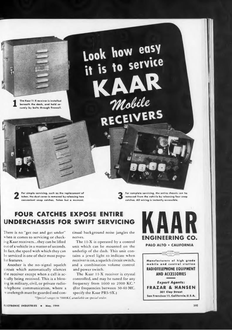
FOUR CATCHES EXPOSE ENTIREUNDERCHASSIS FOR SWIFT SERVICING
205
For simple servicing, such os the replacement of tubes, the dust cover is removed by releasing two convenient snap catches Takes bul a moment
For complete servicing, the entire chassis can be removed from the vehicle by releasing four snap catches All wiring is instantly accessible
The Kaarll-X receiver is installed beneath the dash, and held securely by bolts through firewall.
PALO ALTO • CALIFORNIA
Special ranges to 7000KC at ailable on specral order.
ELECTRONIC INDUSTRIES • Mey, 1944
Manufacturers of high grad* mobile and central station
RADIOTELEPHONE EQUIPMENT AND ACCESSORIES
Export Agents: FRAZAR & HANSEN
301 Clay StreetSan Francisco 11. California,U.S.A.
tinual background noise jangles the nerves.
The 11-X is operated by a control unit which can be mounted on the underlip of the dash. This unit contains a jewel light to indicate when receiver is on,a squelch circuit switch, and a combination volume control and power switch.
The Kaar 11-X receiver is crystal controlled, and may be tuned for any frequency from 1600 to 2900 KC.* (For frequencies between 30-40 MC. specify the Kaar PRS-9X.)
There is no "get out and get under” when it comes to servicing or checking Kaar receivers...they can be lifted out of a vehicle in a matter of seconds. In fact, the speed with which they can be serviced is one of their most popular features.
Another is the no-signal squelch circuit which automatically silences t ie receiver except when a call is actually being received. This is a blessing in military, civil, or private radiotelephone communication, where a wavelength must be guarded and con-
KAARENGINEERING CO.
KAAR
00*00
took how easy•.* ic io servite
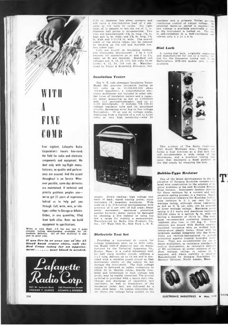
WITH
FIKECOMBEver vigilant, Lafayette Radio
Corporation's tracers fine-comb
the field for radio and electronic
components and equipment. We
deal only with top-flight manu
facturers, so quality and perform
ance are assured. And the accent
throughout is on Service. Wher
ever possible, same-day deliveries
are maintained. If technical and
priority problems perplex you—
we've got 25 years of experience
behind us to help pull you
through. Call, write, wire, or tele
type—either to Chicago or Atlanta
Orders, in any quantities, filled
from both cities. Note: we build
equipment to specifications.
Write or wire Dept. J-5 for our new 8 page circular listing merchandise available for immediate delivery. All of this material is subject to prior sale.
ff ana Ure in nr near nite nf the Hit Maori bank renter ri tie», rail the Hai Cm»» Imino far an antfoinf- ment ....... tiour Moori i» nrrrieri.
3 16 in. diameter fine silver contacts and will carry ■ non-inductive load of 5 amperes at 110 volts 60 cycles. For light loads of % ampere or less the use of 14 in. diameter ball points is recommended. Two sizes are manufactured: 2% in. long, 1% in. high and 14 in. wide; and 2% in. long, 1% in. high and 1-11/16 in. wide. The overall width of the above relays can be reduced by bending up the coil and movable contact solder lugs.
Coils are wound on insulating bobbins and thoroughly impregnated. 3 to 4 volt amperes for operation on ac and 2 to 214 watts on de are required. Standard coil voltages are: 6, 12. 24, 110, 220 volts 50-60 cycles: 6, 12, 24, 110 volt de. Manufactured by Potter & Brumfield, Princeton, Ind.
OPEN
CLOSEP
Bobbin-Type Resistor
Insulation Tester
The V. T. volt ohmegger Insulation Tester Model 665 provides insulation testing at 500 volts up to 10,000,000,000 ohms (10.000 megohms), a comprehensive electronic multitester not included in other similar types of insulation testers and a capacity meter measuring as low ns 0.0000025 mfd. (2.5 micromicrofarads), and up to 2,000 microfarads. It includes VR 105-30 voltage regulator tube and its associated circuits, decreasing error due to line voltage fluctuations. 13 ac and de voltage scales, measuring from a fraction of a volt to 6,000 volts, at very high sensitivity—with 29
ranges. Direct reading; high voltage test leads rf lead; signal tracing probe; input resistance 16 megohms maximum. Wide scale on 8 in. D'Arsonval microammeter with accuracy of 2 per cent of full scale; linear meter movement; maximum protection against burnout; meter cannot be damaged by checking a live resistor or using too low a range for making a measurement. Manufactured by Radio City Products C< , Inc., 127 West 26th St., New York 1, N. Y.
Dielectric Test Set
Providing a convenient de source for voltage breakdown tests up to 4000 volts, the Model 1031-F dielectric test set manufactured by the Technical Apparatus Co., Boston, Mass., is a useful laboratory tool. Its half wave rectifier circuit, utilizing a 2x2 tube, delivers up to 18 ma and is provided with a resistive guard circuit so that momentary shorts on the output do not damage the instrument. The high voltage output is delivered at safety connectors to which 24 in. flexible cables, heavily insulated and terminated in high voltage test prods, may be readily connected. The ground terminal is provided with n heavy duty clip. Charge and discharge of capacitive test specimens, as well as breakdown of the insulation under test, are indicated by a neon glow lamp. An output indicating meter shows the voltage being applied to the
specimen and n primary Variac pro ide continuous control of output voltage No extended warm-up period is require,■ the test voltage is available practically a- oon as the instrument is turned on. The mi> is self-contained in a well-ventilated ’eel cabinet only 8 x 10 x 8 in.
Dial Cork
A tuning-dial lock, originally engin, red and manufactured for use us a tuning on. trol for the frequency tuning unit o the Hallicrafters SCR-299 mobile unit, in now available.
This product of The Radio Craftsmen, 1341 South Michigan Ave., Chicago, performs a dual function ns a dial lock that will accommodate a wide range of dial thicknesses, and a precision tuning indicator that maintains a fixed position on the dial simply by snapping the lock.
One of the latest developments in the application of Sprague Koolohm ceramic-insulated wire construction to the solution of resistor problems is the new Koolohm Bobbin- Type resistor. Instrument resistor stability for these resistors by * current and temperature ageing process, is a feature. Standard resistance tolerance for Koolohm bobbintype resistors is ± 5 per cent for full wattage rating, although closer tolerance- as low an ± per cent, can be provided at lower wattage ratings. Maximum power rating is 2.5 watts and maximum resistance 250,000 ohms in a section % in. wide and having a diameter of 13/16 in. The maximum recommended (ambient plus rise) resistors are wound insulated resistance temperature plastic
operating temperature is 150 deg. C. These with flexible ceramic
wire on molded high- forms, fitted with lug
terminals molded integrally into the forms Units are varnish-impregnated to pro ide protection against tropical humidity conditions. They are recommended for use n- meter multipliers, as resistance standards in control instruments, as resistance element- of RC oscillators, as power resistors of mt dium wattage ratings in values to megohm, and where stability is requir’d. Manufactured by Sprague Specialties Resistor Division, North Adams, Mass.
206 ELECTRONIC INDUSTRIES • May, 1 H IFl’ TR
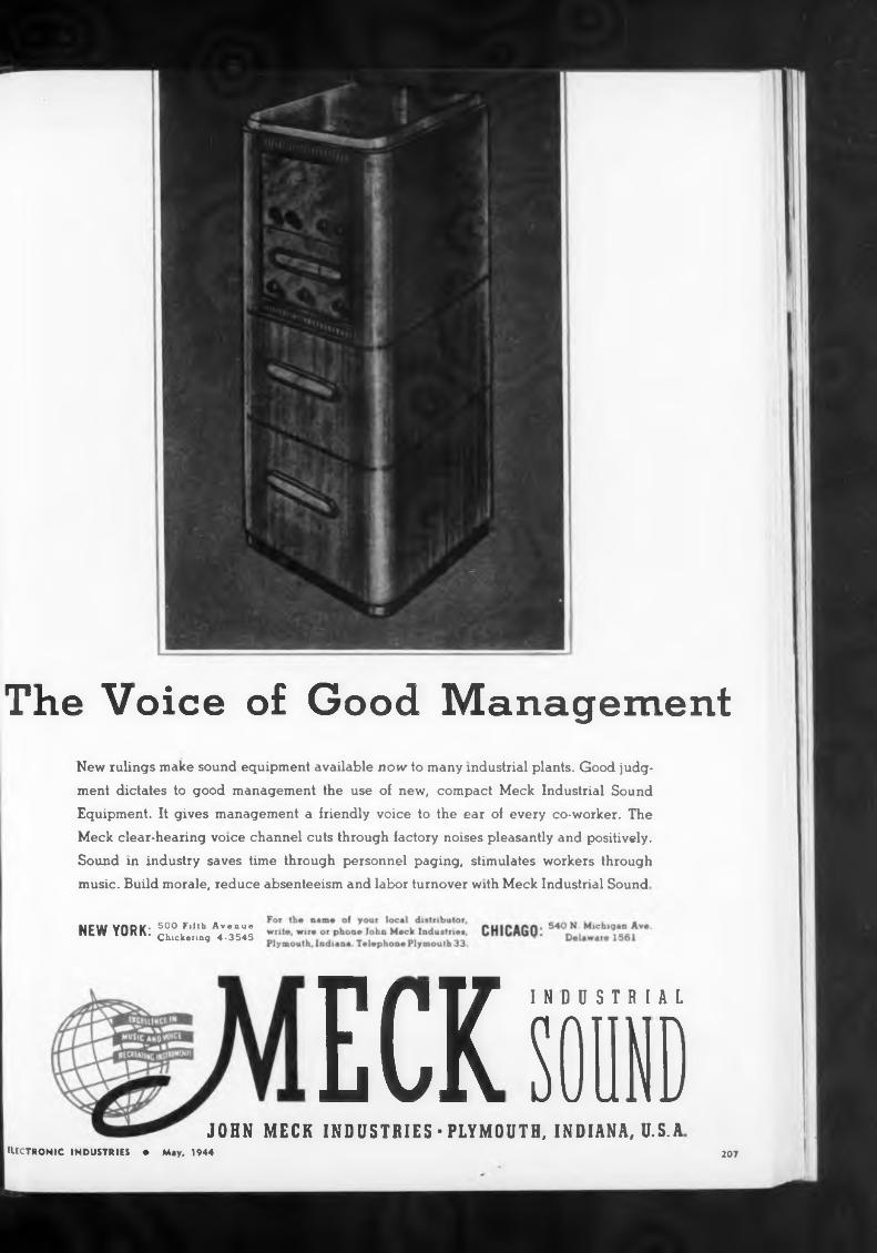
The Voice of Good Management
ITI T 7 INDUSTRIAL ECK SOUNDMECK INDUSTRIES-PLYMOUTH, INDIANA, U.S.A
207
New rulings make sound equipment available now to many industrial plants. Good judgment dictates to good management the use of new, compact Meek Industrial Sound Equipment. It gives management a friendly voice to the ear of every co-worker. The Meek clear-hearing voice channel cuts through factory noises pleasantly and positively. Sound in industry saves time through personnel paging, stimulates workers through music. Build morale, reduce absenteeism and labor turnover with Meek Industrial Sound
air ill VADV- 500 Fifth AvenueNtW YUKK. Chickerinq 4.354s
JOHNELECTRONIC INDUSTRIES • May, 1944
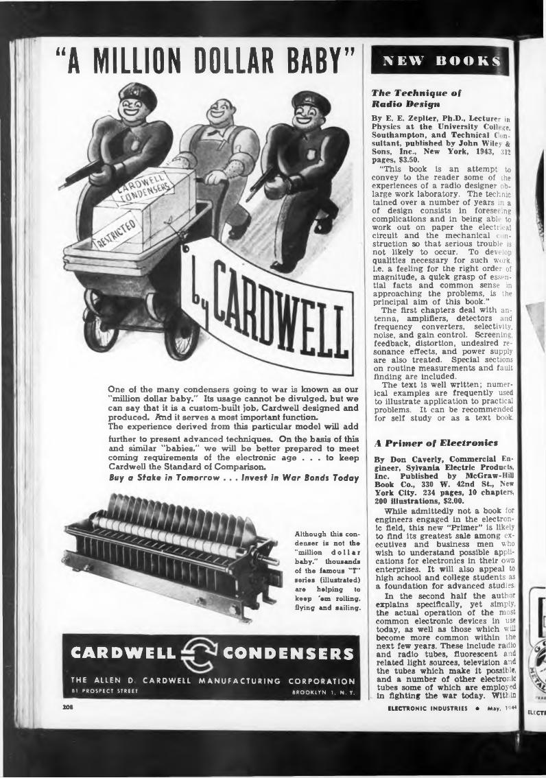
“A MILLION DOLLAR BABY"
One of the many condensers going to war is known as our "million dollar baby." Its usage cannot be divulged, but we can say that it is a custom-built job, Cardwell designed and produced. And it serves a most important function.The experience derived from this particular model will add further to present advanced techniques. On the basis of this and similar "babies," we will be better prepared to meet coming requirements of the electronic age ... to keep Cardwell the Standard of Comparison.Buy a Stake in Tomorrow . . . Invest in War Bonds Today
Although this condenser is not tho "million dollar baby," thousands oi the famous "T" series (illustrated) are helping to keep 'em rolling, flying and sailing.
CARDWELL CONDENSERSTHE ALLEN D CARDWELL MANUFACTURING CORPORATION81 PROSPECT STREET BROOKLYN 1, N. Y.
NEW BOOKS
The Technique of Radio DesignBy E. E. Zeplter, Ph.D., Lecturer in Physics at the University Coll, ge, Southampton, and Technical Consultant, published by John Wilej &Sons, Inc., New York, 1943,pages, $3.50.
“This book convey to the experiences of
is an reader a radio
attempt some of
312
to the
large work laboratory.designer ob- The technic
tained over a number of years in a of design consists in foreset ing complications and in being able to work out on paper the electrical circuit and the mechanical construction so that serious trouble is not likely to occur. To develop qualities necessary for such work, i.e. a feeling for the right order of magnitude, a quick grasp of essential facts and common sense in approaching the problems, is the principal aim of this book.”
The first chapters deal with antenna, amplifiers, detectors and frequency converters, selectivity, noise, and gain control. Screening, feedback, distortion, undesired resonance effects, and power supply are also treated. Special sections on routine measurements and fault finding are included.
The text is well written; numerical examples are frequently used to illustrate application to practical problems. It can be recommended for self study or as a text book.
A Primer of ElectronicsBy Don Caverly, Commercial Engineer, Sylvania Electric Products, Inc. Published by McGraw-Hill Book Co., 330 W. 42nd St., New York City. 234 pages, 10 chapters, 200 illustrations, $2.00.
While admittedly not a book for engineers engaged in the electronic field, this new “Primer” is likely to find its greatest sale among executives and business men who wish to understand possible applications for electronics in their own enterprises. It will also appeal to high school and college students as a foundation for advanced studies.
In the second half the author explains specifically, yet simply, the actual operation of the most common electronic devices in use today, as well as those which will become more common within the next few years. These include radio and radio tubes, fluorescent and related light sources, television and the tubes which make it possible, and a number of other electronic tubes some of which are employed in fighting the war today. Within
ELECTRONIC INDUSTRIES • May, 1944EUCH
20t
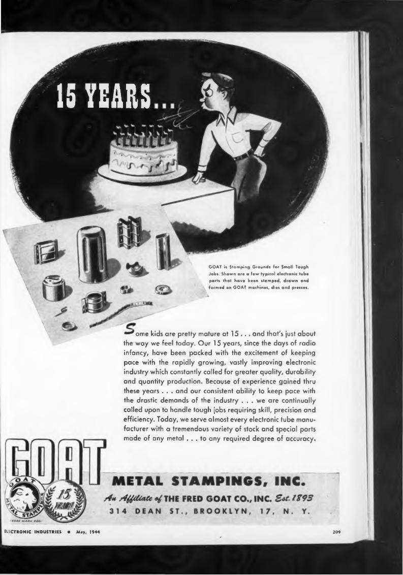
209
GOAT i< Stamping Ground« for Small Tough
Job*. Shown are a few typical electronic tube
part» that have been »tamped, drawn and
formed on GOAT machine», die» and pre»»es.
ELECTRONIC INDUSTRIES • Mey. 1944
•^ome kids are pretty mature at 15 ... and that's ¡ust about the way we feel today. Our 15 years, since the days of radio infancy, have been packed with the excitement of keeping pace with the rapidly growing, vastly improving electronic industry which constantly called for greater quality, durability and quantity production. Because of experience gained thru these years . . . and our consistent ability to keep pace with the drastic demands of the industry ... we are continually called upon to handle tough jobs requiring skill, precision and efficiency. Today, we serve almost every electronic tube manufacturer with a tremendous variety of stock and special parts made of any metal ... to any required degree of accuracy.
15 YEARS
Slide Rule Simplified
wrong
day. Shaping and forming to precision
was
eacen
anc
210
the next few years many of these tubes in wartime use will find peacetime uses to assure gre. ter comfort and happiness for n inkind.
you think of MICA think of MAC ALLEN
Mica we can
standards. Whatever can be done with
are doing new things with mica every
- BOSTON 27anfiiAWt mm
Practical Radio and Electronics Course
Practical Radio Communication
ELECTRONIC INDUSTRIES • May, 1944
By A. R. Nilson and J. L. Hornung. Published by McGraw-Hill Book Co., New York. 1943. Second edition, 927 pages, price $6.00.
This manual of radio operating procedures presents a well-roundf d- out plan of study and reference to the commercial operating side of radio communication. In this si cond edition about 2/3 of the text is new, and all of it is revised and brought up to date. It should continue to be the standard manual of Instruction for courses In radio operating, and preparation for operator’s license examinations.
By Charles O. Harris, B.S., M.S., Sc. I), Assistant Professor of Mechanics, Illinois Institute of Technology, published by the American Technical Society, Chicago, 1944, 258 pages, $3.15.
The basic slide rule operations (multiplication, division, square, square root, cube, cube root, sines, cosines, tangents, and logarithms* are extensively explained so as to be understood by anyone who has studied arithmetic and can multiply two numbers and divide one number by another, even though he has never before seen a slide rule. A ten inch Dietzgen slide rule comes with the book.
Prepared under direction of M. N. Beitman. Three volumes, ap. proximately 350 pages. Price $3.95. Published by Supreme Publications, Chicago, Ill.
Intended for home study, these three books are addressed to “progressive mechanically inclined persons”. Fifty-three lessons present basic fundamentals of radio, television, uhf., facsimile, X-Rays, FM, servicing, welding, etc. Covering as it does so much electronic territory, the course of study is necessarily brief and oversimplified, especially in its treatment of underlying principles, but is undoubtedly adequate as introductory material. The lessons are well illustrated, and special comments printed adjacent to the text offer suggestions, give references, and in general are intended to take the place of a teacher
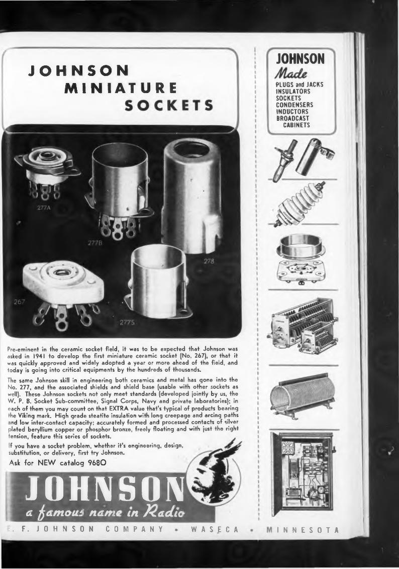
I N N E S O T A
JOHNSON MINIATURE
JOHNSON
PLUGS and JACKS INSULATORS SOCKETS CONDENSERS INDUCTORS BROADCAST
CABINETS
Pre-eminent in the ceramic socket field, it was to be expected that Johnson was asked in 1941 to develop the first miniature ceramic socket (No. 267), or that it was quickly approved and widely adopted a year or more ahead of the field, and today is going into critical equipments by the hundreds of thousands.
The same Johnson skill in engineering both ceramics and metal has gone into the No. 277, and the associated shields and shield base (usable with other sockets as well). These Johnson sockets not only meet standards (developed jointly by us, the W. P. B. Socket Sub-committee, Signal Corps, Navy and private laboratories); in each of them you may count on that EXTRA value that's typical of products bearing the Viking mark. High grade steatite insulation with long creepage and arcing paths
nd low inter-contact capacity; accurately formed and processed contacts of silver plated beryllium copper or phosphor bronze, freely floating and with just the right tension, feature this series of sockets.If you have a socket problem, whether it's engineering, design, substitution, or delivery, first try Johnson.
Ask for NEW catalog 9680
JOHNSONa fatnoni name in )2adio
. F. JOHNSON COMPANY WASECA
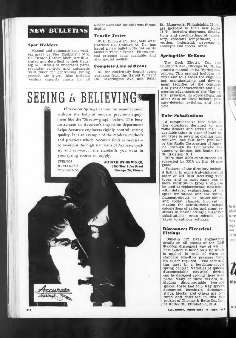
Spring-life Bellows2700
SEEING BELIEVINGTube Substitutions
your spring source of supply.
In th
and
ELEC
A comprehensive tube tion directory, designed radio dealers and service
The Cook Electric
available tubes in place of hard-to- get types in servicing civilian radio receivers, has just been published by the Radio Corporation of America, through its Commercial Engineering Section, 596 South Fifth St., Harrison, N. J.
More than 2,000 substitutions are suggested by RCA in this 16-page guide.
Features of the directory include: A listing, in numerical-alphabetical order of 304 RCA Receiving Tube types—and in most cases one or more substitution types which can be used as replacements; notations, with detailed explanations, of the space limitations and the wiring, filament-circuit or heater-circuit, and socket changes involved in making the substitutions; sample calculations of series and shunt resistors in heater strings; suggested
welder sizes and for different throat depths.
substituto help men use
Disconnect Electrical Fittings
substitutions cross-indexed keyed to cathode voltages.
Bulletin 522 gives engineering details on all phases of the T&B Sta-Kon disconnect way of wiring. This system is based on a tip which is applied to ends of wires by standard Sta-Kon pressure tools. No solder required. Two identical tips meet in a beryllium-copper spring coupler. Varieties of quickly disconnectable electrical devices can be designed around these basic parts. Many of these devices, including disconnectable two-way splices, three and four way splices, disconnect terminals, disconnect strips, blocks, and others are pictured and described in this new booklet of Thomas & Betts Co., Inc . 36 Butler St., Elizabeth 1. N. J.
St., Manayunk, Philadelphia 27, Pa., are Included in their new leaflet 71-T. Includes diagrams, illustrations and specifications of lab a- tory. constant temperature, convection, industrial, processing, conveyor and special ovens
Southport Ave., Chicago 14, Ill., has issued a manual on its “Spring-life" bellows. This manual includes pictures and tells about the engineering, manufacturing and development facilities of the company. Also gives characteristics and engineering advantages of the “Springlife” principle, its applications, and other data on Cook bellows, pressure-detector switches, and products.
ACCURATE SPRING MFG. CO. u 3808 West Lake Street
Chicago 24, Illinois
ELECTRONIC INDUSTRIES • May, 19*4
SPRINGS WIREFORMS STAMPINGS
recor wise
• Precision Springs cannot be manufactured without the help of modern precision equipment like the ’’Shadow-graph” below. This busy instrument in Accurate’s inspection department helps Accurate engineers rigidly control spring quality. It is an example of the modern methods and practices which Accurate finds is necessary to maintain the high standards of Accurate quality and service. . . the standards you want in
Complete Line of OvensAll the electrically heated ovens
available from the Harold E. Trent Co., Leverington Ave. and Wilde
Tensile TesterW. C. Dillon & Co., Inc., 5410 West
Harrison St., Chicago 44, Hl., has issued a new bulletin No. 144 on its Model K Tensile Tester. Shows special gripping jaws available, and also special models.
berat testir
Spot WeldersManual and automatic spot weld
ers made by Pier Equipment Mfg. Co., Benton Harbor, Mich., are illustrated and described in their Catalog 42. Details of important parts, regulator controls and automatic weld timer for controlling timing periods are given. Also includes welding capacity charts for all
NEW BULLETINS
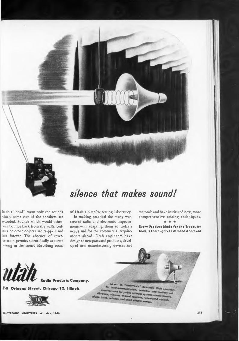
methods and have instituted new, more comprehensive testing techniques.
ELECTRONIC INDUSTRIES • May, 1944
Keyad to „
silence that makes sound!
In this ’'dead" room only the sounds which come out of the speakers are recorded. Sounds which would otherwise bounce back from the walls, ceilings or other objects are trapped and lost forever. The absence of reverberation permits scientifically accurate testing in the sound absorbing room
Radio Products Company,
850 Orleans Street, Chicago 10, Illinois
of Utah’s complete testing laboratory.In making practical the many war-
created radio and electronic improvements—in adapting them to today’s needs and for the commercial requirements ahead, Utah engineers have designed new parts and products, developed new manufacturing devices and
Every Product Made for the Trade, by Utah, Is Thoroughly Tested and Approved
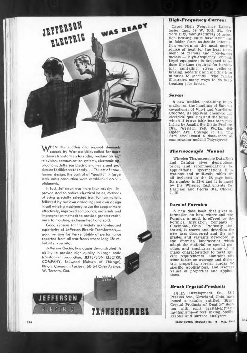
Saran
'HEN the sudden and unusual demandsThermocouple Manual
Brush Crystal Products3311
TRANSFORMERSELEC
Brush DevelopmentPerkins Ave., Cleveland, Ohio, have issued a catalog entitled “Brush Crystal Products of Quality” dealing with some crystal-actuated mechanisms—direct inking oscillographs and surface analyzers.
Wheelco Thermocouple Data Book and Catalog gives descriptions, prices and recommendations for applications. Specifications, illustrations and milli-volt tables are all included in the 36-page book Its number is 52-4 and it is issued by the Wheelco Instruments Co., Harrison and Peoria Sts., Chicago
ELECTRONIC INDUSTRIES * May, 1944
A new booklet containing information on the handling of Saran, a co-polymer of Vinyl and Vinylidene Chloride, its physical, chemical and electrical qualities and the forms in which it is available has been published by Acadia Synthetic Products Div., Western Felt Works, 4029 Ogden Ave., Chicago 23, Ill. This firm also issued a data-sheet on compression-molded Polystyrene.
’ ’ caused by War activities called for more and more transformers for radio, '‘walkie-talkies,’’ television, communication systems, electronic applications, Jefferson Electric engineers and production facilities were ready.... The art of transformer design, the control of “quality” in large scale mass production were established accomplishments.
In fact, Jefferson was more than ready:—improved steel to reduce electrical losses; methods of using specially selected iron for laminations followed by our own annealing; our own design in coil winding machinery to use the copper more effectively; improved compounds, materials and impregnation methods to provide greater resistance to moisture, extreme heat and cold.
Good reasons for the widely acknowledged superiority of Jefferson Electric Transformers,— good reasons for the reliability of performance reported from all war fronts where long life reliability is so vital.
Jefferson Electric has again demonstrated its ability to provide high quality in large scale transformer production. JEFFERSON ELECTRIC COMPANY, Bellwood (Suburb of Chicago), Illinois. Canadian Factory: 60-64 Osler Avenue, W. Toronto, Ont. .
High-Frequency Current |Lepel High Frequency Lab ra-
tories, Inc., 39 W. 60th St., New York City, manufacturers of im uc- tion heating units have assembled in folder form authentic infor. ia- tion concerning the most modern source of heat for the heat treatment of ferrous and non-ferrous metals — high-frequency current. Lepel equipment is designed to reduce the time required for hardening, annealing, stress relieving, brazing, soldering and melting from minutes to seconds. The catalog illustrates many ways to do heattreating jobs faster.
Ilses of FormicaA new data book that gives in
formation on how, where and why Formica is used, is offered by the Formica Insulation Company of Cincinnati, Ohio. Profusely illustrated, it shows and describes the new uses discovered and the new grades and variants developed in the Formica laboratories which adapt the material to special purposes and emphasize some of its many characteristics to meet specific requirements. Contains also some tables on average and dielectric properties, special grades for specific applications, and average values of properties and applications.
JEFFERSONELECTRIC
eierence
QUARTZ OSCILLATOR PLATES
1519 McGEE STREET, KANSAS CITY, MO.Producers of Approved Precision Crystals
for Radio Frequency Control
Here is common-sense, understandable data about the characteristics, production, and adaptation of quartz crystals. Graphically illustrated, these papers are combined in a convenient file for instant accessability. Write for your copy today.
ELECTRONIC INDUSTRIES • May, 1944
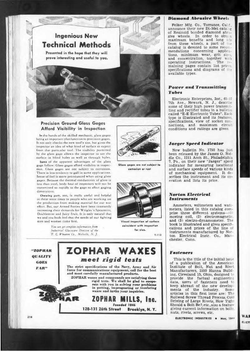
Presented in the hope that they will prove interesting and useful to you*
Ingenious NewTechnical Methods
Precision Ground Glass Gages Afford Visibility in Inspection
In the hands of the skilled mechanic, glass gages bring an important plus function to precision gages. It not only checks the new tool’s size, but gives the inspector an idea of what kind of surface to expect from that particular tool. The visibility permitted by the glass gage allows the inspector to see the surface in blind holes as well as through holes.
Some of the apparent advantages of the glass gage follow: Glass gages afford visibility in inspection. Glass gages are not subject to corrosion. There is less tendency to gall in some applications. Sense of feel is more pronounced when using glass gages. Because the thermal conductivity of glass is less than steel, body heat of inspectors will not be transmitted so rapidly to the gage to affect gaging dimensions.
Chawing gum, too, is really useful and helpful in these tense times to people who are working on the production front making material for our war effort. But, our Armed Forces have been constantly increasing their demands for Wrigley’s Spearmint, Doublemint and Juicy Fruit. It is only natural that we and you both feel that the needs of our fighting men and women come first.
Yow can get complete information from Industrial Glassware Division of the T. C. Wheaton Co., Millville, N. J.
Diamond Abrasive WheelsFelker Mfg. Co., Torrance, Calif.,
announce their new Di-Met catalog of Resinoid bonded diamond abrasive wheels. In order to obtain maximum benefits and long Pfe from these wheels, a part of the catalog is devoted to some recommendations concerning applic: - tions, minimum wear, grit sizes, and concentration, together with operating instructions. The remaining pages contain list pric s, specifications and diagrams of the available types.
Power and Transmitting Tubes
Glast gages are na» tubjact to corrosion or rust
Electronic Enterprises, Inc., 65-57 7th Ave., Newark, N. J., describe some of their high power transmitting and rectifier tubes in a bulletin called “E-E Electronic Tubes”. Each type is illustrated and its features, specifications, view of socket connections, and maximum circuit conditions and ratings are given.
Visual inspection of surface coincident with inspection
for size.
Jaeger Speed IndicatorNew bulletin No. 1750 has just
been released by the James G. Biddle Co., 1211 Arch St., Philadelphia 7, Pa., on their new “Jaeger” speed indicator for measuring locational and surface speeds of various kinds of mechanical equipment. It describes the instrument and its operation and lists its price.
Norton Electrical instruments
Ammeters, voltmeters and wattmeters, listed in this catalog comprise three different systems—(1) moving coil, (2) electromagnetic, and (3) electro-dynamometer. The book is Illustrated and gives specifications and prices of the line of instruments manufactured by Norton Electrical Instr. Co., Manchester, Conn.
“ZOPHAR QUALITY
GOES FAR”
ZOPHAR WAXESmeet rigid tests
The strict specifications of the Navy, Army and Air force for communications equipment, call for the best and most carefully manufactured products.
ZOPHAR waxes and compounds are satisfying these rigid teste. We shall be glad to cooperate with you in solving your problems in potting, impregnating or insulating waxes and invite your inquiries.
ZOPHAR MILLS, Inc.Foaaded 1846
128-131 26th Stmt Brooklyn. N. Y.
FastenersThis is the title of the initial issue
of a publication of the American Institute of Bolt, Nut and Rivet Manufacturers, 1550 Hanna Building, Cleveland 15, Ohio, designed to provide the factual engineering data, users of fasteners need to keep abreast of the new developments of the industry. Some articles in this first issue are: The Rollwed Screw Thread Process, Cold Driving of Large Rivets, How Tight Should a Bolt Be?,etc.,also a feature giving current information on bolt., nuts, rivets, screws, etc.
ELECTRONIC INDUSTRIES • May, 1944 WARILECTI
216
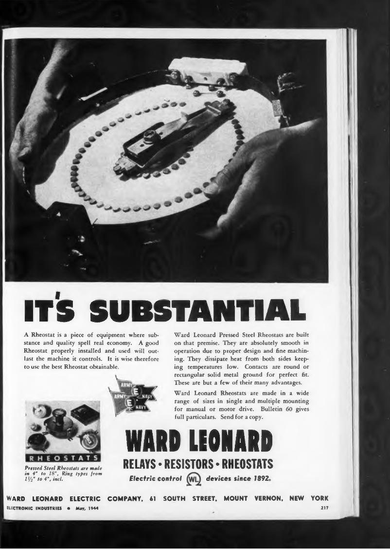
it's substantialA Rheostat is a piece of equipment where substance and quality spell real economy. A good Rheostat properly installed and used will outlast the machine it controls. It is wise therefore to use the best Rheostat obtainable.
Pressed Steel Rheostats are made in 4" to 18", Ring types from 1 ¥2“ to 4”, inch
Ward Leonard Pressed Steel Rheostats are built on that premise. They are absolutely smooth in operation due to proper design and fine machining. They dissipate heat from both sides keeping temperatures low. Contacts are round or rectangular solid metal ground for perfect fit. These are but a few of their many advantages.Ward Leonard Rheostats are made in a wide range of sizes in single and multiple mounting for manual or motor drive. Bulletin 60 gives full particulars. Send for a copy.
WMIHOI*URELAYS • RESISTORS • RHEOSTATS
Electric control devices since 1892
WARD LEONARD ELECTRICIL CTRONIC INDUSTRIES • May, 1944
COMPANY, 61 SOUTH STREET. MOUNT VERNON. NEW YORK217
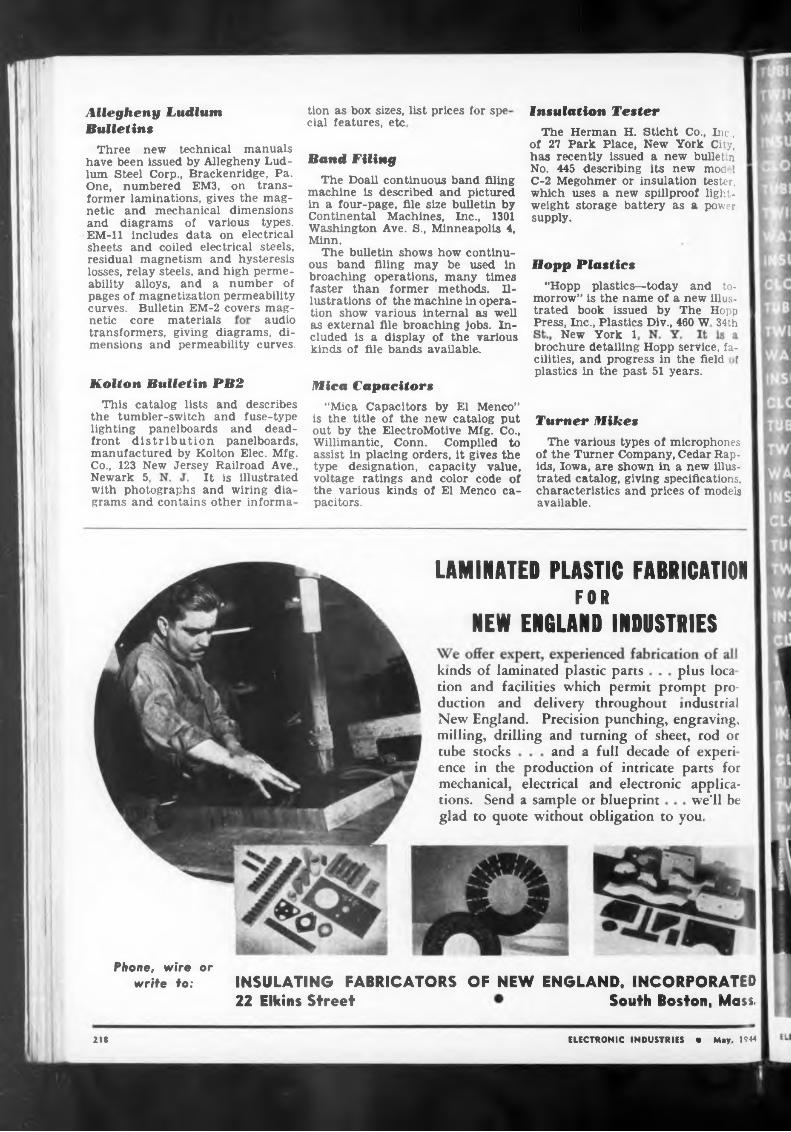
Insulation Tester
Hopp Plastics
audioNew York 1
Kolton Bulletin PB2 Mica Capacitors
Turner Mikes
It is illustratedNewark 5,
LAMINATED PLASTIC FABRICATIONFOR
NEW ENGLAND INDUSTRIESkinds of laminated plastic parts plus loca
tube stocks
we’ll beglad to quote without obligation to you.
INSULATING FABRICATORS OF NEW ENGLAND. INCORPORATEDSouth Boston, Moss.22 Elkins Street
218
with photographs and wiring dia grams and contains other informa
transformers, giving diagrams, dimensions and permeability curves. brochure detailing Hopp service, fa
cilities, and progress in the field f plastics in the past 51 years.
tion as box sizes, list prices for spe cial features, etc
The various types of microphones of the Turner Company, Cedar Rapids, Iowa, are shown in a new illustrated catalog, giving specifications, characteristics and prices of models available.
and a full decade of experi
"Hopp plastics—today and tomorrow” is the name of a new illustrated book issued by The Hopp Press, Inc., Plastics Div., 460 W 34thnetic core materials
This catalog lists and describes the tumbler-switch and fuse-type lighting panelboards and deadfront distribution panelboards, manufactured by Kolton Elec. Mfg. Co., 123 New Jersey Railroad Ave.,
The Herman H. Sticht Co., Inc., of 27 Park Place, New’ York City, has recently issued a new bulletin No. 445 describing its new mod 1 C-2 Megohmer or insulation tester, which uses a new spillproof lightweight storage battery as a power supply.
Allegheny Ludlum Bulletins
"Mica Capacitors by El Menco” is the title of the new catalog put out by the ElectroMotive Mfg. Co., Willimantic, Conn. Compiled to assist in placing orders, it gives the type designation, capacity value, voltage ratings and color code of the various kinds of El Menco capacitors.
tions. Send a sample or blueprint
tion and facilities which permit prompt production and delivery throughout industrial New England. Precision punching, engraving, milling, drilling and turning of sheet, rod or
Three new technical manuals have been issued by Allegheny Ludlum Steel Corp., Brackenridge, Pa. One, numbered EM3, on transformer laminations, gives the magnetic and mechanical dimensions and diagrams of various types. EM-11 includes data on electrical sheets and coiled electrical steels, residual magnetism and hysteresis losses, relay steels, and high permeability alloys, and a number of pages of magnetization permeability curves. Bulletin EM-2 covers mag-
ELECTRONIC INDUSTRIES • May. 1944
ence in the production of intricate parts for mechanical, electrical and electronic applica-
Phone, wire or write to:
Band FilingThe Doall continuous band filing
machine is described and pictured in a four-page, file size bulletin by Continental Machines, Inc., 1301 Washington Ave. S., Minneapolis 4, Minn.
The bulletin shows how’ continuous band filing may be used in broaching operations, many times faster than former methods. Illustrations of the machine in operation show various internal as well as external file broaching jobs. Included is a display of the various kinds of file bands available.
w»s°
fro«*
COMtOUHO»
Cotttp01and the
tion
ELECTRONIC INDUSTRIES 219
^Vattdshe’
étages, t
suide Bo°k-. wt'te
they avv,t the» »" v
INGS
INES
MICA
TAPES
G VARNISHESINGS
NES SLEEVINGS
MICAULATING V TAPES
SLEEVINGS
BRINGS
OUNDS
TING VARNISHES
LOTHS
BINGS
TAPES PAPERS
fARNISHES SLEEVINGS
COMPOUNDS
MIC
UBI
corMITCHELL-RAND INSULATION COMPANY INC51-C MURRAY STREET NEW YORK, N. YCOrtlandt 7-9264
EB8INGS
[OUNDS
BINGS
UNOS
MICA
TAPIS
SLEEVINGS
WEBBINGS *
OTHS
BINGS
/Ines
papers •SLEEVINGS
Fib«rg>nt Vami»h«d Tap« and Cloth Instating Pap««*» and TpltnCable Filling and Pothead Compounds Friction Tape and Splioe Transformer Compounds
CLOTHS
TUBINGS
Azines waxes •
A PARTIAL LIST OF M-R PRODUCTSFiberglas Braided St«eving Catton Topes. Webbing, «nd Sleevings Impregnated Varnish Tubing Insulating Varnishes of all types
- PAPERS
SLEEVINGS
• CLOTHS
TUBINGS •
WEBBIfR^COMPOUND
Fiberglas Laferated Sleeving and Varnished TubingAsbestos Sleeving and TopeEitruded P’ostic TubingVarnished Cambric Cloth and Tape Mica Plate. Tape. Paper. Cloth and Tubing
WAXES • COMP
XES • CON
XES • COMPOUN
ULATING VARNISH
PERS • TWINES • WEBBINGS • MICA
EES • COMPOUNDS •
LAYING VARNISHES
THS •
INES • WEBBIN
WEBBINGS • MIC
WEBBINGS • MICA • INSUL
SLEEVINGS • WAXES
TUBINGS • SLEEVINGS
MICA -INSULATING VARNISHr
TAPES
TUBINGS • SLEEVINGS
THS • PAPERS
PAPERS • TWINES
NG VARNISHES ITHS • PAPERS
WAXES • COMPOUNDS • TAPES • CLOTHS • PAPERS
FS - WEBBINGS - MICA
COMPOUNDS • TAPES
INSULATING VARNISHES
>THS • PAP
INGS • SLEEV
Saxes • compounds • tapes 1 SULATING VARNISHES • TUBINGS
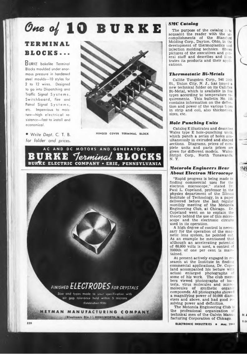
BLOCKS
Patrol Signal Systems
HINGED COVER TERMINAL BLOCK
molecules
elec220
compounds. All photographs showed a magnifying power of 50,000 diameters and above, and had good re solving power and definition.
The Motorola Engineering Club the professional organization o' technical men of the Galvin Manufacturing Corporation of Chicago.
synthetic organic
ELECTRONIC INDUSTRIES • May, 1944
Motorola Engineers Hear About Electron Microscope
“Rapid progress is being made in finding commercial uses for the electron microscope,” stated Dr. Paul L Copeland, professor in the physics department of the Illinois Institute of Technology, in a paper delivered before the last regular monthly meeting of the Motorola Engineering Club, at Chicago. Dr. Copeland went on to explain the theory behind the use of this microscope and the electronic circuits used in its operation.
A high degree of control is necessary for the operation of the magnetic lens system, he pointed out. As an example he mentioned that although an accelerating potential of 60,000 volts is used, a control of 2000th of one per cent is maintained.
At present actively engaged in research at the Institute in finding commercial applications, Dr. Copeland accompanied his lecture with actual enlarged photographs of some of his work. The club members viewed photographs of bac teria, virus molecules and micro-
Hole Punching UnitsCatalog E illustrates and describes
Wales type E hole-punching units, which punch a series of holes simultaneously in extruded and shaped sections. Diagrams, prices of complete units and parts prices are given for different models. WalesStripit Corp., North Tonawanda. N. Y.
♦ Write Dept. C. T. B for folder and prices
Thermostatic Bi-MetalsCallite Tungsten Corp., 540 39th
St., Union City, N. J., has issued a new technical folder on its Calliflex Bi-Metal, which is available in five types according to temperature requirements. This bulletin No. 155 contains information on the deflection and power of the various types in strip and coil, also thicknesses, sizes, etc.
SMC CatalogThe purpose of the catalog is to
acquaint the reader with the accomplishments of the Standard Molding Corp., Dayton, Ohio, in the development of thermoplastics ;.nd injection molding technics. St ;ws pictures of the executives and general staff and describes and illustrates its products and their a» ,li- cations.
etc. Impervious to moisture—high electrical resistance—fast to install and economical.
DURKE bakelite Terminal Blocks moulded under enormous pressure in hardened steel moulds—10 styles for 2 to 12 wires. Designed to go into Dispatching and Traffic Signal Systems, Switchboard, Fire and
FINISHED
to you' jpecificafion
ELECTRODESFOR CRYSTALS
gap tolerance held within 5
(Established 19261
AC AND DC MOTORS AND GENERATORS
BÜRKE BLOCKSBUR&E ELECTRIC COMPANY • ERIE. PENNSYLVANIA
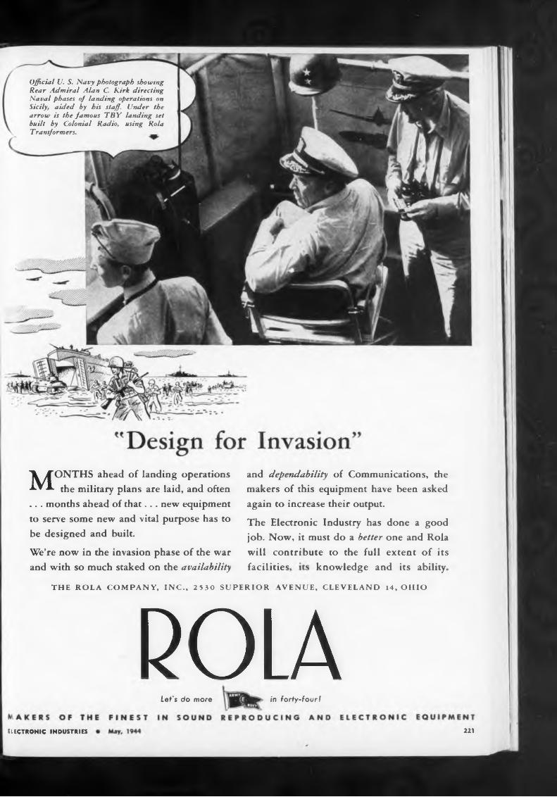
knowledge and its ability,facilities
THE ROLA
POLAin forty-four!Let's do more
221ELECTRONIC INDUSTRIES
and dependability of Communications, the makers of this equipment have been asked again to increase their output.
The Electronic Industry has done a good job. Now, it must do a better one and Rola will contribute to the full extent of its
Official U. S. Navy photograph showing Rear Admiral Alan C. Kirk directing Naval phases of landing operations on Sicily, aided by his staff. Under the arrow is the famous TBY landing set built by Colonial Radio, using Rola T ransformers.
We’re now in the invasion phase of the war and with so much staked on the availability
COMPANY, INC., 2530 SUPERIOR AVENUE, CLEVELAND 14, OHIO
MONTHS ahead of landing operations the military plans are laid, and often
... months ahead of that... new equipment to serve some new and vital purpose has to be designed and built.
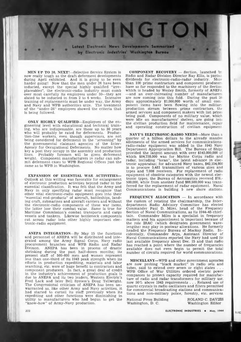
Latest Electronic News Developments Summarized by Electronic Industrie»' Washington Bureau
MEN UP TO 30, NEXT!—Selective Service System is now really tough as the draft deferment developments during April exhibited. And it is going to be even harder going! Now that the men under 26 have been inducted, except the special highly qualified “irre- placeables”, the electronic-radio industry must comb over most carefully its employees under 30—they are slated to be inducted in from 2 to 6 weeks. Intensive training of replacements must be under way, the Army and Navy and WPB authorities urge. The treatment of the “under-26” employees showed the criteria that is being followed.
ONLY HIGHLY QUALIFIED—Employees of the engineering level with educational and technical training, who are indispensable, are those up to 30 years who will probably be rated for deferments. Production-line workers, even though supervisors, are not being considered for deferment in the “screening” by the governmental claimant agencies of the Inter-r Agency for Occupational Deferments. No matter how key a post they occupy in the assembly and production lines. Probably foremen will be given deferment weight. Component manufacturers in radar can submit deferment cases to WPB Regional Offices just the same as to WPB in Washington.
EXPANSION OF ESSENTIAL WAR ACTIVITIES— Outlook at this writing was favorable for enlargement of electronic production activities beyond radar in the essential classification. It was felt that the Army and Navy in only specifying radar must recognize that other vital electronic-radio equipment goes into their “essential end-products” of aircraft, battleships, landing craft, submarines and aircraft carriers and without the electronic-radio components of these war items, the latter lose their combat value. Same is true for Maritime Commission’s combat transports and cargo vessels and tankers. Likewise bottleneck components cut across radar into other highly important electronic-radio equipment.
ANEPA INTEGRATION—By May 15 the functions and personnel of ANEPA will be distributed and integrated among the Army Signal Corps, Navy radio procurement branches and WPB Radio and Radar Division. ANEPA has been in process of drastic shrinking during the past half-dozen months; its present staff of 500-600 men and women represent less than one-third of its 1943 peak strength when its efforts in production expediting, materials and labor searching, etc. were of huge benefit to contractors and component producers. In fact, a great deal of credit in the industry’s achievement of production goals is due to ANEPA and its two leaders, Western Electric’s Fred Lack and later Bell System’s Doug Tellwright. The Congressional criticism of ANEPA has been unwarranted as, like other Army and Navy activities, it had started to curtail its staff previously when its expediting and other functions were diminishing in utility to manufacturers who had begun to get the “know-how” of Army-Navy production.
COMPONENT RECOVERY — Section, launched by Radio and Radar Division Director Ray Ellis, is paying dividends for electronic-radio-radar industry. Mon than 100 prime contractors and component producers have so far responded to the machinery of the Section which is headed by Wesley Smith, formerly of ANEPA —and an ever-increasing number of manufacturer are now coming into this fold. During the past 3< days approximately $1,000,000 worth of small component items have been flowing into the military production stream between prime contractors, the armed services and component makers with list prices being paid. Components of no military value, which were idle on manufacturers’ shelves, are going into the civilian production field for maintenance, repair and operating construction of civilian equipment
NAVY’S ELECTRONIC-RADIO NEEDS—More than a quarter of a billion dollars to the already massive allotments of the armed services for cominunications- radio-radar equipment was added in the 1945 Navy Department Appropriation Bill. The Bureau of Ships provided the largest amount with over $145,000,000 of which $84,718,000 was for Marine Corps radio and radar, including “loran”, the latest advance in electronic apparatus; for advanced Navy bases, $42,154,000 is to procure 5,481 transmitters of various sizes and types and 7,008 receivers. For replacement of radio equipment of obsolete categories with the newest electronic types, the Bureau of Aeronautics received $79,500,000, while from another fund $66,500,000 was transferred for the replacement of radar equipment. Naval Communications is building 5 new shore stations
*1
FREQUENCY ALLOCATION — In accordance with the custom of rotating the chairmanship, the Interdepartment Radio Advisory Committee has elected Commander Paul D. Miles, head of the Frequency Section of Naval Communications, as its 1944-45 chieftain. Commander Miles is a specialist in frequency matters and his appointment is important because of the role IRAC (which designates government wavelengths) may play in postwar allocations. He formerly headed the Frequency Bureau of Mackay Radio. Incidentally, Commander Arps, Assistant Director of Naval Communications reported the Navy had used its last available frequency about Dec. 15 and that radio has reached a point where the number of frequencies available does not even begin to permit the total number of circuits required for world communications.
MISCELLANY—WPB and other government agencies are now probing “black market” in radio sets and tubes, said to extend over seven or eight states . . . WPB Office of War Utilities ordered electric power companies to protect capacity required for manufacture of radio and radar transformers for military use, now 50% above 1943 requirements . . . Relaxed use of quartz crystals in radio oscillators and filters permitted for commercial broadcasting stations and communications and non-military police, forestry, etc. services.National Press Building Washington, D. C.
ROLAND C. DAVIES Washington Editor
ELEC*222 ELECTRONIC INDUSTRIES • May, 1944
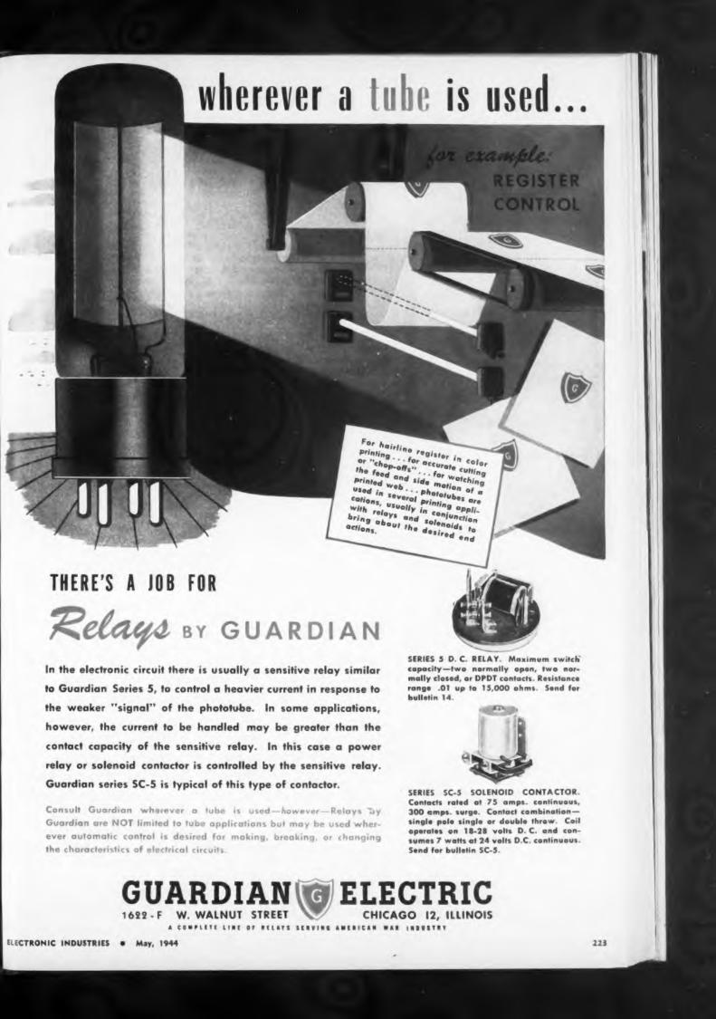
NBC PLANS NATIONWIDE TELEVISION SYSTEM
number
stations.
Tentative program
1947
EL C
which could be provided over these cables will be considerably greater than the initial number.
AT&T SCHEDULES COAST-TO-COAST COAXIAL
the interconnection
will give
television facilities
one-way televisionchannel of 2.7 megacycles in width. Future technical developments will increase this to 4.0 megacycles and also provide for simultaneous use of a single coaxial unit to transmit a television channel and a large number of telephone channels. Consequently, the ultimate
“The approximate dates at which television transmission facilities might be made available, if demand justifies their provision and manufactured cable and equipment can be secured, in accordance with present tentative program for extension of principal coaxial cable or equivalent routes for telephone purposes, follows:
plans call for between six and seven thousand route miles of coaxial cable in the next five or six years.
“The equipment now developed
ELECTRONIC INDUSTRIES • May W44
EXPORT DEPT. ROYAL NATIONAL COMPANY. INC. •» broad mm, n. y
That the future of television is bright, not to say brilliant, is the opinion of more than one engineering executive in a position to judge from experience, and no one is more optimistic regarding postwar possibilities than is President Niles Trammel of National Broadcasting Co. That organization, he has made plain, has very definite plans, already laid, and they go even so far as to include a network set up that will cover the country. Says Mr. Trammel:
“The economic basis for television broadcasting on a national scale must eventually depend upon
The tributes paid to "Black Seal" discs by many leading engineers have been earned by distinguished service on the turntable. Your ears will recognize the difference in quality of reproduction, and the longer play-back life will prove the superiority of "Black Seal" construction. Choice of two weights — thin, flexible, interchangeable with aluminum, or medium weight — both with four holes.An AA-2X rating is automatically available to broadcasting stations, recording studios and schools. Enclosure of your priority rating will facilitate delivery Old Aluminum Blanka Racoatad with
Black Seal'* Formula on Short Notice
The networking of stations will be effected either by coaxial cable lines or radio relays which must be established. NBC has experimented with both and the ultimate determination of which is to be used will be governed by the relative efficiency of the service they render and their comparative costs.”
In the meantime, though, it is significant that American Telephone and Telegraph Co., according to Vice-President Keith McHugh, “is planning to construct within the next few years a large amount of coaxial cable. The extent of this construction, when and where it will be undertaken, will depend upon the requirements of the armed forces, general business conditions, the volume and distribution of long distance telephone messages, the availability of the necessary manufactured cable and equipment, and other factors. Tentatively, however, our
RECORDING BLANK DIVISION
395 BROADWAY • NEW YORK 13, N. Y.
19451946
New York-WashingtonNew York-Boston Washington-Charlotte Chicago-Terre Haute-St
LouisLos Angeles-PhoenixChicago -Toledo - Cleve -
land-BuffaloSouthern Transconti
nental Route (a large part)
(Continued on page 226)
GOULD-MOODY
GLASS BASE INSTANTANEOUS
RECORDING BLANKS
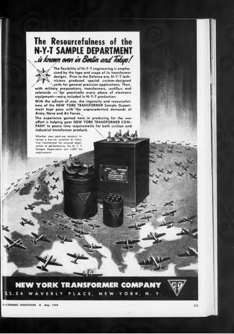
225ELECTRONIC INDUSTRIES • May, 1944
The Resourcefulness of the N-Y-T SAMPLE DEPARTMENT ..it hunm wen in anfTohfo/
■ l , The flexibility of N-Y-T engineering is emphasized by the type and scope of its transformer designs. Prior to the Defense era, N-Y-T lech- nicians produced special custom-designed
z \ynits for general precision applications. Then, with military preparations, transformers, rectifiers and solenoids — for practically every phase of electronic equipment—were included in N-Y-T production.With the advent ofxwar, the ingenuity and resourcefulness ef the NEW YORK TRANSFORMER Sample Department kept pace with the unprecedented demands of Army, Navy and Air Forces. vThe experience gained nowjn producing for the war effort is helping gear NEW YORK TRANSFORMER COMPANY to peace time requirements for both civilian and industrial transformer products n cWhether your post-wor product in- \ .A«olves n marine, av<atio*t or industrial transformer for unusual appliCO' on or j”,- the N " Ifampln Dcpai'm'"» en *L f '• 're q v । r mt i>
NEW YORK TRANSFORMER COMPANY
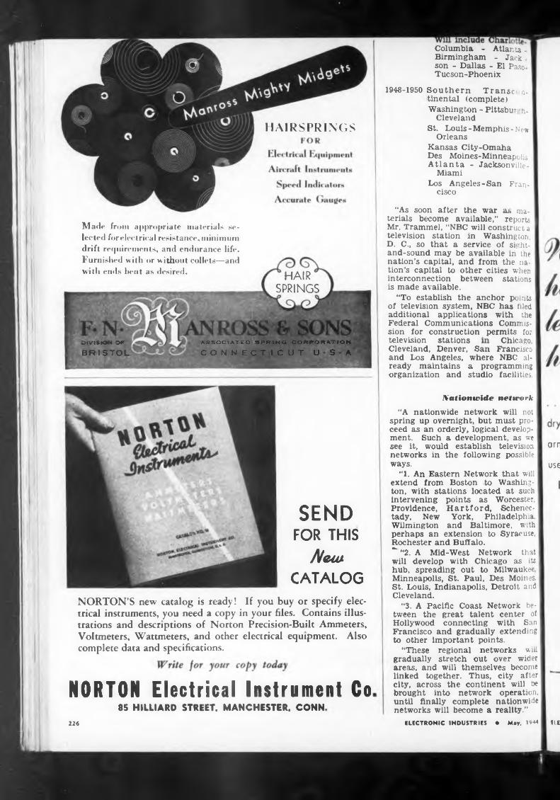
HAIRSPRINGS
Chicago,
Nationwide network
arnuseSEND
FOR THIS
NewCATALOG
NORTON Electrical Instrument Co85 HILLIARD STREET, MANCHESTER, CONN
ELEI226
television stations
intervening Providence, tady, New Wilmington perhaps an
Cleveland, Denver, San Francisco and Los Angeles, where NBC already maintains a programming organization and studio facilities.
HAIR SPRINGS
points as Worcester, Hartford, Scheneo
York, Philadelphia, and Baltimore, with
extension to Syracuse,
Columbia - Atlanta ■ Birmingham - Jack. son - Dallas - El Paso. Tucson-Phoenix
“A nationwide network will not spring up overnight, but must proceed as an orderly, logical development. Such a development, as we see it, would establish television networks in the following possible ways.
•T. An Eastern Network that will extend from Boston to Washington, with stations located at such
NORTON’S new catalog is ready! If you buy or specify electrical instruments, you need a copy in your files. Contains illustrations and descriptions of Norton Precision-Built Ammeters, Voltmeters, Wattmeters, and other electrical equipment. Also complete data and specifications.
ELECTRONIC INDUSTRIES ♦ May, 1944
1948-1950 Southern Transe n- tinental (complete)Washington - Pittsbur h-
ClevelandSt. Louis-Memphis-New
OrleansKansas City-OmahaDes Moines-Minneapohs Atlanta - Jacksonville-
MiamiLos Angeles-San Fran
cisco
“As soon after the war as materials become available,” reports Mr. Trammel, “NBC will construct a television station in Washington, D. C., so that a service of sight- and-sound may be available in the nation’s capital, and from the nation’s capital to other cities when interconnection between stations is made available.
“To establish the anchor points of television system, NBC has filed additional applications with the Federal Communications Commission for construction permits for
oivisio* orBRISTOL
ASSOCIATED SPRING CORPORATION
CONNECTICUT USA
Made from appropriate materials selected forelectrical resistance, minimum drift requirements, and endurance life. Furnished with or without collets—and with ends bent as desired.
Rochester and Buffalo.~ “2. A Mid-West Network that will develop with Chicago as its I hub, spreading out to Milwaukee Minneapolis, St. Paul, Des Moines. St. Louis, Indianapolis, Detroit and Cleveland.
“3. A Pacific Coast Network between the great talent center of Hollywood connecting with San Francisco and gradually extending to other important points.
“These regional networks will gradually stretch out over wider areas, and will themselves become linked together. Thus, city after city, across the continent will be brought into network operation, until finally complete nationwide networks will become a reality.”
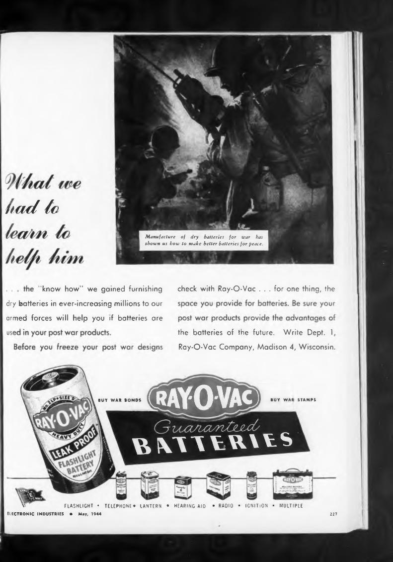
fiad to
dry batteries in ever-increasing millions to our
Ray-O-Vac Company, Madison 4, Wisconsin
BUY WAR STAMPSBUY WAR BONDS
227
the batteries of the future. Write Dept. 1
armed forces will help you if batteries are
check with Ray-O-Vac ... for one thing, theknow how we gained furnishing
TELEPHONF • LANTERN • HEARING AID • RADIO • IGNITiON ■ MULTIPLEV FLASHLIGHT •ELECTRONIC INDUSTRIES • May, 1944
Manufacture of dry batteries for war has shown us bow to make better batteries for peace.
gWOVAcg
B XTVVU X V S
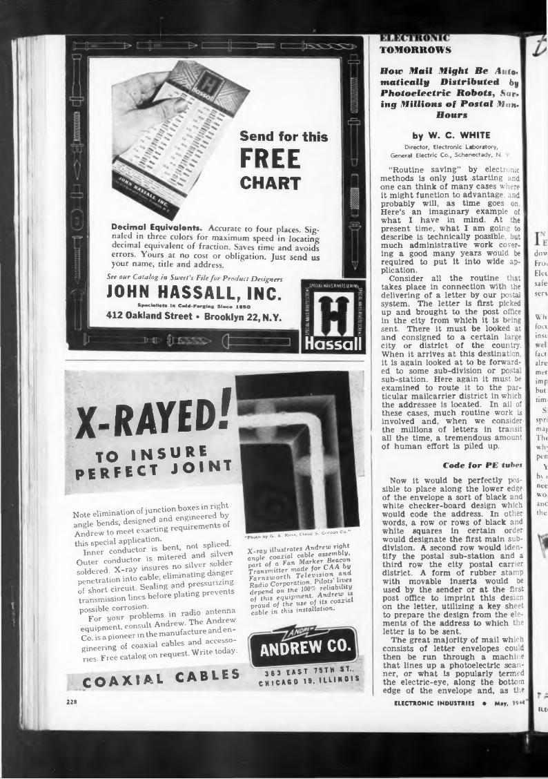
Send for thisFREECHART
Decimal Equivalents. Accurate to four places. Signaled in three colors for maximum speed in locating decimal equivalent of fraction. Saves time and avoids errors. Yours at no cost or obligation. Just send us your name, title and address.
See our Catalog in Sweet’s File for Product Designers
JOHN HASSALL, INC.Specialist« in Cold-Forging Since 1B5O
412 Oakland Street • Brooklyn 22, N.Y.
.SPfCIAl NAHS RIVtTS URI WS
5
£
Hassall
TOMORROWS
How Mail Might Be Auto, matically Distributed by Photoelectric Robots, Saving Millions of Postal Man-
Hours
by W. C. WHITEDirector, Electronic Laboratory,
General Electric Co., Schenectady, N.
“Routine saving” by electronic methods is only just starting and one can think of many cases where it might function to advantage, and probably will, as time goes on. Here’s an imaginary example of what I have in mind. At the present time, what I am going to describe is technically possible, but much administrative work cover-ing a good required to plication.
Consider takes place
many years would be put it into wide ap
all the routine that in connection with the
t
x-rayed!TO INSURE
PERFECT JOINT
Note elimination of junction boxes in right angle bends, designed and engineered by Andrew to meet exacting requirements of
this special application.Inner conductor is bent, not spliced. Outer conductor is mitered and silver» soldered. X-ray insures no silver solder penetration into cable, eliminating danger of short circuit. Sealing and pressurizing transmission lines before plating prevents
possible corrosion.For your problems in radio antenna
equipment, consult Andrew. The Andrew Co. is a pioneer in the manufacture and engineering of coaxial cables and accessories. Free catalog on request. Write today.
COAXIAL CABLES
“Photo by G. A. Russ, Claud S. Gordon Co."
X-ray illustrates Andrew right angle coaxial cable assembly, part of a Fan Marker Beacon Transmitter made for CAA by Farnsworth Television and Radio Corporation. Pilots’ lives depend on the 100% reliability of this equipment. Andrew is proud of the use of its coaxial cable in this installation.
delivering of a letter by our postal system. The letter is first picked up and brought to the post office in the city from which it is being sent. There it must be looked at and consigned to a certain large city or district of the country. When it arrives at this destination, it is again looked at to be forwarded to some sub-division or postal sub-station. Here again it must be examined to route it to the particular mailcarrier district in which the addressee is located. In all of these cases, much routine work is involved and, when we consider the millions of letters in transit all the time, a tremendous amount of human effort is piled up.
Code for PE tubes
ANDREW CO.363 EAST 75TH ST.,
CHICAGO 19, ILLINOIS
Now it would be perfectly possible to place along the lower edge of the envelope a sort of black and white checker-board design which would code the address. In other words, a row or rows of black and white squares in certain order would designate the first main subdivision. A second row would identify the postal sub-station and a third row the city postal carrier district. A form of rubber stamp with movable inserts would be used by the sender or at the first post office to imprint this design on the letter, utilizing a key sheet to prepare the design from the elements of the address to which t le letter is to be sent.
The great majority of mail which consists of letter envelopes cou d then be run through a machine that lines up a photoelectric scanner, or what is popularly termed the electric-eye, along the bottom edge of the envelope and, as the
ELECTRONIC INDUSTRIES • May, 1944
dov Froi Elei safe sen
Wh foci insi
fact aire met imp but tim<
Si spri ma) Th« wh; pen
Y by I nee wo and the
ELE<228
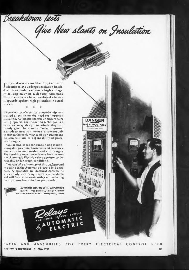
service
DANGERHIGH VOLTAGE
NEED229ELECTRONIC INDUSTRIES « May, 1944
In special test rooms like this. Automatic Electric relays undergo insulation break
down tests under extremely high voltage. From long study of such tests. Automatic Electric engineers have developed effective safeguards against high potentials in actual
- AUTOMATIC ELECTRIC SALES CORPORATION ‘ 1033 West Van Burén St., Chicago 7, llliaois!<• Cañada Automatic tl.ciric ( Cañada) Limited, Tarante
\\ hen war uses of electrical control equipment focused attention on the need for improved insulation, Automatic Electric engineers were well prepared. For insulation technique is a factor in relay design to which they had already given long study. Today, improved methods to meet wartime needs have not only improved the performance of war equipment, but also will add to dependability of peacetime designs.
Similar studies are constantly being made of spring design, contact materials and pressures, magnetic circuits, finishes and coil designs. The resulting experience is one basic reason why Automatic Electric relays perform so dept ndably under tough conditions.
You can take advantage of this background b\ calling in the Automatic Electric field engineer. A specialist in electrical control, he works daily with designers of war products, and will be glad to work with you in selecting the apparatus best suited to your needs.
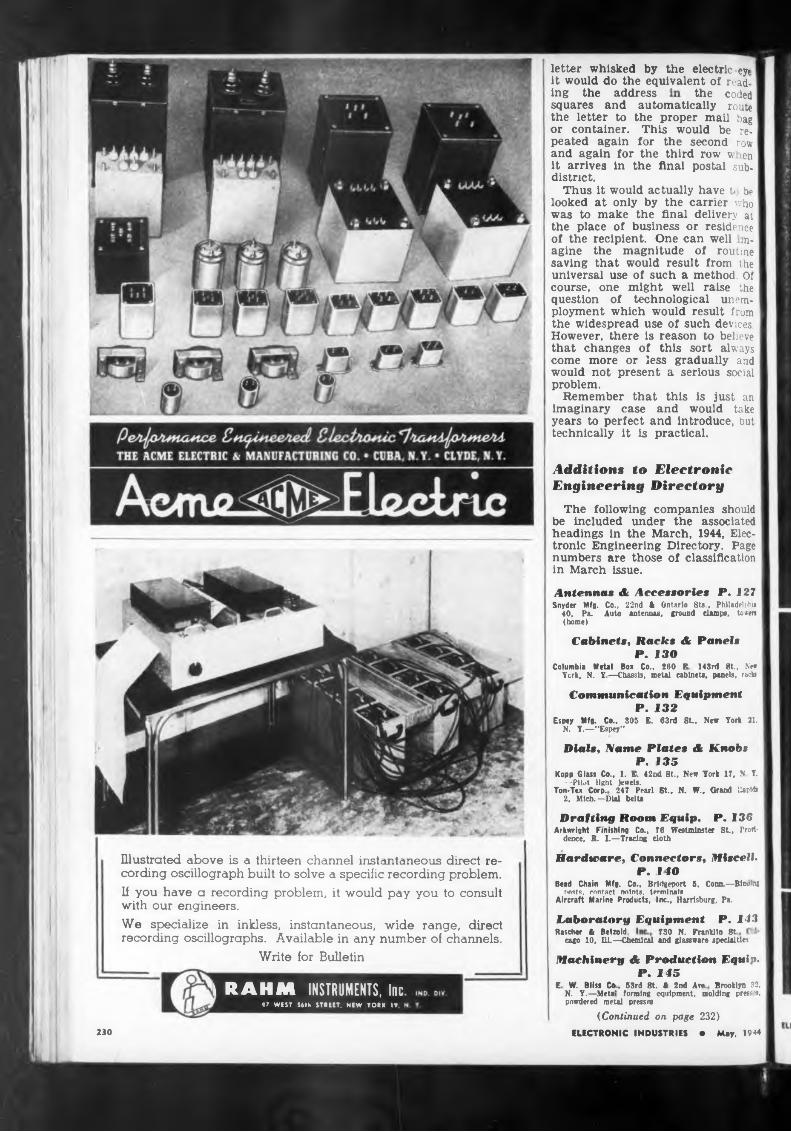
the coded
Laboratory Equipment P. 143Rascher & Betzold, 730 N. Franklin St.
cago 10. HL—Chemical and glassware specialties
Write for Bulletin
(Continued on page 232)230
letter whisked by the electric -eyi it would do the equivalent of read-ing the address
The following companies should be included under the associated headings in the March, 1944, Electronic Engineering Directory. Page numbers are those of classification in March issue.
Drafting Room Equip. P. 136Arkwright Finishing Co., 76 Westminster SL, Provi
dence, B. L—Tracing cloth
ELECTRONIC INDUSTRIES • May. 1944
squares and automatically route the letter to the proper mail bag or container. This would be repeated again for the second row and again for the third row v ten it arrives in the final postal subdistrict.
Thus it would actually have t be looked at only by the carrier vho was to make the final delivery at the place of business or residence of the recipient. One can well m- agine the magnitude of routine saving that would result from the universal use of such a method. Of course, one might well raise the question of technological unemployment which would result from the widespread use of such devices. However, there is reason to believe that changes of this sort always come more or less gradually and would not present a serious social problem.
Remember that this is just an imaginary case and would take years to perfect and introduce, but technically it is practical.
Additions to Electronic Engineering Directory
machinery & Production Equip. P. 145
E W. Bliss Co. 53rd 8t. < 2nd Are. Brooklyn 32. N. Y.—Melo' forming equipment, molding press's, powdered metal presses
Antenna« & Accessorie« P. 127Snyder Mfg. Co., 22nd A Ontario Sts., Philadelphia
40, Pa. Auto antennas, ground damps, tonen (home)
Illustrated above is a thirteen channel instantaneous direct recording oscillograph built tc solve a specific recording problem. If you have a recording problem, it would pay you to consult with our engineers.We specialize in inkless, instantaneous, wide range, direct recording oscillographs. Available in any number of channels.
Hardware, Connectors, Miscell. P. 110
Bead Chain Mfg. Co., Bridgeport 5, Corm.—Binong nosts. contact nolnts. terminals
Aircraft Marine Products, Inc., Harrisburg, Pa.
Cabinets, Racks & Panels P. 130
Columbia Metal Box Co., 260 E 143rd St., Ne«York. N. Y—Chassis, metal cabinets, panels, ratte
Dials, Name Plates & Knabs P. 135
Kopp Glass Co., 1. E. 42nd St., New Tork 17, N Y.—Pilot light jewels.
Ton-Tex Corp. 247 Pearl St„ N. W., Grand lUpi* 2, Mich.—Dial belU
Communication Equipment P. 132
Espey Mfg. Co., 305 E. 63rd SL. New Tork 21. N. Y.—“Espey"
I RAHM INSTRUMENTS, Incer west san st«eet. new roux i«. i
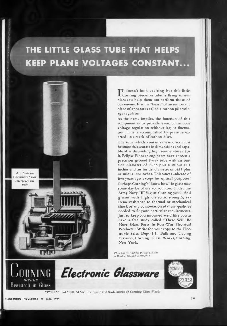
ük A -4 A. M R.
231
Photo Courtesy Eclipse-Pioneer Ditmin of Bendix Aviation Corporation
ELECTRONIC INDUSTRIES • May, 1944
‘PYREX” and “CORNING” are registered trade
Available forGovernment uar
emergency use
IT doesn’t look exciting but this little Corning precision tube is flying in our
planes to help them out-perform those of our enemy. It is the "heart” of an important piece of apparatus called a carbon pile voltage regulator.As the name implies, the function of this equipment is to provide even, continuous voltage regulation without lag or fluctuation. This is accomplished by pressure exerted on a stack of carbon discs.The tube which contains these discs must be smooth, accurate in dimensions and capable of withstanding high temperatures. For it, Eclipse-Pioneer engineers have chosen a precision ground Pyrex tube with an outside diameter of .6245 plus 0 minus .001 inches and an inside diameter of .435 plus or minus .002 inches. Tolerances unheard of five years ago except for optical purposes! Perhaps Corning’s "know how” in glass may some day be of use to you, too. Under the Army-Navy "E” flag at Corning you’ll find glasses with high dielectric strength, extreme resistance to thermal or mechanical shock or any combination of these qualities needed to fit your particular requirements. Just to keep you informed we’d like you to have a free study called "There Will Be More Glass Parts In Post-War Electrical Products.” Write for your copy to the Electronic Sales Dept. 1-5, Bulb and Tubing Division, Corning Glass Works, Corning, New York.
THE LITTLE GLASS TUBE THAT HELPSKEEP PLANE VOLTAGES CONSTANT
jOKMMmeans
esrarch in lilas

York
tion
Harris burs
not slavescreative engineering skill and
an oil impreg
Ehrenhaft’s
Pat Pending
ELECTRONIC INDUSTRIES232
AircraftCable
Thomas
these conditions no bubbles were formed and no movement of the liquid in the magnetic field took place. However, if water was slowly I poured into the solution, thus providing an non-uniform concentration of ferrous chloride, movement of the liquid in the magnetic field did occur. If the addition of water was stopped, the motion gradually died away as the concentration of ferrous chloride regained uniformi-
Motor* & Generator* P. 150
Wire & Cable P. 164
ferrous chloride. Under
‘The account
Marine Products, connectors& Betts Co., Im
Columbia Wire & Supply Co., 4106 N Pulaski Rd Chicago 41, Ill.—Cord sets, cables, radio harness
BUY
BONDS
Waugh Laboratories, 420 Lexington Ave., New 17, N. Y.—Magnetic measuring equipment
"The movement of the liquid un-1 der the conditions above described I can be explained very easily. It is I due to the action of the strong,! non-uniform magnetic field on the! non-uniform concentration of pa-1 ra-magnetic ferrous ions. The parts I of the liquid containing a high! concentration of ferrous ions will tend to move In the strongest parts I of the field. In confirmation of I this, a number of other electrolytes I were tried, both with waxed and unwaxed pole-pieces. No movement! was observed with potassium chlor-1 ide or cadmium sulphate under any j conditions. Movement was observed! with ferrous sulphate, ferric chloride, and nickel sulphate under conditions of non-uniform concentrations.
These experiments demonstrate conclusively that the general movement of the liquid, disclosed by I refractive index striations, depends essentially on the presence of ferrous or other ions of high magnetic1 susceptibility. We wished to be sure that the movement of the bubbles formed at the unprotected ion polepieces was also due to the move-
the DU-
The Egyptian Pyramids stand majestically, through the ages, as mute witnesses to the skill and rugjed craftsmanship of the thousands of slaves whc
J. T. Kendall of the Research Department, Metropolitan-Vickers Co., repeated the experiments on which Prof. Ehrenhaft bases his claim: establishment of the existence of magnetic current. The following report of Mr. Kendall’s findings and conclusions, which he again verified by further investigations, have been reported in Nature, London:
claim to have discovered a magnetic current which appeared in the daily Press of January 17, is very brief and possibly inexact. However, it appeared to be so completely contrary to the fundamental conceptions of electricity and magnetism, that thoughtful readers must search their minds for other interpretations of the experimental phenomena he is reported to have observed. Accordingly, we at once set up apparatus to repeat the experiments which the Press had described.
"The soft iron pole-pieces of a powerful electro-magnet were immersed in dilute hydrochloric acid. The pole-pieces were soldered to a brass block to ensure that the experiments could not be vitiated by the passage of unsuspected leakage currents through the liquid.
"A fine stream of bubbles was given off at each pole, and when
TO- but
On Ehrenhaft9» Magnetic Current
the magnetising current was I switched on, the streams of bubbles tended to be deflected into the I space between the poles, which was 1.5 mm. wide. Some of the bubbles were deflected downwards, ag nSt their buoyancy. Close observation I showed that the motion of the bubbles was apparently caused by the motion of the liquid as a w :ole | Small inequalities of concentra on, I which are shown up as refractive index striations, permit any motion of the liquid to be recognized. Under the influence of the magnetic field, a steady streaming of the liquid from the pole faces into the centre of the gap and the consequent setting up of rotary currents in the liquid were observed. The streams of bubbles were entrained and carried along with this movement, and their motion was mainly controlled by it.
“Confirmation of this motion of the liquid was obtained by repeating the experiment with the polepieces covered with a film of paraffin wax, and Immersed in a solu-
willing hands achieved same result with the new
Bead Chain Mfg. Co, Bridgeport 5, Conn—Base pins, tube seal leads
Correction* to Alphabetical Index Page 166
nated oil sealed capacitor that gives assured “LONGER LIFE” for continuous opera* tion. ... Its special features and construction are exclusive features with Dumont.
Explanation and control experiment*
Follansbee Steel Corp., 3rd It Liberty Ave., Pittsburgh 30, Pa.—Lamination’
Great Metal Mfg. Corp., 9 Wyckoff Ave., Brooklyn N. Y.—Metal stampings
Small Motors, Inc., 1308-22 Elston Ave., Chicago 22. Ill.—Miniature control and blower motors
Universal Electric Co., 300 E. Main St., Owosso, Mich Miniature control motors
Measuring Instrument* P. 146Rascher & Belzold, Inc., 730 N. Franklin St , Chl-
ragn 10, Ill.—Thermometers, hygrometers, PH meters
•ectnr«Callite Tungsten Corp., Union City, N. J.—Contact
points, tungstenWaugh Laboratories, New York, N. Y.—Measurir.;
instruments
Sound Systems P. 158Springfield Sound Co., 12 Cass St, Springfield
Mass.—Sound systems
Suitable for Operation Up to 300 FOil Impregnated—Oil Filled OH SealedCeramic or Bakelite Tube* Bakelite Cement End» I OH Proof IIdeal for Extreme HighAltitude DutyNo Danger of “Flash Over"No Metal for "Body Capacity" No Internal Corrosion
Metal for Radio P. 148Allegheny-Ludlum Steel Corp., Pittsburgh 22, Pa —
Laminations, electrical alloysCallite Tungsten Corp., 558 39th St., Union City
N. J.—Tungsten
oLonaer oL.ife
DUE TO ITS CONSTRUCTION
DUMONT ELECTRIC CO.CAPACITORS FOB f V f R r I I Q .1 * I * I N T
)4 HUBERT k T * 11T
NIW YORK N V
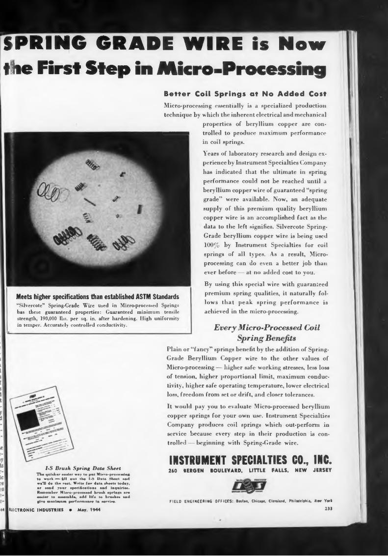
SPRING GRADE WIRE is Nowthe First Step in Micro-Processing
Meets higher specifications than established ASTM Standards “Silvercote” Spring-Grade Wire used in Micro-processed Springs has these guaranteed properties: Guaranteed minimum tensile strength, 190,000 lbs. per sq. in. after hardening. High uniformity in temper. Accurately controlled conductivity.
FIELD ENGINEERING OFFICES Boston, Chicago, Clcnlant, Philadelphia, New York
233
By using this special wire with guaranteed premium spring qualities, it naturally follow-. that peak spring performance is achieved in the micro-processing.
f-S Brush Spring Data Sheet The quicker easier way Io put Mirtu- prurr^inc tu work — fill out the I-S Data Sheet sad we’ll do the rest. Write lor data sheets today, or send your specifications and inquiries. Remember Micro-processed brush sprinpa are racier to assemble, add life to brushes and give maximum performance in service.
ELECTRONIC INDUSTRIES • May, 1944
INSTRUMENT SPECIALTIES CO., INC.260 BERGEN BOULEVARD, LITTLE FALLS, NEW JERSEY
It would pay you to evaluate Microprocessed beryllium copper springs for your own use. Instrument Specialties Company produces coil springs which out-perform in service because every step in their production is controlled — beginning with Spring-Grade wire.
Plain or “fancy” springs benefit by the addition of SpringGrade Beryllium Copper wire to the other values of Micro-processing — higher safe working stresses, less loss of tension, higher proportional limit, maximum conductivity, higher safe operating temperature, lower electrical loss, freedom from set or drift, and closer tolerances.
Every Micro-Processed Coil Spring Benefits
Better Coil Springs at No Added Cost Micro-processing essentially is a specialized production technique by w hicli the inherent electrical and mechanical
properties of beryllium copper are con-MMMMM trolled to produce maximum performance
in coil springs.
Years of laboratory research and design experience by Instrument Specialties Company has indicated that the ultimate in spring performance could not be reached until a beryllium copper wire of guaranteed “spring grade” were available. Now, an adequate supply of this premium quality beryllium copper wire is an accomplished fact as the data to the left signifies. Silvercote SpringGrade beryllium copper wire is being used 100% by Instrument Specialties for coil springs of all types. As a result, Microprocessing can do even a better job than ever before — at no added cost to you.
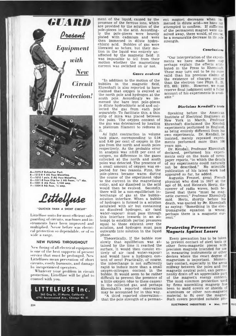
GUARO
Equipment
with
New
Circuit
A—1075-F Extractor PostF—1212-8 4 AG Fuse Mounting.C—1010 1 pole, 8 AG Fuse Mounting.D—1011-B Fuse Clip for 3 AG Fuses, Ve" dia.E—1001 8 AG Fuse. 1/100 amp.F—1004 8 AG Fuse, •/• amp.
Protection!
"QUICKER THAN A SHORT CIRCUIT"
Littelfuse units for most efficient safeguarding of circuits, machines and instruments have been improved and multiplied. Never before was electrical protection so dejiendable. or of so wide a range.
NEW FUSING THROUGHOUTNew fusing of all electrical equipment is one of the best supports of present service that must be prolonged. New Littelfuses mean prevention of short circuits, costly burnouts, and damage by inexperienced operators.
W hatever your problem in circuit protection, Littelfuse will be glad to counsel with you.
LITTELFUSE Inc.263 Ong Si . El Monte, California
4793 Ravenswood Ave., Chicago 40, III.
234
ment of the liquid, caused by the presence of the ferrous ions, which are provided by the solution of the pole-pieces in the acid. Accordingly the pole-pieces were heavily plated with cadmium and were then immersed in dilute hydrochloric acid. Bubbles of gas were liberated as before, but their motion in the liquid was entirely unaffected by the magnetic field: it was impossible to tell from their motion whether the magnetising current was switched on or not.
Gases evolved
“In addition to the motion of the bubbles in the magnetic field, Ehrenhaft is also reported to have claimed that oxygen is evolved at the north pole and hydrogen at the south pole. Accordingly we immersed the bare iron pole-pieces in dilute hydrochloric acid and collected the gas from each pole separately. To facilitate this, a thin strip of mica was placed between the poles. The oxygen content of the gas was determined by heating a platinum filament to redness in it.
As light contraction in volume took place, corresponding to 0.54 and 0.49 per cent of oxygen in the gas from the north and south poles respectively. As the probable error in analysis was ±0.03 per cent of oxygen, no difference in the gases collected at the north and south poles was detected. The presence of a small amount of oxygen was expected for two reasons. First, the pole-pieces became warm during the course of the experiment (due to the current in the magnetising coils), and air dissolved in the acid would then be evolved. Secondly, there will be a non-equilibrium interchange of gas at the bubblesolution interface. When a bubble of hydrogen is formed in a solution saturated with air but containing no dissolved hydrogen, air (and water-vapour) must pass through this interface inwards in an attempt to establish partial pressures equal to those existent over the solution, and hydrogen must pass outwards into solution in the liquid phase.
Theoretically, if the bubble rose slowly that equilibrium was attained by the time it reached the surface, it would then consist entirely of air (and water-vapour) and would have a hydrogen content of zero! Practically, of course, the interchange is not sufficiently rapid to induce more than a small oxygen-nitrogen content In the bubble. It would seem to be rather difficult to prevent the presence of a little oxygen (due to these causes) in the collected gas, and perhaps Ehrenhaft’s reported observation may be accounted for in this way.
“A third reported observation— that the pole strength of a perman-
ent magnet decreases when immersed in dilute acid—we have not attempted to confirm. If suffic.ent of the permanent magnet were dissolved away, there would, of course, be a measurable decrease in its pole strength.
Conclusion«
“Our interpretation of the experiments we have made here may perhaps explain the effects attributed in the Press to Ehrenhaft. These may turn out to be no more valid than his previous claims of the existence of charges smaller than the electron (see Phys. Z 21, 675, 683; 1920). However, we must reserve final judgment until a fuller account of his experiments is available.”
Disclaims Kendall's tests
Speaking before the American Institute of Electrical Engineers at New York in March, Professor Ehrenhaft disclaimed the Kendall experiments performed in England, as being entirely different from his own experiments. Dr. Kendall, he Insisted, merely repeated experiments performed more than 100 years ago. .
Dr. Kendall, Professor Ehrenhaft declared, performed his experiments only on the basis of newspaper reports, “in which the details of my experiments could naturally not be described.” No scientific publication of his latest work had appeared so far, he added.
Augustin Fresnel, great French physicist who died in 1827 at the age of 39, and Heinrich Hertz, discoverer of radio waves, both believed that there “must be magnetic current,” Professor Ehrenhaft said. Hertz, shortly before his death, was quoted by Dr. Ehrenhaft as saying: “Something in the electromagnetic equation is wrong; perhaps there is a magnetic current.”
Protecting Permanent Magnets Against Losses
Every precaution has to be taken | to prevent contact of steel tools or other ferro-magnetic pieces with precision magnets intended for use in measuring instruments or other devices where the exact degree of magnetism is important. Momentary contact, especially in the areas midway between the poles and the magnetic neutral point, can permanently drain off an appreciable part of the magnet’s energy content. The most common protection used by firms assembling magnets has been to mold covers or shields of aluminum or other non-magnetic material to fit over the magnet. Such covers provided suitable pro-
ELECTRONIC INDUSTRIES • May, 1944 tuc
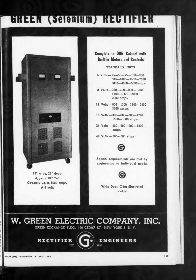
eienium
STANDARD UNITS
235
Complete in ONE Cabinet with Built-in Meters and Controls
Special requirements are met by engineering to individual needs.
Volts—300—600 amps.
42" wide. 24" deep Approx. 81" Tall
Capacity up to 5000 amps, at 6 volts Write Dept. C for illustrated
booklet.
Volts—600—1200—1800—24003000 amps.
6 Volts—25—50—75—100—300 500—1000—1500—2000 3000—4000—5000 amps.
8 Volts—300—600—900—1200 1800—2400—3000 3600 amps.
Volts—300—600—900—1200 amps.
Volts—300—600—900—1200 1500—1800 amps.
ELECTRONIC INDUSTRIES • May. 1944
W. GREEN ELECTRIC COMPANY, INCGREEN EXCHANGE BLDG.. 130 CEDAR ST. NEW YORK 6, N. Y.
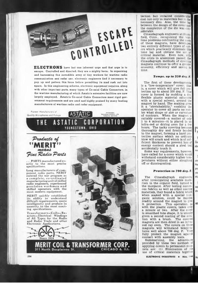
Temps, up to 350 deg. F.
met
Protection to 700 deg. F.
skilled!ern equipmentmost nn
Since 1924
23«
The first of these developmentis a “low-temperature” cover; that is, a cover which will give full protection up to about 350 deg. F. This cover is formed by molding a dry, flexible plastic material saturated with a special solvent, around the magnet by hand. The soaking give- it a “stretchability,” enabling the operator to cover all parts no matter what shape or size or curvature of contours. When the magnet is suitably covered—a matter of only 2 to 4 minutes—it is placed in an' infra-red or drying oven for a few hours. The tacky covering becomes thoroughly dry and firmly bonded to the magnet, forming a hard protective surface which no ordinary blow will crack and which is of sufficient thickness to prevent loss of energy content should a steel tool accidentally touch it.
Some war requirements, however, have called for a cover which would withstand considerably higher temperatures without either sloughing off or disintegrating.
tection but entailed considerable cost not only in materials but in the necessary dies. Also, the time lag between the design of the cover and the completion of the die was con-' siderable.
Cinaudagraph engineers at Stamford, Conn., recognizing the wartime problems confronting the users of these magnets, have developed two entirely different types of covers which practically eliminate this time lag and obviate the use of critical material. Even now, with the crisis in aluminum passed, the Cinaudagraph methods of covering magnets continue to offer a greater economy, efficiency and saving in time.
The Cinaudagraph engineers, after investigating available materials in the organic field, turned to the inorganic. After testing numerous fabrics as well as other coating materials, they found a fabric which when soaked with a special inorganic solution, could be molded I readily around the magnet to give it protection. This operation, as with the plastic covers, takes only a minute or two. After the cover is smoothed into shape, it is usually given a second coating of the solution with a brush. The covered magnets are then dried in an infra-| red ray oven. The covers on these magnets will withstand temperatures well above 700 deg. F. They fully protect the magnet against contact with assembly tools.
Summarizing, the advantages provided by these two methods of applying covers to permanent magnets are: (1) Elimination of the use of critical materials together
ELECTRONIC INDUSTRIES • May, 1944
"MERIT”kite fëadài Ponte
.. . PARTS manufactured exactly to the most precise specifications.Long manufacturers of component radio parts, MERIT entered the war program as a complete, co-ordinated manufacturing unit of skilled
Pioneer Manufacturers ofQuality Microphones and Pickups
ELECTRONS have but one inherent urge and that urge is to escape. Controlled and directed, they are a mighty force. In organizing and harnessing thin incredible army of tiny workers for wartime radio communication and radar use, electronic engineers find it necessary to pep up and pattern this force before permitting its mad rush out into space. In this engineering scheme, electronic equipment requires, along with other important parts, many types of Co-axial Cable Connectors, in the wartime manufacturing of which Astatic's extensive facilities are now largely employed. Astatic's Co-axial Cable Connectors meet rigid government requirements and are used and highly praised by many leading manufacturers of wartime radio and radar equipment.
MERIT quickly established its ability to understand difficult requirements, quote intelligently and produce in quantity to the most exacting specifications.Transformers—Coils—Reactors—Electrical Windings of All Types for the Radio and Radar Trade and other Electronic Applications.
MERIT COIL & TRANSFORMER CORP
STEWART STAMPING COMPANY421 E. 2UHi 5fr..f
ELECTRONIC INDUSTRIES 217
The Stewart Line gives you the assurance of outstanding Quality, both in material and fabrication. And, over and above Quality, it gives you a Service that interprets and meets your individual needs.
blue print» and tpocifien- tian». Quick Kotponta tn
Inquiria».
411 piana» ran ba furnitkad in any dettrcd finith
Sand for »ampla» and quo-
Stewart Service is the friendly voice at the other end of your phone. It is the intelligent answer to your inquiry. It is the engineering experience that helps you to work out your problems. It is the co-operation that gets fast action when you are in a jam. Lastly, it is efficiency and promptness in shipping your orders.
Stewart SERVICE — invisible, yet a thing of tremendous weight on the scales of business, particularly under Wartime stress — put it to the test!
IN any product, Quality is the first consideration. Bui ' beyond that — invisible yet highly important — is Service We carry hundreds of items
in stock to meet practically every installation requirement.
Odd shaped pieces stamped and formed from strip or wire on high speed machines.
Our Tool Room is equipped to make dies for your special needs.
HOT TINNINGNICKEL, CADMIUM,
SILVER AND ZINC PLATING
IT. TOO, HAS WEIGHT
SERWCE
I
V
ELEC238
EXCEL
3571 W. 62nd. St. CLEVELAND 2, OHIO
V
Specialists. . . in Assembly and sub-assembly of Precision Electronic Products
• Complete Facilities for Production and Testing of Audio Equipment
• Consult us with your Production /Xssembling ProblemsRADILI
CORPORATION
6323-27 GUILFORD AVENUE, INDIANAPOLIS 5, INDIANA
4. SEASONED PRODUCTIONRADIART VIBRATORS and VIPOWERS give ragged, dependable service under all sorts of conditions because they have achieved seasoned production through years of painstaking developments.Carefully engineered improvements, checked by millions of vibrators in actual operation, have perfected RADIART VIBRATORS and VIPOWERS and have given them wide recognition for unexcelled per
formance.The Army, Navy and Signal Corps recognize that performance as evidenced by their large demands for RADIART PRODUCTS for use on all battle
fronts.
with the time lag and expense qulred for making the necedies; (2) speed of application; ij' ease of application even with thmost intricate of magnet design (4) toughness of cover.
Senate Studies Radio Train Control
Considerable impetus to the use of radio communications by railroads for dispatching and safety purposes was viewed as a likely result from testimony before the Senate Military Affairs Subcommittee on War Mobilization, headed by Senator Kilgore (D., W. Vaj. it was generally felt, however, that the railways need to program their communications operations with a greater degree of coordination and cooperation between the carriers in order to achieve improved operating methods and equipment, both in their wire facilities, telephone and telegraph, which are now in use, and in any projected expansion of radio communications, especially using the radiotelephone on FM bands.
Two experts gave their views on the potentialities of radio communication’s use by the railroads. One was the new FCC Commissioner, E. K. Jett, who was making his final appearance before a Congressional committee in his previous capacity of Chief Engineer, and in an executive session of the Senate body was understood to have pointed out that the FCC would be most sympathetic towards the consideration of a general and coordinated plan for frequency assignment to railroads in this service. The other was William S. Halstead, president of the Halstead Traffic Communication Corp, of New York, who stated Feb. 11 that radio communication equipment is available now for use in railroad freight yards and within 3 to 6 months should be ready for installation along railroad main lines.
Mr. Jett, who was accompanied by FCC Safety Services Division Chief William Krebs, Assistant General Counsel Harry Plotkin and FCC Engineer Glenn West, was understood to have given a complete historical background of the experiments in radio communications by railroads. Mr. Jett also gave his views on the frequency situation in the postwar period.
Radiart Corporation
Increased safety factor
Senator Kilgore indicated also that his own subcommittee would prepare in the near future a report to the Senate recommending the feasibility of radio communications in the railroad field.
In his testimony before the Senate subcommittee, Mr. Halstead emphasized that the wartime applica-
ELECTRONIC INDUSTRIES • May, 1944
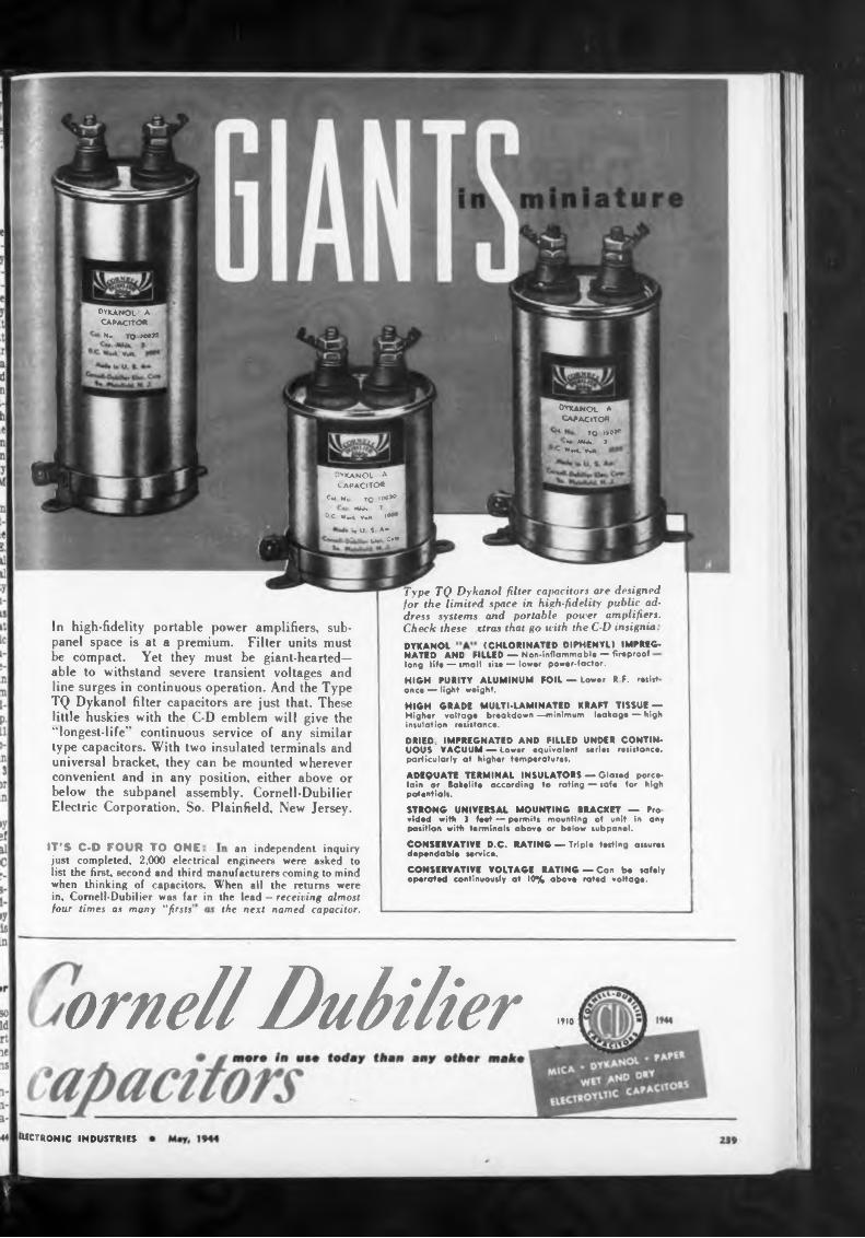
(CHLORINATED DIPHENYL) IMPREG-DYKANOL
IT’S C-D FOUR TO ONE
the next named capacitor.
ornell Dubilier 1*10
electronic industries
HIGH GRADE MULTI-LAMINATED KRAFT TISSUE — Higher voltage breakdown —minimum leakage — high insulation resistance.
four times ax many ''firsts'
an independent inquiry
HIGH PURITY ALUMINUM FOIL — Lower R F. resist once — light weight.
Type TQ Dykanol filter capacitors are designed for the limited space in high-fidelity public address systems and portable power amplifiers. Check these ctras that go with the C-D insignia
NATED AND FILLED — Non-inflammable — fireproof long life — small sixe — lower power-factor.
just completed, 2,000 electrical engineers were asked to list the first, second and third manufacturers coming to mind when thinking of capacitors. When all the returns were in, Comell-Dubilier was far in the lead — receiving almost
In high-fidelity portable power amplifiers, subpanel space is at a premium. Filter units must be compact. Yet they must be giant-hearted— able to withstand severe transient voltages and line surges in continuous operation. And the Type TQ Dykanol filter capacitors are just that. These little huskies with the C-D emblem will give the “longest-life" continuous service of any similar type capacitors. With two insulated terminals and universal bracket, they can be mounted wherever convenient and in any position, either above or below the subpanel assembly. Comell-Dubilier Electric Corporation, So. Plainfield, New Jersey.
DYKANOL A
capacito«N. TQ 300*’
dykanol a capacito«
ÍH N, TQ l<X»O
Md* 1 , ° c w^. v,» iM*
.. u 1 *• i kw O’
DRIED. IMPREGNATED AND FILLED UNDER CONTINUOUS VACUUM — Lower equivalent series resistance, particularly at higher temperatures.
ADEQUATE TERMINAL INSULATORS — Glaxed porcelain or Bakelite according to rating —safe for high potentials.
STRONG UNIVERSAL MOUNTING BRACKET — Pro vided with ) feet — permits mounting of unit in any position with terminals above or below subpanel.
CONSERVATIVE O.C. RATING — Triple testing assures dependable service.
CONSERVATIVE VOLTAGE RATING — Can bo safety operated continuously at 10% above rated voltage.
dykanol * capacito«
*■ TQ 110*' W MÍA i
- »«»VW
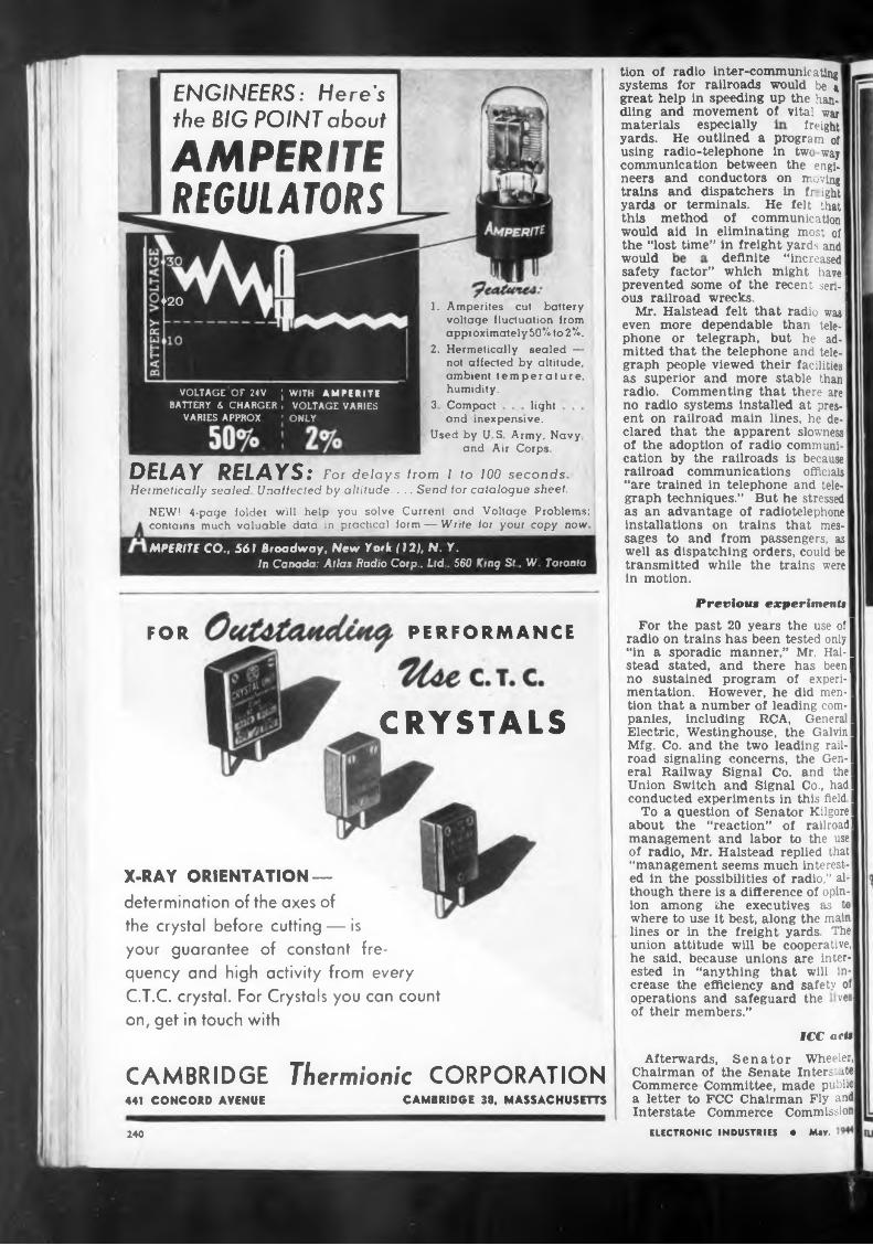
freight
would
3 Compact light
Previous experiment*
PERFORMANCEFOR
CRYSTALS
ICC act»
CAMBRIDGE Thermionic CORPORATIONCAMBRIDGE 38, MASSACHUSETTS441 CONCORD AVENUE
240
NEW! 4-page folder will help you solve Current and Voltage Problems; contains much valuable data in practical form — Write tor your copy now
materials especially
Afterwards, Senator Wheeler, Chairman of the Senate Inters' ite Commerce Committee, made public a letter to FCC Chairman Fly and Interstate Commerce Commission
tion of radio inter-communicating systems for railroads would be & great help in speeding up the handling and movement of vital war
definite “increasedsafety factor” which might have prevented some of the recent serf-1 ous railroad wrecks.
Mr. Halstead felt that radio was I even more dependable than telephone or telegraph, but he admitted that the telephone and telegraph people viewed their facilities as superior and more stable than radio. Commenting that there are no radio systems installed at present on railroad main lines, he de-1 dared that the apparent slowness of the adoption of radio communication by the railroads is because railroad communications officials “are trained in telephone and telegraph techniques.” But he stressed as an advantage of radiotelephone installations on trains that messages to and from passengers, as well as dispatching orders, could be transmitted while the trains were in motion.
yards. He outlined a program of using radio-telephone in twc way communication between the engineers and conductors on moving trains and dispatchers in fr ight yards or terminals. He felt that this method of communication would aid in eliminating most of the “lost time” in freight yards and
DELAY RELAYS: For delays from I to 100 seconds Hermetically sealed Unaffected by altitude. . .. Send for catalogue sheet.
For the past 20 years the use of I radio on trains has been tested only I “in a sporadic manner,” Mr. Hal-1 stead stated, and there has been! no sustained program of experi-I mentation. However, he did men-1 tion that a number of leading com-I panies, including RCA, Genera I Electric, Westinghouse, the Galvin I Mfg. Co. and the two leading rail-1 road signaling concerns, the Gen-1 eral Railway Signal Co. and th el Union Switch and Signal Co., had I conducted experiments in this field I
To a question of Senator Kilgore I about the “reaction” of railroad! management and labor to the use of radio, Mr. Halstead replied that “management seems much interested in the possibilities of radio,” although there is a difference of opinion among the executives as to where to use it best, along the main lines or in the freight yards The union attitude will be cooperative, he said, because unions are interested in “anything that will increase the efficiency and safety of I operations and safeguard the vesl of their members.”
and inexpensive.Used by U S Army, Navy
and Air Corps
ELECTRONIC INDUSTRIES • May,
1. Amperites cut battery voltage fluctuation from approximately50%to2%.
2. Hermetically sealed — not affected by altitude, ambient temperature, humidity.
AMPERITEREGULATORS
ENGINEERS: Here's the BIG POINT about
X-RAY ORIENTATION —determination of the axes of the crystal before cutting — is your guarantee of constant frequency and high activity from every C.T.C. crystal. For Crystals you can count on, get in touch with
420
MPERITE CO., 561 Broadway, New York (12), N. Y.In Canada: Atlas fíadio Corp.. Ltd . 560 King St, W Toronto
VOLTAGE or 24 V J WITH AMPERITEBATTERY 6 CHARGER , VOLTAGE VARIES
VARIES APPROX 1 ONLY
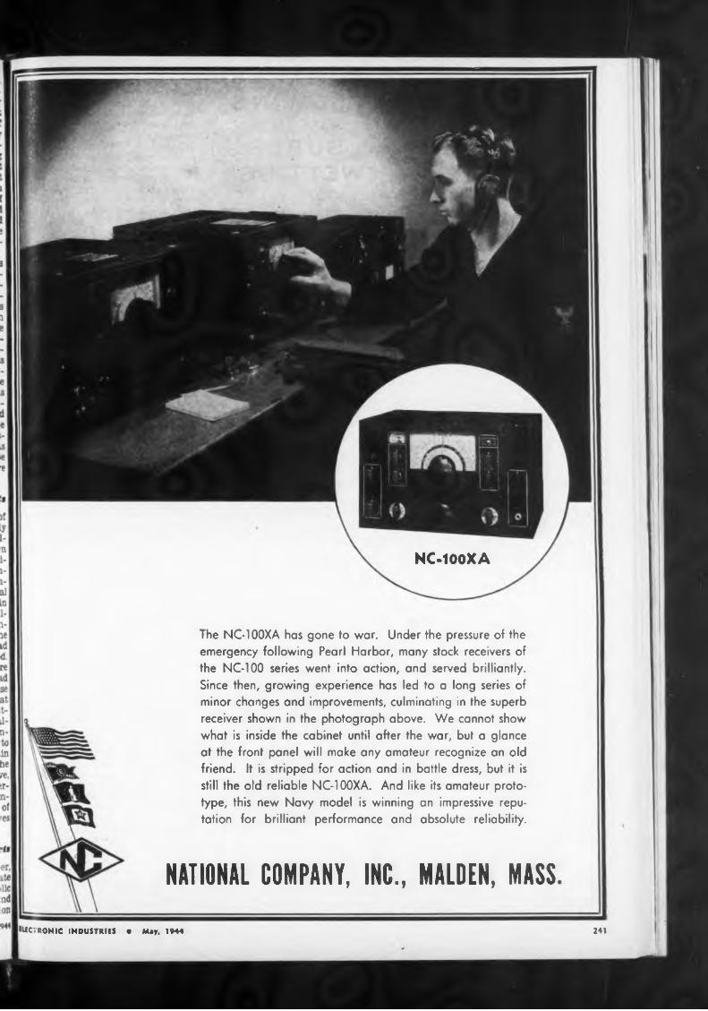
NC-100XA
NATIONAL COMPANY, INC., MALDEN, MASS241
The NC-100XA has gone to war. Under the pressure of the emergency following Pearl Harbor, many stock receivers of the NC-100 series went into action, and served brilliantly. Since then, growing experience has led to a long series of minor changes and improvements, culminating in the superb receiver shown in the photograph above. We cannot show what is inside the cabinet until after the war, but a glance at the front panel will make any amateur recognize an old friend. It is stripped for action and in battle dress, but it is still the old reliable NC-100XA. And like its amateur prototype, this new Navy model is winning an impressive reputation for brilliant performance and absolute reliability.
ELECTRONIC INDUSTRIES • May, 1944
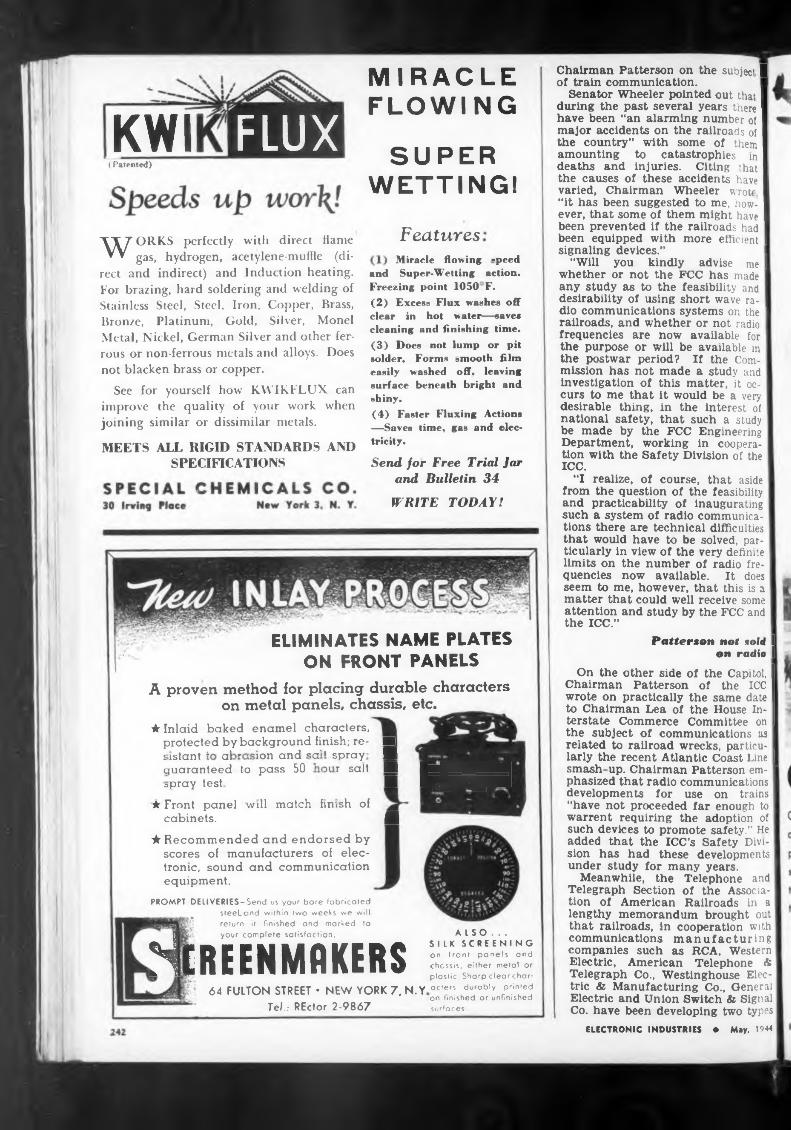
KWI( Patented)
Features
and
WRITE TODAY!
Miracle flowing -peed Super-Wetting action.
MIRACLE FLOWING
SUPER WETTING!
ELIMINATES NAME PLATES ON FRONT PANELS
MEETS ALL RIGID STANDARDS AND SPECIFICATIONS
★ Recommended and endorsed by scores of manufacturers of electronic, sound and communication equipment.
ALSO...SILK SCREENING on front panels and chassis, either metal or plastic Sharp clearcharacters durably prin’ed on finished or unfinished surfaces.
64 FULTON STREET • NEW YORK 7. N.Y Tel..- REctor 2-9867
WORKS perfectly with direct flame gas, hydrogen, acetylene-muffle (di
rect and indirect) and Induction heating. For brazing, hard soldering and welding of Stainless Steel, Steel, Iron, Copper, Brass, Bronze, Platinum, Gold, Silver, Monel Metal, Nickel, German Silver and other ferrous or non-ferrous metals and alloys. Does not blacken brass or copper.
See for yourself how KWIKFLUX can improve the quality of your work when joining similar or dissimilar metals.
Chairman Patterson on the subject 1 of train communication.
Senator Wheeler pointed out that I during the past several years there I have been “an alarming number of I major accidents on the railroads of I the country” with some of them I amounting to catastrophes in I deaths and injuries. Citing that I the causes of these accidents have I varied, Chairman Wheeler wrote I “it has been suggested to me, how- I ever, that some of them might have I been prevented if the railroads had I been equipped with more efficient I signaling devices.”
“Will you kindly advise me I whether or not the FCC has made any study as to the feasibility and desirability of using short wave radio communications systems on the I railroads, and whether or not radio frequencies are now available for the purpose or will be available in the postwar period? If the Com- I mission has not made a study and investigation of this matter, it occurs to me that it would be a very desirable thing, in the interest of national safety, that such a study be made by the FCC Engineering Department, working in cooperation with the Safety Division of the ICC.
"I realize, of course, that aside from the question of the feasibility and practicability of inaugurating such a system of radio communications there are technical difficulties that would have to be solved, particularly in view of the very definite limits on the number of radio frequencies now available. It does seem to me, however, that this is a matter that could well receive some attention and study by the FCC and the ICC.”
Freezing point 1050 F.(2) Excess Flux washes off clear in hot water—save* cleaning and finishing time.(3) Does not lump or pit solder. Forms smooth film easily washed off. leaving surface beneath bright and shiny.(4) Faster Fluxing Actions —Saves time, gas and electricity.
Send for Free Trial Jar and Bulletin 34
Patterson not sold I on radio I
On the other side of the Capitol, I Chairman Patterson of the ICC I wrote on practically the same date I to Chairman Lea of the House In- I terstate Commerce Committee on I the subject of communications as related to railroad wrecks, particularly the recent Atlantic Coast Line I smash-up. Chairman Patterson emphasized that radio communications developments for use on trains “have not proceeded far enough to warrent requiring the adoption of such devices to promote safety." He added that the ICC’s Safety Division has had these developments under study for many years.
Meanwhile, the Telephone and Telegraph Section of the Association of American Railroads in a lengthy memorandum brought out that railroads, in cooperation with communications manufacturing companies such as RCA. Western Electric, American Telephone * Telegraph Co., Westinghouse Electric & Manufacturing Co., General Electric and Union Switch & Signal Co. have been developing two types
ELECTRONIC INDUSTRIES • May. 1944
PROMPT DEUVERIES-Send us your bore fabricated _________steeLond within two weeks we will
return it finished and marked to your complete satisfaction.Hereenmrkers
A proven method for placing durable characters on metal panels, chassis, etc. _
★ Inlaid baked enamel characters, protected by background finish; re- ■ 5 intent * al r 1 ion and c-a’t spray fl guaranteed Ij pass 50 'air salt fl ^M^HflHMH|3pray test ■ H^^fl|^^Hfl
★ Front panel will match fm>sh of cabinets. fl
FLUX
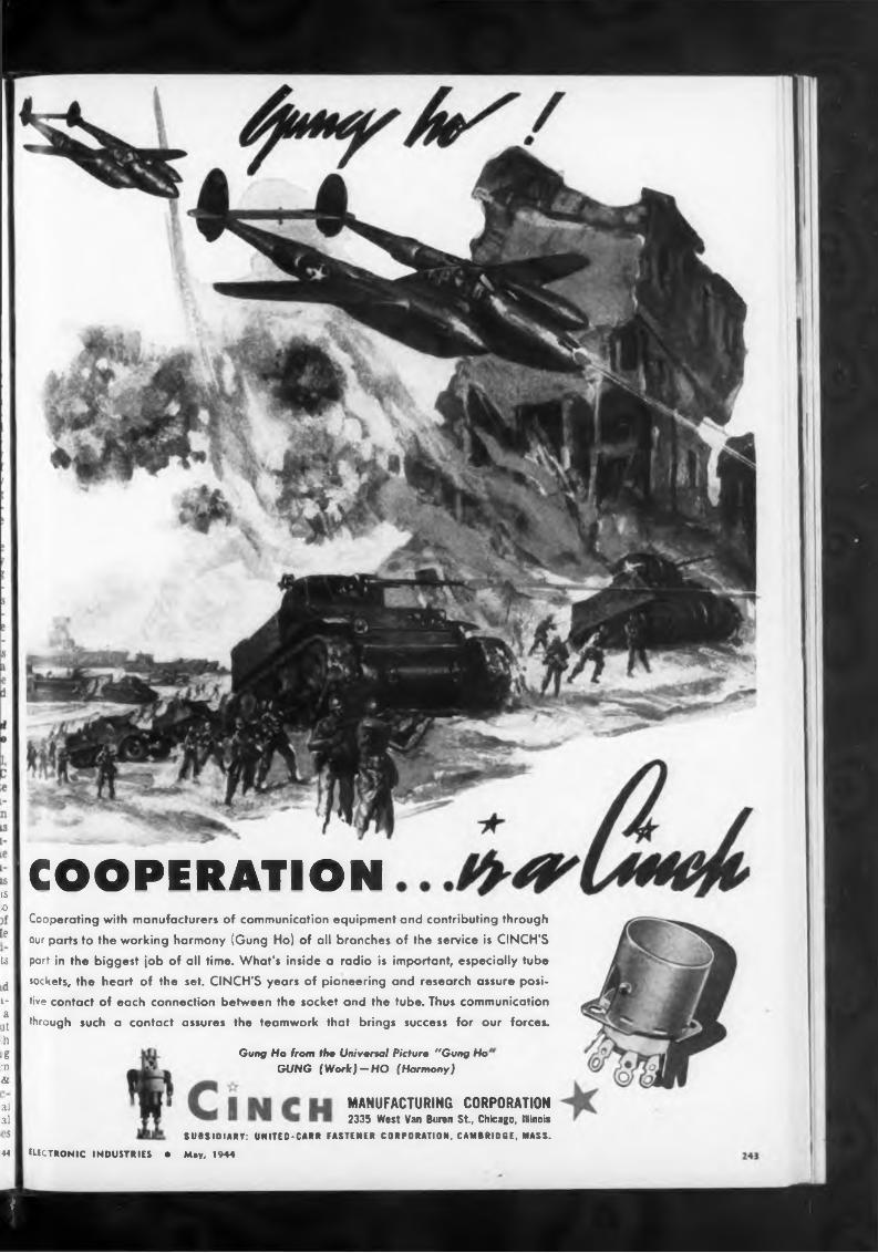
a
ts
COOPERATION
Gung Ho from tho Univenal Pitturo "Gung Ho GUNG (Work)-HO (Harmony)
S IS o
e
MANUFACTURING CORPORATION 2335 West Van Buren St, Chicago, Illinois
SUBSIDIARY: UNITEO-CARR FASTENER CORPORATION. CAMBRIDGE. MASS.
ELECTRONIC INDUSTRIES • May, 1944
d i- a .it hg
•n &
al al
844
Cooperating with manufacturers of communication equipment and contributing through
our parts to the working harmony (Gung Ho) of all branches of the service is CINCH’S
part in the biggest job of all time. What's inside a radio is important, especially tube
sockets, the heart of the set. CINCH’S years of pioneering and research assure positive contact of each connection between the socket and the tube. Thus communication
through such a contact assures the teamwork that brings success for our forces.
J
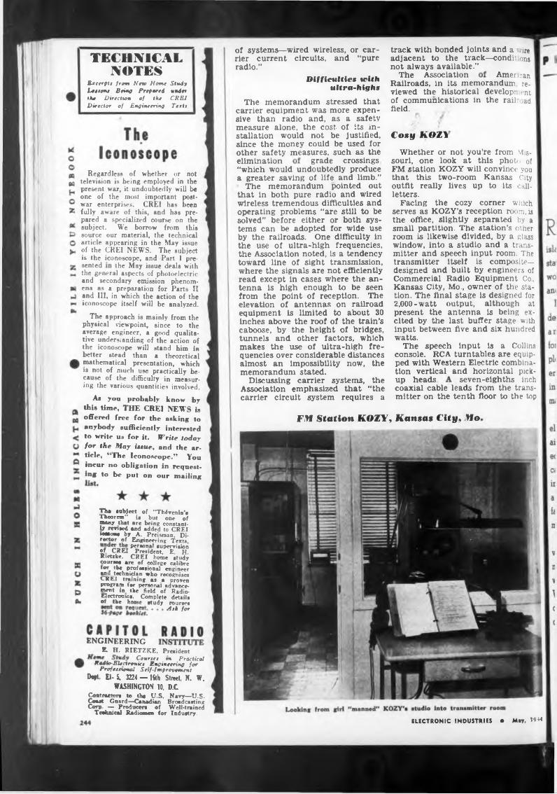
TECHNICALNOTES American
Cosy KOl\
elimination
is the iconoscope, and Part I pre-sented the May issue deals with
seven-eighths inchup heads.
FM Station KOZY, Kansas City, Mo.
ENGINEERING
coaxial cable leads from the transmitter on the tenth floor to the top
grade crossings,
track with bonded joints and a /ire adjacent to the track—condr ons not always available.”
The AssociationRailroads, in its memorandum reviewed the historical develop: ent of communications in the rail, ad field.
of systems—wired wireless, or carrier current circuits, and “pure radio.”
“which would undoubtedly produce a greater saving of life and limb.”
The memorandum pointed out that in both pure radio and wired wireless tremendous difficulties and operating problems “are still to be solved" before either or both systems can be adopted for wide use by the railroads. One difficulty in the use of ultra-high frequencies, the Association noted, is a tendency toward line of sight transmission, where the signals are not efficiently read except in cases where the antenna is high enough to be seen from the point of reception. The elevation of antennas on railroad equipment is limited to about 30 inches above the roof of the train’s caboose, by the height of bridges, tunnels and other factors, which makes the use of ultra-high frequencies over considerable distances almost an impossibility now, the memorandum stated.
Discussing carrier systems, the Association emphasized that “the carrier circuit system requires a
Difficulties with ultra-high»
Whether or not you’re from Missouri, one look at this phot/: of FM station KOZY will convince you that this two-room Kansas City outfit really lives up to its callletters.
Facing the cozy corner which serves as KOZY’s reception room, is the office, slightly separated by a small partition. The station’s other room is likewise divided, by a glass window, into a studio and a transmitter and speech input room. The transmitter itself is composite- designed and built by engineers of Commercial Radio Equipment Co., Kansas City, Mo., owner of the station. The final stage is designed for 2,000-watt output, although at present the antenna is being excited by the last buffer stage with input between five and six hundred watts.
The speech input is a Collins console. RCA turntables are equipped with Western Electric combination vertical and horizontal pick-
The memorandum stressed that carrier equipment was more expensive than radio and, as a safety measure alone, the cost of its installation would not be justified, since the money could be used for other safety measures, such as the
Study under CREI Textt
Regardless of whether or not television is being employed in the present war, it undoubtedly will be one of the most important postwar enterprises. CREI has been fully aware of this, and has prepared a specialized course on the subject. We borrow from this source our material, the technical article appearing in the May issue of the CREI NEWS. The subject
ELECTRONIC INDUSTRIES • May, 1944
Excerpts from New Home Leetom Being Prepared the Direction of the Director of Engineering
k H. RIETZKE, PresidentCourtes tn Practical
Redlo-Elertronict Engineering for Professional Self-Improvement
Dept El- 5, 3224 — IM Street. N. W.WASHINGTON 10. D.C
Coatraeton to the U.S. Navy—U.S. Coast Guard—Canadian Broadcasting Corp — Producers of Well-trained
Testali cal Radiomen for Industry.
As you probably know by thia time, THE CREI NEWS is offered free for the asking to anybody sufficiently interested to write us for it. Write today for the May isaue, and the article, “ The Iconoscope.” You incur no obligation in requesting to be put on our mailing
The subject of “Thivenin’s Theorem” is but one of many that are being constantly revised and added to CREI Masons by A. Preisman, Director of Engineering Texts,
personal supervision of CREI President, E. H. Rietzke. CREI home study courses are of (»liege calibre tor the professional engineer •»a technician who recognizes CREI training as a provenprogram tor personal advance- meat in the field of Radio- Electronics. Complete details •f the home study rourtes
Ask for
the general aspects of photoelectric and secondary emission phenomena as a preparation for Parts II and III, in which the action of the iconoscope itself will be analyzed.
The approach is mainly from the physical viewpoint, since to the average engineer, a good qualitative understanding of the action of the iconoscope will stand him ia better stead than a theoretical mathematical presentation, which is not of much use practically because of the difficulty in measuring the various quantities involved.
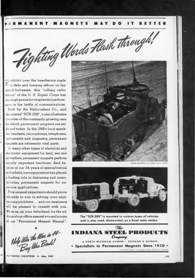
permanent magnets may do it better
The "SCR-299” is mounted in various types of vehicles and is also used, dismounted, as a fixed radio station.
Ru MB LING over the treacherous roads in Italy and lunging ashore on Jap
I island-fortresses, this "rolling radio I station" of the U. S. Signal Corps has I won high praise for its splendid perform-
’ I ance in the battle of communications, t I Built by the Hallicrafters Co., and j I designated "SCR-299", it also illustrates 1 I a number of the constantly growing uses s I for which permanent magnets are em-
I ployed today. In the 299's loud speak- I ers, headsets, microphones, telephones, i I- I instruments and magnetos, permanent
p I magnets are extremely vital parts.I In many other types of electrical and I electronic equipment for land, sea and I air warfare, permanent magnets perform
‘ I equally important functions. And be-I cause of our 34 years of specialization I in this field, our organization has played I a leading role in designing and manu- I facturing permanent magnets for nu- I merous applications.
This unusual experience should prove I valuable to you in solving your engi-
, I neering problems... and our engineers I will be pleased to consult with you. I Write us, on your letterhead, for the ad- I dress of our office nearest you and a copy I of our "Permanent Magnet Manual".
I.VDIANA STEEL PRODUCTS6 NORTH MICHIGAN AVENUE • CHICAGO 2, ILLINOIS
* Specialists in Permanent Magnets Since 1910 *COPYRIGHT 1944, THE INDIANA STEEL PRODUCTS COMPANY
ELECTRONIC INDUSTRIES • May, 1944 245
OPERATES
STANDARD DC
SHUNT MOTORS
FROM AC POWERA revolutionary variable speed DC motor control which eliminates for the first time the need for special motors when operating from AC is now available from Weltronic.Embodying all the operating features of other types of AC to DC motor controls it also eliminates the need for external transformers and reduces motor heating by a new method of tube control.
With this motor control, it is possible to operate at any desired constant speed, re-
L gardless of load, from 140 rpm to twice rated motor speed — reverse motor rotation — accelerate rapidly or "inch” the motor—brake the motor dynamically—all from a single dial control and start, stop and reverse buttons.
Also available with auto-matic multiple speed controls to provide different machine speeds in one automatic cycle.
Atk for Bulletin No. WTM-44
COMPANYDETROIT 19, MICH.
of the building five floors up, where the coaxial type antenna is located atop a penthouse.
All-girl staff
Another factor contributing not a little to KOZY’s coziness is its all- girl staff. Three attractive young ladies serve as program manager, announcer, and engineer, keeping the station on the air six hours every weekday with a program consisting 100 per cent of vertical transcriptions, most of them furnished by the World Recording Co.
Commercial Radio Equipment Co. has been manufacturing quartz crystals since the late ’twenties and now operates in Silver Springs, Md., Kansas City, and Hollywood, Calif. The company is approved by the F.C.C. to manufacture high quality crystals for broadcast station use, but has been mass-producing war radio crystals since February, 1942.
Nazis Using Continental Radio as Air-Raid Warning
A London dispatch to the New York Herald Tribune April 1 called attention to the Nazi’s new network of air-raid warnings, employing a continent-wide radio broadcasting network to announce current Allied bombing attacks. The new system requires Deutschlandsender and all Reich broadcasting stations to report Allied air activity over Nazi- occupied Europe every hour on the hour, with bulletins interrupting programs “in the event of any change.”
The system is basically regarded as an aircraft warning network, plus its propaganda value to the Nazis in that the German listeners stay tuned to their own stations, instead of listening to Allied propaganda emissions. According to the article, “the development has jolted Allied authorities, who are busy now trying to devise some means of winning back that audience.” The warnings are also regarded as a “Strength Through Fear” propaganda campaign of the Nazis.
Yale MD’s Detect Pregnancy Electronically
Using a new supersentitive electrocardiograph, with a special intermediate electronic amplifier, research physicians at the Yale School of Medicine at New Haven, Conn., have succeeded in recording the heartbeats of embryos as early as the fourth month of pregnancy.
In the Yale Journal of Biology and Medicine, Drs. A. V. N. Good- yer, A. J. Geiger, and W. M. Monroe report that their technic worked
i in 87 per cent of the 181 examina-
“HOT” AND
COLD” WELDS
ELIMINATEDBoth of the prime objections to welding such materials as aluminum, stainless steel, etc., have now been overcome through exclusive developments in Synchronous Electronic Controls by Weltronic. “Hot” welds (due to residual flux in welding transformers) and "misfiring” (due to even small line voltage fluctuations) have both been eliminated.Weltronic Synchronous Timers assure exact welding current and time cycle desired, resulting in welds as perfect as is possible within limitations of welders and materials being welded.All other features of conventional synchronous timers are retained: Low Maintenance, no noise, in- i creased welding speed, lower peak current demand, elimination, of transient currents, longer electrode life, freedom from arcing and pitting, ability to weld dissimilar metals, minimum floor or wall space and ease of adjustment.
Weltronic Control* or* all in
on* Cabin«!
Ask for Bulletin No. 51
24« ELECTRONIC INDUSTRIES • May, 19^4
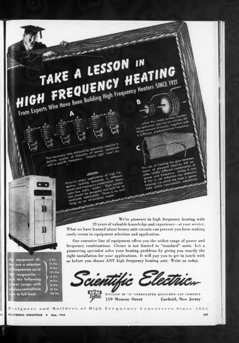
Garfield, New Jersey119 Monroe Street
ELECTRONIC INDUSTRIES • May, 1944
DIVISION OF -S" CORRUGATED QUENCHED CAP COMPANY
23 years of valuable knowledge and experience—at your service. What we have learned about heater unit circuits can prevent you from making costly errors in equipment selection and application.
Our extensive line of equipment offers you the widest range of power and frequency combinations. Choice is not limited to “standard'* units. Let a pioneering specialist solve your heating problem* by giving you exactly the right installation for your applications. It will pay you to get in touch with ut» before you choose ANY high frequency heating unit. Write us today.
ibin®'com'
thing
7S Kw
10 Kw
12S Kw
IS Kw
18 Kw
25 Kw
40 Kw
WO Kw
ha^e Been
Oyr equipment offers you a selection of$requencies up to
3(10 megacycles — aRd the following power range, with stepless control from z£o to full load:
iu*nCy„ but
«°’
<°ce. dll
nt '^î ^ent. P’
' ot PW*
o,h ' and h P°*e’ is "°' B L^in heot”,977
l^S°N n oi „Gcot'°n ° differ®m
ISO» 'h°ïoOP»'4"^. mode'-
trial deaths
T teins reeealed
Get AIRIONICS information NOW.
INCORPORATED
248
PLANNING FOR TOMORROW—TODAYi
1609 Milwaukee Ave. Carter, a well known name in radio for over twenty years. Cable: Genemoto.
tackled and solved right now
ELECTRONIC INDUS-TRKS • May, 1944
tions made to date, and promises to solve many hitherto baffling obstetrical problems.
The Yale men’s innovation vas a special amplifier, placed in the electrical circuit between the pregnant woman and a portable elec ro- cardiograph. They set up three contacts with the patient’s b dy, one high and one low on her abdomen, the third on her left leg— this last to minimize interference. The amplifier boosted the power of the electric currents produced by the fetal heart muscles and produced electrocardiograph tracings strong enough to be analyzed with precision.
X-rays or the stethoscope can detect twins no earlier than the sixth month. Because the electrocardiograph makes recordings from the fourth month, It should now make a diagnosis possible some two months earlier, the investigators indicate. Further refinement of the method is also expected to give more definite answers to the important questions of how drugs and anesthetics administered to mothers affect babies’ hearts.
The Yale researchers blasted at least two popular obstetrical beliefs. One is the theory that the sex of a child can be determined from its heartbeats, since girls’ fetal pulses supposedly beat faster in the womb than those of boys. The electrocardiograms revealed that the average rate for males and females Is 145 and 143 beats per minute, respectively, or too close to be worth while in sex determination. Also exposed as a myth was the belief that the heart rate declines as birth approaches and thus indicates the time of labo'.
The researchers cited eleven case histories as proof that electrocardiograms (tracings) often tell more about the baby’s condition than the X-ray, stethoscope, and other methods. In some cases, it reassured women who had felt no movement for a few days and feared that their babies might be dead. In others, early discovery that the babies actually were dead probably saved the mothers’ lives.
The electrocardiograph also proved more accurate in differentiating between pregnancy and certain tumors. One woman had been diagnosed as pregnant after a positive urine test. When she developed serious disease symptoms, doctors considered an abortion to save her life. The electrocardiograph, however, detected no fetal heart waves. Soon it was discovered that the patient wasn’t pregnant at all. Instead she was suffering from a growth of cysts.
YOUR^^PRDBLEMS
For many year». Carter Dynamotors have been a familiar part of the specifications of leading Communication Equipment Manufacturers, Police Departments, Government Agencies, etc. May we suggest you
submit your Dynamotor requirements too, and see for yourself the reason for this recognised preference.
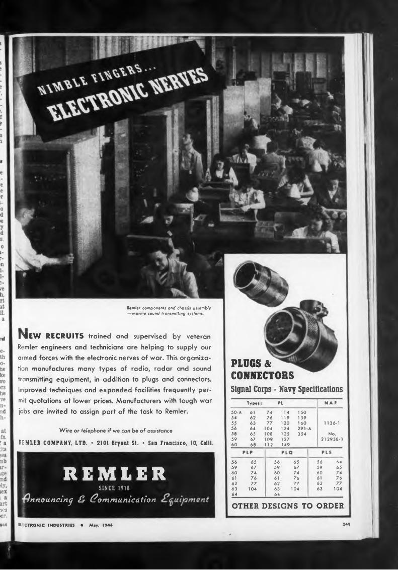
les
249
Remler components and chassis assembly —marine sound transmitting systems
PLUGS & CONNECTOBSSignal Corps • Navy Specifications
IMEW RECRUITS trained and supervised by veteran Remler engineers and technicians are helping to supply our armed forces with the electronic nerves of war. This organization manufactures many types of radio, radar and sound transmitting equipment, in addition to plugs and connectors. Improved techniques and expanded facilities frequently permit quotations at lower prices. Manufacturers with tough war jobs are invited to assign part of the task to Remler.
ELECTRONIC INDUSTRIES • Moy, 1944
Wire or telephone if we can be of assistance
REMLER COMPANY. LTD. ♦ 2101 Bryant St. • San Francisco, 10, Calif
REMLERSINCE 1918
^nnouncin^ 3 Communication
Typ.» PL N AF
50-A 61 74 114 15054 62 76 119 15955 63 77 120 160 1136-156 64 104 124 291-A58 65 108 125 354 No.59 67 109 127 212938-160 68 112 149
OTHER DESIGNS TO ORDER
56 65 56 65 56 6459 67 59 67 59 6560 74 60 74 60 7461 76 61 76 61 7662 77 62 77 62 7763 104 63 104 63 104
64 64
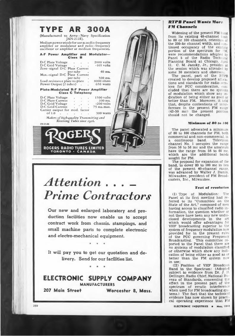
TYPE AR 300A(Manufactured to Army - Navy Specification
JAN-212E).Medium power triode for use as audio-frequency amplifier or modulator and radio - frequency oscillator or amplifier at medium frequencies.
A-F Power Amplifier and Modulator— Class B
D-C Plate Voltage . . . 2000 volts D-C Grid Voltage . . . -105 volts Zero-signal D-C Plate Current
per tube . 40 ma.Max.-signal D-C Plate Current
per tube . 300 ma.Load resistance plate-to-plate . 8000 ohmsPower Output (2 tubes) . . 650 watts
Plate-Modulated R-F Power Amplifier— Class C Telephony
D-C Plate Voltage . . 1500 voltsD-C Plate Current . . . 300 ma.D-C Grid Voltage . . -200 voltsD-C Grid Current . . . 75 ma. max. Carrier output for mod. factor
of 1.0 ...................................... 300 wattsMakers of high-quality Transmitting and
Receiving Tubes since 1926.IN-2-«
ROGERS RADIO TUBES LIMITED TORONTO• CANADA
Attention . . . _ Prime Contractors
Our new and enlarged laboratory and production facilities now enable us to accept contract work from chassis, stampings, and small machine parts to complete electronic and electro-mechanical equipment.
★ * *
It will pay you to get our quotation and delivery. Send for our facilities list.
ELECTRONIC SUPPLY COMPANY MANUFACTURERS
207 Main Street Worcester 8, Mass.
RTPB Panel Wants More I FM Channels
Widening of the present FM band I from its existing 40-channel hmit I to 80 or 100 channels, retention of I the 200-kc channel width, and * on- I tinned occupancy of the exi ng I portion of the spectrum for ?M, were recommendations adopted by Panel 5 of the Radio Technical Planning Board at Chicago, April 11. C. M. Jansky, Jr., presided at the session which was attended by some 30 members and observers.
The panel, part of the RTPB created to develop proposed allocations and standards for radio services for FCC consideration, concluded that there are no systems of modulation which show any indication of being either as good or better than FM. Moreover, it held ' that, despite contentions of interference in the present FM range (42-50 me) the present position should not be changed.
Minimum of 80 to 100
The panel advocated a minimum of 80 to 100 channels for FM, both commercial and non-commercial, in a continuous band. Television channel No. 1 occupies the range from 50 to 56 me and the amateurs have the range from 56. to 60 me, which are the additional bands sought for FM.
The proposal for expansion of the band, to cover 80 to 100 me in lieu of the present 40-channel range, was advanced by Walter J. Damm, Milwaukee, president of FM Broadcasters, Inc., Milwaukee.
Text of resolution
(I) Type of Modulation: The Panel at its first meeting had referred to its “Committee on the State of the Art,” composed of men having access to classified radio information, the question whether or not there have been any new undisclosed developments in the art which would offer advantages for VHF broadcasting superior to the system of frequency modulation now provided for in the present rules of the FCC governing Frequency Broadcasting. This committee reported to the Panel that there are no systems of modulation classified or otherwise which show any indication of being either as good as or better than the FM system now in use;
(II) Position of VHF Broadcast Band in the Spectrum: (Adopted subject to evidence from Dr. J. H. Dellinger, Radio Chief, National Bureau of Standards, concerning the effect in the present part of the spectrum of erratic interference when used for FM broadcasting systems.) The fact that the technical evidence has now shown by pract -
I cal operating experience that FMELECTRONIC INDUSTRIES • May, 1944250
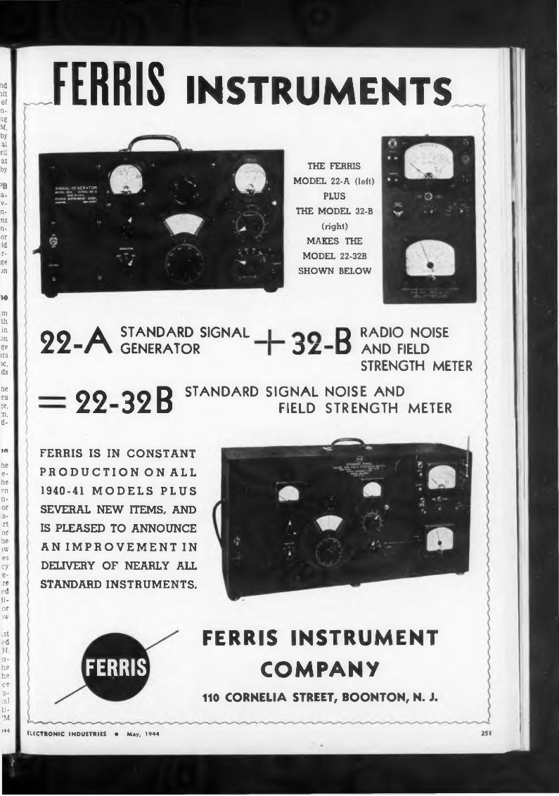
)0
>n FERRIS IS IN CONSTANTPRODUCTION ON ALL1940-41 MODELS PLUSSEVERAL NEW ITEMS, ANDIS PLEASED TO ANNOUNCEAN IMPROVEMENT INDELIVERY OF NEARLY ALLSTANDARD INSTRUMENTS.
FERRIS INSTRUMENTCOMPANY
110 CORNELIA STREET, BOONTON, N. J
ELECTRONIC INDUSTRIES • May, 1944
SIGNAL GENERATOR
FERRIS
m th in an ge irs ic, ds
LSt ed H. u- he he ce 'filai ti- 'M144
ad ilt of n- ng M, by al rii at by
he eu je, m, d-
a- V- n- ns n- or Id r- ge an
FERRIS INSTRUMENTS
THE FERRIS MODEL 22-A (left)
PLUSTHE MODEL 32-B
(right)MAKES THE
MODEL 22-32B SHOWN BELOW
OO A STANDARD SIGNAL | DZ/-A GENERATOR OX-D RADIO NOISE AND FIELD STRENGTH METER
22 32 ß STANDARD SIGNAL NOISE AND FIELD STRENGTH METER
he e- he en n- or iS- irt ore
)W es cy e- ,re ed li- or )W
i
ngineers
200-kw channels
BOX NO. P-100
252
May 24 Is Morse Centennial
Congress has approved with the greatest of speed the Bulwinkle- Wheeler Resolution to launch on May 24 the commemoration of the Centennial of the first telegram of Professor Samuel F. B. Morse over a telegraph line from the old Supreme Court room in the Capitol to Baltimore. The House enacted the Resolution with Rep. Bulwlnkle paying tribute to Dr. Morse and his contributions to the communications industry. An identical Resolution was passed by the Senate after Senator Wheeler had brought it up.
The Centennial is to be held May 24 and Congress will place an appropriate plaque or other suitable memorial in commemoration of the historic event which took place May 24, 1844, with exercises in which Congressional leaders, high government officials and Western
can provide a satisfactory service in its present position in the frequency spectrum, and the fact t at there is no technical evidence to indicate that certain erratic propagation characteristics of the presently assigned portion of the spectrum would be improved by any shift in the present allocation, or that there would be any other advantages accruing through the use of other locations of the spectrum, and the fact that there is already a substantial public investment m FM equipment and a highly organized public service already being rendered by existing FM stations in this position of the spectrum;
Be it hereby resolved that it is the consensus of this Committee that the present position of FM Broadcasting in the spectrum should not be changed;
ELECTRONIC INDUSTRIES • May. 1944
(III) (Approved by an 18 to fl vote). Width of Channel: It was the general thought of the Panel that they saw no reason to discuss changing the present FM channel width of 200 kc and that there was no need at this time for reconsideration;
(IV) (Approved by a 23 to 1 vote). Number of Channels Required for an Adequate VHF Broadcast Structure:
It is the consensus of the Committee that a minimum of 80 to 100 channels for commercial and noncommercial broadcasting stations is necessary for the development of an adequate nationwide FM Broadcast structure, and the Committee recommends that these 80 to 100 channels, comprising a band of 16 to 20 megacycles, be so assigned that they shall be continuous.
ELECTRONIC INDUSTRIES480 Lexington Avenue New York 17, N. Y
""'O’ee7p«ok e*^e"C et >«be V,*e ’°0' ondto"9e'X|eodM
b*“« P^. („cWtetto* e u °’
me
A well established company of excellent reputation located in the East, offers permanent position to a few engineers who have educational training and background in Electronic Engineering or Physics. Unusual opportunities offered men who possess originality and initiative in connection with research and developments relating to television, radio, sound reproduction and other applications. Write full particulars relative to education and experience, so that we can arrange an interview for you.
FRACTIONAL H. P.
MOTORSCENTRIFUGAL
BLOWERS
JWARnd now:
PREPARES
FOR
253
TODAY—Magna vox is producing such scientific instruments of war as electric gun-firing solenoids, giant radio direction finders and radio communication equipment of many kinds for all branches of service. Magnavox skills and craftsmanship won the first "E” award in this field (in 1941)—now with three White Star Renewal Citations.
TOMORROW— Peace will find Magnavox skills and facilities at their peak, stepped-up by the necessities of war. In this modern six-acre factory, Magnavox engineers again will build components for the radio industry ... and will figure prominently in the new developments of electronics. The Magnavox Company, Fort Wayne 4, Indiana.
YESTERDAY—in the first World War. Magnavox received this award "For Distinguished Service.” And the peacetime history of Magnavox also is distinguished by outstanding achievements. In 32 years’ service to the radio industry, this company made many important contributions, prominent among them the electro-dynamic speaker.
LOUD SPEAKERS« CAPACITORS • SOLENOIDS • COMMUNICATION A ELECTRONIC EQUIPMENT
ELECTRONIC INDUSTRIES • May. 1944
ihe War Department ofTHE UNITED STATES Cr AMERICARECOGNIZES IN THIS AWARD FOR DISTINGUISHED SERVK E IHE IOYQB ENERGY AND EFFICIENCY IN IHE PERFORMANCE
OF THE WAR WORK FT WHICH
AIDED MATERIALLY IN OBTAINING VICTORY FOR IHE -JIMS
of ihe United States of America in the war with THE IMPERIAL GERMAN GOVERNMENT AND THE iMPFRlAl
and Royal Austro Hungarian Government
er commi
Interphone Equipmentand Component Parts
JACK JK-48
PLUG Pl-58
CORD CD-3I8-ANOW IN PRODUCTION
Travler Karerola
That’s impor-
Brooklyn, New York1445 39th Street
254
mon am
PL-68 "A" Plug
BC-366
DC-347-CSW-141
TD-3
—and keep out of Enemy Range! _tant! That communicated orders be kept out of
JK-48PL-47PL-54PL-55
ELECTRONIC INDUSTRIES • May. 1944
tions companies will take part.In his address, Rep. Bulwinkle
who handled the telegraph-merger legislation through the House, reviewed the history of the sending of the first telegraphic message jy Professor Morse and how Congress had initiated the step by appropriating $30,000 for the construction of the first experimental line from Washington to Baltimore. He quoted extensively from the Congressional Globe (the Record of that day) and from the Washington newspaper reports when the famous first message—“What Hath God Wrought?”—was transmitted. The North Carolina Representative declared that Congress will deem it fitting to recognize the outstanding achievement of Professor Morse in giving to the world a new system of communications which was the forerunner of the present-day telegraph, cable, telephone, teletype, radio and television.
CD-318-A
CD-307-A
CD-874
JK-26
PE-86
JB-47
enemy range is even more vital. Radio signals are dead giveaways of vulnerable positions. For this reason the highly directional Loud Speaker is coming more and more into use, because it confines signals to a limited area. Loud Speakers used thus must give all-out, all-weather, all-the-time performance such as Atlas Sound Instruments are now giving on all Invasion Fronts. Let Atlas Sound inject these qualities into new designs or minor conversions for you.Complete Atlas Sound Catalog on request.
In an interpretation of Limitation Order L-265, the WPB holds that radio cabinets, regardless of the material from which they are made, are included within the definition of “electronic equipment,” and are subject to all provisions of the order. The interpretation also noted that provisions of the order do not apply to the transfer of “radio receiving sets” which were produced and designed for home use, and which were completely manufactured on or before April 24, 1943. An impression had existed, the WPB pointed out, that sets partly assembled or almost complete on that date could be finished and transferred free of the restrictions of the order.
At the same time, the WPB interpreted procedures under Order L-183-a to clarify its relation to General Scheduling Order M-293 and Priorities Regulation 1. While representing no change in the scope or operation of the order, the interpretation outlines procedures for scheduling electronic equipment and components in accordance with Army and Navy precedence.
The WPB also noted that methods of speeding up delivery of components to increase production of test instruments was discussed at a recent meeting of the Test Instrument Manufacturers’ Industry Advisory Committee. Lack of certain critical components has retarded production by as much as 30 to 50 per cent. It was recommended that procurement of critical components be placed on AAA priority basis to meet estimated 1944 needs, which are expected to exceed those of 1943 by 60 per cent.
WPB Holds Radio Cabinets Electronic Equipment
RADIO AND TELEVISION CORPORATION1032 W. VAN BUREN ST., CHICAGO 7, ILL.
PROMPT
COIL FORMS OF
BODY (302)
and BODY (400)
255
★ Contredite is •specially indicated where Low Thermal Expansion, High Resistance to Heat Shock, Low Porosity and Low Loss Factor are requisites.
Division of GLOBE-UNION INC., MilwaukeePRODUCERS OF VARIABLE RESISTORS • SELECTOR SWITCHES • CERAMIC CAPACITORS, FIXED AND VARIABLE • STEATITE INSULATORS
An almost endless variety of coil forms (up to 5 inches in diameter) are available processed to your specifications within reasonable tolerances. We are also able to furnish pressed pieces to approximately 6 inches square. • The facilities of Centralab's engineering and laboratory experience are at your disposal.
Write for Bulletin 720
ELECTRONIC INDUSTRIES • May, 1944
PROMPT SERVICETelephone BArday 7-1840
Calibration
^^WORKMANSHIP
PARK METALWARE CO., Inc
25C
NEW 1944
EDITION —JUST
OUT!
The conveying device is quite heavy and bulky; but to prevent it from imparting a shaking movement to adjacent parts, it is fully counterbalanced.
The conveyor drive is a motor of conventional type, connected by belt and pulley to a countershaft. A worm drive on the countershaft operates a worm gear at considerably reduced speed; this gear drives the crank arms which move the conveyor, and the timing cams.
In the event of a shell falling off the conveyor into a position in which it may jam against the conveyor, the belt is intended to slip and thereby prevent breakage
OVER 10,000 ITEMS — IN STOCK!
DIMENSION GAGE(Continued from page 99)
Purrhating dgrnttl Engineer! I
This complete ready reference directory is yours simply by writing on company stationery giving your title. Address Box AY.
QUALITY TOOLS PREFERRED BY THE EXPERTS
Represents Astatic at Memphis
R. T. Schottenberg, sales manager, Astatic Corporation, Youngstown, Ohio, announces the appointment of J. M. Cartwright, 1276 Peabody Avenue, Memphis, Tenn., as Astatic representative for Louisiana, Mississippi, Arkansas and western Tennessee. Mr. Cartwright, long familiar with radio and sound pr< ducts, is well known in this territory.
The operator is provided with a set of gages which are accurately ground to size. Four shell gages are required to fully adjust one measuring station, making a total of thirty-tw’o shell gages in all.
For a typical measuring station, the requirement is to inspect the shell for an external diameter of 0.875 in. ± 0.004 in. That is, all shells passing through this measuring station require to be sorted into three groups:
Undersize: smaller than 0.871 in.Within tolerance:
between 0.871 and 0.879 in.Oversize: larger than 0.879 in.To allow for possible small errors
in the adjustment, it is well to adjust these limits slightly to make the machine sort as follows:
Undersize: smaller than 0.8711 in.Within tolerance:
between 0.8711 and 0.8789 in.Oversize: larger than 0.8789 in.It is quite impossible to make any
machine sort shells with such precision as is indicated by the above tabulation; shells in the vicinity of 0.8711 in. will sometimes be called undersize, and sometimes within tiie tolerance.
Similarly, shells in the vicinity of 0.8789 In. will be called oversize or within tolerance, according to unpredictable changes. Consequently, the following tabulation is used to represent what actually is being
tUCTWONIC INDUSTRIES • May, 1944
For details and prices on XceLite Tools, ask your regular dealer—or write Dept. K
Baek the .ittaek. Bug More War Hand».
NUT DRIVERS |Ideal tools for electrical work, espe
cially panel jobs. Extra deep sockets,
precision machined, handles two nuts.
Handles are genuine shock-proof, fire
resistant XceLite Supplied in 6" and
9" lengths; 9 sizes from 3/16“ to
•/a" nut size.
available on satisfactory priority ratings.
4 SCREWDRIVERSThe original screwdrivers with the tougr, transparent XceLite shock-proof plastic handles. Blades of high quality steel, accurately machined. Unsurpassed tools for electrical and general use. Over 50 sizes and styles, square and round blades. Many sizes available with special fire-resistant handles at slightly higher prices.
XceLite Screwdrivers and Nut drivers are
TO SPEED VICTORY!
WE HAVE
PARTS
I U & ELECTRONICS CO.212 FULTON ST. • NEW YORK 7
it’s the suiSinko Plastic Engineers
MOLDING
OPPORTUNITIESIF I Tn SPaAGUE
must be rejected
SPRAGUE SPECIALTIES CO
258
Photo courtesy Voltee Aircraft
superior skill of American
two are passed, then this clearly proves that the adjustment of that measuring station is properly made. Since the gages may be passed through the machine at any time, it is obvious that the adjustment may be checked whenever desired.
It is convenient and economical to arrange the gages so that those which pass through one station are rejected at the next station. That is, the gages which pass through station 3 are the ones which should be rejected at station 4. Then, only 18 gages instead of 32 are required in all, and the gages may all be found in the reject containers, after passing through the machine, except for the last two.
If a gage does not come into the proper reject pocket, a simple table
perience olwhich are responsible for the ex-
undersize and oversize rejected, and the other
Applicants will, of course, be engaged only in strict compliance with regulations of the War Manpower Commission
0.8789 oversize. If the
shells are
done in this or any other gaging machine:
Definitely undersize: smaller than 0.8711 in.
Possibly undersize:between 0.8711 in. and 0.8715 in
Definitely within tolerance:between 0.8715 in. and 0.8785 in.
Possibly oversize:between 0.8785 in. and 0.8789 in.
Definitely oversize: larger than 0.8789 in.
It should be noted that absolutely no shells which are 0.004 In. off the mean dimension can be called within tolerance, but that some shells close to the tolerance limits and within tolerance, may be called bad. This conservative practice is necessary and desirable, and involves only a small loss of good shells, since only the shells which are within 0.005 in. of the maximum tolerance limit are likely to be rejected.
ELECTRONIC INDUSTRIES • May, 1944
1 pilots wins air battles on every lighting front. In the same sense.
;rior skill and long ex-
traordinary success of so many intricate Sinko Injection Moldings.
Sinko has been making better tools and dies for 25 years . . . and better injection moldings ever since thermoplastics were introduced. Small wonder we’ve developed superior methods and techniques, an unsurpassed knowledge of simple and intricate steel reinforced injection molding. Many peacetime products we’ve made have helped capture coveted markets. For your own best interests, discuss your post-war plans and products with a Sinko engineer, NOW!
The operator places the gages into the magazine feed of the machine, and allows the gages to pass through all measurements as best they may. A gage for the fourth station, for example, is required to pass through the first three stations without being rejected. Four gages are required to have dimensions precisely right for readjusting the calibration of each measuring station. Using the figures of the previous example, these gages would be dimensioned as follows:
0.8711 in. must be rejected undersize;
0.8715 in. must be passed as within tolerance;
0.8785 in. must be passed as within tolerance;
Readjusting the rulihrarion
There are numerous adjustments necessary to initially bring the individual measuring stations into proper operation; but after this is once accomplished, a simple procedure is available for maintaining
JUNIOR ENGINEERS FOR QUALITY CONTROLFor this work, we need four or five practical men who are qualified, not only to check up on capacitor and resistor production, but who can also pick up a soldering iron or other tool on occasion and show how things should be done. Technically- informed men with better-than-average radio service or similar practical experience should find this a worthwhile opportunity.WRITE AT ONCE if you feel that you can qualify for either of these positions To tho right men, Sprague offers interesting work, good living conditions and salaries in keeping with experience, plus worthwhile future opportunities made possible by planned post-war developments of far-reaching importance.
RESISTOR ENGINEERThe man to fill this position will need a good, practical working knowledge of resistance problems and a particular leaning toward the broad electrical field rather than radio alone. The work is interesting and has to deal with further development and expansion of the most unusual and most rapidly-growing resistor line.
SINKO TOOL & MANUFACTURING (OMFANY, 351 NO CRAWFORD AVENUE. CHICAGO, ILLINOIS
on
New
ans
ans
INDISPENSABLE FOR REFERENCE
EIECTRONIC INDUSTRIES
259
ose are
A working tool for every engineer interested in electronic developments and applications in the industrial or communication field. Most of the material in the Handbook has never before been published in any form. No other single volume approaches The ELECTRONIC ENGINEERING HANDBOOK for completeness, authority and up-to-dateness.
It is lavishly illustrated. Every important circuit, each essential application, everything that re quires picturization is illustrated—to afford you facts at a glance.
ELECTRONIC INDUSTRIES • May, 1944
Available Only toElectronic Industries Subscribers
The ELECTRONIC HANDBOOK is not for sale. It can be had only in conjunction with a subscription to ELECTRONIC INDUSTRIES (new or renewal) for two years at $6.00 or three years at $7.50. Edition is limited. Paper restrictions make any reprint of The Handbook impossible in 1944. Subscriptions will be filled in the order of their receipt. The right is reserved to withdraw this offer without notice.
Set In Clear, Legible Type.
464 Pages: 4 Sections: 560
Charts, Diagrams, Tables,
Drawings, Photographs;
Completely Indexed for
Reference Purposes.
For the engineer specialist in the radioelectronic field—a convenient, reliable source of formulae, principles and modern electronic problems. While it includes the latest information in the electronic field, the Handbook is written to be readily understood by any engineer with a basic knowledge of electrical principles.
The Handbook is new and original, written by some of the foremost men in their fields
Milt*BUTTON TYPE. FLAT OR STEPPED TYPE
SQUARE, OBLONG AND ROUND
CLOSEST TOLERANCES
EXCELLENT FINISH
MINIMUM LAPPING continually
mechanical
260
checking and rechecking the adjustment of each station by procedures similar to the above, and thereby maintains the adjustment in spite of wear on the gaging sur-
The operator
faces, looseningparts, changes in sensitivity, etc.
If trouble should arise on some station, whereby readjustment is not possible, the operator will become aware of it instantly because that station will reject all shells, or because it will not properly differentiate between the gages. For such emergency service, the entire measuring assembly is replaceable with a spare. The electrical assembly which is part of the measuring assembly is also removable from it, and arranged with plug-in connectors for quick change.
^1111“'’
ELECTRONIC INDUSTRIES • May, 1944
tells the operator how to readjust^ the machine. For example, suppose that the 0.8711 in. gage was not rejected as undersize, but passed through to the next station, and was there rejected with the 0 715 in. gage.
The operator, upon finding the shell in the wrong container, re ers to his table of instructions. There he is instructed to turn the screw which controls the position of the mirror for the undersize ad.ust- ment of that measuring sta ion, one quarter turn, anti-clockwise’ This changes the adjustment of that mirror by an amount corresponding to 0.0001 in., in the desired direction The gage is then placed in the magazine again, and allowed to pass through the machine a second time. After one or several such adjustments, the shell will be required to appear in the desired reject container.
The measurements taken on the I present machine include outside I diameters, inside diameters, overall lengths, and depth of counterbore The outside diameter must be measured at several locations, since it is not of the same diameter all 1 over, but has a band, a bulge, and a groove to be measured.
Some of the measurements are \ ± 0.001 in. tolerance, while others are less close, up to ± 0.008 in. For those measurements which have closer tolerance, the optical magnification Is increased. The magnifications actually used vary from 100 diameters to 660 diameters. No mechanical leverage magnification is used, except such as cannot be avoided because of the arrangement of the measuring bar.
The limit of sensitivity is not reached for inspections which have a tolerance of ± 0.001 in.; but tor this and closer tolerances, some changes in design are clearly in i- cated as being desirable, to make
Range and sensitivity of measurements
HEATERS • SPOT WELDERS • FLUORESCENT BALLASTS
SPECIAL CONTROLS
GREAT SAVINGS IN MAN HOURS AND COSTS
PROMPT DELIVERIESSend for full information
DC and AC WELDERS TRANSFORMERS • MAGNETIC CLAMPS • SOLENOIDS • RIVET
SPECIFICATIONS
2416 ATLANTIC AVENUE * BROOKLYN 33
Prompt EngineeringService always available
& MFG. COF 0
HERCULES ELECTRICINCORPORAT
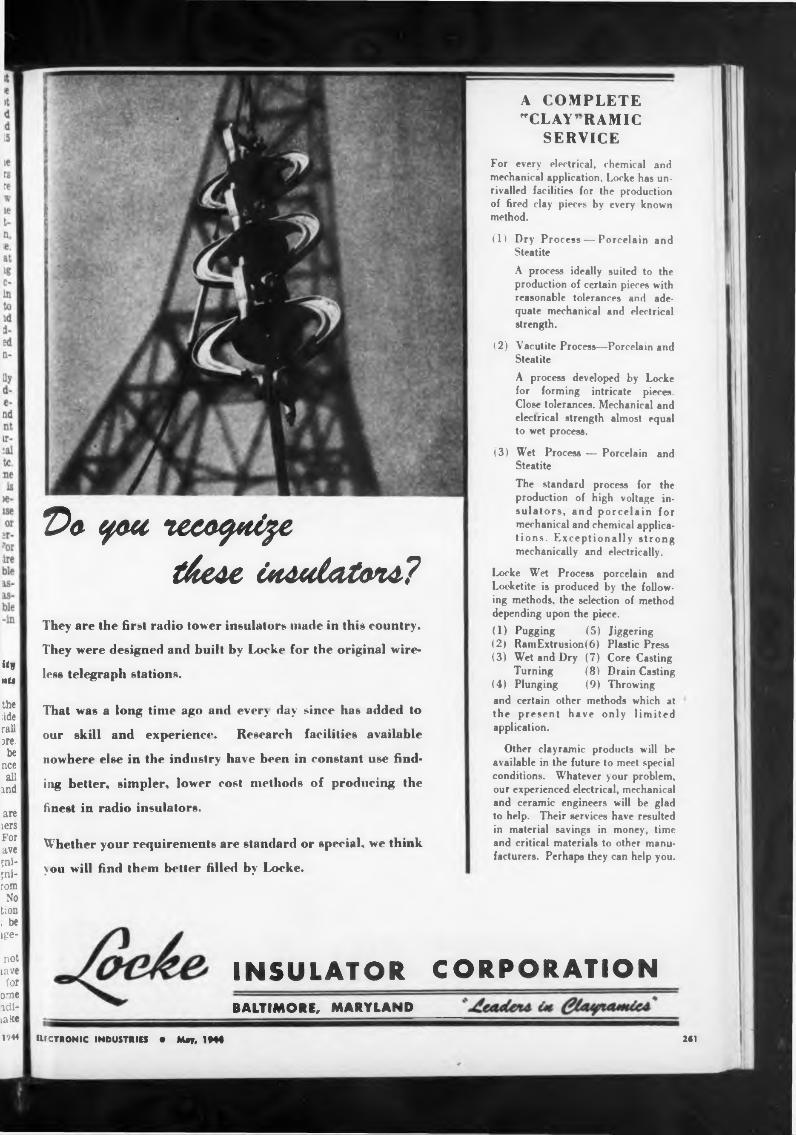
«w nü
the àde rail are.
be nce ail
md
are lers For ave jni- ;ni- rom
No tion ; be ige-
not lave for
orne ridila ke1944
Da you zeea^ti^c
t&ede CadatetoM?
They are the first radio tower insulators made in this country.
They were designed and built by Locke for the original wire
less telegraph stations.
That was a long time ago and ever} day since has added to
our skill and experience. Research facilities available
nowhere else in the industry have been in constant use find
ing better, simpler, lower cost methods of producing the
finest in radio insulators.
Whether your requirements are standard or special, we think
you will find them better filled by Locke.
A COMPLETE "CLAY’RAMIC
SERVICEFor every electrical, chemical and mechanical application, Locke has unrivalled facilities for the production of fired clay pieces by every known method.
(1) Dry Process — Porcelain and SteatiteA process ideally suited to the production of certain pieces with reasonable tolerances and adequate mechanical and electrical strength.
(2) Vacutite Process—Porcelain and SteatiteA process developed by Locke for forming intricate pieces. Close tolerances. Mechanical and electrical strength almost equal to wet process.
(3) Wet Process — Porcelain and SteatiteThe standard process for the production of high voltage insulators, and porcelain for mechanical and chemical applies- tions. Exceptionally strong mechanically and electrically.
Locke Wet Process porcelain and Loeketite is produced by the following methods, the selection of method depending upon the piece.(1) Pugging (5) Jiggering (2) Ram Extrusion (6) Plastic Press (3) Wet and Dry (7) Core Casting
Turning (8) Drain Casting (4) Plunging (9) Throwing and certain other methods which at the present have only limited application.
Other clayramic products will be available in the future to meet special conditions. Whatever your problem, our experienced electrical, mechanical and ceramic engineers will be glad to help. Their services have resulted in material savings in money, time and critical materials to other manufacturers. Perhaps they can help you.
INSULATOR CORPORATIONBALTIMORE, MARYLAND______
tUCTRONIC INDUSTRIES • May, 1H4 261
BENDER
SHEAR
BRAKE
PRECISION MACHINES
MINNEAPOLIS 15, MINN.
-;W
DUPl^ 348 EIGHTH AVENUE so
CHECKERTYPE 110-A
OliEIL-IRWin mf6.co^
tne initial setting up easier, and to permit a more precise readjustment from time to time.
In all of the measurements, the indecisive or doubtful region, for which the machine is permitted to call the shell good or bad, is less than 10 per cent of the tolerance range. For those measurements which have wide tolerances, it i far less than 10 per cent while for the 0.001 in. tolerance, it was found to be possible to use the 10 per cent figure, and perhaps improve upon it.
Design principiei
After many experimental runs with production shells, it has been found possible to consider the machine successful and usable in its present form. However, the following general design considerations are worth noting:
(1) The surrounding atmosphere must be dust free, because dust on the anvils or measuring bars, or on the lenses of the microscopes, causes errors. The more precise the measurements, the more important this requirement.
(2) The shell handling design must be such as will permit a shell to fall off and get into unexpected positions without damage to the machine. All delicate regions ofthe machine must prevent the flying shell thrown off device, so that the
be covered to entrance of a the conveying shell may not
A dependable
TEST AND MEASURING INSTRUMENTThe factory counterpart of the Q-Meter. Compares fundamental characteristics of inductance or capacitance and Q under production line conditions with a high degree of accuracy, yet quickly and simply. Insures uniform parts held within close tolerances. Frequency range 100 kc. to 25 me.
jam between moving members.(3) The gages must be of such
design as will pass through the stations of the machine successfully to reach their critical measurement station; and they must be so designed as to be undamaged by con-1 tinuous use and readily recognized and identified by the operator. They must be rechecked frequently.
(4) Certain minor structural and electrical changes are indicated, which will improve the maintenance of the adjustment over long periods of time.
(5) The temperature of the machine as a whole must not be subject to wide changes. Trouble with this was not experienced as yet, but it is known that on long runs, the changes in the temperature of some structural members will require continuous readjustment as a means of compensating.
TUBES ON THE JOB(Continued from page 128)
BOONTONBOONTON, N, J. \__ ,
RADIO
DESIGNERS AND MANUFACTURERS OF THE Q' METER QB CHECKER FREQUENCY MODULATED SIGNAL
GENERATOR . BEAT FREQUENCY GENERATOR AND OTHER DIRECT READING TEST INSTRUMENTS
effect shown In Fig. 9, which consists of a slight rounding-off of the corner, plus a slight raised spot on the top surface of the cut. It should be noted that these drawings are enlarged and the error is exaggerated In order to show the result more clearly.
(Continued on page 2M)ELECTRONIC INDUSTRIES • May, 1941262
,, '9*
NEW LETTER CONTESTfor SERVICEMEN!
on- ong
SO—HERE WE GO AGAINIGet in on this NEW letter contest—write and tell us your first hand experiences with all types of Radio Communications equipment built by Hallicrafters including the famous SCR-2991
ELEVEN 1st PRIZE WINNERS IN 5 MONTHS IN CONTEST #1!
Yes sir, guys, the hundreds of letters received were so swell that double first prize winners had to be awarded each of the first four months and there were triple first prize winners the fifth and last month . . .
on- zed tor. itly. and ted,
ma- ;ub- vithbut the
ome [uire i a
:on- the
t on ould
are;ger- esult
RULES FOR THE CONTESTHallicrafters will give $100.00 for the best letter received during
each of the five months of April, May, June, July and August. (Deadline: Received by midnight, the last day of each month.)... For every serious letter received Hallicrafters will send $1.00 so even if you do not win a big prize your time will not be in vain.... Your letter will become the property of Hallicrafters and they will have the right to reproduce it in a Hallicrafters advertisement. Write as many letters as you wish. V-mail letters will do. . . . Military regulations prohibit the publication of winners' names and photos at present... monthly winners will be notified immediately upon judging.
W. hallicrafters rato ND SI
THE HALLICRAFTERS CO., MANUFACTURERS OF RADIO AND ELECTRONIC EQUIPM
ELECTRONIC INDUSTRIES • May, 1944
BENDER
Design principiai
SHEAR
BRAKE
PRECISION MACHINES
348 EIGHTH AVENUE SO. MINNEAPOLIS 15, MINN.
CHECKER
TUBES ON THE JOB(Continued from page 128)
2C2
After many experimental runs with production shells, it has been found possible to consider the machine successful and usable in its present form. However, the following general design considerations are worth noting:
(1) The surrounding atmosphere must be dust free, because dust on the anvils or measuring bars, or on the lenses of the microscopes, causes errors. The more precise the measurements, the more important this requirement.
(2) The shell handling design must be such as will permit a shell to fall off and get into unexpected positions without damage to the machine. All delicate regions of
tne initial setting up easier, and to permit a more precise readjustment from time to time.
In all of the measurements, the indecisive or doubtful region, for which the machine is permits d to call the shell good or bad, is less than 10 per cent of the tolerance range. For those measuren. nts which have wide tolerances, it i far less than 10 per cent while for the 0.001 in. tolerance, it was found to be possible to use the 10 per cent figure, and perhaps improve upon
the machine must prevent the flying shell thrown off device, so that the
ELECTRONIC INDUSTRIES • May,
be covered to entrance of a the conveying shell may not
jam between moving members.(3) The gages must be of such
design as will pass through the stations of the machine successfully to reach their critical measurement station; and they must be so designed as to be undamaged by continuous use and readily recognized and identified by the operator. They must be rechecked frequently.
(4) Certain minor structural and electrical changes are indicated, which will improve the maintenance of the adjustment over long periods of time.
(5) The temperature of the machine as a whole must not be subject to wide changes. Trouble with this was not experienced as yet, but it is known that on long runs, the changes in the temperature of some structural members will require continuous readjustment as a means of compensating.
effect shown in Fig. 9, which consists of a slight rounding-off of the corner, plus a slight raised spot on the top surface of the cut. It should be noted that these drawings are enlarged and the error is exaggerated in order to show the result more clearly.
(Continued on page 264)
The factory counterpart of the Q-Meter. Compares fundamental characteristics of inductance or capacitance and Q under production line conditions with a high degree of accuracy, yet quickly and simply. Insures uniform parts held within close tolerances. Frequency range 100 kc. to 25 me.
A dependable
TEST AND MEASURING INSTRUMENT
O'nEIL-lfUUin mFG.coMK
BOONTO RADIO
DESIGNERS AND MANUFACTURERS OF
ft I
ns I en I a- I its I w- I >ns I
?re I on I or I
>es I ;he I int I
igr. I lell I ted I the I
of I to I
f a ing not
uch sta- ully tent de-:on- ized itor. itly. anc ,ted, ten- long
ma- sub- with, but
the»me tuire5 a
NEW LETTER CONTESTfor SERVICEMEN!ELEVEN 1st PRIZE WINNERS IN 5 MONTHS IN CONTEST #1!
Yes sir, guys, the hundreds of letters received were so swell that double first prize winners had to be awarded each of the first four months and there were triple first prize winners the fifth and last month . . .
SO-HERE WE GO AGAIN!Get in on this NEW letter contest—write and
tell us your first hand experiences with all types of Radio Communications equipment built by Hallicrafters including the famous SCR-2991
RULES FOR THE CONTESTHallicrafters will give $100.00 for the best letter received during
each of the five months of April, May, June, July and August. (Deadline: Received by midnight, the last day of each month.)... For every serious letter received Hallicrafters will send $1.00 so even if you do not win a big prize your time will not be in vain.... Your letter will become the property of Hallicrafters and they will have the right to reproduce it in a Hallicrafters advertisement. Write as many letters as you wish. V-mail letters will do. . . . Military regulations prohibit the publication of winners' names and photos at present... monthly winners will be notified immediately upon judging.
con- ! the it on ould
are >Sfr* esult hallicrafters radio
|THt HALLICRAFTERS CO., MANUFACTURERS OF RADIO AND ELECTRONIC EQUIPMENT. CHICAGO 16, U. S. A.
'' ■ ELECTRONIC INDUSTRIES • May, 1944 263
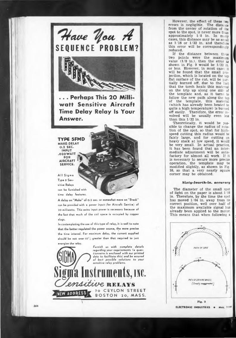
cw-eSEQUENCE PROBLEM
tek
• • • Perhaps This 20 Milliwatt Sensitive Aircraft Time Delay Relay Is Your Answer.
TYPE 5FMDMAKE-DELAY0.2 SEC.
INPUT .020WATT
FOR AIRCRAFT SERVICE. A
However, the effect of these two errors is negligible. The distance ' from the center of rotation of he spot to the spot, is never more t an approximately 1/8 in. In nuny cases, this distance may be as small as 1/16 or 1/32 in. and therefore this error will be correspondingly reduced.
If the distance between these two points were the maximum value (1/8 in.), then the error as shown in Fig. 9 would be 1/32 in. or less. However, in most cases it will be found that the small projection, which Is located on the top flat surface of the cut, will be partially burned off, due to the fact that the torch heats this material on the trip up along one side of the template and, as it turns to follow the new path along the top of the template, this material (which has already been heated to quite a high temperature) is burned off easily. Therefore, the error involved will be usually even less than this 1/32 in.
Theoretically, it would be possible to change the radius of rotation of the spot, so that for highspeed cutting this radius would be fairly large, and for cutting on heavy stock at low speed, it would be very small. In actual practice, it has been found that an intermediate adjustment will be satisfactory for almost all work. If it is necessary to secure more precise operation, the template may be modified slightly, as shown in Fig.
All SigmaType 5 Sen- sitive Relays can be furnished with
time delay features.
Break'can be provided with a power input (for Aircraft Service) of 20 milliwatt*. Thi» extra input power it necessary because of
the fact that much of the coil space is occupied by copper
slugs.In contemplating the use of this type of relay, it is well to note
the time interval. For maximum delay, the current supplied
should be not over IO% greater than that required to just
energize the relay.Furnish us with complete details regarding your requirements (a questionnaire is enclosed with our printed data to facilitate this) and be assured of best possible solutions to your sensitive relay problems.
Sigma Instruments, incRELAYS
cornerthat a very nearly square may be obtained.
Sixty-fourth-in. accuracy
diameter of the small spotof light on the paper is about 1 16 in. Therefore, by the time the spot has moved 1/64 in. away from its correct position, well over half of the maximum available signal has already been applied to the motor This means that when following a
PATHOPSPOr
PATH OF DRIVING WHEEL(Greatly naggrratrd 1
new address 70 CEYLON STREET BOSTON 20, MASS.
2«4 ELECTRONIC INDUSTRIES • May, 1 M
?
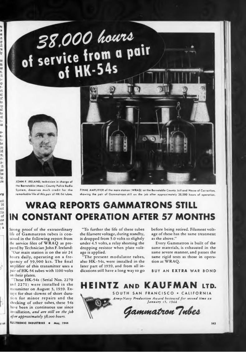
WRAQ REPORTS GAMMATRONS STILLIN CONSTANT OPERATION AFTER 57 MONTHS
BUY AN EXTRA WAR BOND
HEINTZ and KAUFMAN ltd
265
FINAL AMPLIFIER of th« main station (WRAQ) at the Barnstable County Jail and House of Correction, showing the pair of Gammatrons still on the job after approximately 38,000 hours of operation.
ELECTRONIC INDUSTRIES • Mey, 1944
JOHN F IRELAND, technician in charge of the Barnstable (Mass.) County Police Radio System, deserves much credit for the remarkable life of this pair of HK 54 tubes
"To further the life of these tubes the filament voltage, during standby, is dropped from 5.0 volts to slightly under 4.5 volts, a relay shorting the dropping resistor when plate voltage is applied."The present modulator tubes,
also HK-54s, were installed in the later part of 1939, and from all indications still have a long way to go
before being retired. Filament voltage of these has the same treatment as the above.”
Every Gammatron is built of the same materials, is exhausted in the same severe manner, and passes the same rigid tests as those in operation at WRAQ.
Strong proof of the extraordinary life of Gammatron tubes is con* tained in the following report from the service files of WRAQ as prepared by Technician John F. Ireland: "Our main station is on the air 24
hours daily, operating on a frequency of 39,900 kcs. The final amplifier of this transmitter uses a pair of HK-54 tubes with 1100 volts on their plates."These HK-54s (Serial Nos. 2270
and 2271) were installed in the transmitter on August 3, 1939. Except for shut-downs of short duration for minor repairs and the ch eking of other tubes, these 54s have been in continuous use since installation, and are still on the job after approximately 38,000 hours.
SOUTH SAN FRANCISCO • CALIFORNIAArmy-Navy Production Award bestowed for second time on
January 15, 1944
Smooth control signal»
Cfurtt » »onTfo/
266
nue cuTfMPUTf C
One feature which contributes materially to the accuracy and speed of response is the smoothness of operation of the control. The control does not provide an “off-on” signal, but instead provides a signal which varies smoothly as the spot is moved from its correct position to a position on either the black line or the white paper. Therefore, it provides a correction which Is approximately proportional to the amount of error.
This type of control, together with an anti-hunt circuit which is included m the electrical circuit of the equipment, combine to provide a control which rotates the spindle around a corner much more rapidly than could be done by hand, and yet maintains better accuracy than that obtained under manual control. The speed of rotation of the driving spindle when allowed to rotate freely is approximately 100 rpm, or almost two complete revolutions every second. Therefore, when the driving wheel approaches a corner, it is turned to its new position very rapidly. This makes
(The wing-placed charts depict the metabolism branch of Sanborn's service to the medical profession.)
ELECTRONIC INDUSTRIES • May. 1944
straight or slightly curved line he error will usually not exceed 1 64 in. at most.
Since a full sized template is used, the accuracy with which tx m- plates can be drawn is well within the permissible tolerance. Due to the fact that the machine ccn- stantly compares the torch posi on directly with the templates, cumulative errors due to the driving wheel slipping are not present.
The gear is so placed in the design to indicate a close affiliation of mechanical with electronic precision.Such a background, coupled with our present electronic accomplishments and our potentialities are reasons why you might want to know us better.
Yes, this emblem does look like a caduceus, the medical symbol. And that's quite fitting —for Sanborn Company has long been a recognized leader in the medical diagnostic field.Notice that the nucleus of the design is the electron tube symbol. Around and below it are entwined electronically-produced electrocardiograph records, representing a worthwhile background for our present electronic war work.
SANBORN COMPANYMAKERS OF ELECTRONIC INSTRUMENTS
CAMBRIDGE 39, MASS.
th hour11th day...
11th month...
1918 tumistue w„—.November 10th, 1918 . . 1,081 men were killed, captured, and
wounded! That EXTRA day may mean YOUR boy's life! . . . Those EXTRA
bonds, scrap, pints of blood . . . will mean VICTORY sooner! . .
Are YOU making the most of your weapons?
THE MARK OF EXCELLENCE
Here, at Kenyon, we're mighty proud to be playing
a small part in winning a big war. That is why
every Kenyon transformer used by our armed forces
reflects the same high craftsmanship and precision
that went into our peacetime production. To bring
victory closer, Kenyon workers are determined to do
their share by turning out good transformers as fast
as they know how.
KENYON TRANSFORMER CO., Inc 840 BARRY STREET
■ NEW YORK, U. S. A.1944
ELECTRONIC industries May. 1944 247
LOB AL WARFARE!NM
GLOBALTHINKING!
WIDERVISION!
PANORAMIC
PANORAMIC RADIO CORPORATION 242-251 W. 55th STREET, NEW YORK
ML CHEWf EWGtUTED
268
Only PANORAMIC shows you a wide bond
of frequencies—* . all af once! //'ft
it possible to follow intricate shape;» I with very good accuracy.
The electronic control circuit is I shown in Fig. 11. Tube 1 is a recti-1 tier tube which supplies de power I for the phototube and for amplifier I tubes 2 and 3. A separate rectifier I supplies de power for the motor I field.
The phototube is connected in a bridge circuit which is made up o! resistors RI, R2. R3 and the phototube. The resistance of the phototube varies as a function of the amount of light which it receives I Therefore, the circuit is adjusted so that when the spot of light is half | on the white paper of the template I and half on the black Une, the signal applied to the left grid of tube 2, is equal to the signal applied to the right grid of this tube. In I other words, the voltages across RI and R2 are equal. Under these conditions the output of both plates of tube 2 wfil be equal. Therefore, the signals applied to the grids of tube 3 will be equal.
Since an equal signal appears on each grid of tube 3, the currents which flow in the windings of saturable reactors SRI and SR2, which are connected in the plate circuit of tube 3, will be equal.
The ac windings of saturable reactors SRI and SR2 are connected in the grid circuits of tubes 4 and 5 respectively. These tubes are thyratrons connected in inverse parallel, so that when tube 4 is
ELECTRONIC INDUSTRIES • May. 1944
Au Engineering Organization Devoted to Radio Research, Development and Manufacture.
PANORAMIC reception is keyed to today’s needs—and to the future. Panoramic shows you, visually, a wide band of frequencies to see and analyze.
RADIO, ELECTRICAL AND
ELECTRONIC COMPONENTS
ELECTRONIC PRODUCTS MFG. CORP DEXTER, MICHIGAN
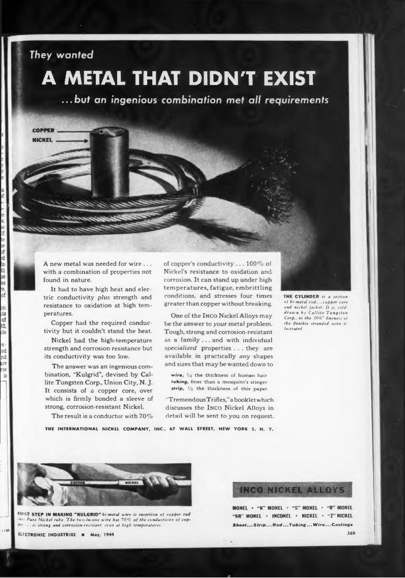
They wanted
A METAL THAT DIDN'T EXIST...but an ingenious combination met all requirements
COPPERNICKEL
e-■d
nd ire rse
13
A new metal was needed for wire ... with a combination of properties not found in nature.
It had to have high heat and electric conductivity plus strength and resistance to oxidation at high temperatures.
Copper had the required conductivity but it couldn’t stand the heat.
Nickel had the high-temperature strength and corrosion resistance but its conductivity was too low.
The answer was an ingenious combination, “Kulgrid”, devised by Callite Tungsten Corp., Union City, N. J. It consists of a copper core, over which is firmly bonded a sleeve of strong, corrosion-resistant Nickel.
The result is a conductor with 70%
of copper’s conductivity ... 100% of Nickel’s resistance to oxidation and corrosion. It can stand up under high temperatures, fatigue, embrittling conditions, and stresses four times greater than copper without breaking.
One of the Inco Nickel Alloys may be the answer to your metal problem. Tough, strong and corrosion-resistant as a family ... and with individual specialized properties . . . they are available in practically any shapes and sizes that may be wanted down to
wire, Vi the thickness of human hair tubing, finer than a mosquito’s stinger strip, VS the thickness of this paper
“TremendousTrifles/’abookletwhich discusses the Inco Nickel Alloys in detail will be sent to you on request.
THE CYLINDER it a section of bi-metal rod... copper core and nickel jacket, ft it cold- drawn by Callite Tungsten Corp., to the .006" fineness of the flexible stranded wire illustrated
THE INTERNATIONAL NICKEL COMPANY, INC., 67 WALL STREET, NEW YORK 5, N. Y.
FIRST STEP IN MAKING “KULGRID" bs-metal wire it insertion of copper rod '•I Pure Nickel tube. The two-in-one wire bat 70% of the conductivity of cop-
. it ttrong and corrosionresistart. even at high temperatures.
INCO NICKEL ALLOYS
MONEL • “K” MONEL • “S” MONEL • “R” MONEL “KR” MONEL * INCONEL • NICKEL * “T' NICKEL iheet... S trip... Rod... Tubing... Wirts... Canting»
1944ELECTRONIC INDUSTRIES May. 1944 269
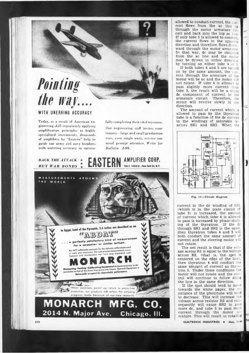
Pointing the way....WITH UNERRING ACCURACYToday, as a result of American engineering skill ingeniously applying amplification principles to highly specialized instruments, thousands of amplifiers by “Eastern” help to guide our army and navy bombers with unerring accuracy in success
fully completing their vital missions.
Our engineering staff invites your
inquiry—large and small production
runs, even single units, receive our
usual prompt attention. Write for Bulletin 1-99.
allowed to conduct current, the current flows from the ac line up through the motor armature ir- cuit and back into the top ac line. If only tube 5 is allowed to cond :t, the current flows in the oppe. >e direction and therefore, flows do n- ward through the motor arman e. In that way, de may be obtai d from the ac line and the m or may be driven in either direc. jn by turning on either tube 4 or 5.
If both tubes 4 and 5 are turned on by the same amount, the c ur- rent through the armature of he motor will be ac and the motor vill not rotate. If tube 4 is allowed to pass slightly more current than tube 5, the result will be a slight de component of current in armature circuit. Therefore, motor will revolve slowly in direction.
the the one
The amount of current which is I allowed to pass by the thyratron I tube is a function of the de current I In the windings of saturable re- 1 actors SRI and SR2. When the I
BACK THE ATTACK ★ CASTEDM AMPLIFIER CORP. BUY WAR BONDS « LliO I dill 7ME.140tliSt.N(wYMliS4.N.Y.
a o.rfectly satisfactory kind of mea.urem.nt ' ’ * *tor a carpenter or similar artisan.
But NOT monu’in radio end electronKS depended upon♦actor." and mormon« mm have tong
monarch
When conditions permit our return Io peace time production, our products will reflect the amazing progress made because of war-time research.
MEASUREMENTS THE WORLD
A R O U N D1000000 J P0WH; àJûûûûLrJ
MONARCH MFG. CO.2014 N, Major Ave. Chicago, III.
current in the de winding of SRI (which is in the plate circuit of tube 3) is increased, the amount of current which tube 4 is allowed to pass is increased by phase-shifting of the thyratron. If the de through SRI and SR2 is the same, then thyratron tubes 4 and 5 will both conduct the same amount of current and the steering motor will not rotate.
The net result is that if the voltage across RI is equal to the voltage across R2, (that is, the spot Is centered on the edge of the line), then thyratron 4 will conduct the same amount of current as thyratron 5. Under these conditions the motor will not rotate and the control will continue to follow along the line in the same direction.
If the spot should tend to move towards the white paper, the resistance of the phototube will te? d to decrease. This will increase tne voltage across resistor R2 and consequently will cause SR2 to pa<s more de, and tube 5 to pass more current through the motor armature. This will result in rotating
ELECTRONIC INDUSTRIES • May, UM270
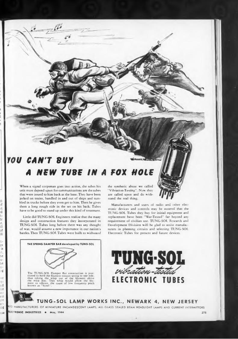
Ildì 1 it
I tic ie, 111 of ill
It-geIs
ï). he ahe ling
tve rend hemiss ire ir- tag944
the synthetic abuse we called "Vibration-Testing". Now they are called upon and do withstand the real thing.
10U CAN'T BUY A NEW TUBE IN A FOX HOLE
When a signal corpsman goes into action, the tubes his unit must depend upon for communications are the tubes that were issued to him back at the base. They have been jerked on trains, handled in and out of ships and tumbled in trucks before they even get to him. Then he gives them a long rough ride in the set on his back. Tubes have to be good to stand up under this kind of treatment.
Little did TUNG-SOL Engineers realize that the many design and construction features they incorporated in TUNG-SOL Tubes long before there was any thought of war, would assume a new importance in our nation's battles Then TUNG-SOL Tubes were built to withstand
THE SPRING DAMPER BAR developed by TUNG-SOL
The TUNG-SOL Damper Bar construction is positioned to hold the filament tension spring to one side, thus taking the whip out of the filament above the mici disc. This whip would allow the filament to vibrate, the cause of low frequency pitch known as ’'howl".
Manufacturers and users of radio and other electronic devices and controls may be assured that the TUNG-SOL Tubes they buy for initial equipment and replacement have been "War-Tested” far beyond any requirement of civilian use. TUNG-SOL Research and Development Division will be glad to assist manufacturers in planning circuits and selecting TUNG-SOL Electronic Tubes for present and future devices.
TJNGMELECTRONIC TUBES
TUNG-SOL LAMP WORKS INC., NEWARK 4, NEW JERSEY kso MANUFACTURERS OF MINIATURE INCANDESCENT LAMPS, ALL-GLASS SEALED BEAM HEADLIGHT LAMPS AND CURRENT INTERMITTORS
ELECTRONIC INDUSTRIES • May, 1944 271
WIDE READING
Z = Zotanh (a
methods intangible
and that the unknown impedance Z is given by the expression
the steering motor In such a direction that the spot returns to the position where it is centered on the edge of the line.
The action of this control is such that it provides a smooth sig tai which produces only as much correction as is required. That is. if the spot is only slightly away from its correct position, the amount of torque which is delivered by he steering motor is small and th- refore the spot moves smoothly to its correct position. If, on the other hand a corner is reached and the amount of light on the phototube suddenly becomes considerably greater than it should be, then full voltage will be applied to the correcting motor and the steering spindle will be rapidly rotated until the correct position is reached
where ti is the propagation constant of the wires, which is purely imaginary, and Zo is the characteristic impedance of the wires. Constant Ki is found experimentally; the values of a and b and the wavelength are determined graphically from suitably plotted curves.
The method has been used to measure the impedances of carbon
(Continued from page 131)
DANIEL KONDAKJIAN
UHF Impedance Measurement G. Williams (Proceedings of the Physical Society, London, January, 1944)
A method using Lecher wires has been developed to determine impedances at uhf frequencies; the method eliminates errors due to fluctuations in the oscillator power output.
The unknown impedance Z is connected across the end of the Lecher wires, and the ratios of the currents Ii and Is, as a function of the distance s, are used to calculate the value of Z. It is proved that, for a certain adjustment of si, the absolute value p of this complex ratio, which is the quantity measured in the experiments, is given by the expression
cosh la—cos2(b+ßs)
ELECTRONIC INDUSTRIES • May, 1944
present features in their manufacture
. THE DANIEL KONDAKJIAN SPOT WELDERL offers production advantages derived > R from more than 20 years in the field.
Compact and efficient, this specialised equipment is precision-perfected for dependability even under severe, con
SS* tinuous operation.
DANIEL KONDAKJIAN components li offer exceptional functional advan- \
I tages born of over twenty years ex- \ A perience in this highly specialized \ W field. \ '
* Micro accuracy, consistent high qual- ’ ity, fine finish and rugged durability '
»A are inherent mechanical features emI k bodied in their design. Economies,
efficiencies and ingenious production
from experience aminated plastic
our experience and yours. our plans -f- Greenhut’s line equipment for fabricating plastic parts = Precision,
Satisfaction and Profit. Our swift, accurate machines turn out screw machine ¡»arts, fuse blocks, transformer terminals.
AUX POWER PANEL
LAUNDRY
GREENHUT INSULATION COMPANY
ELECTRONIC TUBE
TUNGSTEN LEADS
BASES, CAPS, METAL
SPECIALTIES ETC
AND MACHINES
THE ENGINEERIHG COWRIGHT STREET NEWARK NEW JERSEY
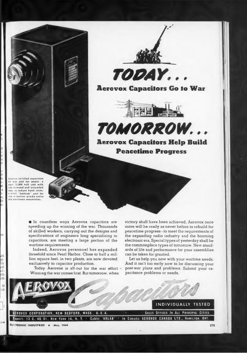
• f
Sales Offices In All Principal Cities
Aerovox nil-filled capacitors for war and tor peace - a giant 15,000 volt unit with side terminal and grounded case, io reduce head room: a small "bathtub" unit tor use in better-grade radio and electronic assemblies.
»
.nt g- tic ,r t .il- >thm
ELECTRONIC INDUSTRIES • May, 1944
It- d-
•• in
• In countless ways Aerovox capacitors are speeding up the winning of the war. Thousands of skilled workers, carrying out the designs and specifications of engineers long specializing in capacitors, are meeting a large portion of the wartime requirements.
Indeed, Aerovox personnel has expanded threefold since Pearl Harbor. Close to half a million square feet, in two plants, are now devoted exclusively io capacitor production.
Today Aerovox is all-out for the war effort - Winning the war comes first. Bui iomorrow, when
toMD
944
INDIVIDUALLY TESTED
gEROVOX CORPORATION,. NEW BEDFORD, MASS.. U S AExport: 13 E. 40 ST. New York 16. N. Y. ♦ Cable: ARLAB' • In Canada: AEROVOX CANADA LTD., Hamilton. Ont
TOMYAetovox Capacitors Go to War
TOMORROW.Aerovox Capacitors Help Build
Peacetime Progress
viclory shall have been achieved, Aerovox once more will be ready as never before io rebuild for peacetime progress—to meet the requirements of the expanding radio industry and the booming electronic era. Special types of yesterday shall be the commonplace types of tomorrow. New standards of life and performance for your assemblies can be taken for granted.
Lei us help you now with your wartime needs. And ii isn't too early now to be discussing your post-war plans and problems. Submit your capacitance problems or needs.
back and impedance is derivedPulse Generation
J. M. A. Lehihan (Electronic Engi
where Z
and Fn
down any
mass Spectrometer
illustrated cat-
Haydon On Permanent magnet Alloyshave brakes for instant
Schrmntic feedbuck network
Alloy
ayaonMay, 1944ELECTRONIC INDUSTRIES
the the
WRITEFOR YOUR
COPY TODAY
neering, London, March, 1944)The basic circuits used for
generation of pulses and for sharpening and shortening
Typical Composition (Per Cent)
reversible shift de* automatic
Send for alog!
High-Potcer HF magnetron Oscillator
Effect of Feedback on Impedance
pulses are summarized. Thyratron circuits, squegging and blocking oscillators, squaring circuits, rc circuits and multivibrators are treated.
speed from 450 RPM or faster, to one revolution a month.
M. S. Wilson and J. M. Whittenton (Electrical Engineering, March, 1944)
In an article on the influence of improved magnetic alloys on the design trends of electrical instruments, the electrical and mechanical properties of these alloys are compared, production methods discussed and applications mentioned. The table shows the essential characteristics of various magnetic alloys.
James E. Taylor (Review of Scientific Instruments, January, 1944)
A mass spectrometer suitable for routine isotope abundance measurements was constructed to analyze mixtures of carbon isotope compounds. The apparatus is described in detail.
Hot forge, punch mochi Cast. Muter, or grind Cast, sinter, or grind Cast, sinter, or grind Caat, water, as grind
resistors and to investigate the properties of liquids, especially the dielectric constant of a transformer oil, at frequencies of the order of 150 megacycles. It has also been used to measure the capacitances between the electrodes of tubes.
DEPENDABLE as the PLANETS
AC MOTORAvailable 450 RPM to I REV. per month; manufactured to your specific voltage, frequency, speed and torque requirements. The smallest l<0 volt, 50 cycle I-RPM units consume only 2 watts.
N. F. Alekseev (IRE Proceedings. March, 1944)
Experimental magnetrons for high power output were designed and tested in the centimeter range. Details of tube construction are given and suggestions for further developments based on the experimental results are made.
1. Cobalt (36 per cent) magnet Heel..............................
4, Cobalt-nickel-eopper alloy.5 Iron-nickel -copper alloy...........6 Comol magnet alloy....................
To use the equation for the determination of feedback by impedance measurements, it is essential to choose a pair of terminals for which either F8h or Fop is equal to zero so that the other is identical with the normal feedback which
Complete information on Timing Motors by the originators o f Timing Motors is recorded in this new Haydon z catalog.
Zi is the impedance which will be seen at the terminals 1,1' when terminals 2,2' are connected together and the only source of emf acting on the network is the external circuit connected to the terminals 1,1'. Zr is the impedance which will be seen at the terminals 1,1' when terminals 2,2' are connected together and the amplification factor of the tube is nullified. Fop is the feedback to the tube with the terminals 1,1' connected together, and Fo, is the feedback to the tube with the terminals 1,1' left open.
R. B. Blackman (Bell System 1* fa. nival Journal, October, 1943)
By considering the equations for the network shown, the follow .ng general relationship between f< d-
L e t our Engineering Service help you with your timing problem!
regular, as precise ** as the movements of planets . . . such are Haydon Timing Motors and Devices. Equipped with special motors to fit your particular requirements and geared DC MOTOR
Reversible — Compact — light in weight—«even segment commutator —low reactance rotor winding — alnico magnet field— totally enclosed. Sealed-in lubrication.
stop . . . are and possess vices for any reset.
Hot forge, punch and W» >•* Hot forge, punch caet.
Hot farge, punch enei, •“*
ih lufacturers
Gentlemen
repair charges by securing replacement parts and installing them
Many instruments returned to only the replacement of some G-R equipment very often can
number and priority a telegraphic order
REPLACEMENT PARTS NOW AVAILABLE FOR G-R EQUIPMENT
We maintain small stocks of the more commonly used parts for just such replacements. Many times you can secure these parts from us more quickly than from any other source.
When urgently needed we will accept telegraphic orders for replacement parts for instruments of our manufacture, in many cases saving a number of days of "out of service" time to users.
General radio company
Before ordering these parts, be sure they cannot be obtained locally. Restrict your orders to parts for General Radio equipment and please do not order more than is needed for the instrument being repaired. Always specify Type and Serial Number of instrument, part designation by wiring
our Service Department for repair require simple and inexpensive part. Users of save themselves valuable time, labor, and
diagram and manufacturers part number, purchase order certificate. In many cases, wo can ship the same day is received
THIRTY STATE STREET
CAMBRIDGE 39. MASSAC HUSETTS
Genome"•V, 19«
This service in no way curtails the facilities of our factory Service Department, when it is necessary to return instruments for major repair, or for recalibration. Even under wartime pressure, the Service Department is able to give remarkably quick service. It will be glad to assist you in any manner possible.
Our SERVICE AND MAINTENANCE NOTES should be of considerable help in avoiding and shooting trouble in many G-R instruments. Do you have a copy?We will be glad to send one, gratis, on request.
Sincerely
Service Manager
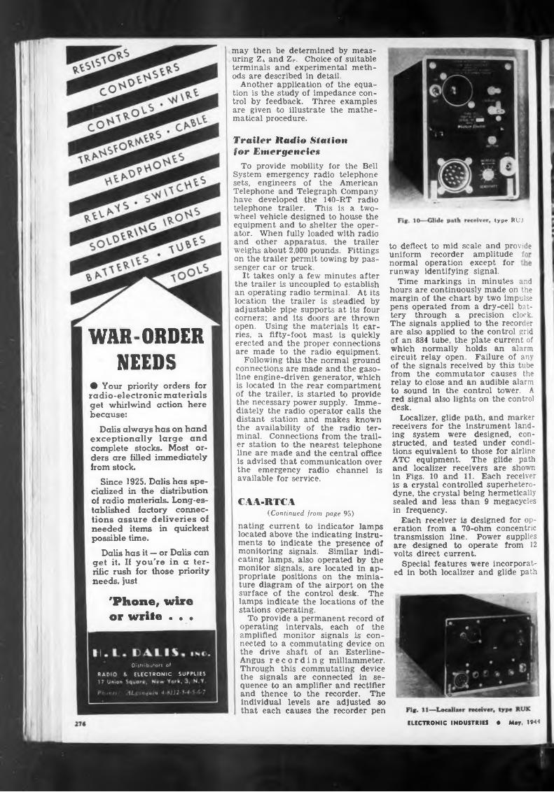
type RUJ
to deflect to mid scale and provide
and
WAR-ORDERNEEDS
than 9 megacyclesCAA-RTCA(Continued from page 95)
nating current to indicator lampsis designed for op- 70-ohm concentric
may then be determined by measuring Za and ZP. Choice of suitable terminals and experimental methods are described in detail.
Another application of the equation is the study of impedance control by feedback. Three examples are given to illustrate the mathematical procedure.
located above the indicating instruments to indicate the presence of monitoring signals. Similar indicating lamps, also operated by the monitor signals, are located in appropriate positions on the miniature diagram of the airport on the surface of the control desk. The lamps indicate the locations of the stations operating.
To provide a permanent record of operating intervals, each of the amplified monitor signals is connected to a commutating device on the drive shaft of an Esterline- Angus recording milliammeter. Through this commutating device the signals are connected in sequence to an amplifier and rectifier and thence to the recorder. The individual levels are adjusted so that each causes the recorder pen
uniform recorder amplitude normal operation except for runway identifying signal.
Time markings in minutes
sealed and less in frequency.
Each receiver eration from a
Dalis has it — or Dalis can get it. If you're in a terrific rush for those priority needs, just
ELECTRONIC INDUSTRIES • May, 1944
transmission line. Power supplies are designed to operate from 12 volts direct current.
Special features were incorporated in both localizer and glide path
'Phone, wire or write . • •
hours are continuously made on the margin of the chart by two impulse pens operated from a dry-cell battery through a precision clock. The signals applied to the recorder are also applied to the control grid of an 884 tube, the plate current of which normally holds an alarm circuit relay open. Failure of any of the signals received by this tube from the commutator causes the relay to close and an audible alarm to sound in the control tower. A red signal also lights on the control desk.
Localizer, glide path, and marker receivers for the instrument landing system were designed, constructed, and tested under conditions equivalent to those for airline ATC equipment. The glide path and localizer receivers are shown in Figs. 10 and 11. Each receiver is a crystal controlled superheterodyne, the crystal being hermetically
Trailer Radio Station for Emergenciex
To provide mobility for the Bell System emergency radio telephone sets, engineers of the American Telephone and Telegraph Company have developed the 140-RT radio telephone trailer. This is a two- wheel vehicle designed to house the equipment and to shelter the operator. When fully loaded with radio and other apparatus, the trailer weighs about 2,000 pounds. Fittings on the trailer permit towing by passenger car or truck.
It takes only a few minutes after the trailer is uncoupled to establish an operating radio terminal. At its location the trailer is steadied by adjustable pipe supports at its four corners; and its doors are thrown open. Using the materials it carries, a fifty-foot mast is quickly erected and the proper connections are made to the radio equipment.
Following this the normal ground connections are made and the gasoline engine-driven generator, which is located in the rear compartment of the trailer, is started to provide the necessary power supply. Immediately the radio operator calls the distant station and makes known the availability of the radio terminal. Connections from the trailer station to the nearest telephone line are made and the central office is advised that communication over the emergency radio channel is available for service.
• Your priority orders for radio-electronic materials get whirlwind action here because:
Dalis always has on hand exceptionally large and complete stocks. Most orders are filled immediately from stock.
Since 1925, Dalis has specialized in the distribution of radio materials. Long-established factory connections assure deliveries of needed items in quickest possible time.
Distributors of
ELECTRONIC SUPPLIES
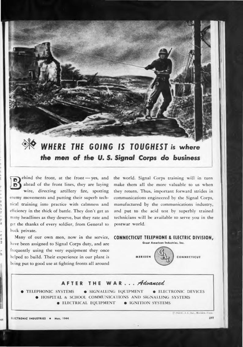
WHERE THE GOING IS TOUGHEST is where
ehind the front, at the front and
MERIDEN CONNECTICUT
y4cludMced
CONNECTICUT TELEPHONE & ELECTRIC DIVISION Great American Industrie», Inc.
the world. Signal Corps training will in turn
make them all the more valuable to us when they return. Thus, important forward strides in communications engineered by the Signal Corps,
manufactured by the communications industry, and put to the acid test by superbly trained technicians will be available to serve you in the postwar world.
• TELEPHONIC SYSTEMS • SIGNALLING EQUIPMENT • ELECTRONIC DEVICES• HOSPITAL & SCHOOL COMMUNICATIONS AND SIGNALLING SYSTEMS
• ELECTRICAL EQUIPMENT • IGNITION SYSTEMS
ELECTRONIC INDUSTRIES • May, 1944
D j ahead of the front lines, they are laying wire, directing artillery fire, spotting
enemy movements and putting their superb tech
nical training into practice with calmness and efficiency in the thick of battle. They don’t get as
many headlines as they deserve, but they rate and
get the thanks of every soldier, from General to buck private.
Many of our own men, now in the service, have been assigned to Signal Corps duty, and are frequently using the very equipment they once helped to build. Their experience in our plant is being put to good use at fighting fronts all around
Type "C" D.C. Generator
Permanent Magnet Field, ball-beoring equipped: l%" outside diameter, 3%" in length i . . weighs 16 ounces
THEALL-IMPORTANT
PROMPT DELIVERYElinco fractional — h.p. motors and generators combine compactness and small size with utmost precision and accuracy, the result of long experience and extreme manufacturing care and testing . . . plus adequate production to assure the most prompt delivery possible.
Type "8" A.C. Generator
Permanent Magnet Field wound for one, two or three phase A.C. Ball-bearing equipped; flange or bate mounted. 2%" outside diameter . . . weighs 14 ounces.
Can supply quantity production on standard items, or produce experimental or production machines built to your own specifications.
ELECTRIC INDICATOR CO.STAMFORD U.S.A. CONN.
receivers to meet the specification requirements. For example, temperature compensation of receiver sensitivity was necessary. In the glide path receiver this was especially important. Compensation had to be applied, in the glide path receiver, for momentary and prolonged change of battery voltage such as usually results from the starting of the airplane radio transmitter or the operating of landing lights. For a prolonged drop in battery voltage, two types of compensation are employed, one to correct for the immediate change caused by reduction of receiver plate voltage and the other to compensate for the gradual change in emission of the filaments. In the localizer receiver, careful consideration in the design of the 90/150- cycle filter and its associated circuit was required to avoid variation of the indicated course for signal levels below that at which the receiver automatic volume control was in operation. The rectifiers operating on the output of the 90/150-cycle filter had to be of special design and, as supplied, were balanced with respect to signal volume and temperature. Under test at prolonged high relative humidity, difficulty of leakage in certain parts of the wiring and in the IF transformers were overcome.
Although instrument landing systems, using a radio-electronic “localizer” are at present being installed for military use only and general applications for civilian operation await the end of the war, this improvement for the Federal Airways which is being done by the Civil Aeronautic Administration is slated eventually to be installed in all the busier airports of the nation. The equipment for postwar installation is being manufactured by eight or ten electronic manufacturing companies.
Jungle Troubles Solved by Radio Men
No critical shortage of communications and radio equipment has occurred in the Pacific theaters of war. All three commanding officers —Admirals Nimitz and Halsey and General MacArthur — report that they had never been delayed in their operations by the lack of signal apparatus and facilities.
This was related at a War Department press conference by Major General Harry C. Ingles, Chief Signal Officer of the Army, who returned after an inspection tour of five weeks of Signal Corps installations in the Central Pacific, Southwest Pacific and South Pacific Theaters of Operation, as briefly reported in our Washington News for April.
General Ingles paid the highest tribute to the great ingenuity which
the Signal Corps troops in the Pacific combat zones display in th lr work of installing and operating communications, both radio and wire, under the most difficult fig; . ing conditions in the world—te jungles of the Southwest Pacific - lands. He declared that dear e these difficult conditions, the Am - ican soldiers preserve their hun )r and throughout his trip he s w many illustrations of the latter - tribute.
The Chief Signal Officer emphasized that the relations between Army and Navy in the Pacific t- - aters of war are “just splendid” and, although this has been a goal which has been preached by the military leadership since the beginning of the war, “I do not see how they could be improved upon.” General Ingles related that the Signal Centers in every case throughout th* se theaters are combined and one sometimes sees an Army radio channel manned by a sailor and a Navy circuit operated by a Signal Corps soldier. The whole relationship is excellent, he stressed.
The enormous distances of the Pacific theaters where a couple of thousand miles are just a normal distance throws a great burden on communications, General Ingles stated.
Procurement now satisfactory
Declaring that in the other theaters of operations such as Europe, Africa, Mediterranean and Caribbean the primary communications medium is wire with radio regarded as auxiliary but valuable General Ingles pointed out that in the Pacific theaters radio is not only the primary means but in most cases the only method of communications because of the huge spaces of water.
In discussing the procurement problems of the Signal Corps, General Ingles brought out that the Corps’ procurement and distribution now is quite satisfactory and that this phase of its activities had come up in improvement a great deal, by over 75 per cent, during the past year. He told the newspapermen that the Signal Corps procures 96,000 different items of communications equipment, including a great many parts.
Relating that the jungles in the Solomons and New Guinea were the worst that he had ever seen—much more difficult than those of Central and South America—the Chief Signal Officer described how the jungle affects both the operations and the equipment of the radio apparatus The jungle has a blanketing effec' on radio so that walkie-talkies don transmit with their normal rang« particularly if the jungle is wet he said. Sets with normal range of five or ten miles can’t get more
ELECTRONIC INDUSTRIES • Mey, 1944278
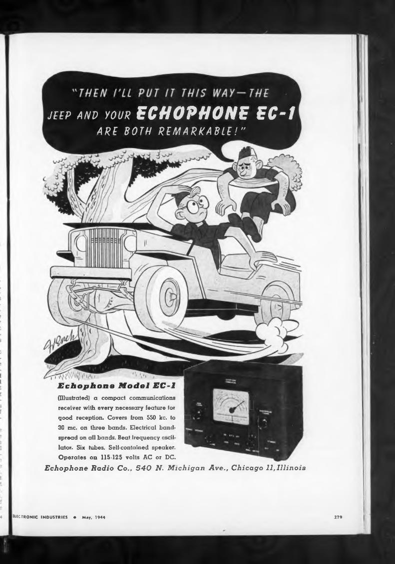
279ELECTRONIC INDUSTRIES ♦ May, 1944
Echophone Model EC-l(Illustrated) u compact communications Wreceiver with every necessary feature lor I
good reception. Covers from 550 kc. Io ■30 me. on three bands. Electrical bond WBkspread on all band1’. Beat frequency □ vi!
Icrtor. Six tubes. Self-contained speaker.Operates on 115-125 volts AC or DC.
Echophone Radio Co.. 540 N. Michigan Ave., Chicago 11,Illinois
JEEP AND YOUR ECHOPHONE EC~1 ARE BOTH REMARKABLE!"
Equipment take» awful beating
the unloading
CIRCUIT ACTION(Continued from page 102)
Signal Corp» in thick of fighting
ative pulses, curve These
Control Pulses
Without I diode
Controlst I nTTTiTT tati
stressed
280
And 1001 Other Vital Radio and Electronic Needs for Wartime!
Communications equipment also takes an awful beating in the Pacific theaters both in use and being unloaded in nets from the ocean-
than two or three miles, he noted. Therefore, the Signal Corps as soon as it is possible lays telephone wire networks on shore.
going vessels
pulses can be separated by the use of diodes so as to operate the respective relays. A circuit is shown
Geophysical Instrument Company has announced the occupancy of its new research laboratories and scientific instrument plant at Key Blvd, and Nash St., Arlington, Va.
This company manufactures electronic medical and industrial equipment, such as metal locators, X-ray intensity meters, optical equipment,
this war and cited how the Army' Engineers at Milne Bay left their bulldozers and took up their machine guns and rifles and mowed down an attack wave of Japanese. He also paid special tribute to the Signal Corps photographers wh go with the Infantry in the first w ves, although not armed.
country in infantry methods because of their being right in the combat operations. He added that this applies to all service troops in
actions, General Ingles They are trained in this
barges. They often lie on the beaches, too, in the rain without any protection.
The jungle weather is also extremely hard on the radio sets and they have to be treated especially with protective chemicals for water-proofing and to prevent fungus growth. The equipment, General Ingles stated, is treated for the tropics with the best methods available. It is especially important that the containers be made water-proof. It is a bad country for dry batteries, he added, and in order to keep them in a good condition the batteries have to be placed in cold storage. He related that the troops build refrigerating structures out of sawdust from the lumber that they have used in making Army buildings and then put the refrigerating apparatus inside the sawdust housings. The Signal Corps is now trying to develop a special battery for the tropical climate which it is hoped will be an improvement. The heavy radio station equipment does not need to have such extensive water-proofing protection since they are housed practically entirely in buildings.
closely proportional to der/dt when er is small. This principle can be used to alter the waveform of an applied signal, as from a sine wave to a peaked wave. A sine wave is first “clipped” in a limiter circuit and applied to a series RC combination with a capacitor of a small value (X large for the frequency involved, preferably many times the value of R).
Differentiation circuits are often used to discriminate between pulse varieties as to wave shape, as for example the separation of a pulse with a sharp front, from one with a gradual wave front and an abrupt falling off. A combination of these pulses which might be used in some remote control system, is shown in the er curve in the oscillogram, Fig. 6.
The first derivative of this waveform has a sharp positive and neg-
ELECTRONIC INDUSTRIES • May, W44
The Signal Corps troops’ ingenuity is remarkable, according to the Chief Signal Officer. The sergeants and enlisted men in their small “teams” or units often do not perform their installation and maintenance and repair operations according to the book but try out different methods of their own invention. He related that he had never seen so many different ways of putting up field wire and told about a young lieutenant at Bougainville who made cross-arms with little notches instead of the usual insulators and tied the wire into these notches with basket-weave knots in a very good method. He noted that the field wire (which weighed 185 pounds per mile in World War I) is lighter in this war, weighing only 125 pounds.
The Signal Corps soldiers are combat troops, taking part in the fighting a great deal and engaging
TELEPHONE ORDERS TO BRyant 9-1946
HARVEY fills orders and rushes them to you as quickly as wartime conditions permit. Our trained advisors help to locate supply sources of hard- to-find components. We maintain a staff to help solve your priority problems. And, WE DELIVER to all parts of the United States.
New Research Lab Completed
From all leading manufacturers . . . products that you can depend on to see you safely through essential production.
TUBES! RELAYS!
RESISTORS! CAPACITORS!
TRANSFORMERS! POTENTIOMETERS TEST EQUIPMENT!
CONTROLS!
SOURCES
103 WEST 43rd ST.. NEW YORK 18. N. Y
ELECTRONIC INDUSTRIES
B-L metallic rectifier* provide efficient, dependable conversion of AC
to DC over a wide range of temperature and climatic condition*. Ambient temperature* ranging from below minu* 40 C to above plus 60° C are common.
B L metallic rectifier* are available in a wide variety of »ize* and
arrangement* to fit practically any power requirement or application.
Long experience ha* made B-L the recognized source of authentic
information on metallic rectifier*. No matter what rectifier application
you are considering, B-L will be glad to work with you on the engineering detail*.
Write for Bulletin No. 95
Copper Sulphide lumBL
METALLIC RECTIFIERS
UNZE COMPANY ■ ST. Ind manufacturer* of Copper Sulphide and Selenium Rectifier* ge»». and DC. Fewer Supplies ter practically every reqviremonl
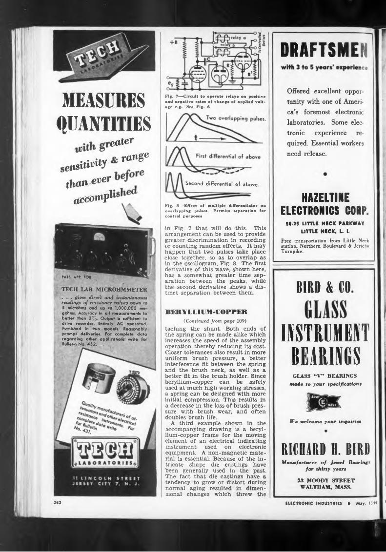
DRAFTSMEN
MEASURESQUANTITIES
eater
rang6nsitirity
Second differential of above,
HAZELTINEELECTRONICS CORP
58-25 LITTLE NECK PARKWAYLITTLE NECK. L. I.
CATS. A PF. FOR
BIRD & CO
BERYLLIUM-COPPER
INSTRUMENTBEARINGS
We welcome your inquiries
RICHARD H. DIRD
282
Free transportation from Little Neck station. Northern Boulevard & Jericho Turnpike.
laboratories. Some elecca’s foremost electronic
tronic experience
in Fig. 7 that will do this. This arrangement can be used to provide greater discrimination in recording or counting random effects. It may happen that two pulses take place close together, so as to overlap as in the oscillogram, Fig. 8. The first derivative of this wave, shown here, has a somewhat greater time separation between the peaks, while the second derivative shows a distinct separation between them.
Fig. 7—Circuit to operate relays on positive and negative rates of change of applied voltage r-g See Fig. 6
Manufacturer of Jewel Rearing i
for thirty years
23 MOODY STREET WALTHAM, MASS.
ELECTRONIC INDUSTRIES • May, 1944
GLASS “V” BEARINGS made to your specifications
(Continued from page 109) taching the shunt. Both ends of the spring can be made alike which increases the speed of the assembly operation thereby reducing its cost. Closer tolerances also result in more uniform brush pressure, a better interference fit between the spring and the brush neck, as well as a better fit in the brush holder. Since beryllium-copper can be safely used at much high working stresses, a spring can be designed with more initial compression. This results in a decrease in the loss of brush pressure with brush wear, and often doubles brush life.
A third example shown in the accompanying drawing is a beryllium-copper frame for the moving element of an electrical indicating instrument used on electronic equipment. A non-magnetic material is essential. Because of the intricate shape die castings have been generally used in the past. The fact that die castings have a tendency to grow or distort during normal aging resulted in dimensional changes which threw the
quired. Essential workers need release.
thanever
acCOW1
TECH LAB MICROHMMETER . . give» direct and instantaneousreadings of resistance values down to 5 microhm« and up to 1,000,000 mo gohms. Accuracy in all measurement* to better than 2%. Output is sufficient to drive recorder Entirely AC operated. Furnished In two models. Reasonably prompt deliveries. For complete data regarding other applications write for Bulletin No- 432.
Offered excellent oppoi tunity with one of Ameri
Fig. 8—Effect of multiple differentiator on overlapping pulses. Permits separation for control purposes
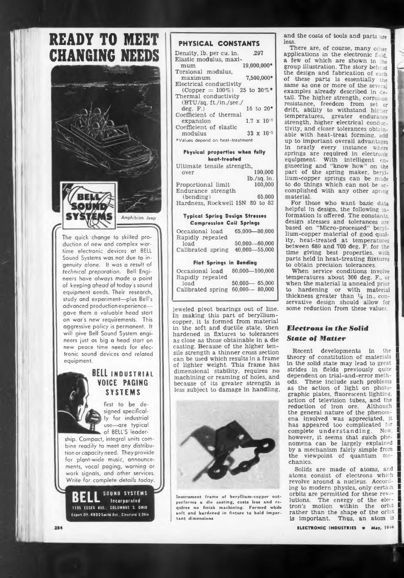
READY TO MEET CHANGING NEEDS
Amphibian Jeep
The quick change to skilled production of new and complex wartime electronic devices at KELL Sound Systems was not due to ingenuity alone. It was a result of technical preparation. Bell Engineers have always made a point of keeping ahead of today's sound equipment needs. Their research, study and experiment—plus Bell s advanced production experience— gave them a valuable head start on war s new requirements. This aggressive policy is permanent. It will give Bell Sound System engineers ¡ust as big a head start on new peace time needs for electronic sound devices and related equipment.
PHYSICAL CONSTANTSDensity, lb. per cu. in. .297Elastic modulus, maxi
mum 19,000,000*Torsional modulus,
maximum 7,500,000*Electrical conductivity
(Copper = 100%) 25 to 30%•Thermal conductivity
(BTU/sq. ft./in./sec./deg. F.) 16 to 20*
Coefficient of thermal expansion 1.7 x IO-5
Coefficient of elastic modulus 33 x 10-5
♦Values depend on heat-treatment
Physical properties when fully heat-treated
Ultimate tensile strength, over 190,000
Ib./sq. in.Proportional limit 100,000Endurance strength
(bending) 65,000Hardness, Rockwell 15N 80 to 82
Typical Spring Design Stresses Compression Coil Springs
Occasional load 65,000—80,000Rapidly repeated
load 50,000—60,000Calibrated spring 40,000—55,000
Flat Springs in BendingOccasional load 80,000—100,000Rapidly repeated
load 50,000— 65,000Calibrated spring 60,000— 80,000
BELL INDUSTRIAL
VOICE PAGING SYSTEMS
jeweled pivot bearings out of line. In making this part of berylliumcopper, it is formed from material in the soft and ductile state, then hardened in fixtures to tolerances as close as those obtainable in a die casting. Because of the higher tensile strength a thinner cross section can be used which results in a frame of lighter weight. This frame has dimensional stability, requires no machining or reaming of holes, and because of its greater strength is less subject to damage in handling.
first to be designed specifically for industrial use—are typical of BELL’S leader
ship. Compact, integral units combine readily to meet any distribution or capacity need. They provide for plant-wide music, announcements, vocal paging, warning or work signals, and other services. Write for complete details today.
BELL SOUND SYSTEMS Incorparated
lies ESSEX ME . COLUMBUS 3 OHIO
Ei port OH 4900 EtCM Cleveland 3 Ohio
Instrument frame of beryllium-copper out- perfoi ms a die casting, costs less and requires no finish machining. Formed while soft and hardened in fixture to hold important dimensions
and the costs of tools and parts ire I less.
There are, of course, many ot ier I applications in the electronic field, I a few of which are shown in :he I x group illustration. The story behind I the design and fabrication of each I 1 of these parts is essentially the I same as one or more of the several I ■ examples already described in de- 11 tail. The higher strength, corrasion I resistance, freedom from set or I I drift, ability to withstand higher I temperatures, greater endura ce I I strength, higher electrical conauc- I tivity, and closer tolerances obta n- I able with heat-treat forming, add I up to important overall advanU. es I in nearly every instance where I springs are required in electronic I equipment. With intelligent en- I eineering and “know how” on the I part of the spring maker, beryl- I lium-copper springs can be made I to do things which can not be ac- I complished with any other spring I material. I
For those who want basic data I helpful in design, the following in- I lormation is offered. The constants, I design stresses and tolerances are I based on “Micro-processed” beryl- I Jium-copper materia! of good qual- I ity. heat-treated at temperatures I between 680 and 700 deg. F. for the I time giving best properties, with I parts held in heat-treating tiixtures I to obtain precision tolerances. I
When service conditions involve I temperatures about 300 deg. F, ur I when the material is annealed prior I to hardening or with material I thickness greater than % in., con- I servative design should allow for I some reduction from these values. I
Electrons in the SolidState of Matter
Recent developments in the I theory of constitution of materials I in the solid state may lead to great I strides in fields previously quite I dependent on trial-and-error meth- I ods. These include such problems I as the action of light on photo- I graphic plates, fluorescent lighting. I action of television tubes, and the I reduction of iron ore. Although I the general nature of the phenom- I ena involved was appreciated, it I has appeared too complicated for I complete understanding. Now, I however, it seems that suich phe- I nomena can be largely explained I by a mechanism fairly simple from I the viewpoint of quantum me- I chanics.
Solids are made of atoms, and I atoms consist of electrons which I revolve around a nucleus. Accord- I ing to modern physics, only certain I orbits are permitted for these revo- I lutions. The energy of the elec- I tron’s motion within the orbit I rather than the shape of the orbit I is important. Thus, an atom is I
ELECTRONIC INDUSTRIES • May, 1944
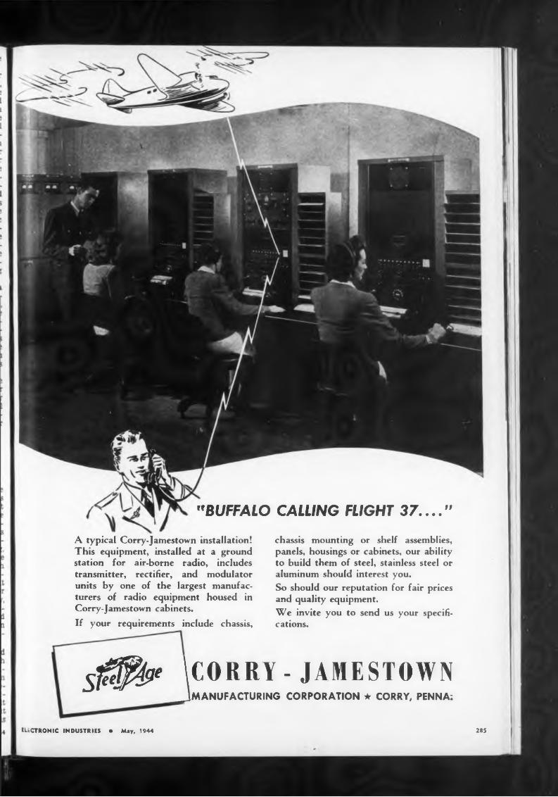
ELECTRONIC INDUSTRIES • May, 1944 285
h
••BUFFALO CALLING FLIGHT 37...."A typical Corry-Jamestown installation! This equipment, installed at a ground station for air-borne radio, includes transmitter, rectifier, and modulator units by one of the largest manufacturers of radio equipment housed in Corry-Jamestown cabinets.If your requirements include chassis,
chassis mounting or shelf assemblies, panels, housings or cabinets, our ability to build them of steel, stainless steel or aluminum should interest you.So should our reputation for fair prices and quality equipment.We invite you to send us your specifications.
5^^ \C0RRY -JAMESTOWN___ JMANUFACTURING CORPORATION * CORRY, PENNA;
Clarostat Greenohms — those greencolored inorganic - cement - coated
power resistors—are found today in most radio, electronic and electrical assemblies that must stand the gaff. They are the TOUGHER power resistors. They can take it—and then some.
Available in wattage ratings up to 200. Widest choice oi resistance values. Fixed, adjustable, tapped. Also choice of mountings and terminals.
Write for Literature . . .
POWER RESISTORS
CLAROSTAT MFG. CO., Inc. • 285-7 N. fa St., Brooklyn, N.Y.286
considered as a scale of actual and potential energy levels. When two atoms combine to form a molecule, the number of levels stays constant, giving the combination a double energy-level system. The interaction of the atoms on each other causes the energy levels to shift slightly to give pairs of different, rather than identical, levels. When a large number of atoms form a solid, such as a crystal, each original atomic energy level is split into a number of levels which are separate but so close together that they are considered as a band.
The energy-level scheme of an atom could be pictured as a tall house with many stories, but only one room in each story. These houses are populated by electrons, which prefer to inhabit the lower levels. No more than two electrons occupy the same room. The more complicated atoms can be considered as houses whose lower rooms are entirely filled, but whose upper rooms generally are only partially occupied by tenants.
Electrons “on the loose"
The formation of a solid can be visualized as the grouping of the single-room houses to form an apartment house, with many rooms on the same floor. If the original houses had each room occupied by a pair of electrons, there would not be much intermingling in the apartment house. This Is why inert gases, like helium, with all levels filled, do not condense to solids except at very low temperatures. Many simple molecules behave similarly, and form soft solids like paraffin wax. If, however, the individual houses had upper floors only partly filled, as in the reactive elements, the interaction is very curious. In the community of electrons morals are quite free. There is a tendency of single occupants to double up, sharing the lowest room available as an electron pair. The pair will always live on a lower floor than before the union, which in our analogy means a lower energy level, which gives the system stability. This phenomenon of electron coupling binds the ninety- two elements into compounds and crystals.
When metallic elements form a solid, a simple population count shows the upper floors are only partially filled. If there is any attraction on one side of the house, such as a passing fire-engine, some of the inhabitants of the upper floors will rush to that side. This is typical of the migration of electrons under the influence of an external electric field, the motion producing an electric current. In the heat of summer some inhabitants will vacate their rooms and move to the top floor. This is the
case of an electron In a photocell I exposed to radiation. Some will I leave altogether, showing the phe- I nomenon of electron emission of I the alkali metals used in ph I tubes.
In more elaborate structures x- I _ posure to light may cause an । ;ec- I H tron to move to another win of I the apartment, where it may ind I a single inhabitant to join. The I a formation of an image on a ph to- I graphic plate is supposed to follow I such a mechanism. Light fai mg I A on an electron causes it to mig ate I and eventually encounter a silver I atom with a missing electron, which I in it joins, thereby producing the me- I tallic silver of the image. Thus by I simply taking a count of the rooms I c] available and the number of elec- I trons to be accommodated, it is pos- I sible to predict which elements I q form weak crystals, metals, or semi- I ” conductors, and to arrive at a con- I sistent explanation of the various I w phenomena observed in solids.
Quantitative investigations of the I relative positions of the energy I n levels and widths of the bands has I led to further advances in the un- I derstanding of the constitution of I _ many substances and of the mech- I 1 anism of the more fascinating phe- I nomena and reactions of the solid I state. The green color of a radio’s I " “magic-eye” is caused by bombard- I ment of a screen of tiny crystals by I electrons. Brighter and more per- I manent screens have been made as I f a result of the understanding of the I energy bands in the crystals. Sim- I ilarly three - dimensional X-ray I. views of the interior of a patient’s I body have been made possible by I the discovery of more responsive I. crystals. Television screens can be 11 thought of as numerous minute I magic-eyes blinking under a stream I ( of continually changing radio sig- I nals. The materials of these I screens, in particular those for I color television, are being devel- Ia oped by research guided by the I band theory of solids. Much the I same considerations can be applied Ie to research in photocells, photo- I graphic materials, and fluorescent I lights. Other fruitful fields where |< the theory of the solid state would I lead to practical developments are I rectification, reduction of ores, cor- I rosion, scaling of iron, sintering, I soldering, and powder metallurgy - I Industrial Bulletin of Arthur D. I Little, Inc., Massachusetts Institute I of Technology, Cambridge, Mass.
DISCONTINUITIES(Continued from page 125)
neglected. To give an idea of these I effects, the measured results on : I quarter wave piece of 3.50 cm I length are: ZOi=76.7 ohms and I Zo2=17.3 ohms. Then k=Z2oi/Z:2 I =19.7 for the section xy„ by com- I putation; k=18.9±l% for 1=14 0 I
ELECTRONIC INDUSTRIES • May, 1944 I
;s
IS
>
I-
d’s
yIS IP
a TI d
y iS
p r
e y IS
if
0
•y ’s•y re )p
v £ e T h
ip le d )-t
4 1
BUT AS FOR ME16 > years ago this month
a man arose in the 2nd
Virginia Convention and
into just nineteen crystal
clear words compressed a
question and an answer
which will never pass from
men's memories. Said Pat-
rick Henry, "’I know not
what course others may take, but as for me, give me liberty or give me death.
Patrick Henry's speech carried the convention, and ultimately a young nation was committed
to fight for its life—and its freedom, which it valued more. That nation has never since hesi
tated in the pursuit and defense of freedom, and never will. Today, in freedom’s name,
America and her allies are fighting a war greater than all the wars of history put together,
a war in which the amount of weapons and materials needed surpasses the imagination
of most men. But they are being provided and will continue to be provided, with the
aid of your War Bonds. It’s the extra punch that wins battles—provide it bv buying extri
War Bonds.
ELECTRONIC INDUSTRIES • May, 1944
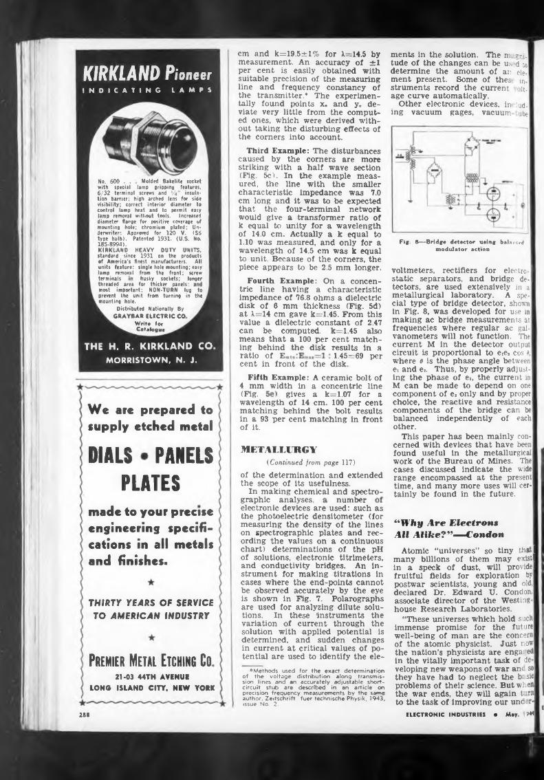
Molded Bakelite socketlamp gripping
6/32 terminal screws and Ç4'
terminalsthreaded area for thicker panels:
Nationally By
ratio Of E,cent in front of the disk
(Fig.
METALLURGYDIALS PANELS (Continued from page 117)
PLATESgraphic analyses, number
Premier Metal Etching Co21-03 44TH AVENU!
LONG ISLAND CITY, NEW YORK
288
NON-TURN lug to from turning in the
means that a 100 per cent matching behind the disk results in a
No. 600 . . with special features,
' insula-
Fifth Example: A ceramic bolt of4 mm width in a concentric line
wavelength of 14 cm. 100 per cent matching behind the bolt results in a 93 per cent matching in front of it.
gives a k=1.07 for a
1.45=69 per
145 also
of the determination and extended the scope of its usefulness.
In making chemical and spectro-
husky sockets; longer
cm and k=19.5±l% for X=14.5 by measurement. An accuracy of ±1 per cent is easily obtained with suitable precision of the measuring line and frequency constancy of the transmitter.* The experimentally found points xo and y„ deviate very little from the computed ones, which were derived without taking the disturbing effects of the corners into account.
can be computed.
electronic devices are used: such as the photoelectric densitometer (for measuring the density of the lines on spectrographic plates and recording the values on a continuous chart) determinations of the pH of solutions, electronic titrimeters, and conductivity bridges. An instrument for making titrations in cases where the end-points cannot be observed accurately by the eye is shown in Fig. 7. Polarographs are used for analyzing dilute solutions. In these Instruments the variation of current through the solution with applied potential is determined, and sudden changes in current at critical values of potential are used to identify the ele-
Fig. 8—Bridge detector using balanced modulator action
“Why Are Electrons All Alike?"—Condon
ments in the solution. The xr. gm. tude of the changes can be us d to determine the amount of an element present. Some of thes in. I struments record the current it- age curve automatically.
Other electronic devices, in lading vacuum gages, vacuum ube
Atomic “universes” so tiny tha I many billions of them may exist I in a speck of dust, will provide! fruitful fields for exploration by postwar scientists, young and old, declared Dr. Edward U. Condon, associate director of the Westinghouse Research Laboratories.
“These universes which hold such immense promise for the future well-being of man are the concern of the atomic physicist. Just now the nation’s physicists are enga: ed in the vitally important task of developing new weapons of war anc so| they have had to neglect the b sic problems of their science. But when the war ends, they will again t rn to the task of improving our uncr-
ELECTRONIC INDUSTRIES • May. 944
We are prepared to supply etched metal
of America’s finest manufacturers. All units feature: single hole mounting; easy lamp removal from the front; screw
most important; prevent the unit mounting hole.k Distributed
GRAYBAR ELECTRIC CO Write lor Catalogue
voltmeters, rectifiers for electro-1 static separators, and bridge de-1 tectors, are used extensively in a metallurgical laboratory. A special type of bridge detector, shown in Fig. 8, was developed for use in making ac bridge measurements at frequencies where regular ac galvanometers will not function. The current M in the detector output circuit is proportional to eie» cos < where e is the phase angle between ei and e2. Thus, by properly adjusting the phase of eb the current in M can be made to depend on one component of e2 only and by proper I choice, the reactive and resistance components of the bridge can be' balanced independently of each other.
This paper has been mainly concerned with devices that have been found useful in the metallurgical work of the Bureau of Mines. The cases discussed indicate the wide range encompassed at the present time, and many more uses will certainly be found in the future.
tion barrier; high arched lens for side visibility; correct interior diameter to control lamp heat and to permit easy lamp removal without tools. Increased diameter flange for positive roverage of mounting hole; chromium plated; Underwriters Approved for 120 V. (S6
THIRTY YEARS OF SERVICE TO AMERICAN INDUSTRY
♦Methods used for the exact determination of the voltage distribution along transmission lines and an accurately adjustable shortcircuit stub are described in an article on precision frequency measurements by the same author, Zeitschrift fuer technische Physik, 1943, issue No. 2.
made to your precise engineering specifications in all metals and finishes.
type bulb). Patented 185-8994).KIRKLAND HEAVY standard since 1931
1931. (U.S. No.
DUTY UNITS, on the products
Third Example: The disturbances caused by the comers are more striking with a half wave section (Fig. 5c). In the example measured, the line with the smaller characteristic impedance was 7.0 cm long and it was to be expected that the four-terminal network would give a transformer ratio of k equal to unity for a wavelength of 14.0 cm. Actually a k equal to 1.10 was measured, and only for a wavelength of 14.5 cm was k equal to unit. Because of the corners, the piece appears to be 2.5 mm longer.
Fourth Example: On a concentric line having a characteristic impedance of 76.8 ohms a dielectric disk of 6 mm thickness (Fig. 5d) at X=14 cm gave k=1.45. From this value a dielectric constant of 2.47
THE H. R. KIRKLAND COMORRISTOWN, N. J.
KIRKLAND Pi«™INDICATING LAMPS
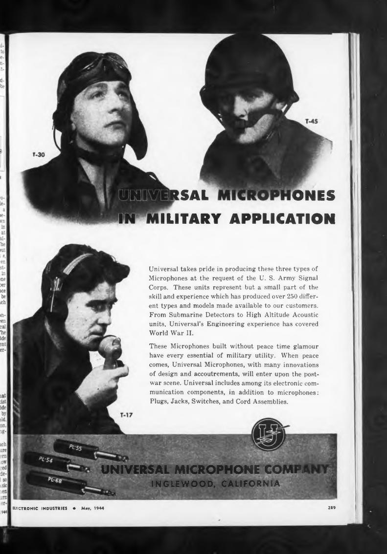
SAL ONESILITARY APPLICATION
2S9
Universal takes pride in producing these three types of Microphones at the request of the U. S. Army Signal Corps. These units represent but a small part of the skill and experience which has produced over 250 different types and models made available to our customers. From Submarine Detectors to High Altitude Acoustic units. Universal’s Engineering experience has covered World War II.
These Microphones built without peace time glamour have every essential of military utility. When peace comes, Universal Microphones, with many innovations of design and accoutrements, will enter upon the postwar scene. Universal includes among its electronic communication components, in addition to microphones: Plugs, Jacks, Switches, and Cord Assemblies.
ELECTRONIC INDUSTRIES • May, 1944
UNIVERSAL MICROPHONE COMPiINGLEWOOD, CALIFORNIA
WE TAKE THE WORRIED OUT OF YOUR HANDS!
1 OUR
SPECIALTY
FABRICATING MYCALEX
IN ALL FORMS, to
Specifications
COLONIAL KOLONITE COMPANY 2212 W. ARMITAGE AVE., CHICAGO, III
JONESBARRIER STRIPS
SOLVE MOST TERMINAL PROBLEMS
No. 151
A compact, sturdy terminal strip with Bakelite Barriers that provide maximum metal shorts
cover
to metal spacing and prevent direct from frayed wires at terminals.
6 SIZESevery requirement. From wide
ond 13/32” high with 5 40 screws to 2'/i” wide and 1%** high with '/4”-28 screws.
Jones Barrier Strips will improve as well as simplify your electrical intra-connecting problems. Write today for catalog and prices.
HOWARD B. JONES2460 WEST GEORGE STREET
CHICAGO, 18 ILLINOIS
standing of the fundamental constitution of all matter.
“During a war we must live on our scientific ‘capital,’ because fundamental research does not yield results rapidly enough to help win battles. But in the postwar period, atomic physicists will return to their real task, building new foundations for advances which may result in a world so different from the present one as to be almost unrecognizable.”
There are many things still unknown about the tiny universes that are called atoms and the electrons, protons and neutrons which are found in each atom. Dr. Condon said.
“Why are all electrons, particles of negative electricity, identically alike instead of differing slightly one from the other, as do peas in a pod?” he asked. “We know that bits with like electrical charges repel each other, so what holds together the different parts of an electron? Does it make sense to talk of the parts of anything so fundamental as the electron? If you are looking for places to contribute to physics, I will tell you that there are no answers known as yet to these questions.”
The atom of hydrogen is the simplest of all the 92 elements which form all the matter known to scientists today, Dr. Condon said. It consists of a proton charged with positive electricity, and an electron whose negative charge is equal to the proton’s positive charge but whose “weight” or mass is 1800 times smaller than the proton’s mass. Other atoms are more complicated but they follow the same pattern; there Is a nucleus, a tightly constructed center composed of protons and neutrons, which have no electrical charge and around this nucleus are electrons.
“For the physicist,” Dr. Condon said, “the primary problem is the discovery of the mechanics of the nucleus—the laws of motion of its particles and the nature of the forces which hold them together.
“In any nucleus except hydrogen we are confronted with protons stuck together at distances 10,000 times smaller than the distances between atoms in a molecule. Since the energy between electrically charged particles Increases as the particles get closer together, this means that the electrical energy tending it blow up any nucleus is some 10,000 times greater than usual chemical energies like fuel value of coal.
“Nevertheless, most atoms quite stable so there must
the
are be
strongly attractive forces of a new kind operating between the particles of the nucleus to hold it together In spite of the explosive tendencies of the electrical forces. These new forces are presumably non-electrical in character for they act between proton and neutron in
much the same way as between nro- ton and proton.”
Sell Phono SurplusApproximately 40,000 hand-wind-
ing portable phonographs, which the United States Government will sell as surplus commodities, wen given specific dollars - and - cents prices at wholesale and retail le /els by the Office of Price Administration. The personnel of the armed services and export customers, it is understood, will get all Instruments.
For the sale of a Model No. 64 Special (with Swiss motor) a consumer may be charged a maximum price of $14.25, and for the sale of Model R (rebuilt with American motor), $12.75. At wholesale the maximum prices are set at $8.50 f.o.b. sellers point of shipment for a Model No. 64 Special, and $7.00 f.o.b. sellers point of shipment for a Model R.
SAW-TOOTH GENERATOR IB(Continued from page 121)
R, R^, Rc. C.-Cp. R4 is the limiting I resistor for the highest frequency I to be generated, in this case 2000 1 X ohms, where F = 1 megacycle. Ct I to C» is the “rough” frequency con- I * trol and R. covers the “fine” con-1 I trol from 1 cycle to 1000 cycles. I Above 1000 cycles a switch is thrown I so as to cut R« out and R* in, which I is a 15,000 ohm control which will 11 serve to cover the balance of the 11 required frequency spectrum from 11 1000 cycles to 1 me.
Rs located in the screen circut of I the tube must handle 4 watts. Un- I J der operating conditions the screen I *' current will reach 20 milliamperes. I Considering normal tube functions, I I this would seem excessive, and has I I proven so for any tubes not having I certain characteristics pertinent to I - the grid structure. Of all the va-1 rieties tried the 7G7 tube definitely 1I proved its worth in operating with- I out one single failure. The screen 11 in this tube seems to remain In the 11 cool region, that is. Judging by 11 sight, while In others the screen I grid became quite red after a few I minutes of operation. The screen 11 operating voltage Is about 250 volts I I at the tube socket terminal. The 11 400 to 425 volt supply is dropped I through Ri and Rt. C. is an Isola-1 tion capacitor. In some cases G ■ c should be shunted by 0.006 mfd to I isolate high frequencies. The plate ■ voltage at the tube socket runs from 11 +14 volts minimum to about +55I * volts maximum. The plate load re-1 sistor R- must be kept at this value I , +10 per cent. Any change of this I A resistor will result in linearity dis-11 tortion. 11
Ci is the feedback capacitor. Its I size (0.006 mfd.) should preferably I not be changed. An increase to I
ELECTRONIC INDUSTRIES • May, 1944 111290
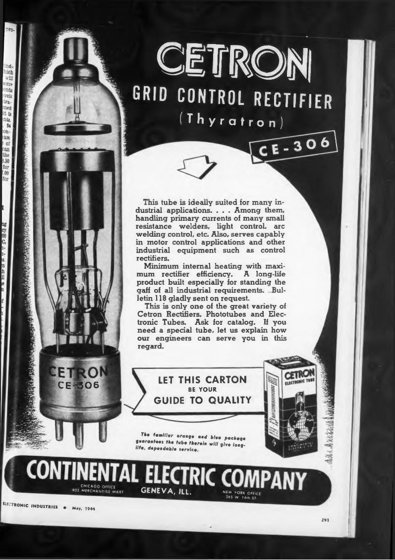
w
:All]
-f
tìlò , raed 33 fe I
64 >?> I 7 I Of I u I M I ' I
tú.» I< I ■' I
CE«O6
CETROSGRID CONTROL RECTIFIER
[ (Thyratron)f _3 o6\
1ms tube is ideally suited tor many industrial applications. . . . Among them, handling primary currents of many small resistance welders, light control, arc welding control, etc. Also, serves capably in motor control applications and other industrial equipment such as control rectifiers.
Minimum internal heating with maximum rectifier efficiency. A long-life product built especially for standing the gaff of all industrial requirements. Bulletin 118 gladly sent on request.
This is only one of the great variety of Cetron Rectifiers, Phototubes and Electronic Tubes. Ask for catalog. If you need a special tube, let us explain how our engineers can serve you in this regard.
LET THIS CARTON BE YOUR
GUIDE TO QUALITY
T*« familiar orang» and bla» packag» guarant—» th» tub» th»r»¡n will glv» lOK9. Ufo, dep»ndabl» tarvlc», 9
CHICAGO OFFICE «03 MERCHASCSE MART GENEVA, ILL. NEA »OHK OFFICE
265 W I 4rh JJ
^ectronic industries• M*y, 1944
291
Condition» of control
292
best results are obtained with theWIDE RANGE
VACUUM TUBE
trol is to successful
that it adequately fulfills these c m-ditions
ELECTRONIC INDUSTRIES • May W
7N7 inverter.
VOLTMETERS
• High input impedance for both AC and DC measurement*.
• Convenient, low capacity "Probe” especially adapted to high frequency radio use—100 megacycles and over.
• Self-regulating operation from power line; no batteries.
• Multiple voltage ranges—accurate and stable.
BULLETIN ON REQUEST
ALFRED W. BARBER LARORATORIES
34-04 Francis Lewis Blvd. Flashing, N. Y.
REM
—official Navy Photo
Premax AntennasAre Maintaining Communications
On land . . . and on the sea . .these Tubular Antennas in many dif-ferent designs and with many ditferent mountings are doing excellentservice under trying conditions.
Division Chisholm-Ryder Co., IncM03 Highland Avenue, Niagara Falli, N
capacity has degenerative effects on low frequencies. Its function and size have been well established and
present set-up.Studying the circuit we would
feel that it is either a transitron or negative resistance or dynatron type of oscillator, but another few points will show that actually it has a little of all three.
Circuit waveform»
In Fig. 2A, the wave forms developed at the screen grid and the suppressor of the tube are shown. The steeper or higher, these wave forms (which are of a negative character) the more linear the output will be. This wave form holds true for all frequencies above 500 cycles. On the ranges above 100 kc it changes in that the wave forms lose their flat-top characteristic, *but are still steep enough to give the desired effects. The oscilloscope used for observing these high frenquency pulses had apnar- ently insufficient response characteristic to permit true observation. Observation on an oscilloscope will show one readilv the wave form on these points. We now come to the synchronizing input control Ri. This resistor is of a rather low value about 2,000 ohms. With a large enough synchronizing input signal, this value was found to be adequate. Large values of grid resistors have a disastrous effect, in erratic operation and also distortion of the output wave. For good synchronization, a pulse signal seems to be the best wave form, especially at low frequencies. Sinusoidal waves do not cause proper lock in. but tend to cause wandering of the generated frequencies. Conversion of any synchronizing signal of any wave form into a pulse appears to be the best solution. C10 is a 1 mfd output capacitor. A smaller value will cause low frequency distortion The values for C. to C« are about as follows: C» = 1 mfd, C« = .1, CR = .05, C, = .01, C? = .005, C. = .001, Co = 50 mmfd. Circuit construction might cause the last two values to be changed slightly.
No doubt improvements can and will be made. It is hoped that the data given will be helpful in promoting an improvement in oscilloscopes for the laboratories and industry.
In Fig. 3, the synchronizing amplifier and inverter for the timing generator of a conventional oscilloscope are shown. For internal synchronization, the output of the first vertical amplifier stage is connected through a shielded cable to the 7A4 grid. The amplified output is connected through a selector switch to the grid of one section of the
The plate load ofthis tube is divided into the equal sections and either positive or negative pulses may be applied to the
timing generator grid circuit, tsynchronization.
The component values in th» synchronizing amplifier and im rter stages are so chosen as to produce a desirable steep-wave front essential to accurate synchronization. This can be accomplished by supplying the 7A4 with an excessive signal so as to drive the tube to saturation and also beyond cut-off in order to produce an approximate square wave. This square wave is passed through a C-R coupling network which acts as a differentiator to produce the peaked waves shown in Fig. 2A.
Photocell Control forBessemer Steelmaking
In a recent paper given before the American Institute of Mining and Metallurgical Engineers, by Dr. H. K. Work, manager of research and development, Jones & Laughlin Steel Corporation, Pittsburgh, Pa., fundamental principles of operation underlying the Bessemer electronic flame-control process were discussed, along with considerable background material concerning the Bessemer process
A great deal of work has been done in the past aiming toward more precise control of Bessemer steel-making, but to a large extent this work has failed to contribute anything definite. The course of the reactions is so rapid that the usual chemical control methods cannot be applied, and the quality of the Bessemer “blow,” therefore, in the past depended upon human observation and judgment.
In the development of the new photocell control it was considered desirable that the human element be eliminated as far as possible, and that in addition the following conditions be fulfilled to have a successful control:
(1) Speed—The rapidity with which the reaction takes place makes speed a prime requisite of methods for control of the blow.
(2) Quantitative accuracy — Because of inability to meet the speed requirements, qualitative methods have been resorted to in the past and undoubtedly this has contributed to the lack of uniformity of Bessemer steel.
(3) Reference points — Reference points must be known if the con-
(4) Records—Records allow scientific comparisons and subsequent improvements.
The success of the photocell method of control is due to the fact
The basic control equipment c n- sists of (1) a photoelectric viewing
STANDARD OFEXCELLENCE
nee
293
Let's AU Hack The Attack—BUY MORE WAR BONDS
ELECTRONIC INDUSTRIES « May, 1944
TODAY, the entire output oi Bliley Crystal Units is directed to vital communications equipment for war purposes. When the United Nations
win the last battle, as they most certainly will, the fruits of increased engi* neering knowledge, expanded facilitiesand improved production technique, will be available to a peace time world ... a new world of greater human comfort through applied engineering and science.
In this new world, Bliley Crystals will take their rightful place with their pre-war record of dependability, accuracy and user acceptance. Not counting applications covered by war time secrecy necessities, there will be Bliley Precision-made Crystals for diathermy, ultrasonic generators, pressure gauges, carrier-current communications systems, radio frequency filters, and precision interval timers. And, of course, in greater quantities than ever before, frequency controlling crystal units for all radio communication necessities, F. M. or A. M., fixed, portable, mobile or air borne. As always, Bliley Engineers are ready to extend their assistance to you . . . call on them freely.
C 0 M PA
■ ■■■■■■■■■■a
METHODS ENGINEERCommunications Equipment
Transformers, filters, jacks, etc. Work involves study and organization of manufacturing procedures. Working knowledge of common shop machinery and tools, methods, and mechanical aptitude required. Salary open. Draft exempt or deferrable by reason of education or experience. Excellent post * war prospects. USES referral card will be required.
Audio Development Company2833 13TH AVENUE
SOUTH MINNEAPOLIS, MINNESOTA
BBBBBBBBBBBB
Platinum metals scrap and residues refined and reworked on toll charges; or purchased outright by us ...
Write for list of Products. Discussion of technical problems invited ....
SIGMUND COHN & CO.44 GOLD ST » NEW YORK
5/NCf 4^
294
element, containing suitable filters, that receive radiation from substantially the whole flame, (2) an electronic amplifier to amplify the current received from the viewing element so that it can be recorded on (3) a strip chart recorder.
The active element for picking up radiation from the Bessemer flame is a group of three PJ-22- tubes. This arrangement of cells is set up about 60 feet from the converter, in a position controlled primarily by such mechanical conditions in the mill as: (1) convenience of mountings on parts of buildings; (2) possible interference by cranes or smoke; (3) exclusion of other Bessemer flames, sun, and sky from field of view; (4) ease of servicing; and, (5) a variety of other considerations related to physical surroundings and peculiar to the individual application. The response of the cells is amplified and recorded, so that there is available a recorded history of the blow. This written record, or autograph, makes it possible to scientifically study the best blowing conditions.
In operation, a continuous record is obtained throughout the blow. During the first few minutes of the blow the indication remains very low on the chart but as soon as most of the silicon is burned out and the flame begins to Increase in brilliance the indication rises. The magnitude of the Indication is used to determine the approximate finishing temperature of the blow. As the finish of the carbon elimination approaches, the Indication drops rapidly to a low value.
The resultant curve traced on the record during the decrease in indication has reproducible characteristics that are used as reference points to guide In the finish of the blow’. It has been found that the amount of time that the heat is blown after this reference point Is reached affects the quality of the blow. The chart Is, therefore, automatically marked at the point of the finish of the blow so that the interval between the reference point and the finish of the blow (afterblow) can be determined.
Variation factors
In applying the control to the Bessemer converter, it has been found that variations of several factors affect the course of the blow, and these factors must be considered to obtain the proper afterblow for the particular type of steel being made. The factors for which corrections are normally applied are (1) the silicon content of the iron, (2) the rate of air flow in the converter, and (3) the weight of iron charged.
The use of the photocell control has favorably affected tne quality of the Bessemer steel produced, and
suggests a way by which Bes: mer steel may return to greater p mi- nence as a method of steelmaking | Heats not meeting specification« | have been reduced materially, and both internal soundness and surface of Bessemer steel have s own marked improvement because । the more accurate control of the endpoint of the blow. Nitrogen now considered an important varia • in Bessemer steel, can also be .-on- trolled more closely by the u.e of photocells.
CONTROL METHODS(Continued from page 114)
may desire more specific arrange-1 ments.
Displacements that are relative I to other effects or with respect to I the time during an operating cycle I may be more important. Other I effects such as the product of two I effects, the quotient (or ratio), the | sum, the difference, or the phas* I difference.
As long as the two effects are in I phase, the first named effects are I obtainable with means well known I in measuring technic. A dyna-1 mometer Instrument with armature I and field operated by the two ef-1 fects will indicate their product, I various null or bridge circuits will I indicate quotients or ratios, and the sum or difference, values can be obtained by simple series connections in the grid circuit of an amplifier stage.
Double winding indicating instruments, with split or tapped rotor I windings are useful with electro-1 magnetic pickup units, of the type described in Part in (April, 1944».
Here alternating current is applied both to the pickup unit and to the field of the instrument or relay. The output of the pickup— which might be considered as an | amplitude modulated version of that “carrier” frequency—is applied to the rotor of the same meter or relay, whereupon mutual reaction takes place in accordance with the per cent modulation of the carrier, caused by the vibration, the inertia of the instrument being enough to average the more rapid fluctuations.
These conversions are all right for low frequency vibrational studies of a simple nature, but when one tries to combine waves with a harmonic content, no completely satisfactory method is known, in view of errors caused by different natural resonances in the pickup converters, or by the mechanical phase delay introduced by the travel time of the pressure waves through the metal. This is particularly true of the inertia operated piezo-electrical system, operating on acceleration values, which, as mentioned before, permit the up er frequencies to be emphasized.
ELECTRONIC INDUSTRIES • May,
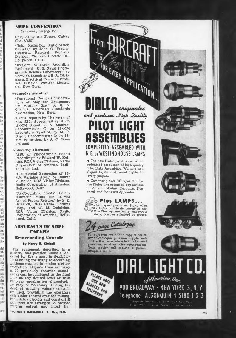
DIIUO
16-MM
Dalgleish,and W
Re-recording Console
295
Armed Forces Release,” by P. E. Brigand!, RKO Radio PicturesCorp RCACorporation of America, Holly wood, Calif.
Considera- Equipment by S. L. Standards
tainment Films
Victor Division, Radio
• The new Dialco plant is geared for redoubled production of high quality Pilot Light Assemblies, Warning and Signal Lights, and Panel Lights for every purpose.• Comprising over 300 types of units, the Dialco line covers all applications in Aircraft, Marine, Electronic, Electrical, and Industrial Apparatus.
Wednesday afternoon:“ABC of Photographic Sound Recording,” by Edward W. Kellogg, RCA Victor Division, Radio Corporation of America, Indianapolis, Ind.“Commercial Processing of 16MM Variable Area,” by Robert V. McKie, RCA Victor Division, Radio Corporation of America, Hollywood, Calif.“Re-Recording 35-MM Enter-
Wednesday morning:“Functional Design tions of Amplifier for Military Use,” Chertok, American
For guidance, we offer a copy of our 24- page Catalogue, plus new Supplements .For the immediate solution of special ?toblems, send or wire specifications,
our inquiry will receive a prompt, complete reply.
n^PIv» LAMPS...-To help speed production, Dialco offers Pilot Lights completely assembled with G.E. or Westinghouse Lamps—any type or voltage. Samples submitted on request
Association, New York.Status Reports by Chairman of ASA Z52: Subcommittee B on 16-MM Sound, J. A. Maurer; Subcommittee C on 16-MM Laboratory Practice, by M. R. Boyer; Subcommittee D on 16MM Projection, by A. G. Zimmerman.
ABSTRACTS OF SMPE PAPERS
SMPE CONVENTION (Continued from page 142)
Unit, Army Air Forces, Culver City, Calif.“Noise Reduction Anticipation Circuits,” by John G. Frayne, Electrical Research Products Division, Western Electric Co., Hollywood, Calif.“Western Electric Recording Equipment—U. S. Naval Photographic Science Laboratory,” by Reeve O. Strock and E. A. Dickinson, Electrical Research Products Division, Western Electric Co., New York.
produced cdrùfik Qualify
PILOT LIGHT ASSEmBLIES COMPLETELY ASSEMBLED WITH G. E. or WESTINGHOUSE LAMPS
The equipment described is a modern, two-positlon console designed for the utmost In flexibility for handling the many re-recordlng problems entailed in motion-picture production. Signals from as many as 20 previously recorded sound- tra ks can be combined in the final print at any desired level or with whatever equalization characteristics may be necessary. Sliding instead of rotating volume controls are used, providing the operators with better control over the mixing. The mixing circuits and constant B equalizers are arranged to provide un form output and Input im-ElECTRONIC INDUSTRIES • May, 1944
OIRLUEHTCO900 BROADWAY - NEW YORK 3, N.Y. Telephone: ALGONQUIN 4-5180-1-2-3
Telegraph Address Dial Light WUX Ne* York Direct Western Union Teleprinter on premises
Noise-Reduction Antic
plate circuit serves a pulse
RADIO TUBE
ELECTRONIC TESTING and
PRECISION MACHINERY
For the past 25 years
the
For Quick Action
2*6
pedances regardless of the number of signal circuits (in pairs) being mixed.
greater than those for which selector switch is set.
INCANDESCENT LAMP
Direct-reading Audio Frequency Meter
counting device, and provisions are made to use an external recorder
A means of recalibrating the instrument when tube replacement is necessary is incorporated to use the ac line frequency or its second harmonic.
Gas-discharge tubes employed in the B voltage supply serve to stabilize operation from 105 to 125 volts with less than 3 per cent full scale change in frequency indication.
A plate overload relay is used to protect the panel meter, should frequencies applied to input circuit be
portable, relatively high - qu uity field or studio work Moreover, :he practicability of extensions nd adaptations to postwar requirements have been kept In mind so that its flexibility and value nay later be enhanced by arrangir it to handle more refined work if desired. It also will probably nd a place in studio work when up. ply conditions are such as to make it commercially available. The entire equipment operates from 24 volt portable-type storage battery, the camera and recorder being driven by interlocked de motor
MEGOHMER NEW BATTERY-VIBRATOR TYPE No more tiresome cranking of a hand-driven generator Entirely self-contained. Steady test potential of 500 volts D.C. available at the touch of a switch. Direct reading in insulation resistance. Various new models
and ranges.Write or phone for Bulletin 430
ELECTRONIC INDUSTRIES • May.
Submit your drawings and designs, which will be treated with strict confidence.
Mr. Strauss announced an instrument capable of indicating audio frequencies of 10 to 50,000 cycles to accuracies limited only by the panel meter or pen-and-ink-chart recording meter employed, regardless of audio voltage variations.
The source of audio-frequency voltage is fed into a high-impedance grid circuit and, due to plate saturation of the input tube, the incoming frequency wave shape is changed to a square wave, which retains the original frequency but is not affected by variations in signal voltage amplitudes. Only one volt is necessary to trigger the grid circuit.
The output of the first tube is amplified by a direct-coupled multivibrator or flip-flop circuit, consisting of two tubes whose circuit constants have no resonant effects on the frequencies ordinarily under test. Wave shape remains unchanged and amplification is constant. Appropriately chosen capacitive and resistive networks then permit the integrated pulses to collect on the grid of the countertube circuit.
To produce a linear frequency calibration, the grid circuit of the countertube is biased to plate current cut-off with zero signal input. A 0 to 5 ma milliammeter in the
The paper described a superportable double system film recording equipment designed under the auspices of the Research Council of the Academy of Motion Picture Arts and Sciences, at the request of the Army Pictorial Service, to provide a type of equipment not ordinarily available to the armed forces.
The equipment fills the immediate wartime need for completely
JARRELL-ASH COMPANY165 Newbury St., Boston 16, Masa
In recording sound-on-film, it is common practice to reduce the clear or unexposed area of the soundtrack during periods of silence or low modulation in order to minimize “grain” or background noise from the projected print. This process is controlled by a de voltage derived by rectification of a portion of the signal, the de bias being applied to the recording galvanometer or an auxiliary shutter admitting light to the film A universal problem involved with such a system is “clipping” of the
(Continued on page 297)
MICROSCOPES MAGNIFIERS
TEST INSULATION THE MODERN WAY
We do not design or sell machinery.
pation Circuits by John G Frayn»
PROMPT DELIVERYon most type* of Bausch & l.omb and Spencer Inspection, Research and Special Microscopes; also Maynificrs Requests for new leaflet, prices, etc., will have prompt reply.
PH 346A Recording Equipment
by Wesley C. Miller
...WITH A MODEL B-5
Builders of— SPECIALLY DESIGNED
Daly Machine &Tool Works 923 FRELINGHUYSEN AVENUE
NEWARK. N. J.
HEDMAN H
77 PARK PLACECOMPANY. IN‘
NEW YORK N V
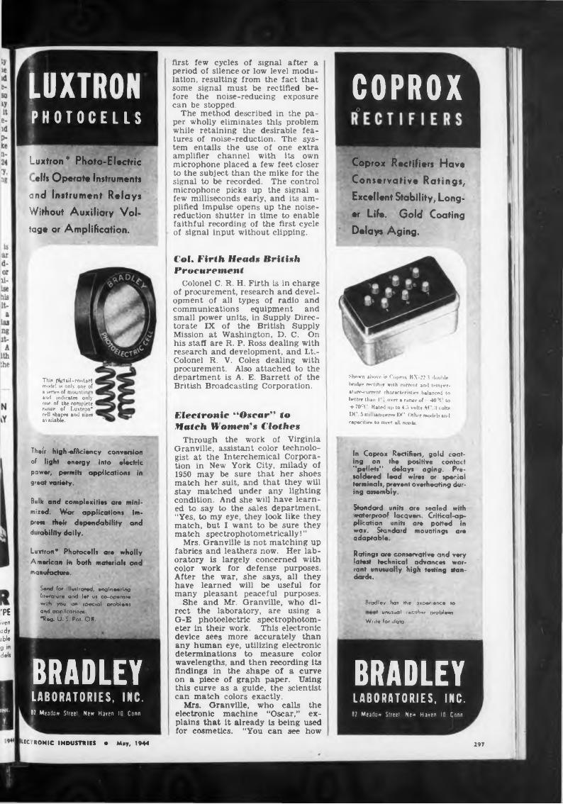
LUXTRONPHOTOCELLS
Luxtron* Photo-Electric
ells Operate Instruments
and Instrument Relays
Without Auxiliary Vol
tage or Amplification.
This pigtail-contact model is only one of n series of mountings and indicates only one of the complete range of Luxtron* cell shapes and sues available.
first few cycles of signal after a period of silence or low level modulation, resulting from the fact that some signal must be rectified before the noise-reducing exposure can be stopped.
The method described in the paper wholly eliminates this problem while retaining the desirable features of noise-reduction. The system entails the use of one extra amplifier channel with its own microphone placed a few feet closer to the subject than the mike for the signal to be recorded. The control microphone picks up the signal a few milliseconds early, and its amplified impulse opens up the noisereduction shutter in time to enable faithful recording of the first cycle of signal input without clipping.
Col. Firth Heads British Procurement
Colonel C. R. H. Firth is in charge of procurement, research and development of all types of radio and communications equipment and small power units, in Supply Directorate IX of the British Supply Mission at Washington, D. C. On his staff are R. P. Ross dealing with research and development, and Lt.-
J Colonel R. V. Coles dealing with procurement. Also attached to the department is A. E. Barrett of the British Broadcasting Corporation.
Electronic “Oscar" toMatch W omen's Clothes
COPROXo
Coprox Rectifiers Have
Conservative Ratings,
Excellent Stability, Long
er Life. Gold Coating
Delays Aging.
Shown above is Coprox BX-22.3 double bruiser rrctiher with current and tetn|>er- ature-current characteristics balanced to better than I', over a rance of • -lO'V to + 70cC Rated up to 4.5 volts AC. 3 volts IX’. 5 miilianuiereH IX'. (Mhcr mod«*!» and cwpacitira to meet all nets la.
'PEiven ady ■bl« g i” dels
Luxtron* Photocells ore wholly American in both materials and manufacture.
Their high-efficiency conversion of light energy into electric power, permits applications in great variety.
Bulk and complexities are minimized. War applications impress their dependability and d rability daily.
Send for illustrated, engineering literature and let us co-op« rate with you on special problems and application*.*Ree. U. S. Pat. Off..
BRADLEYLABORATORIES, INC.8? Meadow Street New Haren 10 Conn
Through the work of Virginia Granville, assistant color technologist at the Interchemical Corporation in New York City, milady of 1950 may be sure that her shoes match her suit, and that they will stay matched under any lighting condition. And she will have learned to say to the sales department, “Yes, to my eye, they look like they match, but I want to be sure they match spectrophotometrically! ”
Mrs. Granville is not matching up fabrics and leathers now. Her laboratory is largely concerned with color work for defense purposes. After the war, she says, all they have learned will be useful for many pleasant peaceful purposes.
She and Mr. Granville, who direct the laboratory, are using a G-E photoelectric spectrophotometer in their work. This electronic device sees more accurately than any human eye, utilizing electronic determinations to measure color wavelengths, and then recording its findings in the shape of a curve on a piece of graph paper. Using this curve as a guide, the scientist can match colors exactly.
Mrs. Granville, who calls the electronic machine “Oscar,” explains that it already Is being used for cosmetics. "You can see how
In Coprox Rectifiers, gold coating on the positive contact “pellets” delays aging. Presoldered lead wires or special terminals, prevent overheating during assembly.
Standard units are sealed with waterproof lacquers. Critical-application units are potted in wax. Standard mountings are adaptable
Ratings ore conservative and latest technical advances rant unusually high testing dards.
I very war- stan-
Bradley ha* »he jxperience to
unusual racrihor probloan. Writ« for data.
BRADLEYLABORATORIES. INC.
8? Mearfo* Street Ne« Haren 10 Conn
ELECTRONIC INDUSTRIES • May, 1944 297
AT 100 MCPOWER FACTOR 0.0033
DIELECTRIC CONSTANT 3.57
DILECTENEA CONTINENTAL-DIAMOND
ENGINEERED U-H-F
INSULATING PLASTIC
STABLE UNDER♦ High Humidity
♦ Temperature Extremes♦ Mechanical Streu
♦ Chemical Condition \. *
READILY MACHINED For complote technical data, sind for Bulletin DN
CONTINENTAL-DIAMOND FIBRE COMPANY
NEWARK 50 DC
DELAWARE
New En?'an^ (Aanuiaciuters
Your production con be increased by properly installed sound equipment. Our distributors can furnish Turner miltes, Masco amps and intercoms, University speakers, Radiotone recorders.
We represent leading manufacturers of basic electronic components—chassis, coils, condensers, relays, resistors, sockets, solder, tranformers, timers*— dependable sources whose deliveries will enable you to meet your schedules.
*Our ,3dei gives the compete listing— yours for the asking if you are in N.E.
HENRY P. SEGEL CO.Manufacturers Representatives
Field Engineers221 COLUMBUS AVENUE
BOSTON 16, MASS.Telephones KENmore 3012-6333
Branch Office in Hartford, ConnecticutServing Manufacturer«, Jobbers, Schools and
Laboratories in New England.
it would help match up lipstick and nailpolish and how it keeps different batches of shade.” She is the day when house painters
powder the same looking forward to she can tell the just what color
curve number she wants to use, for then she will be sure of the right shade on the living room walls.
Industrial X-raying of Ceramics
Some interesting developments onthe application of X-ray to ceramic materials and products were presented by John P. Nielson, application engineer, North American Philips Company, Inc., at the annual convention of the American Ceramic Society, held in Pittsburgh on April 5.
Radiograph» »how defects
In cooperation with approximately twenty ceramic companies, North American Philips investigated problems involving refractories, glass, insulators, crucibles and chinaware. Radiographs, made with Searchray equipment during the laboratory tests, showed that plate glass and lead glass—which look the same to the naked eye—are radically different when photographed by X-ray. Since lead greatly affects ray absorption, it is possible to detect any small differences in lead content.
Several radiographs were shown covering voids, cracks and laminations that occur in fire brick and refractory furnace orifice rings. In all instances, the X-ray revealed hidden defects, not visible on the exterior.
Bread plates which were radiographed before and after glazing showed the uneven distribution of the glaze after firing. Glaze mixtures usually contain compounds having high atomic weights (high ray absorption) and though applied in thin layers, differences in thickness showed up remarkably.
The First Wave-Filter
Filters, to a photographer, areoptical systems selective in their transmission of light waves that can be Interposed between lens and scene to favor certain colors. By analogy, the name “filter” was applied to the networks which G. A. Campbell patented in 1917, to select electric currents on the basis of wavelengths.
Campbell’s wave filters take many forms, for his invention was broad and basic. In general, they are artificial transmission lines formed by a succession of sections, each a network of inductances and capacitances. In general, also, they are of three types: high-pass, which
discriminate against all compo .end of current with frequencies elow a designed “cut-off”; low pass, which transmit only currents elow a specified frequency; and, most' important, band filters which passi only frequencies between ass ned values.
Finds many usedCampbell’s invention mad pos-l
sible many important advan< s ini all the arts where complex currents I carry signals or speech. Carrier-1 current transmission, for example,I depends upon band-pass filters to I select desired bands of frequencies! from a complex current involving! several simultaneous messages.
Throughout the years since Campbell’s epoch-making invention Bell Laboratories has made many important contributions to filter theory and to its analytical methods; also, many new types oi filters have been invented and perfected 1
Much of the advance has cornel from intensive development studies and ingenious designs of the coils and condensers which form the filter sections. That work was profitable because the more closely a filter’s circuit elements can approximate the ideal of pure inductance and pure capacitance, the I more sharply can it discriminate between wanted and unwanted frequencies.
Great discrimination
Near its cut-off point, for example, a one per cent change n.l frequency can cause a hundred-1 fold difference in transmitted power. (For comparison: a human ear listening to a pure tone of concert pitch A cannot perceive a pitch change much smaller than one per cent.) In the high-frequency range, when quartz crystals are used as resonant elements, a precision of discrimination can be reached such that a 10,000-fold change in power follows a 0.1 ped cent change in frequency. Filters of this type are used in coaxial cable systems. — Bell Laboratories Record.
sy wl19
Pj
di rw
Sj
Wire Basic Communication Medium in Sicily
While radio was used extensively! during military operations in Sicily I wire remained the basic medium oil combat communications, the War Department announces, in an analysis of reports from commai dersl of Signal Corps field units. Thisl has also been true in the ca of the Fifth Army in Italy.
The Signal Corps commandera emphasized the ability of wire-laying units in Sicily to maintain < munications at a pace whica matched that of the advancin Ind
ELECTRONIC INDUSTRIES • Maya
29S
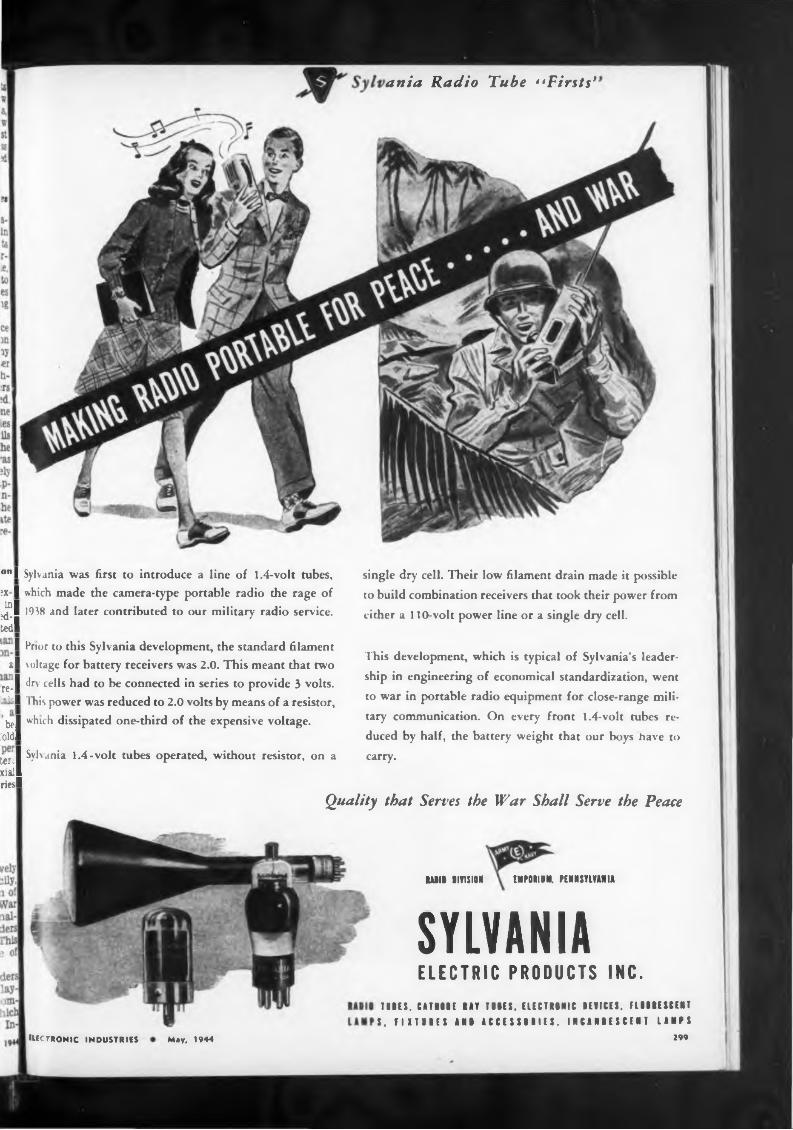
ania Radio Tube 1‘Firsts*
°" I Sylvania was first to introduce a line of 1.4-volt tubes, ?x I which made the camera-type portable radio the rage of ^1 1938 and later contributed to our military radio service, tedi
‘“I ^r’or to th*8 Sylvania development, the standard filament al voltage for battery receivers was 2.0. This meant that two
re-1 dfv ce^s had to be connected in series to provide 3 volts, alsl This power was reduced to 2.0 volts by means of a resistor,
bel wh>ch dissipated one-third of the expensive voltage, .'old!
tórsi Syhania 1.4-volt tubes operated, without resistor, on a xiall riesl
single dry cell. Their low filament drain made it possible
to build combination receivers that took their power from
either a 110-volt power line or a single dry cell.
This development, which is typical of Sylvania’s leader
ship in engineering of economical standardization, went
to war in portable radio equipment for close-range mili
tary communication. On every front 1.4-volt tubes re
duced by half, the battery weight that our boys have to
carry.
Quality that Serves the War Shall Serve the Peace
BABIB DIVISION EMPBBIBM. PENNSYLVANIA
SYLVANIAELECTRIC PRODUCTS INC.
TUBES. CATHIE BAT TIBES, ELECTBBNIC DEVICES. FLBBBESBENTS. FIXTBBES ANB ACCESSBBIIS. INCANBESCENT LAMPS
299EIECTRONIC industries May, 1944
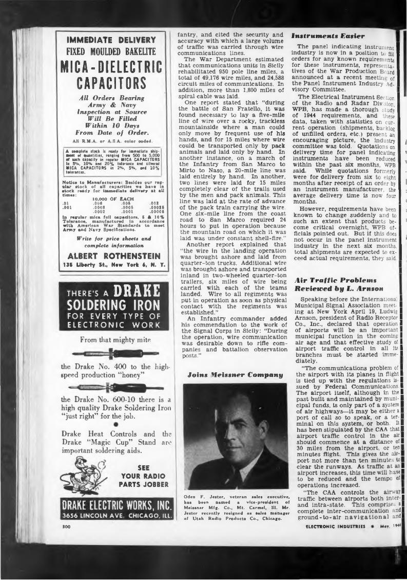
IMMEDIATE DELIVERY
FIXED MOULDED BAKELITEMICA-DIELECTRIC
CAPACITORSAU Orders Bearing
Army & Navy Inspection at Source
Will Be Filled Within 10 Days
From Date of Order.Ail R.M.A. or A.S.A. color coded.
A cemplete stock is ready for immediate ship- ■ent of quantities, ranging from 500 to 5,000 •f each capacity in regular MICA CAPACITORS in 5%, 10% and 20% tolerance and silvered MICA CAPACITORS in 2%, 5%, and 10% tolerances.
Notice to Manufacturers: Besides our regular stock of all capacities we have in stock ready for immediate delivery at all times:
10,000 OF EACH.01 .00« .005 .002.001 .0008 .0005 .00085
.0002 .0001 .00005in regular mica foil capacitors, 5 A 10% Tolerance, manufactured in accordance with American War Standards to meet Army and Navy Specifications.
Write for price sheet» and complete information
ALBERT ROTHENSTEIN135 Liberty St., New York 4, N. Y.
THERE'S A DRAKE SOLDERING IRON FOR EVERY TYPE OF ELECTRONIC WORK
From that mighty mite
the Drake No. 400 to the highspeed production “honey”
the Drake No. 600-10 there is a high quality Drake Soldering Iron “just right” for the job.
Drake Heat Controls and the Drake “Magic Cup” Stand are important soldering aids.
SEE YOUR RADIO
PARTS JOBBER
DRAKE ELECTRIC WORKS, INC.3656 LINCOLN AVE CHICAGO, ILL.
fantry, and cited the security and accuracy with which a large volume of traffic was carried through wire communications lines.
The War Department estimated that communications units in Sicily rehabilitated 950 pole line miles, a total of 49,176 wire miles, and 24,588 circuit miles of communications. In addition, more than 1,800 miles of spiral cable was laid.
One report stated that “during the battle of San Fratello, it was found necessary to lay a five-mile line of wire over a rocky, trackless mountainside where a man could only move by frequent use of his hands, and for 15 miles where wire could be transported only by pack animals and laid only by hand. In another instance, on a march of the Infantry from San Marco to Mirto to Naso, a 20-mile line was laid entirely by hand. In another, two lines were laid for 15 miles completely clear of the trails used by the men and pack animals. This line was laid at the rate of advance of the pack train carrying the wire. One six-mile line from the coast road to San Marco required 24 hours to put in operation because the mountain road on which it was laid was under constant shell-fire.”
Another report explained that “the wire in the landing operation was brought ashore and laid from quarter-ton trucks. Additional wire was brought ashore and transported inland in two-wheeled quarter-ton trailers, six miles of wire being carried with each of the teams landed. Wire to all regiments was put in operation as soon as physical contact with the regiments was established.”
An Infantry commander added his commendation to the work of the Signal Corps in Sicily: “During the operation, wire communication was desirable down to rifle companies and battalion observation posts.”
Joins Meissner Company
Oden F. Jester, veteran sales executive, has been named a vice-president of Meissner Mfg. Co., Mt. Carmel, 111. Mr. Jester recently resigned 11 sales manager of Utah Radio Products Co., Chicago.
Instruments EasierThe panel indicating instrument I
industry is now in a position u fill I orders for any known requirenuntg I for these instruments, represe; ta- I tives of the War Production Board I announced at a recent meeting of I the Panel Instrument Industry Ad-1 visory Committee.
The Electrical Instrument Ser tion I of the Radio and Radar Division, I WPB, has made a thorough study I of 1944 requirements, and hese I data, taken with statistics on cur- I rent operation (shipments, backlog I of unfilled orders, etc.) present an I encouraging picture, the industry I } committee was told. Quotations on I delivery time for panel indicating I ’ instruments have been reduced I within the past six months, WPB I ’ said While quotations formerly I - were for delivery from six to eight I months after receipt of an order by I । an instrument manufacturer, the I ; average delivery time is now four I months. I <
However, requirements have been I । known to change suddenly and to I such an extent that products be- I 1 come critical overnight, WPB of-I flcials pointed out. But if this does I . not occur in the panel instrument I 1 industry in the next six months, I total shipments are expected to ex-1 ceed actual requirements, they said I
I i
Air Traffic Problems Reviewed by L. Arnson
Speaking before the International I Municipal Signal Association meet- I ing at New York April 19, Ludwig I Arnson, president of Radio Receptor I Co., Inc., declared that operation I of airports will be an important I municipal function in the coming I air age and that effective study o' I airport traffic control in all it' I branches must be started imme-1 diately.
“The communications problem of I the airport with its planes in flight I is tied up with the regulations is-1 sued by Federal Communications I The airport itself, although in the! past built and maintained by muni-1 cipal funds, is only part of a system I of air highways—it may be either a I port of call so to speak, or a ter-1 minal on this system, or both It I has been stipulated by the CAA that I airport traffic control in the air I should commence at a distance of I 30 miles from the airport, or ten! minutes flight. This gives the air-1 port not more than ten minutes to I clear the runways. As traffic at an I airport increases, this time will have! to be reduced and the tempo o’I operations increased.
“The CAA controls the airway I traffic between airports both inter-! and intra-state. This comprises al complete inter-communication and I ground-to-air navigational and!
300 ELECTRONIC INDUSTRIES May, 1H4
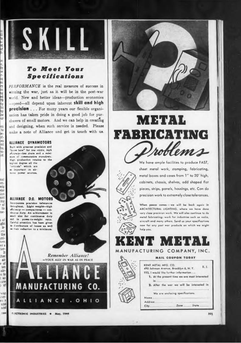
For many years our flexible organi
METALFABRICATING
metal boxes and cases from 1" to 20' high,
ior
ans.
KENT METALtern
State
ELECTRONIC INDUSTRIES
We have ample facilities to produce FAST,
sheet metal work, stamping, fabricating,
cabinets, chassis, shelves, odd shaped flat
pieces, strips, panels, housings, etc. Can do
precision work to extremely close tolerances.
■way iter-
t ar lave
ALLIANCE DYNAMOTORSBuilt with greatest precision and "know how" for law rippit, high dHctency—law drain and • wwns mum of commutation trannmit.
Remember Alliance!•YOUR ALLY IN WAR AS IN PEACE
KENT METAL MFG. CO.490 Johnson Avenue, Brooklyn 6, N. Y.YES, I would like further information ..
ARCHITECTURAL LIGHTING, where we have done very dose precision work. We will also continue to do metal fabricating; work for industries such as radio, aircraft and many others. Send us your specifications
now for any post war products on which we might help you.
will be back again
High production retains highest degree all the “critical” which are su important in airborne power sources.
PERFORMANCE is the real measure of success in winning the war, just as it will be in the post-war world. New and better ideas—production economies —speed—all depend upon inherent skill and high
ration has taken pride in doing a good job for purchasers of small motors. And we can help in creating and designing, when such service is needed. Please make a note of Alliance and get in touch with us.
ALLIANCE D.C. MOTORS Incorporate precision tolerances throughout. Light weight—high efficiency — compactness — continuous duty. An achievement in •mall sue for continuous duty •nd ill power-to-weight ratio. Careful attention haa been given tn distribution of losses as well m their reduction to a minimum
We are enclosing specifications.
Name ■ ......... .......Add r eu .................................. -
SKILL
Rare Gases and Mixtures
WORTH REMEMBERING!
ases as well as tures are nvatl- uction and ex
pedal mixtures meet any need
ILLINOIS CONDENSER COMPANY
1160 NORTH HOWE STREET CHICAGO, ILLINOIS
Airco Rare Ga of active gases, uniformly and available in I containers.
The individ many standard able both for perimental u can be supplie
Mte pure and free res are blended tely. They are
g glass or pyrex
ARGONNEON
HELIUMXENON
KRYPTON
AIR REDUCTIONOanrrol Office; 60 E. 42nd ST., NEW YORK, N. Y.
ILLINOIS CONDENSERS
Next time you purchase
capacitors let the satisfactory experiences of our many users be your guide— choose from the “ILLINI” line of electrolytic and paper types. They’re known for reliability, durability and consistent quality. Manufactured by condenser specialists for eight years who produce nothing but condensers.
meteorological reporting system. The situation is somewhat confused today because some of these airports are either wholly or partially controlled by the Air Forces. In normal times, however, all principal airports are on communications networks prescribed by the FCC. They are the red, blue, brown, green, purple, yellow and orange. The red network, for instance, is called the Northern Trans-Continental Chain and Feeders, and the principal airline using It Is the United. There are twenty-two frequencies assigned to this network, ranging from 3147.5 kc to 141.22 kc The control tower should be prepared to receive on at least three of these frequencies, any one of which may be required if the other two channels are occupied. It should be pointed out that there are any number of frequencies used by planes of all nations for aircraft on sea flight, distress signals, scheduled and off-schedule routes, etc. Thus it will be seen how the airport is tied down to the airways system and functions as part of it.
“Like the airplane itself, the airport and its traffic control will have to accommodate itself to changing conditions in the postwar world. For Instance, It is said that at the new Idlewild Airport there will be 13y2 miles of runways. Hangar lines for airplanes will be six miles long, and for sea planes one mile long—altogether making it possible to handle 900 planes every 15 hours or one per minute. Three or four control points may become necessary. Tying these together, using all receivers and transmitters, will become a problem unless properly worked out. That, however, is for the future. Our job now is to study each project on a long-range viewpoint. Lots of experience has been gained—a number of helpful devices have been developed and progress is continuously going on.”
Place Joins RCAEdward R. Place, former assistant
to the director general of the War Production Drive, has joined the staff of the Department of Information of the Radio Corporation of America. Mr. Place has had wide experience in the newspaper, advertising and publicity fields. He formerly was radio editor of “The Providence Journal,” managing editor of “Labor Management News," editor and publisher of “Playtime” magazine, and columnist on the old “Boston Transcript.” In 1935, he was publicity director in New England for N. W. Ayer & Son, Inc.
SF Office for SylvaniaOpening of a West coast head
quarters office at 111 Sutter Street, San Francisco, In charge of B. K. Wickstrum, Pacific coast sales manager for the company’s lighting
products, has been completed by Sylvania Electric Products, I ic Heavily engaged in war product; n, Sylvania will serve the many industrial establishments on the Pacific coast through the new office and will deal with export matters af er the war Sylvania recently ope >ed offices In Los Angeles and Seattie, with G. W. “Chick” Field as meager of the California Division which includes Nevada, Utah and Arizona, and C. W. Dickinson as manager of the Northwest Division, assisting Mr. Wickstrum
Airtronics Adds TwoAirtronics Mfg. Co., Los Angeles,
maker of high-frequency generators for heating molding compounds in the plastics industry, has appointed two regional representatives for sales and service. L. R. Liljequist will take over the middle-Western States, with offices at 121 West Wacker Drive, Chicago; Edward K Kellogg will be in charge of the Atlantic seaboard and other Eastern States. His offices are at 31-28 Queens Blvd., Long Island City. N Y.
IRE Sponsor* Industrial Electronics Demonstration
The Institute of Radio Engineers has scheduled the first of a group of meetings of special interest to the industrial electronic engineers on May 24, at 7:30 P.M. in the auditorium of the Western Union Building. 60 Hudson St., New York City. At this meeting several papers will be delivered on the subject of industrial electronics, with demonstrations.
Since activity in this field is increasing, there has been need for more frequent meetings devoted to the non-communlcation uses of radio principles and the IRE is making great progress In promoting Interest In this subject. All persons interested in this subject are invited to attend.
Schott in ChicagoIn order to give quicker and bet
ter delivery service to their nationwide customers, the Walter L. Schott Co. has discontinued the New York warehouse and has occupied large space in the Terminal Bldg., 537 South Dearborn Street, Chicago. The main office of the Walter L. Schott Co., 9306 Santo Monica Blvd., Beverly Hills, Calif.. continues to be the regular mailing address.
Ken-Rad ProtestsOccupation of Plant
The Ken-Rad Tube and Lamp Corporation, which employs approximately 4,000 persons at Ito Owensboro, Ky., plant, was taken over by the War Department April 14 under the order of President
ELECTRONIC INDUSTRIES • May. 1944
I
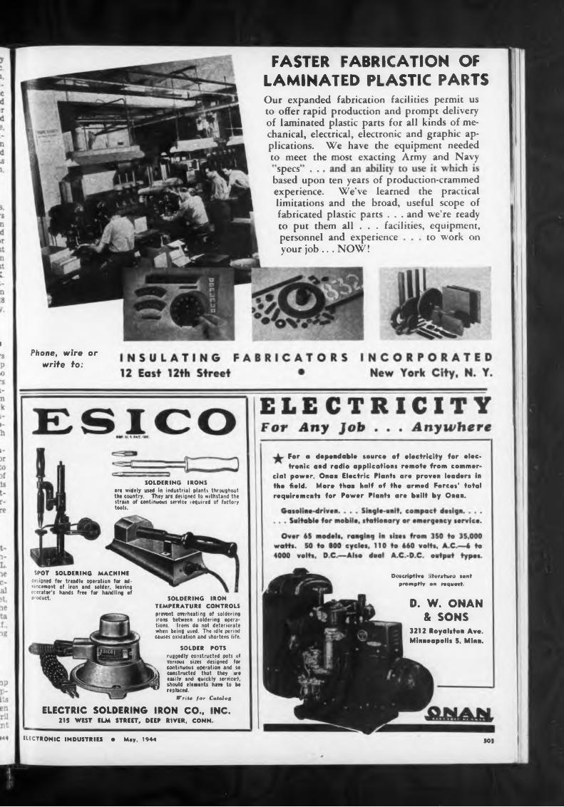
specs
ELECTRIC SOLDERING
)O3
FASTER FABRICATION OF LAMINATED PLASTIC PARTS
Descriptiva literatura sent promptly on request
Phone, wire or write to:
D. W. ONAN & SONS
3212 Royal*fon Av«. Minneapolis 5, Minn.
to work on
21S WEST ELM STREET, DEEP RIVER, CONN
Our expanded fabrication facilities permit us to offer rapid production and prompt delivery of laminated plastic parts for all kinds of mechanical, electrical, electronic and graphic applications. We have the equipment needed to meet the most exacting Army and Navy
SPOT SOLDERING MACHINE
designed for treadle operation for advancement of iron and solder, leaving operator’s hands free for handling of product SOLDERING IRON
TEMPERATURE CONTROLS
prevent overheating of soldering irons between soldering opera tions. Irons do not deteriorate when being used. The idle period causes oxidation and shortens life.
SOLDER POTS
ruggedly constructed pots tit various sizes designed for
k continuous operation and so kA constructed that they tro ¡St easily and quickly serviced, fl should elements have to be v replaced.
ITritv for Catalog
IRON CO.. INC.
For a dependable source of electricity for electronic and radio application* remote from commer
cial power, Onan Electric Plants are proven leader* In the field. More than half of the armed Force*' total requirement* for Power Plants are built by Onan.
based upon ten years of production-crammed experience. We’ve learned the practical limitations and the broad, useful scope of fabricated plastic parts . . . and we’re ready to put them all . . . facilities, equipment.personnel and experience your job ... NOW !
SOLDERING IRONS
art widely used in industrial plant\ throughout the country. They ire designed to withstand the strain of continuous service required of factory toots.
EIECTRONIC INDUSTRIES • May, 1944
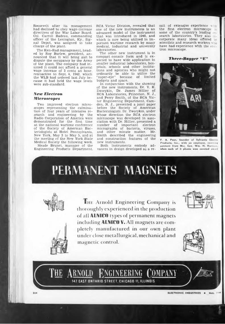
Three-Bagger “E
limited
Zworykin
Radio Corporation of America weredemonstrated the first time
number
304
budgets and space.In conjunction with the showing
of the new instruments, Dr. V. K.
suit of extensive experience w \h the first electron microscope in some of the country’s leading -a. search laboratories. They also n- corporate many ideas offered ay scientists and research workers v o have had experience with the el . tron microscope.
James Hillier
improved electron microrepresenting the culmina- four years of intensive re- and engineering by the
important electronat the national wartime conference of the Society of American Bacteriologists at Hotel Pennsylvania, New York, May 3 to May 5, and at the meeting of the New York State Medical Society the following week.
Meade Brunet, manager of the Engineering Products Department,
‘super-eye” because
RCA Laboratories, Princeton, N. J, and Perry Smith, of the RCA Victor Engineering Department, Camden, N. J., presented a joint paper before the Society of American Bacteriologists. Dr. Zworykin, under whose direction the RCA electron microscope was developed in association with Dr. Hillier, presented a
RCA Victor Division, revealed that one of the new instruments is an advanced model of the instrument that was introduced in 1940, and which is now being utilized in important wartime research by many medical, industrial and university laboratories.
The other new instrument is in compact console form and is expected to have wide application in smaller industrial laboratories, hospitals, schools and other institutions and agencies who might not ordinarily be able to utilize the
Roosevelt after its management had declined to obey wage-increase directives of the War Labor Board. Col. Carroll Badeau, commanding officer of the Lexington, Ky., Signal Depot, was assigned to take charge of the plant.
The Ken-Rad management, headed by Roy Burlew, president, announced that it will bring suit to dispute the occupancy by the Army of the plant. The company had insisted it could not afford a general wage increase of 3 cents an hour, retroactive to Sept. 4, 1942, which the WLB had ordered last July because it had held the wage levels were sub-standard.
micrographs of bacteria, viruses, and other minute matter. Mr. Smith described the engineering and construction features of the new instruments.
Both instruments embody advances in design developed as a re-
ELECTRONIC INDUSTRIES * May 1544
Two scopes tion of search
F. A. Poor, founder of Sylvania Electric Products, Inc., with an employee, receiving pennant from Maj. Gen. Wm H H «rrison,
New Electron Microscopes
■ he Arnold Engineering Company is thoroughly expei ienced in the production of all ALNICO types of permanent magnets ine hiding ALNICO V. All magnets are completely manufactured in oui own plant under close metallurgical, mechanical and magnetic control.
PERMANENT MAGNETS
TUB AKNOLli ENGINEERING COMPANY147 EAST ONTARIO STREET, CHICAGO 11. ILLINOIS
THERE IS AN
ELEMENT OF SUPERIORITY
ELECTRIC SOLDERING IRON
TEMPERATURE REGULATING STANO
AMERICAN ELECTRICAL HEATER COMPANYDETROIT 2, MICHIGAN, U. S A PEED the very essence of this service
direction through 360' Capacity up to 5 lbs
ELECTRONIC INDUSTRIES 305
An adjustable-thermostati- cally controlled stand for regulating the temperature of an electric soldering iron when at rest, t_
This instrument was originally developed for our own use in testing the Relays which we manufacture W» are now making it -ivailable to other manufacturers who are likewise desir Ous of makin , their products immune In the effects of vibration.
harmonic motion with variable amplitude. • Variable frequency from
20 to 70 C.P.S • Vibration testing can be made in any
bration acceleration is provided to 30 G. plus. • Only 75 <watts are required for maximum test conditions. • Can j be mounted on any bench without transmitting extraneous vibration. • Variable frequency direction provided. • No moving cranks, gears, or bearings in the vibration system.
Not only the superior construction of the heating element, but the sturdy quality of the other units, makes this the preferred iron for all industrial uses . . . . It is dependable, durable and efficient.
rushing vitally needed tools, as well as other radio and electronic supplies, to war industries. Emergency Service departments have been developed; stocks greatly enlarged and diversified to include many items you d never expect to get from a radio supply house. Personnel is picked and trained to move fast . . to know instantly where to get what you want if it docs not appear in our stocks.
Here then is a TIME SAVER of major importance to industry. It functions with amazing efficiency, serving a fast growing list of critical buyers from coast to coast. We invite you to use this streamlined source of supply. Send your orders to the nearest distributor below, ot write on company stationery for valuable free reference book and buyer’s guide.
X*, Radio and^9 .
TERMINAL RADIO CORP.85 Cordandt St, Phone WOrth 2-4416 NEW YORK 1 WALKER-JIMIESON, INC. 311 S. Western Ave^ Phone Canal 2525 CHICAGO 12 RADIO SPECIALTIES CO. 20th & Figueroa. Phone Prospect 7271 LOS ANGELES 7
NO. I OF A SERIES
f MW, SIMPLE
POWER FORK for VIBRATION
TEST
Get this Emergency Service on
TOOLSJlmericanBeaut
WP/TE OP PHONE YOUR NEAREST DISTRIBUTOR
NATIONAL INDUSTRIAL EMERGENCY SERVICE35-lff 37th STREET LONG ISLAND CITY I
S-nd nlrv lot complete ^formation on the now Ime of KJjRMANiHbr&iwpraot tfLAYS
that
light
Discussed by Dr. A. N. Goldsmith
WIRE WOUND
PROMPT DELIVERY
BETTER CONNECTIONSVitreous Enameled
Reimers Electrical Appliance Co.594 56TH STREET WEST NEW YORK, NEW JERSEY
pregnating compounds are anothe' problem which the manufacture-
changes in temperature encounter ed in military service.
almost-certain sudden
must withstand severe thermal
must radii
Television Opportunities and Problems
shock and salt water emersion and cycling tests as a guarantee of reasonable life, Mr. Chertok told the motion - picture engineers. Here again impregnating or over-all molding compounds are a problem which must be considered in the
transformers should now be pottei and hermetically sealed. Where de must pass through the windings is considered good practice today use acetate winding cores, layer insulation, inter-layer insulation and cross-strip insulation. Both carbon and wire wound resistors
of motion-picture equipment face as the manufacturers of equipment have had to do.
Mr. Chertok pointed out
keep moisture from entering through the small clearance between shaft and bearing. A common occurrence with commercial equipment was to have various parts attacked by fungi. Voice coils were particularly susceptible; tropical insects frequently ate all of the cloth insulation from wiring. Glass insulation is, therefore, Imperative in certain locations.
The basic requirement of any military motion-picture or other equipment is that it render long and consistent service under really tough conditions and the most common cause for failure in amplifier equipment is humidity. Many parts in the future must be hermetically sealed using gasketed terminals, solder sealed to glass or porcelain or metal to glass seals with special alloys.
Mr. Chertok stressed the fact that electrolytic capacitors are considered a necessary evil to be avoided when possible. Special electrolytics designed for the particular ambients are used but since electrolytics designed for low temperature operation are not the best for high temperature applications each problem must be studied in the light of the fact that equipment may be stored for long periods outdoors under sheds in sub-arctic temperatures or in a ship’s hold at 185 degrees F. Various wax im-
Motion-Picture Amplifier Design
Arousing considerable interest at the 55th technical conference of the Society of Motion Picture Engineers in New York, a paper “Functional Design Considerations of Amplifier Equipment for Military Use” was presented by S. L. Chertok of the American Standards Association.
Mr. Chertok emphasized the fact already well known in the radio industry, that amplifiers for military use are invariably subjected to extreme conditions of vibration, shock, humidity, low or high temperatures and salt and dust-laden atmosphere. Designers should keep in mind that the equipment may not always be used by carefully trained sound men and should, therefore, be simple to operate and service. It is not only possible to forget “eye appeal” but it is wisest to shun symmetrical placement of controls in order to prevent accidental incorrect operation. Controls always must be placed far enough apart so that they can be operated with a gloved hand, and equipment must be drip and splash proof in order to meet Navy specifications and actual conditions often encountered in use or transportation. Parts such as volume controls which protrude through the projector case must have special neoprene gaskets to
The present state of the television art, its problems, and its future, were outlined from the viewpoint of the expert, in an address by Dr. A. N. Goldsmith to the April 6th
(Continued on page 309)
BALANCED MATERIALSLacquered Precision
Coils Special Elements Stampings 35 Years ExperienceHYDER
Continuously Since 1930
HIPOWER CRYSTAL COMPANYSales Division — 205 W. Wacker Drive, Chicago 6 Factory — 20JJ Charleston St., Chicago 47, III.
When day» of Peace return, our increased facilities and manpower will not only continue in the production of better Radio and Automotive equipment, but will also turn to pioneering other developments to make the postwar period worth while fighting for Patience please
WE HAVE GONE TO WAR!» kw suits or
(INCORPORATING G F OR WESTINGHOUSE NEON LAMPS!
DIAMOND WIRE & CABLE CO
PATENT AND GENERAL ATTORNEYS SPECIFICATIONWRITERS—COST AND GENERAL ACCOUNTANTS
INCL
We manufacture a complete line of Pilot Light Assemblies for every possible use in Aircraft, Marine, Radio, Electronic end Electrical apparatus. Send sketch for prompt estimates and suggestions.
This volume to net an awfi- neering text. There to, however, contained tn the votame a «om »tele and elaborerà exptonatien et the theory ot the tube It to th»« information »les the t»K' tkal applies tiens. which SMbe this booh so vstaobto
I snumoA. I
book, so that the reader may knew Just what image he «hould see under any given circum stances.
D KAPPS T*L: COrHaad 7.6835 t ». CURTZ Director 2 John Street, New York City Techn. Dept.
CFA'a PURCHASING AND ALL EXECUTIVE AND OFFICE PERSONNEL
well oa ALL TYPES OF ENGINEERS, DESIGNERS. PHYSICISTS, TECHNICIANS, etc.
A PHONE CALL WILL BRINO RESULTS!
ACCURATE PERSONNEL (an agency)
PURVEYORS OF TALENT ♦o the
ELECTRONIC INDUSTRY-r cause of our thorough experience with and long sort ice to the
industry, wo can supply on short notice
THE cathode-ray tabe has become the most valuable and universally used device tor ro
search, engmevnng and main* tenance in the radio and electrical fields. It it difficult te find a laboratory where research •s carried un in the radio, electrical and allied fields where the cathode-ray tube as a part ef the cathode-ray oscillograph does act receive daily use.
This book presents a complete explanation of the various type« of cathode ray tubes and what role each element within the device pteye te making visible the voltageo and currents encoun* feted in rartem kinds of tests
More than halt the book to devoted to the practical appli rattens of the cathode-ray tube eeeMtogreph OsciNograsns, made in the Laboratory maintained by the author have been need to •Mestrate this so« t lew of the
BURSTEIN-APPLEBEE CO1012-10)4 McGee St
ASSEMBLIES
COMPLETE WITH
LAMPS:Wo can supply any G E or Westinghouse Lamp together with the required Pilot Assembly thus saving time in your production schedule . .Write foe samples.
Illustrated <A> Neon Pilot Light with fullview plastic head 'Bl Neon Pilot Light with dome lens Lompi removable horn liant of panel.
AND ELECTRONIC
DEV ICE S
Signal Indicator894 BROADWAY ,.,NEW YORK 3, N Y.
Telephone: Algonquin 4 4770
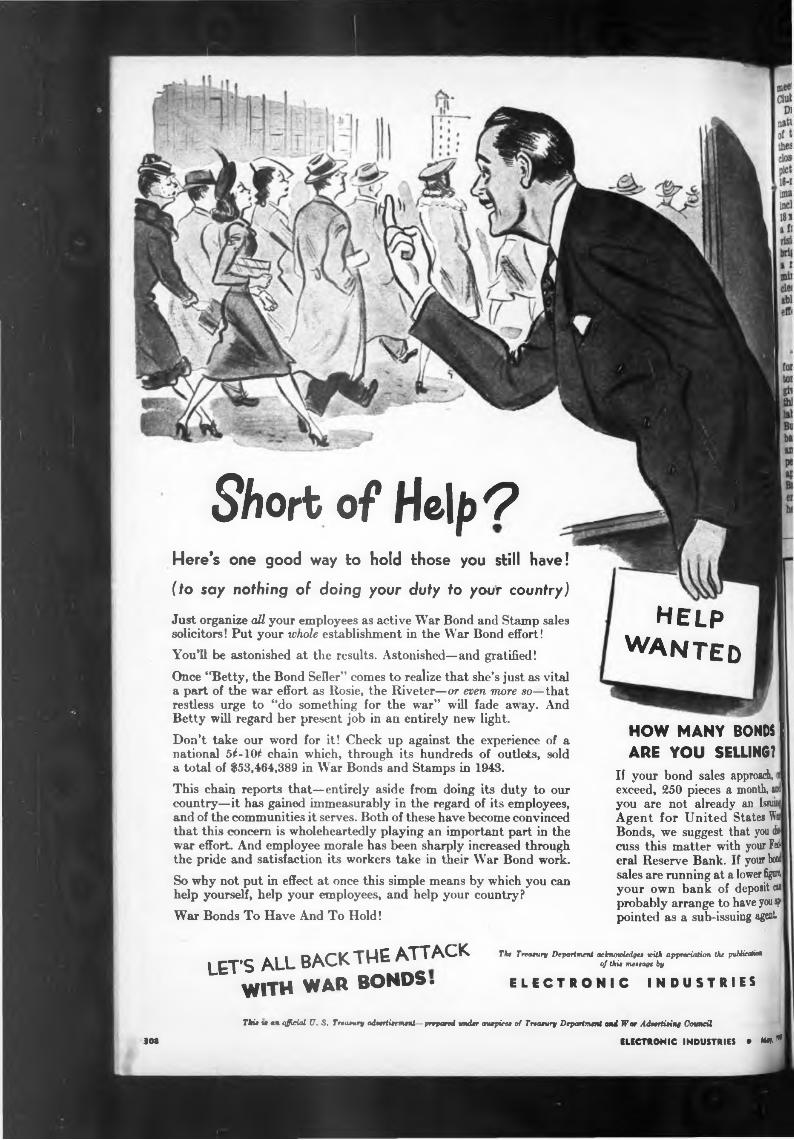
Short of Help *2Here’s one good way to hold those you still have!
(to say nothing of doing your duty to your country)
Just organize all your employees as active War Bond and Stamp sales solicitors! Put your whole establishment in the War Bond effort!
You’ll be astonished at the results. Astonished—and gratified!Once “Betty, the Bond Seller” comes to realize that she’s just as vital a part of the war effort as Rosie, the Riveter—or even more so—that restless urge to “do something for the war” will fade away. And Betty will regard her present job in an entirely new light.
Don’t take our word for it! Check up against the experience of a national 5^-10^ chain which, through its hundreds of outlets, sold a total of $53,464,389 in War Bonds and Stamps in 1943.
This chain reports that—entirely aside from doing its duty to our country—it has gained immeasurably in the regard of its employees, and of the communities it serves. Both of these have become convinced that this concern is wholeheartedly playing an important part in the war effort. And employee morale has been sharply increased through the pride and satisfaction its workers take in their War Bond work.
So why not put in effect at once this simple means by which you can help yourself, help your employees, and help your country?
War Bonds To Have And To Hold!
help wanted
HOW MANY BONDS I ARE YOU SELLING?
If your bond sales approach, fl exceed, 250 pieces a month, and you are not already an Issuing Agent for United States Wai Bonds, we suggest that you discuss this matter writh your Federal Reserve Bank. If your bond sales are running at a lower figure, your own bank of deposit cu probably arrange to have youap pointed as a sub-issuing agent
lets all back THE ATTACKWITH WAR BONDS.
The Treaeury Department acknowledge, with appreciation the pubKcetim of thio meeoage by
ELECTRONIC INDUSTRIES
Thit m an official U. S. Treaewry adeertieement—prepared under auepicee of Treasury Department ami IFar Adoertieinf Council
3M ELECTRONIC INDUSTRIES • MH,*
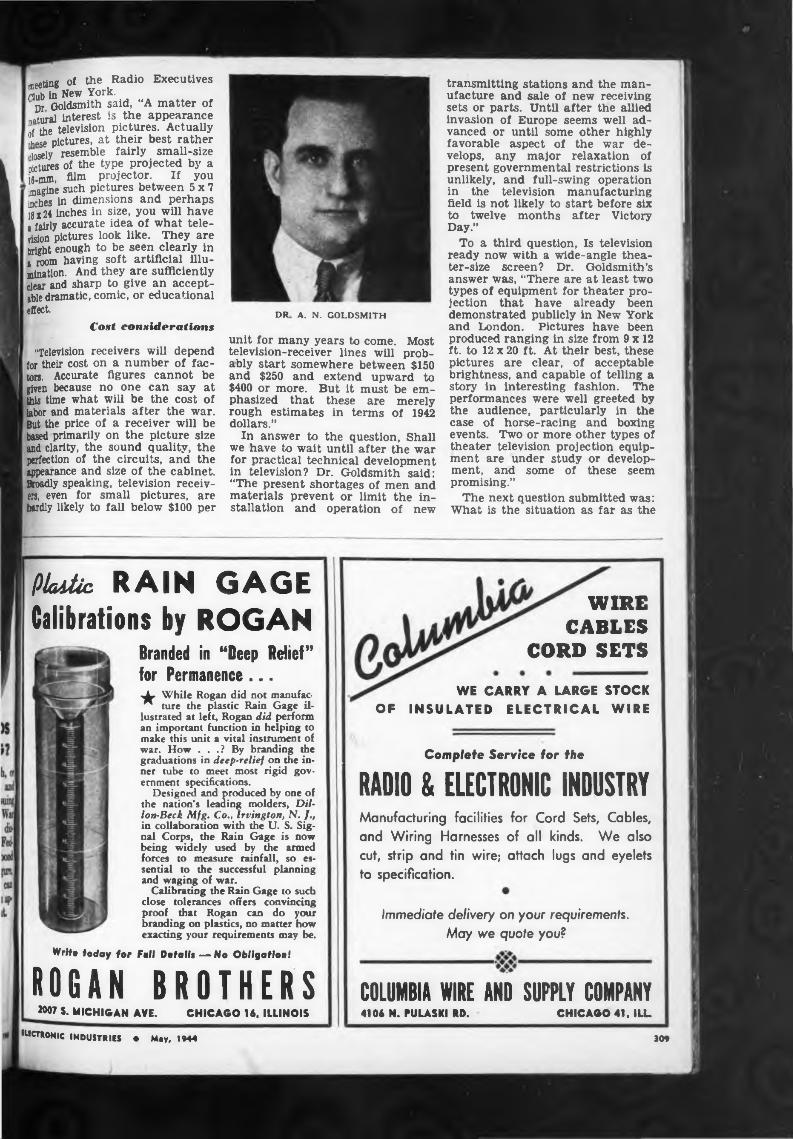
meeting of the Radio Executives Flub in New York.
Dr Goldsmith said, “A matter of natural interest is the appearance nf the television pictures. Actually Lge pictures, at their best rather •losely resemble fairly small-size oictures of the type projected by a 16-mm, Alm projector. If you imagine such pictures between 5x7 inches in dimensions and perhaps 18x24 inches in size, you will have i fairly accurate idea of what television pictures look like. They are bright enough to be seen clearly in । room having soft artificial illumination. And they are sufficiently dear and sharp to give an acceptable dramatic, comic, or educational effect.
Cost considerations
"Television receivers will depend for their cost on a number of factors. Accurate figures cannot be given because no one can say at this time what will be the cost of labor and materials after the war. But the price of a receiver will be based primarily on the picture size and clarity, the sound quality, the perfection of the circuits, and the appearance and size of the cabinet. Broadly speaking, television receivers, even for small pictures, are hardly likely to fall below $100 per
DR A. N. GOLDSMITH
unit for many years to come. Most television-receiver lines will probably start somewhere between $150 and $250 and extend upward to $400 or more. But it must be emphasized that these are merely rough estimates in terms of 1942 dollars.”
In answer to the question, Shall we have to wait until after the war for practical technical development in television? Dr. Goldsmith said: “The present shortages of men and materials prevent or limit the installation and operation of new
transmitting stations and the manufacture and sale of new receiving sets or parts. Until after the allied invasion of Europe seems well advanced or until some other highly favorable aspect of the war develops, any major relaxation of present governmental restrictions is unlikely, and full-swing operation in the television manufacturing field is not likely to start before six to twelve months after Victory Day.”
To a third question, Is television ready now with a wide-angle theater-size screen? Dr. Goldsmith’s answer was, “There are at least two types of equipment for theater projection that have already been demonstrated publicly in New York and London. Pictures have been produced ranging in size from 9 x 12 ft. to 12 x 20 ft. At their best, these pictures are clear, of acceptable brightness, and capable of telling a story in interesting fashion. The performances were well greeted by the audience, particularly in the case of horse-racing and boxing events. Two or more other types of theater television projection equipment are under study or development, and some of these seem promising.”
The next question submitted was: What is the situation as far as the
Platte RAIN GAGE Calibrations by ROGAN
Branded in “Deep Relief” for Permanence ...-JL- While Rogan did not manufac- R ture the plastic Rain Gage il
lustrated at left, Rogan did perform an important function in helping to make this unit a vital instrument of war. How . . .? By branding the graduations in deep-relief on the inner tube to meet most rigid government specifications.
Designed and produced by one of the nation’s leading molders, Dillon-Beck Mfg. Co., Irvington, N. J., in collaboration with the U. S. Signal Corps, the Rain Gage is now being widely used by the armed forces to measure rainfall, so essential to the successful planning and waging of war.
Calibrating the Rain Gage to such close tolerances offers convincing proof that Rogan can do your branding on plastics, no matter how exacting your requirements may be.
Write today for Full Details — No Obligation!
ROGAN BROTHERS2007 5. MICHIGAN AVE. CHICAGO 1«, ILLINOIS
WE CARRY A LARGE STOCK OF INSULATED ELECTRICAL WIRE
WIRE CABLES
CORD SETS
Complete Service for the
RADIO & ELECTRONIC INDUSTRYManufacturing facilities for Cord Sets, Cables, and Wiring Harnesses of all kinds. We also cut, strip and tin wire; attach lugs and eyelets to specification.
Immediate delivery on your requirements. May we quote you?
COLUMBIA WIRE AND SUPPLY COMPANY4106 N. PULASKI RD. CHICAGO 41. ILL
'«CTRONIC INDUSTRIES • May, 1944309
present
It is generally admitted that thisl
Higher frequencies
special dcsig
BES
LAMPINC
1307-1315 SEVENTH ST., NORTH BERGEN, N.J.,USA-
SALES REPRESENTATIVE WANTED;
no
“It has been suggested, as indicated in the question, that television might go to higher frequencies for example and purely illustrative-
broadcasting, which
ELECTRONIC INDUSTRIES • *****
color television was ready for public use and offered for that purpose
sends out sound programs directly below the lowest-frequency television channel, has asked through some of its representatives for twice its present number of channels, these to be obtained by transferring the first television channel to frequency modulation broadcasting. Recommendations in this regard will be made by the recently organized Radio Technical Planning Board.
»DI «AT T ESCENT I DESCENT
would mean a delay of a number oil years before commercial television could be used. For reasons whkh have been mentioned earlier in thisdiscussion, it seems undesirable that television shall be held bad for any reason other than the w needs of our country.”
0° «
Sicknt <c«»nn
it fi*»1
use of higher frequencies for television is concerned?
“The present television frequencies assigned by the Federal Communications Commission lie in the general range between 50 and 200 megacycles. One group of television experts have suggested that television should have 30 assignments or channels, each 6 megacycles wide, beginning at or near 40 megacycles. This would require a continuous band from 40 to 220 mega- cycles. Frequency modulation
ly, somewhere between 200 and 2,000 megacycles. But grave problems would then at once face this young and promising field of television broadcasting—and these problems might well take years to solve. For example, transmitting tubes giving high power output in the new range of frequencies are not available and will require considerable time for their development. The circuits, antennas, and operating methods will similarly need thought and time. Accordingly, if we go to these high frequencies for television, we may face locked factory doors and inactivity at the television broadcasting stations. And this is utterly inacceptable since America must offer the returning service men wide opportunities for employment such as can come by the rapid commercialization of new and existing fields.”
The next question proposed was: Is color television practical on an electronic basis?
“Electronic color television was under development before the war. It has not been fully worked out in practice but will doubtless be effectively accomplished in the years following the war. The problems of electronic color television are nu-
to handle built-to-specifications electrical wiring hw nesses, assemblies, and cordages. Must already h calling on and serving the electronic and allied »na with non-competitive items. Principal is east« small, comparatively new outfit but thoroughly ap rienced in field. In reply, supply complete details » gatding lines carried, territory coverage and 1» quency, including other pertinent information. IX n*«
lipment and anufiteture olì
NEON TUBES PHOTO CELLS X-RAY TUBES GLASS PRODUCTS
aboratory basis
Color televiliM“It has been proposed by sone
that television broadcasting should not be commercially exploited untlll
'Icniil like ji
BOX M-12ELECTRONIC INDUSTRIES480 LEXINGTON AVE., NEW YORK CITY 17. N. Y.
merous and substantial, and it«J undoubtedly require a numM years to work them out 0n\?| other hand, a number of televisual engineers believe that mech-r I color television of the tynT3 available is unlikely to be theShI mate answer in the color-televS field, any more than mechS black-and-white television me£i J were the answers in that field.present black-and-white televlZ
electronically in receivers which have no mechanical moving parts There seems little reason to doubt that color television will ultimato? take the same course.
turn blie». tattle
Tiickn® quick, 4 DRAKE
This electronic tube making unit fills the needs of schools, colleges, experimental and research laboratories for a compact machine complete in itself and capable of performing all operations required in the construction of incandescent lamps, radio tubes, electronic tubes and similar devices. j aits
LABORATORY EQUIPMENT
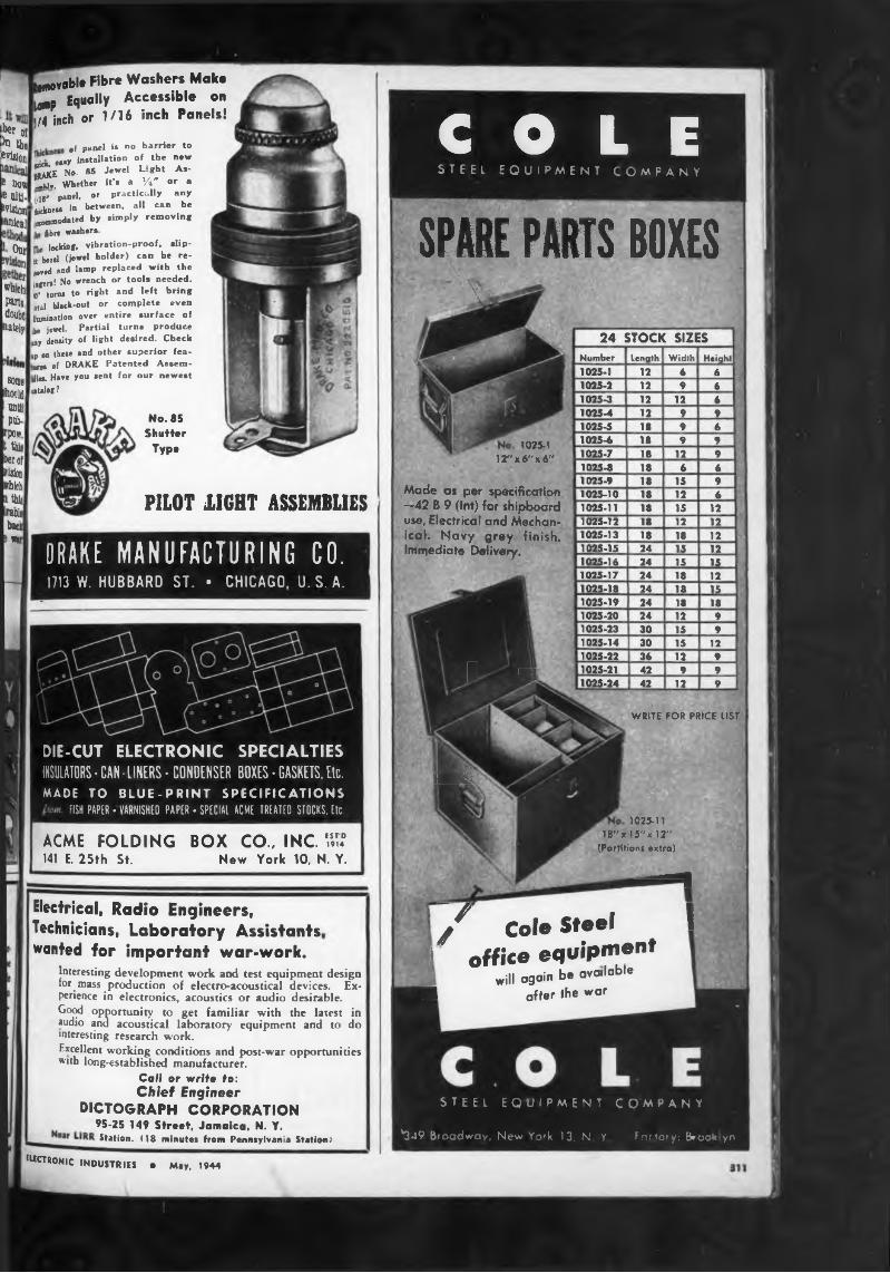
PILOT 1IGHT ASSEMBLIES
(«aunodated by simply removing fibre washers.
manteau
’ 1 AS1 Our
wr.ch parts, doujt
nateiy
W „„ .5v&otl 'bicknes* in between.
tmOvable Fibre Washers Make lamp Eq“a,,y Accessible on ^4 inch or 1/16 inch Paneis!
her ot>n theevlsioi
e bow
of Panel is no barrier to easy installation of the new
Se No- 85 Jewel Light As- X Whether it’s a TV or . |/ir panel, or practically any iu »_ all can be
some ihoiid
una] Ptó-
rpcç t this be? of vision rbh 1 this wrle baci»*r
locking, vibration-proof, slip- it bezel (jewel holder) can be re- wvea »«d lamP replaced with the iofen! No wrench or tools needed. 10» turn* to right and left bring otal black-out or complete even Umnination over entire surface of tie jewel. Partial turns produce ay density of light desired. Check up on these and other superior features of DRAKE Patented Assemble!. Have you sent for our newest catalog?
No. 85 Shutter
Typo
DRAKE MANUFACTURING CO.1713 W. HUBBARD ST. • CHICAGO, U.S.A.
ACME FOLDING BOX CO., INC. HE141 E. 25th St. New York 10, N. Y.
DIE-CUT ELECTRONIC SPECIALTIESINSULATORS• CAN-LINERS• CONDENSER BOXES• GASKETS.Etc.MADE TO BLUE-PRINT SPECIFICATIONS
FISH PAPER • VARNISHED PAPER • SPECIAL ACME TREATED STOCKS. Etc.
Electrical! Radio Engineers, Technicians, Laboratory Assistants, wanted for important war-work.
Interesting development work and test equipment design for mass production of electro-acoustical devices. Experience in electronics, acoustics or audio desirable.Good opportunity to get familiar with the latest in audio and acoustical laboratory equipment and to do interesting research work.Excellent working conditions and post-war opportunities with long-established manufacturer.
Calf or write to:Chief Engineer
DICTOGRAPH CORPORATION95-25 149 Street, Jamaica, N. Y.Station. (18 minutes from Pennsylvania Station)
e«CTRONIC INDUSTRIES e May, 1944
COLESTEEL EQUIPMENT COMPANY'. '
SPARE PAR.
* V
ITS BOXES24 STOCK SIZES
Number Length Width Height1025-1 12 6 6
1025-1 irx«"x6»
Made as per specification —42 B 9 (Int) for shipboard use, Electrical and Meehan- ical. Navy grey finish. Immediate Delivery.
B my
1025-2 12 9 61025-3 12 12 61025-4 12 9 91025-5 18 9 61025-6 18 9 91025-7 18 12 91025-8 18 6 61025-9 18 15 91025-10 18 12 61025-11 18 15 121025-12 18 12 121025-13 18 18 121025-15 24 15 121025-16 24 15 151025-17 24 18 121025-18 24 18 151025-19 24 18 181025-20 24 12 91025-23 30 15 91025-14 30 15 121025-22 36 12 91025-21 42 9 91025-24 42 12 9
WR'TE FÜR PRICE LIST
ML
1025-11 18"x15"xl2"
(ParHHons extra)
■ —I/ Cole Steel 1
! office equipmentwill again b. available
M after the war
STEEL EQUIPMENT COMPANY
*349 Broadway, New Yofk 13, N Y Factory: Brooklyn
Television Licenses and Applications
Because of the tremendous amount of publicity now being given to television, television station applications at the Federal Communications Commission are growing in number.
Latest check with the FCC shows that the following have applied for commercial television station licenses:
Earle C. Anthony, Inc., Los Angeles, C 1, (Held CP under call
COMPACT: 4 IN HIGH 2'j IN DEEP 2* j IN WIDE
WEIGHT: 1V1 POUNDS
: ■ •
ELIZABETH
KSEE), 96000-102000, Channel 6; Bamberger Broadcasting Service, Inc., New York City, Channel 6, Washington, D. C., Channel 4, Philadelphia, Channel 7, all 96000- 102000 kc.; Broadcasting Corp, of America, Riverside, Calif., Channel 3, 66000-72000 kc.; Allen B. DuMont Laboratories, Inc., Washington, D. C., Channel 3, 660000-72000 kc.; Havens & Martin, Inc., Richmond, Va., Channel 3; Hughes Productions, Division of Hughes Tool Co., Los Angeles, also San Mateo County, California, Channel 2; KLZ Broadcasting Co., Denver, Colo.,
Lnew jersey
Channel 3; Don Lee Broaden I System, San Francisco SIChannel 1; Loyola University t i Orleans, La., not specified; ¿Cir politan Television, Inc., New v J City, Channel 8; Xork|
60000—66000 kc.: NBC WaAk I ton, D. C., NBC, Denver, Cha jJ Cleveland and Chicago, Channel il Los Angeles, Channel 3 and &I Francisco, Channel 4; News ¿3 dicate Co., Inc., New York £1 Channel 1; Philco Radio & vision Corp., Washington, Del Channel 4; WCAU Broaden! Co., Philadelphia, Pa., Channel 3
78000-84000: WGN, Inc., Chtol Ill., Channel 4; WHY Radiopil Co., Oklahoma City, Okla., J 1; Louis Wasmer, Spokane, Wa& I Channel 1; Westinghouse kJ Stations, Inc., Boston, Channel si Philadelphia, Channel 7 and Pit .1 burgh, Channel 1. Stromberg-cæJ son Co., Rochester, N. Y., Char I not listed.
Experimental licm«| applicatimi
The applications for experimental television licenses are:Albuquerque Broadcasting Co., Albuquertul
N. Mex. : 50,000-56,000 kc, Channel ll V*-3 kw, A*-3 kw, (4 kw peak). I
CBS (Held CP under call W9XCB): 78.0: 84,000 kc, Channel 4, V-1 kw, A-l k»
Industrial Tool & Die Works, Inc., Minnea^J Minn.: 78,000-84,000 kc, Channel 4/tl kw, A-3 kw, (5 kw peak).
Intermountain Broadcasting Corp., Salt LaJ City, Utah: 50,000-56,000 kc, Channell V-100 w, A-200 w.
Wm. B. Still, Jama ca Radio & Tele Ct] Jamaica, L. I.: 66,000-72,000 kc, Owd 3, V-250 w, A-250 w, (1 kw peak). J
Guz Zaharis, Charleston, W. Va,: 50,■ 56,000 kc, Channel 1, V-50 w, A-DOi (200 w peak).
RCA, Camden, N. J. (Reinstatement I W3XEB) : Channel 5.
Experimental relay statiMl
Pending applications for expatl mental television relay stations 41 elude:Albuquerque Broadcasting Co., Area of 41
buquerque: 282,000-294,000, 25 w IptAl The Journal Co. (Milwaukee Journal), m
of Milwaukee, Wis., (Had CP undarJ, W9XCV): 200,000-202,000, 25 w W power not in excess of 6.5 watts). .
Philco Radio & Tele. Corp., Area of Ne York City 204,000-216,000, 15 w, Chan* 11 and 12
RCA, Area of Camden, N. J., (reinstate«- of W3XAD): 321,000-327,000.
312
PermanentMagnets
All Shapes, Sizes and Alloys. Alnico magnets cast or sintered under G. E. license. Chrome, Tungsten and Cobalt magnets stamped,
formed or cast.
THOMAS & SKINNERSTEEL PRODUCTS CO. • INDIANAPOLIS, IND.
42 YEARS' EXPERIENCE
Commercial stations •» «if
The following commercial television stations are now on the air:60,000-66,000 kc: Balaban and Katz,»«»
III., KBKB, Channel 2; CBS, New York WWCBW, Channel 2. J w
50,000-56,000 kc: Don Lee Bro^castir<N»tem, Hollywood, Calif., rBroadcasting Co., Inc.,
r-, KTSL; Natiw New Vork Gï.
WNBT, Channel 1. „ _66,000-72,000 kc: General Electnc £
Schenectady, N. Y.. WRGB, Channel 3, Journal Co., (Milwaukee Journal’ waukee, Wis., WMJT, Channel 3. .Radio & Tele. Corp., Philadelphia'* WPTZ; Zenith Radio & Tele. Corp., CM* III., WTZR, Channel 1.DuMont’s experimental static
W2XWG is now on the air in channel 78,000-84,000 kc.
* V=Visual Power; A~Aural Power
ELECTRONIC INDUSTRIES • *" ""
unti L
lentil
^8® Lexington Ave. New York 17, N. Y.
-
r.^
ELECTRIC SPECIALTY CO 214 SOUTH ST., STAMFORD, COHN.
ve
k»
SUCTRONIC INDUSTRIES • May, 1944
(round ctaM4)
Retaining Ringssave moneyand metal
Calif, N*w
We&o. F York
^hing. ane¡2
Saj 5 S?n- : C-5. ; Tele- 0. C. - ?
mel 5. llicîzo. di.se har.-.a Wai, Rato Mi Piti. ■U- ia’?i
ANSWERS TO QUESTIONS PAGE us LET LESS METAL
MAKE MORE MONEY
Are You Keeping Up-to-dateON LOW VOLTAGE RECTIFIERS?
1. Th» thr»» mo»t commonly uaod type» of low-voltage rec- tifi»n ar» Selenium, Copper-Oxide and Tungar.I, They differ in characterietic», basic material» and oonstruo- lion
j The »pacific remit» to be obtained and the conditions undsr which the rectifier is to operate will determine which typs will do the most economical, most efficient and most ntiriactory job. In some applications all serve equally well, bat in most instances consideration must be given to space requirement«, weight, cost differences, and life expectancy.4, The only designer-manufacturer of all three types is Gen- in| Deciric Co. (Tungar and Metallic Rectifier Division, Bridgeport, Conn.)I. When the rectifier user consults General Electric, the only dsugnet-manufacturer of all throe standard types of low- vslisge rectifiers, he can be assured of engineering advice on which type will meet his needs most economically and efficiently.
For complete details write: Section A547-124, Tungar and Metallic Rectifier Division, General Electric Company, Bridgeport, Conn.
GENERAL ELECTRIC■'ne'1
e. Co
à
ms-
« si
Oft
w» c*a.*• n Pi U
E Ü
— INDUSTRIAL
ccpn mar|ne LuuU A,RCRAFT " ELECTRONICSA complete line of o.c., d e., and Universal motors, d.c. and all Freq a.c. generators, moto- gc-'ero’O's. converters, dynamotors, gas & Die sei Elec, plants, explosion p>oof units, Machines designed for every purpose
COMPLETE ENGINEERING SERVICEO.’ engineers will be pleased to discuss your problems and aid in the design of machines to meet your requirements.
WANTEDELECTROLYTIC CAPACITOR
CHIEF ENGINEERCapable of designing and supervising installation of equip- m*1^’ T° take complete charge of laboratory and supervise Production quality control. Must have previous experience with etching and formation processes. Write stating expe- n»nce, education, diaft status, present and previous earn-
requirements. All replies will be held in Ivi*** - confidence- Excellent post war possibilities in-
•olving inclusion in owner-management group of young, ag- ireesive capacitor manufacturer.
ADDRESS BOX N ELECTRONIC INDUSTRIES
It's expensive to hold a mechanism in place with unnecessarily big shoulders or collars,— or to temporize with small cotter pins, etc. Let us show you how spring steel retaining rings can do a thoroughly efficient job for you.
More and more retaining rings are being used in these days of necessary economy. Every ounce of metal and every cent of cost is more important today than ever before.
It is needless waste in most instances to turn your shoulders by cutting down larger shafts, when you can groove a smaller shaft and apply a spring steel retaining ring. You'll get excellent results at unbelievable savings.
Every shoulder on your machines or on your metal products should be examined to see whether or not smart engineering could take advantage of these modem artificial shoulders on shafts or in housings.
Write today for our descriptive folder on Retaining Rings.
THE NATIONAL LOCK WASHER COMPANYNewark, N.J., Milwaukee, Wise., U.S.A.
t -
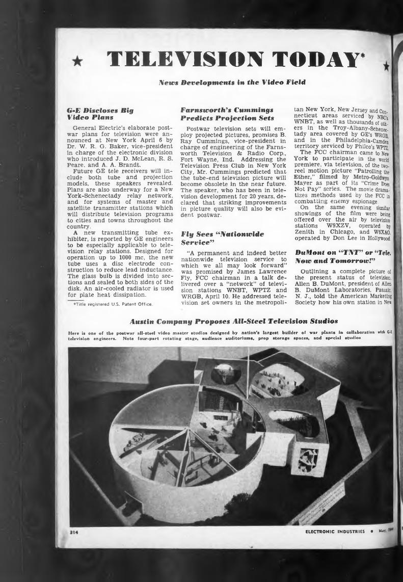
TELEVISION TODAYNews Developments in the Video Field
Austin Company Proposes All-Steel Television Studios
G-E Discloses Big Video Plans
Fly Sees “Nationwide Service"
“A permanent and Indeed better nationwide television service to which we all may look forward” was promised by James Lawrence Fly, FCC chairman in a talk delivered over a “network” of television stations WNBT, WPTZ and WRGB, April 10. He addressed television set owners in the metropoli-
ELECTRONIC INDUSTRIES • May.
Mayer as part of its “Crime Does Not Pay” series. The movie dramatizes methods used by the FCC in combatting enemy espionage.
On the same evening similar showings of the film were being offered over the air by television stations W9XZV, operated by Zenith in Chicago, and W6XA0. operated by Don Lee in Hollywood.
Here is one of the postwar all-steel video master studios designed by nation’s largest builder of war plants in collaboration with GE television engineers. Note four-part rotating stage, audience auditoriums, prop storage spaces, and special studios
tan New York, New Jersey and Connecticut areas serviced by NBC’s WNBT, as well as thousands of others in the Troy-Albany-Schenectady area covered by GE’s WRGB and in the Philadelphia-Camden territory serviced by Philco’s WPTZ
The FCC chairman came to New York to participate in the world premiere, via television, of the two- reel motion picture “Patrolling the TiHhnr ” filmed hv
DuMont on “TNT" or “Tele. Now and Tomorrow!"
Outlining a complete picture of the present status of television. Allen B. DuMont, president of Allen B. DuMont Laboratories, Passaic. N. J., told the American Marketing Society how his own station in New
Farnsworth’s Cummings Predicts Projection Sets
Postwar television sets will employ projected pictures, promises B. Ray Cummings, vice-president in charge of engineering of the Farnsworth Television & Radio Corp., Fort Wayne, Ind. Addressing the Television Press Club in New York City, Mr. Cummings predicted that the tube-end television picture will become obsolete in the near future. The speaker, who has been in television development for 20 years, declared that striking improvements in picture quality will also be evident postwar.
General Electric’s elaborate postwar plans for television were announced at New York April 6 by Dr. W. R. G. Baker, vice-president in charge of the electronic division who introduced J. D. McLean, R. S. Peare. and A. A. Brandt.
Future GE tele receivers will include both tube and projection models, these speakers revealed. Plans are also underway for a New York-Schenectady relay network, and for systems of master and satellite transmitter stations which will distribute television programs to cities and towns throughout the country.
A new transmitting tube ex- hibiter, is reported by GE engineers to be especially applicable to television relay stations. Designed for operation up to 1000 me, the new tube uses a disc electrode construction to reduce lead inductance. The glass bulb is divided into sections and sealed to both sides of the disk. An air-cooled radiator is used for plate heat dissipation.
♦Title registered U.S. Patent Office
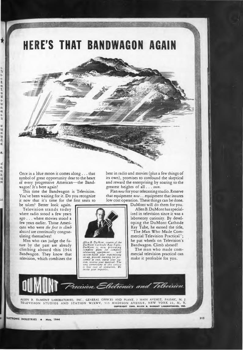
HERE’S THAT BANDWAGON AGAIN
arecans who were the first to climb aboard are continually congratulating themselves!
Once in a blue moon it comes along ... that symbol of great opportunity dear to the heart of every progressive American—the Bandwagon! It’s here again!
This time the Bandwagon is Television. You’ve been waiting for it. Do you recognize it now that it’s time for the first seats to
Men who can judge the future by the past are already climbing aboard this 1944 Bandwagon. They know that television, which combines the
HtCTRONlC INDUSTRIES • May, 1944
ALLEN B. DuMONT LABORATORIES, INC., GENERAL OFFICES AND PLANT. 2 MAIN AVENUE. PASSAIC, N. J. TELEVISION STUDIOS AND STATION W2XWV, 515 MADISON AVENUE, NEW YORK 22, N. Y.
Allen B. DuMont, creator of the DuMont Cathode Ray Tube. DuMont is now providing complete plans for complete telecasting equipment . . . will custom-build your transmitting set-up, provide training for personnel at cost, equip your station, reserve your material. The very cornerstone of this service is low cost of operation. We invite your inquiries.
best in radio and movies (plus a few things of its own), promises to confound the skeptical and reward the enterprising by soaring to the greatest heights of all. . . soon.
Plan now for your telecasting studio. Reserve that equipment now.. .equipment that insures low cost operation. These things can be done.
be taken? Better look again. Television stands today
where radio stood a few years ago . . . where movies stood a few years earlier. Those Ameri-
DuMont will do them for you.Allen B. DuMont has special
ized in television since it was a laboratory curiosity. By developing the DuMont Cathode Ray Tube, he earned the title, "The Man Who Made Commercial Television Practical”; he put wheels on Television’s Bandwagon. Climb aboard!
The man who made commercial television practical can make it profitable for you.
SMALL METAL PARTS byZIERICK
Our standard parts are usually shipped on day order comes in.
Clip» Lug» Terminal» Hardware Grid Cap» Fuse Clips Light Sockets Dies Wire Forms Hot Tinning Automatic
Stampings
Many of these parts are approved by the Army and Navy.
PLEASE TEAR AND MAIL TO Zierick Mfg. Corp.
ZIERICK MFG. CORP.385 Gerard Avenue
New York City 51. N. Y. Telephone MOtt Haven 9-2727
Please send your descriptive catalog.
NAME....................................................................
COMPANT............................................................
ADDRESS...............................................................
York City is serving as an experimental laboratory or “Television Kindergarten.”
Turning to future television operations, Mr. DuMont suggested motion-picture films as a third important method of joining up television networks, in addition to radio relays and coaxial cable.
Regarding future contests between the new visual art and the older aural broadcasting, said Mr. DuMont, “there seems to be a definite place for broadcasting and a definite place for television. In fact, the relationship is pretty much the same as that between the daily newspaper and the. Sunday magazine section. One is the news, the meat of the matter, the plain facts. The other is the embellished presentation, the pictures, the more complete story. Both have their place.
Television 7 to 11
“Likewise between television and broadcasting. In many localities the broadcast station and the television station will be operated side by side, the one supplementing the other. Either the broadcaster will sooner or later be operating a television supplementary service, or someone else will step in and do that essential job. Television — the complete home entertainment — will reign supreme from 7 to 11 at night when the family can concentrate on a real show.
“And in terms of marketing, television will open up brand new possibilities. Merchandise can be actually shown—hats, garments, styles, pretty models. That new-model car can be presented in all its attractiveness and in the ideal outdoor setting. Recipes can be worked out on the television screen, creating a desire that no verbal description can possibly equal. The shop or store can be virtually brought right to the home, with a full display of wares. By comparison, broadcasting is like a plain type advertisement as against a beautifully illustrated and appeal-packed display advertisement.
“Television will set new standards in marketing,” declared Mr. DuMont, “fully in keeping with the coming age of super-marketing if America is to provide jobs and prosperity and the better life for its millions of workers.”
When we re-establish ourselves after this war, we must get the idea that we cannot have a continuity of sameness, that we are going to have a continuity of change. We need to go Into the new era convinced that if there is one thing eternal, it is change.—Charles F. Kettering.
AUDAXIN
SELECTIVE?SERVICE
MU « Alene
• ' d a
.k lenw< !
•Mati« Alla* Aidek Mdio
■ -
-‘RELAYED-FLUX#Joes
Microdyne Sogen Boo it Bradl«
The Standard by Which OtherAre Judged and Valued'
Equipment for the war effort.—
3l4i Sir nr Sr-na
3anib;ann<
(1.) MUST perform up to high« àpa<standards.
(2.) MUST continue to perform Carte » CeLn
respective of climatic variations Cent' Thal is why AUDAX magnetics!; S
powered pickups are selected for n fore
contracts. In building pickups unde ^n such contracts, we do not have io Cole
change our peacetime specifications k cause such MUSTS have always b* Coni
a basic requirement in AUDAX Instn- q.onCommenta. .oni
The sharp clean-cut facsimile repte Com
duction of MICRODYNE — regard!«of climatic conditions—is a marvel » Cool— - ---------------------- — - , j
all who have put it to the only test Uu Cc Con.on
really count* ... the EAR TEST. i •'
WITH OUR COMPLIMENTS A copy of “PICKUP FACTS” is yours for the asking. It answers many questions concerning record reproduction.
Dai .Dm Du
Dai Del« Den Dia Dia DieDre Dr; Dui Du]
BUY WAR BONDS
AUDAK COMPAQ ’rt lie
500 Fifth Ave. New York ®
“Creators of High Grade Electrid
and Acoustical Apparatus since 1915-
316ELECTRONIC INDUSTRIES • MW.*
cW
. . 48
.. 62216316216
Westinghouse Electric & Mfg. Co............ 55Weston Electrical Instrument Corp. . . 163
Advertisers
Industrial & Commercial Electronica ... 36ipitol Radio Engineering Inatitute . . . .244 Industrial Instruments, Inc.
33, 69, 1SSSperti, Inc.
1791MH-
tt*
Hunter HytronIllinois Indiana
233300
218269
6723
268250
272147
Page 154
. 61
Stewart Stamping Co............Sticht Co., Inc., Herman H. Struthers-Dunn, Inc.................
Preaaed Steel Co.Corp..............................Condenser Co. . .. Steel Products Co.
_ ««urti* F'*1
k* â
Sprague Specialties Co.Standard Transformer Co.
Special Chemicals Co. Speer Carbon Co. . .
turata P«»onne1L-' r ' nring Mfg. Co.
Spencer Thermostat Co. . Sperry Gyroscope Co., Inc.
............ 5. 6, 7, 8, 40, 41, 57, 71, 165, 313General Electronics, Inc..................................... 13General Electronics Industries,
. .166
. .139
Snyder Mfg. Co. Sola Electric Co. Solar Mfg. Corp.
Div. of Maguire Industries, Inc........32 General Instrument Corp.General Radio Co.
Industrial Synthetics Corp.. .Instrument Specialties Co., Inc. Insulating Fabricators Inc........................... Insulating Fabricators of New England,
While every precaution is taken to insure accuracy, we cannot guarantee against the possibility of an occasional change or omission in the preparation of this index.
E^CTRONIC INDUSTRIES • May, 1944
Birdwell Mfg. Corp., Allen D.. Carter Motor Co....................
® ’ Celanese Celluloid Corp........... tioai Centralab ...................................
Chicago Telephone Supply Co.
may, 1944J'ectricP & Mf«- Co. . ..
line Folding Box Co., Inc. . .4 Westlake Co
trovos Corp. ...........¿craft Accessories Corp. ¿craft-Marine Products Inc. lit Reduction .............................Electrothermic Corp. . . .
liance Mfg. Co.......................... lied Radio Corp.......................
taerican Coils Co................ - - -taerican Electrical Heater Co. ^riran Gas Accumulator Co. Menean Lava Corp.................. taerican Phenolic Corp.............¿nericai* Time Products, Inc. morirán Transformer Co. . . . taperea Electronic Products . faconda Wire & Calle Co. . . «drew Co. ............................... kmoid Engineering Co............... Matic Corp. ............................. Atlas Sound Corp........................
IAadak Co......................................... .Aadio Development Co.....................Attomatic Electric Sales Corp. . larber Laboratories, Alfred W. .
Jarker 4 Williamson ................... Jell Sound Systems, Inc.................
Jentley, Harris Mfg. Co....................Jenwood Linze Co...........................Jiddle Co., James G.......................
tra- Jird, Richard H...............................K*' Bliley Electric Co............................ * Joe; Co., W. W...............................
Sogen Co., Inc., David ...............Boonton Radio Corp........................Bradley Laboratories, Inc......
. Brilhart Ltd.. Arnold ................... MH Browning Laboratories, Inc...........
Burke Electric Co............................Burndy Engineering Co., Inc. . . .Burnstein- Applebee Co....................
— Cambridge Thermionic Corp. . . .Bannos Electric Development Co.
ghti >pacitrons, Inc................................
. . Chicago Transformer Corp.............■nl' Cinch Mfg. Corp................................
«ir Clare 4 Co., C. P............................ , Clarostat Mfg. Co., Inc..................
1 ™ Cohn 4 Co- Sigmund ..................... e li Cole Steel Equipment Co.................
, Colonial Kolonite Co.........................18 *■ Columbia Wire & Supply Co. bttt Communication Measurements
1 i-or «t.iry ....................................Communication Products Co., Inc-Connecticut Tel. & Elec...................Connector Corp...........................
tpn Consolidated Radio Products Co. JU “on*¡nental Diamond Fibre Co. . .
, Continental Electric Co................... el I Cook Electric Co..............................
I thi ;orn*H’Dubilier Electric Corp. .1 Corning Glass Works . , .
TS iurs nés- ion.
0 ¡0
Page . . 307
. 212 . ..146 ...230 ...311 ...169 ...27330, 31 . . . 34 ...302 . . . 77 ...301...168 ...152
.305 . ..312 ... 195 . . . 64
. 183. . . 60. . . 2
240 ... 39 ...228 ...304 ...236
254 ...316 ...294 ...229...292 ...191. . 284
82 ...281 ...176 ...282
. 293
148 262 297
14 81
220 85
306.240 .190 . 74
....208
.... 248
....17122, 255 .... 79 ....186
243 66
286 .... 294 58, 311 ... 290 ... 309
2779
19 298
.291204
.239—-----, „„„ nuift, 231Cornish Wire Co., Inc. ” 202Corry-Jamestown Mfg. Corp. . . 285Creative Plastics Corp.........................................29Crystal Producta Co................. . . 215Crystal Research Laboratories, Inc. .198Dali«, Inc., H. L.............................................276Daly Machine & Tool Works . . . 296
Co................................................Cover 3Dayton Rogers Mfg. Co.............................. 12
Co.............................................. 56J, * Radio Div., General Motors Corp.. 70Deutschman Corp., Tobe .......................... 301*1 Light Co. of America ........................ 295Diamond Wire & Cable Co........................ 307Dietograph Corp.............................................311n l* Works, Inc........................... 300“rake Mfg. Co.......... .................................... 311Dumont Electric Co.......................................232uuMont Laboratories, Inc., Allen B. 14, 315Pattern Air Devices, Inc............. ^stern Amplifier Corp............... £bophone Radio Co..................... “tor, Inc...............................
Engineering Co...................Jtel-McCullough, Inc.....................Jco Resistors Co.............................
Indicator Co.S°*dering Iron Co., Inc.
uectric Specialty Co....................
175 270279 196 310
7524
.278
.303313
Electrocon Corp........................................Electronic Corp, of America Electronic Mechanics, Inc.................. Electronic Products Mfg. Corp. . .Electronic Supply Co...............................Electro-Voice Mfg. Co., Inc...............Engineering Co..........................................Erie Resistor Corp..................................Ferris Instrument Co.............................Foote, Pierson & Co., Inc.................Formica Insulation Co.........................Gatea-Aadio & Supply Co...................Gemex Co....................................................Generei Ceramics & Steatite Corp.General Electric Co.
Monarch MycalexNational National National National National
Mfg. Co................................Corp, of America ....Co., Inc................................Lock Washer Co............Scientific Products Co. Union Radio Corp. . . . Vulcanized Fibre Co. .
...251
. . . 15
. . . 51
. ..172
...260
. . . 38
Goat Metal Stampings, Inc.................... Gould-Moody Co.......................................... Great Metal Mfg. Corp............................. Green Electric Co., Inc............................. Greenhut Insulation Co............................. Guardian Electric Mfg. Co...................... Guthman & Co., Edwin 1........................Hallicrafters Co............................................. Hammarlund Mfg. Co., Inc.................... Hanovia Chemical & Mfg. Co............... Harvey Radio Co........................................ Harvey Radio Laboratories, Inc. . . . Harvey-Wells Communications, Inc. Hassall, Inc., John .................................. Haydon Mfg. Co., Inc. ........................ Hazeltine Electronics Corp.................... Heinemann Circuit Breaker Co............ Heintz & Kaufman Ltd........................... Hercules Electric & Mfg. Co................. Heyman Mfg. Co......................................... Hipower Crystal Co....................................Howard Mfg. Corp.......................................
Inc............................................... International Nickel Co. . . . International Products Corp. International Resistance Co. . International Tel. & Tel.
Corp................................................
275 209 224160 235 .272223
. 1S7. .263. .201 . .194 . .280. . 84 . .248 . .228 . .274 . .282 . . 35 . .265.260
. .220
. .307
. . 21
. .167
.135
. .302
. 245
Jackson Electrical Instrument Co................150Jarrell-Ash Co........................................................296J-B-T Instruments, Inc......................................170Jefferson Electric Co...........................................214Jensen Radio Mfg. Co...................................... 283Johnson Co., E. F................... ............................. 211Jones, Howard B.................................................. 290Kaar Engineering Co.........................................205Kahle Engineering Co........................................ 310Karp Metal Products Co., Inc........................... 20Ken-Rad Tube & Lamp Co..............................257Kent Metal Mfg. Co., Inc.................................301Kenyon Transformer Co., Inc....................... 267Kirkland Co., H. R.................................................288Knights Co., James .......................................... 78Kurman Electric Co.............................................305Kurz-Kasch, Inc.................................................... 68Lafayette Radii- Corp. ................................... 206Langevin Co., Inc.................................................. 80Lapp Insulator Co., Inc....................................181Lavoie Laboratories .........................................137Leland Electric Co............................................... 83Lenoxite Div., Lenox Inc................................. 151Lewyt Corp............................................................. 45Littelfuse Inc.......................................................... 234Locke Insulator Corp........................................261Lord Mfg. Co............................................................32Maas & Waldstein Co..................................... 87Macallen Co.............................................................210Magnavox Co..................................... •..................253Mallory & Co., Inc., P. R............Cover 2, 149Manross & Sons, F. N......................................226McElroy Mfg. Corp............................................ 59Measurements Corp..............................................164Meek Industries, John ................................... 207Merit Coil & Transformer Corp...................236Metropolitan Electric Mfg. Co.................. 144Meyercord Co..........................................................145Micro Switch Corp............................................. 52Millen Mfg. Co., Inc., James .....................138Mitchell-Rand Insulation Co., Inc............... 219
Newcomb Audio Products Co. . New York Transformer Co. . . . North American Philips Co., Inc. Norton Electrical Instrument Co.Ohmite Mfg. Co..................................Onan & Sons, D. W.......................... O’Neil-Irwin Mfg. Co........................ Operadio Mfg. Co.............................Palnut Co...............................................Panoramic Radio Corp.................... Park Metalware Co., Inc............... Permoflux Corp................................... Picker X-Ray Corp......................... Pioneer Gen-E-Motor ................... Premax Products ............................. Premier Metal Etching Co. . . .Press Wireless, Inc.............................Radell Corp............................................ Radiart Corp.......................................Radio Corporation of America:
Page ...270
.... 143
....241
....313 180
.... 46
. ... 37
....140
. . . .225
.... 76
....226
.... 197
... 303
....262
. . ..158
. ...192
....268
....256. . . .17826, 27 ....200 ....292 :::fg
....238
....238
RCA Commercial Engineering . . .Cover 4RCA Laboratories .........................................153
Radio Specialties Co...........................................305Rahm Instruments, Inc......................................230Ray-O-Vac Co......................................................... 227Raytheon Mfg. Co...................................... 16, 65Reimers Electrical Appliance Co., Inc.. .306Remler Co., Ltd.................................................... 249Rider Publisher, Inc., John F...........................307Rogan Brothers ............................... 309Rogers Radio Tubes Ltd.................................250Roba Co., Inc........................................................... 221Rothenstein, Albert .......................................... 300Sanborn Co.............................................................. 266Scientific Radio Products Co........................174“S” Corrugated Quenched Gap Co.............247Screenmakers .......................................................242Seeburg Corp., J. P.............................................287Segel Co., Henry P.............................................298Shallct oss Mfg. Co............................................... 162Sherron Metallic Corp.......................................199Sigma Instruments, Inc..................................... 264Signal Indicator Corp........................................ 307Sinko Tool & Mfg. Co....................................... 258Smith Mfg. Co., Inc., F. A............................252- - - ..........306
.......... 25
..........318
..........242
..........189
..........28
.......... 193
..........182 157, 258 ..........156..........237 ..........296 ......... 185
Stupakoff Ceramic 4 Mfg. Co............ 50, 141Sun Radio & Electronics Co...........................256Superior Electric Co.......................................... 72Sylvania Electric Producta, Inc.................... 299Taylor Fibre Co.....................................................159Taylor Tubes, Inc................................................177Tech Laboratoriea .............................................282Terminal Radio Corp............................................305Thomas & Skinner Steel Producta Co. . .312Thordaraon Electric Mfg. Co. 4Transmitter Equipment Mfg. Co., Inc. 10Trav-Ler Kar enol a Radio & Telev. Corp. 254Triplett Electrical Instrument Co.Tung-Sol Lamp Works, Inc. . ..Turner Co.................................................Ungar, Inc., Harry A..........................United Electronics Co.......................United Screw & Bolt Corp............United Transformer Co......................Universal Microphone Co.................U. S. Treasury .....................................Utah Radio Products Co.................Walker- Jimieson, Inc..........................Ward Leonard Electric Co................Ward Products Corp...........................Waugh Laboratories ...................... Webster Products .............................. Weltronic Co...........................................
White Dental Mfg. Co., S. S. .White Research ................................Wrigley Co., Wm................................Zierick Mfg. Corp............................Zophar Mills, Inc................................
161 271 203.187
18 .173 . 88 .289 .308 .213.305 .217 . 49 . 86 . 43 .246
317
4
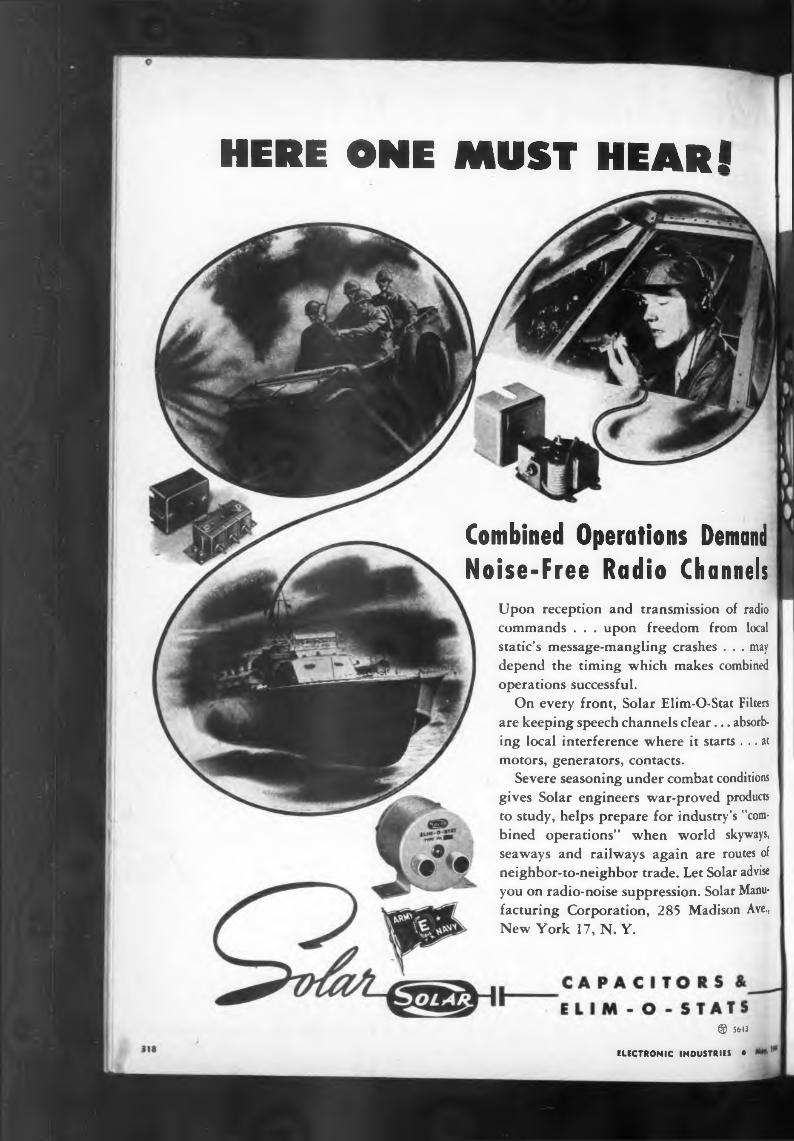
® 5643
ELECTRONIC INDUSTRIES •
HERE ONE MUST HEAR!
Combined Operations DemandNoise-Free Radio Channels
Upon reception and transmission of radio commands . . . upon freedom from local static’s message-mangling crashes . . . may depend the timing which makes combined operations successful.
On every front. Solar Elim-O-Stat Filters are keeping speech channels clear... absorbing local interference where it starts ... at motors, generators, contacts.
Severe seasoning under combat conditions gives Solar engineers war-proved products to study, helps prepare for industry’s ’'combined operations” when world skyways, seaways and railways again are routes of neighbor-to-neighbor trade. Let Solar advise you on radio-noise suppression. Solar Manufacturing Corporation, 285 Madison Ave., New York 17, N. Y.
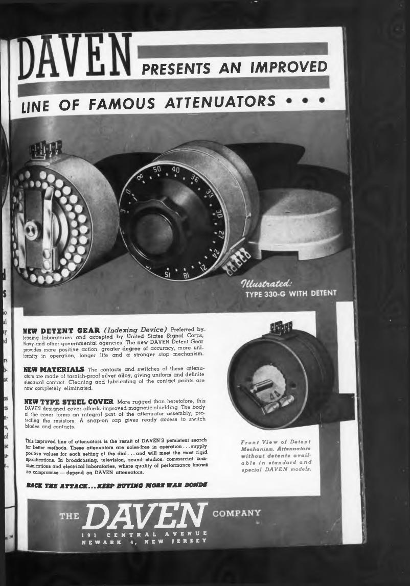
Front View of Detent Mechanism. Attenuators
able in standard and special DAVEN models.
NEW MATERIALS The contacts and switches of these attenuators are made of tarnish-proof silver alloy, giving uniform and definite electrical contact. Cleaning and lubricating of the contact points are now completely eliminated.
NEW TYPE STEEL COVER More rugged than heretofore, this DA VEN designed cover affords improved magnetic shielding. The body ci the cover forms an integral part of the attenuator assembly, protecting the resistors. A snap-on cap gives ready access to switch blades and contacts.
This improved line of attenuators is the result of DAVEN'S persistent search for better methods. These attenuators are noise-free in operation... supply positive values for each setting of the dial... and will meet the most rigid specifications. In broadcasting, television, sound studios, commercial communications and electrical laboratories, where quality of performance knows no compromise — depend on DAVEN attenuators.
Mar the attack...jump buying mom war bond*
NEW DETENT GEAR (Indexing Device) Preferred by- leading laboratories and accepted by United States Signal Corps, Navy and other governmental agencies. The new DAVEN Detent Gear provides more positive action, greater degree of accuracy, more uniformity in operation, longer life and a stronger stop mechanism.
PRESENTS AN IMPROVED
LINE OF FAMOUS ATTENUATORS
DAVEN ■191 CENTRAL AVENUE NEWARK 4, NEW JERSEY
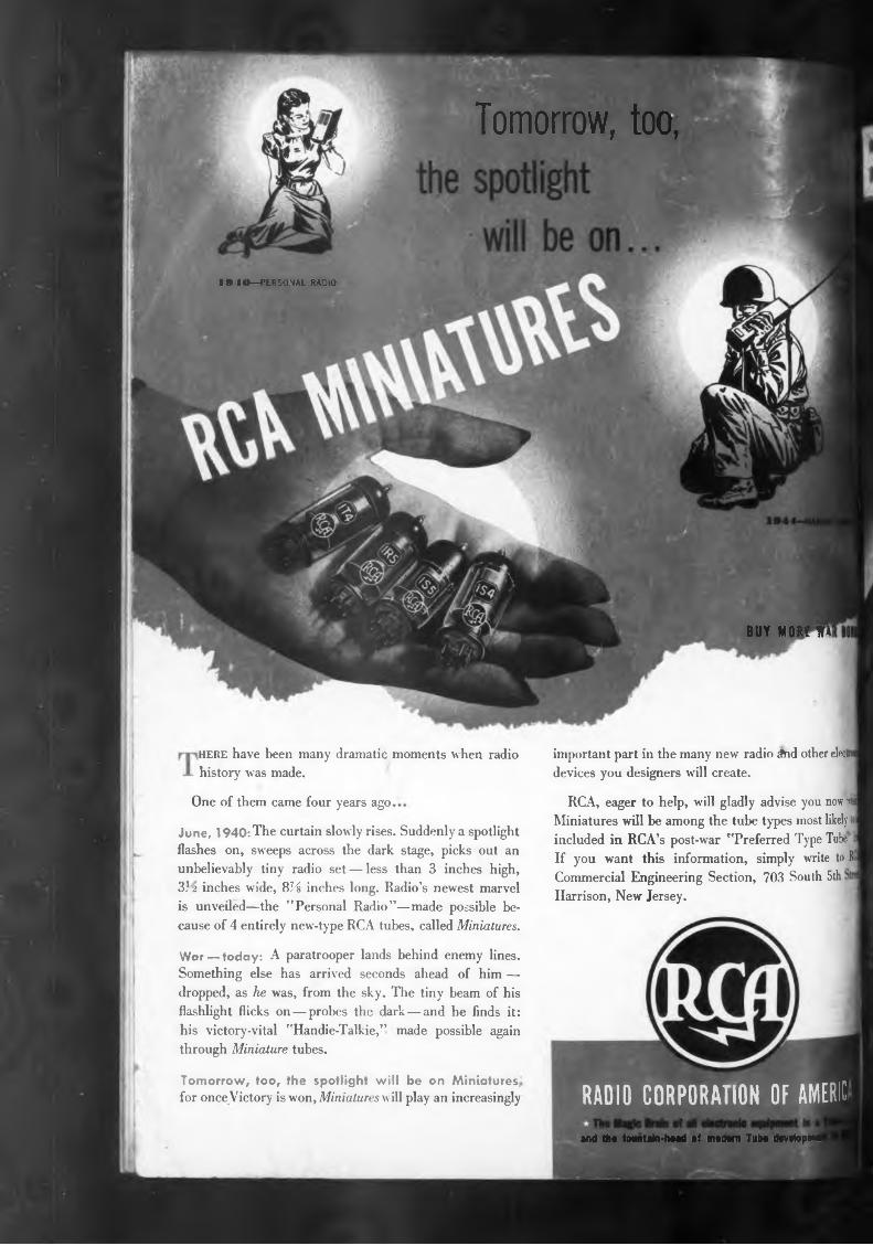
Tomorrow, too,
1940—PERSONAL RADIO
BUY MOUE fl!
and th« fovntain-haad of modem Tib* devetopmo
here have been many dramatic moments when radio history was made.
One of them came four years ago
Tomorrow, too, the spotlight will be on Miniatures« for once Victory is won, Miniatures will play an increasingly
important part in the many new radio Aid other elect devices you designers will create.
RCA, eager to help, will gladly advise you now »1» Miniatures will be among the tube types most likely tol included in RCA’s post-war "Preferred Type Tube li If you want this information, simply write to RC Commercial Engineering Section, 703 South 5th Harrison, New Jersey.
War — today: A paratrooper lands behind enemy lines. Something else has arrived seconds ahead of him — dropped, as he was, from the sky. The tiny beam of his flashlight flicks on — probes the dark — and he finds it: his victory-vital "Handie-Talkie,” made possible again through Miniature tubes.
June, 1940: The curtain slowly rises. Suddenly a spotlight flashes on, sweeps across the dark stage, picks out an unbelievably tiny radio set — less than 3 inches high, 3?2 inches wide, 8% inches long. Radio’s newest marvel is unveiled—the "Personal Radio”—made possible because of 4 entirely new-type RCA tubes, called Miniatures.
RADIO CORPORATION OF AMERIC


