Embed Size (px)
Citation preview
MARK-IT: A MARKING USER INTERFACE FOR
CUTTING DECOMPOSITION TIME
Nicholas C. Yang1 Andrew S. Forsberg1 Jason F. Shepherd2 Ricardo M. Garcia2
Karl G. Merkley3
1Brown University, Providence, RI, U.S.A. {nyang, asf}@cs.brown.edu2Sandia National Laboratories, Albuquerque, NM, U.S.A. {jfsheph, ricgarc}@sandia.gov
3Elemental Technologies, Inc., American Fork, UT, U.S.A. [email protected]
ABSTRACT
We present Mark-It, a marking user interface that reduced the time to decompose a set of CAD models exhibiting arange of decomposition problems by as much as fifty percent. Instead of performing about 50 mesh decompositionoperations using a conventional UI, Mark-It allows users to perform the same operations by drawing 2D marks in thecontext of the 3D model. The motivation for this study was to test the potential of a marking user interface for thedecomposition aspect of the meshing process. To evaluate Mark-It, we designed a user study that consisted of a brieftutorial of both the non-marking and marking UIs, performing the steps to decompose four models contributed to usby experienced meshers at Sandia National Laboratories, and a post-study debriefing to rate the speed, preference,and overall learnability of the two interfaces. Our primary contributions are a practical user interface design forspeeding-up mesh decomposition and an evaluation that helps characterize the pros and cons of the new user interface.
Keywords: meshing, decomposition, marking user interface, gestural commands, time-to-mesh, post-
WIMP
1. INTRODUCTION
The goal of meshing is to produce a discretization ofa space, a mesh, that is suitable for the simulationof a given engineering problem. Meshing, particularlyhexahedral meshing, is a complicated procedure thatoften requires the use of rather sophisticated, inter-active tools (i.e. CUBIT, TurboMesh, SolidMesh) toproduce a usable mesh. For the user, decompositioncan be the most time-consuming part of the meshingprocess; it includes determining and specifying oper-ations such as dividing and simplifying a model’s ge-ometry into more primitive pieces. Decomposition isusually required before an automatic meshing algo-rithm can be applied to components of a model. Inmany cases, the decomposition as a whole cannot beautomatically performed and must be done manually;oftentimes, the user is an irremovable part of the mesh-ing process [1]. Algorithmic and user interface (UI)
research are the current techniques for alleviating thisbottleneck . This study focuses on the latter by testingwhether the use of marking gestures, in the context ofthe 3D tasks at hand, can significantly reduce decom-position time. As noted in [2], any type of automationor optimization in decomposition could “vastly reducethe time to mesh for hexahedral elements.”
Decomposition operations must be accessed througha user interface in any meshing system. Two popu-lar UI styles are Windows-Icon-Menu-Pointer (WIMP)and command-line. In general, user interfaces have re-mained mostly unchanged for the past two decades andpredominantly consist of WIMP UIs [3]. TraditionalWIMP UIs are widely popular mainly because theyhave proven to be relatively easy-to-learn. Command-line UIs originated much longer ago but are sometimespreferred for systems with large numbers of operatorsand operands. Oftentimes, command-line UIs are sig-

nificantly more efficient than WIMP UIs once mas-tered.
In this study, we applied the concept of a post-WIMPUI to a sophisticated meshing system, Sandia NationalLaboratories’ CUBIT, which has been in developmentfor about 8 years and combines the best aspects ofboth conventional WIMP and command-line UIs. CU-BIT is a 2D and 3D finite element mesh generationtool that produces meshes for finite element analysis.Development for the marking interface was done ex-clusively in CUBIT, but we expect the concepts ofthe implemented marking UI to extend over to othermeshing systems as well.
Specifically, we developed a post-WIMP marking UI,which we have termed “Mark-It.” With Mark-It, usersdraw 2D lines in the context of 3D Computer-AidedDesign (CAD) models to specify meshing operationsand operands. We hypothesized a marking UI wouldbe effective due to the graphical nature of meshingtasks. The intent was to discover the advantagesand disadvantages of a specific marking UI targetedat mesh decomposition. Results from this study arepreliminary data that show how effective a markingpost-WIMP interface could be in a meshing context.Our results and evaluation suggest that for purposesof meshing, our post-WIMP marking interface is fasterthan most traditional WIMP interfaces. Furthermore,we also received feedback about several possible im-provements to our marking UI that would make itfaster and easier to learn. The advantages and dis-advantages of both WIMP and post-WIMP interfacesare discussed in [3].
The non-marking CUBIT interface we comparedMark-It to consists of toolbars, menus, point-and-clickselection, and a command-line. Users in our studywere asked to click on separate toolbar icons or to usehot-keys in order pan, rotate, zoom, and enter certainentity (e.g. surface, volume, curve, vertex) selectionmodes when using the non-marking interface. To ex-ecute a decomposition command, users had to selectappropriate tools using the WIMP GUI and then typein the commands based on entity IDs. Mark-It aimsto extend meshing UIs of this type to go beyond usingthe mouse in the 3D graphics window for only pickingand navigating. It allows the user to use the mouse toperform several different decomposition operations bydrawing directly on a model.
2. RELATED WORK
Time-to-mesh is the total time it takes to create afinite element mesh given a geometric model. A com-mon goal of many researchers is to minimize the time-to-mesh. As stated above, decomposition is neces-sary because many meshing algorithms require pre-
processing of the geometric model. In many cases,especially cases with high problem complexity, a usermust manually make decisions, using a tool such asCUBIT, to prepare a model for a given meshing al-gorithm. These human-made decisions can improveoverall efficiency in a way automatic algorithms can-not. For example, the user may improve efficiencyby reducing the total number of elements created, im-proving the quality of elements created, or by mini-mizing the number of steps to achieve the required de-composition. Nevertheless, this section goes into moredetail on non-user-based algorithmic approaches to re-duce the time-to-mesh and also discusses related workin marking post-WIMP UIs.
2.1 Algorithmic Approaches
Historically, a great deal of effort has been spent inreducing the time-to-mesh by introducing new mesh-ing algorithms or improving the scope of existing al-gorithms. Because of limitations in current hexahe-dral meshing algorithms, algorithms for decomposingmodels into mesh-able primitive shapes have receiveda great deal of attention. Several examples of algo-rithmic work to reduce the time-to-mesh will be high-lighted in this section.
Two of the most highly used algorithms in hexahedralmeshing today include the “mapping” and “sweep-ing” methods [4][5]. Enhancements to each of thesealgorithms have been made specifically to reduce theamount of decomposition necessary to produce a mesh,thereby speeding up the time to produce the mesh [6][1] [7]. Specifically, the “submapping” algorithm [1]and the many-to-many sweeping tools [8][9][10] [11]are the algorithms used heavily in CUBIT today. Bothof these techniques are geometry pre-processing algo-rithms that extend the existing “primitive” algorithm.Many-to-one sweeping and multi-sweeping involve ex-truding surface meshes from multiple source surfaces,as opposed to the conventional sweeping algorithmwhich allows only one source surface. Volume submap-ping involves breaking up volumes into sub-regionsthat are quicker and easier to mesh as separate en-tities, instead of as a whole, using standard mappingtransformations.
Another study tried to completely automate the de-composition process entirely by using a techniquecalled Feature Recognition (FR), which was able to au-tomatically generate mesh-able volumes directly froma class of imported ACIS models [12]. Although theresults of FR were impressive, the implemented sys-tem was not general enough to supplant the need forhuman interaction. The implemented FR system alsolacked some options, such as the ability to specify au-tomatic meshing patterns to guide the decomposition.
Several other algorithmic approaches for reducingtime-to-mesh exist as well, and not surprisingly, noneare fully automatic. [13] reduces datasets to waveletrepresentations and coefficients, but it also requiresobtaining triangulation calculations in a lookup ta-ble and performing inverse wavelet transformations.[14] uses features on a “reference mesh” to automati-cally generate mesh-able volumes on a desired model,but consequently, it requires having to find the appro-priate reference meshes for specific geometries. [15],[16], [17], and [18] try to improve time-to-mesh byusing an octree approach to produce an automatic,all-hexahedral meshing algorithm. However, these ap-proaches impose some additional work for dealing withelements on the boundary, and they do not inherentlywork well for producing contiguous meshes across ma-terial interfaces or boundaries of the simulation model.
The goal of these techniques is the same as the goal ofthis study: to reduce the time-to-mesh. Rather thanimproving on the underlying algorithms to further au-tomate the meshing process, Mark-It focuses primarilyon optimizing the user interface.
2.2 Post-WIMP UIs
Several research studies have shown the potential ofintegrating marking UIs into various application areas,as is discussed in the following paragraphs.
In [19] gestural movements and marks were used tocreate 3D geometry in a program called SKETCH.Mark-It also uses gestural marks to perform certainoperations, but it is different because it contains a con-siderably greater number of gestures. There is no sim-ple set of SKETCH-like gestures that can be directlyapplied to mesh decomposition.
In [20], a stylus pen was used in combination with amarking menu for composing music. This post-WIMPinterface received much positive feedback and was evennoted by many users to be preferred over existing al-ternatives. [20] relates to Mark-It in a number of ways.First, both use a marking interface involving gesturesand marking-menu-like mechanisms. Second, both in-terfaces call for a sensible approach to learning andteaching a gestural interface. Third, they both ap-ply the idea of being able to draw what is desired di-rectly in the graphics window. The main differencesbetween [20] and Mark-It is the number of commandssupported and the dimensionality of the problem do-mains.
In [21], which specifically studied the use of markingmenus, a radial menu or straight-line marks were usedto select operations to perform. The study showedthat once learned, marks were used more often andwere more efficient, on average being 3.5 times fasterthan conventional pull-down menus. There is a noted
learning curve, however. Both the speedup and learn-ing curve are expected in Mark-It as well. [21] onlyimplemented menus containing even numbers of op-erations, where each menu contained 12 operationsat most, because it was determined in [22] that sucha setup tended to increase user performance. Dueto the large number of possible decomposition com-mands, Mark-It was implemented as a variation ofsuch a marking menu system, using more than justradial and straight-line marks. The number of opera-tions is only bounded by the number of distinct marksthat can be recognized and learned by the user. Thisimplementation was intended to address the limita-tion of traditional marking menus by combining theadvantages of marking menus with a gesture recogni-tion system.
3. THE TWO INTERFACES
3.1 Non-Marking CUBIT UI
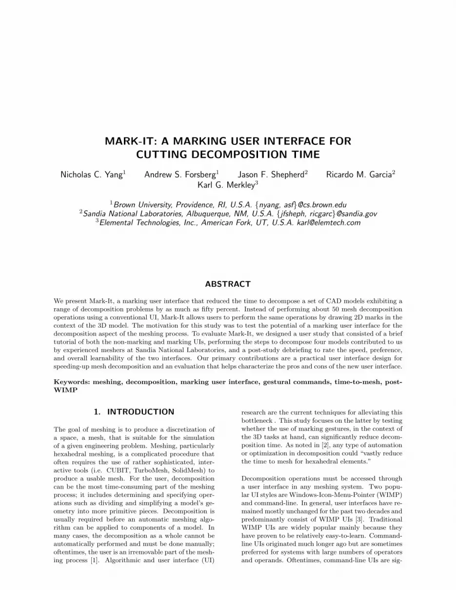
Figure 1: The CUBIT window. In the non-marking UI,users must select modes either by using the toolbars orby using corresponding shortcut keys on the keyboard.Modes include entity (surface/volume/curve/vertex) se-lection and camera pan/zoom/translate. Selection is re-quired to discover IDs of model entities. At the bottomis a command-line prompt for users to type in commandsto execute on entities, based on IDs.
The original CUBIT UI’s decomposition operationswere primarily executed using combinations of tool-bars, menus, key presses, mouse interactions, and a

command-line window. Many operations can be in-voked through either 2D widgets or the command-line.The mouse is used to change modes using the toolbar,to perform camera movements, and to make entity se-lections to find IDs. Figure 1 shows a screenshot of theCUBIT window. All of the toolbar commands used inthis study have corresponding shortcut keys on thekeyboard. It is also possible to use abbreviations intyped commands. Many commands require param-eters. Parameters include ID numbers, coordinates,and fractional values. Specifying the right coordinatesand fractions may require some previous knowledge ofwhere the model is located in world-space, relative tothe origin.
Figure 2: In this example, the four small surfaces drawnin blue that connect the rectangular solid to the cube areto be removed using the “tweak surface replace” com-mand. In the non-marking UI, the user would need toknow the IDs of all 5 surfaces and then type in or echothose IDs to the prompt. Using the marking UI, the userselects the four surfaces and then draws a “tweak sur-face replace” mark starting from the plane of the cube,as illustrated.
The syntax of typed commands must be knownby the user. There is extensive documentation onCUBIT’s command-line syntax available online athttp://cubit.sandia.gov. At least 1000 different typesof commands exist in CUBIT. While a complete lan-guage of marking gestures has not been devised for allof the commands, we believe that a marking interfacefor just the most common operations would still yielda significant improvement on the time-to-mesh.
At times, certain entities may not be selectable dueto other occluding entities. For such cases, the usercan use the “visibility off” command to hide occludingentities. Alternatively, the tab key can be used to cyclethrough the set of entities appearing underneath thecursor.
3.2 Marking CUBIT UI
The marking UI is intended to simplify the overalluser interface for executing decomposition commands.Most interactions are done right in the graphics win-dow and involve just the mouse. The hope is thatthis is fast, intuitive, and direct. In the WIMP GUI,users must frequently switch between graphics win-dows, toolbars, menus, and buttons. The time takento switch between different panels or parts of the in-terface is nontrivial.
The marking interface does not rely on toolbar iconselections. All camera operations are done using a sin-gle mouse button [23]. Decomposition operations areperformed by drawing marks with the left mouse but-ton. The user executes an operation by first clicking toselect one or more entities and then drawing an appro-priate mark, possibly relative to a specific model fea-ture, to execute a desired command. Different types ofentities are selected by toggling modes; from the “sur-face selection” mode, the user double-clicks to enter orexit “body selection” mode and triple-clicks for “curveselection” mode. To perform an operation on all theentities in a model, the user should not manually selectany entities.
There are many possible marks, making it hard to re-member or distinguish some of the commands. Al-though the implemented system contains only a subsetof the full range of CUBIT commands, the markingUI still implements over 50 different CUBIT opera-tions, which can be overwhelming for beginners. Con-sequently, a primitive help system was implementedto draw help text or hints directly inside the graphicsto give the user a better idea about how to executedifferent commands.
When a user draws a mark that corresponds to a validcommand, a label will appear by the cursor, denotingthe command that will be executed if the user releasesthe button at that moment. If the user makes a mis-take while drawing a mark, the user may recover bymoving the cursor to the cancel area, a circle at thestart of the mark, release the button and draw themark again. Examples of mark drawing are illustratedin Figures 2 and 3.
Mark-It’s novel gesture recognition algorithm was in-spired by marking menus [21]. The recognition systemtracks which quadrants are intersected, relative to themark’s initial click point. Because the implementedgesture recognition is based on quadrants and whichquadrant the user initially moves the cursor into, axislines are drawn whenever the user makes a mark. De-pending on which direction the user initially moves themouse, certain commands will become valid or invalid.If the user holds down the left mouse button withoutmoving, hints on which quadrant to start a particu-
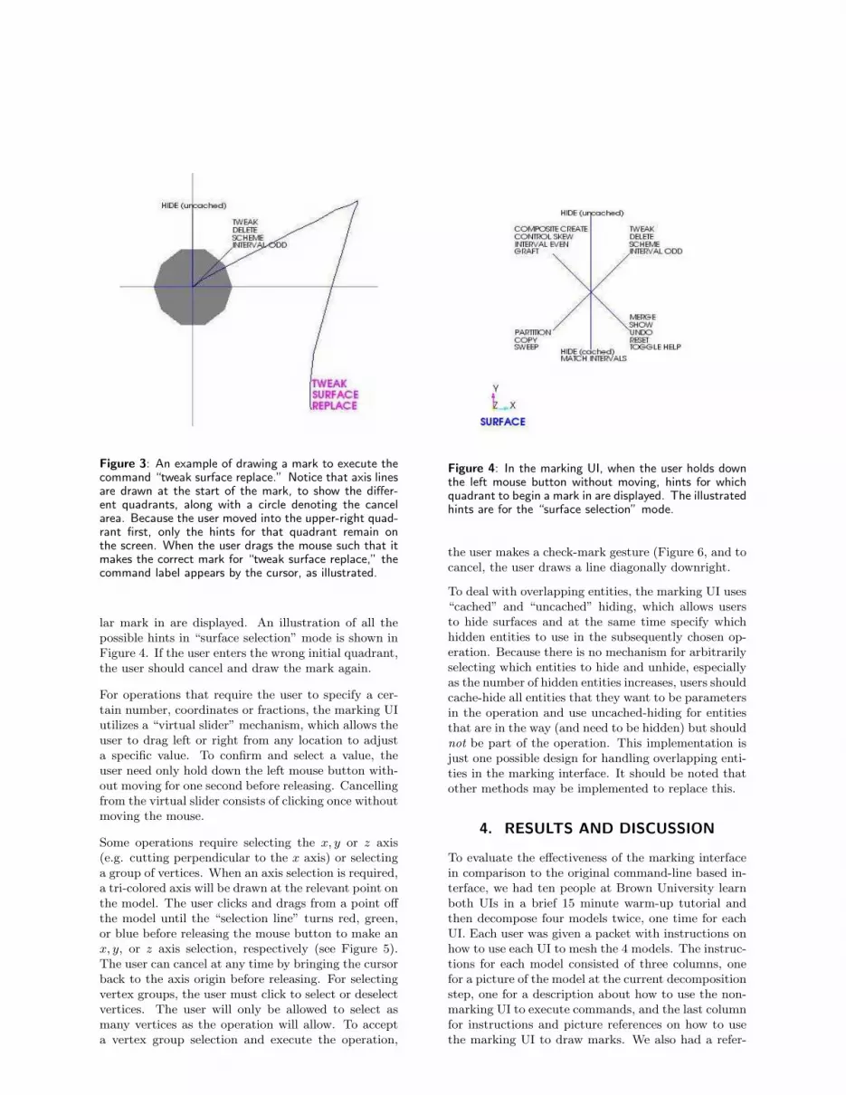
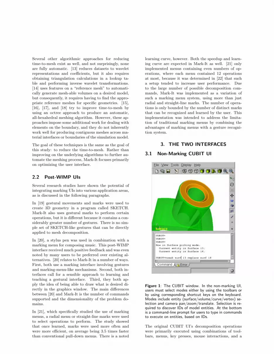
Figure 3: An example of drawing a mark to execute thecommand “tweak surface replace.” Notice that axis linesare drawn at the start of the mark, to show the differ-ent quadrants, along with a circle denoting the cancelarea. Because the user moved into the upper-right quad-rant first, only the hints for that quadrant remain onthe screen. When the user drags the mouse such that itmakes the correct mark for “tweak surface replace,” thecommand label appears by the cursor, as illustrated.
lar mark in are displayed. An illustration of all thepossible hints in “surface selection” mode is shown inFigure 4. If the user enters the wrong initial quadrant,the user should cancel and draw the mark again.
For operations that require the user to specify a cer-tain number, coordinates or fractions, the marking UIutilizes a “virtual slider” mechanism, which allows theuser to drag left or right from any location to adjusta specific value. To confirm and select a value, theuser need only hold down the left mouse button with-out moving for one second before releasing. Cancellingfrom the virtual slider consists of clicking once withoutmoving the mouse.
Some operations require selecting the x, y or z axis(e.g. cutting perpendicular to the x axis) or selectinga group of vertices. When an axis selection is required,a tri-colored axis will be drawn at the relevant point onthe model. The user clicks and drags from a point offthe model until the “selection line” turns red, green,or blue before releasing the mouse button to make anx, y, or z axis selection, respectively (see Figure 5).The user can cancel at any time by bringing the cursorback to the axis origin before releasing. For selectingvertex groups, the user must click to select or deselectvertices. The user will only be allowed to select asmany vertices as the operation will allow. To accepta vertex group selection and execute the operation,
Figure 4: In the marking UI, when the user holds downthe left mouse button without moving, hints for whichquadrant to begin a mark in are displayed. The illustratedhints are for the “surface selection” mode.
the user makes a check-mark gesture (Figure 6, and tocancel, the user draws a line diagonally downright.
To deal with overlapping entities, the marking UI uses“cached” and “uncached” hiding, which allows usersto hide surfaces and at the same time specify whichhidden entities to use in the subsequently chosen op-eration. Because there is no mechanism for arbitrarilyselecting which entities to hide and unhide, especiallyas the number of hidden entities increases, users shouldcache-hide all entities that they want to be parametersin the operation and use uncached-hiding for entitiesthat are in the way (and need to be hidden) but shouldnot be part of the operation. This implementation isjust one possible design for handling overlapping enti-ties in the marking interface. It should be noted thatother methods may be implemented to replace this.
4. RESULTS AND DISCUSSION
To evaluate the effectiveness of the marking interfacein comparison to the original command-line based in-terface, we had ten people at Brown University learnboth UIs in a brief 15 minute warm-up tutorial andthen decompose four models twice, one time for eachUI. Each user was given a packet with instructions onhow to use each UI to mesh the 4 models. The instruc-tions for each model consisted of three columns, onefor a picture of the model at the current decompositionstep, one for a description about how to use the non-marking UI to execute commands, and the last columnfor instructions and picture references on how to usethe marking UI to draw marks. We also had a refer-

Figure 5: Selecting an axis. A “selection line” is drawnfrom the cursor to the axis origin. When the line changesto the corresponding axis color, the user can release themouse button to select that axis. In this example, thebody is being cut by a plane perpendicular to the x-axis,so a corresponding cutting plane is also drawn for thisx-axis selection.
ence sheet of all the possible marks available for usersto look at if they so desired (see Appendix). Becausewe did not require users to have any previous knowl-edge of CUBIT or decomposition, we allowed themto ask questions when they needed help rememberingcommands, had trouble completing steps in the pro-cedure, or were confused about the general procedure.After users completed the study, they were asked to fillout a questionnaire that asked them to rate the learn-ability, speed, and preference of one interface over theother.
Each session lasted about 1-2 hours, depending on howwell the user adapted to and learned the CUBIT sys-tem. We suspect that the time it took was highlycorrelated to the users’ background experience, par-ticularly experience having to do with 3D modelingor CAD programs. None of the users noted any dis-comfort, distortion in vision, fatigue, or disorientationduring the study.
In addition to the marking UI, we also allowed usersto try using two other devices in conjunction with themarking UI as post-WIMP options. We had a free3D tracker with a 2-stage push-button that was capa-ble of rotating and translating the camera, dependingon whether the user pushed the button softly or withmore force. Also installed was a Wacom tablet forhelping users to draw marks, in case it was too diffi-cult to draw marks with the mouse.
Figure 6: An example of selecting 3 vertices and accept-ing the selection by making a check-mark.
4.1 Demographics
All of the test subjects had experience in using both2D and 3D graphics programs. The list of programsincludes Photoshop, GIMP, Illustrator, CorelDraw,Maya, 3D Studio Max, AutoCAD, and Infini-D. Mostof the programs were noted as having been used beforefor more than 10 hours. Only three users wrote thatthey used some programs for less than two hours. Oneuser had prior experience in meshing, but it was notusing CUBIT.
The age group ranges from 19 to 32, where 6 ofthe users are male and 4 are female. A majority ofthe users are currently students, one being a post-doctorate, and some of the listed concentrations in-clude Applied Math, Geophysics, Education, Engi-neering, and Computer Science. The users who werenot students had job titles such as UI Developer andmedia coordinator.
4.2 Ease of Use
Overall. Every user commented that the marking in-terface outperformed the non-marking interface. Allbut one of the users noted, though, that there was asignificant learning curve that had to be overcome be-fore the marking interface could be effectively used.About half of the users found that only in the laterexamples did the marking interface became easier andfaster. The users agreed that using the marking UI,commands were more direct. They also appreciatedhow the marking interface eliminated the need to knowentity IDs. There was one user who commented thatlearning either interface required roughly the same
amount of work but that it would probably be moreworthwhile to learn the marking UI.
Comparison. Both interfaces had their strengths andweaknesses. We noticed that several users frequentlymade a lot of typos in the non-marking UI, but sim-ilarly, users drew incorrect marks using the markingUI, especially in cases where the user had to to startthe mark on a particular curve or surface. One ofthe noted advantages of the typing interface was theability to enter commands without having to activelylook at the graphics window the whole time, althoughit sometimes made it harder for users to notice whenthey made a typo. Users found the marking UI to be alot more intuitive and simpler to perform certain oper-ations. However, a distinct disadvantage of the mark-ing UI was bad gesture recognition, which was partic-ularly noticeable when users wanted to draw gesturesquickly without having to confirm that a commandwas correctly selected. Users often executed undesiredoperations on the model by accident.
Modes. Half of the users thought that the tool-bar mode selection of the non-marking UI was morestraightforward for selecting different types of entities,as opposed to the required double and triple clickingof the marking UI. The modes of the marking UI wasalso confusing to users particularly in cases where auser had to be in “body selection” mode to cut a body,but the mark to be drawn had to start on a certaincurve or surface.
4.3 Camera Controls
Non-Marking. About half of the users remarkedthat the camera functions of the non-marking UI weremore intuitive than the single button camera (the Uni-cam [23]) of the marking UI. They had a better im-mediate understanding of how to navigate by click-ing toolbar icons for rotating, panning, and zoom-ing the camera. One user remarked that the con-trols were almost exactly identical to a CAD programthat this user had previous experience with. The Uni-cam seemed to be difficult for users that had not usedUnicam-like camera navigation before. Particularly,a Unicam is supposed to zoom or pan, depending onwhether the user initially drags the mouse horizontallyor vertically, but several users had difficulty in gettingthe mouse to initially drag vertically when they wantedto. One of the users mentioned that it was annoying tohave to first move left or right to pan up or down; theuser preferred moving the mouse directly up or down,instead of having to first move left or right. Anotheruser, who had extensive experience using Maya, re-marked that some “unlearning” of Maya was requiredin order to get used to the Unicam controls.
Marking. On the other hand, the use of Unicam also
received much positive feedback from several users inthe study. For instance, one of the users said thatfor many operations, the Unicam saved at least a halfsecond of time that was required in the non-markingUI when switching between different camera or selec-tion modes. Another user wanted to use the Unicamfor both the marking and non-marking examples in-stead of having to resort back to the toolbar icons fornon-marking examples.
4.4 Speed
Typing. About a quarter of the users noted that typ-ing commands was more direct and faster than havingto learn a gesture mark in order to execute a com-mand. There were two users who simply preferredtyping over mouse interactions in general, saying thatmouse-drawn commands took too long to learn andthat drawing the shapes of the various gestures wasdifficult to remember and do quickly, even with thereference sheet. One user said that had all of theIDs and arguments been known ahead of time, thenon-marking UI might have been easier to use for theparticular examples used in the study. A number ofusers did also complain, however, about the lengthyand confusing syntax of some of the commands.
Drawing Marks. The marking interface receivedmostly positive feedback. We had one user who hadprevious meshing experience, and this user expressedinterest in the concept of the implemented markingUI. All the users said that the marking UI was harderto learn. They also commented, though, that withmore practice, the marking UI would be faster thanthe non-marking UI. Certain annoyances that usersnoted in the non-marking UI include having to typein ID numbers and having to navigate from windowto window in order to select a toolbar icon, type acommand, or navigate the camera. The marking UIbundled all of these tasks into the graphics windowalone. In particular, for longer and more repetitiveexamples, the marking UI was always preferred overthe non-marking UI. Users commented that such ex-amples were “tedious” and “painful” to complete usingthe non-marking UI. In the post-questionnaire, usersrated the non-marking UI to be between 30-80% slowerthan the marking UI.
4.5 Learnability
Previous Experience. Many of the users who hadprevious experience in using 3D modeling or CAD pro-grams commented that the non-marking UI was moreintuitive to initially learn. Comparisons were made toprograms with similar toolbar icon camera functions.Users also said that it was more obvious what com-mand was going to be executed using the non-marking
interface. To them, typing in actual commands usingwords was more intuitive than having to rememberhow to draw shapes or patterns. More than half ofthe users also thought that using the keyboard to inputexact numbers was easier than using the slider-basedmechanism of the marking UI. A common complaintwas that there was not enough visual feedback or accu-racy in using the slider. Users who said that their pre-vious experience helped them in completing the tasksmostly said that their background facilitated cameranavigations. Those who had never used a Unicam be-fore found the Unicam hard to use. Although the hopefor the marking UI was to have it readily learnable byany user, the eventual target audience will consist ofpeople who perform decomposition on a regular every-day basis. Perhaps, we should have limited the userstudy to users with more background experience.
Making Marks. The marking UI was difficult tolearn, even with the reference sheet, and we suspectthat there was not enough time for users to becomeaccustomed to the restrictions and rules for makingmarks. At the beginning, many users had to drawsome marks several times before they were able to getthe right command to show up. Most of the users be-lieved that this problem was a simple matter of prac-ticing. However, one user commented that the mark-ing UI was not intuitive at all and that even with ev-eryday practice, it would be difficult to learn. It shouldbe noted, though, that the implemented gesture rec-ognizer can easily be replaced with any other type ofmarking-menu or gesture recognition system. A pos-sibility is using the stroke recognition techniques de-scribed in [24], which would probably significantly in-crease the accuracy of the recognition. The quadrant-based marking UI in this study is only a preliminarysystem that was implemented to demonstrate the pos-sibility of using a marking post-WIMP UI in decompo-sition. There is a wide range of possibilities for furtherexpanding and developing the work started here in thisstudy.
Using the Mouse. About a quarter of the usersfound themselves clicking the wrong button while us-ing the marking UI. Some users had difficulty in re-membering to use the middle button for camera nav-igations and the left button for marking commands.While this is a minor detail, perhaps the learnabilitycould have been improved had the controls been lim-ited to one mouse button. Other complaints includehaving to hold down the button one second before aparameter was accepted by the virtual slider. One usercommented that using conventional “OK” and ”Can-cel” buttons would have sufficed.
Help System. Users thought that the help systemfor the marking UI was indeed beneficial, but manythought that it was insufficient for becoming familiar-
ized with the interface. Two of the users wanted amore interactive system that updated as marks werebeing drawn. Perhaps the number of commands wassimply too overwhelming in the marking UI for noviceusers.
4.6 Preference
Nearly all of the users agreed that the command-linebased UI was easier and more intuitive to learn. How-ever, they pointed out that it was still rather annoy-ing or frustrating to have to click the toolbar, graphicswindow, and then the command-line to execute a sin-gle command. One of the users pointed out that usingjust the mouse for all commands was a lot more con-venient. For longer examples, all users preferred usingthe marking UI. A lot of users still missed the comfortand familiarity of using the traditional non-markingWIMP interface, however.
Some of the positive comments about the markingUI include the ability to make marks directly on themodel, which was a noted improvement over havingto echo ID numbers on the command-line after select-ing entities. For commands such as cutting by a planeperpendicular to the x, y, or z axis, cutting by a planedefined by three vertices, deleting entities, and par-titioning entities, this was a significant improvement.Two of the users said that the tasks themselves seemedinherently visual, and that is why they preferred themarking UI over the non-marking UI.
More than one user liked the idea of having a hybridinterface, where there would be a method for switchingbetween the non-marking and marking UIs, becauseaccording to four of the users, certain tasks seemedbetter-suited for one UI than the other. Particularly,for tasks requiring number values such as fractions orcoordinates, many users wanted to just type in thedesired values as opposed to having to use the sliderin the marking UI. Users also voiced a concern overnot being able to select certain numbers when usingthe slider, as the values only change in 0.05 increments.
The marking UI was almost always noted as beingmore fun to use, because it was something differentand unconventional, but the non-marking UI receivedmore votes for being easier to learn and easier touse. The non-marking UI was straightforward to manyusers, although one user acknowledged the method was“old-fashioned.” Many users were more confident us-ing the non-marking UI, although two of the 10 usersin the study did not note a significant difference inthe difficulty of either interface; it was noted by allusers that with practice, any implemented UI wouldbecome easier to use. The non-marking UI did receivemore negative feedback in regards to being tedious,especially on models requiring repetitive steps. Three

Figure 7: An example that was considered tedious byseveral users in the user study. Similar operations had tobe done on all six sides of the model. The non-markingUI received especially negative feedback on this example.
users voiced a need for some more automation on thesemodels. Figure 7 is an example of such a model.
5. ERROR ANALYSIS
There are several sources of error in the user study.Discussion of each follows:
First, it is possible that some of the controls were toosensitive. More than one user believed that some tun-ing was required, especially mouse movement in slidernumber selections. Many of the mouse and gesturemovements could have been further tweaked or ad-justed to accustom the different ways that users ini-tially react to and interact with such a system.
Second, it is possible that given more practice withmesh decomposition or more knowledge about mesh-ing concepts, the users might have reported differentlyon the two interfaces. Most of the users did not knowthe purpose or steps behind meshing. A more detailedexplanation of the reason for each step may have con-tributed to more confident user feedback.
Third, there were several bugs in the prototype code.Given the focus of the study, these bugs were con-sidered to be trivial enough to ignore. Some of thebugs included drawing errors in the graphics windowand erroneously chosen rotation points for the cam-era. However, had such bugs been fixed perhaps therewould have been more positive feedback regarding vi-suals in the graphics window, as some users noted nothaving enough visuals to confirm or know about whatcertain commands or settings were doing in the pro-
gram.
Finally, the Wacom tablet and 3D tracker were alsobuggy. In the marking UI, clicks were detected onlywhen the user did not move the mouse because anycursor movement during a click implied dragging. TheWacom tablet was too sensitive in that every time theuser lifted the pen, it would oftentimes report a dragwhen the user actually wanted to click. The effective-ness of the Wacom might also be related to previousexperience; the two users who had experience in us-ing a Wacom-type of input device were the only oneswho commented on the ease of use for making someof the marks. As for the 3D tracker, we had problemsin the camera translation. Perhaps the Wacom tabletand the tracker would have shown better potential hadthey been more thoroughly tested and implemented,but they still demonstrated good possibilities for post-WIMP interfaces in a meshing environment.
6. FUTURE WORK
More Visuals. Mark-It’s UI is only one possibil-ity for a marking UI in a meshing system. Some ofthe goals that we wanted to achieve included avoid-ing unnecessary movement of the mouse and unnec-essary interaction with the keyboard. Hence, we im-plemented double and triple clicking at arbitrary loca-tions to avoid having to move the mouse or press keyson the keyboard in order switch modes. The samelogic applies to the “1-second accept method”; insteadof requiring the user to have to move the mouse to an“OK” or “Cancel” button, the user could click wher-ever the cursor was currently at, and release the mouseaccordingly. One of the major problems of Mark-It’sinterface was a lack of visual feedback. Perhaps hadthere been more visual feedback, especially in the “1-second accept method,” users would have been morereceptive to the idea of not having “OK” and “Can-cel” buttons. Creating more visuals may be a possiblefirst step in improving the marking interface.
Hybrid Interface. More than one user expressedan interest in having some combination of typing andmaking marks as one unified user interface. We believethat such a system may especially be effective for userswho are accustomed to previous programs that utilizeWIMP techniques and wish to slowly transition to orcomplement their methods of interaction with a ges-tural marking interface.
More User Studies. Perhaps a more interesting userstudy would have involved implementing and compar-ing a user interface more comparable to such commer-cial software programs as Maya, and comparing thatwith the currently implemented marking UI. One ofthe users remarked that it was rather unfair to com-pare a command-line based UI to a more state-of-the-
art marking UI. A possibility would be to compareMark-It to Tracking Menus [25] or to future versionsof CUBIT.
More Post-WIMP. The Wacom tablet and 3Dtracker showed very good possibilities for future im-plementations. In respect to the Wacom tablet, two ofthe users, who had experience in using pen and tabletinput devices, liked the ease of use and natural motionsof drawing marks by using a pen instead of the mouse.For the 3D tracker, most of the users commented thathad the tracker been better implemented, they wouldhave liked to use it more than they did during thestudy. This was especially true for the users that dis-liked the Unicam. One of the inconveniences about thetracker that was mentioned was having to deal withthe cable getting in the way and making awkward ro-tations with their wrists. Some users said that theywould have preferred using their non-dominant handfor doing camera navigations with the tracker whilethey did commands with their other hand. Others didnot think a two-handed interface would be beneficial.The use of these two devices as well as the possibil-ity of two-handed interfaces in a meshing system canserve as a basis for other user studies in future work.Further extensions to the tracking system may involvestereo viewing and head-tracking.
Better Learning. Finally, future work may also in-volve studies about improving the learnability of mark-ing interfaces. The implemented help system onlyshows hints about how users should start a mark, butit does not actively update to show what hints are pos-sible after drawing a partial mark. A more thoroughand complete system that helps users avoid using thereference sheet would have been ideal.
7. CONCLUSION
The implemented marking UI has shown the potentialof a post-WIMP marking interface when integratedwith a complex meshing system such as CUBIT. Themarking UI is only one of the many possibilities fora post-WIMP interface and could be substituted withvariations or entirely different interfaces. An exam-ple would be using gesture recognition algorithms de-scribed in [24].
Being able to specify commands and operands bydrawing marks inside the graphics window in the con-text of the 3D model helped users significantly inachieving the decomposition goals in less time. In thenon-marking UI, much time was consumed in switch-ing between different parts of the WIMP GUI. Webelieve that marking UIs are scalable and extensibleto other meshing systems, and implementing a mark-ing UI in other systems would be worthwhile in futurestudies.
Although this version of Mark-It is in its early stagesof development, we believe that there is much poten-tial for post-WIMP UIs in a meshing environment. Webelieve future studies should focus on the scalabilityof the UI, ability to learn the UI, and evaluating effec-tiveness.
8. ACKNOWLEDGEMENTS
This work was supported by LLNL Research Subcon-tract No. B527302. We would like to thank the CU-BIT team at Sandia National Laboratories for theircontinued support and collaboration in this study. Wewould like to thank Jon Goldman for his help, includ-ing feedback and comments on designing the Mark-Itprototype.
References
[1] White D.R., Mingwu L., Benzley S.E., SjaardemaG.D. “Automated Hexahedral Mesh Generationby Virtual Decomposition.” Proceedings of the
4th International Meshing Roundtable, pp. 165–176. Sandia National Laboratories, October 1995
[2] White D.R., Saigal S., Owen S.J. “Meshing Com-plexity of Single Part CAD Models.” Proceedings
of the 12th International Meshing Roundtable, pp.121–134. September 2003
[3] van Dam A. “Post-WIMP User Interfaces.” Com-
munications of the ACM, vol. 40, no. 2, 63–67,1997
[4] Cook W.A., Oakes W.R. “Mapped Methods forGenerating Three-Dimensional Meshes.” Com-
puters in Mechanical Engineering, pp. 67–72. Au-gust 1982
[5] Staten M.L., Canaan S.A., Owen S.J. “BM-SWEEP: Locating Interior Nodes During Sweep-ing.” Proceedings of the 7th International Mesh-
ing Roundtable, pp. 7–18. Sandia National Labo-ratories, October 1998
[6] Knupp P. “Next-Generation Sweep Tool: AMethod for Generating All-Hex Meshes OnTwo-And-One-Half Dimensional Geometries.”Proceedings of the 7th International Meshing
Roundtable, pp. 505–513. Sandia National Lab-oratories, October 1998
[7] White D.R., Tautges T.J. “Automatic SchemeSelection for Toolkit Hex Meshing.” International
Journal for Numerical Methods in Engineering,vol. 49, no. 1, 127–144, September 2000
[8] Blacker T. “The Cooper Tool.” Proceedings of the
5th International Meshing Roundtable, pp. 13–29.Sandia National Laboratories, October 1996

[9] Mingwu L., Benzley S.E., Sjaardema G., Taut-ges T. “A Multiple Source and Target SweepingMethod for Generating All Hexahedral Finite El-ement Meshes.” Proceedings of the 5th Interna-
tional Meshing Roundtable, pp. 217–225. SandiaNational Laboratories, October 1996
[10] Shepherd J., Mitchell S.A., Knupp P., White D.“Methods for MultiSweep Automation.” Proceed-
ings of the 9th International Meshing Roundtable,pp. 77–87. Sandia National Laboratories, October2000
[11] White D.R., Saigal S., Owen S.J. “CCSweep:Automatic Decomposition of Multi-Sweep Vol-umes.” 4th Symposium on Trends in Unstructured
Mesh Generation. July 2003
[12] Lu Y., Gadh R., Tautges T. “Volume Decompo-sition and Feature Recognition For HexahedralMesh Generation.” Proceedings of the 8th Inter-
national Meshing Roundtable. 1999
[13] Gross M.H., Gatti R., Staadt O. “Fast Multireso-lution Surface Meshing.” Proceedings of the IEEE
Visualization ’95, pp. 135–142. IEEE ComputerSociety Press, 1995
[14] Yamada A., Inoue K., Itoh T., Shimada K. “AnApproach for Generating Meshes Similar to a Ref-erence Mesh.” Proceedings of the 9th Interna-
tional Meshing Roundtable, pp. 101–107. SandiaNational Laboratories, October 2000
[15] Walton K.S., Benzley S.E., Shepherd J.F.“Sculpting: An Improved Inside-Out Scheme ForAll-Hexahedral Meshing.” Proceedings of the 11th
International Meshing Roundtable, pp. 153–159.Sandia National Laboratories, September 2002
[16] Tchon K.F., Hirsch C., Schneiders R. “Octree-Based Hexahedral Mesh Generation For Vis-cous Flow Simulations.” 13th AIAA Compu-
tational Fluid Dynamics Conference, AIAA-97-1980. AIAA, June 1997
[17] Marechal L. “A New Approach to Octree-BasedHexahedral Meshing.” Proceedings of the 10th
International Meshing Roundtable, pp. 209–221.Sandia National Laboratories, October 2001
[18] Schneiders R. “Octree-Based Hexahedral MeshGeneration.” International Journal of Computa-
tional Geometry and Applications, vol. 10, no. 4,383–398, 2000
[19] Zeleznik R.C., Herndon K.P., Hughes J.F.“SKETCH: An Interface for Sketching 3DScenes.” Proceedings of SIGGRAPH’96, pp. 163–170. 1996
[20] Forsberg A.S., Dieterich M., Zeleznik R.C. “TheMusic Notepad.” ACM Symposium on User In-
terface Software and Technology, pp. 203–210.1998
[21] Kurtenbach G., Buxton W. “User Learning andPerformance with Marking Menus.” Proceedings
of the CHI94, pp. 258–264. 1994
[22] Kurtenbach G., Sellen A., Buxton W. “An Em-pirical Evaluation of Some Articulatory and Cog-nitive Aspects of “Marking Menus”.” Journal of
Human Computer Interaction, vol. 8, no. 1
[23] Zeleznik R., Forsberg A. “Unicam 2D GesturalCamera Controls for 3D Environments.” Pro-
ceedings of the 1999 symposium on Interactive 3D
graphics, pp. 169–173. ACM Press, 1999
[24] Lopresti D., Tomkins A., Zhou J. “Algorithms forMatching Hand-Drawn Sketches.” Proceedings of
the 5th International Workshop on Frontiers in
Handwriting Recognition, pp. 233–238. 1996
[25] Fitzmaurice G., Khan A., Pieke R., Buxton B.,Kurtenbach G. “Tracking menus.” Proceedings of
the 16th Annual ACM Symposium on User Inter-
face Software and Technology, pp. 71–79. ACMPress, 2003
9. APPENDIX
The figures in this section show operations that wereimplemented in Mark-It.
Figure 8: Curve operations.

Figure 9: Body operations.
Figure 10: Marks that are specific to various modes re-lated to body selections.
Figure 11: Surface operations.
Figure 12: Marks that are specific to modes related tosurface selections.


