Embed Size (px)
Citation preview
MARINE INVESTIGATION REPORT
M00C0026
STRUCTURAL FAILURE
BULK CARRIER ALGOWOOD
BRUCE MINES, ONTARIO
01 JUNE 2000

The Transportation Safety Board of Canada (TSB) investigated this occurrence for the purpose of advancing
transportation safety. It is not the function of the Board to assign fault or determine civil or criminal liability.
Marine Investigation Report
Structural Failure
Bulk Carrier Algowood Bruce Mines, Ontario 01 June 2000
Report Number M00C0026
Synopsis
At about 2345 local time, 01 June 2000, while loading a cargo of aggregates at Bruce Mines, Ontario, the hull of the Canadian bulk carrier Algowood buckled in way of hold No. 3. The vessel flooded, sat on the bottom alongside the dock, and was later salvaged and towed to dry dock for repairs. Ce rapport est également disponible en français.


TABLE OF CONTENTS
TRANSPORTATION SAFETY BOARD iii
1.0 Factual Information ................................................................................... 1
1.1 Particulars of the Vessel ........................................................................................................ 1
1.1.2 Description of the Vessel ....................................................................................................... 1
1.1.3 Certification of the Vessel ..................................................................................................... 2
1.2 History of Events ................................................................................................................... 3
1.3 Certification of Personnel ...................................................................................................... 5
1.4 Loading Summary .................................................................................................................. 6
1.5 Condition of the Bottom Alongside the Berth ....................................................................... 6
1.6 Injuries to Persons .................................................................................................................. 6
1.7 Damage Surveys at Bruce Mines ........................................................................................... 7
1.8 Damage Survey in Dry Dock ............................................................................................... 8
1.9 Shell Plating Thickness Gauging, Laboratory Testing, and Hull Stresses ............................ 9
1.10 Vessel Strength and Stability ............................................................................................... 11
1.11 Loading Sequence ................................................................................................................ 11
1.12 Cargo Watch Schedules ....................................................................................................... 13
1.13 Previous Safety Recommendations Regarding Bulk Carriers ............................................. 13
1.14 Loading Plan and Operating Procedures ............................................................................. 14
2.0 Analysis ................................................................................................... 17
2.1 General Communications ..................................................................................................... 17
2.2 Communications and Coordination S Loading/Deballasting .............................................. 17
2.3 Loading and Deballasting .................................................................................................... 17
2.4 Determination of Draughts .................................................................................................. 18
2.5 Condition of the Bottom Alongside the Berth ..................................................................... 19
2.6 Officers= Knowledge of Structural Stresses ......................................................................... 19
2.7 Existing Safety Measures for Bulk Carriers ........................................................................ 20
3.0 Conclusions .............................................................................................. 21
3.1 Findings as to Causes and Contributing Factors ................................................................. 21
3.2 Findings as to Risk ............................................................................................................... 21
3.3 Other Findings ..................................................................................................................... 21

TABLE OF CONTENTS
iv TRANSPORTATION SAFETY BOARD
4.0 Safety Action ........................................................................................... 23
4.1 Action Taken ........................................................................................................................ 23
4.2 Safety Action Required ........................................................................................................ 24
5.0 Appendices
Appendix A - Glossary ........................................................................................................................ 27

FACTUAL INFORMATION
TRANSPORTATION SAFETY BOARD 1
1.0 Factual Information
1.1 Particulars of the Vessel
Algowood Port of Registry
Sault Ste. Marie, Ontario
Flag
Canada
Official Number
372055
Type
Great Lakes bulk carrier, self-unloader
Gross Tonnage
1
22 558.32
Length Over All
222.5 metres
Breadth
23.13 metres
Depth
14.17 metres
Classification Society
Lloyd=s Register of Shipping
Classification of Voyage
Inland Voyage, Class II
Built
1981, Canadian Shipbuilding & Engineering Ltd., Collingwood, Ontario
Propulsion
2 MAK Diesels, Model 6M552 7600 kw, single screw controllable pitch
propeller Owner and Technical Manager
Algoma Central Corporation
(Algoma Central Marine)
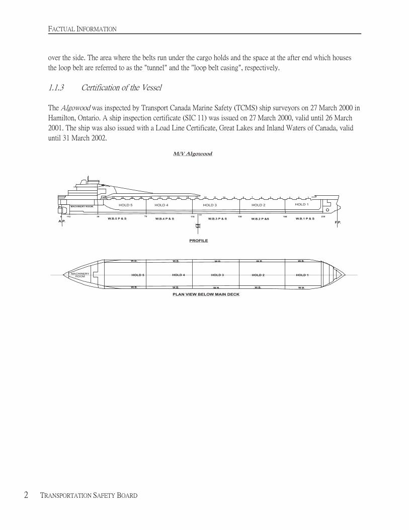
1.1.2 Description of the Vessel
The Algowood is a self-unloading bulk carrier of all-welded steel construction, with five cargo holds. The
propelling machinery, steering gear, wheelhouse, life-saving equipment, and all crew accommodation are
located at the after end of the vessel. The location of cargo holds and water ballast tanks are shown in Figure 1.
The hull is subdivided by transverse watertight bulkheads: a collision bulkhead, a bulkhead at the after end of
the cargo space, and a bulkhead at the after end of the engine room.
1 Units of measurement in this report conform to International Maritime Organization (IMO)
standards or, where there is no such standard, are expressed in the International System (SI) of
units.
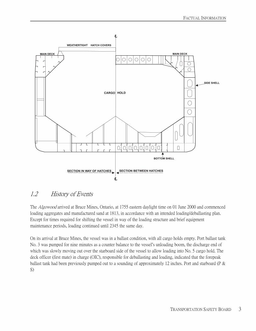
To unload the vessel, gates at the bottom of the five hopper-shaped holds are opened. This allows cargo to fall
onto two fore-and-aft conveyor belts which transport the cargo to the transfer-and-loop belt system at the after
end of the cargo space. It is then raised by the loop belt system to an above-deck unloading boom for discharge
FACTUAL INFORMATION
2 TRANSPORTATION SAFETY BOARD
over the side. The area where the belts run under the cargo holds and the space at the after end which houses
the loop belt are referred to as the "tunnel" and the "loop belt casing", respectively.
1.1.3 Certification of the Vessel
The Algowood was inspected by Transport Canada Marine Safety (TCMS) ship surveyors on 27 March 2000 in
Hamilton, Ontario. A ship inspection certificate (SIC 11) was issued on 27 March 2000, valid until 26 March
2001. The ship was also issued with a Load Line Certificate, Great Lakes and Inland Waters of Canada, valid
until 31 March 2002.
FACTUAL INFORMATION
TRANSPORTATION SAFETY BOARD 3
1.2 History of Events
The Algowood arrived at Bruce Mines, Ontario, at 1755 eastern daylight time on 01 June 2000 and commenced
loading aggregates and manufactured sand at 1813, in accordance with an intended loading/deballasting plan.
Except for times required for shifting the vessel in way of the loading structure and brief equipment
maintenance periods, loading continued until 2345 the same day.
On its arrival at Bruce Mines, the vessel was in a ballast condition, with all cargo holds empty. Port ballast tank
No. 3 was pumped for nine minutes as a counter balance to the vessel=s unloading boom, the discharge end of
which was slowly moving out over the starboard side of the vessel to allow loading into No. 5 cargo hold. The
deck officer (first mate) in charge (OIC), responsible for deballasting and loading, indicated that the forepeak
ballast tank had been previously pumped out to a sounding of approximately 12 inches. Port and starboard (P &
S)

FACTUAL INFORMATION
4 TRANSPORTATION SAFETY BOARD
No. 5 ballast tanks, which were not fully pressed up, were being pumped as of 1805. At 1813, the vessel was
ready to load into cargo hold No. 5, hatches nos. 21, 19, and 20, respectively. Loading started at 1823.
As of 1843, P & S ballast tanks No. 4 were being discharged. At 2035, loading of cargo in hold No. 5 was
completed with 5700 tons of sand (see table in section 1.4). The draught aft was reported to be 6.553 metres (21
feet 6 inches). As of 1952, pumping of No. 3 P & S ballast tanks recommenced and was suspended at 2010. At
2032, No.3 P & S ballast tanks were pumped again, this time to completion at 2145.
According to the loading plan, the after draught of the vessel was near the maximum allowable of 6.858 metres
(22 feet 6 inches). At this time, the OIC deviated from the loading sequence and directed the shore rig loader to
load HL1 aggregates into hatch No. 9 instead of hatch No. 13. The shore rig loader, who was provided with a
copy of the intended loading plan for clarification, questioned and acknowledged the sudden change to the
loading plan. Loading into hatch No. 9 commenced at 2044. Pumping of No. 2 and No.1 P & S ballast tanks
started at 2111 and 2130 respectively. By 2126, 1756 tons of cargo had been loaded into cargo hold No. 3.
Starboard ballast tank No. 3 was completely pumped out between 2032 and 2145.
At this time, the vessel had reached the maximum draught aft and shifting of the vessel aft began. The vessel
came to a sudden and abrupt stop, indicating that after end of the vessel might have touched bottom near the
end of the slip. The loading rig was just able to reach into hatch No. 2 of cargo hold No. 1, in which loading
commenced at 2132. While loading hatch No. 2, the vessel trimmed2 forward and the draught aft was reduced.
The OIC shifted the vessel further aft so that the loading rig could begin loading into hatch No. 1. At
approximately 2145, the master returned to the ship and inquired briefly about the vessel=s condition of loading
with the OIC, after which he proceeded to his cabin.
At 2202, pumping of P & S ballast tanks Nos. 1 and 2 was stopped. Ballast tanks No. 1 P & S were pumped
again from 2240 to 2242. Pumping of No. 2 P & S ballast tanks resumed at 2242 and finished at 2315.
2 Refers to the relationship between forward and after draughts.

FACTUAL INFORMATION
TRANSPORTATION SAFETY BOARD 5
Reading draughts in the dark was difficult at this time because visibility was further reduced in rain showers.
The after draught was 6.477 metres (21 feet 3 inches) at this time and was decreasing as loading forward
continued. At 2242, pumping of P & S ballast tanks No. 2 resumed. The loading of cargo hold No. 1 was
almost completed, with an additional 1800 tons loaded through hatches nos. 1, 2, and 3 at 2322. Draughts at
this point were 6.096 metres (20 feet) aft, 4.801 metres (15 feet 9 inches) at midship, and 3.962 metres (13 feet)
forward; according to the OIC, the vessel was hogged3 by approximately 0.229 metre (9 inches). The rig
operator indicated that there would be a shut down for minor repairs. At 2315, P & S ballast tanks No. 2 were
pumped out.
At 2345, while continuing to load into hatch No. 3 of cargo hold No. 1, the ship made a very loud wrenching
sound and buckled4 between hatches nos. 13 and 14, in way of the transverse bulkhead, between frames 117
and 119. Loading was stopped and the general alarm sounded.
At 0010, all crew members were evacuated to shore with the exception of the master and the chief engineer. An
initial survey revealed no major pollution. However, an oil boom was deployed to contain some minor
hydraulic oil leaks.
The forefoot5 and stern section of the vessel struck the ground; subsequently, the hull settled on the bottom. All
cargo holds of the vessel were progressively flooded through the tunnel. Concurrent damage to the ballast
suction piping led to flooding of the water ballast tanks forward of the structural damage. As flooding
progressed, the vessel settled on the bottom with the hull immersed at 8.2 metres (26 feet 11 inches) forward
and 8.1 metres (26 feet 7 inches) aft. Flooding extended from the collision bulkhead to the forward bulkhead
of the engine room.
In the days following the occurrence, salvage operations were monitored by Lloyd=s Register of Shipping, the
Salvage Association, and TCMS. Temporary repairs included substantial steel bracing welded to the outside of
the shell plating spanning the hull damage. Cargo was unloaded from the holds and diesel oil was discharged.
On 10 July 2000, the vessel was towed to the dry docks at Port Weller, Ontario, for a detailed damage survey,
repairs, and reconstruction.
1.3 Certification of Personnel
The master and officers held certificates valid for their positions and for the trade in which the vessel was
engaged. The master held a certificate for master, local voyage, issued in 1979. The first mate held a certificate
for master, local voyage, issued in 1999. The most recent continued proficiency endorsement for both
individuals was acquired in 1999.
3 Refers to longitudinal hull deflection, such that the ends are more deeply immersed than midships.
4 Refers to deformation of a structural member such that its stiffening properties are reduced.
5 Refers to junction of forward end of keel and stempost.

FACTUAL INFORMATION
6 TRANSPORTATION SAFETY BOARD
FACTUAL INFORMATION
TRANSPORTATION SAFETY BOARD 7
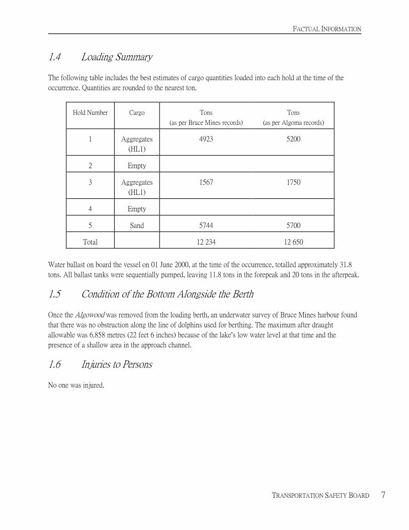
1.4 Loading Summary
The following table includes the best estimates of cargo quantities loaded into each hold at the time of the
occurrence. Quantities are rounded to the nearest ton.
Hold Number
Cargo
Tons
(as per Bruce Mines records)
Tons
(as per Algoma records)
1 Aggregates
(HL1)
4923
5200
2
Empty
3
Aggregates
(HL1)
1567
1750
4
Empty
5
Sand
5744
5700
Total
12 234
12 650
Water ballast on board the vessel on 01 June 2000, at the time of the occurrence, totalled approximately 31.8
tons. All ballast tanks were sequentially pumped, leaving 11.8 tons in the forepeak and 20 tons in the afterpeak.
1.5 Condition of the Bottom Alongside the Berth
Once the Algowood was removed from the loading berth, an underwater survey of Bruce Mines harbour found
that there was no obstruction along the line of dolphins used for berthing. The maximum after draught
allowable was 6.858 metres (22 feet 6 inches) because of the lake=s low water level at that time and the
presence of a shallow area in the approach channel.
1.6 Injuries to Persons
No one was injured.
FACTUAL INFORMATION
8 TRANSPORTATION SAFETY BOARD
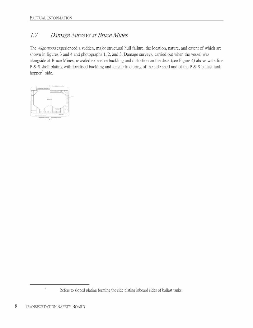
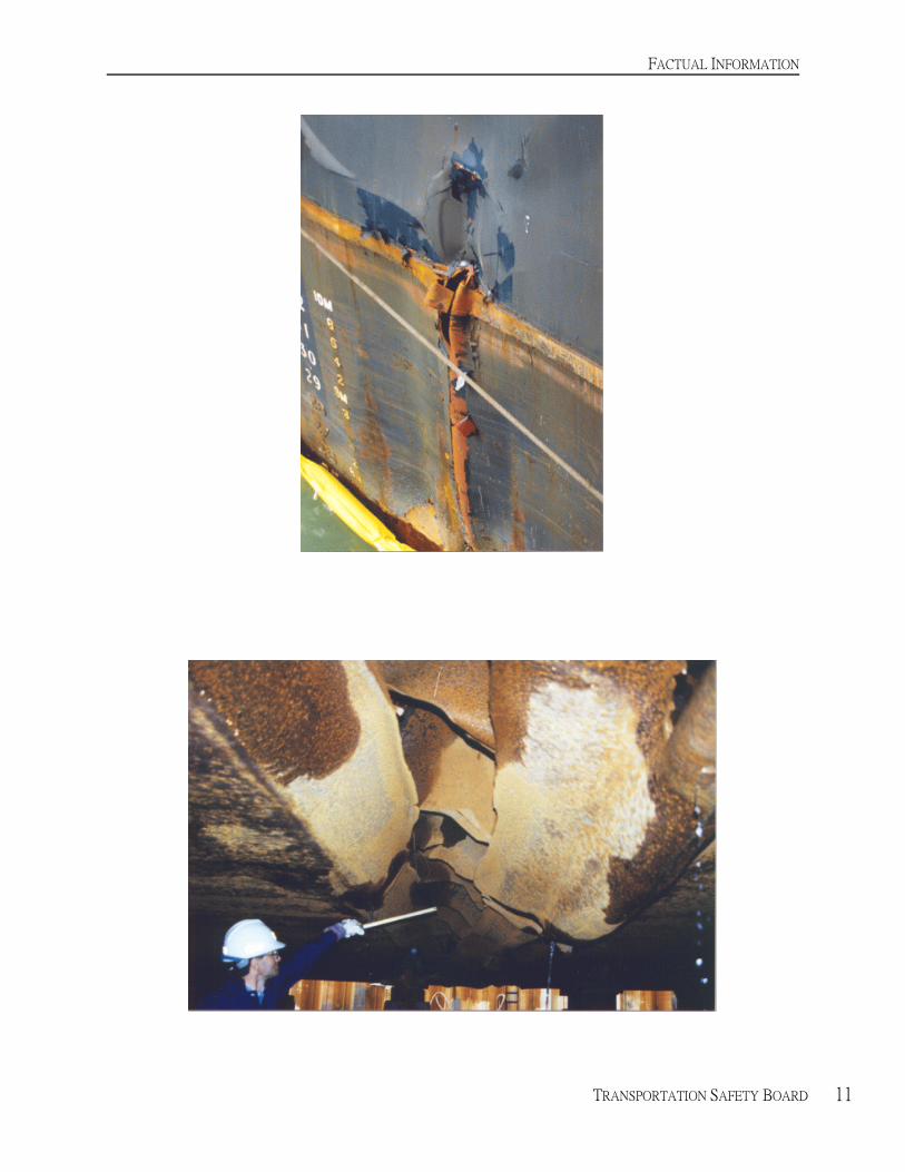
1.7 Damage Surveys at Bruce Mines
The Algowood experienced a sudden, major structural hull failure, the location, nature, and extent of which are
shown in figures 3 and 4 and photographs 1, 2, and 3. Damage surveys, carried out when the vessel was
alongside at Bruce Mines, revealed extensive buckling and distortion on the deck (see Figure 4) above waterline
P & S shell plating with localised buckling and tensile fracturing of the side shell and of the P & S ballast tank
hopper6 side.
6 Refers to sloped plating forming the side plating inboard sides of ballast tanks.
FACTUAL INFORMATION
TRANSPORTATION SAFETY BOARD 9
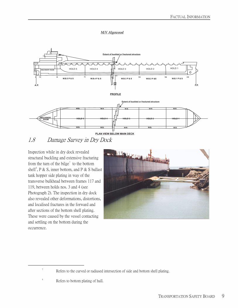
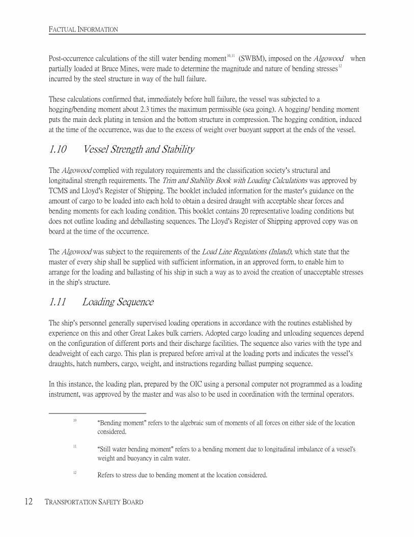
1.8 Damage Survey in Dry Dock
Inspection while in dry dock revealed
structural buckling and extensive fracturing
from the turn of the bilge7 to the bottom
shell8, P & S, inner bottom, and P & S ballast
tank hopper side plating in way of the
transverse bulkhead between frames 117 and
119, between holds nos. 3 and 4 (see
Photograph 2). The inspection in dry dock
also revealed other deformations, distortions,
and localised fractures in the forward and
after sections of the bottom shell plating.
These were caused by the vessel contacting
and settling on the bottom during the
occurrence.
7 Refers to the curved or radiused intersection of side and bottom shell plating.
8 Refers to bottom plating of hull.
FACTUAL INFORMATION
10 TRANSPORTATION SAFETY BOARD
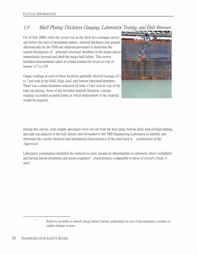
1.9 Shell Plating Thickness Gauging, Laboratory Testing, and Hull Stresses
On 18 July 2000, while the vessel was in dry dock for a damage survey
and before the start of permanent repairs, material thickness was gauged
ultrasonically by the TSB and shipyard personnel to determine the
current thicknesses of principal structural members in the frame spaces
immediately forward and abaft the major hull failure. This survey
included measurements taken in a band around the vessel in way of
frames 117 to 119.
Gauge readings at each of these locations generally showed wastage of 1
to 7 per cent in the shell, bilge, keel, and bottom structural members.
There was a mean thickness reduction of some 13 per cent in way of the
tank top plating. None of the recorded material thickness wastage
readings exceeded accepted limits at which replacement of the material
would be required.
During this survey, steel sample specimens were cut out from the keel plate, bottom shell, turn-of-bilge plating,
and tank top adjacent to the hull failure, and forwarded to the TSB Engineering Laboratory to identify and
determine the current chemical and mechanical characteristics of the steel used in construction of the
Algowood .
Laboratory examination identified the material as steel, having no abnormalities to adversely affect weldability
and having tensile properties and notch-toughness9 characteristics comparable to those of Lloyd=s Grade A
steel.
9 Refers to an ability to absorb energy before fracture, particularly in way of discontinuities, notches, or
sudden changes in area.
FACTUAL INFORMATION
TRANSPORTATION SAFETY BOARD 11
FACTUAL INFORMATION
12 TRANSPORTATION SAFETY BOARD
Post-occurrence calculations of the still water bending moment10,11
(SWBM), imposed on the Algowood when
partially loaded at Bruce Mines, were made to determine the magnitude and nature of bending stresses12
incurred by the steel structure in way of the hull failure.
These calculations confirmed that, immediately before hull failure, the vessel was subjected to a
hogging/bending moment about 2.3 times the maximum permissible (sea going). A hogging/ bending moment
puts the main deck plating in tension and the bottom structure in compression. The hogging condition, induced
at the time of the occurrence, was due to the excess of weight over buoyant support at the ends of the vessel.
1.10 Vessel Strength and Stability
The Algowood complied with regulatory requirements and the classification society=s structural and
longitudinal strength requirements. The Trim and Stability Book with Loading Calculations was approved by
TCMS and Lloyd=s Register of Shipping. The booklet included information for the master=s guidance on the
amount of cargo to be loaded into each hold to obtain a desired draught with acceptable shear forces and
bending moments for each loading condition. This booklet contains 20 representative loading conditions but
does not outline loading and deballasting sequences. The Lloyd=s Register of Shipping approved copy was on
board at the time of the occurrence.
The Algowood was subject to the requirements of the Load Line Regulations (Inland), which state that the
master of every ship shall be supplied with sufficient information, in an approved form, to enable him to
arrange for the loading and ballasting of his ship in such a way as to avoid the creation of unacceptable stresses
in the ship's structure.
1.11 Loading Sequence
The ship=s personnel generally supervised loading operations in accordance with the routines established by
experience on this and other Great Lakes bulk carriers. Adopted cargo loading and unloading sequences depend
on the configuration of different ports and their discharge facilities. The sequence also varies with the type and
deadweight of each cargo. This plan is prepared before arrival at the loading ports and indicates the vessel=s
draughts, hatch numbers, cargo, weight, and instructions regarding ballast pumping sequence.
10 ABending moment@ refers to the algebraic sum of moments of all forces on either side of the location
considered.
11 AStill water bending moment@ refers to a bending moment due to longitudinal imbalance of a vessel's
weight and buoyancy in calm water.
12 Refers to stress due to bending moment at the location considered.
In this instance, the loading plan, prepared by the OIC using a personal computer not programmed as a loading
instrument, was approved by the master and was also to be used in coordination with the terminal operators.

FACTUAL INFORMATION
TRANSPORTATION SAFETY BOARD 13
LOADING PLAN:
DRAFTS:
FWD: 25'06"
MID: 25' 06"
AFT: 25' 06"
TRIP #
0016
DATE:
JUNE 01/00
CARGO:
AGGREGATES
HOLD
NO. 5
NO. 4
NO. 3
NO. 2
NO. 1
PORT
BRUCE MINES
MELDRUM BAY
BRUCE MINES
MELDRUM BAY
BRUCE MINES
CARGO
SAND
HL1
HL1
TONS
5700 T
7200 T
3500 T
5600 T
5800 T
TOTAL TONNAGE (APPROXIMATELY): 27 900 T
HATCH
HOLD
CARGO
TONS
REMARKS
BRUCE MINES
21 5 SAND 4000 Pump out #3 PORT and BOOM OUT.
19
5
SAND
1200
Pump out #5 tks./Pump out #4 tks.
20
5
SAND
500
F 13' 09" A 21' 04" Approx.
13
3
HL1
1750
Pump out #3 STBD and BOOM IN to centre.
09
3
HL1
1750
Pump out #3 tks P & S when boom in centre.
F 14' 00" A 21' 06" Approx.
02
1
HL1
4400
Pump out #2 tks./ Pump out #1 tks.
01
1
HL1
500
Strip F/Pk if needed. Ensure A/Pk out.
03
1
HL1
900
F 15' 06" A 19' 08" Approx.
MELDRUM BAY
06
2
4000
Raise boom to maximum height.
04 2 900
F 23' 09" A 17' 00"
16
4
4000
14
4
1200
18T
4
(2000)
TRIM TO AFT DRAFT.
08
2
(700)
TRIM TO FWD DRAFT.
FACTUAL INFORMATION
14 TRANSPORTATION SAFETY BOARD
The cargo loading and deballasting sequences were not carried out according to the agreed upon plan. This is
due in part to the fact that, at a point in the loading, the vessel could not be moved further astern in the limited
depth of water available near the northern extremity of the slip until the aft draught was decreased. Verbal
communication was used to enable the OIC to confirm and validate the actual pumping performed by engine
room staff. Ballast tank water levels would be confirmed later by tank soundings from deck level. Because a
record of tank soundings while deballasting was not kept in the deck log book, it was difficult to coordinate
pumping of tanks. It was not possible to confirm the sequence for deballasting, especially when deviations to
the plan took place.
1.12 Cargo Watch Schedules
The second mate and first mate stood their normal 1200 to 1600 and 1600 to 2000 watches, respectively.
Between watches, each had eight hours off, which included several hours of rest. Consequently, fatigue is not
considered to have been a contributing factor in this occurrence.
1.13 Previous Safety Recommendations Regarding Bulk Carriers
During the course of an investigation concerning damage to the S.S. Beechglen, (TSB Report M91C2007), the
TSB issued recommendation M94-17 with respect to industry operational practices and to loading/unloading
procedures:
The Department of Transport require that masters on all Canadian bulk carriers be
provided with comprehensive written loading and unloading guidance, including the
maintenance of a "Cargo Book", to ensure that maximum allowable hull girder stresses
are not exceeded.
(M94-17, issued October 1994)
Transport Canada (TC) accepted the recommendation. In response to it and associated correspondence, TC
advised that the Canadian Code of Safe Practice for Solid Bulk Cargoes (TP 5761) would be revised to reflect
the latest International Maritime Organization (IMO) requirements. On 17 July 1995, Ship Safety Bulletin
(SSB) No. 13/95 was issued by TC, warning that improper practices and procedures during cargo handling
operations was a major cause of extensive structural overstressing damage. A copy of IMO circular MSC 690
was attached to the bulletin. On 26 October 1998, SSB 13/98 was issued, which included the Code of Practice
for the Safe Loading and Unloading of Bulk Carriers. Further attention was drawn to the new International
Convention for the Safety of Life at Sea (SOLAS) chapter VI amendments on carriage of cargoes, in particular
Regulation 7 that came into force internationally on 01 July 1998. The regulation requires ships to be provided
with a booklet that specifies maximum permissible forces and moments on the ship=s hull during loading,
unloading, and the voyage.
FACTUAL INFORMATION
TRANSPORTATION SAFETY BOARD 15
TCMS has also published SSB 07/1996 and 15/1999 to give wide distribution to the issue of bulk carrier safety.
It was recommended that all parties involved in loading and unloading bulk cargoes take the Code of Practice
for the Safe Loading and Unloading of Bulk Carriers into consideration, become fully familiar with and include
the use of these procedures in their operations.
Following the damage to the S.S. Beechglen, the owners revised their procedure manuals to require ships' crews
to monitor ballasting and deballasting during all loading and unloading operations and to record such operations
in a permanent record book, kept in both the engine room and on the bridge. In addition, at the change of
watch, the officer being relieved is required to instruct the relieving officer as to the state of the ballast tanks.
In a TSB report on the break up and sinking of the bulk carrier Flare (TSB Report M98N0001), the Board was
concerned that mariners may not fully appreciate that deviation from approved loading manuals may overstress
the structure and lead to catastrophic failures. The Board recommended that:
The Department of Transport, in coordination with international agencies (including the
International Maritime Organization and the International Association of Classification
Societies), bring the need for stricter adherence to approved loading manuals to the
attention of shipowners, ship operators and ship masters in order to avoid undue
structural stresses in bulk carriers.
(M00-05, issued June 2000)
Transport Canada accepted the recommendation. In response, TC advised that the matter will be brought to the
attention of future Port State Control (PSC) meetings to ensure that signing member states to the Paris and
Tokyo memoranda of understanding on PSC are aware of and understand the importance of ensuring
compliance during PSC inspections. TC has also advised that the matter has been brought to the attention of
IMO and TCMS will continue its participation in Working Groups on Bulk Carrier Safety at IMO. The
Dangerous Goods, Solid Cargoes & Containers (DSC) Subcommittee is developing a manual on Loading and
Unloading of Solid Bulk Cargoes for Terminal Representatives.
1.14 Loading Plan and Operating Procedures
At the time of the occurrence, the Trim and Stability Book with Loading Calculations, including longitudinal
strength data such as SWBM, was aboard for the guidance of ship personnel. This copy was approved by
Lloyd=s on 22 February 1982 and contains 20 representative loading conditions. The Notes for the Master state
that Athis book is for information and that it must be considered as such at all times@.
FACTUAL INFORMATION
16 TRANSPORTATION SAFETY BOARD
It is general practice for the first mate to prepare a loading plan and present it to the master for approval.
Details and calculations for the loading plan are based on the knowledge and experience of both first mate and
master, combined with past loading/unloading data for the vessel.
The first mate had the option of using either a form prepared by the Marine Division of Algoma Central
Railway (Form 226, Vessel Loading Plan) or a computer spreadsheet using the vessel=s onboard computer. Both
methods ask for a description of the vessel, cargo weight and location, draughts and ballast, and loading time.
However, neither includes information or makes calculations of the hull girder longitudinal strength, shear
forces, and bending moments relative to the maximum SWBM approved by Lloyd=s.
Post-occurrence calculations of the SWBM imposed on the Algowood, when loaded according to the intended
loading plan, were made to determine the magnitude and nature of the related bending stresses. These
calculations indicate that the vessel would have been subjected to a hogging/bending moment about 1.9 times
the maximum permissible bending moment approved by Lloyd=s. Adoption of similar loading cargo distribution
in previous voyages would lead to fatigue in the hull structure.
Canadian regulations do not currently require that vessels of this class carry written guidance on cargo loading
or unloading sequences. The company=s Safety Management System Manual, which was on board the vessel at
the time of the occurrence, contains a section entitled ACargo Procedures@. The manual refers to loading and
unloading sequences, responsibilities, preparations for loading, loading, deballasting, preparations for
unloading, unloading, ballasting, special precautions, and draught survey procedures.
Longitudinal stresses and loading procedures are addressed as follows:
$ In preparing the load plan, the following must be taken into consideration: ...minimizing
bulkhead, tank top, and longitudinal stresses during loading and deballasting processes.
$ The cargo stowage in each compartment must be monitored frequently to ensure even
distribution, having due regard for the avoidance of excessive list, load on the tank tops, and
load against bulkheads.

ANALYSIS
18 TRANSPORTATION SAFETY BOARD
2.0 Analysis
2.1 General Communications
In this occurrence, a telephone communication between the officer in charge (OIC) of loading/deballasting and
the engine room staff was not formally reiterated. There is a time interval between the commencement of
pumping ballast and the time when a watchman takes a water level reading from a respective tank. If there are
10 - 14 ballast tanks to be read, it is possible that it may be some time before a tank pumping sequence error is
detected and the OIC is informed.
A formal, handwritten instruction may be the surest method for ensuring that a critical operation is carried out;
on many ships, this is standard procedure for ballasting operations. In the case of a telephone instruction, if that
instruction is repeated by the receiving party, the person issuing the order knows immediately if the order has
been understood and can expect that it will be acted upon. Further, when the person carrying out the action
confirms that it has been done, a second confirmation of the original order is completed.
2.2 Communications and Coordination S Loading/Deballasting
While loading was in progress, verbal instructions given to engine room staff to deballast were acknowledged,
recorded, and carried out, but there was no corroboration from the engine room when the tanks had been
emptied or pumped down. Most of the communication was one-way, from the deck to the engine room, with
very little feedback. This lack of follow-up meant that the OIC ordering the deballasting of the vessel could
only keep current of the vessel condition by noting physical tank soundings some time later, after pumping had
commenced.
The result was that the vessel was subjected to bending moments that were markedly higher than the maximum
permissible. This situation could have been avoided if more formal communications had been used and the
agreed deballasting/loading plan was adhered to.
When the master returned to the vessel, some two hours prior to the occurrence, deviation from the loading plan
and pumping sequence caused him some concern, but he indicated that he had faith in his officer=s abilities.
However, had the vessel=s loaded condition been reassessed at that time, and appropriate corrective action been
taken, the occurrence may have been prevented.
2.3 Loading and Deballasting
To minimize structural stress, cargo should be loaded and a similar weight of appropriately located water ballast
discharged concurrently, (this is not always possible, given the rate at which bulk cargoes are loaded) and
particular attention must be paid to the sequence of loading and deballasting.
Shortly before the hull failure, the loading was almost completed in hold No. 1 and it contained approximately
4923 tons of cargo. Port and starboard (P & S) ballast tanks No. 2 were nearly empty and there was no cargo in
hold No. 2.

ANALYSIS
TRANSPORTATION SAFETY BOARD 19
The total weight and distribution of cargo, in conjunction with no loading in way of cargo hold No. 2,
contributed significantly to a bending moment on the hull girder of approximately 2.3 times the maximum
permissible.
At 2035, loading of cargo into hatch nos. 19, 20, and 21 was completed. The OIC deviated for the first time
from the planned loading sequence and directed the shore rig to load HL1 aggregates into hatch No. 9 instead
of hatch No. 13. This initial departure from the intended loading/ deballasting sequence led to complications
and called for further deviations which eventually caused stresses that the hull could not withstand.
Deviations from the loading sequence, combined with a lack of appropriate compensatory ballasting measures
to minimize hull stresses, caused the vessel to hog. The mechanical failure of the bottom structure occurred
when compressive stress exceeded the critical buckling stress of the bottom structure. This caused extensive
buckling and tensile fracturing of the adjacent structure, which culminated in the loss of longitudinal hull
integrity.
2.4 Determination of Draughts
Factors affecting an accurate reading of the vessel=s draught marks during loading were as follows: cold
weather, poor lighting, driving rain, darkness, and a flashlight with reportedly insufficient candle power. The
distance from the shoreline, where the draught was read, to the ship side markings at the stern was over 30
metres. At the bow, this distance was approximately 25 metres.
Because of changes in the accepted loading plan, close and frequent monitoring of draught marks forward,
midship, and aft was necessary. For the majority of the loading period, weather was not a factor. As the weather
deteriorated, the distance from the shore and the type of flashlight available made draught monitoring difficult;
consequently, accurate readings were not obtainable.
Although the OIC of loading/deballasting believed that the vessel was hogged nine inches at the time of the
occurrence, subsequent calculations indicate that the actual hog was significantly greater. Because of the
difficulty of reading draught marks in prevailing conditions, the rate at which the cargo was loaded and the
frequency of reading the draughts, the extent of deflection was not determined before the hull girder was
overstressed.

ANALYSIS
20 TRANSPORTATION SAFETY BOARD
2.5 Condition of the Bottom Alongside the Berth
The possibility that the vessel could have suffered localised distortions and fractures due to obstructions on the
harbour bottom alongside the berth was examined. A hydrographic survey of the area was last conducted in
September 1997. On 10 July 2000, divers conducted a localised survey to assess the depth and condition of the
bottom. The survey found no features to indicate uncharted obstructions, boulders, or other features that could
have caused bottom shell damage and contributed to the initiation of the hull failure. Furthermore, review of the
mining company=s ship loading record before June 2000 indicated that vessels had loaded at the berth to a
departure draught deeper than that of the Algowood, and there were no reports of these ships having suffered
damage as a result.
2.6 Officers= Knowledge of Structural Stresses
In 1998, Transport Canada Marine Safety (TCMS) published The Examination and Certification of Seafarers
(TP2293). These standards are intended as a guide for the certification of officers on ships, reflecting the
requirements of the Marine Certification and Crewing Regulations. Examination requirements of these
standards, for a master local voyage, address requirements for ship construction and engineering, including the
following:
Structures and Construction Methods
Knowledge of structural stresses; difference between stress and strain; sheer force and bending
moments and interpretation of graphical solutions;...reasons for extra strengthening;...special
construction features of VLCCs [very large crude carrier] and special methods employed to ensure
adequate longitudinal and transverse strength; special construction features of oil/bulk/ore carriers.13
Stresses in Ships
Knowledge of predominant stresses when unloading bulk carriers with grabs and by uneven
off-loading; predominant stresses on bulk carriers when loading concentrates or other bulk products
at a high rate; uneven distribution of cargo; heavy weights on deck or tank tops; stresses on hull
caused by motion of a vessel at sea, including panting, pounding, hogging, sagging and racking;
structural stresses when grounded.
The master and first mate held valid certificates for their positions and had passed examinations for each of the
required subjects for that class of voyage, including the examination for ship construction and engineering.
13 Refers to a ship specifically designed for bulk carriage of ore with additional facilities for the alternative
carriage of oil or loose dry cargo.
Post-occurrence calculations, based on the intended loading plan, indicate the vessel would have been subjected
to a SWBM 1.9 times that of the maximum approved level. In the absence of any prior calculations to
determine the relative SWBM for the intended loading condition, neither the ship nor the company operating
ANALYSIS
TRANSPORTATION SAFETY BOARD 21
personnel were aware of its magnitude.
2.7 Existing Safety Measures for Bulk Carriers
Canada's bulk carrier fleet comprises some 70 vessels, which have an average age of over 33 years. Because of
their particular service, bulk carriers operating exclusively on the Great Lakes are not required to conform to
the more stringent requirements for ocean-going vessels and have especially reduced structural, scantling, and
load line standards. However, basic principles of hull bending stress distribution are still applicable and,
because of a bulk carriers' greater length-to-beam proportions, special attention is required during loading and
unloading operations to ensure that excessively high stressing does not occur.
A review of structural failures history in Canada suggests that the probability of a catastrophic failure is
minimal, but the consequences on people, property, and environment are considerable. Therefore, this small
probability presents an undesirable risk which can be easily managed, using proven cargo loading practices to
keep deck/bottom stresses within acceptable limits.
The International Maritime Organization (IMO), recognizing a need to improve the safe loading and
unloading of bulk carriers engaged on international voyages, has amended the International Convention for the
Safety of Life at Sea (SOLAS) by adding safety measures for bulk carriers. In particular, Chapter XII,
Regulation 11 of SOLAS, addresses the loading of bulk carriers at least 150 metres long. This regulation
requires that bulk carriers be fitted with loading instruments capable of providing information on hull girder
shear forces and bending moments. It is recognised that the loading instrument is a necessary tool to more
efficiently ensure that hull girder shear forces and bending moments are kept within permissible limits during,
and at the conclusion of, loading or discharging operations. Although a loading instrument is not a regulatory
requirement aboard Great Lakes bulk carriers, TCMS encourages the installation of such instruments.
The IMO has also adopted the Code of Practice for the Safe Loading and Unloading of Bulk Carriers to assist
masters and officers in ensuring a safe operating environment.

CONCLUSIONS
22 TRANSPORTATION SAFETY BOARD
3.0 Conclusions
3.1 Findings as to Causes and Contributing Factors
1. The intended loading and deballasting sequence was not adhered to and the vessel was subjected to
excessive bending stress which resulted in structural failure of the hull. The disposition of the cargo
and ballast at the time of the failure caused a still water bending moment about 2.3 times the
maximum permissible.
2. A lack of feedback communication, after deballasting instructions had been given, resulted in the
OIC not being kept current with the progress of deballasting.
3. The frequency and accuracy with which the draught marks were read during loading were
insufficient to closely monitor the hogging of the hull. Draught mark readings became estimates as
the weather deteriorated and not all means available to assist in accurately reading draughts were
utilized.
4. The magnitude of the stresses imposed on the Algowood, as a result of deviating from the intended
loading sequence, were not known nor appreciated by shipboard personnel.
3.2 Findings as to Risk
1. Neither the ship nor company operational personnel were aware that the stresses that would have
been imposed on the vessel by the intended loading plan, were 1.9 times the maximum permissible
SWBM approved by Lloyd=s.
3.3 Other Findings
1. Laboratory examination determined that samples of steel taken from the area of structural failure
had no abnormalities which adversely affected weldability and had tensile properties and
notch-toughness characteristics comparable to those of Lloyd=s Grade A steel.
2. None of the recorded material thickness wastage readings exceeded accepted limits at which
replacement of the material would have been required.
3. A post-occurrence survey of the bottom alongside the berth confirmed that there were no uncharted
obstructions, boulders, or other features that could have contributed to the initiation of the hull
failure.
4. The ship=s approved loading manual on board the vessel contains representative loading conditions
but does not outline loading and deballasting sequences.

SAFETY ACTION
TRANSPORTATION SAFETY BOARD 23
4.0 Safety Action
4.1 Action Taken
As a result of this occurrence, Algoma Central Marine has initiated a review of its practices and procedures and
has taken the following actions:
1. Immediately following the incident, the company modified its cargo handling policy to put in place
procedures that require all split loading and unloading to be reviewed by the company=s naval
architects to determine if the proposed load/unload falls within the allowable limits set for various
vessels with respect to stress and shear forces.
2. A training course was developed by the company=s naval architects, addressing stresses and strains
that occur on vessels during cargo handling operations. This seminar was presented to all masters
and chief officers in the winter of 2000. A copy of this information was given to all participants and
copies were sent to all vessels for junior officers to review.
3. The company was investigating requirements for Stress and Stability Computers (loading
instruments) prior to the incident in Bruce Mines. Subsequent to the incident, the company has
contracted with a firm to develop and install loading computers in its fleet. Installation of these
systems started in the fall of 2001 and should be completed by the summer of 2003.
4. A review of past cargo handling practices was carried out on a sample of the company=s fleet to
determine if practices similar to those that took place on the Algowood were occurring on other
Algoma ships. This review found no significant occurrences where a vessel=s allowable SWBM had
been exceeded.
5. The company contracted with a marine consultant to perform an audit on company cargo handling
procedures. Results of this audit were reviewed with management and led to development of the
training program outlined above.
6. A condition survey was carried out on all company vessels to determine if any structural
deficiencies are occurring in the area where the Algowood failed. These surveys found no evidence
of structural deficiencies in any of the vessels.
SAFETY ACTION
24 TRANSPORTATION SAFETY BOARD
4.2 Safety Action Required
Loading information
Because of their particular service, bulk carriers operating exclusively on the Great Lakes are not required to
conform to the more stringent requirements for ocean-going vessels and have especially reduced structural,
scantling, and load line standards. However, basic principles of hull bending stress distribution are still
applicable and, because of bulk carriers' greater length-to-beam proportions, special attention is required during
loading and unloading operations to ensure that excessively high stressing does not occur.
The Canadian Load Line Regulations (Inland) require that the master of every ship shall be supplied with
sufficient information, in an approved form, to enable him to arrange for the loading and ballasting of his ship
in such a way as to avoid the creation of unacceptable stresses in the ship's structure.
Loading manuals onboard Canadian vessels provide masters with guidelines to assist them in ensuring that their
vessels are safely ballasted and trimmed throughout a voyage, to maintain adequate structural integrity in port
and in various operating conditions. The Algowood approved vessel=s Loading Manual made reference to
acceptable shear forces and bending moments for various loading conditions. However, these manuals do not
address the vessel=s loading sequence which, in this occurrence, led to complications which eventually caused
stresses that the hull could not withstand.
It is possible, by improper distribution of loading, to highly stress the structure locally (under the load) and/or
the basic longitudinal hull girder. Since the structural arrangements may vary greatly, the limitations associated
with setting out exact rules for the distribution of loading in all ships have been recognized by International
Maritime Organization (IMO). Toward this end, IMO14 requires that bulk carriers engaged on international
voyages be fitted with loading instruments capable of providing information on hull girder shear forces and
bending moments. This provides the master with accurate and timely information on hull girder shear forces
and bending moments to assist in preventing overstressing of the ship=s structure.
Although the Algowood was in class and had passed all regulatory inspections, the Board is concerned that
Canada's ageing bulk carrier fleet of some 70 registered ships, is vulnerable to structural failures with serious
consequences. The Board is concerned that mariners may not fully appreciate that deviation from approved
loading manuals and loading plans may overstress the structure and lead to catastrophic failures, in particular,
the adverse consequences
14 In particular, Chapter XII, Regulation 11 of International Convention for the Safety of Life at Sea
(SOLAS), addresses the loading of bulk carriers at least 150 metres long.
on the hull caused by the disposition of the cargo and ballast during loading operations. Overstressing of the
hull may not be immediately evident during loading/discharging and could become manifested after the vessel
leaves port and is at sea. Such failures could result in the loss of the vessel, cause extensive pollution, and also
put the crew at serious risk, depending upon the circumstances at the time.
SAFETY ACTION
TRANSPORTATION SAFETY BOARD 25
The Board believes that comprehensive loading and unloading information will help masters to arrange the
loading and unloading so as not to overstress the structure. Therefore, the Board recommends that:
The Department of Transport require that masters on all Canadian bulk carriers of 150 m in length
and over have continuous access to on-board or company shore-based hull stress monitoring
systems to help ensure that maximum allowable hull girder stresses are not exceeded.
M03-01
This report concludes the Transportation Safety Board=s investigation into this occurrence. Consequently, the
Board authorized the release of this report on 22 April 2003.
Visit the Transportation Safety Board of Canada web site, www.tsb.gc.ca for information about the TSB and its
products and services. There you will also find links to other safety organizations and related sites.


APPENDICES
TRANSPORTATION SAFETY BOARD 27
Appendix A - Glossary
IMO International Maritime Organization
OIC officer in charge
P & S port and starboard
PSC Port State Control
SIC ship inspection certificate
SOLAS International Convention for the Safety of Life at Sea
SSB Ship Safety Bulletin
SWBM still water bending moment
TC Transport Canada
TCMS Transport Canada, Marine Safety
TSB Transportation Safety Board of Canada


