Embed Size (px)
Citation preview

ENGINEERING
Innovative belt & chain solutions
for every industry & application
Manual


Innovative Belt and Chain solutions for every industry & application
Engineering Manual
�Contents
Section 1
Section 2
Section 3
Introduction
Belt and Chain Selection
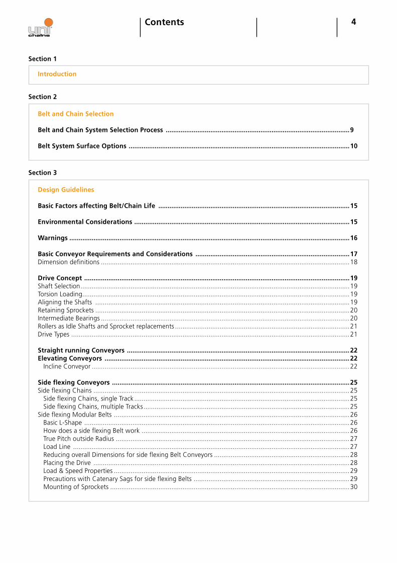
Belt and Chain System Selection Process ...................................................................................................9
Belt System Surface Options .......................................................................................................................10
Design Guidelines Basic Factors affecting Belt/Chain Life .......................................................................................................15
Environmental Considerations ....................................................................................................................15
Warnings .......................................................................................................................................................16
Basic Conveyor Requirements and Considerations ...................................................................................17Dimension definitions ......................................................................................................................................18
Drive Concept ...............................................................................................................................................19Shaft Selection .................................................................................................................................................19 Torsion Loading................................................................................................................................................19Aligning the Shafts .........................................................................................................................................19Retaining Sprockets .........................................................................................................................................20Intermediate Bearings ......................................................................................................................................20Rollers as Idle Shafts and Sprocket replacements ..............................................................................................21Drive Types ......................................................................................................................................................21
Straight running Conveyors ........................................................................................................................22Elevating Conveyors ....................................................................................................................................22 Incline Conveyor ...........................................................................................................................................22
Side flexing Conveyors ................................................................................................................................25Side flexing Chains ..........................................................................................................................................25 Side flexing Chains, single Track ....................................................................................................................25 Side flexing Chains, multiple Tracks ...............................................................................................................25Side flexing Modular Belts ...............................................................................................................................26 Basic L-Shape ...............................................................................................................................................26 How does a side flexing Belt work ................................................................................................................26 True Pitch outside Radius ..............................................................................................................................27 Load Line .....................................................................................................................................................27 Reducing overall Dimensions for side flexing Belt Conveyors .........................................................................28 Placing the Drive ..........................................................................................................................................28 Load & Speed Properties ...............................................................................................................................29 Precautions with Catenary Sags for side flexing Belts ....................................................................................29 Mounting of Sprockets .................................................................................................................................30
5
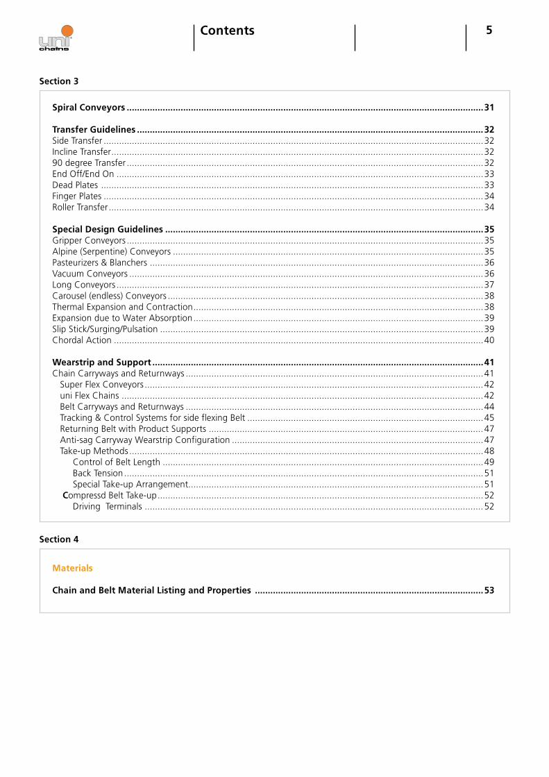
Spiral Conveyors ...........................................................................................................................................31
Transfer Guidelines .......................................................................................................................................32Side Transfer ....................................................................................................................................................32Incline Transfer .................................................................................................................................................3290 degree Transfer ...........................................................................................................................................32End Off/End On ...............................................................................................................................................33Dead Plates .....................................................................................................................................................33Finger Plates ....................................................................................................................................................34Roller Transfer ..................................................................................................................................................34
Special Design Guidelines ............................................................................................................................35Gripper Conveyors ...........................................................................................................................................35Alpine (Serpentine) Conveyors .........................................................................................................................35Pasteurizers & Blanchers ..................................................................................................................................36Vacuum Conveyors ..........................................................................................................................................36Long Conveyors ...............................................................................................................................................37Carousel (endless) Conveyors ...........................................................................................................................38Thermal Expansion and Contraction .................................................................................................................38Expansion due to Water Absorption .................................................................................................................39Slip Stick/Surging/Pulsation ..............................................................................................................................39Chordal Action ................................................................................................................................................40
Wearstrip and Support .................................................................................................................................�1Chain Carryways and Returnways ....................................................................................................................41 Super Flex Conveyors ....................................................................................................................................42 uni Flex Chains .............................................................................................................................................42 Belt Carryways and Returnways ....................................................................................................................44 Tracking & Control Systems for side flexing Belt ............................................................................................45 Returning Belt with Product Supports ...........................................................................................................47 Anti-sag Carryway Wearstrip Configuration ..................................................................................................47 Take-up Methods ..........................................................................................................................................48 Control of Belt Length .............................................................................................................................49 Back Tension ............................................................................................................................................51 Special Take-up Arrangement ...................................................................................................................51 Compressd Belt Take-up ...............................................................................................................................52 Driving Terminals ....................................................................................................................................52
Contents
Section 3
Section �
Materials
Chain and Belt Material Listing and Properties .........................................................................................53
6Contents
Section 5
Calculations
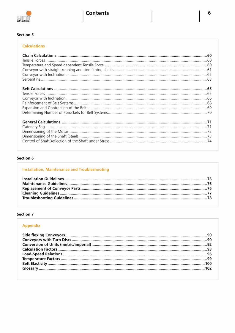
Chain Calculations ........................................................................................................................................60Tensile Forces ...................................................................................................................................................60Temperature and Speed dependent Tensile Force .............................................................................................60Conveyor with straight running and side flexing chains ....................................................................................61Conveyor with Inclination ................................................................................................................................62Serpentine .......................................................................................................................................................63
Belt Calculations ...........................................................................................................................................65Tensile Forces ...................................................................................................................................................65Conveyor with Inclination ................................................................................................................................66Reinforcement of Belt Systems .........................................................................................................................68Expansion and Contraction of the Belt .............................................................................................................69Determining Number of Sprockets for Belt Systems ..........................................................................................70
General Calculations ....................................................................................................................................71Catenary Sag ...................................................................................................................................................71Dimensioning of the Motor ..............................................................................................................................72Dimensioning of the Shaft (Steel) .....................................................................................................................73Control of Shaft Deflection of the Shaft under Stress ........................................................................................74
Section 6
Installation, Maintenance and Troubleshooting
Installation Guidelines ..................................................................................................................................76Maintenance Guidelines ...............................................................................................................................76Replacement of Conveyor Parts...................................................................................................................76Cleaning Guidelines ......................................................................................................................................77Troubleshooting Guidelines .........................................................................................................................78
Appendix
Side flexing Conveyors .................................................................................................................................90Conveyors with Turn Discs ...........................................................................................................................90Conversion of Units (metric/imperial) .........................................................................................................92Calculation Factors ........................................................................................................................................93Load-Speed Relations ...................................................................................................................................96Temperature Factors .....................................................................................................................................99Belt Elasticity ...............................................................................................................................................100Glossary .......................................................................................................................................................102
Section 7

7Contents
Section 7
Chemical Resistance Chart .........................................................................................................................108Technical Data Sheet for Belt/Chains Applications (metric) .....................................................................133Technical Data Sheet for Belt/Chains Applications (imperial) .................................................................135Technical Data Sheet for Spiral Applications (metric) ..............................................................................137Technical Data Sheet for Spiral Applications (imperial) ...........................................................................139
8Section 1Introduction
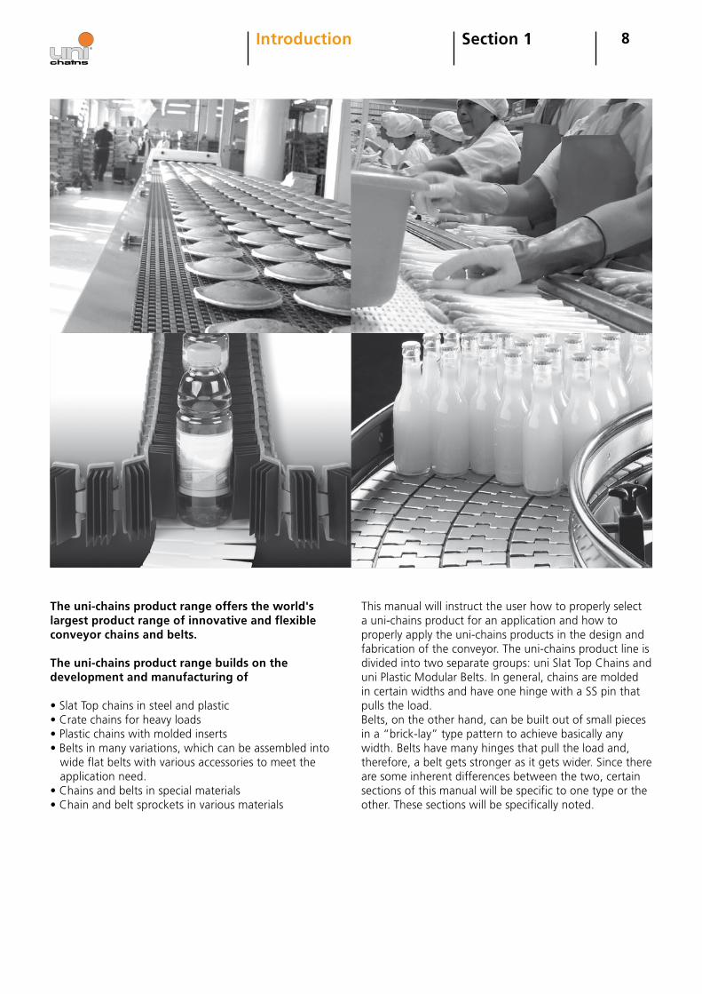
The uni-chains product range offers the world's largest product range of innovative and flexible conveyor chains and belts. The uni-chains product range builds on the development and manufacturing of
• Slat Top chains in steel and plastic• Crate chains for heavy loads• Plastic chains with molded inserts• Belts in many variations, which can be assembled into wide flat belts with various accessories to meet the application need.• Chains and belts in special materials• Chain and belt sprockets in various materials
This manual will instruct the user how to properly select a uni-chains product for an application and how to properly apply the uni-chains products in the design and fabrication of the conveyor. The uni-chains product line is divided into two separate groups: uni Slat Top Chains and uni Plastic Modular Belts. In general, chains are molded in certain widths and have one hinge with a SS pin that pulls the load. Belts, on the other hand, can be built out of small pieces in a “brick-lay” type pattern to achieve basically any width. Belts have many hinges that pull the load and, therefore, a belt gets stronger as it gets wider. Since there are some inherent differences between the two, certain sections of this manual will be specific to one type or the other. These sections will be specifically noted.
�Section 2Belt and Chain Selection
Once you have the information above you can use it to select the proper belt.
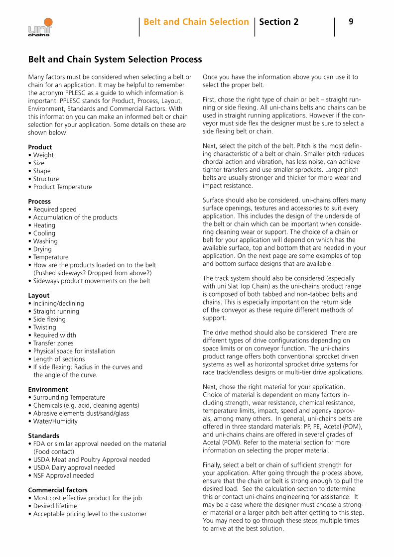
First, chose the right type of chain or belt – straight run-ning or side flexing. All uni-chains belts and chains can be used in straight running applications. However if the con-veyor must side flex the designer must be sure to select a side flexing belt or chain.
Next, select the pitch of the belt. Pitch is the most defin-ing characteristic of a belt or chain. Smaller pitch reduces chordal action and vibration, has less noise, can achieve tighter transfers and use smaller sprockets. Larger pitch belts are usually stronger and thicker for more wear and impact resistance.
Surface should also be considered. uni-chains offers many surface openings, textures and accessories to suit every application. This includes the design of the underside of the belt or chain which can be important when conside-ring cleaning wear or support. The choice of a chain or belt for your application will depend on which has the available surface, top and bottom that are needed in your application. On the next page are some examples of top and bottom surface designs that are available.
The track system should also be considered (especially with uni Slat Top Chain) as the uni-chains product range is composed of both tabbed and non-tabbed belts and chains. This is especially important on the return side of the conveyor as these require different methods of support.
The drive method should also be considered. There are different types of drive configurations depending on space limits or on conveyor function. The uni-chains product range offers both conventional sprocket driven systems as well as horizontal sprocket drive systems for race track/endless designs or multi-tier drive applications.
Next, chose the right material for your application. Choice of material is dependent on many factors in-cluding strength, wear resistance, chemical resistance, temperature limits, impact, speed and agency approv-als, among many others. In general, uni-chains belts are offered in three standard materials: PP, PE, Acetal (POM), and uni-chains chains are offered in several grades of Acetal (POM). Refer to the material section for more information on selecting the proper material.
Finally, select a belt or chain of sufficient strength for your application. After going through the process above, ensure that the chain or belt is strong enough to pull the desired load. See the calculation section to determine this or contact uni-chains engineering for assistance. It may be a case where the designer must choose a strong-er material or a larger pitch belt after getting to this step. You may need to go through these steps multiple times to arrive at the best solution.
Many factors must be considered when selecting a belt or chain for an application. It may be helpful to remember the acronym PPLESC as a guide to which information is important. PPLESC stands for Product, Process, Layout, Environment, Standards and Commercial Factors. With this information you can make an informed belt or chain selection for your application. Some details on these are shown below:
Product• Weight• Size• Shape• Structure• Product Temperature
Process• Required speed• Accumulation of the products• Heating• Cooling• Washing• Drying• Temperature• How are the products loaded on to the belt (Pushed sideways? Dropped from above?)• Sideways product movements on the belt
Layout• Inclining/declining• Straight running• Side flexing• Twisting• Required width• Transfer zones• Physical space for installation• Length of sections• If side flexing: Radius in the curves and the angle of the curve.
Environment• Surrounding Temperature• Chemicals (e.g. acid, cleaning agents)• Abrasive elements dust/sand/glass• Water/Humidity
Standards• FDA or similar approval needed on the material (Food contact)• USDA Meat and Poultry Approval needed• USDA Dairy approval needed• NSF Approval needed
Commercial factors• Most cost effective product for the job• Desired lifetime• Acceptable pricing level to the customer
Belt and Chain System Selection Process
10Section 2Belt and Chain Selection
0%
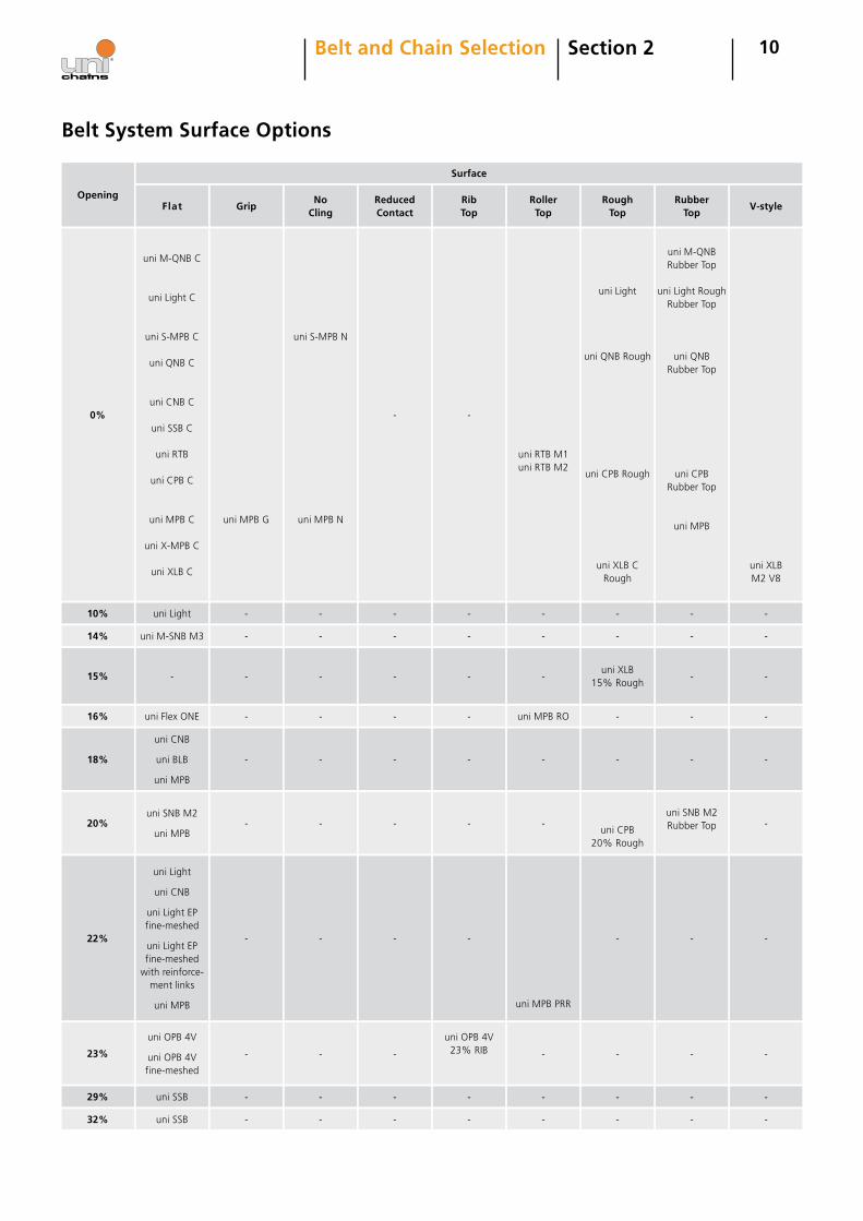
Opening
10%
14%
15%
16%
18%
20%
22%
23%
2�%
32%
uni M-QNB C
uni Light C
uni S-MPB C
uni QNB C
uni CNB C
uni SSB C
uni RTB
uni CPB C
uni MPB C
uni X-MPB C
uni XLB C
uni Light
uni M-SNB M3
-
uni Flex ONE
uni CNB
uni BLB
uni MPB
uni SNB M2
uni MPB
uni Light
uni CNB
uni Light EP fine-meshed
uni Light EP fine-meshed
with reinforce-ment links
uni MPB
uni OPB 4V
uni OPB 4Vfine-meshed
uni SSB
uni SSB
uni MPB G
-
-
-
-
-
-
-
-
-
-
uni S-MPB N
uni MPB N
-
-
-
-
-
-
-
-
-
-
-
-
-
-
-
-
-
-
-
-
-
-
-
-
-
-
-
-
-
uni OPB 4V 23% RIB
-
-
uni RTB M1uni RTB M2
-
-
-
uni MPB RO
-
-
uni MPB PRR
-
-
-
uni Light
uni QNB Rough
uni CPB Rough
uni XLB CRough
-
-
uni XLB 15% Rough
-
-
uni CPB 20% Rough
-
-
-
-
uni M-QNB Rubber Top
uni Light Rough Rubber Top
uni QNB Rubber Top
uni CPB Rubber Top
uni MPB
-
-
-
-
-
uni SNB M2 Rubber Top
-
-
-
-
uni XLB M2 V8
-
-
-
-
-
-
-
-
-
-
Surface
Flat GripNo
ClingReduced Contact
Rib Top
Roller Top
Rough Top
Rubber Top
V-style
Belt System Surface Options

11
34%
36%
37%
40%
uni SNB M2
uni OPB 4V
uni M-TTB
-
-
-
-
-
-
-
-
-
uni SNB M234%
uni L-SNB
uni M-TTB CS
uni M-PNB M1
uni SNB M234% Rib
uni L-SNB Rib
-
-
-
-
-
-
-
-
-
-
-
-
-
-
-
-
-
-
43%
uni Flex ASB
uni Flex ASB T - -
uni Flex ASB CS
uni Flex ASB CST
- - - - -
47%
uni Flex SNB C
uni Flex SNB CR
uni Flex L-ASB
uni Flex L-ASB R
uni Flex L-ASB T
- - - - - -
uni Flex SNB CR Rubber Top
uni Flex SNB C Rubber Top
-
55% - - -
uni Flex SNB L
uni Flex SNB W
uni Flex SNB WT
uni Flex SNB WO
- - - - -
Vacuumuni M-QNB
Vacuum- - - - - - - -
Section 2Belt and Chain Selection
66% - - - uni OWL - - - - -
Opening
Surface
Flat GripNo
ClingReduced Contact
Rib Top
Roller Top
Rough Top
Rubber Top
V-style
Belt System Surface Options
12
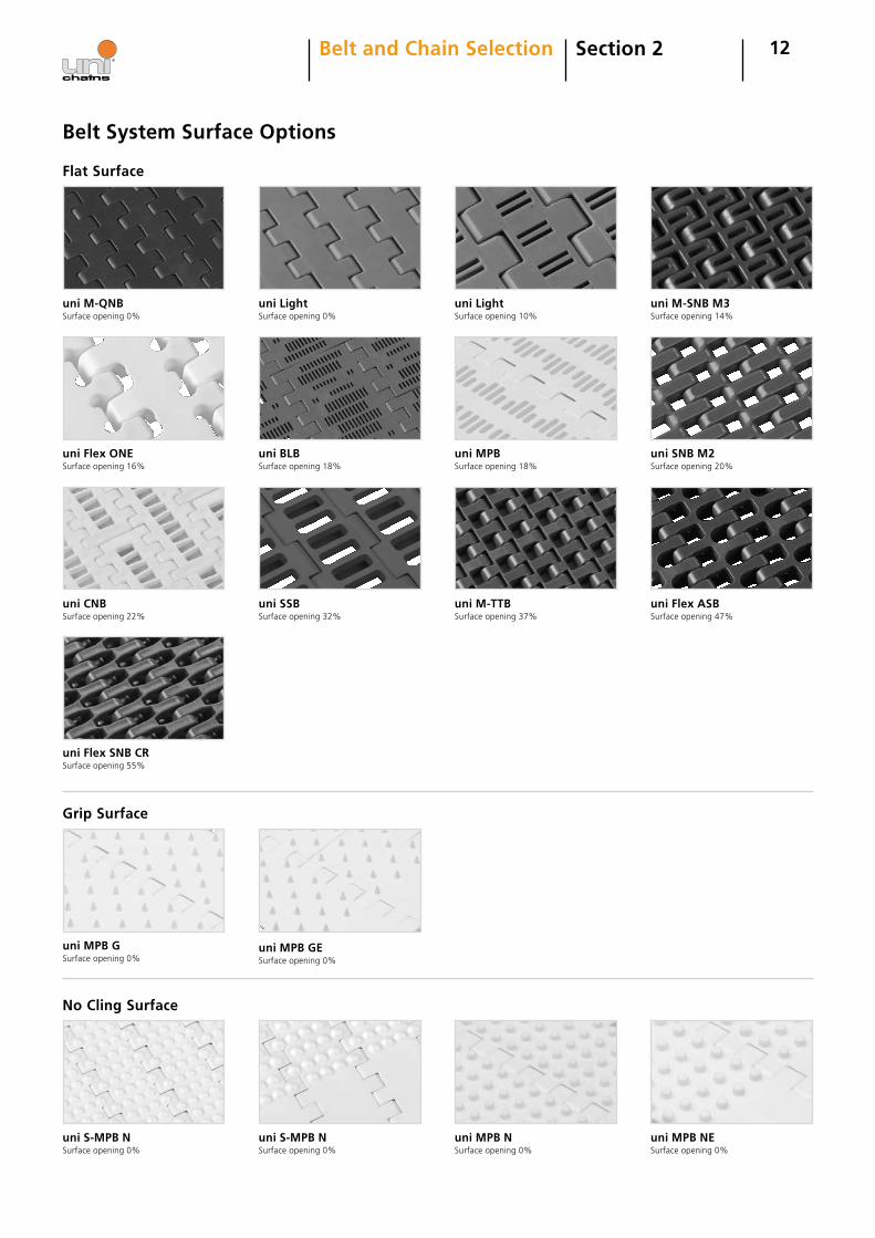
Flat Surface
uni M-QNB Surface opening 0%
uni Light Surface opening 0%
uni S-MPB N Surface opening 0%
No Cling Surface
Grip Surface
uni MPB G Surface opening 0%
uni Light Surface opening 10%
uni M-SNB M3 Surface opening 14%
uni Flex ONE Surface opening 16%
uni SNB M2 Surface opening 20%
uni BLB Surface opening 18%
uni CNBSurface opening 22%
uni M-TTB Surface opening 37%
uni Flex SNB CRSurface opening 55%
uni Flex ASB Surface opening 47%
Section 2Belt and Chain Selection
uni SSB Surface opening 32%
uni MPBSurface opening 18%
uni S-MPB NSurface opening 0%
uni MPB GE Surface opening 0%
uni MPB NSurface opening 0%
uni MPB NESurface opening 0%
Belt System Surface Options
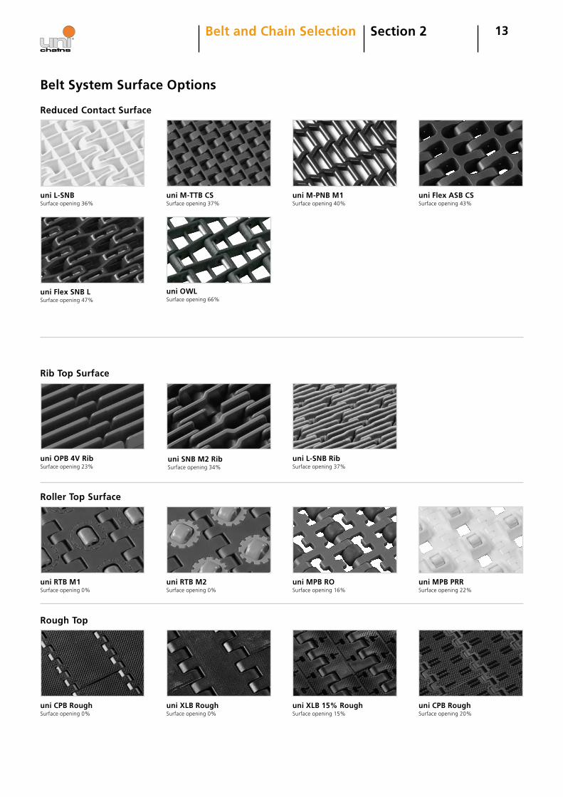
uni L-SNB Rib Surface opening 37%
13
uni OWLSurface opening 66%
Rough Top
uni RTB M2 Surface opening 0%
uni CPB Rough Surface opening 0%
uni XLB Rough Surface opening 0%
uni XLB 15% Rough Surface opening 15%
Roller Top Surface
uni MPB RO Surface opening 16%
uni CPB Rough Surface opening 20%
uni OPB 4V Rib Surface opening 23%
Reduced Contact Surface
Rib Top Surface
uni L-SNB Surface opening 36%
uni M-TTB CS Surface opening 37%
uni Flex ASB CS Surface opening 43%
uni M-PNB M1 Surface opening 40%
Section 2Belt and Chain Selection
uni RTB M1 Surface opening 0%
uni Flex SNB L Surface opening 47%
uni SNB M2 Rib Surface opening 34%
uni MPB PRR Surface opening 22%
Belt System Surface Options
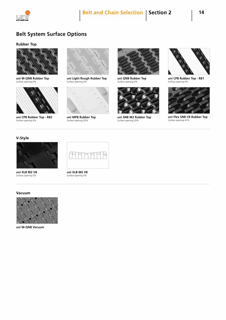
Belt System Surface Options
14Section 2Belt and Chain Selection
Rubber Top
uni M-QNB Rubber Top Surface opening 0%
uni Flex SNB CR Rubber Top Surface opening 47%
V-Style
uni XLB M2 V8 Surface opening 0%
Vacuum
uni M-QNB Vacuum
uni SNB M2 Rubber Top Surface opening 20%
uni Light Rough Rubber Top Surface opening 0%
uni MPB Rubber Top Surface opening 20%
uni QNB Rubber Top Surface opening 0%
uni CPB Rubber Top - RB1 Surface opening 0%
uni CPB Rubber Top - RB2 Surface opening 0%
uni XLB M2 V8 Surface opening 0%
15Section 3Design Guidelines
Successful operation of uni-chains products requires their ability to stand up to the environment that they are used in. The information below comes from previous similar experiences and customer input.
Specifying the right belt for the application requires a good knowledge of the environmental conditions. Below are some important environmental considerations to keep in mind when choosing a belt. Forms are available at the back of this manual that include a more complete list of most of the possible application parameters that could apply.
1. Chemical Degradation The effect of chemicals on the performance of the sup-plied conveyor components must be considered at initial selection of the materials. Chemical degradation can cause premature failure of the conveyor components.
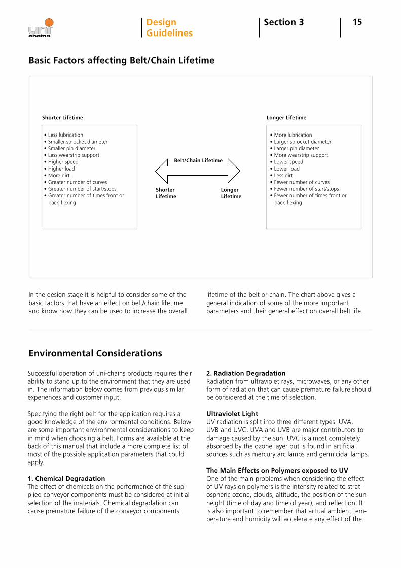
• Less lubrication• Smaller sprocket diameter• Smaller pin diameter• Less wearstrip support• Higher speed• Higher load• More dirt• Greater number of curves• Greater number of start/stops • Greater number of times front or back flexing
Longer Lifetime
• More lubrication• Larger sprocket diameter• Larger pin diameter• More wearstrip support• Lower speed• Lower load• Less dirt• Fewer number of curves• Fewer number of start/stops • Fewer number of times front or back flexing
Basic Factors affecting Belt/Chain Lifetime
2. Radiation DegradationRadiation from ultraviolet rays, microwaves, or any other form of radiation that can cause premature failure should be considered at the time of selection.
Ultraviolet LightUV radiation is split into three different types: UVA, UVB and UVC. UVA and UVB are major contributors to damage caused by the sun. UVC is almost completely absorbed by the ozone layer but is found in artificial sources such as mercury arc lamps and germicidal lamps.
The Main Effects on Polymers exposed to UVOne of the main problems when considering the effect of UV rays on polymers is the intensity related to strat-ospheric ozone, clouds, altitude, the position of the sun height (time of day and time of year), and reflection. It is also important to remember that actual ambient tem-perature and humidity will accelerate any effect of the
Environmental Considerations
In the design stage it is helpful to consider some of the basic factors that have an effect on belt/chain lifetime and know how they can be used to increase the overall
lifetime of the belt or chain. The chart above gives a general indication of some of the more important parameters and their general effect on overall belt life.
Shorter Lifetime
Belt/Chain Lifetime
Shorter Lifetime
Longer Lifetime
16Section 3DesignGuidelines
intensity level. All types of UV can cause a photochemical effect within the polymer structure, which can be either a benefit or lead to degradation of some sort to the material.
DegradationThe main visible effects are a chalky appearance and a color shift on the surface of the material and the compo-nent surface becomes brittle. This predominantly affects the surface layer of the material and is unlikely to extend to depths above 0.5 mm into the structure. However, stress concentrations caused by the highly brittle nature of some plastics may lead to a complete failure of the component.
UV-C and uni-chains Products UV-C will most commonly be used in the meat cutting belt applications. This is because infection through con-tact with surfaces is one of the most common causes of the infection of foodstuffs with bacteria and mould. Generally it is conveyor belts, and in particular meat cutting belts, in the meat processing industry that are affected by this and therefore have to address the UV-C protection. This special UV-C light is usually generated from a special UV light source/radiation box. This UV-C radiation box is positioned at the meat cutting belt. Often it will be placed under the belt in the area just before the belt turns to the topside. We have divided the UV protec-tion package into two groups:
1. UV Package (standard package) This protection package can be used when our product is going to be used outside, where it can be exposed to UV light from the sun. In this UV package we are using our standard protection system.
2. UV-C Package We also offer an extended UV protection where we combine our standard system with another UV absorber to get the optimal UV protection. This package comes into consideration when our product is being exposed to extreme UV light. This can be needed in e.g. the meat industry, where UV light is used to kill bacteria. At the
Warnings
moment we only provide this UV-C protection for acetal (POM) material.
3. Abrasive RequirementsWear on chain parts highly depends on the wearstrip hardness and roughness. Generally in abrasive condi-tions the harder the surface hardness and the lower the roughness of the wearstrip, the better wear resistance that combination will have. This is because the particles will embed in the softer material and wear away at the harder material.Some examples of abrasive particles include flour, salt, sugar, sand, paper dust, glass and dirt.
4. MoistureAll plastic materials absorb water from the surroundings, but very often it is not a major factor – except when dealing with the Nylon (PA) material. Here there can be a considerable change in dimension depending on the environment where the part is placed. The absorption of water causes the polyamide part to swell and thus leads to an increase in volume. Refer to the section on Expan-sion due to water Absorption (page 39). Tables can also be found in this section for coefficients for expansion due to water absorption so calculations can be made.
5. TemperatureTemperature relates to conveyor design and performance, within our published recommended temperature ranges, at progressive levels from 20º C (68º F) as follows: At low temperature the plastic selected will be harder, very brittle, and less resistant to impact and deflection. At high temperature plastic will be 70-85% weaker, softer with less resistance to abrasion, and greater deflection will be possible, although at lower stresses. Refer to the Calculations in Temperature Dependent Tensile Forces (Page 60) or contact uni-chains engineering for assistance.
Fireuni-chains plastic products are, unless clearly specified, made from materials which support open flame. Prod-ucts made from acetal (POM) material when so exposed, will emit toxic fumes. uni-chains plastic products should therefore not be exposed to extreme temperatures or open flame. Special care should be taken when undertak-ing repair work particularly when welding at a conveyor if the conveyor is fitted with plastic chains or belts.
Personal ProtectionAlways use safety glasses when mounting or repairing chains and belts and while securing or removing pins. Use only suitable tools in good conditions. The weight of some products calls for the use of safety shoes. When mounting/dismounting or repairing chains or belts on a conveyor the motor must be turned off.
17Section 3DesignGuidelines
Design Safety GuidelinesMost plastic products will loose their mechanical proper-ties if exposed to the sun or ultraviolet beams, which can lead to chain or belt breakage. This can also happen if the products are exposed to strong chemicals. Generally this is a problem with pH values lower than 4.5 or higher than 9.
Always make sure that there is enough space in the con-veyor frame to allow chains and belts to retract or expand when exposed to temperature variations. Never exceed the maximum or minimum temperatures given for the uni-chains product range.
Care should be taken with high chain/belt speeds with
which friction can lead to heating and subsequently melting of chain/belt as well as wearstrips. Do not exceed speeds recommended for the uni-chains product range.
Use only original uni-chains sprockets with uni-chains belts and chains.
When constructing conveyors it is important always to in-clude sufficient cover around the moving parts to prevent fingers and clothing from being caught up in the ma-chinery. We can also supply uni-chains safety chains and side flexing belts which leave minimal gaps when turning through curves making them incredibly safe.
Basic Conveyor Requirements and Considerations
There are specific guidelines that go along with each conveyor that a designer should know well. Below are the basic requirements of a conveyor and an explanation of their design. Throughout this manual specific details are mentioned that expand on each of these topics. With these basic guidelines you can start to design a conveyor or retrofit an existing conveyor.
1. Clearance The amount of clearance between the chains, belts, wear strips, channels, or any guide component must be sufficient to accommodate any temperature or fabrica-tion variation and construction tolerance that may exist. Adequate clearance is defined as absence of binding or fit interference between moving parts and supporting surfaces (wearstrips etc.) that would cause additional resistance than what is required to support the chain/belt and load being conveyed. This condition must be held through the complete operating range of the conveyor under all conditions that it is exposed to.
2. Wearstrip AlignmentAlignment between all chain/belt and bearing surfaces must be consistent and accurate to avoid adding resi-stance (fit-up binding, etc.) or creating a situation where premature wear of the chain/belt or wearstrip occurs. Particular attention must be given to where the chain/belt changes direction (curves up, down or side to side). This is where the chain tension combines with the product/chain weight to increase the bearing surface require-ments. At these locations we specify a minimum radius that the chain/belt will turn in either the side or backflex direction (see product catalog data).
3. SpeedFor speeds over 30 m/min. (100 ft/min.) the use of a soft
start motor control is recommended. High speed convey-ors must also be designed with wear strips that will not melt when the speed is combined with the load at the bearing surfaces. Lubrication of the chain/belts can also be very beneficial in high speed conveyors. Speed is a very complicated issue, and it is difficult to come up with guaranteed figures. This is mainly because of the many variables from one conveyor to another.
These variables could include:• Surface roughness of the wearstrips• Actual speed vs. designed speed• Load• Cooling/lubrication• Surrounding temperature• Actual friction• Possibility to conduct the heat away
Side flexing belts must be treated as a special situation and there are charts available for speed/load determina-tion on these. uni-chains' engineering can recommend wear strip materials that will stand up to most conditions. 4. Conveyor Length The maximum length of a conveyor can be limited by the effects of elastic surging even if the belt is below the tension limit. Surging/pulsation occurs when the chain/belt stretches and the spring force stored becomes strong enough to accelerate a portion of the belt and product. This portion of the belt is accelerated at a rate that is equivalent to the force stored in the chain/belt. It is independent of belt width and is very dependent on belt resistance and the spring force constant of the chain/belt type and material. Surging can be a problem in some cases where product stability is a factor or where fatigue
18Section 3DesignGuidelines
loading is a problem. It is dependent on conveyor con-figuration, length, product weight and speed, among other factors. As a general rule surging can be an is-sue for straight running conveyors 20 m (65 ft) center distance or greater and for side flexing conveyors 12 m (39.4 ft), surging is more of an issue at slower speeds than at high speeds. 5. SprocketsSprockets should be located in a position relative to the chain/belt such that they engage so that the sprocket pitch diameter intersects the pin center line. Chains typically use one sprocket per shaft. For belts the rule of thumb for the minimum number of sprockets is the width of the belt (in inches) divided by six (rounded up) and plus
one per shaft. If this result is an even number it is com-mon practice to add another sprocket to make an odd number and have a true center sprocket. More sprockets will be required based on belt tension and temperature. Some belts have sprocket paths that must be followed when locating the sprockets on the shaft. The center sprocket on both shafts is generally fixed and the oth-ers are allowed to move laterally with the expansion and contraction of the belt as it changes with temperature.
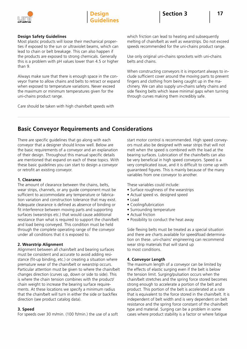
Dimension definitions
A – The vertical distance from the centerline of the shaft and sprocket to the top of the wear strip. This distance will remain the same until the chain/belt engages with the sprocket. After engagement this distance will vary as the pins will raise and lower and this effect is called Chordal Action. Refer to section on Chordal Action (page 40).
B ± (3.0 mm) 0.13 in. – The horizontal distance from the centerline of the shaft to the top surface of the belt. Thisdimension is equal to ½ x PD of the sprocket plus the distance from the center of the pin to the top of the belt.
C – The minimum distance between the center of the shaft and any framework. This is determined by sprocket diameter. Care should be taken that there is adequate clearance between the frame and product supports, side guards or other accessoires on the belt or chain.See fig. 3-1.
E – The clearance between the side of the frame and the edges of the chain/belt. The minimum of 3.2 mm (0.13 in.) should always be measured when the belt is at maximum operating temperature. This will ensure the belt is at its maximum width and enough clearance will always exist. Note: This recommended clearance is for straight running belts only. Guide clearance for side flexing belts should be calculated on an individual basis.See the calculations section in the back of the manual to determine how much expansion your belt/chain will undergo.See fig. 3-2.
A
C (min.)
B
Belt width at maximum temperature
WearstripsIntermediate supports
E E
Fig. 3-1 Fig. 3-2
19Section 3DesignGuidelines
Conveyors can use either round or square shafts. Square shafts have a few advantages over round shafts. To drive the sprockets round shafts use keyways where square shafts drive the sprockets with a square bore on their own. Square shafts can transmit higher loads and have less deflection than round shafts with keyways. Sprockets with square bores will slide more easily on square shafts than round bored sprockets do on keyways and square bored sprockets are easier to align. Square shafts are recommended over round shafts when feasible.
Drive Concept
Square shafts are recommended on long and big shafts (sq 60 x 60 mm) (sq 2.5 x 2.5 in.) or bigger. Choosing the correct shaft size is crucial for chain/belt life. Torsion or bending in the shaft will misalign the sprockets so they don’t engage the chain/belt properly and cause greater wear. This can also cause uneven forces in the belt that can lead to breakage or pin migration. Calculations for proper shaft size can be found in Dimensioning of Shaft in Calculations (page 73).
Since the drive shaft is only attached to the motor on one end and the other end is resting in a bearing, torsion occurs in the shaft. As the motor engages the end of the shaft it is rigidly attached to, the shaft twists under the load of the chain/belt and the product. The larger the sprockets, the greater the torsion load on the shaft. If a particular size shaft is desired and the torque to be ab-
sorbed is greater than the maximum torque on shaft, use smaller sprockets and recalculate the torque on the shaft. Since the sprocket diameter has been decreased, the motor’s RPMs must be increased to maintain the same speed. Other methods to address torsion include placing a motor on both ends of the shaft or placing the motor in the center of the shaft.
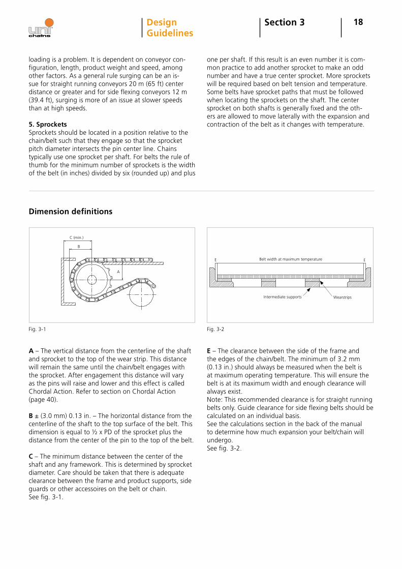
Aligning the Shafts
To ensure smooth operation without problems the con-veyor must be absolutely level and the shafts must have the correct placement with respect to each other. For straight running conveyors the drive and idle shaft must be parallel to each other. For side flexing belts the drive shaft must be perpendicular to the straight section after the final curve and the idle shaft must be perpendicular to the straight section before the first curve. Shaft align-ment can be checked using the methods shown below.
In the method fig. 3-4 on the left, the distance “l” must be the same at both sides and the length of the two diagonals “d” must be the same.
The method fig. 3-5 to the right can be useful for long conveyors. You can chose the measure of “a” and “b” as you wish. The point is that the two “c” values have to be identical.
Note: The center line must be very accurate. The alignment of the sprockets must be performed in both the drive and idler ends.
Shaft Selection
Torsion Loading
d d
ll
b b
cca
Fig. 3-4 Fig. 3-5
20Section 3DesignGuidelines
Retaining Sprockets
Intermediate Bearings
The center sprocket on both the drive shaft and idle shaft should be laterally retained to ensure proper belt align-ment throughout operation.The other sprockets should be left to move freely along the shaft. This allows the sprockets to move with belt expansion and contraction from changes in operating temperature.
The uni-chains product range offers retainer rings for both round and square shafts. Refer to the belt catalog for more information.
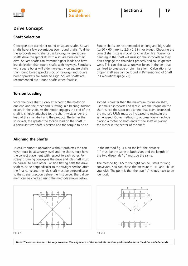
An intermediate bearing is placed in the center of the shaft to reduce shaft deflection. Excessive shaft deflection
Note: Drawing has been exaggerated for understanding purposes.
as seen on fig. 3-6 can cause disengagement between belt and sprocket as well as shaft breakage.
When working with a wide conveyor or a conveyor with a high tensile load the shaft must be large enough to handle the load without deflection, or intermediate bear-ings should be considered. In cases where a sufficiently large diameter shaft is not an option intermediate bear-ings are a must. An intermediate bearing is placed at the center of the drive shaft and its purpose is to reduce shaft deflection. Minimal shaft deflection will ensure sprocket and chain engagement.
Mounting of intermediate bearings should be noted since intermediate bearings are usually split journal bearings. The bearings should be aligned so that the split is perpen-
dicular to the carryway. If they are not mounted in this alignment, the reinforcement strength of the bearings is reduced significantly. Intermediate bearings also require significant space to install so increasing the sprocket diameter may be necessary. When increasing the sprocket size also keep in mind if there is a transfer at this point. Refer to Shaft Calculation Section (page 74).
Drive Concept
Force (belt pull) Force (belt pull)
Force (belt pull)
Fig. 3-6
21Section 3DesignGuidelines
Rollers as Idle Shafts and Sprocket Replacements
In some cases it is more advantageous to use rollers instead of an idler shaft with sprockets. One case where this should be used is, for example, where the designer wants to avoid using intermediate bearings. With wide
conveyors with higher loads, a roller can withstand more load and can reduce the need for intermediate bearing(s).
Note: If a roller is used on the idle shaft it does not provide the benefit of the horizontal tracking of the sprockets. Measures can be taken to guide the belt such as edge guide wearstrips on the side frame or a flange on the sides of the roller to track the belt.
Drive Types
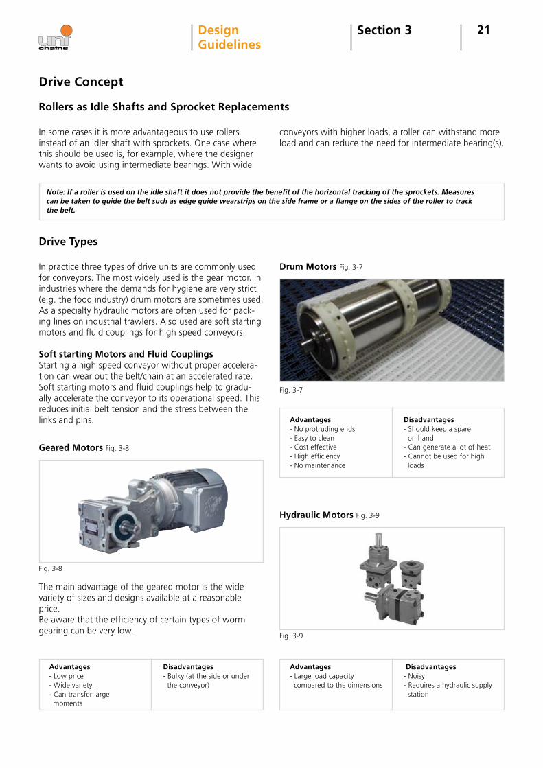
In practice three types of drive units are commonly used for conveyors. The most widely used is the gear motor. In industries where the demands for hygiene are very strict (e.g. the food industry) drum motors are sometimes used. As a specialty hydraulic motors are often used for pack-ing lines on industrial trawlers. Also used are soft starting motors and fluid couplings for high speed conveyors.
Soft starting Motors and Fluid CouplingsStarting a high speed conveyor without proper accelera-tion can wear out the belt/chain at an accelerated rate. Soft starting motors and fluid couplings help to gradu-ally accelerate the conveyor to its operational speed. This reduces initial belt tension and the stress between the links and pins.
Advantages- Low price- Wide variety- Can transfer large moments
Disadvantages- Bulky (at the side or under the conveyor)
Drum Motors Fig. 3-7
Hydraulic Motors Fig. 3-9
Drive Concept
Advantages- Large load capacity compared to the dimensions
Disadvantages - Noisy- Requires a hydraulic supply station
Advantages- No protruding ends- Easy to clean - Cost effective- High efficiency- No maintenance
Disadvantages- Should keep a spare on hand- Can generate a lot of heat- Cannot be used for high loads
Fig. 3-7
Fig. 3-8
Fig. 3-9
The main advantage of the geared motor is the wide variety of sizes and designs available at a reasonable price.Be aware that the efficiency of certain types of worm gearing can be very low.
Geared Motors Fig. 3-8
22Section 3DesignGuidelines
Straight running Conveyors
The simplest design of a conveyor is a straight running conveyor with a single drive unit. In certain applications, multiple drive units are required, such as a combiner or decombiner.
Elevating Conveyors
The principles in the next section apply for both belts and chains.
Incline Conveyor
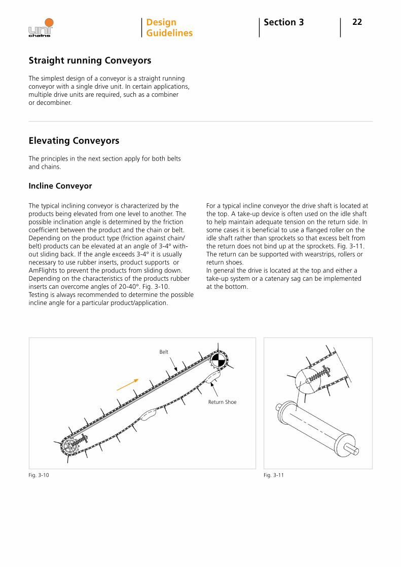
The typical inclining conveyor is characterized by the products being elevated from one level to another. The possible inclination angle is determined by the friction coefficient between the product and the chain or belt.Depending on the product type (friction against chain/belt) products can be elevated at an angle of 3-4º with-out sliding back. If the angle exceeds 3-4° it is usually necessary to use rubber inserts, product supports or AmFlights to prevent the products from sliding down. Depending on the characteristics of the products rubber inserts can overcome angles of 20-40°. Fig. 3-10.Testing is always recommended to determine the possible incline angle for a particular product/application.
For a typical incline conveyor the drive shaft is located at the top. A take-up device is often used on the idle shaft to help maintain adequate tension on the return side. In some cases it is beneficial to use a flanged roller on the idle shaft rather than sprockets so that excess belt from the return does not bind up at the sprockets. Fig. 3-11. The return can be supported with wearstrips, rollers or return shoes. In general the drive is located at the top and either a take-up system or a catenary sag can be implemented at the bottom.
Belt
Return Shoe
Fig. 3-10 Fig. 3-11
IdGP
S
A-A
23Section 3DesignGuidelines
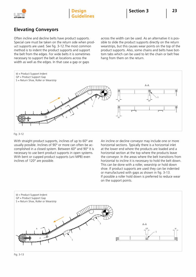
Often incline and decline belts have product supports. Special care must be taken on the return side when prod-uct supports are used. See fig. 3-12.The most common method is to indent the product supports and support the belt from the edges. For wide belts it is sometimes necessary to support the belt at locations across the width as well as the edges. In that case a gap or gaps
across the width can be used. As an alternative it is pos-sible to slide the product supports directly on the return wearstrips, but this causes wear points on the top of the product supports. Also, some chains and belts have bot-tom tabs which can be used to let the chain or belt free hang from them on the return.
Id = Product Support IndentGP = Product Support GapS = Return Shoe, Roller or Wearstrip
With straight product supports, inclines of up to 60° are usually possible. Inclines of 90° or more can often be ac-complished in a closed system. Between 60° and 90° it is necessary to use bent product supports in open systems. With bent or cupped product supports (uni MPB) even inclines of 120° are possible.
An incline or decline conveyor may include one or more horizontal sections. Typically there is a horizontal inlet at the lower end where the products are loaded and a horizontal section at the top where the products leave the conveyor. In the areas where the belt transitions from horizontal to incline it is necessary to hold the belt down. This can be done with a roller, wearstrip or hold down shoe. If product supports are used they can be indented or manufactured with gaps as shown in fig. 3-13. If possible a roller hold down is preferred to reduce wear on the support points.
Id = Product Support IndentGP = Product Support GapS = Return Shoe, Roller or Wearstrip
Elevating Conveyors
A
A
Id
Id GP
S
A-A
A
A
Fig. 3-12
Fig. 3-13
S
S
S
24Section 3DesignGuidelines
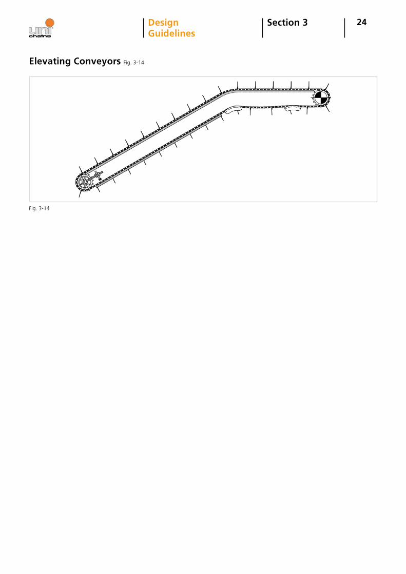
Elevating Conveyors Fig. 3-14
Fig. 3-14
25Section 3DesignGuidelines
Side flexing Conveyors
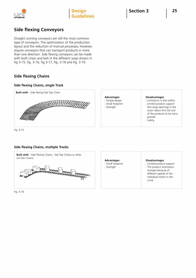
Straight running conveyors are still the most common type of conveyors. The optimization of the production layout and the reduction of manual processes, however, require conveyors that can transport products in more than one direction. Side flexing conveyors can be made with both chain and belt in the different ways shown in fig 3-15, fig. 3-16, fig 3-17, fig. 3-18 and fig. 3-19.
Side flexing Chains
Side flexing Chains, single Track
Built with - Side flexing Slat Top Chain
Disadvantages- Limitations in the widths- Limited product support (the large openings in the outer radius limit the size of the products to be trans- ported)- Safety
Side flexing Chains, multiple Tracks
Built with - Side flexing Chains, Slat Top Chains or other uni Flex Chains
Disadvantages- Limited product support- The product orientation changes because of different speeds of the individual chains in the curve
Advantages- Simple design- Small footprint - Strength
Advantages- Small footprint - Strength
Fig. 3-15
Fig. 3-16
26Section 3DesignGuidelines
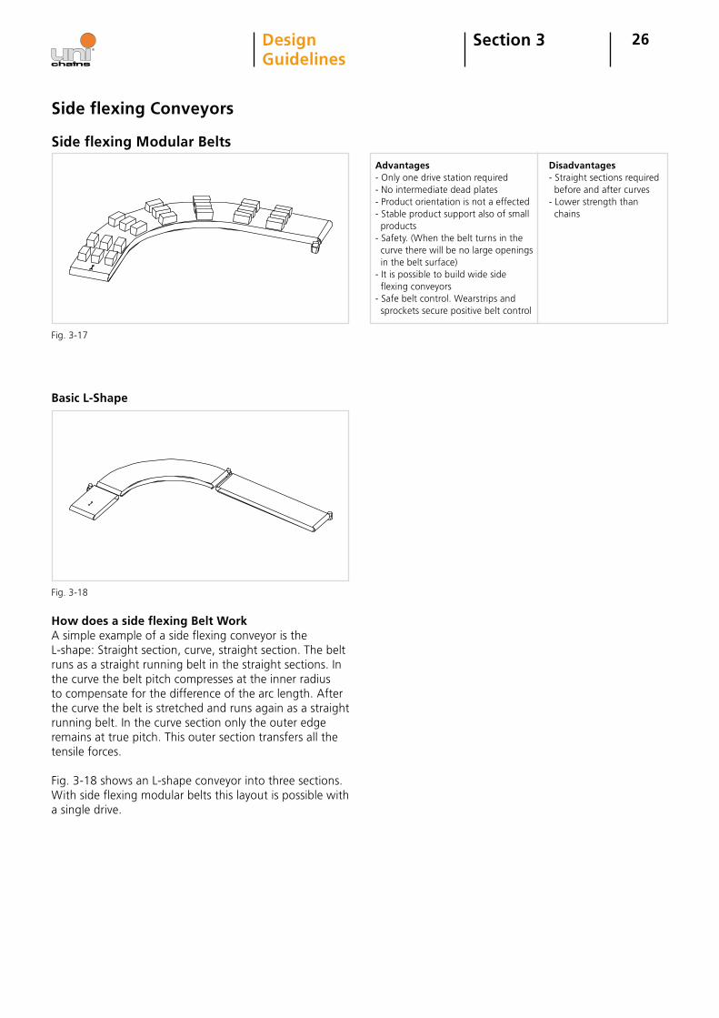
Side flexing Modular Belts
Advantages- Only one drive station required- No intermediate dead plates- Product orientation is not a effected- Stable product support also of small products- Safety. (When the belt turns in the curve there will be no large openings in the belt surface)- It is possible to build wide side flexing conveyors- Safe belt control. Wearstrips and sprockets secure positive belt control
Basic L-Shape
How does a side flexing Belt Work A simple example of a side flexing conveyor is the L-shape: Straight section, curve, straight section. The belt runs as a straight running belt in the straight sections. In the curve the belt pitch compresses at the inner radius to compensate for the difference of the arc length. After the curve the belt is stretched and runs again as a straight running belt. In the curve section only the outer edge remains at true pitch. This outer section transfers all the tensile forces.
Fig. 3-18 shows an L-shape conveyor into three sections.With side flexing modular belts this layout is possible with a single drive.
Side flexing Conveyors
Disadvantages- Straight sections required before and after curves- Lower strength than chains
Fig. 3-17
Fig. 3-18
27Section 3DesignGuidelines
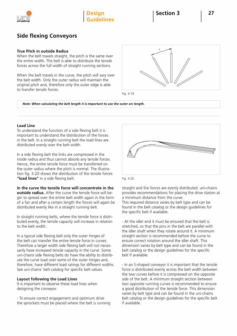
True Pitch in outside RadiusWhen the belt travels straight, the pitch is the same over the entire width. The belt is able to distribute the tensile forces across the full width of straight running sections.
When the belt travels in the curve, the pitch will vary over the belt width. Only the outer radius will maintain the original pitch and, therefore only the outer edge is able to transfer tensile forces.
Note: When calculating the belt length it is important to use the outer arc length.
Load LineTo understand the function of a side flexing belt it is important to understand the distribution of the forces in the belt. In a straight running belt the load lines are distributed evenly over the belt width.
In a side flexing belt the links are compressed in the inside radius and thus cannot absorb any tensile forces. Hence, the entire tensile force must be transferred on the outer radius where the pitch is normal. The illustra-tion fig. 3-20 shows the distribution of the tensile forces "load lines" in a side flexing belt.
In the curve the tensile force will concentrate in the outside radius. After the curve the tensile force will be-gin to spread over the entire belt width again in the form of a fan and after a certain length the forces will again be distributed evenly like in a straight running belt.
In straight running belts, where the tensile force is distri- buted evenly, the tensile capacity will increase in relation to the belt width.
In a typical side flexing belt only the outer hinges of the belt can transfer the entire tensile force in curves. Therefore a larger width side flexing belt will not neces-sarily have increased tensile capacity in the curve. Some uni-chains side flexing belts do have the ability to distrib-ute the curve load over some of the outer hinges and, therefore, have different load ratings for different widths. See uni-chains' belt catalog for specific belt values.
Layout following the Load LinesIt is important to observe these load lines when designing the conveyor.
- To ensure correct engagement and optimum drive the sprockets must be placed where the belt is running
straight and the forces are evenly distributed. uni-chains provides recommendations for placing the drive station at a minimum distance from the curve. This required distance varies by belt type and can be found in the belt catalog or the design guidelines for the specific belt if available.
- At the idler end it must be ensured that the belt is stretched, so that the pins in the belt are parallel with the idler shaft when they rotate around it. A minimum straight section is recommended before the curve to ensure correct rotation around the idler shaft. This dimension varies by belt type and can be found in the belt catalog or the design guidelines for the specific belt if available.
- In an S-shaped conveyor it is important that the tensile force is distributed evenly across the belt width between the two curves before it is compressed on the opposite side of the belt. A minimum straight section between two opposite running curves is recommended to ensure a good distribution of the tensile force. This dimension varies by belt type and can be found in the uni-chains belt catalog or the design guidelines for the specific belt if available.
Side flexing Conveyors
Fig. 3-20
Fig. 3-19
P
28
Side flexing Conveyors
Reducing Side flexing Belt Width ratioSome belts have a smaller belt width turn ratio than others. By selecting a tight radius belt the dimensions of the curved sections are reduced because the outer turning radius is smaller than the standard radius belt.
Reducing Belt WidthAll dimensional requirements for a side flexing belt layout are related to the belt width. If the belt width is reduced the overall dimensions will be reduced as well. There are several ways to do this. For example, using a belt with side tabs or bottom tabs can allow the belt to be narrow-er than the products conveyed because the product can overhang the edges. Using this narrower belt will make the overall conveyor dimensions smaller.
Split wide Conveyors in two BeltsAnother method of reducing the belt width is by splitting a conveyor into two parallel belt lanes. For example two 229 mm (9 in.) wide belts can thus replace a 457 mm (18 in.) wide belt and reduce the space required by 66%. If this option is chosen attention must be paid to the dif-ferent speeds of the two belts in the curves and the fact that there is a distance between the two belts.
Placing the Drive
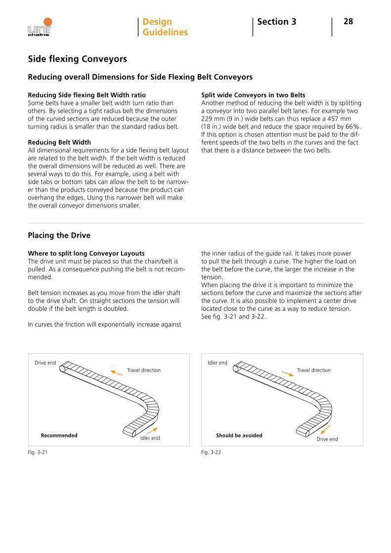
Where to split long Conveyor LayoutsThe drive unit must be placed so that the chain/belt is pulled. As a consequence pushing the belt is not recom-mended.
Belt tension increases as you move from the idler shaft to the drive shaft. On straight sections the tension will double if the belt length is doubled.
In curves the friction will exponentially increase against
the inner radius of the guide rail. It takes more power to pull the belt through a curve. The higher the load on the belt before the curve, the larger the increase in the tension.When placing the drive it is important to minimize the sections before the curve and maximize the sections after the curve. It is also possible to implement a center drive located close to the curve as a way to reduce tension.See fig. 3-21 and 3-22.
Section 3DesignGuidelines
Drive endTravel direction
Recommended Idler end
Travel directionIdler end
Drive endShould be avoided
Fig. 3-21 Fig. 3-22
Reducing overall Dimensions for Side Flexing Belt Conveyors
29Section 3DesignGuidelines
Load & Speed Properties
The permissible tensile force of a side flexing belt de-pends on the ability of the outer hinges to bear the load or distribute the load. In side flexing belts, however, the speed is also an essential parameter. Therefore attention should be paid to the maximum permissible tensile forces stated in the catalog as these will decrease as speed increases.
In side flexing belts there is a great inward radial load in the curve. At the point of contact between belt and wearstrip heat will occur due to friction. The tempera-ture influences the friction properties of the materials. The friction coefficient will increase as the temperature increases and a higher friction coefficient will result in more heat being generated. It is important to avoid this
as it could result in either the belt/chain or the wearstrip melting.
On the basis of numerous tests and data collated from existing applications uni-chains has established some load/speed relations between our belt types and materials against various wearstrip materials. These are sometimes called Pressure-Velocity (PV) Limits. These load-speed rela-tions can be found in the appendix of this manual.
Precautions with Catenary Sags for side flexing Belts
Over time side flexing belts can elongate more in the loaded side of the belt than the other. Catenary sags and tension rollers must be able to absorb this uneven elongation and care must be taken that the return section can accommodate this.
Side flexing Conveyors
30Section 3DesignGuidelines
Mounting of Sprockets
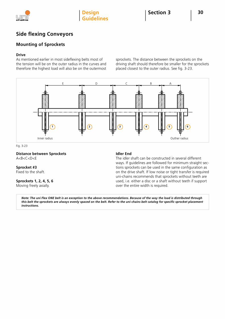
Drive As mentioned earlier in most sideflexing belts most of the tension will be on the outer radius in the curves and therefore the highest load will also be on the outermost
sprockets. The distance between the sprockets on the driving shaft should therefore be smaller for the sprockets placed closest to the outer radius. See fig. 3-23.
Distance between SprocketsA<B<C<D<E
Sprocket #3Fixed to the shaft.
Sprockets 1, 2, 4, 5, 6 Moving freely axially.
Idler EndThe idler shaft can be constructed in several different ways. If guidelines are followed for minimum straight sec-tions sprockets can be used in the same configuration as on the drive shaft. If low noise or tight transfer is required uni-chains recommends that sprockets without teeth are used, i.e. either a disc or a shaft without teeth if support over the entire width is required.
Note: The uni Flex ONE belt is an exception to the above recommendations. Because of the way the load is distributed through this belt the sprockets are always evenly spaced on the belt. Refer to the uni-chains belt catalog for specific sprocket placement instructions.
Side flexing Conveyors
Inner radius Outher radius
E D C B A
1 2 3 4 5 6
Fig. 3-23
31
Spiral Conveyors
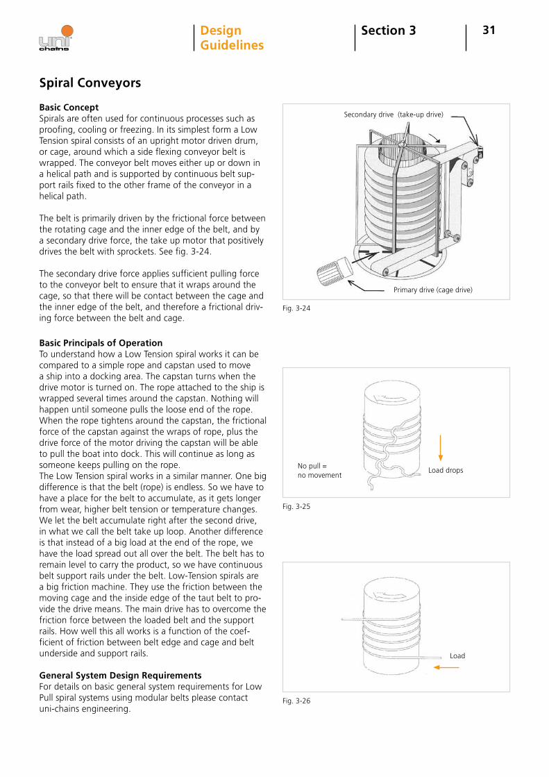
Basic ConceptSpirals are often used for continuous processes such as proofing, cooling or freezing. In its simplest form a Low Tension spiral consists of an upright motor driven drum, or cage, around which a side flexing conveyor belt is wrapped. The conveyor belt moves either up or down in a helical path and is supported by continuous belt sup-port rails fixed to the other frame of the conveyor in a helical path.
The belt is primarily driven by the frictional force between the rotating cage and the inner edge of the belt, and by a secondary drive force, the take up motor that positively drives the belt with sprockets. See fig. 3-24.
The secondary drive force applies sufficient pulling force to the conveyor belt to ensure that it wraps around the cage, so that there will be contact between the cage and the inner edge of the belt, and therefore a frictional driv-ing force between the belt and cage.
Basic Principals of OperationTo understand how a Low Tension spiral works it can be compared to a simple rope and capstan used to move a ship into a docking area. The capstan turns when the drive motor is turned on. The rope attached to the ship is wrapped several times around the capstan. Nothing will happen until someone pulls the loose end of the rope. When the rope tightens around the capstan, the frictional force of the capstan against the wraps of rope, plus the drive force of the motor driving the capstan will be able to pull the boat into dock. This will continue as long as someone keeps pulling on the rope.The Low Tension spiral works in a similar manner. One big difference is that the belt (rope) is endless. So we have to have a place for the belt to accumulate, as it gets longer from wear, higher belt tension or temperature changes. We let the belt accumulate right after the second drive, in what we call the belt take up loop. Another difference is that instead of a big load at the end of the rope, we have the load spread out all over the belt. The belt has to remain level to carry the product, so we have continuous belt support rails under the belt. Low-Tension spirals are a big friction machine. They use the friction between the moving cage and the inside edge of the taut belt to pro-vide the drive means. The main drive has to overcome the friction force between the loaded belt and the support rails. How well this all works is a function of the coef-ficient of friction between belt edge and cage and belt underside and support rails.
General System Design RequirementsFor details on basic general system requirements for Low Pull spiral systems using modular belts please contact uni-chains engineering.
Section 3DesignGuidelines
Fig. 3-24
Fig. 3-25
Fig. 3-26
Secondary drive (take-up drive)
Primary drive (cage drive)
Load
Load dropsNo pull = no movement
32
Transfer Guidelines
It is not practical to make a conveyor if you cannot place the products on the conveyor or transfer them at the end of the transport. In practice it is also impossible to build
Section 3DesignGuidelines
sufficiently long conveyors. So there is usually a need to transfer products from one conveyor to another. Following are different methods to do this.
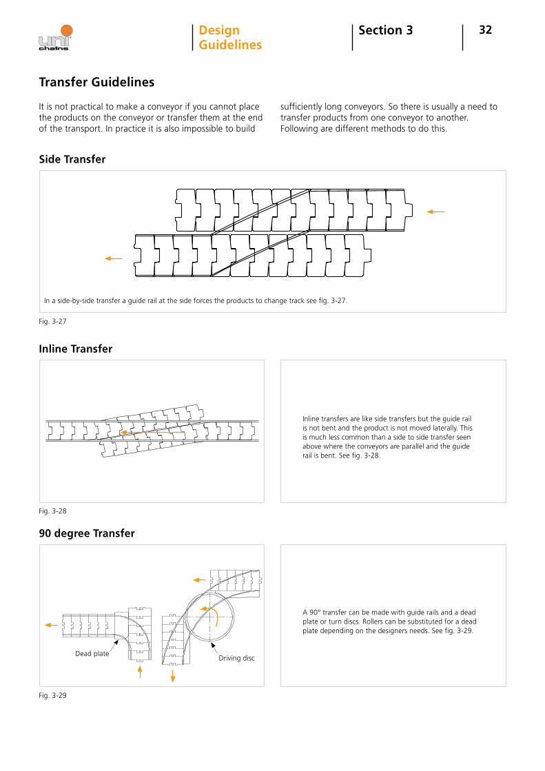
Side Transfer
In a side-by-side transfer a guide rail at the side forces the products to change track see fig. 3-27.
Inline Transfer
Inline transfers are like side transfers but the guide rail is not bent and the product is not moved laterally. This is much less common than a side to side transfer seen above where the conveyors are parallel and the guide rail is bent. See fig. 3-28.
90 degree Transfer
A 90° transfer can be made with guide rails and a dead plate or turn discs. Rollers can be substituted for a dead plate depending on the designers needs. See fig. 3-29.
Dead plateDriving disc
Fig. 3-27
Fig. 3-28
Fig. 3-29
33Section 3DesignGuidelines
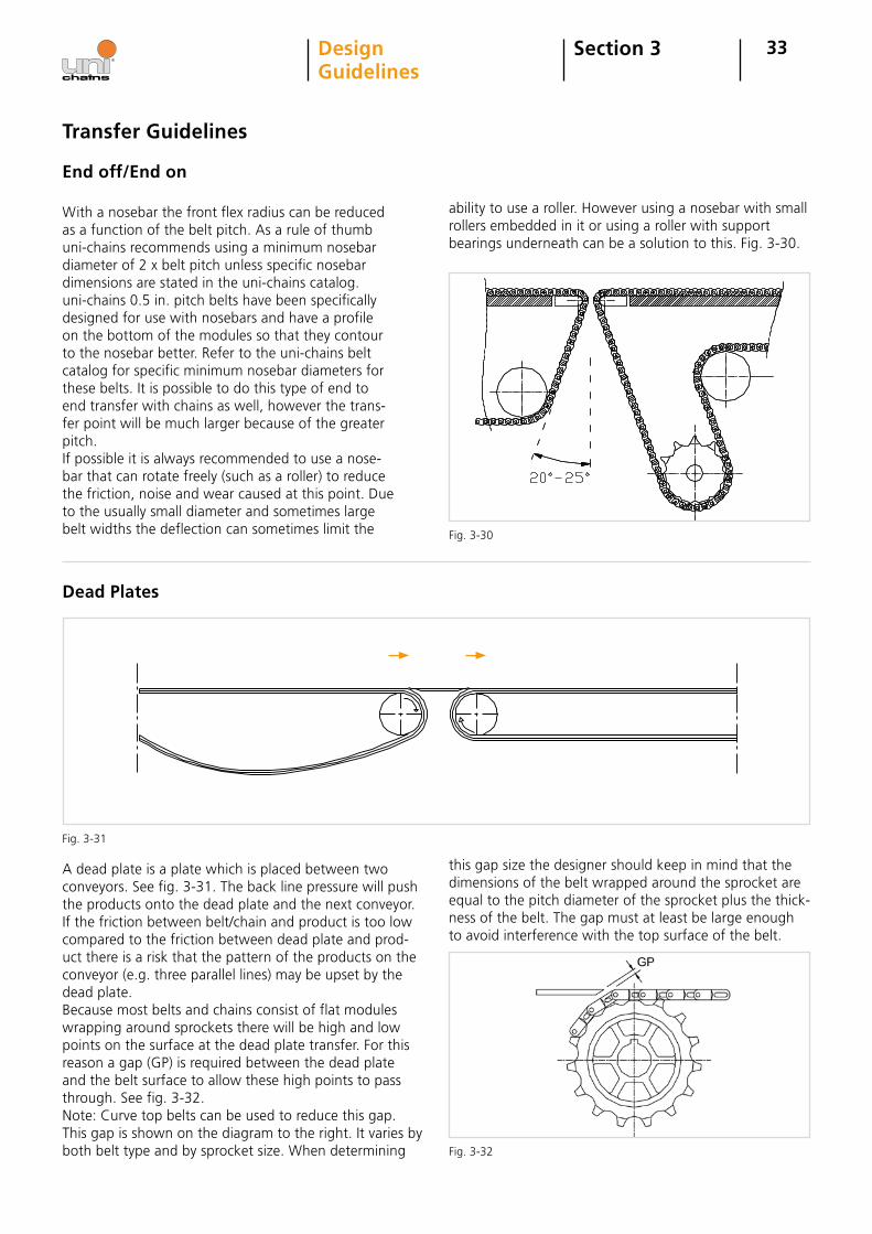
End off/End on
With a nosebar the front flex radius can be reduced as a function of the belt pitch. As a rule of thumb uni-chains recommends using a minimum nosebar diameter of 2 x belt pitch unless specific nosebar dimensions are stated in the uni-chains catalog. uni-chains 0.5 in. pitch belts have been specifically designed for use with nosebars and have a profile on the bottom of the modules so that they contour to the nosebar better. Refer to the uni-chains belt catalog for specific minimum nosebar diameters for these belts. It is possible to do this type of end to end transfer with chains as well, however the trans-fer point will be much larger because of the greater pitch. If possible it is always recommended to use a nose-bar that can rotate freely (such as a roller) to reduce the friction, noise and wear caused at this point. Due to the usually small diameter and sometimes large belt widths the deflection can sometimes limit the
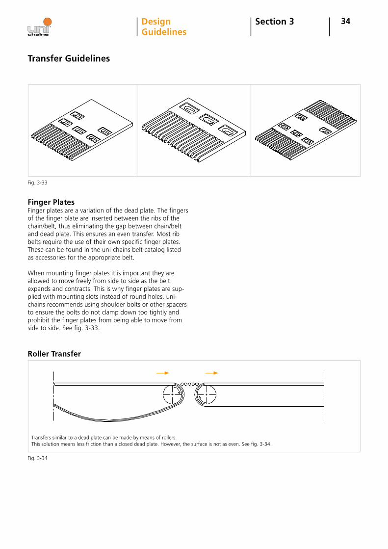
Dead Plates
A dead plate is a plate which is placed between two conveyors. See fig. 3-31. The back line pressure will push the products onto the dead plate and the next conveyor. If the friction between belt/chain and product is too low compared to the friction between dead plate and prod-uct there is a risk that the pattern of the products on the conveyor (e.g. three parallel lines) may be upset by the dead plate.Because most belts and chains consist of flat modules wrapping around sprockets there will be high and low points on the surface at the dead plate transfer. For this reason a gap (GP) is required between the dead plate and the belt surface to allow these high points to pass through. See fig. 3-32. Note: Curve top belts can be used to reduce this gap.This gap is shown on the diagram to the right. It varies by both belt type and by sprocket size. When determining
Transfer Guidelines
ability to use a roller. However using a nosebar with small rollers embedded in it or using a roller with support bearings underneath can be a solution to this. Fig. 3-30.
this gap size the designer should keep in mind that the dimensions of the belt wrapped around the sprocket are equal to the pitch diameter of the sprocket plus the thick-ness of the belt. The gap must at least be large enough to avoid interference with the top surface of the belt.
Fig. 3-30
Fig. 3-31
Fig. 3-32
34Section 3DesignGuidelines
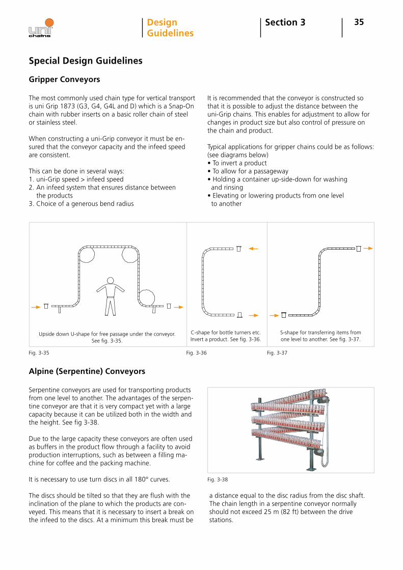
Finger PlatesFinger plates are a variation of the dead plate. The fingers of the finger plate are inserted between the ribs of the chain/belt, thus eliminating the gap between chain/belt and dead plate. This ensures an even transfer. Most rib belts require the use of their own specific finger plates. These can be found in the uni-chains belt catalog listed as accessories for the appropriate belt.
When mounting finger plates it is important they are allowed to move freely from side to side as the belt expands and contracts. This is why finger plates are sup-plied with mounting slots instead of round holes. uni-chains recommends using shoulder bolts or other spacers to ensure the bolts do not clamp down too tightly and prohibit the finger plates from being able to move from side to side. See fig. 3-33.
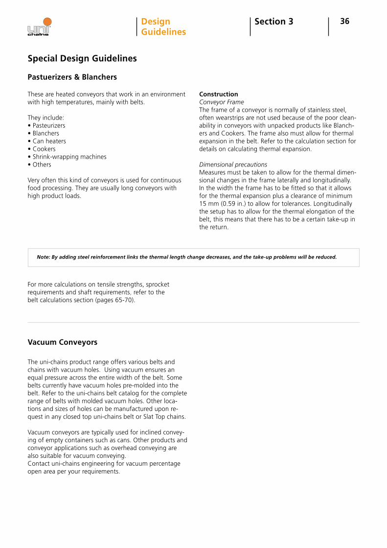
Roller Transfer
Transfers similar to a dead plate can be made by means of rollers.This solution means less friction than a closed dead plate. However, the surface is not as even. See fig. 3-34.
Transfer Guidelines
Fig. 3-33
Fig. 3-34
35Section 3DesignGuidelines
Special Design Guidelines
Gripper Conveyors
The most commonly used chain type for vertical transport is uni Grip 1873 (G3, G4, G4L and D) which is a Snap-On chain with rubber inserts on a basic roller chain of steel or stainless steel.
When constructing a uni-Grip conveyor it must be en-sured that the conveyor capacity and the infeed speed are consistent.
This can be done in several ways:1. uni-Grip speed > infeed speed2. An infeed system that ensures distance between the products3. Choice of a generous bend radius
It is recommended that the conveyor is constructed so that it is possible to adjust the distance between the uni-Grip chains. This enables for adjustment to allow for changes in product size but also control of pressure on the chain and product.
Typical applications for gripper chains could be as follows: (see diagrams below)• To invert a product• To allow for a passageway• Holding a container up-side-down for washing and rinsing• Elevating or lowering products from one level to another
Alpine (Serpentine) Conveyors
Serpentine conveyors are used for transporting products from one level to another. The advantages of the serpen-tine conveyor are that it is very compact yet with a large capacity because it can be utilized both in the width and the height. See fig 3-38. Due to the large capacity these conveyors are often used as buffers in the product flow through a facility to avoid production interruptions, such as between a filling ma-chine for coffee and the packing machine.
It is necessary to use turn discs in all 180° curves.
The discs should be tilted so that they are flush with the inclination of the plane to which the products are con-veyed. This means that it is necessary to insert a break on the infeed to the discs. At a minimum this break must be
a distance equal to the disc radius from the disc shaft.The chain length in a serpentine conveyor normally should not exceed 25 m (82 ft) between the drive stations.
Upside down U-shape for free passage under the conveyor.See fig. 3-35.
C-shape for bottle turners etc.Invert a product. See fig. 3-36.
S-shape for transferring items from one level to another. See fig. 3-37.
Fig. 3-35 Fig. 3-36 Fig. 3-37
Fig. 3-38
36
Pastuerizers & Blanchers
These are heated conveyors that work in an environment with high temperatures, mainly with belts. They include:• Pasteurizers• Blanchers• Can heaters• Cookers• Shrink-wrapping machines• Others
Very often this kind of conveyors is used for continuous food processing. They are usually long conveyors with high product loads.
Special Design Guidelines
ConstructionConveyor FrameThe frame of a conveyor is normally of stainless steel, often wearstrips are not used because of the poor clean-ability in conveyors with unpacked products like Blanch-ers and Cookers. The frame also must allow for thermal expansion in the belt. Refer to the calculation section for details on calculating thermal expansion.
Dimensional precautionsMeasures must be taken to allow for the thermal dimen-sional changes in the frame laterally and longitudinally. In the width the frame has to be fitted so that it allows for the thermal expansion plus a clearance of minimum 15 mm (0.59 in.) to allow for tolerances. Longitudinally the setup has to allow for the thermal elongation of the belt, this means that there has to be a certain take-up in the return.
Note: By adding steel reinforcement links the thermal length change decreases, and the take-up problems will be reduced.
For more calculations on tensile strengths, sprocket requirements and shaft requirements, refer to the belt calculations section (pages 65-70).
Vacuum Conveyors
The uni-chains product range offers various belts and chains with vacuum holes. Using vacuum ensures an equal pressure across the entire width of the belt. Some belts currently have vacuum holes pre-molded into the belt. Refer to the uni-chains belt catalog for the complete range of belts with molded vacuum holes. Other loca-tions and sizes of holes can be manufactured upon re-quest in any closed top uni-chains belt or Slat Top chains.
Vacuum conveyors are typically used for inclined convey-ing of empty containers such as cans. Other products and conveyor applications such as overhead conveying are also suitable for vacuum conveying.Contact uni-chains engineering for vacuum percentage open area per your requirements.
Section 3DesignGuidelines
37
Special Design Guidelines
Long Conveyors
Section 3DesignGuidelines
The requirements for long conveyors have increased recently, especially within the automobile and the tourist industries.
The great advantage of long conveyors is the reduced need for transfers between conveyors. Transfers often create problems involving increased costs. Another advantage is the reduced number of driving stations, reducing the construction costs of the conveyor.
When building long conveyors you should pay great attention to the increased risk of pulsation.
Another important aspect is the belt elongation which can be considerable.
Definition of a long ConveyorNormally, a straight running conveyor is defined as being long if the total length exceeds 20 m (65 ft). For a side flexing conveyor the length is 12 m (39 ft). If these lengths are exceeded the risk of pulsation increases. For ways to reduce pulsation, refer to slip-stick/surging/pulsa-tion on page 39.
Belt ElongationThere are several ways to absorb the belt elongation. Below the two most common methods will be described.
Method 1The elongation is absorbed by a catenary sag on the return. The return belt must run on rollers with a given distance, the elongation will then distribute between the rollers in the catenary sag. It is important when apply-ing this method to ensure that the distance between the first and the second roller is the largest because the belt weight must be the largest at that spot. This ensures that the catenary sag will be located there to provide a good engagement between belt and driving sprockets.
Method 1 is relatively simple and economical but it has some disadvantages. One is that it requires a large con-struction height. Another is the risk that the belt between the rollers will start to oscillate and thus increase the pulsation (to address this the roller spacing should vary from one roller to the next). Furthermore noise may also be generated.
Method 2In this method the elongation is absorbed by means of air cylinders mounted either on the side of the conveyor or between top and return.
Length of stroke of the cylinders must be min. 0.5 x total belt elongation.
The advantages of this method are that it is possible to build a conveyor with a relatively low construction height. Furthermore the risk of pulsation caused by vibrations from the return is reduced because this is "tight" due to the cylinders.
Method 2 is considerably more costly than method no 1, so it is recommended in each case to consider thoroughly what is necessary for the conveyor in question.
Contact uni-chains engineering for further information.
38
Carousel (endless) Conveyors
Section 3DesignGuidelines
Special Design Guidelines
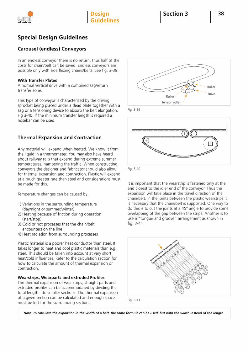
In an endless conveyor there is no return, thus half of the costs for chain/belt can be saved. Endless conveyors are possible only with side flexing chains/belts. See fig. 3-39.
With Transfer PlatesA normal vertical drive with a combined sag/return transfer zone.
This type of conveyor is characterized by the driving sprocket being placed under a dead plate together with a sag or a tensioning device to absorb the belt elongation. Fig 3-40. If the minimum transfer length is required a nosebar can be used.
Thermal Expansion and Contraction
Any material will expand when heated. We know it from the liquid in a thermometer. You may also have heard about railway rails that expand during extreme summer temperatures, hampering the traffic. When constructing conveyors the designer and fabricator should also allow for thermal expansion and contraction. Plastic will expand at a much greater rate than steel and considerations must be made for this.
Temperature changes can be caused by:
1) Variations in the surrounding temperature (day/night or summer/winter)2) Heating because of friction during operation (start/stop)3) Cold or hot processes that the chain/belt encounters on the line4) Heat radiation from surrounding processes
Plastic material is a poorer heat conductor than steel. It takes longer to heat and cool plastic materials than e.g. steel. This should be taken into account at very short heat/cold influences. Refer to the calculation section for how to calculate the amount of thermal expansion or contraction.
Wearstrips, Wearparts and extruded ProfilesThe thermal expansion of wearstrips, straight parts and extruded profiles can be accommodated by dividing the total length into smaller sections. The thermal expansion of a given section can be calculated and enough space must be left for the surrounding sections.
It is important that the wearstrip is fastened only at the end closest to the idler end of the conveyor. Thus the expansion will take place in the travel direction of the chain/belt. In the joints between the plastic wearstrips it is necessary that the chain/belt is supported. One way to do this is to cut the joints at a 45º angle to provide some overlapping of the gap between the strips. Another is to use a “tongue and groove” arrangement as shown infig. 3-41
Note: To calculate the expansion in the width of a belt, the same formula can be used, but with the width instead of the length.
Fig. 3-39
Fig. 3-41
Roller
Roller
Drive
Tension roller
Fig. 3-40
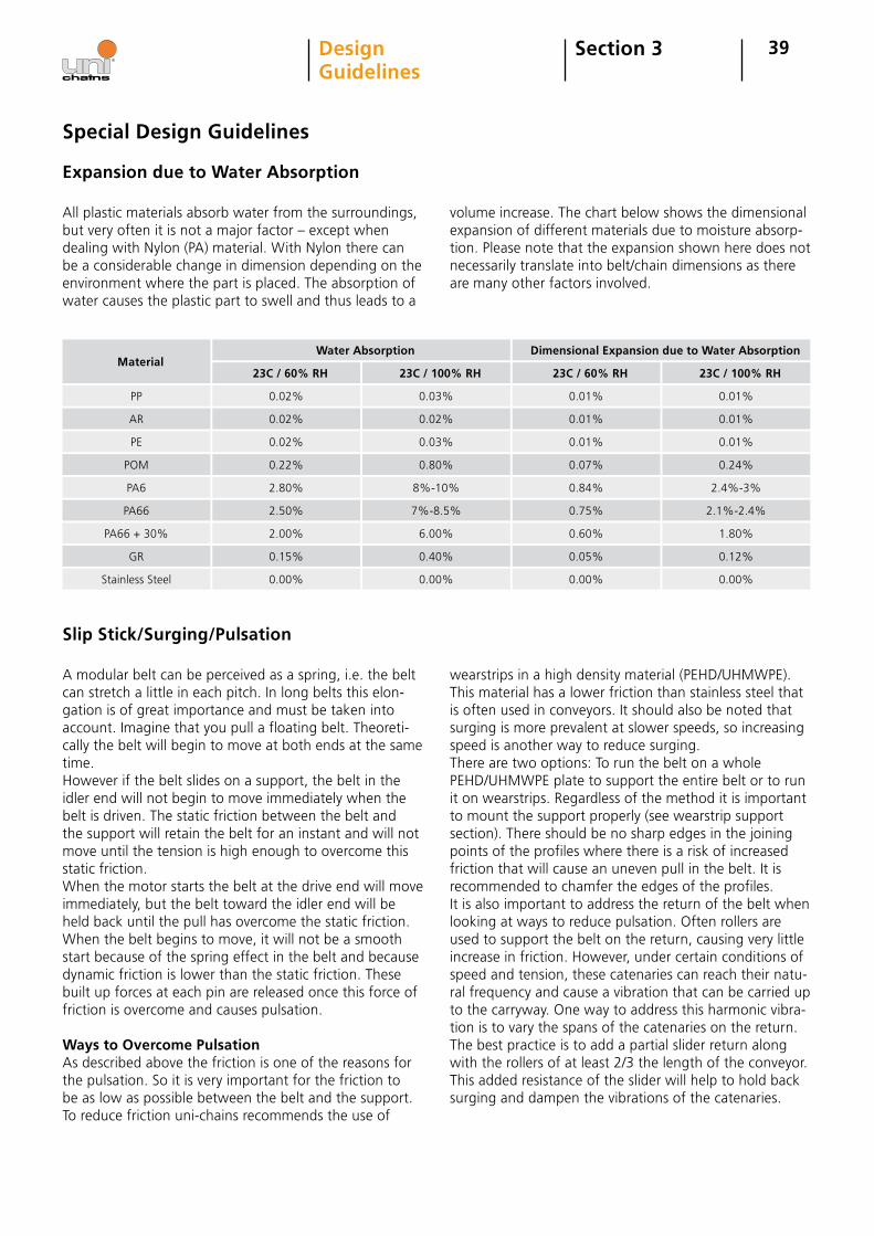
39Section 3DesignGuidelines
Expansion due to Water Absorption
Special Design Guidelines
All plastic materials absorb water from the surroundings, but very often it is not a major factor – except when dealing with Nylon (PA) material. With Nylon there can be a considerable change in dimension depending on the environment where the part is placed. The absorption of water causes the plastic part to swell and thus leads to a
volume increase. The chart below shows the dimensional expansion of different materials due to moisture absorp-tion. Please note that the expansion shown here does not necessarily translate into belt/chain dimensions as there are many other factors involved.
AR
PP
Material
PE
0.02%
0.02%
Water Absorption
0.02%
0.02%
0.03%
0.03%
0.01%
0.01%
Dimensional Expansion due to Water Absorption
0.01%
0.01%
0.01%
0.01%
POM 0.22% 0.80% 0.07% 0.24%
PA6 2.80% 8%-10% 0.84% 2.4%-3%
PA66 2.50% 7%-8.5% 0.75% 2.1%-2.4%
PA66 + 30% 2.00% 6.00% 0.60% 1.80%
GR 0.15% 0.40% 0.05% 0.12%
Stainless Steel 0.00% 0.00% 0.00% 0.00%
Slip Stick/Surging/Pulsation
A modular belt can be perceived as a spring, i.e. the belt can stretch a little in each pitch. In long belts this elon-gation is of great importance and must be taken into account. Imagine that you pull a floating belt. Theoreti-cally the belt will begin to move at both ends at the same time. However if the belt slides on a support, the belt in the idler end will not begin to move immediately when the belt is driven. The static friction between the belt and the support will retain the belt for an instant and will not move until the tension is high enough to overcome this static friction.When the motor starts the belt at the drive end will move immediately, but the belt toward the idler end will be held back until the pull has overcome the static friction. When the belt begins to move, it will not be a smooth start because of the spring effect in the belt and because dynamic friction is lower than the static friction. These built up forces at each pin are released once this force of friction is overcome and causes pulsation.
Ways to Overcome PulsationAs described above the friction is one of the reasons for the pulsation. So it is very important for the friction to be as low as possible between the belt and the support. To reduce friction uni-chains recommends the use of
wearstrips in a high density material (PEHD/UHMWPE). This material has a lower friction than stainless steel that is often used in conveyors. It should also be noted that surging is more prevalent at slower speeds, so increasing speed is another way to reduce surging.There are two options: To run the belt on a whole PEHD/UHMWPE plate to support the entire belt or to run it on wearstrips. Regardless of the method it is important to mount the support properly (see wearstrip support section). There should be no sharp edges in the joining points of the profiles where there is a risk of increased friction that will cause an uneven pull in the belt. It is recommended to chamfer the edges of the profiles.It is also important to address the return of the belt when looking at ways to reduce pulsation. Often rollers are used to support the belt on the return, causing very little increase in friction. However, under certain conditions of speed and tension, these catenaries can reach their natu-ral frequency and cause a vibration that can be carried up to the carryway. One way to address this harmonic vibra-tion is to vary the spans of the catenaries on the return. The best practice is to add a partial slider return along with the rollers of at least 2/3 the length of the conveyor. This added resistance of the slider will help to hold back surging and dampen the vibrations of the catenaries.
23C / 60% RH 23C / 100% RH 23C / 60% RH 23C / 100% RH
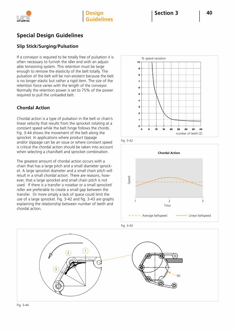
3
21
40
If a conveyor is required to be totally free of pulsation it is often necessary to furnish the idler end with an adjust-able tensioning system. This retention must be large enough to remove the elasticity of the belt totally. The pulsation of the belt will be non-existent because the belt is no longer elastic but rather a rigid item. The size of the retention force varies with the length of the conveyor. Normally the retention power is set to 75% of the power required to pull the unloaded belt.
Section 3DesignGuidelines
Special Design Guidelines
Chordal Action
Chordal action is a type of pulsation in the belt or chain’s linear velocity that results from the sprocket rotating at a constant speed while the belt hinge follows the chords. Fig. 3-44 shows the movement of the belt along the sprocket. In applications where product tippageand/or slippage can be an issue or where constant speed is critical the chordal action should be taken into account when selecting a chain/belt and sprocket combination.
The greatest amount of chordal action occurs with a chain that has a large pitch and a small diameter sprock-et. A large sprocket diameter and a small chain pitch will result in a small chordal action. There are reasons, how-ever, that a large sprocket and small chain pitch is not used. If there is a transfer a nosebar or a small sprocket/roller are preferable to create a small gap between the transfer. Or more simply a lack of space could limit the use of a large sprocket. Fig. 3-42 and fig. 3-43 are graphs explaining the relationship between number of teeth and chordal action.
Time
Chordal Action
Spee
d
1 2 3
Average beltspeed Linear beltspeed
Slip Stick/Surging/Pulsation
PD
number of teeth (Z)
% speed variation
Fig. 3-42
Fig. 3-43
Fig. 3-44
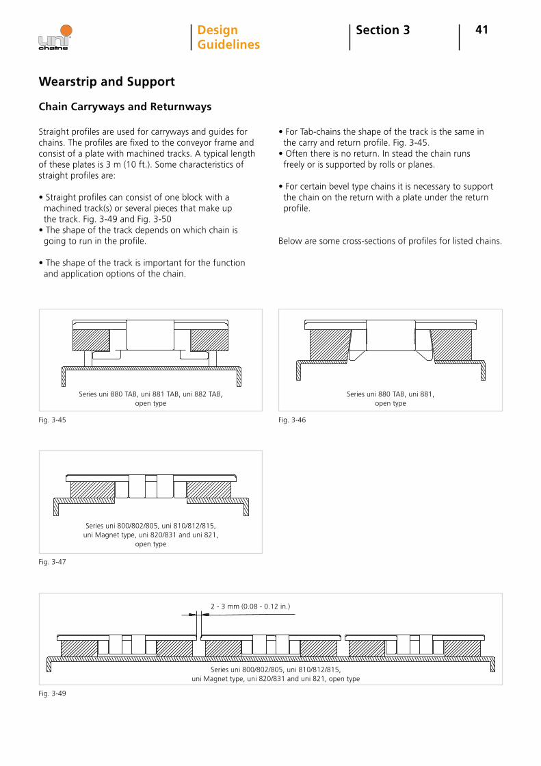
41
Wearstrip and Support
Chain Carryways and Returnways
Section 3DesignGuidelines
Straight profiles are used for carryways and guides for chains. The profiles are fixed to the conveyor frame and consist of a plate with machined tracks. A typical length of these plates is 3 m (10 ft.). Some characteristics of straight profiles are:
• Straight profiles can consist of one block with a machined track(s) or several pieces that make up the track. Fig. 3-49 and Fig. 3-50• The shape of the track depends on which chain is going to run in the profile.
• The shape of the track is important for the function and application options of the chain.
• For Tab-chains the shape of the track is the same in the carry and return profile. Fig. 3-45.• Often there is no return. In stead the chain runs freely or is supported by rolls or planes.
• For certain bevel type chains it is necessary to support the chain on the return with a plate under the return profile.
Below are some cross-sections of profiles for listed chains.
Series uni 800/802/805, uni 810/812/815, uni Magnet type, uni 820/831 and uni 821,
open type
Series uni 800/802/805, uni 810/812/815, uni Magnet type, uni 820/831 and uni 821, open type
2 - 3 mm (0.08 - 0.12 in.)
Fig. 3-45 Fig. 3-46
Fig. 3-47
Fig. 3-49
Series uni 880 TAB, uni 881 TAB, uni 882 TAB, open type
Series uni 880 TAB, uni 881,open type
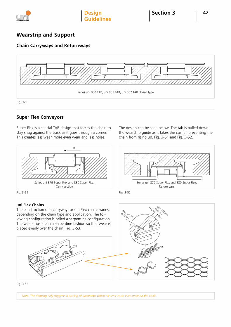
R
42
Series uni 880 TAB, uni 881 TAB, uni 882 TAB closed type
Wearstrip and Support
Section 3DesignGuidelines
Fig. 3-50
uni Flex ChainsThe construction of a carryway for uni Flex chains varies, depending on the chain type and application. The fol-lowing configuration is called a serpentine configuration. The wearstrips are in a serpentine fashion so that wear is placed evenly over the chain. Fig. 3-53.
Note: The drawing only suggests a placing of wearstrips which can ensure an even wear on the chain.
Max. 150 mm
(5.91 in.)Min. 10 mm
(0.39 in.)
Fig. 3-53
Chain Carryways and Returnways
Super Flex Conveyors
Super Flex is a special TAB design that forces the chain to stay snug against the track as it goes through a corner. This creates less wear, more even wear and less noise.
The design can be seen below. The tab is pulled down the wearstrip guide as it takes the corner, preventing the chain from rising up. Fig. 3-51 and Fig. 3-52.
Fig. 3-51 Fig. 3-52
Series uni 879 Super Flex and 880 Super Flex, Carry section
Series uni 879 Super Flex and 880 Super Flex, Return type
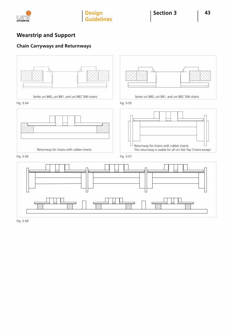
Returnway for chains with rubber inserts
43Section 3DesignGuidelines
Chain Carryways and Returnways
Wearstrip and Support
Series uni 880, uni 881, and uni 882 TAB chains Series uni 880, uni 881, and uni 882 TAB chains
Returnway for chains with rubber insertsThis returnway is usable for all uni Slat Top Chains except
Fig. 3-54 Fig. 3-55
Fig. 3-56 Fig. 3-57
Fig. 3-58
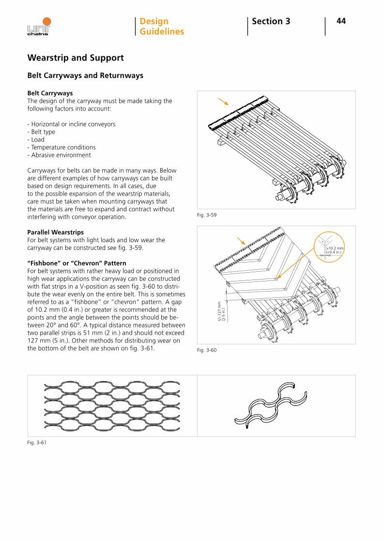
>10.2 mm (<0.4 in.)
51-1
27 m
m(2
-5 in
.)
44Section 3DesignGuidelines
Wearstrip and Support
Belt Carryways and Returnways
Belt CarrywaysThe design of the carryway must be made taking the following factors into account:
- Horizontal or incline conveyors- Belt type- Load- Temperature conditions- Abrasive environment
Carryways for belts can be made in many ways. Below are different examples of how carryways can be built based on design requirements. In all cases, due to the possible expansion of the wearstrip materials, care must be taken when mounting carryways that the materials are free to expand and contract without interfering with conveyor operation.
Parallel WearstripsFor belt systems with light loads and low wear the carryway can be constructed see fig. 3-59.
“Fishbone” or “Chevron” PatternFor belt systems with rather heavy load or positioned in high wear applications the carryway can be constructed with flat strips in a V-position as seen fig. 3-60 to distri-bute the wear evenly on the entire belt. This is sometimes referred to as a “fishbone” or “chevron” pattern. A gap of 10.2 mm (0.4 in.) or greater is recommended at the points and the angle between the points should be be-tween 20° and 60°. A typical distance measured between two parallel strips is 51 mm (2 in.) and should not exceed 127 mm (5 in.). Other methods for distributing wear on the bottom of the belt are shown on fig. 3-61.
Fig. 3-59
Fig. 3-60
Fig. 3-61
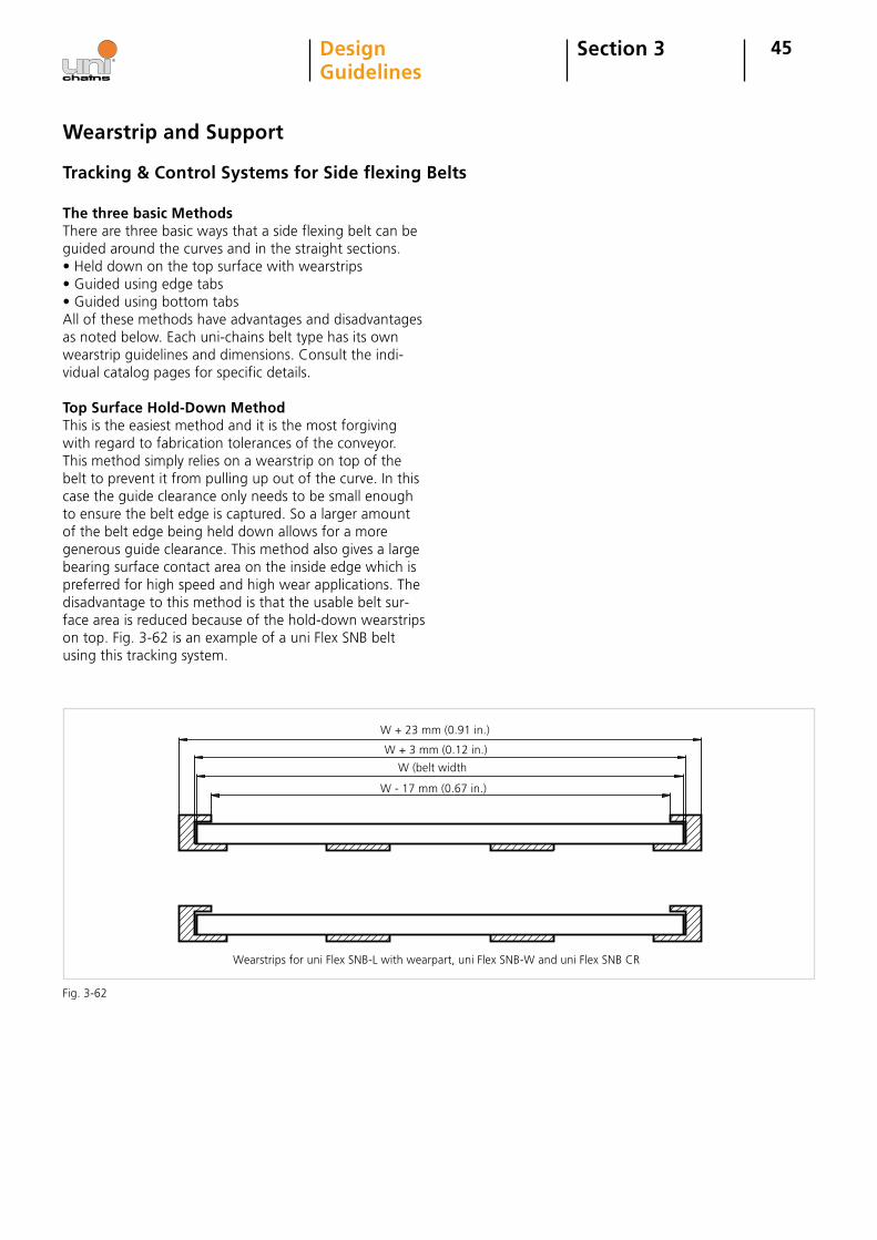
W + 3 mm (0.12 in.)
W - 17 mm (0.67 in.)
W (belt width
45Section 3DesignGuidelines
Tracking & Control Systems for Side flexing Belts
The three basic MethodsThere are three basic ways that a side flexing belt can be guided around the curves and in the straight sections.• Held down on the top surface with wearstrips• Guided using edge tabs• Guided using bottom tabsAll of these methods have advantages and disadvantages as noted below. Each uni-chains belt type has its own wearstrip guidelines and dimensions. Consult the indi-vidual catalog pages for specific details.
Top Surface Hold-Down MethodThis is the easiest method and it is the most forgiving with regard to fabrication tolerances of the conveyor. This method simply relies on a wearstrip on top of the belt to prevent it from pulling up out of the curve. In this case the guide clearance only needs to be small enough to ensure the belt edge is captured. So a larger amount of the belt edge being held down allows for a more generous guide clearance. This method also gives a large bearing surface contact area on the inside edge which is preferred for high speed and high wear applications. The disadvantage to this method is that the usable belt sur-face area is reduced because of the hold-down wearstrips on top. Fig. 3-62 is an example of a uni Flex SNB belt using this tracking system.
Wearstrip and Support
Wearstrips for uni Flex SNB-L with wearpart, uni Flex SNB-W and uni Flex SNB CR
W + 23 mm (0.91 in.)
Fig. 3-62
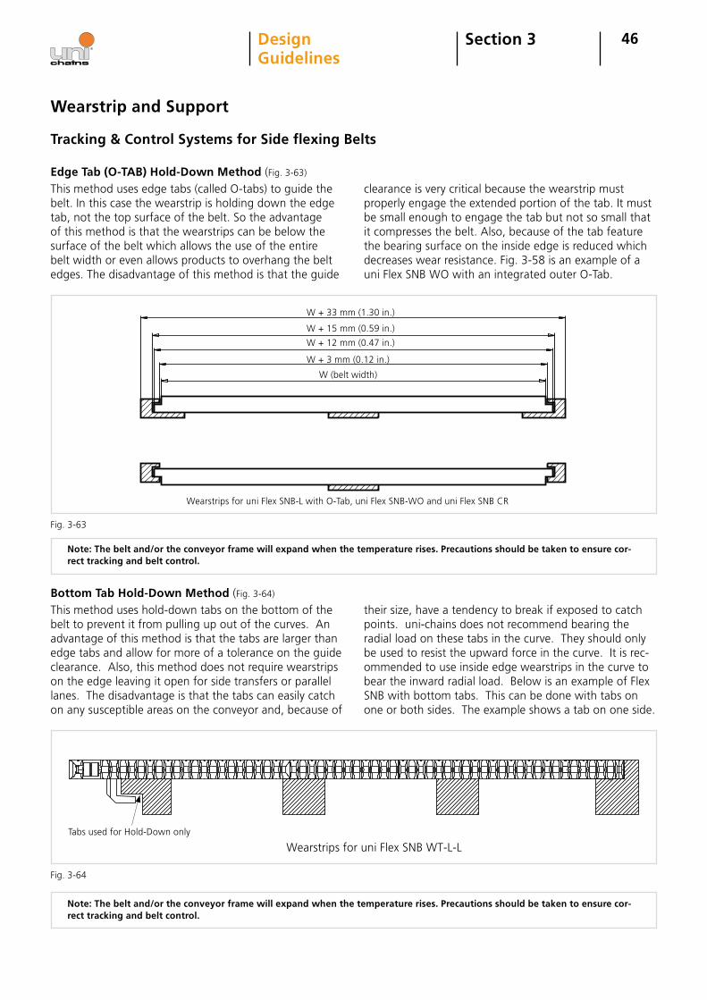
46
This method uses edge tabs (called O-tabs) to guide the belt. In this case the wearstrip is holding down the edge tab, not the top surface of the belt. So the advantage of this method is that the wearstrips can be below the surface of the belt which allows the use of the entire belt width or even allows products to overhang the belt edges. The disadvantage of this method is that the guide
clearance is very critical because the wearstrip must properly engage the extended portion of the tab. It must be small enough to engage the tab but not so small that it compresses the belt. Also, because of the tab feature the bearing surface on the inside edge is reduced which decreases wear resistance. Fig. 3-58 is an example of a uni Flex SNB WO with an integrated outer O-Tab.
Note: The belt and/or the conveyor frame will expand when the temperature rises. Precautions should be taken to ensure cor-rect tracking and belt control.
W + 33 mm (1.30 in.)
W + 15 mm (0.59 in.)
W + 3 mm (0.12 in.)
W + 12 mm (0.47 in.)
W (belt width)
Wearstrips for uni Flex SNB-L with O-Tab, uni Flex SNB-WO and uni Flex SNB CR
Fig. 3-63
Wearstrip and Support
Edge Tab (O-TAB) Hold-Down Method (Fig. 3-63)
Wearstrips for uni Flex SNB WT-L-LTabs used for Hold-Down only
Fig. 3-64
Note: The belt and/or the conveyor frame will expand when the temperature rises. Precautions should be taken to ensure cor-rect tracking and belt control.
Section 3DesignGuidelines
This method uses hold-down tabs on the bottom of the belt to prevent it from pulling up out of the curves. An advantage of this method is that the tabs are larger than edge tabs and allow for more of a tolerance on the guide clearance. Also, this method does not require wearstrips on the edge leaving it open for side transfers or parallel lanes. The disadvantage is that the tabs can easily catch on any susceptible areas on the conveyor and, because of
their size, have a tendency to break if exposed to catch points. uni-chains does not recommend bearing the radial load on these tabs in the curve. They should only be used to resist the upward force in the curve. It is rec-ommended to use inside edge wearstrips in the curve to bear the inward radial load. Below is an example of Flex SNB with bottom tabs. This can be done with tabs on one or both sides. The example shows a tab on one side.
Bottom Tab Hold-Down Method (Fig. 3-64)
Tracking & Control Systems for Side flexing Belts
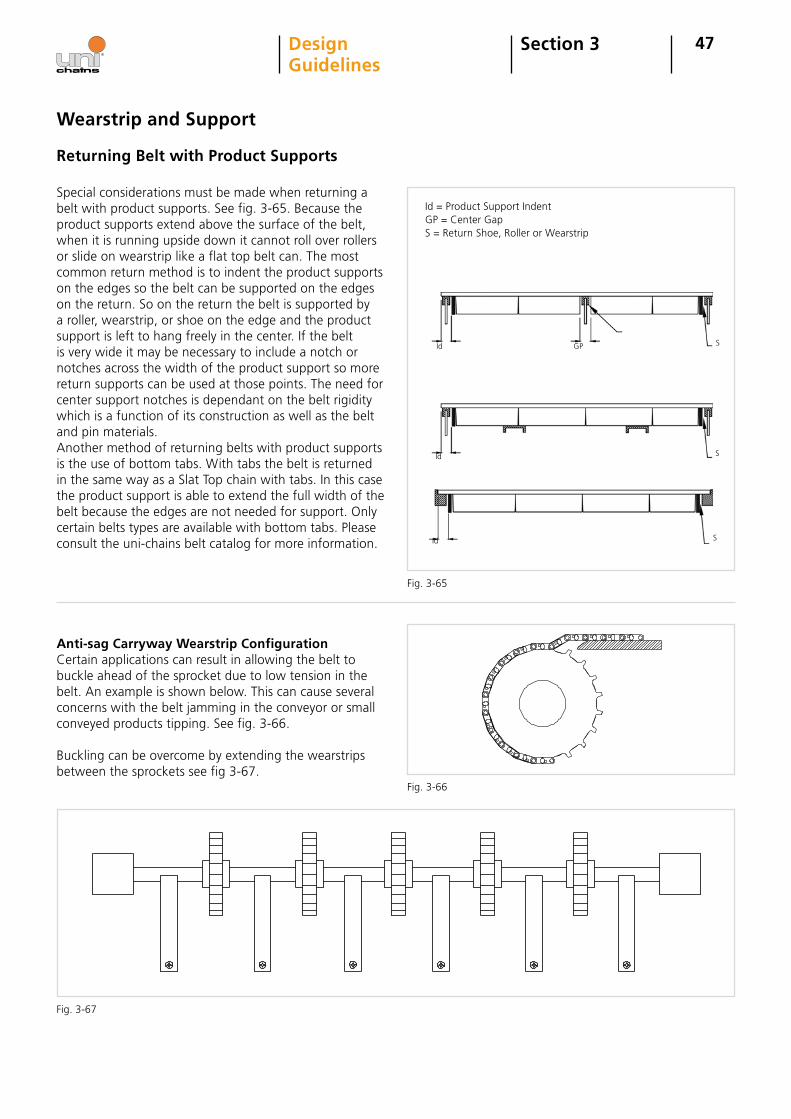
Special considerations must be made when returning a belt with product supports. See fig. 3-65. Because the product supports extend above the surface of the belt, when it is running upside down it cannot roll over rollers or slide on wearstrip like a flat top belt can. The most common return method is to indent the product supports on the edges so the belt can be supported on the edges on the return. So on the return the belt is supported by a roller, wearstrip, or shoe on the edge and the product support is left to hang freely in the center. If the belt is very wide it may be necessary to include a notch or notches across the width of the product support so more return supports can be used at those points. The need for center support notches is dependant on the belt rigidity which is a function of its construction as well as the belt and pin materials. Another method of returning belts with product supports is the use of bottom tabs. With tabs the belt is returned in the same way as a Slat Top chain with tabs. In this case the product support is able to extend the full width of the belt because the edges are not needed for support. Only certain belts types are available with bottom tabs. Please consult the uni-chains belt catalog for more information.
Id = Product Support IndentGP = Center GapS = Return Shoe, Roller or Wearstrip
Id GP
Id
Id
S
S
S
47Section 3DesignGuidelines
Anti-sag Carryway Wearstrip ConfigurationCertain applications can result in allowing the belt to buckle ahead of the sprocket due to low tension in the belt. An example is shown below. This can cause several concerns with the belt jamming in the conveyor or small conveyed products tipping. See fig. 3-66.
Buckling can be overcome by extending the wearstrips between the sprockets see fig 3-67.
Wearstrip and Support
Fig. 3-66
Fig. 3-67
Returning Belt with Product Supports
Fig. 3-65
48Section 3DesignGuidelines
Take-up Methods
Control of Belt Length
Belt or Chain Running in One DirectionAs temperature, load and friction vari, the belt expands or contracts, increasing or decreasing belt length respec-tively. To counteract this effect a catenary sag is used after the drive sprocket in the returnway. A catenary sag is a section of free hanging belt that absorbs excess belt in expansion or gives excess belt to the conveyor in the event of contraction. The catenary sag also serves as a weight on the return-way of the belt. This weight of the belt in the catenary sag is enough to ensure sprocket engagement by creating tension after the drive sprocket and before the idler sprocket.
When designing the conveyor frame, the designer must keep in mind the dimensions of the catenary sag and make sure there are no obstructions hindering or sup-porting the catenary sag. If the sag rests on the con-veyor frame, the effect of the sag to serve as a weight is reduced greatly. If the belt becomes too long, links
from the belt should be removed so the catenary sag is returned to its intended dimensions. Below are different setups for a conveyor with a catenary sag.
Keep in mind that for all return arrangements the backflex radius of the particular belt/chain must not be reduced. The backflex (or backbend) radius is the mini-mum negative bend (opposite of the belt bending over the sprocket) the belt can safely undergo. This value is different for each belt type and can also change for each belt/chain when certain accessories like sideguards are used. Backflex radius can be found for each belt in the uni-chains belt catalog on the product main page next to this icon:
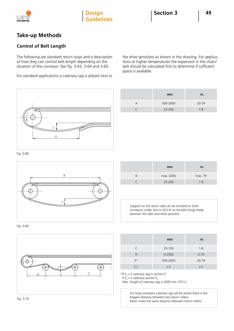
C
A
C
B
C
D E Fx
49
The following are standard return ways and a description of how they can control belt length depending on the situation of the conveyor. See fig. 3-63, 3-64 and 3-65.
For standard applications a catenary sag is placed next to
Take-up Methods
Section 3DesignGuidelines
Control of Belt Length
C
A
25-200
500-2000
mm
1-8
20-79
in.
C
B
25-200
max. 2000
mm
1-8
max. 79
in.
D
C
0-2000
25-100
mm
0-79
1-8
in.
E* 500-2000 20-79
the drive sprockets as shown in the drawing. For applica-tions at higher temperatures the expansion in the chain/belt should be calculated first to determine if sufficient space is available.
For long conveyors catenary sag will be where there is the biggest distance between two return rollers.Never make the same distance between return rollers.
Support on the return side can be omitted on short conveyors under two m (6.6 ft) so the belt hangs freely between the idler and drive sprocket.
Fig. 3-68
Fig. 3-69
Fig. 3-70
Fx* ≠ E ≠ E
*If Fx < E catenary sag in section E If Fx > E catenary section Fx
Max. length of catenary sag is 2000 mm (79 in.)
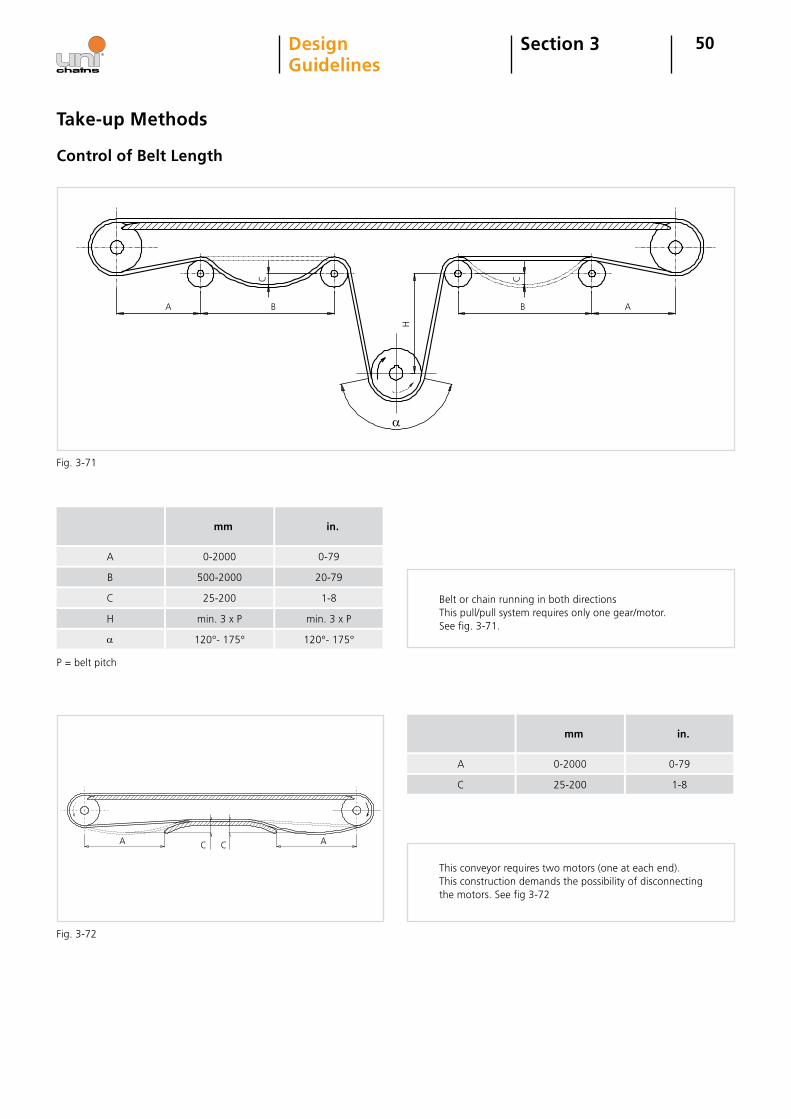
A B B A
C
H
A AC C
C
50
B
A
500-2000
0-2000
mm
20-79
0-79
in.
P = belt pitch
A 0-2000
mm
0-79
in.
Section 3DesignGuidelines
Take-up Methods
Control of Belt Length
This conveyor requires two motors (one at each end). This construction demands the possibility of disconnecting the motors. See fig 3-72
C 25-200 1-8
Belt or chain running in both directionsThis pull/pull system requires only one gear/motor.See fig. 3-71.
Fig. 3-71
Fig. 3-72
a
H
C
min. 3 x P
25-200
min. 3 x P
1-8
a 120°- 175° 120°- 175°
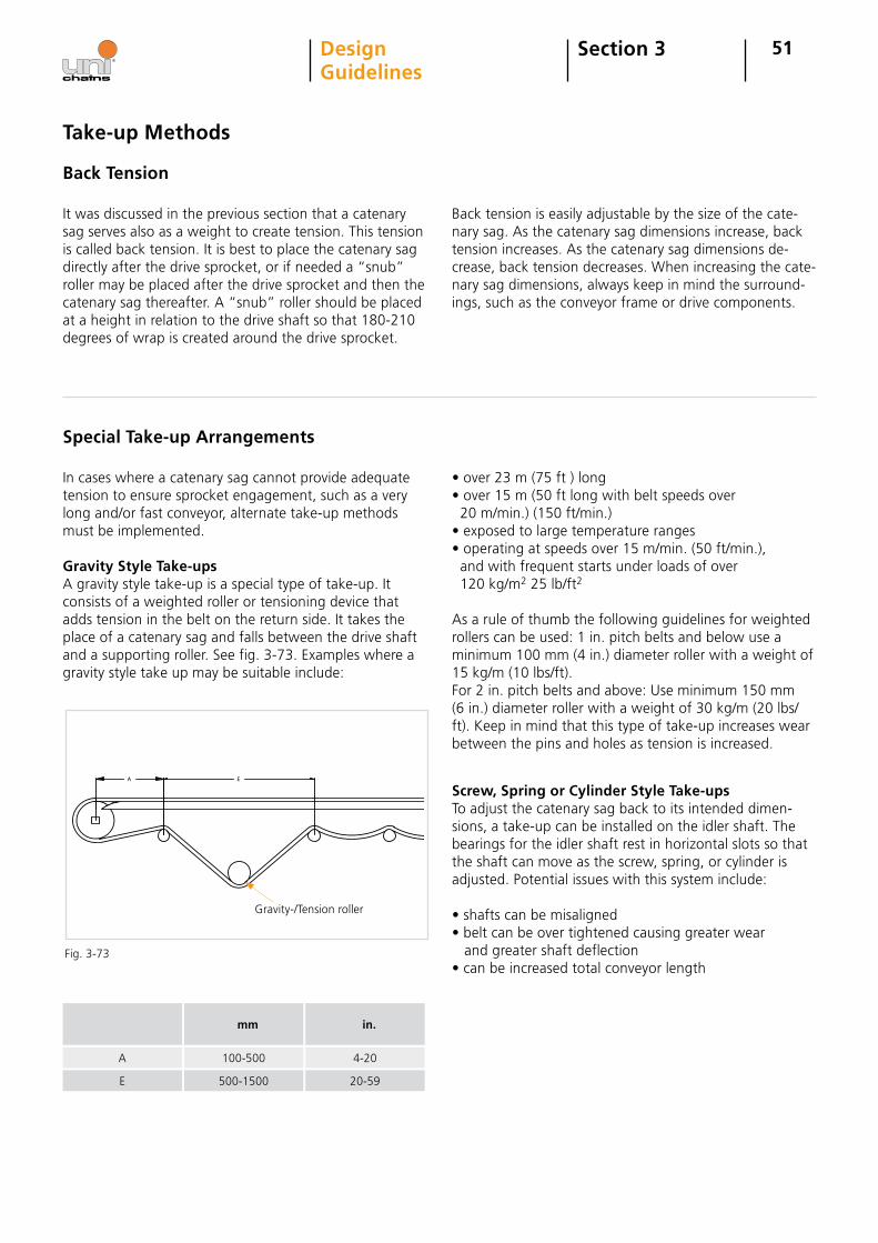
A E
51Section 3DesignGuidelines
Back Tension
Take-up Methods
It was discussed in the previous section that a catenary sag serves also as a weight to create tension. This tension is called back tension. It is best to place the catenary sag directly after the drive sprocket, or if needed a “snub” roller may be placed after the drive sprocket and then the catenary sag thereafter. A “snub” roller should be placed at a height in relation to the drive shaft so that 180-210 degrees of wrap is created around the drive sprocket.
Back tension is easily adjustable by the size of the cate- nary sag. As the catenary sag dimensions increase, back tension increases. As the catenary sag dimensions de-crease, back tension decreases. When increasing the cate- nary sag dimensions, always keep in mind the surround-ings, such as the conveyor frame or drive components.
Special Take-up Arrangements
In cases where a catenary sag cannot provide adequate tension to ensure sprocket engagement, such as a very long and/or fast conveyor, alternate take-up methods must be implemented.
Gravity Style Take-ups A gravity style take-up is a special type of take-up. It consists of a weighted roller or tensioning device that adds tension in the belt on the return side. It takes the place of a catenary sag and falls between the drive shaft and a supporting roller. See fig. 3-73. Examples where a gravity style take up may be suitable include:
E
A
500-1500
100-500
mm
20-59
4-20
in.
• over 23 m (75 ft ) long• over 15 m (50 ft long with belt speeds over 20 m/min.) (150 ft/min.)• exposed to large temperature ranges• operating at speeds over 15 m/min. (50 ft/min.), and with frequent starts under loads of over 120 kg/m2 25 lb/ft2
As a rule of thumb the following guidelines for weighted rollers can be used: 1 in. pitch belts and below use a minimum 100 mm (4 in.) diameter roller with a weight of 15 kg/m (10 lbs/ft).For 2 in. pitch belts and above: Use minimum 150 mm (6 in.) diameter roller with a weight of 30 kg/m (20 lbs/ft). Keep in mind that this type of take-up increases wear between the pins and holes as tension is increased.
Screw, Spring or Cylinder Style Take-upsTo adjust the catenary sag back to its intended dimen-sions, a take-up can be installed on the idler shaft. The bearings for the idler shaft rest in horizontal slots so that the shaft can move as the screw, spring, or cylinder is adjusted. Potential issues with this system include:
• shafts can be misaligned• belt can be over tightened causing greater wear and greater shaft deflection• can be increased total conveyor length
Fig. 3-73
Gravity-/Tension roller
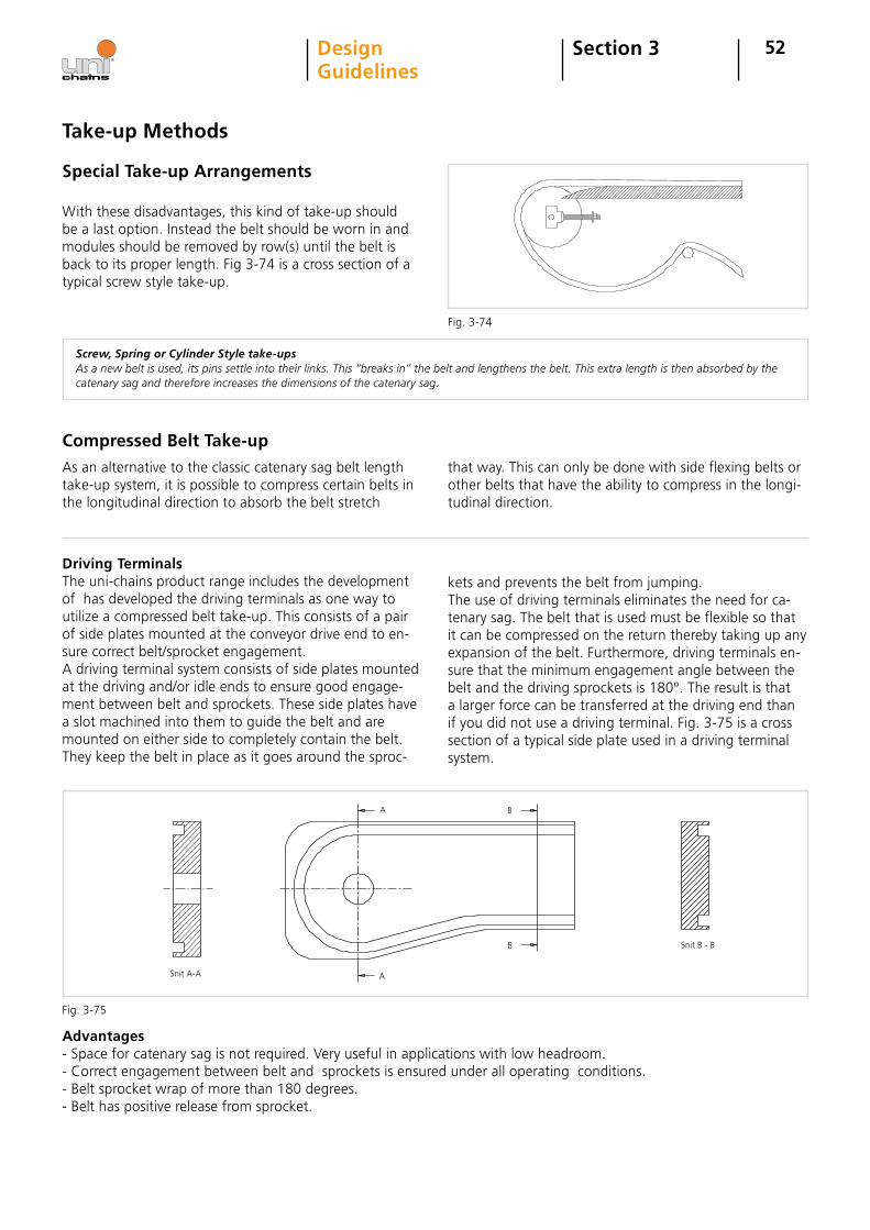
52Section 3DesignGuidelines
With these disadvantages, this kind of take-up should be a last option. Instead the belt should be worn in and modules should be removed by row(s) until the belt is back to its proper length. Fig 3-74 is a cross section of a typical screw style take-up.
Special Take-up Arrangements
Take-up Methods
As an alternative to the classic catenary sag belt length take-up system, it is possible to compress certain belts in the longitudinal direction to absorb the belt stretch
that way. This can only be done with side flexing belts or other belts that have the ability to compress in the longi-tudinal direction.
Advantages- Space for catenary sag is not required. Very useful in applications with low headroom. - Correct engagement between belt and sprockets is ensured under all operating conditions. - Belt sprocket wrap of more than 180 degrees.- Belt has positive release from sprocket.
A B
B
ASnit A-A
Snit B - B
Fig. 3-74
Fig. 3-75
Screw, Spring or Cylinder Style take-upsAs a new belt is used, its pins settle into their links. This “breaks in” the belt and lengthens the belt. This extra length is then absorbed by the catenary sag and therefore increases the dimensions of the catenary sag.
Driving TerminalsThe uni-chains product range includes the development of has developed the driving terminals as one way to utilize a compressed belt take-up. This consists of a pair of side plates mounted at the conveyor drive end to en-sure correct belt/sprocket engagement. A driving terminal system consists of side plates mounted at the driving and/or idle ends to ensure good engage-ment between belt and sprockets. These side plates have a slot machined into them to guide the belt and are mounted on either side to completely contain the belt. They keep the belt in place as it goes around the sproc-
kets and prevents the belt from jumping.The use of driving terminals eliminates the need for ca-tenary sag. The belt that is used must be flexible so that it can be compressed on the return thereby taking up any expansion of the belt. Furthermore, driving terminals en-sure that the minimum engagement angle between the belt and the driving sprockets is 180°. The result is that a larger force can be transferred at the driving end than if you did not use a driving terminal. Fig. 3-75 is a cross section of a typical side plate used in a driving terminal system.
Compressed Belt Take-up
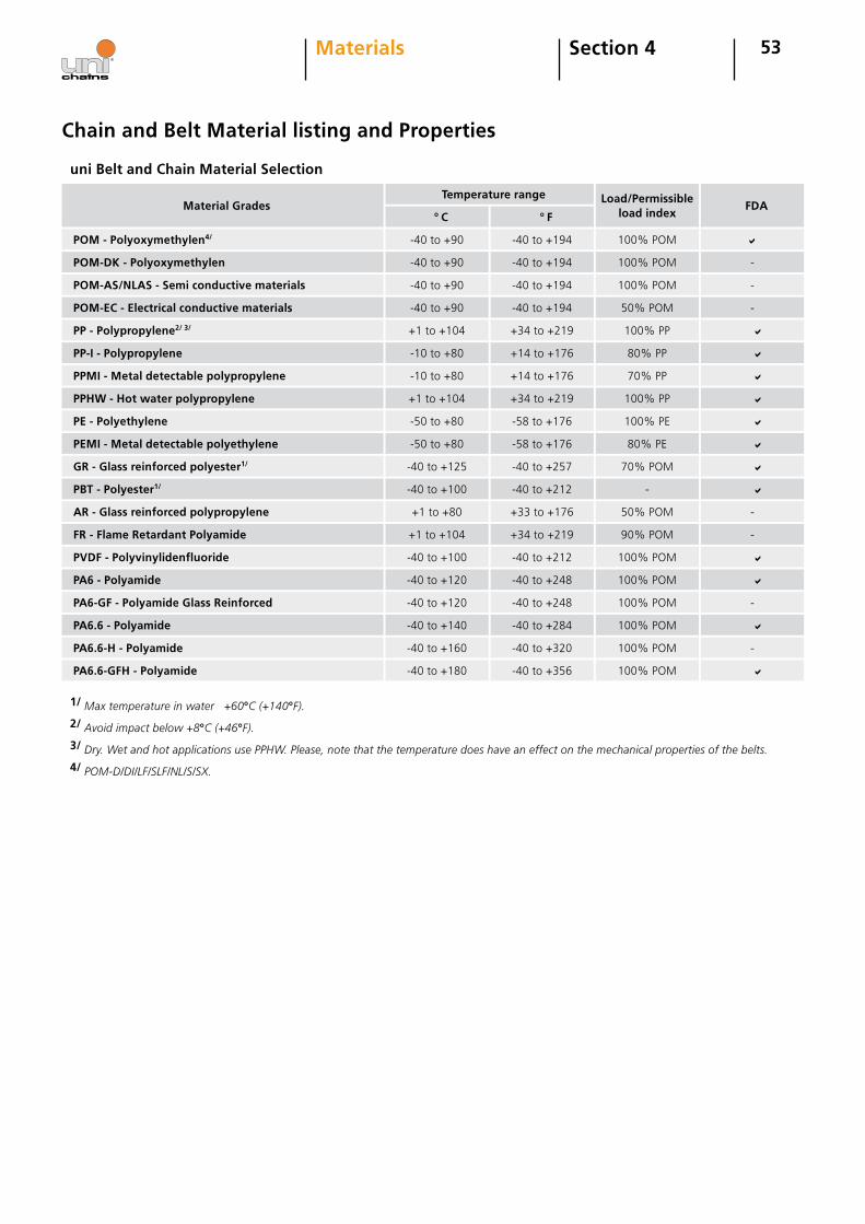
53Section 4Materials
Chain and Belt Material listing and Properties
POM-DK - Polyoxymethylen
POM - Polyoxymethylen4/
Material Grades
POM-AS/NLAS - Semi conductive materials
-40 to +90
-40 to +90
Temperature range
-40 to +90
-40 to +194
-40 to +194
-40 to +194
100% POM
100% POM
100% POM
-
-
Load/Permissible load index
FDA
POM-EC - Electrical conductive materials -40 to +90 -40 to +194 50% POM -
PP - Polypropylene2/ 3/ +1 to +104 +34 to +219 100% PP
PP-I - Polypropylene -10 to +80 +14 to +176 80% PP
PPMI - Metal detectable polypropylene -10 to +80 +14 to +176 70% PP
PPHW - Hot water polypropylene +1 to +104 +34 to +219 100% PP
PE - Polyethylene -50 to +80 -58 to +176 100% PE
PEMI - Metal detectable polyethylene -50 to +80 -58 to +176 80% PE
GR - Glass reinforced polyester1/ -40 to +125 -40 to +257 70% POM
PBT - Polyester1/ -40 to +100 -40 to +212 -
AR - Glass reinforced polypropylene +1 to +80 +33 to +176 50% POM -
FR - Flame Retardant Polyamide +1 to +104 +34 to +219 90% POM -
PVDF - Polyvinylidenfluoride -40 to +100 -40 to +212 100% POM
PA6 - Polyamide -40 to +120 -40 to +248 100% POM
PA6-GF - Polyamide Glass Reinforced -40 to +120 -40 to +248 100% POM -
1/ Max temperature in water +60°C (+140°F).
2/ Avoid impact below +8°C (+46°F).
3/ Dry. Wet and hot applications use PPHW. Please, note that the temperature does have an effect on the mechanical properties of the belts.
4/ POM-D/DI/LF/SLF/NL/S/SX.
PA6.6 - Polyamide -40 to +140 -40 to +284 100% POM
PA6.6-H - Polyamide -40 to +160 -40 to +320 100% POM -
uni Belt and Chain Material Selection
PA6.6-GFH - Polyamide -40 to +180 -40 to +356 100% POM
° C ° F
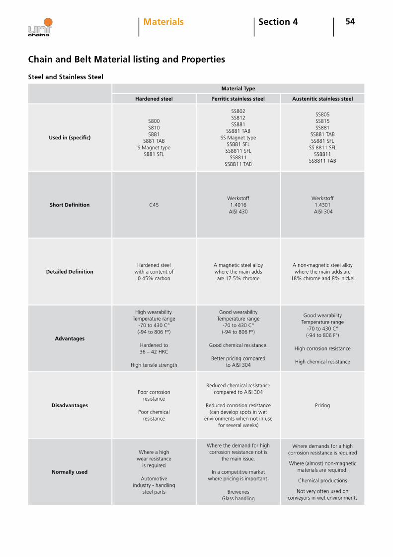
54Section 4Materials
Chain and Belt Material listing and Properties
Material Type
Hardened steel
Used in (specific)
S800S810S881
S881 TABS Magnet type
S881 SFL
SS802SS812SS881
SS881 TABSS Magnet type
SS881 SFLSS8811 SFL
SS8811SS8811 TAB
SS805SS815SS881
SS881 TABSS881 SFL
SS 8811 SFLSS8811
SS8811 TAB
Short Definition C45Werkstoff
1.4016AISI 430
Werkstoff 1.4301
AISI 304
Detailed DefinitionHardened steel
with a content of 0.45% carbon
A magnetic steel alloy where the main adds are 17.5% chrome
A non-magnetic steel alloy where the main adds are
18% chrome and 8% nickel
Advantages
High wearability.Temperature range
-70 to 430 C° (-94 to 806 F°)
Hardened to 36 – 42 HRC
High tensile strength
Good wearabilityTemperature range
-70 to 430 C° (-94 to 806 F°)
Good chemical resistance.
Better pricing compared to AISI 304
Good wearabilityTemperature range
-70 to 430 C° (-94 to 806 F°)
High corrosion resistance
High chemical resistance
Disadvantages
Poor corrosion resistance
Poor chemical resistance
Reduced chemical resistance compared to AISI 304
Reduced corrosion resistance (can develop spots in wet
environments when not in use for several weeks)
Pricing
Normally used
Where a high wear resistance
is required
Automotive industry - handling
steel parts
Where the demand for high corrosion resistance not is
the main issue.
In a competitive market where pricing is important.
BreweriesGlass handling
Where demands for a high corrosion resistance is required
Where (almost) non-magnetic materials are required.
Chemical productions
Not very often used on conveyors in wet environments
Ferritic stainless steel Austenitic stainless steel
Steel and Stainless Steel
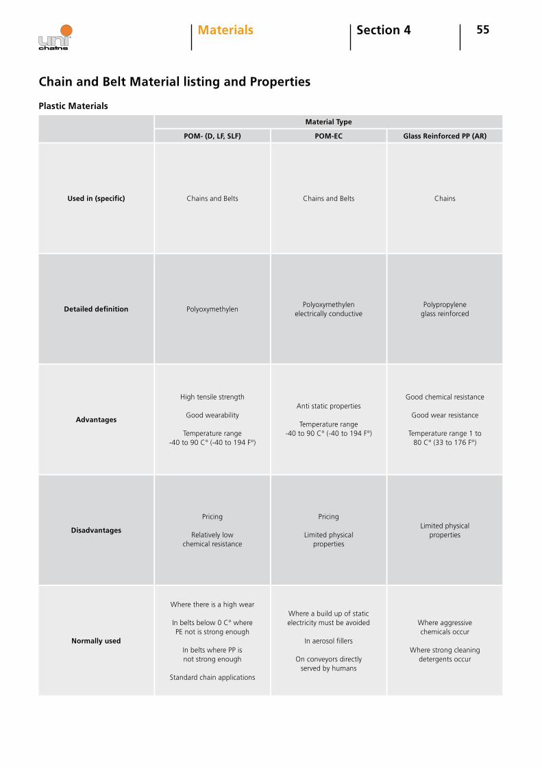
55
Chain and Belt Material listing and Properties
Material Type
POM- (D, LF, SLF)
Used in (specific) Chains and Belts Chains and Belts Chains
POM-EC Glass Reinforced PP (AR)
Plastic Materials
PolyoxymethylenPolyoxymethylen
electrically conductivePolypropylene
glass reinforced
High tensile strength
Good wearability
Temperature range -40 to 90 C° (-40 to 194 F°)
Anti static properties
Temperature range -40 to 90 C° (-40 to 194 F°)
Good chemical resistance
Good wear resistance
Temperature range 1 to 80 C° (33 to 176 F°)
Pricing
Relatively low chemical resistance
Pricing
Limited physical properties
Limited physical properties
Where there is a high wear
In belts below 0 C° where PE not is strong enough
In belts where PP is not strong enough
Standard chain applications
Where a build up of static electricity must be avoided
In aerosol fillers
On conveyors directly served by humans
Where aggressive chemicals occur
Where strong cleaning detergents occur
Detailed definition
Advantages
Disadvantages
Normally used
Section 4Materials
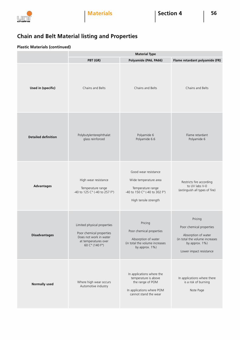
56
Chain and Belt Material listing and Properties
Material Type
PBT (GR)
Used in (specific) Chains and Belts Chains and Belts Chains and Belts
Polyamide (PA6, PA66) Flame retardant polyamide (FR)
Plastic Materials (continued)
Polybutylenterephthalat glass reinforced
Polyamide 6Polyamide 6.6
Flame retardant Polyamide 6
High wear resistance
Temperature range -40 to 125 C° (-40 to 257 F°)
Good wear resistance
Wide temperature area
Temperature range -40 to 150 C° (-40 to 302 F°)
High tensile strength
Restricts fire according to UV labs V-0
(extinguish all types of fire)
Limited physical properties
Poor chemical propertiesDoes not work in water
at temperatures over 60 C° (140 F°)
Pricing
Poor chemical properties
Absorption of water (in total the volume increases
by approx. 1%)
Pricing
Poor chemical properties
Absorption of water (in total the volume increases
by approx. 1%)
Lower impact resistance
Where high wear occursAutomotive industry
In applications where the temperature is above
the range of POM
In applications where POM cannot stand the wear
In applications where there is a risk of burning
Note Page
Detailed definition
Advantages
Disadvantages
Normally used
Section 4Materials

57
Chain and Belt Material listing and Properties
Material Type
Polycarbonate (PC)
Used in (specific)Chains
(Snap-On chains only)Chains and Belts Belts
Polyvinylidenfluoride (PVDF) Xenoy (Xenoy)
Plastic Materials (continued)
Polycarbonate Polyvinylidenfluoride Xenoy
Very high impact strength
Temperature range -20 to 135 C° (-4 to 275 F°)
Good wear resistance
Temperature range -40 to 100 C° (-40 to 212 F°)
High chemical resistance
High impact resistance
Temperature range -70 to 80 C° (-94 to 176 F°)
Poor creep properties
Impact properties disappear below 29 C° (84 F°)
PricingLow tensile strength
Low wear resistance
Where high impact occursWhere aggressive chemicals occur
In applications where the temperature is low
In applications with high impacts
Detailed definition
Advantages
Disadvantages
Normally used
Section 4Materials

58
Chain and Belt Material listing and Properties
Material Type
Polyethylene (PE)
Used in (specific) Belts Belts -
Polypropylene (PP) -
Plastic Materials (continued)
PolyethyleneHigh density
Polypropylene -
Low price
Good chemical resistance
Temperature range -50 to 80 C° (-58 to 176 F°)
High impact strength
Suitable for application with dry ice
Low price
Good chemical resistance
Temperature range 1 to 104 C° (34 to 219 F°)
-
Poor tensile strength
Poor creep properties
Becomes brittle at temperatures below
1 C° (34 F°)
Poor impact strength
Poor tensile strength
-
Freezers
Where a low price material is needed for use below
0C° (32 F°)
Where tensile strength andtemperature enable
it to be used or for chemicalresistance
-
Detailed definition
Advantages
Disadvantages
Normally used
Section 4Materials
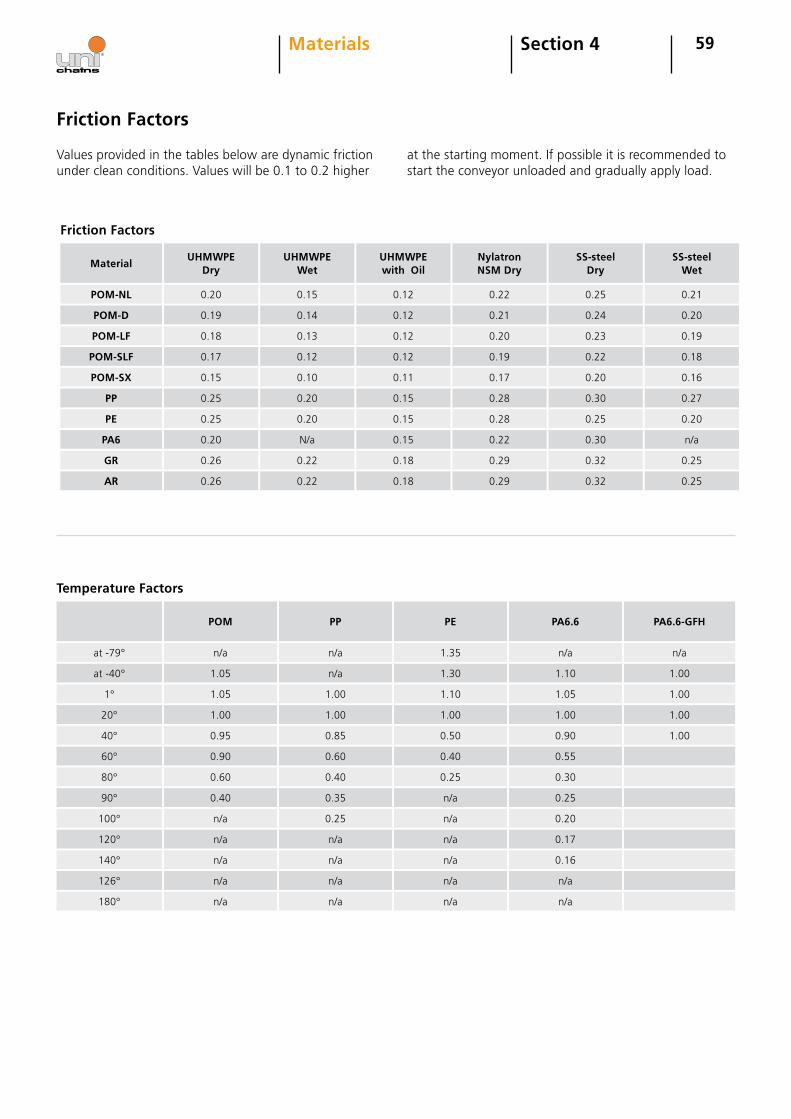
59
Friction Factors
Values provided in the tables below are dynamic friction under clean conditions. Values will be 0.1 to 0.2 higher
at the starting moment. If possible it is recommended to start the conveyor unloaded and gradually apply load.
Section 4Materials
Material
POM-NL
UHMWPE Dry
0.19
0.20
0.17
0.18
0.25
0.15
0.20
0.25
0.26
0.26
Friction Factors
UHMWPE Wet
0.14
0.15
0.12
0.13
0.20
0.10
N/a
0.20
0.22
0.22
UHMWPE with Oil
0.12
0.12
0.12
0.12
0.15
0.11
0.15
0.15
0.18
0.18
NylatronNSM Dry
0.21
0.22
0.19
0.20
0.28
0.17
0.22
0.28
0.29
0.29
SS-steelDry
0.24
0.25
0.22
0.23
0.30
0.20
0.30
0.25
0.32
0.32
SS-steelWet
0.20
0.21
0.18
0.19
0.27
0.16
n/a
0.20
0.25
0.25
POM-D
POM-LF
POM-SLF
POM-SX
PP
PE
PA6
GR
AR
at -79°
POM
1.05
n/a
1.00
1.05
0.90
0.95
0.40
0.60
n/a
n/a
Temperature Factors
PP
n/a
n/a
1.00
1.00
0.60
0.85
0.35
0.40
n/a
0.25
PE
1.30
1.35
1.00
1.10
0.40
0.50
n/a
0.25
n/a
n/a
PA6.6
1.10
n/a
1.00
1.05
0.55
0.90
0.25
0.30
0.17
0.20
PA6.6-GFH
1.00
n/a
1.00
1.00
1.00
at -40°
1°
20°
40°
60°
80°
90°
100°
120°
n/a n/a n/a 0.16140°
n/a n/a n/a n/a126°
n/a n/a n/a n/a180°
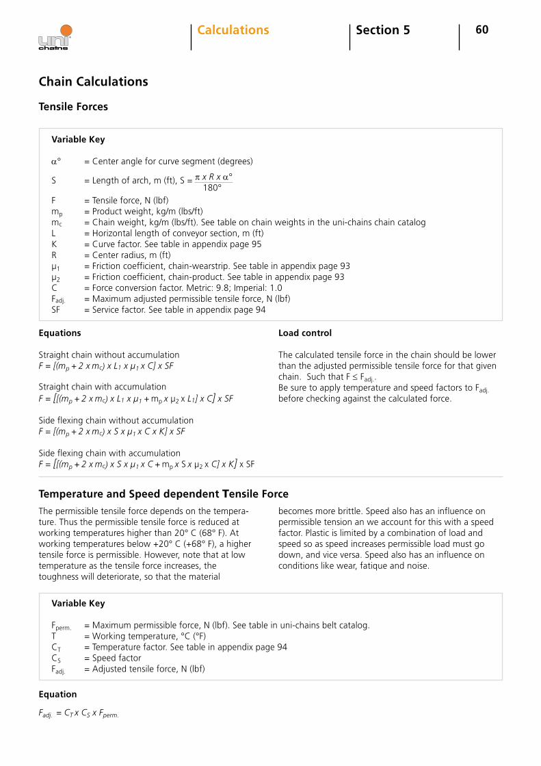
60Section 5Calculations
Chain Calculations
Tensile Forces
Variable Key
a° =Centerangleforcurvesegment(degrees)
S =Lengthofarch,m(ft),S= π x R x a° 180°F =Tensileforce,N(lbf)mp =Productweight,kg/m(lbs/ft)mc =Chainweight,kg/m(lbs/ft).Seetableonchainweightsintheuni-chainschaincatalogL =Horizontallengthofconveyorsection,m(ft)K =Curvefactor.Seetableinappendixpage95R =Centerradius,m(ft)µ1 =Frictioncoefficient,chain-wearstrip.Seetableinappendixpage93µ2 =Frictioncoefficient,chain-product.Seetableinappendixpage93C =Forceconversionfactor.Metric:9.8;Imperial:1.0Fadj. =Maximumadjustedpermissibletensileforce,N(lbf)SF =Servicefactor.Seetableinappendixpage94
Equations
StraightchainwithoutaccumulationF = [(mp + 2 x mc) x L1 x µ1 x C] x SFStraightchainwithaccumulationF = [[(mp + 2 x mc) x L1 x µ1 + mpx µ2xL1] x C] x SFSideflexingchainwithoutaccumulationF = [(mp + 2 x mc) x S x µ1 x C x K] x SF
SideflexingchainwithaccumulationF = [[(mp + 2 x mc) x S x µ1 x C+ mpx Sx µ2xC] x K]xSF
Load control
Thecalculatedtensileforceinthechainshouldbelowerthantheadjustedpermissibletensileforceforthatgivenchain.SuchthatF≤Fadj..BesuretoapplytemperatureandspeedfactorstoFadj.beforecheckingagainstthecalculatedforce.
Temperature and Speed dependent Tensile Force
Thepermissibletensileforcedependsonthetempera-ture.Thusthepermissibletensileforceisreducedatworkingtemperatureshigherthan20°C(68°F).Atworkingtemperaturesbelow+20°C(+68°F),ahighertensileforceispermissible.However,notethatatlowtemperatureasthetensileforceincreases,thetoughnesswilldeteriorate,sothatthematerial
Variable Key
Fperm. =Maximumpermissibleforce,N(lbf).Seetableinuni-chainsbeltcatalog.T =Workingtemperature,°C(°F)CT =Temperaturefactor.Seetableinappendixpage94CS =SpeedfactorFadj. =Adjustedtensileforce,N(lbf)
Equation
Fadj. = CT x CS x Fperm.
becomesmorebrittle.Speedalsohasaninfluenceonpermissibletensionanweaccountforthiswithaspeedfactor.Plasticislimitedbyacombinationofloadandspeedsoasspeedincreasespermissibleloadmustgodown,andviceversa.Speedalsohasaninfluenceonconditionslikewear,fatiqueandnoise.
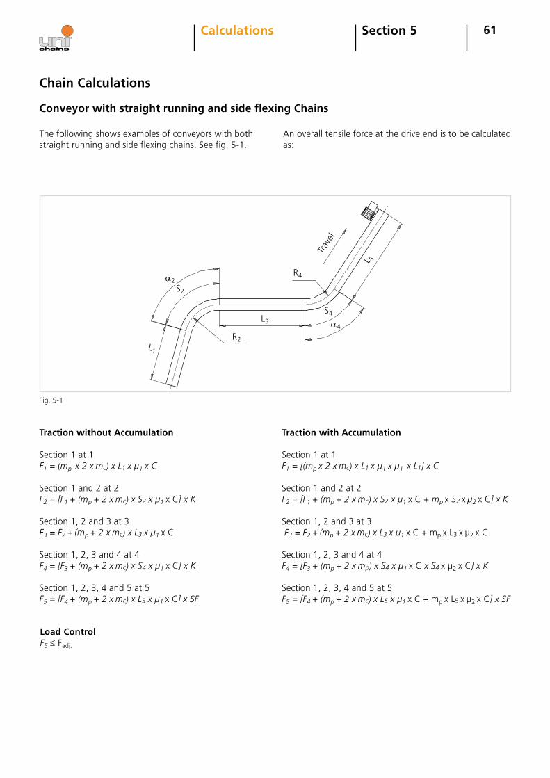
61Section 5Calculations
Chain Calculations
Conveyor with straight running and side flexing Chains
Thefollowingshowsexamplesofconveyorswithbothstraightrunningandsideflexingchains.Seefig.5-1.
Traction without Accumulation
Section1at1F1 = (mp x 2 x mc) x L1 x µ1 x CSection1and2at2F2 = [F1 + (mp + 2 x mc) x S2 x µ1 xC] x K
Section1,2and3at3F3 = F2 + (mp + 2 x mc) x L3 x µ1 xC
Section1,2,3and4at4F4 = [F3 + (mp + 2 x mc) x S4 x µ1 xC] x K
Section1,2,3,4and5at5F5 = [F4 + (mp + 2 x mc) x L5 x µ1 xC] x SF
Traction with Accumulation
Section1at1F1 = [(mp x 2 x mc) x L1 x µ1 x µ1 x L1] x C
Section1and2at2F2 = [F1 + (mp + 2 x mc) x S2 x µ1 xC+mp xS2 x µ2 xC] x K
Section1,2and3at3F3 = F2 + (mp + 2 x mc) x L3 x µ1 xC+mpxL3xµ2xC
Section1,2,3and4at4F4 = [F3 + (mp + 2 x mp) x S4 x µ1 xC x S4 xµ2xC] x K
Section1,2,3,4and5at5F5 = [F4 + (mp + 2 x mc) x L5 x µ1 xC + mpxL5xµ2xC]x SF
Load ControlF5≤Fadj.
Anoveralltensileforceatthedriveendistobecalculatedas:
Fig.5-1
S2
R2L1
L3
R4
S4
a2
a4
L 5
Trav
el
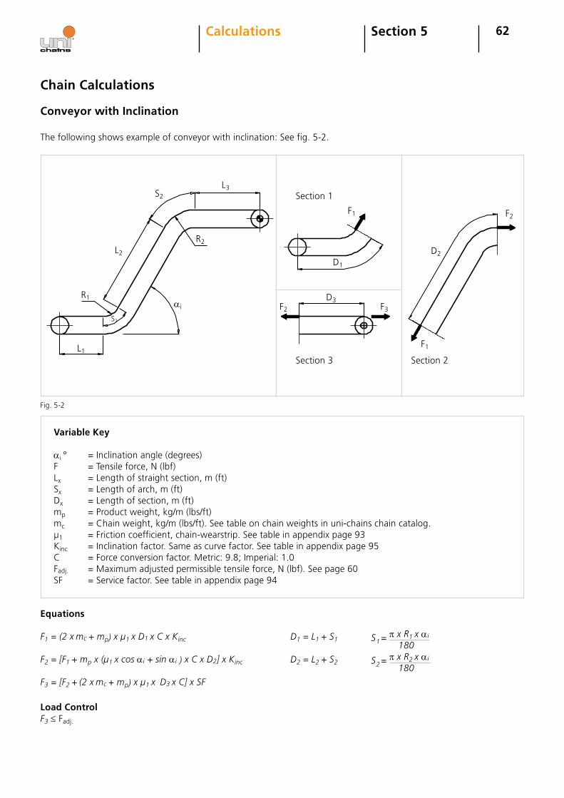
62Section 5Calculations
Conveyor with Inclination
Variable Key
ai° =Inclinationangle(degrees)F =Tensileforce,N(lbf)Lx =Lengthofstraightsection,m(ft)Sx =Lengthofarch,m(ft)Dx =Lengthofsection,m(ft)mp =Productweight,kg/m(lbs/ft)mc =Chainweight,kg/m(lbs/ft).Seetableonchainweightsinuni-chainschaincatalog.µ1 =Frictioncoefficient,chain-wearstrip.Seetableinappendixpage93Kinc =Inclinationfactor.Sameascurvefactor.Seetableinappendixpage95C =Forceconversionfactor.Metric:9.8;Imperial:1.0Fadj. =Maximumadjustedpermissibletensileforce,N(lbf).Seepage60SF =Servicefactor.Seetableinappendixpage94
Equations
F1 = (2 x mc + mp) x µ1 x D1 x C x KincF2 = [F1 + mp x (µ1 x cos ai + sin ai ) x C x D2] x Kinc
F3 = [F2 + (2 x mc + mp) x µ1 x D3 x C] x SF
Load ControlF3≤Fadj.
Chain Calculations
D1 = L1 + S1
D2 = L2 + S2
S = π x R1 x ai 1 180
S = π x R2 x ai 2 180
Fig.5-2
ai
S2
L3
L2
R2
R1
S1
L1
F1
D1
D3
F2
F3F2
F1
Section1
Section3 Section2
D2
Thefollowingshowsexampleofconveyorwithinclination:Seefig.5-2.
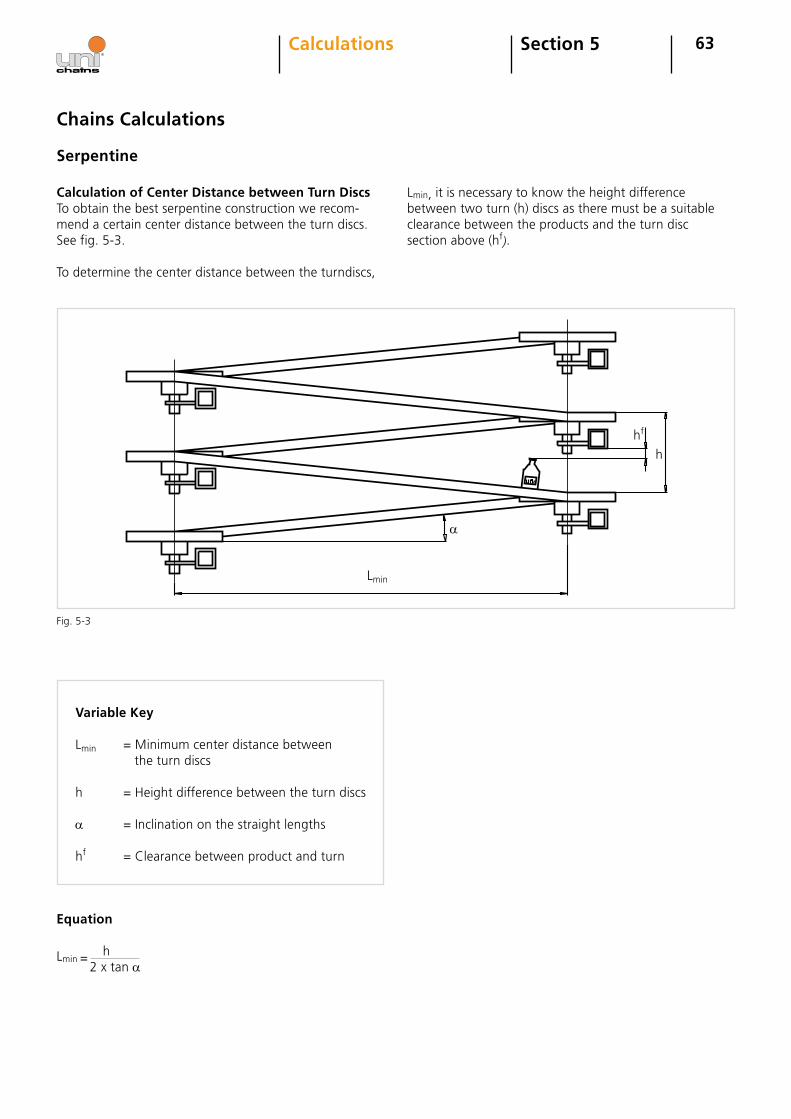
63
Variable Key
Lmin =Minimumcenterdistancebetweentheturndiscs
h =Heightdifferencebetweentheturndiscs
a =Inclinationonthestraightlengths
hf =Clearancebetweenproductandturn
Calculation of Center Distance between Turn DiscsToobtainthebestserpentineconstructionwerecom-mendacertaincenterdistancebetweentheturndiscs.Seefig.5-3.
Todeterminethecenterdistancebetweentheturndiscs,
Chains Calculations
Serpentine
Equation
Lmin= h2xtana
Lmin,itisnecessarytoknowtheheightdifferencebetweentwoturn(h)discsastheremustbeasuitableclearancebetweentheproductsandtheturndiscsectionabove(hf).
Calculations
Fig.5-3
Section 5
h
hf
Lmin
a
64Section 5Calculations
Determination of Tensile Force in the Chain
Chain Calculations
Serpentine
Variable Key
FC =Tensileforceinthechain,N(lbf)A =Tensileforceperstraightlength,N(lbf)L =Centerdistancebetweenturndiscs,m(ft)L≥ Lmin.mp =Productweight,kg/m(lbs/ft)mc =Chainweight,kg/m(lbs/ft).Seetableonchainweightsinuni-chainschaincatalog.µ1 =Frictioncoefficient,chain-wearstrip.Seetableinappendixpage93µ2 =Frictioncoefficient,chain-product.Seetableinappendixpage93ai° =InclinationangleforstraightsectionR =Turndiscradius,m(ft)C =Forceconversionfactor.Metric:9.8;Imperial:1.0Fadj. =Maximumadjustedpermissibletensileforce,N(lbf).Seepage60SF =Servicefactor.Seetableinappendixpage93
Equations
FC=[∑ A]xSF
A = [ L [(mc + mp)(sin ai + µ1 x cos ai) + mp x µ2 x cos ai] + π x R x [µ1 x (mp + mc) + µ2 x mp]] x C cos aLoad Control
FC≤ Fadj.
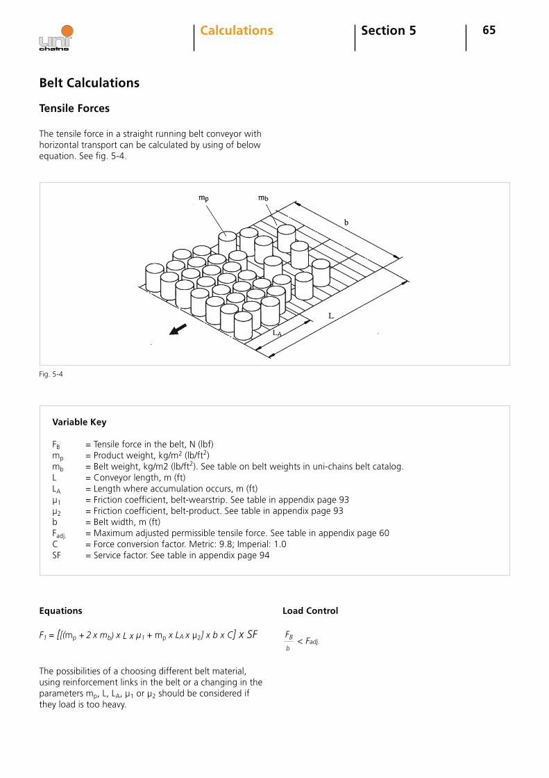
65Section 5Calculations
Belt Calculations
Tensile Forces
Variable Key
FB =Tensileforceinthebelt,N(lbf)mp =Productweight,kg/m2(lb/ft2)mb =Beltweight,kg/m2(lb/ft2).Seetableonbeltweightsinuni-chainsbeltcatalog.L =Conveyorlength,m(ft)LA =Lengthwhereaccumulationoccurs,m(ft)µ1 =Frictioncoefficient,belt-wearstrip.Seetableinappendixpage93µ2 =Frictioncoefficient,belt-product.Seetableinappendixpage93b =Beltwidth,m(ft)Fadj. =Maximumadjustedpermissibletensileforce.Seetableinappendixpage60C =Forceconversionfactor.Metric:9.8;Imperial:1.0SF =Servicefactor.Seetableinappendixpage94
Equations
F1 = [[(mp + 2 x mb) x L x µ1 + mp x LA x µ2] x b x C] x SF
Load Control
Thepossibilitiesofachoosingdifferentbeltmaterial,usingreinforcementlinksinthebeltorachangingintheparametersmp,L,LA,µ1orµ2shouldbeconsiderediftheyloadistooheavy.
FB b
<Fadj.
Fig.5-4
Thetensileforceinastraightrunningbeltconveyorwithhorizontaltransportcanbecalculatedbyusingofbelowequation.Seefig.5-4.
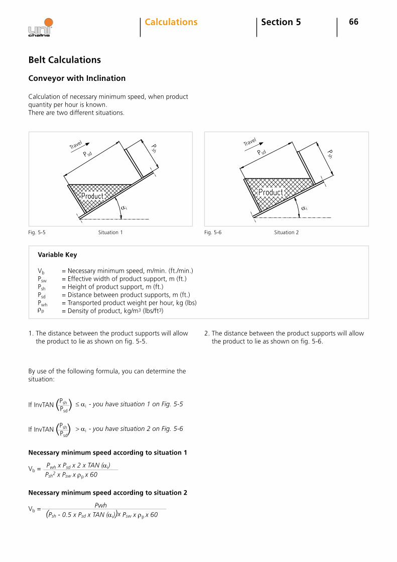
Travel
66
Conveyor with Inclination
Calculationofnecessaryminimumspeed,whenproductquantityperhourisknown.Therearetwodifferentsituations.
1.Thedistancebetweentheproductsupportswillallowtheproducttolieasshownonfig.5-5.
2.Thedistancebetweentheproductsupportswillallowtheproducttolieasshownonfig.5-6.
Fig.5-5 Fig.5-6
Byuseofthefollowingformula,youcandeterminethesituation:
IfInvTAN(Psh)
Psd≤ ai- you have situation 1 on Fig. 5-5
IfInvTAN(Psh)
Psd> ai- you have situation 2 on Fig. 5-6
Necessary minimum speed according to situation 1
Vb = Pwh x Psd x 2 x TAN (ai) Psh2 x Psw x ρpx 60
Necessary minimum speed according to situation 2
Vb = Pwh (Psh - 0.5 x Psd x TAN (ai))x Psw x ρpx 60
Section 5Calculations
Variable Key
Vb =Necessaryminimumspeed,m/min.(ft./min.)Psw =Effectivewidthofproductsupport,m(ft.)Psh =Heightofproductsupport,m(ft.)Psd =Distancebetweenproductsupports,m(ft.)Pwh =Transportedproductweightperhour,kg(lbs)ρp =Densityofproduct,kg/m3(lbs/ft3)
P sd P sd
Psh
a i
Travel
a i
Psh
Belt Calculations
Situation1 Situation2
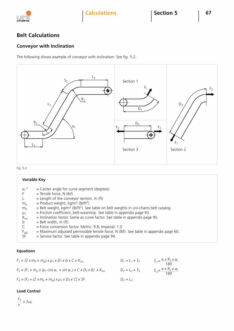
67
Conveyor with Inclination
Variable Key
ai° =Centerangleforcurvesegment(degrees)F =Tensileforce,N(lbf)L =Lengthoftheconveyorsection,m(ft)mp =Productweight,kg/m2(lb/ft2)mb =Beltweight,kg/m2(lb/ft2).Seetableonbeltweightsinuni-chainsbeltcatalog.µ1 =Frictioncoefficient,belt-wearstrip.Seetableinappendixpage93.Kinc =Inclinationfactor.Sameascurvefactor.Seetableinappendixpage95.b =Beltwidth,m(ft)C =Forceconversionfactor.Metric:9.8;Imperial:1.0Fadj. =Maximumadjustedpermissibletensileforce,N(lbf).Seetableinappendixpage60.SF =Servicefactor.Seetableinappendixpage94.
Section 5Calculations
Load Control
Equations
F1 = (2 x mb + mp) x µ1 x D1 x b x C x KincF2 = [F1 + mp x (µ1 cos ai + sin ai) x C x D2 x b] x Kinc
F3 = [F2 + (2 x mb + mp) x µ1 x D3 x C] x SF
F3 b
≤Fadj.
D1 = L1 + S1
D2 = L2 + S2
D3 = L3
S = π x R1 x ai 1 180
S = π x R2 x ai 2 180
Belt Calculations
Fig.5-2
ai
S2
L3
L2
R2
R1
S1
L1
F1
D1
D3
F2
F3F2
F1
Section1
Section3 Section2
D2
Thefollowingshowsexampleofconveyorwithinclination:Seefig.5-2.

68Section 5Calculations
Belt Calculations
Reinforcement of Belt Systems
Variable Key
FB,b =Tensileforceinthebelt,N/m(lbf/ft)Eperm. =Maximumpermissibletensileforceforthereinforcementlinks,N/pcs(lbf/pcs)nmod. =Numberofreinforcementlinkspermodule,Eanmet. =Numberofreinforcementlinkspermeter,Eanft. =Numberofreinforcementlinksperfeet,Ea
Permissible tensile force for the reinforcement links Eperm. can be found in the uni-chains belt catalog.
*Note: uni Flex SNB can only accommodate two rows of reinforcement links on the outer edge of the turn radius.
Required number of reinforcement links per meter
Required number of reinforcement links per module
nmet.
Metric Imperial
≥ FB,b
Eperm.
nmod = nmet. 6.56
nmod = nft. 2
Metric Imperial
nft. ≥ FB,b
Eperm.
69Section 5Calculations
Expansion and Contraction of the Belt
Belt Calculations
Expansion/contractionofthebeltmayoccuratspecialworkingconditionswherethebeltisexposedtochangesintemperature.
Variable Key
∆L =Length/Widthexpansion,mm(in.)L =Length/WidthofbeltattemperatureT1,m(ft)T2 =Workingtemperature,°C(°F)T1 =Surroundingtemperature,°C(°F)ec =Expansioncoefficient.Seetablebelow.
Expansion Coefficients (ec)
The change in belt dimensions formula
PP
POM
PE
0.13
0.12
mmm x °C
0.18
0.0009
0.0008
in.ft x °F
0.0012
Expansion/contractioninthelongitudinaldirectioncanbeavoidedbyuseofsteelreinforcementlinks.
∆L = L x ec x (T2 - T1)
Determining Number of Sprockets for Belt Systems
Thenumberofsprocketsrequiredforthebeltconveyordependsontheloadonthebeltandthetemperatureunderwhichtheconveyorisworking.Asaruleofthumb
uni-chainsrecommendsaminimumofonesprocketper6in.module.Belowistheequationtodeterminetheminimumnumberofsprocketsneeded.
Metric Imperial
nsp. ≈ b 0.1524
+1 nsp. = b 0.5
+1
Suchchangesinthebeltwidthandbeltlengthmustbetakenintoconsiderationwhentheconveyoriscon-structed.
PA6/PA6.6 0.11 0.0007
Variable Key
nsp =Minimumnumberofsprocketsrequiredforthebelt,Eab =Beltwidth,m(ft)SPperm. =Permissibleloadpersprocket,N/Ea(lbf/Ea).Seeuni-chainsbeltcatalog.FB =Tensileforceinthebelt,N(lbf).
70Section 5Calculations
Permissibleloadpersprocketdiffersforeachbeltandmaterialcombinationandcanbefoundintheuni-chainsbeltcatalog.Caremustbetakenthattheselectedbeltcanaccommodatethenumberofsprocketsrequired.Numberofsprocketpaths,placementoftabsandrein-forcementlinksmustbeconsideredwhendeterminingthepossiblenumberofsprockets.
Afterhavingcalculatedthequantityofsprockets,itisnecessarytomakeacontrolinordertosee,ifthereareenoughsprocketsconsideringtheload.
Byuseofthefollowingformula,youcancontrolthis.
Belt Calculations
Determining Number of Sprockets for Belt Systems
nsp ≥ FB
SPperm.
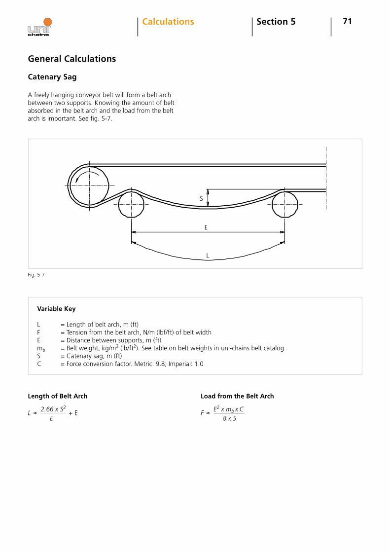
Fig.5-7
S
E
L
71
General Calculations
Catenary Sag
Variable Key
L =Lengthofbeltarch,m(ft)F =Tensionfromthebeltarch,N/m(lbf/ft)ofbeltwidthE =Distancebetweensupports,m(ft)mb =Beltweight,kg/m2(lb/ft2).Seetableonbeltweightsinuni-chainsbeltcatalog.S =Catenarysag,m(ft)C =Forceconversionfactor.Metric:9.8;Imperial:1.0
Length of Belt Arch Load from the Belt Arch
L ≈ 2.66 x S2
E+E F ≈ E
2 x mb x C
8 x S
Section 5Calculations
Afreelyhangingconveyorbeltwillformabeltarchbetweentwosupports.Knowingtheamountofbeltabsorbedinthebeltarchandtheloadfromthebeltarchisimportant.Seefig.5-7.

72
Dimensioning of the Motor
Variable Key
P =Therequiredpower,kW(HP)F =Tensileforceinbeltorchain,N(lbf)v =Beltorchainspeed,m/min.(ft/min.)η =EfficiencyofgearT =Torqueondriveshaft,Nm(lbfft)GR =GearratioRdm =Numberofrevolutionsondrivemotor,rpmRds =Numberofrevolutionsondriveshaft,rpmPd =Pitchdiameterofdrivesprocket,mm(in.)
Required Power
P = F x v
60000 x η
Note: In this formula allowance for losses is not made in other mechanical parts than the gear. When calculating conveyors with inclination, allowance must be made for the energy required for lifting the product and then chain or belt.
Section 5Calculations
Belt Calculations
Metric Imperial
P = F x v
33000 x η
Torque on Drive Shaft
T = F x Pd
2000
Metric Imperial
T = F x Pd
24
Number of Revolutions on Drive Shaft, rpm
Rds= v x 1000Pdx π
Metric Imperial
Rds= v x 12Pdx π
Number of Revolutions on Drive Motor
Rdm=Rdsx GR
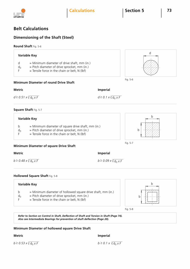
d
b
b
b
b
73Section 5Calculations
Belt Calculations
Dimensioning of the Shaft (Steel)
Variable Key
d =Minimumdiameterofdriveshaft,mm(in.)d0 =Pitchdiameterofdrivesprocket,mm(in.)F =Tensileforceinthechainorbelt,N(lbf)
Round Shaft Fig.5-6
Minimum Diameter of round Drive Shaft
d0 x F
Metric Imperial
d ≥ 0.51 x √3 d0 x Fd ≥ 0.1 x √3
Square Shaft Fig.5-7
Variable Key
b =Minimumdiameterofsquaredriveshaft,mm(in.)d0 =Pitchdiameterofdrivesprocket,mm(in.)F =Tensileforceinthechainorbelt,N(lbf)
Minimum Diameter of square Drive Shaft
d0 x F
Metric Imperial
b ≥ 0.48 x √3 d0 x Fb ≥ 0.09 x √3
Hollowed Square Shaft Fig.5-8
Variable Key
b =Minimumdiameterofhollowedsquaredriveshaft,mm(in.)d0 =Pitchdiameterofdrivesprocket,mm(in.)F =Tensileforceinthechainorbelt,N(lbf)
Refer to Section on Control in Shaft, Deflection of Shaft and Torsion in Shaft (Page 74). Also see Intermediate Bearings for prevention of shaft deflection (Page 20).
Fig.5-6
Fig.5-7
Fig.5-8
Minimum Diameter of hollowed square Drive Shaft
d0 x F
Metric Imperial
b ≥ 0.53 x √3 d0 x Fb ≥ 0.1 x √3
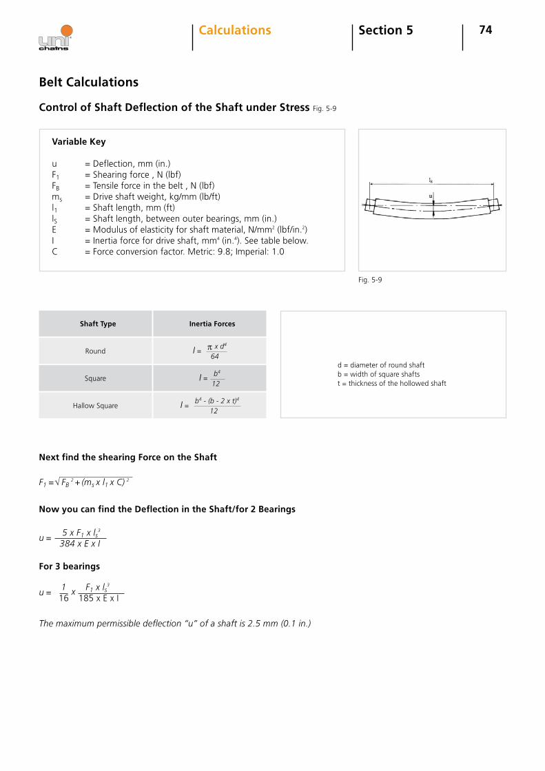
74
Next find the shearing Force on the Shaft
Now you can find the Deflection in the Shaft/for 2 Bearings
For 3 bearings
The maximum permissible deflection “u” of a shaft is 2.5 mm (0.1 in.)
√F1 = FB 2 + (ms x l1 x C)
2
u= 5 x F1 x ls
3
384 x E x I
u= 1 x F1 x ls
3
16 185xExI
Section 5Calculations
Belt Calculations
Control of Shaft Deflection of the Shaft under Stress Fig.5-9
Variable Key
u =Deflection,mm(in.)F1 =Shearingforce,N(lbf)FB =Tensileforceinthebelt,N(lbf)ms =Driveshaftweight,kg/mm(lb/ft)l1 =Shaftlength,mm(ft)lS =Shaftlength,betweenouterbearings,mm(in.)E =Modulusofelasticityforshaftmaterial,N/mm2(lbf/in.2)I =Inertiaforcefordriveshaft,mm4(in.4).Seetablebelow.C =Forceconversionfactor.Metric:9.8;Imperial:1.0
Fig.5-9
d=diameterofroundshaftb=widthofsquareshaftst=thicknessofthehollowedshaft
Square
Round
Shaft Type
I = b4
12
I = π x d4
64
Inertia Forces
HallowSquare I = b4 - (b - 2 x t)4
12
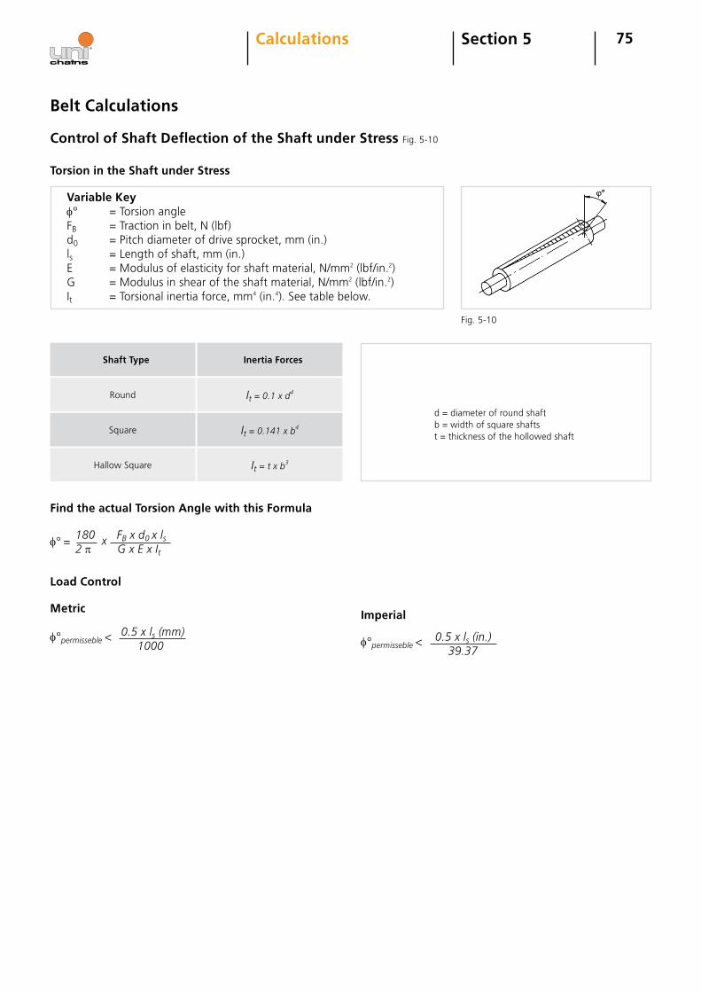
75Section 5Calculations
Control of Shaft Deflection of the Shaft under Stress Fig.5-10
Belt Calculations
Torsion in the Shaft under Stress
Variable Keyφ° =TorsionangleFB =Tractioninbelt,N(lbf)d0 =Pitchdiameterofdrivesprocket,mm(in.)ls =Lengthofshaft,mm(in.)E =Modulusofelasticityforshaftmaterial,N/mm2(lbf/in.2)G =Modulusinshearoftheshaftmaterial,N/mm2(lbf/in.2)It =Torsionalinertiaforce,mm4(in.4).Seetablebelow.
d=diameterofroundshaftb=widthofsquareshaftst=thicknessofthehollowedshaft
Square
Round
Shaft Type
It = 0.141 x b4
It = 0.1 x d4
Inertia Forces
HallowSquare It = t x b3
Find the actual Torsion Angle with this Formula
Load Control
φ°=180 x FB x d0 x ls2 π G x E x It
φ°permisseble<0.5 x ls (mm) 1000
Metric Imperial
φ°permisseble< 0.5 x ls (in.) 39.37
Fig.5-10
76Section 6Installation, Maintenan- ce & Troubleshooting
Installation Guidelines
Assembly instructions for uni-chains belts with various locking systems are available. Please contact uni-chains for these instructions or download them at www.unichains.com
Maintenance Guidelines
Service
All parts of a conveyor should be inspected regularly to ensure the longest wear life possible for chain and wearstrips. The following points should be controlled at the inspection:
1. Examine the chain wear2. Check that the chain can run freely between the wearstrips, at transfer plates etc.
Replacement of Conveyor Parts
Chain and belt should be replaced when:1. The chain has been extended so much that it does not fit the drive sprocket.2. The chain is worn below half the plate thickness.3. The chain surface is worn unevenly.4. The bottom parts of the chain is worn so much that the pins are laid bare. The pins can then damage the wearstrips and other conveyor parts.5. Tab or belt edge is worn on side flexing belts.
Sprockets should be replaced when:1. The tooth profiles are worn.2. The chain jumps the sprocket.
Wearstrips should be replaced when:1. They are worn 50%.2. The surface finish has become rough.3. Hard particles have become embedded into the wearstrip material.
Special care must be taken to inspect curved wearstrip sections for wear, since excessive wear can result in the chain pulling out of the conveyor in curves.
3. Check the chain for cracks4. Check the chain for elongation/catenary sag5. Examine the chain sprockets for wear6. Examine the wearstrips7. Check shoes and rollers for wear
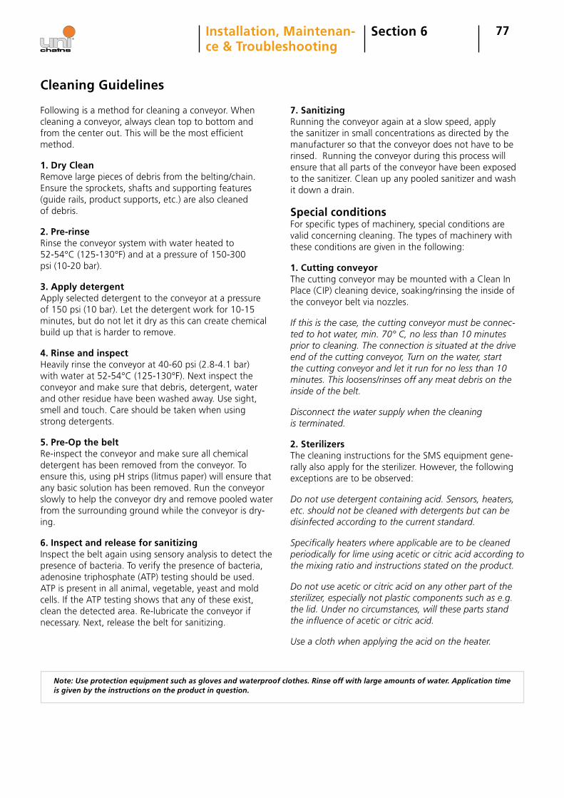
77Section 6Installation, Maintenan- ce & Troubleshooting
Cleaning Guidelines
Following is a method for cleaning a conveyor. When cleaning a conveyor, always clean top to bottom and from the center out. This will be the most efficient method.
1. Dry Clean Remove large pieces of debris from the belting/chain. Ensure the sprockets, shafts and supporting features (guide rails, product supports, etc.) are also cleaned of debris.
2. Pre-rinse Rinse the conveyor system with water heated to 52-54°C (125-130°F) and at a pressure of 150-300 psi (10-20 bar).
3. Apply detergent Apply selected detergent to the conveyor at a pressure of 150 psi (10 bar). Let the detergent work for 10-15 minutes, but do not let it dry as this can create chemical build up that is harder to remove.
4. Rinse and inspectHeavily rinse the conveyor at 40-60 psi (2.8-4.1 bar) with water at 52-54°C (125-130°F). Next inspect the conveyor and make sure that debris, detergent, water and other residue have been washed away. Use sight, smell and touch. Care should be taken when using strong detergents.
5. Pre-Op the belt Re-inspect the conveyor and make sure all chemical detergent has been removed from the conveyor. To ensure this, using pH strips (litmus paper) will ensure that any basic solution has been removed. Run the conveyor slowly to help the conveyor dry and remove pooled water from the surrounding ground while the conveyor is dry-ing.
6. Inspect and release for sanitizing Inspect the belt again using sensory analysis to detect the presence of bacteria. To verify the presence of bacteria, adenosine triphosphate (ATP) testing should be used. ATP is present in all animal, vegetable, yeast and mold cells. If the ATP testing shows that any of these exist, clean the detected area. Re-lubricate the conveyor if necessary. Next, release the belt for sanitizing.
7. Sanitizing Running the conveyor again at a slow speed, apply the sanitizer in small concentrations as directed by the manufacturer so that the conveyor does not have to be rinsed. Running the conveyor during this process will ensure that all parts of the conveyor have been exposed to the sanitizer. Clean up any pooled sanitizer and wash it down a drain.
Special conditionsFor specific types of machinery, special conditions are valid concerning cleaning. The types of machinery with these conditions are given in the following:
1. Cutting conveyor The cutting conveyor may be mounted with a Clean In Place (CIP) cleaning device, soaking/rinsing the inside of the conveyor belt via nozzles.
If this is the case, the cutting conveyor must be connec-ted to hot water, min. 70° C, no less than 10 minutes prior to cleaning. The connection is situated at the drive end of the cutting conveyor, Turn on the water, start the cutting conveyor and let it run for no less than 10 minutes. This loosens/rinses off any meat debris on the inside of the belt.
Disconnect the water supply when the cleaning is terminated.
2. SterilizersThe cleaning instructions for the SMS equipment gene-rally also apply for the sterilizer. However, the following exceptions are to be observed:
Do not use detergent containing acid. Sensors, heaters, etc. should not be cleaned with detergents but can be disinfected according to the current standard.
Specifically heaters where applicable are to be cleaned periodically for lime using acetic or citric acid according to the mixing ratio and instructions stated on the product.
Do not use acetic or citric acid on any other part of the sterilizer, especially not plastic components such as e.g. the lid. Under no circumstances, will these parts stand the influence of acetic or citric acid.
Use a cloth when applying the acid on the heater.
Note: Use protection equipment such as gloves and waterproof clothes. Rinse off with large amounts of water. Application time is given by the instructions on the product in question.
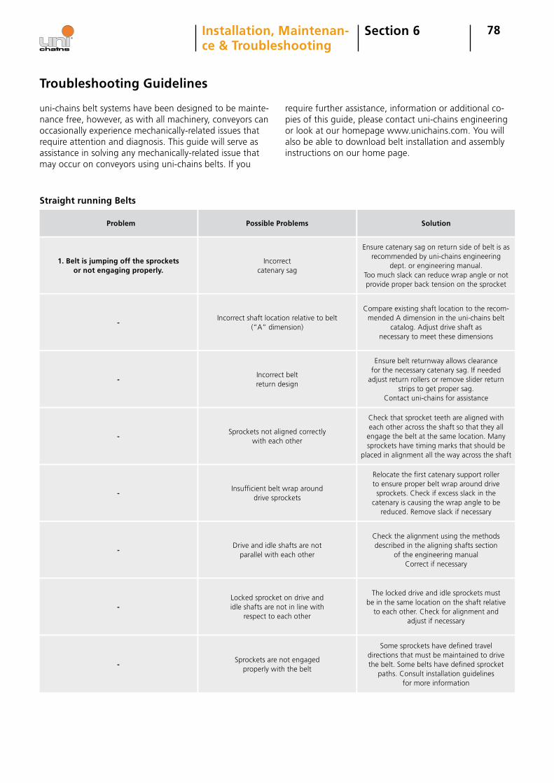
78
Troubleshooting Guidelines
uni-chains belt systems have been designed to be mainte-nance free, however, as with all machinery, conveyors can occasionally experience mechanically-related issues that require attention and diagnosis. This guide will serve as assistance in solving any mechanically-related issue that may occur on conveyors using uni-chains belts. If you
require further assistance, information or additional co-pies of this guide, please contact uni-chains engineering or look at our homepage www.unichains.com. You will also be able to download belt installation and assembly instructions on our home page.
Straight running Belts
Section 6Installation, Maintenan- ce & Troubleshooting
1. Belt is jumping off the sprockets or not engaging properly.
Problem
Incorrect catenary sag
Possible Problems
Ensure catenary sag on return side of belt is as recommended by uni-chains engineering
dept. or engineering manual. Too much slack can reduce wrap angle or not provide proper back tension on the sprocket
Solution
-Incorrect shaft location relative to belt
(“A” dimension)
Compare existing shaft location to the recom-mended A dimension in the uni-chains belt
catalog. Adjust drive shaft as necessary to meet these dimensions
-Incorrect belt return design
Ensure belt returnway allows clearance for the necessary catenary sag. If needed
adjust return rollers or remove slider return strips to get proper sag.
Contact uni-chains for assistance
-Sprockets not aligned correctly
with each other
Check that sprocket teeth are aligned with each other across the shaft so that they all
engage the belt at the same location. Many sprockets have timing marks that should be
placed in alignment all the way across the shaft
-Insufficient belt wrap around
drive sprockets
Relocate the first catenary support roller to ensure proper belt wrap around drive sprockets. Check if excess slack in the
catenary is causing the wrap angle to be reduced. Remove slack if necessary
-Drive and idle shafts are not
parallel with each other
Check the alignment using the methods described in the aligning shafts section
of the engineering manual Correct if necessary
-Locked sprocket on drive and idle shafts are not in line with
respect to each other
The locked drive and idle sprockets must be in the same location on the shaft relative
to each other. Check for alignment and adjust if necessary
-Sprockets are not engaged
properly with the belt
Some sprockets have defined travel directions that must be maintained to drivethe belt. Some belts have defined sprocket
paths. Consult installation guidelines for more information
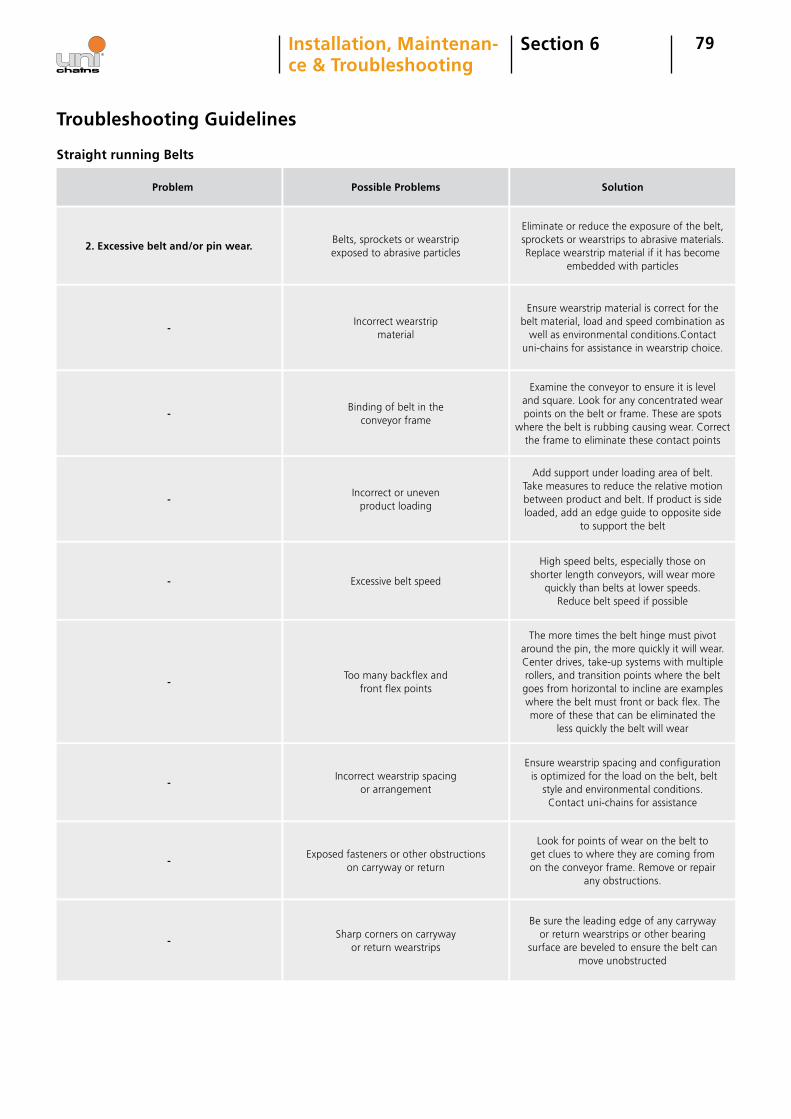
79Section 6Installation, Maintenan- ce & Troubleshooting
2. Excessive belt and/or pin wear.
Problem
Belts, sprockets or wearstrip exposed to abrasive particles
Possible Problems
Eliminate or reduce the exposure of the belt, sprockets or wearstrips to abrasive materials. Replace wearstrip material if it has become
embedded with particles
Solution
Straight running Belts
Troubleshooting Guidelines
-Incorrect wearstrip
material
Ensure wearstrip material is correct for the belt material, load and speed combination as
well as environmental conditions.Contact uni-chains for assistance in wearstrip choice.
-Binding of belt in the
conveyor frame
Examine the conveyor to ensure it is level and square. Look for any concentrated wear points on the belt or frame. These are spots
where the belt is rubbing causing wear. Correct the frame to eliminate these contact points
-Incorrect or uneven
product loading
Add support under loading area of belt. Take measures to reduce the relative motion between product and belt. If product is side loaded, add an edge guide to opposite side
to support the belt
- Excessive belt speed
High speed belts, especially those on shorter length conveyors, will wear more
quickly than belts at lower speeds. Reduce belt speed if possible
-Too many backflex and
front flex points
The more times the belt hinge must pivot around the pin, the more quickly it will wear. Center drives, take-up systems with multiple rollers, and transition points where the belt goes from horizontal to incline are examples where the belt must front or back flex. The more of these that can be eliminated the
less quickly the belt will wear
-Incorrect wearstrip spacing
or arrangement
Ensure wearstrip spacing and configuration is optimized for the load on the belt, belt
style and environmental conditions. Contact uni-chains for assistance
-Exposed fasteners or other obstructions
on carryway or return
Look for points of wear on the belt to get clues to where they are coming from on the conveyor frame. Remove or repair
any obstructions.
-Sharp corners on carryway
or return wearstrips
Be sure the leading edge of any carryway or return wearstrips or other bearing
surface are beveled to ensure the belt can move unobstructed
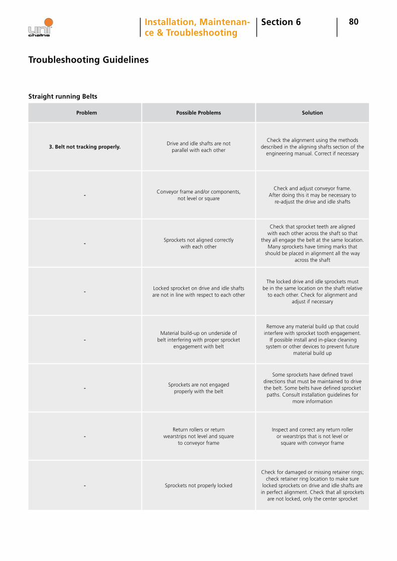
80Section 6Installation, Maintenan- ce & Troubleshooting
3. Belt not tracking properly.
Problem
Drive and idle shafts are not parallel with each other
Possible Problems
Check the alignment using the methods described in the aligning shafts section of the
engineering manual. Correct if necessary
Solution
Straight running Belts
Troubleshooting Guidelines
-Conveyor frame and/or components,
not level or square
Check and adjust conveyor frame. After doing this it may be necessary to
re-adjust the drive and idle shafts
-Sprockets not aligned correctly
with each other
Check that sprocket teeth are aligned with each other across the shaft so that
they all engage the belt at the same location. Many sprockets have timing marks that
should be placed in alignment all the way across the shaft
-Locked sprocket on drive and idle shafts are not in line with respect to each other
The locked drive and idle sprockets must be in the same location on the shaft relative
to each other. Check for alignment and adjust if necessary
-Material build-up on underside of
belt interfering with proper sprocket engagement with belt
Remove any material build up that could interfere with sprocket tooth engagement.
If possible install and in-place cleaning system or other devices to prevent future
material build up
-Sprockets are not engaged
properly with the belt
Some sprockets have defined travel directions that must be maintained to drive the belt. Some belts have defined sprocket paths. Consult installation guidelines for
more information
-Return rollers or return
wearstrips not level and square to conveyor frame
Inspect and correct any return roller or wearstrips that is not level or
square with conveyor frame
- Sprockets not properly locked
Check for damaged or missing retainer rings; check retainer ring location to make sure
locked sprockets on drive and idle shafts are in perfect alignment. Check that all sprockets
are not locked, only the center sprocket
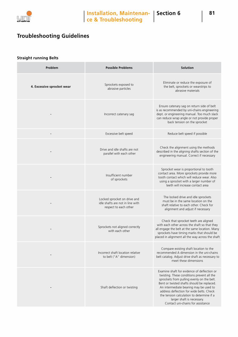
81
4. Excessive sprocket wear
Problem
Sprockets exposed to abrasive particles
Possible Problems
Eliminate or reduce the exposure of the belt, sprockets or wearstrips to
abrasive materials
Solution
Straight running Belts
Troubleshooting Guidelines
- Incorrect catenary sag
Ensure catenary sag on return side of belt is as recommended by uni-chains engineering dept. or engineering manual. Too much slack can reduce wrap angle or not provide proper
back tension on the sprocket
- Excessive belt speed Reduce belt speed if possible
-Drive and idle shafts are not
parallel with each other
Check the alignment using the methods described in the aligning shafts section of the
engineering manual. Correct if necessary
-Insufficient number
of sprockets
Sprocket wear is proportional to tooth contact area. More sprockets provide more tooth contact which will reduce wear. Also using a sprocket with a larger number of
teeth will increase contact area
-Locked sprocket on drive and idle shafts are not in line with
respect to each other
The locked drive and idle sprockets must be in the same location on the
shaft relative to each other. Check for alignment and adjust if necessary
-Sprockets not aligned correctly
with each other
Check that sprocket teeth are aligned with each other across the shaft so that they
all engage the belt at the same location. Many sprockets have timing marks that should be
placed in alignment all the way across the shaft
-Incorrect shaft location relative
to belt (“A” dimension)
Compare existing shaft location to the recommended A dimension in the uni-chains
belt catalog. Adjust drive shaft as necessary to meet these dimensions
- Shaft deflection or twisting
Examine shaft for evidence of deflection or twisting. These conditions prevent all the sprockets from pulling evenly on the belt. Bent or twisted shafts should be replaced. An intermediate bearing may be used to address deflection for wide belts. Check the tension calculation to determine if a
larger shaft is necessary. Contact uni-chains for assistance
Section 6Installation, Maintenan- ce & Troubleshooting
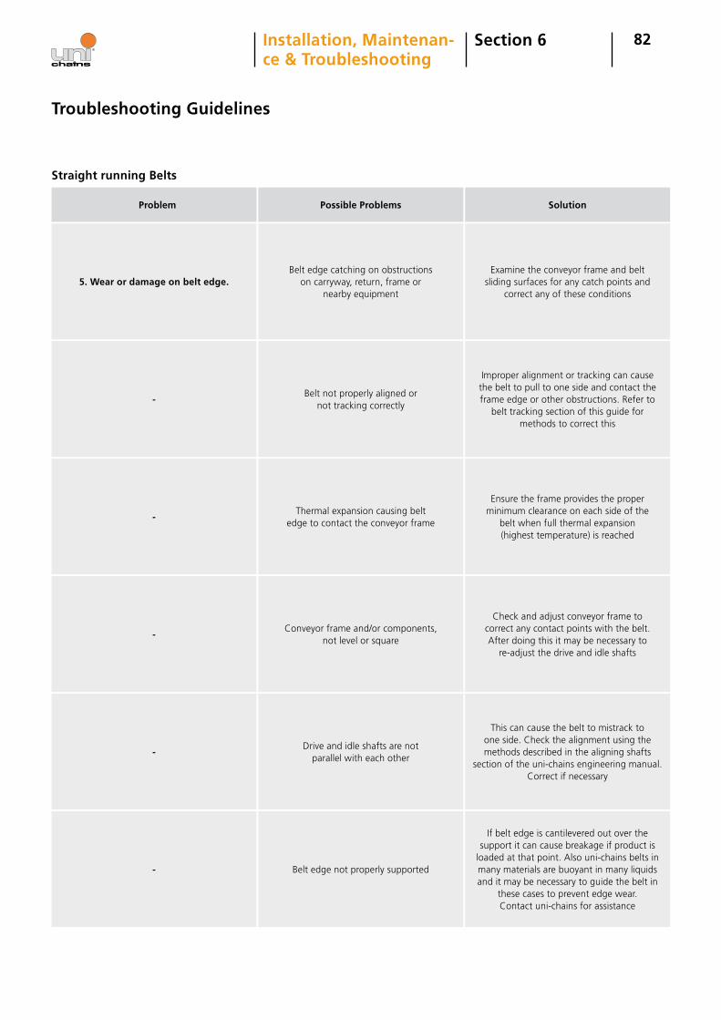
82Section 6Installation, Maintenan- ce & Troubleshooting
5. Wear or damage on belt edge.
Problem
Belt edge catching on obstructions on carryway, return, frame or
nearby equipment
Possible Problems
Examine the conveyor frame and belt sliding surfaces for any catch points and
correct any of these conditions
Solution
Straight running Belts
Troubleshooting Guidelines
-Belt not properly aligned or
not tracking correctly
Improper alignment or tracking can cause the belt to pull to one side and contact the frame edge or other obstructions. Refer to
belt tracking section of this guide for methods to correct this
-Thermal expansion causing belt
edge to contact the conveyor frame
Ensure the frame provides the proper minimum clearance on each side of the
belt when full thermal expansion (highest temperature) is reached
-Conveyor frame and/or components,
not level or square
Check and adjust conveyor frame to correct any contact points with the belt. After doing this it may be necessary to
re-adjust the drive and idle shafts
-Drive and idle shafts are not
parallel with each other
This can cause the belt to mistrack to one side. Check the alignment using the methods described in the aligning shafts
section of the uni-chains engineering manual. Correct if necessary
- Belt edge not properly supported
If belt edge is cantilevered out over the support it can cause breakage if product is
loaded at that point. Also uni-chains belts in many materials are buoyant in many liquids and it may be necessary to guide the belt in
these cases to prevent edge wear. Contact uni-chains for assistance
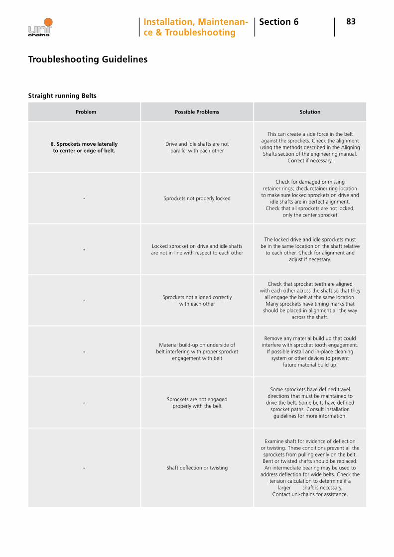
83Section 6Installation, Maintenan- ce & Troubleshooting
6. Sprockets move laterally to center or edge of belt.
Problem
Drive and idle shafts are not parallel with each other
Possible Problems
This can create a side force in the belt against the sprockets. Check the alignment using the methods described in the Aligning Shafts section of the engineering manual.
Correct if necessary.
Solution
Straight running Belts
Troubleshooting Guidelines
- Sprockets not properly locked
Check for damaged or missing retainer rings; check retainer ring location
to make sure locked sprockets on drive and idle shafts are in perfect alignment.
Check that all sprockets are not locked, only the center sprocket.
-Locked sprocket on drive and idle shafts are not in line with respect to each other
The locked drive and idle sprockets must be in the same location on the shaft relative
to each other. Check for alignment and adjust if necessary.
-Sprockets not aligned correctly
with each other
Check that sprocket teeth are aligned with each other across the shaft so that they
all engage the belt at the same location. Many sprockets have timing marks that
should be placed in alignment all the way across the shaft.
-Material build-up on underside of
belt interfering with proper sprocket engagement with belt
Remove any material build up that could interfere with sprocket tooth engagement.
If possible install and in-place cleaning system or other devices to prevent
future material build up.
-Sprockets are not engaged
properly with the belt
Some sprockets have defined travel directions that must be maintained to
drive the belt. Some belts have defined sprocket paths. Consult installation
guidelines for more information.
- Shaft deflection or twisting
Examine shaft for evidence of deflection or twisting. These conditions prevent all the sprockets from pulling evenly on the belt. Bent or twisted shafts should be replaced. An intermediate bearing may be used to
address deflection for wide belts. Check the tension calculation to determine if a
larger shaft is necessary. Contact uni-chains for assistance.
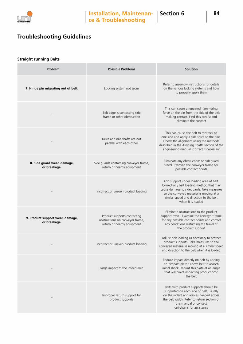
84Section 6Installation, Maintenan- ce & Troubleshooting
Problem Possible Problems Solution
Straight running Belts
Troubleshooting Guidelines
7. Hinge pin migrating out of belt. Locking system not securRefer to assembly instructions for details on the various locking systems and how
to properly apply them
-Belt edge is contacting side frame or other obstruction
This can cause a repeated hammering force on the pin from the side of the belt
making contact. Find this area(s) and eliminate the contact
-Drive and idle shafts are not
parallel with each other
This can cause the belt to mistrack to one side and apply a side force to the pins.
Check the alignment using the methods described in the Aligning Shafts section of the
engineering manual. Correct if necessary
8. Side guard wear, damage, or breakage.
Side guards contacting conveyor frame, return or nearby equipment
Eliminate any obstructions to sideguard travel. Examine the conveyor frame for
possible contact points
- Incorrect or uneven product loading
Add support under loading area of belt. Correct any belt loading method that may
cause damage to sideguards. Take measures so the conveyed material is moving at a similar speed and direction to the belt
when it is loaded
9. Product support wear, damage, or breakage.
Product supports contacting obstructions on conveyor frame,
return or nearby equipment
Eliminate obstructions to the product support travel. Examine the conveyor frame for any possible contact points and correct
any conditions restricting the travel of the product support
- Incorrect or uneven product loading
Adjust belt loading as necessary to protect product supports. Take measures so the
conveyed material is moving at a similar speed and direction to the belt when it is loaded
- Large impact at the infeed area
Reduce impact directly on belt by adding an “impact plate” above belt to absorb
initial shock. Mount this plate at an angle that will direct impacting product onto
the belt
-Improper return support for
product supports
Belts with product supports should be supported on each side of belt, usually
on the indent and also as needed across the belt width. Refer to return section of
this manual or contact uni-chains for assistance
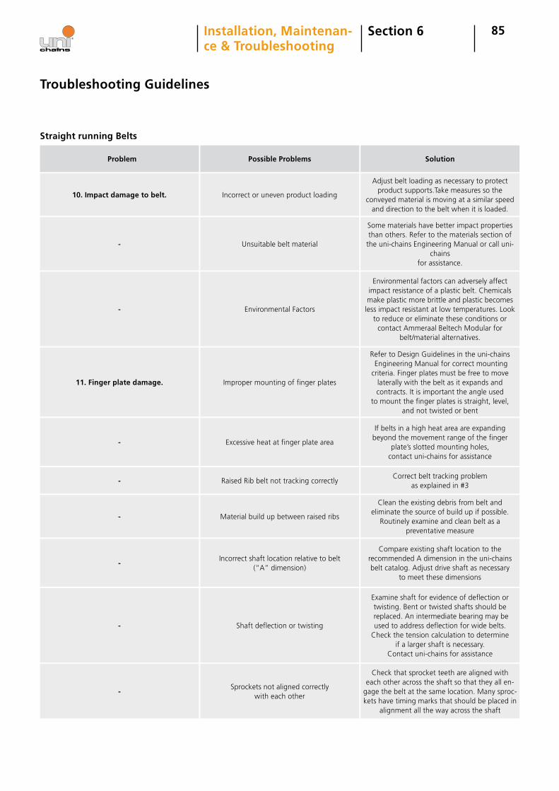
85Section 6Installation, Maintenan- ce & Troubleshooting
Problem Possible Problems Solution
Straight running Belts
Troubleshooting Guidelines
10. Impact damage to belt. Incorrect or uneven product loading
Adjust belt loading as necessary to protect product supports.Take measures so the
conveyed material is moving at a similar speed and direction to the belt when it is loaded.
- Unsuitable belt material
Some materials have better impact properties than others. Refer to the materials section of
the uni-chains Engineering Manual or call uni-chains
for assistance.
- Environmental Factors
Environmental factors can adversely affect impact resistance of a plastic belt. Chemicals make plastic more brittle and plastic becomes less impact resistant at low temperatures. Look
to reduce or eliminate these conditions or contact Ammeraal Beltech Modular for
belt/material alternatives.
11. Finger plate damage. Improper mounting of finger plates
Refer to Design Guidelines in the uni-chains Engineering Manual for correct mounting criteria. Finger plates must be free to move
laterally with the belt as it expands and contracts. It is important the angle used
to mount the finger plates is straight, level, and not twisted or bent
- Excessive heat at finger plate area
If belts in a high heat area are expanding beyond the movement range of the finger
plate’s slotted mounting holes, contact uni-chains for assistance
- Raised Rib belt not tracking correctlyCorrect belt tracking problem
as explained in #3
- Material build up between raised ribs
Clean the existing debris from belt and eliminate the source of build up if possible.
Routinely examine and clean belt as a preventative measure
-Incorrect shaft location relative to belt
(“A” dimension)
Compare existing shaft location to the recommended A dimension in the uni-chains belt catalog. Adjust drive shaft as necessary
to meet these dimensions
- Shaft deflection or twisting
Examine shaft for evidence of deflection or twisting. Bent or twisted shafts should be replaced. An intermediate bearing may be used to address deflection for wide belts.
Check the tension calculation to determine if a larger shaft is necessary.
Contact uni-chains for assistance
-Sprockets not aligned correctly
with each other
Check that sprocket teeth are aligned with each other across the shaft so that they all en-
gage the belt at the same location. Many sproc-kets have timing marks that should be placed in
alignment all the way across the shaft
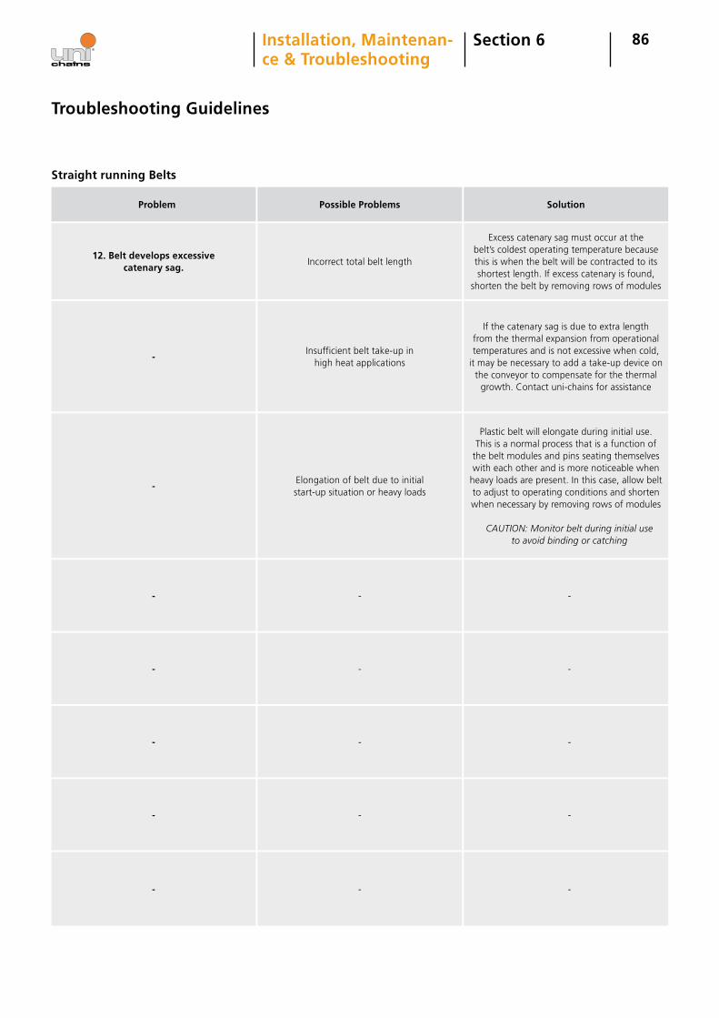
86Section 6Installation, Maintenan- ce & Troubleshooting
Problem Possible Problems Solution
Straight running Belts
Troubleshooting Guidelines
12. Belt develops excessive catenary sag.
Incorrect total belt length
Excess catenary sag must occur at the belt’s coldest operating temperature because this is when the belt will be contracted to its shortest length. If excess catenary is found,
shorten the belt by removing rows of modules
-Insufficient belt take-up in
high heat applications
If the catenary sag is due to extra length from the thermal expansion from operational temperatures and is not excessive when cold,
it may be necessary to add a take-up device on the conveyor to compensate for the thermal
growth. Contact uni-chains for assistance
-Elongation of belt due to initial start-up situation or heavy loads
Plastic belt will elongate during initial use. This is a normal process that is a function of
the belt modules and pins seating themselves with each other and is more noticeable when
heavy loads are present. In this case, allow belt to adjust to operating conditions and shorten when necessary by removing rows of modules
CAUTION: Monitor belt during initial use to avoid binding or catching
- - -
- - -
- - -
- - -
- - -
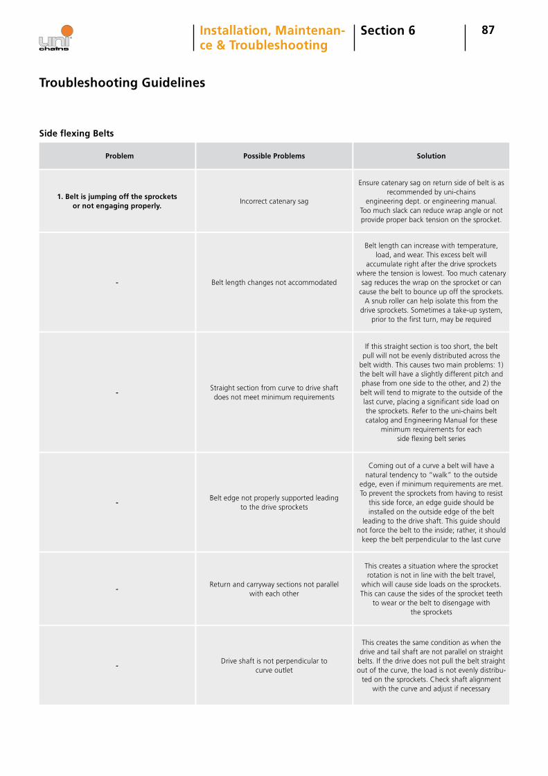
87Section 6Installation, Maintenan- ce & Troubleshooting
Problem Possible Problems Solution
Side flexing Belts
Troubleshooting Guidelines
1. Belt is jumping off the sprockets or not engaging properly.
Incorrect catenary sag
Ensure catenary sag on return side of belt is as recommended by uni-chains
engineering dept. or engineering manual. Too much slack can reduce wrap angle or not provide proper back tension on the sprocket.
- Belt length changes not accommodated
Belt length can increase with temperature, load, and wear. This excess belt will
accumulate right after the drive sprockets where the tension is lowest. Too much catenary
sag reduces the wrap on the sprocket or can cause the belt to bounce up off the sprockets.
A snub roller can help isolate this from the drive sprockets. Sometimes a take-up system,
prior to the first turn, may be required
-Straight section from curve to drive shaft does not meet minimum requirements
If this straight section is too short, the belt pull will not be evenly distributed across the
belt width. This causes two main problems: 1) the belt will have a slightly different pitch and phase from one side to the other, and 2) the belt will tend to migrate to the outside of the last curve, placing a significant side load on the sprockets. Refer to the uni-chains belt catalog and Engineering Manual for these
minimum requirements for each side flexing belt series
-Belt edge not properly supported leading
to the drive sprockets
Coming out of a curve a belt will have a natural tendency to “walk” to the outside
edge, even if minimum requirements are met. To prevent the sprockets from having to resist
this side force, an edge guide should be installed on the outside edge of the belt
leading to the drive shaft. This guide should not force the belt to the inside; rather, it should
keep the belt perpendicular to the last curve
-Return and carryway sections not parallel
with each other
This creates a situation where the sprocket rotation is not in line with the belt travel,
which will cause side loads on the sprockets. This can cause the sides of the sprocket teeth
to wear or the belt to disengage with the sprockets
-Drive shaft is not perpendicular to
curve outlet
This creates the same condition as when the drive and tail shaft are not parallel on straight
belts. If the drive does not pull the belt straight out of the curve, the load is not evenly distribu-
ted on the sprockets. Check shaft alignment with the curve and adjust if necessary
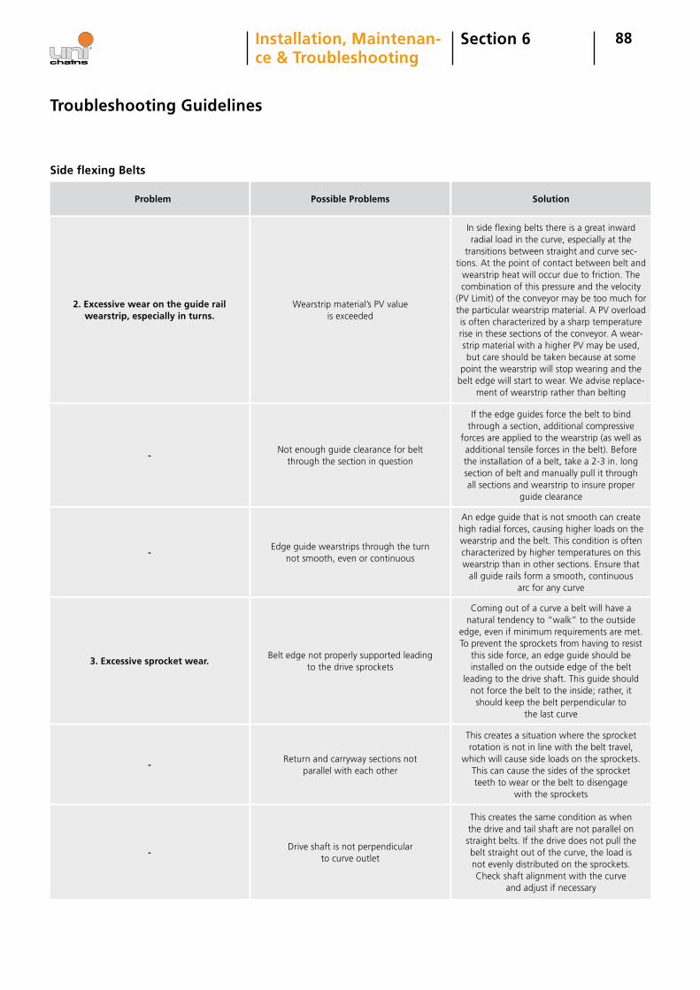
88Section 6Installation, Maintenan- ce & Troubleshooting
Problem Possible Problems Solution
Side flexing Belts
Troubleshooting Guidelines
2. Excessive wear on the guide rail wearstrip, especially in turns.
Wearstrip material’s PV value is exceeded
In side flexing belts there is a great inward radial load in the curve, especially at the
transitions between straight and curve sec-tions. At the point of contact between belt and
wearstrip heat will occur due to friction. The combination of this pressure and the velocity
(PV Limit) of the conveyor may be too much for the particular wearstrip material. A PV overload is often characterized by a sharp temperature rise in these sections of the conveyor. A wear- strip material with a higher PV may be used, but care should be taken because at some
point the wearstrip will stop wearing and the belt edge will start to wear. We advise replace-
ment of wearstrip rather than belting
-Not enough guide clearance for belt
through the section in question
If the edge guides force the belt to bind through a section, additional compressive
forces are applied to the wearstrip (as well as additional tensile forces in the belt). Before the installation of a belt, take a 2-3 in. long section of belt and manually pull it through all sections and wearstrip to insure proper
guide clearance
-Edge guide wearstrips through the turn
not smooth, even or continuous
An edge guide that is not smooth can create high radial forces, causing higher loads on the wearstrip and the belt. This condition is often characterized by higher temperatures on this wearstrip than in other sections. Ensure that
all guide rails form a smooth, continuous arc for any curve
3. Excessive sprocket wear.Belt edge not properly supported leading
to the drive sprockets
Coming out of a curve a belt will have a natural tendency to “walk” to the outside
edge, even if minimum requirements are met. To prevent the sprockets from having to resist
this side force, an edge guide should be installed on the outside edge of the belt
leading to the drive shaft. This guide should not force the belt to the inside; rather, it should keep the belt perpendicular to
the last curve
-Return and carryway sections not
parallel with each other
This creates a situation where the sprocket rotation is not in line with the belt travel,
which will cause side loads on the sprockets. This can cause the sides of the sprocket teeth to wear or the belt to disengage
with the sprockets
-Drive shaft is not perpendicular
to curve outlet
This creates the same condition as when the drive and tail shaft are not parallel on straight belts. If the drive does not pull the belt straight out of the curve, the load is not evenly distributed on the sprockets. Check shaft alignment with the curve
and adjust if necessary
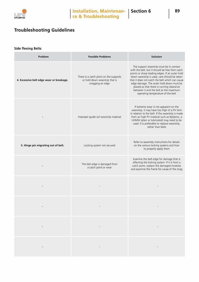
89Section 6Installation, Maintenan- ce & Troubleshooting
Problem Possible Problems Solution
Side flexing Belts
Troubleshooting Guidelines
4. Excessive belt edge wear or breakage.There is a catch point on the supports
or hold down wearstrip that is snagging an edge
The support wearstrip must be in contact with the belt, but it should be free from catch points or sharp leading edges. If an outer hold down wearstrip is used, care should be taken
that it does not catch the belt which can cause edge damage. The outer hold down must be
placed so that there is running clearance between it and the belt at the maximum
operating temperature of the belt
- Improper guide rail wearstrip material
If extreme wear is not apparent on the wearstrip, it may have too high of a PV limit
in relation to the belt. If the wearstrip is made from an high PV material such as Nylatron, a UHMW (plain or lubricated) may need to be used. It is preferable to replace wearstrip,
rather than belts
5. Hinge pin migrating out of belt. Locking system not securedRefer to assembly instructions for details on the various locking systems and how
to properly apply them
-The belt edge is damaged from
a catch point or wear
Examine the belt edge for damage that is affecting the locking system. If it is from a catch point, replace the damaged modules
and examine the frame for cause of the snag
- - -
- - -
- - -
- - -
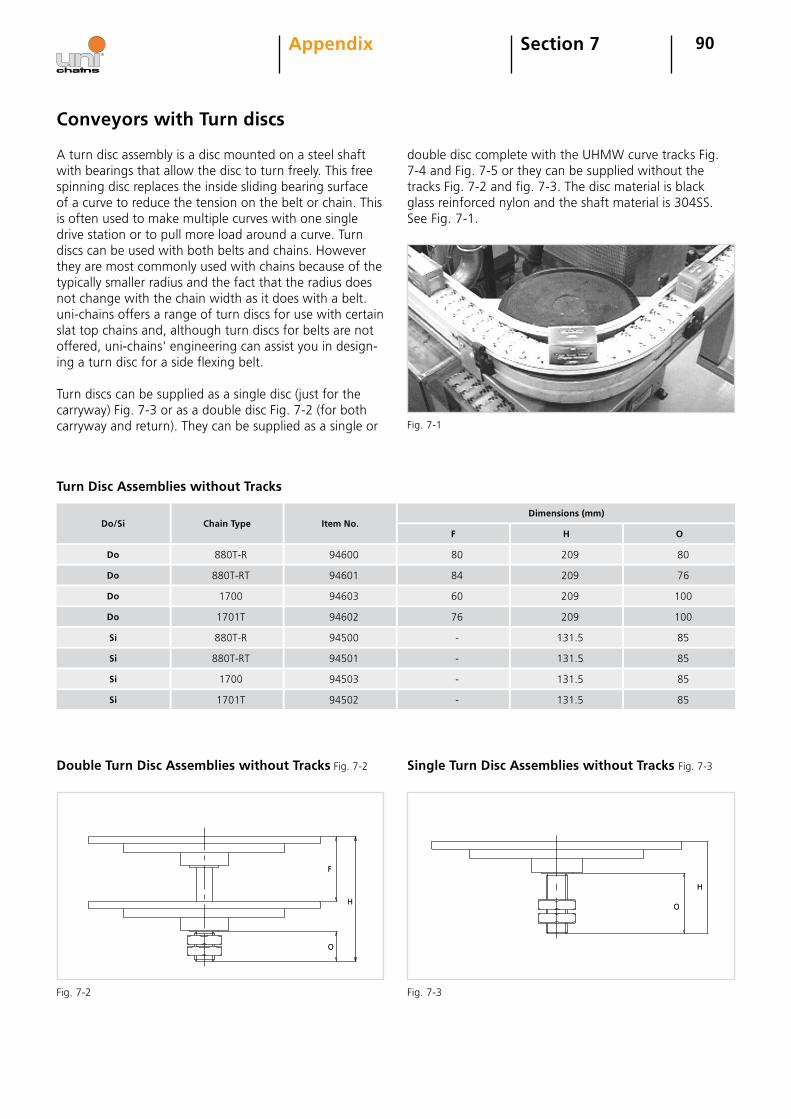
90Section 7Appendix
Conveyors with Turn discs
A turn disc assembly is a disc mounted on a steel shaft with bearings that allow the disc to turn freely. This free spinning disc replaces the inside sliding bearing surface of a curve to reduce the tension on the belt or chain. This is often used to make multiple curves with one single drive station or to pull more load around a curve. Turn discs can be used with both belts and chains. However they are most commonly used with chains because of the typically smaller radius and the fact that the radius does not change with the chain width as it does with a belt. uni-chains offers a range of turn discs for use with certain slat top chains and, although turn discs for belts are not offered, uni-chains' engineering can assist you in design-ing a turn disc for a side flexing belt.
Turn discs can be supplied as a single disc (just for the carryway) Fig. 7-3 or as a double disc Fig. 7-2 (for both carryway and return). They can be supplied as a single or
double disc complete with the UHMW curve tracks Fig. 7-4 and Fig. 7-5 or they can be supplied without the tracks Fig. 7-2 and fig. 7-3. The disc material is black glass reinforced nylon and the shaft material is 304SS. See Fig. 7-1.
Fig. 7-1
F
O
HO
H
Fig. 7-2 Fig. 7-3
Turn Disc Assemblies without Tracks
Do
Do
Do/Si
Do
Chain Type Item No.
Si
Si
1700
880T-R
1701T
880T-R
1700
94603
94600
94602
94500
94503
60
80
76
-
-
209
209
209
131.5
131.5
100
80
100
85
85
Si 1701T 94502 - 131.5 85
Dimensions (mm)
F H O
Do 880T-RT 94601 84 209 76
Si 880T-RT 94501 - 131.5 85
F
O
HO
H
Double Turn Disc Assemblies without Tracks Fig. 7-2 Single Turn Disc Assemblies without Tracks Fig. 7-3
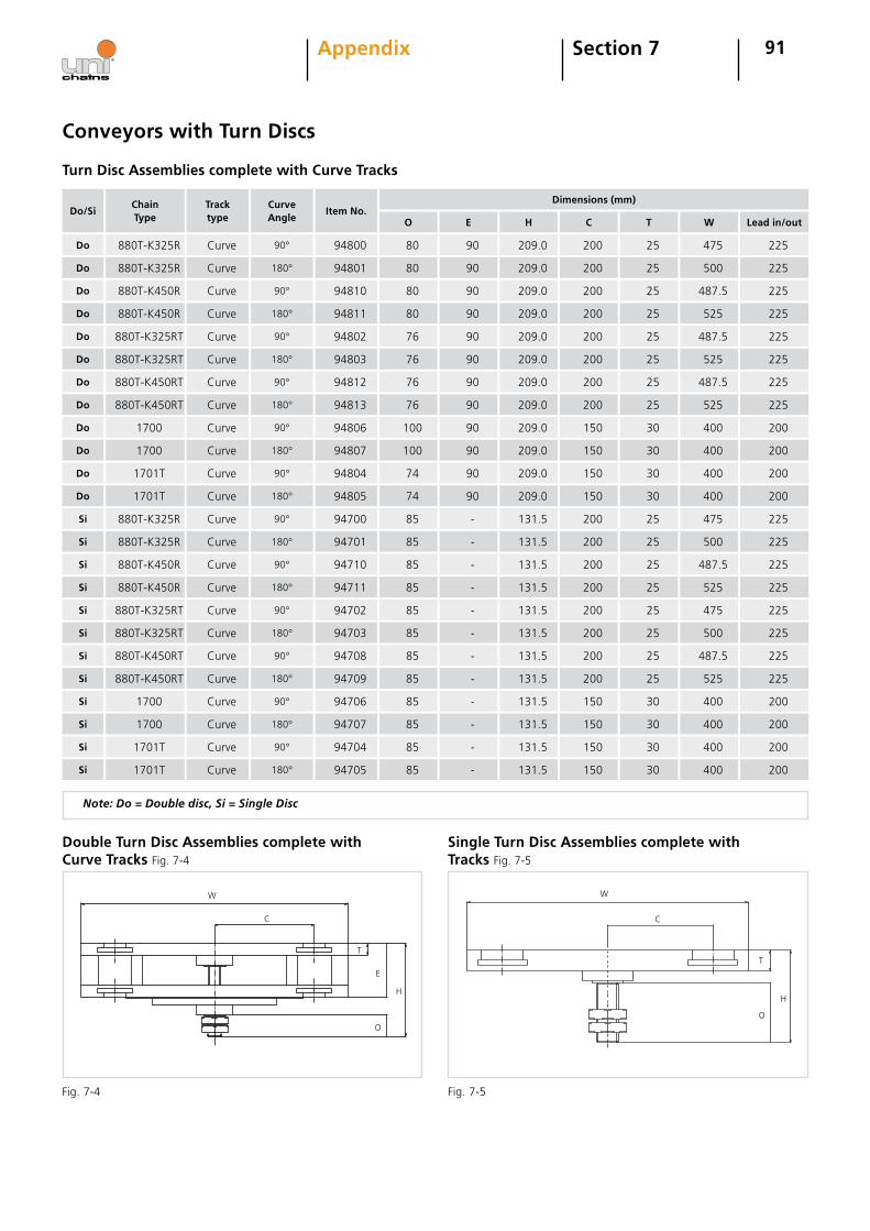
91Section 7Appendix
Do
Do
Do/Si
Do
880T-K325R
880T-K325R
Chain Type
880T-K450R
180°
90°
Curve Angle
90°
Curve
Curve
Tracktype
Curve
94801
94800
Item No.
94810
80
80
Dimensions (mm)
80
90
90
90
209.0
209.0
209.0
200
200
200
25
25
25
500
475
487.5
Do 880T-K450R 180°Curve 94811 80 90 209.0 200 25 525
Do 1700 90°Curve 94806 100 90 209.0 150 30 400
Do 1700 180°Curve 94807 100 90 209.0 150 30 400
Do 1701T 90°Curve 94804 74 90 209.0 150 30 400
Do 1701T 180°Curve 94805 74 90 209.0 150 30 400
Si 880T-K325R 90°Curve 94700 85 - 131.5 200 25 475
Si 880T-K325R 180°Curve 94701 85 - 131.5 200 25 500
Si 880T-K450R 90°Curve 94710 85 - 131.5 200 25 487.5
Si 880T-K450R 180°Curve 94711 85 - 131.5 200 25 525
Si 1700 90°Curve 94706 85 - 131.5 150 30 400
Si 1700 180°Curve 94707 85 - 131.5 150 30 400
Si 1701T 90°Curve 94704 85 - 131.5 150 30 400
Si 1701T 180°Curve 94705 85 - 131.5 150 30 400
Turn Disc Assemblies complete with Curve Tracks
Note: Do = Double disc, Si = Single Disc
Conveyors with Turn Discs
O E H C T W
W
C
H
O
E
T
W
C
O
T
H
Fig. 7-4 Fig. 7-5
225
225
225
225
200
200
200
200
225
225
225
225
200
200
200
200
Lead in/out
Do
Do
Do
880T-K325RT
880T-K325RT
880T-K450RT
180°
90°
90°
Curve
Curve
Curve
94803
94802
94812
76
76
76
90
90
90
209.0
209.0
209.0
200
200
200
25
25
25
525
487.5
487.5
Do 880T-K450RT 180°Curve 94813 76 90 209.0 200 25 525
225
225
225
225
Si 880T-K325RT 90°Curve 94702 85 - 131.5 200 25 475
Si 880T-K325RT 180°Curve 94703 85 - 131.5 200 25 500
Si 880T-K450RT 90°Curve 94708 85 - 131.5 200 25 487.5
Si 880T-K450RT 180°Curve 94709 85 - 131.5 200 25 525
225
225
225
225
Double Turn Disc Assemblies complete with Curve Tracks Fig. 7-4
Single Turn Disc Assemblies complete with Tracks Fig. 7-5

92Section 7Appendix
Conversion of Units (metric/imperial)
Imperial
Length
Multiply Metric Multiply Imperial
inch (in.) 25.4 millimeter (mm) 0.03937 inch (in.)
inch (in.) 0.0254 meter (m) 39.37 inch (in.)
foot (ft.) 304.8 millimeter (mm) 0.0033 foot (ft.)
foot (ft.) 0.3048 meter (m) 3.281 foot (ft.)
Area
square inch 645.2 square millimeter 0.00155 square inch
square inch 0.000645 square meter 1550 square inch
square foot 92,903 square millimeter 0.00001 square foot
square foot 0.0929 square meter 10.764 square foot
Volume
cubic foot 0.0283 cubic meter 35.31 cubic foot
cubic foot 28.32 liter 0.0353 cubic foot
Velocity and Speed
foot/second 18.29 meter/min 0.0547 foot/second
foot/minute 0.3048 meter/min 3.281 foot/second
Mass and Density
pound 0.4536 kilogram 2.205 pound
pound/cubic foot 16.02 kilogram/cubic meter 0.0624 pound/cubic foot
Force
pound-force 0.4536 kilogram-force 2.205 pound-force
pound-force 4.448 newton 0.225 pound-force
kilogram-force 9.807 newton 0.102 kilogram-force
Work (Force/Length)
pound/foot 1.488 kilogram/meter 0.672 pound/foot
pound/foot 14.59 newton/meter 0.0685 pound/foot
kilogram/meter 9.807 newton/meter 0.102 kilogram/meter
Torque
inch-pound 11.52 kilogram-millimeter 0.0868 inch-pound
inch-pound 0.113 newton-meter 8.85 inch-pound
kilogram-millimeter 9.81 newton/millimeter 0.102 kilogram-millimeter
Moment of Inertia
Inch4 416,231 millimeter4 0.0000024 Inch4
Inch4 41.62 centimeter4 0.024 Inch4
Pressure
pound/square inch 0.0007 kilogram/square millimeter 1422 pound/square inch
pound/square inch 0.0703 kilogram/square millimeter 14.22 pound/square inch
pound/square inch 0.00689 newton/millimeter 145 pound/square inch
pound/square inch 0.689 newton/millimeter 1.45 pound/square inch
Stress
pound/square foot 4.882 kilogram/square meter 0.205 pound/square foot
pound/square foot 47.88 newton/square meter 0.0209 pound/square foot
Power
Horsepower 745.7 Watt 0.00134 Horsepower
foot-pound/minute 0.0226 Watt 44.25 foot-pound/minute
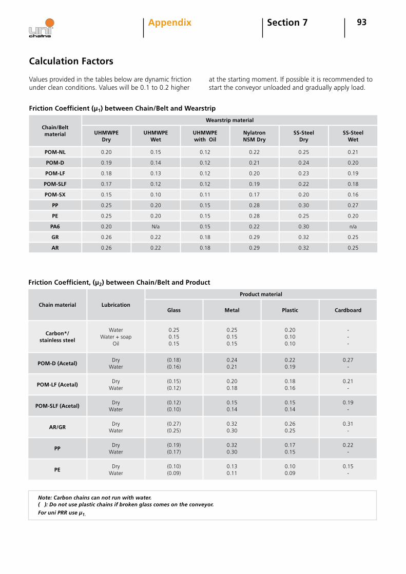
93Section 7Appendix
Calculation Factors
Values provided in the tables below are dynamic friction under clean conditions. Values will be 0.1 to 0.2 higher
Chain/Beltmaterial
POM-NL
at the starting moment. If possible it is recommended to start the conveyor unloaded and gradually apply load.
UHMWPE Dry
0.19
0.20
0.17
0.18
0.25
0.15
0.20
0.25
0.26
0.26
Friction Coefficient (µ1) between Chain/Belt and Wearstrip
UHMWPE Wet
0.14
0.15
0.12
0.13
0.20
0.10
N/a
0.20
0.22
0.22
UHMWPE with Oil
0.12
0.12
0.12
0.12
0.15
0.11
0.15
0.15
0.18
0.18
NylatronNSM Dry
0.21
0.22
0.19
0.20
0.28
0.17
0.22
0.28
0.29
0.29
SS-SteelDry
0.24
0.25
0.22
0.23
0.30
0.20
0.30
0.25
0.32
0.32
SS-SteelWet
0.20
0.21
0.18
0.19
0.27
0.16
n/a
0.20
0.25
0.25
POM-D
POM-LF
POM-SLF
POM-SX
PP
PE
PA6
GR
AR
Wearstrip material
Chain material
Carbon*/stainless steel
Lubrication
DryWater
WaterWater + soap
Oil
Friction Coefficient, (µ2) between Chain/Belt and Product
Glass
(0.18)(0.16)
0.250.150.15
Metal
0.240.21
0.250.150.15
Plastic
0.220.19
0.200.100.10
Cardboard
0.27-
---
POM-D (Acetal)
Product material
DryWater
(0.15)(0.12)
0.200.18
0.180.16
0.21-
POM-LF (Acetal)
DryWater
(0.12)(0.10)
0.150.14
0.150.14
0.19-
POM-SLF (Acetal)
DryWater
(0.27)(0.25)
0.320.30
0.31-
AR/GR
DryWater
(0.19)(0.17)
0.320.30
0.170.15
0.22-
PP
DryWater
(0.10)(0.09)
0.130.11
0.100.09
0.15-
PE
0.260.25
Note: Carbon chains can not run with water.( ): Do not use plastic chains if broken glass comes on the conveyor.
For uni PRR use µ1.
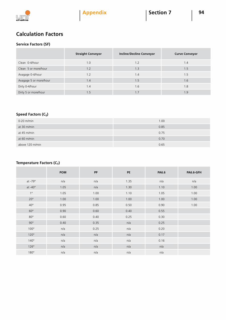
94
Speed Factors (CS)
0-20 m/min 1.00
at 30 m/min 0.85
at 45 m/min 0.75
at 60 m/min 0.70
above 120 m/min 0.65
Service Factors (SF)
Clean 0-4/hour
Clean 5 or more/hour
Avagage 0-4/hour
Avagage 5 or more/hour
Dirty 0-4/hour
Straight Conveyor
1.0
1.2
1.2
1.4
1.4
Incline/Decline Conveyor
1.2
1.3
1.4
1.5
1.6
Curve Conveyor
1.4
1.5
1.5
1.6
1.8
Dirty 5 or more/hour 1.5 1.7 1.9
Section 7Appendix
at -79°
POM
1.05
n/a
1.00
1.05
0.90
0.95
0.40
0.60
n/a
n/a
Temperature Factors (CT)
PP
n/a
n/a
1.00
1.00
0.60
0.85
0.35
0.40
n/a
0.25
PE
1.30
1.35
1.00
1.10
0.40
0.50
n/a
0.25
n/a
n/a
PA6.6
1.10
n/a
1.00
1.05
0.55
0.90
0.25
0.30
0.17
0.20
PA6.6-GFH
1.00
n/a
1.00
1.00
1.00
at -40°
1°
20°
40°
60°
80°
90°
100°
120°
n/a n/a n/a 0.16140°
n/a n/a n/a n/a126°
n/a n/a n/a n/a180°
Calculation Factors
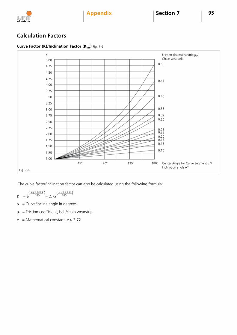
95Section 7Appendix
Curve Factor (K)/Inclination Factor (Kinc) Fig. 7-6
Center Angle for Curve Segment α°/ Inclination angle α°
K
5.00
4.75
4.50
4.25
4.00
3.75
3.50
3.25
3.00
2.75
2.50
2.25
2.00
1.75
1.50
1.00
1.25
45° 90° 135° 180°
Friction chain/wearstrip µ1/Chain wearstrip
0.50
0.45
0.40
0.35
0.320.30
0.25
0.200.180.15
0.10
0.23
The curve factor/inclination factor can also be calculated using the following formula:
α = Curve/incline angle in degrees)
µ1 = Friction coefficient, belt/chain wearstrip
e = Mathematical constant, e ≈ 2.72
Fig. 7-6
Calculation Factors
µ1 x α x π 180K = e ≈ 2.72
µ1 x α x π 180
( ) ( )
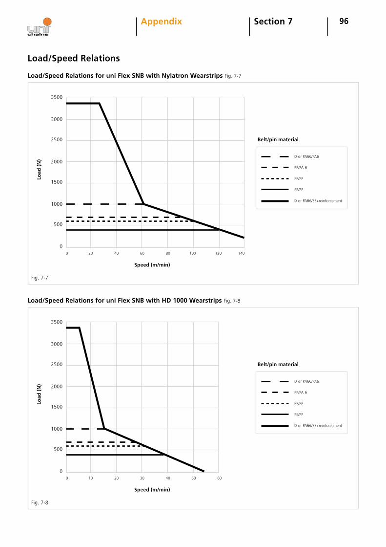
96Section 7Appendix
Load/Speed Relations for uni Flex SNB with HD 1000 Wearstrips Fig. 7-8
Load/Speed Relations for uni Flex SNB with Nylatron Wearstrips Fig. 7-7
Load/Speed Relations
3500
3000
2500
2000
1500
1000
500
0
Load
(N
)
Speed (m/min)
0 20 40 60 80 100 120 140
D or PA66/PA6
PP/PA 6
PP/PP
PE/PP
D or PA66/SS+reinforcement
3500
3000
2500
2000
1500
1000
500
0
Load
(N
)
Speed (m/min)
0 10 20 30 40 50 60
D or PA66/PA6
PP/PA 6
PP/PP
PE/PP
D or PA66/SS+reinforcement
Fig. 7-7
Fig. 7-8
Belt/pin material
Belt/pin material
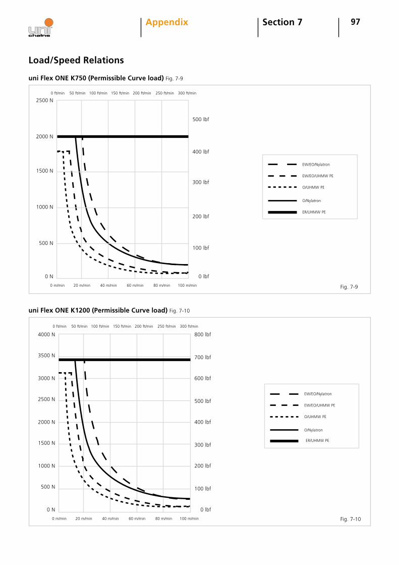
97
uni Flex ONE K1200 (Permissible Curve load) Fig. 7-10
uni Flex ONE K750 (Permissible Curve load) Fig. 7-9
Section 7Appendix
Load/Speed Relations
2500 N
2000 N
1500 N
1000 N
500 N
0 N
0 m/min 20 m/min 40 m/min 60 m/min 80 m/min 100 m/min
0 ft/min 50 ft/min 100 ft/min 150 ft/min 200 ft/min 250 ft/min 300 ft/min
500 lbf
400 lbf
300 lbf
200 lbf
100 lbf
0 lbf
EW/EO/Nylatron
EW/EO/UHMW PE
O/UHMW PE
O/Nylatron
ER/UHMW PE
EW/EO/Nylatron
EW/EO/UHMW PE
O/UHMW PE
O/Nylatron
ER/UHMW PE
3500 N
3000 N
2500 N
2000 N
1500 N
1000 N
500 N
0 N
0 m/min 20 m/min 40 m/min 60 m/min 80 m/min 100 m/min
0 ft/min 50 ft/min 100 ft/min 150 ft/min 200 ft/min 250 ft/min 300 ft/min
800 lbf
700 lbf
600 lbf
500 lbf
400 lbf
300 lbf
200 lbf
100 lbf
0 lbf
4000 N
Fig. 7-9
Fig. 7-10
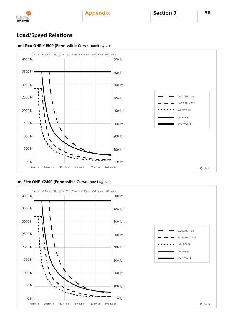
98
uni Flex ONE K1500 (Permissible Curve load) Fig. 7-11
uni Flex ONE K2400 (Permissible Curve load) Fig. 7-12
3500 N
3000 N
2500 N
2000 N
1500 N
1000 N
500 N
0 N
0 m/min 20 m/min 40 m/min 60 m/min 80 m/min 100 m/min
0 ft/min 50 ft/min 100 ft/min 150 ft/min 200 ft/min 250 ft/min 300 ft/min
800 lbf
700 lbf
600 lbf
500 lbf
400 lbf
300 lbf
200 lbf
100 lbf
0 lbf
4000 N
EW/EO/Nylatron
EW/EO/UHMW PE
O/UHMW PE
O/Nylatron
ER/UHMW PE
3500 N
3000 N
2500 N
2000 N
1500 N
1000 N
500 N
0 N
0 m/min 20 m/min 40 m/min 60 m/min 80 m/min 100 m/min
0 ft/min 50 ft/min 100 ft/min 150 ft/min 200 ft/min 250 ft/min 300 ft/min
800 lbf
700 lbf
600 lbf
500 lbf
400 lbf
300 lbf
200 lbf
100 lbf
0 lbf
4000 N
EW/EO/Nylatron
EW/EO/UHMW PE
O/UHMW PE
O/Nylatron
ER/UHMW PE
Section 7Appendix
Fig. 7-11
Fig. 7-12
Load/Speed Relations
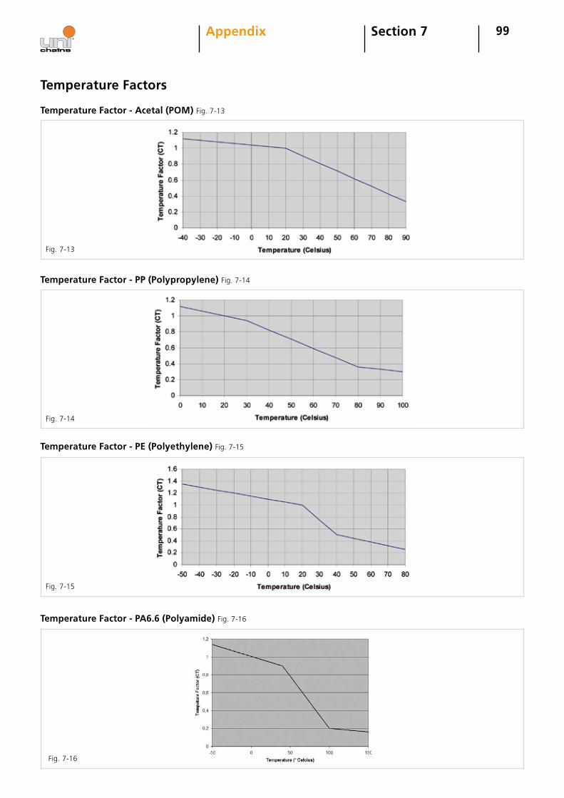
99
Temperature Factor - PA6.6 (Polyamide) Fig. 7-16
Section 7Appendix
Temperature Factors
Temperature Factor - Acetal (POM) Fig. 7-13
Temperature Factor - PP (Polypropylene) Fig. 7-14
Temperature Factor - PE (Polyethylene) Fig. 7-15
Fig. 7-13
Fig. 7-14
Fig. 7-15
Fig. 7-16
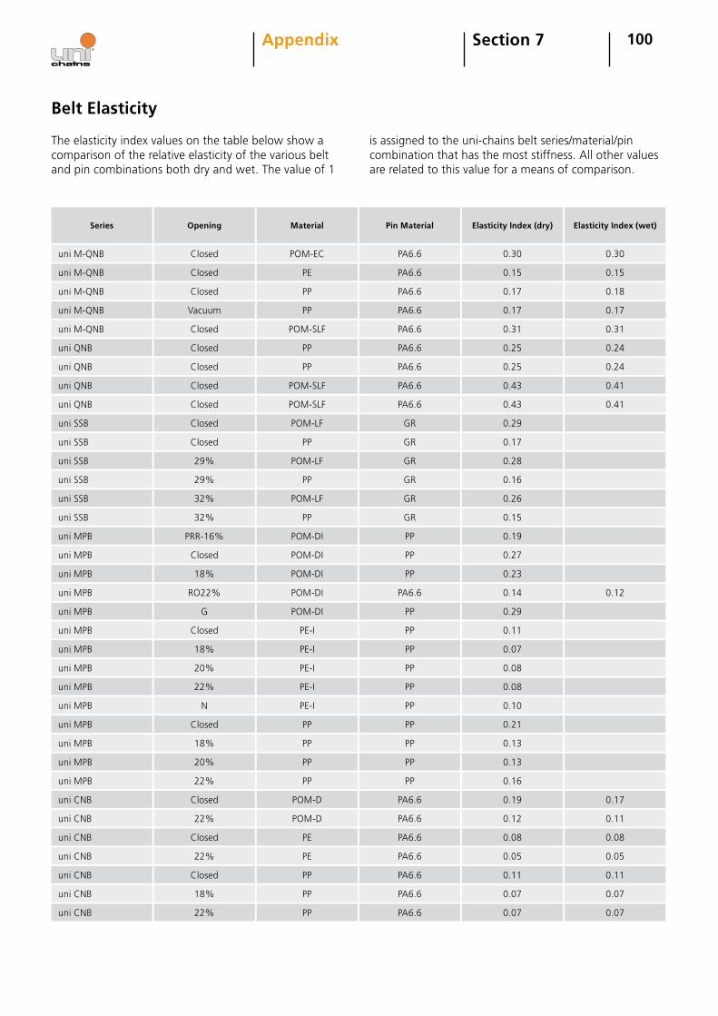
100Section 7Appendix
Belt Elasticity
The elasticity index values on the table below show a comparison of the relative elasticity of the various belt and pin combinations both dry and wet. The value of 1
is assigned to the uni-chains belt series/material/pin combination that has the most stiffness. All other values are related to this value for a means of comparison.
Series
uni M-QNB
Opening
Closed
Material
POM-EC
Pin Material
PA6.6
Elasticity Index (dry)
0.30
Elasticity Index (wet)
0.30
uni M-QNB Closed PE PA6.6 0.15 0.15
uni M-QNB Closed PP PA6.6 0.17 0.18
uni M-QNB Vacuum PP PA6.6 0.17 0.17
uni M-QNB Closed POM-SLF PA6.6 0.31 0.31
uni QNB Closed PP PA6.6 0.25 0.24
uni QNB Closed PP PA6.6 0.25 0.24
uni QNB Closed POM-SLF PA6.6 0.43 0.41
uni QNB Closed POM-SLF PA6.6 0.43 0.41
uni SSB Closed POM-LF GR 0.29
uni SSB Closed PP GR 0.17
uni SSB 29% POM-LF GR 0.28
uni SSB 29% PP GR 0.16
uni SSB 32% POM-LF GR 0.26
uni SSB 32% PP GR 0.15
uni MPB PRR-16% POM-DI PP 0.19
uni MPB Closed POM-DI PP 0.27
uni MPB 18% POM-DI PP 0.23
uni MPB RO22% POM-DI PA6.6 0.14 0.12
uni MPB G POM-DI PP 0.29
uni MPB Closed PE-I PP 0.11
uni MPB 18% PE-I PP 0.07
uni MPB 20% PE-I PP 0.08
uni MPB 22% PE-I PP 0.08
uni MPB N PE-I PP 0.10
uni MPB Closed PP PP 0.21
uni MPB 18% PP PP 0.13
uni MPB 20% PP PP 0.13
uni MPB 22% PP PP 0.16
uni CNB Closed POM-D PA6.6 0.19 0.17
uni CNB 22% POM-D PA6.6 0.12 0.11
uni CNB Closed PE PA6.6 0.08 0.08
uni CNB 22% PE PA6.6 0.05 0.05
uni CNB Closed PP PA6.6 0.11 0.11
uni CNB 18% PP PA6.6 0.07 0.07
uni CNB 22% PP PA6.6 0.07 0.07
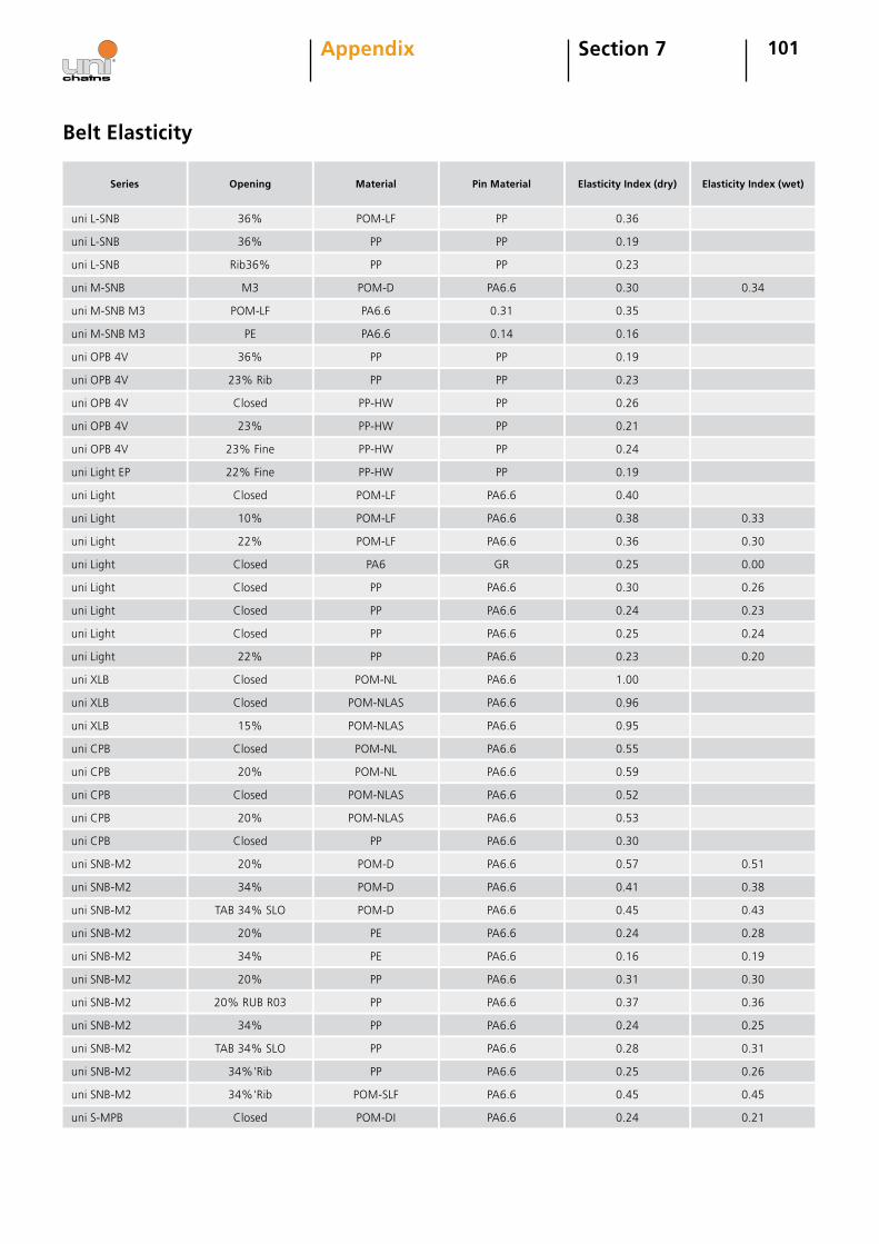
101Section 7Appendix
Series
uni L-SNB
Opening
36%
Material
POM-LF
Pin Material
PP
Elasticity Index (dry)
0.36
Elasticity Index (wet)
uni L-SNB 36% PP PP 0.19
uni L-SNB Rib36% PP PP 0.23
uni M-SNB M3 POM-D PA6.6 0.30 0.34
uni M-SNB M3 POM-LF PA6.6 0.31 0.35
uni M-SNB M3 PE PA6.6 0.14 0.16
uni OPB 4V 36% PP PP 0.19
uni OPB 4V 23% Rib PP PP 0.23
uni OPB 4V Closed PP-HW PP 0.26
uni OPB 4V 23% PP-HW PP 0.21
uni OPB 4V 23% Fine PP-HW PP 0.24
uni Light EP 22% Fine PP-HW PP 0.19
uni Light Closed POM-LF PA6.6 0.40
uni Light 10% POM-LF PA6.6 0.38 0.33
uni Light 22% POM-LF PA6.6 0.36 0.30
uni Light Closed PA6 GR 0.25 0.00
uni Light Closed PP PA6.6 0.30 0.26
uni Light Closed PP PA6.6 0.24 0.23
uni Light Closed PP PA6.6 0.25 0.24
uni Light 22% PP PA6.6 0.23 0.20
uni XLB Closed POM-NL PA6.6 1.00
uni XLB Closed POM-NLAS PA6.6 0.96
uni XLB 15% POM-NLAS PA6.6 0.95
uni CPB Closed POM-NL PA6.6 0.55
uni CPB 20% POM-NL PA6.6 0.59
uni CPB Closed POM-NLAS PA6.6 0.52
uni CPB 20% POM-NLAS PA6.6 0.53
uni CPB Closed PP PA6.6 0.30
uni SNB-M2 20% POM-D PA6.6 0.57 0.51
uni SNB-M2 34% POM-D PA6.6 0.41 0.38
uni SNB-M2 TAB 34% SLO POM-D PA6.6 0.45 0.43
uni SNB-M2 20% PE PA6.6 0.24 0.28
uni SNB-M2 34% PE PA6.6 0.16 0.19
uni SNB-M2 20% PP PA6.6 0.31 0.30
uni SNB-M2 20% RUB R03 PP PA6.6 0.37 0.36
uni SNB-M2 34% PP PA6.6 0.24 0.25
uni SNB-M2 TAB 34% SLO PP PA6.6 0.28 0.31
uni SNB-M2 34%'Rib PP PA6.6 0.25 0.26
uni SNB-M2 34%'Rib POM-SLF PA6.6 0.45 0.45
uni S-MPB Closed POM-DI PA6.6 0.24 0.21
Belt Elasticity
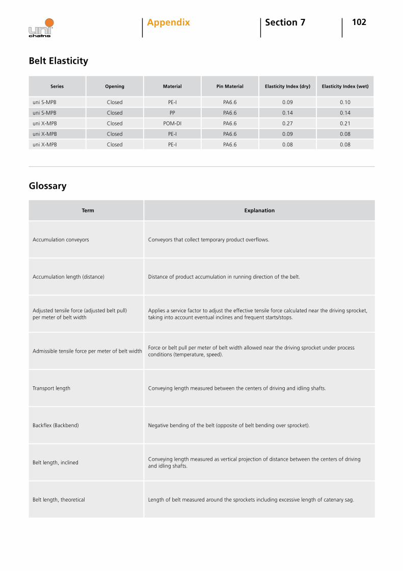
102
Series
uni S-MPB
Opening
Closed
Material
PE-I
Pin Material
PA6.6
Elasticity Index (dry)
0.09
Elasticity Index (wet)
0.10
uni S-MPB Closed PP PA6.6 0.14 0.14
uni X-MPB Closed POM-DI PA6.6 0.27 0.21
uni X-MPB Closed PE-I PA6.6 0.09 0.08
uni X-MPB Closed PE-I PA6.6 0.08 0.08
Belt Elasticity
Glossary
Section 7Appendix
Term Explanation
Accumulation conveyors Conveyors that collect temporary product overflows.
Accumulation length (distance) Distance of product accumulation in running direction of the belt.
Adjusted tensile force (adjusted belt pull) per meter of belt width
Applies a service factor to adjust the effective tensile force calculated near the driving sprocket, taking into account eventual inclines and frequent starts/stops.
Admissible tensile force per meter of belt widthForce or belt pull per meter of belt width allowed near the driving sprocket under process conditions (temperature, speed).
Transport length Conveying length measured between the centers of driving and idling shafts.
Backflex (Backbend) Negative bending of the belt (opposite of belt bending over sprocket).
Belt length, inclinedConveying length measured as vertical projection of distance between the centers of driving and idling shafts.
Belt length, theoretical Length of belt measured around the sprockets including excessive length of catenary sag.
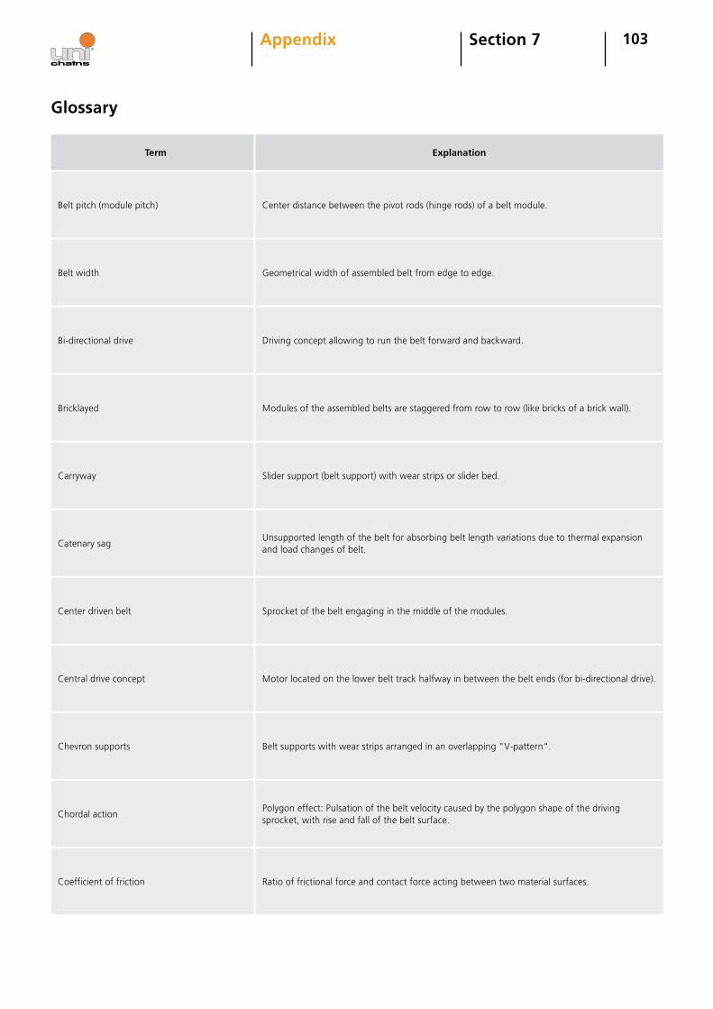
103Section 7Appendix
Glossary
Term Explanation
Belt pitch (module pitch) Center distance between the pivot rods (hinge rods) of a belt module.
Belt width Geometrical width of assembled belt from edge to edge.
Bi-directional drive Driving concept allowing to run the belt forward and backward.
Bricklayed Modules of the assembled belts are staggered from row to row (like bricks of a brick wall).
Carryway Slider support (belt support) with wear strips or slider bed.
Catenary sagUnsupported length of the belt for absorbing belt length variations due to thermal expansion and load changes of belt.
Center driven belt Sprocket of the belt engaging in the middle of the modules.
Central drive concept Motor located on the lower belt track halfway in between the belt ends (for bi-directional drive).
Chevron supports Belt supports with wear strips arranged in an overlapping "V-pattern".
Chordal actionPolygon effect: Pulsation of the belt velocity caused by the polygon shape of the driving sprocket, with rise and fall of the belt surface.
Coefficient of friction Ratio of frictional force and contact force acting between two material surfaces.
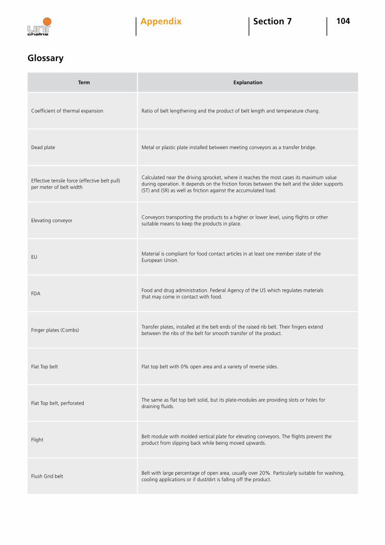
104Section 7Appendix
Glossary
Term Explanation
Coefficient of thermal expansion Ratio of belt lengthening and the product of belt length and temperature chang.
Dead plate Metal or plastic plate installed between meeting conveyors as a transfer bridge.
Effective tensile force (effective belt pull) per meter of belt width
Calculated near the driving sprocket, where it reaches the most cases its maximum value during operation. It depends on the friction forces between the belt and the slider supports (ST) and (SR) as well as friction against the accumulated load.
Elevating conveyorConveyors transporting the products to a higher or lower level, using flights or other suitable means to keep the products in place.
EUMaterial is compliant for food contact articles in at least one member state of the European Union.
FDAFood and drug administration. Federal Agency of the US which regulates materials that may come in contact with food.
Finger plates (Combs)Transfer plates, installed at the belt ends of the raised rib belt. Their fingers extend between the ribs of the belt for smooth transfer of the product.
Flat Top belt Flat top belt with 0% open area and a variety of reverse sides.
Flat Top belt, perforatedThe same as flat top belt solid, but its plate-modules are providing slots or holes for draining fluids.
FlightBelt module with molded vertical plate for elevating conveyors. The flights prevent the product from slipping back while being moved upwards.
Flush Grid beltBelt with large percentage of open area, usually over 20%. Particularly suitable for washing, cooling applications or if dust/dirt is falling off the product.
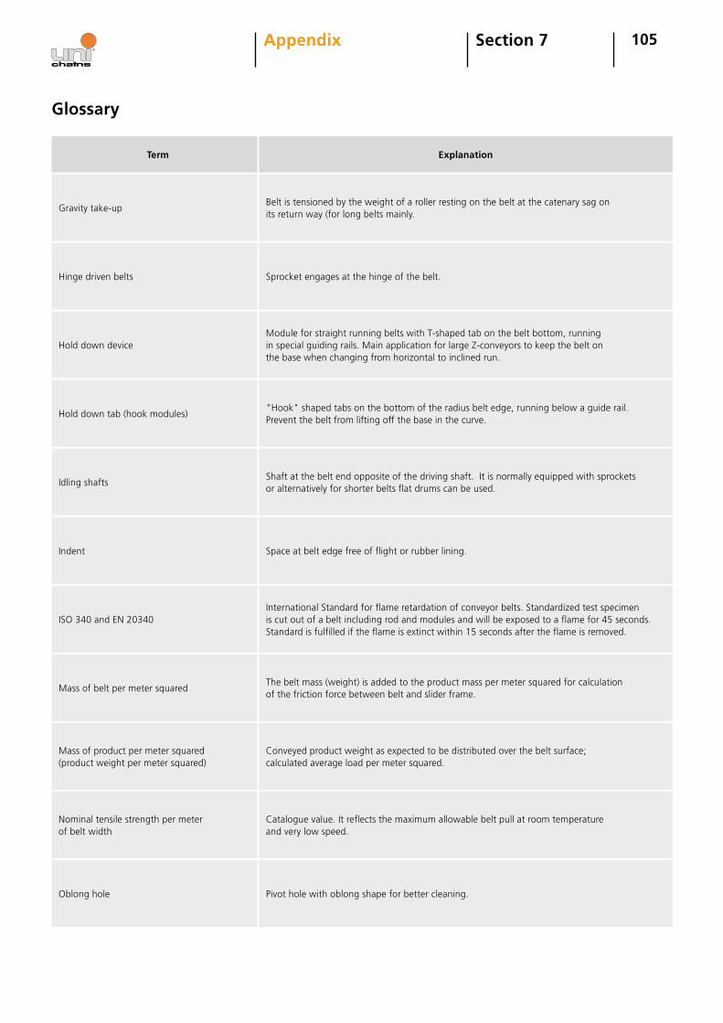
105Section 7Appendix
Glossary
Term Explanation
Gravity take-upBelt is tensioned by the weight of a roller resting on the belt at the catenary sag on its return way (for long belts mainly.
Hinge driven belts Sprocket engages at the hinge of the belt.
Hold down deviceModule for straight running belts with T-shaped tab on the belt bottom, running in special guiding rails. Main application for large Z-conveyors to keep the belt on the base when changing from horizontal to inclined run.
Hold down tab (hook modules)"Hook" shaped tabs on the bottom of the radius belt edge, running below a guide rail. Prevent the belt from lifting off the base in the curve.
Idling shaftsShaft at the belt end opposite of the driving shaft. It is normally equipped with sprockets or alternatively for shorter belts flat drums can be used.
Indent Space at belt edge free of flight or rubber lining.
ISO 340 and EN 20340International Standard for flame retardation of conveyor belts. Standardized test specimenis cut out of a belt including rod and modules and will be exposed to a flame for 45 seconds. Standard is fulfilled if the flame is extinct within 15 seconds after the flame is removed.
Mass of belt per meter squaredThe belt mass (weight) is added to the product mass per meter squared for calculation of the friction force between belt and slider frame.
Mass of product per meter squared(product weight per meter squared)
Conveyed product weight as expected to be distributed over the belt surface; calculated average load per meter squared.
Nominal tensile strength per meter of belt width
Catalogue value. It reflects the maximum allowable belt pull at room temperature and very low speed.
Oblong hole Pivot hole with oblong shape for better cleaning.
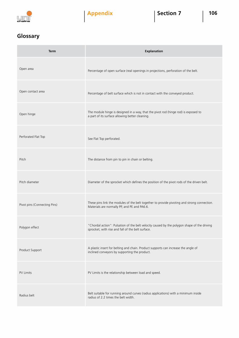
106Section 7Appendix
Glossary
Term Explanation
Open areaPercentage of open surface (real openings in projections, perforation of the belt.
Open contact areaPercentage of belt surface which is not in contact with the conveyed product.
Open hingeThe module hinge is designed in a way, that the pivot rod (hinge rod) is exposed to a part of its surface allowing better cleaning.
Perforated Flat TopSee Flat Top perforated.
Pitch The distance from pin to pin in chain or belting.
Pitch diameter Diameter of the sprocket which defines the position of the pivot rods of the driven belt.
Pivot pins (Connecting Pins)These pins link the modules of the belt together to provide pivoting and strong connection. Materials are normally PP, and PE and PA6.6.
Polygon effect"Chordal action": Pulsation of the belt velocity caused by the polygon shape of the driving sprocket, with rise and fall of the belt surface.
Product SupportA plastic insert for belting and chain. Product supports can increase the angle of inclined conveyors by supporting the product.
PV Limits PV Limits is the relationship between load and speed.
Radius beltBelt suitable for running around curves (radius applications) with a minimum inside radius of 2.2 times the belt width.

107Section 7Appendix
Glossary
Term Explanation
Raised Rib beltBelt with higher longitudinal ribs on its top surface. These ribs create longitudinal "slots" for the engagement of finger plates for smooth product transfer at the belt ends.
Screw type take-upThe catenary sag is adjusted by means of a screw tensioning device at the idling shaft of the conveyor.
Service factorThe calculated effective belt pull is adjusted with the service factor taking into account eventual heavy running conditions (start/stop, inclination).
Side guardsPlates designed to be installed lengthwise at the belt edge to form a wall. Usually used in connection with Flights.
Slider support/bedFrame equipped with wear strips to carry the running belt with low friction and wear. A closed plate is called a slider bed.
Speed factorThe nominal tensile force, valid at very low speed and room temperature, is reduced to the permissible tensile force by the influence of higher speed and/or temperature; therefore it is multiplied with the respective factor.
Spiral conveyorRadius belt with more than 1 full turn, traveling in a helical path around a central cylinder upwards or downwards.
SprocketGear, mostly plastic or exceptionally from metal, shaped to engage in the grid pattern of the belt modules, providing positive torque transmission to the belt.
Take-upTensioning device for adjustment of the catenary sag, screw type, gravity type or spring loaded type at the idling shaft of the conveyor.
Temperature factorThe nominal tensile force, valid at very low speed and room temperature, is reduced to the admissible tensile force by the influence of higher speed and/or temperature; therefore it is multiplied with the respective factor.
USDAUnited States Department of Agriculture. US federal agency which had defined requirements for equipment which may be in contact with meat, dairy and poultry.
WearstripPlastic strip, mainly from PE, used on the support frame of the belt to provide low friction and low wear.

108Section 7Appendix
Tem
per
atu
re C
Chemical
Co
nce
ntr
atio
n %
PP PE POM
PA
PET/
PBT
PC GR
PP +
GF
PA +
GF
PVD
F
PSU
TEFL
ON
TPE
Chemical Resistance Chart
POMdehyde Aq.POMdehyde Aq. POMydePOMydeAcetamide Soln.Acetate SolvAcethyl ChlorideAcetic Acid Aq.Acetic Acid Aq.Acetic Acid Aq.Acetic Acid Aq.Acetic Acid Aq.Acetic Acid Aq.Acetic Acid Aq.Acetic Acid Aq.Acetic anhydrideAcetic anhydrideAcetone
206020202020202060206020602060206020
40
4010050
55
101020209595
100100100
RS
NR
RRRRRRSSRRR
R
SS
RRRRRRSQ
S
R
RSR
QRRRSQQNRNRNR
R
S
SSQSQSQQQNRNRNR
R
R
R
RRRSQQ
S
QNR
R
RSRSSS
Q
R Q
Q R
A
Acetone AcetophenoneAcetyl ChlorideAcetyleneAcrylic AcidAcrylic EmulsionsAcrylic EmulsionsAcrylonitrilAdipic acidAirAlcohols (see Methanol, Ethanol ect)Alcohols, Aliphatic
602020202020602020202020
100 SR
R
S
R
Q
RS
R
R
SR
RQ
RR
RR
NRR
NR
RR
NRR
RR
R
NR
RNR
NR
Alcohols, AmylAlcohols, Benzyl Alcohols, ButylAlcohols, DiacetoneAlcohols, EthylAlcohols, HexylAlcohols, IsobutylAlcohols, IsopropylAlcohols, Methyl
202020202020202020
S RRRRRRRRR
R
Alcohols, OctylAlcohols, PropylAliphatic Hydrocarbon BlendAlkylbenzenes (Shellsol A)Allyl alcoholAllyl chloride
202020202020
96 R R
RRRRS
RRS
RRR Q S
R = Recommended. No attack, possibly slight absorption. No effect on mechanical properties.
S = Suitable. Slight attack by absorption. Some swelling and a small reduction in mechanical properties likely.
Q = Questionable. Moderate attack of appreciable absorption. Material will have limited life.
NR = Not Recommended. Material will decompose or dissolve in a short time.

109Section 7Appendix
Chemical Resistance Chart
Chemical
Tem
per
atu
re C
Co
nce
ntr
atio
n %
PP PE POM
PA
PET/
PBT
PC GR
PP +
GF
PA +
GF
PVD
F
PSU
TEFL
ON
TPE
Alum Potassium Sulfate (Alum)Alum Potassium Sulfate (Alum)Aluminium acetateAluminium Chloride Aq.Aluminium Chloride Aq.Aluminium ChlorideAluminium ChlorideAluminium Fluoride
2020202060206020
10100
2020
100100
RR
RRRRR
R
RRRRRR
RSQSQS
RNRRSS
NRNRNR
RR
Aluminium HydroxideAluminium HydroxideAluminium OxalateAluminium NitrateAluminium Potassium SulfateAluminium Potassium SulfateAluminium Salts of Minerals (Chloride, Sulfate ect)Aluminium Sulphate Aq.Aluminium Sulphate Aq.
2060202020202020
10100
RR
R
R
R
RR
R
RR
SQQSS
R
SR
R
R
QNR
R
60 R R S R
Ammonia AnhydrousAmmonia, liquid Ammonia, NitrateAmmonium, AcetateAmmonium bicarbonateAmmonium bifluorideAmmonium Carbonate Aq.Ammonium Carbonate Aq.
20 R NR R20 R NR20 R Q20 NR R20 R20 NR20 R R NR S60 R R NR S
AlumsAmino AcidsAminesAmmoniaAmmoniaAmmoniaAmmoniaAmmonia GasAmmonia Gas
20 R20 R R R20 NR R20 10 R R NR R60 10 R R NR NR20 NR Q60 NR NR20 20 R R NR R Q Q60 20 R R NR R NR
Ammonium CaseinateAmmonium Chloride Aq.Ammonium Chloride Aq. Ammonium FluorideAmmonium FluorideAmmonium HydrogenAmmonium Hydrosulphide
20 NR20 R R S Q R R60 R R S R20 20 R R60 20 R R20 R R R20 R
Ammonium HydroxideAmmonium HydroxideAmmonium HydroxideAmmonium HydroxideAmmonium MetaphosphateAmmonium Metaphosphate
20 5 R R S R R Q S60 5 R R S R NR20 30 R R Q NR60 30 R R Q NR20 R60 R
Ammonium NitrateAmmonium NitrateAmmonium OxalateAmmonium PersulphateAmmonium PersulphateAmmonium PhrosphateAmmonium Phrosphate DibasicAmmonium Phrosphate MonobasicAmmonium Phrosphate Tribasic
20 R R S Q60 R R S Q20 R S20 R R NR NR60 R R NR NR20 R R S R20 R20 R20 R

110Section 7Appendix
Chemical Resistance Chart
Chemical
Ammonium Salts of minerals
Tem
per
atu
re C
Co
nce
ntr
atio
n %
PP PE POM
PA
PET/
PBT
PC GR
PP +
GF
PA +
GF
PVD
F
PSU
TEFL
ON
TPE
Ammonium SulphateAmmonium SulphateAmmonium SulfideAmmonium SulfideAmmonium ThiosulfateAmmonium ThiocyanateAmmonium ThiocyanateAmyl AcetateAmyl AcetateAmyl AlcoholAmyl AlcoholAmyl ChlorideAmyl ChlorideAnilineAniline HydrochlorideAniline SulphateAnilineAnilineAnimal OilsAntimony ChlorideAntimony ChlorideAntimony PentachlorideAntimony TrichlorideAnodizing Baths (30% nitric acid 10% sulfuric acid)AnthraquinoneAntifreeze (see Coolants)Antimony Trichloride Aq.Aqua Regia (HCL/HNO3)Aqua Regia (HCL/HNO3)ArctonArgonAromatic Hydrocarbon BlendArcenic AcidAsphalt
B1-Butene, cis-2-butene (Liquefied gas DIN 51622)Bacteria (DIN 53739)Baking EnamelsBarium CarbonateBarium CarbonateBarium Chloride Aq.Barium Chloride Aq.Barium compoundsBarium compoundsBarium CyanideBarium HydroxideBarium HydroxideBarium NitrateBarium Sulphate Aq.Barium Sulphate Aq.Barium SulphideBarium SulphideBeef SuetBeer
20206020602020602060206020602020
RR
RRRR
RSS
NRNR
RQQ
R RQ
20206020206020202020202020602020202020
20202020602060206020206020206020602020
100100
SQRR
NRNRSR
RRQQRRSQRQQ
R
RSRRRRR
R
QQRRQQQ
R
R
R
Q
NRNR
100 R R S S S Q Q R100 Q Q NR
SRRR
RQ S SR S
NRQ Q R
Q Q Q Q QQ NR NR
SR R RR R S
R R Q R QR S R R
R R RR R RS R R
R R R RR R R RR R R QR R R QR R
SR R NR RR R NR R
SR R S RR R S RR R R SR R R S
RS R R R R R
S

111Section 7Appendix
Chemical Resistance Chart
Chemical
Benzaldehyde
Tem
per
atu
re C
Co
nce
ntr
atio
n %
PP PE POM
PA
PET/
PBT
PC GR
PP +
GF
PA +
GF
PVD
F
PSU
TEFL
ON
TPE
206020602060202020
20202020206020
100100
100
QQQNRR
QS
R
Q
SQRSRS
RR
RRRR
SR
R
R
R
QNRRR
QR
RRR
R
R
RQ
R
R
R
QNRNRNR
R
20 R R Q Q S R20 R R Q Q Q Q60 R20 R20 100 Q Q Q Q Q Q20 R R S R60 R20 R R S S R R R60 R R S Q R20 R Q Q Q20 R R R R R Q60 R20 R S R Q Q20 Q Q R Q20 R R R Q20 R R R20 S20 R R20 R NR60 R NR20 Q Q Q Q Q60 NR Q NR Q NR20 Q Q S Q20 Q Q S Q20 NR60 NR20 R R R20 R R R20 R R R NR60 R NR20 R R60 Q20 10 R60 10 R20 100 R60 100 R20 Q R R R R R R60 R20 R R R R R
BenzaldehydeBenzeneBenzeneBenzene Sulphonic AcidBenzene Sulphonic AcidBenzoic AcidBenzoleBenzonitril
Benzyl ChlorideBenzylBeveragesBoi DieselBismuth CarbonateBismuth CarbonateBitumen (DIN 51567)Bleaching agentn (Aqueous: 12,5% Active Chlorine)Bleaching Lye (Borax)Bleaching Lye (Borax)BloodBromine BoraxBoraxBoric Acid Aq.Boric Acid Aq.Boron TrifluorideBrake FluidBrake FluidBrake Fluid (DOT 3-5, FMVSS 116)Brake Fluid (SEA J 1703, DIN 53521)Brake Fluid Hydraulan (BASF)BrandyBrewery SlopBrineBromic AcidBromic AcidBromine LiquidBromine LiquidBromine VapourBromine WaterBromoformBromoformBromochlorodifluoromethaneBromotrifluoromethaneButadieneButadieneButanolButanolButandiolButandiolButandiolButandiolButaneButaneButanediols
20 S Q R S Q Q SBenzyl Alcohol

112Section 7Appendix
Chemical Resistance Chart
Chemical
Butanols
Tem
per
atu
re C
Co
nce
ntr
atio
n %
PP PE POM
PA
PET/
PBT
PC GR
PP +
GF
PA +
GF
PVD
F
PSU
TEFL
ON
TPE
20202020206020206020202020202020
100100
S
SQSS
R
SS
RR
Q
RRR
R
R
QNRRR
RR
RRRRR
R
RR
RRR
SSS
RR
RR
QNR
SQ
S
Q
NR
20 R Q R Q Q Q60 R Q S NR NR20 R R R20 R R R
20 NR R20 R R NR R60 R R NR20 R R R R R R60 R R R R20 R R R60 R R R20 R R S R R R R S60 R R Q R20 R R Q R R Q60 R R Q R NR20 R R Q Q S S60 R R NR NR NR20 50 R Q60 50 R NR20 R20 R R Q R60 R R NR20 R20 R R20 R R R R Q20 Q R60 Q20 NR20 100 Q S R R20 R R R R R R60 R R R20 Q Q S S Q NR60 Q NR S Q Q NR20 R R R R R60 R R R20 Q Q S R R NR60 Q NR S R Q NR20 R R R
Butene GlycolButter, ButtermilkButylButyl AcetateButyl AcetateButyl AcrylateButyl AlcoholButyl AlcoholButyl AmineButyl EtherButyl GlycolateButyl PhthalateButyraldehydeButylacetateButyleneButyric AcidButyric Acidn-butyl Ethern-butyl Glycol
CCalcium BisulfateCalcium BisulphiteCalcium BisulphiteCalcium CarbonateCalcium CarbonateCalcium ChlorateCalcium ChlorateCalcium ChlorideCalcium ChlorideCalcium HydroxideCalcium HydroxideCalcium HypochloriteCalcium HypochloriteCalcium NitrateCalcium NitrateCalcium OxideCalcium SulphateCalcium SulphateCalsium PhosphateCalgonCamphorCamphor OilCamphor OilCarbolic AcideCarbon BisulphideCarbon DioxideCarbon DioxideCarbon DisulfideCarbon DisulfideCarbon MonoxideCarbon MonoxideCarbon TetrachlorideCarbon TetrachlorideCarbonated Water

113Section 7Appendix
Chemical Resistance Chart
Chemical
Carbonic Acid
Tem
per
atu
re C
Co
nce
ntr
atio
n %
PP PE POM
PA
PET/
PBT
PC GR
PP +
GF
PA +
GF
PVD
F
PSU
TEFL
ON
TPE
20602020602020202020602020202020
1010050
RR
RR
R
RR
RS
R
R
SSR
S
RRR
R
R
RRRR
RRR
R
R
RRR
R
QNR
20 Q NR NR NR20 Q NR20 Q NR Q20 S60 Q Q NR NR NR S20 Q Q NR NR NR Q20 Q20 S Q S S Q20 Q Q Q20 Q S NR R Q R60 NR Q NR NR20 S R20 R R R20 R R R20 S S S Q NR NR Q60 Q Q S Q NR NR20 Q Q Q Q Q60 NR Q NR Q2020 R20 NR NR20 P S60 S Q20 1 R R Q Q R20 10 R S NR NR S R60 10 R Q NR NR S20 50 S S NR NR60 50 Q Q NR NR20 Q Q
20 NR20 10 R R S S R R60 10 S R S Q Q R20 R R R20 R R R R20 R R R20 R R R20 Q S R20 R R R20 R R R
20 R R
Carbonic AcidCaseinCastor oilCastor oilCatsupCaustic Soda (see Sodium Hydroxide)Caustic Soda (see Sodium Hydroxide)Caustic Potash SolutionCellosolveCellosolveCellulose LacquersCemnetCeresinCetyl Alcohol (see Hexadecanol)CFCChloracetic AcidChloral HydrateChloraminesChlorinated BiphenylsChlorineChlorineChlorine BleachChlorine water max. 5ppmChloroacetic AcidChlorobenzeneChlorobenzeneChlorobromomethaneChlorodifluoroethyleneChlorodifluorormethane, ChlorodifluoroethaneChloroformChloroformChlorosulphonic Acid Aq.Chlorosulphonic Acid Aq.Chlorothene (see 1,1,1-Trichloroethane)Chocolate SyrupChlorox (Bleach)Chrome Alum Aq.Chrome Alum Aq.Chromic Acid Aq.Chromic Acid Aq.Chromic Acid Aq.Chromic Acid Aq.Chromic Acid Aq.Chromyl chloride
Cinnamaldehyde Citric Acid Aq.Citric Acid Aq.Citrus Fruit JuicesCitrus OilsCleaning Agent: all-purpose cleanerCleaning Agent: Household cleaning (Ajax, ATA, Domestos ect)Cleaning Agent: Toilet cleanerCleaning Agent: Window CleanerClophen A 60 / Petroleum ether (1:1)
Cider

114Section 7Appendix
Chemical Resistance Chart
Chemical
Cobalt salt
Tem
per
atu
re C
Co
nce
ntr
atio
n %
PP PE POM
PA
PET/
PBT
PC GR
PP +
GF
PA +
GF
PVD
F
PSU
TEFL
ON
TPE
202020602060202020
120206020602020 2
R
RRRR
RRRR
RRRR
R
R
RRR
RRRRS
SR
R
SQQNRRS
R
Q
R
60 2 R20 R R20 R R R NR60 R R R NR2020 R R Q Q R R60 R R NR NR20 5 R Q NR20 R60 R20 R R R20 Q NR NR20 S Q Q NR Q NR60 Q NR NR NR NR NR20 Q NR NR20 R R R60 S R20 R60 R2020 R60 R20 R20 R2020 NR20 R R R S20 Q S R R R20 R S R S R60 S20 S Q R R R R60 NR R S
2020 R R R20 S R R S R20 10 S R R20 R R R R R20 R R R
Coal GasCoconut Oil AlcoholsCoconut Oil AlcoholsCola ConcentratesCola ConcentratesConcreteCoffeeCoolants: Glysantin / Water 1 .1Cooling Liquids DIN 53521Copper ChlorideCopper ChlorideCopper CyanideCopper CyanideCopper FluoborateCopper FluorideCopper FluorideCopper MonochlorideCopper NitrateCopper NitrateCopper SaltCopper SulphateCopper SulphateCopper Sulphate Cottonseed OilCottonseed OilCoumarone and Coumarone resinsCreosoteCresol (Metacreosol)Cresol (Metacreosol)Cresylic AcidCrude oil (see Petroleum) Crude oil (see Petroleum)Cuprous ChlorideCuprous ChlorideCupric AcidCupric ChlorideCupric ChlorideCupric NitrateCupric SulphateCutting Oils (see Lubricating Oils)Cyanic AcidCycloalkanesCyclohexane, CycloheptaneCyclohexanolCyclohexanolCyclohexanoneCyclohexanone
D1,2-DichloroethaneDecontaminating agents (MIL-D-50030 F)DekalinDescaler (based on formic, acetic, citric acids)Detergents, OrganicDetergents, Synthetic

115Section 7Appendix
Chemical Resistance Chart
Chemical
Detergents, Synthetic
Tem
per
atu
re C
Co
nce
ntr
atio
n %
PP PE POM
PA
PET/
PBT
PC GR
PP +
GF
PA +
GF
PVD
F
PSU
TEFL
ON
TPE
60206020206020602020206020202020
NR
R
S
RRR
RRRR
SQ
Q
R
RR
R
RR
R
Q
RRR
RRRR
RR
RQQQRR
Q
20 S R R R R60 R R20 R Q R R R Q S60 Q20 Q S20 R R R S R S60 R R Q20 NR60 NR20 Q20 R60 R20 R R R20 NR R2020 R R20 Q R60 NR20 Q S R NR60 NR20 R20 S R60 NR20 R S R R R S20 S R S R R Q Q60 NR NR20 R R Q20 NR20 S R S60 Q20 10 R R R20 10 R R R20 10 S S S20 10 R R R20 10 R R R20 10 Q Q R20 R R S20 R R2020 R R S
Developers, Photographic (Rodinal, Agfa, PH 11)Developers, Photographic (Rodinal, Agfa, PH 11)DexronDextrinDextrinDextroseDextroseDiacetoneDichlorethaneDibutylphthalateDibutylphthalateDichlormethane (see Methylene Chloride)DichlorobenzeneDichlorofluoromethaneDichlorotetrafluoroethaneDiesel Oil + Fuel (see Fuels)Diesel Oil + Fuel (see Fuels)Diethyle EtherDiethyle EtherDiethylamineDiethylene GlycolDiethylene GlycolDiethylene formamideDiethylene formamideDichlorethyleneDiglycolic AcidDiglycolic AcidDifluoromethaneDimethyl AnilineDimethyl Carbinol (see Isopropyl Alcohol)DimethylacetamideDimethylamineDimethylamineDimethylformamideDimethylformamideDimethylsilaneDimethylsulfoxide (DMSO)Dimethylsulfoxide (DMSO)Dioctyl PhthalateDioxanDioxanDiphenyl (Diphenyl and Diphenyl Ether)Diphenyl OxideDishwasher detergentDishwasher detergentDisinfectant (Alcohol-based)Disinfectant (Aldehyde-based)Disinfectant (Based on phenols)Disinfectant (based on quaternary ammonium compounds) Disinfectant (based on quaternary phosphonium compounds)Disinfectant (Chlorine-based)Disinfection by boilingDisinfection by fractional vaccum processDisinfection by gas sterilization (see Ethylene oxide)Disinfection by hot air/steam/hot air

116Section 7Appendix
Chemical Resistance Chart
Chemical
Disinfection by irradiation (25 kGy for 6 h)
Tem
per
atu
re C
Co
nce
ntr
atio
n %
PP PE POM
PA
PET/
PBT
PC GR
PP +
GF
PA +
GF
PVD
F
PSU
TEFL
ON
TPE
2020602020
202020202060202020 R
RR
RRR
S
R
RQR
S
R
R
RQR
RS
R
R
RRS
R
20 R R R20 R R R R R S60 R20 NR20 10 R R Q R20 Q R Q20 R R R20 R R20 100 S S R R Q NR Q60 100 Q NR R NR NR20 35 R S60 35 R Q20 100 R R S R
20 S60 Q20 S Q R R NR60 Q NR R NR20 100 S Q NR60 NR20 NR NR R R R NR60 NR NR R NR2020 R R R20 R Q20 S Q S R Q60 Q NR S NR20 Q NR S Q60 NR20 S Q S R Q60 Q NR S NR20 NR20 R R R S R R R60 R R S S NR20 Q Q Q R R Q60 NR NR20 R20 R R R
60 100 R NR S
Disodium PhosphateDisodium PhosphateDisopropyl EtherDispersions, Aqueous (BASF Acronal, Propifan)
EEdible OilsElectroplating baths, acidicElectroplating baths, alkali (Cyanides)EmulsifiersEmulsions, PhotographicEmulsions, PhotographicEngine oils (see Lubricating Oils)EpichlorhydrinEpsom SaltsEthaneEthanolEthanolEthanolamineEthanoic AcidEther, DiethylEthereal oilEthylEthyl AcetateEthyl AcetateEthyl AlcoholEthyl AlcoholEthyl Alcohol
Ethyl ButyrateEthyl ButyrateEthyl ChlorideEthyl ChlorideEthyl DichlorideEthyl DichlorideEthyl EtherEthyl EtherEthyl FormateEthyleneEthylene CarbonateEthylene ChlorideEthylene ChlorideEthylene ChlorohydrinEthylene ChlorohydrinEthylene Dichloride (see Ethylene Chloride)Ethylene Dichloride (see Ethylene Chloride)Ethylene DiamineEthylene Glycol Aq.Ethylene Glycol Aq.Ethylene OxideEthylene OxideEthylenediamineExhaust fumes from Internal combustion engine
F
Ethyl Alcohol

117Section 7Appendix
Chemical Resistance Chart
Chemical
Fats and Waxes, edible fats
Tem
per
atu
re C
Co
nce
ntr
atio
n %
PP PE POM
PA
PET/
PBT
PC GR
PP +
GF
PA +
GF
PVD
F
PSU
TEFL
ON
TPE
202020202060202060202020602060
1010
R
RRRRRR
RRRR
RRRRRRRRRRR
RRRR
NRNR
NRNRNR
NRNRNRNR
RRRRQNR
NRNRR
QNRNRNR
RRRR
R
20 R R20 R Q R R20 R R R Q60 R R R Q20 R R R20 NR20 S S Q Q Q60 Q NR NR20 30 R R R NR60 30 R R R NR20 100 R R NR60 100 Q R NR20 10 R R R S R S Q Q20 40 R S R NR R60 40 R R S20 R S20 10 R R S Q R R Q60 10 R R S NR NR Q20 50 R R Q NR Q60 50 R R Q NR NR20 100 S R Q NR NR60 100 S R Q NR NR20 NR R R60 NR R20 S S S R S20 R R20 R R60 R20 NR R20 R60 R20 R R Q R R20 R Q20 S R R R R60 S Q R20 R R R S S20 R R R Q NR20 Q Q R R R S NR20 R R S NR20 R R R NR
Fatty AcidsFatty AlcoholsFatty Alcohols, SulfonatedFerric ChlorideFerric ChlorideFerric CyanideFerric NitrateFerric NitrateFerric SulphateFerrous Ammonium CitrateFerrous Chloride Aq.Ferrous Chloride Aq.Ferrous Sulphate Ferrous Sulphate Fish SolublesFixing Solution, PhotographicFluoboric AcidFluoboric AcidFluorinated hydrocarbons, FluorocarbonsFluorFluorine FluorineFluosilicic Acid Aq.Fluosilicic Acid Aq.Fluosilicic AcidFluosilicic AcidFormaldehyde Aq.FormaldehydeFormaldehydeFormamideFormic Acid Aq.Formic Acid Aq.Formic AcidFormic AcidFormic AcidFormic AcidFreon 11Freon 11Freon 12 (Arcton 12)Freon 22Freon 113Freon 113Freon TFFructose Fructose Fruit JuicesFruit PulpFuel OilFuel OilFuel, engine DieselFuel, engine FAM test fuel (5% ethanol)Fuel, engine Gasoline (Normal & Premium grade)Fuel, engine High performance fuels (Dekalin)Fuel, engine M15 mixture (15% Methanol)
20 R R RFungi (DIN 53739 ISO 846)

118Section 7Appendix
Chemical Resistance Chart
Chemical
Furan Resin
Tem
per
atu
re C
Co
nce
ntr
atio
n %
PP PE POM
PA
PET/
PBT
PC GR
PP +
GF
PA +
GF
PVD
F
PSU
TEFL
ON
TPE
2020602060
20602020 6020202020
100100
NRNRRR
QQQQ
RR
NRRRRR
SS
R
RR
RR
RRRR
R
RR
R
R
Q
20 R R R R
20 R
60 Q
20 NR
60 NR
20 R R R R R R
60 R R R
20 R R R
20 R R R R R S R R
60 R R R
20 R R R R R S
60 R
20 R R R S R S
60 R Q
20 30 R R S Q
60 30 R R Q
2020 R
60 R
20 Q Q
20 S S R Q
20 S R Q
20 R S20 R R R20 R R R20 R R R20 NR NR R R R R R60 NR NR R20 R R20 R R20 Q20 NR NR NR20 R20 R NR R R R Q R60 S R R NR20 R60 R20 R R
FurfuralFurfural Furfural AlcoholFurfural Alcohol
GGallic AcidGallic AcidGas sterilization (see Ethylene oxide)Gasoline (see Fuels)Gasoline (see Fuels)Gasoline LeadedGasoline UnleadedGear oils (EP, hypoid, ATF, Manual transmission)Gease antifriction bearing grease DIN 51825Gelatine GinGinGlacial Acetic AcidGlacial Acetic AcidGlucoseGlucoseGlueGlycerineGlycerineGlycerol GlycerolGlycol, alkyl glycol etherGlycol, alkyl glycol etherGlycolic AcidGlycolic AcidGlysantin BASF (see Coolants)Grape SugarGrape SugarGrase (Based on silicone oils) See Silicone oilsGrease (Based on ester oils, diester oils, phosphoric acid ester, synthethic oils)Grease (Based on Polyphenylester)
HHair dyesHardening oilsHeating oils (DIN 51603)HeliumHeptaneHeptaneHexachlorobenzeneHexachloroethaneHexadecanol (Hexanol)HexafluoroisopropanolHexamethylenetetramineHexaneHexaneHexanol Hexanol Hexyl

119Section 7Appendix
Chemical Resistance Chart
Chemical
Honey
Tem
per
atu
re C
Co
nce
ntr
atio
n %
PP PE POM
PA
PET/
PBT
PC GR
PP +
GF
PA +
GF
PVD
F
PSU
TEFL
ON
TPE
20202060202020202020202020206020
2102040101025
R
QQQ
RRRRRRR
RRRRRRR
RSR
RQSQNRNRNRNRNR
SRRRRR
QQQNRNRNRNRNR
RRRRRR
SRSSQSQQ Q
20 30 R R NR NR Q NR Q20 36 R R NR NR NR NR Q20 100 R NR NR NR NR60 100 R NR NR NR NR20 R S60 R S20 4 R R Q R NR20 10 R Q R NR60 10 R NR R NR20 40 R R NR Q R NR20 60 S R NR NR NR20 75 S R NR NR NR60 75 S Q NR NR NR20 30 R R Q Q Q20 100 R R R R60 100 R20 10 R60 10 R20 R R Q Q Q60 R NR20 R NR NR NR20 R20 NR20 0.5 R R R S R R R20 5 R R R Q R R R20 10 R R Q NR R R R60 10 R NR20 20 NR R60 20 NR NR20 30 R R NR NR S R60 30 R NR NR20 90 R NR NR NR S60 90 S NR NR NR S20 10 R S S R20 100 R60 100 R20 R R S S R60 R R S Q2020 R R Q R
Humic AcidHydraulic fluidsHydraulic fluidsHydraulic oil (DIN 51525)Hydraulic oil (MIL-H 5606)Hydraulic oil (VDMA 24318)HydrazineHydriodic acid, Hydrogen iodideHydrobromic acidHydrobromic Acid Aq.Hydrobromic Acid Aq.Hydrobromic Acid Aq.Hydrochloric Acid Aq.Hydrochloric Acid Aq.Hydrochloric Acid Aq.Hydrochloric Acid Aq.Hydrochloric Acid Aq.Hydrochloric Acid Aq.Hydrochloric Acid Aq.Hydrocyanic AcidHydrocyanic AcidHydrofluoric Acid Aq.Hydrofluoric Acid Aq.Hydrofluoric Acid Aq.Hydrofluoric Acid Aq.Hydrofluoric Acid Aq.Hydrofluoric Acid Aq.Hydrofluoric Acid Aq.Hydrofluosilicic acidHydrogenHydrogenHydrogen BromideHydrogen BromideHydrogen ChlorideHydrogen ChlorideHydrogen Fluoride (Anhydrous)Hydrogen GasHydrigen IodideHydrogen Peroxide Aq.Hydrogen Peroxide Aq.Hydrogen Peroxide Aq.Hydrogen Peroxide Aq.Hydrogen Peroxide Aq.Hydrogen Peroxide Aq.Hydrogen Peroxide Aq.Hydrogen Peroxide Aq.Hydrogen Peroxide Aq.Hydrogen Peroxide Aq.Hydrogen PhosphideHydrogen PhosphideHydrogen PhosphideHydrogen SulphideHydrogen SulphideHydrogenated Vegetable OilsHydroquinone

120Section 7Appendix
Chemical Resistance Chart
Chemical
Hydroquinone
Tem
per
atu
re C
Co
nce
ntr
atio
n %
PP PE POM
PA
PET/
PBT
PC GR
PP +
GF
PA +
GF
PVD
F
PSU
TEFL
ON
TPE
602060202020
2020602060202020
7010
10
R
R
R
NRR
RRR
RRSQ
R
R
RRRQ
RRRQ
NRNR
RR
20 10 Q Q2020 R R20 Q R R R S20 R R R20 R R20 NR20 NR NR20 R R R R R S S60 NR20 R
20 NR R
20 Q R R R R S60 NR R Q20 100 R R R R60 100 R20 NR Q R S
20 10 R R R R R R R60 10 R R S Q S20 90 R R R NR Q S R60 90 R R S NR S20 R NR20 S NR20 R R20 R S20
Hypochlorous AcidHypochlorous AcidHydroxyacetic AcidHydroxylamine SulphateHyraulan BASF (see Brakr Fluids)
IImpregnating oilsInksInksIodine (In Alcohol)Iodine (In Alcohol)Iodine (In Pot Iodine) Aq.Iodine (Wet)Iron ChlorideIron Chloride, acidicIron ThiocyanateIsobutylIsoctaneIsocyanates, aromaticsIsopropylIsopropyl AcetateIsopropyl EtherIsopropanolIsopropanolIsopropylalcohol
JJet Fuel (JP3, JP4, JP5)
Kerosene (Jet Fuel)Kerosene (Jet Fuel)KerosineKerosineKetones
LLactic Acid Aq.Lactic Acid Aq.Lactic Acid Aq.Lactic Acid Aq.LacquersLacquers ThinnersLardLatexLaughing gas (see Nitrous oxide)
20 R60 R20 10 R R R R R60 10 R R S20 R20 R20 R R
Laundry SoapLaundry SoapLead Acetate Aq.Lead Acetate Aq.Lead ArsenateLead NitrateLead Sulfamate
20
K

121Section 7Appendix
Chemical Resistance Chart
Chemical
Tem
per
atu
re C
Co
nce
ntr
atio
n %
PP PE POM
PA
PET/
PBT
PC GR
PP +
GF
PA +
GF
PVD
F
PSU
TEFL
ON
TPE
20
20202020202020
110
10
RRRR
R
RRRR
R
RSSR
R
RRSR
Q
R
RSRR
RR
110 R110 R20 R R R20 NR20 R20 Q
2020 R R60 R R20 10 R R R R R R R60 10 R R R20 R R R R60 R R R20 R R R60 R R R20 R20 R R R20 R R R R R R60 R R S20 NR20 S R R S20 25 S R Q S2020 R R R20 10 R R R R R20 R20 R R R20 R20 R20 R R R NR60 R R S20 R R60 R R20 R60 R20 R R R R R R60 R R R20 R R
Lead Tetra-Ethyl
Lithium hydroxideLPG (DIN 516222) (see Propane, Porpene)Lubricating Oil HD Engien oils, hydraulic oilsLubricating Oil hypoid gaer oil (with EP additives)Lubricating Oil without HD or EP additivesLubricating oil, Gear oilLubricating Oils (Petroleum)Lubricating Grease, base Diester oilLubricating Grease, base Polyphenyle esterLubricating Grease, base Silicone oilLutensit, Lutensol BASFLye: Ca(OH)2 Calcium HydroxideLye: KOH Potassium HydroxideLye: NaOH Sodium Hydroxide
Magnesium BisulfateMagnesium CarbonateMagnesium CarbonateMagnesium Chloride Aq.Magnesium Chloride Aq.Magnesium HydroxideMagnesium HydroxideMagnesium NitrateMagnesium NitrateMagnesium OxideMagnesium saltMagnesium SulphateMagnesium SulphateMaleic AnhydrideMalic AcidMalic AcidMalonic Acid Aq.MaltManganese Salt (Chlorine, Sulphate)MashMAPP Gas (C3, C4 aliphatic hydrocarbonats)MayonnaiseMelamineMercuric Chloride Aq.Mercuric Chloride Aq.Mercuric CyanideMercuric CyanideMercurous NitrateMercurous NitrateMercuryMercuryMersolates
20 NR SLigroin20 SLime (see Cement)20 SLinoleic Acid20 S R R RLinseed Oil60 RLinseed Oil20 10 R S RLithium bromide, lithium chloride20 20 R NRLithium chloride
M

122Section 7Appendix
Chemical Resistance Chart
Chemical
Metallic Soaps
Tem
per
atu
re C
Co
nce
ntr
atio
n %
PP PE POM
PA
PET/
PBT
PC GR
PP +
GF
PA +
GF
PVD
F
PSU
TEFL
ON
TPE
20202060202020202020602060202020
6100100
R
RR
RR
Q
RNR
R
R
Q
RSSS
NR
Q
RR
R
R
NR
NRNRR
RR
RR
NRSRSQ
R
RR
NR
S
S
RQ
Q
SQ
S
Q
R
R60 NR20 R20 NR20 100 R Q S R Q Q Q Q60 100 R NR NR NR20 R R R20 R R20 Q NR60 Q NR20 NR20 Q R Q20 R R20 R60 R20 100 Q Q S NR NR NR NR60 100 NR NR Q NR NR NR20 R R R20 R R R R R60 R R R20 R S R R R R R60 Q R R S20 R R R R R20 R20 R R R R R60 R R R R R20 NR20 NR202020 R R R R R60 R20 R R R20 R S20 R R
20 R NR R R R20 S R R R20 Q Q20 R R R
MethaneMethanolMethanolMethylMethyl AcetateMethyl AcetoneMethyl AcrylateMethyl AlcoholMethyl AlcoholMethyl AlcoholMethyl BromideMethyl BromideMethyl Butyl KetoneMethyl CellosolveMethyl ChlorideMethyl ChlorideMethyl Chloroform (see 1,1,1-Trichloroethane)Methyl DichlorideMethyl Ethyl KetoneMethyl Ethyl KetoneMethyl FormateMethyl GlycolMethyl Isobutyl KetoneMethyl Isobutyl KetoneMethyl MethacrylateMethylamineMethylbromideMethylsulfuric AcidMethylsulfuric AcidMethylene ChlorideMethylene ChlorideMicrobesMilkMilkMineral Oils (see Lubricating oils)Mineral Oils (see Lubricating oils)Mineral SpiritsMono Chloroacetic alidMolassesMolassesMonochloroacetic AcidMonoethanolamineMorpholineMortars (see Cemnet)Motor OilMotor OilMoulds (DIN 53739, ISO 846A,B, MIL-T 18404)Mustard N-Methylpyrrolidone
NNaphthaNaphthaleneNaphthalenesulfonic acidsNaphthenic acids

123Section 7Appendix
Chemical Resistance Chart
Chemical
Naphthols
Tem
per
atu
re C
Co
nce
ntr
atio
n %
PP PE POM
PA
PET/
PBT
PC GR
PP +
GF
PA +
GF
PVD
F
PSU
TEFL
ON
TPE
20202020206020602060206020602060
10
R
R
RR
RRRRRRRRRRRR
SRRR
R
RR
QRRR
S
S
S
RRR
R
20 NR20 2 R Q Q Q R R20 10 NR Q60 10 NR NR20 50 S R NR NR NR S R60 50 NR Q NR NR NR Q20 70 Q S NR NR NR Q60 70 NR Q NR NR NR NR20 100 NR NR NR NR NR NR60 100 NR NR NR NR NR NR20 R R R20 S S S S R NR Q60 S Q S NR20 100 NR60 100 NR20 R S S20 R R S20 R R R20 Q20 R S20 NR NR NR NR20 R NR NR R20 Q S S20 R R R20 Q S R
20 R R R60 R20 R R60 Q20 R R R NR20 R R R R R20 R NR20 NR20 NR20 NR20 S20 R NR20 R S
Natur gasNekanil, Nkal surfactants (BASF)NeonNickel ChlorideNickel ChlorideNickel nitratNickel nitratNickel salt (Chloride, Sulfate)Nickel salt (Chloride, Sulfate)Nickel Sulphate Aq.Nickel Sulphate Aq.Nicotine DiluteNicotine DiluteNicotinic AcidNicotinic AcidNitrating AcidNitric Acid Aq.Nitric Acid Aq.Nitric Acid Aq.Nitric Acid Aq.Nitric Acid Aq.Nitric Acid Aq.Nitric Acid Aq.Nitric Acid Aq.Nitric Acid Aq.Nitrilotriacetic acidNitrobenzene, NitrotolueneNitrobenzene, NitrotolueneNitrobenzene, NitrotolueneNitrobenzene, NitrotolueneNitrocellulose (alcoholic, hazard class A)Nitrocellulose (alcoholic-free, hazard class A)NitrogenNitro GlyserinNitromethaneNitrous AcidNitrous Oxide (dry)Nitrus fumesNoble gases (Argon, Helium, Neon)Notrogen oxides (Dinitrogen Tetraoxide)
OOctane, OcteneOctane, OcteneOctylOctylOil, for transformers, switchgear (DIN 51507)Oils VegetableOils: AnilineOils: AniseOils: BayOils: BoneOils: CastorOils: CinnamonOils: Citric

124Section 7Appendix
Chemical Resistance Chart
Chemical
Oils: Clove
Tem
per
atu
re C
Co
nce
ntr
atio
n %
PP PE POM
PA
PET/
PBT
PC GR
PP +
GF
PA +
GF
PVD
F
PSU
TEFL
ON
TPE
20202020202020202020202020202060
SRRRR
NRRS
NRRSR
RRR
NRNRNRRR
NRRRR R
R20 R NR20 R20 R60 R20 Q R20 Q NR20 R20 R20 R20 NR20 R R20 R R20 NR20 NR20 S20 R20
S R R R R20Q60
Q Q Q NR Q20 25NR Q NR NR60 25
NR NR NR20 100NR NR NR60 100
R20R R20
R R S Q R R R20 10R R Q NR60 10R R S R20Q Q Q Q Q R R20 100
NR60 100R R R R R20S S S Q R20
20R R S20R R R20
20S R R R R20R R R R R20
Oils: CoconutOils: Cod LiverOils: CornOils: Cotton SeedOils: CreosoteOils: Diesel Fuel (2D,3D,4D,5D)Oils: Fuel (1,2,3,5A,5B,6)Oils: GingerOils: Hydraulic Oil (Petro)Oils: Hydrailic Oil (Synthetic)Oils: LemonOils: LinseedOils: MineralOils: OliveOils: OliveOils: OrangeOils: PalmOils: ParaffinOils: ParaffinOils: PeanutOils: PeppermintOils: PineOils: RapseedOils: RosinOils: Sesame SeedOils: SiliconeOils: SoybeanOils: Sperm (whale)Oils: TanningOils: TransformerOils: TurbineOils:Oleic AcidOleic AcidOleumOleumOleumOleumOliveOrangeOxalic AcidOxalic AcidOxygenOzoneOzoneOzone (1 ppm in water)Ozone (20 ppm in air)
PIso Propyl AlcoholPaint SolventsPalamoll, Palatinol grades (BASF)Palatal resisn(BASF) (see Polyester resins)Palmitic AcidParaffin Oil

125Section 7Appendix
Chemical Resistance Chart
Chemical
Paraffin Oil
Tem
per
atu
re C
Co
nce
ntr
atio
n %
PP PE POM
PA
PET/
PBT
PC GR
PP +
GF
PA +
GF
PVD
F
PSU
TEFL
ON
TPE
60202020602060206020202060206020
10107070
RRRS
NRNR
RRRS
QNRNRNRR
R
SQNRNRNRNRR
R
RRQNRNRNRNRQNRR
RRRRR
NRNRNRNR
60 R20 S20 R R S R R Q R20 S Q R R R Q60 NR NR20 10 R Q Q NR NR S60 10 S Q NR NR NR NR20 90 NR NR60 90 NR NR20 Q Q20 S2020 R R R20 R R R20 100 S S20 10 R R Q Q S R R S60 10 R R NR Q NR20 20 R R NR Q S60 20 R R NR NR NR20 85 R R NR NR Q Q R60 85 R Q NR NR NR Q20 NR R20 100 R S S60 10020 NR20 R R S R R60 R R Q20 R S R R60 R Q20 R R R S R20 S R20 R60 R20 R R20 R R R20 R R R20 R R R20 R R20 R R S R R60 R R Q R S
PentanePeracetic acidPerchloric Acid Aq.Perchloric Acid Aq.Perchloric Acid Aq.Perchloric Acid Aq.Perchloroethylene (see Tetrachloroethylene)Perchloroethylene (see Tetrachloroethylene)Perfume (alcoholic)Perhydrol (see Hydrogen Peroxide)Petrol, Low-octanePetrol, Low-octanePetrol, High-octanePetrol, High-octanePetrol, Methanol 85/15Petrol, Methanol 85/16PetrolatumPetroleumPetroleum ether, Petroleum solventsPetroleum ether, Petroleum solventsPhenolPhenolPhenol (Carbolic Acid)Phenol (Carbolic Acid)Phenyl EtherPhenylethyl AlcoholPhosphat ester (see Hydrolic Fluids)PhosphatePhosphinePhosgenePhosphoric Acid Aq.Phosphoric Acid Aq.Phosphoric Acid Aq.Phosphoric Acid Aq.Phosphoric Acid Aq.Phosphoric Acid Aq.Phosphoric AnyhdridePhosphorus PentoxidePhosphorus PentoxidePhosphorus TrichloridePhotographic developerPhotographic developerPhotographic fixerPhotographic fixerPhthalic Acid Aq.Phthalic AnhydridePickling BathsPickling BathsPicric AcidPlastomollPolyglycols, polyolsPolyvinyl AcetatePotash (Potassium Carbonate)Potassium BicarbonatePotassium Bicarbonate

126Section 7Appendix
Chemical Resistance Chart
Chemical
Potassium bisulphite
Tem
per
atu
re C
Co
nce
ntr
atio
n %
PP PE POM
PA
PET/
PBT
PC GR
PP +
GF
PA +
GF
PVD
F
PSU
TEFL
ON
TPE
20206020602060206020602060206020
11
10101010
10104040
R
R
RRRRRRRR
RRRRRRRRRRRRRRRR
RR
SSRRQQ
R
QQRR
NRNRSS
R
R
RR
20 R R S R Q60 R R Q R20 5 R R R S S R60 5 R R R Q S20 10 S S60 10 Q S20 40 R S S60 40 R Q Q20 R S R60 R S R20 R60 R20 1 R R S S Q Q60 1 R R R S NR20 10 R R S S Q60 10 R R S S NR20 20 R R S60 20 R R S20 100 R S NR NR60 100 R S NR NR20 R2020 10 R R R S R60 10 R R R Q2020 R60 R20 10 R NR R60 10 R NR20 1 R R R Q R R20 10 NR R60 10 NR NR20 20 S R R NR S R60 20 S R R NR NR S20 R60 R20 R20 R R S Q60 R R S Q20 R
Potassium BoratePotassium BoratePotassium BromatePotassium BromatePotassium BromidePotassium BromidePotassium CarbonatePotassium CarbonatePotassium ChloratePotassium ChloratePotassium ChloridePotassium ChloridePotassium ChromatePotassium ChromatePotassium CuprocyanidePotassium CyanidePotassium CyanidePotassium DichromatePotassium DichromatePotassium DichromatePotassium DichromatePotassium DichromatePotassium DichromatePotassium FerricyanidePotassium FerricyanidePotassium Fluoride
Potassium HydroxidePotassium HydroxidePotassium HydroxidePotassium HydroxidePotassium HydroxidePotassium HydroxidPotassium HydroxidePotassium HydroxidePotassium HypochloridePotassium IodidePotassium NitratePotassium NitratePotassium OxalatePotassium PerboratePotassium PerboratePotassium PerchloratePotassium PerchloratePotassium PermanganatePotassium Permanganate Potassium PermanganatePotassium PermanganatePotassium PermanganatePotassium PersulphatePotassium PersulphatePotassium PhosphatePotassium SulphatePotassium SulphatePotassium Suphide
Potassium Fluoride

127Section 7Appendix
Potassium Suphide
Chemical Resistance Chart
Chemical
Potassium Sulfite
Tem
per
atu
re C
Co
nce
ntr
atio
n %
PP PE POM
PA
PET/
PBT
PC GR
PP +
GF
PA +
GF
PVD
F
PSU
TEFL
ON
TPE
60206020202060202060202060202060
5100100
QNR
R
R
RRR
R
RR
RR
NRNR
RRR
R
NR
RRS
R
R
RRR
R
QNRR
R
20 Q20 R S S Q60 R S S NR20 R R R20 R20 S R S20 Q20 NR R20 R
20 R60 R20 R R R20 S Q Q R20 R R R20 R S20 R R R
20 R Q R R20 R R R2020 R R R R R60 R R R20 R60 R20 R R R20 R R R20 R60 R20 R R20 R60 R20 R S R
20 R R
Potassium SulfitePotassium ThiocyanatePotassium ThiosulphatePropane, PropenePropane, PropenePropanolPropargyl AlcoholPropargyl AlcoholPropylPropyl AlcoholPropyl AlcoholPropionic acidPropylene DichloridePropylene DichloridePropylene ChloridePropylene GlycolPropylene GlycolProtein solutionsPulp SlurriesPyridinePyrocatecholPyrogallic AcidPyrrolidonePyruvic acid
Q
RRayon Coagulating BathRayon Coagulating BathRefrigerator oilResorcinolRoad saltRosinsRumRust Inhibitors
SSalicylic AcidSalad DressingSalt BrineSea WaterSea WaterSelenic AcidSelenic AcidShellac (Bleached)Shellac (Orange)ShorteningShorteningSilaneSilicic AcidSilicic AcidSilicone Fluids
20 Q S R
2020

128Section 7Appendix
Chemical Resistance Chart
Chemical
Silicone oils
Tem
per
atu
re C
Co
nce
ntr
atio
n %
PP PE POM
PA
PET/
PBT
PC GR
PP +
GF
PA +
GF
PVD
F
PSU
TEFL
ON
TPE
20202020602060202020602020202060
105010
3535
R
RRR
RR
R
S
RRRRR
RR
RRRR
RQ
QNRR
R
S
S
R
R
R
R
R
R
R
R
RNRR
R
S
R
R
20 R R R R60 R R R R20 R R S Q60 R R S Q20 R R Q NR R60 R R Q NR R20 R R60 R R20 10 R R S60 10 R R20 10 R R R S R60 10 R R R S R20 10 R R R R R60 10 R R R R20 10 R R R S R R60 10 R R R Q R20 R NR R60 R NR20 R R R S R60 R R R Q20 R R S60 R20 R R R20 R60 R20 R R60 R R20 R R60 R R20 10 R R R R20 10 R R20 10 Q R R2020 10 R R R S Q Q60 10 R R Q NR Q Q20 50 R R S Q Q Q60 50 R R Q20 80 R R NR60 80 R R NR20 10 R R S S S Q
Silver BromideSilver CyanideSilver NitrateSilver NitrateSoap SolutionsSoap SolutionsSoda solutionSoda Ash (see Sodium Carbonate)Sodium Acetate Aq.Sodium Acetate Aq.Sodium Acid Sulphate (see Sodium Bisulphate)Sodium AluminateSodium AntimonateSodium BenzoateSodium BenzoateSodium Bicarbonate Aq.Sodium Bicarbonate Aq.Sodium BisulphateSodium BisulphateSodium BisulphiteSodium BisulphiteSodium Borate (Borax)Sodium Borate (Borax)Sodium BromideSodium BromideSodium CarbonateSodium CarbonateSodium Chlorate Sodium ChlorateSodium ChlorideSodium Chloride Sodium ChromateSodium ChromateSodium CyanideSodium CyanideSodium DichromateSodium DichromateSodium DodecylbenzenesulfonateSodium FerricyanideSodium FerricyanideSodium FerrocyanideSodium FerrocyanideSodium FluorideSodium FluorideSodium Hydrogen carbonateSodium hydrogen SulfateSodium Hydrogen SulfitSodium HydroslufiteSodium HydroxideSodium HydroxideSodium HydroxideSodium HydroxideSodium HydroxideSodium HydroxideSodium Hypochlorite Chlorine Bleach

129Section 7Appendix
Chemical Resistance Chart
Chemical
Sodium Hypochlorite Chlorine Bleach
Tem
per
atu
re C
Co
nce
ntr
atio
n %
PP PE POM
PA
PET/
PBT
PC GR
PP +
GF
PA +
GF
PVD
F
PSU
TEFL
ON
TPE
60206020202020206020602060202020
1010010010
30
10
RQNR
NRNR
RR
R
R
RR
QNRNRR
RRSS
NRNRRRRR
QQNRR
RRR
RRRRR
R
R
RR
Q
20 3 R R R R60 R R R R20 R NR NR60 NR NR20 S60 S20 R R20 10 R20 10 R R R20 R R S R60 R Q20 R R S R S60 R R S20 25 R R S R60 25 R R S R20 100 R R60 100 R R20 R R NR60 R20 S60 S20 R R Q R60 R Q20 R20 R R R20 R20 Q Q R20 R R60 R20 R R20 R R Q R60 R R Q R20 Q60 Q20 R NR60 R NR20 R R R R60 R R R20 R S Q20 100 R
Sodium Hypochlorite Chlorine BleachSodium Hypochlorite Chlorine BleachSodium hypophosphiteSodium HyposulfateSodium Lauryl SulfateSodium LignosulfonateSodium MetaphosphateSodium MetaphosphateSodium MetasilicateSodium MetasilicateSodium NitrateSodium NitrateSodium NitrilotriacetateSodium OleateSodium PentachlorophenolateSodium PerborateSodium PerborateSodium PeroxideSodium PeroxideSodium PolyphosphateSodium PolyphosphateSodium PhosphateSodium PyrosulfiteSodium Salt solutionSodium SilicateSodium SilicateSodium SulphateSodium SulphateSodium Sulphide Sodium Sulphide Sodium SulphideSodium SulphideSodium SulphiteSodium SulphiteSodium TetraborateSodium TetraborateSodium ThiosulphateSodium ThiosulphateSoft soapSoilSoil BurialSoldering FluidSorghumSorghumSoy SauceStannic Chloride Aq.Stannic Chloride Aq.Stannic FluoborateStannic FluoborateStannous ChlorideStannous ChlorideStarch SolutionStarch SolutionSteamSteanc Acid

130Section 7Appendix
Chemical Resistance Chart
Chemical
Steanc Acid
Tem
per
atu
re C
Co
nce
ntr
atio
n %
PP PE POM
PA
PET/
PBT
PC GR
PP +
GF
PA +
GF
PVD
F
PSU
TEFL
ON
TPE
60206020202020202020202020202020
100100100
20
50
SNRNRS
RRR
QS
NRR
RRR
SRR
R
R
RRRR
RNRNRRR
NRQQ
R
RR
RNR
RR
NRSQ
R
R
RR
R
R
S R
R
6020 R NR NR60 NR20 2 R R S Q R R60 2 R R S Q20 10 NR R60 10 NR Q20 50 R R Q NR Q S60 50 R R NR NR NR Q20 80 S S NR NR Q Q60 80 S Q NR NR NR Q20 96 S S NR NR NR Q60 96 Q NR NR NR NR Q20 NR60 NR20 10 R R S Q R Q20 30 R S Q NR20 Q R20 R20 R20 R R R
20 R R R20 R R R R60 S20 10 R R R S R60 10 R R S Q20 R B60 R20 R2020 R R S R R R20 S R S S Q60 R20 R R R60 R R2020 S R R20 Q
Stearic AcidStearic AcidStoddard SolventStyrene (Monomer)SucroseSugar (Liquids)Sulfamic AcidSulfate LiquorsSulfolane (Tetramethylenesulfone)Sulfonates (eg. Alkyl aryl Sulfonate)Sulfochromic acidSulphur ChlorideSulphur DioxideSulphur Dioxide (Dry Gas)Sulphur HexafluorideSulphur HexafluorideSulphur TrioxideSulphur TrioxideSulphuric Acid Aq.Sulphuric Acid Aq.Sulphuric Acid Aq.Sulphuric Acid Aq.Sulphuric Acid Aq.Sulphuric Acid Aq.Sulphuric Acid Aq.Sulphuric Acid Aq.Sulphuric Acid Aq.Sulphuric Acid Aq.Sulphuric Acid FumingSulphuric Acid FumingSulphurous Acid Aq.Sulphurous Acid Aq.Sulphuryl ChlorideSurface Active Agents (Emulsifiers, Synthetic Detergents)SyrupSweat (DIN 54020)
TTall OilTallowTallowTannic AcidTannic AcidTanning ExtractsTanning ExtractsTanning LiquorsTarTartaric AcidTetrachloroethyleneTetrachloroethyleneTetrachloroethaneTetrachloroethaneTetrachlorometganeTetrafluoromethaneTetraflurorpropanol

131Section 7Appendix
Chemical Resistance Chart
Chemical
Tetrahydrofuran
Tem
per
atu
re C
Co
nce
ntr
atio
n %
PP PE POM
PA
PET/
PBT
PC GR
PP +
GF
PA +
GF
PVD
F
PSU
TEFL
ON
TPE
20602020202020602020602020602020
SQQ
SQR
R
QNRS
QQNRQNRNR
QNR
SSR
R
SQS
R
R
R
S
NRR
R
R
QNRR
R
QNR
RR
QNRQ
NRQNR
R
S
S
20 100 Q Q Q Q20 R20 R NR NR NR Q60 NR NR NR NR20 Q Q20 Q Q Q Q Q NR NR Q60 NR NR Q NR NR20 NR20 R60 R20 R R R20 R S Q60 Q20 NR60 NR20 R R R R20 10 R R R20 R R20 R R R20 R R60 R R2020 Q NR R R R Q60 Q R NR20 Q R R R R
20 Q Q Q20 R R R R R NR60 R R R NR20 R R R6020 R R R R R R60 R R R R R R
20 R R20 R R60 R R20 R R R R
TetrahydrofuranTetralinTetrehydronaphtaleneTinTitanium TrichlorideTitanium TetrachlorideTitanium TetrachlorideThionyl ChlorideTolueneTolueneTomato JuiceTransformer OilTransformer OilTributyl PhosphateTrichlorbenzeneTrichlorethyleneTrichlorethaneTrichloroacetic AcidTrichloroacetic AcidTrichloroethanolTrichloroethyleneTrichloroethyleneTrichloroethyl PhosphateTrichloropropane TrichloropropaneTricklorotrifluoroethaneTricresylphosphate (see Tritolyl Phosphate)Tricresylphosphate (see Tritolyl Phosphate)TriethylamineTriethylamineTriethanolamineTrilon A, B (BASF)TrimethylamineTri-p-creyl PhosphateTrisodium Phosphate Aq.Trisodium Phosphate Aq.Tritolyl PhosphateTurpentine oilTurpentine oilTurpentine Substitute (white spirit)
UUranium FluorideUreaUreaUric acidUric acidUrineUrine
VVanilla ExtractVarnishVarnishVaseline

132Section 7Appendix
Chemical Resistance Chart
Chemical
Vegetable Oils
Tem
per
atu
re C
Co
nce
ntr
atio
n %
PP PE POM
PA
PET/
PBT
PC GR
PP +
GF
PA +
GF
PVD
F
PSU
TEFL
ON
TPE
20602020602020
20602020202060
100
RRRS
RR
S
RR
RR
RR
RSQ
R
RRRQR
RSS
S
RRRSR
RR
R
R
RSRR
R
RR
R
20 R20 R NR20 R S20 R R R R R
20 100 Q Q R R S Q60 100 NR NR R NR NR20 R R Q
20 R R R R
20 R R R20 R20 R R Q NR R60 R R NR NR20 R20 NR20 Q60 NR20 R R Q R60 R R NR20 Q R
Vegetable OilsVegetable JuiceVinegar VinegarVinyl AcetatVinyl Chloride
WWaterWaterWax (Molten)WC CleanerWeed KillersWetting AgantsWetting AgantsWheyWhite Liquor (Pulp Mill)White Water (Paper Mill)Wines and Spirits
XXyleneXyleneXylenol
YYeast
ZZincZinc CarbamateZinc Chloride Aq.Zinc Chloride Aq.Zinc OxideZinc HalidesZinc HydrosulphiteZinc HydrosulphiteZinc SulphateZinc SulphateZinc Thiocyanate, Bromide, Iodide, Nitrate
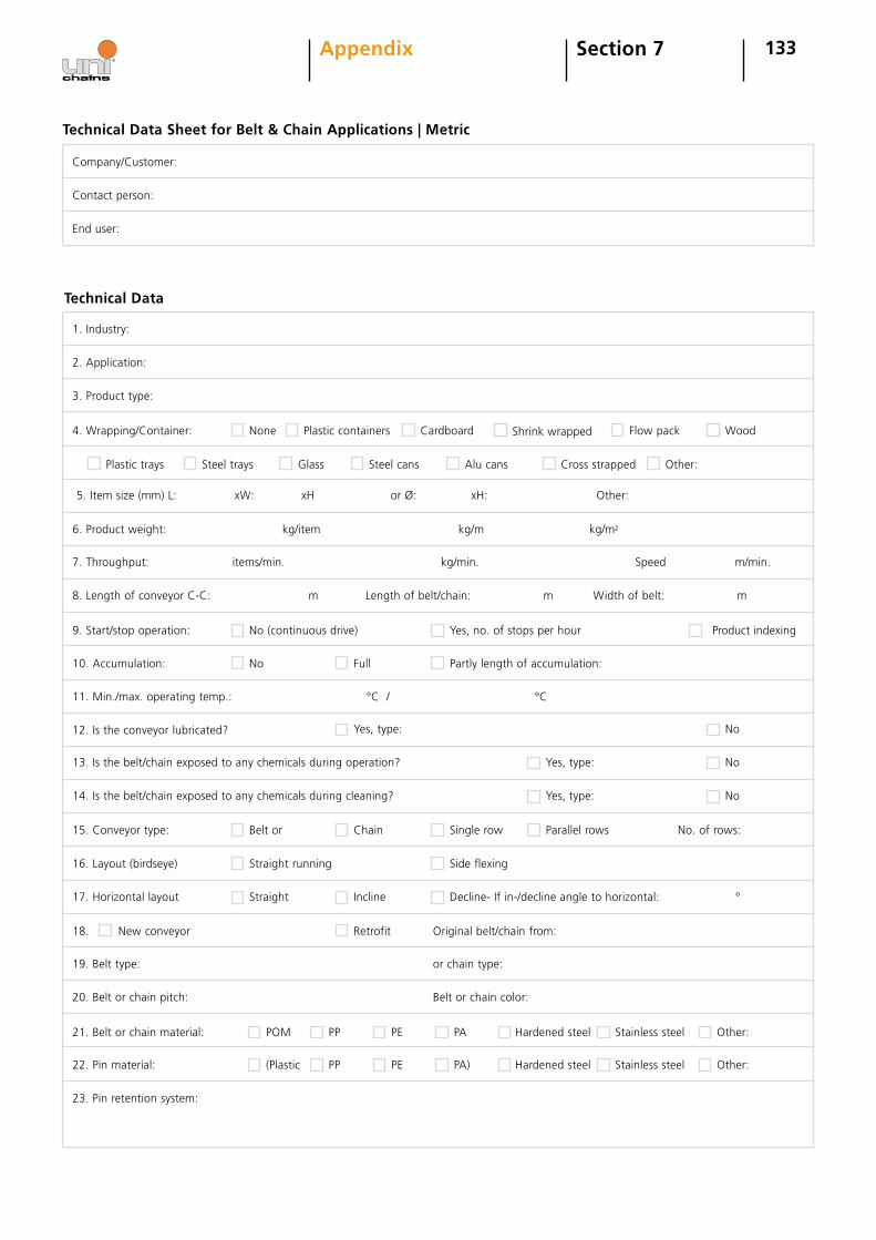
133Section 7Appendix
Technical Data Sheet for Belt & Chain Applications | Metric
Company/Customer:
Contact person:
End user:
Technical Data
1. Industry:
2. Application:
3. Product type:
4. Wrapping/Container:
5. Item size (mm) L: xW: xH or Ø: xH: Other:
6. Product weight: kg/item kg/m kg/m2
7. Throughput: items/min. kg/min. Speed m/min.
8. Length of conveyor C-C: m Length of belt/chain: m Width of belt: m
9. Start/stop operation:
None Cardboard Shrink wrapped Flow pack Wood
Plastic trays Steel trays Glass Steel cans Alu cans Cross strapped Other:
No (continuous drive) Yes, no. of stops per hour Product indexing
No
10. Accumulation:
11. Min./max. operating temp.: °C / °C
12. Is the conveyor lubricated?
No Full
Yes, type:
No13. Is the belt/chain exposed to any chemicals during operation? Yes, type:
No14. Is the belt/chain exposed to any chemicals during cleaning? Yes, type:
Partly length of accumulation:
Plastic containers
Chain Single row Parallel rows15. Conveyor type: Belt or
Side flexing
Decline- If in-/decline angle to horizontal: °
Original belt/chain from:
16. Layout (birdseye) Straight running
Incline
Retrofit
POM PP Hardened steel Stainless steel
Stainless steel Other:
17. Horizontal layout
or chain type:19. Belt type:
Belt or chain color:20. Belt or chain pitch:
21. Belt or chain material:
(Plastic PP Hardened steel22. Pin material:
23. Pin retention system:
Straight
New conveyor
Other:
18.
PE PA
PE PA)
No. of rows:

134Section 7Appendix
Technical Data Sheet for Belt/Chain Applications
25. Side accessories: Indent from side:
No of rows:
no. of teeth z=pitch diameter:
Position:
per shaft pcs
no. of teeth z= (0 if non)
dimension
Date:
+ keyway
pitch diameter: per shaft pcs
26. Bottom tabs (belt): Spacing in travel direction:
27: Wearstrip material:
28: Sprockets : Drive end:
Idler end:
29. Sprocket bore: Drive end:
30. Form filled in by:
31. Sketch of conveyor, stating travel direction and drive motor location
Other
Additional Data
24. Top accessories: Spacing in travel direction: Indent:
SS PE HD 1000 PE HD500

135Section 7Appendix
Technical Data Sheet for Belt & Chain Applications | Imperial
Company/Customer:
Contact person:
End user:
Technical Data
1. Industry:
2. Application:
3. Product type:
4. Wrapping/Container:
5. Item size (in.) L: xW: xH or Ø: xH: Other:
6. Product weight: lb/item lb/ft lb/ft2
7. Throughput: items/min. lb/min. Speed ft/min.
8. Length of conveyor C-C: ft Length of belt/chain: ft Width of belt: ft
9. Start/stop operation:
None Cardboard Shrink wrapped Flow pack Wood
Plastic trays Steel trays Glass Steel cans Alu cans Cross strapped Other:
No (continuous drive) Yes, no. of stops per hour Product indexing
10. Accumulation: No Full Partly length of accumulation:
Plastic containers
No
11. Min./max. operating temp.: °F / °F
12. Is the conveyor lubricated? Yes, type:
Chain Single row
No13. Is the belt/chain exposed to any chemicals during operation? Yes, type:
No14. Is the belt/chain exposed to any chemicals during cleaning? Yes, type:
Parallel rows15. Conveyor type: Belt or
Side flexing
Decline- If in-/decline angle to horizontal: °
Original belt/chain from:
16. Layout (birdseye) Straight running
Incline
Retrofit
POM PP Hardened steel Stainless steel
Stainless steel Other:
17. Horizontal layout
or chain type:19. Belt type:
Belt or chain color:20. Belt or chain pitch:
21. Belt or chain material:
(Plastic PP Hardened steel22. Pin material:
23. Pin retention system:
Straight
New conveyor
Other:
18.
PE PA
PE PA)
No. of rows:
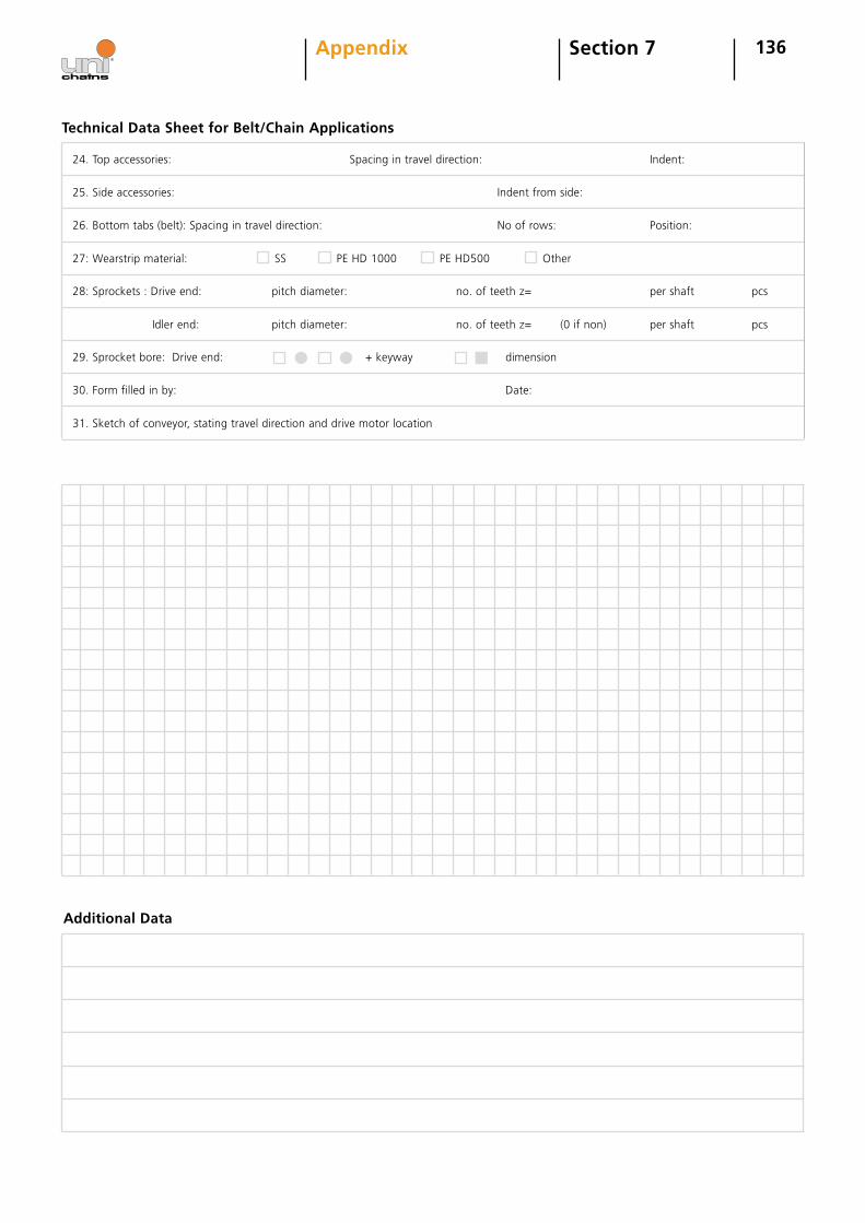
136Section 7Appendix
Additional Data
Technical Data Sheet for Belt/Chain Applications
25. Side accessories: Indent from side:
No of rows:
no. of teeth z=pitch diameter:
Position:
per shaft pcs
no. of teeth z= (0 if non)
dimension
Date:
+ keyway
pitch diameter: per shaft pcs
26. Bottom tabs (belt): Spacing in travel direction:
27: Wearstrip material:
28: Sprockets : Drive end:
Idler end:
29. Sprocket bore: Drive end:
30. Form filled in by:
31. Sketch of conveyor, stating travel direction and drive motor location
Other
24. Top accessories: Spacing in travel direction: Indent:
SS PE HD 1000 PE HD500