Embed Size (px)
Citation preview

28TH INTERNATIONAL CONGRESS OF THE AERONAUTICAL SCIENCES
1
Abstract
This paper revisits a powerful yet much over-looked stress analysis technique known as Thermoelastic Stress Analysis. Beginning with a historical perspective that traces the development of this technology, punctuated by a number of seemingly unrelated events in aeronautics, this paper gradually draws these links together to conclude that, instead of the odd application to validate computational models, this technology should be used systematically and persistently to monitor aircraft structures under fatigue testing. This would allow the reporting of any unanticipated hotspots or cracking at the earliest possible time so that re-analyses and fixes can be planned and designed well ahead of any actual failures.
1 Introduction
Thermoelastic, or Thermographic, Stress Analysis (TSA) has been around for the past 30 years, but to date, it has not been widely utilised or, indeed, widely publicised. Although there are devoted groups of practitioners in the automotive industry in Japan, this technology is largely unknown to the international aerospace sector. On the other hand, the Defence Science & Technology Organisation (DSTO) has been in the forefront of this technology for some time, achieving many pioneering feats. Examples include the discovery and characterisation of a second order effect, the quantification of frequency effects when applied to laminated composites, and development of stress component separation techniques, to name just a few. In particular, two DSTO developments stand out as the most significant.
The first is the development of the world’s first scanning array system. This achieved a 100-fold improvement on scanning time compared to its predecessor, thus allowing stress scans to be achieved in just minutes instead of hours. The other is the world’s first, and to date still the only, microbolometer-based TSA system. Microbolometer imagers are typically an order of magnitude cheaper, and much more amenable to miniaturisation as their sensors do not require cryogenic cooling. These advancements have made TSA’s utility and accessibility to the structural engineer/researcher greater than ever.
Besides partaking in advanced
developments and fundamental research in this area, DSTO has also applied this technology with great effect on numerous practical military aircraft problems. In this role, TSA has proved to be a tremendous model-validation tool. However, its full power has yet to be harnessed as will be shown in this paper.
2 The Beginning
The relationships amongst volume, pressure and temperature of gases have long been known and well understood. Even the lay person would be familiar with the artefacts of these as some are experienced in our everyday lives, such as the heating up of a gas when compressed (e.g., the warming of a bicycle pump in action) or the fall in temperature when a gas is allowed to expand (e.g., cooling down of an aerosol can during discharge).
Essentially, these relationships are merely statements of conservation of energy and mass. As such, one expects a similar effect when
MAKING THE INVISIBLE VISIBLE: JOINING THE DOTS FROM LORD KELVIN TO FIGHTER JET FATIGUE
Albert K. Wong
Keywords: thermoelastic, stress, fatigue, FSFT, FSDT
A.K. Wong
2
compressible solids are being deformed. Such a phenomenon is known as the thermoelastic effect. Stanley [1] provides a lucid historical account on the earliest documentation of this, citing works such as that by the blind philosopher, John Gough (1757-1825) who experimented with rubber using, amusingly, his own lip as a temperature sensor, and the sophisticated but simple experiments of Wilhelm Weber (1804-1891) on copper and steel wires. Other 19th century scientific greats such as Joules and J.J. Thomson have also contributed, but it was William Thomson (1824-1907, better known as Lord Kelvin) who set the foundation for our true understanding of this phenomenon. The relationship between temperature and stress was formally derived in his seminal 1853 paper [2], to which the present form of the thermoeastic equation is attributed (referred hereafter as Kelvin’s Law), viz.,
where ∂ denotes changes, T and To are the instantaneous and reference temperatures respectively, K1 is known as the thermoelastic constant, and s is the bulk stress2.
Kelvin’s contributions in the science of thermodynamics are undisputed, with his legacy fittingly honoured by the absolute temperature scale that bears his name. Less well known, however, are his contributions to other technologies that span as wide a field as ship design to electric oscillations and transmission. He was not only a brilliant theoretician, but an exceptional engineer who played a crucial role in the laying of the transatlantic submarine cable, and served in the Admiralty Committee for designing war ships. A visionary for both land and sea, he appeared to be less insightful in the air domain. In 1895, he was reputed to have made the infamous statement that “heavier-than-
1 K is equal to the coefficient of thermal expansion divided by the product of density and the specific heat. 2 Bulk stress is defined as the sum of the principal stresses, which is also known as the first stress invariant.
air flying machines are impossible”3. Less than a decade later, the Wright Brothers recorded the first manned powered flight off the coast of North Carolina in 1903.
3 The Conception
At around the time of the Wright Brothers, Turner [3] was the first to make the link between Kelvin’s Law and its potential for measuring stresses. His attention, however, appeared to be focused on the exploration of the limit of proportionality and how this is related to the elastic limit and, interestingly, to Wöhler’s fatigue endurance limit [4]. It was perhaps not until Coker’s 1904 paper [5] entitled “On the Measurement of Stress by Thermal Methods” that the idea of using Kelvin’s Law as a viable means of stress analysis was realised. Nonetheless, the use of temperature measurements to infer stress appeared to add an unnecessary layer of complexity compared to other, more direct, methods. Henceforth, we witnessed the development of the conventional strain gauge, which dominated the field of experimental stress analysis over the next century.
The importance of stress measurements is
no more recognised than in the aviation world, where structural strength and fatigue are of paramount concern. Even prior to the Comet disaster in 1954, aircraft manufacturers and regulators were well aware of the need to proof against fatigue, though their knowledge on the scatter in lives and the margin of safety required was still at a formative stage (see Cardrick & Mew [6]). In the illuminating 1951 Wright Lecture, Percy Walker [7] described the ultimate load testing of the wings and fuselage of an aircraft off the assembly line, as well as the fatigue testing of 50 Meteor tail planes as scaled-down wing-sets. In the discussion section of the paper, a senior Boeing engineer indicated
3 Although this quote is widely attributed to Lord Kelvin, no primary source was able to be located, other than being referenced by the following authoritative website: http://www.nasa.gov/centers/dryden/news/X-Press/stories/2004/013004/res_feathers.html
sKTT
∂−=∂
0, (1)

3
MAKING THE INVISIBLE VISIBLE: JOINING THE DOTS FROM LORD KELVIN TO FIGHTER JET FATIGUE
that 1,500 strain gauges were used on the B-47 Stratojet test. Walker also agreed “that testing is no substitute for a proper stress analysis.” It is therefore not entirely surprising that the next important step towards a practical TSA system also came from this sector. In 1967, Belgen, an engineer working for North American Aviation Inc., on a NASA funded project, was the first to apply infrared (IR) radiometry to successfully measure the stress of a steel cantilever beam [8].
By now, the Comet incidents, as well as
later but equally notable air accidents, had brought about a deeper understanding of structural fatigue and the important role played by stresses and stress concentrators. This ulti-mately led to the entrenchment of the full scale fatigue test (FSFT) as an integral part of aircraft certification. At the same time, DSTO made its contribution via the biggest FSFT program ever undertaken by testing 110 Mustang wing-sets (for a good historical account of fatigue testing in DSTO, see Molent [9]).
4 The Birth of a New Tool
Over the next decade or so, a few more researchers explored the use of IR radiometry for determining stresses. In particular, David Mountain of the Admiralty Surface Weapons Establishment joined forces with an electronic instrumentation company SIRA Ltd in 1973 to develop a practical thermographic device called SPATE (Stress Pattern Analysis by Thermal Emission). A prototype of this device was unveiled by Mountain & Webber [10] in 1978. Shortly afterward, a commercial system named SPATE 8000 was launched in 1982 by Ometron Ltd (a subsidiary company of SIRA) and soon sold throughout the world. Equipped with a single mercury-cadmium-telluride (HgCdTe) IR photodetector, and a 2-axis mechanical scanning mirror system, coupled with an analogue phase-lock amplifier, the system could achieve a raster scan of a component under dynamic loading, with a reported stress resolution of 1MPa for steel and 0.3MPa for aluminium.
This period also saw the start of a long but not entirely trouble-free service of the F-111
multi-role fighter/bomber by the Royal Australian Air Force (RAAF). After an initial 4 ½ year delay in its delivery in 1973, structural issues surrounding its wings and wing carry-through-box began to emerge through the series of mandated cold-proof-load tests, less than a decade into its service [11]. Eventually, these issues would, to a large extent, determine this aircraft’s economic life. But well before its re-tirement, Australia took delivery of her current frontline fighters, the F/A-18 Hornets, in 1984.
5 The Golden Age
The arrival of SPATE was seen as a game changer for experimental stress analysis. For the first time, stress maps of components under load could be obtained with relative ease. Its developer, SIRA, was duly recognised by receiving the Queen’s Award for Technological Achievement in 1985, and a second Queen’s Award to Ometron for Export Achievement in 1987 [1]. Realising its great potential in stress analysis, DSTO was amongst the first customers, where this new device was quickly put through its paces, pointing at various bits of aircraft material/specimen that could be loaded in a testing machine. Elsewhere, SPATE users were doing the same, exploring the envelope of this new found tool. Ometron initiated the SPATE Users Group, where practitioners around the world met regularly to exchange experiences and ideas. As with the introduction of any new technology, it immediately led to a flurry of research and applications. TSA was being applied to a wide and varied range of problems. Papers were produced on deter-mining optimised parameters such as loading frequencies and paint coatings, as well as applications to determine stress concentrations and stress intensity factors, analysing welds, and studies on composites. In the US, the University of Wisconsin established itself as the centre of expertise in TSA, making many worthy contributions as well as forming the core of the US SPATE Users Group (e.g., [12]), and eventually spun off a private enterprise in 1987 called Stress Photonics. Amongst the applications came reports of anomalies and
A.K. Wong
4
discoveries too, with DSTO being one of the most active participants. These included the first report of the mean stress effect [13] followed shortly by an explanation of its cause and the revision of the thermoelastic equation [14] as well as demonstrating that this phenomenon could potentially be used to measure residual stresses [15]; combining TSA with analytical and numerical methods to determine stress components [16, 17]; the quantification of the frequency effect for composites applications [18, 19]; and the reporting of motion effects [20] and devising a real-time motion compensation algorithm [21].
While SPATE experiments were
performed in a small corner of the DSTO laboratory in Melbourne, a multi-million dollar program was being planned and initiated for the full scale fatigue testing of one of the RAAF’s newly acquired F/A-18s. Designated as IFOSTP (International Follow-On Structural Test Program), it was a major collaborative FSFT program involving the US, Canada and Australia to qualify the fighter’s airframe life under Australian/Canadian flight loads [22].
6 FAST and Fabulous
The potential to use TSA to measure residual stresses was indeed tantalising, but it pivots around the second order effects in the thermoelastic phenomenon [14, 15]. Given SPATE had a temperature resolution of 10-3°C, it means that a practical tool for this purpose might well need a temperature resolution of some 10-4°C or better. Consequently, DSTO set its sight on developing such an instrument in the early 1990s. Using a commercial IR imager available at the time that had a 512x512 platinum-silicide (PtSi) focal plane array, DSTO researchers developed real-time digital signal processing algorithms to produce the world’s first array-based TSA system [23, 24]. Named FAST, for Focal-plane Array Synchronous Thermography, this system represented a major advancement in the field [25]. Because of inherent signal drifts and fixed pattern noise that were (and still are) characteristics of
cryogenically cooled photodetectors, the initial aim on the minuscule temperature resolution required for residual stress measurement was never achieved4. What resulted, however, was an extremely fast TSA system that had no equals at the time. What used to take hours of SPATE scanning could now be achieved in just minutes, and with much better spatial resolution. When FAST was first publicised at an SEM5 conference in 1993, a Stress Photonics newsletter highlighted that “[t]his paper may have raised the most interest at the conference” [26]. A year or so later, Stress Photonics, with the backing of NASA [27], unveiled their project based on a 128x128 indium-antimonide (InSb) focal plane IR imager, and launched this system commercially in 1995 under the trade name DeltaTherm, thus making high speed TSA accessible to others.
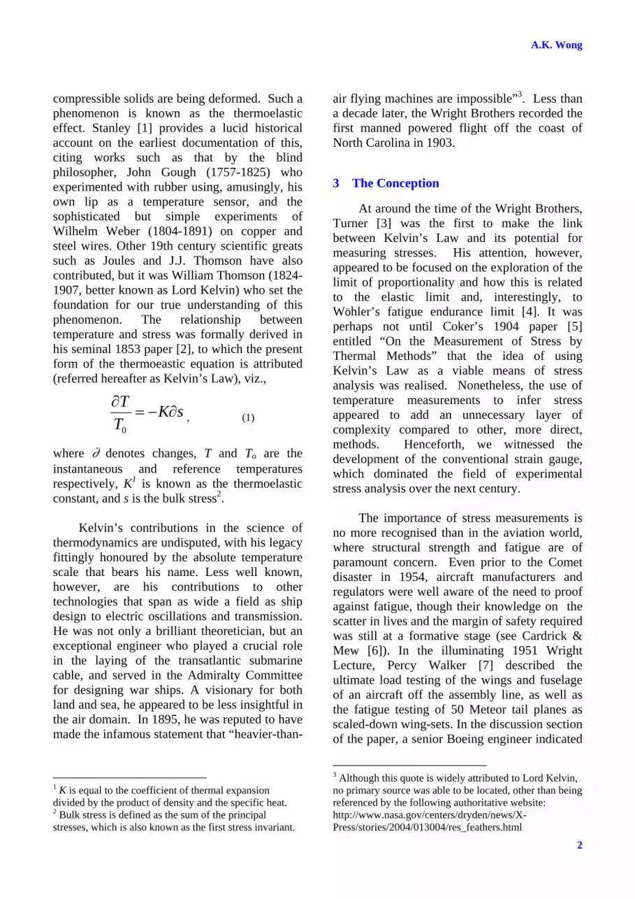
At around the same time, FAST was being
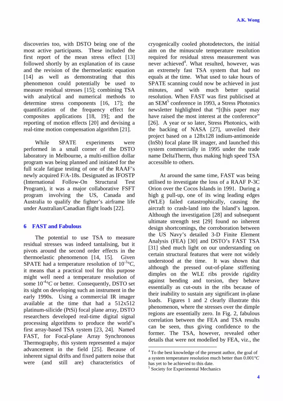
utilised to investigate the loss of a RAAF P-3C Orion over the Cocos Islands in 1991. During a high g pull-up, one of its wing leading edges (WLE) failed catastrophically, causing the aircraft to crash-land into the Island’s lagoon. Although the investigation [28] and subsequent ultimate strength test [29] found no inherent design shortcomings, the corroboration between the US Navy’s detailed 3-D Finite Element Analysis (FEA) [30] and DSTO’s FAST TSA [31] shed much light on our understanding on certain structural features that were not widely understood at the time. It was shown that although the pressed out-of-plane stiffening dimples on the WLE ribs provide rigidity against bending and torsion, they behave essentially as cut-outs in the ribs because of their inability to sustain any significant in-plane loads. Figures 1 and 2 clearly illustrate this phenomenon, where the stresses over the dimple regions are essentially zero. In Fig. 2, fabulous correlation between the FEA and TSA results can be seen, thus giving confidence to the former. The TSA, however, revealed other details that were not modelled by FEA, viz., the 4 To the best knowledge of the present author, the goal of a system temperature resolution much better than 0.001°C has yet to be achieved to this date. 5 Society for Experimental Mechanics
5
MAKING THE INVISIBLE VISIBLE: JOINING THE DOTS FROM LORD KELVIN TO FIGHTER JET FATIGUE
stress concentrating effects of the rivets. The detailed results in [31] clearly showed that the peak stress occurred at a rivet hole above one of the stiffening dimples, thus corroborating the forensic investigation that found the origin of the fracture was indeed at such a location.
The other little-known phenomenon that was revealed is the effects of curvature on a flange’s capacity to carry load. At the inner perimeter of the WLE, a flange is formed by channel-strips riveted to the rib (see inset in Fig. 1). Whilst this flange is laid out relatively flat towards its ends, it forms almost a circular arc over the failed location. TSA was able to clearly show that the load-carrying capacity for such a flange is effectively halved compared to if it were straight (see original text in Wong et al [31]).
The use of TSA in this example not only
highlights the fact that this technique can serve as an excellent validation tool for FEAs, but demonstrates its power to reveal structurally significant features in its own right, quickly and with great detail.
Also in 1996, IFOSTP started in earnest in
DSTO and would go on for some six years, accruing 23,000 simulated flight hours in what was considered the world’s most advanced fatigue test rig. In 2001, this program was honoured with the prestigious Von Karman Award by the International Council of the Aeronautical Sciences.
7 Economic MiTE
The accessibility of the TSA technology was further increased when the French thermographic company CEDIP (now a part of the global conglomerate FLIR) entered the market in the early 2000s with the AltaIR LI system that was based on a 320x256 HgCdTe or InSb array detector. Still, acquiring either a US or French system even now would set one back over $100,0006. This is indeed a significant cost, particularly compared to other emerging 6 The list price was approx. twice this amount back in the early 2000s, inflation notwithstanding.
Fig. 2: Analysis of critical region: a) FAST TSA scan, b) 3-D FEA performed by NAVAIR; blue shading shows areas of low stresses in these images.
Fig. 1. FAST TSA scan of Orion WLE; inset: failed region of one of the test articles; dark-green shading in the scan shows areas of low stresses in this image.

A.K. Wong
6
full-field methods such as speckle interferometry or digital image correlation. Another apparent disadvantage for TSA is the necessity to apply sustained cyclic loading that is not required by other methods. Consequently, the uptake of this technology has not been as high as it might have been. Interest over recent years appeared to have tapered, and TSA Users Groups slipped into relative abeyance.
Recognising the access costs of this
technology to be a major hurdle for most, DSTO again stepped into the fray to make a difference with the development of a low-cost system based on a 160x120 microbolometer array imager. These imagers typically cost a tenth of the photodetector types used in current systems, but their intrinsic temperature sensitivities are some 5 times poorer. However, by using appropriate signal processing techniques, Rajic et al [32, 33] showed that their system, MiTE (Microbolometer ThermoElasticity), was able to achieve system temperature resolutions that are comparable to existing devices. Furthermore, they were able to exploit such imagers’ ruggedness and compactness in situations that were not previously possible; e.g., see Fig. 3, where two imagers were mounted on an F/A-18 structure undergoing fatigue testing (the pint-size devices in front of the black areas).
As the 21st century approached, DSTO’s
involvement in FSFT continued beyond IFOSTP, and undertook (and in some cases, is still undertaking) major test programs, including the Pilatus PC-9 airframe, F-111 wings, F/A-18 Centre Barrel structure, C-130J wings, and the Hawk jet trainer airframe. The DSTO MiTE TSA system was utilised for a number of locations on the F/A-18 tests as previously mentioned, with two of the highlight results reproduced herein:
1) F/A-18 Centre-Barrel (CB) Access Hole One outcome of IFOSTP was that the CB for this aircraft required replacement midway through its service life at substantial costs. However, it was thought that some of the assumed conservatisms could well be shaved away if only better failure data and improved
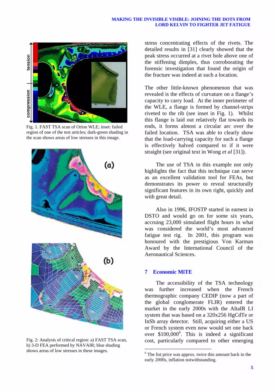
modelling were available. To achieve this, a fatigue testing program, designated FINAL (for Flaw IdeNtification through the Application of Loading), was pursued via testing to failure of a large number of retired Canadian Forces, USN and RAAF CBs [34]. One of the known hot-spots in this structure is a hydraulic line access hole in one of the bulkheads. In order to develop an improved lifing model, this location was modelled using detailed 3-D FEA. TSA was subsequently used to validate this model, ensuring that appropriate boundary conditions and meshing were applied to this region. As can be seen from Fig. 4, excellent agreement between the modelled and measured stress distributions was achieved.
2) Bonded Doubler on the F/A-18 Bulkhead
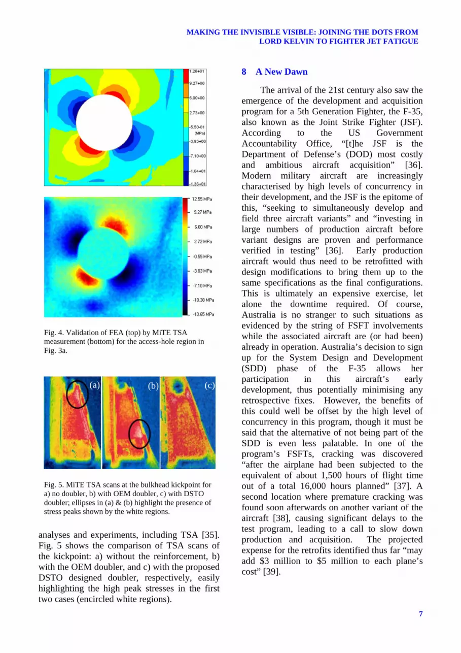
Premature debonding of an Original Equipment Manufacturer (OEM) doubler had been found in service at the bulkhead location nicked-named as the kickpoint. (see inset b in Fig. 3). DSTO found a design deficiency in that this structural enhancement had simply shifted the peak stress to the end of the doubler. A new design, with a longer transition length, was proposed and shown to be effective via
Fig. 3. F/A-18 Centre-Barrel test rig and article; insets: a) access-hole region, b) kickpoint region showing bonded doubler.
7
MAKING THE INVISIBLE VISIBLE: JOINING THE DOTS FROM LORD KELVIN TO FIGHTER JET FATIGUE
analyses and experiments, including TSA [35]. Fig. 5 shows the comparison of TSA scans of the kickpoint: a) without the reinforcement, b) with the OEM doubler, and c) with the proposed DSTO designed doubler, respectively, easily highlighting the high peak stresses in the first two cases (encircled white regions).
8 A New Dawn
The arrival of the 21st century also saw the emergence of the development and acquisition program for a 5th Generation Fighter, the F-35, also known as the Joint Strike Fighter (JSF). According to the US Government Accountability Office, “[t]he JSF is the Department of Defense’s (DOD) most costly and ambitious aircraft acquisition” [36]. Modern military aircraft are increasingly characterised by high levels of concurrency in their development, and the JSF is the epitome of this, “seeking to simultaneously develop and field three aircraft variants” and “investing in large numbers of production aircraft before variant designs are proven and performance verified in testing” [36]. Early production aircraft would thus need to be retrofitted with design modifications to bring them up to the same specifications as the final configurations. This is ultimately an expensive exercise, let alone the downtime required. Of course, Australia is no stranger to such situations as evidenced by the string of FSFT involvements while the associated aircraft are (or had been) already in operation. Australia’s decision to sign up for the System Design and Development (SDD) phase of the F-35 allows her participation in this aircraft’s early development, thus potentially minimising any retrospective fixes. However, the benefits of this could well be offset by the high level of concurrency in this program, though it must be said that the alternative of not being part of the SDD is even less palatable. In one of the program’s FSFTs, cracking was discovered “after the airplane had been subjected to the equivalent of about 1,500 hours of flight time out of a total 16,000 hours planned” [37]. A second location where premature cracking was found soon afterwards on another variant of the aircraft [38], causing significant delays to the test program, leading to a call to slow down production and acquisition. The projected expense for the retrofits identified thus far “may add $3 million to $5 million to each plane’s cost” [39].
Fig. 5. MiTE TSA scans at the bulkhead kickpoint for a) no doubler, b) with OEM doubler, c) with DSTO doubler; ellipses in (a) & (b) highlight the presence of stress peaks shown by the white regions.
Fig. 4. Validation of FEA (top) by MiTE TSA measurement (bottom) for the access-hole region in Fig. 3a.
(a) (b) (c)
(MPa)
A.K. Wong
8
Although the JSF program’s high profile and level of scrutiny make such stumbles highly publicised, similar challenges are faced by any other new aircraft development program. As long as OEMs continue to chase ever increasing performance and affordability, high levels of concurrency will continue, and surprises will continue to emerge. The ability to remove, or at least minimise, such surprises can therefore make a significant impact on such programs.
Unanticipated failures in any fatigue test
are invariably due to oversights in design. Modern aircraft design is heavily reliant on models and analyses as these have developed to a stage where, if done correctly, good life predictions can be derived. As a result, many OEMs emphasise analyses and the grandfathering of related earlier tests as a means of avoiding the tremendous effort and costs of FSFTs. Yet in reality, surprises still crop up, and the reason is simply that not everything can be modelled to the degree necessary. This is where FSFTs can faithfully serve as a last safeguard against any structural design oversights prior to the declaration of a certified life. In DSTO at least, TSA has played a role in conjunction with FSFT to determine aircraft lives as shown previously. However, a much greater role can be played immediately and in the future. To date, TSA has only been used as a validation tool for stress models of known potential problem areas. To the best knowledge of the present author, it has not previously been deployed to seek out unknown hotspots in a FSFT. It is argued here that this is where TSA can make the most impact. The fact that this technology can provide broad-area non-contact stress maps of structures under cyclic loading (a natural feature of any FSFT) makes it ideally suited for this purpose. Under FSFT, the whole aircraft structure (at least wherever visible) can be systematically and persistently scanned to seek out initial design hotspots as well as any developing flaws. This should provide the design/test engineers with the earliest possible warning of any potential problem locations, and thus allowing rectification plans to be put in place well prior to any actual failures.
9 Roadmap Ahead
Although existing TSA systems can already achieve many elements of the proposal now, some improvements and research will add significantly to this objective. For example, modification of the signal processing software to handle spectrum loading will be crucial for the integration of this technology into a FSFT program. We already know that this can be achieved with relative ease – FAST, as well as the most of the current systems could/can already handle random loading sequence. However, FSFT involves more than just non-uniform loading, but also distinct load cases (e.g., bending vs torsion) and the system needs to be able to distinguish these – a task that can be achieved with only minor software modification. Being able to move around the test rig autonomously to take zonal scans and then piecing all the separate scans together to form an overall airframe scan would also be valuable. This can be achieved manually now, but an automated system based on robotics is easily conceivable. Furthermore, the same robotics can be exploited to remove the effects of large scale motion (i.e., heaving, panning and tilting the imager in sync with the flexing structure under load). The adaptation of small or miniaturised microbolometer imagers would increase accessibility to currently unreachable places, and ultimately, embedded systems can pave the way for structural prognostics and health management (SPHM) applications. On the research side, studies on coatings to improve sensitivity, applications to composites, extrapolation to adiabatic results, integration with finite element models, and perhaps even with rapid prototyping and structural shape optimisation are all interesting possibilities. This list, summarised in Table 1, is by no means exhaustive, but serves as a provocative strawman for others to build upon. DSTO is already actively pursuing some of these, whilst some others may not even be realisable, but in any case, it is clear that TSA has a very bright and colourful future indeed.

9
MAKING THE INVISIBLE VISIBLE: JOINING THE DOTS FROM LORD KELVIN TO FIGHTER JET FATIGUE
References
[1] Stanley P. “Beginnings and Early Development of Thermoelastic Stress Analysis”. Strain, Vol. 44, pp 284-297, 2008.
[2] Thomson W. (Lord Kelvin) “On the Dynamical Theory of Heat”. Trans. R. Soc (Edin), Vol. 20, pp 161-283, 1853.
[3] Turner C.A.P. “Thermo-electric Measurement of Stress”. Trans. Am. Soc. Civ. Eng., Vol. 48, pp 140–179, 1902.
[4] Wöhler, A. “Versuche uber die Festigkeit der Eisenbahnwagenachsen”. Zeitschrift fur Bauwesen, 10, 1860; English summary in Engineering, Vol. 4, pp 160-161, 1867.
[5] Coker E.G. “On the Measurement of Stress by Thermal Methods”. Trans R. Soc. Edin., Vol. 41, pp 229–250, 1904.
[6] Cardrick A.W., Mew A.B. “Scatter Considerations in the Interpretation of Major Fatigue Tests”. Proc. 20th Sym. ICAF, Bellevue, WA, USA, pp 14-16, Jul 1999.
[7] Walker P.B. “The Experimental Approach to Aircraft Structural Research: The Fifteenth Wright Brothers Lecture”. Aircraft Eng. Aerospace Tech., Vol. 24, Iss. 3, pp 62 – 71, 1952; reprinted in J. Aero. Sci., Vol. 19, No. 5, pp 145-172, 1952.
[8] Belgen, M.H. “Structural Stress Measurements with an Infrared Radiometer”. ISA Trans., Vol. 6, No. 1, pp 49-53, Mar 1967.
[9] Molent L. “The History of Structural Fatigue Testing at Fishermans Bend Australia”. DSTO-TR-1773, 2005.
[10] Mountain D.S., Webber J.M.B. “Stress Pattern Analysis by Thermal Emission (SPATE)”. Proc. SPIE, Vol. 164, pp 189–196, 1978.
[11] Swanton G. “40 Years of F-111 Aircraft Structural Integrity Support by the Defence Science and Technology Organisation”, Proc. 13th AIAC, Melbourne, AU, Mar 2009.
[12] Oliver D.E., Jaeger P. “SPATE Applications in North America: report on U.S. SPATE Users Group”. Stress Analysis by Thermoelastic Techniques, Proc. Meeting, London, England, Feb. 17, 18, 1987; Proc. SPIE, Bellingham, WA, pp 213-226, 1987.
[13] Machin A.S., Sparrow J.G., Stimson M.G. “Mean Stress Dependence of the Thermoelastic Constant”. Strain, Vol. 23, No. 1, pp 27-30, 1987.
[14] Wong A.K., Jones R., Sparrow J.G. “Thermoelastic Constant or Thermoelastic Parameter?” J. Phys. Chem. Solids, Vol. 48, No. 8, pp 749-753, 1987.
[15] Wong A.K., Dunn S.A., Sparrow J.G. “Residual Stress Measurement by means of the Thermoelastic Effect”. Nature, Vol. 332, pp 613-615, 1988.
System Development Research Near-Term (1-2 years)
• Modification of software to handle spectrum loading such as those used in FSFTs, viz, being able separate distinct load cases.
• Adaptation of smaller and higher resolution microbolometer imagers (e.g., [33]).
• Rapid attachment systems on aircraft structures (e.g., use of vacuum suction devices)
• Implement software to piece together individual scans to form overall aircraft scan.
• Incorporation of smarter image processing algorithms to compensate large scale structural movements.
• Integration of high-speed IR imagers (>500Hz) for buffet load cases.
• Study the effects of paint coating, including applications to as-delivered aircraft type under-coats.
• Understanding TSA on aircraft composites structures, particularly those used on current and next generation aircraft.
• Extracting stress or damage information from phase information (e.g, [40]).
• Use of microscopic lenses (currently available for high-end photodetector type imagers) in understanding crack-tip behaviour, particularly crack closure (e.g, [41]).
• Investigate the potential use of the first stress invariant (essentially TSA output) to directly predict fatigue lives.
Mid-Term (2-5 years)
• Exploit robotics to automatically and systematically scan full aircraft during FSFT, including its use to physically compensate for large scale motion (i.e., heaving, panning and tilting the imager to follow the structural motion during FSFT).
• Exploit miniaturised IR imagers to gain access to confined or enclosed regions (e.g., [33]).
• Exploit image jitters to achieve spatial super-resolution.
• Explore methods to recover adiabatic conditions from rich excitation information (e.g, [18, 33]).
• Study of buffet problems using high-speed systems. • Follow up on the use of 2nd order effect to
potentially measure residual stresses (e.g., [42]). • Further study on the fusion of TSA data with
analytic or numerical methods to achieve stress decomposition (e.g., [43]).
Far-Term (>5 years)
• Develop high quality microscopic lenses for microbolometer imagers.
• Investigate/develop optical fibres/wave-guides for the frequency range of interest for TSA.
• Develop embedded IR camera systems (e.g., [33]), including the use of wireless image transmission for TSA applications.
• Investigate the use of TSA as a SPHM tool (e.g., [33]).
• Explore possible integration of TSA with structural optimisation tools (e.g., that used currently with FEA [44]) for in-situ optimisation of structural designs using rapid prototyping technology.
Table 1. Roadmap Ahead for TSA Applications in FSFTs: Suggested Areas of System Development and Research.
A.K. Wong
10
[16] Ryall T.G., Wong A.K. “Determining Stress Components from Thermoelastic Data – A Theoretical Study”. Mech. Mat., Vol. 7, pp 205-214, 1988.
[17] Ryall T.G., Heller M., Jones R. “Determination of Stress Components from Thermoelastic Data without Boundary Conditions”. J. Appl. Mech., Vol. 59, pp 841-847, 1992.
[18] Wong A.K. “A Non-adiabatic Thermoelastic Theory for Composite Laminates”. J. Phys. Chem. Solids, Vol. 52, No. 3, pp 483-494, 1991.
[19] Dunn S.A. “Analysis of Thermal Conduction Effects on Thermoelastic Temperature Measurements for Composite. J. Appl. Mech. – Trans. ASME, Vol. 59, pp 552-558, 1992.
[20] Van Hemelrijck D., Schillemans L., Cardon A.H., Wong A.K. “The Effect of motion of Thermoelastic Stress Analysis”. Comp. Struct., Vol. 18, pp 221-238, 1991.
[21] Wong A.K., Ryall T.G. “The Use of FAST on Structures Undergoing Large Motions”. Proc. 1st Australasian Cong. Exp. Mech., Melbourne, AU, pp 701-706, Feb 1996.
[22] Graham D, Symons D., Sherman D., Eames T. “ARL F/A-18 IFOSTP Full Scale Fatigue Test”. Proc. 5th Aust. Aero. Conf., pp 317-323, Melbourne, AU, Sep 1993.
[23] Ryall T.G., Wong A.K., “Infrared Staring Arrays and Digital Signal Processing”. Invited Paper, Proc. SEM 50th Ann. Spring Conf. Exp. Mech., pp 730-739, Michigan, June 1993.
[24] Ryall T.G., Wong A.K. “The Design of a Focal-plane Array Thermographic Stress Analysis System”. Exp. Mech., Vol. 35, pp 144-147, 1994.
[25] Wong A.K., Ryall T.G., “Performance of the ‘FAST’ System for Stress Analysis”. Exp. Mech., Vol. 35 pp 148-152, 1994.
[26] Boyce B. “Spring SEM Conference Highlights”. Stress Photonics Thermoelastic Forum, Vol. 1, No. 4, Sep 1993.
[27] Haggerty J.J., “Stress Measurement System”. Spinoff 1996, p69, NASA Publication, 1996.
[28] Callinan R.J., Kepert J.L., Stimson M.G. “Investigation of the Accident to Lockheed P-3C Orion A9-754”. ARL-STRUC-TM-554, 1992.
[29] Wong A.K., Luke G. “The Static Testing of a Lockheed P-3 Orion Wing Leading Edge Centre Section”. DSTO-TR-0423, 1996.
[30] Phan N.D., Personal Communications, 1995. [31] Wong A.K., Richmond M., Ryall T.G. “Structural
Assessment of the Orion P3 Wing Leading Edge by a State-of-the-Art Thermal Imaging System”. Proc. 6th Aust. Aero. Conf., pp 795-800, Mar 1995.
[32] Rajic N., Weinberg S., Rowlands D. “Low-cost Thermoelastic Stress Analysis”. Mat. Aust., pp 40-41, Mar/Apr 2007.
[33] Rajic N., Rowlands D., Galea S. “Probing the Limits – New Opportunities in Thermoelastic Stress Analysis”. Proc. 28th ICAS, 2012.
[34] Molent L., Dixon B., Barter S. “Flaw IdeNtification through the Application of Loading”. Proc. Struct. Int. Frac. Conf., pp 26-29, Brisbane, AU, Sep 2004.
[35] Rider A., Stoyanovski I., Wang J., Tata D. “Verification and Validation Program for the F/A-18 Y488 Bulkhead Fatigue Life Enhancement Doubler - Full Scale Testing”. In prep. DSTO Tech Rept, 2012.
[36] Sullivan M. “Joint Strike Fighter: Significant Challenges Remain as DOD Restructures Program”. Testimony Comm. Arm. Serv. US Sen., 11 Mar 2010.
[37] Gertler J. “F-35 Joint Strike Fighter (JSF) Program: Background and Issues for Congress”. Congressional Research Service Rept, Apr 2011.
[38] Capaccio A. “Lockheed F-35 Fighter Has ‘Design Flaw’ In Wing Part, Pentagon Tester Says”. Bloomberg News, 2 Sep 2011.
[39] Whittle R. “JSF's Build and Test was 'Miscalculation,' Adm. Venlet Says; Production Must Slow”. AOL Defense, 1 Dec., 2011.
[40] Sathon N., Dulieu-Barton J.M. “Damage Analysis of Internal Surface Flaws Using Thermoelastic Stress Analysis”. Key Eng. Mat., Vol. 293-294, pp 279-288, 2005.
[41] Díaz F.A., Yates J.R., Patterson E.A. “Some Improvements in the Analysis of Fatigue Cracks using Thermoelasticity”. Int. J. Fatigue, Vol. 26, No. 4, pp 365-376, 2004.
[42] Robinson A.F., Dulieu-Barton J.M., Quinn S., Burguete R.L. “A Review of Residual Stress Analysis using Thermoelastic Techniques”. J. Phys.: Conf. Ser. Vol. 181, No. 1, 012029, 2009.
[43] Hayabusa K., Inoue H., Kishimoto K., Shibuya T. “Improvement of Accuracy of Inverse Analysis for Stress Separation in Thermoelastic Stress Analysis”. ATEM’99 Proc. Int. Conf. Adv. Tech. Exp. Mech., Ube City, Japon, Vol. 43, No. 4, pp 305-313, 1999.
[44] Heller M., Burchill M., Wescott R., Waldman W., Kaye R., Evans R., McDonald M. “Airframe Life Extension by Optimised Shape Reworking – Overview of DSTO Developments”. Proc. 25th Sym. ICAF, Rotterdam NL, pp 379-300, May 2009.
Copyright Statement
The author confirms that he, and/or his company or organization, hold copyright on all of the original material included in this paper. The author also confirms that he has obtained permission, from the copyright holder of any third party material included in this paper, to publish it as part of his paper. The author confirms that he gives permission, or has obtained permission from the copyright holder of this paper, for the publication and distribution of this paper as part of the ICAS2012 proceedings or as individual off-prints from the proceedings.


