Embed Size (px)
Citation preview
MAINTENANCE MANUAL
AQUILA AT01A
MAINTENANCE MANUAL
AQUILA AT01 (A210)
Doc.-No. MM-AT01-1020-100
This document is protected by copyright. All associated rights, in particular those of translation, reprinting, reproductionby photo mechanical or similar means and storing in data processing facilities in whole or part are reserved.The technical content of this document is approved under the authority of DOA ref. EASA.21J.025.
AQUILA Aviation International GmbH Phone:++49 33 731 707 - 0Flugplatz Fax: ++49 33 731 707 - 1114959 Schönhagen e-mail: [email protected]
AQUILA Aviation International GmbH

MAINTENANCE MANUAL
AQUILA AT01A
MAINTENANCE MANUAL
AQUILA AT01A
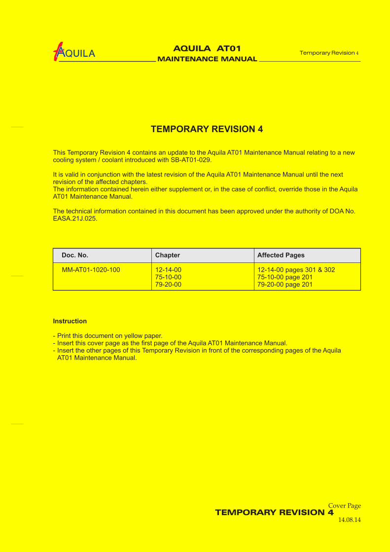
TEMPORARY REVISION 4
This Temporary Revision 4 contains an update to the Aquila AT01 Maintenance Manual relating to a newcooling system / coolant introduced with SB-AT01-029.
It is valid in conjunction with the latest revision of the Aquila AT01 Maintenance Manual until the nextrevision of the affected chapters.The information contained herein either supplement or, in the case of conflict, override those in the AquilaAT01 Maintenance Manual.
The technical information contained in this document has been approved under the authority of DOA No.EASA.21J.025.
MM-AT01-1020-100 12-14-00 12-14-00 pages 301 & 30275-10-00 75-10-00 page 20179-20-00 79-20-00 page 201
- Print this document on yellow paper.- Insert this cover page as the first page of the Aquila AT01 Maintenance Manual.- Insert the other pages of this Temporary Revision in front of the corresponding pages of the Aquila
AT01 Maintenance Manual.
Doc. No. Chapter Affected Pages
Instruction
Temporary Revision 4
TEMPORARY REVISION 414.08.14
Cover Page4

MAINTENANCE MANUAL
AQUILA AT01A
TABLE OF CONTENTS
Cha/Sec/Sub Title Pages
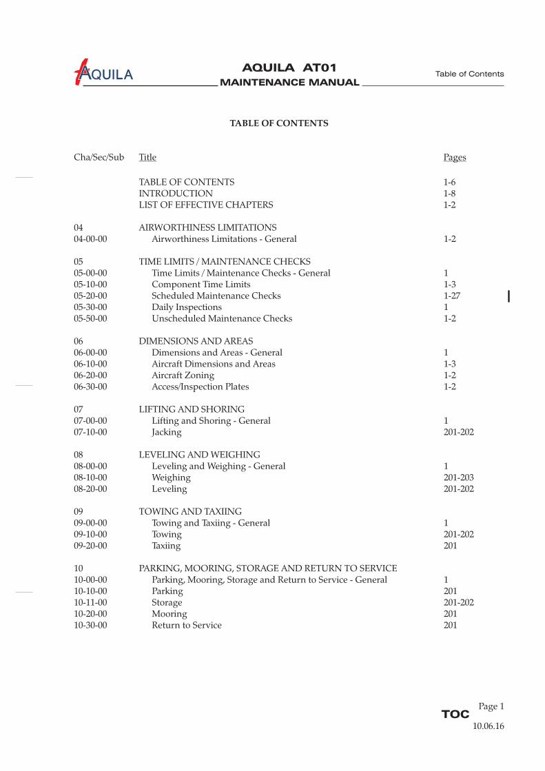
TABLE OF CONTENTS 1-6INTRODUCTION 1-8LIST OF EFFECTIVE CHAPTERS 1-2
04 AIRWORTHINESS LIMITATIONS04-00-00 Airworthiness Limitations - General 1-2
05 TIME LIMITS / MAINTENANCE CHECKS05-00-00 Time Limits / Maintenance Checks - General 105-10-00 Component Time Limits 1-305-20-00 Scheduled Maintenance Checks 1-2705-30-00 Daily Inspections 105-50-00 Unscheduled Maintenance Checks 1-2
06 DIMENSIONS AND AREAS06-00-00 Dimensions and Areas - General 106-10-00 Aircraft Dimensions and Areas 1-306-20-00 Aircraft Zoning 1-206-30-00 Access/Inspection Plates 1-2
07 LIFTING AND SHORING07-00-00 Lifting and Shoring - General 107-10-00 Jacking 201-202
08 LEVELING AND WEIGHING08-00-00 Leveling and Weighing - General 108-10-00 Weighing 201-20308-20-00 Leveling 201-202
09 TOWING AND TAXIING09-00-00 Towing and Taxiing - General 109-10-00 Towing 201-20209-20-00 Taxiing 201
10 PARKING, MOORING, STORAGE AND RETURN TO SERVICE10-00-00 Parking, Mooring, Storage and Return to Service - General 110-10-00 Parking 20110-11-00 Storage 201-20210-20-00 Mooring 20110-30-00 Return to Service 201
TOCPage 1
Table of Contents
10.06.16
MAINTENANCE MANUAL
AQUILA AT01A
TABLE OF CONTENTS (Cont.)
Cha/Sec/Sub Title Pages
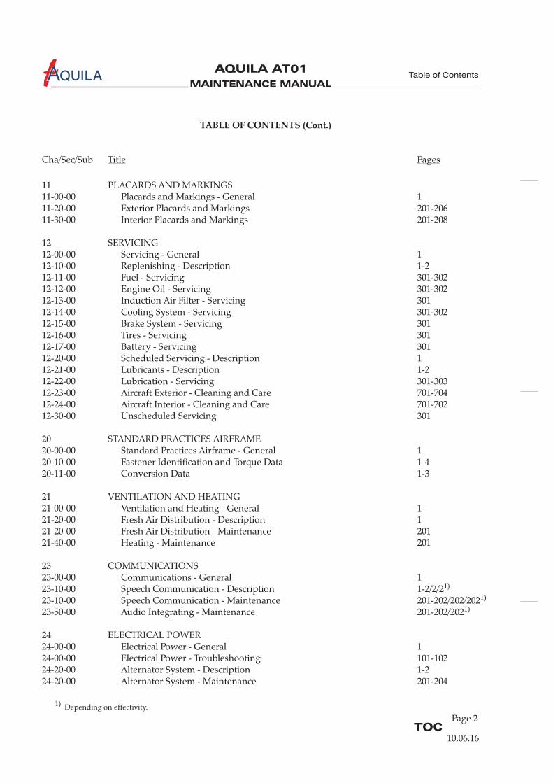
11 PLACARDS AND MARKINGS11-00-00 Placards and Markings - General 111-20-00 Exterior Placards and Markings 201-20611-30-00 Interior Placards and Markings 201-208
12 SERVICING12-00-00 Servicing - General 112-10-00 Replenishing - Description 1-212-11-00 Fuel - Servicing 301-30212-12-00 Engine Oil - Servicing 301-30212-13-00 Induction Air Filter - Servicing 30112-14-00 Cooling System - Servicing 301-30212-15-00 Brake System - Servicing 30112-16-00 Tires - Servicing 30112-17-00 Battery - Servicing 30112-20-00 Scheduled Servicing - Description 112-21-00 Lubricants - Description 1-212-22-00 Lubrication - Servicing 301-30312-23-00 Aircraft Exterior - Cleaning and Care 701-70412-24-00 Aircraft Interior - Cleaning and Care 701-70212-30-00 Unscheduled Servicing 301
20 STANDARD PRACTICES AIRFRAME20-00-00 Standard Practices Airframe - General 120-10-00 Fastener Identification and Torque Data 1-420-11-00 Conversion Data 1-3
21 VENTILATION AND HEATING21-00-00 Ventilation and Heating - General 121-20-00 Fresh Air Distribution - Description 121-20-00 Fresh Air Distribution - Maintenance 20121-40-00 Heating - Maintenance 201
23 COMMUNICATIONS23-00-00 Communications - General 123-10-00 Speech Communication - Description 1-2/2/223-10-00 Speech Communication - Maintenance 201-202/202/20223-50-00 Audio Integrating - Maintenance 201-202/202
24 ELECTRICAL POWER24-00-00 Electrical Power - General 124-00-00 Electrical Power - Troubleshooting 101-10224-20-00 Alternator System - Description 1-224-20-00 Alternator System - Maintenance 201-204
1)
1)
1)
TOCPage 2
Table of Contents
10.06.16
1) Depending on effectivity.

MAINTENANCE MANUAL
AQUILA AT01A
TABLE OF CONTENTS (Cont.)
Cha/Sec/Sub Title Pages
24-30-00 Battery System - Description 1-224-30-00 Battery System - Maintenance 201-20324-40-00 External Power - Maintenance 201-20324-60-00 Electrical Load Distribution - Description 124-61-00 Circuit Breaker - Maintenance 20124-97-00 Electrical System Wiring - Maintenance 201
25 EQUIPMENT / FURNISHINGS25-00-00 Equipment / Furnishings - General 125-10-00 Seats - Maintenance 201-20325-11-00 Restraint System - Maintenance 20125-12-00 Cabin Interior - Maintenance 201-20325-50-00 Cargo Tie Downs - Maintenance 20125-60-00 Emergency Equipment - Description 1-225-62-00 Emergency Locater Transmitter - Maintenance 201-20225-66-00 Fire Extinguisher - Maintenance 201-201/202
27 FLIGHT CONTROLS27-00-00 Flight Controls - General 127-10-00 Aileron Control System - Description 1-227-10-00 Aileron Control System - Maintenance 201-20727-20-00 Rudder Control System - Description 1-227-20-00 Rudder Control System - Maintenance 201-20527-30-00 Elevator Control System - Description 1-227-30-00 Elevator Control System - Maintenance 201-20527-31-00 Elevator Trim Control System - Description 1-227-31-00 Elevator Trim Control System - Maintenance 201-20227-50-00 Flap Control System - Description 1-227-50-00 Flap Control System - Maintenance 201-205
28 FUEL28-00-00 Fuel - General 1-228-10-00 Fuel Storage - Maintenance 20128-20-00 Fuel Distribution - Maintenance 201-20528-41-00 Fuel Quantity Indication - Maintenance 201-206
31 INDICATING / RECORDING SYSTEMS31-00 00 Indicating / Recording Systems - General 1-2/2/231-10-00 Instrument Panel - Maintenance 201-20231-30-00 Recorders - Maintenance 201-204
1)
1)
TOCPage 3
Table of Contents
10.06.16
1) Depending on effectivity.
MAINTENANCE MANUAL
AQUILA AT01A
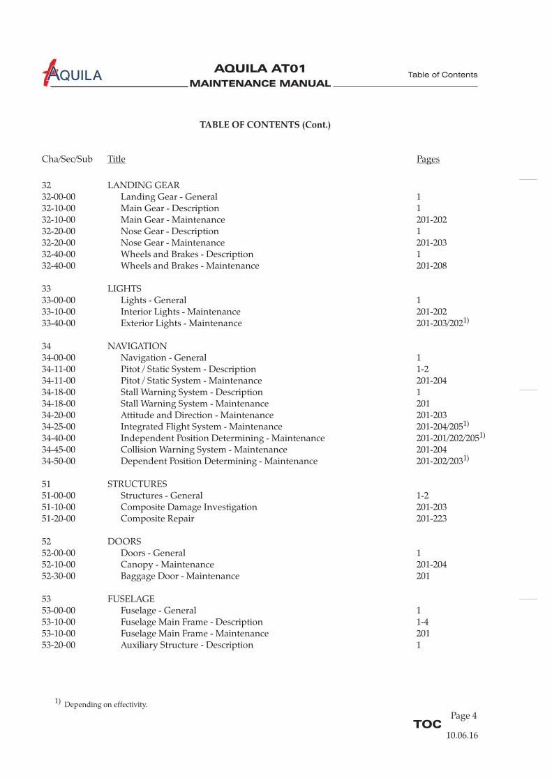
32 LANDING GEAR32-00-00 Landing Gear - General 132-10-00 Main Gear - Description 132-10-00 Main Gear - Maintenance 201-20232-20-00 Nose Gear - Description 132-20-00 Nose Gear - Maintenance 201-20332-40-00 Wheels and Brakes - Description 132-40-00 Wheels and Brakes - Maintenance 201-208
33 LIGHTS33-00-00 Lights - General 133-10-00 Interior Lights - Maintenance 201-20233-40-00 Exterior Lights - Maintenance 201-
34 NAVIGATION34-00-00 Navigation - General 134-11-00 Pitot / Static System - Description 1-234-11-00 Pitot / Static System - Maintenance 201-20434-18-00 Stall Warning System - Description 134-18-00 Stall Warning System - Maintenance 20134-20-00 Attitude and Direction - Maintenance 201-20334-25-00 Integrated Flight System -34-40-00 Independent Position Determining - Maintenance 201-201/202/20534-45-00 Collision Warning System - Maintenance 201-20434-50-00 Dependent Position Determining - Maintenance 201-202/203
51 STRUCTURES51-00-00 Structures - General 1-251-10-00 Composite Damage Investigation 201-20351-20-00 Composite Repair 201-223
52 DOORS52-00-00 Doors - General 152-10-00 Canopy - Maintenance 201-20452-30-00 Baggage Door - Maintenance 201
53 FUSELAGE53-00-00 Fuselage - General 153-10-00 Fuselage Main Frame - Description 1-453-10-00 Fuselage Main Frame - Maintenance 201
203/202
Maintenance 201-204/205
53-20-00 Auxiliary Structure - Description 1
1)
1)
1)
1)
TABLE OF CONTENTS (Cont.)
Cha/Sec/Sub Title Pages
TOCPage 4
Table of Contents
10.06.16
1) Depending on effectivity.
MAINTENANCE MANUAL
AQUILA AT01A
TABLE OF CONTENTS (Cont.)
Cha/Sec/Sub Title Pages
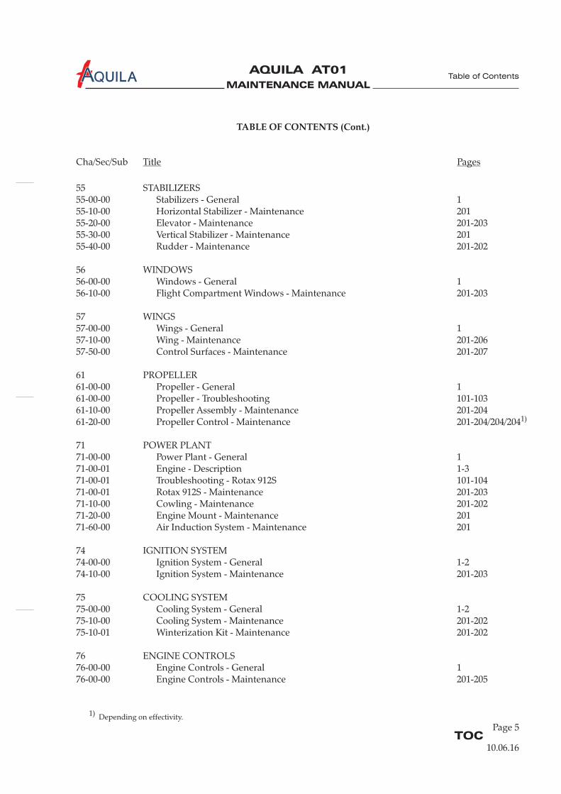
55 STABILIZERS55-00-00 Stabilizers - General 155-10-00 Horizontal Stabilizer - Maintenance 20155-20-00 Elevator - Maintenance 201-20355-30-00 Vertical Stabilizer - Maintenance 20155-40-00 Rudder - Maintenance 201-202
57-00-00 Wings - General 157-10-00 Wing - Maintenance 201-20657-50-00 Control Surfaces - Maintenance 201-207
61 PROPELLER61-00-00 Propeller - General 161-00-00 Propeller - Troubleshooting 101-10361-10-00 Propeller Assembly - Maintenance 201-20461-20-00 Propeller Control - Maintenance 201-204/204/204
71 POWER PLANT71-00-00 Power Plant - General 171-00-01 Engine - Description 1-371-00-01 Troubleshooting - Rotax 912S 101-10471-00-01 Rotax 912S - Maintenance 201-20371-10-00 Cowling - Maintenance 201-20271-20-00 Engine Mount - Maintenance 20171-60-00 Air Induction System - Maintenance 201
74 IGNITION SYSTEM74-00-00 Ignition System - General 1-274-10-00 Ignition System - Maintenance 201-203
75 COOLING SYSTEM75-00-00 Cooling System - General 1-275-10-00 Cooling System - Maintenance 201-20275-10-01 Winterization Kit - Maintenance 201-202
76 ENGINE CONTROLS76-00-00 Engine Controls - General 176-00-00 Engine Controls - Maintenance 201-205
56 WINDOWS56-00-00 Windows - General 156-10-00 Flight Compartment Windows - Maintenance 201-203
57 WINGS
1)
TOCPage 5
Table of Contents
10.06.16
1) Depending on effectivity.
MAINTENANCE MANUAL
AQUILA AT01A
TABLE OF CONTENTS (Cont.)
Cha/Sec/Sub Title Pages
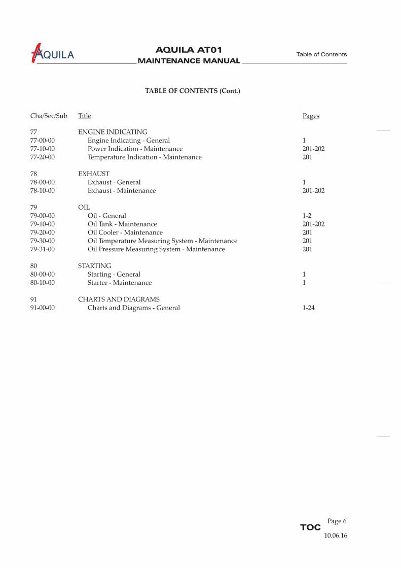
77 ENGINE INDICATING77-00-00 Engine Indicating - General 177-10-00 Power Indication - Maintenance 201-20277-20-00 Temperature Indication - Maintenance 201
78 EXHAUST78-00-00 Exhaust - General 178-10-00 Exhaust - Maintenance 201-202
79 OIL79-00-00 Oil - General 1-279-10-00 Oil Tank - Maintenance 201-20279-20-00 Oil Cooler - Maintenance 20179-30-00 Oil Temperature Measuring System - Maintenance 20179-31-00 Oil Pressure Measuring System - Maintenance 201
80 STARTING80-00-00 Starting - General 180-10-00 Starter - Maintenance 1
91 CHARTS AND DIAGRAMS91-00-00 Charts and Diagrams - General 1-24
TOCPage 6
Table of Contents
10.06.16
MAINTENANCE MANUAL
AQUILA AT01A
Revision
Number
Revision
Number
Date of
Revision
Date of
Revision
Date
Inserted
Date
InsertedBy By
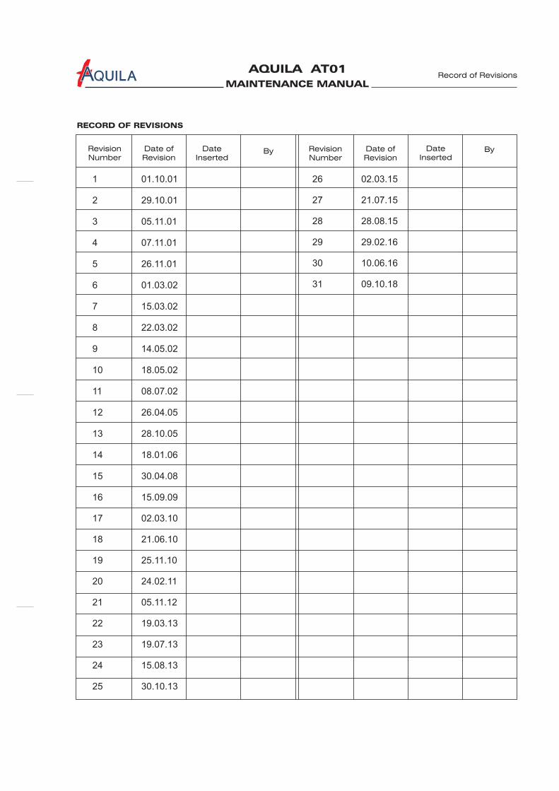
RECORD OF REVISIONS
Record of Revisions
1 01.10.01
2 29.10.01
3 05.11.01
4 07.11.01
5 26.11.01
6 01.03.02
7 15.03.02
8 22.03.02
9 14.05.02
10 18.05.02
11 08.07.02
12 26.04.05
13 28.10.05
14 18.01.06
15 30.04.08
16 15.09.09
17 02.03.10
18 21.06.10
19 25.11.10
20 24.02.11
21 05.11.12
22 19.03.13
23 19.07.13
24 15.08.13
25 30.10.13
26 02.03.15
27 21.07.15
28 28.08.15
29 29.02.16
30 10.06.16
31 09.10.18

MAINTENANCE MANUAL
AQUILA AT01A
MAINTENANCE MANUAL
AQUILA AT01A
Temp. Revision
NumberPage Date of
RevisionBy ByDate
Removed
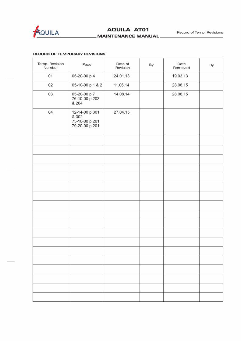
RECORD OF TEMPORARY REVISIONS
Record of Temp. Revisions
01 05-20-00 p.4 24.01.13 19.03.13
02 05-10-00 p.1 & 2 11.06.14 28.08.15
03 05-20-00 p.7 14.08.14 28.08.1576-10-00 p.203& 204
04 12-14-00 p.301 27.04.15& 30275-10-00 p.20179-20-00 p.201

MAINTENANCE MANUAL
AQUILA AT01A
MAINTENANCE MANUAL
AQUILA AT01A
Revision
Number
Revision
Number
Date of
Revision
Date of
Revision
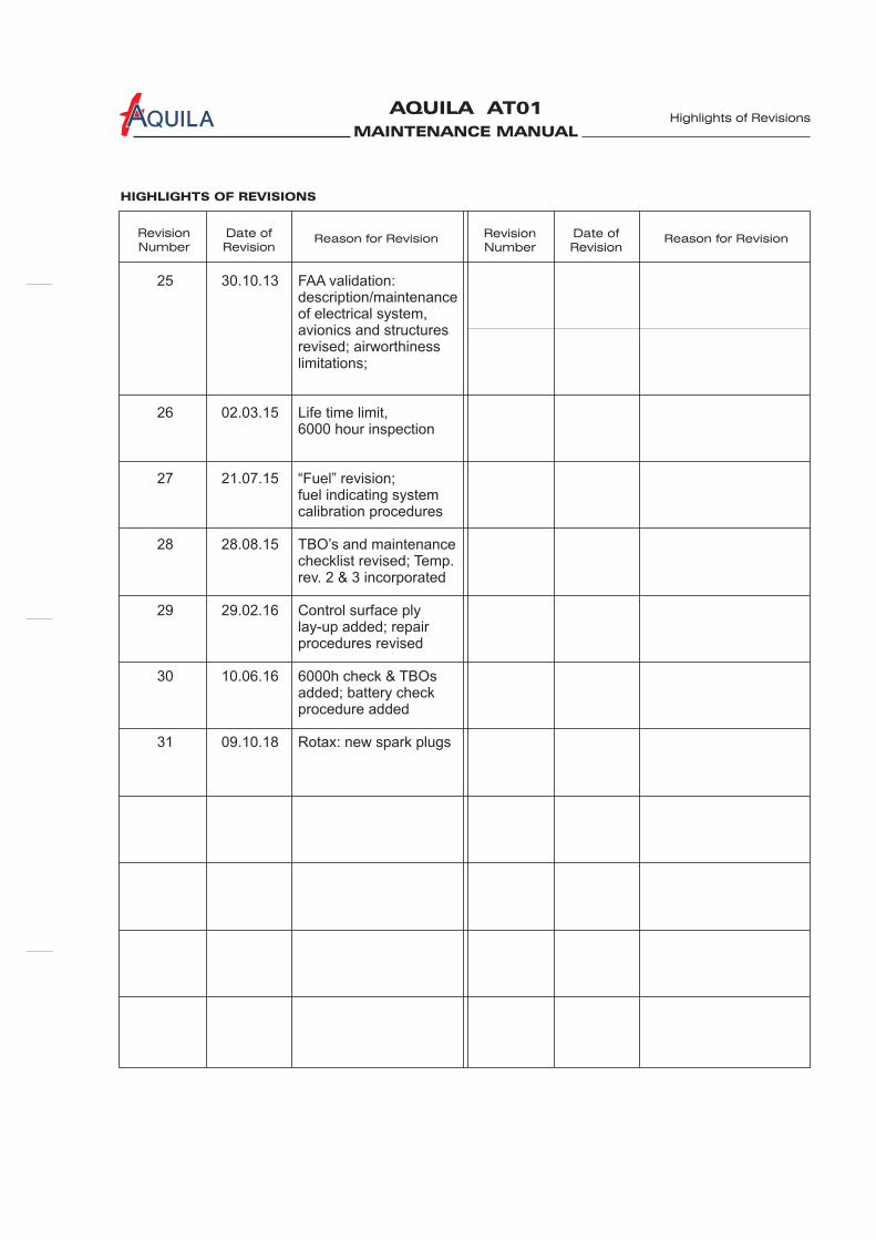
HIGHLIGHTS OF REVISIONS
Highlights of Revisions
Reason for Revision Reason for Revision
25 30.10.13 FAA validation:description/maintenanceof electrical system,avionics and structures revised; airworthiness limitations;
26 02.03.15 Life time limit,6000 hour inspection
27 21.07.15 “Fuel” revision; fuel indicating systemcalibration procedures
28 28.08.15 TBO’s and maintenancechecklist revised; Temp. rev. 2 & 3 incorporated
29 29.02.16 Control surface plylay-up added; repairprocedures revised
30 10.06.16 6000h check & TBOsadded; battery checkprocedure added
31 09.10.18 Rotax: new spark plugs

MAINTENANCE MANUAL
AQUILA AT01A
MAINTENANCE MANUAL
AQUILA AT01A
INTRODUCTION
Introduction
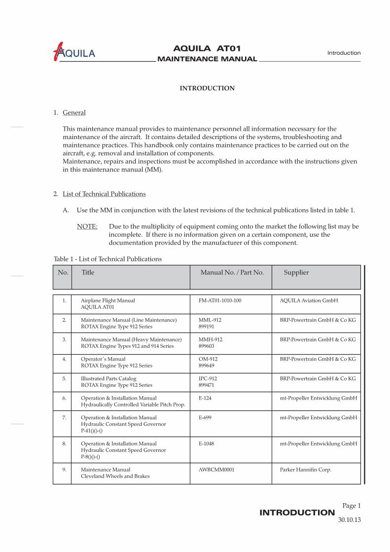
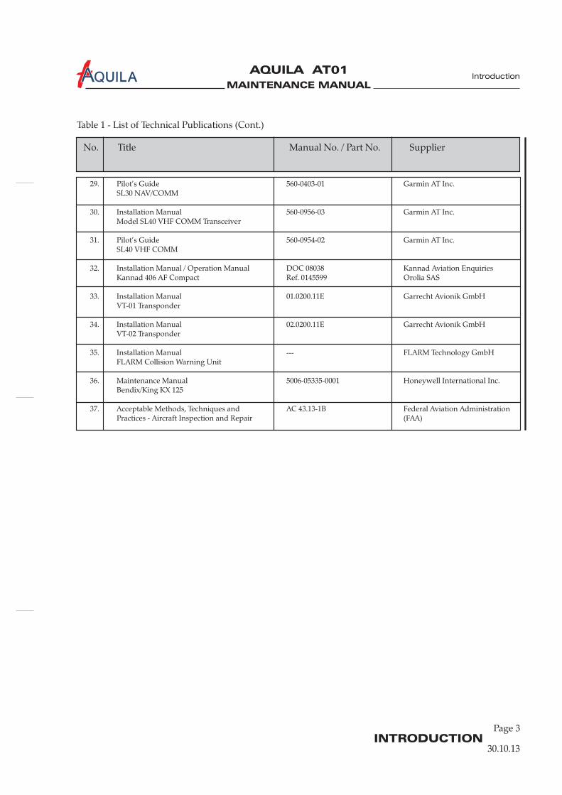
Table 1 - List of Technical Publications
30.10.13
INTRODUCTION
1.
This maintenance manual provides to necessary for themaintenance of the aircraft. It contains detailed descriptions of the systems, troubleshooting andmaintenance practices. This handbook only contains maintenance practices to be carried out on theaircraft, e.g. removal and installation of components.Maintenance, repairs and inspections must be accomplished in accordance with the instructions givenin this maintenance manual (MM).
2.
A. Use the MM in conjunction with the latest revisions of the technical publications listed in table 1.
Due to the multiplicity of equipment coming onto the market the following list may beincomplete. If there is no information given on a certain component, use thedocumentation provided by the manufacturer of this component.
General
List of Technical Publications
NOTE:
maintenance personnel all information
Page 1
1. Airplane Flight Manual FM-AT01-1010-100 AQUILA Aviation GmbHAQUILA AT01
2. Maintenance Manual (Line Maintenance) MML-912 BRP-Powertrain GmbH & Co KGROTAX Engine Type 912 Series 899191
3. Maintenance Manual (Heavy Maintenance) MMH-912 BRP-Powertrain GmbH & Co KGROTAX Engine Types 912 and 914 Series 899603
4. Operator’s Manual OM-912 BRP-Powertrain GmbH & Co KGROTAX Engine Type 912 Series 899649
5. Illustrated Parts Catalog IPC-912 BRP-Powertrain GmbH & Co KGROTAX Engine Type 912 Series 899471
6. Operation & Installation Manual E-124 mt-Propeller Entwicklung GmbHHydraulically Controlled Variable Pitch Prop.
7. Operation & Installation Manual E-699 mt-Propeller Entwicklung GmbHHydraulic Constant Speed GovernorP-41()()-()
8. Operation & Installation Manual E-1048 mt-Propeller Entwicklung GmbHHydraulic Constant Speed GovernorP-8()()-()
9. Maintenance Manual AWBCMM0001 Parker Hannifin Corp.Cleveland Wheels and Brakes
No. Title Manual No. / Part No. Supplier
MAINTENANCE MANUAL
AQUILA AT01A
INTRODUCTIONPage 2
Introduction
30.10.13
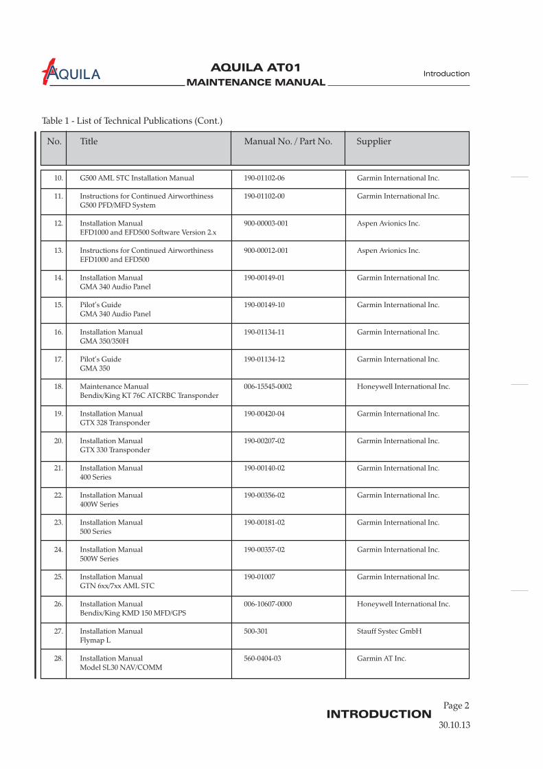
Table 1 - List of Technical Publications (Cont.)
No. Title Manual No. / Part No. Supplier
10. G500 AML STC Installation Manual 190-01102-06 Garmin International Inc.
11. Instructions for Continued Airworthiness 190-01102-00 Garmin International Inc.G500 PFD/MFD System
12. Installation Manual 900-00003-001 Aspen Avionics Inc.EFD1000 and EFD500 Software Version 2.x
13. Instructions for Continued Airworthiness 900-00012-001 Aspen Avionics Inc.EFD1000 and EFD500
14. Installation Manual 190-00149-01 Garmin International Inc.GMA 340 Audio Panel
15. Pilot’s Guide 190-00149-10 Garmin International Inc.GMA 340 Audio Panel
16. Installation Manual 190-01134-11 Garmin International Inc.GMA 350/350H
17. Pilot’s Guide 190-01134-12 Garmin International Inc.GMA 350
18. Maintenance Manual 006-15545-0002 Honeywell International Inc.Bendix/King KT 76C ATCRBC Transponder
19. Installation Manual 190-00420-04 Garmin International Inc.GTX 328 Transponder
20. Installation Manual 190-00207-02 Garmin International Inc.GTX 330 Transponder
21. Installation Manual 190-00140-02 Garmin International Inc.400 Series
22. Installation Manual 190-00356-02 Garmin International Inc.400W Series
23. Installation Manual 190-00181-02 Garmin International Inc.500 Series
24. Installation Manual 190-00357-02 Garmin International Inc.500W Series
25. Installation Manual 190-01007 Garmin International Inc.GTN 6xx/7xx AML STC
26. Installation Manual 006-10607-0000 Honeywell International Inc.Bendix/King KMD 150 MFD/GPS
27. Installation Manual 500-301 Stauff Systec GmbHFlymap L
28. Installation Manual 560-0404-03 Garmin AT Inc.Model SL30 NAV/COMM
MAINTENANCE MANUAL
AQUILA AT01A
INTRODUCTION
Page 3
Introduction
30.10.13
No. Title Manual No. / Part No. Supplier
Table 1 - List of Technical Publications (Cont.)
29. Pilot’s Guide 560-0403-01 Garmin AT Inc.SL30 NAV/COMM
30. Installation Manual 560-0956-03 Garmin AT Inc.Model SL40 VHF COMM Transceiver
31. Pilot’s Guide 560-0954-02 Garmin AT Inc.SL40 VHF COMM
32. Installation Manual / Operation Manual DOC 08038 Kannad Aviation EnquiriesKannad 406 AF Compact Ref. 0145599 Orolia SAS
33. Installation Manual 01.0200.11E Garrecht Avionik GmbHVT-01 Transponder
34. Installation Manual 02.0200.11E Garrecht Avionik GmbHVT-02 Transponder
35. Installation Manual --- FLARM Technology GmbHFLARM Collision Warning Unit
36. Maintenance Manual 5006-05335-0001 Honeywell International Inc.Bendix/King KX 125
37. Acceptable Methods, Techniques and AC 43.13-1B Federal Aviation AdministrationPractices - Aircraft Inspection and Repair (FAA)
MAINTENANCE MANUAL
AQUILA AT01A
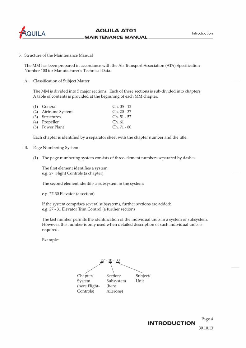
3.
The MM has been prepared in accordance with the Air Transport Association (ATA) SpecificationNumber 100 for Manufacturer’s Technical Data.
A. Classification of Subject Matter
The MM is divided into 5 major sections. Each of these sections is sub-divided into chapters.A table of contents is provided at the beginning of each MM chapter.
(1) General Ch. 05 - 12(2) Airframe Systems Ch. 20 - 37(3) Structures Ch. 51 - 57(4) Propeller Ch. 61(5) Power Plant Ch. 71 - 80
Each chapter is identified by a separator sheet with the chapter number and the title.
B. Page Numbering System
(1) The page numbering system consists of three-element numbers separated by dashes.
The first element identifies a system:e.g. 27 Flight Controls (a chapter)
The second element identifis a subsystem in the system:
e.g. 27-30 Elevator (a section)
If the system comprises several subsystems, further sections are added:e.g. 27 - 31 Elevator Trim Control (a further section)
The last number permits the identification of the individual units in a system or subsystem.However, this number is only used when detailed description of such individual units isrequired.
Example
27 - 10 - 00
Chapter/ Section/ Subject/System Subsystem Unit(here Flight- (hereControls) Ailerons)
Structure of the Maintenance Manual
:
30.10.13
Page 4INTRODUCTION
Introduction
MAINTENANCE MANUAL
AQUILA AT01A
Page 5INTRODUCTION
Introduction
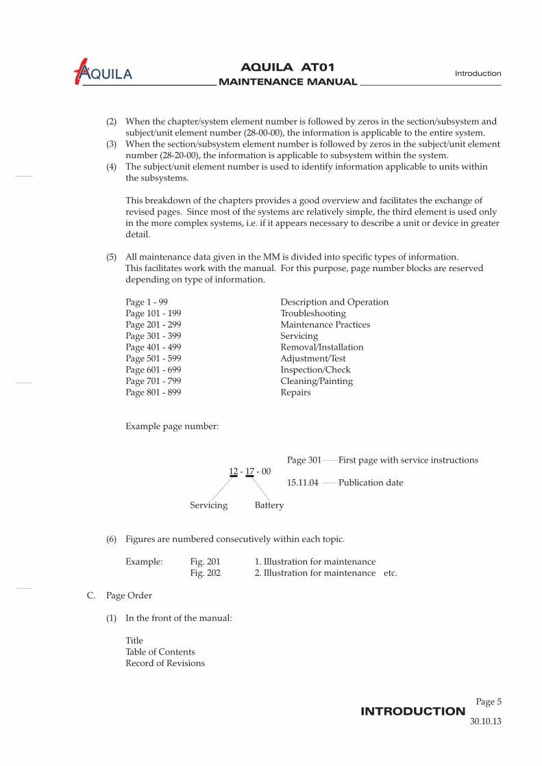
(2) When the chapter/system element number is followed by zeros in the section/subsystem andsubject/unit element number (28-00-00), the information is applicable to the entire system.
(3) When the section/subsystem element number is followed by zeros in the subject/unit elementnumber (28-20-00), the information is applicable to subsystem within the system.
(4) The subject/unit element number is used to identify information applicable to units withinthe subsystems.
This breakdown of the chapters provides a good overview and facilitates the exchange ofrevised pages. Since most of the systems are relatively simple, the third element is used onlyin the more complex systems, i.e. if it appears necessary to describe a unit or device in greaterdetail.
(5) All maintenance data given in the MM is divided into specific types of information.This facilitates work with the manual. For this purpose, page number blocks are reserveddepending on type of information.
Page 1 - 99 Description and OperationPage 101 - 199 TroubleshootingPage 201 - 299 Maintenance PracticesPage 301 - 399 ServicingPage 401 - 499 Removal/InstallationPage 501 - 599 Adjustment/TestPage 601 - 699 Inspection/CheckPage 701 - 799 Cleaning/PaintingPage 801 - 899 Repairs
Example page number:
Page 301 First page with service instructions12 - 17 - 00
15.11.04 Publication date
Servicing Battery
(6) Figures are numbered consecutively within each topic.
Example: Fig. 201 1. Illustration for maintenanceFig. 202 2. Illustration for maintenance etc.
C. Page Order
(1) In the front of the manual:
TitleTable of ContentsRecord of Revisions
30.10.13
MAINTENANCE MANUAL
AQUILA AT01A
INTRODUCTIONPage 6
Introduction
MeterCommon
MeterPlus
PSI DesiredValue (VDC)
Unit undertest
Pin 2 (blk) Pin 4 (red) 0 4.95 to 5.0 3010016,17,18
Pin 2 (blk) Pin 1 (wht) 0 1.70 to 2.10 3010016,17,18
Pin 2 (bik) Pin 3 (grn) 0 1.70 to 2.10 3010016,17,18
Pin 3 (grn) Pin 1 (wht) 0 -0.003 to +0.003 3010016,17,18
Pin 3 (grn) Pin 1 (wht) 10 0.031 to +0.034 3010016
Pin 3 (grn) Pin 1 (wht) 30 0.028 to +0.032 3010017
Pin 3 (grn) Pin 1 (wht) 60 0.028 to +0.032 3010018
77-40-00
Page 101
13.07.01
EFFECTIVITY
Aircraft equipped with VM 1000 Engine ManagementSystem
effectivity block
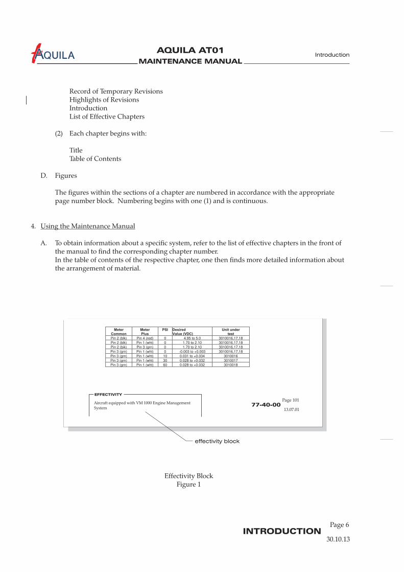
Effectivity BlockFigure 1
Record of Temporary RevisionsHighlights of RevisionsIntroductionList of Effective Chapters
(2) Each chapter begins with:
TitleTable of Contents
D. Figures
The figures within the sections of a chapter are numbered in accordance with the appropriatepage number block. Numbering begins with one (1) and is continuous.
4.
A. To obtain information about a specific system, refer to the list of effective chapters in the front ofthe manual to find the corresponding chapter number.In the table of contents of the respective chapter, one then finds more detailed information aboutthe arrangement of material.
Using the Maintenance Manual
30.10.13
MAINTENANCE MANUAL
AQUILA AT01A
Page 7INTRODUCTION
Introduction
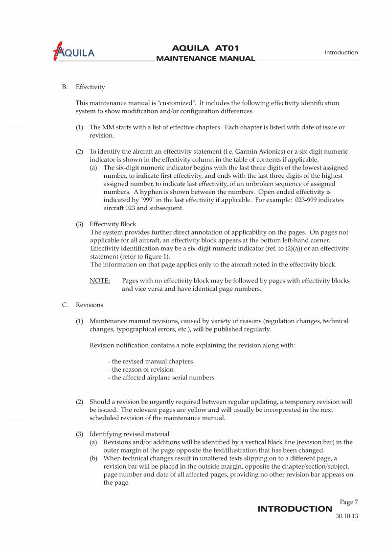
B. Effectivity
This maintenance manual is "customized". It includes the following effectivity identificationsystem to show modification and/or configuration differences.
(1) The MM starts with a list of effective chapters. Each chapter is listed with date of issue orrevision.
(2) To identify the aircraft an effectivity statement (i.e. Garmin Avionics) or a six-digit numericindicator is shown in the effectivity column in the table of contents if applicable.(a) The six-digit numeric indicator begins with the last three digits of the lowest assigned
number, to indicate first effectivity, and ends with the last three digits of the highestassigned number, to indicate last effectivity, of an unbroken sequence of assignednumbers. A hyphen is shown between the numbers. Open ended effectivity isindicated by "999" in the last effectivity if applicable. For example: 023-999 indicatesaircraft 023 and subsequent.
(3) Effectivity BlockThe system provides further direct annotation of applicability on the pages. On pages notapplicable for all aircraft, an effectivity block appears at the bottom left-hand corner.Effectivity identification may be a six-digit numeric indicator (ref. to (2)(a)) or an effectivitystatement (refer to figure 1).The information on that page applies only to the aircraft noted in the effectivity block.
Pages with no effectivity block may be followed by pages with effectivity blocksand vice versa and have identical page numbers.
C. Revisions
(1) Maintenance manual revisions, caused by variety of reasons (regulation changes, technicalchanges, typographical errors, etc.), will be published regularly.
Revision notification contains a note explaining the revision along with:
- the revised manual chapters- the reason of revision- the affected airplane serial numbers
(2) Should a revision be urgently required between regular updating, a temporary revision willbe issued. The relevant pages are yellow and will usually be incorporated in the nextscheduled revision of the maintenance manual.
(3) Identifying revised material(a) Revisions and/or additions will be identified by a vertical black line (revision bar) in the
outer margin of the page opposite the text/illustration that has been changed.(b) When technical changes result in unaltered texts slipping on to a different page, a
revision bar will be placed in the outside margin, opposite the chapter/section/subject,page number and date of all affected pages, providing no other revision bar appears onthe page.
NOTE:
30.10.13
MAINTENANCE MANUAL
AQUILA AT01A
Page 8INTRODUCTION
Introduction
(4) Incorporating revisions into the manual(a) In order to keep track of revisions and to facilitate the use of the manual, a revision
always affects the entire chapter, i.e. all pages of a chapter have the same date of issue orrevision and the entire chapter is replaced during a revision.
(b) MM revisions contain an effectivity page. Chapters to be removed or inserted are listedin sequence and assigned with the respective action.Incorporation of revisions into the manual must be documented in the record ofrevisions at the front of the MM.
(c) Temporary revisions are issued as single pages and must be incorporated according tothe notes on the effectivity page delivered with the revision. They become invalid andmust be removed when the corresponding permanent revision is issued.
D. WARNINGS, CAUTIONS and NOTES
When carrying out maintenance on the airplane, general safety and maintenance rules shouldalways be observed.In addition, the MM contains warnings, cautions and notes to highlight or emphasize importantand critical instructions.
Hazard for maintenance personnel!
Hazard for systems and equipment!
Specific information
E. Abbreviations
Where it appears reasonable, abbreviations are used. They conform to recognized standards.
WARNING:
CAUTION:
NOTE:
30.10.13
MAINTENANCE MANUAL
AQUILA AT01A
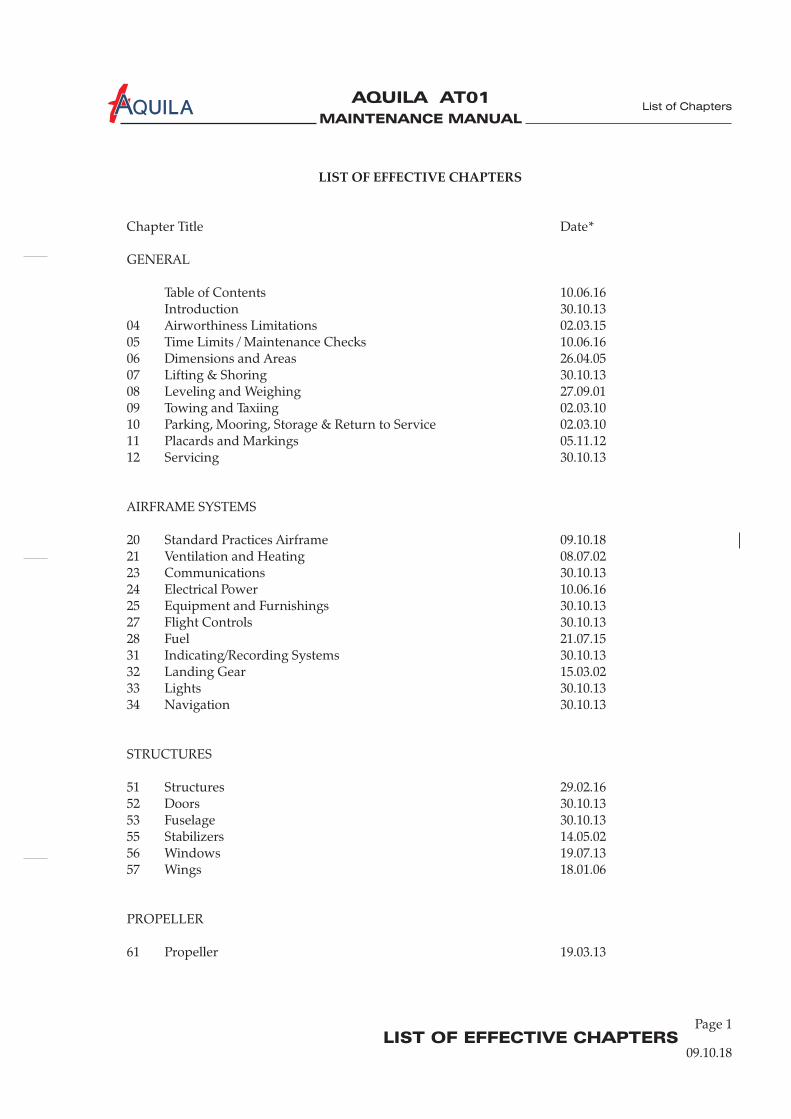
LIST OF EFFECTIVE CHAPTERS
LIST OF EFFECTIVE CHAPTERS
Chapter Title Date*
GENERAL
Table of Contents 10.06.16Introduction 30.10.13
04 Airworthiness Limitations 02.03.1505 Time Limits / Maintenance Checks 10.06.1606 Dimensions and Areas 26.04.0507 Lifting & Shoring 30.10.1308 Leveling and Weighing 27.09.0109 Towing and Taxiing 02.03.1010 Parking, Mooring, Storage & Return to Service 02.03.1011 Placards and Markings 05.11.1212 Servicing 30.10.13
AIRFRAME SYSTEMS
20 Standard Practices Airframe 09.10.1821 Ventilation and Heating 08.07.0223 Communications 30.10.1324 Electrical Power 10.06.1625 Equipment and Furnishings 30.10.1327 Flight Controls 30.10.1328 Fuel 21.07.1531 Indicating/Recording Systems 30.10.1332 Landing Gear 15.03.0233 Lights 30.10.1334 Navigation 30.10.13
STRUCTURES
51 Structures 29.02.1652 Doors 30.10.1353 Fuselage 30.10.1355 Stabilizers 14.05.0256 Windows 19.07.1357 Wings 18.01.06
PROPELLER
61 Propeller 19.03.13
List of Chapters
09.10.18
Page 1
MAINTENANCE MANUAL
AQUILA AT01A
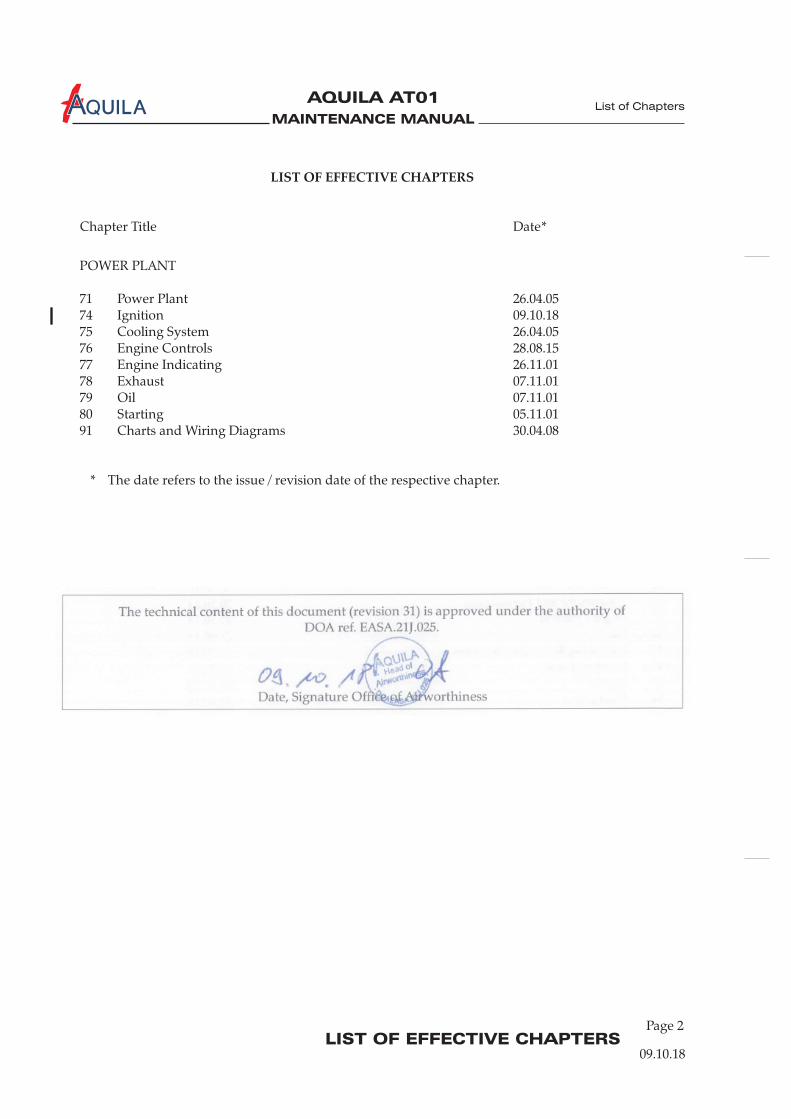
LIST OF EFFECTIVE CHAPTERS
POWER PLANT
71 Power Plant 26.04.0574 Ignition 09.10.1875 Cooling System 26.04.0576 Engine Controls 28.08.1577 Engine Indicating 26.11.0178 Exhaust 07.11.0179 Oil 07.11.0180 Starting 05.11.0191 Charts and Wiring Diagrams 30.04.08
* The date refers to the issue / revision date of the respective chapter.
LIST OF EFFECTIVE CHAPTERS
Chapter Title Date*
List of Chapters
09.10.18
Page 2
The technical content of this document (revision 31) is approved under the authority of DOA ref. EASA.21J.025.
Date, Signature Office of Airworthiness
MAINTENANCE MANUAL
AQUILA AT01A
CHAPTER 4
AIRWORTHINESS LIMITATIONS

MAINTENANCE MANUAL
AQUILA AT01A
MAINTENANCE MANUAL
AQUILA AT01A
04 - RECORD OF REVISIONS
RECORD OF REVISIONS - CHAPTER 4
Airworthiness Limitations
02.03.15
Page 1
Revision
Number
Date of
Revision
Revised
Pages Descriptions of Revisions
LBA Approval
Signature
and Date
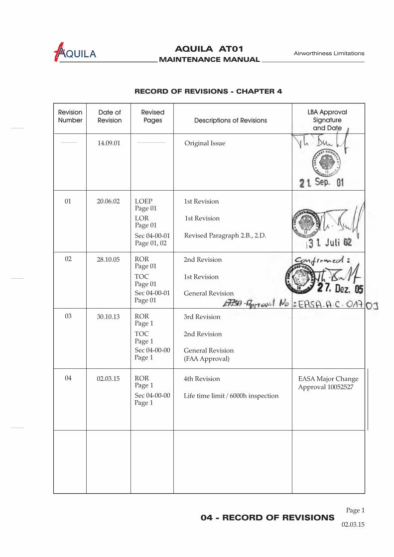
Original Issue14.09.01
01
02
20.06.02
28.10.05
Sec 04-00-01
TOC
Page 01
Page 01
Page 01
Page 01, 02
Page 01
Page 01
Revised Paragraph 2.B., 2.D.
1st Revision
General Revision
LOEP
LOR
ROR
1st Revision
1st Revision
2nd Revision
03 30.10.13
TOC
Page 1
Page 1
Page 1
2nd Revision
General Revision(FAA Approval)
ROR 3rd Revision
Sec 04-00-01
Sec 04-00-00
04 02.03.15Page 1
Page 1Life time limit / 6000h inspection
ROR 4th Revision
Sec 04-00-00
EASA Major ChangeApproval 10052527

MAINTENANCE MANUAL
AQUILA AT01A
MAINTENANCE MANUAL
AQUILA AT01A
04 - TOCPage 1
Airworthiness Limitations
02.03.15
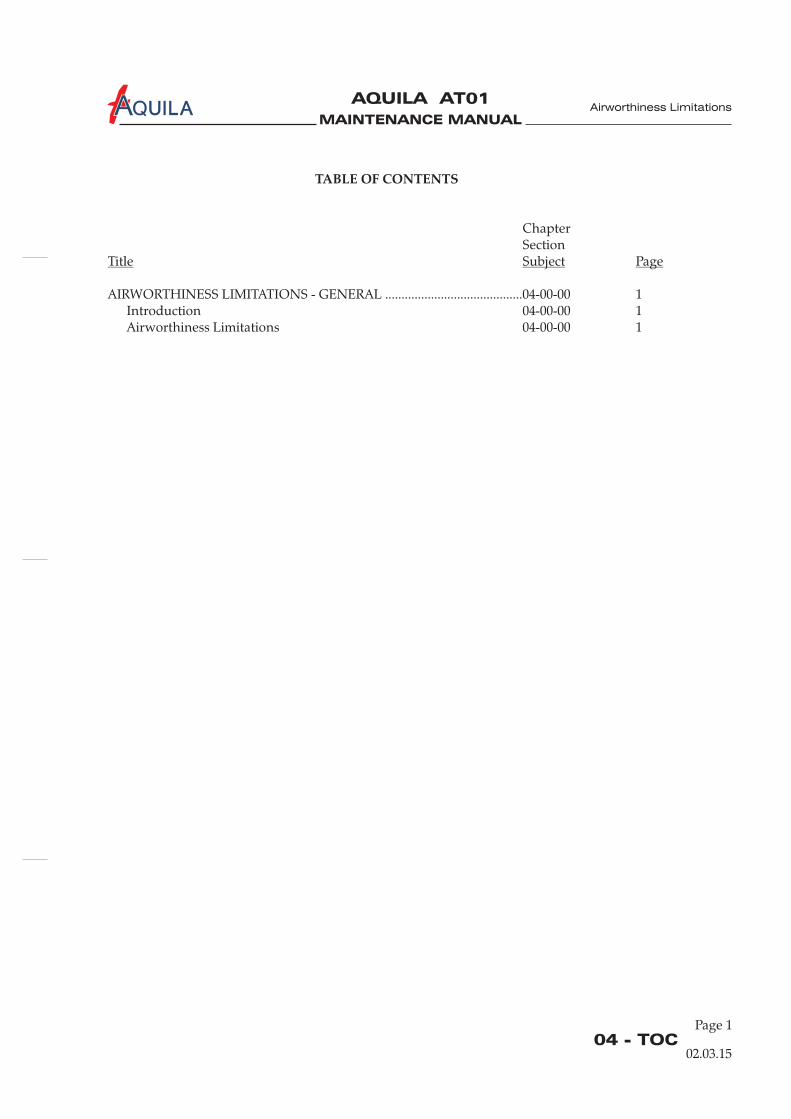
TABLE OF CONTENTS
ChapterSection
AIRWORTHINESS LIMITATIONS - GENERAL ..........................................04-00-00 1IntroductionAirworthiness Limitations 04-00-00 1
Title Subject Page
04-00-00 1

MAINTENANCE MANUAL
AQUILA AT01A
MAINTENANCE MANUAL
AQUILA AT01A
04-00-00
Airworthiness Limitations
02.03.15
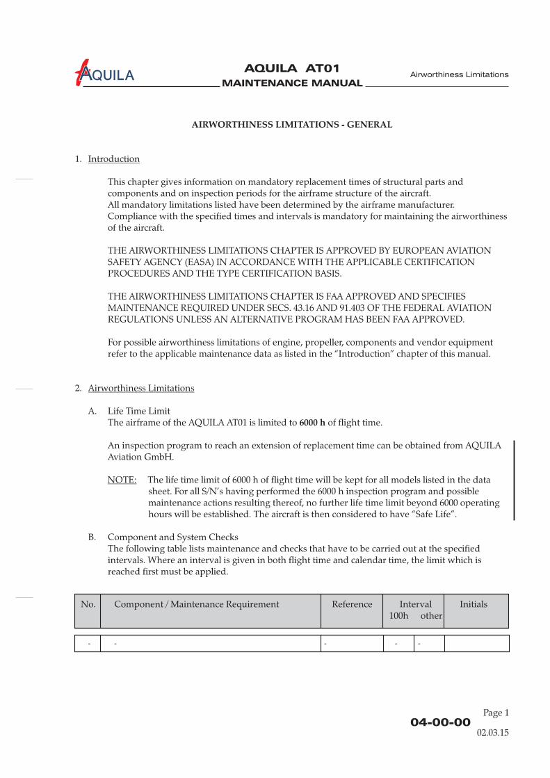
AIRWORTHINESS LIMITATIONS - GENERAL
1.
This chapter gives information on mandatory replacement times of structural parts andcomponents and on inspection periods for the airframe structure of the aircraft.All mandatory limitations listed have been determined by the airframe manufacturer.Compliance with the specified times and intervals is mandatory for maintaining the airworthinessof the aircraft.
2.
A. Life Time LimitThe
Introduction
Airworthiness Limitations
THE AIRWORTHINESS LIMITATIONS CHAPTER IS APPROVED BY EUROPEAN AVIATIONSAFETY AGENCY (EASA) IN ACCORDANCE WITH THE APPLICABLE CERTIFICATIONPROCEDURES AND THE TYPE CERTIFICATION BASIS.
THE AIRWORTHINESS LIMITATIONS CHAPTER IS FAA APPROVED AND SPECIFIESMAINTENANCE REQUIRED UNDER SECS. 43.16 AND 91.403 OF THE FEDERAL AVIATIONREGULATIONS UNLESS AN ALTERNATIVE PROGRAM HAS BEEN FAA APPROVED.
For possible airworthiness limitations of engine, propeller, components and vendor equipmentrefer to the applicable maintenance data as listed in the “Introduction” chapter of this manual.
airframe of the AQUILA AT01 is limited to of flight time.
An inspection program to reach an extension of replacement time can be obtained from AQUILAAviation GmbH.
The life time limit of 6000 h of flight time will be kept for all models listed in the datasheet. For all S/N’s having performed the 6000 h inspection program and possiblemaintenance actions resulting thereof, no further life time limit beyond 6000 operatinghours will be established. The aircraft is then considered to have “Safe Life”.
B. Component and System ChecksThe following table lists maintenance and checks that have to be carried out at the specifiedintervals. Where an interval is given in both flight time and calendar time, the limit which isreached first must be applied.
6000 h
NOTE:
Page 1
No. Component / Maintenance Requirement Reference Interval Initials100h other
- - - - -
MAINTENANCE MANUAL
AQUILA AT01A
04-00-00Page 2
02.03.15
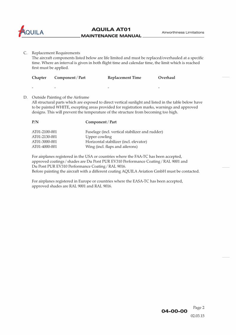
C. Replacement RequirementsThe aircraft components listed below are life limited and must be replaced/overhauled at a specifictime. Where an interval is given in both flight time and calendar time, the limit which is reachedfirst must be applied.
- - - -
AT01-2100-001 Fuselage (incl. vertical stabilizer and rudder)AT01-2130-001 Upper cowlingAT01-3000-001 Horizontal stabilizer (incl. elevator)AT01-4000-001 Wing (incl. flaps and ailerons)
For airplanes registered in the USA or countries where the FAA-TC has been accepted,approved coatings / shades are Du Pont PUR EV310 Performance Coating / RAL 9001 andDu Pont PUR EV310 Performance Coating / RAL 9016.Before painting the aircraft with a different coating AQUILA Aviation GmbH must be contacted.
For airplanes registered in Europe or countries where the EASA-TC has been accepted,approved shades are RAL 9001 and RAL 9016.
Chapter Component / Part Replacement Time Overhaul
P/N Component / Part
D. Outside Painting of the AirframeAll structural parts which are exposed to direct vertical sunlight and listed in the table below haveto be painted WHITE, excepting areas provided for registration marks, warnings and approveddesigns. This will prevent the temperature of the structure from becoming too high.
Airworthiness Limitations
MAINTENANCE MANUAL
AQUILA AT01A
CHAPTER 5
TIME LIMITS / MAINTENANCE CHECKS

MAINTENANCE MANUAL
AQUILA AT01A
MAINTENANCE MANUAL
AQUILA AT01A
05 - TOCPage 1
Maintenance Checks
TABLE OF CONTENTS
ChapterSection
TIME LIMITS / MAINTENANCE CHECKS - GENERAL ...........................05-00-00 1Introduction 05-00-00 1General Description 05-00-00 1
SCHEDULED MAINTENANCE CHECKS....................................................05-20-00 1General 05-20-00 1Inspection Time Intervals Chart 05-20-00 16000-Hour Inspection 05-20-00 17
DAILY INSPECTIONS......................................................................................05-30-00 1General 05-30-00 1Pre-Flight Check 05-30-00 1Post-Flight Check 05-30-00 1
UNSCHEDULED MAINTENANCE CHECKS .............................................05-50-00 1General 05-50-00 1Special Checks 05-50-00 1
Title Subject Page
COMPONENT TIME LIMITS .........................................................................05-10-00 1General 05-10-00 1Component Time Limits 05-10-00 1
10.06.16

MAINTENANCE MANUAL
AQUILA AT01A

MAINTENANCE MANUAL
AQUILA AT01A
05-00-00
Maintenance Checks
TIME LIMITS / MAINTENANCE CHECKS - GENERAL
1.
A. This chapter provides scheduled and unscheduled maintenance checks and inspections,recommended by the type certificate holder as well as the time limits for service life limitedcomponents and parts.
2.
In the following, a brief description and intended purpose of each section of this chapter is given.
A. Section 05-00-00 - Time limits / Maintenance Checks - General. This section provides a generaloverview of the content and purpose of this chapter.
B. Section 05-10-00 – Component Time Limits. This section contains the time limits of all service lifelimited components and parts and recommended time between overhaul (TBO) for components.
C. Section 05-20-00 - Scheduled Maintenance Checks. This section contains information aboutrecommended scheduled maintenance and inspections. The recommended maintenance andinspection program for the systems and components as well as the relevant intervals areembodied in a checklist included in this section.
D. Section 05-30-00 - Daily Inspections. In this section pre-flight and post-flight checks are described,that have to be carried out every day the aircraft is in operation.
E. Section 05-50-00 - Unscheduled Maintenance Checks. This section specifies checks, which have tobe conducted after unusual events and incidences such as hard landings.
Introduction
General Description
10.06.16
Page 1

MAINTENANCE MANUAL
AQUILA AT01A
MAINTENANCE MANUAL
AQUILA AT01A
COMPONENT TIME LIMITS
Chapter Component / Part Replacement Time Overhaul
1.
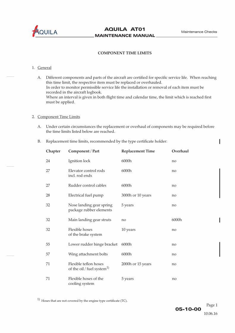
A. Different components and parts of the aircraft are certified for specific service life. When reachingthis time limit, the respective item must be replaced or overhauled.In order to monitor permissible service life the installation or removal of each item must berecorded in the aircraft logbook.Where an interval is given in both flight time and calendar time, the limit which is reached firstmust be applied.
2.
A. Under certain circumstances the replacement or overhaul of components may be required beforethe time limits listed below are reached.
B. Replacement time limits, :
24 Ignition lock 6000h no
27 Elevator control rods 6000h noincl. rod ends
27 Rudder control cables 6000h no
28 Electrical fuel pump 3000h or 10 years no
32 Nose landing gear spring 5 years nopackage rubber elements
55 Lower rudder hinge bracket 6000h no
57 Wing attachment bolts 6000h no
71 Flexible teflon hoses 2000h or 15 years no
General
Component Time Limits
recommended by the type certificate holder
32 Main landing gear struts no 6000h
32 Flexible hoses 10 years noof the brake system
of the oil / fuel system
71 Flexible hoses of the 5 years nocooling system
1)
05-10-00
Maintenance Checks
10.06.16
Page 1
1) Hoses that are not covered by the engine type certificate (TC).

MAINTENANCE MANUAL
AQUILA AT01A
05-10-00Page 2
10.06.16
Maintenance Checks
C. Vendor Established Component Time Limits
25 ELT battery Note 1 no
25 Fire extinguisher 10 years Note 4Air Total
25 Fire extinguisher 12 years noH3R
31 ASPEN internal battery 800h or 3 years no
34 KMD 150 MFD/GPS 10 years nointernal battery (recommended)
34 WINTER instruments no
61 Propeller noMTV-21-A/175-05
61 Propeller governor noP-410-13
71 Engine ROTAX 912S no
71 ROTAX mechanical 5 years nofuel pump Note 3
71 ROTAX flexible teflon with engine overhaul nohoses of the fuel system Note 3
Chapter Component / Part Replacement Time Overhaul
Note 5
2000h or 6 yearsNote 2
61 Propeller governor no 6 years, with engineWoodward A210786 Note 6
2000h or 6 yearsNote 2
61 Propeller governor no 2000h or 6 yearsP-850-12 Note 2
2000h or 15 years,1500h or 12 years,1200h or 10 yearsNote 3
71 AQUILA engine mount 6000h noand attaching bolts
71 Engine shock with engine nomounts overhaul
MAINTENANCE MANUAL
AQUILA AT01A
05-10-00Page 3
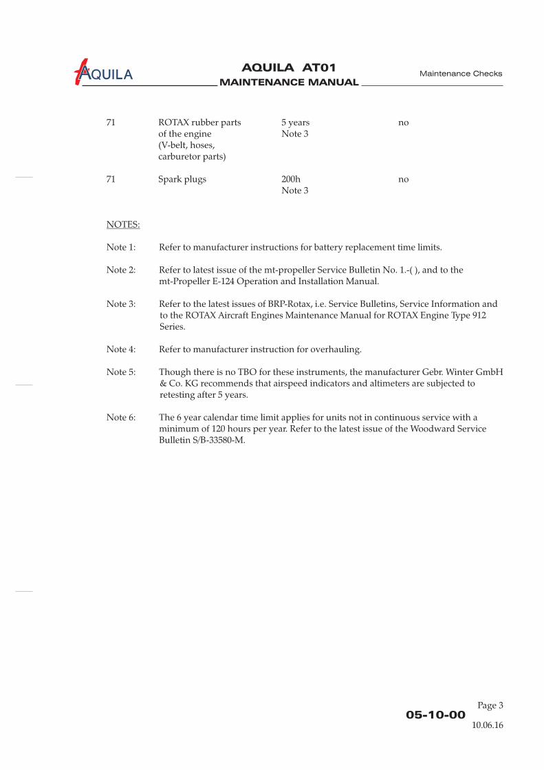
71 ROTAX rubber parts 5 years no
(V-belt, hoses,
Note 1: Refer to manufacturer instructions for battery replacement time limits.
Note 2: Refer to latest issue of the mt-propeller Service Bulletin No. 1.-( ), and to themt-Propeller E-124 Operation and Installation Manual.
Note 3: Refer to the latest issues of BRP-Rotax, i.e. Service Bulletins, Service Information andto the ROTAX Aircraft Engines Maintenance Manual for ROTAX Engine Type 912Series.
Note 4: Refer to manufacturer instruction for overhauling.
Note 5: Though there is no TBO for these instruments, the manufacturer Gebr. Winter GmbH& Co. KG recommends that airspeed indicators and altimeters are subjected toretesting after 5 years.
Note 6: The 6 year calendar time limit applies for units not in continuous service with aminimum of 120 hours per year. Refer to the latest issue of the Woodward ServiceBulletin S/B-33580-M.
of the engine Note 3
carburetor parts)
71 Spark plugs 200h noNote 3
NOTES:
10.06.16
Maintenance Checks

MAINTENANCE MANUAL
AQUILA AT01A Maintenance Checks
MAINTENANCE MANUAL
AQUILA AT01A
05-20-00
SCHEDULED MAINTENANCE CHECKS
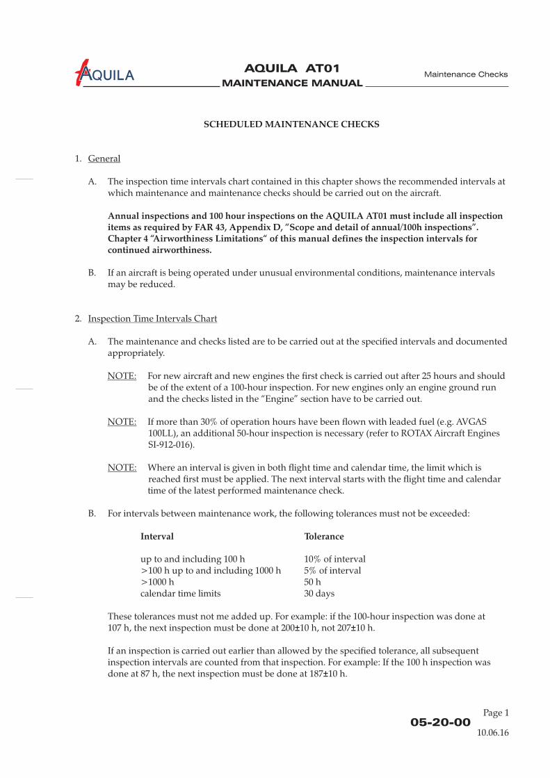
Annual inspections and 100 hour inspections on the AQUILA AT01 must include all inspectionitems as required by FAR 43, Appendix D, “Scope and detail of annual/100h inspections”.Chapter 4 “Airworthiness Limitations“ of this manual defines the inspection intervals forcontinued airworthiness.
1.
A. The inspection time intervals chart contained in this chapter shows the recommended intervals atwhich maintenance and maintenance checks should be carried out on the aircraft.
B. If an aircraft is being operated under unusual environmental conditions, maintenance intervalsmay be reduced.
2.
A. The maintenance and checks listed are to be carried out at the specified intervals and documentedappropriately.
up to and including 100 h 10% of interval>100 h up to and including 1000 h 5% of interval>1000 h 50 hcalendar time limits 30 days
These tolerances must not me added up. For example: if the 100-hour inspection was done at107 h, the next inspection must be done at 200 10 h, not 207 10 h.
If an inspection is carried out earlier than allowed by the specified tolerance, all subsequentinspection intervals are counted from that inspection. For example: If the 100 h inspection wasdone at 87 h, the next inspection must be done at 187 10 h.
General
Inspection Time Intervals Chart
NOTE:
NOTE:
NOTE:
For new aircraft and new engines the first check is carried out after 25 hours and shouldbe of the extent of a 100-hour inspection. For new engines only an engine ground runand the checks listed in the “Engine” section have to be carried out.
If more than 30% of operation hours have been flown with leaded fuel (e.g. AVGAS100LL), an additional 50-hour inspection is necessary (refer to ROTAX Aircraft EnginesSI-912-016).
Where an interval is given in both flight time and calendar time, the limit which isreached first must be applied. The next interval starts with the flight time and calendartime of the latest performed maintenance check.
B. For intervals between maintenance work, the following tolerances must not be exceeded:
Interval Tolerance
± ±
±
Maintenance Checks
10.06.16
Page 1
MAINTENANCE MANUAL
AQUILA AT01A
05-20-00Page 2
Maintenance Checks
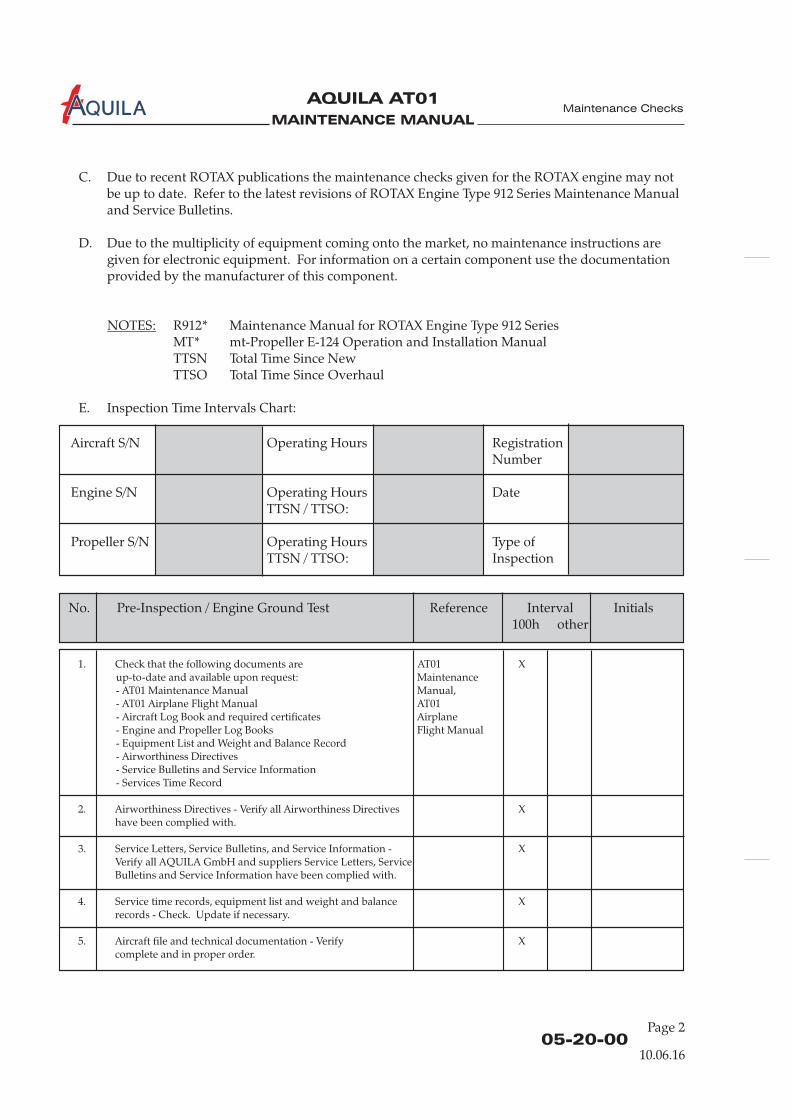
1. Check that the following documents are AT01 Xup-to-date and available upon request: Maintenance- AT01 Maintenance Manual Manual,- AT01 Airplane Flight Manual AT01- Aircraft Log Book and required certificates Airplane- Engine and Propeller Log Books Flight Manual- Equipment List and Weight and Balance Record- Airworthiness Directives- Service Bulletins and Service Information- Services Time Record
2. Airworthiness Directives - Verify all Airworthiness Directives Xhave been complied with.
3. Service Letters, Service Bulletins, and Service Information - XVerify all AQUILA GmbH and suppliers Service Letters, ServiceBulletins and Service Information have been complied with.
4. Service time records, equipment list and weight and balance Xrecords - Check. Update if necessary.
5. Aircraft file and technical documentation - Verify Xcomplete and in proper order.
No. Pre-Inspection / Engine Ground Test Reference Interval Initials100h other
Aircraft S/N Operating Hours Registration
Engine S/N Operating Hours DateTTSN / TTSO:
Propeller S/N Operating Hours Type ofTTSN / TTSO:
Number
Inspection
10.06.16
C. Due to recent ROTAX publications the maintenance checks given for the ROTAX engine may notbe up to date. Refer to the latest revisions of ROTAX Engine Type 912 Series Maintenance Manualand Service Bulletins.
D. Due to the multiplicity of equipment coming onto the market, no maintenance instructions aregiven for electronic equipment. For information on a certain component use the documentationprovided by the manufacturer of this component.
NOTES:
E. Inspection Time Intervals Chart:
R912* Maintenance Manual for ROTAX Engine Type 912 SeriesMT* mt-Propeller E-124 Operation and Installation ManualTTSN Total Time Since NewTTSO Total Time Since Overhaul
MAINTENANCE MANUAL
AQUILA AT01A
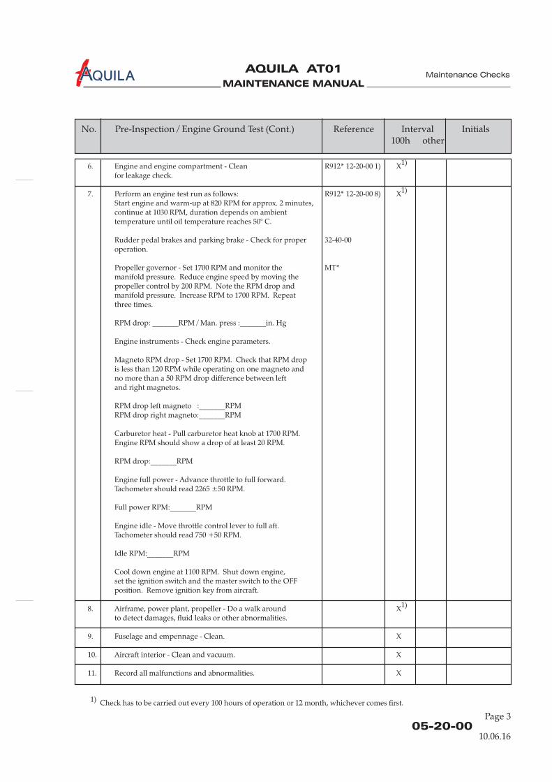
6. Engine and engine compartment - Clean R912* 12-20-00 1) X1)
for leakage check.
7. Perform an engine test run as follows: R912* 12-20-00 8) X1)
Start engine and warm-up at 820 RPM for approx. 2 minutes,continue at 1030 RPM, duration depends on ambienttemperature until oil temperature reaches 50° C.
Rudder pedal brakes and parking brake - Check for proper 32-40-00operation.
Propeller governor - Set 1700 RPM and monitor the MT*manifold pressure. Reduce engine speed by moving thepropeller control by 200 RPM. Note the RPM drop andmanifold pressure. Increase RPM to 1700 RPM. Repeatthree times.
RPM drop: _______RPM / Man. press :_______in. Hg
Engine instruments - Check engine parameters.
Magneto RPM drop - Set 1700 RPM. Check that RPM dropis less than 120 RPM while operating on one magneto andno more than a 50 RPM drop difference between leftand right magnetos.
RPM drop left magneto :_______RPMRPM drop right magneto:_______RPM
Carburetor heat - Pull carburetor heat knob at 1700 RPM.Engine RPM should show a drop of at least 20 RPM.
RPM drop:_______RPM
Engine full power - Advance throttle to full forward.Tachometer should read 2265 ±50 RPM.
Full power RPM:_______RPM
Engine idle - Move throttle control lever to full aft.Tachometer should read 750 +50 RPM.
Idle RPM:_______RPM
Cool down engine at 1100 RPM. Shut down engine,set the ignition switch and the master switch to the OFFposition. Remove ignition key from aircraft.
8. Airframe, power plant, propeller - Do a walk around X1)
to detect damages, fluid leaks or other abnormalities.
9. Fuselage and empennage - Clean. X
10. Aircraft interior - Clean and vacuum. X
11. Record all malfunctions and abnormalities. X
05-20-00Page 3
Maintenance Checks
No. Pre-Inspection / Engine Ground Test (Cont.) Reference Interval Initials100h other
10.06.16
1) Check has to be carried out every 100 hours of operation or 12 month, whichever comes first.
MAINTENANCE MANUAL
AQUILA AT01A
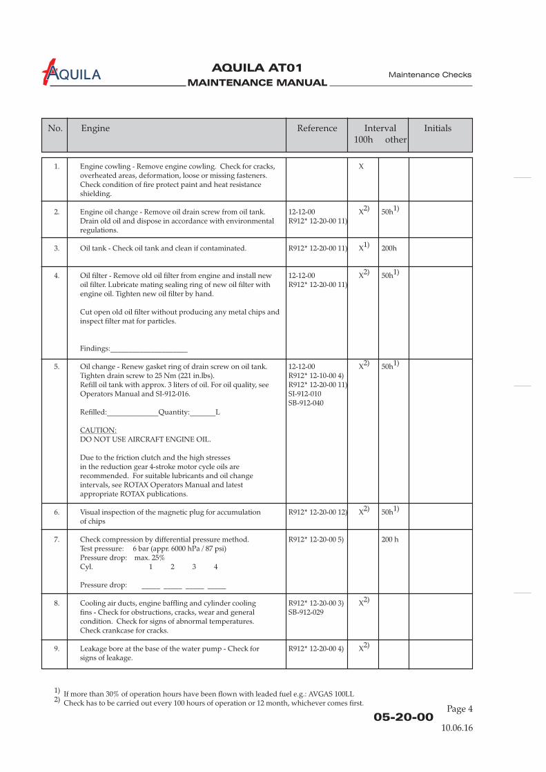
1. Engine cowling - Remove engine cowling. Check for cracks, Xoverheated areas, deformation, loose or missing fasteners.Check condition of fire protect paint and heat resistanceshielding.
2. Engine oil change - Remove oil drain screw from oil tank. 12-12-00 X2) 50h1)
Drain old oil and dispose in accordance with environmental R912* 12-20-00 11)regulations.
3. Oil tank - Check oil tank and clean if contaminated. R912* 12-20-00 11) X1) 200h
4. Oil filter - Remove old oil filter from engine and install new 12-12-00 X2) 50h1)
oil filter. Lubricate mating sealing ring of new oil filter with R912* 12-20-00 11)engine oil. Tighten new oil filter by hand.
Cut open old oil filter without producing any metal chips andinspect filter mat for particles.
Findings:_____________________
5. Oil change - Renew gasket ring of drain screw on oil tank. 12-12-00 X2) 50h1)
Tighten drain screw to 25 Nm (221 in.lbs). R912* 12-10-00 4)Refill oil tank with approx. 3 liters of oil. For oil quality, see R912* 12-20-00 11)Operators Manual and SI-912-016. SI-912-010
SB-912-040Refilled:______________Quantity:_______L
DO NOT USE AIRCRAFT ENGINE OIL.
Due to the friction clutch and the high stressesin the reduction gear 4-stroke motor cycle oils arerecommended. For suitable lubricants and oil changeintervals, see ROTAX Operators Manual and latestappropriate ROTAX publications.
6. Visual inspection of the magnetic plug for accumulation R912* 12-20-00 12) X2) 50h1)
of chips
7. Check compression by differential pressure method. R912* 12-20-00 5) 200 hTest pressure: 6 bar (appr. 6000 hPa / 87 psi)Pressure drop: max. 25%Cyl. 1 2 3 4
Pressure drop: _____ _____ _____ _____
8. Cooling air ducts, engine baffling and cylinder cooling R912* 12-20-00 3) X2)
fins - Check for obstructions, cracks, wear and general SB-912-029condition. Check for signs of abnormal temperatures.Check crankcase for cracks.
9. Leakage bore at the base of the water pump - Check for R912* 12-20-00 4) X2)
signs of leakage.
CAUTION:
Page 405-20-00
Maintenance Checks
No. Engine Reference Interval Initials100h other
1) If more than 30% of operation hours have been flown with leaded fuel e.g.: AVGAS 100LL2) Check has to be carried out every 100 hours of operation or 12 month, whichever comes first.
10.06.16
MAINTENANCE MANUAL
AQUILA AT01A
Page 505-20-00
Maintenance Checks
No. Engine (Cont.) Reference Interval Initials100h other
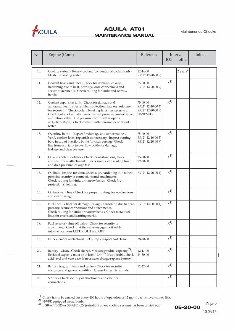
10. Cooling system - Renew coolant (conventional coolant only). 12-14-00 2 years3)
Flush the cooling system. R912* 12-20-00 9)
11. Coolant hoses and lines - Check for damage, leakage, 75-00-00 X1)
hardening due to heat, porosity, loose connections and R912* 12-20-00 9)secure attachments. Check routing for kinks and narrowbends.
12. Coolant expansion tank - Check for damage and 75-00-00 X1)
abnormalities. Inspect rubber protection plate on tank base R912* 12-10-00 3)for secure fit. Check coolant level, replenish as necessary. R912* 12-20-00 9)Check gasket of radiator cover, inspect pressure control valve, SB-912-043and return valve. The pressure control valve opensat 1,2 bar (18 psi). Check coolant with densimeter or glycoltester.
13. Overflow bottle - Inspect for damage and abnormalities. 75-00-00 X1)
Verify coolant level, replenish as necessary. Inspect venting R912* 12-10-00 3)bore in cap of overflow bottle for clear passage. Check R912* 12-20-00 9)line from exp. tank to overflow bottle for damage,leakage and clear passage.
14. Oil and coolant radiator - Check for obstructions, leaks 75-00-00 X1)
and security of attachment. If necessary, clean cooling fins 79-20-00and do a pressure leakage test.
15. Oil lines - Inspect for damage, leakage, hardening due to heat, R912* 12-20-00 4) X1)
porosity, security of connections and attachments.Check routing for kinks or narrow bends. Check fireprotection shielding.
16. Oil tank vent line - Check for proper routing, for obstructions X1)
and clear passage
17. Fuel lines - Check for damage, leakage, hardening due to heat, R912* 12-20-00 4) X1)
porosity, secure connections and attachments.Check routing for kinks or narrow bends. Check metal fuellines for cracks and scuffing marks.
18. Fuel selector / shut-off valve - Check for security of X1)
attachment. Check that the valve engages noticeableinto the positions LEFT, RIGHT and OFF.
19. Filter element of electrical fuel pump - Inspect and clean. 28-20-00 X1)
20. Battery - Clean. Check charge. Measure residual capacity 2). 12-17-00 X1)
Residual capacity must be at least 19Ah 2). If applicable, check 24-30-00acid level and vent case. If necessary, charge/replace battery.
21. Battery tray, terminals and cables - Check for security, 12-22-00 X1)
corrosion and general condition. Grease battery terminals.
22. Starter - Check security of attachment and electrical X1)
connections.
10.06.16
1) Check has to be carried out every 100 hours of operation or 12 month, whichever comes first.2) N/VFR equipped aircraft only.3) If SB-AT01-025 or SB-AT01-029 (retrofit of a new cooling system) has been carried out.

MAINTENANCE MANUAL
AQUILA AT01A
Page 605-20-00
Maintenance Checks
23. Alternator - Check attachment and V-belt tension. R912* 12-20-00 6) X2)
Inspect electrical connections.
24. Spark plugs - Remove all spark plugs, check the heat range R912* 12-20-00 13) X2)
designation, clean, check electrode gap and adjust if necessary.Replace as required.
25. Spark plug connectors - Check that resistance spark plug 200hconnectors fit tightly on the spark plugs.Minimum pull-off force is 30 N (7 lb).
26. Spark plugs - Replace spark plugs R912* 12-20-00 13) X 1) 200h
27. Oil temperature / oil pressure sensor - Check for tight fit X2)
and condition.
28. Exhaust system - Check attachment screws and springs X2)
for security and fit. Inspect system for damage and missingparts. Visual inspection of the muffler, exaust pipes andmounting flanges for cracks, corrosion and leakage.Check heat shielding for condition.
29. Cabin heat - Check heat shroud and heat ducts for damage X2)
and security of attachment. Check heat control function.
30. Exhaust muffler - Remove heat shroud from muffler 78-10-00 200hand inspect muffler for condition, corrosion and leakage.
FAILURE TO INSPECT MUFFLER FOR LEAKS COULDRESULT IN CARBON MONOXIDE ENTERING THE CABIN,LEADING TO SERIOUS INJURY OR DEATH!
31. Propeller gear box - Check the friction torque in free rotation. R912* 12-20-00 14) X2)
Actual friction torque is measured: _________Nm
32. Propeller gear box - Inspect overload clutch. R912* 05-50-00 2) 600h1)
SB-912-033
33. Propeller gear box - Check the propeller gearbox (with R912* 12-20-00 14) 1000hoverload clutch).
34. Carburetors - Check carburetor synchronization. Mechanical R912* 12-20-00 10) X2)
and pneumatic synchronization.
35. Carburetors - Inspect the float chamber assy for R912* 12-20-00 10) 200hcontamination and corrosion. SI-912-021
36. Carburetors - Check the ventilation of the float chambers. 200hAny trouble with float chamber ventilation impairs engineand carburetor function and must therefore be avoided.Check that the passage of the ventilation lines is free and thatno kinks can arise.
WARNING:
No. Engine (Cont.) Reference Interval Initials100h other
10.06.16
1) If more than 30% of operation hours have been flown with leaded fuel e.g.: AVGAS 100LL2) Check has to be carried out every 100 hours of operation or 12 month, whichever comes first.
MAINTENANCE MANUAL
AQUILA AT01A
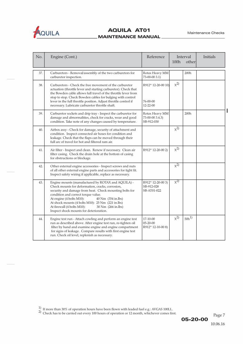
37. Carburetors - Removal/assembly of the two carburetors for Rotax Heavy MM 200hcarburetor inspection. 73-00-00 3.1)
38. Carburetors - Check the free movement of the carburetor R912* 12-20-00 10) X2)
actuation (throttle lever and starting carburetor). Check thatthe Bowden cable allows full travel of the throttle lever fromstop to stop. Check Bowden cables for bulging with controllever in the full throttle position. Adjust throttle control if 76-00-00necessary. Lubricate carburetor throttle shaft. 12-22-00
39. Carburetor sockets and drip tray - Inspect the carburetor for Rotax Heavy MM 200hdamage and abnormalities, check for cracks, wear and good 73-00-00 3.4.3)condition. Take note of any changes caused by temperature. SB-912-030
40. Airbox assy - Check for damage, security of attachment and X2)
condition. Inspect connected air hoses for condition andleakage. Check that the flaps can be moved through theirfull arc of travel for hot and filtered ram air.
41. Air filter - Inspect and clean. Renew if necessary. Clean air R912* 12-20-00 2) X2)
filter casing. Check the drain hole at the bottom of casingfor obstructions or blockage.
42. Other external engine accessories - Inspect screws and nuts X2)
of all other external engine parts and accessories for tight fit.Inspect safety wiring if applicable, replace as necessary.
43. Engine mounts (manufactured by ROTAX and AQUILA) - R912* 12-20-00 3) X2)
Check mounts for deformation, cracks, corrosion, SB-912-028security and damage from heat. Check mounting bolts for SB-AT01-022condition and correct torque value.At engine (4 bolts M10): 40 Nm (354 in.lbs)At shock mounts (4 bolts M10): 25 Nm (221 in.lbs)At firewall (4 bolts M10): 30 Nm (266 in.lbs)Inspect shock mounts for deterioration.
44. Engine test run - Attach cowling and perform an engine test 17-10-00 X2) 50h1)
run as described above. After engine test run, re-tighten oil 05-20-00filter by hand and examine engine and engine compartment R912* 12-10-00 8)for signs of leakage. Compare results with first engine test
run. Check oil level, replenish as necessary.
Page 705-20-00
Maintenance Checks
No. Engine (Cont.) Reference Interval Initials100h other
1) If more than 30% of operation hours have been flown with leaded fuel e.g.: AVGAS 100LL.2) Check has to be carried out every 100 hours of operation or 12 month, whichever comes first.
10.06.16
MAINTENANCE MANUAL
AQUILA AT01A
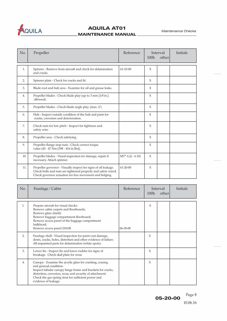
1. Spinner - Remove from aircraft and check for delamination 61-10-00 Xand cracks.
2. Spinner plate - Check for cracks and fit. X
3. Blade root and hub area - Examine for oil and grease leaks. X
4. Propeller blades - Check blade play (up to 3 mm [1/8 in.] Xallowed).
5. Propeller blades - Check blade angle play. (max. 2°) X
6. Hub - Inspect outside condition of the hub and parts for Xcracks, corrosion and deterioration.
7. Check nuts for low pitch - Inspect for tightness and Xsafety wire.
8. Propeller assy - Check safetying. X
9. Propeller flange stop nuts - Check correct torque Xvalue (45 - 47 Nm [398 - 416 in.lbs]).
10. Propeller blades - Visual inspection for damage, repair if MT* 6.2) - 6.10) Xnecessary. Attach spinner.
11. Propeller governor - Visually inspect for signs of oil leakage. 61-20-00 XCheck bolts and nuts are tightened properly and safety wired.Check governor actuation for free movement and bulging.
Page 805-20-00
Maintenance Checks
1. Prepare aircraft for visual checks: XRemove cabin carpets and floorboards;Remove glare shield;Remove baggage compartment floorboard;Remove access panel of the baggage compartmentbulkhead;Remove access panel 210AB. 06-30-00
2. Fuselage shell - Visual inspection for paint coat damage, Xdents, cracks, holes, distortion and other evidence of failure.All unpainted parts for delamination (white spots).
3. Lower fin - Inspect fin and lower rudder for signs of Xbreakage. Check skid plate for wear.
4. Canopy - Examine the acrylic glass for cracking, crazing Xand general condition.Inspect tubular canopy hinge frame and brackets for cracks,distortion, corrosion, wear, and security of attachment.Check the gas spring strut for sufficient power andevidence of leakage.
No. Fuselage / Cabin Reference Interval Initials100h other
No. Propeller Reference Interval Initials100h other
10.06.16
MAINTENANCE MANUAL
AQUILA AT01A
Page 905-20-00
Maintenance Checks
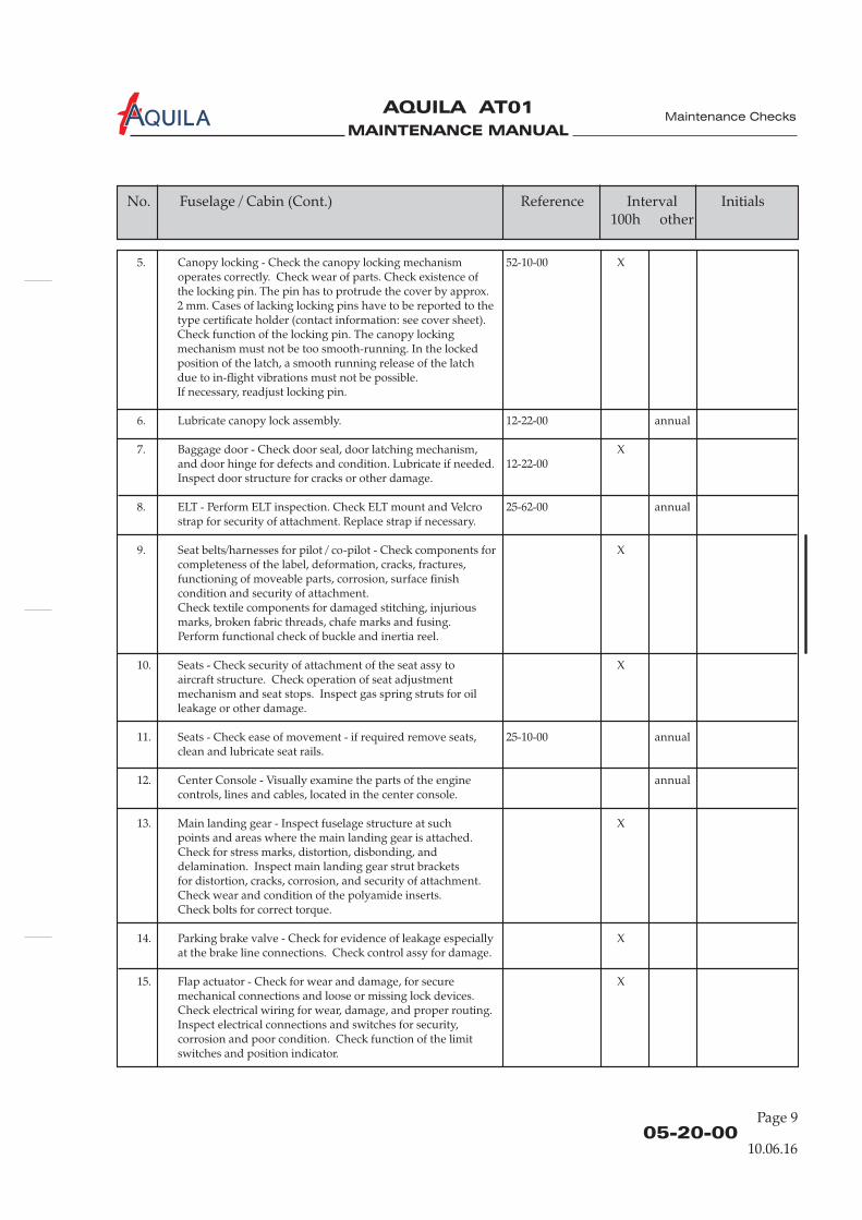
5. Canopy locking - Check the canopy locking mechanism 52-10-00 Xoperates correctly. Check wear of parts. Check existence ofthe locking pin. The pin has to protrude the cover by approx.2 mm. Cases of lacking locking pins have to be reported to thetype certificate holder (contact information: see cover sheet).Check function of the locking pin. The canopy lockingmechanism must not be too smooth-running. In the lockedposition of the latch, a smooth running release of the latchdue to in-flight vibrations must not be possible.If necessary, readjust locking pin.
6. Lubricate canopy lock assembly. 12-22-00 annual
7. Baggage door - Check door seal, door latching mechanism, Xand door hinge for defects and condition. Lubricate if needed. 12-22-00Inspect door structure for cracks or other damage.
8. ELT - Perform ELT inspection. Check ELT mount and Velcro 25-62-00 annualstrap for security of attachment. Replace strap if necessary.
9. Seat belts/harnesses for pilot / co-pilot - Check components for Xcompleteness of the label, deformation, cracks, fractures,functioning of moveable parts, corrosion, surface finishcondition and security of attachment.Check textile components for damaged stitching, injuriousmarks, broken fabric threads, chafe marks and fusing.Perform functional check of buckle and inertia reel.
10. Seats - Check security of attachment of the seat assy to Xaircraft structure. Check operation of seat adjustmentmechanism and seat stops. Inspect gas spring struts for oilleakage or other damage.
11. Seats - Check ease of movement - if required remove seats, 25-10-00 annualclean and lubricate seat rails.
12. Center Console - Visually examine the parts of the engine annualcontrols, lines and cables, located in the center console.
13. Main landing gear - Inspect fuselage structure at such Xpoints and areas where the main landing gear is attached.Check for stress marks, distortion, disbonding, anddelamination. Inspect main landing gear strut bracketsfor distortion, cracks, corrosion, and security of attachment.Check wear and condition of the polyamide inserts.Check bolts for correct torque.
14. Parking brake valve - Check for evidence of leakage especially Xat the brake line connections. Check control assy for damage.
15. Flap actuator - Check for wear and damage, for secure Xmechanical connections and loose or missing lock devices.Check electrical wiring for wear, damage, and proper routing.Inspect electrical connections and switches for security,corrosion and poor condition. Check function of the limitswitches and position indicator.
No. Fuselage / Cabin (Cont.) Reference Interval Initials100h other
10.06.16
MAINTENANCE MANUAL
AQUILA AT01A
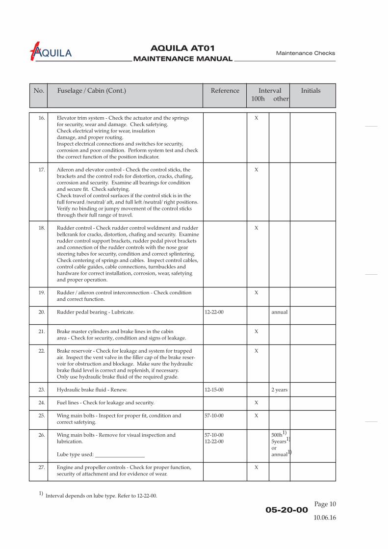
16. Elevator trim system - Check the actuator and the springs Xfor security, wear and damage. Check safetying.Check electrical wiring for wear, insulationdamage, and proper routing.Inspect electrical connections and switches for security,corrosion and poor condition. Perform system test and checkthe correct function of the position indicator.
17. Aileron and elevator control - Check the control sticks, the Xbrackets and the control rods for distortion, cracks, chafing,corrosion and security. Examine all bearings for conditionand secure fit. Check safetying.Check travel of control surfaces if the control stick is in thefull forward /neutral/ aft, and full left /neutral/ right positions.Verify no binding or jumpy movement of the control sticksthrough their full range of travel.
18. Rudder control - Check rudder control weldment and rudder Xbellcrank for cracks, distortion, chafing and security. Examinerudder control support brackets, rudder pedal pivot bracketsand connection of the rudder controls with the nose gearsteering tubes for security, condition and correct splintering.Check centering of springs and cables. Inspect control cables,control cable guides, cable connections, turnbuckles andhardware for correct installation, corrosion, wear, safetyingand proper operation.
19. Rudder / aileron control interconnection - Check condition Xand correct function.
20. Rudder pedal bearing - Lubricate. 12-22-00 annual
21. Brake master cylinders and brake lines in the cabin Xarea - Check for security, condition and signs of leakage.
22. Brake reservoir - Check for leakage and system for trapped Xair. Inspect the vent valve in the filler cap of the brake reser-voir for obstruction and blockage. Make sure the hydraulicbrake fluid level is correct and replenish, if necessary.Only use hydraulic brake fluid of the required grade.
23. Hydraulic brake fluid - Renew. 12-15-00 2 years
24. Fuel lines - Check for leakage and security. X
25. Wing main bolts - Inspect for proper fit, condition and 57-10-00 Xcorrect safetying.
26. Wing main bolts - Remove for visual inspection and 57-10-00 500h1)
lubrication. 12-22-00 5years1)
orLube type used: ___________________ annual1)
27. Engine and propeller controls - Check for proper function, Xsecurity of attachment and for evidence of wear.
Page 1005-20-00
Maintenance Checks
No. Fuselage / Cabin (Cont.) Reference Interval Initials100h other
10.06.16
1) Interval depends on lube type. Refer to 12-22-00.
MAINTENANCE MANUAL
AQUILA AT01A
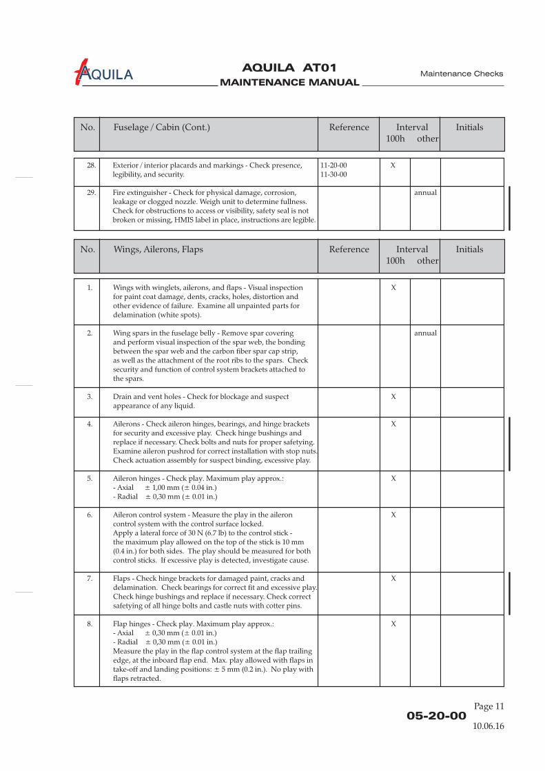
1. Wings with winglets, ailerons, and flaps - Visual inspection Xfor paint coat damage, dents, cracks, holes, distortion andother evidence of failure. Examine all unpainted parts fordelamination (white spots).
2. Wing spars in the fuselage belly - Remove spar covering annualand perform visual inspection of the spar web, the bondingbetween the spar web and the carbon fiber spar cap strip,as well as the attachment of the root ribs to the spars. Checksecurity and function of control system brackets attached tothe spars.
3. Drain and vent holes - Check for blockage and suspect Xappearance of any liquid.
4. Ailerons - Check aileron hinges, bearings, and hinge brackets Xfor security and excessive play. Check hinge bushings andreplace if necessary. Check bolts and nuts for proper safetying.Examine aileron pushrod for correct installation with stop nuts.Check actuation assembly for suspect binding, excessive play.
5. Aileron hinges - Check play. Maximum play approx.: X- Axial ± 1,00 mm (± 0.04 in.)- Radial ± 0,30 mm (± 0.01 in.)
6. Aileron control system - Measure the play in the aileron Xcontrol system with the control surface locked.Apply a lateral force of 30 N (6.7 lb) to the control stick -the maximum play allowed on the top of the stick is 10 mm(0.4 in.) for both sides. The play should be measured for bothcontrol sticks. If excessive play is detected, investigate cause.
7. Flaps - Check hinge brackets for damaged paint, cracks and Xdelamination. Check bearings for correct fit and excessive play.Check hinge bushings and replace if necessary. Check correctsafetying of all hinge bolts and castle nuts with cotter pins.
8. Flap hinges - Check play. Maximum play approx.: X- Axial ± 0,30 mm (± 0.01 in.)- Radial ± 0,30 mm (± 0.01 in.)Measure the play in the flap control system at the flap trailingedge, at the inboard flap end. Max. play allowed with flaps intake-off and landing positions: ± 5 mm (0.2 in.). No play withflaps retracted.
Page 1105-20-00
Maintenance Checks
No. Wings, Ailerons, Flaps Reference Interval Initials100h other
10.06.16
No. Fuselage / Cabin (Cont.) Reference Interval Initials100h other
28. Exterior / interior placards and markings - Check presence, 11-20-00 Xlegibility, and security. 11-30-00
29. Fire extinguisher - Check for physical damage, corrosion, annualleakage or clogged nozzle. Weigh unit to determine fullness.Check for obstructions to access or visibility, safety seal is notbroken or missing, HMIS label in place, instructions are legible.
MAINTENANCE MANUAL
AQUILA AT01A
1. Empennage - Inspect complete surface of the vertical and Xhorizontal stabilizers, the elevator and the rudder fordents, cracks, holes and delamination.
2. Rudder hinge, elevator hinge and bellcranks - Check brackets Xand bellcranks for security of attachment and corrosion.Examine bearings for binding and excessive play. Check hingebushings and replace if necessary. Check correct safetying ofthe lower rudder pivot pin with castellated nut and cotter pin.
3. Hinge play and control surface positioning - Verify clearance annualbetween horizontal stabilizer and elevator horns andclearance between vertical stabilizer and rudder horn is atleast 1 mm (0.04 in.). Check elevator hinge and rudderhinge play. Maximum play approx.:- Axial ± 0,30 mm (± 0.01 in.)- Radial ± 0,30 mm (± 0.01 in.)
Page 1205-20-00
Maintenance Checks
No. Reference Interval Initials100h other
Empennage, Elevator, Rudder
10.06.16
No. Wings, Ailerons, Flaps (Cont.) Reference Interval Initials100h other
9. Flaps and ailerons - Check that the gap between fuselage and Xflaps, between flaps and ailerons, and at the outboard end ofthe ailerons is at least 2 mm ( 0.08 in.).
10. Stall warning system - Check for condition and proper Xoperation.
11. For serial numbers from AT01-100 to AT01-126: 57-10-00 annualBonding between wing spar and upper shell - Check SB-AT01-002condition.
12. Navigation / strobe lights - Check operation, condition 33-40-00 Xof glass, and security of attachments.
13. Inner fuel tank ribs - Check connection of fuel and vent 28-10-00 annuallines to the fuel tank and the flange gasket of the fuel level 28-20-00sensors for signs of leakage. 28-40-00
14. Fuel vent lines - Check for blockage. X
15. Fuel tank drain valves - Check for correct function and Xleakage.
16. Fuel filler caps - Check for proper function and leakage. X
17. Tank inlet and upper wing shell in the fuel tank area - Check SB-AT01-027 annualsealing of the bore hole in the tank inlet. Check wing skin forbubble formation or bulging.
18. Tie-down points - Check thread and structure around the tie- 10-20-00 Xdown attach points for any damage.
MAINTENANCE MANUAL
AQUILA AT01A
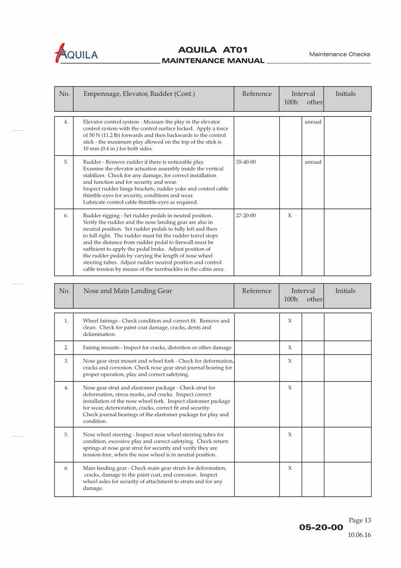
1. Wheel fairings - Check condition and correct fit. Remove and Xclean. Check for paint coat damage, cracks, dents anddelamination.
2. Fairing mounts - Inspect for cracks, distortion or other damage. X
3. Nose gear strut mount and wheel fork - Check for deformation, Xcracks and corrosion. Check nose gear strut journal bearing forproper operation, play and correct safetying.
4. Nose gear strut and elastomer package - Check strut for Xdeformation, stress marks, and cracks. Inspect correctinstallation of the nose wheel fork. Inspect elastomer packagefor wear, deterioration, cracks, correct fit and security.Check journal bearings of the elastomer package for play andcondition.
5. Nose wheel steering - Inspect nose wheel steering tubes for Xcondition, excessive play and correct safetying. Check returnsprings at nose gear strut for security and verify they aretension-free, when the nose wheel is in neutral position.
6. Main landing gear - Check main gear struts for deformation, Xcracks, damage to the paint coat, and corrosion. Inspect
wheel axles for security of attachment to struts and for anydamage.
Page 1305-20-00
Maintenance Checks
10.06.16
No. Reference Interval Initials100h other
Nose and Main Landing Gear
No. (Cont.) Reference Interval Initials100h other
Empennage, Elevator, Rudder
4. Elevator control system - Measure the play in the elevator annualcontrol system with the control surface locked. Apply a forceof 50 N (11.2 lb) forwards and then backwards to the controlstick - the maximum play allowed on the top of the stick is10 mm (0.4 in.) for both sides.
5. Rudder - Remove rudder if there is noticeable play. 55-40-00 annualExamine the elevator actuation assembly inside the verticalstabilizer. Check for any damage, for correct installationand function and for security and wear.Inspect rudder hinge brackets, rudder yoke and control cablethimble-eyes for security, conditions and wear.Lubricate control cable thimble-eyes as required.
6. Rudder rigging - Set rudder pedals in neutral position. 27-20-00 XVerify the rudder and the nose landing gear are also inneutral position. Set rudder pedals to fully left and thento full right. The rudder must hit the rudder travel stopsand the distance from rudder pedal to firewall must besufficient to apply the pedal brake. Adjust position ofthe rudder pedals by varying the length of nose wheelsteering tubes. Adjust rudder neutral position and controlcable tension by means of the turnbuckles in the cabin area.

MAINTENANCE MANUAL
AQUILA AT01A
7. Wheels and rims - Clean. Check tires for wear, cuts, Xforeign matter and deterioration. Inspect rims for security,deformation, cracks and other damage. Examine wheelbearings for excessive play, corrosion and irregular operation.Check tire pressure and proper location of the red slide marks.
8. Wheel bearings - Clean and lubricate. 12-22-00 500hannual
9. Wheel brakes - Clean. Apply brakes, examine system for leaks. 32-40-00 XInspect brake fluid carrying lines at the main landing gear forcondition, leakage and security of attachment. Inspect brakediscs for cracks, corrosion and wear. Replace brake discs ifworn below 4.3mm (0.17 in.). Inspect brake pads for conditionand wear. Replace linings when worn to 2.6mm (0.10 in.).Check freedom of movement of the pistons and pressure plates.
10. Wheel axles - Clean. Visually inspect for cracks, nicks, every wheelcorrosion or other damage. removal
1. Electrical wiring system - Check the complete electrical R912* 12-20-00 13) X1)
wiring system for security, damage, wear and secure fit.Check all cable connections for tight fit, good contact,corrosion and condition.
2. Tank inlet bonding wires - Check bonding between electric annualground (exhaust port) and tank inlet (max. 1 ).
3. Tank inlet bonding wires - Check bonding wires at the SB-AT01-027 annualairframe ground tube for yellow discoloration.
4. Instruments - Check instrument panel mounting brackets for annualsecurity and condition. Examine instruments for security ofattachment. Check electrical cables, hoses and lines for correctinstallation, condition and proper routing. Inspect air filterof the pitot / static system for obstructions and contamination.
5. Pitot / static system - Check pitot tube for security of 34-11-00 Xattachment, condition and obstructions. Check pitot andstatic pressure lines for correct installation, condition,water and proper routing. Check water traps for water.2)
6. Pitot heating system - Carefully check pitot tube for heating up X2)
with pitot heating switched ON.
RISK OF SKIN BURNS! DO NOT TOUCHPITOT TUBE WHEN HEATING IS SWITCHED ON!
Ω
WARNING:
Page 1405-20-00
Maintenance Checks
No. Reference Interval Initials100h other
Electrical System / Avionics
10.06.16
No. Reference Interval Initials100h other
Nose and Main Landing Gear (Cont.)
1) Check has to be carried out every 100 hours of operation or 12 month, whichever comes first.2) If installed.

MAINTENANCE MANUAL
AQUILA AT01A
1. Install wheel fairings. XInstall seats (if removed).Install cabin floor boards.Install baggage compartment floorboard.Install access panel of the baggage compartment bulkhead.Install access panel 210AB. 06-30-00
2. Flight controls - Check for full range of travel and excessive Xfriction.
3. Flaps - Operate through full extension and retraction for Xsteady and complete deployment. Check correct limitswitches operation at CRUISE, T/O and LDG flap positions.Verify the corresponding flap switch position and thecorresponding flap position indicator reading.
4. Elevator trim - Check for full range of travel and excessive Xfriction. Inspect proper operation of the trim control switch,limit switches, and the trim position indicator. Verify thatelevator control forces decrease or increase whenoperating elevator trim.
5. Engine and propeller controls - Check full range of motion Xwithout any obstruction or excessive friction to travel.Check throttle and propeller control levers friction lock.
6. Foreign items - Remove any foreign items from the aircraft. X
No. Reference Interval Initials100h other
Return to Service
Page 1505-20-00
Maintenance Checks
10.06.16
No. (Cont.) Reference Interval Initials100h other
Electrical System / Avionics
7. Garmin G500 system - Check all components and wiring for 34-25-00 X1) 2)
damage, corrosion, proper operation and security ofattachment.
8. Garmin G500 system - Check bonding. 34-25-00 2000h2)
10 years2)
9. Aspen EFD1000 system - Check all components and wiring for 34-25-00 annual2)
damage, corrosion, proper operation and security ofattachment. Perform bonding check.
1) Check has to be carried out every 100 hours of operation or 12 month, whichever comes first.2) If installed.
MAINTENANCE MANUAL
AQUILA AT01A
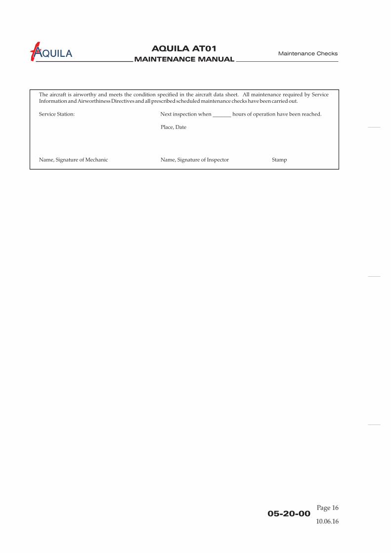
The aircraft is airworthy and meets the condition specified in the aircraft data sheet. All maintenance required by ServiceInformation and Airworthiness Directives and all prescribed scheduled maintenance checks have been carried out.
Service Station: Next inspection when _______ hours of operation have been reached.
Place, Date
Name, Signature of Mechanic Name, Signature of Inspector Stamp
Maintenance Checks
Page 1605-20-00
10.06.16
MAINTENANCE MANUAL
AQUILA AT01A
Page 1705-20-00
10.06.16
Maintenance Checks
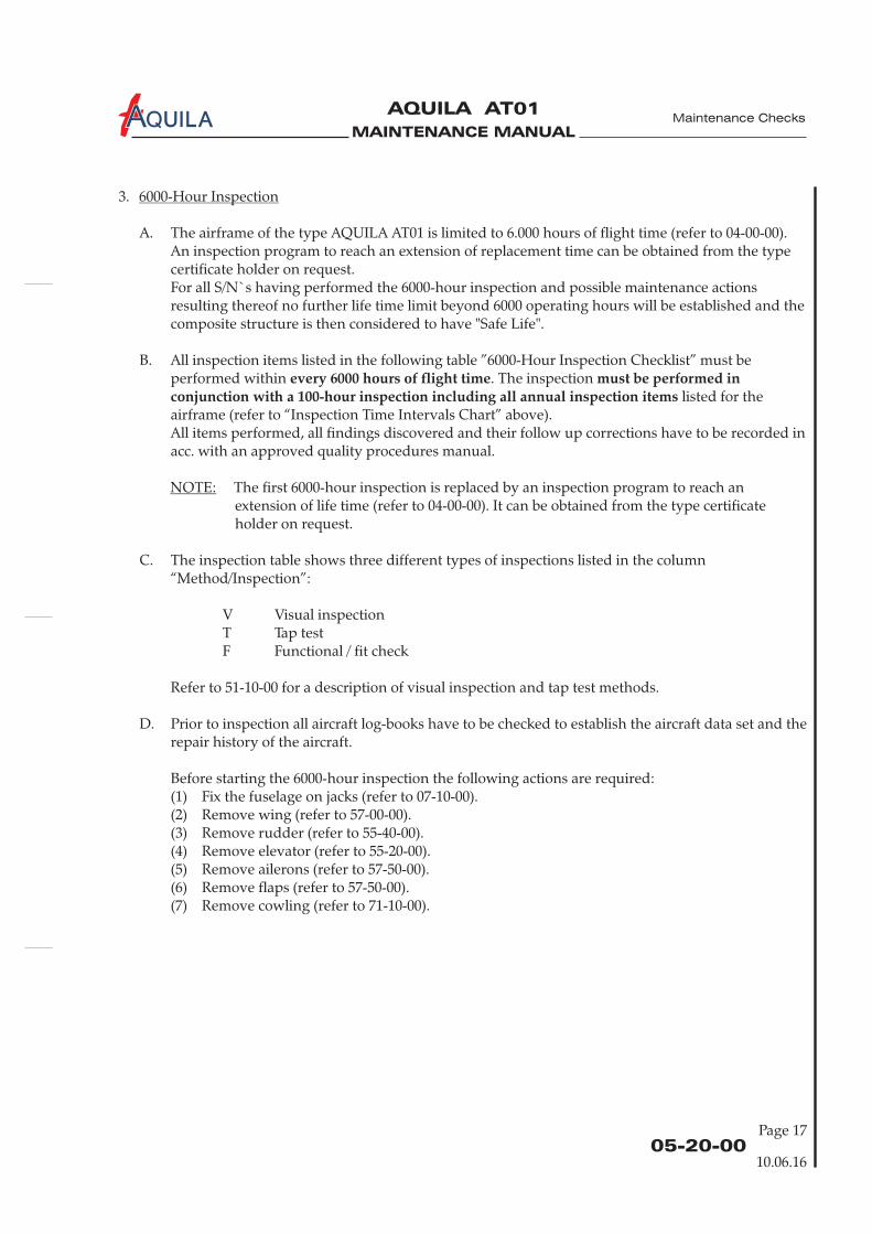
3.
A. The airframe of the type AQUILA AT01 is limited to 6.000 hours of flight time (refer to 04-00-00).An inspection program to reach an extension of replacement time can be obtained from the typecertificate holder on request.For all S/N`s having performed the 6000-hour inspection and possible maintenance actionsresulting thereof no further life time limit beyond 6000 operating hours will be established and thecomposite structure is then considered to have "Safe Life".
B. All inspection items listed in the following table ”6000-Hour Inspection Checklist” must beperformed within . The inspection
listed for theairframe (refer to “Inspection Time Intervals Chart” above).All items performed, all findings discovered and their follow up corrections have to be recorded inacc. with an approved quality procedures manual.
6000-Hour Inspection
every 6000 hours of flight time must be performed inconjunction with a 100-hour inspection including all annual inspection items
NOTE: The first 6000-hour inspection is replaced by an inspection program to reach anextension of life time (refer to 04-00-00). It can be obtained from the type certificateholder on request.
C. The inspection table shows three different types of inspections listed in the column“Method/Inspection”:
V Visual inspectionT Tap testF Functional / fit check
Refer to 51-10-00 for a description of visual inspection and tap test methods.
D. Prior to inspection all aircraft log-books have to be checked to establish the aircraft data set and therepair history of the aircraft.
Before starting the 6000-hour inspection the following actions are required:(1) Fix the fuselage on jacks (refer to 07-10-00).(2) Remove wing (refer to 57-00-00).(3) Remove rudder (refer to 55-40-00).(4) Remove elevator (refer to 55-20-00).(5) Remove ailerons (refer to 57-50-00).(6) Remove flaps (refer to 57-50-00).(7) Remove cowling (refer to 71-10-00).
MAINTENANCE MANUAL
AQUILA AT01A
Page 1805-20-00
10.06.16
Maintenance Checks
Aircraft S/N Operating Hours RegistrationTTSN
Engine S/N Operating Hours DateTTSN / TTSO
Propeller S/N Operating Hours DateTTSN / TTSO
Number
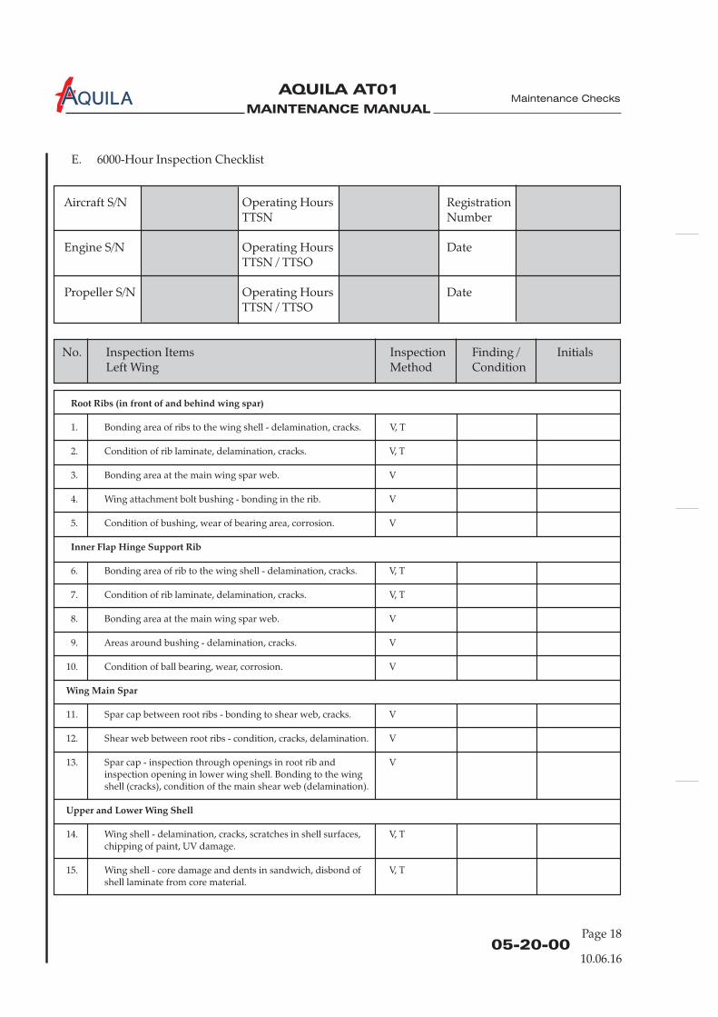
E. 6000-Hour Inspection Checklist
Root Ribs (in front of and behind wing spar)
Inner Flap Hinge Support Rib
Wing Main Spar
Upper and Lower Wing Shell
1. Bonding area of ribs to the wing shell - delamination, cracks. V, T
2. Condition of rib laminate, delamination, cracks. V, T
3. Bonding area at the main wing spar web. V
4. Wing attachment bolt bushing - bonding in the rib. V
5. Condition of bushing, wear of bearing area, corrosion. V
6. Bonding area of rib to the wing shell - delamination, cracks. V, T
7. Condition of rib laminate, delamination, cracks. V, T
8. Bonding area at the main wing spar web. V
9. Areas around bushing - delamination, cracks. V
10. Condition of ball bearing, wear, corrosion. V
11. Spar cap between root ribs - bonding to shear web, cracks. V
12. Shear web between root ribs - condition, cracks, delamination. V
13. Spar cap - inspection through openings in root rib and Vinspection opening in lower wing shell. Bonding to the wingshell (cracks), condition of the main shear web (delamination).
14. Wing shell - delamination, cracks, scratches in shell surfaces, V, Tchipping of paint, UV damage.
15. Wing shell - core damage and dents in sandwich, disbond of V, Tshell laminate from core material.
No. Inspection Items Inspection Finding / InitialsMethod ConditionLeft Wing
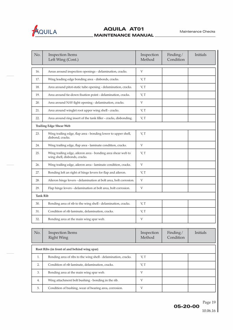
MAINTENANCE MANUAL
AQUILA AT01A
Page 1905-20-00
10.06.16
Maintenance Checks
No. Inspection Items Inspection Finding / InitialsMethod ConditionLeft Wing (Cont.)
16. Areas around inspection openings - delamination, cracks. V
17. Wing leading edge bonding area - disbonds, cracks. V, T
18. Area around pitot-static tube opening - delamination, cracks. V, T
19. Area around tie-down fixation point - delamination, cracks. V, T
20. Area around NAV-light opening - delamination, cracks. V
21. Area around winglet root upper wing shell - cracks. V, T
22. Area around ring insert of the tank filler - cracks, disbonding. V, T
23. Wing trailing edge, flap area - bonding lower to upper shell, V, Tdisbond, cracks.
24. Wing trailing edge, flap area - laminate condition, cracks. V
25. Wing trailing edge, aileron area - bonding area shear web to V, Twing shell, disbonds, cracks.
26. Wing trailing edge, aileron area - laminate condition, cracks. V
27. Bonding left an right of hinge levers for flap and aileron. V, T
28. Aileron hinge levers - delamination at bolt area, bolt corrosion. V
29. Flap hinge levers - delamination at bolt area, bolt corrosion. V
30. Bonding area of rib to the wing shell - delamination, cracks. V, T
31. Condition of rib laminate, delamination, cracks. V, T
32. Bonding area at the main wing spar web. V
Trailing Edge Shear Web
Tank Rib
No. Inspection Items Inspection Finding / InitialsRight Method ConditionWing
Root Ribs (in front of and behind wing spar)
1. Bonding area of ribs to the wing shell - delamination, cracks. V, T
2. Condition of rib laminate, delamination, cracks. V, T
3. Bonding area at the main wing spar web. V
4. Wing attachment bolt bushing - bonding in the rib. V
5. Condition of bushing, wear of bearing area, corrosion. V
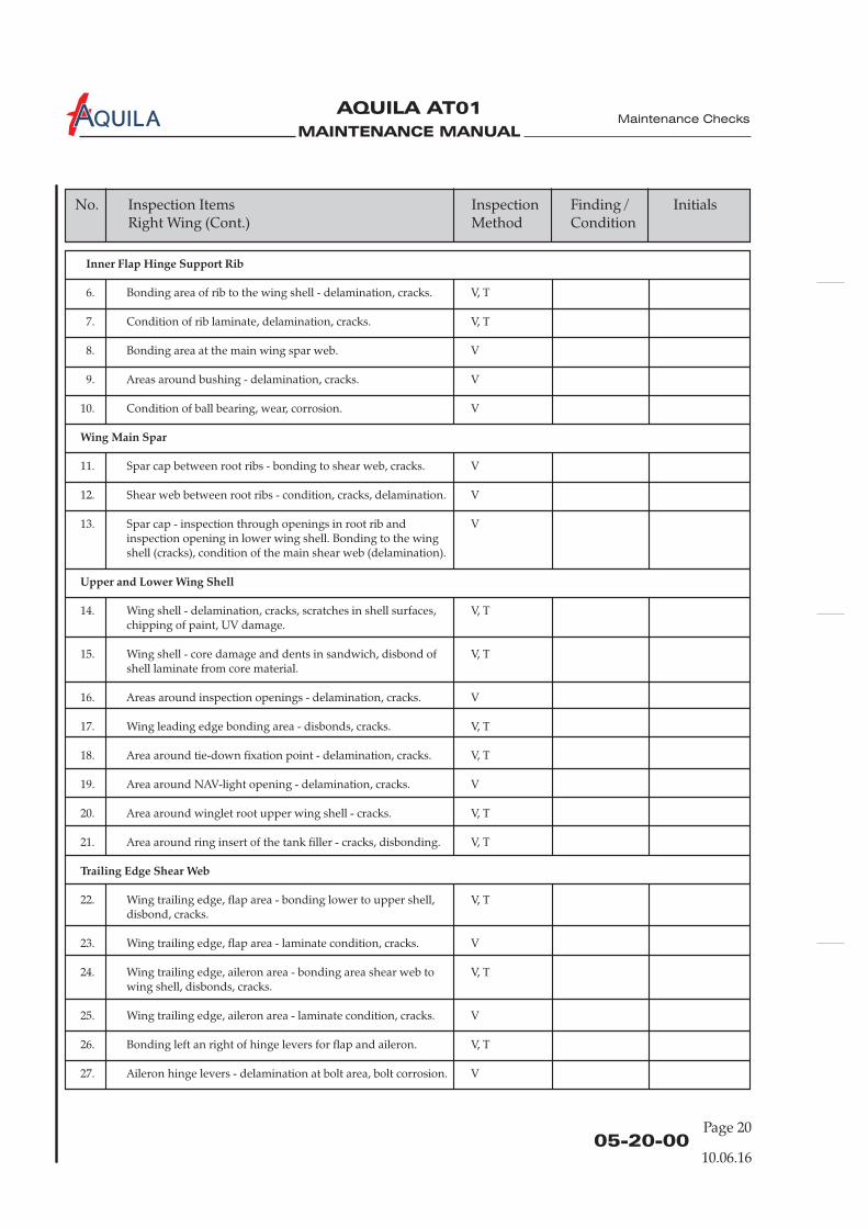
MAINTENANCE MANUAL
AQUILA AT01A
Page 2005-20-00
10.06.16
Maintenance Checks
No. Inspection Items Inspection Finding / InitialsRight Method ConditionWing (Cont.)
Inner Flap Hinge Support Rib
Wing Main Spar
Upper and Lower Wing Shell
Trailing Edge Shear Web
6. Bonding area of rib to the wing shell - delamination, cracks. V, T
7. Condition of rib laminate, delamination, cracks. V, T
8. Bonding area at the main wing spar web. V
9. Areas around bushing - delamination, cracks. V
10. Condition of ball bearing, wear, corrosion. V
11. Spar cap between root ribs - bonding to shear web, cracks. V
12. Shear web between root ribs - condition, cracks, delamination. V
13. Spar cap - inspection through openings in root rib and Vinspection opening in lower wing shell. Bonding to the wingshell (cracks), condition of the main shear web (delamination).
14. Wing shell - delamination, cracks, scratches in shell surfaces, V, Tchipping of paint, UV damage.
15. Wing shell - core damage and dents in sandwich, disbond of V, Tshell laminate from core material.
16. Areas around inspection openings - delamination, cracks. V
17. Wing leading edge bonding area - disbonds, cracks. V, T
18. Area around tie-down fixation point - delamination, cracks. V, T
19. Area around NAV-light opening - delamination, cracks. V
20. Area around winglet root upper wing shell - cracks. V, T
21. Area around ring insert of the tank filler - cracks, disbonding. V, T
22. Wing trailing edge, flap area - bonding lower to upper shell, V, Tdisbond, cracks.
23. Wing trailing edge, flap area - laminate condition, cracks. V
24. Wing trailing edge, aileron area - bonding area shear web to V, Twing shell, disbonds, cracks.
25. Wing trailing edge, aileron area - laminate condition, cracks. V
26. Bonding left an right of hinge levers for flap and aileron. V, T
27. Aileron hinge levers - delamination at bolt area, bolt corrosion. V
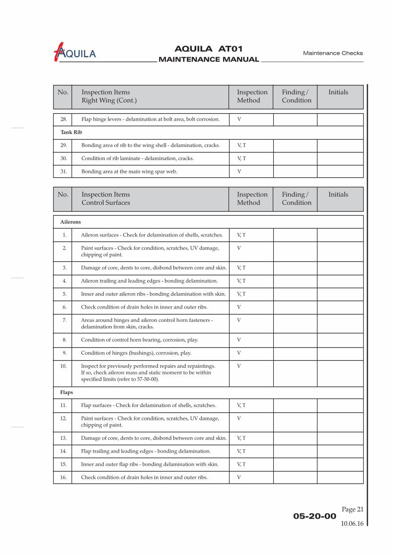
MAINTENANCE MANUAL
AQUILA AT01A
Page 2105-20-00
10.06.16
Maintenance Checks
No. Inspection Items Inspection Finding / InitialsRight Method ConditionWing (Cont.)
28. Flap hinge levers - delamination at bolt area, bolt corrosion. V
29. Bonding area of rib to the wing shell - delamination, cracks. V, T
30. Condition of rib laminate - delamination, cracks. V, T
31. Bonding area at the main wing spar web. V
Tank Rib
No. Inspection Items Inspection Finding / InitialsControl Surfaces Method Condition
Ailerons
Flaps
1. Aileron surfaces - Check for delamination of shells, scratches. V, T
2. Paint surfaces - Check for condition, scratches, UV damage, Vchipping of paint.
3. Damage of core, dents to core, disbond between core and skin. V, T
4. Aileron trailing and leading edges - bonding delamination. V, T
5. Inner and outer aileron ribs - bonding delamination with skin. V, T
6. Check condition of drain holes in inner and outer ribs. V
7. Areas around hinges and aileron control horn fasteners - Vdelamination from skin, cracks.
8. Condition of control horn bearing, corrosion, play. V
9. Condition of hinges (bushings), corrosion, play. V
10. Inspect for previously performed repairs and repaintings. VIf so, check aileron mass and static moment to be withinspecified limits (refer to 57-50-00).
11. Flap surfaces - Check for delamination of shells, scratches. V, T
12. Paint surfaces - Check for condition, scratches, UV damage, Vchipping of paint.
13. Damage of core, dents to core, disbond between core and skin. V, T
14. Flap trailing and leading edges - bonding delamination. V, T
15. Inner and outer flap ribs - bonding delamination with skin. V, T
16. Check condition of drain holes in inner and outer ribs. V
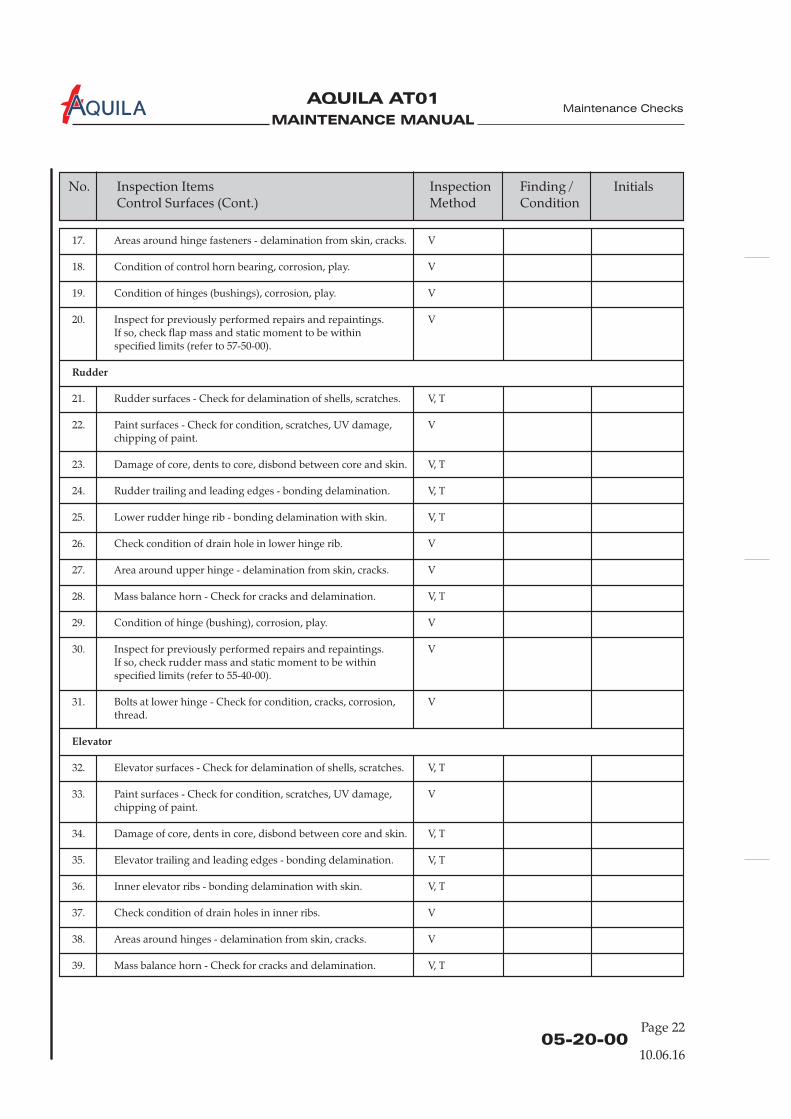
MAINTENANCE MANUAL
AQUILA AT01A
Page 2205-20-00
10.06.16
Maintenance Checks
No. Inspection Items Inspection Finding / InitialsControl Surfaces Method Condition(Cont.)
17. Areas around hinge fasteners - delamination from skin, cracks. V
18. Condition of control horn bearing, corrosion, play. V
19. Condition of hinges (bushings), corrosion, play. V
20. Inspect for previously performed repairs and repaintings. VIf so, check flap mass and static moment to be withinspecified limits (refer to 57-50-00).
21. Rudder surfaces - Check for delamination of shells, scratches. V, T
22. Paint surfaces - Check for condition, scratches, UV damage, Vchipping of paint.
23. Damage of core, dents to core, disbond between core and skin. V, T
24. Rudder trailing and leading edges - bonding delamination. V, T
25. Lower rudder hinge rib - bonding delamination with skin. V, T
26. Check condition of drain hole in lower hinge rib. V
27. Area around upper hinge - delamination from skin, cracks. V
28. Mass balance horn - Check for cracks and delamination. V, T
29. Condition of hinge (bushing), corrosion, play. V
30. Inspect for previously performed repairs and repaintings. VIf so, check rudder mass and static moment to be withinspecified limits (refer to 55-40-00).
31. Bolts at lower hinge - Check for condition, cracks, corrosion, Vthread.
32. Elevator surfaces - Check for delamination of shells, scratches. V, T
33. Paint surfaces - Check for condition, scratches, UV damage, Vchipping of paint.
34. Damage of core, dents in core, disbond between core and skin. V, T
35. Elevator trailing and leading edges - bonding delamination. V, T
36. Inner elevator ribs - bonding delamination with skin. V, T
37. Check condition of drain holes in inner ribs. V
38. Areas around hinges - delamination from skin, cracks. V
39. Mass balance horn - Check for cracks and delamination. V, T
Rudder
Elevator
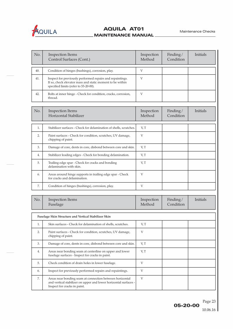
MAINTENANCE MANUAL
AQUILA AT01A
Page 2305-20-00
10.06.16
Maintenance Checks
No. Inspection Items Inspection Finding / InitialsControl Surfaces Method Condition(Cont.)
40. Condition of hinges (bushings), corrosion, play. V
41. Inspect for previously performed repairs and repaintings. VIf so, check elevator mass and static moment to be withinspecified limits (refer to 55-20-00).
42. Bolts at inner hinge - Check for condition, cracks, corrosion, Vthread.
No. Inspection Items Inspection Finding / InitialsHorizontal Stabilizer Method Condition
1. Stabilizer surfaces - Check for delamination of shells, scratches. V, T
2. Paint surfaces - Check for condition, scratches, UV damage, Vchipping of paint.
3. Damage of core, dents in core, disbond between core and skin. V, T
4. Stabilizer leading edges - Check for bonding delamination. V, T
5. Trailing edge spar - Check for cracks and bonding V, Tdelamination with skin.
6. Areas around hinge supports in trailing edge spar - Check Vfor cracks and delamination.
7. Condition of hinges (bushings), corrosion, play. V
No. Inspection Items Inspection Finding / InitialsFuselage Method Condition
Fuselage Skin Structure and Vertical Stabilizer Skin
1. Skin surfaces - Check for delamination of shells, scratches. V, T
2. Paint surfaces - Check for condition, scratches, UV damage, Vchipping of paint.
3. Damage of core, dents in core, disbond between core and skin. V, T
4. Areas near bonding seam at centerline on upper and lower V, Tfuselage surfaces - Inspect for cracks in paint.
5. Check condition of drain holes in lower fuselage. V
6. Inspect for previously performed repairs and repaintings. V
7. Areas near bonding seam at connection between horizontal Vand vertical stabilizer on upper and lower horizontal surfaces -Inspect for cracks in paint.
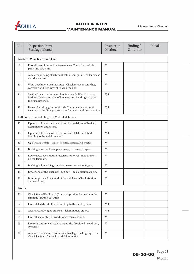
MAINTENANCE MANUAL
AQUILA AT01A
Page 2405-20-00
10.06.16
Maintenance Checks
No. Inspection Items Inspection Finding / InitialsFuselage Method Condition(Cont.)
Fuselage / Wing Interconnection
Bulkheads, Ribs and Hinges in Vertical Stabilizer
Firewall
8. Root ribs and intersection to fuselage - Check for cracks in Vpaint and structure.
9. Area around wing attachment bolt bushings - Check for cracks Vand disbonding.
10. Wing attachment bolt bushings - Check for wear, scratches, Vcorrosion and tightness of fit with the bolt.
11. Seat bulkhead and forward landing gear bulkhead in spar V, Tbridge - Check condition of laminate and bonding areas withthe fuselage shell.
12. Forward landing gear bulkhead - Check laminate around V, Tfasteners of landing gear supports for cracks and delamination.
13. Upper and lower shear web in vertical stabilizer - Check for Vdelamination and cracks.
14. Upper and lower shear web in vertical stabilizer - Check V, Tbonding to the stabilizer shell.
15. Upper hinge plate - check for delamination and cracks. V
16. Bushing in upper hinge plate - wear, corrosion, fit/play. V
17. Lower shear web around fasteners for lower hinge bracket - VCheck laminate.
18. Bushing in lower hinge bracket - wear, corrosion, fit/play. V
19. Lower end of the stabilizer (bumper) - delamination, cracks. V
20. Bumper plate at lower end of the stabilizer - Check fixation Vand condition.
21. Check firewall bulkhead (from cockpit side) for cracks in the Vlaminate (around cut outs).
22. Firewall bulkhead - Check bonding to the fuselage skin. V, T
23. Areas around engine brackets - delamination, cracks. V, T
24. Firewall metal shield - condition, wear, corrosion. V
25. Fire resistant firewall sealer around the fire shield - condition, Vcorrosion.
26. Areas around Camloc fasteners at fuselage cowling support - VCheck laminate for cracks and delamination.

MAINTENANCE MANUAL
AQUILA AT01A
Page 2505-20-00
10.06.16
Maintenance Checks
No. Inspection Items Inspection Finding / InitialsFuselage Method Condition(Cont.)
27. Area around pedal control brackets - delamination, cracks. V
28. Front cockpit floor - Check for delamination and cracks. V, TCheck bonding area to the fuselage structure for disbonding.
29. Front shear bulkhead - Check for delamination and cracks. V, TCheck bonding area to the fuselage structure for disbonding.
30. Front seat bulkhead - Check for delamination and cracks. V, TCheck bonding area to the fuselage structure for disbonding.
31. Seat elements and attachments - delamination, cracks. V, T
32. Rear seat bulkhead - Check for delamination and cracks. V, TCheck bonding area to the fuselage structure for disbonding.
33. Front landing gear bulkhead - Check for delamination and V, Tcracks. Check bonding area to the fuselage structure fordisbonding.
34. Rear landing gear bulkhead - Check for delamination and V, Tcracks. Check bonding area to the fuselage structure fordisbonding.
35. Baggage bulkhead - Check for delamination and cracks. V, TCheck bonding area to the fuselage structure for disbonding.
36. Lower lap belt attachments - Check for delamination and Vcracks. Check bonding area to the fuselage structure fordisbonding.
37. Lower lap belt fitting - Check for wear and corrosion. V
38. Upper lap belt attachments - Check for delamination and V, Tcracks at the baggage bulkhead.
39. Baggage compartment floor supports - Check for delamination Vand cracks. Check bonding area to the fuselage structure fordisbonding.
40. Gas spring supports - Check for delamination and cracks. VCheck bonding area to the fuselage structure for disbonding.
41. Composite tube stiffener and attachments - Check for Vdelamination and cracks. Check bonding area to the fuselagestructure for disbonding.
42. Baggage compartment door, doorframe and supports - Check Vfor delamination and cracks. Check bonding area to thefuselage structure for disbonding.
43. Tailboom bulkheads - Check for delamination and cracks. VCheck bonding area to the fuselage structure for disbonding.
Cockpit Area and Baggage Compartment

MAINTENANCE MANUAL
AQUILA AT01A
Page 2605-20-00
10.06.16
Maintenance Checks
No. Inspection Items Inspection Finding / InitialsFuselage Method Condition(Cont.)
44. Elevator control lever mounting supports on baggage Vbulkhead - Check for delamination and cracks. Check bondingarea to the fuselage structure for disbonding.
45. Flap actuator mounting supports in middle tunnel - Check for Vdelamination and cracks. Check bonding area to the fuselagestructure for disbonding.
46. Canopy frame (at the fuselage) - Check for delamination and V, Tcracks.
47. Step supports - Check for delamination and cracks. Check Vbonding area to the fuselage structure for disbonding.
48. Check step component for wear and corrosion. V
49. Canopy frame - Check for delamination and cracks. Check Vbonding area of Plexiglas to the canopy frame structure fordisbonding.
50. Canopy latching components - corrosion, wear, damage. V
51. Canopy pin and bushing components - Check for corrosion, Vwear and fit/play.
52. Canopy Plexiglas including side windows - cracks, damage. V
Canopy
No. Inspection Items Inspection Finding / InitialsLanding Gear Method Condition
Main Landing Gear
Nose Landing Gear and Engine Mount
1. Main landing gear struts - Check condition (distortion, Vcorrosion, wear and paint damages).
2. Remove main wheels from axles and check axles for distortion, Vcorrosion, wear and damages.
3. Check inner and outer main brackets for fit of shims, cracks Vand wear.
4. Nose landing gear main strut and wheel fork - Check Vcondition (cracks, distortion, corrosion, wear and paintdamages).
5. Nose wheel steering tubes - Check condition (cracks and Vdistortion).
6. Engine mount - Check the entire tube frame and all welded Vjoints, in particular at the firewall and nose gear suspension,for distortion, wear and cracks.
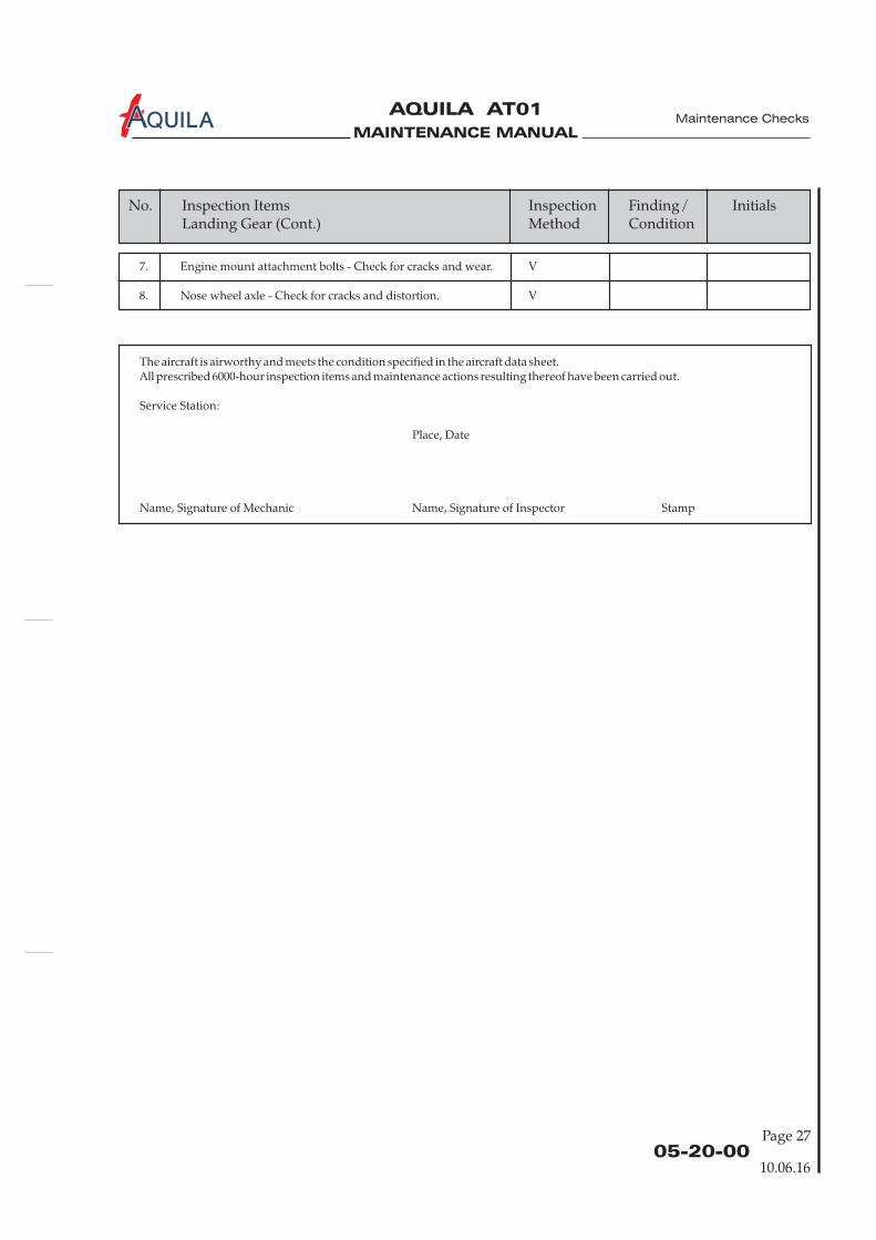
MAINTENANCE MANUAL
AQUILA AT01A
Page 2705-20-00
10.06.16
Maintenance Checks
No. Inspection Items Inspection Finding / InitialsLanding Gear Method Condition(Cont.)
7. Engine mount attachment bolts - Check for cracks and wear. V
8. Nose wheel axle - Check for cracks and distortion. V
The aircraft is airworthy and meets the condition specified in the aircraft data sheet.All prescribed 6000-hour inspection items and maintenance actions resulting thereof have been carried out.
Service Station:
Place, Date
Name, Signature of Mechanic Name, Signature of Inspector Stamp

MAINTENANCE MANUAL
AQUILA AT01A Maintenance Checks
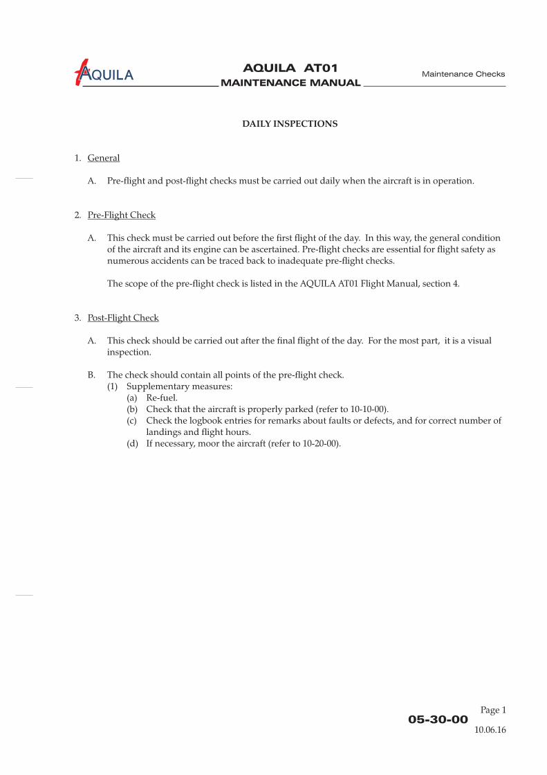
MAINTENANCE MANUAL
AQUILA AT01A
05-30-00
DAILY INSPECTIONS
1.
A. Pre-flight and post-flight checks must be carried out daily when the aircraft is in operation.
2.
A. This check must be carried out before the first flight of the day. In this way, the general conditionof the aircraft and its engine can be ascertained.
The scope of the pre-flight check is listed in the AQUILA AT01 Flight Manual, section 4.
3.
A. This check should be carried out after the final flight of the day. For the most part, it is a visualinspection.
B. The check should contain all points of the pre-flight check.(1) Supplementary measures:
(a) Re-fuel.(b) Check that the aircraft is properly parked (refer to 10-10-00).(c) Check the logbook entries for remarks about faults or defects, and for correct number of
landings and flight hours.(d) If necessary, moor the aircraft (refer to 10-20-00).
General
Pre-Flight Check
Post-Flight Check
Pre-flight checks are essential for flight safety asnumerous accidents can be traced back to inadequate pre-flight checks.
Maintenance Checks
10.06.16
Page 1

MAINTENANCE MANUAL
AQUILA AT01A
MAINTENANCE MANUAL
AQUILA AT01A
05-50-00
Maintenance Checks
UNSCHEDULED MAINTENANCE CHECKS
1.
A. Special checks are to be carried out when an incident has occurred that may have caused damageto the aircraft or impaired airworthiness.
In addition, a 25-hour inspection must be carried out on new aircraft and its engine, onoverhauled engines and after extensive airframe repairs.
2.
A. 25-Hour InspectionAfter the first 25 hours of operation of a new aircraft and its engine or an overhauled engine orafter extensive airframe repairs, an inspection of the extent of a 100-hour inspection must becarried out (refer to 05-20-00).
After the first 25 hours of operation of a new or overhauled engine, the engine and the propellermust be inspected. Refer to ROTAX Aircraft Engines Maintenance Manual for ROTAX EnginesType 912 Series for detailed information on this inspection.
B. Hard LandingAfter an excessively hard landing or other unusual loading of the landing gear a thoroughinspection of the affected components and their attachments is required. Even if no obviousdefects are detectable, a visual inspection must be carried out. Perform the following:
(1) Prepare aircraft for visual checks as follows:(a) Remove engine cowling (refer to 71-10-00).(b) Remove landing gear fairings.(c) Inside the cabin and baggage compartment - remove carpets and floorboards as required
to gain access to the landing gear mounting brackets (refer to 25-12-00).(2) Inspect main landing gear.
(a) Check wheel fairings for cracks, dents and delamination.(b) Check fairing mounts for cracks, distortion and other damage.(c) Check fuselage structure visually at such points and areas where the main landing gear
is attached. Check for stress marks, distortion, disbonding, and delamination. Checkmain landing gear strut brackets for distortion, cracks and security of attachment. Checkcondition of the polyamide inserts. Check bolts for correct torque.
(d) Check main gear struts for deformation and cracks. Examine wheel axles for security ofattachment to struts and for any damage.
(e) Inspect tires for integrity and proper location of the red slide marks.(f) Inspect brake fluid carrying lines at the main landing gear for condition, leakage, and
security of attachment.
General
Special Checks
10.06.16
Page 1

MAINTENANCE MANUAL
AQUILA AT01A
05-50-00Page 2
Maintenance Checks
(3) Inspect nose landing gear.(a) Check wheel fairing for cracks, dents and delamination.(b) Inspect fairing mounts for cracks, distortion and other damage.(c) Check nose gear strut mount for deformation and cracks. Check nose gear strut journal
bearing for proper operation and play.(d) Check strut for deformation, stress marks, and cracks. Check elastomer package for
deterioration, cracks, correct fit and security. Check journal bearings of the elastomerpackage for play and condition.
(e) Inspect nose wheel steering tubes for condition and excessive play.(f) Inspect tire for integrity and proper location of the red slide marks.
(4) Re-mount all items removed during the inspection.(5) Perform a brake and steering system operational test (refer to 32-40-00).
C. Engine FireAfter an engine fire, carry out the following:
IF IT IS SUSPECTED THAT PARTS OF THE STRUCTURE OR COWLING COULDHAVE BEEN DAMAGED BY HIGH TEMPERATURES (INDICATED BYBLISTERING ON THE PROTECTIVE COATING), THE MANUFACTURER MUSTBE CONTACTED FOR DEFECT APPRAISAL BEFORE THE AIRCRAFT ISFLOWN AGAIN.
(1)(2)(3)(4) Examine electrical cables for damaged insulation.(5) Examine fuel lines for damage of the fire-protection sleeves.(6) Check oil lines for damage of the fire-protection sleeves.(7) Check air filter element for fire damage.(8) Examine engine mount and shock mounts for any fire damage.(9) Check all other hoses and pipes, as well as all gaskets and seals for fire damage.(10) Replace damaged items.(11) Re-mount engine cowling (refer to 71-10-00).(12) Perform an engine test run (refer to 05-20-00).
D. Violent Stop of the EngineIn event that the propeller has touched the ground or the engine has been inadvertently stoppedviolently (shock loading), the propeller gear box must be disassembled and inspected by anauthorized workshop. For further information on engine inspections necessary after a propellerground strike and for more general information, refer to the relevant technical documents and theROTAX Maintenance Manual.
ONLY QUALIFIED TECHNICIANS (AUTHORIZED BY THE NATIONALAVIATION AUTHORITY AND AFTER SUCCESSFULLY COMPLETING THERELEVANT ROTAX TRAINING COURSE) ARE AUTHORIZED TO PERFORMTHIS WORK.
Check additional equipment (external alternator, hydraulic governor, ignition unit, coolant and oilhoses) for damage.
WARNING:
CAUTION:
Remove engine cowling (refer to 71-10-00).Examine engine cowling. Check for signs of fire damage.Disconnect battery (refer to 24-30-00).
10.06.16
MAINTENANCE MANUAL
AQUILA AT01
Aviation by Excellence GmbH
CHAPTER 06
DIMENSIONS AND AREAS

MAINTENANCE MANUAL
AQUILA AT01
Aviation by Excellence GmbH
MAINTENANCE MANUAL
AQUILA AT01
Aviation by Excellence GmbH
Page 0106 - TOC
TABLE OF CONTENTS
ChapterSection
DIMENSIONS AND AREAS - GENERAL.....................................................06-00-00 1Introduction 06-00-00 1General Description 06-00-00 1
AIRCRAFT DIMENSIONS AND AREAS.......................................................06-10-00 1General 06-10-00 1Dimensions and Areas 06-10-00 1
AIRCRAFT ZONING ........................................................................................06-20-00 1General 06-20-00 1Description 06-20-00 1
ACCESS/INSPECTION PLATES .....................................................................06-30-00 1General 06-30-00 1
Title Subject Page
Weight and Static Moments of Control Surfaces 06-10-00 2
Dimensions and Areas
26.04.05

MAINTENANCE MANUAL
AQUILA AT01
Aviation by Excellence GmbH
MAINTENANCE MANUAL
AQUILA AT01
Aviation by Excellence GmbH
06-00-00
Page 01
DIMENSIONS AND AREAS - GENERAL
1.
A. This chapter provides information about dimensions and control surface travel and tolerances ofthe AQUILA AT01.Furthermore, this chapter contains information about aircraft zoning, access and inspection plates.
B. Dimensions are presented to aid the operator and/or maintenance personnel in ground handlingthe aircraft, e.g. in hangars with small park areas.The knowledge about aircraft zoning and position of access / inspection plates facilitates thelocating and access to aircraft components.
2.
The following sets out a brief description and intended purpose of each section of this chapter:
A. Section 6-00-00 - Dimensions and Areas - General. This section provides a general overview ofcontent and purpose of the chapter.
B. Section 6-10-00 - Aircraft Dimensions and Areas. This section provides aircraft dimensions andidentifies areas of the aircraft.
C. Section 6-20-00 - Aircraft Zoning. This section shows illustrations of all aircraft zones.
D. Section 6-30-00 - Access and Inspection Plates. This section contains the position and numberingof all accesses and of all inspection plates.
Introduction
General Description
Dimensions and Areas
26.04.05

MAINTENANCE MANUAL
AQUILA AT01
Aviation by Excellence GmbH
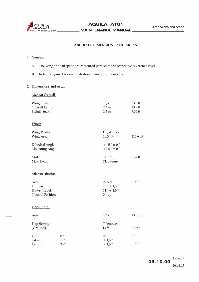
MAINTENANCE MANUAL
AQUILA AT01
Aviation by Excellence GmbH
06-10-00
Page 01
AIRCRAFT DIMENSIONS AND AREAS
1.
A. The wing and tail spans are measured parallel to the respective reverence level.
B. Refer to Figure 1 for an illustration of aircraft dimensions.
2.
Wing Span 10,3 m 33.8 ftOverall Length 7,3 m 23.9 ftHeigth max. 2,3 m 7.55 ft
Wing Profile HQ 42 mod.Wing Area 10,5 m² 113.6 ft²
Dihedral Angle +4,5 ° ± 0 °Mounting Angle +2,5 ° ± 0 °
MAC 1,07 m 3.52 ftMax. Load 71,4 kg/m²
Area 0,65 m² 7.0 ft²Up Travel 16 ° + 1,5 °Down Travel 11 ° + 1,0 °Neutral Position 0 ° up
Area 1,23 m² 13.31 ft²
Flap Setting Tolerance(Ground)
Up 0 ° 0 ° 0 °Takeoff 17 ° ± 1,5 ° ± 1,5 °Landing 35 ° ± 1,5 °
General
Dimensions and Areas
Aircraft Overall:
Wing:
Ailerons (both):
Flaps (both):
Left Right
± 1,5 °
Dimensions and Areas
26.04.05
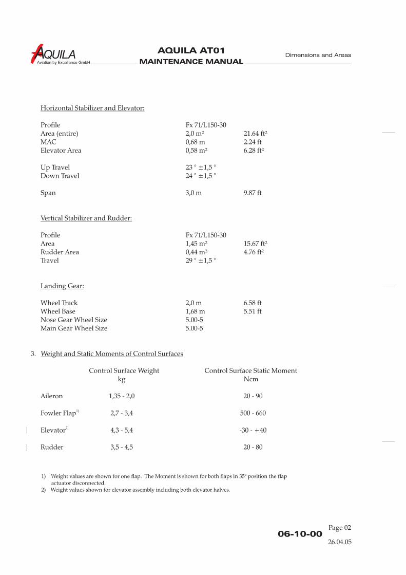
MAINTENANCE MANUAL
AQUILA AT01
Aviation by Excellence GmbH
06-10-00Page 02
Horizontal Stabilizer and Elevator:
Vertical Stabilizer and Rudder:
Landing Gear:
Weight and Static Moments of Control Surfaces
Profile Fx 71/L150-30Area (entire) 2,0 m² 21.64 ft²MAC 0,68 m 2.24 ftElevator Area 0,58 m² 6.28 ft²
Up Travel 23 ° ±1,5 °Down Travel
Span 3,0 m 9.87 ft
ProfileArea 1,45 m² 15.67 ft²Rudder Area 0,44 m² 4.76 ft²Travel
Wheel Track 2,0 m 6.58 ftWheel Base 1,68 m 5.51 ftNose Gear Wheel Size 5.00-5Main Gear Wheel Size 5.00-5
3.
Control Surface Weight Control Surface Static Momentkg Ncm
Aileron 1,35 - 2,0 20 - 90
Fowler Flap 2,7 - 3,4 500 - 660
Elevator 4,3 - 5,4 -30 - +40
Rudder 3,5 - 4,5 20 - 80
24 ° ±1,5 °
Fx 71/L150-30
29 ° ±1,5 °
1)
2)
Dimensions and Areas
1) Weight values are shown for one flap. The Moment is shown for both flaps in 35° position the flapactuator disconnected.
2) Weight values shown for elevator assembly including both elevator halves.
26.04.05
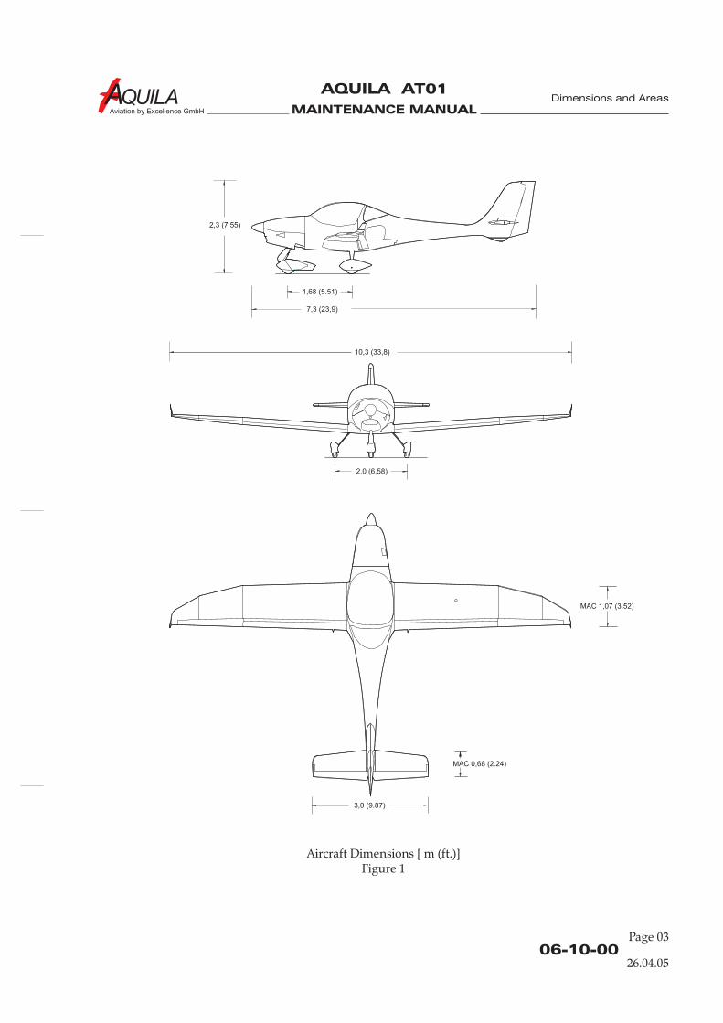
MAINTENANCE MANUAL
AQUILA AT01
Aviation by Excellence GmbH
06-10-00
Page 03
Aircraft Dimensions [ m (ft.)]Figure 1
1,68 (5.51)
7,3 (23,9)
10,3 (33,8)
2,0 (6,58)
3,0 (9.87)
MAC 1,07 (3.52)
MAC 0,68 (2.24)
2,3 (7.55)
Dimensions and Areas
26.04.05

MAINTENANCE MANUAL
AQUILA AT01
Aviation by Excellence GmbH
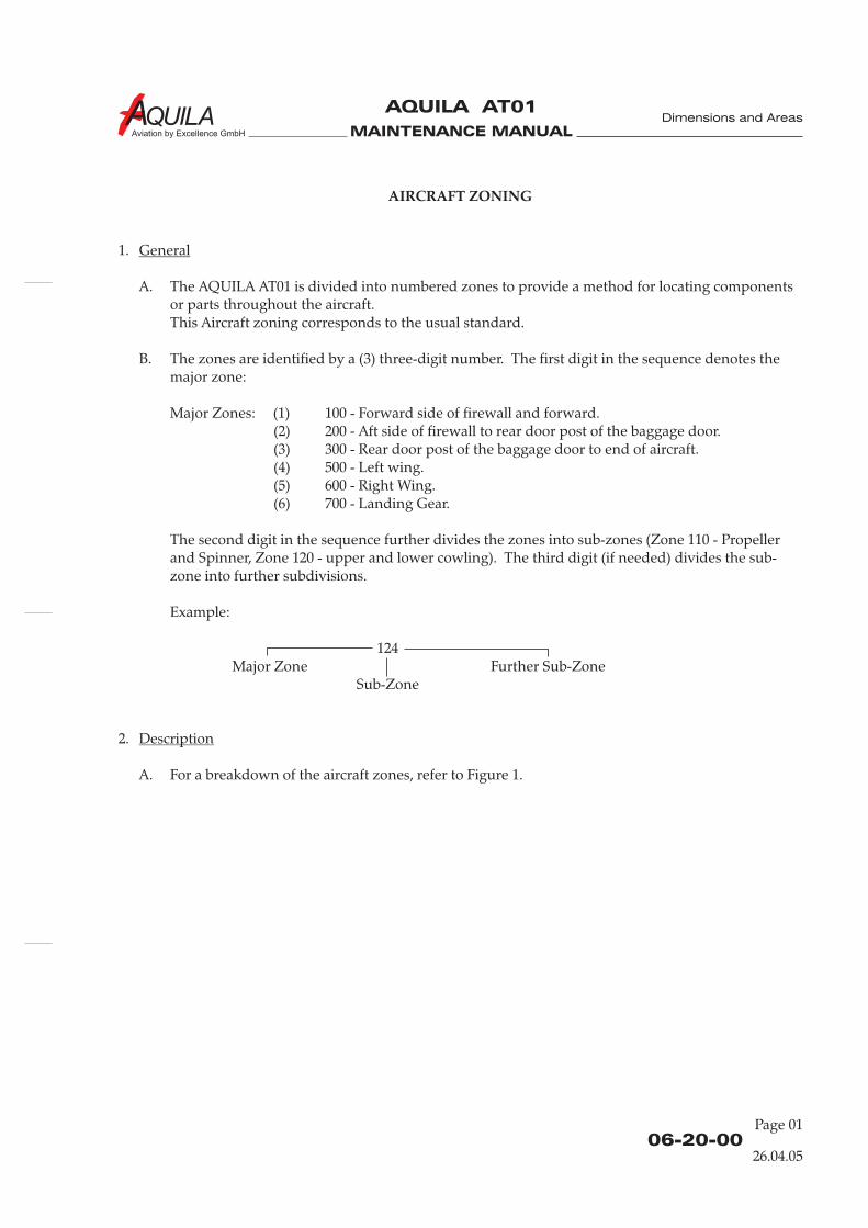
MAINTENANCE MANUAL
AQUILA AT01
Aviation by Excellence GmbH
06-20-00
Page 01
AIRCRAFT ZONING
1.
A. The AQUILA AT01 is divided into numbered zones to provide a method for locating componentsor parts throughout the aircraft.This Aircraft zoning corresponds to the usual standard.
B. The zones are identified by a (3) three-digit number. The first digit in the sequence denotes themajor zone:
Major Zones: (1) 100 - Forward side of firewall and forward.(2) 200 - Aft side of firewall to rear door post of the baggage door.(3) 300 - Rear door post of the baggage door to end of aircraft.(4) 500 - Left wing.(5) 600 - Right Wing.(6) 700 - Landing Gear.
The second digit in the sequence further divides the zones into sub-zones (Zone 110 - Propellerand Spinner, Zone 120 - upper and lower cowling). The third digit (if needed) divides the sub-zone into further subdivisions.
Example:
124Major Zone Further Sub-Zone
Sub-Zone
2.
A. For a breakdown of the aircraft zones, refer to Figure 1.
General
Description
Dimensions and Areas
26.04.05
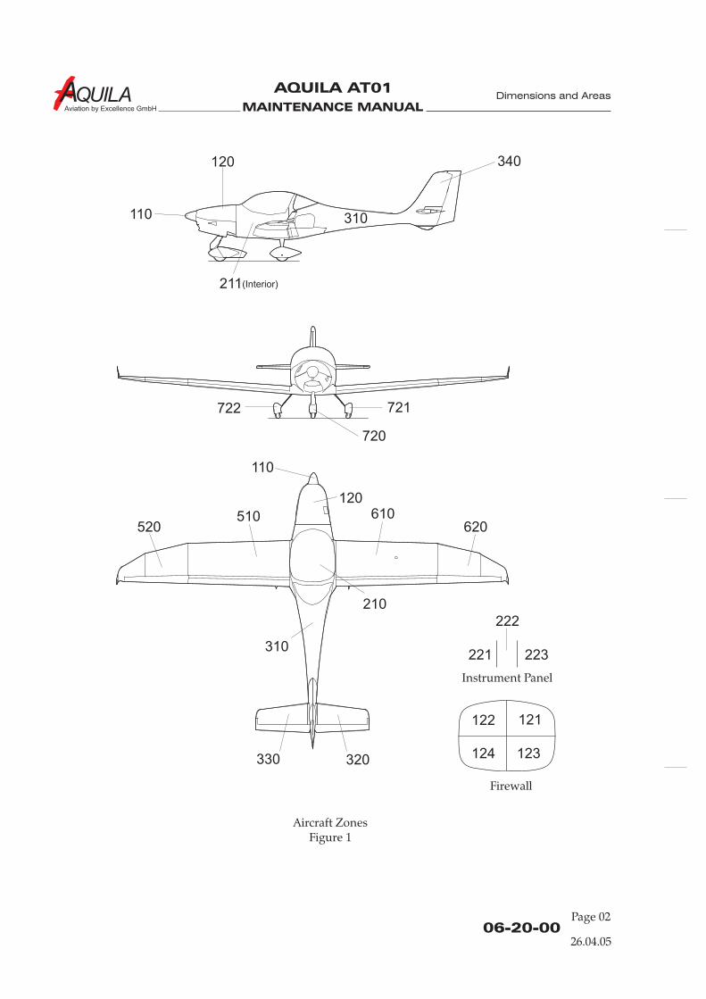
MAINTENANCE MANUAL
AQUILA AT01
Aviation by Excellence GmbH
110
110
120
120
211
310
310
330 320
520510 610
620
340
722
720
721
210
(Interior)
Aircraft ZonesFigure 1
06-20-00Page 02
122 121
124 123
221
222
223
Instrument Panel
Firewall
Dimensions and Areas
26.04.05

MAINTENANCE MANUAL
AQUILA AT01
Aviation by Excellence GmbH
06-30-00
Page 01
ACCESS & INSPECTION PLATES
1.
A. Accesses / inspection plates on the AQUILA AT01 are used to gain access to various systems,components and parts of structure during maintenance and for inspection.
B. The access and inspection plates are designated logically.
(1) System of numbering of the access / inspection platesAll access / inspection plates are identified using a series of numbers and letters which specifyzone (see section 6-20-00) and location within this zone. Primary identifiers follow the three-number sequence, with the first plate identified as „A“, the second as „B“ and so on. Locatorsfollow the primary identifier and denote top, left, right or internal orientation of the plate.
Example:
340ALVertical Stabilizer left-hand side
First access / inspection plateIn this region
2.
A. For an illustration that shows the various accesses / inspection plates used on the AQUILA AT01,refer to Figure 1.
210AB Wing Removal /Installation, Aileron / Flap Control Systems, Fuel System, WingStructure.
510AB Left Flap Actuation Lever610AB Right
510BB Left610BB Right
520AB Left Aileron Bellcrank620AB Right
General
Description
Flap Actuation Lever
Inboard Fuel Tank Rib, Fuel / Vent Lines, Fuel Lever SenderInboard Fuel Tank Rib, Fuel / Vent Lines, Fuel Lever Sender
Aileron Bellcrank
Dimensions and Areas
26.04.05

MAINTENANCE MANUAL
AQUILA AT01
Aviation by Excellence GmbH
Access / Inspection PlatesFigure 1
06-30-00Page 02
610AB 510AB
610BB 510BB
210AB620AB 520AB
Dimensions and Areas
26.04.05
MAINTENANCE MANUAL
AQUILA AT01A
CHAPTER 07
LIFTING AND SHORING

MAINTENANCE MANUAL
AQUILA AT01A

MAINTENANCE MANUAL
AQUILA AT01A
Page 107 - TOC
TABLE OF CONTENTS
ChapterSection
LIFTING AND SHORING - GENERAL.........................................................07-00-00 1Introduction 07-00-00 1General Description 07-00-00 1
JACKING.............................................................................................................07-10-00 201General 07-10-00 201Tools, Equipment and Material 07-10-00 201Jacking 07-10-00 201Hoisting 07-10-00 202
Title Subject Page
Lifting and Shoring
30.10.13

MAINTENANCE MANUAL
AQUILA AT01A
MAINTENANCE MANUAL
AQUILA AT01A
07-00-00
LIFTING AND SHORING - GENERAL
1.
A. This chapter describes procedures used to jack the aircraft. The equipment required to jack theaircraft and the procedures to be followed are described.
2.
In the following, a brief description and intended purpose of each section of this chapter is given.
A. Section 7-00-00 - Lifting and Shoring - General. This section provides a general overview ofcontent and purpose of the chapter.
B. Section 7-10-00 - Jacking. This section contains procedures, supplementary information andrequired equipment for jacking the aircraft.
Introduction
General Description
Lifting and Shoring
30.10.13
Page 1

MAINTENANCE MANUAL
AQUILA AT01A

MAINTENANCE MANUAL
AQUILA AT01A
07-10-00Page 201
30.10.13
JACKING
1.
A. The aircraft is jacked at two points and supported at the tail. The jack points are located at thebottom of the fuselage root ribs (see figure 201). Special adapters must be installed prior to jacking.
B. If necessary, the aircraft may be lifted on a hoist.
2.
Quantity Equipment Parts No. Manufacturer
3.A 2 Jack - commercially available3.A 2 Adapter3.A 1 Tail stand -
3.
A. Jacking the Aircraft
DO NOT JACK THE AIRCRAFT IN THE OPEN IF WIND VELOCITY EXCEEDS 6KNOTS.
(1) In the open, postion the aircraft with thenose into the wind.
: ONLY USE JACKS IN COMBINATION WITH ADAPTERS DELIVERED BY
(2) Install adapters to jack points (marked red).(3) Place jacks at the correct positions under the fuselage (see figure 201) and extend to engage
with the jacking points.(4) Remove wheel chocks.(5) Place the tail stand with adapter under the lower fin and extend to engage with the lower fin
skid plate. Secure tail stand lock.(6) Raise jacks simultaneously, keeping the aircraft as level as possible.(7) Secure jack locks.(8) Place the wing trestles in position under each wing (zone 530 /630).
B. Lowering the Aircraft(1) Remove the wing trestles from under the wings.(2) Check that the areas immediately under and over the aircraft are clear.(3) Slowly lower the jacks simultaneously,(4) When the main tires are resting on the ground, lower the jacks completely and remove them.
General
Tools, Equipment and Material
Jacking
CAUTION:
CAUTION
AQUILA Aviation GmbHcommercially available
3.A 2 Wing trestles - commercially available
Position the aircraft on a hard, flat, level surface.
AQUILA.
keeping the aircraft as level as possible.
Lifting and Shoring

MAINTENANCE MANUAL
AQUILA AT01A
07-10-00Page 202
Aircraft Jack PointsFigure 201
A
A
B
B
- jack points (right / left hand)
- tail stand positioning zone
(5) Remove tail stand.(6) Remove adapters from jack points.
4.
A. Hoisting Procedure(1) The airplane may be lifted with a one metric ton (2205 lbs) hoist for maintenance purposes.
The front sling is hooked to the two upper engine mount bars. The aft sling is positionedaround the aft fuselage forward the vertical stabilizer.
Hoisting
Lifting and Shoring
30.10.13

MAINTENANCE MANUAL
AQUILA AT01
Aviation by Excellence GmbH
CHAPTER 08
LEVELING AND WEIGHING

MAINTENANCE MANUAL
AQUILA AT01
Aviation by Excellence GmbH
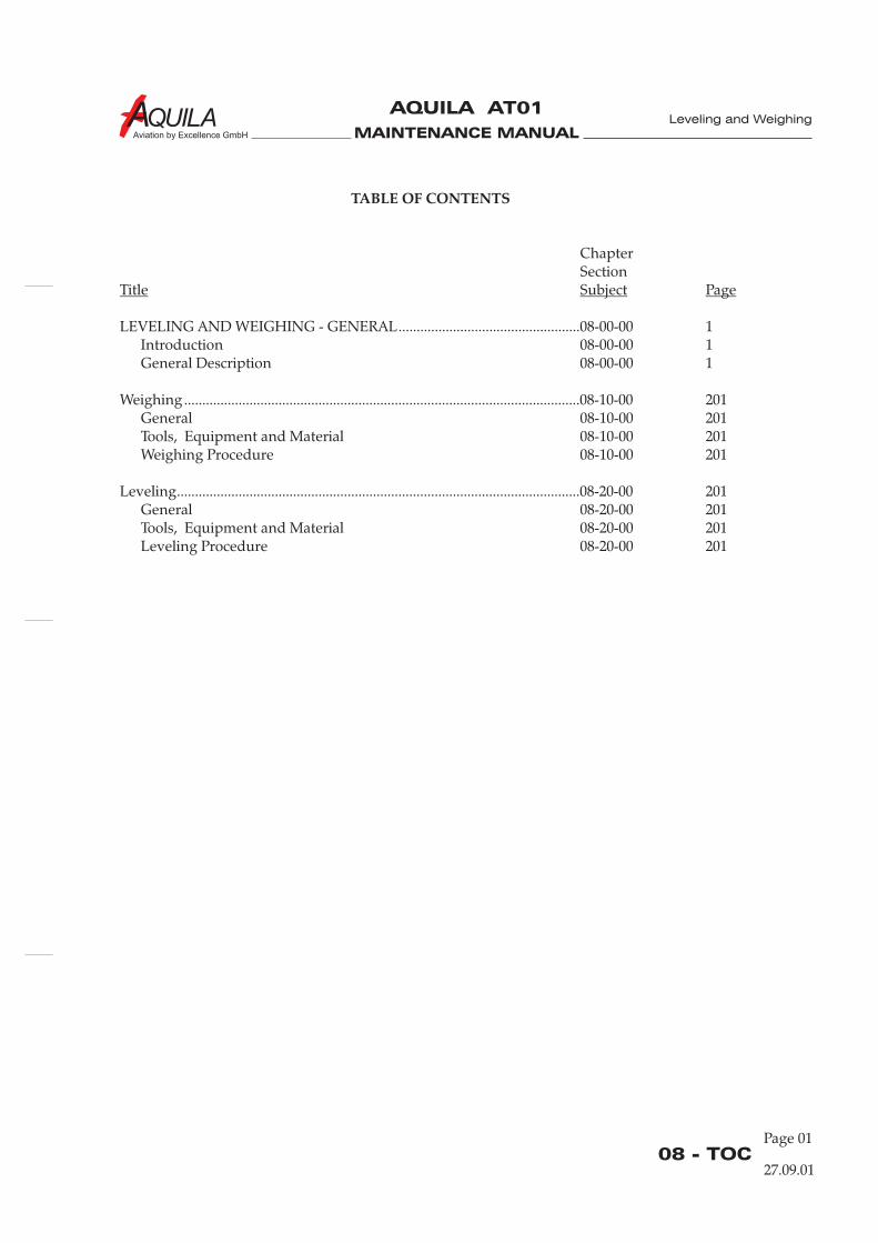
MAINTENANCE MANUAL
AQUILA AT01
Aviation by Excellence GmbH
Page 0108 - TOC
TABLE OF CONTENTS
ChapterSection
LEVELING AND WEIGHING - GENERAL..................................................08-00-00 1Introduction 08-00-00 1General Description 08-00-00 1
Weighing .............................................................................................................08-10-00 201General 08-10-00 201Tools, Equipment and Material 08-10-00 201Weighing Procedure 08-10-00 201
Leveling...............................................................................................................08-20-00 201General 08-20-00 201Tools, Equipment and Material 08-20-00 201Leveling Procedure 08-20-00 201
Title Subject Page
27.09.01
Leveling and Weighing

MAINTENANCE MANUAL
AQUILA AT01
Aviation by Excellence GmbH
MAINTENANCE MANUAL
AQUILA AT01
Aviation by Excellence GmbH
08-00-00Page 01
LEVELING AND WEIGHING - GENERAL
1.
A. This chapter provides all the necessary information to properly level the aircraft and to prepare itfor weighing.
2.
In the following, a brief description and intended purpose of each section of this chapter is given.
A. Section 8-00-00 - Leveling and Weighing - General. This section provides a general overview ofcontent and purpose of the chapter.
B. Section 8-10-00 - Weighing. This section contains maintenance practices, supplementaryinformation and required equipment for weighing the aircraft.
C. Section 8-20-00 Leveling. This section provides maintenance practices and required equipmentfor longitudinal and lateral leveling of the aircraft.
Introduction
General Description
27.09.01
Leveling and Weighing

MAINTENANCE MANUAL
AQUILA AT01
Aviation by Excellence GmbH
MAINTENANCE MANUAL
AQUILA AT01
Aviation by Excellence GmbH
08-10-00Page 201
WEIGHING
1.
A. For safety and in order to achieve the performances and flying characteristics, which are designedin the aircraft, it should be flown with the weight and center of gravity (C.G.) position within theapproved operating range.
Whenever new equipment is added or any modification work is done, which may have an effecton the empty weight or C.G. position, an empty weight determination and a center of gravitylocation is to be redefined.
2.
Required in Quantity Equipment Parts No. Manufacturer
3.A. 3 Industry scales - commercially500 kg available(approx. 1100 lbs)Scale capacity
3.
A. Weighing can be carried out by means of mechanical or electrical scales. The instructions of thescale manufacturer are to be considered.
Preparation:(1) Be certain that all items checked in the aircraft equipment list are installed in the proper
location in the aircraft.(2) Clean and dry the aircraft, remove foreign items such as bags, rags, tools, etc.(3) De-fuel aircraft except for unusable fuel (refer to 12-11-00).(4) Fill engine operating fluids (oil, coolant) and brake fluid up to the maximum markings (refer
to 12-12-00, 12-14-00, 12-15-00).(5) Move sliding seats to the most forward position.(6) Retract flaps completely.(7) Place all control surfaces in neutral position.
After these preparations, place scales under each wheel. Be sure that no side forces act on thescales to avoid wrong readings.After this level the aircraft such as described in section 08-20-00 "Leveling".
Weigh the aircraft inside a closed building to prevent errors in the scale readingsdue to wind.
Close the canopy and then weigh the aircraft. The weight shown on each scale can now beentered into the weight data form (see Abb.201). Deduct the non-aircraft parts, if any (i. e. wheelchocks), from each reading.
General
Tools, Equipment and Material
Weighing Procedure
NOTE:
27.09.01
Leveling and Weighing
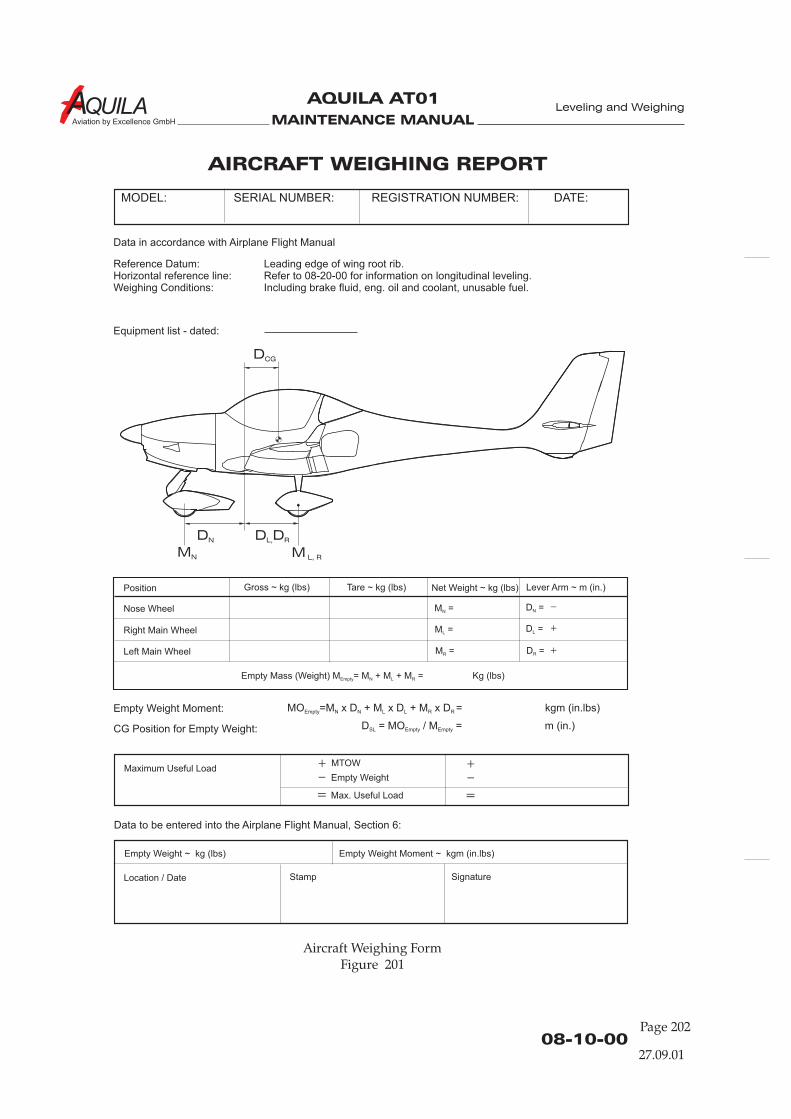
MAINTENANCE MANUAL
AQUILA AT01
Aviation by Excellence GmbH
08-10-00Page 202
27.09.01
Aircraft Weighing FormFigure 201
Position Gross ~ kg (lbs) Net Weight ~ kg (lbs)Tare ~ kg (lbs) Lever Arm ~ m (in.)
Nose Wheel
Empty Mass (Weight) M = M + M + M = Kg (lbs)Empty N L R
Right Main Wheel
Left Main Wheel
AIRCRAFT WEIGHING REPORT
SERIAL NUMBER: REGISTRATION NUMBER: DATE:MODEL:
Data in accordance with Airplane Flight Manual
Reference Datum: Leading edge of wing root rib.Horizontal reference line: Refer to 08-20-00 for information on longitudinal leveling.Weighing Conditions: Including brake fluid, eng. oil and coolant, unusable fuel.
Equipment list - dated:
Empty Weight Moment:
Empty Weight Moment ~ kgm (in.lbs)
MO =M x D + M x D + M x D = kgm (in.lbs)Empty N N L L R R
CG Position for Empty Weight: D = MO / M = m (in.)SL Empty Empty
Data to be entered into the Airplane Flight Manual, Section 6:
Empty Weight kg (lbs)~
Maximum Useful LoadMTOW
Empty Weight
Max. Useful Load= =
_ _+ +
Location / Date Stamp Signature
M =N
M =L
M =R
D =N
D =L
D =R
+
+
_
Leveling and Weighing
DCG
DN
MN M L, R
D DL, R
MAINTENANCE MANUAL
AQUILA AT01
Aviation by Excellence GmbH
08-10-00Page 203
Obtain measurement „D “ and „D / D “ (Refer Fig. 201) by dropping a plumb bob from leading
edge of wing at root rib to a flat surface (floor).
The distances must be measured on every weighing!
Further information for computing the C. G. are contained in the AQUILA AT01 Airplane FlightManual, section 6.
N L R
NOTE: „D “ and „D / D “N L R
27.09.01
Leveling and Weighing

MAINTENANCE MANUAL
AQUILA AT01
Aviation by Excellence GmbH
MAINTENANCE MANUAL
AQUILA AT01
Aviation by Excellence GmbH
08-20-00Page 201
LEVELING
1.
A. Before every weighing process, the aircraft is to be leveled.
2.
Required in Quantity Equipment Parts No. Manufacturer
3. 1 Spirit level - commerciallyat least 1m available(3.28 ft) length
3. 1 Straight Edge - commerciallyavailable
3.
AFTER WEIGHING PROCEDURE IS ACCOMPLISHED, INFLATE TIRES TORECOMMENDED OPERATING PRESSURES (REFER TO 12-16-00).
A. Longitudinal Leveling(1) Place a wedge on fuselage tube (refer to Figure 201).(2) Place a spirit level on top the wedge.(3) To level the aircraft longitudinally, deflate nose gear tire to center bubble in level.
B. Lateral Leveling(1) Open the canopy.(2) Place a straight edge on top and perpendicular to cabin sidewalls, centered.(3) Place level on top and parallel to straight edge, centered.(4) To level aircraft laterally, deflate main gear tire to center bubble in level.
General
Tools, Equipment and Material
Leveling Procedure
CAUTION:
27.09.01
Leveling and Weighing
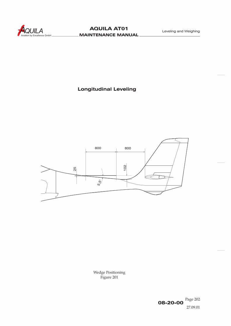
MAINTENANCE MANUAL
AQUILA AT01
Aviation by Excellence GmbH
08-20-00Page 202
27.09.01
Leveling and Weighing
800
25
10
2
5,5
°
800
Wedge PositioningFigure 201
Longitudinal Leveling
MAINTENANCE MANUAL
AQUILA AT01
Aviation by Excellence GmbH
CHAPTER 09
TOWING AND TAXIING

MAINTENANCE MANUAL
AQUILA AT01
Aviation by Excellence GmbH

MAINTENANCE MANUAL
AQUILA AT01
Aviation by Excellence GmbH
Page 0109 - TOC
TABLE OF CONTENTS
ChapterSection
TOWING AND TAXIING - GENERAL..........................................................09-00-00 1Introduction 09-00-00 1General Description 09-00-00 1
TOWING.............................................................................................................09-10-00 201General 09-10-00 201Tools, Equipment and Material 09-10-00 201Towing Procedure 09-10-00 202
TAXIING .............................................................................................................09-20-00 201General 09-20-00 201Taxiing Procedure 09-20-00 201
Title Subject Page
Towing and Taxiing
02.03.10

MAINTENANCE MANUAL
AQUILA AT01
Aviation by Excellence GmbH

MAINTENANCE MANUAL
AQUILA AT01
Aviation by Excellence GmbH
09-00-00Page 01
TOWING AND TAXIING - GENERAL
1.
A. This chapter describes the towing procedure and the taxiing procedure for the AQUILA AT01.It contains instructions as to how the aircraft can be moved without a tow bar.
2.
In the following, a brief description and intended purpose of each section of this chapter is given.
A. Section 9-00-00 - Towing and Taxiing - General. This section provides a general overview ofcontent and purpose of the chapter.
B. Section 9-10-00 - Towing. This section contains procedures, supplementary information andrequired equipment for towing the aircraft.
C. Section 9-20-00 - Taxiing. This section contains taxiing procedure.
Introduction
General Description
Towing and Taxiing
02.03.10

MAINTENANCE MANUAL
AQUILA AT01
Aviation by Excellence GmbH
MAINTENANCE MANUAL
AQUILA AT01
Aviation by Excellence GmbH
09-10-00Page 201
TOWING
1.
A. The aircraft may be moved by hand with a tow bar or by a towing vehicle. In the following, thetowing procedure is described.
2.
Required in Quantity Equipment Parts No. Manufacturer
3.A. 1 Tow bar - AQUILA A. b. E. AG3.B. 1 Tow bar -
(Vehicle)
3.
A. Towing by Tow Bar
The AQUILA AT01 is usually moved manually by means of a tow bar. The following techniqueshould be kept:
(1) Insert tow bar into nose wheel towing lugs.(2) Remove wheel chocks.(3) Tow the aircraft to desired location.(4)(5) Remove tow bar.
B. Towing With Tow Vehicle
The following procedure is to be kept if the aircraft should be moved by means of a vehicle:
WHILE TOWING THE AIRCRAFT WITH A VEHICLE, A PERSON SHOULD BE INTHE COCKPIT, IN ORDER TO BE ABLE TO APPLY THE BRAKES IN THE EVENTOF AN EMERGENCY.
DO NOT EXCEED THE NOSE GEAR TURNING ANGLE OF 20° EITHER SIDEOF CENTER, OR DAMAGE TO THE NOSE GEAR CANNOT BE EXCLUDED.
MAKE SURE THAT THE TOW BAR IS PROPERLY CONNECTED TO THEVEHICLE.
(1)(2) Attach the tow bar to tow vehicle.(3) Remove any installed rudder lock.
General
Tools, equipment and materials Required
Towing procedure
CAUTION:
AQUILA A. b. E. AG
Chock the main wheels fore/aft as required.
Insert tow bar into nose wheel towing lugs.
02.03.10
Towing and Taxiing
MAINTENANCE MANUAL
AQUILA AT01
Aviation by Excellence GmbH
09-10-00Page 202
(4) Release parking brake.(4) Remove wheel chocks.(5) Tow aircraft to desired location.(6) Chock the main wheels fore/aft as required.(7) If necessary install any rudder lock.(8) Remove tow bar from tow vehicle and aircraft.
C. Moving Aircraft Without Tow Bar
DO NOT EXERT A PUSHING OR PULLING FORCE ON THE CONTROLSURFACES, THE PROPELLER TIPS, OR ON THE PROPELLER SPINNER.
(1) Turn Aircraft Around Main WheelsPress down on the fuselage in front of the vertical stabilizer to raise the nose wheel offground. With the nose wheel clear of the ground, the aircraft can be turned by pivotingabout the main wheels.
CAUTION:
Towing and Taxiing
02.03.10

MAINTENANCE MANUAL
AQUILA AT01
Aviation by Excellence GmbH
09-20-00Page 201
TAXIING
1.
The AQUILA AT01 is controlled with a steerable nose wheel linked through the rudder pedals and toeoperated brakes during taxiing.While taxiing, the engine is to be operated as well as described in Section 4 of the AQUILA AT01Airplane Flight Manual.
2.
A. To move the aircraft on ground by means of its engine consider the following:
TAXIING OF THE AIRCRAFT MUST BE CARRIED OUT BY AUTHORIZEDPERSONNEL ONLY.
(1) Remove all items (workshop trolley, GPU etc) near of the aircraft.(2) Remove any control locks, wheel chocks, tow bar and tie-downs.
CHECK ONCE MORE, NO MAINTENANCE PERSONNEL OR OTHEROBSTACLE IS NEAR OF THE AIRCRAFT.
(3) Start the engine (Refer to AQUILA AT01 Airplane Flight Manual, Section 4).(4) Release parking brake.(5) Power should be applied slowly to start the taxi roll. Taxi a few feet forward and apply
brakes to determine their full effectiveness.(6) While taxiing, use the steerable nose wheel to change direction..
ALWAYS SELECT THE TAXI SPEED IN SUCH MANNER THAT IN THE EVENTOF BRAKE FAILURE A COLLISION WITH PERSONS OR STATIONARYOBJECTS IS EXCLUDED.
DO NOT OPERATE THE ENGINE AT HIGH RPM WHILE RUNNING UP ORTAXIING OVER GRAVEL, LOOSE STONES, OR ANY LOOSE MATERIAL, TOPREVENT ABRASION AND STONE DAMAGE TO THE PROPELLER BLADES.
(7) Taxi aircraft to the desired place.(8) Shut down the engine (Refer to AQUILA AT01 Airplane Flight Manual, Section 4).(9) Park and secure the aircraft as prescribed (Refer to Chapter 10).
General
Taxiing procedure
WARNING!
WARNING!
WARNING!
CAUTION!
Towing and Taxiing
02.03.10

MAINTENANCE MANUAL
AQUILA AT01
Aviation by Excellence GmbH
MAINTENANCE MANUAL
AQUILA AT01
Aviation by Excellence GmbH
CHAPTER 10PARKING, MOORING, STORAGE
AND RETURN TO SERVICE

MAINTENANCE MANUAL
AQUILA AT01
Aviation by Excellence GmbH
MAINTENANCE MANUAL
AQUILA AT01
Aviation by Excellence GmbH
Page 0110 - TOC
TABLE OF CONTENTS
ChapterSection
PARKING, MOORING, STORAGE ANDRETURN TO SERVICE - GENERAL ..............................................................10-00-00 1
Introduction 10-00-00 1General Description 10-00-00 1
PARKING............................................................................................................10-10-00 201General 10-10-00 201Parking 10-10-00 201
STORAGE ...........................................................................................................10-11-00 201Storage with a Duration up to 30 Days 10-11-00 201Storage with a Duration up to 90 Days 10-11-00 201
MOORING .........................................................................................................10-20-00 201General 10-20-00 201Tools, Equipment and Material 10-20-00 201Mooring 10-20-00 201
RETURN TO SERVICE .....................................................................................10-30-00 201Return to Service After a Storage up to 30 Days 10-30-00 201Return to Service After a Storage up to 90 Days 10-30-00 202
Title Subject Page
Parking, Mooring . .
02.03.10

MAINTENANCE MANUAL
AQUILA AT01
Aviation by Excellence GmbH

MAINTENANCE MANUAL
AQUILA AT01
Aviation by Excellence GmbH
10-00-00Page 01
PARKING, MOORING, STORAGE AND RETURN TO SERVICE -
GENERAL
1.
This chapter provides instructions necessary to park and moor the aircraft.
2.
The chapter is subdivided into different sections in order to facilitate the location of requiredinformation the maintenance personnel. Subsequently, a short description of the sections:
A. Section 10-00-00 - Parking, Mooring, Storage and Return to Service - General. This section gives asurvey via content and purpose of the chapter.
B. Section 10-10-00 - Parking. This section contains information as the airplane is to be parked.
C. Section 10-11-00 - Storage. The section provides instructions for proper storage of the aircraft.
D. Section 10-20-00 - Mooring. This section contains procedure, supplementary information andrequired equipment for anchoring the aircraft.
E. Section 10-30-00 - Return to Service. This section provides information about necessary serviceafter storage in dependence of different duration of storage.
Introduction
General description
Parking, Mooring . .
02.03.10

MAINTENANCE MANUAL
AQUILA AT01
Aviation by Excellence GmbH
MAINTENANCE MANUAL
AQUILA AT01
Aviation by Excellence GmbH
10-10-00Page 201
PARKING
1.
A. In order to protect the aircraft when it is parked in the open, the following parking instructionsshould be applied. The extent of the measures depends on park duration and weather conditions.
2.
A. If the aircraft for shorter time is parked, the following procedure should be applied:
(1) Taxi or tow aircraft into parking position (Refer to Chapter 9).(2) Head the aircraft into the wind if possible.(3) If flaps down, retract flaps.(4) Set parking brake.(4) Chock main gear wheels.(5) If necessary install any rudder lock.(6) Install the pitot head cover.(7) Close and lock canopy.
When parking the aircraft in adverse weather conditions such as gusty or strongwinds, it is recommended that the aircraft is stored indoors or secured outside moresecurely (Refer to 10-20-00).
General
Parking
NOTE:
Parking, Mooring . .
02.03.10

MAINTENANCE MANUAL
AQUILA AT01
Aviation by Excellence GmbH
MAINTENANCE MANUAL
AQUILA AT01
Aviation by Excellence GmbH
10-11-00Page 201
STORAGE
1.
A. The following guidelines are applicable for situations in which the aircraft is not to be used forperiods of time between 7 and 30 Days. They are meant to help prevent deterioration of theaircraft during periods of non-use.(1) To prepare the engine for storage, check for correct oil level and add oil if necessary to bring
the level to the full mark. Then, run the engine for at least five minutes at 1200 to 1500 RPMwith oil and cylinder heat temperatures in the normal operating range. Shut down theengine.
(2) Top up the fuel tanks to prevent condensation of water in the tanks.(3) Install covers over the cabin area to keep out moisture and sunlight. Install Pitot tube cover.
To prevent oxidation of the finish, the use of covers over the composite fuselage duringextended periods of outdoor tie-down, especially in summer time, is recommended.
BEFORE ROTATING THE PROPELLER BLADES, MAKE CERTAIN THAT THEIGNITION SWITCH IS IN THE OFF-POSITION AND THE THROTTLE ISCLOSED.
DO NOT ROTATE THE PROPELLER CLOCKWISE.
(4) After every seven days during storage, rotate the propeller by hand. After rotating theengine six revolutions, stop the propeller 60° to 120° from its former position.
(5) If, at the end of 30 days, the aircraft will not be removed from storage, the engine should bestarted and run in a safe area. The preferred method is to fly the aircraft for at least 30minutes.
2.
A. For storage periods not to exceed 90 days, the following methods of treatment are required:
(1). Fuel system(a) The fuel tanks must be filled completely with correct grade fuel.
(2) Engine(a) Consult the ROTAX Aircraft Engines Operator ’s Manual for engine preservation
recommendations for the installed engine.
(3) Electrical System(a) Remove battery and store in a cool, dry room. Perform service as described in chapter
12 "Ground Services".(b) Cover or mask any disconnected electrical leads to protect against corrosion.
(4) Airframe(a) Clean aircraft inside and outside. Remove any oil or grease from surfaces.(b) Wax aircraft thoroughly.
Storage - up to 30 Days
WARNING:
CAUTION:
Storage with a Duration up to 90 Days
Parking, Mooring . .
02.03.10
MAINTENANCE MANUAL
AQUILA AT01
Aviation by Excellence GmbH
10-11-00Page 202
(5) Brakes(a) Frequently apply brakes at least once week.
(6) Pitot tube(a) Install a pitot head cover.
(7) Ventilation of the aircraft(a) Ventilate aircraft well before store.(b) In the open air, depending on external conditions (high humidity, high temperatures
etc.) possibly ventilate aircraft several times during storage.
(8) Landing gear, wheels and tires(a) Landing gear:
It is recommended to jack up the aircraft to relieve load of the landing gear.
(b) Wheels:Rotate wheels at least once a week 3 - 4 revolutions to avoid brake/disc corrosion.
(c) Tire:Clean any oil or grease from tires and treat with a tire protective.
The aircraft cannot be blocked up:Rotate wheels. Mark position of the tire and date with chalk.
1
2
Parking, Mooring . .
02.03.10
MAINTENANCE MANUAL
AQUILA AT01
Aviation by Excellence GmbH
10-20-00Page 201
MOORING
1.
A. If the airplane is temporary stored in the open air, it should always be anchored. Strong wind andgusts of wind can cause great damage to an aircraft, which is not securely anchored.
2.
Required in Quantity Equipment Parts No. Manufacturer
3.B. 3 Ropes - AQUILA A. b. E. AG3.B. 2 Tie-Down -
3.
A. The aircraft has three tie-down points; two are located on the underside of the wings and thethird is located on the lower fin.
B. Tie-down the aircraft as follows:(1) Park aircraft, as in section 10-10-00 "Parking" described manner.(2) Immobilize the ailerons and elevator by looping the seat belt around the control stick and
pulling it tight.(3) Chock the main gear wheels fore and aft.(4) Screw tie-down ring into the adapter at the underside of each wing (red marked).(5) Secure tie-down ropes to the wing tie-down rings and to the lower fin. Secure at
approximately 45-degree angles to the ground and secure each rope to a ramp tie-downpoint.
(6) Install pitot cover.(7) Remove all loose parts and foreign items, which can cause damage to the aircraft.
REMOVE TIE-DOWN RINGS BEFORE FLIGHT. FLIGHT WITH INSERTEDTIE-DOWN RINGS HAS NOT BEEN TESTED.
General
Tools, Equipment and Material
Mooring
WARNING:
AQUILA A. b. E. AGRings
Parking, Mooring . .
02.03.10

MAINTENANCE MANUAL
AQUILA AT01
Aviation by Excellence GmbH
MAINTENANCE MANUAL
AQUILA AT01
Aviation by Excellence GmbH
10-30-00Page 201
RETURN TO SERVICE
1.
A. After storage with duration of between 5 and 30 days, the following procedures are necessary forreturning to service:(1) Perform a complete pre-flight check
2.
A. After storage with duration from 30 to 90 days, the following procedures are necessary forreturning to service:
(1) Remove aircraft from blocks (Refer to Chapter 7 "Lifting and Shoring").
(2) Engine(a) In accordance with the practiced preserving measures, return engine to service as
described in the ROTAX Aircraft Engines Operator's Manuel for installed engine model.(b) After removing spark plugs, rotate propeller several revolutions counterclockwise. Then
reinstall spark plugs.(c) Check oil level and grade.
(3) Fuel System(a) Check fuel filter and clean it if necessary(b) Check fuel tanks and lines for water and sediment. Drain fuel into clear cup and check
for water and sediment. Drain until water or sediment is gone.
(4) Electrical System(a) Check battery and install.(b) Remove all covers, which have been installed against corrosion at separate connections
and restore connection.
(5) Airframe(a) Remove any installed locks and all materials to cover openings.
(6) Perform a thorough pre-flight inspection.
After Storage with Duration of 5 - 30 Days
After Storage with a Duration from 30 up to90 Days
Parking, Mooring . .
02.03.10

MAINTENANCE MANUAL
AQUILA AT01
Aviation by Excellence GmbH

MAINTENANCE MANUAL
AQUILA AT01
Aviation by Excellence GmbH
CHAPTER 11
PLACARDS AND MARKINGS

MAINTENANCE MANUAL
AQUILA AT01
Aviation by Excellence GmbH

MAINTENANCE MANUAL
AQUILA AT01
Aviation by Excellence GmbH
11 - TOCPage 01
TABLE OF CONTENTS
ChapterSection
PLACARDS AND MARKINGS - GENERAL .................................................11-00-00 1Introduction 11-00-00 1General Description 11-00-00 1
EXTERIOR PLACARDS AND MARKINGS...................................................11-20-00 201General 11-20-00 201Tools, Equipment and Material 11-20-00 201Removal/Installation 11-20-00 201Maintenance / Care 11-20-00 204
INTERIOR PLACARDS AND MARKINGS ...................................................11-30-00 201General 11-30-00 201Tools, Equipment and Material 11-30-00 201Removal/Installation 11-30-00 201
Title Subject Page
Placards and Markings
05.11.12

MAINTENANCE MANUAL
AQUILA AT01
Aviation by Excellence GmbH
MAINTENANCE MANUAL
AQUILA AT01
Aviation by Excellence GmbH
11-00-00Page 01
PLACARDS AND MARKINGS - GENERAL
1.
A. This chapter provides information about interior and exterior graphics, placards, labels andinterior markings, their maintenance and repair.
2.
Below a brief description and intended purpose of each section of this chapter is given.
A. Section 11-00-00 - Placards and Markings General. This section provides a general overview ofcontent and purpose of the chapter.
B. Section 11-20-00 - Exterior Placards and Markings. This section gives maintenance and careinstructions for external placards, graphics, markings etc. and contains information about theequipment and material required.
C. Section 11-30-00 - Interior placards and Markings. This section gives maintenance and careinstructions for internal placards, graphics, markings etc. and contains information about theequipment and material .
Introduction
General Description
required
Placards and Markings
05.11.12

MAINTENANCE MANUAL
AQUILA AT01
Aviation by Excellence GmbH
MAINTENANCE MANUAL
AQUILA AT01
Aviation by Excellence GmbH
11-20-00Page 201
EXTERIOR PLACARDS AND MARKINGS
1.
A. This section gives maintenance and care instructions for exterior graphics, markings, etc.Figure 201 shows the locations of the exterior placards and markings.
2.
Quantity Equipment Parts No. Manufacturer
3.A. and B. 1 Heat gun - commercially available3.A. and B. as Isopropyl Alcohol - commercially available
required3.B. 1 Needle - commercially available3.B. 1 Handy, dense, - commercially available
closed cell foamblock
3.
A. Remove self-adhesive placards
NOTE: Reference marks should be made on aircraft before removing old graphics.
(1) Warm the placard a little using a heat gun (approx. 40-50°).(2) Carefully separate a corner of the placard from the aircraft and then pull off parallel to the
surface to remove it.(3) Remove all traces of old adhesive by using a cloth with isopropyl alcohol as required.
B. Placing self-adhesive placards(1) Clean aircraft surface carefully. Remove all old adhesive traces using isopropyl alcohol.(2) Remove paperliner from backside of placard to expose adhesive.(3) Position top edge of the placard precisely.(4) Work uniformly downward and apply placard to aircraft with a dry, clean cloth.(5) Remove the premask (outer protective film) from the placard.(6) Remove air bubbles by perforating bubble with a small needle and then flattening.
4.
A. The following instructions should be followed to guarantee a maximum service life for thegraphics:(1) Clean aircraft exterior surface as in chapter 12, section "Aircraft Exterior - Cleaning",
paragraph 4.(2) Do not use any solvents to clean the graphics.
General
Tools, Equipment and Material
Removal / Installation
Maintenance / Care
described
Placards and Markings
05.11.12
MAINTENANCE MANUAL
AQUILA AT01
Aviation by Excellence GmbH
(3) Test other cleaning agents on a small inconspicuous part of the graphic.(4) Do not allow fuel to spill on to graphics. If fuel spills on to graphics, wipe off with a cloth and
rinse with water thoroughly.(5) Do not remove snow and ice from surfaces using sharp-edged instruments.(6) If a high-pressure washer is used, keep nozzle at least 0,5 m (approx. 1,6 ft) from edge of
graphic.
11-20-00Page 202
Placards and Markings
05.11.12
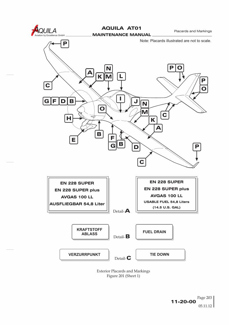
MAINTENANCE MANUAL
AQUILA AT01
Aviation by Excellence GmbH
BDetail-
CDetail-
ADetail-
KRAFTSTOFFABLASS FUEL DRAIN
EN 228 SUPER
EN 228 SUPER plus
AVGAS 100 LL
AUSFLIEGBAR 54,8 Liter
EN 228 SUPER
EN 228 SUPER plus
AVGAS 100 LL
USABLE FUEL 54,8 Liters
(14.5 U.S. GAL)
VERZURRPUNKT TIE DOWN
E
AK
K
A
O
B
B
C
C
C
BDFG
H
F
G D
JI
LM
N
M
N
OP
P
P
PNote: Placards illustrated are not to scale.
O
Exterior Placards and MarkingsFigure 201 (Sheet 1)
11-20-00Page 203
Placards and Markings
05.11.12
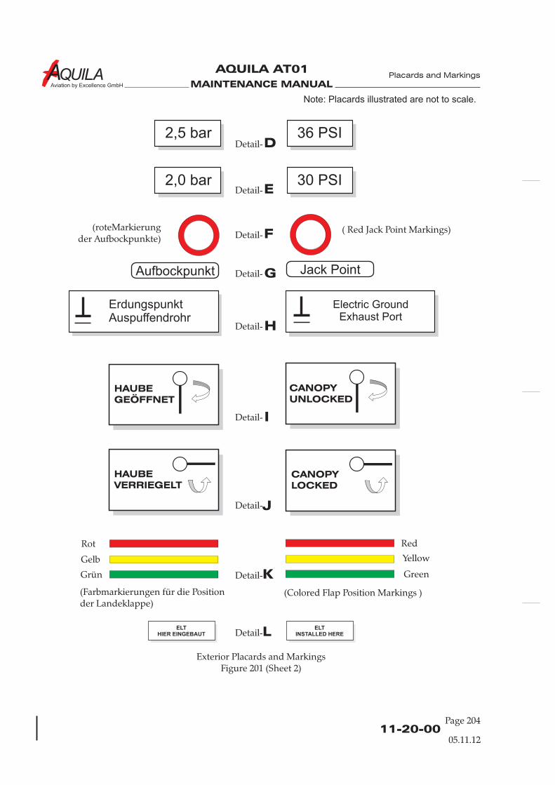
MAINTENANCE MANUAL
AQUILA AT01
Aviation by Excellence GmbH
11-20-00Page 204
Exterior Placards and MarkingsFigure 201 (Sheet 2)
DDetail-
EDetail-
FDetail-
GDetail-
HDetail-
IDetail-
JDetail-
KDetail-
LDetail-
Placards and Markings
2,5 bar 36 PSI
2,0 bar 30 PSI
(roteMarkierungder Aufbockpunkte)
( Red Jack Point Markings)
ErdungspunktAuspuffendrohr
Electric GroundExhaust Port
HAUBEGEÖFFNET
CANOPYUNLOCKED
HAUBEVERRIEGELT
CANOPYLOCKED
Rot Red
Gelb
Grün
(Farbmarkierungen für die Positionder Landeklappe)
(Colored Flap Position Markings )
Yellow
Green
ELTHIER EINGEBAUT
ELTINSTALLED HERE
05.11.12
Jack PointAufbockpunkt
Note: Placards illustrated are not to scale.
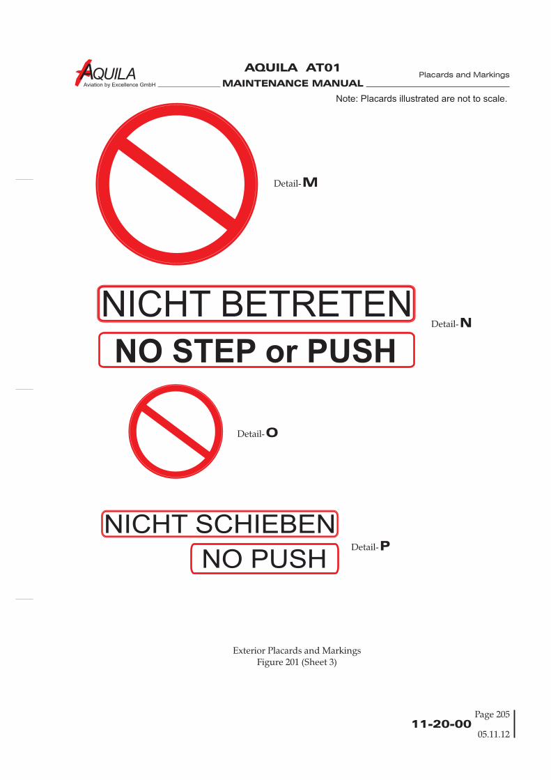
MAINTENANCE MANUAL
AQUILA AT01
Aviation by Excellence GmbH
Exterior Placards and MarkingsFigure 201 (Sheet 3)
11-20-00Page 205
Placards and Markings
05.11.12
NICHT BETRETEN
NICHT SCHIEBEN
NO STEP or PUSH
NO PUSH
MDetail-
NDetail-
ODetail-
PDetail-
Note: Placards illustrated are not to scale.
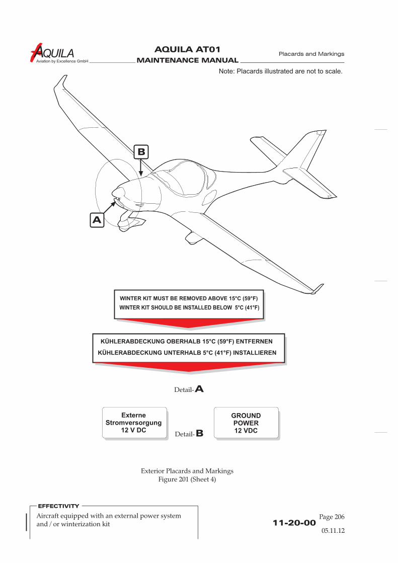
MAINTENANCE MANUAL
AQUILA AT01
Aviation by Excellence GmbH
11-20-00Page 206
Placards and Markings
BDetail-
ADetail-
ExterneStromversorgung
12 V DC
GROUNDPOWER12 VDC
A
B
WINTER KIT SHOULD BE INSTALLED BELOW 5°C (41°F)
WINTER KIT MUST BE REMOVED ABOVE 15°C (59°F)
KÜHLERABDECKUNG UNTERHALB 5°C (41°F) INSTALLIEREN
KÜHLERABDECKUNG OBERHALB 15°C (59°F) ENTFERNEN
Aircraft equipped with an external power systemand / or winterization kit
EFFECTIVITY
Exterior Placards and MarkingsFigure 201 (Sheet 4)
Note: Placards illustrated are not to scale.
05.11.12
MAINTENANCE MANUAL
AQUILA AT01
Aviation by Excellence GmbH
11-30-00Page 201
INTERIOR PLACARDS AND MARKINGS
1.
A. This section gives information about removal and installation of interior placards, markings etc.
B. If the information on the placard is no longer legible or the placard is partially destroyed or is nolonger in place, it must be replaced.
2.
Quantity Equipment Parts No. Manufacturer
3.A 1 Heat gun - commercially available3.A as Isopropyl alcohol - commercially available
required3.B 1 Needle - commercially available
3.
A. Removing self-adhesive placards(1) Warm the placard a little using a heat gun (approx. 40-50°C).(2) Carefully separate a corner of the placard from the aircraft and then pull off parallel to the
surface to remove it.(3) Remove all traces of old adhesive by using a cloth with isopropyl alcohol as required.
B. Placing self-adhesive placards(1) Remove protective film from backside of placard to expose adhesive.(2) Position top edge of the placard precisely.(3) Apply placard by rubbing with a dry, clean cloth.(4) Remove air bubbles by perforating bubble with a small needle and then flattening.
General
Tools, Equipment and Material
Removal / Installation
Figure 201 shows the aircraft interior placards and markings.
Placards and Markings
05.11.12
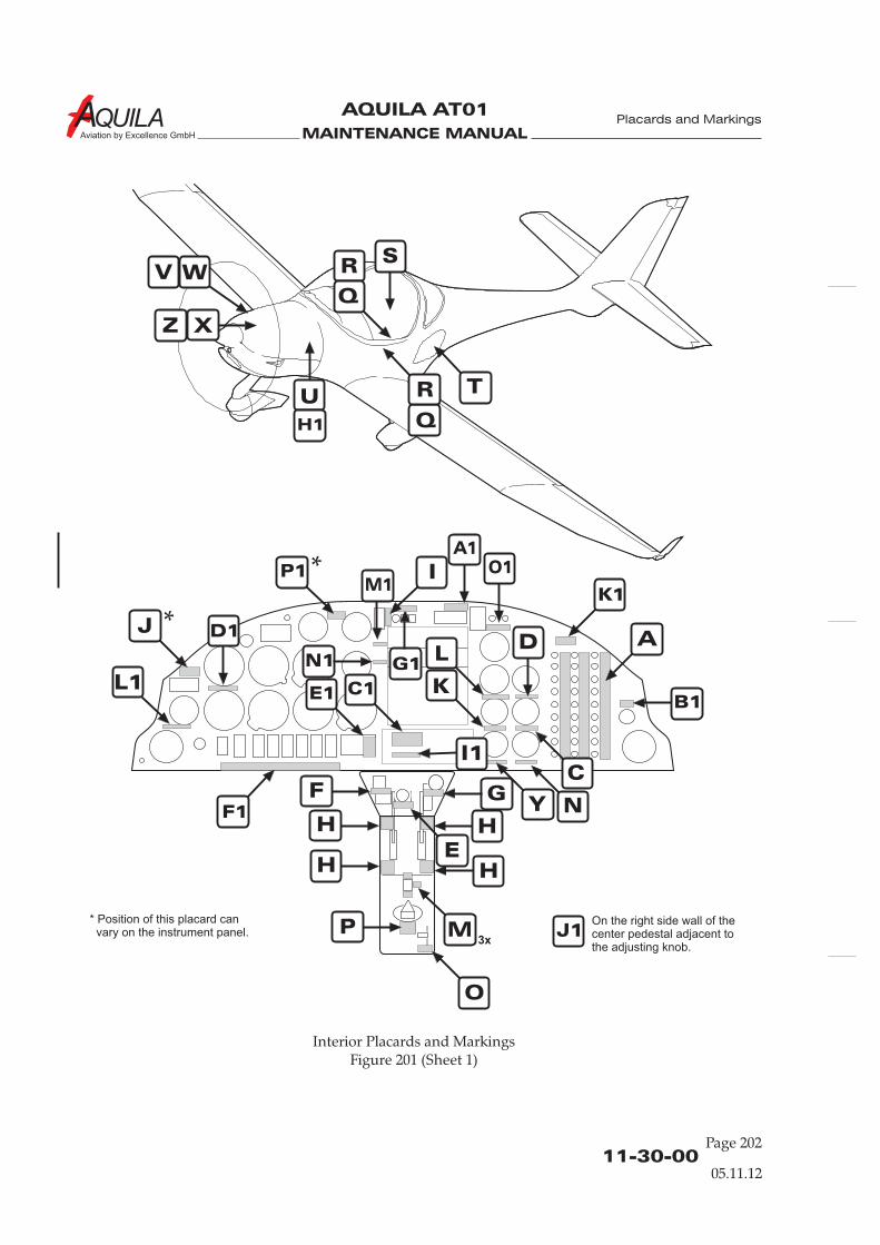
MAINTENANCE MANUAL
AQUILA AT01
Aviation by Excellence GmbH
11-30-00Page 202
Interior Placards and MarkingsFigure 201 (Sheet 1)
Placards and Markings
A
P1
B1
D1
F1
C
D
E
J1
L
L1
Y
K
K1
M
GN
O
F
E1
O1A1
H
H
W
TR
V R
Q
Z
Q
U
X
S
H1
H
H
J
P3x
I1
C1
G1
On the right side wall of thecenter pedestal adjacent tothe adjusting knob.
N1
M1I
* Position of this placard canvary on the instrument panel.
05.11.12
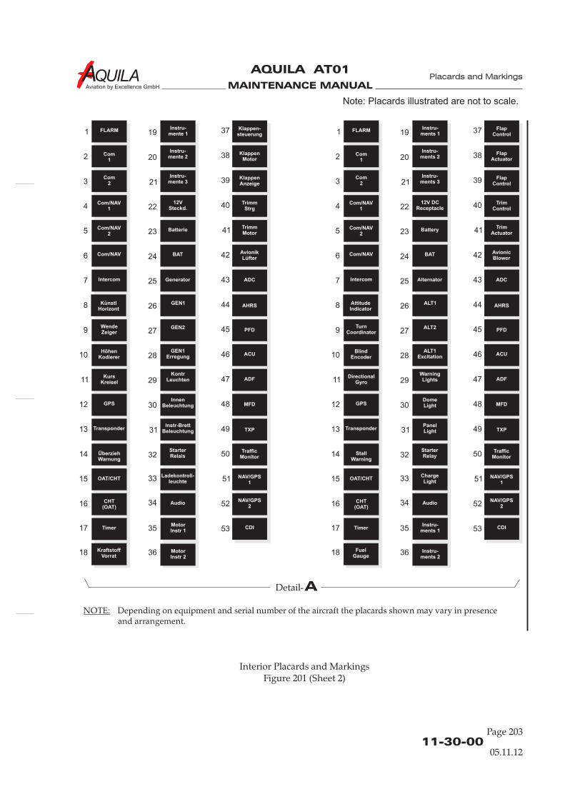
MAINTENANCE MANUAL
AQUILA AT01
Aviation by Excellence GmbH
11-30-00Page 203
Placards and Markings
Interior Placards and MarkingsFigure 201 (Sheet 2)
Note: Placards illustrated are not to scale.
05.11.12
FLARM FLARM
KraftstoffVorrat
FuelGauge
KlappenMotor
FlapActuator
1 1
2 2
3 3
4 4
5 5
6 6
7 7
8 8
9 9
10 10
11 11
12 12
13 13
14 14
15 15
16 16
17 17
18 18
Com/NAV Com/NAV
Generator AlternatorADC ADC
Com/NAV1
Com/NAV1
12VSteckd.
12V DCReceptacle
TrimmMotor
TrimActuator
Com1
Com1
Instru-mente 2
Instru-ments 2
Instru-mente 1
Instru-ments 1
KlappenAnzeige
FlapControl
Instru-mente 3
Instru-ments 3
TrimmStrg
TrimControl
Com2
Com2
Com/NAV2
Com/NAV2
Batterie Battery
BAT BATAvionikLüfter
AvionicBlower
KünstlHorizont
AttitudeIndicator
GEN2 ALT2PFD PFDWendeZeiger
TurnCoordinator
GEN1Erregung
ALT1ExcitationACU ACU
HöhenKodierer
BlindEncoder
KursKreisel
DirectionalGyro
KontrLeuchten
WarningLightsADF ADF
GPS GPSInnen
BeleuchtungDomeLightMFD MFD
OAT/CHT OAT/CHTLadekontroll-
leuchteChargeLight
Audio Audio
NAV/GPS1
NAV/GPS1
NAV/GPS2
NAV/GPS2
CDI CDI
CHT(OAT)
CHT(OAT)
Timer Timer
Klappen-steuerung
FlapControl
Transponder TransponderInstr-Brett
BeleuchtungPanelLightTXP TXP
ÜberziehWarnung
StallWarning
StarterRelais
StarterRelay
MotorInstr 1
Instru-ments 1
MotorInstr 2
Instru-ments 2
TrafficMonitor
TrafficMonitor
Intercom Intercom
GEN1 ALT1AHRS AHRS
19 19
20 20
21 21
22 22
23 23
24 24
25 25
26 26
27 27
28 28
29 29
30 30
31 31
33 33
35 35
32 32
34 34
36 36
37 37
38 38
39 39
40 40
41 41
42 42
43 43
44 44
45 45
46 46
47 47
49 49
48 48
50 50
52 52
51 51
53 53
ADetail-
NOTE: Depending on equipment and serial number of the aircraft the placards shown may vary in presenceand arrangement.
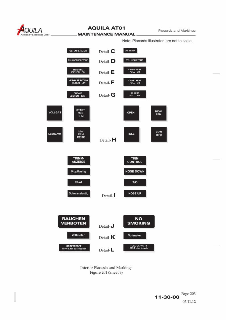
MAINTENANCE MANUAL
AQUILA AT01
Aviation by Excellence GmbH
11-30-00Page 203
Placards and Markings
Interior Placards and MarkingsFigure 201 (Sheet 3)
KRAFTSTOFF109,6 Liter ausfliegbar
FUEL CAPACITY109,6 Liter Usable
IDetail-
JDetail-
KDetail-
LDetail-
HDetail-
RAUCHENVERBOTEN
NOSMOKING
CDetail-
DDetail-
EDetail-
FDetail-
GDetail-CHOKE
ZIEHEN EINCHOKE
PULL ON
VERGASERVORW.ZIEHEN EIN
CARB. HEATPULL ON
HEIZUNGZIEHEN EIN
CABIN HEATPULL ON
ÖLTEMPERATUR
ZYLINDERKOPFTEMP.
OIL TEMP.
CYL. HEAD TEMP.
VOLLGAS OPEN
LEERLAUF IDLE
STARTMax.RPM
HIGHRPM
Min.RPM
REISE
LOWRPM
TRIMM-ANZEIGE
TRIMCONTROL
Kopflastig NOSE DOWN
Start T/O
Schwanzlastig
VoltmeterVoltmeter
NOSE UP
Note: Placards illustrated are not to scale.
05.11.12
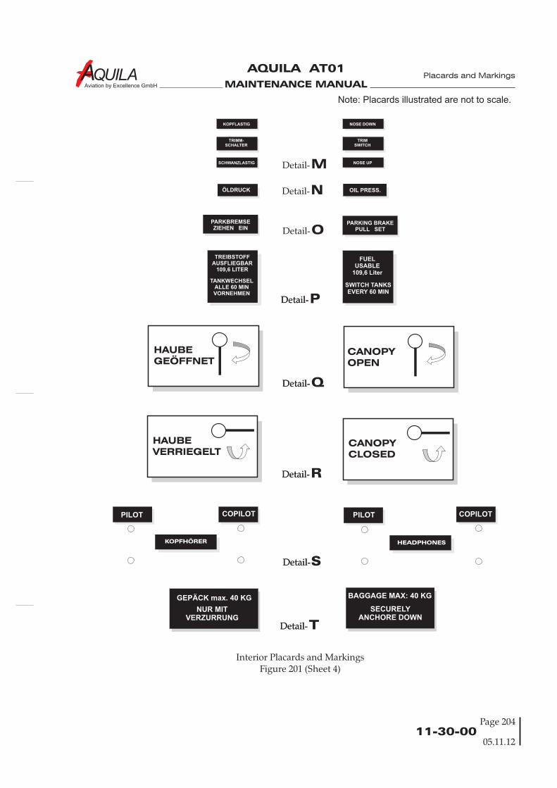
MAINTENANCE MANUAL
AQUILA AT01
Aviation by Excellence GmbH
11-30-00
Interior Placards and MarkingsFigure 201 (Sheet 4)
Page 204
Placards and Markings
Note: Placards illustrated are not to scale.
05.11.12
PARKBREMSEZIEHEN EIN
OIL PRESS.
TREIBSTOFFAUSFLIEGBAR
109,6 LITER
TANKWECHSELALLE 60 MINVORNEHMEN
SWITCH TANKSEVERY 60 MIN
FUELUSABLE
109,6 Liter
MDetail-
NDetail-
ODetail-
Q
R
P
Detail-
Detail-
Detail-
Detail-
Detail-
SDetail-Detail-
Detail-
HAUBEGEÖFFNET
CANOPYOPEN
HAUBEVERRIEGELT
CANOPYCLOSED
TDetail-Detail-
GEPÄCK max. 40 KG
NUR MITVERZURRUNG
BAGGAGE MAX: 40 KG
SECURELYANCHORE DOWN
KOPFLASTIG NOSE DOWN
SCHWANZLASTIG NOSE UP
TRIMM-SCHALTER
TRIMSWITCH
ÖLDRUCK
PARKING BRAKEPULL SET
COPILOTPILOTCOPILOTPILOT
KOPFHÖRER HEADPHONES
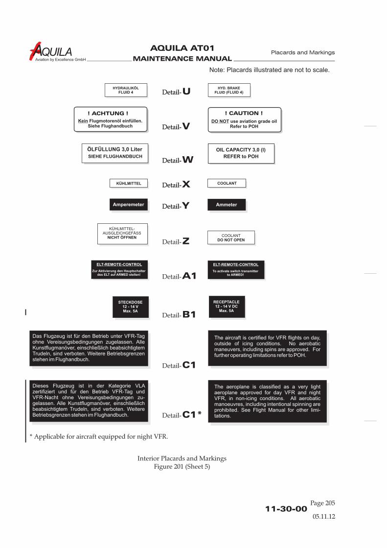
MAINTENANCE MANUAL
AQUILA AT01
Aviation by Excellence GmbH
Placards and Markings
Interior Placards and MarkingsFigure 201 (Sheet 5)
11-30-00Page 205
KÜHLMITTEL-AUSGLEICHGEFÄSS
NICHT ÖFFNEN COOLANTDO NOT OPEN
STECKDOSE12 - 14 VMax. 5A
RECEPTACLE12 - 14 V DC
Max. 5A
ZDetail-
A1Detail-
B1Detail-
C1Detail-
C1*Detail-
KÜHLMITTEL COOLANTXDetail-Detail-
YDetail-Detail-
WDetail-Detail-
ÖLFÜLLUNG 3,0 LiterSIEHE FLUGHANDBUCH
OIL CAPACITY 3,0 (l)REFER to POH
HYD. BRAKEFLUID (FLUID 4)
HYDRAULIKÖLFLUID 4 UDetail-Detail-
VDetail-Detail-
! ACHTUNG !
Kein Flugmotorenöl einfüllen.Siehe Flughandbuch
! CAUTION !
DO NOT use aviation grade oilRefer to POH
ELT-REMOTE-CONTROL
Zur Aktivierung den Hauptschalterdes ELT auf ARMED stellen!
ELT-REMOTE-CONTROL
To activate switch transmitterto ARMED!
Das Flugzeug ist für den Betrieb unter VFR-Tagohne Vereisungsbedingungen zugelassen. AlleKunstflugmanöver, einschließlich beabsichtigtemTrudeln, sind verboten. Weitere Betriebsgrenzenstehen im Flughandbuch.
The aircraft is certified for VFR flights on day,outside of icing conditions. No aerobaticmaneuvers, including spins are approved. Forfurther operating limitations refer to POH.
The aeroplane is classified as a very lightaeroplane approved for day VFR and nightVFR, in non-icing conditions. All aerobaticmanoeuvres, including intentional spinning areprohibited. See Flight Manual for other limi-tations.
Amperemeter Ammeter
Dieses Flugzeug ist in der Kategorie VLAzertifiziert und für den Betrieb VFR-Tag undVFR-Nacht ohne Vereisungsbedingungen zu-gelassen. Alle Kunstflugmanöver, einschließlichbeabsichtigtem Trudeln, sind verboten. WeitereBetriebsgrenzen stehen im Flughandbuch.
Note: Placards illustrated are not to scale.
* Applicable for aircraft equipped for night VFR.
05.11.12
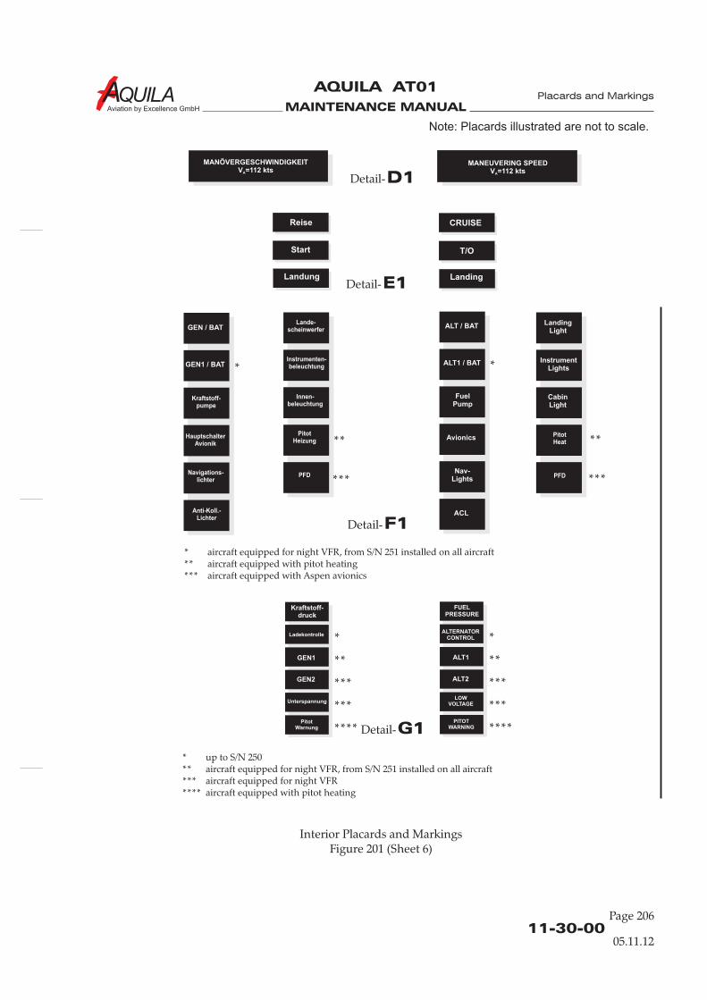
MAINTENANCE MANUAL
AQUILA AT01
Aviation by Excellence GmbH
11-30-00Page 206
Placards and Markings
Interior Placards and MarkingsFigure 201 (Sheet 6)
Note: Placards illustrated are not to scale.
05.11.12
E1Detail-
G1Detail-
Reise
Start
Landung
Kraftstoff-druck
GEN1 ALT1
GEN2 ALT2
ALTERNATORCONTROL
FUELPRESSURE
CRUISE
T/O
Landing
UnterspannungLOW
VOLTAGE
Ladekontrolle
PitotWarnung
PITOTWARNING
D1Detail-
MANÖVERGESCHWINDIGKEITV =112 ktsA
MANEUVERING SPEEDV =112 ktsA
F1Detail-
GEN / BAT
GEN1 / BAT
Kraftstoff-pumpe
HauptschalterAvionik
Navigations-lichter
Anti-Koll.-Lichter
Lande-scheinwerfer
Instrumenten-beleuchtung
Innen-beleuchtung
PitotHeizung
PFD
ALT / BAT
ALT1 / BAT
FuelPump
Avionics
Nav-Lights
ACL
PitotHeat
PFD
LandingLight
InstrumentLights
CabinLight
* aircraft equipped for night VFR, from S/N 251 installed on all aircraft** aircraft equipped with pitot heating*** aircraft equipped with Aspen avionics
* up to S/N 250** aircraft equipped for night VFR, from S/N 251 installed on all aircraft*** aircraft equipped for night VFR**** aircraft equipped with pitot heating
* *
****
******
* *
** **
*** ***
*** ***
**** ****
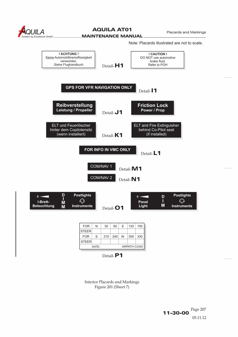
MAINTENANCE MANUAL
AQUILA AT01
Aviation by Excellence GmbH
Interior Placards and MarkingsFigure 201 (Sheet 7)
Placards and Markings
11-30-00Page 207
H1Detail-
I1Detail-
J1Detail-
O1Detail-
K1Detail-
L1Detail-
M1Detail-
N1Detail-
! ACHTUNG !Automobilbremsflüssigkeit
verwenden.Siehe Flughandbuch
Keine! CAUTION !
DO NOT use automotivebrake fluid.
Refer to POH
ReibverstellungLeistung / Propeller
Friction LockPower / Prop
ELT und Feuerlöscherhinter dem Copilotensitz
(wenn installiert)
ELT and Fire Extinguisherbehind Co-Pilot seat
(if installed)
GPS FOR VFR NAVIGATION ONLY
FOR INFO IN VMC ONLY
COM/NAV 1
COM/NAV 2
I-Brett-Beleuchtung Instrumente
PostlightsDI
MM
0
PanelLight Instruments
PostlightsDIM
0
P1Detail-
FOR
STEER
FOR
STEER
N 30 60 E 120 150
S 210 240 W 300 330
DATE: AIRPATH C2300
Note: Placards illustrated are not to scale.
05.11.12

MAINTENANCE MANUAL
AQUILA AT01A
CHAPTER 12
SERVICING

MAINTENANCE MANUAL
AQUILA AT01A
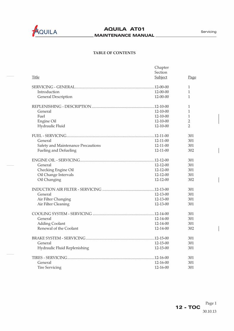
MAINTENANCE MANUAL
AQUILA AT01A
Page 112 - TOC
TABLE OF CONTENTS
ChapterSection
SERVICING - GENERAL..................................................................................12-00-00 1Introduction 12-00-00 1General Description 12-00-00 1
REPLENISHING - DESCRIPTION.................................................................12-10-00 1General 12-10-00 1Fuel 12-10-00 1Engine Oil 12-10-00 2Hydraulic Fluid 12-10-00 2
FUEL - SERVICING...........................................................................................12-11-00 301General 12-11-00 301Safety and Maintenance Precautions 12-11-00 301Fueling and Defueling 12-11-00 302
ENGINE OIL - SERVICING.............................................................................12-12-00 301General 12-12-00 301Checking Engine Oil 12-12-00 301Oil Change Intervals 12-12-00 301Oil Changing 12-12-00 302
INDUCTION AIR FILTER - SERVICING ......................................................12-13-00 301General 12-13-00 301Air Filter Changing 12-13-00 301Air Filter Cleaning 12-13-00 301
COOLING SYSTEM - SERVICING ................................................................12-14-00 301General 12-14-00 301Adding Coolant 12-14-00 301Renewal of the Coolant 12-14-00 302
BRAKE SYSTEM - SERVICING.......................................................................12-15-00 301General 12-15-00 301Hydraulic Fluid Replenishing 12-15-00 301
TIRES - SERVICING..........................................................................................12-16-00 301General 12-16-00 301Tire Servicing 12-16-00 301
Title Subject Page
Servicing
30.10.13
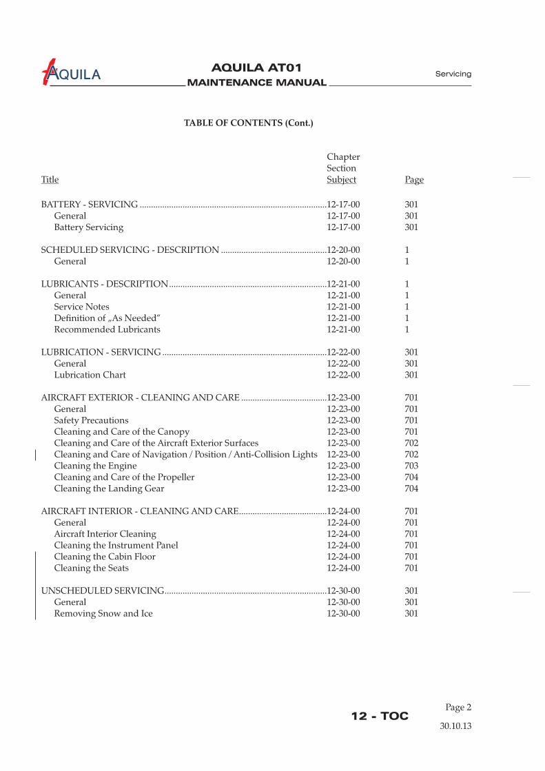
MAINTENANCE MANUAL
AQUILA AT01A
12 - TOCPage 2
30.10.13
BATTERY - SERVICING ...................................................................................12-17-00 301General 12-17-00 301Battery Servicing 12-17-00 301
SCHEDULED SERVICING - DESCRIPTION ...............................................12-20-00 1General 12-20-00 1
LUBRICANTS - DESCRIPTION......................................................................12-21-00 1General 12-21-00 1Service Notes 12-21-00 1Definition of „As Needed“ 12-21-00 1Recommended Lubricants 12-21-00 1
LUBRICATION - SERVICING .........................................................................12-22-00 301General 12-22-00 301Lubrication Chart 12-22-00 301
AIRCRAFT EXTERIOR - CLEANING AND CARE ......................................12-23-00 701General 12-23-00 701Safety Precautions 12-23-00 701Cleaning and Care of the Canopy 12-23-00 701Cleaning and Care of the Aircraft Exterior Surfaces 12-23-00 702
Cleaning the Engine 12-23-00 703Cleaning and Care of the Propeller 12-23-00 704Cleaning the Landing Gear 12-23-00 704
AIRCRAFT INTERIOR - CLEANING AND CARE.......................................12-24-00 701General 12-24-00 701Aircraft Interior Cleaning 12-24-00 701Cleaning the Instrument Panel 12-24-00 701Cleaning the Cabin Floor 12-24-00 701Cleaning the Seats 12-24-00 701
UNSCHEDULED SERVICING........................................................................12-30-00 301General 12-30-00 301Removing Snow and Ice 12-30-00 301
Cleaning and Care of Navigation / Position / Anti-Collision Lights 12-23-00 702
Servicing
TABLE OF CONTENTS (Cont.)
ChapterSection
Title Subject Page
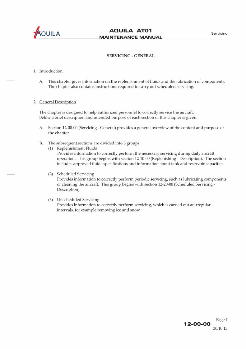
MAINTENANCE MANUAL
AQUILA AT01A
12-00-0030.10.13
SERVICING - GENERAL
1.
A. This chapter gives information on the replenishment of fluids and the lubrication of components.The chapter also contains instructions required to carry out scheduled servicing.
2.
The chapter is designed to help authorized personnel to correctly service the aircraft.Below a brief description and intended purpose of each section of this chapter is given.
A. Section 12-00-00 (Servicing - General) provides a general overview of the content and purpose ofthe chapter.
B. The subsequent sections are divided into 3 groups.(1) Replenishment Fluids
Provides information to correctly perform the necessary servicing during daily aircraftoperation. This group begins with section 12-10-00 (Replenishing - Description). The sectionincludes approved fluids specifications and information about tank and reservoir capacities.
(2) Scheduled ServicingProvides information to correctly perform periodic servicing, such as lubricating componentsor cleaning the aircraft. This group begins with section 12-20-00 (Scheduled Servicing -Description).
(3) Unscheduled ServicingProvides information to correctly perform servicing, which is carried out at irregularintervals, for example removing ice and snow.
Introduction
General Description
Servicing
Page 1

MAINTENANCE MANUAL
AQUILA AT01A
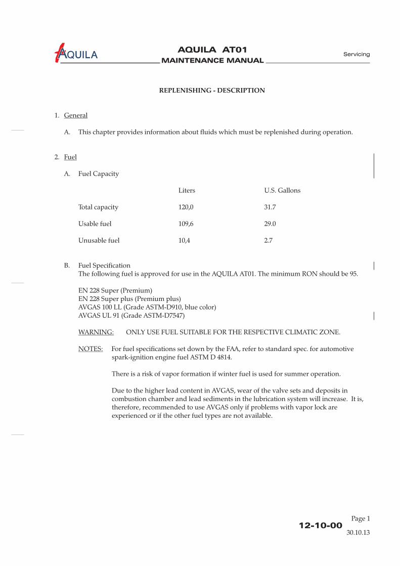
MAINTENANCE MANUAL
AQUILA AT01A
12-10-00
REPLENISHING - DESCRIPTION
1.
A. This chapter provides information about fluids which must be replenished during operation.
2.
A. Fuel Capacity
Liters U.S. Gallons
Total capacity 120,0 31.7
Usable fuel 109,6 29.0
Unusable fuel 10,4 2.7
B. Fuel SpecificationThe following fuel is approved for use in the AQUILA AT01. The minimum RON should be 95.
EN 228 Super (Premium)EN 228 Super plus (Premium plus)AVGAS 100 LL (Grade ASTM-D910, blue color)AVGAS UL 91 (Grade ASTM-D7547)
For fuel specifications set down by the FAA, refer to standard spec. for automotivespark-ignition engine fuel ASTM D 4814.
There is a risk of vapor formation if winter fuel is used for summer operation.
Due to the higher lead content in AVGAS, wear of the valve sets and deposits incombustion chamber and lead sediments in the lubrication system will increase. It is,therefore, recommended to use AVGAS only if problems with vapor lock areexperienced or if the other fuel types are not available.
General
Fuel
NOTES:
ONLY USE FUEL SUITABLE FOR THE RESPECTIVE CLIMATIC ZONE.WARNING:
Servicing
30.10.13
Page 1
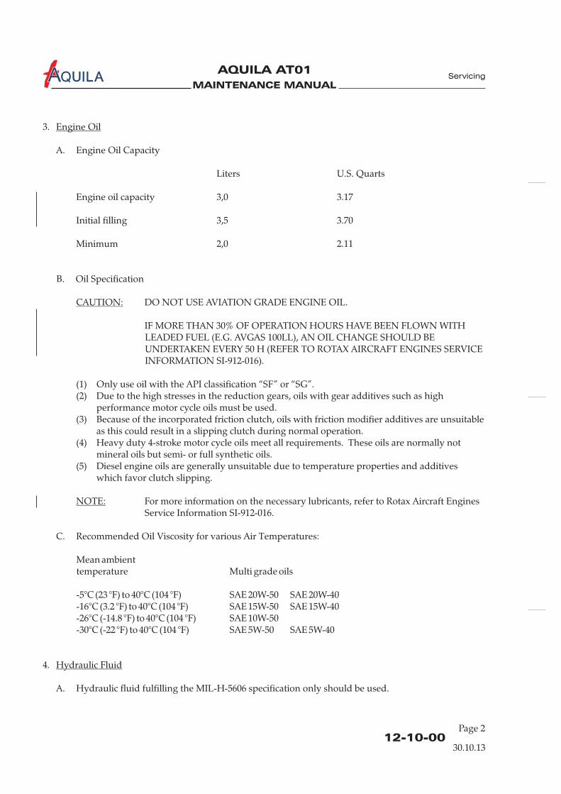
MAINTENANCE MANUAL
AQUILA AT01A
12-10-00
3.
A. Engine Oil Capacity
Liters U.S. Quarts
Engine oil capacity 3,0 3.17
Initial filling 3,5 3.70
Minimum 2,0 2.11
B. Oil Specification
DO NOT USE AVIATION GRADE ENGINE OIL.
IF MORE THAN 30% OF OPERATION HOURS HAVE BEEN FLOWN WITHLEADED FUEL (E.G. AVGAS 100LL), AN OIL CHANGE SHOULD BEUNDERTAKEN EVERY 50 H (REFER TO ROTAX SERVICEINFORMATION SI-912-016).
(1) Only use oil with the API classification “SF” or “SG”.(2) Due to the high stresses in the reduction gears, oils with gear additives such as high
performance motor cycle oils must be used.(3) Because of the incorporated friction clutch, oils with friction modifier additives are unsuitable
as this could result in a slipping clutch during normal operation.(4) Heavy duty 4-stroke motor cycle oils meet all requirements. These oils are normally not
mineral oils but semi- or full synthetic oils.(5) Diesel engine oils are generally unsuitable due to temperature properties and additives
which favor clutch slipping.
For more information on the necessary lubricants, refer to Rotax Aircraft EnginesService Information .
C. Recommended Oil Viscosity for various Air Temperatures:
4.
A. Hydraulic fluid fulfilling the MIL-H-5606 specification only should be used.
Engine Oil
CAUTION:
NOTE:
Hydraulic Fluid
AIRCRAFT ENGINES
SI-912-016
Mean ambienttemperature Multi grade oils
-5°C (23 °F) to 40°C (104 °F) SAE 20W-50 SAE 20W-40-16°C (3.2 °F) to 40°C (104 °F) SAE 15W-50 SAE 15W-40-26°C (-14.8 °F) to 40°C (104 °F) SAE 10W-50-30°C (-22 °F) to 40°C (104 °F) SAE 5W-50 SAE 5W-40
Servicing
30.10.13
Page 2
MAINTENANCE MANUAL
AQUILA AT01A
12-11-00Page 301
FUEL - SERVICING
1.
A. Fuel Tanks(1) The aircraft is equipped with two integral wing fuel tanks.
The fuel tanks are located inside each wing between the front and rear spars. Each fuel tankhas a filler cap on the top wing surface.
B. Drain System(1) The fuel system is equipped with drain valves to allow examination for contamination, water
and for de-fueling.Each wing fuel tank has a drain valve at the bottom, inboard rear corner. A further drainvalve is located at the lowest point of the fuel system; at the base of the electrical fuel pump.The pump is attached to the lower right firewall in the engine compartment. The drain isaccessible from outside the nose section.The center of the fuel drains can be pushed inward with the fuel sampler to inspect for waterand contamination.
Chapter 28 (Fuel) contains more detailed information about the fuel system.
2.
A. Safety Precautions
SERVICEABLE FIRE FIGHTING EQUIPMENT MUST BE AVAILABLE.
AIRCRAFT AND FILLING FITTINGS MUST BE GROUNDED.
ALL ELECTRICAL EQUIPMENT IN THE AIRCRAFT SHOULD BE TURNEDOFF. THE ALT / BAT SWITCH SHOULD BE IN THE OFF POSITION ANDTHE IGNITION KEY REMOVED FROM THE AIRCRAFT.
NO SMOKING!
(1) Before beginning maintenance, a serviceable fire extinguisher (at least foam extinguisher)must be positioned within easy access.
(2) Do not wear clothing that has a tendency to generate static electricity (i.e. synthetic fabrics).(3) No metal tabs on footwear.(4) Carry out fuel system servicing procedures only in a designated fuel loading/unloading area.(5) Ground equipment near the aircraft must be turned off.(6) While filling do not turn on any electrical device.(7) Make sure that the aircraft and filling fittings are properly grounded:
(a) First ground the aircraft;(b) If a mobile filling device is being used, ground the filling device (same potential as
aircraft);(c) Ground the mobile filling device with the aircraft.
General
NOTE:
Safety and Maintenance Precautions
WARNING: DURINGALL FUEL SYSTEM SERVICING PROCEDURES
" "
Servicing
30.10.13

MAINTENANCE MANUAL
AQUILA AT01A
12-11-00Page 302
B. Maintenance Precautions(1) Use designated equipment for fuel loading / unloading to prevent contamination.(2) Only use approved anti-icing additive.(3) Blend fuel in accordance with prescribed procedures.(4) Document all fuel blending.
3.
A. Fueling(1) Move aircraft to a designated fuel loading / fuel unloading area.(2) Make sure that the ALT / BAT switch is in the OFF position.(3) Ground aircraft and filling device as described above.(4) Position a fire extinguisher near to the fuel tank to be serviced.(5) Remove fuel filler cap and fill fuel tank to desired level.(6) Remove fuel service nozzle and install fuel cap.(7) Move fire extinguisher and the fuel service nozzle to the other tank to be filled.
(10) Check correct lock of both fuel filler caps. Remove excess fuel from the wing area using acloth.
(11) Remove ground cables.(12) Compare reading of fueled amount on filling device with readings on the fuel indicators in
the aircraft.
B. Defueling(1) Move aircraft to a designated fuel loading / fuel unloading area.(2) Make sure you have enough fuel collectors.(3) Make sure that the ALT / BAT switch is in OFF position.(4) Ground aircraft and filling device as described above.(5)(6) Remove fuel cap and remove as much fuel as possible using a defueling nozzle.
(8)
(11) Drain remaining fuel from each wing fuel tank.(12) Drain remaining fuel from the drain valve located at the base of the electrical fuel pump with
the fuel selector valve in the position LEFT and then in the position RIGHT.(13) Make sure all drain valves are closed securely.(14)
Fueling and Defueling
(8) Remove fuel filler cap and fill fuel tank to desired level.(9) Remove fuel service nozzle and install fuel cap.
Position a fire extinguisher near to the fuel tank to be defueled.
(7) Install fuel cap.Move fire extinguisher and the defueling nozzle to the other tank to be defueled.
(9) Remove fuel cap and remove as much fuel as possible using a defueling nozzle.(10) Install fuel cap.
Remove ground cables.
Servicing
30.10.13
MAINTENANCE MANUAL
AQUILA AT01A
12-12-00Page 301
ENGINE OIL - SERVICING
1.
A. This chapter provides information for checking and changing engine oil.
B. The oil filler cap of the oil tank is located on the right (starboard) side of the engine behindcylinder no. 3. It is accessible by opening the oil access plate on the upper cowling. The oil fillercap has a dipstick with min - max markings to check oil level.
2.
A. Oil Checking Procedure
AVOID SKIN CONTACT WITH ENGINE OIL. USED OIL IN PARTICULARCONTAINS MATERIALS DETRIMENTAL TO HEALTH.
(1) Turn the propeller several times by hand to transfer all the oil from the engine to the tank.
The process is completed when air flows back to the oil tank. This flow of air can beperceived as gurgling sound when the cover of the tank is removed.
(2) Open oil access plate on upper right cowling.(3) Remove oil filler cap and withdraw dipstick.(4) Wipe oil dipstick dry with a cloth.(5) Reinsert dipstick.(6) Withdraw dipstick and read oil level on dipstick.(7) If necessary, refill engine oil with correct grade and viscosity (refer to 12-10-00).
For normal engine operation maintain the oil level between the two marks as anexcessive oil level will allow oil to escape via the venting line.For longer flights replenish oil to max. mark to warrant more oil reserve.
(8) Reinsert oil dipstick, close filler cap, check for proper seating.(9) Close oil access plate.
3.
FOR ENGINE OPERATION WITH AVGAS; OIL SHOULD BE CHANGED EVERY50 HOURS (REFER TO ROTAX AIRCRAFT ENGINES SI-912-016).
General
Checking Engine Oil
WARNING:
NOTE:
NOTE:
Oil Change Intervals
CAUTION:
WARNING:
CAUTION:
BEFORE ROTATING THE PROPELLER BY HAND, ENSURE IGNITION SWITCHIS OFF, MIXTURE CONTROL IS IN THE IDLE CUT-OFF POSITION, AND THETHROTTLE IS CLOSED.
DO NOT ROTATE THE PROPELLER CLOCKWISE.
Servicing
30.10.13
MAINTENANCE MANUAL
AQUILA AT01A
12-12-00Page 302
CAUTION:
Oil Changing
WARNING:
WARNING:
UNDER SEVERE OPERATING CONDITIONS, THE FREQUENCY OF OILCHANGES MUST BE INCREASED REGARDLESS OF THE TYPE OF FUEL USED(MOGAS OR AVGAS).
A. Oil Change Intervals(1) Under normal operating conditions, oil must be changed every 100 hours.(2) For oil specifications, refer to 12-10-00 and to ROTAX Aircraft Engines SI-912-016. The
4.
A. Oil Changing Procedure(1) Run engine until operating temperature is reached.(2) Shut down engine.
HOT ENGINE COMPONENTS MAY CAUSE SKIN BURNS!
(3) Remove engine cowling (refer to 71-10-00).(4) Cut safety wire on drain screw at oil tank base. Remove drain screw.(5) Drain oil and dispose of it as per environmental regulations.(6) Remove oil filter from engine.(7) Lubricate mating sealing ring of new oil filter with engine oil.(8) Install new oil filter. Screw on new oil filter by hand.(9) Cut oil filter out of its casing (without producing any metal chips) and inspect filter material.(10) Renew gasket ring of drain screw on oil tank. Fit drain screw and tighten
to 25 Nm (220 in.lbs). Secure drain screw with safety wire.(11) Refill oil tank with approx. 3 liters (3.17 quarts) of oil. For oil specification, refer to 12-10-00
and to(12) Reinsert oil dipstick, close filler cap, check for proper seating.(13) Run engine until normal operating temperature is reached. Shut down engine.
HOT ENGINE COMPONENTS MAY CAUSE SKIN BURNS!
(14) Check oil system for leaks.(15) Tighten oil filter again by hand.(16) Reinstall cowling.(17) Document oil change as prescribed.
ROTAX Aircraft Engines SI-912-016 contains further operating information for ROTAXengines.
ROTAX Aircraft Engines SI-912-016.
Servicing
30.10.13
MAINTENANCE MANUAL
AQUILA AT01A
12-13-00Page 301
INDUCTION AIR FILTER - SERVICING
1.
A. The air filter in the air induction system keeps dust and dirt particles from entering the system.It is located in the air filter box on the left inside of lower cowling.To increase its effectiveness, the filter element should be treated with filter oil.
B. The condition of the air filter element will be determined primarily by engine operatingconditions. Therefore, it should be regularly inspected, cleaned and replaced, if necessary, at leastevery 100 hours or once a year, whichever comes first.
2.
A. Air Filter Changing Procedure(1) Remove upper cowling (refer to 71-10-00).(2) Remove the cover of the air filter box.(3) Remove air filter element and replace by a new one.(4) Install(5) Install upper cowling (refer to 71-10-00).
3.
A. Cleaning Procedures(1) Remove air filter element as described above.(2) Inspect air filter element for damage. If necessary renew filter element.
NEVER USE GASOLINE, STEAM, CAUSTIC LIQUIDS, DETERGENTS OR HIGHPRESSURE CLEANING.
(3) Lightly tap and brush off surface dirt.(4) Spray filter cleaner on to entire element and let it soak for approx. 10 min.
DO NOT DRY OVER NAKED FLAME OR WITH HOT AIR GUN. EXCESSIVE HEATWILL SHRINK THE PORES OF THE FILTER MATERIAL RESTRICTING ENGINEAIR FLOW.
(5) Rinse filter element with water from the inside out and let it dry naturally.
(6) After cleaning, lubricate filter element evenly with filter oil spray or filter oil according to themanufacturer ’s instructions.
(7) Ensure air filter box is clean and free of debris.(8) Install air filter as described above, pay attention to correct fit.
General
Air Filter Changing
Air Filter Cleaning
CAUTION:
WARNING:
the cover of the air filter box.
NEVER USE GEAR OIL, DIESEL OIL OR MOTOR OIL AS THEY ATTRACT WATER.CAUTION:
Servicing
30.10.13

MAINTENANCE MANUAL
AQUILA AT01A
12-13-00Page 302
12.04.00
MAINTENANCE MANUAL
AQUILA AT01A
12-14-00Page 301
COOLING SYSTEM - SERVICING
1.
A. The cooling system of the ROTAX 912 is designed for liquid cooling of the cylinder heads and ramair cooling of the cylinders. The cooling system of the cylinder heads is a closed circuit with anexpansion tank. For a more detailed description and related maintenance procedures of thecooling system, refer to 75-20-00.
B. CoolantThere are two different cooling systems possible on the AQUILA AT01 each requiring a differentcoolant. The standard cooling system of the AQUILA AT01 (combined water / oil radiator) mustonly be operated with waterless coolant based on propylene glycol. If SB-AT01-029 has beencarried out (installation of the AT01-100 cooling system with separate water and oil radiators) onlyconventional coolant based on ethylene glycol with 50% water content must be used.
(1) Waterless coolant based on propylene glycol such as EVANS Aero Cool 180
This type of coolant must be used on the standard AQUILA AT01 cooling systemwith a combined water / oil radiator.
WATER OR COOLANT CONTAINING WATER MUST NEVER BE ADDED TOTHE COOLING SYSTEM! THE MAX. WATER CONTENT MUST NOT EXCEED3,6%; IT CAN BE TESTED USING A BRIX REFRACTOMETER. ANY WATERPRESENT IN THE COOLING SYSTEM IS SEPARATED OUT AS VAPOR. THISCAN CAUSE THE COOLING SYSTEM TO FAIL DUE TO INSUFFICIENTCOOLANT QUANTITY.
USE COOLANT IN ACCORDANCE WITH MANUFACTURER SINSTRUCTIONS.
General
CAUTION:
WARNING:
NOTE:
NOTE:
NEVER OPEN PRESSURE CAP OR RADIATOR CAP WHEN THE COOLING SYSTEMIS HOT. FOR SAFETY REASONS, COVER CAP WITH A CLOTH AND OPENSLOWLY. SUDDEN OPENING OF THE CAP COULD PROVOKE THE EXIT OFBOILING COOLANT AND RESULT IN SEVERE SCALDING.
Refer to the ROTAX Service Instruction SI-912-016, latest revision, for further information onsuitable coolants. The maximum coolant quantity is 2,5 liters (2.6 U.S. quarts).
'
If EVANS Aero Cool 180 is not available locally for servicing the cooling system, aconventional coolant based on pure 100% ethylene glycol can be usedtemporarily. However, the coolant must be replaced again with EVANS AeroCool 180 within the next 15 days. Only add 100% pure ethylene glycol!
(2) Conventional coolant based on ethylene glycol such as BASF Glysantin Protect Plus / G4850% antifreeze concentrate with additives against corrosion and 50 % pure water, or use of anequivalent premixed coolant. The coolant must be renewed every two years.
Servicing
Temporary Revision 4, 27.04.15
MAINTENANCE MANUAL
AQUILA AT01A
NOTE:
CAUTION:
Renewal of the Coolant
Flushing the Cooling System
This type of coolant must be used if SB-AT01-029 has been carried out and thestandard AQUILA AT01 cooling system has been replaced by the AT01-100cooling system with separate water and oil radiators.
ENSURE THAT ONLY ANTIFREEZE CONCENTRATE CONTAININGADDITIVES AGAINST CORROSION FOR LIGHT METAL ENGINES IS USED.
USE ANTIFREEZE CONCENTRATE IN ACCORDANCE WITHMANUFACTURER'S INSTRUCTIONS.
again
3.
A. Servicing procedures(1) Open the radiator cap, remove the bottom attachment screw (with sealing ring) of the water
pump and drain the coolant.(2) Install attachment screw (stainless steel) along with a new sealing ring. Tighten to 10 Nm
(90 in.lbs).(3) Refill coolant into expansion tank (highest point of the cooling system). Install radiator cap.(4) Run engine to operating temperature and allow engine to cool down before checking coolant
level. Replenish as necessary.
4. (conventional coolant only!)
A. Servicing Procedure(1) Open the lowest coolant hose (either at water pump or radiator).(2) Flush system with a water hose at a max. pressure of 2 bar (30 psi).(3) Reconnect coolant hose.(4) Refill freshly mixed coolant into the expansion tank.(5) Run engine to operating temperature and allow engine to cool down before checking coolant
level. Replenish as necessary.
2.
A. Prior to adding coolant, the reason for the loss of the liquid must be investigated and corrected.
B. Servicing procedures(1) Remove engine cowling (refer to 71-10-00).(2) When engine is cold, open pressure cap of the expansion tank and fill up the expansion tank
completely.(3) Run engine to operating temperature and allow engine to cool down before checking coolant
level . Replenish as necessary.(4) Close pressure cap, check the condition of the rubber sealing rings.(5) Install engine cowling (refer to 71-10-00).
Adding Coolant
Servicing
12-14-00Page 302
Temporary Revision 4, 27.04.15
MAINTENANCE MANUAL
AQUILA AT01A
12-15-00Page 301
BRAKE SYSTEM - SERVICING
1.
A. Ground service for the brake system is limited to the replenishment of brake fluid. The brakefluid reservoir is located at the upper left firewall in the engine compartment.
2.
A. Hydraulic Fluid Replenishing
ONLY USE HYDRAULIC FLUID WHICH CONFORMS TO MIL-H-5606SPECIFICATION.
(1) Remove upper cowling (refer to 71-10-00).(2) Remove filler plug from hydraulic fluid reservoir.
REMOVE EXCESSIVE HYDRAULIC FLUID IMMEDIATELY FROM PAINTSURFACES TO PREVENT CHEMICAL ATTACK.
(3) Refill hydraulic fluid.(4) Install filler plug.(5) Install upper cowling (refer to 71-10-00).
General
Hydraulic Fluid
CAUTION:
CAUTION:
Replenishing
Servicing
30.10.13

MAINTENANCE MANUAL
AQUILA AT01A
MAINTENANCE MANUAL
AQUILA AT01A
12-16-00Page 301
TIRES - SERVICING
1.
A. The landing gear is equipped with 5.00-5 tires. Required tire pressure is:
(a) Main gear tire: 2,5 bar (36 psi)(b) Nose gear tire: 2,0 bar (29 psi)
Checking tire pressure regularly is the most important preventive measure in tire service.Improper tire pressure causes deterioration in the ground handling behavior of the aircraft andreduces the service life of the tire.Under-pressure is indicated by excessive wear in the tire shoulder area, over-pressure by excessivewear in the center of tire.
2.
WHILE SERVICING, DO NOT STAND IN FRONT OF EITHER BEAD AREA OF THETIRE BECAUSE BURSTING TIRES HAVE THE TENDENCY TO RUPTURE ALONGTHE BEAD. ALWAYS STAND AT A 90° ANGLE TO THE AXLE ALONG THE TIRECENTERLINE.
A. Service Notes(1) If possible, do not expose the tires permanently to intensive solar radiation.(2) Ensure tire pressure gauges used are accurate.(3) While checking tire pressure, the aircraft should be on level ground and the tire cold.(4) A freshly mounted and installed tube-type tire should be closely monitored during the first
hours of operation. Air trapped between the tire and the tube at the time of mounting couldseep out, resulting in under pressure in the tire.
B. Tire servicing comprises the following items:(1) Check tire pressure regularly. If necessary inflate or drain air.(2) Examine tires for wear, cuts, bruises, and foreign bodies in the tread.(3) Check proper location of the red slide marks.(4) Always remove oil, grease and mud from tires with soap and water.
General
Tire Servicing
WARNING:
Servicing
30.10.13

MAINTENANCE MANUAL
AQUILA AT01A
MAINTENANCE MANUAL
AQUILA AT01A
12-17-00Page 301
BATTERY - SERVICING
1.
A. The battery should be serviced every 100 hours. In the case of heavy-duty operation or operationin cold regions, service intervals should be shorter.
B. For procedures on how to remove and install the battery, refer to 24-30-00.
2.
The battery should be serviced only after it has been removed from the aircraft.
A. Battery servicing involves the following:(1) Check battery and battery tray for any corrosion and dirt. Clean with clear water and dry.(2) Check electrolyte level. Maintain the level approx. 10mm (0.4 in.) over the lead plates. If
necessary refill with distilled water.
TO MAINTAIN ELECTROLYTE LEVEL USE DISTILLED WATER ONLY.
(3) Check battery charging using a battery tester. Recharge battery if required.(4) Clean and grease battery terminals (refer to 12-22-00).(5) If existent, test ventilation tube for condition and obstructions.
General
Battery Servicing
NOTE:
CAUTION:
Servicing
30.10.13

MAINTENANCE MANUAL
AQUILA AT01A
MAINTENANCE MANUAL
AQUILA AT01A
12-20-00
SCHEDULED SERVICING - DESCRIPTION
1.
A. This section provides instructions necessary to carry out scheduled servicing, such as the periodiclubrication of aircraft components; external and internal cleaning. Service intervals are alsoprovided. This section does not include lubrication procedures required to complete maintenancemeasures.
General
Servicing
30.10.13
Page 1

MAINTENANCE MANUAL
AQUILA AT01A

MAINTENANCE MANUAL
AQUILA AT01A
12-21-00
LUBRICANTS - DESCRIPTION
Abbreviation Specification Description
1.
A. This section assists with the selection of proper lubricants used to maintain the aircraft.To ensure a long service life of the lubricated components, it is recommended to always pureand authorized lubricants.
2.
A. Use of the lubricants(1) Cleanliness is essential to good lubrication. Lubricants and required equipment must be kept
clean.(2) Store the lubricants in a secure place and in accordance with the manufacturer's
specifications.(3) Wipe grease fittings and areas to be lubricated with clean dry cloths before lubricating.(4) When lubricating bearings which are vented, force grease into fitting until old grease is
expelled. Remove old grease.(5) Control cables should not be lubricated, unless to prevent corrosion.
3.
A. In the following sections, time requirements for lubrication are shown either by a specific timeinterval or by „as needed“. The latter means that no interval is determined for this item. Themechanic decides when lubrication is required.
B. If one or several of the following conditions occurs simultaneously, the component must belubricated:(1) The old lubricant has been removed.(2) Dirt or wear residue are visible near the movement contact area.(3) While moving squeaks, grinding or other abnormal sounds are audible.(4) During movement by the hand, jerky or restricted movement occurs throughout portions of
travel range.
4.
A. Categories of lubricants, their specifications and typical areas of application are provided below.
GR MIL-PRF-81322 Grease, wide temperature range
GH MIL-PRF-23827 Grease, aircraft and instrument,Gear and actuator screw
General
Service Notes
Definition of "As Needed"
Recommended Lubricants
use
Servicing
30.10.13
Page 1
MAINTENANCE MANUAL
AQUILA AT01A
12-21-00
OG MIL-L-7870 Oil, general purpose
PL VV-P-236 Technical petrolatum
PG SS-G-659 Powdered graphite
GL MIL-G-21164 Grease, molybdenum disulfide, for high and lowtemperatures
OL VV-L-800 Light oil
B. Recommended Lubricants
GR AeroShell Grease 22 Shell Oil Company
GL AeroShell Grease 33ms Shell Oil Company
PL Royco 1 Royal Lubricants Co. Inc.DC 4 Dow Corning
Abbrevation Product Manufacturer
Servicing
30.10.13
Page 2
MAINTENANCE MANUAL
AQUILA AT01A
12-22-00Page 301
LUBRICATION - SERVICING
1.
A. This section contains information on lubrication intervals for components or parts.
2.
A. Figure 201 shows the location of components or parts to be regularly lubricated.The following chart contains detailed information about the lubrication interval, therecommended lubricant and the dispensing equipment.
General
Lubrication Chart
Servicing
30.10.13

MAINTENANCE MANUAL
AQUILA AT01A
Lubrication ChartFigure 301 (1)
12-22-00Page 302
Servicing
A
A
C
B
E
F
H D
G
I
30.10.13
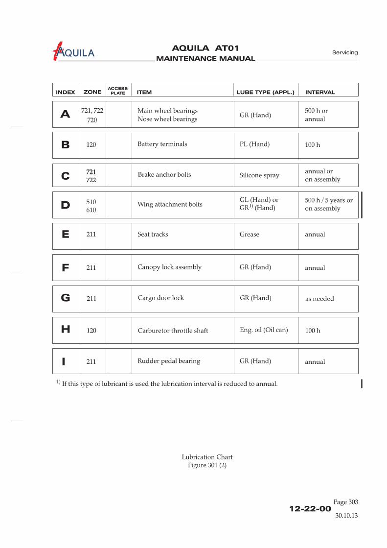
MAINTENANCE MANUAL
AQUILA AT01A
12-22-00Page 303
Lubrication ChartFigure 301 (2)
Servicing
Rudder pedal bearing GR (Hand) annualI 211
100 hH Carburetor throttle shaft Eng. oil (Oil can)120
as neededG Cargo door lock GR (Hand)211
Canopy lock assembly GR (Hand) annualF 211
annualE Seat tracks Grease211
500 h / 5 years oron assemblyD Wing attachment bolts
GL (Hand) orGR (Hand)1)
510610
Battery terminals PL (Hand) 100 hB 120
INDEX ZONE ITEM LUBE TYPE (APPL.) INTERVALACCESS
PLATE
30.10.13
Main wheel bearings
Nose wheel bearingsGR (Hand)
500 h or
annualA
720
722721,
Brake anchor bolts Silicone sprayannual oron assemblyC
721722721722
1) If this type of lubricant is used the lubrication interval is reduced to annual.

MAINTENANCE MANUAL
AQUILA AT01A
12-22-00Page 304
12.04.00
MAINTENANCE MANUAL
AQUILA AT01A
12-23-00Seite 701
AIRCRAFT EXTERIOR - CLEANING AND CARE
1.
A. The good flight performance of the aircraft is achieved due to the modern construction and theuse of specific materials. For efficient laminar flow, a clean surface is very important. Therefore,one should always keep the entire aircraft clean, but especially the leading edges of the wing.
B. Information on preventive and protection such as waxing specific surfaces, is alsogiven.
2.
A. Read and adhere to all manufacturer ’s instructions, warnings and cautions on cleaning/solventcompounds used.
B. Do not use silicone-based wax to polish the aircraft exterior.C. Do not clean the aircraft at ambient temperatures close to 0°C with water.D. Cover all lubricated parts during any cleaning process.E. During the application of cleaners (e.g. cleaning the engine), the other
surfaces must be covered carefully or otherwise protected.
3.
NEVER USE GASOLINE, BENZENE, ALCOHOL, ACETONE, CARBONTETRACHLORIDE, LACQUER THINNER OR GLASS CLEANER. THESEMATERIALS WILL SOFTEN THE PLASTIC AND MAY CAUSE IT TO CRAZE.
DO NOT USE CLEANERS WITH CHEMICAL SUPPLEMENTS WHOSE EFFECT ONTHE ACRYLIC SURFACE .
A. Cleaning Canopy(1) Park the aircraft in a hangar or in the shadows, avoid places with a lot of dust caused by wind
or vehicles.(2) To prevent scratches, wash the canopy carefully with plenty of mild soap and water, using
the palm of the hand to feel and dislodge dirt and mud. A soft cloth, chamois leather orsponge should be used.
(3) Rinse thoroughly and then dry with a clean moist chamois.(4) Remove oil and grease with a cloth moistened with isopropyl alcohol.
B. Care of the Canopy(1) As a protection from mechanical and chemical actions and to cover slight cuts in the canopy,
a polish or a wax for acrylic glass can be applied in accordance with the manufacturer'sspecifications.
Clean surfaces before applying polish or wax.
General
Safety Precautions
Cleaning and Care of the Canopy
CAUTION:
CAUTION:
NOTE:
measures,
containing solvents
IS UNKNOWN
Servicing
30.10.13
MAINTENANCE MANUAL
AQUILA AT01A
12-23-00Page 702
4.
A. Procedure for cleaning the exterior surface of(1) Park the aircraft in a hangar or in the shadows, avoid places with a lot of dust caused by wind
or vehicles.(2) Close the canopy, close access / inspection doors.
KEEP WATER AWAY FROM PITOT AND STATIC PORTS AND ELECTRICAL ANDAVIONIC EQUIPMENT.
(3) Flush away loose dirt with water.
DO NOT USE HARSH ABRASIVES, ALKALINE SOAPS OR DETERGENTS.
DO NOT USE CLEANING OR POLISHING AGENTS WHICH CONTAINSILICONE.
(4) Using a soft cleaning cloth or a sponge, wash with a mild, non-alkaline soap and watersolution.
(5) Rinse thoroughly with clean water and then dry with a soft cloth or chamois.
B. Care of the Aircraft Exterior Surface(1) To protect against corrosion, mechanical and chemical actions during operation, the exterior
surfaces can be waxed with a good polish or aircraft wax in accordance with themanufacturer ’s instructions.
Clean aircraft exterior before applying polish or wax.
(2) After using cleaners containing any solvent or chemical, the relevant surfaces should alwaysbe waxed.
(3) If the aircraft is operated in a coastal or other salt-water environment, it must be washed andwaxed more frequently.
(4) A heavier wax layer on the leading edges of the wings and tail and on the cowl nose andpropeller spinner will reduce abrasion in these areas.
5.
A. Lights can be polished with a good wax and/or a liquid polishing compound. Refresh polish andhand buff once or twice a month.
B. After using a polishing compound, the lights should be waxed.
UNDER NO CIRCUMSTANCES USE ANY PETROLEUM BASED PRODUCT TOCLEAN THE LIGHTS.
Cleaning and Care of the Aircraft Exterior Surfaces
CAUTION
CAUTION:
NOTE:
Cleaning and Care of Navigation / Position / Anti-Collision Lights
CAUTION:
the aircraft
Servicing
30.10.13

MAINTENANCE MANUAL
AQUILA AT01A
12-23-00Page 703
6.
A. Safety and Maintenance Precautions(1) The engine should be cleaned during every 100-hour inspection.(2) Handle chemical cleaners and solvents with caution. Always read the manufacturer ’s
instruction .(3) Cleaning should be performed in the open air or in a well ventilated hangar.(4) Suitable fire fighting and safety equipment should be available.(5) If compressed air is used to apply solvents or to dry components, the lowest practical
pressure level should be used.
B. Cleaning Procedures
DO NOT SMOKE OR EXPOSE A FLAME WITHIN 100 FEET OF THE CLEANINGAREA.
(1) Remove cowling (refer to 71-10-00).
DO NOT USE GASOLINE OR OTHER HIGHLY FLAMMABLE SUBSTANCES.
DO NOT ATTEMPT TO WASH AN ENGINE WHEN IT IS STILL HOT ORRUNNING.
DO NOT DIRECT CLEANING SOLVENTS OR WATER STREAMS AT OPENINGSOF THE ALTERNATOR OR THE STARTER.
(2) Carefully cover the openings of the alternator and the starter.(3) If the engine is contaminated with salt or corrosive chemicals, first flush engine compartment
with water.(4) Apply a suitable solvent or cleaning agent to the engine compartment in accordance with the
manufacturer ’s instructions.(5) Leave the solvent on the engine for approx. ten minutes.
CLEANING AGENTS SHOULD NEVER BE LEFT IN ENGINE COMPARTMENT.CLEANER OR SOLVENT RESIDUE MAY CAUSE DAMAGE TO COMPONENTSSUCH AS NEOPRENE SEALS AND SILICONE FIRE SLEEVES.
(6) Rinse thoroughly with clean warm water.(7) Allow engine to dry or dry it using compressed air.(8) Remove all protection .(9) Re-lubricate all control arms and moving parts as required.(10) Reinstall cowling (refer to 71-10-00).
DO NOT OPERATE THE ENGINE UNTIL EXCESS SOLVENT HASEVAPORATED OR OTHERWISE BEEN REMOVED.
BEFORE ROTATING THE PROPELLER BY HAND, ENSURE IGNITION SWITCHIS OFF, MIXTURE CONTROL IS IN THE IDLE CUT-OFF POSITION, AND THETHROTTLE IS CLOSED.
Cleaning the Engine
WARNING:
WARNING:
CAUTION:
CAUTION:
WARNING:
and follow them carefully
Engine
coverings
Servicing
30.10.13
MAINTENANCE MANUAL
AQUILA AT01A
12-23-00Page 704
CAUTION:
CAUTION:
DO NOT ROTATE THE PROPELLER CLOCKWISE.
IT IS IMPORTANT TO AVOID MOISTURE PENETRATING INTO THE WOODENCORE.
(11) Before starting the engine, rotate the propeller by hand no less than five completerevolutions.
7.
A. Clean propeller if necessary with any car wash solution or equivalent. This should be done atleast every 50 hours.Remove grease and dirt with a commercial detergent, which is suitable for polyurethane-lacquers.
Small scratches and nicks should be dealt with during routine maintenance applying a coating ofwater-resistant varnish, preferably Polyurethane.Replace damaged or missing PU strips on the propeller leading edge as soon as possible.
8.
A. The landing gear struts and wheel fairings should be washed with clear water or with a milddetergent and water.
B. After cleaning, the tires can be treated with standard tire protection.
Cleaning and Care of the Propeller
Cleaning the Landing Gear
Servicing
30.10.13

MAINTENANCE MANUAL
AQUILA AT01A
12-24-00Page 701
AIRCRAFT INTERIOR - CLEANING AND CARE
1.
A. This section provides the information required to clean the aircraft interior properly. Severalrecommended types of cleaning agents for different materials and the relevant cleaning and careprocedures are also described below.
2.
A. Interior panels such as sidewalls, door panels etc. may be cleaned using a mild detergent solution.Stubborn deposits may be removed using a suitable material cleaner in accordance withmanufacturer's instructions. If in doubt, apply a small amount of cleaner to a small unobtrusivepart and test it for reaction.
3.
A. The instrument panel, center pedestal and instruments/displays can be cleaned with a soft cottoncloth dampened with clean water. Ensure that the ALT / BAT switch is in OFF position. Switch onthe electrical systems and components of the aircraft only after the instrument panel has driedcompletely.
4.
A. The floor area, the area under the seats and the baggage compartment should be cleanedregularly with a vacuum.
B. The carpet is made of high-quality, dirt repellant material and usually requires only a minimum ofmaintenance. If it becomes soiled, a standard carpet cleaner can be used.
5.
A. Seat upholstery is made of a dirt repellant, hardwearing material. They should, however, becleaned regularly to keep them in good condition. The following recommendations should befollowed.
B. To remove dust and loose dirt from the seats, first clean with a vacuum.
For cleaning and care use a foam type detergent, such as is available for car seats. Follow themanufacturer ’s instructions.
General
Aircraft Interior Cleaning
Cleaning the Instrument Panel
Cleaning the Cabin Floor
Cleaning the Seats
CAUTION: DO NOT USE ANY CHEMICAL CLEANING AGENTS. CARE SHOULD BE TAKENTO AVOID SCRATCHING THE SURFACE OF DISPLAYS.
Servicing
30.10.13
MAINTENANCE MANUAL
AQUILA AT01A
12-24-00Page 702
30.10.13
Servicing
C. Blot up any liquid spilled promptly with an absorbent tissue or cloth. Press the blotting materialfirmly against the upholstery and hold for several seconds. Continue blotting until no more liquidis absorbed.
Scrape off sticky materials cautiously with a dull knife, then clean area as required.
Oil spots may be removed with household spot removers. Before using, read the instructions, testit on an obscure place on the seat and use it sparingly.
MAINTENANCE MANUAL
AQUILA AT01A
12-30-00Page 301
UNSCHEDULED SERVICING
1.
A. This section contains those instructions necessary to carry out unscheduled servicing, for exampleremoving ice and snow from a parked aircraft.
2.
DO NOT REMOVE SNOW AND ICE FROM SURFACES USING SHARP-EDGEDINSTRUMENTS.
NEVER USE DE-ICING FLUIDS TO REMOVE SNOW OR ICE DEPOSITS FROMAIRCRAFT SURFACES.HEATED DE-ICING FLUIDS CAN DAMAGE COMPOSITE STRUCTURES DUE TOEXTREME TEMPERATURE CHANGE. SOME DE-ICING FLUIDS MAY ALSODAMAGE THE ACRYLIC GLASS OF THE CANOPY.
A. After snowfall, the snow should be removed immediately from the surface of the aircraft toprevent it from refreezing on the surface and/or in slits and gaps after it has started to thaw.
B. Procedure(1) Remove loose snow from the wing surface with a broom, working outwards from the wing
root.
The areas between wings and ailerons and stabilizers and rudders must be treatedparticularly carefully.
: DO NOT DAMAGE THE ANTENNAE.
(2) Free canopy of snow.(3) Remove snow from cowling, fuselage and empennage.
C. In the case of ice, it defrost the aircraft in a heated hangar. Allow all aircraftsurfaces to completely dry prior to flight to prevent control surfaces from freezing.
General
Removing Snow and Ice
CAUTION:
NOTE:
CAUTION
is recommended to
Servicing
30.10.13

MAINTENANCE MANUAL
AQUILA AT01A
MAINTENANCE MANUAL
AQUILA AT01 A
CHAPTER 20
STANDARD PRACTICES - AIRFRAME

MAINTENANCE MANUAL
AQUILA AT01A
MAINTENANCE MANUAL
AQUILA AT01 A
Page 120 - TOC
TABLE OF CONTENTS
ChapterSection
Title Subject Page
STANDARD PRACTICES AIRFRAME - GENERAL.....................................20-00-00 1Introduction 20-00-00 1General Description 20-00-00 1
FASTENER IDENTIFICATION AND TORQUE DATA...............................20-10-00 1General 20-10-00 1Bolt Types 20-10-00 1Torques 20-10-00 2
CONVERSION DATA.......................................................................................20-11-00 1General 20-11-00 1Conversion Factors 20-11-00 1Equivalents for Standard Values 20-11-00 3
Standard Practices
09.10.18

MAINTENANCE MANUAL
AQUILA AT01A
MAINTENANCE MANUAL
AQUILA AT01 A
20-00-00
STANDARD PRACTICES AIRFRAME - GENERAL
1. Introduction
A. This chapter describes standard maintenance practices applicable to the entire airframe and related systems. Maintenance procedures which are unique to a specific system / component / part are described in the corresponding chapter.
B. As far as the maintenance of the AQUILA AT01 is concerned, there are no standard practices or relevant safety regulations, which require special knowledge other than that which is commonly expected for the maintenance of small aircraft. Therefore, this chapter should serve basically as a source for conversion data.
2. General Description
Below a brief description and intended purpose of each section of this chapter is given.
A. Section 20-00-00 - Standard Practices Airframe - General. This section provides a general overview of content and purpose of the chapter.
B. Section 20-10-00 - Conversion Data. This section provides various formulae for converting metric, Imperial and US measurements.
Standard Practices
09.10.18
Page 1

MAINTENANCE MANUAL
AQUILA AT01A

MAINTENANCE MANUAL
AQUILA AT01 A
FASTENER IDENTIFICATION AND TORQUE DATA
1. General
A. This section contains information concerning the identification of bolts, the correct usage of bolts and nuts and torque data.
CAUTION: OBSERVE STANDARD OR TORQUE VALUES RECOMMENDED BY THE MANUFACTURER AND MAKE SURE THE RECOMMENDED SAFETYING DEVICE FOR EVERY FASTENER IS APPLIED.
2. Bolt Types
A. The bolts used fulfill AN, MS, LN and DIN specifications. They can be identified by code marking(s) on the bolt heads. These markings generally denote the material of which the bolt is made, whether the bolt is a standard type or a special purpose bolt and sometimes include the manufacturer.
10.6
VEB manufacturer
property class
Bolt heads marked with “x” indicate
a non-corrosion resistant steel bolt.
Bolt heads marked with a dash indicate
a corrosion resistant steel bolt.
AN-BOLT
DIN-BOLT
surface
cadmium plated
zink coated
C
SPEC
5
C
AN standard
steel boltAN standard
steel boltAN standard
steel bolt
aluminun
alloy (2024)
bolt
special bolt
special bolt special bolt
NAC close
tolerance bolt
63-59131
AE
R
O
Typical Aircraft Bolt MarkingsFigure 1
20-10-00
Page 1
Standard Practices
09.10.18

MAINTENANCE MANUAL
AQUILA AT01A
3. Torques
NOTE: When a specific torque is not provided in the maintenance instructions contained in this maintenance manual, use the standard torque patterns shown in table 201 respectively the special torques in table 202.
A. A correct torque application is very important. Undertorque can result in unnecessary wear of nuts and bolts, as well as the parts they secure. Overtorque can cause failure of a bolt or nut due to the overstressing of the threaded areas. Uneven or additional loads that are applied to the assembly may result in wear or premature failure. To ensure that correct torque is applied, observe the following:
(1) Be sure that the torque applied is for the size of the bolt shank and not the wrench size.
(2) Calibrate the torque wrench at least once a year, or immediately after it has been misused or dropped, to ensure continued accuracy.
(3) Be sure that bolt and nut threads are clean and dry, unless otherwise specified by the manufacturer.
(4) Run the nut down to near contact with the washer or bearing surface and check the friction drag torque required to turn the nut. Whenever possible, apply the torque to the nut and not the bolt. This will reduce rotation of the bolt in the hole and reduce wear.
(5) Add the friction drag torque to the desired torque. This is referred to as "final torque," which should register on the indicator or setting for a snap-over type torque wrench.
(6) Apply a smooth even pull when applying torque pressure. If rattling or a jerking motion occurs during final torque, turn back the nut and retorque.
(7) Many uses of bolts in aircraft/engines require stretch checks prior to reuse. This requirement is due primarily to bolt stretching caused by overtorquing.
(8) When installing a castle nut, start alignment with the cotter pin hole at the minimum recommended torque plus friction drag torque.
(9) Do not exceed the maximum torque plus the friction drag. If the hole and nut castellation do not align, change washer or nut and try again. Exceeding the maximum recommended torque is not recommended.
(10) When torque is applied to bolt heads or cap screws, apply the recommended torque plus friction drag torque.
(11) If special adapters are used which will change the effective length of the torque wrench, the final torque indication or wrench setting must be adjusted accordingly. Determine the torque wrench indication or setting with adapter installed as shown in figure 2.
B. Table 201/202 shows the recommended torque to be used when the manufacturer does not supply a specific torque for maintenance procedures.
20-10-00Page 2
09.10.18
Standard Practices

MAINTENANCE MANUAL
AQUILA AT01 A
20-10-00
Page 3
09.10.18
Standard Practices
DIN and LN specifications
Thread sizeTorque values Torque values
Nm in.lbs
M4
M5
M6
M8
M10
M12
1.8
3.6
6.4
16
32
60
15.9
31.9
56.6
141.6
283.2
531.1
Table 201: Standard Torques
1)Table 202: Special Torques
Part Torque (Nm / in.lbs) Remarks
Bolts attaching lap belts to fuselage structure
Bolts attaching inertia reel retractor of shoulder harness to fuselage structure
Bolts attaching engine to ROTAX engine mount
Oil drain screw
Old spark plugs (P/N 297940)New spark plugs (P/N 297656)
Main gear spring leaf attachment bolts to inner bracket
Fuel drainer
4 / 35
8 / 71
40 / 354
25 / 221
20 / 17716 / 142
1) Refer to the appropriate ROTAX publications for engine parts.
45 / 398
- -tighten until the outer o-ring is snug against the mating surface
NOTE: Castellated nuts (DIN 935, 937) should be finger tightened.
Bolt attaching nose gear leg to support brace 28 / 248
refer to Rotax SI-912-027
Bolts attaching main gear wheel axle to landing gear leg 28 / 248

MAINTENANCE MANUAL
AQUILA AT01A
adapter drive centerline
adapter drive centerline
wrench drive centerline
wrench drive centerline
handgrip centerline
handgrip centerline
E
E
L
L
Y = apparent (indicated) torque
T = actual (desired) torque
L = effective length lever
E = effective length of extension
T = 14 Nm
L = 30 cm
Y = ?
E = 8 cm
T = 14 Nm
L = 30 cm
Y = ?
E = 8 cm
formula:
formula:
T x LL + E
=Y
T x L
L - E=Y
example:
example:
Torque Wrench with AdaptersFigure 2
1. Variant - The adapter increases the effective length of the torque wrench.
2. Variant - The adapter decreases the effective length of the torque wrench.
Y=
Y=
14 Nm x 0,3 m
14 Nm x 0,3 m
0,3 m + 0,08 m
0,3 m - 0,08 m
4,2 Nm
4,2 Nm
0,38
0,22
=11,05 Nm
=19,09 Nm
=
=
20-10-00Page 4
Standard Practices
09.10.18

MAINTENANCE MANUAL
AQUILA AT01 A
Page 1
CONVERSION DATA
1. General
A. This chapter is designed to assist the operator with the conversion of commonly used measuring units found in this manual from Imperial, US and metric measuring systems.
2. Conversion Factors
A. Subsequent conversion factors of units of measurement are given from the metric system to the US / Imperial systems and vice versa.
(1) Distance and length
Table 1 - Conversion of Distances and Lengths
(2) Square measures
Table 2 - Conversion of Square Measures
Standard Practices
20-11-00
Unit: m in. ft. yd
1 meter; m 1 39,37 3,281 1,09
1 inch; in. (") 0,0254 1 0,083 0,02
1 foot; ft. (') 0,3048 12 1 0,33
1 yard; yd. 0,914 36 3 1
statute mile = 1.609 kilometers, nautical mile=1.852 kilometers
Unit cm² m² Sq. in. Sq. ft. Sq. yd.
1 cm² 1 0,0001 0,155 0,00108 0,0001196
1 m² 10000 1 1550 10,764 1,196
1 sq. in. 6,452 0,00064516 1 0,006944 0,0007716
1 sq. ft. 929 0,092903 144 1 0,111111
1 sq. yd. 8361 0,836127 1296 9 1
09.10.18
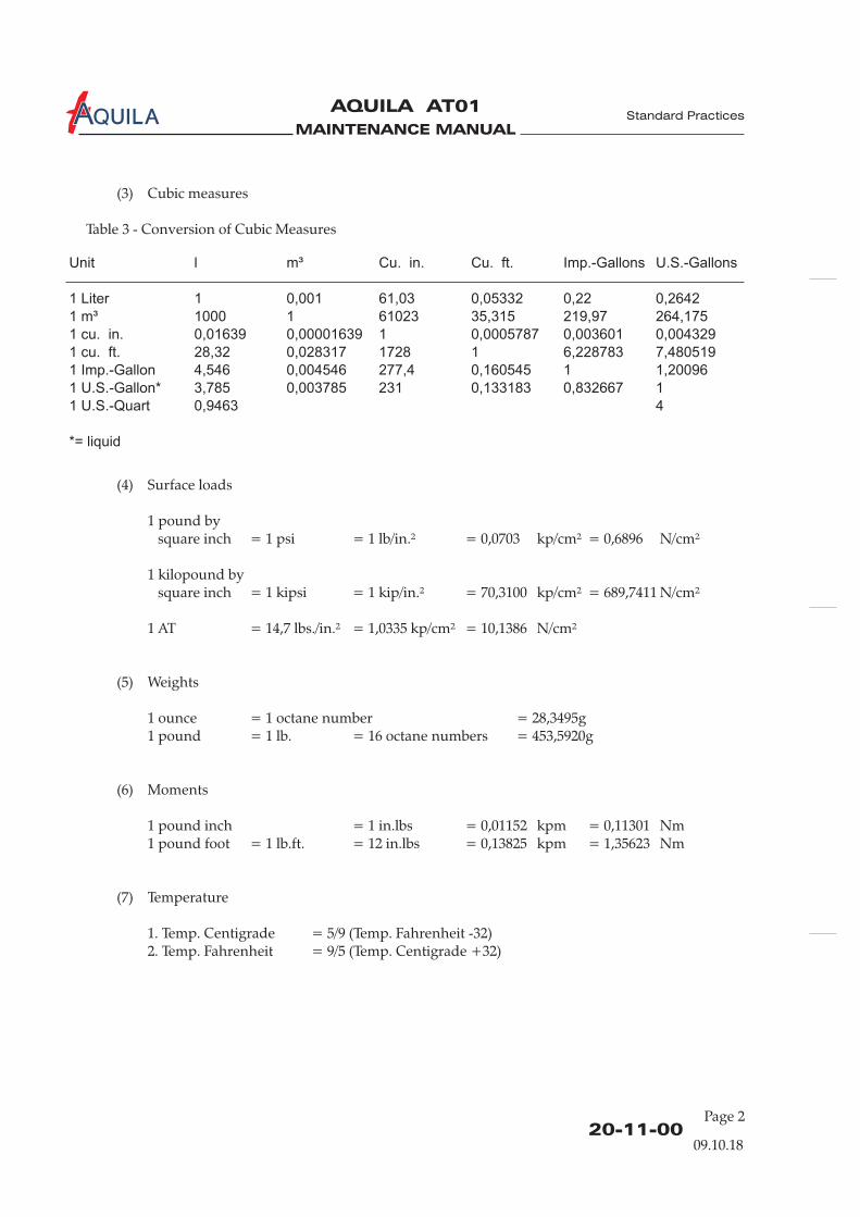
MAINTENANCE MANUAL
AQUILA AT01A
Page 2
Unit l m³ Cu. in. Cu. ft. Imp.-Gallons U.S.-Gallons
1 Liter 1 0,001 61,03 0,05332 0,22 0,2642
1 m³ 1000 1 61023 35,315 219,97 264,175
1 cu. in. 0,01639 0,00001639 1 0,0005787 0,003601 0,004329
1 cu. ft. 28,32 0,028317 1728 1 6,228783 7,480519
1 Imp.-Gallon 4,546 0,004546 277,4 0,160545 1 1,20096
1 U.S.-Gallon* 3,785 0,003785 231 0,133183 0,832667 1
1 U.S.-Quart 0,9463 4
*= liquid
(3) Cubic measures
Table 3 - Conversion of Cubic Measures
(4) Surface loads
1 pound bysquare inch = 1 psi = 1 lb/in.² = 0,0703 kp/cm² = 0,6896 N/cm²
1 kilopound bysquare inch = 1 kipsi = 1 kip/in.² = 70,3100 kp/cm² = 689,7411 N/cm²
1 AT = 14,7 lbs./in.² = 1,0335 kp/cm² = 10,1386 N/cm²
(5) Weights
1 ounce = 1 octane number = 28,3495g1 pound = 1 lb. = 16 octane numbers = 453,5920g
(6) Moments
1 pound inch = 1 in.lbs = 0,01152 kpm = 0,11301 Nm1 pound foot = 1 lb.ft. = 12 in.lbs = 0,13825 kpm = 1,35623 Nm
(7) Temperature
1. Temp. Centigrade = 5/9 (Temp. Fahrenheit -32)2. Temp. Fahrenheit = 9/5 (Temp. Centigrade +32)
Standard Practices
20-11-0009.10.18
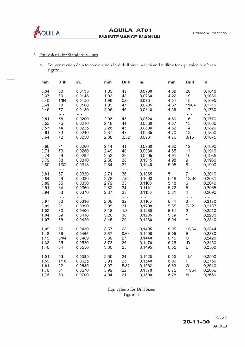
MAINTENANCE MANUAL
AQUILA AT01 A
Equivalents for Drill SizesFigure 1
Page 3
mm Drill in. mm in. mm in.
0,34 80 0,0135 1,85 49 0,0730 4,09 20 0,16100,37 79 0,0145 1,93 48 0,0760 4,22 19 0,16600,40 1/64 0,0156 1,98 5/64 0,0781 4,31 18 0,16950,41 78 0,0160 1,99 47 0,0785 4,37 11/64 0,17190,46 77 0,0180 2,06 46 0,0810 4,39 17 0,1730
- - - - - - - - 0,51 76 0,0200 2,08 45 0,0820 4,50 16 0,17700,53 75 0,0210 2,18 44 0,0860 4,57 15 0,18000,57 74 0,0225 2,26 43 0,0890 4,62 14 0,18200,61 73 0,0240 2,37 42 0,0935 4,70 13 0,18500,64 72 0,0250 2,38 3/32 0,0937 4,76 3/16 0,1875
- - - - - - - - 0,66 71 0,0260 2,44 41 0,0960 4,80 12 0,18900,71 70 0,0280 2,49 40 0,0980 4,85 11 0,19100,74 69 0,0292 2,53 39 0,0995 4,91 10 0,19350,79 68 0,0310 2,58 38 0,1015 4,98 9 0,19600,80 1/32 0,0313 2,64 37 0,1040 5,05 8 0,1990
- - - - - - - - - - - - 0,81 67 0,0320 2,71 36 0,1065 5,11 7 0,20100,84 66 0,0330 2,78 7/64 0,1093 5,16 13/64 0,20310,89 65 0,0350 2,79 35 0,1100 5,18 6 0,20400,91 64 0,0360 2,82 34 0,1110 5,22 5 0,20550,94 63 0,0370 2,87 33 0,1130 5,31 4 0,2090
- - - - - - - - - - - - 0,97 62 0,0380 2,95 32 0,1160 5,41 3 0,21300,99 61 0,0390 3,05 31 0,1200 5,55 7/32 0,21871,02 60 0,0400 3,18 1/8 0,1250 5,61 2 0,22101,04 59 0,0410 3,26 30 0,1285 5,79 1 0,22801,07 58 0,0420 3,45 29 0,1360 5,94 A 0,2340
- - - - - - - - - - - - 1,09 57 0,0430 3,57 28 0,1405 5,95 15/64 0,23441,18 56 0,0465 3,57 9/64 0,1406 6,05 B 0,23801,19 3/64 0,0469 3,66 27 0,1440 6,15 C 0,24201,32 55 0,0520 3,73 26 0,1470 6,25 D 0,24601,40 54 0,0550 3,80 25 0,1495 6,35 E 0,2500
- - - - - - - - - - - - 1,51 53 0,0595 3,86 24 0,1520 6,35 1/4 0,25001,59 1/16 0,0625 3,91 23 0,1540 6,99 F 0,27501,61 52 0,0635 3,97 5/32 0,1562 6,63 G 0,26101,70 51 0,0670 3,99 22 0,1570 6,75 17/64 0,26561,78 50 0,0700 4,04 21 0,1590 6,76 H 0,2660
Drill Drill
20-11-00
Standard Practices
09.10.18
3. Equivalents for Standard Values
A. For conversion data to convert standard drill sizes to inch and millimeter equivalents refer to figure 1.

MAINTENANCE MANUAL
AQUILA AT01A
MAINTENANCE MANUAL
AQUILA AT01
Aviation by Excellence GmbH
CHAPTER 21
VENTILATION AND HEATING

MAINTENANCE MANUAL
AQUILA AT01
Aviation by Excellence GmbH
MAINTENANCE MANUAL
AQUILA AT01
Aviation by Excellence GmbH
Page 0121 - TOC
08.07.02
TABLE OF CONTENTS
ChapterSection
VENTILATION AND HEATING - GENERAL..............................................21-00-00 1Introduction 21-00-00 1General Description 21-00-00 1
FRESH AIR DISTRIBUTION - DESCRIPTION ............................................21-20-00 1General 21-20-00 1Description and Operation 21-20-00 1
FRESH AIR DISTRIBUTION - MAINTENANCE PRACTICES ..................21-20-00 201General 21-20-00 201Eyeball Ventilators Removal/Installation 21-20-00 201Heat Relief Valve Removal/Installation 21-20-00 201
HEATING - MAINTENANCE PRACTICES ..................................................21-40-00 201General 21-40-00 201Heat Exchanger Removal/Installation 21-40-00 201
Title Subject Page
Ventilation and Heating

MAINTENANCE MANUAL
AQUILA AT01
Aviation by Excellence GmbH
MAINTENANCE MANUAL
AQUILA AT01
Aviation by Excellence GmbH
21-00-00
Page 01
08.07.02
AIR-CONDITIONING - GENERAL
1.
A. This chapter describes those systems and components, which furnish a means of heating andventilating the cabin.
2.
A. Fresh air for ventilation comes through air intakes and adjustable eyeball ventilators into thecabin.
B. For heating and defrosting ram air flows through a heat exchanger at the engine into the cabinand to the windshield. By means of a cabin heat valve the supply of heated air can be controlled.
Introduction
General Description
Ventilation and Heating

MAINTENANCE MANUAL
AQUILA AT01
Aviation by Excellence GmbH
MAINTENANCE MANUAL
AQUILA AT01
Aviation by Excellence GmbH
21-20-00
Page 01
08.07.02
FRESH AIR DISTRIBUTION - DESCRIPTION
1.
A. Fresh air with outside temperature for ventilation and heated fresh air for heating and windshielddefrosting can reach the cabin. The amount of fresh air can be regulated.
2.
A. Direct Fresh Air Supply(1) For the supply of fresh air into the cabin, two adjustable eyeball ventilators are provided.
These are located on the far left and right instrument panel.The ram air reaches through an NACA air intake on each outer side of the cabin and a duct tothe eyeball ventilator.
(2) The amount of fresh air can be adjusted by pivot tabs inside the eyeball ventilators.
B. Supply of Heated Fresh Air(1) Ram air flows through a shroud attached to the exhaust and a duct to the heat relief valve.
The heat relief valve is located on the firewall in the engine compartment. By means of it theamount of heated air can be regulated. It is actuated by a control „CABIN HEAT“, located onthe center pedestal below the instrument panel, via a control cable.Passing the firewall the hot air travels through the heated air distributor that is located in thecabin at the firewall. The heated air will be distributed to the area of the pilot and co-pilot'sfeet and to the canopy.
(2) If the „CABIN HEAT“ knob in the full forward position the heat relief valve is closed andheated air cannot enter the cabin. If the knob is pulled out, the heat relief valve is opened.Additional heat is available by pulling the knob out further. Maximum heat is available withthe cabin heat knob in the most rear position.For maximum effect, the fresh air nozzles should be closed.
General
Description and Operation
Ventilation and Heating

MAINTENANCE MANUAL
AQUILA AT01
Aviation by Excellence GmbH
MAINTENANCE MANUAL
AQUILA AT01
Aviation by Excellence GmbH
FRESH AIR DISTRIBUTION MAINTENANCE PRACTICES
1.
A. Maintenance is limited to removal and installation of the components.
2.
Removal of the left and right eyeball ventilator is typical.
A. Remove Eyeball Ventilator(1) Disconnect flexible air duct from eyeball ventilator.(2) Remove screws securing eyeball ventilator to the instrument panel. Remove eyeball
ventilator.
B. Install Eyeball Ventilator(1) Position eyeball ventilator in the instrument panel and secure with 4 screws.
3.
A. Remove Heat Relief Valve(1) Remove upper cowling (Refer to 71-10-00).(2) Remove clamp securing flexible air duct to heat relief valve. Remove flexible air duct.(3) Disconnect control cable from heat relief valve control arm.(4) Remove bolts securing heat relief valve to fire wall.(5) Remove heat relief valve from aircraft.
B. Install Heat Relief Valve(1) Attach heat relief valve to fire wall using bolts.(2) Close valve plate, leave in this position.(3) In the cabin move heat control "HEATING" full forward.(4) Reconnect control cable to the control arm of the heat relief valve.(5) Install flexible air duct to heat relief valve and secure with clamps.(6) Install upper cowling (Refer to 71-10-00).
General
Eyeball Ventilators Removal/Installation
NOTE:
Heat Relief Valve Removal/Installation
21-20-00
Page 201
08.07.02
Ventilation and Heating

MAINTENANCE MANUAL
AQUILA AT01
Aviation by Excellence GmbH
MAINTENANCE MANUAL
AQUILA AT01
Aviation by Excellence GmbH
HEATING - MAINTENANCE PRACTICES
1.
A. Fresh air is heated up by passing the heat exchanger at the engine.The heat exchanger consists of a shroud, which is set around the exhaust muffler. Flexible
ducts are connected to the heat exchanger for air entering and air exiting. The ram air enters theengine compartment through a inlet located on the lower engine cowling and is then directed viaducting to the heat exchange section of the exhaust muffler. As air passes around the exhaustmuffler, it picks up heat from engine exhaust.
B. Maintenance is limited to inspection and removal / installation of the heat exchanger.
2.
A. Remove Heat Exchanger(1) Remove engine cowling (Refer to 71-10-00).(2) Remove clamps securing flexible ducts to heat exchanger. Disconnect ducts from heat
exchanger.(3) Remove clamps securing heat exchanger to exhaust muffler.(4) Carefully remove exchanger from around muffler.
B. Installation heater radiators(1) Wrap heat exchanger around muffler and secure with clamps.(2) Reconnect flexible ducts to heat exchanger and secure using clamps.(3) Install cowling (Refer to 71-10-00).
General
Heat Exchanger Removal/Installation
21-40-00
Page 201
08.07.02
Ventilation and Heating

MAINTENANCE MANUAL
AQUILA AT01
Aviation by Excellence GmbH

MAINTENANCE MANUAL
AQUILA AT01A
CHAPTER 23
COMMUNICATIONS

MAINTENANCE MANUAL
AQUILA AT01A
MAINTENANCE MANUAL
AQUILA AT01A
Page 123 - TOC
Communications
30.10.13
TABLE OF CONTENTS
ChapterSection
COMMUNICATIONS - GENERAL ....................................................23-00-00 1Introduction 23-00-00 1General Description 23-00-00 1
SPEECH COMMUNICATION - DESCRIPTION .............................23-10-00 1 Garmin 430/530/650Introduction 23-10-00 1Description and Operation 23-10-00 1
SPEECH COMMUNICATION - MAINTENANCE..........................23-10-00 201General 23-10-00 201
COM Antenna Removal/Installation 23-10-00 201
SPEECH COMMUNICATION - DESCRIPTION .............................23-10-00 1 SL30/SL40Introduction 23-10-00 1Description and Operation 23-10-00 1
SPEECH COMMUNICATION - MAINTENANCE..........................23-10-00 201General 23-10-00 201NAV/COM Transceiver Removal/Installation 23-10-00 201COM Antenna Removal/Installation 23-10-00 201
AUDIO INTEGRATING - MAINTENANCE .....................................23-50-00 201 PM 501 / PM 500EXGeneral 23-50-00 201Audio Control Unit Removal/Installation 23-50-00 202
AUDIO INTEGRATING - MAINTENANCE .....................................23-50-00 201 Garmin 340/350General 23-50-00 201Audio Control Unit Removal/Installation 23-50-00 201
Title Subject Page Effectivity
SPEECH COMMUNICATION - DESCRIPTION .............................23-10-00 1 Bendix/King KX 125Introduction 23-10-00 1 Bendix/King KX 125Description and Operation 23-10-00 1 Bendix/King KX 125
SPEECH COMMUNICATION - MAINTENANCE..........................23-10-00 201 Bendix/King KX 125General 23-10-00 201 Bendix/King KX 125NAV/COM Transceiver Removal/Installation 23-10-00 201 Bendix/King KX 125COM Antenna Removal/Installation 23-10-00 201 Bendix/King KX 125Inspection/Check 23-10-00 202 Bendix/King KX 125
Garmin 430/530/650Garmin 430/530/650
Garmin 430/530/650Garmin 430/530/650
NAV/COM Transceiver Removal/Installation 23-10-00 201 Garmin 430/530/650Garmin 430/530/650
Inspection/Check 23-10-00 202 Garmin 430/530/650
GarminGarmin SL30/SL40Garmin SL30/SL40
Garmin SL30/SL40Garmin SL30/SL40Garmin SL30/SL40Garmin SL30/SL40
Inspection/Check 23-10-00 202 Garmin SL30/SL40
PM 501 / PM 500EXPM 501 / PM 500EX
Garmin 340/350Garmin 340/350

MAINTENANCE MANUAL
AQUILA AT01A

MAINTENANCE MANUAL
AQUILA AT01A
23-00-00
Communications
30.10.13
COMMUNICATIONS - GENERAL
1.
A. This chapter describes and provides maintenance instructions for components and systems usedto communicate between occupants of the aircraft and between the aircraft and other aircraft orground stations.
B. Technical publications available from the manufacturer or vendor of the various components andsystems, which are not covered in this manual, must be utilized as necessary for the maintenanceof those components and systems.
2.
A. The equipment includes a VHF COM transceiver and an intercom system.
(1) The COM is for radio communication with ground control or other aircraft.(2) Crew member headsets are connected to the COM radio and controlled by the internal or
external intercom system. It facilitates external and internal communication of the crewmembers.
14 VDC power for the transceiver is controlled by the AVIONICS switch. The radio and theintercom system are protected by the circuit breakers labeled “COM”, “NAV” and “Audio” /”Intercom”.
B. The following NAV/COM equipment and audio panel combinations may be installed:
(1)
(3)
Garmin GNS 430(W), GNS 530(W) or GTN 650 VHF communications transceiver /VOR/ILS/GS receiver / GPS receiver in combination with a Garmin GMA 340 or GMA 350audio panel.
All devices listed are mounted in the center of the instrument panel in the avionics column.
Introduction
General Description
Garmin SL40 VHF communications transceiver with an integrated intercom.(2) Bendix/King KX 125 VHF communications transceiver / VOR/ILS/GS receiver with an
integrated intercom. This NAV/COM equipment may be combined with a Bendix/KingKI 208 CDI.Garmin SL30 VHF communications transceiver / VOR/ILS/GS receiver with an integratedintercom. This NAV/COM equipment may be combined with a Garmin GI 106A CDI.
(4)
Page 1

MAINTENANCE MANUAL
AQUILA AT01A
MAINTENANCE MANUAL
AQUILA AT01A
SPEECH COMMUNICATION - DESCRIPTION
1.
A.
2.
A.
Introduction
Description and Operation
he left frontside of the KX 125 is used for controlling and displaying purposes. An active anda standby frequency can be adjusted. The left COM frequency window displays the activeCOM frequency and below the standby COM frequency. To exchange between the twofrequencies, push the frequency transfer button on the left window side. COM frequencyselection knobs are located below the COM frequency window. The larger knob adjusts thefrequency in the MHz range. The smaller knob adjusts the frequency in the KHz range, in50Khz increments. If the knob is pulled, one can also adjust the frequency in 25 kHz steps.
The VHF COM antenna is mounted to the bottom of the fuselage, behind the baggagecompartment.S/N AT01-165 and higher:The VHF COM antenna is
This section covers the portion of the system which utilizes voice communication from air-to-airor air-to-ground installations. It includes the VHF speech communications portion of theNAV/COM radio Bendix/King KX 125.The KX 125 combines a VHF communication transceiver and a VHF navigation receiver whichincludes a VOR, localizer and glideslope receiver as well as a built-in course deviation indicator.
Fig. 1 shows the KX 125 front view.
B. KX 125 VHF Speech Communication Portion – Description(1) T
(2) Up to S/N AT01-164:
laminated on the inner shell of the vertical stabilizer. The VHFNAV antenna is laminated on the inner shell of the horizontal stabilizer. Both antennascannot be removed or replaced. A second VHF COM antenna may be installed on the bottomof the fuselage when the aircraft is equipped with a second NAV/COM transceiver.
23-10-0030.10.13
EFFECTIVITY
Aircraft equipped with Bendix/King KX 125Page 1
Communications
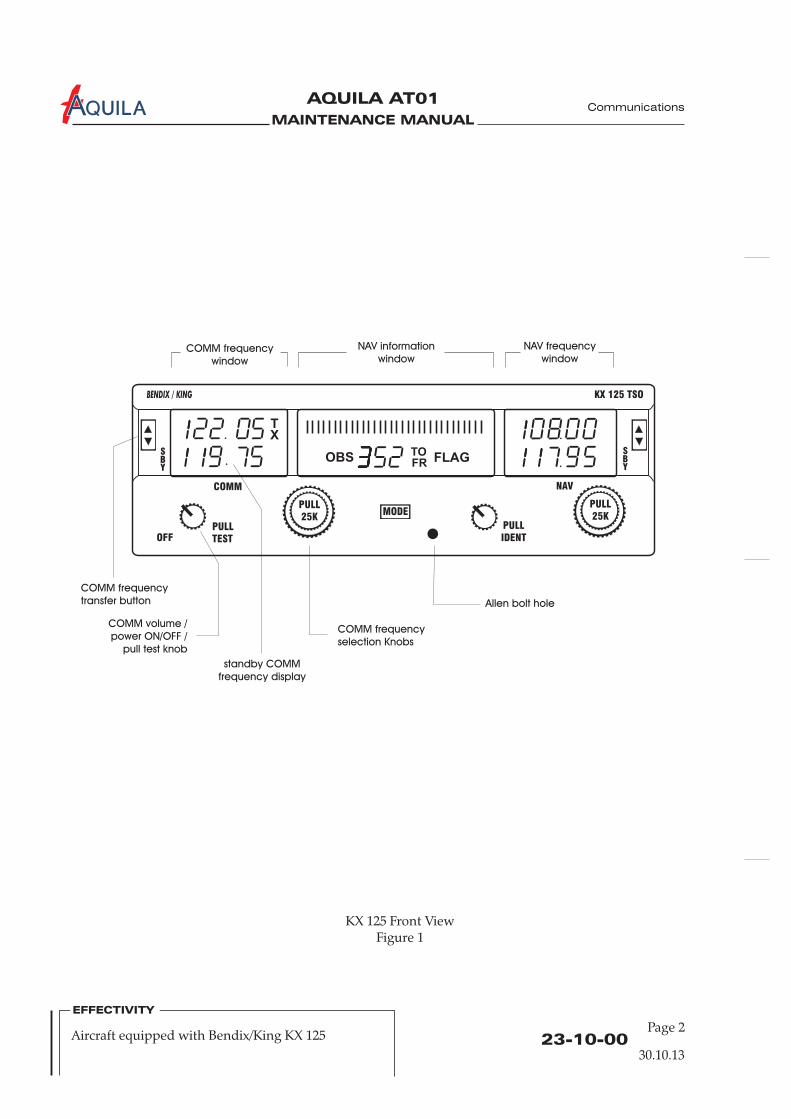
MAINTENANCE MANUAL
AQUILA AT01A
KX 125 Front ViewFigure 1
Allen bolt hole
COMM frequency
window
NAV information
window
NAV frequency
window
COMM frequency
transfer button
standby COMM
frequency display
COMM volume /
power ON/OFF /
pull test knob
COMM frequency
selection Knobs
OBS
TX
TOFR
FLAG
PULL
25K
PULL
25K
PULL
TEST
PULL
IDENTOFF
COMM NAV
KX 125 TSO
MODE
BENDIX / KING
SBY
SBY
23-10-00Page 2
30.10.13
EFFECTIVITY
Aircraft equipped with Bendix/King KX 125
Communications
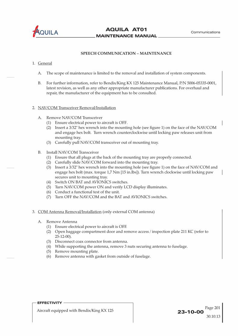
MAINTENANCE MANUAL
AQUILA AT01A Communications
SPEECH COMMUNICATION – MAINTENANCE
1.
A. The scope of maintenance is limited to the removal and installation of system components.
B. For further information, refer to Bendix/King KX 125 Maintenance Manual, P/N 5006-05335-0001,latest revision, as well as any other appropriate manufacturer publications. For overhaul andrepair, the manufacturer of the equipment has to be consulted.
2.
A. Remove NAV/COM Transceiver(1) Ensure electrical power to aircraft is OFF.(2) Insert a 3/32" hex wrench into the mounting hole (see figure 1) o
and engage hex bolt. Turn wrench counterclockwise until locking paw releases unit frommounting tray.
(3) Carefully pull out of mounting tray.
B. Install NAV/COM Transceiver(1) Ensure that all plugs at the back of the mounting tray are properly connected.(2) Carefully slide NAV/COM forward into the mounting tray.(3) Insert a 3/32" hex wrench into the mounting hole (see figure 1) o and
engage hex bolt (max. torque 1,7 Nm [15 in.lbs]). Turn wrench clockwise until locking pawsecures unit to mounting tray.
(4) Switch ON BAT and AVIONICS switches.(5) Turn NAV/COM power ON and verify LCD display illuminates.(6) Conduct a functional test of the unit.(7) Turn OFF the NAV/COM and the BAT and AVIONICS switches.
General
NAV/COM Transceiver Removal/Installation
n the face of the NAV/COM
n the face of
(only external COM antenna)
A. Remove Antenna(1) Ensure electrical power to aircraft is OFF.(2) Open baggage compartment door and remove access / inspection plate 211 KC (refer to
25-12-00).(3) Disconnect coax connector from antenna.(4) While supporting the antenna, remove 3 nuts securing antenna to fuselage.(5) Remove mounting plate.(6) Remove antenna with gasket from outside of fuselage.
Antenna Removal/Installation
NAV/COM transceiver
NAV/COM
3. COM
23-10-00Page 201
30.10.13
EFFECTIVITY
Aircraft equipped with Bendix/King KX 125
MAINTENANCE MANUAL
AQUILA AT01A
B. Install Antenna
(1) Position antenna with gasket to fuselage.(2) Install mounting plate from inside the fuselage.(3) Secure antenna base to fuselage using screws, nuts and washers. Reinstall ground wire.(4) Check bonding of the re-installed connection. Resistance must not exceed 3 mΩ.(5) Reconnect coaxial connector and secure.(6) Install access / inspection plate 211 KC (refer to 25-12-00).
4.
A. A flight test is recommended after the KX 125 unit installation to ensure proper function. Checkthe communications transceiver for satisfactory operating range in several altitudes. Verify that theunit is communicating properly with in-panel instruments. Compare on-screen indications withthe information depicted on the CDI.
Inspection/Check
CAUTION: WIRING MUST NOT INTERFERE WITH THE OPERATION OF MOVEABLEAIRCRAFT COMPONENTS.
23-10-00Page 202
EFFECTIVITY
Aircraft equipped with Bendix/King KX 125
30.10.13
Communications
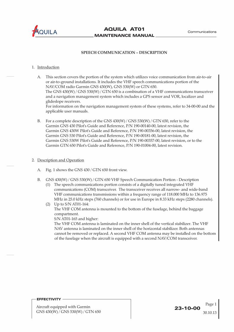
MAINTENANCE MANUAL
AQUILA AT01A
23-10-0030.10.13
EFFECTIVITY
SPEECH COMMUNICATION – DESCRIPTION
1.
A. This section covers the portion of the system which utilizes voice communication from air-to-airor air-to-ground installations. It includes the VHF speech communications portion of theNAV/COM radio Garmin GNS 430(W), GNS 530(W) or GTN 650.The GNS 430(W) / GNS 530(W) / GTN 650 is a combination of a VHF communications transceiverand a navigation management system which includes a GPS sensor and VOR, localizer andglideslope receivers.For information on the navigation management system of these systems, refer to 34-00-00 and theapplicable user manuals.
B. For a complete description of the GNS 430(W) / GNS 530(W) / GTN 650, refer to theGarmin GNS 430 Pilot's Guide and Reference, P/N 190-00140-00, latest revision, the
Garmin GTN 650 Pilot's Guide and Reference, P/N 190-01004-00, latest revision.
2.
A. Fig. 1 shows the GNS 430 / GTN 650 front view.
B. GNS 430(W) / GNS 530(W) / GTN 650 VHF Speech Communication Portion - Description(1) The speech communications portion consists of a digitally tuned integrated VHF
communications (COM) transceiver. The transceiver receives all narrow- and wide-bandVHF communications transmissions within a frequency range of 118.000 MHz to 136.975MHz in 25.0 kHz steps (760 channels) or for use in Europe in 8.33 kHz steps (2280 channels).
(2) Up to S/N AT01-164:The VHF COM antenna is mounted to the bottom of the fuselage, behind the baggagecompartment.S/N AT01-165 and higher:
A second VHF COM antenna may be installed on the bottomof the fuselage when the aircraft is equipped with a second NAV/COM transceiver.
Introduction
Description and Operation
Garmin GNS 430W Pilot's Guide and Reference, P/N 190-00356-00, latest revision, theGarmin GNS 530 Pilot's Guide and Reference, P/N 190-00181-00, latest revision, theGarmin GNS 530W Pilot's Guide and Reference, P/N 190-00357-00, latest revision, or to the
laminated on the inner shell of the vertical stabilizer. The VHFNAV antenna is laminated on the inner shell of the horizontal stabilizer. Both antennascannot be removed or replaced.
The VHF COM antenna is
Aircraft equipped with GarminGNS 430(W) / GNS 530(W) / GTN 650
Page 1
Communications
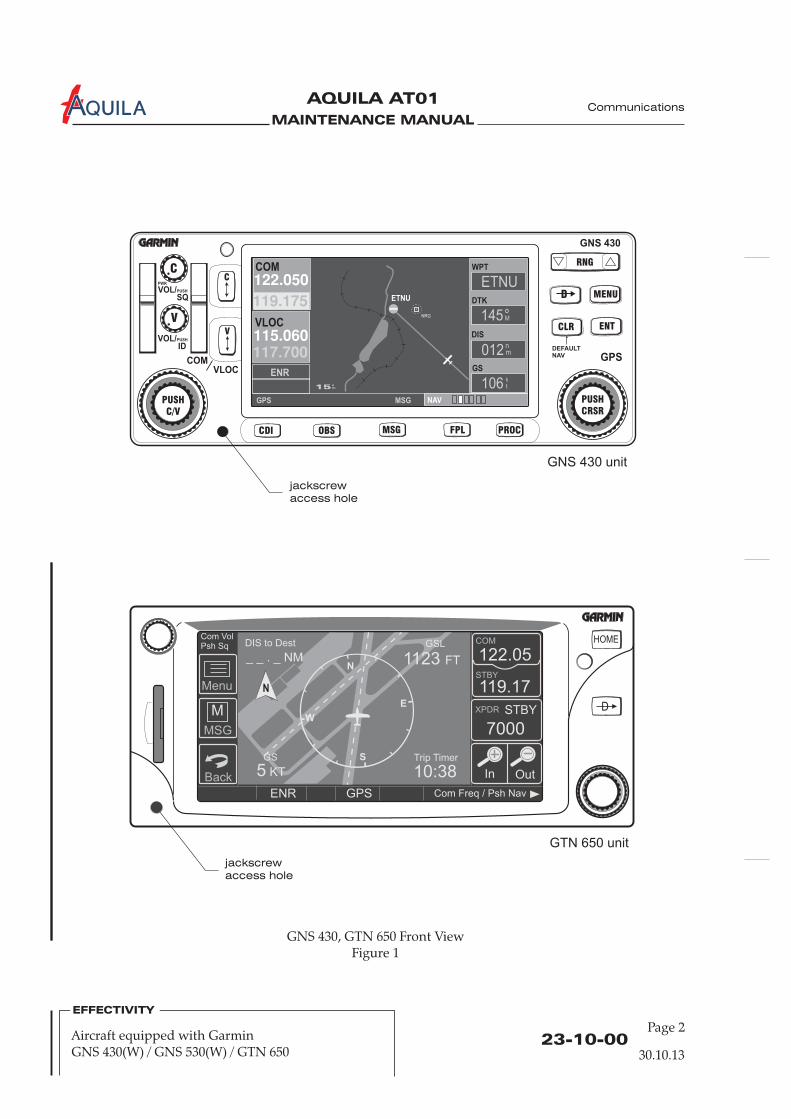
MAINTENANCE MANUAL
AQUILA AT01A
23-10-00Page 2
30.10.13
GNS 430, GTN 650 Front ViewFigure 1
EFFECTIVITY
Aircraft equipped with GarminGNS 430(W) / GNS 530(W) / GTN 650
jackscrew
access hole
jackscrew
access hole
Communications
WPT
DTK
DIS
GS
GNS 430 unit
GTN 650 unit
MAINTENANCE MANUAL
AQUILA AT01A
23-10-00Page 201
30.10.13
EFFECTIVITY
Aircraft equipped with GarminGNS 430(W) / GNS 530(W) / GTN 650
SPEECH COMMUNICATION – MAINTENANCE
1.
A. The scope of maintenance is limited to the removal and installation of the components. Forremoval and installation procedures for the GNS 430(W) / GNS 530(W) / GTN 650 GPS antenna,refer to 34-40-00.
B. For additionalefer to the
Garmin GTN 6XX/7XX AML STC Installation Manual, P/N 190-01007-A3, latest revision.
General
maintenance information on the GNS 430(W) / GNS 530(W) / GTN 650 system,rGarmin 400 Series Installation Manual, P/N 190-00140-02, latest revision, theGarmin 400W Series Installation Manual, P/N 190-00356-02, latest revision, theGarmin 500 Series Installation Manual, P/N 190-00181-02, latest revision, theGarmin 500W Series Installation Manual, P/N 190-00357-02, latest revision, or to the
(only external COM antenna)
A. Remove Antenna(1) Ensure electrical power to aircraft is OFF.(2) Open baggage compartment door and remove access / inspection plate 211 KC (refer to
25-12-00).(3) Disconnect coax connector from antenna.(4) While supporting the antenna, remove 3 nuts securing antenna to fuselage.(5) Remove mounting plate.(6) Remove antenna with gasket from outside of fuselage.
Antenna Removal/Installation
2.
A. Remove NAV/COM(1) Ensure electrical power to aircraft is OFF.(2) Insert a 3/32" hex wrench into the mounting hole (see figure 1) on the face of the NAV/COM
and engage hex bolt. Turn wrench counterclockwise until locking paw releases unit frommounting tray.
(3) Carefully pull NAV/COM out of mounting tray.
B. Install NAV/COM(1) Ensure that all plugs at the back of the mounting tray are properly connected.(2) Carefully slide NAV/COM forward into the mounting tray.(3) Insert a 3/32" hex wrench into the mounting hole (see figure 1) on the face of NAV/COM and
engage hex bolt (max. torque 1,7 Nm [15 in.lbs]). Turn wrench clockwise until locking pawsecures unit to mounting tray.
(4) Switch ON BAT and AVIONICS switches.(5) Turn NAV/COM power ON and verify LCD display illuminates.(6) Conduct a functional test of the unit.(7) Turn OFF the NAV/COM and the BAT and AVIONICS switches.
3.
NAV/COM Transceiver Removal/Installation
COM
transceiver
Communications

MAINTENANCE MANUAL
AQUILA AT01A Communications
23-10-00Page 202
30.10.13
Aircraft equipped with GarminGNS 430(W) / GNS 530(W) / GTN 650
EFFECTIVITY
B. Install Antenna
(1) Position antenna with gasket to fuselage.(2) Install mounting plate from inside the fuselage.(3) Secure antenna base to fuselage using screws, nuts and washers. Reinstall ground wire.(4) Check bonding of the re-installed connection. Resistance must not exceed 3 m .(5) Reconnect coaxial connector and secure.(6) Install access / inspection plate 211 KC (refer to 25-12-00).
4.
A. A flight test is recommended after the GNS 430(W) / GNS 530(W) / GTN 650 unit installation toensure proper function. Check the communications transceiver for satisfactory operating range inseveral altitudes. Verify that the unit is communicating properly with in-panel instruments.Compare on-screen indications with the information depicted on the CDI.
Ω
Inspection/Check
CAUTION: WIRING MUST NOT INTERFERE WITH THE OPERATION OF MOVEABLEAIRCRAFT COMPONENTS.
MAINTENANCE MANUAL
AQUILA AT01A
SPEECH COMMUNICATION - DESCRIPTION
1.
A. This section covers the portion of the system which utilizes voice communication from air-to-airor air-to-ground installations. It includes the VHF speech communications portion of theNAV/COM radio Garmin SL30 or SL40.The SL30 combines a VHF communication transceiver and a VHF navigation receiver whichincludes a VOR, localizer and glideslope receiver as well as a built-in course deviation indicator.For information on the navigation portion of the SL30, refer to the SL30 NAV/COM Pilot's Guide,
, latest revision.The SL40 is a derivative of the SL30 having only its communication functions. The SL30 and SL40contain an independent, voice-activated intercom unit with a separate power supply.
B. For a complete description of the SL30 / SL40, refer to the Garmin SL30 Pilot's Guide,P/N 560-0403-01 or to the SL40 Pilot’s Guide, P/N 560-0954-02, latest revision.
2.
A. Fig. 1 shows the SL30 / SL40 front view.
B. SL30 VHF Speech Communication Portion / SL40 – Description(1) The knob on the left side of the SL30 / SL40 controls power on/off, volume and squelch test.
To turn the power on, the knob must be rotated clockwise past the detent. Once thetransceiver is turned on, clockwise rotation of the knob increases the speaker and headphonevolume level, counter-clockwise rotation reduces the volume level. Frequency tuning isaccomplished by rotating the large (for MHz settings) and small (for kHz settings) knobs toselect the desired standby frequency. The active frequency is displayed on the left side of thedisplay, the standby frequency is indicated on the right side adjacent to the active frequency.To switch between the frequencies, the frequency flip/flop button must be pressed. Aphotocell located on the upper left side of the display automatically adjusts the brightness ofthe display to the ambient light conditions.
(2) Up to S/N AT01-164:
Introduction
Description and Operation
P/N 560-0403-01
laminated on the inner shell of the vertical stabilizer. The VHFNAV antenna is laminated on the inner shell of the horizontal stabilizer. Both antennascannot be removed or replaced. A second VHF COM antenna may be installed on the bottomof the fuselage when the aircraft is equipped with a second NAV/COM transceiver.
The VHF COM antenna is mounted to the bottom of the fuselage, behind the baggagecompartment.S/N AT01-165 and higher:The VHF COM antenna is
23-10-0030.10.13
EFFECTIVITY
Aircraft equipped with Garmin SL30 / SL40
Communications
Page 1
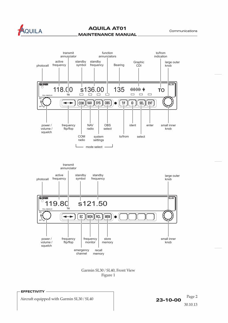
MAINTENANCE MANUAL
AQUILA AT01A
23-10-00Page 2
30.10.13
EFFECTIVITY
Aircraft equipped with Garmin SL30 / SL40
Communications
Garmin SL30 / SL40, Front ViewFigure 1
TX
118.00 s136.00 135 oT
SL30
PULL SQUELCH
VOL
OFF
COM NAV SYS OBS T/F ID SEL ENT
frequencyflip/flop
NAVradio
ident
photocell
activefrequency
to/fromindication
GraphicCDIBearing
transmitannunciator
functionannunciators
power /volume /squelch
COMradio
to/from
OBSselect
enter small innerknob
large outerknob
systemsettings
select
mode select
standbyfrequency
standbysymbol
TX
119.80 s121.50SL40
PULL SQUELCH
VOL
OFF
EC MON RCL MEM
frequencyflip/flop
frequencymonitor
photocell
activefrequency
standbyfrequency
standbysymbol
transmitannunciator
power /volume /squelch
emergencychannel
storememory
small innerknob
large outerknob
recallmemory
MAINTENANCE MANUAL
AQUILA AT01A
SPEECH COMMUNICATION – MAINTENANCE
1.
A. The scope of maintenance is limited to the removal and installation of system components.
B. For further information, refer to Garmin SL30 NAV/COM Installation Manual, P/N 560-0404-03,latest revision, or Garmin SL40 VHF COM Installation Manual, P/N 560-0956-03, latest revision, aswell as any other appropriate manufacturer publications. For overhaul and repair, themanufacturer of the equipment has to be consulted.
2.
A. Remove NAV/COM Transceiver(1) Ensure electrical power to aircraft is OFF.(2) Insert a 3/32" hex wrench into the mounting hole (see figure 1) o
and engage hex bolt. Turn wrench counterclockwise until locking paw releases unit frommounting tray.
(3) Carefully pull out of mounting tray.
B. Install NAV/COM Transceiver(1) Ensure that all plugs at the back of the mounting tray are properly connected.(2) Carefully slide NAV/COM forward into the mounting tray.(3) Insert a 3/32" hex wrench into the mounting hole (see figure 1) o and
engage hex bolt (max. torque 1,7 Nm [15 in.lbs]). Turn wrench clockwise until locking pawsecures unit to mounting tray.
(4) Switch ON BAT and AVIONICS switches.(5) Turn NAV/COM power ON and verify LCD display illuminates.(6) Conduct a functional test of the unit.(7) Turn OFF the NAV/COM and the BAT and AVIONICS switches.
General
NAV/COM Transceiver Removal/Installation
n the face of the NAV/COM
n the face of NAV/COM
(only external COM antenna)
A. Remove Antenna(1) Ensure electrical power to aircraft is OFF.(2) Open baggage compartment door and remove access / inspection plate 211 KC (refer to
25-12-00).(3) Disconnect coax connector from antenna.(4) While supporting the antenna, remove 3 nuts securing antenna to fuselage.(5) Remove mounting plate.(6) Remove antenna with gasket from outside of fuselage.
Antenna Removal/Installation
NAV/COM transceiver
3. COM
23-10-00Page 201
30.10.13
EFFECTIVITY
Aircraft equipped with Garmin SL30 / SL40
Communications
MAINTENANCE MANUAL
AQUILA AT01A
B. Install Antenna
(1) Position antenna with gasket to fuselage.(2) Install mounting plate from inside the fuselage.(3) Secure antenna base to fuselage using screws, nuts and washers. Reinstall ground wire.(4) Check bonding of the re-installed connection. Resistance must not exceed 3 mΩ.(5) Reconnect coaxial connector and secure.(6) Install access / inspection plate 211 KC (refer to 25-12-00).
4.
A. A flight test is recommended after the SL30 / SL40 unit installation to ensure proper function.Check the communications transceiver for satisfactory operating range in several altitudes. Verifythat the unit is communicating properly with in-panel instruments. Compare on-screenindications with the information depicted on the CDI (SL30 only).
Inspection/Check
CAUTION: WIRING MUST NOT INTERFERE WITH THE OPERATION OF MOVEABLEAIRCRAFT COMPONENTS.
23-10-00Page 202
EFFECTIVITY
Aircraft equipped with Garmin SL30 / SL40
Communications
30.10.13
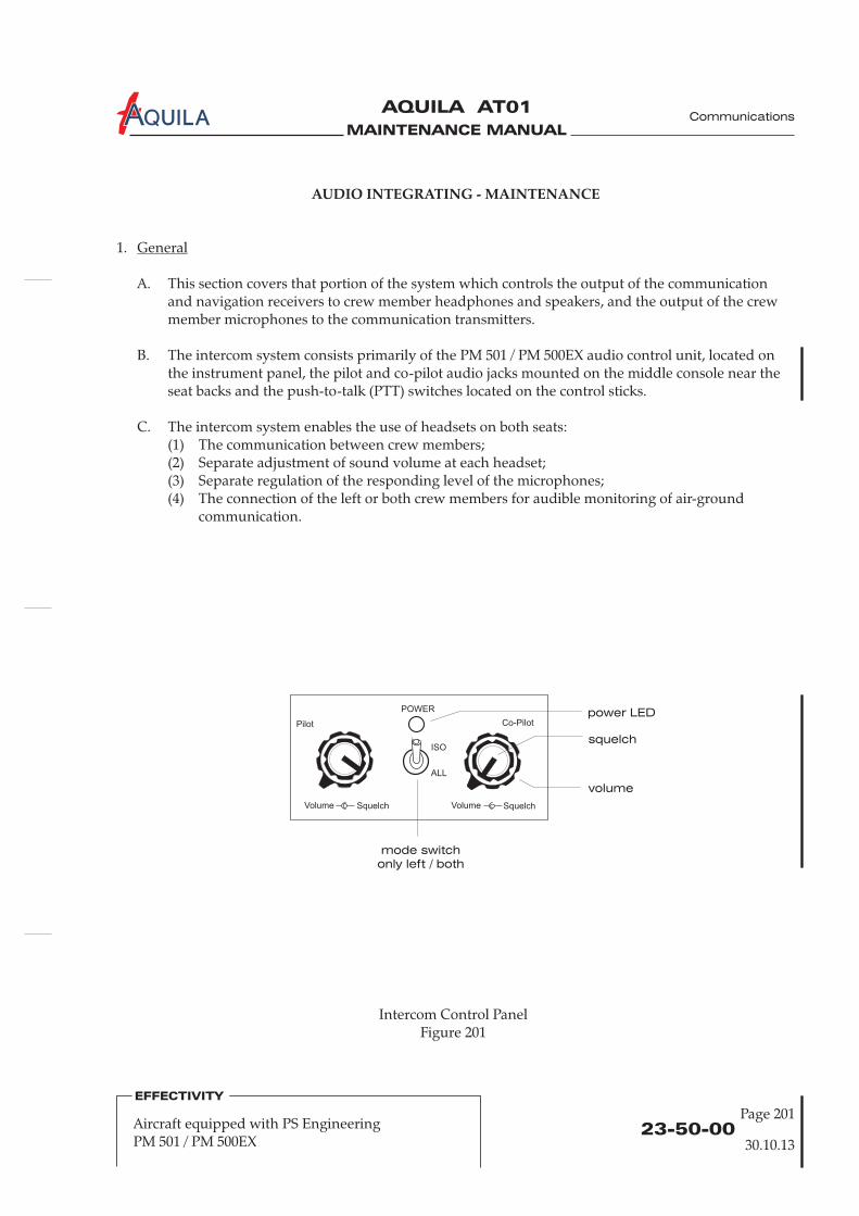
MAINTENANCE MANUAL
AQUILA AT01A
Intercom Control PanelFigure 201
POWER
ISO
ALL
Pilot
Volume Squelch SquelchVolume
Co-Pilotpower LED
volume
squelch
mode switch
only left / both
23-50-00Page 201
Communications
AUDIO INTEGRATING - MAINTENANCE
1.
A. This section covers that portion of the system which controls the output of the communicationand navigation receivers to crew member headphones and speakers, and the output of the crewmember microphones to the communication transmitters.
B. The intercom system consists primarily of the PM 501 / PM 500EX audio control unit, located onthe instrument panel, the pilot and co-pilot audio jacks mounted on the middle console near theseat backs and the push-to-talk (PTT) switches located on the control sticks.
C. The intercom system enables the use of headsets on both seats:(1) The communication between crew members;(2) Separate adjustment of sound volume at each headset;(3) Separate regulation of the responding level of the microphones;(4) The connection of the left or both crew members for audible monitoring of air-ground
communication.
General
30.10.13
EFFECTIVITY
Aircraft equipped with PS EngineeringPM 501 / PM 500EX
MAINTENANCE MANUAL
AQUILA AT01A
23-50-00Page 202
Communications
2.
A. Remove Audio Control Unit(1) Ensure electrical power to aircraft is OFF.(2) Disconnect the plug at the back of the audio control unit.(3) Remove control knob caps o .(4) Loosen and remove nuts attaching audio control unit on the left side to mounting bracket.(5) Holding the audio control unit, remove two screws on front panel fixing the control unit to
instrument panel.(6) Remove audio control unit.
B. Install Audio Control Unit(1) Install audio control unit to the instrument panel and secure using two screws.(2) Secure audio control unit on the left-hand side to the mounting bracket using two nuts.
During installation make sure that the position of control knob caps is conform tothe position of the control knob axles.
(3) Install the control knob caps o .(4) Reconnect the plug connector and secure as required at the back of the audio control unit.(5) Conduct a functional test of the unit.
Audio Control Unit Removal/Installation
NOTE:
n the front panel of the audio control unit
n the face of the audio control unit
30.10.13
EFFECTIVITY
Aircraft equipped with PS EngineeringPM 501 / PM 500EX
MAINTENANCE MANUAL
AQUILA AT01A
AUDIO INTEGRATING - MAINTENANCE
1.
A. This section covers that portion of the system which controls the output of the communicationand navigation receivers to crew member headphones and speakers, and the output of the crewmember microphones to the communication transmitters.
B. The GMA 340 / GMA 350 intercom system consists primarily of the GMA 340 / GMA 350 audiocontrol unit, located on the instrument panel in the avionics column, the pilot and co-pilot audiojacks mounted on the middle console near the seat backs and the push-to-talk (PTT) switcheslocated on the control sticks.
The Garmin GMA 340 / GMA 350 audio panel (refer to figure 201) provides audio amplification,audio selection, marker beacon control (optional) and a voice activated intercom system for theheadsets and microphones. The system allows audio switching for up to three transceivers (COM1,COM 2 and COM 3) and five receivers (NAV 1, NAV 2, ADF, DME and MKR). A fail-safe modeconnects the pilot headphone and microphone to COM 1 if power is removed or if the MICselector switch is turned to the OFF position.
D. For a complete description of the GMA 340 / GMA 350 audio panel, refer to the Garmin GMA 340to the Garmin GMA 350 Pilot's Guide,
P/N 190-01134-12, latest revision.
E. F efer to theGarmin GMA 340 Installation Manual, P/N 190-00149-01, latest revision, or to the
.
2.
A. Remove Audio Control Unit(1) Ensure electrical power to aircraft is OFF.(2)
B. Install Audio Control Unit(1)
(4) Conduct a functional test of the unit.
General
Audio Control Unit Removal/Installation
C.
Pilot's Guide, P/N 190-00149-10, latest revision, or
or additional information on maintenance of the GMA 340 / GMA 350 audio panel, rGarmin GMA
350 Installation Manual, P/N 190-01134-11, latest revision
Insert a 3/32" hex wrench into the mounting hole (see figure 1) on the face of the unit andengage hex bolt. Turn wrench counterclockwise until locking paw releases unit frommounting tray.
(3) Carefully pull audio control unit out of mounting tray.
Ensure that all plugs at the back of the mounting tray are properly connected.(2) Carefully slide unit forward into the mounting tray.(3) Insert a 3/32" hex wrench into the mounting hole (see figure 1) on the face of the unit and
engage hex bolt (max. torque 1,7 Nm [15 in.lbs]). Turn wrench clockwise until locking pawsecures unit to mounting tray.
23-50-00Page 201
EFFECTIVITY
Aircraft equipped with GarminGMA 340 / GMA 350
Communications
30.10.13

MAINTENANCE MANUAL
AQUILA AT01A
COM1
MIC
COM1
SENS
TEST
COM2
MIC
COM2 NAV1 DME
COM3
MIC
COM
1/2
COM3 NAV2 ADF
SPKR PILOT
PA CREW
CABIN AUDIO ICS ISOLATION
MKRMUTEA O M
HI
LO
PILOT COPILOT
SQ
OFF/
VOL
SQ
VOL
PULLPASS
VOL
MKR/BCN COM NAV
ICS
jackscrew
access hole
GMA 340 / GMA 350 Audio Panel, Front ViewFigure 201
23-50-00Page 202
EFFECTIVITY
Aircraft equipped with GarminGMA 340 / GMA 350
Communications
30.10.13
jackscrew
access hole
MAINTENANCE MANUAL
AQUILA AT01A
CHAPTER 24
ELECTRICAL POWER

MAINTENANCE MANUAL
AQUILA AT01A
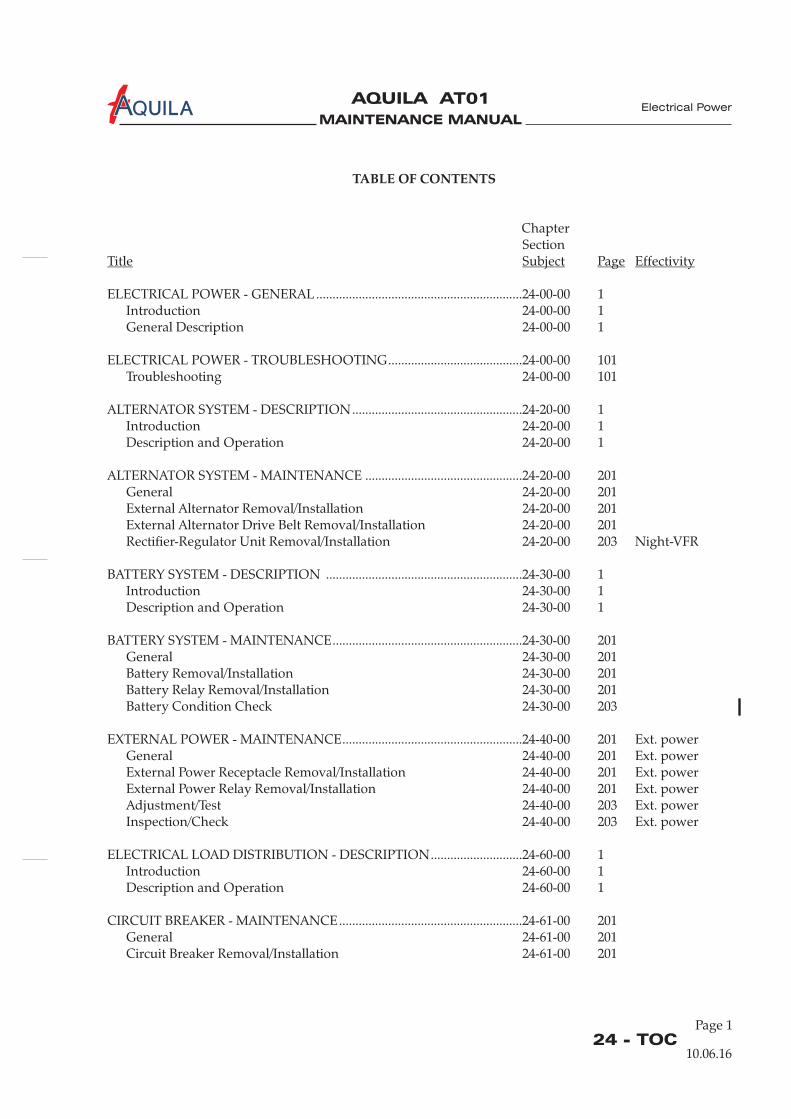
MAINTENANCE MANUAL
AQUILA AT01A
Page 124 - TOC
Electrical Power
TABLE OF CONTENTS
ChapterSection
ELECTRICAL POWER - GENERAL...............................................................24-00-00 1Introduction 24-00-00 1General Description 24-00-00 1
ELECTRICAL POWER - TROUBLESHOOTING.........................................24-00-00 101Troubleshooting 24-00-00 101
ALTERNATOR SYSTEM - DESCRIPTION....................................................24-20-00 1Introduction 24-20-00 1Description and Operation 24-20-00 1
ALTERNATOR SYSTEM - MAINTENANCE ................................................24-20-00 201General 24-20-00 201External Alternator Removal/Installation 24-20-00 201
BATTERY SYSTEM - DESCRIPTION ............................................................24-30-00 1Introduction 24-30-00 1Description and Operation 24-30-00 1
BATTERY SYSTEM - MAINTENANCE..........................................................24-30-00 201General 24-30-00 201Battery Removal/Installation 24-30-00 201
EXTERNAL POWER - MAINTENANCE.......................................................24-40-00 201 Ext. powerGeneral 24-40-00 201 Ext. powerExternal Power Receptacle Removal/Installation 24-40-00 201 Ext. powerExternal Power Relay Removal/Installation 24-40-00 201 Ext. powerAdjustment/Test 24-40-00 203 Ext. powerInspection/Check 24-40-00 203 Ext. power
ELECTRICAL LOAD DISTRIBUTION - DESCRIPTION............................24-60-00 1Introduction 24-60-00 1Description and Operation 24-60-00 1
CIRCUIT BREAKER - MAINTENANCE........................................................24-61-00 201General 24-61-00 201Circuit Breaker Removal/Installation 24-61-00 201
Title Subject Page Effectivity
External Alternator Drive Belt Removal/Installation 24-20-00 201Rectifier-Regulator Unit Removal/Installation 24-20-00 203 Night-VFR
Battery Relay Removal/Installation 24-30-00 201Battery Condition Check 24-30-00 203
10.06.16
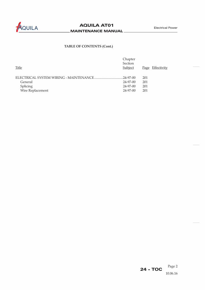
MAINTENANCE MANUAL
AQUILA AT01A
ELECTRICAL SYSTEM WIRING - MAINTENANCE..................................24-97-00 201General 24-97-00 201Splicing 24-97-00 201Wire Replacement 24-97-00 201
TABLE OF CONTENTS (Cont.)
ChapterSection
Title Subject Page Effectivity
24 - TOCPage 2
10.06.16
Electrical Power
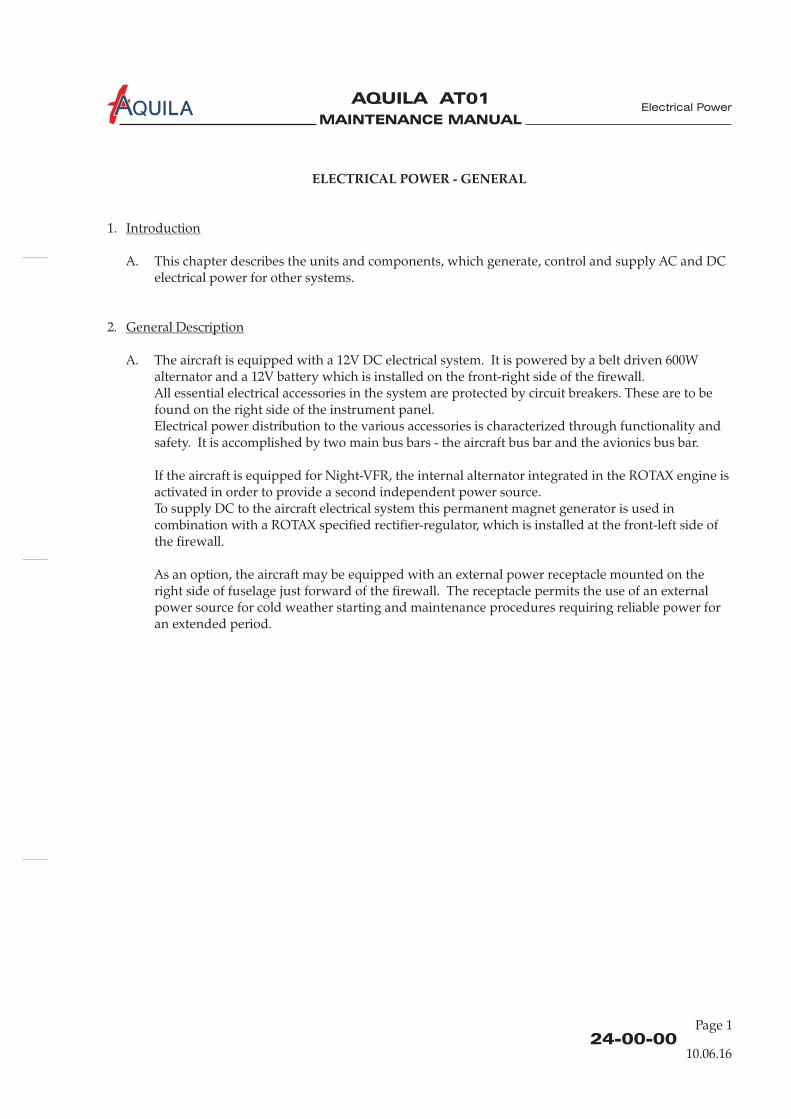
MAINTENANCE MANUAL
AQUILA AT01A
24-00-00
Electrical Power
ELECTRICAL POWER - GENERAL
1.
A. This chapter describes the units and components, which generate, control and supply AC and DCelectrical power for other systems.
2.
A. The aircraft is equipped with a 12V DC electrical system. It is powered by a belt driven 600Walternator and a 12V battery which is installed on the front-right side of the firewall.All essential electrical accessories in the system are protected by circuit breakers. These are to befound on the right side of the instrument panel.Electrical power distribution to the various accessories is characterized through functionality andsafety. It is accomplished by two main bus bars - the aircraft bus bar and the avionics bus bar.
If the aircraft is equipped for Night-VFR, the internal alternator integrated in the ROTAX engine isactivated in order to provide a second independent power source.To supply DC to the aircraft electrical system this permanent magnet generator is used incombination with a ROTAX specified rectifier-regulator, which is installed at the front-left side ofthe firewall.
As an option, the aircraft may be equipped with an external power receptacle mounted on theright side of fuselage just forward of the firewall. The receptacle permits the use of an externalpower source for cold weather starting and maintenance procedures requiring reliable power foran extended period.
Introduction
General Description
10.06.16
Page 1

MAINTENANCE MANUAL
AQUILA AT01A
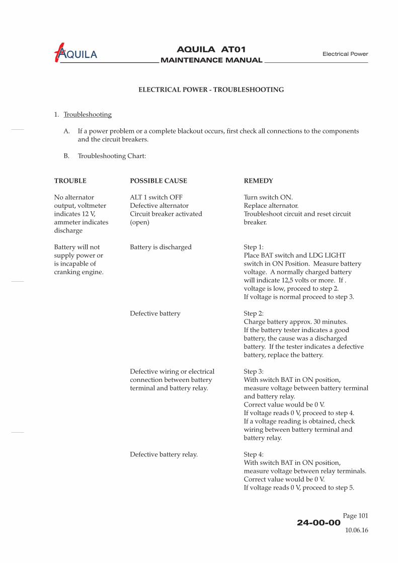
MAINTENANCE MANUAL
AQUILA AT01A
ELECTRICAL POWER - TROUBLESHOOTING
TROUBLE POSSIBLE CAUSE REMEDY
1.
A. If a power problem or a complete blackout occurs, first check all connections to the componentsand the circuit breakers.
B. Troubleshooting Chart:
No alternator ALT 1 switch OFF Turn switch ON.output, voltmeter Defective alternator Replace alternator.indicates 12 V, Circuit breaker activated Troubleshoot circuit and reset circuitammeter indicates (open) breaker.discharge
Battery will not Battery is discharged Step 1:supply power or Place BAT switch and LDG LIGHTis incapable of switch in ON Position. Measure batterycranking engine. voltage. A normally charged battery
will indicate 12,5 volts or more. If .voltage is low, proceed to step 2.If voltage is normal proceed to step 3.
Defective battery Step 2:Charge battery approx. 30 minutes.If the battery tester indicates a goodbattery, the cause was a dischargedbattery. If the tester indicates a defectivebattery, replace the battery.
Defective wiring or electrical Step 3:connection between battery With switch BAT in ON position,terminal and battery relay. measure voltage between battery terminal
and battery relay.Correct value would be 0 V.If voltage reads 0 V, proceed to step 4.If a voltage reading is obtained, checkwiring between battery terminal andbattery relay.
Defective battery relay. Step 4:With switch BAT in ON position,measure voltage between relay terminals.Correct value would be 0 V.If voltage reads 0 V, proceed to step 5.
Troubleshooting
24-00-00Page 101
Electrical Power
10.06.16
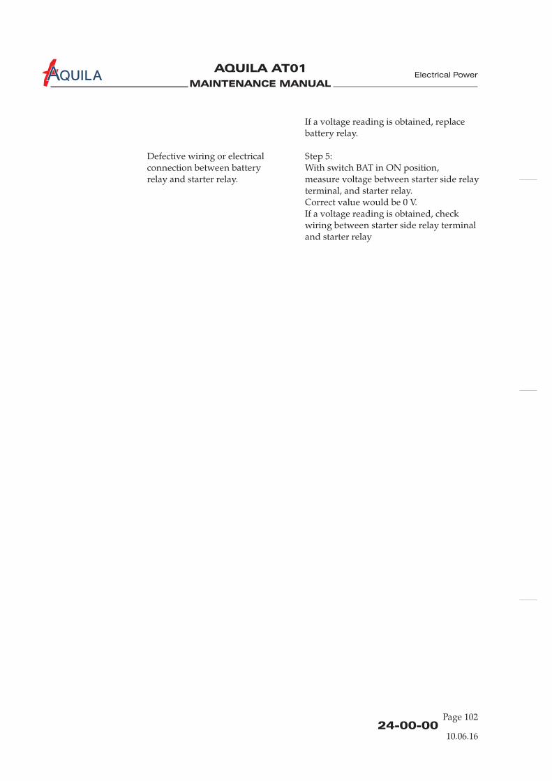
MAINTENANCE MANUAL
AQUILA AT01A
If a voltage reading is obtained, replacebattery relay.
Defective wiring or electrical Step 5:connection between battery With switch BAT in ON position,relay and starter relay. measure voltage between starter side relay
terminal, and starter relay.
If a voltage reading is obtained, checkwiring between starter side relay terminaland starter relay
Correct value would be 0 V.
24-00-00Page 102
Electrical Power
10.06.16
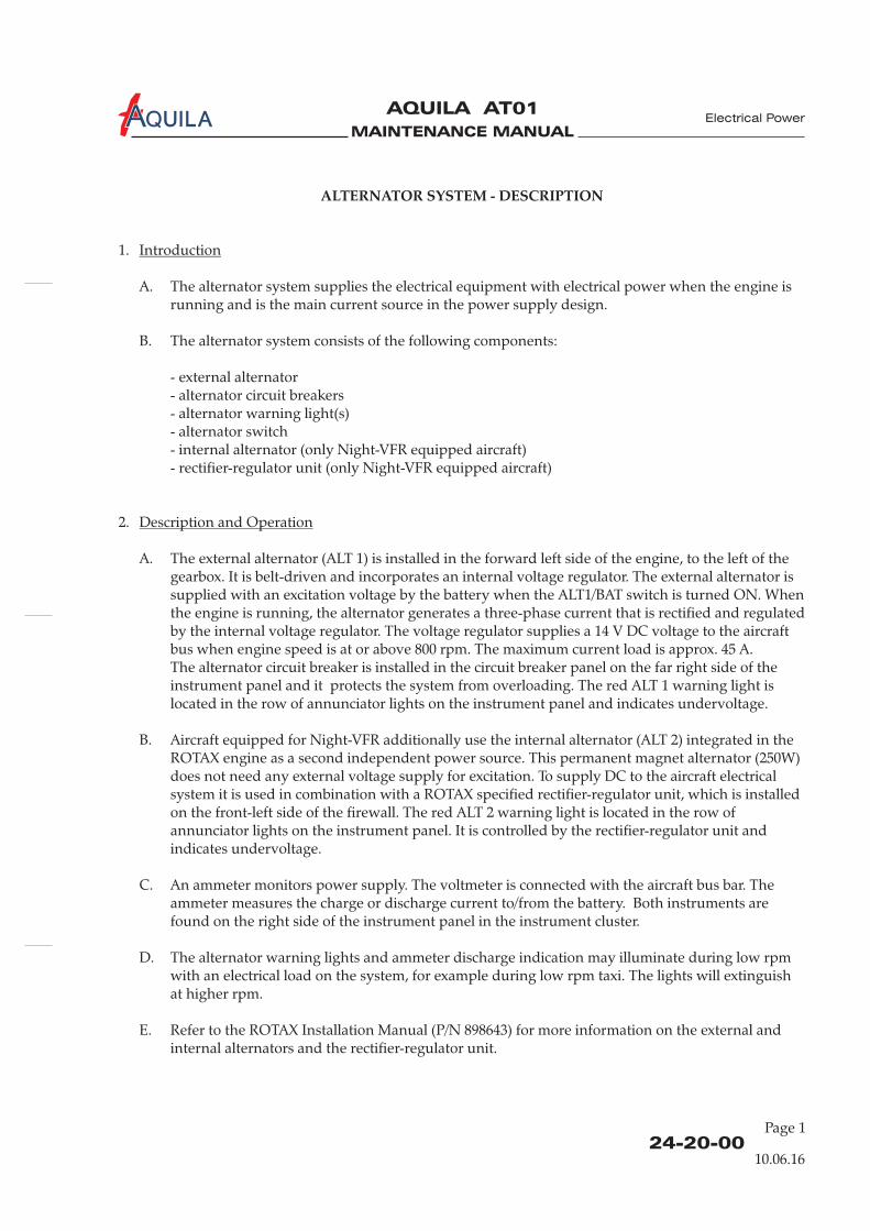
MAINTENANCE MANUAL
AQUILA AT01A
24-20-00
ALTERNATOR SYSTEM - DESCRIPTION
1.
A. The alternator system supplies the electrical equipment with electrical power when the engine isrunning and is the main current source in the power supply design.
B. The alternator system consists of the following components:
- external alternator- alternator circuit breakers- alternator warning light(s)- alternator
2.
A. The external alternator (ALT 1) is installed in the forward left side of the engine, to the left of thegearbox. It is belt-driven and incorporates an internal voltage regulator.
The alternator circuit breaker is installed in the circuit breaker panel on the far right side of theinstrument panel and it protects the system from overloading. The red ALT 1 warning light islocated in the row of annunciator lights on the instrument panel and indicates undervoltage.
Introduction
Description and Operation
switch- internal alternator (only Night-VFR equipped aircraft)- rectifier-regulator unit (only Night-VFR equipped aircraft)
The external alternator issupplied with an excitation voltage by the battery when the ALT1/BAT switch is turned ON. Whenthe engine is running, the alternator generates a three-phase current that is rectified and regulatedby the internal voltage regulator. The voltage regulator supplies a 14 V DC voltage to the aircraftbus when engine speed is at or above 800 rpm. The maximum current load is approx. 45 A.
B. Aircraft equipped for Night-VFR additionally use the internal alternator (ALT 2) integrated in theROTAX engine as a second independent power source. This permanent magnet alternator (250W)does not need any external voltage supply for excitation. To supply DC to the aircraft electricalsystem it is used in combination with a ROTAX specified rectifier-regulator unit, which is installedon the front-left side of the firewall. The red ALT 2 warning light is located in the row ofannunciator lights on the instrument panel. It is controlled by the rectifier-regulator unit andindicates undervoltage.
C. An ammeter monitors power supply. The voltmeter is connected with the aircraft bus bar. Theammeter measures the charge or discharge current to/from the battery. Both instruments arefound on the right side of the instrument panel in the instrument cluster.
D. The alternator warning lights and ammeter discharge indication may illuminate during low rpmwith an electrical load on the system, for example during low rpm taxi. The lights will extinguishat higher rpm.
E. Refer to the ROTAX Installation Manual (P/N 898643) for more information on the external andinternal alternators and the rectifier-regulator unit.
Electrical Power
10.06.16
Page 1
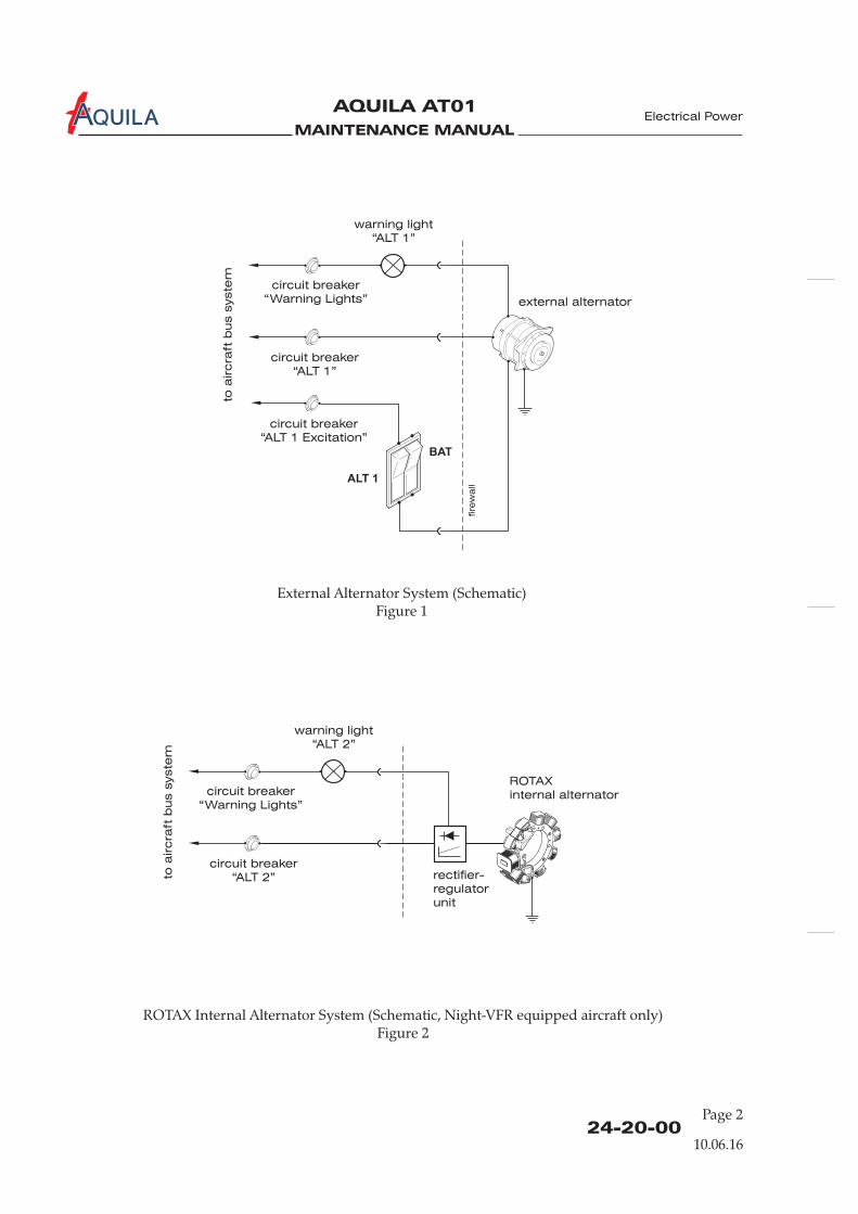
MAINTENANCE MANUAL
AQUILA AT01A
24-20-00Page 2
Electrical Power
ROTAX Internal Alternator System (Schematic, Night-VFR equipped aircraft only)Figure 2
External Alternator System (Schematic)Figure 1
external alternator
warning light
“ALT 1”
ALT 1
BAT
to a
ircra
ft b
us s
yste
m
circuit breaker
“ALT 1 Excitation”
circuit breaker
“Warning Lights”
circuit breaker
“ALT 1”
fire
wa
ll
10.06.16
warning light
“ALT 2”
to a
ircra
ft b
us s
yste
m
circuit breaker
“Warning Lights”
circuit breaker
“ALT 2”
ROTAX
internal alternator
rectifier-
regulator
unit
MAINTENANCE MANUAL
AQUILA AT01A
24-20-00Page 201
ALTERNATOR SYSTEM - MAINTENANCE
1.
A. Maintenance is limited to the (external) alternator, drive belt andrectifier-regulator unit (only Night-VFR equipped aircraft). Refer to the appropriate ROTAXpublications for maintenance procedures on the internal alternator.
2.
A. Remove External Alternator(1) Ensure electrical power to aircraft and ignition switch is OFF. Remove key.(2) Remove cowling (refer to 71-10-00).(3) Disconnect battery (refer to 24-30-00).(4) Disconnect electrical cables (include ground cable) from alternator.(5) Cut safety wire and loosen adjusting bolt and alternator mounting bolts.(6) Slip drive belt off alternator pulley.(7) Remove mounting bolts securing alternator to engine. Remove alternator from engine.
B. Install External Alternator(1) Position alternator into mounting bracket.(2) Install shim and mounting bolt as shown in figure 201. Do not tighten yet.(3) Loosely secure lower alternator mounting boss to adjustment cam using washers and bolt
(refer to figure 201).(4) Place drive belt on alternator pulley. Verify pulleys are aligned.
IF A NEW DRIVE BELT IS INSTALLED: THE ENGINE BELT TENSION SHOULDBE RECHECKED WITHIN THE FIRST 15 TO 20 HOURS OF OPERATION.
(5) Apply a torque wrench to the alternator pulley nut and adjust belt tension so the belt slips at:(a) 10 - 12 Nm (88 - 106 in.lbs) of torque with a used belt;(b) 15 - 18 Nm (133 - 159 in.lbs) of torque with a new belt
(6) Tighten adjusting bolt. Torque to 22 Nm (195 in.lbs).(7) Tighten alternator mounting bolts.
(a) Torque M10 bolt (upper alternator mounting bracket) to 40 Nm (355 in.lbs).(b) Torque M8 bolt to 22 Nm (195 in.lbs).
(8) Safety wire all bolts.(9) Reconnect electrical cables including the ground cable.(10) Reconnect battery (refer to 24-30-00).(11) Install cowling (refer to 71-10-00).
3.
A. Remove Alternator Drive Belt(1) Ensure electrical power to aircraft and ignition switch is OFF. Remove key.(2) Remove engine cowling (refer to 71-10-00).(3) Disconnect battery (refer to 24-30-00).
General
External Alternator Removal/Installation
CAUTION:
External Alternator Drive Belt Removal/Installation
removal and installation of the
Electrical Power
10.06.16
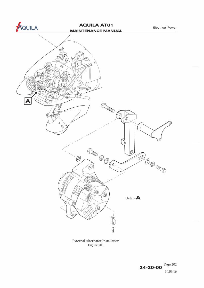
MAINTENANCE MANUAL
AQUILA AT01A
24-20-00Page 202
Electrical Power
External Alternator InstallationFigure 201
10.06.16
A
ADetail-
MAINTENANCE MANUAL
AQUILA AT01A
(4) Cut safety wire and loosen adjusting bolt and alternator mounting bolts.(5) Slip drive belt off alternator pulley.(6) Remove propeller (refer to 61-10-00).(7) Remove alternator drive belt.
B. Install Alternator Drive Belt(1) Install alternator drive belt around drive pulley.(2) Install propeller (refer to 61-10-00).(3) Place drive belt on alternator pulley. Verify pulleys are aligned.
IF A NEW DRIVE BELT IS INSTALLED: THE ENGINE BELT TENSION SHOULDBE RECHECKED WITHIN THE FIRST 15 TO 20 HOURS OF OPERATION.
(4) Apply a torque wrench to the alternator pulley nut and adjust the belt tension so the beltslips at:(a) 10 - 12 Nm (88 - 106 in.lbs) of torque with a used belt;(b) 15 - 18 Nm (133 - 159 in.lbs) of torque with a new belt
(5) Tighten adjusting bolt. Torque to 22 Nm (195 in.lbs).(6) Tighten alternator mounting bolts.
(a) Torque M10 bolt (upper alternator mounting bracket) to 40 Nm (355 in.lbs).(b) Torque M8 bolt to 22 Nm (195 in.lbs).
(7) Safety wire all bolts.(8) Reconnect battery (refer to 24-30-00).(9) Install engine cowling (refer to 71-10-00).
CAUTION:
4. (Ref. Fig. 202, Night-VFR equipped aircraft only)
A. Remove Rectifier-Regulator Unit(1) Ensure electrical power to aircraft is OFF.(2) Remove engine cowling (refer to 71-10-00).(3) Disconnect battery (refer to 24-30-00).(4) Disconnect all wires from rectifier-regulator unit.(5) Remove the attachment bolt and the nuts from the mounting plate and rectifier-regulator
unit. Attend to the ''Nordlock'' washers.
B. Install Rectifier-Regulator Unit(1) Install the rectifier-regulator unit with two screws M8x20 (DIN ISO 4762), four ''Nordlock''
washers and two nuts M8 (DIN ISO 934) on the mounting plate. Attend to the variouswashers and their installation sequence.
(2) Connect the wire to the rectifier-regulator unit.(3) Reconnect battery (refer to 24-30-00).(4) Install engine cowling (refer to 71-10-00).
Rectifier-Regulator Unit Removal/Installation
24-20-00Page 203
Electrical Power
10.06.16
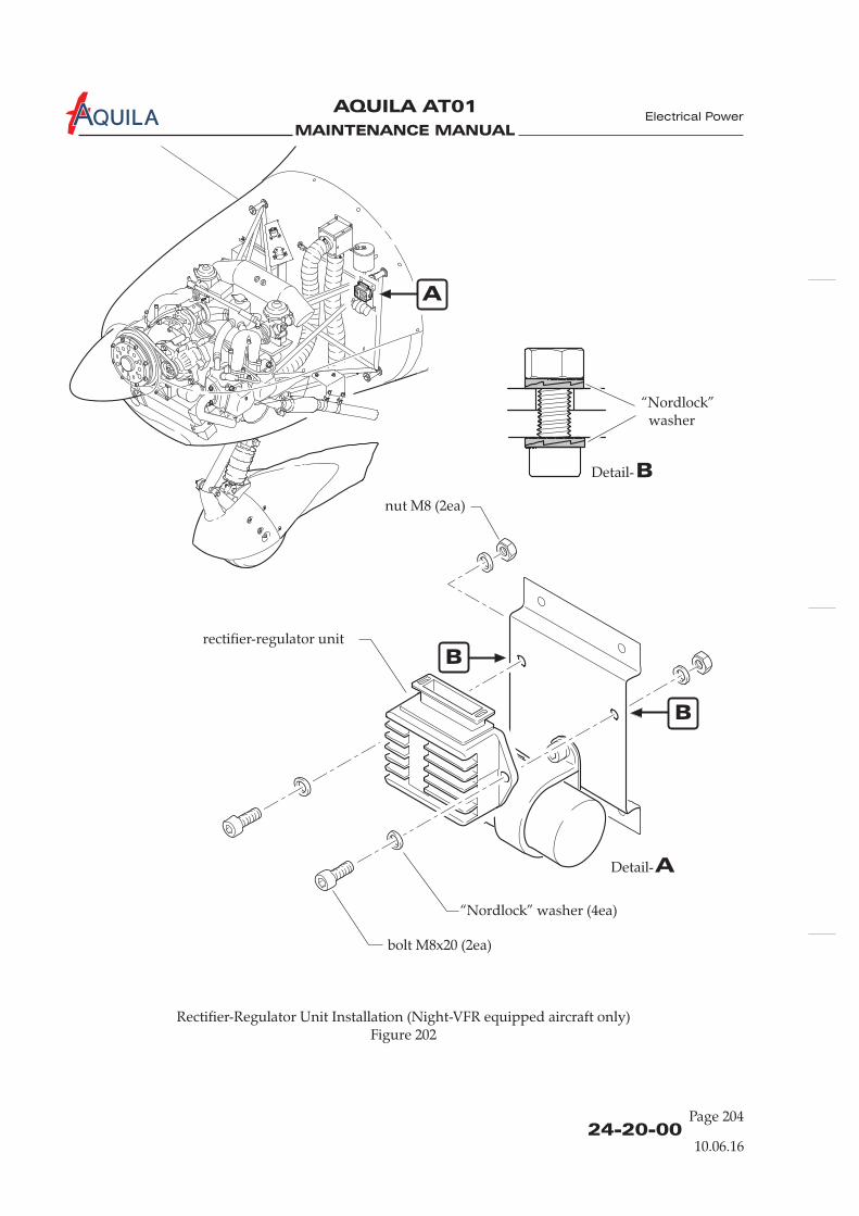
MAINTENANCE MANUAL
AQUILA AT01A
24-20-00Page 204
Electrical Power
Rectifier-Regulator Unit Installation (Figure 202
Night-VFR equipped aircraft only)
rectifier-regulator unit
“Nordlock” washer (4ea)
bolt M8x20 (2ea)
nut M8 (2ea)
10.06.16
ADetail-
A
“Nordlock”washer
BDetail-
B
B
MAINTENANCE MANUAL
AQUILA AT01A
24-30-00
BATTERY SYSTEM - DESCRIPTION
1.
A. The battery system supplies power to the electrical equipment if the alternator fails. It representsthe auxiliary power source in supply design.
B. The battery system consists of the following components:
- battery- battery relay- BAT switch- voltmeter- ammeter
2.
A. The aircraft has a 12-volt lead-acid battery, which is installed in a battery tray on the front-rightside of the firewall. It is accessible by removing the upper engine cowling. The battery box isvented. The vent line discharges out of the bottom of the engine cowling, preventing the build upof dangerous or explosive gases in the engine compartment. The battery relay is fixed above thebattery at the engine mount.
B. To connect the battery to the aircraft bus the switch, located on the lower left instrumentpanel, must be in the ON position, thus connecting one battery relay terminal to aircraft ground.The other relay terminal is permanently supplied with a positive voltage by the battery. In thisway the aircraft bus bar is supplied with current via the battery relay.The voltmeter is connected with the aircraft bus bar. The ammeter measures the charge ordischarge current to/from the battery via a shunt. Both instruments are located on the rightinstrument panel in the instrument cluster.
Introduction
Description and Operation
BAT
Electrical Power
10.06.16
Page 1
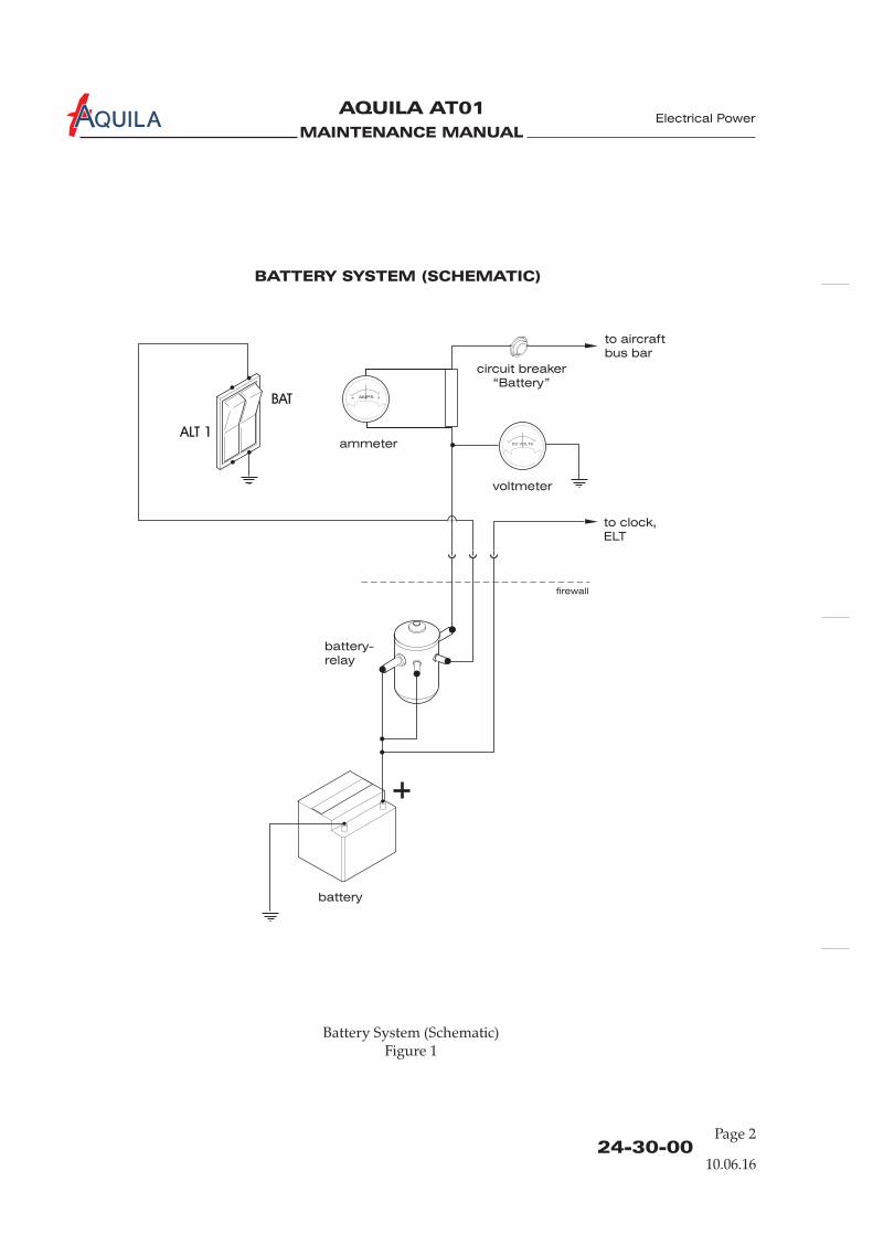
MAINTENANCE MANUAL
AQUILA AT01A
Battery System (Schematic)Figure 1
battery-
relay
to aircraft
bus bar
to clock,
ELT
battery
ALT 1
BAT
ammeter
AMPS- +
DC VOLTS
circuit breaker
“Battery”
firewall
BATTERY SYSTEM (SCHEMATIC)
24-30-00
Electrical Power
10.06.16
Page 2
voltmeter

MAINTENANCE MANUAL
AQUILA AT01A
24-30-00Page 201
BATTERY SYSTEM - MAINTENANCE
1.
A. Maintenance is limited to the removal and installation of the battery and the battery relay and abattery condition check. For information on the regular servicing required, refer to 12-17-00.
2.
A. Remove Battery(1) Ensure BAT switch is in OFF position.(2) Remove upper engine cowling (refer to 71-10-00).(3) Remove battery hold down strap.(4) Disconnect battery cables.(5) Remove battery from mounting tray.
B. Install Battery(1) Place battery into mounting tray and secure with battery hold down strap. Torque nuts to
max. 2 Nm (18 in.lbs).
(2) Reconnect battery vent line.(3) Reconnect battery cables.(4) Install engine cowling (refer to 71-10-00).
General
Battery Removal/Installation
CAUTION:
NOTE:
Battery Relay Removal/Installation
ALWAYS DISCONNECT THE BATTERY BEFORE DOING ANY MAINTENANCE ONTHE ELECTRICAL SYSTEM. DISCONNECT THE NEGATIVE LEAD FIRST. RECONNECTTHE NEGATIVE LEAD LAST. SECURE THE BATTERY LEADS FROM ACCIDENTALCONNECTION DURING MAINTENANCE WORKS.
It is recommended to remove the battery from the aircraft before doing any maintenanceon the electrical system to avoid the risk of accidental connection.
3. (Ref. Fig. 201)
A. Remove Battery Relay(1) Ensure electrical power to aircraft is OFF.(2) Remove engine cowling (refer to 71-10-00).(3) Disconnect battery (refer to 24-30-00).(4) Identify and disconnect wires at battery relay.(5) Remove nuts, washers and bolts securing relay to engine mount and remove relay.
CAUTION: EXCESSIVELY HIGH TORQUES COULD RESULT IN DAMAGE TO THEBATTERY AND ESCAPING BATTERY ACID.
Electrical Power
10.06.16
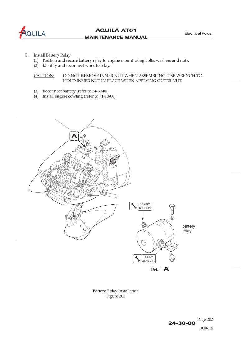
MAINTENANCE MANUAL
AQUILA AT01A
B. Install Battery Relay(1) Position and secure battery relay to engine mount using bolts, washers and nuts.(2) Identify and reconnect wires to relay.
DO NOT REMOVE INNER NUT WHEN ASSEMBLING. USE WRENCH TOHOLD INNER NUT IN PLACE WHEN APPLYING OUTER NUT.
(3) Reconnect battery (refer to 24-30-00).(4) Install engine cowling (refer to 71-10-00).
CAUTION:
Electrical Power
24-30-0010.06.16
Page 202
ADetail-
batteryrelay
1,4-2 Nm
5-6 Nm
12-18 in.lbs
44-55 in.lbs
Battery Relay InstallationFigure 201
A
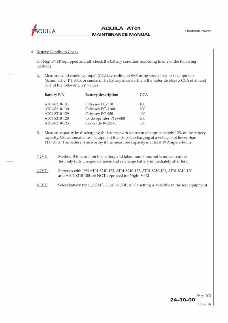
MAINTENANCE MANUAL
AQUILA AT01A
4.
For Night-VFR equipped aircraft, check the battery condition according to one of the followingmethods:
A. Measure „cold cranking amps“ (CCA) according to SAE using specialized test equipment(Schumacher PTI900X or similar). The battery is airworthy if the tester displays a CCA of at least80% of the following test values:
AT01-8210-131 Odyssey PC-310 100AT01-8210-130 Odyssey PC-1100 500AT01-8210-129 Odyssey PC-950 400AT01-8210-128 Exide Sprinter P12V600 200AT01-8210-125 Concorde RG25XC 350
B. Measure capacity by discharging the battery with a current of approximately 10% of the batterycapacity. Use automated test equipment that stops discharging at a voltage not lower than11,0 Volts. The battery is airworthy if the measured capacity is at least 19 Ampere-hours.
Method B is harder on the battery and takes more time, but is more accurate.Test only fully charged batteries and re-charge battery immediately after test.
Batteries with P/N AT01-8210-123, AT01-8210-122, AT01-8210-121, AT01-8210-120and AT01-8210-100 are NOT approved for Night-VFR!
Select battery type „AGM“, „SLA“ or „VRLA“ if a setting is available in the test equipment.
Battery Condition Check
NOTE:
NOTE:
NOTE:
Battery P/N Battery description CCA
Electrical Power
24-30-00Page 203
10.06.16

MAINTENANCE MANUAL
AQUILA AT01A
MAINTENANCE MANUAL
AQUILA AT01A
24-40-00Page 201
Electrical Power
EXTERNAL POWER - MAINTENANCE
1.
A. This section covers that portion of the system which connects external electrical power to theaircraft's electrical systems. It includes items such as external power receptacle and relays.
B. As an option the aircraft may be equipped with an external power receptacle mounted on theright side of the engine mount, just below the battery. The standard, oval shaped, 3-pin receptacleis accessible through an hinged access plate in the right side of the engine cowling. Furthermore,the system includes an external power relay attached to the engine mount and a relay behind theinstrument panel. For wiring refer to 91-00-00.When a 12 V DC power supply is connected to the external power receptacle the shorter, thirdconnector engages the external power relay, which connects the external power to the aircraftmain bus. Simultaneously, the battery switch will be disconnected from the ground terminal bythe second relay behind the instrument panel. This prevents an energizing of the battery relaywhile an external power supply is being used.The signal power to the external power relay contains an isolation diode to prevent reversepolarity.
C. Maintenance is limited to the removal and installation of components.
2. (Ref. Fig. 201)
A. Remove External Power Receptacle(1) Ensure electrical power to aircraft is OFF.
(3) Disconnect battery (refer to 24-30-00).(4) Identify and disconnect all wires at EPU receptacle.(5) Remove nuts, washers and bolts securing receptacle to engine mount and remove receptacle.
B. Install External Power Receptacle(1) Position and secure EPU receptacle to engine mount using bolts, washers and nuts.(2) Identify and reconnect wires to EPU receptacle.(3) Reconnect battery (refer to 24-30-00).(4) Install engine cowling (refer to 71-10-00).(5) Perform an external power system functional check (refer to “Adjustment/Test” below).
3.
A. Remove External Power Relay(1) Ensure electrical power to aircraft is OFF.(2) Remove engine cowling (refer to 71-10-00).(3) Disconnect battery (refer to 24-30-00).(4) Identify and disconnect wires at external power relay.(5) Remove nuts, washers and bolts securing relay to engine mount and remove relay.
General
External Power Receptacle Removal/Installation
External Power Relay Removal/Installation
(2) Remove engine cowling (refer to 71-10-00).
(Ref. Fig. 201)
10.06.16Aircraft equipped with an external power receptacle
EFFECTIVITY

MAINTENANCE MANUAL
AQUILA AT01A
24-40-00Page 202
Electrical Power
External Power Receptacle InstallationFigure 201
Aircraft equipped with an external power receptacle
EFFECTIVITY
A
ADetail-
ground
power
Signal
4 Pl.
10.06.16
B
BDetail-
externalpowerrelay
8212A04N
8212B04
8212A20
1,4-2 Nm
5-6 Nm
12-18 in.lbs
44-55 in.lbs

MAINTENANCE MANUAL
AQUILA AT01A
B. Install External Power Relay(1) Position and secure external power relay to engine mount using bolts, washers and nuts.(2) Identify and reconnect wires to external power relay.
(3) Reconnect battery (refer to 24-30-00).(4) Install engine cowling (refer to 71-10-00).(5) Perform an external power system functional check (refer to “Adjustment/Test below).
4.
A. External Power System Functional Check(1) Connect an 14 V DC external power supply to aircraft.(2) Place the BAT switch to the ON position.(3) Verify the voltmeter shows 14 V.(4) Disconnect external power supply from aircraft.(5) The voltmeter must show 12 V.(6) Place the BAT switch in OFF position.
5.
A. External Power System Inspection/Check(1) Check latching mechanism and hinge of the external power access plate for integrity and
condition.(2) Remove engine cowling (refer to 71-10-00).(3) Remove glare shield (refer to 31-10-00).(4) Check external power receptacle for security.(5) Check system relays for condition and security.(6) Inspect electrical cables of the system for proper routing, chafing, broken or loose terminals,
general condition, and sharp bends in wiring.(7) Verify the external power placard is firmly in place and legible.(8) Install glare shield (refer to 31-10-00).(9) Install engine cowling (refer to 71-10-00).
CAUTION: DO NOT REMOVE INNER NUT WHEN ASSEMBLING. USE WRENCH TOHOLD INNER NUT IN PLACE WHEN APPLYING OUTER NUT.
Adjustment/Test
Inspection/Check
24-40-00Page 203
Electrical Power
Aircraft equipped with an external power receptacle
EFFECTIVITY
10.06.16

MAINTENANCE MANUAL
AQUILA AT01A
MAINTENANCE MANUAL
AQUILA AT01A
24-60-00
ELECTRICAL LOAD DISTRIBUTION - DESCRIPTION
1.
A. Distribution of electrical power supplied by the external and optional the internal alternator andthe battery is accomplished by bus bars. The bus architecture allows power to be routed to theessential circuitry if any one of the main power sources fails.All essential electrical accessories in the system are protected by push pull type circuit breakerswhich can be reset in flight. The circuit breaker panel is on the far right of the instrument paneland each circuit breaker is labeled. All circuit breakers have their rated values identified on thetop of the shaft.
B. For power routing throughout the aircraft, refer to wiring diagrams shown in 91-00-00.
2.
A. The electrical system has two main bus bars: the aircraft bus bar and the avionics bus bar. Allsystems are connected to the aircraft bus bar. Theavionics bus bar supplies the avionics equipment with power.
B. The external alternator output and the battery are connected with the aircraft bus via 50A circuitbreakers. Optional the internal alternator is connected with the aircraft bus via a rectifier-regulatorunit and a 25A circuit breaker. The circuit breakers are located on the right side of the instrumentpanel in the circuit breaker panel.The current is distributed from the aircraft bus bar via circuit breakers to the electrical circuits ofseveral systems and components and via the switch to the avionics bus bar. Fromthere, it is further distributed to the several components of the avionics equipment via circuitbreakers. The AVIONICS switch allows avionics equipment to be removed separately from theresidual electrical system.
Introduction
Description and Operation
which are essential for aircraft operation
AVIONICS
Electrical Power
10.06.16
Page 1

MAINTENANCE MANUAL
AQUILA AT01A
MAINTENANCE MANUAL
AQUILA AT01A
CIRCUIT BREAKER - MAINTENANCE
1.
A. The circuit breaker panel is equipped with circuit breakers of the push to reset type.One terminal of each switch/breaker is directly connected to the appropriate bus bar, the other iswired to the component/system it protects.
2.
A. Remove Circuit Breaker(1) Ensure electrical power to aircraft is OFF.(2) Disconnect battery (refer to 24-30-00).(3) Remove glare shield (refer to 31-10-00).(4) Disconnect wire and bus from selected circuit breaker.(5) Remove retaining ring and washer from circuit breaker on the front of the instrument panel.(6) Remove circuit breaker.
It may be necessary to loosen more than one circuit breaker to remove the selectedcircuit breaker.
B. Install Circuit Breaker(1) Place circuit breaker into position on the instrument panel and secure.(2) Identify and connect wire and bus to the selected circuit breaker.(3) Reinstall glare shield (refer to 31-10-00).(4) Reconnect battery (refer to 24-30-00).
General
Circuit Breaker Removal/Installation
NOTE:
" "
24-61-00Page 201
Electrical Power
10.06.16

MAINTENANCE MANUAL
AQUILA AT01A
MAINTENANCE MANUAL
AQUILA AT01A
ELECTRICAL SYSTEM WIRING - MAINTENANCE
1.
A. Repairs of the electrical system wiring are limited to the replacement and splicing of electricalwires. In general all repairs have to be carried out by certified repair stations or properly certifiedand trained persons.
B. Carry out a complete functional check of the concerned equipment after every repair.
C. Refer to 91-00-00 for wiring diagrams.
A. Splicing is permitted on wiring as long as it does not affect the reliability and theelectromechanical characteristics of the wiring. Splicing of power wires, coaxial cables, shieldedwires or wire sizes above AWG 18 is not permitted. There should not be more than one splice inany one wire segment between any two connectors or other disconnect points.
3 “Splicing splicing procedures andequipment
General
2.
3.
A. If wires are replaced, they have to be replaced by identical ones (same MIL specification andAWG). New wires have to be routed, fixed and protected in the same manner as the old wires.
Splicing
Wire Replacement
Refer toAC 43.13-1B, chapter 11, section 1 ” for further information on
.
24-97-00Page 201
10.06.16
Electrical Power

MAINTENANCE MANUAL
AQUILA AT01A
MAINTENANCE MANUAL
AQUILA AT01A
CHAPTER 25
EQUIPMENT / FURNISHINGS

MAINTENANCE MANUAL
AQUILA AT01A

MAINTENANCE MANUAL
AQUILA AT01A
Page 125 - TOC
Equipment / Furnishings
TABLE OF CONTENTS
ChapterSection
EQUIPMENT / FURNISHINGS - GENERAL................................................25-00-00 1Introduction 25-00-00 1General Description 25-00-00 1
SEATS - MAINTENANCE ................................................................................25-10-00 201General 25-10-00 201Seat Removal/Installation 25-10-00 201Gas Spring Strut Assembly Removal/Installation 25-10-00 203
RESTRAINT SYSTEM - MAINTENANCE.....................................................25-11-00 201General 25-11-00 201Restraint System Removal/Installation 25-11-00 201
CABIN INTERIOR - MAINTENANCE ..........................................................25-12-00 201General 25-12-00 201Panels, Coverings and Carpets Removal/Installation 25-12-00 202
CARGO TIE-DOWNS - MAINTENANCE.....................................................25-50-00 201General 25-50-00 201
EMERGENCY EQUIPMENT - DESCRIPTION............................................25-60-00 1Introduction 25-60-00 1Description and Operation 25-60-00 1
EMERGENCY LOCATER TRANSMITTER - MAINTENANCE.................25-62-00 201General 25-62-00 201ELT Removal/Installation 25-62-00 201ELT Antenna Removal/Installation 25-62-00 201Battery Replacement 25-62-00 202Adjustment/Test 25-62-00 202Inspection/Check 25-62-00 203
FIRE EXTINGUISHER - MAINTENANCE....................................................25-66-00 201 Air TotalGeneral 25-66-00 201Description and Operation 25-66-00 201Maintenance Instructions 25-66-00 201
Title Subject Page Effectivity
Air TotalAir TotalAir Total
Fire Extinguisher Removal/Installation 25-66-00 201 Air Total
FIRE EXTINGUISHER - MAINTENANCE....................................................25-66-00 201 H3RGeneral 25-66-00 201 H3RDescription and Operation 25-66-00 201 H3RMaintenance Instructions 25-66-00 201 H3RFire Extinguisher Removal/Installation 25-66-00 202 H3R
30.10.13

MAINTENANCE MANUAL
AQUILA AT01A
Page 0225 - TOC
15.09.09
Equipment / Furnishings
MAINTENANCE MANUAL
AQUILA AT01A
25-00-00
EQUIPMENT / FURNISHINGS - GENERAL
1.
A. This chapter describes removable items of equipment and interior furnishings contained in thecabin and baggage compartment.
2.
A. The seats can be adjusted back and forward. The restraint system of each seat is attached to thefuselage structure. It consists of shoulder harness with an inertia-reel retractor and lap belts whichallow for complete freedom of movement of the upper torso area. In the event of a suddendeceleration, the reels lock to provide positive restraint for the user.
B. The cabin interior is easy to care for and designed for functionally. Thefor maintenance purposes.
C. The baggage compartment is directly behind the seats. It can be loaded through the baggagecompartment door on the left side of fuselage.
D. An emergency locator transmitter (ELT) is installed. The transmitter unit is fitted to the baggagecompartment floor immediately behind the right seat back.
Introduction
General Description
panels and coverings canbe removed
Equipment / Furnishings
30.10.13
Page 1

MAINTENANCE MANUAL
AQUILA AT01A
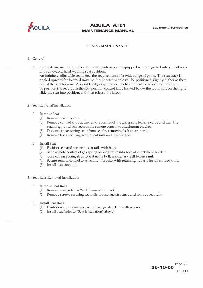
MAINTENANCE MANUAL
AQUILA AT01A
25-10-00Page 201
Equipment / Furnishings
SEATS - MAINTENANCE
1.
A. The seats are made from fiber composite materials and equipped with integrated safety head restsand removable, hard-wearing seat cushions.An infinitely adjustable seat meets the requirements of a wide range of pilots. The seat track isangled upward for forward travel so that shorter people will be positioned slightly higher as theyadjust the seat forward. A lockable oil/gas spring strut holds the seat in the desired position.To position the seat, push the seat position control knob located below the seat frame on the right,slide the seat into position, and then release the knob.
2.
A. Remove Seat(1) Remove seat cushion.(2) Remove control knob at the remote control of the gas spring locking valve and then the
retaining nut which secures the remote control to attachment bracket.(3) Disconnect gas spring strut from seat by removing bolt at strut end.(4) Remove bolts securing seat to seat rails and remove seat.
B. Install Seat(1) Position seat and secure to seat rails with bolts.(2) Slide remote control of gas spring locking valve into hole of attachment bracket.(3) Connect gas spring strut to seat using bolt, washer and self locking nut.(4) Secure remote control to attachment bracket with retaining nut and install control knob.(5) Install seat cushion.
3.
A. Remove Seat Rails(1) Remove seat (refer to “Seat Removal” above).(2) Remove screws securing seat rails to fuselage structure and remove seat rails.
B. Install Seat Rails(1) Position seat rails and secure to fuselage structure with screws.(2) Install seat (refer to “Seat Installation” above).
General
Seat Removal/Installation
Seat Rails Removal/Installation
30.10.13
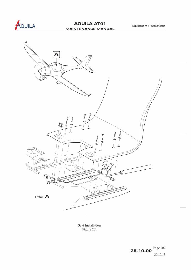
MAINTENANCE MANUAL
AQUILA AT01A
25-10-00Page 202
Seat InstallationFigure 201
Equipment / Furnishings
30.10.13
ADetail-
A

MAINTENANCE MANUAL
AQUILA AT01A
25-10-00Page 203
Equipment / Furnishings
4.
A. Remove Gas Spring Strut Assembly(1) Remove seat cushion.(2)
(3) Disconnect gas spring strut from seat by removing bolt at strut end.(4) Disconnect gas spring strut from fuselage structure by removing bolt at strut base and
remove gas spring strut assembly.
B. Install Gas Spring Strut Assembly(1) Slide remote control of gas spring locking valve into hole of attachment bracket.(2) Reconnect gas spring strut to seat using bolt, washer and self locking nut.(3) Connect gas spring strut to fuselage structure using bolt, washer and self locking nut.(4) Secure remote control to attachment bracket with retaining nut and install control knob.(5) Install seat cushion.
Gas Spring Strut Assembly Removal/Installation
Remove control knob at the remote control of the gas spring locking valve and then theretaining nut which secures the remote control to attachment bracket.
30.10.13

MAINTENANCE MANUAL
AQUILA AT01A
MAINTENANCE MANUAL
AQUILA AT01A
RESTRAINT SYSTEM - MAINTENANCE
1.
A. The seats are equipped with automatic, four point seat belts/shoulder harness assemblies. Afasten the seat belts/shoulder harness. The design incorporates an
inertia reel system for the shoulder portion. The shoulder harnesses are attached to the baggagecompartment bulkhead, and allow complete freedom of movement of the upper torso. In theevent of a sudden deceleration, the reels lock automatically to protect the occupants.The seat belts are attached to fittings on the landing gear bulkhead.
B. Maintenance is limited to the removal and installation of restraint systems.
2.
A. Remove Restraint System(1) Open baggage compartment bulkhead access panel.(2) Remove baggage compartment floor board.(3) Remove bolts securing inertia reel to baggage compartment bulkhead and remove shoulder
harness from aircraft.(4) Remove bolts securing seat belts to fuselage structure and remove seat belts.
B. Install Restraint System(1) Install inertia reel in baggage compartment bulkhead using hex bolts, washers and self-
locking nuts. Route shoulder belts through belt guide in the seat back.(2) Attach seat belts to fuselage structure using hex bolts, spacers, washers and self- locking nuts.(3) Install all items removed for access.
General
Restraint System Removal/Installation
central rotary buckle is used to
25-11-00Page 201
Equipment / Furnishings
30.10.13

MAINTENANCE MANUAL
AQUILA AT01A

MAINTENANCE MANUAL
AQUILA AT01A
CABIN INTERIOR - MAINTENANCE
1.
A. The panels, coverings and carpets can be removed for maintenance purposes.
B. For cabin interior cleaning and care refer to chapter 12, section "Cabin interior - Cleaning andCare".
2.
A. Panels are typically attached to the aircraft fuselage structure .
B. Seat cushions and carpets are fixed with hook-and-loop fasteners.
C. See figure 201 for an exploded view of the cabin interior.
General
Panels, Coverings and Carpets Removal and Installation
with small screws
25-12-00Page 201
30.10.13

MAINTENANCE MANUAL
AQUILA AT01A
25-12-00Page 202
Equipment / Furnishings
Panels and CoversFigure 201 (1)
30.10.13
211 DL
remove 211 BB
remove 211 CCremove 211 ECremove 211 FBremove 211 FTremove 211 GT
remove 211 FT
remove 211 FTremove 211 FBremove 211 LC
1)
remove 211 FTremove 211 FB
see 211 DL
211 AB 211 BB
211 FT
211 FB
211 EC
211 LC1)
211 GT
211 DR211 CC
211 Hl
211 HR
A
ADetail-
1)AT01-101 up to AT01-114 only.
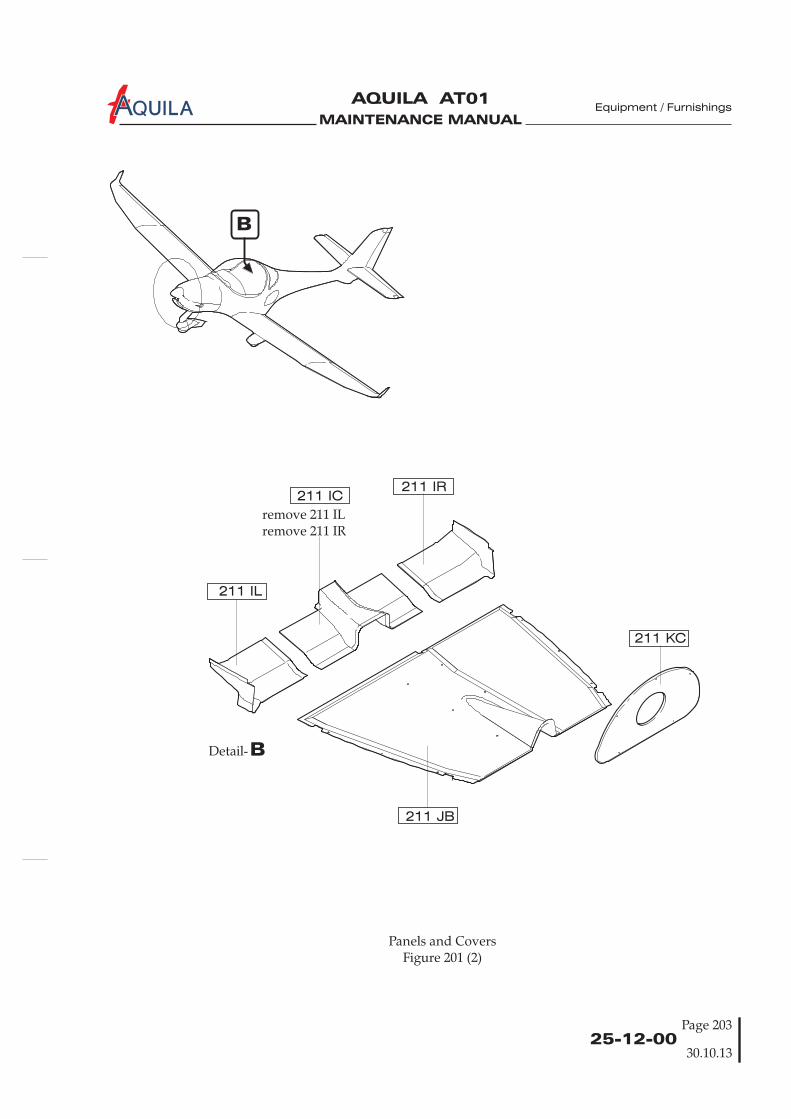
MAINTENANCE MANUAL
AQUILA AT01A
25-12-00Page 203
Equipment / Furnishings
remove 211 ILremove 211 IR
211 IC211 IR
211 IL
211 JB
211 KC
B
BDetail-
Panels and CoversFigure 201 (2)
30.10.13

MAINTENANCE MANUAL
AQUILA AT01A Equipment / Furnishings
MAINTENANCE MANUAL
AQUILA AT01A
CARGO TIE-DOWNS - MAINTENANCE
1.
A. Eight cargo tie-down rings are provided to secure baggage. Baggage nets may be used to holdbaggage in position during flight.The cargo tie-down rings are secured directly to the floorboard by nutplates or they secure thefloorboard to the supports.
General
25-50-00Page 201
Equipment / Furnishings
30.10.13

MAINTENANCE MANUAL
AQUILA AT01A
MAINTENANCE MANUAL
AQUILA AT01A
EMERGENCY EQUIPMENT - DESCRIPTION
1.
A. This section describes those items of equipment carried for use in emergencies and includes theemergency locator transmitter (ELT) and a fire extinguisher.
B. As standard the aircraft is equipped with a Kannad 406 AF Compact ELT. Due to the multiplicityof equipment coming onto the market a different ELT may be installed. Refer to the manualsprovided by the equipment manufacturer for further information.
2. (Ref. Fig. 1)
A. The ELT is designed to transmit on the frequencies 121,5 MHz (some ELT's additionally 243 MHz)and 406 MHz. The basic emergency frequency 121,5 MHz is mainly used for homing in the finalstages of the rescue operations. The 406 MHz frequency is used by the COSPAS-SARSAT satellitesfor precise pinpointing and identification of the aircraft in distress.The ELT can be activated either automatically when a crash occurs or manually by means of acontrol switch on the front panel. The incorporated g-switch activates the unit if it detects adeceleration along the longitudinal axis.Once activated, the transmitter operates continuously on 121,5 (and 243 MHz).Simultaneously, during the first 24 hours of operation, a 112 bit digital message (identification onlyin the short message configuration) is transmitted on 406 MHz every 50 seconds.
B. The ELT is installed on the baggage compartment floor immediately behind the right seat back.The ELT antenna is located on top of fuselage behind the cabin. The ELT remote control panel /indicator (RCPI) is mounted on the instrument panel, right side.For in-flight use, both the front panel of the ELT and the RCPI are easily accessible from the pilot’snormal seated position. If it is equipped with a portable antenna the unit can be removed fromthe aircraft and used as a personal locating device when it is necessary to leave the aircraft after anaccident.The ELT front panel includes a 3-position ARM/OFF/ON switch.With the control switch in ARM position the ELT is in stand-by mode for automatic activation, thenormal operation mode. Selecting the ON position starts the transmission on 121,5 / 243 MHzimmediately after the self-test, the 406 MHZ transmission starts after 50 seconds.
Introduction
Description and Operation
MHZ
Equipment / Furnishings
25-60-0030.10.13
Page 1
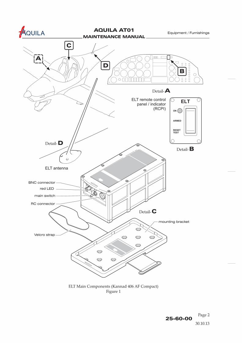
MAINTENANCE MANUAL
AQUILA AT01A
ELT Main Components (Kannad 406 AF Compact)Figure 1
Page 2
Equipment / Furnishings
25-60-00
A
ADetail-
BDetail-
CDetail-
DDetail-
D
C
B
ELT remote controlpanel / indicator
(RCPI)
ELT antenna
BNC connector
red LED
main switch
Velcro strap
mounting bracket
RC connector
30.10.13
MAINTENANCE MANUAL
AQUILA AT01A
EMERGENCY LOCATER TRANSMITTER - MAINTENANCE
1.
A. This section covers removal and installation procedures of ELT components as well necessaryperiodic maintenance.
B. Consider all publications / requirements of the appropriate national authority regarding ELToperation and maintenance.
C. Refer to the publications provided by the ELT manufacturer for complete information oninstallation, programming, operation and maintenance of the ELT.
2.
A. Remove ELT(1) Open the baggage compartment door.(2) Turn the main transmitter control switch on the ELT to the OFF position.(3) Disconnect antenna cable from front panel off the ELT.(4) Unstrap transmitter unit and remove from aircraft.
B. Install ELT
THE ELT MUST BE MOUNTED WITH THE ARROW (PRINTED ON THEBATTERY CASE AND LABELED “FLIGHT DIRECTION”) POINTING IN THEDIRECTION OF FLIGHT.
(1) Install transmitter on to mounting tray with arrow on battery case pointing in direction offlight and secure with strap.
(2) Connect antenna cable to front of ELT.(3) Perform a functional test (refer to “Adjustment/Test” below).
3.
A. Remove ELT Antenna(1) Open baggage compartment door and remove access / inspection plate 211 KC (refer to
25-12-00).(2) Disconnect antenna cable from antenna base.(3) Supporting the antenna, remove nuts and washers securing ELT antenna to fuselage, remove
ground wire.(4) Remove mounting plate.(5) Remove antenna with gasket from topside of fuselage.
General
ELT Removal/Installation
WARNING:
ELT Antenna Removal/Installation
Page 201
Equipment / Furnishings
25-62-0030.10.13

MAINTENANCE MANUAL
AQUILA AT01A
B. Install ELT Antenna(1) Position antenna with gasket on topside of fuselage.(2) From inside the fuselage install mounting plate.(3) Secure antenna base to topside of fuselage using screws, nuts and washers. Reinstall ground
wire.(4) Reconnect coaxial connector and secure.(5) Install access / inspection plate 211 KC (refer to 25-12-00).(6) Perform a functional test (refer to “Adjustment/Test” below).
4.
BATTERY REPLACEMENT MAY ONLY BE CARRIED OUT BY A MAINTENANCEORGANIZATION.
A. The transmitter battery expiry date is fixed at 5 or 6 years after manufacture. Battery replacement is mandatory:
(1) after any activation for distress purposes;(2) after any unintentional activation for an unknown duration;(3) after more than one hour of real transmission (cumulated duration);(4) before or on battery expiration date.
The identification and maintenance marking affixed to the ELT casing providesinformation on battery (type, expiry date), identification data programmed in the ELT(protocol, identification number, hexadecimal transcription of the beacon identificationcode) and aircraft (tail number).
5.
Battery Replacement
WARNING:
NOTE:
Adjustment/Test
depending onmanufacturer
A. For signal transmission test, operational test of the controls and crash sensor and self-testprocedures refer to the Kannad 406 AF Compact Installation/Operation Manual, P/N 0141922,respectively to the documentation provided by the ELT manufacturer.
6.
A. The following inspections must be performed at least once every 12 months. For inspection of theKannad 406 AF Compact ELT, refer to the Kannad 406 AF Compact Installation/Operation Manual,P/N 0141922.
(1) Remove ELT from mounting bracket (refer to “ELT Removal/Installation” above).(2) Inspect ELT, mounting bracket and fasteners for cracks and other obvious damage.(3) Inspect cable connection for cuts or abrasions on its outer jacket. Disconnect the BNC
connectors at both ends. Examine the BNC connectors and the mating plug on the antennaand ELT unit for any signs of corrosion or damage.
(4) Gain access to the ELT battery and inspect. No corrosion should be detectable. Verify that thebatteries are approved and check the expiration date. Replace if necessary.
(5) Verify the external placard “ELT LOCATED HERE” is firmly in place and legible.(6) Perform ELT functional test (refer to “Adjustment/Test” above) and reinstall ELT.
Inspection/Check
Page 202
Equipment / Furnishings
25-62-0030.10.13
MAINTENANCE MANUAL
AQUILA AT01A
25-66-00Page 201
Equipment / Furnishings
FIRE EXTINGUISHER - MAINTENANCE
1.
A. The aircraft is equipped with a liquefied-gas type fire extinguisher AIR TOTAL HAL 1 mounted ina quick-release bracket attached to the floor board of the baggage compartment, behind the rightseat.The fire extinguisher uses Halon 1211, a liquid gas which is non-toxic and is approved for use onclass A, B (liquid, grease) and class C (electrical equipment) fires.
B. For more information on the fire extinguisher, refer to the operating instructions for fireextinguishers AIR TOTAL HAL 1; HAL 1,2; HAL 2,5 supplied with the extinguisher.
2.
A. Technical data:(1) Extinguishing agent Halon 1211(2) Fire class GER. ABC(3) U.S. class ABC(4) Total weight 2,2 kg (- 2% / year, max. 10%)(5) Filling pressure 11 bars
B. Handling(1) Lift carrying handle.(2) Press down safeguard.(3) Depress trigger.
3.
B. The charge pressure must be checked regularly via the manometer. Verify that the seal wire is notbroken. After use, the extinguisher must be refilled by the manufacturer. After 10 years, a majoroverhaul must be carried out by the manufacturer.
General
Description and Operation
Maintenance Instructions
4.
A. Remove Fire Extinguisher(1) Release quick-release clamp.(2) Remove fire extinguisher from bracket assembly.
B. Install Fire Extinguisher(1) Position fire extinguisher in bracket assembly.(2) Secure with quick release clamp.
Fire Extinguisher Removal/Installation
Aircraft equipped with an AIR TOTAL fireextinguisher
EFFECTIVITY
30.10.13

MAINTENANCE MANUAL
AQUILA AT01A
MAINTENANCE MANUAL
AQUILA AT01A
25-66-00Page 201
FIRE EXTINGUISHER - MAINTENANCE
1.
A. The aircraft is equipped with a liquefied-gas type fire extinguisher H3R Aviation RT A400mounted in a quick-release bracket attached to the floor board of the baggage compartment,behind the right seat.The fire extinguisher uses Halon 1211 / 1301, a liquid gas which is non-toxic and is approved foruse on class B (liquid, grease) and class C (electrical equipment) fires.
B. For more information on the fire extinguisher, refer to the instruction manual for the fireextinguisher supplied with the extinguisher. See also the “Monthly Inspection Record”.
2.
A. Technical data:(1) Extinguishing agent Halon 1211 / 1301(2) Fire class GER. A, B, C(3) U.S. class(4) Total weight 0.530 kg (± 10g)
B. Handling(1) Lift carrying handle.(2) Pull out pin.(3) Press lever.
3.
A. Inspect monthly.B. Verify that the yellow seal wire is not broken.C. No obvious physical damage, corrosion, or clogged nozzle.D. HMIS label (Hazardous Materials Identification System) is in place.E. Weigh the unit and return to the manufacturer if the gross weight is below 500g.
: When an inspection reveals a deficiency in any of the conditions listed above, the fireextinguisher must be removed from service, not discharged, and returned to H3R, a fireequipment dealer or distributor so that the halon can be recovered.
F. After use, the extinguisher must be returned to the manufacturer.G. After 12 years, remove extinguisher from service regardless of condition.
General
Description and Operation
Maintenance Instructions
NOTE
A, B, C
Aircraft equipped with a H3R fire extinguisher
EFFECTIVITY
Equipment / Furnishings
30.10.13
MAINTENANCE MANUAL
AQUILA AT01A Equipment / Furnishings
Page 20225-66-00
30.10.13
4.
A. Remove Fire Extinguisher(1) Release quick-release clamp.(2) Remove fire extinguisher from bracket assembly.
B. Install Fire Extinguisher(1) Position fire extinguisher in bracket assembly.(2) Secure with quick release clamp.
Fire Extinguisher Removal/Installation
Aircraft equipped with a H3R fire extinguisher
EFFECTIVITY

MAINTENANCE MANUAL
AQUILA AT01A
CHAPTER 27
FLIGHT CONTROLS

MAINTENANCE MANUAL
AQUILA AT01A
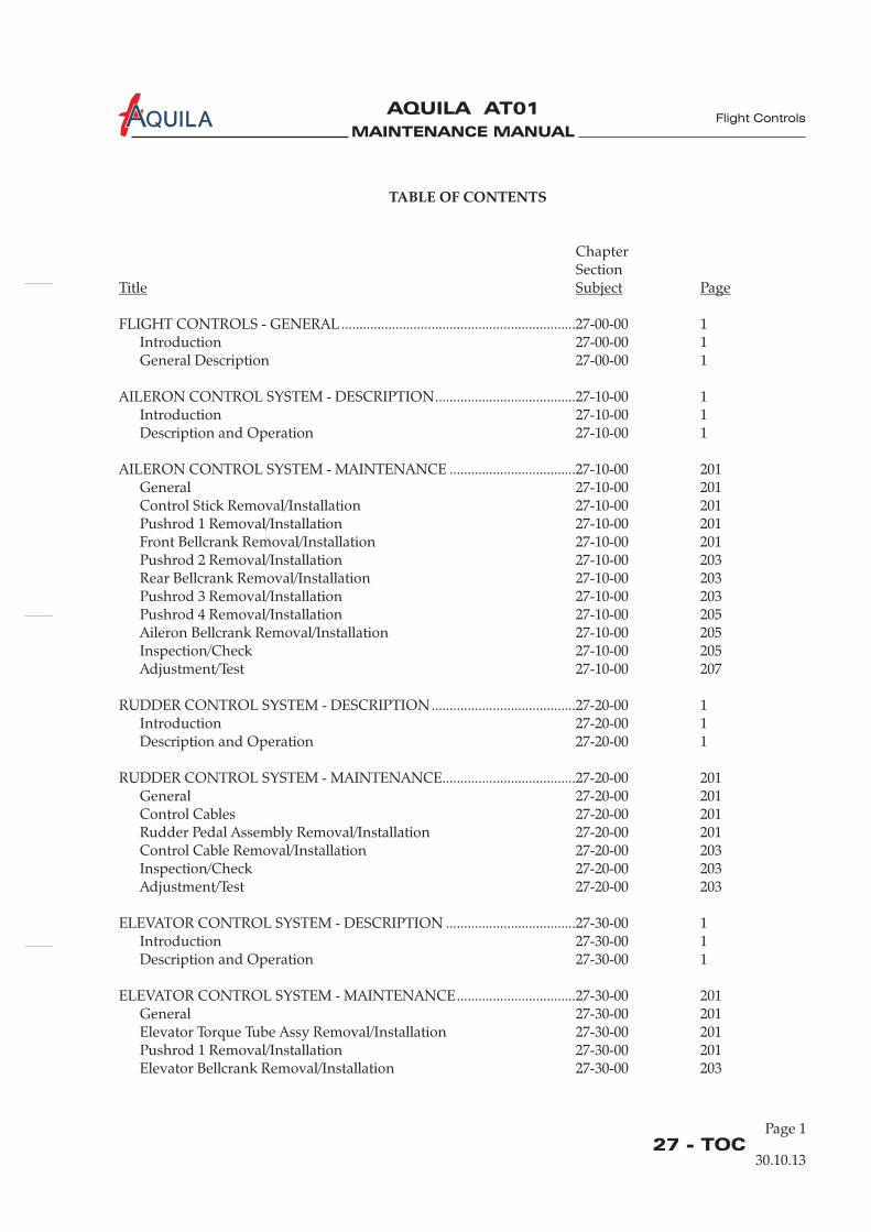
MAINTENANCE MANUAL
AQUILA AT01A
Page 127 - TOC
Flight Controls
TABLE OF CONTENTS
ChapterSection
FLIGHT CONTROLS - GENERAL .................................................................27-00-00 1Introduction 27-00-00 1General Description 27-00-00 1
AILERON CONTROL SYSTEM - DESCRIPTION.......................................27-10-00 1Introduction 27-10-00 1Description and Operation 27-10-00 1
AILERON CONTROL SYSTEM - MAINTENANCE ...................................27-10-00 201General 27-10-00 201Control Stick Removal/Installation 27-10-00 201Pushrod 1 Removal/Installation 27-10-00 201Front Bellcrank Removal/Installation 27-10-00 201Pushrod 2 Removal/Installation 27-10-00 203Rear Bellcrank Removal/Installation 27-10-00 203Pushrod 3 Removal/Installation 27-10-00 203Pushrod 4 Removal/Installation 27-10-00 205Aileron Bellcrank Removal/Installation 27-10-00 205Inspection/Check 27-10-00 205Adjustment/Test 27-10-00 207
RUDDER CONTROL SYSTEM - DESCRIPTION........................................27-20-00 1Introduction 27-20-00 1Description and Operation 27-20-00 1
RUDDER CONTROL SYSTEM - MAINTENANCE.....................................27-20-00 201General 27-20-00 201Control Cables 27-20-00 201Rudder Pedal Assembly Removal/Installation 27-20-00 201Control Cable Removal/Installation 27-20-00 203Inspection/Check 27-20-00 203Adjustment/Test 27-20-00 203
ELEVATOR CONTROL SYSTEM - DESCRIPTION ....................................27-30-00 1Introduction 27-30-00 1Description and Operation 27-30-00 1
ELEVATOR CONTROL SYSTEM - MAINTENANCE.................................27-30-00 201General 27-30-00 201Elevator Torque Tube Assy Removal/Installation 27-30-00 201Pushrod 1 Removal/Installation 27-30-00 201Elevator Bellcrank Removal/Installation 27-30-00 203
Title Subject Page
30.10.13
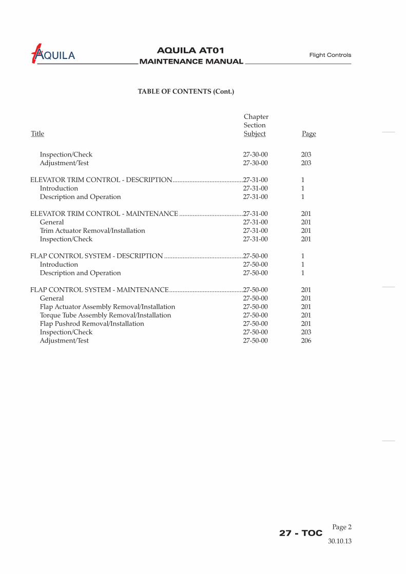
MAINTENANCE MANUAL
AQUILA AT01A
27 - TOC
TABLE OF CONTENTS (Cont.)
ChapterSection
Title Subject Page
Flight Controls
Inspection/Check 27-30-00 203Adjustment/Test 27-30-00 203
ELEVATOR TRIM CONTROL - DESCRIPTION..........................................27-31-00 1Introduction 27-31-00 1Description and Operation 27-31-00 1
ELEVATOR TRIM CONTROL - MAINTENANCE ......................................27-31-00 201General 27-31-00 201Trim Actuator Removal/Installation 27-31-00 201Inspection/Check 27-31-00 201
FLAP CONTROL SYSTEM - DESCRIPTION ...............................................27-50-00 1Introduction 27-50-00 1Description and Operation 27-50-00 1
FLAP CONTROL SYSTEM - MAINTENANCE............................................27-50-00 201General 27-50-00 201Flap Actuator Assembly Removal/Installation 27-50-00 201Torque Tube Assembly Removal/Installation 27-50-00 201Flap Pushrod Removal/Installation 27-50-00 201Inspection/Check 27-50-00 203Adjustment/Test 27-50-00 206
30.10.13
Page 2
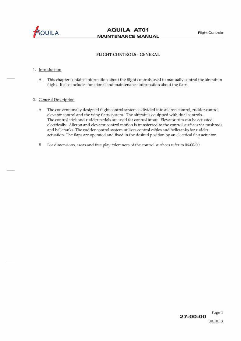
MAINTENANCE MANUAL
AQUILA AT01A
27-00-00
FLIGHT CONTROLS - GENERAL
1.
A. This chapter contains information about the flight controls used to manually control the aircraft inflight. It also includes functional and maintenance information about the flaps.
2.
A. The conventionally designed flight control system is divided into aileron control, rudder control,elevator control and the wing flaps system. The aircraft is equipped with dual controls.The control stick and rudder pedals are used for control input. Elevator trim can be actuatedelectrically. Aileron and elevator control motion is transferred to the control surfaces via pushrodsand bellcranks. The rudder control system utilizes control cables and bellcranks for rudderactuation. The flaps are operated and fixed in the desired position by an electrical flap actuator.
B. For dimensions, areas and free play tolerances of the control surfaces refer to 06-00-00.
Introduction
General Description
Flight Controls
30.10.13
Page 1

MAINTENANCE MANUAL
AQUILA AT01A
MAINTENANCE MANUAL
AQUILA AT01A
27-10-00
Flight Controls
AILERON CONTROL SYSTEM - DESCRIPTION
1.
A. This section describes that portion of the flight control system which controls the position andmovement of the ailerons. The rigging procedure for the aileron control system is also provided.The ailerons are actuated via pushrods and bellcranks. Each aileron has weight compensation.To correct the tendency to roll precisely, a ground-adjustable trim tab is provided at the leadingedge of the left aileron.
2.
A. For aileron control system design and function refer to figure 1.
Introduction
Description and Operation
30.10.13
Page 1
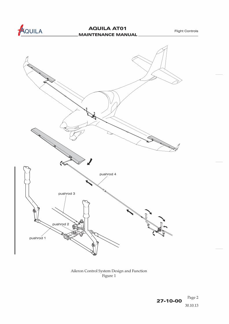
MAINTENANCE MANUAL
AQUILA AT01A
27-10-00
Aileron Control System Design and FunctionFigure 1
pushrod 4
pushrod 3
pushrod 1
pushrod 2
Flight Controls
30.10.13
Page 2
MAINTENANCE MANUAL
AQUILA AT01A
27-10-00Page 201
Flight Controls
AILERON CONTROL SYSTEM - MAINTENANCE
WARNING: WHEN INSTALLING COMPONENTS OF CONTROL SYSTEM, NEW SELF-LOCKINGNUTS SHOULD ALWAYS BE USED. NEVER USE A SELF-LOCKING NUT MORE THANONCE.
A. For a breakdown of components, refer to figure 201, 202 and 203.
1.
2.
A. Remove Control Stick(1) Remove access panel 211 HL (HR) (refer to 25-12-00).(2) Disconnect electrical cable to the transmission button.(3) Disconnect pushrod at control stick base.(4) Remove bolt securing control stick to torque tube assembly and remove stick.
B. Install Control Stick(1) Position control stick and secure to torque tube assembly using bolt, washer and nut.(2) Connect pushrod to control stick base.(3) Reconnect electrical cable to the transmission button.(4) Install access panel 211 HL (HR) (refer to 25-12-00).
3.
A. Remove Pushrod 1(1) Remove access panel 211 HL (HR) (refer to 25-12-00).(2) Disconnect pushrod at control stick base.(3) Disconnect pushrod at front bell crank and remove pushrod.
B. Install Pushrod 1(1) Connect pushrod to front bellcrank and control stick base.(2) Perform aileron control system inspection/check (refer to “Inspection/Check” below).(3) Install access panel 211 HL (HR) (refer to 25-12-00).
4.
A. Remove Front Bellcrank(1) Remove access plate 210 AB (refer to 06-30-00).(2) Remove access panel 211 HL and 211 HR (refer to 25-12-00).(3) Disconnect pushrods at front bellcrank.(4) Remove pivot bolt securing bellcrank to bellcrank brackets and remove bellcrank.
General
Control Stick Removal/Installation
Pushrod Removal/Installation
Front Bellcrank Removal/Installation
30.10.13
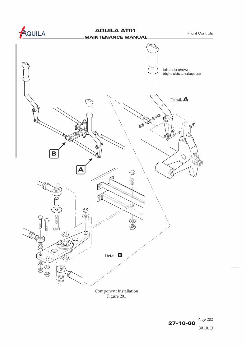
MAINTENANCE MANUAL
AQUILA AT01A
27-10-00Page 202
Component InstallationFigure 201
ADetail-
BDetail-
B
A
left side shown
(right side analogous)
Flight Controls
30.10.13
MAINTENANCE MANUAL
AQUILA AT01A
27-10-00Page 203
Flight Controls
B. Install Front Bellcrank(1) Position front bellcrank between brackets and secure using bolt, washer and nut.(2) Connect pushrods to front bellcrank.(3) Perform aileron control system inspection/check ( ).(4) Install access plate 210 AB (refer to 06-30-00).(5) Install access panel 211 HL and 211 HR (refer to 25-12-00).
5.
A. Remove Pushrod 2(1) Remove access plate 210 AB (refer to 06-30-00).(2) Disconnect pushrod at front bellcrank.(3) Disconnect pushrod at rear bell crank and remove pushrod.
B. Install Pushrod 2(1) Connect pushrod to front bellcrank and rear bellcrank.(2) Perform aileron control system inspection/check ( ).(3) Install access plate 210 AB (refer to 06-30-00).
6.
A. Remove Rear Bellcrank(1) Remove access plate 210 AB (refer to 06-30-00).(2) Disconnect pushrods at rear bellcrank.(3) Remove nuts, washers and bellcrank axle securing bellcrank to bellcrank brackets and remove
bellcrank.
B. Install Rear Bellcrank(1) Position rear bellcrank between brackets and secure using axle, washers and nuts.(2) Attach pushrods to rear bellcrank.(3) Perform aileron control system inspection/check ( ).(4) Install access plate 210 AB (refer to 06-30-00).
7.
A. Remove Pushrod 3(1) Remove access plate 210 AB (refer to 06-30-00).(2) Disconnect pushrod at rear bellcrank.(3) Disconnect pushrod at pushrod 4.
B. Install Pushrod 3(1) Connect pushrod to rear bellcrank and pushrod 4.(2) Perform aileron control system inspection/check ( ).(3) Install access plate 210 AB (refer to 06-30-00).
refer to “Inspection/Check” below
refer to “Inspection/Check” below
refer to “Inspection/Check” below
refer to “Inspection/Check” below
Pushrod 2 Removal/Installation
Rear Bellcrank Removal/Installation
Pushrod 3 Removal/Installation
30.10.13
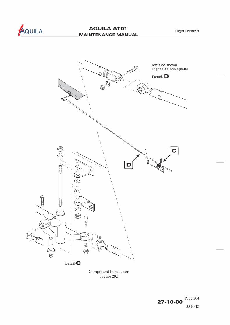
MAINTENANCE MANUAL
AQUILA AT01A
27-10-00Page 204
Component InstallationFigure 202
C
D
DDetail-
CDetail-
left side shown
(right side analogous)
Flight Controls
30.10.13
MAINTENANCE MANUAL
AQUILA AT01A
27-10-00Page 205
Flight Controls
8.
A. Remove Pushrod 4(1) Remove wing (refer to 57-10-00).(2) Open access panel 520 (620) AB (refer to 06-30-00).(3) Disconnect pushrod at aileron bellcrank.(4) Remove rod end bearing.(5) Cautiously withdraw pushrod from wing.
B. Install Pushrod 4(1) Position pushrod into the wing.(2) Install rod end bearing.(3) Attach pushrod to aileron bellcrank.(4) Install wing (refer to 57-10-00).(5) Connect pushrod 4 to pushrod 3.(6) Re-rig aileron control system ( ).(7) Perform aileron control system inspection/check ( ).(8) Close access panel 520 (620) AB (refer to 06-30-00).
9.
A. Remove Aileron Bellcrank(1) Open access plate 520 (620) AB (refer to 06-30-00).(2) Disconnect pushrods at aileron bellcrank.(3) Remove pivot bolt securing bellcrank to bellcrank bracket assembly. Remove bellcrank and
washers through access plate.
B. Install Aileron Bellcrank(1) Attach bellcrank to structure using pivot bolt, ensuring required washers are in place.(2) Reconnect aileron pushrod to bellcrank.(4) Reconnect pushrod 4 to the bellcrank.(5) Perform aileron control system inspection/check ( ).(6) Close inspection/access plate 520 (620) AB (refer to 06-30-00).
10.
A. Inspection/Check(1) Perform a visual inspection of the aileron control system. Check all components for proper
installation and security. No signs of excessive play.
The maximum permissible value of aileron play at the hinge pins is 1,0 mm(0.04 in.) axial play and 0,3 mm (0.01 in.) radial play. The maximum control circuitbacklash is 10 mm (0.4 in.).In case of excessive play of the control surfaces in their hinges, replace worn hingebushings (refer also to 57-50-00).
Pushrod 4 Removal/Installation
Aileron Bellcrank Removal/Installation
Inspection/Check
NOTE:
refer to “Adjustment/Test” belowrefer to “Inspection/Check” below
refer to “Inspection/Check” below
30.10.13
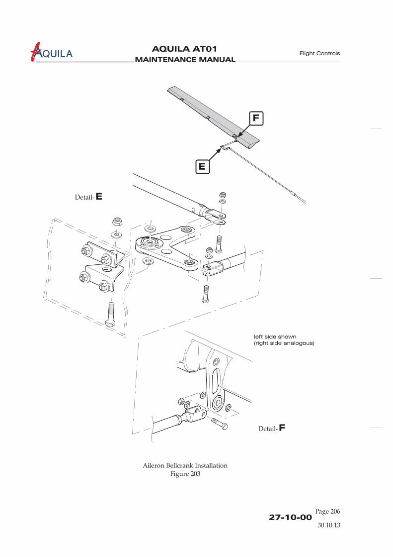
MAINTENANCE MANUAL
AQUILA AT01A
27-10-00Page 206
Aileron Bellcrank InstallationFigure 203
E
F
FDetail-
EDetail-
left side shown
(right side analogous)
Flight Controls
30.10.13

MAINTENANCE MANUAL
AQUILA AT01A
27-10-00Page 207
Flight Controls
(2) Verify minimum rod end thread engagement of 8 mm (0.312 in.).(3) Verify ailerons can be moved smoothly through the full travel. No grinding is audible.(4) Check ailerons for correct travel using an inclinometer. If necessary perform aileron control
system adjustment/test ( ).
For aileron rigging specifications, refer to chapter 6 „Dimensions and Areas“.
(5) Install all items removed for access.
11.
A. Adjustment/Test(1) Remove access plate 210 AB (refer to 06-30-00).(2) Remove access plate 620 AB and 520 AB (refer to 06-30-00).(3) Remove access plate 211 HL and HR (refer to 06-30-00).(4) Adjust pushrod 2 until:
(a) front and rear bellcrank are parallel to each other.(b) both bellcranks are perpendicular to the wing spar.
(5) Fix bellcranks in a suitable manner.(6) Adjust pushrod 3 for each aileron so the aileron bellcrank is in neutral position (line between
bellcrank pivot bolt and aileron pushrod attach bolt is parallel to the wing spar).(7) Adjust each aileron pushrod until the control surface is neutral with reference to wing trailing
edge.(8) Adjust pushrod 1 for each control stick until the control stick is in neutral position.(9) Set free the front and rear bellcrank.(10) Fasten inclinometer to left aileron and set at 0°.(11) Adjust aileron stop bolts at control yoke assembly to allow up and down aileron travel
specified in 06-10-00.(12) Perform an aileron control system inspection/check ( ).(13) Install all items removed for access.
refer to “Adjustment/Test” below
refer to “Inspection/Check” above
NOTE:
Adjustment/Test
30.10.13

MAINTENANCE MANUAL
AQUILA AT01A
MAINTENANCE MANUAL
AQUILA AT01A
27-20-00
RUDDER CONTROL SYSTEM - DESCRIPTION
1.
A. This section describes that portion of the flight control system which controls the position andmovement of the rudder. The rigging procedure for the rudder control system is also provided.The rudder control system consists of conventional rudder pedals, cables and pulleys.
2.
A. For rudder control system design and function refer to figure 1.
Introduction
Description and Operation
Flight Controls
30.10.13
Page 1

MAINTENANCE MANUAL
AQUILA AT01A
27-20-00
Rudder Control Design and FunctionFigure 1
Flight Controls
30.10.13
Page 2
MAINTENANCE MANUAL
AQUILA AT01A
27-20-00Page 201
RUDDER CONTROL SYSTEM - MAINTENANCE
WARNING: WHEN INSTALLING COMPONENTS OF THE CONTROL SYSTEM, NEW SELF-LOCKING NUTS SHOULD ALWAYS BE USED. NEVER USE A SELF-LOCKING NUTMORE THAN ONCE.
A SYSTEM RIGGING AND INSPECTION/CHECK MUST BE PERFORMED AFTERLOOSENING ANY FLIGHT CONTROL CABLE TO ENSURE PROPER CONTROLSURFACE OPERATION.
1.
A. For a breakdown of the components, refer to figure 201 and 202.
2.
A. The maintenance of the control cables is important for the precise and safe functioning of therudder control system. Control cables should be regularly checked for mechanical damage anddamage caused by corrosion.
(1)Check cables for broken strands of wire by passing a cloth along length of cable. The clothwill snag at such places. If broken wires are found, the affected control cable must beexamined in more detail and removed if necessary. If a broken single wire is found, thecontrol cable must be replaced. The procedures for control cable removal and installation aredescribed below.
(2)External corrosion can be detected by a careful visual examination of the cables. Findinginternal corrosion is more difficult. If internal corrosion is suspected, remove cable from theaircraft and examine more closely, especially in areas with broken wires.
3.
A. Remove Rudder Pedal Assembly(1) Slacken control cables of rudder control.(2) Disconnect control cables from rudder control actuator arms.(4) Disconnect brake master cylinders at rudder pedal assembly.(5) Disconnect steering tubes at rudder bars.(6) Remove bolts securing lower half of the middle bearing block to upper half and remove
lower bearing block half.(7) Remove bolts attaching left and right bearing blocks to firewall and work rudder bars out of
area below instrument panel.
B. Install Rudder Pedal Assembly(1) Position rudder bars in left and right bearing blocks and secure bearing blocks to firewall
using bolts.
General
Control Cables
Broken Wire Check
Corrosion Check
Rudder Pedal Assembly Removal/Installation
Flight Controls
30.10.13
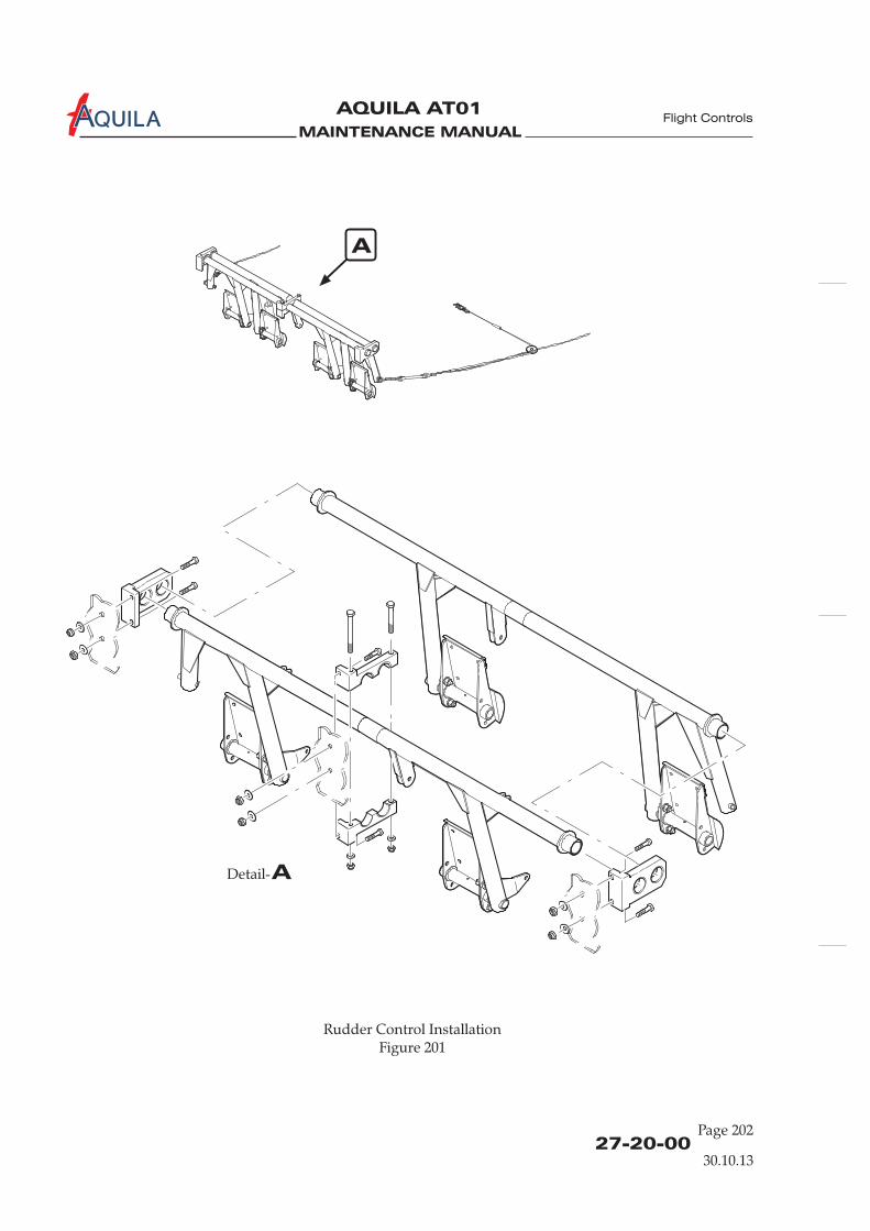
MAINTENANCE MANUAL
AQUILA AT01A
27-20-00Page 202
Rudder Control InstallationFigure 201
ADetail-
A
Flight Controls
30.10.13
MAINTENANCE MANUAL
AQUILA AT01A
27-20-00Page 203
(2) Reinstall lower half of middle bearing block.(3) Reconnect steering tubes to rudder bars.(4) Reconnect master cylinders to the rudder pedal assembly.(5) Reconnect control cables to rudder control actuator arms and re-rig system (refer to
“Adjustment/Test“ below).(6) Check correct operation of the rudder control system (refer to “Inspection/Check” below).
4.
A. Remove a Control Cable(1) Relieve cable tension at turnbuckle.(2) Disconnect control cable at the turnbuckle.(3) Disconnect control cable at the rudder.(4) Cut the eye-end from the control cable which is to be removed at the turnbuckle end.(5) Withdraw control cable from the aircraft.
B. Install a Control Cable
THE CONTROL CABLE EYE-ENDS SHOULD BE INSTALLED BY TRAINEDAND AUTHORIZED PERSONNEL ONLY. IF THE EYE-ENDS ARE NOTINSTALLED PROPERLY; A RUDDER CONTROL SYSTEM FAILURE MAYOCCUR.USE CABLES TO SPECIFICATION LN9374 OR ISO 2020 OR MIL-DTL-83420,STRECHED TO 60% MBS (DIAMETER 3,2 MM [1/8 IN.]).
(1) Prepare a new control cable with the required length and one eye-end.(2) Push that control cable through the tube from the rudder side.(3) Install the second eye-end at the turnbuckle end.(4) Reconnect the control cable to the rudder using bolt, washer and nut.(5) Reconnect the control cable to the turnbuckle using bolt , washer and nut.(6) Rig rudder control cable including cables of the aileron-rudder interconnect and check
correct operation of rudder control system / aileron-rudder interconnect (refer to“Adjustment/Test“ and “Inspection/Check” below).
Control Cable Removal/Installation
WARNING:
Flight Controls
5.
A. Inspection/Check(1) Perform a visual inspection of the rudder control system. Check all components for proper
installation and security. No signs of excessive play.
The maximum permissible value of rudder play at hinge pins is 1,0 mm (0.04 in.)axial play and 0,3 mm (0.01 in.) radial play.In case of excessive play of the control surface in its hinges, replace worn hingebushings (refer also to 57-50-00).
(2) Examine control cables for broken wires and corrosion.
Inspection/Check
NOTE:
30.10.13

MAINTENANCE MANUAL
AQUILA AT01A
Rudder Pedal / Master Cylinder InstallationFigure 202
27-20-00Page 204
Flight Controls
30.10.13
ADetail-
A
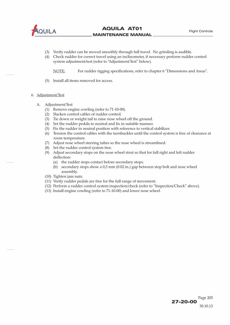
MAINTENANCE MANUAL
AQUILA AT01A
(3) Verify rudder can be moved smoothly through full travel. No grinding is audible.(4) Check rudder for correct travel using an inclinometer, if necessary perform rudder control
system adjustment/test (refer to “Adjustment/Test” below).
For rudder rigging specifications, refer to chapter 6 “Dimensions and Areas“.
(5) Install all items removed for access.
6.
A. Adjustment/Test(1) Remove engine cowling (refer to 71-10-00).(2) Slacken control cables of rudder control.(3) Tie down or weight tail to raise nose wheel off the ground.(4) Set the rudder pedals to neutral and fix in suitable manner.(5) Fix the rudder in neutral position with reference to vertical stabilizer.(6) Tension the control cables with the turnbuckles until the control system is free of clearance at
room temperature.(7) Adjust nose wheel steering tubes so the nose wheel is streamlined.(8) Set the rudder control system free.(9) Adjust secondary stops on the nose wheel strut so that for full right and left rudder
deflection:(a) the rudder stops contact before secondary stops.(b) secondary stops show a 0,5 mm (0.02 in.) gap between stop bolt and nose wheel
assembly.(10) Tighten jam nuts.(11) Verify rudder pedals are free for the full range of movement.(12) Perform a rudder control system inspection/check (refer to “Inspection/Check” above).(13) Install engine cowling (refer to 71-10-00) and lower nose wheel.
NOTE:
Adjustment/Test
27-20-00Page 205
Flight Controls
30.10.13

MAINTENANCE MANUAL
AQUILA AT01A
MAINTENANCE MANUAL
AQUILA AT01A
27-30-00
ELEVATOR CONTROL SYSTEM - DESCRIPTION
1.
A. This section describes that portion of the flight control system which controls the position andmovement of the elevator. The rigging procedure for the elevator control system is also provided.The system consists of control sticks, elevator torque tube assembly, pushrods and the elevatorbellcrank.The aircraft is equipped with an electrical spring-force elevator trim system.
2.
A. For elevator control system design and function refer to figure 1.
Introduction
Description and Operation
Flight Controls
30.10.13
Page 1

MAINTENANCE MANUAL
AQUILA AT01A
27-30-00
Elevator Control System Design and FunctionFigure 1
Flight Controls
pushrod 1
pushrod 2
30.10.13
Page 2

MAINTENANCE MANUAL
AQUILA AT01A
27-30-00Page 201
ELEVATOR CONTROL SYSTEM - MAINTENANCE
WARNING: WHEN INSTALLING COMPONENTS OF THE CONTROL SYSTEM NEW SELF-LOCKING NUTS SHOULD ALWAYS BE USED. NEVER USE A SELF-LOCKING NUTMORE THAN ONCE.
1.
A. For a breakdown of the components, refer to figure 201 and 202.
2.
A. Remove Elevator Torque Tube Assy(1) Remove seats (refer to 25-10-00).(2) Remove control sticks (refer to 27-10-00).(3) Disconnect pushrod 1 from elevator actuation arm.(4) Remove pivot bolt, washers and nut from both ends of the torque tube with which the torque
tube is attached to the support bracket.(5) Remove torque tube from aircraft.
B. Install Elevator Torque Tube Assy(1) Position torque tube between support brackets.(2) Attach pivot bolt, washers and nut to both ends of the torque tube with which the torque
tube is attached to the support bracket.(3) Connect pushrod 1 to elevator actuation arm.(4) Install control sticks (refer to 27-10-00).(5) Check elevator and aileron control for proper operation and rig if necessary (refer to “Aileron
Control System Maintenance“ and „Adjustment/Test“ below).
3.
A. Remove Pushrod 1(1) Remove seats (refer to 25-10-00).(2) Remove baggage compartment floor panel (refer to 25-12-00).(3) Disconnect trim system springs from pushrod.(4) Disconnect pushrod at elevator actuation arm.(5) Disconnect pushrod at elevator bellcrank.(6) Remove pushrod from aircraft.
B. Install Pushrod 1(1) Position pushrod and connect to elevator bellcrank.(2) Connect pushrod to elevator actuation arm.(3) Connect springs of trim system to pushrod.
If spring attachment clamps have been removed, refer to 27-31-00 for their correctposition.
General
Elevator Torque Tube Assy Removal/Installation
Pushrod 1 Removal/Installation
NOTE:
Flight Controls
30.10.13
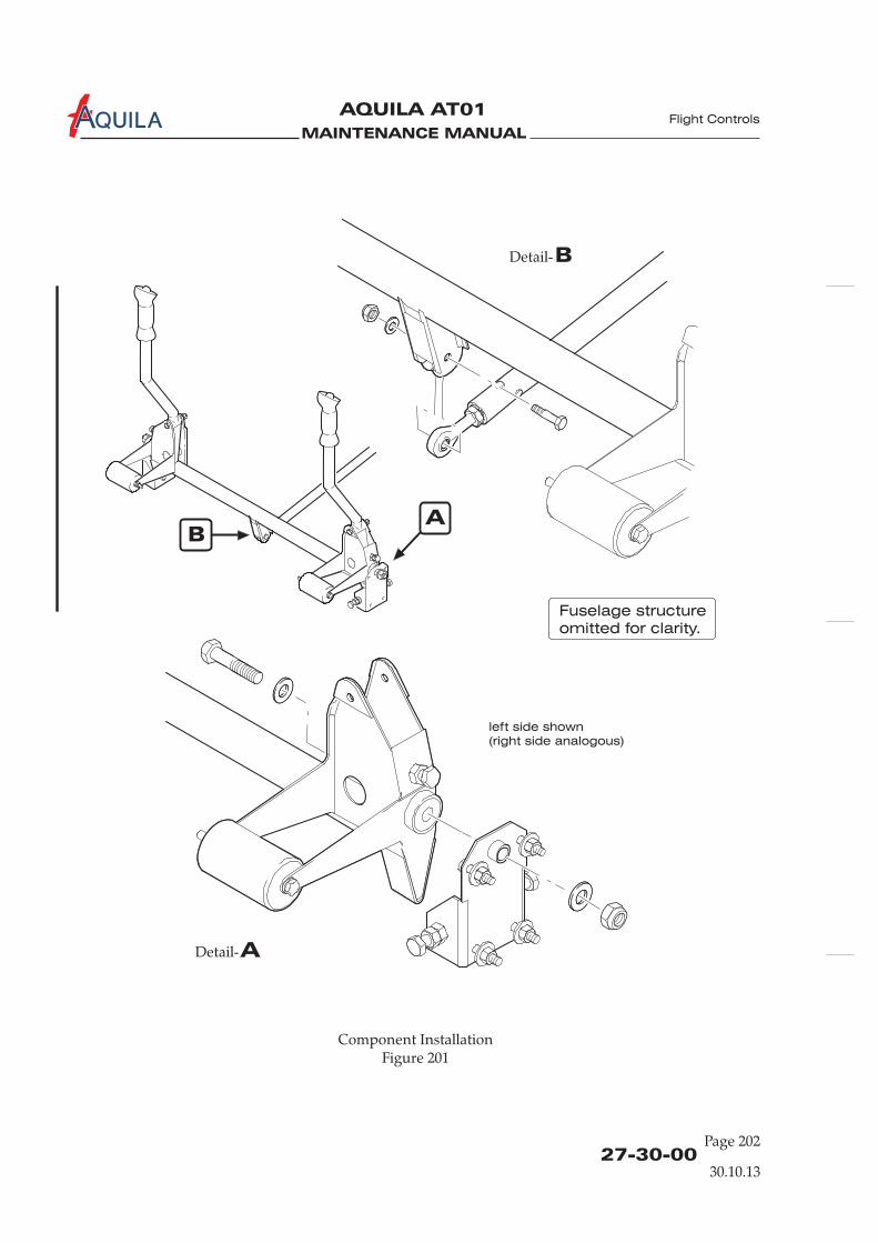
MAINTENANCE MANUAL
AQUILA AT01A
27-30-00Page 202
Component InstallationFigure 201
AB
ADetail-
BDetail-
left side shown
(right side analogous)
Flight Controls
Fuselage structure
omitted for clarity.
30.10.13

MAINTENANCE MANUAL
AQUILA AT01A
27-30-00Page 203
(4) Check elevator control system and elevator trim system for proper operation and rig ifnecessary (refer to 27-30-00 and 27-31-00).
(5) Install baggage compartment floor panel (refer to 25-12-00).(6) Install seats (refer to 25-10-00).
4.
A. Remove Elevator Bellcrank(1) Remove baggage compartment floor panel (refer to 25-12-00).(2) Disconnect pushrods from elevator bellcrank.(3) Remove pivot bolt securing elevator bellcrank to support brackets.(4) Remove elevator bellcrank.
B. Install Elevator Bellcrank(1) Mount bellcrank to structure using pivot bolt, nut and washer. Ensure spacers are placed
correctly.(2) Reconnect pushrods to bellcrank.(3) Check elevator control system and elevator trim system for proper operation and rig if
necessary (refer to 27-30-00 and 27-31-00).(4) Install baggage compartment floor panel (refer to 25-12-00).
Elevator Bellcrank Removal/Installation
Flight Controls
5.
A. Inspection/Check(1) Perform a visual inspection of elevator control system. Check all components for proper
installation and security. No signs off excessive play.
The maximum permissible value of elevator play at hinge pins is 1,0 mm (0.04 in.)axial play and 0,3 mm (0.01 in.) radial play. The maximum control circuit backlashis 10 mm (0.4 in.).In case of excessive play of the control surfaces in their hinges, replace worn hingebushings (refer also to 57-50-00).
(2) Verify minimum rod end thread engagement of 8 mm (0.312 in.).(3) Verify elevator can be moved smoothly through full travel. No grinding is audible.(4) Verify both sticks are free for the full range of movement and maximum up and down
elevator travel is achieved.(5) Check elevator for correct travel using an inclinometer, if necessary perform elevator control
system adjustment/test (refer to “Adjustment/Test” below).
For elevator rigging specifications, refer to chapter 6 “Dimensions and Areas“.
(6) Install all items removed for access.
Inspection/Check
NOTE:
NOTE:
30.10.13
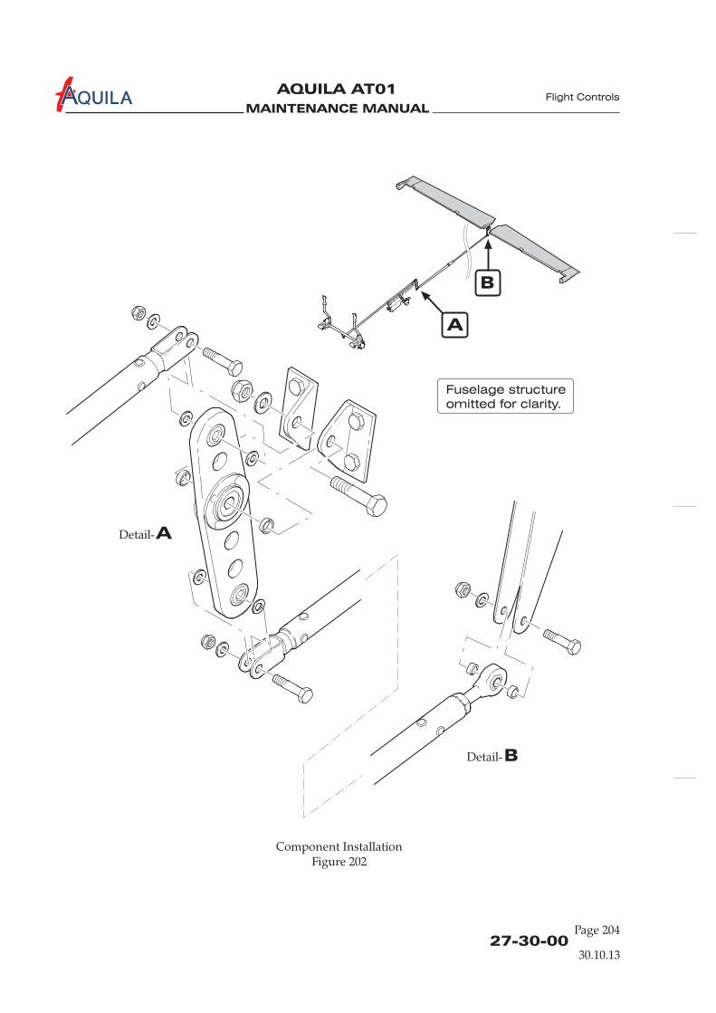
MAINTENANCE MANUAL
AQUILA AT01A
27-30-00Page 204
Component InstallationFigure 202
ADetail-
BDetail-
A
B
Flight Controls
Fuselage structure
omitted for clarity.
30.10.13
MAINTENANCE MANUAL
AQUILA AT01A
27-30-00Page 205
Flight Controls
6.
A. Adjustment/Test(1) Remove baggage compartment floor panel (refer to 25-12-00).(2) Remove access plate 211 HL and HR (refer to 25-12-00).(3) Lock elevator bellcrank in neutral position in a suitable manner (the line between pushrod
attach points on bellcrank is perpendicular to the pushrod 2).(4) Streamline elevator to neutral with horizontal stabilizer by adjusting elevator pushrod
(pushrod 2).(5) Adjust pushrod 1 until the control yoke assembly is in neutral position.
Adjustment/Test
30.10.13

MAINTENANCE MANUAL
AQUILA AT01A
MAINTENANCE MANUAL
AQUILA AT01A
27-31-00
Flight Controls
ELEVATOR TRIM CONTROL - DESCRIPTION
1.
A. The aircraft isequipped with an electrical spring-force trim system. An electrical trim actuatorchanges the pre-load of a pair of springs that applies a defined force to the elevator pushrod.
2.
A. For an illustration of elevator trim control design and function refer to figure 1.
B. The trim system is controlled by a rocker switch located on the rear portion of the middle console.Pressing the forward side of the switch will trim nose down; pressing the rear side of the switchwill trim nose up.The switch operates an electrical trim actuator that is mounted under the baggage compartmentfloor panel, parallel to the elevator pushrod.The electrical circuit of the trim system is protected by a circuit breaker that can be pulled in theevent of a trim system malfunction.
Introduction
Description and Operation
30.10.13
Page 1

MAINTENANCE MANUAL
AQUILA AT01A
ADetail-
elevator pushrod
trim actuator
Elevator Trim System Design and FunctionFigure 1
27-31-00
Flight Controls
Fuselage structure
omitted for clarity.
trim position sensor
30.10.13
A
Page 2

MAINTENANCE MANUAL
AQUILA AT01A Flight Controls
27-31-00Page 201
ELEVATOR TRIM CONTROL - MAINTENANCE
1.
A. For a breakdown of the components, refer to figure 201.
2.
A. Remove Trim Actuator(1) Set the elevator trim system to neutral.(2) Ensure electrical power to aircraft is OFF.(3) Remove baggage compartment floor panel (refer to 25-12-00).(4) Disconnect trim actuator electrical wires at connector.(5) Disconnect the springs at trim system actuation arm.(6) Disconnect trim actuator push rod at trim system actuation arm.(7) Remove bolts securing trim actuator to fuselage structure and remove trim actuator from
aircraft.
B. Install Trim Actuator(1) Attach trim actuator to fuselage structure with bolts, washers and nuts.(2) Reconnect trim actuator push rod to trim system actuation arm using hardware.(3) Reconnect springs to trim system actuation arm.
(4) Connect trim actuator electrical connection.(5) Check for proper function (refer to “Inspection/Check” below).(6) Install baggage compartment floor panel (refer to 25-12-00).
3.
A. Inspection/Check(1) Perform a visual inspection of elevator trim system. Check all components for proper
installation and security. No signs off excessive play.(2) Place BAT switch in ON position.(3) Keep hands away from control stick and run trim actuator to full nose-down trim position
until travel is stopped by limit switch.(4) Check the forward movement of the control stick. Verify the proper trim position indicator
reading.(5) Keep hands away from control stick and run trim actuator to full nose-up trim position until
travel is stopped by limit switch.(6) Check the backward movement of the control stick. Verify the proper trim position indicator
reading.(7) Set the elevator trim to neutral and place BAT switch in OFF position.(8) Install all items removed for access.
General
Trim Actuator Removal/Installation
Inspection/Check
NOTE: There are two different types of springs used in the trim system. The spring onthe forward side is black colored, the spring on the rear side is silver colored.
elevator trim control
30.10.13
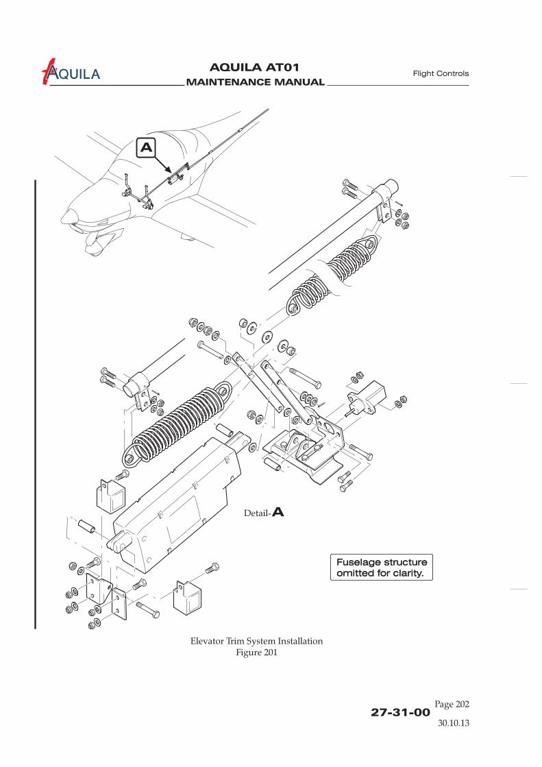
MAINTENANCE MANUAL
AQUILA AT01A
27-31-00Page 202
Elevator Trim System InstallationFigure 201
Flight Controls
Fuselage structure
omitted for clarity.
Fuselage structure
omitted for clarity.
ADetail-
30.10.13
A
MAINTENANCE MANUAL
AQUILA AT01A
FLAP CONTROL SYSTEM - DESCRIPTION
1.
A. This section describes that portion of the flight control system which controls the position andmovement of the flaps. The rigging procedure forthe flap control system is also provided.The aircraft is equipped with electrically actuated flaps. They are operated and fixed in thedesired position by an electrical flap actuator.
2.
A. The wing flaps system consists of a three-position selector switch which is incorporated in theinstrument panel, a LED flap position indicator near the three-position selector switch, the electricflap actuator, located under the baggage floor, a torque tube, pushrods and the flaps on each wing.
B. The linear flap actuator drives the torque tube interconnected between the left and right flaps.Limit switches are attached to the flap actuator. They identify flap position and surface travel, andturn off the actuator once the desired position is reached, i.e: 17° or 35°.The flap actuator has a slip coupling to prevent mechanical damage if a restriction occurs. In theevent of a failure in the electric flap control circuit, torque tube/actuator geometry prevents theflaps from causing an uncontrollable flight condition.
C. For an illustration of flap control system design and function refer to figure 1.
Introduction
Description and Operation
27-50-00
Flight Controls
30.10.13
Page 1
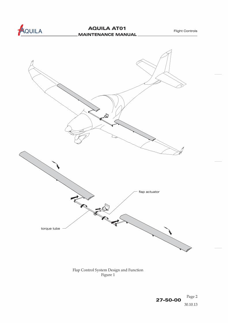
MAINTENANCE MANUAL
AQUILA AT01A
flap actuator
torque tube
Flap Control System Design and FunctionFigure 1
27-50-00Page 2
Flight Controls
30.10.13
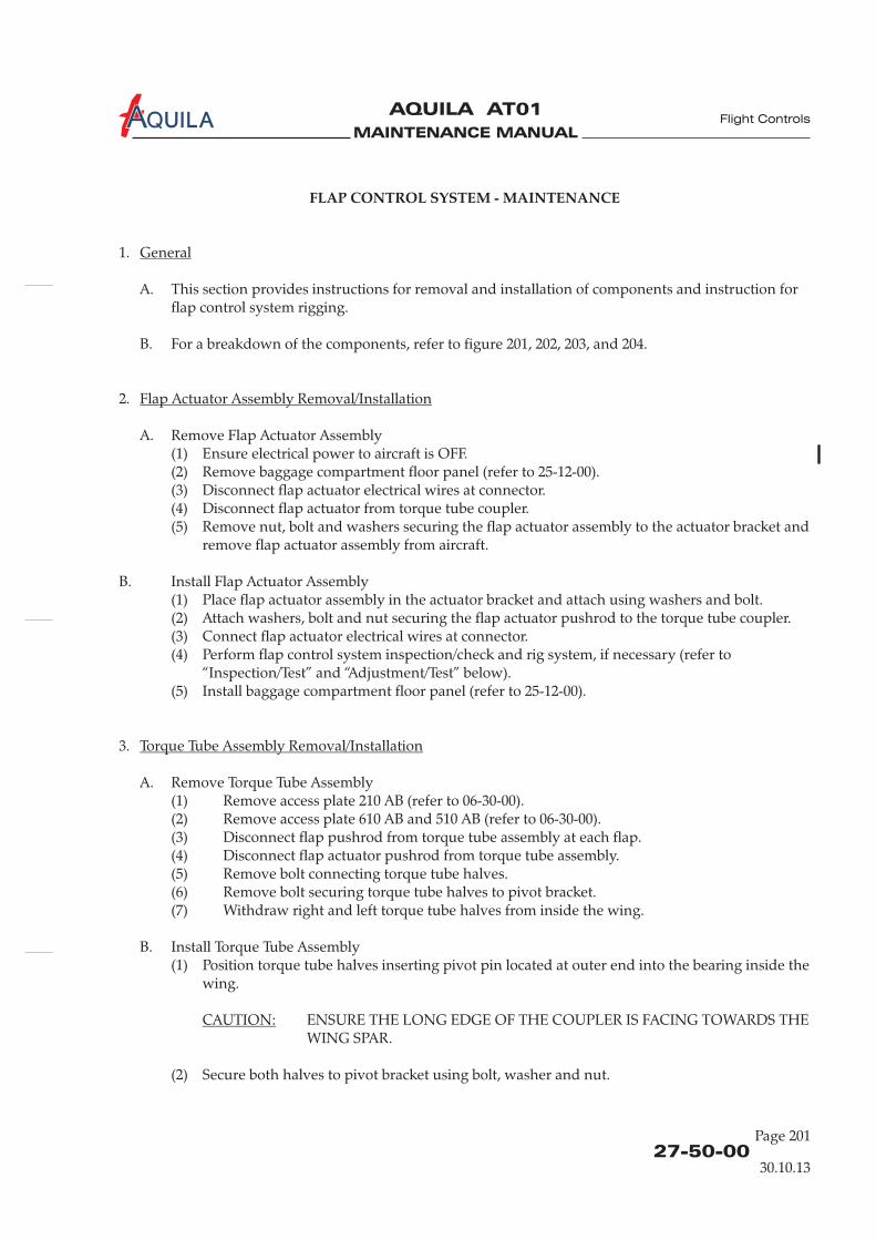
MAINTENANCE MANUAL
AQUILA AT01A Flight Controls
27-50-00Page 201
FLAP CONTROL SYSTEM - MAINTENANCE
1.
A. This section provides instructions for removal and installation of components and instruction forflap control system rigging.
B. For a breakdown of the components, refer to figure 201, 202, 203, and 204.
2.
A. Remove Flap Actuator Assembly(1) Ensure electrical power to aircraft is OFF.(2) Remove baggage compartment floor panel (refer to 25-12-00).(3) Disconnect flap actuator electrical wires at connector.(4) Disconnect flap actuator from torque tube coupler.(5) Remove nut, bolt and washers securing the flap actuator assembly to the actuator bracket and
remove flap actuator assembly from aircraft.
B. Install Flap Actuator Assembly(1) Place flap actuator assembly in the actuator bracket and attach using washers and bolt.(2) Attach washers, bolt and nut securing the flap actuator pushrod to the torque tube coupler.(3) Connect flap actuator electrical wires at connector.(4) Perform flap control system inspection/check and rig system, if necessary (refer to
“Inspection/Test” and “Adjustment/Test” below).(5) Install baggage compartment floor panel (refer to 25-12-00).
3.
A. Remove Torque Tube Assembly(1) Remove access plate 210 AB (refer to 06-30-00).(2) Remove access plate 610 AB and 510 AB (refer to 06-30-00).(3) Disconnect flap pushrod from torque tube assembly at each flap.(4) Disconnect flap actuator pushrod from torque tube assembly.(5) Remove bolt connecting torque tube halves.(6) Remove bolt securing torque tube halves to pivot bracket.(7) Withdraw right and left torque tube halves from inside the wing.
B. Install Torque Tube Assembly(1) Position torque tube halves inserting pivot pin located at outer end into the bearing inside the
wing.
ENSURE THE LONG EDGE OF THE COUPLER IS FACING TOWARDS THEWING SPAR.
(2) Secure both halves to pivot bracket using bolt, washer and nut.
General
Flap Actuator Assembly Removal/Installation
Torque Tube Assembly Removal/Installation
CAUTION:
30.10.13
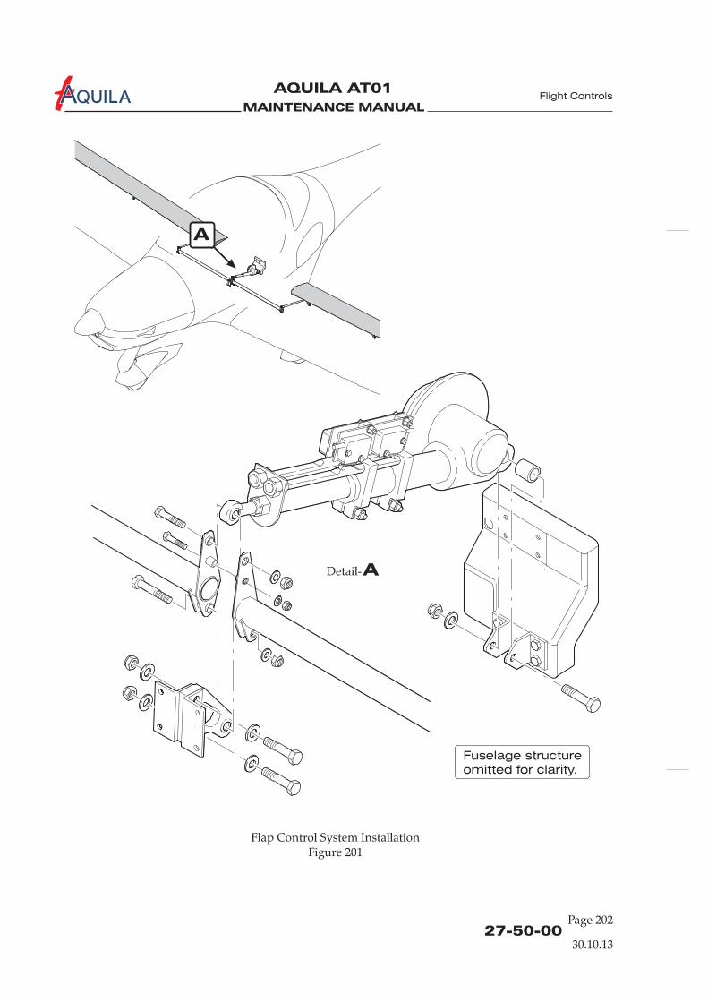
MAINTENANCE MANUAL
AQUILA AT01A
27-50-00Page 202
Flight Controls
ADetail-
A
Flap Control System InstallationFigure 201
Fuselage structure
omitted for clarity.
30.10.13
MAINTENANCE MANUAL
AQUILA AT01A
27-50-00Page 203
Flight Controls
(3) Install spacer and bolt, washer and nut connecting halves.(4) Connect torque tube assembly to flap actuator pushrod.(5) Perform flap control system inspection/check and rig system, if necessary (refer to
“Inspection/Check” and “Adjustment/Test” below).
4.
Left and right flap pushrod removal/installation is analogous.
A. Remove Flap Pushrod(1) Remove wing access plate 610 AB (510 AB)(refer to 06-30-00).
WHEN DISCONNECTING FLAP PUSHROD FROM FLAP HORN, EXERCISECAUTION TO PREVENT THE FLAP FROM INADVERTENT SWINGINGDOWNWARD.
(2) Supporting the flap, disconnect flap pushrod at the flap horn.(3) Disconnect flap pushrod from torque tube assembly and remove pushrod from wing.
B. Install Flap Pushrod(1) Position and connect flap pushrod to torque tube assembly.(2) Connect flap pushrod at flap horn.(3) Re-rig flap control system and perform inspection/check (refer to “Inspection/Check” and
“Adjustment/Test” below).(4) Install all items removed for access.
5.
A. Inspection/Check(1) Prepare inspection.
(a) Remove baggage compartment floor panel.(b) Remove fuselage access panel 210 AB (refer to 06-30-00).(c) Remove access panel 610 AB and 510 AB (refer to 06-30-00).
(2) Inspect flap control system visually.(a) Verify proper installation and safetying of all items in the entire flap control system.(b) Check electrical connections.(c) Examine limit switches for security and condition.(d) Verify minimum rod end thread engagement of 8 mm (0.312 in.).(e) Verify no excessive play of control surfaces at hinge pins. Check the control circuit
backlash.
The maximum permissible value of control surface play at hinge pins is 1,0 mm(0.04 in.) axial play and 0,3 mm (0.01 in.) radial play. The maximum control circuitbacklash is 5 mm (0.2 in.).In case of excessive play of the control surfaces in their hinges, replace worn hingebushings (refer also to 57-50-00).
Flap Pushrod Removal/Installation
NOTE:
CAUTION!
Inspection/Check
NOTE:
30.10.13

MAINTENANCE MANUAL
AQUILA AT01A
27-50-00Page 204
Flight Controls
A
Flap Control System InstallationFigure 201
Wing structure
omitted for clarity.
ADetail-
30.10.13
MAINTENANCE MANUAL
AQUILA AT01A
(3) Perform operational check of the flap control system.(a) Operate flaps through their full range of travel, observing for uneven travel or jumpy
motion and binding.(b) Check correct flap full UP position. Rig if necessary (refer to “Adjustment/Test” below).(c) With flap full UP, fasten an inclinometer to inboard side of left flap and set to 0°.(d) Lower flap to T/O and then to LDG positions and check flap angles as specified in
06-10-00.(e) Repeat check on right flap.
If the results of inspection do not fall within the tolerance specified in 06-10-00,contact AQUILA Aviation GmbH for disposition.
(4) Install all items removed for access.
6.
A. Adjustment/Test(1) Remove access plate 210 AB (refer to 06-30-00).(2) With BAT switch in ON position turn flap control switch to CRUISE.(3) Turn BAT switch OFF.(4) Adjust push rod at flap actuator so that the flap torque tube assembly is in neutral position
(refer to figure 201).(5) Adjust pushrods at each flap until the control surfaces are neutral with reference to wing
trailing edge at root area.(6) Perform an flap control system inspection/check (refer to “Inspection/Check” above).(7) Install all items removed for access.
NOTE:
Adjustment/Test
27-50-00Page 205
Flight Controls
30.10.13

MAINTENANCE MANUAL
AQUILA AT01A
MAINTENANCE MANUAL
AQUILA AT01A
CHAPTER 28
FUEL

MAINTENANCE MANUAL
AQUILA AT01A
MAINTENANCE MANUAL
AQUILA AT01A
Page 128 - TOC
TABLE OF CONTENTS
ChapterSection
FUEL - GENERAL .............................................................................................28-00-00 1Introduction 28-00-00 1General Description 28-00-00 1
FUEL STORAGE - MAINTENANCE..............................................................28-10-00 201General 28-10-00 201Wing Fuel Tank Leakage Test 28-10-00 201
FUEL DISTRIBUTION - MAINTENANCE ...................................................28-20-00 201General 28-20-00 201Fuel Selector / Shut-Off Valve Removal/Installation 28-20-00 201Electrical Fuel Pump Removal/Installation 28-20-00 204Electrical Fuel Pump Filter Element Maintenance 28-20-00 204Fuel System Pressure Test 28-20-00 205
FUEL QUANTITY INDICATION - MAINTENANCE ................................28-41-00 201
Fuel Sensor Removal/Installation 28-41-00 201Fuel Quantity Indicating System Test/Calibration 28-41-00 203
Title Subject Page Effectivity
General 28-41-00 201Fuel Quantity Indicator Removal/Installation 28-41-00 201
Quantity
Fuel
21.07.15

MAINTENANCE MANUAL
AQUILA AT01A

MAINTENANCE MANUAL
AQUILA AT01A
28-00-00
FUEL - GENERAL
1.
A. This chapter covers those units and components which are not part of the engine but store ordeliver fuel to the engine or indicate fuel quantity and pressure.For additional information on the internal engine fuel system components, refer to the respectiveengine manufacturer’s publications.
2.
A. The fuel system consists of two main fuel tanks which are integral parts of the wings, a fuelselector / shut-off valve on the center console, an auxiliary fuel pump with an integrated fuel filter,an engine driven fuel pump and two single-barrel float type carburetors in the enginecompartment as well as flexible hoses and aluminum-fuel-lines.
Fuel Quantity Data:
Total fuel: 120 liters (31.7 gallons)Usable fuel: 109,6 liters (28.9 gallons)Unusable fuel: 10,4 liters (2.8 gallons)
B. Fuel Supply(1) Fuel is delivered to the carburetors by the engine driven fuel pump from the fuel tank that is
pre-selected by the fuel selector / shut-off valve. An electrical fuel pump is provided in caseof failure of the engine driven fuel pump. Excessive fuel flows through return lines and thefuel selector valve back to the same tank.
(2) A fuel selector / shut-off valve is provided to select the desired fuel tank and to interrupt fuelsupply in case of an emergency. The selector handle is mounted in view of the pilot and iseasily accessible in the center console between the seats. The red, arrow shaped handle has aLEFT, RIGHT, and OFF position. Each position has a positive detent.
C. Fuel IndicationFuel quantity is measured by capacitive or resistive type fuel level sensors and indicated by a dual fuellevel indicator. Fuel pressure is measured at the engine and low fuel pressure is indicated by awarning light.
D. Fuel System VentilationThe fuel tanks are vented from the top of each fuel tank through a vent line, connected at theoutboard fuel tank rib, to a vent located on the winglets.
E. Fuel Drain SystemEach tank has a manually operated drain at the bottom, inboard rear corner. A further drain valveis installed at the fuel system’s lowest point, namely at the base of electrical fuel pump.
F. Fuel LinesFuel lines are made of aluminum tubing behind the firewall and stainless steel in the enginecompartment. Flexible Hoses are made of Teflon with steel fittings and silicone-coated fire sleeves.
Introduction
General Description
Fuel
21.07.15
Page 1
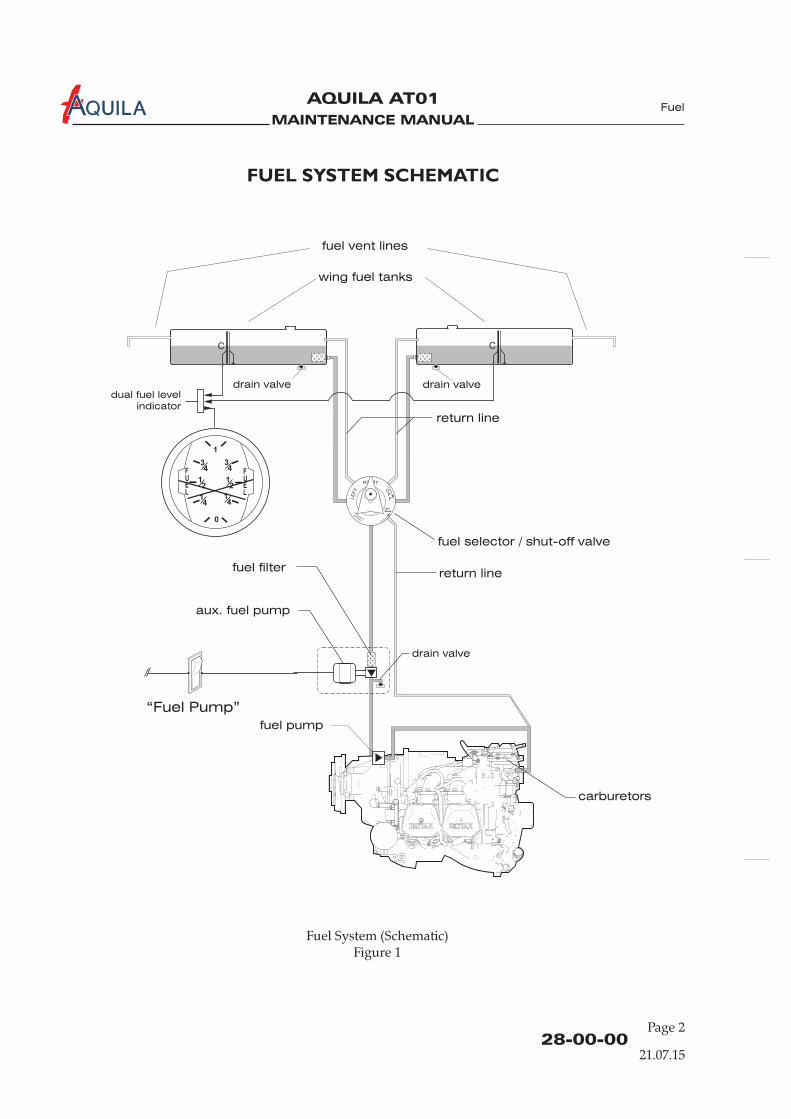
MAINTENANCE MANUAL
AQUILA AT01A
28-00-00Page 2
Fuel System (Schematic)Figure 1
Fuel
21.07.15
FUEL SYSTEM SCHEMATIC
wing fuel tanks
drain valve
drain valvedrain valve
aux. fuel pump
fuel filterreturn line
return line
fuel vent lines
fuel selector / shut-off valve
fuel pump
carburetors
“Fuel Pump”
dual fuel level
indicator
C C
RIGHT
LE
FT O
FF
LIFT
KNOB
AN
DAIR
LTD
E
NGLA
ND
1
0
34
34
14
14
12
12
FUEL
FUEL
MAINTENANCE MANUAL
AQUILA AT01A
28-10-00Page 201
FUEL STORAGE - MAINTENANCE
WARNING:
General
PERFORM ALL FUEL SYSTEM MAINTENANCE IN ACCORDANCE WITH SAFETYPRECAUTIONS CONTAINED IN 12-11-00!
1.
A. The fuel storage system consists of two integral fuel tanks, located at the inboard portion of eachwing in front of the main spar. They are bounded by the upper and lower wing skins which arereinforced in this area, the main spar web, and the inboard and outboard fuel tank ribs.Each fuel tank has a lockable fuel filler cap which is grounded to the airframe. The inner surfacesof the composite integral tanks are sealed with a special fuel tank sealing material to protect thecomposite fiber structure. A fuel baffle rib is provided to reduce fuel slosh in the fuel outlet andthe fuel quantity sensor areas. The fuel tanks are vented from the top of each fuel tank through avent line connected at the outboard fuel tank rib to a vent located on the winglets. Each inboardfuel tank rib has an outlet over the sump level that is equipped with a removable mesh strainer.
The inboard fuel tank ribs are easily accessible for maintenance work through access panel610 BB / 510 BB in the lower wing skin.
B. T
(1) Ensure electrical power to aircraft is OFF.(2) Disconnect battery (refer to 24-30-00).
he wing fuel tanks are maintenance-free. However, if a leak is suspected, AQUILA AviationGmbH should be consulted.
2.
A. The following procedure should be used to check a wing fuel tank for leakage.
(3) Drain fuel from wing fuel tank.(4) Open access plate 610 BB / 510 BB (refer to 06-30-00).(5) Disconnect fuel outlet line from fuel tank.(6) Disconnect fuel return line from fuel tank.(7) Cap fuel tank vent line.(8) Attach a suitable manometer (water manometer) to fuel tank outlet fitting.
NEVER APPLY REGULATED OR UNREGULATED AIR FROM AN AIRCOMPRESSOR TO THE FUEL SYSTEM OR COMPONENTS.
DO NOT PRESSURIZE THE FUEL TANKS TO MORE THAN 1.0 PSI.STRUCTURAL DAMAGE MAY OCCUR TO THE FUEL TANK IF MORE THAN1.0 PSI IS APPLIED.
(9) Connect a well-regulated supply of air (1.0 psi maximum) to the return line fitting.(10) Make sure filler cap is installed and sealed.(11) Apply pressure slowly until 1.0 psi is obtained.(12) Shut off air supply.(13) If fuel tank holds pressure for 15 minutes, the tank with vent line is sealed.
Wing Fuel Tank Leakage Test
WARNING:
CAUTION:
Fuel
21.07.15

MAINTENANCE MANUAL
AQUILA AT01A
MAINTENANCE MANUAL
AQUILA AT01A
28-20-00Page 201
FUEL DISTRIBUTION - MAINTENANCE
WARNING: PERFORM ALL FUEL SYSTEM MAINTENANCE IN ACCORDANCE WITH SAFETYPRECAUTIONS CONTAINED IN 12-11-00!
A. The fuel distribution system consists primarily of the fuel selector / shut-off valve, an electrical fuelpump, fuel lines and the fuel pump switch.
The fuel selector handle is located in the center console between the seats. The red, arrow shapedhandle has a LEFT, RIGHT and OFF position. To switch the valve to the OFF position a knoblocated at the top of the handle must be pulled while the handle is rotated simultaneously. Withthe valve in this position fuel flow from and to the tanks is stopped. In both operating positionsthe fuel supply / return lines of the selected fuel tank are open while the fuel supply/ return linesof the other one are closed.
The electrical fuel pump is incorporated into the system without a bypass. In this way fuel flowsthrough a fuel strainer which is integral of the fuel pump even if the pump is off. The electricalfuel pump is mounted in the engine compartment at the lower left firewall.
for the secure and continuous supply of fuel tothe engine
(1) Ensure electrical power to aircraft is OFF.(2) Disconnect
(refer to 25-12-00)
1.
B. A clean fuel distribution system is very important. The fuel system is equipped with drain valves with which fuel in the system can be
examined for contamination and grade.(1) The electrical fuel pump has a filter screen which must be cleaned regularly. The filter screen
can be removed for maintenance.(2) A mesh strainer is installed on the fuel outlet in each fuel tank. The strainer is accessible by
opening the fuel tank rib access panel 610 BB / 510 BB. The strainer is brazed to a fitting thatis installed in the fuel tank port. The fuel strainers in the fuel tanks should always be cleanedafter aircraft has been in storage. If any damage or restrictions are noted, the strainer shouldbe replaced.
(3) The fuel system has a drain valve at it’s lowest point, namely at the base of the electrical fuelpump. The drain valve is accessible from outside the nose section without removing anycomponent. It should be used regularly to check fuel for water and contamination.
(4) Each wing fuel tank has a drain-valve at it’s base. The drain valves are accessible fromoutside at the bottom of the wings in the wing root area. They should be used regularly tocheck fuel for water and contamination.
2.
A. Remove Fuel Selector / Shut-Off Valve
battery (refer to 24-30-00).(3) Drain fuel from fuel system completely using the wing fuel tank drains and the drain at the
electrical fuel pump.(4) Remove access panels 211 BB and 211 HL/HR in the cabin .(5) Remove access panel 211 GT with fuel selector / shut-off valve control lever and connecting
shaft (refer to 25-12-00).
General
Fuel Selector / Shut-Off Valve Removal/Installation
Fuel
21.07.15
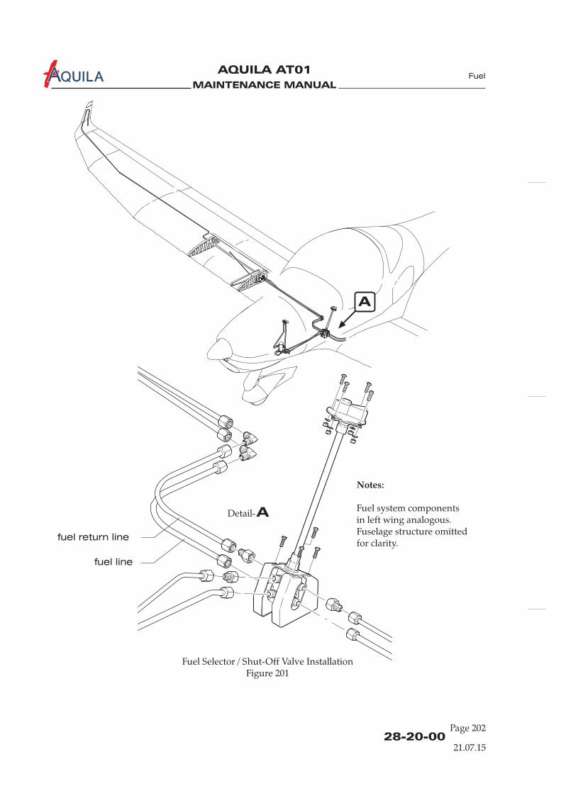
MAINTENANCE MANUAL
AQUILA AT01A
A
ADetail-
Notes:
Fuel system componentsin left wing analogous.Fuselage structure omittedfor clarity.
Fuel Selector / Shut-Off Valve InstallationFigure 201
fuel line
fuel return line
28-20-00Page 202
21.07.15
Fuel
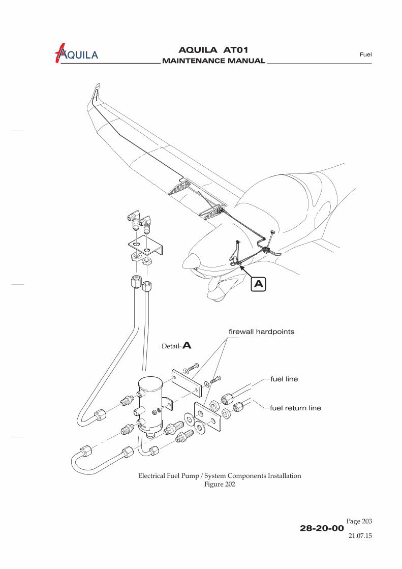
MAINTENANCE MANUAL
AQUILA AT01A
ADetail-
Electrical Fuel Pump / System Components InstallationFigure 202
A
firewall hardpoints
fuel line
fuel return line
28-20-00Page 203
21.07.15
Fuel
MAINTENANCE MANUAL
AQUILA AT01A
(6) Disconnect the fuel supply and return lines at valve.(7) Remove bolts securing valve to mounting bracket and remove the fuel selector / shut-off
valve assembly from aircraft.
B. Install Fuel Selector / Shut-Off Valve
(2) Place fuel selector / shut-off valve in position and secure using washers and bolts.(3) Connect all fuel supply and return lines at valve.(4) Connect the fuel selector / shut-off valve control lever. Make sure that both the valve and the
valve control lever are set to OFF and install access panel 211 GT with fuel selector / shut-offvalve control lever and connecting shaft (refer to 25-12-00).
(5) Refuel the aircraft.(6) Pressure check complete fuel system (refer to “Fuel System Pressure Test” below).(7) Inspect fuel selector / shut-off valve and enclosure for any signs of fuel leakage.(8) Reconnect battery (refer to 24-30-00).(9) Perform operational check of the fuel distribution system.(10) Install all items removed for access.
3.
A. Remove Electrical Fuel Pump(1) Ensure electrical power to aircraft is OFF.
battery (refer to 24-30-00).(4) Close fuel selector / shut-off valve.(5) Disconnect the pump wires.(6) Disconnect fuel lines at electrical fuel pump. Drain fuel from line.(7) Remove bolts, washers and nuts securing electrical fuel pump to firewall and remove
electrical fuel pump.
B. Install Electrical Fuel Pump
(2) Secure electrical fuel pump to firewall using bolts, washers and nuts.(3) Reconnect fuel lines to electrical fuel pump.(4) Reconnect the pump electrical wires.(5) Reconnect battery (refer to 24-30-00).
4.
A. Maintenance is accomplished by the following procedure:(1) Remove locking wire at lower fuel pump cap.(2) Remove lower cap.(3) Remove filter element and clean by washing.(4) Check disk magnet for metal particles.(5) Reassemble filter and cap.(6) Secure cap using locking wire.
(1) Verify battery is disconnected and electrical power to aircraft is OFF.
(2) Remove engine cowling (refer to 71-10-00).(3) Disconnect
(1) Verify battery is disconnected and electrical power to aircraft is OFF.
Electrical Fuel Pump Removal/Installation
Electrical Fuel Pump Filter Element Maintenance
28-20-00Page 204
21.07.15
Fuel
MAINTENANCE MANUAL
AQUILA AT01A
5.
A. Leak-test the fuel system by the following procedure:(1) Fill the wing fuel tank with approved fuel.(2) Remove engine cowling, crew seats and all other panels and covers to gain access to all fuel
system components and fuel lines (refer to 25-10-00, 25-12-00 and 71-10-00).(3) Place the fuel selector / shut-off valve in LEFT (RIGHT) position.(4) Disconnect the pressure fuel line and return line in the where the
flexible fuel lines are connected to the aluminum lines and cap fittings.(5) Connect a rubber hose with a well-regulated supply of air (1.0 psi maximum) to the outboard
end of either fuel tank vent line.(6) Connect a suitable manometer (water manometer) to the other fuel vent line.(7) Make sure filler caps are installed and sealed.
NEVER APPLY REGULATED OR UNREGULATED AIR FROM AN AIRCOMPRESSOR TO THE FUEL SYSTEM OR COMPONENTS.
NEVER ATTEMPT TO REMOVE THE FUEL FILLER CAP WITH PRESSURE INTHE FUEL SYSTEM.
DO NOT PRESSURIZE THE FUEL SYSTEM TO MORE THAN 1.0 PSI. DAMAGEMAY OCCUR TO SYSTEM COMPONENTS IF MORE THAN 1.0 PSI IS APPLIED.
(8) Apply pressure to the system slowly until 1.0 psi is reached.(9) Shut off air supply(10) System pressure should remain constant for 15 minutes.(11) Inspect the seams, fittings and connections of the accessible portion of the wing fuel tank.
Check the fuel lines, the fuel selector / shut-off valve and all other fuel related areas for signsof leakage.
(12) If leakage is suspected (pressure readings drop) apply soapy water to the area in question andinspect for bubbles.
(13) Release all pressure from the fuel system.(14) Remove the rubber hose with the supply of air and the manometer from the end of fuel vent
lines.(15) Reconnect the pressure fuel line to the electrical fuel pump.(16) Remove plugs of fuel filler caps vent holes.(17) Install all items that have been removed prior to performing the test (refer to 25-10-00,
25-12-00 and 71-10-00).(18) If any leakage is detected, seal as required.
Fuel System Pressure Test
WARNING:
CAUTION:
engine compartment
Fuel
28-20-00Page 205
21.07.15

MAINTENANCE MANUAL
AQUILA AT01A
MAINTENANCE MANUAL
AQUILA AT01A
28-41-00Page 201
FUEL QUANTITY INDICATION - MAINTENANCE
WARNING:
Fuel Q Indicator Removal/Installation
Fuel Sensor Removal/Installation
PERFORM ALL FUEL SYSTEM MAINTENANCE IN ACCORDANCE WITH SAFETYPRECAUTIONS CONTAINED IN 12-11-00!
2.
A. Remove Fuel Q Indicator(1) Ensure electrical power to aircraft is OFF.
(3) Remove glare shield (refer to 31-10-00).(4) Remove cable connector from back of indicator.(5) While supporting indicator, remove screws attaching indicator to instrument panel.(6) Remove indicator from aircraft.
B. Install Fuel Q Indicator.(1) Position indicator to instrument panel hole and secure with screws.(2) Install cable connector at back of indicator.
(4) Perform a fuel indicating system test / calibration (refer to “Test/Calibration” below).(5) Install glare shield (refer to 31-10-00).
3.
A. Remove Fuel Sensor
(3) Drain wing fuel tank with sensor that is to be removed (refer to 12-11-00).(4) Open access / inspection plate 610 BB / 510 BB to gain access to sensor .(5) Remove nuts securing sensor to inboard fuel tank rib.
(7) Carefully withdraw sensor from wing tank.
1.
A. The fuel quantity indicating system consists of two fuel quantity sensors, one in eachtank, a dual fuel quantity indicator and wiring connecting the components.The fuel quantity indicator is located on the right side of the instrument panel. It has themarkings FULL, ¾, ½, ¼ and EMPTY for each tank and has been calibrated during installation.The fuel quantity sensors are either capacitive or resistive type and easily accessible formaintenance or replacement through access panels in the lower wing skin.
B. Maintenance is limited to the removal and installation of the system components.
uantity
(2) Disconnect battery (refer to 24-30-00).
uantity
(3) Reconnect battery (refer to 24-30-00).quantity
Quantity(1) Ensure electrical power to aircraft is OFF.(2) Disconnect battery (refer to 24-30-00).
(refer to 06-30-00)
(6) Disconnect electrical cables from sensor.
General
uantity
Quantity
21.07.15
Fuel
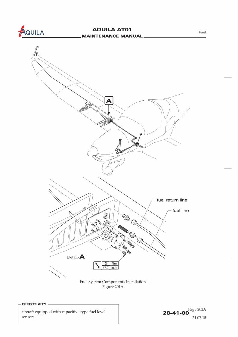
MAINTENANCE MANUAL
AQUILA AT01A
ADetail-
A
Nm
in.lb
2
17.7
Fuel System Components InstallationFigure 201A
fuel line
fuel return line
Fuel
28-41-00Page 202A
21.07.15
EFFECTIVITY
aircraft equipped with capacitive type fuel levelsensors

MAINTENANCE MANUAL
AQUILA AT01A
ADetail-
Nm
in.lb
2
17.7
fuel line
fuel return line
Fuel System Components InstallationFigure 201B
A
28-41-00Page 202B
21.07.15
aircraft equipped with resistive type fuel levelsensors
EFFECTIVITY
Fuel
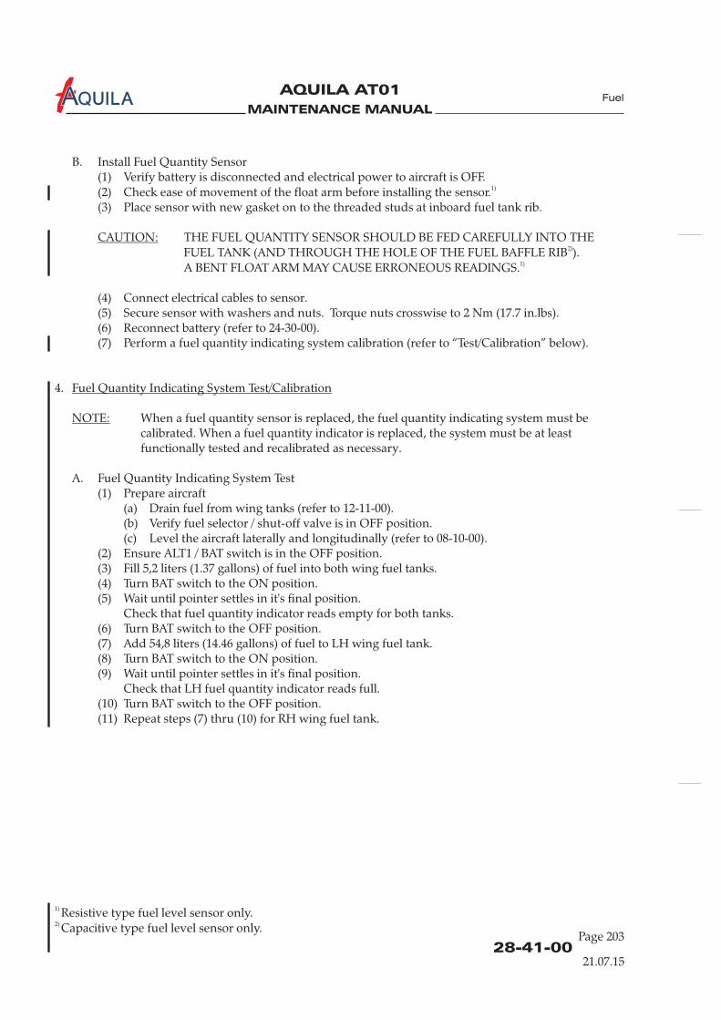
MAINTENANCE MANUAL
AQUILA AT01A
28-41-00Page 203
21.07.15
B. Install Fuel Sensor(1) Verify battery is disconnected and electrical power to aircraft is OFF.(2) Check ease of movement(3) Place sensor with new gasket on to the threaded studs at inboard fuel tank rib.
(5) Secure sensor with washers and nuts. Torque nuts crosswise to 2 Nm (17.7 in.lbs).(6) Reconnect battery (refer to 24-30-00).(7) Perform a fuel indicating system calibration (refer to “Test/Calibration” below).
Quantity
of the float arm before installing the sensor.
THE FUEL QUANTITY SENSOR SHOULD BE FED CAREFULLY INTO THEFUEL TANK (AND THROUGH THE HOLE OF THE FUEL BAFFLE RIB ).A BENT FLOAT ARM MAY CAUSE ERRONEOUS READINGS.
(4) Connect electrical cables to sensor.
quantity
4.
When a fuel quantity sensor is replaced, the fuel quantity indicating system must becalibrated. When a fuel quantity indicator is replaced, the system must be at leastfunctionally tested and recalibrated as necessary.
A. Fuel Quantity Indicating System Test(1) Prepare aircraft
(a) Drain fuel from wing tanks (refer to 12-11-00).(b) Verify fuel selector / shut-off valve is in OFF position.(c) Level the aircraft laterally and longitudinally (refer to 08-10-00).
(2) Ensure ALT1 / BAT switch is in the OFF position.(3) Fill 5,2 liters (1.37 gallons) of fuel into both wing fuel tanks.(4) Turn BAT switch to the ON position.(5) Wait until pointer settles in it's final position.
Check that fuel quantity indicator reads empty for both tanks.(6) Turn BAT switch to the OFF position.(7) Add 54,8 liters (14.46 gallons) of fuel to LH wing fuel tank.(8) Turn BAT switch to the ON position.(9) Wait until pointer settles in it's final position.
Check that LH fuel quantity indicator reads full.(10) Turn BAT switch to the OFF position.(11) Repeat steps (7) thru (10) for RH wing fuel tank.
1)
2)
1)
CAUTION:
Fuel Quantity Indicating System Test/Calibration
NOTE:
Fuel
1)
2)
Resistive type fuel level sensor only.Capacitive type fuel level sensor only.
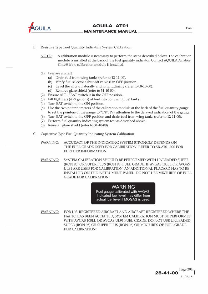
MAINTENANCE MANUAL
AQUILA AT01A Fuel
B. Resistive Type Fuel Quantity Indicating System Calibration
A calibration module is necessary to perform the steps described below. The calibrationmodule is installed at the back of the fuel quantity indicator. Contact AQUILA AviationGmbH if no calibration module is installed.
(1) Prepare aircraft(a) Drain fuel from wing tanks (refer to 12-11-00).(b) Verify fuel selector / shut-off valve is in OFF position.(c) Level the aircraft laterally and longitudinally (refer to 08-10-00).(d) Remove glare shield (refer to 31-10-00).
(2) Ensure ALT1 / BAT switch is in the OFF position.(3) Fill 18,9 liters (4.99 gallons) of fuel into both wing fuel tanks.(4) Turn BAT switch to the ON position.(5) Use the two potentiometers of the calibration module at the back of the fuel quantity gauge
to set the pointers of the gauge to “1/4”. Pay attention to the delayed indication of the gauge.(6) Turn BAT switch to the OFF position and drain fuel from wing tanks (refer to 12-11-00).(7) Perform fuel quantity indicating system test as described above.(8) Reinstall glare shield (refer to 31-10-00).
C. Capacitive Type Fuel Quantity Indicating System Calibration
ACCURACY OF THE INDICATING SYSTEM STRONGLY DEPENDS ONTHE FUEL GRADE USED FOR CALIBRATION! REFER TO SB-AT01-020 FORFURTHER INFORMATION.
SYSTEM CALIBRATION SHOULD BE PERFORMED WITH UNLEADED SUPER(RON 95) OR SUPER PLUS (RON 98) FUEL GRADE. IF AVGAS 100LL OR AVGASUL91 ARE USED FOR CALIBRATION, AN ADDITIONAL PLACARD HAS TO BEINSTALLED ON THE INSTRUMENT PANEL. DO NOT USE MIXTURES OF FUELGRADE FOR CALIBRATION!
FOR U.S. REGISTERED AIRCRAFT AND AIRCRAFT REGISTERED WHERE THEFAA TC HAS BEEN ACCEPTED, SYSTEM CALIBRATION MUST BE PERFORMEDWITH AVGAS 100LL OR AVGAS UL91 FUEL GRADE. DO NOT USE UNLEADEDSUPER (RON 95) OR SUPER PLUS (RON 98) OR MIXTURES OF FUEL GRADEFOR CALIBRATION!
NOTE:
WARNING:
WARNING:
WARNING:
28-41-00Page 204
21.07.15
WARNINGFuel gauge calibrated with AVGAS.Indicated fuel level may differ fromactual fuel level if MOGAS is used.

MAINTENANCE MANUAL
AQUILA AT01A
28-41-00Page 205
21.07.15
Fuel
NOTE:
NOTE:
Type A: Fuel level sensors with potentiometers:
Calibration procedure depends on the type of fuel quantity sensor installed:Type A: Capacitive sensor with potentiometers for calibration.Type B: Capacitive sensor without potentiometers and without “mag” label.Type C: Capacitive sensor without potentiometers and with “mag” label (figure 202).
Senders without potentiometer are calibrated by using a magnet (type C) as shown infigure 202 or by applying a jumper between sender wire (yellow) and ground (type B).For these senders a second person is necessary for calibration as timing is important.One for using the magnet / jumper, the other one for switching the power.
(1) Prepare aircraft(a) Drain fuel from wing tanks (refer to 12-11-00).(b) Verify fuel selector / shut-off valve is in OFF position.(c) Level the aircraft laterally and longitudinally (refer to 08-10-00).(d) Open access panel 610 BB and 510 BB (refer to 06-10-30).
(2) Ensure ALT1 / BAT switch is in the OFF position.(3) Fill 5,2 liters (1.37 gallons) of fuel into both wing fuel tanks.
(4) Turn both the “empty” and “full” potentiometers on both fuel level sensors to the fullclockwise position.
(5) Turn BAT switch to the ON position.(6) Turn potentiometers “empty” on the fuel level sensors counterclockwise until fuel level
indicator reads “empty” for both tanks.(7) Turn BAT switch to the OFF position.(8) Add 27,4 liters (7.23 gallons) of fuel to both wing fuel tanks.(9) Turn BAT switch to the ON position.(10) Turn potentiometer “full” on the fuel level sensors counterclockwise until fuel level
indicator reads “1/2” for both tanks.(11) Turn BAT switch to the OFF position.
Magnet positioning during calibrationFigure 202
verticalmagnet
Label
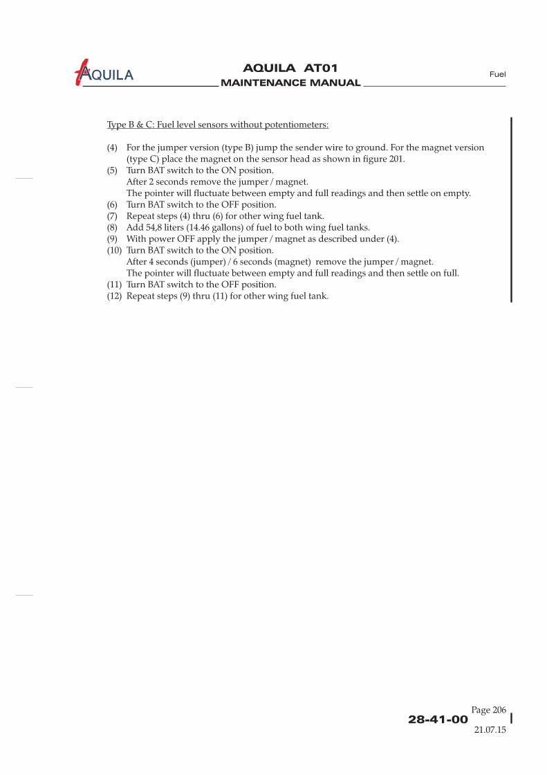
MAINTENANCE MANUAL
AQUILA AT01A Fuel
Type B & C: Fuel level sensors without potentiometers:
(4) For the jumper version (type B) jump the sender wire to ground. For the magnet version(type C) place the magnet on the sensor head as shown in figure 201.
(5) Turn BAT switch to the ON position.After 2 seconds remove the jumper / magnet.The pointer will fluctuate between empty and full readings and then settle on empty.
(6) Turn BAT switch to the OFF position.(7) Repeat steps (4) thru (6) for other wing fuel tank.(8) Add 54,8 liters (14.46 gallons) of fuel to both wing fuel tanks.(9) With power OFF apply the jumper / magnet as described under (4).(10) Turn BAT switch to the ON position.
After 4 seconds (jumper) / 6 seconds (magnet) remove the jumper / magnet.The pointer will fluctuate between empty and full readings and then settle on full.
(11) Turn BAT switch to the OFF position.(12) Repeat steps (9) thru (11) for other wing fuel tank.
28-41-00Page 206
21.07.15

MAINTENANCE MANUAL
AQUILA AT01A

MAINTENANCE MANUAL
AQUILA AT01A
CHAPTER 31
INDICATING / RECORDING SYSTEMS

MAINTENANCE MANUAL
AQUILA AT01A
MAINTENANCE MANUAL
AQUILA AT01A
Page 131 - TOC
Indicating / Recording
TABLE OF CONTENTS
ChapterSection
INDICATING / RECORDING SYSTEMS - GENERAL..................................31-00-00 1 Analog instr.Introduction 31-00-00 1General Description 31-00-00 1
INDICATING / RECORDING SYSTEMS - GENERAL..................................31-00-00 1Introduction 31-00-00 1General Description 31-00-00 1
INDICATING / RECORDING SYSTEMS - GENERAL..................................31-00-00 1Introduction 31-00-00 1General Description 31-00-00 1
INSTRUMENT PANEL - MAINTENANCE.....................................................31-10-00 201General 31-10-00 201Glare Shield Removal/Installation 31-10-00 201Instrument Panel Removal/Installation 31-10-00 201
Title Subject Page Effectivity
Analog instr.Analog instr.
Aspen EFD1000Aspen EFD1000Aspen EFD1000
Garmin G500Garmin G500Garmin G500
RECORDERS - MAINTENANCE ...................................................................31-30-00 201 KAPI systemGeneral 31-30-00 201 KAPI systemKAPI Unit Removal/Installation 31-30-00 203 KAPI systemKAPI GPS/GSM Antenna Removal/Installation 31-30-00 203 KAPI systemKAPI Airspeed Sensor Removal/Installation 31-30-00 204 KAPI systemKAPI G-Sensor Removal/Installation 31-30-00 204 KAPI system
30.10.13

MAINTENANCE MANUAL
AQUILA AT01A

MAINTENANCE MANUAL
AQUILA AT01A
31-00-00Page 1
INDICATING / RECORDING SYSTEMS - GENERAL
1.
A.
2.
A. For easy and quick reference, the instruments and controls are clearly divided in groups.The group of flight instruments is directly in front of the pilot. Below the flight instruments is arow of switches. The middle section of the panel contains the avionics equipment including theNAV/COM transceiver and the transponder. O
p of instrumentsfor monitoring engine and system conditions is located below. These gauges show the fuel level ineach tank, cylinder head temperature, oil temperature, oil pressure as well as amperes and volts ofthe electrical system. The circuit breaker panel is located in front of the co-pilot.
B. A center console contains the control knobs for the carburetor heat, the choke, cabin heating, thethrottle and rpm control levers, the fuel selector / shut-off valve, the parking brake control knob,and the trim control switch.
C. The description, function and maintenance of the several specific instruments is contained in theappropriate section of this manual.
D. For an overview of the position of the various instruments, devices and controls on the instrumentpanel and center pedestal, refer to figure 1.
Introduction
General Description
Basically the instruments and avionic equipment can be chosen by the customer, but it cannot beinstalled in any arbitrary combination. Before removing or installing equipment the airplanemanufacturer AQUILA must be contacted, with the exception of replacing a unit by an identicalone.
n the right side of the avionics column the powergauges, the tachometer and the manifold pressure indicator, are mounted. A grou
Indicating / Recording
30.10.13
EFFECTIVITY
Aircraft equipped with analog instruments
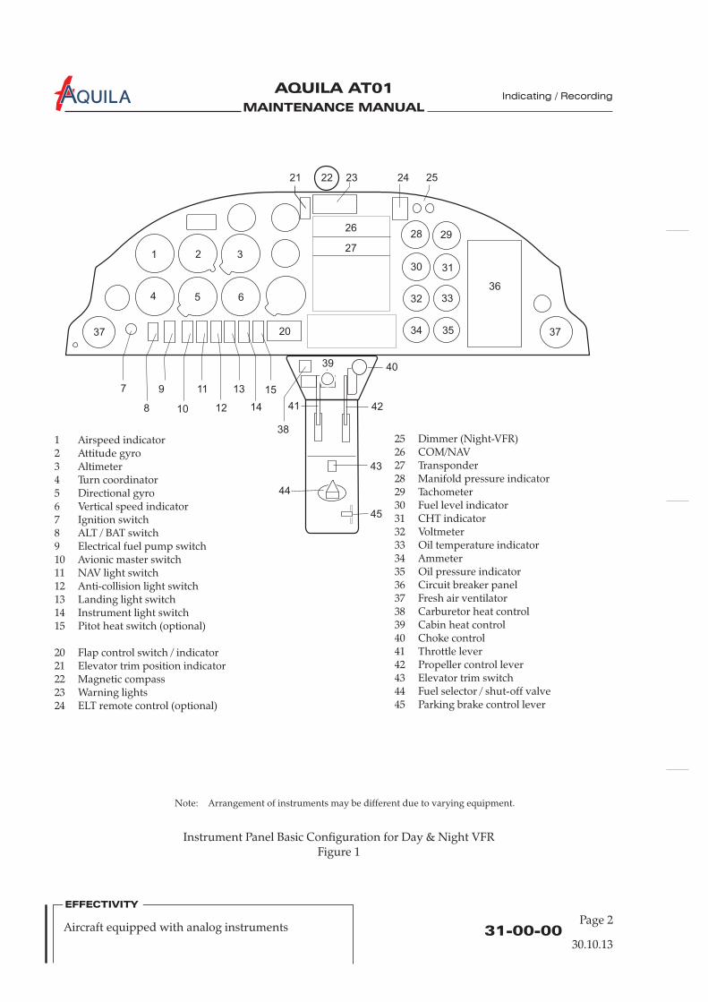
MAINTENANCE MANUAL
AQUILA AT01A
31-00-00Page 2
Instrument Panel Basic Configuration for Day & Night VFRFigure 1
Indicating / Recording
30.10.13
Note: Arrangement of instruments may be different due to varying equipment.
EFFECTIVITY
Aircraft equipped with analog instruments
12345
12
Airspeed indicatorAttitude gyroAltimeterTurn coordinatorDirectional gyro
6 Vertical speed indicator7 Ignition switch8 ALT / BAT switch9 Electrical fuel pump switch10 Avionic master switch11 NAV light switch
Anti-collision light switch13 Landing light switch14 Instrument light switch15 Pitot heat switch (optional)
20 Flap control switch / indicator21 Elevator trim position indicator22 Magnetic compass23 Warning lights24 ELT remote control (optional)
25 Dimmer (Night-VFR)26 COM/NAV27 Transponder28 Manifold pressure indicator29 Tachometer30 Fuel level indicator31 CHT indicator32 Voltmeter33 Oil temperature indicator34 Ammeter35 Oil pressure indicator36 Circuit breaker panel37 Fresh air ventilator
Carburetor heat controlCabin heat controlChoke controlThrottle leverPropeller control leverElevator trim switchFuel selector / shut-off valveParking brake control lever
3839404142434445
2221 23 24 25
262928
1 2 3
30
27
31
4 5 6 32 3336
37
8
97
10
11
12
13
14
15
20 37
38
4039
41 42
43
45
44
34 35
MAINTENANCE MANUAL
AQUILA AT01A
INDICATING / RECORDING SYSTEMS - GENERAL
1.
A. Basically the instrument and avionic equipment can be chosen by the customer, but it cannot beinstalled in any arbitrary combination. Before removing or installing equipment the airplanemanufacturer AQUILA must be contacted, with the exception of replacing a unit by an identicalone.
2.
A.
B.
C.
Introduction
General Description
For easy and quick reference, the instruments and controls are clearly divided in groups.The Aspen EFD1000 PFD as the primary flight display is directly in front of the pilot. The back-upattitude indicator for Night-VFR is installed close to the Aspen EFD1000 PFD. Below the AspenEFD1000 PFD is a row of switches. The middle section of the panel contains the avionicsequipment including the NAV/COM transceiver and the transponder. On the right side of theavionics column the power gauges, the tachometer and the manifold pressure indicator, aremounted. A group of instruments for monitoring engine and system conditions is located below.These gauges show the fuel level in each tank, cylinder head temperature, oil temperature, oilpressure as well as amperes and volts of the electrical system. The circuit breaker panel is locatedin front of the co-pilot.
A center console contains the control knobs for the carburetor heat, the choke, cabin heating, thethrottle and rpm control levers, the fuel selector / shut-off valve, the parking brake control knob,and the trim control switch.
The description, function and maintenance of the several specific instruments is contained in theappropriate section of this manual.
D. For an overview of the position of the various instruments, devices and controls on the instrumentpanel and center pedestal, refer to figure 1.
31-00-00
Indicating / Recording
30.10.13
EFFECTIVITY
Aircraft equipped with Aspen EFD1000 PFDPage 1

MAINTENANCE MANUAL
AQUILA AT01A
31-00-00
Indicating / Recording
30.10.13
EFFECTIVITY
Instrument Panel Basic Configuration for Day & Night VFRFigure 1
Page 2Aircraft equipped with Aspen EFD1000 PFD
Note: Arrangement of instruments may be different due to varying equipment.
12
9
Aspen EFD1000 PFDAttitude gyro (Night-VFR)
3 Ignition switch4 ALT / BAT switch5 Electrical fuel pump switch6 PFD switch7 Avionic master switch8 NAV light switch
Anti-collision light switch10 Landing light switch11 Instrument light switch
20 Flap control switch / indicator21 Elevator trim position indicator22 Magnetic compass23 Warning lights24 ELT remote control (optional)25 Dimmer (Night-VFR)26 COM/NAV
27 Transponder28 Manifold pressure indicator29 Tachometer30 Fuel level indicator31 CHT indicator32 Voltmeter33 Oil temperature indicator34 Ammeter35 Oil pressure indicator36 Circuit breaker panel37 Fresh air ventilator
Carburetor heat controlCabin heat controlChoke controlThrottle leverPropeller control leverElevator trim switchFuel selector / shut-off valveParking brake control lever
3839404142434445
2221 23 24 25
262928
1
2
30
27
31
32 3336
37
4
53
6
7
8
9
10
11
20 37
38
4039
41 42
43
45
44
34 35
MAINTENANCE MANUAL
AQUILA AT01A
INDICATING / RECORDING SYSTEMS - GENERAL
1.
A. Basically the instrument and avionic equipment can be chosen by the customer, but it cannot beinstalled in any arbitrary combination. Before removing or installing equipment the airplanemanufacturer AQUILA must be contacted, with the exception of replacing a unit by an identicalone.
2.
A. For easy and quick reference, the instruments and controls are clearly divided in groups.The Garmin G500 as the primary flight display is directly in front of the pilot. The back-up attitudeindicator for Night-VFR is installed close to the Garmin G500.
B.
C.
Introduction
General Description
Below the G500 is a row of switches.The middle section of the panel contains the avionics equipment including the NAV/COMtransceiver and the transponder. On the right side of the avionics column the power gauges, thetachometer and the manifold pressure indicator, are mounted. A group of instruments formonitoring engine and system conditions is located below. These gauges show the fuel level ineach tank, cylinder head temperature, oil temperature, oil pressure as well as amperes and volts ofthe electrical system. The circuit breaker panel is located in front of the co-pilot.
A center console contains the control knobs for the carburetor heat, the choke, cabin heating, thethrottle and rpm control levers, the fuel selector / shut-off valve, the parking brake control knob,and the trim control switch.
The description, function and maintenance of the several specific instruments is contained in theappropriate section of this manual.
D. For an overview of the position of the various instruments, devices and controls on the instrumentpanel and center pedestal, refer to figure 1.
31-00-00
Indicating / Recording
30.10.13
EFFECTIVITY
Aircraft equipped with Garmin G500 PFD/MFDPage 1
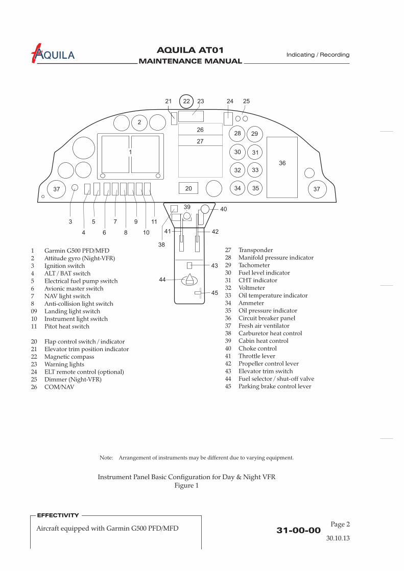
MAINTENANCE MANUAL
AQUILA AT01A
EFFECTIVITY
31-00-0030.10.13
EFFECTIVITY
Instrument Panel Basic Configuration for Day & Night VFRFigure 1
Page 2Aircraft equipped with Garmin G500 PFD/MFD
Note: Arrangement of instruments may be different due to varying equipment.
Indicating / Recording
1
12
8
Garmin G500 PFD/MFDAttitude gyro (Night-VFR)
3 Ignition switch4 ALT / BAT switch5 Electrical fuel pump switch6 Avionic master switch7 NAV light switch
Anti-collision light switch09 Landing light switch10 Instrument light switch11 Pitot heat switch
20 Flap control switch / indicator21 Elevator trim position indicator22 Magnetic compass23 Warning lights24 ELT remote control (optional)25 Dimmer (Night-VFR)26 COM/NAV
27 Transponder28 Manifold pressure indicator29 Tachometer30 Fuel level indicator31 CHT indicator32 Voltmeter33 Oil temperature indicator34 Ammeter35 Oil pressure indicator36 Circuit breaker panel37 Fresh air ventilator
Carburetor heat controlCabin heat controlChoke controlThrottle leverPropeller control leverElevator trim switchFuel selector / shut-off valveParking brake control lever
3839404142434445
2221 23 24 25
262928
2
30
27
31
32 3336
37
4
53
6
7
8
9
10
11
20 37
38
4039
41 42
43
45
44
34 35

MAINTENANCE MANUAL
AQUILA AT01A
31-10-00Page 201
INSTRUMENT PANEL - MAINTENANCE
1.
A. The instrument panel is made from aluminum alloy and is formed in one piece with a shelf. Theshelf fits between the panel and the firewall. The panel shelf is attached on the left and right sidesto support consoles and secured to the fuselage with bolts. The equipment is mounted in cut-outsand can be easily accessed from the rear of the panel when the glare shield is removed.If required, e.g. during maintenance on the fuselage structure, the instrument panel assembly canbe removed completely.
2.
A. Remove Glare Shield(1) Ensure electrical power to aircraft is OFF.(2) Remove 4 screws on top of glare shield securing glare shield to instrument panel.(3) Remove 3 screws on each side of glare shield securing glare shield to fuselage.(4) Disconnect electrical connectors to allow removal of the glare shield.(5) Remove glare shield.
B. Install Glare Shield(1) Check all connections, wires, electrical connectors and hoses on rear side of instrument panel.(2) Put glare shield in position and connect electrical connectors to glare shield.(3) Secure glare shield to fuselage and instrument panel using screws.
3.
A. Remove Instrument Panel(1) Disconnect battery (refer to 24-30-00).(2) Remove glare shield (refer to “Glare Shield Removal/Installation” above).
It is recommended to label wires, hoses and plugs which must be disconnected toensure correct reinstallation of the instrument panel.
Refer to 91-00-00 for wiring diagrams. Refer to 34-10-00 (system schematic) for properconnecting components of the pitot-static system.
(3) Identify all electrical connectors, hoses, and associated wiring.(4) Disconnect all electrical connectors, hoses, and associated wiring to allow removal of the
instrument panel assembly.(5) Remove nuts, bolts, washers and spacers securing instrument panel to center console.(6) Remove nuts, bolts, washers and spacers securing instrument panel to fuselage. Remove
instrument panel assembly from aircraft.
General
Glare Shield Removal/Installation
Instrument Panel Removal/Installation
NOTE:
Indicating / Recording
30.10.13
MAINTENANCE MANUAL
AQUILA AT01A
31-10-00Page 202
B. Install Instrument Panel(1) Put instrument panel assembly in position and secure to fuselage using bolts, spacers,
washers and nuts.(2) Secure instrument panel to center console using bolts, spacers, washers, and nuts.(3) Connect all electrical connectors, hoses, and associated wiring that have been disconnected
during disassembly procedure.(4) Install glare shield (refer(5) Reconnect battery (refer to 24-30-00).(6) Perform instrument panel inspection/check as described below.
C. Instrument Panel Inspection/Check(1) Perform pitot system leakage test (refer to 34-11-00).(2) Perform static system leakage test (refer to 34-11-00).(3) Perform functional test for all instruments and systems to assure proper operation.
A flight test is recommended after instrument panel installation to ensure the properfunctioning of all instruments and systems.
to “Glare Shield Removal/Installation” above).
NOTE:
Indicating / Recording
30.10.13
MAINTENANCE MANUAL
AQUILA AT01A Indicating / Recording
31-30-0030.10.13
EFFECTIVITY
Aircraft equipped with KAPI data logger systemPage 201
RECORDERS – MAINTENANCE
1.
A. This section covers miscellaneous avionic equipment, including the KAPI Air Control FDR 07 DataLogger System. The scope of maintenance is limited to the removal and installation ofcomponents. For further information on the equipment, refer to the appropriate publications ofthe equipment manufacturer. For overhaul and repair, the manufacturer of the equipment has tobe consulted.
B. The KAPI Air control FDR 07 is derived from KAPI Flight Data Recorder (FDR) and is designed toprovide a system for the recording, storing, processing, evaluating and transmitting technical,operational and flight data. The KAPI Air Control FDR 07 is based on a one-circuit-board systemwhich is controlled by a microprocessor made by VDO. To store data or transmit data to theground station, the processing unit of the KAPI system accesses data signals of sensors alreadyinstalled in the aircraft (engine parameters) along with data from its own sensors that have to beadditionally installed together with the KAPI system (airspeed and g-sensor). Furthermore, theKAPI system processes data derived from GPS signals that are received via an external GPSantenna which is a combined GPS receiving and GSM transmitting antenna for data transfer tothe ground station.
The GPS/GSM antenna is mounted on a support bracket attached to the LH side support plate ofthe instrument panel.
on the other side of the LH side support of the instrument panel. The KAPIsystem also includes two additional sensor units, the airspeed and g-sensor, both of which aremounted with attachment angles on the base plate of the instrument panel behind the gyros.
Power is supplied directly to the sensors by the main KAPI unit and is integrated into itsconnection cable. The airspeed sensor is additionally connected to the pitot pressure system ofthe aircraft. Both electrical supply circuits of the KAPI system are protected by properly labeledfuses that are located in the engine compartment.
C.
General
The KAPI unit which is the main item of the complete KAPI data loggersystem is installed
For more information on the KAPI Air Control FDR 07 Data Logger System, refer to thedocumentation and manuals of the manufacturer of the KAPI System.
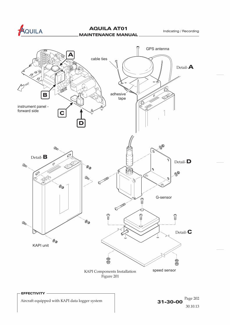
MAINTENANCE MANUAL
AQUILA AT01A Indicating / Recording
EFFECTIVITY
31-30-0030.10.13
EFFECTIVITY
Page 202Aircraft equipped with KAPI data logger system
KAPI Components InstallationFigure 201
B
C
D
instrument panel -forward side
KAPI unit
speed sensor
G-sensor
GPS antenna
cable ties
adhesivetape
A
BDetail-
ADetail-
DDetail-
CDetail-
MAINTENANCE MANUAL
AQUILA AT01A Indicating / Recording
31-30-0030.10.13
EFFECTIVITY
Aircraft equipped with KAPI data logger systemPage 203
2. (Ref. Fig. 201)
A. Remove KAPI Unit(1) Ensure electrical power to aircraft is OFF.(2) Disconnect battery (refer to 24-30-00).(3) Remove glare shield (refer to 31-10-00).(4) Disconnect all plug connectors and cables. Mark the removed cables, as required, and the
installation position of the unit.(5) While supporting the KAPI unit, remove nuts and washers from the attachment screws and
carefully remove KAPI unit from aircraft.
The upper forward attachment screw of the KAPI unit constitutes the forwardattachment point of the support bracket of the KAPI GPS/GSM antenna.
B. Install KAPI Unit(1) Hold the KAPI unit correctly aligned in its installation position as previously marked and
install all attachment screws, nuts and washers.(2) Reconnect all required plug connectors and cables to the KAPI unit.
Make sure that all plugs and cables are properly connected.(3) Install glare shield (refer to 31-10-00).(4) Reconnect battery (refer to 24-30-00).(5) Conduct a functional test of the installed unit.
3. (Ref. Fig. 201)
A. Remove KAPI GPS/GSM Antenna(1) Ensure electrical power to aircraft is OFF.(2) Disconnect battery (refer to 24-30-00).(3) Remove glare shield (refer to 31-10-00).(3) Disconnect antenna cable from KAPI unit and remove cable ties.(4) Mark the installation position and remove the cable ties of the antenna attachment.(5) Carefully remove antenna from aircraft.
The antenna is additionally attached to the installation bracket by double-sidedadhesive tape. Remove tape and adhesive residue with acetone.
B. Install KAPI GPS/GSM Antenna(1) Put double-sided adhesive tape on the installation bracket of the GPS antenna and remove
the protective film from the adhesive tape.(2) Attach the antenna to the installation bracket in its correct installation position as previously
marked and press it on the installation bracket. Secure the antenna on the bracket with 2cross-wise mounted cable ties.
(3) Install the antenna cable properly and connect it to the KAPI unit.(4)
(6) Perform a functional check of the KAPI system.
KAPI Unit Removal/Installation
NOTE:
KAPI GPS/GSM Antenna Removal/Installation
NOTE:
Install glare shield (refer to 31-10-00).(5) Reconnect battery (refer to 24-30-00).
MAINTENANCE MANUAL
AQUILA AT01A Indicating / Recording
EFFECTIVITY
31-30-0030.10.13
EFFECTIVITY
Page 204Aircraft equipped with KAPI data logger system
4. (Ref. Fig. 201)
A. Remove KAPI Airspeed Sensor(1) Ensure electrical power to aircraft is OFF.(2) Disconnect battery (refer to 24-30-00).(3) Remove glare shield (refer to 31-10-00).(4) Disconnect pitot pressure line from the forward end of the sensor.
PLUG OR CAP THE SENSOR PORT AND THE END OF THE PRESSURELINE IMMEDIATELY AFTER DISCONNECTION TO PREVENT DIRT ORFOREIGN OBJECTS ENTERING THE SENSOR OR PRESSURE SYSTEM.
(5) Disconnect the plug connector from the sensor. Mark the removed plug as required.(6) Mark the installation position of the sensor and remove nuts and washers securing sensor.(7) Carefully remove sensor from aircraft.
B. Install KAPI Airspeed Sensor(1) Put sensor on instrument panel base plate and position it correctly as previously marked
(pitot pressure port of the sensor has to point towards flight direction). The correctinstallation position of the sensor is vital for a correct data acquisition.
(2) Secure KAPI airspeed sensor in its installation position using screws, washers and nuts.(3) Remove plugs/caps from sensor port and pitot pressure line. Reconnect pitot pressure line to
the respective sensor port. Make sure that the pressure line is properly connected to the portand secure the connection with a cable tie.
(4) Connect the required plug connector to the sensor. Make sure that all plugs and cables areproperly connected.
(5) Conduct a leak test of the pitot pressure system (refer to 34-11-00).(6) Install glare shield (refer to 31-10-00).(7) Reconnect battery (refer to 24-30-00).(8) Perform a functional check of the KAPI system.
5. (Ref. Fig. 201)
A. Remove KAPI G-Sensor(1) Ensure electrical power to aircraft is OFF.(2) Disconnect battery (refer to 24-30-00).(3) Remove glare shield (refer to 31-10-00).(4) Disconnect plug connector from sensor. Mark the removed plug as required.(5) Mark installation position of the sensor and remove nuts and washers from sensor mounting.
KAPI Airspeed Sensor Removal/Installation
CAUTION:
KAPI G-Sensor Removal/Installation
(6) Carefully remove sensor from its installation position.
B. Install KAPI G-Sensor(1) Place sensor on its mounting bracket and position it correctly as previously marked.
The correct installation position of the sensor is vital for a correct data acquisition.(2) Secure KAPI G-sensor on its installation bracket using attachment screws, washers and nuts.(3) Connect plug connector to sensor. Make sure that the plug is properly connected.(4) Install glare shield (refer to 31-10-00).(5) Reconnect battery (refer to 24-30-00).(6) Perform a functional check of the KAPI system.

MAINTENANCE MANUAL
AQUILA AT01
Aviation by Excellence GmbH
CHAPTER 32
LANDING GEAR

MAINTENANCE MANUAL
AQUILA AT01
Aviation by Excellence GmbH
MAINTENANCE MANUAL
AQUILA AT01
Aviation by Excellence GmbH
Page 0132 - TOC
15.03.02
TABLE OF CONTENTS
ChapterSection
LANDING GEAR - GENERAL ........................................................................32-00-00 1Introduction 32-00-00 1General Description 32-00-00 1
MAIN GEAR - DESCRIPTION........................................................................32-10-00 1Introduction 32-10-00 1Description and Operation 32-10-00 1
MAIN GEAR - MAINTENANCE PRACTICES..............................................32-10-00 201Main Gear Leg Removal/Installation 32-10-00 201
NOSE GEAR - DESCRIPTION........................................................................32-20-00 1Introduction 32-20-00 1Description and Operation 32-20-00 1
NOSE GEAR - MAINTENANCE PRACTICES..............................................32-20-00 201Nose Gear Leg Removal/Installation 32-20-00 201
WHEELS AND BRAKES - DESCRIPTION....................................................32-40-00 1Introduction 32-40-00 1Description and Operation 32-40-00 1
WHEELS AND BRAKES - MAINTENANCE PRACTICES .........................32-40-00 201Main Gear Wheels Removal/Installation 32-40-00 201Main Gear Wheel Disassembly/Assembly 32-40-00 201Nose Gear Wheel Removal/Installation 32-40-00 203Nose Gear Wheel Disassembly/Assembly 32-40-00 203Brake Master Cylinder Removal/Installation 32-40-00 205Brake Caliper Removal/Installation 32-40-00 205Brake Disc Removal/Installation 32-40-00 207Brake Lining Replacement 32-40-00 207Brake System Bleeding 32-40-00 208Adjustment/Test 32-40-00 208
Title Subject Page
Landing Gear

MAINTENANCE MANUAL
AQUILA AT01
Aviation by Excellence GmbH
Page 02
20.02.00
Table of Contentssverzeichnis - Fortsetzung
Kapitel-Abschnitt-
Title Unterabschnitt Page
32 - TOC
MAINTENANCE MANUAL
AQUILA AT01
Aviation by Excellence GmbH
32-00-00Page 01
30.01.03
LANDING GEAR - GENERAL
1.
A. This chapter describes units and components, which furnish a means of supporting and steeringthe aircraft on the ground. Includes main and nose landing gears, brakes, wheels and tires.
2.
A. The AQUILA AT01 aircraft has a fixed tricycle landing gear with a steerable nose gear.All three wheels are equipped with an aerodynamic wheel fairing to decrease drag forces.The main gear struts are leaf springs, which are attached to the center section of fuselage usingtwo mounting brackets each.The nose gear is a tubular strut, which is attached to the engine mount and linked through therudder pedals to provide ground control. For shock absorbing an elastomer package is installedbetween nose gear strut and nose wheel fork.Hydraulically actuated disc type brakes are provided on the main gear wheels on the inboard side.
B. Descriptive Data
Tire Type: 6-PLYWheelbase: 1,685 m (5,53 ft)Track Width (maximum. fuel,Without persons on board): 1,938 m (6,36 ft)Main Tire Size: 5.00x5Nose Tire size: 5.00x5Main Tire Pressure: 2,5 bars (36 psi)Nose Tire Pressure: 2,0 bar (29 psi)Max. Nose Gear Wheel Fork Deflection: +/- 20°
Introduction
General Description
Landing Gear

MAINTENANCE MANUAL
AQUILA AT01
Aviation by Excellence GmbH

MAINTENANCE MANUAL
AQUILA AT01
Aviation by Excellence GmbH
32-10-00Page 01
15.03.02
MAIN LANDING GEAR - DESCRIPTION
1.
A. The AQUILA AT01 main landing gear consists of the main landing gear struts, the wheels withbrakes and the wheel fairings. The wheel fairings appertain for standard equipment.The main gear struts are spring legs. They made of high quality leaf steel and carry the landingloads. The AQUILA AT01 is equipped in series with disc type brakes.
2.
B. Each main landing gear strut is attached to the fuselage structure by means of two aluminummounting brackets. These brackets are bolted to the main landing gear ribs, which are bondedinto the fuselage belly.To the inner bracket the struts are mounted with a special single bolt. The outer mounting bracketconsists of two parts; the upper part locates on top of the main strut and the lower retaining barlocates below the main strut. The retaining bar is attached to the upper part of the bracket withtwo bolts. This arrangement ensures correct absorption of the landing loads like a rocker plate.To prevent chafing damage and allow angular movement of the struts, synthetic rubber inserts areinstalled between the contact surfaces.The wheel axle is attached to the lower end of the landing gear strut with four bolts.A mounting plate for the wheel fairing is installed on the inboard side of the lower end of eachmain landing gear strut using the bolts securing the wheel axle to strut.
Introduction
Description and Operation
Landing Gear

MAINTENANCE MANUAL
AQUILA AT01
Aviation by Excellence GmbH

MAINTENANCE MANUAL
AQUILA AT01
Aviation by Excellence GmbH
32-10-00Page 201
15.03.02
MAIN LANDING GEAR - MAINTENANCE
1.
CONTACT WITH HYDRAULIC FLUID CAN CAUSE SKIN IRRITATIONS.
EXCESSIVE HYDRAULIC FLUID WILL ATTACK THE SURFACE OF VARIOUSMATERIALS. TO ALL MANUFACTURERS INSTRUCTIONS.PROVIDE A SUITABLE COLLECTING VESSEL FOR HYDRAULIC FLUID.
A. Remove a Main Landing Gear Leg(1) Gain access to the appropriate landing gear mounting brackets in the fuselage belly (refer to
25-00-00).(2) Lift aircraft (refer to 07-10-00).(3) Remove screws securing wheel fairing to wheel assembly and remove fairing.(4) Disconnect brake line at fitting on strut. Insert a plug into disconnected fittings immediately.(5) In the fuselage belly, remove bolt and nut attaching inboard end of main landing gear strut to
inner mounting bracket.(6) Loosen two bolts securing main gear strut retainer clamp to outer mounting bracket.(7) Pull main gear strut from fuselage.
B. Install a Main Landing Gear Leg(1) Slide main gear strut into place so the strut retainer clamp is supporting the strut.(2) In the fuselage belly, install bolt attaching inboard end of main landing gear strut to inner
mounting bracket. Ensure flexible washers and washers are in correct position.(3) Tighten two bolts securing main gear strut retainer clamp to outer mounting bracket.(4) Reconnect brake line.(5) Install wheel fairing using screws.(6) Refill and bleed brake system.(7) Test brake system and ensure brakes are operating properly.
Main Landing Gear Leg Removal/Installation
WARNING:
CAUTION:READ AND ADHERE
Landing Gear
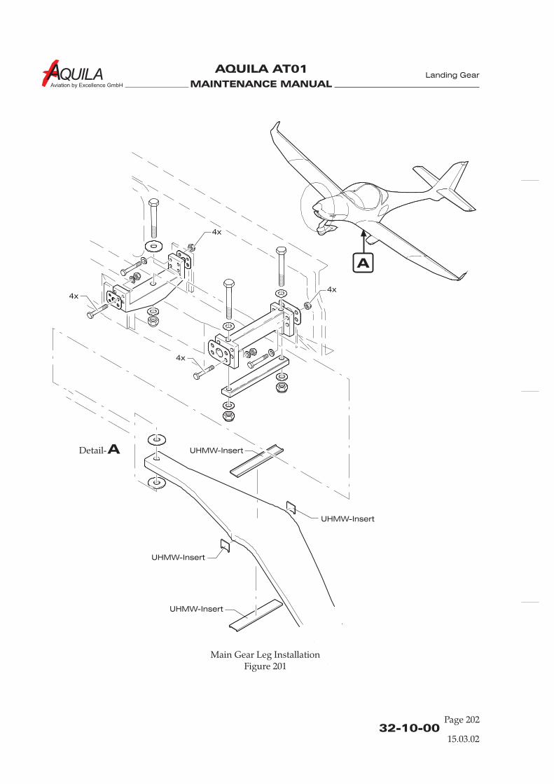
MAINTENANCE MANUAL
AQUILA AT01
Aviation by Excellence GmbH
32-10-00Page 202
Main Gear Leg InstallationFigure 201
15.03.02
Landing Gear
A
ADetail-
UHMW-Insert
UHMW-Insert
UHMW-Insert
UHMW-Insert
4x
4x
4x
4x
MAINTENANCE MANUAL
AQUILA AT01
Aviation by Excellence GmbH
32-20-00Page 01
15.03.02
NOSE GEAR - DESCRIPTION
1.
A. The AQUILA AT01 incorporates a steerable nose landing gear, which is equipped with a shockabsorber and wheel fairing.
2.
A. The nose gear consists of a welded tubular steel strut attached turnable to the engine mount.The forward bottom end of the nose gear strut has a horizontal pivot for the nose wheel fork.Thereby the nose wheel fork with the nose gear wheel can move only up and down.Shock absorbing is provided by a shock absorber unit equipped with stacked rubber disks, whichis installed between nose wheel fork and nose gear strut.Nose wheel steering is accomplished through use of the rudder pedals. Spring loaded steeringrod assemblies connect the nose gear steering arm at the upper end of the nose gear strut to armson the rudder pedals. Steering is afforded up to approximately 20 degrees each side of neutral.
Introduction
Description and Operation
Landing Gear

MAINTENANCE MANUAL
AQUILA AT01
Aviation by Excellence GmbH
MAINTENANCE MANUAL
AQUILA AT01
Aviation by Excellence GmbH
32-20-00Page 201
15.03.02
NOSE GEAR - MAINTENANCE
1. (Refer to Figure 201)
A. Remove Nose Gear Leg(1) Jack aircraft or weight tail of aircraft to raise nose wheel (refer to 07-00-00).(2) Remove engine cowling (refer to 71-10-00).(3) Disconnect retaining springs at the nose gear steering arm.(4) Disconnect steering rod assemblies at nose gear steering arm.(5) Remove nut securing upper end of the nose gear strut to engine mount.(6) Remove pivot bolt securing nose gear strut assembly to the engine mount at the bracket.(7) Remove nose gear leg from the aircraft downwards.
B. Install Nose Gear Leg(1) Place nose gear leg in position.(2) Install pivot bolt securing nose gear strut assembly to the engine mount at the bracket.(3) Install nut securing upper end of the nose gear strut to engine mount.(4) Connect steering rod assemblies to the nose gear steering arm.(5) Connect retaining springs to the nose gear steering arm.(6) Install engine cowling (refer to 71-10-00)
Nose Gear Leg Removal/Installation
Landing Gear
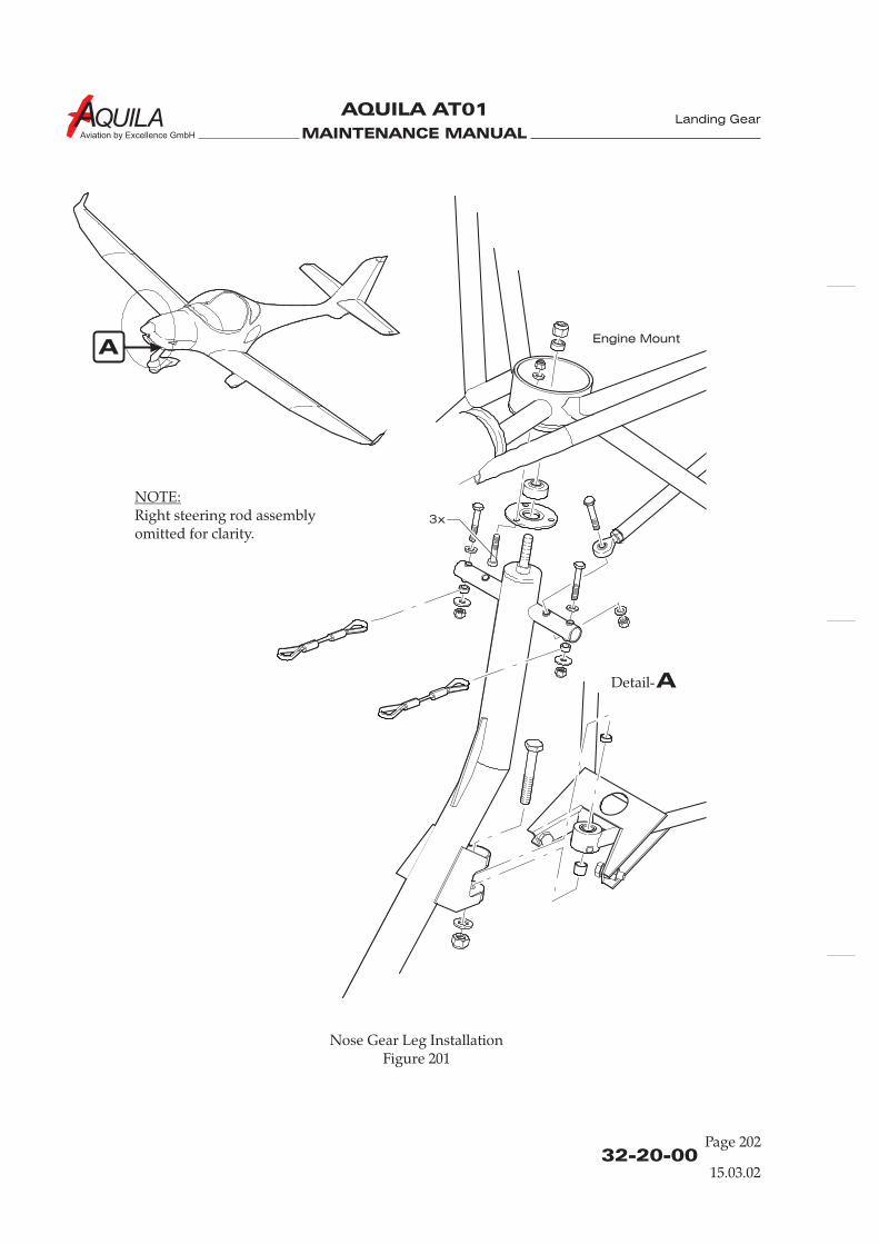
MAINTENANCE MANUAL
AQUILA AT01
Aviation by Excellence GmbH
32-20-00Page 202
Nose Gear Leg InstallationFigure 201
15.03.02
Landing Gear
A
ADetail-
NOTE:Right steering rod assemblyomitted for clarity.
3x
Engine Mount
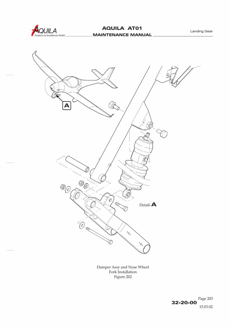
MAINTENANCE MANUAL
AQUILA AT01
Aviation by Excellence GmbH
Damper Assy and Nose WheelFork Installation
Figure 202
32-20-00Page 203
15.03.02
Landing Gear
ADetail-
A

MAINTENANCE MANUAL
AQUILA AT01
Aviation by Excellence GmbH
MAINTENANCE MANUAL
AQUILA AT01
Aviation by Excellence GmbH
32-40-00Page 01
15.03.02
WHEELS AND BRAKES - DESCRIPTION
1.
A. Nose and main landing gear wheels are of conventional design.The wheels of the main landing gear are each equipped with a single brake disc, floating cylinderbrake assembly.
B. For tire specifications, refer to “Landing Gear General”.
2.
A. The main gear wheels consist of the two wheel halves, the tubing, and the tire. The brake disc isbolted to the inboard wheel side. The tire valve is on the outboard wheel side. There are two setsof roller bearings in each wheel, one on the inboard wheel half and one on the outboard wheelhalf.The nose gear wheel construction is the same as that of the main gear wheels but without brakedisc.
B. The brake system of the AQUILA AT01 comprises of single disc, hydraulically actuated brakes oneach main landing gear wheel, four master cylinders, linked with the rudder pedals, a brake fluidreservoir on the left cabin wall in front of the fire wall, and brake fluid lines and hoses.
The brakes are operated by pushing the upper part of either the left or right rudder pedal- in eachpilot position. Each set of rudder pedals is interconnected. This motion is mechanicallytransmitted to the respective brake master cylinder, and through brake fluid carrying lines andhoses out to the respective hydraulic brake assembly.
Introduction
Description and Operation
Landing Gear

MAINTENANCE MANUAL
AQUILA AT01
Aviation by Excellence GmbH

MAINTENANCE MANUAL
AQUILA AT01
Aviation by Excellence GmbH
32-40-00Page 201
15.03.02
WHEELS AND BRAKES - MAINTENANCE
1.
A. Remove a Main Gear Wheel(1) Jack aircraft or appropriate main gear wheel (Refer to 7-00-00).(2) Remove screws securing wheel fairing and remove wheel fairing.(3) Remove bolts securing brake back plate to brake caliper. Remove back plate.(4) Remove wheel axle nut.(5) Pull wheel from axle.
B. Install a Main Gear Wheel(1) Slide the wheel assembly onto the axle, with the brake disc onboard and the valve stem
outboard.(2) Install axle nut and finger-tighten. Then, while slowly continuing to tighten with a wrench,
simultaneously rotate the wheel assembly by hand. Tighten until a slight resistance in thewheel bearings is obvious. Back off nut to nearest castellation and install cotter pin.
When the axle nut is set in its final position, there should be no resistance torotation and no side-to-side play in the wheel bearings.
(4) Position brake back plate between brake disc and inboard wheel hub and secure using boltsand washers.
(5) Install wheel fairing.
2.
A. Disassemble a Main Gear Wheel
DO NOT ATTEMPT SEPARATE WHEEL HALVES BEFORE WHEEL AND TUBECOMPLETELY ARE DEFLATED.
(1) Completely deflate tire and tube, and break loose tire bead.(2) Remove tree bolts to separate wheel halves and brake disc.(3) Remove wheel halves and brake disc from tire.(4) Remove tube from tire.(5) If necessary remove wheel bearing assembly from wheel halves.
B. Assemble a Main Gear Wheel(1) If removed, install wheel bearing assembly to wheel halves.(2) Insert tube into tire with the valve stem aligned with the painted reference mark on the tire.
Inflate the tube with just enough pressure to give it shape inside the tire.(3) Insert the two wheel halves into the tire, taking care to avoid pinching the tube between
them. Guide the valve stem through the rubber-grommeted hole in the outboard wheel halfwhile bringing the halves together.
: It is recommended, when the wheel halves are joined, double check that the tubeisn't pinched, using an inspection mirror and a flashlight.
Main Gear Wheels Removal/Installation
NOTE:
Main Gear Wheel Disassembly/Assembly
WARNING:
NOTE
Landing Gear

MAINTENANCE MANUAL
AQUILA AT01
Aviation by Excellence GmbH
32-40-00Page 202
Main Gear Wheel InstallationFigure 201
15.03.02
Landing Gear
A
ADetail-
4x
MAINTENANCE MANUAL
AQUILA AT01
Aviation by Excellence GmbH
32-40-00Page 203
15.03.02
(4) Reassemble the wheel unit, including the brake disc, with bolts, washers, and nuts. Torque to10 - 12 Nm.
(5) Inflate the tire as required, refer to “Landing Gear General”.
3.
A. Remove Nose Gear Wheel(1) Jack aircraft or weight tail of aircraft to raise nose wheel, refer to Chapter 7, “Lifting and
Shoring”.(2) Remove screws securing wheel fairing and remove wheel fairing.(3) Remove axle bolt from wheel fork.(4) Remove cap bushings from wheel fork arms.(5) Remove nose wheel assembly backwards from wheel fork.
B. Install Nose Gear Wheel(1) Slide the whole wheel assembly (with axle, spacers, and washers in position) between wheel
fork arms.(2) Insert cap bushings into wheel fork arms.(3) Insert axle bolt and torque nut until slight bearing drag, when the wheel is rotated. Then,
back off nut to nearest castellation and install pin.
When the axle bolt nut is set in its final position, there should be no resistance torotation and no side-to-side play in the wheel bearings.
(4) Install wheel fairing.
4.
A. Disassemble Nose Gear Wheel(1) Remove spacers, washers, and axle from wheel.
DO NOT ATTEMPT SEPARATE WHEEL HALVES BEFORE WHEEL AND TUBECOMPLETELY ARE DEFLATED.
(2) Completely deflate tire and tube, and break loose tire bead.(3) Remove tree bolts to separate wheel halves.(4) Remove wheel halves from tire.(5) Remove tube from tire.(6) If necessary remove wheel bearing assembly from wheel halves.
B. Assemble Nose Gear Wheel(1) If removed, install wheel bearing assembly to wheel halves.(2) Insert tube into tire with the valve stem aligned with the painted reference mark on the tire.
Inflate the tube with just enough pressure to give it shape inside the tire.(3) Insert the two wheel halves into the tire, taking care to avoid pinching the tube between
them. Guide the valve stem through the rubber-grommeted hole in the outboard wheel halfwhile bringing the halves together.
Nose Gear Wheel Removal/Installation
NOTE:
Nose Gear Wheel Disassembly/Assembly
WARNING:
Landing Gear
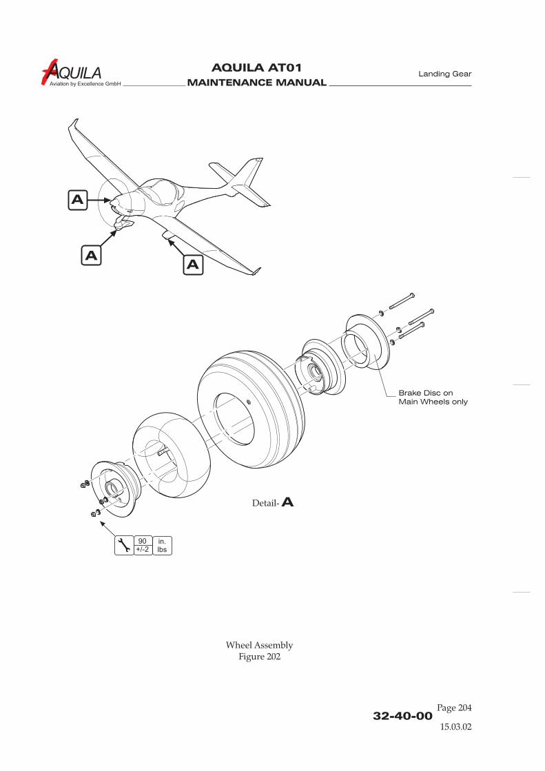
MAINTENANCE MANUAL
AQUILA AT01
Aviation by Excellence GmbH
32-40-00Page 204
A
A
A
A
Detail-
in.lbs
90+/-2
Wheel AssemblyFigure 202
15.03.02
Landing Gear
Brake Disc on
Main Wheels only

MAINTENANCE MANUAL
AQUILA AT01
Aviation by Excellence GmbH
32-40-00Page 205
15.03.02
NOTE
Brake Master Cylinder Removal/Installation
WARNING:
CAUTION:
NOTE:
Brake Caliper Removal/Installation
WARNING:
CAUTION:
: It is recommended, when the wheel halves are joined, double check that the tubeisn't pinched, using an inspection mirror and a flashlight.
(4) Reassemble the wheel unit with bolts, washers, and nuts. Torque to 10 - 12 Nm.(5) Inflate the tire as required, refer to “Landing Gear General”.(6) Insert wheel axle and place washers and spacers onto the axle.
5.
CONTACT WITH HYDRAULIC FLUID CAN CAUSE SKIN IRRITATIONS.
EXCESSIVE HYDRAULIC FLUID WILL ATTACK THE SURFACE OF VARIOUSMATERIALS. READ AND ADHERE TO ALL MANUFACTURERS INSTRUCTIONS.PROVIDE A SUITABLE COLLECTING VESSEL FOR HYDRAULIC FLUID.
A. Remove a Brake Master Cylinder(1) Remove bleeder fitting at wheel brake caliper and drain hydraulic fluid from master brake
cylinders.(2) Disconnect brake master cylinder from rudder pedal assembly.(3) Disconnect hydraulic brake line hoses from master cylinder and remove brake master
cylinder.(4) Plug or cap hydraulic fittings, hoses and lines to prevent the entry of contaminants.
Brake master cylinder repair should be accomplished according tomanufacturer's specifications.
B. Install a Brake Master Cylinder(1) Connect hydraulic hoses to brake master cylinder.(2) Place brake master cylinder into position and connect brake master cylinder to rudder pedal
assembly.(3) Install bleeder fitting at wheel brake caliper.(4) Refill and bleed brake system, refer to “Brake System Bleeding” below.(5) Test brake system and ensure brakes are operating properly, refer to “Adjustment/Test”.
6.
CONTACT WITH HYDRAULIC FLUID CAN CAUSE SKIN IRRITATIONS.
EXCESSIVE HYDRAULIC FLUID WILL ATTACK THE SURFACE OF VARIOUSMATERIALS. READ AND ADHERE TO ALL MANUFACTURERS INSTRUCTIONS.PROVIDE A SUITABLE COLLECTING VESSEL FOR HYDRAULIC FLUID.
A. Remove a Caliper(1) Disconnect brake line at brake caliper and immediately plug or cap hydraulic fitting and
brake line.(2) Remove the two bolts that secure the back plate to caliper housing.(3) Remove back plate and slide caliper housing with pressure plate away from the wheel.
Landing Gear

MAINTENANCE MANUAL
AQUILA AT01
Aviation by Excellence GmbH
32-40-00Page 206
15.03.02
A
A
ADetail-
Brake Caliper AssemblyFigure 203
Landing Gear
Torque
Plate
Back Plate
Lining
O-Ring
Anchor Bolt
Piston
Inlet Fitting
Cylinder
Bleeder Assy
MAINTENANCE MANUAL
AQUILA AT01
Aviation by Excellence GmbH
32-40-00Page 207
15.03.02
B. Install a Caliper(1) Slide the caliper housing anchor pins into the torque plate bushings until the lining on the
pressure plate contacts the brake disc.(2) Position the back plate against the other side of the disc and thread the two caliper housing
bolts with their washers into the back plate from opposite side of the caliper housing.Tighten bolts to 90 in.lbs..
(3) Safety-wire the bolts.(4) Reconnect brake line to caliper.(5) Refill if necessary, and bleed brake system, refer to “Brake System Bleeding” below.(6) Test brake system and ensure brakes are operating properly, refer to “Adjustment/Test”.
7.
A. Remove Brake Disc(1) Remove main gear wheel from main gear strut, refer to “Main Gear Wheels
Removal/Installation” above.(2) Disassemble main gear wheel, refer to “Main Gear Wheel Disassembly/Assembly” above.(3) Remove brake disc.
B. Install Brake Disc
Before reinstalling the brake disc, inspect brake disc for camber and excessive scoring.Scoring should not deeper than 0,5 mm (0.02 in.).
(1) Install brake disc, refer to “Main Gear Wheel Disassembly/Assembly” above.
8.
Minimum allowable brake lining thickness is 2,5 mm (3/32 in.).
A. Remove Brake Linings(1) Remove caliper from main gear wheel, as described in pt. 6.(2) Slide pressure plate off anchor pins of the brake caliper housing assembly.(3) Place the back plate or pressure plate on a vise with the lining material down and with the
rivets positioned over gap between the vise jaws. Drive the rivets out using a hammer and apunch.
B. Install Brake Lining(1) Position the new lining material against the back plate or the pressure plate, making sure that
the counterbores on both pieces are facing outward (away from each other).(2) Insert a rivet into each of the holes in the lining material with the head of the rivet fitting into
the counterbore in the lining.(3) Place the plate and lining into a brake lining installation fixture with the head of the rivet
down against the bucking anvil of the tool. Insert the rivet setting mandrel into the fixturewith the mandrel contacting the rivet tail.
(4) Support the plate and the lining in the installation fixture with one hand while tapping themandrel with a hammer. Proceed slowly and rotate the assembly while driving the rivet sothat the tail is evenly formed.
Brake Disc Removal/Installation
NOTE:
Brake Lining Replacement
Landing Gear
MAINTENANCE MANUAL
AQUILA AT01
Aviation by Excellence GmbH
32-40-00Page 208
15.03.02
NOTE:
Brake System Bleeding
Adjustment/Test
Before setting the first rivet fully, start the other rivets to keep the lining alignedproperly with the plate.
(5) Set all the rivets fully.(6) Slide the pressure plate with its new lining material over the caliper housing anchor pins.(7) Reinstall caliper from main gear wheel, as described in pt. 6.
9.
To bleed the brakes, use a fluid pump, a clear tube, and a collecting container.
A. Bleeding Procedures(1) Connect fluid pump to the brake caliper bleeder fitting.(2) Connect collecting container with clear tube to brake fluid reservoir.(3) Open the bleeder and pump fluid from the caliper through the master cylinder(s) to the
reservoir until no air bubbles are evident in the reservoir (clear tube). Then, tighten thebleeder fitting.
(4) Repeat for both brake calipers.
10.
A. There is no need to adjust the brakes since the brake pistons move to compensate for brake andwear.
B. After component replacement or repair:(1) Check the brakes for firm pedal pressure and bleed the system if either brake feels spongy.(2) Perform a minimum of six stops from a speed of between 25 and 40 knots, using light pedal effort
and letting the brakes cool partially (about one minute) between stops. Check the aircraft is notturning from centerline while apply left and right brakes uniformly.
(3) Check all fittings and hoses for any leakage.
Landing Gear

MAINTENANCE MANUAL
AQUILA AT01A
CHAPTER 33
LIGHTS

MAINTENANCE MANUAL
AQUILA AT01A
MAINTENANCE MANUAL
AQUILA AT01A
Page 133 - TOC
Lights
30.10.13
TABLE OF CONTENTS
ChapterSection
Introduction 33-00-00 1General Description 33-00-00 1
Title Subject Page Effectivity
LIGHTS - GENERAL.........................................................................................33-00-00 1
INTERIOR LIGHTS - MAINTENANCE ........................................................33-10-00 201General 33-10-00 201Post Light Removal/Installation 33-10-00 201Nulite Removal/Installation 33-10-00 201Cockpit Light Removal/Installation 33-10-00 202
EXTERIOR LIGHTS - MAINTENANCE........................................................33-40-00 201General 33-40-00 201Landing Light Removal/Installation/Check 33-40-00 201Navigation/Position Light Bulb Replacement 33-40-00 202 Whelen lightsFlash Tube Assembly Replacement 33-40-00 202 Whelen lightsAnti-Collision Strobe Light Assembly Removal/Installation 33-40-00 202 Whelen lightsStrobe Light Module Removal/Installation 33-40-00 202 Whelen lightsNavigation/Position/Anti-Collision LightRemoval/Installation/Check 33-40-00 202 Aveo lights

MAINTENANCE MANUAL
AQUILA AT01A
MAINTENANCE MANUAL
AQUILA AT01A
33-00-00Page 1
Lights
LIGHTS - GENERAL
1.
A. This chapter describes interior and exterior lighting systems used on the aircraft, includingremoval and installation procedures of components and light bulb replacement instructions.
2.
A. A cockpit light is installed for general cabin lighting, for emergency instrument panel lighting andas a reading light. The dimmable and swivel cockpit light is located in the roof of the cabin justbehind the seats. The light is controlled through a dimmer switch on the light.
The voltmeter, the ammeter, the oil temperature, the oil pressure and the cylinder headtemperature indicators as well as most of the avionic equipment are internally lighted. Refer toappropriate manufacturer's publications for maintenance instructions.In aircraft equipped for Night-VFR additional instrument and panel lighting is installed:If instruments do not have internal lighting they are illuminated by post lights or Nulites. As asecond source of light a LED row is integrated into the instrument panel cover. Both, LED rowand Nulites / post lights are controlled by a separate dimmer.To avoid shadowing on placards there is a placard bar below the switches on the bottom of theinstrument panel. For emergency lighting there are flashlights and all placards are luminescent.
B. Exterior lighting consists of wing tip navigation lights with integral anti-collision strobe lights andposition lights and a single landing light.
Introduction
General Description
30.10.13

MAINTENANCE MANUAL
AQUILA AT01A
MAINTENANCE MANUAL
AQUILA AT01A
INTERIOR LIGHTS - MAINTENANCE
1.
A.
aintenance of post lights and Nulites islimited to their removal and installation.
2.
A. Remove Post Light(1) Ensure electrical power to aircraft is OFF.(2) Disconnect battery (refer to 24-30-00).(3) Remove glare shield (refer to 31-10-00).(4) Disconnect electrical connector at back of post light.(5) Remove washer and nut securing post light to instrument panel and remove cable shoe and
post light.
B. Install Post Light(1) Put post light and cable shoe in position and secure using washer and nut.(2) Connect electrical connector at back of post light.(3) Install glare shield (refer to 31-10-00).(4) Reconnect battery (refer to 24-30-00).(5) Perform functional check.
General
Post Light Removal/Installation
If instruments do not have internal lighting, they are illuminated by post lights or Nulites. Postlights are LED lights that illuminate the instrument panel and function as instrument mountingbolts. Nulites are installed between the instrument and the instrument panel. They have a specialbezel that focuses the light toward the instrument. M
B. In Night-VFR equipped aircraft a LED row is integrated into the instrument panel cover. The rowis bonded to the instrument panel cover and therefore cannot be replaced or removed. Refer to31-10-00 for glare shield removal/installation procedures.
C. A cockpit light is installed in the roof of the cabin just behind the seats. Maintenance is limited tothe removal/installation of the light.
3.
A. Remove Nulite(1) Ensure electrical power to aircraft is OFF.(2) Disconnect battery (refer to 24-30-00).(3) Remove glare shield (refer to 31-10-00).(4) Cut electrical wires to Nulite .(5) Remove affected instrument as described in the appropriate chapter of this manual.(6) Remove Nulite.
Nulite Removal/Installation
Lights
33-10-00Page 201
30.10.13
MAINTENANCE MANUAL
AQUILA AT01A Lights
33-10-00Page 202
30.10.13
B. Install Nulite(1) Put Nulite in position between the instrument panel and the instrument with the wires
coming out of the top.(2) Install affected instrument as described in the apropriate chapter of this manual.(3) Reconnect wires to Nulite using crimp seal butt connector. Secure with cable ties.(4) Install glare shield (refer to 31-10-00).(5) Reconnect battery (refer to 24-30-00).(6) Perform functional check.
4.
A. Remove Cockpit Light(1) Ensure electrical power to aircraft is OFF.(2) Disconnect electrical wires at connector.(3) Remove screws securing light to headset bracket and remove light.
B. Install Cockpit Light(1) Put light in position and secure to the headset bracket using screws, washers and nuts.(2) Reconnect electrical wires at connector.(3) Perform functional check.
Cockpit Light Removal/Installation
MAINTENANCE MANUAL
AQUILA AT01A
33-40-00Page 201
Lights
30.10.13
EXTERIOR LIGHTS - MAINTENANCE
1.
A. The maintenance of exterior lights is limited to the removal and installation of components andlight bulb replacement.
B.
C. The illumination unit of the LED versions cannot be repaired. If one LED of the cluster has failedthe complete illumination unit has to be replaced.
2.
A. Remove Landing Light(1)(2) Remove upper cowling (refer to 71-10-00)(3) Disconnect landing light electrical wires at connector.(4) Remove screws securing landing light to cowling and remove landing light from aircraft.
B. Install Landing Light(1) Put landing light in position in the cowling and secure using screws.(2) Reconnect landing light electrical wires at connector.(3) Perform functional check, adjust landing light if necessary (refer to “Inspection/Check”
below).(4) Install upper cowling (refer to 71-10-00).
C. Landing Light Inspection/Check(1) Turn BAT switch ON.(2) Turn LDG light ON.(3) Verify the landing light works properly.(4) Turn OFF all switches.
General
Landing Light Removal/Installation/Check
The navigation / anti-collision lights installed are produced either by Whelen Engineering or AveoEngineering. Whelen lights are available either with or without LED navigation lights. Aveolights use LED's for navigation, position and anti-collision lights.
Ensure electrical power to aircraft is OFF.
MAINTENANCE MANUAL
AQUILA AT01A
33-40-00Page 202
30.10.13
Lights
3.
DO NOT ALLOW THE GLASS PORTION OF THE LIGHT BULB TO COME INCONTACT WITH EXPOSED SKIN.PAY ATTENTION WHILE DISASSEMBLING ANTI-COLLISION STROBE LIGHTASSEMBLY TO PREVENT GLASS LENSES FROM DROPPING DOWN.
Not applicable for the LED version of the navigation / position light.
A. Navigation / Position Light Bulb Replacement(1) Ensure electrical power to aircraft is OFF.(2) Remove screws securing lens retainer to base plate. Carefully remove lens retainer and lenses.(3) Take a hold of the navigation light bulb, depress slightly and turn counterclockwise to release
bulb from bayonet mount.(4) To remove the position light bulb, pull it straight out of the socket.(5) Place the navigation light bulb into the bayonet socket, depress, and gently turn clockwise
until bulb seats in socket.(6) To install the position light bulb, push it straight into the socket.(7) Put all lenses in position and secure using lens retainer and screws.(8) Perform navigation/position light functional test (refer to “Inspection/Check” below).
B. Navigation / Position Lights Inspection/Check(1) Turn BAT switch ON.(2) Turn NAV light switch ON.(3) Verify that the navigation / position lights work properly.(4) Turn OFF all switches.
4.
HIGH VOLTAGE! MAKE SURE THAT ELECTRICAL POWER TO STROBE LIGHTSYSTEM IS OFF.
(1) Ensure electrical power to aircraft is OFF.(2) Disconnect battery (refer to 24-30-00).(3) Remove screws securing lens retainer to base plate. Carefully remove lens retainer and lenses.(4) Pull the flash tube assembly and wire out of the base plate. Disconnect wire at connector.(5) Connect wire at connector, and route wire through the base plate. Insert light assembly into
base plate.(6) Put all lenses in position and secure using lens retainer and screws.(7) Reconnect battery (refer to 24-30-00).
5.
HIGH VOLTAGE! MAKE SURE THAT ELECTRICAL POWER TO STROBE LIGHTSYSTEM IS OFF.
Removal and installation is analogous for the left wing anti-collision strobe lightassembly and the right wing anti-collision strobe light assembly.
Navigation / Position Light Bulb Replacement
CAUTION:
NOTE:
Flash Tube Assembly Replacement
WARNING:
Anti-Collision Strobe Light Assembly Removal/Installation
WARNING:
NOTE:
EFFECTIVITY
Aircraft equipped with Whelen navigation / anti-collision lights
MAINTENANCE MANUAL
AQUILA AT01A
33-40-00Page 203
30.10.13
Lights
A. Remove Anti-Collision Strobe Light Assembly(1) Ensure electrical power to aircraft is OFF.(2) Disconnect battery (refer to 24-30-00).(3) Remove screws securing lens retainer to base plate. Carefully remove lens retainer and lenses.(4) Pull the flash tube assembly and wire out of the base plate. Disconnect wire at connector.(5) Remove screws securing base plate to wing tip fairing and remove base plate.(6) Disconnect wires from light at connector.
B. Install Anti-Collision Strobe Light Assembly(1) Reconnect wires to light at connector.(2) Position base plate on wing tip fairing and secure with screws.(3) Reconnect wire to flash light assembly at connector, and route wire through the base plate.
Insert light assembly into the base plate.(4) Put all lenses in position and secure using lens retainer and screws.(5) Reconnect battery (refer to 24-30-00).(6) Perform anti-collision light functional test (refer to “Inspection/Check” below).
C. Anti-Collision Strobe Light Inspection/Check(1) Turn BAT switch ON.(2) Turn ACL light switch ON.(3) Verify that anti-collision strobe light works properly.(4) Turn OFF all switches.
6.
HIGH VOLTAGE! MAKE SURE THAT ELECTRICAL POWER TO STROBE LIGHTSYSTEM IS OFF.
A. Remove Strobe Light Module(1) Ensure electrical power to aircraft is OFF.(2) Disconnect battery (refer to 24-30-00).(3) Remove baggage compartment floorboard / 211 JB (refer to 25-21-00).(4) Disconnect module connectors.(5) Remove bolts securing module to fuselage structure and remove module from aircraft.
B. Install Strobe Light Module(1) Position module on fuselage structure and secure using hardware.(2) Reconnect module connectors.(3) Reconnect battery (refer to 24-30-00).(4) Perform anti-collision light functional test (refer to “Inspection/Check” below).
C. Anti-Collision Strobe Light Inspection/Check(1) Turn BAT switch ON.(2) Turn ACL light switch ON.(3) Verify that anti-collision strobe lights work properly.(4) Turn OFF all switches.
Strobe Light Module Removal/Installation
WARNING:
EFFECTIVITY
Aircraft equipped with Whelen navigation / anti-collision lights

MAINTENANCE MANUAL
AQUILA AT01A Lights
3.
A. Remove Navigation/Position/Anti-Collision Light(1) Ensure electrical power to aircraft is OFF.(2) Remove screws securing base plate to wing tip fairing. Carefully remove light.(3) Disconnect wires from light at connector.
B. Install Navigation/Position/Anti-Collision Light(1) Reconnect wires to light at connector.(2) Position gasket and base plate on wing tip fairing and secure with screws.(3) Perform a navigation / position / anti-collision light functional test (refer to
“Inspection/Check” below).
C. Navigation/Position/Anti-Collision Light Inspection/Check(1) Turn BAT switch ON.(2) Turn NAV light switch ON.(3) Verify that the navigation / position light works properly.(4) Turn ACL light switch ON.(5) Verify that the anti-collision strobe light works properly.(6) Turn OFF all switches.
Navigation/Position/Anti-Collision Light Removal/Installation/Check
33-40-00Page 202
30.10.13
Aircraft equipped with Aveo navigation / anti-collision lights
EFFECTIVITY
MAINTENANCE MANUAL
AQUILA AT01A
CHAPTER 34
NAVIGATION

MAINTENANCE MANUAL
AQUILA AT01A
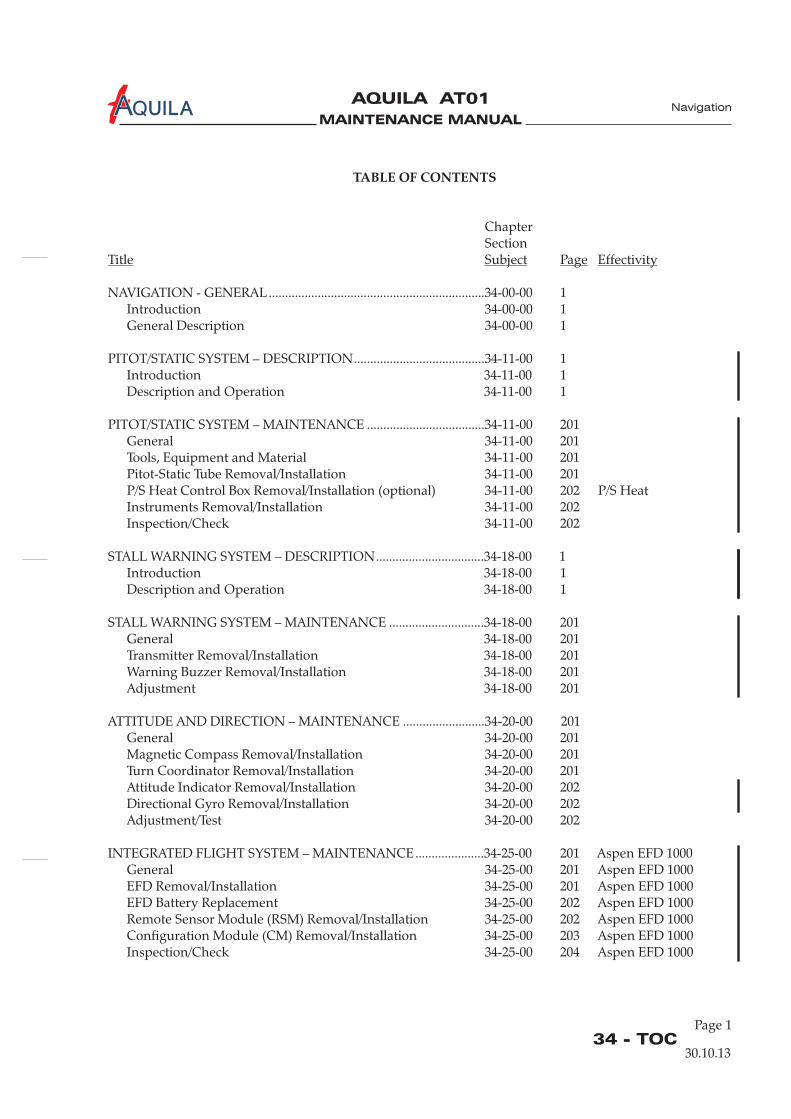
MAINTENANCE MANUAL
AQUILA AT01A
Page 134 - TOC
Navigation
30.10.13
TABLE OF CONTENTS
ChapterSection
NAVIGATION - GENERAL..................................................................34-00-00 1Introduction 34-00-00 1General Description 34-00-00 1
PITOT/STATIC SYSTEM – DESCRIPTION........................................34-11-00 1Introduction 34-11-00 1Description and Operation 34-11-00 1
PITOT/STATIC SYSTEM – MAINTENANCE ....................................34-11-00 201General 34-11-00 201Tools, Equipment and MaterialPitot-Static Tube Removal/Installation 34-11-00 201
Instruments Removal/Installation 34-11-00 202Inspection/Check 34-11-00 202
STALL WARNING SYSTEM – DESCRIPTION.................................34-18-00 1Introduction 34-18-00 1Description and Operation 34-18-00 1
STALL WARNING SYSTEM – MAINTENANCE .............................34-18-00 201General 34-18-00 201Transmitter Removal/Installation 34-18-00 201
Adjustment 34-18-00 201
ATTITUDE AND DIRECTION – MAINTENANCE .........................34-20-00 201General 34-20-00 201Magnetic Compass Removal/Installation 34-20-00 201Turn Coordinator Removal/Installation 34-20-00 201Attitude Indicator Removal/Installation 34-20-00 202Directional Gyro Removal/Installation 34-20-00 202Adjustment/Test 34-20-00 202
Title Subject Page Effectivity
34-11-00 201
P/S Heat Control Box Removal/Installation (optional) 34-11-00 202 P/S Heat
Warning Buzzer Removal/Installation 34-18-00 201
INTEGRATED FLIGHT SYSTEM – MAINTENANCE.....................34-25-00 201 Aspen EFD 1000General 34-25-00 201 Aspen EFD 1000EFD Removal/Installation 34-25-00 201 Aspen EFD 1000EFD Battery Replacement 34-25-00 202 Aspen EFD 1000Remote Sensor Module (RSM) Removal/Installation 34-25-00 202 Aspen EFD 1000Configuration Module (CM) Removal/Installation 34-25-00 203 Aspen EFD 1000Inspection/Check 34-25-00 204 Aspen EFD 1000
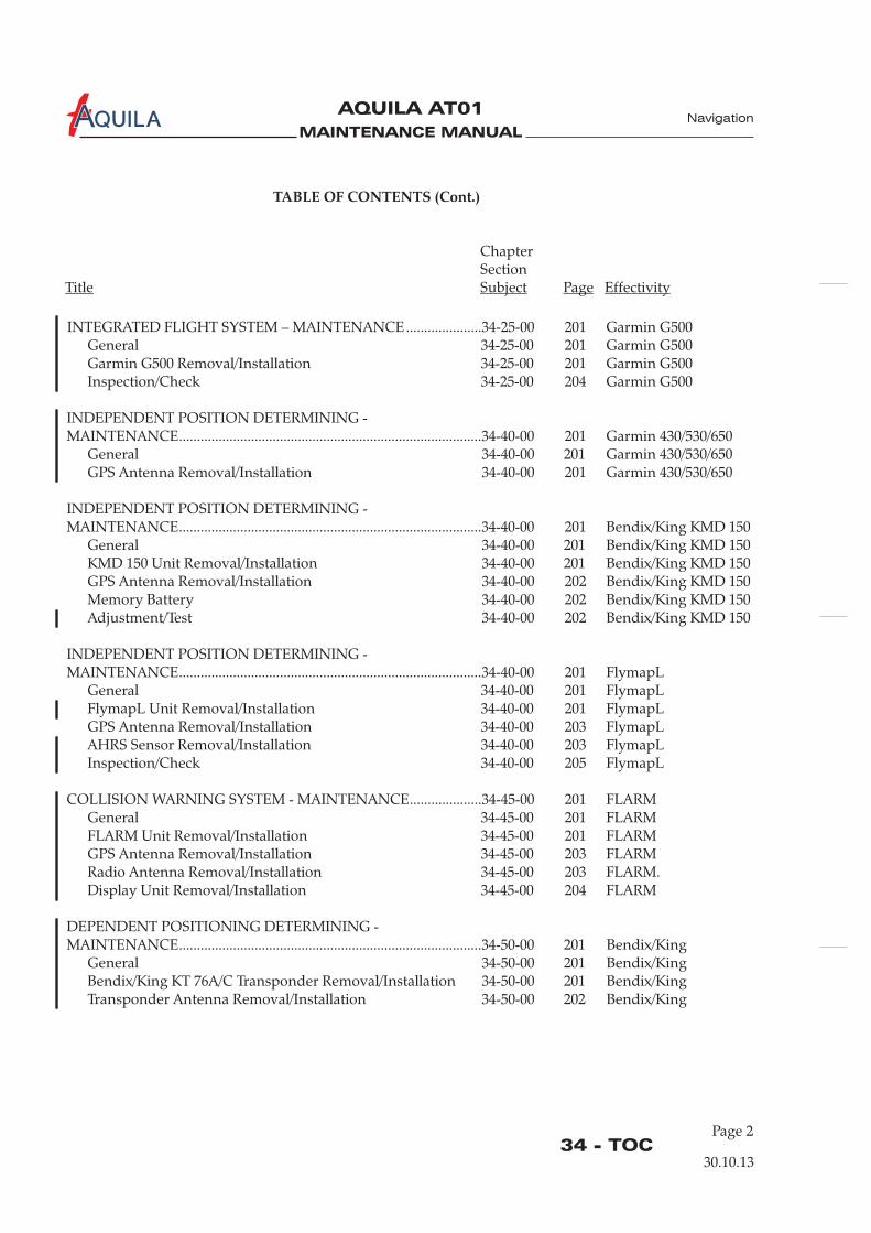
MAINTENANCE MANUAL
AQUILA AT01A Navigation
TABLE OF CONTENTS (Cont.)
ChapterSection
Title Subject Page Effectivity
Page 234 - TOC
30.10.13
INTEGRATED FLIGHT SYSTEM – MAINTENANCE.....................34-25-00 201 Garmin G500General 34-25-00 201 Garmin G500Garmin G500 Removal/Installation 34-25-00 201 Garmin G500Inspection/Check 34-25-00 204 Garmin G500
Garmin 430/530/650Garmin 430/530/650
INDEPENDENT POSITION DETERMINING -MAINTENANCE....................................................................................34-40-00 201 Bendix/King KMD 150
General 34-40-00 201 Bendix/King KMD 150KMD 150 Unit Removal/Installation 34-40-00 201 Bendix/King KMD 150GPS Antenna Removal/Installation 34-40-00 202 Bendix/King KMD 150Memory Battery 34-40-00 202 Bendix/King KMD 150Adjustment/Test 34-40-00 202 Bendix/King KMD 150
NDEPENDENT POSITION DETERMINING -MAINTENANCE....................................................................................34-40-00 201 FlymapL
COLLISION WARNING SYSTEM - MAINTENANCE....................34-45-00 201 FLARMGeneral 34-45-00 201 FLARMFLARM Unit Removal/Installation 34-45-00 201 FLARMGPS Antenna Removal/Installation 34-45-00 203 FLARMRadio Antenna Removal/Installation 34-45-00 203 FLARM.Display Unit Removal/Installation 34-45-00 204 FLARM
Bendix/KingBendix/KingBendix/King
INDEPENDENT POSITION DETERMINING -MAINTENANCE....................................................................................34-40-00 201 Garmin 430/530/650
General 34-40-00 201GPS Antenna Removal/Installation 34-40-00 201
I
General 34-40-00 201 FlymapLFlymapL Unit Removal/Installation 34-40-00 201 FlymapLGPS Antenna Removal/Installation 34-40-00 203 FlymapLAHRS Sensor Removal/Installation 34-40-00 203 FlymapLInspection/Check 34-40-00 205 FlymapL
DEPENDENT POSITIONING DETERMINING -MAINTENANCE....................................................................................34-50-00 201 Bendix/King
General 34-50-00 201Bendix/King KT 76A/C Transponder Removal/Installation 34-50-00 201Transponder Antenna Removal/Installation 34-50-00 202
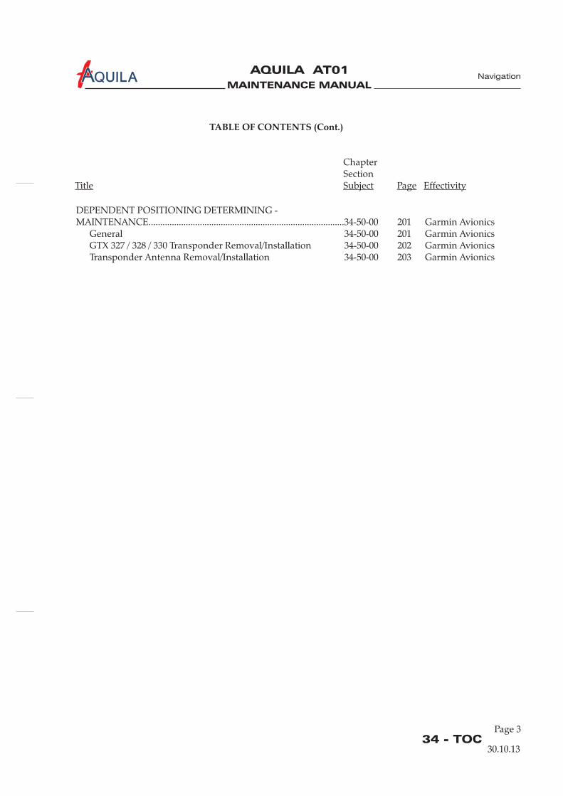
MAINTENANCE MANUAL
AQUILA AT01A
Page 334 - TOC
30.10.13
TABLE OF CONTENTS (Cont.)
ChapterSection
Title Subject Page Effectivity
Navigation
DEPENDENT POSITIONING DETERMINING -MAINTENANCE....................................................................................34-50-00 201 Garmin Avionics
General 34-50-00 201 Garmin AvionicsGTX 327 / 328 / 330 Transponder Removal/Installation 34-50-00 202 Garmin AvionicsTransponder Antenna Removal/Installation 34-50-00 203 Garmin Avionics

MAINTENANCE MANUAL
AQUILA AT01A
MAINTENANCE MANUAL
AQUILA AT01A
34-00-00
Navigation
NAVIGATION - GENERAL
1.
A. This chapter describes units and components that provide aircraft navigational information.
2.
A. Different instruments and devices offer a means of determining flight conditions, aircraft attitudeand position of the aircraft over the ground.The following groups can be separated according to way data is sourced:
(1) Devices which use magnetic, gyroscopic and inertia forces to supply data to determineaircraft attitude and heading, including:(a) Attitude indicator(b) Directional gyro(c) Turn coordinator(d) Magnetic compass
(2) Devices which sense environmental conditions and use the data to influence navigation,including:(a) Airspeed indicator(b) Altimeter(c) Vertical speed indicator(d) Stall warning system
(3) Devices which provide information to determine position and are mainly independent ofground installations, including:(a) GPS receiver
(4) Devices which provide information to determine position and are mainly dependent onground installations. That includes:(a) VOR/LOC receiver(b) Transponder
Introduction
General Description
30.10.13
Page 1

MAINTENANCE MANUAL
AQUILA AT01A
MAINTENANCE MANUAL
AQUILA AT01A
34-11-00
PITOT/STATIC SYSTEM - DESCRIPTION
1.
A. The static and pitot pressure system supplies static and pitot pressure for the airspeed indicator,altimeter and vertical speed indicator as well as for the air data computer and the airspeed sensorof the KAPI logger (both are optional).
2.
A. Pitot-Static Tube and LinesPitot and static pressures are picked up by the pitot-static tube installed on the underside of theleft wing, and carried through lines inside the wing and fuselage to the gauges on the instrumentpanel. The pitot and static pressure lines have filter elements to prevent foreign material such asdust or water entering the flight instruments. These filter elements are located in the lines andmay be easiliy replaced.
Introduction
Description and Operation
B. Pitot HeatingOptional the aircraft is equipped with a heated pitot tube to prevent icing. It consists of a heatingcoil and a temperature sensor inside the pitot tube and a control box installed on the bottom of theinstrument panel (left-hand side). Both are connected by electrical wires. Additionally there is awarning light in the instrument panel that indicates if the pitot heat is switched off or if theheating is not working even though it is switched on and the temperature in the pitot tube isbelow approx. 50°C (122°F).
C. Figure 1 shows the pitot/static system schematically.
Navigation
30.10.13
Page 1

MAINTENANCE MANUAL
AQUILA AT01A
34-11-00Page 2
Navigation
30.10.13
Pitot-Static System SchematicFigure 1 static pressure
pitot pressure
pitot-static tube
filter
airspeed indicator
airspeed sensorKAPI data logger
(optional)
air data computer(optional)
altimeter
vertical speed Indicator
compensation tank
MAINTENANCE MANUAL
AQUILA AT01A
34-11-00Page 201
Navigation
PITOT/STATIC SYSTEM - MAINTENANCE
1.
A. Proper maintenance of the pitot/static system is essential for proper altimeter, airspeed and verticalspeed indications. Moisture, obstructions and leaks in the system will result in erroneous, erraticor zero readings on the associated instruments.Filters should be regularly inspected and replaced as required.
B. A cover should be placed over the pitot-static tube when the aircraft is parked, to prevent insectsand water from entering the pitot orifice.
2.
Quantity Equipment Parts No. Manufacturer
6.B./6.C. 1 Sphygmo- - commerciallymanometer pres- availablesure bulb withcheck valve
6.B. 1 Surgical hose commerciallyavailable
3.
A. Remove Pitot-Static Tube(1) Ensure electrical power to aircraft is OFF.(2) Remove screws securing pitot-static tube to wing skin.(3) Identify and disconnect pitot / static lines and electrical connector (optional) at pitot tube.(4) Remove pitot-static tube from aircraft.
B. Install Pitot-Static Tube(1) Connect pitot / static lines and electrical connector (optional) at pitot-static tube(2) Put pitot-static tube in position on the wing and secure using screws.(3) Perform a pitot-static system functional test (refer to “Inspection/Check” below).
General
Tools, Equipment and Material
Pitot-Static Tube Removal/Installation
CAUTION:
CAUTION:
NEVER BLOW COMPRESSED AIR THROUGH PITOT OR STATIC LINES TOWARDINSTRUMENTS AS THIS CAN CAUSE DAMAGE TO INSTRUMENTS.
ENSURE THE PITOT HEAT (OPTIONAL) IS SWITCHED OFF AND THE TUBE HASCOOLED DOWN BEFORE TOUCHING THE TUBE. A HEATED PITOT TUBE CANGET EXTREMELY HOT DURING OPERATION.
30.10.13
MAINTENANCE MANUAL
AQUILA AT01A
34-11-00Page 202
Navigation
4. (optional)
NEVER OPERATE PITOT HEATING WITHOUT THE CONTROL BOX AS THIS CANDESTROY THE PITOT TUBE.
A. Remove the Control Box(1) Ensure electrical power to aircraft is OFF.(2) Disconnect battery (refer to 24-30-00).(3) Remove glare shield (refer to 31-10-00).(4) Disconnect electrical connector from control box.(5) Remove cable ties securing control box to instrument panel.(6) Remove control box from aircraft.
B. Install the Control Box(1) Put control box in position in instrument panel and secure using cable ties.(2) Reconnect electrical connector to control box.(3) Install glare shield (refer to 31-10-00).(4) Reconnect battery (refer to 24-30-00).(5) Carry out a functional test of the P/S heating.
erform a pitot-static system functional test (refer to “Inspection/Check” below).
P/S Heat Control Box Removal/Installation
CAUTION:
5.
A. Remove an Instrument
PLUG OR CAP INSTRUMENT PORTS IMMEDIATELY AFTER DISCONNECTINGPITOT OR STATIC LINES TO PREVENT DIRT OR FOREIGN MATERIAL FROMENTERING.
(1) Gain access to the back of instrument and disconnect static/pitot hose from instrument.(2) While supporting the instrument, remove screws securing instrument to instrument panel.(3) Remove instrument.
B. Install an Instrument(1) Place instrument to instrument panel and secure with screws.(2) Reconnect static/pitot hose to instrument.(3) P
6.
A. After any component replacement or repair, the system should be checked for proper function anda leakage test should be performed.
B. Pitot System Leak Test(1) Fasten surgical hose and sphygmomanometer bulb over pitot head.(2) Pump bulb until airspeed indicator registers 150 KIAS.(3) Close check valve.(4) Wait 15 seconds for airspeed indicator to stabilize.
Instruments Removal/Installation
CAUTION:
Inspection/Check
30.10.13
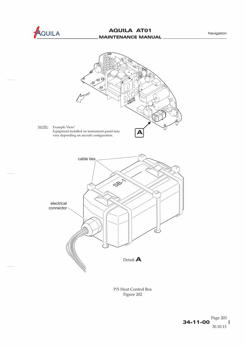
MAINTENANCE MANUAL
AQUILA AT01A
34-11-00Page 203
Navigation
30.10.13
P/S Heat Control BoxFigure 202
A
ADetail-
cable ties
electricalconnector
NOTE: Example View!Equipment installed on instrument panel mayvary depending on aircraft configuration.

MAINTENANCE MANUAL
AQUILA AT01A
34-11-00Page 204
Navigation
30.10.13
(5) Observe airspeed indicator for one minute.(6) The airspeed should drop no more than 10 KIAS.(7) Slowly release check valve so pressure is reduced gradually to prevent instrument damage.(8) If test reveals a leak in system, check all connections for tightness and repair faulty
components.
C. Static System Leak Test(1) Tape over static ports at pitot-static tube.(2) Insert a “T” in a static pressure line.(3) Squeeze sphygmomanometer bulb and close check valve to establish a vacuum inside bulb.(4) Connect sphygmomanometer to the static pressure line.(5) Slowly open air bulb check valve until altimeter indicates a 1000 ft increase in altitude then
close check valve to trap suction in system.(6) While increasing suction and altimeter indicating 1000 ft, ensure that the airspeed indicator
shows an increase and the vertical speed indicator shows a climb indication.(7) Leakage must not exceed 100 ft/min of altitude loss as indicated on the altimeter.(8) If leakage rate exceeds the maximum allowable, check all fittings and hoses for condition and
tightness and repeat leak test.(9) If leakage rate still exceeds the maximum allowable, undertake the following:(10) Disconnect static pressure lines from airspeed indicator, vertical speed indicator and altitude
encoder.(11) Connect lines together using suitable fittings so altimeter is the only instrument still
connected to static pressure system.(12) Repeat leak test to ascertain whether the static pressure system or the bypassed instruments
are causing the leakage. If instruments are at fault, they must be repaired by an approvedrepair station or replaced. If static pressure system is faulty, proceed as follows:
DO NOT APPLY POSITIVE PRESSURE WITH AIRSPEED INDICATOR ORVERTICAL SPEED INDICATOR CONNECTED TO STATIC PRESSURE SYSTEM.
(13) Remove sphygmomanometer assembly.(14) Insert a “T” in a static pressure line.(15) Attach hose to “T” and slowly apply positive pressure until altimeter indicates a 500 ft
decrease in altitude. Maintain this altimeter indication while checking for leaks.(16) Coat line with a solution of mild soap and water, watching for bubbles to locate leaks.(17) Tighten leaking connections. Repair or replace defective components.(18) Reconnect airspeed, vertical speed indicator and altitude encoder. Repeat static system leak
test.
CAUTION:
MAINTENANCE MANUAL
AQUILA AT01A
34-18-00
STALL WARNING SYSTEM - DESCRIPTION
1.
A. The aircraft is equipped in with a stall warning system. It signals an approaching stall to the pilotby an audible alarm in the cockpit.
2.
A. The stall warning system consists of a mechanical transmitter, located in the leading edge of theleft wing and a warning buzzer behind the instrument panel. Both are connected by electricalwires.
B. As the aircraft approaches a stall, the low pressure on the upper surface of the wings movesforward around the leading edge of the wings. As a result, a microplate at the transmitter isdeflected upwards. A mechanical contact is made which sends an electrical signal to the warningbuzzer in the cockpit. The warning buzzer gives off a 2 kHz alerting tone.
Introduction
Description and Operation
Navigation
30.10.13
Page 1

MAINTENANCE MANUAL
AQUILA AT01A

MAINTENANCE MANUAL
AQUILA AT01A
34-18-00Page 201
STALL WARNING SYSTEM - MAINTENANCE
1.
A. Maintenance is limited to the removal/installation of system components. In wintry conditions,make sure that the system transmitter microplate is always clear of ice and snow.
2.
A. Remove Transmitter(1) Ensure electrical power to aircraft is OFF.(2) Remove 3 screws securing transmitter covering to wing structure. Carefully pull transmitter
with covering out of wing.(3) Disconnect electrical connector.(4) Remove 2 screws securing covering to transmitter and remove covering.
B. Install Transmitter(1) Install transmitter covering on transmitter.(2) Connect electrical connector.(3) Put transmitter with covering in position and secure to wing structure.
4.
The stall warning system is so adjusted that the system will come into action approx. 10 – 15 km/h(6 - 8kts) before the aircraft stalls. If these values are not achieved, it is possible to modify thesystem behavior by shortening the microplate by a few millimeters. This will lower the speed thesystem is activated. A test for proper system operation is only possible in flight. Repeat theprocedure until the microplate has the correct length.
General
Transmitter Removal/Installation
Adjustment
(4) Perform a flight test to check the stall warning system (refer to “Adjustment” below).
3.
A. Remove Warning Buzzer(1) Ensure electrical power to aircraft is OFF.(2) Disconnect battery (refer to 24-30-00).(3) Remove glare shield (refer to 31-10-00).(4) Disconnect electrical connector.(5) Remove nuts securing buzzer to instrument panel and remove buzzer.
B. Install Warning Buzzer(1) Put buzzer in position at back of instrument panel and secure using two nuts.(2) Connect electrical connector.(3) Install glare shield (refer to 31-10-00).(4) Reconnect battery (refer to 24-30-00).(5) Perform a functional check of the stall warning system.
A.
Warning Buzzer Removal/Installation
Navigation
30.10.13

MAINTENANCE MANUAL
AQUILA AT01A Navigation
MAINTENANCE MANUAL
AQUILA AT01A
34-20-00Page 201
ATTITUDE AND DIRECTION - MAINTENANCE
1.
A. The construction and function of the magnetic compass, turn coordinator, attitude indicator anddirectional gyro is conventional, with no special features.
B. Maintenance is limited to component removal and re-installation.
2.
A. Remove Magnetic Compass(1) Ensure electrical power to aircraft is OFF.(2)(3)(4) Disconnect electrical wires from compass.(5) Remove screws securing compass and remove compass from aircraft.
B. Install Magnetic Compass(1) Put compass in position and secure using screws.(2) Connect electrical wires to magnetic compass.(3) Install glare shield (refer to 31-10-00).(4) Re (refer to 24-30-00).(5) Do a compass swing (refer to “Adjustment/Test” below).
3.
A. Remove Turn Coordinator(1)(2)
(4) Disconnect electrical connector from turn coordinator.(5) While supporting the turn coordinator, remove screws securing turn coordinator to
instrument panel.(6) Remove turn coordinator from aircraft.
B. Install Turn Coordinator(1) Put turn coordinator in position in instrument panel and secure using screws.(2) Reconnect electrical connector to turn coordinator.(3)
General
Magnetic Compass Removal/Installation
Turn Coordinator Removal/Installation
CAUTION: GYROS ARE DELICATE AND CAN NOT WITHSTAND THE SHOCK OF BEINGDROPPED, JARRED OR STRUCK BY PIECES OF EQUIPMENT. DO NOT PLACEGYROS ON ANY HARD SURFACE. PAD WITH GENEROUS FOAM.
Disconnect battery (refer to 24-30-00).Remove glare shield (refer to 31-10-00).
connect battery
Ensure electrical power to aircraft is OFF.Disconnect battery (refer to 24-30-00).
(3) Remove glare shield (refer to 31-10-00).
Install glare shield (refer to 31-10-00).(4) Reconnect battery (refer to 24-30-00).(5) Conduct a functional test of the unit.
Navigation
30.10.13
MAINTENANCE MANUAL
AQUILA AT01A
34-20-00Page 202
4.
A. Remove Attitude Indicator(1)
(3)(4) Disconnect electrical connector from attitude indicator.(5) While supporting the indicator, remove screws securing indicator to instrument panel.(6) Remove attitude indicator from aircraft.
B. Install Attitude Indicator(1) Put attitude indicator in position in instrument panel and secure with screws.(2) Connect electrical connector to the instrument.(3) Install glare shield (refer to 31-10-00).(4) Reconnect battery (refer to 24-30-00).(5) Conduct a functional test of the unit.
A. Remove Directional Gyro(1)
(4) Disconnect electrical connector from back of the instrument.(5) While supporting the gyro, remove screws securing directional gyro to instrument panel.(6) Remove directional gyro from aircraft.
B. Install Directional Gyro(1) Put directional gyro in position in instrument panel and secure with screws.(2) Connect electrical connector to the instrument.(3) Install glare shield (refer to 31-10-00).(4) Reconnect battery (refer to 24-30-00).(5) Conduct a functional test of the unit.
6.
A. Magnetic Compass Calibration(1) Prior to calibrating the compass, the aircraft should be in a flight environment which is as
realistic as possible.(a) Place aircraft in level flight attitude(b) Check the canopy is closed.(c) Check flaps are retracted.(d) Start engine and turn ON all electrical equipment that is usually used at cruise (refer toAQUILA AT01 Airplane Flight Manual).
DUE TO INSUFFICIENT ENGINE COOLING ON THE GROUND, DO NOTCONTINUOUSLY OPERATE THE ENGINE AT CRUISE RPM FOR MORE THAN3 MIN.
Attitude Indicator Removal/Installation
irectional Gyro Removal/Installation
Adjustment/Test
CAUTION:
Ensure electrical power to aircraft is OFF.(2) Disconnect battery (refer to 24-30-00).
Remove glare shield (refer to 31-10-00).
5.
Ensure electrical power to aircraft is OFF.(2) Disconnect battery (refer to 24-30-00).(3) Remove glare shield (refer to 31-10-00).
D
Navigation
30.10.13
MAINTENANCE MANUAL
AQUILA AT01A
34-20-00Page 203
30.10.13
Navigation
(e) Run engine and set throttle at cruise position.
When performing maintenance on the magnetic compass, use a non-magnetic orplastic screwdriver.
(2) Remove screws securing access plate to compass casing to reveal adjustment screws.(3) Set adjustment screws of compensator to zero. Zero position is indicated when dot of screw
is aligned with dot on compass frame.(4) Taxi airplane to compass rose.(5) Align centerline of aircraft on magnetic North heading. Adjust N - S set screw until compass
reads North.(6) Align centerline of aircraft on magnetic East heading. Adjust E - W set screw until compass
reads East.(7) Align centerline of aircraft on magnetic South heading and note resulting South error.(8) Adjust N - S set screw until half of error is removed.(9) Align centerline of aircraft on magnetic West heading and note resulting West error.(10) Adjust E - W set screw until half of error is removed.(11) Align centerline of aircraft in successive magnetic 30-degree headings and record compass
readings on appropriate compass correction (deviation) card. Deviations must not exceed 10degrees on any heading.
NOTE:

MAINTENANCE MANUAL
AQUILA AT01A
MAINTENANCE MANUAL
AQUILA AT01A
INTEGRATED FLIGHT SYSTEM - MAINTENANCE
All Service Information released from AQUILA and related to software versions have to beattached to this maintenance manual for continuing airworthiness!
1.
A. This section provides instructions necessary for authorized personnel to inspect and maintain theEFD1000 system. I
B. The Aspen EFD1000 PFD system is comprised of the primary flight display (PFD), remote sensormodule (RSM) and configuration module (CM). The EFD1000 PFD system provides display ofattitude, airspeed, altitude, direction of flight, vertical speed, turn rate and turn quality. Thesystem may optionally provide display of navigation information through interfaces to GPSreceivers and/or VHF navigation receivers.
C. The operation of the Aspen EFD 1000 PFD requires the following software version:
- for ASPEN EFD 1000 PFD: software version MAP 2.x or newer approved versions
Software-updates will be released via Service Information (SI) at www.aquila-aviation.de.
A.
General
nstructions for removal and replacement of LRUs that have been previouslyinstalled in the aircraft are included.
Only install ETSO’d software versions (for airplanes registered in Europe or countries where theEASA-TC has been accepted) respectively FAA approved software versions (for airplanesregistered in the USA or countries where the FAA-TC has been accepted).
The actual software version is documented in the aircraft equipment list, located in chapter 6.5.1 ofthe AQUILA AT01 Airplane Flight Manual.
D. No special tools are required for the removal and replacement of any system LRUs. If a LRU isfound to be defective it should be removed and returned to a properly rated facility for repair orreplacement. If fasteners are deformed in any way, they must be replaced.
E. For bonding checks on the AQUILA AT01 no procedures or equipment are necessary other thanthat which are commonly expected for bonding measurements on small aircraft. Refer toAC 43.13-1B, chapter 11, section 15 “Grounding and Bonding” for further information on bondingcheck procedures and equipment.
F. Refer to the Aspen EFD1000 and EFD500 SW v2.x Installation Manual, P/N 900-00003-001, revisionZ or later and the Aspen EFD1000 and EFD500 Instructions for Continued Airworthiness, P/N 900-00012-001, revision K or later for additional maintenance information on the EFD 1000 system andfastener identification and discard recommendations.
2.
Remove EFD(1) Verify electrical power to aircraft is OFF.(2) (refer to 24-30-00).
EFD Removal/Installation
Disconnect battery
34-25-00Page 201
Navigation
EFFECTIVITY
Aircraft equipped with ASPEN EFD1000 PFD
30.10.13
MAINTENANCE MANUAL
AQUILA AT01A
(3) Carefully insert a flat blade screw driver into the locking mechanism on the top center of theEFD.
(4) While gently prying pull back the top of the EFD and extract from bracket.(5) Remove nut securing braided ground strap to EFD.
B. Install EFD(1) Verify electrical power to aircraft is OFF.(2)
erify all system interfaces are functional (refer to Aspen EFD1000 andEFD500 SW v2.x Installation Manual, P/N 900-00003-001, revision Z or later
of the Aspen EFD1000 and EFD500 SW v2.xInstallation Manual, P/N 900-00003-001, revision Z or later
3.
(refer to “EFD Removal/Installation” above)
4.
erify electrical power to aircraft is OFF.(2) (refer to 24-30-00).(3)
(6) Remove pitot and static quick connectors (EFD1000 only) by pulling back outer springloaded locking sleeve while unplugging connectors. To remove 44 pin D-sub connectorunscrew both jackscrews fully and pull connector straight back.
Install 44 pin D-sub connector and tighten jacks crews until connector is fully seated.(3) Install pitot and static lines (EFD1000 only) to back of EFD by firmly pressing the fitting until
fully seated (pitot and static quick connectors are keyed and cannot be crossed).(4) Gently pull on connector to ensure proper connection.(5) Connect braided bonding strap to EFD with nut.(6) Insert bottom of EFD into bracket and pivot top forward until it locks into place on bracket.(7) Reconnect battery (refer to 24-30-00).(8) V section 10.6 of the
) and the correctsoftware version is installed.
(9) Verify proper bonding per section 10.1.2.
(10) Perform a pitot/static system leak test (refer to 34-11-00).
A. Replace EFD Battery
EFD battery replacement must only be performed by a properly certified individual orfacility.
(1) Remove EFD (refer to “EFD Removal/Installation” above).(2) Remove two screws on each end of the oval-shaped cover plate on backside of the EFD.(3) Unplug electrical connector and slide battery out of EFD.(4) Install new battery into EFD, then connect battery plug.(5) Position cover plate and tighten the cover screws. Tighten to 1,4 Nm (12 in.lbs).(6) Re-install and test EFD .
A. Remove RSM(1) V
Gain access to the underside of the RSM mounting location.(4) Unplug the RSM connector. Unscrew RSM electrical connector from inside and undo shield
ground wire from ground stud.(5) Remove sealant from around base of RSM and on mounting screws.
EFD Battery Replacement
Remote Sensor Module (RSM) Removal/Installation
NOTE:
Disconnect battery
34-25-00Page 202
Navigation
30.10.13
EFFECTIVITY
Aircraft equipped with ASPEN EFD1000 PFD
MAINTENANCE MANUAL
AQUILA AT01A
(6) Remove four 8-32 non-ferrous mounting screws from RSM and remove RSM from aircrafttaking care to guide 24 inch “pigtail” connector out through ½ inch hole in aircraft skin.
Replace the O-ring on the RSM. Contact Aspen Avionics for O-ring replacement(256-00001-001).
(3) Verify RSM shim is installed between aircraft skin and RSM if required.(4) Feed circular connector down through ½ inch hole in aircraft skin and mount RSM (vent
hole faces aft) with four 8-32 non-ferrous screws.
It is critical that the screws are non-ferrous to avoid compass errors.
Connect the circular electrical connector and cable tie harness to prevent chafing andinterference.
(6) Connect shield ground wire to ground stud.(7) Seal around base and on top of four mounting screws of the RSM using
(8) Reconnect battery (refer to 24-30-00).(9) Verify proper bonding per section 10.1.2 and perform RSM calibration per section 10.5 of the
(10) Check OAT operation per section 10.6.4 and check RSM GPS operation per section 10.6.6 ofthe
.
A. Remove CM(1)
Cut the two cable ties affixing the CM to the PFD wiring harness.(4) Unplug the Molex connector by pressing down on the locking tab and gently pulling the
connector from the module.
Plug the Molex connector into the module until it clicks.(3) Cable tie the module to the PFD wiring harness..(4) Reconnect battery (refer to 24-30-00).(5) Perform the installation menu unit configuration per section 10.4.5 of the
.(6) Perform RSM calibration per section 10.5 of the
B. Install RSM(1) Verify electrical power to aircraft is OFF.(2)
Tighten to 1,4-1,7 Nm (12-15 in.lbs).
(5)
a good qualityelectrical sealant (Sikaflex-221 or equivalent, silicone-free).
Aspen EFD1000 and EFD500 SW v2.x Installation Manual, P/N 900-00003-001, revision Z orlater.
Aspen EFD1000 and EFD500 SW v2.x Installation Manual, P/N 900-00003-001, revision Zor later
5.
Verify electrical power to aircraft is OFF.(2) (refer to 24-30-00).(3)
B. Install CM(1) Verify electrical power to aircraft is OFF.(2)
Aspen EFD1000 andEFD500 SW v2.x Installation Manual, P/N 900-00003-001, revision Z or later
Aspen EFD1000 and EFD500 SW v2.xInstallation Manual, P/N 900-00003-001, revision Z or later.
NOTE:
Configuration Module (CM) Removal/Installation
Disconnect battery
34-25-00Page 203
Navigation
30.10.13
EFFECTIVITY
Aircraft equipped with ASPEN EFD1000 PFD
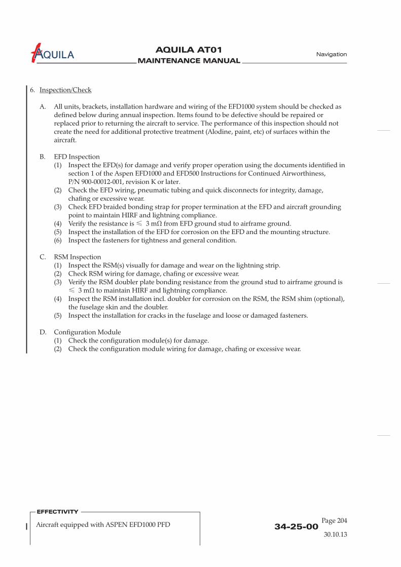
MAINTENANCE MANUAL
AQUILA AT01A
6.
mΩ
Inspection/Check
A. All units, brackets, installation hardware and wiring of the EFD1000 system should be checked asdefined below during annual inspection. Items found to be defective should be repaired orreplaced prior to returning the aircraft to service. The performance of this inspection should notcreate the need for additional protective treatment (Alodine, paint, etc) of surfaces within theaircraft.
B. EFD Inspection(1) Inspect the EFD(s) for damage and verify proper operation using the documents identified in
section 1 of the Aspen EFD1000 and EFD500 Instructions for Continued Airworthiness,P/N 900-00012-001, revision K or later.
(2) Check the EFD wiring, pneumatic tubing and quick disconnects for integrity, damage,chafing or excessive wear.
(3) Check EFD braided bonding strap for proper termination at the EFD and aircraft groundingpoint to maintain HIRF and lightning compliance.
(4) Verify the resistance is 3 m from EFD ground stud to airframe ground.(5) Inspect the installation of the EFD for corrosion on the EFD and the mounting structure.(6) Inspect the fasteners for tightness and general condition.
C. RSM Inspection(1) Inspect the RSM(s) visually for damage and wear on the lightning strip.(2) Check RSM wiring for damage, chafing or excessive wear.(3) Verify the RSM doubler plate bonding resistance from the ground stud to airframe ground is
3 to maintain HIRF and lightning compliance.(4) Inspect the RSM installation incl. doubler for corrosion on the RSM, the RSM shim (optional),
the fuselage skin and the doubler.(5) Inspect the installation for cracks in the fuselage and loose or damaged fasteners.
D. Configuration Module(1) Check the configuration module(s) for damage.(2) Check the configuration module wiring for damage, chafing or excessive wear.
≤
≤
Ω
34-25-00Page 204
Navigation
30.10.13
EFFECTIVITY
Aircraft equipped with ASPEN EFD1000 PFD
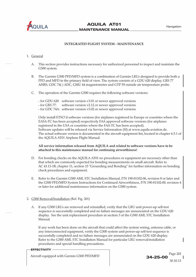
MAINTENANCE MANUAL
AQUILA AT01A
INTEGRATED FLIGHT SYSTEM - MAINTENANCE
All service information released from AQUILA and related to software versions have to beattached to this maintenance manual for continuing airworthiness!
1.
A. This section provides instructions necessary for authorized personnel to inspect and maintain theG500 system.
B. The Garmin G500 PFD/MFD system is a combination of Garmin LRUs designed to provide both aPFD and MFD in the primary field of view. The system consists of a GDU 620 display, GRS 77AHRS, GDC 74( ) ADC, GMU 44 magnetometer and GTP 59 outside air temperature probe.
C. The operation of the Garmin G500 requires the following software versions:
- for GDU 620: software version v3.01 or newer approved versions- for GRS 77: software version v2.12- for GDC 74A: software version v3.02
Only install ETSO’d software versions (for airplanes registered in Europe or countries where theEASA-TC has been accepted) respectively FAA approved software versions (for airplanesregistered in the USA or countries where the FAA-TC has been accepted).Software updates will be released via Service Information (SI) at www.aquila-aviation.de.The actual software version is documented in the aircraft equipment list, located in chapter 6.5.1 ofthe AQUILA AT01 Airplane Flight Manual.
2. (Ref. Fig. 201)
A. lf any G500 LRUs are removed and reinstalled, verify that the LRU unit power-up self-testsequence is successfully completed and no failure messages are annunciated on the GDU 620display. See the unit replacement procedure in section 3 of the G500 AML STC InstallationManual.
If any work has been done on the aircraft that could affect the system wiring, antenna cable, orany interconnected equipment, verify the G500 system unit power-up self-test sequence issuccessfully completed and no failure messages are annunciated on the GDU 620 display.Refer to the G500 AML STC Installation Manual for particular LRU removal/installationprocedures and special handling precautions.
General
G500 Removal/Installation
or newer approved versionsor newer approved versions
D. For bonding checks on the AQUILA AT01 no procedures or equipment are necessary other thanthat which are commonly expected for bonding measurements on small aircraft. Refer toAC 43.13-1B, chapter 11, section 15 “Grounding and Bonding” for further information on bondingcheck procedures and equipment.
E. Refer to the Garmin G500 AML STC Installation Manual, P/N 190-01102-06, revision 8 or later andthe G500 PFD/MFD System Instructions for Continued Airworthiness, P/N 190-01102-00, revision 4or later for additional maintenance information on the G500 system.
34-25-00Page 201
Navigation
30.10.13
EFFECTIVITY
Aircraft equipped with Garmin G500 PFD/MFD
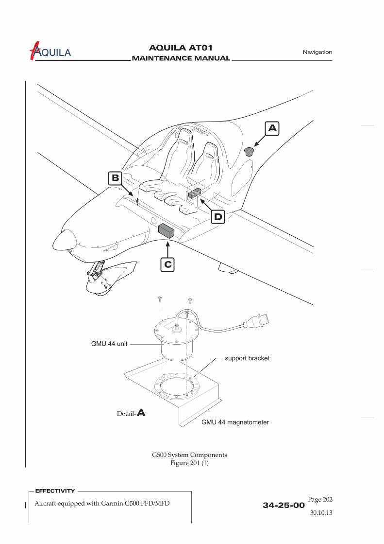
MAINTENANCE MANUAL
AQUILA AT01A
34-25-00Page 202
Navigation
30.10.13
EFFECTIVITY
Aircraft equipped with Garmin G500 PFD/MFD
A
B
C
D
G500 System ComponentsFigure 201 (1)
ADetail-
GMU 44 magnetometer
support bracket
GMU 44 unit
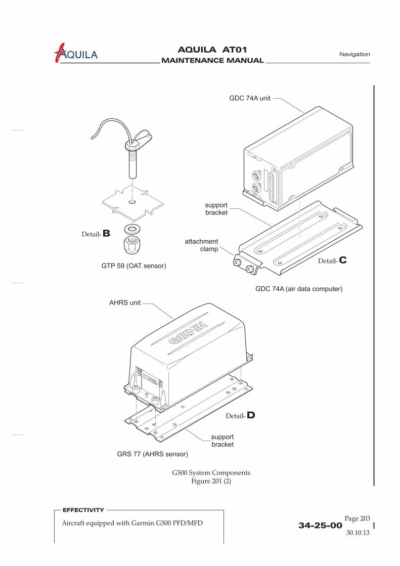
MAINTENANCE MANUAL
AQUILA AT01A
34-25-00Page 203
Navigation
30.10.13
EFFECTIVITY
Aircraft equipped with Garmin G500 PFD/MFD
G500 System ComponentsFigure 201 (2)
BDetail-
CDetail-
DDetail-
supportbracket
supportbracket
GRS 77 (AHRS sensor)
AHRS unit
GDC 74A (air data computer)
GDC 74A unit
GTP 59 (OAT sensor)
attachmentclamp

MAINTENANCE MANUAL
AQUILA AT01A
34-25-00Page 204
Navigation
30.10.13
EFFECTIVITY
Aircraft equipped with Garmin G500 PFD/MFD
3.
A. All G500 system LRUs are designed to detect internal failures. A thorough self-test is executedautomatically upon application of power to the units, and built-in tests are continuously executed.Detected errors are indicated on the GDU 620 display via failure annunciations.
Operation of the G500 system is not permitted unless an inspection as described in this section hasbeen completed within the preceding 12 calendar months. Conduct a visual inspection (look forsigns of wear, deterioration, or damage to wires, backshells, connectors, overbraid, bonding strapsor foil) of the G500 system LRUs and wiring harnesses to ensure installation integrity:(1) Inspect all units for security of attachment, including visual inspection of brackets and other
supporting structure attaching all units to the airframe.(2) Inspect all knobs and buttons for legibility.(3) Visually inspect each unit's wiring for chafing or wear at each termination.(4) Visually check for any signs of corrosion.
B. GDU 620 - Display Unit(1) Maintenance of the GDU 620 is “on condition” only.
C. GRS 77 - Attitude, Heading Reference System (AHRS)(1) The GRS 77 utilizes an earth magnetic field model which is updated once every five years as
part of the aviation database maintained by the owner/operator. If the magnetic model is notup to date, the unit will issue an alert upon startup indicating the model has expired. Themodel can be updated in accordance with the database update section of the G500 AML STCInstallation Manual. Otherwise maintenance of the GRS 77 is “on condition” only.
D. GMU 44 – Magnetometer(1) Maintenance of the GMU 44 is “on condition” only.
E. GDC 74( ) - Air Data Computer(1) Test according to title 14 CFR §§ 91.411 and 91.413 as well as 14 CFR §§ 43 Appendix E. See
the pitot-static checkout procedure in section 5.8 of the G500 AML STC Installation Manualfor the test procedure.
F. GTP 59 - OAT Probe(1) Maintenance of the OAT Probe is “on condition” only.
G. Electrical Bonding Test(1) G500 LRU electrical bonding must be tested every 2000 flight hours or ten (10) years,
whichever is first. During the test, any cables normally attached to the LRU must bedisconnected from the LRU. lf measured resistance is greater than applicable values in thefollowing table, bonding must be improved to meet applicable requirements for a newinstallation in accordance with section 3.8 of the G500 AML STC Installation Manual.
Inspection/Check
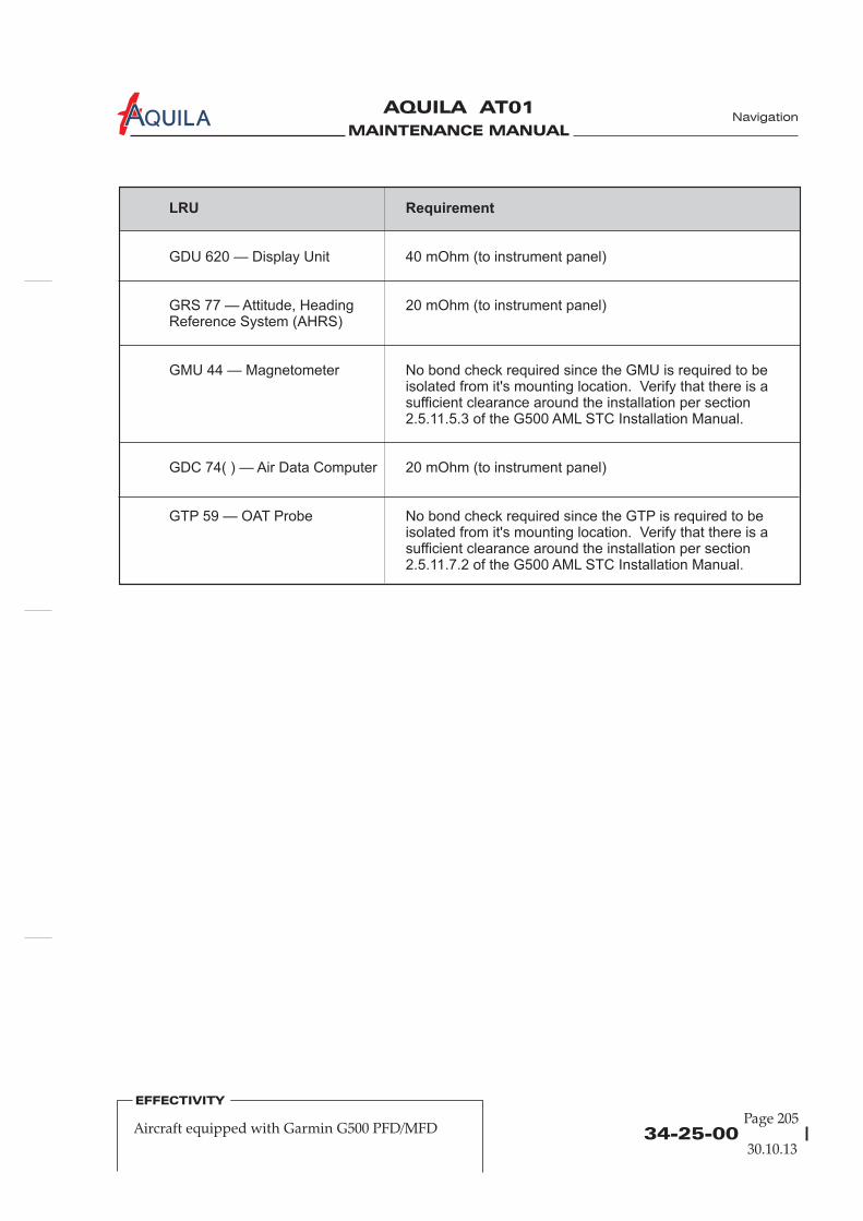
MAINTENANCE MANUAL
AQUILA AT01A
34-25-00Page 205
Navigation
30.10.13
EFFECTIVITY
Aircraft equipped with Garmin G500 PFD/MFD
LRU Requirement
GDU 620 — Display Unit 40 mOhm (to instrument panel)
GRS 77 — Attitude, Heading
GMU 44 — Magnetometer No bond check required since the GMU is required to beisolated from it's mounting location. Verify that there is asufficient clearance around the installation per section2.5.11.5.3 of the G500 AML STC Installation Manual.
GDC 74( ) — Air Data Computer
GTP 59 — OAT Probe No bond check required since the GTP is required to beisolated from it's mounting location. Verify that there is asufficient clearance around the installation per section2.5.11.7.2 of the G500 AML STC Installation Manual.
20 mOhm (to instrument panel)Reference System (AHRS)
20 mOhm (to instrument panel)

MAINTENANCE MANUAL
AQUILA AT01A

MAINTENANCE MANUAL
AQUILA AT01A
34-40-00Page 201
Navigation
EFFECTIVITY
Aircraft equipped with GarminGNS 430(W) / GNS 530(W) / GTN 650
INDEPENDENT POSITION DETERMINING – MAINTENANCE
1.
A. This section covers that portion of the system which provides information to determine positionand is mainly independent of ground installations. This includes the GPS portion of theGNS 430(W), GNS 530(W) or GTN 650 navigation management system (NMS).
B. The GNS 430(W) / GNS 530(W) / GTN 650 system is a fully integrated, panel-mounted instrumentwhich contains a VHF communications transceiver, a VOR/ILS/GS receiver and GPS navigationcomputer. The primary function of the GPS portion of the system is to acquire signals from theGPS system satellites, recover orbital data, make range and Doppler measurements and processthis information in real-time to obtain the user's position, velocity and time. GPS signals arereceived by an antenna mounted on top of fuselage behind the cabin.
2.
A. Remove GPS Antenna(1) Open baggage compartment door and remove access / inspection plate 211 KC (refer to
25-12-00).(2) Disconnect antenna cable from antenna.(3) Remove nuts and washers securing antenna to fuselage.(4) Remove antenna from aircraft.
B. Install GPS Antenna(1) Put gasket and antenna from outside,(2) Install washers and nuts securing antenna to fuselage. Simultaneously connect ground cable
to backing plate.(3) Seal the antenna and gasket to fuselage using a good quality electrical sealant (Sikaflex-221 or
equivalent, silicone-free).(4) Connect antenna cable.(5) Close baggage compartment door and install access / inspection plate 211 KC (refer to
25-12-00).
General
GPS Antenna Removal/Installation
The scope ofmaintenance is limited to the removal and installation of the GPS antenna. For removal andinstallation procedures for the GNS 430(W) / GNS 530(W) / GTN 650, refer to 23-10-00.
and backing plate from inside in position in fuselage.
30.10.13

MAINTENANCE MANUAL
AQUILA AT01A
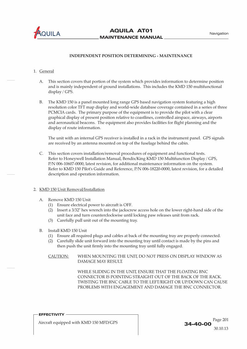
MAINTENANCE MANUAL
AQUILA AT01A
INDEPENDENT POSITION DETERMINING - MAINTENANCE
1.
A. This section covers that portion of the system which provides information to determine positionand is mainly independent of ground installations. This includes the KMD 150 multifunctionaldisplay / GPS.
B. The KMD 150 is a panel mounted long range GPS based navigation system featuring a highresolution color TFT map display and world-wide database coverage contained in a series of threePCMCIA cards. The primary purpose of the equipment is to provide the pilot with a cleargraphical display of present position relative to coastlines, controlled airspace, airways, airportsand aeronautical beacons. The equipment also provides facilities for flight planning and thedisplay of route information.
The unit with an internal GPS receiver is installed in a rack in the instrument panel. GPS signalsare received by an antenna mounted on top of the fuselage behind the cabin.
C. This section covers installation/removal procedures of equipment and functional tests.Refer to Honeywell Installation Manual, Bendix/King KMD 150 Multifunction Display / GPS,P/N 006-10607-0000, latest revision, for additional maintenance information on the system.Refer to KMD 150 Pilot's Guide and Reference, P/N 006-18220-0000, latest revision, for a detaileddescription and operation information.
General
2.
A. Remove KMD 150 Unit(1) Ensure electrical power to aircraft is OFF.(2) Insert a 3/32" hex wrench into the jackscrew access hole on the lower right-hand side of the
unit face and turn counterclockwise until locking paw releases unit from rack.(3) Carefully pull unit out of the mounting tray.
B. Install KMD 150 Unit(1) Ensure all required plugs and cables at back of the mounting tray are properly connected.(2) Carefully slide unit forward into the mounting tray until contact is made by the pins and
then push the unit firmly into the mounting tray until fully engaged.
WHEN MOUNTING THE UNIT, DO NOT PRESS ON DISPLAY WINDOW ASDAMAGE MAY RESULT.
WHILE SLIDING IN THE UNIT, ENSURE THAT THE FLOATING BNCCONNECTOR IS POINTING STRAIGHT OUT OF THE BACK OF THE RACK.TWISTING THE BNC CABLE TO THE LEFT/RIGHT OR UP/DOWN CAN CAUSEPROBLEMS WITH ENGAGEMENT AND DAMAGE THE BNC CONNECTOR.
KMD 150 Unit Removal/Installation
CAUTION:
34-40-00Page 201
EFFECTIVITY
Aircraft equipped with KMD 150 MFD/GPS
30.10.13
Navigation
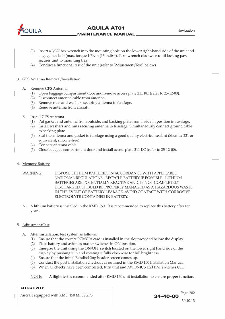
MAINTENANCE MANUAL
AQUILA AT01A
(3) Insert a 3/32" hex wrench into the mounting hole on the lower right-hand side of the unit andengage hex bolt (max. torque 1,7Nm [15 in.lbs]). Turn wrench clockwise until locking pawsecures unit to mounting tray.
(4) Conduct a functional test of the unit (refer to “Adjustment/Test” below).
3.
A. Remove GPS Antenna(1) Open baggage compartment door and remove access plate 211 KC (refer to 25-12-00).(2) Disconnect antenna cable from antenna.(3) Remove nuts and washers securing antenna to fuselage.(4) Remove antenna from aircraft.
B. Install GPS Antenna(1) Put gasket and antenna from outside, and backing plate from inside in position in fuselage.(2) Install washers and nuts securing antenna to fuselage. Simultaneously connect ground cable
to backing plate.(3)
(4) Connect antenna cable.(5) Close baggage compartment door and install access plate 211 KC (refer to 25-12-00).
4.
DISPOSE LITHIUM BATTERIES IN ACCORDANCE WITH APPLICABLENATIONAL REGULATIONS. RECYCLE BATTERY IF POSSIBLE. LITHIUMBATTERIES ARE POTENTIALLY REACTIVE AND, IF NOT COMPLETELYDISCHARGED, SHOULD BE PROPERLY MANAGED AS A HAZARDOUS WASTE.IN THE EVENT OF BATTERY LEAKAGE, AVOID CONTACT WITH CORROSIVEELECTROLYTE CONTAINED IN BATTERY.
A. A lithium battery is installed in the KMD 150. It is recommended to replace this battery after tenyears.
5.
A. After installation, test system as follows:(1) Ensure that the correct PCMCIA card is installed in the slot provided below the display.(2) Place battery and avionics master switches in ON position.(3) Energize the unit using the ON/OFF switch located on the lower right hand side of the
display by pushing it in and rotating it fully clockwise for full brightness.(4) Ensure that the initial Bendix/King header screen comes up.(5) Conduct the post installation checkout as outlined in the KMD 150 Installation Manual.(6) When all checks have been completed, turn unit and AVIONICS and BAT switches OFF.
A flight test is recommended after KMD 150 unit installation to ensure proper function.
GPS Antenna Removal/Installation
Memory Battery
WARNING:
Adjustment/Test
NOTE:
Seal the antenna and gasket to fuselage using a good quality electrical sealant (Sikaflex-221 orequivalent, silicone-free).
34-40-00Page 202
30.10.13
EFFECTIVITY
Aircraft equipped with KMD 150 MFD/GPS
Navigation
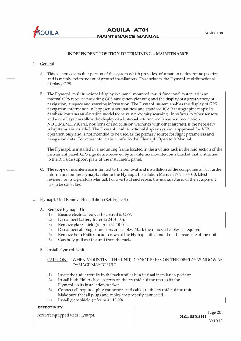
MAINTENANCE MANUAL
AQUILA AT01A
INDEPENDENT POSITION DETERMINING – MAINTENANCE
1.
A. This section covers that portion of the system which provides information to determine positionand is mainly independent of ground installations. This includes the FlymapL multifunctionaldisplay / GPS.
B. The FlymapL multifunctional display is a panel-mounted, multi-functional system with aninternal GPS receiver providing GPS navigation planning and the display of a great variety ofnavigation, airspace and warning information. The FlymapL system enables the display of GPSnavigation information in Jeppesen® aeronautical and standard ICAO cartographic maps: Itsdatabase contains an elevation model for terrain proximity warning. Interfaces to other sensorsand aircraft systems allow the display of additional information (weather information,NOTAMs/METAR/TAF, positions of and collision warnings with other aircraft), if the necessarysubsystems are installed. The FlymapL multifunctional display system is approved for VFRoperation only and is not intended to be used as the primary source for flight parameters andnavigation data. For more information, refer to the perator's Manual.
The FlymapL is installed in a mounting frame located in the avionics rack in the mid section of theinstrument panel. GPS signals are received by an antenna mounted on a bracket that is attachedto the RH side support plate of the instrument panel.
2. (Ref. Fig. 201)
A. Remove FlymapL Unit(1) Ensure electrical power to aircraft is OFF.(2) (refer to 24-30-00).(3) Remove glare shield (refer to 31-10-00).(4) Disconnect all plug connectors and cables. Mark the removed cables as required.(5) Remove both Philips-head screws of the FlymapL attachment on the rear side of the unit.(6) Carefully pull out the unit from the rack.
B. Install FlymapL Unit
WHEN MOUNTING THE UNIT, DO NOT PRESS ON THE DISPLAY WINDOW ASDAMAGE MAY RESULT.
(1) Insert the unit carefully in the rack until it is in its final installation position.(2) Install both Philips-head screws on the rear side of the unit to fix the
FlymapL to its installation bracket.(3) Connect all required plug connectors and cables to the rear side of the unit.
Make sure that all plugs and cables are properly connected.(4) Install glare shield (refer to 31-10-00).
General
FlymapL Unit Removal/Installation
CAUTION:
FlymapL O
C. The scope of maintenance is limited to the removal and installation of the components. For furtherinformation on the FlymapL, refer to the FlymapL Installation Manual, P/N 500-310, latestrevision, or its Operator's Manual. For overhaul and repair, the manufacturer of the equipmenthas to be consulted.
Disconnect battery
34-40-00Page 201
EFFECTIVITY
Aircraft equipped with FlymapL
Navigation
30.10.13
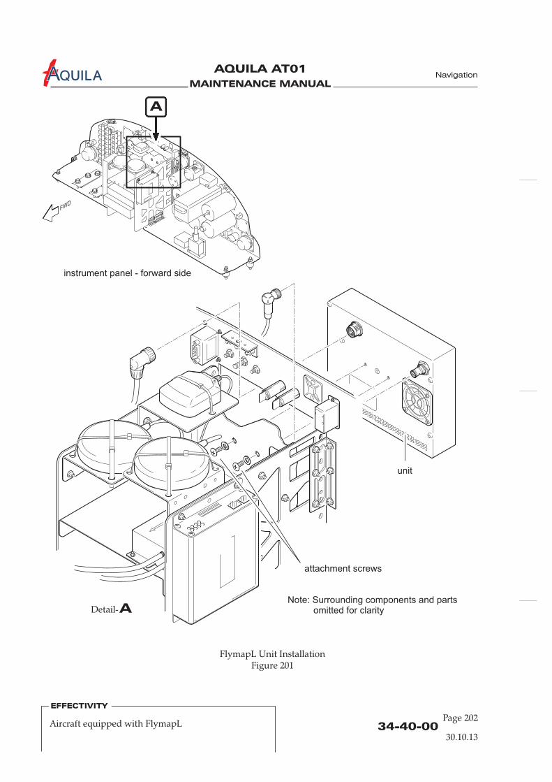
MAINTENANCE MANUAL
AQUILA AT01A
34-40-00Page 202
EFFECTIVITY
Aircraft equipped with FlymapL
Navigation
instrument panel - forward side
A
Note: Surrounding components and partsomitted for clarity
unit
attachment screws
FlymapL Unit InstallationFigure 201
ADetail-
30.10.13

MAINTENANCE MANUAL
AQUILA AT01A
(5) Reconnect battery (refer to 24-30-00).(6) Conduct a functional test of the installed unit.
3. (Ref. Fig. 202)
A. Remove FlymapL GPS Antenna(1) Ensure electrical power to aircraft is OFF.(2) Disconnect battery (refer to 24-30-00).(3) Remove glare shield (refer to 31-10-00).(4) Disconnect antenna cable from FlymapL unit and remove cable ties.(5) Mark installation position and remove cable ties of the antenna attachment.(6) Carefully remove antenna which is additionally secured to its installation bracket by
double-sided adhesive tape. Remove tape and adhesive residue with acetone.
B. Install FlymapL GPS Antenna(1) Install double-sided adhesive tape on the installation bracket of the GPS antenna and
remove the protective film from the adhesive tape.(2) Attach the antenna to the installation bracket in its correct installation position as previously
marked and press it on the installation bracket. Secure the GPS-antenna with 2 cross-wisemounted cable ties.
(3) Install antenna cable properly and connect it to the FlymapL unit.(4) Install glare shield (refer to 31-10-00).(5) Reconnect battery (refer to 24-30-00).(6) Perform a functional check of the unit.
GPS Antenna Removal/Installation
4. (Ref. Fig. 202)
A. Remove AHRS-Sensor(1) Ensure electrical power to aircraft is OFF.(2) Disconnect battery (refer to 24-30-00).(3) Remove glare shield (refer to 31-10-00).(4) Disconnect pitot and static pressure lines from the forward end of the sensor.
PLUG OR CAP THE SENSOR PORTS AS WELL AS THE END OF THEPRESSURE LINES IMMEDIATELY AFTER DISCONNECTION TOPREVENT DIRT OR FOREIGN OBJECTS ENTERING INTO THESENSOR AND THE PRESSURE SYSTEM.
(5) Disconnect plug connector from sensor. Mark the removed plug as required.(6) Mark the installation position of the sensor and remove the 4 nuts and washers from the
sensor mounting.(7) Carefully pull out the sensor from its installation bracket.
B. Install AHRS-Sensor(1) Put the sensor on its mounting bracket and position it as previously marked.(2) Secure the AHRS sensor on its installation bracket by installing the 4 attachment screws,
washers and nuts.
AHRS Sensor Removal/Installation
CAUTION:
34-40-00Page 203
EFFECTIVITY
Aircraft equipped with FlymapL
Navigation
30.10.13
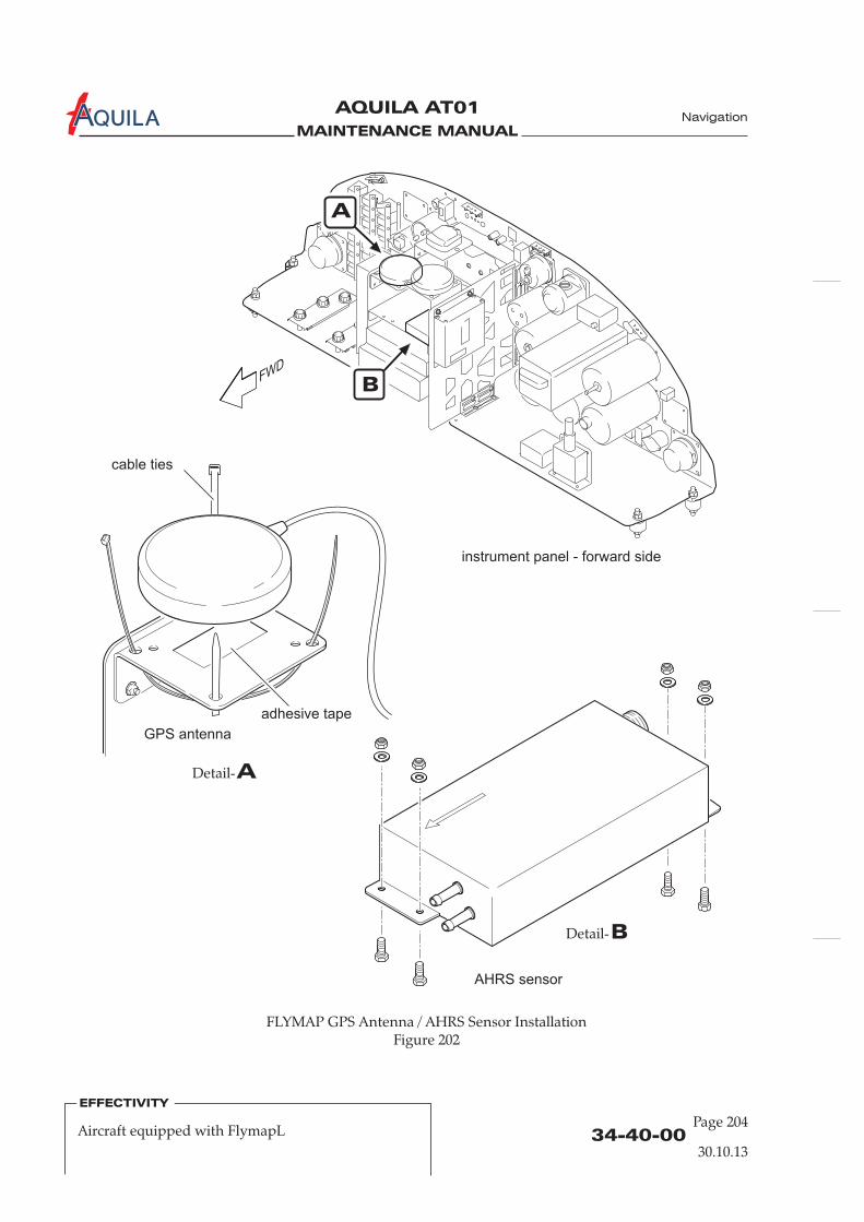
MAINTENANCE MANUAL
AQUILA AT01A
34-40-00Page 204
EFFECTIVITY
Aircraft equipped with FlymapL
Navigation
30.10.13
instrument panel - forward side
FLYMAP GPS Antenna / AHRS Sensor InstallationFigure 202
ADetail-
BDetail-
cable ties
adhesive tape
A
B
GPS antenna
AHRS sensor

MAINTENANCE MANUAL
AQUILA AT01A
34-40-00Page 205
Navigation
EFFECTIVITY
Aircraft equipped with FlymapL
30.10.13
(3) Remove the plugs/caps from the sensor ports and the pressure lines.Reconnect pitot and static pressure lines to the respective sensor port.Make sure that the pressure lines are properly connected to the correct port and secure theconnections with cable ties.
(4) Connect the required plug connector at the sensor. Make sure that the plug is properlyconnected.
(6) Install glare shield (refer to 31-10-00).(7) Reconnect battery (refer to 24-30-00).(8) Perform a functional check of the unit.
FlymapL
5.
A. When the power is connected to the it will automatically switch on. After a short startupperiod the map will appear. If in the centre of the screen a red cross appears together with theword GPS, no GPS signal is detected. Check GPS antenna connection and make sure that the GPSantenna has full view to the open sky without any obstacles.
If an aircraft symbol is displayed on the screen at the current location and the map isautomatically align either with the aircraft in the centre (for North Up display) or with the aircraftnear to the bottom of the screen (for Course Up display), the system is working properly (refer tothe FlymapL Operating Manual for additional functions of the FlymapL display system).
A flight test is recommended after FlymapL unit or AHRS sensor installation to ensurethe proper functioning of the system.
Inspection/Check
NOTE:
(5) Perform a pitot-static system leak test (refer to 34-11-00).

MAINTENANCE MANUAL
AQUILA AT01A

MAINTENANCE MANUAL
AQUILA AT01A
34-45-00Page 201
EFFECTIVITY
Aircraft equipped with FLARM Collision WarningSystem 30.10.13
Navigation
COLLISION WARNING SYSTEM – MAINTENANCE
1.
A. This section covers miscellaneous avionic equipment. This includes the FLARM Collision WarningSystem. The scope of maintenance is limited to the removal and installation of the components.For further information on the equipment, refer to the appropriate publications of the equipmentmanufacturer. For overhaul and repair, the manufacturer of the equipment has to be consulted.
B. The FLARM receives position and motion information from an internal 16 channel GPS receiverwith an external antenna. The predicted flight path is calculated by FLARM and the informationtransmitted by radio as low-power digital burst signals at one-second intervals. Provided thatthey are within receiving range, the signals are received by other aircraft also equipped withFLARM. The incoming signal is compared with the flight path predicted by calculation for thesecond aircraft. At the same time, FLARM compares the predicted flight path with known data onobstacles, including electric power lines, radio masts and cable cars. If FLARM determines the riskof dangerous proximity to one or more aircraft or obstacles, the unit gives the pilot warning of thegreatest danger at that moment. The warning is given by a whistle sound (beep) and bright lightemitting diodes (LED). The display also gives indication of the threat level, plus the horizontaland vertical bearing to the threat. The GPS and collision information received from other aircraftcan also be made available for other equipment like the FLYMAP via a serial data output interface.For more information, refer to the Operating Manual of the FLARM Collision Warning Unit, latestrevision.
The electrical circuit of the FLARM system is protected by a circuit breaker labeled “FLARM”. TheGPS signals are received by an antenna which is mounted on a bracket attached to the RH sidesupport plate of the instrument panel. The radio antenna for the transmission of the FLARMsignals to other aircrafts equipped with FLARM is attached to the rear side of the instrument panelbetween the circuit breakers and the engine instruments and is protected by a rubber sleeve. TheFLARM unit itself is mounted underneath the base plate of the instrument panel in the leftsection. The LED display unit of the FLARM system is located in the left section of the instrumentpanel.
C. For additional maintenance information on the FLARM unit, refer to the FLARM InstallationManual, latest revision. For the installation of software or database updates, refer to thedocumentation and manuals of the manufacturer of the FLARM Collision Warning System.
General
2. (Ref. Fig. 201)
A. Remove FLARM Unit(1)
Mark the removed cables, as required, and the installation position of the unit.(5) Remove both attachment screws of the FLARM unit. While removing the attachment screw
secure the FLARM unit by hand to prevent it from falling down.(6) Carefully remove the unit.
FLARM Unit Removal/Installation
Ensure electrical power to aircraft is OFF.(2) Disconnect battery (refer to 24-30-00).(3) Remove glare shield (refer to 31-10-00).(4) Disconnect all plug connectors and cables.
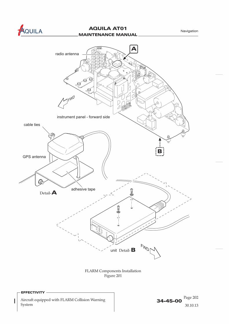
MAINTENANCE MANUAL
AQUILA AT01A Navigation
34-45-00Page 202
EFFECTIVITY
Aircraft equipped with FLARM Collision WarningSystem 30.10.13
FLARM Components InstallationFigure 201
instrument panel - forward side
B
ADetail-
BDetail-
cable ties
adhesive tape
Aradio antenna
GPS antenna
unit
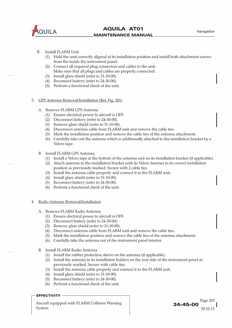
MAINTENANCE MANUAL
AQUILA AT01A Navigation
34-45-00Page 203
EFFECTIVITY
Aircraft equipped with FLARM Collision WarningSystem 30.10.13
B. Install FLARM Unit(1) Hold the unit correctly aligned at its installation position and install both attachment screws
from the inside the instrument panel.(2) Connect all required plug connectors and cables to the unit.
Make sure that all plugs and cables are properly connected.(3)
3.
A. Remove FLARM GPS Antenna(1)
(4) Disconnect antenna cable from FLARM unit and remove the cable ties.(5) Mark the installation position and remove the cable ties of the antenna attachment.(6) Carefully take out the antenna which is additionally attached to the installation bracket by a
Velcro tape.
B. Install FLARM GPS Antenna(1) Install a Velcro tape at the bottom of the antenna and on its installation bracket (if applicable).(2) Attach antenna to the installation bracket with its Velcro fastener in its correct installation
position as previously marked. Secure with 2 cable ties.(3) Install the antenna cable properly and connect it to the FLARM unit.(4)
4.
A. Remove FLARM Radio Antenna(1)
(4) Disconnect antenna cable from FLARM unit and remove the cable ties.(5) Mark the installation position and remove the cable ties of the antenna attachment.(6) Carefully take the antenna out of the instrument panel interior.
B. Install FLARM Radio Antenna(1) Install the rubber protection sleeve on the antenna (if applicable).(2) Install the antenna in its installation holders on the rear side of the instrument panel as
previously marked. Secure with cable ties.(3) Install the antenna cable properly and connect it to the FLARM unit.(4)
Install glare shield (refer to 31-10-00).(4) Reconnect battery (refer to 24-30-00).(5) Perform a functional check of the unit.
Ensure electrical power to aircraft is OFF.(2) Disconnect battery (refer to 24-30-00).(3) Remove glare shield (refer to 31-10-00).
Install glare shield (refer to 31-10-00).(5) Reconnect battery (refer to 24-30-00).(6) Perform a functional check of the unit.
Ensure electrical power to aircraft is OFF.(2) Disconnect battery (refer to 24-30-00).(3) Remove glare shield (refer to 31-10-00).
Install glare shield (refer to 31-10-00).(5) Reconnect battery (refer to 24-30-00).(6) Perform a functional check of the unit.
GPS Antenna Removal/Installation (Ref. Fig. 201)
Radio Antenna Removal/Installation
MAINTENANCE MANUAL
AQUILA AT01A
34-45-00Page 204
EFFECTIVITY
Aircraft equipped with FLARM Collision WarningSystem 30.10.13
5.
A. Remove FLARM Display Unit(1)
(4) Disconnect plug connector from display unit and mark it as required.(5) Carefully remove the display unit with suitable tools/means. The display unit is bonded to
the instrument panel with double-sided adhesive tape (see also the FLARM CollisionWarning System Operating Manual).
(6) Remove adhesive residue from instrument panel with acetone.
B. Install FLARM Display Unit(1) Remove the protective film from the double-sided adhesive tape on the rear side of the
FLARM display unit and install it in the instrument panel in its correct installation position.(2) Connect plug connector on the rear side of the display unit. Make sure that the plug is
properly connected.(3)
Display Unit Removal/Installation
Ensure electrical power to aircraft is OFF.(2) Disconnect battery (refer to 24-30-00).(3) Remove glare shield (refer to 31-10-00).
Install glare shield (refer to 31-10-00).(4) Reconnect battery (refer to 24-30-00).(5) Perform a functional check of the unit.
Navigation

MAINTENANCE MANUAL
AQUILA AT01A
34-50-00Page 201
EFFECTIVITY
Aircraft equipped with Bendix/KingKX 125 / KT 76A/C 30.10.13
Navigation
DEPENDENT POSITIONING DETERMINING - MAINTENANCE PRACTICES
1.
A. This section covers that portion of the system which provides information to determine positionand is mainly dependent on ground installations. This includes the NAV portion of theBendix/King KX 125 transceiver and the Bendix/King KT 76A/C transponder.
B. Bendix/King KX 125 RadioFor navigation purposes, data from ground stations can be received and indicated with thenavigation portion of the Bendix/King KX 125 radio. The NAV signals are received by the NAVantenna located in the fuselage belly behind the baggage compartment. This antenna is embeddedin the fuselage shell structure and is thus maintenance-free. However, if any maintenance shouldbe required, contact the manufacturer.For removal/installation of the KX 125 unit, refer to 23-10-00.
C. Bendix/King KT 76A/C TransponderThe KT 76A/C transponder is a radio transmitter and receiver which operates on radarfrequencies. Receiving ground radar interrogations at 1030 MHz, it returns a coded response ofpulses to ground-based radar on a frequency of 1090 MHz.The KT 76A/C unit is mounted in the instrument panel in the avionics column.The transponder antenna is installed on the bottom of the cabin, below the co-pilot's seat.
efer to theKT 76C Installation Manual, P/N 006-10545-0001, latest revision, and to theKT 76A/C Maintenance Manual, P/N 006-15545-0002, latest revision.
2.
A. Remove KT 76A/C Transponder Unit(1)
B. Install KT 76A/C Transponder Unit(1)
(3)
General
Bendix/King KT 76A/C Transponder Removal/Installation
D. For additional maintenance information on the KT 76A/C transponder, r
Ensure electrical power to aircraft is OFF.(2) Insert a 3/32" hex wrench into the jackscrew access hole on the face of the transponder unit
and turn counterclockwise until locking paw releases unit from rack.(3) Carefully pull unit out of the mounting tray.
Ensure all required plugs and cables at back of the mounting tray are properly connected.(2) Carefully slide unit forward into the mounting tray until contact is made by the pins and
then push the unit firmly into the mounting tray until fully engaged.Insert a 3/32" hex wrench into the mounting hole on the lower right-hand side of the unit andengage hex bolt (max. torque 1,7Nm [15 in.lbs]). Turn wrench clockwise until locking pawsecures unit to mounting tray.
(4) Conduct a functional test of the unit.
MAINTENANCE MANUAL
AQUILA AT01A
3.
A. Remove Transponder Antenna(1) Ensure electrical power to aircraft is OFF.(2) Remove access/inspection plate 211 BB (refer to 25-12-00) to gain access to the transponder
antenna.(3) Remove nuts and washers securing transponder antenna to fuselage.
The connected antenna cable prevents the antenna from falling away from theaircraft.
(4) From outside the aircraft, disconnect antenna cable at connector and remove antenna fromaircraft.
B. Install Transponder Antenna(1) From outside the aircraft, connect antenna cable to the transponder antenna.(2) From inside the fuselage, insert antenna studs through mounting holes and position the
backing plate.(3) Install washers and nuts securing transponder antenna to fuselage skin.(4) Seal the antenna to fuselage using a good quality electrical sealant (Sikaflex-221 or equivalent,
silicone-free).(5) Install access/inspection plate 211 BB (refer to 25-12-00).
Transponder Antenna Removal/Installation
NOTE:
34-50-00Page 202
EFFECTIVITY
Aircraft equipped with Bendix/KingKX 125 / KT 76A/C 30.10.13
Navigation

MAINTENANCE MANUAL
AQUILA AT01A Navigation
34-50-00Page 201
EFFECTIVITY
Aircraft equipped with Garmin Avionics
30.10.13
DEPENDENT POSITIONING DETERMINING - MAINTENANCE
1.
A. This section covers that portion of the system which provides information to determine positionand is mainly dependent on ground installations. This includes the VOR/ILS receiver portion ofthe GNS 430(W) / GNS 530(W) / GTN 650 navigation management system (NMS), the VOR/ILSreceiver portion of the SL30 COM/NAV transceiver as well as the Garmin GTX 327 / GTX 328 /GTX 330 mode S transponder.
B. Garmin GNS 430(W) / GNS 530(W) / GTN 650 SystemThe GNS 430(W) / GNS 530(W) / GTN 650 system is a fully integrated, panel mounted instrument,which contains a VHF communications transceiver, a VOR/ILS/GS receiver and a GPS navigationcomputer. The primary function of the VOR/ILS receiver portion of the equipment is to receiveand demodulate VOR, localizer and glideslope signals. NAV/LOC/GS signals are received by theVOR/LOC antenna located in the fuselage belly behind the baggage compartment. This antennais embedded in the fuselage shell structure and is therefore maintenance-free. However, if anymaintenance should be required, contact the manufacturer.For further information on the GNS 430(W) / GNS 530(W) / GTN 650 unit, refer to 23-10-00.
C. Garmin SL30 COM/NAV TransceiverThe SL30 is a combination of a VHF communications transceiver and a VHF navigation receiverwhich includes VOR, localizer and glideslope receiver, a built-in course deviation indicator and anindependent voice-activated intercom.The VOR, localizer and glideslope receivers provide 200 channels with a frequency range of 108 to117.95 MHz for VOR, 108 to 111.95 for localizer and 329.15 to 335 MHz for glideslope reception.VOR/LOC/GS signals are received by the VOR/LOC antenna which is integrated into the lowerfuselage shell structure behind the baggage compartment. This antenna is maintenance free andcannot be removed. However, if any maintenance or repair is necessary, contact the manufacturer.For further information on the SL30 unit, refer to 23-10-00.
D. Garmin GTX 327 TransponderThe Garmin GTX 327 transponder, located in the middle avionics panel, receives interrogationsfrom a ground-based secondary radar transmitter and transmits aircraft identification to the airtraffic control center via Mode A transmissions and altitude information via Mode C.
Refer to the Garmin GTX 327 Installation Manual, P/N 190-00187-02, latest revision, for additionalmaintenance information on the GTX 327 transponder system.
E. Garmin GTX 328 Mode S TransponderThe GTX 328 transponder is a radio transmitter and receiver that operates on radar frequencies,receiving ground radar or TCAS interrogations at 1030 MHz and transmitting a coded response ofpulses to ground based radar on a frequency of 1090 MHz. The GTX 328 is equipped with IDENTcapability that activates the special position identification (SPI) pulse for 18 seconds. The GTX 328replies to Mode A, Mode C and Mode S all-call interrogation. As a level 2 transponder, the GTX328 provides a downlink of aircraft information. Ground stations can interrogate Mode Stransponders individually using a 24-bit ICAO Mode S address which is unique to that particular
General
The transponder antenna is installed on the bottom of the cabin, below the co-pilot's seat.
MAINTENANCE MANUAL
AQUILA AT01A
34-50-00Page 202
Navigation
EFFECTIVITY
Aircraft equipped with Garmin Avionics
30.10.13
aircraft. In addition, ground stations may interrogate a GTX 328 for its transponder datacapability and aircraft flight ID which may be the registration number or another call sign.The electrical circuit of the GTX 328 Mode S transponder is protected by a circuit breaker labeled“Transponder”. The transponder antenna is installed on the bottom of the cabin, below the co-pilot's seat.
For a complete description of the GTX 328, refer to the Pilot's Guide of the GTX 328,P/N 190-00420-03, latest revision. For additional maintenance information on the GTX 328 Mode Stransponder, refer to GTX 328 Installation Manual, P/N 190-00420-04, latest revision.
F. Garmin GTX 330 Mode S TransponderThe Garmin GTX 330 is a panel-mounted non-diversity Mode S transponder working like a radiotransmitter and receiver that operates on radar frequencies, receiving ground radar or TCASinterrogations at 1030 MHz and transmitting a coded response of pulses to ground based radar ona frequency of 1090 MHz. The GTX 330 is equipped with IDENT capability that activates thespecial position identification (SPI) pulse for 18 seconds. The GTX 330 replies to Mode A, Mode Cand Mode S all-call interrogation. As a level 2 transponder, the GTX 330 provides downlink ofaircraft information. Ground stations can interrogate Mode S transponders individually using a24-bit ICAO Mode S address, which is unique to that particular aircraft. In addition, groundstations may interrogate a GTX 330 for its transponder data capability and aircraft flight ID whichmay be the registration number or another call sign.The electrical circuit of the GTX 330 mode S transponder is protected by a circuit breaker labeled“Transponder”. The transponder antenna is installed on the bottom of the cabin, below the co-pilot's seat.
For a complete description of the GTX 330, refer to the Pilot's Guide of the GTX 330,P/N 190-00207-00, latest revision. For additional maintenance information on the GTX 330 Mode Stransponder, refer to GTX 330 Installation Manual, P/N 190-00207-02, latest revision.
2.
A. Remove Garmin GTX 327 / GTX 328 / GTX 330 Transponder(1)
B. Install Garmin GTX 327 / GTX 328 / GTX 330 Transponder
BE SURE NOT TO OVERTIGHTEN THE UNIT INTO THE RACK. APPLICATIONOF HEX WRENCH TORQUE EXCEEDING 1,7 NM [15 IN.LBS] CAN DAMAGETHE LOCKING MECHANISM.
It may be necessary to insert the hex wrench into the access hole on the unit faceand rotate the mechanism 90° counterclockwise to ensure correct position prior toplacing the unit in the rack.
(1) Slide unit carefully straight in the rack until it stops, about 1 inch short of the final position.
Garmin GTX 327 / GTX 328 / GTX 330 Transponder Removal/Installation
CAUTION:
NOTE:
Ensure electrical power to aircraft is OFF.(2) Insert a 3/32" hex wrench into the jackscrew access hole on the face of the transponder unit
and turn counterclockwise until locking paw releases unit from rack.(3) Carefully pull unit out of the mounting tray.
MAINTENANCE MANUAL
AQUILA AT01A
34-50-00Page 203
Navigation
EFFECTIVITY
Aircraft equipped with Garmin Avionics
30.10.13
(2) Insert a 3/32 hex wrench into the access hole at the bottom of the unit face and engage hexbolt.
(3) Turn wrench clockwise until the unit is secured in the rack.(4) Carry out a functional test of the installed unit in accordance with section 1.9 of the GTX 327
Installation Manual respectively section 3.4 of the GTX 328 / GTX 330 Installation Manual.
3.
A. Remove Transponder Antenna(1) Ensure electrical power to aircraft is OFF.(2) Remove access/inspection plate 211 BB (refer to 25-12-00) to gain access to the transponder
antenna.(3) Remove nuts and washers securing transponder antenna to fuselage.
The connected antenna cable prevents the antenna from falling away from theaircraft.
(4) From outside the aircraft, disconnect antenna cable at connector and remove antenna fromaircraft.
B. Install Transponder Antenna(1) From outside the aircraft, connect antenna cable to the transponder antenna.(2) From inside the fuselage, insert antenna studs through mounting holes and position the
backing plate.(3) Install washers and nuts securing transponder antenna to fuselage skin.(4) Seal the antenna to fuselage using a good quality electrical sealant (Sikaflex-221 or equivalent,
silicone-free).(5) Install access/inspection plate 211 BB (refer to 25-12-00).
Transponder Antenna Removal/Installation
NOTE:

MAINTENANCE MANUAL
AQUILA AT01A

MAINTENANCE MANUAL
AQUILA AT01A
CHAPTER 51
STRUCTURES

MAINTENANCE MANUAL
AQUILA AT01A
MAINTENANCE MANUAL
AQUILA AT01A
Page 151 - TOC
TABLE OF CONTENTS
ChapterSection
STRUCTURES - GENERAL..............................................................................51-00-00 1Introduction 51-00-00 1General Description 51-00-00 1
COMPOSITE DAMAGE INVESTIGATION ..................................................51-10-00 201General 51-10-00 201Inspection Methods 51-10-00 201Damage Classification 51-10-00 202
COMPOSITE REPAIR.......................................................................................51-20-00 201General 51-20-00 201Repair Requirements 51-20-00 201Approved Materials 51-20-00 202Tools, Equipment and Material 51-20-00 203Material Data Sheet 51-20-00 204Repair of Sandwich Components 51-20-00 217Repair of Monolithic Components 51-20-00 222Exterior Finish 51-20-00 223
Title Subject Page
Structure Classes 51-00-00 2
Structures
29.02.16

MAINTENANCE MANUAL
AQUILA AT01A

MAINTENANCE MANUAL
AQUILA AT01A
51-00-00
STRUCTURES - GENERAL
1.
A. This chapter provides a general overview of the structural design. The chapter containsinformation and procedures applicable to all composite repairs as well as information andprocedures for aircraft painting and priming.
B. Please contact AQUILA Aviation GmbH for support in case damage to the aircraft structure thecause of which is unknown or suspect, and prior to major repairs to obtain detailed information.
AQUILA Tel.: +49(0) 33731 707-0Flugplatz Fax.: +49(0) 33731 707-1114959 SchönhagenGermany
2.
Most of the aircraft structure is made from composite materials. Glass-fiber (GFRP) and carbon-fiberreinforced plastics (CFRP) are used which are bedded in an epoxy resin matrix. The aircraft structureconsists of monolithic GFRP or CFRP shells and structure components as well as sandwich shellswhich have a rigid foam core.
A. FuselageThe fuselage with the vertical and horizontal stabilizers represents one component. Including thevertical stabilizer, it consists of two half-shells. The fuselage portion of the half-shells is made fromsolid (non-foam) fiberglass laminate, the vertical stabilizer has a sandwich structure. The fuselageGFRP skin is reinforced by four carbon-fiber stringers, arranged lengthwise through the entirefuselage.Four ring frames and a baggage compartment frame provide support to the fuselage shells in thetail section. A landing gear bulkhead, a seat bulkhead and a side-force bulkhead carry singleloads.The front of fuselage ends with the firewall which includes the metal fittings for supporting theengine mount. The firewall, constructed of a GFRP/CFRP composite sandwich, has a fireprotection lining which consists of an especially fire-resistant ceramic fleece anda stainless-steel sheet.The landing gear bulkhead which together with the seat bulkhead supports the main landinggear struts, is complemented upwards through a compact CFRP/GFRP roll-over bar.
B. WingsThe plan view of the wing is a triple trapezoid that is complemented by a winglet at its end.The wing has top and bottom shells, constructed of a GFRP composite sandwich and locallyreinforced by CFRP straps. The aircraft has a one-piece wing because the wing spar ismanufactured in one piece and is continuous from wing tip to wing tip. The I-section spar hascaps made from unidirectional carbon-fiber and a GFRP composite sandwich web.Each wing half ends inboard with a front root rib and a rear root rib, which are mounted to thefuselage center section with a bolt apiece.
Introduction
General Description
Aviation GmbH
on the front side
Structures
29.02.16
Page 1

MAINTENANCE MANUAL
AQUILA AT01A
51-00-00Page 2
29.02.16
AQUILA AT01 Primary StructureFigure 01
The four lateral force bolts are inserted from the cabin through the fuselage bushings into thewing bolt casings and secured axially with screws.The outboard end of the wing has a winglet with the NAV lights and the fuel tank vents. Theinboard portion of the wings contains an integral fuel tank with a capacity of 60 liters per wing.The ailerons are located at the wing trailing edge near the wing tips. They are of a semi-monocoque sandwich construction consisting of rigid foam core and glass and carbon fiber layers.The flaps, of a semi-monocoque CFRP sandwich construction, are mounted to the trailing edge ofeach wing between the inboard end of the ailerons and the fuselage.They are attached to the wings using hinges that are located below the bottom of the wing. Thisresults in the gap between wing trailing edge and flap leading edge and increases as the flapextend. This increases the lift force and simultaneously the drag force.
C. StabilizersThe vertical and horizontal stabilizers, as well as the elevator and rudder are of semi-monocoquedesign consisting of shells fabricated from GFRP sandwich reinforced with CFRP.The vertical and the horizontal stabilizers have a main spar and a rear shear web with integratedhinges. The horizontal stabilizer is molded to the fuselage and cannot be removed.
3.
A. Primary StructureThese parts are important for the structural integrity of the aircraft. For example: fuselage, wing,stabilizer and control surface shells, spars, frames, joints, brackets.
B. Secondary StructureThese parts are not important for the structural integrity of the aircraft. For example: panels,covers, access plates, fairings.
Structure Classes
Structures
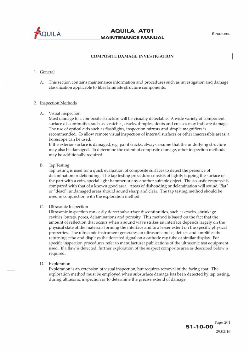
MAINTENANCE MANUAL
AQUILA AT01A
51-10-00Page 201
29.02.16
COMPOSITE DAMAGE INVESTIGATION
1.
A. This section contains maintenance information and procedures such as investigation and damageclassification applicable to fiber laminate structure components.
2.
A. Visual InspectionMost damage to a composite structure will be visually detectable. A wide variety of componentsurface discontinuities such as scratches, cracks, dimples, dents and creases may indicate damage.The use of optical aids such as flashlights, inspection mirrors and simple magnifiers isrecommended. To allow remote visual inspection of internal surfaces or other inaccessible areas, aborescope can be used.If the exterior surface is damaged, e.g. paint cracks, always assume that the underlying structuremay also be damaged. To determine the extent of composite damage, other inspection methodsmay be additionally required.
B. Tap TestingTap testing is used for a quick evaluation of composite surfaces to detect the presence ofdelamination or debonding. The tap testing procedure consists of lightly tapping the surface ofthe part with a coin, special hammer or any another suitable object. The acoustic response iscompared with that of a known good area. Areas of disbonding or delamination will sound “flat”or “dead”, undamaged areas should sound sharp and clear. The tap testing method should beused in conjunction with the exploration method.
C. Ultrasonic InspectionUltrasonic inspection can easily detect subsurface discontinuities, such as cracks, shrinkagecavities, bursts, pores, delaminations and porosity. This method is based on the fact that theamount of reflection that occurs when a sound wave strikes an interface depends largely on thephysical state of the materials forming the interface and to a lesser extent on the specific physicalproperties. The ultrasonic instrument generates an ultrasonic pulse, detects and amplifies thereturning echo and displays the detected signal on a cathode ray tube or similar display. Forspecific inspection procedures refer to manufacturer publications of the ultrasonic test equipmentused. If a flaw is detected, further exploration of the suspect composite area as described below isrequired.
D. ExplorationExploration is an extension of visual inspection, but requires removal of the facing coat. Theexploration method must be employed when subsurface damage has been detected by tap testing,during ultrasonic inspection or to determine the precise extend of damage.
General
Inspection Methods
light
Structures

MAINTENANCE MANUAL
AQUILA AT01A
51-10-00Page 202
3.
A. Damage to composite structures can be divided into four classes:
(1) Damage Class 1Severe, extensive damage that requires partial component restoration or general componentreplacement.
(2) Damage Class 2Damage to primary or secondary structures with sandwich penetration such as holes orfractures. Both sides of sandwich penetrated and the laminate on both sides must be repairedand the core section replaced.
(3) Damage Class 3Damage only to outer laminate layers on one side of a sandwich construction without or onlyminor gouging of core material.
(4) Damage Class 4Damage to outer surface of composite structures such as superficial scars, scratches, surfaceabrasion or erosion. No holes or laminate fractures.
Damage Classification
B. Minor DamagesOnly the damages listed below can be considered as small damages and repaired by qualifiedpersonnel without a repair scheme which has been approved by the manufacturer. In general alldamages in force introduction or reinforced areas (i.e. spars, ribs) have to be carried out bycertified repair stations for composite aircraft structure works.
(1) Any damages limited to varnish or filler.
(2) Damages not exceeding the permissible dimensions of holes, dents and cracks that are listedin the following table:
(3) Damages not affecting glass and carbon rovings or carbon tapes in the primary structure.
(4) No class 1 damages and no damages in critical areas. Refer to figure 201 for an overview ofthe main critical areas of the aircraft.
Structures
29.02.16
Part Average hole or dent diam. Crack length
Front fuselage (cockpit) 75 mm [3 in.]50 mm [2 in.]
Rear fuselage (tail boom) 25 mm [1 in.] 50 mm [2 in.]
Wing 75 mm [3 in.] 100 mm [4 in.]
Stabilizers
Flap, Aileron
Rudder, Elevator
25 mm [1 in.]
25 mm [1 in.]
25 mm [1 in.]
50 mm [2 in.]
50 mm [2 in.]
50 mm [2 in.]
Cowling, Fairings 75 mm [3 in.] 100 mm [4 in.]
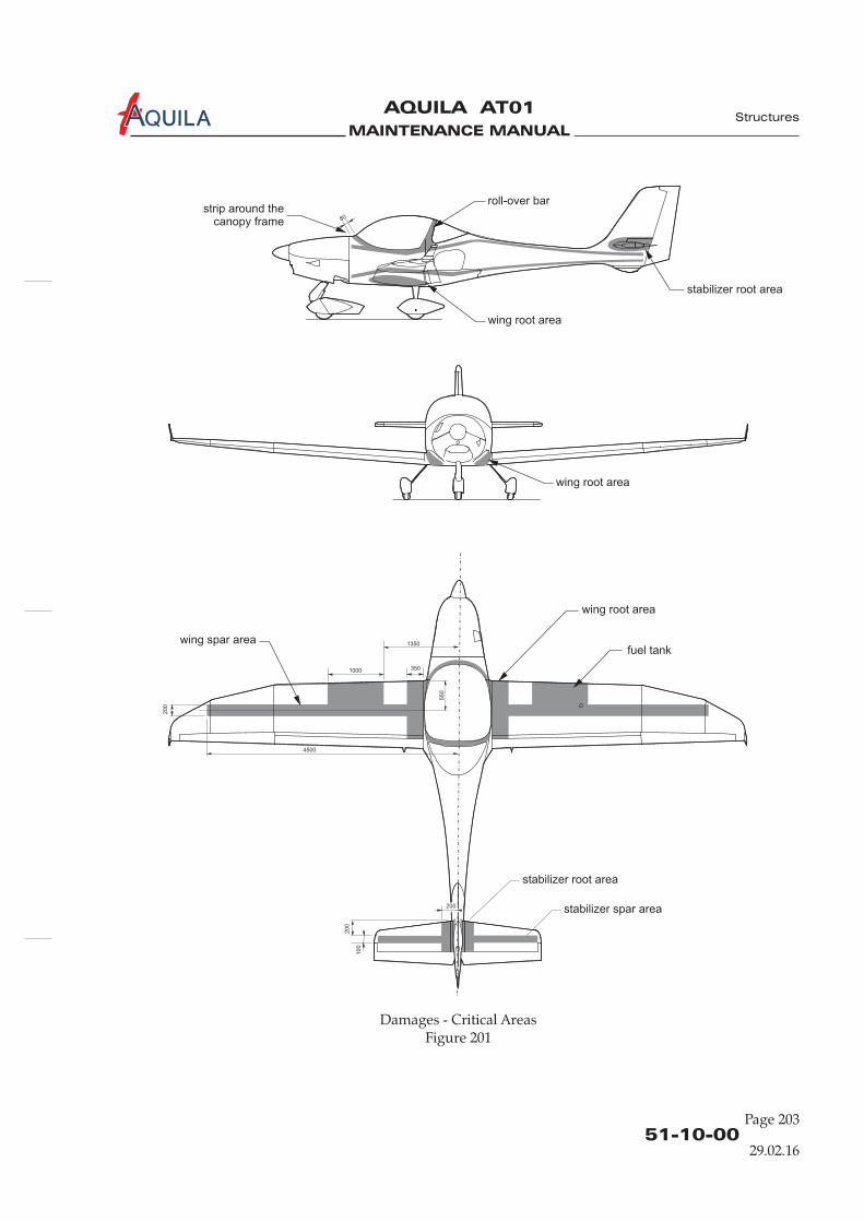
MAINTENANCE MANUAL
AQUILA AT01A
51-10-00Page 203
29.02.16
Structures
Damages - Critical AreasFigure 201
4500
1000
1350
350
550
200
200
200
100
80
wing root area
wing root area
wing root area
wing spar area
stabilizer root area
stabilizer root area
stabilizer spar area
roll-over barstrip around the
canopy frame
fuel tank

MAINTENANCE MANUAL
AQUILA AT01A
MAINTENANCE MANUAL
AQUILA AT01A
COMPOSITE REPAIR
1.
A. This section covers required information to complete successful repairs to aircraft components thatare made from fiber laminate. Necessary repair data, such as ply lay-up and ply orientation forvarious areas, as well as repair materials and procedures are provided. Not included are generalpractices used during most composite repairs, such as cleaning and preparing the damaged area,proper preparation of materials, mixing and applying resin or proper curing the repair. Personnelmust be familiar with these practices prior to attempting fiberglass composite repairs on thisaircraft.
2.
A. The following requirements must be met:(1) Repairs for which no description is given in this chapter may only be carried out in
accordance with a repair scheme which must be approved in accordance with the proceduresestablished by the competent certifying authority.
(2) Only damages classified as minor damages (refer to 51-10-00) can be repaired by qualifiedpersonnel
(5) Repairs must be completed by competent technicians trained in composite repair.(6) Before beginning a repair make sure all required tools, equipment and materials are ready. If
you are not familiar with the proper use of all the repair tools, never attempt a fiberglasscomposite repair.
(7) Use the approved materials outlined in this section . Prepare materials in accordancewith information given in this manual and manufacturer instructions.
(8) Review material safety data sheets for material to be used. Observe shelf life.(9) Repairs should be made in a clean, temperature controlled environment. Optimal repair
temperature lies between 16°C and 27°C (60°F - 80°F) with 50% relative humidity or less.(10) It is recommended to prepare a test specimen during actual repair which can be subjected to
a destructive test to establish the quality of the adhesive bond in the repaired part.(11) To preserve the good aerodynamic characteristics of the aircraft smooth and precisely contour
repaired surfaces.
B. Safety Precautions(1) Read and adhere to all manufacturer instructions, warnings and cautions on the materials
and chemicals used.(2) Sanding fiber laminates results in a fine dust that may cause skin and/or respiratory irritation
unless suitable protection is used.(3) Never handle fabric materials with bare hands, use clean cotton or rubber gloves.
General
Repair Requirements
without a repair scheme which has been approved by the manufacturer orcognizant regulatory authority.
(3) In general all damages in force introduction or reinforced areas (i.e. spars, ribs) have to becarried out by certified repair stations for composite aircraft structure works or properlycertified and trained persons.
(4) Class 4 damages (refer to 51-10-00) don’t have to be repaired immediately after detection ifadequately protected from environmental conditions (e.g. adhesive tape).
only
(12) All control surfaces have to be checked for weight and control surface moment after repair.
51-20-00Page 201
Structures
29.02.16
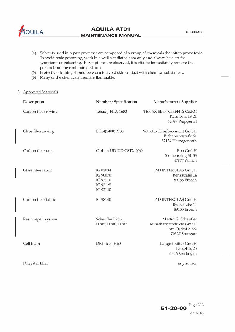
MAINTENANCE MANUAL
AQUILA AT01A
51-20-00Page 202
Structures
29.02.16
(4) Solvents used in repair processes are composed of a group of chemicals that often prove toxic.To avoid toxic poisoning, work in a well-ventilated area only and always be alert forsymptoms of poisoning. If symptoms are observed, it is vital to immediately remove theperson from the contaminated area.
(5) Protective clothing should be worn to avoid skin contact with chemical substances.(6) Many of the chemicals used are flammable.
3.
Carbon fiber roving Tenax-J HTA-1600 TENAX fibers GmbH & Co.KGKasinostr. 19-21
42097 Wuppertal
Glass fiber roving EC14(2400)P185 Vetrotex Reinforcement GmbHBicherouxstraße 61
52134 Herzogenrath
Carbon fiber tape Carbon UD-UD CST240/60 Epo GmbHSiemensring 31-33
47877 Willich
Glass fiber fabric IG 02034 P-D INTERGLAS GmbHIG 90070 Benzstraße 14IG 92110 89155 ErbachIG 92125IG 92140
Carbon fiber fabric IG 98140 P-D INTERGLAS GmbHBenzstraße 1489155 Erbach
Resin repair system Scheufler L285 Martin G. ScheuflerH285, H286, H287 Kunstharzprodukte GmbH
Am Ostkai 21/2270327 Stuttgart
Cell foam Divinicell H60 Lange+Ritter GmbHDieselstr. 25
70839 Gerlingen
Polyester filler any source
Approved Materials
Description Number / Specification Manufacturer / Supplier

MAINTENANCE MANUAL
AQUILA AT01A
4.
6.A. as sandpaper - commerciallyrequired 30-grit to available
400 grit
as isopropyl - commerciallyrequired alcohol available
as peel ply - commerciallyrequired available
as release film - commerciallyrequired available
as hot glue - commerciallyrequired available
as cotton cloth - commerciallyrequired available
1 mixing container - commerciallyavailable
as stir sticks - commerciallyrequired available
1 scale - commerciallyavailable
1 pair gloves - commerciallyavailable
8.A. as masking tape - commerciallyrequired 2-inch available
as sandpaper - commerciallyrequired 240-grit to available
360-grit
as cotton cloth - commerciallyrequired available
as isopropyl - commerciallyrequired alcohol available
Tools, Equipment and Material
Quantity Equipment Parts No. Manufacturer
51-20-00Page 203
Structures
29.02.16
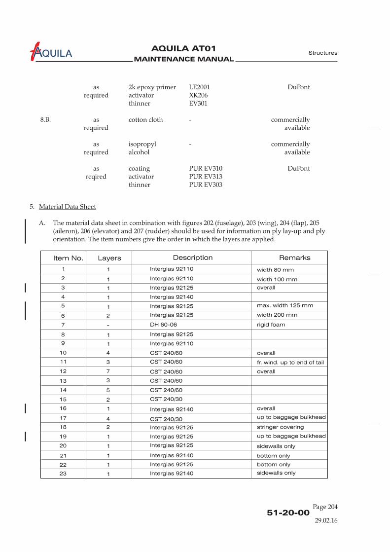
MAINTENANCE MANUAL
AQUILA AT01A
51-20-00Page 204
Item No. Layers Description Remarks
1 1
1
1
1
1
1
1
1
1
1
1
1
1
2
2
overall
rigid foam
fr. wind. up to end of tail
stringer covering
overall
up to baggage bulkhead
sidewalls only
sidewalls only
bottom only
bottom only
2
2
3
3
3
4
4
4
5
5
6
7
7
8
9
10
11
12
13
14
15
16
17
18
19
20
21
22
23
Interglas 92110
Interglas 92110
Interglas 92110
Interglas 92125
Interglas 92125
Interglas 92125
Interglas 92125
Interglas 92125
Interglas 92125
Interglas 92125
Interglas 92125
DH 60-06
Interglas 92140
Interglas 92140
Interglas 92140
Interglas 92140
width 80 mm
width 100 mm
-
CST 240/60
CST 240/60
CST 240/60
CST 240/60
CST 240/60
CST 240/30
CST 240/30
5.
A. The material data sheet in combination with figures 202 (fuselage), 203 (wing), 204 (flap), 205(aileron), 206 (elevator) and 207 (rudder) should be used for
. The item numbers give the order in which the layers are applied.
Material Data Sheet
information on ply lay-up and plyorientation
Structures
29.02.16
overall
overall
up to baggage bulkhead
as 2k epoxy primer DuPontrequired activator XK206
thinner EV301
8.B.
as coating PUR EV310 DuPontreqired activator PUR EV313
thinner PUR EV303
LE2001
as cotton cloth - commerciallyrequired available
as isopropyl - commerciallyrequired alcohol available
max. width 125 mm
width 200 mm
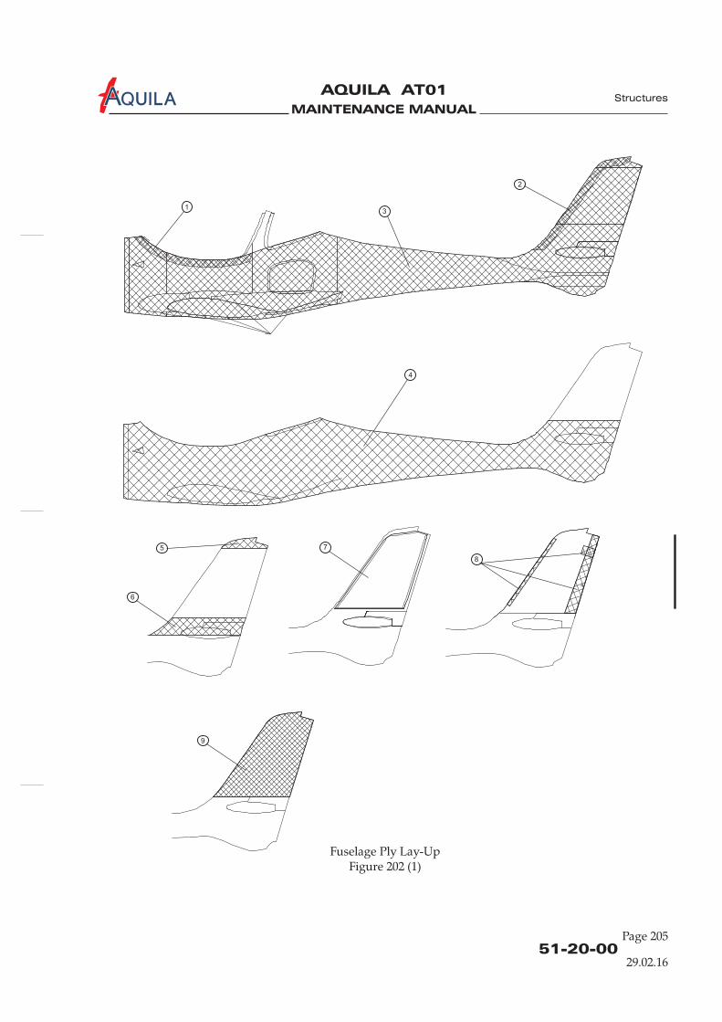
MAINTENANCE MANUAL
AQUILA AT01A
Fuselage Ply Lay-UpFigure 202 (1)
51-20-00Page 205
1
2
3
4
5
6
7
9
8
Structures
29.02.16
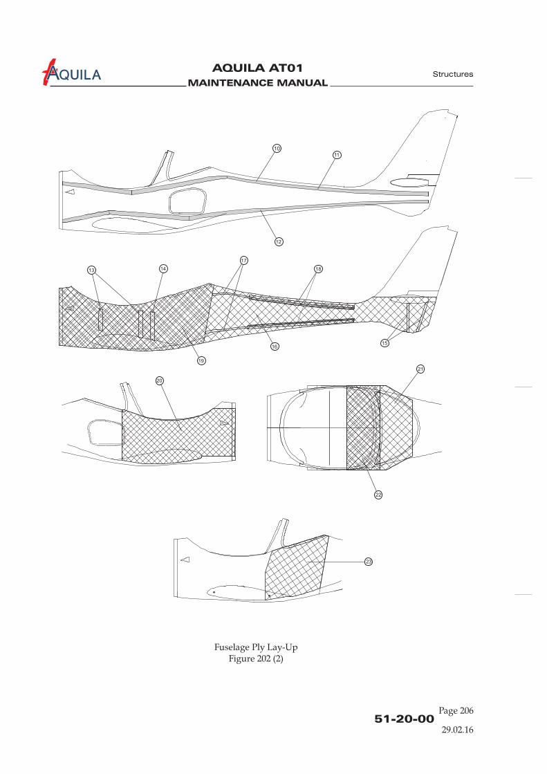
MAINTENANCE MANUAL
AQUILA AT01A
51-20-00Page 206
Fuselage Ply Lay-UpFigure 202 (2)
10
17
1813
20
21
22
23
15
14
11
16
19
12
Structures
29.02.16

MAINTENANCE MANUAL
AQUILA AT01A
51-20-00Page 207
Structures
29.02.16
Item No. Layers Description Remarks
1 1 Interglas 92110 width 110 mm
2 1 Interglas 92125
3 1 Interglas 92125 width 100 mm strip, overlap in winglet area
4 1 Interglas 92125
5 1 Interglas 92125
6 2 Interglas 92125 up to aileron
7 1 Interglas 92125 up to y=1030 mm
8 1 Interglas 92125
9 2 Interglas 92125
10 2 Interglas 92125 only left-hand side
11 2 CST 240/60 length 800 mm
12 1 CST 240/60 length 280 mm
13 1 CST 240/60 length 330 mm
14 1 CST 240/60
15 2 CST 240/30 obliquely outwards
16 2 CST 240/30
17 2 roving 5x EC 14-2400 P185
18 8 roving 5x EC 14-2400 P185
19 6 roving 5x EC 14-2400 P185
20 1 Interglas 90070
21 1 Interglas 92110 from 1350 mm
22 1 Interglas 92125 up to 2350
23 1 Interglas 92110
24 1 Interglas 92110 circle 123 mm x 63 mm, centered beneath filler
25 1 Interglas 92125 strip width 80 mm, overlap in winglet area
26 Interglas 92125 strip 240 mm x 50 mm, bent around filler
27 3 roving 5x EC 14-2400 P185 wrapped around filler
28 3 Interglas 92125 graduated by 5 mm
29 1 Interglas 90070
30 1 Interglas 92110
31 DH 60 - 08 rigid foam
32 Pregnit GGBE/GMBE GFRP plate
33 2 CST 240/30 at 50% winglet depth, up to 60 mm before winglet end

MAINTENANCE MANUAL
AQUILA AT01A
23
8
26
2726
8
16
28
14
11
12
13
14
33
9
8
9
8
88
8
7
filler
25
8
8
24
300
1030
416
960
36003000
1900
850
50
50
50
30 3030
300
300
350
350
346
160
70
22
0
50
67
15
0
240
10
1010
240
10
10
0
32
03
30 90
0
28
0
y=1450
29.02.1651-20-00
Page 208
Structures
Upper Wing Shell Ply Lay-UpFigure 203 (1)
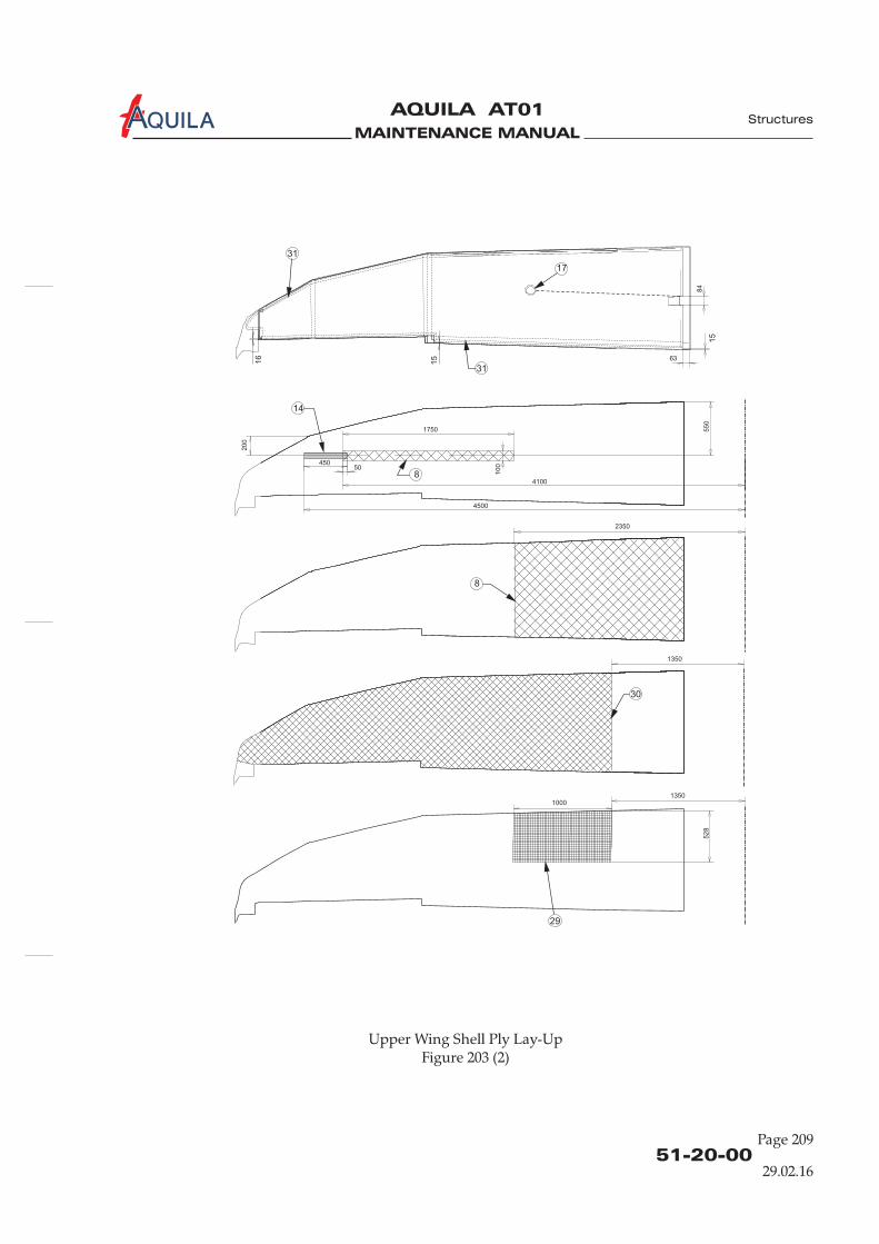
MAINTENANCE MANUAL
AQUILA AT01A
29.02.1651-20-00
Page 209
Structures
31
31
17
84
29
52
8
10001350
30
1350
8
2350
14
8
20
0
55
0
10
0
4100
4500
45050
1750
6316
15
15
Upper Wing Shell Ply Lay-UpFigure 203 (2)
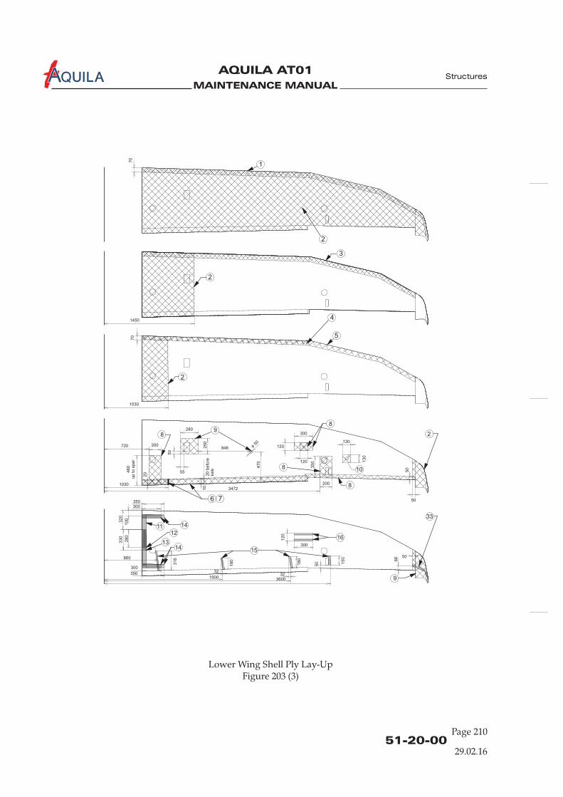
MAINTENANCE MANUAL
AQUILA AT01A
1
70
2
3
2
2
4
5
6 7
8
89
ø 50
846
8 10
1411
1413
12
350
32
0
316
300
10
0
33
0
28
0
860
300
350
1450
1030
720 200
10303472
50
70
50
55
20
be
fore
kin
k
10
300
35
0
120
120
130
200
13
0
47
0
280
50
2
8
25
0
48
0u
p t
o s
pa
r
20
15
33
9
16
50
3232
66
150
36001900
50180
180
300
12
0
51-20-00Page 210
Structures
29.02.16
Lower Wing Shell Ply Lay-UpFigure 203 (3)
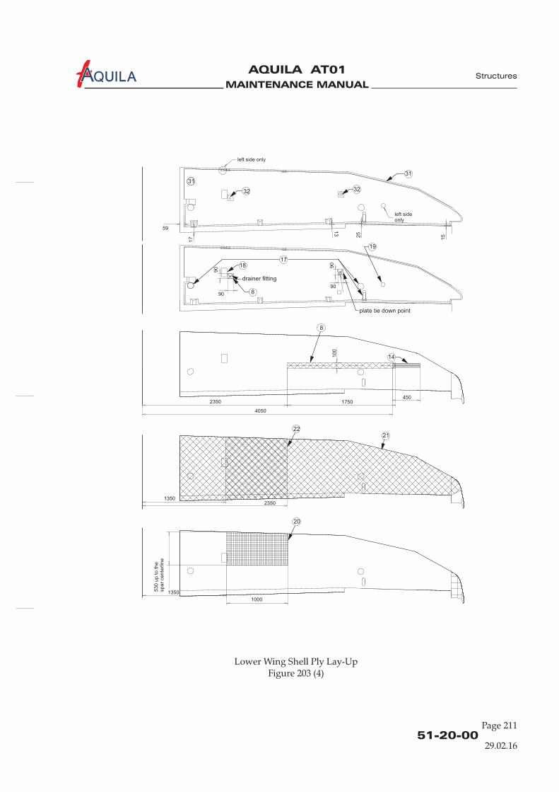
MAINTENANCE MANUAL
AQUILA AT01A
51-20-00Page 211
Structures
29.02.16
Lower Wing Shell Ply Lay-UpFigure 203 (4)
3232
1718
drainer fitting
8
19
plate tie down point
31
left side only
left sideonly
31
59
90
90
90
90
17
13
25
15
20
1350
53
0 u
p t
o t
he
sp
ar
ce
nte
rlin
e
1000
2221
13502350
8
14
1750
4050
4502350
10
0
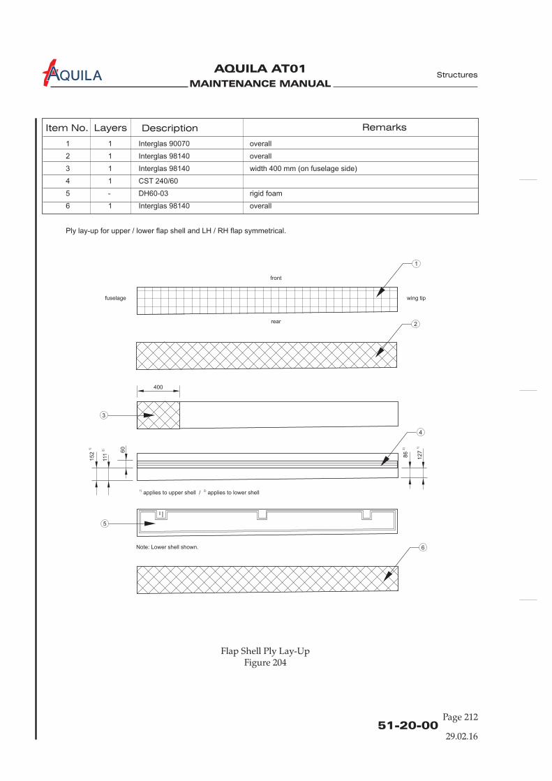
MAINTENANCE MANUAL
AQUILA AT01A
51-20-00Page 212
29.02.16
Item No. Layers Description Remarks
1 1 Interglas 90070 overall
2 1 Interglas 98140 overall
3 1 Interglas 98140 width 400 mm (on fuselage side)
4 1 CST 240/60
5 - DH60-03 rigid foam
6 1 Interglas 98140 overall
Ply lay-up for upper / lower flap shell and LH / RH flap symmetrical.
Flap Shell Ply Lay-UpFigure 204
Structures
152
1)
111
2)
60
86
2)
127
1)
400
2
1
3
4
5
6
1) 2)applies to upper shell / applies to lower shell
Note: Lower shell shown.
front
rear
fuselage wing tip
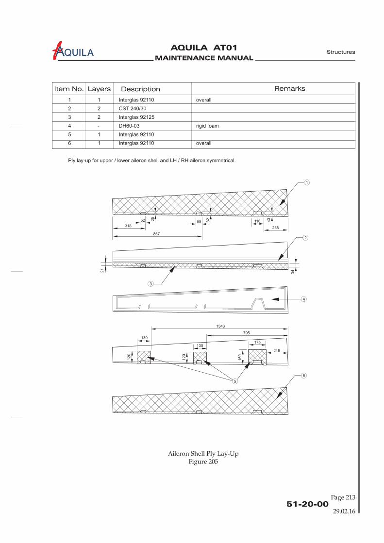
MAINTENANCE MANUAL
AQUILA AT01A
51-20-00Page 213
29.02.16
Aileron Shell Ply Lay-UpFigure 205
Structures
Item No. Layers Description Remarks
1 1 Interglas 92110 overall
2 2 CST 240/30
3 2 Interglas 92125
4 - DH60-03 rigid foam
5 1 Interglas 92110
6 1 Interglas 92110 overall
Ply lay-up for upper / lower aileron shell and LH / RH aileron symmetrical.
318
52 5525
21
34
32
43
116
238
867
130
120
120
150
130175
215
795
1343
2
3
4
6
1
5
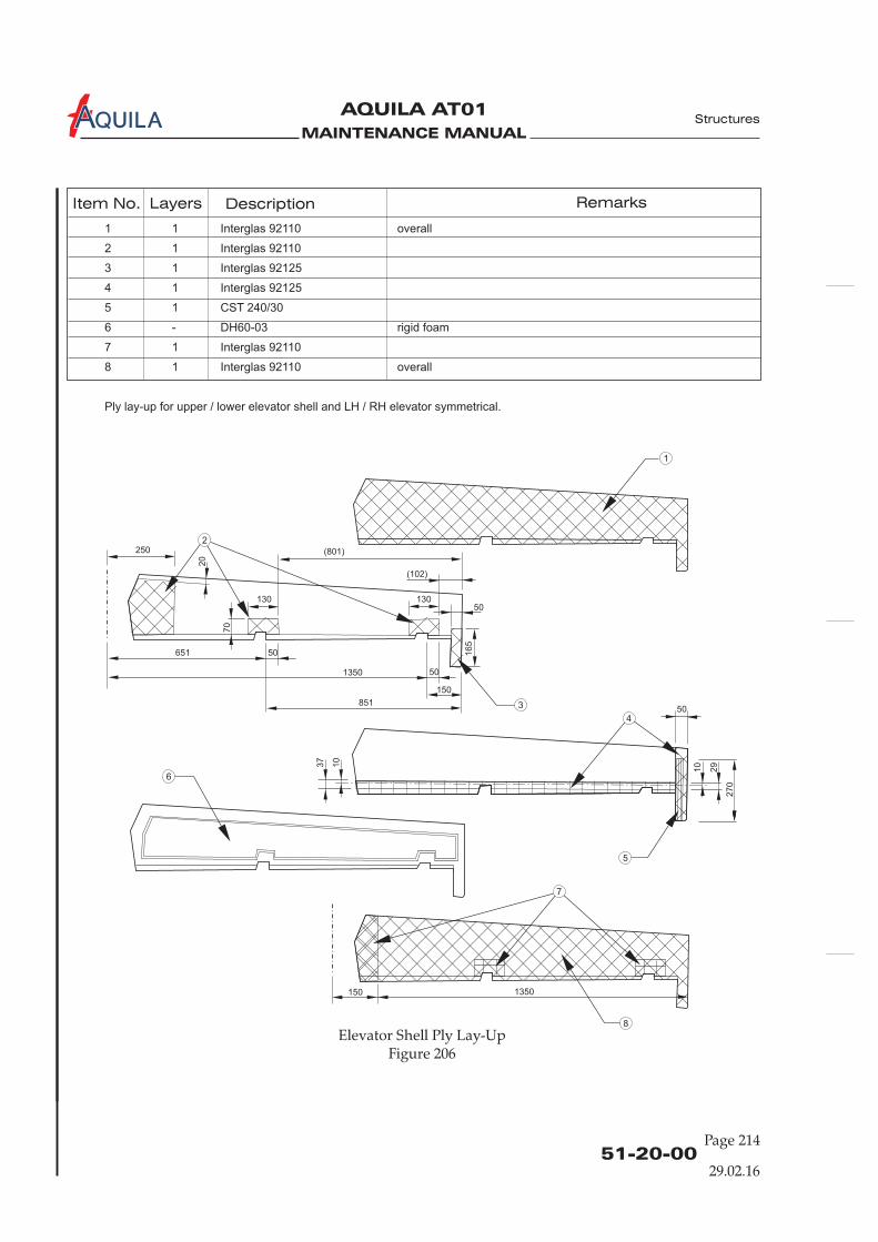
MAINTENANCE MANUAL
AQUILA AT01A Structures
51-20-00Page 214
29.02.16
Elevator Shell Ply Lay-UpFigure 206
Item No. Layers Description Remarks
1 1 Interglas 92110 overall
2 1 Interglas 92110
3 1 Interglas 92125
4 1 Interglas 92125
5 1 CST 240/30
6 - DH60-03 rigid foam
7 1 Interglas 92110
8 1 Interglas 92110 overall
Ply lay-up for upper / lower elevator shell and LH / RH elevator symmetrical.
250
651
851
130
165
270
37
10
10
29
70
20
130
150
50
50
50
50
1350
(801)
(102)
150 1350
1
2
3
4
5
6
7
8
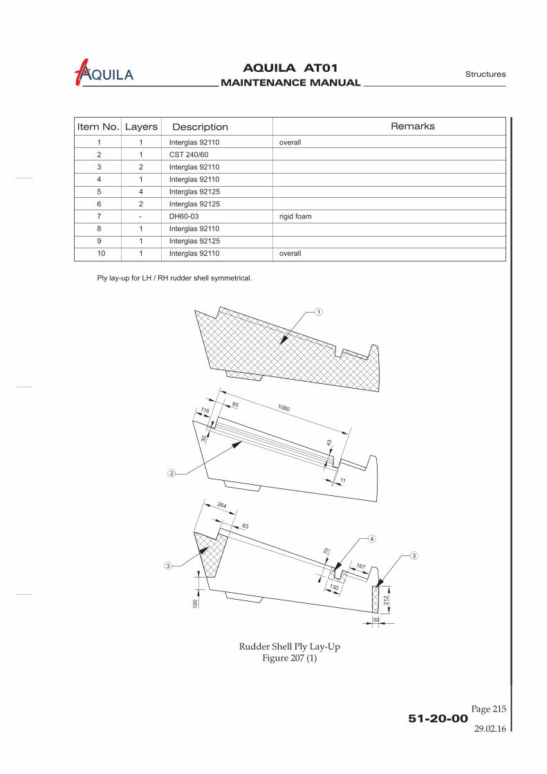
MAINTENANCE MANUAL
AQUILA AT01A Structures
51-20-00Page 215
29.02.16
Rudder Shell Ply Lay-UpFigure 207 (1)
Item No. Layers Description Remarks
1 1 Interglas 92110 overall
2 1 CST 240/60
3 2 Interglas 92110
4 1 Interglas 92110
5 4 Interglas 92125
6 2 Interglas 92125
7 - DH60-03 rigid foam
8 1 Interglas 92110
9 1 Interglas 92125
10 1 Interglas 92110 overall
Ply lay-up for LH / RH rudder shell symmetrical.
108065
83
116
264
167
130
11
433
0
70
50
212
100
1
2
3
3
4
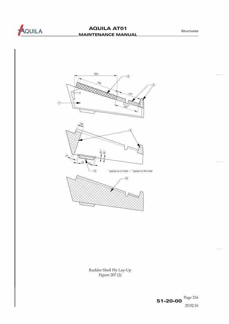
MAINTENANCE MANUAL
AQUILA AT01A
51-20-00Page 216
29.02.16
Structures
794
437
447
800
Y Z
X
20
31
108
20
20
2)
30
1)
Rudder Shell Ply Lay-UpFigure 207 (2)
5
7
6
9
8
10
1) 2)applies to LH shell / applies to RH shell
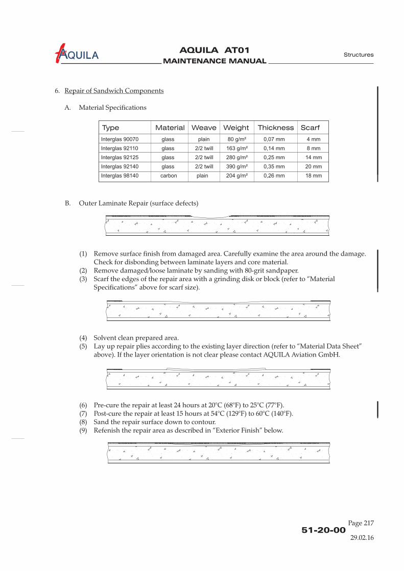
MAINTENANCE MANUAL
AQUILA AT01A
51-20-00Page 217
29.02.16
Structures
Type Material Weave Weight Thickness Scarf
Interglas 90070 glass plain 80 g/m² 0,07 mm 4 mm
Interglas 92110 glass 2/2 twill 163 g/m² 0,14 mm 8 mm
Interglas 92125 glass 2/2 twill 280 g/m² 0,25 mm 14 mm
Interglas 92140 glass 2/2 twill 390 g/m² 0,35 mm 20 mm
Interglas 98140 carbon plain 204 g/m² 0,26 mm 18 mm
6.
A. Material Specifications
Repair of Sandwich Components
B. Outer Laminate Repair (surface defects)
(1) Remove surface finish from damaged area. Carefully examine the area around the damage.Check for disbonding between laminate layers and core material.
(2) Remove damaged/loose laminate by sanding with 80-grit sandpaper.(3) Scarf the edges of the repair area with a grinding disk or block (refer to “Material
Specifications” above for scarf size).
(4) Solvent clean prepared area.(5) Lay up repair plies according to the existing layer direction (refer to “Material Data Sheet”
above). If the layer orientation is not clear please contact AQUILA Aviation GmbH.
(6) Pre-cure the repair at least 24 hours at 20°C (68°F) to 25°C (77°F).(7) Post-cure the repair at least 15 hours at 54°C (129°F) to 60°C (140°F).(8) Sand the repair surface down to contour.(9) Refenish the repair area as described in “Exterior Finish” below.

MAINTENANCE MANUAL
AQUILA AT01A
51-20-00Page 218
Structures
29.02.16
C. Minor Core Damage
(1) Remove surface finish from damaged area. Carefully examine the area around the damage.Check for disbonding between laminate layers and core material.
(2) Remove damaged/loose laminate by sanding with 80-grit sandpaper.(3) Scarf the edges of the repair area with a grinding disk or block (refer to “Material
Specifications” above for scarf size).(4) Solvent clean prepared area.(5) Fill the damaged foam area with resin thickened by microballoons and allow to cure.(6) Sand the repair area down to contour.
(7) Solvent clean prepared area.(8) Lay up repair plies according to the existing layer direction (refer to “Material Data Sheet”
above). If the layer orientation is not clear please contact AQUILA Aviation GmbH.
.(9) Pre-cure the repair at least 24 hours at 20°C (68°F) to 25°C (77°F).(10) Post-cure the repair at least 15 hours at 54°C (129°F) to 60°C (140°F).(11) Sand the repair surface down to contour.(12) Refenish the repair area as described in “Exterior Finish” below.
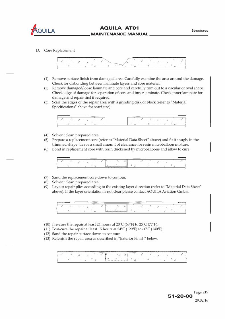
MAINTENANCE MANUAL
AQUILA AT01A
51-20-00Page 219
Structures
29.02.16
D. Core Replacement
(1) Remove surface finish from damaged area. Carefully examine the area around the damage.Check for disbonding between laminate layers and core material.
(2) Remove damaged/loose laminate and core and carefully trim out to a circular or oval shape.Check edge of damage for separation of core and inner laminate. Check inner laminate fordamage and repair first if required.
(3) Scarf the edges of the repair area with a grinding disk or block (refer to “MaterialSpecifications” above for scarf size).
(4) Solvent clean prepared area.(5) Prepare a replacement core (refer to “Material Data Sheet” above) and fit it snugly in the
trimmed shape. Leave a small amount of clearance for resin microballoon mixture.(6) Bond in replacement core with resin thickened by microballoons and allow to cure.
(7) Sand the replacement core down to contour.(8) Solvent clean prepared area.(9) Lay up repair plies according to the existing layer direction (refer to “Material Data Sheet”
above). If the layer orientation is not clear please contact AQUILA Aviation GmbH.
(10) Pre-cure the repair at least 24 hours at 20°C (68°F) to 25°C (77°F).(11) Post-cure the repair at least 15 hours at 54°C (129°F) to 60°C (140°F).(12) Sand the repair surface down to contour.(13) Refenish the repair area as described in “Exterior Finish” below.
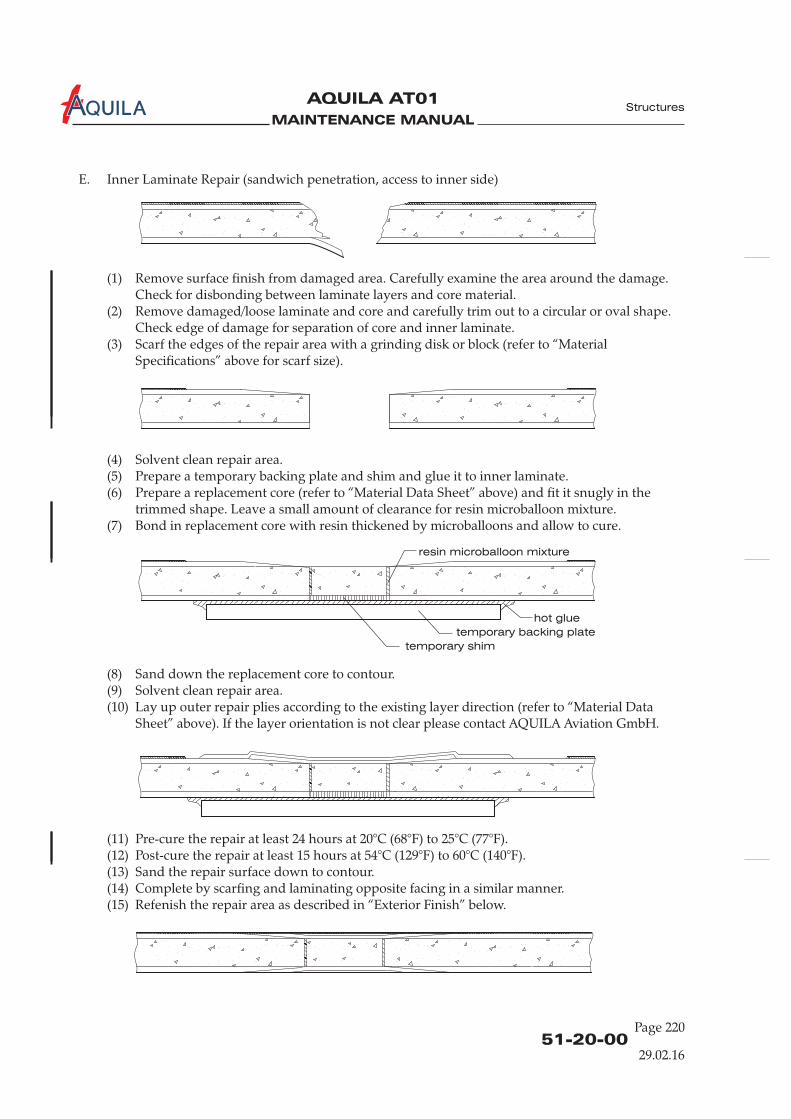
MAINTENANCE MANUAL
AQUILA AT01A
51-20-00Page 220
Structures
E. Inner Laminate Repair (sandwich penetration, access to inner side)
(1) Remove surface finish from damaged area. Carefully examine the area around the damage.Check for disbonding between laminate layers and core material.
(2) Remove damaged/loose laminate and core and carefully trim out to a circular or oval shape.Check edge of damage for separation of core and inner laminate.
(3) Scarf the edges of the repair area with a grinding disk or block (refer to “MaterialSpecifications” above for scarf size).
(4) Solvent clean repair area.(5) Prepare a temporary backing plate and shim and glue it to inner laminate.(6) Prepare a replacement core (refer to “Material Data Sheet” above) and fit it snugly in the
trimmed shape. Leave a small amount of clearance for resin microballoon mixture.(7) Bond in replacement core with resin thickened by microballoons and allow to cure.
(8) Sand down the replacement core to contour.(9) Solvent clean repair area.(10) Lay up outer repair plies according to the existing layer direction (refer to “Material Data
Sheet” above). If the layer orientation is not clear please contact AQUILA Aviation GmbH.
(11) Pre-cure the repair at least 24 hours at 20°C (68°F) to 25°C (77°F).(12) Post-cure the repair at least 15 hours at 54°C (129°F) to 60°C (140°F).(13) Sand the repair surface down to contour.(14) Complete by scarfing and laminating opposite facing in a similar manner.(15) Refenish the repair area as described in “Exterior Finish” below.
29.02.16
resin microballoon mixture
temporary shim
temporary backing plate
hot glue
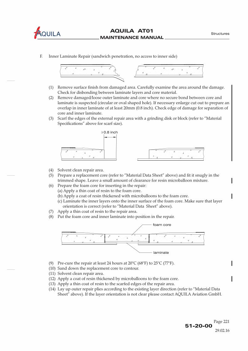
MAINTENANCE MANUAL
AQUILA AT01A
F. Inner Laminate Repair (sandwich penetration, no access to inner side)
(1) Remove surface finish from damaged area. Carefully examine the area around the damage.Check for disbonding between laminate layers and core material.
(2) Remove damaged/loose outer laminate and core where no secure bond between core andlaminate is suspected (circular or oval shaped hole). If necessary enlarge cut out to prepare anoverlap in inner laminate of at least 20mm (0.8 inch). Check edge of damage for separation ofcore and inner laminate.
(3) Scarf the edges of the external repair area with a grinding disk or block (refer to “MaterialSpecifications” above for scarf size).
(4) Solvent clean repair area.(5) Prepare a replacement core (refer to “Material Data Sheet” above) and fit it snugly in the
trimmed shape. Leave a small amount of clearance for resin microballoon mixture.(6) Prepare the foam core for inserting in the repair:
(a) Apply a thin coat of resin to the foam core.(b) Apply a coat of resin thickened with microballoons to the foam core.(c) Laminate the inner layers onto the inner surface of the foam core. Make sure that layer
orientation is correct (refer to “Material Data Sheet” above).(7) Apply a thin coat of resin to the repair area.(8) Put the foam core and inner laminate into position in the repair.
(9) Pre-cure the repair at least 24 hours at 20°C (68°F) to 25°C (77°F).(10) Sand down the replacement core to contour.(11) Solvent clean repair area.(12) Apply a coat of resin thickened by microballoons to the foam core.(13) Apply a thin coat of resin to the scarfed edges of the repair area.(14) Lay up outer repair plies according to the existing layer direction (refer to “Material Data
Sheet” above). If the layer orientation is not clear please contact AQUILA Aviation GmbH.
51-20-00Page 221
Structures
29.02.16
laminate
foam core
0.8 inch
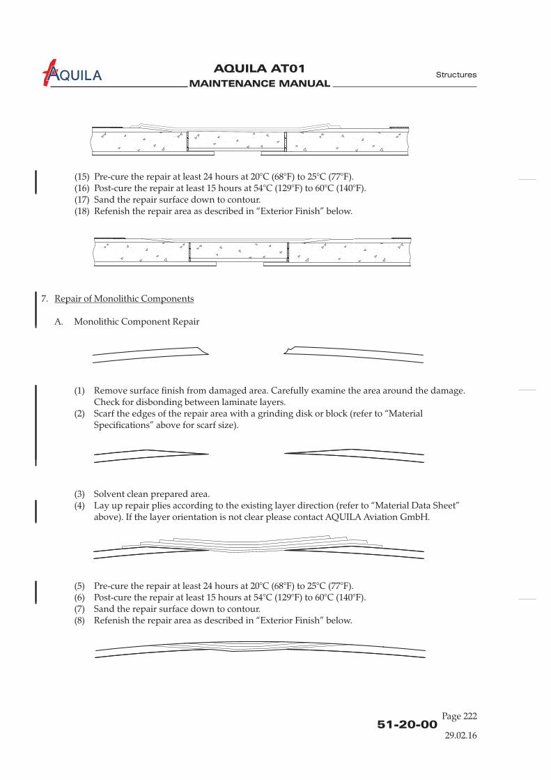
MAINTENANCE MANUAL
AQUILA AT01A
51-20-00Page 222
Structures
29.02.16
7.
A. Monolithic Component Repair
(1)
(3) Solvent clean prepared area.(4)
(5)
(7) Sand the repair surface down to contour.(8) R
Repair of Monolithic Components
Remove surface finish from damaged area. Carefully examine the area around the damage.Check for disbonding between laminate layers.
(2) Scarf the edges of the repair area with a grinding disk or block (refer to “MaterialSpecifications” above for scarf size).
Lay up repair plies according to the existing layer direction (refer to “Material Data Sheet”above). If the layer orientation is not clear please contact AQUILA Aviation GmbH.
Pre-cure the repair at least 24 hours at 20°C (68°F) to 25°C (77°F).(6) Post-cure the repair at least 15 hours at 54°C (129°F) to 60°C (140°F).
efenish the repair area as described in “Exterior Finish” below.
(15) Pre-cure the repair at least 24 hours at 20°C (68°F) to 25°C (77°F).(16) Post-cure the repair at least 15 hours at 54°C (129°F) to 60°C (140°F).(17) Sand the repair surface down to contour.(18) Refenish the repair area as described in “Exterior Finish” below.
MAINTENANCE MANUAL
AQUILA AT01A
51-20-00Page 223
Structures
29.02.16
8.
Prior painting over a repair, inspect the repair to ensure that it has hardened completely and has beenproperly contoured.
MASK OFF SURFACE AROUND REPAIR AREA THAT DOES NOT REQUIRE FILLINGOR PAINT, PAY SPECIAL ATTENTION TO STATIC PORTS, ANTENNAS AND DRAINHOLES.
A. Filler
NOTE: Filler should be used for repairing cosmetic blemishes and minor surface defects.
(1) Sand the application area with 240 to 280-grit dry sandpaper.(2) Clean the application area with a suitable solvent.(3) Mix filler thoroughly in accordance with the manufacturer’s instructions.(4) Apply filler with a clean applicator according to the manufacturer’s instructions.(5) When the filler has hardened, lightly sand the repair area with 280-grit sandpaper and then
switch for final sanding to 360-grit sandpaper to remove all sanding scratches.
B. Paint(1) Prepare the surface for paint by applying filler as required.(2) Clean the application area with a suitable solvent.(3) Visually inspect prepared surface for imperfections prior to painting.(4) Mix and apply paint as recommended by the manufacturer.
Exterior Finish
CAUTION:

MAINTENANCE MANUAL
AQUILA AT01A Structures

MAINTENANCE MANUAL
AQUILA AT01A
CHAPTER 52
DOORS

MAINTENANCE MANUAL
AQUILA At01A
MAINTENANCE MANUAL
AQUILA AT01A
Page 152 - TOC
TABLE OF CONTENTS
ChapterSection
DOORS - GENERAL.........................................................................................52-00-00 1Introduction 52-00-00 1General Description 52-00-00 1
CANOPY - MAINTENANCE ..........................................................................52-10-00 201General 52-10-00 201Canopy Removal/Installation 52-10-00 201Canopy Latching Mechanism Maintenance 52-10-00 201
Title Subject Page
BAGGAGE DOOR - MAINTENANCE...........................................................52-30-00 201General 52-30-00 201Baggage Door Removal/Installation 52-30-00 201
Doors
30.10.13

MAINTENANCE MANUAL
AQUILA At01A
MAINTENANCE MANUAL
AQUILA AT01A
52-00-00
DOORS - GENERAL
1.
A. This chapter describes the canopy and the baggage door. It includes items such as structure,latching mechanism and maintenance instructions.
2.
A. The canopy consists of a composite frame and a large one-piece acrylic glass window which arebonded together. The window has two direct vision panels that can be opened in flight.The canopy moves up and forward to open. A latching mechanism holds the canopy closed bytwo latching pins. The canopy is locked from the outside with a key lock.
B. The baggage door is located on the left side of the fuselage, just aft of the wing. It is made ofcomposite materials. The door allows easy access to the baggage compartment. The baggage dooris hinged on the forward edge and latched on the rear edge. The door is locked from the outsidewith a key lock.
Introduction
General Description
Doors
30.10.13
Page 1

MAINTENANCE MANUAL
AQUILA At01A

MAINTENANCE MANUAL
AQUILA AT01A
52-10-00
Page 201
Doors
CANOPY - MAINTENANCE
1.
A. The canopy consists of a frame fabricated from carbon fiber laminate and rovings, and a large one-piece acrylic glass window which are bonded together. The window has two direct-vision panels,one on each side. The direct-vision panels can be opened in flight.The canopy is mounted to a tubular steel frame at the front. The frame attaches to two hinges onthe rear face of the firewall. The canopy moves up and forward to open. A gas strut will helpraise the canopy to the full up position and holds the canopy open.
B. The canopy latching mechanism is shown in figure 201. It incorporates two latching pins, one oneither side, and an inner and outer door handle in the left canopy frame. Rotating the doorhandle either from inside or outside the aircraft, either inserts or retracts the two latching pins intoor out of the receivers in the fuselage. The right pin operates synchronously via a push-pull cablethat runs inside the canopy frame. Roll pins hold the latch in the fully latched position.
2.
A. Remove Canopy(1) Open canopy.
(3) While helpers support the canopy, remove four hex bolts securing the canopy to the hingeframe and lift the canopy clear of the aircraft.
B. Install Canopy(1) Lift canopy into position on the aircraft.(2) Install washers and hex bolts securing the canopy to the hinge frame.
3. (Ref. Fig. 201)
A. Access Canopy Latching MechanismTo gain access to the central portion of the canopy latching mechanism, remove screws securingthe covering to canopy frame and remove covering.
THE DRIVESHAFT OF THE CANOPY LOCKING MECHANISM MAY FALLDOWN WHEN REMOVING THE ATTACHMENT SCREW.
B. Adjust Latching Pin(1) Remove screws securing the covering to the canopy and remove covering.(2) Remove the bolt, securing appropriate rod end to the actuation lever.(3) Turn the rod end in the corresponding direction.(4) Reconnect rod end to the actuation lever using bolt, washer and nut.(5) Check proper functioning of the canopy latching mechanism. Repeat the above procedures
as required.(6) Install the covering to canopy frame using screws.
General
Canopy Removal/Installation
Canopy Latching Mechanism Maintenance
CAUTION:
(2) Remove flexible air hose from canopy frame.
(3) Install flexible air hose to canopy frame.
30.10.13
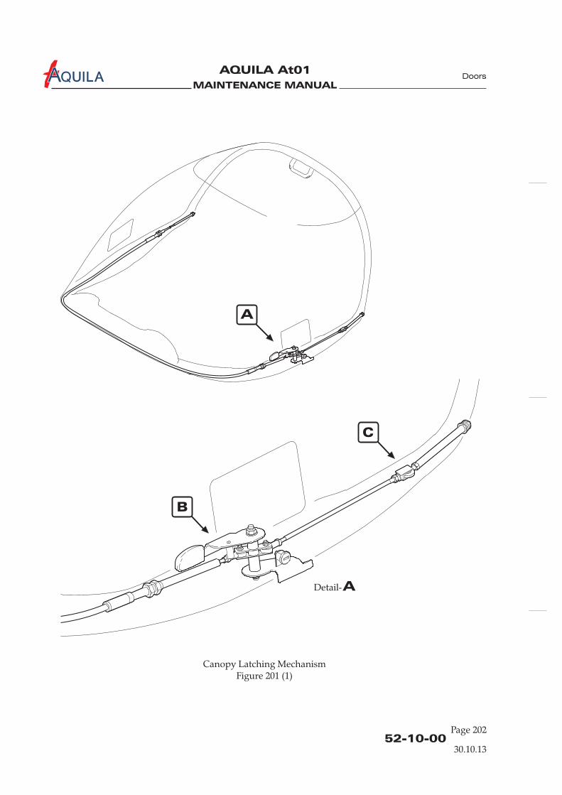
MAINTENANCE MANUAL
AQUILA At01A
52-10-00Page 202
A
B
C
ADetail-
Canopy Latching MechanismFigure 201 (1)
Doors
30.10.13

MAINTENANCE MANUAL
AQUILA AT01A
52-10-00
Page 203
Doors
30.10.13
BDetail-
CDetail-
Canopy Latching MechanismFigure 201 (2)
latching pin
receiver
inner handle
outer handle
canopy lock
push-pull road
spacer
spacer
locking pin
shaft
actuation lever
spacer
MAINTENANCE MANUAL
AQUILA At01A
52-10-00Page 204
Doors
C. Install/Adjust Locking Pin(1) Remove screws securing the covering to the canopy and remove covering.(2) Clean thread of hole and locking pin with ethyl alcohol.(3) Thoroughly apply epoxy resin to the thread tapped inside the GRP plate of the cover.(4) Screw locking pin into cover, starting from outer side in downward direction. The locking
pins spring loaded thrust pad has to face in upward direction. As initial setting adjust thelocking pin so that the pin potrudes the surface of the cover by 2 mm.
(5) Reinstall covering to canopy frame using screws.(6) Functional test of the canopy locking and fine adjustment of the locking pin:
(a) If canopy locking latch is excessively tight and rough-running, the locking pin has to beturned slightly downward.
(b) If canopy locking latch is too smooth-running, the locking pin has to be turned slightlyupward.
(7) Cure bonded locking pin at approx. 20°C for at least 24 hours.(8) Do a final functional test of the canopy locking mechanism.
NOTE: The bonded locking pin can be loosened with a gripper after removing the cover.
If the complete locking mechanism is too smooth-running, the inner friction of thelocking mechanism can be increased by an additional tightening of the self-lockingnut. If necessary, an additional Washer 1800125_8,4 (DIN 125, zinc-plated) can beinstalled between the washer of the self-locking nut and the outer canopy lockinglatch.
30.10.13
MAINTENANCE MANUAL
AQUILA AT01A
BAGGAGE DOOR - MAINTENANCE
1.
A. The baggage door is made of glass fiber laminate. It is hinged on the forward edge via two GFRPhinge arms and latched on the rear edge. The door is locked from the outside with a key lock.
2.
A. Remove Baggage Door(1) Open baggage door.(2) While supporting the baggage door, remove the cotter pins, bolts and washers securing the
baggage door hinge arms to the fuselage.(3) Remove baggage door.
B. Install Baggage Door(1) Lift baggage door into position on the aircraft.(2) Install bolts, washers and cotter pins securing the baggage door hinge arms to the fuselage.(3) Perform functional check of the baggage door latching mechanism.
General
Baggage Door Removal/Installation
52-30-00
Page 201
30.10.13
Doors

MAINTENANCE MANUAL
AQUILA At01A
MAINTENANCE MANUAL
AQUILA AT01A
CHAPTER 53
FUSELAGE

MAINTENANCE MANUAL
AQUILA AT01A
MAINTENANCE MANUAL
AQUILA AT01A
Page 1
30.10.1353 - TOC
Fuselage
TABLE OF CONTENTS
ChapterSection
FUSELAGE - GENERAL...................................................................................53-00-00 1Introduction 53-00-00 1General Description 53-00-00 1
FUSELAGE MAIN FRAME - DESCRIPTION ...............................................53-10-00 1Description and Operation 53-10-00 1
FUSELAGE MAIN FRAME - MAINTENANCE............................................53-10-00 201General 53-10-00 201
Title Subject Page
AUXILIARY STRUCTURE - DESCRIPTION.................................................53-20-00 1Description and Operation 53-20-00 1

MAINTENANCE MANUAL
AQUILA AT01A

MAINTENANCE MANUAL
AQUILA AT01A
53-00-0030.10.13
FUSELAGE - GENERAL
1.
A. This chapter provides a description of the general fuselage structure. For systems andcomponents installed in the fuselage structure, refer to the respective chapters in this manual.
2.
A. The fuselage is a semi-monocoque structure made primarily of composite materials. The fuselagestructure consists of two halves made from fiberglass laminate bonded along a centerline lap-joint.The vertical stabilizer is an integral part of the fuselage structure. Bulkheads and frames give thefuselage strength and stiffness.
The fuselage shells are primarily solid laminate (no foam) constructions. Only the area of thevertical stabilizer is made of fiberglass with a foam core. The fuselage skin is reinforced by fourcarbon-fiber stringers, arranged lengthwise through the entire fuselage.
Introduction
General Description
Fuselage
Page 1

MAINTENANCE MANUAL
AQUILA AT01A
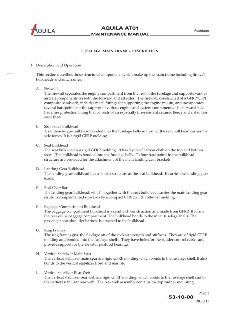
MAINTENANCE MANUAL
AQUILA AT01A
53-10-0030.10.13
FUSELAGE MAIN FRAME - DESCRIPTION
1.
This section describes those structural components which make up the main frame including firewall,bulkheads and ring frames.
A. FirewallThe firewall separates the engine compartment from the rest of the fuselage and supports variousaircraft components on both the forward and aft sides. The firewall, constructed of a GFRP/CFRPcomposite sandwich, includes metal fittings for supporting the engine mount, and incorporatesseveral hardpoints for the support of various engine and system components. The forward sidehas a fire protection lining that consists of an especially fire-resistant ceramic fleece and a stainlesssteel sheet.
B. Side Force BulkheadA sandwich-type bulkhead bonded into the fuselage belly in front of the seat bulkhead carries theside forces. It is a rigid GFRP molding.
C. Seat BulkheadThe seat bulkhead is a rigid GFRP molding. It has layers of carbon cloth on the top and bottomfaces. The bulkhead is bonded into the fuselage belly. To four hardpoints in the bulkheadstructure are provided for the attachment of the main landing gear brackets.
D. Landing Gear BulkheadThe landing gear bulkhead has a similar structure as the seat bulkhead. It carries the landing gearloads.
E. Roll-Over BarThe landing gear bulkhead, which, together with the seat bulkhead, carries the main landing gearstruts, is complemented upwards by a compact CFRP/GFRP roll-over molding.
F. Baggage Compartment BulkheadThe baggage compartment bulkhead is a sandwich construction and made from GFRP. It formsthe rear of the baggage compartment. The bulkhead bonds to the inner fuselage shells. Thepassenger seat shoulder harness is attached to the bulkhead.
G. Ring FramesThe ring frames give the fuselage aft of the cockpit strength and stiffness. They are of rigid GFRPmolding and bonded into the fuselage shells. They have holes for the rudder control cables andprovide support for the elevator pushrod bearings.
H. Vertical Stabilizer Main SparThe vertical stabilizer main spar is a rigid GFRP molding which bonds to the fuselage shell. It alsobonds to the vertical stabilizer front and rear rib.
I. Vertical Stabilizer Rear WebThe vertical stabilizer rear web is a rigid GFRP molding, which bonds to the fuselage shell and tothe vertical stabilizer rear web. The rear web assembly contains the top rudder mounting.
Description and Operation
Fuselage
Page 1

MAINTENANCE MANUAL
AQUILA AT01A
53-10-00Page 2
30.10.13
Fuselage
Fuselage StructureFigure 201 (1)
side force bulkhead
seat bulkhead
landing gear bulkhead
firewall
carbon fiber
stringers
carbon fiber
stringers
baggage compartment
bulkhead
ring frames
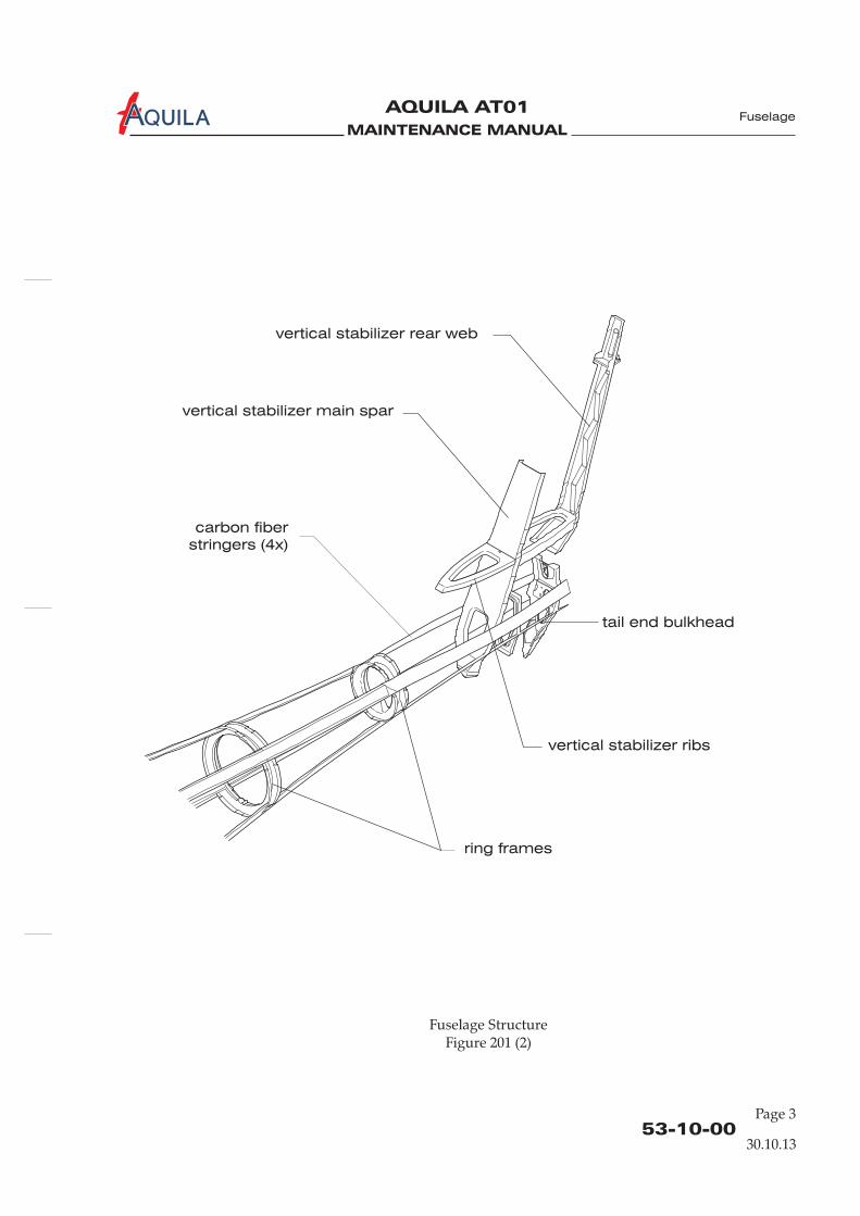
MAINTENANCE MANUAL
AQUILA AT01A
53-10-00Page 3
Fuselage
30.10.13
Fuselage StructureFigure 201 (2)
carbon fiber
stringers (4x)
ring frames
vertical stabilizer main spar
vertical stabilizer rear web
vertical stabilizer ribs
tail end bulkhead
MAINTENANCE MANUAL
AQUILA AT01A
J. Vertical Stabilizer RibsThe vertical stabilizer front and rear ribs are of rigid GFRP molding and bonded to the fuselageshells and to the vertical stabilizer main spar. The rear rib also bonds to the rear web.
K. Tail End BulkheadThe tail end bulkhead is a rigid GFRP molding that is bonded to the fuselage shells. The bulkheadcontains a reinforced area to which the lower rudder attachment bracket is bolted.
53-10-00Page 4
30.10.13
Fuselage
MAINTENANCE MANUAL
AQUILA AT01A
FUSELAGE MAIN FRAME - MAINTENANCE
1.
A. Maintenance of the fuselage is limited to the repair of the fuselage skin. Most areas of the fuselageskin are field-repairable, some areas are difficult to repair or require special procedures to ensurethe structural integrity of the repair. Refer to chapter 51 for standard repair procedures and forrepair data for the fuselage shells.
B. If the damage area is inside the fuselage AQUILA Aviation GmbH must be contacted prior tobeginning repair work.
C. Repairs must be completed by competent technicians who are trained in composite repair.
General
53-10-00Page 201
Fuselage
30.10.13

MAINTENANCE MANUAL
AQUILA AT01A

MAINTENANCE MANUAL
AQUILA AT01A
53-20-0030.10.13
AUXILIARY STRUCTURE - DESCRIPTION
1.
This section describes those structural components which make up the auxiliary structure includingfuselage floor structure, center console, access panels and entry step.
A.
B. Center ConsoleThe center console consists of a left, right, upper forward, lower forward and aft compositelaminate part and metal covers.
Description and Operation
Fuselage Floor StructureThe floor structure of the aircraft consists of a forward floor, a left and right baggage compartmentfloor, a left and right control stick cover and a left, right and center cover of the well of the landinggear. Forward floor and baggage compartment floors are foam core composite laminate panelsdesigned to support flight and user loads. The covers of the well of the landing gear are compositelaminate panels. Refer to 25-12-00 for an exploded view of the cabin interior.
Refer to 25-12-00 for an exploded view of the cabin interior.
C. Entry StepThe entry step is made of 28x1,5 mm [1.1x0.06 in.] steel tubes welded to a 3 mm [0.12 in.] steelflange. It is secured to the fuselage by 3 screws.
Page 1

MAINTENANCE MANUAL
AQUILA AT01A
MAINTENANCE MANUAL
AQUILA AT01
Aviation by Excellence GmbH
CHAPTER 55
STABILIZERS

MAINTENANCE MANUAL
AQUILA AT01
Aviation by Excellence GmbH

MAINTENANCE MANUAL
AQUILA AT01
Aviation by Excellence GmbH
Page 0155 - TOC
07.07.03
TABLE OF CONTENTS
ChapterSection
STABILIZERS - GENERAL...............................................................................55-00-00 1Introduction 55-00-00 1General Description 55-00-00 1
HORIZONTAL STABILIZER - MAINTENANCE PRACTICES..................55-10-00 201General 55-10-00 201
ELEVATOR - MAINTENANCE PRACTICES ................................................55-20-00 201General 55-20-00 201Elevator Removal/Installation 55-20-00 201Adjustment - Elevator Balancing 55-20-00 201
VERTICAL STABILIZER - MAINTENANCE PRACTICES..........................55-30-00 201General 55-30-00 201
RUDDER - MAINTENANCE PRACTICES....................................................55-40-00 201General 55-40-00 201Rudder Removal/Installation 55-40-00 201
Title Subject Page
Adjustment - Rudder Balancing 55-40-00 201
Stabilizers

MAINTENANCE MANUAL
AQUILA AT01
Aviation by Excellence GmbH

MAINTENANCE MANUAL
AQUILA AT01
Aviation by Excellence GmbH
55-00-00
Page 01
14.05.02
STABILIZERS - GENERAL
1.
A. This chapter describes the horizontal and vertical stabilizers as well as the structure of the elevatorand rudder. Maintenance information is provided.
2.
A. The AQUILA AT01 empennage consists of a horizontal stabilizer, a two-piece elevator, a vertical finand a rudder. All of the structure components are made from composite materials.The horizontal and vertical stabilizers are of fully cantilever, semi-monocoque design consisting ofspars, ribs, and skin. Skin is bonded to the supporting structure. The vertical stabilizer iscomposite structure integral to the main fuselage shell.
The aerodynamically and mass balanced rudder is connected to the vertical stabilizer by twohinged brackets. The lower one has a yoke that drives the rudder by means of control cables.
The aerodynamically and mass balanced elevator is attached to the horizontal stabilizer rear shearweb at five hinge points. A torque tube connects the elevator halves.
Introduction
General Description
Stabilizers

MAINTENANCE MANUAL
AQUILA AT01
Aviation by Excellence GmbH
MAINTENANCE MANUAL
AQUILA AT01
Aviation by Excellence GmbH
55-10-00
Page 201
14.05.02
HORIZONTAL STABILIZER MAINTENANCE PRACTICES
1.
A. The horizontal stabilizer is of fully cantilever, semi-monocoque design. The structure, made fromcomposite materials, consists of a front spar, a rear shear web, root ribs, and top and bottom shells.The shells have a GFRP skin with a rigid foam core.The horizontal stabilizer is molded to the fuselage.
The rear shear web integrates hinge brackets for elevator attachment.
B. Because the horizontal stabilizer is made from composite materials and is molded to the fuselage,no servicing is required.
General
Stabilizers

MAINTENANCE MANUAL
AQUILA AT01
Aviation by Excellence GmbH

MAINTENANCE MANUAL
AQUILA AT01
Aviation by Excellence GmbH
55-20-00
Page 201
07.07.03
ELEVATOR - MAINTENANCE PRACTICES
1.
A. The two-piece elevator is made from composite materials. Each half has a top and a bottom shellwhich are bonded together. The shells have a sandwich structure with a rigid foam core. Betweenthe shells, at the outer end a horn rib, in the front area two hinge brackets, and at the inboard endrib are bonded. All structure components are GFRP moldings.A mass balance weight is fastened to the outboard horn rib. To the inboard rib a welded, two-piece torque tube assembly is bolted. By means of the torque tube assembly the elevator halvesare mounted together.
B. This section provides removal and installation instructions for the elevator assembly andprocedures for elevator balancing.
2.
A. Remove Elevator(1) Remove rudder (Refer to 55-40-00).(2) Remove bellcrank/elevator mounting bolts, self-locking nuts, washers and spacers (3 places).(3) Slide the elevator off of the horizontal stabilizer hinge pins by sliding the elevator away from
the fuselage.
B. Install Elevator(1) Install the elevator onto the hinge pins.(2) Install bellcrank/elevator mounting bolts.
(a) Position spacer between left and right torque tube assemblies.(b) Insert bolt from left side, and install washer and new self-locking nut.(c) Install hinge bolt at center hinge from left. Ensure the spacers are in position. Install
washer and new self-locking nut.(d) Reconnect elevator push-pull rod using hardware.
(3) Install rudder (Refer to 55-40-00).(4) Check proper aileron control system operation (Refer to 27-30-00).
General
Elevator Removal/Installation
Stabilizers
3.
Weighing and determination of control surface moment should be performed after repairs or painting.The residual moment of the control surface and its maximum permissible total weight should be withinthe ranges as specified in 06-10-00.
To weigh a control surface, it must be removed from aircraft. Weighing can be accomplished using anyconvenient method.
CORRECT CONTROL SURFACE BALANCE IS IMPORTANT FOR THE FLIGHTSAFETY. OUT OF BALANCE CONTROL SURFACES CAN FLUTTER AND CAUSESTRUCTURAL FAILURE.
Adjustment - Elevator Balancing
WARNING:
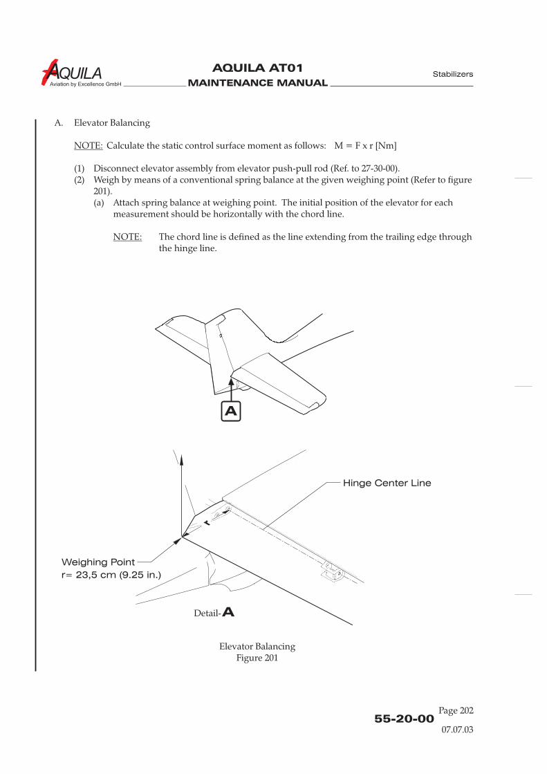
MAINTENANCE MANUAL
AQUILA AT01
Aviation by Excellence GmbH
Elevator BalancingFigure 201
Hinge Center Line
Weighing Point
A
ADetail-
A. Elevator Balancing
Calculate the static control surface moment as follows: M = F x r [Nm]
(1) Disconnect elevator assembly from elevator push-pull rod (Ref. to 27-30-00).(2) Weigh by means of a conventional spring balance at the given weighing point (Refer to figure
201).(a) Attach spring balance at weighing point. The initial position of the elevator for each
measurement should be horizontally with the chord line.
The chord line is defined as the line extending from the trailing edge throughthe hinge line.
NOTE:
NOTE:
55-20-00Page 202
07.07.03
Stabilizers
r= 23,5 cm (9.25 in.)
MAINTENANCE MANUAL
AQUILA AT01
Aviation by Excellence GmbH
(b) Raise the spring balance slowly until the control surface begins to move. Note thereading and the direction of the movement (i.e. 11.2 N up).
(c) Lower the spring balance slowly until the control surface begins to move down. Notethe reading and the direction of the movement to (i.e. 11.8 N down).
(3) Calculate moments as described above. Both results must be within the permitted limits.
55-20-00
Page 203
Stabilizers
07.07.03

MAINTENANCE MANUAL
AQUILA AT01
Aviation by Excellence GmbH
MAINTENANCE MANUAL
AQUILA AT01
Aviation by Excellence GmbH
55-30-00
Page 201
14.05.02
VERTICAL STABILIZER - MAINTENANCE PRACTICES
1.
A. The vertical stabilizer is integral of the fuselage structure and is made from composite laminatematerials. No servicing is required.
B. For more information on fuselage structure, refer to 53-10-00.
General
Stabilizers

MAINTENANCE MANUAL
AQUILA AT01
Aviation by Excellence GmbH

MAINTENANCE MANUAL
AQUILA AT01
Aviation by Excellence GmbH
RUDDER - MAINTENANCE PRACTICES
1.
A. The rudder is made from composite materials. The assembly consists primarily of left and rightshells which are bonded together. The shells have a sandwich structure with a rigid foam core.Between the shells, at the rudder tip a horn rib, near the top in the front area a hinge rib, and atthe base a hinge rib are bonded. All structure components are GFRP moldings.
A mass balance weight is fastened to the horn rib. To the lower hinge rib the rudder bellcrankis bolted.
B. This section provides removal and installation instructions for the rudder
2.
A. Remove Rudder(1) Relieve tension of rudder control cables by loosening carry through cable turnbuckles and
disconnect from the rudder bellcrank.(2) Remove castellated nut from hinge bolt at the base of rudder.(3) Slide the rudder off of the second hinge pin by lifting the rudder, and remove from vertical
stabilizer.
B. Install Rudder(1) Place the rudder into position and install washer and castellated nut. Secure bolt with cotter
pin.
Make sure a washer remains on the hinge bolt before installing the rudder. Installingrudder without that washer in place can cause the rudder to bind.
(2) Reconnect control cables to the rudder bellcrank.(3) Adjust cable tension (Refer to 27-20-00).(4) Check proper rudder control function and adjustment and rig where necessary (Refer to 27-
20-00).
General
Rudder Removal/Installation
NOTE:
and procedure forrudder balancing.
55-40-00
Page 201
07.07.03
Stabilizers
3.
Weighing and determination of control surface moment should be performed after repairs or painting.The residual moment of the control surface and its maximum permissible total weight should bewithin the ranges as specified in 06-10-00.
To weigh a control surface, it must be removed from aircraft. Weighing can be accomplished using anyconvenient method.
CORRECT CONTROL SURFACE BALANCE IS IMPORTANT FOR THE FLIGHTSAFETY. OUT OF BALANCE CONTROL SURFACES CAN FLUTTER AND CAUSESTRUCTURAL FAILURE.
Adjustment - Rudder Balancing
WARNING:
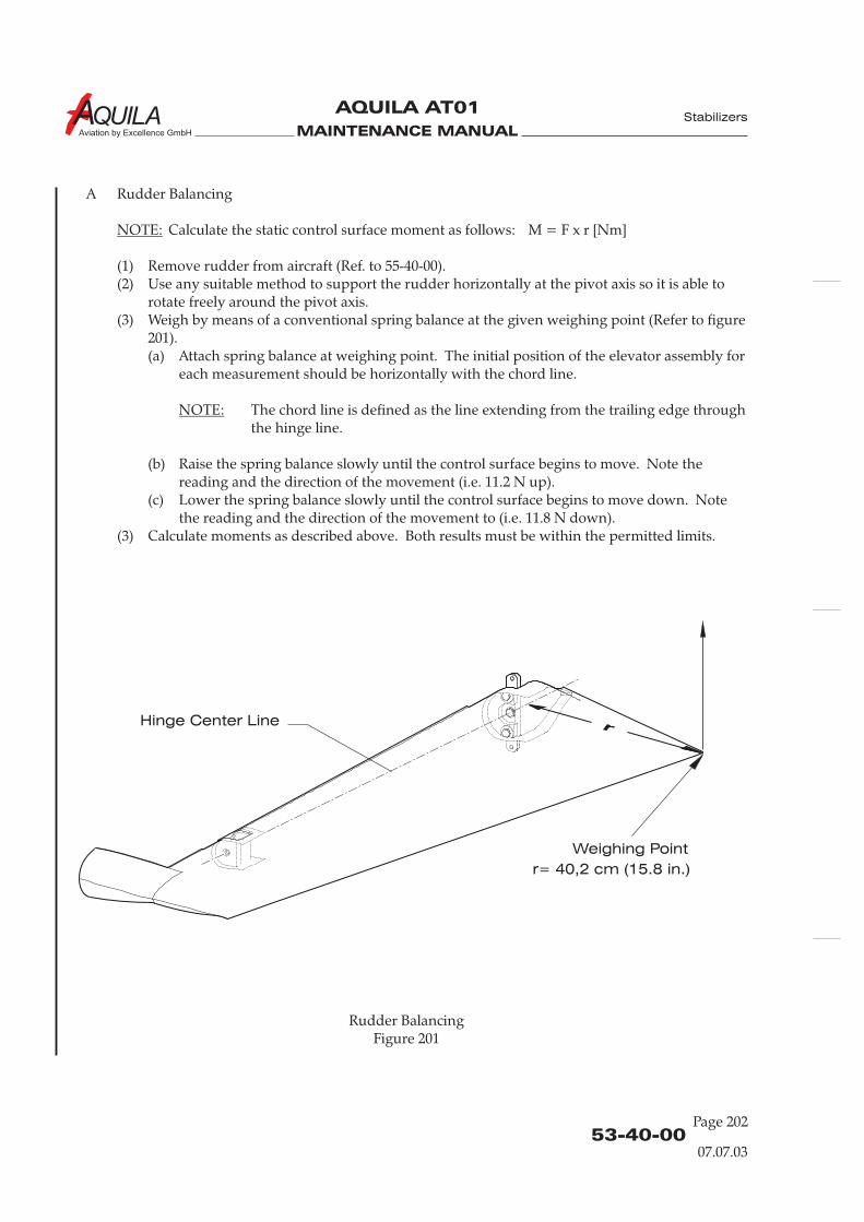
MAINTENANCE MANUAL
AQUILA AT01
Aviation by Excellence GmbH
Rudder BalancingFigure 201
Hinge Center Line
Weighing Point
r= 40,2 cm (15.8 in.)
A Rudder Balancing
Calculate the static control surface moment as follows: M = F x r [Nm]
(1) Remove rudder from aircraft (Ref. to 55-40-00).(2) Use any suitable method to support the rudder horizontally at the pivot axis so it is able to
rotate freely around the pivot axis.(3) Weigh by means of a conventional spring balance at the given weighing point (Refer to figure
201).(a) Attach spring balance at weighing point. The initial position of the elevator assembly for
each measurement should be horizontally with the chord line.
The chord line is defined as the line extending from the trailing edge throughthe hinge line.
(b) Raise the spring balance slowly until the control surface begins to move. Note thereading and the direction of the movement (i.e. 11.2 N up).
(c) Lower the spring balance slowly until the control surface begins to move down. Notethe reading and the direction of the movement to (i.e. 11.8 N down).
(3) Calculate moments as described above. Both results must be within the permitted limits.
NOTE:
NOTE:
53-40-00Page 202
07.07.03
Stabilizers
MAINTENANCE MANUAL
AQUILA AT01A
CHAPTER 56
WINDOWS

MAINTENANCE MANUAL
AQUILA AT01A
MAINTENANCE MANUAL
AQUILA AT01A
Page 156 - TOC
19.07.13
TABLE OF CONTENTS
ChapterSection
WINDOWS - GENERAL ..................................................................................56-00-00 1Introduction 56-00-00 1General Description 56-00-00 1
FLIGHT COMPARTMENT WINDOWS - MAINTENANCE......................56-10-00 201General 56-10-00 201Tools, Equipment and Materials 56-10-00 201Window Repair 56-10-00 201
Title Subject Page
Windows

MAINTENANCE MANUAL
AQUILA AT01A
MAINTENANCE MANUAL
AQUILA AT01A
56-00-00
Page 1
19.07.13
WINDOWS - GENERAL
1.
A. This chapter describes the acrylic glass windows of the canopy and the fuselage.
2.
A.
Introduction
General Description
B. Refer to 52-10-00 for information on the canopy structure.
C. Refer to 12-23-00 for information on cleaning and care of acrylic glass windows.
The aircraft has two windows. The one-piece canopy window covers the cockpit and is also thewindscreen. The window has two direct-vision panels, one on each side, which can be opened inflight. The second window covers the rear section of the cabin.Both windows are molded acrylic glass (plexiglass). A high-performance elastic adhesive bondseach window to the structure.
Windows

MAINTENANCE MANUAL
AQUILA AT01A
MAINTENANCE MANUAL
AQUILA AT01A
FLIGHT COMPARTMENT WINDOWS - MAINTENANCE
1.
A. This section describes the repair of damaged acrylic glass windows.
B. A properly carried out repair is essential to preserve the optical properties of acrylic glasswindows. Personnel must be familiar with repair practices prior to attempting acrylic glass repairson the aircraft.
3.
A. Damage LimitsMaximum crack length: 150 mm (6 in.)Do not repair cracks which are located in the pilot’s forward field of view.
General
Window Repairs
CAUTION:
Tools, Equipment and Material
DO NOT USE ANY ORGANIC SOLVENTS SUCH AS THINNER, FUEL ORALCOHOL ON ACRYLIC GLASS!
2.
Quantity Equipment Parts No. Manufacturer
3.C. 1 small high-speed - commerciallyrotary grinder available
3.C. as required filler Acrifix 192 commerciallyor Tensol cement No. 70 availableor Agovit 1900
3.C. as required masking tape - commerciallyavailable
3.C. as required plastic adhesive - commerciallytape available
3.C. 1 cold ultra-violet - commerciallylight source available(only for Acrifix 192)
3.C. as required wet abrasive paper Micro Mesh 3200 commerciallyMicro Mesh 8000 available
3.C. 1 rubber block - commerciallyavailable
3.C. as required polish Xerapol commerciallyavailable
3.C. as required finish - commerciallyavailable
3.C. as required polishing cloth - commerciallyavailable
56-10-00
Page 201
19.07.13
Windows
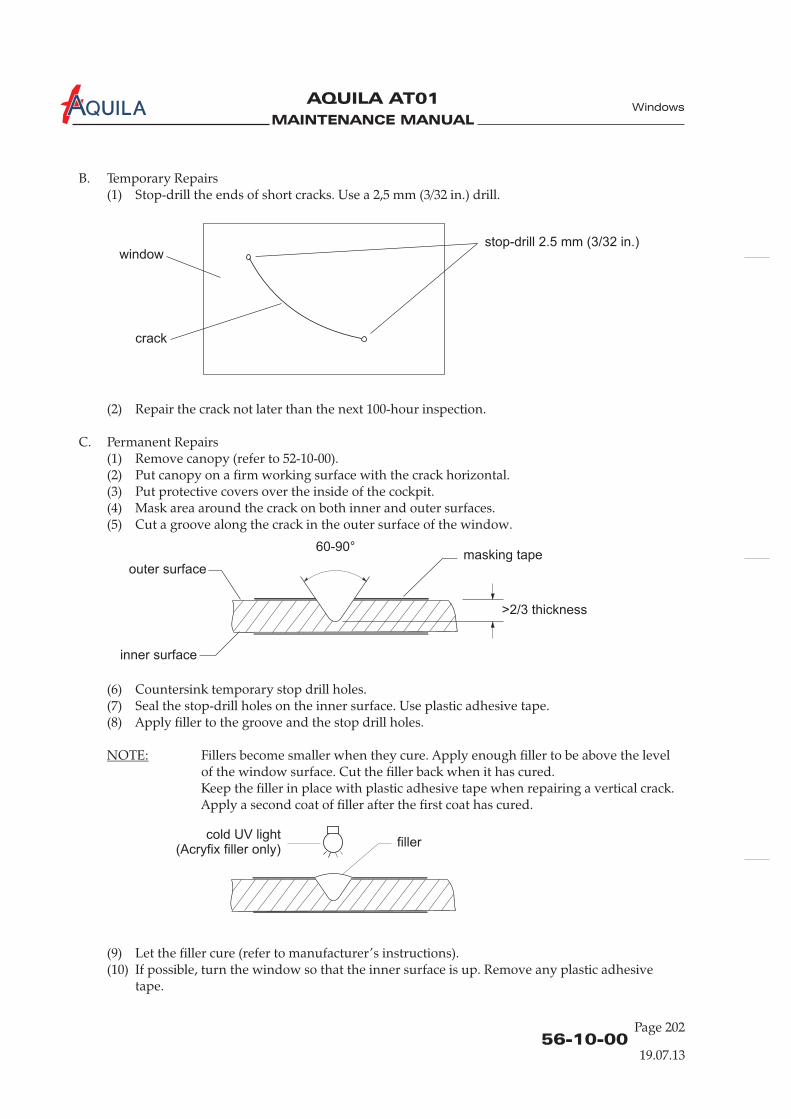
MAINTENANCE MANUAL
AQUILA AT01A
B. Temporary Repairs(1) Stop-drill the ends of short cracks. Use a 2,5 mm (3/32 in.) drill.
(1) Remove canopy (refer to 52-10-00).(2) Put canopy on a firm working surface with the crack horizontal.(3) Put protective covers over the inside of the cockpit.(4) Mask area around the crack on both inner and outer surfaces.(5) Cut a groove along the crack in the outer surface of the window.
(6) Countersink temporary stop drill holes.(7) Seal the stop-drill holes on the inner surface. Use plastic adhesive tape.(8) Apply filler to the groove and the stop drill holes.
(9) Let the filler cure (refer to manufacturer ’s instructions).(10) If possible, turn the window so that the inner surface is up. Remove any plastic adhesive
tape.
(2) Repair the crack not later than the next 100-hour inspection.
C. Permanent Repairs
Fillers become smaller when they cure. Apply enough filler to be above the levelof the window surface. Cut the filler back when it has cured.Keep the filler in place with plastic adhesive tape when repairing a vertical crack.Apply a second coat of filler after the first coat has cured.
NOTE:
Windows
56-10-00Page 202
19.07.13
stop-drill 2.5 mm (3/32 in.)
crack
window
60-90°masking tape
>2/3 thickness
outer surface
inner surface
cold UV light(Acryfix filler only)
filler
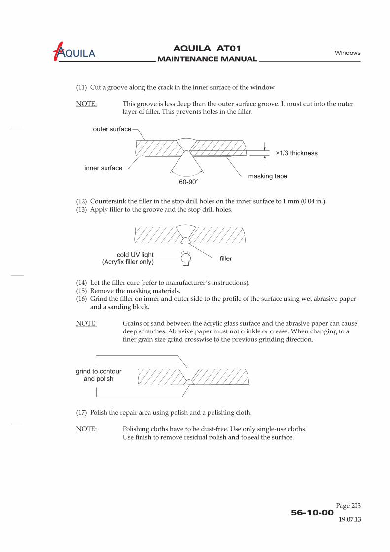
MAINTENANCE MANUAL
AQUILA AT01A
56-10-00
Page 203
19.07.13
(11) Cut a groove along the crack in the inner surface of the window.
NOTE:
NOTE:
NOTE:
This groove is less deep than the outer surface groove. It must cut into the outerlayer of filler. This prevents holes in the filler.
(12) Countersink the filler in the stop drill holes on the inner surface to 1 mm (0.04 in.).(13) Apply filler to the groove and the stop drill holes.
(14) Let the filler cure (refer to manufacturer ’s instructions).(15) Remove the masking materials.(16) Grind the filler on inner and outer side to the profile of the surface using wet abrasive paper
and a sanding block.
Grains of sand between the acrylic glass surface and the abrasive paper can causedeep scratches. Abrasive paper must not crinkle or crease. When changing to afiner grain size grind crosswise to the previous grinding direction.
(17) Polish the repair area using polish and a polishing cloth.
Polishing cloths have to be dust-free. Use only single-use cloths.Use finish to remove residual polish and to seal the surface.
Windows
60-90°masking tape
>1/3 thickness
outer surface
inner surface
cold UV light(Acryfix filler only)
filler
grind to contourand polish

MAINTENANCE MANUAL
AQUILA AT01A

MAINTENANCE MANUAL
AQUILA AT01
Aviation by Excellence GmbH
CHAPTER 57
WINGS

MAINTENANCE MANUAL
AQUILA AT01
Aviation by Excellence GmbH

MAINTENANCE MANUAL
AQUILA AT01
Aviation by Excellence GmbH
Page 0157 - TOC
18.01.06
Wings
TABLE OF CONTENTS
ChapterSection
WINGS - GENERAL..........................................................................................57-00-00 1Introduction 57-00-00 1General Description 57-00-00 1
WINGS - MAINTENANCE PRACTICES .......................................................57-10-00 201General 57-10-00 201Tools, Equipment and Material 57-10-00 201Wings Removal/Installation 57-10-00 201
CONTROL SURFACES - MAINTENANCE PRACTICES ...........................57-50-00 201General 57-50-00 201Flaps Removal/Installation 57-50-00 201Ailerons Removal/Installation 57-50-00 201Adjustment - Control Surface Balancing 57-50-00 203
Title Subject Page
Inspection of bonding between Wing Spar and Wing, upper shell 57-10-00 205

MAINTENANCE MANUAL
AQUILA AT01
Aviation by Excellence GmbH
MAINTENANCE MANUAL
AQUILA AT01
Aviation by Excellence GmbH
57-00-00
Page 01
18.01.06
WINGS - GENERAL
1.
A. This chapter describes the wing, flaps, and aileron structures. Maintenance information isprovided.
2.
A. The wings of the AQUILA AT01 are manufactured from composite materials, which provideexcellent smooth and seamless flight surfaces. They are of cantilever, semi-monocoque design,with a one-piece main spar, ribs and shear webs covered with top and bottom shells. The wingtrailing edge contains conventional ailerons and flaps.Each wing incorporates an integral fuel tank, which is located in front of the main spar at theinboard portion of the wing.
Introduction
General Description
Wings

MAINTENANCE MANUAL
AQUILA AT01
Aviation by Excellence GmbH
MAINTENANCE MANUAL
AQUILA AT01
Aviation by Excellence GmbH
57-10-00
Page 201
18.01.06
WING - MAINTENANCE PRACTICE
1.
A. The wing structure is shown in figure 201. The wing main spar is manufactured in one piece. TheI-section spar has caps, made from unidirectional carbon fiber and a GFRP composite sandwichweb.The ribs, including the flap control ribs and the shear webs are of a rigid GFRP molding. The wingtop and bottom shells are bonded to the spar, ribs and aft shear web forming a torsion box thatcarries all of the wing bending and torsion loads. Each shell has a sandwich structure with a rigidfoam core.The wing main spar passes under the fuselage below the two seats. Each wing half ends inboard witha front root rib and a rear root rib, which are mounted to the fuselage center section with a bolt each.The four lateral force bolts are inserted from the cabin through the fuselage bushings into the wingbolt housings and secured axially with screws. The bushes and bolts transfer shear loads into thefuselage center section.
B. The section provides removal and installation instructions for the wings.
2.
Required in Quantity Equipment Parts No. Manufacturer
3. A./B. 1 Wing Stand - AQUILA GmbH3. A. 1 Wing Attach Bolt - AQUILA GmbH
Removal Tool
3.
AT LEAST SEVEN PERSONS MUST BE INVOLVED FOR WING REMOVAL ORINSTALLATION. A SHORT BRIEFING IS RECOMMENDED PRIOR TOACCOMPLISHING PROCEDURE.
A. Remove the Wing(1) Prepare a suitable, padded stand for proper storage of the removed wing.
It is recommended to use the special wing stand, which may be obtained fromAQUILA Technische Entwicklungen GmbH.
(2) Shock the main wheels fore and aft.(3) Ensure the fuel selector / shut-off valve and the BAT switch are in off position.(4) Drain fuel from wing fuel tanks.(5) Remove elevator pushrod No. 1 (Refer to 27-30-00).(6) Open access / inspection plate 210 AB (belly closeout) (Refer to 06-10-00).(7) Inside the spar tunnel disconnect electrical wires at connector.(8) Disconnect fuel lines (four places).
General
Tools, Equipment and Material
Wing Removal/Installation
CAUTION!
NOTE:
Wings
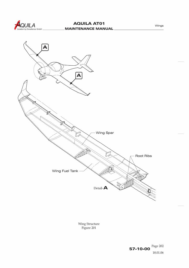
MAINTENANCE MANUAL
AQUILA AT01
Aviation by Excellence GmbH
57-10-00Page 202
18.01.06
Wing StructureFigure 201
A
A
ADetail-
Wings
Wing Spar
Wing Fuel Tank
Root Ribs
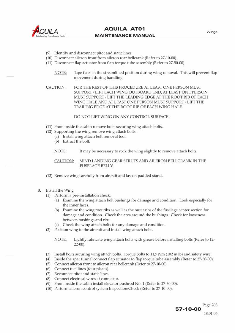
MAINTENANCE MANUAL
AQUILA AT01
Aviation by Excellence GmbH
(9) Identify and disconnect pitot and static lines.(10) Disconnect aileron front from aileron rear bellcrank (Refer to 27-10-00).(11) Disconnect flap actuator from flap torque tube assembly (Refer to 27-50-00).
Tape flaps in the streamlined position during wing removal. This will prevent flapmovement during handling.
FOR THE REST OF THIS PROCEDURE AT LEAST ONE PERSON MUSTSUPPORT / LIFT EACH WING OUTBOARD END, AT LEAST ONE PERSONMUST SUPPORT / LIFT THE LEADING EDGE AT THE ROOT RIB OF EACHWING HALF, AND AT LEAST ONE PERSON MUST SUPPORT / LIFT THETRAILING EDGE AT THE ROOT RIB OF EACH WING HALF.
DO NOT LIFT WING ON ANY CONTROL SURFACE!
(11) From inside the cabin remove bolts securing wing attach bolts.(12) Supporting the wing remove wing attach bolts.
(a) Install wing attach bolt removal tool.(b) Extract the bolt.
: It may be necessary to rock the wing slightly to remove attach bolts.
MIND LANDING GEAR STRUTS AND AILERON BELLCRANK IN THEFUSELAGE BELLY:
(13) Remove wing carefully from aircraft and lay on padded stand.
B. Install the Wing(1) Perform a pre-installation check.
(a) Examine the wing attach bolt bushings for damage and condition. Look especially forthe inner faces.
(b) Examine the wing root ribs as well as the outer ribs of the fuselage center section fordamage and condition. Check the area around the bushings. Check for loosenessbetween bushings and ribs.
(c) Check the wing attach bolts for any damage and condition.(2) Position wing to the aircraft and install wing attach bolts.
Lightly lubricate wing attach bolts with grease before installing bolts (Refer to 12-22-00).
(3) Install bolts securing wing attach bolts. Torque bolts to 11,5 Nm (102 in.lb) and safety wire.(4) Inside the spar tunnel connect flap actuator to flap torque tube assembly (Refer to 27-50-00).(5) Connect aileron front to aileron rear bellcrank (Refer to 27-10-00).(6) Connect fuel lines (four places).(7) Reconnect pitot and static lines.(8) Connect electrical wires at connector.(9) From inside the cabin install elevator pushrod No. 1 (Refer to 27-30-00).(10) Perform aileron control system Inspection/Check (Refer to 27-10-00).
NOTE:
CAUTION:
NOTE
CAUTION:
NOTE:
57-10-00
Page 203
18.01.06
Wings
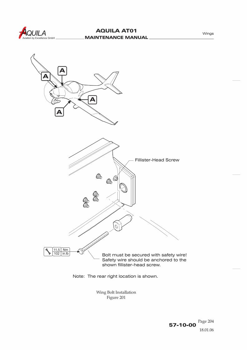
MAINTENANCE MANUAL
AQUILA AT01
Aviation by Excellence GmbH
57-10-00Page 204
18.01.06
A
A
A
A
Wing Bolt InstallationFigure 201
Bolt must be secured with safety wire!
Safety wire should be anchored to the
shown fillister-head screw.
Fillister-Head Screw
Wings
Note: The rear right location is shown.
Nmin.lb
11,5102
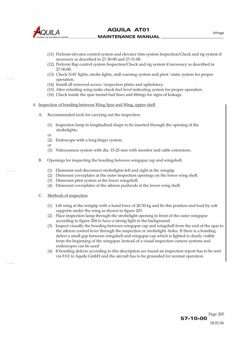
MAINTENANCE MANUAL
AQUILA AT01
Aviation by Excellence GmbH
57-10-00
Page 205
18.01.06
Wings
(11) Perform elevator control system and elevator trim system Inspection/Check and rig system ifnecessary as described in 27-30-00 and 27-31-00.
(12) Perform flap control system Inspection/Check and rig system if necessary as described in27-50-00.
(13) Check NAV lights, strobe lights, stall warning system and pitot / static system for properoperation.
(14) Install all removed access / inspection plates and upholstery.(15) After refueling wing tanks check fuel level indicating system for proper operation.(16) Check inside the spar tunnel fuel lines and fittings for signs of leakage.
4.
A. Recommended tools for carrying out the inspection.
(1) Inspection lamp in longitudinal shape to be inserted through the opening of thestrobelights.
or(2) Endoscope with a long finger system.or(3) Videocamera system with dia. 15-25 mm with monitor and cable extensions.
B. Openings for inspecting the bonding between wingspar cap and wingshell.
(1) Dismount and disconnect strobelights left and right at the wingtip.(2) Dismount coverplates at the outer inspection openings on the lower wing shell.(3) Dismount pitot system at the lower wingshell.(4) Dismount coverplates of the aileron pushrods at the lower wing shell.
C.
(1) Lift wing at the wingtip with a hand force of 20-30 kg and fix this position and load by softsupports under the wing as shown in figure 203.
(2) Place inspection lamp through the strobelight opening in front of the outer wingsparaccording to figure 204 to have a strong light in the background.
(3) Inspect visually the bonding between wingspar cap and wingshell from the end of the spar tothe aileron control lever through the inspection or strobelight -holes. If there is a bondingdefect a small gap between wingshell and wingspar cap which is lighted is clearly visiblefrom the beginning of the wingspar. Instead of a visual inspection camera systems andendoscopes can be used
(4) If bonding defects according to this description are found an inspection report has to be sentvia FAX to Aquila GmbH and the aircraft has to be grounded for normal operation.
Inspection of bonding between Wing Spar and Wing, upper shell
Methods of inspection
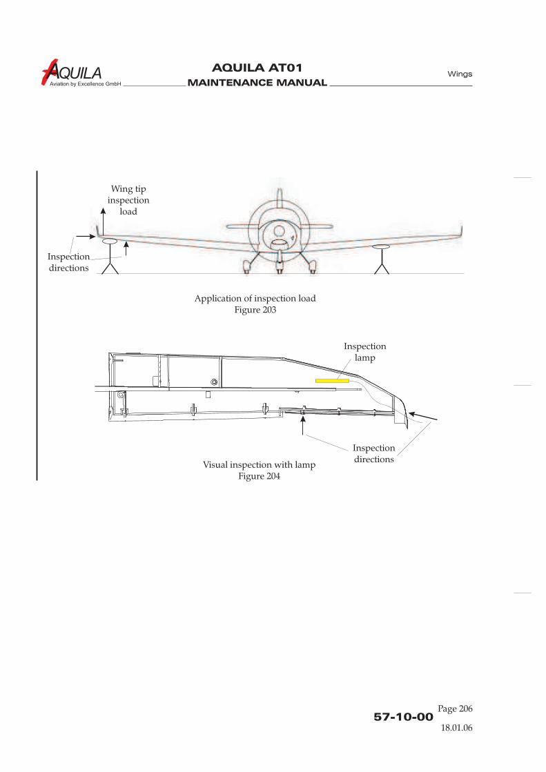
MAINTENANCE MANUAL
AQUILA AT01
Aviation by Excellence GmbH
Application of inspection loadFigure 203
Visual inspection with lampFigure 204
Wing tipinspection
load
Inspectiondirections
Inspectiondirections
Inspectionlamp
57-10-00Page 206
Wings
18.01.06
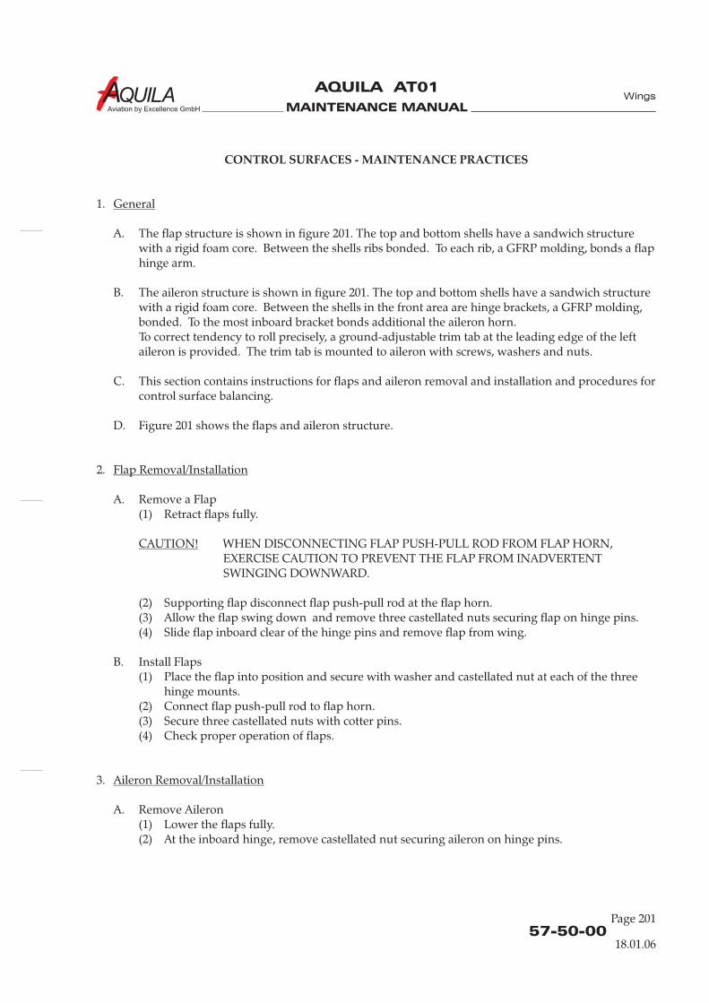
MAINTENANCE MANUAL
AQUILA AT01
Aviation by Excellence GmbH
57-50-00
Page 201
CONTROL SURFACES - MAINTENANCE PRACTICES
1.
A. The flap structure is shown in figure 201. The top and bottom shells have a sandwich structurewith a rigid foam core. Between the shells ribs bonded. To each rib, a GFRP molding, bonds a flaphinge arm.
B. The aileron structure is shown in figure 201. The top and bottom shells have a sandwich structurewith a rigid foam core. Between the shells in the front area are hinge brackets, a GFRP molding,bonded. To the most inboard bracket bonds additional the aileron horn.To correct tendency to roll precisely, a ground-adjustable trim tab at the leading edge of the leftaileron is provided. The trim tab is mounted to aileron with screws, washers and nuts.
C. This section contains instructions for flaps and aileron removal and installation and procedures forcontrol surface balancing.
D. Figure 201 shows the flaps and aileron structure.
2.
A. Remove a Flap(1) Retract flaps fully.
WHEN DISCONNECTING FLAP PUSH-PULL ROD FROM FLAP HORN,EXERCISE CAUTION TO PREVENT THE FLAP FROM INADVERTENTSWINGING DOWNWARD.
(2) Supporting flap disconnect flap push-pull rod at the flap horn.(3) Allow the flap swing down and remove three castellated nuts securing flap on hinge pins.(4) Slide flap inboard clear of the hinge pins and remove flap from wing.
B. Install Flaps(1) Place the flap into position and secure with washer and castellated nut at each of the three
hinge mounts.(2) Connect flap push-pull rod to flap horn.(3) Secure three castellated nuts with cotter pins.(4) Check proper operation of flaps.
3.
A. Remove Aileron(1) Lower the flaps fully.(2) At the inboard hinge, remove castellated nut securing aileron on hinge pins.
General
Flap Removal/Installation
CAUTION!
Aileron Removal/Installation
Wings
18.01.06
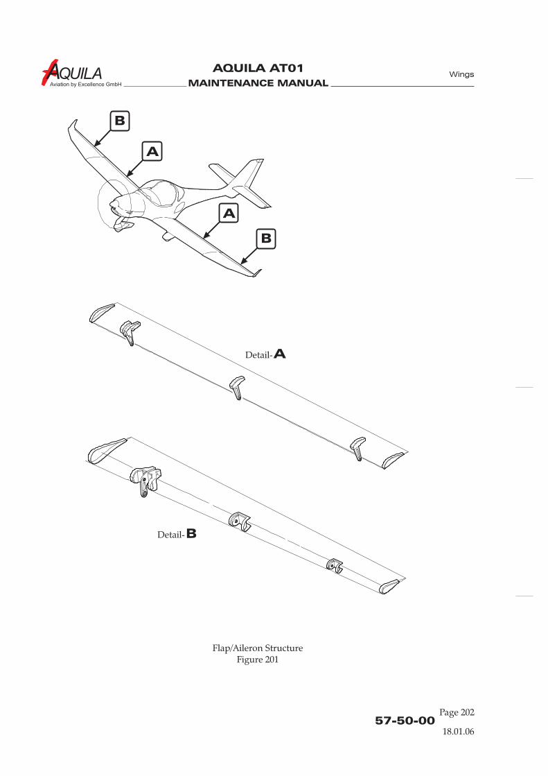
MAINTENANCE MANUAL
AQUILA AT01
Aviation by Excellence GmbH
57-50-00Page 202
A
A
ADetail-
B
B
BDetail-
Flap/Aileron StructureFigure 201
Wings
18.01.06
MAINTENANCE MANUAL
AQUILA AT01
Aviation by Excellence GmbH
57-50-00
Page 203
(3) Slide aileron inboard clear of the hinge pins and remove aileron from wing.
B. Install Aileron(1) Place the aileron into position and secure with washer and castellated nut at inboard hinge.
Wings
4.
Weighing and determination of control surface moment should be performed after repairs or painting.The residual moment of the control surface and its maximum permissible total weight should be withinthe ranges as specified in 06-10-00.
To weigh a control surface, it must be removed from aircraft. Weighing can be accomplished using anyconvenient method.
CORRECT CONTROL SURFACE BALANCE IS IMPORTANT FOR THE FLIGHTSAFETY. OUT OF BALANCE CONTROL SURFACES CAN FLUTTER AND CAUSESTRUCTURAL FAILURE.
A Aileron Balancing
Calculate the static control surface moment as follows: M = F x r [Nm]
The following procedure is typically for left and right aileron.
(1) Disconnect aileron from aileron push-pull rod.(2) Weigh by means of a conventional spring balance at the given weighing point (Refer to figure
204).(a) Attach spring balance at weighing point. The initial position of the aileron for each
measurement should be horizontally with the chord line.
The chord line is defined as the line extending from the trailing edge throughthe hinge line.
(b) Raise the spring balance slowly until the control surface begins to move. Note thereading and the direction of the movement (i.e. 11.2 N up).
(c) Lower the spring balance slowly until the control surface begins to move down. Notethe reading and the direction of the movement to (i.e. 11.8 N down).
(3) Calculate moments as described above. Both results must be within the permitted limits.
B Wing Flap Balancing
Calculate the static control surface moment as follows: M = F x r [Nm]
(1) Disconnect flap actuator from torque tube coupler (Ref. to 27-50-00).(2) Weigh by means of a conventional spring balance at the given weighing point (Refer to figure
204).(a) Attach spring balance at weighing point. The initial position of the flaps for each
Adjustment - Control Surface Balancing
WARNING:
NOTE:
NOTE:
NOTE:
NOTE:
18.01.06

MAINTENANCE MANUAL
AQUILA AT01
Aviation by Excellence GmbH
A
A
ADetail-
Flap Installation (Inboard Hinge with Flap Horn)Figure 202
Right Flap
Wing
Wings
57-50-00Page 204
18.01.06
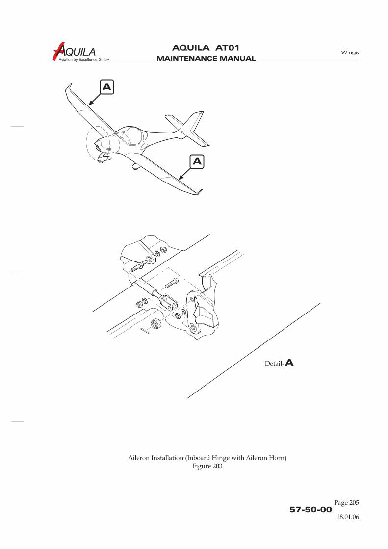
MAINTENANCE MANUAL
AQUILA AT01
Aviation by Excellence GmbH
A
A
ADetail-
Aileron Installation (Inboard Hinge with Aileron Horn)Figure 203
Wings
57-50-00
Page 205
18.01.06
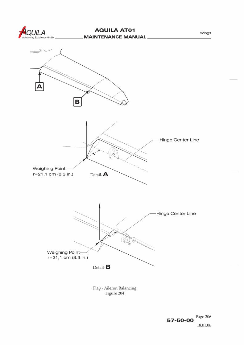
MAINTENANCE MANUAL
AQUILA AT01
Aviation by Excellence GmbH
Hinge Center Line
Hinge Center Line
Weighing Point
Weighing Point
ADetail-
BDetail-
A
B
Flap / Aileron BalancingFigure 204
Wings
57-50-00Page 206
r=21,1 cm (8.3 in.)
r=21,1 cm (8.3 in.)
18.01.06
MAINTENANCE MANUAL
AQUILA AT01
Aviation by Excellence GmbH
measurement should be 35° down.(b) Raise the spring balance slowly until the control surface begins to move. Note the
reading and the direction of the movement (i.e. 11.2 N up).(c) Lower the spring balance slowly until the control surface begins to move down. Note
the reading and the direction of the movement to (i.e. 11.8 N down).(3) Calculate moments as described above. Both results must be within the permitted limits.
Wings
57-50-00
Page 207
18.01.06

MAINTENANCE MANUAL
AQUILA AT01
Aviation by Excellence GmbH
MAINTENANCE MANUAL
AQUILA AT01
Aviation by Excellence GmbH
CHAPTER 61
PROPELLER

MAINTENANCE MANUAL
AQUILA AT01
Aviation by Excellence GmbH
MAINTENANCE MANUAL
AQUILA AT01
Aviation by Excellence GmbH
Page 0161 - TOC
Propeller
TABLE OF CONTENTS
ChapterSection
PROPELLER - GENERAL ................................................................................61-00-00 1Introduction 61-00-00 1General Description 61-00-00 1
TROUBLESHOOTING.....................................................................................61-00-00 101General 61-00-00 101Troubleshooting 61-00-00 101
PROPELLER ASSEMBLY - MAINTENANCE PRACTICES........................61-10-00 201General 61-10-00 201
Description 61-10-00 201Propeller Removal/Installation 61-10-00 202
61-10-00 203Cleaning 61-10-00 204Repairs 61-10-00 204
PROPELLER CONTROL - MAINTENANCE PRACTICES ........................61-20-00 201 mt P-410General 61-20-00 201 mt P-410Tools, Equipment and Material 61-20-00 201 mt P-410Description 61-20-00 201 mt P-410Governor Removal/Installation 61-20-00 201 mt P-410
61-20-00 202 mt P-41061-20-00 203 mt P-410
PROPELLER CONTROL - MAINTENANCE PRACTICES ........................61-20-00 201 mt P-850General 61-20-00 201 mt P-850Tools, Equipment and Material 61-20-00 201 mt P-850Description 61-20-00 201 mt P-850Governor Removal/Installation 61-20-00 201 mt P-850
61-20-00 202 mt P-85061-20-00 203 mt P-850
PROPELLER CONTROL - MAINTENANCE PRACTICES ........................61-20-00 201 WoodwardGeneral 61-20-00 201 Woodward
Description 61-20-00 201 WoodwardGovernor Removal/Installation 61-20-00 201 WoodwardInspection/Check 61-20-00 202 WoodwardAdjustment/Test 61-20-00 202 Woodward
Title Subject Page Effectivity
Tools, Equipment and Material 61-10-00 201
Inspection/Check
Inspection/CheckAdjustment/Test
Inspection/CheckAdjustment/Test
Tools, Equipment and Material 61-20-00 201 Woodward
19.03.13

MAINTENANCE MANUAL
AQUILA AT01
Aviation by Excellence GmbH
MAINTENANCE MANUAL
AQUILA AT01
Aviation by Excellence GmbH
61-00-00
Page 01
PROPELLER - GENERAL
1.
A. This chapter describes the AQUILA AT01 propeller. Maintenance information is provided.
2.
A. The AQUILA AT01 uses a mt-Propeller MTV-21-A/175-05 variable pitch, two blade wood-composite propeller. The propeller has a governor which controls propeller pitch hydraulically.The governor keeps the pre-selected propeller speed at a constant value, regardless of manifoldpressure and airspeed.
Introduction
General Description
Propeller
19.03.13

MAINTENANCE MANUAL
AQUILA AT01
Aviation by Excellence GmbH
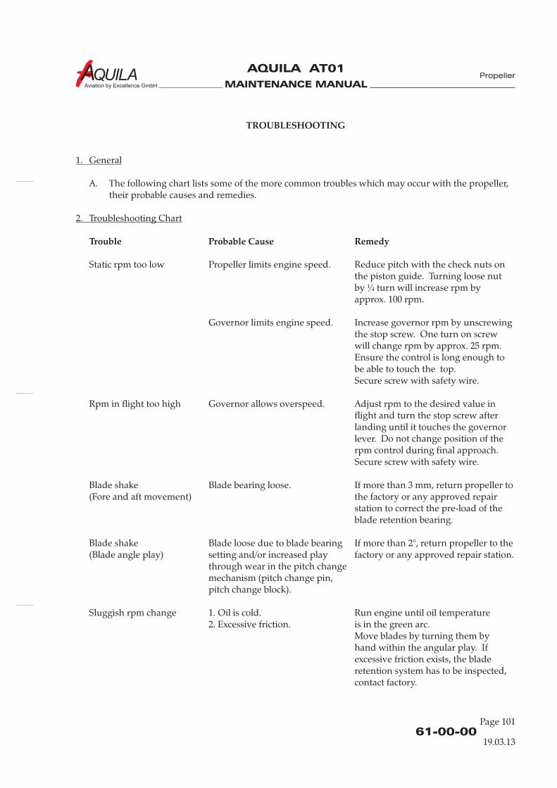
MAINTENANCE MANUAL
AQUILA AT01
Aviation by Excellence GmbH
61-00-00
Page 101
TROUBLESHOOTING
Trouble Probable Cause Remedy
1. General
2. Troubleshooting Chart
A. The following chart lists some of the more common troubles which may occur with the propeller,their probable causes and remedies.
Static rpm too low Propeller limits engine speed. Reduce pitch with the check nuts onthe piston guide. Turning loose nutby ¼ turn will increase rpm byapprox. 100 rpm.
Governor limits engine speed. Increase governor rpm by unscrewingthe stop screw. One turn on screwwill change rpm by approx. 25 rpm.Ensure the control is long enough tobe able to touch the top.Secure screw with safety wire.
Rpm in flight too high Governor allows overspeed. Adjust rpm to the desired value inflight and turn the stop screw afterlanding until it touches the governorlever. Do not change position of therpm control during final approach.Secure screw with safety wire.
Blade shake Blade bearing loose. If more than 3 mm, return propeller to(Fore and aft movement) the factory or any approved repair
station to correct the pre-load of theblade retention bearing.
Blade shake Blade loose due to blade bearing If more than 2°, return propeller to the(Blade angle play) setting and/or increased play factory or any approved repair station.
through wear in the pitch changemechanism (pitch change pin,pitch change block).
Sluggish rpm change 1. Oil is cold. Run engine until oil temperature2. Excessive friction. is in the green arc.
Move blades by turning them byhand within the angular play. Ifexcessive friction exists, the bladeretention system has to be inspected,contact factory.
Propeller
19.03.13
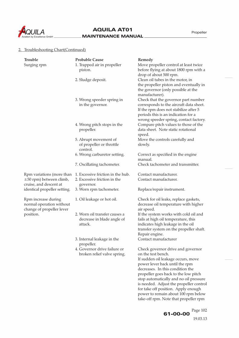
MAINTENANCE MANUAL
AQUILA AT01
Aviation by Excellence GmbH
61-00-00Page 102
19.03.13
Surging rpm 1. Trapped air in propeller Move propeller control at least twicepiston. before flying at about 1800 rpm with a
drop of about 500 rpm.2. Sludge deposit. Clean oil tubes in the motor, in
the propeller piston and eventually inthe governor (only possible at themanufacturer).
3. Wrong speeder spring in Check that the governor part numberin the governor. corresponds to the aircraft data sheet.
If the rpm does not stabilize after 5periods this is an indication for awrong speeder spring, contact factory.
4. Wrong pitch stops in the Compare pitch values to those of thepropeller. data sheet. Note static rotational
speed.5. Abrupt movement of Move the controls carefully and
of propeller or throttle slowly.control.
6. Wrong carburetor setting. Correct as specified in the enginemanual.
7. Oscillating tachometer. Check tachometer and transmitter.
Rpm variations (more than 1. Excessive friction in the hub. Contact manufacturer.±50 rpm) between climb, 2. Excessive friction in the Contact manufacturer.cruise, and descent at governor.identical propeller setting. 3. Worn rpm tachometer. Replace/repair instrument.
Rpm increase during 1. Oil leakage or hot oil. Check for oil leaks, replace gaskets,normal operation without decrease oil temperature with higherchange of propeller lever air speed.position. 2. Worn oil transfer causes a If the system works with cold oil and
decrease in blade angle of fails at high oil temperature, thisattack. indicates high leakage in the oil
transfer system on the propeller shaft.Repair engine.
3. Internal leakage in the Contact manufacturerpropeller.
4. Governor drive failure or Check governor drive and governorbroken relief valve spring. on the test bench.
If sudden oil leakage occurs, movepower lever back until the rpmdecreases. In this condition thepropeller goes back to the low pitchstop automatically and no oil pressureis needed. Adjust the propeller controlfor take off position. Apply enoughpower to remain about 100 rpm belowtake-off rpm. Note that propeller rpm
2. Troubleshooting Chart(Continued)
Trouble Probable Cause Remedy
Propeller
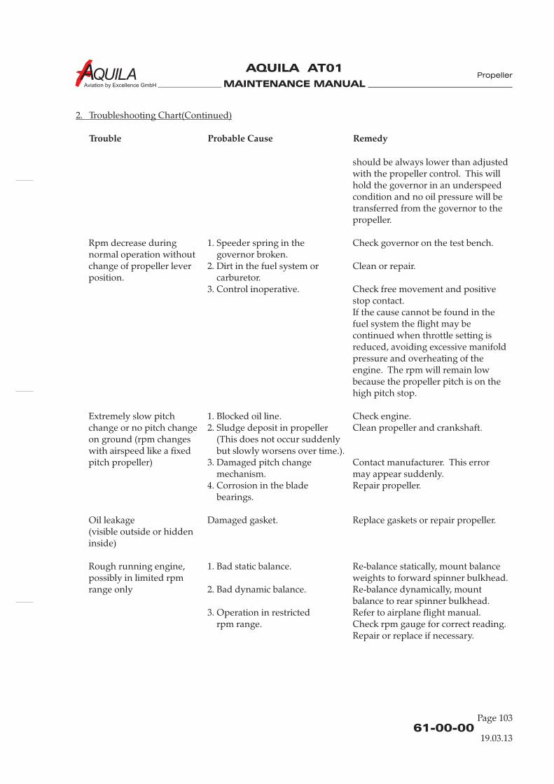
MAINTENANCE MANUAL
AQUILA AT01
Aviation by Excellence GmbH
should be always lower than adjustedwith the propeller control. This willhold the governor in an underspeedcondition and no oil pressure will betransferred from the governor to thepropeller.
Rpm decrease during 1. Speeder spring in the Check governor on the test bench.normal operation without governor broken.change of propeller lever 2. Dirt in the fuel system or Clean or repair.position. carburetor.
3. Control inoperative. Check free movement and positivestop contact.If the cause cannot be found in thefuel system the flight may becontinued when throttle setting isreduced, avoiding excessive manifoldpressure and overheating of theengine. The rpm will remain lowbecause the propeller pitch is on thehigh pitch stop.
Extremely slow pitch 1. Blocked oil line. Check engine.change or no pitch change 2. Sludge deposit in propeller Clean propeller and crankshaft.on ground (rpm changes (This does not occur suddenlywith airspeed like a fixed but slowly worsens over time.).pitch propeller) 3. Damaged pitch change Contact manufacturer. This error
mechanism. may appear suddenly.4. Corrosion in the blade Repair propeller.
bearings.
Oil leakage Damaged gasket. Replace gaskets or repair propeller.(visible outside or hiddeninside)
Rough running engine, 1. Bad static balance. Re-balance statically, mount balancepossibly in limited rpm weights to forward spinner bulkhead.range only 2. Bad dynamic balance. Re-balance dynamically, mount
balance to rear spinner bulkhead.3. Operation in restricted Refer to airplane flight manual.
rpm range. Check rpm gauge for correct reading.Repair or replace if necessary.
2. Troubleshooting Chart(Continued)
Trouble Probable Cause Remedy
61-00-00
Page 103
19.03.13
Propeller

MAINTENANCE MANUAL
AQUILA AT01
Aviation by Excellence GmbH
MAINTENANCE MANUAL
AQUILA AT01
Aviation by Excellence GmbH
PROPELLER ASSEMBLY - MAINTENANCE PRACTICES
1.
A. For more detailed information on the installed propeller, refer to mt-Propeller E-124 Operationand Installation Manual for Hydraulically Controlled Variable Pitch Propeller.
3.
A. The variable pitch propeller consists of the following main groups: hub with blade bearings andpitch change mechanism, blades, and spinner.
Hub
The one-piece hub is made from forged or milled aluminum alloy with the outer surface shot-peened and anodized. The blade bearings are specially designed ball bearings where the ball actsas a split retainer in order to hold the blades in the hub, creating an increased safety factor againstblade loss. The outer bearing race is made as one-piece and is pressed into the hub, while theinner race is split and installed on the blade ferrule. The blade preload is adjusted by thethickness of plastic shims. Blade and bearing are held in the hub by a retention ring.Blade pitch change is achieved via a pin in the blade root. A plastic block connects the blade withthe piston and the axial movement of the servo piston turns the blades. The return spring and thesleeve, which acts as high (low) pitch stop, are installed on the front piston.There are two check nuts outside the hub with which the low (high) pitch stop can be adjusted.The inner part of the hub is used as the cylinder for the pressure oil. This arrangement allows asimple and light-weight design. Balance wieghts are installed in the front spinner support.
Blades
The propeller has wood-composite (natural composite) blades, using high compressed wood inthe root and lightweight wood in the remaining body. Epoxy fiberglass covers the entire bladesurface and is painted with acryl varnish. The outer portion is protected against erosion by astainless steel erosion sheath bonded to the blade edge. The inner portion of the blade is protectedby a self-adhesive PU-strip.The blade ferrule is attached with special lag screws to the blade root and is additionally bondedwith epoxy resin.
General
Description
2.
Quantity Equipment Parts No.4.B. 1 O-ring AT01-7310-104
Tools, Equipment and Material
61-10-00
Page 201
Propeller
19.03.13

MAINTENANCE MANUAL
AQUILA AT01
Aviation by Excellence GmbH
4.
A. Remove Propeller(1) Ensure ALT / BAT and ignition switches are OFF, mixture control is in the IDLE CUT-OFF
position and the throttle is closed.(2) Remove upper engine cowling (refer to 71-10-00).(3) Remove screws securing spinner dome to spinner bulkhead and remove spinner.(4) Remove alternator belt from alternator pulley (refer to 24-30-00).(5) Position a hoist and lifting sling in front of the aircraft and attach sling to propeller.(6) Place a drain pan beneath propeller to catch oil spillage.(7) Loosen and remove nuts and washers attaching propeller to engine flange.(8) Remove propeller from aircraft.
DO NOT STORE PROPELLER ON IT’S TIPS!
B. Install Propeller(1) Clean engine and propeller flange with a suitable cleaning agent.(2) Apply a light coat of engine oil to new O-ring and insert O-ring into groove inside hub at
flange mounting. Check correct position of O-ring in propeller flange.(3) Place alternator belt around V-belt pulley.
CARE MUST BE TAKEN WHEN INSTALLING THE PROPELLER. THEPROPELLER SHOULD NOT BE PULLED ON TO THE ENGINE FLANGE WITHTHE NUTS IN ORDER TO AVOID DAMAGE TO THE HUB AND TO AVOIDSHEARING OFF MATERIAL CAUSING OIL LEAKS ON THE O-RING.
(4) Using hoist and sling, put propeller in position to engine mounting flange.(5) Put V-belt pulley with carriers in position to engine mounting flange.
STOP NUTS WITH WASHERS SHOULD BE TIGHTENED CROSSWISE WITHEQUAL FORCE TO AVOID HUB DAMAGE.
(6) Install washers and nuts securing propeller assembly to engine flange. Torque nuts to 45 - 47Nm (33 - 35 ft.lb).
(7) Check track of blades (max. 3mm [1/8 in.] measured approx. 10 cm [4 in.] from the tip on thetrailing edge).
(8) Install spinner dome on bulkhead observing mating marks. Torque screws with plasticwashers 4 - 5 Nm (35 - 44 in.lb). Check runout of the dome. Max. 2 mm (0.08 in.) permissible.
(9) Install alternator belt and adjust belt tension (refer to 24-30-00).(10) Install upper engine cowling (refer to 71-10-00).(11) Carry out a functional check (refer to 61-20-00).
Propeller Removal/Installation
CAUTION:
CAUTION:
CAUTION:
61-10-00Page 202
Propeller
19.03.13
Spinner
The spinner dome is a one-piece part made from fiber reinforced composite. The bulkhead istruncated aluminum alloy.Filler plates increase the stiffness of the dome on the cutouts for the blades. The dome is mountedto the bulkhead by means of screws.
MAINTENANCE MANUAL
AQUILA AT01
Aviation by Excellence GmbH
61-10-00
Page 203
Propeller
19.03.13
5.
A. Inspection/Check(1) Remove screws securing spinner dome to spinner bulkhead and remove spinner.(2) Check spinner for cracks and other damage.
(3) Perform a visual inspection of the propeller blades.(a) Check for critical cracks (refer to mt-Propeller E-124 Operation and Installation Manual
for Hydraulically Controlled Variable Pitch Propeller)(b) Inspect for notches, dents, nicks or other damage. Repair as required (refer to 61-10-00).(c) Check that the metal erosion sheath is not loose.(d) Check that proper PU-strip is in place.
(4) Check blade shake, max. 3 mm (1/8 in.).(5) Check blade angle play, max. 2°.(6) Check track of blades (max. 3mm [1/8 in.] measured approx. 10 cm [4 in.] from the tip on the
trailing edge).(7) Inspect outside condition of the hub and parts for cracks, corrosion, deterioration.(8) Inspect check nut for low pitch stop for tightness.(9) Check safety wiring.(10) Check flange stopnuts for tightness.(11) Inspect blade root and hub for oil and grease leaks.
B. OverspeedIf up to 110 % take-off rpm of the approved engine/propeller combination is experienced,immediately perform a 100 hrs inspection (refer to mt-Propeller E-124 Operation and InstallationManual for Hydraulically Controlled Variable Pitch Propeller). A factory overhaul is required ifoverspeeds between 111 % and 120 % are experienced. A ferry flight can be undertaken afterperforming a 100-hours inspection. If more than 121 % is experienced, the propeller may not beused again and must be returned to the factory for investigation.
Inspection/Check
MAINTENANCE MANUAL
AQUILA AT01
Aviation by Excellence GmbH
6.
A. Clean propeller if necessary with any car wash solution or equivalent.
7.
IT IS IMPORTANT TO AVOID MOISTURE PENETRATING INTO THE WOODEN COREOF THE PROPELLER BLADES. IF IN DOUBT, CONSULT AN AIRCRAFT INSPECTORFOR FINAL DECISION ON REPAIR.
A. Normal stone nicks are unimportant as long as the plastic protection of the wood core exists. Airbubbles with a maximum diameter of 15 mm (0.6 in.) are also unimportant as long as their sizedoes not increase during use.
Scratches and nicks should be protected during routine maintenance with a coating of waterresistant varnish.
B. Trailing edge splitting can arise from a stone hit. If the split is not longer than 40 mm (1.5 in.), itcan be glued with epoxy cement. If some wood is missing (not deeper than 8 mm [0.25 in.]), filldamaged area with epoxy, let it harden, grind surface smooth and cover with water-resistantvarnish, preferably polyurethane.
C. Small surface scratches and nicks can be repaired by filling them with epoxy resin and coveringthem with polyurethane varnish.
D. The manufacturer can repair broken blade tips if more than 7/8 of the blade still exists withoutcracks. Blade tipping can be replaced. Damaged trailing edges can be repaired.
E. Damaged or missing PU strips on the leading edge must be replaced by new ones.
Cleaning
Repairs
CAUTION:
61-10-00Page 204
Propeller
19.03.13
MAINTENANCE MANUAL
AQUILA AT01
Aviation by Excellence GmbH
PROPELLER CONTROL - MAINTENANCE PRACTICES
1.
A. The AQUILA AT01 is equipped with a constant speed propeller. A mt-Propeller P-410-13 governorcontrols the blade pitch.
B. For more detailed information on the installed governor, refer to mt-Propeller E-699 Operationand Installation Manual for Hydraulically Constant Speed Governor P-41( )( ), latest revision.
2.
Quantity Equipment Parts No.4.B. 1 gasket AT01-7080-012
3.
A. The necessary pressure to adjust the propeller is achieved by a gear pump in the governor whichincreases engine oil pressure. A flyweight and a speeder spring move a valve, allowing oil flow toand from the piston in the propeller. In on-speed condition there is no oil flow. A speed-adjustinglever changes the pre-load of the speeder spring which finally results in a change in engine speed.The propeller has a single-acting piston to increase pitch, whereas the natural twisting forces ofthe blades reduce propeller pitch. The governor produces oil pressure to change pitch. The reliefvalve pressure should be set to 310 10 psi.
4.
TO PREVENT FOREIGN MATERIAL ENTERING THE SYSTEM, INSTALL COVER TOGOVERNOR MOUNTING PAD.
A. Remove Governor(1) Remove upper engine cowling (refer to 71-10-00).(2) Disconnect governor control cable end from governor control arm.(3) Remove nuts and lockwashers securing governor to crankcase and remove governor from
engine.(4) Remove and discard gasket.
B. Install Governor(1) Clean engine pad, studs and mounting hardware before installing new mounting gasket.
Ensure governor drive spline mates correctly with engine accessory drive spline.(2) Install new gasket coated with engine oil or equivalent over studs on engine mounting pad.(3) Install governor over studs on to gasket. Secure with mounting hardware. Torque nuts to
11 - 15 Nm (100 - 140 in.lbs).(4) Install governor control cable to governor control arm.(5) Adjust governor (refer to “Adjustment/Test” below).(6) Install upper engine cowling (refer to 76-10-00)
General
Tools, Equipment and Material
Description
Governor Removal/Installation
CAUTION:
±
61-20-00
Page 201
Propeller
EFFECTIVITY
Aircraft equipped with mt-Propeller P-410-13governor 19.03.13
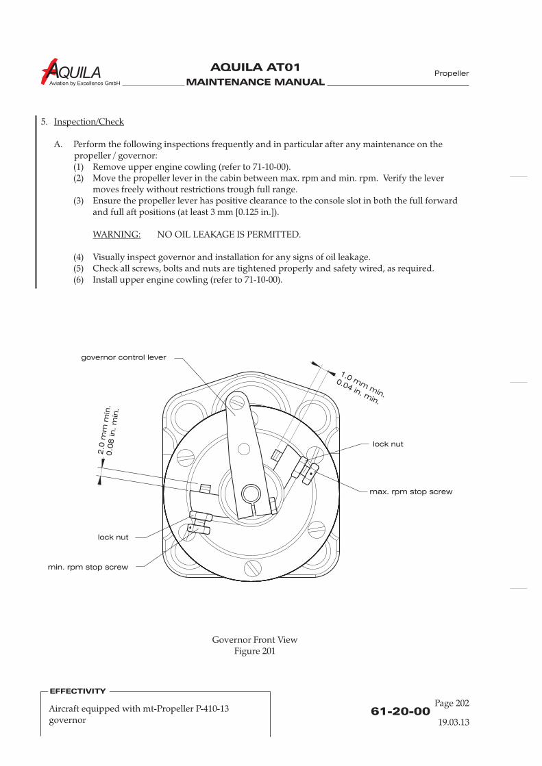
MAINTENANCE MANUAL
AQUILA AT01
Aviation by Excellence GmbH
5.
A. Perform the following inspections frequently and in particular after any maintenance on thepropeller / governor:(1) Remove upper engine cowling (refer to 71-10-00).(2) Move the propeller lever in the cabin between max. rpm and min. rpm. Verify the lever
moves freely without restrictions trough full range.(3) Ensure the propeller lever has positive clearance to the console slot in both the full forward
and full aft positions (at least 3 mm [0.125 in.]).
NO OIL LEAKAGE IS PERMITTED.
(4) Visually inspect governor and installation for any signs of oil leakage.(5) Check all screws, bolts and nuts are tightened properly and safety wired, as required.(6) Install upper engine cowling (refer to 71-10-00).
Inspection/Check
WARNING:
Governor Front ViewFigure 201
61-20-00Page 202
Propeller
EFFECTIVITY
Aircraft equipped with mt-Propeller P-410-13governor 19.03.13
max. rpm stop screw
min. rpm stop screw
lock nut
lock nut
governor control lever
2.0
mm
min
.0.0
8in
. m
in.
1.0 mm
min.
0.04 in. min.
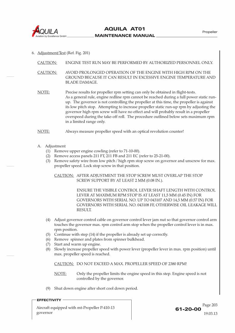
MAINTENANCE MANUAL
AQUILA AT01
Aviation by Excellence GmbH
6. (Ref. Fig. 201)
ENGINE TEST RUN MAY BE PERFORMED BY AUTHORIZED PERSONNEL ONLY.
Precise results for propeller rpm setting can only be obtained in flight-tests.As a general rule, engine redline rpm cannot be reached during a full power static run-up. The governor is not controlling the propeller at this time, the propeller is againstits low pitch stop. Attempting to increase propeller static run-up rpm by adjusting thegovernor high rpm screw will have no effect and will probably result in a propelleroverspeed during the take-off roll. The procedure outlined below sets maximum rpmin a limited range only.
A. Adjustment(1) Remove upper engine cowling (refer to 71-10-00).
Adjustment/Test
CAUTION:
NOTE:
CAUTION:
NOTE:
CAUTION:
CAUTION:
NOTE:
AVOID PROLONGED OPERATION OF THE ENGINE WITH HIGH RPM ON THEGROUND BECAUSE IT CAN RESULT IN EXCESSIVE ENGINE TEMPERATURE ANDBLADE DAMAGE.
Always measure propeller speed with an optical revolution counter!
(2) Remove access panels 211 FT, 211 FB and 211 EC (refer to 25-21-00).(3) Remove safety wire from low pitch / high rpm stop screw on governor and unscrew for max.
propeller speed. Lock stop screw in that position.
AFTER ADJUSTMENT THE STOP SCREW MUST OVERLAP THE STOPSCREW SUPPORT BY AT LEAST 2 MM (0.08 IN.).
ENSURE THE VISIBLE CONTROL LEVER SHAFT LENGTH WITH CONTROLLEVER AT MAXIMUM RPM STOP IS AT LEAST 11,5 MM (0.45 IN) FORGOVERNORS WITH SERIAL NO. UP TO 043107 AND 14,5 MM (0.57 IN) FORGOVERNORS WITH SERIAL NO. 043108 FF, OTHERWISE OIL LEAKAGE WILLRESULT.
(4) Adjust governor control cable on governor control lever jam nut so that governor control armtouches the governor max. rpm control arm stop when the propeller control lever is in max.rpm position.
(5) Continue with step (14) if the propeller is already set up correctly.(6) Remove spinner and plates from spinner bulkhead.(7) Start and warm up engine.(8) Slowly increase propeller speed with power lever (propeller lever in max. rpm position) until
max. propeller speed is reached.
DO NOT EXCEED A MAX. PROPELLER SPEED OF 2380 RPM!
Only the propeller limits the engine speed in this step. Engine speed is notcontrolled by the governor.
(9) Shut down engine after short cool down period.
61-20-00
Page 203
Propeller
EFFECTIVITY
Aircraft equipped with mt-Propeller P-410-13governor 19.03.13

MAINTENANCE MANUAL
AQUILA AT01
Aviation by Excellence GmbH
EFFECTIVITY
Aircraft equipped with mt-Propeller P-410-13governor
61-20-00Page 204
19.03.13
(10) Loosen check nuts on propeller hub and mark their position. Adjust max. propeller speed byadjusting the nuts. Turning loose by ¼ turn will increase the propeller speed by approx. 100rpm. Secure nuts again.
The max. static propeller speed on ground should be approx. 2280 rpm.
(11) Repeat steps (7) thru (10) until max. propeller speed is set up correctly.(12) Safety wire check nuts on propeller hub.(13) Re-install spinner and plates to spinner bulkhead (refer to 61-10-00).(14) Start engine.(15) Place power and propeller levers in full forward position for max. propeller speed.(16) Slowly move propeller lever back until governor starts reducing propeller speed.
Leave propeller lever in that position.(17) Shut down engine after short cool down period.(18) Adjust low pitch / high rpm stop screw on governor to current position of governor control
arm. Safety wire stop screw.(19) Push propeller lever full forward and pull slightly back again by approx. 2 mm (0.08 in.).(20) Adjust governor control cable on governor control arm so that governor control arm touches
the governor max. rpm control arm stop with the propeller lever in it’s current position.(21) Start engine.(22) Adjust power lever for approx. 1700 rpm (propeller lever in max. rpm position).(23) Pull back propeller lever until the propeller speed drops by 200 rpm.(24) Pull back power lever in idle position.(25) Adjust propeller lever low rpm stop screw to the current propeller lever position.(26) Repeat steps (22) thru (25) until drop of propeller speed is 200 rpm.(27) Perform a test-flight. At 130-140 kts with propeller and power levers full forward propeller
speed should be approx. 2310 rpm. If popeller speed is 2310 rpm governor adjustment isfinished. If propeller speed is too high pull back propeller lever slowly until propeller speedis 2310 rpm. Mark position of the power lever and continue with step (28).
(28) After landing move propeller lever to the position that has been marked during test-flight.(29) Repeat steps (18) to (27) until max. propeller speed in flight is adjusted.
B. Functional Test(1)(2) Adjust power lever for approx. 1700 rpm with propeller lever full forward. Pull propeller
lever back to the low rpm stop. Propeller speed should drop by 200 rpm. Push propellerlever full forward and observe rpm increase. Decrease and increase of propeller speedshould have about the same time. Cycle three times to bleed air out of the system.
(2) Adjust power lever at approx. 2200 rpm now. Pull propeller lever back until rpm drops about100 rpm. When the rpm is stabilized, increase manifold pressure by about 3 in.Hg andobserve the governor function. Propeller speed must stabilize.
(3) Watch for a clean ground surface to avoid blade damage and advance power lever andpropeller lever for take-off power and rpm. The static rpm must be limited by the propellerand should be approx. 2280 rpm. See troubleshooting section to check, if the propeller orgovernor limits the rpm.
NOTE:
Start and warm up engine.

MAINTENANCE MANUAL
AQUILA AT01
Aviation by Excellence GmbH
PROPELLER CONTROL - MAINTENANCE PRACTICES
1.
A. The AQUILA AT01 is equipped with a constant speed propeller. A mt-Propeller P-850-12 governorcontrols the blade pitch.
A. For more detailed information on the installed governor, refer to mt-Propeller E-1048 Operationand Installation Manual for Hydraulically Constant Speed Governor P-8( )( )-( ), latest revision.
2.
Quantity Equipment Parts No.4.B. 1 gasket AT01-7080-012
3.
A. The necessary pressure to adjust the propeller is achieved by a gear pump in the governor whichincreases engine oil pressure. A flyweight and a speeder spring move a valve, allowing oil flow toand from the piston in the propeller. In on-speed condition there is no oil flow. A speed-adjustinglever changes the pre-load of the speeder spring which finally results in a change in engine speed.The propeller has a single-acting piston to increase pitch, whereas the natural twisting forces ofthe blades reduce propeller pitch. The governor produces oil pressure to increase pitch. The reliefvalve pressure should be set to 310 10 psi.
4.
TO PREVENT FOREIGN MATERIAL ENTERING THE SYSTEM, INSTALL COVER TOGOVERNOR MOUNTING PAD.
A. Remove Governor(1) Remove upper engine cowling (refer to 71-10-00).(2) Disconnect governor control cable end from governor control arm.(3) Remove nuts and lockwashers securing governor to crankcase and remove governor from
engine.(4) Remove and discard gasket.
B. Install Governor(1) Clean engine pad, studs and mounting hardware before installing new mounting gasket.
Ensure governor drive spline mates correctly with engine accessory drive spline.(2) Install new gasket coated with engine oil or equivalent over studs on engine mounting pad.(3) Install governor over studs on to gasket. Secure with mounting hardware. Torque nuts to
11 - 15 Nm (100 - 140 in.lbs).(4) Install governor control cable to governor control arm.(5) Adjust governor (refer to “Adjustment/Test” below).(6) Install upper engine cowling (refer to 76-10-00).
General
Tools, Equipment and Material
Description
Governor Removal/Installation
CAUTION:
±
61-20-00
Page 201
Propeller
EFFECTIVITY
Aircraft equipped with mt-Propeller P-850-12governor 19.03.13
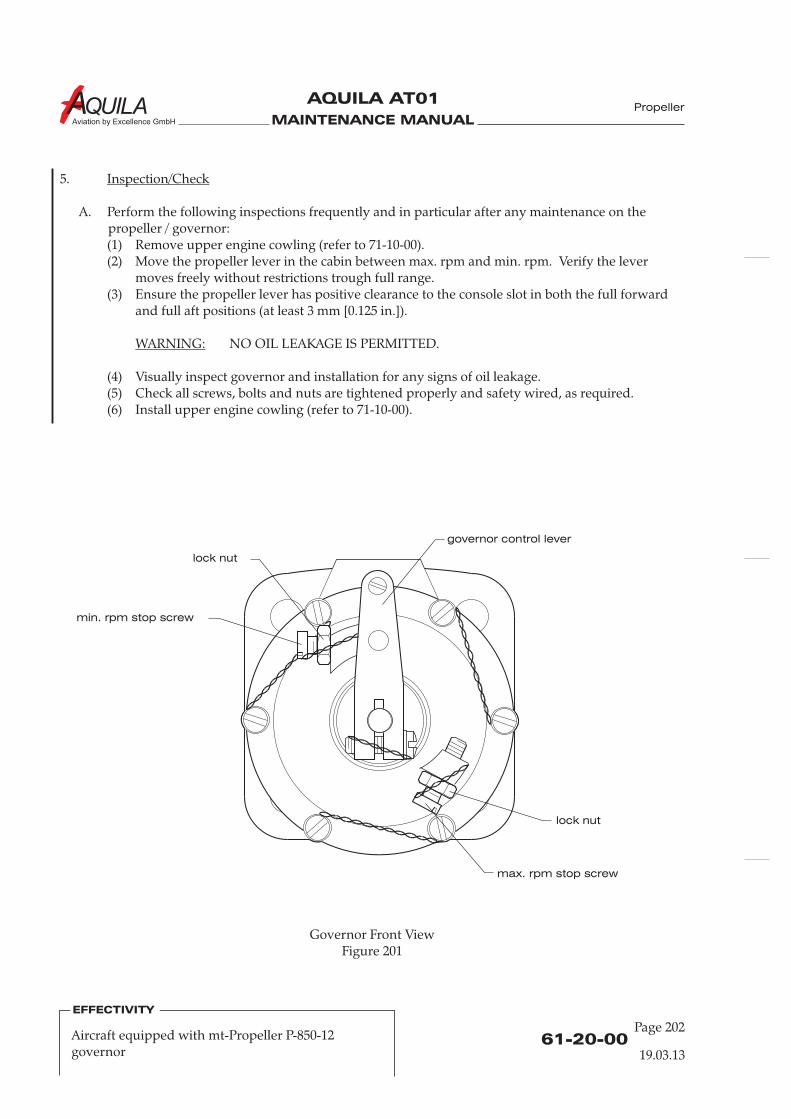
MAINTENANCE MANUAL
AQUILA AT01
Aviation by Excellence GmbH
5.
A. Perform the following inspections frequently and in particular after any maintenance on thepropeller / governor:(1) Remove upper engine cowling (refer to 71-10-00).(2) Move the propeller lever in the cabin between max. rpm and min. rpm. Verify the lever
moves freely without restrictions trough full range.(3) Ensure the propeller lever has positive clearance to the console slot in both the full forward
and full aft positions (at least 3 mm [0.125 in.]).
NO OIL LEAKAGE IS PERMITTED.
(4) Visually inspect governor and installation for any signs of oil leakage.(5) Check all screws, bolts and nuts are tightened properly and safety wired, as required.(6) Install upper engine cowling (refer to 71-10-00).
Inspection/Check
WARNING:
61-20-00Page 202
Propeller
Governor Front ViewFigure 201
EFFECTIVITY
Aircraft equipped with mt-Propeller P-850-12governor 19.03.13
max. rpm stop screw
min. rpm stop screw
lock nut
lock nut
governor control lever
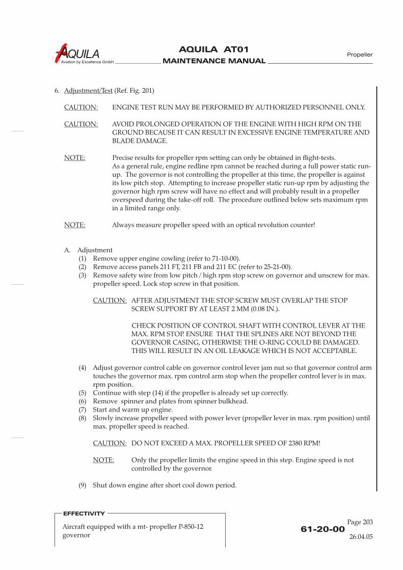
MAINTENANCE MANUAL
AQUILA AT01
Aviation by Excellence GmbH
6. (Ref. Fig. 201)
ENGINE TEST RUN MAY BE PERFORMED BY AUTHORIZED PERSONNEL ONLY.
AVOID PROLONGED OPERATION OF THE ENGINE WITH HIGH RPM ON THEGROUND BECAUSE IT CAN RESULT IN EXCESSIVE ENGINE TEMPERATURE ANDBLADE DAMAGE.
Precise results for propeller rpm setting can only be obtained in flight-tests.As a general rule, engine redline rpm cannot be reached during a full power static run-up. The governor is not controlling the propeller at this time, the propeller is againstits low pitch stop. Attempting to increase propeller static run-up rpm by adjusting thegovernor high rpm screw will have no effect and will probably result in a propelleroverspeed during the take-off roll. The procedure outlined below sets maximum rpmin a limited range only.
Always measure propeller speed with an optical revolution counter!
A. Adjustment(1) Remove upper engine cowling (refer to 71-10-00).(2) Remove access panels 211 FT, 211 FB and 211 EC (refer to 25-21-00).(3) Remove safety wire from low pitch / high rpm stop screw on governor and unscrew for max.
propeller speed. Lock stop screw in that position.
AFTER ADJUSTMENT THE STOP SCREW MUST OVERLAP THE STOPSCREW SUPPORT BY AT LEAST 2 MM (0.08 IN.).
CHECK POSITION OF CONTROL SHAFT WITH CONTROL LEVER AT THEMAX. RPM STOP. ENSURE THAT THE SPLINES ARE NOT BEYOND THEGOVERNOR CASING, OTHERWISE THE O-RING COULD BE DAMAGED.THIS WILL RESULT IN AN OIL LEAKAGE WHICH IS NOT ACCEPTABLE.
(4) Adjust governor control cable on governor control lever jam nut so that governor control armtouches the governor max. rpm control arm stop when the propeller control lever is in max.rpm position.
(5) Continue with step (14) if the propeller is already set up correctly.(6) Remove spinner and plates from spinner bulkhead.(7) Start and warm up engine.(8) Slowly increase propeller speed with power lever (propeller lever in max. rpm position) until
max. propeller speed is reached.
DO NOT EXCEED A MAX. PROPELLER SPEED OF 2380 RPM!
Only the propeller limits the engine speed in this step. Engine speed is notcontrolled by the governor.
(9) Shut down engine after short cool down period.
Adjustment/Test
CAUTION:
CAUTION:
NOTE:
NOTE:
CAUTION:
CAUTION:
NOTE:
61-20-00
Page 203
Propeller
EFFECTIVITY
Aircraft equipped with a mt- propeller P-850-12governor 26.04.05
MAINTENANCE MANUAL
AQUILA AT01
Aviation by Excellence GmbH
(10) Loosen check nuts on propeller hub and mark their position. Adjust max. propeller speed byadjusting the nuts. Turning loose by ¼ turn will increase the propeller speed by approx. 100rpm. Secure nuts again.
The max. static propeller speed on ground should be approx. 2280 rpm.
(11) Repeat steps (7) thru (10) until max. propeller speed is set up correctly.(12) Safety wire check nuts on propeller hub.(13) Re-install spinner and plates to spinner bulkhead (refer to 61-10-00).(14) Start engine.(15) Place power and propeller levers in full forward position for max. propeller speed.(16) Slowly move propeller lever back until governor starts reducing propeller speed.
Leave propeller lever in that position.(17) Shut down engine after short cool down period.(18) Adjust low pitch / high rpm stop screw on governor to current position of governor control
arm. Safety wire stop screw.(19) Push propeller lever full forward and pull slightly back again by approx. 2 mm (0.08 in.).(20) Adjust governor control cable on governor control arm so that governor control arm touches
the governor max. rpm control arm stop with the propeller lever in it’s current position.(21) Start engine.(22) Adjust power lever for approx. 1700 rpm (propeller lever in max. rpm position).(23) Pull back propeller lever until the propeller speed drops by 200 rpm.(24) Pull back power lever in idle position.(25) Adjust propeller lever low rpm stop screw to the current propeller lever position.(26) Repeat steps (22) thru (25) until drop of propeller speed is 200 rpm.(27) Perform a test-flight. At 130-140 kts with propeller and power levers full forward propeller
speed should be approx. 2310 rpm. If popeller speed is 2310 rpm governor adjustment isfinished. If propeller speed is too high pull back propeller lever slowly until propeller speed is2310 rpm. Mark position of the power lever and continue with step (28).
(28) After landing move propeller lever to the position that has been marked during test-flight.(29) Repeat steps (18) to (27) until max. propeller speed in flight is adjusted.
B. Functional Test(1) Start and warm up engine.(2) Adjust power lever for approx. 1700 rpm with propeller lever full forward. Pull propeller
lever back to the low rpm stop. Propeller speed should drop by 200 rpm. Push propellerlever full forward and observe rpm increase. Decrease and increase of propeller speedshould have about the same time. Cycle three times to bleed air out of the system.
(2) Adjust power lever at approx. 2200 rpm now. Pull propeller lever back until rpm drops about100 rpm. When the rpm is stabilized, increase manifold pressure by about 3 in.Hg andobserve the governor function. Propeller speed must stabilize.
(3) Watch for a clean ground surface to avoid blade damage and advance power lever andpropeller lever for take-off power and rpm. The static rpm must be limited by the propellerand should be approx. 2280 rpm. See troubleshooting section to check, if the propeller orgovernor limits the rpm.
NOTE:
61-20-00Page 204
Propeller
EFFECTIVITY
Aircraft equipped with mt-Propeller P-850-12governor 19.03.13
MAINTENANCE MANUAL
AQUILA AT01
Aviation by Excellence GmbH
PROPELLER CONTROL - MAINTENANCE PRACTICES
1.
A. The AQUILA AT01 is equipped with a constant speed propeller. A Woodward governor controlsthe blade pitch.
B. For more detailed information on the installed governor, refer to mt-Propeller E-124 Operationand Installation Manual for Hydraulically Controlled Variable Pitch Propeller and to theWoodward Governor Manual.
3.
A. The necessary pressure to adjust the propeller is achieved by a gear pump in the governor whichincreases engine oil pressure. A flyweight and a speeder spring move a valve, allowing oil flow toand from the piston in the propeller. In on-speed condition there is no oil flow. A speed-adjustinglever changes the pre-load of the speeder spring which finally results in a change in engine speed.The propeller has a single-acting piston to increase pitch, whereas the natural twisting forces ofthe blades reduce propeller pitch. The governor produces oil pressure to change pitch. The reliefvalve pressure should be set between 270 and 340 psi.
4.
TO PREVENT FOREIGN MATERIAL ENTERING THE SYSTEM, INSTALL COVER TOGOVERNOR MOUNTING PAD.
A. Remove Governor(1) Remove upper engine cowling (refer to 71-10-00).(2) Disconnect governor control cable end from governor control arm.(3) Remove nuts and lockwashers securing governor to crankcase and remove governor from
engine.(4) Remove and discard gasket.
B. Install Governor(1)
(2)
General
Description
Governor Removal/Installation
CAUTION:
2.
Quantity Equipment Parts No.4.B. 1 gasket AT01-7080-012
Clean engine pad, studs and mounting hardware before installing new mounting gasket.Ensure governor drive spline mates correctly with engine accessory drive spline.Install new gasket coated with engine oil or equivalent over studs on engine mounting pad.
(3) Install governor over studs on to gasket. Secure with mounting hardware. Torque nuts to23 Nm (17 ft.lb.).
(4) Install governor control cable to governor control arm.
Tools, Equipment and Material
61-20-00
Page 201
Propeller
EFFECTIVITY
Aircraft equipped with Woodward governor
19.03.13
MAINTENANCE MANUAL
AQUILA AT01
Aviation by Excellence GmbH
61-20-00Page 202
EFFECTIVITY
Aircraft equipped with Woodward governor
19.03.13
5.
A. Perform the following inspections frequently and in particular after any maintenance on thepropeller / governor:(1) Remove upper engine cowling (refer to 71-10-00).(2) Move the propeller lever in the cabin between max. rpm and min. rpm. Verify the lever
moves freely without restrictions trough full range.(3) Ensure the propeller lever has positive clearance to the console slot in both the full forward
and full aft positions (at least 3 mm [0.125 in.]).
NO OIL LEAKAGE IS PERMITTED.
(4) Visually inspect governor and installation for any signs of oil leakage.(5) Check all screws, bolts and nuts are tightened properly and safety wired, as required.(6) Install upper engine cowling (refer to 71-10-00).
6.
ENGINE TEST RUN MAY BE PERFORMED BY AUTHORIZED PERSONNEL ONLY.
AVOID PROLONGED OPERATION OF THE ENGINE WITH HIGH RPM ON THEGROUND BECAUSE IT CAN RESULT IN EXCESSIVE ENGINE TEMPERATURE ANDBLADE DAMAGE.
Precise results for propeller rpm setting can only be obtained in flight-tests.As a general rule, engine redline rpm cannot be reached during a full power static run-up. The governor is not controlling the propeller at this time, the propeller is againstits low pitch stop. Attempting to increase propeller static run-up rpm by adjusting thegovernor high rpm screw will have no effect and will probably result in a propelleroverspeed during the take-off roll. The procedure outlined below sets maximum rpmin a limited range only.
Always measure propeller speed with an optical revolution counter!
A. Adjustment(1) Remove upper engine cowling (refer to 71-10-00).(2) Remove access panels 211 FT, 211 FB and 211 EC (refer to 25-21-00).(3) Unscrew low pitch / high rpm stop screw on governor for max. propeller speed. Lock stop
screw in that position.(4) Adjust governor control cable on governor control lever jam nut so that governor control arm
touches the governor max. rpm control arm stop when the propeller control lever is in max.rpm position.
(5) Continue with step (14) if the propeller is already set up correctly.(6) Remove spinner and plates from spinner bulkhead.(7) Start and warm up engine.(8) Slowly increase propeller speed with power lever (propeller lever in max. rpm position) until
max. propeller speed is reached.
Inspection/Check
WARNING:
Adjustment/Test
CAUTION:
CAUTION:
NOTE:
NOTE:

MAINTENANCE MANUAL
AQUILA AT01
Aviation by Excellence GmbH
61-20-00
Page 203
EFFECTIVITY
Aircraft equipped with Woodward governor
19.03.13
CAUTION:
NOTE:
NOTE:
DO NOT EXCEED A MAX. PROPELLER SPEED OF 2380 RPM!
Only the propeller limits the engine speed in this step. Engine speed is notcontrolled by the governor.
(9) Shut down engine after short cool down period.
(10) Loosen check nuts on propeller hub and mark their position. Adjust max. propeller speed byadjusting the nuts. Turning loose by ¼ turn will increase the propeller speed by approx. 100rpm. Secure nuts again.
The max. static propeller speed on ground should be approx. 2280 rpm.
(11) Repeat steps (7) thru (10) until max. propeller speed is set up correctly.(12) Safety wire check nuts on propeller hub.(13) Re-install spinner and plates to spinner bulkhead (refer to 61-10-00).(14) Start engine.(15) Place power and propeller levers in full forward position for max. propeller speed.(16) Slowly move propeller lever back until governor starts reducing propeller speed.
Leave propeller lever in that position.(17) Shut down engine after short cool down period.(18) Adjust low pitch / high rpm stop screw on governor to current position of governor control
arm. Safety wire stop screw.(19) Push propeller lever full forward and pull slightly back again by approx. 2 mm (0.08 in.).(20) Adjust governor control cable on governor control arm so that governor control arm touches
the governor max. rpm control arm stop with the propeller lever in it’s current position.(21) Start engine.(22) Adjust power lever for approx. 1700 rpm (propeller lever in max. rpm position).(23) Pull back propeller lever until the propeller speed drops by 200 rpm.(24) Pull back power lever in idle position.(25) Adjust propeller lever low rpm stop screw to the current propeller lever position.(26) Repeat steps (22) thru (25) until drop of propeller speed is 200 rpm.(27) Perform a test-flight. At 130-140 kts with propeller and power levers full forward propeller
speed should be approx. 2310 rpm. If popeller speed is 2310 rpm governor adjustment isfinished. If propeller speed is too high pull back propeller lever slowly until propeller speed is2310 rpm. Mark position of the power lever and continue with step (28).
(28) After landing move propeller lever to the position that has been marked during test-flight.(29) Repeat steps (18) to (27) until max. propeller speed in flight is adjusted.
MAINTENANCE MANUAL
AQUILA AT01
Aviation by Excellence GmbH
61-20-00Page 204
Propeller
EFFECTIVITY
Aircraft equipped with Woodward governor
19.03.13
B. Functional Test(1) Start and warm up engine.(2) Adjust power lever for approx. 1700 rpm with propeller lever full forward. Pull propeller
lever back to the low rpm stop. Propeller speed should drop by 200 rpm. Push propeller leverfull forward and observe rpm increase. Decrease and increase of propeller speed shouldhave about the same time. Cycle three times to bleed air out of the system.
(2) Adjust power lever at approx. 2200 rpm now. Pull propeller lever back until rpm drops about100 rpm. When the rpm is stabilized, increase manifold pressure by about 3 in.Hg andobserve the governor function. Propeller speed must stabilize.
(3) Watch for a clean ground surface to avoid blade damage and advance power lever andpropeller lever for take-off power and rpm. The static rpm must be limited by the propellerand should be approx. 2280 rpm. See troubleshooting section to check, if the propeller orgovernor limits the rpm.
MAINTENANCE MANUAL
AQUILA AT01
Aviation by Excellence GmbH
CHAPTER 71
POWER PLANT

MAINTENANCE MANUAL
AQUILA AT01
Aviation by Excellence GmbH

MAINTENANCE MANUAL
AQUILA AT01
Aviation by Excellence GmbH
Page 0171 - TOC
TABLE OF CONTENTS
ChapterSection
POWER PLANT - GENERAL ..........................................................................71-00-00 1Introduction 71-00-00 1General Description 71-00-00 1
ENGINE - DESCRIPTION ...............................................................................71-00-01 1Description and Operation 71-00-01 1
TROUBLESHOOTING - ROTAX ENGINE 912S........................................71-00-01 101
General 71-00-01 101Troubleshooting 71-00-01 101
General 71-00-01 201Engine Removal/Installation 71-00-01 201Engine Cleaning 71-00-01 201Engine Storage 71-00-01 201
COWLING - MAINTENANCE PRACTICES.................................................71-10-00 201General 71-10-00 201Cowling Removal/Installation 71-10-00 201
ENGINE MOUNT - MAINTENANCE PRACTICES....................................71-20-00 201General 71-20-00 201Maintenance InstructionsEngine Mount - Removal/Installation 71-20-00 201
AIR INDUCTION SYSTEM - MAINTENANCE PRACTICES ....................71-60-00 201General 71-60-00 201Maintenance InstructionsInduction Air Filter Change 71-60-00 201
Title Subject Page
®
ROTAX ENGINE 912S - MAINTENANCE PRACTICES............................71-00-01 201®
Powerplant
26.04.05

MAINTENANCE MANUAL
AQUILA AT01
Aviation by Excellence GmbH

MAINTENANCE MANUAL
AQUILA AT01
Aviation by Excellence GmbH
71-00-00
Page 01
POWER PLANT - GENERAL
1.
A. This chapter provides maintenance information on the power plant and associated components.Engine related information is limited to most important specifications. For further, more detailedinformation, refer to applicable ROTAX Aircraft Engines publications.
For engine operation instructions use the Operator's Manual for ROTAX 912 Engines.
2.
A. The aircraft is powered by an air/liquid-cooled, four-cylinder, horizontally opposed engine withdry sump lubrication. The engine is a ROTAX 912S engine and is rated at 73,5 kW (98,6 HP) at
5800 RPM.
The engine is mounted at four points on a steel tube construction via dynafocal mounts.
A variable pitch, two blade wood-composite propeller is driven via a reduction gear. The propellerhas a governor, which controls the propeller pitch hydraulically.
For maintenance and repairs, the cowling, which consists of a upper and lower half can beremoved.
Introduction
General Description
®
®
®
Powerplant
26.04.05

MAINTENANCE MANUAL
AQUILA AT01
Aviation by Excellence GmbH
MAINTENANCE MANUAL
AQUILA AT01
Aviation by Excellence GmbH
71-00-01
Page 01
ENGINE - DESCRIPTION
1.
A. The AQUILA AT01 aircraft is powered by a ROTAX 912S engine.
It is a four cylinder, horizontally opposed, spark ignition engine with dry sump forced lubrication.The cylinder heads are liquid cooled and the cylinders are ram air cooled. The propeller is drivenvia a reduction gear with integrated shock absorber and overload clutch.The engine is equipped with 2 constant depression Bing carburetors and a dual breakerlesscapacitor discharge ignition.A electric starter, a belt driven 40A-12V DC external alternator, a mechanical fuel pump, and ahydraulic constant speed propeller governor are mounted to the engine.The cylinders are numbered from front to rear, odd numbers on the right, even numbers on theleft. The right front cylinder is number 1, the left front cylinder is number 2, the right rear cylinderis number 3, and the left rear is number 4.
B. The most important technical data are contained in Table 1.
Table 1: ROTAX 912S Technical Data
Certification FAR 33 (TW9 - ACG)Takeoff Performance (ISA) /MCP 69 kW at 5500 RPMNumber of Cylinders 4Bore, mm (in.) 84 (3.31)Stroke, mm (in.) 61 (2.40)Displacement, cm (in ) 1352 (82.5)Compression Ratio 10,5:1Firing Order 1-4-2-3Spark Occurs, degrees BTC 26Direction of Rotation (looking at p.t.o. side) CounterclockwiseMax. Oil Capacity, l (qts) 3 (3.2)Engine speed measurement ElectronicallyAcceleration Limitation: 0 up to -0,5g 5 sec.Min. Oil Pressure below 3500 RPM, bar (psi) 0,8 (12)Norm. Oil Pressure above 3500 RPM, bar (psi) 2,0 - 5,0 (29 - 73)Max. Oil Temperature, °C (°F) 130 (266)Min. Oil Temperature, °C (°F) 50 (120)Norm. Operating Oil Temperature, °C (°F) 90 - 110 (19 - 230)Max. Cylinder Head Temperature, °C (°F) 135 (284)
Weight - dry, without ext. Alt., kg (lbs) 58,3 (128)
C. Components(1) Starter
The starter is mounted at the rear lower right side of the engine. It is a direct drive 12 V DCmotor. While starting a pinion gear within the starter engages the crankshaft ring gear and
Description and Operation
®
3 3
Powerplant
26.04.05
MAINTENANCE MANUAL
AQUILA AT01
Aviation by Excellence GmbH
71-00-01Page 02
26.04.05
Intentionally left blank!
Powerplant
MAINTENANCE MANUAL
AQUILA AT01
Aviation by Excellence GmbH
turns the engine over. When the engine reaches a predetermined speed, centrifugal actiondecouples the starter pinion from the crankshaft ring gear.
(2) AlternatorA 40-ampere, belt driven alternator is mounted on the forward left side of the engine. Itpowers the entire aircraft electrical load and charge the battery during normal systemoperation. The alternator contains the rectifier internally, which provides 12 VDC current.
(3) Ignition SystemThe engine is equipped with a breakerless capacitor discharge type dual ignition system,which operates independent from the aircraft electrical system. The ignition unit iscompletely free of maintenance.
(4) CarburetorsThe Bing carburetors are constant compression carburetors comprising a cross-draught,butterfly-valve carburetor with variable choke tube. The carburetors equipped with adouble-float system, and a rotary-valve type starting carburetor. The throttle slide issuspended from the roller diaphragm and projected into the venturi. This changes thesmallest cross-section of the venturi as a function of the vacuum at this point. In this way thedevice provides an almost constant pressure drop and an almost constant velocity in thechoke tube.
(5) Reduction GearThe power plant incorporates a propeller gearbox to reduce the propeller speed in relation tothe crankshaft speed. The reduction ratio between crankshaft and propeller is 2,43:1. Toreduce torsional vibrations, the gearbox contains a torsional shock absorber. The shockabsorbing is based on progressive torsional cushioning due to axial spring load acting on adog hub.Further the design incorporates a overload clutch. The friction damped free play at the dogsis necessary to achieve a smooth idling.Due to this backlash at the dogs a distinct torsional impact arises during engine start, shut-down and at sudden load changes, but due to the built-in overload clutch it will remainharmless.The overload clutch will also protect the crankshaft from undue load in case of groundcontact of the propeller.
(6) Hydraulic GovernorThe governor keeps the preselected propeller speed at a constant value, regardless ofmanifold pressure and airspeed. It is mounted to the propeller gear box.
D. For further, more detailed information, refer to applicable publications published by ROTAX
Aircraft Engines GmbH or other suppliers.For information concerning external engine systems such as the cooling system or the oil system,refer to applicable chapters of this manual.
®
71-00-01
Page 03
Powerplant
26.04.05

MAINTENANCE MANUAL
AQUILA AT01
Aviation by Excellence GmbH
Powerplant
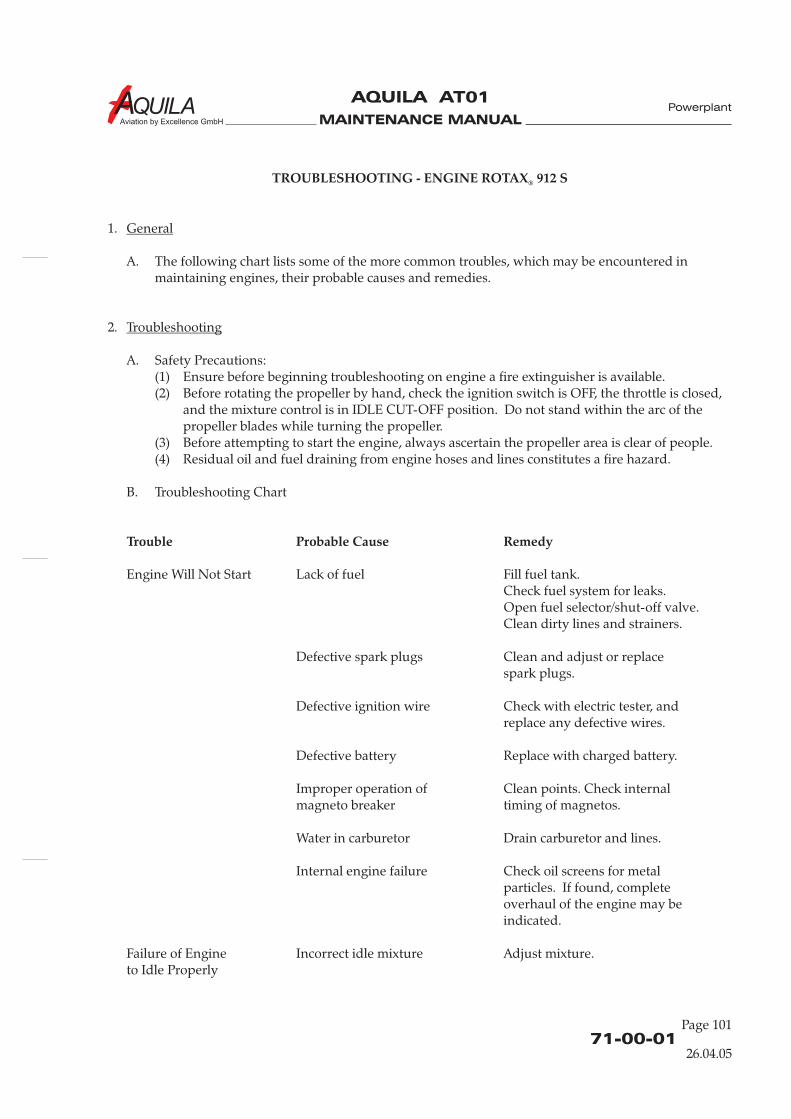
MAINTENANCE MANUAL
AQUILA AT01
Aviation by Excellence GmbH
71-00-01
Page 101
TROUBLESHOOTING - ENGINE ROTAX 912 S
Trouble Probable Cause Remedy
®
1.
A. The following chart lists some of the more common troubles, which may be encountered inmaintaining engines, their probable causes and remedies.
2.
A. Safety Precautions:(1) Ensure before beginning troubleshooting on engine a fire extinguisher is available.(2) Before rotating the propeller by hand, check the ignition switch is OFF, the throttle is closed,
and the mixture control is in IDLE CUT-OFF position. Do not stand within the arc of thepropeller blades while turning the propeller.
(3) Before attempting to start the engine, always ascertain the propeller area is clear of people.(4) Residual oil and fuel draining from engine hoses and lines constitutes a fire hazard.
B. Troubleshooting Chart
Engine Will Not Start Lack of fuel Fill fuel tank.Check fuel system for leaks.Open fuel selector/shut-off valve.Clean dirty lines and strainers.
Defective spark plugs Clean and adjust or replacespark plugs.
Defective ignition wire Check with electric tester, andreplace any defective wires.
Defective battery Replace with charged battery.
Improper operation of Clean points. Check internalmagneto breaker timing of magnetos.
Water in carburetor Drain carburetor and lines.
Internal engine failure Check oil screens for metalparticles. If found, completeoverhaul of the engine may beindicated.
Failure of Engine Incorrect idle mixture Adjust mixture.to Idle Properly
General
Troubleshooting
Powerplant
26.04.05
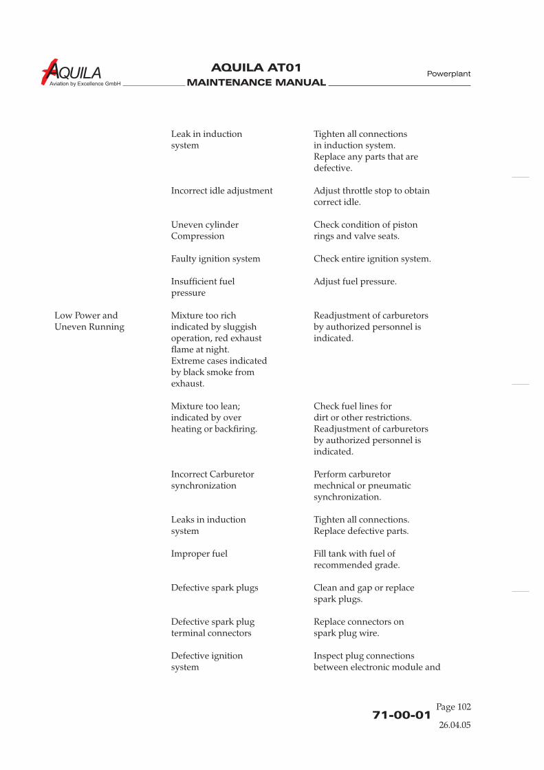
MAINTENANCE MANUAL
AQUILA AT01
Aviation by Excellence GmbH
Leak in induction Tighten all connectionssystem in induction system.
Replace any parts that aredefective.
Incorrect idle adjustment Adjust throttle stop to obtaincorrect idle.
Uneven cylinder Check condition of pistonCompression rings and valve seats.
Faulty ignition system Check entire ignition system.
Insufficient fuel Adjust fuel pressure.pressure
Low Power and Mixture too rich Readjustment of carburetorsUneven Running indicated by sluggish by authorized personnel is
operation, red exhaust indicated.flame at night.Extreme cases indicatedby black smoke fromexhaust.
Mixture too lean; Check fuel lines forindicated by over dirt or other restrictions.heating or backfiring. Readjustment of carburetors
by authorized personnel isindicated.
Incorrect Carburetor Perform carburetorsynchronization mechnical or pneumatic
synchronization.
Leaks in induction Tighten all connections.system Replace defective parts.
Improper fuel Fill tank with fuel ofrecommended grade.
Defective spark plugs Clean and gap or replacespark plugs.
Defective spark plug Replace connectors onterminal connectors spark plug wire.
Defective ignition Inspect plug connectionssystem between electronic module and
71-00-01Page 102
Powerplant
26.04.05

MAINTENANCE MANUAL
AQUILA AT01
Aviation by Excellence GmbH
ignition coils for security, wearand corrosion. Check cablesfor damage, for ground contactand security.
Failure of Engine Leak in induction system Tighten all connections andto Develop Full Power replace defective parts.Power
Throttle lever out of Adjust throttle lever.adjustment
Improper fuel flow Check strainers, linesflow and flow at the fuel inlet.
Restriction in air scoop Examine air scoop andremove restrictions.
Improper fuel Drain and refill tankwith recommended fuel.
Incorrect Carburetor Perform carburetorsynchronization mechnical or pneumatic
synchronization.
Propeller or governor Refer to troubleshootinglimit the engine speed section in 61-00-00.
Rough Engine Cracked engine mount Replace or repair mount.
Defective mounting Install new mountingbushings bushings.
Uneven compression Check compression.
Low Oil Insufficient oil Fill to proper level withPressure recommended oil.
Air lock or dirt in Inspect and clean oilpressure regulator pressure regulator.
Leak in suction line or Check for signs of leakage,pressure line Replace defective parts as
required.
High off temperature See "High Oil Temperature”
in "Trouble" column.
Defective pressure gage Replace.
71-00-01
Page 103
Powerplant
26.04.05

MAINTENANCE MANUAL
AQUILA AT01
Aviation by Excellence GmbH
Stoppage in oil pump Check line for obstruction.intake passage Clean suction strainer.
High Oil Insufficient air cooling Check oil cooler for condition,Temperature deformation or obstruction.
Insufficient oil supply Fill to proper level withspecified oil.
Low grade of oil Replace with oil conformingto specifications.
Clogged oil lines or Remove and clean oilstrainers strainers.
Excessive blow-by Usually caused by worn orstuck rings.
Failing or failed bearing Examine oil filter for metalparticles. If found, overhaulof engine is indicated.
Defective temperature Replace gage.gage
Excessive Oil Low grade of oil Fill tank with oil conformingConsumption to specifications.
Failing or failed bearings Check sump for metalparticles.
Worn piston rings Install new rings.
Incorrect installation Install new rings.of piston rings
71-00-01Page 104
Powerplant
26.04.05
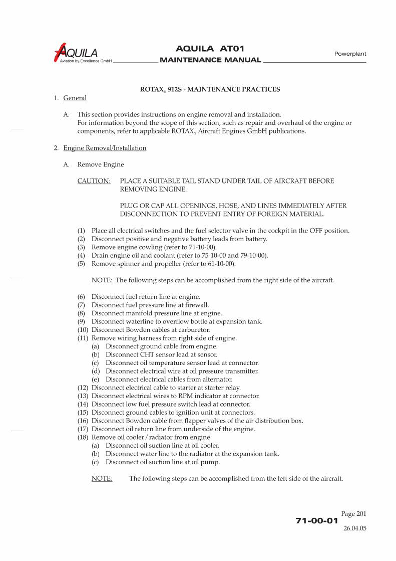
MAINTENANCE MANUAL
AQUILA AT01
Aviation by Excellence GmbH
71-00-01
Page 201
Powerplant
ROTAX 912S - MAINTENANCE PRACTICES®
1.
A. This section provides instructions on engine removal and installation.For information beyond the scope of this section, such as repair and overhaul of the engine orcomponents, refer to applicable ROTAX Aircraft Engines GmbH publications.
2.
A. Remove Engine
PLACE A SUITABLE TAIL STAND UNDER TAIL OF AIRCRAFT BEFOREREMOVING ENGINE.
PLUG OR CAP ALL OPENINGS, HOSE, AND LINES IMMEDIATELY AFTERDISCONNECTION TO PREVENT ENTRY OF FOREIGN MATERIAL.
(1) Place all electrical switches and the fuel selector valve in the cockpit in the OFF position.(2) Disconnect positive and negative battery leads from battery.(3) Remove engine cowling (refer to 71-10-00).(4) Drain engine oil and coolant (refer to 75-10-00 and 79-10-00).(5) Remove spinner and propeller (refer to 61-10-00).
The following steps can be accomplished from the right side of the aircraft.
(6) Disconnect fuel return line at engine.(7) Disconnect fuel pressure line at firewall.(8) Disconnect manifold pressure line at engine.(9) Disconnect waterline to overflow bottle at expansion tank.(10) Disconnect Bowden cables at carburetor.(11) Remove wiring harness from right side of engine.
(a) Disconnect ground cable from engine.(b) Disconnect CHT sensor lead at sensor.(c) Disconnect oil temperature sensor lead at connector.(d) Disconnect electrical wire at oil pressure transmitter.(e) Disconnect electrical cables from alternator.
(12) Disconnect electrical cable to starter at starter relay.(13) Disconnect electrical wires to RPM indicator at connector.(14) Disconnect low fuel pressure switch lead at connector.(15) Disconnect ground cables to ignition unit at connectors.(16) Disconnect Bowden cable from flapper valves of the air distribution box.(17) Disconnect oil return line from underside of the engine.(18) Remove oil cooler / radiator from engine
(a) Disconnect oil suction line at oil cooler.(b) Disconnect water line to the radiator at the expansion tank.(c) Disconnect oil suction line at oil pump.
The following steps can be accomplished from the left side of the aircraft.
General
Engine Removal/Installation
CAUTION:
NOTE:
NOTE:
®
26.04.05
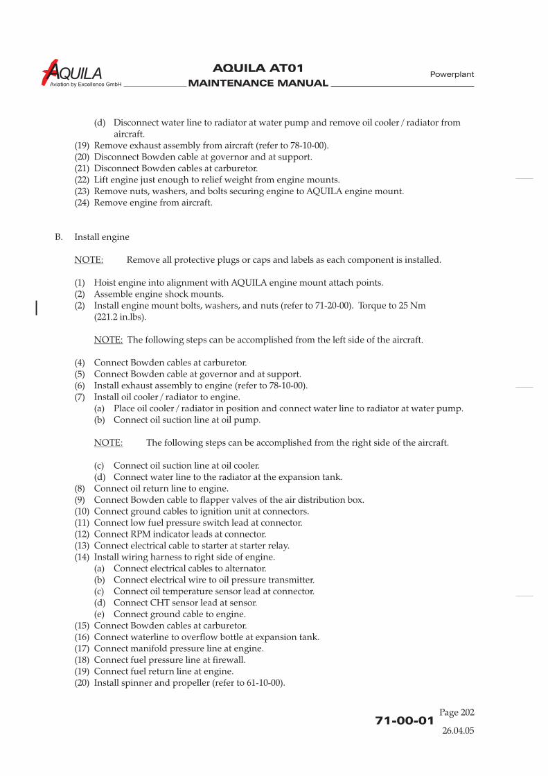
MAINTENANCE MANUAL
AQUILA AT01
Aviation by Excellence GmbH
71-00-01Page 202
Powerplant
(d) Disconnect water line to radiator at water pump and remove oil cooler / radiator fromaircraft.
(19) Remove exhaust assembly from aircraft (refer to 78-10-00).(20) Disconnect Bowden cable at governor and at support.(21) Disconnect Bowden cables at carburetor.(22) Lift engine just enough to relief weight from engine mounts.(23) Remove nuts, washers, and bolts securing engine to AQUILA engine mount.(24) Remove engine from aircraft.
B. Install engine
Remove all protective plugs or caps and labels as each component is installed.
(1) Hoist engine into alignment with AQUILA engine mount attach points.(2) Assemble engine shock mounts.(2) Install engine mount bolts, washers, and nuts (refer to 71-20-00). Torque to 25 Nm
(221.2 in.lbs).
The following steps can be accomplished from the left side of the aircraft.
(4) Connect Bowden cables at carburetor.(5) Connect Bowden cable at governor and at support.(6) Install exhaust assembly to engine (refer to 78-10-00).(7) Install oil cooler / radiator to engine.
(a) Place oil cooler / radiator in position and connect water line to radiator at water pump.(b) Connect oil suction line at oil pump.
The following steps can be accomplished from the right side of the aircraft.
(c) Connect oil suction line at oil cooler.(d) Connect water line to the radiator at the expansion tank.
(8) Connect oil return line to engine.(9) Connect Bowden cable to flapper valves of the air distribution box.(10) Connect ground cables to ignition unit at connectors.(11) Connect low fuel pressure switch lead at connector.(12) Connect RPM indicator leads at connector.(13) Connect electrical cable to starter at starter relay.(14) Install wiring harness to right side of engine.
(a) Connect electrical cables to alternator.(b) Connect electrical wire to oil pressure transmitter.(c) Connect oil temperature sensor lead at connector.(d) Connect CHT sensor lead at sensor.(e) Connect ground cable to engine.
(15) Connect Bowden cables at carburetor.(16) Connect waterline to overflow bottle at expansion tank.(17) Connect manifold pressure line at engine.(18) Connect fuel pressure line at firewall.(19) Connect fuel return line at engine.(20) Install spinner and propeller (refer to 61-10-00).
NOTE:
NOTE:
NOTE:
26.04.05
MAINTENANCE MANUAL
AQUILA AT01
Aviation by Excellence GmbH
71-00-01
Page 203
Powerplant
(21) Replenish engine oil and coolant (refer to 75-10-00 and 79-10-00).(22) Connect positive and negative battery leads to battery.(23) Place fuel selector valve to desired tank.(24) Perform operational check (refer to 05-20-00).(25) Perform visual check for signs of leakage.(26) Install engine cowling (refer to 71-10-00).
2.
A. For engine cleaning procedures, refer to 12-23-00.
3.
A. If the engine is being removed for storage purposes, it should be preserved. The ROTAX 912
series engines Operator's Manual, Section 11, contains information on preservation techniques.
Engine Cleaning
Engine Storage
®
26.04.05

MAINTENANCE MANUAL
AQUILA AT01
Aviation by Excellence GmbH

MAINTENANCE MANUAL
AQUILA AT01
Aviation by Excellence GmbH
71-10-00
Page 201
Powerplant
COWLING - MAINTENANCE PRACTICES
1.
A. The AQUILA A210 engine cowling, fabricated from laminated fiberglass, consists of one upper andlower half.The oil access door is located on the right side of the upper cowling. An air intake and theinduction air filter housing are placed on the lower cowling left side.Both cowling halves are fixed to fuselage, and among one another with CAMLOC quick-releasefastener. That allows their fast removal during necessary maintenance at the engine.The engine cowling is equipped with a specific fire proofing finish on the inside.
2.
A. Remove Engine Cowling
DO NOT REMOVE COWLING IF ENGINE RUNS.
IF ENGINE WAS RUNNING RECENTLY, HOT ENGINE COMPONENTS MAYCAUSE SKIN BURNS!
(1) Close Canopy.
DO NOT ROTATE THE PROPELLER CLOCKWISE.
(2) Rotate propeller to horizontal position.(3) Release CAMLOC quick-release fasteners securing upper cowl to lower cowl.(4) Release CAMLOC quick-release fasteners securing upper cowl to fuselage.(5) Remove upper cowl from aircraft.(6) Remove flexible air hose from induction air filter housing.(7) Remove flexible air hose from cylinder air cooling intake.(8) Release CAMLOC fasteners securing radiator and oil cooler to lower cowl.(9) Disconnect electrical cable to landing light at connector.(10) Release CAMLOC quick-release fasteners securing close-out plate to bottom of lower cowl
and remove close-out plate from aircraft.
TWO PEOPLE ARE REQUIRED WHEN REMOVING OR INSTALLING LOWERENGINE COWLING TO PREVENT DAMAGING THE COWLING DUE TOBENDING, SCRATCHING, OR FALLING DOWN.
(10) Release CAMLOC quick-release fasteners securing lower cowl to fuselage.(11) Remove lower cowl from aircraft.
B. Install Cowling(1) Position lower cowl in place and fasten to fuselage with CAMLOC quick-release fasteners.(2) Position close-out plate to bottom of lower cowl and secure with CAMLOC quick-release
fasteners.
General
Engine Cowling Removal/Installation
WARNING:
CAUTION:
CAUTION:
26.04.05
MAINTENANCE MANUAL
AQUILA AT01
Aviation by Excellence GmbH
(3) Install flexible air hose to cylinder air cooling intake.(4) Connect electrical cable to landing light at connector.(5) Fasten radiator and oil cooler to lower cowl with CAMLOC quick-release fasteners.(6) Install flexible air hose to induction air filter housing and secure using clamp.(7) Place upper cowl in position and secure to lower cowl and fuselage with CAMLOC quick-
release fasteners.
71-10-00Page 202
Powerplant
26.04.05

MAINTENANCE MANUAL
AQUILA AT01
Aviation by Excellence GmbH
71-20-00
Page 201
Powerplant
ENGINE MOUNT - MAINTENANCE PRACTICES
1.
A. The engine is elastically attached to the aircraft by means of an engine mount, which is equippedwith vibration dampers. The engine mount consists of welded steel tubes and is fastened to thefuselage at four points on the firewall by steel bolts. The vibration dampers isolates engine noiseand vibration from the airframe.
B. This section is applicable to the engine mount made by AQUILA GmbH.
2.
A. If engine is removed, the components of vibration dampers should be inspected for condition.Metal components should be examined for cracks and excessive wear due to aging anddeterioration. Rubber components should be inspected for separation, swelling, cracking or apronounced set of the pad. Vibration dampers showing such or other signs of aging must bereplaced.
B. Vibration dampers should never be cleaned with any type of solvent. If they need cleaning, use aclean, dry cloth.
3.
A. Remove Engine Mount(1) Remove engine (refer to 71-00-01).(2) Remove battery from aircraft (refer to 24-30-00).(3) Remove master relay, starter relay and electrical connectors secured to the engine mount
from engine mount.(4) Disconnect all ground cables from engine mount.(5) Remove oil tank from aircraft (refer to 79-10-00).(6) Remove overflow bottle from aircraft (refer to 75-10-00).(7) Disconnect pushrods of the nose gear steering assembly from nose gear strut.(8) Remove bolt securing governor Bowden cable support clamp to engine mount and remove
support clamp.(9) Remove bolts securing engine mount to aircraft structure and remove engine mount.
B. Install Engine Mount(1) Align engine mount with mounting points on firewall.(2) Install engine mount to firewall using bolts, torque to 30 Nm (265.5 In.lb).(3) Install governor Bowden cable support clamp to engine mount using bolt and nut.(4) Connect pushrods of the nose gear steering assembly to nose gear strut.(5) Install overflow bottle to engine mount (refer to 75-10-00).(6) Install oil tank to engine mount (refer to 79-10-00).(7) Reconnect all ground cables to engine mount.
General
Maintenance Instructions
Engine Mount Removal/Installation
26.04.05

MAINTENANCE MANUAL
AQUILA AT01
Aviation by Excellence GmbH
MAINTENANCE MANUAL
AQUILA AT01
Aviation by Excellence GmbH
71-60-00
Page 201
AIR INDUCTION SYSTEM - MAINTENANCE PRACTICES
1.
A. Induction air enters the carburetors through the air intake, the induction air filter, the airdistribution box as well as flexible ducts. The air intake and the induction air filter housing areplaced on the lower cowling left side. The air distribution box is of welded aluminum design andis located on top of the engine. To the air distribution box is a second duct connected, which isopen close to the engine exhaust muffler.
B. The air distribution box comprises two coupled flap valves. Those valves are manually controlledfrom the cabin by pulling the “Carburetor Heat”control knob. The valves stop the airflow from the air intake, and allow heated alternate air from
the exhaust muffler area to flow to the carburetors.
2.
A. Induction Air FilterFor induction air filter servicing, refer to 12-13-00.
B. Flap ValvesAlways ensure one flap is closed the other is fully open.(a) Adjust the correct position of the valve flaps to each other by changing the length of the
linkage bar between the two flap valve control arms.(b) Adjust bowden cable so that with the “Carburetor Heat” knob pushed in, the carburetor heat
valve fully closes.
General
Maintenance Instructions
Powerplant
26.04.05

MAINTENANCE MANUAL
AQUILA AT01
Aviation by Excellence GmbH
MAINTENANCE MANUAL
AQUILA AT01 A
CHAPTER 74
IGNITION SYSTEM

MAINTENANCE MANUAL
AQUILA AT01A
MAINTENANCE MANUAL
AQUILA AT01 A
Page 174 - TOC
TABLE OF CONTENTS
ChapterSection
Title Subject Page
IGNITION SYSTEM - GENERAL ...................................................................74-00-00 1Introduction 74-00-00 1General Description 74-00-00 1
IGNITION SYSTEM - MAINTENANCE........................................................74-00-00 201General 74-00-00 201SMD-Electronic Module Removal/Installation 74-00-00 201Double Ignition Coil Assembly Removal/Installation 74-00-00 201Spark Plug Removal/Installation 74-00-00 202Inspection/Check 74-00-00 202
Ignition System
09.10.18

MAINTENANCE MANUAL
AQUILA AT01A
MAINTENANCE MANUAL
AQUILA AT01 A
74-00-00
IGNITION SYSTEM - GENERAL
1. Introduction
A. This chapter describes those units and components which generate, distribute and control an electrical current to ignite the fuel air mixture in the engine cylinders.
2. General Description
A. The engine is equipped with a breakerless dual ignition system (DCDI - Dual Capacitor Discharge Ignition). The ignition unit is completely maintenance-free and needs no external power supply.
Refer to figure 1 for an schematic circuit diagram of the ignition system. Each of the two independent charging coils (1) located on the generator stator supplies one of the two ignition circuits. The energy is stored in capacitors of the electronic modules (2). At the moment of ignition 2 of the 4 external trigger coils (3) actuate the discharge of the capacitors via the primary circuit of the dual ignition transformers (4). The 5th trigger coil (5) is provided for the rev counter signal.
A combined, rotary-type switch, mounted on the instrument panel right side in the row of switches below the flight instruments, controls ignition system and starter operation. It has the positions OFF, R, L, BOTH and START. With the switch OFF, the charging coils are grounded and will not supply capacitors with current. During normal engine operation, the switch is in the BOTH position. It is switched to L or R only to check the ignition circuits or if one ignition circuit is not working properly. To start the engine, the switch should be rotated to the right into the spring-loaded START position, activating the starter (if ALT/BAT is ON). When the switch is released, it will automatically return to the BOTH position.
Ignition System
09.10.18
Page 1
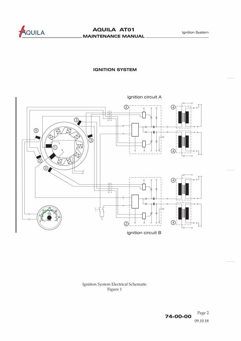
MAINTENANCE MANUAL
AQUILA AT01A Ignition System
74-00-00Page 2
Ignition System Electrical SchematicFigure 1
IGNITION SYSTEM
09.10.18
ignition circuit A
ignition circuit B
1
2
3
4
5
4
4
42
3
3
3

MAINTENANCE MANUAL
AQUILA AT01 A
74-00-00
Page 201
IGNITION SYSTEM - MAINTENANCE
1. General
A. Maintenance of the ignition system is limited to the removal and installation of components. Information on verification and renewal of spark plugs is also provided.
B. For information beyond the scope of this section pertaining to the ignition system, refer to the maintenance manual for ROTAX Engine Type 912 Series.®
C. For inspection time requirements of the ignition system components, refer to 05-20-00.
2. SMD-Electronic Module Removal/Installation
A. Remove SMD-Electronic Module(1) Remove upper engine cowling (refer to 71-10-00).(2) Remove battery from aircraft (refer to 24-30-00).(3) Disconnect electrical connections to electronic module.(4) Remove machine screws, lock washer and washers securing electronic module, cable clamp,
and ground cable terminal to engine.(5) Remove electronic module from engine.
B. Install SMD-Electronic Module(1) Put electronic module, cable clamp and ground cable terminal in position and secure to the
engine using lock washer, washers and screws.(2) Connect electrical connections to electronic module.(3) Install battery (refer to 24-30-00).(4) Install upper engine cowling (refer to 71-10-00).
3. Double Ignition Coil Assembly Removal/Installation
A. Remove Double Ignition Coil Assembly(1) Remove upper engine cowling (refer to 71-10-00).(2) Remove battery from aircraft (refer to 24-30-00).(3) Remove clamps and cable ties securing ignition cables to engine.(4) Remove spark plug connectors from spark plugs.(5) Remove machine screws, bolts, nuts, lock washers and washers securing coil assembly to
engine.(6) Remove coil assembly.
B. Install Double Ignition Coil Assembly(1) Install coil assembly to engine using machine screws, bolts, nuts, lock washers and washers.
Ensure correct position of the hardware.(2) Route ignition cables to the appropriate spark plug position.
NOTE: There are yellow marking sleeves on the cables.
Ignition System
09.10.18
MAINTENANCE MANUAL
AQUILA AT01A
(3) Install spark plug connectors to spark plugs.(4) Install clamps and cable ties securing ignition cables to engine.(5) Install battery (refer to 24-30-00).(6) Install engine cowling (refer to 71-10-00).
4. Spark Plug Removal/Installation
A. Remove Spark Plug(1) Remove engine cowling (refer to 71-10-00).(2) Disconnect battery (refer to 24-30-00).(3) Remove resistor spark plug connector from spark plug.
CAUTION: COVER SPARK PLUG HOLE TO PREVENT ENTRY OF FOREIGN MATERIALS.
(4) Unscrew spark plug and remove from engine.
B. Install Spark Plug
NOTE: New spark plugs and spark plug connectors have been introduced by Rotax. Refer to Rotax SI-912-027 for further information.
(1) Clean spark plug as required.(2) Apply a small amount of heat conduction compound to spark plug thread.(3) Install spark plug to engine. Torque old plug type to 20 Nm (177 in.lbs) / new plug type to 16
Nm (142 in.lbs) on the cold engine.(4) Install spark plug connector to spark plug.(5) Reconnect battery (refer to 24-30-00).(6) Install engine cowling (refer to 71-10-00).
5. Inspection/Check
A. Spark Plugs
NOTE: Always renew both spark plugs of a cylinder and do not interchange spark plugs between cylinders.
NOTE: Mixing of spark plug types and spark plug connector types is NOT allowed.All spark plugs and spark plug connectors must be of the same part number for the entire engine.
(1) Mark position of the spark plugs (e.g. cyl. 1 top) and remove spark plugs as described above.(2) Inspect the spark plugs for damage (melt beads, burn off). Renew spark plug if required.(3) Inspect spark plug thread for damage (especially at burn off). Renew spark plug if required.(4) Inspect plug face appearance (refer to table 1).(5) Inspect spark plug electrode gap. Renew spark plug if required.
74-00-00Page 202
Ignition System
09.10.18
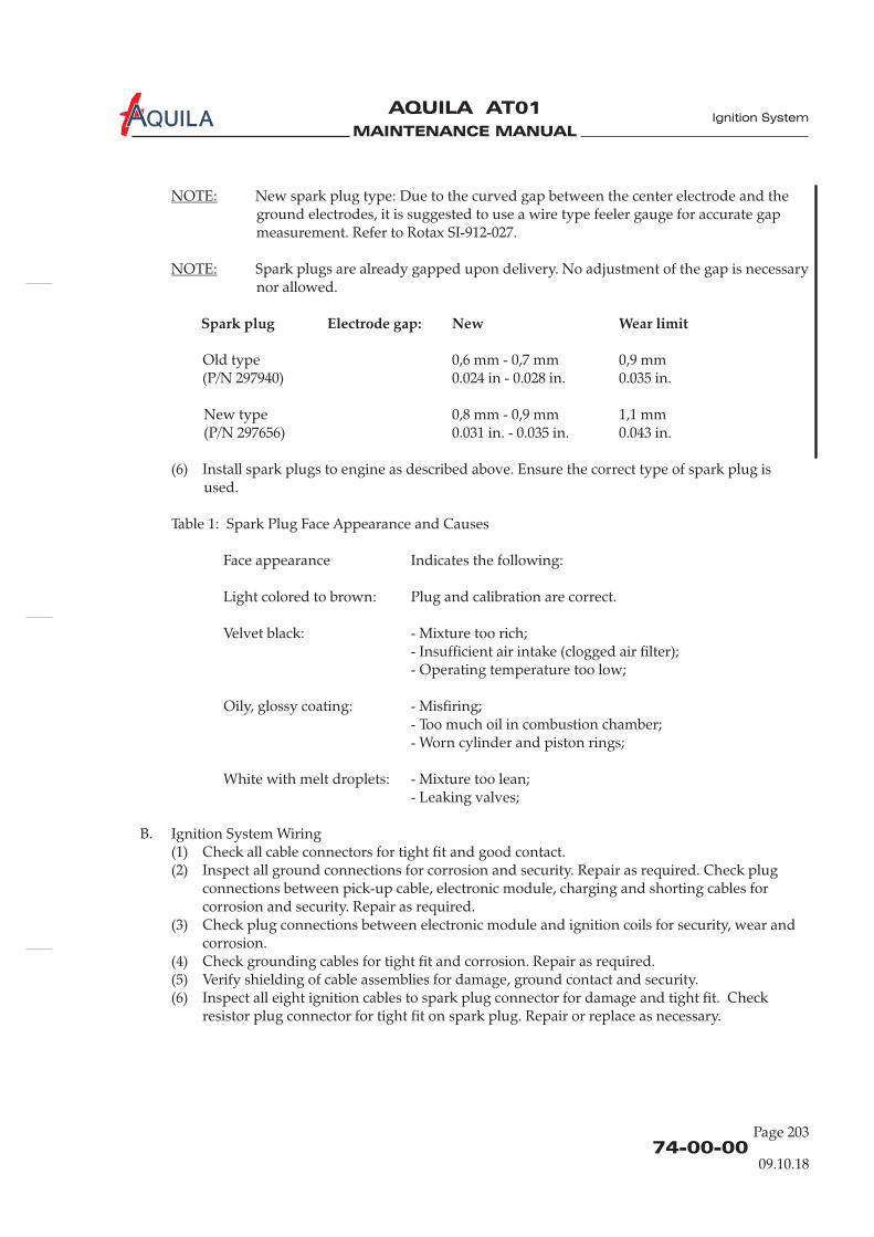
MAINTENANCE MANUAL
AQUILA AT01 A
NOTE:ground electrodes, it is suggested to use a wire type feeler gauge for accurate gap measurement. Refer to Rotax SI-912-027.
NOTE: Spark plugs are already gapped upon delivery. No adjustment of the gap is necessary nor allowed.
Spark plug Electrode gap: New Wear limit
Old type 0,6 mm - 0,7 mm 0,9 mm (P/N 297940) 0.024 in - 0.028 in. 0.035 in.
New type 0,8 mm - 0,9 mm 1,1 mm(P/N 297656) 0.031 in. - 0.035 in. 0.043 in.
(6) Install spark plugs to engine as described above. Ensure the correct type of spark plug is used.
Table 1: Spark Plug Face Appearance and Causes
Face appearance Indicates the following:
Light colored to brown: Plug and calibration are correct.
Velvet black: - Mixture too rich;- Insufficient air intake (clogged air filter);- Operating temperature too low;
Oily, glossy coating: - Misfiring;- Too much oil in combustion chamber;- Worn cylinder and piston rings;
White with melt droplets: - Mixture too lean;- Leaking valves;
B. Ignition System Wiring(1) Check all cable connectors for tight fit and good contact.(2) Inspect all ground connections for corrosion and security. Repair as required. Check plug
connections between pick-up cable, electronic module, charging and shorting cables for corrosion and security. Repair as required.
(3) Check plug connections between electronic module and ignition coils for security, wear and corrosion.
(4) Check grounding cables for tight fit and corrosion. Repair as required.(5) Verify shielding of cable assemblies for damage, ground contact and security.(6) Inspect all eight ignition cables to spark plug connector for damage and tight fit. Check
resistor plug connector for tight fit on spark plug. Repair or replace as necessary.
New spark plug type: Due to the curved gap between the center electrode and the
74-00-00
Page 203
Ignition System
09.10.18

MAINTENANCE MANUAL
AQUILA AT01A
MAINTENANCE MANUAL
AQUILA AT01
Aviation by Excellence GmbH
CHAPTER 75
ENGINE COOLING SYSTEM

MAINTENANCE MANUAL
AQUILA AT01
Aviation by Excellence GmbH
MAINTENANCE MANUAL
AQUILA AT01
Aviation by Excellence GmbH
Page 0175 - TOC
Cooling System
TABLE OF CONTENTS
ChapterSection
ENGINE COOLING - GENERAL...................................................................75-00-00 1Introduction 75-00-00 1General Description 75-00-00 1
ENGINE COOLING SYSTEM - MAINTENANCE PRACTICES................75-10-00 201General 75-10-00 201Water Pump Removal/Installation 75-10-00 201Radiator Removal/Installation 75-10-00 201Overflow Bottle Removal/Installation 75-10-00 202Expansions Tank Removal/Installation 75-10-00 202Engine Cooling System Inspection/Check 75-10-00 202
WINTERIZATION KIT - MAINTENANCE PRACTICES ............................75-10-01 201 Winter. KitGeneral 75-10-01 201Air Inlet Cover Removal/Installation 75-10-01 202Inspection/Check 75-10-01 202
Title Subject Page Effectivity
Winter. KitWinter. KitWinter. Kit
26.04.05

MAINTENANCE MANUAL
AQUILA AT01
Aviation by Excellence GmbH

MAINTENANCE MANUAL
AQUILA AT01
Aviation by Excellence GmbH
ENGINE COOLING SYSTEM - GENERAL
1.
A. This chapter describes those units and components, which cool and ventilate engine cylinderswith cylinder heads.
B. For cooling system servicing, such as replenishing or flushing, refer to 12-14-00.
2.
A. The cooling system of the ROTAX 912S engine is designed for liquid cooling of the cylinder heads
and ram air cooling of the cylinders. The cooling system of the cylinder heads is a closed circuitwith an expansion tank.The coolant flow is forced by a camshaft driven water pump from the radiator to the cylinderheads. From the top of cylinder heads the coolant passes onto the expansion tank. Since thelocation of the radiator is below engine level, the expansion tank located on top of the engineallows for coolant expansion.
Introduction
General Description
®
75-00-00
Page 01
Cooling System
Engine Cooling System (Schematic)Figure 01
Radiator
Expansion Tank
Overflow
Bottle
Water Pump
Hot
26.04.05
MAINTENANCE MANUAL
AQUILA AT01
Aviation by Excellence GmbH
The expansion tank is closed by a pressure cap (with excess pressure valve and return valve). Attemperature rise of the coolant the excess pressure valve opens and the coolant will flow via hoseat atmospheric pressure to the transparent overflow bottle. When cooling down, the coolant willbe sucked back into the cooling circuit.Coolant temperatures are measured by means of temperature probes installed in cylinder heads 2and 3.
B. Optional is a winterization kit provided for cold weather operations. Refer to 75-10-01.
75-00-00Page 02
Cooling System
26.04.05
MAINTENANCE MANUAL
AQUILA AT01A
75-10-00
Page 201
Cooling System
ENGINE COOLING SYSTEM - MAINTENANCE PRACTICES
1.
A.
B. For information beyond the scope of this section pertaining to the engine cooling system, refer tothe Operator's Manual for ROTAX 912 series engines, and to Maintenance Manual for ROTAX
Engine Type 912 Serie.
C. For inspection time requirements of the cooling system components, refer to 05-20-00.
NEVER OPEN RADIATOR, EXPANSION TANK OR OVERFLOW BOTTLE CAPWHEN THE COOLING SYSTEM IS STILL HOT! FOR SAFETY'S SAKE, COVER CAPWITH A CLOTH AND OPEN SLOWLY. SUDDEN OPENING OF THE CAP WOULDPROVOKE EXIT OF BOILING COOLANT AND RESULT IN SEVERE SCALDS.
2.
A. Refer to applicable engine manufacturers documentation.
3.
A. Remove Radiator(1) Remove engine cowling (refer to 71-10-00).(2) Disconnect inlet and outlet hoses at radiator.(3) Disconnect inlet and outlet hoses at oil cooler (cooling system type 1 only).(4) Remove bolts securing radiator to mounting plate ( ).(5) Remove radiator from aircraft.
B. Install Radiator(1) Secure radiator to mounting plate using bolts, washers and spacers (
).(2) Connect inlet and outlet hoses at oil cooler ( ).(3) Connect inlet and outlet hoses at radiator.(4) Install engine cowling (refer to 71-10-00).(5) Replenish engine coolant and oil as required (refer to 12-12-00 and 12-14-00).
IF ENGINE WAS RUNNING RECENTLY, HOT ENGINE COMPONENTS MAYCAUSE SKIN BURNS!
(6) Perform an engine run and check oil cooler / radiator and connections for leaks.
General
WARNING:
Water Pump Removal/Installation
Radiator Removal/Installation
CAUTION:
® ®
The water radiator is mounted on the inner forward part of the lower engine cowling behind themain air intake. There are two types of cooling systems in use:- Type 1: Standard cooling system of the AQUILA AT01 with a combined oil / water radiator.- Type 2: A retrofit cooling system with separate oil and water radiators. Refer to SB-AT01-029 for
further information on upgrading to this type of cooling system.
cooling system type 2 only
cooling system type 2only
cooling system type 1 only
Temporary Revision 4, 27.04.15
MAINTENANCE MANUAL
AQUILA AT01
Aviation by Excellence GmbH
4.
A. Remove Overflow bottle(1) Remove engine cowling (Refer to 71-10-00).(2) Disconnect hose at overflow bottle.(3) Remove cable ties securing overflow bottle to bracket and remove overflow bottle from
aircraft.
B. Install Overflow bottle(1) Place overflow bottle on bracket. Ensure the correct position of the protection rubbers.(2) Secure overflow bottle to bracket with cable ties.(3) Connect hose at overflow bottle.(4) Install engine cowling (Refer to 71-10-00).
5.
A. Remove Expansion Tank(1) Remove engine cowling (Refer to 71-10-00).(2) Drain coolant as required either at water pump or radiator.(3) Remove all hoses connected to expansion tank.(4) Remove expansion tank from engine.
B. Install Expansion Tank(1) Position expansion tank on engine.(2) Connect all hoses to expansion tank.(3) Replenish coolant as required (Refer to 12-14-00).(4) Install engine cowling (Refer to 71-10-00).
6.
A. Engine Cooling System(1) Inspect all coolant hoses for damage by heat, cracking, wear and evidence of leaking.(2) Check all connections on cylinder head top- and bottom side and on the water pump.(3) Check expansion tank for damages. Check protection rubber at bottom of the tank for tight
fit.(4) Check gasket of radiator cover as well as the pressure control valve and return valve. The
pressure control valve opens at 1,2 bar (17.4 psi).
Use only coolant in accordance to 12-14-00.
(5) Check coolant with densimeter or glycol tester. lf necessary, replenish with coolant of samecomposition. Remarkably discoloured or thickened coolant must be renewed.
Overflow Bottle Removal/Installation
Expansion Tank Removal/Installation
Inspection/Check
CAUTION:
75-10-00Page 202
Cooling System
26.04.05

MAINTENANCE MANUAL
AQUILA AT01
Aviation by Excellence GmbH
WINTERIZATION KIT - MAINTENANCE PRACTICES
1.
A. Optional is a winterization kit provided and may be utilized when cold weather operations areconducted.
The kit includes a special metallic air inlet cover with fasteners, a placard (refer to 11-20-00) andthe appropriate AFM supplement. The cover should be installed in front of oil and cooling liquidradiators as shown in figure 201. This restricts the flow of air entering the engine compartment forcooling and will aid in faster and sufficient warming-up of engine oil and cooling liquid in coldweather conditions.
General
Air Inlet Cover InstallationFigure 201
75-10-01
Page 201
Cooling System
26.04.05
Quick Release Fastener
EFFECTIVITY
Aircraft equipped with a winterization kit

MAINTENANCE MANUAL
AQUILA AT01
Aviation by Excellence GmbH
CAUTION:
Air Inlet Cover Removal/Installation
Inspection/Check
THE MAXIMUM PERMISSIBLE OUTSIDE AIR TEMPERATURE TO PERFORMTAKE-OFF WITH INSTALLED AIR INLET COVER IS 15°C (59°F)
It is recommended to use the kit in outside air temperatures below 5°C (41°F).
2.
A. Install Air Inlet Cover as shown in Figure 201. The placard regarding the air inlet cover (refer to11-20-00) should be stuck at engine cowling front side just below the landing light.
2.
A. Perform the following checks if the air inlet cover is installed.(1) Verify the cover is fastened correctly (both quick release fasteners are closed).(2) Check the placard delivered with the winterization kit is firmly in place, not damaged and
readable.
75-10-01Page 202
Cooling System
26.04.05
EFFECTIVITY
Aircraft equipped with a winterization kit

MAINTENANCE MANUAL
AQUILA AT01A
CHAPTER 76
ENGINE CONTROLS

MAINTENANCE MANUAL
AQUILA AT01A
MAINTENANCE MANUAL
AQUILA AT01A
Page 176 - TOC
TABLE OF CONTENTS
ChapterSection
Governor Control Cable Removal/Installation 76-00-00 204Choke Control Adjustment/Test 76-00-00 204Throttle Control Adjustment/Test 76-00-00 205
Title Subject Page Effectifity
ENGINE CONTROLS - GENERAL ..........................................................76-00-00 1Introduction 76-00-00 1General Description 76-00-00 1
ENGINE CONTROLS - MAINTENANCE ..............................................76-00-00 201General 76-00-00 201Control Quadrant Disassembly/Assembly 76-00-00 201Throttle Control Cable Removal/Installation 76-00-00 201
Engine Controls
28.08.15

MAINTENANCE MANUAL
AQUILA AT01A
MAINTENANCE MANUAL
AQUILA AT01A
76-00-00
ENGINE CONTROLS - GENERAL
1.
A. This chapter describes and provides maintenance instructions for components and systems usedto control the engine.
2.
A. Engine controls include throttle, choke, propeller and carburetor heat.
Throttle ControlThe throttle control lever is connected via Bowden cables with the throttle actuation arm on eachcarburetor. The Bowden cable jackets are attached at both ends to a support bracket which isadjustable on the carburetor side.
Propeller ControlMovement of the propeller speed control lever is transferred to the propeller governor controlarm via a Bowden cable. The Bowden cable is adjustable on the propeller governor.
ChokeThe choke control knob is connected via Bowden cables to the choke actuation lever on eachcarburetor.
Carburetor HeatBy pulling the carburetor heat control knob, two coupled flap valves in the air distribution box areoperated. The valves stop airflow from the air intake and allow heated alternate air from theexhaust muffler area to flow to the carburetors. Movement of the carburetor heat knob istransferred to the flap valves through a Bowden cable.
Introduction
General Description
The primary enginecontrols, the throttle and propeller controls, employ conventional push-pull type levers and areconnected to a control quadrant mounted on the center console. The push-pull type choke andcarburetor heat control knobs are to be found in the center console, below the instrument panel.
Engine Controls
28.08.15
Page 1

MAINTENANCE MANUAL
AQUILA AT01A
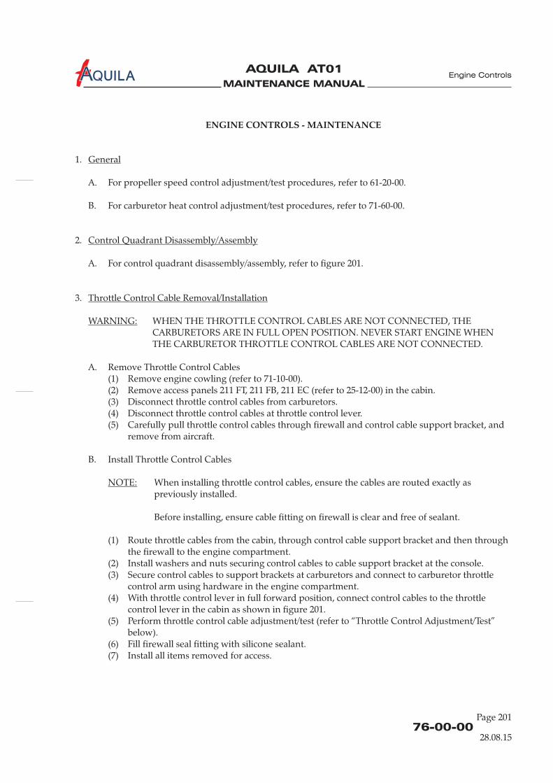
MAINTENANCE MANUAL
AQUILA AT01A
76-00-00
Page 201
ENGINE CONTROLS - MAINTENANCE
1.
A. For propeller speed control adjustment/test procedures, refer to 61-20-00.
B. For carburetor heat control adjustment/test procedures, refer to 71-60-00.
2.
A. For control quadrant disassembly/assembly, refer to figure 201.
3.
WHEN THE THROTTLE CONTROL CABLES ARE NOT CONNECTED, THECARBURETORS ARE IN FULL OPEN POSITION. NEVER START ENGINE WHENTHE CARBURETOR THROTTLE CONTROL CABLES ARE NOT CONNECTED.
A. Remove Throttle Control Cables(1) Remove engine cowling (refer to 71-10-00).(2) Remove access panels 211 FT, 211 FB, 211 EC (refer to 25-12-00) in the cabin.(3) Disconnect throttle control cables from carburetors.(4) Disconnect throttle control cables at throttle control lever.(5) Carefully pull throttle control cables through firewall and control cable support bracket, and
remove from aircraft.
B. Install Throttle Control Cables
When installing throttle control cables, ensure the cables are routed exactly aspreviously installed.
Before installing, ensure cable fitting on firewall is clear and free of sealant.
(1) Route throttle cables from the cabin, through control cable support bracket and then throughthe firewall to the engine compartment.
(2) Install washers and nuts securing control cables to cable support bracket at the console.(3) Secure control cables to support brackets at carburetors and connect to carburetor throttle
control arm using hardware i .(4) With throttle control lever in full forward position, connect control cables to the throttle
control lever i as shown in figure 201.(5) Perform throttle control cable adjustment/test (refer to “Throttle Control Adjustment/Test”
below).(6) Fill firewall seal fitting with silicone sealant.(7) Install all items removed for access.
General
Control Quadrant Disassembly/Assembly
Throttle Control Cable Removal/Installation
WARNING:
NOTE:
n the engine compartment
n the cabin
Engine Controls
28.08.15
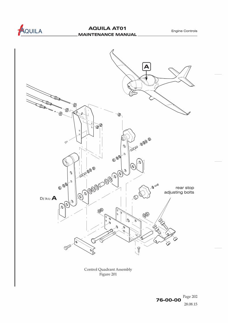
MAINTENANCE MANUAL
AQUILA AT01A Engine Controls
76-00-00Page 202
28.08.15
Control Quadrant AssemblyFigure 201
A
A❉ETAIL�
rear stop
adjusting bolts
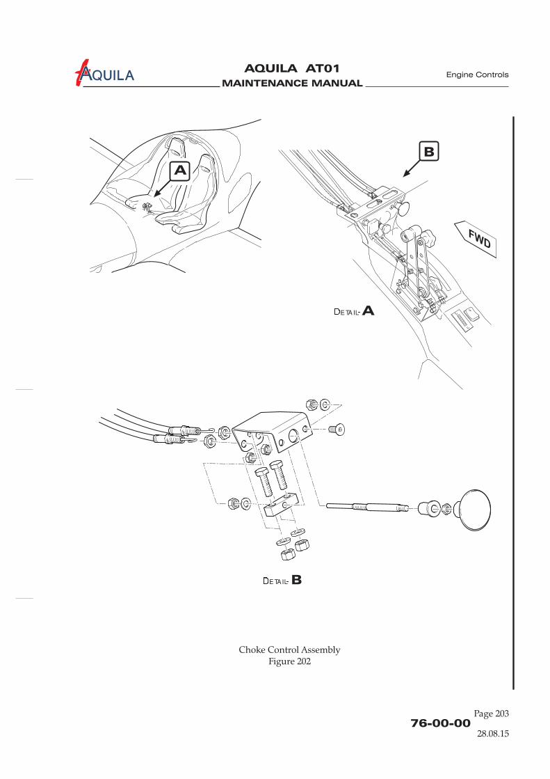
MAINTENANCE MANUAL
AQUILA AT01A Engine Controls
76-00-00
Page 203
28.08.15
A
A✁ETAIL✂
B
B✁ETAIL✂
Choke Control AssemblyFigure 202
MAINTENANCE MANUAL
AQUILA AT01A
4.
A. Remove Governor Control Cable(1) Remove engine cowling (refer to 71-10-00).(2) Remove access panels 211 FT, 211 FB, 211 EC (refer to 25-12-00) in the cabin.(3) Disconnect governor control cable from governor control arm.(4) Remove any clamps or ties securing governor cable to engine or engine mount.(5) Disconnect governor control cable at propeller control lever.(6) Carefully pull governor control cable through firewall and control cable support bracket, and
remove from aircraft.
B. Install Governor Control Cables
When installing throttle control cables, ensure the cables are routed exactly aspreviously installed.
Before installing, ensure cable fitting on firewall is clear and free of sealant.
(1) Route governor cable from the cabin, through control cable support bracket and thenthrough the firewall to the engine compartment.
(2) Install washers and nuts securing control cable to cable support bracket at the console.(3) Install governor control cable to governor control arm using hardware at the governor in the
engine compartment.(4) Connect control cable to the propeller control lever in the cabin as shown in figure 201.(5) Re-install clamps or ties securing governor cable to engine or engine mount.(6) Perform governor control adjustment/test (refer to 61-20-00).(7) Fill firewall seal fitting with silicone sealant.(8) Install all items removed for access.
5.
A. Adjust Choke Control(1) Adjust control cables so, if the choke control knob is in the full forward position, the starting
carburetor control arms on both carburetors reach their low stop.
Governor Control Cable Removal/Installation
NOTE:
Choke Control Adjustment/Test
76-00-00Page 204
28.08.15
Engine Controls
MAINTENANCE MANUAL
AQUILA AT01A
76-00-00
Page 205
28.08.15
Engine Controls
6.
A. Idle Speed Adjustment
Always perform idle speed adjustment at operating temperature of the engine.
(1) Close idle mixture control screw by turning clockwise.(2) Open idle mixture control screw again 1.5 turns counterclockwise.
Turning idle mixture control screw in clockwise direction results in a leaner mixtureand turning counterclockwise in a richer mixture.If no satisfactory engine idling cannot be achieved, an additional pneumaticsynchronization will be necessary.
B. Adjust Throttle Control(1) Move throttle lever in the cockpit to full throttle position.(2) Disconnect control cables from the throttle control arms of both carburetors.(3) Move throttle lever in the cockpit 1-2 mm (0.04-0.08 in.) back.(4) Tighten the Bowden cable clamps on the throttle control arms of both carburetors.(5) Move throttle control lever between idle and full throttle positions. Ensure the throttle
control lever is only limited by the throttle control arm stops on the carburetors and haspositive clearance of 1 mm (0.04 in.) to the console slot in both the full forward and full aftpositions. There must be no notable bulging of the Bowden cables on the carburetors withcontrol lever in the full throttle position.
IN FULL THROTTLE POSITION THE THROTTLE WIRE MUST NOT BULGENOTABLE OUT OF LINE BETWEEN THE CARBURETOR LEVER AND THEBOWDEN CABLE ADJUSTMENT, BECAUSE THIS MAY RESULT IN FATIGUEFAILURE OF THE THROTTLE WIRE!
(6) Adjust rear stop adjusting bolt in the cockpit so the throttle control lever and the control armsof the carburetors contact their rear stops simultaneously.
(7) Perform carburetor synchronization (refer to ROTAX Maintenance Manual for Rotax EngineType 912 Series, chapter 12-20-00, section 10).
C. Throttle Inspection/Check(1) Check proper Bowden cable routing to prevent influence to carburetors actuation caused by
any movement of engine or other controls, thus possibly falsifying precise idle speed settingand synchronization.
(2) Inspect the throttle control cable attachment to carburetors throttle control arm and to thecontrol quadrant. Check hardware for security and condition.
(3) Check the throttle control slides smoothly and without any resistance to movementthroughout its full range of travel. Verify the throttle control lever is only limited by thethrottle control arm stops on carburetors and has positive clearance of 1 mm (0.04 in.) to theconsole slot in both the full forward and full aft positions. There must be no notable bulgingof the Bowden cables on the carburetor with control lever in the full throttle position.
(4) Check reset springs and inspect engagement holes for wear.(5) If required lubricate carburetors actuation linkage with engine oil.
Throttle Control Adjustment/Test
NOTE:
NOTE:
WARNING:

MAINTENANCE MANUAL
AQUILA AT01A

MAINTENANCE MANUAL
AQUILA AT01
Aviation by Excellence GmbH
CHAPTER 77
ENGINE INDICATING

MAINTENANCE MANUAL
AQUILA AT01
Aviation by Excellence GmbH
MAINTENANCE MANUAL
AQUILA AT01
Aviation by Excellence GmbH
Page 0177 - TOC
26.11.01
Engine Indicating
TABLE OF CONTENTS
ChapterSection
ENGINE INDICATING - GENERAL..............................................................77-00-00 1Introduction 77-00-00 1General Description 77-00-00 1
POWER - MAINTENANCE PRACTICES ......................................................77-10-00 201General 77-10-00 201Tachometer Removal/Installation 77-10-00 201RPM Sensor Removal/Installation 77-10-00 201Manifold Pressure Gage Removal/Installation 77-10-00 201
TEMPERATURE - MAINTENANCE PRACTICES........................................77-20-00 201General 77-20-00 201CHT Indicator Removal/Installation 77-20-00 201CHT Sensor Removal/Installation 77-20-00 201
Title Subject PageEffectivity

MAINTENANCE MANUAL
AQUILA AT01
Aviation by Excellence GmbH
MAINTENANCE MANUAL
AQUILA AT01
Aviation by Excellence GmbH
77-00-00
Page 01
26.11.01
Engine Indicating
ENGINE INDICATING - GENERAL
1.
A. This chapter describes those systems and components, which indicate engine operation.
B. Oil pressure and oil temperature measuring systems are described in Chapter 79, section „OIL"(refer to 79-30-00).
2.
A. The following parameters of the engine output and condition are measured and indicated:(1) Engine Speed(2) Manifold Pressure(3) Oil Pressure(4) Oil Temperature(5) Cylinder Head Temperature
B. Except the manifold pressure, all parameters are measured with sensors, which transform engineparameters in equivalent electrical signals. These signals are transmitted to the indicator andtranslated into readings.The manifold pressure is measured mechanically by a pressure gage, which is connected with theengine through a rubber hose.
C. The engine gages are placed in a cluster on the instrument panel, to the right of the avionicequipment.
Introduction
General Description

MAINTENANCE MANUAL
AQUILA AT01
Aviation by Excellence GmbH

MAINTENANCE MANUAL
AQUILA AT01
Aviation by Excellence GmbH
77-10-00
Page 201
26.11.01
Engine Indicating
POWER - MAINTENANCE PRACTICES
1.
A. The AQUILA AT01 engine speed is indicated by a tachometer, which is mounted on the leftinstrument panel adjacent to flight instruments. The tachometer receives an electrical speedsignal from a sensor mounted on the aft end of the engine, on ignition housing. The maintenanceis limited to removal and installation of the tachometer and the sensor assy.
B. The manifold pressure is measured mechanically by a pressure gage, which is connected througha rubber hose to the compensating tube, located on top of engine. The maintenance is limited toremoval and installation of the pressure gage.If the rubber hose is damaged or in bad condition it must be replaced.
1.
A. Remove Tachometer(1) Ensure BAT switch is in OFF position.(2) Remove glareshield (refer to 31-10-00).(3) Locate tachometer and disconnect electrical cables from backside of tachometer.(4) While supporting tachometer, remove screws securing unit to instrument panel.(5) Remove tachometer from aircraft.
B. Install Tachometer and Drive Cable(1) Position tachometer in instrument panel and attach with four screws.(2) Reconnect electrical cables to backside of tachometer.(3) Install glareshield (refer to 31-10-00).
2.
A. Remove RPM Sensor(1) Ensure BAT switch is in OFF position.(2) Remove engine cowling (refer to 71-10-00).(3) Disconnect RPM sensor leads at connector.(4) Locate RPM sensor and remove screw and washer securing RPM sensor to ignition housing.
Remove sensor from aircraft.
B. Install Sensor(1) Install RPM sensor to ignition housing using washer and screw.(2) Route sensor leads and reconnect at connector.(3) Install engine cowling (refer to 71-10-00).
General
Tachometer Removal/Installation
RPM Sensor Removal/Installation
MAINTENANCE MANUAL
AQUILA AT01
Aviation by Excellence GmbH
77-10-00Page 201
Engine Indicating
26.11.01
3.
A. Remove Manifold Pressure Gage(1) Remove glareshield (refer to 31-10-00).(2) Locate gage and remove rubber hose from gage.(4) While supporting manifold pressure gage, remove screws securing unit to instrument panel.(5) Remove manifold pressure gage from aircraft.
B. Install Manifold Pressure Gage(1) Position Gage in instrument panel and attach with four screws.(2) Attach rubber hose.(3) Install glareshield (refer to 31-10-00).
Manifold Pressure Gage Removal/Installation
MAINTENANCE MANUAL
AQUILA AT01
Aviation by Excellence GmbH
77-20-00
Page 201
26.11.01
Engine Indicating
TEMPERATURE - MAINTENANCE PRACTICES
1.
A. The cylinder head temperature is measured by a temperature sensitive sensor that is mounted inthe No. 3 cylinder head.The indicator is located within the cluster of engine gauges on the right instrument panel. Ittranslates the electrical signal from the sensor in a reading.
B. The maintenance of the CHT measuring system is limited to the removal and installation of thesensor and indicator.
2.
A. Remove CHT Indicator(1) Ensure electrical power to aircraft is OFF.(2) Remove glareshield (refer to 31-10-00).(2) Disconnect electrical connectors from backside of indicator.(3) While supporting CHT indicator, remove screws securing indicator to instrument panel, and
remove indicator from aircraft.
B. Install CHT Indicator(1) Position CHT indicator in instrument panel and attach with screws.(2) Connect electrical connectors to indicator.
3.
A. Remove CHT Sensor(1) Ensure electrical power to aircraft is OFF.(2) Remove engine cowling (refer to 71-10-009.(3) Disconnect sensor electrical lead at sensor.(4) Unscrew and remove sensor from engine.
B. Install CHT Sensor(1) Install sensor to engine. Torque to 10 Nm (90 in.lb).(2) Connect electrical connector to sensor.(3) Install engine cowling (refer to 71-10-00).
General
CHT Indicator Removal/Installation
CHT Sensor Removal/Installation

MAINTENANCE MANUAL
AQUILA AT01
Aviation by Excellence GmbH
MAINTENANCE MANUAL
AQUILA AT01
Aviation by Excellence GmbH
CHAPTER 78
EXHAUST

MAINTENANCE MANUAL
AQUILA AT01
Aviation by Excellence GmbH

MAINTENANCE MANUAL
AQUILA AT01
Aviation by Excellence GmbH
Page 0178 - TOC
07.11.01
Exhaust
TABLE OF CONTENTS
ChapterSection
EXHAUST - GENERAL.....................................................................................78-00-00 1Introduction 78-00-00 1General Description 78-00-00 1
EXHAUST SYSTEM - MAINTENANCE PRACTICES .................................78-10-00 201General 78-10-00 201Exhaust System Removal/Installation 78-10-00 201Main Muffler Inspection/Check 78-10-00 201
Title Subject Page

MAINTENANCE MANUAL
AQUILA AT01
Aviation by Excellence GmbH
MAINTENANCE MANUAL
AQUILA AT01
Aviation by Excellence GmbH
78-00-00
Page 01
07.11.01
Exhaust
EXHAUST SYSTEM - GENERAL
1.
A. This chapter describes such systems and components, which direct the engine exhaust gasesoverboard.
2.
A. The exhaust system is comprised of four exhaust pipes (from each cylinder), a main muffler, asecond muffler, and a tailpipe.A shroud around the main muffler serves as a heat exchanger. The air that is heated by the heatexchanger is then ducted to the aircraft cabin for heating of the cabin and windshield defrosting.
Introduction
General Description

MAINTENANCE MANUAL
AQUILA AT01
Aviation by Excellence GmbH

MAINTENANCE MANUAL
AQUILA AT01
Aviation by Excellence GmbH
78-10-00
Page 201
07.11.01
Exhaust
EXHAUST SYSTEM - MAINTENANCE PRACTICES
1.
A. Each engine cylinder has an exhaust pipe leading down to the main muffler that is locatedbeneath the engine. The exhaust pipes and the second muffler are connected to the main mufflerover ball joints. The ball joints are employed to allow movement due to heat expansion andnormal operating loads at connections. The ball joints are secured with two springs each.The single tail pipe routes the exhaust gases out through the lower cowling area.
B. Maintenance practices for the exhaust system include the exhaust system removal and installationand the leak test.
2.
A. Remove Exhaust System(1) Remove engine cowling (refer to 71-10-00).(2) Disconnect flexible heat ducts from heat shroud.(3) Remove nut and washer securing tailpipe support bracket to engine mount.(4) While supporting exhaust system, remove nuts securing risers to engine and remove exhaust
system from engine.
B. Install Exhaust System
(1) Position exhaust system with new gaskets to engine and secure to engine using nuts.(2) Secure tailpipe support bracket to engine mount with washer and nut.(3) Connect flexible heat ducts to heat shroud.(4) Install engine cowling (refer to 71-10-00).
3.
FAILURE TO INSPECT MAIN MUFFLER FOR LEAKS COULD RESULT IN CARBONMONOXIDE ENTERING THE CABIN AREA, LEADING TO SERIOUS INJURY ORDEATH.
A. The main muffler inspection/check time intervals contained in chapter 5 “Time Limits /Maintenance Checks”.
B. Main Muffler Inspection/Check Procedures(1) Remove risers from muffler and unwrap heat shroud from around muffler.(2) Using visual inspection, examine the exterior of muffler, looking for cracks, dents, soot, and
evidence of exhaust gasses escaping through holes or tears. Pay particular attention to welds.(3) Examine the interior of the main muffler with a flashlight and a mirror, looking for tears,
holes and general condition.(4) Use a water test to determine main muffler integrity:
(a) Install solid test plugs on three muffler openings.
General
Exhaust System Removal/Installation
Main Muffler Inspection/Check
WARNING:

MAINTENANCE MANUAL
AQUILA AT01
Aviation by Excellence GmbH
78-10-00Page 202
07.11.01
Exhaust
(b) Install ported test plug on remaining muffler opening.(c) Attach pressure source and apply 2.5 psi to interior of muffler.(d) Submerge pressurized muffler in water and inspect for leaks.(e) If any leaks are detected, the muffler must be removed from service and repaired or
replaced.(f) Remove muffler from water, remove test plugs and dry muffler with compressed air.
MAINTENANCE MANUAL
AQUILA AT01
Aviation by Excellence GmbH
CHAPTER 79
OIL

MAINTENANCE MANUAL
AQUILA AT01
Aviation by Excellence GmbH

MAINTENANCE MANUAL
AQUILA AT01
Aviation by Excellence GmbH
Page 0179 - TOC
07.11.01
Oil
TABLE OF CONTENTS
ChapterSection
OIL - GENERAL ................................................................................................79-00-00 1Introduction 79-00-00 1General Description 79-00-00 1
OIL TANK - MAINTENANCE PRACTICES..................................................79-10-00 201General 79-10-00 201Oil Tank Removal/Installation 79-10-00 201Oil Tank Cleaning 79-10-00 201
OIL COOLER - MAINTENANCE PRACTICES............................................79-20-00 201General 79-20-00 201Oil Cooler Removal/Installation 79-20-00 201
OIL TEMPERATURE MEASURINGSYSTEM - MAINTENANCE PRACTICES .....................................................79-30-00 201
General 79-30-00 201Oil Temperature Indicator Removal/Installation 79-30-00 201Oil Temperature Sensor Removal/Installation 79-30-00 201
OIL PRESSURE MEASURINGSYSTEM - MAINTENANCE PRACTICES .....................................................79-31-00 201
General 79-31-00 201Oil Pressure Indicator Removal/Installation 79-31-00 201Oil Pressure Sensor Removal/Installation 79-31-00 201
Title Subject Page

MAINTENANCE MANUAL
AQUILA AT01
Aviation by Excellence GmbH

MAINTENANCE MANUAL
AQUILA AT01
Aviation by Excellence GmbH
79-00-00
Page 01
07.11.01
Oil
OIL - GENERAL
1.
A. This chapter covers those units and components external to the engine concerned with storingand delivering lubricating oil to and from engine, and with indicating oil condition.For additional information on the internal engine oil system components, refer to the respectiveengine manufacturers publications.
1.
A. The external oil system is comprised of an oil tank, oil cooler, and an oil filter. For monitoring oilconditions serves an oil pressure- and an oil temperature measuring system.The oil tank is attached to the engine mount on the right hand side of the engine. The oil cooler islocated in the forward part of the lower engine cowling behind the main air intake. It isconnected with the engine and the oil tank via flexible hoses. The oil pump with an integrated oilpressure regulator is mounted at the front of the engine below the propeller gearbox. It is drivenby the camshaft. The oil filter is installed on the left side of the oil pump housing.
Introduction
General Description
Oil Tank
Oil Cooler
Oil Pump
Oil Temperature
Sensor
Oil Pressure Transducer
Oil Filter
Lubrication System (Schematic)Figure 01
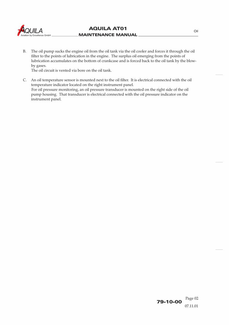
MAINTENANCE MANUAL
AQUILA AT01
Aviation by Excellence GmbH
B. The oil pump sucks the engine oil from the oil tank via the oil cooler and forces it through the oilfilter to the points of lubrication in the engine. The surplus oil emerging from the points oflubrication accumulates on the bottom of crankcase and is forced back to the oil tank by the blow-by gases.The oil circuit is vented via bore on the oil tank.
C. An oil temperature sensor is mounted next to the oil filter. It is electrical connected with the oiltemperature indicator located on the right instrument panel.For oil pressure monitoring, an oil pressure transducer is mounted on the right side of the oilpump housing. That transducer is electrical connected with the oil pressure indicator on theinstrument panel.
79-10-00Page 02
07.11.01
Oil
MAINTENANCE MANUAL
AQUILA AT01
Aviation by Excellence GmbH
79-10-00
Page 201
07.11.01
Oil
OIL TANK - MAINTENANCE PRACTICES
1.
A. The oil tank is attached to the engine mount on the right hand side of the engine. Formaintenance purposes it can be removed and/ or disassembled (Figure 201).
B. In case of any oil contamination, the oil tank must be removed, disassembled and cleaned.
2.
A. Remove the Oil Tank(1) Remove upper engine cowling (refer to 71-10-00).(2) Disconnect inlet and outlet hoses at oil tank.(3) Loosen clamps securing oil tank to engine. Remove oil tank from aircraft.
B. Install Oil Cooler(1) Position oil tank to engine and secure with clamps.(2) Connect inlet and outlet hoses at oil tank.(3) Install engine cowling (refer to 71-10-00).(4) Replenish engine oil as required.
IF ENGINE WAS RUNNING RECENTLY, HOT ENGINE COMPONENTS MAYCAUSE SKIN BURNS!
(5) Perform an engine run and check oil tank and connections for leaks.
3.
A. Oil Tank Cleaning Procedure(1) Remove upper engine cowling (refer to 71-10-00).(2) Disconnect inlet and outlet hoses at oil tank.(3) Remove clamp and oil tank cover with O-ring.(4) Remove baffle insert and partition.(5) Unscrew and remove drain screw.(6) Clean all parts and inspect for damage.(7) Re-assemble oil tank.(8) Fit drain screw with a new gasket, torque to 25 Nm (220 in.lb) and safety wire.(9) Connect inlet and outlet hoses at oil tank.(10) Install engine cowling (refer to 71-10-00).(11) Replenish engine oil as required.
IF ENGINE WAS RUNNING RECENTLY, HOT ENGINE COMPONENTS MAYCAUSE SKIN BURNS!
(12) Perform an engine run and check oil tank and connections for leaks.
General
Oil Tank Removal/Installation
CAUTION:
Oil Tank Cleaning
CAUTION:
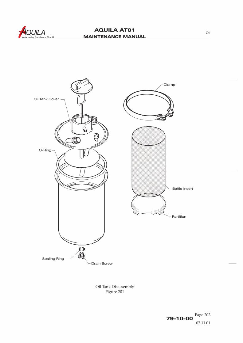
MAINTENANCE MANUAL
AQUILA AT01
Aviation by Excellence GmbH
79-10-00Page 202
07.11.01
Oil
Oil Tank Cover
O-Ring
Sealing Ring
Drain Screw
Baffle Insert
Partition
Clamp
Oil Tank DisassemblyFigure 201
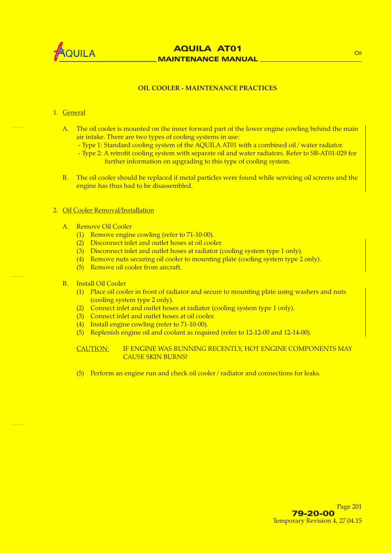
MAINTENANCE MANUAL
AQUILA AT01A
79-20-00
Page 201
Temporary Revision 4, 27.04.15
Oil
OIL COOLER - MAINTENANCE PRACTICES
1.
A. The oil cooler is mounted on the inner forward part of the lower engine cowling behind the mainair intake. There are two types of cooling systems in use:- Type 1: Standard cooling system of the AQUILA AT01 with a combined oil / water radiator.- Type 2: A retrofit cooling system with separate oil and water radiators. Refer to SB-AT01-029 for
further information on upgrading to this type of cooling system.
B. The oil cooler should be replaced if metal particles were found while servicing oil screens and theengine has thus had to be disassembled.
2.
A. Remove Oil Cooler(1) Remove engine cowling (refer to 71-10-00).(2) Disconnect inlet and outlet hoses at oil cooler.(3) Disconnect inlet and outlet hoses at radiator (cooling system type 1 only).(4) Remove nuts securing oil cooler to mounting plate ( ).(5) Remove oil cooler from aircraft.
B. Install Oil Cooler(1) Place oil cooler in front of radiator and secure to mounting plate using washers and nuts
( ).(2) Connect inlet and outlet hoses at radiator ( .(3) Connect inlet and outlet hoses at oil cooler.(4) Install engine cowling (refer to 71-10-00).(5) Replenish engine oil and coolant as required (refer to 12-12-00 and 12-14-00).
IF ENGINE WAS RUNNING RECENTLY, HOT ENGINE COMPONENTS MAYCAUSE SKIN BURNS!
(5) Perform an engine run and check oil cooler / radiator and connections for leaks.
General
Oil Cooler Removal/Installation
CAUTION:
cooling system type 2 only
cooling system type 2 onlycooling system type 1 only)

MAINTENANCE MANUAL
AQUILA AT01
Aviation by Excellence GmbH
79-30-00
Page 201
07.11.01
Oil
OIL TEMPERATURE MEASURING SYSTEM - MAINTENANCE PRACTICES
1.
A. The oil temperature measuring system consists of a temperature sensor, an oil temperatureindicator, and wire connecting the two components.The oil temperature is measured in the oil filter / oil pump area. The resistance-type sensor isoperating with system voltage. It sends a temperature equivalent electrical signal to the oiltemperature indicator in the cockpit. The indicator translates the electrical signal in a temperaturereading. The oil temperature indicator is mounted on the right instrument panel, within thecluster of engine gauges.
B. Maintenance is limited to the removal and installation of the system components.
2.
A. Remove Oil Temperature Indicator(1) Ensure electrical power to aircraft is OFF.(2) Remove cable connector from rear of indicator.(3) Remove screws attaching indicator to instrument panel.(4) Remove indicator from aircraft.
B. Install Oil Temperature Indicator(1) Position indicator to instrument panel hole and secure with screws.(2) Install cable connector at rear of indicator.
3.
A. Remove Oil Temperature Sensor(1) Ensure electrical power to aircraft is OFF.(2) Remove engine cowling (refer to 71-10-00).(3) Disconnect electrical lead at sensor.
CAP OR PLUG SENSOR PORT TO PREVENT ENTRY OF FOREIGN MATERIAL.
(4) Unscrew and remove sensor and washer from engine.
B. Install Oil Temperature Sensor(1) Install new washer and sensor to engine. Torque to 10 Nm (90 in.lb).(2) Connect electrical connector to sensor.(3) Install engine cowling (refer to 71-10-00).
General
Oil Temperature Indicator Removal/Installation
Oil Temperature Sensor Removal/Installation
CAUTION:

MAINTENANCE MANUAL
AQUILA AT01
Aviation by Excellence GmbH
MAINTENANCE MANUAL
AQUILA AT01
Aviation by Excellence GmbH
79-31-00
Page 201
07.11.01
Oil
OIL PRESSURE MEASURING SYSTEM - MAINTENANCE PRACTICES
1.
A. The oil pressure measuring system consists of an oil pressure transducer, an oil pressure indicator,and wire connecting the two components.The oil pressure transducer is mounted on the right side of the oil pump housing. The oilpressure transducer is a membrane pressure transducer with a built-in potentiometer whoseresistance is varying depending on oil pressure. It is supplied with system voltage. The pressureequivalent electrical signal is routed via electro cable to the cockpit mounted oil pressure indicator.The indicator translates the electrical signal in a pressure reading. The oil pressure indicator islocated on the right instrument panel, within the cluster of engine gauges.
B. Maintenance is limited to the removal and installation of the system components.
2.
A. Remove Oil Pressure Indicator(1) Ensure electrical power to aircraft is OFF.(2) Remove cable connector from rear of indicator.(3) Remove screws attaching indicator to instrument panel.(4) Remove indicator from aircraft.
B. Install Oil Pressure Indicator(1) Position indicator to instrument panel hole and secure with screws.(2) Install cable connector at rear of indicator.
3.
A. Remove Oil Pressure Transducer(1) Ensure electrical power to aircraft is OFF.(2) Remove engine cowling (refer to 71-10-00).(3) Disconnect electrical lead at transducer.
CAP OR PLUG TRANSDUCER PORT TO PREVENT ENTRY OF FOREIGNMATERIAL.
(4) Unscrew and remove transducer and gasket from engine.
B. Install Oil Pressure Transducer(1) Install new gasket and transducer to engine. Torque to 15 Nm (135 in.lb).(2) Connect electrical connector to transducer.
The torque of cable connector is 1 Nm (9 in.lb).
(3) Install engine cowling (refer to 71-10-00).
General
Oil Pressure Indicator Removal/Installation
Oil Pressure Transducer Removal/Installation
CAUTION:
NOTE:

MAINTENANCE MANUAL
AQUILA AT01
Aviation by Excellence GmbH
MAINTENANCE MANUAL
AQUILA AT01
Aviation by Excellence GmbH
CHAPTER 80
STARTING

MAINTENANCE MANUAL
AQUILA AT01
Aviation by Excellence GmbH
MAINTENANCE MANUAL
AQUILA AT01
Aviation by Excellence GmbH
Page 0180 - TOC
TABLE OF CONTENTS
ChapterSection
STARTING - GENERAL....................................................................................80-00-00 1Introduction 80-00-00 1General Description 80-00-00 1
STARTER - MAINTENANCE PRACTICES....................................................80-10-00 201General 80-10-00 201Starter Removal/Installation 80-10-00 201
Title Subject Page
05.11.01
Starting

MAINTENANCE MANUAL
AQUILA AT01
Aviation by Excellence GmbH
MAINTENANCE MANUAL
AQUILA AT01
Aviation by Excellence GmbH
80-00-00
Page 01
STARTING - GENERAL
1.
A. In this chapter, the starter as a component of the starting system is described.
1.
A. The starting system is comprised of the starter, a relay and ignition / starter switch.While starting the engine, it cooperates with the ignition system. The starter is mounted at therear lower right side of the engine.During the engine starting process the starter pinion gear drives the crankshaft through afreewheel ring gear and turns the engine over.
Introduction
General Description
05.11.01
Starting

MAINTENANCE MANUAL
AQUILA AT01
Aviation by Excellence GmbH

MAINTENANCE MANUAL
AQUILA AT01
Aviation by Excellence GmbH
80-10-00
Page 01
STARTER - MAINTENANCE PRACTICES
1.
A. The aircraft is equipped with a direct drive 12 VDC starter. The starter is mounted at the rearlower right side of the engine.While starting, a starter relay is activated by the ignition key. Its contacts close and electricalcurrent energizes the starter motor. The starter pinion gear drives the crankshaft through afreewheel gear and turns the engine over.When engine is running, a sprag clutch decouples the freewheel gear from the crankshaft.
B. For complete description, operation, troubleshooting, maintenance, overhaul and repairinformation pertaining the starter, refer to appropriate manufacturers publication.
2.
A. Remove the Starter
(1) Remove engine (Refer to 71-00-01).(2) Disconnect large (P-lead) electrical cable at starter.(3) Remove clamp, securing starter to engine.(4) Remove nuts, lock washers, and washers securing starter to engine.(5) Remove starter with spacers and washers from engine.
B. Install Starter(1) Position starter to engine. Ensure washers and spacers are in place.(2) Install washers, lock washers, and nuts securing starter to engine.(3) Install clamp, securing starter to engine.(4) Reconnect large (P-lead) electrical cable at starter.(5) Install engine cowling (Refer to 71-00-01).
General
Starter Removal /Installation
05.11.01
Starting

MAINTENANCE MANUAL
AQUILA AT01
Aviation by Excellence GmbH
MAINTENANCE MANUAL
AQUILA AT01
Aviation by Excellence GmbH
CHAPTER 91
CHARTS AND WIRING DIAGRAMS

MAINTENANCE MANUAL
AQUILA AT01
Aviation by Excellence GmbH
MAINTENANCE MANUAL
AQUILA AT01
Aviation by Excellence GmbH
Page 0191 - TOC
Charts and Diagrams
TABLE OF CONTENTS
ChapterSection
CHARTS AND DIAGRAMS - GENERAL ......................................................91-00-00 1Introduction 91-00-00 1General Description 91-00-00 1
Instrument Panel Wiring Diagram 91-00-01 1COM/NAV and Intercom Wiring Diagram (InstrumentPanel) 91-00-01 3COM/NAV and Intercom Wiring Diagram (Fuselage) 91-00-01 5Engine Wiring Diagram 91-00-01 7Fuselage Wiring Diagram 91-00-01 9Wings Wiring Diagram 91-00-01 11Avionics Wiring Diagram, Modification 1 (Instrument Panel)(KX125, GNS 430, GTX 327, GMA 340) 91-00-01 13Avionics Wiring Diagram, Modification 1 (Fuselage) 91-00-01 15Avionics Wiring Diagram, Modification 2(KX125, GNS 430, GTX 330, GMA 340) 91-00-01 17Avionics Wiring Diagram, Modification 3(KX 125, GNS530; GTX 330, GMA 340) 91-00-01 19Avionics Wiring Diagram, Modification 4(KX 125, GTX 330) 91-00-01 21Avionics Wiring Diagram, Modification 5(SL 30, GTX 330, FLYMAP L) 91-00-01 23
Title Subject Page Effectivity
30.04.08

MAINTENANCE MANUAL
AQUILA AT01
Aviation by Excellence GmbH
MAINTENANCE MANUAL
AQUILA AT01
Aviation by Excellence GmbH
91-00-00
Page 01
Charts and Diagrams
CHARTS AND WIRING DIAGRAMS - GENERAL
1.
A. This chapter includes several wiring diagrams for reverence purposes.
1.
A. The wiring diagrams listed below define the wiring of the electrical equipment which is installedin the standard aircraft.
(1) Instrument Panel (Ref. Fig. 1)(2) COM/NAV and Intercom
(Instrument Panel) (Ref. Fig. 2)(3) COM/NAV and Intercom
(Fuselage) (Ref. Fig. 3)(4) Engine (Ref. Fig. 4)(5) Fuselage (Ref. Fig. 4)(6) Wings (Ref. Fig. 6)
B. The wiring diagrams listed below define the wiring of optional equipment which may be installedin the aircraft.
(1) Avionics Wiring Diagram, Modification 1(Instrument Panel)(KX125, GNS 430, GTX 327, GMA 340) (Ref. Fig. 7)
(2) Avionics Wiring Diagram, Modification 1(Fuselage) (Ref. Fig. 8)
(3) Avionics Wiring Diagram, Modification 2(KX125, GNS 430, GTX 330, GMA 340) (Ref. Fig. 9)
(4) Avionics Wiring Diagram, Modification 3(KX 125, GNS530; GTX 330, GMA 340) (Ref. Fig. 10)
(5) Avionics Wiring Diagram, Modification 4(KX 125, GTX 330) (Ref. Fig. 11)
(6) Avionics Wiring Diagram, Modification 5(SL 30, GTX 330, FLYMAP L) (Ref. Fig. 12)
General
General Description
30.04.08
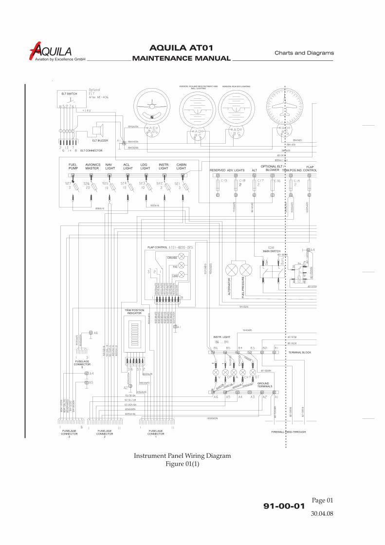
MAINTENANCE MANUAL
AQUILA AT01
Aviation by Excellence GmbH
Instrument Panel Wiring DiagramFigure 01(1)
91-00-01Page 01
Charts and Diagrams
OPTIONAL ELT /BLOWER
VERSION: RCA AND MIDCONTINENT 4300INCL. LIGHTING
VERSION: RCA W/O LIGHTING
ELT SWITCH
ELT CONNECTOR
ELT BUZZER
FLAP CONTROL
CRUISE
T/O
LDG
TRIM POSITIONINDICATOR
FUSELAGECONNECTOR
5
FUSELAGECONNECTOR
3
FUSELAGECONNECTOR
2
FUSELAGECONNECTOR
1
INSTR. LIGHT
ALT
ER
NA
TO
R
MAIN SWITCH
FU
EL
PR
ES
SU
RE
TERMINAL BLOCK
GROUNDTERMINALS
FIREWALL FEED-THROUGH
30.04.08
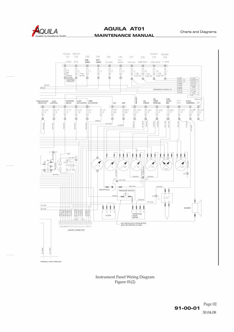
MAINTENANCE MANUAL
AQUILA AT01
Aviation by Excellence GmbH
Instrument Panel Wiring DiagramFigure 01(2)
91-00-01
Page 02
Charts and Diagrams
FIREWALL FEED-THROUGH
TRIM POSITIONINDICATOR
FLAPCONTROL
IF OPTIONWITH MODE STRANSPONDERIS INSTALLED
ANDFOR
ENGINE CONNECTOR
PRESSURE SWITCH
CLOCKOPERATIONHOURMETER
BUZZER
RECEPTACLE
NOT INSTALLED IF HOUR METER2840-186 (WINTER) IS USED
30.04.08
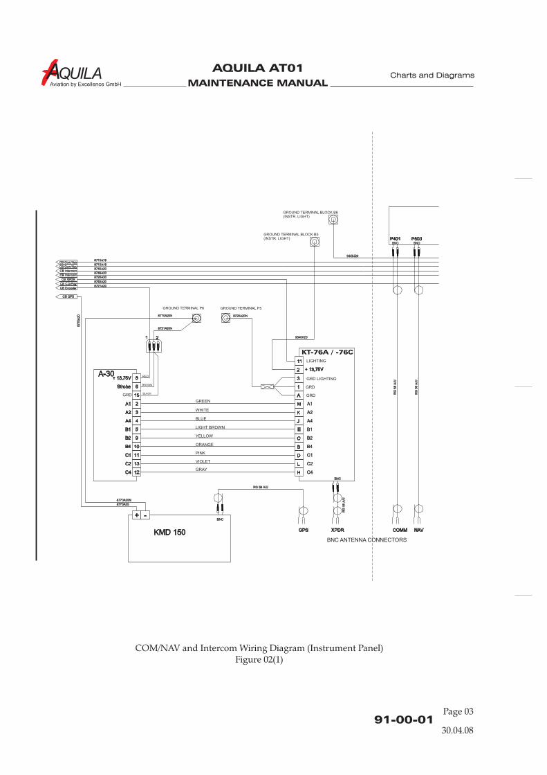
MAINTENANCE MANUAL
AQUILA AT01
Aviation by Excellence GmbH
COM/NAV and Intercom Wiring Diagram (Instrument Panel)Figure 02(1)
91-00-01Page 03
Charts and Diagrams
30.04.08
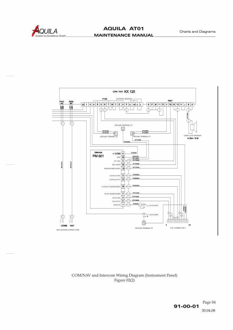
MAINTENANCE MANUAL
AQUILA AT01
Aviation by Excellence GmbH
COM/NAV and Intercom Wiring Diagram (Instrument Panel)Figure 02(2)
91-00-01
Page 04
Charts and Diagrams
30.04.08

MAINTENANCE MANUAL
AQUILA AT01
Aviation by Excellence GmbH
COM/NAV and Intercom Wiring Diagram (Fuselage)Figure 03(1)
91-00-01Page 05
Charts and Diagrams
30.04.08
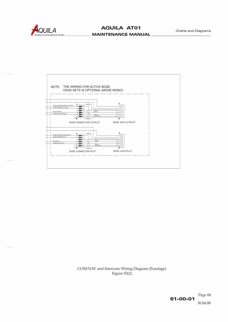
MAINTENANCE MANUAL
AQUILA AT01
Aviation by Excellence GmbH
COM/NAV and Intercom Wiring Diagram (Fuselage)Figure 03(2)
91-00-01
Page 06
Charts and Diagrams
30.04.08
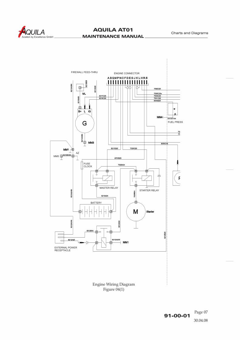
MAINTENANCE MANUAL
AQUILA AT01
Aviation by Excellence GmbH
Engine Wiring DiagramFigure 04(1)
91-00-01Page 07
Charts and Diagrams
FIREWALL FEED-THRUENGINE CONNECTOR
FUEL PRESS
FUSECLOCK
MASTER RELAYSTARTER RELAY
EXTERNAL POWERRECEPTACLE
BATTERY
30.04.08
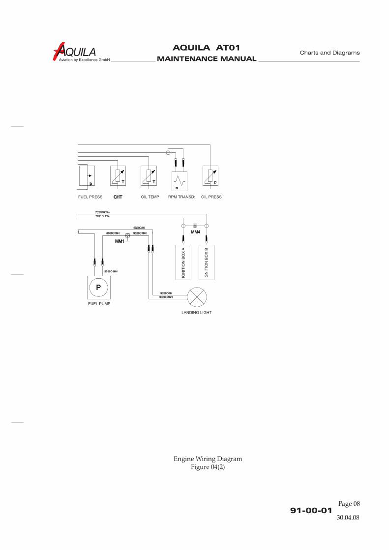
MAINTENANCE MANUAL
AQUILA AT01
Aviation by Excellence GmbH
Engine Wiring DiagramFigure 04(2)
91-00-01
Page 08
Charts and Diagrams
FUEL PRESS
FUEL PUMP
LANDING LIGHT
OIL PRESS
IGN
ITIO
N B
OX
A
IGN
ITIO
N B
OX
B
OIL TEMP RPM TRANSD:
30.04.08

MAINTENANCE MANUAL
AQUILA AT01
Aviation by Excellence GmbH
91-00-01Page 09
Charts and Diagrams
Fuselage Wiring DiagramFigure 05(1)
FUSELAGECONNECTOR 5
CABIN LIGHTASSEMBLY
TRIM CONTROLSWITCH ASSEMBLY
FLAPS
WING FUEL TANK
CA
BLE
HA
RN
ES
S D
W-A
T01-8
220-0
21
EXTERIOR LIGHTING(WING)
TRIM CONTROL
FUSELAGECONNECTOR 3
FUSELAGECONNECTOR 2
FUSELAGECONNECTOR 1
1
13
1a
1b
6055C20 6055AS20
6055AK20
30.04.08
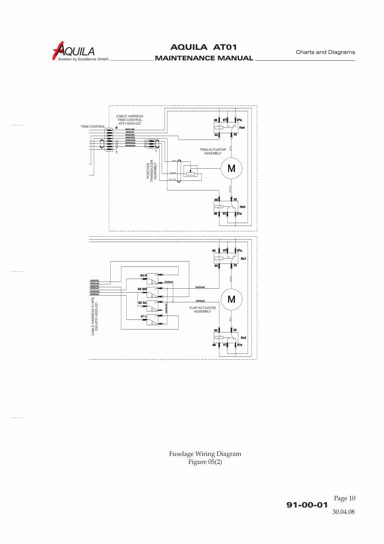
MAINTENANCE MANUAL
AQUILA AT01
Aviation by Excellence GmbH
91-00-01
Page 10
Charts and Diagrams
Fuselage Wiring DiagramFigure 05(2)
CA
BLE
HA
RN
ES
S F
LA
PS
DW
-AT
01-8
220-0
21
TRIM CONTROL
RED
RE
DB
LA
CK
GREEN
YELLOW
BR
OW
NB
LU
E
TRIM ACTUATORASSEMBLY
FLAP ACTUATORASSEMBLY
PO
SIT
ION
TR
AN
SD
UC
ER
AS
SE
MB
LY
CABLE HARNESSTRIM CONTROLAT01-8220-022
30.04.08
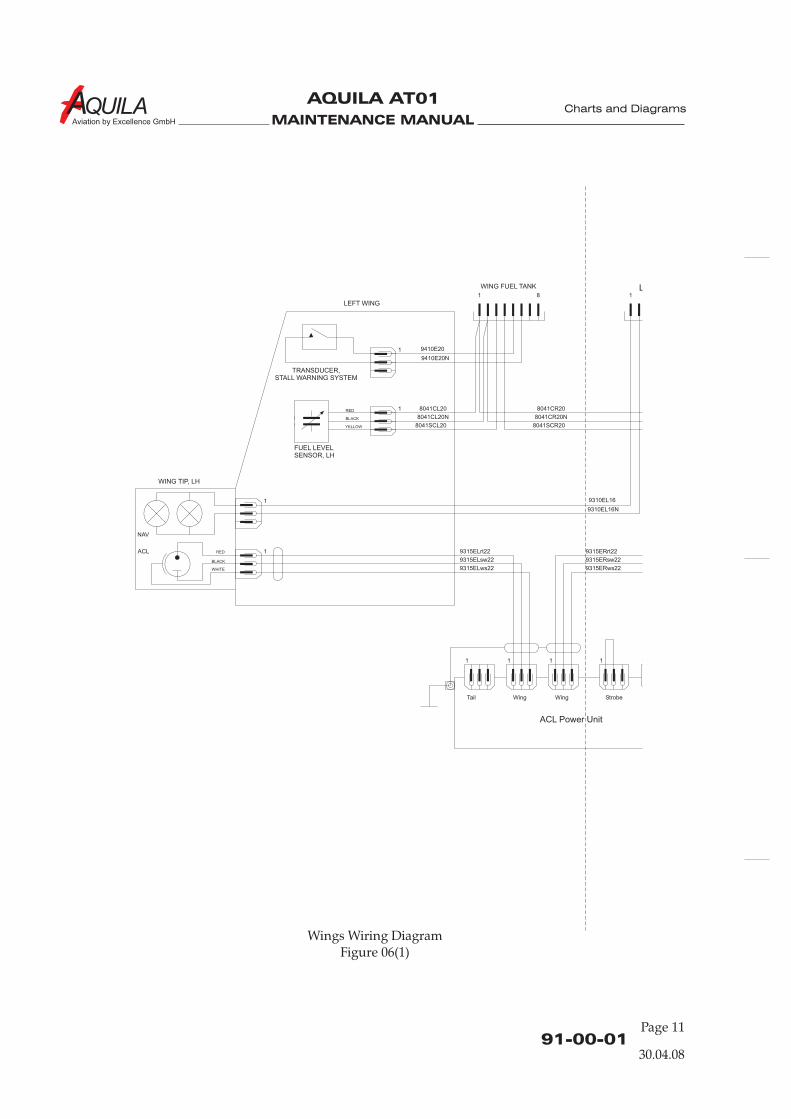
MAINTENANCE MANUAL
AQUILA AT01
Aviation by Excellence GmbH
91-00-01Page 11
Charts and Diagrams
Wings Wiring DiagramFigure 06(1)
WING FUEL TANK
LEFT WING
TRANSDUCER,STALL WARNING SYSTEM
RED
RED
BLACK
BLACK
WHITE
YELLOW
FUEL LEVELSENSOR, LH
WING TIP, LH
30.04.08
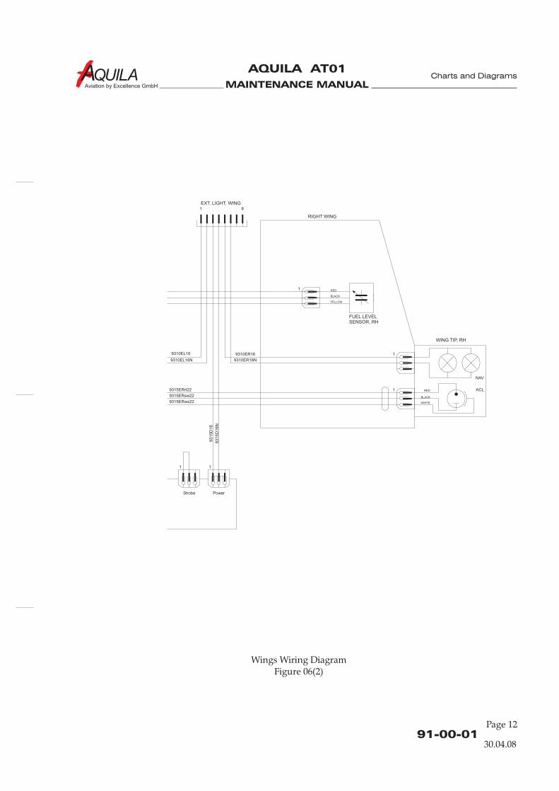
MAINTENANCE MANUAL
AQUILA AT01
Aviation by Excellence GmbH
91-00-01
Page 12
Charts and Diagrams
Wings Wiring DiagramFigure 06(2)
EXT. LIGHT, WING
RIGHT WING
RED
RED
BLACK
BLACK
WHITE
YELLOW
FUEL LEVELSENSOR, RH
WING TIP, RH
30.04.08
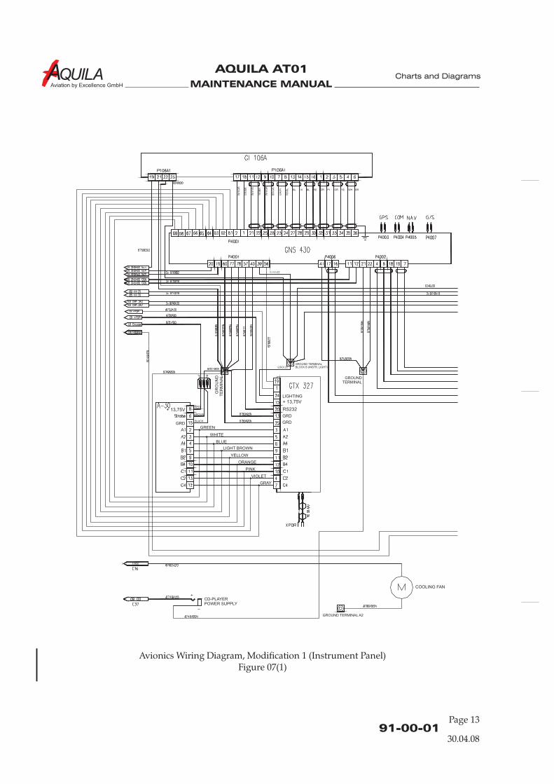
MAINTENANCE MANUAL
AQUILA AT01
Aviation by Excellence GmbH
Avionics Wiring Diagram, Modification 1 (Instrument Panel)Figure 07(1)
91-00-01Page 13
Charts and Diagrams
WH
/GR
WH
/GR
WH
/YE
GR
/PI
GR
/BR
BR
/GR
YE
/BR YE WH BRPIGR GRRE
RE
/BL BLBL VI
GROUND TERMINALBLOCK B (INSTR. LIGHT)
GROUNDTERMINAL
GROUND TERMINAL A2
FAN
CD-PLAYERPOWER SUPPLY
COOLING FAN
GR
OU
ND
TE
RM
INA
L
30.04.08

MAINTENANCE MANUAL
AQUILA AT01
Aviation by Excellence GmbH
Avionics Wiring Diagram, Modification 1 (Instrument Panel)Figure 07(2)
91-00-01
Page 14
Charts and Diagrams
GROUNDTERMINAL
NAV 2 AUDIO
LIGHT 14V LO
CO-PILOT PHONES RET
PILOT PHONES RET
CO-PILOT PHONES R
PILOT PHONES L
PILOT PHONES R
CO-PILOT PHONES L
LIGHT 14V HI
LIGHT 14V HI
GRD
SPEAKER
SPEAKER RETURN
MUSIC 1 RETURN
MUSIC 1 RIGHT
MUSIC 1 LEFT
GRD
NAV 1 AUDIO
NAV 2 RETURN
NAV 1 RETURN
COM 1 RETURN
COM 2 RETURN
COM 2 PHONES
COM 1 PHONES
COM 2 MIC
COM 1 MIC
COM 1 PTT
COM 2 PTT
PILOT MIC
CO-PILOT MIC
PILOT PTT
CO-PILOT PTT
PILOT MIC RETURN
CO-PILOT MIC RETURN
CABIN SPEAKER
FUSELAGECONNECTOR 4/1
PILOT
FUSELAGECONNECTOR 4/2
CO-PILOT
4/3 HEAD SETCONNECTOR
(INTERNAL BRIDGES)
30.04.08

MAINTENANCE MANUAL
AQUILA AT01
Aviation by Excellence GmbH
Avionics Wiring Diagram, Modification 1 (Fuselage)Figure 08
91-00-01Page 15
Charts and Diagrams
4/3 Headset 4/2 Copilot 4/1 Pilot
HEAD SET CONNECTOR 3 HEAD SET CONNECTOR 1
PTT PILOT
PTT CO-PILOT
HEAD SET CONNECTOR 2
POWER SUPPLYFOR ACTIVE HEAD SETS(CONNECTOR DESIGN DEP.ON TYPE OF HEAD SETS)
8742Ebsh22s
8741Ebsh22s
874
1C
c2
2s
(1)
874
1B
c2
2s
(1)
87
42
Bsh
22s
(2)
87
42
Bsh
22s
(1)
87
41
Bsh
22s
(1)
87
42
Csh
22s
(1)
874
2C
c2
2s
(1)
874
2C
b2
2s
(1)
874
2C
d2
2s
(2)
874
2C
e2
2s
(2)
874
2C
a2
2s
(1)
874
2C
f22s
(2)
874
1C
b2
2s
(1)
874
1C
a2
2s
(1)
87
41
Csh
22s
(1)
87
42
Csh
22s
(2)
874
1B
a2
2s
(1)
874
1B
b2
2s
(1)
874
2B
a2
2s
(1)
874
2B
f22s
(2)
874
2B
e2
2s
(2)
874
2B
d2
2s
(2)
874
2B
b2
2s
(1)
874
2B
c2
2s
(1)
87
41
Bsh
22s
(2)
874
1C
d2
2s
(2)
874
1C
e2
2s
(2)
874
1C
f22s
(2)
87
41
Csh
22s
(2)
8741Eb22s
8742Eb22s874
1B
f22s
(2)
874
1B
e2
2s
(2)
874
1B
d2
2s
(2)
87
49
B20
87
49
C20
87
49
B20
N8
74
9C
20
N
R
R
MIC
MIC
PTT
PTT
L
L
GND MIC PTT
LRGNDConnector
Connector
30.04.08
MAINTENANCE MANUAL
AQUILA AT01
Aviation by Excellence GmbH
91-00-01
Page 16
Charts and Diagrams
Intentionally left blank
30.04.08
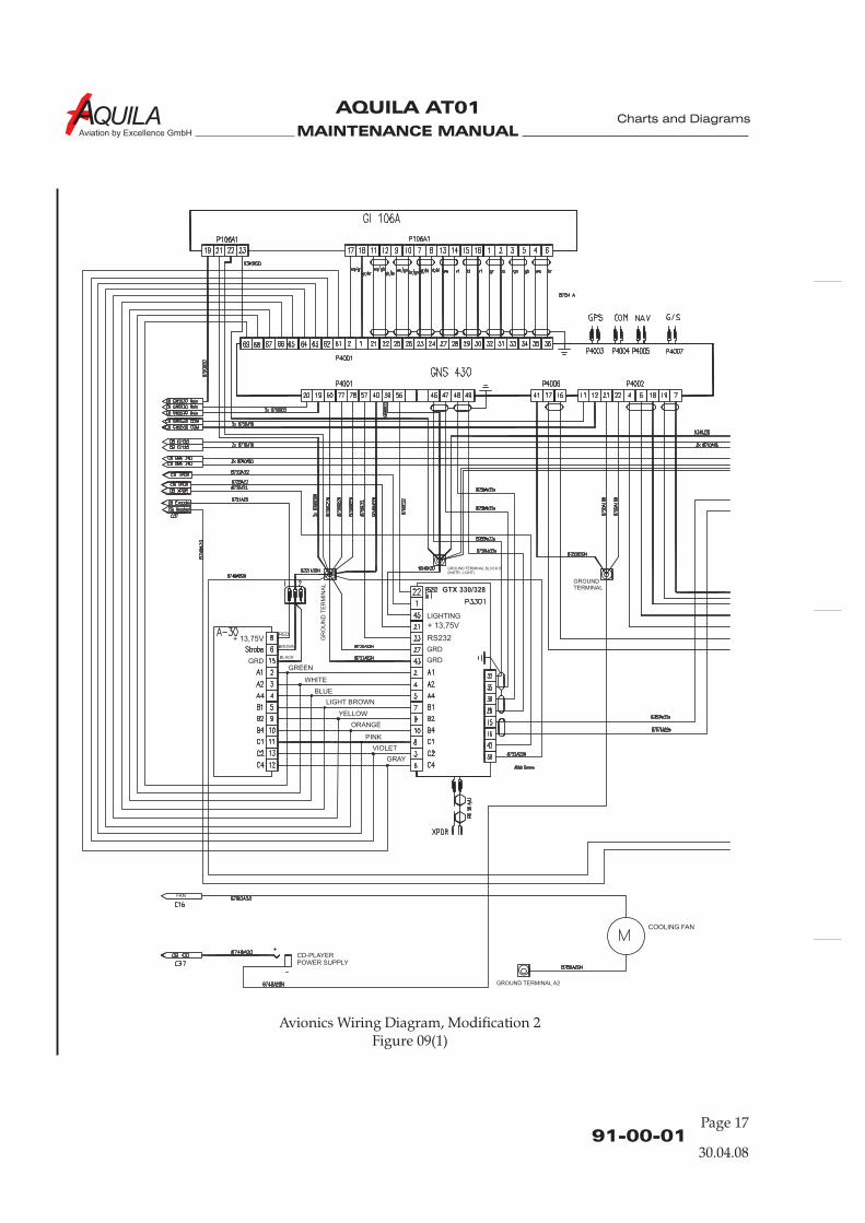
MAINTENANCE MANUAL
AQUILA AT01
Aviation by Excellence GmbH
91-00-01Page 17
Charts and Diagrams
Avionics Wiring Diagram, Modification 2Figure 09(1)
GR
OU
ND
TE
RM
INA
L
GROUNDTERMINAL
GROUND TERMINAL BLOCK B(INSTR. LIGHT)
GROUND TERMINAL A2
FAN
CD-PLAYERPOWER SUPPLY
COOLING FAN
GTX 330/328
30.04.08
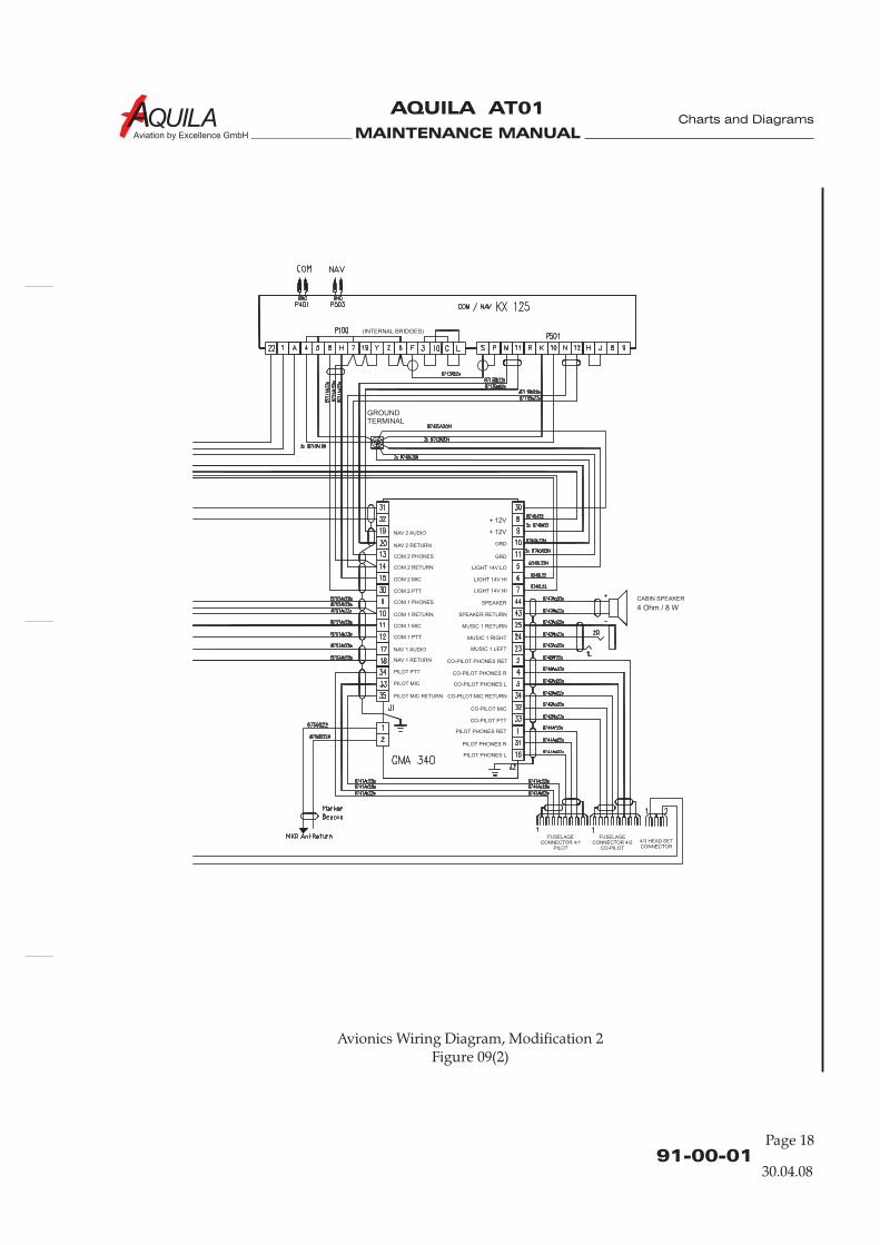
MAINTENANCE MANUAL
AQUILA AT01
Aviation by Excellence GmbH
91-00-01
Page 18
Charts and Diagrams
Avionics Wiring Diagram, Modification 2Figure 09(2)
NAV 2 AUDIO
NAV 1 AUDIO
NAV 2 RETURN
NAV 1 RETURN
COM 1 RETURN
COM 2 RETURN
COM 2 PHONES
COM 1 PHONES
COM 2 MIC
COM 1 MIC
COM 1 PTT
COM 2 PTT
PILOT MIC
PILOT PTT
PILOT MIC RETURN
LIGHT 14V LO
CO-PILOT PHONES RET
PILOT PHONES RET
CO-PILOT PHONES R
PILOT PHONES L
PILOT PHONES R
CO-PILOT PHONES L
LIGHT 14V HI
LIGHT 14V HI
GRD
SPEAKER
SPEAKER RETURN
MUSIC 1 RETURN
MUSIC 1 RIGHT
MUSIC 1 LEFT
GRD
CO-PILOT MIC
CO-PILOT PTT
CO-PILOT MIC RETURN
FUSELAGECONNECTOR 4/1
PILOT
FUSELAGECONNECTOR 4/2
CO-PILOT
4/3 HEAD SETCONNECTOR
CABIN SPEAKER
GROUNDTERMINAL
(INTERNAL BRIDGES)
30.04.08
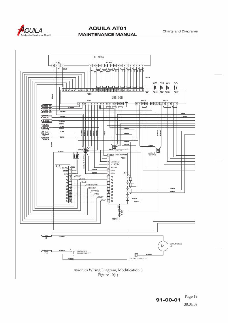
MAINTENANCE MANUAL
AQUILA AT01
Aviation by Excellence GmbH
91-00-01Page 19
Charts and Diagrams
Avionics Wiring Diagram, Modification 3Figure 10(1)
GROUNDTERMINAL
GR
OU
ND
TE
RM
INA
L
GROUND TERMINAL BLOCK B(INSTR. LIGHT)
GROUND TERMINAL A2
FAN
CD-PLAYERPOWER SUPPLY
COOLING FAN
GTX 330/328
30.04.08
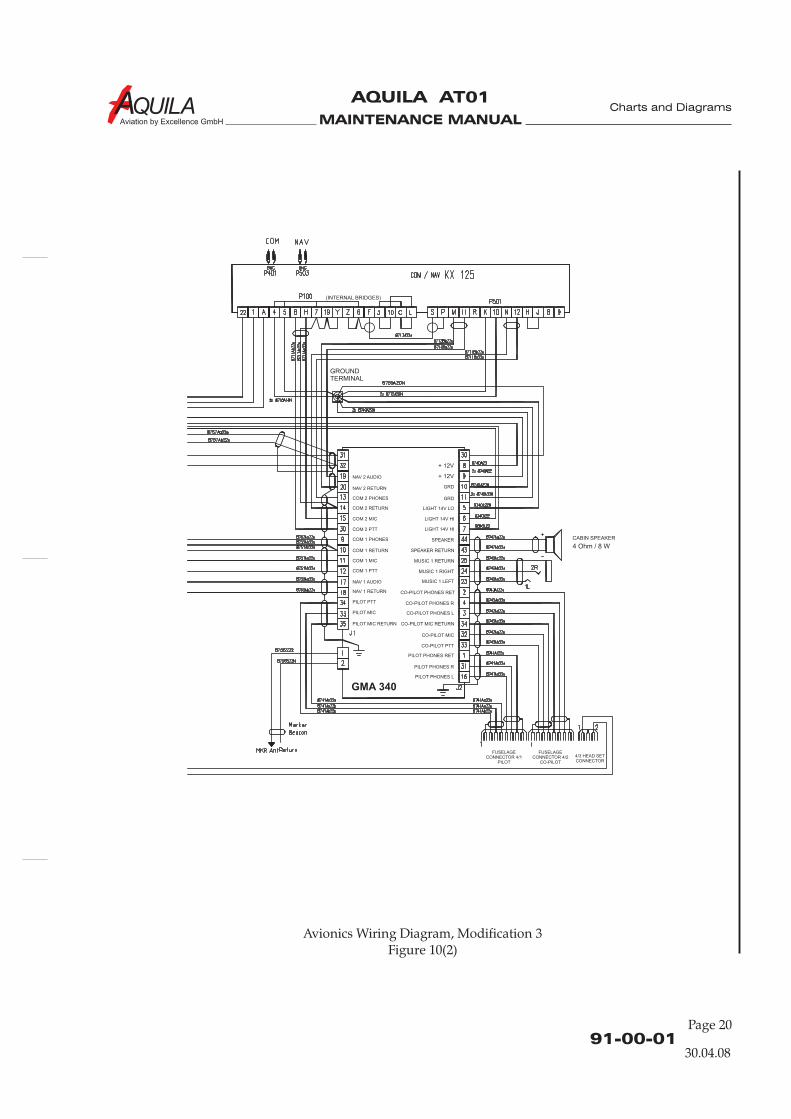
MAINTENANCE MANUAL
AQUILA AT01
Aviation by Excellence GmbH
91-00-01
Page 20
Charts and Diagrams
Avionics Wiring Diagram, Modification 3Figure 10(2)
NAV 2 AUDIO
NAV 1 AUDIO
NAV 2 RETURN
NAV 1 RETURN
COM 1 RETURN
COM 2 RETURN
COM 2 PHONES
COM 1 PHONES
COM 2 MIC
COM 1 MIC
COM 1 PTT
COM 2 PTT
PILOT MIC
PILOT PTT
PILOT MIC RETURN
LIGHT 14V LO
CO-PILOT PHONES RET
PILOT PHONES RET
CO-PILOT PHONES R
PILOT PHONES L
PILOT PHONES R
CO-PILOT PHONES L
LIGHT 14V HI
LIGHT 14V HI
GRD
SPEAKER
SPEAKER RETURN
MUSIC 1 RETURN
MUSIC 1 RIGHT
MUSIC 1 LEFT
GRD
CO-PILOT MIC
CO-PILOT PTT
CO-PILOT MIC RETURN
CABIN SPEAKER
FUSELAGECONNECTOR 4/1
PILOT
FUSELAGECONNECTOR 4/2
CO-PILOT
4/3 HEAD SETCONNECTOR
GROUNDTERMINAL
(INTERNAL BRIDGES)
GMA 340
30.04.08
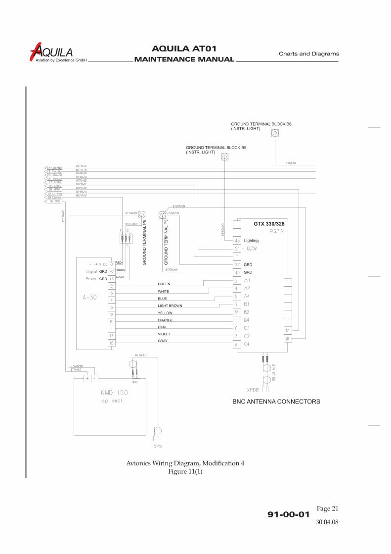
MAINTENANCE MANUAL
AQUILA AT01
Aviation by Excellence GmbH
91-00-01Page 21
Charts and Diagrams
Avionics Wiring Diagram, Modification 4Figure 11(1)
Lighting
GTX 330/328
30.04.08
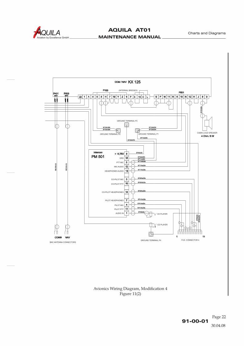
MAINTENANCE MANUAL
AQUILA AT01
Aviation by Excellence GmbH
91-00-01
Page 22
Charts and Diagrams
Avionics Wiring Diagram, Modification 4Figure 11(2)
30.04.08
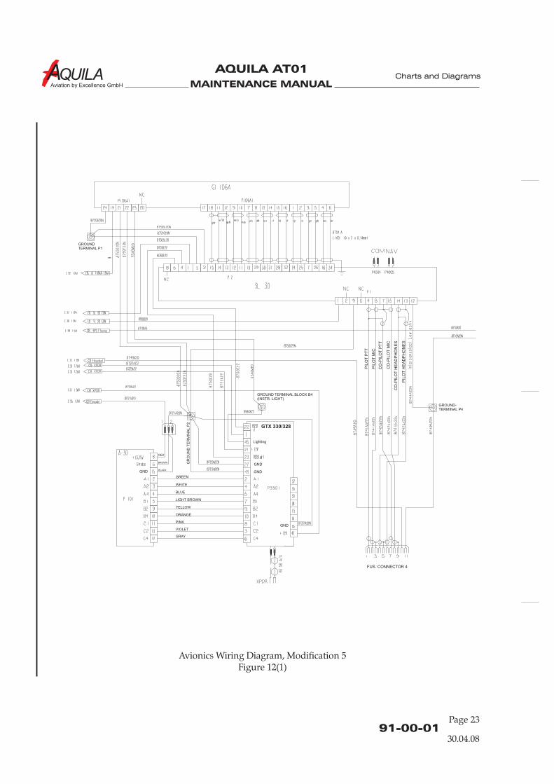
MAINTENANCE MANUAL
AQUILA AT01
Aviation by Excellence GmbH
91-00-01Page 23
Charts and Diagrams
Avionics Wiring Diagram, Modification 5Figure 12(1)
GROUND-TERMINAL P4
Lighting
GR
OU
ND
TE
RM
INA
LP
2
GROUNDTERMINAL P1
GROUND TERMINAL BLOCK B4(INSTR. LIGHT)
GND
GND
GND
GND
GTX 330/328
30.04.08
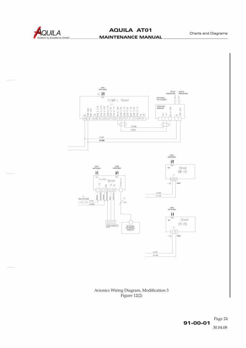
MAINTENANCE MANUAL
AQUILA AT01
Aviation by Excellence GmbH
91-00-01
Page 24
Charts and Diagrams
Avionics Wiring Diagram, Modification 5Figure 12(2)
GPSANTENNA
GPSANTENNA
COMANTENNA
GPSANTENNA
GPSANTENNA
OPTIONALTO FLYMAP L
PITOTPRESSURE
STATICPRESSURE
POSITIONSENSOR
GND
GND
OPTIONALEXTERNAL
DISPLAY
9-PIN SUB D RECEPTACLEOPTIONAL INTERFACE TOFLYMAP
500 mA FUSE BR
OW
N
BLU
E
OR
AN
GE
BR
OW
N/W
HIT
E
OR
AN
GE
/WH
ITE
GR
EE
N/W
HIT
E
30.04.08

MAINTENANCE MANUAL
AQUILA AT01
Aviation by Excellence GmbH
Charts and Diagrams