Embed Size (px)
Citation preview
LSISAS6160 SAS Switch User Guide
Version 2.0 April 2015
DB15-000636-12

LSISAS6160 SAS Switch User GuideApril 2015
For a comprehensive list of changes to this document, see the Revision History.
Avago, Avago Technologies, the A logo, LSI, and Storage by LSI are trademarks of Avago Technologies in the United States and other countries. All other brand and product names may be trademarks of their respective companies.
Data subject to change. Copyright © 2010–2015 Avago Technologies. All Rights Reserved.
Corporate Headquarters Email Website
San Jose, CA [email protected] www.avagotech.com
LSISAS6160 SAS Switch User GuideApril 2015
Table of Contents
Table of Contents
Chapter 1: Overview . . . . . . . . . . . . . . . . . . . . . . . . . . . . . . . . . . . . . . . . . . . . . . . . . . . . . . . . . . . . . . . . . . . . . . . . . . . . . . . . . . . . . . . . . . . . . . . . . . . . . . . . . . . . 6
1.1 LSISAS6160 Switch Features . . . . . . . . . . . . . . . . . . . . . . . . . . . . . . . . . . . . . . . . . . . . . . . . . . . . . . . . . . . . . . . . . . . . . . . . . . . . . . . . . . . . . . . . . . . . . . . . . . . . . . . . 61.2 SAS and the LSISAS6160 Switch . . . . . . . . . . . . . . . . . . . . . . . . . . . . . . . . . . . . . . . . . . . . . . . . . . . . . . . . . . . . . . . . . . . . . . . . . . . . . . . . . . . . . . . . . . . . . . . . . . . . . 61.3 SAS Phys, Ports, and Connectors . . . . . . . . . . . . . . . . . . . . . . . . . . . . . . . . . . . . . . . . . . . . . . . . . . . . . . . . . . . . . . . . . . . . . . . . . . . . . . . . . . . . . . . . . . . . . . . . . . . . 91.4 SAS Connectors and Cabling . . . . . . . . . . . . . . . . . . . . . . . . . . . . . . . . . . . . . . . . . . . . . . . . . . . . . . . . . . . . . . . . . . . . . . . . . . . . . . . . . . . . . . . . . . . . . . . . . . . . . . . 111.5 SAS Routing and Zoning . . . . . . . . . . . . . . . . . . . . . . . . . . . . . . . . . . . . . . . . . . . . . . . . . . . . . . . . . . . . . . . . . . . . . . . . . . . . . . . . . . . . . . . . . . . . . . . . . . . . . . . . . . . 11
1.5.1 SAS Zoning Overview . . . . . . . . . . . . . . . . . . . . . . . . . . . . . . . . . . . . . . . . . . . . . . . . . . . . . . . . . . . . . . . . . . . . . . . . . . . . . . . . . . . . . . . . . . . . . . . . . . . . . . . 121.5.2 Creating SAS Zones . . . . . . . . . . . . . . . . . . . . . . . . . . . . . . . . . . . . . . . . . . . . . . . . . . . . . . . . . . . . . . . . . . . . . . . . . . . . . . . . . . . . . . . . . . . . . . . . . . . . . . . . . 121.5.3 Configuring SAS Zones . . . . . . . . . . . . . . . . . . . . . . . . . . . . . . . . . . . . . . . . . . . . . . . . . . . . . . . . . . . . . . . . . . . . . . . . . . . . . . . . . . . . . . . . . . . . . . . . . . . . . . 13
1.6 Connecting Devices to the LSISAS6160 Switch . . . . . . . . . . . . . . . . . . . . . . . . . . . . . . . . . . . . . . . . . . . . . . . . . . . . . . . . . . . . . . . . . . . . . . . . . . . . . . . . . . . . . . 15
Chapter 2: Installation and Hardware Setup . . . . . . . . . . . . . . . . . . . . . . . . . . . . . . . . . . . . . . . . . . . . . . . . . . . . . . . . . . . . . . . . . . . . . . . . . . . . . . . . . . . . . 22
2.1 Unpacking the Switch . . . . . . . . . . . . . . . . . . . . . . . . . . . . . . . . . . . . . . . . . . . . . . . . . . . . . . . . . . . . . . . . . . . . . . . . . . . . . . . . . . . . . . . . . . . . . . . . . . . . . . . . . . . . . 222.2 Identifying Switch Components . . . . . . . . . . . . . . . . . . . . . . . . . . . . . . . . . . . . . . . . . . . . . . . . . . . . . . . . . . . . . . . . . . . . . . . . . . . . . . . . . . . . . . . . . . . . . . . . . . . . 22
2.2.1 LSISAS6160 Connectors . . . . . . . . . . . . . . . . . . . . . . . . . . . . . . . . . . . . . . . . . . . . . . . . . . . . . . . . . . . . . . . . . . . . . . . . . . . . . . . . . . . . . . . . . . . . . . . . . . . . . 232.2.2 LSISAS6160 LEDs . . . . . . . . . . . . . . . . . . . . . . . . . . . . . . . . . . . . . . . . . . . . . . . . . . . . . . . . . . . . . . . . . . . . . . . . . . . . . . . . . . . . . . . . . . . . . . . . . . . . . . . . . . . . 232.2.3 LSISAS6160 Power Supply . . . . . . . . . . . . . . . . . . . . . . . . . . . . . . . . . . . . . . . . . . . . . . . . . . . . . . . . . . . . . . . . . . . . . . . . . . . . . . . . . . . . . . . . . . . . . . . . . . . 23
2.3 Installing the LSISAS6160 Switch . . . . . . . . . . . . . . . . . . . . . . . . . . . . . . . . . . . . . . . . . . . . . . . . . . . . . . . . . . . . . . . . . . . . . . . . . . . . . . . . . . . . . . . . . . . . . . . . . . . 232.3.1 Installing the LSISAS6160 Shelf . . . . . . . . . . . . . . . . . . . . . . . . . . . . . . . . . . . . . . . . . . . . . . . . . . . . . . . . . . . . . . . . . . . . . . . . . . . . . . . . . . . . . . . . . . . . . . 24
2.4 Connecting to a Host . . . . . . . . . . . . . . . . . . . . . . . . . . . . . . . . . . . . . . . . . . . . . . . . . . . . . . . . . . . . . . . . . . . . . . . . . . . . . . . . . . . . . . . . . . . . . . . . . . . . . . . . . . . . . . 262.5 Changing the IP Address . . . . . . . . . . . . . . . . . . . . . . . . . . . . . . . . . . . . . . . . . . . . . . . . . . . . . . . . . . . . . . . . . . . . . . . . . . . . . . . . . . . . . . . . . . . . . . . . . . . . . . . . . . . 26
2.5.1 Setting a Static IP Address . . . . . . . . . . . . . . . . . . . . . . . . . . . . . . . . . . . . . . . . . . . . . . . . . . . . . . . . . . . . . . . . . . . . . . . . . . . . . . . . . . . . . . . . . . . . . . . . . . . 272.5.1.1 Using SDM-GUI . . . . . . . . . . . . . . . . . . . . . . . . . . . . . . . . . . . . . . . . . . . . . . . . . . . . . . . . . . . . . . . . . . . . . . . . . . . . . . . . . . . . . . . . . . . . . . . . . . . . . . . 272.5.1.2 Using SDM-CLI . . . . . . . . . . . . . . . . . . . . . . . . . . . . . . . . . . . . . . . . . . . . . . . . . . . . . . . . . . . . . . . . . . . . . . . . . . . . . . . . . . . . . . . . . . . . . . . . . . . . . . . 27
2.5.2 Setting a Dynamic IP Address . . . . . . . . . . . . . . . . . . . . . . . . . . . . . . . . . . . . . . . . . . . . . . . . . . . . . . . . . . . . . . . . . . . . . . . . . . . . . . . . . . . . . . . . . . . . . . . . 272.5.2.1 Using SDM-GUI . . . . . . . . . . . . . . . . . . . . . . . . . . . . . . . . . . . . . . . . . . . . . . . . . . . . . . . . . . . . . . . . . . . . . . . . . . . . . . . . . . . . . . . . . . . . . . . . . . . . . . . 272.5.2.2 Using SDM-CLI . . . . . . . . . . . . . . . . . . . . . . . . . . . . . . . . . . . . . . . . . . . . . . . . . . . . . . . . . . . . . . . . . . . . . . . . . . . . . . . . . . . . . . . . . . . . . . . . . . . . . . . 27
2.6 Connecting the SAS and SATA Hardware . . . . . . . . . . . . . . . . . . . . . . . . . . . . . . . . . . . . . . . . . . . . . . . . . . . . . . . . . . . . . . . . . . . . . . . . . . . . . . . . . . . . . . . . . . . 282.7 Safety Notices . . . . . . . . . . . . . . . . . . . . . . . . . . . . . . . . . . . . . . . . . . . . . . . . . . . . . . . . . . . . . . . . . . . . . . . . . . . . . . . . . . . . . . . . . . . . . . . . . . . . . . . . . . . . . . . . . . . . . 28
2.7.1 FCC . . . . . . . . . . . . . . . . . . . . . . . . . . . . . . . . . . . . . . . . . . . . . . . . . . . . . . . . . . . . . . . . . . . . . . . . . . . . . . . . . . . . . . . . . . . . . . . . . . . . . . . . . . . . . . . . . . . . . . . . . 282.7.2 Canada Mark . . . . . . . . . . . . . . . . . . . . . . . . . . . . . . . . . . . . . . . . . . . . . . . . . . . . . . . . . . . . . . . . . . . . . . . . . . . . . . . . . . . . . . . . . . . . . . . . . . . . . . . . . . . . . . . . 292.7.3 VCCI . . . . . . . . . . . . . . . . . . . . . . . . . . . . . . . . . . . . . . . . . . . . . . . . . . . . . . . . . . . . . . . . . . . . . . . . . . . . . . . . . . . . . . . . . . . . . . . . . . . . . . . . . . . . . . . . . . . . . . . . 292.7.4 BSMI . . . . . . . . . . . . . . . . . . . . . . . . . . . . . . . . . . . . . . . . . . . . . . . . . . . . . . . . . . . . . . . . . . . . . . . . . . . . . . . . . . . . . . . . . . . . . . . . . . . . . . . . . . . . . . . . . . . . . . . . 292.7.5 CCC . . . . . . . . . . . . . . . . . . . . . . . . . . . . . . . . . . . . . . . . . . . . . . . . . . . . . . . . . . . . . . . . . . . . . . . . . . . . . . . . . . . . . . . . . . . . . . . . . . . . . . . . . . . . . . . . . . . . . . . . . 30
Chapter 3: SAS Domain Manager Graphical User Interface . . . . . . . . . . . . . . . . . . . . . . . . . . . . . . . . . . . . . . . . . . . . . . . . . . . . . . . . . . . . . . . . . . . . . . . 31
3.1 SDM-GUI Accounts . . . . . . . . . . . . . . . . . . . . . . . . . . . . . . . . . . . . . . . . . . . . . . . . . . . . . . . . . . . . . . . . . . . . . . . . . . . . . . . . . . . . . . . . . . . . . . . . . . . . . . . . . . . . . . . . 313.2 Starting SDM-GUI . . . . . . . . . . . . . . . . . . . . . . . . . . . . . . . . . . . . . . . . . . . . . . . . . . . . . . . . . . . . . . . . . . . . . . . . . . . . . . . . . . . . . . . . . . . . . . . . . . . . . . . . . . . . . . . . . . 313.3 Summary Tab and Menu Options . . . . . . . . . . . . . . . . . . . . . . . . . . . . . . . . . . . . . . . . . . . . . . . . . . . . . . . . . . . . . . . . . . . . . . . . . . . . . . . . . . . . . . . . . . . . . . . . . . 313.4 File, Server, and Help Menu Options . . . . . . . . . . . . . . . . . . . . . . . . . . . . . . . . . . . . . . . . . . . . . . . . . . . . . . . . . . . . . . . . . . . . . . . . . . . . . . . . . . . . . . . . . . . . . . . . 323.5 Views Tab . . . . . . . . . . . . . . . . . . . . . . . . . . . . . . . . . . . . . . . . . . . . . . . . . . . . . . . . . . . . . . . . . . . . . . . . . . . . . . . . . . . . . . . . . . . . . . . . . . . . . . . . . . . . . . . . . . . . . . . . . 34
3.5.1 View End Device Table . . . . . . . . . . . . . . . . . . . . . . . . . . . . . . . . . . . . . . . . . . . . . . . . . . . . . . . . . . . . . . . . . . . . . . . . . . . . . . . . . . . . . . . . . . . . . . . . . . . . . . 343.5.2 View Alias Table . . . . . . . . . . . . . . . . . . . . . . . . . . . . . . . . . . . . . . . . . . . . . . . . . . . . . . . . . . . . . . . . . . . . . . . . . . . . . . . . . . . . . . . . . . . . . . . . . . . . . . . . . . . . . 353.5.3 View Zone Groups . . . . . . . . . . . . . . . . . . . . . . . . . . . . . . . . . . . . . . . . . . . . . . . . . . . . . . . . . . . . . . . . . . . . . . . . . . . . . . . . . . . . . . . . . . . . . . . . . . . . . . . . . . 363.5.4 View Zone Sets . . . . . . . . . . . . . . . . . . . . . . . . . . . . . . . . . . . . . . . . . . . . . . . . . . . . . . . . . . . . . . . . . . . . . . . . . . . . . . . . . . . . . . . . . . . . . . . . . . . . . . . . . . . . . . 37
3.6 Domain Tab . . . . . . . . . . . . . . . . . . . . . . . . . . . . . . . . . . . . . . . . . . . . . . . . . . . . . . . . . . . . . . . . . . . . . . . . . . . . . . . . . . . . . . . . . . . . . . . . . . . . . . . . . . . . . . . . . . . . . . . 383.6.1 Alias Management . . . . . . . . . . . . . . . . . . . . . . . . . . . . . . . . . . . . . . . . . . . . . . . . . . . . . . . . . . . . . . . . . . . . . . . . . . . . . . . . . . . . . . . . . . . . . . . . . . . . . . . . . . 38
3.6.1.1 Create/Modify Aliases . . . . . . . . . . . . . . . . . . . . . . . . . . . . . . . . . . . . . . . . . . . . . . . . . . . . . . . . . . . . . . . . . . . . . . . . . . . . . . . . . . . . . . . . . . . . . . . . . 383.6.1.2 View/Delete Aliases . . . . . . . . . . . . . . . . . . . . . . . . . . . . . . . . . . . . . . . . . . . . . . . . . . . . . . . . . . . . . . . . . . . . . . . . . . . . . . . . . . . . . . . . . . . . . . . . . . . 39
3.6.2 Automatically Configure Zone Groups and Zone Sets . . . . . . . . . . . . . . . . . . . . . . . . . . . . . . . . . . . . . . . . . . . . . . . . . . . . . . . . . . . . . . . . . . . . . . . . 403.6.2.1 Initiator Isolation Wizard . . . . . . . . . . . . . . . . . . . . . . . . . . . . . . . . . . . . . . . . . . . . . . . . . . . . . . . . . . . . . . . . . . . . . . . . . . . . . . . . . . . . . . . . . . . . . . 403.6.2.2 Connector Wizard . . . . . . . . . . . . . . . . . . . . . . . . . . . . . . . . . . . . . . . . . . . . . . . . . . . . . . . . . . . . . . . . . . . . . . . . . . . . . . . . . . . . . . . . . . . . . . . . . . . . 413.6.2.3 End Device Wizard . . . . . . . . . . . . . . . . . . . . . . . . . . . . . . . . . . . . . . . . . . . . . . . . . . . . . . . . . . . . . . . . . . . . . . . . . . . . . . . . . . . . . . . . . . . . . . . . . . . . 41
Avago Technologies- 3 -
LSISAS6160 SAS Switch User GuideApril 2015
Table of Contents
3.6.3 Manually Configure Zone Groups . . . . . . . . . . . . . . . . . . . . . . . . . . . . . . . . . . . . . . . . . . . . . . . . . . . . . . . . . . . . . . . . . . . . . . . . . . . . . . . . . . . . . . . . . . . . 423.6.3.1 Create Zone Group . . . . . . . . . . . . . . . . . . . . . . . . . . . . . . . . . . . . . . . . . . . . . . . . . . . . . . . . . . . . . . . . . . . . . . . . . . . . . . . . . . . . . . . . . . . . . . . . . . . 423.6.3.2 View Zone Groups . . . . . . . . . . . . . . . . . . . . . . . . . . . . . . . . . . . . . . . . . . . . . . . . . . . . . . . . . . . . . . . . . . . . . . . . . . . . . . . . . . . . . . . . . . . . . . . . . . . . 433.6.3.3 Modify Zone Group . . . . . . . . . . . . . . . . . . . . . . . . . . . . . . . . . . . . . . . . . . . . . . . . . . . . . . . . . . . . . . . . . . . . . . . . . . . . . . . . . . . . . . . . . . . . . . . . . . . 433.6.3.4 Delete Zone Group . . . . . . . . . . . . . . . . . . . . . . . . . . . . . . . . . . . . . . . . . . . . . . . . . . . . . . . . . . . . . . . . . . . . . . . . . . . . . . . . . . . . . . . . . . . . . . . . . . . 44
3.6.4 Manually Configure Zone Sets . . . . . . . . . . . . . . . . . . . . . . . . . . . . . . . . . . . . . . . . . . . . . . . . . . . . . . . . . . . . . . . . . . . . . . . . . . . . . . . . . . . . . . . . . . . . . . . 443.6.4.1 Synchronize Zone Manager Password . . . . . . . . . . . . . . . . . . . . . . . . . . . . . . . . . . . . . . . . . . . . . . . . . . . . . . . . . . . . . . . . . . . . . . . . . . . . . . . . . 443.6.4.2 Create Zone Set . . . . . . . . . . . . . . . . . . . . . . . . . . . . . . . . . . . . . . . . . . . . . . . . . . . . . . . . . . . . . . . . . . . . . . . . . . . . . . . . . . . . . . . . . . . . . . . . . . . . . . 443.6.4.3 View Zone Set . . . . . . . . . . . . . . . . . . . . . . . . . . . . . . . . . . . . . . . . . . . . . . . . . . . . . . . . . . . . . . . . . . . . . . . . . . . . . . . . . . . . . . . . . . . . . . . . . . . . . . . . 453.6.4.4 Modify Zone Set . . . . . . . . . . . . . . . . . . . . . . . . . . . . . . . . . . . . . . . . . . . . . . . . . . . . . . . . . . . . . . . . . . . . . . . . . . . . . . . . . . . . . . . . . . . . . . . . . . . . . . 453.6.4.5 Activate/Deactivate Zone Set . . . . . . . . . . . . . . . . . . . . . . . . . . . . . . . . . . . . . . . . . . . . . . . . . . . . . . . . . . . . . . . . . . . . . . . . . . . . . . . . . . . . . . . . . 463.6.4.6 Delete Zone Set . . . . . . . . . . . . . . . . . . . . . . . . . . . . . . . . . . . . . . . . . . . . . . . . . . . . . . . . . . . . . . . . . . . . . . . . . . . . . . . . . . . . . . . . . . . . . . . . . . . . . . 47
3.7 Devices Tab . . . . . . . . . . . . . . . . . . . . . . . . . . . . . . . . . . . . . . . . . . . . . . . . . . . . . . . . . . . . . . . . . . . . . . . . . . . . . . . . . . . . . . . . . . . . . . . . . . . . . . . . . . . . . . . . . . . . . . . 483.7.1 Properties Tab . . . . . . . . . . . . . . . . . . . . . . . . . . . . . . . . . . . . . . . . . . . . . . . . . . . . . . . . . . . . . . . . . . . . . . . . . . . . . . . . . . . . . . . . . . . . . . . . . . . . . . . . . . . . . . 503.7.2 Environmentals Tab . . . . . . . . . . . . . . . . . . . . . . . . . . . . . . . . . . . . . . . . . . . . . . . . . . . . . . . . . . . . . . . . . . . . . . . . . . . . . . . . . . . . . . . . . . . . . . . . . . . . . . . . . 50
3.7.2.1 Set SES Thresholds . . . . . . . . . . . . . . . . . . . . . . . . . . . . . . . . . . . . . . . . . . . . . . . . . . . . . . . . . . . . . . . . . . . . . . . . . . . . . . . . . . . . . . . . . . . . . . . . . . . . 513.7.3 Attached Devices Tab . . . . . . . . . . . . . . . . . . . . . . . . . . . . . . . . . . . . . . . . . . . . . . . . . . . . . . . . . . . . . . . . . . . . . . . . . . . . . . . . . . . . . . . . . . . . . . . . . . . . . . . 533.7.4 Phys Tab . . . . . . . . . . . . . . . . . . . . . . . . . . . . . . . . . . . . . . . . . . . . . . . . . . . . . . . . . . . . . . . . . . . . . . . . . . . . . . . . . . . . . . . . . . . . . . . . . . . . . . . . . . . . . . . . . . . . 533.7.5 Phy Counters Tab . . . . . . . . . . . . . . . . . . . . . . . . . . . . . . . . . . . . . . . . . . . . . . . . . . . . . . . . . . . . . . . . . . . . . . . . . . . . . . . . . . . . . . . . . . . . . . . . . . . . . . . . . . . 543.7.6 Zone Group Tab . . . . . . . . . . . . . . . . . . . . . . . . . . . . . . . . . . . . . . . . . . . . . . . . . . . . . . . . . . . . . . . . . . . . . . . . . . . . . . . . . . . . . . . . . . . . . . . . . . . . . . . . . . . . . 553.7.7 Operations Tab . . . . . . . . . . . . . . . . . . . . . . . . . . . . . . . . . . . . . . . . . . . . . . . . . . . . . . . . . . . . . . . . . . . . . . . . . . . . . . . . . . . . . . . . . . . . . . . . . . . . . . . . . . . . . 56
3.7.7.1 Download Firmware . . . . . . . . . . . . . . . . . . . . . . . . . . . . . . . . . . . . . . . . . . . . . . . . . . . . . . . . . . . . . . . . . . . . . . . . . . . . . . . . . . . . . . . . . . . . . . . . . . 573.7.7.2 Upload Firmware . . . . . . . . . . . . . . . . . . . . . . . . . . . . . . . . . . . . . . . . . . . . . . . . . . . . . . . . . . . . . . . . . . . . . . . . . . . . . . . . . . . . . . . . . . . . . . . . . . . . . 583.7.7.3 Enable/Disable/Reset Phys . . . . . . . . . . . . . . . . . . . . . . . . . . . . . . . . . . . . . . . . . . . . . . . . . . . . . . . . . . . . . . . . . . . . . . . . . . . . . . . . . . . . . . . . . . . . 583.7.7.4 Reset Switch . . . . . . . . . . . . . . . . . . . . . . . . . . . . . . . . . . . . . . . . . . . . . . . . . . . . . . . . . . . . . . . . . . . . . . . . . . . . . . . . . . . . . . . . . . . . . . . . . . . . . . . . . . 593.7.7.5 Configure IP . . . . . . . . . . . . . . . . . . . . . . . . . . . . . . . . . . . . . . . . . . . . . . . . . . . . . . . . . . . . . . . . . . . . . . . . . . . . . . . . . . . . . . . . . . . . . . . . . . . . . . . . . . 593.7.7.6 Get Date . . . . . . . . . . . . . . . . . . . . . . . . . . . . . . . . . . . . . . . . . . . . . . . . . . . . . . . . . . . . . . . . . . . . . . . . . . . . . . . . . . . . . . . . . . . . . . . . . . . . . . . . . . . . . 603.7.7.7 Set Date . . . . . . . . . . . . . . . . . . . . . . . . . . . . . . . . . . . . . . . . . . . . . . . . . . . . . . . . . . . . . . . . . . . . . . . . . . . . . . . . . . . . . . . . . . . . . . . . . . . . . . . . . . . . . . 613.7.7.8 Display Device Log . . . . . . . . . . . . . . . . . . . . . . . . . . . . . . . . . . . . . . . . . . . . . . . . . . . . . . . . . . . . . . . . . . . . . . . . . . . . . . . . . . . . . . . . . . . . . . . . . . . 613.7.7.9 Performance Monitoring . . . . . . . . . . . . . . . . . . . . . . . . . . . . . . . . . . . . . . . . . . . . . . . . . . . . . . . . . . . . . . . . . . . . . . . . . . . . . . . . . . . . . . . . . . . . . . 61
3.7.8 SNMP/SMTP Tab . . . . . . . . . . . . . . . . . . . . . . . . . . . . . . . . . . . . . . . . . . . . . . . . . . . . . . . . . . . . . . . . . . . . . . . . . . . . . . . . . . . . . . . . . . . . . . . . . . . . . . . . . . . . 643.8 Configuration Backup and Restore . . . . . . . . . . . . . . . . . . . . . . . . . . . . . . . . . . . . . . . . . . . . . . . . . . . . . . . . . . . . . . . . . . . . . . . . . . . . . . . . . . . . . . . . . . . . . . . . . 68
3.8.1 Restore . . . . . . . . . . . . . . . . . . . . . . . . . . . . . . . . . . . . . . . . . . . . . . . . . . . . . . . . . . . . . . . . . . . . . . . . . . . . . . . . . . . . . . . . . . . . . . . . . . . . . . . . . . . . . . . . . . . . . 693.8.2 Smart Restore . . . . . . . . . . . . . . . . . . . . . . . . . . . . . . . . . . . . . . . . . . . . . . . . . . . . . . . . . . . . . . . . . . . . . . . . . . . . . . . . . . . . . . . . . . . . . . . . . . . . . . . . . . . . . . . 69
Chapter 4: SAS Domain Manager Command Line Interface . . . . . . . . . . . . . . . . . . . . . . . . . . . . . . . . . . . . . . . . . . . . . . . . . . . . . . . . . . . . . . . . . . . . . . . 70
4.1 Command Usage and Syntax . . . . . . . . . . . . . . . . . . . . . . . . . . . . . . . . . . . . . . . . . . . . . . . . . . . . . . . . . . . . . . . . . . . . . . . . . . . . . . . . . . . . . . . . . . . . . . . . . . . . . . . 704.2 SDM-CLI Commands . . . . . . . . . . . . . . . . . . . . . . . . . . . . . . . . . . . . . . . . . . . . . . . . . . . . . . . . . . . . . . . . . . . . . . . . . . . . . . . . . . . . . . . . . . . . . . . . . . . . . . . . . . . . . . . 70
4.2.1 Help Command . . . . . . . . . . . . . . . . . . . . . . . . . . . . . . . . . . . . . . . . . . . . . . . . . . . . . . . . . . . . . . . . . . . . . . . . . . . . . . . . . . . . . . . . . . . . . . . . . . . . . . . . . . . . . 714.2.2 Passwd Command . . . . . . . . . . . . . . . . . . . . . . . . . . . . . . . . . . . . . . . . . . . . . . . . . . . . . . . . . . . . . . . . . . . . . . . . . . . . . . . . . . . . . . . . . . . . . . . . . . . . . . . . . . 714.2.3 Quit Command . . . . . . . . . . . . . . . . . . . . . . . . . . . . . . . . . . . . . . . . . . . . . . . . . . . . . . . . . . . . . . . . . . . . . . . . . . . . . . . . . . . . . . . . . . . . . . . . . . . . . . . . . . . . . 714.2.4 Alias Command . . . . . . . . . . . . . . . . . . . . . . . . . . . . . . . . . . . . . . . . . . . . . . . . . . . . . . . . . . . . . . . . . . . . . . . . . . . . . . . . . . . . . . . . . . . . . . . . . . . . . . . . . . . . . 714.2.5 Device Command . . . . . . . . . . . . . . . . . . . . . . . . . . . . . . . . . . . . . . . . . . . . . . . . . . . . . . . . . . . . . . . . . . . . . . . . . . . . . . . . . . . . . . . . . . . . . . . . . . . . . . . . . . . 724.2.6 Show Command . . . . . . . . . . . . . . . . . . . . . . . . . . . . . . . . . . . . . . . . . . . . . . . . . . . . . . . . . . . . . . . . . . . . . . . . . . . . . . . . . . . . . . . . . . . . . . . . . . . . . . . . . . . . 734.2.7 Zonegroup Command . . . . . . . . . . . . . . . . . . . . . . . . . . . . . . . . . . . . . . . . . . . . . . . . . . . . . . . . . . . . . . . . . . . . . . . . . . . . . . . . . . . . . . . . . . . . . . . . . . . . . . 744.2.8 Zoneset Command . . . . . . . . . . . . . . . . . . . . . . . . . . . . . . . . . . . . . . . . . . . . . . . . . . . . . . . . . . . . . . . . . . . . . . . . . . . . . . . . . . . . . . . . . . . . . . . . . . . . . . . . . . 754.2.9 SES Threshold . . . . . . . . . . . . . . . . . . . . . . . . . . . . . . . . . . . . . . . . . . . . . . . . . . . . . . . . . . . . . . . . . . . . . . . . . . . . . . . . . . . . . . . . . . . . . . . . . . . . . . . . . . . . . . . 764.2.10 Get Date . . . . . . . . . . . . . . . . . . . . . . . . . . . . . . . . . . . . . . . . . . . . . . . . . . . . . . . . . . . . . . . . . . . . . . . . . . . . . . . . . . . . . . . . . . . . . . . . . . . . . . . . . . . . . . . . . . . 764.2.11 Set Date . . . . . . . . . . . . . . . . . . . . . . . . . . . . . . . . . . . . . . . . . . . . . . . . . . . . . . . . . . . . . . . . . . . . . . . . . . . . . . . . . . . . . . . . . . . . . . . . . . . . . . . . . . . . . . . . . . . 774.2.12 Performance Monitoring . . . . . . . . . . . . . . . . . . . . . . . . . . . . . . . . . . . . . . . . . . . . . . . . . . . . . . . . . . . . . . . . . . . . . . . . . . . . . . . . . . . . . . . . . . . . . . . . . . . 774.2.13 Get SNMP . . . . . . . . . . . . . . . . . . . . . . . . . . . . . . . . . . . . . . . . . . . . . . . . . . . . . . . . . . . . . . . . . . . . . . . . . . . . . . . . . . . . . . . . . . . . . . . . . . . . . . . . . . . . . . . . . . 784.2.14 Set SNMP . . . . . . . . . . . . . . . . . . . . . . . . . . . . . . . . . . . . . . . . . . . . . . . . . . . . . . . . . . . . . . . . . . . . . . . . . . . . . . . . . . . . . . . . . . . . . . . . . . . . . . . . . . . . . . . . . . 784.2.15 Get SMTP . . . . . . . . . . . . . . . . . . . . . . . . . . . . . . . . . . . . . . . . . . . . . . . . . . . . . . . . . . . . . . . . . . . . . . . . . . . . . . . . . . . . . . . . . . . . . . . . . . . . . . . . . . . . . . . . . . 794.2.16 Set SMTP . . . . . . . . . . . . . . . . . . . . . . . . . . . . . . . . . . . . . . . . . . . . . . . . . . . . . . . . . . . . . . . . . . . . . . . . . . . . . . . . . . . . . . . . . . . . . . . . . . . . . . . . . . . . . . . . . . 794.2.17 Configuration Backup . . . . . . . . . . . . . . . . . . . . . . . . . . . . . . . . . . . . . . . . . . . . . . . . . . . . . . . . . . . . . . . . . . . . . . . . . . . . . . . . . . . . . . . . . . . . . . . . . . . . . . 804.2.18 Configuration Smart Restore . . . . . . . . . . . . . . . . . . . . . . . . . . . . . . . . . . . . . . . . . . . . . . . . . . . . . . . . . . . . . . . . . . . . . . . . . . . . . . . . . . . . . . . . . . . . . . . 804.2.19 Configuration Restore . . . . . . . . . . . . . . . . . . . . . . . . . . . . . . . . . . . . . . . . . . . . . . . . . . . . . . . . . . . . . . . . . . . . . . . . . . . . . . . . . . . . . . . . . . . . . . . . . . . . . . 80
Avago Technologies- 4 -
LSISAS6160 SAS Switch User GuideApril 2015
Table of Contents
4.2.20 Display SDM Event Log . . . . . . . . . . . . . . . . . . . . . . . . . . . . . . . . . . . . . . . . . . . . . . . . . . . . . . . . . . . . . . . . . . . . . . . . . . . . . . . . . . . . . . . . . . . . . . . . . . . . . 814.2.21 Query and Display Switch/Expander Firmware Event Log . . . . . . . . . . . . . . . . . . . . . . . . . . . . . . . . . . . . . . . . . . . . . . . . . . . . . . . . . . . . . . . . . . . . 81
4.3 Sample Output for Show Command . . . . . . . . . . . . . . . . . . . . . . . . . . . . . . . . . . . . . . . . . . . . . . . . . . . . . . . . . . . . . . . . . . . . . . . . . . . . . . . . . . . . . . . . . . . . . . . . 814.3.1 show alias . . . . . . . . . . . . . . . . . . . . . . . . . . . . . . . . . . . . . . . . . . . . . . . . . . . . . . . . . . . . . . . . . . . . . . . . . . . . . . . . . . . . . . . . . . . . . . . . . . . . . . . . . . . . . . . . . . 814.3.2 show alias <alias> . . . . . . . . . . . . . . . . . . . . . . . . . . . . . . . . . . . . . . . . . . . . . . . . . . . . . . . . . . . . . . . . . . . . . . . . . . . . . . . . . . . . . . . . . . . . . . . . . . . . . . . . . . . 824.3.3 show device . . . . . . . . . . . . . . . . . . . . . . . . . . . . . . . . . . . . . . . . . . . . . . . . . . . . . . . . . . . . . . . . . . . . . . . . . . . . . . . . . . . . . . . . . . . . . . . . . . . . . . . . . . . . . . . . 824.3.4 show device <alias> . . . . . . . . . . . . . . . . . . . . . . . . . . . . . . . . . . . . . . . . . . . . . . . . . . . . . . . . . . . . . . . . . . . . . . . . . . . . . . . . . . . . . . . . . . . . . . . . . . . . . . . . . 824.3.5 show domain . . . . . . . . . . . . . . . . . . . . . . . . . . . . . . . . . . . . . . . . . . . . . . . . . . . . . . . . . . . . . . . . . . . . . . . . . . . . . . . . . . . . . . . . . . . . . . . . . . . . . . . . . . . . . . . 834.3.6 show phy . . . . . . . . . . . . . . . . . . . . . . . . . . . . . . . . . . . . . . . . . . . . . . . . . . . . . . . . . . . . . . . . . . . . . . . . . . . . . . . . . . . . . . . . . . . . . . . . . . . . . . . . . . . . . . . . . . . 844.3.7 show phy <alias> . . . . . . . . . . . . . . . . . . . . . . . . . . . . . . . . . . . . . . . . . . . . . . . . . . . . . . . . . . . . . . . . . . . . . . . . . . . . . . . . . . . . . . . . . . . . . . . . . . . . . . . . . . . 854.3.8 show phy <alias>: <phy> . . . . . . . . . . . . . . . . . . . . . . . . . . . . . . . . . . . . . . . . . . . . . . . . . . . . . . . . . . . . . . . . . . . . . . . . . . . . . . . . . . . . . . . . . . . . . . . . . . . . 864.3.9 show version . . . . . . . . . . . . . . . . . . . . . . . . . . . . . . . . . . . . . . . . . . . . . . . . . . . . . . . . . . . . . . . . . . . . . . . . . . . . . . . . . . . . . . . . . . . . . . . . . . . . . . . . . . . . . . . . 874.3.10 show zonegroup <name> . . . . . . . . . . . . . . . . . . . . . . . . . . . . . . . . . . . . . . . . . . . . . . . . . . . . . . . . . . . . . . . . . . . . . . . . . . . . . . . . . . . . . . . . . . . . . . . . . . 874.3.11 show zoneset active . . . . . . . . . . . . . . . . . . . . . . . . . . . . . . . . . . . . . . . . . . . . . . . . . . . . . . . . . . . . . . . . . . . . . . . . . . . . . . . . . . . . . . . . . . . . . . . . . . . . . . . 874.3.12 show zoneset data <name> . . . . . . . . . . . . . . . . . . . . . . . . . . . . . . . . . . . . . . . . . . . . . . . . . . . . . . . . . . . . . . . . . . . . . . . . . . . . . . . . . . . . . . . . . . . . . . . . 88
Chapter 5: Troubleshooting . . . . . . . . . . . . . . . . . . . . . . . . . . . . . . . . . . . . . . . . . . . . . . . . . . . . . . . . . . . . . . . . . . . . . . . . . . . . . . . . . . . . . . . . . . . . . . . . . . . . 89
Revision History . . . . . . . . . . . . . . . . . . . . . . . . . . . . . . . . . . . . . . . . . . . . . . . . . . . . . . . . . . . . . . . . . . . . . . . . . . . . . . . . . . . . . . . . . . . . . . . . . . . . . . . . . . . . . . . 90Version 2.0, April 2015 . . . . . . . . . . . . . . . . . . . . . . . . . . . . . . . . . . . . . . . . . . . . . . . . . . . . . . . . . . . . . . . . . . . . . . . . . . . . . . . . . . . . . . . . . . . . . . . . . . . . . . . . . . . . . . . . . .90Version 1.9, February 2014 . . . . . . . . . . . . . . . . . . . . . . . . . . . . . . . . . . . . . . . . . . . . . . . . . . . . . . . . . . . . . . . . . . . . . . . . . . . . . . . . . . . . . . . . . . . . . . . . . . . . . . . . . . . . .90Version 1.8, December 2012 . . . . . . . . . . . . . . . . . . . . . . . . . . . . . . . . . . . . . . . . . . . . . . . . . . . . . . . . . . . . . . . . . . . . . . . . . . . . . . . . . . . . . . . . . . . . . . . . . . . . . . . . . . . .90Version 1.7, April 2012 . . . . . . . . . . . . . . . . . . . . . . . . . . . . . . . . . . . . . . . . . . . . . . . . . . . . . . . . . . . . . . . . . . . . . . . . . . . . . . . . . . . . . . . . . . . . . . . . . . . . . . . . . . . . . . . . . .90Version 1.6, March 2012 . . . . . . . . . . . . . . . . . . . . . . . . . . . . . . . . . . . . . . . . . . . . . . . . . . . . . . . . . . . . . . . . . . . . . . . . . . . . . . . . . . . . . . . . . . . . . . . . . . . . . . . . . . . . . . . .90Version 1.5, January 2012 . . . . . . . . . . . . . . . . . . . . . . . . . . . . . . . . . . . . . . . . . . . . . . . . . . . . . . . . . . . . . . . . . . . . . . . . . . . . . . . . . . . . . . . . . . . . . . . . . . . . . . . . . . . . . . .90Version 1.4, September 2011 . . . . . . . . . . . . . . . . . . . . . . . . . . . . . . . . . . . . . . . . . . . . . . . . . . . . . . . . . . . . . . . . . . . . . . . . . . . . . . . . . . . . . . . . . . . . . . . . . . . . . . . . . . .91Version 1.3, April 2011 . . . . . . . . . . . . . . . . . . . . . . . . . . . . . . . . . . . . . . . . . . . . . . . . . . . . . . . . . . . . . . . . . . . . . . . . . . . . . . . . . . . . . . . . . . . . . . . . . . . . . . . . . . . . . . . . . .91Version 1.2, December 2010 . . . . . . . . . . . . . . . . . . . . . . . . . . . . . . . . . . . . . . . . . . . . . . . . . . . . . . . . . . . . . . . . . . . . . . . . . . . . . . . . . . . . . . . . . . . . . . . . . . . . . . . . . . . .91Version 1.1, September 2010 . . . . . . . . . . . . . . . . . . . . . . . . . . . . . . . . . . . . . . . . . . . . . . . . . . . . . . . . . . . . . . . . . . . . . . . . . . . . . . . . . . . . . . . . . . . . . . . . . . . . . . . . . . .91
Avago Technologies- 5 -
LSISAS6160 SAS Switch User GuideApril 2015
Chapter 1: Overview LSISAS6160 Switch Features
Chapter 1: Overview
This document is the primary reference for the LSISAS6160 Serial Attached SCSI (SAS) switch. It describes the features of the switch and explains how to install and physically configure the switch. The document also explains how to use both the web-based interface and the command-driven interface of the SAS Domain Manager (SDM) utility to create storage configurations in the SAS domain. It also includes troubleshooting information.
This document assumes that you are familiar with SAS devices and SAS hardware configuration. The following persons are the intended audience of this document:
Engineers and managers who are evaluating the LSISAS6160 switch for possible use in a system System administrators and users who are installing and using the LSISAS6160 switch
1.1 LSISAS6160 Switch Features
The LSISAS6160 switch has the following features:
A total of 16 connectors that support passive copper cables— Fourteen external SAS connectors for SAS initiators and targets that use passive cables— Two external active Mini SAS connectors for SAS initiators and targets that use active or passive cables
Connectors support SAS link rates of 6.0Gb/s, 3.0Gb/s, or 1.5Gb/s Connectors support Serial ATA (SATA) link rates of 6.0Gb/s, 3.0Gb/s, or 1.5Gb/s 10/100 Base-T Ethernet for enclosure management Nonblocking feature provides simultaneous access of any port to any port at full port bandwidth
1.2 SAS and the LSISAS6160 Switch
SAS replaces Ultra320 SCSI as the next phase in the evolution of the SCSI standard. The SAS interface addresses enterprise data storage and retrieval requirements with features such as point-to-point topology, 6.0Gb/s transfer rate, minimum arbitration overhead, native support for both SAS and SATA drives, and smaller cables and connectors.
In SAS storage environments, the LSISAS6160 switch allows connection of multiple targets and initiators through a switched device for manageable scalability. The integrated SDM application provides a central management point to view the SAS topology, manage other switches or expanders in the domain, and configure zoning to provide exclusive access between endpoints in the domain. The LSISAS6160 switch allows data centers to benefit from the improved performance, minimum arbitration overhead, simplified cabling, and lower system implementation costs of SAS and SATA, while easing migration from Direct Attached Storage.
The LSISAS6160 switch is a half rack width and uses an external power supply. The following figure shows the LSISAS6160 switch.
Avago Technologies- 6 -
LSISAS6160 SAS Switch User GuideApril 2015
Chapter 1: Overview SAS and the LSISAS6160 Switch
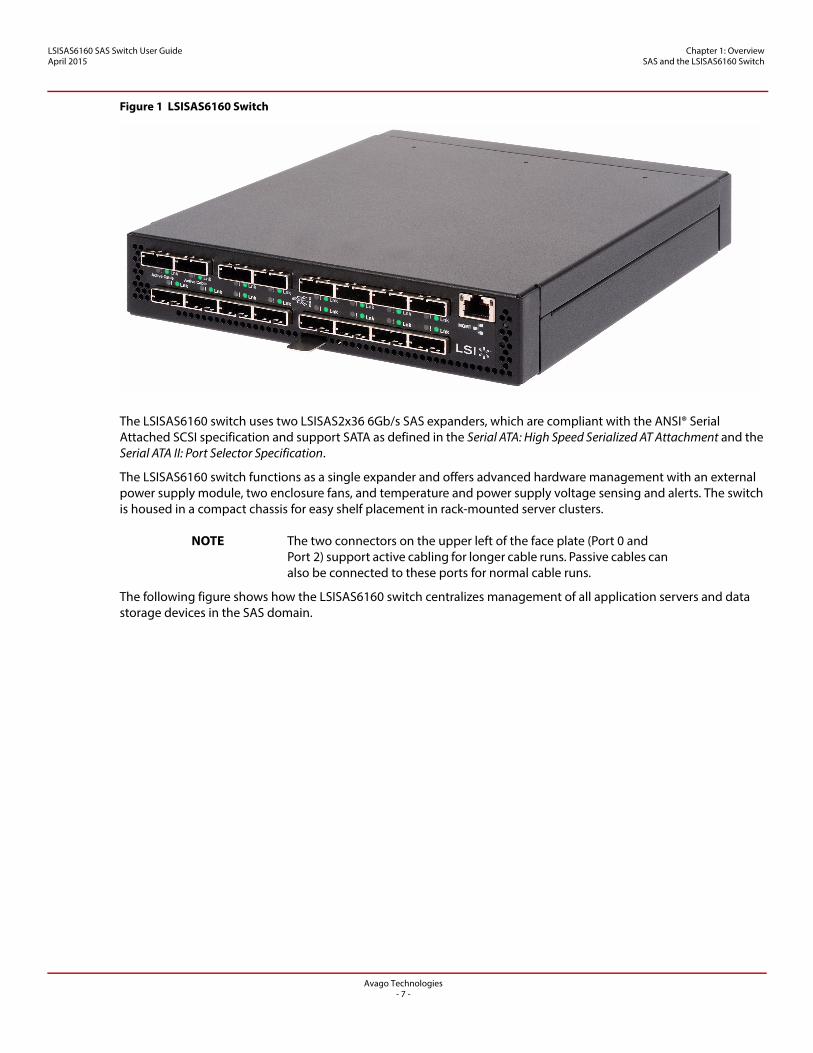
Figure 1 LSISAS6160 Switch
The LSISAS6160 switch uses two LSISAS2x36 6Gb/s SAS expanders, which are compliant with the ANSI® Serial Attached SCSI specification and support SATA as defined in the Serial ATA: High Speed Serialized AT Attachment and the Serial ATA II: Port Selector Specification.
The LSISAS6160 switch functions as a single expander and offers advanced hardware management with an external power supply module, two enclosure fans, and temperature and power supply voltage sensing and alerts. The switch is housed in a compact chassis for easy shelf placement in rack-mounted server clusters.
NOTE The two connectors on the upper left of the face plate (Port 0 and Port 2) support active cabling for longer cable runs. Passive cables can also be connected to these ports for normal cable runs.
The following figure shows how the LSISAS6160 switch centralizes management of all application servers and data storage devices in the SAS domain.
Avago Technologies- 7 -
LSISAS6160 SAS Switch User GuideApril 2015
Chapter 1: Overview SAS and the LSISAS6160 Switch
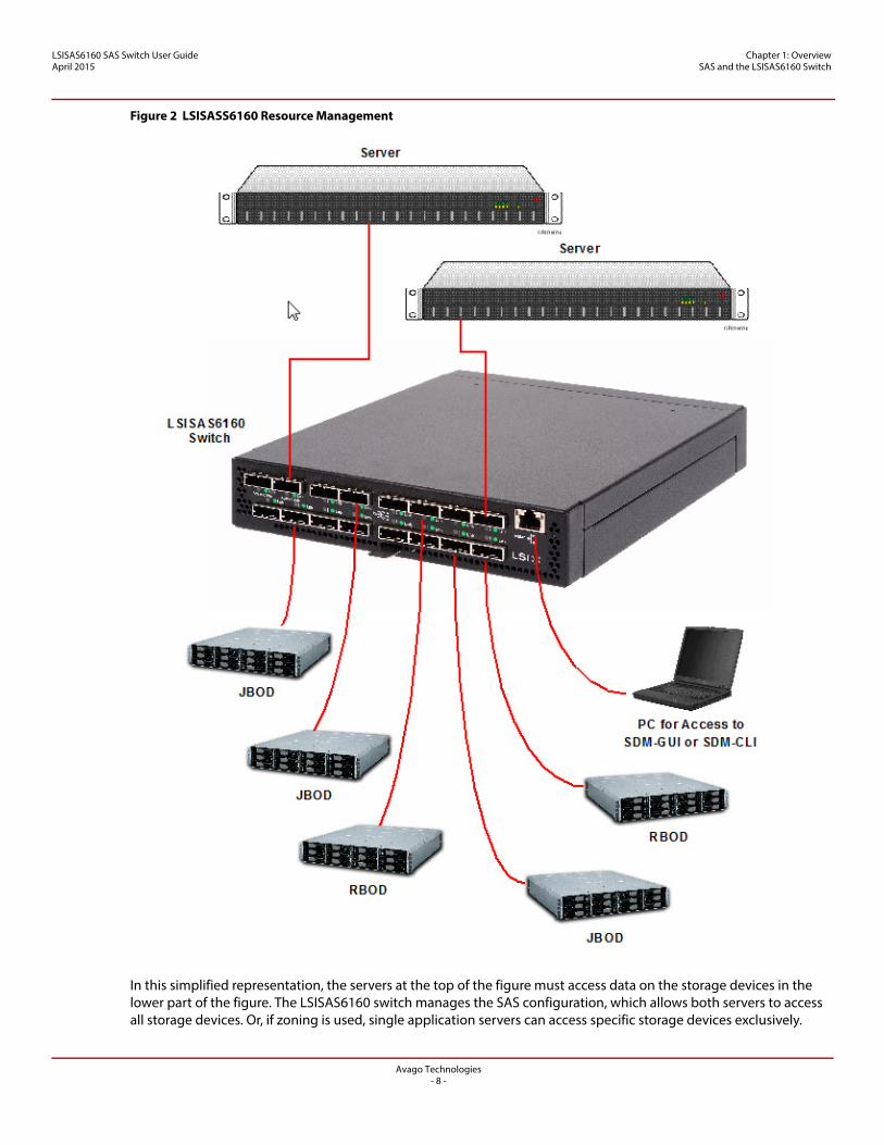
Figure 2 LSISASS6160 Resource Management
In this simplified representation, the servers at the top of the figure must access data on the storage devices in the lower part of the figure. The LSISAS6160 switch manages the SAS configuration, which allows both servers to access all storage devices. Or, if zoning is used, single application servers can access specific storage devices exclusively.
Avago Technologies- 8 -
LSISAS6160 SAS Switch User GuideApril 2015
Chapter 1: Overview SAS Phys, Ports, and Connectors
You can connect multiple LSISAS6160 switches in various topologies to provide failover support and to increase the number of connected devices in the SAS domain. The theoretical upper limit of SAS devices in a domain is 16,000. The upper limit of SAS addresses in an LSISAS6160 switch topology is 1000.
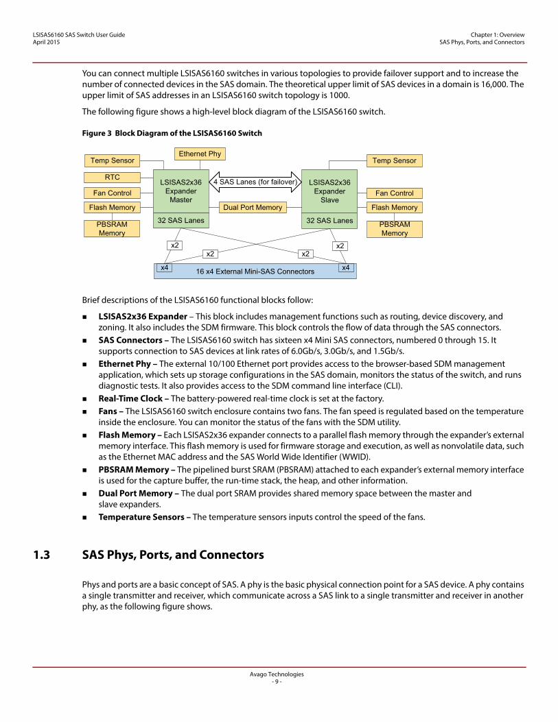
The following figure shows a high-level block diagram of the LSISAS6160 switch.
Figure 3 Block Diagram of the LSISAS6160 Switch
Brief descriptions of the LSISAS6160 functional blocks follow:
LSISAS2x36 Expander – This block includes management functions such as routing, device discovery, and zoning. It also includes the SDM firmware. This block controls the flow of data through the SAS connectors.
SAS Connectors – The LSISAS6160 switch has sixteen x4 Mini SAS connectors, numbered 0 through 15. It supports connection to SAS devices at link rates of 6.0Gb/s, 3.0Gb/s, and 1.5Gb/s.
Ethernet Phy – The external 10/100 Ethernet port provides access to the browser-based SDM management application, which sets up storage configurations in the SAS domain, monitors the status of the switch, and runs diagnostic tests. It also provides access to the SDM command line interface (CLI).
Real-Time Clock – The battery-powered real-time clock is set at the factory. Fans – The LSISAS6160 switch enclosure contains two fans. The fan speed is regulated based on the temperature
inside the enclosure. You can monitor the status of the fans with the SDM utility. Flash Memory – Each LSISAS2x36 expander connects to a parallel flash memory through the expander’s external
memory interface. This flash memory is used for firmware storage and execution, as well as nonvolatile data, such as the Ethernet MAC address and the SAS World Wide Identifier (WWID).
PBSRAM Memory – The pipelined burst SRAM (PBSRAM) attached to each expander’s external memory interface is used for the capture buffer, the run-time stack, the heap, and other information.
Dual Port Memory – The dual port SRAM provides shared memory space between the master and slave expanders.
Temperature Sensors – The temperature sensors inputs control the speed of the fans.
1.3 SAS Phys, Ports, and Connectors
Phys and ports are a basic concept of SAS. A phy is the basic physical connection point for a SAS device. A phy contains a single transmitter and receiver, which communicate across a SAS link to a single transmitter and receiver in another phy, as the following figure shows.
16 x4 External Mini-SAS Connectors
Ethernet Phy
Dual Port Memory
32 SAS Lanes
LSISAS2x36 Expander
Master
Temp Sensor
Fan Control
Flash Memory
32 SAS Lanes
LSISAS2x36 Expander
Slave
Temp Sensor
Fan Control
Flash Memory
RTC
PBSRAM Memory
4 SAS Lanes (for failover)
x4 x4
PBSRAM Memory
x2x2
x2x2
Avago Technologies- 9 -
LSISAS6160 SAS Switch User GuideApril 2015
Chapter 1: Overview SAS Phys, Ports, and Connectors
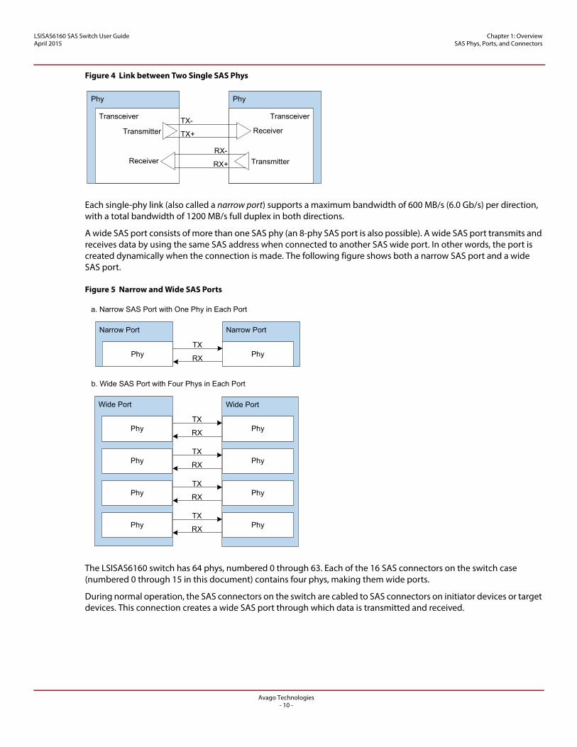
Figure 4 Link between Two Single SAS Phys
Each single-phy link (also called a narrow port) supports a maximum bandwidth of 600 MB/s (6.0 Gb/s) per direction, with a total bandwidth of 1200 MB/s full duplex in both directions.
A wide SAS port consists of more than one SAS phy (an 8-phy SAS port is also possible). A wide SAS port transmits and receives data by using the same SAS address when connected to another SAS wide port. In other words, the port is created dynamically when the connection is made. The following figure shows both a narrow SAS port and a wide SAS port.
Figure 5 Narrow and Wide SAS Ports
The LSISAS6160 switch has 64 phys, numbered 0 through 63. Each of the 16 SAS connectors on the switch case (numbered 0 through 15 in this document) contains four phys, making them wide ports.
During normal operation, the SAS connectors on the switch are cabled to SAS connectors on initiator devices or target devices. This connection creates a wide SAS port through which data is transmitted and received.
Phy
TransceiverTX-
TX+Transmitter
Phy
Transceiver
Receiver
RX-
RX+ TransmitterReceiver
a. Narrow SAS Port with One Phy in Each Port
b. Wide SAS Port with Four Phys in Each Port
Narrow Port
Phy
Narrow Port
PhyTX
RX
Wide Port Wide Port
Phy PhyTX
RX
Phy PhyTX
RX
Phy PhyTX
RX
Phy PhyTX
RX
Avago Technologies- 10 -
LSISAS6160 SAS Switch User GuideApril 2015
Chapter 1: Overview SAS Connectors and Cabling
1.4 SAS Connectors and Cabling
Use a crossover cable to connect the LSISAS6160 switch to a server or to another host device. Use 4x Mini SAS connectors (also called SFF-8088 connectors) on both ends of the crossover cable to connect the switch to the device.
The keyed connectors at port 0 and port 2, located at the upper left on the LSISAS6160 switch, support active cabling. Active cabling permits longer cable lengths and requires a special cable type. These cables are keyed so that they do not attach to a passive connector. However, you can attach a passive cable to a connector that supports active cabling. Chapter 2, Installation and Hardware Setup, has information about recommended cable lengths.
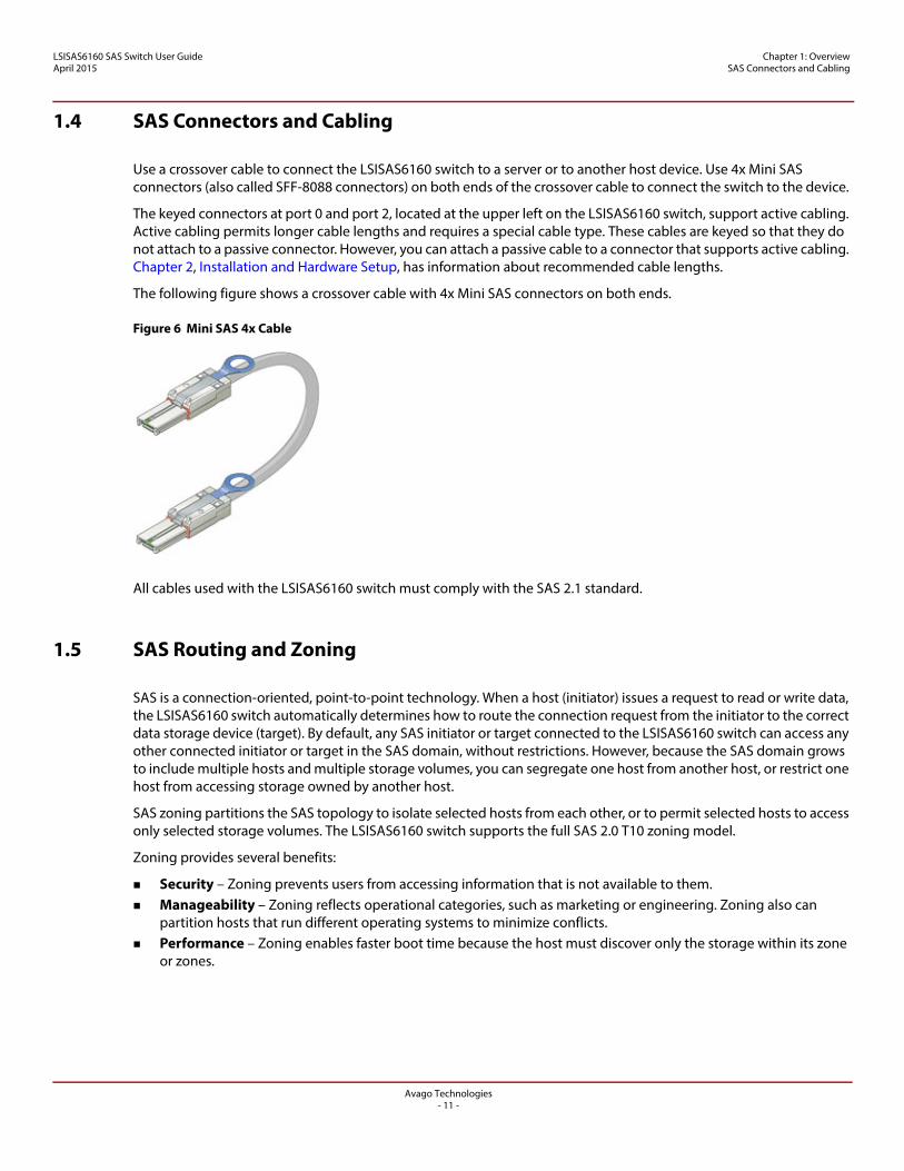
The following figure shows a crossover cable with 4x Mini SAS connectors on both ends.
Figure 6 Mini SAS 4x Cable
All cables used with the LSISAS6160 switch must comply with the SAS 2.1 standard.
1.5 SAS Routing and Zoning
SAS is a connection-oriented, point-to-point technology. When a host (initiator) issues a request to read or write data, the LSISAS6160 switch automatically determines how to route the connection request from the initiator to the correct data storage device (target). By default, any SAS initiator or target connected to the LSISAS6160 switch can access any other connected initiator or target in the SAS domain, without restrictions. However, because the SAS domain grows to include multiple hosts and multiple storage volumes, you can segregate one host from another host, or restrict one host from accessing storage owned by another host.
SAS zoning partitions the SAS topology to isolate selected hosts from each other, or to permit selected hosts to access only selected storage volumes. The LSISAS6160 switch supports the full SAS 2.0 T10 zoning model.
Zoning provides several benefits:
Security – Zoning prevents users from accessing information that is not available to them. Manageability – Zoning reflects operational categories, such as marketing or engineering. Zoning also can
partition hosts that run different operating systems to minimize conflicts. Performance – Zoning enables faster boot time because the host must discover only the storage within its zone
or zones.
Avago Technologies- 11 -
LSISAS6160 SAS Switch User GuideApril 2015
Chapter 1: Overview SAS Routing and Zoning
1.5.1 SAS Zoning Overview
SAS zoning access control is implemented by linked switch and expander devices, with zoning enabled. These devices define a Zoned Portion of a Service Delivery System (ZPSDS). No host device intervention is required. Each zoning switch and expander device maintains an identical zone permission table, so zone access control is maintained across the entire ZPSDS.
To be part of the ZPSDS, the switch requires a SAS expander that supports saving the zone configuration, as explained in the T-10 SAS Specification. Any expander that does not support zone configuration saving is treated as a nonzoning expander and is not included in the ZPSDS.
Initiators and targets see only the portions of the ZPSDS to which they are assigned in the zone permission table. These zoned portions are called zone groups. Zone groups are activated when they belong to a set. When the set is enabled, the zoning is enforced. When the set is disabled, the zoning disappears. More than one set can exist in a ZPSDS, and initiators and targets can belong to more than one set. However, only one set can be active. In addition, more than one ZPSDS can exist in a SAS domain.
A ZPSDS has a zone manager for its configuration and management. The SDM utility (see Chapter 3, SAS Domain Manager Graphical User Interface) configures the zone manager.
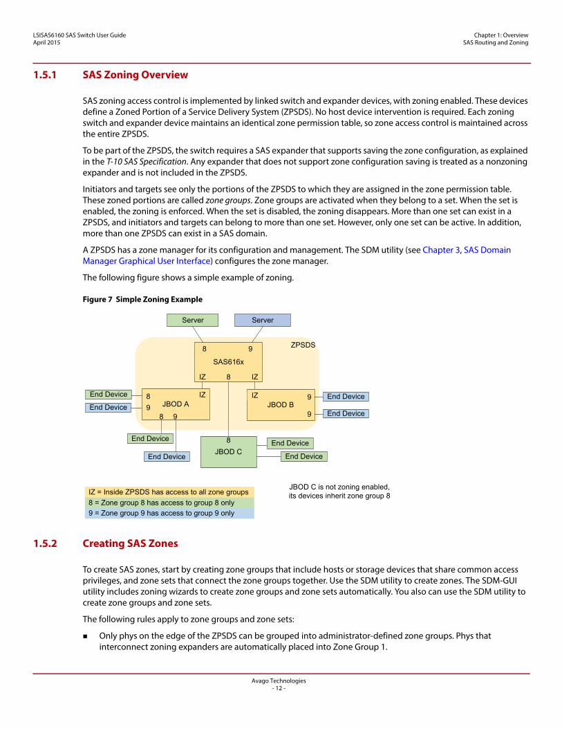
The following figure shows a simple example of zoning.
Figure 7 Simple Zoning Example
1.5.2 Creating SAS Zones
To create SAS zones, start by creating zone groups that include hosts or storage devices that share common access privileges, and zone sets that connect the zone groups together. Use the SDM utility to create zones. The SDM-GUI utility includes zoning wizards to create zone groups and zone sets automatically. You also can use the SDM utility to create zone groups and zone sets.
The following rules apply to zone groups and zone sets:
Only phys on the edge of the ZPSDS can be grouped into administrator-defined zone groups. Phys that interconnect zoning expanders are automatically placed into Zone Group 1.
ZPSDS
Server
End Device
JBOD C
Server
End Device
End Device
JBOD B9IZ
9JBOD A
8 IZ
98 9
8
End Device
End Device
End Device
IZ = Inside ZPSDS has access to all zone groups
8 = Zone group 8 has access to group 8 only
9 = Zone group 9 has access to group 9 only
End Device
End Device
SAS616x
98
IZIZ 8
JBOD C is not zoning enabled, its devices inherit zone group 8
Avago Technologies- 12 -
LSISAS6160 SAS Switch User GuideApril 2015
Chapter 1: Overview SAS Routing and Zoning
An administrator defines zone group permissions. This procedure permits end devices attached to, or downstream of, the zoned phy to communicate with one another.
Zoning limits a host's access to only the targets downstream of zoned phys in which its zone phy is granted zoning access permission. A host can access all logical unit numbers (LUNs) behind the SAS phy, and it does not restrict access to individual storage LUNs.
You can create up to 248 zone groups within a single zone set. SAS phys within a zone group cannot automatically access each other, but you can grant them access privileges. You can grant a zone group permission to access multiple zone groups, if required. A zone group can be a member of more than one zone set. A phy can be a member of only one zone group per zone set. A zone set must be active for its definitions to be applied to the SAS domain. Zone sets are activated in the
SDM utility. Only one zone set can be active at one time. When no zone set is active, zoning is disabled and domain access
is unrestricted. Changes to the active zone set (for example, a change to zone group or zone set membership, or a change to
zone group permissions) do not take effect until the next zone set activate command. When the SAS topology changes (for example, when you move a host or storage attachment from one switch
connection to another) you must manually redefine zone group permissions within the active zone set. The switch does not do this task automatically. Changes to the active zone set do not take effect until the zone set is updated and reactivated.
Zoning is managed throughout the ZPSDS formed around the LSISAS6160 switch, used to manage zoning, and any SAS 2.0 zoning expanders that can be linked back to it without crossing a nonzoning expander. When zoning is enabled, zone group and permission data are migrated automatically between the LSISAS6160 switches and the SAS 2.0 zoning-enabled expanders throughout the ZPSDS. If a storage configuration includes a legacy expander that is not zoning-enabled, that expander and its attached devices inherit the zone group and permissions of the zone phy to which it is connected.
To create a high-availability (failover) configuration, use one LSISAS6160 switch for each data path between the host and the shared storage. SAS allows for only a single path between endpoints. See Figure 13 for more information.
1.5.3 Configuring SAS Zones
The following figure shows a sample configuration with three hosts and five JBODs.
Avago Technologies- 13 -
LSISAS6160 SAS Switch User GuideApril 2015
Chapter 1: Overview SAS Routing and Zoning
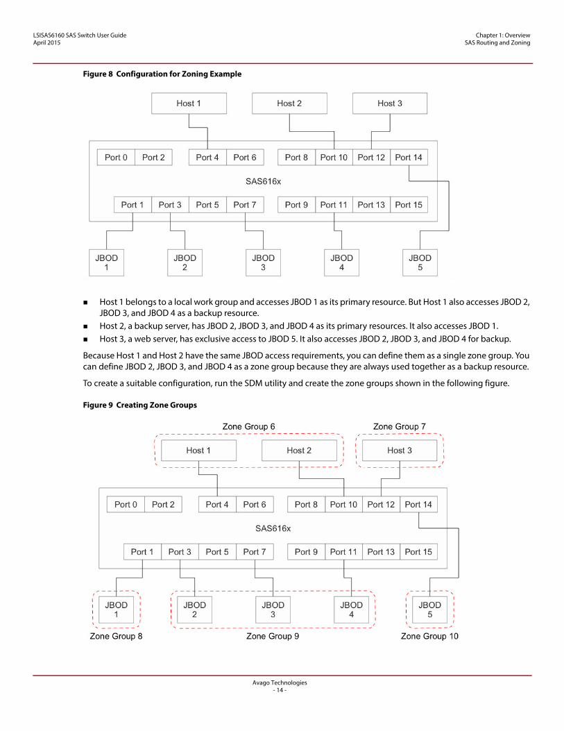
Figure 8 Configuration for Zoning Example
Host 1 belongs to a local work group and accesses JBOD 1 as its primary resource. But Host 1 also accesses JBOD 2, JBOD 3, and JBOD 4 as a backup resource.
Host 2, a backup server, has JBOD 2, JBOD 3, and JBOD 4 as its primary resources. It also accesses JBOD 1. Host 3, a web server, has exclusive access to JBOD 5. It also accesses JBOD 2, JBOD 3, and JBOD 4 for backup.
Because Host 1 and Host 2 have the same JBOD access requirements, you can define them as a single zone group. You can define JBOD 2, JBOD 3, and JBOD 4 as a zone group because they are always used together as a backup resource.
To create a suitable configuration, run the SDM utility and create the zone groups shown in the following figure.
Figure 9 Creating Zone Groups
Avago Technologies- 14 -
LSISAS6160 SAS Switch User GuideApril 2015
Chapter 1: Overview Connecting Devices to the LSISAS6160 Switch
Next, use the SDM utility to assign the following permissions, by creating zone sets:
Zone Group 6 accesses Zone Groups 8 and 9, and vice versa. Zone Group 7 accesses Zone Groups 9 and 10, and vice versa.
1.6 Connecting Devices to the LSISAS6160 Switch
The rules for connecting devices to the 16 SAS connectors on the LSISAS6160 switch are as follows:
Any SAS initiator can be connected to any SAS connector on the switch. Any SAS target can be connected to any SAS connector on the switch. A target can be a RAID array, a JBOD, or
another switch. Individual SAS drives or SATA drives cannot be connected to the switch. Switches can be cascaded by connecting any SAS connector of the downstream switch to any SAS connector on
the upstream switch. When SAS zoning is used, and multiple LSISAS6160 switches are used in the domain, the switches can be cabled
directly to one another. Two switches can be connected with more than one cable to increase bandwidth between switches. All SAS connectors on the switch are Mini SAS, wide port-style connectors. In addition, Connector 0 and
Connector 2 are keyed for active cables (see Section 1.4, SAS Connectors and Cabling). All connections must be x4. For any other configuration, contact your field applications engineer. The maximum connections permitted are as follows:
— Six cascaded expanders, with each switch counting as one expander— Four cascaded switches— A total of 64 total expanders in the topology
The following examples show several ways in which you can connect devices to the LSISAS6160 switch.
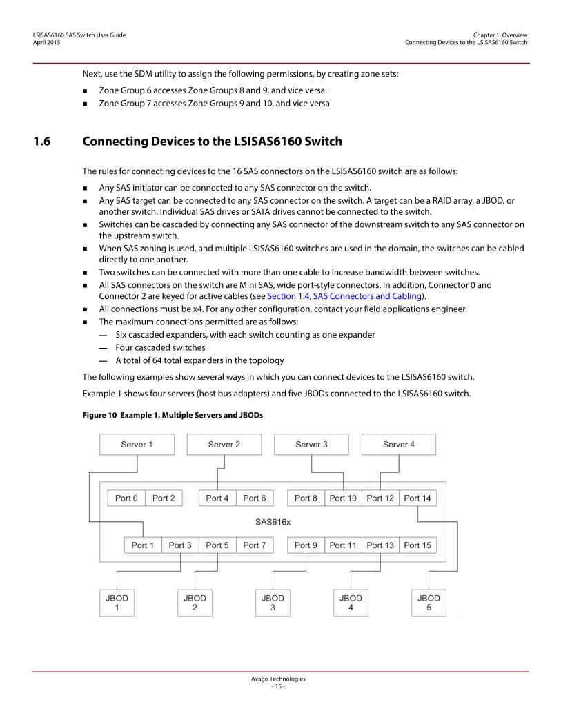
Example 1 shows four servers (host bus adapters) and five JBODs connected to the LSISAS6160 switch.
Figure 10 Example 1, Multiple Servers and JBODs
Avago Technologies- 15 -
LSISAS6160 SAS Switch User GuideApril 2015
Chapter 1: Overview Connecting Devices to the LSISAS6160 Switch
A single rack can contain the switch and all the other devices. The configuration requires nine SAS cables with a Mini SAS connector on each end. Depending on how you set up zoning for the devices, all servers could access data on all the JBODs, or servers could be restricted to accessing a subset of the JBODs.
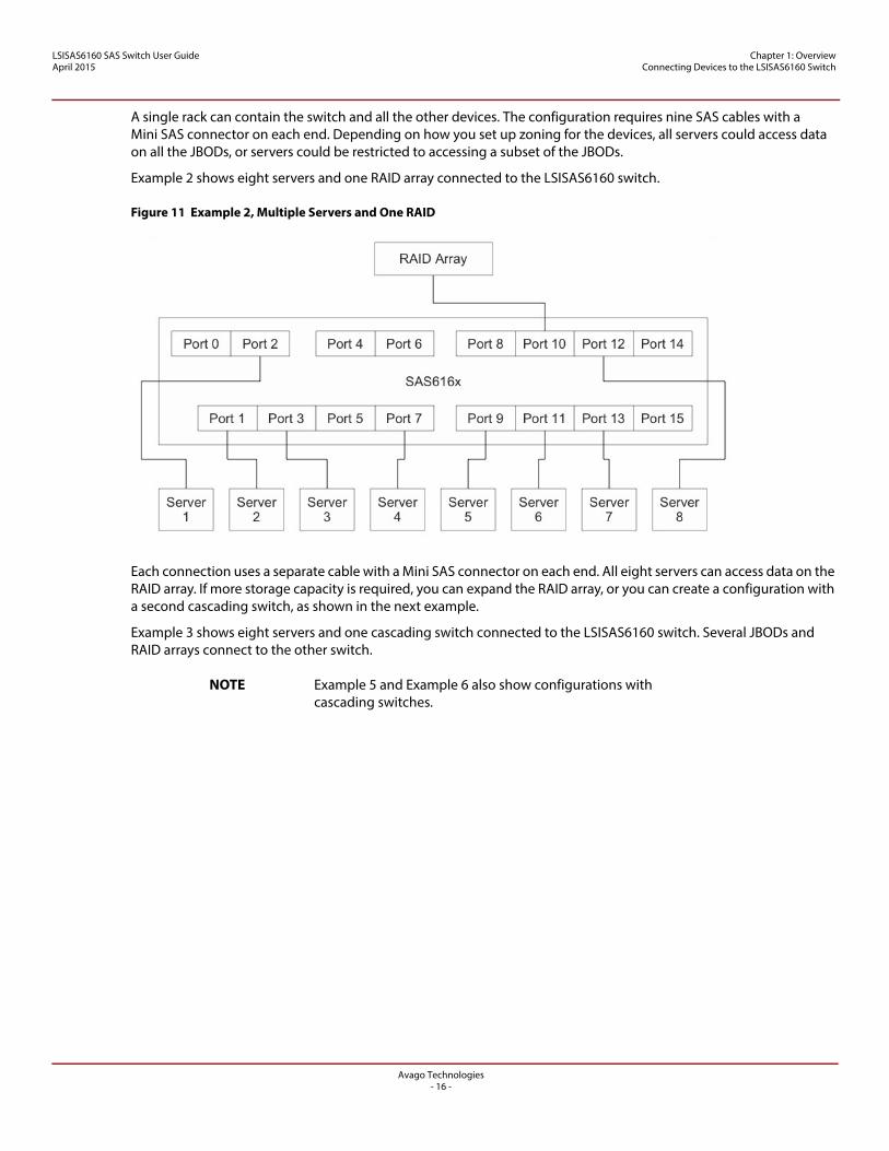
Example 2 shows eight servers and one RAID array connected to the LSISAS6160 switch.
Figure 11 Example 2, Multiple Servers and One RAID
Each connection uses a separate cable with a Mini SAS connector on each end. All eight servers can access data on the RAID array. If more storage capacity is required, you can expand the RAID array, or you can create a configuration with a second cascading switch, as shown in the next example.
Example 3 shows eight servers and one cascading switch connected to the LSISAS6160 switch. Several JBODs and RAID arrays connect to the other switch.
NOTE Example 5 and Example 6 also show configurations with cascading switches.
Avago Technologies- 16 -
LSISAS6160 SAS Switch User GuideApril 2015
Chapter 1: Overview Connecting Devices to the LSISAS6160 Switch
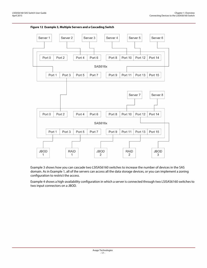
Figure 12 Example 3, Multiple Servers and a Cascading Switch
Example 3 shows how you can cascade two LSISAS6160 switches to increase the number of devices in the SAS domain. As in Example 1, all of the servers can access all the data storage devices, or you can implement a zoning configuration to restrict the access.
Example 4 shows a high-availability configuration in which a server is connected through two LSISAS6160 switches to two input connectors on a JBOD.
Avago Technologies- 17 -
LSISAS6160 SAS Switch User GuideApril 2015
Chapter 1: Overview Connecting Devices to the LSISAS6160 Switch
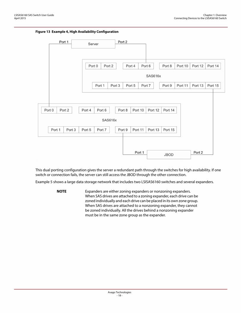
Figure 13 Example 4, High Availability Configuration
This dual porting configuration gives the server a redundant path through the switches for high availability. If one switch or connection fails, the server can still access the JBOD through the other connection.
Example 5 shows a large data storage network that includes two LSISAS6160 switches and several expanders.
NOTE Expanders are either zoning expanders or nonzoning expanders. When SAS drives are attached to a zoning expander, each drive can be zoned individually and each drive can be placed in its own zone group. When SAS drives are attached to a nonzoning expander, they cannot be zoned individually. All the drives behind a nonzoning expander must be in the same zone group as the expander.
Avago Technologies- 18 -
LSISAS6160 SAS Switch User GuideApril 2015
Chapter 1: Overview Connecting Devices to the LSISAS6160 Switch
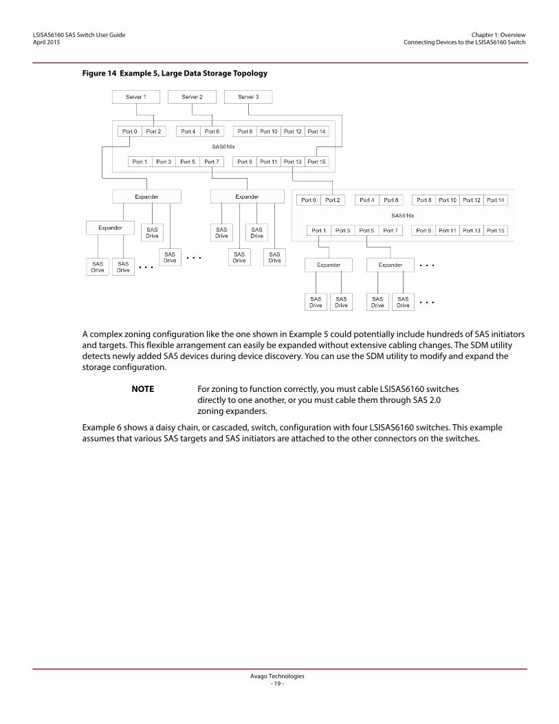
Figure 14 Example 5, Large Data Storage Topology
A complex zoning configuration like the one shown in Example 5 could potentially include hundreds of SAS initiators and targets. This flexible arrangement can easily be expanded without extensive cabling changes. The SDM utility detects newly added SAS devices during device discovery. You can use the SDM utility to modify and expand the storage configuration.
NOTE For zoning to function correctly, you must cable LSISAS6160 switches directly to one another, or you must cable them through SAS 2.0 zoning expanders.
Example 6 shows a daisy chain, or cascaded, switch, configuration with four LSISAS6160 switches. This example assumes that various SAS targets and SAS initiators are attached to the other connectors on the switches.
Avago Technologies- 19 -

LSISAS6160 SAS Switch User GuideApril 2015
Chapter 1: Overview Connecting Devices to the LSISAS6160 Switch
Figure 15 Example 6, Cascaded Switch Configuration
As in Example 3 (Figure 12), the cables in this example can run from any connector of the downstream switch to any connector in the switch above it. The cascade sequence is limited to four switches.
Example 7 shows a star (tree) configuration of four switches, with Switch B, Switch C, and Switch D connected directly to Switch A. As in Example 6 (Figure 15), this example assumes that various SAS targets and SAS initiators are attached to the other connectors on the switches.
Avago Technologies- 20 -
LSISAS6160 SAS Switch User GuideApril 2015
Chapter 1: Overview Connecting Devices to the LSISAS6160 Switch
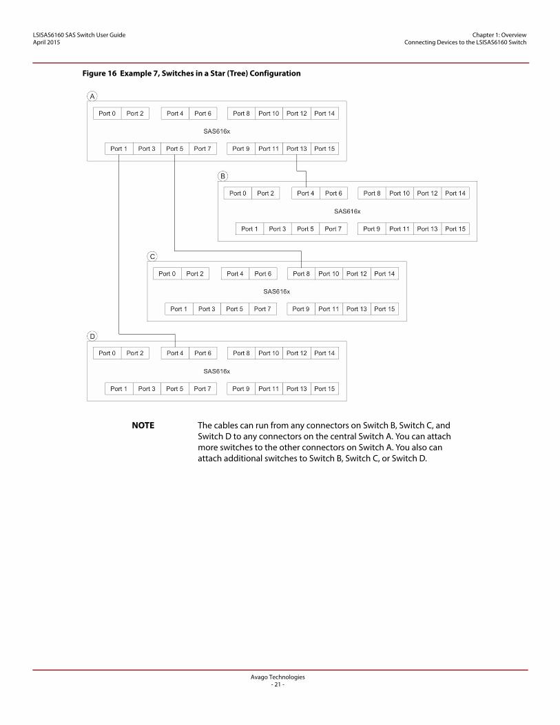
Figure 16 Example 7, Switches in a Star (Tree) Configuration
NOTE The cables can run from any connectors on Switch B, Switch C, and Switch D to any connectors on the central Switch A. You can attach more switches to the other connectors on Switch A. You also can attach additional switches to Switch B, Switch C, or Switch D.
Avago Technologies- 21 -
LSISAS6160 SAS Switch User GuideApril 2015
Chapter 2: Installation and Hardware Setup Unpacking the Switch
Chapter 2: Installation and Hardware Setup
This chapter explains how to unpack the LSISAS6160 SAS switch, install it on an optional rack shelf, connect power cables and other cables to it, change the default static IP address, and connect SAS storage devices to it. This chapter also explains how to interpret the LEDs on the switch.
2.1 Unpacking the Switch
Place the LSISAS6160 switch shipping carton on a grounded surface before opening the carton. Open the shipping carton and carefully unpack its contents. The carton contains the following items:
One LSISAS6160 SAS switch One AC power cord with an inline power supply One CD-ROM that contains this document
If any item is missing or damaged, contact your local reseller for replacement.
2.2 Identifying Switch Components
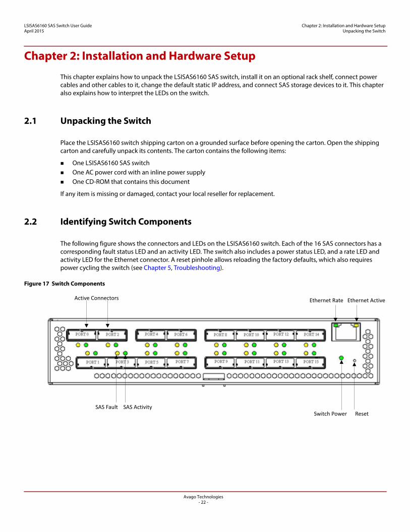
The following figure shows the connectors and LEDs on the LSISAS6160 switch. Each of the 16 SAS connectors has a corresponding fault status LED and an activity LED. The switch also includes a power status LED, and a rate LED and activity LED for the Ethernet connector. A reset pinhole allows reloading the factory defaults, which also requires power cycling the switch (see Chapter 5, Troubleshooting).
Figure 17 Switch Components
Active Connectors Ethernet Rate Ethernet Active
SAS Fault SAS Activity Switch Power Reset
Avago Technologies- 22 -
LSISAS6160 SAS Switch User GuideApril 2015
Chapter 2: Installation and Hardware Setup Installing the LSISAS6160 Switch
2.2.1 LSISAS6160 Connectors
All 16 connectors on the LSISAS6160 switch accept standard passive SAS cabling. The connectors at Port 0 and Port 2 are active, which permits longer cable lengths when using active SAS cabling. See Chapter 1, Overview, for an explanation of SAS connectors and cables.
2.2.2 LSISAS6160 LEDs
The following table shows how to interpret the LEDs for the system, the phys, the power supply module, and the Ethernet (RJ-45) connector. The LEDs in the RJ-45 connector are built into the left and right corners of the connector.
2.2.3 LSISAS6160 Power Supply
The power supply provided with the LSISAS6160 switch includes an IEC320 C5-to-North American standard (NEMA) 5 connector, 18AWG SVT 60 °C, 300-V cable.
You can interchange an international power cord with the supplied power cord if the international power cord includes an IEC320 C5 connection to the power supply, has an equivalent cable construction, and is certified by UL®, CUL, CE, or an equivalent local agency.
2.3 Installing the LSISAS6160 Switch
CAUTION To prevent the LSISAS6160 switch from overheating, do not operate it in an environment that exceeds the maximum recommended ambient temperature of 50 °C (122 °F).
Table 1 SAS Cable Lengths
Connectors Cable Type Minimum Length Maximum Length
1 and 3 to 15 Passive 0.5 m 10 m
0 and 2 only Active — 25 m
Passive 0.5 m 10 m
Table 2 LED Modes
LED Name Color Meaning
Power (P12V) Green 12-V power is present on the board.
SAS Activity Green Blinks with activity on at least one of the four phys in the x4 SAS port.
SAS Fault Amber – solid At least one of the phys in the x4 SAS port is down.
SAS Fault Amber – blinking All blinking amber LEDs indicate an enclosure fault.
Ethernet Link/Activity Amber The link is active. Blinks with activity.
Ethernet Link Rate Green Rate of link. Off = 10 Mb/s. On = 100 Mb/s.
Avago Technologies- 23 -
LSISAS6160 SAS Switch User GuideApril 2015
Chapter 2: Installation and Hardware Setup Installing the LSISAS6160 Switch
When installing the switch, consider the following information:
The acceptable temperature and humidity operating ranges for installation and operation of the switch are as follows:— Temperature range: 5 °C to 50 °C (dry bulb)— Relative humidity range: 5 percent to 90 percent noncondensing— Maximum dew point temperature: 32 °C
Install the LSISAS6160 switch in a site free from strong electromagnetic field generators (such as motors), vibration, and dust.
Allow some space for proper ventilation at the back of the switch, where the fans draw air into the switch for cooling.
The AC power adapter is rated at 100 V to 240 V, and 50 Hz to 60 Hz.
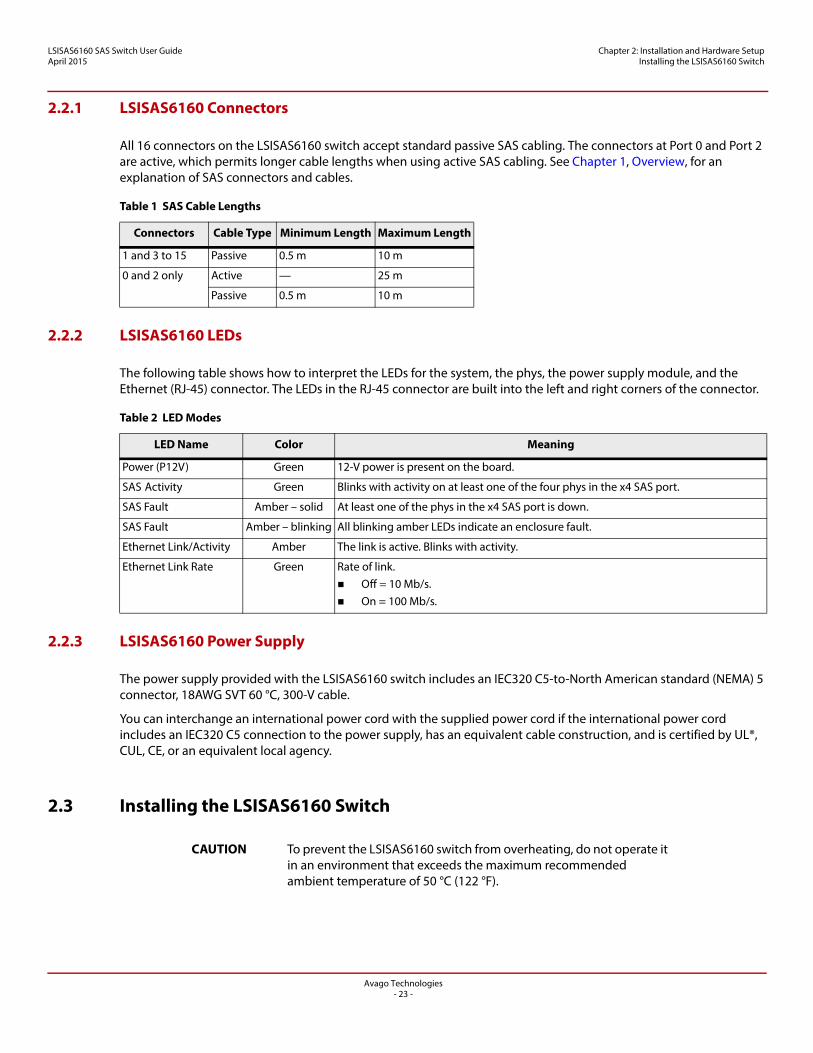
2.3.1 Installing the LSISAS6160 Shelf
A special shelf is available for mounting one or two LSISAS6160 switches in a standard rack. The following figure shows these options.
Figure 18 Mounting LSISAS6160 Switches on a Rack-Mounted Shelf
To assemble and mount the shelf in a rack, follow these steps:
1. Unpack the shelf unit. Make sure that it contains a shelf and two shelf rails along with eight screws.
2. Insert the two side rails from the back of the shelf, as shown in the following figure.
Avago Technologies- 24 -
LSISAS6160 SAS Switch User GuideApril 2015
Chapter 2: Installation and Hardware Setup Installing the LSISAS6160 Switch
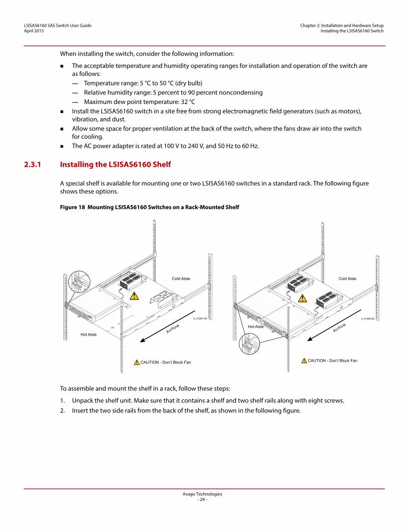
Figure 19 Inserting Side Rails into the Shelf
These rails allow you to adjust the shelf to fit different rack depths. Make sure the mounting ears on the rails are turned outward as shown in the figure.
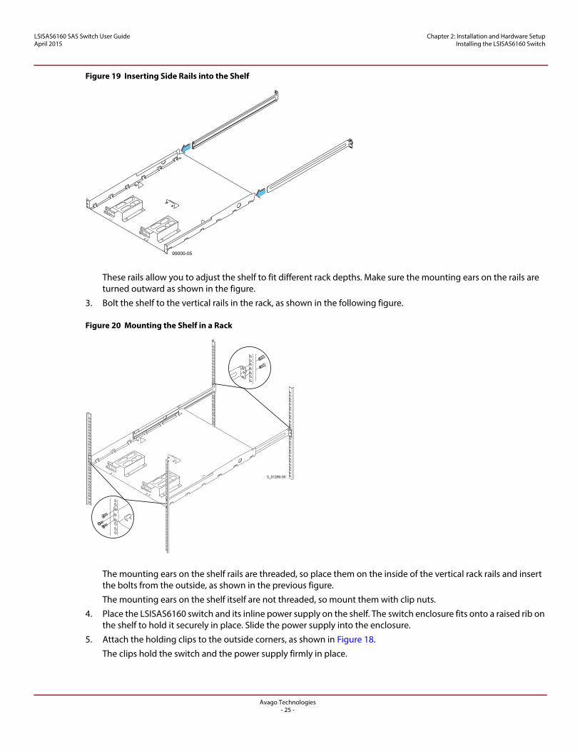
3. Bolt the shelf to the vertical rails in the rack, as shown in the following figure.
Figure 20 Mounting the Shelf in a Rack
The mounting ears on the shelf rails are threaded, so place them on the inside of the vertical rack rails and insert the bolts from the outside, as shown in the previous figure.
The mounting ears on the shelf itself are not threaded, so mount them with clip nuts.
4. Place the LSISAS6160 switch and its inline power supply on the shelf. The switch enclosure fits onto a raised rib on the shelf to hold it securely in place. Slide the power supply into the enclosure.
5. Attach the holding clips to the outside corners, as shown in Figure 18.
The clips hold the switch and the power supply firmly in place.
99000-05
Avago Technologies- 25 -
LSISAS6160 SAS Switch User GuideApril 2015
Chapter 2: Installation and Hardware Setup Connecting to a Host
6. When power is available at the connector side of the switch, route the power cords along the enclosure on the far left or far right of the shelf.
The LSISAS6160 switch is now ready to connect to a host.
2.4 Connecting to a Host
To connect the LSISAS6160 switch to a host, follow these steps:
1. Attach one end of a cable to the 10/100 Ethernet connector (RJ-45 connector) on the connector side of the switch to gain access to the SDM utility, which you use to configure and manage the switch.
— Use a standard RJ-45 cable to connect to an external Ethernet hub or switch.— Use a crossover RJ-45 cable to connect directly to a computer.
2. Plug the other end of the RJ-45 cable into an Ethernet hub, a switch, or a computer. Use a web browser (Microsoft® Internet Explorer®, or Mozilla® Firefox®) on the host. By default, the switch supports the configuration parameters listed in the following table, which provides a point-to-point (non-network) Ethernet connection between the switch and the host.
WARNING Provide the LSISAS6160 switch with an AC-protective earth-ground connection. Never defeat the ground conductor or operate the LSISAS6160 switch without a suitably installed ground conductor.
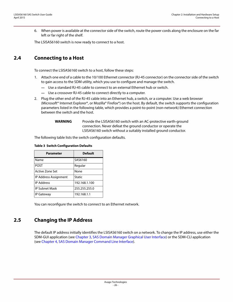
The following table lists the switch configuration defaults.
You can reconfigure the switch to connect to an Ethernet network.
2.5 Changing the IP Address
The default IP address initially identifies the LSISAS6160 switch on a network. To change the IP address, use either the SDM-GUI application (see Chapter 3, SAS Domain Manager Graphical User Interface) or the SDM-CLI application (see Chapter 4, SAS Domain Manager Command Line Interface).
Table 3 Switch Configuration Defaults
Parameter Default
Name SAS6160
POST Regular
Active Zone Set None
IP Address Assignment Static
IP Address 192.168.1.100
IP Subnet Mask 255.255.255.0
IP Gateway 192.168.1.1
Avago Technologies- 26 -
LSISAS6160 SAS Switch User GuideApril 2015
Chapter 2: Installation and Hardware Setup Changing the IP Address
2.5.1 Setting a Static IP Address
Follow these steps to set a static IP address for the LSISAS6160 switch.
2.5.1.1 Using SDM-GUI
1. Log on to SDM-GUI using the admin account.
2. Select the switch from the Devices tab.
3. Click the Operations tab.
4. Click the Configure IP link to open the Configure IP box.
5. Click the Static IP radio button.
6. Configure the static IP address, DNS, and gateway provided by your network administrator.
7. Exit SDM-GUI and power-cycle the switch.
2.5.1.2 Using SDM-CLI
1. Log on to SDM-CLI using the admin account.
2. Enter the following command:
device <sasaddress> ip static <ipaddress> <netmask> <defaultgateway>
An example of the command follows:
device 500605b0002453ff ip static 172.21.25.204 255.255.255.0 172.21.25.1
3. Exit SDM-CLI and power-cycle the switch.
2.5.2 Setting a Dynamic IP Address
2.5.2.1 Using SDM-GUI
1. Log on to SDM-GUI using the admin account.
2. Select the switch from the Devices tab. Record the switch SAS address for possible reference and identification later.
3. Click the Operations tab.
4. Click the Configure IP link to open the Configure IP box.
5. Click the DHCP IP radio button.
6. Power off the switch.
7. Connect the switch to the network.
8. Power on the switch, which now receives an IP address assignment.
9. Run the provided Xip utility with these options to see the SAS address and IP information for all attached devices.
xip -i get avail
For network management, contact your system administrator to create a static reservation for this IP address.
2.5.2.2 Using SDM-CLI
1. Log on to SDM-CLI using the admin account.
2. Enter the following command:
device <sasaddress> ip dhcp
An example of the command follows:
device 500605b0002453ff ip dhcp
Avago Technologies- 27 -
LSISAS6160 SAS Switch User GuideApril 2015
Chapter 2: Installation and Hardware Setup Connecting the SAS and SATA Hardware
3. Exit SDM-CLI and power-cycle the switch.
4. Run the provided Xip utility with these options to see the SAS address and IP information for all attached devices.xip -i get avail
2.6 Connecting the SAS and SATA Hardware
The LSISAS6160 switch centralizes management for all SAS initiators and SAS targets in the SAS domain. The SAS ports on the switch are, by default, both input ports and output ports. Depending on the requirements, you can attach each port to a SAS host bus adapter, a SAS or SATA JBOD, a RAID array, or a SAS expander. You cannot connect the LSISAS6160 switch to individual SAS HDD drives or SATA HDD drives, but you can connect one direct-attach tape drive to any odd-numbered port (the lower row). You can use any SAS port on the LSISAS6160 switch to cascade to any port on another LSISAS6160 switch to increase the size of the storage configuration.
Chapter 1, Overview, shows examples of various kinds of hardware configurations and explains the types of SAS connectors and cables that are needed for these configurations.
2.7 Safety Notices
The LSISAS6160 switch uses a 3-V coin cell lithium battery for the real-time clock. The battery is not user replaceable. The following warning and caution apply if you must dispose of a LSISAS6160 switch for some reason.
CAUTION Potentially hazardous material – The lithium coin cell battery contains perchlorate that might be considered hazardous material. If the used battery is physically damaged and is leaking, do not ship the battery to a recycling center. Handling a damaged battery exposes you and others to potentially hazardous material. Dispose of the damaged battery according to all applicable regulations. If you recycle a used battery that is not damaged, use the proper facilities. Handle the battery according to all applicable regulations.
WARNING Risk of fire or chemical burn – The battery used in this device might present a risk of fire or chemical burn if mistreated. Do not disassemble, heat above 60 °C (140 °F), crush or puncture, short-circuit external contacts, or dispose of the battery in fire or water.
2.7.1 FCC
This equipment has been tested and found to comply with the limits for a Class A digital device, pursuant to Part 15 of the Federal Communications Commission (FCC) Rules. These limits are designed to provide reasonable protection against harmful interference in a commercial installation. This equipment generates, uses, and can radiate radio frequency energy and, if not installed and used in accordance with the instructions, may cause harmful interference to radio communications. Operation of this equipment in a residential area is likely to cause harmful interference, in which case you must correct the interference at your own expense.
Avago Technologies® is not responsible for any radio or television interference caused by unauthorized modification of this equipment or the substitution or attachment of connecting cables and equipment other than those specified by Avago®. It is your responsibility to correct interference caused by such unauthorized modification, substitution, or attachment.
Avago Technologies- 28 -
LSISAS6160 SAS Switch User GuideApril 2015
Chapter 2: Installation and Hardware Setup Safety Notices
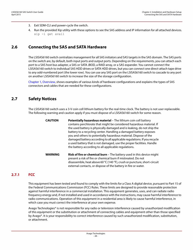
2.7.2 Canada Mark
2.7.3 VCCI
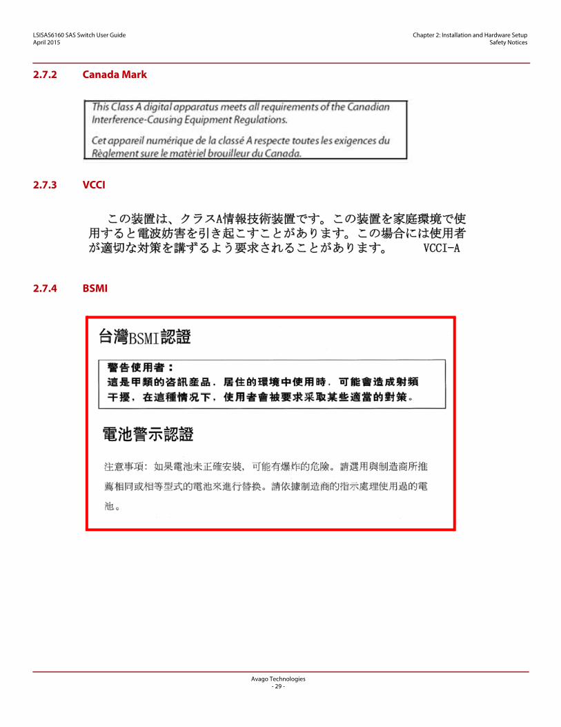
2.7.4 BSMI
Avago Technologies- 29 -
LSISAS6160 SAS Switch User GuideApril 2015
Chapter 2: Installation and Hardware Setup Safety Notices
2.7.5 CCC
电池警示认证
注意事项:
如果电池未正确安装,可能有爆炸的危险。请选用与制造商所推荐相同或相等型式
的电池来进行替换。请依据制造商的指示处理使用过的电池。
Avago Technologies- 30 -
LSISAS6160 SAS Switch User GuideApril 2015
Chapter 3: SAS Domain Manager Graphical User Interface SDM-GUI Accounts
Chapter 3: SAS Domain Manager Graphical User Interface
This chapter explains how to use the SAS Domain Manager Graphical User Interface (SDM-GUI) application to configure and monitor storage configurations with the LSISAS6160 switch. The SDM-GUI utility is a Java® Web Start® application, and the LSISAS6160 functions as an HTTP server that launches the utility. To run SDM-GUI from a browser, point the browser to the switch’s IP address. SDM-GUI uses TCP/IP port 5573 to communicate with the LSISAS6160 switch. Therefore, the 5573 port must be available for communication between the management station and the switch.
SDM-GUI has an easy-to-use graphical interface that enables you to manage the host switch and other switches or expanders within the domain in which the host switch resides. Use the interface to view domain information, create and modify aliases, and manage zone groups and zone sets.
3.1 SDM-GUI Accounts
You can run SDM-GUI from a user account or from an admin account.
The user account allows you to view the domain topology, configuration, and operating environment. The default password for this account is user.
The admin account allows you to view the same information as the user account. In addition, you can change the configuration of the domain and of the managed devices within the domain. The default password for this account is admin.
The LSISAS6160 switch’s zone manager password is handled separately. Its default password is lynx.
3.2 Starting SDM-GUI
Follow these steps to start SDM-GUI:
1. Open a web browser and point it to the switch’s IP address or host name.
The Java Web Start application downloads and launches SDM-GUI automatically.
The Password window appears.
2. Enter your user name and password.
3. Click Login.
The main window and Summary tab appear.
3.3 Summary Tab and Menu Options
The following figure shows the SDM main window, with the menu bar and Summary tab.
Avago Technologies- 31 -
LSISAS6160 SAS Switch User GuideApril 2015
Chapter 3: SAS Domain Manager Graphical User Interface File, Server, and Help Menu Options
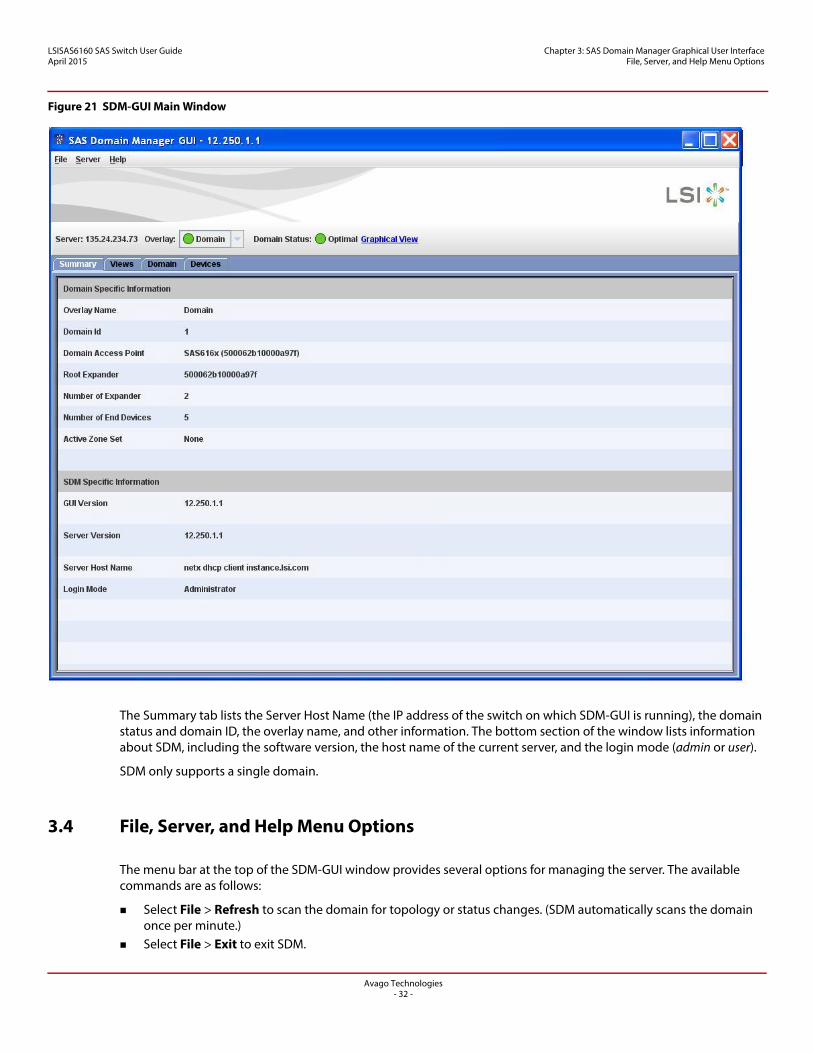
Figure 21 SDM-GUI Main Window
The Summary tab lists the Server Host Name (the IP address of the switch on which SDM-GUI is running), the domain status and domain ID, the overlay name, and other information. The bottom section of the window lists information about SDM, including the software version, the host name of the current server, and the login mode (admin or user).
SDM only supports a single domain.
3.4 File, Server, and Help Menu Options
The menu bar at the top of the SDM-GUI window provides several options for managing the server. The available commands are as follows:
Select File > Refresh to scan the domain for topology or status changes. (SDM automatically scans the domain once per minute.)
Select File > Exit to exit SDM.
Avago Technologies- 32 -
LSISAS6160 SAS Switch User GuideApril 2015
Chapter 3: SAS Domain Manager Graphical User Interface File, Server, and Help Menu Options
Select Server > Connect to return to the login screen. Select Server > Change Password to change passwords for either the admin account or the user account. To
change either password, you must know the current admin password. Select Server > Event Log to see the event log, which you can filter by domain and by severity (optimal, failed,
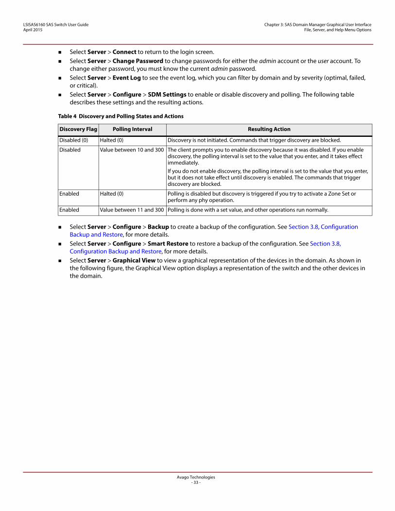
or critical). Select Server > Configure > SDM Settings to enable or disable discovery and polling. The following table
describes these settings and the resulting actions.
Select Server > Configure > Backup to create a backup of the configuration. See Section 3.8, Configuration Backup and Restore, for more details.
Select Server > Configure > Smart Restore to restore a backup of the configuration. See Section 3.8, Configuration Backup and Restore, for more details.
Select Server > Graphical View to view a graphical representation of the devices in the domain. As shown in the following figure, the Graphical View option displays a representation of the switch and the other devices in the domain.
Table 4 Discovery and Polling States and Actions
Discovery Flag Polling Interval Resulting Action
Disabled (0) Halted (0) Discovery is not initiated. Commands that trigger discovery are blocked.
Disabled Value between 10 and 300 The client prompts you to enable discovery because it was disabled. If you enable discovery, the polling interval is set to the value that you enter, and it takes effect immediately.If you do not enable discovery, the polling interval is set to the value that you enter, but it does not take effect until discovery is enabled. The commands that trigger discovery are blocked.
Enabled Halted (0) Polling is disabled but discovery is triggered if you try to activate a Zone Set or perform any phy operation.
Enabled Value between 11 and 300 Polling is done with a set value, and other operations run normally.
Avago Technologies- 33 -
LSISAS6160 SAS Switch User GuideApril 2015
Chapter 3: SAS Domain Manager Graphical User Interface Views Tab
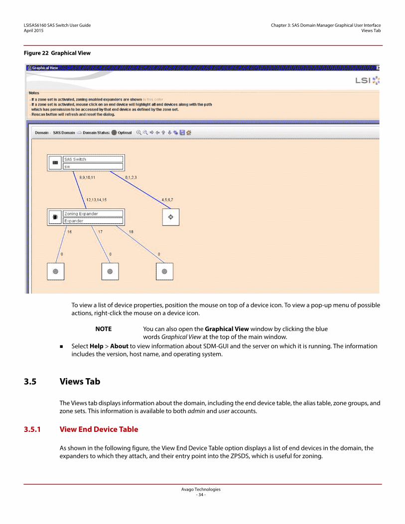
Figure 22 Graphical View
To view a list of device properties, position the mouse on top of a device icon. To view a pop-up menu of possible actions, right-click the mouse on a device icon.
NOTE You can also open the Graphical View window by clicking the blue words Graphical View at the top of the main window.
Select Help > About to view information about SDM-GUI and the server on which it is running. The information includes the version, host name, and operating system.
3.5 Views Tab
The Views tab displays information about the domain, including the end device table, the alias table, zone groups, and zone sets. This information is available to both admin and user accounts.
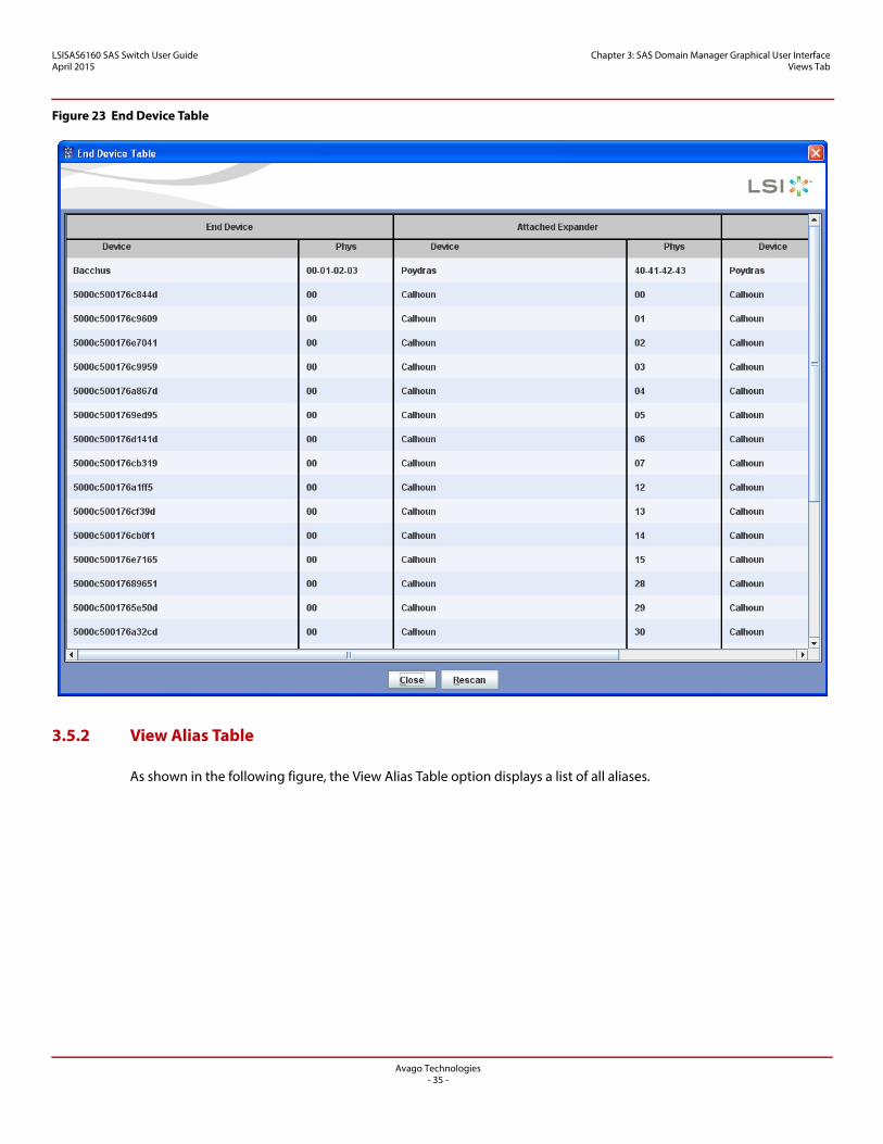
3.5.1 View End Device Table
As shown in the following figure, the View End Device Table option displays a list of end devices in the domain, the expanders to which they attach, and their entry point into the ZPSDS, which is useful for zoning.
Avago Technologies- 34 -
LSISAS6160 SAS Switch User GuideApril 2015
Chapter 3: SAS Domain Manager Graphical User Interface Views Tab
Figure 23 End Device Table
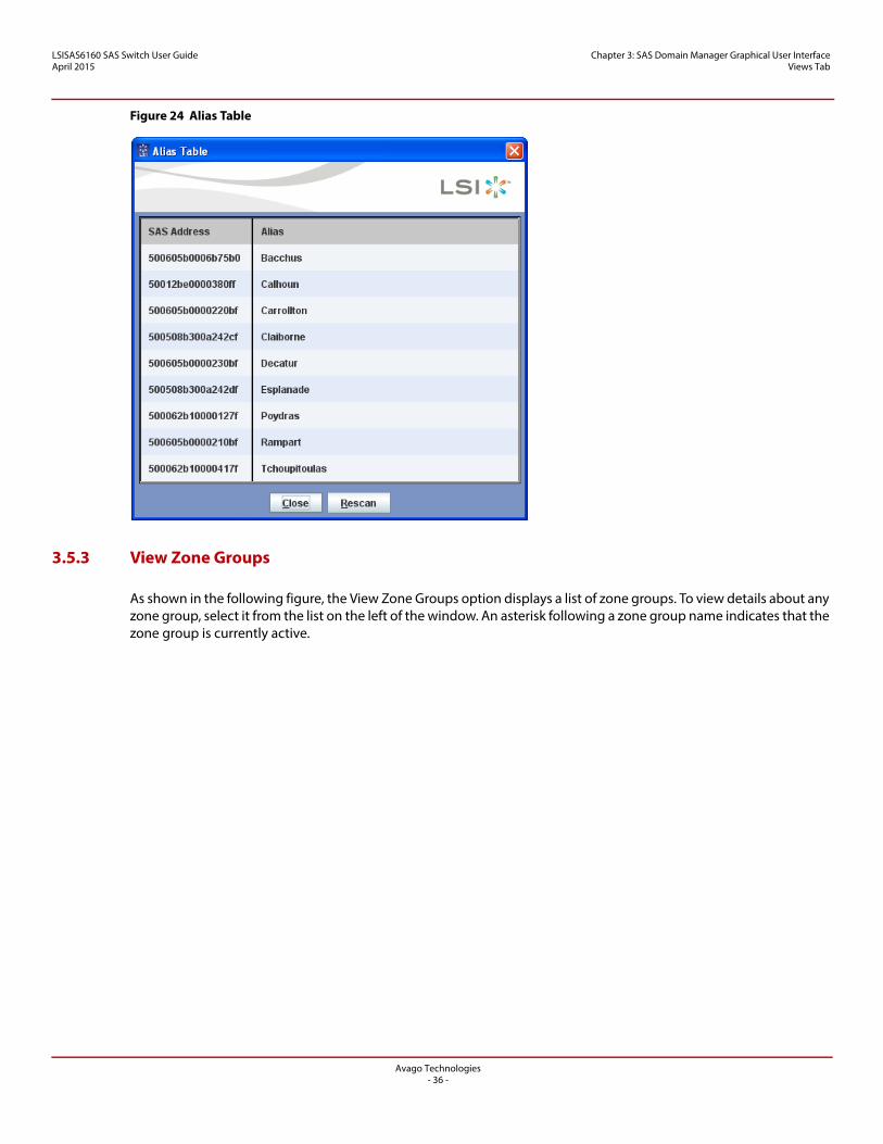
3.5.2 View Alias Table
As shown in the following figure, the View Alias Table option displays a list of all aliases.
Avago Technologies- 35 -
LSISAS6160 SAS Switch User GuideApril 2015
Chapter 3: SAS Domain Manager Graphical User Interface Views Tab
Figure 24 Alias Table
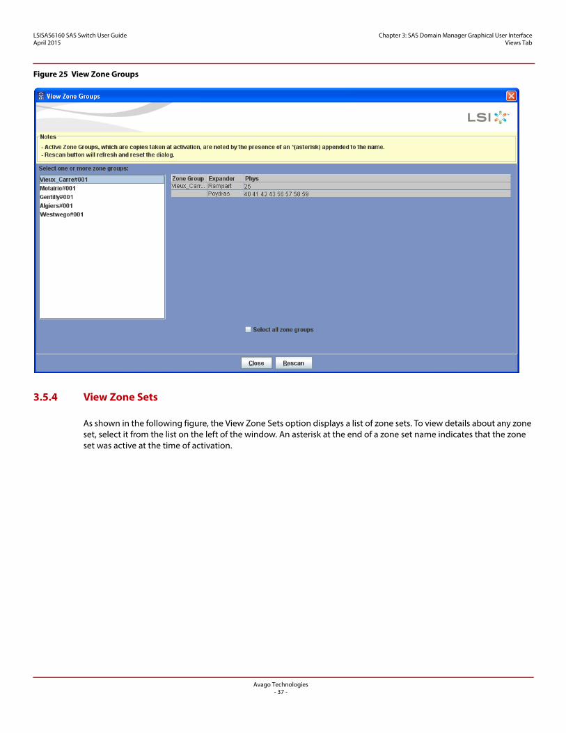
3.5.3 View Zone Groups
As shown in the following figure, the View Zone Groups option displays a list of zone groups. To view details about any zone group, select it from the list on the left of the window. An asterisk following a zone group name indicates that the zone group is currently active.
Avago Technologies- 36 -
LSISAS6160 SAS Switch User GuideApril 2015
Chapter 3: SAS Domain Manager Graphical User Interface Views Tab
Figure 25 View Zone Groups
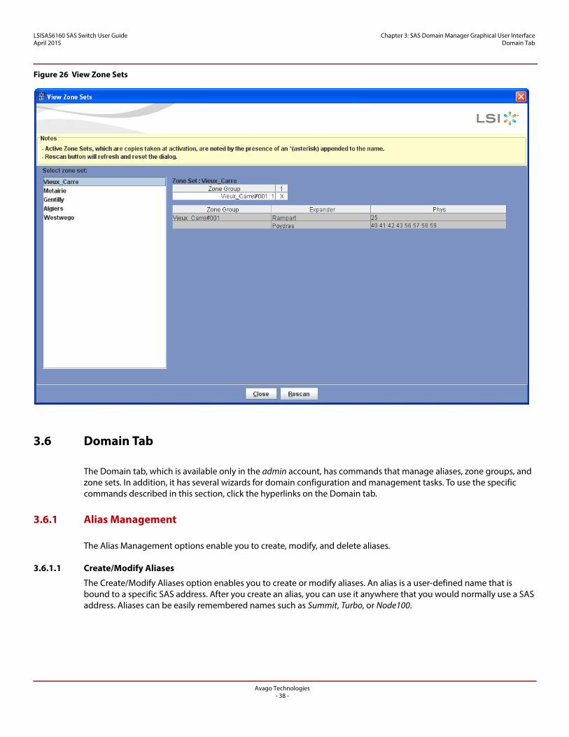
3.5.4 View Zone Sets
As shown in the following figure, the View Zone Sets option displays a list of zone sets. To view details about any zone set, select it from the list on the left of the window. An asterisk at the end of a zone set name indicates that the zone set was active at the time of activation.
Avago Technologies- 37 -
LSISAS6160 SAS Switch User GuideApril 2015
Chapter 3: SAS Domain Manager Graphical User Interface Domain Tab
Figure 26 View Zone Sets
3.6 Domain Tab
The Domain tab, which is available only in the admin account, has commands that manage aliases, zone groups, and zone sets. In addition, it has several wizards for domain configuration and management tasks. To use the specific commands described in this section, click the hyperlinks on the Domain tab.
3.6.1 Alias Management
The Alias Management options enable you to create, modify, and delete aliases.
3.6.1.1 Create/Modify Aliases
The Create/Modify Aliases option enables you to create or modify aliases. An alias is a user-defined name that is bound to a specific SAS address. After you create an alias, you can use it anywhere that you would normally use a SAS address. Aliases can be easily remembered names such as Summit, Turbo, or Node100.
Avago Technologies- 38 -
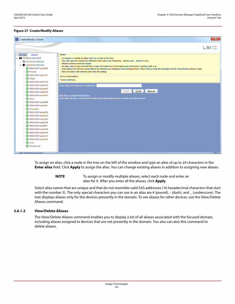
LSISAS6160 SAS Switch User GuideApril 2015
Chapter 3: SAS Domain Manager Graphical User Interface Domain Tab
Figure 27 Create/Modify Aliases
To assign an alias, click a node in the tree on the left of the window and type an alias of up to 24 characters in the Enter alias field. Click Apply to assign the alias. You can change existing aliases in addition to assigning new aliases.
NOTE To assign or modify multiple aliases, select each node and enter an alias for it. After you enter all the aliases, click Apply.
Select alias names that are unique and that do not resemble valid SAS addresses (16 hexadecimal characters that start with the number 5). The only special characters you can use in an alias are # (pound), - (dash), and _ (underscore). The tree displays aliases only for the devices presently in the domain. To see aliases for other devices, use the View/Delete Aliases command.
3.6.1.2 View/Delete Aliases
The View/Delete Aliases command enables you to display a list of all aliases associated with the focused domain, including aliases assigned to devices that are not presently in the domain. You also can also this command to delete aliases.
Avago Technologies- 39 -
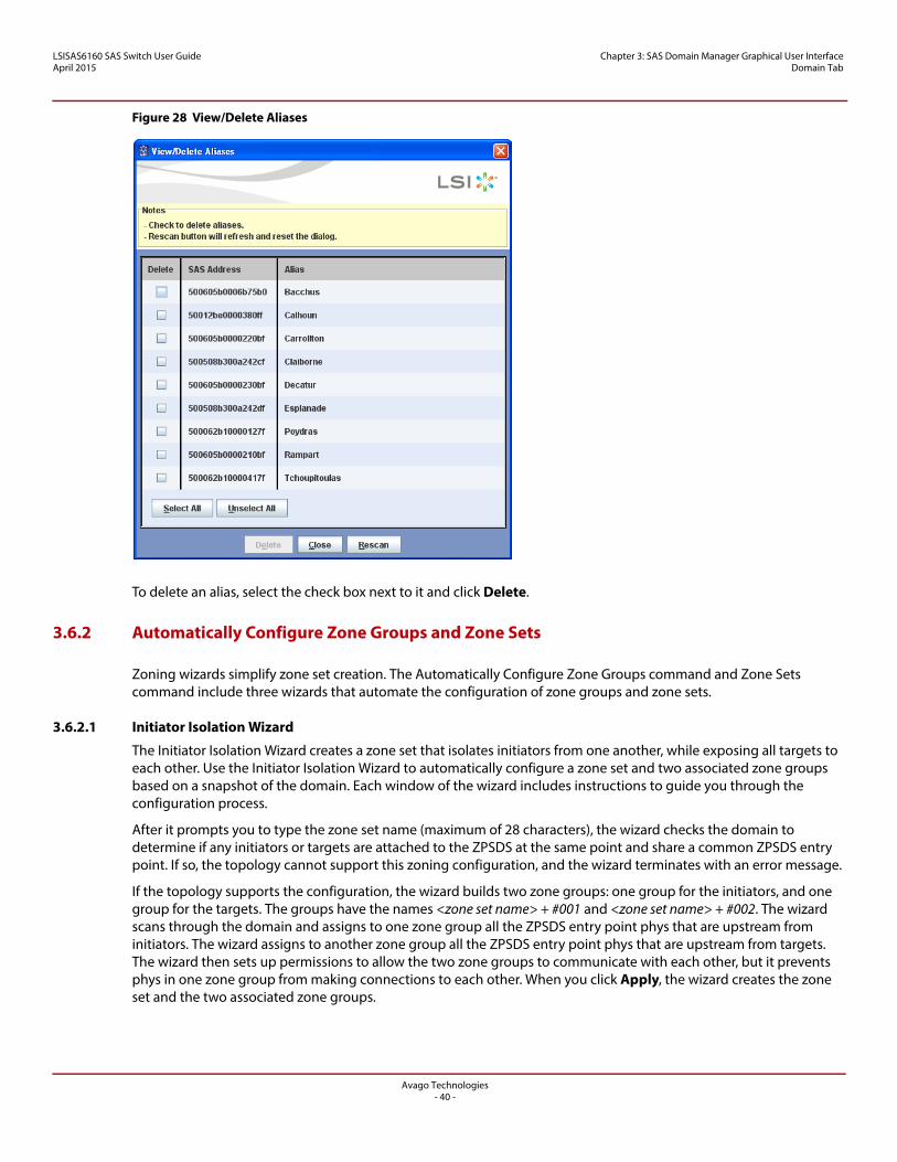
LSISAS6160 SAS Switch User GuideApril 2015
Chapter 3: SAS Domain Manager Graphical User Interface Domain Tab
Figure 28 View/Delete Aliases
To delete an alias, select the check box next to it and click Delete.
3.6.2 Automatically Configure Zone Groups and Zone Sets
Zoning wizards simplify zone set creation. The Automatically Configure Zone Groups command and Zone Sets command include three wizards that automate the configuration of zone groups and zone sets.
3.6.2.1 Initiator Isolation Wizard
The Initiator Isolation Wizard creates a zone set that isolates initiators from one another, while exposing all targets to each other. Use the Initiator Isolation Wizard to automatically configure a zone set and two associated zone groups based on a snapshot of the domain. Each window of the wizard includes instructions to guide you through the configuration process.
After it prompts you to type the zone set name (maximum of 28 characters), the wizard checks the domain to determine if any initiators or targets are attached to the ZPSDS at the same point and share a common ZPSDS entry point. If so, the topology cannot support this zoning configuration, and the wizard terminates with an error message.
If the topology supports the configuration, the wizard builds two zone groups: one group for the initiators, and one group for the targets. The groups have the names <zone set name> + #001 and <zone set name> + #002. The wizard scans through the domain and assigns to one zone group all the ZPSDS entry point phys that are upstream from initiators. The wizard assigns to another zone group all the ZPSDS entry point phys that are upstream from targets. The wizard then sets up permissions to allow the two zone groups to communicate with each other, but it prevents phys in one zone group from making connections to each other. When you click Apply, the wizard creates the zone set and the two associated zone groups.
Avago Technologies- 40 -
LSISAS6160 SAS Switch User GuideApril 2015
Chapter 3: SAS Domain Manager Graphical User Interface Domain Tab
3.6.2.2 Connector Wizard
The Connector Wizard automatically configures a zone set and associated zone groups by grouping connectors on the edge of the ZPSDS. The wizard includes instructions to guide you through the configuration process.
The wizard uses a snapshot of the domain to identify the connectors on the edge of the ZPSDS and then displays a list of these connectors. (The list does not include connectors that link expanders within the ZPSDS.) Type the zone set name (maximum of 28 characters) and bundle the connectors into zones by selecting one or more connectors from the list. You can define multiple zones as needed to meet your zoning requirements. Zones can overlap, but the wizard removes zones that are subsets of larger zones. You can delete the defined zones by selecting the check box and clicking Delete.
After you define all the zones, the wizard uses the zone definitions to create the minimal number of zone groups and to configure their permissions. The wizard creates one zone group per defined zone, populating the zone group with the phys associated with the connectors in that zone, and setting up permission for the phys in the zone group to communicate with each other.
The wizard then compares each zone group to all other zone groups, including zone groups created during this process, searching for phys that are in both zone groups. If it finds any such phys (parents), it creates a new zone group (child) and moves the identified phys to the child. The wizard then grants permission for the child’s phys to communicate with each other, as well as with the phys of the two parent zone groups.
If one of the parent zone groups is emptied in this process, the wizard transfers all permissions from the parent to the child. Empty zone groups are later ignored and are not transferred to the zone manager.
The wizard creates the zone set and associated zone group when you click Apply. It assigns to zone groups the names <zone set name> + #001, <zone set name> + #002, and so on. If the number of generated zone groups exceeds the maximum number of 248, the wizard displays an error message.
NOTE If phys on the edge of the ZPSDS are associated with connectors, their connectors are displayed in the selection list. If phys on the edge of the ZPSDS are not associated with connectors, but they have formed into ports (they are connected to a device), ports appear in the selection list. If phys on the edge of the ZPSDS are not associated with connectors and have not formed into ports, individual phys are displayed in the selection list.
3.6.2.3 End Device Wizard
Use the End Device Wizard to automatically configure a zone set and associated zone groups by grouping end devices. Each window of the wizard includes instructions to guide you through the configuration process.
This wizard uses a snapshot of the domain to determine the available end devices and then displays lists of initiators and targets. Type the zone set name (maximum of 28 characters) and bundle one or more initiators with one or more targets into a zone by selecting them from these lists. You can define multiple zones as needed to meet your zoning requirements. Zones can overlap, but zones that are subsets of larger zones are removed. The wizard forces devices that share the same ZPSDS entry point (siblings) into the same zone by automatically selecting all siblings when you select a single sibling. You can delete the defined zones by selecting the check box and clicking Delete.
After you define all the zones, the wizard uses the zone definitions to create the minimal number of zone groups and to configure their permissions. The wizard creates one zone group per defined zone, populating the zone group with the ZPSDS entry point phys of the end devices in that zone, and setting up permission for the phys in the zone group to communicate with each other.
The wizard then compares each zone group to all other zone groups, including zone groups created during this process, searching for phys that are in both zone groups. If it finds any such phys (parents), it creates a new zone group (child) and moves the identified phys to the child. The wizard then grants permission for the child’s phys to communicate with each other, as well as with the phys of the two parent zone groups.
Avago Technologies- 41 -
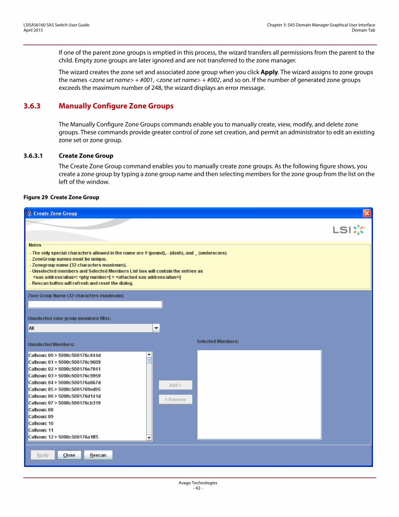
LSISAS6160 SAS Switch User GuideApril 2015
Chapter 3: SAS Domain Manager Graphical User Interface Domain Tab
If one of the parent zone groups is emptied in this process, the wizard transfers all permissions from the parent to the child. Empty zone groups are later ignored and are not transferred to the zone manager.
The wizard creates the zone set and associated zone group when you click Apply. The wizard assigns to zone groups the names <zone set name> + #001, <zone set name> + #002, and so on. If the number of generated zone groups exceeds the maximum number of 248, the wizard displays an error message.
3.6.3 Manually Configure Zone Groups
The Manually Configure Zone Groups commands enable you to manually create, view, modify, and delete zone groups. These commands provide greater control of zone set creation, and permit an administrator to edit an existing zone set or zone group.
3.6.3.1 Create Zone Group
The Create Zone Group command enables you to manually create zone groups. As the following figure shows, you create a zone group by typing a zone group name and then selecting members for the zone group from the list on the left of the window.
Figure 29 Create Zone Group
Avago Technologies- 42 -
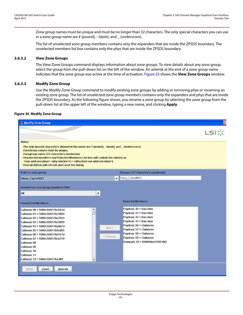
LSISAS6160 SAS Switch User GuideApril 2015
Chapter 3: SAS Domain Manager Graphical User Interface Domain Tab
Zone group names must be unique and must be no longer than 32 characters. The only special characters you can use in a zone group name are # (pound), - (dash), and _ (underscore).
The list of unselected zone group members contains only the expanders that are inside the ZPSDS boundary. The unselected members list box contains only the phys that are inside the ZPSDS boundary.
3.6.3.2 View Zone Groups
The View Zone Groups command displays information about zone groups. To view details about any zone group, select the group from the pull-down list on the left of the window. An asterisk at the end of a zone group name indicates that the zone group was active at the time of activation. Figure 25 shows the View Zone Groups window.
3.6.3.3 Modify Zone Group
Use the Modify Zone Group command to modify existing zone groups by adding or removing phys or renaming an existing zone group. The list of unselected zone group members contains only the expanders and phys that are inside the ZPSDS boundary. As the following figure shows, you rename a zone group by selecting the zone group from the pull-down list at the upper left of the window, typing a new name, and clicking Apply.
Figure 30 Modify Zone Group
Avago Technologies- 43 -
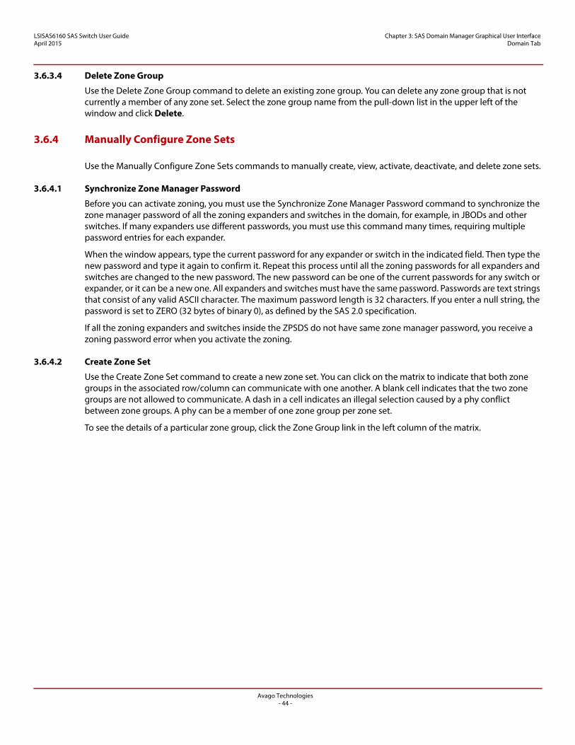
LSISAS6160 SAS Switch User GuideApril 2015
Chapter 3: SAS Domain Manager Graphical User Interface Domain Tab
3.6.3.4 Delete Zone Group
Use the Delete Zone Group command to delete an existing zone group. You can delete any zone group that is not currently a member of any zone set. Select the zone group name from the pull-down list in the upper left of the window and click Delete.
3.6.4 Manually Configure Zone Sets
Use the Manually Configure Zone Sets commands to manually create, view, activate, deactivate, and delete zone sets.
3.6.4.1 Synchronize Zone Manager Password
Before you can activate zoning, you must use the Synchronize Zone Manager Password command to synchronize the zone manager password of all the zoning expanders and switches in the domain, for example, in JBODs and other switches. If many expanders use different passwords, you must use this command many times, requiring multiple password entries for each expander.
When the window appears, type the current password for any expander or switch in the indicated field. Then type the new password and type it again to confirm it. Repeat this process until all the zoning passwords for all expanders and switches are changed to the new password. The new password can be one of the current passwords for any switch or expander, or it can be a new one. All expanders and switches must have the same password. Passwords are text strings that consist of any valid ASCII character. The maximum password length is 32 characters. If you enter a null string, the password is set to ZERO (32 bytes of binary 0), as defined by the SAS 2.0 specification.
If all the zoning expanders and switches inside the ZPSDS do not have same zone manager password, you receive a zoning password error when you activate the zoning.
3.6.4.2 Create Zone Set
Use the Create Zone Set command to create a new zone set. You can click on the matrix to indicate that both zone groups in the associated row/column can communicate with one another. A blank cell indicates that the two zone groups are not allowed to communicate. A dash in a cell indicates an illegal selection caused by a phy conflict between zone groups. A phy can be a member of one zone group per zone set.
To see the details of a particular zone group, click the Zone Group link in the left column of the matrix.
Avago Technologies- 44 -
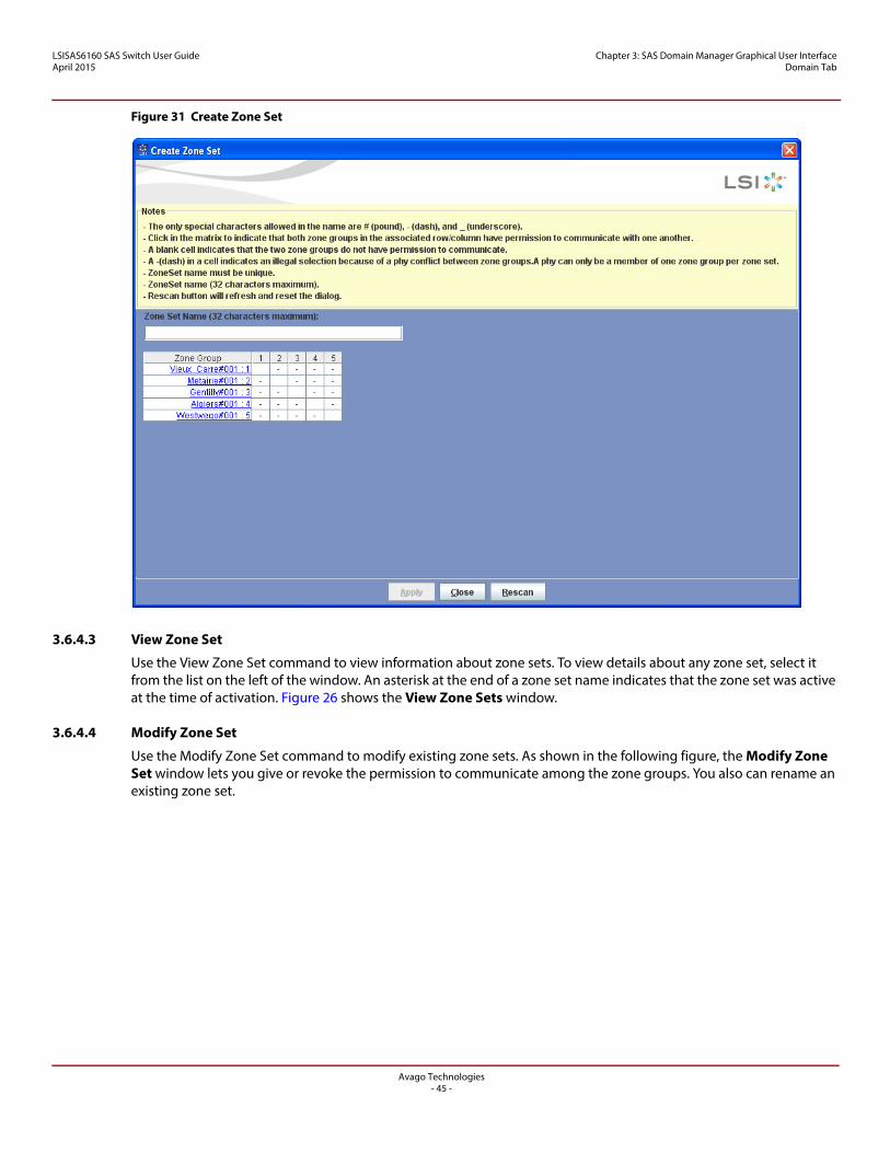
LSISAS6160 SAS Switch User GuideApril 2015
Chapter 3: SAS Domain Manager Graphical User Interface Domain Tab
Figure 31 Create Zone Set
3.6.4.3 View Zone Set
Use the View Zone Set command to view information about zone sets. To view details about any zone set, select it from the list on the left of the window. An asterisk at the end of a zone set name indicates that the zone set was active at the time of activation. Figure 26 shows the View Zone Sets window.
3.6.4.4 Modify Zone Set
Use the Modify Zone Set command to modify existing zone sets. As shown in the following figure, the Modify Zone Set window lets you give or revoke the permission to communicate among the zone groups. You also can rename an existing zone set.
Avago Technologies- 45 -
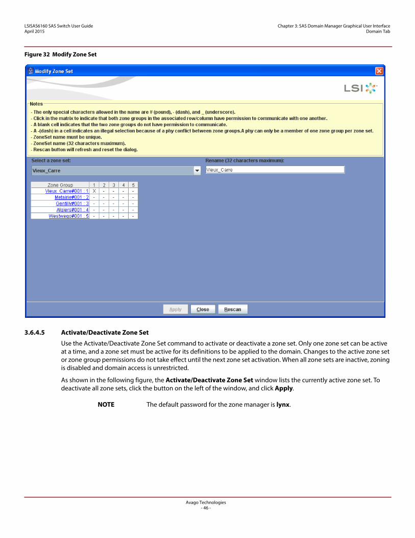
LSISAS6160 SAS Switch User GuideApril 2015
Chapter 3: SAS Domain Manager Graphical User Interface Domain Tab
Figure 32 Modify Zone Set
3.6.4.5 Activate/Deactivate Zone Set
Use the Activate/Deactivate Zone Set command to activate or deactivate a zone set. Only one zone set can be active at a time, and a zone set must be active for its definitions to be applied to the domain. Changes to the active zone set or zone group permissions do not take effect until the next zone set activation. When all zone sets are inactive, zoning is disabled and domain access is unrestricted.
As shown in the following figure, the Activate/Deactivate Zone Set window lists the currently active zone set. To deactivate all zone sets, click the button on the left of the window, and click Apply.
NOTE The default password for the zone manager is lynx.
Avago Technologies- 46 -
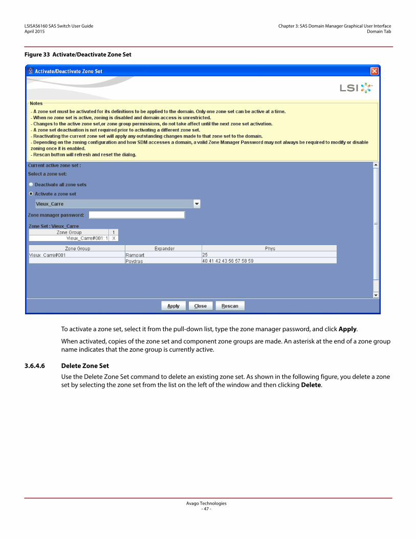
LSISAS6160 SAS Switch User GuideApril 2015
Chapter 3: SAS Domain Manager Graphical User Interface Domain Tab
Figure 33 Activate/Deactivate Zone Set
To activate a zone set, select it from the pull-down list, type the zone manager password, and click Apply.
When activated, copies of the zone set and component zone groups are made. An asterisk at the end of a zone group name indicates that the zone group is currently active.
3.6.4.6 Delete Zone Set
Use the Delete Zone Set command to delete an existing zone set. As shown in the following figure, you delete a zone set by selecting the zone set from the list on the left of the window and then clicking Delete.
Avago Technologies- 47 -
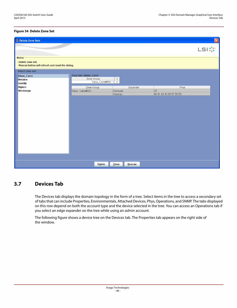
LSISAS6160 SAS Switch User GuideApril 2015
Chapter 3: SAS Domain Manager Graphical User Interface Devices Tab
Figure 34 Delete Zone Set
3.7 Devices Tab
The Devices tab displays the domain topology in the form of a tree. Select items in the tree to access a secondary set of tabs that can include Properties, Environmentals, Attached Devices, Phys, Operations, and SNMP. The tabs displayed on this row depend on both the account type and the device selected in the tree. You can access an Operations tab if you select an edge expander on the tree while using an admin account.
The following figure shows a device tree on the Devices tab. The Properties tab appears on the right side of the window.
Avago Technologies- 48 -
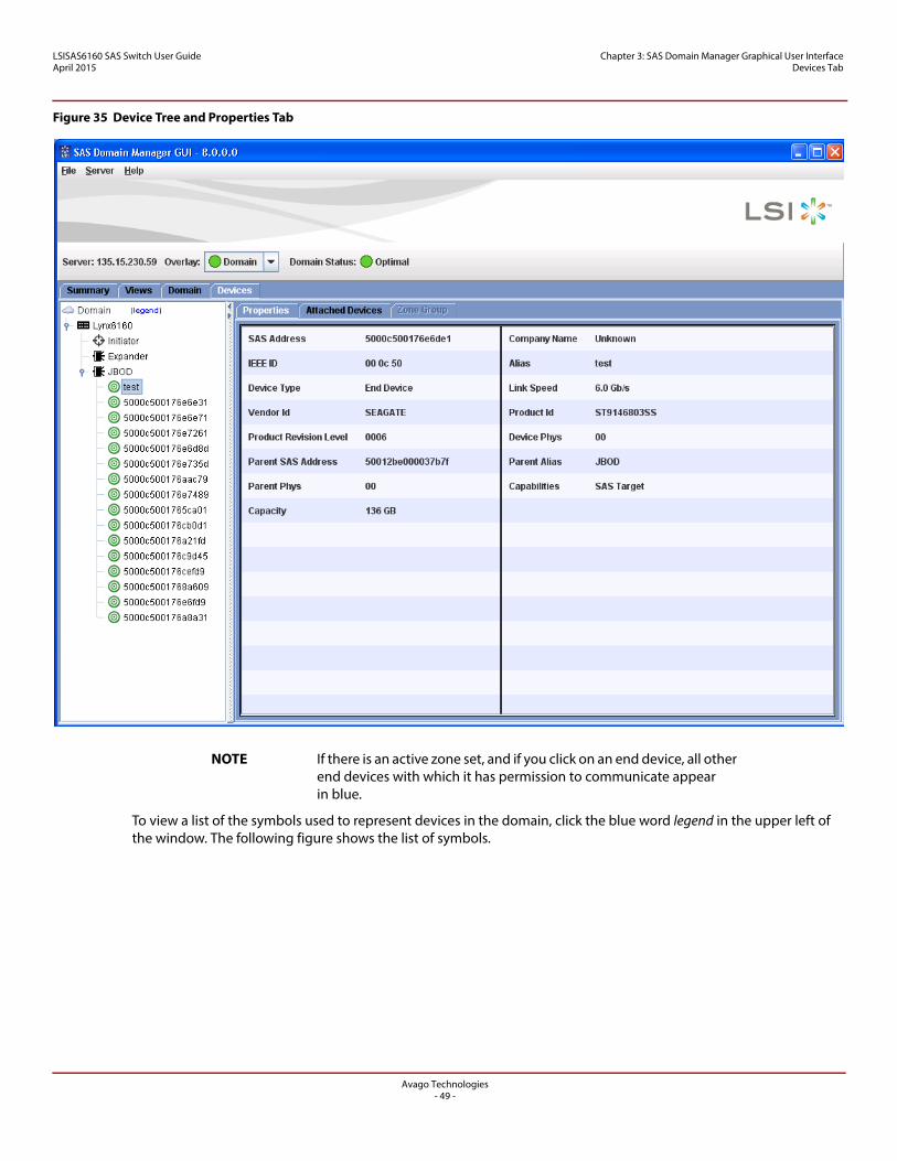
LSISAS6160 SAS Switch User GuideApril 2015
Chapter 3: SAS Domain Manager Graphical User Interface Devices Tab
Figure 35 Device Tree and Properties Tab
NOTE If there is an active zone set, and if you click on an end device, all other end devices with which it has permission to communicate appear in blue.
To view a list of the symbols used to represent devices in the domain, click the blue word legend in the upper left of the window. The following figure shows the list of symbols.
Avago Technologies- 49 -
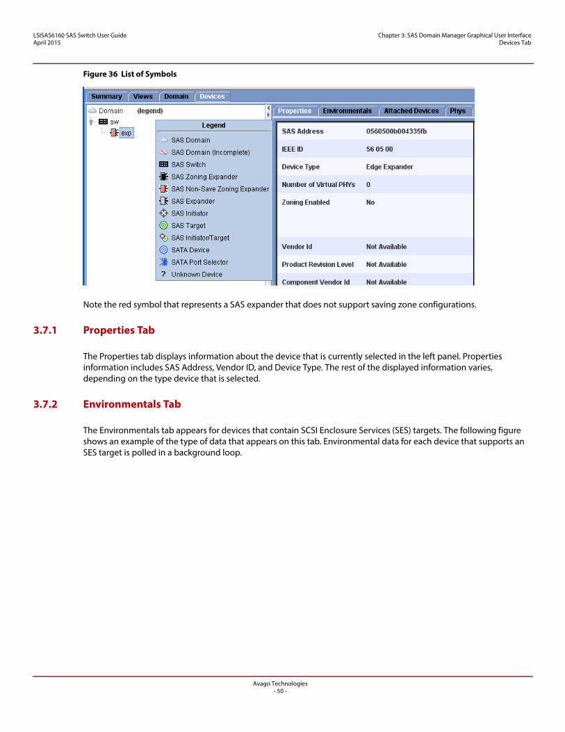
LSISAS6160 SAS Switch User GuideApril 2015
Chapter 3: SAS Domain Manager Graphical User Interface Devices Tab
Figure 36 List of Symbols
Note the red symbol that represents a SAS expander that does not support saving zone configurations.
3.7.1 Properties Tab
The Properties tab displays information about the device that is currently selected in the left panel. Properties information includes SAS Address, Vendor ID, and Device Type. The rest of the displayed information varies, depending on the type device that is selected.
3.7.2 Environmentals Tab
The Environmentals tab appears for devices that contain SCSI Enclosure Services (SES) targets. The following figure shows an example of the type of data that appears on this tab. Environmental data for each device that supports an SES target is polled in a background loop.
Avago Technologies- 50 -
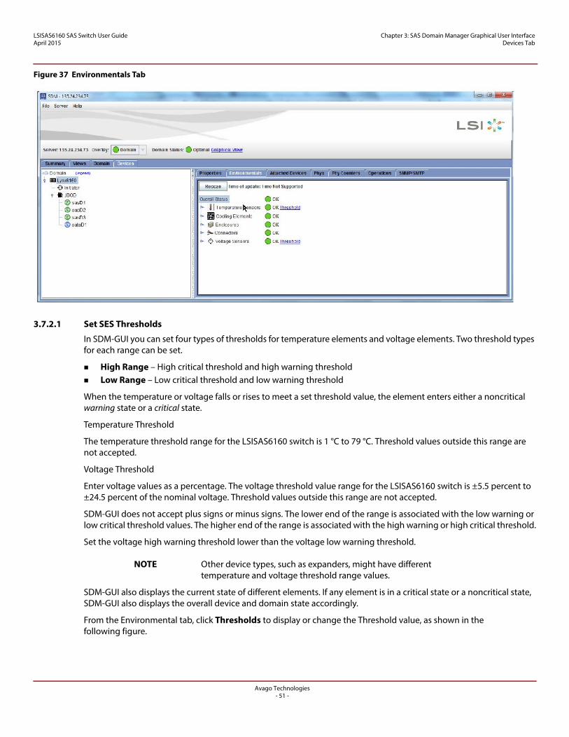
LSISAS6160 SAS Switch User GuideApril 2015
Chapter 3: SAS Domain Manager Graphical User Interface Devices Tab
Figure 37 Environmentals Tab
3.7.2.1 Set SES Thresholds
In SDM-GUI you can set four types of thresholds for temperature elements and voltage elements. Two threshold types for each range can be set.
High Range – High critical threshold and high warning threshold Low Range – Low critical threshold and low warning threshold
When the temperature or voltage falls or rises to meet a set threshold value, the element enters either a noncritical warning state or a critical state.
Temperature Threshold
The temperature threshold range for the LSISAS6160 switch is 1 °C to 79 °C. Threshold values outside this range are not accepted.
Voltage Threshold
Enter voltage values as a percentage. The voltage threshold value range for the LSISAS6160 switch is ±5.5 percent to ±24.5 percent of the nominal voltage. Threshold values outside this range are not accepted.
SDM-GUI does not accept plus signs or minus signs. The lower end of the range is associated with the low warning or low critical threshold values. The higher end of the range is associated with the high warning or high critical threshold.
Set the voltage high warning threshold lower than the voltage low warning threshold.
NOTE Other device types, such as expanders, might have different temperature and voltage threshold range values.
SDM-GUI also displays the current state of different elements. If any element is in a critical state or a noncritical state, SDM-GUI also displays the overall device and domain state accordingly.
From the Environmental tab, click Thresholds to display or change the Threshold value, as shown in the following figure.
Avago Technologies- 51 -
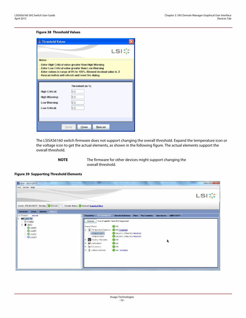
LSISAS6160 SAS Switch User GuideApril 2015
Chapter 3: SAS Domain Manager Graphical User Interface Devices Tab
Figure 38 Threshold Values
The LSISAS6160 switch firmware does not support changing the overall threshold. Expand the temperature icon or the voltage icon to get the actual elements, as shown in the following figure. The actual elements support the overall threshold.
NOTE The firmware for other devices might support changing the overall threshold.
Figure 39 Supporting Threshold Elements
Avago Technologies- 52 -
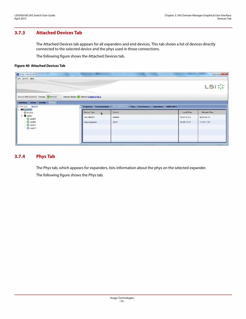
LSISAS6160 SAS Switch User GuideApril 2015
Chapter 3: SAS Domain Manager Graphical User Interface Devices Tab
3.7.3 Attached Devices Tab
The Attached Devices tab appears for all expanders and end devices. This tab shows a list of devices directly connected to the selected device and the phys used in those connections.
The following figure shows the Attached Devices tab.
Figure 40 Attached Devices Tab
3.7.4 Phys Tab
The Phys tab, which appears for expanders, lists information about the phys on the selected expander.
The following figure shows the Phys tab.
Avago Technologies- 53 -
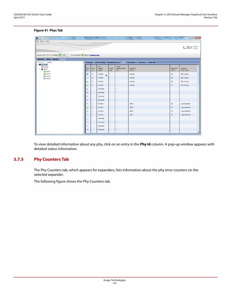
LSISAS6160 SAS Switch User GuideApril 2015
Chapter 3: SAS Domain Manager Graphical User Interface Devices Tab
Figure 41 Phys Tab
To view detailed information about any phy, click on an entry in the Phy Id column. A pop-up window appears with detailed status information.
3.7.5 Phy Counters Tab
The Phy Counters tab, which appears for expanders, lists information about the phy error counters on the selected expander.
The following figure shows the Phy Counters tab.
Avago Technologies- 54 -
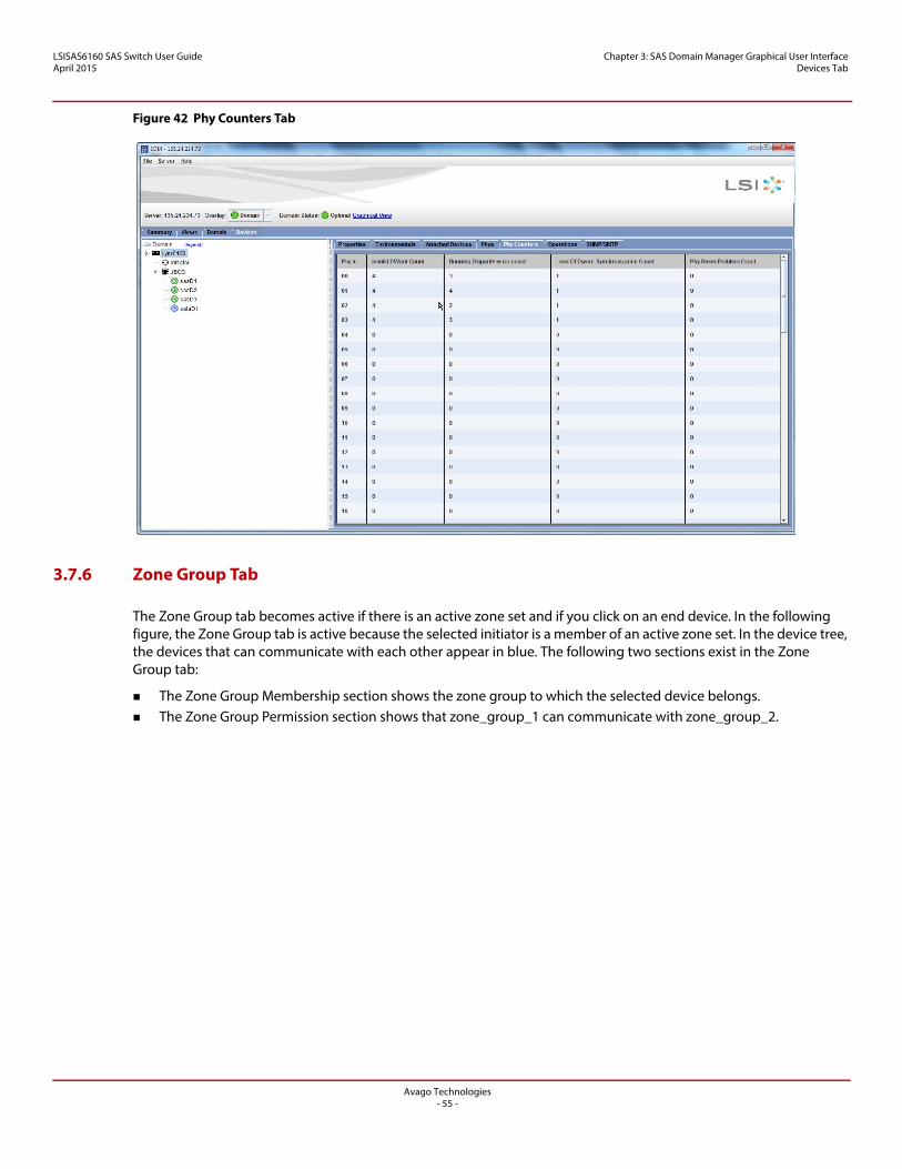
LSISAS6160 SAS Switch User GuideApril 2015
Chapter 3: SAS Domain Manager Graphical User Interface Devices Tab
Figure 42 Phy Counters Tab
3.7.6 Zone Group Tab
The Zone Group tab becomes active if there is an active zone set and if you click on an end device. In the following figure, the Zone Group tab is active because the selected initiator is a member of an active zone set. In the device tree, the devices that can communicate with each other appear in blue. The following two sections exist in the Zone Group tab:
The Zone Group Membership section shows the zone group to which the selected device belongs. The Zone Group Permission section shows that zone_group_1 can communicate with zone_group_2.
Avago Technologies- 55 -
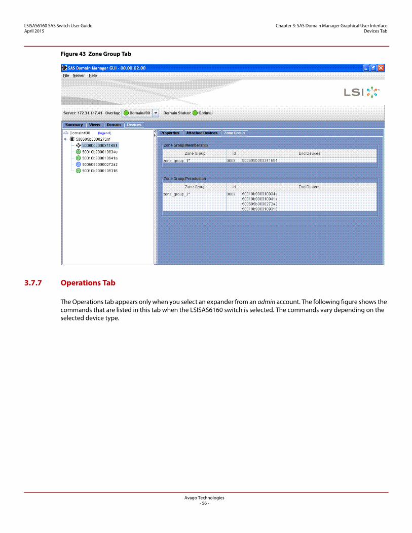
LSISAS6160 SAS Switch User GuideApril 2015
Chapter 3: SAS Domain Manager Graphical User Interface Devices Tab
Figure 43 Zone Group Tab
3.7.7 Operations Tab
The Operations tab appears only when you select an expander from an admin account. The following figure shows the commands that are listed in this tab when the LSISAS6160 switch is selected. The commands vary depending on the selected device type.
Avago Technologies- 56 -
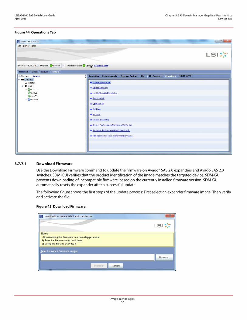
LSISAS6160 SAS Switch User GuideApril 2015
Chapter 3: SAS Domain Manager Graphical User Interface Devices Tab
Figure 44 Operations Tab
3.7.7.1 Download Firmware
Use the Download Firmware command to update the firmware on Avago® SAS 2.0 expanders and Avago SAS 2.0 switches. SDM-GUI verifies that the product identification of the image matches the targeted device. SDM-GUI prevents downloading of incompatible firmware, based on the currently installed firmware version. SDM-GUI automatically resets the expander after a successful update.
The following figure shows the first steps of the update process: First select an expander firmware image. Then verify and activate the file.
Figure 45 Download Firmware
Avago Technologies- 57 -
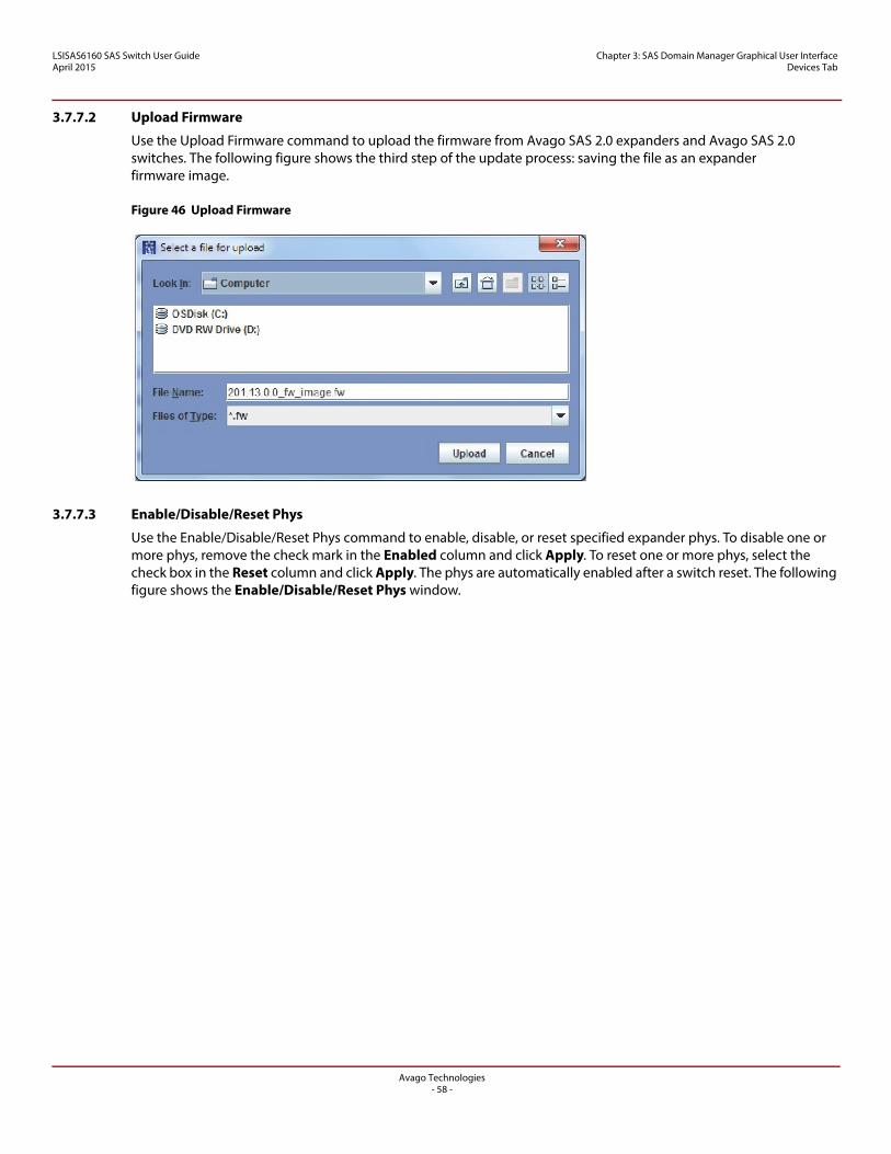
LSISAS6160 SAS Switch User GuideApril 2015
Chapter 3: SAS Domain Manager Graphical User Interface Devices Tab
3.7.7.2 Upload Firmware
Use the Upload Firmware command to upload the firmware from Avago SAS 2.0 expanders and Avago SAS 2.0 switches. The following figure shows the third step of the update process: saving the file as an expander firmware image.
Figure 46 Upload Firmware
3.7.7.3 Enable/Disable/Reset Phys
Use the Enable/Disable/Reset Phys command to enable, disable, or reset specified expander phys. To disable one or more phys, remove the check mark in the Enabled column and click Apply. To reset one or more phys, select the check box in the Reset column and click Apply. The phys are automatically enabled after a switch reset. The following figure shows the Enable/Disable/Reset Phys window.
Avago Technologies- 58 -
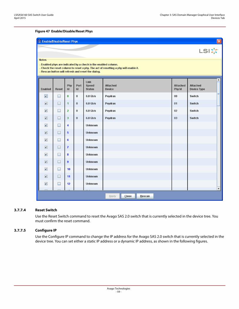
LSISAS6160 SAS Switch User GuideApril 2015
Chapter 3: SAS Domain Manager Graphical User Interface Devices Tab
Figure 47 Enable/Disable/Reset Phys
3.7.7.4 Reset Switch
Use the Reset Switch command to reset the Avago SAS 2.0 switch that is currently selected in the device tree. You must confirm the reset command.
3.7.7.5 Configure IP
Use the Configure IP command to change the IP address for the Avago SAS 2.0 switch that is currently selected in the device tree. You can set either a static IP address or a dynamic IP address, as shown in the following figures.
Avago Technologies- 59 -
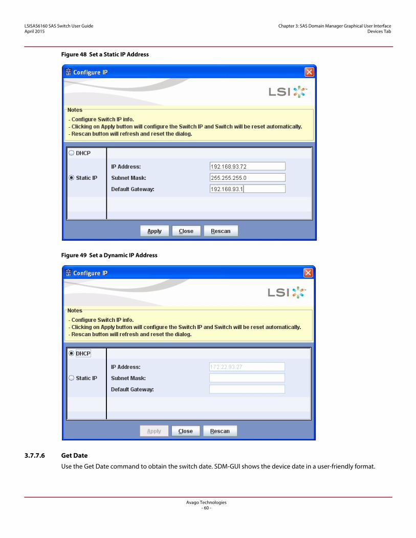
LSISAS6160 SAS Switch User GuideApril 2015
Chapter 3: SAS Domain Manager Graphical User Interface Devices Tab
Figure 48 Set a Static IP Address
Figure 49 Set a Dynamic IP Address
3.7.7.6 Get Date
Use the Get Date command to obtain the switch date. SDM-GUI shows the device date in a user-friendly format.
Avago Technologies- 60 -
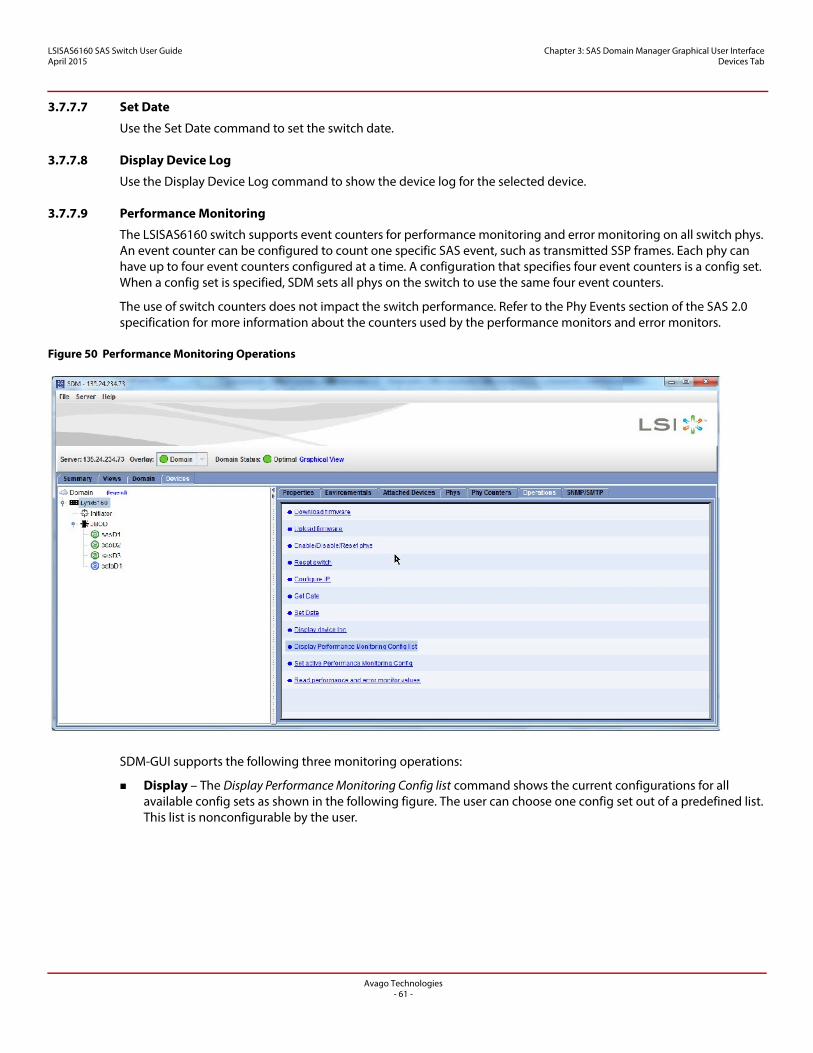
LSISAS6160 SAS Switch User GuideApril 2015
Chapter 3: SAS Domain Manager Graphical User Interface Devices Tab
3.7.7.7 Set Date
Use the Set Date command to set the switch date.
3.7.7.8 Display Device Log
Use the Display Device Log command to show the device log for the selected device.
3.7.7.9 Performance Monitoring
The LSISAS6160 switch supports event counters for performance monitoring and error monitoring on all switch phys. An event counter can be configured to count one specific SAS event, such as transmitted SSP frames. Each phy can have up to four event counters configured at a time. A configuration that specifies four event counters is a config set. When a config set is specified, SDM sets all phys on the switch to use the same four event counters.
The use of switch counters does not impact the switch performance. Refer to the Phy Events section of the SAS 2.0 specification for more information about the counters used by the performance monitors and error monitors.
Figure 50 Performance Monitoring Operations
SDM-GUI supports the following three monitoring operations:
Display – The Display Performance Monitoring Config list command shows the current configurations for all available config sets as shown in the following figure. The user can choose one config set out of a predefined list. This list is nonconfigurable by the user.
Avago Technologies- 61 -
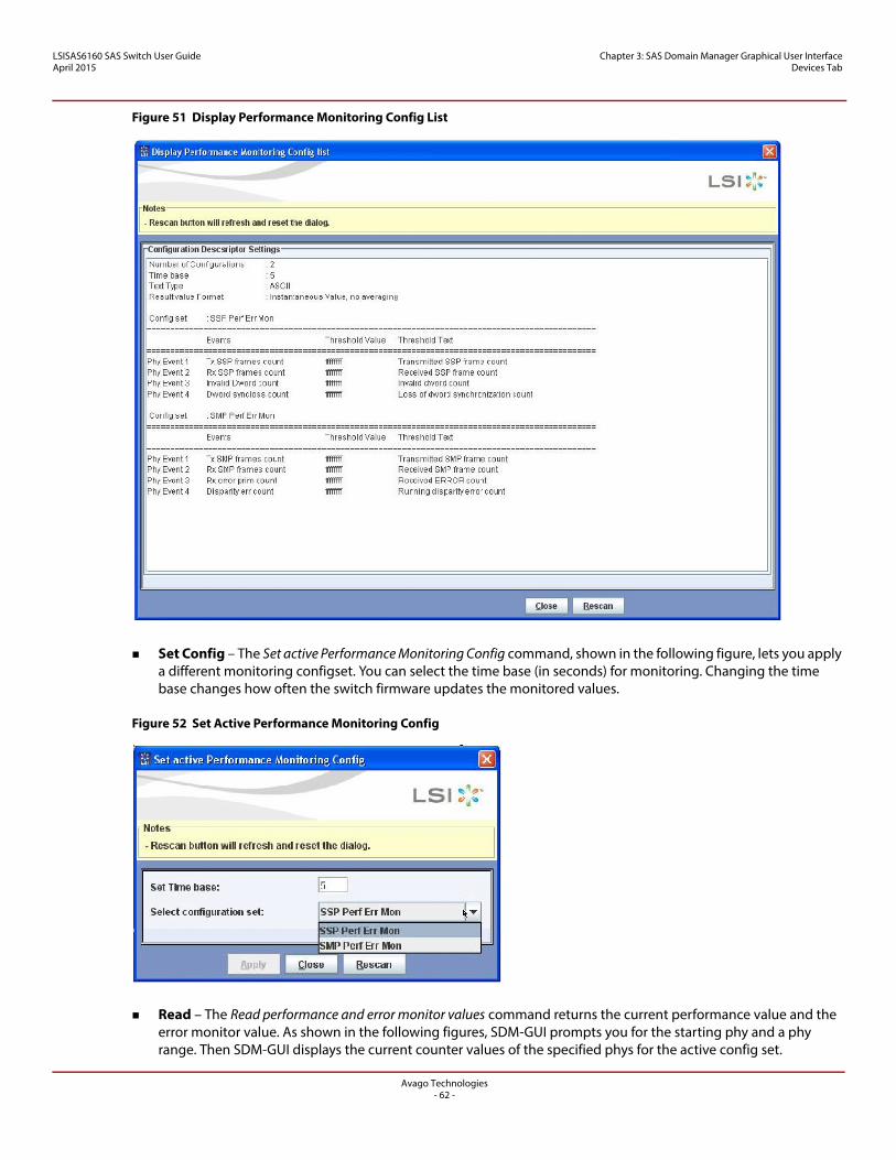
LSISAS6160 SAS Switch User GuideApril 2015
Chapter 3: SAS Domain Manager Graphical User Interface Devices Tab
Figure 51 Display Performance Monitoring Config List
Set Config – The Set active Performance Monitoring Config command, shown in the following figure, lets you apply a different monitoring configset. You can select the time base (in seconds) for monitoring. Changing the time base changes how often the switch firmware updates the monitored values.
Figure 52 Set Active Performance Monitoring Config
Read – The Read performance and error monitor values command returns the current performance value and the error monitor value. As shown in the following figures, SDM-GUI prompts you for the starting phy and a phy range. Then SDM-GUI displays the current counter values of the specified phys for the active config set.
Avago Technologies- 62 -
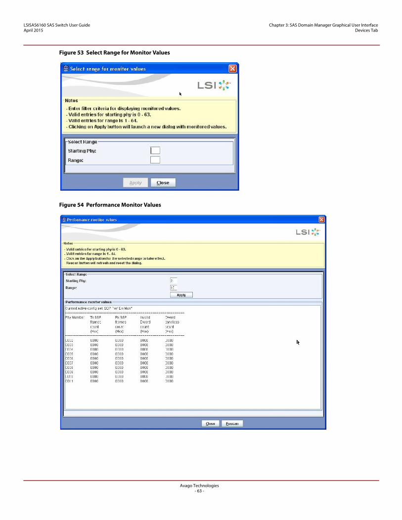
LSISAS6160 SAS Switch User GuideApril 2015
Chapter 3: SAS Domain Manager Graphical User Interface Devices Tab
Figure 53 Select Range for Monitor Values
Figure 54 Performance Monitor Values
Avago Technologies- 63 -
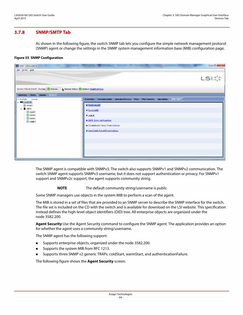
LSISAS6160 SAS Switch User GuideApril 2015
Chapter 3: SAS Domain Manager Graphical User Interface Devices Tab
3.7.8 SNMP/SMTP Tab
As shown in the following figure, the switch SNMP tab lets you configure the simple network management protocol (SNMP) agent or change the settings in the SNMP system management information base (MIB) configuration page.
Figure 55 SNMP Configuration
The SNMP agent is compatible with SNMPv3. The switch also supports SNMPv1 and SNMPv2 communication. The switch SNMP agent supports SNMPv3 username, but it does not support authentication or privacy. For SNMPv1 support and SNMPv2c support, the agent supports community string.
NOTE The default community string/username is public.
Some SNMP managers use objects in the system MIB to perform a scan of the agent.
The MIB is stored in a set of files that are provided to an SNMP server to describe the SNMP interface for the switch. The file set is included on the CD with the switch and is available for download on the LSI website. This specification instead defines the high-level object identifiers (OID) tree. All enterprise objects are organized under the node 3582.200.
Agent Security Use the Agent Security command to configure the SNMP agent. The application provides an option for whether the agent uses a community string/username.
The SNMP agent has the following support:
Supports enterprise objects, organized under the node 3582.200. Supports the system MIB from RFC 1213. Supports three SNMP v2 generic TRAPs: coldStart, warmStart, and authenticationFailure.
The following figure shows the Agent Security screen.
Avago Technologies- 64 -
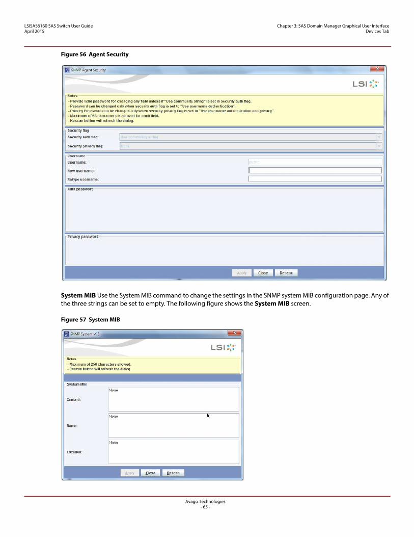
LSISAS6160 SAS Switch User GuideApril 2015
Chapter 3: SAS Domain Manager Graphical User Interface Devices Tab
Figure 56 Agent Security
System MIB Use the System MIB command to change the settings in the SNMP system MIB configuration page. Any of the three strings can be set to empty. The following figure shows the System MIB screen.
Figure 57 System MIB
Avago Technologies- 65 -
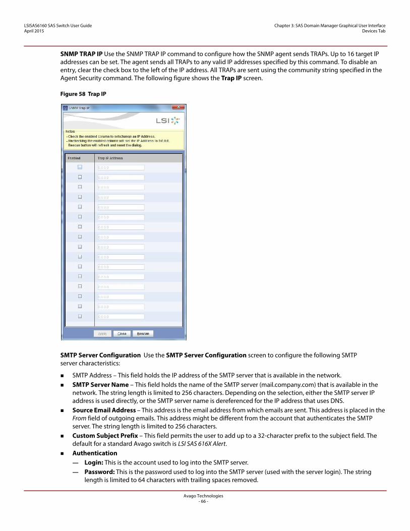
LSISAS6160 SAS Switch User GuideApril 2015
Chapter 3: SAS Domain Manager Graphical User Interface Devices Tab
SNMP TRAP IP Use the SNMP TRAP IP command to configure how the SNMP agent sends TRAPs. Up to 16 target IP addresses can be set. The agent sends all TRAPs to any valid IP addresses specified by this command. To disable an entry, clear the check box to the left of the IP address. All TRAPs are sent using the community string specified in the Agent Security command. The following figure shows the Trap IP screen.
Figure 58 Trap IP
SMTP Server Configuration Use the SMTP Server Configuration screen to configure the following SMTP server characteristics:
SMTP Address – This field holds the IP address of the SMTP server that is available in the network. SMTP Server Name – This field holds the name of the SMTP server (mail.company.com) that is available in the
network. The string length is limited to 256 characters. Depending on the selection, either the SMTP server IP address is used directly, or the SMTP server name is dereferenced for the IP address that uses DNS.
Source Email Address – This address is the email address from which emails are sent. This address is placed in the From field of outgoing emails. This address might be different from the account that authenticates the SMTP server. The string length is limited to 256 characters.
Custom Subject Prefix – This field permits the user to add up to a 32-character prefix to the subject field. The default for a standard Avago switch is LSI SAS 616X Alert.
Authentication — Login: This is the account used to log into the SMTP server.— Password: This is the password used to log into the SMTP server (used with the server login). The string
length is limited to 64 characters with trailing spaces removed.
Avago Technologies- 66 -
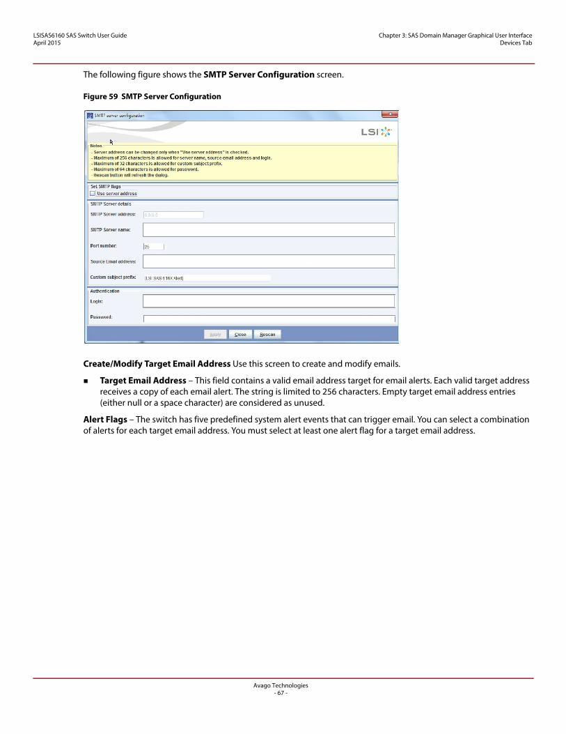
LSISAS6160 SAS Switch User GuideApril 2015
Chapter 3: SAS Domain Manager Graphical User Interface Devices Tab
The following figure shows the SMTP Server Configuration screen.
Figure 59 SMTP Server Configuration
Create/Modify Target Email Address Use this screen to create and modify emails.
Target Email Address – This field contains a valid email address target for email alerts. Each valid target address receives a copy of each email alert. The string is limited to 256 characters. Empty target email address entries (either null or a space character) are considered as unused.
Alert Flags – The switch has five predefined system alert events that can trigger email. You can select a combination of alerts for each target email address. You must select at least one alert flag for a target email address.
Avago Technologies- 67 -
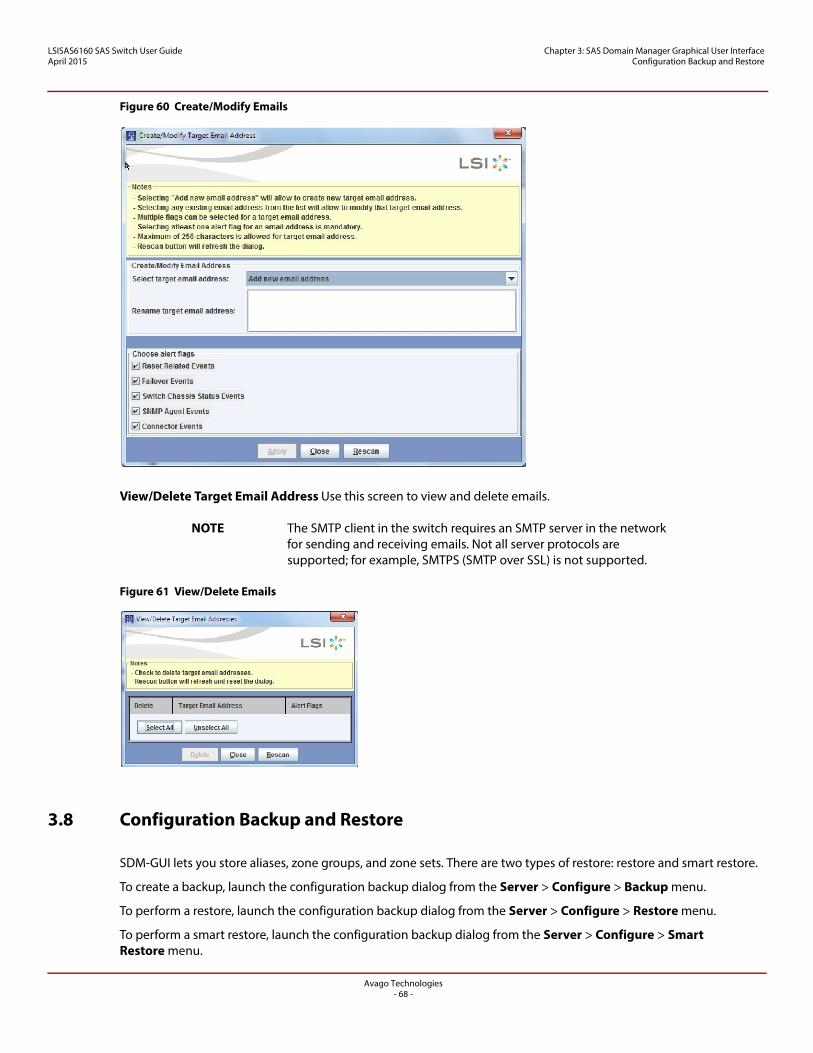
LSISAS6160 SAS Switch User GuideApril 2015
Chapter 3: SAS Domain Manager Graphical User Interface Configuration Backup and Restore
Figure 60 Create/Modify Emails
View/Delete Target Email Address Use this screen to view and delete emails.
NOTE The SMTP client in the switch requires an SMTP server in the network for sending and receiving emails. Not all server protocols are supported; for example, SMTPS (SMTP over SSL) is not supported.
Figure 61 View/Delete Emails
3.8 Configuration Backup and Restore
SDM-GUI lets you store aliases, zone groups, and zone sets. There are two types of restore: restore and smart restore.
To create a backup, launch the configuration backup dialog from the Server > Configure > Backup menu.
To perform a restore, launch the configuration backup dialog from the Server > Configure > Restore menu.
To perform a smart restore, launch the configuration backup dialog from the Server > Configure > Smart Restore menu.
Avago Technologies- 68 -
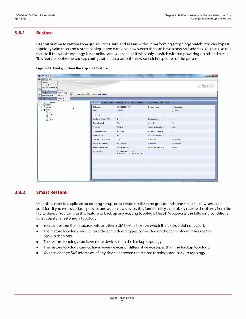
LSISAS6160 SAS Switch User GuideApril 2015
Chapter 3: SAS Domain Manager Graphical User Interface Configuration Backup and Restore
3.8.1 Restore
Use this feature to restore zone groups, zone sets, and aliases without performing a topology match. You can bypass topology validation and restore configuration data on a new switch that can have a new SAS address. You can use this feature if the whole topology is not online and you can use it with only a switch without powering up other devices. This feature copies the backup configuration data onto the new switch irrespective of the present.
Figure 62 Configuration Backup and Restore
3.8.2 Smart Restore
Use this feature to duplicate an existing setup, or to create similar zone groups and zone sets on a new setup. In addition, if you remove a faulty device and add a new device, this functionality can quickly restore the aliases from the faulty device. You can use this feature to back up any existing topology. The SDM supports the following conditions for successfully restoring a topology:
You can restore the database onto another SDM host (a host on which the backup did not occur). The restore topology should have the same device types connected on the same phy numbers as the
backup topology. The restore topology can have more devices than the backup topology. The restore topology cannot have fewer devices or different device types than the backup topology. You can change SAS addresses of any device between the restore topology and backup topology.
Avago Technologies- 69 -
LSISAS6160 SAS Switch User GuideApril 2015
Chapter 4: SAS Domain Manager Command Line Interface Command Usage and Syntax
Chapter 4: SAS Domain Manager Command Line Interface
This chapter explains how to use the commands supported by the SAS Domain Manager command line interface (SDM-CLI) with the LSISAS6160 switch. Access SDM-CLI using a telnet client or Secure Shell (SSH) client.
SDM-CLI has powerful, flexible commands that enable you to manage the host switch and other switches or expanders within the domain.
4.1 Command Usage and Syntax
The syntax for CLI commands is as follows:
command [arguments]
In this syntax,[arguments] can consist of any combination of the following:
Optional argument: [optional] Choice between a or b: (a|b) User-supplied value or string: <string>
SDM-CLI does not permit spaces in file names and paths, even if the operating system permits them. All user-supplied names (domains, aliases, zone groups, zone sets, and so on) are case sensitive.
Use the up and down arrow keys to access a small command history buffer. Move the cursor with the left arrow key and right arrow key to edit commands.
To start SDM-CLI, open a telnet session or an SSH session to the IP address or host name of the LSISAS6160 switch. Log in when you see the prompt.
SDM-CLI provides two accounts that control access and privileges: user and admin.
The user account permits you to view the domain topology, configuration, and operating environment. The default password is user.
The admin account permits you to view domain information. It also grants permission to use commands that can change the configuration of the domain or of managed devices within the domain. The default password is admin.
The LSISAS6160 zone manager is handled separately. Its default password is lynx.
4.2 SDM-CLI Commands
Two types of SDM-CLI commands exist:
Extra-Domain commands, such as passwd, have no impact on any device in the domain topology. Intra-Domain commands, such as show, have an impact on devices in the domain.
Each of the following command descriptions indicates whether the command is Extra-Domain or Intra-Domain.
NOTE You can use shortcuts when you type commands. In the following command descriptions, the bolded letters indicate the minimum characters that are necessary to recognize the command. For example, you can enter ali cr to invoke the alias create command.
Avago Technologies- 70 -
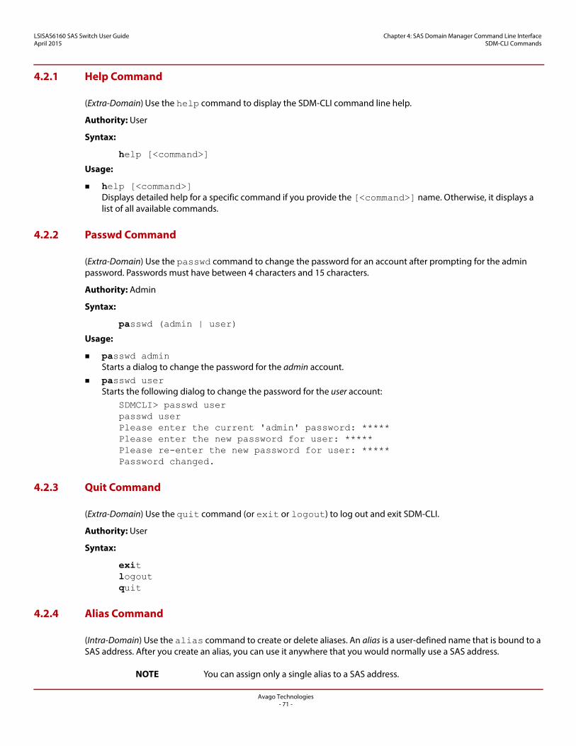
LSISAS6160 SAS Switch User GuideApril 2015
Chapter 4: SAS Domain Manager Command Line Interface SDM-CLI Commands
4.2.1 Help Command
(Extra-Domain) Use the help command to display the SDM-CLI command line help.
Authority: User
Syntax:
help [<command>]
Usage:
help [<command>]Displays detailed help for a specific command if you provide the [<command>] name. Otherwise, it displays a list of all available commands.
4.2.2 Passwd Command
(Extra-Domain) Use the passwd command to change the password for an account after prompting for the admin password. Passwords must have between 4 characters and 15 characters.
Authority: Admin
Syntax:
passwd (admin | user)
Usage:
passwd adminStarts a dialog to change the password for the admin account.
passwd userStarts the following dialog to change the password for the user account:
SDMCLI> passwd userpasswd userPlease enter the current 'admin' password: ***** Please enter the new password for user: ***** Please re-enter the new password for user: ***** Password changed.
4.2.3 Quit Command
(Extra-Domain) Use the quit command (or exit or logout) to log out and exit SDM-CLI.
Authority: User
Syntax:
exitlogoutquit
4.2.4 Alias Command
(Intra-Domain) Use the alias command to create or delete aliases. An alias is a user-defined name that is bound to a SAS address. After you create an alias, you can use it anywhere that you would normally use a SAS address.
NOTE You can assign only a single alias to a SAS address.
Avago Technologies- 71 -
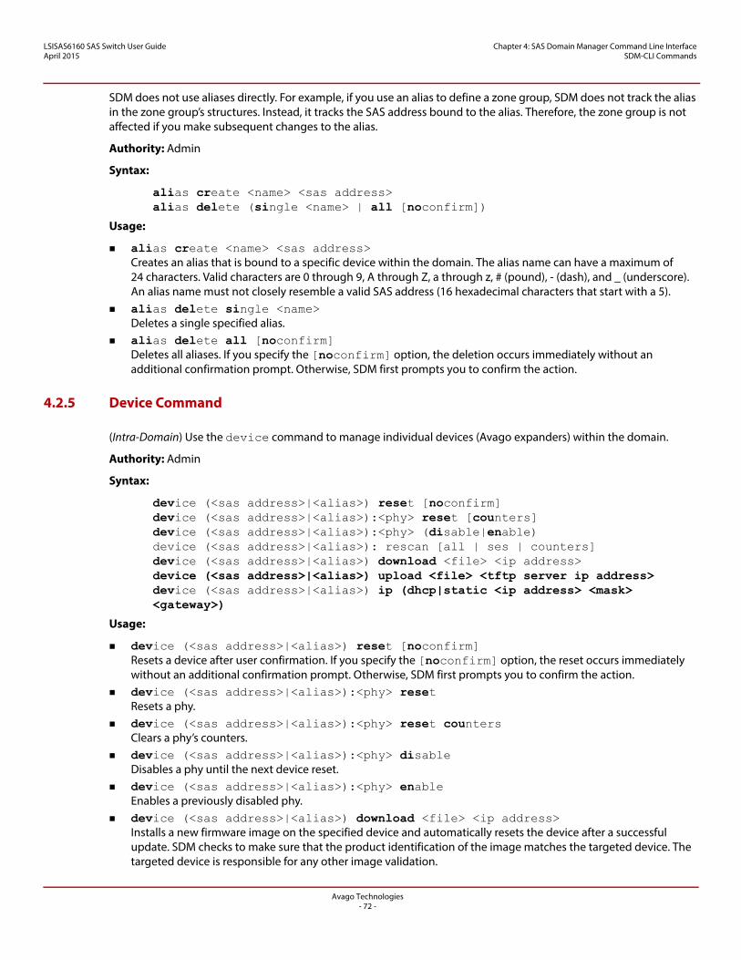
LSISAS6160 SAS Switch User GuideApril 2015
Chapter 4: SAS Domain Manager Command Line Interface SDM-CLI Commands
SDM does not use aliases directly. For example, if you use an alias to define a zone group, SDM does not track the alias in the zone group’s structures. Instead, it tracks the SAS address bound to the alias. Therefore, the zone group is not affected if you make subsequent changes to the alias.
Authority: Admin
Syntax:
alias create <name> <sas address>alias delete (single <name> | all [noconfirm])
Usage:
alias create <name> <sas address>Creates an alias that is bound to a specific device within the domain. The alias name can have a maximum of 24 characters. Valid characters are 0 through 9, A through Z, a through z, # (pound), - (dash), and _ (underscore). An alias name must not closely resemble a valid SAS address (16 hexadecimal characters that start with a 5).
alias delete single <name>Deletes a single specified alias.
alias delete all [noconfirm]Deletes all aliases. If you specify the [noconfirm] option, the deletion occurs immediately without an additional confirmation prompt. Otherwise, SDM first prompts you to confirm the action.
4.2.5 Device Command
(Intra-Domain) Use the device command to manage individual devices (Avago expanders) within the domain.
Authority: Admin
Syntax:
device (<sas address>|<alias>) reset [noconfirm]device (<sas address>|<alias>):<phy> reset [counters]device (<sas address>|<alias>):<phy> (disable|enable)device (<sas address>|<alias>): rescan [all | ses | counters]device (<sas address>|<alias>) download <file> <ip address>device (<sas address>|<alias>) upload <file> <tftp server ip address>device (<sas address>|<alias>) ip (dhcp|static <ip address> <mask> <gateway>)
Usage:
device (<sas address>|<alias>) reset [noconfirm]Resets a device after user confirmation. If you specify the [noconfirm] option, the reset occurs immediately without an additional confirmation prompt. Otherwise, SDM first prompts you to confirm the action.
device (<sas address>|<alias>):<phy> resetResets a phy.
device (<sas address>|<alias>):<phy> reset countersClears a phy’s counters.
device (<sas address>|<alias>):<phy> disableDisables a phy until the next device reset.
device (<sas address>|<alias>):<phy> enableEnables a previously disabled phy.
device (<sas address>|<alias>) download <file> <ip address>Installs a new firmware image on the specified device and automatically resets the device after a successful update. SDM checks to make sure that the product identification of the image matches the targeted device. The targeted device is responsible for any other image validation.
Avago Technologies- 72 -
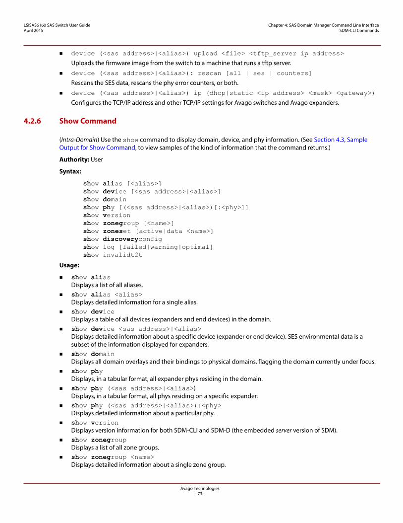
LSISAS6160 SAS Switch User GuideApril 2015
Chapter 4: SAS Domain Manager Command Line Interface SDM-CLI Commands
device (<sas address>|<alias>) upload <file> <tftp_server ip address>
Uploads the firmware image from the switch to a machine that runs a tftp server.
device (<sas address>|<alias>): rescan [all | ses | counters]
Rescans the SES data, rescans the phy error counters, or both.
device (<sas address>|<alias>) ip (dhcp|static <ip address> <mask> <gateway>)
Configures the TCP/IP address and other TCP/IP settings for Avago switches and Avago expanders.
4.2.6 Show Command
(Intra-Domain) Use the show command to display domain, device, and phy information. (See Section 4.3, Sample Output for Show Command, to view samples of the kind of information that the command returns.)
Authority: User
Syntax:
show alias [<alias>]show device [<sas address>|<alias>]show domainshow phy [(<sas address>|<alias>)[:<phy>]]show versionshow zonegroup [<name>]show zoneset [active|data <name>]show discoveryconfigshow log [failed|warning|optimal]show invalidt2t
Usage:
show aliasDisplays a list of all aliases.
show alias <alias>Displays detailed information for a single alias.
show deviceDisplays a table of all devices (expanders and end devices) in the domain.
show device <sas address>|<alias>Displays detailed information about a specific device (expander or end device). SES environmental data is a subset of the information displayed for expanders.
show domainDisplays all domain overlays and their bindings to physical domains, flagging the domain currently under focus.
show phyDisplays, in a tabular format, all expander phys residing in the domain.
show phy (<sas address>|<alias>)Displays, in a tabular format, all phys residing on a specific expander.
show phy (<sas address>|<alias>):<phy>Displays detailed information about a particular phy.
show versionDisplays version information for both SDM-CLI and SDM-D (the embedded server version of SDM).
show zonegroupDisplays a list of all zone groups.
show zonegroup <name>Displays detailed information about a single zone group.
Avago Technologies- 73 -
LSISAS6160 SAS Switch User GuideApril 2015
Chapter 4: SAS Domain Manager Command Line Interface SDM-CLI Commands
show zonesetDisplays a list of all zone sets.
show zoneset activeDisplays the name and detailed information for the active zone set.
show zoneset data <name>Displays detailed information about a single zone set.
show discoveryconfig
Displays discovery configuration details, such as discovery status and polling interval.
show log [failed|warning|optimal]
Displays SDM event logs according to severity.
show invalidt2t
Displays attributes and SAS address of those phys whose routing attributes differs on attached device.
4.2.7 Zonegroup Command
(Intra-Domain) Use the zonegroup command to manage zone groups and zone group membership. Zonegroup commands have no effect on the active zone set until you reactivate it.
Authority: Admin
Syntax:
zonegroup add <name> (<sas_address>|<alias>):<phy>zonegroup create <name>zonegroup delete ((single <name>)|(all [noconfirm]))zonegroup remove <name> (<sas_address>|<alias>):<phy>zonegroup rename <old> <new>
Usage:
zonegroup add <name> (<sas address>|<alias>):<phy>Adds a phy to an existing zone group.
NOTE Phys internal to the ZPSDS must be in Zone Group 1. Therefore, exclude them from this command.
zonegroup create <name>Creates a new zone group. The zone group name can have a maximum of 32 characters. Valid characters are 0 through 9, A through Z, a through z, # (pound), - (dash), and _ (underscore).
zonegroup delete single <name>Deletes a single zone group.
NOTE You cannot delete a zone group if it is currently a member of a zone set. This restriction also applies to the zonegroup delete all command.
zonegroup delete all [noconfirm]Deletes all zone groups. If you specify the [noconfirm] option, the action occurs immediately without an additional confirmation prompt. Otherwise, SDM first prompts you to confirm the action.
zonegroup remove <name> (<sas address>|<alias>):<phy>Removes a phy from an existing zone group.
zonegroup rename <old> <new>Renames an existing zone group.
Avago Technologies- 74 -
LSISAS6160 SAS Switch User GuideApril 2015
Chapter 4: SAS Domain Manager Command Line Interface SDM-CLI Commands
4.2.8 Zoneset Command
(Intra-Domain) Use the zoneset command to manage zone sets and zone set membership.
Before you can activate zoning, you must use the zoneset passwd command to synchronize the zone manager password of all the zoning expanders and switches on the domain. If the zoning expanders and switches use different zoning passwords, you must use this command many times and make multiple entries for each different password.
NOTE Only the zoneset activate and zoneset deactivate commands affect the state of the active zone set. Other types of zonegroup commands and zoneset commands have no effect until you subsequently activate the zone set.
Authority: Admin
Syntax:
zoneset activate <name>zoneset add <name> <zone group> <zone group>zoneset create <name>zoneset deactivatezoneset delete (single <name> | all [noconfirm])zoneset passwdzoneset remove <name> <zone group> <zone group>zoneset rename <old> <new>
Usage:
zoneset activate <name>Activates a zone set after prompting you for the zone manager password. Only a single zone set can be active at a time, so this command also deactivates the current active zone set before it activates a new one. Changes to the active zone set, or changes to zone group permissions, do not take effect until the next zone set activates.
NOTE Depending on the zoning configuration and how SDM accesses the domain, you might not always be required to enter a valid zone manager password to modify or disable zoning after it is enabled. You can apply changes made to the active zone set by reactivating it. SDM validates the zone set within the topology when activation occurs.
zoneset add <name> <zone group> <zone group>Adds two zone groups to an existing zone set, which gives them permission to communicate with one another. The maximum number of zone groups is 248 for a zone set.
NOTE A phy can be only a member of one zone group per zone set. zoneset create <name>
Creates a new zone set. The zone set name can have a maximum of 32 characters. Valid characters are 0 through 9, A through Z, a through z, # (pound), - (dash), and _ (underscore).
zoneset deactivateDeactivates the active zone set after it prompts you for the zone manager password.
NOTE Zoning within the domain is disabled when no zone set is active, and access is unrestricted. When zoning is disabled, all end devices in the domain can see one another.
zoneset delete single <name>Deletes a single zone set.
Avago Technologies- 75 -
LSISAS6160 SAS Switch User GuideApril 2015
Chapter 4: SAS Domain Manager Command Line Interface SDM-CLI Commands
zoneset delete all [noconfirm]Deletes all zone sets. If you specify the [noconfirm] option, the action occurs immediately without an additional confirmation prompt. Otherwise, SDM first prompts you to confirm the action.
zoneset passwdChanges the zone manager password for an expander or switch. Passwords are text strings that contain any valid ASCII character. The maximum password length is 32 characters.
When prompted for the current zone password, type the current password for any expander or switch. When prompted for the new zone manager password, type the new password. Type it again to confirm it when asked to re-enter.
Repeat this process until all the expander and switch zoning passwords are changed to the new password. The new password can be one of the current passwords for any switch or expander, or it can be a new one. All expanders and switches must have the same password. If all the zoning expanders and switches inside the ZPSDS do not have the same zone manager password, you receive a zoning password error while activating the zoning.
NOTE The default zone manager password is lynx. zoneset remove <name> <zone group> <zone group>
Removes communication privileges between two zone groups in an existing zone set. A zone group is purged from the zone set if no other communication privileges remain.
zoneset rename <old> <new>Renames an existing zone set.
NOTE If you have other zoning-capable devices in the topology, each with its own zone manager password that is different from the switch default, you must synchronize passwords to avoid a situation in which the default password for the switch does not work.
4.2.9 SES Threshold
(Intra-Domain) Use the threshold command to set the high critical, high warning, low critical, and low warning threshold values for temperature elements and voltage elements. See Section 3.7.2.1, Set SES Thresholds, for more SES-threshold details.
Authority: Admin
Syntax:
show device <sas_addr>|<alias> thresholddevice <sas_addr>|<alias> threshold <element_id> <HC> <HW> <LW> <LC>
Usage:
show device <sas_addr>|<alias> thresholdShows the device thresholds.
device <sas_addr>|<alias> threshold <element_id> <HC> <HW> <LW> <LC>
Allows you to set the device thresholds.
4.2.10 Get Date
(Intra-Domain) Use the date command to get the switch date.
Authority: User
Syntax:
show device ({SAS address} | {alias}) date
Avago Technologies- 76 -
LSISAS6160 SAS Switch User GuideApril 2015
Chapter 4: SAS Domain Manager Command Line Interface SDM-CLI Commands
Usage:
show device ({SAS address} | {alias}) dateShows the device date in DAY YYYY-MM-DDThh:mm:ss format. For example, SUN 2011-11-28T23:56:55.
4.2.11 Set Date
(Intra-Domain) Use the date command to set the switch date.
Authority: Admin
Syntax:
device ({sas address} | {alias}) date weekday year month month-day hour minute seconds
Usage:
device ({sas address} | {alias}) date weekday year month month-day hour minute seconds
Enter the date and time parameters in the format specified by ISO® 8601. The format is DAY YYYY-MM-DDThh:mm:ss. For example, SUN 2010-02-28T23:56:55.
4.2.12 Performance Monitoring
(Intra-Domain) Use the monitor command to monitor the performance and errors on all switch phys.
Authority: Admin
Syntax:
device <sas_addr>|<alias> monitor selectconfigset <Config>device <sas_addr>|<alais> monitor changetimebase <time_base>
Usage:
device <sas_addr>|<alias> monitor selectconfigset <Config>Moves the active Config set to <Config>.
device <sas_addr>|<alais> monitor changetimebase <time_base>
Changes the time base.
Authority: User
Syntax:
show device <sas_addr>|<alais> monitor configsettingsshow device <sas_addr>|<alais> monitor montiredvalues <phy_offset> <phy_range>
Usage:
show device <sas_addr>|<alais> monitor configsettingsShows the Config settings options from the device <sas_addr>|<alias> monitor selectconfigset <Config> command.
show device <sas_addr>|<alais> monitor monitoredvalues <phy_offset> <phy_range>Shows monitored values for the active Config set.
Avago Technologies- 77 -
LSISAS6160 SAS Switch User GuideApril 2015
Chapter 4: SAS Domain Manager Command Line Interface SDM-CLI Commands
4.2.13 Get SNMP
(Intra-Domain) Use the snmp command to show the SNMP configuration.
Authority: User
Syntax: show device <sas-address|alias> snmp agentsecurityshow device <sas-address|alias> snmp systemmib
Usage:
show device <sas-address|alias> snmp agentsecurityShows the agent security details used to configure the SNMP agent.
show device <sas-address|alias> snmp systemmib
Shows the SNMP system MIB configuration.
4.2.14 Set SNMP
(Intra-Domain) Use the snmp command to configure SNMP.
Authority: Admin
Syntax: device <sas-address|alias> snmp agentsecurity usernamedevice <sas-address|alias> snmp agentsecurity authsecflagdevice <sas-address|alias> snmp agentsecurity privsecflagdevice <sas-address|alias> snmp agentsecurity authpassdevice <sas-address|alias> snmp agentsecurity privpassdevice <sas-address|alias> snmp systemmib contactstringdevice <sas-address|alias> snmp systemmib locationstring
Usage:
device <sas-address|alias> snmp agentsecurity usernameSets the username or community string.
device <sas-address|alias> snmp agentsecurity authsecflagSets the security authentication flag.
device <sas-address|alias> snmp agentsecurity privsecflagSets the security privacy flag.
device <sas-address|alias> snmp agentsecurity authpassSets the password for SNMPv3 authentication.
device <sas-address|alias> snmp agentsecurity privpassSets the password for SNMPv3 privacy.
device <sas-address|alias> snmp systemmib contactstringSets the name of the person responsible for the device at an end-user site.
device <sas-address|alias> snmp systemmib locationstringSets the physical location of the device.
Avago Technologies- 78 -
LSISAS6160 SAS Switch User GuideApril 2015
Chapter 4: SAS Domain Manager Command Line Interface SDM-CLI Commands
4.2.15 Get SMTP
(Intra-Domain) Use the smtp command to show the SMTP configuration.
Authority: User
Syntax:
show device (<sas_address> | <alias>) smtp outputconfig
show device (<sas_address> | <alias>) smtp serverconfig
show device (<sas_address> | <alias>) smtp email
show device (<sas_address> | <alias>) smtp alertflags
Usage:
show device (<sas_address> | <alias>) smtp outputconfig
Displays the SMTP output page configuration of a switch.
show device (<sas_address> | <alias>) smtp serverconfig
Displays the SMTP configuration of a switch.
show device (<sas_address> | <alias>) smtp email
Displays the SMTP email addresses and their alert flags.
show device (<sas_address> | <alias>) smtp alertflags
Displays the SMTP alert flags.
4.2.16 Set SMTP
(Intra-Domain) Use the smtp command to configure the SMTP.
Authority: Admin
Syntax:
device (<sas_address> | <alias>) smtp serverconfigdevice (<sas_address> | <alias>) smtp add emaildevice (<sas_address> | <alias>) smtp remove email (entry_number)device (<sas_address> | <alias>) smtp remove email alldevice (<sas_address> | <alias>) smtp remove email all noconfirm
Usage:
device (<sas_address> | <alias>) smtp serverconfig
Configures SMTP server values.
device (<sas_address> | <alias>) smtp add email
Adds an email address and its supported alert flags.
device (<sas_address> | <alias>) smtp remove email (entry_number)
Removes an email address.
device (<sas_address> | <alias>) smtp remove email all
Removes all email addresses with a confirmation.
device (<sas_address> | <alias>) smtp remove email all noconfirm
Removes all email addresses with no confirmation.
Avago Technologies- 79 -
LSISAS6160 SAS Switch User GuideApril 2015
Chapter 4: SAS Domain Manager Command Line Interface SDM-CLI Commands
4.2.17 Configuration Backup
(Extra-Domain) Use the backup command to backup settings. See Section 3.8, Configuration Backup and Restore, for more information.
Authority: Admin
Syntax: config backup <file name>config backup <file name> <ip-address>
Usage:
config backup <file name>Use in a single-switch system. Saves the topology configuration.
config backup <file name> <ip-address>Use in a multiple-switch system. Saves the topology configuration of the specified switch.
4.2.18 Configuration Smart Restore
(Extra-Domain) Use the smart restore command to restore saved settings. See Section 3.8, Configuration Backup and Restore, for more information.
Authority: Admin
Syntax:
config smartrestore <file name>config smartrestore <file name> <ip-address>
Usage:
config smartrestore <file name>
Use in a single-switch system. Restores the topology configuration.
config smartrestore <file name> <ip-address>
Use in a single-switch system. Restores the topology configuration to the specified switch.
4.2.19 Configuration Restore
(Extra-Domain) Use the restore command to restore saved settings. See Section 3.8, Configuration Backup and Restore, for more information.
Authority: Admin
Syntax: config restore <file name>config restore <file name> <ip-address>
Usage:
config restore <file name>Use in a single-switch system. Restores the topology configuration.
config restore <file name> <ip-address>Use in a multiple-switch system. Restores the topology configuration to the specified switch.
Avago Technologies- 80 -
LSISAS6160 SAS Switch User GuideApril 2015
Chapter 4: SAS Domain Manager Command Line Interface Sample Output for Show Command
4.2.20 Display SDM Event Log
(Intra-Domain) Use the log command to get the device log.
Authority: User
Syntax: show logshow <domain id> logshow <domain id> log (<failed|<critical>|<optimal>)
Usage:
show logShows the event log for all domains and all severities.
show <domain id> logShows the event log of the specified domain and all severities.
show <domain id> log (<failed|<critical>|<optimal>)Shows the event log of the specified domain and filters by severity.
4.2.21 Query and Display Switch/Expander Firmware Event Log
(Intra-Domain) Use the log command to show the switch or expander event log.
Authority: User
Syntax: show device <sas-address> log
Usage:
show device <sas-address> logShow the specified device’s firmware event log.
4.3 Sample Output for Show Command
This section shows sample output for some variations of the show command. The first line of each example shows the actual syntax of the command that you enter at the SDMCLI> prompt.
4.3.1 show alias
SDMCLI> show aliasSAS Address Alias-----------------------------------------------------500605b0006b75b0 Bacchus50012be0000380ff Calhoun500605b0000220bf Carrollton
Avago Technologies- 81 -
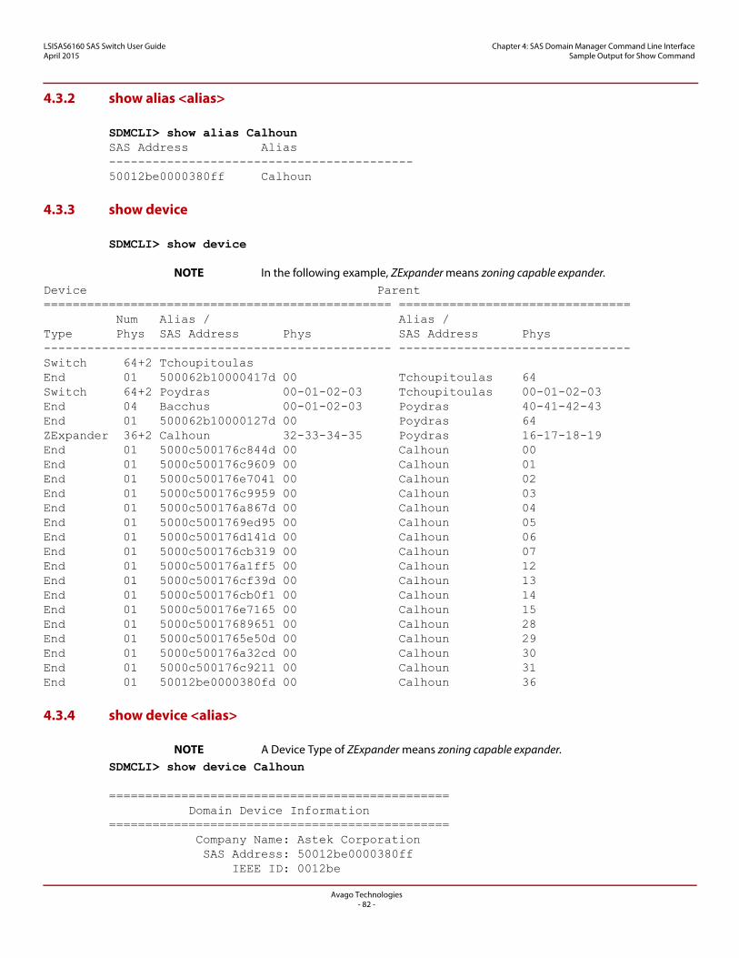
LSISAS6160 SAS Switch User GuideApril 2015
Chapter 4: SAS Domain Manager Command Line Interface Sample Output for Show Command
4.3.2 show alias <alias>
SDMCLI> show alias CalhounSAS Address Alias------------------------------------------50012be0000380ff Calhoun
4.3.3 show device
SDMCLI> show device
NOTE In the following example, ZExpander means zoning capable expander.Device Parent================================================ ================================ Num Alias / Alias /Type Phys SAS Address Phys SAS Address Phys------------------------------------------------ --------------------------------Switch 64+2 TchoupitoulasEnd 01 500062b10000417d 00 Tchoupitoulas 64Switch 64+2 Poydras 00-01-02-03 Tchoupitoulas 00-01-02-03End 04 Bacchus 00-01-02-03 Poydras 40-41-42-43End 01 500062b10000127d 00 Poydras 64ZExpander 36+2 Calhoun 32-33-34-35 Poydras 16-17-18-19End 01 5000c500176c844d 00 Calhoun 00End 01 5000c500176c9609 00 Calhoun 01End 01 5000c500176e7041 00 Calhoun 02End 01 5000c500176c9959 00 Calhoun 03End 01 5000c500176a867d 00 Calhoun 04End 01 5000c5001769ed95 00 Calhoun 05End 01 5000c500176d141d 00 Calhoun 06End 01 5000c500176cb319 00 Calhoun 07End 01 5000c500176a1ff5 00 Calhoun 12End 01 5000c500176cf39d 00 Calhoun 13End 01 5000c500176cb0f1 00 Calhoun 14End 01 5000c500176e7165 00 Calhoun 15End 01 5000c50017689651 00 Calhoun 28End 01 5000c5001765e50d 00 Calhoun 29End 01 5000c500176a32cd 00 Calhoun 30End 01 5000c500176c9211 00 Calhoun 31End 01 50012be0000380fd 00 Calhoun 36
4.3.4 show device <alias>
NOTE A Device Type of ZExpander means zoning capable expander.SDMCLI> show device Calhoun
=============================================== Domain Device Information=============================================== Company Name: Astek Corporation SAS Address: 50012be0000380ff IEEE ID: 0012be
Avago Technologies- 82 -
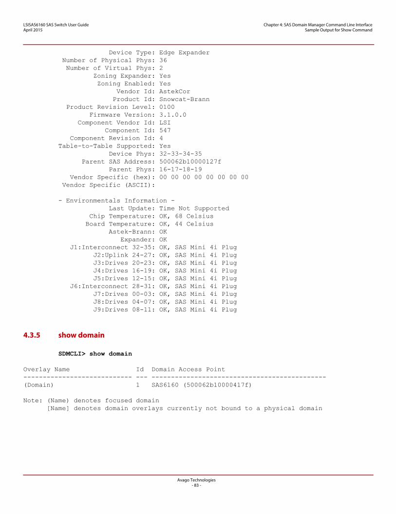
LSISAS6160 SAS Switch User GuideApril 2015
Chapter 4: SAS Domain Manager Command Line Interface Sample Output for Show Command
Device Type: Edge Expander Number of Physical Phys: 36 Number of Virtual Phys: 2 Zoning Expander: Yes Zoning Enabled: Yes Vendor Id: AstekCor Product Id: Snowcat-Brann Product Revision Level: 0100 Firmware Version: 3.1.0.0 Component Vendor Id: LSI Component Id: 547 Component Revision Id: 4Table-to-Table Supported: Yes Device Phys: 32-33-34-35 Parent SAS Address: 500062b10000127f Parent Phys: 16-17-18-19 Vendor Specific (hex): 00 00 00 00 00 00 00 00 Vendor Specific (ASCII):
- Environmentals Information - Last Update: Time Not Supported Chip Temperature: OK, 68 Celsius Board Temperature: OK, 44 Celsius Astek-Brann: OK Expander: OK J1:Interconnect 32-35: OK, SAS Mini 4i Plug J2:Uplink 24-27: OK, SAS Mini 4i Plug J3:Drives 20-23: OK, SAS Mini 4i Plug J4:Drives 16-19: OK, SAS Mini 4i Plug J5:Drives 12-15: OK, SAS Mini 4i Plug J6:Interconnect 28-31: OK, SAS Mini 4i Plug J7:Drives 00-03: OK, SAS Mini 4i Plug J8:Drives 04-07: OK, SAS Mini 4i Plug J9:Drives 08-11: OK, SAS Mini 4i Plug
4.3.5 show domain
SDMCLI> show domain
Overlay Name Id Domain Access Point---------------------------- --- ---------------------------------------------(Domain) 1 SAS6160 (500062b10000417f)
Note: (Name) denotes focused domain [Name] denotes domain overlays currently not bound to a physical domain
Avago Technologies- 83 -
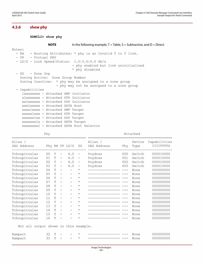
LSISAS6160 SAS Switch User GuideApril 2015
Chapter 4: SAS Domain Manager Command Line Interface Sample Output for Show Command
4.3.6 show phy
SDMCLI> show phy
NOTE In the following example, T = Table, S = Subtractive, and D = Direct.Notes: - RA - Routing Attributes: * phy is an Invalid T to T link. - VP - Virtual PHY - LS/S - Link Speed/Status: 1.5|3.0|6.0 Gb/s - phy enabled but link uninitialized * phy disabled - ZG - Zone Grp Zoning Active: Zone Group Number Zoning Inactive: * phy may be assigned to a zone group - phy may not be assigned to a zone group - Capabilities 1xxxxxxxx - Attached SMP Initiator x1xxxxxxx - Attached STP Initiator xx1xxxxxx - Attached SSP Initiator xxx1xxxxx - Attached SATA Host xxxx1xxxx - Attached SMP Target xxxxx1xxx - Attached STP Target xxxxxx1xx - Attached SSP Target xxxxxxx1x - Attached SATA Target xxxxxxxx1 - Attached SATA Port Selector
Phy Attached===================================== ==========================================Alias / Alias / Device CapabilitiesSAS Address Phy RA VP LS/S ZG SAS Address Phy Type IIIITTTTS------------------------------------- ------------------------------------------Tchoupitoulas 00 T - 6.0 - Poydras 000 Switch 000010000Tchoupitoulas 01 T - 6.0 - Poydras 001 Switch 000010000Tchoupitoulas 02 T - 6.0 - Poydras 002 Switch 000010000Tchoupitoulas 03 T - 6.0 - Poydras 003 Switch 000010000Tchoupitoulas 04 T - - * ---------------- --- None 000000000Tchoupitoulas 05 T - - * ---------------- --- None 000000000Tchoupitoulas 06 T - - * ---------------- --- None 000000000Tchoupitoulas 07 T - - * ---------------- --- None 000000000Tchoupitoulas 08 T - - * ---------------- --- None 000000000Tchoupitoulas 09 T - - * ---------------- --- None 000000000Tchoupitoulas 10 T - - * ---------------- --- None 000000000Tchoupitoulas 11 T - - * ---------------- --- None 000000000Tchoupitoulas 12 T - - * ---------------- --- None 000000000Tchoupitoulas 13 T - - * ---------------- --- None 000000000Tchoupitoulas 14 T - - * ---------------- --- None 000000000Tchoupitoulas 15 T - - * ---------------- --- None 000000000Tchoupitoulas 16 T - - * ---------------- --- None 000000000
Not all output shown in this example.
Rampart 32 T - - * ---------------- --- None 000000000Rampart 33 T - - * ---------------- --- None 000000000
Avago Technologies- 84 -
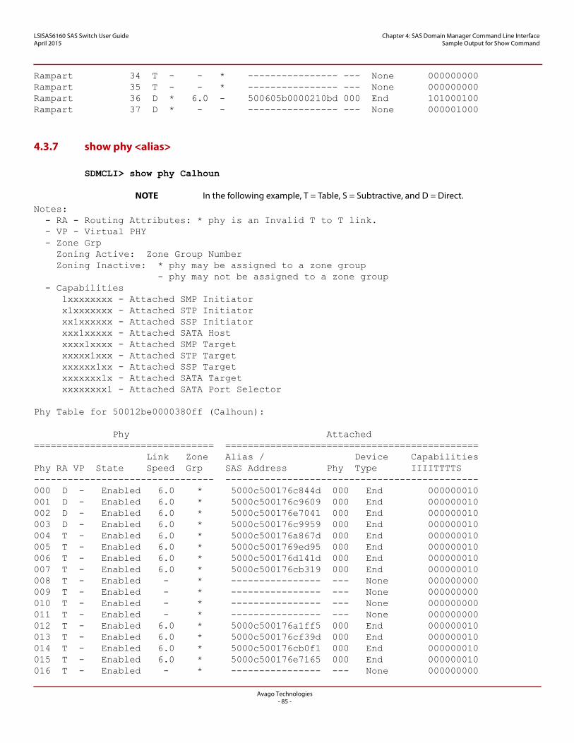
LSISAS6160 SAS Switch User GuideApril 2015
Chapter 4: SAS Domain Manager Command Line Interface Sample Output for Show Command
Rampart 34 T - - * ---------------- --- None 000000000Rampart 35 T - - * ---------------- --- None 000000000Rampart 36 D * 6.0 - 500605b0000210bd 000 End 101000100Rampart 37 D * - - ---------------- --- None 000001000
4.3.7 show phy <alias>
SDMCLI> show phy Calhoun
NOTE In the following example, T = Table, S = Subtractive, and D = Direct.Notes: - RA - Routing Attributes: * phy is an Invalid T to T link. - VP - Virtual PHY - Zone Grp Zoning Active: Zone Group Number Zoning Inactive: * phy may be assigned to a zone group - phy may not be assigned to a zone group - Capabilities 1xxxxxxxx - Attached SMP Initiator x1xxxxxxx - Attached STP Initiator xx1xxxxxx - Attached SSP Initiator xxx1xxxxx - Attached SATA Host xxxx1xxxx - Attached SMP Target xxxxx1xxx - Attached STP Target xxxxxx1xx - Attached SSP Target xxxxxxx1x - Attached SATA Target xxxxxxxx1 - Attached SATA Port Selector
Phy Table for 50012be0000380ff (Calhoun):
Phy Attached================================ ============================================= Link Zone Alias / Device CapabilitiesPhy RA VP State Speed Grp SAS Address Phy Type IIIITTTTS-------------------------------- ---------------------------------------------000 D - Enabled 6.0 * 5000c500176c844d 000 End 000000010001 D - Enabled 6.0 * 5000c500176c9609 000 End 000000010002 D - Enabled 6.0 * 5000c500176e7041 000 End 000000010003 D - Enabled 6.0 * 5000c500176c9959 000 End 000000010004 T - Enabled 6.0 * 5000c500176a867d 000 End 000000010005 T - Enabled 6.0 * 5000c5001769ed95 000 End 000000010006 T - Enabled 6.0 * 5000c500176d141d 000 End 000000010007 T - Enabled 6.0 * 5000c500176cb319 000 End 000000010008 T - Enabled - * ---------------- --- None 000000000009 T - Enabled - * ---------------- --- None 000000000010 T - Enabled - * ---------------- --- None 000000000011 T - Enabled - * ---------------- --- None 000000000012 T - Enabled 6.0 * 5000c500176a1ff5 000 End 000000010013 T - Enabled 6.0 * 5000c500176cf39d 000 End 000000010014 T - Enabled 6.0 * 5000c500176cb0f1 000 End 000000010015 T - Enabled 6.0 * 5000c500176e7165 000 End 000000010016 T - Enabled - * ---------------- --- None 000000000
Avago Technologies- 85 -
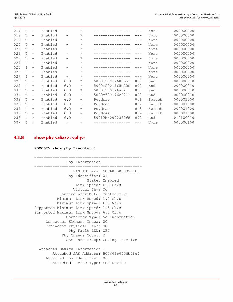
LSISAS6160 SAS Switch User GuideApril 2015
Chapter 4: SAS Domain Manager Command Line Interface Sample Output for Show Command
017 T - Enabled - * ---------------- --- None 000000000018 T - Enabled - * ---------------- --- None 000000000019 T - Enabled - * ---------------- --- None 000000000020 T - Enabled - * ---------------- --- None 000000000021 T - Enabled - * ---------------- --- None 000000000022 T - Enabled - * ---------------- --- None 000000000023 T - Enabled - * ---------------- --- None 000000000024 S - Enabled - * ---------------- --- None 000000000025 S - Enabled - * ---------------- --- None 000000000026 S - Enabled - * ---------------- --- None 000000000027 S - Enabled - * ---------------- --- None 000000000028 T - Enabled 6.0 * 5000c50017689651 000 End 000000010029 T - Enabled 6.0 * 5000c5001765e50d 000 End 000000010030 T - Enabled 6.0 * 5000c500176a32cd 000 End 000000010031 T - Enabled 6.0 * 5000c500176c9211 000 End 000000010032 T - Enabled 6.0 - Poydras 016 Switch 000001000033 T - Enabled 6.0 - Poydras 017 Switch 000001000034 T - Enabled 6.0 - Poydras 018 Switch 000001000035 T - Enabled 6.0 - Poydras 019 Switch 000001000036 D * Enabled 6.0 - 50012be0000380fd 000 End 010100010037 D * Enabled - - ---------------- --- None 000000100
4.3.8 show phy <alias>: <phy>
SDMCLI> show phy Lincoln:01
=============================================== Phy Information=============================================== SAS Address: 500605b0000282bf Phy Identifier: 01 State: Enabled Link Speed: 6.0 Gb/s Virtual Phy: No Routing Attribute: Subtractive Minimum Link Speed: 1.5 Gb/s Maximum Link Speed: 6.0 Gb/sSupported Minimum Link Speed: 1.5 Gb/sSupported Maximum Link Speed: 6.0 Gb/s Connector Type: No Information Connector Element Index: 00 Connector Physical Link: 00 Phy Fault LED: OFF Phy Change Count: 2 SAS Zone Group: Zoning Inactive
- Attached Device Information - Attached SAS Address: 500605b0006b75c0 Attached Phy Identifier: 06 Attached Device Type: End Device
Avago Technologies- 86 -
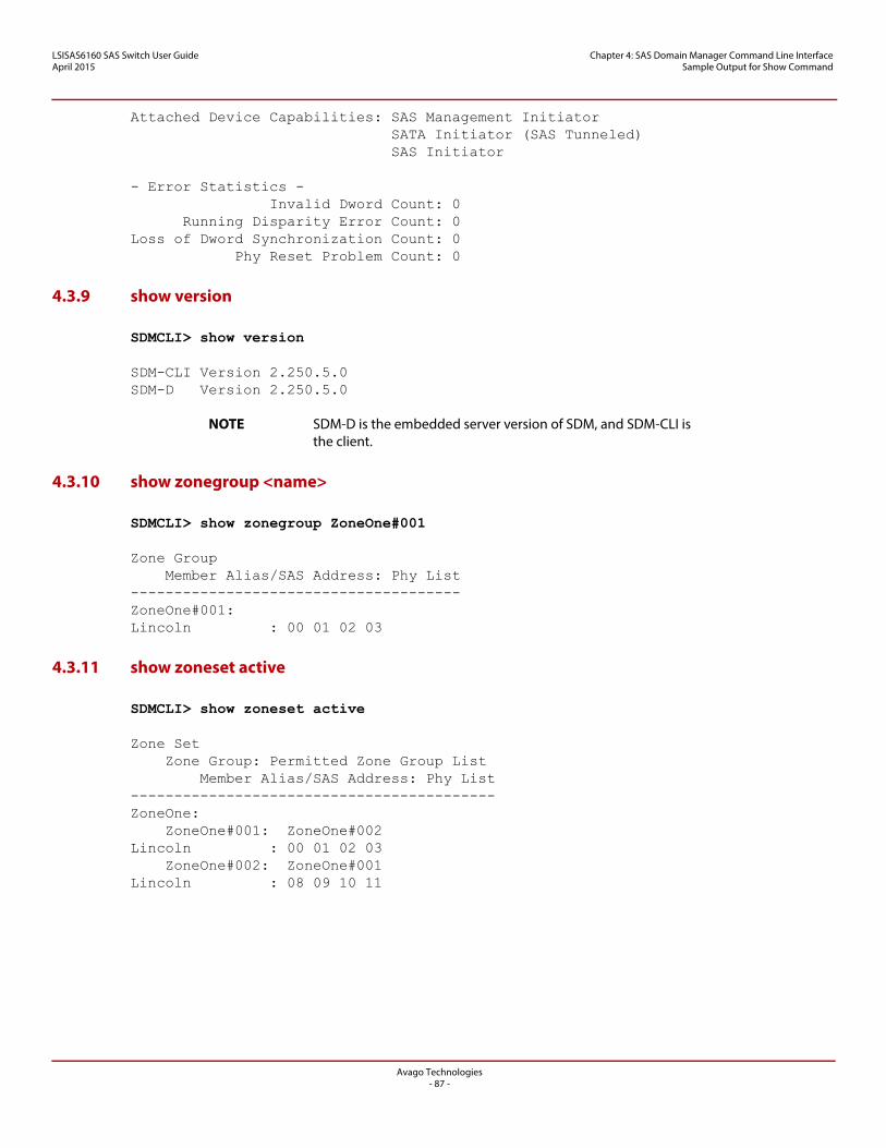
LSISAS6160 SAS Switch User GuideApril 2015
Chapter 4: SAS Domain Manager Command Line Interface Sample Output for Show Command
Attached Device Capabilities: SAS Management Initiator SATA Initiator (SAS Tunneled) SAS Initiator
- Error Statistics - Invalid Dword Count: 0 Running Disparity Error Count: 0Loss of Dword Synchronization Count: 0 Phy Reset Problem Count: 0
4.3.9 show version
SDMCLI> show version
SDM-CLI Version 2.250.5.0SDM-D Version 2.250.5.0
NOTE SDM-D is the embedded server version of SDM, and SDM-CLI is the client.
4.3.10 show zonegroup <name>
SDMCLI> show zonegroup ZoneOne#001
Zone Group Member Alias/SAS Address: Phy List--------------------------------------ZoneOne#001:Lincoln : 00 01 02 03
4.3.11 show zoneset active
SDMCLI> show zoneset active
Zone Set Zone Group: Permitted Zone Group List Member Alias/SAS Address: Phy List------------------------------------------ZoneOne: ZoneOne#001: ZoneOne#002Lincoln : 00 01 02 03 ZoneOne#002: ZoneOne#001Lincoln : 08 09 10 11
Avago Technologies- 87 -
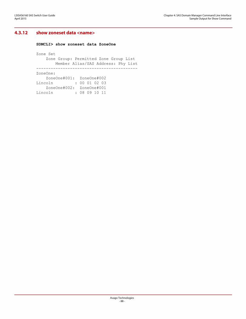
LSISAS6160 SAS Switch User GuideApril 2015
Chapter 4: SAS Domain Manager Command Line Interface Sample Output for Show Command
4.3.12 show zoneset data <name>
SDMCLI> show zoneset data ZoneOne
Zone Set Zone Group: Permitted Zone Group List Member Alias/SAS Address: Phy List------------------------------------------ZoneOne: ZoneOne#001: ZoneOne#002Lincoln : 00 01 02 03 ZoneOne#002: ZoneOne#001Lincoln : 08 09 10 11
Avago Technologies- 88 -
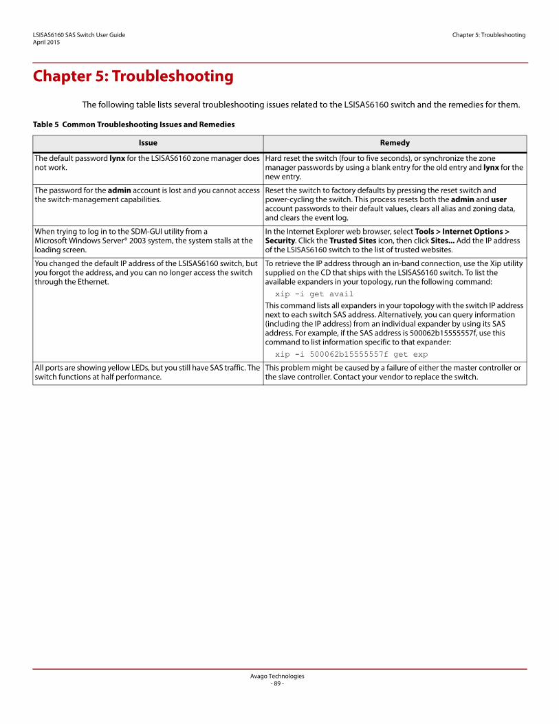
Avago Technologies- 89 -
LSISAS6160 SAS Switch User GuideApril 2015
Chapter 5: Troubleshooting
Chapter 5: Troubleshooting
The following table lists several troubleshooting issues related to the LSISAS6160 switch and the remedies for them.
Table 5 Common Troubleshooting Issues and Remedies
Issue Remedy
The default password lynx for the LSISAS6160 zone manager does not work.
Hard reset the switch (four to five seconds), or synchronize the zone manager passwords by using a blank entry for the old entry and lynx for the new entry.
The password for the admin account is lost and you cannot access the switch-management capabilities.
Reset the switch to factory defaults by pressing the reset switch and power-cycling the switch. This process resets both the admin and user account passwords to their default values, clears all alias and zoning data, and clears the event log.
When trying to log in to the SDM-GUI utility from a Microsoft Windows Server® 2003 system, the system stalls at the loading screen.
In the Internet Explorer web browser, select Tools > Internet Options > Security. Click the Trusted Sites icon, then click Sites... Add the IP address of the LSISAS6160 switch to the list of trusted websites.
You changed the default IP address of the LSISAS6160 switch, but you forgot the address, and you can no longer access the switch through the Ethernet.
To retrieve the IP address through an in-band connection, use the Xip utility supplied on the CD that ships with the LSISAS6160 switch. To list the available expanders in your topology, run the following command: xip -i get avail This command lists all expanders in your topology with the switch IP address next to each switch SAS address. Alternatively, you can query information (including the IP address) from an individual expander by using its SAS address. For example, if the SAS address is 500062b15555557f, use this command to list information specific to that expander: xip -i 500062b15555557f get exp
All ports are showing yellow LEDs, but you still have SAS traffic. The switch functions at half performance.
This problem might be caused by a failure of either the master controller or the slave controller. Contact your vendor to replace the switch.
LSISAS6160 SAS Switch User GuideApril 2015
Revision History Version 2.0, April 2015
Revision History
Version 2.0, April 2015
Changed the password length maximum to 15 characters in Section 4.2.2, Passwd Command. Added one new entry to Table 5, Common Troubleshooting Issues and Remedies. Rebranded LSI Corporation to Avago Technologies. Converted the document to the new template.
Version 1.9, February 2014
Updated the document footer.
Version 1.8, December 2012
Reformatted all notes and clarified that the switch uses an external power supply in Section 1.2, SAS and the LSISAS6160 Switch.
Version 1.7, April 2012
Added new graphics to Chapter 3, SAS Domain Manager Graphical User Interface. Added new text to Chapter 3, SAS Domain Manager Graphical User Interface. Added new text to Chapter 4, SAS Domain Manager Command Line Interface.
Version 1.6, March 2012
Replaced Figures 18 and 20. Added Figures 49, 50, 51, and 52.
Version 1.5, January 2012
Added new Graphical View information. Added information about device icons, including new SAS Non-Save Zoning Expander icon. Removed the domain command, which is obsolete. Applied low-level editing to the entire document.
Avago Technologies- 90 -
LSISAS6160 SAS Switch User GuideApril 2015
Revision History Version 1.4, September 2011
Version 1.4, September 2011
Added graphics. Converted document to new template.
Version 1.3, April 2011
Added information about new features.
Version 1.2, December 2010
Added information about new features.
Version 1.1, September 2010
Initial release of this document.
Avago Technologies- 91 -