Embed Size (px)
Citation preview
1
LIST OF FIGURES i
LIST OF TABLES ii
1 INTRODUCTION 3
2 BLOCK DIAGRAM 4
2.1 BLOCK DIAGRAM OF MICROCONTROLLER BASED
AUTOMATIC ENGINE LOCKING SYSTEM
FORDRUNKEN WORKER 4
2.2BLOCK DIAGRAM DESCRIPTION
2.2.1 HARDWARE COMPONENTS 5
2.2.2 SOFTWARE COMPONENTS 5
3 SCHEMATIC CIRCUIT DIAGRAM 6
4 HARDWARE COMPONENTS DESCRIPTION 8
5 SOFTWARE COMPONENTS DESCRIPTION 18
6 FEATURES 25
2
LIST OF FIGURES
SNO FIGURE PAGE NO
1. BLOCK DIAGRAM OF MICROCONTROLLER BASD
AUTOMATIC ENGINE LOCKING SYSTEM FOR
DRUNKEN WORKER 2
2. SCHEMATIC CIRCUIT DIAGRAM 4
3. PIN DIAGRAM OF MICROCONTROLLER 7
4. BLOCK DIAGRAM OF MICROCONTROLLER 8
5. MQ-3 ALCOHOL DETECTION SENSOR 10
6. BUZZER 11
7. LCD DISPLAY 12
8. MOTOR 13
9. RESISTORS 14
10. CAPACITORS 14
11. SYSTEM CONFIGURATION
3
1. INTRODUCTION
1.2 INTRODUCTION TO MICROCONTROLLER BASED
AUTOMATIC ENGINE LOCKING SYSTEM FOR DRUNKEN
DRIVERS
Most of these days, we hear lot of accidents due to drunken driving. Drunken drivers will not
be in stable condition and so the rash driving is the inconvenience for other road users and
also question of life and death for the drunken driver and for others.
The system uses a compact circuitry built around Flash version of AT89S52 microcontroller
with a non-volatile memory capable of retaining the password data for over ten years.
Programs are developed in embedded C. ISP is used to dump the code into the
microcontroller. The main purpose behind this project is “Drunken driving detection”.
Nowadays, many accidents are happening because of the alcohol consumption of the driver
or the person who is driving the vehicle. Thus drunk driving is a major reason of accidents in
almost all countries all over the world. Alcohol Detector in Car project is designed for the
safety of the people seating inside the car. This project should be fitted / installed inside the
vehicle.
2. BLOCK DIAGRAM
2.1 BLOCK DIAGRAM OF MICROCONTROLLER BASED AUTOMATIC ENGINE
LOCKING SYSTEM WHEN DRUNKEN DRIVERS:
4
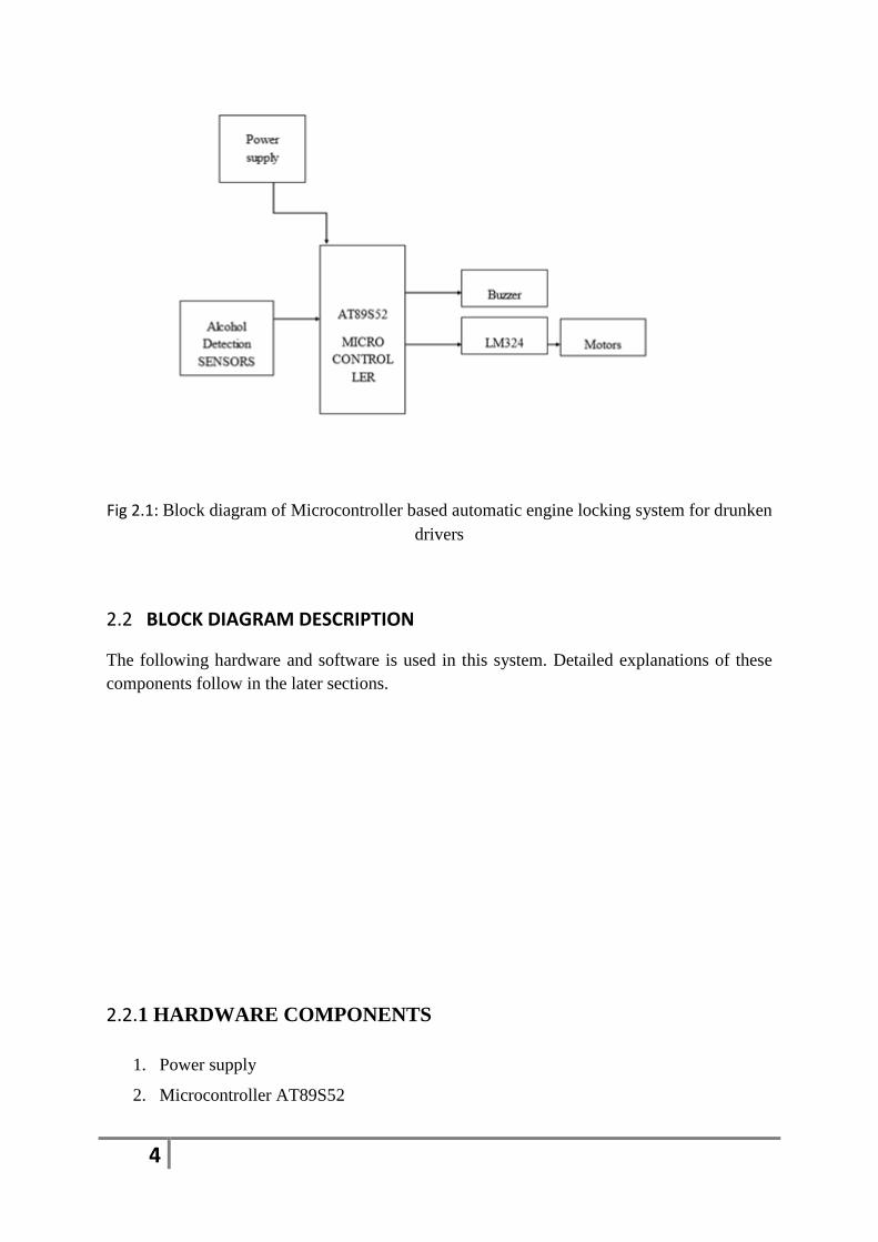
Fig 2.1: Block diagram of Microcontroller based automatic engine locking system for drunken
drivers
2.2 BLOCK DIAGRAM DESCRIPTION
The following hardware and software is used in this system. Detailed explanations of these
components follow in the later sections.
2.2.1 HARDWARE COMPONENTS
1. Power supply
2. Microcontroller AT89S52

5
3. Alcohol detection sensor
4. Buzzer
5. Rectifier
6. Regulator
7. LCD
8. Engine/Motors
9. LM324 op-amp
10. Resistors
11. Capacitors
2.2.2 SOFTWARE COMPONENTS
1. Keil software
2. Keil software programming
6
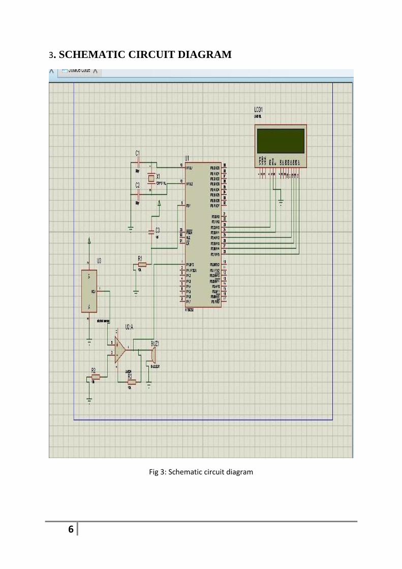
3. SCHEMATIC CIRCUIT DIAGRAM
Fig 3: Schematic circuit diagram
7
4 HARDWARE COMPONENTS DESCRIPTION
4.1 POWER SUPPLY
1. Power supply is a supply of electrical power. A device or system that supplies
electrical or other types of energy to an output load or group of loads is called a power
supply unit or PSU. The term is most commonly applied to electrical energy supplies,
less often to mechanical ones, and rarely to others.
2. A power supply may include a power distribution system as well as primary or
secondary sources of energy such as:
3. Chemical fuel cells and other forms of energy storage systems.
4. Solar power and batteries.
5. Generators or alternators. A brief description:
6. Transformer-steps down high voltage AC mains to low voltage AC
7. Rectifier-converts AC to DC, but the DC output is varying
4.2 MICROCONTROLLER AT89S52
Microcontrollers are "embedded" inside some other device. They can control the
features or actions of the product. Another name for a microcontroller is "embedded
controller”. Microcontrollers are dedicated to one task and run one specific program. The
program is stored in ROM (read-only memory) and generally does not change.
Microcontrollers are often low-power devices. A microcontroller has a dedicated input device
and has a small LED or LCD display for output. A microcontroller also takes input from the
device it is controlling and controls the device by sending signals to different components in
the device.
4.2.1 FEATURES
Compatible with MCS-51 Products;
1. 8K Bytes of In-System Programmable (ISP) Flash Memory Endurance: 10,000
Write/Erase Cycles
2. 4.0V to 5.5V Operating Range
3. Fully Static Operation: 0 Hz to 33 MHz
4. Three- bit Internal RAM
5. 32 Programmable I/O Lines

8
6. Three 16-bit Timer/Counters
7. Eight Interrupt Sources
8. Full Duplex UART Serial Channel
9. Low-power Idle and Power-down Modes
10. Interrupt Recovery from Power-down Mode
11. Watchdog Timer
12. Dual Data Pointer
13. Power-off Flag
14. Fast Programming Time
15. Level Program Memory Lock
16. Flexible ISP Programming (Byte and Page Mode)
17. Green ( Pp /Halide-free) Packaging Option
9
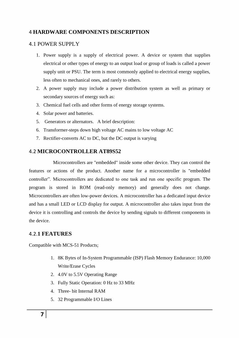
4.2.2 PIN DIAGRAM
Fig 4.1: Pin diagram of microcontroller
10
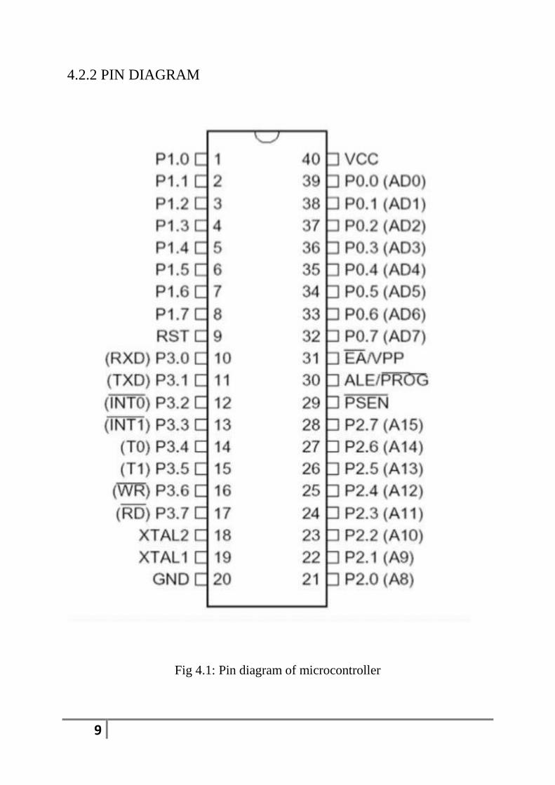
4.2.3 BLOCK DIAGRAM
Fig 4.2: Block diagram of micro controller
11
4.2.4 PIN DESCRIPTION
VCC: Supply voltage
GND: Ground
PORT 0:
Port 0 is an 8-bit open-drain bi-directional I/O port. As an output port, each pin can sink
eight TTL inputs. When 1s are written to port 0 pins, the pins can be used as high impedance
inputs. Port 0 may also be configured to be the multiplexed low order address/data bus during
accesses to external program and data memory. In this mode P0 has internal pull-ups.
PORT 1:
Port 1 is an 8-bit bi-directional I/O port with internal pull-ups. The Port 1 output buffers can
sink/source four TTL inputs. When 1s are written to Port 1 pins they are pulled high by the
internal pull-ups and can be used as inputs.
PORT 2:
Port 2 is a 8-bit bi-directional I/O port with internal pull-ups. The Port 2 output buffers can
sink/source four TTL inputs. When 1s are written to Port 2 pins they are pulled high by the
internal pull-ups and can be used as inputs. As inputs, Port 2 pins that are externally being
pulled low will source current During accesses to external data memory that uses (IIL)
because of the internal pull-ups.
PORT 3:
Port 3 is an 8-bit bi-directional I/O port with internal pull-ups. The Port 3 output buffers can
sink/source four TTL inputs. When 1s are written to Port 3 pins they are pulled high by the
internal pull-ups and can be used as inputs. As inputs, Port 3 pins that are externally being
pulled low will source current (IIL) because of the pull-ups.
12
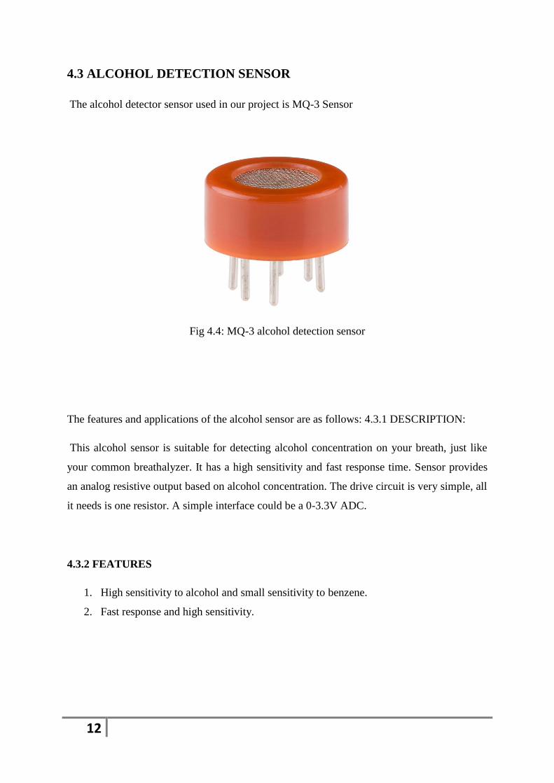
4.3 ALCOHOL DETECTION SENSOR
The alcohol detector sensor used in our project is MQ-3 Sensor
Fig 4.4: MQ-3 alcohol detection sensor
The features and applications of the alcohol sensor are as follows: 4.3.1 DESCRIPTION:
This alcohol sensor is suitable for detecting alcohol concentration on your breath, just like
your common breathalyzer. It has a high sensitivity and fast response time. Sensor provides
an analog resistive output based on alcohol concentration. The drive circuit is very simple, all
it needs is one resistor. A simple interface could be a 0-3.3V ADC.
4.3.2 FEATURES
1. High sensitivity to alcohol and small sensitivity to benzene.
2. Fast response and high sensitivity.
13
4.3.3 APPLICATIONS:
1. They are suitable for alcohol checker, breath analyzer.
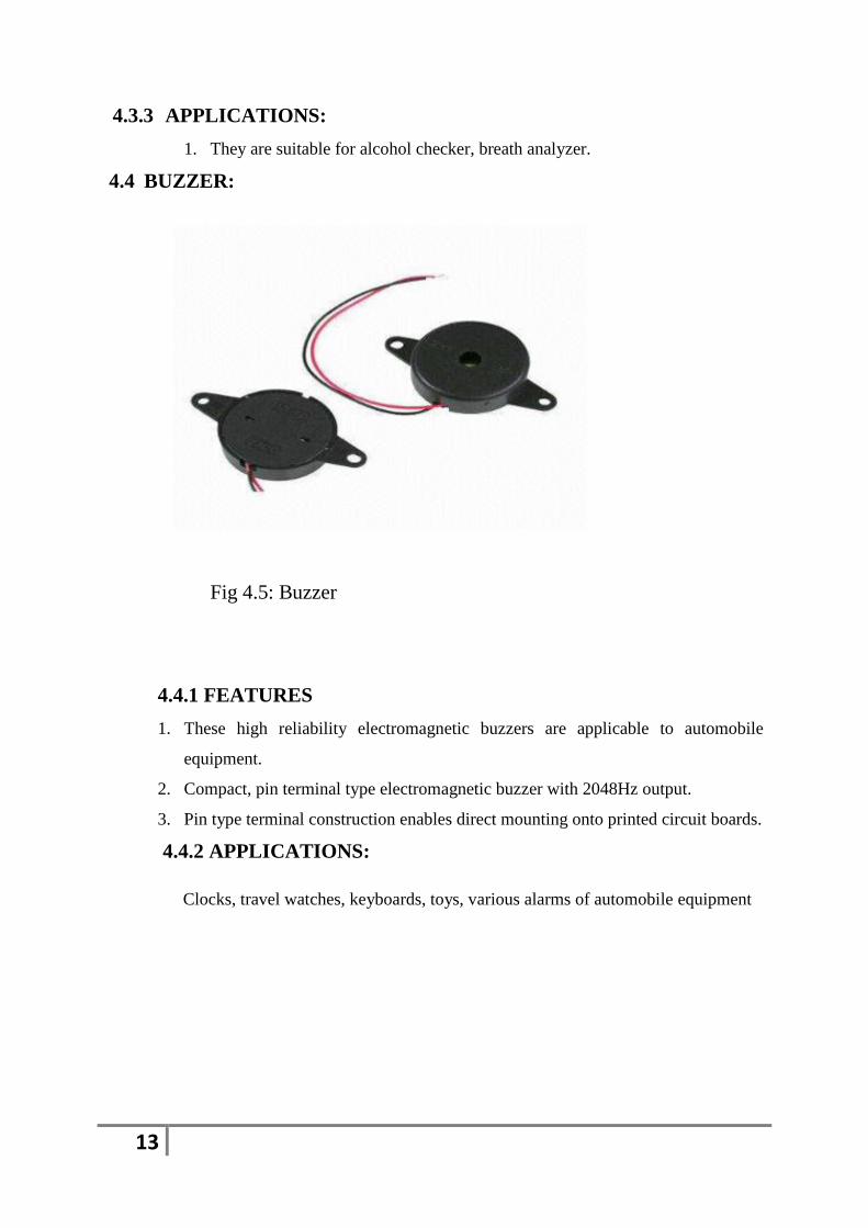
4.4 BUZZER:
Fig 4.5: Buzzer
4.4.1 FEATURES
1. These high reliability electromagnetic buzzers are applicable to automobile
equipment.
2. Compact, pin terminal type electromagnetic buzzer with 2048Hz output.
3. Pin type terminal construction enables direct mounting onto printed circuit boards.
4.4.2 APPLICATIONS:
Clocks, travel watches, keyboards, toys, various alarms of automobile equipment
14
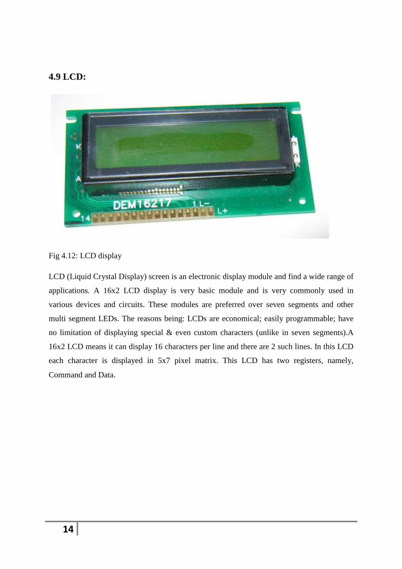
4.9 LCD:
Fig 4.12: LCD display
LCD (Liquid Crystal Display) screen is an electronic display module and find a wide range of
applications. A 16x2 LCD display is very basic module and is very commonly used in
various devices and circuits. These modules are preferred over seven segments and other
multi segment LEDs. The reasons being: LCDs are economical; easily programmable; have
no limitation of displaying special & even custom characters (unlike in seven segments).A
16x2 LCD means it can display 16 characters per line and there are 2 such lines. In this LCD
each character is displayed in 5x7 pixel matrix. This LCD has two registers, namely,
Command and Data.
15
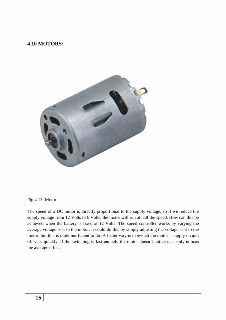
4.10 MOTORS:
Fig 4.13: Motor
The speed of a DC motor is directly proportional to the supply voltage, so if we reduce the
supply voltage from 12 Volts to 6 Volts, the motor will run at half the speed. How can this be
achieved when the battery is fixed at 12 Volts. The speed controller works by varying the
average voltage sent to the motor. It could do this by simply adjusting the voltage sent to the
motor, but this is quite inefficient to do. A better way is to switch the motor’s supply on and
off very quickly. If the switching is fast enough, the motor doesn’t notice it, it only notices
the average effect.
16
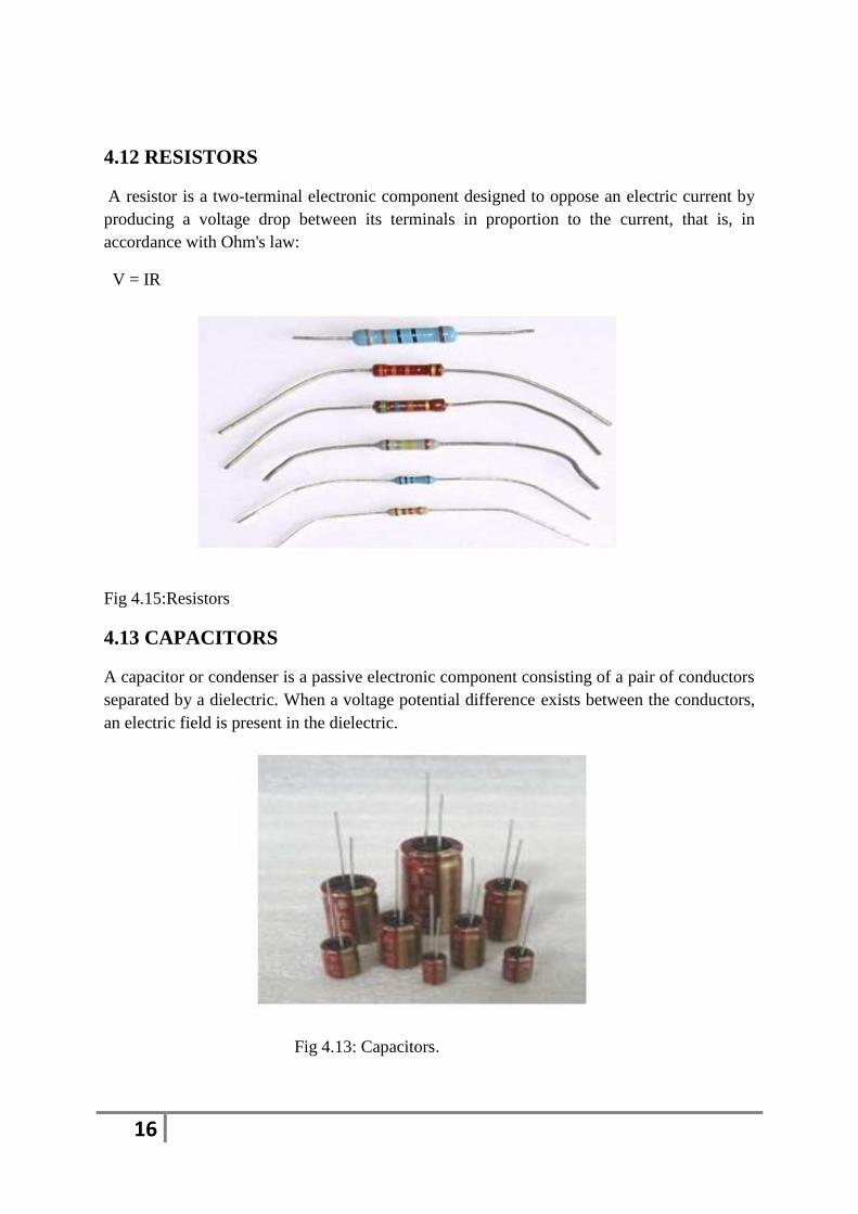
4.12 RESISTORS
A resistor is a two-terminal electronic component designed to oppose an electric current by
producing a voltage drop between its terminals in proportion to the current, that is, in
accordance with Ohm's law:
V = IR
Fig 4.15:Resistors
4.13 CAPACITORS
A capacitor or condenser is a passive electronic component consisting of a pair of conductors
separated by a dielectric. When a voltage potential difference exists between the conductors,
an electric field is present in the dielectric.
Fig 4.13: Capacitors.

17
5. SOFTWARE COMPONENTS DESCRIPTION
5.1 KEIL SOFTWARE
Keil compiler is software used where the machine language code is written and compiled.
After compilation, the machine source code is converted into hex code which is to be dumped
into the microcontroller for further processing. Keil compiler also supports C language code.
STEPS TO WRITE AN ASSEMBLY LANGUAGE PROGRAM IN KEIL
AND HOW TO COMPILE IT:
1. Install the Keil Software in the PC in any of the drives.
2. After installation, an icon will be created with the name “Keil uVision3”. Just drag this
icon onto the desktop so that it becomes easy whenever you try to write programs in keil.
3. Double click on this icon to start the keil compiler.
4. A page opens with different options in it showing the project workspace at the leftmost
corner side, output window in the bottom and an ash colored space for the program to be
written.
5. Now to start using the keil, click on the option “project”.
6. A small window opens showing the options like new project, import project, open project
etc. Click on “New project”.
7. A small window with the title bar “Create new project” opens. The window asks the user
to give the project name with which it should be created and the destination location.
8. The project can be created in any of the drives available. You can create a new folder and
destination location, a window opens where a list of vendors will be displayed and you have .

18
6. SOURCE CODE
#include<reg52.h>
#define lcdport P2
sbit rs=P2^0;
sbit en=P2^1;
sbit buzzer=P3^7;
sbit smoke=P1^7;
sbit mp1=P1^0;
sbit mn1=P1^1;
void lcd _cmd(unsigned char);
void delay(unsigned int);
void lcd_msg(unsigned char *);
void lcd_data(unsigned char);
void dis_data(unsigned char);
void dis_cmd(unsigned char);
void lcd_ini();
void main()
lcd_ini();
smoke=1;
19
mp1=1;
mn1=0;
lcd_ini();
dis_cmd(0x80);
lcd_msg(" DRUNK DRIVE");
dis_cmd(0xc0);
lcd_msg(" BASED");
delay(100);
dis_cmd(0x01);
dis_cmd(0x80);
lcd_msg(" ENGINE LOCK");
dis_cmd(0xc0);
lcd_msg(" SYSTEM ");
delay(100);
dis_cmd(0x01);
while(1)
{
if(smoke==0)
{
buzzer=0;
mp1=mn1=0;
lcd_msg("ALOCHOL DETECTED");
20
dis_cmd(0xc0);
lcd msg(" BUZZER ON ");
delay (50);
dis_cmd(0x01);
}
else
{
smoke=1;
buzzer=1;
mp1=1;
mn1=0;
dis_cmd(0x80);
lcd_msg(" NO ALOCHOL");
dis_cmd(0xc0);
lcd_msg(" BUZZER OFF");
delay(50);
dis_cmd(0x01);
}
}
void delay(unsigned int ms)
21
{
int i,j;
for(i=0;i<ms;i++)
for(j=0;j<1275;j++);
}
void lcd_ini()
{
dis_cmd(0x02);
dis_cmd(0x28);
dis_cmd(0x0C);
dis_cmd(0x06);
dis_cmd(0x80);
}
void dis_cmd(unsigned char cmd_value)
{
unsigned char cmd_value1;
cmd_value1 = (cmd_value & 0xF0);
lcd_cmd(cmd_value1);
cmd_value1 = ((cmd_value<<4) & 0xF0);
}
void dis_data(unsigned char data_value)
{

22
unsigned char data_value1;
data_value1=(data_value&0xF0);
lcd_data(data_value1);
data_value1=((data_value<<4)&0xF0);
lcd_data(data_value1);
}
Void lcd_cmd(unsigned char cmdout)
{
lcdport=cmdout;
rs=0;
//rw=0;
en=1;
delay(1);
en=0;
}
void lcd_data(unsigned char dataout) {
lcdport=dataout;
rs=1;
en=1;
delay(1);
en=0;
}

23
void lcd_msg(unsigned char *ptr2)
{
while(*ptr2)
{
dis_data(*ptr2);
delay(10);
ptr2++;
}
}
24
7. FEATURES
7.1 ADVANTAGES:
1. Low cost.
2. Automated operation.
3. Low Power consumption.
4. It provides an automatic safety system for cars and other vehicles as well
7.2 APPLICATIONS
1. “Alcohol Detector project” can be used in the various vehicles for detecting whether
the driver has consumed alcohol or not.
2. This project can also be used in various companies or organization to detect alcohol
consumption of employees.
Conclusion
In this project we have developed a real time model that can automatically lock the engine
when a drunken driver tries to drive a car. Now-a-days car accidents are mostly seen. By
fitting this alcohol sensor into the car, we can save guard the life of the driver and also the
remaining passengers. It is very simple application. The life time of the project is high. It has
low or zero maintenance cost and of course low power consumption.
This is a developed design to efficiently check drunken driving. By implementing this design
a safe car journey is possible decreasing the accident rate due to drinking. By implementing
this design, drunken drivers can be controlled so are the accidents due to drunken driving.
Government must enforce laws to install such circuit in every car and must regulate all car
companies to preinstall such mechanisms while manufacturing the car itself. If this is
achieved the deaths due to drunken drivers can be brought to minimum level. In this type of
system, future scope can be safely landing of car aside without disturbing other vehicles.

25
References
1. Muhammad Ali Mazidi (8051 Microcontroller and Embedded Systems)
2. www.wikipedia.org
3. www.atmel.com

26


![Fragmentary Pleasures: Some Minor [Hellenistic] Figures](https://img.dokumen.tips/doc/110x75/631882fe831644824d03ed34/fragmentary-pleasures-some-minor-hellenistic-figures.jpg)


