Embed Size (px)
Citation preview
Link Budget Analysis Guide iii
Evolution Release 1.3
Link Budget Analysis Guide
iDX Release 4.1.3
May 10, 2019
ii Link Budget Analysis Guide, iDX Release 4.1.3
Copyright © 2019. VT iDirect, Inc., 13861 Sunrise Valley Drive, Suite 300, Herndon, VA 20171, USA.
All rights reserved. Reproduction in whole or in part without permission is prohibited. Information contained herein is subject to change without notice. The specifications and information regarding the products in this document are subject to change without notice. All statements, information and recommendations in this document are believed to be accurate, but are presented without warranty of any kind, express, or implied. Users must take full responsibility for their application of any products. Trademarks, brand names and products mentioned in this document are the property of their respective owners. All such references are used strictly in an editorial fashion with no intent to convey any affiliation with the name or the product's rightful owner.
VT iDirect® is a global leader in IP-based satellite communications providing technology and solutions that enable our partners worldwide to optimize their networks, differentiate their services and profitably expand their businesses. Our product portfolio, branded under the name iDirect®, sets standards in performance and efficiency to deliver voice, video and data connectivity anywhere in the world. VT iDirect® is the world’s largest TDMA enterprise VSAT manufacturer and is the leader in key industries including mobility, military/government and cellular backhaul.
Company web site: www.idirect.net ~ Main Phone: 703.648.8000 TAC Contact Information: Phone: 703.648.8151 ~ Email: [email protected] ~ Web site: tac.idirect.net
iDirect Government™, created in 2007, is a wholly owned subsidiary of VT iDirect and was formed to better serve the U.S. government and defense communities. Company web site: www.idirectgov.com ~ Main Phone: 703.648.8118 TAC Contact Information: Phone: 703.648.8111 ~ Email: [email protected] ~ Web site: tac.idirectgov.com
Document Name: HI_LBA_Guide_iDX_4.1.3_T0001089_RevA_05_02_19
Link Budget Analysis Guide, iDX Release 4.1.3 iii
Revision History
The following table shows all prior revisions of the document. The most recent revision is available on the Technical Assistance Center (TAC) Web site. Refer to Getting Help on page xi for TAC access information.
Release / Revision Date Released Reason for Change(s)
iDX4.1.3 / Revision A 01-May-2019
Updates to TDMA Upstream Carrier Performance Specifications and TDMA Upstream Modes and Throughput Limitations sections of the guide for 16QAM feature introduction.
iv Link Budget Analysis Guide, iDX Release 4.1.3
Disclaimer
While iDirect, Inc. strives to make the information in this document as accurate as possible, iDirect makes no claims, promises, or guarantees about the accuracy, completeness, or adequacy of the contents, and expressly disclaims liability for errors and omissions. No warranty of any kind, whether implied, expressed, or statutory, including but not limited to the warranties of non-infringement of third party rights, title, merchantability, or fitness for a particular purpose, is given with respect to the contents of this document.
VT iDirect, Inc. reserves the right to change or update this document at any time.
Link Budget Analysis Guide, iDX Release 4.1.3 v
Contents
Revision History .................................................................................. iii
Disclaimer ......................................................................................... iv
Contents ............................................................................................ v
About .............................................................................................. viii
Purpose ................................................................................................... viii
Target Audience ......................................................................................... viii
Getting Help ............................................................................................. viii
1 Downstream .................................................................................. 1
DVB-S2 ACM Downstream ................................................................................ 2
DVB-S2X ACM Downstream ............................................................................... 7
Transmit Hub Line Cards ............................................................................... 10
Multi-Protocol Encapsulation Mode Downstream Configuration ................................ 10
2 Upstream .................................................................................... 11
SCPC Upstream Carrier Performance Specifications .............................................. 12
TDMA Upstream Carrier Performance Specifications ............................................. 15
TDMA Upstream Modes and Throughput Limitations .............................................. 19
3 System Guidelines ......................................................................... 22
DVB-S2/S2X ACM System Guidelines ................................................................. 23
Adaptive TDMA System Guidelines ................................................................... 24
vi Link Budget Analysis Guide, iDX Release 4.1.3
List of Figures
Figure 1: Downstream Performance Graph for DVB-S2 .................................................. 6
Figure 2: Downstream Performance Graph for DVB-S2X ................................................. 9
Figure 3: Downstream Efficiency Comparison for DVB-S2X and DVB-S2 modes .................... 10
Figure 4: Upstream SCPC Performance Graph (170 and 438 Bytes Payload) ....................... 14
Figure 5: Upstream Performance Graphs for Non-SS and SS Modes .................................. 18
Link Budget Analysis Guide, iDX Release 4.1.3 vii
List of Tables
Table 1. DVB-S2 Modem Performance Limit by Remote Model Type .................................. 2
Table 2: DVB-S2X Modem Performance Limit .............................................................. 7
Table 3. SNR Performance Limit for SCPC Carriers ..................................................... 12
Table 4. SNR Performance Limit for TDMA Carriers .................................................... 15
viii Link Budget Analysis Guide, iDX Release 4.1.3
About
Purpose The purpose of this guide is to provide system and network engineers with satellite modem performance parameters necessary to conduct link budget analysis and accordingly plan system resources for implementing an iDirect network. The information presented in this guide is specific to the iDirect Evolution series of hub and remote products for networks associated with Evolution 4.1.3 Software Release.
Target Audience The intended audience for this guide are network engineers who are planning the integration of the iDirect hub equipment in an existing teleport or Earth station.
Getting Help The iDirect Technical Assistance Center (iDirect TAC) and the iDirect Government Technologies Technical Assistance Center (iDirectGov TAC) are available to provide assistance 24 hours a day, 365 days a year. Software user guides, installation procedures, an FAQ page, and other documents that support iDirect and iDirect Government products are available on the respective TAC Web site.
IDirect Contact Information • Web site: http://tac.idirect.net
• Telephone: (703) 648-8151
• E-mail: [email protected]
For sales or product purchasing information, contact iDirect Corporate Sales at:
• Telephone: (703) 848-8000
• E-mail: [email protected]
Link Budget Analysis Guide, iDX Release 4.1.3 ix
iDirect Government Contact Information • Web site: http://tac.idirectgov.com
• Telephone: (703) 648-8111
• E-mail: [email protected]
iDirect and iDirect Government strive to produce documentation that are technically accurate, easy to use, and helpful to our customers. Please assist us in improving this document by providing feedback. Send comments to:
• iDirect: [email protected]
• iDirect Government: [email protected]

Link Budget Analysis Guide, iDX Release 4.1.3 1
1 Downstream
This chapter describes Downstream Carrier specifications for the Evolution 4.1.3 network and contains the following sections:
• DVB-S2 ACM Downstream
• DVB-S2X ACM Downstream
• Transmit Hub Line Cards
• Multi-Protocol Encapsulation Mode Downstream Configuration
The ULC-T/DLC-T series transmit hub line cards support both DVB-S2 and DVB-S2X Downstream modes of operation. DVB-S2X mode enablement and symbol rate increment are licensed features for these line card models.
2 Link Budget Analysis Guide, iDX Release 4.1.3
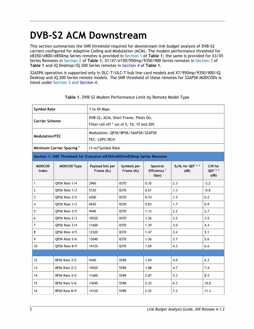
DVB-S2 ACM Downstream This section summarizes the SNR threshold required for downstream link budget analysis of DVB-S2 carriers configured for Adaptive Coding and Modulation (ACM). The modem performance threshold for e8350/e800/e850mp Series remotes is provided in Section 1 of Table 1; the same is provided for X3/X5 Series Remotes in Section 2 of Table 1, X1/X7/e150/950mp/9350/900 Series remotes in Section 3 of Table 1 and iQ Desktop/iQ 200 Series remotes in Section 4 of Table 1.
32ASPK operation is supported only in DLC-T/ULC-T hub line card models and X7/950mp/9350/900/iQ Desktop and iQ 200 Series remote models. The SNR threshold of these remotes for 32APSK MODCODs is listed under Section 3 and Section 4.
Table 1. DVB-S2 Modem Performance Limit by Remote Model Type
Symbol Rate 1 to 45 Msps
Carrier Scheme DVB-S2, ACM, Short Frame, Pilots On,
Filter roll off 1 (α) of 5, 10, 15 and 20%
Modulation/FEC Modulation: QPSK/8PSK/16APSK/32APSK
FEC: LDPC/BCH
Minimum Carrier Spacing 1 (1+α)*Symbol Rate
Section 1: SNR Threshold for Evolution e8350/e800/e850mp Series Remotes
MODCOD Index
MODCOD Type Payload bits per Frame (Kb)
Symbols per Frame (Ns)
Spectral Efficiency 2
(bps)
Eb/No for QEF 3, 4 (dB)
C/N for QEF 3, 4
(dB)
1 QPSK Rate 1/4 2960 8370 0.35 2.3 -2.2
2 QPSK Rate 1/3 5120 8370 0.61 1.3 -0.8
3 QPSK Rate 2/5 6200 8370 0.74 1.5 0.2
4 QPSK Rate 1/2 6920 8370 0.83 1.7 0.9
5 QPSK Rate 3/5 9440 8370 1.13 2.2 2.7
6 QPSK Rate 2/3 10520 8370 1.26 2.5 3.5
7 QPSK Rate 3/4 11600 8370 1.39 3.0 4.4
8 QPSK Rate 4/5 12320 8370 1.47 3.4 5.1
9 QPSK Rate 5/6 13040 8370 1.56 3.7 5.6
10 QPSK Rate 8/9 14120 8370 1.69 4.3 6.6
12 8PSK Rate 3/5 9440 5598 1.69 4.0 6.3
13 8PSK Rate 2/3 10520 5598 1.88 4.7 7.4
14 8PSK Rate 3/4 11600 5598 2.07 5.3 8.5
15 8PSK Rate 5/6 13040 5598 2.33 6.3 10.0
16 8PSK Rate 8/9 14120 5598 2.52 7.3 11.3
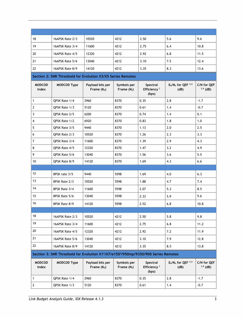
Link Budget Analysis Guide, iDX Release 4.1.3 3
18 16APSK Rate 2/3 10520 4212 2.50 5.6 9.6
19 16APSK Rate 3/4 11600 4212 2.75 6.4 10.8
20 16APSK Rate 4/5 12320 4212 2.92 6.8 11.5
21 16APSK Rate 5/6 13040 4212 3.10 7.5 12.4
22 16APSK Rate 8/9 14120 4212 3.35 8.3 13.6
Section 2: SNR Threshold for Evolution X3/X5 Series Remotes
MODCOD Index
MODCOD Type Payload bits per Frame (Kb)
Symbols per Frame (Ns)
Spectral Efficiency 2
(bps)
Eb/No for QEF 3,4 (dB)
C/N for QEF 3,4 (dB)
1 QPSK Rate 1/4 2960 8370 0.35 2.8 -1.7
2 QPSK Rate 1/3 5120 8370 0.61 1.4 -0.7
3 QPSK Rate 2/5 6200 8370 0.74 1.4 0.1
4 QPSK Rate 1/2 6920 8370 0.83 1.8 1.0
5 QPSK Rate 3/5 9440 8370 1.13 2.0 2.5
6 QPSK Rate 2/3 10520 8370 1.26 2.3 3.3
7 QPSK Rate 3/4 11600 8370 1.39 2.9 4.3
8 QPSK Rate 4/5 12320 8370 1.47 3.2 4.9
9 QPSK Rate 5/6 13040 8370 1.56 3.6 5.5
10 QPSK Rate 8/9 14120 8370 1.69 4.3 6.6
12 8PSK rate 3/5 9440 5598 1.69 4.0 6.3
13 8PSK Rate 2/3 10520 5598 1.88 4.7 7.4
14 8PSK Rate 3/4 11600 5598 2.07 5.3 8.5
15 8PSK Rate 5/6 13040 5598 2.33 5.9 9.6
16 8PSK Rate 8/9 14120 5598 2.52 6.8 10.8
18 16APSK Rate 2/3 10520 4212 2.50 5.8 9.8
19 16APSK Rate 3/4 11600 4212 2.75 6.8 11.2
20 16APSK Rate 4/5 12320 4212 2.92 7.2 11.9
21 16APSK Rate 5/6 13040 4212 3.10 7.9 12.8
22 16APSK Rate 8/9 14120 4212 3.35 8.5 13.8
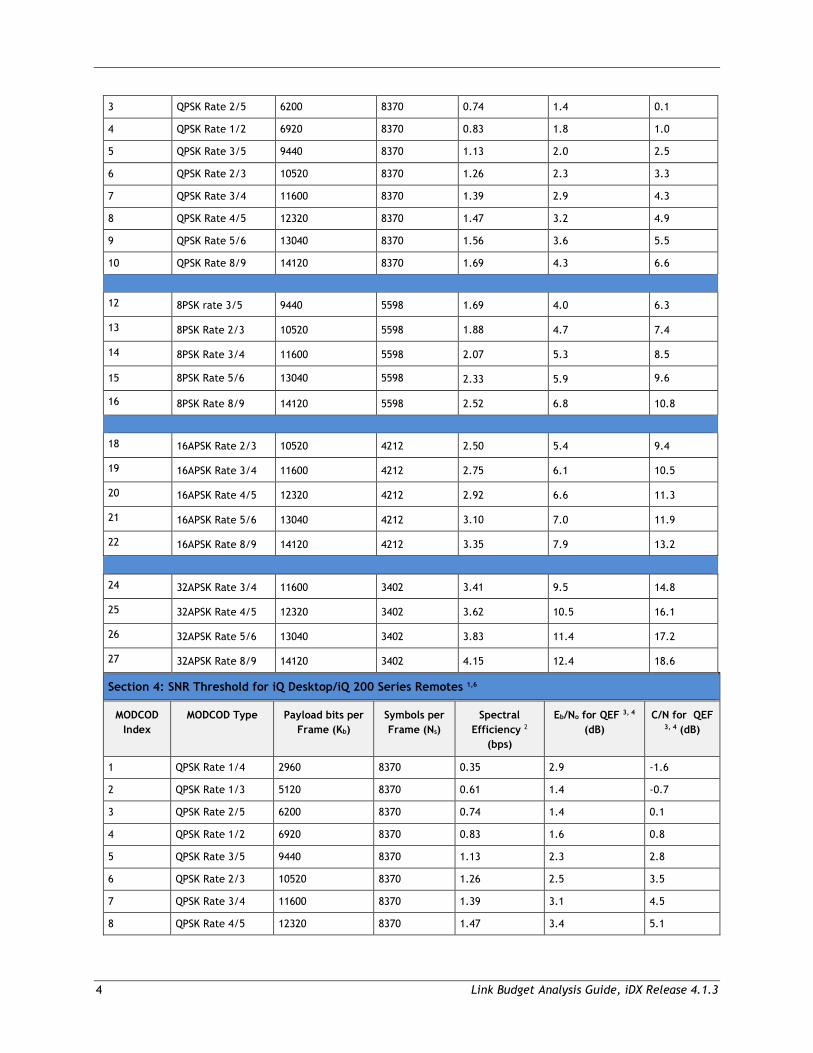
Section 3: SNR Threshold for Evolution X15/X7/e1505/950mp/9350/900 Series Remotes
MODCOD Index
MODCOD Type Payload bits per Frame (Kb)
Symbols per Frame (Ns)
Spectral Efficiency 2
(bps)
Eb/No for QEF 3,4 (dB)
C/N for QEF 3,4 (dB)
1 QPSK Rate 1/4 2960 8370 0.35 2.8 -1.7
2 QPSK Rate 1/3 5120 8370 0.61 1.4 -0.7
4 Link Budget Analysis Guide, iDX Release 4.1.3
3 QPSK Rate 2/5 6200 8370 0.74 1.4 0.1
4 QPSK Rate 1/2 6920 8370 0.83 1.8 1.0
5 QPSK Rate 3/5 9440 8370 1.13 2.0 2.5
6 QPSK Rate 2/3 10520 8370 1.26 2.3 3.3
7 QPSK Rate 3/4 11600 8370 1.39 2.9 4.3
8 QPSK Rate 4/5 12320 8370 1.47 3.2 4.9
9 QPSK Rate 5/6 13040 8370 1.56 3.6 5.5
10 QPSK Rate 8/9 14120 8370 1.69 4.3 6.6
12 8PSK rate 3/5 9440 5598 1.69 4.0 6.3
13 8PSK Rate 2/3 10520 5598 1.88 4.7 7.4
14 8PSK Rate 3/4 11600 5598 2.07 5.3 8.5
15 8PSK Rate 5/6 13040 5598 2.33 5.9 9.6
16 8PSK Rate 8/9 14120 5598 2.52 6.8 10.8
18 16APSK Rate 2/3 10520 4212 2.50 5.4 9.4
19 16APSK Rate 3/4 11600 4212 2.75 6.1 10.5
20 16APSK Rate 4/5 12320 4212 2.92 6.6 11.3
21 16APSK Rate 5/6 13040 4212 3.10 7.0 11.9
22 16APSK Rate 8/9 14120 4212 3.35 7.9 13.2
24 32APSK Rate 3/4 11600 3402 3.41 9.5 14.8
25 32APSK Rate 4/5 12320 3402 3.62 10.5 16.1
26 32APSK Rate 5/6 13040 3402 3.83 11.4 17.2
27 32APSK Rate 8/9 14120 3402 4.15 12.4 18.6
Section 4: SNR Threshold for iQ Desktop/iQ 200 Series Remotes 1,6
MODCOD Index
MODCOD Type Payload bits per Frame (Kb)
Symbols per Frame (Ns)
Spectral Efficiency 2
(bps)
Eb/No for QEF 3, 4 (dB)
C/N for QEF 3, 4 (dB)
1 QPSK Rate 1/4 2960 8370 0.35 2.9 -1.6
2 QPSK Rate 1/3 5120 8370 0.61 1.4 -0.7
3 QPSK Rate 2/5 6200 8370 0.74 1.4 0.1
4 QPSK Rate 1/2 6920 8370 0.83 1.6 0.8
5 QPSK Rate 3/5 9440 8370 1.13 2.3 2.8
6 QPSK Rate 2/3 10520 8370 1.26 2.5 3.5
7 QPSK Rate 3/4 11600 8370 1.39 3.1 4.5
8 QPSK Rate 4/5 12320 8370 1.47 3.4 5.1
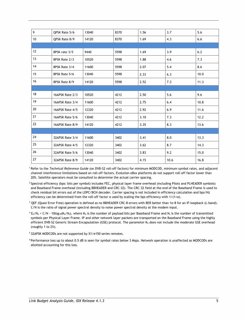
Link Budget Analysis Guide, iDX Release 4.1.3 5
9 QPSK Rate 5/6 13040 8370 1.56 3.7 5.6
10 QPSK Rate 8/9 14120 8370 1.69 4.3 6.6
12 8PSK rate 3/5 9440 5598 1.69 3.9 6.2
13 8PSK Rate 2/3 10520 5598 1.88 4.6 7.3
14 8PSK Rate 3/4 11600 5598 2.07 5.4 8.6
15 8PSK Rate 5/6 13040 5598 2.33 6.3 10.0
16 8PSK Rate 8/9 14120 5598 2.52 7.3 11.3
18 16APSK Rate 2/3 10520 4212 2.50 5.6 9.6
19 16APSK Rate 3/4 11600 4212 2.75 6.4 10.8
20 16APSK Rate 4/5 12320 4212 2.92 6.9 11.6
21 16APSK Rate 5/6 13040 4212 3.10 7.3 12.2
22 16APSK Rate 8/9 14120 4212 3.35 8.3 13.6
24 32APSK Rate 3/4 11600 3402 3.41 8.0 13.3
25 32APSK Rate 4/5 12320 3402 3.62 8.7 14.3
26 32APSK Rate 5/6 13040 3402 3.83 9.2 15.0
27 32APSK Rate 8/9 14120 3402 4.15 10.6 16.8
1 Refer to the Technical Reference Guide (on DVB-S2 roll-off factors) for minimum MODCOD, minimum symbol rates, and adjacent channel interference limitations based on roll-off factors. Evolution e8xx platforms do not support roll-off factor lower than 20%. Satellite operators must be consulted to determine the actual carrier spacing.
2 Spectral efficiency (bps: bits per symbol) includes FEC, physical layer frame overhead (including Pilots and PLHEADER symbols) and Baseband Frame overhead (including BBHEADER and CRC-32). The CRC-32 field at the end of the Baseband Frame is used to check residual bit errors out of the LDPC/BCH decoder. Carrier spacing is not included in efficiency calculation and bps/Hz efficiency can be determined from the roll-off factor α used by scaling the bps efficiency with 1/(1+α).
3 QEF (Quasi Error Free) operation is defined as no BBHEADER CRC-8 errors with BER better than 1e-8 for an IF-loopback (L-band). C/N is the ratio of signal power spectral density to noise power spectral density at the modem input.
4 Eb/No = C/N - 10log10(Kb/Ns), where Kb is the number of payload bits per Baseband Frame and Ns is the number of transmitted symbols per Physical Layer Frame. IP and other network layer packets are transported on the Baseband Frame using the highly efficient DVB-S2 Generic Stream Encapsulation (GSE) protocol. The parameter Kb does not include the moderate GSE overhead (roughly 1 to 2%).
5 32APSK MODCODs are not supported by X1/e150 series remotes.
6 Performance loss up to about 0.5 dB is seen for symbol rates below 3 Msps. Network operation is unaffected as MODCODs are allotted accounting for this loss.
6 Link Budget Analysis Guide, iDX Release 4.1.3
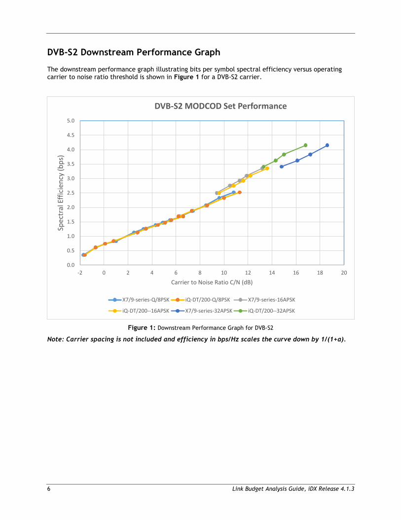
DVB-S2 Downstream Performance Graph
The downstream performance graph illustrating bits per symbol spectral efficiency versus operating carrier to noise ratio threshold is shown in Figure 1 for a DVB-S2 carrier.
Figure 1: Downstream Performance Graph for DVB-S2
Note: Carrier spacing is not included and efficiency in bps/Hz scales the curve down by 1/(1+α).
0.0
0.5
1.0
1.5
2.0
2.5
3.0
3.5
4.0
4.5
5.0
-2 0 2 4 6 8 10 12 14 16 18 20
Spec
tral
Effi
cien
cy (b
ps)
Carrier to Noise Ratio C/N (dB)
DVB-S2 MODCOD Set Performance
X7/9-series-Q/8PSK iQ-DT/200-Q/8PSK X7/9-series-16APSK
iQ-DT/200--16APSK X7/9-series-32APSK iQ-DT/200--32APSK
Link Budget Analysis Guide, iDX Release 4.1.3 7
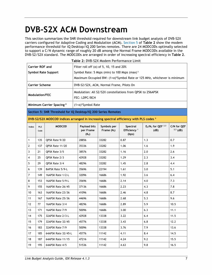
DVB-S2X ACM Downstream This section summarizes the SNR threshold required for downstream link budget analysis of DVB-S2X carriers configured for Adaptive Coding and Modulation (ACM). Section 5 of Table 2 show the modem performance threshold for iQ Desktop/iQ 200 Series remotes. There are 24 MODCODs optimally selected to support a C/N dynamic range of roughly 20 dB among the Normal Frame MODCODs available in the DVB-S2/S2X standard. The MODCODs are arranged in order of increasing spectral efficiency in Table 2.
Table 2: DVB-S2X Modem Performance Limit
Carrier ROF and
Symbol Rate Support
Filter roll off (α) of 5, 10, 15 and 20%
Symbol Rate: 5 Msps (min) to 100 Msps (max) 5
Maximum Occupied BW: (1+α)*Symbol Rate or 125 MHz, whichever is minimum
Carrier Scheme DVB-S2/S2X, ACM, Normal Frame, Pilots On
Modulation/FEC Modulation: All S2/S2X constellations from QPSK to 256APSK
FEC: LDPC/BCH
Minimum Carrier Spacing 4 (1+α)*Symbol Rate
Section 5: SNR Threshold for iQ Desktop/iQ 200 Series Remotes
DVB-S2/S2X MODCOD indices arranged in increasing spectral efficiency with PLS codes 5
Index PLS
Code
MODCOD Payload bits per Frame
(Kb)
Symbols per Frame (Ns)
Spectral Efficiency 1
(bps)
Eb/No for QEF 2,3 (dB)
C/N for QEF 2,3 (dB)
1 135 QPSK Rate 9/20 28856 33282 0.87 1.3 0.7
2 137 QPSK Rate 11/20 35336 33282 1.06 1.6 1.9
3 21 QPSK Rate 3/5 38576 33282 1.16 2.0 2.6
4 25 QPSK Rate 2/3 42928 33282 1.29 2.3 3.4
5 29 QPSK Rate 3/4 48296 33282 1.45 2.8 4.4
6 139 8APSK Rate 5/9-L 35696 22194 1.61 3.0 5.1
7 149 16APSK Rate 1/2-L 32096 16686 1.92 3.6 6.4
8 153 16APSK Rate 5/9-L 35696 16686 2.14 4.0 7.3
9 155 16APSK Rate 26/45 37136 16686 2.23 4.3 7.8
10 163 16APSK Rate 23/36 41096 16686 2.46 4.8 8.7
11 167 16APSK Rate 25/36 44696 16686 2.68 5.3 9.6
12 77 16APSK Rate 3/4 48296 16686 2.89 5.9 10.5
13 171 16APSK Rate 7/9 50096 16686 3.00 6.3 11.1
14 175 32APSK Rate 2/3-L 42928 13338 3.22 6.4 11.5
15 179 32APSK Rate 32/45 45776 13338 3.43 6.8 12.2
16 183 32APSK Rate 7/9 50096 13338 3.76 7.9 13.6
17 185 64APSK Rate 32/45-L 45776 11142 4.11 8.4 14.5
18 187 64APSK Rate 11/15 47216 11142 4.24 9.2 15.5
19 195 64APSK Rate 4/5 51536 11142 4.63 9.8 16.5
8 Link Budget Analysis Guide, iDX Release 4.1.3
20 205 256APSK Rate 29/45-L 41456 8370 4.95 10.8 17.7
21 201 128APSK Rate 3/4 48296 9576 5.04 11.7 18.7
22 209 256APSK Rate 31/45-L 44336 8370 5.30 11.8 19.0
23 211 256APSK Rate 32/45 45776 8370 5.47 12.3 19.7
24 215 256APSK Rate 3/4 48296 8370 5.77 13.2 20.8
1 Spectral efficiency (bps: bits per symbol) includes FEC, physical layer frame overhead (including Pilots and PLHEADER symbols) and Baseband Frame overhead (including BBHEADER and CRC-32). The CRC-32 field at the end of the Baseband Frame (BBFRAME) is used to check residual bit errors out of the LDPC/BCH decoder. Carrier spacing is not included in spectral efficiency calculation and bps/Hz (bits per second per Hz) efficiency can be determined from the roll-off factor α used by scaling the bps efficiency with 1/(1+α).
2 QEF (Quasi Error Free) operation is defined as BBFRAME error rate of 1e-5 for an IF-loopback (L-band). C/N is the ratio of signal power spectral density to noise power spectral density at the modem input. Performance shall not degrade by more than 0.25 dB with two adjacent identical rate carriers nominally spaced each at +7dBc for symbol rates up to 45 Msps and at +0 dBc for symbol rates above 45 Msps.
3 Eb/No = C/N - 10log10(Kb/Ns), where Kb is the number of Payload bits per Baseband Frame and Ns is the number of transmitted symbols per Physical Layer Frame. IP and other network layer packets are transported on the Baseband Frame using the highly efficient DVB-S2 Generic Stream Encapsulation (GSE) protocol. The parameter Kb does not include the moderate GSE overhead (roughly 1 to 2%).
4 Satellite operators must be consulted to determine the actual carrier spacing.
5 Symbol rates outside the defined range and MODCODs below QPSK-9/20 are not supported in iDX 4.1.3 Release. Note NMS allows MODCOD definition down to QPSK-1/4 and symbol rates outside this limit.
Link Budget Analysis Guide, iDX Release 4.1.3 9
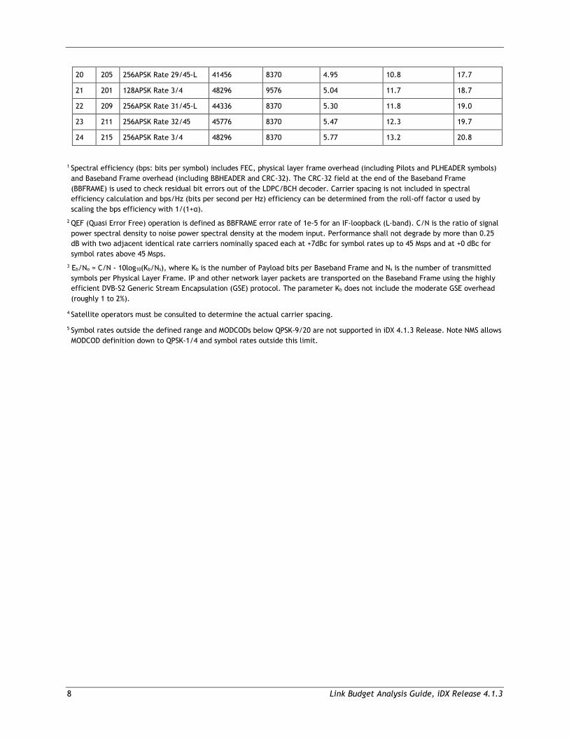
DVB-S2X Downstream Performance Graph
Downstream performance graph illustrating bits per symbol spectral efficiency versus operating carrier to noise ratio threshold is shown in Figure 2 for DVB-S2X carrier.
Figure 2: Downstream Performance Graph for DVB-S2X
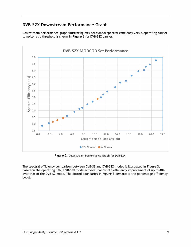
The spectral efficiency comparison between DVB-S2 and DVB-S2X modes is illustrated in Figure 3. Based on the operating C/N, DVB-S2X mode achieves bandwidth efficiency improvement of up to 40% over that of the DVB-S2 mode. The dotted boundaries in Figure 3 demarcate the percentage efficiency boost.
0.5
1.0
1.5
2.0
2.5
3.0
3.5
4.0
4.5
5.0
5.5
6.0
0.0 2.0 4.0 6.0 8.0 10.0 12.0 14.0 16.0 18.0 20.0 22.0
Spec
tral
Effi
cien
cy (b
ps)
Carrier to Noise Ratio C/N (dB)
DVB-S2X MODCOD Set Performance
S2X Normal S2 Normal
10 Link Budget Analysis Guide, iDX Release 4.1.3
Figure 3: Downstream Efficiency Comparison for DVB-S2X and DVB-S2 modes
Transmit Hub Line Cards iDX 4.1.3 Release continues to support XLC-11 and eM1D1 Transmit hub line cards for DVB-S2 outbound transmissions from 1 to 45 Msps with 16APSK-8/9 Max MODCOD. The DLC-T Defense and ULC-T Commercial series transmit hub line cards are necessary to support:
• 32APSK MODCODs in DVB-S2 mode operation • DVB-S2X mode • Linear pre-distortion for full transponder operation (both DVB-S2 / DVB-S2X modes)
Multi-Protocol Encapsulation Mode Downstream Configuration Multi-Protocol Encapsulation (MPE) mode of operation is supported as Receive only mode in 950mp/9350 series remotes. Supported MPE DVB-S2 MODCODs are QPSK and 8PSK, Normal Frames (all DVB-S2 code-rates) only with 35% filter roll off. Pilot symbols are recommended to be configured for demodulation robustness. Performance in QPSK mode (without pilots) and 8PSK modes (with pilots) comply with the standard LBA figures provided for 950mp/9350/900 series remotes in Section 3 of Table 1 for QEF operation. Standard MPE mode is not supported by any of the transmit hub line cards.
Link Budget Analysis Guide, iDX Release 4.1.3 11
2 Upstream
This chapter describes Upstream Carrier specifications for the Evolution 4.1.3 network and consists of the following sections:
• SCPC Upstream Carrier Performance Specifications
• TDMA Upstream Carrier Performance Specifications
• TDMA Upstream Modes and Throughput Limitations
12 Link Budget Analysis Guide, iDX Release 4.1.3
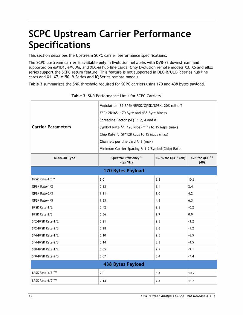
SCPC Upstream Carrier Performance Specifications This section describes the Upstream SCPC carrier performance specifications.
The SCPC upstream carrier is available only in Evolution networks with DVB-S2 downstream and supported on eM1D1, eM0DM, and XLC-M hub line cards. Only Evolution remote models X3, X5 and e8xx series support the SCPC return feature. This feature is not supported in DLC-R/ULC-R series hub line cards and X1, X7, e150, 9-Series and iQ Series remote models.
Table 3 summarizes the SNR threshold required for SCPC carriers using 170 and 438 bytes payload.
Table 3. SNR Performance Limit for SCPC Carriers
Carrier Parameters
Modulation: SS-BPSK/BPSK/QPSK/8PSK, 20% roll off
FEC: 2D16S, 170 Byte and 438 Byte blocks
Spreading Factor (SF) 1: 2, 4 and 8
Symbol Rate 1,6: 128 ksps (min) to 15 Msps (max)
Chip Rate 1: SF*128 kcps to 15 Mcps (max)
Channels per line card 1: 8 (max)
Minimum Carrier Spacing 2: 1.2*Symbol(Chip) Rate
MODCOD Type Spectral Efficiency 3
(bps/Hz) Eb/No for QEF 4 (dB) C/N for QEF 2,4
(dB)
170 Bytes Payload
8PSK Rate-4/5 6 2.0 6.8 10.6
QPSK Rate-1/2 0.83 2.4 2.4
QPSK Rate-2/3 1.11 3.0 4.2
QPSK Rate-4/5 1.33 4.3 6.3
BPSK Rate-1/2 0.42 2.8 -0.2
BPSK Rate-2/3 0.56 2.7 0.9
SF2-BPSK Rate-1/2 0.21 2.8 -3.2
SF2-BPSK Rate-2/3 0.28 3.6 -1.2
SF4-BPSK Rate-1/2 0.10 2.5 -6.5
SF4-BPSK Rate-2/3 0.14 3.3 -4.5
SF8-BPSK Rate-1/2 0.05 2.9 -9.1
SF8-BPSK Rate-2/3 0.07 3.4 -7.4
438 Bytes Payload
8PSK Rate-4/5 (6) 2.0 6.4 10.2
8PSK Rate-6/7 (6) 2.14 7.4 11.5
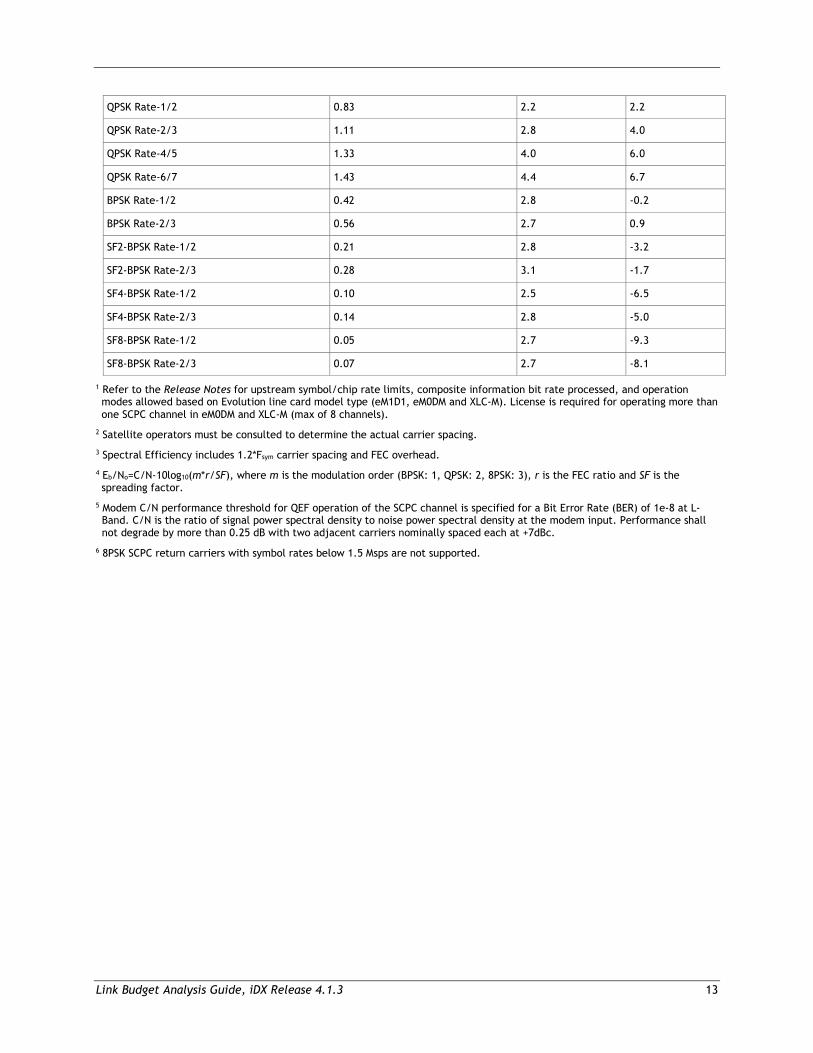
Link Budget Analysis Guide, iDX Release 4.1.3 13
QPSK Rate-1/2 0.83 2.2 2.2
QPSK Rate-2/3 1.11 2.8 4.0
QPSK Rate-4/5 1.33 4.0 6.0
QPSK Rate-6/7 1.43 4.4 6.7
BPSK Rate-1/2 0.42 2.8 -0.2
BPSK Rate-2/3 0.56 2.7 0.9
SF2-BPSK Rate-1/2 0.21 2.8 -3.2
SF2-BPSK Rate-2/3 0.28 3.1 -1.7
SF4-BPSK Rate-1/2 0.10 2.5 -6.5
SF4-BPSK Rate-2/3 0.14 2.8 -5.0
SF8-BPSK Rate-1/2 0.05 2.7 -9.3
SF8-BPSK Rate-2/3 0.07 2.7 -8.1
1 Refer to the Release Notes for upstream symbol/chip rate limits, composite information bit rate processed, and operation modes allowed based on Evolution line card model type (eM1D1, eM0DM and XLC-M). License is required for operating more than one SCPC channel in eM0DM and XLC-M (max of 8 channels).
2 Satellite operators must be consulted to determine the actual carrier spacing. 3 Spectral Efficiency includes 1.2*Fsym carrier spacing and FEC overhead. 4 Eb/No=C/N-10log10(m*r/SF), where m is the modulation order (BPSK: 1, QPSK: 2, 8PSK: 3), r is the FEC ratio and SF is the spreading factor.
5 Modem C/N performance threshold for QEF operation of the SCPC channel is specified for a Bit Error Rate (BER) of 1e-8 at L-Band. C/N is the ratio of signal power spectral density to noise power spectral density at the modem input. Performance shall not degrade by more than 0.25 dB with two adjacent carriers nominally spaced each at +7dBc.
6 8PSK SCPC return carriers with symbol rates below 1.5 Msps are not supported.
14 Link Budget Analysis Guide, iDX Release 4.1.3
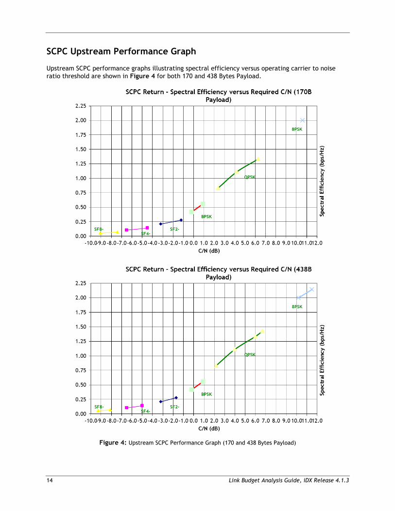
SCPC Upstream Performance Graph
Upstream SCPC performance graphs illustrating spectral efficiency versus operating carrier to noise ratio threshold are shown in Figure 4 for both 170 and 438 Bytes Payload.
Figure 4: Upstream SCPC Performance Graph (170 and 438 Bytes Payload)
Link Budget Analysis Guide, iDX Release 4.1.3 15
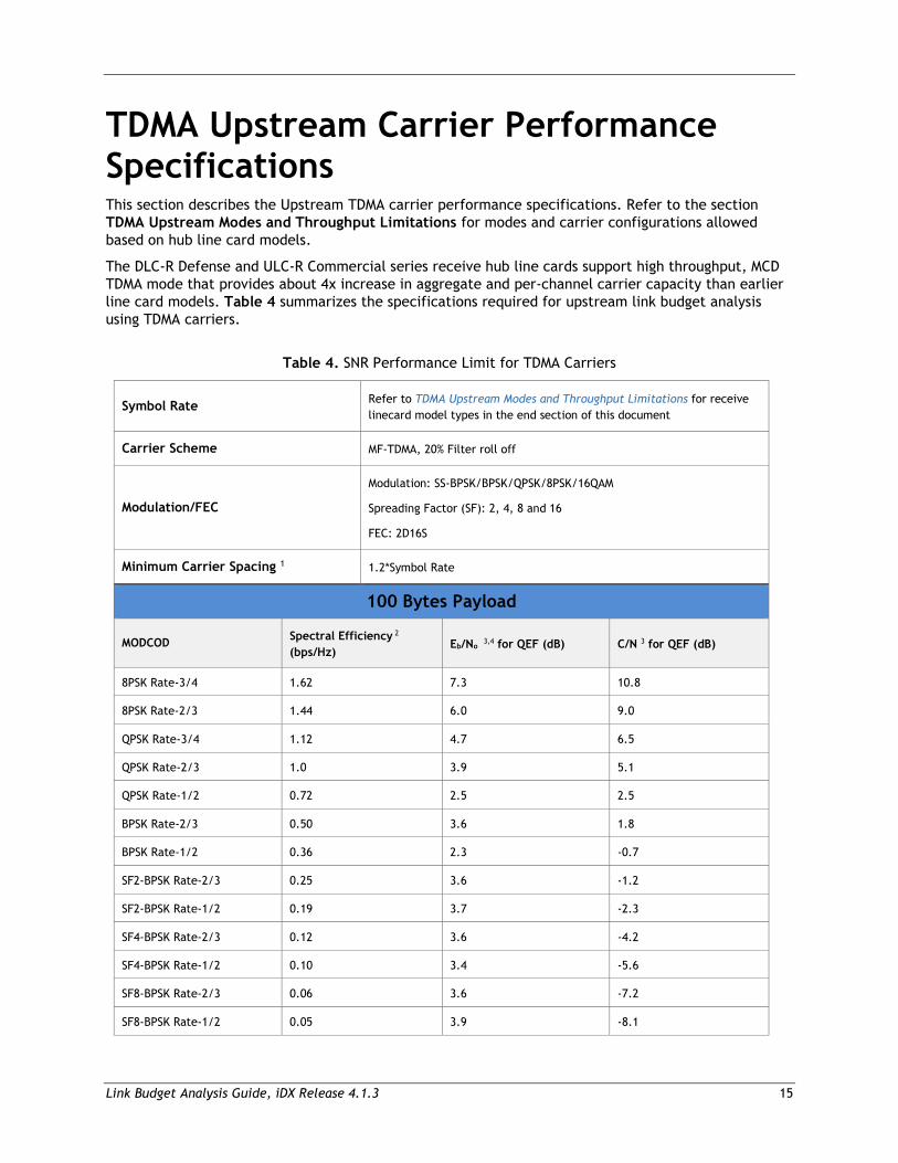
TDMA Upstream Carrier Performance Specifications This section describes the Upstream TDMA carrier performance specifications. Refer to the section TDMA Upstream Modes and Throughput Limitations for modes and carrier configurations allowed based on hub line card models.
The DLC-R Defense and ULC-R Commercial series receive hub line cards support high throughput, MCD TDMA mode that provides about 4x increase in aggregate and per-channel carrier capacity than earlier line card models. Table 4 summarizes the specifications required for upstream link budget analysis using TDMA carriers.
Table 4. SNR Performance Limit for TDMA Carriers
Symbol Rate Refer to TDMA Upstream Modes and Throughput Limitations for receive linecard model types in the end section of this document
Carrier Scheme MF-TDMA, 20% Filter roll off
Modulation/FEC
Modulation: SS-BPSK/BPSK/QPSK/8PSK/16QAM
Spreading Factor (SF): 2, 4, 8 and 16
FEC: 2D16S
Minimum Carrier Spacing 1 1.2*Symbol Rate
100 Bytes Payload
MODCOD Spectral Efficiency 2
(bps/Hz) Eb/No 3,4 for QEF (dB) C/N 3 for QEF (dB)
8PSK Rate-3/4 1.62 7.3 10.8
8PSK Rate-2/3 1.44 6.0 9.0
QPSK Rate-3/4 1.12 4.7 6.5
QPSK Rate-2/3 1.0 3.9 5.1
QPSK Rate-1/2 0.72 2.5 2.5
BPSK Rate-2/3 0.50 3.6 1.8
BPSK Rate-1/2 0.36 2.3 -0.7
SF2-BPSK Rate-2/3 0.25 3.6 -1.2
SF2-BPSK Rate-1/2 0.19 3.7 -2.3
SF4-BPSK Rate-2/3 0.12 3.6 -4.2
SF4-BPSK Rate-1/2 0.10 3.4 -5.6
SF8-BPSK Rate-2/3 0.06 3.6 -7.2
SF8-BPSK Rate-1/2 0.05 3.9 -8.1
16 Link Budget Analysis Guide, iDX Release 4.1.3
SF16-BPSK Rate-2/3 0.03 3.9 -9.9
SF16-BPSK Rate-1/2 0.02 3.9 -11.2
170 Bytes Payload
MODCOD 6 Spectral Efficiency 2
(bps/Hz) Eb/No 3,4 for QEF (dB) C/N 3 for QEF (dB)
16QAM Rate-6/7 2.56 8.6 14.0
16QAM Rate-4/5 2.40 7.5 12.6
16QAM Rate-3/4 2.24 7.3 12.1
8PSK Rate-6/7 1.85 8.2 12.3
8PSK Rate-4/5 1.73 7.0 10.8
8PSK Rate-3/4 1.62 6.3 9.8
8PSK Rate-2/3 1.44 5.4 8.4
QPSK rate-6/7 1.33 5.5 7.8
QPSK Rate-3/4 1.17 4.2 6.0
QPSK Rate-2/3 1.00 3.1 4.3
QPSK Rate-1/2 0.75 2.2 2.2
BPSK Rate-2/3 0.52 3.1 1.3
BPSK Rate-1/2 0.36 1.9 -1.1
438 Bytes Payload 6
MODCOD 6 Spectral Efficiency 2
(bps/Hz) Eb/No 3,4 for QEF (dB) C/N 3 for QEF (dB)
16QAM Rate-6/7 2.66 7.8 13.2
16QAM Rate-4/5 2.49 7.0 12.1
16QAM Rate-3/4 2.33 6.3 11.1
8PSK Rate-6/7 2.00 7.6 11.7
8PSK Rate-4/5 1.87 6.4 10.2
8PSK Rate-2/3 1.56 4.9 7.9
QPSK rate-6/7 1.33 4.3 6.6
QPSK Rate-4/5 1.24 3.7 5.7
QPSK Rate-2/3 1.04 2.8 4.0
QPSK Rate-1/2 0.75 2.0 2.0
BPSK Rate-2/3 0.52 3.1 1.3
BPSK Rate-1/2 0.36 1.9 -1.1
Link Budget Analysis Guide, iDX Release 4.1.3 17
Acquisition Burst 5
MODCOD Spectral Efficiency Eb/No for QEF (dB) C/N 3 for QEF (dB)
Superburst (BPSK RM FEC) N/A N/A -2.0
Traditional (legacy) Same as MODCOD and payload employed for traffic slots in the carrier
1 Satellite operators must be consulted to determine the actual carrier spacing. The carrier spacing is 1.2*Chip rate for spread carriers where the Chip Rate is determined as SF*Symbol Rate.
2 Spectral Efficiency includes 1.2*Fsym carrier spacing, FEC and TDMA burst overhead to aid burst detection and synchronization. This does not include the guard band between traffic slots and the acquisition slot duration that roughly amounts 2 to 3% loss based on symbol rates and MODCODs.
3 Modem C/N performance threshold for QEF operation of the TDMA channel is specified for a Cell Loss Rate (CLR) of 1e-5 at L-Band. C/N is the ratio of signal power spectral density to noise power spectral density at the modem input. Performance shall not degrade by more than 0.25 dB with two adjacent carriers nominally spaced each at +7dBc.
4 Eb/No=C/N-10log10(m*r/SF), where m is the modulation order (BPSK: 1, QPSK: 2, 8PSK: 3), r is the FEC ratio and SF is the spreading factor. This does not include TDMA burst pilot overhead, traffic guard band and acquisition slot duration – loss in Eb/No due to these factors is bounded within 0.8 dB based on payload size and MODCOD. Customers are encouraged to compute TDMA link budgets based on C/N thresholds specified and iNPT tool be referred for network throughput requirements.
5 Acquisition is supported through either superburst or traditional traffic burst. Superburst waveform uses Reed-Muller (RM) FEC codes with BPSK modulation and facilitates fast acquisition of remotes due to its high frequency error tolerance and C/N robustness compared to traditional acquisition.
6 16QAM feature is supported in ULC-R/DLC-R line cards and iQ Desktop/iQ 200 Series remotes only.
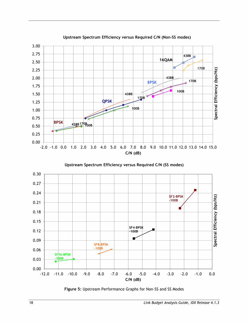
TDMA Upstream Performance Graph
Upstream TDMA performance graphs illustrating spectral efficiency versus operating C/N ratio threshold are shown in Figure 5 for non-SS and SS modes with payload sizes supported.
18 Link Budget Analysis Guide, iDX Release 4.1.3
Figure 5: Upstream Performance Graphs for Non-SS and SS Modes
0.00
0.25
0.50
0.75
1.00
1.25
1.50
1.75
2.00
2.25
2.50
2.75
3.00
-2.0 -1.0 0.0 1.0 2.0 3.0 4.0 5.0 6.0 7.0 8.0 9.0 10.0 11.0 12.0 13.0 14.0 15.0
Spec
tral
Eff
icie
ncy
(bps
/Hz)
C/N (dB)
Upstream Spectrum Efficiency versus Required C/N (Non-SS modes)
170B
QPSK
8PSK
BPSK 438B 100B
170B
170B438B
438B
100B
100B
16QAM438B
0.00
0.03
0.06
0.09
0.12
0.15
0.18
0.21
0.24
0.27
0.30
-12.0 -11.0 -10.0 -9.0 -8.0 -7.0 -6.0 -5.0 -4.0 -3.0 -2.0 -1.0 0.0
Spec
tral
Eff
icie
ncy
(bps
/Hz)
C/N (dB)
Upstream Spectrum Efficiency versus Required C/N (SS modes)
SF16-BPSK-100B
SF8-BPSK-100B
SF4-BPSK-100B
SF2-BPSK-100B
Link Budget Analysis Guide, iDX Release 4.1.3 19
TDMA Upstream Modes and Throughput Limitations This section provides carrier size restrictions, carrier properties, and model types supported based on the TDMA operating mode of the Evolution receive line card with applicable licenses.
Single Channel TDMA Static, Non-Spread (XLC-11, XLC-M, eM1D1 and eM0DM)
• All payload types supported (100/170/438 Bytes).
• For 100B payloads, maximum symbol rate is 2 Msps across all MODCODs.
• For 170B payloads, maximum symbol rate is 3.1, 4.25 and 7.5 Msps for 8PSK, QPSK and BPSK MODCODs, respectively.
• For 438B, maximum symbol rate is 7.5 Msps across all MODCODs.
• Acquisition type supported is traditional for static configuration mode. MODCOD of the carrier remains static in this operating mode across the IGCs.
Single Channel TDMA Adaptive, Non-Spread (eM1D1)
• All payload types supported (100/170/438 Bytes).
• For 100B payloads, maximum symbol rate is 3.5 Msps for 8PSK MODCODs and 5.875 Msps for QPSK and BPSK MODCODs.
• For 170B and 438B payloads, maximum symbol rate is 5.875 Msps across all MODCODs.
• Acquisition type supported is traditional or superburst in adaptive configuration mode. In this operating mode, MODCOD of the carrier can change dynamically if configured to change across the IGCs.
Single Channel TDMA, Spread (XLC-11, eM1D1)
• Only 100B payload mode with BPSK MODCOD is supported. Maximum chip rate is 7.5 Mcps.
• Maximum symbol rate is 3.75, 1.875, 0.9375 and 0.46875 Msps for Spreading Factors of 2, 4, 8 and 16, respectively.
• Acquisition type supported is traditional in spread configuration mode. MODCOD of the carrier remains static in this operating mode across the IGCs.
Multi-Channel TDMA, Non-Spread (XLC-M, eM0DM)
• All payload types supported (100/170/438 Bytes).
• Maximum composite symbol rate, aggregate of all carriers assigned to the line card, is 7.5 Msps.
• Number of channels per line card is 1 (default), licensable up to 4 and up to 8 in standard modes.
• For 100B payloads, per channel maximum symbol rate is 3.5 Msps for 8PSK MODCODs and 5.875 Msps for QPSK and BPSK MODCODs.
• For 170B and 438B payloads, per channel maximum symbol rate is 5.875 Msps across all MODCODs.
• Acquisition type supported is traditional or superburst in adaptive configuration mode for up to 8 channels and cannot be mixed. MODCOD of the carrier can change dynamically, if configured to change across the IGCs, in this operating mode.
20 Link Budget Analysis Guide, iDX Release 4.1.3
• For the 16 channel narrowband case, per channel maximum symbol rate is 468.75 ksps and acquisition type is traditional.
Single Channel TDMA, Spread (DLC-R, ULC-R)
• 100B payload mode with BPSK MODCOD is supported. Maximum chip rate is 7.5 Mcps.
• Maximum symbol rate is 3.75, 1.875, 0.9375 and 0.46875 Msps for Spreading Factors of 2, 4, 8 and 16, respectively.
• Acquisition type supported is traditional in spread configuration mode. MODCOD of the carrier remains static in this operating mode across the IGCs.
Multi-Channel TDMA, Non-Spread (DLC-R, ULC-R)
• Maximum composite symbol rate, aggregate of all carriers assigned to the line card in MCD mode, is 29.0 Msps.
• Maximum number of channels is 16.
• Minimum and Maximum symbol rate per channel are 0.128 and 7.5 Msps respectively.
• 100/170/438B payload types supported with BPSK/QPSK/8PSK MODCODs. 170/438B payload types supported with 16QAM MODCODs.
• Acquisition type supported is traditional or superburst for up to 8 channels and cannot be mixed in MCD mode. For >8 channels, only traditional acquisition is supported.
• MODCOD of the assigned carrier in MCD mode can be kept static or adaptive across the IGCs.
• Evolution Mesh receiver features ULC-R in Multi-Channel TDMA, non-spread mode of operation.
Multi Wide-Channel (WC) TDMA, Non-Spread (DLC-R, ULC-R)
• Maximum composite symbol rate, aggregate of all carriers assigned to the line card in MCD WC mode, is 29.0 Msps.
• Maximum number of channels is 16.
• Minimum and Maximum symbol rates per channel are 0.512 and 29 Msps respectively.
• 100B payload: Not supported.
• 170B payload: Supported till 15 Msps symbol rate maximum. For 8PSK and 16QAM MODCODs only, the maximum symbol rate is restricted by the maximum slots per frame system processing limit of 1998. Approximate 8PSK max symbol rate limits are 11.7, 12.5, 13.4 and 15 Msps for code rates of 6/7, 4/5, 3/4 and 2/3 respectively to be within the slots per frame limit. Approximate 16QAM max symbol rate limits are 8.4, 9.0 and 9.6 Msps for code rates of 6/7, 4/5 and 3/4 respectively to be within the slots per frame limit.
• 438B payload: Supported till 29 Msps symbol rate maximum. For 8PSK and 16QAM MODCODs only, the maximum symbol rate is restricted by the maximum slots per frame system processing limit of 1998. Approximate 8PSK max symbol rate limits are 27.9, 29, 29 Msps for code rates of 6/7, 4/5 and 2/3 respectively to be within the slots per frame limit. Approximate 16QAM max symbol rate limits are 20.9, 22.4 and 23.9 Msps for code rates of 6/7, 4/5 and 3/4 respectively to be within the slots per frame limit.
• Acquisition type supported is traditional or superburst for up to 8 channels and cannot be mixed in MCD WC mode. For >8 channels, only traditional acquisition is supported.
• MODCOD of the assigned carrier in MCD WC mode can be kept static or adaptive across the IGCs.
Link Budget Analysis Guide, iDX Release 4.1.3 21
Minimum TDMA Symbol Rates (All operating modes and line card types)
• 100B payload: 128 ksps for SS-BPSK/BPSK/QPSK/8PSK
• 170B payload: 128 ksps for BPSK/QPSK/8PSK
• 438B payload: 384 ksps for BPSK; 256 ksps for QPSK/8PSK
• DLC-R/ULC-R Only:
o When a line card is configured for Multi Wide-Channel TDMA mode with 170B/438B payload types, the minimum symbol rate allowable for any carrier assigned to it is 512 ksps, independent of payload size and MODCOD.
o 170B payload: 128 ksps for 16QAM
o 438B payload: 256 ksps for 16QAM
22 Link Budget Analysis Guide, iDX Release 4.1.3
3 System Guidelines
This chapter describes System Guidelines for the Evolution 4.1.3 network and consists of the following sections:
• DVB-S2/S2X ACM System Guidelines
• Adaptive TDMA System Guidelines
Link Budget Analysis Guide, iDX Release 4.1.3 23
DVB-S2/S2X ACM System Guidelines This section explains how DVB-S2/S2X Adaptive Coding and Modulation (ACM) is implemented in an iDirect network.
Satellite network systems that use Constant Coding and Modulation (CCM) on the downstream are typically designed to include a 1 dB to 2 dB steady-state margin at the worst-case service area (defined by the Edge of Coverage EIRP) and to meet worst-case propagation conditions (typically determined by the target link availability) with the minimum antenna size used in the network (as dictated by link closure for the upstream channel). This kind of network design can result in the occurrence of high power margins for most of the remotes during most of the time (up to 95%). The margin is typically near 6 dB to 8 dB, since a difference of at least 4 dB exists between the peak antenna gain at beam center as compared to edge of coverage EIRP, and since the rain fade curves can be particularly steep (99.0% to 99.9% availability), depending on the rain region. iDirect’s Adaptive Coding and Modulation (ACM) system can use the otherwise unused (and unavailable) power margin in CCM systems to increase the system throughput to remotes that experience favorable Signal-to-Noise Ratio (SNR) conditions due to a remote’s location, antenna size, and channel conditions. Under nominal conditions, the ACM control loop adapts the coding and modulation every five seconds at each remote to match the path conditions in real-time. Under steady-state conditions, the remote operates at a margin of 0.5 dB. Under fast-fade conditions, the ACM control loop adaptation rate increases to every one second. An additional margin of 1.0 dB above the steady-state margin is used for the modulation/coding combinations (MODCODs) assigned to the remote during these conditions. The margin reverts to the default steady-state value once the fast-fade condition ends. The system can manage a fade slope of 0.5 dB/s, which is typical in severe rain regions of the world.
In addition to the margin added to the SNR threshold during operation, the system must also account for the variance, or margin of error, associated with the remote SNR measurement. To account for this margin of error, an additional 0.2 dB is added to the SNR threshold when determining when to switch between MODCODs. This error margin is added in both steady state and fade conditions.
By default, both steady-state margin and fast-fade margins are set at 0.5 dB and 1.0 dB, respectively. You can change these values by setting custom parameters for the network. To operate all remotes close to the thresholds stated within this Link Budget Analysis, set both steady-state margin and fast-fade margins to zero. The procedure for setting the DVB-S2/S2X margins for steady state and fade conditions is contained in the section “DVB-S2/S2X Network Parameters” of the iBuilder User Guide.
Broadcast signaling information for synchronization of the upstream channel, the burst time plan assignments, and other data that is categorized as high-priority traffic and vital for network operation are sent on the lowest MODCOD setting for the network. Data transmitted to a remote is sent in a higher MODCOD (within the maximum MODCOD set for the network) as appropriate for channel conditions. It is critical that the minimum MODCOD is carefully evaluated to ensure reliable reception by all remotes in the network. To achieve targeted link availability, this evaluation should be based on a remote’s location within the satellite foot print, available G/T, and amount of predicted rain fade depth that is characteristic for the region where the remote is located.
24 Link Budget Analysis Guide, iDX Release 4.1.3
Adaptive TDMA System Guidelines This section provides a brief overview of the manner in which adaptive TDMA transmission is implemented in the iDirect system. For a more in-depth explanation, please refer to the Technical Reference Guide.
The upstream channel is subject to the same propagation phenomena and impairments as discussed in this guide for the downstream DVB-S2 ACM operation. Without adaptivity to the channel conditions, resources would have to be set aside permanently as a safeguard against these phenomena. The iDirect system implements fade mitigation techniques in the upstream that are similar in nature to the ACM in the downstream. There are, however, some differences dictated by the different nature of the air interface (TDMA vs. continuous TDM).
The core element of iDirect’s adaptive TDMA system is a heterogeneous group of TDMA carriers, known as an Inroute Group, which is managed as a single entity. These carriers support different transmission rates and provide different levels of protection (MODCOD) against adverse channel effects such as rain fade. Individual terminals are assigned time slots on carriers commensurate with their need and with their instantaneous capability, as determined by the channel state. A control process continuously monitors the channel state of each remote. In a manner similar to that used for the downstream, the control process speeds up when rapid fade variation is detected and slows down when the situation is more stable. This serves to keep the required margins small and constant. The process also manages transmit power control for the remote.
The link margin required for adaptive operation is relatively small. It needs to account for propagation variation only to the extent that this can vary in the time it takes for the system to detect changes and react. This reaction time is typically 2–3 seconds. The corresponding “reaction time margin” is referred to as M1 in the NMS. There is a further margin, called M2 or “hysteresis margin”, which serves to prevent spurious equivocation between carrier choices. The control loop will attempt to adjust the carrier choice and transmit power such that the power available from the remote is well utilized and the C/N on any carrier used is equal to the values given in Table 4, plus M1 + M2. Refer to the Release Notes for the default values of M1 and M2.
In order to maximize the resource utilization, a remote may transmit on several different carriers within a single TDMA frame considered viable by the uplink control process. Different carriers typically require different transmitted power. This variation is too fast for the closed-loop power control loop. An open-loop adjustment is applied to account for this.
In addition, the configuration of the Inroute Group is adjusted over time to maximize the system efficiency. Depending on the number of faded remotes at any time, there will be a higher or lower demand for more-protected carriers. To account for this, a separate process periodically (typically every 30 seconds; this is configurable) assesses the suitability of a number of pre-defined compositions of the Inroute Group and selects the best one for use in the next period. This assessment can also be triggered by sudden, excessive mismatch between the requested and offered capacity. In the current implementation, only the MODCOD of carriers can vary between compositions. The payload block size, the number of carriers, and their frequencies and symbol rates must be the same in all compositions.
Design of the Inroute Group Compositions (IGC), including choice of suitable symbol rates and MODCOD combinations, is an integral part of the overall network design.