Embed Size (px)
Citation preview

LES/CMC predictions of spark ignition probability in
a liquid fuelled swirl combustor
A. Tyliszczak� and E. Mastorakosy
Department of Engineering, University of Cambridge, CB2 1PZ, United Kingdom
The Large Eddy Simulation / Conditional Moment Closure approach with closures forthe spray terms appearing in the CMC equation and for the mixture fraction sub-gridvariance has been used to predict ignition probability, Pign, for a swirling spray amefor which relevant experimental data are available. The localised spark was modelled as asmall region where the conditionally averaged reactive scalars were kept constant for a shorttime. For each of 20 locations across the ow, Pign was estimated by launching 16 separatesimulations from di�erent cold- ow realisations and monitoring the ame evolution. Thepredicted large variability in ignition behaviour, the overall time for ame expansion, andthe spatial distributions of Pign agree qualitatively well with the experiment. The failureof a ame kernel to grow is traced to high scalar dissipations in the spark neighbourhood,which in turn depends on the mixture fraction sub-grid variance model, showing that thespray a�ects both quantities and that the corresponding models need further validation.
I. Introduction
Large Eddy Simulation (LES) is increasingly being used for challenging combustion phenomena, includ-ing transient processes such as thermoacoustic instabilities,1,2 localised extinction,3,4 and spark ignition.5{9
In LES the large ow scales are directly resolved on the numerical mesh whilst the small scales, the so-calledsub-grid scales, are �ltered out and their in uence on the ow �eld is modelled.10 In the case of two-phase ows, which are present in liquid-fuelled burners, the interactions between turbulence and liquid fuel makenumerical simulations very complicated.
Spark ignition is very important for propulsion technologies in general and high-altitude relight of gasturbine combustors is obviously of extreme importance for aviation. Predicting spark ignition in liquid fu-elled systems is very challenging as it is in uenced by a range of interlinked phenomena including dropletdispersion and evaporation, mixing of fuel vapour with air, chemical reaction induced by the spark, andthe ame evolution following the initial generation of a kernel.11,12 A particularly important experimentalobservation is the large variability seen between individual spark events, which has been attributed to localprocesses at the spark vicinity, but also to unfavourable convection that can move a kernel out of the burnerbefore the ame grows to �ll the whole combustor. As a consequence, the resulting ignition probability, Pign,de�ned as the percentage of sparks ending in successful overall ignition, has very strong spatial variationsand is a very challenging quantity to predict.
Experimental and numerical studies of forced ignition with gaseous fuels have focussed on the axisym-metric jet that has been studied both experimentally13 and by the corresponding LES7,8 and on blu�-body ames.5,6, 14 Both experiment and simulation revealed the large variation in the behaviour of a spark, al-though none of the previous LES studies performed enough simulations from which Pign could be compiled.
For spray ames, Pign has been examined experimentally as a function of spark parameters and loca-tions.12 The ames studied in Ref.12 were relatively easy to ignite as they were at conditions far fromthe weak extinction limit. Extending this work to conditions with higher velocities and using non-intrusivelaser ignition rather than electrodes,15,16 it was found that even the large kernels created by powerful laserbreakdown still resulted in signi�cant Pign spatial variations. The physical �ndings above have been used toconstruct a physical model for spark ignition and for Pign in gas turbine combustors.17
�Presently: Institute of Thermal Machinery, Czestochowa University of Technology, PolandyAssociate Fellow AIAA. Professor of Energy Technologies. Email: [email protected]
1 of 11
American Institute of Aeronautics and Astronautics
51st AIAA Aerospace Sciences Meeting including the New Horizons Forum and Aerospace Exposition07 - 10 January 2013, Grapevine (Dallas/Ft. Worth Region), Texas
AIAA 2013-0427
Copyright © 2013 by Epaminondas Mastorakos. Published by the American Institute of Aeronautics and Astronautics, Inc., with permission.
Dow
nloa
ded
by E
pam
inon
das
Mas
tora
kos
on J
anua
ry 1
7, 2
013
| http
://ar
c.ai
aa.o
rg |
DO
I: 1
0.25
14/6
.201
3-42
7

The present work aims to simulate spark ignition of a swirling n-heptane spray ame applying LES andthe CMC combustion model. Our focus is on the direct prediction of Pign by performing many individualLES simulations starting from di�erent realisations of the cold ow, which has not been done before withLES, and, in terms of model development, on the spray e�ects in the combustion model.
II. Methods and ow con�guration
A. CMC for sprays
Mortensen and Bilger18 derived the CMC equations for spray combustion. Here, we consider the �nal formof the equations and some special models needed to account for evaporation in the mixture fraction andthe CMC equations. These models have been discussed in the context of RANS for autoignition19 and areextended here to LES.
For a dilute spray, the CMC equations are:18
@Q�@t
+ guj j� @Q�@xj
= e� + gN j� @2Q�@�2
+g_!j� + ��;fg�j� � �Q� + (1� �)@Q�@�
�g�j� (1)
where Q� = gY�j� is the conditionally �ltered mass fraction of species � and guj j�, gN j�, g_!j�, g�j� are theconditionally �ltered velocity, scalar dissipation rate, reaction rate and the mass evaporation rate. TheKronecker delta, ��;f is equal to one for fuel and zero otherwise. The species equations (1) are complementedwith the equation for temperature or enthalpy.18,19 The terms e�, g_!j�, guj j�, gN j� are closed with the usualmodels.20,21 We focus below on the modelling of the conditional evaporation rate g�j� and the mixturefraction variance f�002, which is then used in the evaluation of the conditional scalar dissipation calculatedusing the Amplitude Mapping Closure (AMC) with the �ltered scalar dissipation rate.21,22
The mixture fraction variance is often modelled as f�002 = CV �2 @e�@xj
@e�@xj
, where � is the mixture fraction,
� is the LES �lter width (taken as V 1=3 where V is the local cell volume), and CV is a parameter whosevalue may be computed dynamically or may be a �xed constant.23 In two-phase ows the above formulafor f�002 is expected to be fairly correct when the evaporation rate is low and the turbulent scalar mixing isthe dominant process. In cases of strong evaporation one should expect that a high vapour concentrationclose to the droplet surface may a�ect f�002. Assuming equilibrium between production, dissipation and spraysource terms, the mixture fraction variance is modelled as:24
��f�002 = C�
CV ���2 @
e�@xj
@e�@xj
+�2
�tg�00�00! (2)
where �t is the turbulent viscosity and �00 is the uctuation of the evaporation rate. This model requiresdetermination of C� and CV as well as a closure for the �ltered uctuations of the mixture fraction andevaporation rate (discussed later). Estimations of C� and CV revealed to be troublesome24 even in simplehomogeneous ow and even with g�00�00 extracted from DNS. Hence, one may expect that in more complexinhomogeneous ows a dynamic estimate of C� and CV would be questionable as well. Therefore, forsimplicity here we assumed CV = 0:1, as suggested by Branley and Jones25 for gaseous ows, while C� wasset arbitrarily equal to one. A model for g�00�00 in Eq. (2) is discussed below.
Due to lack of consensus on how to model g�00�00 and g�j� these terms are often neglected arguing that theymay be considered as small.26,27 Existing approaches for g�j� include a single droplet model (SDM)28 and amodel formulated recently19 for RANS simulation. In the framework of LES, by implication the followingmodel is proposed: g�j� = e� �(� � ��s)=P(��s) (3)
where �s is the value of the fuel mass fraction at saturation (evaluated at the droplet temperature) and Pis the �ltered density function of the mixture fraction. In the context of RANS, P is the mixture fractionPDF19 and was presumed by a user-de�ned de�ned blending of the classical �-function and a ��functiondependent on parameters of the spray.19 In present work, we simplify P and we use the PDF as de�ned byGe and Gutheil29 where the classical �-function PDF was modi�ed taking into account the local values of
2 of 11
American Institute of Aeronautics and Astronautics
Dow
nloa
ded
by E
pam
inon
das
Mas
tora
kos
on J
anua
ry 1
7, 2
013
| http
://ar
c.ai
aa.o
rg |
DO
I: 1
0.25
14/6
.201
3-42
7

�s. Integration of Eq. (3) leads to the unconditionally �ltered values e� = 1V
PNp
i=1 _mi, where V is the volumeof the cell containing Np droplets, and _mi is the mass evaporation rate of the i�th droplet. In Eq.(3) weuse the mean saturated mixture fraction ��s computed as the average over all droplets in each computationalvolume V .Given the conditional evaporation rate from Eq.(3), g�00�00 in Eq. (2) can be found. Using
g�00�00 = f��� e� e� =Z 1
0
�g�j� eP(�)d� � e� e� (4)
with Eq. (3), and applying the shifting property of the delta-function we obtain:
g�00�00 = f��� e� e� = ��se�� e�e� (5)
Modelling of f�� as ��se� is similar to the model of Demoulin and Borghi30 where f�� = 1V
PNp
i=1 �s; i _mi wassuggested. The basic behaviour of the model of Eq. (5) has been analysed by solving the equations for massand energy of the droplets31{33 in a motionless volume of hot air. The results obtained show close similarityto previous results,28 where the mixture fraction variance computed with the source term resulting fromspray and without this term were compared through DNS.
B. Numerical methods and ow considered
Concerning the LES, a 2nd-order �nite volume incompressible solver called PRECISE was used21,34 withthe Smagorinsky subgrid model. The liquid phase was tracked using a Lagrangian formulation with two-waycoupling.31{33
Following common practice in LES-CMC,21,22 two di�erent computational meshes were used, the �nerone for the LES solver and the coarse one for the CMC. The CMC equations were solved applying theoperator splitting approach where the transport in physical space, transport in mixture fraction space andchemistry are solved separately. Time integration in physical space was performed with a �rst order explicitEuler method, supplemented with an automatic time step reduction algorithm. In mixture fraction spacethe CMC equations were integrated applying the VODPK35 solver that is well suited for sti� systems.
The reaction was modelled by a modi�ed one-step chemistry for heptane. The modi�cations are basedon a tuning of the heat release rate as a function of the local equivalence ratio,36 to give approximatelythe correct ame speed and temperature across the whole ammable range. It has been shown that thisprocedure also gives a reasonable extinction scalar dissipation for non-premixed ames.37
The computational domain is shown in Fig. 1a. It consisted of a circular duct of inner diameter D = 37mm �tted with a conical blu� body of diameter Db = 25 mm, shown in Fig. 1b. A 60� swirler was located40 mm upstream of the blu� body. A hollow-cone atomiser was placed inside the blu� body and injectedheptane. Available experimental data include air velocity in the absence of fuel ow and the probabilityof ignition determined at di�erent location in the combustion chamber.16 Also, from chemiluminescencerecords, the time taken to fully establish the ame has been estimated.
The computational domain consisted of a block-structured mesh with approximately 3 � 106 cells. Thespray injection was modelled by injecting the spray droplets through 64 slots located on a circle of 0:15 mmdiameter. Ten classes of droplet diameters were computed from a Rossin-Ramler distribution with a meanSauter diameter equal to 30�m. The CMC equations in mixture fraction space were discretized in 51 nodesstretched in the vicinity of the stoichiometric mixture fraction. The physical domain for the CMC meshwas limited to the combustion chamber only and it consisted of a Cartesian mesh with 30� 60� 30 nodes.Except for a region close to the blu� body, the CMC mesh was stretched to provide a good resolution witha relatively small number of nodes.
C. Initialisation and spark modelling
The ow �eld was initialised with a uniform temperature 295 K and zero fuel mass fraction. The solutionprocedure started with the simulation with only air ow, and then, after the ow had fully developed,statistics were collected to compare with available air-only velocity measurements. The spray was theninjected and the computations were continued until the spray spread in the combustion chamber. Thisconstituted the un-ignited ow solution, which was stored at a large number of timesteps to representdi�erent realisations of the ow. The spark was then initialised.
3 of 11
American Institute of Aeronautics and Astronautics
Dow
nloa
ded
by E
pam
inon
das
Mas
tora
kos
on J
anua
ry 1
7, 2
013
| http
://ar
c.ai
aa.o
rg |
DO
I: 1
0.25
14/6
.201
3-42
7

Detailed simulation of spark ignition from electrodes or laser breakdown is a di�cult task that is beyondthe scope of the present work. Here, we model the spark in a very simpli�ed manner because we are interestedin what happens after the energy deposition process has �nished. The motivation behind this choice is theexperimental observation that in virtually all locations with even very small amounts of fuel, the verypowerful laser spark always produced a visible kernel, which could then either grow or extinguish.15,16 In agiven volume representing the spark, the overlapping nodes of the CMC mesh were given a steady amelet(burning) solution that was pre-computed for a maximum scalar dissipation rate equal to 20 s�1. During ashort time (taken as 0.5 ms), this distribution is prescribed at the beginning of each time step and then theCMC equations are solved for all CMC nodes. The initial volume that is considered as \burnt" is a sphereof diameter 5 mm, corresponding to the estimated size of the kernel from the images from the experiment.16
For stability reasons, it was necessary to apply relaxation on the density returned to the LES code from theCMC code during the �rst few iterations and to exponentially smooth the shape of the spark in space.
(a) (b)
Figure 1. (a) Computational domain with the boundary conditions indicated. (b) Details of the blu� body.
III. Results and Discussion
A. Cold ow
Assessment of the correctness of the boundary conditions, the mesh quality and the accuracy of LES mod-elling was done for the cold ow without spray (no experimental data are available for the spray). Thepro�les of mean axial, radial and tangential velocity components and RMS of axial velocity are shown inFig. 2. These results are in very good agreement with experimental data both close to the blu� body at adistance z = 8 mm as well as further downstream at z = 33 mm. We may conclude that the aerodynamicsin the burner are captured well.
B. Ignition modelling - successful spark
The droplets found in the spark region experience a high temperature rise and evaporate quickly, the mixturefraction FDF builds up, and the resolved temperature rises. The neighbouring CMC cells feel the burningstate by the terms in the CMC equation representing convection/di�usion in physical space. If there areconducive conditions, the ame propagates further and more fuel evaporates, as presented in Fig. 3 andFig. 4. Initially the spark region included 3� 3� 3 CMC cells but at the end of the ignition the ame hasalready expanded in all directions as shown in Fig. 3a which includes also the CMC mesh. The expanding ame generates mixture fraction, which becomes very rich close to the spray cone.
4 of 11
American Institute of Aeronautics and Astronautics
Dow
nloa
ded
by E
pam
inon
das
Mas
tora
kos
on J
anua
ry 1
7, 2
013
| http
://ar
c.ai
aa.o
rg |
DO
I: 1
0.25
14/6
.201
3-42
7

Figure 2. Pro�les of the mean axial, radial and tangential velocity and RMS of the axial velocity at a distancez = 8 mm and z = 33 mm from the blu� body: solid line - numerical data; symbols - experimental data.38
A three-dimensional view of the temperature isosurface T = 2100 K immediately after the spark hasbeen switched o� is presented in Fig. 5a. The nearly spherical shape survives for only a short time, the owand interactions with the neighbouring cells rapidly deform the initial kernel. In these particular results, thespark was located in a place resulting in good ignition behaviour (i.e. on the burner axis, 18 mm from theblu� body), and therefore the ame spreads over the cells and eventually stabilises close to the blu� bodysurface as shown in Fig. 5b. The time taken to fully establish the ame is around 15 ms, which compareswell with the measured time.15
The simulated ame spreading is a�ected by the convective and di�usive terms of the CMC equationsas well as the encountered mixture fraction and its variance, scalar dissipation rate, and evaporation rate.Figure 5a shows two cells pointed by the arrows. In these cells we compare the results in mixture fractionspace obtained with f�002 given by Eq. (2) with and without the term g�00�00. The marked cells are denotedas Cell ’A’, which is the neighbour of a cell inside the spark, and Cell ’B’, which is located downstreamof ’Cell ’A’. The time evolution of the conditional temperature is shown in Fig. 6. During a �rst stage, arise of temperature in the cells ’A’ and ’B’ is caused by the transport in physical space which is manifestedby a shape of the pro�les similar to the initial amelet used in the region of spark. This demonstrates thetransport of heat from the spark to this point. At some stage, a sudden rise occurs, which demonstratesignition of this point. In cell ’A’ the temperature obtained neglecting the in uence of g�00�00 rises faster, butthe di�erences are not signi�cant. In cell ’B’ the in uence of g�00�00 is much more pronounced and, as a result,during the duration of the spark, ignition has not occurred yet in that cell.
Direct comparison of the conditional scalar dissipation rate at stoichiometry and the mixture fractionvariance (f�002�) in cell ’B’ (i.e. the quantities supplied to the CMC code from the LES21) are shown in Fig. 7.It is clear that inclusion of g�00�00 considerably increases the level of scalar dissipation rate. The maximumvalues occur shortly after the spark has been switched o�, which may be associated with the very steepmixture fraction gradients and uctuations created by the evaporation inside the spark.
C. Failed spark
Although in both cases described above the spark led to a stable ame development, in di�erent realisationsor a di�erent spark location this was not always the case. In cases when the spark is located in a regionof high velocity then the convection mechanism has a considerable impact on the ignition. When the sparkis located in a region where the ow motion is rather slow (in our case in the centre of the chamber) thein uence of the convection mechanism is small. Then, there is no quenching due to surrounding cold owand the success of ignition is conditioned by the initial fuel distribution as there are not many ‘new’ dropletsentering the spark region. In this case the ame development in the cells neighbouring to the spark is mainlyrelated to the solution in mixture fraction space which depends on g�00�00 ! f�002 ! gN j�. The overall e�ects
5 of 11
American Institute of Aeronautics and Astronautics
Dow
nloa
ded
by E
pam
inon
das
Mas
tora
kos
on J
anua
ry 1
7, 2
013
| http
://ar
c.ai
aa.o
rg |
DO
I: 1
0.25
14/6
.201
3-42
7

(a) time = 0.0000s (b) time = 0.0010s
(c) time = 0.0020s (d) time = 0.0030s
Figure 3. Time evolution of the resolved temperature. Isocontours at t = 0:0 s correspond to the time thespark has been switched o�. The bold line indicates the stoichiometric mixture fraction.
of convection for the success of the spark in the present simulations are very similar to those observed byLES of gaseous fuel spark ignition simulations.5,6
The computations performed have shown that in some cases when gN j� was high the ignition failed,although both in physical space as well as in mixture fraction space the solution looked initially as in Fig. 3and Fig. 6. The statistics of failed and successful sparks are given in the next section.
D. Ignition probability
For computing the ignition probability, 16 solutions of the cold ow (with spray) were stored. The timedistance between these was 2:5 ms, which is long enough to consider them statistically independent. 20spark locations were used, corresponding to the experimentally-studied locations, covering the vicinity ofthe blu� body and extending for 1Db axially and radially. Therefore a total of 320 simulations have beenperformed. Each of these lasted for about 1 ms after the spark has been switched o�, allowing the amekernel to develop or extinguish. Although for most cases this time was su�cient to assess the ame state,in case of any doubts the computations were continued for longer.
The success or failure of ignition was determined based on the maximum of the resolved temperaturein the domain. Sample time histories of the temperature from separate computations are shown in Fig. 8(these results were obtained without g�00�00). One may observe that in some cases the maximum temperatureremains high indicating successful ignition, while in other cases the temperature drops to low values indicatingextinction. The computations performed including the term g�00�00 show that the time evolutions of themaximum temperature are very similar to those obtained previously, but they di�er in the frequency of thesuccessful and failed events.
The probability of ignition Pign is presented in Fig. 9 from the experimental data,16 from the simulationswithout the model for g�00�00 in the sub-grid variance estimation, and from the simulations with the model.
6 of 11
American Institute of Aeronautics and Astronautics
Dow
nloa
ded
by E
pam
inon
das
Mas
tora
kos
on J
anua
ry 1
7, 2
013
| http
://ar
c.ai
aa.o
rg |
DO
I: 1
0.25
14/6
.201
3-42
7

(a) time = 0.0000s (b) time = 0.0010s
(c) time = 0.0020s (d) time = 0.0030s
Figure 4. Time evolution of the mixture fraction. As in Fig. 3.
(a) (b)
Figure 5. Temperature isosurface T = 2100 K corresponding to (a) the time instant immediately after thespark has been switched o�, (b) the fully developed stable ame.
As expected, the location of the spark has a great impact on the ignition probability. The experimental datashow that Pign decreases when the spark is moved radially or downstream from the blu� body. In the radialdirection, both sets of computations reveal this. Along the axis of the ow, the simulations with the modelfor g�00�00 (Fig. 9c) show a reduction in Pign as we go downstream and Pign drops to zero at z = 40 mm
7 of 11
American Institute of Aeronautics and Astronautics
Dow
nloa
ded
by E
pam
inon
das
Mas
tora
kos
on J
anua
ry 1
7, 2
013
| http
://ar
c.ai
aa.o
rg |
DO
I: 1
0.25
14/6
.201
3-42
7

Figure 6. Conditional temperature evolution for cells ’A’ and ’B’. Solutions without the model for g�00�00 (leftcolumn) and with the model (right column). The lines correspond to solutions every 50�s.
(in the experiment, Pign approaches zero at z = 23 mm), while the simulations without the model predicterroneously a high Pign even at downstream locations. Although complete agreement with the experimentaldata is not achieved, the fact that the Pign distribution has qualitatively the same shape as that obtainedin the experiment is very promising. Including the spray in the sub-grid variance has a pronounced e�ecton the calculated Pign due to the higher scalar dissipation it produces.
Further evaluation of the present models through well-resolved DNS data, further advances in the sparkmodelling, and comparison with experiment concerning fuel distribution are necessary. The present resultssuggest that LES-CMC o�ers a way to capture the statistical features of ignition in complicated systems.
IV. Conclusions
Simulations of spark ignition in a liquid fuelled swirl burner have been performed applying the LES-CMCapproach. Depending on the spark location, the results showed both successful and failed ignition events,consistent with experimental observations. The ignition probability Pign distribution was directly calculatedby performing 16 simulations for each of 20 locations across the ow. Inclusion of a model for g�00�00 in themixture fraction sub-grid variance estimation resulted in a Pign spatial distribution reaonably close to theexperiment and the larger number of failed events compared to the simulation without the model was due toits resulting increase in the scalar dissipation. It can be concluded that the LES-CMC approach o�ers a wayto capture ignition probability in non-premixed systems. Further developments and validation are neededto achieve a greater accuracy in the prediction of Pign.
Acknowledgements
This work has been funded by the European Commission (Projects \MYPLANET" and \TECC-AE").We wish to thank Drs. M.S. Anand, M. Zedda, and R.L.G.M. Eggels for assistance with the Rolls-Roycecorporate code PRECISE and Mr. D.E. Cavaliere of the University of Cambridge for the velocity data.
8 of 11
American Institute of Aeronautics and Astronautics
Dow
nloa
ded
by E
pam
inon
das
Mas
tora
kos
on J
anua
ry 1
7, 2
013
| http
://ar
c.ai
aa.o
rg |
DO
I: 1
0.25
14/6
.201
3-42
7

Figure 7. Maximum of the conditional scalar dissipation rate (i.e. at � = 0:5) and the sub-grid mixture fractionvariance at point B as a function of time.
References
1M. Boileau, S. Pascaud, E. Riber, B. Cuenot, L. Y. M. Gicquel, T. J. Poinsot, M. Cazalens, Flow Turbul. Combust 80(2008) 291{321.
2M. Boileau, G. Sta�elbach, B. Cuenot, T. Poinsot and C. Berat, Combust. Flame 154 (2008) 2{22.3W. P. Jones, V. N. Prasad, Combust. Flame 157 (2010) 1621{16364A. Garmory, E. Mastorakos, Proc. Combust. Inst. 33 (2011) 1673{1680.5A. Triantafyllidis, E. Mastorakos, R.L.G.M. Eggels, Combust. Flame 156 (2009) 2328{2345.6V. Subramanian, P. Domingo, L. Vervisch, Combust. Flame 157 (2010) 579{601.7G. Lacaze, E. Richardson, T. Poinsot, Combust. Flame 156 (2009) 1993{2009.8W. P. Jones, V. N. Prasad, Proc. Combust. Inst. 33 (2011) 1355{1363.9W. P. Jones, A. Tyliszczak, Flow Turbul. Combust 85 (2010) 711{734.
10B.J. Geurts, Elements of Direct and Large-Eddy Simulation, Edwards Publishing, 2003.11E. Mastorakos, Prog. Energy Combust. Sci. 35 (2009) 57{97.12T. Marchione, S.F. Ahmed, E. Mastorakos, Combust. Flame 156 (2009) 166{180.13S. F. Ahmed, E. Mastorakos, Combust. Flame 146 (2006) 215{231.14S.F. Ahmed, R. Balachandran, T. Marchione and E. Mastorakos, Combust. Flame 151 (2007) 366{385.15C. Letty, E. Mastorakos, A.R. Masri, M. Juddoo and W. O’Loughlin, Exp. Therm. Fluid Sci. 43 (2012) 47{54.16C. Letty, E. Mastorakos, M. Juddoo, W. O’Loughlin, A. R. Masri, in: Proc. of the 23th ICDERS Conference, 2011.17A. Neophytou, E.S. Richardson, E. Mastorakos, Combust. Flame 159 (2012) 1503{1522.18M. Mortensen, R.W. Bilger, Combust. Flame 156 (2009) 62{72.19G. Borghesi, E. Mastorakos, C.B. Devaud, R.W. Bilger, Combust. Th. Model. 15 (2011) 725{752.20Y.A. Klimenko, R.W. Bilger, Prog. Energy Combust. Sci. 25 (1999) 595{687.21A. Triantafyllidis, E. Mastorakos, Flow Turbul. Combust 84 (2009) 481{512.22S. Navarro-Martinez, A. Kronenburg, F. di Mare, Flow Turbul. Combust 75 (2005) 245{274.23C. D. Pierce, P. Moin, Phys. Fluids 10 (12) (1998) 3041{3044.24C. P�era, J. R�eveillon, L. Vervisch, P. Domingo, Combust. Flame 146 (2006) 635{648.25N. Branley, W. P. Jones, Combust. Flame 127 (2001) 1914{1934.26Wright Y.M., De Paola G., Boulouchos K., Mastorakos E., Combust. Flame 143 (2005) 402{419.27K.Y. Huh, T.W. Kim, Proc. Combust. Inst. 29 (2002) 569{576.28J. R�eveillon, L. Vervisch, Combust. Flame 121 (2000) 75{90.29H. Ge, E. Gutheil, Atomiz. Sprays 16 (2006) 531{542.30F. X. Demoulin, R. Borghi, Combust. Flame 129, (2002) 281-293.31R. S. Miller, K. Harstad, J. Bellan, Int. J. Multiph. Flow 24 (1998) 1025{1055.32S. V. Apte, K. Mahesh, P. Moin, Proc. Combust. Inst. 32 (2009) 2247{2256.33W. P. Jones, S. Lyra, A.J. Marquis, Int. J. Heat Mass Trans. 53 (2010) 2491{2505.
9 of 11
American Institute of Aeronautics and Astronautics
Dow
nloa
ded
by E
pam
inon
das
Mas
tora
kos
on J
anua
ry 1
7, 2
013
| http
://ar
c.ai
aa.o
rg |
DO
I: 1
0.25
14/6
.201
3-42
7

34S. James, J. Zhu, M.S. Anand, AIAA Journal 44 (2006) 674{686.35P.N. Brown, A.C. Hindmarsh, J. Applied Math. Comp. 31 (1989) 40{91.36E. Fern�andez-Tarrazo, A.L. S�anchez , A. Li~n�an, F.A. Williams, Combust. Flame 147 (2006) 32{38.37E.S. Richardson, Ignition modelling for turbulent non-premixed ows, Ph.D. thesis, Cambridge University (2007).38D.E. Cavaliere, Blow-o� in gas turbine combustors, Ph.D. thesis in preparation, Cambridge University (2013).
(a) z = 3 mm, x = 5 mm (b) z = 3 mm, x = 15 mm
(c) z = 13 mm, x = 15 mm
Figure 8. Maximum temperature for di�erent spark locations and for di�erent realizations.
10 of 11
American Institute of Aeronautics and Astronautics
Dow
nloa
ded
by E
pam
inon
das
Mas
tora
kos
on J
anua
ry 1
7, 2
013
| http
://ar
c.ai
aa.o
rg |
DO
I: 1
0.25
14/6
.201
3-42
7
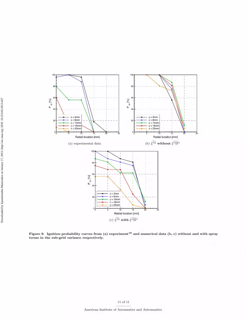
(a) experimental data (b) f�002 without g�00�00
(c) f�002 with g�00�00Figure 9. Ignition probability curves from (a) experiment16 and numerical data (b, c) without and with sprayterms in the sub-grid variance respectively.
11 of 11
American Institute of Aeronautics and Astronautics
Dow
nloa
ded
by E
pam
inon
das
Mas
tora
kos
on J
anua
ry 1
7, 2
013
| http
://ar
c.ai
aa.o
rg |
DO
I: 1
0.25
14/6
.201
3-42
7


