Embed Size (px)
Citation preview

L0192A
i
AUTOMATED MERCHANDISING SYSTEMS INC.
255 WEST BURR BLVD.
KEARNEYSVILLE, WV 25430
(304) 725‐6921
(304) 725‐6983 FAX
www.amsvendors.com
INTERNATIONAL A.M.S. S DE RL DE CV
KM. 9 CARR. AL CASTILLO NO. 8200
MPIO. DE EL SALTO, JAL. MEXICO 45680
5233‐36‐88‐07‐17
5233‐36‐88‐13‐14 FAX
www.amsint.com.mx
OPERATION AND SERVICE MANUAL
AMS TOUCHLESS Glass Front Vendor

L0192A
ii
LIMITED WARRANTY
Automated Merchandising Systems Inc. (AMS) warrants this equipment to the Original Purchaser only, for a period of one (1) year from the date of shipment, to be free under normal use and service from defects in material or workmanship, and for three (3) years on the refrigeration unit, electronic control board, and the two sensor boards. The refrigeration unit consist of the compressor, fan motors, relay, and the sealed components of the system. Light bulbs, glass, and painted surfaces are not covered by this warranty.
Should any part prove defective within the warranty period, AMS will repair or replace (at its option) the defective component. AMS will provide normal ground shipment for parts replaced under warranty. This warranty does not cover the labor or other costs associated with removal and reinstallation of a defective component. All defective components, at the option of AMS, are to be returned, properly packaged, freight prepaid, to AMS or to the authorized dealer or distributor from whom the equipment was purchased for verification of the defect. Prior to returning any parts for replacement, the customer is to contact the AMS Service Department at (304) 725-6921 for return authorization. AMS reserves the right to refuse any collect shipment.
This warranty applies only if the equipment has been serviced and maintained in strict accordance with the instructions presented in the AMS service manual and no unauthorized repair, alteration, or disassembly has been done. Any defects caused by improper power source, abuse of the product, accident, alteration, vandalism, improper service techniques, or damage incurred during return shipment due to improper packaging will not be covered by this warranty. Likewise, any equipment that has had the serial number removed, defaced or otherwise altered will not be coved by this warranty.
AMS reserves the right to make changes or improvements in its products without notice and without obligation, and without being required to make corresponding changes or improvements in equipment already manufactured or sold.
AMS SHALL NOT BE BOUND BY ANY REPRESENTATION OR WARRANTY MADE BY ANY PERSON, INCLUDING BY EMPLOYEES OF AMS, EXCEPT AS SET FORTH IN THIS LIMITED WARRANTY. AMS DISCLAIMS ANY AND ALL OTHER EXPRESS OR IMPLIED WARRANTIES OF ANY NATURE, INCLUDING WITHOUT LIMITATION, WARRANTIES OF MERCHANTABILITY, FITNESS OF A PARTICULAR PURPOSE OR OTHER IMPLIED WARRANTIES.
L0192A
iii
Title Page LIMITED WARRANTY ii TABLE OF FIGURES v PUBLICATION NOTICE vi 1 INTRODUCTION 1 SENSIT 3 SYSTEM 1 Guaranteed Delivery Instant Refund Adjustable Helix Motion Additional Benefits MODEL IDENTIFICATION 1 Model Number Breakdown SERIAL NUMBERING SYSTEM 2 GENERAL SPECIFICATIONS 2 Operating Environment Touchless
Cabinet Dimensions Cabinet Weight Product Capacity Power Requirements
Energy Consumption Patent Disclosure MERCHANDISER CONFIGURATIONS 4 Example Configuration Table Helix Orientations Available Helices 5 2 SAFETY 7 COMMITMENT TO SAFETY 7 SAFETY PRECAUTIONS 7 High Voltage Contact Grounding Helix Motion and Jamming Vendor Tipping Other Improper Conditions 8 To Safely Move a Machine Ground Fault Circuit Interrupter TEST STANDARDS 8
ANSI/UL 751 3 VENDOR SYSTEMS AND COMPONENTS 9 SENSIT 3 SYSTEM OPERATION 9 CONTROL BOARD 9 Upgrading AMS Firmware
Mode Switch DEX Jack VEND SENSOR 9 Primary Sensor Secondary Sensor VAGABOND PAYMENT AND SELECTION SYSTEM 10 Display Keypad Door Switch TRAY RAILS 10 TRAYS 10 Vend Motors Sensit 3 Vend Motors Sensit II Vend Motors 11 Helices Dividers Candy Pusher Bar ELECTRICAL PANEL 11 Power Switch Fuse Holder Transformer RFI Filter Ground Attachment 4 VENDOR PREPARATION AND INSTALLATION 13 CONFIRMING POWER AT OUTLET 13 Checking the Outlet (U.S. and Canada) Checking the Outlet (Outside the U.S. and Canada) VENDOR PREPARATION 13 Inspection Test Loading and Configuration 14 Configuring Motors Setting Prices ON-SITE INSTALLATION 14 Removing the Shipping Boards Placing the Vendor in Location Leveling the Vendor False Leg Installation 15 5 TRAY ADJUSTMENT AND CONFIGURATION 17 SNACK AND CANDY TRAY 17 Removal Installation TRAY VERTICAL POSITIONS 17 Removal Installation
TABLE OF CONTENTS
L0192A
iv
TRAY COLUMN POSITIONS 17 Tray Motor Wire Colors Table 18 CHANGING DIVIDERS 18 CHANGING HELICES 18 HELIX ADAPTER 18 HELIX EJECTOR 18 HELIX ALIGNMENT DEVICE 18 MOTOR POSITIONS 18 HELIX HOME POSITION 19 AVOIDING PRODUCT HANG-UPS 19 TALL PRODUCT VENDING 19 CANDY PUSHER BAR INSTALLATION 19 6 SERVICE PROGRAMMING 21 VAGABOND SYSTEM ACTIVATION 21 SERVICE MODE 21 ERROR CODES 21 ACCOUNTING DATA 21 FILL/DISPENSE 21 DELAYED SALES 21 TEMPERATURE 21 PRICE SETTINGS 21 Set Prices ValueVend Calories TRAY SETUP 22 Test Motors Link Motors Motor Type Motor Types Table 23 Delayed Stop 24 Letter/Number Configure Motors Coupled Motors MDB (MULTI-DROP BUS) SETTINGS 24 Force Vend No Cheat Change Bill Hold Lost Credit Multi-Vend Lev2 Coin Mech Instant Revaluation
Hide Card Value Card Refund 25 Special MDB-Related Operation OPTIONS 25 Message Prize Language Speech Serial Number SALES BLOCKING 26 1-4 Set Periods CLOCK SETTINGS 26 Time and Date Daylight Savings Display Clock 12/24 Format FREE VEND 27 AUXILIARY OUTPUT 27 DATA LOGS 27 Temperature Power Outage Door Switch EnergySENSIT 27
7 TROUBLESHOOTING 29 ERROR CODES: CAUSES AND SOLUTIONS TABLE 29 Viewing Top Level Error Codes Viewing Sub-Level Error Codes OUT OF SERVICE MESSAGE 30 ERROR CODES: CAUSES AND SOLUTIONS TABLE 30 Viewing Top Level Error Codes Viewing Sub-Level Error Codes CLEARING JAMMED MOTOR 30 MACHINE TROUBLESHOOTING CHART 31 8 MAINTENANCE 33 FIRMWARE UPDATES 33 About SD Cards UPGRADING FIRMWARE 33 SAVING AND TRANSFERRING MACHINE 33 SETTINGS (CONFIGURATIONS) Saving a Configuration File 34 Loading a Configuration File
L0192A
v
RECORDING DEX DATA ON SD CARD 34 CLEANING THE VENDOR EXTERIOR 34 CLEANING THE VENDOR INTERIOR 34
SENSIT 3 UTILITY 35 REPLACING THE POWER CORD AND GFCI TEST 35 STORING THE VENDOR 35 9 WIRING DIAGRAM 37 10 SUPPORTED DEX FIELDS 39 11 OPTIONAL EQUIPMENT 41 SERVICE MENU MAP 42
TABLE OF FIGURES NUMBER NAME PAGE Figure 1.1 Typical Serial Plate 1 Figure 1.2 Cabinet Dimensions 3 Figure 1.3 Machine Configurations 4 Figure 1.4 Helix Orientations 4 Figure 1.5 Available Helices 5 Figure 2.1 Tray Extension Warning Label 8 Figure 3.1 Control Board Components 9 Figure 3.2 Control Box 10 Figure 4.1 Tip-Over Warning 14 Figure 4.2 False Leg Installation 15 Figure 5.1 Helix Install Position 19 Figure 5.2 Large Bag Vending 19 Figure 5.3 Candy Pusher Bar Installation 19 Figure 6.1 Motor Types and Operation 23 Figure 8.1 Loading Control Firmware 33 Figure 8.2 Replacing Power Cord and Protective Cover 35

L0192A
vi
Publication Notice L0192, Initial Release A, ECN 4159, 03/13/18
It is our intent to assist our customers with up-to-date documentation: however, this manual may not contain all updates and is subject to revision without notice. Please contact our Service Department with your requests or comments. Note 1 The Sensit 3 Control Board is sometimes referred to as the ‘VMC’ or Vending Machine Controller.
L0192A
1
Congratulations on the purchase of your new AMS Touchless vendor. Operation is based on the time-proven AMS Sensit 3 system providing a versatile, high-capacity vending machine. AMS machines are designed, tested, and built to provide years of reliable, low-maintenance service in an indoor environment. A fully insulated cabinet with flexible product configuration, a mobile phone enabled payment system and remote pricing and VMS are just some of the many features built into this AMS merchandiser. TM TOUCHLESS VENDINGTM SYSTEM This revolutionary payment and selection system allows users to make purchases right from their mobile device. An easy to use mobile app allows them to see pricing and calorie information before the purchase and then allows them the flexibility of several different payment methods as shown here:
Users can store several payment methods in the Vagabond system and choose among these different methods on each vend. SENSIT 3 SYSTEM Your vendor is equipped with the Sensit 3 control system. The Sensit 3 system is a patented vend-sensing system that detects when products fall into the delivery bin. Basically, a plane of infra-red light is created across the top of the delivery bin, and the Sensit 3 system can detect when the light has been blocked by a falling product. Using this technology, the vendor “knows” when your customer gets the product. The Sensit 3 system has several important benefits: Guaranteed Delivery During the vending process, if the product hangs up or an opening was missed in loading, the helix can rotate several additional partial revolutions to attempt to deliver the product. No more hitting or shaking the vendor to get products that did not fall! Instant Refund If the customer does not receive a product, he will be notified via the app that the vend failed and there will be no charge made to the account. Adjustable Helix Motion With the Sensit 3 system, the helix can stop as soon as the product falls, or when the helix returns to the home position. (See TRAY SETUP on page 22 for more information.)
Additional Benefits:
a. Opening the delivery bin door will not affect the Sensit 3 system. The sensors are located above the delivery bin and will not be blocked by the bin door. Product that falls while the door is open will still pass through the beam.
b. Shining a light at a sensor will not allow vandals to receive free product. Any tampering which changes the precise amount of light normally received will be treated as a successful vend, resulting in the vandal losing his money.
c. Disabling or blocking the sensor will not allow vandals to receive free product. The Sensit 3 system can over-ride blocked or malfunctioning sensors and still vend.
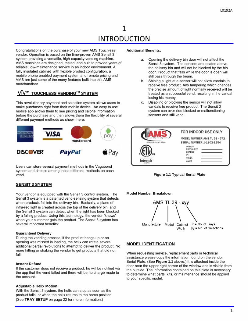
Figure 1.1 Typical Serial Plate Model Number Breakdown MODEL IDENTIFICATION When requesting service, replacement parts or technical assistance please copy the information found on the vendor Serial Plate. (See Figure 1.1 above.) It is attached inside the door near the upper right corner of the window and is visible from the outside. The information contained on this plate is necessary to determine what parts, kits, or maintenance should be applied to your specific model.
1
INTRODUCTION
L0192A
2
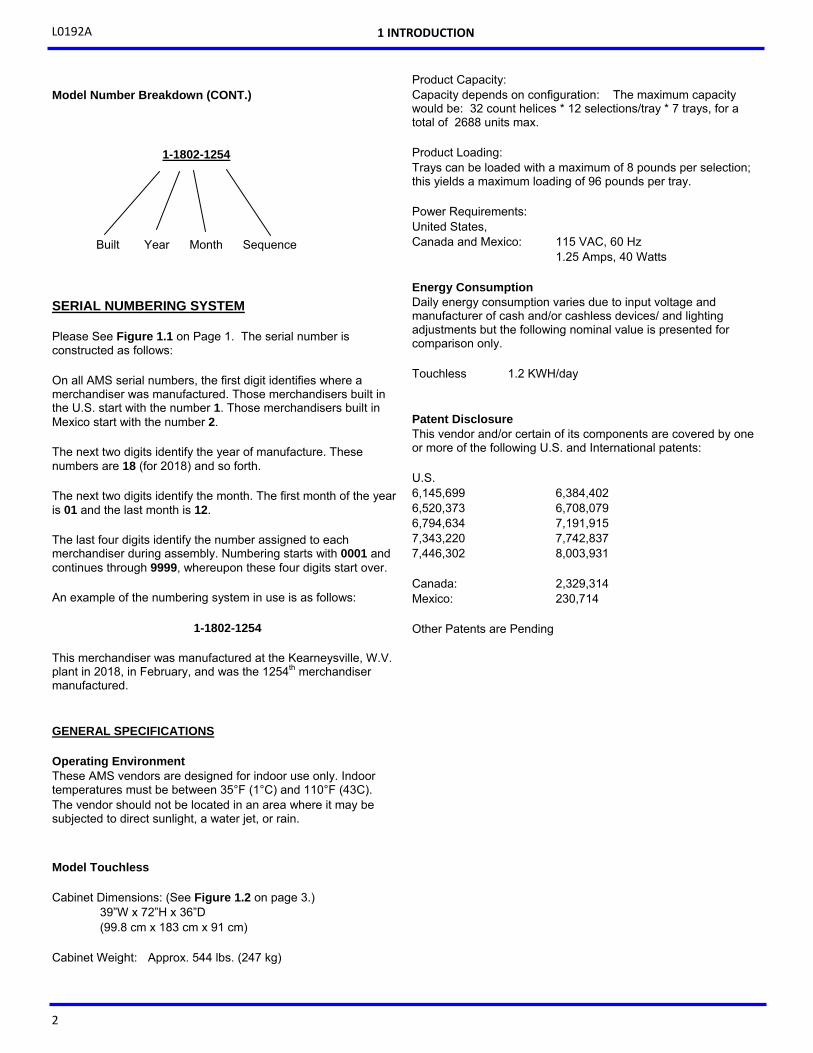
Model Number Breakdown (CONT.)
SERIAL NUMBERING SYSTEM Please See Figure 1.1 on Page 1. The serial number is constructed as follows: On all AMS serial numbers, the first digit identifies where a merchandiser was manufactured. Those merchandisers built in the U.S. start with the number 1. Those merchandisers built in Mexico start with the number 2. The next two digits identify the year of manufacture. These numbers are 18 (for 2018) and so forth. The next two digits identify the month. The first month of the year is 01 and the last month is 12. The last four digits identify the number assigned to each merchandiser during assembly. Numbering starts with 0001 and continues through 9999, whereupon these four digits start over. An example of the numbering system in use is as follows:
1-1802-1254
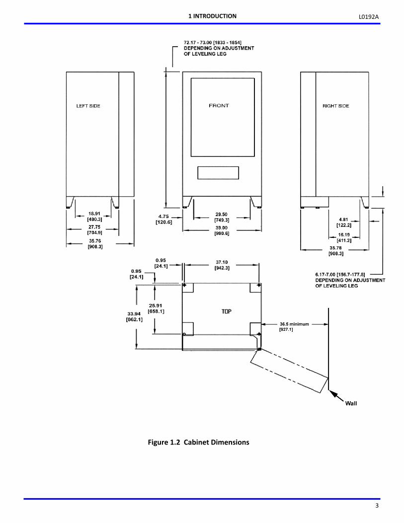
This merchandiser was manufactured at the Kearneysville, W.V. plant in 2018, in February, and was the 1254th merchandiser manufactured. GENERAL SPECIFICATIONS Operating Environment These AMS vendors are designed for indoor use only. Indoor temperatures must be between 35°F (1°C) and 110°F (43C). The vendor should not be located in an area where it may be subjected to direct sunlight, a water jet, or rain. Model Touchless Cabinet Dimensions: (See Figure 1.2 on page 3.)
39”W x 72”H x 36”D (99.8 cm x 183 cm x 91 cm)
Cabinet Weight: Approx. 544 lbs. (247 kg)
Product Capacity: Capacity depends on configuration: The maximum capacity would be: 32 count helices * 12 selections/tray * 7 trays, for a total of 2688 units max.
Product Loading: Trays can be loaded with a maximum of 8 pounds per selection; this yields a maximum loading of 96 pounds per tray. Power Requirements: United States, Canada and Mexico: 115 VAC, 60 Hz 1.25 Amps, 40 Watts Energy Consumption Daily energy consumption varies due to input voltage and manufacturer of cash and/or cashless devices/ and lighting adjustments but the following nominal value is presented for comparison only. Touchless 1.2 KWH/day Patent Disclosure This vendor and/or certain of its components are covered by one or more of the following U.S. and International patents: U.S. 6,145,699 6,384,402 6,520,373 6,708,079 6,794,634 7,191,915 7,343,220 7,742,837 7,446,302 8,003,931 Canada: 2,329,314 Mexico: 230,714 Other Patents are Pending
1 INTRODUCTION
1-1802-1254
Built Year Month Sequence
L0192A
3
Figure 1.2 Cabinet Dimensions
1 INTRODUCTION
L0192A
4
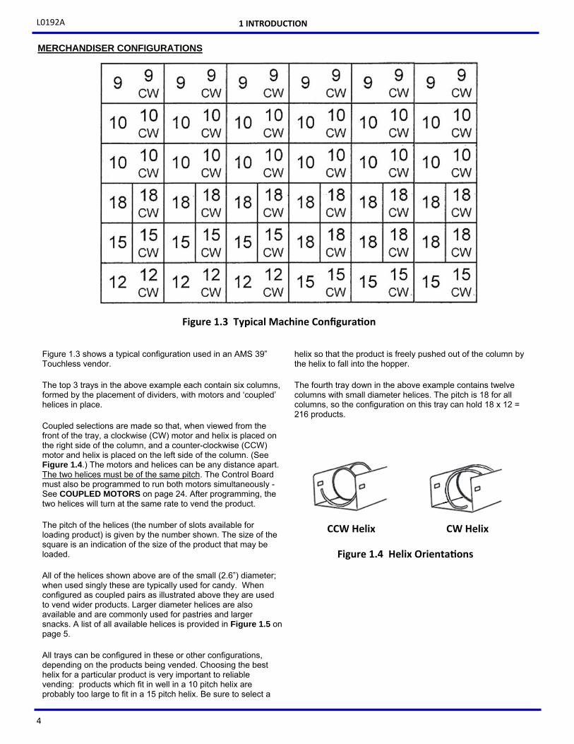
Figure 1.3 shows a typical configuration used in an AMS 39” Touchless vendor. The top 3 trays in the above example each contain six columns, formed by the placement of dividers, with motors and ‘coupled’ helices in place. Coupled selections are made so that, when viewed from the front of the tray, a clockwise (CW) motor and helix is placed on the right side of the column, and a counter-clockwise (CCW) motor and helix is placed on the left side of the column. (See Figure 1.4.) The motors and helices can be any distance apart. The two helices must be of the same pitch. The Control Board must also be programmed to run both motors simultaneously - See COUPLED MOTORS on page 24. After programming, the two helices will turn at the same rate to vend the product. The pitch of the helices (the number of slots available for loading product) is given by the number shown. The size of the square is an indication of the size of the product that may be loaded. All of the helices shown above are of the small (2.6”) diameter; when used singly these are typically used for candy. When configured as coupled pairs as illustrated above they are used to vend wider products. Larger diameter helices are also available and are commonly used for pastries and larger snacks. A list of all available helices is provided in Figure 1.5 on page 5. All trays can be configured in these or other configurations, depending on the products being vended. Choosing the best helix for a particular product is very important to reliable vending: products which fit in well in a 10 pitch helix are probably too large to fit in a 15 pitch helix. Be sure to select a
helix so that the product is freely pushed out of the column by the helix to fall into the hopper. The fourth tray down in the above example contains twelve columns with small diameter helices. The pitch is 18 for all columns, so the configuration on this tray can hold 18 x 12 = 216 products.
1 INTRODUCTION
CCW Helix CW Helix
Figure 1.4 Helix Orienta ons
MERCHANDISER CONFIGURATIONS
Figure 1.3 Typical Machine Configura on
L0192A
5
AVAILABLE HELICES
DESCRIPTION
20119 -05 Helix, Candy Clockwise, 5-Pitch
20119 -07 Helix, Candy Clockwise, 7-Pitch
20119 -09 Helix, Candy Clockwise, 9-Pitch
20119 -10 Helix, Candy Clockwise, 10-Pitch
20119 -12 Helix, Candy Clockwise, 12-Pitch
20119 -15 Helix, Candy Clockwise, 15-Pitch
20119 -18 Helix, Candy Clockwise, 18-Pitch
20119 -24 Helix, Candy Clockwise, 24-Pitch
20120 -05 Helix, Candy Counter-Clockwise, 5-Pitch
20120 -07 Helix, Candy Counter-Clockwise, 7-Pitch
20120 -08 Helix, Candy Counter-Clockwise, 8-Pitch
20120 -09 Helix, Candy Counter-Clockwise, 9-Pitch
20120 -10 Helix, Candy Counter-Clockwise, 10-Pitch
20120 -12 Helix, Candy Counter-Clockwise, 12-Pitch
20120 -15 Helix, Candy Counter-Clockwise, 15-Pitch
20120 -18 Helix, Candy Counter-Clockwise, 18-Pitch
20120 -24 Helix, Candy Counter-Clockwise, 24-Pitch
20120 -32 Helix, Candy Counter-Clockwise, 32-Pitch
21207 -15 Helix, G & M, Counter-Clockwise, Black (15 pitch)
21207 -25 Helix, G & M, Counter-Clockwise, Black (25 pitch)
21336 -06 Helix, CCW, 3.5" Opening (Bottle)
21337 -06 Helix, CCW, 3.2" Opening (Can)
21465 -04 Helix, Snack Counter-Clockwise, 4-Pitch
21465 -05 Helix, Snack Counter-Clockwise, 5-Pitch
21465 -07 Helix, Snack Counter-Clockwise, 7-Pitch
21465 -09 Helix, Snack Counter-Clockwise, 9-Pitch
21465 -10 Helix, Snack Counter-Clockwise, 10-Pitch
21465 -12 Helix, Snack Counter-Clockwise, 12-Pitch
21465 -15 Helix, Snack Counter-Clockwise, 15-Pitch
21465 -24 Helix, Snack Counter-Clockwise, 24-Pitch
23268 -10 Helix, Mini-Dispenser, Counter-Clockwise, 10 pitch
23268 -20 Helix, Mini-Dispenser, Counter-Clockwise, 20 pitch
23268 -32 Helix, Mini-Dispenser, Counter-Clockwise, 32 pitch
P/N & SUFFIX
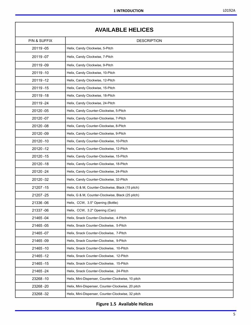
Figure 1.5 Available Helices
1 INTRODUCTION

L0192A
6
THIS PAGE INTENTIONALY LEFT BLANK

L0192A
7
COMMITMENT TO SAFETY Automated Merchandising Systems Inc. is committed to designing and producing a safe product. As with all electrical or mechanical pieces of equipment, some potential hazards exist. It is the intent of Automated Merchandising Systems, through this manual and service technician training, to alert individuals who will be servicing our equipment to these potential hazards, and to provide basic safety guidelines. To reduce the risk of serious injury or death, please read and follow all warnings in this manual. It is important that we point out that these warnings are not comprehensive. Automated Merchandising Systems cannot possibly anticipate all of the ways that service may be conducted, or all of the possible safety hazards that may result from service. Therefore at all times we urge you to beware of hazards such as electrical shock, mechanical entrapment, and tipping a vendor during movement. Automated Merchandising Systems strongly recommends a commitment to safety on the part of all servicing personnel or organizations. Only personnel properly trained in vendor servicing should attempt any service to the internal components of the vendor. Automated Merchandising Systems has no control over the vendor once it leaves our factory. Maintaining the vendor in a safe condition is the sole responsibility of the owner. If you have questions concerning safety or service, or would like more information, please contact the Automated Merchandising Systems Service Department at 304-725-6921 or e-mail [email protected]. SAFETY PRECAUTIONS Below are listed safety precautions and safe practices to follow to avoid injury from selected hazards. This list cannot possibly cover all hazards, therefore please remember to
To Protect Yourself from Injuries Plan ahead to employ proper personal protective equipment (PPE), including safety glasses, slip resistant steel-toed boots and leather/protective gloves. Don’t place hands against edges of metal drawers or bare parts inside the machine. Beware that parts on the inside of the Vending Unit can be sharp. High Voltage Contact Each vendor is designed to operate on a specific voltage, either single phase 115VAC 60Hz or 220-240VAC 50-60Hz, depending on the country. The voltage is specified on the serial plate. (See MODEL IDENTIFICATION on page 1.) High voltage areas include the electrical panel. It is important to understand that contact with the high voltage wiring can result in injury or death.
a. Always test the outlet for proper voltage, polarity and grounding before plugging in the vendor.
b. Always disconnect power to the vendor before servicing. Allow only fully trained service technicians to service the vendor.
c. Always keep electrical connections dry. Do not place the vendor in or near standing water.
d. Never use a worn or damaged power cord. e. Always wear hand and eye protection when
servicing the vendor. Grounding Some electrical components have a green or green/yellow ground wire attached to a grounding point in the vendor. If it becomes necessary to remove a ground wire during service, note how the wire is attached, including the locations of any washers. After servicing, make sure that the wires and washers are replaced exactly as they were. Note that the vendor may appear to work normally without the ground wires, but there will be a potential shock hazard from ungrounded components.
a. Always test the outlet for proper grounding before plugging in the vendor.
b. Always reconnect ground wires after servicing. c. Test the ground fault circuit interrupter (GFCI)
periodically to insure proper operation. (See REPLACING THE POWER CORD AND GFCI TEST on page 37.)
Helix Motion and Jamming Energized vend motors can turn a helix with considerable torque, creating a possible entrapment hazard. Also, turning helices may eject tools or other objects left on trays. A helix that is jammed or caught can store energy as it binds, which can cause it to twist or spring outward suddenly even if power is disconnected. Use gloves and caution when freeing a jammed helix.
a. Always disconnect power to the vendor or control
board before servicing the vend motors. b. Always check for proper fit when loading products
in helices to avoid jamming. c. Always restrain the helix before freeing a jammed
or caught helix. d. Always wear hand and eye protection when
servicing the vendor. e. Always keep hands, hair, loose clothing and tools
away from moving parts.
Vendor Tipping The weight of an empty vendor is over 450 pounds, and can be more than 600 pounds! A falling vendor can cause serious injury or death. Caution should always be taken to avoid dropping or tipping a vendor.
a. Never rock or tip the vendor. It must be kept
vertical for safe operation. b. Never place the vendor in an inclined position,
such as on a ramp or with all the legs not on the same horizontal surface.
THINK SAFETY FIRST!
2
SAFETY
L0192A
8
c. Never place the vendor in a moving environment such as on a ship without properly securing it in place.
d. Never place the vendor in a location where it may be struck by a vehicle.
e. Never transport an unsecured vendor, or a vendor still containing product.
f. Never attempt to lift or move the vendor by hand. Always use equipment with the proper load rating. Note that the Specification weight listed is empty weight.
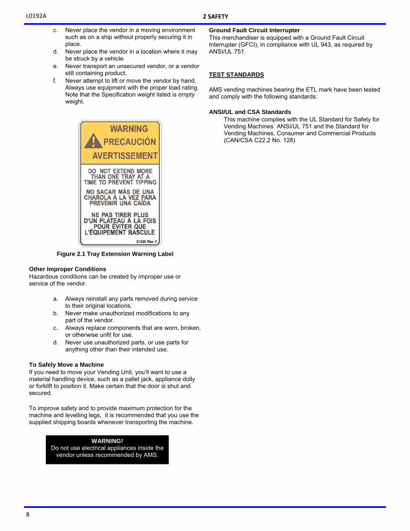
Figure 2.1 Tray Extension Warning Label
Other Improper Conditions Hazardous conditions can be created by improper use or service of the vendor.
a. Always reinstall any parts removed during service to their original locations.
b. Never make unauthorized modifications to any part of the vendor.
c. Always replace components that are worn, broken, or otherwise unfit for use.
d. Never use unauthorized parts, or use parts for anything other than their intended use.
To Safely Move a Machine If you need to move your Vending Unit, you’ll want to use a material handling device, such as a pallet jack, appliance dolly or forklift to position it. Make certain that the door is shut and secured. To improve safety and to provide maximum protection for the machine and levelling legs, it is recommended that you use the supplied shipping boards whenever transporting the machine.
Ground Fault Circuit Interrupter This merchandiser is equipped with a Ground Fault Circuit Interrupter (GFCI), in compliance with UL 943, as required by ANSI/UL 751. TEST STANDARDS AMS vending machines bearing the ETL mark have been tested and comply with the following standards:
ANSI/UL and CSA Standards
This machine complies with the UL Standard for Safety for Vending Machines ANSI/UL 751 and the Standard for Vending Machines, Consumer and Commercial Products (CAN/CSA C22.2 No. 128)
WARNING! Do not use electrical appliances inside the
vendor unless recommended by AMS.
2 SAFETY
L0192A
9
3
VENDOR SYSTEMS AND COMPONENTS
SENSIT 3 SYSTEM OPERATION
The Sensit 3 system is comprised of the primary sensor, the secondary sensor, and the control logic. The primary and secondary sensors are attached to the cabinet at opposite ends of the hopper and infrared light is passed between them.
When a selection is made, the vend motor will begin to run. After several seconds, if no product falls in the hopper (or motor returns to home position), the motor will be stopped and the credit will be returned to the Vagabond system.
When the controller measures a variation in the light intensity during the vend cycle, it recognizes that a product has fallen through the light into the hopper. The controller stops the vend motor (or returns it to home position) and sends a successful vend message to the Vagabond system.
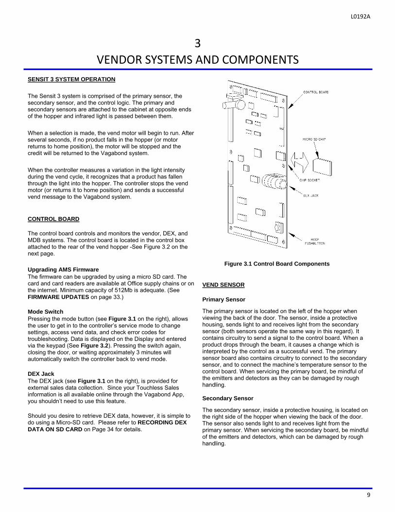
CONTROL BOARD The control board controls and monitors the vendor, DEX, and MDB systems. The control board is located in the control box attached to the rear of the vend hopper -See Figure 3.2 on the next page.
Upgrading AMS Firmware The firmware can be upgraded by using a micro SD card. The card and card readers are available at Office supply chains or on the internet. Minimum capacity of 512Mb is adequate. (See FIRMWARE UPDATES on page 33.) Mode Switch Pressing the mode button (see Figure 3.1 on the right), allows the user to get in to the controller’s service mode to change settings, access vend data, and check error codes for troubleshooting. Data is displayed on the Display and entered via the keypad (See Figure 3.2). Pressing the switch again, closing the door, or waiting approximately 3 minutes will automatically switch the controller back to vend mode. DEX Jack The DEX jack (see Figure 3.1 on the right), is provided for external sales data collection. Since your Touchless Sales information is all available online through the Vagabond App, you shouldn’t need to use this feature. Should you desire to retrieve DEX data, however, it is simple to do using a Micro-SD card. Please refer to RECORDING DEX DATA ON SD CARD on Page 34 for details.
VEND SENSOR Primary Sensor
The primary sensor is located on the left of the hopper when viewing the back of the door. The sensor, inside a protective housing, sends light to and receives light from the secondary sensor (both sensors operate the same way in this regard). It contains circuitry to send a signal to the control board. When a product drops through the beam, it causes a change which is interpreted by the control as a successful vend. The primary sensor board also contains circuitry to connect to the secondary sensor, and to connect the machine’s temperature sensor to the control board. When servicing the primary board, be mindful of the emitters and detectors as they can be damaged by rough handling. Secondary Sensor
The secondary sensor, inside a protective housing, is located on the right side of the hopper when viewing the back of the door. The sensor also sends light to and receives light from the primary sensor. When servicing the secondary board, be mindful of the emitters and detectors, which can be damaged by rough handling.
Figure 3.1 Control Board Components
L0192A
10
PAYMENT AND SELECTION SYSTEM
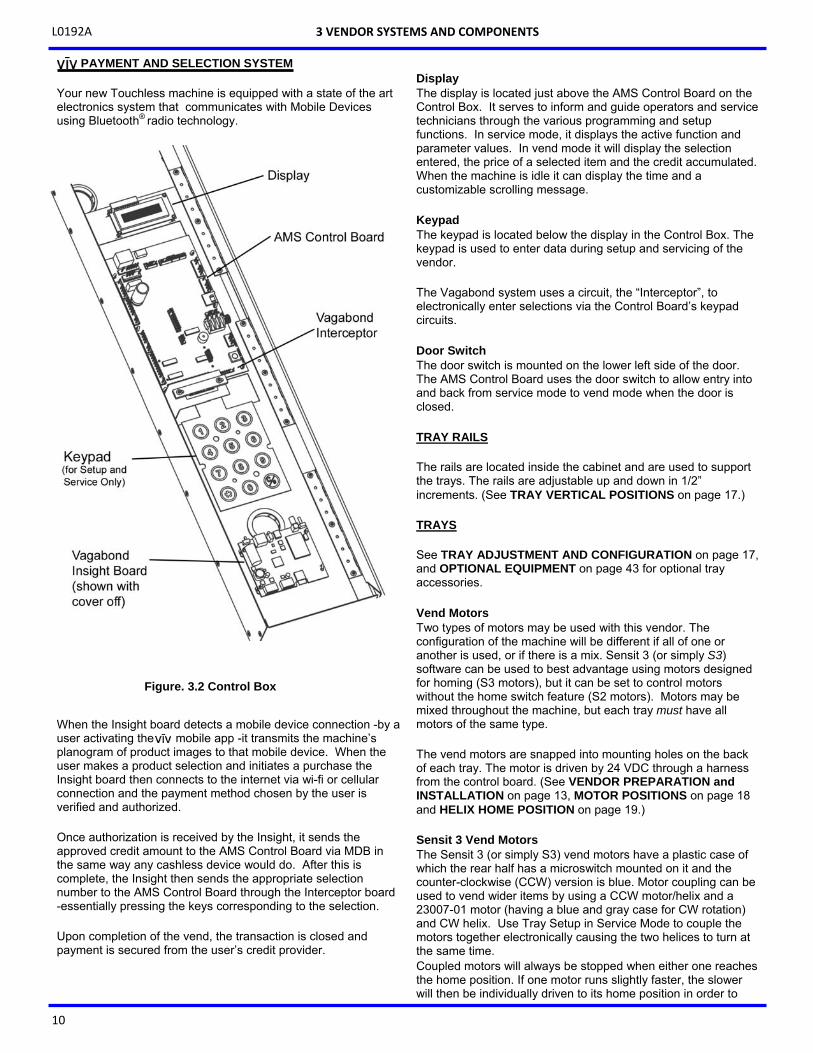
Your new Touchless machine is equipped with a state of the art electronics system that communicates with Mobile Devices using Bluetooth® radio technology.
When the Insight board detects a mobile device connection -by a user activating the mobile app -it transmits the machine’s planogram of product images to that mobile device. When the user makes a product selection and initiates a purchase the Insight board then connects to the internet via wi-fi or cellular connection and the payment method chosen by the user is verified and authorized. Once authorization is received by the Insight, it sends the approved credit amount to the AMS Control Board via MDB in the same way any cashless device would do. After this is complete, the Insight then sends the appropriate selection number to the AMS Control Board through the Interceptor board -essentially pressing the keys corresponding to the selection. Upon completion of the vend, the transaction is closed and payment is secured from the user’s credit provider.
Display The display is located just above the AMS Control Board on the Control Box. It serves to inform and guide operators and service technicians through the various programming and setup functions. In service mode, it displays the active function and parameter values. In vend mode it will display the selection entered, the price of a selected item and the credit accumulated. When the machine is idle it can display the time and a customizable scrolling message. Keypad The keypad is located below the display in the Control Box. The keypad is used to enter data during setup and servicing of the vendor. The Vagabond system uses a circuit, the “Interceptor”, to electronically enter selections via the Control Board’s keypad circuits. Door Switch The door switch is mounted on the lower left side of the door. The AMS Control Board uses the door switch to allow entry into and back from service mode to vend mode when the door is closed.
TRAY RAILS The rails are located inside the cabinet and are used to support the trays. The rails are adjustable up and down in 1/2” increments. (See TRAY VERTICAL POSITIONS on page 17.) TRAYS See TRAY ADJUSTMENT AND CONFIGURATION on page 17, and OPTIONAL EQUIPMENT on page 43 for optional tray accessories. Vend Motors Two types of motors may be used with this vendor. The configuration of the machine will be different if all of one or another is used, or if there is a mix. Sensit 3 (or simply S3) software can be used to best advantage using motors designed for homing (S3 motors), but it can be set to control motors without the home switch feature (S2 motors). Motors may be mixed throughout the machine, but each tray must have all motors of the same type. The vend motors are snapped into mounting holes on the back of each tray. The motor is driven by 24 VDC through a harness from the control board. (See VENDOR PREPARATION and INSTALLATION on page 13, MOTOR POSITIONS on page 18 and HELIX HOME POSITION on page 19.) Sensit 3 Vend Motors The Sensit 3 (or simply S3) vend motors have a plastic case of which the rear half has a microswitch mounted on it and the counter-clockwise (CCW) version is blue. Motor coupling can be used to vend wider items by using a CCW motor/helix and a 23007-01 motor (having a blue and gray case for CW rotation) and CW helix. Use Tray Setup in Service Mode to couple the motors together electronically causing the two helices to turn at the same time. Coupled motors will always be stopped when either one reaches the home position. If one motor runs slightly faster, the slower will then be individually driven to its home position in order to
3 VENDOR SYSTEMS AND COMPONENTS
Figure. 3.2 Control Box
L0192A
11
keep the two helices synchronized. Depending on motor configuration, the motors may jog twice during vend cycles to try to dislodge hanging product.
Note: When not in Service Mode, and with door open, press #
to reset all switched motors to Home position. (This is not applicable for non-switched motors.) Motors already at home will not move. (See TRAY SETUP on page 22.)
Sensit II Vend Motors A Sensit II (or simply S2) vend motor has a plastic case which is all ivory in color. As mentioned earlier, a dual helix S2 motor has a larger “butterfly” gearbox allowing two helices, one for CW and another for CCW rotation, to be installed. The dual helix housing only allows helices to be adjacent to each other. These motors have no home switches and have been discontinued and replaced with S3 vend motors. However, the S3 Control Board can be set to accommodate these motors. (See TRAY SETUP on page 22 for details on changing motor types.)
Helices There are four sizes of helices available, approximately 1 1/2”, 2 5/8”, 3”, and 4” in diameter. There are several pitches available in each size, and is determined by counting the number of product openings in the helix. (See CHANGING HELICES on page 18, MOTOR POSITIONS on page 18 and HELIX HOME POSITION on page 19.) Dividers The dividers separate product columns on the tray. To remove the divider, push rearward and lift. To install, insert the rear tab in the desired slot, push rearward and then down. Make sure the locking tabs on the bottom have engaged their respective slots and pull forward. Bottle tray dividers are held in place with rivets. Candy Pusher Bar On snack trays, 2 horizontal slots in the divider allow for the installation of a candy pusher bar. The candy pusher bar keeps items pushed to one side of the column. This is typically used with tall and narrow products. The candy pusher bar is removed by pulling the bar free from the plastic clips. To reinstall, it is easiest to squeeze the bar into the clip using pliers (See CANDY PUSHER BAR INSTALLATION on page 19).
ELECTRICAL PANEL Power Switch The power switch is located on a panel inside the cabinet on the lower right side of the machine The power switch is used to disconnect 24VAC power to the control board.
Note: The power should be shut off when any electronic devices are being connected or disconnected, when the board is being serviced, or before any wiring harness is connected to or disconnected from the electronic control boards or sensors.
Fuse Holder The fuse holder is located on the panel just below the power switch inside the lower right rail mount. It contains a 3 amp fast-
blow fuse to protect the 24 VAC power supply to the control board. A spare fuse is stored in the cover. The fuse holder is opened by pressing back on the indicated side of the cover and pulling out.
Transformer The transformer reduces the input voltage to 24 volts AC for the control board. It is located beneath the cover which protects the power switch and fuse holder. RFI Filter The filter removes electrical noise from the power supplied to the 24VAC transformer to prevent interference with operation of the control board and software. It is located next to the transformer. Ground Attachment The vendor electrical ground is made through the use of grounding studs or screws at the lower back wall of the right rail mount. Earth ground and individual ground wires from the high voltage components are attached here, and should always be replaced after service or repair.
3 VENDOR SYSTEMS AND COMPONENTS

L0192A
12
THIS PAGE INTENTIONALLY LEFT BLANK
L0192A
13
4
VENDOR PREPARATION AND INSTALLATION Setting up a vendor has been divided into three stages:
CONFIRMING POWER AT OUTLET (below), confirms power and site suitability. VENDOR PREPARATION on pages 13 & 14, includes preparations accomplished in the shop. ON-SITE INSTALLATION on page 14, is accomplished on-site, where the vendor is to be located.
NOTE: These vendors are not to be installed within motor fuel dispensing facilities.
CONFIRMING POWER AT OUTLET Checking the Outlet (U.S. and Canada) AMS recommends using a dedicated outlet which can supply 7 or more amps per vendor.
Using a volt meter set to AC VOLTS, check the voltage between the positive (smaller) lug entry and the ground lug entry (or center screw on two-lug outlets). The reading should be between 110 volts and 130 volts. Next, check the voltage between the neutral (larger) lug entry and the ground. The reading should be 0 volts. If your results vary, contact a qualified electrician to correct the outlet wiring before plugging in the vendor. Abnormal voltage, reversed polarity or improper grounding may cause the vendor to malfunction or create hazardous conditions in the vendor, resulting in possible injury, damage to the vendor, or fire. The power cord is shipped in the hopper on the inside of the door. The cord is supplied with a standard NEMA 3-wire plug. If there are no 3-wire outlets available for powering the vendor, a grounding adapter may be used to convert a 2-wire outlet to accept the 3-wire plug. The adapter must have a ground tab or wire which must be fastened to the center screw of the outlet. If the outlet isn’t grounded, the machine could present a shock hazard.
Checking the Outlet (Outside the U.S. and Canada) Consult a qualified electrician to check the outlet for proper polarity, voltage, and grounding. Check the serial plate on the side of the door to confirm the vendor is rated for the outlet voltage. VENDOR PREPARATION Inspection Inspect the vendor carefully for shipping damage prior to signing the carrier’s delivery receipt. Check for dents on the top or sides of the vendor, bent legs, broken glass, or other damage on the exterior of the machine. Check the interior for components that may have been knocked loose or have sustained other damage.
To improve safety and to provide maximum protection for the machine and levelling legs, it is recommended that you use the supplied shipping boards whenever transporting the machine.
Test Loading and Configuration Before putting the vendor on location, it is a good idea to determine the placement of products on the trays. Place at least one product in each helix to check for fit.
1. Remove the cardboard spacers and ties securing the trays.
2. Make use of the adjustable TRAY VERTICAL POSITIONS for tray vertical adjustments and TRAY COLUMN POSITIONS, both on page 17, for tray column configuration when configuring your vendor to suit your product.
3. Make sure the product can slide in and out of the helix easily. If the product is too snug, it may cause the helix to jam during vending. Place it in a helix with a larger opening.
4. Likewise, if the product is too loose in the helix, it may not vend properly. Use a helix with the smallest opening that will allow the product to slide in and out freely. (See CHANGING DIVIDERS on through HELIX ALIGNMENT DEVICE on page 18.)
5. Place tall, narrow products in a column with a candy pusher bar, which is an adjustable bar used to push the product to one side of the column. Typically these are installed in columns 10 and 11 on the candy trays.
6. Make sure there is adequate clearance between the tops of the packages and the trays above when sliding the trays in and out, and when the product is being vended.
Configuring Motors The vend motors MUST BE CONFIGURED after any changes in the arrangement, type, or number of motors have been made.
1. Press the service mode switch on the control board
(See Figure 3.1 on page 9.) 2. Using the # or the * key, scroll through the menu to
“TRAY SETUP”. 3. Press 6 to configure the motors. Each switched
motor will be moved to its home position if it is not presently at home. In addition, all motors present and detected will be counted and the total number of motors will be displayed. Note: Coupled motors will be counted as 1 motor even though 2 are connected.
4. If the number of motors displayed does not match the number of motors in the vendor, press 1 * 2 to jog all the motors in the vendor and watch to see which motor(s) do not run. Check the state of any motor that does not run: that motor may be disconnected, jammed or have home switch problems.
5. After the motors have been configured check to make sure all the helices are in the home position. If the end of a helix is not in its desired home
NEVER USE AN EXTENSION CORD WITH THE VENDOR.
L0192A
14
position (see Fig. 5.1 on page 19), pull it out of the motor, turn it until it is properly positioned, and reinsert the helix into the motor.
Note: When not in Service Mode but with the door open, you
can press # to force switched motors to Home position (Not applicable to motors set to “Sensit”. See TRAY SETUP on page 22). Motors already at home will not move.
6. Test vend the product and adjust the position of
helix ejector if necessary. The helix ejector is the plastic device installed on the front end of the helix to kick out the product (See HELIX EJECTOR on page 18.)
Setting Prices After product placement set the prices in the vendor (See Price Settings on page 21.)
ON-SITE INSTALLATION Remove the Shipping Boards Split the shipping boards by inserting a crowbar or wedge into the slots at either end. If necessary, lift the vendor to remove the broken boards using properly rated equipment. Do not tilt the vendor. Do not attempt to lift the vendor with a 2-wheel hand truck. Placing the Vendor in Location
1. Place the vendor within 5 feet of the designated power outlet. The power outlet should be accessible when the vendor is in position, and the ventilation opening in the back of the vendor must be clear of obstructions.
2. For refrigerated models, allow at least 4 inches between the wall and the back of the vendor for air circulation.
3. Make sure the vendor does not block walkways or exits.
4. Do not place the vendor in a location where it can be struck by vehicles.
5. Leave at least 18 inches between a wall and the hinge side of the vendor to prevent the door hitting the wall when opened, or use a protective wall bumper. The door must open wide enough to allow the trays to be pulled out.
6. The vendor is designed to meet the 1991 ADA guidelines for persons in wheelchairs using a parallel approach (side of wheelchair adjacent to front of vendor). Make sure there is adequate room to maneuver a wheelchair into this position in front of the vendor.
Leveling the Vendor For safe operation the vendor must be level.
1. On the bottom of the vendor are four (4) threaded leveling legs located at the corners of the cabinet and a fifth support screw under the door. Before beginning, be sure that all five leveling legs are screwed in completely.
2. With the door closed and locked, check the four main legs and adjust any leg that is not contacting the floor. Make sure the support screw under the door is all the way up and is not contacting the floor at this time.
3. Place a level on top of the cabinet and check for horizontal from side-to-side.
4. Adjust the leveling legs on the low side one turn at a time until the cabinet is level.
5. Repeat the last two steps to level the vendor front-to-back.
6. After the vendor is level, adjust the support screw under the door until it contacts the floor.
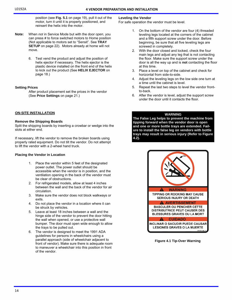
Figure 4.1 Tip-Over Warning
4 VENDOR PREPARATION AND INSTALLATION
WARNING The False Leg helps to prevent the machine from tipping forward when the vendor door is open and one or more bottle trays are extended. Fail-ure to install the false leg on vendors with bottle trays may result in serious injury (Refer to Figure 4.2).
L0192A
15
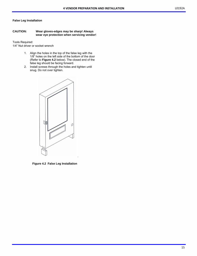
False Leg Installation
CAUTION: Wear gloves-edges may be sharp! Always wear eye protection when servicing vendor!
Tools Required: 1/4” Nut driver or socket wrench
1. Align the holes in the top of the false leg with the 1/8” holes on the left side of the bottom of the door (Refer to Figure 4.2 below). The closed end of the false leg should be facing forward.
2. Install screws through the holes and tighten until snug. Do not over tighten.
.
Figure 4.2 False Leg Installation
4 VENDOR PREPARATION AND INSTALLATION

L0192A
16
THIS PAGE INTENTIONALLY LEFT BLANK
L0192A
17
5
TRAY ADJUSTMENT AND CONFIGURATION
The trays in AMS Sensit 3 vendors are highly configurable. Practically any combination of wide and narrow columns can be set up on a tray. Before changing the configuration of your trays, make sure to order the parts you will need, such as new helices, dividers or additional motors. SNACK AND CANDY TRAY Removal
1. To remove the tray, start with the tray pushed to its rearmost position. Lift the back of the tray up and pull the tray forward about ten inches. Reposition your hands to grasp the tray at its sides and slide the tray out. If the tray is spaced close to the tray above, it may be helpful to raise the front of the tray as you pull it free.
2. When removing a tray, it is not necessary to disconnect the tray harness. The harness is long enough that it will allow a removed tray to be placed on the floor without having to be disconnected.
Installation
To install the tray, place the tray on top of the rails and slide the tray all the way to the rear. It will automatically drop into position. Make sure the harness slack is draped over the outside of the rail.
TRAY VERTICAL POSITIONS The trays can be adjusted to different vertical positions in 1 inch increments. To reposition a tray use the following steps. Removal
1. Remove the tray for access to the support rails. 2. Remove the screw located at the front of each rail. 3. The front of the rail can now be lifted upward and
disengaged from the vertical column. 4. Pull forward to disengage the rail from the slots at
the back of the cabinet. 5. Use these same steps for the other side.
Installation
1. To reinstall the rail in the new position, locate the rear “T” slots that will be used.
2. Then push the two tabs at the back of the rail into the appropriate slots.
3. Engage the hooked tabs at the front of the rail into the appropriate rectangular holes and pull down.
4. Make sure the rail is level. 5. Replace the screw to prevent the trays slipping out. 6. Use these same steps for the other side. 7. Reinstall the tray, making sure the harness is
routed over the top of the rail and all slack is draped to the outside of the rail.
TRAY COLUMN POSITIONS The tray columns used for snacks and candy can be configured by the user for up to 12 columns wide trays. Typically the vend columns are set to single (2.66”) or double (5.32”) width, to be used with the standard small or large helices, respectively. Single and double width columns can be configured in any arrangement on the tray by following the procedure below. Plan your tray arrangement before beginning to determine which extra parts may be required. Contact your distributor to order the necessary parts.
1. Disconnect the harness and remove the tray. Place the tray on a flat, stable work surface.
2. Reposition, remove, or add tray dividers in the desired locations. To remove the divider, push rearward then lift. Reverse the procedure to reinstall.
3. It may be necessary to remove a motor and helix in order to install some dividers. Pull forward on the helix to remove it from the motor. Press down and rearward on the top motor tab to remove the motor from the tray.
4. Reposition the motors to the center of each vend column, using the upper mounting position for the large helix and the lower position for the small helix. It may be easiest to disconnect the motors from the harness first.
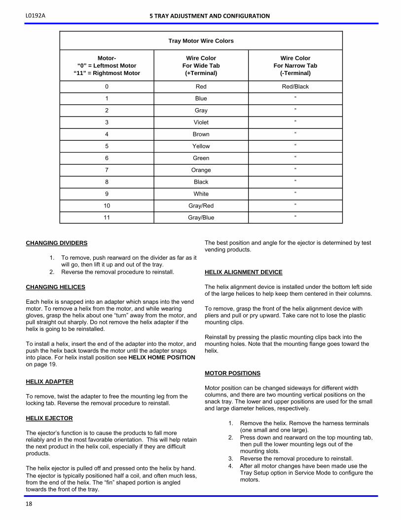
5. The harness has 12 sets of motor connections. The first set of connections (at the end of the harness farthest away from the connector) is position 0, followed by 1, 2, 3, and so on. The last set (nearest to the wire connector) is position 11. Starting at the left side of the tray, attach the harness connectors to the motors in order. For double columns, use the even numbered connection and disregard the odd numbered connection. (Example: If the first column on the left is double width, disregard position 1 and attach the connectors for position 0). Each set of connectors has a wide and a narrow connector, corresponding to a wide and a narrow tab on the back of the motor. (See table of Tray Motor Wire Colors on page 18.)
6. Place the correct Selection ID label in front of each column, according to the motor connections used.
7. Replace the tray in the machine, routing the harness over the tray rail and through the back of the column.
8. Reconnect the harness, routing it over the rail and through the back of the column.
9. Reinstall the tray. 10. After changing the tray configuration, it will be
necessary to reconfigure the motor matrix (See VENDOR PREPARATION and INSTALLATION on page 13.)
L0192A
18
CHANGING DIVIDERS
1. To remove, push rearward on the divider as far as it will go, then lift it up and out of the tray.
2. Reverse the removal procedure to reinstall. CHANGING HELICES Each helix is snapped into an adapter which snaps into the vend motor. To remove a helix from the motor, and while wearing gloves, grasp the helix about one “turn” away from the motor, and pull straight out sharply. Do not remove the helix adapter if the helix is going to be reinstalled. To install a helix, insert the end of the adapter into the motor, and push the helix back towards the motor until the adapter snaps into place. For helix install position see HELIX HOME POSITION on page 19.
HELIX ADAPTER To remove, twist the adapter to free the mounting leg from the locking tab. Reverse the removal procedure to reinstall. HELIX EJECTOR The ejector’s function is to cause the products to fall more reliably and in the most favorable orientation. This will help retain the next product in the helix coil, especially if they are difficult products.
The helix ejector is pulled off and pressed onto the helix by hand. The ejector is typically positioned half a coil, and often much less, from the end of the helix. The “fin” shaped portion is angled towards the front of the tray.
The best position and angle for the ejector is determined by test vending products. HELIX ALIGNMENT DEVICE The helix alignment device is installed under the bottom left side of the large helices to help keep them centered in their columns. To remove, grasp the front of the helix alignment device with pliers and pull or pry upward. Take care not to lose the plastic mounting clips. Reinstall by pressing the plastic mounting clips back into the mounting holes. Note that the mounting flange goes toward the helix. MOTOR POSITIONS Motor position can be changed sideways for different width columns, and there are two mounting vertical positions on the snack tray. The lower and upper positions are used for the small and large diameter helices, respectively.
1. Remove the helix. Remove the harness terminals (one small and one large).
2. Press down and rearward on the top mounting tab, then pull the lower mounting legs out of the mounting slots.
3. Reverse the removal procedure to reinstall. 4. After all motor changes have been made use the
Tray Setup option in Service Mode to configure the motors.
5 TRAY ADJUSTMENT AND CONFIGURATION
Motor- “0” = Leftmost Motor
“11” = Rightmost Motor
Wire Color For Wide Tab (+Terminal)
Wire Color For Narrow Tab
(-Terminal)
0 Red Red/Black
1 Blue “
2 Gray “
3 Violet “
4 Brown “
5 Yellow “
6 Green “
7 Orange “
8 Black “
9 White “
Tray Motor Wire Colors
10 Gray/Red “
11 Gray/Blue “
L0192A
19
Figure 5.2 Large Bag Vending
Figure 5.3 Candy Pusher Bar Installation
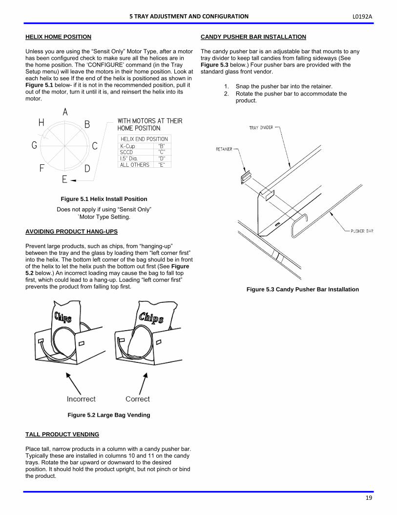
HELIX HOME POSITION Unless you are using the “Sensit Only” Motor Type, after a motor has been configured check to make sure all the helices are in the home position. The ‘CONFIGURE’ command (in the Tray Setup menu) will leave the motors in their home position. Look at each helix to see If the end of the helix is positioned as shown in Figure 5.1 below- if it is not in the recommended position, pull it out of the motor, turn it until it is, and reinsert the helix into its motor.
AVOIDING PRODUCT HANG-UPS Prevent large products, such as chips, from “hanging-up” between the tray and the glass by loading them “left corner first” into the helix. The bottom left corner of the bag should be in front of the helix to let the helix push the bottom out first (See Figure 5.2 below.) An incorrect loading may cause the bag to fall top first, which could lead to a hang-up. Loading “left corner first” prevents the product from falling top first. TALL PRODUCT VENDING
Place tall, narrow products in a column with a candy pusher bar. Typically these are installed in columns 10 and 11 on the candy trays. Rotate the bar upward or downward to the desired position. It should hold the product upright, but not pinch or bind the product.
CANDY PUSHER BAR INSTALLATION The candy pusher bar is an adjustable bar that mounts to any tray divider to keep tall candies from falling sideways (See Figure 5.3 below.) Four pusher bars are provided with the standard glass front vendor.
1. Snap the pusher bar into the retainer. 2. Rotate the pusher bar to accommodate the
product.
5 TRAY ADJUSTMENT AND CONFIGURATION
Figure 5.1 Helix Install Position
Does not apply if using “Sensit Only” `Motor Type Setting.
AH
G
FE
D
C
B WITH MOTORS AT THEIRHOME POSITION:
HELIX END POSITIONK-Cup "B"
ALL OTHERS "E"
SCCD1.5" Dia.
"C""D"

L0192A
20
THIS PAGE INTENTIONALLY LEFT BLANK

L0192A
21
Attention: To activate your AMS Touchless machine, call your Vagabond Account Manager at 202-695-8228, option 2.
SERVICE MODE Access the service mode by pressing the yellow mode button on the control board (See Figure 3.1 on page 9.) If there are no errors, ACCOUNTING DATA is displayed. Press # or * to scroll through the errors and functions. Return to vend mode by closing the door, pressing the mode switch or allowing the 3 minute time-out to occur. For convenience, there is an instruction card inside the cabinet, and in this manual that presents the basic information in this section in a flow-chart format. ERROR CODES Any errors that have been recorded will be displayed when the mode switch is pressed. ERROR CODES: CAUSES AND SOLUTIONS on page 30 provides descriptions of errors and tips for troubleshooting them.
ALWAYS CORRECT THE ERROR BEFORE CLEARING THE MESSAGE! # NEXT ERROR – View the next top level error code. 1. SUBLVL ERRORS – Displays any sublevel error codes. 2. DETAILS – Displays date and time of the last sublevel error. 0. CLEAR ERROR – Erases the error code from memory.
ACCOUNTING DATA Limited sales information can be displayed directly on the vendor display.
1. HIST. VENDS – Displays number of vends since initialization of the control board. Non-resettable.
2. HIST. VALUE – Displays the total value of sales since initialization of the control board. Non-resettable.
3. RESET. VENDS – Displays the number of vends since the last reset. Resettable
4. RESET. VALUE – Displays the total sales since the last reset. Resettable
5. HIST. SELEC’NS – Displays sequential number of paid vends for each individual selection since initialization of the control board.
a. Depending on the configuration, up to 80 selections may be audited.
b. Enter a selection by entering its characters. The display will show the total paid count for the selection for 2 seconds. At this time another selection may be entered. All selections can be accessed this way. Press # to return to the Accounting Menu.
These vend counts are non-resettable.
6. CLEAR ALL – Clears RESET. VENDS, RESET. CASH, RESET CARD, CASHBOX COINS and STACKED BILLS.
7. RESET. CARD – Displays the total cashless sales since the last reset. Resettable.
8. CASHBOX COINS – This is meaningless in the Touchless machine -there are no coins involved.
9. STACKED BILLS – This is meaningless in the Touchless machine -there are no bills involved.
NOTE: More detailed sales information is contained in the DEX data. This data can be collected with any DEX data collection system.
FILL/DISPENSE The FILL/DISPENSE function will never be used in the Touchless machine. DELAYED SALES The FILL/DISPENSE function will never be used in the Touchless machine. TEMPERATURE This menu applies only to other AMS vendors and has no bearing on Touchless operations. PRICE SETTINGS Prices for the AMS Control Board in the Touchless must all be set to $0.05 to ensure proper operation. Actual pricing will be maintained in the Vagabond System and customers will be charged based on those prices. 1. SET PRICES Enter ’100’ as the first item to be priced. The current price for this selection will be displayed. Press 9 to edit, then enter the new price of ’5’. The press ’*’ to Save, the ’2’ to Save All Selections at the $0.05 price. 2. VALUEVEND - This menu applies only to other AMS vendors and should not be used in the Touchless vendor -it will not operate properly in this Model. 3. CALORIES -Pressing ‘3’ on the keypad takes you to a menu of 3 calorie display options. Since all nutrition information is maintained in the Vagabond system, this function is not used on the AMS Control Board. Option 1 – Display Off is chosen the machine operates exactly as in previous AMS machines – this Option should be selected in the Touchless vendor.
6
SERVICE PROGRAMMING
L0192A
22
Option 2 – – Do not choose this option. Option 3 – – Do not choose this option. TRAY SETUP This section is used to establish the presence of and test the motors that are present in your machine as it is configured. It is also used to program the motors to operate per your preferences. 1. Test Motors Enter the selection number to be tested, or press * to see the following options for testing multiple motors.
a. JOG TRAY – All motor positions on the selected
tray will be tested. The display will show the number of the motor being jogged, or it will show a message that a motor is missing.
b. JOG ALL – All motor positions in the vendor will be tested. Each motor will be turned only a very small amount, so that products loaded in the vendor will not be dispensed. The display will show the number of the motor being jogged, or it will show a message that a motor is missing.
c. CHECK JAMMED – The control will attempt to run each motor that has caused a jammed motor error. The status of the motor will be displayed afterward.
2. Link Motors This function is performed by the Vagabond system in the Touchless model. An explanation is provided below, but this feature should never be enabled in the AMS Control Board. The user can link selections to ensure even vending of dated products, or other “space-to-sales” functions. Linked selections are vended sequentially for better product rotation. Up to 40 groups can have motors linked together regardless of location or tray. The linked selection with the lowest number is the master selection. All other linked selections are vended using the selection number and price of the master selection. Entering the selection number of any linked selection will default to the master selection number, and the control will vend the next linked selection in the sequence. If motors are linked- but not present (or jammed), the next available motor will run. From Tray Setup, select 2-Link Motors. Enter Selection: then select from the following. 9- EDIT – Use 1 & 2 to select desired link group. * saves this selection to this link group. 0- CLEAR – This will unlink the current selection. The price will revert to its original value. All other linked selections in that group will remain unchanged. * NEXT – Press to increment by one selection. Any selection number may be entered directly for faster access. # EXIT – Returns to the Tray Setup menu.
Repeat for each linked selection.
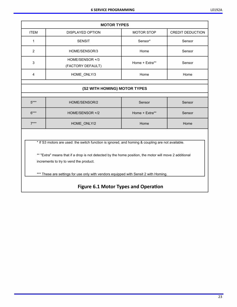
3. Motor Type Motor Type allows the user to change the motor-stop and credit deduction behavior. See the ‘Motor Types’ table below for more details on the various settings available under this function.
Enter tray – enter tray number to change motor type.
Press 1 to change motor type. Press # to save and exit. Press 2 to save entire vendor to this motor type.
Note: All motors on a tray must be of the same design (S2 or S3), but trays with different motor types can be used in the same vendor. Motor Type Descriptions:
HomeSensor/ After a selection is made, the motor will make one full turn and stop at home position. If a drop was detected the users phone will read “Please take your products and enjoy!”. If no drop is detected, the users phone will read “Vend Failed” and he/she will not be charged for the transaction. Sensit This setting ignores the Motor’s home switch (if present) completely. When the product is detected the motor is stopped and the vend cycle is complete. HomeSensor +/ This is similar to HomeSensor/, except that if no drop is detected the motor will make 2 short jogs in an effort to dislodge the product. If the motor stops off the home position, the next vend will begin the process again: it will stop at home and if a drop is detected the vend cycle is complete. If not, try up to two jogs. This is similar to the original Sensit sequence, and is the factory default setting for all vendors. Home_Only/ This setting disregards the Sensit system, and will make one complete turn and the users phone will read “Please take your products and enjoy!” whether the vend was successful or not. Auto Sensor Recovery is an improvement to the AMS Sensit system, that allows certain vends even when the sensor system is blocked or malfunctioning. If Motor Type is set to Home/Sensor/3 or Home Sensor+/3, and the sensor system is inoperable, the control will automatically switch to Home_Only/3 and allow a vend. Simply put, the sensors will be ignored, the helix will make a full turn and the vend will be treated as successful. Once the error is cleared, the vendor will return to its original sensor setting. Note that this will only work with the 23007 and 23007-01 motors, and during this temporary mode, selecting an item with the older Sensit 2 motor will read “selection unavailable”.
6 SERVICE PROGRAMMING
L0192A
23
6 SERVICE PROGRAMMING
MOTOR TYPES
ITEM DISPLAYED OPTION MOTOR STOP CREDIT DEDUCTION
1 SENSIT Sensor* Sensor
2 HOME/SENSOR/3 Home Sensor
3 HOME/SENSOR +/3
(FACTORY DEFAULT) Home + Extra** Sensor
4 HOME_ONLY/3 Home Home
(S2 WITH HOMING) MOTOR TYPES
5*** HOME/SENSOR/2 Sensor Sensor
6*** HOME/SENSOR +/2 Home + Extra** Sensor
7*** HOME_ONLY/2 Home Home
Figure 6.1 Motor Types and Opera on
* If S3 motors are used: the switch function is ignored, and homing & coupling are not available.
** "Extra" means that if a drop is not detected by the home position, the motor will move 2 additional
increments to try to vend the product.
*** These are settings for use only with vendors equipped with Sensit 2 with Homing.
L0192A
24
4. Delayed Stop The user can program a delayed stop of up to one second to allow a motor to continue running after the product has been dispensed. Note: this feature will only work with the 1-Sensit motor setting.
ENTER SELECTION – Enter the number of the selection to be delayed, enter 9 to edit, then enter the time in tenths of a second. The decimal point is placed automatically.
Example: Entering 8 will program a delay of 0.8 seconds.
The user can save the programmed delay to the selection, the entire tray, or all selections in the vendor. Linked selections will use the delay programmed for the master selection. 5. Letter / Number Allows use of either keyboard format. The control board/software default is for the NUMERIC, 12-key keypad and this setting must always be used in the Touchless Vendor. 6. Configure Motors Configure Motors moves each switched motor to the home position (moving the motor only if it is not at home) in addition to detecting connected motors. Since the vendor will not vend from a given helix when the motor is missing, jammed or has home switch problems, this selection MUST BE RUN after any change in the arrangement and/or the number of motors. The configuration of connected motors is stored in memory. If a configured motor is later found to be missing during a vend, an error message will be generated in service mode to alert the service person that the motor is disconnected. (Motors cannot be auto-configured as in earlier Sensit 2 systems.) 7. Coupled Motors Configurations to vend extra wide product can be made by using the coupled-motors feature (See MERCHANDISER CONFIGURATIONS on page 4). The coupled motor feature works by coupling together a set of two motors. One motor turns counter-clockwise, and the other motor must turn clockwise – corresponding CW and CCW helices must be used as well. Both motors turn for the same length of time. Trays may have multiple coupled motors.
1. From the Tray Setup menu, press “7”, then enter the first selection to couple (for example 204).
2. The Display will change to “ENTIRE TRAY ?” and prompt you for a YES (1) or NO (2) entry.
Choose ‘YES’ if you intend to couple all of the motor pairs on a Tray -you will be prompted to enter the Tray number and when you do all of the motor pairs on that tray will be coupled. Example: 100 and 101, 102 and 103, 104 and 105, etc. Choose ‘NO’ if you want to couple only selected motors on a tray -continue as described in the following paragraphs.
3. Press “9” to edit, then enter the column number of the second motor to couple. For this example, press “05” to couple selections 204 and 205. The second column could also be 6 or 7 for this set. In this example, the display will read “COUPLE 205,204”.
4. Press the “*” to save these selections and move to the next selection. When reviewing current settings, the “*” button is pressed the display will move to the next selection. Entering the desired selection number will also take you to another selection.
Press “0” to clear coupled motor sets from the control board. The display will read “XXX: COUPLE OFF”.
To return to Tray Setup, press the “#” key at any time. The tray numbers on the front of the tray should be changed to suit. The Coupled Motor feature will not work with Sensit 2 motors. Note: The selections created by the motor configuration must match the planogram that is entered into the Vagabond system. MDB (MULTI-DROP BUS) SETTINGS The user can select from many different operating features using the following settings. 1. Force Vend This feature is not used in the Touchless Vendor and should be left at the default setting of ’N’. 2. No Cheat This feature is not used in the Touchless Vendor and should be left at the default setting of “Y” for yes. 3. Change Bill This feature is not used in the Touchless Vendor and should be left at the default setting of “N” for no. 4. Hold Lost Credit This feature is not used in the Touchless Vendor and should be left at the default setting of “Y” for yes. 5. Multi-Vend This feature is not used in the Touchless Vendor and should be left at the default setting of “N” for no.
6. Lev2 Coin Mech This feature is not used in the Touchless Vendor and should be left at the default setting of “N” for no. 7. Instant Revaluation This feature is not used in the Touchless Vendor and should be left at the default setting of “N” for no. 8. Hide Card Value This feature is not used in the Touchless Vendor and should be left at the default setting of “N” for no.
6 SERVICE PROGRAMMING
L0192A
25
9. Card Refund This setting must be maintained at he factory default of “Y” for yes . With this setting, the vendor will refund credit from a failed vend back to the Insight device . Special MDB-Related Operation MDB Out-of-Service: The VMC will go out-of-service if it determines that the cashless system, the Vagabond Insight Module has become non-responsive. OPTIONS 1. Message Since the VMC’s Display is never available for a user to view, this feature is probably unnecessary. However, this feature could be used if the operator wanted to display a special reminder for a route person or Service Technician when they opened the machine. The scrolling message that is displayed when the vendor is idle. The factory default message is ‘GUARANTEED DELIVERY’, but tis message can be changed if desired. When changing the message It is best to write out the desired message first. The message to be displayed on the scrolling display can be up to 50 characters, including letters, numbers, punctuation and spaces. New messages erase old ones. Select the message option and the controller will prompt the user to press “1” to change the message, or press “#” to exit. To enter a message, the user should rapidly tap a particular key to cycle through a list of characters for that key. Stop at the desired character. When the keypad is left idle, the last-displayed character is moved over to the end of the message. Continue to select the next character. The key definitions are similar to those of cell phones:
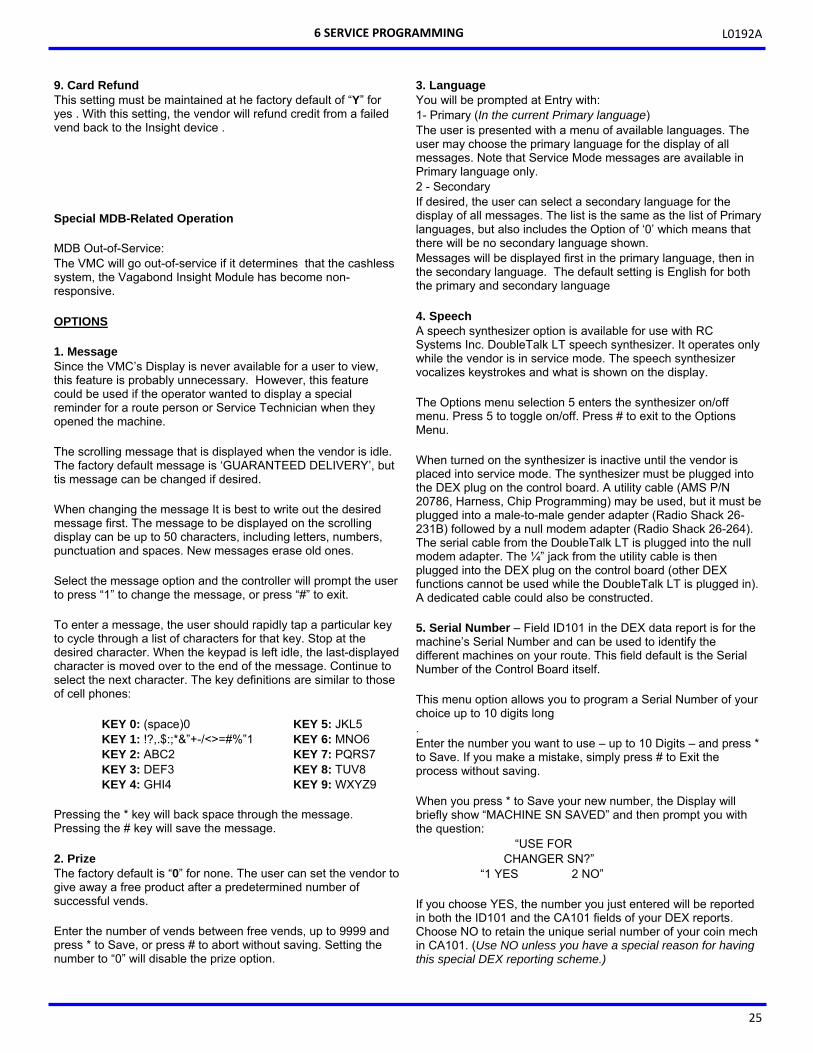
KEY 0: (space)0 KEY 5: JKL5 KEY 1: !?,.$:;*&”+-/<>=#%‟1 KEY 6: MNO6 KEY 2: ABC2 KEY 7: PQRS7 KEY 3: DEF3 KEY 8: TUV8 KEY 4: GHI4 KEY 9: WXYZ9
Pressing the * key will back space through the message. Pressing the # key will save the message. 2. Prize The factory default is “0” for none. The user can set the vendor to give away a free product after a predetermined number of successful vends. Enter the number of vends between free vends, up to 9999 and press * to Save, or press # to abort without saving. Setting the number to “0” will disable the prize option.
3. Language You will be prompted at Entry with: 1- Primary (In the current Primary language) The user is presented with a menu of available languages. The user may choose the primary language for the display of all messages. Note that Service Mode messages are available in Primary language only. 2 - Secondary If desired, the user can select a secondary language for the display of all messages. The list is the same as the list of Primary languages, but also includes the Option of ‘0’ which means that there will be no secondary language shown. Messages will be displayed first in the primary language, then in the secondary language. The default setting is English for both the primary and secondary language 4. Speech A speech synthesizer option is available for use with RC Systems Inc. DoubleTalk LT speech synthesizer. It operates only while the vendor is in service mode. The speech synthesizer vocalizes keystrokes and what is shown on the display. The Options menu selection 5 enters the synthesizer on/off menu. Press 5 to toggle on/off. Press # to exit to the Options Menu. When turned on the synthesizer is inactive until the vendor is placed into service mode. The synthesizer must be plugged into the DEX plug on the control board. A utility cable (AMS P/N 20786, Harness, Chip Programming) may be used, but it must be plugged into a male-to-male gender adapter (Radio Shack 26-231B) followed by a null modem adapter (Radio Shack 26-264). The serial cable from the DoubleTalk LT is plugged into the null modem adapter. The ¼” jack from the utility cable is then plugged into the DEX plug on the control board (other DEX functions cannot be used while the DoubleTalk LT is plugged in). A dedicated cable could also be constructed.
5. Serial Number – Field ID101 in the DEX data report is for the machine’s Serial Number and can be used to identify the different machines on your route. This field default is the Serial Number of the Control Board itself. This menu option allows you to program a Serial Number of your choice up to 10 digits long . Enter the number you want to use – up to 10 Digits – and press * to Save. If you make a mistake, simply press # to Exit the process without saving. When you press * to Save your new number, the Display will briefly show “MACHINE SN SAVED” and then prompt you with the question:
“USE FOR CHANGER SN?”
“1 YES 2 NO” If you choose YES, the number you just entered will be reported in both the ID101 and the CA101 fields of your DEX reports. Choose NO to retain the unique serial number of your coin mech in CA101. (Use NO unless you have a special reason for having this special DEX reporting scheme.)
6 SERVICE PROGRAMMING
L0192A
26
SALES BLOCKING Four separate time periods in each day of the week can be set, during which selections can be blocked (prevented from vending). All or any combination of selections in the vendor can be blocked from vending, or are exempt from blocking (free to vend). 1-4 Set Periods
1. Enter the number (1-4) of the time period to set-up. For example, choose #1.
2. The Display will prompt to enter the time when sales blocking period #1 is to BEGIN. Enter the time using the keypad, then press “*” to SAVE as indicated. If you make a mistake, press “#” to exit and then start over.
3. Select a.m. or p.m. for the starting time. The “BEGIN PERIOD 1” and the time you’ve entered will be displayed briefly and you will be prompted to enter the END time.
4. Enter the time when sales blocking period #1 is to end, then press “*” to SAVE as indicated.
5. Select a.m. or p.m. for the ending time. NOTE: A time period can be started, for example, at 9:00 p.m., and may be set to end at 6:00 a.m. (which would be the following day). 6. Now you are prompted to enter which days of the
week will use this blocking period. Starting with Sunday, press “1” to set this blocking period to be ON or OFF. Select “2” to continue with the next day of the week.
7. After you save the setting for Saturday, you will be prompted with the question:
ALL SELECTIONS?
3-YES 4-NO
8. To block all selections in the vendor in time period #1 select “YES”.
9. To choose different selections to block in time period (#1 in this example) select “NO”. As prompted, enter the selections one by one to BLOCK or EXEMPT as desired. Any combination of tray and column may be blocked (for example, trays 3, 4 and 5, and selections 61, 62 and 66).
10. In this Selection Entry display, enter the number of the first selection. For example, choose 10.
11. The display will show 10, and if it is blocked or exempt.
12. Press the number “9” on the keypad anytime to switch 10 from being blocked to being exempt, or back again.
13. Press “#”on the keypad to exit - your choice for this selection will be saved and you will be prompted to enter the next selection – or Press “*” for more options:
*-Saves setting for just this selection 1-Saves this setting to this Tray 2-Saves this setting to All Selections
14. After you’ve programmed all of the selections in this manner, press “*” on the keypad to return to the ENTER SELECTION menu.
15. Repeat the process for the other selections as desired or press “#” to return to save all of your settings and return to main SALES BLOCKING menu.
Note: If you are in these menus and go for an extended time without making any entries, the control will save entries as-is and return to the Selection Entry display.
16. If you have different times, days, or selections to block, return to 1-4 SET PERIODS, choose another time period, then repeat the times and days and selections setting process following the same steps as given above for time period #1.
17. The settings in sales blocking may be changed at any time by selecting the time period and changing the time of day, day of the week, and/or selections.
CLOCK SETTINGS
1. TIME AND DATE – Enter the current time and date. This information will be used for data logs and error records.
# - Exit without saving (if you make a mistake) *-Saves your setting You will then be prompted to press 1 for AM, or 2 for PM. After you make this choice, you will be prompted to enter the date.
Enter the 4 digits for today’s date. Press # to exit without saving, or * to save. After you save the date, you will be prompted to enter the year. Again, Press # to exit without saving, or * to save and return to the CLOCK SETTINGS Menu. 2. DAYLIGHT SAVINGS – The factory default is “Y”,
and the time is automatically adjusted for Daylight Savings Time to the US scheme. Press “2” to step through the rules settings for ‘EU’( Europe), ‘AU’(Australia), ‘MX’(Mexico), or “N” to disable this feature completely.
3. DISPLAY CLOCK – The factory default is “Y”. The current time will appear on the display beneath the scrolling message when the vendor is not in use. If you choose “N”, the time will not be displayed. Press “3” to toggle between Y and N, then press “#” to Save the setting and exit.
4. 12/24 FORMAT – The user can choose to display the time in 12-hour or 24-hour (military) format. The factory default is 12-hour format. Press “4” to toggle between Y and N, then press “#” to Save the setting and exit.
6 SERVICE PROGRAMMING
L0192A
27
FREE VEND Since the Vagabond system controls all selection entry, free vend operation can only be controlled with that system. This setting must be left at the default setting of “N” for no. Press “1” to VIEW / EDIT and then to toggle between Y and N, then press “#” to Save the setting and exit. If you turn free vend on, the Display will briefly show “FREE VEND IS ON” before returning to the menu. AUXILIARY OUTPUT The auxiliary output is a 5VDC signal lasting 100 milliseconds following a successful vend. This signal can be used to trigger user-supplied external devices. AMS does not currently supply such accessory devices and cannot offer technical assistance for such devices. This feature is provided only as a convenience to those users of advanced technical skill who wish to connect such a device to their AMS vendor and have sufficient electronic expertise to do so. Press “1” to VIEW / EDIT and then to toggle between Y and N, then press “#” to Save the setting and exit. DATA LOGS The user can review recorded data on vendor temperature, power outages, and door openings. This data is sometimes helpful in diagnosing problems with the vendor. These logs are cleared whenever the software is changed, and once the maximum number of entries is reached, the oldest entry will drop from the list. There are some special situations on these logs – please read the Notes indicated. TEMPERATURE – (Note: The Touchless machine has no
temperature controls or measurement device, so the readings displayed will have no meaning.)
The temperature log contains temperature measurements
taken at half-hour intervals over the previous 48 hours. When you enter this submenu, the Display will show you to press “1” to move to the next ‘older’ reading or “2” to move up to the next ‘more recent’ reading. After a brief delay, the program will begin at the most recent reading (#1).
The reading number (1 through 96NOTE), the recorded temperature and the date and time of the reading will be displayed. Press either “1” or “2” to step through the readings. Press “#” to EXIT when you’ve finished.
POWER OUTAGE – The power outage log shows power off and
on information. When you enter this submenu, the Display will show you to press “1” to move to the next ‘older’ event or “2” to move up to the next ‘more recent’ reading. After a brief delay, the program will begin at the last power ON data (#1).
The reading number (1 - 10 NOTE), then whether this record was for power ON or OFF, and the recorded temperature at the time will be shown on the top line, with the date and time of the reading displayed on the bottom line of the Display. Press either “1” or “2” to step through the readings. Press “#” to EXIT when you’ve finished.
DOOR SWITCH – The door switch log records door openings
and closings. Display will show you to press “1” to move to the next ‘older’ event or “2” to move up to the next ‘more recent’ reading. After a brief delay, the program will begin at the last door OPEN data (#1).
The reading number (1 - 10 NOTE), then whether this record was for door OPEN or CLOSED, and the recorded temperature at the time will be shown on the top line, with the date and time of the reading displayed on the bottom line of the Display.
Press either “1” or “2” to step through the readings. Press “#” to EXIT when you’ve finished.
NOTES: In a new machine, or right after a software upgrade, temperature readings will not be taken for 30 minutes, so you will not be able to enter the Temperature Menu. Records will not be displayed if they haven’t been recorded yet – so you will not have all 96 temperature readings until the new board or software upgrade has been operating for a full 48 hours. The temperature readings for an ambient (not chilled) snack machine will be shown as 125°.
EnergySENSIT The EnergySensit feature is a way of reducing energy consumption. When enabled, EnergySensit predicts periods of inactivity and allows the internal temperature of the vendor to rise slightly – and the lighting turned off - to take advantage of these inactive times. This feature is not available in the Touchless vendor.
6 SERVICE PROGRAMMING

L0192A
28
6 SERVICE PROGRAMMING
THIS PAGE INTENTIONALLY LEFT BLANK
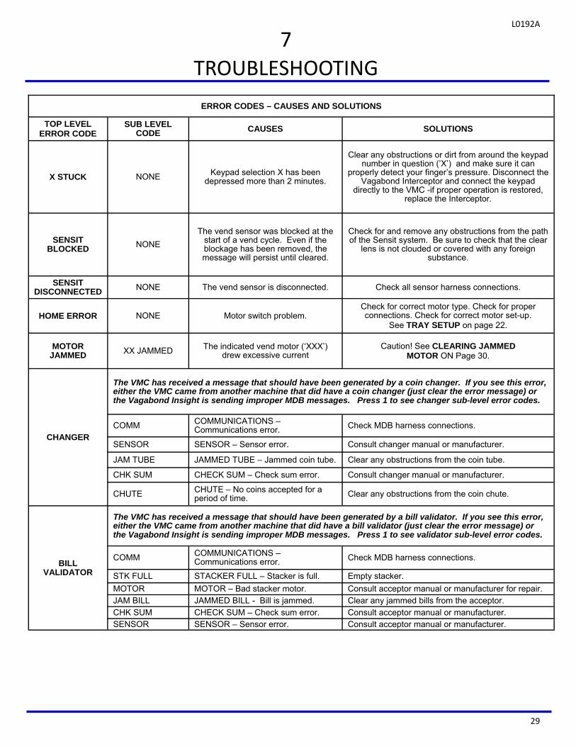
L0192A
29
7
TROUBLESHOOTING
ERROR CODES – CAUSES AND SOLUTIONS
TOP LEVEL ERROR CODE
SUB LEVEL CODE CAUSES SOLUTIONS
X STUCK NONE Keypad selection X has been depressed more than 2 minutes.
Clear any obstructions or dirt from around the keypad number in question (’X’) and make sure it can
properly detect your finger’s pressure. Disconnect the Vagabond Interceptor and connect the keypad
directly to the VMC -if proper operation is restored, replace the Interceptor.
SENSIT BLOCKED NONE
The vend sensor was blocked at the start of a vend cycle. Even if the blockage has been removed, the message will persist until cleared.
Check for and remove any obstructions from the path of the Sensit system. Be sure to check that the clear
lens is not clouded or covered with any foreign substance.
SENSIT DISCONNECTED NONE The vend sensor is disconnected. Check all sensor harness connections.
HOME ERROR NONE Motor switch problem. Check for correct motor type. Check for proper connections. Check for correct motor set-up.
See TRAY SETUP on page 22.
MOTOR JAMMED XX JAMMED The indicated vend motor (‘XXX’)
drew excessive current Caution! See CLEARING JAMMED
MOTOR ON Page 30.
CHANGER
The VMC has received a message that should have been generated by a coin changer. If you see this error, either the VMC came from another machine that did have a coin changer (just clear the error message) or the Vagabond Insight is sending improper MDB messages. Press 1 to see changer sub-level error codes.
COMM COMMUNICATIONS – Communications error. Check MDB harness connections.
SENSOR SENSOR – Sensor error. Consult changer manual or manufacturer.
JAM TUBE JAMMED TUBE – Jammed coin tube. Clear any obstructions from the coin tube.
CHK SUM CHECK SUM – Check sum error. Consult changer manual or manufacturer.
CHUTE CHUTE – No coins accepted for a period of time. Clear any obstructions from the coin chute.
BILL VALIDATOR
The VMC has received a message that should have been generated by a bill validator. If you see this error, either the VMC came from another machine that did have a bill validator (just clear the error message) or the Vagabond Insight is sending improper MDB messages. Press 1 to see validator sub-level error codes.
COMM COMMUNICATIONS – Communications error. Check MDB harness connections.
STK FULL STACKER FULL – Stacker is full. Empty stacker.
MOTOR MOTOR – Bad stacker motor. Consult acceptor manual or manufacturer for repair.
JAM BILL JAMMED BILL - Bill is jammed. Clear any jammed bills from the acceptor.
CHK SUM CHECK SUM – Check sum error. Consult acceptor manual or manufacturer. SENSOR SENSOR – Sensor error. Consult acceptor manual or manufacturer.
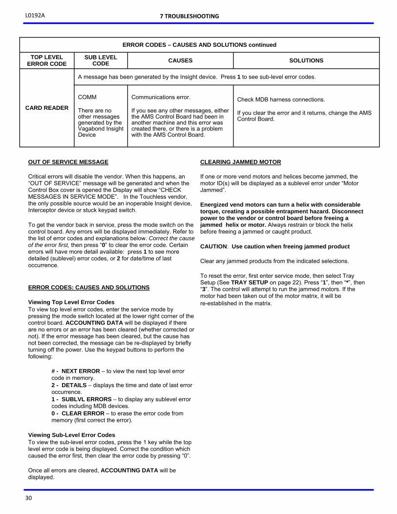
L0192A
30
OUT OF SERVICE MESSAGE Critical errors will disable the vendor. When this happens, an “OUT OF SERVICE” message will be generated and when the Control Box cover is opened the Display will show “CHECK MESSAGES IN SERVICE MODE”. In the Touchless vendor, the only possible source would be an inoperable Insight device, Interceptor device or stuck keypad switch. To get the vendor back in service, press the mode switch on the control board. Any errors will be displayed immediately. Refer to the list of error codes and explanations below. Correct the cause of the error first, then press “0” to clear the error code. Certain errors will have more detail available: press 1 to see more detailed (sublevel) error codes, or 2 for date/time of last occurrence. ERROR CODES: CAUSES AND SOLUTIONS Viewing Top Level Error Codes To view top level error codes, enter the service mode by pressing the mode switch located at the lower right corner of the control board. ACCOUNTING DATA will be displayed if there are no errors or an error has been cleared (whether corrected or not). If the error message has been cleared, but the cause has not been corrected, the message can be re-displayed by briefly turning off the power. Use the keypad buttons to perform the following:
# - NEXT ERROR – to view the next top level error code in memory. 2 - DETAILS – displays the time and date of last error occurrence. 1 - SUBLVL ERRORS – to display any sublevel error codes including MDB devices. 0 - CLEAR ERROR – to erase the error code from memory (first correct the error).
Viewing Sub-Level Error Codes To view the sub-level error codes, press the 1 key while the top level error code is being displayed. Correct the condition which caused the error first, then clear the error code by pressing “0”. Once all errors are cleared, ACCOUNTING DATA will be displayed.
CLEARING JAMMED MOTOR If one or more vend motors and helices become jammed, the motor ID(s) will be displayed as a sublevel error under “Motor Jammed”. Energized vend motors can turn a helix with considerable torque, creating a possible entrapment hazard. Disconnect power to the vendor or control board before freeing a jammed helix or motor. Always restrain or block the helix before freeing a jammed or caught product. CAUTION: Use caution when freeing jammed product Clear any jammed products from the indicated selections. To reset the error, first enter service mode, then select Tray Setup (See TRAY SETUP on page 22). Press “1”, then “*”, then “3”. The control will attempt to run the jammed motors. If the motor had been taken out of the motor matrix, it will be re-established in the matrix.
7 TROUBLESHOOTING
ERROR CODES – CAUSES AND SOLUTIONS continued
TOP LEVEL ERROR CODE
SUB LEVEL CODE CAUSES SOLUTIONS
CARD READER
A message has been generated by the Insight device. Press 1 to see sub-level error codes.
COMM There are no other messages generated by the Vagabond Insight Device
Communications error. If you see any other messages, either the AMS Control Board had been in another machine and this error was created there, or there is a problem with the AMS Control Board.
Check MDB harness connections. If you clear the error and it returns, change the AMS Control Board.
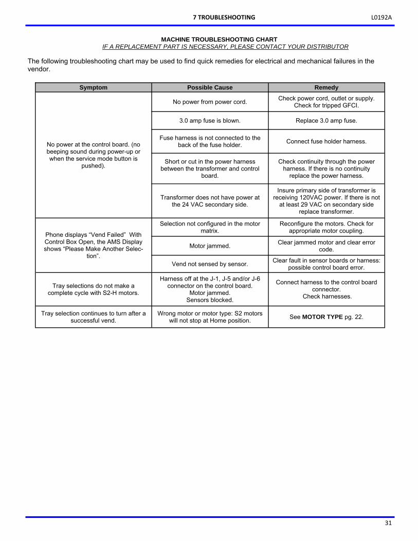
L0192A
31
MACHINE TROUBLESHOOTING CHART IF A REPLACEMENT PART IS NECESSARY, PLEASE CONTACT YOUR DISTRIBUTOR
The following troubleshooting chart may be used to find quick remedies for electrical and mechanical failures in the vendor.
Symptom Possible Cause Remedy
No power at the control board. (no beeping sound during power-up or when the service mode button is
pushed).
No power from power cord. Check power cord, outlet or supply. Check for tripped GFCI.
3.0 amp fuse is blown. Replace 3.0 amp fuse.
Fuse harness is not connected to the back of the fuse holder. Connect fuse holder harness.
Short or cut in the power harness between the transformer and control
board.
Check continuity through the power harness. If there is no continuity
replace the power harness.
Transformer does not have power at the 24 VAC secondary side.
Insure primary side of transformer is receiving 120VAC power. If there is not
at least 29 VAC on secondary side replace transformer.
Phone displays “Vend Failed” With Control Box Open, the AMS Display shows “Please Make Another Selec-
tion”.
Selection not configured in the motor matrix.
Reconfigure the motors. Check for appropriate motor coupling.
Motor jammed. Clear jammed motor and clear error code.
Vend not sensed by sensor. Clear fault in sensor boards or harness: possible control board error.
Tray selections do not make a complete cycle with S2-H motors.
Harness off at the J-1, J-5 and/or J-6 connector on the control board.
Motor jammed. Sensors blocked.
Connect harness to the control board connector.
Check harnesses.
Tray selection continues to turn after a successful vend.
Wrong motor or motor type: S2 motors will not stop at Home position. See MOTOR TYPE pg. 22.
7 TROUBLESHOOTING

L0192A
32
MACHINE TROUBLESHOOTING CHART -CONTINUED
THIS PAGE INTENTIONALLY LEFT BLANK
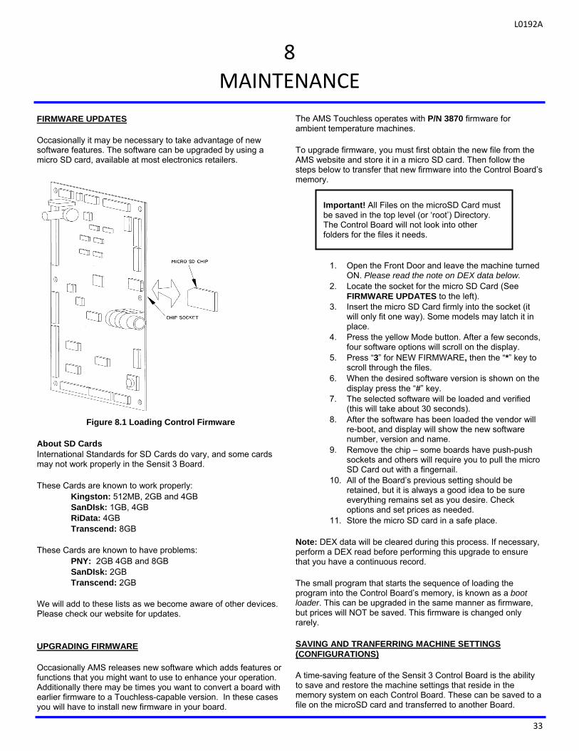
L0192A
33
8
MAINTENANCE
FIRMWARE UPDATES Occasionally it may be necessary to take advantage of new software features. The software can be upgraded by using a micro SD card, available at most electronics retailers.
Figure 8.1 Loading Control Firmware
About SD Cards International Standards for SD Cards do vary, and some cards may not work properly in the Sensit 3 Board. These Cards are known to work properly:
Kingston: 512MB, 2GB and 4GB SanDIsk: 1GB, 4GB RiData: 4GB Transcend: 8GB
These Cards are known to have problems:
PNY: 2GB 4GB and 8GB SanDIsk: 2GB Transcend: 2GB
We will add to these lists as we become aware of other devices. Please check our website for updates. UPGRADING FIRMWARE Occasionally AMS releases new software which adds features or functions that you might want to use to enhance your operation. Additionally there may be times you want to convert a board with earlier firmware to a Touchless-capable version. In these cases you will have to install new firmware in your board.
The AMS Touchless operates with P/N 3870 firmware for ambient temperature machines. To upgrade firmware, you must first obtain the new file from the AMS website and store it in a micro SD card. Then follow the steps below to transfer that new firmware into the Control Board’s memory.
1. Open the Front Door and leave the machine turned ON. Please read the note on DEX data below.
2. Locate the socket for the micro SD Card (See FIRMWARE UPDATES to the left).
3. Insert the micro SD Card firmly into the socket (it will only fit one way). Some models may latch it in place.
4. Press the yellow Mode button. After a few seconds, four software options will scroll on the display.
5. Press “3” for NEW FIRMWARE, then the “*” key to scroll through the files.
6. When the desired software version is shown on the display press the “#” key.
7. The selected software will be loaded and verified (this will take about 30 seconds).
8. After the software has been loaded the vendor will re-boot, and display will show the new software number, version and name.
9. Remove the chip – some boards have push-push sockets and others will require you to pull the micro SD Card out with a fingernail.
10. All of the Board’s previous setting should be retained, but it is always a good idea to be sure everything remains set as you desire. Check options and set prices as needed.
11. Store the micro SD card in a safe place. Note: DEX data will be cleared during this process. If necessary, perform a DEX read before performing this upgrade to ensure that you have a continuous record. The small program that starts the sequence of loading the program into the Control Board’s memory, is known as a boot loader. This can be upgraded in the same manner as firmware, but prices will NOT be saved. This firmware is changed only rarely. SAVING AND TRANFERRING MACHINE SETTINGS (CONFIGURATIONS) A time-saving feature of the Sensit 3 Control Board is the ability to save and restore the machine settings that reside in the memory system on each Control Board. These can be saved to a file on the microSD card and transferred to another Board.
Important! All Files on the microSD Card must be saved in the top level (or ‘root’) Directory. The Control Board will not look into other folders for the files it needs.
L0192A
34
This is helpful if you are replacing the Control Board in a certain machine and is especially useful if you are setting up a number of machines that have the same number of motors, prices and options settings. Saving a Configuration File
1. Open the Front Door and leave the machine turned ON.
2. Locate the socket for the micro SD Card (See Figure 8.1 on page 33).
3. Insert the micro SD Card into the socket (it will only fit one way). Push in until it latches in place.
4. Press the yellow Mode button. After a few seconds, four software options will be shown on the display.
5. Press “2”, to ‘SAVE CONFIG’ . You will be prompted to ENTER FILE NAME.
6. Use the Keypad to enter a unique filename that you can remember in the future. The keypad buttons work like a telephone keypad – for example the ‘2’ button will cycle through A,B,C,2,A,B… If you pause after a key entry, the display will shift one character to the left and prompt you for the next entry. Press the “*” button to erase a mistake.
7. Keep the filenames brief (maximum is 8 characters) for convenience, and press “#” to Save the file.
8. When the file writing process is complete, there will be a file on your microSD Card with the name you entered with a “.cfg” extension.
The saved file will contain the list of motors as connected in this machine, along with all prices, temperature settings and options settings. Loading a Configuration File
1. Open the Front Door and leave the machine turned ON.
2. Locate the socket for the micro SD Card (See Figure 8.1 on page 33).
3. Insert the micro SD Card into the socket (it will only fit one way). Push in until it latches in place or is fully seated.
4. Press the yellow Mode button. After a few seconds, four software options will scroll on the display.
5. Press “1”, to ‘LOAD CONFIG’. If the microSD Card has any .cfg files, the first (alphabetically) filename will be displayed.
6. Press the “*” button to scroll through the filenames until your choice is displayed.
7. Press the “#” button to load the contents of the displayed file into the Control Board’s memory.
8. You will be prompted “OVERWRITE S/N ?”. If you are loading the same configuration to several different machines, you will want to retain those unique Serial Numbers and you should choose NO. If you are replacing a Control Board, and want to retain the Serial Number of the board that supplied the configuration file, choose YES. This is very important for operations that utilize DEX reporting.
RECORDING DEX DATA ON SD CARD DEX data can be saved to a file on the microSD card for analysis late via PC or other computing device.
1. Open the Front Door and leave the machine turned ON.
2. Locate the socket for the micro SD Card (See Figure 8.1 on page 33).
3. Insert the micro SD Card into the socket (it will only fit one way). Push in until it latches in place.
4. Press the yellow Mode button. After a few seconds, four software options will be shown on the display.
5. Press “4”, to ‘SAVE AUDIT’ 6. ‘PLEASE WAIT’ will be displayed as the data is
transferred to the SD Card. ‘SAVED’ will display briefly when the process is complete.
7. Text files will be saved on the card with filenames generated as follows: a. The first character will always be ‘A’ b. The next 4 characters will be the last four
digits of the machine’s Serial Number (see OPTIONS -Serial Number on Page 26.
c. The 6th character will be an underscore (‘_’). d. The 7th and 8th characters will be an ever-
incrementing 2 digit number represent the number of DEX reads performed in this manner. (In this way you can keep multiple readings from each machine on a card without ever over-writing the previous file -until you reach 100 reads of the same machine!)
e. The file extension will be “txt” and these files can be read and analyzed with many different computer apps.
CLEANING THE VENDOR EXTERIOR Clean the vendor exterior as necessary using mild household cleaners and water. Dampen a cloth or sponge with the cleaning solution and gently wipe clean the exterior.
a. Do not use chemicals or solvents. These can damage paint, plastic trim and decals.
b. Do not use abrasive cleaners. c. Do not use a water jet. d. Do not let water or cleaning solutions contact
electrical or electronic components. e. Clean the glass front inside and out with a good
window cleaner. CLEANING THE VENDOR INTERIOR Clean the interior using mild household cleaners and water. Dampen a cloth or sponge with the cleaning solution and gently wipe the interior surfaces clean.
1. Unplug the vendor from the power socket. 2. Open the vendor door. 3. Do not use chemicals or solvents. These can
damage paint, extruded plastic parts and other plastic parts.
8 MAINTENANCE
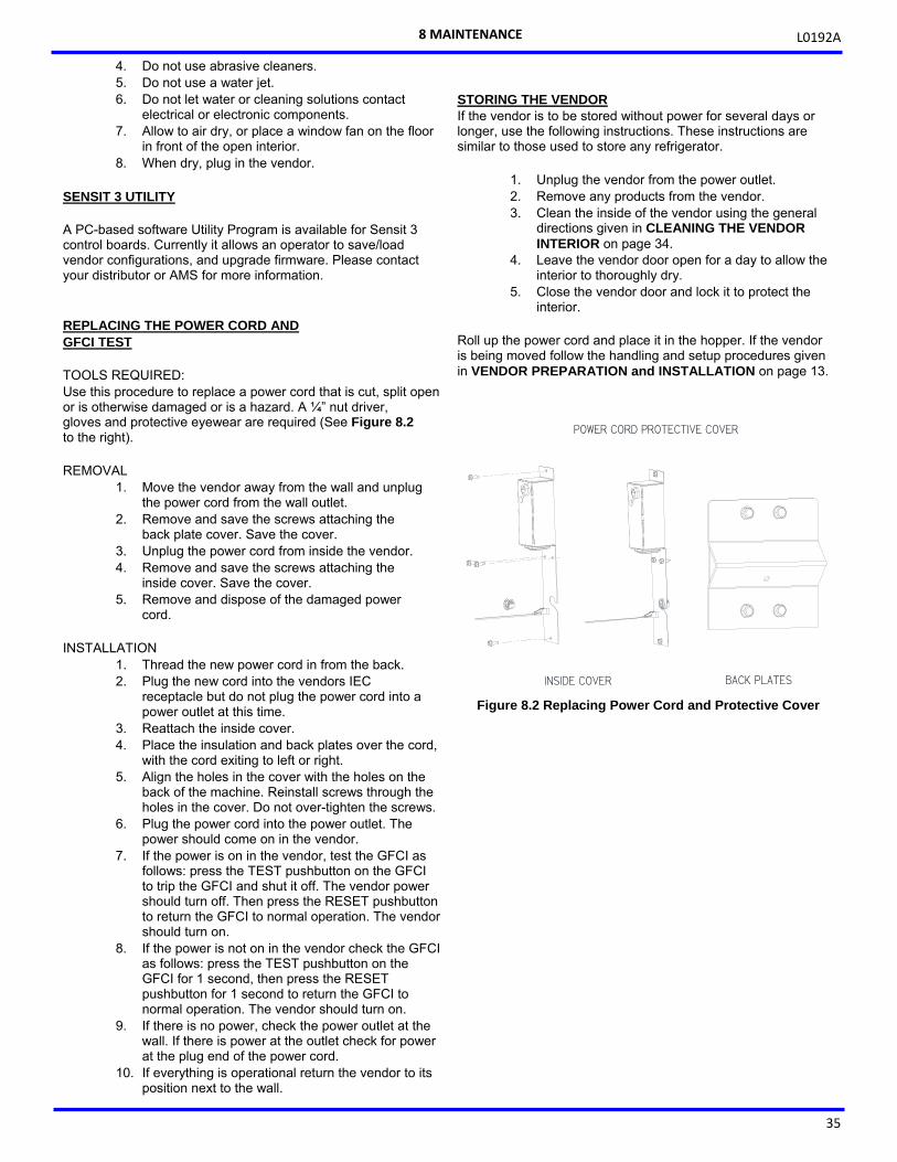
L0192A
35
4. Do not use abrasive cleaners. 5. Do not use a water jet. 6. Do not let water or cleaning solutions contact
electrical or electronic components. 7. Allow to air dry, or place a window fan on the floor
in front of the open interior. 8. When dry, plug in the vendor.
SENSIT 3 UTILITY A PC-based software Utility Program is available for Sensit 3 control boards. Currently it allows an operator to save/load vendor configurations, and upgrade firmware. Please contact your distributor or AMS for more information. REPLACING THE POWER CORD AND GFCI TEST TOOLS REQUIRED: Use this procedure to replace a power cord that is cut, split open or is otherwise damaged or is a hazard. A ¼” nut driver, gloves and protective eyewear are required (See Figure 8.2 to the right). REMOVAL
1. Move the vendor away from the wall and unplug the power cord from the wall outlet.
2. Remove and save the screws attaching the back plate cover. Save the cover.
3. Unplug the power cord from inside the vendor. 4. Remove and save the screws attaching the
inside cover. Save the cover. 5. Remove and dispose of the damaged power
cord. INSTALLATION
1. Thread the new power cord in from the back. 2. Plug the new cord into the vendors IEC
receptacle but do not plug the power cord into a power outlet at this time.
3. Reattach the inside cover. 4. Place the insulation and back plates over the cord,
with the cord exiting to left or right. 5. Align the holes in the cover with the holes on the
back of the machine. Reinstall screws through the holes in the cover. Do not over-tighten the screws.
6. Plug the power cord into the power outlet. The power should come on in the vendor.
7. If the power is on in the vendor, test the GFCI as follows: press the TEST pushbutton on the GFCI to trip the GFCI and shut it off. The vendor power should turn off. Then press the RESET pushbutton to return the GFCI to normal operation. The vendor should turn on.
8. If the power is not on in the vendor check the GFCI as follows: press the TEST pushbutton on the GFCI for 1 second, then press the RESET pushbutton for 1 second to return the GFCI to normal operation. The vendor should turn on.
9. If there is no power, check the power outlet at the wall. If there is power at the outlet check for power at the plug end of the power cord.
10. If everything is operational return the vendor to its position next to the wall.
STORING THE VENDOR If the vendor is to be stored without power for several days or longer, use the following instructions. These instructions are similar to those used to store any refrigerator.
1. Unplug the vendor from the power outlet. 2. Remove any products from the vendor. 3. Clean the inside of the vendor using the general
directions given in CLEANING THE VENDOR INTERIOR on page 34.
4. Leave the vendor door open for a day to allow the interior to thoroughly dry.
5. Close the vendor door and lock it to protect the interior.
Roll up the power cord and place it in the hopper. If the vendor is being moved follow the handling and setup procedures given in VENDOR PREPARATION and INSTALLATION on page 13.
8 MAINTENANCE
Figure 8.2 Replacing Power Cord and Protective Cover
POWER CORD PROTECTIVE COVER
INSIDE COVER BACK PLATES

L0192A
36
THIS PAGE INTENTIONALLY LEFT BLANK
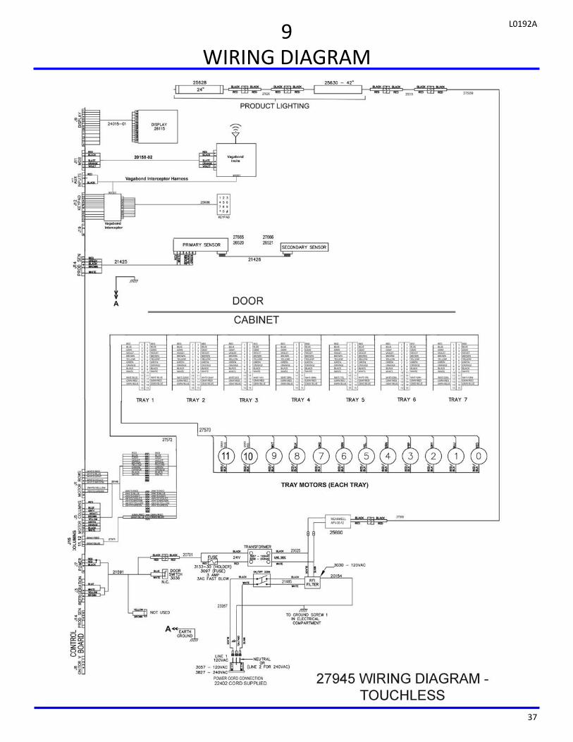
L0192A
37
9 WIRING DIAGRAM

L0192A
38
THIS PAGE INTENTIONALLY LEFT BLANK

L0192A
39
10
SUPPORTED DEX FIELDS NOTE: Certain fields may not be reported if the value is zero.
BA101 Bill Validator Serial Number BA102 Bill Validator Model Number BA103 Bill Validator Software Revision CA101 Coin changer serial number CA102 Coin changer model number CA103 Coin changer software revision CA201 Value of cash sales since initialization CA202 Number of cash vends since initialization CA203 Value of cash sales since last reset CA204 Number of cash vends since last reset CA301 Value of cash in since last reset CA302 Value of cash to the cash box since last reset CA303 Value of cash to tubes since last reset CA304 Value of bills in since last reset CA305 Value of cash in since initialization CA306 Value of cash to the cash box since initialization CA307 Value of cash to the tubes since initialization CA308 Value of bills in since initialization CA309 Value of bills in since last reset (DEX 6.0 Format) CA310 Value of bills in since initialization (DEX 6.0 Format) CA401 Value of cash dispensed since last reset CA402 Value of cash manually dispensed since last reset CA403 Value of cash dispensed since initialization CA404 Value of cash manually dispensed since initialization CA601 Number of DEX reads performed since initialization CA602 Number of door openings since initialization CA701 Value of cash discounts since last reset CA702 Value of cash discounts since initialization CA703 Number of cash discounts since last reset CA704 Number of cash discounts since initialization CA801 Value of cash overpay since last reset CA802 Value of cash overpay since initialization CA1001 Value of cash filled since last reset CA1002 Value of cash filled since initialization CA1501 Value of coin tube contents (as reported by the mech) CA1701 Coin type in payout tube (per MDB spec) CA1702 Coin value in payout tube (per MDB spec) CA1703 Number of coins in payout tube (as tracked by VMC) CA1706 Tube Full (1 if Yes, not sent if No) CB101 Control board serial number CB102 Control board model number CB103 Control board software revision
DA101 Cashless 1 Serial Number DA102 Cashless 1 Model Number DA103 Cashless 1 Software Revision DA201 Value of cashless 1 sales since initialization DA202 Number of cashless 1 vends since initialization DA203 Value of cashless 1 sales since last reset DA204 Number of cashless 1 vends since last reset DA401 Value credited to cashless 1 device since initialization DA402 Value credited to cashless 1 device since last reset DA501 Value of cashless 1 discounts since last reset DA502 Number of cashless 1 discounts since last reset DA503 Value of cashless 1 discounts since initialization DA504 Number of cashless 1 discounts since initialization DA505 Value of cashless 1 surcharges since last reset DA506 Number of cashless 1 surcharges since last reset DA507 Value of cashless 1 surcharges since initialization DA508 Number of cashless 1 surcharges since initialization DA901 Value of cashless overpay since last reset DA902 Value of cashless overpay since initialization DB101 Cashless 2 Serial Number DB102 Cashless 2 Model Number DB103 Cashless 2 Software Revision DB201 Value of cashless 2 sales since initialization DB202 Number of cashless 2 vends since initialization DB203 Value of cashless 2 sales since last reset DB204 Number of cashless 2 vends since last reset DB401 Value credited to cashless 2 device since initialization DB402 Value credited to cashless 2 device since last reset DB501 Value of cashless 2 discounts since last reset DB502 Number of cashless 2 discounts since last reset DB503 Value of cashless 2 discounts since initialization DB504 Number of cashless 2 discounts since initialization DB505 Value of cashless 2 surcharges since last reset DB506 Number of cashless 2 surcharges since last reset DB507 Value of cashless 2 surcharges since initialization DB508 Number of cashless 2 surcharges since initialization DXE01 Transmission Control Number: “1” DXE02 Number of Included Sets: “1” EA1011 Event Identification* EA1021 Date of Event (yymmdd – local date) EA1031 Time of Event (“hhmm”-DEX 5.0, “hhmmss” DEX 6.0)
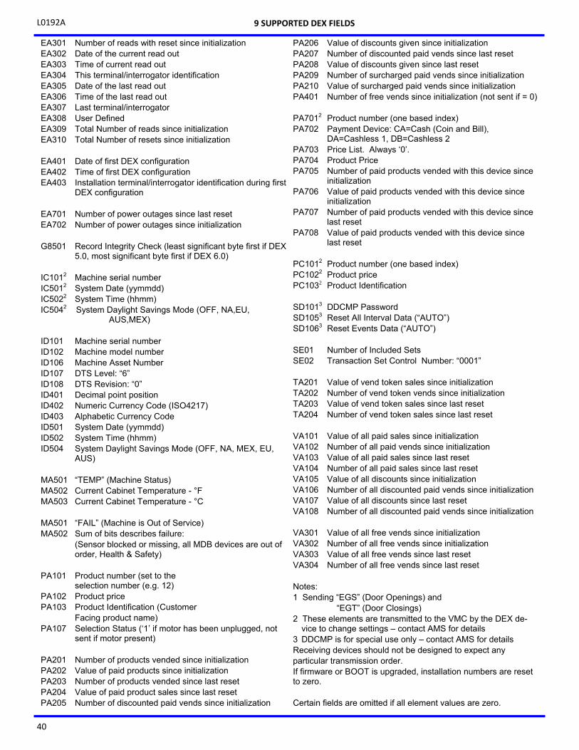
L0192A
40
EA301 Number of reads with reset since initialization EA302 Date of the current read out EA303 Time of current read out EA304 This terminal/interrogator identification EA305 Date of the last read out EA306 Time of the last read out EA307 Last terminal/interrogator EA308 User Defined EA309 Total Number of reads since initialization EA310 Total Number of resets since initialization EA401 Date of first DEX configuration EA402 Time of first DEX configuration EA403 Installation terminal/interrogator identification during first
DEX configuration EA701 Number of power outages since last reset EA702 Number of power outages since initialization G8501 Record Integrity Check (least significant byte first if DEX
5.0, most significant byte first if DEX 6.0) IC1012 Machine serial number IC5012 System Date (yymmdd) IC5022 System Time (hhmm) IC5042 System Daylight Savings Mode (OFF, NA,EU,
AUS,MEX) ID101 Machine serial number ID102 Machine model number ID106 Machine Asset Number ID107 DTS Level: “6” ID108 DTS Revision: “0” ID401 Decimal point position ID402 Numeric Currency Code (ISO4217) ID403 Alphabetic Currency Code ID501 System Date (yymmdd) ID502 System Time (hhmm) ID504 System Daylight Savings Mode (OFF, NA, MEX, EU,
AUS) MA501 “TEMP” (Machine Status) MA502 Current Cabinet Temperature - °F MA503 Current Cabinet Temperature - °C MA501 “FAIL” (Machine is Out of Service) MA502 Sum of bits describes failure: (Sensor blocked or missing, all MDB devices are out of
order, Health & Safety) PA101 Product number (set to the selection number (e.g. 12) PA102 Product price PA103 Product Identification (Customer Facing product name) PA107 Selection Status (‘1’ if motor has been unplugged, not
sent if motor present) PA201 Number of products vended since initialization PA202 Value of paid products since initialization PA203 Number of products vended since last reset PA204 Value of paid product sales since last reset PA205 Number of discounted paid vends since initialization
PA206 Value of discounts given since initialization PA207 Number of discounted paid vends since last reset PA208 Value of discounts given since last reset PA209 Number of surcharged paid vends since initialization PA210 Value of surcharged paid vends since initialization PA401 Number of free vends since initialization (not sent if = 0) PA7012 Product number (one based index) PA702 Payment Device: CA=Cash (Coin and Bill),
DA=Cashless 1, DB=Cashless 2 PA703 Price List. Always ‘0’. PA704 Product Price PA705 Number of paid products vended with this device since
initialization PA706 Value of paid products vended with this device since
initialization PA707 Number of paid products vended with this device since
last reset PA708 Value of paid products vended with this device since
last reset PC1012 Product number (one based index) PC1022 Product price PC1032 Product Identification SD1013 DDCMP Password SD1053 Reset All Interval Data (“AUTO”) SD1063 Reset Events Data (“AUTO”) SE01 Number of Included Sets SE02 Transaction Set Control Number: “0001” TA201 Value of vend token sales since initialization TA202 Number of vend token vends since initialization TA203 Value of vend token sales since last reset TA204 Number of vend token sales since last reset VA101 Value of all paid sales since initialization VA102 Number of all paid vends since initialization VA103 Value of all paid sales since last reset VA104 Number of all paid sales since last reset VA105 Value of all discounts since initialization VA106 Number of all discounted paid vends since initialization VA107 Value of all discounts since last reset VA108 Number of all discounted paid vends since initialization VA301 Value of all free vends since initialization VA302 Number of all free vends since initialization VA303 Value of all free vends since last reset VA304 Number of all free vends since last reset Notes: 1 Sending “EGS” (Door Openings) and “EGT” (Door Closings) 2 These elements are transmitted to the VMC by the DEX de-
vice to change settings – contact AMS for details 3 DDCMP is for special use only – contact AMS for details Receiving devices should not be designed to expect any particular transmission order. If firmware or BOOT is upgraded, installation numbers are reset to zero. Certain fields are omitted if all element values are zero.
9 SUPPORTED DEX FIELDS
L0192A
41
11
OPTIONAL EQUIPMENT
Part No. 20449 - Kit, Candy Pusher The candy pusher is an adjustable bar that mounts to any tray divider to keep tall candies from falling sideways. Four of these are provided with the standard glass front vendor. Part No. 20450 - Kit, Helix Splitter The helix splitter is a plastic divider that can be inserted into a small helix to divide each coil into two product openings, thereby doubling product capacity. The helix splitter works best with narrow products such as Life Savers.
Part No. 20535 - Kit, Cup Rail, Small Helix Part No. 20536 - Kit, Cup Rail, 4” Helix Part No. 20723 - Kit, Cup Rail, 3” Helix The cup rail is a flat plastic bar that can be placed inside the helix to provide a flat surface for rigid flat-bottomed packages that otherwise do not stay upright when placed in a helix. Examples would be drink boxes, small bottles, or individual serving cups of soup, pudding, etc. P/N 20786, Harness, Chip Programming Use with the speech hardware and software program. P/N 3701, S3 Utility Programming software Use with 20786 harness. Part No. 24046 - Kit, Mini Dispenser Replaces a snack selection with 1.5” helix and spacer. Part No. 25722 -K-Cup Kit Installation of K-Cup rail assembly to a snack tray assembly.

L0192A
42
SERVICE MODE 1. Open door and press the yellow switch on the con-
trol board to enter SERVICE MODE. 2. Press “#” or “*” to scroll through the functions. 3. Return to vend mode by closing the door or press-
ing the mode switch. SERVICE MENU ITEMS (UNABBREVIATED) ERROR CODES
# NEXT ERROR 2 DETAILS 1 SUBLEVEL ERRORS 0 CLEAR ERROR
ACCOUNTING DATA
1. HISTORICAL VENDS 2. HISTORICAL VALUE 3. RESETTABLE VENDS 4. RESETTABLE VALUE 5. HISTORICAL SELECTIONS 6. CLEAR ALL 7. RESETTABLE CARD 8. CASHBOX COINS 9. STACKED BILLS
FILL/DISPENSE
1. SELECT TUBE 1-6 2. OR INSERT COIN
DELAYED SALES
1. START DELAY 2. CANCEL DELAY 3. SET DELAY 4. CLEAR ALL 5. EDIT SELECTIONS
TEMPERATURE
1. CURRENT TEMP 2. SETPOINT 3. START LOG 4. VIEW LOG 5. HEALTH TEST* EDIT SELECTIONS
PRICE SETTINGS 1. SET PRICES 2. VALUEVEND 3. CALORIES
TRAY SETUP
1. TEST MOTORS 2. LINK MOTORS 3. MOTOR TYPE 4. DELAYED STOP 5. LETTER / NUMBER 6. CONFIGURE 7. COUPLE MOTORS
MDB SETTINGS 1. FORCE VEND 2. NO CHEAT 3. CHANGE BILL 4. HOLD LOST CREDIT 5. MULTI-VEND 6. LEVEL2 COIN MECH. 7. INSTANT REVALUATION 8. HIDE CARD VALUE 9. CARD REFUND
OPTIONS
1. MESSAGE 2. PRIZE 3. LANGUAGE 4. PRODUCT SENSOR 5. SPEECH 6. SERIAL NUMBER 7. INSTANT REFUND
SALES BLOCKING 1 - 4 SET PERIODS CLOCK SETTINGS
1. TIME AND DATE 2. DAYLIGHT SAVINGS 3. DISPLAY CLOCK 4. 12/24 FORMAT
FREE VEND
1. VIEW / EDIT AUXILIARY OUTPUT
1. VIEW / EDIT DATA LOGS
1. TEMPERATURE 2. POWER 3. DOOR SWITCH
ENERGYSENSIT
1. ON/OFF 2. CLEAR HISTORY 3. SET TEMPERATURE CHANGE 4. SET PATTERN TIME 5. SET HISTORICAL FACTOR 6. SET DELAY TIME 7. LIGHTING
Note: When not in Service Mode and with door open, press # to move out-of-position switched motors to Home position (Home/Sensor +/2 or Home/Sensor +/3 only).
SERVICE MENU MAP

L0192A
43

L0192A
44
THIS PAGE INTENTIONALLY LEFT BLANK


