Embed Size (px)
Citation preview
Structure-Property Relationships in the Design of High Performance Membranes for
Water Desalination, Specifically Reverse Osmosis, Using Sulfonated Poly(Arylene Ether
Sulfone)s
Dana Abraham Kazerooni
Dissertation submitted to the faculty of the Virginia Polytechnic Institute and State
University in partial fulfillment of the requirements for the degree of
Doctor of Philosophy
In
Macromolecular Science and Engineering
Judy S. Riffle, Committee Chair
John J. Lesko
Michael J. Bortner
Michael D. Schulz
Benny D. Freeman
September 2021
Blacksburg, VA
Keywords: Sulfonated Polysulfones, Post-Sulfonation, Polycondensation, Water
Desalination, Reverse Osmosis, Poly(Arylene Ether Sulfone)s
Copyright 2021: Dana Abraham Kazerooni
i
Structure-Property Relationships in the Design of High Performance Membranes for Water
Desalination, Specifically Reverse Osmosis, Using Sulfonated Poly(Arylene Ether Sulfone)s
Dana Abraham Kazerooni
ABSTRACT
Over 30% of the world’s population does not have access to safe drinking water, and the
need for clean water spans further than just for human consumption. Currently, we use
freshwater for growing agriculture, raising livestock, generating power, sanitizing waste, mining
resources, and fabricating consumer goods. With that being said, the world is beginning to feel
pressure from the excessive freshwater withdrawal compared to the current freshwater supply.
This water stress is causing a water crisis. Places including Australia, South Africa, and
California in the United States, just to name a few, are beginning to run out of fresh water to
support daily societal demands. This is a phenomenon that is indiscriminately observed in all
ranges of economically and politically developed countries and environments. However, it is
important to note that less politically and economically developed countries especially those in
arid climates, experience higher water stress than countries without such qualities.
With only 2.5% of the world’s water being freshwater and 30% of it being accessible as
either ground or surface water, freshwater is a scarce resource, especially with the growing
population and society’s demand for water. Since the remaining 97.5% of water is composed of
either brackish or seawater (saline water sources), one way to overcome the water stress would
be to convert saline water into freshwater. As a result, various desalination techniques have been
developed in the last 80 years that employ either membrane technology or temperature
alterations to desalinate either brackish or seawater.
One of the fastest growing methods for producing freshwater is reverse osmosis. Reverse
osmosis uses an externally applied pressure, in the form of a cross flow back pressure, to
overcome the osmotic pressure produced by the saline gradient across a semi-permeable
membrane. The semi permeable membrane commercially consists of an interfacially
polymerized aromatic polyamide thin film composite with a polysulfone porous backing that
allows water to pass through while barring the transport of salt ions.
This research focuses on the development of sulfonated poly(arylene ether sulfone)
derivatives with differing amounts of sulfonation and with the ions placed at different structural
positions. Previously, such materials were tested as potential high performance fuel cell
membranes, but they are also of interest as potential high performance water desalination
membranes, specifically for reverse osmosis.
Two different methods were used to synthesize the sulfonated polysulfone derivatives: direct
polymerization and post-modification of a non-sulfonated active polysulfone. The polysulfones
from direct polymerization incorporated specialty sulfonated monomers, which were
stoichiometrically controlled during the polymerization. Sulfonated polysulfones that were
synthesized from post sulfonation incorporated biphenol and hydroquinone monomer units
randomly throughout the polysufone backbones. These units could be sulfonated selectively
because of their activation towards electrophilic aromatic substitution with sulfuric acid.
Each of the polymers were cast into films ranging between 20-100 microns in thickness and
tested for water uptake, hydrated uniaxial tensile properties, crossflow water and salt transport
properties, and for crosslinked samples, gel fractions. The water uptakes from all the
ii
polysulfones were tuned by the degree of sulfonation or disulfonation present in the polymer.
This was either controlled via the presence of a sulfonated monomer or a monomer that was
active toward electrophilic aromatic substitution after polycondensation of the polysulfone. All
polymers exhibited increases in their water uptake as the degree of sulfonation increased. We
also observed a decreasing trend in the hydrated mechanical properties of the films for all the
high molecular weight linear polymers as the water uptake was increased. The directly
polymerized sulfonated polysulfones were found to have high hydrated elastic moduli ranging
between 400 and 1000 MPa, while the post sulfonated counterparts (with either hydroquinone or
biphenol incorporated in their structures) exhibited elastic moduli ranging between 1000 and
1500 MPa. It is important to note that the structures of the polymers were slightly different from
one another because of the technique used to synthesize them. Thus, the increases in hydrated
moduli among polymers synthesized via different routes may have influences from differences in
chemical structures.
Some of the polymers with higher degrees of sulfonation were synthesized as amine
terminated oligomers with varying controlled molecular weights. The two targeted molecular
weights were 5 and 10 kDa. Those oligomers were then crosslinked with a tetra-functional
epoxide agent. The increases in sulfonation allowed for increases in water uptake and in theory,
the water throughput through the sulfonated polysulfone membrane. Decreases in hydrated
mechanical performance of the crosslinked networks with increasing degrees of sulfonation were
also observed, similar to their high molecular weight linear counterparts. The directly
polymerized crosslinked networks had salt permeabilities that plateaued at 70% disulfonation for
both the 5 and 10 kDa polymers. Thus, we expect disulfonation content greater than 70% would
lead to higher water throughput without significant increases in salt transport.
iii
Structure-Property Relationships in the Design of High Performance Membranes for Water
Desalination, Specifically Reverse Osmosis, Using Sulfonated Poly(Arylene Ether Sulfone)s
Dana Abraham Kazerooni
GENERAL AUDIENCE ABSTRACT
A worldwide shortage of freshwater is becoming more problematic by each passing day. The
World Health Organization and the United Nation’s World Water Assessment Program predict
that by 2025, 50-66% of the world’s population will be living in a water-stressed area. This
includes any area that experiences higher clean water withdrawals than are available. This
includes but is not limited to areas that are politically unstable, technologically disadvantaged,
resource deficient, located in arid climates, and highly populated. To put this further into
perspective, only 2.5% of the available water on earth is freshwater. Freshwater typically has low
concentrations of dissolved salts that are safe for human consumption and use. Of the available
freshwater, only 30% of it is actually accessible for use through either surface or groundwater
reservoirs, making the amount of clean water available for usage already a scarce resource.
On the other hand, 97.5% of the world’s water is composed of saline water reservoirs in the
form of brackish and seawater. Through harnessing, seawater and removing the excess dissolved
salt ions, the salt water can be converted to freshwater. Two major methods have been developed
to remove the dissolved ions from water through either membrane filtration or thermal phase
changes. One of the fastest growing membrane filtration techniques used worldwide is reverse
osmosis. Reverse osmosis refers to the use of applied pressure across a semipermeable
membrane to desalinate saline water. The semipermeable membrane prevents the migration of
salt ions through the membrane while allowing transport of water.
This work has focused on developing new polymers that can increase the overall efficiency
of water desalination. Different types of high performance sulfonated polysulfone derivative
polymers were synthesized and used to make membranes that were subsequently tested for
performance. Relationships between the polymer structure, process, and properties were
quantified through different analytical techniques. This study showed how the properties of
sulfonated polysulfone membranes may be manipulated depending on structural modifications
and processing to increase both the material’s water throughput and salt rejection.
iv
Acknowledgements
My PhD journey has been both enlightening and entertaining. The opportunities that I had
and the people I met along the journey will forever resonate with me. I could not have achieved
this feat without the support and encouragement of both my family and friends. Thus, I would
like to extend my gratitude to those who supported me during my doctoral pursuit at Virginia
Tech.
I would like to thank both the faculty and staff at Virginia Tech that helped me through my
journey. Without the support from the departments of Macromolecular Innovation Institute,
Materials Science and Engineering, and Chemistry, I would not have made it this far.
Specifically, I would like to thank Kim Felix, Kim Grandstaff, Susan Fleming-Cook, Dr. Thomas
Staley, Dr. Carlos Suchicital, and Joli Huynh from the above departments. I also want to extend
my gratitude to the faculty who allowed me to audit their classes for my own intellectual
enrichment.
I would like to thank my parents, John and Mehri Kazerooni, as well as my older brother and
sister-in-law, Borna Kazerooni and Pariya Pourazam, for their continual support throughout my
educational career. I would also like to acknowledge my extended family, Paria Moghaddar,
Parvin Moghaddar, and Nima Babr. I also could not have achieved this feat without my friends
Aaron Okwei, Alain Mbtang, Kevin Mekulu, Abideena Dambo, Dr. Tianran Chen, Josh Thomas,
David Park, Ryan Gray, Daina Novo, Brittany Nichols, Austin Fergussen, Stella Petrova, Chris
Cole, and Tyler Sequine who provided support during my studies at Virginia Tech. I also would
like to give special thanks to my lab mates, Dr. Amin Daryaei, Dr. Shreya Roy Choudhury, Dr.
Rui Zhang, Dr. Matt Joseph, Dr. Ran Liu, Dr. Greg Miller, and Dr. Trevor Schumacher, for their
help during my time as a PhD student in the lab.
v
In addition, I would like to thank the people, who inspired me to be who I am today, Jeff
Bezos, Warren Buffet, Bill Gates, Elon Musk, Mukesh Ambani, Amancio Ortega, CT Fletcher,
Ronnie Coleman, Al Pacino, Robert De Niro, Daivd Goggins, Les Brown, Jeff Cavalier, Walter
Bond, JeMone Smith, Dr. Donald Sadoway, Dr. Ben Colman, and Dr. James McGrath. I would
like to give a special thanks to my colleagues and mentors from the Naval Research Laboratory,
Dr. James Wollmershauser and Dr. Ed Gorzkowski. Lastly, I would like to thank my advisors,
Dr. Judy Riffle and Dr. Jack Lesko, and the remainder of my committee, Dr. Michael Bortner,
Dr. Michael Schulz, and Dr. Benny Freeman.
vi
Attributions
This section acknowledges the various colleagues that have aided in the research presented in the
chapters in this dissertation. There contriburions are to the work are highlighted below:
Chapter 2 – Post-Sulfonation of Activated Biphenol Containing Poly(Arylene Ether
Sulfone) Polymers for Reverse Osmosis Membranes
Shreya Roy Choudhury, PhD, is currently working at Corning Incorporated and she ran and
analyzed Gel Permeation Chromatography data on the synthesized polymers.
Trevor I. Schumacher, PhD, is currently working at NALA Systems, Inc. and he assisted in
running and analyzing Gel Permeation Chromatography of various copolymers.
Kyle Titus-Glover, MBA, is currently working on his PhD in Mechanical Engineering and he
running the crossflow apparatus to get membrane transport properties.
John J. Lesko, PhD, is currently the Director of Engineering Research at the Rou Insitute at
Northeastern University and he was the advisor and one of the overseers of the project as a
co-principal investigator.
Judy S. Riffle, PhD, is currently the Chief Technical Officer at NALA Systems, Inc. and she
was the advisor and one of the overseers of the project as a co-prinicpal investigator.
Chapter 3 – Hydrated Mechanical Properties of Sulfonated Poly(Arylene Ether Sulfone)
Membranes
Chapter 4 – Quantifying Transport through a Reverse Osmosis Membrane: Design,
Construction, and Testing of a Crossflow Apparatus
Chapter 5 – Structure-Property Relationships of Crosslinked Disulfonated Poly(Arylene
Ether Sulfone) Membranes for Desalination of Water
Amin Daryaei, PhD, is currently working at Vertex Pharmaceticals and he synthesized the
polymers.
Eui-Soung Jang, PhD, is currently working at Intel and he contributed to measuring the water
transport of the copolymers.
Shreya Roy Choudhury, PhD, is currently working at Corning Incorporated and she ran and
alnayzed Gel Permeation Chromatography data on the synthesized polymers.
John J. Lesko, PhD, is currently the Director of Engineering Research at the Rou Insitute at
Northeastern University and he was the advisor and one of the overseers of the project as a
co-principal investigator.
Benny D. Freeman, PhD, is currently a professor at the University of Texas at Austin and he
was the advisor and one of the overseers of the project as a co-prinicpal investigator.
Judy S. Riffle, PhD, is currently the Chief Technical Officer at NALA Systems, Inc. and she
was the advisor and one of the overseers of the project as a co-prinicpal investigator.
James E. McGrath, PhD, currently deceased was the advisor and of the overseers of the
project as a co-prinicpal investigator.
vii
Chapter 6 – Synthesis and Membrane Properties of Sulfonated Poly(Arylene Ether
Sulfone) Statistical Copolymers for Electrolysis of Water: Influence of Meta- and Para-
Subsituted Comonomers
Amin Daryaei, PhD, is currently working at Vertex Pharmaceticals and he synthesized the
polymers.
Gregory C. Miller, PhD, is currently working at Plastics Engineering Company and he
oversaw the thermal anaylsis of the linear copolymers.
Jason Willey, MS, currently works at Giner Electrochemical Systems Inc. and he preformed
proton conductivity and H2 gas permeability tests.
Shreya Roy Choudhury, PhD, is currently working at Corning Incorporated and she ran and
alnayzed Gel Permeation Chromatography data on the synthesized polymers.
Britannia Vondrasek, PhD, is currently working at Arvin Education Center and she prepared
samples for mechanical testing as well assist in analsysis of uniaxial measurements.
Matthew R. Burtner, BS, is currently working at the Chemours Company and he assisted in
measuring mechanical properties.
Cortney Mittelsteadt, PhD, is currently the Chief Technical Officer at Giner Electrochemical
Systems Inc. and she oversaw the membranes transport properties testing.
John J. Lesko, PhD, is currently the Director of Engineering Research at the Rou Insitute at
Northeastern University and he was the advisor and one of the overseers of the project as a
co-principal investigator.
Judy S. Riffle, PhD, is currently the Chief Technical Officer at NALA Systems, Inc. and she
was the advisor and of the overseers of the project as a co-prinicpal investigator.
James E. McGrath, PhD, currently deceased was the advisor and of the overseers of the
project as a co-prinicpal investigator.
Chapter 7 – Synthesis and Characterization of Post-Sulfonated Poly(Arylene Ether
Sulfone) Membranes for Potential Applications in Water Desalination
Shreya Roy Choudhury, PhD, is currently working at Corning Incorporated and she
preformed the synthesis and Gel Permeation Chromatrogrpahy analysis for the various
polymers and oligomers.
Ozma Lane, PhD, is currently working at Owens Corning Corporation and she preformed the
kinetic studies of the polymers.
Gurtej Singh Narang, PhD, is currently working at Sterimed Group and he assisted in
synthesing some of the oligomers and polymers.
Eui-Soung Jang, PhD, is currently working at Intel and he contributed to measuring the water
transport of the copolymers.
Benny D. Freeman, PhD, is currently a professor at the University of Texas at Austin and he
was the advisor and one of the overseers of the project as a co-prinicpal investigator.
John J. Lesko, PhD, is currently the Director of Engineering Research at the Rou Insitute at
Northeastern University and he was the advisor and one of the overseers of the project as a
co-principal investigator.
Judy S. Riffle, PhD, is currently the Chief Technical Officer at NALA Systems, Inc. and she
was the advisor and of the overseers of the project as a co-prinicpal investigator.
viii
Table of Contents
Chapter 1: Review of Water Purification and Desalination: Specifically Materials for
Reverse Osmosis Membranes ................................................................................................ 1
1.1 Abstract .......................................................................................................................... 1
1.2 Putting Water into Perspective ....................................................................................... 1
1.3 Emerging Water Scarcity Crisis ..................................................................................... 4
1.4 Water Treatment/Desalination Techniques .................................................................. 12
1.4.1 Membrane Based Desalination/Separation ......................................................... 14
1.4.1.1 Reverse Osmosis (RO) ......................................................................... 17
1.4.1.2 Nanofiltration (NF) ............................................................................... 18
1.4.1.3 Ultrafiltration (UF) ............................................................................... 19
1.4.1.4 Microfiltration ...................................................................................... 20
1.4.1.5 Membrane Distillation (MD) ................................................................ 22
1.4.1.6 Electrodiaylsis (ED) ............................................................................. 24
1.4.1.7 Capacitive Deionization (CDI) and Membrane Capacitive Deionization
(MCDI) ............................................................................................................. 27
1.4.2 Thermally Processed Desalination ...................................................................... 30
1.4.2.1 Distillation ............................................................................................ 31
1.4.2.1.1 Multi-Stage Flash Distillation (MSFD) ........................................... 32
1.4.2.1.2 Solar Distillation .............................................................................. 33
1.4.2.1.3 Vacuum Distillation ......................................................................... 34
1.4.2.1.4 Multiple Effect Distillation (MED) .................................................. 34
1.4.2.2 Freeze-Thaw or Freezing-Melting ........................................................ 36
1.5 Desalination Plant Designs ........................................................................................... 37
1.6 RO Membrane Design and Materials: Past, Present, and Future ................................. 39
1.6.1 Membrane Designs .............................................................................................. 41
1.6.1.1 Porous Membranes ............................................................................... 43
1.6.1.2 Asymmetric Membranes ...................................................................... 44
1.6.1.3 Thin Film Composites (TFCs) ............................................................. 45
1.6.2 Membrane Materials ........................................................................................... 49
1.6.2.1 Cellulose Acetate Membranes .............................................................. 50
1.6.2.2 Polyamide Membranes ......................................................................... 54
1.6.2.3 Nanoporous Graphene Membranes ...................................................... 61
1.6.2.4 Ceramic Membranes ............................................................................. 63
ix
1.7 Research Objectives ..................................................................................................... 64
1.8 Conclusion .................................................................................................................... 65
1.9 References .................................................................................................................... 65
Chapter 2: Post-Sulfonation of Activated Biphenol Containing Poly(Arylene Ether
Sulfone) Polymers for Reverse Osmosis Membranes ........................................................ 77
2.1 Abstract ........................................................................................................................ 77
2.2 Introduction .................................................................................................................. 78
2.3 Experimental ................................................................................................................ 81
2.3.1 Materials .............................................................................................................. 81
2.3.2 Synthesis of biphenol containing linear poly(arylene ether sulfone) and
sulfonated poly(arylene ether sulfone) copolymers ..................................................... 82
2.3.3 Proton nuclear magnetic resonance spectroscopy (1H NMR) ............................. 83
2.3.4 Molecular weight determination using size exclusion chromatography (SEC) .. 83
2.3.5 Polymer titration .................................................................................................. 84
2.3.6 Film casting ......................................................................................................... 84
2.3.7 Water uptake ....................................................................................................... 85
2.3.8 Hydrated uniaxial tensile testing ......................................................................... 85
2.3.9 Membrane cross flow measurements to analyze water flux and salt rejection and
to calculate water permeability ..................................................................................... 86
2.4 Results and Discussion ................................................................................................. 87
2.4.1 Synthesis of non-sulfonated and sulfonated biphenol containing poly(arylene
ether sulfone) copolymers ............................................................................................ 87
2.4.2 1H NMR analysis suggesting selective and quantitative post-sulfonation .......... 88
2.4.3 Molecular weights of the copolymers before and after post-sulfonation ............ 90
2.4.4 Quantifying sulfonate groups on SBiPS polymers through titration................... 92
2.4.5 Water uptake of non-sulfonated and post-sulfonated BiPS films ....................... 93
2.4.6 Hydrated mechanical properties of BiPS and SBiPS polymers .......................... 94
2.4.7 Transport properties ............................................................................................ 95
2.5 Conclusions .................................................................................................................. 97
2.6 References .................................................................................................................... 97
Chapter 3: Hydrated Mechanical Properties of Sulfonated Poly(Arylene Ether
Sulfone) Membranes ........................................................................................................... 100
3.1 Abstract ...................................................................................................................... 100
x
3.2 Introduction ................................................................................................................ 101
3.3 Experimental .............................................................................................................. 106
3.3.1 High molecular weight sulfonated poly(arylene ether sulfone) synthesis ........ 106
3.3.1.1 Direct polymerization of sulfonated poly(arylene ether sulfone)s using
sulfonated monomers ....................................................................................... 106
3.3.1.2 Synthesis of activated poly(arylene ether sulfone)s and post-sulfonation
……………………………………………………………………….107
3.3.2 Crosslinked sulfonated poly(arylene ether sulfone) oligomers ......................... 108
3.3.2.1 One pot synthesis of meta-aminophenol (m-AP) terminated oligomers
of sulfonated poly(arylene ether sulfone)s through direct polymerization of
sulfonated monomers ....................................................................................... 108
3.3.2.2 Synthesis of m-AP terminated activated poly(arylene ether sulfone)s
and its post-sulfonation .................................................................................... 109
3.3.3 Molecular weight determination using size exclusion chromatography (SEC) 110
3.3.4 Film casting ....................................................................................................... 110
3.3.5 High molecular weight film casting .................................................................. 110
3.3.6 Epoxy crosslinked m-AP oligomers film casting .............................................. 111
3.3.7 Hydrated uniaxial tensile testing ....................................................................... 111
3.3.8 Ion exchange capacity calculations ................................................................... 112
3.3.9 Water uptake ..................................................................................................... 112
3.4 Results and Discussion ............................................................................................... 113
3.4.1 Directly polymerized sulfonated poly(arylene ether sulfone) ........................... 113
3.4.2 Non-sulfonated and post sulfonation of hydroquinone and biphenol containing
poly(arylene ether sulfone)s ....................................................................................... 118
3.4.3 Epoxy-amine sulfonated poly(arylene ether sulfone) networks synthesized with 5
and 10 kDa molecular weight oligomers .................................................................... 122
3.4.4 Directly polymerized crosslinked disulfonated poly(arylene ether sulfone)
networks.. …………………………………………………………………………...125
3.4.5 Post-sulfonated crosslinked poly(arylene ether sulfone) networks ................... 128
3.5 Conclusions ................................................................................................................ 130
3.6 References .................................................................................................................. 131
Chapter 4: Quantifying Transport through a Reverse Osmosis Membrane: Design,
Construction, and Testing of a Crossflow Apparatus ..................................................... 134
4.1 Abstract ...................................................................................................................... 134
4.2 Introduction ................................................................................................................ 134
xi
4.3 Experimental .............................................................................................................. 139
4.3.1 Crossflow apparatus design and construction ................................................... 139
4.3.2 Measuring flux and salt rejection for membranes ............................................. 140
4.4 Results and Discussion ............................................................................................... 141
4.5 Conclusions ................................................................................................................ 144
4.6 References .................................................................................................................. 144
Chapter 5: Structure-Property Relationships of Crosslinked Disulfonated
Poly(Arylene Ether Sulfone) Membranes for Desalination of Water ............................ 146
5.1 Abstract ...................................................................................................................... 146
5.2 Introduction ................................................................................................................ 147
5.3 Experimental .............................................................................................................. 149
5.3.1 Materials ............................................................................................................ 149
5.3.2 Synthesis of m-AP terminated oligomers .......................................................... 150
5.3.3 Nuclear magnetic resonance spectroscopy (NMR) ........................................... 151
5.3.4 Size exclusion chromatography (SEC) ............................................................. 151
5.3.5 Membrane casting and characterization ............................................................ 152
5.3.6 Gel fraction measurements ................................................................................ 152
5.3.7 Water uptake ..................................................................................................... 153
5.3.8 Tensile tests ....................................................................................................... 153
5.3.9 Salt permeability ............................................................................................... 154
5.4 Results and discussion ................................................................................................ 154
5.4.1 Synthesis and characterization of disulfonated poly(arylene ether sulfone)
oligomers with terminal functionality ........................................................................ 154
5.4.2 Crosslinking of the oligomers and membrane casting ...................................... 157
5.4.3 Fundamental properties of the crosslinked membranes .................................... 158
5.4.4 Salt permeability ............................................................................................... 161
5.5 Conclusions ................................................................................................................ 165
5.6 References .................................................................................................................. 165
Chapter 6: Synthesis and Membrane Properties of Sulfonated Poly(Arylene Ether
Sulfone) Statistical Copolymers for Electrolysis of Water: Influence of Meta- and Para-
Substituted Comonomers ................................................................................................... 169
6.1 Abstract ...................................................................................................................... 169
6.2 Introduction ................................................................................................................ 170
xii
6.3 Experimental Section ................................................................................................. 172
6.3.1 Materials ............................................................................................................ 172
6.3.2 Synthesis of Statistical Copolymers .................................................................. 173
6.3.3 Nuclear Magnetic Resonance Spectroscopy (NMR) ........................................ 174
6.3.4 Size Exclusion Chromatography (SEC) ............................................................ 174
6.3.5 Membrane Casting and Characterization .......................................................... 175
6.3.6 Ion Exchange Capacity (IEC) ........................................................................... 176
6.3.7 Water Uptake at Ambient and Elevated Temperatures ..................................... 176
6.3.8 Differential Scanning Calorimetry (DSC)......................................................... 177
6.3.9 Tensile Tests ...................................................................................................... 177
6.3.10 H2 Gas Permeability (P) ............................................................................ 178
6.3.11 Proton Conductivity (σ) ............................................................................ 179
6.3.12 Performance .............................................................................................. 179
6.4 Results and Discussion ............................................................................................... 180
6.4.1 Synthesis and Characterization of Statistical Copolymers ................................ 180
6.4.2 Membrane Water Uptake .................................................................................. 182
6.4.3 Membrane Thermal Properties .......................................................................... 184
6.4.4 Mechanical Properties ....................................................................................... 186
6.4.5 Proton Conductivity .......................................................................................... 189
6.4.6 H2 Gas Permeability in Saturated Water Vapor ................................................ 191
6.4.7 Performance ...................................................................................................... 192
6.5 Conclusions ................................................................................................................ 193
6.6 References .................................................................................................................. 194
Chapter 7: Synthesis and Characterization of Post-Sulfonated Poly(Arylene Ether
Sulfone) Membranes for Potential Applications in Water Desalination ....................... 199
7.1 Abstract ...................................................................................................................... 199
7.2 Introduction ................................................................................................................ 200
7.3 Experimental .............................................................................................................. 203
7.3.1 Materials ............................................................................................................ 203
7.3.2 Kinetics of post-sulfonation of a poly(arylene ether sulfone) containing
hydroquinone: Post-sulfonation of Radel A ............................................................... 204
xiii
7.3.3 Synthesis of sulfonated poly(arylene ether sulfone)s with isolated sulfonated
rings by post-sulfonation ............................................................................................ 205
7.3.3.1 Synthesis of amine terminated hydroquinone containing polysulfone
(xx-HQS-y) oligomers (I) with different amounts of hydroquinone relative to
Bis-S (where xx = degree of sulfonation, y = targeted molecular weight) ...... 205
7.3.3.2 Synthesis of high molecular weight hydroquinone sulfone (xx-HQS)
polymers ........................................................................................................... 206
7.3.3.3 Post sulfonation of hydroquinone sulfone oligomers (xx-SHQS-5k and
xx-SHQS-10k) and high molecular weight polymers (xx-SHQS) .................. 206
7.3.4 Characterization ................................................................................................ 207
7.3.4.1 Nuclear magnetic resonance spectroscopy (NMR) ............................ 207
7.3.4.2 End group analysis of the oligomers by fluorine derivatization ........ 207
7.3.4.3 Size Exclusion Chromatography (SEC) ............................................. 208
7.3.5 Film casting and characterization ...................................................................... 209
7.3.5.1 Epoxy-amine crosslinking of the oligomer ........................................ 209
7.3.5.2 Film casting of the high molecular weight polymers ......................... 209
7.3.5.3 Gel fraction of the high molecular weight polymers .......................... 210
7.3.5.4 Water uptake ....................................................................................... 210
7.3.5.5 Tensile tests of hydrated membranes ................................................. 211
7.4 Results and discussion ................................................................................................ 211
7.4.1 Synthesis and characterization of controlled molecular weight oligomers ....... 212
7.4.1.1 Post -sulfonation of structure II .......................................................... 214
7.4.2 Structure and molecular weights of the functional oligomers........................... 216
7.4.3 Film casting ....................................................................................................... 221
7.4.4 Membrane properties......................................................................................... 222
7.4.5 Hydrated mechanical properties of the membranes .......................................... 225
7.5 Conclusions ................................................................................................................ 228
7.6 References .................................................................................................................. 228
Chapter 8: Conclusions and Recommended Future Work ......................................... 232
8.1 Research Conclusions ................................................................................................. 232
8.1.1 Synthesis and characterization of sulfonated poly(arlyene ether sulfone)s ...... 233
8.2 Suggested Future Work .............................................................................................. 236
8.2.1 Further characterization of sulfonated poly(arylene ether sulfone)s ................. 236

xiv
8.2.2 Synthesis of macrocyclic nanoporouns membrane for reverse osmosis and
nanofiltration .............................................................................................................. 239
8.3 References .................................................................................................................. 244
xv
List of Figures
Figure 1.1 Breakdown of world’s water resources. From Where is Earth’s Water? U.S.
Geological Survey [2, 4]. ..................................................................................... 2
Figure 1.2 Pie chart categorizing the amount of water that was distributed in (A) the United
States in 2015 and (B) globally. Values in parentheses refer to the amount of
water used in billions of gallons per day. From Estimated use of water in the
United States in 2015, U.S. Geological Survey and Food and Agriculture
Organization of the United Nations AQUASTAT Report [6, 7]. ........................ 3
Figure 1.3 Global physical fresh water stress levels. Physical fresh water stress is
calculated as a percent volume ratio of fresh water withdrawn annually over the
total fresh water sources in the specific region. ................................................... 8 Figure 1.4 Average annual people impacted from inadequate water and sanitation caused
by water related disasters, diseases, and conflicts. *People affected refer to
people requiring immediate assistance during emergencies; this may include
displaced and evacuated people. .......................................................................... 9 Figure 1.5 Prediction of (A) Water Supply, (B) Water Demand, and (C) Water Stress,
Worldwide in 2030 using the World Resource Institutes AQUEDUCT Software
assuming “business as usual,” which refers to a world with a stable developing
economy with steady rise in global carbon emissions. ...................................... 11
Figure 1.6 Pie chart demonstrating each major desalination’s percent water capacity
produced [58]. .................................................................................................... 14
Figure 1.7 Membrane filtration methods used to filter out different particles based on size.
Image reproduced from Armstrong et al. “Challenges and opportunities at the
nexus of energy, water, and food: A perspective from southwest United States”
[36]. .................................................................................................................... 15
Figure 1.8 Inline and cross flow filtration configurations. Image was reproduced from
............................................................................................................................ 16 Figure 1.9 Inner workings of a RO plant. Breakdown of what is inside a spiral wound RO
module and the principle of a reverse osmosis membrane. Images were used
from sources [67], [68], and ............................................................................... 17
Figure 1.10 Four major configurations of membrane distillation for desalinating briny
solutions: direct contact MD (DCMD), air gap MD (AGMD), sweeping gas MD
(SGMD) or thermostatic sweeping gas MD, and vacuum MD (VMD) [94]. .... 23 Figure 1.11 Donnan equilibrium and Donnan exclusion of ions represented in a porous
membrane model. Figure was reproduced with permission from source [99]. . 25 Figure 1.12 Electrodialysis cell assembly of filtration methodology. Parts of the figure are
reproduced from [101], [102], and ..................................................................... 26 Figure 1.13 Various capacitive deionization architectures ................................................... 28 Figure 1.14 Salt influence on water colligative properties. (A) Dissolved salts reduce the
solution chemical potential which increases the boiling point, called boiling
point elevation, and decreases the freezing point, called freezing point
depression. (B) Influence of boiling point elevation and freezing point
depression on the phase diagram of water. ........................................................ 31 Figure 1.15 Flow diagram of multi-stage flash distillation. The MSFD system shown has
been optimized to recycle the brine solution near the cold end of the plant. ..... 33
xvi
Figure 1.16 Schematic of flow in a multi-effect distillation plant. Image reproduced from
https://en.wikipedia.org/wiki/Multiple-effect_distillation ................................. 35 Figure 1.17 Membrane structures that either use a symmetric or asymmetric architecture. . 42 Figure 1.18 Defects that can occur during development of a thin film composite.
Reproduced with permission from [9]. .............................................................. 47 Figure 1.19 Surface roughness of an interfacially polymerized TFC. (A) Formation of the
ridges and valleys of the membrane’s surface is attributed to the diamine
monomers migration from the aqueous phase to the organic phase. (B) Atomic
force microscopy of a DOW BW30 interfacially polymerized polyamide TFC.
Reproduced with permission from [183]. .......................................................... 56 Figure 1.20 Chemical vapor deposition of carbon precursors onto a copper substrate. (A)
graphene surface segregation and precipitation from randomly mixed carbon
isotopes, (B) graphene precipitation with uniform isotopes. Figure reproduced
with permission from [206]. .............................................................................. 63 Figure 2.1 Proton NMR spectra of 34 BiPS and 34 SBiPS. ................................................ 90
Figure 2.2 Hydrated stress-strain curves for linear BiPS and SBiPS polymer films. ......... 95 Figure 3.1 Reverse osmosis membrane architectures ....................................................... 104
Figure 3.2 Chemical structures for directly polymerized linear sulfonated poly(arylene
ether sulfone)s and their respective nomenclature. .......................................... 115 Figure 3.3 Hydrated stress-strain curves for linear high molecular weight directly
polymerized disulfonated/biphenol poly(arylene ether sulfone)s at varying
degrees of sulfonation. ..................................................................................... 116
Figure 3.4 Chemical structures for high molecular weight linear post and non-sulfonated
poly(arylene ether sulfone)s and their respective nomenclature. ..................... 120 Figure 3.5 Hydrated stress-strain curves for linear sulfonated and non-sulfonated
bhydroquinone and (B) biphenol containing poly(arylene ether sulfone) films.
The SHQS hydrated stress strain curves were reproduced from [25]. ............. 122 Figure 3.6 Chemical structure for directly polymerized amine terminated disulfonated
poly(arylene ether sulfone) oligomer and its respective nomenclature. .......... 125
Figure 3.7 Hydrated stress-strain curves for networks synthesized with directly
polymerized disulfonated monomers and biphenol with targeted number
average molecular weights of (A) 5 kDa and (B) 10 kDa. Both hydrated stress-
strain curves were reproduced from [22]. ........................................................ 127
Figure 3.8 Chemical structures for amine terminated post and non-sulfonated poly(arylene
ether sulfone) oligomers and their respective nomenclature. .......................... 128 Figure 3.9 Hydrated stress-strain curves for 5 and 10 kDa crosslinked post-sulfonated
hydroquinone poly(arylene ether sulfone) networks. Figure was reproduced
from [25]. ......................................................................................................... 130 Figure 4.1 Cross sectional depictions of the dense, porous, asymmetric, and thin film
composite architectures used in desalination membranes. .............................. 135
Figure 4.2 Filtration methods used to filter different sizes of materials. Image reproduced
from Armstrong et al. “Challenges and opportunities at the nexus of energy,
water, and food: A perspective from southwest United States”[20]. ............... 138 Figure 4.3 Flow schematic of water through the crossflow apparatus system. ................. 139 Figure 4.4 Calibration curve that correlates the NaCl concentration with the conductivity
measured with the conductivity probe. ............................................................ 142
xvii
Figure 4.5 Water flux and salt rejection measurements on an iSpring brackish water
membrane over 700+ hours of continuous operation. The TFC membrane shows
an exponential decay in flux as time progresses while consistently rejecting
about 96% of salt throughout the full operation of the crossflow device. It is
recognized that the large decrease in flux could be due to a combination of
microbiological fouling in addition to concentration polarization. Feed water
concentration consisted of 2000 ppm NaCl pumped at an applied pressure of
400 psi. ............................................................................................................. 143 Figure 5.1
1H NMR spectrum of mB6-10 as a representative example of m-AP functional
oligomers.......................................................................................................... 156 Figure 5.2 Modulus vs. IEC in fully hydrated crosslinked membranes comprised of 5000
Da and 10,000 Da disulfonated poly(arylene ether sulfone) oligomers reacted
with a tetrafunctional epoxy curing agent. The degree of disulfonation in these
materials is shown in Table 5.2........................................................................ 160 Figure 5.3 Stress-strain plots of fully hydrated crosslinked membrane. ........................... 161
Figure 5.4 Salt permeability, Ps, measured with 0.1 M NaCl upstream solution for mBx-y
membranes and commercial ion exchange membranes as a function of water
uptake. .............................................................................................................. 162 Figure 5.5 Effect of fixed charge concentration on salt permeability, Ps, measured with a
0.1 M NaCl upstream solution for crosslinked mBx-y and commercial ion
exchange membranes. ...................................................................................... 163 Figure 6.1
1H NMR spectra of HQ 16 (left) and HQRSC 17 (right). ............................... 182
Figure 6.2 Water uptake of the membranes at room temperature (left) and ~80 ºC (right).
Numbers on the graphs refer to % water uptake. ............................................. 183 Figure 6.3 Tgs of the random copolymers in their dry and hydrated states. ...................... 184
Figure 6.4 Tg vs room-temperature water uptake for HQ and HQRSC copolymers. ........ 185
Figure 6.5 Young’s moduli vs IEC for polymer films in the fully hydrated state at room
and high temperatures. ..................................................................................... 187 Figure 6.6 Transition between morphological regimes shown by Young’s moduli vs water
uptake for hydrated membranes. ...................................................................... 187 Figure 6.7 H2 gas permeability, P, through selected membranes in saturated water vapor at
various temperatures. ....................................................................................... 191 Figure 6.8 Performance of the selected copolymers at various temperatures. .................. 193
Figure 7.1 Synthesis of controlled molecular weight random oligomers by nucleophilic
aromatic substitution X=0.4, 0.50, 0.65, 0.80. ................................................. 212 Figure 7.2 Fluorine derivatization of the oligomers to check for unreacted monomers and
completion of the reaction. .............................................................................. 213
Figure 7.3 19
F NMR spectra of the oligomers showing unreacted hydroxyl end groups and
amine groups of the oligomer- aliquot at 24 h of the reaction and only amine
end groups at 36 h. ........................................................................................... 214
Figure 7.4 Post-sulfonation of hydroquinone-based amine terminated oligomers by
electrophilic sulfonation under mild conditions .............................................. 215 Figure 7.5 Progress of sulfonation of hydroquinone (%) as a function of reaction time and
temperature. ..................................................................................................... 215 Figure 7.6
1H NMR of an oligonmer with a target molecular weight of ~5000 g/mol and
65% hydroquinone containing repeat units before and after sulfonation. ....... 217
xviii
Figure 7.7 COSY-NMR of a sulfonated oligomer with a target molecular weight of ~5,000
g/mol and 65% hydroquinone containing repeat units (65-SHQS-5k). ........... 218 Figure 7.8 Offline measurement of the refractive index of 65-SHS-5k. ........................... 219 Figure 7.9 SEC light scattering chromatograms of a ~5000 g/mol oligomer before
sulfonation (65-HQS-5k) and after sulfonation (65-SHQS-5k)....................... 219 Figure 7.10 Schematic representation of the crosslinking reaction of amine terminated
oligomer with an epoxy resin (TGBAM)......................................................... 222 Figure 7.11 Fixed charge concentration of linear SHQS polymers and crosslinked (~5000
g/mol) SHQS oligomers as a function of their ion exchange capacities. ......... 224
Figure 7.12 Water uptake of the membranes based on linear SHQS polymers and
crosslinked (~5,000 g/mol) SHQS oligomers as a function of their ion exchange
capacities. ......................................................................................................... 224 Figure 7.13 Stress-strain plots of linear and crosslinked SHQS membranes. ..................... 226
Figure 7.14 Elastic moduli and yield strengths decrease with an increase in water uptake for
both the crosslinked and linear SHQS membranes. ......................................... 227
Figure 8.1 Quantities and locations of water and their states derived using cooling DSC
traces for PVOH [5]. ........................................................................................ 237
Figure 8.2 (A) PALS ortho-positronium pickoff lifetime measurements versus water
content percentage showing three regions in various hydrated PVOH films. (B)
PALS ortho-positronium pickoff lifetime intensity measurements vs. water
content shows the same three regions as the pickoff lifetime. Region I:
unchanged free volume concentration due to filling of existing free volume
spots. Region II: decrease in free volume concentration speculated due to
PVOH crystallinity or apparent impression of filled free volume. Region III:
increase in free volume because of ortho-positronium ability to annihilate via a
“bubbling” mechanism [1]. .............................................................................. 238
Figure 8.3 Cartoon depiction of a jellyfish star polymer with a cyclodextrin core that has
long hydrophobic tails shown in light grey and ionic groups shown in red. ... 241
xix
List of Tables
Table 1.1 Standard reduction potentials of Faradiac reactions for select species at 298 K and
referenced using a standard hydrogen electrode (SHE). Half reactions and potentials
are reproduced from source [112]. .............................................................................. 29 Table 2.1 Molecular weights of non-sulfonated biphenol containing poly(arylene ether sulfone)s
(BiPS) and their sulfonated counterparts (SBiPS). ..................................................... 92 Table 2.2 IEC values for SBiPS polymers. ................................................................................. 93 Table 2.3 Water uptake and hydrated mechanical properties for BiPS and SBiPS films. ......... 95
Table 2.4 Membrane thicknesses, water flux, water permeability, and salt rejection for SBiPS
films. ........................................................................................................................... 97 Table 3.1 Molecular weight averages from SEC, water uptake, and hydrated uniaxial
mechanical properties for various directly polymerized sulfonated and non-sulfonated
poly(arylene ether sulfone)s with their associated IEC values. Reproduced data from
[24]. ........................................................................................................................... 115
Table 3.2 Molecular weight averages from SEC, water uptake, and hydrated uniaxial
mechanical properties for directly polymerized sulfonated and non-sulfonated
poly(arylene ether sulfone)s with their associated IEC values. Reproduced data from
[24]. ........................................................................................................................... 121 Table 3.3 Molecular weight averages of the oligomers from NMR, and network IECs, water
uptake, fixed charge concentration and hydrated uniaxial mechanical properties for
directly polymerized disulfonated poly(arylene ether sulfone) networks. Reproduced
data from [22]. .......................................................................................................... 126 Table 3.4 Molecular weight averages from SEC, water uptake, and hydrated uniaxial
mechanical properties for various post-sulfonated and non-sulfoanted poly(arylene
ether sulfone) oligomers with their associated IEC values. Reproduced data from
[25]. ........................................................................................................................... 129 Table 5.1 Structures and molecular weights of the mBx-5 and mBx-10 oligomers. ................ 157 Table 5.2 Properties of biphenol-based crosslinked networks made via ~5000 Da and ~ 10,000
Da oligomers. ............................................................................................................ 158 Table 6.1 Degree of Disulfonation, IEC per Gram of Dry Copolymer, and Molecular Weights of
the Copolymers ......................................................................................................... 182 Table 6.2 Relative Proton Conductivity of the Selected Copolymers Compared with Nafion in
Liquid Water. ............................................................................................................ 190 Table 7.1 Mw of Radel A (g/mol) before and after post-sulfonation at 50 and 60ºC. Mw obtained
by SEC in DMAc with 0.1 M LiCl ........................................................................... 216 Table 7.2 Molecular weights and polydispersities of the oligomers and the polymers before and
after sulfonation as obtained by SEC. ....................................................................... 220
xx
List of Schemes
Scheme 1.1 Synthesis of cellulose acetate with differing degrees of substitution depending on
the amount of acetic anhydride used. ....................................................................... 51
Scheme 1.2 General synthesis of today’s interfacially polymerized polyamide membranes using
m-phenylenediamine and trimesoyl chloride developed by John Cadotte in 1980
called FilmTec-30 (FT-30). ..................................................................................... 55 Scheme 1.3 Most common degradation pathway of aromatic polyamide TFC in the presence of
chlorinated disinfectants. Degradation mechanism undergoes N-chlorination
followed by irreversible Orton rearrangement and finally hydrolysis. .................... 57 Scheme 1.4 Synthesis of 4,4’,4”-[benzene-1,3,5-triyltris(oxy)]tribenzoyl chloride and its
subsequent membranes using meta and para substituted phenylenediamine.
Reproduced and modified with permission from [198]. .......................................... 60
Scheme 1.5 Synthesis of Xie et al. disulfonated diamine monmer used to react with trimesoyl
chloride to yield an interfacially polymerized sulfonated polyamide sulfone thin
film composite. This scheme was reproduced and modified with permission from
[199]. ........................................................................................................................ 61 Scheme 2.1 Step growth polymerization of biphenol containing poly(arylene ether sulfone) and
its post sulfonation. .................................................................................................. 88 Scheme 3.1 One pot synthesis of sulfonated poly(arylene ether sulfone)s through direct
polymerization of sulfonated monomers with different diols. The degree of
sulfonation was controlled by varying the ratio of 3,3’-disulfonate-4,4’-
dichlorodiphenylsulfone with that of 4,4’-dichlorodiphenylsulfone. .................... 114
Scheme 3.2 Two step synthesis of post-sulfonated poly(arylene ether sulfone). The first step is
focused on synthesis of the non-sulfonated polymer with different active phenyl
rings that can readily undergo electrophilic aromatic sulfonation. After isolation, the
polymer is post-sulfonated to produce the final polymer. ..................................... 119
Scheme 3.3 Synthetic scheme highlighting the synthesis of 5 and 10 kDa oligomers for directly
polymerized biphenol based sulfonated poly(arylene ether sulfone) (mBx-y) on the
left and post-sulfonated hydroquinone oligomers (x-SHQS-y) on the right.......... 124
Scheme 3.4 Crosslinking of x-SHQS-y and mBx-y oligomers into films through the use of a
tetra-functional epoxide with a triphenylphosphine catalyst through nucleophilic
attach. ..................................................................................................................... 125 Scheme 5.1 Nucleophilic aromatic substitution reaction for direct polymerization of controlled
molecular weight disulfonated oligomers with a random rearrangement of repeat
units. ....................................................................................................................... 155 Scheme 6.1 Random Copolymer Synthesis of a 100% Para-Substituted Phenolic HQ-Based
Copolymer or a 75% Para-Substituted and 25% Meta-Substituted Phenolic HQRSC
Copolymer.............................................................................................................. 181 Scheme 8.1 Complete carboxylation of β-CD to β-CD hepta-acid. .......................................... 242 Scheme 8.2 Synthesis of polystyrene arms using ATRP initiator and styrene. The polystyrene is
then endcapped with a vinyl group so that it could later be polymerized via free
radical polymerization/crosslinking by UV light. .................................................. 243 Scheme 8.3 Anhydride esterification with the secondary hydroxyls to create the jellyfish
polymer. ................................................................................................................. 243
1
Chapter 1: Review of Water Purification
and Desalination: Specifically Materials for
Reverse Osmosis Membranes
1.1 Abstract
Water is an invaluable resource used for many different things such as irrigation, sanitation,
electricity generation, and consumption. Clean water has become a scarce resource as of late
because the water withdrawals have been out-pacing the clean water supply. This review will
provide a detailed perspective of water technologies and discuss the impacts of our actions.
Furthermore it will discuss methods of potentially alleviating the water crisis scarcity. Finally,
this review will discuss water desalination membranes for reverse osmosis as it is the major
membrane technology that produces the largest supply of clean/freshwater globally.
1.2 Putting Water into Perspective
Approximately 71% of the earth’s surface is covered with water [1]. In 1993 Igor
Shiklomanov estimated the world’s water volume to be approximately 1.4 billion km3 [2, 3]. Of
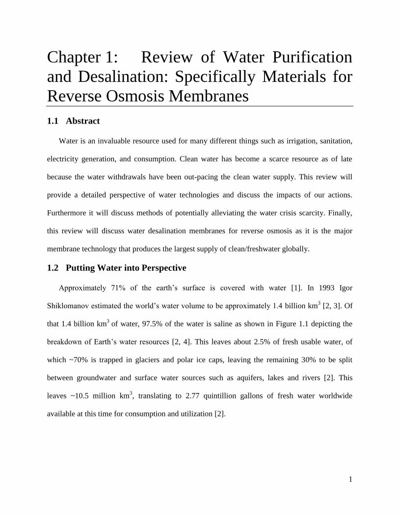
that 1.4 billion km3
of water, 97.5% of the water is saline as shown in Figure 1.1 depicting the
breakdown of Earth’s water resources [2, 4]. This leaves about 2.5% of fresh usable water, of
which ~70% is trapped in glaciers and polar ice caps, leaving the remaining 30% to be split
between groundwater and surface water sources such as aquifers, lakes and rivers [2]. This
leaves ~10.5 million km3, translating to 2.77 quintillion gallons of fresh water worldwide
available at this time for consumption and utilization [2].
2
Figure 1.1 Breakdown of world’s water resources. From Where is Earth’s Water? U.S. Geological
Survey [2, 4].
https://www.usgs.gov/special-topic/water-science-school/science/where-earths-water?qt-
science_center_objects=0#qt-science_center_objects
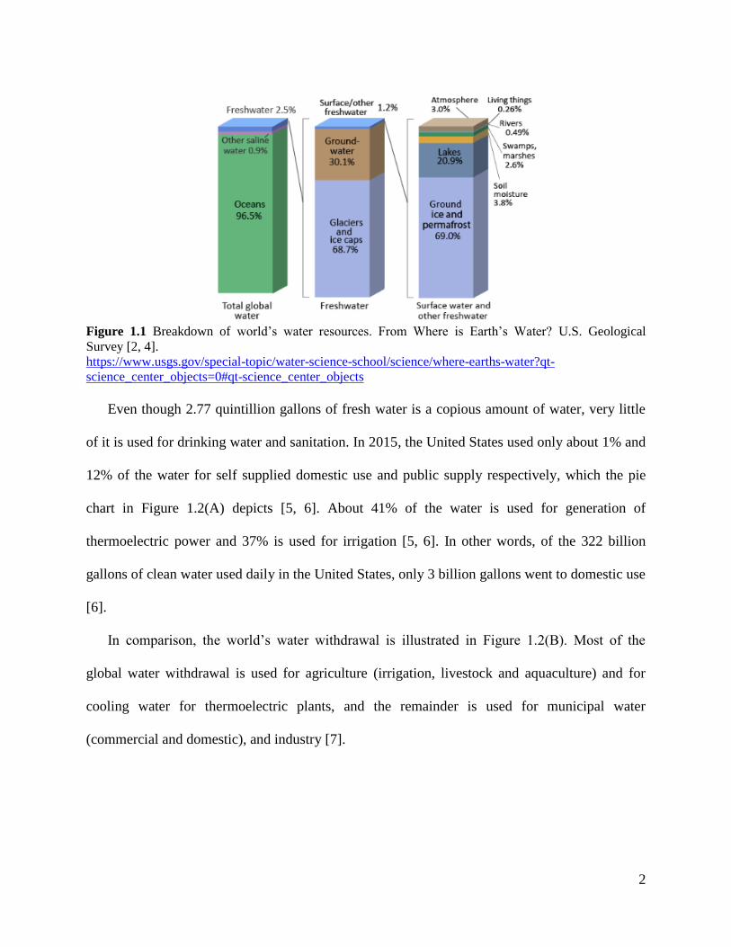
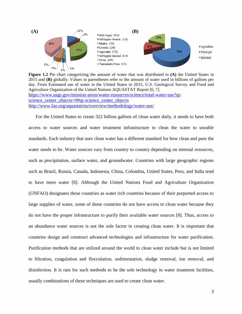
Even though 2.77 quintillion gallons of fresh water is a copious amount of water, very little
of it is used for drinking water and sanitation. In 2015, the United States used only about 1% and
12% of the water for self supplied domestic use and public supply respectively, which the pie
chart in Figure 1.2(A) depicts [5, 6]. About 41% of the water is used for generation of
thermoelectric power and 37% is used for irrigation [5, 6]. In other words, of the 322 billion
gallons of clean water used daily in the United States, only 3 billion gallons went to domestic use
[6].
In comparison, the world’s water withdrawal is illustrated in Figure 1.2(B). Most of the
global water withdrawal is used for agriculture (irrigation, livestock and aquaculture) and for
cooling water for thermoelectric plants, and the remainder is used for municipal water
(commercial and domestic), and industry [7].
3
(A)
(B)
Figure 1.2 Pie chart categorizing the amount of water that was distributed in (A) the United States in
2015 and (B) globally. Values in parentheses refer to the amount of water used in billions of gallons per
day. From Estimated use of water in the United States in 2015, U.S. Geological Survey and Food and
Agriculture Organization of the United Nations AQUASTAT Report [6, 7].
https://www.usgs.gov/mission-areas/water-resources/science/total-water-use?qt-
science_center_objects=0#qt-science_center_objects
http://www.fao.org/aquastat/en/overview/methodology/water-use/
For the United States to create 322 billion gallons of clean water daily, it needs to have both
access to water sources and water treatment infrastructure to clean the water to useable
standards. Each industry that uses clean water has a different standard for how clean and pure the
water needs to be. Water sources vary from country to country depending on internal resources,
such as precipitation, surface water, and groundwater. Countries with large geographic regions
such as Brazil, Russia, Canada, Indonesia, China, Colombia, United States, Peru, and India tend
to have more water [8]. Although the United Nations Food and Agriculture Organization
(UNFAO) designates these countries as water rich countries because of their purported access to
large supplies of water, some of those countries do not have access to clean water because they
do not have the proper infrastructure to purify their available water sources [8]. Thus, access to
an abundance water sources is not the sole factor in creating clean water. It is important that
countries design and construct advanced technologies and infrastructure for water purification.
Purification methods that are utilized around the world to clean water include but is not limited
to filtration, coagulation and flocculation, sedimentation, sludge removal, ion removal, and
disinfection. It is rare for such methods to be the sole technology in water treatment facilities,
usually combinations of these techniques are used to create clean water.
4
However, availability of copious amounts of water and proper water treatment plants are not
the sole reasons why a country would have clean water. Other reasons for clean water may
include low to no pollution and contamination due to strict legislation or lack of industrialization
or access to already clean water sources such as polar ice caps.
As previously mentioned, 97.5% of the world’s 1.4 billion km3 of water is saline. Saline
water can be sub-divided into brackish water and seawater. Brackish water is defined as saline
water with a total dissolved salt concentration between 1000 and 10,000 ppm, while seawater is
characterized as saline water sources with total dissolved salt concentrations above 10,000 ppm
[1, 9]. Ocean water typically contains about 35,000 ppm of dissolved salt ions consisting but not
limited to about 55.07% chloride, 30.62% sodium, 7.72% sulfate, 3.68% magnesium, 1.17%
calcium, 1.10% potassium, 0.40% bicarbonate, 0.19% bromide, and 0.02% strontium [1]. Thus,
very large amounts of salt must be removed from seawater to make it useable and this also
results in large volumes of highly salty brine as a by-product. Even though there is very little
usable and potable water to begin with, climate change, pollution, and over exhaustion of the
freshwater resources from population growth and urbanization have begun to cause a water
scarcity crisis worldwide [2, 10].
1.3 Emerging Water Scarcity Crisis
As mentioned above, most of the Earth’s water is saline and above the recommended salinity
consumption levels, leaving very little water for human consumption and other uses such as
removing or diluting waste, growing food, producing energy, and manufacturing goods [11].
Understanding water inflow, outflow, and water resources is complicated. In this review,
water consumption will refer to “water that is permanently removed from surface or ground
water reservoirs for human consumption, evaporation, used for growing agriculture or livestock,
5
or removed from the immediate water environment” [12]. In this section water withdrawal will
refer to “water that is diverted or removed from a surface water or groundwater source” [12].
This includes water that is to be consumed but also refers to water that is reused such as for
sanitation. Some products do not consume water but instead withdraw it, like the generation of
electricity. Water can be categorized as either a renewable or non-renewable/depletable resource
[13]. As the water is withdrawn and used, various negative external effects may arise causing a
positive feedback loop that ultimately causes water stress.
One major cause of water scarcity is rapid population growth and urbanization. In a city with
a rapidly growing population, the withdrawal of water will increase because of hydration and
sanitation needs. Migrations from rural areas to urban centers shift and increase the water stress
in urban centers [14]. These urban areas undergo industrialization which brings further needs for
electricity and consumer products [14-16].
Population, agriculture, and livestock will rapidly consume water, causing already scarce
freshwater sources to deplete. Many farms use high amounts of fertilizer and produce
concentrated waste from overcrowded livestock. When it rains, the fertilizer and fecal waste
flows into streams and rivers as runoff. This can cause an overload of nutrients leading to algal
blooms that eutrophicates the water upon the algae’s death, killing aerobic aquatic life [17]. One
of the most prominent case studies on the subject includes chicken waste runoff in the
Chesapeake Bay watershed [18, 19]. Human waste is also added to the rivers. In developed
countries, human waste water and surface water are collected in water treatment plants where
bacteria are killed and particles are coagulated and sedimented so that they can be removed.
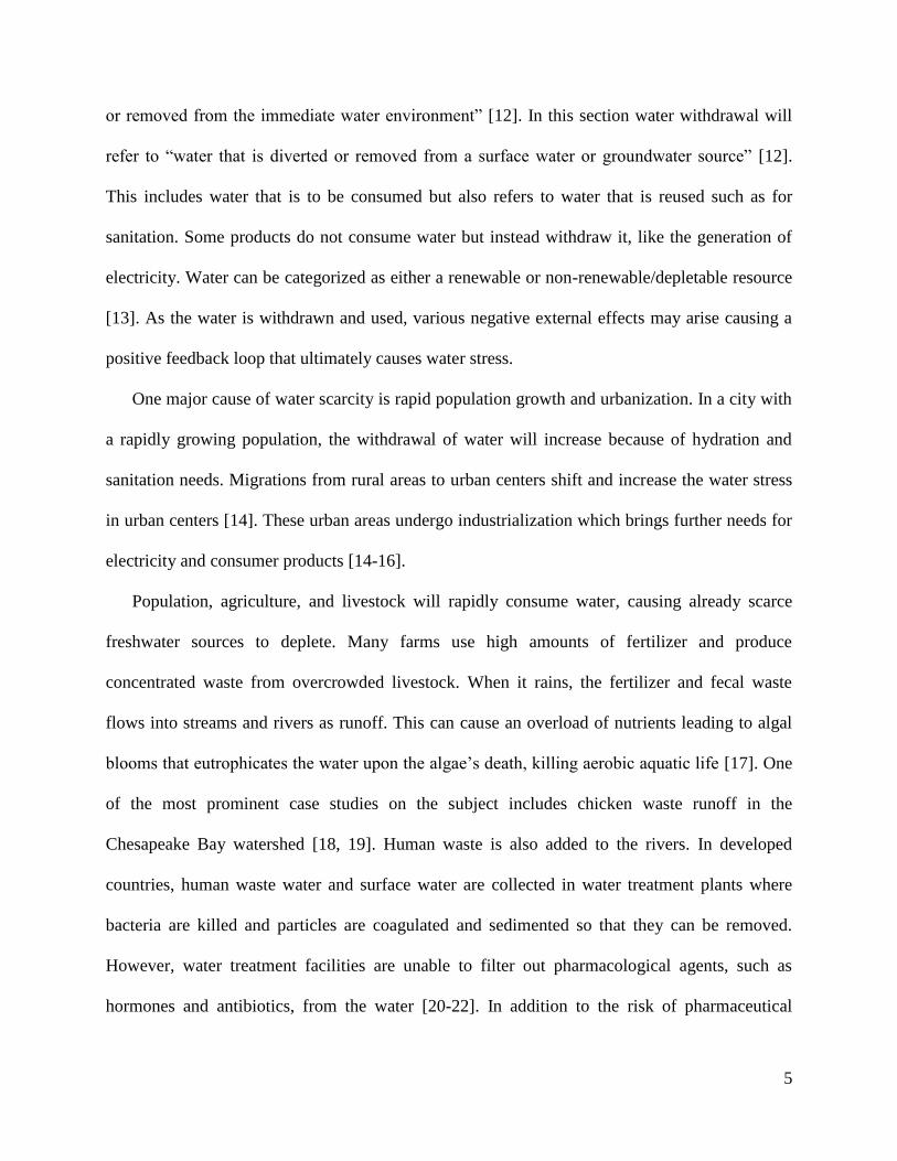
However, water treatment facilities are unable to filter out pharmacological agents, such as
hormones and antibiotics, from the water [20-22]. In addition to the risk of pharmaceutical

6
ingestion, countries including India that do not treat the waste water before returning it to the
rivers exhibit higher degrees of maladies and waterborne illnesses such as cholera, typhoid, and
dysentery [23, 24]. Thus, runoff and waste reduce the supply of clean water.
About 90% of the world’s electricity is generated from power plants that use either
hydropower or hydrothermal technology, which utilizes coal, natural gas, or nuclear power as
energy to boil water to create steam that spins a turbine to produce electricity [25, 26]. Coal and
nuclear power plants produce different types of waste that can sometimes contaminate drinking
water supplies. Coal power plants burn low purity coal, which has high contaminants and less
stored energy, to turn water into steam. Despite the use of wet scrubbers, this process still emits
toxic gases and heavy metals into the atmosphere in the form of COx, NOx, SOx, Arsenic,
Beryllium, Cadmium, Chromium, and Mercury [27, 28]. These gases react in the atmosphere to
cause acid rain that damages plants and alters pH levels of aquatic ecosystems [29]. This
combined with heavy metal toxicity can kill various organisms in these aquatic ecosystems
causing the waters to become even more toxic. In nuclear reactors, water is used to produce
steam and thus electricity, and also used as a coolant to control the nuclear reaction within the
reactors [30]. This causes the water to heat up before being released back into rivers, which
causes eutrophication (oxygen deficiency) during the summer months, as well as the concern of
overheating streams and lakes. Nuclear power also presents a fear of nuclear material leaking
and spreading through groundwater contamination, which will kill various organisms that keep
the streams and lakes thriving [30, 31]. Furthermore, increases in atmospheric greenhouse gases
have begun to alter the world’s climates causing severe storms such as hurricanes to become
more sporadic and destructive [32-34]. These intense storms cause damage to water
7
infrastructure. In addition, droughts have become more severe, further diminishing the dwindling
water supply [34].
Countries with arid climates and already low supplies of water have begun to destabilize due
to controversies over water rights. As a result, tensions and conflicts have risen between these
countries [35]. If the world continues to increase water demand and decrease existing clean water
supplies, the world will begin to find itself in a position that is irreversible.
Food, water, and energy are inherently interdependent, and water withdrawal from
overpopulation can have cascading effects on all three sectors [36-39]. In 2018 the World
Economic Forum (WEF) identified the water crisis as humanity’s number one global threat [40].
In 2017 the WHO/United Nations Children’s Fund (UNICEF) Joint Monitoring Programme
(JMP) on Water Supply, Sanitation, and Hygiene reported that “2.2 billion people lacked safely
managed water, 4.2 billion people lacked safely managed sanitation, and 3 billion people lacked
basic hand washing facilities” [41, 42]. Recent estimates show that 4 billion people, about two
thirds of the world’s population, live under severe water scarcity conditions at least 1 month of
the year [43]. Figure 1.3 depicts the percent level of various countries of physical water stress
worldwide based on the data obtained from AQUASTAT [44].
8
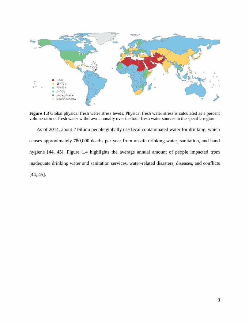
Figure 1.3 Global physical fresh water stress levels. Physical fresh water stress is calculated as a percent
volume ratio of fresh water withdrawn annually over the total fresh water sources in the specific region.
As of 2014, about 2 billion people globally use fecal contaminated water for drinking, which
causes approximately 780,000 deaths per year from unsafe drinking water, sanitation, and hand
hygiene [44, 45]. Figure 1.4 highlights the average annual amount of people impacted from
inadequate drinking water and sanitation services, water-related disasters, diseases, and conflicts
[44, 45].
9
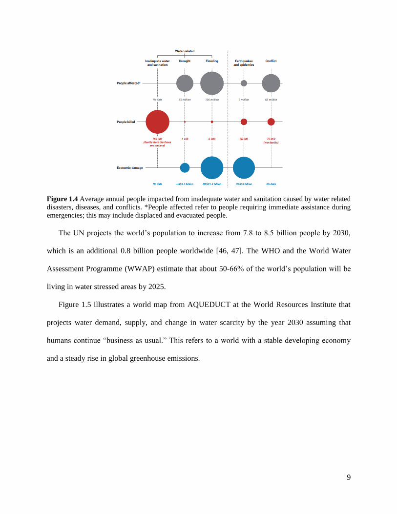
Figure 1.4 Average annual people impacted from inadequate water and sanitation caused by water related
disasters, diseases, and conflicts. *People affected refer to people requiring immediate assistance during
emergencies; this may include displaced and evacuated people.
The UN projects the world’s population to increase from 7.8 to 8.5 billion people by 2030,
which is an additional 0.8 billion people worldwide [46, 47]. The WHO and the World Water
Assessment Programme (WWAP) estimate that about 50-66% of the world’s population will be
living in water stressed areas by 2025.
Figure 1.5 illustrates a world map from AQUEDUCT at the World Resources Institute that
projects water demand, supply, and change in water scarcity by the year 2030 assuming that
humans continue “business as usual.” This refers to a world with a stable developing economy
and a steady rise in global greenhouse emissions.
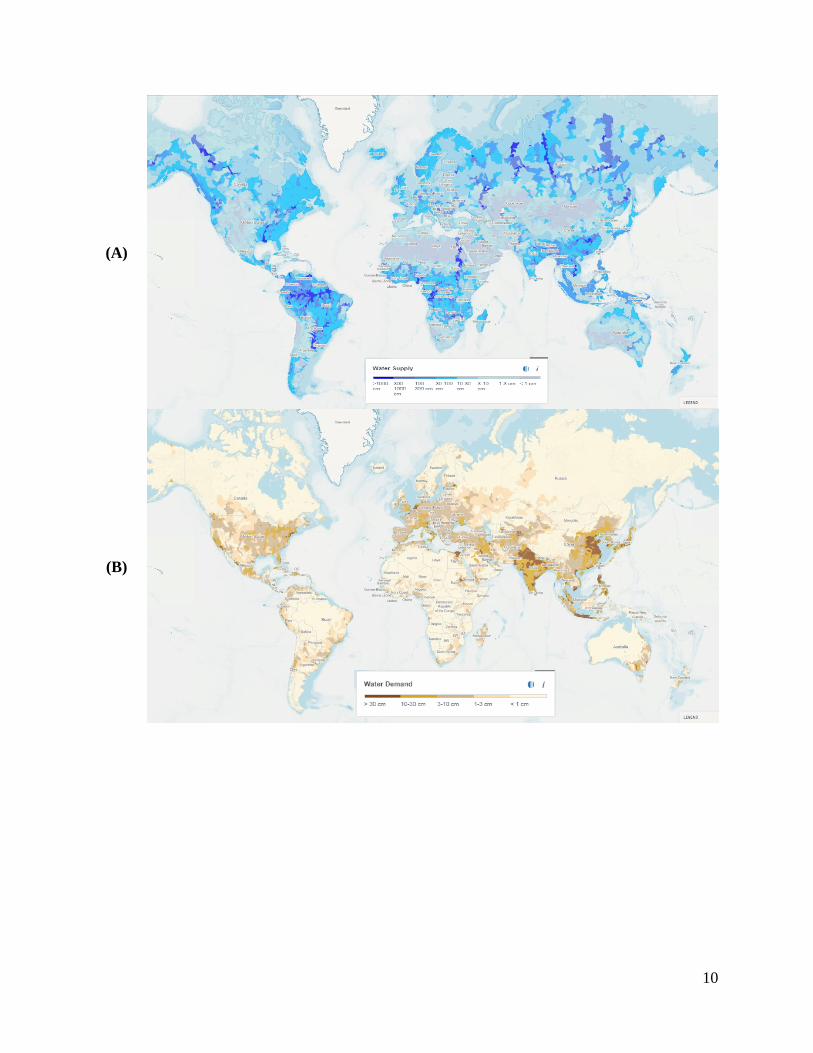
10
(A)
(B)
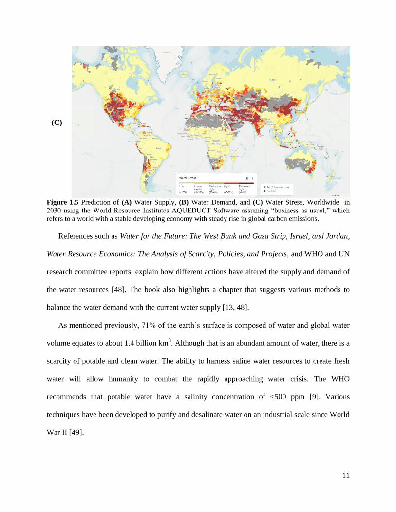
11
(C)
Figure 1.5 Prediction of (A) Water Supply, (B) Water Demand, and (C) Water Stress, Worldwide in
2030 using the World Resource Institutes AQUEDUCT Software assuming “business as usual,” which
refers to a world with a stable developing economy with steady rise in global carbon emissions.
References such as Water for the Future: The West Bank and Gaza Strip, Israel, and Jordan,
Water Resource Economics: The Analysis of Scarcity, Policies, and Projects, and WHO and UN
research committee reports explain how different actions have altered the supply and demand of
the water resources [48]. The book also highlights a chapter that suggests various methods to
balance the water demand with the current water supply [13, 48].
As mentioned previously, 71% of the earth’s surface is composed of water and global water
volume equates to about 1.4 billion km3. Although that is an abundant amount of water, there is a
scarcity of potable and clean water. The ability to harness saline water resources to create fresh
water will allow humanity to combat the rapidly approaching water crisis. The WHO
recommends that potable water have a salinity concentration of <500 ppm [9]. Various
techniques have been developed to purify and desalinate water on an industrial scale since World
War II [49].
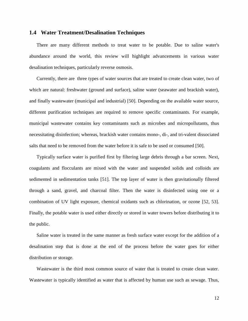
12
1.4 Water Treatment/Desalination Techniques
There are many different methods to treat water to be potable. Due to saline water's
abundance around the world, this review will highlight advancements in various water
desalination techniques, particularly reverse osmosis.
Currently, there are three types of water sources that are treated to create clean water, two of
which are natural: freshwater (ground and surface), saline water (seawater and brackish water),
and finally wastewater (municipal and industrial) [50]. Depending on the available water source,
different purification techniques are required to remove specific contaminants. For example,
municipal wastewater contains key contaminants such as microbes and micropollutants, thus
necessitating disinfection; whereas, brackish water contains mono-, di-, and tri-valent dissociated
salts that need to be removed from the water before it is safe to be used or consumed [50].
Typically surface water is purified first by filtering large debris through a bar screen. Next,
coagulants and flocculants are mixed with the water and suspended solids and colloids are
sedimented in sedimentation tanks [51]. The top layer of water is then gravitationally filtered
through a sand, gravel, and charcoal filter. Then the water is disinfected using one or a
combination of UV light exposure, chemical oxidants such as chlorination, or ozone [52, 53].
Finally, the potable water is used either directly or stored in water towers before distributing it to
the public.
Saline water is treated in the same manner as fresh surface water except for the addition of a
desalination step that is done at the end of the process before the water goes for either
distribution or storage.
Wastewater is the third most common source of water that is treated to create clean water.
Wastewater is typically identified as water that is affected by human use such as sewage. Thus,
13
wastewater is treated before being used directly or allowed to enter surface water sources such as
rivers and lakes. Sewage water is treated similarly to surface water treatment. Usually there are
three stages. The primary treatment is used to remove any large debris and suspended particles.
First this consists of screening the wastewater to remove any large debris. Then coagulants and
flocculants are added to the water and it is allowed to settle in sedimentation tanks [51]. The
secondary treatment consists of adding and stirring aerobic bacteria and allowing the bacteria to
breakdown dissolved organics in aeration biotowers. The water is then allowed to flow into
another sedimentation tank to settle populations of bacteria out of the water. Finally, the water
may undergo a tertiary treatment which includes running the water through sand and activated
carbon filters and disinfecting it using chlorination, UV light, or ozonolysis [52, 54].
Since ~97% of Earth’s water consists of saline water, the remainder of this review will focus
on desalination techniques. The purpose of desalination is to remove dissolved salts from water.
Membrane separation and thermal separation are two different methods of desalination [55].
Membrane based desalination utilizes membranes as the primary technology to separate
dissolved salts from saline water sources. Such techniques include but are not limited to reverse
osmosis (RO), membrane distillation (MD), nanofiltration (NF), ultrafiltration (UF),
electrodiaylsis (ED), and membrane capacitive deionization (MCDI). On the other hand, thermal
separation focuses on using phase transformations to separate dissolved salts from water. Such
techniques used to achieve such means include but are not limited to multi-stage flash distillation
(MSF), solar distillation, vacuum distillation, multiple effect distillation (MED), and freeze-thaw
systems.
Energy and infrastructure costs are the major barriers that preclude the production and
distribution of clean water [55]. By the end of 2015, about 18,000 desalination plants were
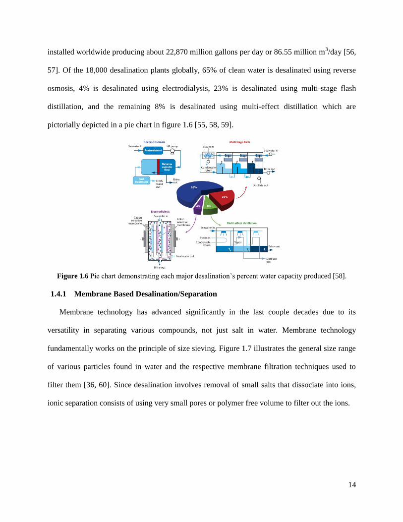
14
installed worldwide producing about 22,870 million gallons per day or 86.55 million m3/day [56,
57]. Of the 18,000 desalination plants globally, 65% of clean water is desalinated using reverse
osmosis, 4% is desalinated using electrodialysis, 23% is desalinated using multi-stage flash
distillation, and the remaining 8% is desalinated using multi-effect distillation which are
pictorially depicted in a pie chart in figure 1.6 [55, 58, 59].
Figure 1.6 Pie chart demonstrating each major desalination’s percent water capacity produced [58].
1.4.1 Membrane Based Desalination/Separation
Membrane technology has advanced significantly in the last couple decades due to its
versatility in separating various compounds, not just salt in water. Membrane technology
fundamentally works on the principle of size sieving. Figure 1.7 illustrates the general size range
of various particles found in water and the respective membrane filtration techniques used to
filter them [36, 60]. Since desalination involves removal of small salts that dissociate into ions,
ionic separation consists of using very small pores or polymer free volume to filter out the ions.
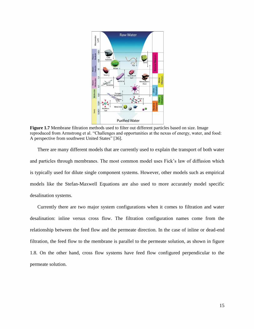
15
There are many different models that are currently used to explain the transport of both water
and particles through membranes. The most common model uses Fick’s law of diffusion which
is typically used for dilute single component systems. However, other models such as empirical
models like the Stefan-Maxwell Equations are also used to more accurately model specific
desalination systems.
Currently there are two major system configurations when it comes to filtration and water
desalination: inline versus cross flow. The filtration configuration names come from the
relationship between the feed flow and the permeate direction. In the case of inline or dead-end
filtration, the feed flow to the membrane is parallel to the permeate solution, as shown in figure
1.8. On the other hand, cross flow systems have feed flow configured perpendicular to the
permeate solution.
Figure 1.7 Membrane filtration methods used to filter out different particles based on size. Image
reproduced from Armstrong et al. “Challenges and opportunities at the nexus of energy, water, and food:
A perspective from southwest United States” [36].
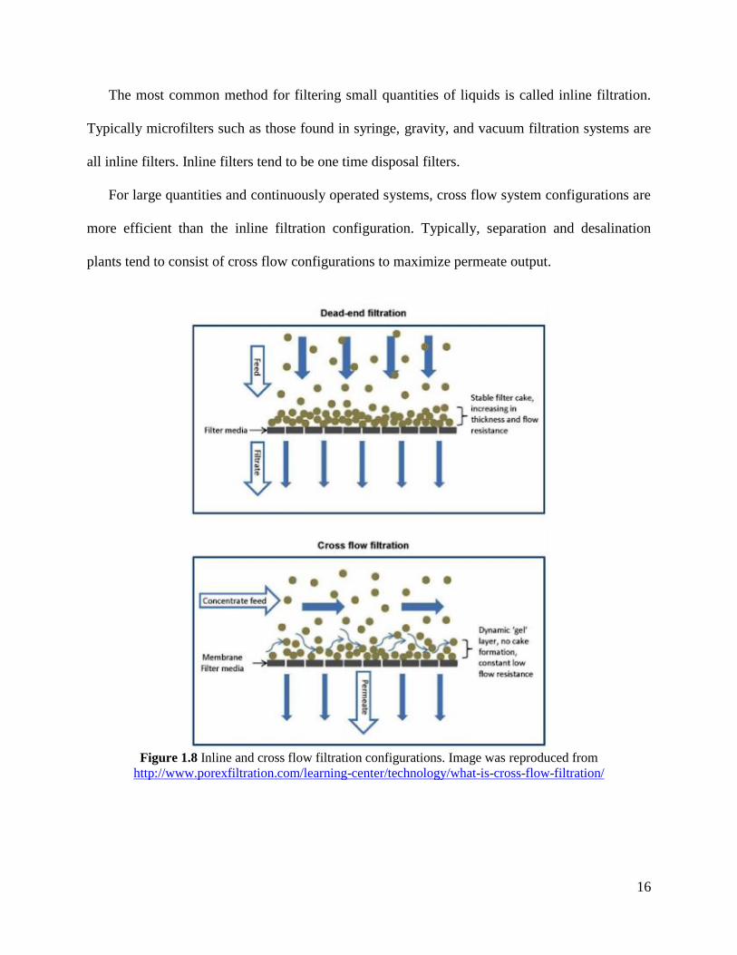
16
The most common method for filtering small quantities of liquids is called inline filtration.
Typically microfilters such as those found in syringe, gravity, and vacuum filtration systems are
all inline filters. Inline filters tend to be one time disposal filters.
For large quantities and continuously operated systems, cross flow system configurations are
more efficient than the inline filtration configuration. Typically, separation and desalination
plants tend to consist of cross flow configurations to maximize permeate output.
Figure 1.8 Inline and cross flow filtration configurations. Image was reproduced from
http://www.porexfiltration.com/learning-center/technology/what-is-cross-flow-filtration/
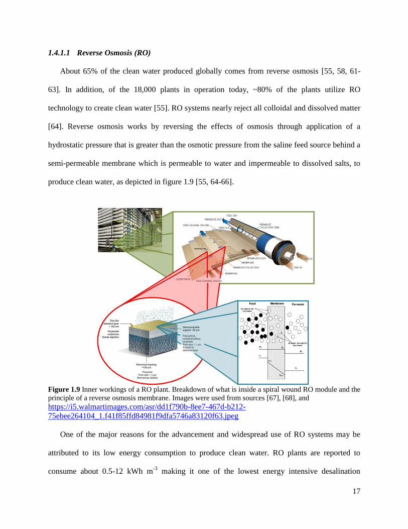
17
1.4.1.1 Reverse Osmosis (RO)
About 65% of the clean water produced globally comes from reverse osmosis [55, 58, 61-
63]. In addition, of the 18,000 plants in operation today, ~80% of the plants utilize RO
technology to create clean water [55]. RO systems nearly reject all colloidal and dissolved matter
[64]. Reverse osmosis works by reversing the effects of osmosis through application of a
hydrostatic pressure that is greater than the osmotic pressure from the saline feed source behind a
semi-permeable membrane which is permeable to water and impermeable to dissolved salts, to
produce clean water, as depicted in figure 1.9 [55, 64-66].
Figure 1.9 Inner workings of a RO plant. Breakdown of what is inside a spiral wound RO module and the
principle of a reverse osmosis membrane. Images were used from sources [67], [68], and
https://i5.walmartimages.com/asr/dd1f790b-8ee7-467d-b212-
75ebee264104_1.f41f85ffd84981f9dfa5746a83120f63.jpeg
One of the major reasons for the advancement and widespread use of RO systems may be
attributed to its low energy consumption to produce clean water. RO plants are reported to
consume about 0.5-12 kWh m-3
making it one of the lowest energy intensive desalination
18
techniques available [9, 55, 57, 64, 69, 70]. Various energy recovery techniques can be used to
reduce the amount of energy that is consumed [71]. One thing to note is that salinity of feed
water will dictate the amount of pressure required to desalinate the water to appropriate, safe,
and usable levels. Thus, water with lower salt concentrations tend to use lower energies due to
lower applied pressures used to overcome the osmotic pressure.
However, regardless of the salt concentration used in the feed water, RO systems have to be
cleaned regularly to reduce build ups of scaling salts and various types of organic, inorganic, and
biological foulants on the surface of the membrane [72]. Increases in both fouling and scaling on
the surface of the membrane cause the water flux to decrease, which lowers the overall efficiency
of the RO plant.
Appropriate water fluxes for plants that use seawater feed range between 12-17 L•m-2•h
-1
while brackish water plants produce a water flux of 12-45 L•m-2•h
-1 [55]. On the other hand,
seawater plants use an applied pressure between 55-68 bar (~800-985 psi) while brackish water
plants use an applied pressure between 10-30 bar (~145-435 psi) [55, 64]. A brackish water
reverse osmosis plant capital costs, which is the amount of USD per plant’s expected daily
volume, over the last two decades have consistently ranged from 250-500 USD/m3/day (1-2
USD/gal/day) [9].
1.4.1.2 Nanofiltration (NF)
NF membranes just like RO membranes can effectively separate chemicals such as
pharmaceuticals, antibiotics, dyes, hormones, pesticides and organic solvents as shown in figure
1.7 [73-75]. In addition, nanofiltration membranes can be used to separate feed water with
multivalent salts and ions with large hydration shells such as magnesium and cesium ions [62,
76]. However, NF membranes have difficulty separating monovalent salts such as potassium and
19
sodium ions from feed water because of their smaller hydration shells. At first glance, such
membranes were considered as “poor/coarse RO membranes” because the membrane possessed
pore sizes about 1 nm (corresponding to molecular weight cutoff of 300-500Da); however, over
time NF membranes helped satisfy niche applications [77, 78]. Thus, these membranes are used
in separating pharmaceuticals and multivalent salts (water softening) before proceeding with RO.
By coupling NF with RO, nanofiltration helps reduce the scaling that occurs on the surface of the
RO membrane from the less soluble multivalent sulfate salts. Due to NF membranes having 2-5x
more permeability than RO membranes, such membranes are operated at pressures as low as 3-
5bar to produce clean water [9, 79].
Commercially NF membranes are utilized in filtration plants that either require molecular
weight cutoffs such as in pharmaceutical purification systems or water purification of household
water supplies with feed waters ranging between 1000- 2000 ppm dissolved salt concentrations
or lower.
1.4.1.3 Ultrafiltration (UF)
In this review we separate ultrafiltration membranes from other types of membranes because
of their pore size. In literature however, UF systems are usually coupled with microfiltration
because they both share the same mechanism for filtration. An UF membrane uses the principle
of size sieving through pores to separate materials in a liquid medium while NF and RO use
solution-diffusion size sieving.
The average pore size of UF membranes is between 10-1000 Å, which correlates with
molecular weight cutoffs between 1-100 kDa [9, 80]. Ultrafiltration membranes are typically
used to remove and collect colloidal paints, dyes, and proteins [9, 81-83]. Ultrafiltration was first
coined in studies that focused on colloid chemistry in the 1950s [82]. In the 1960s, development
20
of commercial UF membranes began and advancements in UF membranes proceeded shortly
thereafter. The first membranes for UF were made from nitrocellulose, and were eventually
replaced with cellulose acetate, polyacrylonitrile and its copolymers, poly(vinylidene fluoride),
aromatic polyamides, and polysulfones which are all still used today [9]. UF systems just like in
RO and NF are typically run in a cross flow configuration at operating pressures lower than 100
psi [9, 84]. Even though such methods are not directly used for desalination, they can be used
similarly to NF membranes to soften water. The use of polyelectrolyte coagulants and
flocculation techniques could increase the applications of UF membranes in desalting processes
[85-87]. However, it is important to note that polyelectrolytes are very sensitive to the feed pH
making the membrane work better in some pH ranges over others [9].
Large scale separation processes using UF were limited because of their susceptibility to
fouling. As a result, the focus of ultrafiltration literature has generally been in mechanisms of
fouling in UF membranes, methodical innovations for cleaning fouled UF membranes, and
reducing/controlling the fouling in UF systems [83, 88-90]. Some cleaning methods that are used
include backwashing, chemical cleaning, and physical cleaning through sonication [9, 88]. It has
been reported that by increasing the flow rate or coupling microfiltration membranes with UF
membranes, during constant flux operations, UF membrane have been reported to reduce fouling
[9].
1.4.1.4 Microfiltration
Microfiltration membranes started out at the same time and same way as ultrafiltration
membranes. However, microfiltration membranes were designed to have coarser pore sizes than
its UF counterparts. Microfiltration membranes contain an average pore size between 0.1 and 10
microns that can filter suspended particles compared to UF filters which separate out
21
macromolecules and colloids [9]. In addition, these membranes utilize the same size sieving
principle and materials as ultrafiltration membranes mentioned previously.
However, these membranes have some key differences other than pore size. Firstly,
microfiltration membranes may be run in one of two configurations: inline or cross flow [9].
Depending on which configuration is used, the operator would choose between a depth filter and
a screen filter. The depth filters are used for inline configurations because it allows for large
particles to become lodged in the filter [9, 91]. These are mainly disposal filters such as
regenerated cellulose filters for vacuum filtration systems and syringe filters. Although inline
filtration is the most common form of filtration for microfilters, other applications that require
continuous operation still utilize the cross flow configurations. Just like UF membranes, these
membranes are notorious for fouling; thus scientists and engineers have designed microfiltration
membranes for cross flow applications with a porous skin surface, called a screen filter
membrane. Those contain slightly smaller pores on the skin surface compared to the inside of the
membrane [9, 91]. The smaller pores help trap the particles on the surface of the membrane
instead of within. This allows for the perpendicular flow to wash away the built up particles on
the surface of the membrane which helps control the fouling similarly to that of UF, NF, and RO
membranes.
Just like UF membranes these filters cannot desalinate water on their own. Thus, they
typically are coupled with other techniques such as nanofiltration and reverse osmosis as a
pretreatment to filter out larger particles that can cause dramatic drops in efficiency in the RO
stage of the filtration.
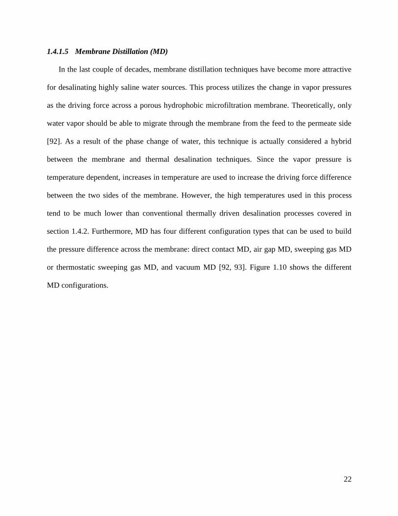
22
1.4.1.5 Membrane Distillation (MD)
In the last couple of decades, membrane distillation techniques have become more attractive
for desalinating highly saline water sources. This process utilizes the change in vapor pressures
as the driving force across a porous hydrophobic microfiltration membrane. Theoretically, only
water vapor should be able to migrate through the membrane from the feed to the permeate side
[92]. As a result of the phase change of water, this technique is actually considered a hybrid
between the membrane and thermal desalination techniques. Since the vapor pressure is
temperature dependent, increases in temperature are used to increase the driving force difference
between the two sides of the membrane. However, the high temperatures used in this process
tend to be much lower than conventional thermally driven desalination processes covered in
section 1.4.2. Furthermore, MD has four different configuration types that can be used to build
the pressure difference across the membrane: direct contact MD, air gap MD, sweeping gas MD
or thermostatic sweeping gas MD, and vacuum MD [92, 93]. Figure 1.10 shows the different
MD configurations.
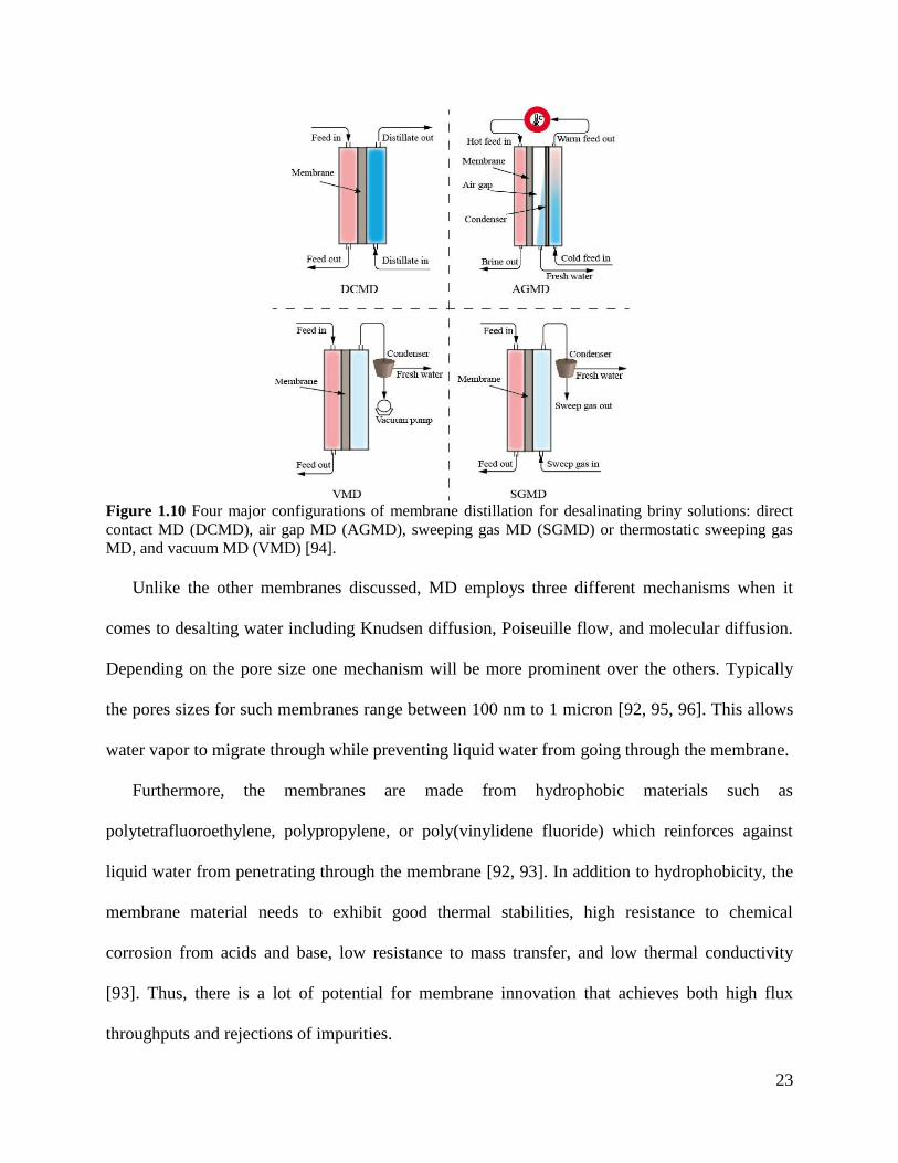
23
Figure 1.10 Four major configurations of membrane distillation for desalinating briny solutions: direct
contact MD (DCMD), air gap MD (AGMD), sweeping gas MD (SGMD) or thermostatic sweeping gas
MD, and vacuum MD (VMD) [94].
Unlike the other membranes discussed, MD employs three different mechanisms when it
comes to desalting water including Knudsen diffusion, Poiseuille flow, and molecular diffusion.
Depending on the pore size one mechanism will be more prominent over the others. Typically
the pores sizes for such membranes range between 100 nm to 1 micron [92, 95, 96]. This allows
water vapor to migrate through while preventing liquid water from going through the membrane.
Furthermore, the membranes are made from hydrophobic materials such as
polytetrafluoroethylene, polypropylene, or poly(vinylidene fluoride) which reinforces against
liquid water from penetrating through the membrane [92, 93]. In addition to hydrophobicity, the
membrane material needs to exhibit good thermal stabilities, high resistance to chemical
corrosion from acids and base, low resistance to mass transfer, and low thermal conductivity
[93]. Thus, there is a lot of potential for membrane innovation that achieves both high flux
throughputs and rejections of impurities.
24
When it comes to modeling mass transport, each configuration has slight modifications to the
equations to compensate for the resistances to mass transfer and differing conditions. For an in
depth review of the varying models and conditions used for each configuration, the reader is
referred to Membrane distillation: A comprehensive review [92].
Even though MD has a plethora of applications, it is currently only used in laboratory, small
scale, or pilot plant settings. With new material development and better pore size and distribution
control, this technique may become economical to be used to mass produce fresh water.
1.4.1.6 Electrodiaylsis (ED)
The process of electrodiaylsis has its roots in ion exchange membranes. These membranes
had fixed charged pendant groups attached to the backbone or side chains of the polymer
membrane. Such polymers include polyelectrolytes and ionomers [9, 97, 98]. In the late 1800s
and early 1900s Donnan proposed that non-charged membranes separating two different
solutions with different concentrations of permeable and non permeable ions will form an
equilibrium with both the concentration gradient and electrical potential gradient, called the
Gibbs-Donnan equilibrium [99]. By adding fixed charges onto the membrane you can exclude
the co-ion from the feed water, ions with the same charge as the ions appended to the polymer
membrane. This is called the Donnan-exclusion effect which alters the Gibbs-Donnan
equilibrium as show in figure 1.11 [99, 100].
25
Figure 1.11 Donnan equilibrium and Donnan exclusion of ions represented in a porous membrane model.
Figure was reproduced with permission from source [99].
To desalinate water by electrodialysis, alternating layers of anion exchange membranes
(AEMs), which allow anions to migrate through while rejecting cations, and cation exchange
membranes (CEMs), which allow cations to migrate through the membrane while rejecting
anions, are stacked between a cathode and an anode. One typical class of CEMs consist of
derivatized polymers with sulfonate salt pendant groups which are negatively charged to allow
for positive cations to permeate. AEMs consist of derivatized polymers with, for example,
quaternary ammonium salt pendant groups which are positively charged to attract and facilitate
anion transport. The anode and cathode produce the respective positive and negative charged
plates that produces an electric field through the stack. The externally generated electric field is
used to drive the disassociated salt ions (cations towards the anode and anions towards the
cathode). The AEMs and CEMs facilitate the transport of the desired ion while trapping the
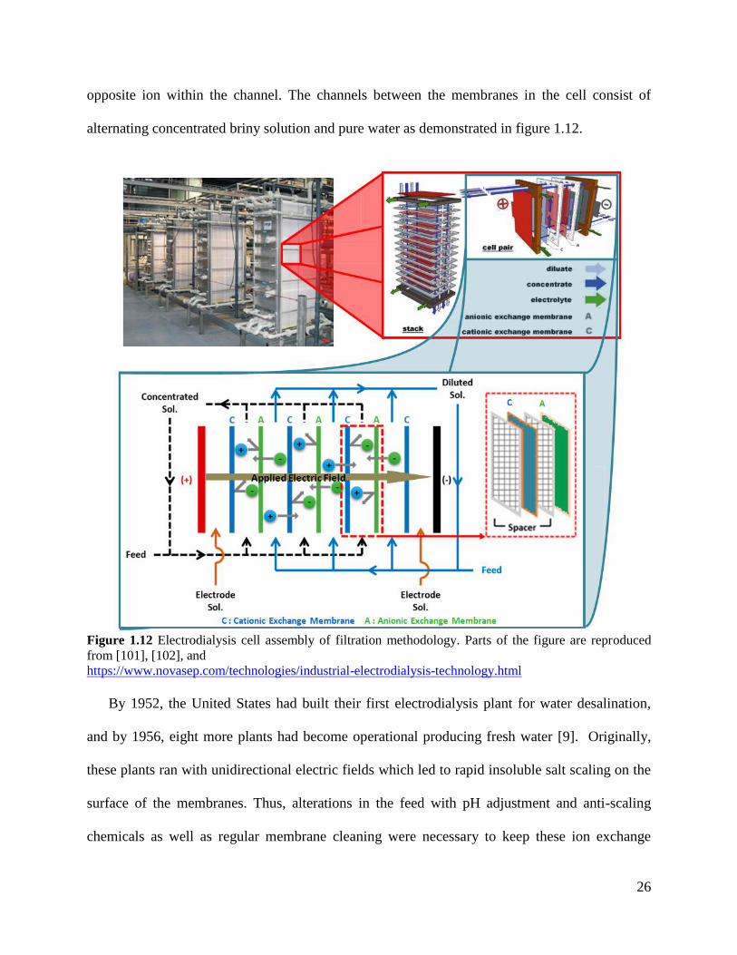
26
opposite ion within the channel. The channels between the membranes in the cell consist of
alternating concentrated briny solution and pure water as demonstrated in figure 1.12.
Figure 1.12 Electrodialysis cell assembly of filtration methodology. Parts of the figure are reproduced
from [101], [102], and
https://www.novasep.com/technologies/industrial-electrodialysis-technology.html
By 1952, the United States had built their first electrodialysis plant for water desalination,
and by 1956, eight more plants had become operational producing fresh water [9]. Originally,
these plants ran with unidirectional electric fields which led to rapid insoluble salt scaling on the
surface of the membranes. Thus, alterations in the feed with pH adjustment and anti-scaling
chemicals as well as regular membrane cleaning were necessary to keep these ion exchange
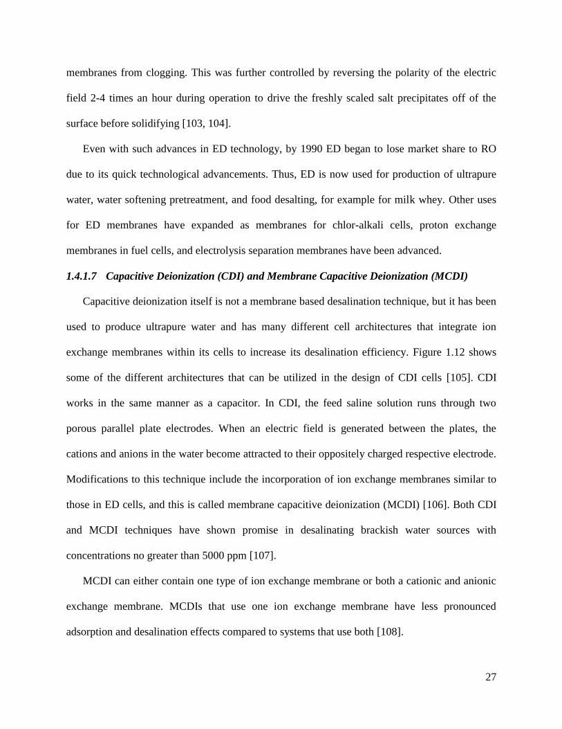
27
membranes from clogging. This was further controlled by reversing the polarity of the electric
field 2-4 times an hour during operation to drive the freshly scaled salt precipitates off of the
surface before solidifying [103, 104].
Even with such advances in ED technology, by 1990 ED began to lose market share to RO
due to its quick technological advancements. Thus, ED is now used for production of ultrapure
water, water softening pretreatment, and food desalting, for example for milk whey. Other uses
for ED membranes have expanded as membranes for chlor-alkali cells, proton exchange
membranes in fuel cells, and electrolysis separation membranes have been advanced.
1.4.1.7 Capacitive Deionization (CDI) and Membrane Capacitive Deionization (MCDI)
Capacitive deionization itself is not a membrane based desalination technique, but it has been
used to produce ultrapure water and has many different cell architectures that integrate ion
exchange membranes within its cells to increase its desalination efficiency. Figure 1.12 shows
some of the different architectures that can be utilized in the design of CDI cells [105]. CDI
works in the same manner as a capacitor. In CDI, the feed saline solution runs through two
porous parallel plate electrodes. When an electric field is generated between the plates, the
cations and anions in the water become attracted to their oppositely charged respective electrode.
Modifications to this technique include the incorporation of ion exchange membranes similar to
those in ED cells, and this is called membrane capacitive deionization (MCDI) [106]. Both CDI
and MCDI techniques have shown promise in desalinating brackish water sources with
concentrations no greater than 5000 ppm [107].
MCDI can either contain one type of ion exchange membrane or both a cationic and anionic
exchange membrane. MCDIs that use one ion exchange membrane have less pronounced
adsorption and desalination effects compared to systems that use both [108].
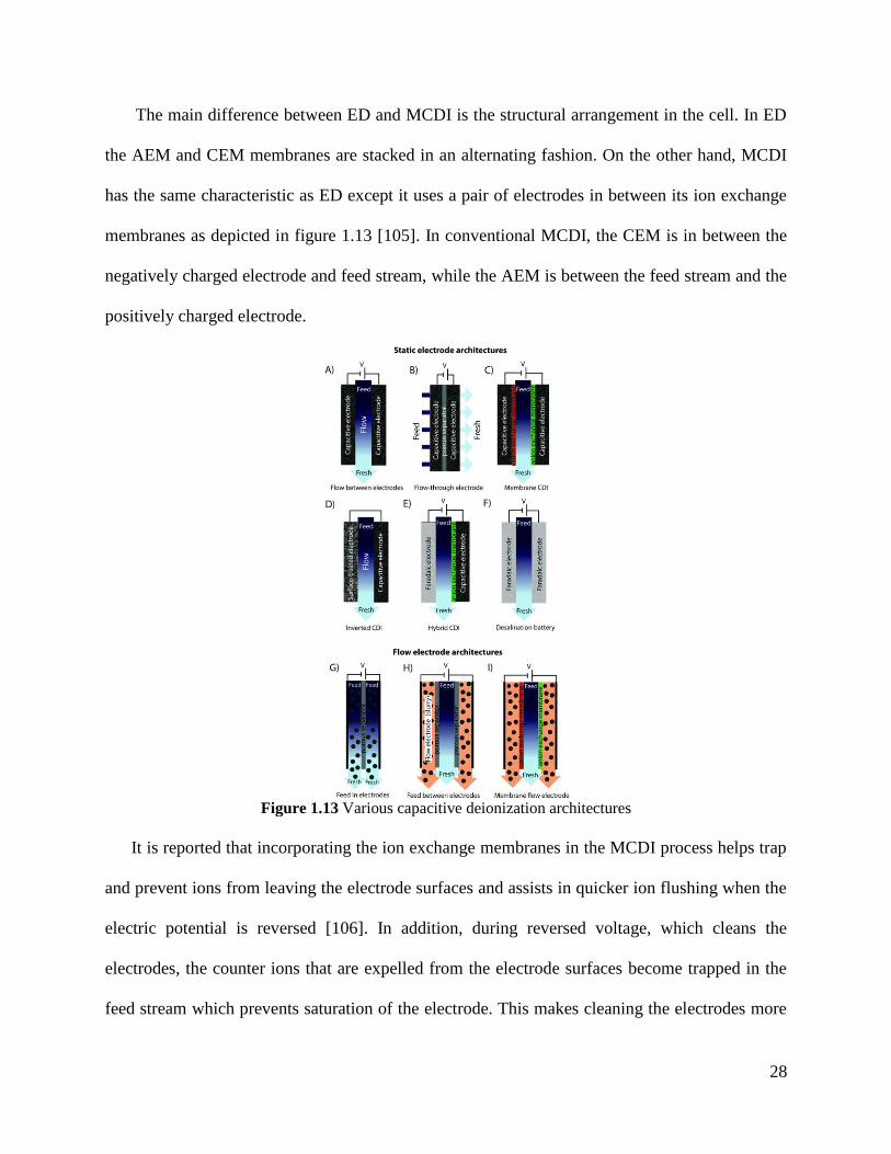
28
The main difference between ED and MCDI is the structural arrangement in the cell. In ED
the AEM and CEM membranes are stacked in an alternating fashion. On the other hand, MCDI
has the same characteristic as ED except it uses a pair of electrodes in between its ion exchange
membranes as depicted in figure 1.13 [105]. In conventional MCDI, the CEM is in between the
negatively charged electrode and feed stream, while the AEM is between the feed stream and the
positively charged electrode.
Figure 1.13 Various capacitive deionization architectures
It is reported that incorporating the ion exchange membranes in the MCDI process helps trap
and prevent ions from leaving the electrode surfaces and assists in quicker ion flushing when the
electric potential is reversed [106]. In addition, during reversed voltage, which cleans the
electrodes, the counter ions that are expelled from the electrode surfaces become trapped in the
feed stream which prevents saturation of the electrode. This makes cleaning the electrodes more
29
streamlined [108]. Overall MCDI systems adsorb more salt ions per run cycle and consume less
energy compared to their CDI analogues, making them more effective in water desalination [107,
108].
Regardless of the technique employed, ED, CDI, or MCDI, when electrodes have an electric
current running through them, they act both as a Faradaic and non-Faradaic (capacitive)
electrode [109]. In other words, both electrochemical redox reactions (Faradaic) and electrostatic
attractions and repulsions (non-Faradaic/capacitive) interactions can occur. In a Faradiac process
electrochemical reactions occur which can create new chemical species such as acids and bases
which can cause further corrosion or degradation within the cell. Examples of Faradiac reactions
are shown in table 1.1. Furthermore, electropotential desalination techniques tend to have
dramatic changes in pH between the feed and permeate streams, which is implicated to be caused
by Faradaic reactions [108, 110, 111].
Table 1.1 Standard reduction potentials of Faradiac reactions
for select species at 298 K and referenced using a standard
hydrogen electrode (SHE). Half reactions and potentials are
reproduced from source [112].
Half reactions Potential, Eº (V)
2H2O + 2e- H2 + 2OH
- -0.83
H2O2 + 2H+ + 2e
- 2H2O 1.78
O2 + 2H+ + 2e
- H2O2 0.70
O2 + 4H+ + 4e
- 2H2O 1.23
O2 + 2H2O + 2e- H2O2 + OH
- -0.15
O3 + 2H+ + 2e
- H2O + O2 2.10
Na+ + e
- Na -2.71
Cl2 + 2e- 2Cl
- 1.36
ClO- + H2O + 2e
- Cl
- + 2OH
- 0.81
Ca2+
+ 2e- Ca -2.87
Mg2+
+ 2e- Mg -2.37
SO42-
+ H2O + 2e- SO3
2- + 2OH
- -0.93
2H+ + 2e
- H2 0.00
H2 + 2e- 2H
- -2.23
K+ + e
- K -2.93
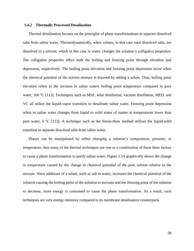
30
1.4.2 Thermally Processed Desalination
Thermal desalination focuses on the principles of phase transformations to separate dissolved
salts from saline water. Thermodynamically, when solutes, in this case total dissolved salts, are
dissolved in a solvent, which in this case is water, changes the solution’s colligative properties.
The colligative properties affect both the boiling and freezing point through elevation and
depression, respectively. The boiling point elevation and freezing point depression occur when
the chemical potential of the solvent mixture is lowered by adding a solute. Thus, boiling point
elevation refers to the increase in saline waters boiling point temperature compared to pure
water, 100 ºC [113]. Techniques such as MSF, solar distillation, vacuum distillation, MED, and
VC all utilize the liquid-vapor transition to desalinate saline water. Freezing point depression
refers to saline water changes from liquid to solid states of matter at temperatures lower than
pure water, 0 ºC [113]. A technique such as the freeze-thaw method utilizes the liquid-solid
transition to separate dissolved salts from saline water.
Phases can be manipulated by either changing a solution’s composition, pressure, or
temperature, thus many of the thermal techniques use one or a combination of these three factors
to cause a phase transformation to purify saline water. Figure 1.14 graphically shows the change
in temperature caused by the change in chemical potential of the pure solvent relative to the
mixture. Since additions of a solute, such as salt in water, increases the chemical potential of the
solution causing the boiling point of the solution to increase and the freezing point of the solution
to decrease, more energy is consumed to cause the phase transformation. As a result, such
techniques are very energy intensive compared to its membrane desalination counterparts.
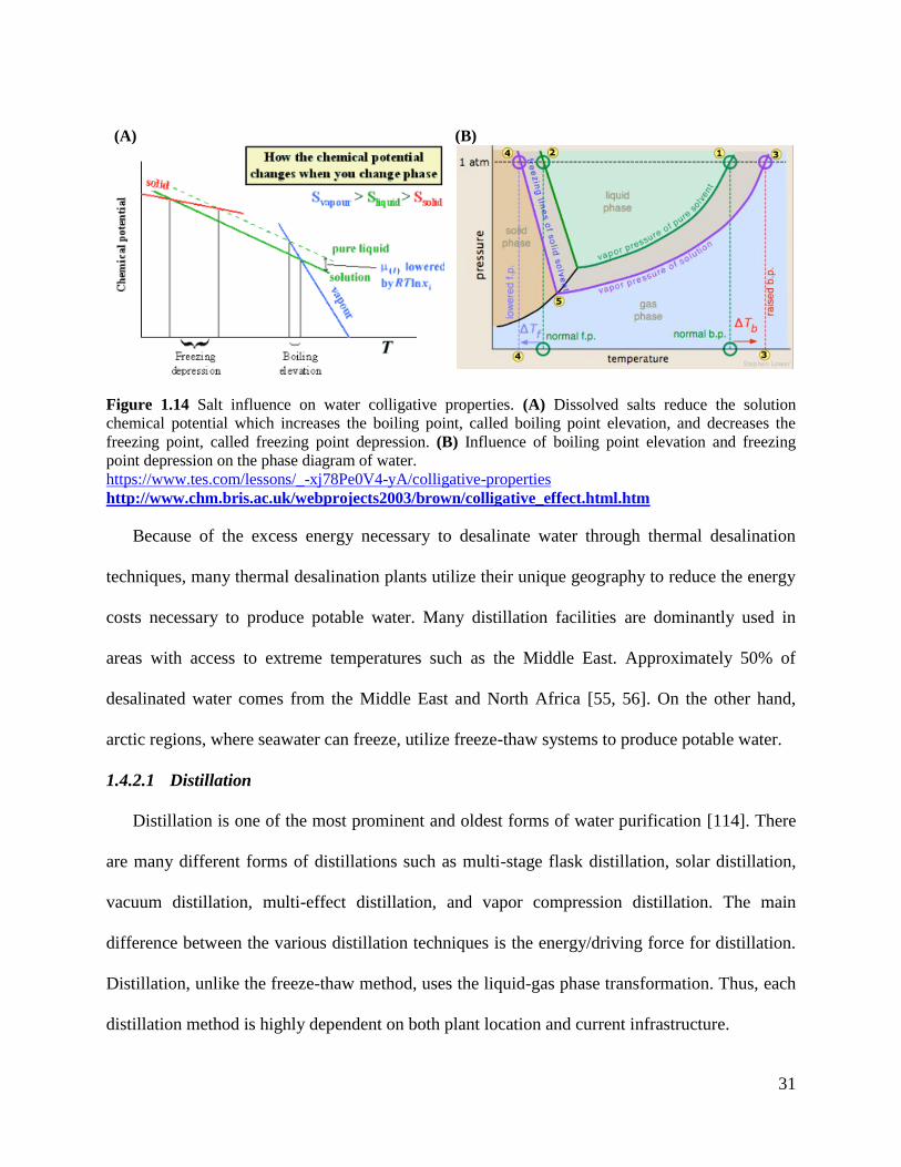
31
(A) (B)
Figure 1.14 Salt influence on water colligative properties. (A) Dissolved salts reduce the solution
chemical potential which increases the boiling point, called boiling point elevation, and decreases the
freezing point, called freezing point depression. (B) Influence of boiling point elevation and freezing
point depression on the phase diagram of water.
https://www.tes.com/lessons/_-xj78Pe0V4-yA/colligative-properties
http://www.chm.bris.ac.uk/webprojects2003/brown/colligative_effect.html.htm
Because of the excess energy necessary to desalinate water through thermal desalination
techniques, many thermal desalination plants utilize their unique geography to reduce the energy
costs necessary to produce potable water. Many distillation facilities are dominantly used in
areas with access to extreme temperatures such as the Middle East. Approximately 50% of
desalinated water comes from the Middle East and North Africa [55, 56]. On the other hand,
arctic regions, where seawater can freeze, utilize freeze-thaw systems to produce potable water.
1.4.2.1 Distillation
Distillation is one of the most prominent and oldest forms of water purification [114]. There
are many different forms of distillations such as multi-stage flask distillation, solar distillation,
vacuum distillation, multi-effect distillation, and vapor compression distillation. The main
difference between the various distillation techniques is the energy/driving force for distillation.
Distillation, unlike the freeze-thaw method, uses the liquid-gas phase transformation. Thus, each
distillation method is highly dependent on both plant location and current infrastructure.
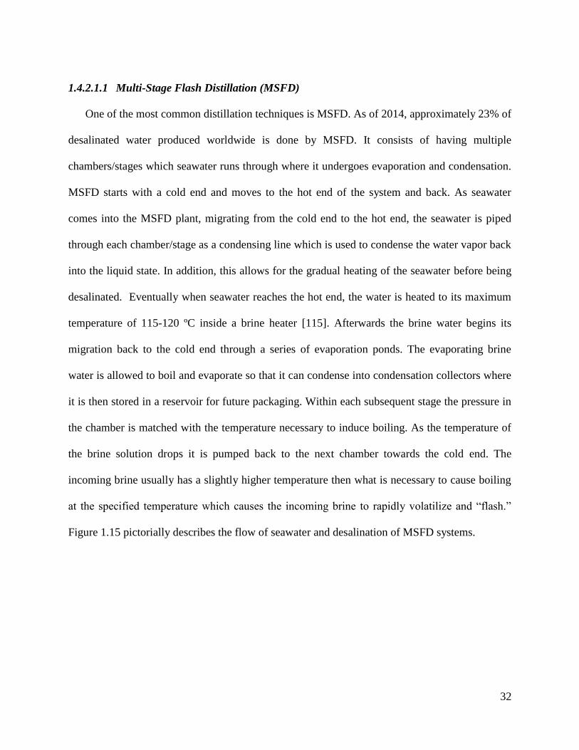
32
1.4.2.1.1 Multi-Stage Flash Distillation (MSFD)
One of the most common distillation techniques is MSFD. As of 2014, approximately 23% of
desalinated water produced worldwide is done by MSFD. It consists of having multiple
chambers/stages which seawater runs through where it undergoes evaporation and condensation.
MSFD starts with a cold end and moves to the hot end of the system and back. As seawater
comes into the MSFD plant, migrating from the cold end to the hot end, the seawater is piped
through each chamber/stage as a condensing line which is used to condense the water vapor back
into the liquid state. In addition, this allows for the gradual heating of the seawater before being
desalinated. Eventually when seawater reaches the hot end, the water is heated to its maximum
temperature of 115-120 ºC inside a brine heater [115]. Afterwards the brine water begins its
migration back to the cold end through a series of evaporation ponds. The evaporating brine
water is allowed to boil and evaporate so that it can condense into condensation collectors where
it is then stored in a reservoir for future packaging. Within each subsequent stage the pressure in
the chamber is matched with the temperature necessary to induce boiling. As the temperature of
the brine solution drops it is pumped back to the next chamber towards the cold end. The
incoming brine usually has a slightly higher temperature then what is necessary to cause boiling
at the specified temperature which causes the incoming brine to rapidly volatilize and “flash.”
Figure 1.15 pictorially describes the flow of seawater and desalination of MSFD systems.
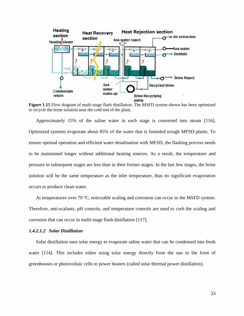
33
Figure 1.15 Flow diagram of multi-stage flash distillation. The MSFD system shown has been optimized
to recycle the brine solution near the cold end of the plant.
Approximately 15% of the saline water in each stage is converted into steam [116].
Optimized systems evaporate about 85% of the water that is funneled trough MFSD plants. To
ensure optimal operation and efficient water desalination with MFSD, the flashing process needs
to be maintained longer without additional heating sources. As a result, the temperature and
pressure in subsequent stages are less than in their former stages. In the last few stages, the brine
solution will be the same temperature as the inlet temperature, thus no significant evaporation
occurs to produce clean water.
At temperatures over 70 ºC, noticeable scaling and corrosion can occur in the MSFD system.
Therefore, anti-scalants, pH controls, and temperature controls are used to curb the scaling and
corrosion that can occur in multi-stage flash distillation [117].
1.4.2.1.2 Solar Distillation
Solar distillation uses solar energy to evaporate saline water that can be condensed into fresh
water [114]. This includes either using solar energy directly from the sun in the form of
greenhouses or photovoltaic cells to power heaters (called solar thermal power distillation).
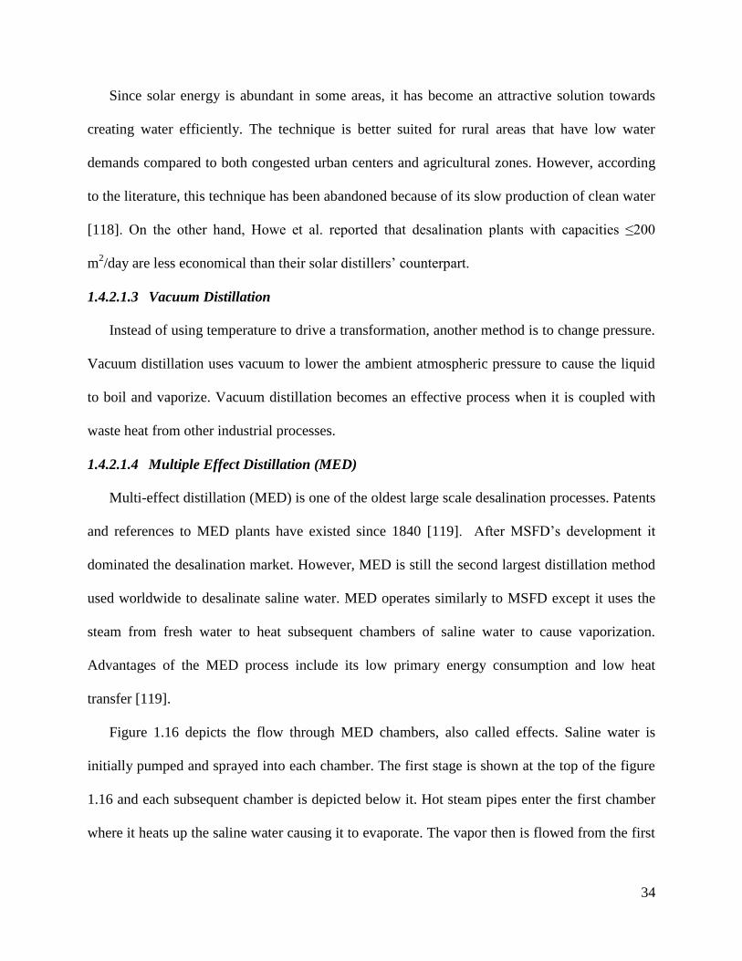
34
Since solar energy is abundant in some areas, it has become an attractive solution towards
creating water efficiently. The technique is better suited for rural areas that have low water
demands compared to both congested urban centers and agricultural zones. However, according
to the literature, this technique has been abandoned because of its slow production of clean water
[118]. On the other hand, Howe et al. reported that desalination plants with capacities ≤200
m2/day are less economical than their solar distillers’ counterpart.
1.4.2.1.3 Vacuum Distillation
Instead of using temperature to drive a transformation, another method is to change pressure.
Vacuum distillation uses vacuum to lower the ambient atmospheric pressure to cause the liquid
to boil and vaporize. Vacuum distillation becomes an effective process when it is coupled with
waste heat from other industrial processes.
1.4.2.1.4 Multiple Effect Distillation (MED)
Multi-effect distillation (MED) is one of the oldest large scale desalination processes. Patents
and references to MED plants have existed since 1840 [119]. After MSFD’s development it
dominated the desalination market. However, MED is still the second largest distillation method
used worldwide to desalinate saline water. MED operates similarly to MSFD except it uses the
steam from fresh water to heat subsequent chambers of saline water to cause vaporization.
Advantages of the MED process include its low primary energy consumption and low heat
transfer [119].
Figure 1.16 depicts the flow through MED chambers, also called effects. Saline water is
initially pumped and sprayed into each chamber. The first stage is shown at the top of the figure
1.16 and each subsequent chamber is depicted below it. Hot steam pipes enter the first chamber
where it heats up the saline water causing it to evaporate. The vapor then is flowed from the first
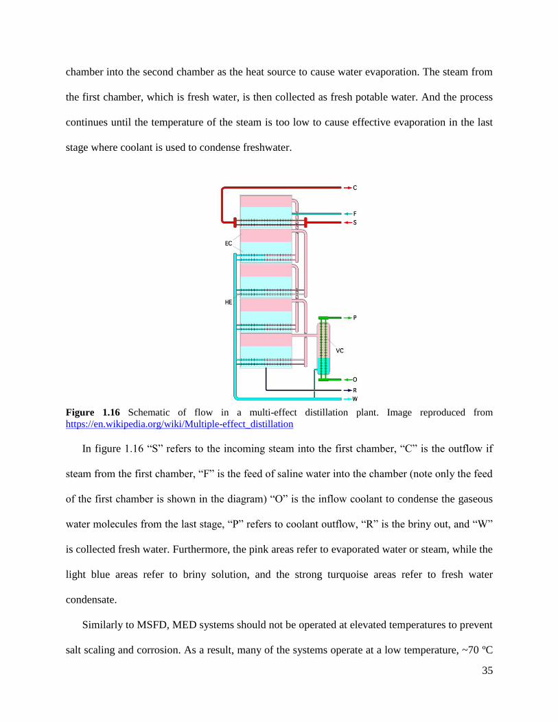
35
chamber into the second chamber as the heat source to cause water evaporation. The steam from
the first chamber, which is fresh water, is then collected as fresh potable water. And the process
continues until the temperature of the steam is too low to cause effective evaporation in the last
stage where coolant is used to condense freshwater.
Figure 1.16 Schematic of flow in a multi-effect distillation plant. Image reproduced from
https://en.wikipedia.org/wiki/Multiple-effect_distillation
In figure 1.16 “S” refers to the incoming steam into the first chamber, “C” is the outflow if
steam from the first chamber, “F” is the feed of saline water into the chamber (note only the feed
of the first chamber is shown in the diagram) “O” is the inflow coolant to condense the gaseous
water molecules from the last stage, “P” refers to coolant outflow, “R” is the briny out, and “W”
is collected fresh water. Furthermore, the pink areas refer to evaporated water or steam, while the
light blue areas refer to briny solution, and the strong turquoise areas refer to fresh water
condensate.
Similarly to MSFD, MED systems should not be operated at elevated temperatures to prevent
salt scaling and corrosion. As a result, many of the systems operate at a low temperature, ~70 ºC
36
[103]. Currently, most studies are focused on thermos-economic optimization of the MED
process. This can entail utilizing solar thermal collectors to heat up the boiler fluid or saline
water, altering the fluid used to transfer heat from the boiler to the first chamber, or adding
thermo-vapor compressors [120].
A 14-effect MED plant that uses evacuated tube collectors is able to produce 40 m3/day
while a 16-effect MED plant outfitted with solar collectors produces 16 m3/day [120-122].
However, MED plants with parabolic trough concentrators and evacuated tube collectors can
produce up to 6000 m3/day [120, 123]. Presently, the largest MED plant is in Abu Dhabi which
has a capacity of 240,000 m3/day [120, 124].
1.4.2.2 Freeze-Thaw or Freezing-Melting
Freeze-thaw, also known as freezing-melting, historically was used by sailors who travelled
in cold climates to produce potable water during their travels. Typically the sailors would collect
frozen blocks and allow them to thaw before consuming it. It was later understood that as salt
water freezes it causes the salt ions to become less soluble which concentrates it into the center
of the block [125-127]. Thus, it was observed that ice blocks contained a liquid brine solution
surrounded by high purity ice.
Anton Maria Lorgana found that purifying seawater to potable levels required multiple
freeze-thaw cycles [128]. Due to the technologies necessity for subzero temperatures, the
technology fizzled away until ~1930 with the development of refrigeration. Research interest in
freeze-thaw desalination systems was revived in the 1950s to 1970s where many technical
innovations were developed [126].
Advantages of freeze-thaw systems include its very high water-salt separation factor, higher
energy efficiency, no fouling, no scaling, no corrosion, and no need for chemical pretreatment
37
[126]. One of the most attractive reasons for using freeze-thaw desalination is its energy
efficiency compared to distillation methods. The latent heat of freezing and vaporization are 334
kJ/kg and 2256 kJ/kg, respectively, which makes the amount of energy needed to freeze water
instead of vaporize it, one-seventh [126, 129]. Different configurations of freeze-thaw systems
include direct freezing, indirect freezing, and absorption [129].
1.5 Desalination Plant Designs
Designing a desalination plant takes careful planning. Some important factors to consider
include location, climate/temperature, technology and industry coupling, materials, and proper
disposal of waste. In this case, the authors assume the demand for clean water is high enough to
provide a profit and changes in weather, such as rainfall, will not cause drastic changes in the
business of the plant.
Firstly, location is one of the most important factors in desalination plant design because the
plant needs to access a water reservoir. Such reservoirs can include rivers/bays, lakes/dams, and
seas/oceans. Without a large and continuous source of water, such a plant will shut down once
the reservoir dries up. Furthermore, it is important to situate the desalination plant near an area
where the demand for clean water is high because that consumer base will produce enough
revenue to maintain and pay for the desalination facility. Thus, ideal locations for such plants
include highly populated river or coastal cities.
Climate and temperature, which are both location dependent, are also very important factors
in plant design because depending on the climate and temperature, certain desalination
techniques become more profitable over others. For example in very hot and arid locations with
long sun exposures, distillation techniques such as MSFD, solar distillation, and MED, are
highly efficient because part of the energy costs can be replaced with solar energy from solar
38
collectors, whereas in very cold areas such as in the arctic, freeze-thaw systems would be more
efficient. However, in temperate climates where temperatures can dramatically change
seasonally over the course of the year, systems such as RO are more efficient and thus profitable.
Another way to help reduce cost and be more efficient includes technological and/or
industrial coupling. Many water desalination plants are beginning to incorporate technologies
such as photovoltaic cells to help reduce the energy demand from power plants. More
interestingly, many desalination plants have begun to partner with power plant companies to use
the waste steam from the power plant to drive the water desalination process, primarily for
distillation technologies. Most power plants use water vapor to spin turbines to ultimately create
electricity, which then is released into the atmosphere as waste. However by connecting a power
plant with a desalination plant, the steam waste can then be used as a heat source for water
desalination. In turn by coupling both the power industry with water desalination, the waste of
the power plant can be used to power the operation of the desalination plant which lowers the
operational cost of the water desalination plant. In other words, the desalination plant uses the
power plant’s “waste” to power the distillation process.
Also, material selection becomes important when designing a water desalination plant.
Without the proper materials the plant will begin to corrode and cause both financial and
infrastructural strain. It is common knowledge that saline water needs to be treated before
becoming safe enough for human ingestion, it is less commonly known that both saline water
and de-ionized water are highly corrosive to many metals and metal alloys. Many desalination
plants utilize materials such as stainless steel, admiralty, aluminum-brass, and copper based
alloys as piping in their systems, with stainless steel being one of the most widely used materials
in desalination plants [130, 131]. Although, stainless steels tend to be considered an anti-
39
corrosive alloy because of its high amount of chromium, it still may rapidly corrode in the
presence of both saline and fresh water under the proper conditions [132-134]. Degradation in
metal and metal alloy materials include uniform reduction-oxidation attack, galvanic corrosion,
crevice-corrosion, pitting, erosion-corrosions, and leaching [130]. Ideally, plants would want to
consist of titanium inflow piping and high density polyethylene outflow piping [130, 135, 136].
However, titanium is more expensive than its stainless steel counterpart. Thus, new alloys and
coatings such as polymers and enamels are under investigation to prevent such infrastructure
issues in the water desalination plant.
Last but not least, desalination plant also produces environmental concerns, specifically their
concentrated saline waste. These high concentrations can become very toxic to both aquatic and
terrestrial life; as a result, disposal of concentrated saline solution can be problematic. Some
desalination plants have thus invested in further drying the salt and then commercially selling the
sea salt to various industries.
It is important to consider that even in dry and arid areas that are prone to prolonged droughts
such as in California, eventual rainfall can end up driving the price of clean water low enough to
shut down a desalination plant. One such plant includes the Charles E. Meyer desalination plant
in California where it shut down months after opening because of the return of rainfall.
1.6 RO Membrane Design and Materials: Past, Present, and Future
In 1931, the concept of reverse osmosis was patented as a method to desalinate water. Most
of the early research focused on desalting seawater because of seawater abundance and
availability. Since seawater consisted of high amounts of dissolved salt, it was necessary to reject
more than 99.5% of the salt to produce safe drinking water. As a result, early on these
40
membranes were run under high pressures, as high as 100 bar, to reach the desired performance
to produce acceptable permeate fluxes with maximum salt rejections [9].
However, over the years it became more profitable to desalt sources with lower salt
concentrations such as brackish water, if available in the area. This resulted in relaxing the
minimum 99.5% salt rejection criterion, allowing other membranes with slightly lower salt
rejections, between 98-99%, to enter the market. Furthermore, it allowed operators to lower the
applied transmembrane pressure, ranging from 10 to 30 bar, to reach similar safe levels for water
consumption [9].
Finally, different systems were designed for different needs. For example, the safe salt
concentration for consuming water is drastically different than the water needed to wash
electronic devices and silicon wafers. Since such industries need ultrapure water to prevent any
impurity from damaging the electronics, the saline water was desalted at lower pressures (8-12
bar) to ensure that specific salts such as divalents did not pass through and were rejected above
99.5% [9].
As a result, companies would use the same material and tailor it depending on the needs and
applications that the membrane was to be used for using either chemical modifications or
processing techniques. Most advancements in the membrane realm for RO membranes have
focused on one or more subjects listed: increase in water throughput, increase in salt rejection or
water salt selectivity, increases in membrane’s antifouling and antiscaling properties, increases in
salt ion to ion selectivity, and/or increases in the membrane’s mechanical integrity which are all
tunable either by altering the chemical composition of the material or by altering the
fabrication/processing techniques.
41
This review will highlight the various membrane architectures that are possible to be
fabricated as well as materials that are used both industrially today and being researched to
produce clean water for different applications. We will further elaborate on optimizations done in
each class of membrane material ranging from how it is synthesized and processed and its
change in performance in desalinating water. We will finally discuss the future of the different
classes of materials.
1.6.1 Membrane Designs
When it comes to selecting the correct membrane, one must consider the membrane’s
chemical structure, topology (linear or crosslinked) and architecture. Currently, there are two
classifications of membrane architecture, symmetric or asymmetric. Symmetric architectures can
further be divided into dense films which utilize free volume to facilitate the material transport,
and porous films which instead use pores (volume in pore >> free volume) to facilitate mass
transport. Asymmetric architectures can also be divided into asymmetric membranes and thin
film composites (TFC). Figure 1.17 pictorially shows cross sections of the four membrane
architectures: dense, porous, asymmetric, and TFCs.
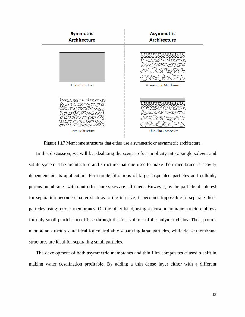
42
Figure 1.17 Membrane structures that either use a symmetric or asymmetric architecture.
In this discussion, we will be idealizing the scenario for simplicity into a single solvent and
solute system. The architecture and structure that one uses to make their membrane is heavily
dependent on its application. For simple filtrations of large suspended particles and colloids,
porous membranes with controlled pore sizes are sufficient. However, as the particle of interest
for separation become smaller such as to the ion size, it becomes impossible to separate these
particles using porous membranes. On the other hand, using a dense membrane structure allows
for only small particles to diffuse through the free volume of the polymer chains. Thus, porous
membrane structures are ideal for controllably separating large particles, while dense membrane
structures are ideal for separating small particles.
The development of both asymmetric membranes and thin film composites caused a shift in
making water desalination profitable. By adding a thin dense layer either with a different
43
material or as a skin surface onto a porous layer, the membranes were able to achieve much
higher water fluxes while still maintaining extremely high salt rejections.
1.6.1.1 Porous Membranes
One of the benefits that porous membranes have over dense membranes is the increase in
flux. Porous membranes also tend to have lower rejections as well as higher fouling propensities.
One of the methods of producing uniform holes is track etching. Track etching uses a high
intensity source to bombard through the membrane which damages the surface of polymer chains
with either fission of heavy nuclear nuclei or heavy (MeV) ion beams [9, 137]. Afterwards the
membrane is submerged in an etching solution such as KOH or NaOH that erodes the damaged
polymer away [137]. The number of pores and size of pores can be controlled by exposure times
to the radiation and etchant, respectively [138]. This results in a membrane with cylindrical or
tunneled cigar shaped pores which are typically used as screen filters [9, 139]. The pores can
vary in diameter from a few nm to mm with aspect ratios between 10 and 1000 [137].
In some cases it is possible to create a porous membrane using a melt extruder. This leads to
a specific class of membranes called expanded film membranes. This is achieved by subjecting a
semi-crystalline polymer to a temperature just below its melting point and rapidly drawing it out
of a melt extruder. This forces the crystallites to align along the draw direction. The film is
allowed to cool and subsequently annealed. Afterwards the film is stretched tangentially to the
draw direction, up to 300%, causing the amorphous sections of the polymer to form slit like
voids that range between 250 and 2500 Å between crystallites [9]. The pore size for expanded
film membranes may be controlled by the percent elongation of the tangential stretching.
Another common technique used to produce isotropic porous membranes is template
leaching. In this case, the polymer is doped or blended with a leaching agent that is then
44
extracted after the film has been made. To ensure that the leachant is homogeneously dispersed,
the polymer is mixed with the leachant and pelletized multiple times before making the final
film. Once the film is made it is drawn into a solvent that is miscible with the leachant but
insoluble with the matrix to extract the leachant leaving voids in the film.
1.6.1.2 Asymmetric Membranes
For water desalination, almost all the membranes used to desalt the feed water uses a hybrid
between dense and porous membranes. These hybrids utilize a very thin layer that is made either
from the same material as the rest of the membrane or separate. In the case for the thin layer
being made from the same material it is called an asymmetric membrane. The asymmetric
membrane typically contains a top skin layer that is considered a dense film and the pore sizes
increase from top to bottom. In some cases, the skin layer may contain pores but such
membranes would not be used for water desalination.
During the early years of cellulose acetate membrane development, Loeb and Sourirajan
found means to fabricate the first asymmetric membranes. They found that because of the thin
dense skin, the membranes, were able to achieve high salt rejections, similar to conventional
thick dense membranes but also allow higher water fluxes to pass through; thus making RO a
viable option for water desalination. The four essential steps that are common to all of the Loeb-
Sourirajan membranes are: 1) a polymer solution needs to be cast as a thin film in the appropriate
solvent or solvent mixture; 2) some of the solvent needs to evaporate from the surface of the
film; 3) the film is immersed into a non-solvent that will precipitate the polymer but is miscible
with the solvent or solvent mixture; and 4) the film is usually annealled [140]. The general
technique for precipitating the polymer membrane in a non-solvent is conventionally called the
45
phase inversion or phase separation process while the Loeb-Sourirajan technique is a specific
processing technique under the phase inversion umbrella.
This technique is further rationalized by building a ternary or three component phase diagram
between the polymer, solvent, and non-solvent for consistent and reproducible development of
asymmetric membranes [9, 140, 141]. Thus a lot of research has been spent in trying to
understand how the system works to fully utilize the technique to control the final membrane
properties.
Another technique used to fabricate asymmetric membranes uses the same track etching
technology mentioned in designing porous membranes but instead slowly ramps up the ion beam
intensity through the tracking process, thus allowing researchers to develop conical shaped pores
through the thickness of the membrane using this general technique [142].
1.6.1.3 Thin Film Composites (TFCs)
Since Loeb and Sourirajan’s development of the asymmetric membranes with a thin dense
skin layer and their ability to allow higher water fluxes through the membrane, other researchers
have shifted their focus to developing thin films which they can append onto the surface of a
microfiltration or ultrafiltration membrane to form a thin film composite.
One of the most industrially adapted techniques to create thin film composites is interfacial
polymerization developed by John Cadotte at FilmTec Corporation in the 1970s. This typically
requires at least two monomers or oligomers that can react with one another exemplified by the
reaction between an amine and an acid halide. First, the polymer support UF membrane is
deposited into an aqueous diamine solution. This coats the desired exterior surface of the UF
membrane and traps some of the diamine solution within the pores near the surface of the UF
membrane. Subsequently the membrane is eposed to a saturated solution of diacid and/or triacid
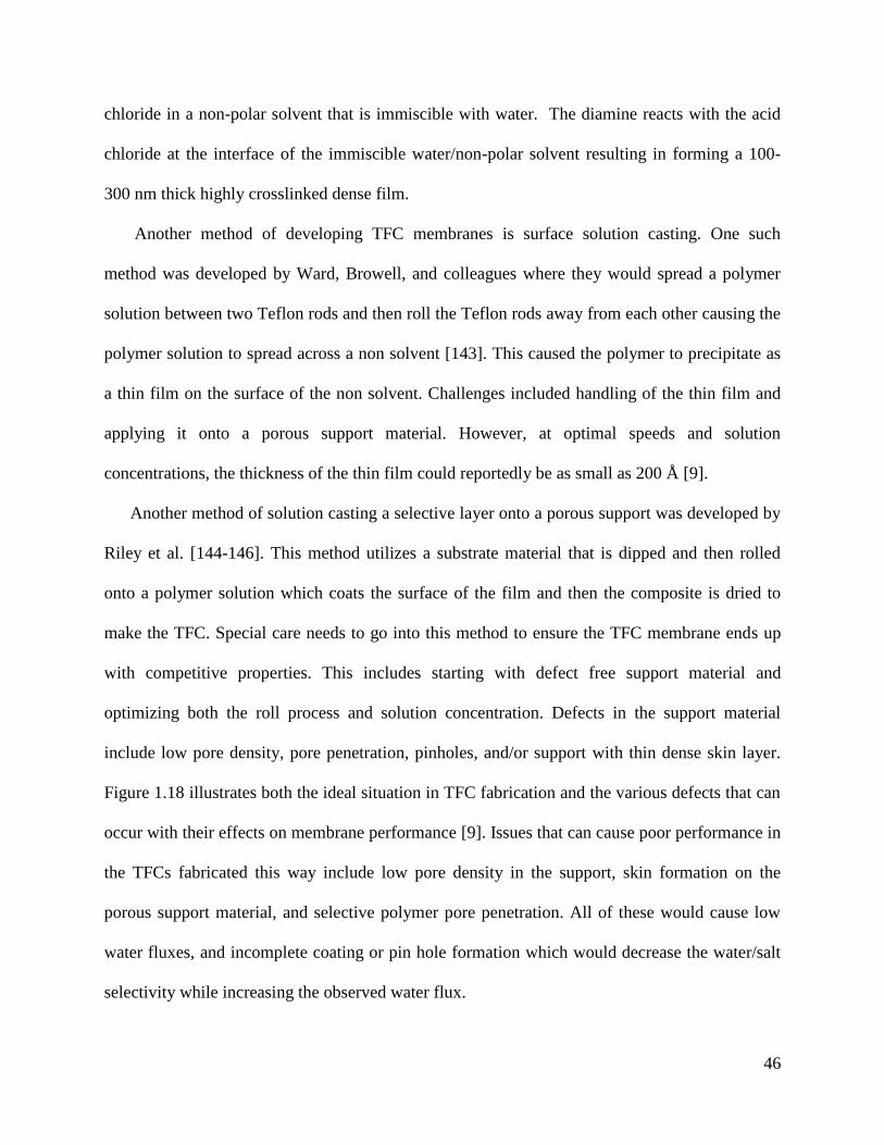
46
chloride in a non-polar solvent that is immiscible with water. The diamine reacts with the acid
chloride at the interface of the immiscible water/non-polar solvent resulting in forming a 100-
300 nm thick highly crosslinked dense film.
Another method of developing TFC membranes is surface solution casting. One such
method was developed by Ward, Browell, and colleagues where they would spread a polymer
solution between two Teflon rods and then roll the Teflon rods away from each other causing the
polymer solution to spread across a non solvent [143]. This caused the polymer to precipitate as
a thin film on the surface of the non solvent. Challenges included handling of the thin film and
applying it onto a porous support material. However, at optimal speeds and solution
concentrations, the thickness of the thin film could reportedly be as small as 200 Å [9].
Another method of solution casting a selective layer onto a porous support was developed by
Riley et al. [144-146]. This method utilizes a substrate material that is dipped and then rolled
onto a polymer solution which coats the surface of the film and then the composite is dried to
make the TFC. Special care needs to go into this method to ensure the TFC membrane ends up
with competitive properties. This includes starting with defect free support material and
optimizing both the roll process and solution concentration. Defects in the support material
include low pore density, pore penetration, pinholes, and/or support with thin dense skin layer.
Figure 1.18 illustrates both the ideal situation in TFC fabrication and the various defects that can
occur with their effects on membrane performance [9]. Issues that can cause poor performance in
the TFCs fabricated this way include low pore density in the support, skin formation on the
porous support material, and selective polymer pore penetration. All of these would cause low
water fluxes, and incomplete coating or pin hole formation which would decrease the water/salt
selectivity while increasing the observed water flux.
47
Figure 1.18 Defects that can occur during development of a thin film composite. Reproduced with
permission from [9].
Some unique techniques that have been experimented with for fabricating TFCs but that are
not common in the membrane world include plasma polymerization and spin coating. Plasma
polymerization volatilizes monomers and initiators into a plasma reactor chamber with the
porous support material. In some cases the chamber is evacuated (between 1.0•10-3
and 9.0•10-3
mbar) before incorporation of the monomers and initiators. In other cases, inert gas such as
helium or argon are incorporated into the reactor at a pressure between 50-100 mTorr [9, 147,
148]. The monomer vapor is subsequently introduced at a pressure of 200-300 mTorr for 1-15
minutes and at an RF frequency ranging between 2 and 50 MHz. The RF field generates a
plasma which ionizes the monomers and initiators into radicals which then polymerize onto the
surface of the substrate. Such polymerization is different from conventional polymerizations
because the polymer consists of monomer fragments instead of the monomer itself making it
difficult to determine the exact structure of the polymer generated. Moreover, these films tend to
48
be highly crosslinked. The films formed through plasma polymerization tend to have thicknesses
between 20-60 nm depending on length of time the polymer was allowed to form.
Another technique utilized to form TFCs is spin coating. It is a very common technique when
it comes to making microscopy samples for atomic force microscopy and scanning electron
microscopy, but it isn’t scalable to make water purification membranes. Additionally, spin
coaters are industrially used to coat electronics and semiconductors. Spin coated films can vary
in thickness between 0.5 and 10 μm. First the substrate is placed on a rotating disk. As the disk
and substrate rotate, a dilute solution of polymer is injected onto the surface of the substrate.
Because of the high frequency at which the substrate is spinning the dilute polymer solution
spreads from the center of the substrate to the edges due to centripetal force forming a thin film.
Furthermore, the spreading will increase the surface area of the solution which will make it
easier and quicker to evaporate the solvent the polymer was suspended or dissolved in. There are
two major ways to control the final thickness of the thin film: 1) angular velocity of the substrate
(faster speeds will yield thinner films), and 2) polymer concentration (lower concentrations will
yield thinner films).
Moreover deposition techniques used to develop thin film composites include but are not
limited to chemical vapor deposition (CVD), spin coating, and plasma polymerizations. Even
though such techniques may bring about some unique chemistries and structures, such
techniques are not ideal for commercially making membranes for RO systems. However, one
technique that might receive traction in developing thin films would be electrodeposition or
electropolymerization also called electrochemical polymerizations. To fabricate such materials a
conductive support material is used to polymerize monomers onto the surface of the conductive
material. Supports such as stainless steel meshes or even indium tin oxide (ITO) mesh materials
49
can be used. The conductive support is then dipped into a solution of monomers with a free
radical initiator such as ammonium persulfate [148]. As soon as a current is applied to the
support material the monomer undergoes an anodic oxidation with the assistance of the oxidant
causing the monomers to polymerize onto the surface of the conductive support [148]. However,
not all monomers can be polymerized this way. The most common polymers produced this way
are conductive polymers which consist of conjugated systems, which are very brittle especially
when dry. The applied potential and time are means to control the thickness of the deposited
polymer and may be useful in mass producing water desalination membranes for both reverse
osmosis and electrodialysis.
An interesting technique recently developed is called reactive surface treatment [9, 149-155].
Typically this method has been used to modify existing active layers in gas separation
membranes but may be altered to actually form the active layer similar to plasma polymerization
deposition and CVD. Currently, the modifications today alter the structure of the active layer to
improve the membrane’s gas selectivity instead of adding an active layer. Further experiments
have been done with both dilute amounts of fluorine and ozone to carefully modify a thickness of
100-200 Å.
1.6.2 Membrane Materials
As previously mentioned there are four major membrane architectures: dense, porous,
asymmetric, and thin film composites. Some of these architectures limit the type of polymer that
may be used to effectively fabricate the membrane. As a result, some unique methods have been
developed to incorporate different polymers in the fabrication of the desired membrane
architecture. In addition, unique chemistries have also been developed that makes one fabrication
method more attractive over others. This section will highlight classes of membranes that have
50
been developed for reverse osmosis applications. The past, present, and future of commercial and
research membranes, the various synthetic routes to develop the base polymer, general
membrane architecture fabrication, and finally the effects of various additives incorporated into
the membranes will be discussed.
This section is divided into four different classes of membranes: 1) cellulose acetate, 2)
crosslinked polyamide, 3) pure graphene, and 4) ceramic membranes. The classes refer to the
composition of the matrix material. For example, in the case of discussion of a polyamide
membrane that incorporates graphene or graphene oxide nanosheets, the matrix would be
considered polyamide while the additive is graphene or graphene oxide; thus, such discussion is
in the polyamide section.
1.6.2.1 Cellulose Acetate Membranes
Cellulose based films were one of the first commercial membranes used to create fresh water.
These membranes were easy to fabricate, mechanically robust, and chemically resistant to
degradation from chlorine and other oxidants [9, 156, 157]. Additionally, cellulose is typically
found woody mateirals. Cellulose is also produced by bacteria and tunicates, and is found in
various non wood forms such as cotton linter. Cellulose acetate (CA) is one of the most common
forms of cellulose based membranes but it is important to note that cellulose membranes can
include blends of cellulose butyrate, cellulose triacetate, as well as other cellulose derivatives [9].
Cellulose esters are formed by esterifying or acetylating cellulose. This is generally achieved
by mixing cellulose with an organic acid anhydride. In the case of cellulose acetate, acetic
anhydride is used in the presence of an acid catalyst which is shown in scheme 1.1 [158]. Other
methods of synthesizing cellulose esters include reacting cellulose with either carboxylic acids
under heat or an acyl chloride. Note that cellulose is very difficult to dissolve due to its highly
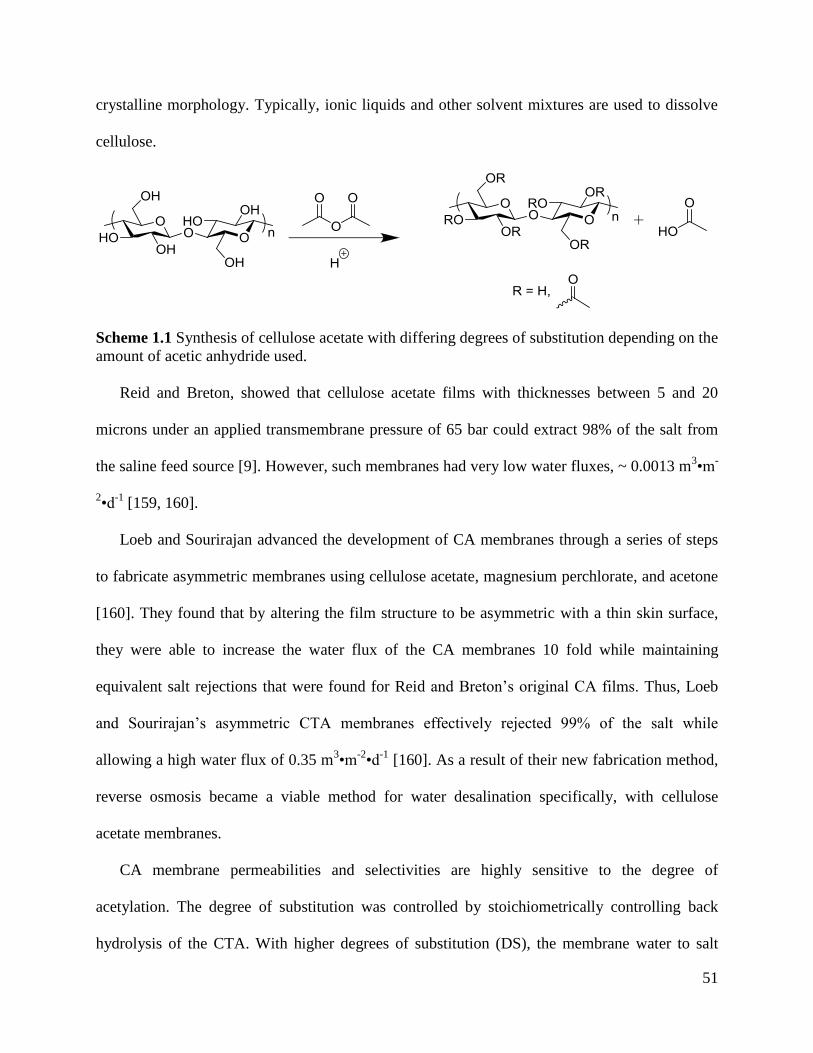
51
crystalline morphology. Typically, ionic liquids and other solvent mixtures are used to dissolve
cellulose.
Scheme 1.1 Synthesis of cellulose acetate with differing degrees of substitution depending on the
amount of acetic anhydride used.
Reid and Breton, showed that cellulose acetate films with thicknesses between 5 and 20
microns under an applied transmembrane pressure of 65 bar could extract 98% of the salt from
the saline feed source [9]. However, such membranes had very low water fluxes, ~ 0.0013 m3•m
-
2•d
-1 [159, 160].
Loeb and Sourirajan advanced the development of CA membranes through a series of steps
to fabricate asymmetric membranes using cellulose acetate, magnesium perchlorate, and acetone
[160]. They found that by altering the film structure to be asymmetric with a thin skin surface,
they were able to increase the water flux of the CA membranes 10 fold while maintaining
equivalent salt rejections that were found for Reid and Breton’s original CA films. Thus, Loeb
and Sourirajan’s asymmetric CTA membranes effectively rejected 99% of the salt while
allowing a high water flux of 0.35 m3•m
-2•d
-1 [160]. As a result of their new fabrication method,
reverse osmosis became a viable method for water desalination specifically, with cellulose
acetate membranes.
CA membrane permeabilities and selectivities are highly sensitive to the degree of
acetylation. The degree of substitution was controlled by stoichiometrically controlling back
hydrolysis of the CTA. With higher degrees of substitution (DS), the membrane water to salt
52
selectivity increased but at the cost of dramatically reduced water permeability. In some cases,
fully acetylated cellulose also called cellulose triacetate (CTA) is used in some applications to
desalinate water because it can achieve about 99.6% salt rejection which is just above the
minimum 99.5% salt rejection threshold for single stage seawater operation [9]. But because the
water flux for CTA is very low, most commercial CA membranes typically have a degree of
substitution of 2.7 which reduces the crystallinity and improve solubility [9].
While operating reverse osmosis with cellulose acetate membranes, feed pretreatment is
crucial to reduce fouling and biodegradation of the membrane. Microorganisms such as
Pestalotiopsis weserdijkii, Pseudomonas paucimobilis, and Neisseria sicca have been reported to
enzymatically biodegrade cellulose acetate with varying degrees of substitution [161-164]. As a
result, feed water is pretreated with sodium hypochlorite or other chlorination compounds to kill
the microorganisms in the feed. In addition, cellulose acetate is prone to hydrolysis at various pH
ranges which can cause decreases in molecular weight and in the degree of substitution. Thus,
the pH of the feed is typically maintained between a pH of 4 – 6 at room temperature.
El-Saied et al. prepared various blends of CA produced from viscose pulp, cotton linters, and
bagasse pulp that were either heterogeneously or homogenously acetylated [156]. Some of the
membranes contained approximately 9.1% polypropylene. Each membrane was cast to have a
thickness of 140 μm and tested for RO performance and efficiency with feed water that
contained mixed salts with concentrations ranging from 10,000 – 11,000 ppm under an applied
transmembrane pressure of 400-520 psi. El-Saied et al. reported that all the membranes had salt
rejections ranging between 83 - 92% but heterogeneously acetylated cellulose was found to have
profound effects in increasing the salt rejection and water fluxes compared to its homogeneously
acetylated counterparts. To achieve the desired DS of CA polymers, some groups grafted
53
different CA polymers together. One such work appended poly(N-isopropylacrylamides) onto
cellulose diacetate and cellulose triacetate backbones and crosslinked them together with N,N-
methylene bisacrylamide. Neat cellulose acetate RO membranes were observed to have a salt
rejection of 93.7 % while the membrane with 0.1 wt % of grafted poly(N-isopropylacrylamides)
was observed to have a salt rejection of 98.9% [165, 166].
Adding different particulates or surface modifications to cellulose acetate can make the
membrane more resistant to bacterial or chemical degradation or increase the materials transport
or mechanical properties. Li et al. modified CA membranes with bromoacetyl bromide through
esterification followed by alkylation with a tertiary amine to create a bi-antibacterial membrane
[157]. The pendant groups did not alter the architecture of the membrane but decreased its
thermal stability while slightly increasing its mechanical integrity. Furthermore, it was found that
a surface-doped CA asymmetric membrane showed above 99.9% bactericidal properties against
both gram negative and gram positive bacteria such as E. coli and S. aureus [157]. Antibacterial
functional groups may be incorporated into the membrane through physical blending or by
chemically reacting (reversible addition-fragmentation chain transfer, “click” chemistry, free
radical, etc.) inorganic and/or organic antimicrobial agents into the CA matrix or by applying
such materials as a coating on the surface of the membrane [157, 167-170]. Inorganic
antibacterial materials include silver and titanium silicon oxide nanoparticles. Organic
antibacterial materials include polymers such as chitosan; or chemical agents such as
bromoacetate, chlorhexidine, and quartenary amines.
Some researchers have incorporated nanodiamond, various graphene derivatives, and hard
ceramic particulates into CA membranes to minimize compaction effects. Under normal reverse
osmosis operational pressures, porous polymeric materials have can undergo compaction from
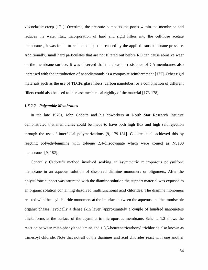
54
viscoelastic creep [171]. Overtime, the pressure compacts the pores within the membrane and
reduces the water flux. Incorporation of hard and rigid fillers into the cellulose acetate
membranes, it was found to reduce compaction caused by the applied transmembrane pressure.
Additionally, small hard particulates that are not filtered out before RO can cause abrasive wear
on the membrane surface. It was observed that the abrasion resistance of CA membranes also
increased with the introduction of nanodiamonds as a composite reinforcement [172]. Other rigid
materials such as the use of TLCPs glass fibers, carbon nanotubes, or a combination of different
fillers could also be used to increase mechanical rigidity of the material [173-178].
1.6.2.2 Polyamide Membranes
In the late 1970s, John Cadotte and his coworkers at North Star Research Institute
demonstrated that membranes could be made to have both high flux and high salt rejection
through the use of interfacial polymerizations [9, 179-181]. Cadotte et al. achieved this by
reacting polyethylenimine with toluene 2,4-diisocyanate which were coined as NS100
membranes [9, 182].
Generally Cadotte’s method involved soaking an asymmetric microporous polysulfone
membrane in an aqueous solution of dissolved diamine monomers or oligomers. After the
polysulfone support was saturated with the diamine solution the support material was exposed to
an organic solution containing dissolved multifunctional acid chlorides. The diamine monomers
reacted with the acyl chloride monomers at the interface between the aqueous and the immiscible
organic phases. Typically a dense skin layer, approximately a couple of hundred nanometers
thick, forms at the surface of the asymmetric microporous membrane. Scheme 1.2 shows the
reaction between meta-phenylenediamine and 1,3,5-benzenetricarbonyl trichloride also known as
trimesoyl chloride. Note that not all of the diamines and acid chlorides react with one another
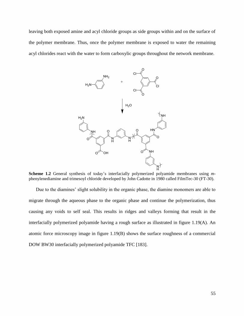
55
leaving both exposed amine and acyl chloride groups as side groups within and on the surface of
the polymer membrane. Thus, once the polymer membrane is exposed to water the remaining
acyl chlorides react with the water to form carboxylic groups throughout the network membrane.
Scheme 1.2 General synthesis of today’s interfacially polymerized polyamide membranes using m-
phenylenediamine and trimesoyl chloride developed by John Cadotte in 1980 called FilmTec-30 (FT-30).
Due to the diamines’ slight solubility in the organic phase, the diamine monomers are able to
migrate through the aqueous phase to the organic phase and continue the polymerization, thus
causing any voids to self seal. This results in ridges and valleys forming that result in the
interfacially polymerized polyamide having a rough surface as illustrated in figure 1.19(A). An
atomic force microscopy image in figure 1.19(B) shows the surface roughness of a commercial
DOW BW30 interfacially polymerized polyamide TFC [183].
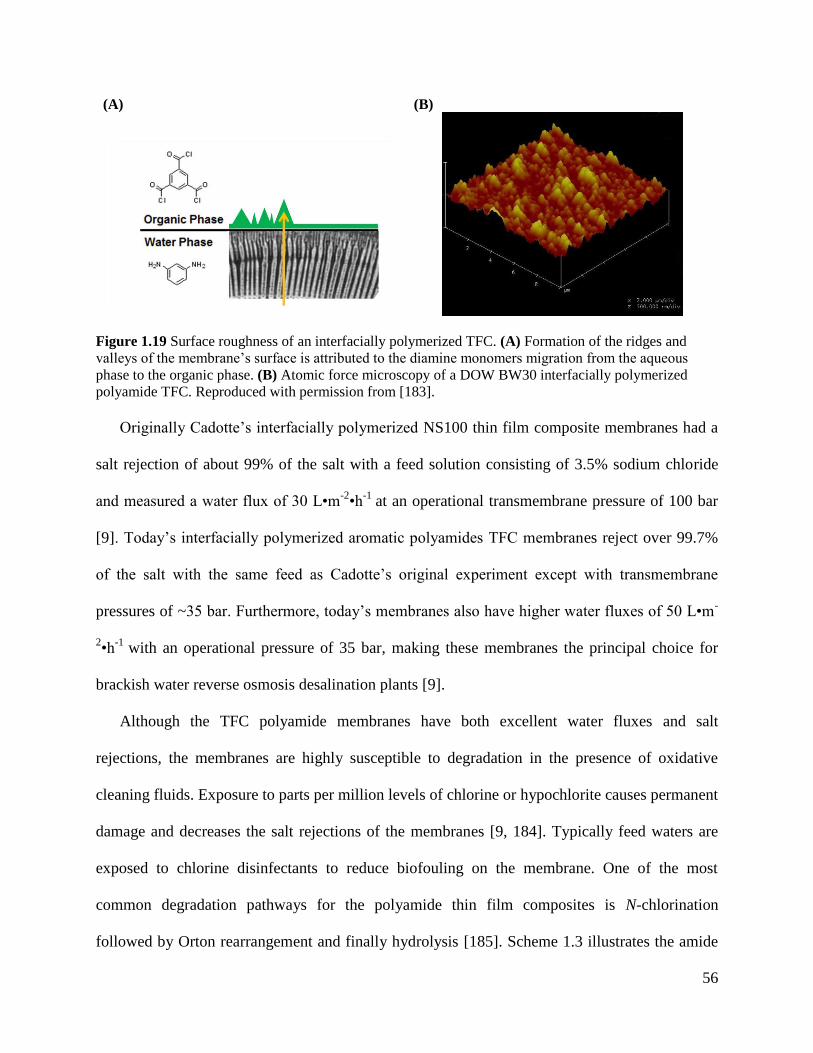
56
(A) (B)
Figure 1.19 Surface roughness of an interfacially polymerized TFC. (A) Formation of the ridges and
valleys of the membrane’s surface is attributed to the diamine monomers migration from the aqueous
phase to the organic phase. (B) Atomic force microscopy of a DOW BW30 interfacially polymerized
polyamide TFC. Reproduced with permission from [183].
Originally Cadotte’s interfacially polymerized NS100 thin film composite membranes had a
salt rejection of about 99% of the salt with a feed solution consisting of 3.5% sodium chloride
and measured a water flux of 30 L•m-2•h
-1 at an operational transmembrane pressure of 100 bar
[9]. Today’s interfacially polymerized aromatic polyamides TFC membranes reject over 99.7%
of the salt with the same feed as Cadotte’s original experiment except with transmembrane
pressures of ~35 bar. Furthermore, today’s membranes also have higher water fluxes of 50 L•m-
2•h
-1 with an operational pressure of 35 bar, making these membranes the principal choice for
brackish water reverse osmosis desalination plants [9].
Although the TFC polyamide membranes have both excellent water fluxes and salt
rejections, the membranes are highly susceptible to degradation in the presence of oxidative
cleaning fluids. Exposure to parts per million levels of chlorine or hypochlorite causes permanent
damage and decreases the salt rejections of the membranes [9, 184]. Typically feed waters are
exposed to chlorine disinfectants to reduce biofouling on the membrane. One of the most
common degradation pathways for the polyamide thin film composites is N-chlorination
followed by Orton rearrangement and finally hydrolysis [185]. Scheme 1.3 illustrates the amide
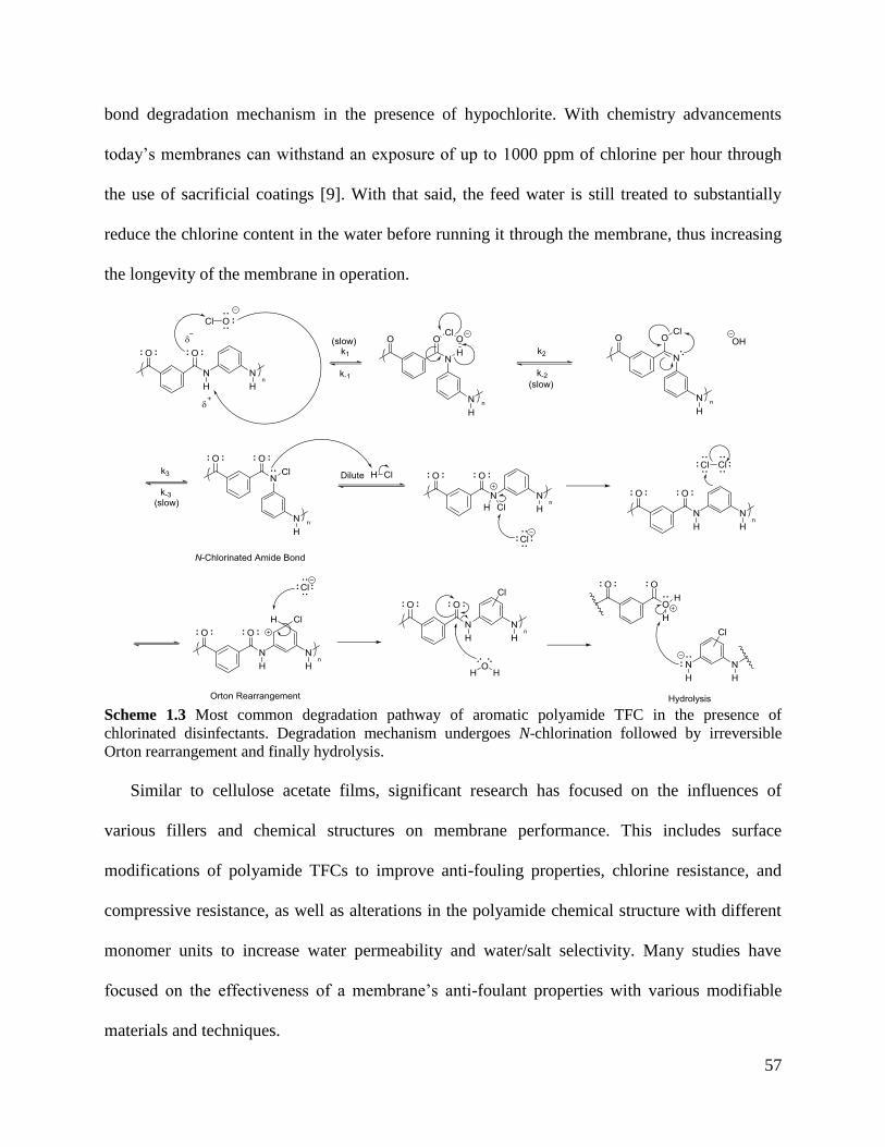
57
bond degradation mechanism in the presence of hypochlorite. With chemistry advancements
today’s membranes can withstand an exposure of up to 1000 ppm of chlorine per hour through
the use of sacrificial coatings [9]. With that said, the feed water is still treated to substantially
reduce the chlorine content in the water before running it through the membrane, thus increasing
the longevity of the membrane in operation.
Scheme 1.3 Most common degradation pathway of aromatic polyamide TFC in the presence of
chlorinated disinfectants. Degradation mechanism undergoes N-chlorination followed by irreversible
Orton rearrangement and finally hydrolysis.
Similar to cellulose acetate films, significant research has focused on the influences of
various fillers and chemical structures on membrane performance. This includes surface
modifications of polyamide TFCs to improve anti-fouling properties, chlorine resistance, and
compressive resistance, as well as alterations in the polyamide chemical structure with different
monomer units to increase water permeability and water/salt selectivity. Many studies have
focused on the effectiveness of a membrane’s anti-foulant properties with various modifiable
materials and techniques.
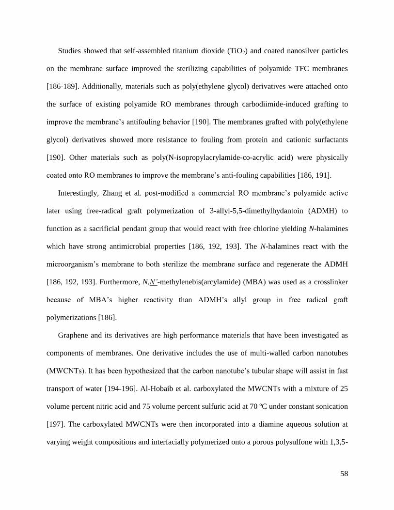
58
Studies showed that self-assembled titanium dioxide (TiO2) and coated nanosilver particles
on the membrane surface improved the sterilizing capabilities of polyamide TFC membranes
[186-189]. Additionally, materials such as poly(ethylene glycol) derivatives were attached onto
the surface of existing polyamide RO membranes through carbodiimide-induced grafting to
improve the membrane’s antifouling behavior [190]. The membranes grafted with poly(ethylene
glycol) derivatives showed more resistance to fouling from protein and cationic surfactants
[190]. Other materials such as poly(N-isopropylacrylamide-co-acrylic acid) were physically
coated onto RO membranes to improve the membrane’s anti-fouling capabilities [186, 191].
Interestingly, Zhang et al. post-modified a commercial RO membrane’s polyamide active
later using free-radical graft polymerization of 3-allyl-5,5-dimethylhydantoin (ADMH) to
function as a sacrificial pendant group that would react with free chlorine yielding N-halamines
which have strong antimicrobial properties [186, 192, 193]. The N-halamines react with the
microorganism’s membrane to both sterilize the membrane surface and regenerate the ADMH
[186, 192, 193]. Furthermore, N,N’-methylenebis(arcylamide) (MBA) was used as a crosslinker
because of MBA’s higher reactivity than ADMH’s allyl group in free radical graft
polymerizations [186].
Graphene and its derivatives are high performance materials that have been investigated as
components of membranes. One derivative includes the use of multi-walled carbon nanotubes
(MWCNTs). It has been hypothesized that the carbon nanotube’s tubular shape will assist in fast
transport of water [194-196]. Al-Hobaib et al. carboxylated the MWCNTs with a mixture of 25
volume percent nitric acid and 75 volume percent sulfuric acid at 70 ºC under constant sonication
[197]. The carboxylated MWCNTs were then incorporated into a diamine aqueous solution at
varying weight compositions and interfacially polymerized onto a porous polysulfone with 1,3,5-
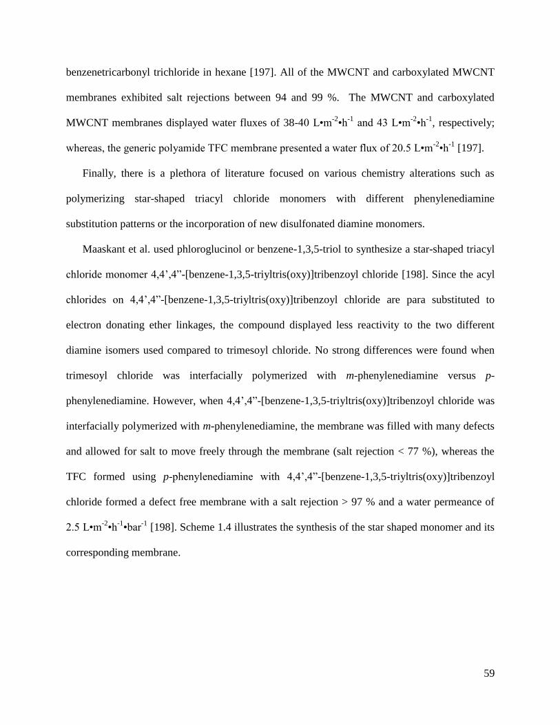
59
benzenetricarbonyl trichloride in hexane [197]. All of the MWCNT and carboxylated MWCNT
membranes exhibited salt rejections between 94 and 99 %. The MWCNT and carboxylated
MWCNT membranes displayed water fluxes of 38-40 L•m-2•h
-1 and 43 L•m
-2•h
-1, respectively;
whereas, the generic polyamide TFC membrane presented a water flux of 20.5 L•m-2•h
-1 [197].
Finally, there is a plethora of literature focused on various chemistry alterations such as
polymerizing star-shaped triacyl chloride monomers with different phenylenediamine
substitution patterns or the incorporation of new disulfonated diamine monomers.
Maaskant et al. used phloroglucinol or benzene-1,3,5-triol to synthesize a star-shaped triacyl
chloride monomer 4,4’,4”-[benzene-1,3,5-triyltris(oxy)]tribenzoyl chloride [198]. Since the acyl
chlorides on 4,4’,4”-[benzene-1,3,5-triyltris(oxy)]tribenzoyl chloride are para substituted to
electron donating ether linkages, the compound displayed less reactivity to the two different
diamine isomers used compared to trimesoyl chloride. No strong differences were found when
trimesoyl chloride was interfacially polymerized with m-phenylenediamine versus p-
phenylenediamine. However, when 4,4’,4”-[benzene-1,3,5-triyltris(oxy)]tribenzoyl chloride was
interfacially polymerized with m-phenylenediamine, the membrane was filled with many defects
and allowed for salt to move freely through the membrane (salt rejection < 77 %), whereas the
TFC formed using p-phenylenediamine with 4,4’,4”-[benzene-1,3,5-triyltris(oxy)]tribenzoyl
chloride formed a defect free membrane with a salt rejection > 97 % and a water permeance of
2.5 L•m-2•h
-1•bar
-1 [198]. Scheme 1.4 illustrates the synthesis of the star shaped monomer and its
corresponding membrane.
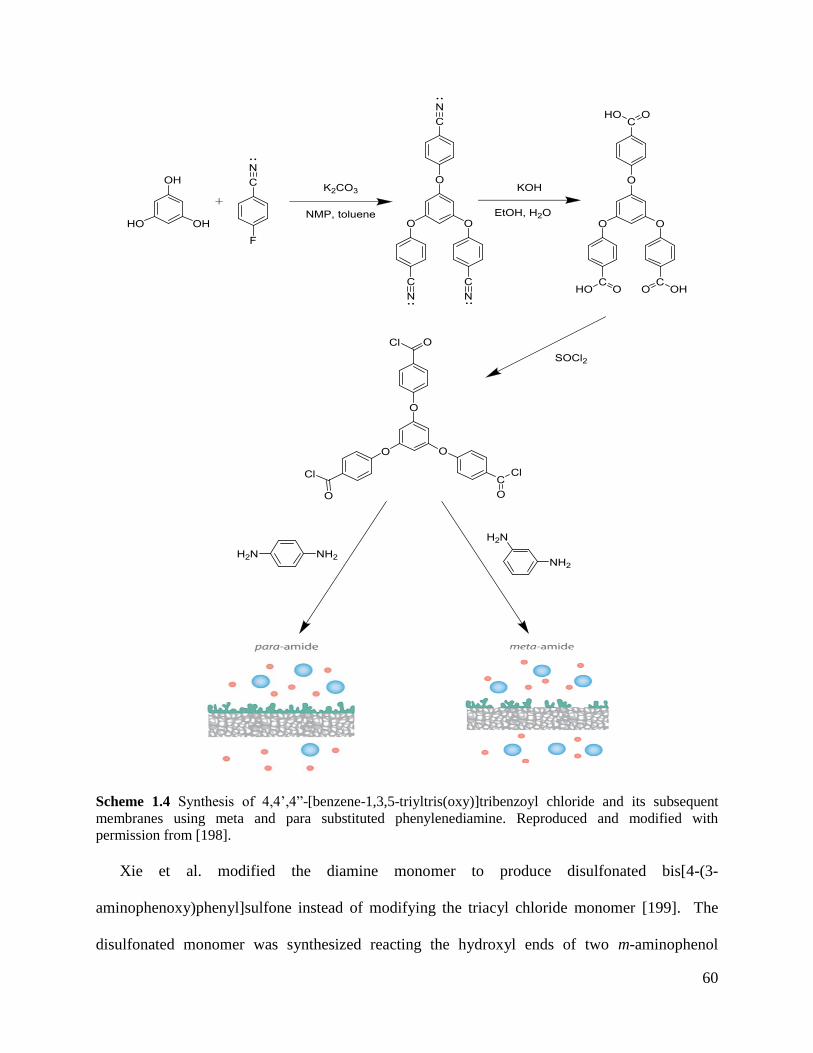
60
Scheme 1.4 Synthesis of 4,4’,4”-[benzene-1,3,5-triyltris(oxy)]tribenzoyl chloride and its subsequent
membranes using meta and para substituted phenylenediamine. Reproduced and modified with
permission from [198].
Xie et al. modified the diamine monomer to produce disulfonated bis[4-(3-
aminophenoxy)phenyl]sulfone instead of modifying the triacyl chloride monomer [199]. The
disulfonated monomer was synthesized reacting the hydroxyl ends of two m-aminophenol
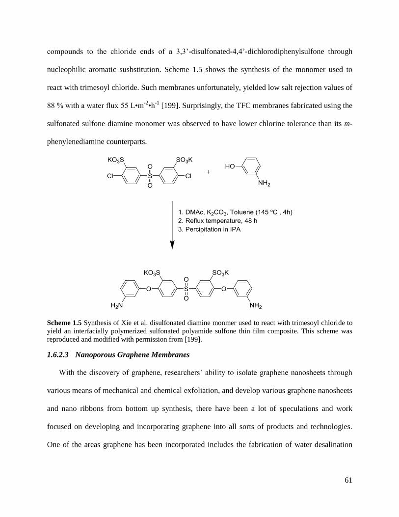
61
compounds to the chloride ends of a 3,3’-disulfonated-4,4’-dichlorodiphenylsulfone through
nucleophilic aromatic susbstitution. Scheme 1.5 shows the synthesis of the monomer used to
react with trimesoyl chloride. Such membranes unfortunately, yielded low salt rejection values of
88 % with a water flux 55 L•m-2•h
-1 [199]. Surprisingly, the TFC membranes fabricated using the
sulfonated sulfone diamine monomer was observed to have lower chlorine tolerance than its m-
phenylenediamine counterparts.
Scheme 1.5 Synthesis of Xie et al. disulfonated diamine monmer used to react with trimesoyl chloride to
yield an interfacially polymerized sulfonated polyamide sulfone thin film composite. This scheme was
reproduced and modified with permission from [199].
1.6.2.3 Nanoporous Graphene Membranes
With the discovery of graphene, researchers’ ability to isolate graphene nanosheets through
various means of mechanical and chemical exfoliation, and develop various graphene nanosheets
and nano ribbons from bottom up synthesis, there have been a lot of speculations and work
focused on developing and incorporating graphene into all sorts of products and technologies.
One of the areas graphene has been incorporated includes the fabrication of water desalination
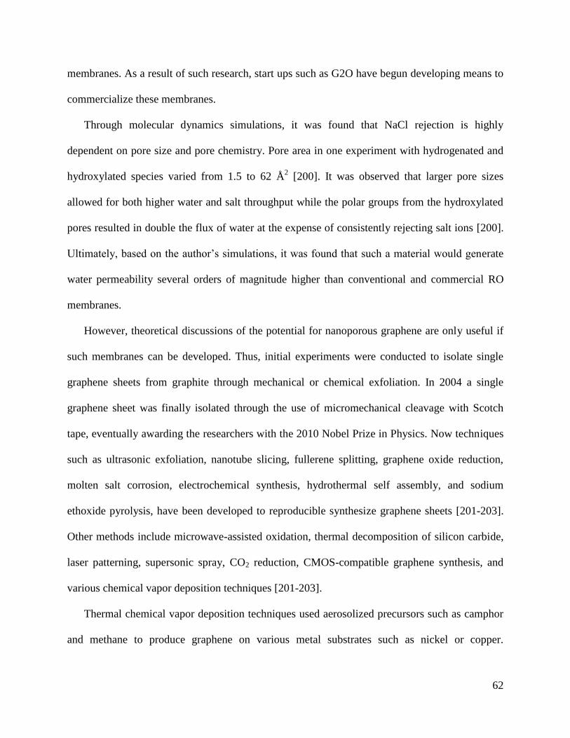
62
membranes. As a result of such research, start ups such as G2O have begun developing means to
commercialize these membranes.
Through molecular dynamics simulations, it was found that NaCl rejection is highly
dependent on pore size and pore chemistry. Pore area in one experiment with hydrogenated and
hydroxylated species varied from 1.5 to 62 Å2 [200]. It was observed that larger pore sizes
allowed for both higher water and salt throughput while the polar groups from the hydroxylated
pores resulted in double the flux of water at the expense of consistently rejecting salt ions [200].
Ultimately, based on the author’s simulations, it was found that such a material would generate
water permeability several orders of magnitude higher than conventional and commercial RO
membranes.
However, theoretical discussions of the potential for nanoporous graphene are only useful if
such membranes can be developed. Thus, initial experiments were conducted to isolate single
graphene sheets from graphite through mechanical or chemical exfoliation. In 2004 a single
graphene sheet was finally isolated through the use of micromechanical cleavage with Scotch
tape, eventually awarding the researchers with the 2010 Nobel Prize in Physics. Now techniques
such as ultrasonic exfoliation, nanotube slicing, fullerene splitting, graphene oxide reduction,
molten salt corrosion, electrochemical synthesis, hydrothermal self assembly, and sodium
ethoxide pyrolysis, have been developed to reproducible synthesize graphene sheets [201-203].
Other methods include microwave-assisted oxidation, thermal decomposition of silicon carbide,
laser patterning, supersonic spray, CO2 reduction, CMOS-compatible graphene synthesis, and
various chemical vapor deposition techniques [201-203].
Thermal chemical vapor deposition techniques used aerosolized precursors such as camphor
and methane to produce graphene on various metal substrates such as nickel or copper.
63
Mechanistically it was determined that the aerosolized carbon source would dissolve into the
metal substrate at 800-1000 ºC and upon moderate cooling would leach out of the metal and
precipitate as graphene [203, 204]. Other precursors such as hexabromobenzene have also been
used to synthesize graphene at temperatures as low as 220-250 ºC [205]. Figure1.20 pictorially
demonstrates the synthesis of graphene using chemical vapor deposition.
Figure 1.20 Chemical vapor deposition of carbon precursors onto a copper substrate. (A) graphene
surface segregation and precipitation from randomly mixed carbon isotopes, (B) graphene precipitation
with uniform isotopes. Figure reproduced with permission from [206].
Challenges still exist in producing large single crystal graphene materials. Furthermore,
handling such thin films also becomes challenging. Thus most of the research done with
graphene membranes tend to be simulations rather than experimental.
1.6.2.4 Ceramic Membranes
Ceramic membranes, also known as inorganic membranes, have recently generated
considerable research interest because of their excellent properties such as chemical inertness
and stability at high temperatures, all of which are conditions polymer membranes tend to fail
64
[9]. Inorganic membranes are currently used commercially for both ultrafiltration and
microfiltration [9]. Commercial ceramic membranes are made from alumina (Al2O3), titania
(TiO2), or silica (SiO2) [9].
Currently there are two major methods used to generate ceramic or inorganic membranes:
slip coating-sintering or sol-gel. Membranes made from slip coating-sintering tend to have pore
diameters between 0.01 to 10 μm whereas membranes made from sol-gel methods tend to have
pore diameters between 10 to 100 Å [9].
1.7 Research Objectives
The research objectives of the various projects worked on are outlined briefly below:
Objective 1: Synthesize various sulfonated poly(arylene ether sulfone) derivatives
via either direct polymerization or post-sulfonation. The directly polymerized
sulfonated poly(arylene ether sulfone)s were polymerized using either disodium 3,3’-
disulfonate 4,4’-dichlorodiphenylsulfone or sodium 3-sulfonate 4,4’-
dichlorodiphenylsulfone while the post-sulfonated poly(arylene ether sulfone)s used
either hydroquinone or biphenol to create a non sulfonated poly(arylene ether
sulfone) that can later be sulfonated in the presence of concentrated sulfuric acid.
Note, 5 and 10 kDa amine terminated oligomers were also synthesized to be
crosslinked into netowrks for some but not all chemistries explored.
Objective 2: Characterize the synthesized polymers properties which includes
molecular weight analysis through gel permeation chromatography (GPC) also
known as size exclusion chromatography (SEC), and chemical composition
reaffirmation through both proton and carbon nuclear magnetic resonance (1H/
13C
NMR) and back titrations to corroborate the desired structure being synthesized.
65
Objective 3: Characterize the effect of sulfonation in the various classes of the
sulfonated poly(arylene ether sulfone)s on the film/membrane properties such as
water uptake, hydrated mechanical properties, viscoelastic properties, and transport
properties to determine the best film chemistry and degree of sulfonation for reverse
osmosis. Gel-fractions were used to quantify the crosslinked networks.
1.8 Conclusion
The world currently has an abundance of water. However, very little of it is clean enough to
drink or be used for producing products, food, and energy. In addition, with global climate
change and pollution, the already tiny amount of fresh water available is dwindling causing
various areas around the world to become water strained. As a result, scientists and researchers
are developing novel techniques and materials to overcome the emerging water crisis. Due to the
abundance of sea water, techniques focused on desalination have begun to grow, leading to the
generation of desalination plants. The most prominent desalination method is now reverse
osmosis. As a result, research has gone into developing materials that can increase RO’s clean
water performance. This review was written to provide the reader with a plethora of knowledge
about various water desalination techniques and materials used to make educated and smart
decisions when applying it to overcome the emerging water crisis.
1.9 References [1] F.R. Spellman, Earth's Oceans and Their Margins, in: The Handbook of Nature, 2019,
pp. 176.
[2] P.H. Gleick, Water in crisis, Pacific Institute for Studies in Dev., Environment &
Security. Stockholm Env. Institute, Oxford Univ. Press. 473p, 9 (1993).
[3] B. Eakins, G. Sharman, Volumes of the World’s Oceans from ETOPO1, NOAA National
Geophysical Data Center, Boulder, CO, 7 (2010).
[4] M.R. Fisher, Environmental Biology, (2018).
[5] M.A. Maupin, J.F. Kenny, S.S. Hutson, J.K. Lovelace, N.L. Barber, K.S. Linsey,
Estimated use of water in the United States in 2010, in, US Geological Survey, 2014.
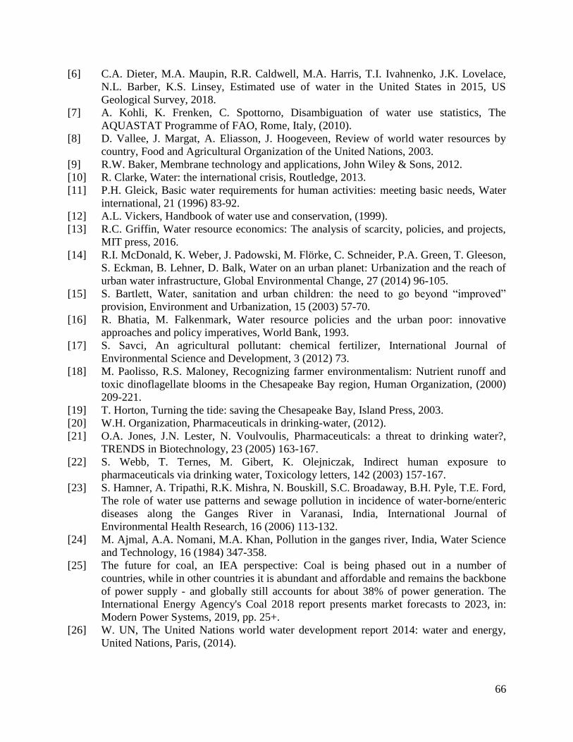
66
[6] C.A. Dieter, M.A. Maupin, R.R. Caldwell, M.A. Harris, T.I. Ivahnenko, J.K. Lovelace,
N.L. Barber, K.S. Linsey, Estimated use of water in the United States in 2015, US
Geological Survey, 2018.
[7] A. Kohli, K. Frenken, C. Spottorno, Disambiguation of water use statistics, The
AQUASTAT Programme of FAO, Rome, Italy, (2010).
[8] D. Vallee, J. Margat, A. Eliasson, J. Hoogeveen, Review of world water resources by
country, Food and Agricultural Organization of the United Nations, 2003.
[9] R.W. Baker, Membrane technology and applications, John Wiley & Sons, 2012.
[10] R. Clarke, Water: the international crisis, Routledge, 2013.
[11] P.H. Gleick, Basic water requirements for human activities: meeting basic needs, Water
international, 21 (1996) 83-92.
[12] A.L. Vickers, Handbook of water use and conservation, (1999).
[13] R.C. Griffin, Water resource economics: The analysis of scarcity, policies, and projects,
MIT press, 2016.
[14] R.I. McDonald, K. Weber, J. Padowski, M. Flörke, C. Schneider, P.A. Green, T. Gleeson,
S. Eckman, B. Lehner, D. Balk, Water on an urban planet: Urbanization and the reach of
urban water infrastructure, Global Environmental Change, 27 (2014) 96-105.
[15] S. Bartlett, Water, sanitation and urban children: the need to go beyond “improved”
provision, Environment and Urbanization, 15 (2003) 57-70.
[16] R. Bhatia, M. Falkenmark, Water resource policies and the urban poor: innovative
approaches and policy imperatives, World Bank, 1993.
[17] S. Savci, An agricultural pollutant: chemical fertilizer, International Journal of
Environmental Science and Development, 3 (2012) 73.
[18] M. Paolisso, R.S. Maloney, Recognizing farmer environmentalism: Nutrient runoff and
toxic dinoflagellate blooms in the Chesapeake Bay region, Human Organization, (2000)
209-221.
[19] T. Horton, Turning the tide: saving the Chesapeake Bay, Island Press, 2003.
[20] W.H. Organization, Pharmaceuticals in drinking-water, (2012).
[21] O.A. Jones, J.N. Lester, N. Voulvoulis, Pharmaceuticals: a threat to drinking water?,
TRENDS in Biotechnology, 23 (2005) 163-167.
[22] S. Webb, T. Ternes, M. Gibert, K. Olejniczak, Indirect human exposure to
pharmaceuticals via drinking water, Toxicology letters, 142 (2003) 157-167.
[23] S. Hamner, A. Tripathi, R.K. Mishra, N. Bouskill, S.C. Broadaway, B.H. Pyle, T.E. Ford,
The role of water use patterns and sewage pollution in incidence of water-borne/enteric
diseases along the Ganges River in Varanasi, India, International Journal of
Environmental Health Research, 16 (2006) 113-132.
[24] M. Ajmal, A.A. Nomani, M.A. Khan, Pollution in the ganges river, India, Water Science
and Technology, 16 (1984) 347-358.
[25] The future for coal, an IEA perspective: Coal is being phased out in a number of
countries, while in other countries it is abundant and affordable and remains the backbone
of power supply - and globally still accounts for about 38% of power generation. The
International Energy Agency's Coal 2018 report presents market forecasts to 2023, in:
Modern Power Systems, 2019, pp. 25+.
[26] W. UN, The United Nations world water development report 2014: water and energy,
United Nations, Paris, (2014).
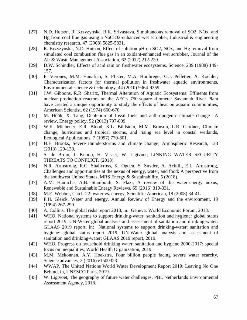
67
[27] N.D. Hutson, R. Krzyzynska, R.K. Srivastava, Simultaneous removal of SO2, NOx, and
Hg from coal flue gas using a NaClO2-enhanced wet scrubber, Industrial & engineering
chemistry research, 47 (2008) 5825-5831.
[28] R. Krzyzynska, N.D. Hutson, Effect of solution pH on SO2, NOx, and Hg removal from
simulated coal combustion flue gas in an oxidant-enhanced wet scrubber, Journal of the
Air & Waste Management Association, 62 (2012) 212-220.
[29] D.W. Schindler, Effects of acid rain on freshwater ecosystems, Science, 239 (1988) 149-
157.
[30] F. Verones, M.M. Hanafiah, S. Pfister, M.A. Huijbregts, G.J. Pelletier, A. Koehler,
Characterization factors for thermal pollution in freshwater aquatic environments,
Environmental science & technology, 44 (2010) 9364-9369.
[31] J.W. Gibbons, R.R. Sharitz, Thermal Alteration of Aquatic Ecosystems: Effluents from
nuclear production reactors on the AEC's 750-square-kilometer Savannah River Plant
have created a unique opportunity to study the effects of heat on aquatic communities,
American Scientist, 62 (1974) 660-670.
[32] M. Höök, X. Tang, Depletion of fossil fuels and anthropogenic climate change—A
review, Energy policy, 52 (2013) 797-809.
[33] W.K. Michener, E.R. Blood, K.L. Bildstein, M.M. Brinson, L.R. Gardner, Climate
change, hurricanes and tropical storms, and rising sea level in coastal wetlands,
Ecological Applications, 7 (1997) 770-801.
[34] H.E. Brooks, Severe thunderstorms and climate change, Atmospheric Research, 123
(2013) 129-138.
[35] S. de Bruin, J. Knoop, H. Visser, W. Ligtvoet, LINKING WATER SECURITY
THREATS TO CONFLICT, (2018).
[36] N.R. Armstrong, R.C. Shallcross, K. Ogden, S. Snyder, A. Achilli, E.L. Armstrong,
Challenges and opportunities at the nexus of energy, water, and food: A perspective from
the southwest United States, MRS Energy & Sustainability, 5 (2018).
[37] A.M. Hamiche, A.B. Stambouli, S. Flazi, A review of the water-energy nexus,
Renewable and Sustainable Energy Reviews, 65 (2016) 319-331.
[38] M.E. Webber, Catch-22: water vs. energy, Scientific American, 18 (2008) 34-41.
[39] P.H. Gleick, Water and energy, Annual Review of Energy and the environment, 19
(1994) 267-299.
[40] A. Collins, The global risks report 2018, in: Geneva: World Economic Forum, 2018.
[41] WHO, National systems to support drinking-water: sanitation and hygiene: global status
report 2019: UN-Water global analysis and assessment of sanitation and drinking-water:
GLAAS 2019 report, in: National systems to support drinking-water: sanitation and
hygiene: global status report 2019: UN-Water global analysis and assessment of
sanitation and drinking-water: GLAAS 2019 report, 2019.
[42] WHO, Progress on household drinking water, sanitation and hygiene 2000-2017: special
focus on inequalities, World Health Organization, 2019.
[43] M.M. Mekonnen, A.Y. Hoekstra, Four billion people facing severe water scarcity,
Science advances, 2 (2016) e1500323.
[44] WWAP, The United Nations World Water Development Report 2019: Leaving No One
Behind, in, UNESCO Paris, 2019.
[45] W. Ligtvoet, The geography of future water challenges, PBL Netherlands Environmental
Assessment Agency, 2018.
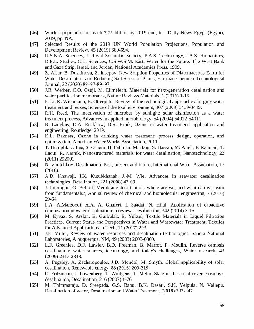
68
[46] World's population to reach 7.75 billion by 2019 end, in: Daily News Egypt (Egypt),
2019, pp. NA.
[47] Selected Results of the 2019 UN World Population Projections, Population and
Development Review, 45 (2019) 689-694.
[48] U.S.N.A. Sciences, J. Royal Scientific Society, P.A.S. Technology, I.A.S. Humanities,
D.E.L. Studies, C.L. Sciences, C.S.W.S.M. East, Water for the Future: The West Bank
and Gaza Strip, Israel, and Jordan, National Academies Press, 1999.
[49] Z. Alsar, B. Duskinova, Z. Insepov, New Sorption Properties of Diatomaceous Earth for
Water Desalination and Reducing Salt Stress of Plants, Eurasian Chemico-Technological
Journal, 22 (2020) 89‒97-89‒97.
[50] J.R. Werber, C.O. Osuji, M. Elimelech, Materials for next-generation desalination and
water purification membranes, Nature Reviews Materials, 1 (2016) 1-15.
[51] F. Li, K. Wichmann, R. Otterpohl, Review of the technological approaches for grey water
treatment and reuses, Science of the total environment, 407 (2009) 3439-3449.
[52] R.H. Reed, The inactivation of microbes by sunlight: solar disinfection as a water
treatment process, Advances in applied microbiology, 54 (2004) 54012-54011.
[53] B. Langlais, D.A. Reckhow, D.R. Brink, Ozone in water treatment: application and
engineering, Routledge, 2019.
[54] K.L. Rakness, Ozone in drinking water treatment: process design, operation, and
optimization, American Water Works Association, 2011.
[55] T. Humplik, J. Lee, S. O’hern, B. Fellman, M. Baig, S. Hassan, M. Atieh, F. Rahman, T.
Laoui, R. Karnik, Nanostructured materials for water desalination, Nanotechnology, 22
(2011) 292001.
[56] N. Voutchkov, Desalination–Past, present and future, International Water Association, 17
(2016).
[57] A.D. Khawaji, I.K. Kutubkhanah, J.-M. Wie, Advances in seawater desalination
technologies, Desalination, 221 (2008) 47-69.
[58] J. Imbrogno, G. Belfort, Membrane desalination: where are we, and what can we learn
from fundamentals?, Annual review of chemical and biomolecular engineering, 7 (2016)
29-64.
[59] F.A. AlMarzooqi, A.A. Al Ghaferi, I. Saadat, N. Hilal, Application of capacitive
deionisation in water desalination: a review, Desalination, 342 (2014) 3-15.
[60] M. Eyvaz, S. Arslan, E. Gürbulak, E. Yüksel, Textile Materials in Liquid Filtration
Practices. Current Status and Perspectives in Water and Wastewater Treatment, Textiles
for Advanced Applications. InTech, 11 (2017) 293.
[61] J.E. Miller, Review of water resources and desalination technologies, Sandia National
Laboratories, Albuquerque, NM, 49 (2003) 2003-0800.
[62] L.F. Greenlee, D.F. Lawler, B.D. Freeman, B. Marrot, P. Moulin, Reverse osmosis
desalination: water sources, technology, and today's challenges, Water research, 43
(2009) 2317-2348.
[63] A. Pugsley, A. Zacharopoulos, J.D. Mondol, M. Smyth, Global applicability of solar
desalination, Renewable energy, 88 (2016) 200-219.
[64] C. Fritzmann, J. Löwenberg, T. Wintgens, T. Melin, State-of-the-art of reverse osmosis
desalination, Desalination, 216 (2007) 1-76.
[65] M. Thimmaraju, D. Sreepada, G.S. Babu, B.K. Dasari, S.K. Velpula, N. Vallepu,
Desalination of water, Desalination and Water Treatment, (2018) 333-347.
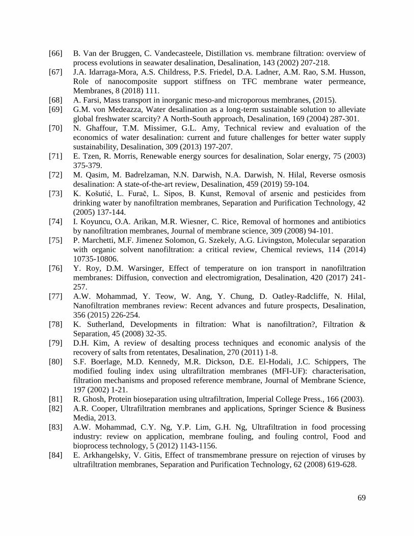
69
[66] B. Van der Bruggen, C. Vandecasteele, Distillation vs. membrane filtration: overview of
process evolutions in seawater desalination, Desalination, 143 (2002) 207-218.
[67] J.A. Idarraga-Mora, A.S. Childress, P.S. Friedel, D.A. Ladner, A.M. Rao, S.M. Husson,
Role of nanocomposite support stiffness on TFC membrane water permeance,
Membranes, 8 (2018) 111.
[68] A. Farsi, Mass transport in inorganic meso-and microporous membranes, (2015).
[69] G.M. von Medeazza, Water desalination as a long-term sustainable solution to alleviate
global freshwater scarcity? A North-South approach, Desalination, 169 (2004) 287-301.
[70] N. Ghaffour, T.M. Missimer, G.L. Amy, Technical review and evaluation of the
economics of water desalination: current and future challenges for better water supply
sustainability, Desalination, 309 (2013) 197-207.
[71] E. Tzen, R. Morris, Renewable energy sources for desalination, Solar energy, 75 (2003)
375-379.
[72] M. Qasim, M. Badrelzaman, N.N. Darwish, N.A. Darwish, N. Hilal, Reverse osmosis
desalination: A state-of-the-art review, Desalination, 459 (2019) 59-104.
[73] K. Košutić, L. Furač, L. Sipos, B. Kunst, Removal of arsenic and pesticides from
drinking water by nanofiltration membranes, Separation and Purification Technology, 42
(2005) 137-144.
[74] I. Koyuncu, O.A. Arikan, M.R. Wiesner, C. Rice, Removal of hormones and antibiotics
by nanofiltration membranes, Journal of membrane science, 309 (2008) 94-101.
[75] P. Marchetti, M.F. Jimenez Solomon, G. Szekely, A.G. Livingston, Molecular separation
with organic solvent nanofiltration: a critical review, Chemical reviews, 114 (2014)
10735-10806.
[76] Y. Roy, D.M. Warsinger, Effect of temperature on ion transport in nanofiltration
membranes: Diffusion, convection and electromigration, Desalination, 420 (2017) 241-
257.
[77] A.W. Mohammad, Y. Teow, W. Ang, Y. Chung, D. Oatley-Radcliffe, N. Hilal,
Nanofiltration membranes review: Recent advances and future prospects, Desalination,
356 (2015) 226-254.
[78] K. Sutherland, Developments in filtration: What is nanofiltration?, Filtration &
Separation, 45 (2008) 32-35.
[79] D.H. Kim, A review of desalting process techniques and economic analysis of the
recovery of salts from retentates, Desalination, 270 (2011) 1-8.
[80] S.F. Boerlage, M.D. Kennedy, M.R. Dickson, D.E. El-Hodali, J.C. Schippers, The
modified fouling index using ultrafiltration membranes (MFI-UF): characterisation,
filtration mechanisms and proposed reference membrane, Journal of Membrane Science,
197 (2002) 1-21.
[81] R. Ghosh, Protein bioseparation using ultrafiltration, Imperial College Press., 166 (2003).
[82] A.R. Cooper, Ultrafiltration membranes and applications, Springer Science & Business
Media, 2013.
[83] A.W. Mohammad, C.Y. Ng, Y.P. Lim, G.H. Ng, Ultrafiltration in food processing
industry: review on application, membrane fouling, and fouling control, Food and
bioprocess technology, 5 (2012) 1143-1156.
[84] E. Arkhangelsky, V. Gitis, Effect of transmembrane pressure on rejection of viruses by
ultrafiltration membranes, Separation and Purification Technology, 62 (2008) 619-628.
70
[85] W. Xu, Q. Yue, B. Gao, B. Du, Impacts of organic coagulant aid on purification
performance and membrane fouling of coagulation/ultrafiltration hybrid process with
different Al-based coagulants, Desalination, 363 (2015) 126-133.
[86] K. Konieczny, D. Sąkol, J. Płonka, M. Rajca, M. Bodzek, Coagulation—ultrafiltration
system for river water treatment, Desalination, 240 (2009) 151-159.
[87] L. Ju, J. Pretelt, T. Chen, J.M. Dennis, K.V. Heifferon, D.G. Baird, T.E. Long, R.B.
Moore, Synthesis and characterization of phosphonated Poly (ethylene terephthalate)
ionomers, Polymer, 151 (2018) 154-163.
[88] X. Shi, G. Tal, N.P. Hankins, V. Gitis, Fouling and cleaning of ultrafiltration membranes:
A review, Journal of Water Process Engineering, 1 (2014) 121-138.
[89] M. Goosen, S. Sablani, H. Al‐Hinai, S. Al‐Obeidani, R. Al‐Belushi, a. Jackson, Fouling
of reverse osmosis and ultrafiltration membranes: a critical review, Separation science
and technology, 39 (2005) 2261-2297.
[90] A. Fane, C. Fell, A review of fouling and fouling control in ultrafiltration, Desalination,
62 (1987) 117-136.
[91] M. Cheryan, Ultrafiltration and microfiltration handbook, CRC press, 1998.
[92] A. Alkhudhiri, N. Darwish, N. Hilal, Membrane distillation: A comprehensive review,
Desalination, 287 (2012) 2-18.
[93] P. Wang, T.-S. Chung, Recent advances in membrane distillation processes: Membrane
development, configuration design and application exploring, Journal of membrane
science, 474 (2015) 39-56.
[94] H.C. Duong, Membrane distillation for strategic desalination applications, (2017).
[95] K.W. Lawson, D.R. Lloyd, Membrane distillation, Journal of membrane Science, 124
(1997) 1-25.
[96] M. El-Bourawi, Z. Ding, R. Ma, M. Khayet, A framework for better understanding
membrane distillation separation process, Journal of membrane science, 285 (2006) 4-29.
[97] A.D. Wilson, Developments in Ionic Polymers—2, Springer Science & Business Media,
2012.
[98] D. Xu, J. Guo, F. Yan, Porous ionic polymers: Design, synthesis, and applications,
Progress in Polymer Science, 79 (2018) 121-143.
[99] P. Biesheuvel, L. Zhang, P. Gasquet, B. Blankert, M. Elimelech, W. Van Der Meer, Ion
selectivity in brackish water desalination by reverse osmosis: theory, measurements, and
implications, Environmental Science & Technology Letters, 7 (2019) 42-47.
[100] B. Domènech, J. Bastos-Arrieta, A. Alonso, J. Macanás, M. Muñoz, D.N. Muraviev,
Bifunctional polymer-metal nanocomposite ion exchange materials, Ion exchange
technologies, (2012) 35-72.
[101] Y. Cho, K. Kim, J. Ahn, J. Lee, Application of Multistage Concentration (MSC)
Electrodialysis to Concentrate Lithium from Lithium-Containing Waste Solution, Metals,
10 (2020) 851.
[102] V. Montiel, V. García-García, E. Expósito, J.M. Ortiz, A. Aldaz, Membrane Processes,
Electrodialysis, in: G. Kreysa, K.-i. Ota, R.F. Savinell (Eds.) Encyclopedia of Applied
Electrochemistry, Springer New York, New York, NY, 2014, pp. 1224-1229.
[103] A. Panagopoulos, K.-J. Haralambous, M. Loizidou, Desalination brine disposal methods
and treatment technologies-A review, Science of the Total Environment, 693 (2019)
133545.
[104] W.E. Katz, The electrodialysis reversal (EDR) process, Desalination, 28 (1979) 31-40.
71
[105] M. Suss, S. Porada, X. Sun, P. Biesheuvel, J. Yoon, V. Presser, Water desalination via
capacitive deionization: what is it and what can we expect from it?, Energy &
Environmental Science, 8 (2015) 2296-2319.
[106] P. Biesheuvel, A. Van der Wal, Membrane capacitive deionization, Journal of Membrane
Science, 346 (2010) 256-262.
[107] P. Długoł cki, A. van der Wal, Energy recovery in membrane capacitive deionization,
Environmental science & technology, 47 (2013) 4904-4910.
[108] S. Porada, R. Zhao, A. Van Der Wal, V. Presser, P. Biesheuvel, Review on the science
and technology of water desalination by capacitive deionization, Progress in materials
science, 58 (2013) 1388-1442.
[109] P. Biesheuvel, S. Porada, J. Dykstra, The difference between Faradaic and non-Faradaic
electrode processes.
[110] J. Dykstra, K. Keesman, P. Biesheuvel, A. Van der Wal, Theory of pH changes in water
desalination by capacitive deionization, Water research, 119 (2017) 178-186.
[111] C. Zhang, D. He, J. Ma, W. Tang, T.D. Waite, Comparison of faradaic reactions in flow-
through and flow-by capacitive deionization (CDI) systems, Electrochimica Acta, 299
(2019) 727-735.
[112] D.R. Lide, CRC handbook of chemistry and physics, CRC press, 2004.
[113] K. Thomsen, Electrolyte solutions: Thermodynamics, crystallization, separation methods,
(2009).
[114] K. Sampathkumar, T. Arjunan, P. Pitchandi, P. Senthilkumar, Active solar distillation—
A detailed review, Renewable and sustainable energy reviews, 14 (2010) 1503-1526.
[115] I. Khoshrou, M.J. Nasr, K. Bakhtari, New opportunities in mass and energy consumption
of the Multi-Stage Flash Distillation type of brackish water desalination process, Solar
Energy, 153 (2017) 115-125.
[116] G. Tiwari, L. Sahota, Advanced solar-distillation systems: basic principles, thermal
modeling, and its application, Springer, 2017.
[117] S. Ghani, N.S. Al-Deffeeri, Impacts of different antiscalant dosing rates and their thermal
performance in Multi Stage Flash (MSF) distiller in Kuwait, Desalination, 250 (2010)
463-472.
[118] G. Tiwari, H. Singh, R. Tripathi, Present status of solar distillation, Solar energy, 75
(2003) 367-373.
[119] M. Al-Shammiri, M. Safar, Multi-effect distillation plants: state of the art, Desalination,
126 (1999) 45-59.
[120] M.A. Sharaf, A. Nafey, L. García-Rodríguez, Exergy and thermo-economic analyses of a
combined solar organic cycle with multi effect distillation (MED) desalination process,
Desalination, 272 (2011) 135-147.
[121] A. Madani, Economics of desalination for three plant sizes, Desalination, 78 (1990) 187-
200.
[122] E.-E. Delyannis, Status of solar assisted desalination: a review, Desalination, 67 (1987)
3-19.
[123] V. Belessiotis, E. Delyannis, The history of renewable energies for water desalination,
Desalination, 128 (2000) 147-159.
[124] B. Milow, E. Zarza, Advanced MED solar desalination plants. Configurations, costs,
future—seven years of experience at the Plataforma Solar de Almeria (Spain),
Desalination, 108 (1997) 51-58.
72
[125] R. Boyle, C. Merret, New experiments and observations touching cold, Pr. for John
Crook, 1774.
[126] P.M. Williams, M. Ahmad, B.S. Connolly, D.L. Oatley-Radcliffe, Technology for freeze
concentration in the desalination industry, Desalination, 356 (2015) 314-327.
[127] M. Mahdavi, A.H. Mahvi, S. Nasseri, M. Yunesian, Application of freezing to the
desalination of saline water, Arabian Journal for Science and Engineering, 36 (2011)
1171-1177.
[128] G. Nebbia, G.N. Menozzi, Early experiments on water desalination by freezing,
Desalination, 5 (1968) 49-54.
[129] S. Sethi, G. Wetterau, Seawater Desalination Overview, de Desalination of Seawater,
Denver, (2011) 1-13.
[130] A. Warner, Selection of Materials for Use in Desalination Plants: A Corrosion Literature
Review Paper.
[131] R. Ahlgren, Selection of materials for desalination plants, Materials Protection, 7 (1968)
31-&.
[132] M.-D. Bermúdez, F.J. Carrión, G. Martínez-Nicolás, R. López, Erosion–corrosion of
stainless steels, titanium, tantalum and zirconium, Wear, 258 (2005) 693-700.
[133] F.-Y. Ouyang, C.-H. Chang, J.-J. Kai, Long-term corrosion behaviors of Hastelloy-N and
Hastelloy-B3 in moisture-containing molten FLiNaK salt environments, Journal of
nuclear materials, 446 (2014) 81-89.
[134] F. Mansfeld, G. Liu, H. Xiao, C. Tsai, B. Little, The corrosion behavior of copper alloys,
stainless steels and titanium in seawater, Corrosion science, 36 (1994) 2063-2095.
[135] H. Richaud-Minier, P. Gerard, H. El-Alami, H. Marchebois, Super Stainless Steel
Welded Tubing Solutions: An Alternative To Titanium Welded Tubing For Seawater-
Cooled Heat Exchangers?, in: CORROSION 2009, OnePetro, 2009.
[136] H. Richaud-Minier, H. Marchebois, P. Gerard, Titanium and super stainless steel welded
tubing solutions for sea water cooled heat exchangers, Materials Technology, 24 (2009)
191-200.
[137] S. Chakarvarti, Track-etch membranes enabled nano-/microtechnology: A review,
Radiation measurements, 44 (2009) 1085-1092.
[138] E. Ferain, R. Legras, Track-etched membrane: dynamics of pore formation, Nuclear
Instruments and Methods in Physics Research Section B: Beam Interactions with
Materials and Atoms, 84 (1994) 331-336.
[139] A. Kapoor, S. Balasubramanian, E. Kavitha, E. Poonguzhali, S. Prabhakar, Role of
Membranes in Wastewater Treatment, in: Water Pollution and Remediation:
Photocatalysis, Springer, 2021, pp. 247-281.
[140] H. Strathmann, P. Scheible, R. Baker, A rationale for the preparation of
Loeb‐Sourirajan‐type cellulose acetate membranes, Journal of Applied Polymer Science,
15 (1971) 811-828.
[141] H. Strathmann, K. Kock, P. Amar, R. Baker, The formation mechanism of asymmetric
membranes, Desalination, 16 (1975) 179-203.
[142] I. Blonskaya, N. Lizunov, K. Olejniczak, O. Orelovich, Y. Yamauchi, M. Toimil-
Molares, C. Trautmann, P. Apel, Elucidating the roles of diffusion and osmotic flow in
controlling the geometry of nanochannels in asymmetric track-etched membranes,
Journal of Membrane Science, 618 (2021) 118657.
73
[143] W. Ward Iii, W. Browall, R. Salemme, Ultrathin silicone/polycarbonate membranes for
gas separation processes, Journal of Membrane Science, 1 (1976) 99-108.
[144] R. Riley, H. Lonsdale, C. Lyons, Composite membranes for seawater desalination by
reverse osmosis, Journal of applied polymer science, 15 (1971) 1267-1276.
[145] R. Riley, H. Lonsdale, L. LaGrange, C. Lyons, Development of Ultrathin Membranes,
(1969).
[146] F.-J. Tsai, D. Kang, M. Anand, Thin-film-composite gas separation membranes: On the
dynamics of thin film formation mechanism on porous substrates, Separation science and
technology, 30 (1995) 1639-1652.
[147] L. Zou, I. Vidalis, D. Steele, A. Michelmore, S. Low, J. Verberk, Surface hydrophilic
modification of RO membranes by plasma polymerization for low organic fouling,
Journal of Membrane Science, 369 (2011) 420-428.
[148] R. Reis, L.F. Dum e, L. He, F. She, J.D. Orbell, B. Winther-Jensen, M.C. Duke, Amine
enrichment of thin-film composite membranes via low pressure plasma polymerization
for antimicrobial adhesion, ACS applied materials & interfaces, 7 (2015) 14644-14653.
[149] M. Langsam, A.C. Savoca, Polytrialkylgermylpropyne polymers and membranes,
US4759776, 1988.
[150] M. Langsam, Fluorinated polymeric membranes for gas separation processes,
US4657564, 1987.
[151] M. Langsam, M. Anand, E. Karwacki, Substituted propyne polymers: I. Chemical surface
modification of poly [1-(trimethylsilyl] propyne] for gas separation membranes, Gas
Separation & Purification, 2 (1988) 162-170.
[152] J. Mohr, D. Paul, I. Pinnau, W. Koros, Surface fluorination of polysulfone asymmetric
membranes and films, Journal of membrane science, 56 (1991) 77-98.
[153] J. Le Roux, D. Paul, J. Kampa, R. Lagow, Surface fluorination of poly (phenylene oxide)
composite membranes Part I. Transport properties, Journal of membrane science, 90
(1994) 21-35.
[154] J. Le Roux, D. Paul, M. Arendt, Y. Yuan, I. Cabasso, Surface fluorination of poly
(phenylene oxide) composite membranes: Part II. Characterization of the fluorinated
layer, Journal of membrane science, 90 (1994) 37-53.
[155] P.W. Kramer, M.K. Murphy, D.J. Stookey, J.M. Henis, E.R. Stedronsky, Membranes
having enhanced selectivity and method of producing such membranes, US5215554,
1993.
[156] H. El-Saied, A.H. Basta, B.N. Barsoum, M.M. Elberry, Cellulose membranes for reverse
osmosis Part I. RO cellulose acetate membranes including a composite with
polypropylene, Desalination, 159 (2003) 171-181.
[157] F. Li, P. Fei, B. Cheng, J. Meng, L. Liao, Synthesis, characterization and excellent
antibacterial property of cellulose acetate reverse osmosis membrane via a two-step
reaction, Carbohydrate polymers, 216 (2019) 312-321.
[158] A. Sagle, B. Freeman, Fundamentals of membranes for water treatment, The future of
desalination in Texas, 2 (2004) 137.
[159] C. Reid, E. Breton, Water and ion flow across cellulosic membranes, Journal of Applied
Polymer Science, 1 (1959) 133-143.
[160] S. Loeb, The Loeb-Sourirajan membrane: How it came about, in, ACS Publications,
1981.
74
[161] K. Sakai, T. Yamauchi, F. Nakasu, T. Ohe, Biodegradation of cellulose acetate by
Neisseria sicca, Bioscience, biotechnology, and biochemistry, 60 (1996) 1617-1622.
[162] B. Norkrans, Degradation of cellulose, Annual Review of Phytopathology, 1 (1963) 325-
350.
[163] P. Cantor, B. Mechalas, Biological degradation of cellulose acetate reverse‐osmosis
membranes, in: Journal of Polymer Science Part C: Polymer Symposia, Wiley Online
Library, 1969, pp. 225-241.
[164] T. Ishigaki, W. Sugano, M. Ike, M. Fujita, Enzymatic degradation of cellulose acetate
plastic by novel degrading bacterium Bacillus sp. S2055, Journal of bioscience and
bioengineering, 90 (2000) 400-405.
[165] Y. Elkony, E.S. Mansour, A. Elhusseiny, S. Ebrahim, Effect of cellulose acetate/cellulose
triacetate ratio on reverse osmosis blend membrane performance, Polymer Engineering &
Science, 60 (2020) 2852-2863.
[166] Y. Elkony, E.-S. Mansour, A. Elhusseiny, H. Hassan, S. Ebrahim, novel
Grafted/crosslinked cellulose Acetate Membrane with N-isopropylacrylamide/N, N-
methylenebisacrylamide for Water Desalination, Scientific reports, 10 (2020) 1-13.
[167] A. Ahmad, F. Jamshed, T. Riaz, S. Waheed, A. Sabir, A.A. AlAnezi, M. Adrees, T.
Jamil, Self-sterilized composite membranes of cellulose acetate/polyethylene glycol for
water desalination, Carbohydrate polymers, 149 (2016) 207-216.
[168] P. Fei, L. Liao, J. Meng, B. Cheng, X. Hu, J. Song, Synthesis, characterization and
antibacterial properties of reverse osmosis membranes from cellulose bromoacetate,
Cellulose, 25 (2018) 5967-5984.
[169] J. Dasgupta, S. Chakraborty, J. Sikder, R. Kumar, D. Pal, S. Curcio, E. Drioli, The effects
of thermally stable titanium silicon oxide nanoparticles on structure and performance of
cellulose acetate ultrafiltration membranes, Separation and Purification Technology, 133
(2014) 55-68.
[170] S. Waheed, A. Ahmad, S.M. Khan, T. Jamil, A. Islam, T. Hussain, Synthesis,
characterization, permeation and antibacterial properties of cellulose acetate/polyethylene
glycol membranes modified with chitosan, Desalination, 351 (2014) 59-69.
[171] L. Baayens, S. Rosen, Hydrodynamic resistance and flux decline in asymmetric cellulose
acetate reverse osmosis membranes, Journal of Applied Polymer Science, 16 (1972) 663-
670.
[172] H. Etemadi, R. Yegani, V. Babaeipour, Performance evaluation and antifouling analyses
of cellulose acetate/nanodiamond nanocomposite membranes in water treatment, Journal
of applied polymer science, 134 (2017).
[173] T. Chen, D. Kazerooni, L. Ju, D.A. Okonski, D.G. Baird, Development of recyclable and
high-performance in situ hybrid tlcp/glass fiber composites, Journal of Composites
Science, 4 (2020) 125.
[174] T. Chen, C.D. Mansfield, L. Ju, D.G. Baird, The influence of mechanical recycling on the
properties of thermotropic liquid crystalline polymer and long glass fiber reinforced
polypropylene, Composites Part B: Engineering, 200 (2020) 108316.
[175] T. Chen, The Influence of Recycling On Thermotropic Liquid Crystalline Polymer and
Glass Fiber Composites.
[176] T. Chen, J. Han, D.A. Okonski, D. Kazerooni, L. Ju, D.G. Baird, Thermotropic Liquid
Crystalline Polymer Reinforced Polyamide Composite for Fused Filament Fabrication,
Additive Manufacturing, (2021) 101931.
75
[177] J.Y. Han, T. Chen, Q. Mu, D.G. Baird, Thermotropic liquid crystalline polymer
reinforced polypropylene composites enhanced with carbon nanotubes for use in fused
filament fabrication, Polymer Composites, (2021).
[178] T. Chen, Generation of Recyclable Liquid Crystalline Polymer Reinforced Composites
for Use in Conventional and Additive Manufacturing Processes, in, Virginia Tech, 2021.
[179] J.E. Cadotte, R. King, R. Majerle, R. Petersen, Interfacial synthesis in the preparation of
reverse osmosis membranes, Journal of Macromolecular Science—Chemistry, 15 (1981)
727-755.
[180] J.E. Cadotte, Interfacially synthesized reverse osmosis membrane, US4277344, 1981.
[181] J.E. Cadotte, R. Petersen, R. Larson, E. Erickson, A new thin-film composite seawater
reverse osmosis membrane, Desalination, 32 (1980) 25-31.
[182] J. Cadotte, Reverse osmosis membrane, US4039440, (1977).
[183] Y. Fang, S.J. Duranceau, Study of the effect of nanoparticles and surface morphology on
reverse osmosis and nanofiltration membrane productivity, Membranes, 3 (2013) 196-
225.
[184] R.J. Petersen, J.E. Cadotte, Thin film composite reverse osmosis membranes, Handbook
of industrial membrane technology, (1990) 307-348.
[185] G. Barassi, T. Borrmann, N-Chlorination and Orton rearrangement of aromatic
polyamides, revisited, J. Membr. Sci. Technol, 2 (2012) 1000115.
[186] Z. Zhang, Z. Wang, J. Wang, S. Wang, Enhancing chlorine resistances and anti-
biofouling properties of commercial aromatic polyamide reverse osmosis membranes by
grafting 3-allyl-5, 5-dimethylhydantoin and N, N′-Methylenebis (acrylamide),
Desalination, 309 (2013) 187-196.
[187] H.S. Lee, S.J. Im, J.H. Kim, H.J. Kim, J.P. Kim, B.R. Min, Polyamide thin-film
nanofiltration membranes containing TiO2 nanoparticles, Desalination, 219 (2008) 48-
56.
[188] S.H. Kim, S.-Y. Kwak, B.-H. Sohn, T.H. Park, Design of TiO2 nanoparticle self-
assembled aromatic polyamide thin-film-composite (TFC) membrane as an approach to
solve biofouling problem, Journal of Membrane Science, 211 (2003) 157-165.
[189] H.-L. Yang, J. Chun-Te Lin, C. Huang, Application of nanosilver surface modification to
RO membrane and spacer for mitigating biofouling in seawater desalination, Water
research, 43 (2009) 3777-3786.
[190] G. Kang, H. Yu, Z. Liu, Y. Cao, Surface modification of a commercial thin film
composite polyamide reverse osmosis membrane by carbodiimide-induced grafting with
poly (ethylene glycol) derivatives, Desalination, 275 (2011) 252-259.
[191] S. Yu, Z. Lü, Z. Chen, X. Liu, M. Liu, C. Gao, Surface modification of thin-film
composite polyamide reverse osmosis membranes by coating N-isopropylacrylamide-co-
acrylic acid copolymers for improved membrane properties, Journal of membrane
science, 371 (2011) 293-306.
[192] X. Wei, Z. Wang, J. Chen, J. Wang, S. Wang, A novel method of surface modification on
thin-film-composite reverse osmosis membrane by grafting hydantoin derivative, Journal
of Membrane Science, 346 (2010) 152-162.
[193] X. Wei, Z. Wang, Z. Zhang, J. Wang, S. Wang, Surface modification of commercial
aromatic polyamide reverse osmosis membranes by graft polymerization of 3-allyl-5, 5-
dimethylhydantoin, Journal of Membrane Science, 351 (2010) 222-233.
[194] S. Iijima, Helical microtubules of graphitic carbon, nature, 354 (1991) 56-58.
76
[195] S. Iijima, T. Ichihashi, Single-shell carbon nanotubes of 1-nm diameter, nature, 363
(1993) 603-605.
[196] G. Hummer, J.C. Rasaiah, J.P. Noworyta, Water conduction through the hydrophobic
channel of a carbon nanotube, Nature, 414 (2001) 188-190.
[197] A.S. Al-Hobaib, K.M. Al-Sheetan, M.R. Shaik, M. Al-Suhybani, Modification of thin-
film polyamide membrane with multi-walled carbon nanotubes by interfacial
polymerization, Applied Water Science, 7 (2017) 4341-4350.
[198] E. Maaskant, W. Vogel, T.J. Dingemans, N.E. Benes, The use of a star-shaped
trifunctional acyl chloride for the preparation of polyamide thin film composite
membranes, Journal of membrane science, 567 (2018) 321-328.
[199] W. Xie, G.M. Geise, B.D. Freeman, H.-S. Lee, G. Byun, J.E. McGrath, Polyamide
interfacial composite membranes prepared from m-phenylene diamine, trimesoyl chloride
and a new disulfonated diamine, Journal of Membrane Science, 403 (2012) 152-161.
[200] D. Cohen-Tanugi, J.C. Grossman, Water desalination across nanoporous graphene, Nano
letters, 12 (2012) 3602-3608.
[201] J.Y. Lim, N. Mubarak, E. Abdullah, S. Nizamuddin, M. Khalid, Recent trends in the
synthesis of graphene and graphene oxide based nanomaterials for removal of heavy
metals—A review, Journal of Industrial and Engineering Chemistry, 66 (2018) 29-44.
[202] R. Munoz, C. Gómez‐Aleixandre, Review of CVD synthesis of graphene, Chemical
Vapor Deposition, 19 (2013) 297-322.
[203] W. Choi, I. Lahiri, R. Seelaboyina, Y.S. Kang, Synthesis of graphene and its applications:
a review, Critical Reviews in Solid State and Materials Sciences, 35 (2010) 52-71.
[204] C. Wang, K. Vinodgopal, G.-P. Dai, Large-area synthesis and growth mechanism of
graphene by chemical vapor deposition, Chem. Vap. Depos. Nanotechnol, 5 (2018) 97-
113.
[205] L. Jiang, T. Niu, X. Lu, H. Dong, W. Chen, Y. Liu, W. Hu, D. Zhu, Low-temperature,
bottom-up synthesis of graphene via a radical-coupling reaction, Journal of the American
Chemical Society, 135 (2013) 9050-9054.
[206] X. Li, W. Cai, L. Colombo, R.S. Ruoff, Evolution of graphene growth on Ni and Cu by
carbon isotope labeling, Nano letters, 9 (2009) 4268-4272.
77
Chapter 2: Post-Sulfonation of Activated
Biphenol Containing Poly(Arylene Ether
Sulfone) Polymers for Reverse Osmosis
Membranes
Dana A. Kazerooni,1,2
Shreya Roy Choudhury,1,2
Trevor I. Schumacher,1,2
Kyle Titus-Glover, 3
John J. Lesko,1,3
Judy S. Riffle1,2
1
Macromolecules Innovation Institute, Virginia Polytechnic Institute and State University,
Blacksburg, VA 24061, United States 2
Department of Chemistry, Virginia Polytechnic Institute and State University, Blacksburg, VA
24061, United States 3
Department of Mechanical Engineering, Virginia Polytechnic Institute and State University,
Blacksburg, VA 24061, United States
Article Submitted to Journal of Membrane Science
2.1 Abstract
In recent years, Sslfonated polysulfones have been showing promise as high performance reverse
osmosis (RO) membranes because of their excellent mechanical integrity and resistance to
degradation. Thus, this work focuses on the development of linear high molecular weight post-
sulfonated biphenol containing poly(arylene ether sulfone)s (SBiPS). The sulfonated polymer
was targeted to have 22, 28, 31, and 34% disulfonation. The polymers where cast into ~30
micron thick films and tested for water uptake and hydrated mechanical properties. By increasing
the degree of sulfonation, we increase the water uptake, which plasticizes the film and thus
reducing the mechanical properties. Amidst all of that, the polymers still retained a hydrated
elastic modulus over 1 GPa. Furthermore, the 28 and 34 SBiPS films were cast into ~5 micron
thick films and tested under crossflow conditions with a feed solution consisting of 2000 ppm of
NaCl at an applied pressure of 400 psi and a flow rate of 3.8 L/min. The 28 SBiPS polymer
78
membrane yielded a water permeability and salt rejection of 9.3•10-7
cm2/s and 98.7%,
respectively, while its 34 SBiPS counterpart yielded a water permeability and salt rejection of
2.2•10-6
cm2/s and 97.6%, respectively.
2.2 Introduction
In 2017-2018, Cape Town, South Africa almost ran out of water [1, 2]. Even though we tend
to associate water shortages with regions that have arid climates, civilizations throughout the
world can undergo water stress depending on the ratio of clean water production over clean
water withdrawal [3]. Areas including California in the United States, Australia, South Africa,
Mexico, and China, as well as many of the countries in the Middle East, Southern Asia, and
Northern Africa have also experienced water shortages either due to environmental factors or
technological limitations [4].
Even though the world’s surface is predominately composed of water, only ~2.5% of it is
freshwater while the remaining 97.5% is saline [5-7]. Of that 2.5%, only ~30% is accessible for
public supply, irrigation, livestock, aquaculture, mining, and thermoelectric power [6, 8, 9].
Since the 1940s, advancements in desalination technology helped usher in the possibility for
using the other 97.5% of the world’s water in large quantities.
Desalination techniques are used to desalinate saline water sources for human use and
consumption. One common method is reverse osmosis (RO). It is rapidly expanding and
currently is the largest method for producing potable water [4, 10]. As of 2016, RO water
accounted for 65% of desalinated water globally [4, 11]. Reverse osmosis works by pressurizing
saline water (feed water) over its osmotic pressure to force water through a semipermeable
membrane while largely preventing the migration of salt. The permeate water forced through the
membrane is potable water, which is then transported and used for various purposes. Reports
79
show that RO is one of the most economical desalination techniques after multi-effect
evaporation [4, 10, 12].
Membrane desalination techniques employed today include RO, nanofiltration, membrane
distillation, electrodiaylsis, and capacitive deionization. Other desalination methods require
phase changes to purify the feed water. Such techniques include multistage flash distillation,
solar distillation, vacuum distillation, multiple effect distillation, vapor compression distillation,
and freeze-thaw systems [13]. Depending on the region and the contents of contaminants in the
feed water, different techniques may be more cost effective than others.
Today’s RO membranes are interfacially-polymerized aromatic polyamide thin film
composites (TFCs). The membranes consist of a thin (~100-nm) active polyamide layer on top of
a porous support material, usually polysulfone or poly(vinylidene fluoride). These composite
films have very high water fluxes and salt rejections [10]. However, they come with some
inherent challenges. The interfacial polymerization process between the aromatic diamine and
aromatic tri-acyl chloride leads to a rough topography that may increase the susceptibility of the
membrane to scaling and fouling [10]. On the other hand, the high water fluxes that are achieved
may be associated with increased surface area caused by the rough topography [14]. In addition,
these aromatic polyamides undergo rapid degradation in the presence of oxidizing solutions such
as sodium hypochlorite, which cleaves the amide bonds through N-chlorination and Orton
rearrangement followed by hydrolysis [15].
Advancements in membrane technology have focused on increasing the membrane
mechanical integrity, water flux, and salt rejection. Methods of achieving such means include
developing asymmetric membranes that consist of a porous single-material membrane with a
surface skin [16, 17]. Also, some fillers such as graphene and its derivatives, and various
80
nanoparticles have been utilized to improve the polyamide TFC mechanical properties and
mediate its degradation in highly basic media [18-20].
Polysulfones have shown promise as a high performance RO membrane family primarily due
to their better stability against oxidants and high elastic moduli [21]. However, such materials are
not sufficiently hydrophilic to allow water to pass through unless they are porous. Sulfonating
the polysulfones to improve their hyprophilicity and augment this with Donnan exclusion of ions
has received a lot of acclaim in the membrane desalination community because of their capacity
to transport water, reject salts and resist degradation [21].
Two methodologies can be used to synthesize sulfonated polysulfones – post-sulfonation and
direct polymerization from sulfonated monomers. Early methods post-sulfonated bisphenol A-
containing (Udel) materials with stoichiometric amounts of sulfonating agents in efforts to obtain
specific desired degrees of sulfonation [21]. The degree of sulfonation with this method was hard
to control and the placement of the sulfonate ions on the polymers, although it occurred primarily
on the bisphenol A moieties, was difficult to reproduce. Rose et al. incorporated hydroquinone in
controlled amounts along with bisphenol-S, then post-sulfonated the materials with excess
amounts of sulfonating agents [22-24]. The hydroquinone rings were the only ones that were
activated for electrophilic sulfonation, and Rose was able to show that, under his synthetic
conditions, monosulfonation on the hydroqinone was quantitative and other rings that were not
activated for sulfonation did not react. A second method utilizes direct polymerization of
disulfonated polysulfones by employing 3,3’-disulfonate-4,4’-dichlorodiphenylsulfone as a
monomer [25-27]. The direct polymerization method eliminated the irreproducibility that had
been encountered with the earlier post-sulfonated Udel materials.
81
This paper describes the synthesis and characterization of post sulfonated poly(arylene ether
sulfone)s. The degree of sulfonation and the placement of fixed sulfonates along the chains has
been controlled by incorporating specific amounts of activated biphenol units in combination
with non-activated bisphenol-S units. The biphenol rings undergo sulfonation by electrophilic
aromatic substitution [22-24, 28, 29]. This paper builds on the work of Choudhury et al. and
explores the difference in hydrated mechanical and transport properties of high molecular weight
post-sulfonated biphenol containing poly(arylene ether sulfone) films [27]. We also highlight the
differences in physical properties between the disulfonated post-sulfonated polysulfones
containing biphenol moieties and their monosulfonated counterparts from Choudhury et al. that
contained hydroquinone units.
2.3 Experimental
2.3.1 Materials
The monomers used to synthesize post sulfonated biphenol containing poly(arylene ether
sulfone) copolymers include 4,4’-biphenol, 4,4’-sulfonyldiphenol (bisphenol S), and 4,4’-
difluorodiphenylsulfone. The 4,4’-biphenol (Eastman Chemical Company), 4,4’-
sulfonyldiphenol (Solvay Advanced Polymers), and 4,4’-difluorodiphenylsulfone (Oakwood
Chemicals) were recrystallized from toluene and dried under vacuum at 110ºC for 12 h.
Potassium carbonate (K2CO3) was purchased from Sigma-Aldrich and dried in a convection oven
at 160 ºC for 72 h before each reaction. Toluene and N,N-dimethylacetamide were purchased
from Sigma-Aldrich. Sulfuric acid (95-97%) was obtained from VWR. Standardized sodium
hydroxide (0.01 N), and powdered sodium chloride (≥99.0%) were purchased from Fisher
Chemical.
82
2.3.2 Synthesis of biphenol containing linear poly(arylene ether sulfone) and sulfonated
poly(arylene ether sulfone) copolymers
Linear random polysulfones were synthesized with differing percentages of repeat units
containing biphenol relative to bisphenol S. The copolymers were synthesized via step growth
polymerization by reacting 4,4’-difluorodiphenylsulfone, 4,4’-biphenol, and bisphenol-S. To
synthesize a polysulfone with 31% of the repeat units containing biphenol, 10.0 g (39.3 mmol) of
difluorodiphenylsulfone, 2.27 g (12.2 mmol) of biphenol, and 6.78 g (27.1 mmol) of bisphenol-S
were charged into a 3-neck round bottom flask outfitted with a mechanical stirrer, Dean-Stark
trap with a condenser, and nitrogen inlet. Dimethylacetamide (DMAc, 65 mL) was added to
dissolve the monomers, then 30 mL of toluene was added to azeotropically remove water that
formed during the reaction. K2CO3 (6.52 g, 1.2 moles of base per eq. of phenol groups) was
added. The Dean-Stark trap was filled with toluene. The reaction was azeotropically dried at
150ºC for 4 h, then the oil bath temperature was increased to 185 ºC and maintained for another
24 h. After 24 h, the reaction was diluted with DMAc, filtered hot, and precipitated in
isopropanol. The precipitate was filtered and stirred in DI water where it was allowed to reflux
for 2 h. This was repeated 2X to remove any trapped solvent. The polymer was dried under
vacuum at 110 ºC for 24 h.
About 2 g of the polymer was charged into another 3-neck round bottom flask outfitted with
a mechanical stirrer, condenser, and nitrogen inlet. Concentrated sulfuric acid (20 mL) was
added, the mixture was dissolved by heating it to 55 ºC, and allowed to stir rapidly for 2 h. The
sulfonated polymer was precipitated into isopropanol. The precipitated polymer in isopropanol
was subsequently chilled in an ice bath and slowly neutralized using 10M NaOH. The sulfonated
83
polymer was filtered and washed in DI water. Then the sulfonated polymer was stirred and
refluxed in DI water for 2 h. This was repeated 2X to remove any trapped solvent.
2.3.3 Proton nuclear magnetic resonance spectroscopy (1H NMR)
The non-sulfonated and sulfonated polymers were dissolved at a concentration of 10
wt/vo1% in DMSO-d6 to analyze the polymer structure and degree of sulfonation. Each proton
NMR spectrum was acquired with a 400 MHz Varian Unity Plus Spectrometer. The proton NMR
experiments were run using a pulse angle of 30º and a pulse delay of 5s with 128 scans.
2.3.4 Molecular weight determination using size exclusion chromatography (SEC)
The mobile phase of the SEC consisted of dissolving LiCl in DMAc that had been previously
dried over CaH2 to make a 0.1 M solution. Polymer samples were dissolved in the mobile phase
at a concentration between 2.5 and 3.0 mg/mL. An Agilent 1260 Infinity II LC system, outfitted
with an auto-sampler, degasser, and isocratic pump from Agilent Technologies were used. The
column set consisted of a guard column followed by three Agilent PLgel 10-mm Mixed B-LS
columns with a polystyrene/divinylbenzene packing material. A DAWN-HELEOS II multi-angle
laser light scattering detector and an Optilab T-rEX refractive index detector both from Wyatt
Technology Corp., operating at 658 nm were used to analyze the polymer molecular weight and
concentration. Both the columns and detectors were maintained at 50ºC. The system was
corrected for interdetector delay and band broadening using a 21 kDa polystyrene standard. Astra
6 software from Wyatt Technology Corp. was used to collect and analyze the data obtained from
the detectors.
84
2.3.5 Polymer titration
The sulfonated poly(arylene ether sulfone)s were titrated to measure the degree of
sulfonation. The sulfonated polymer (~0.1 g) was dispersed in 100 mL of 0.1 M sulfuric acid,
and gently refluxed for 1 h to exchange the sodium counterion to a proton. The polymer was
washed with DI water at room temperature for 1 h, then dried under vacuum at room temperature
for 72 h. A sample of the polymer was analyzed gravimetrically to quantify the amount of
residual water in the polymer using a TA Thermogravimetric Analyzer (TGA) 5500. The TGA
was ramped at 10°C/min to 320°C under nitrogen. The acidified polymer (0.1 g) was stirred in 2
M NaCl solution for 72 h to release the acidic protons from the fixed sulfonic acid groups and
eliminate HCl. The HCl was titrated using standardized 0.01 N NaOH with phenolphthalein as
an indicator.
2.3.6 Film casting
The sulfonated or non-sulfonated polymer (0.5 g) was dissolved in 12 mL of DMAc, and the
solution was filtered through a 0.45 micron PTFE syringe filter (Whatman). The filtered solution
was sonicated for 5 min, then poured onto a 4”x4” glass plate. An IR lamp placed above the
glass plate was used to incrementally increase the temperature of the polymer film on the glass
plate from 40 to 50, then to 80 ºC, every 2h. The film was held under the IR lamp at 80°C for
another 12 h. It was then placed in a vacuum oven for 12 h at 110ºC under vacuum. Upon
removal, the film was allowed to cool to room temperature and then submerged in a 2 M NaCl
solution for 72 h to delaminate the film from the glass plate, and convert counterions from
potassium to sodium. For crossflow measurements, the membranes were fabricated by drawing a
0.45 micron PTFE filtered 3.4 vol% solution of polymer in DMAc using a doctor’s blade with a
85
200-nm gap. These films were then dried as described above with nominal thicknesses ranging
from 1 to 5 m.
2.3.7 Water uptake
A hydrated film sample was cut into three pieces and used to calculate the percent of water
uptake, WU, presented in equation 1. Each piece was lightly dabbed with a Kimwipe to remove
any visible surface water, and then weighed on an analytical balance to measure MWet, in grams.
The film pieces were subsequently placed in a vacuum oven and dried at 120 ºC under vacuum,
then reweighed until the mass of the film stabilized, MDry. The average water uptake and
standard deviation was calculated for each film.
(1)
2.3.8 Hydrated uniaxial tensile testing
Each film was cut into a minimum of 4 dogbone replicate samples in accordance with Type
V of ASTM D6338-14 guidelines using a Cricut Explore One™ stencil cutter. A Mitutoyo
Digimatic Micrometer Model MDC-1SXF was used to measure the hydrated dogbone thickness
at 4 different points for each sample along the dogbone gauge length, and the average thickness
was used to compute the stress in the material. The samples were immersed in DI water for 24 h
prior to testing. The stress-strain curve for each membrane sample was obtained under
submerged conditions at room temperature with a displacement rate of 10 mm/min with an
ElectroPuls E1000 Uniaxial Instron, equipped with a 250-N Dynacell load cell. The hydrated
samples were loaded into the Instron, the Instron was submerged in water, and the samples were
86
equilibrated for at least 3 min before testing. Each sample was tested to failure and analyzed
using the stress-strain curves.
2.3.9 Membrane cross flow measurements to analyze water flux and salt rejection and to
calculate water permeability
The water and salt transport properties of the post-sulfonated linear biphenol containing
poly(arylene ether sulfone)s were measured in cross-flow mode with an instrument consisting of
six cells. The 28 and 34 SBiPS copolymers in their sodium counterion form were tested. The
parts for the cross-flow filtration system were purchased from Sterlitech and assembled prior to
testing. A water recirculation chiller/heater maintained the water in the feedwater tank at 25 ºC.
Films of sulfonated poly(arylene ether sulfone) were cut with a die and mounted on a porous
polysulfone ultrafiltration membrane inside the Sterlitech CF042 cells (surface area 42 cm2). The
filtration system was operated continuously at a transmembrane pressure of 400 psi (27.6 bar)
with a flow rate of 3.8 L/min. The feed water contained 2000 ppm sodium chloride. The pH of
the feed was adjusted between 6.5 and 7.5 using a 10 g/L sodium bicarbonate solution. The flux
of the permeating water and conductivity were measured by weighing the mass of water
collected in the specified time frame and using an APERA PC400S conductivity meter. Equation
2 was used to calculate the flux (ɸ) of water through the membrane in L•m-2•h
-1, where Mp is the
mass of the permeate water collected in grams, ρw is the density of water (assumed to be 1
g/mL), Am is the cross sectional area of the membrane in cm2, t is the time allowed for the
permeate to collect in seconds, and CF1 is the unit conversion factor from mL•cm-2•s
-1 to L•m
-
2•h
-1, which is 3.6•10
4. The feed (CS,F) and permeate salt concentrations (CS,P) were calculated in
ppm using a calibration curve for the conductivities and further used to calculate the percent salt
rejection using equation 3.
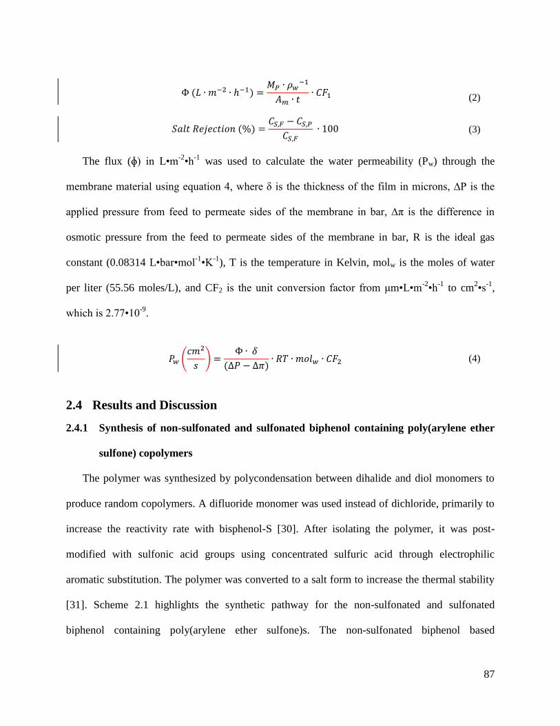
87
(2)
(3)
The flux (ɸ) in L•m-2•h
-1 was used to calculate the water permeability (Pw) through the
membrane material using equation 4, where δ is the thickness of the film in microns, ∆P is the
applied pressure from feed to permeate sides of the membrane in bar, ∆π is the difference in
osmotic pressure from the feed to permeate sides of the membrane in bar, R is the ideal gas
constant (0.08314 L•bar•mol-1•K
-1), T is the temperature in Kelvin, molw is the moles of water
per liter (55.56 moles/L), and CF2 is the unit conversion factor from μm•L•m-2•h
-1 to cm
2•s
-1,
which is 2.77•10-9
.
(4)
2.4 Results and Discussion
2.4.1 Synthesis of non-sulfonated and sulfonated biphenol containing poly(arylene ether
sulfone) copolymers
The polymer was synthesized by polycondensation between dihalide and diol monomers to
produce random copolymers. A difluoride monomer was used instead of dichloride, primarily to
increase the reactivity rate with bisphenol-S [30]. After isolating the polymer, it was post-
modified with sulfonic acid groups using concentrated sulfuric acid through electrophilic
aromatic substitution. The polymer was converted to a salt form to increase the thermal stability
[31]. Scheme 2.1 highlights the synthetic pathway for the non-sulfonated and sulfonated
biphenol containing poly(arylene ether sulfone)s. The non-sulfonated biphenol based
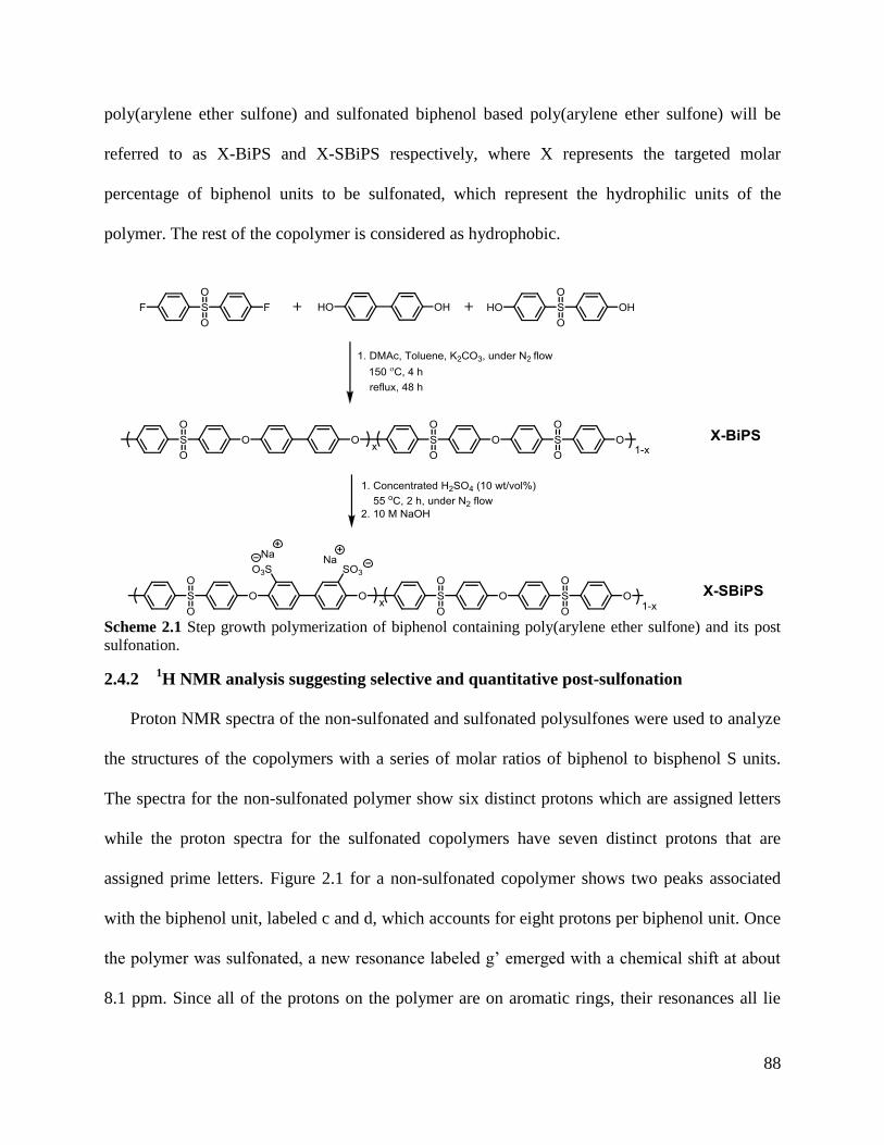
88
poly(arylene ether sulfone) and sulfonated biphenol based poly(arylene ether sulfone) will be
referred to as X-BiPS and X-SBiPS respectively, where X represents the targeted molar
percentage of biphenol units to be sulfonated, which represent the hydrophilic units of the
polymer. The rest of the copolymer is considered as hydrophobic.
2.4.2 1H NMR analysis suggesting selective and quantitative post-sulfonation
Proton NMR spectra of the non-sulfonated and sulfonated polysulfones were used to analyze
the structures of the copolymers with a series of molar ratios of biphenol to bisphenol S units.
The spectra for the non-sulfonated polymer show six distinct protons which are assigned letters
while the proton spectra for the sulfonated copolymers have seven distinct protons that are
assigned prime letters. Figure 2.1 for a non-sulfonated copolymer shows two peaks associated
with the biphenol unit, labeled c and d, which accounts for eight protons per biphenol unit. Once
the polymer was sulfonated, a new resonance labeled g’ emerged with a chemical shift at about
8.1 ppm. Since all of the protons on the polymer are on aromatic rings, their resonances all lie
Scheme 2.1 Step growth polymerization of biphenol containing poly(arylene ether sulfone) and its post
sulfonation.
89
between 7 and 9 ppm. Protons on aromatic rings connected to the electron withdrawing sulfone
linkages have downfield chemical shifts as shown with the peaks located between 7.8 and 8.1
ppm. On the other hand, aromatic protons adjacent to the electron donating ether linkages have
chemical shifts further upfield.
As an example, the amount of biphenol units was calculated based on the NMR resonance
integrals presented in figure 2.1. For a targeted 34% of the repeat units containing biphenol,
NMR integrations show that approximately 35% biphenol units are present. After post
sulfonating the polymer, equation 5 was used to calculate that the % disulfonation for the post
sulfonated biphenol containing polymer was also approximately 35% disulfonated.
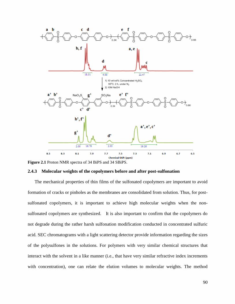
90
Figure 2.1 Proton NMR spectra of 34 BiPS and 34 SBiPS.
2.4.3 Molecular weights of the copolymers before and after post-sulfonation
The mechanical properties of thin films of the sulfonated copolymers are important to avoid
formation of cracks or pinholes as the membranes are consolidated from solution. Thus, for post-
sulfonated copolymers, it is important to achieve high molecular weights when the non-
sulfonated copolymers are synthesized. It is also important to confirm that the copolymers do
not degrade during the rather harsh sulfonation modification conducted in concentrated sulfuric
acid. SEC chromatograms with a light scattering detector provide information regarding the sizes
of the polysulfones in the solutions. For polymers with very similar chemical structures that
interact with the solvent in a like manner (i.e., that have very similar refractive index increments
with concentration), one can relate the elution volumes to molecular weights. The method
91
produces a direct measurement of weight average molecular weight, then the SEC software is
used to calculate number average molecular weights.
Chromatograms from the SBiPS’s have consistently decreased elution times relative to their
non-sulfonated BiPS counterparts (Table 2.1). The sizes of these sulfonated copolymers in
solution are complicated in that they are ionic and the SEC solvent itself contains salt where the
solvent cations can exchange with the polymer counterions. Moreover, the sulfonate ions are
pendent to the chain, so the expected increase in weight does not necessarily mean that the
chains have become longer. Thus, one cannot directly compare molecular weights of the non-
sulfonated and sulfonated analogues. That being said, the decrease in elution volume with
sulfonation suggests that the sulfonated copolymers may have higher molecular weights.
Moreover, the lack of severe increases in elution volumes with sulfonation suggests that any
degradation due to the sulfonation conditions is minimal. In addition, chromatograms for both
the non-sulfonated and sulfonated polymers indiscriminately had unimodal, symmetrical
distributions, further suggesting that the polymers did not degrade during the sulfonation process.
If degradation occurred, such as chain scission, we would expect that the distribution might alter
from the symmetrical unimodal distributions. The appearance of degraded molecular weights for
portions of the polymers could even result in new peaks appearing at higher elution times on the
SEC chromatograms.
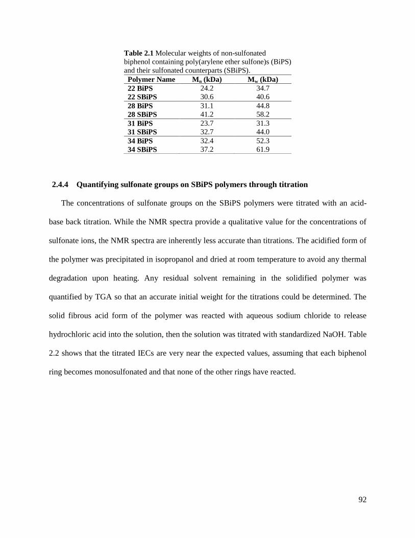
92
Table 2.1 Molecular weights of non-sulfonated
biphenol containing poly(arylene ether sulfone)s (BiPS)
and their sulfonated counterparts (SBiPS).
Polymer Name Mn (kDa) Mw (kDa)
22 BiPS 24.2 34.7
22 SBiPS 30.6 40.6
28 BiPS 31.1 44.8
28 SBiPS 41.2 58.2
31 BiPS 23.7 31.3
31 SBiPS 32.7 44.0
34 BiPS 32.4 52.3
34 SBiPS 37.2 61.9
2.4.4 Quantifying sulfonate groups on SBiPS polymers through titration
The concentrations of sulfonate groups on the SBiPS polymers were titrated with an acid-
base back titration. While the NMR spectra provide a qualitative value for the concentrations of
sulfonate ions, the NMR spectra are inherently less accurate than titrations. The acidified form of
the polymer was precipitated in isopropanol and dried at room temperature to avoid any thermal
degradation upon heating. Any residual solvent remaining in the solidified polymer was
quantified by TGA so that an accurate initial weight for the titrations could be determined. The
solid fibrous acid form of the polymer was reacted with aqueous sodium chloride to release
hydrochloric acid into the solution, then the solution was titrated with standardized NaOH. Table
2.2 shows that the titrated IECs are very near the expected values, assuming that each biphenol
ring becomes monosulfonated and that none of the other rings have reacted.
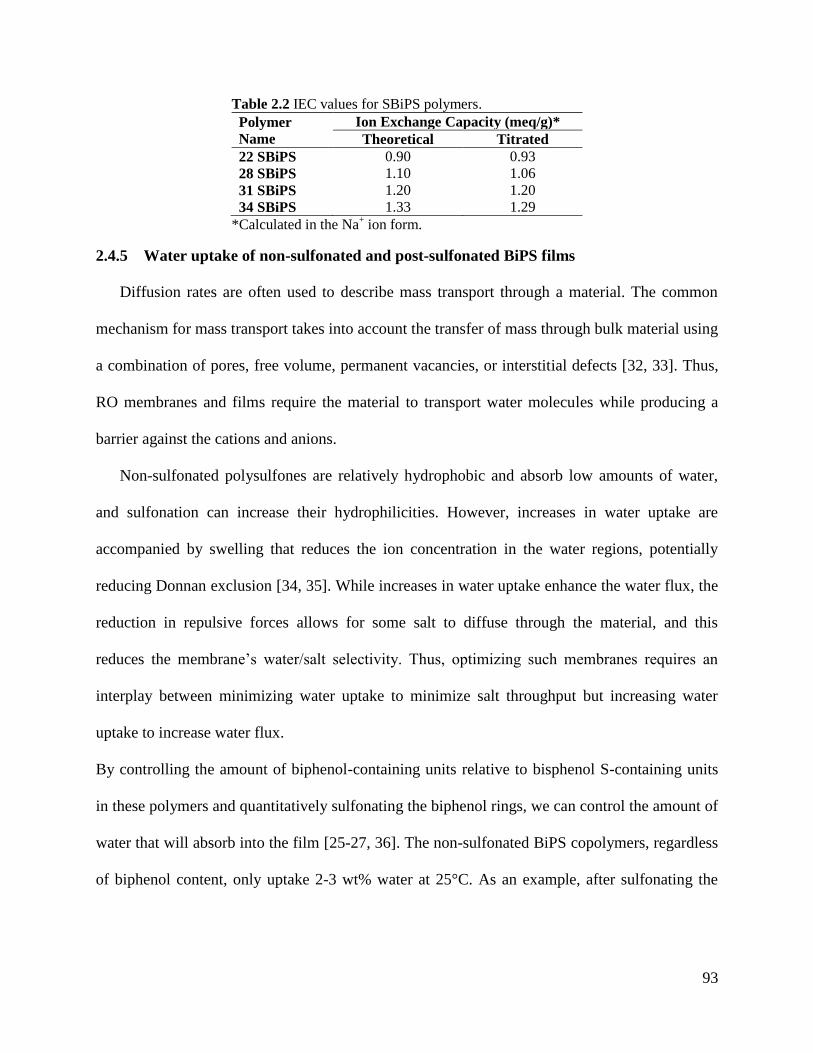
93
Table 2.2 IEC values for SBiPS polymers.
Polymer
Name
Ion Exchange Capacity (meq/g)*
Theoretical Titrated
22 SBiPS 0.90 0.93
28 SBiPS 1.10 1.06
31 SBiPS 1.20 1.20
34 SBiPS 1.33 1.29
*Calculated in the Na+ ion form.
2.4.5 Water uptake of non-sulfonated and post-sulfonated BiPS films
Diffusion rates are often used to describe mass transport through a material. The common
mechanism for mass transport takes into account the transfer of mass through bulk material using
a combination of pores, free volume, permanent vacancies, or interstitial defects [32, 33]. Thus,
RO membranes and films require the material to transport water molecules while producing a
barrier against the cations and anions.
Non-sulfonated polysulfones are relatively hydrophobic and absorb low amounts of water,
and sulfonation can increase their hydrophilicities. However, increases in water uptake are
accompanied by swelling that reduces the ion concentration in the water regions, potentially
reducing Donnan exclusion [34, 35]. While increases in water uptake enhance the water flux, the
reduction in repulsive forces allows for some salt to diffuse through the material, and this
reduces the membrane’s water/salt selectivity. Thus, optimizing such membranes requires an
interplay between minimizing water uptake to minimize salt throughput but increasing water
uptake to increase water flux.
By controlling the amount of biphenol-containing units relative to bisphenol S-containing units
in these polymers and quantitatively sulfonating the biphenol rings, we can control the amount of
water that will absorb into the film [25-27, 36]. The non-sulfonated BiPS copolymers, regardless
of biphenol content, only uptake 2-3 wt% water at 25°C. As an example, after sulfonating the
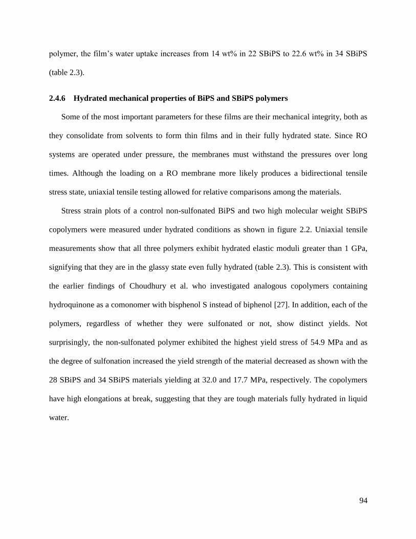
94
polymer, the film’s water uptake increases from 14 wt% in 22 SBiPS to 22.6 wt% in 34 SBiPS
(table 2.3).
2.4.6 Hydrated mechanical properties of BiPS and SBiPS polymers
Some of the most important parameters for these films are their mechanical integrity, both as
they consolidate from solvents to form thin films and in their fully hydrated state. Since RO
systems are operated under pressure, the membranes must withstand the pressures over long
times. Although the loading on a RO membrane more likely produces a bidirectional tensile
stress state, uniaxial tensile testing allowed for relative comparisons among the materials.
Stress strain plots of a control non-sulfonated BiPS and two high molecular weight SBiPS
copolymers were measured under hydrated conditions as shown in figure 2.2. Uniaxial tensile
measurements show that all three polymers exhibit hydrated elastic moduli greater than 1 GPa,
signifying that they are in the glassy state even fully hydrated (table 2.3). This is consistent with
the earlier findings of Choudhury et al. who investigated analogous copolymers containing
hydroquinone as a comonomer with bisphenol S instead of biphenol [27]. In addition, each of the
polymers, regardless of whether they were sulfonated or not, show distinct yields. Not
surprisingly, the non-sulfonated polymer exhibited the highest yield stress of 54.9 MPa and as
the degree of sulfonation increased the yield strength of the material decreased as shown with the
28 SBiPS and 34 SBiPS materials yielding at 32.0 and 17.7 MPa, respectively. The copolymers
have high elongations at break, suggesting that they are tough materials fully hydrated in liquid
water.
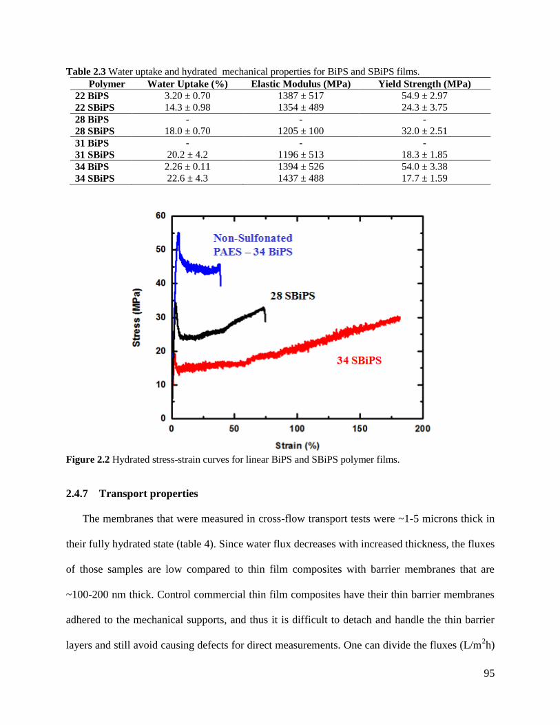
95
Table 2.3 Water uptake and hydrated mechanical properties for BiPS and SBiPS films.
Polymer Water Uptake (%) Elastic Modulus (MPa) Yield Strength (MPa)
22 BiPS 3.20 ± 0.70 1387 ± 517 54.9 ± 2.97
22 SBiPS 14.3 ± 0.98 1354 ± 489 24.3 ± 3.75
28 BiPS - - -
28 SBiPS 18.0 ± 0.70 1205 ± 100 32.0 ± 2.51
31 BiPS - - -
31 SBiPS 20.2 ± 4.2 1196 ± 513 18.3 ± 1.85
34 BiPS 2.26 ± 0.11 1394 ± 526 54.0 ± 3.38
34 SBiPS 22.6 ± 4.3 1437 ± 488 17.7 ± 1.59
2.4.7 Transport properties
The membranes that were measured in cross-flow transport tests were ~1-5 microns thick in
their fully hydrated state (table 4). Since water flux decreases with increased thickness, the fluxes
of those samples are low compared to thin film composites with barrier membranes that are
~100-200 nm thick. Control commercial thin film composites have their thin barrier membranes
adhered to the mechanical supports, and thus it is difficult to detach and handle the thin barrier
layers and still avoid causing defects for direct measurements. One can divide the fluxes (L/m2h)
Figure 2.2 Hydrated stress-strain curves for linear BiPS and SBiPS polymer films.
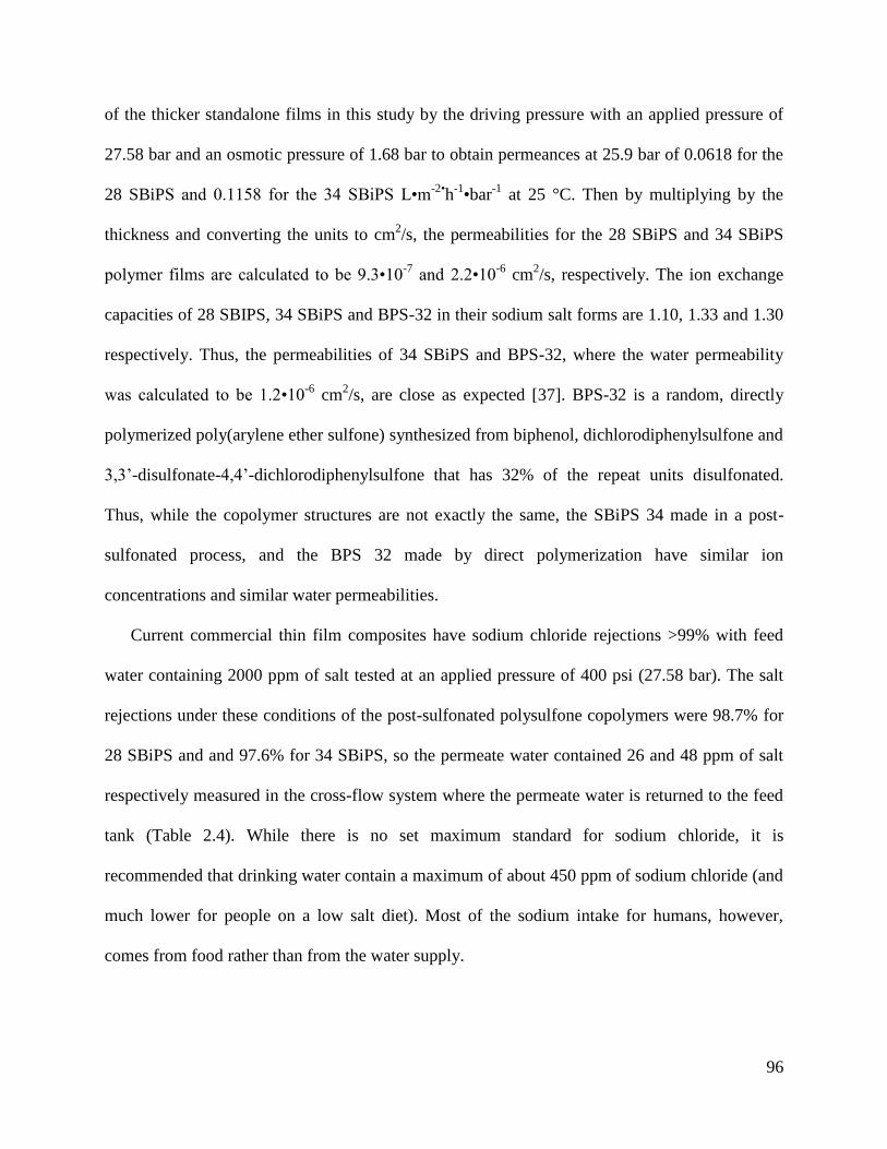
96
of the thicker standalone films in this study by the driving pressure with an applied pressure of
27.58 bar and an osmotic pressure of 1.68 bar to obtain permeances at 25.9 bar of 0.0618 for the
28 SBiPS and 0.1158 for the 34 SBiPS L•m-2•
h-1•bar
-1 at 25 °C. Then by multiplying by the
thickness and converting the units to cm2/s, the permeabilities for the 28 SBiPS and 34 SBiPS
polymer films are calculated to be 9.3•10-7
and 2.2•10-6
cm2/s, respectively. The ion exchange
capacities of 28 SBIPS, 34 SBiPS and BPS-32 in their sodium salt forms are 1.10, 1.33 and 1.30
respectively. Thus, the permeabilities of 34 SBiPS and BPS-32, where the water permeability
was calculated to be 1.2•10-6
cm2/s, are close as expected [37]. BPS-32 is a random, directly
polymerized poly(arylene ether sulfone) synthesized from biphenol, dichlorodiphenylsulfone and
3,3’-disulfonate-4,4’-dichlorodiphenylsulfone that has 32% of the repeat units disulfonated.
Thus, while the copolymer structures are not exactly the same, the SBiPS 34 made in a post-
sulfonated process, and the BPS 32 made by direct polymerization have similar ion
concentrations and similar water permeabilities.
Current commercial thin film composites have sodium chloride rejections >99% with feed
water containing 2000 ppm of salt tested at an applied pressure of 400 psi (27.58 bar). The salt
rejections under these conditions of the post-sulfonated polysulfone copolymers were 98.7% for
28 SBiPS and and 97.6% for 34 SBiPS, so the permeate water contained 26 and 48 ppm of salt
respectively measured in the cross-flow system where the permeate water is returned to the feed
tank (Table 2.4). While there is no set maximum standard for sodium chloride, it is
recommended that drinking water contain a maximum of about 450 ppm of sodium chloride (and
much lower for people on a low salt diet). Most of the sodium intake for humans, however,
comes from food rather than from the water supply.
97
Table 2.4 Membrane thicknesses, water flux, water permeability, and salt rejection for SBiPS films.
Polymer Thickness
(μm)
Water Flux
(L•m-2
•h-1
)
Water Permeability
(cm2/s)
Salt Rejection*
(%)
28 SBiPS 4.3 1.6 9.3•10-7
98.7
34 SBiPS 5.3 3.0 2.2•10-6
97.6
*2000 ppm NaCl in the feedwater and 400 psi applied pressure
2.5 Conclusions
Past studies have shown sulfonated polysulfone films to be promising high performance RO
membranes due to their excellent mechanical properties and chemical resistance. This work
focused on synthesizing active biphenol containing poly(arylene ether sulfone) copolymers that
were then exposed to concentrated sulfuric acid to create a sulfonated polysulfone with the each
ring on the biphenol quantitatively being monosulfonated. This post sulfonation allowed control
over the degree of sulfonation and the water uptake. The polymers synthesized were observed to
have a glassy elastic modulus, over 1 GPa, even in the hydrated state, which suggests that the
SBiPS films can sustain high transmembrane pressures to increase both water throughput and
salt rejection. The SBiPS polymers achieved high salt rejections ≥97%; thus making them
attractive candidates as an active layer for RO membrane applications. The 28 and 34 SBiPS
membranes were calculated to have water permeabilities of 9.3•10-7
and 2.2•10-6
cm2/s,
respectively. Optimization of the synthesis of the SBiPS polymers in terms of the degree of
sulfonation and molecular weight to maximize both water throughput and salt rejection is being
pursued.
2.6 References [1] S. Robins, ‘Day Zero’, hydraulic citizenship and the defence of the commons in Cape
Town: A case study of the politics of water and its infrastructures (2017–2018), Journal
of Southern African Studies, 45 (2019) 5-29.
[2] J.P. Enqvist, G. Ziervogel, Water governance and justice in Cape Town: An overview,
Wiley Interdisciplinary Reviews: Water, 6 (2019) e1354.
[3] WWAP, The United Nations World Water Development Report 2019: Leaving No One
Behind, in, UNESCO Paris, 2019.
98
[4] J. Imbrogno, G. Belfort, Membrane desalination: where are we, and what can we learn
from fundamentals?, Annual review of chemical and biomolecular engineering, 7 (2016)
29-64.
[5] F.R. Spellman, Earth's Oceans and Their Margins, in: The Handbook of Nature, 2019,
pp. 176.
[6] P.H. Gleick, Water in crisis, Pacific Institute for Studies in Dev., Environment &
Security. Stockholm Env. Institute, Oxford Univ. Press. 473p, 9 (1993).
[7] M.R. Fisher, Environmental Biology, (2018).
[8] M.A. Maupin, J.F. Kenny, S.S. Hutson, J.K. Lovelace, N.L. Barber, K.S. Linsey,
Estimated use of water in the United States in 2010, in, US Geological Survey, 2014.
[9] C.A. Dieter, M.A. Maupin, R.R. Caldwell, M.A. Harris, T.I. Ivahnenko, J.K. Lovelace,
N.L. Barber, K.S. Linsey, Estimated use of water in the United States in 2015, US
Geological Survey, 2018.
[10] R.W. Baker, Membrane technology and applications, John Wiley & Sons, 2012.
[11] T.E. Culp, B. Khara, K.P. Brickey, M. Geitner, T.J. Zimudzi, J.D. Wilbur, S.D. Jons, A.
Roy, M. Paul, B. Ganapathysubramanian, Nanoscale control of internal inhomogeneity
enhances water transport in desalination membranes, Science, 371 (2021) 72-75.
[12] M. Qasim, M. Badrelzaman, N.N. Darwish, N.A. Darwish, N. Hilal, Reverse osmosis
desalination: A state-of-the-art review, Desalination, 459 (2019) 59-104.
[13] T. Humplik, J. Lee, S. O’hern, B. Fellman, M. Baig, S. Hassan, M. Atieh, F. Rahman, T.
Laoui, R. Karnik, Nanostructured materials for water desalination, Nanotechnology, 22
(2011) 292001.
[14] S.Y. Kwak, S.G. Jung, Y.S. Yoon, D.W. Ihm, Details of surface features in aromatic
polyamide reverse osmosis membranes characterized by scanning electron and atomic
force microscopy, Journal of Polymer Science Part B: Polymer Physics, 37 (1999) 1429-
1440.
[15] G. Barassi, T. Borrmann, N-Chlorination and Orton rearrangement of aromatic
polyamides, revisited, J. Membr. Sci. Technol, 2 (2012) 1000115.
[16] A. Ismail, P. Lai, Development of defect-free asymmetric polysulfone membranes for gas
separation using response surface methodology, Separation and purification technology,
40 (2004) 191-207.
[17] H. Strathmann, K. Kock, P. Amar, R. Baker, The formation mechanism of asymmetric
membranes, Desalination, 16 (1975) 179-203.
[18] M. Hosseini, J. Azamat, H. Erfan-Niya, Water desalination through fluorine-
functionalized nanoporous graphene oxide membranes, Materials Chemistry and Physics,
223 (2019) 277-286.
[19] L. Jin, S. Yu, W. Shi, X. Yi, N. Sun, Y. Ge, C. Ma, Synthesis of a novel composite
nanofiltration membrane incorporated SiO2 nanoparticles for oily wastewater
desalination, Polymer, 53 (2012) 5295-5303.
[20] H. Dong, L. Zhao, L. Zhang, H. Chen, C. Gao, W.W. Ho, High-flux reverse osmosis
membranes incorporated with NaY zeolite nanoparticles for brackish water desalination,
Journal of Membrane Science, 476 (2015) 373-383.
[21] A. Noshay, L. Robeson, Sulfonated polysulfone, Journal of applied polymer science, 20
(1976) 1885-1903.
[22] J. Rose, Preparation and properties of poly (arylene ether sulphones), Polymer, 15 (1974)
456-465.
99
[23] J.B. Rose, Sulphonated polyarylethersulphone copolymers, US4273903, 1981.
[24] J.B. Rose, Sulphonated polyaryletherketones, US4268650, 1981.
[25] A. Daryaei, G.C. Miller, J. Willey, S. Roy-Choudhury, B. Vondrasek, D. Kazerooni,
M.R. Burtner, C.K. Mittelsteadt, J.J. Lesko, J.S. Riffle, Synthesis and Membrane
Properties of Sulfonated Poly (arylene ether sulfone) Statistical Copolymers for
Electrolysis of Water: Influence of meta and para-Substituted Comonomers, ACS
Applied Materials & Interfaces, (2017).
[26] A. Daryaei, E.-S. Jang, S.R. Choudhury, D. Kazerooni, J.J. Lesko, B.D. Freeman, J.S.
Riffle, J.E. McGrath, Structure-property relationships of crosslinked disulfonated poly
(arylene ether sulfone) membranes for desalination of water, Polymer, 132 (2017) 286-
293.
[27] S.R. Choudhury, O. Lane, D. Kazerooni, G.S. Narang, E.S. Jang, B.D. Freeman, J.J.
Lesko, J. Riffle, Synthesis and characterization of post-sulfonated poly (arylene ether
sulfone) membranes for potential applications in water desalination, Polymer, 177 (2019)
250-261.
[28] Z. Li, X. Liu, D. Chao, W. Zhang, Controllable sulfonation of aromatic poly (arylene
ether ketone) s containing different pendant phenyl rings, Journal of Power Sources, 193
(2009) 477-482.
[29] P.Y. Bruice, Organic Chemistry. International Edition, in, Pearson Education, Upper
Saddle River, NJ, USA, 2004.
[30] Y. Meng, A. Hay, X. Jian, S. Tjong, Synthesis and properties of poly (aryl ether sulfone)
s containing the phthalazinone moiety, Journal of applied polymer science, 68 (1998)
137-143.
[31] D.D. Jiang, Q. Yao, M.A. McKinney, C.A. Wilkie, TGA/FTIR studies on the thermal
degradation of some polymeric sulfonic and phosphonic acids and their sodium salts,
Polymer degradation and stability, 63 (1999) 423-434.
[32] C.S. Kong, D.-Y. Kim, H.-K. Lee, Y.-G. Shul, T.-H. Lee, Influence of pore-size
distribution of diffusion layer on mass-transport problems of proton exchange membrane
fuel cells, Journal of Power Sources, 108 (2002) 185-191.
[33] G. Taylor, Diffusion and mass transport in tubes, Proceedings of the Physical Society.
Section B, 67 (1954) 857.
[34] R. Epsztein, E. Shaulsky, N. Dizge, D.M. Warsinger, M. Elimelech, Role of ionic charge
density in donnan exclusion of monovalent anions by nanofiltration, Environmental
science & technology, 52 (2018) 4108-4116.
[35] M. Perry, C. Linder, Intermediate reverse osmosis ultrafiltration (RO UF) membranes for
concentration and desalting of low molecular weight organic solutes, Desalination, 71
(1989) 233-245.
[36] R.W. Kopitzke, C.A. Linkous, H.R. Anderson, G.L. Nelson, Conductivity and water
uptake of aromatic‐based proton exchange membrane electrolytes, Journal of the
Electrochemical Society, 147 (2000) 1677.
[37] W. Xie, G.M. Geise, B.D. Freeman, C.H. Lee, J.E. McGrath, Influence of processing
history on water and salt transport properties of disulfonated polysulfone random
copolymers, Polymer, 53 (2012) 1581-1592.
100
Chapter 3: Hydrated Mechanical
Properties of Sulfonated Poly(Arylene Ether
Sulfone) Membranes
3.1 Abstract
In the last 50 years, clean water sources have begun to deplete because of a combination of
urbanization, industrialization, and pollution. Thus, various researchers have been focused on
developing novel techniques to purify water. Because of the abundance of saline water sources
such as seawater and brackish water, these water sources have become an attractive input to
produce fresh potable water. One of the most cost effective techniques used to remove salt from
saline water is reverse osmosis. Reverse osmosis uses a semi-permeable membrane and pressure
to drive the desalination process. Since sulfonated poly(arylene ether sulfone)s have been
reported to have excellent mechanical properties, various classes of sulfonated poly(arylene ether
sulfone)s were synthesized through either direct polymerization or post-sulfonation. Varying
degrees of sulfonation were targeted for each class of synthesized polymer. Furthermore,
crosslinkable oligomers with targeted molecular weights of 5 and 10 kDa were also synthesized
and fabricated into films by crosslinking them with a tetra functional epoxide. The hydrated
mechanical properties, elastic modulus and yield strength, were calculated from stress-strain
curves developed from an uniaxial Instron with an attached in situ hydration chamber. Majority
of the polymer classes showed that the hydrated membranes exhibited a high
hydrated/plasticized elastic modulus of approximately 1 GPa. Furthermore, each polymer class
showed that as the number of sulfonate ions increased the water uptake of the material also
101
increased. Moreover, the increase in water uptake reduced the mechanical properties of the
material due to plasticization.
3.2 Introduction
The World Health Organization (WHO) speculates that 50-66% of the world’s population
will be living in water stressed areas by 2025 [1]. After World War II, there was a surge of
research interest focused on developing water transport theories through membranes, new
membrane materials, and novel techniques that can desalinate water both effectively and
efficiently [2]. The technique that shows the highest potential is reverse osmosis (RO). Currently,
the RO process is typically conducted in spiral wound modules containing a semi-permeable
membrane that are pressurized above the osmotic pressure between the feed and permeate
solutions. The RO membranes are thin film composites that are fabricated by interfacially
polymerizing an aromatic polyamide on top of a porous polysulfone. These composites have
high water fluxes and high salt rejections, usually >99 % [3-5].
Important features for water desalination membranes include achieving a high water
permeate flux, maintaining high contaminant and salt rejections, having good chemical and
fouling resistances, and good mechanical stability and durability [6]. In 2014, according to the
Scopus database, the number of journal manuscripts published annually that focused on water
desalination and water treatment membranes was about 2500 of which only 100 of those
publications, equating to 4% of the papers, investigated mechanical properties of those
desalination membranes [6]. Thus, very little publications and advancements have gone into
investigating the mechanical properties needed for various desalination membranes.
Since commercial RO membranes are subjected to pressures as high as 60-65 bar, they need
to be robust enough to handle the internal stresses induced within the material by the applied

102
operational pressures [3, 6]. In the past however, membranes have been operated at very high
pressures, up to 100 bar [3]. Based on the solution diffusion model a direct relationship can be
made between the water flux through the membrane and both the pressure and concentration
gradients through the membrane as shown in equation 1, where J is the flux, A is the water
permeability constant, ∆P is the transmembrane pressure, and ∆π is the osmotic pressure [3, 7].
(1)
The water permeation flux can be modeled in terms of different types of resistances as shown
in equation 2; where μ is the viscosity, Rm is the intrinsic resistance of the membrane, Rr is the
reversible resistance from polarization, and Rir is the irreversible fouling resistance [8]. At low
transmembrane pressures the flux of the water increases linearly because the resistance terms do
not change. However, at higher pressures, the flux begins to plateau because the surface of the
membrane begins to foul, which is observed with the value of the irreversible fouling resistance
increasing in equation 2.
(2)
At the same time, this process artificially increases the solute rejection levels expressed as
percentages because the throughput of water is higher. In a situation where scaling and fouling
can be minimized at high pressures, this may aid in achieving linearity between the
transmembrane pressure and flux. In such a case, RO can be operated at higher pressures to
produce more desalinated water in shorter times. Thus, having materials that can withstand high
stresses tend to be more attractive in the reverse osmosis industry. In addition, understanding the
mechanics of RO membranes are not only used to design novel membrane structures but also to
predict various membrane failure mechanisms [6].
103
Due to the importance of the membrane’s hydrated mechanical integrity, various methods
have been developed to test membrane performance. Tests including uniaxial tensile testing (dry
and hydrated), bend tests, dynamic mechanical analysis, nano-indentation in tapping mode, and
burst testing are the most common methods used to test the mechanical performance for RO
membranes [6]. The most popular technique used for evaluating and investigating membrane
design is uniaxial tensile testing which can be used to extract the Young’s/Elastic modulus, yield
strength, fracture strain, ultimate strength, and fracture toughness from the stress-strain curves
[6]. The author suggests that two important pieces of data that can be extracted from a uniaxial
stress-strain curve is the elastic modulus and the yield stress, primarily because of their link with
a material’s elastic regime [9]. All other extracted properties mentioned from stress-strain curves
involve permanently deforming the material into the plastic regime which may lead to various
membrane failure modes. However, in cases where membranes are fabricated using strain
hardening techniques, one will need to consider the properties in the plastic regime. By focusing
on increasing the material’s elastic modulus and yield strength, theoretically, the material may be
able to experience higher applied transmembrane pressures without failing. Toughness is also an
indicator of whether the materials will be sufficient to manufacture thin membranes.
There are multiple ways to increase the mechanical properties of the membrane. These
methods include manipulating membrane architecture such as the development of thin film
composites, incorporation of physically mixed mechanically robust fillers, and alterations in the
membrane chemistry through additions of rigid compounds or increased crosslink densities.
Presently, membranes utilize a combination of all three methods to ensure that the membrane has
and maintains mechanical durability.
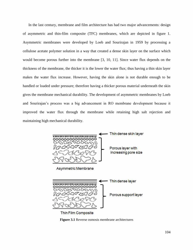
104
In the last century, membrane and film architecture has had two major advancements: design
of asymmetric and thin-film composite (TFC) membranes, which are depicted in figure 1.
Asymmetric membranes were developed by Loeb and Sourirajan in 1959 by processing a
cellulose acetate polymer solution in a way that created a dense skin layer on the surface which
would become porous further into the membrane [3, 10, 11]. Since water flux depends on the
thickness of the membrane, the thicker it is the lower the water flux; thus having a thin skin layer
makes the water flux increase. However, having the skin alone is not durable enough to be
handled or loaded under pressure; therefore having a thicker porous material underneath the skin
gives the membrane mechanical durability. The development of asymmetric membranes by Loeb
and Sourirajan’s process was a big advancement in RO membrane development because it
improved the water flux through the membrane while retaining high salt rejection and
maintaining high mechanical durability.
Figure 3.1 Reverse osmosis membrane architectures
105
FilmTec Corporation used the same logic to develop thin film composites in the 1970s. The
design of the TFC membranes was similar to that of the asymmetric membranes where a dense
polymer layer was placed on top of a porous membrane, except the materials for the dense and
porous regions of the membrane no longer had to be the same material. This way, the thin dense
active layer of the membrane could be tailored to have high water fluxes and high salt rejections
while the porous support layer of the composite could be tailored to have robust mechanical
properties. Commonly, the porous supports in the commercial TFC membranes include
poly(ether sulfone)s, polyacrylonitrile, and polyimides [9]. Almost all commercial RO
membranes utilize the thin-film composite architecture because of the ability to mismatch
materials between the thinly dense active and porous support layer, unlike with asymmetric
membranes.
Another method of increasing the mechanical properties of membrane materials include
additions of filler materials such as graphene/graphene oxide, carbon nanotubes, diamond, silica,
titania, zeolite, alumina, and other inorganic fillers [12-16]. Additions of such fillers have been
shown to reduce compaction within the active layer from the applied transmembrane pressure
which would otherwise cause a decrease in water flux through the membrane [12, 17]. In some
instances the fillers can be chemically crosslinked within the active layer of the material or
mixed into the matrix. Even though the addition of these fillers were found to increase the
mechanical durability of the material through compaction resistance, the main intentions of
incorporation of such fillers were to either increase water flux, increase salt rejection, and/or
decrease biofouling on the surface of the membrane.
In recent years, sulfonated poly(arylene ether sulfone)s have shown promise as a high
performance RO membrane [18-23]. One such reason is for its excellent mechanical integrity.
106
This paper focuses on trying to relate various sulfonated poly(arylene ether sulfone) chemical
differences to their observed hydrated mechanical properties.
3.3 Experimental
3.3.1 High molecular weight sulfonated poly(arylene ether sulfone) synthesis
The linear sulfonated poly(arylene ether sulfone) polymers were synthesized through various
methods. One method is through direct polymerization of disulfonated monomers. Another
process utilized post-sulfonation modification of activated poly(arylene ether sulfone)s.
3.3.1.1 Direct polymerization of sulfonated poly(arylene ether sulfone)s using sulfonated
monomers
The directly polymerized sulfonated poly(arylene ether sulfone)s with varying degrees of
disulfonation were controlled by the ratio of 3,3’-disulfonate-4,4’dichlorodiphenylsulfone
monomer to 4,4’-dichlorodiphenylsulfone. These polymers were also synthesized with different
aromatic diol monomers including biphenol, hydroquinone, and 75 mol% hydroquinone to 25
mol% resorcinol. Detailed methods on the synthesis for these polymers can be found in Daryaei
et al.’s manuscript. [24] Briefly, the polymers were synthesized by dissolving 4,4’-
dichlorodiphenylsulfone (29.06 mmol, 8.3451 g), 3,3’-disulfonate-4,4’-dichlorodiphenylsulfone
(7.265 mmol, 3.57 g), and an aromatic diol such as hydroquinone (36.33 mmol, 4.00 g) in 55 mL
of N,N-dimethylacetamide (DMAc) in a 250-mL, three-neck, round bottom flask outfitted with a
Dean-Stark trap and condenser, nitrogen inlet, and mechanical stirrer to produce HQ-20. The
HQ-X nomenclature, refers to a disulfonated polymer copolymerized with hydroquinone that
consists of “X” percent of disulfonated repeat units. Once dissolved, 47.22 mmol (6.52 g) of
potassium carbonate (K2CO3) was added with 25 mL of toluene. The Dean-Stark trap was filled
with toluene and the temperature of the solution was raised to 150 ºC for 4 h to azeotropically
107
remove water from the reaction. After 4 h the Dean-Stark trap was drained and the temperature
of the reaction was raised to 180 ºC for 48 h. After 48 h, the solution was diluted with 150 mL of
DMAc and allowed to cool to room temperature before filtering out the precipitated salt from the
polymer solution. The polymer solution was then precipitated in isopropanol, filtered, and dried
under vacuum at 120 ºC.
3.3.1.2 Synthesis of activated poly(arylene ether sulfone)s and post-sulfonation
Both non-sulfonated and sulfonated poly(arylene ether sulfone) polymers containing either
hydroquinone or biphenol were synthesized by varying the ratio of hydroquinone or biphenol to
bisphenol-S. These polymers were synthesized as described in Choudhury et al. [25]. For
example, to synthesize a polysulfone with 31% of the repeat units containing biphenol, 39.3
mmol of difluorodiphenylsulfone, 12.2 mmol biphenol, and 27.1 mmol bisphenol-S were
dissolved in 65 mL of dimethylacetamide. A 1.2 mol excess of potassium carbonate and 30 mL
of toluene were added to the dissolved monomers and the mixture was azeotropically dried by
refluxing at 150 ºC for 4 h. A dean-stark trap was used to collect the condensate and recycle the
toluene back into the reaction. After drying the mixture and removing the toluene from the
reaction the temperature was increased to 185 ºC for 24 h. The polymer was precipitated and
then dried. To synthesize the sulfonated counterpart, the dry polymer was reacted in concentrated
sulfuric acid at 55 ºC for 2 h. The sulfonated polymer was subsequently precipitated, neutralized
with sodium hydroxide, and dried.
108
3.3.2 Crosslinked sulfonated poly(arylene ether sulfone) oligomers
3.3.2.1 One pot synthesis of meta-aminophenol (m-AP) terminated oligomers of sulfonated
poly(arylene ether sulfone)s through direct polymerization of sulfonated monomers
Similarly to the synthesis of the directly polymerized sulfonated poly(arylene ether sulfone)
high molecular weight polymers, 5 kDa and 10 kDa oligomer analogues of varying degrees of
sulfonated random copolymers were synthesized based on Carother’s equations and m-
aminophenonl (m-AP) terminal groups. This synthesis is described in Daryaei et al. [22]. The
nomenclature for these polymers follows a mBX-Y format, where “m” refers to the m-AP end
groups, “B” refers to biphenol, “X” refers to 10% disulfonation percentage, and “Y” refers to the
molecular weight of the oligomer in kDa. For example, mB6-10 refers to a m-AP endcapped
biphenol based poly(arylene ether sulfone) with 60% of the units disulfonated and a molecular
weight of 10 kDa. To summarize briefly the synthesis of the oligomer, mB6-10 was synthesized
by dissolving m-aminophenol (6 mmol, 0.639 g), 4,4’-dichlorodiphenylsulfone (20 mmol, 5.743
g), 3,3’-disulfonate-4,4’-dichlorodiphenylsulfone (30 mmol, 14.767 g), and biphenol (0.47
mmol, 8.752 g) in DMAc (100 mL) with a mechanical stirrer at 150 ºC. After dissolving the
monomers, K2CO3 (51 mmol, 8.44 g) and toluene (50 mL) were added to the round bottom flask
and the phenol monomers were azeotropically dried at 150 ºC using a Dean-Stark trap filled with
refluxing toluene for 4 h under nitrogen. After removing the water, the toluene was drained from
the Dean-Stark trap and the temperature was raised to 180 ºC and held for 48 h. After completion
the oligomer solution was allowed to return to room temperature where it was diluted with 100
mL of DMAc, filtered, precipitated in isopropyl alcohol, and then dried at 120 ºC under vacuum.
109
3.3.2.2 Synthesis of m-AP terminated activated poly(arylene ether sulfone)s and its post-
sulfonation
This polymer was prepared in the same manner as the directly polymerized poly(arylene ether sulfone)
oligomers. However, in this case instead of using a sulfonated monomer, a monomer was added into the
synthesis that would be active toward post-sulfonation, such as hydroquinone. Once the oligomer was
synthesized it was sulfonated by electrophilic aromatic substitution. Both 5 and 10 kDa oligomers were
investigated. The nomenclature follows the same naming convention of Choudhury et al. where X-HQS-
Y indicates a hydroquinone oligomer that contains “X” percent of its units sulfonated and a targeted
molecular weight equal to “Y” kDa [25].
To synthesize 50-HQS-10k, m-aminophenol (4 mmol, 0.436 g), hydroquinone (24 mmol, 2.642 g), and
bisphenol-S (24 mmol, 6.006 g) was dissolved in sulfolane (67 mL) at 150 ºC in a 250-mL, three-neck,
round bottom flask with a nitrogen inlet, mechanical stirrer, and a Dean-Stark trap - condenser assembly.
Once all the monomers were dissolved, K2CO3 (62 mmol, 8.624 g) and toluene (34 mL) were added to the
solution and the Dean-Stark trap was filled with toluene. The reaction temperature was increased to 180-
185 ºC and refluxed for 4 h to azeotropically remove any water produced from the monomer. The Dean-
Stark trap was drained and 4,4’-dichlorodiphenylsulfone (50 mmol, 14.358 g) was added to the reaction
vessel to begin the polymerization. The reaction temperature was increased to 200-210 ºC and maintained
for 36 h. After 36 h, the solution was allowed to cool to room temperature and diluted with 40 mL of
DMAc. The oligomer was filtered and precipitated in IPA and then dried at 110 ºC under vacuum.
To sulfonate the oligomer, 10 g of the dried oligomer was placed in a 150-mL, three-neck, round bottom
flask outfitted with a condenser, mechanical stirrer, and nitrogen inlet. Sulfuric acid (95-97%, 100 mL)
was added to dissolve the oligomer. The solution was heated to 50 ºC and stirred for 2 h. Finally, the
oligomer was precipitated in ice cold water and neutralized with 10 M NaOH. The oligomer was filtered
and dried at 110 ºC under vacuum for 12 hours.
110
3.3.3 Molecular weight determination using size exclusion chromatography (SEC)
Molecular weights of all the polymers and oligomers were measured by SEC. The SEC
mobile phase was 0.1 M dry lithium chloride (LiCl) in DMAc. Concentrations between 2.5 and
3.0 mg/mL of the polymer/oligomer samples were analyzed. An Agilent 1260 Infinity II LC
system, with an auto-sampler from Agilent Technologies was used with a column set consisting
of a guard column and three Agilent PLgel 10-mm Mixed B-LS columns which utilizes a
polystyrene/divinylbenzene packing material. The SEC system comprises a DAWN-HELEOS II
multi-angle laser light scattering detector and an Optilab T-rEX refractive index detector both
from Wyatt Technology Corp., which uses 658-nm light to analyze the polymer or oligomer’s
molecular weight and concentration respectively. Both the columns and detectors were
maintained at 50 ºC throughout the test. A 21 kDa polystyrene standard was used to correct for
both interdetector delay and band broadening. Astra 6 software from Wyatt Technology Corp.
was used to collect and analyze the data.
3.3.4 Film casting
High molecular weight polymers were cast on a glass plate using an IR lamp to remove the
bulk of the solvent. The crosslinked networks were cast from DMAc by reacting tetraepoxy
compounds with the amine terminated oligomers.
3.3.5 High molecular weight film casting
Each polymeric material tested (0.5 g) was dissolved in 12 mL of DMAc, and subsequently
the solution was filtered through a 0.45 micron PTFE Whatman syringe filter. The filtered
solution was sonicated for a minimum of 5 min and then poured onto a 4”x4” glass plate. An
infrared (IR) lamp was placed above the glass plate and used to incrementally increase the
temperature of the drying polymer film on the glass plate from 40 to 50, and finally 80 ºC, every
111
2 h. The film was held under the IR lamp at 80 °C for another 12 h before placing it inside a
vacuum oven for 12 h at 110 ºC under vacuum. Upon removal, the film was allowed to cool to
room temperature before submerging it in a 2 M NaCl solution for 72 h to delaminate the film
from the glass plate, and convert any potassium counter ions into sodium.
3.3.6 Epoxy crosslinked m-AP oligomers film casting
Films of the m-aminophenol end capped sulfonated oligomers were cast through crosslinking
them with tetraglycidyl bis(p-aminophenyl)methane (TGBAM). The ratio of oligomer to
TGBAM was 1:2.5 M ratio. Approximately 3.0 g of 10 kDa oligomer, 0.31 g TGBAM, and 7.7
mg of triphenylphosphine were all dissolved in 45 mL of DMAc [22]. The solution was filtered
through a 0.45 micron PTFE syringe filter and subsequently poured into a mold inside a
convection oven. The oven was raised to 140 ºC for 1 h, then raised to 155 ºC for 2 h, and finally
raised again to 190 ºC for 1 h. The oven was turned off and the film was allowed to reach room
temperature before being removed. The film was then transferred into a 0.02 M aqueous solution
of NaOH to delaminate the epoxy cured network from the glass mold. Finally, these films were
stored in 2M NaCl solution until testing.
3.3.7 Hydrated uniaxial tensile testing
A Cricut Explore One™ stencil cutter was used to cut the polymer films into four dogbone
replicate samples in accordance with Type V of ASTM D6338-14 guidelines. The samples were
immediately immersed in DI water and were allowed to remain immersed for at least 24 h prior
to testing. The hydrated dogbone thickness was measured at four different points along the gauge
length of the dogbone sample using a Mitutoyo Digimatic Micrometer Model MDC-1SXF. The
average thickness was used to compute the stresses reported in the stress-strain curves for each
material. Each sample was submerged in DI water at room temperature and allowed to
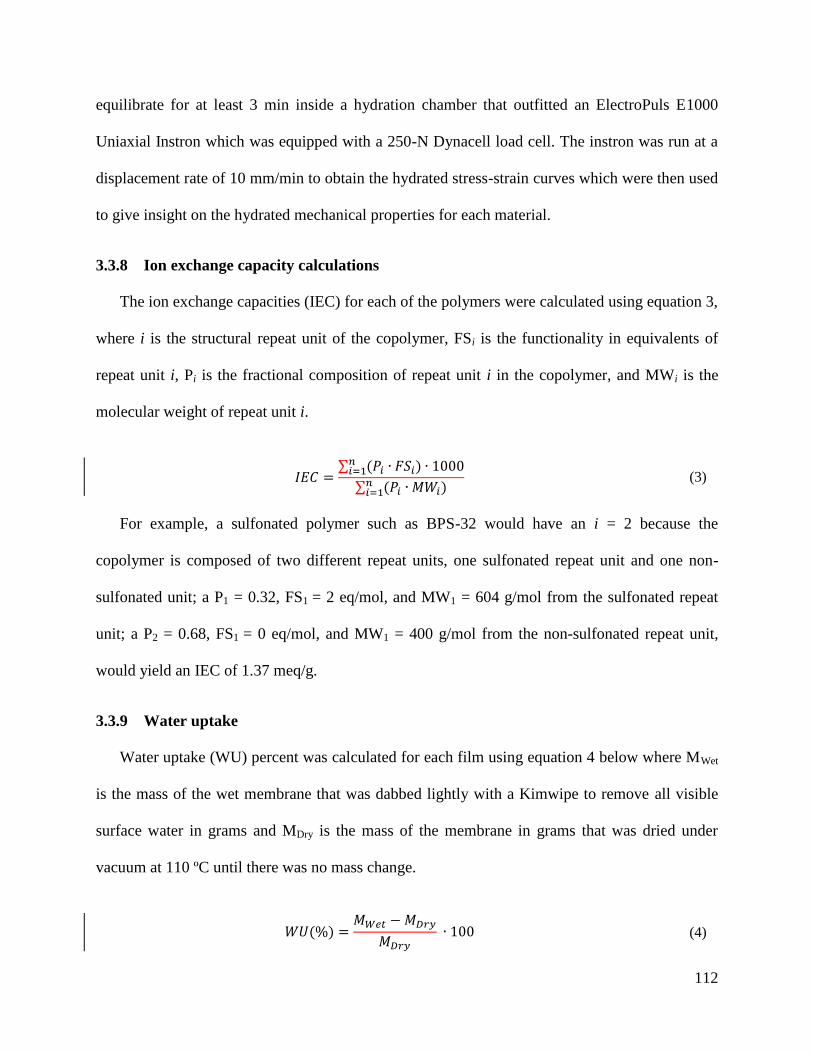
112
equilibrate for at least 3 min inside a hydration chamber that outfitted an ElectroPuls E1000
Uniaxial Instron which was equipped with a 250-N Dynacell load cell. The instron was run at a
displacement rate of 10 mm/min to obtain the hydrated stress-strain curves which were then used
to give insight on the hydrated mechanical properties for each material.
3.3.8 Ion exchange capacity calculations
The ion exchange capacities (IEC) for each of the polymers were calculated using equation 3,
where i is the structural repeat unit of the copolymer, FSi is the functionality in equivalents of
repeat unit i, Pi is the fractional composition of repeat unit i in the copolymer, and MWi is the
molecular weight of repeat unit i.
(3)
For example, a sulfonated polymer such as BPS-32 would have an i = 2 because the
copolymer is composed of two different repeat units, one sulfonated repeat unit and one non-
sulfonated unit; a P1 = 0.32, FS1 = 2 eq/mol, and MW1 = 604 g/mol from the sulfonated repeat
unit; a P2 = 0.68, FS1 = 0 eq/mol, and MW1 = 400 g/mol from the non-sulfonated repeat unit,
would yield an IEC of 1.37 meq/g.
3.3.9 Water uptake
Water uptake (WU) percent was calculated for each film using equation 4 below where MWet
is the mass of the wet membrane that was dabbed lightly with a Kimwipe to remove all visible
surface water in grams and MDry is the mass of the membrane in grams that was dried under
vacuum at 110 ºC until there was no mass change.
(4)
113
3.4 Results and Discussion
3.4.1 Directly polymerized sulfonated poly(arylene ether sulfone)
Sulfonated polymers were originally synthesized by post-sulfonating commercial polymers
such as poly(arylene ether sulfone)s containing bisphenol A with harsh reagents like fuming
sulfuric acid [26]. This resulted in sulfonation primarily on the bisphenol A sites, but
quantitatively controlling the position of sulfonic acid groups and the amount of sulfonic acid
groups both unpredictable and irreproducible. With the development of sulfonated monomers
and their direct polymerization, synthesizing sulfonated polymers became both controllable and
reproducible. For the directly polymerized poly(arylene ether sulfone)s, the degree of sulfonation
was controlled by altering the ratio of 3,3’-disulfonate-4,4’-dichlorodiphenylsulfone to
dichlorodiphenylsulfone. By controlling the amount of sulfonation, systematic studies were
conducted that probed influences of the degree of sulfonation on a material’s mechanical
performance. Other studies included replacing various aromatic diol monomer units in
poly(arylene ether sulfone)s with hydroquinone, biphenol, and 75 mol% hydroquinone to 25
mol% resorcinol to understand their influence on the material properties. Scheme 1 shows the
synthesis of such polymers.
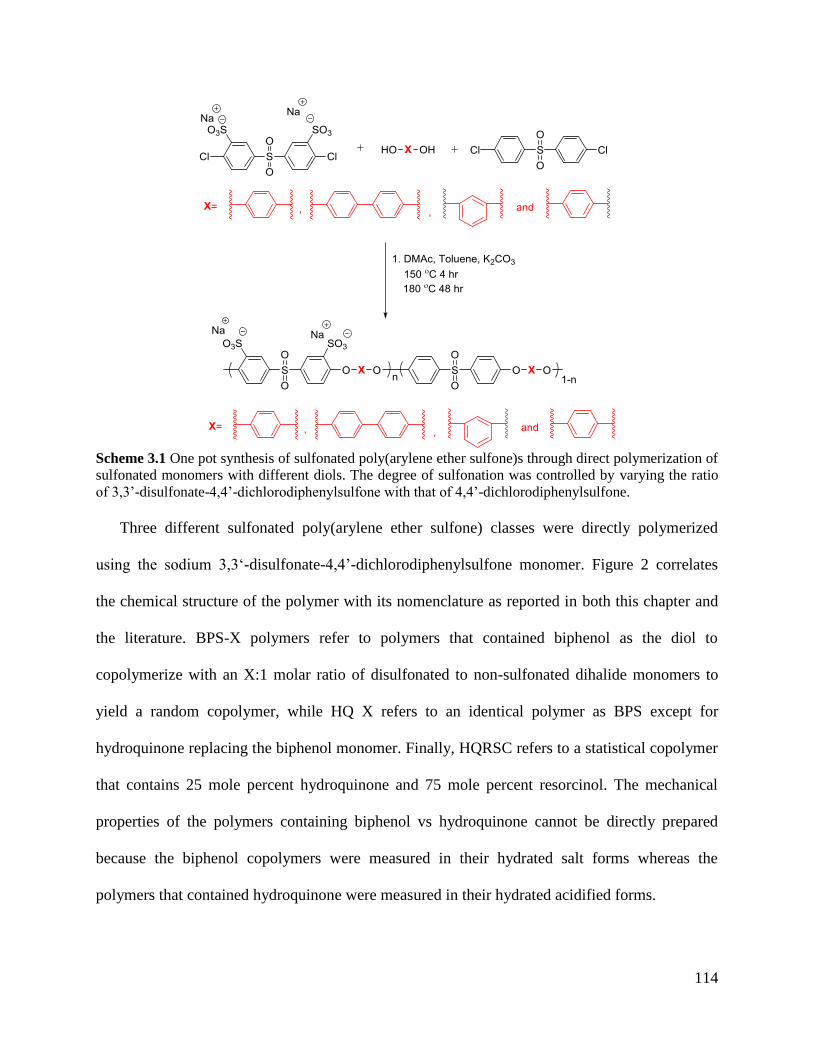
114
Scheme 3.1 One pot synthesis of sulfonated poly(arylene ether sulfone)s through direct polymerization of
sulfonated monomers with different diols. The degree of sulfonation was controlled by varying the ratio
of 3,3’-disulfonate-4,4’-dichlorodiphenylsulfone with that of 4,4’-dichlorodiphenylsulfone.
Three different sulfonated poly(arylene ether sulfone) classes were directly polymerized
using the sodium 3,3‘-disulfonate-4,4’-dichlorodiphenylsulfone monomer. Figure 2 correlates
the chemical structure of the polymer with its nomenclature as reported in both this chapter and
the literature. BPS-X polymers refer to polymers that contained biphenol as the diol to
copolymerize with an X:1 molar ratio of disulfonated to non-sulfonated dihalide monomers to
yield a random copolymer, while HQ X refers to an identical polymer as BPS except for
hydroquinone replacing the biphenol monomer. Finally, HQRSC refers to a statistical copolymer
that contains 25 mole percent hydroquinone and 75 mole percent resorcinol. The mechanical
properties of the polymers containing biphenol vs hydroquinone cannot be directly prepared
because the biphenol copolymers were measured in their hydrated salt forms whereas the
polymers that contained hydroquinone were measured in their hydrated acidified forms.
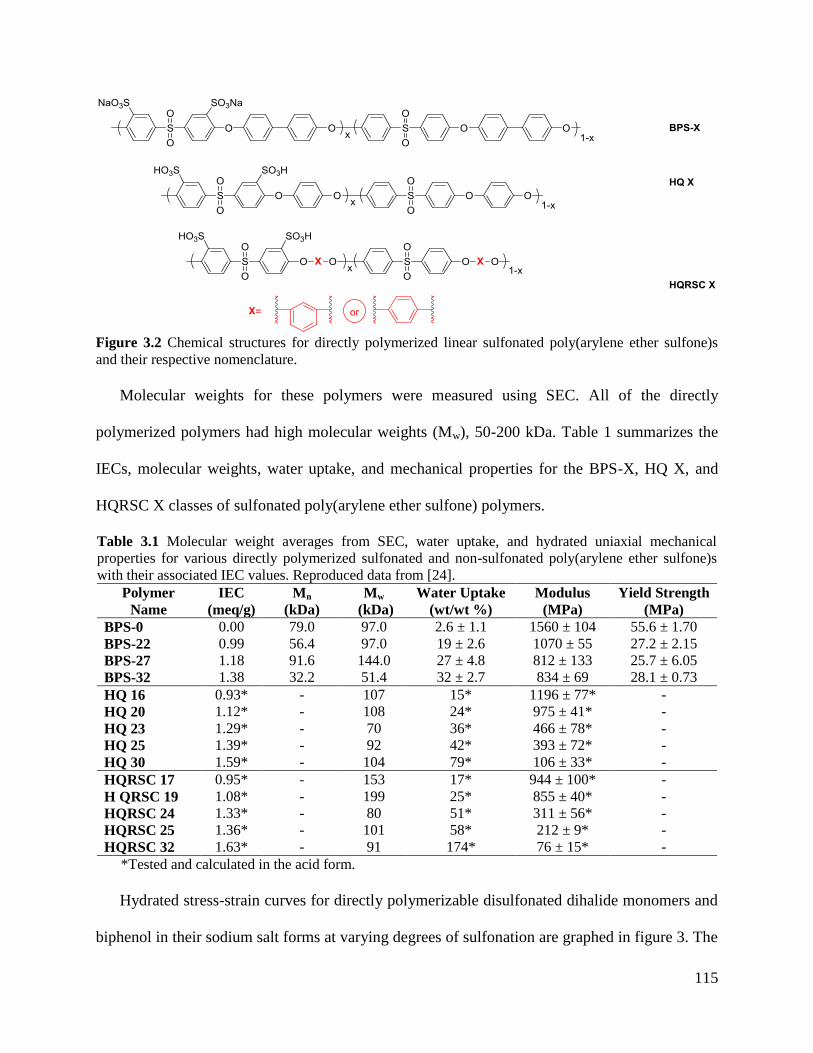
115
Figure 3.2 Chemical structures for directly polymerized linear sulfonated poly(arylene ether sulfone)s
and their respective nomenclature.
Molecular weights for these polymers were measured using SEC. All of the directly
polymerized polymers had high molecular weights (Mw), 50-200 kDa. Table 1 summarizes the
IECs, molecular weights, water uptake, and mechanical properties for the BPS-X, HQ X, and
HQRSC X classes of sulfonated poly(arylene ether sulfone) polymers.
Table 3.1 Molecular weight averages from SEC, water uptake, and hydrated uniaxial mechanical
properties for various directly polymerized sulfonated and non-sulfonated poly(arylene ether sulfone)s
with their associated IEC values. Reproduced data from [24].
Polymer
Name
IEC
(meq/g)
Mn
(kDa)
Mw
(kDa)
Water Uptake
(wt/wt %)
Modulus
(MPa)
Yield Strength
(MPa)
BPS-0 0.00 79.0 97.0 2.6 ± 1.1 1560 ± 104 55.6 ± 1.70
BPS-22 0.99 56.4 97.0 19 ± 2.6 1070 ± 55 27.2 ± 2.15
BPS-27 1.18 91.6 144.0 27 ± 4.8 812 ± 133 25.7 ± 6.05
BPS-32 1.38 32.2 51.4 32 ± 2.7 834 ± 69 28.1 ± 0.73
HQ 16 0.93* - 107 15* 1196 ± 77* -
HQ 20 1.12* - 108 24* 975 ± 41* -
HQ 23 1.29* - 70 36* 466 ± 78* -
HQ 25 1.39* - 92 42* 393 ± 72* -
HQ 30 1.59* - 104 79* 106 ± 33* -
HQRSC 17 0.95* - 153 17* 944 ± 100* -
H QRSC 19 1.08* - 199 25* 855 ± 40* -
HQRSC 24 1.33* - 80 51* 311 ± 56* -
HQRSC 25 1.36* - 101 58* 212 ± 9* -
HQRSC 32 1.63* - 91 174* 76 ± 15* -
*Tested and calculated in the acid form.
Hydrated stress-strain curves for directly polymerizable disulfonated dihalide monomers and
biphenol in their sodium salt forms at varying degrees of sulfonation are graphed in figure 3. The

116
BPS polymer with no sulfonation, BPS-0, exhibited the highest elastic modulus (1560 MPa) as
well as the highest yield strength (55.6 MPa) compared to the sulfonated BPS materials. As
expected, the BPS-0 polymer had a low equilibrium water uptake of 2.6 wt/wt %. As the degree
of sulfonation was increased from 22 to 32 %, (0.99 and 1.38 meq/g IEC, respectively), the
elastic moduli decreased very little (1070 ± 55 MPa to 834 ± 69 MPa) and the yield strengths did
not change significantly (27.2 and 28.1 MPa). By contrast, there are fairly large differences in
the water uptakes for those materials, increasing from 19 to 32 wt/wt %, respectively. The BPS-
X class of materials with sulfonate fixed groups and sodium counterions in pairs on adjacent
rings on the backbones of the polymers absorb significant amounts of water. The water
plasticizes the polymers and decreases their mechanical properties relative to the non-sulfonated
counterpart, but within the range of BPS-22-BPS-32, the hydrated stress-strain properties are
quite similar. Importantly, however, even in their fully hydrated state, the moduli are close to 109
Pa, indicative of glassy polymers, and their ultimate elongations are large.
Figure 3.3 Hydrated stress-strain curves for linear high molecular weight directly polymerized
disulfonated/biphenol poly(arylene ether sulfone)s at varying degrees of sulfonation.
117
The biphenol monomer was replaced with hydroquinone and again with 75 mol%
hydroquinone and 25 mol% resorcinol. These two classes of polymers were tested in their acid
form instead of their salt form. Thus, the mechanical properties observed for the HQ X and
HQRSC X classes of polymers cannot be directly compared to those observed from the BPS-X
materials because the BPS-X (salt form) and HQ X/HQRSC X (acid form) polymer classes were
found to have different water uptakes at equivalent IECs. For example, BPS-32 was calculated to
have an IEC of 1.38 meq/g, while HQ 25 and HQRSC 25 were calculated to have IECs of 1.39
and 1.36 meq/g, respectively. Because the IEC charge ratio is the same between all three
polymers, it was expected that all the polymers would have the same water uptake. However, the
BPS-32 material had a water uptake of 32 %, while the HQ 25 and HQRSC 25 materials had
higher water uptake values of 42 and 58 wt/wt %, respectively. Since the HQ X and HQRSC X
classes of polymers were in their acid form instead of the salt form, the hydration/solvation shells
that form in the membrane around the ions are different; thus causing different degrees of
swelling to occur in the membrane materials [27-31]. Furthermore, since the mechanical
properties show dependence on water uptake, it is difficult to deconvolute the effects caused
from chemical changes in the polymer backbone versus changes from different counterions for
the sulfonate used in the present data.
Nonetheless, both classes of polymers showed the same trend as the BPS-X class, where as
degree of sulfonation was increased (increase in IEC), the water uptake of the material increased,
and the hydrated elastic moduli decreased. The targeted IECs for the HQ X materials ranged
between 0.93 and 1.59 meq/g. The hydrated elastic modulus decreased from 1196 MPa to 106
MPa, while the water uptake increased from 15 to 79 wt/wt % for the HQ 16 to HQ 30 materials,
respectively. Similarly, HQRSC X material class’s IEC ranged between 0.95 and 1.63 meq/g;
118
where the HQRSC X polymer class exhibited a decrease in hydrated elastic moduli from 944
MPa to 76 MPa and an increase in water uptake from 17 to 174 wt/wt% for the HQRSC 17 to
HQRSC 32 materials, respectively.
3.4.2 Non-sulfonated and post sulfonation of hydroquinone and biphenol containing
poly(arylene ether sulfone)s
Although at first, post-sulfonation was neither controllable nor reproducible, Rose et al.
found that by adding hydroquinone monomers that were activated toward sulfonation through
electrophilic aromatic substitution and bisphenol S that was not activated, it was possible to
selectively control the location and amount of sulfonic acid groups that would add to the
backbone of the polymer even while using large excesses of the sulfonation reagents [32-34].
Choudhury and Kazerooni built on this technology by introducing biphenol instead of
hydroquinone. This technique requires a two-step process where the non-sulfonated polymer is
synthesized first, isolated, then sulfonated as illustrated in scheme 2. The degree of sulfonation
was controlled by altering the molar amount of active aromatic diol monomers used in the
synthesis of the polymer. The conditions used to post-sulfonate the polymer ensured that all of
the active rings adjacent to ether linkages from either the hydroquinone or biphenol were
sulfonated while the aromatic rings adjacent to sulfones did not.
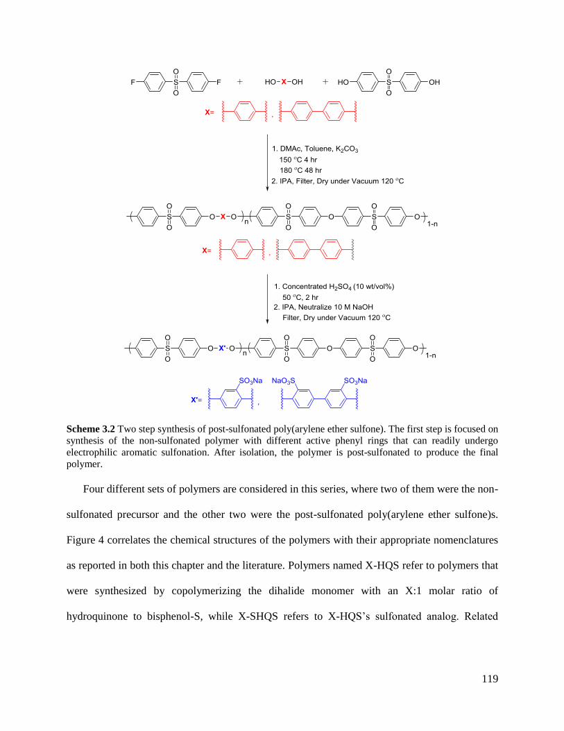
119
Scheme 3.2 Two step synthesis of post-sulfonated poly(arylene ether sulfone). The first step is focused on
synthesis of the non-sulfonated polymer with different active phenyl rings that can readily undergo
electrophilic aromatic sulfonation. After isolation, the polymer is post-sulfonated to produce the final
polymer.
Four different sets of polymers are considered in this series, where two of them were the non-
sulfonated precursor and the other two were the post-sulfonated poly(arylene ether sulfone)s.
Figure 4 correlates the chemical structures of the polymers with their appropriate nomenclatures
as reported in both this chapter and the literature. Polymers named X-HQS refer to polymers that
were synthesized by copolymerizing the dihalide monomer with an X:1 molar ratio of
hydroquinone to bisphenol-S, while X-SHQS refers to X-HQS’s sulfonated analog. Related
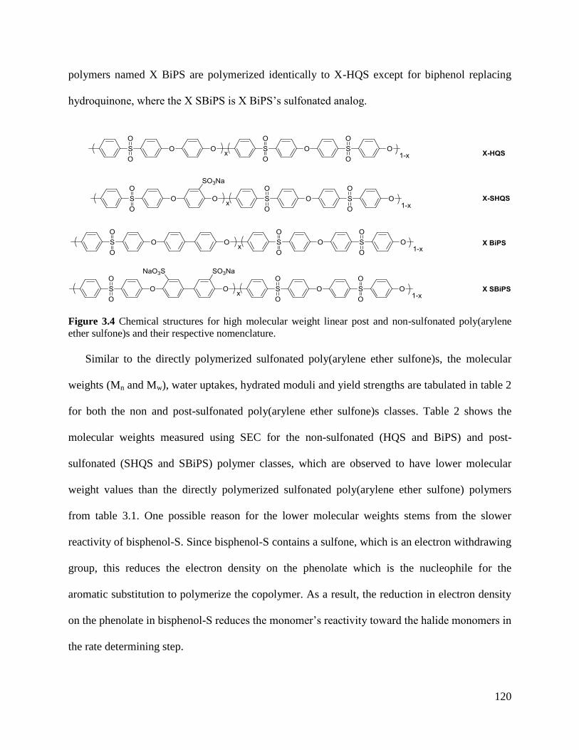
120
polymers named X BiPS are polymerized identically to X-HQS except for biphenol replacing
hydroquinone, where the X SBiPS is X BiPS’s sulfonated analog.
Figure 3.4 Chemical structures for high molecular weight linear post and non-sulfonated poly(arylene
ether sulfone)s and their respective nomenclature.
Similar to the directly polymerized sulfonated poly(arylene ether sulfone)s, the molecular
weights (Mn and Mw), water uptakes, hydrated moduli and yield strengths are tabulated in table 2
for both the non and post-sulfonated poly(arylene ether sulfone)s classes. Table 2 shows the
molecular weights measured using SEC for the non-sulfonated (HQS and BiPS) and post-
sulfonated (SHQS and SBiPS) polymer classes, which are observed to have lower molecular
weight values than the directly polymerized sulfonated poly(arylene ether sulfone) polymers
from table 3.1. One possible reason for the lower molecular weights stems from the slower
reactivity of bisphenol-S. Since bisphenol-S contains a sulfone, which is an electron withdrawing
group, this reduces the electron density on the phenolate which is the nucleophile for the
aromatic substitution to polymerize the copolymer. As a result, the reduction in electron density
on the phenolate in bisphenol-S reduces the monomer’s reactivity toward the halide monomers in
the rate determining step.
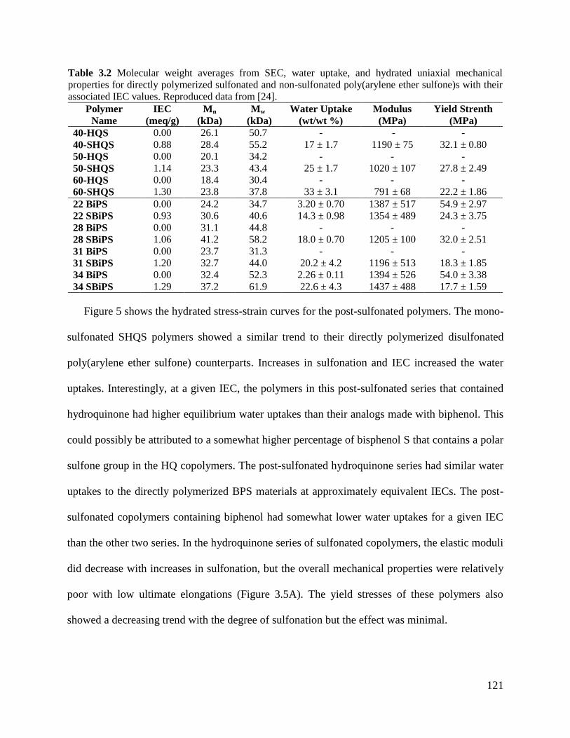
121
Table 3.2 Molecular weight averages from SEC, water uptake, and hydrated uniaxial mechanical
properties for directly polymerized sulfonated and non-sulfonated poly(arylene ether sulfone)s with their
associated IEC values. Reproduced data from [24].
Polymer
Name
IEC
(meq/g)
Mn
(kDa)
Mw
(kDa)
Water Uptake
(wt/wt %)
Modulus
(MPa)
Yield Strenth
(MPa)
40-HQS 0.00 26.1 50.7 - - -
40-SHQS 0.88 28.4 55.2 17 ± 1.7 1190 ± 75 32.1 ± 0.80
50-HQS 0.00 20.1 34.2 - - -
50-SHQS 1.14 23.3 43.4 25 ± 1.7 1020 ± 107 27.8 ± 2.49
60-HQS 0.00 18.4 30.4 - - -
60-SHQS 1.30 23.8 37.8 33 ± 3.1 791 ± 68 22.2 ± 1.86
22 BiPS 0.00 24.2 34.7 3.20 ± 0.70 1387 ± 517 54.9 ± 2.97
22 SBiPS 0.93 30.6 40.6 14.3 ± 0.98 1354 ± 489 24.3 ± 3.75
28 BiPS 0.00 31.1 44.8 - - -
28 SBiPS 1.06 41.2 58.2 18.0 ± 0.70 1205 ± 100 32.0 ± 2.51
31 BiPS 0.00 23.7 31.3 - - -
31 SBiPS 1.20 32.7 44.0 20.2 ± 4.2 1196 ± 513 18.3 ± 1.85
34 BiPS 0.00 32.4 52.3 2.26 ± 0.11 1394 ± 526 54.0 ± 3.38
34 SBiPS 1.29 37.2 61.9 22.6 ± 4.3 1437 ± 488 17.7 ± 1.59
Figure 5 shows the hydrated stress-strain curves for the post-sulfonated polymers. The mono-
sulfonated SHQS polymers showed a similar trend to their directly polymerized disulfonated
poly(arylene ether sulfone) counterparts. Increases in sulfonation and IEC increased the water
uptakes. Interestingly, at a given IEC, the polymers in this post-sulfonated series that contained
hydroquinone had higher equilibrium water uptakes than their analogs made with biphenol. This
could possibly be attributed to a somewhat higher percentage of bisphenol S that contains a polar
sulfone group in the HQ copolymers. The post-sulfonated hydroquinone series had similar water
uptakes to the directly polymerized BPS materials at approximately equivalent IECs. The post-
sulfonated copolymers containing biphenol had somewhat lower water uptakes for a given IEC
than the other two series. In the hydroquinone series of sulfonated copolymers, the elastic moduli
did decrease with increases in sulfonation, but the overall mechanical properties were relatively
poor with low ultimate elongations (Figure 3.5A). The yield stresses of these polymers also
showed a decreasing trend with the degree of sulfonation but the effect was minimal.
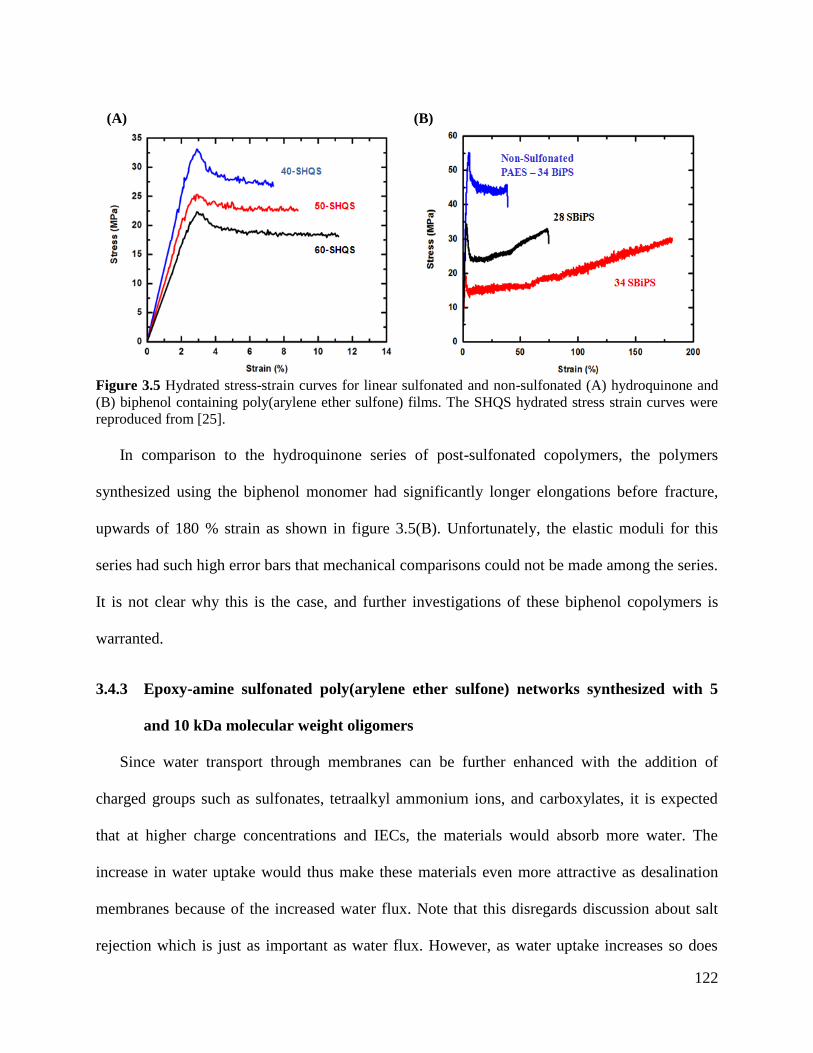
122
In comparison to the hydroquinone series of post-sulfonated copolymers, the polymers
synthesized using the biphenol monomer had significantly longer elongations before fracture,
upwards of 180 % strain as shown in figure 3.5(B). Unfortunately, the elastic moduli for this
series had such high error bars that mechanical comparisons could not be made among the series.
It is not clear why this is the case, and further investigations of these biphenol copolymers is
warranted.
3.4.3 Epoxy-amine sulfonated poly(arylene ether sulfone) networks synthesized with 5
and 10 kDa molecular weight oligomers
Since water transport through membranes can be further enhanced with the addition of
charged groups such as sulfonates, tetraalkyl ammonium ions, and carboxylates, it is expected
that at higher charge concentrations and IECs, the materials would absorb more water. The
increase in water uptake would thus make these materials even more attractive as desalination
membranes because of the increased water flux. Note that this disregards discussion about salt
rejection which is just as important as water flux. However, as water uptake increases so does
(A) (B)
Figure 3.5 Hydrated stress-strain curves for linear sulfonated and non-sulfonated (A) hydroquinone and
(B) biphenol containing poly(arylene ether sulfone) films. The SHQS hydrated stress strain curves were
reproduced from [25].
123
salt ion transport. As more water is absorbed, the spacing between polymer chains and thus
appended ionic groups begin to increase causing the electrostatic repulsion interactions to
decrease between the charged polymer and the dissociated salt ions. Furthermore, at very high
IECs the non-crosslinked polymers themselves will become soluble in water.
It was hypothesized that crosslinking the oligomers would restrict the molecular dynamics of
the chains and decrease swelling by water. In addition to restricting the water uptake of the
material, crosslinking the oligomers into a network would allow for higher ion concentrations to
be studied since the networks were insoluble.
Based on the polymers synthesized through either direct polymerization or post-sulfonation,
5 and 10 kDa oligomer analogs were synthesized using the same monomers that were used for
the linear high molecular weight polymers. Controlling the crosslink density of the final network
was achieved by synthesizing different oligomer molecular weights. Meta-aminophenol was
used as an end-capping agent for the oligomers [22, 25]. Scheme 3.3 illustrates the synthesis of
two types of oligomer chemistries, directly polymerized disulfonated monomer with biphenol
and post-sulfonated hydroquinone containing poly(arylene ether sulfone)s, at target molecular
weights of either 5 or 10 kDa. The molecular weights of the new classes of materials were
controlled using Carother’s equations. The oligomers were crosslinked with a tetra-functional
epoxide, as illustrated in scheme 3.4, to form films.
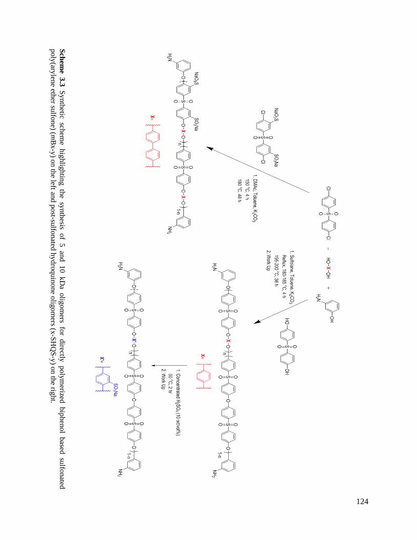
124
Sch
eme
3.3
S
yn
thetic
schem
e h
ighlig
htin
g th
e sy
nth
esis of
5 an
d 10 kD
a olig
om
ers fo
r directly
p
oly
merized
bip
hen
ol
based
su
lfonated
po
ly(ary
lene eth
er sulfo
ne) (m
Bx-y
) on
the left an
d p
ost-su
lfonated
hydro
quin
one o
ligom
ers (x-S
HQ
S-y
) on
the rig
ht.
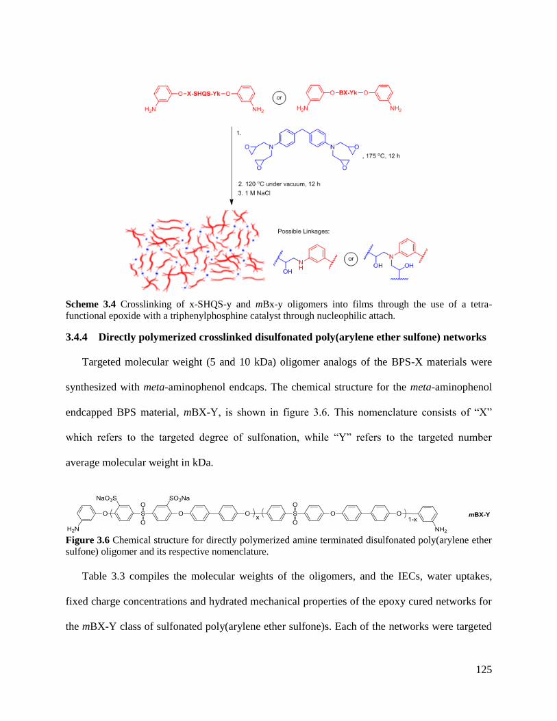
125
Scheme 3.4 Crosslinking of x-SHQS-y and mBx-y oligomers into films through the use of a tetra-
functional epoxide with a triphenylphosphine catalyst through nucleophilic attach.
3.4.4 Directly polymerized crosslinked disulfonated poly(arylene ether sulfone) networks
Targeted molecular weight (5 and 10 kDa) oligomer analogs of the BPS-X materials were
synthesized with meta-aminophenol endcaps. The chemical structure for the meta-aminophenol
endcapped BPS material, mBX-Y, is shown in figure 3.6. This nomenclature consists of “X”
which refers to the targeted degree of sulfonation, while “Y” refers to the targeted number
average molecular weight in kDa.
Figure 3.6 Chemical structure for directly polymerized amine terminated disulfonated poly(arylene ether
sulfone) oligomer and its respective nomenclature.
Table 3.3 compiles the molecular weights of the oligomers, and the IECs, water uptakes,
fixed charge concentrations and hydrated mechanical properties of the epoxy cured networks for
the mBX-Y class of sulfonated poly(arylene ether sulfone)s. Each of the networks were targeted
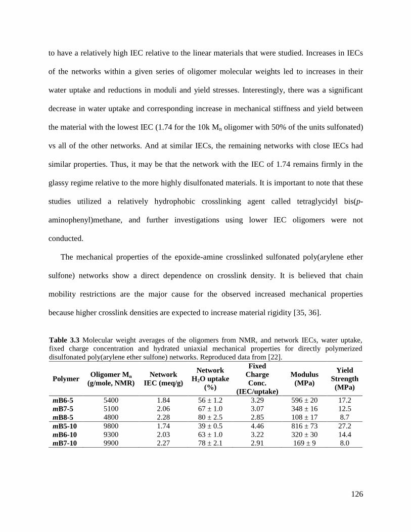
126
to have a relatively high IEC relative to the linear materials that were studied. Increases in IECs
of the networks within a given series of oligomer molecular weights led to increases in their
water uptake and reductions in moduli and yield stresses. Interestingly, there was a significant
decrease in water uptake and corresponding increase in mechanical stiffness and yield between
the material with the lowest IEC (1.74 for the 10k Mn oligomer with 50% of the units sulfonated)
vs all of the other networks. And at similar IECs, the remaining networks with close IECs had
similar properties. Thus, it may be that the network with the IEC of 1.74 remains firmly in the
glassy regime relative to the more highly disulfonated materials. It is important to note that these
studies utilized a relatively hydrophobic crosslinking agent called tetraglycidyl bis(p-
aminophenyl)methane, and further investigations using lower IEC oligomers were not
conducted.
The mechanical properties of the epoxide-amine crosslinked sulfonated poly(arylene ether
sulfone) networks show a direct dependence on crosslink density. It is believed that chain
mobility restrictions are the major cause for the observed increased mechanical properties
because higher crosslink densities are expected to increase material rigidity [35, 36].
Table 3.3 Molecular weight averages of the oligomers from NMR, and network IECs, water uptake,
fixed charge concentration and hydrated uniaxial mechanical properties for directly polymerized
disulfonated poly(arylene ether sulfone) networks. Reproduced data from [22].
Polymer Oligomer Mn
(g/mole, NMR)
Network
IEC (meq/g)
Network
H2O uptake
(%)
Fixed
Charge
Conc.
(IEC/uptake)
Modulus
(MPa)
Yield
Strength
(MPa)
mB6-5 5400 1.84 56 ± 1.2 3.29 596 ± 20 17.2
mB7-5 5100 2.06 67 ± 1.0 3.07 348 ± 16 12.5
mB8-5 4800 2.28 80 ± 2.5 2.85 108 ± 17 8.7
mB5-10 9800 1.74 39 ± 0.5 4.46 816 ± 73 27.2
mB6-10 9300 2.03 63 ± 1.0 3.22 320 ± 30 14.4
mB7-10 9900 2.27 78 ± 2.1 2.91 169 ± 9 8.0
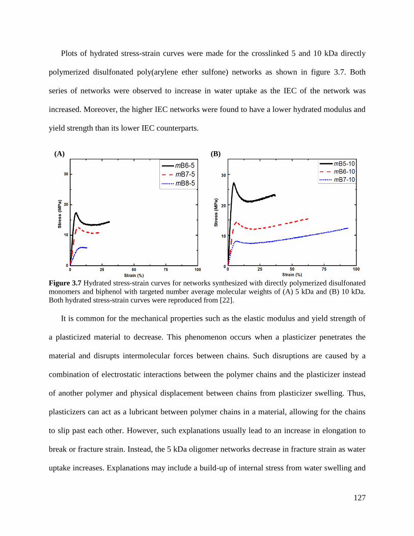
127
Plots of hydrated stress-strain curves were made for the crosslinked 5 and 10 kDa directly
polymerized disulfonated poly(arylene ether sulfone) networks as shown in figure 3.7. Both
series of networks were observed to increase in water uptake as the IEC of the network was
increased. Moreover, the higher IEC networks were found to have a lower hydrated modulus and
yield strength than its lower IEC counterparts.
It is common for the mechanical properties such as the elastic modulus and yield strength of
a plasticized material to decrease. This phenomenon occurs when a plasticizer penetrates the
material and disrupts intermolecular forces between chains. Such disruptions are caused by a
combination of electrostatic interactions between the polymer chains and the plasticizer instead
of another polymer and physical displacement between chains from plasticizer swelling. Thus,
plasticizers can act as a lubricant between polymer chains in a material, allowing for the chains
to slip past each other. However, such explanations usually lead to an increase in elongation to
break or fracture strain. Instead, the 5 kDa oligomer networks decrease in fracture strain as water
uptake increases. Explanations may include a build-up of internal stress from water swelling and
(A) (B)
Figure 3.7 Hydrated stress-strain curves for networks synthesized with directly polymerized disulfonated
monomers and biphenol with targeted number average molecular weights of (A) 5 kDa and (B) 10 kDa.
Both hydrated stress-strain curves were reproduced from [22].
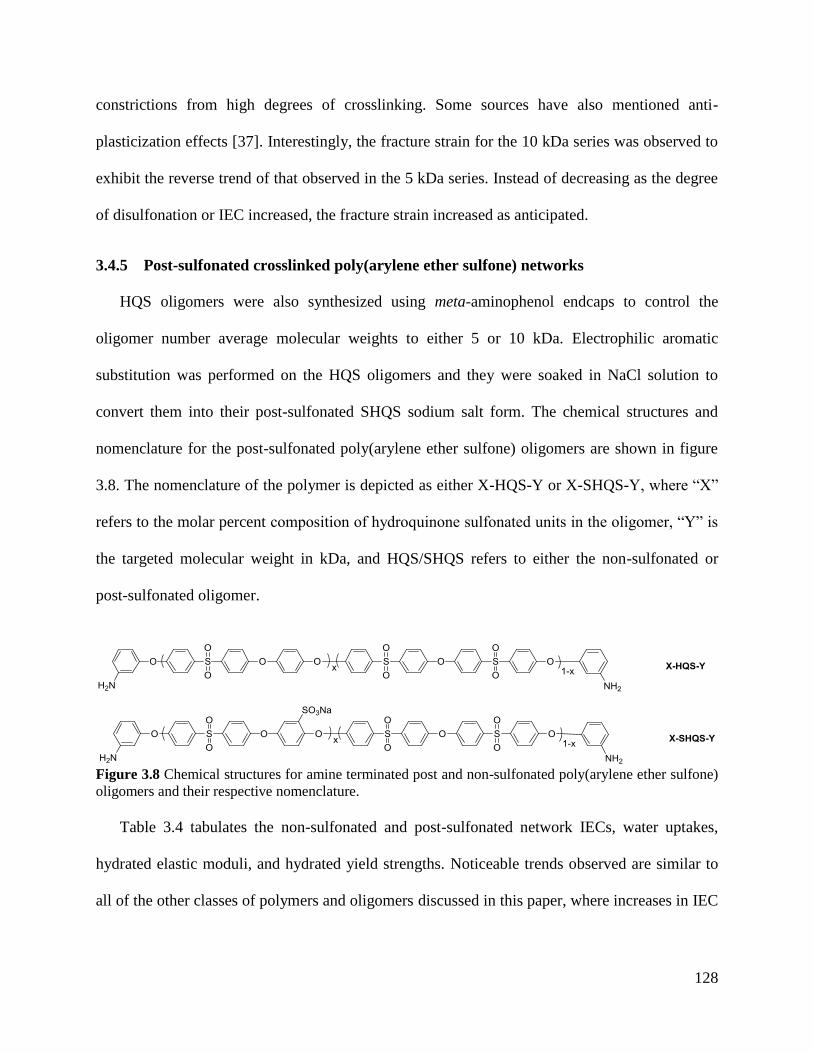
128
constrictions from high degrees of crosslinking. Some sources have also mentioned anti-
plasticization effects [37]. Interestingly, the fracture strain for the 10 kDa series was observed to
exhibit the reverse trend of that observed in the 5 kDa series. Instead of decreasing as the degree
of disulfonation or IEC increased, the fracture strain increased as anticipated.
3.4.5 Post-sulfonated crosslinked poly(arylene ether sulfone) networks
HQS oligomers were also synthesized using meta-aminophenol endcaps to control the
oligomer number average molecular weights to either 5 or 10 kDa. Electrophilic aromatic
substitution was performed on the HQS oligomers and they were soaked in NaCl solution to
convert them into their post-sulfonated SHQS sodium salt form. The chemical structures and
nomenclature for the post-sulfonated poly(arylene ether sulfone) oligomers are shown in figure
3.8. The nomenclature of the polymer is depicted as either X-HQS-Y or X-SHQS-Y, where “X”
refers to the molar percent composition of hydroquinone sulfonated units in the oligomer, “Y” is
the targeted molecular weight in kDa, and HQS/SHQS refers to either the non-sulfonated or
post-sulfonated oligomer.
Figure 3.8 Chemical structures for amine terminated post and non-sulfonated poly(arylene ether sulfone)
oligomers and their respective nomenclature.
Table 3.4 tabulates the non-sulfonated and post-sulfonated network IECs, water uptakes,
hydrated elastic moduli, and hydrated yield strengths. Noticeable trends observed are similar to
all of the other classes of polymers and oligomers discussed in this paper, where increases in IEC
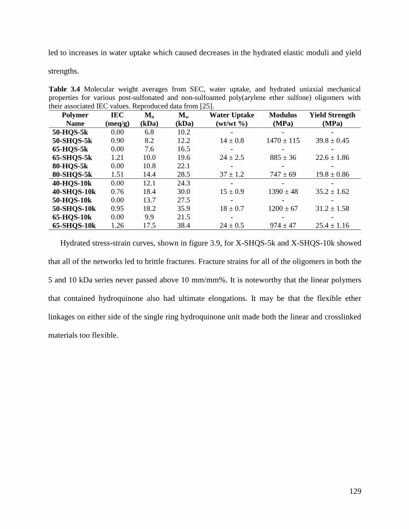
129
led to increases in water uptake which caused decreases in the hydrated elastic moduli and yield
strengths.
Table 3.4 Molecular weight averages from SEC, water uptake, and hydrated uniaxial mechanical
properties for various post-sulfonated and non-sulfoanted poly(arylene ether sulfone) oligomers with
their associated IEC values. Reproduced data from [25].
Polymer
Name
IEC
(meq/g)
Mn
(kDa)
Mw
(kDa)
Water Uptake
(wt/wt %)
Modulus
(MPa)
Yield Strength
(MPa)
50-HQS-5k 0.00 6.8 10.2 - - -
50-SHQS-5k 0.90 8.2 12.2 14 ± 0.8 1470 ± 115 39.8 ± 0.45
65-HQS-5k 0.00 7.6 16.5 - - -
65-SHQS-5k 1.21 10.0 19.6 24 ± 2.5 885 ± 36 22.6 ± 1.86
80-HQS-5k 0.00 10.8 22.1 - - -
80-SHQS-5k 1.51 14.4 28.5 37 ± 1.2 747 ± 69 19.8 ± 0.86
40-HQS-10k 0.00 12.1 24.3 - - -
40-SHQS-10k 0.76 18.4 30.0 15 ± 0.9 1390 ± 48 35.2 ± 1.62
50-HQS-10k 0.00 13.7 27.5 - - -
50-SHQS-10k 0.95 18.2 35.9 18 ± 0.7 1200 ± 67 31.2 ± 1.58
65-HQS-10k 0.00 9.9 21.5 - - -
65-SHQS-10k 1.26 17.5 38.4 24 ± 0.5 974 ± 47 25.4 ± 1.16
Hydrated stress-strain curves, shown in figure 3.9, for X-SHQS-5k and X-SHQS-10k showed
that all of the networks led to brittle fractures. Fracture strains for all of the oligomers in both the
5 and 10 kDa series never passed above 10 mm/mm%. It is noteworthy that the linear polymers
that contained hydroquinone also had ultimate elongations. It may be that the flexible ether
linkages on either side of the single ring hydroquinone unit made both the linear and crosslinked
materials too flexible.
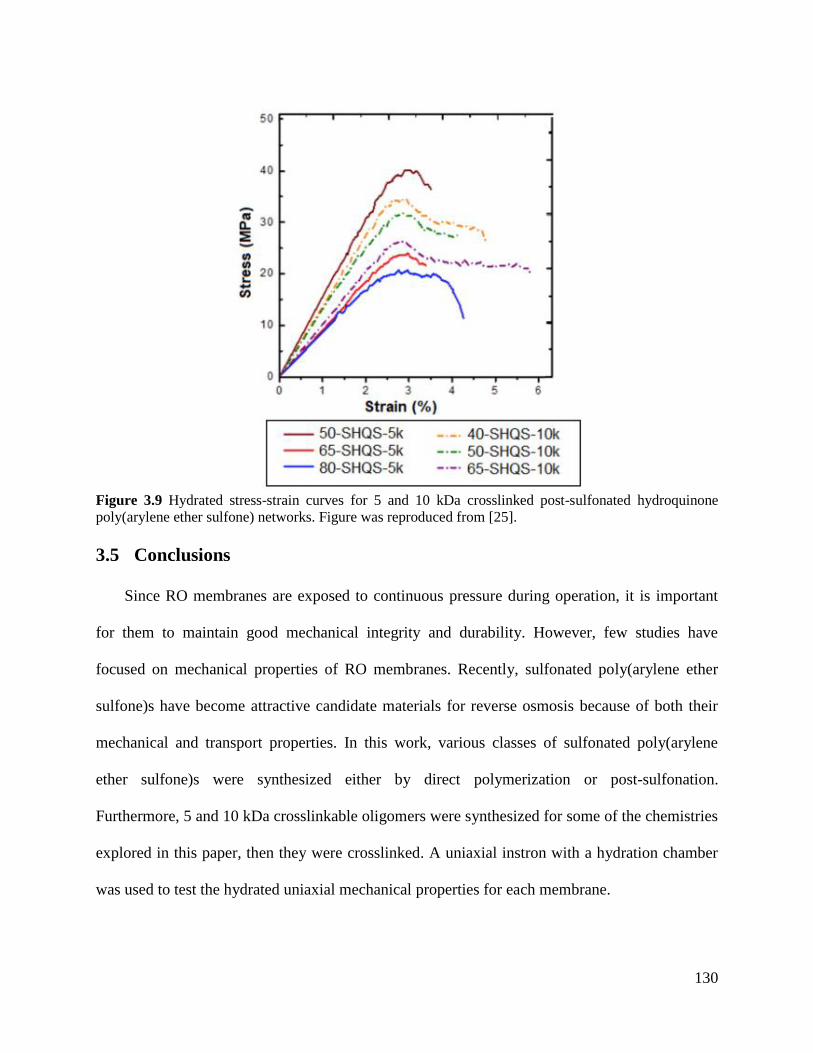
130
3.5 Conclusions
Since RO membranes are exposed to continuous pressure during operation, it is important
for them to maintain good mechanical integrity and durability. However, few studies have
focused on mechanical properties of RO membranes. Recently, sulfonated poly(arylene ether
sulfone)s have become attractive candidate materials for reverse osmosis because of both their
mechanical and transport properties. In this work, various classes of sulfonated poly(arylene
ether sulfone)s were synthesized either by direct polymerization or post-sulfonation.
Furthermore, 5 and 10 kDa crosslinkable oligomers were synthesized for some of the chemistries
explored in this paper, then they were crosslinked. A uniaxial instron with a hydration chamber
was used to test the hydrated uniaxial mechanical properties for each membrane.
Figure 3.9 Hydrated stress-strain curves for 5 and 10 kDa crosslinked post-sulfonated hydroquinone
poly(arylene ether sulfone) networks. Figure was reproduced from [25].
131
Generally, it was observed that the sulfonated polymers regardless of polymer backbone
composition exhibited a high hydrated/plasticized elastic modulus, ~1 GPa. This signifies that
they are glassy materials even when fully hydrated. With the exception of the both the linear and
network polymers that contained sulfonated hydroquinone, the materials with IECs of
approximately 1-1.3 exhibited good mechanical properties, including good elongations at break,
thus suggesting that they were relatively tough materials. Since sulfonate salts have an affinity to
water, the sulfonated polymers all absorbed water. As the degree of sulfonation was increased, so
did the water uptake for each class of sulfonated poly(arylene ether sulfone). As expected, a
decreasing trend in both elastic modulus and yield strength with increasing degree of sulfonation
and IEC were observed within each class of sulfonated poly(arylene ether sulfone). The water
acts as a plasticizer which swells the membrane and begins to space the polymer chains apart,
reducing the intermolecular interactions between the polymer chains. Furthermore, the water acts
as a lubricant allowing the polymer chains to slip past each other which effectively reduces the
polymer’s hydrated mechanical properties. By demonstrating that sulfonated poly(arylene ether
sulfone)s have excellent hydrated mechanical properties in the polymer’s plasticized state,
sulfonated poly(arylene ether sulfone)s show promise as a high performance membrane for water
desalination, specifically reverse osmosis.
3.6 References [1] WWAP, The United Nations World Water Development Report 2019: Leaving No One
Behind, in, UNESCO Paris, 2019.
[2] M. Kumar, T. Culp, Y. Shen, Water desalination: History, advances, and challenges, in:
Proc., Frontiers of Engineering: Reports on Leading-Edge Engineering from the 2016
Symp, 2017, pp. 55-132.
[3] R.W. Baker, Membrane technology and applications, John Wiley & Sons, 2012.
[4] J. Cadotte, R. King, R. Majerle, R. Petersen, Interfacial synthesis in the preparation of
reverse osmosis membranes, Journal of Macromolecular Science—Chemistry, 15 (1981)
727-755.
[5] J.E. Cadotte, Interfacially synthesized reverse osmosis membrane, US4277344, 1981.
132
[6] K. Wang, A.A. Abdalla, M.A. Khaleel, N. Hilal, M.K. Khraisheh, Mechanical properties
of water desalination and wastewater treatment membranes, Desalination, 401 (2017)
190-205.
[7] R. Bird, W. Stewart, E. Lightfoot, Transport Phenomena 2nd edition John Wiley and
Sons, New York, (2002).
[8] C.L. Astudillo-Castro, Limiting flux and critical transmembrane pressure determination
using an exponential model: the effect of concentration factor, temperature, and cross-
flow velocity during casein micelle concentration by microfiltration, Industrial &
Engineering Chemistry Research, 54 (2015) 414-425.
[9] F. Liu, L. Wang, D. Li, Q. Liu, B. Deng, A review: the effect of the microporous support
during interfacial polymerization on the morphology and performances of a thin film
composite membrane for liquid purification, RSC advances, 9 (2019) 35417-35428.
[10] H. Strathmann, P. Scheible, R. Baker, A rationale for the preparation of
Loeb‐Sourirajan‐type cellulose acetate membranes, Journal of Applied Polymer Science,
15 (1971) 811-828.
[11] H. Strathmann, K. Kock, P. Amar, R. Baker, The formation mechanism of asymmetric
membranes, Desalination, 16 (1975) 179-203.
[12] I. Goossens, A. Van Haute, The influence of mineral fillers on the membrane properties
of high flux asymmetric cellulose acetate reverse osmosis membranes, Desalination, 18
(1976) 203-214.
[13] J. Duan, Y. Pan, F. Pacheco, E. Litwiller, Z. Lai, I. Pinnau, High-performance polyamide
thin-film-nanocomposite reverse osmosis membranes containing hydrophobic zeolitic
imidazolate framework-8, Journal of membrane science, 476 (2015) 303-310.
[14] H. Etemadi, R. Yegani, V. Babaeipour, Performance evaluation and antifouling analyses
of cellulose acetate/nanodiamond nanocomposite membranes in water treatment, Journal
of applied polymer science, 134 (2017).
[15] T.H. Lee, J.S. Roh, S.Y. Yoo, J.M. Roh, T.H. Choi, H.B. Park, High-performance
polyamide thin-film nanocomposite membranes containing ZIF-8/CNT hybrid nanofillers
for reverse osmosis desalination, Industrial & Engineering Chemistry Research, 59
(2019) 5324-5332.
[16] W. Lau, A. Ismail, N. Misdan, M. Kassim, A recent progress in thin film composite
membrane: a review, Desalination, 287 (2012) 190-199.
[17] M.T.M. Pendergast, J.M. Nygaard, A.K. Ghosh, E.M. Hoek, Using nanocomposite
materials technology to understand and control reverse osmosis membrane compaction,
Desalination, 261 (2010) 255-263.
[18] Y.S. Kim, L. Dong, M.A. Hickner, T.E. Glass, V. Webb, J.E. McGrath, State of water in
disulfonated poly (arylene ether sulfone) copolymers and a perfluorosulfonic acid
copolymer (Nafion) and its effect on physical and electrochemical properties,
Macromolecules, 36 (2003) 6281-6285.
[19] M. Paul, H.B. Park, B.D. Freeman, A. Roy, J.E. McGrath, J. Riffle, Synthesis and
crosslinking of partially disulfonated poly (arylene ether sulfone) random copolymers as
candidates for chlorine resistant reverse osmosis membranes, Polymer, 49 (2008) 2243-
2252.
[20] G.M. Geise, H.S. Lee, D.J. Miller, B.D. Freeman, J.E. McGrath, D.R. Paul, Water
purification by membranes: the role of polymer science, Journal of Polymer Science Part
B: Polymer Physics, 48 (2010) 1685-1718.
133
[21] B.J. Sundell, K.-s. Lee, A. Nebipasagil, A. Shaver, J.R. Cook, E.-S. Jang, B.D. Freeman,
J.E. McGrath, Cross-linking disulfonated poly (arylene ether sulfone) telechelic
oligomers. 1. Synthesis, characterization, and membrane preparation, Industrial &
Engineering Chemistry Research, 53 (2014) 2583-2593.
[22] A. Daryaei, E.-S. Jang, S.R. Choudhury, D. Kazerooni, J.J. Lesko, B.D. Freeman, J.S.
Riffle, J.E. McGrath, Structure-property relationships of crosslinked disulfonated poly
(arylene ether sulfone) membranes for desalination of water, Polymer, 132 (2017) 286-
293.
[23] A. Roy, M.A. Hickner, H.-S. Lee, T. Glass, M. Paul, A. Badami, J.S. Riffle, J.E.
McGrath, States of water in proton exchange membranes: Part A-Influence of chemical
structure and composition, Polymer, 111 (2017) 297-306.
[24] A. Daryaei, G.C. Miller, J. Willey, S. Roy-Choudhury, B. Vondrasek, D. Kazerooni,
M.R. Burtner, C.K. Mittelsteadt, J.J. Lesko, J.S. Riffle, Synthesis and Membrane
Properties of Sulfonated Poly (arylene ether sulfone) Statistical Copolymers for
Electrolysis of Water: Influence of meta and para-Substituted Comonomers, ACS
Applied Materials & Interfaces, (2017).
[25] S.R. Choudhury, O. Lane, D. Kazerooni, G.S. Narang, E.S. Jang, B.D. Freeman, J.J.
Lesko, J. Riffle, Synthesis and characterization of post-sulfonated poly (arylene ether
sulfone) membranes for potential applications in water desalination, Polymer, 177 (2019)
250-261.
[26] A. Noshay, L. Robeson, Sulfonated polysulfone, Journal of applied polymer science, 20
(1976) 1885-1903.
[27] M. Khorshidi, N. Lu, A. Khorshidi, Intrinsic relationship between matric potential and
cation hydration, Vadose Zone Journal, 15 (2016) 1-12.
[28] L. Degrève, S.M. Vechi, C.Q. Junior, The hydration structure of the Na+ and K+ ions and
the selectivity of their ionic channels, Biochimica et Biophysica Acta (BBA)-
Bioenergetics, 1274 (1996) 149-156.
[29] A.A. Zavitsas, Properties of water solutions of electrolytes and nonelectrolytes, The
Journal of Physical Chemistry B, 105 (2001) 7805-7817.
[30] G. Hulthe, G. Stenhagen, O. Wennerström, C.-H. Ottosson, Water clusters studied by
electrospray mass spectrometry, Journal of Chromatography A, 777 (1997) 155-165.
[31] S.S. Iyengar, M.K. Petersen, T.J. Day, C.J. Burnham, V.E. Teige, G.A. Voth, The
properties of ion-water clusters. I. The protonated 21-water cluster, The Journal of
chemical physics, 123 (2005) 084309.
[32] J. Rose, Preparation and properties of poly (arylene ether sulphones), Polymer, 15 (1974)
456-465.
[33] J.B. Rose, Sulphonated polyarylethersulphone copolymers, US4273903, 1981.
[34] J.B. Rose, Sulphonated polyaryletherketones, US4268650, 1981.
[35] S. Lin, L. Gu, Influence of crosslink density and stiffness on mechanical properties of
type I collagen gel, Materials, 8 (2015) 551-560.
[36] H. Khonakdar, J. Morshedian, U. Wagenknecht, S. Jafari, An investigation of chemical
crosslinking effect on properties of high-density polyethylene, Polymer, 44 (2003) 4301-
4309.
[37] M.L. Sanyang, S.M. Sapuan, M. Jawaid, M.R. Ishak, J. Sahari, Effect of plasticizer type
and concentration on tensile, thermal and barrier properties of biodegradable films based
on sugar palm (Arenga pinnata) starch, Polymers, 7 (2015) 1106-1124.
134
Chapter 4: Quantifying Transport through
a Reverse Osmosis Membrane: Design,
Construction, and Testing of a Crossflow
Apparatus
4.1 Abstract
The purpose of this work was to build a cross flow apparatus to measure the water flux and salt
rejection of filtration membranes. The device was built and was validated using a membrane
from an iSpring reverse osmosis cartridge. The initial water flux was 103.8 L•m-2•h
-1 with an
applied pressure of 400 psi and feed water containing 2000 ppm of sodium chloride that
exponentially decayed as operational time progressed. The initial salt rejection of the membrane
was 96.6 %, and it remained constant as a function of operational time.
4.2 Introduction
One of the most important applications of mass transport is its use in water desalination
membranes. One of the biggest growing technologies for water desalination is reverse osmosis
(RO) [1-3]. Early membranes where synthesized and fabricated from cellulose acetate by Reid,
Breton, and Kuppers [4, 5]. However, the cellulose acetate membranes had very low water fluxes
because of the thick and dense nature of the membrane. It was not until Loeb and Sourirajan
developed a process that allowed them to fabricate asymmetric membranes that made reverse
osmosis a viable technique for desalinating water [6]. Loeb and Sourirajan’s four step process
resulted in increased water flux for cellulose acetate films because the films consisted of a very
thin dense skin layer on top of a highly porous membrane with a gradient from smaller pores at
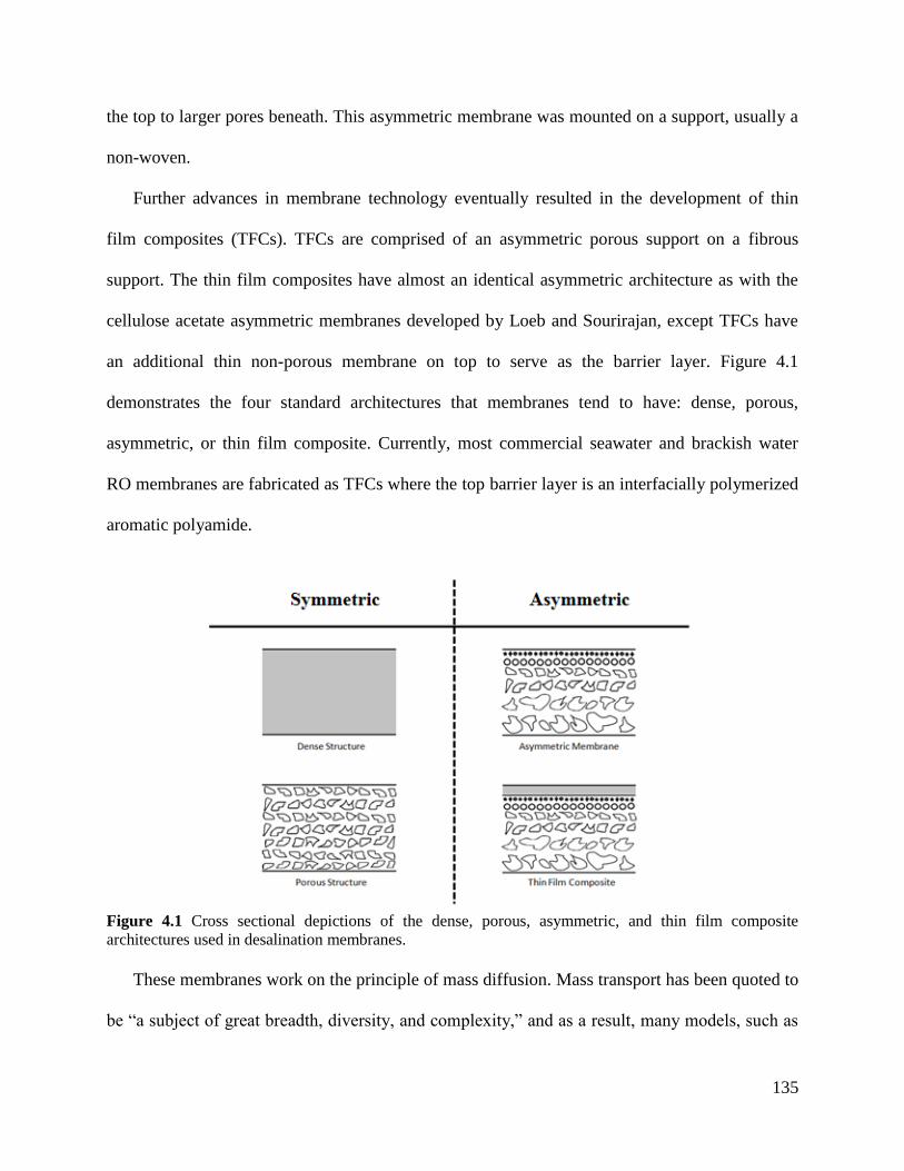
135
the top to larger pores beneath. This asymmetric membrane was mounted on a support, usually a
non-woven.
Further advances in membrane technology eventually resulted in the development of thin
film composites (TFCs). TFCs are comprised of an asymmetric porous support on a fibrous
support. The thin film composites have almost an identical asymmetric architecture as with the
cellulose acetate asymmetric membranes developed by Loeb and Sourirajan, except TFCs have
an additional thin non-porous membrane on top to serve as the barrier layer. Figure 4.1
demonstrates the four standard architectures that membranes tend to have: dense, porous,
asymmetric, or thin film composite. Currently, most commercial seawater and brackish water
RO membranes are fabricated as TFCs where the top barrier layer is an interfacially polymerized
aromatic polyamide.
Figure 4.1 Cross sectional depictions of the dense, porous, asymmetric, and thin film composite
architectures used in desalination membranes.
These membranes work on the principle of mass diffusion. Mass transport has been quoted to
be “a subject of great breadth, diversity, and complexity,” and as a result, many models, such as
136
the solution diffusion model and hydrodynamic model, have been developed to explain how
mass moves through a material [7]. Mathematical descriptions have also been developed to
describe mass transport, from the employment of Fick’s laws to the use of Maxwell-Stefan
equations [8]. It is universally recognized that the media for matter diffusion utilizes free volume
in the bulk material that either originates from free volume, pores, inter-granular spaces,
vacancies, or interstitial defects [9]. In the case of RO membranes, free volume refers to dynamic
elements within the material that are not occupied by membrane matter. With that said it is
important to note that free volume can take on some different definitions depending on how it is
used [10].
During RO’s infancy, Merten developed a solution diffusion model that adequately describes
a cellulose acetate, water, and salt system [11-15]. Merten’s classical theory is still widely used
today due to its simplicity. Merten’s model begins with Fick’s Law to describe steady state mass
flux through the membrane. His model assumes ideal thermodynamics in the membrane-solvent
mixture, irreversible thermodynamics, and pure diffusion as the mode of mass transport over a
concentration gradient [15, 16].
Fick’s First Law, equation 1, states that the flux (Ji) depends on the diffusion coefficient or
diffusivity (Di) of the transporting material in the medium and the concentration gradient (Ci). In
recent years studies have focused on using the solution diffusion model to calculate and predict
the free volume within the membrane material.
(1)
The Doolittle relationship, equation 2, expresses the relationship between diffusivity (D) and
fractional free volume (ƒ) [17, 18]. In this equation, A and B are data fitted constants for a
specific system. Other models such as those developed by Thornton et al. also accurately
137
describe the same relationship with a slight modification to Doolittle’s original relationship
exhibited in equation 3; where D and ƒ are defined identically as in Doolittle’s equation and α
and β are empirically derived constants [17]. This allows for an exact analytical solution to be
solved for the differential equation; thus, allowing for fractional free volume to be calculated.
Note that the Doolittle relationship and modified relationship have been used to model the
diffusion of vacancies through a polymer as it physically ages [17]. Similar trains of thought as
shown with Doolittle’s and Thornton et al.’s relationships can be applied to predict the fractional
free volume and finally the single pore free volume that would be used in facilitating mass
transport [19].
(2)
(3)
Depending on the dimensions of the free volume zones, membranes can separate different
sized particles. As a result, different types of membranes have been made to efficiently reduce
the passage of unwanted materials. Microfilters typically are designed for filtering out large
particles and colloids. As we move to ultrafilters, nanofilters, and finally reverse osmosis
membranes, the size of the particles that are excluded by the membrane decreases rapidly. Figure
4.2 depicts the types of materials and their respective sizes that different membranes filter.
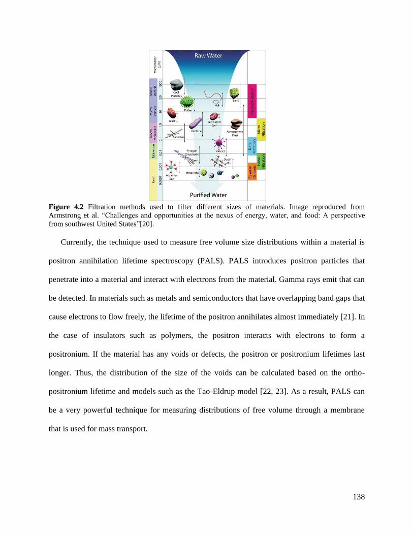
138
Figure 4.2 Filtration methods used to filter different sizes of materials. Image reproduced from
Armstrong et al. “Challenges and opportunities at the nexus of energy, water, and food: A perspective
from southwest United States”[20].
Currently, the technique used to measure free volume size distributions within a material is
positron annihilation lifetime spectroscopy (PALS). PALS introduces positron particles that
penetrate into a material and interact with electrons from the material. Gamma rays emit that can
be detected. In materials such as metals and semiconductors that have overlapping band gaps that
cause electrons to flow freely, the lifetime of the positron annihilates almost immediately [21]. In
the case of insulators such as polymers, the positron interacts with electrons to form a
positronium. If the material has any voids or defects, the positron or positronium lifetimes last
longer. Thus, the distribution of the size of the voids can be calculated based on the ortho-
positronium lifetime and models such as the Tao-Eldrup model [22, 23]. As a result, PALS can
be a very powerful technique for measuring distributions of free volume through a membrane
that is used for mass transport.
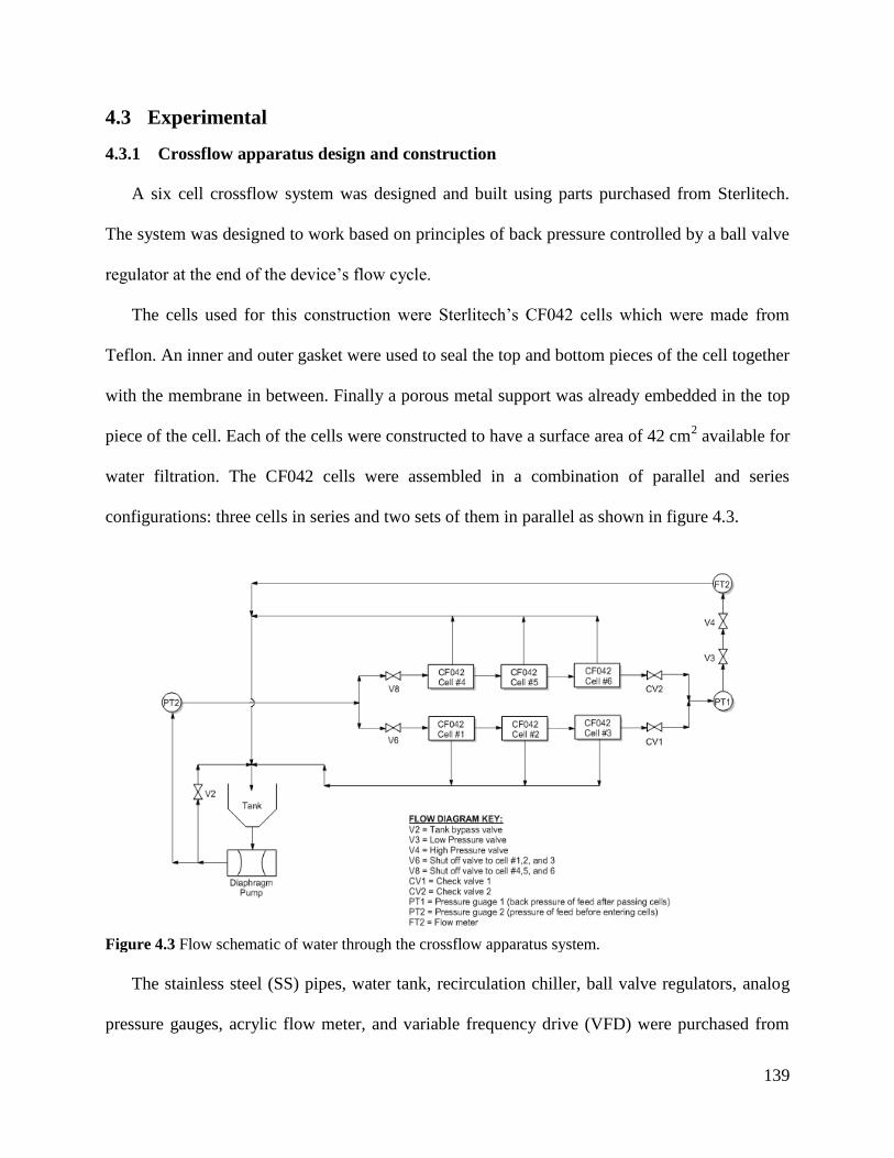
139
4.3 Experimental
4.3.1 Crossflow apparatus design and construction
A six cell crossflow system was designed and built using parts purchased from Sterlitech.
The system was designed to work based on principles of back pressure controlled by a ball valve
regulator at the end of the device’s flow cycle.
The cells used for this construction were Sterlitech’s CF042 cells which were made from
Teflon. An inner and outer gasket were used to seal the top and bottom pieces of the cell together
with the membrane in between. Finally a porous metal support was already embedded in the top
piece of the cell. Each of the cells were constructed to have a surface area of 42 cm2 available for
water filtration. The CF042 cells were assembled in a combination of parallel and series
configurations: three cells in series and two sets of them in parallel as shown in figure 4.3.
Figure 4.3 Flow schematic of water through the crossflow apparatus system.
The stainless steel (SS) pipes, water tank, recirculation chiller, ball valve regulators, analog
pressure gauges, acrylic flow meter, and variable frequency drive (VFD) were purchased from
140
Sterlitech. Extra SS tubing was purchased from McMaster, while cutting, bending, drilling, and
deburring tools were purchased from a combination of Amazon, Home Depot, and Lowes
depending on availability. Finally, a SS rolling table with two levels was purchased from a
restaurant supply store, where all the components were assembled as shown in figure 4.3. The
VFD was wired with a 3-phase 414 gauge wire to the motor on the inlet pump.
4.3.2 Measuring flux and salt rejection for membranes
Water flux and salt rejection were measured using the cross-flow filtration system built using
parts purchased from Sterlitech for commercial brackish water thin film composite membranes.
An iSpring “under the sink” replacement cartridge with an assumed thickness of 100 nm was
purchased from Walmart and tested in the system. Samples were cut using a die and sandwiched
inside the CF042 cells. The sample is mounted in the cell with the water flowing across the
barrier layer (i.e., in the plane of the membrane). As some of the water permeates through the
cell, the amount of permeate can be measured over time to calculate the flux. The conductivity of
the permeate can be measured to calculate the amount of salt that has permeated. After the
measurement, the permeate water is recycled to the feed tank.
The feed water contained 2000 ppm of sodium chloride which was maintained at 25 ºC with
a water recirculation chiller/heater. The apparatus was continuously operated at an applied
pressure of 400 psi (27.6 bar) and a flow rate of 3.8 L/min. The pH of the feed was maintained
between 6.5 and 7.5 with sodium bicarbonate solution (10 g/L). The water flux and salt rejection
were calculated by weighing the collected water per time and measuring the conductivity of the
permeate water with an APERA PC400S conductivity meter. The flux (ɸ) was calculated using
equation 4 in L•m-2•h
-1, where Mp is the mass of the permeate water collected in grams, ρw is the
density of water (assumed to be 1 g/mL), Am is the cross sectional area of the membrane in cm2, t
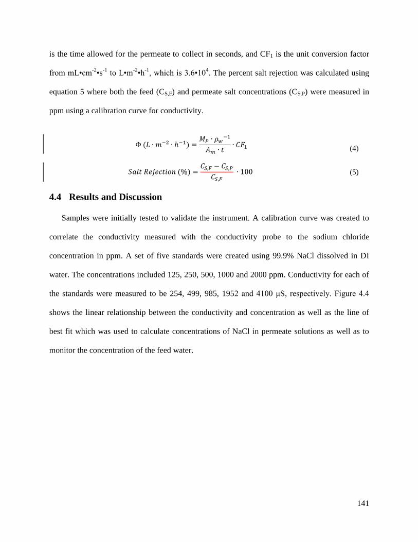
141
is the time allowed for the permeate to collect in seconds, and CF1 is the unit conversion factor
from mL•cm-2•s
-1 to L•m
-2•h
-1, which is 3.6•10
4. The percent salt rejection was calculated using
equation 5 where both the feed (CS,F) and permeate salt concentrations (CS,P) were measured in
ppm using a calibration curve for conductivity.
(4)
(5)
4.4 Results and Discussion
Samples were initially tested to validate the instrument. A calibration curve was created to
correlate the conductivity measured with the conductivity probe to the sodium chloride
concentration in ppm. A set of five standards were created using 99.9% NaCl dissolved in DI
water. The concentrations included 125, 250, 500, 1000 and 2000 ppm. Conductivity for each of
the standards were measured to be 254, 499, 985, 1952 and 4100 μS, respectively. Figure 4.4
shows the linear relationship between the conductivity and concentration as well as the line of
best fit which was used to calculate concentrations of NaCl in permeate solutions as well as to
monitor the concentration of the feed water.
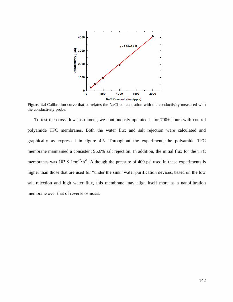
142
Figure 4.4 Calibration curve that correlates the NaCl concentration with the conductivity measured with
the conductivity probe.
To test the cross flow instrument, we continuously operated it for 700+ hours with control
polyamide TFC membranes. Both the water flux and salt rejection were calculated and
graphically as expressed in figure 4.5. Throughout the experiment, the polyamide TFC
membrane maintained a consistent 96.6% salt rejection. In addition, the initial flux for the TFC
membranes was 103.8 L•m-2•h
-1. Although the pressure of 400 psi used in these experiments is
higher than those that are used for “under the sink” water purification devices, based on the low
salt rejection and high water flux, this membrane may align itself more as a nanofiltration
membrane over that of reverse osmosis.
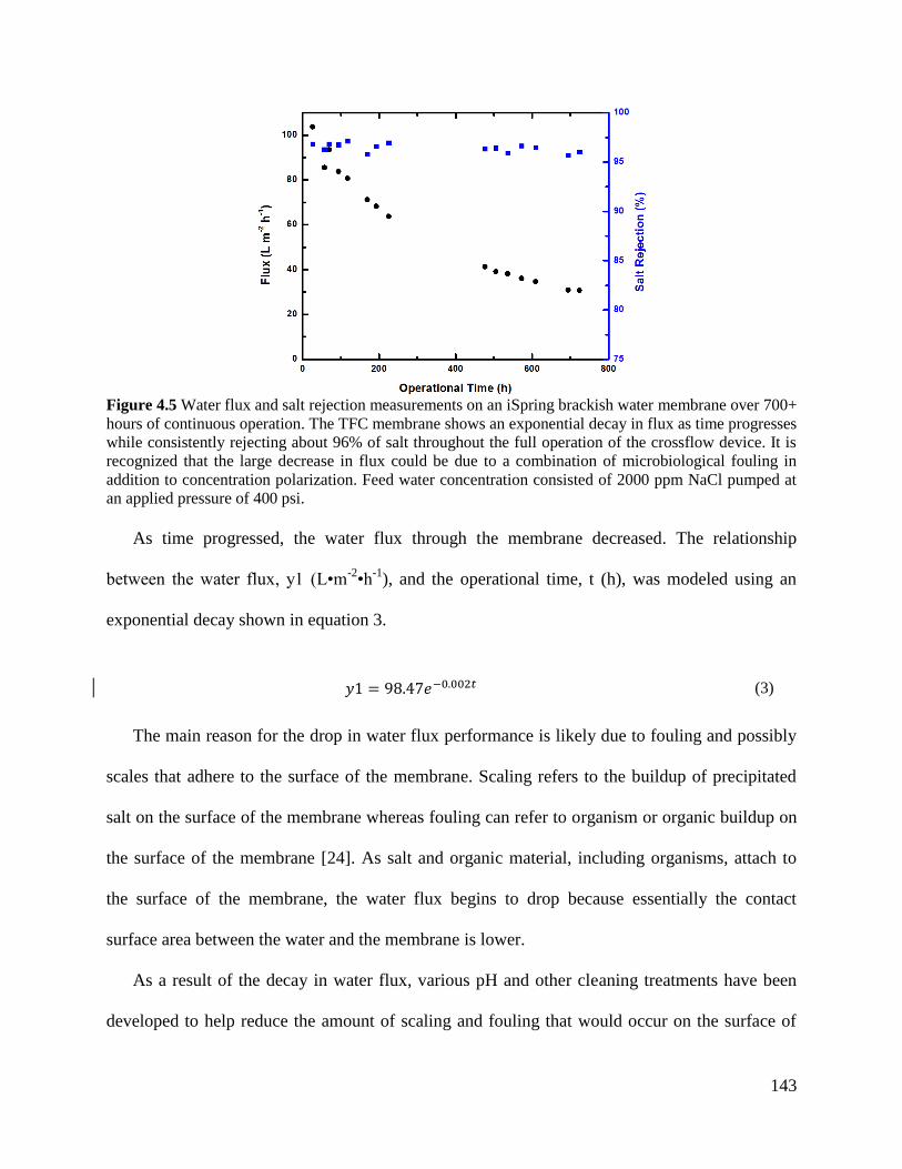
143
Figure 4.5 Water flux and salt rejection measurements on an iSpring brackish water membrane over 700+
hours of continuous operation. The TFC membrane shows an exponential decay in flux as time progresses
while consistently rejecting about 96% of salt throughout the full operation of the crossflow device. It is
recognized that the large decrease in flux could be due to a combination of microbiological fouling in
addition to concentration polarization. Feed water concentration consisted of 2000 ppm NaCl pumped at
an applied pressure of 400 psi.
As time progressed, the water flux through the membrane decreased. The relationship
between the water flux, y1 (L•m-2•h
-1), and the operational time, t (h), was modeled using an
exponential decay shown in equation 3.
(3)
The main reason for the drop in water flux performance is likely due to fouling and possibly
scales that adhere to the surface of the membrane. Scaling refers to the buildup of precipitated
salt on the surface of the membrane whereas fouling can refer to organism or organic buildup on
the surface of the membrane [24]. As salt and organic material, including organisms, attach to
the surface of the membrane, the water flux begins to drop because essentially the contact
surface area between the water and the membrane is lower.
As a result of the decay in water flux, various pH and other cleaning treatments have been
developed to help reduce the amount of scaling and fouling that would occur on the surface of
144
the TFC. Regular maintenance focuses on cleaning the surfaces of the membranes to remove
foulants. However, this leads to operational downtime and may cause irreversible damage to the
TFC.
4.5 Conclusions
Reverse osmosis is a prominent technique used to desalinate water. For a material to be used
as a membrane, there are at least three key criteria that need to be satisfied: free volume,
molecular dynamics, and driving force. By measuring and calculating the material’s flux,
scientists can start to build models and hypotheses about how the material will behave in mass
transport.
A cross flow apparatus was designed and built using parts from Sterlitech to measure and
calculate the water flux and salt rejection of filtration membranes. An iSpring under the sink
reverse osmosis cartridge was disassembled and the membrane inside of it was tested in the cross
flow apparatus. The initial water flux was 103.8 L•m-2•h
-1 that exponentially decayed as time
progressed, while the initial salt rejection of the membrane was calculated to be 96.6%. Unlike
the flux, the salt rejection remained constant as a function of operation time.
4.6 References [1] R.W. Baker, Membrane technology and applications, John Wiley & Sons, 2012.
[2] J. Imbrogno, G. Belfort, Membrane desalination: where are we, and what can we learn
from fundamentals?, Annual review of chemical and biomolecular engineering, 7 (2016)
29-64.
[3] M. Qasim, M. Badrelzaman, N.N. Darwish, N.A. Darwish, N. Hilal, Reverse osmosis
desalination: A state-of-the-art review, Desalination, 459 (2019) 59-104.
[4] C. Reid, E. Breton, Water and ion flow across cellulosic membranes, Journal of Applied
Polymer Science, 1 (1959) 133-143.
[5] C.E. Reid, J.R. Kuppers, Physical characteristics of osmotic membranes of organic
polymers, Journal of Applied Polymer Science, 2 (1959) 264-272.
[6] H. Strathmann, P. Scheible, R. Baker, A rationale for the preparation of
Loeb‐Sourirajan‐type cellulose acetate membranes, Journal of Applied Polymer Science,
15 (1971) 811-828.
[7] G. Flynn, S.H. Yalkowsky, T. Roseman, Mass transport phenomena and models:
theoretical concepts, Journal of Pharmaceutical Sciences, 63 (1974) 479-510.
145
[8] R. Bird, W. Stewart, E. Lightfoot, Transport Phenomena 2nd edition John Wiley and
Sons, New York, (2002).
[9] W.D. Callister, D.G. Rethwisch, Materials science and engineering, John wiley & sons
NY, 2011.
[10] R.P. White, J.E. Lipson, Polymer free volume and its connection to the glass transition,
Macromolecules, 49 (2016) 3987-4007.
[11] U. Merten, Desalination by reverse osmosis, Mit Press, 1966.
[12] U. Merten, Flow relationships in reverse osmosis, Industrial & Engineering Chemistry
Fundamentals, 2 (1963) 229-232.
[13] H. Lonsdale, U. Merten, R. Riley, Transport properties of cellulose acetate osmotic
membranes, Journal of applied polymer science, 9 (1965) 1341-1362.
[14] H. Lonsdale, U. Merten, M. Tagami, Phenol transport in cellulose acetate membranes,
Journal of Applied Polymer Science, 11 (1967) 1807-1820.
[15] D.R. Paul, Reformulation of the solution-diffusion theory of reverse osmosis, Journal of
membrane science, 241 (2004) 371-386.
[16] H. Strathmann, L. Giorno, E. Drioli, Introduction to membrane science and technology,
Wiley-VCH Weinheim, 2011.
[17] A.W. Thornton, K.M. Nairn, A.J. Hill, J.M. Hill, Y. Huang, New relation between
diffusion and free volume: II. Predicting vacancy diffusion, Journal of Membrane
Science, 338 (2009) 38-42.
[18] A.W. Thornton, K.M. Nairn, A.J. Hill, J.M. Hill, New relation between diffusion and free
volume: I. Predicting gas diffusion, Journal of Membrane Science, 338 (2009) 29-37.
[19] S. Thomas, R. Wilson, A. Kumar, S.C. George, Transport properties of polymeric
membranes, Elsevier, 2017.
[20] N.R. Armstrong, R.C. Shallcross, K. Ogden, S. Snyder, A. Achilli, E.L. Armstrong,
Challenges and opportunities at the nexus of energy, water, and food: A perspective from
the southwest United States, MRS Energy & Sustainability, 5 (2018).
[21] K. Saarinen, P. Hautojärvi, C. Corbel, Positron annihilation spectroscopy of defects in
semiconductors, Semiconductors and Semimetals, 51 (1998) 209-285.
[22] Y. Jean, Positron annihilation spectroscopy for chemical analysis: a novel probe for
microstructural analysis of polymers, Microchemical Journal, 42 (1990) 72-102.
[23] M. Eldrup, D. Lightbody, J.N. Sherwood, The temperature dependence of positron
lifetimes in solid pivalic acid, Chemical Physics, 63 (1981) 51-58.
[24] P. Xu, C. Bellona, J.E. Drewes, Fouling of nanofiltration and reverse osmosis membranes
during municipal wastewater reclamation: membrane autopsy results from pilot-scale
investigations, Journal of Membrane Science, 353 (2010) 111-121.
146
Chapter 5: Structure-Property
Relationships of Crosslinked Disulfonated
Poly(Arylene Ether Sulfone) Membranes for
Desalination of Water
This chapter has been adapted from a published manuscript by Amin Daryaei, Eui-Soung
Jang, Shreya Roy Choudhury, Dana Kazerooni, John J Lesko, Benny D Freeman, Judy S Riffle,
James E McGrath from the following reference: Polymer, 2017, 132, 286-293. Reprinted with
permission from Elsevier.
Dana Kazerooni’s contribution to this paper include assisting in synthesizing the polymers,
crosslinking the membranes, performing gel-fraction and water uptake measurements, and
completely running and analyzing hydrated mechanical properties for each membrane.
Amin Daryaei a, Eui-Soung Jang
c, Shreya Roy Choudhury
a, Dana Kazerooni
a,b,
John J. Lesko b
, Benny D. Freeman c, Judy S. Riffle
a, James E. McGrath
a
a Department of Chemistry and Macromolecular Innovations Institute, Virginia Tech,
Blacksburg, VA 24061, United States b
College of Engineering, Virginia Tech, Blacksburg, VA 24061, United States c Department of Chemical Engineering and the Center for Energy and Environmental Resources,
University of Texas at Austin, Austin, TX 78758, United States
5.1 Abstract
Controlled molecular weight poly(arylene ether sulfone) oligomers with aromatic amine end
groups and systematically varied degrees of disulfonation were synthesized by
direct polymerization of disulfonated and non-sulfonated 4,4′-dichlorodiphenylsulfone. The
oligomers were crosslinked with a tetrafunctional epoxy curing agent in the membrane casting
process. Water uptake and IEC were investigated to understand how the structure and ion content
affected the fixed charge concentrations (moles of ions/L of sorbed water). The hydrated
mechanical properties of these copolymer networks were also studied in light of their ion
contents and water uptake. At similar IECs, membranes with shorter ∼5000 Da oligomers
absorbed less water than those with ∼10,000 Da blocks. The salt permeabilities correlated with
147
water uptake and fixed charge density. Among the crosslinked membranes, the one with the
10,000 Da oligomer and with 50% disulfonation (mB5-10) had an excellent combination of
water uptake, hydrated mechanical properties, fixed charge density, and low salt permeability.
5.2 Introduction
The scarcity of pure water is a global challenge that needs to be addressed immediately [1],
[2]. Technologies such as reverse osmosis (RO) [3] and electrodialysis (ED) [4], [5], [6], [7], [8],
[9], [10], [11] use dense, non-porous membranes for water purification [7], [12], [13], [14]. The
principles of these methods differ but both rely on the molecular and topological structures of
polymeric membranes to control water and ion transport.
RO is currently the most used process for desalination of water. It utilizes an applied
hydrostatic pressure on the upstream brine side of the membrane that opposes the osmotic
pressure to drive the water flux downstream. The most prominent separation membranes for RO
are very thin (∼100 nm) crosslinked polyamides atop a porous polymer that supplies the
necessary mechanical support [3], [12], [13].
The main components of ED are anion exchange membranes (AEM) and cation
exchange membranes (CEM) [4], [5], [6], [7], [8], [9], [10], [11], [15]. These are placed
alternately in stacks between cathodic and anodic electrodes. Brine is pumped into the system
between each AEM and CEM and a current is applied to drive the ions in opposite directions
toward the respective electrodes. The role of the AEMs and CEMs is to
promote counterion permeation through the membrane while repelling co-ion transport. The ED
process leaves purified water in the diluate compartments [15]. The ability of ED membranes to
transport counterions to the fixed membrane charges and to block co-ion transport depends
highly on the polymer structure, charge concentration in the membrane and water
148
uptake [9], [16]. Commercial CEMs for ED are highly crosslinked polymers such as sulfonated
poly(styrene-co-divinylbenzene) with inherently poor mechanical properties in the hydrated
state. To improve the mechanical properties, these crosslinked polymers are prepared with a non-
ionic porous or fabric support. Having the non-ionic support membrane results in lower ion
permeability and ion conductivity, and higher electrical resistance
[17], [18], [19], [20], [21], [22]. Thus, a goal of our work is to develop unsupported or reinforced
active membrane materials with high fixed ion concentration and mechanical properties suitable
for the ED process.
It is quite common to characterize charged polymers, such as ion exchange
membranes (IEMs), in terms of their ion exchange capacity (IEC), which is the millimoles of
fixed charge groups on the polymer backbone per gram of dry polymer. However, based on the
Donnan model [12], the ability of RO membranes to reject salt based on electrostatic effects and
for ED membranes to inhibit transport of co-ions across an ED membrane depends on the fixed
charge concentration (FCC), which is the moles of fixed charge groups per unit volume of water
in the polymer matrix. That is, the effective concentration of fixed charged groups experienced
by ions being transported through membranes under either a concentration gradient or electric
field gradient is the FCC, not the IEC, and these two properties are not always proportional to
one another. For example, as additional fixed charge groups are added to a polymer backbone to
increase IEC, these highly hydrophilic charged groups also tend to increase the equilibrium water
uptake in the membrane. Whether FCC increases or decreases with increasing IEC depends on
the delicate balance between the increase in the number of fixed charge groups in the membrane
(i.e., increasing IEC) and the increase in water content coming along with the increase in the
number of fixed charge groups, which tends to reduce FCC.
149
When linear ionic copolymers sorb water, they swell significantly, while crosslinked
membranes with similar IECs sorb less water [23], [24], [25]. Our group has studied the salt
rejection properties of crosslinked disulfonated poly(arylene ether sulfone)s with fairly low IECs
(maximum of 1.84 (meq/g)) [23]. Under reverse osmosis conditions, these copolymers showed
reasonable water flux and NaCl rejection. The properties of such crosslinked copolymers with
higher IECs, however, are not well understood. Moreover, as IEC is increased, the hydrated
mechanical properties of the crosslinked membranes becomes an important issue. Our hypothesis
is that engineering polymers such as the poly(arylene ether)s that are crosslinked only at the
termini of controlled molecular weight oligomers can be designed to have superior hydrated
mechanical properties to the IEMs that are synthesized by conventional free
radical copolymerization.
This paper describes the membrane properties and performance of unsupported membranes
of disulfonated poly(arylene ether sulfone) oligomers that were crosslinked at their termini with
epoxy reagents. Effects of the degree of disulfonation and molecular weight of precursor
oligomers were investigated with respect to water uptake, IEC and fixed ion concentration, then
these properties were related to their salt permeabilities and hydrated mechanical properties.
5.3 Experimental
5.3.1 Materials
Toluene was purchased from Sigma-Aldrich and used asreceived. 4,4’-Biphenol (BP) was
provided by Eastman Chemical Company. 4,4’-Dichlorodiphenylsulfone (DCDPS) was provided
by Solvay Advanced Polymers and was recrystallized from toluene and dried under vacuum at
120ºC prior to use. 3-Aminophenol (m-AP, 99%) was purchased from Acros Organics and used
as received. 3,3’-Disulfonated-4,4’-dichlorodiphenylsulfone (SDCDPS, >99%) was purchased
150
from Akron Polymer Systems and dried under vacuum at180ºC for 72 h before use. Potassium
carbonate was purchased from Sigma-Aldrich and dried under vacuum at 180ºC for 72 h before
use. Calcium hydride (90-95%) was purchased from Alfa Aesar. Triphenylphosphine (TPP,
99%), and tetraglycidyl bis(p-aminophenyl)methane (TGBAM, 92%) were purchased from
Sigma-Aldrich. Toluene and 2-propanol were purchased from Fisher Scientific. N,N-
Dimethylacetamide (DMAc) was purchased from Sigma-Aldrich, distilled from calcium hydride
and stored over molecular sieves before use.
5.3.2 Synthesis of m-AP terminated oligomers
Aromatic nucleophilic substitution step copolymerization was used to synthesize the
terminally-reactive oligomers with m-aminophenol end groups. The nomenclature used in this
manuscript is BiPhenyl Sulfone (mBx-y) in which “x” and “y” represent 10% of the actual
degree of disulfonation value and 0.1% of the oligomer molecular weight, respectively. A typical
disulfonated m-Aminophenol terminated BiPhenyl Sulfone 60 with a molecular weight of10,000
Da expressed in the abbreviated form of mB6-10 was synthesized as follows. BP (0.47 mmol,
8.752 g), DCDPS (20 mmol,5.743 g), SDCDPS (30.0 mmol, 14.767 g), m-AP (6 mmol, 0.639
g)and DMAc (100 mL) were charged into a 250-mL three neck round bottom flask equipped
with a mechanical stirrer, condenser, nitrogen inlet, and Dean-Stark trap filled with toluene. The
mixture was stirred in an oil bath at 150ºC until the monomers completely dissolved. K2CO3 (51
mmol, 8.44 g), and toluene (50 mL) were added into the flask. The reaction was refluxed for 4 h
to azeotropically remove water from the system. Toluene was drained from the Dean-Stark trap,
and the oil bath temperature was raised to 180ºC to remove residual toluene from the reaction.
The reaction solution was stirred for 48 h to complete polymerization, then allowed to cool to
room temperature. After dilution of the resulting solution with DMAc (100 mL), it was filtered
151
to remove the salt. The transparent solution was precipitated by addition into isopropanol with
stirring. The polymer was filtered and dried at 120ºC under reduced pressure in a vacuum oven.
Yield 96% copolymer.
5.3.3 Nuclear magnetic resonance spectroscopy (NMR)
1H NMR analysis of the statistical copolymers was conducted on a Varian Unity Plus
spectrometer operating at 400 MHz. The spectra of the copolymers were obtained from a 10%
(w/v) solution in DMSO-d6 with 256 scans.
5.3.4 Size exclusion chromatography (SEC)
Molecular weights and polydispersities of the polymers were measured using SEC.
The mobile phase was DMAc distilled from CaH2 containing dry LiCl (0.1 M). The column set
consisted of 3 Agilent PLgel 10-mm Mixed B-LS columns 300 × 7.5 mm
(polystyrene/divinylbenzene) connected in series with a guard column having the same
stationary phase. The columns and detectors were maintained at 50 °C. An isocratic pump
(Agilent 1260 Infinity, Agilent Technologies) with an online degasser (Agilent 1260),
autosampler and column oven were used for mobile phase delivery and sample injection. A
system of multiple detectors connected in series was used for the analyses. A multi-angle laser
light scattering detector (DAWN-HELEOS II, Wyatt Technology Corp.), operating at a
wavelength of 658 nm and a refractive index detector operating at a wavelength of 658 nm
(Optilab T-rEX, Wyatt Technology Corp.) provided online results. The system was corrected for
interdetector delay and band broadening using a 21,000 Da polystyrene standard. Data
acquisition and analysis were conducted using Astra 6 software from Wyatt Technology Corp.
Validation of the system was performed by monitoring the molar mass of a known molecular
weight polystyrene sample by light scattering. The accepted variance of the 21,000 Da
152
polystyrene standard was defined as 2 standard deviations (11.5% for Mn and 9% for Mw)
derived from a set of 34 runs. Specific refractive index values were calculated based on the
assumption of 100% recovery.
5.3.5 Membrane casting and characterization
Dense crosslinked films were prepared by adding the oligomers to TGBAM in a 1:2.5 M
ratio. TPP was used in a 2.5% by weight ratio relative to the weight of TGBAM. The following
steps were completed to prepare a crosslinked film containing mB6-10. A mixture of mB6-10
(0.294 mmol, 3.0 g), TGBAM (0.735 mmol, 0.3105 g) and TPP (0.03 mmol, 7.7 mg) were
dissolved in DMAc (45 mL) and stirred until a homogeneous solution was obtained. The solution
was syringe filtered through a 0.45 μm PTFE filter into a new vial. The solution was cast on a
glass mold and a watch glass was placed on top of the mold. The mold was placed on a leveled
surface inside a convection oven at 140 °C for 1 h. The oven temperature was raised to 155 °C
for 2 h and finally to 190 °C for 1 h. The oven was turned off, and the film was allowed to cool
slowly to room temperature for 6 h. The film was transferred to a boiling 0.02 M aqueous NaOH
bath to aid in detaching the epoxy-cured network from the glass substrate. Once separated, the
film was stored in dilute NaOH solution. Film thicknesses were approximately 200 μm.
5.3.6 Gel fraction measurements
Crosslinked films were dried at 120 °C under vacuum overnight. After drying, 0.1–0.2 g
of the sample was placed in a 20-mL scintillation vial filled with DMAc and stirred at 100°C
for ∼12 h. The remaining solid was filtered, transferred to a weighed vial, dried at 160°C
under vacuum for ∼12 h, and then weighed. Three measurements were taken for each film,
and gel fractions were calculated by equation (1).
153
(1)
5.3.7 Water uptake
The water uptakes of the crosslinked membranes were determined gravimetrically. First, the
membranes in their sodium salt form were dried at 120 °C under vacuum for 24 h and weighed.
These membranes were soaked in water at room temperature for 24 h. Wet membranes were
removed from the liquid water, blotted dry to remove surface droplets, and quickly weighed. The
water uptake of the membranes was calculated according to equation (2), where massdry and
masswet refer to the masses of the dry and the wet membranes, respectively.
(2)
5.3.8 Tensile tests
The crosslinked membranes were cut into dogbone samples, Type V according to
ASTM D638-14, using a Cricut Explore One™ cutting machine. Seven samples with uniform
thickness from each membrane were tested. The thickness of the dogbones were measured at five
points along the narrow section using a Mitutoyo digimatic micrometer model MDC-1″SXF. The
Instron was placed in a tank to allow for mechanical testing under fully hydrated conditions. The
wet samples were loaded into the Instron in the tank, and the tank was filled with DI water. The
samples were immersed in DI water for at least 24 h, removed just prior to testing, then
equilibrated in the Instron in the water bath for 3 min. Uniaxial load tests were performed using
an Instron ElectroPuls E1000 testing machine equipped with a 250-N Dynacell load cell at room
temperature. The crosshead displacement rate was 10 mm/min and the initial grip separation was
25 mm.
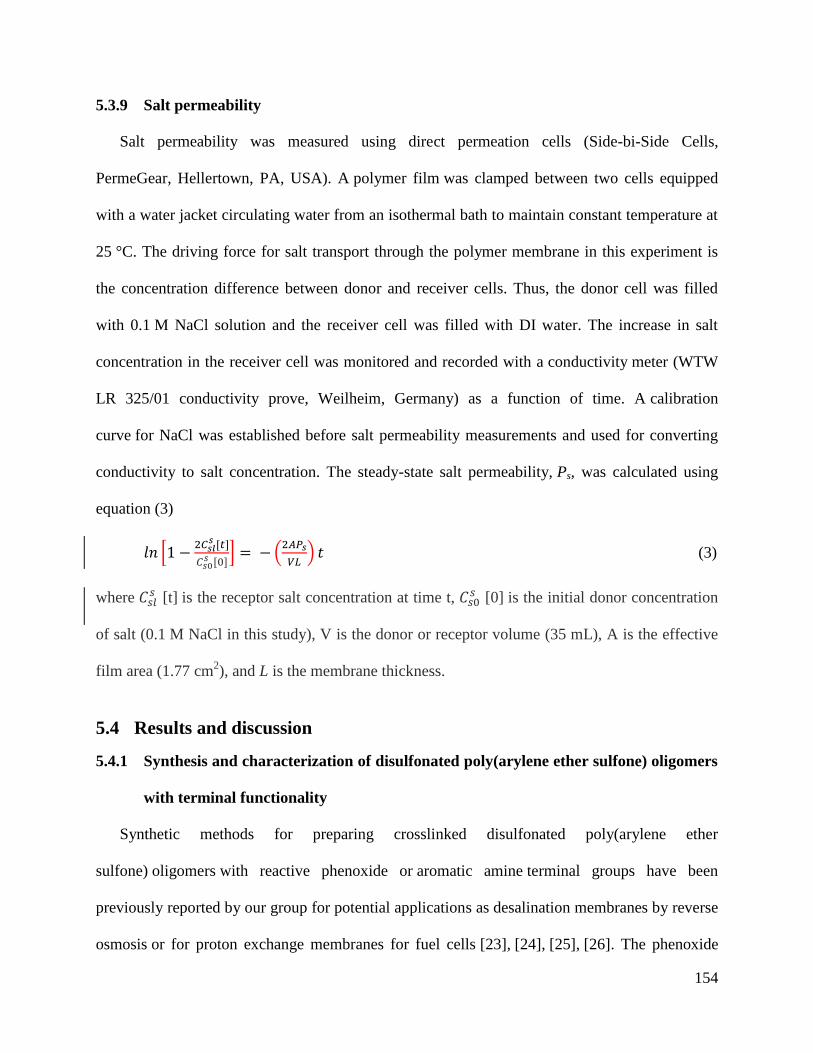
154
5.3.9 Salt permeability
Salt permeability was measured using direct permeation cells (Side-bi-Side Cells,
PermeGear, Hellertown, PA, USA). A polymer film was clamped between two cells equipped
with a water jacket circulating water from an isothermal bath to maintain constant temperature at
25 °C. The driving force for salt transport through the polymer membrane in this experiment is
the concentration difference between donor and receiver cells. Thus, the donor cell was filled
with 0.1 M NaCl solution and the receiver cell was filled with DI water. The increase in salt
concentration in the receiver cell was monitored and recorded with a conductivity meter (WTW
LR 325/01 conductivity prove, Weilheim, Germany) as a function of time. A calibration
curve for NaCl was established before salt permeability measurements and used for converting
conductivity to salt concentration. The steady-state salt permeability, Ps, was calculated using
equation (3)
(3)
where [t] is the receptor salt concentration at time t,
[0] is the initial donor concentration
of salt (0.1 M NaCl in this study), V is the donor or receptor volume (35 mL), A is the effective
film area (1.77 cm2), and L is the membrane thickness.
5.4 Results and discussion
5.4.1 Synthesis and characterization of disulfonated poly(arylene ether sulfone) oligomers
with terminal functionality
Synthetic methods for preparing crosslinked disulfonated poly(arylene ether
sulfone) oligomers with reactive phenoxide or aromatic amine terminal groups have been
previously reported by our group for potential applications as desalination membranes by reverse
osmosis or for proton exchange membranes for fuel cells [23], [24], [25], [26]. The phenoxide
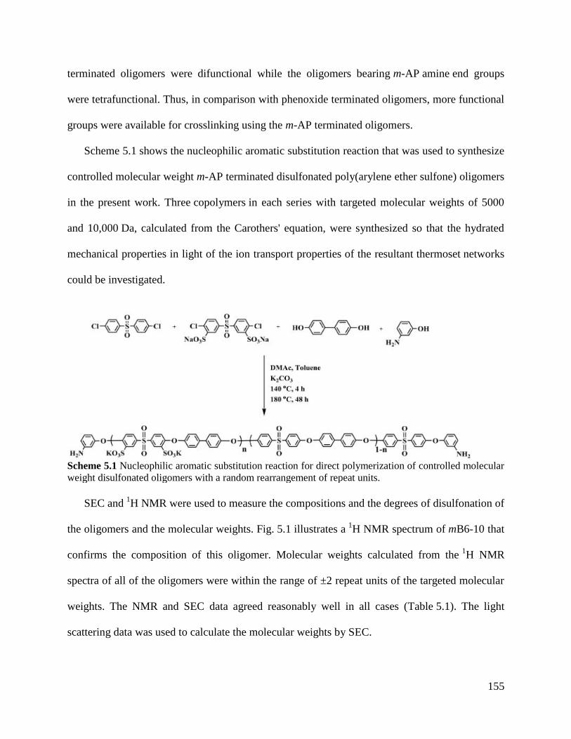
155
terminated oligomers were difunctional while the oligomers bearing m-AP amine end groups
were tetrafunctional. Thus, in comparison with phenoxide terminated oligomers, more functional
groups were available for crosslinking using the m-AP terminated oligomers.
Scheme 5.1 shows the nucleophilic aromatic substitution reaction that was used to synthesize
controlled molecular weight m-AP terminated disulfonated poly(arylene ether sulfone) oligomers
in the present work. Three copolymers in each series with targeted molecular weights of 5000
and 10,000 Da, calculated from the Carothers' equation, were synthesized so that the hydrated
mechanical properties in light of the ion transport properties of the resultant thermoset networks
could be investigated.
Scheme 5.1 Nucleophilic aromatic substitution reaction for direct polymerization of controlled molecular
weight disulfonated oligomers with a random rearrangement of repeat units.
SEC and
1H NMR were used to measure the compositions and the degrees of disulfonation of
the oligomers and the molecular weights. Fig. 5.1 illustrates a 1H NMR spectrum of mB6-10 that
confirms the composition of this oligomer. Molecular weights calculated from the 1H NMR
spectra of all of the oligomers were within the range of ±2 repeat units of the targeted molecular
weights. The NMR and SEC data agreed reasonably well in all cases (Table 5.1). The light
scattering data was used to calculate the molecular weights by SEC.
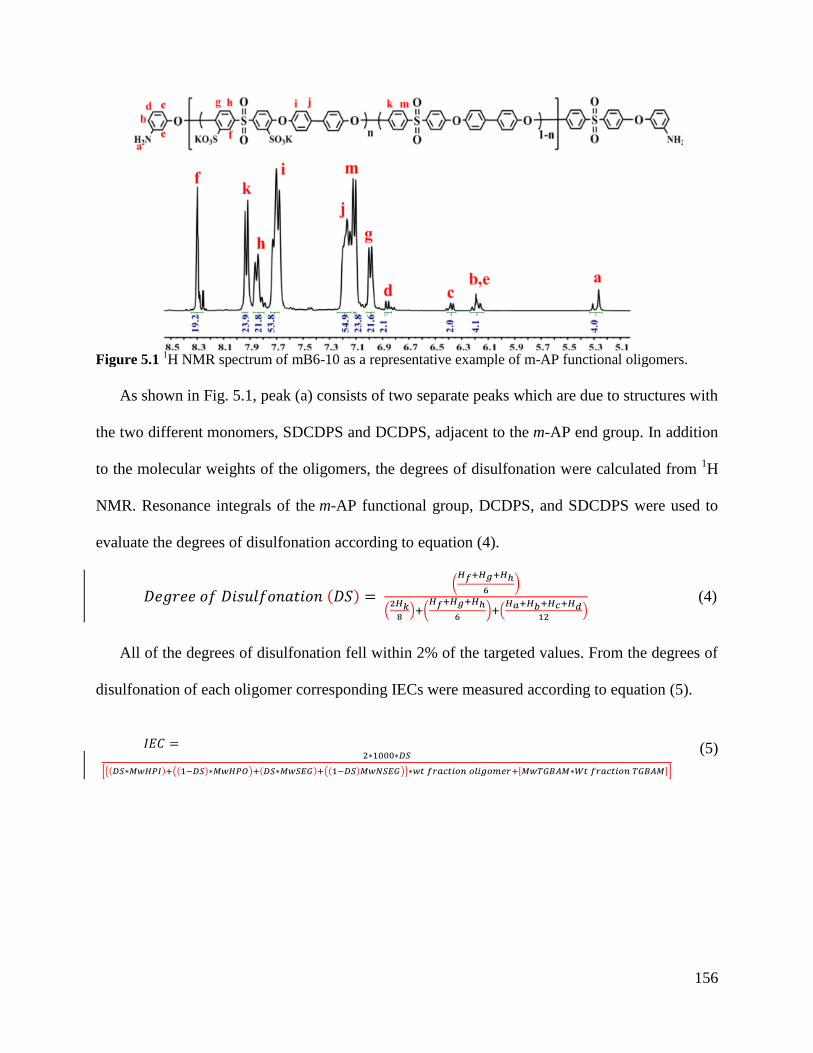
156
Figure 5.1
1H NMR spectrum of mB6-10 as a representative example of m-AP functional oligomers.
As shown in Fig. 5.1, peak (a) consists of two separate peaks which are due to structures with
the two different monomers, SDCDPS and DCDPS, adjacent to the m-AP end group. In addition
to the molecular weights of the oligomers, the degrees of disulfonation were calculated from 1H
NMR. Resonance integrals of the m-AP functional group, DCDPS, and SDCDPS were used to
evaluate the degrees of disulfonation according to equation (4).
(4)
All of the degrees of disulfonation fell within 2% of the targeted values. From the degrees of
disulfonation of each oligomer corresponding IECs were measured according to equation (5).
(5)
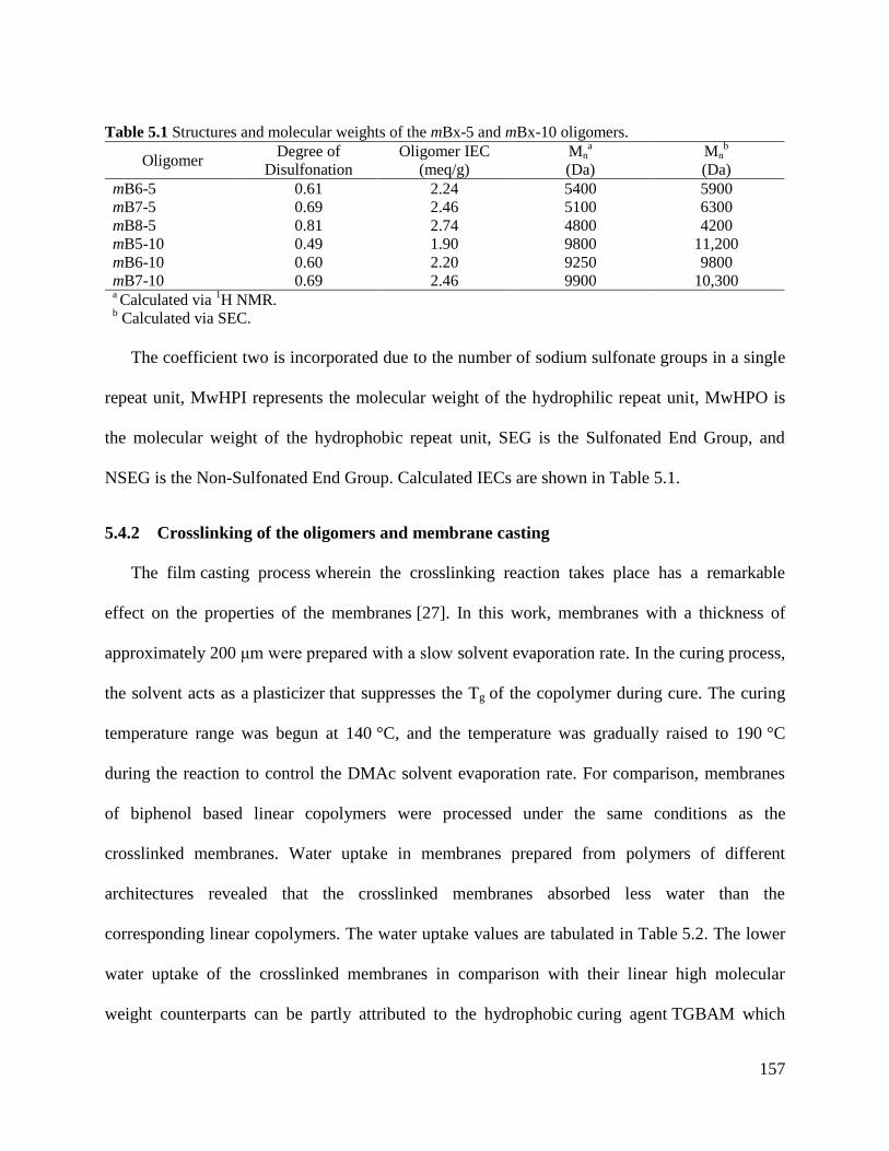
157
Table 5.1 Structures and molecular weights of the mBx-5 and mBx-10 oligomers.
Oligomer Degree of
Disulfonation
Oligomer IEC
(meq/g)
Mna
(Da)
Mnb
(Da)
mB6-5 0.61 2.24 5400 5900
mB7-5 0.69 2.46 5100 6300
mB8-5 0.81 2.74 4800 4200
mB5-10 0.49 1.90 9800 11,200
mB6-10 0.60 2.20 9250 9800
mB7-10 0.69 2.46 9900 10,300 a Calculated via
1H NMR.
b Calculated via SEC.
The coefficient two is incorporated due to the number of sodium sulfonate groups in a single
repeat unit, MwHPI represents the molecular weight of the hydrophilic repeat unit, MwHPO is
the molecular weight of the hydrophobic repeat unit, SEG is the Sulfonated End Group, and
NSEG is the Non-Sulfonated End Group. Calculated IECs are shown in Table 5.1.
5.4.2 Crosslinking of the oligomers and membrane casting
The film casting process wherein the crosslinking reaction takes place has a remarkable
effect on the properties of the membranes [27]. In this work, membranes with a thickness of
approximately 200 μm were prepared with a slow solvent evaporation rate. In the curing process,
the solvent acts as a plasticizer that suppresses the Tg of the copolymer during cure. The curing
temperature range was begun at 140 °C, and the temperature was gradually raised to 190 °C
during the reaction to control the DMAc solvent evaporation rate. For comparison, membranes
of biphenol based linear copolymers were processed under the same conditions as the
crosslinked membranes. Water uptake in membranes prepared from polymers of different
architectures revealed that the crosslinked membranes absorbed less water than the
corresponding linear copolymers. The water uptake values are tabulated in Table 5.2. The lower
water uptake of the crosslinked membranes in comparison with their linear high molecular
weight counterparts can be partly attributed to the hydrophobic curing agent TGBAM which
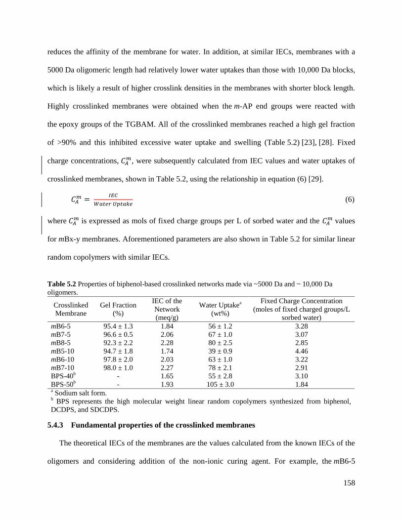
158
reduces the affinity of the membrane for water. In addition, at similar IECs, membranes with a
5000 Da oligomeric length had relatively lower water uptakes than those with 10,000 Da blocks,
which is likely a result of higher crosslink densities in the membranes with shorter block length.
Highly crosslinked membranes were obtained when the m-AP end groups were reacted with
the epoxy groups of the TGBAM. All of the crosslinked membranes reached a high gel fraction
of >90% and this inhibited excessive water uptake and swelling (Table 5.2) [23], [28]. Fixed
charge concentrations, , were subsequently calculated from IEC values and water uptakes of
crosslinked membranes, shown in Table 5.2, using the relationship in equation (6) [29].
(6)
where is expressed as mols of fixed charge groups per L of sorbed water and the
values
for mBx-y membranes. Aforementioned parameters are also shown in Table 5.2 for similar linear
random copolymers with similar IECs.
Table 5.2 Properties of biphenol-based crosslinked networks made via ~5000 Da and ~ 10,000 Da
oligomers.
Crosslinked
Membrane
Gel Fraction
(%)
IEC of the
Network
(meq/g)
Water Uptakea
(wt%)
Fixed Charge Concentration
(moles of fixed charged groups/L
sorbed water)
mB6-5 95.4 ± 1.3 1.84 56 ± 1.2 3.28
mB7-5 96.6 ± 0.5 2.06 67 ± 1.0 3.07
mB8-5 92.3 ± 2.2 2.28 80 ± 2.5 2.85
mB5-10 94.7 ± 1.8 1.74 39 ± 0.9 4.46
mB6-10 97.8 ± 2.0 2.03 63 ± 1.0 3.22
mB7-10 98.0 ± 1.0 2.27 78 ± 2.1 2.91
BPS-40b
- 1.65 55 ± 2.8 3.10
BPS-50b
- 1.93 105 ± 3.0 1.84 a Sodium salt form.
b BPS represents the high molecular weight linear random copolymers synthesized from biphenol,
DCDPS, and SDCDPS.
5.4.3 Fundamental properties of the crosslinked membranes
The theoretical IECs of the membranes are the values calculated from the known IECs of the
oligomers and considering addition of the non-ionic curing agent. For example, the mB6-5
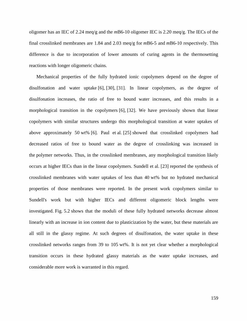
159
oligomer has an IEC of 2.24 meq/g and the mB6-10 oligomer IEC is 2.20 meq/g. The IECs of the
final crosslinked membranes are 1.84 and 2.03 meq/g for mB6-5 and mB6-10 respectively. This
difference is due to incorporation of lower amounts of curing agents in the thermosetting
reactions with longer oligomeric chains.
Mechanical properties of the fully hydrated ionic copolymers depend on the degree of
disulfonation and water uptake [6], [30], [31]. In linear copolymers, as the degree of
disulfonation increases, the ratio of free to bound water increases, and this results in a
morphological transition in the copolymers [6], [32]. We have previously shown that linear
copolymers with similar structures undergo this morphological transition at water uptakes of
above approximately 50 wt% [6]. Paul et al. [25] showed that crosslinked copolymers had
decreased ratios of free to bound water as the degree of crosslinking was increased in
the polymer networks. Thus, in the crosslinked membranes, any morphological transition likely
occurs at higher IECs than in the linear copolymers. Sundell et al. [23] reported the synthesis of
crosslinked membranes with water uptakes of less than 40 wt% but no hydrated mechanical
properties of those membranes were reported. In the present work copolymers similar to
Sundell's work but with higher IECs and different oligomeric block lengths were
investigated. Fig. 5.2 shows that the moduli of these fully hydrated networks decrease almost
linearly with an increase in ion content due to plasticization by the water, but these materials are
all still in the glassy regime. At such degrees of disulfonation, the water uptake in these
crosslinked networks ranges from 39 to 105 wt%. It is not yet clear whether a morphological
transition occurs in these hydrated glassy materials as the water uptake increases, and
considerable more work is warranted in this regard.
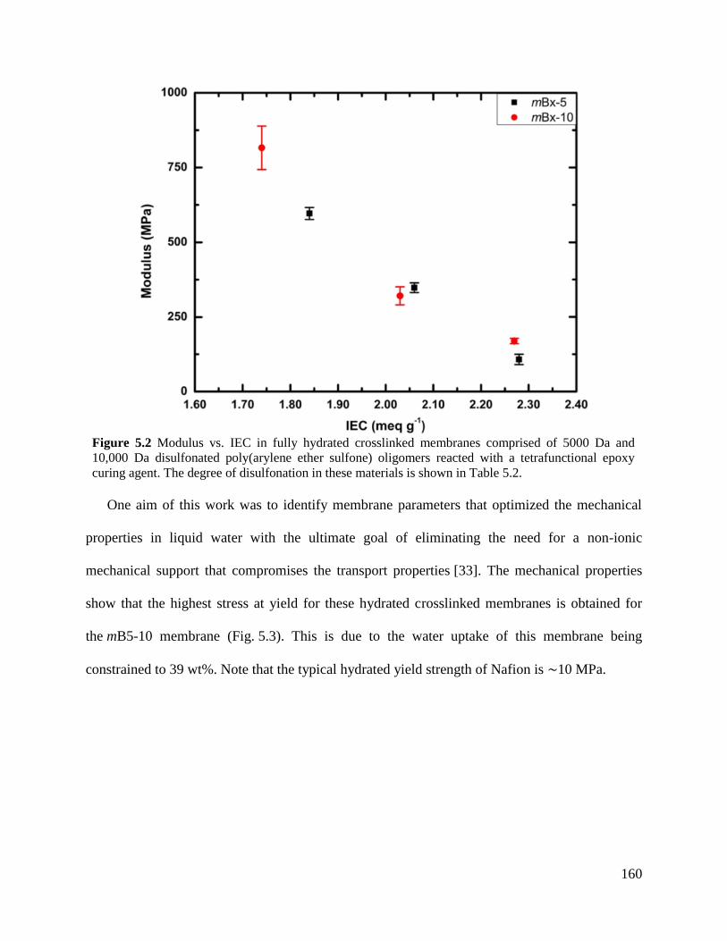
160
Figure 5.2 Modulus vs. IEC in fully hydrated crosslinked membranes comprised of 5000 Da and
10,000 Da disulfonated poly(arylene ether sulfone) oligomers reacted with a tetrafunctional epoxy
curing agent. The degree of disulfonation in these materials is shown in Table 5.2.
One aim of this work was to identify membrane parameters that optimized the mechanical
properties in liquid water with the ultimate goal of eliminating the need for a non-ionic
mechanical support that compromises the transport properties [33]. The mechanical properties
show that the highest stress at yield for these hydrated crosslinked membranes is obtained for
the mB5-10 membrane (Fig. 5.3). This is due to the water uptake of this membrane being
constrained to 39 wt%. Note that the typical hydrated yield strength of Nafion is ∼10 MPa.
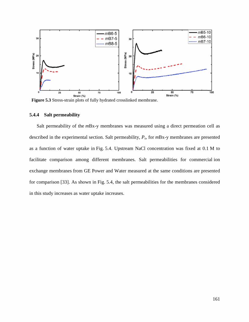
161
Figure 5.3 Stress-strain plots of fully hydrated crosslinked membrane.
5.4.4 Salt permeability
Salt permeability of the mBx-y membranes was measured using a direct permeation cell as
described in the experimental section. Salt permeability, Ps, for mBx-y membranes are presented
as a function of water uptake in Fig. 5.4. Upstream NaCl concentration was fixed at 0.1 M to
facilitate comparison among different membranes. Salt permeabilities for commercial ion
exchange membranes from GE Power and Water measured at the same conditions are presented
for comparison [33]. As shown in Fig. 5.4, the salt permeabilities for the membranes considered
in this study increases as water uptake increases.

162
Figure 5.4 Salt permeability, Ps, measured with 0.1 M NaCl upstream solution for mBx-y membranes
and commercial ion exchange membranes as a function of water uptake.
Salt permeability of these crosslinked membranes shows a strong correlation with water
uptake regardless of the block length of the copolymer. For example, the salt permeabilities
of mB6-10 and mB7-10 fall between the values for mB6-5 and mB8-5. Furthermore, commercial
membranes including polystyrene-divinylbenzene or acrylic structures that are synthesized by
conventional free radical polymerization follow a similar trend [34]. Previous studies suggested
that ion transport in ion exchange membranes is mainly governed by water uptake
and electrostatic interactions between fixed charge groups on the polymer backbone and mobile
ions [35], [36]. However, the hydrated mechanical properties are strongly affected by the block
length of the oligomers. In this work, the mB5-10 is the membrane with the best hydrated
strength and it is also the only example with low water uptake and salt permeability.
To illustrate the influence of electrostatic interactions between fixed charges and mobile
ions on salt transport, salt permeability in crosslinked mBx-y membranes is presented as a
function of fixed charge concentration in Fig. 5.5. Salt permeabilities for membranes from GE
are presented in Fig. 5.5 for comparison. As shown in Fig. 5.5, the salt permeability of the
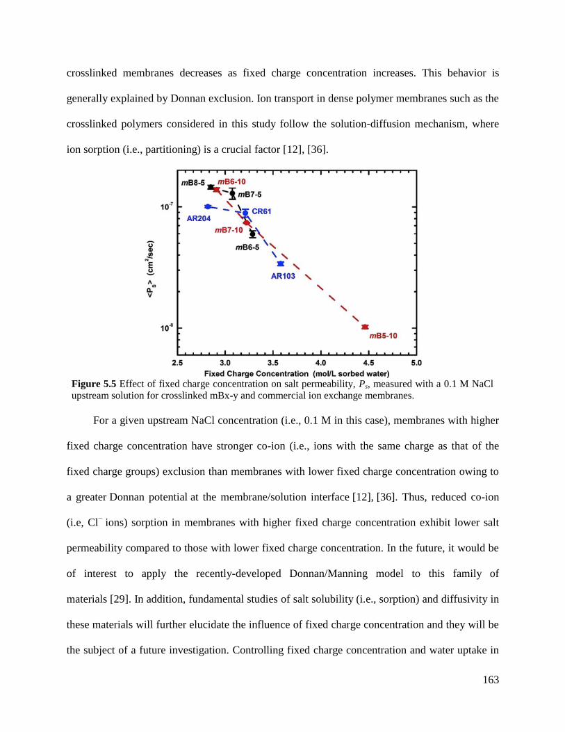
163
crosslinked membranes decreases as fixed charge concentration increases. This behavior is
generally explained by Donnan exclusion. Ion transport in dense polymer membranes such as the
crosslinked polymers considered in this study follow the solution-diffusion mechanism, where
ion sorption (i.e., partitioning) is a crucial factor [12], [36].
Figure 5.5 Effect of fixed charge concentration on salt permeability, Ps, measured with a 0.1 M NaCl
upstream solution for crosslinked mBx-y and commercial ion exchange membranes.
For a given upstream NaCl concentration (i.e., 0.1 M in this case), membranes with higher
fixed charge concentration have stronger co-ion (i.e., ions with the same charge as that of the
fixed charge groups) exclusion than membranes with lower fixed charge concentration owing to
a greater Donnan potential at the membrane/solution interface [12], [36]. Thus, reduced co-ion
(i.e, Cl− ions) sorption in membranes with higher fixed charge concentration exhibit lower salt
permeability compared to those with lower fixed charge concentration. In the future, it would be
of interest to apply the recently-developed Donnan/Manning model to this family of
materials [29]. In addition, fundamental studies of salt solubility (i.e., sorption) and diffusivity in
these materials will further elucidate the influence of fixed charge concentration and they will be
the subject of a future investigation. Controlling fixed charge concentration and water uptake in
164
crosslinked IEMs is crucial for practical applications. In membrane processes driven by a
concentration gradient such as reverse osmosis, forward osmosis, and pressure-retarded osmosis,
low salt permeability and high water permeability are required to obtain high salt rejection and
water recovery [7], [37]. Previously, we reported salt rejection and water permeability results for
a series of crosslinked mBx-5 membranes [23] where increasing fixed charge concentration did
not result in an increase in salt rejection. Salt rejection is related to water/salt selectivity (i.e., the
ratio of water permeability to salt permeability) [37], [38]. Low water uptake results in low water
permeability, which in turn, leads to increased water/salt selectivity and salt rejection. Thus,
water uptake of IEMs needs to be balanced with fixed charge concentration to obtain desirable
transport properties. For membrane processes driven by an electric-field such as ED and
capacitive deionization (CDI), selective transport of counter-ions (i.e., ions with opposite charge
to that of the fixed charge groups) over co-ions is required, which can be better achieved by
strong co-ion exclusion [39], [40]. For IEMs made from linear polymers, increasing IEC does
not necessarily lead to increased fixed charge concentration. TA large amount of water uptake
with respect to IEC, as observed in linear polymers, decreases the effective fixed charge
concentration. For IEMs made from crosslinked networks, however, the amount of water uptake
with increasing IEC is suppressed so that the fixed charge concentration can remain relatively
high. Therefore, crosslinked ion exchange membranes such as those investigated in this work
may be designed to have desired water permeability and simultaneously to have salt permeability
necessary for a given application [23], [25]. It is promising that the mB5-10 membrane from this
work has a combination of high fixed charge concentration, low salt permeability with good
hydrated mechanical properties. Further investigations will confirm whether the water flux in
such a membrane is desirable for practical applications such as ED or capacitive deionization.
165
5.5 Conclusions
In this paper a series of controlled molecular weight disulfonated m-aminophenol
terminated oligomers were synthesized and cured with a tetrafunctional epoxy reagent under
controlled heating conditions to result in highly crosslinked and unsupported membranes.
Structure-property relationships with regard to membranes for water purification were
investigated. These included correlations among polymer network structure and water uptake,
IEC and fixed charge concentration, and these were correlated with hydrated mechanical
properties, and salt transport. The hydrated mechanical properties of the network containing the
higher block length oligomer (10,000 Da) that was 50% disulfonated (mB5-10) and with only
39 wt% water uptake showed an impressive yield strength of ∼27 MPa with a good ultimate
elongation under immersion conditions. Moreover, salt permeabilities correlated with water
uptake and fixed charge concentration, where salt permeability increased with increasing water
uptake and decreased with increasing fixed charge concentration. The mB5-10 network with the
better hydrated mechanical properties and with the highest fixed charge concentration also
showed the lowest salt permeability, thus suggesting that this composition regime is quite
promising. However, further investigation of the higher block length materials with intermediate
degrees of disulfonation will be required to understand and deconvolute the influence of
structure and water uptake on water and salt transport properties in such copolymers.
5.6 References [1] J.R. Werber, C.O. Osuji, M. Elimelech, Materials for next-generation desalination and
water purification membranes, Nat. Rev. Mater, 1 (2016), p. 16018 [2] A. Aghigh, V. Alizadeh, H.Y. Wong, M.S. Islam, N. Amin, M. Zaman, Recent advances
in utilization of graphene for filtration and desalination of water: a review,
Desalination, 365 (2015), pp. 389-397
[3] M. Li, Optimization of multitrain brackish water reverse osmosis (bwro) desalination,
Ind. Eng. Chem. Res., 51 (2012), pp. 3732-3739
[4] Y. Tanaka, Ion-exchange membrane electrodialysis for saline water desalination and its
application to seawater concentration, Ind. Eng. Chem. Res., 50 (2011), pp. 7494-7503
166
[5] S. Schlumpberger, N.B. Lu, M.E. Suss, M.Z. Bazant, Scalable and continuous water
deionization by shock electrodialysis, Environ. Sci. Tech. Let., 2 (2015), pp. 367-372
[6] A. Daryaei, G.C. Miller, J. Willey, S. Roy Choudhury, B. Vondrasek, D. Kazerooni,
M.R. Burtner, C. Mittelsteadt, J.J. Lesko, J.S. Riffle, J.E. McGrath, Synthesis and
membrane properties of sulfonated poly(arylene ether sulfone) statistical copolymers for
electrolysis of water: influence of meta- and para-substituted comonomers, ACS Appl.
Mater. Interfaces, 9 (2017), pp. 20067-20075
[7] G.M. Geise, D.R. Paul, B.D. Freeman, Fundamental water and salt transport properties of
polymeric materials, Prog. Polym. Sci., 39 (2014), pp. 1-42
[8] Y. Zhang, K. Ghyselbrecht, B. Meesschaert, L. Pinoy, B. Van der Bruggen,
Electrodialysis on ro concentrate to improve water recovery in wastewater reclamation,
J. Membr. Sci., 378 (2011), pp. 101-110
[9] H. Strathmann, Electrodialysis, a mature technology with a multitude of new
applications, Desalination, 264 (2010), pp. 268-288
[10] T. Sirivedhin, J. McCue, L. Dallbauman, Reclaiming produced water for beneficial use:
salt removal by electrodialysis, J. Membr. Sci., 243 (2004), pp. 335-343
[11] R.F. Service, Desalination freshens up, Science, 313 (2006), pp. 1088-1090
[12] J. Kamcev, B.D. Freeman, Charged polymer membranes for environmental/energy
applications, Annu. Rev. Chem. Biomol., 7 (2016), pp. 111-133
[13] H.B. Park, J. Kamcev, L.M. Robeson, M. Elimelech, B.D. Freeman, Maximizing the
right stuff: the trade-off between membrane permeability and selectivity,
Science, 356 (2017)
[14] J. Kamcev, D.R. Paul, B.D. Freeman, Effect of fixed charge group concentration on
equilibrium ion sorption in ion exchange membranes, J. Mater. Chem. A, 5 (2017),
pp. 4638-4650
[15] H. Strathmann, A. Grabowski, G. Eigenberger, Ion-exchange membranes in the chemical
process industry, Ind. Eng. Chem. Res., 52 (2013), pp. 10364-10379
[16] P. Długoł cki, B. Anet, S.J. Metz, K. Nijmeijer, M. Wessling, Transport limitations in ion
exchange membranes at low salt concentrations, J. Membr. Sci., 346 (2010), pp. 163-171
[17] S. Tan, A. Laforgue, D. Bélanger, Improving the permselectivity of commercial cation-
exchange membranes for electrodialysis applications, Advanced Materials for Membrane
Separations, American Chemical Society (2004), pp. 311-323
[18] L.J. Banasiak, T.W. Kruttschnitt, A.I. Schafer, Desalination using electrodialysis as a
function of voltage and salt concentration, Desalination, 205 (2007), pp. 38-46
[19] N. White, M. Misovich, A. Yaroshchuk, M.L. Bruening, Coating of nafion membranes
with polyelectrolyte multilayers to achieve high monovalent/divalent cation
electrodialysis selectivities, ACS Appl. Mater. Interfaces, 7 (2015), pp. 6620-6628
[20] S. Caprarescu, A.L. Radu, V. Purcar, R. Ianchis, A. Sarbu, M. Ghiurea, C. Nicolae, C.
Modrogan, D.I. Vaireanu, A. Perichaud, D.I. Ebrasu, Adsorbents/ion exchangers-pva
blend membranes: preparation, characterization and performance for the removal of zn2+
by electrodialysis, Appl. Surf. Sci., 329 (2015), pp. 65-75
[21] G.S. Gohil, R.K. Nagarale, V.V. Binsu, V.K. Shahi, Preparation and characterization of
monovalent cation selective sulfonated poly(ether ether ketone) and poly(ether sulfone)
composite membranes, J. Colloid Interface Sci., 298 (2006), pp. 845-853
167
[22] M. Reig, H. Farrokhzad, B. Van der Bruggen, O. Gibert, J.L. Cortina, Synthesis of a
monovalent selective cation exchange membrane to concentrate reverse osmosis brines
by electrodialysis, Desalination, 375 (2015), pp. 1-9
[23] B.J. Sundell, E.S. Jang, J.R. Cook, B.D. Freeman, J.S. Riffle, J.E. McGrath, Cross-linked
disulfonated poly(arylene ether sulfone) telechelic oligomers. 2. Elevated transport
performance with increasing hydrophilicity, Ind. Eng. Chem. Res., 55 (2016), pp. 1419-
1426
[24] B.J. Sundell, K.S. Lee, A. Nebipasagil, A. Shaver, J.R. Cook, E.S. Jang, B.D. Freeman, J.
E. McGrath, Cross-linking disulfonated poly(arylene ether sulfone) telechelic oligomers.
1. Synthesis, characterization, and membrane preparation, Ind. Eng. Chem.
Res., 53 (2014), pp. 2583-2593
[25] M. Paul, H.B. Park, B.D. Freeman, A. Roy, J.E. McGrath, J.S. Riffle, Synthesis and
crosslinking of partially disulfonated poly(arylene ether sulfone) random copolymers as
candidates for chlorine resistant reverse osmosis membranes, Polymer, 49 (2008),
pp. 2243-2252
[26] J.R. Rowlett, V. Lilavivat, A.T. Shaver, Y. Chen, A. Daryaei, H. Xu, C. Mittelsteadt, S.
Shimpalee, J.S. Riffle, J.E. McGrath, Multiblock poly(arylene ether nitrile) disulfonated
poly(arylene ether sulfone) copolymers for proton exchange membranes: Part 2
electrochemical and h-2/air fuel cell analysis, Polymer, 122 (2017), pp. 296-302
[27] L. Zhu, T.J. Zimudzi, Y. Wang, X.D. Yu, J. Pan, J.J. Han, D.I. Kushner, L.Zhuang, M.A.
Hickner, Mechanically robust anion exchange membranes via long hydrophilic cross-
linkers, Macromolecules, 50 (2017), pp. 2329-2337
[28] Y.S. Kim, M.A. Hickner, L.M. Dong, B.S. Pivovar, J.E. McGrath, Sulfonated
poly(arylene ether sulfone) copolymer proton exchange membranes: composition and
morphology effects on the methanol permeability, J. Membr. Sci., 243 (2004), pp. 317-
326
[29] J. Kamcev, M. Galizia, F.M. Benedetti, E.S.Jang, D.R. Paul, B.D. Freeman, G.S.
Manning, Partitioning of mobile ions between ion exchange polymers and aqueous salt
solutions: importance of counter-ion condensation, Phys. Chem. Chem. Phys., 18 (2016),
pp. 6021-6031
[30] B. Bae, K. Miyatake, M. Watanabe, Sulfonated poly(arylene ether sulfone ketone)
multiblock copolymers with highly sulfonated block. Synthesis and properties,
Macromolecules, 43 (2010), pp. 2684-2691
[31] K. Krajinovic, T. Kaz, T. Haering, V. Gogel, J. Kerres, Highly sulphonated multiblock-
co-polymers for direct methanol fuel cells, Fuel Cells, 11 (2011), pp. 787-800
[32] A. Roy, M.A. Hickner, H.S. Lee, T. Glass, M. Paul, A. Badami, J.S. Riffle, J.E. McGrath,
States of water in proton exchange membranes: Part a - influence of chemical structure
and composition, Polymer, 111 (2017), pp. 297-306
[33] J. Kamcev, D.R. Paul, B.D. Freeman, Ion activity coefficients in ion exchange polymers:
applicability of manning's counterion condensation theory, Macromolecules, 48 (2015),
pp. 8011-8024
[34] J. Kamcev, D.R. Paul, G.S. Manning, B.D. Freeman, Predicting salt permeability
coefficients in highly swollen, highly charged ion exchange membranes, ACS Appl.
Mater. Interfaces, 9 (2017), pp. 4044-4056
[35] G.M. Geise, L.P. Falcon, B.D. Freeman, D.R. Paul, Sodium chloride sorption in
sulfonated polymers for membrane applications, J. Membr. Sci., 423 (2012), pp. 195-208
168
[36] J. Kamcev, M. Galizia, F.M. Benedetti, E.S. Jang, D.R. Paul, B.D. Freeman, G.S.
Manning, Partitioning of mobile ions between ion exchange polymers and aqueous salt
solutions: importance of counter-ion condensation, Phys. Chem. Chem. Phys., 18 (2016),
pp. 6021-6031
[37] J.G. Wijmans, R.W. Baker, The solution-diffusion model - a review, J. Membr.
Sci., 107 (1995), pp. 1-21
[38] G.M. Geise, H.B. Park, A.C. Sagle, B.D. Freeman, J.E. McGrath, Water permeability and
water/salt selectivity tradeoff in polymers for desalination, J. Membr. Sci., 369 (2011),
pp. 130-138
[39] T.W. Xu, Ion exchange membranes: state of their development and perspective,
J. Membr. Sci., 263 (2005), pp. 1-29
[40] P.M. Biesheuvel, A. van der Wal, Membrane capacitive deionization, J. Membr.
Sci., 346 (2010), pp. 256-262
169
Chapter 6: Synthesis and Membrane
Properties of Sulfonated Poly(Arylene Ether
Sulfone) Statistical Copolymers for
Electrolysis of Water: Influence of Meta-
and Para- Substituted Comonomers
This chapter has been adapted from a published manuscript by Amin Daryaei, Gregory C
Miller, Jason Willey, Shreya Roy Choudhury, Brittannia Vondrasek, Dana Kazerooni, Matthew
R Burtner, Cortney Mittelsteadt, John J Lesko, Judy S Riffle, James E McGrath from the
following reference: ACS Applied Materials & Interfaces, 2017, 9, 23, 200067-20075 . Reprinted
with permission from American Chemical Society.
Dana Kazerooni’s contribution to this paper include assisting in synthesizing the polymers,
casting the membranes, water uptake measurements, and completely running and analyzing
hydrated mechanical properties for each membrane.
Amin Daryaei,a Gregory C. Miller,
a Jason Willey,
c Shreya Roy Choudhury,
a Britannia
Vondrasek,b Dana Kazerooni,
a Matthew R. Burtner,
b Cortney Mittelsteadt,
c
John J. Lesko,b Judy S. Riffle,
a and James E. McGrath
a
aMacromolecular Innovation Institute, Virginia Tech, Blacksburg, Virginia, United States
bCollege of Engineering, Virginia Tech, Blacksburg, Virginia, United States
cGiner Electrochemical Systems, Incorporated, Newton, Massachusettes, United States
6.1 Abstract
Two series of high molecular weight disulfonated poly(arylene ether sulfone) random
copolymers were synthesized as proton exchange membranes for high-temperature water
electrolyzers. These copolymers differ based on the position of the ether bonds on the aromatic
rings. One series is comprised of fully para-substituted hydroquinone comonomer, and the other
series incorporated 25 mol % of a meta-substituted comonomer resorcinol and 75 mol %
hydroquinone. The influence of the substitution position on water uptake and electrochemical
properties of the membranes were investigated and compared to that of the state-of-the-art
membrane Nafion. The mechanical properties of the membranes were measured for the first time
170
in fully hydrated conditions at ambient and elevated temperatures. Submerged in water, these
hydrocarbon-based copolymers had moduli an order of magnitude higher than Nafion. Selected
copolymers of each series showed dramatically increased proton conductivities at elevated
temperature in fully hydrated conditions, while their H2 gas permeabilities were well controlled
over a wide range of temperatures. These improved properties were attributed to the high glass
transition temperatures of the disulfonated poly(arylene ether sulfone)s.
6.2 Introduction
Hydrogen gas as a green fuel is a high-energy molecule that can be used in fuel cells to
generate electricity for the grid and automobiles (1). Among different commercial pathways for
hydrogen gas production (2, 3). electrolysis of water using proton exchange membranes has
attracted much attention as a result of positive aspects such as producing high-purity product
(4), high current density (5, 6), and fast kinetics at elevated temperatures (7). The electrolyzers
can also be coupled to renewable energy sources such as wind turbines or solar cells as
environmentally friendly electricity producers. Hydrogen produced by electrolysis can be
directly used in a fuel cell to provide a potential alternative to fossil fuels for generating
electricity.
The state-of-the-art PEM for electrolysis of water is DuPont’s perfluorosulfonic acid
membrane Nafion. Nafion is a good proton conductor, and it is highly chemically resistant and
mechanically robust at temperatures below its Tg. However, it has drawbacks including high gas
permeability and poor mechanical stability above the α relaxation temperature of ∼80 °C and at
the high operating pressure of the electrolyzer. Such operating conditions eventually result in
loss of mechanical strength and reduced proton conductivity (8-10). Sulfonated random and
block copolymers such as polyimides (11, 12), poly(arylene ether ketones) (13), poly(arylene
171
ether sulfones) (14-17), and polybenzimidazoles (18) have been intensively investigated as
PEMs in fuel cells. Fuel cells and electrolyzers have similar requirements regarding membrane
properties. Both systems operate under highly acidic conditions, and this places special durability
requirements on the membranes for extended use. High-temperature water electrolyzers are
operated at temperatures exceeding 100 °C and pressures above 350 bar in a fully hydrated
environment, and this requires a robust membrane to withstand mechanical pressure as well as
hydrolysis reactions (6, 19, 20). However, in the literature, there are not as many studies on
potential alternatives for Nafion for electrolysis of water. Creating a PEM that has decreased gas
permeability to minimize gas crossover and superior conductive properties relative to
perfluorosulfonic acid membranes is a challenge that needs to be addressed.
Smith et al. (21) prepared a poly(ether ketone) via step-growth polymerization and
postsulfonated this polymer in concentrated sulfuric acid at elevated temperatures. In comparison
with Nafion, this copolymer had comparable proton conductivity, lower gas permeability, and
better mechanical stability for use in electrolysis of water with higher efficiencies, most likely as
a result of its microphase-separated structure. Albert et al. (22) grafted styrene and acrylonitrile
and a cross-linker onto an ethylene tetrafluoroethylene film using radiation and then
postsulfonated the styrenic rings. This synthesis method resulted in a cost-effective membrane
with better mechanical properties than Nafion, but using aliphatic chains in PEMs can lead to
lower chemical resistance under harsh electrochemical conditions (23). Moreover,
inhomogeneous sulfonic acid distribution across the membranes resulted in high membrane area
resistance. High membrane resistance could also be at least partially attributed to the presence of
nonconductive hydrophobic polymer on the membrane surface that acts as a water (mass)
transfer inhibitor as suggested by Takimoto et al. (24) It is known that a direct synthesis route to
172
disulfonated polysulfones using predisulfonated comonomers allows control over factors
including random distribution of the sulfonic acid groups, ion exchange capacity (IEC) of the
membrane, morphology, and proton conductivity, and it can also avoid cross-linking of the
membrane (14, 25-27).
In this work, gas permeability and proton conductivity in PEMs were investigated in two
series of sulfonated poly(arylene ether sulfone) statistical copolymers. These series were
synthesized based on the difference between phenolic monomers and their ratio in the polymer
backbone. One series contains solely hydroquinone (HQ) as a para-substituted comonomer. The
second series contains 25 mol % of resorcinol (RSC) as a meta-substituted phenolic comonomer,
coreacted into a hydroquinone-based linear copolymer. Both series of copolymers were
synthesized by direct synthesis of disulfonated dichlorodiphenyl sulfone via step-growth
polymerization. Fundamental properties of these PEMs for high-temperature water electrolysis
systems such as water uptake of the membranes in liquid water at room and elevated
temperatures, H2 gas permeability, mechanical stability, and the ratio of (proton
conductivity)/(gas permeability) from room temperature to 100 °C were established and
compared with Nafion.
6.3 Experimental Section
6.3.1 Materials
1,4-Benzenediol (hydroquinone, HQ) was provided by Eastman Chemical Co.. 4,4′-
Dichlorodiphenylsulfone (DCDPS) was provided by Solvay Advanced Polymers. 1,3-
Benzenediol, resorcinol (RSC, >99%), was purchased from Sigma-Aldrich. Toluene was
purchased from Sigma-Aldrich and used as received. DCDPS, hydroquinone, and resorcinol
were recrystallized from toluene and dried under vacuum at 120 °C prior to use. N,N-
Dimethylacetamide (DMAc) was purchased from Sigma-Aldrich and distilled from calcium
173
hydride before use. Calcium hydride (90–95%) was purchased from Alfa Aesar. 2-Propanol was
obtained from Fisher Scientific and used as received. Sulfuric acid (H2SO4, 98%) was purchased
from Spectrum Chemical and used as received. Potassium carbonate (K2CO3) was purchased
from Aldrich and dried under vacuum at 180 °C prior to use. 3,3′-Disulfonated-4,4′-
dichlorodiphenylsulfone (SDCDPS, >99%) was purchased from Akron Polymer Systems and
dried at 180 °C prior to use. DuPont’s Nafion 212 was provided by Giner Electrochemical
Systems.
6.3.2 Synthesis of Statistical Copolymers
Aromatic nucleophilic substitution step copolymerization was used to synthesize both series
of disulfonated poly(arylene ether sulfone) copolymers. Synthesis of HQ-XX: A typical HQ 20
with 20% of the repeat units disulfonated was synthesized as follows. HQ (36.33 mmol, 4.00 g),
DCDPS (29.06 mmol, 8.3451 g), SDCDPS (7.265 mmol, 3.57 g), and DMAc (55 mL) were
charged into a 250 mL three neck round-bottom flask equipped with a mechanical stirrer,
condenser, nitrogen inlet, and Dean–Stark trap filled with toluene. The mixture was stirred in an
oil bath at 150 °C until all monomers completely dissolved. K2CO3 (47.22 mmol, 6.52 g) and
toluene (25 mL) were added into the flask. The reaction was refluxed for 4 h to azeotropically
remove water from the system. Toluene was drained from the Dean–Stark trap, and the oil bath
temperature was raised to 180 °C to remove residual toluene from the reaction. The reaction
solution was stirred for 48 h to complete polymerization and then allowed to cool to room
temperature. After dilution of the resulting solution with DMAc (150 mL), it was filtered to
remove the salt. The transparent solution was precipitated by addition into isopropanol with
vigorous stirring. The white fibers were filtered and then stirred in boiling DI water for 4 h to
174
remove any residual DMAc. The copolymer was filtered and dried at 120 °C under reduced
pressure in a vacuum oven. Yield of this copolymer synthesis was 94%.
Synthesis of HQ0.75RSC0.25-XX copolymers: A typical HQ0.75RSC0.25 19 with 19% of the
repeat units disulfonated was synthesized as follows. HQ (27.24 mmol, 3.00 g), RSC (9.08
mmol, 1.00 g), DCDPS (28.33 mmol, 8.137 g), SDCDPS (8.0 mmol, 3.93 g), and DMAc (55
mL) were charged into a 250 mL three neck round-bottom flask equipped with a mechanical
stirrer, condenser, nitrogen inlet, and Dean–Stark apparatus filled with toluene. The mixture was
stirred in an oil bath at 150 °C until the monomers completely dissolved. K2CO3 (47.22 mmol,
6.52 g) and toluene (25 mL) were added into the flask. The reaction was refluxed for 4 h, the
toluene was drained from the Dean–Stark apparatus, and then the oil bath temperature was raised
to 180 °C to remove residual toluene from the reaction. The solution was stirred for 48 h at 180
°C and then cooled to room temperature. The solution was diluted with DMAc (150 mL) and
then filtered to remove the salt. The transparent solution was precipitated into isopropanol. The
white fibers were filtered and stirred in boiling DI water for 4 h. The copolymer was then filtered
and dried at 120 °C under reduced pressure in a vacuum oven. Yield of this copolymer synthesis
was 95%
6.3.3 Nuclear Magnetic Resonance Spectroscopy (NMR)
1H NMR analysis of the statistical copolymers was conducted on a Varian Unity Plus
spectrometer operating at 400 MHz. The spectra of the copolymers were obtained from a 10%
(w/v) solution in DMSO-d6.
6.3.4 Size Exclusion Chromatography (SEC)
Molecular weights and polydispersities of the polymers were measured using SEC. The
mobile phase was DMAc distilled from CaH2 containing dry LiCl (0.1 M). The column set
175
consisted of 3 Agilent PLgel 10 mm Mixed B-LS columns 300 × 7.5 mm
(polystyrene/divinylbenzene) connected in series with a guard column having the same
stationary phase. The columns and detectors were maintained at 50 °C. An isocratic pump
(Agilent 1260 infinity, Agilent Technologies) with an online degasser (Agilent 1260),
autosampler, and column oven were used for mobile phase delivery and sample injection. A
system of multiple detectors connected in series was used for the analyses. A multiangle laser
light scattering detector (DAWN-HELEOS II, Wyatt Technology Corp.) operating at a
wavelength of 658 nm, a viscometer detector (Viscostar, Wyatt Technology Corp.), and a
refractive index detector operating at a wavelength of 658 nm (Optilab T-rEX, Wyatt
Technology Corp.) provided online results. The system was corrected for interdetector delay and
band broadening using a 21 000 g/mol polystyrene standard. Data acquisition and analysis were
conducted using Astra 6 software from Wyatt Technology Corp. Validation of the system was
performed by monitoring the molar mass of a known molecular weight polystyrene sample by
light scattering. The accepted variance of the 21 000 g/mol polystyrene standard was defined as 2
standard deviations (11.5% for Mn and 9% for Mw) derived from a set of 34 runs. Specific
refractive index values were calculated based on the assumption of 100% mass recovery.
6.3.5 Membrane Casting and Characterization
The copolymers in their salt form were dissolved in DMAc (∼6% w/v) and then filtered
through a 0.45 μm Teflon syringe filter. The solutions were cast onto clean glass substrates and
dried under an infrared lamp at 50–60 °C for 8 h. Afterward, the membranes were placed in a
vacuum oven under reduced pressure at 120–140 °C for 4 h. The membranes were soaked in
water for an additional 24 h to remove residual solvent and to delaminate them from the glass
176
plates. The membranes were converted to their acid form by boiling in 0.1 M H2SO4 for 2 h, and
they were then boiled in DI water for 2 h to remove residual acid.
6.3.6 Ion Exchange Capacity (IEC)
Dry membranes in their acid form were weighed and then soaked in 1 M NaCl solution for
48 h to convert them to their salt form and eliminate HCl. Each membrane solution was titrated
with 0.1 N NaOH solution. The IEC of each membrane in units of mequiv/g of dry membrane
was calculated from eq 1
(1)
where V is the volume of NaOH solution in mL, N is NaOH normality, and M is the mass of the
dry membrane.
6.3.7 Water Uptake at Ambient and Elevated Temperatures
The water uptakes of the membranes were determined gravimetrically on samples weighing
0.1–0.2 g and 3 samples were measured for each film. First, the membranes in their acid form
were dried at 120 °C under vacuum for 24 h and weighed. These membranes were soaked in
water at room temperature for 48 h. Wet membranes were removed from the liquid water, blotted
dry to remove surface droplets, and quickly weighed. For high-temperature water uptake, the
previously wet membranes were placed in boiling water for at least 4 h. Then the hot, wet
membranes were removed from the boiling water, immediately blotted dry to remove surface
droplets, and quickly weighed. The % water uptake of the membranes was calculated according
to eq 2, where mass dry and mass wet refer to the masses of the dry and the wet membranes,
respectively.
(2)
177
6.3.8 Differential Scanning Calorimetry (DSC)
The glass transition temperatures (Tgs) of the copolymers were investigated using a TA
Instruments DSC Q200. For dry samples, standard aluminum hermetic pans were used, and for
hydrated samples, high-volume DSC pans were used. The samples were hydrated by immersion
in deionized water for 24 h prior to loading into the DSC pans. The polymers were heated under
nitrogen at a rate of 10 °C min–1
to 200 °C, cooled at a rate of 10 °C min–1
to 0 °C, and heated
again at a rate of 10 °C min–1
to 240 °C. The Tgs of the samples were determined from the
second heat by finding the inflection point of the W/g vs temperature curve with the aid of TA
Universal Analysis software.
6.3.9 Tensile Tests
Tensile samples were cut from hydrated solvent cast films using a Cricut Explore One
computer-controlled cutting machine. Nafion samples were prepared in the same manner from
Nafion 212. The resulting dogbone-shaped samples were consistent with sample Type V
described in ASTM D638-14 (minimum 63.5 mm overall length, gage length 7.62 mm, width of
narrow section 3.18 mm). The sample films were inspected for any visible flaws, defects, or
inclusions that may have arisen during the casting process. The seven highest quality samples
were selected for testing. The sample thickness was measured at five points along the narrow
section using a Mitutoyo digimatic micrometer model MDC-1”SXF. Uniaxial load tests were
performed using an Instron ElectroPuls E1000 testing machine equipped with a 250 N Dynacell
load cell. The instrument was fitted with a water bath, and the samples were completely
immersed in deionized water for 24 h. The wet samples were loaded into the Instron situated in a
tank, and the tank was filled with water. For elevated temperature tests, the water was heated to
80 °C; then the sample was allowed to equilibrate in the water for at least 3 min before testing to
178
obtain fully hydrated mechanical data. For high-temperature hydrated tests, the tank was fitted
with an immersion heater and well insulated to maintain the water at the target temperature of 80
°C. For all mechanical tests, the crosshead displacement rate was 10 mm/min and the initial grip
separation was 25 mm.
Young’s moduli were calculated from the slope of the initial linear region of the loading
curve. The yield point was considered to be the intersection of the load curve with a 1% offset of
this modulus line. This offset was chosen because it correlated with the yield point for lower IEC
samples, some of which showed a distinct yield point in the load–displacement curve. Nominal
strain at yield was calculated by dividing the change in grip separation by the initial grip
separation. Tensile strength at yield was calculated by dividing the load by the average cross-
sectional area of the narrow section, which was based on a sample width of 3.18 mm and the
average of the five sample thickness measurements. Since the instrument’s stroke was limited to
around 5 cm (200% strain for this sample geometry) and some of the samples did not fail within
this range, the ultimate properties of the polymers are not presented here.
6.3.10 H2 Gas Permeability (P)
A membrane was loaded into a Fuel Cell Technologies standard fuel cell hardware set. This
setup was installed inside a TestEquity environmental chamber with both heating and cooling
capabilities. All flows were controlled or measured with Alicat mass flow controllers and meters.
A flow of carrier gas was established on one side of the cell and the humidified permeant gas to
the other. For these tests, overhumidified (condensing) permeant gas was used to simulate the
flooded membrane of the electrolyzer. The permeant diffuses through the membrane, and a
slipstream of the carrier gas is sent to an Agilent microGC for analysis of the permeant. The
amount of permeant in the carrier gas was used to calculate the permeation rate of that gas
179
through the membrane at that specific temperature. Then the temperature was changed and the
process repeated. For a specific temperature, eq 3 is used
(3)
where P is the H2 gas permeability, D is the amount of permeant gas, T is the membrane
thickness, t is the permeation time, A is the cell’s effective area, and is the dry gas pressure.
6.3.11 Proton Conductivity (σ)
The conductivity test stand consisted of a house-made four-point probe assembly with
platinum electrodes and a Wayne–Kerr LCR meter. The membrane was clamped between the
probe assemblies and placed in the water bath at room temperature. The water bath was heated
steadily to 100 °C, and ac impedance measurements were taken at temperatures of 30, 60, 90,
and 100 °C. Using the dimensions of the membrane, the conductivity of the ionomer in S/cm was
calculated based on eq 4
(4)
where σ is the conductivity, l is the length between electrodes, R is membrane’s resistance,
and A is the cross-sectional area available for proton transport.
6.3.12 Performance
The ratio of σ/P was calculated for selected membranes at temperatures of 30, 60, 90, and
100 °C. The performance of each copolymer was calculated by normalizing the σ/P to that of
Nafion at each temperature based on eq 5
(5)
180
where σpolymer/Ppolymer is the ratio of proton conductivity to H2 gas permeability for each
copolymer and σNafion/PNafion is the ratio of proton conductivity to H2 gas permeability through
Nafion.
6.4 Results and Discussion
6.4.1 Synthesis and Characterization of Statistical Copolymers
Synthesis of sulfonated poly(arylene ether sulfone) random and block copolymers has been
intensively studied by many research groups.(25, 27-30) In this study, two series of random
copolymers were synthesized via step-growth polymerization based on the reaction shown
in Scheme 6.1. It is noteworthy that as more resorcinol (the meta-substituted monomer) was
incorporated into such copolymers, this detracted from the mechanical properties. Thus, only
copolymers with 25 mol % of resorcinol together with 75 mol % of hydroquinone, where the
mechanical properties were considered to be good, were pursued.
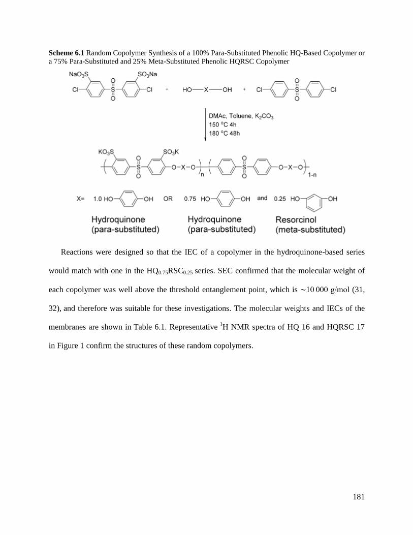
181
Scheme 6.1 Random Copolymer Synthesis of a 100% Para-Substituted Phenolic HQ-Based Copolymer or
a 75% Para-Substituted and 25% Meta-Substituted Phenolic HQRSC Copolymer
Reactions were designed so that the IEC of a copolymer in the hydroquinone-based series
would match with one in the HQ0.75RSC0.25 series. SEC confirmed that the molecular weight of
each copolymer was well above the threshold entanglement point, which is ∼10 000 g/mol (31,
32), and therefore was suitable for these investigations. The molecular weights and IECs of the
membranes are shown in Table 6.1. Representative 1H NMR spectra of HQ 16 and HQRSC 17
in Figure 1 confirm the structures of these random copolymers.
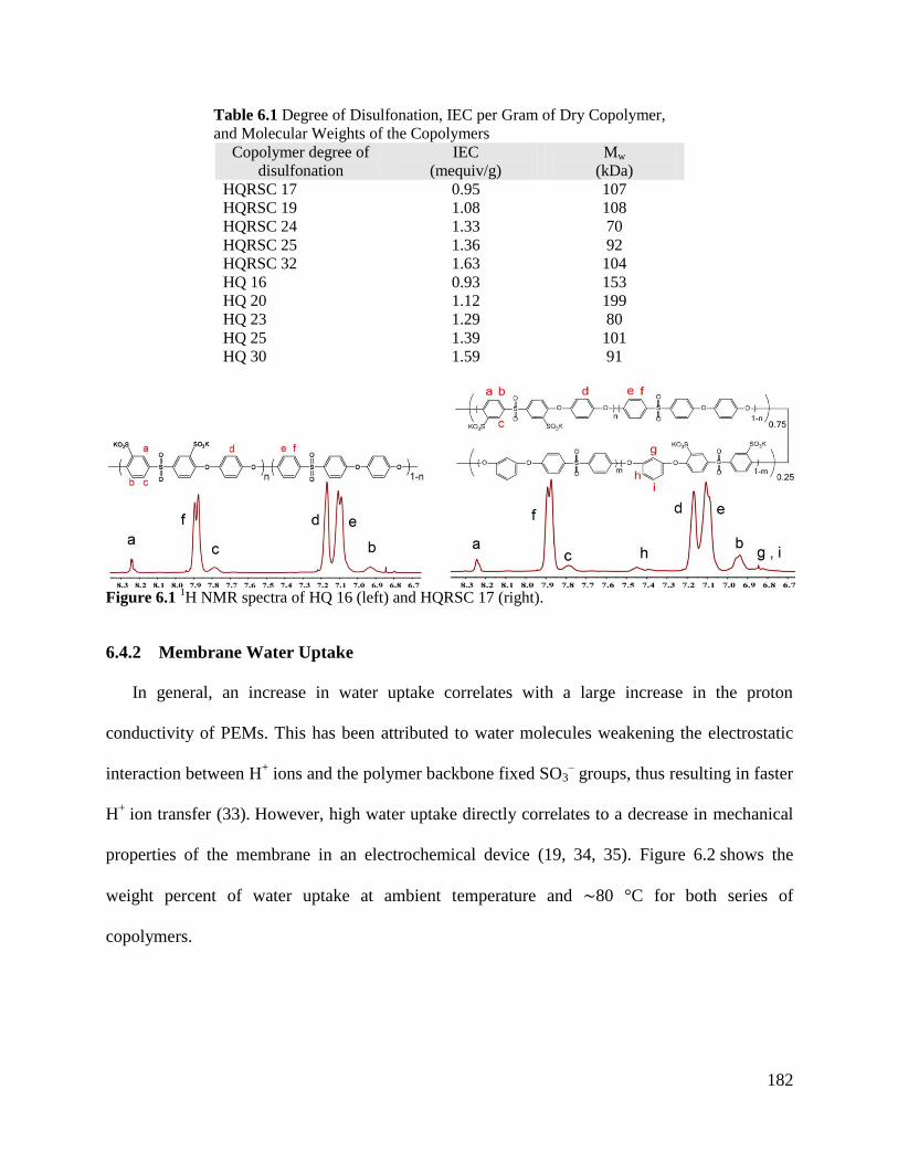
182
Table 6.1 Degree of Disulfonation, IEC per Gram of Dry Copolymer,
and Molecular Weights of the Copolymers
Copolymer degree of
disulfonation
IEC
(mequiv/g)
Mw
(kDa)
HQRSC 17 0.95 107
HQRSC 19 1.08 108
HQRSC 24 1.33 70
HQRSC 25 1.36 92
HQRSC 32 1.63 104
HQ 16 0.93 153
HQ 20 1.12 199
HQ 23 1.29 80
HQ 25 1.39 101
HQ 30 1.59 91
Figure 6.1
1H NMR spectra of HQ 16 (left) and HQRSC 17 (right).
6.4.2 Membrane Water Uptake
In general, an increase in water uptake correlates with a large increase in the proton
conductivity of PEMs. This has been attributed to water molecules weakening the electrostatic
interaction between H+ ions and the polymer backbone fixed SO3
– groups, thus resulting in faster
H+ ion transfer (33). However, high water uptake directly correlates to a decrease in mechanical
properties of the membrane in an electrochemical device (19, 34, 35). Figure 6.2 shows the
weight percent of water uptake at ambient temperature and ∼80 °C for both series of
copolymers.
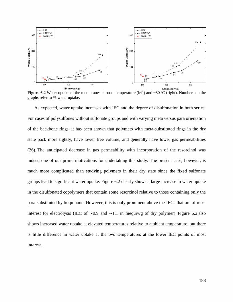
183
Figure 6.2 Water uptake of the membranes at room temperature (left) and ~80 ºC (right). Numbers on the
graphs refer to % water uptake.
As expected, water uptake increases with IEC and the degree of disulfonation in both series.
For cases of polysulfones without sulfonate groups and with varying meta versus para orientation
of the backbone rings, it has been shown that polymers with meta-substituted rings in the dry
state pack more tightly, have lower free volume, and generally have lower gas permeabilities
(36). The anticipated decrease in gas permeability with incorporation of the resorcinol was
indeed one of our prime motivations for undertaking this study. The present case, however, is
much more complicated than studying polymers in their dry state since the fixed sulfonate
groups lead to significant water uptake. Figure 6.2 clearly shows a large increase in water uptake
in the disulfonated copolymers that contain some resorcinol relative to those containing only the
para-substituted hydroquinone. However, this is only prominent above the IECs that are of most
interest for electrolysis (IEC of ∼0.9 and ∼1.1 in mequiv/g of dry polymer). Figure 6.2 also
shows increased water uptake at elevated temperatures relative to ambient temperature, but there
is little difference in water uptake at the two temperatures at the lower IEC points of most
interest.
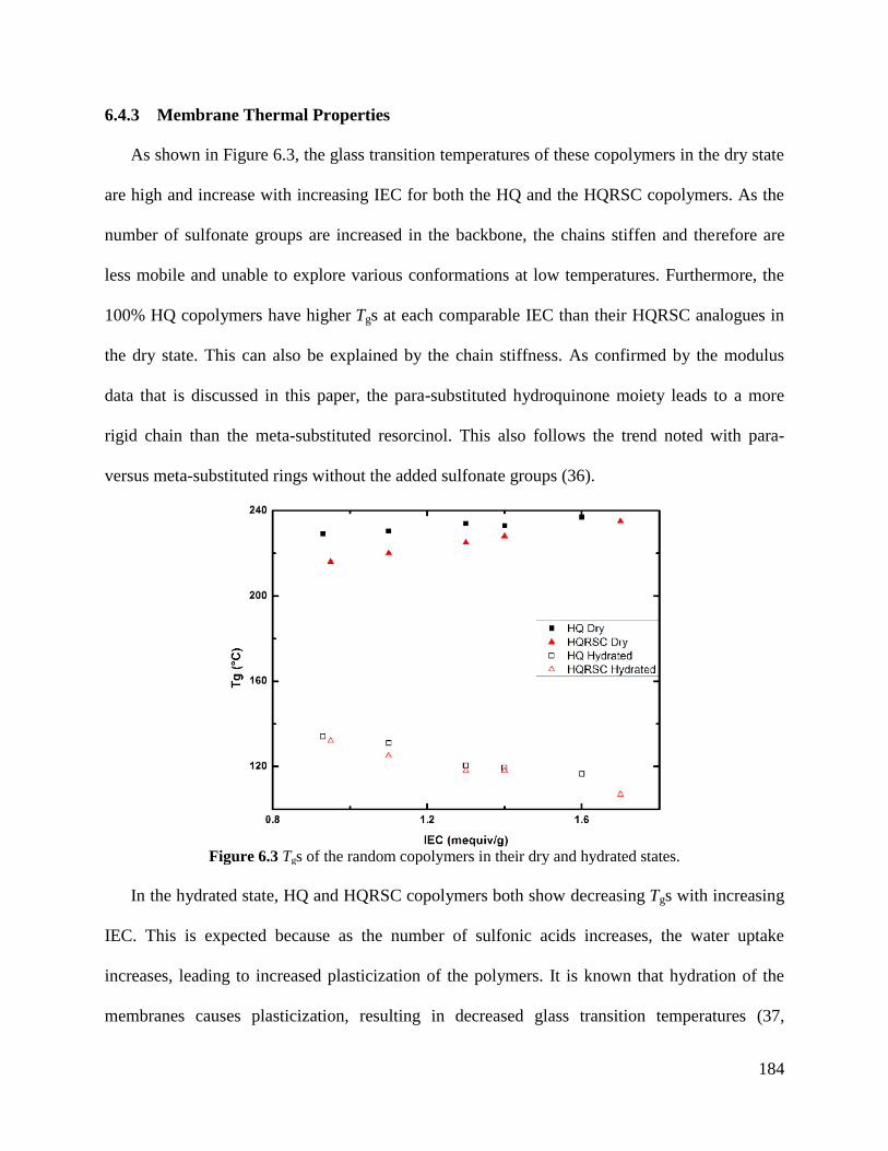
184
6.4.3 Membrane Thermal Properties
As shown in Figure 6.3, the glass transition temperatures of these copolymers in the dry state
are high and increase with increasing IEC for both the HQ and the HQRSC copolymers. As the
number of sulfonate groups are increased in the backbone, the chains stiffen and therefore are
less mobile and unable to explore various conformations at low temperatures. Furthermore, the
100% HQ copolymers have higher Tgs at each comparable IEC than their HQRSC analogues in
the dry state. This can also be explained by the chain stiffness. As confirmed by the modulus
data that is discussed in this paper, the para-substituted hydroquinone moiety leads to a more
rigid chain than the meta-substituted resorcinol. This also follows the trend noted with para-
versus meta-substituted rings without the added sulfonate groups (36).
Figure 6.3 Tgs of the random copolymers in their dry and hydrated states.
In the hydrated state, HQ and HQRSC copolymers both show decreasing Tgs with increasing
IEC. This is expected because as the number of sulfonic acids increases, the water uptake
increases, leading to increased plasticization of the polymers. It is known that hydration of the
membranes causes plasticization, resulting in decreased glass transition temperatures (37,
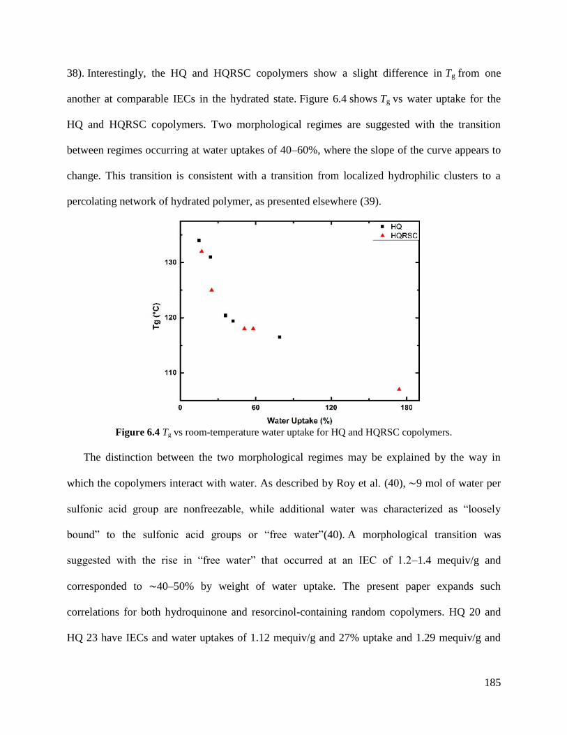
185
38). Interestingly, the HQ and HQRSC copolymers show a slight difference in Tg from one
another at comparable IECs in the hydrated state. Figure 6.4 shows Tg vs water uptake for the
HQ and HQRSC copolymers. Two morphological regimes are suggested with the transition
between regimes occurring at water uptakes of 40–60%, where the slope of the curve appears to
change. This transition is consistent with a transition from localized hydrophilic clusters to a
percolating network of hydrated polymer, as presented elsewhere (39).
Figure 6.4 Tg vs room-temperature water uptake for HQ and HQRSC copolymers.
The distinction between the two morphological regimes may be explained by the way in
which the copolymers interact with water. As described by Roy et al. (40), ∼9 mol of water per
sulfonic acid group are nonfreezable, while additional water was characterized as “loosely
bound” to the sulfonic acid groups or “free water”(40). A morphological transition was
suggested with the rise in “free water” that occurred at an IEC of 1.2–1.4 mequiv/g and
corresponded to ∼40–50% by weight of water uptake. The present paper expands such
correlations for both hydroquinone and resorcinol-containing random copolymers. HQ 20 and
HQ 23 have IECs and water uptakes of 1.12 mequiv/g and 27% uptake and 1.29 mequiv/g and
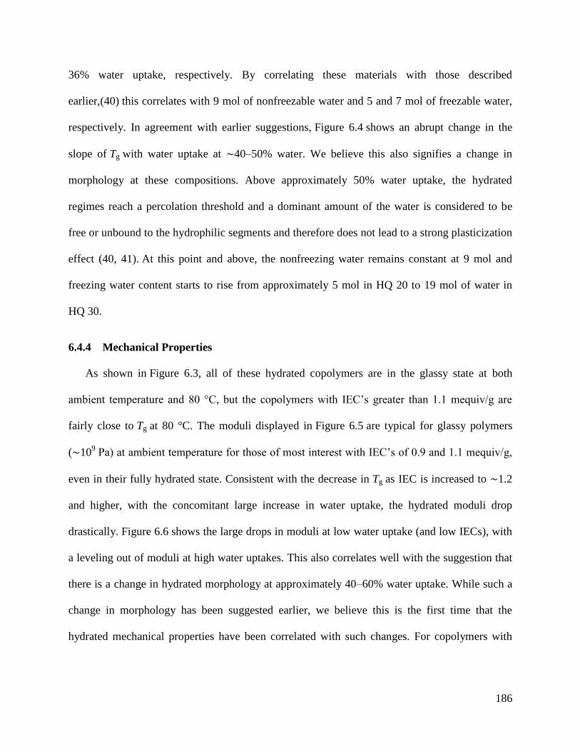
186
36% water uptake, respectively. By correlating these materials with those described
earlier,(40) this correlates with 9 mol of nonfreezable water and 5 and 7 mol of freezable water,
respectively. In agreement with earlier suggestions, Figure 6.4 shows an abrupt change in the
slope of Tg with water uptake at ∼40–50% water. We believe this also signifies a change in
morphology at these compositions. Above approximately 50% water uptake, the hydrated
regimes reach a percolation threshold and a dominant amount of the water is considered to be
free or unbound to the hydrophilic segments and therefore does not lead to a strong plasticization
effect (40, 41). At this point and above, the nonfreezing water remains constant at 9 mol and
freezing water content starts to rise from approximately 5 mol in HQ 20 to 19 mol of water in
HQ 30.
6.4.4 Mechanical Properties
As shown in Figure 6.3, all of these hydrated copolymers are in the glassy state at both
ambient temperature and 80 °C, but the copolymers with IEC’s greater than 1.1 mequiv/g are
fairly close to Tg at 80 °C. The moduli displayed in Figure 6.5 are typical for glassy polymers
(∼109 Pa) at ambient temperature for those of most interest with IEC’s of 0.9 and 1.1 mequiv/g,
even in their fully hydrated state. Consistent with the decrease in Tg as IEC is increased to ∼1.2
and higher, with the concomitant large increase in water uptake, the hydrated moduli drop
drastically. Figure 6.6 shows the large drops in moduli at low water uptake (and low IECs), with
a leveling out of moduli at high water uptakes. This also correlates well with the suggestion that
there is a change in hydrated morphology at approximately 40–60% water uptake. While such a
change in morphology has been suggested earlier, we believe this is the first time that the
hydrated mechanical properties have been correlated with such changes. For copolymers with
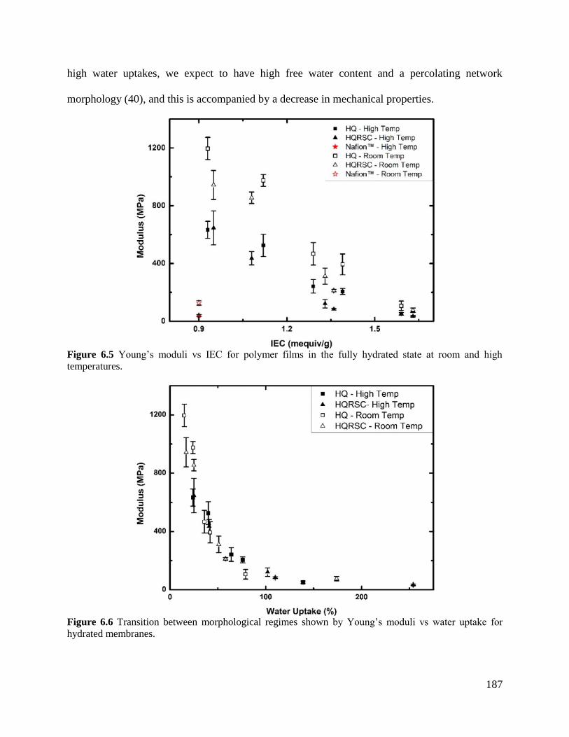
187
high water uptakes, we expect to have high free water content and a percolating network
morphology (40), and this is accompanied by a decrease in mechanical properties.
Figure 6.5 Young’s moduli vs IEC for polymer films in the fully hydrated state at room and high
temperatures.
Figure 6.6 Transition between morphological regimes shown by Young’s moduli vs water uptake for
hydrated membranes.
188
Since fully hydrated mechanical properties of candidate electrolysis membrane materials are
rarely reported, it is instructive to provide such comparisons between Nafion and the materials
investigated in this work. Albert et al. (22) reported fully hydrated properties of Nafion NR212 at
ambient temperature to be 7–8 MPa ultimate stress with an ultimate elongation of ∼60%. In
close agreement, Shi et al. (42) reported hydrated properties of Nafion 212 as having an ultimate
stress of 6 MPa and ultimate elongation of 35% at ambient temperature under immersion
conditions, and these properties fell to an ultimate stress of 2 MPa and approximately 45%
ultimate elongation at 70 °C. The data on Nafion 212 collected in the present study showed the
film extending out to the extension limit of our instrument (200% elongation) without failure, so
we could not discern the ultimate properties, but the stress at that extension limit was ∼25 MPa
(immersed in water at room temperature). All of the four poly(arylene ether sulfone)s of most
interest in this study yielded and then strain hardened. The ultimate stresses at room temperature
under immersion conditions were HQ 16 (54 ± 8.2 MPa), HQ 20 (40 ± 2 MPa), HQRSC 17 (42 ±
3 MPa), and HQRSC 19 (48 ± 1 MPa) with ultimate elongations of HQ 16 (113 ± 8%), HQ 20
(105 ± 8%), HQRSC 17 (82 ± 5%), and HQRSC 19 (162 ± 8%). At 80 °C, these copolymers also
yielded and then strain hardened, but they also extended out to the extension limit of the
instrument. Even so, the stresses at that 200% limit at 80 °C were HQ 16 (∼42 MPa), HQ 20
(∼33 MPa), HQRSC 17 (∼47 MPa), and HQRSC 19 (∼31 MPa), all of which were greater than
the stress at 200% elongation for Nafion 212 at room temperature. Even for the high IEC
disulfonated polysulfone copolymers, both the strengths at yield and the elastic moduli are
notably higher than for Nafion under similar hydration conditions. For lower IEC disulfonated
random copolymers at ambient temperature and in the hydrated condition, the strength at yield is
between 20 and 30 MPa and the modulus is between 800 and 1200 MPa. This result indicates
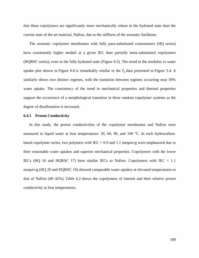
189
that these copolymers are significantly more mechanically robust in the hydrated state than the
current state of the art material, Nafion, due to the stiffness of the aromatic backbone.
The aromatic copolymer membranes with fully para-substituted comonomers (HQ series)
have consistently higher moduli at a given IEC than partially meta-substituted copolymers
(HQRSC series), even in the fully hydrated state (Figure 6.5). The trend in the modulus vs water
uptake plot shown in Figure 6.6 is remarkably similar to the Tg data presented in Figure 5.4. It
similarly shows two distinct regimes, with the transition between regimes occurring near 50%
water uptake. The consistency of the trend in mechanical properties and thermal properties
support the occurrence of a morphological transition in these random copolymer systems as the
degree of disulfonation is increased.
6.4.5 Proton Conductivity
In this study, the proton conductivities of the copolymer membranes and Nafion were
measured in liquid water at four temperatures: 30, 60, 90, and 100 °C. In each hydrocarbon-
based copolymer series, two polymers with IEC = 0.9 and 1.1 mequiv/g were emphasized due to
their reasonable water uptakes and superior mechanical properties. Copolymers with the lower
IECs (HQ 16 and HQRSC 17) have similar IECs to Nafion. Copolymers with IEC = 1.1
mequiv/g (HQ 20 and HQRSC 19) showed comparable water uptakes at elevated temperatures to
that of Nafion (40–42%). Table 6.2 shows the copolymers of interest and their relative proton
conductivity at four temperatures.
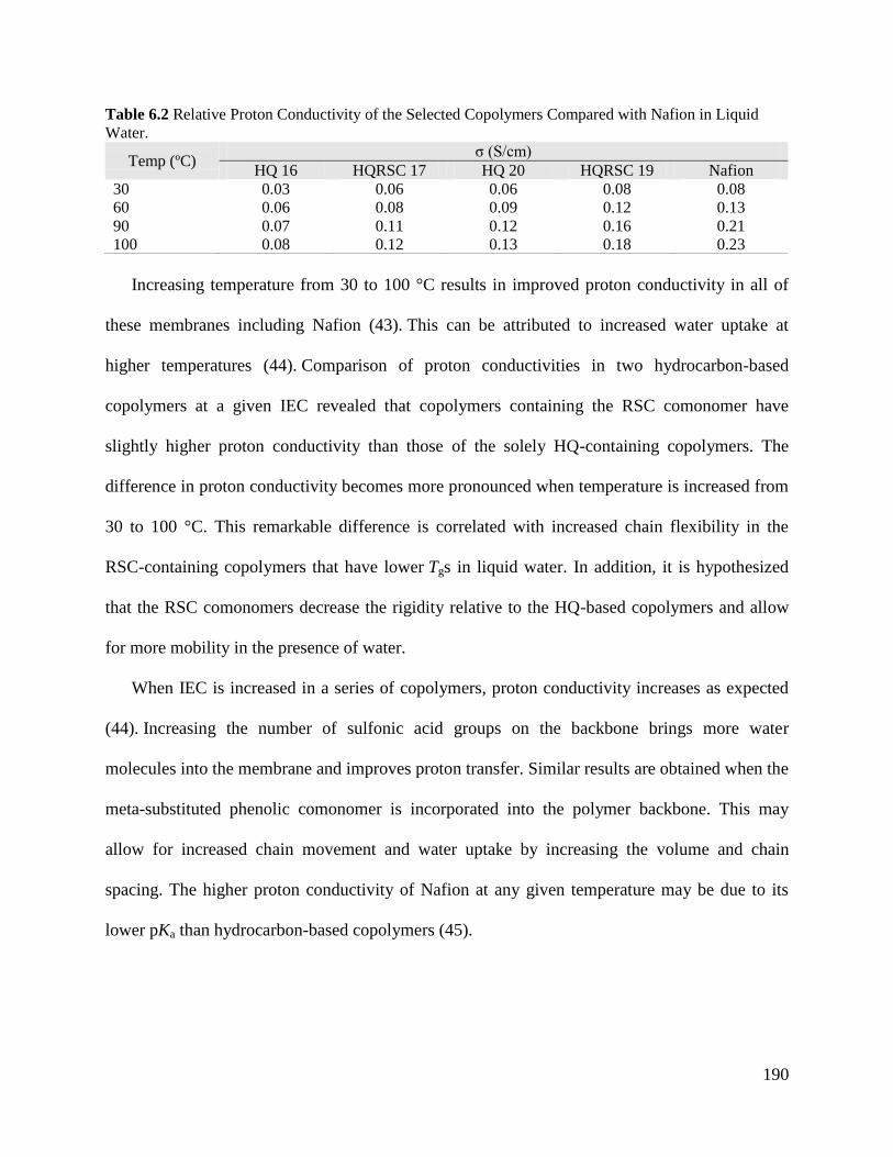
190
Table 6.2 Relative Proton Conductivity of the Selected Copolymers Compared with Nafion in Liquid
Water.
Temp (ºC) σ (S/cm)
HQ 16 HQRSC 17 HQ 20 HQRSC 19 Nafion
30 0.03 0.06 0.06 0.08 0.08
60 0.06 0.08 0.09 0.12 0.13
90 0.07 0.11 0.12 0.16 0.21
100 0.08 0.12 0.13 0.18 0.23
Increasing temperature from 30 to 100 °C results in improved proton conductivity in all of
these membranes including Nafion (43). This can be attributed to increased water uptake at
higher temperatures (44). Comparison of proton conductivities in two hydrocarbon-based
copolymers at a given IEC revealed that copolymers containing the RSC comonomer have
slightly higher proton conductivity than those of the solely HQ-containing copolymers. The
difference in proton conductivity becomes more pronounced when temperature is increased from
30 to 100 °C. This remarkable difference is correlated with increased chain flexibility in the
RSC-containing copolymers that have lower Tgs in liquid water. In addition, it is hypothesized
that the RSC comonomers decrease the rigidity relative to the HQ-based copolymers and allow
for more mobility in the presence of water.
When IEC is increased in a series of copolymers, proton conductivity increases as expected
(44). Increasing the number of sulfonic acid groups on the backbone brings more water
molecules into the membrane and improves proton transfer. Similar results are obtained when the
meta-substituted phenolic comonomer is incorporated into the polymer backbone. This may
allow for increased chain movement and water uptake by increasing the volume and chain
spacing. The higher proton conductivity of Nafion at any given temperature may be due to its
lower pKa than hydrocarbon-based copolymers (45).
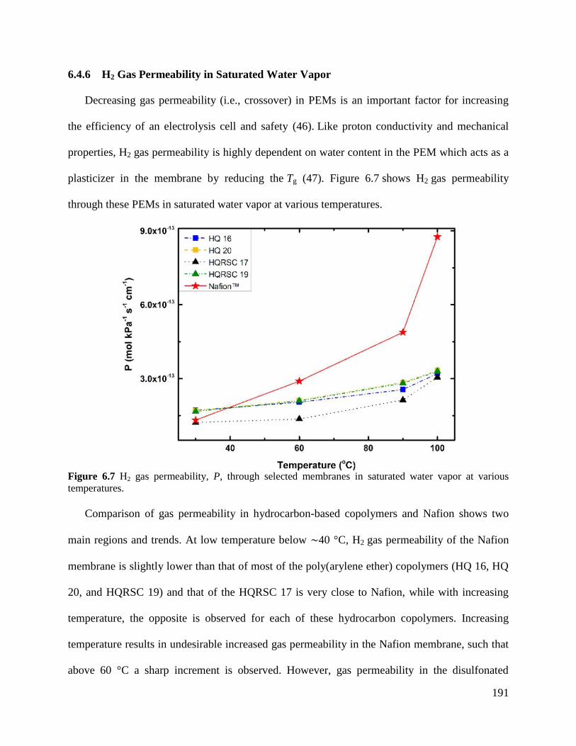
191
6.4.6 H2 Gas Permeability in Saturated Water Vapor
Decreasing gas permeability (i.e., crossover) in PEMs is an important factor for increasing
the efficiency of an electrolysis cell and safety (46). Like proton conductivity and mechanical
properties, H2 gas permeability is highly dependent on water content in the PEM which acts as a
plasticizer in the membrane by reducing the Tg (47). Figure 6.7 shows H2 gas permeability
through these PEMs in saturated water vapor at various temperatures.
Figure 6.7 H2 gas permeability, P, through selected membranes in saturated water vapor at various
temperatures.
Comparison of gas permeability in hydrocarbon-based copolymers and Nafion shows two
main regions and trends. At low temperature below ∼40 °C, H2 gas permeability of the Nafion
membrane is slightly lower than that of most of the poly(arylene ether) copolymers (HQ 16, HQ
20, and HQRSC 19) and that of the HQRSC 17 is very close to Nafion, while with increasing
temperature, the opposite is observed for each of these hydrocarbon copolymers. Increasing
temperature results in undesirable increased gas permeability in the Nafion membrane, such that
above 60 °C a sharp increment is observed. However, gas permeability in the disulfonated
192
copolymers only increases slowly and steadily. This behavior in PEMs is related to their Tgs. As
shown in the bottom of Figure 6.3, the Tgs of all of these copolymers where the gas
permeabilities were measured are above the measurement temperatures, so they are all in the
glassy state. Nafion has a significantly lower Tg relative to those of the aromatic copolymers (41,
48, 49). When Nafion is plasticized by water, its Tg decreases further to lower temperatures
(44). The drastic increase in gas permeability in the water at 60 °C and above is due to the low
polymer Tg.
Unlike Nafion that has a low Tg, these disulfonated copolymers with higher wet Tgs show low
gas permeabilities due to their aromatic rings and increased chain rigidity. Investigation of the
effect of symmetric and asymmetric aromatic comonomers on gas permeability of glassy
copolymers confirms that meta-substituted comonomers act as a good gas barrier in the
copolymer, even in the hydrated state (36). As expected, Figure 6.7 shows that incorporation of
the meta-substituted RSC comonomer into these HQ-based copolymers resulted in lower gas
permeabilities in this temperature range.
6.4.7 Performance
The ratio of proton conductivity (σ) and gas permeability (P), defined as σ/P, gives better
insight regarding the performance of a membrane in the water electrolysis cell. As the high
proton conductivity is critical for a PEM, gas crossover is of similar importance by improving
the efficiency, safety, and purity of gaseous product (4, 50, 51). As an example, consider using
Nafion as a reference point as we have done in this manuscript. Suppose one has a material that
has 1/2 the conductivity of Nafion yet 1/4 of the gas permeability. If that membrane has 1/2 the
thickness, the membrane resistance of the two become equal while the thinner membrane will
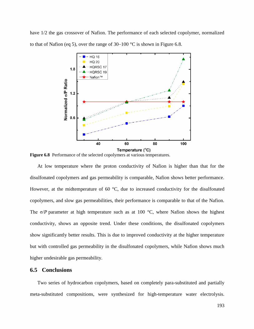
193
have 1/2 the gas crossover of Nafion. The performance of each selected copolymer, normalized
to that of Nafion (eq 5), over the range of 30–100 °C is shown in Figure 6.8.
Figure 6.8 Performance of the selected copolymers at various temperatures.
At low temperature where the proton conductivity of Nafion is higher than that for the
disulfonated copolymers and gas permeability is comparable, Nafion shows better performance.
However, at the midtemperature of 60 °C, due to increased conductivity for the disulfonated
copolymers, and slow gas permeabilities, their performance is comparable to that of the Nafion.
The σ/P parameter at high temperature such as at 100 °C, where Nafion shows the highest
conductivity, shows an opposite trend. Under these conditions, the disulfonated copolymers
show significantly better results. This is due to improved conductivity at the higher temperature
but with controlled gas permeability in the disulfonated copolymers, while Nafion shows much
higher undesirable gas permeability.
6.5 Conclusions
Two series of hydrocarbon copolymers, based on completely para-substituted and partially
meta-substituted compositions, were synthesized for high-temperature water electrolysis.
194
Addition of resorcinol, the meta-substituted comonomer, to the para-substituted copolymer
structure results in decreased chain stiffness (decreased hydrated moduli with meta substitution)
and increased water absorption. These factors are reflected in the increased proton conductivities
of the meta-substituted copolymers in the hydrated state.
Despite the slightly lower proton conductivities of the selected hydrocarbon-based
copolymers in comparison to Nafion, they showed remarkably lower H2 gas permeabilities,
particularly at elevated temperatures. This is attributed to their much higher Tgs in their hydrated
form relative to the perfluorinated polymer. In fact, Nafion has such a high gas permeability that
having exceptional proton conductivity at elevated temperature was not sufficient to elicit
reasonable performance. In addition to gas permeability, the mechanical properties of Nafion
near 100 °C are unsatisfactory for long-term performance as a high-temperature electrolysis
membrane. In contrast, the aromatic HQ 17 and HQRSC 19 copolymers showed good proton
conductivity, excellent mechanical properties, and good σ/P performance ratios at elevated
temperatures in their hydrated state.
6.6 References (1) Ursua, A.; Gandia, L. M.; Sanchis, P. Hydrogen Production From Water Electrolysis:
Current Status and Future Trends. Proc. IEEE 2012, 100, 410−426.
(2) Amjad, U.-E. S.; Vita, A.; Galletti, C.; Pino, L.; Specchia, S. Comparative Study on
Steam and Oxidative Steam Reforming of Methane with Noble Metal Catalysts. Ind. Eng.
Chem. Res. 2013, 52, 15428−15436.
(3) Turner, J. A. A Realizable Renewable Energy Future. Science 1999, 285, 687−689.
(4) Carmo, M.; Fritz, D. L.; Mergel, J.; Stolten, D. A Comprehensive Review on PEM Water
Electrolysis. Int. J. Hydrogen Energy 2013, 38, 4901−4934.
(5) Siracusano, S.; Baglio, V.; Stassi, A.; Merlo, L.; Moukheiber, E.; Arico, A. S.
Performance Analysis of Short-Side-Chain Aquivion Perfluorosulfonic Acid Polymer
for Proton Exchange Membrane Water Electrolysis. J. Membr. Sci. 2014, 466, 1−7.
(6) Millet, P.; Dragoe, D.; Grigoriev, S.; Fateev, V.; Etievant, C. GenHyPEM: A Research
Program on PEM Water Electrolysis Supported by the European Commission. Int. J.
Hydrogen Energy 2009, 34, 4974−4982.
(7) Linkous, C. A.; Andeson, H. R.; Kopitzke, R. W.; Nelson, G. L. Developement of New
Proton Exchange Membrane Electrolytes for Water Electrolysis at Higher Temperatures.
Int. J. Hydrogen Energy 1998, 23, 525−529.
195
(8) Navarra, M. A.; Croce, F.; Scrosati, B. New, High Temperature Superacid Zirconia-
Doped Nafion Composite Membranes. J. Mater. Chem. 2007, 17, 3210−3215.
(9) Schalenbach, M.; Carmo, M.; Fritz, D. L.; Mergel, J.; Stolten, D. Pressurized PEM Water
Electrolysis: Efficiency and Gas Crossover. Int. J. Hydrogen Energy 2013, 38,
14921−14933.
(10) Schalenbach, M.; Hoefner, T.; Paciok, P.; Carmo, M.; Lueke, W.; Stolten, D. Gas
Permeation Through Nafion. Part 1: Measurements. J. Phys. Chem. C 2015, 119,
25145−25155.
(11) Miyatake, K.; Zhou, H.; Matsuo, T.; Uchida, H.; Watanabe, M. Proton Conductive
Polyimide Electrolytes Containing Trifluoromethyl Groups: Synthesis, Properties, and
DMFC Performance. Macromolecules 2004, 37, 4961−4966.
(12) Sarkar, P.; Mohanty, A. K.; Bandyopadhyay, P.; Chattopadhyay, S.; Banerjee, S. Proton
Exchange Properties of Flexible Diamine-based New Fluorinated Sulfonated Polyimides.
RSC Adv. 2014, 4, 11848− 11858.
(13) Gao, Y.; Robertson, G. P.; Guiver, M. D.; Mikhailenko, S. D.; Li, X.; Kaliaguine, S.
Synthesis of Poly(Arylene Ether Ether Ketone Ketone) Copolymers Containing Pendant
Sulfonic Acid Groups Bonded to Naphthalene as Proton Exchange Membrane Materials.
Macromolecules 2004, 37, 6748−6754.
(14) Li, Q.; Chen, Y.; Rowlett, J. R.; McGrath, J. E.; Mack, N. H.; Kim, Y. S. Controlled
Disulfonated Poly(Arylene Ether Sulfone) Multiblock Copolymers for Direct Methanol
Fuel Cells. ACS Appl. Mater. Interfaces 2014, 6, 5779−5788.
(15) Badami, A. S.; Lane, O.; Lee, H. S.; Roy, A.; McGrath, J. E. Fundamental Investigations
of the Effect of the Linkage Group on the Behavior of Hydrophilic-Hydrophobic
Poly(Arylene Ether Sulfone) Multiblock Copolymers for Proton Exchange Membrane
Fuel Cells. J. Membr. Sci. 2009, 333, 1−11.
(16) Higashihara, T.; Matsumoto, K.; Ueda, M. Sulfonated Aromatic Hydrocarbon Polymers
as Proton Exchange Membranes for Fuel Cells. Polymer 2009, 50, 5341−5357.
(17) Lee, C. H.; Lee, S. Y.; Lee, Y. M.; Lee, S. Y.; Rhim, J. W.; Lane, O.; McGrath, J. E.
Surface-Fluorinated Proton-Exchange Membrane with High Electrochemical Durability
for Direct Methanol Fuel Cells. ACS Appl. Mater. Interfaces 2009, 1, 1113−1121.
(18) Yuan, S.; Guo, X. X.; Aili, D.; Pan, C.; Li, Q. F.; Fang, J. H. Poly(Imide Benzimidazole)s
for High Temperature Polymer Electrolyte Membrane Fuel Cells. J. Membr. Sci. 2014,
454, 351−358.
(19) Li, N. W.; Guiver, M. D. Ion Transport by Nanochannels in IonContaining Aromatic
Copolymers. Macromolecules 2014, 47, 2175− 2198.
(20) Danilczuk, M.; Schlick, S.; Coms, D. F. Detection of Radicals by Spin Trapping ESR in a
Fuel Cell Operating with a Sulfonated Poly(Ether Ether Ketone) (SPEEK) Membrane.
Macromolecules 2013, 46, 6110−6117.
(21) Smith, D. W.; Oladoyinbo, F. O.; Mortimore, W. A.; Colquhoun, H. M.; Thomassen, M.
S.; degard, A.; Guillet, N.; Mayousse, E.; Klicpera, T.; Hayes, W. A Microblock
Ionomer in ACS Applied Materials & Interfaces Research Article DOI:
10.1021/acsami.7b02401 ACS Appl. Mater. Interfaces 2017, 9, 20067−20075 20074
Proton Exchange Membrane Electrolysis for the Production of High Purity Hydrogen.
Macromolecules 2013, 46, 1504−1511.
196
(22) Albert, A.; Barnett, A. O.; Thomassen, M. S.; Schmidt, T. J.; Gubler, L. Radiation-
Grafted Polymer Electrolyte Membranes for Water Electrolysis Cells: Evaluation of Key
Membrane Properties. ACS Appl. Mater. Interfaces 2015, 7, 22203−22212.
(23) Zhang, H.; Shen, P. K. Recent Development of Polymer Electrolyte Membranes for Fuel
Cells. Chem. Rev. 2012, 112, 2780− 2832.
(24) Takimoto, N.; Takamuku, S.; Abe, M.; Ohira, A.; Lee, H. S.; McGrath, J. E. Conductive
Area Ratio of Multiblock Copolymer Electrolyte Membranes Evaluated by e-AFM and
its Impact on Fuel Cell Performance. J. Power Sources 2009, 194, 662−667. (25)
Krajinovic, K.; Kaz, T.; Haering, T.; Gogel, V.; Kerres, J. Highly Sulphonated
Multiblock-co-polymers for Direct Methanol Fuel Cells. Fuel Cells 2011, 11, 787−800.
(26) Gil, M.; Ji, X.; Li, X.; Na, H.; Eric Hampsey, J.; Lu, Y. Direct Synthesis of Sulfonated
Aromatic Poly(Ether Ether Ketone) Proton Exchange Membranes for Fuel Cell
Applications. J. Membr. Sci. 2004, 234, 75−81.
(27) Wang, F.; Hickner, M.; Ji, Q.; Harrison, W.; Mecham, J.; Zawodzinski, A. T.; McGrath,
J. E. Synthesis of Highly Sulfonated Poly(Arylene Ether Sulfone) Random(Statistical)
Copolymers via Direct Polymerization. Macromol. Symp. 2001, 175, 387−396.
(28) Kerres, J.; Ullrich, A.; Hein, M. Preparation and Characterization of Novel Basic
Polysulfone Polymers. J. Polym. Sci., Part A: Polym. Chem. 2001, 39, 2874−2888.
(29) Ghassemi, H.; McGrath, J. E.; Zawodzinski, T. A. Multiblock Sulfonated-Fluorinated
Poly(Arylene Ether)s for a Proton Exchange Membrane Fuel Cell. Polymer 2006, 47,
4132−4139.
(30) Lee, H. S.; Roy, A.; Lane, O.; Lee, M.; McGrath, J. E. Synthesis and Characterization of
Multiblock Copolymers Based on Hydrophilic Disulfonated Poly(Arylene Ether Sulfone)
and Hydrophobic Partially Fluorinated Poly(Arylene Ether Ketone) for Fuel Cell
Applications. J. Polym. Sci., Part A: Polym. Chem. 2010, 48, 214−222.
(31) Oh, H. J.; Freeman, B. D.; McGrath, J. E.; Ellison, C. J.; Mecham, S.; Lee, K. S.; Paul, D.
R. Rheological Studies of Disulfonated Poly(Arylene Ether Sulfone) Plasticized with
Poly(Ethylene Glycol) for Membrane Formation. Polymer 2014, 55, 1574−1582.
(32) Roovers, J.; Toporowski, P. M.; Ethier, R. Viscoelastic Properties of Melts of ’RADEL
R’ Polysulfone Fractions. High Perform. Polym. 1990, 2, 165−179.
(33) Hu, N.; Chen, R.; Hsu, A. Molecular Simulation of the Glass Transition and Proton
Conductivity of 2,2′-Benzidinedisulfonic Acid and 4,4′-Diaminodiphenylether-2,2′-
disulfonic Acid-based Copolyimides as Polyelectrolytes for Fuel Cell Applications.
Polym. Int. 2006, 55, 872−882.
(34) Choi, J.; Lee, K. M.; Wycisk, R.; Pintauro, P. N.; Mather, P. T. Nanofiber Network Ion-
Exchange Membranes. Macromolecules 2008, 41, 4569−4572.
(35) Einsla, B. R.; Kim, Y. S.; Hickner, M. A.; Hong, Y. T.; Hill, M. L.; Pivovar, B. S.;
McGrath, J. E. Sulfonated Naphthalene Dianhydride Based Polyimide Copolymers for
Proton-Exchange-Membrane Fuel Cells II. Membrane Properties and Fuel Cell
Performance. J. Membr. Sci. 2005, 255, 141−148.
(36) Aitken, C. L.; Koros, W. J.; Paul, D. R. Effect of Structural Symmetry on Gas-Transport
Properties of Polysulfones. Macromolecules 1992, 25, 3424−3434.
(37) Xie, W.; Ju, H.; Geise, G. M.; Freeman, B. D.; Mardel, J. I.; Hill, A. J.; McGrath, J. E.
Effect of Free Volume on Water and Salt Transport Properties in Directly Copolymerized
Disulfonated Poly- (Arylene Ether Sulfone) Random Copolymers. Macromolecules 2011,
44, 4428−4438.
197
(38) Immergut, E. H.; Mark, H. F. Principles of Plasticization. In Plasticization and Plasticizer
Processes; Advances in Chemistry Series; American Chemical Society: 1965; Vol. 48, pp
1−26.
(39) Kim, Y. S.; Wang, F.; Hickner, M. A.; McCartney, S.; Hong, Y. T.; Harrison, W.;
Zawodzinski, T. A.; Mcgrath, J. E. Effect of Acidification Treatment and Morphological
Stability of Sulfonated Poly(Arylene Ether Sulfone) Copolymer Proton-Exchange
Membranes for Fuel-Cell Use above 100 °C. J. Polym. Sci., Part B: Polym. Phys. 2003,
41, 2816−2828.
(40) Roy, A.; Hickner, M. A.; Lee, H.-S.; Glass, T.; Paul, M.; Badami, A.; Riffle, J. S.;
McGrath, J. E. States of Water in Proton Exchange Membranes: Part A - Influence of
Chemical Structure and Composition. Polymer 2017, 111, 297−306.
(41) Kim, Y. S.; Dong, L. M.; Hickner, M. A.; Glass, T. E.; Webb, V.; McGrath, J. E. State of
Water in Disulfonated Poly(Arylene Ether Sulfone) Copolymers and a Perfluorosulfonic
Acid Copolymer (Nafion) and its Effect on Physical and Electrochemical Properties.
Macromolecules 2003, 36, 6281−6285.
(42) Shi, S. W.; Liu, D.; Liu, D. Z.; Tae, P.; Gao, C. Y.; Yan, L.; An, K.; Chen, X. Mechanical
Properties and Microstructure Changes of Proton Exchange Membrane Under Immersed
Conditions. Polym. Eng. Sci. 2014, 54 (10), 2215−2221.
(43) Saito, M.; Hayamizu, K.; Okada, T. Temperature Dependence of Ion and Water
Transport in Perfluorinated Ionomer Membranes for Fuel Cells. J. Phys. Chem. B 2005,
109, 3112−3119.
(44) Harrison, W. L.; Hickner, M. A.; Kim, Y. S.; McGrath, J. E. Poly(Arylene Ether Sulfone)
Copolymers and Related Systems from Disulfonated Monomer Building Blocks:
Synthesis, Characterization, and Performance - A Topical Review. Fuel Cells 2005, 5,
201−212.
(45) Wang, F.; Hickner, M.; Kim, Y. S.; Zawodzinski, T. A.; McGrath, J. E. Direct
Polymerization of Sulfonated Poly(Arylene Ether Sulfone) Random (Statistical)
Copolymers: Candidates for New Proton Exchange Membranes. J. Membr. Sci. 2002,
197, 231−242.
(46) Mohamed, H. F.; Kobayashi, Y.; Kuroda, C. S.; Ohira, A. Effects of Ion exchange on the
Free Volume and Oxygen Permeation in Nafion for Fuel Cells. J. Phys. Chem. B 2009,
113 (8), 2247−2252.
(47) Sakai, T.; Takenaka, H.; Wakabayashi, N.; Kawami, Y.; Torikai, E. Gas Permeation
Properties of Solid Polymer Electrolyte (SPE) Membranes. J. Electrochem. Soc. 1985,
132, 1328−1332.
(48) Osborn, S. J.; Hassan, M. K.; Divoux, G. M.; Rhoades, D. W.; Mauritz, K. A.; Moore, R.
B. Glass Transition Temperature of Perfluorosulfonic Acid Ionomers. Macromolecules
2007, 40, 3886− 3890. (49) Jung, H. Y.; Kim, J. W. Role of the Glass Transition
Temperature of Nafion 117 Membrane in the Preparation of the Membrane Electrode
Assembly in a Direct Methanol Fuel Cell (DMFC). Int. J. Hydrogen Energy 2012, 37,
12580−12585.
(50) Bose, S.; Kuila, T.; Nguyen, T. X. H.; Kim, N. H.; Lau, K. T.; Lee, J. H. Polymer
Membranes for High Temperature Proton Exchange Membrane Fuel Cell: Recent
Advances and Challenges. Prog. Polym. Sci. 2011, 36 (6), 813−843.
(51) Arico, A. S.; Siracusano, S.; Briguglio, N.; Baglio, V.; Di Blasi, A.; Antonucci, V.
Polymer Electrolyte Membrane Water Electrolysis: Status of Technologies and Potential

198
Applications in Combination with Renewable Power Sources. J. Appl. Electrochem.
2013, 43 (2), 107−118.
199
Chapter 7: Synthesis and Characterization
of Post-Sulfonated Poly(Arylene Ether
Sulfone) Membranes for Potential
Applications in Water Desalination
This chapter has been adapted from a published manuscript by Shreya Roy Choudhury,
Ozma Lane, Dana Kazerooni, Gurtej S Narang, Eui-Soung Jang, Benny D Freeman, John J
Lesko, Judy S Riffle from the following reference: Polymer, 2019, 117, 250-261. Reprinted with
permission from Elsevier.
Dana Kazerooni’s contribution to this paper include assisting in synthesizing the polymers,
crosslinking the membranes, performing gel-fraction and water uptake measurements, and
completely running and analyzing hydrated mechanical properties for each membrane.
Shreya Roy Choudhury,a Ozma Lane,
a Dana Kazerooni,
a,b Gurtej S. Narang,
a Eui Soung
Jang,c
Benny D. Freeman,c John J. Lesko,
b J. S. Riffle
a*
aMacromolecules Innovation Institute, Virginia Tech, Blacksburg, VA 24061, United States
bCollege of Engineering, Virginia Tech, Blacksburg, VA 24061, United States
cDepartment of Chemical Engineering and the Center for Energy and Environmental
Resources, University of Texas at Austin, Austin, TX 78758, United States
7.1 Abstract
This study focuses on post-sulfonated polysulfone membranes for potential applications in
desalination by reverse osmosis or electrodialysis. A series of controlled molecular weight (5000
and 10,000 g/mole) polysulfones containing hydroquinone and their high molecular weight linear
counterparts were synthesized using post-sulfonation of pre-formed polymers under mild
conditions. The sulfonic acid groups were substituted on only the hydroquinone units. Amine
terminated oligomers were crosslinked with a tetrafunctional epoxy molecule under suitable
conditions to form membranes whereas the high molecular weight polymers were cast into linear
films by chain entanglements. Fixed charge concentrations of the linear membranes increased
from 3.94 to 5.14 meq/mL when the ion exchange capacity was decreased from 1.30 to 0.88
200
meq/g. The fixed charge concentration of the networks cast from the 5000 g/mol oligomers
increased from 4.04 to 6.23 meq/mL with a decrease in the ion exchange capacity from 1.51 to
0.90 meq/g.
7.2 Introduction
Clean water is critical to the safety, security and survivability of mankind. Nearly 41% of the
Earth’s population lives in water-stressed areas, and the water scarcity will be exacerbated by an
increasing population [1-4]. According to the U.S. Geological Survey, ~96.5 % of the Earth’s
water is located in seas and oceans with the remaining in surface and ground water, mostly
frozen in glaciers and ice caps. Thus, ~96% of the total water is saline and only ~0.8% is
considered to be accessible fresh water [5]. Thus, saltwater desalination is economically the key
to tackle the problem of water scarcity. Thermal desalination methods are not energetically
efficient because they rely on an energy-intensive phase change and require a large quantity of
fuel to vaporize the water. Membrane based desalination processes have proven to be more
economical and energetically efficient than thermal methods, thus playing a key role in the
desalination industry [6–8]. This paper reports new membranes that may have potential for
desalination by electrodialysis (ED) and reverse osmosis (RO).
ED is applied for demineralization or concentrating salt-containing solutions. In this process,
positively charged anion exchange membranes (AEMs) and negatively charged cation exchange
membranes (CEMs) are alternately stacked between two electrodes [9–11]. When an electric
potential is applied and feed water solution is pumped through the cell, the membranes allow the
oppositely charged counterions to pass through but reject similarly charged co-ions. The
electrolyte becomes concentrated in alternate compartments, and the other compartments are
depleted of ions. ED membranes require high fixed charge concentrations (ion exchange
201
capacity/water uptake) to repel co-ions via Donnan exclusion. However, with an increase in ionic
content, there is often an increase in water uptake that is detrimental to the hydrated mechanical
properties of the membranes [12]. Hence, our goal is to develop membranes for ED with high
fixed charge concentration and optimum water uptake with primary focus on CEMs in this study.
RO is the most widely utilized membrane technique for commercial desalination [13,14]. RO
polymeric membranes are semipermeable and follow the principle of solution diffusion to
achieve desalination [15]. Current state-of-the art RO membranes are thin film composites
comprised of an interfacially polymerized, crosslinked aromatic polyamide atop a porous
polymeric film that provides mechanical support [7,16]. These membranes can provide ~99%
salt rejection. The permselective polyamide layer is very thin (~100 nm) to afford high water
flux. One of the disadvantages of the polyamide thin film composites is that the process of
interfacial polymerization gives rise to a rough surface. This facilitates deposition of salts and
other contaminants, leading to scaling and fouling [17–19]. Sulfonated polysulfone membranes
are a potential alternative to the polyamide membranes. The polysulfones are polymerized then
cast to form membranes with smooth surfaces, and they are also more chemically resistant to
disinfectants such as chlorine than the polyamides [20,21].
Sulfonated poly(arylene ether sulfone) copolymers can be synthesized by two methods – i)
direct polymerization of pre-sulfonated monomers, and ii) synthesis of a non-sulfonated polymer
followed by post-sulfonation. In the first method, the degree of sulfonation is controlled by
changing the concentration of the sulfonated comonomer [22–24]. However, one disadvantage of
this process is the need to synthesize the sulfonated monomer.
Historically, the second method of employing the post-sulfonation route led to uncontrolled
sequences of sulfonic acid groups along the chains unless special compositions were utilized.
202
Most previous work on post-sulfonation of polysulfones utilized rather harsh conditions because
the rings to be sulfonated included both activated and deactivated rings toward the electrophilic
aromatic sulfonation reaction. Hence, post-sulfonation as an approach for sulfonating
poly(arylene ether sulfone)s was abandoned due to poor control over the extent of sulfonation,
inability to control the microstructure of the sulfonated units, and decrease in molecular weight
due to chain scission during sulfonation. These post sulfonated polysulfone membranes were
found to be resistant to degradation by chlorine but showed relatively low salt rejections relative
to the state-of-the-art interfacial polyamides [25]. Alternatively, Rose and coworkers reported
controlled post-sulfonation of poly(arylene ether sulfone)s that contained hydroquinone units
[26]. The sulfonation reaction proceeded only at the hydroquinone because all of the other rings
were deactivated toward electrophilic aromatic sulfonation by the electron withdrawing sulfone
groups. A series of investigations on this class of materials has been published [26–30]. In the
current research, the reaction kinetics and measurements of molecular weight of a commercial
polysulfone containing hydroquinone (Radel A) were studied to optimize the sulfonation
process with a minimal level of chain scission. This information was used as a model study for
developing a series of post-sulfonated polymers with varying structures to determine their
relationships among structures and properties.
Studies have shown that the crosslink density of RO membranes is vital to achieve the
desired transport properties [14,31]. Sundell et al. and Daryaei et al. crosslinked amine
terminated polysulfone oligomers containing a pre-disulfonated monomer with a tetra-epoxide to
obtain membranes with high gel fractions [32,33]. The crosslinked membranes had higher levels
of salt rejection with enhanced water permeability than linear disulfonated membranes at a fixed
anionic group concentration in the backbone [34]. It is postulated that the free volume of the
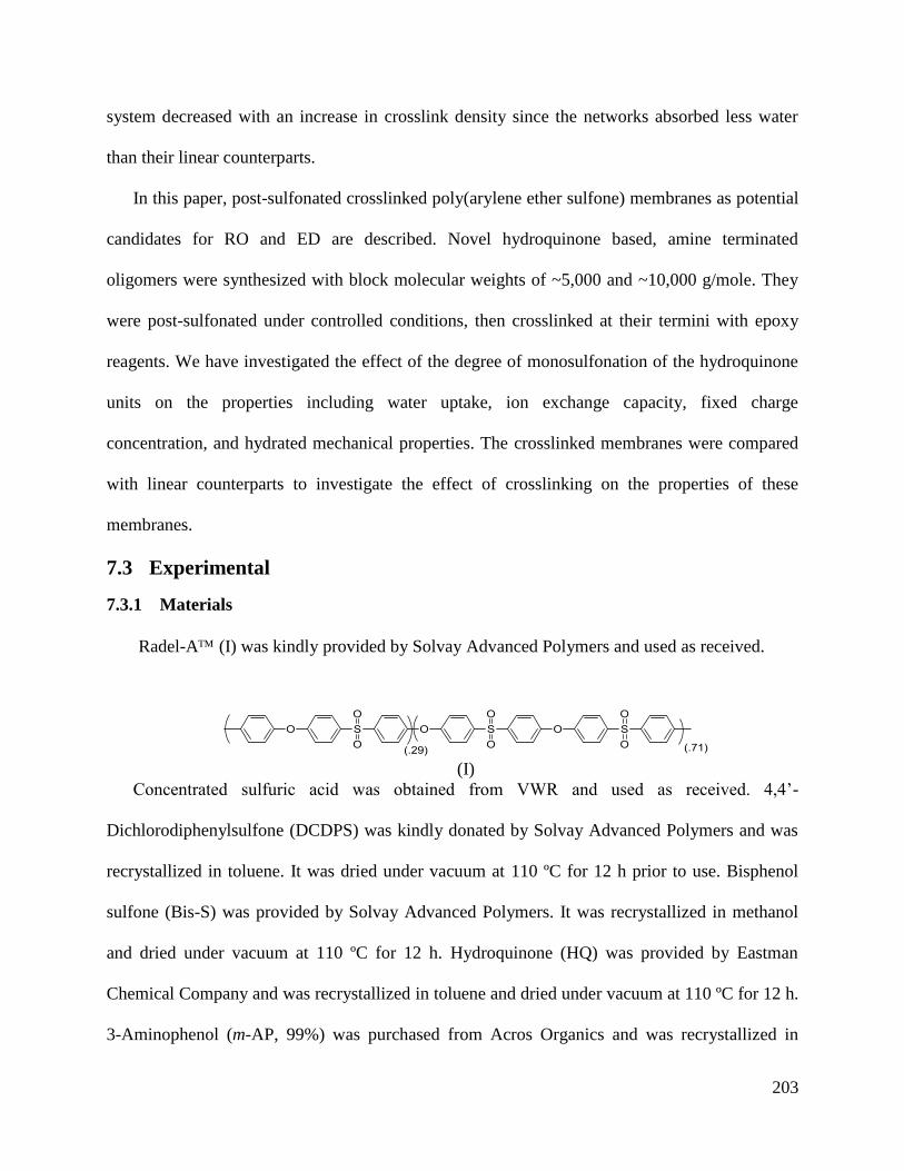
203
system decreased with an increase in crosslink density since the networks absorbed less water
than their linear counterparts.
In this paper, post-sulfonated crosslinked poly(arylene ether sulfone) membranes as potential
candidates for RO and ED are described. Novel hydroquinone based, amine terminated
oligomers were synthesized with block molecular weights of ~5,000 and ~10,000 g/mole. They
were post-sulfonated under controlled conditions, then crosslinked at their termini with epoxy
reagents. We have investigated the effect of the degree of monosulfonation of the hydroquinone
units on the properties including water uptake, ion exchange capacity, fixed charge
concentration, and hydrated mechanical properties. The crosslinked membranes were compared
with linear counterparts to investigate the effect of crosslinking on the properties of these
membranes.
7.3 Experimental
7.3.1 Materials
Radel-A (I) was kindly provided by Solvay Advanced Polymers and used as received.
(I)
Concentrated sulfuric acid was obtained from VWR and used as received. 4,4’-
Dichlorodiphenylsulfone (DCDPS) was kindly donated by Solvay Advanced Polymers and was
recrystallized in toluene. It was dried under vacuum at 110 ºC for 12 h prior to use. Bisphenol
sulfone (Bis-S) was provided by Solvay Advanced Polymers. It was recrystallized in methanol
and dried under vacuum at 110 ºC for 12 h. Hydroquinone (HQ) was provided by Eastman
Chemical Company and was recrystallized in toluene and dried under vacuum at 110 ºC for 12 h.
3-Aminophenol (m-AP, 99%) was purchased from Acros Organics and was recrystallized in
204
ethanol and dried at 70 ºC for 12 h. Potassium carbonate was purchased from Sigma-Aldrich and
was dried under vacuum at 160 ºC for 72 h. For the crosslinking reaction of the sulfonated
oligomers, triphenylphosphine (TPP, 99%) and tetraglycidyl bis(p-aminophenyl)methane
(TGBAM, 92%), sulfolane, N,N-dimethylacetamide (DMAc) and toluene were purchased from
Sigma-Aldrich.
7.3.2 Kinetics of post-sulfonation of a poly(arylene ether sulfone) containing
hydroquinone: Post-sulfonation of Radel A
A solution of 30% (w/v) of Radel A in DMAc was prepared and precipitated in deionized
water in a blender to provide a high surface area powder. This facilitated rapid dissolution during
the sulfonation reaction. The precipitated polymer was filtered, washed with deionized water,
dried without vacuum at 100 ºC for 12 h and then under vacuum at 110 ºC for 12 h to remove the
solvent.
For the sulfonation reaction, a four-neck flask equipped with an overhead stirrer, nitrogen
inlet, condenser and a thermometer was assembled. An oil bath with a thermocouple and
temperature controller was used to control the reaction temperature. Radel A powder (15 g) and
sulfuric acid (150 mL) were added into the flask. Reactions were performed at 40, 50, and 60 ºC.
Time zero was designated when the temperature reached the desired point for the kinetics
experiment (~2 min). Aliquots of 5-10 mL were removed at 5, 10, 15, 30, 60, and 120 min. The
aliquots were quenched by precipitation in deionized water, followed by washing with copious
amounts of deionized water until the pH reached at least 5.
205
7.3.3 Synthesis of sulfonated poly(arylene ether sulfone)s with isolated sulfonated rings by
post-sulfonation
7.3.3.1 Synthesis of amine terminated hydroquinone containing polysulfone (xx-HQS-y)
oligomers (I) with different amounts of hydroquinone relative to Bis-S (where xx =
degree of sulfonation, y = targeted molecular weight)
The hydroquinone sulfone (HQS) oligomer series was synthesized using a nucleophilic
aromatic substitution reaction. The reaction for the synthesis of a 10,000 g/mol, amine-
terminated oligomer with 50 mol % of the bisphenol moieties being hydroquinone (50-HQS-10k)
is provided. HQ (2.642 g, 24 mmol), Bis-S (6.006 g, 24 mmol), and m-AP (0.436 g, 4 mmol)
were dissolved in 67 mL of sulfolane in a 3-neck round bottom flask equipped with a nitrogen
inlet, overhead stirrer, and condenser with a Dean Stark trap. The reaction temperature was
controlled with a temperature controller connected to a thermocouple in a salt bath. Toluene (34
mL) and K2CO3 (8.624 g, 62 mmol) were added and the reaction was refluxed at 180-185 ºC to
azeotropically remove any water. After 4 h, the toluene was removed from the Dean Stark trap.
DCDPS (14.358 g, 50 mmol) was added into the reaction flask and the reaction temperature was
raised to 200-210 ºC. After 36 h of reaction, the mixture was allowed to cool to ~150 ºC and then
diluted with 40 mL of DMAc. The solution was filtered hot to remove salts and subsequently
precipitated in water. The polymer was boiled with 3 changes of water to remove trace amounts
of sulfolane and then dried at 50 ºC for 4 h, followed by 12 h under vacuum at 110 ºC. The other
oligomers in the 5,000 and 10,000 g/mol series were synthesized in a similar manner by varying
the percentage of hydroquinone and m-AP accordingly. Yield of the reaction was 97 %.
206
7.3.3.2 Synthesis of high molecular weight hydroquinone sulfone (xx-HQS) polymers
Aromatic nucleophilic substitution step copolymerization was used to synthesize a series of
hydroquinone-based, high molecular weight poly(arylene ether sulfone) copolymers (XX-HQS).
60-HQS with 60% of the repeat units containing hydroquinone was synthesized as follows. HQ
(19.85 mmol, 2.186 g), DCDPS (33.08 mmol, 9.501 g), Bis-S (13.235 mmol, 3.312 g) and
sulfolane (43 mL) were charged into a 250-mL 3-neck round bottom flask equipped with a
mechanical stirrer, condenser, nitrogen inlet, and Dean-Stark trap filled with toluene. The
mixture was stirred and heated in an oil bath at 150 ºC until the monomers completely dissolved.
K2CO3 (38.382 mmol, 5.305 g) and toluene (21 mL) were added into the flask. The reaction was
refluxed for 6 h to azeotropically remove water from the system. Toluene was drained from the
Dean-Stark trap, and the oil bath temperature was raised to 200 ºC to remove residual toluene
from the reaction. The reaction solution was stirred for 36 h at 200 ºC. The reaction mixture was
hot filtered to remove salts and precipitated in DI water. The polymer was stirred in boiling DI
water for 4 h to remove any residual solvent. The polymer was filtered and dried at 120 ºC under
reduced pressure in a vacuum oven. Yield of the reaction was 95%.
7.3.3.3 Post sulfonation of hydroquinone sulfone oligomers (xx-SHQS-5k and xx-SHQS-
10k) and high molecular weight polymers (xx-SHQS)
The sulfonated hydroquinone sulfone (SHQS) oligomer/polymer series was synthesized by
electrophilic aromatic sulfonation. Ten g of the dried m-AP terminated oligomer or high
molecular weight polymer was dissolved in 100 mL of concentrated sulfuric acid in a 3-neck
round bottom flask equipped with a nitrogen inlet and thermometer, overhead stirrer, and a
condenser. An oil bath was used to maintain a reaction temperature of 50 ºC. The reaction was
stirred vigorously to promote rapid dissolution and to break up any clumps of acid-swollen
207
polymer. After 2 h of reaction, the solution was precipitated into ice-cold water and rinsed
thoroughly to remove the excess acid until litmus paper showed no traces of acid. The oligomer
samples were converted to their salt form by stirring in 0.1 M NaOH for 6 h, filtered, and dried at
50 ºC for 7 h at atmospheric pressure overnight, followed by 12 h under vacuum at 110 ºC.
7.3.4 Characterization
7.3.4.1 Nuclear magnetic resonance spectroscopy (NMR)
Quantitative 1H NMR and COSY NMR analyses were performed on the oligomeric
copolymers and high molecular weight polymers on a Varian Unity Plus spectrometer operating
at 400 MHz at a pulse angle of 30º with a pulse delay of 5 s. The spectra of the copolymers were
obtained from a 10 % (w/v) solution in DMSO-d6 with 64 scans.
7.3.4.2 End group analysis of the oligomers by fluorine derivatization
The amine terminated oligomers with amine and any residual phenolic end groups were
reacted with trifluoroacetic anhydride to produce the respective trifluoroacetate derivatives. The
reaction for the derivatization of a 5,000 g/mol, amine-terminated oligomer with 50 mol % of the
bisphenol moieties being hydroquinone (50-HQS-5k) is provided. 50-HQS-5k oligomer (200 mg,
0.040 mmol), with amine end groups and possibly unreacted hydroxyl end groups, was dissolved
in 5 mL of CHCl3 in a 25-mL flask and trifluoroacetic anhydride (0.5 mL, 3.53 mmol) was
added. The reaction mixture was held at 25 ºC for 12 h. DI water (100 mL) was added to the
reaction mixture to hydrolyze the remaining anhydride, and the mixture was stirred at room
temperature for 2 h. The organic phase was analyzed by 19
F NMR. 19
F NMR spectra were
collected utilizing the same NMR spectrometer operating at 376.29 MHz with a pulse width of
45º and a relaxation delay of 3 s with 64 scans.
208
7.3.4.3 Size Exclusion Chromatography (SEC)
Molecular weights and polydispersities of the polymers were measured using SEC. The
mobile phase was DMAc distilled from CaH2 containing dry LiCl (0.1 M). The column set
consisted of 3 Agilent PLgel 10-mm Mixed B-LS columns 300*7.5 mm
(polystyrene/divinylbenzene) connected in series with a guard column having the same
stationary phase.
The columns and detectors were maintained at 50 ºC. An isocratic pump (Agilent 1260
infinity, Agilent Technologies) with an online degasser (Agilent 1260), autosampler and column
oven were used for mobile phase delivery and sample injection. A system of multiple detectors
connected in series was used for the analyses. A multi-angle laser light scattering detector
(DAWN-HELEOS II, Wyatt Technology Corp.), operating at a wavelength of 658 nm and a
refractive index detector operating at a wavelength of 658 nm (Optilab T-rEX, Wyatt
Technology Corp.) provided online results. The system was corrected for interdetector delay and
band broadening using a 21,000 g/mole polystyrene standard. Data acquisition and analysis were
conducted using Astra 6 software from Wyatt Technology Corp. Validation of the system was
performed by monitoring the molar mass of a known molecular weight polystyrene sample by
light scattering. The accepted variance of the 21,000 g/mole polystyrene standard was defined as
2 standard deviations (11.5% for Mn and 9% for Mw) derived from a set of 34 runs.
Specific refractive indices were measured offline. Oligomer samples with systematically
varying concentrations in DMAc with 0.1M LiCl from ~0.0005 to 0.008 g/L were injected
directly into the RI detector using an injection box. The data was plotted on a graph of dRI
(differential refractive index) versus concentration. dn/dc of the oligomer solution was
determined from the slope of the graph.
209
7.3.5 Film casting and characterization
7.3.5.1 Epoxy-amine crosslinking of the oligomer
The crosslinked films were prepared by adding the oligomer and TGBAM in the molar ratio
of 1:2.5 respectively. TPP was used in a 3.0 % by weight ratio relative to the weight of TGBAM.
The following steps were completed to prepare a crosslinked film containing 10k-50-SHQS. A
mixture of 10k-50-SHQS (0.046 mmol, 0.63 g), TGBAM (0.114 mmol, 0.048 g) and TPP (5.5 x
10-3
mmol, 1.44 mg) were dissolved in 8 mL of DMAc in a vial and stirred until a homogeneous
solution was obtained. The solution was syringe-filtered through a 0.45 μm PTFE filter into a
new vial. The original vial was washed with 7 mL of DMAc and filtered into the new vial to
transfer any residual oligomers. The solution was sonicated for 15 min and was cast on a circular
Teflon mold with flat edges and a diameter of 10 cm. The mold was placed on a levelled surface
inside an oven at 70 ºC. The temperature of the oven was ramped up from 70 to 175 ºC gradually
over 6 h and the film was cured at a steady temperature of 175 ºC for 12 h. The temperature of
the oven was gradually ramped down to 120 ºC and the film was dried under vacuum for 12 h.
The oven was turned off and the film was allowed to cool in the oven to room temperature. The
epoxy-cured network was detached from the Teflon mold by immersion in deionized water and
dried. The thickness of the film was approximately 70 μm +/- 10 μm.
7.3.5.2 Film casting of the high molecular weight polymers
A copolymer (1.2 g) was dissolved in 10 mL of DMAc in a glass vial. The solution was
filtered through a 0.45 μm PTFE filter and the vial was washed with 2 mL of DMAc to form a 10
wt/v% polymer solution. The solution was sonicated for 10 min and cast on a level 4” x 4” clean
glass plate. The plate was cleaned in a base bath, washed and dried prior to film casting. The
films were heated under an IR lamp with a starting temperature of ~45 ºC. The temperature of
210
the IR lamp was ramped up by 20 ºC every 2 h until the temperature reached ~75 ºC. The plate
with the film was kept at that temperature for 8-10 h. The film was dried under vacuum at 110 ºC
for 24 h. The film was delaminated from the glass plate by immersion in deionized water. The
film, in the acidic form, was stirred in 0.1 N NaCl for 3 days to convert it into the salt form. The
film was stirred in deionized water overnight to remove the excess salt and dried under vacuum
at 110 ºC overnight. The thickness of the film was ~100 μm.
7.3.5.3 Gel fraction of the high molecular weight polymers
Crosslinked films were dried at 120 ºC under vacuum overnight. After drying, 0.1−0.2 g of
the sample was placed in a 20-mL scintillation vial filled with DMAc and stirred at 100 ºC for
∼12 h. The remaining solid was filtered, transferred to a weighed vial, dried to a constant weight
at 160 ºC under vacuum for ∼12 h, and then weighed. Three measurements were taken for each
film and gel fractions were calculated by equation 1.
(Equation 1)
7.3.5.4 Water uptake
The water uptakes of the crosslinked and high molecular weight linear membranes were
determined gravimetrically. The membranes in their sodium salt form were dried at 12 ºC under
vacuum for 24 h and weighed. The membranes were soaked in water at room temperature for 24
h. Wet membranes were removed from the water, blotted dry to remove surface droplets, and
quickly weighed. The water uptake of the membranes was calculated according to equation 2,
where massdry and masswet refer to the masses of the dry and the wet membranes, respectively.
(Equation 2)
211
7.3.5.5 Tensile tests of hydrated membranes
The crosslinked membranes were cut into dogbone samples with a gauge width of 3.18 mm
and gauge length of 25 mm, Type V according to ASTM D638-14, using a Cricut Explore One™
cutting machine. Seven samples with uniform thickness of 60-70 μm from each membrane were
tested. The thickness of the dogbones were measured at five points along the gauge length using
a Mitutoyo digimatic micrometer model MDC-1rr
SXF. A hydrated testing cell was secured onto
the Instron to test samples under fully hydrated conditions. The wet samples were loaded into the
hydrated cell of the Instron and the cell was filled with DI water. The samples were immersed in
DI water for at least 24 h prior to testing and allowed to equilibrate in the Instron in the water for
3 min. Uniaxial load tests were performed using an Instron ElectroPuls E1000 testing machine
equipped with a 250-N Dynacell load cell. The crosshead displacement rate was 10 mm/min and
the initial grip separation was 25 mm.
7.4 Results and discussion
Sulfonated polysulfone oligomers with amine end groups prepared from a pre-disulfonated
monomer, 3,3’-disulfonate-4,4’-dichlorodiphenylsulfone (III), were previously investigated by
Sundell et al. and Daryaei et al. [33,34]. The present work deals with the sulfonic acid groups on
isolated rings as opposed to having sulfonates in pairs on adjacent rings so that the placement of
ions could be related to water uptake and fixed charge concentration. Moreover, previous studies
on sulfonated polysulfone membranes in their acid form have shown that above a critical IEC of
~1.3, the absorption of water increases faster as the fixed charge groups on the polymer
backbone is increased [35]. We hypothesize that decreased water uptake per ionic group will
lead to higher salt rejection values due to Donnan exclusion. Thus, the series of membranes
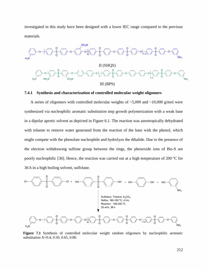
212
investigated in this study have been designed with a lower IEC range compared to the previous
materials.
II (SHQS)
III (BPS)
7.4.1 Synthesis and characterization of controlled molecular weight oligomers
A series of oligomers with controlled molecular weights of ~5,000 and ~10,000 g/mol were
synthesized via nucleophilic aromatic substitution step growth polymerization with a weak base
in a dipolar aprotic solvent as depicted in Figure 6.1. The reaction was azeotropically dehydrated
with toluene to remove water generated from the reaction of the base with the phenol, which
might compete with the phenolate nucleophile and hydrolyze the dihalide. Due to the presence of
the electron withdrawing sulfone group between the rings, the phenoxide ions of Bis-S are
poorly nucleophilic [36]. Hence, the reaction was carried out at a high temperature of 200 ºC for
36 h in a high boiling solvent, sulfolane.
Figure 7.1 Synthesis of controlled molecular weight random oligomers by nucleophilic aromatic
substitution X=0.4, 0.50, 0.65, 0.80.
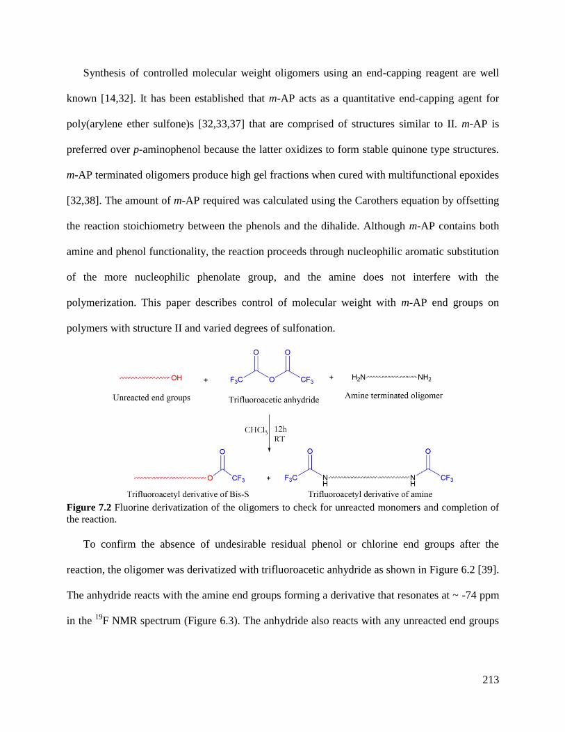
213
Synthesis of controlled molecular weight oligomers using an end-capping reagent are well
known [14,32]. It has been established that m-AP acts as a quantitative end-capping agent for
poly(arylene ether sulfone)s [32,33,37] that are comprised of structures similar to II. m-AP is
preferred over p-aminophenol because the latter oxidizes to form stable quinone type structures.
m-AP terminated oligomers produce high gel fractions when cured with multifunctional epoxides
[32,38]. The amount of m-AP required was calculated using the Carothers equation by offsetting
the reaction stoichiometry between the phenols and the dihalide. Although m-AP contains both
amine and phenol functionality, the reaction proceeds through nucleophilic aromatic substitution
of the more nucleophilic phenolate group, and the amine does not interfere with the
polymerization. This paper describes control of molecular weight with m-AP end groups on
polymers with structure II and varied degrees of sulfonation.
Figure 7.2 Fluorine derivatization of the oligomers to check for unreacted monomers and completion of
the reaction.
To confirm the absence of undesirable residual phenol or chlorine end groups after the
reaction, the oligomer was derivatized with trifluoroacetic anhydride as shown in Figure 6.2 [39].
The anhydride reacts with the amine end groups forming a derivative that resonates at ~ -74 ppm
in the 19
F NMR spectrum (Figure 6.3). The anhydride also reacts with any unreacted end groups
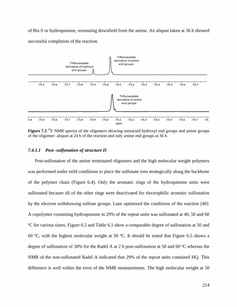
214
of Bis-S or hydroquinone, resonating downfield from the amine. An aliquot taken at 36 h showed
successful completion of the reaction.
Figure 7.3 19
F NMR spectra of the oligomers showing unreacted hydroxyl end groups and amine groups
of the oligomer- aliquot at 24 h of the reaction and only amine end groups at 36 h.
7.4.1.1 Post -sulfonation of structure II
Post-sulfonation of the amine terminated oligomers and the high molecular weight polymers
was performed under mild conditions to place the sulfonate ions strategically along the backbone
of the polymer chain (Figure 6.4). Only the aromatic rings of the hydroquinone units were
sulfonated because all of the other rings were deactivated for electrophilic aromatic sulfonation
by the electron withdrawing sulfone groups. Lane optimized the conditions of the reaction [40].
A copolymer containing hydroquinone in 29% of the repeat units was sulfonated at 40, 50 and 60
ºC for various times. Figure 6.5 and Table 6.1 show a comparable degree of sulfonation at 50 and
60 ºC, with the highest molecular weight at 50 ºC. It should be noted that Figure 6.5 shows a
degree of sulfonation of 30% for the Radel A at 2 h post-sulfonation at 50 and 60 ºC whereas the
NMR of the non-sulfonated Radel A indicated that 29% of the repeat units contained HQ. This
difference is well within the error of the NMR measurements. The high molecular weight at 50
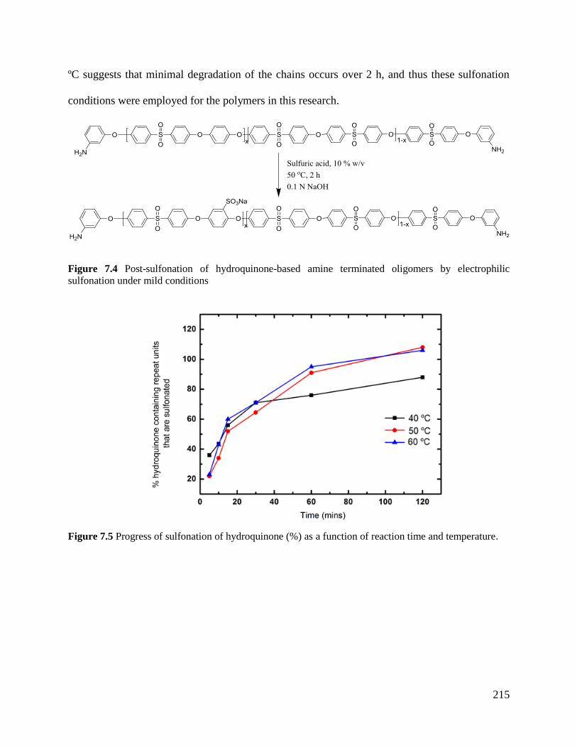
215
ºC suggests that minimal degradation of the chains occurs over 2 h, and thus these sulfonation
conditions were employed for the polymers in this research.
Figure 7.4 Post-sulfonation of hydroquinone-based amine terminated oligomers by electrophilic
sulfonation under mild conditions
Figure 7.5 Progress of sulfonation of hydroquinone (%) as a function of reaction time and temperature.
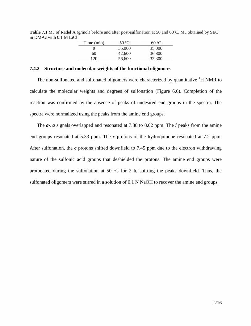
216
Table 7.1 Mw of Radel A (g/mol) before and after post-sulfonation at 50 and 60ºC. Mw obtained by SEC
in DMAc with 0.1 M LiCl
Time (min) 50 ºC 60 ºC
0 35,000 35,000
60 42,600 36,800
120 56,600 32,300
7.4.2 Structure and molecular weights of the functional oligomers
The non-sulfonated and sulfonated oligomers were characterized by quantitative 1H NMR to
calculate the molecular weights and degrees of sulfonation (Figure 6.6). Completion of the
reaction was confirmed by the absence of peaks of undesired end groups in the spectra. The
spectra were normalized using the peaks from the amine end groups.
The a’, a signals overlapped and resonated at 7.88 to 8.02 ppm. The i peaks from the amine
end groups resonated at 5.33 ppm. The c protons of the hydroquinone resonated at 7.2 ppm.
After sulfonation, the c protons shifted downfield to 7.45 ppm due to the electron withdrawing
nature of the sulfonic acid groups that deshielded the protons. The amine end groups were
protonated during the sulfonation at 50 ºC for 2 h, shifting the peaks downfield. Thus, the
sulfonated oligomers were stirred in a solution of 0.1 N NaOH to recover the amine end groups.
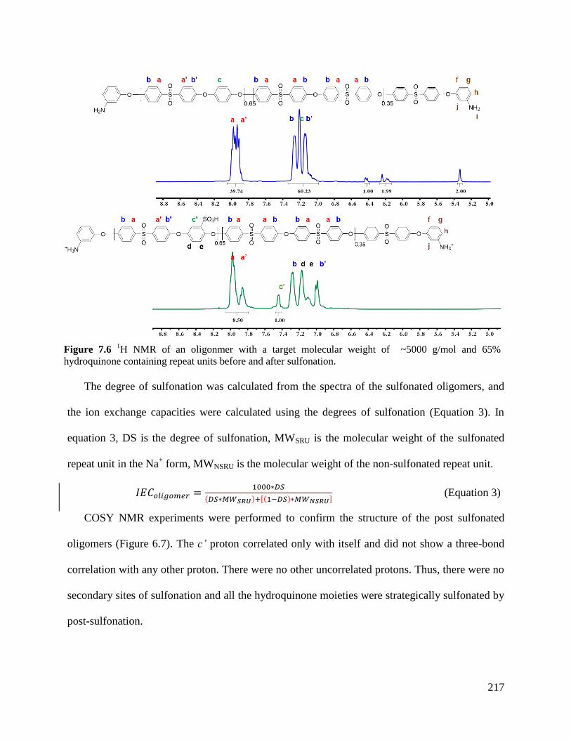
217
The degree of sulfonation was calculated from the spectra of the sulfonated oligomers, and
the ion exchange capacities were calculated using the degrees of sulfonation (Equation 3). In
equation 3, DS is the degree of sulfonation, MWSRU is the molecular weight of the sulfonated
repeat unit in the Na+ form, MWNSRU is the molecular weight of the non-sulfonated repeat unit.
(Equation 3)
COSY NMR experiments were performed to confirm the structure of the post sulfonated
oligomers (Figure 6.7). The c’ proton correlated only with itself and did not show a three-bond
correlation with any other proton. There were no other uncorrelated protons. Thus, there were no
secondary sites of sulfonation and all the hydroquinone moieties were strategically sulfonated by
post-sulfonation.
Figure 7.6 1H NMR of an oligonmer with a target molecular weight of ~5000 g/mol and 65%
hydroquinone containing repeat units before and after sulfonation.
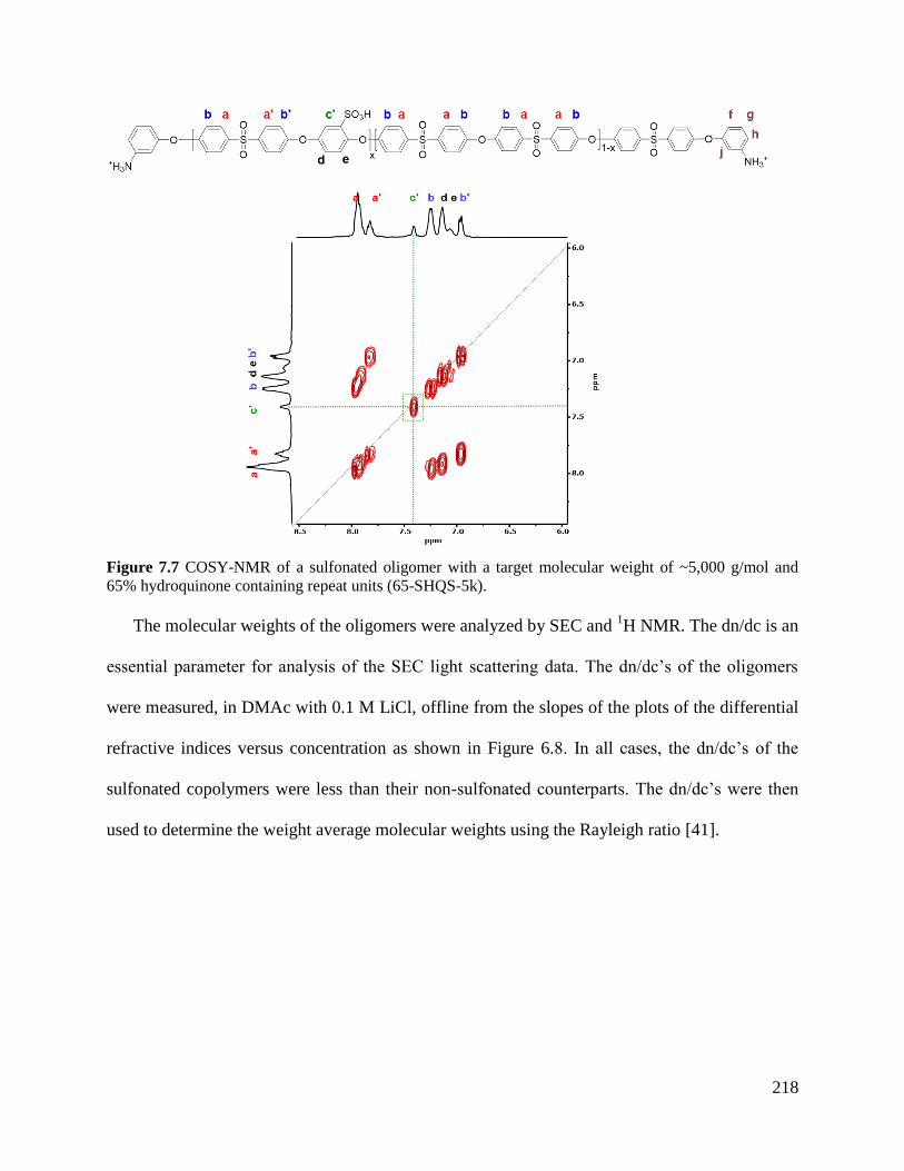
218
Figure 7.7 COSY-NMR of a sulfonated oligomer with a target molecular weight of ~5,000 g/mol and
65% hydroquinone containing repeat units (65-SHQS-5k).
The molecular weights of the oligomers were analyzed by SEC and 1H NMR. The dn/dc is an
essential parameter for analysis of the SEC light scattering data. The dn/dc’s of the oligomers
were measured, in DMAc with 0.1 M LiCl, offline from the slopes of the plots of the differential
refractive indices versus concentration as shown in Figure 6.8. In all cases, the dn/dc’s of the
sulfonated copolymers were less than their non-sulfonated counterparts. The dn/dc’s were then
used to determine the weight average molecular weights using the Rayleigh ratio [41].
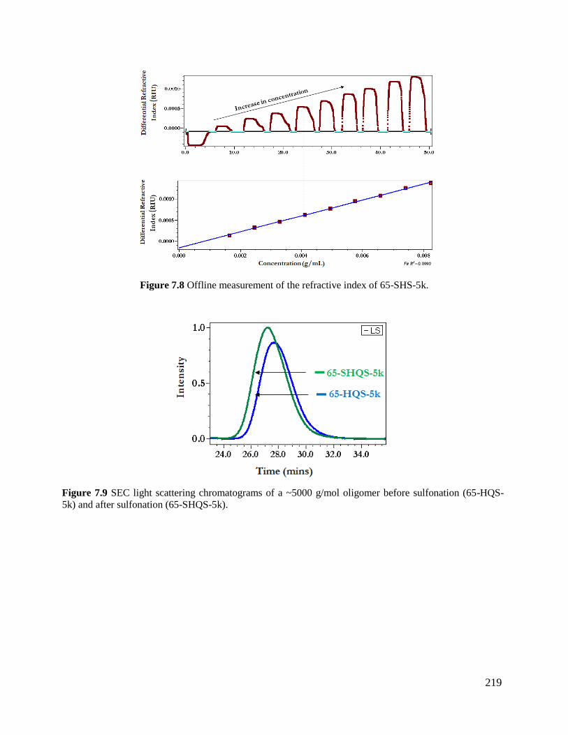
219
Figure 7.8 Offline measurement of the refractive index of 65-SHS-5k.
Figure 7.9 SEC light scattering chromatograms of a ~5000 g/mol oligomer before sulfonation (65-HQS-
5k) and after sulfonation (65-SHQS-5k).
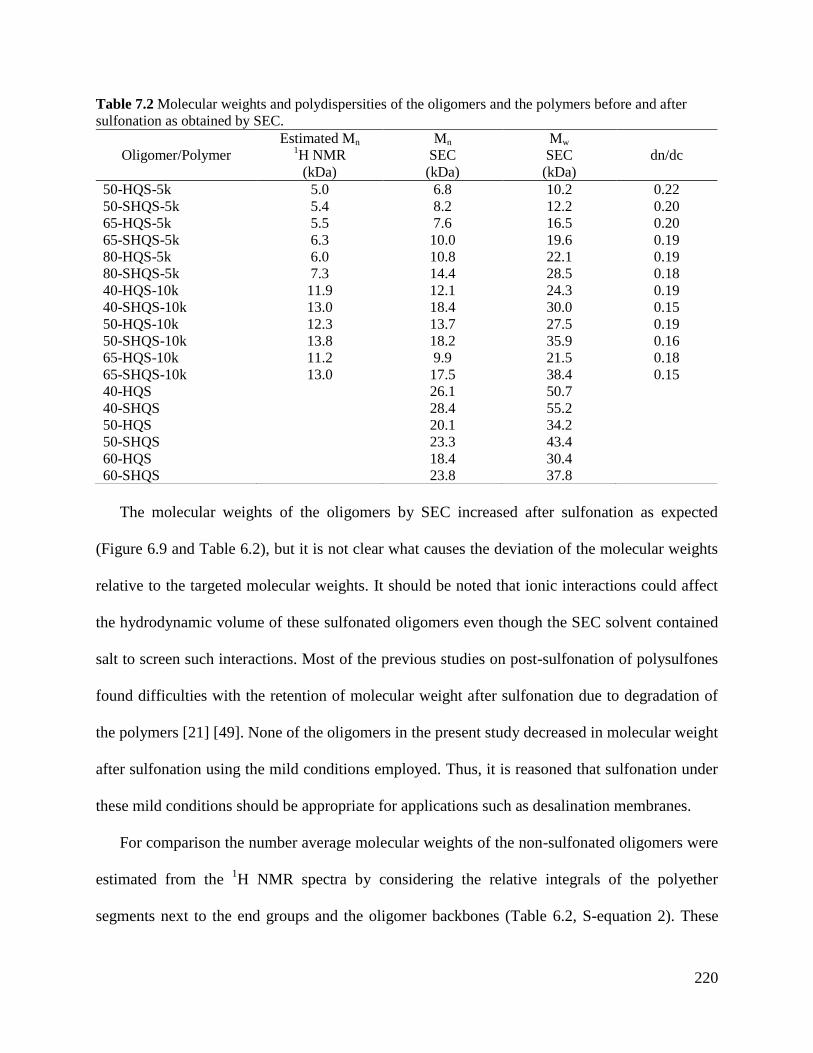
220
Table 7.2 Molecular weights and polydispersities of the oligomers and the polymers before and after
sulfonation as obtained by SEC.
Oligomer/Polymer
Estimated Mn 1H NMR
(kDa)
Mn
SEC
(kDa)
Mw
SEC
(kDa)
dn/dc
50-HQS-5k 5.0 6.8 10.2 0.22
50-SHQS-5k 5.4 8.2 12.2 0.20
65-HQS-5k 5.5 7.6 16.5 0.20
65-SHQS-5k 6.3 10.0 19.6 0.19
80-HQS-5k 6.0 10.8 22.1 0.19
80-SHQS-5k 7.3 14.4 28.5 0.18
40-HQS-10k 11.9 12.1 24.3 0.19
40-SHQS-10k 13.0 18.4 30.0 0.15
50-HQS-10k 12.3 13.7 27.5 0.19
50-SHQS-10k 13.8 18.2 35.9 0.16
65-HQS-10k 11.2 9.9 21.5 0.18
65-SHQS-10k 13.0 17.5 38.4 0.15
40-HQS 26.1 50.7
40-SHQS 28.4 55.2
50-HQS 20.1 34.2
50-SHQS 23.3 43.4
60-HQS 18.4 30.4
60-SHQS 23.8 37.8
The molecular weights of the oligomers by SEC increased after sulfonation as expected
(Figure 6.9 and Table 6.2), but it is not clear what causes the deviation of the molecular weights
relative to the targeted molecular weights. It should be noted that ionic interactions could affect
the hydrodynamic volume of these sulfonated oligomers even though the SEC solvent contained
salt to screen such interactions. Most of the previous studies on post-sulfonation of polysulfones
found difficulties with the retention of molecular weight after sulfonation due to degradation of
the polymers [21] [49]. None of the oligomers in the present study decreased in molecular weight
after sulfonation using the mild conditions employed. Thus, it is reasoned that sulfonation under
these mild conditions should be appropriate for applications such as desalination membranes.
For comparison the number average molecular weights of the non-sulfonated oligomers were
estimated from the 1H NMR spectra by considering the relative integrals of the polyether
segments next to the end groups and the oligomer backbones (Table 6.2, S-equation 2). These
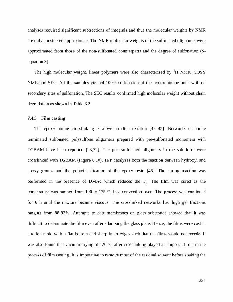
221
analyses required significant subtractions of integrals and thus the molecular weights by NMR
are only considered approximate. The NMR molecular weights of the sulfonated oligomers were
approximated from those of the non-sulfonated counterparts and the degree of sulfonation (S-
equation 3).
The high molecular weight, linear polymers were also characterized by 1H NMR, COSY
NMR and SEC. All the samples yielded 100% sulfonation of the hydroquinone units with no
secondary sites of sulfonation. The SEC results confirmed high molecular weight without chain
degradation as shown in Table 6.2.
7.4.3 Film casting
The epoxy amine crosslinking is a well-studied reaction [42–45]. Networks of amine
terminated sulfonated polysulfone oligomers prepared with pre-sulfonated monomers with
TGBAM have been reported [23,32]. The post-sulfonated oligomers in the salt form were
crosslinked with TGBAM (Figure 6.10). TPP catalyzes both the reaction between hydroxyl and
epoxy groups and the polyetherification of the epoxy resin [46]. The curing reaction was
performed in the presence of DMAc which reduces the Tg. The film was cured as the
temperature was ramped from 100 to 175 ºC in a convection oven. The process was continued
for 6 h until the mixture became viscous. The crosslinked networks had high gel fractions
ranging from 88-93%. Attempts to cast membranes on glass substrates showed that it was
difficult to delaminate the film even after silanizing the glass plate. Hence, the films were cast in
a teflon mold with a flat bottom and sharp inner edges such that the films would not recede. It
was also found that vacuum drying at 120 ºC after crosslinking played an important role in the
process of film casting. It is imperative to remove most of the residual solvent before soaking the
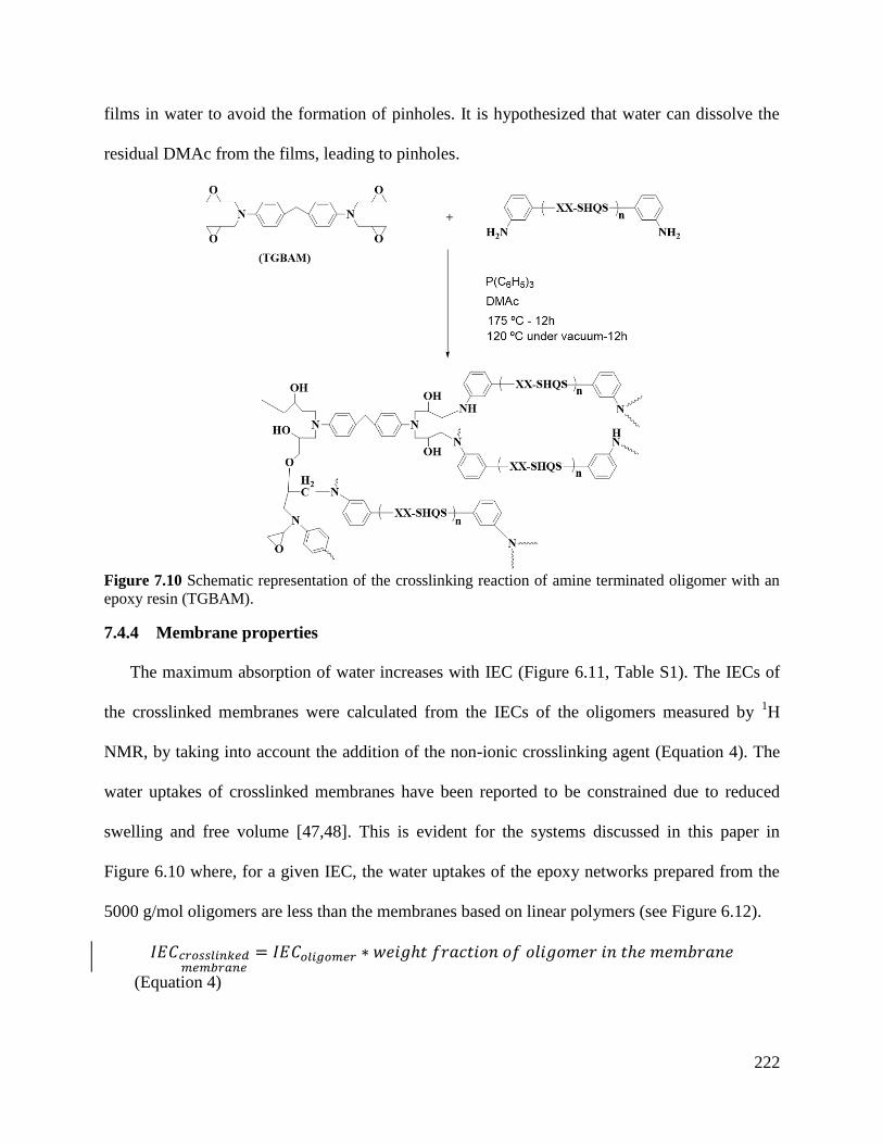
222
films in water to avoid the formation of pinholes. It is hypothesized that water can dissolve the
residual DMAc from the films, leading to pinholes.
Figure 7.10 Schematic representation of the crosslinking reaction of amine terminated oligomer with an
epoxy resin (TGBAM).
7.4.4 Membrane properties
The maximum absorption of water increases with IEC (Figure 6.11, Table S1). The IECs of
the crosslinked membranes were calculated from the IECs of the oligomers measured by 1H
NMR, by taking into account the addition of the non-ionic crosslinking agent (Equation 4). The
water uptakes of crosslinked membranes have been reported to be constrained due to reduced
swelling and free volume [47,48]. This is evident for the systems discussed in this paper in
Figure 6.10 where, for a given IEC, the water uptakes of the epoxy networks prepared from the
5000 g/mol oligomers are less than the membranes based on linear polymers (see Figure 6.12).
(Equation 4)
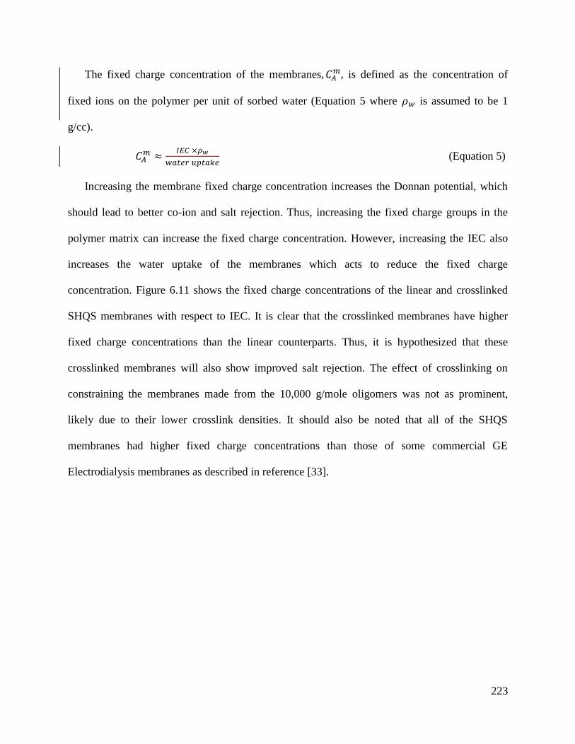
223
The fixed charge concentration of the membranes is defined as the concentration of
fixed ions on the polymer per unit of sorbed water (Equation 5 where is assumed to be 1
g/cc).
(Equation 5)
Increasing the membrane fixed charge concentration increases the Donnan potential, which
should lead to better co-ion and salt rejection. Thus, increasing the fixed charge groups in the
polymer matrix can increase the fixed charge concentration. However, increasing the IEC also
increases the water uptake of the membranes which acts to reduce the fixed charge
concentration. Figure 6.11 shows the fixed charge concentrations of the linear and crosslinked
SHQS membranes with respect to IEC. It is clear that the crosslinked membranes have higher
fixed charge concentrations than the linear counterparts. Thus, it is hypothesized that these
crosslinked membranes will also show improved salt rejection. The effect of crosslinking on
constraining the membranes made from the 10,000 g/mole oligomers was not as prominent,
likely due to their lower crosslink densities. It should also be noted that all of the SHQS
membranes had higher fixed charge concentrations than those of some commercial GE
Electrodialysis membranes as described in reference [33].
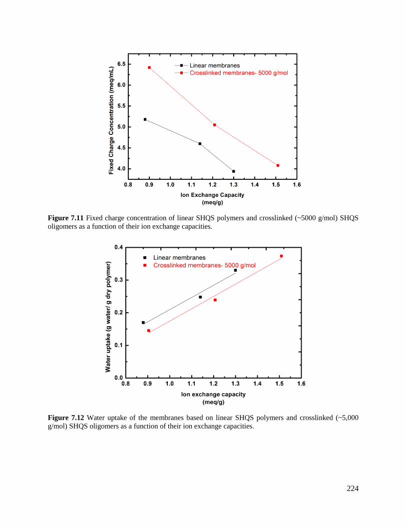
224
Figure 7.11 Fixed charge concentration of linear SHQS polymers and crosslinked (~5000 g/mol) SHQS
oligomers as a function of their ion exchange capacities.
Figure 7.12 Water uptake of the membranes based on linear SHQS polymers and crosslinked (~5,000
g/mol) SHQS oligomers as a function of their ion exchange capacities.
225
7.4.5 Hydrated mechanical properties of the membranes
One of the objectives of this work is to develop membranes with sufficient hydrated
mechanical properties to withstand the resulting in plane and out of plane stress that result from
high applied pressures in reverse osmosis. During fully hydrated uniaxial testing, each membrane
from both the linear and crosslinked sets exhibited elastic moduli on the order of ~108-10
9
Pascals. They also exhibited cavitations leading to brittle fracture at low strain values. Thus, both
families of SHQS membranes demonstrate common glassy polymeric behavior even in fully
hydrated conditions. The tensile data for each membrane, regardless of crosslink density or
molecular weight, showed distinct yield phenomena which quickly led to brittle fracture as
shown in Figure 6.13.
The elastic moduli and yield stresses for all of the materials (Figure 6.14) expectedly
decreased with increasing water uptake. This phenomenon is attributed to plasticization effects
of water in ionically charged polymers. The high dielectric constant of the water and high
affinity between water and ions reduces the van der Waals forces between the polymer chains,
thus leading to an increase in the free volume and chain mobility [50].
Interestingly, the mechanical properties of the crosslinked networks prepared from the 5k and
10k oligomers, and the high molecular weight linear polymers, showed a strong dependence on
water uptake but appeared to be less sensitive to crosslink density. Originally, it was speculated
that an increase in crosslink density should noticeably enhance the material’s strength regardless
of plasticization by water, but the hydrated mechanical properties did not support this premise.
Therefore, the effect of water content, plasticization, supersedes the effect of the 5k to 10k range
of oligomer molecular weights between crosslinks. This might be attributed to the networks
containing the crosslinks were only at the oligomer ends resulting in a low crosslink density. The
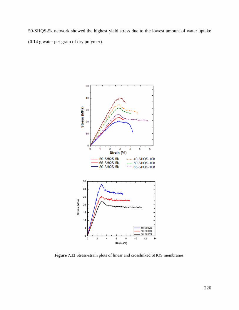
226
50-SHQS-5k network showed the highest yield stress due to the lowest amount of water uptake
(0.14 g water per gram of dry polymer).
Figure 7.13 Stress-strain plots of linear and crosslinked SHQS membranes.
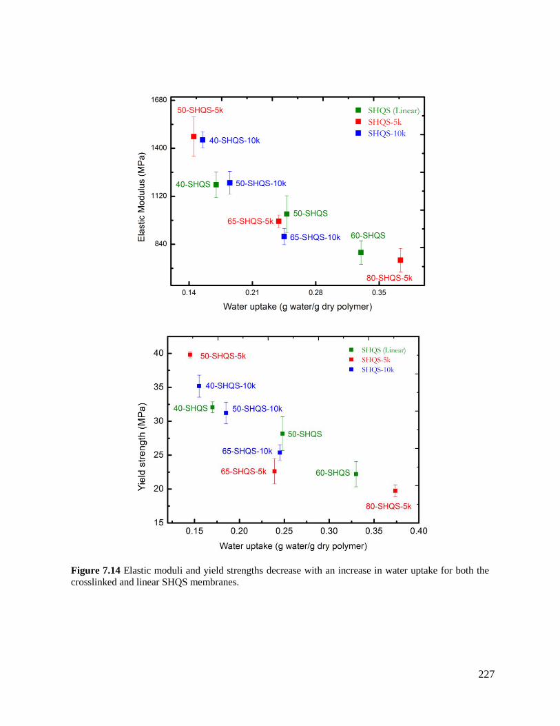
227
Figure 7.14 Elastic moduli and yield strengths decrease with an increase in water uptake for both the
crosslinked and linear SHQS membranes.
228
7.5 Conclusions
This work demonstrates that sulfonated poly(arylene ether sulfone)s can be prepared with
control over both the level of sulfonation and the distribution of sulfonate groups along the
chains, and that this can be achieved by using either pre-sulfonated monomers or by post-
sulfonation. Post-sulfonation is likely to be economically preferred because of its ability to
utilize monomers currently available on the market instead of synthesizing the monomers’
sulfonated derivative. The ability to make sulfonated poly(arylene ether sulfone)s using mild and
economical reagents is the first step towards introducing such polymers into the water
desalination market.
The work reported herein shows that controlled molecular weight oligomers with functional
end groups can be post-sulfonated in a controlled manner, and then crosslinked. Due to the
application of the polymers as potential materials for reverse osmosis membranes, the
membranes’ mechanical integrity was tested under fully hydrated conditions. The films tensile
properties were found to show a strong dependence to water uptake instead of molecular weight
and crosslink density. This has enabled a comparison between linear and crosslinked networks
prepared by the post-sulfonation route.
In general, the crosslinked networks absorb less water than the linear polymers at a given
IEC. This can likely be attributed to constraints that result in higher fixed charge concentrations.
It is thus anticipated that the transport properties, including salt rejection and water to salt
permeability selectivity, will be improved in the crosslinked materials. The transport properties
will be a focus of a second publication.
7.6 References [1] R.F. Service, Desalination freshens up., Science 313 (2006) 1088–90.
[2] M. Elimelech, W.A. Phillip, The future of seawater desalination: energy, technology, and
the environment., Science 333 (2011) 712–7.
229
[3] M.A. Shannon, P.W. Bohn, M. Elimelech, J.G. Georgiadis, B.J. Mariñas, A.M. Mayes,
Science and technology for water purification in the coming decades, Nature 452 (2008)
301–310.
[4] G. Kang, Y. Cao, Development of antifouling reverse osmosis membranes for water
treatment: A review, Water Res. 46 (2012) 584–600.
[5] L.F. Greenlee, D.F. Lawler, B.D. Freeman, B. Marrot, P. Moulin, Reverse osmosis
desalination: Water sources, technology, and today’s challenges, Water Res. 43 (2009)
2317–2348.
[6] I.C. Karagiannis, P.G. Soldatos, Water desalination cost literature: review and
assessment, Desalination 223 (2008) 448–456.
[7] G.M. Geise, H.-S. Lee, D.J. Miller, B.D. Freeman, J.E. McGrath, D.R. Paul, Water
purification by membranes: The role of polymer science, J. Polym. Sci. Part B Polym.
Phys. 48 (2010) 1685–1718.
[8] H. Luo, J. Aboki, Y. Ji, R. Guo, G.M. Geise, Water and Salt Transport Properties of
Triptycene-Containing Sulfonated Polysulfone Materials for Desalination Membrane
Applications, ACS Appl. Mater. Interfaces. 10 (2018) 4102–4112.
[9] Y. Tanaka, Ion-Exchange Membrane Electrodialysis for Saline Water Desalination and
Its Application to Seawater Concentration, Ind. Eng. Chem. Res. 50 (2011) 7494–7503.
[10] H. Strathmann, Electrodialysis, a mature technology with a multitude of new
applications, Desalination 264 (2010) 268–288.
[11] J. Kamcev, B.D. Freeman, Charged Polymer Membranes for Environmental/Energy
Applications, Annu. Rev. Chem. Biomol. Eng. 7 (2016) 111–133.
[12] J. Kamcev, D.R. Paul, B.D. Freeman, M. Elimelech, C. Gavach, M.G. Mclin, J.J.
Fontanella, Effect of fixed charge group concentration on equilibrium ion sorption in ion
exchange membranes, J. Mater. Chem. A. 5 (2017) 4638–4650.
[13] D.M. Stevens, J.Y. Shu, M. Reichert, A. Roy, Next-Generation Nanoporous Materials:
Progress and Prospects for Reverse Osmosis and Nanofiltration, Ind. Eng. Chem. Res. 56
(2017) 10526–10551.
[14] M. Paul, H.B. Park, B.D. Freeman, A. Roy, J.E. McGrath, J.S. Riffle, Synthesis and
crosslinking of partially disulfonated poly(arylene ether sulfone) random copolymers as
candidates for chlorine resistant reverse osmosis membranes, Polymer 49 (2008) 2243–
2252.
[15] J.G. Wijmans, R.W. Baker, The solution-diffusion model: a review, J. Memb. Sci. 107
(1995) 1–21.
[16] W. Xie, G.M. Geise, B.D. Freeman, H.-S. Lee, G. Byun, J.E. McGrath, Polyamide
interfacial composite membranes prepared from m-phenylene diamine, trimesoyl chloride
and a new disulfonated diamine, J. Memb. Sci. 403–404 (2012) 152–161.
[17] C.H. Lee, B.D. McCloskey, J. Cook, O. Lane, W. Xie, B.D. Freeman, Y.M. Lee, J.E.
McGrath, Disulfonated poly(arylene ether sulfone) random copolymer thin film
composite membrane fabricated using a benign solvent for reverse osmosis applications,
J. Memb. Sci. 389 (2012) 363–371.
[18] W. Choi, S. Jeon, S.J. Kwon, H. Park, Y.-I. Park, S.-E. Nam, P.S. Lee, J.S. Lee, J. Choi,
S. Hong, E.P. Chan, J.-H. Lee, Thin film composite reverse osmosis membranes prepared
via layered interfacial polymerization, J. Memb. Sci. 527 (2017) 121–128.
[19] Y. Song, P. Sun, L.L. Henry, B. Sun, Mechanisms of structure and performance
controlled thin film composite membrane formation via interfacial polymerization
230
process, J. Memb. Sci. 251 (2005) 67–79.
[20] B.D. McGrath, J. E.; Park, H. B.; Freeman, Chlorine resistant desalination membranes
based on directly sulfonated poly(arylene ether sulfone) copolymers, US 8,028,842 B2,
2011.
[21] H.B. Park, B.D. Freeman, Z.-B. Zhang, M. Sankir, J.E. McGrath, Highly Chlorine-
Tolerant Polymers for Desalination, Angew. Chemie. 120 (2008) 6108–6113.
[22] F. Wang, M. Hickner, Y.S. Kim, T.A. Zawodzinski, J.E. McGrath, J.E. McGrath, Direct
polymerization of sulfonated poly(arylene ether sulfone) random (statistical) copolymers:
candidates for new proton exchange membranes, J. Memb. Sci. 197 (2002) 231–242.
[23] A. Daryaei, G.C. Miller, J. Willey, S. Roy Choudhury, B. Vondrasek, D. Kazerooni,
M.R. Burtner, C. Mittelsteadt, J.J. Lesko, J.S. Riffle, J.E. McGrath, Synthesis and
Membrane Properties of Sulfonated Poly(arylene ether sulfone) Statistical Copolymers
for Electrolysis of Water: Influence of Meta- and Para-Substituted Comonomers, ACS
Appl. Mater. Interfaces. 9 (2017) 20067–20075.
[24] J.R. Rowlett, V. Lilavivat, A.T. Shaver, Y. Chen, A. Daryaei, H. Xu, C. Mittelsteadt, S.
Shimpalee, J.S. Riffle, J.E. McGrath, Multiblock poly(arylene ether nitrile) disulfonated
poly(arylene ether sulfone) copolymers for proton exchange membranes: Part 2
electrochemical and H2/Air fuel cell analysis, Polymer 122 (2017) 296–302.
[25] A.E. Allegrezza, B.S. Parekh, P.L. Parise, E.J. Swiniarski, J.L. White, Chlorine resistant
polysulfone reverse osmosis modules, Desalination 64 (1987) 285–304.
[26] J. Rose, Sulphonated polyaryletherketones and process for the manufacture thereof,
EP0008895A1, 1978.
[27] J. Rose, Sulphonated polyaryletherketones, EP0041780A1, 1981.
[28] J. Rose, Sulphonated polyarylethersulphone copolymers, EP0008894B1, 1978.
[29] J.B. Rose, Sulphonated polyarylethersulphone copolymers, US4273903, 1978.
[30] J. Rose, Sulphonated polyaryletherketones, US4268650, 1979.
[31] R.J. Petersen, Composite reverse osmosis and nanofiltration membranes, J. Memb. Sci.
83 (1993) 81–150.
[32] B.J. Sundell, K. Lee, A. Nebipasagil, A. Shaver, J.R. Cook, E.-S. Jang, B.D. Freeman,
J.E. McGrath, Cross-linking disulfonated poly(arylene ether sulfone) telechelic
oligomers. 1. Synthesis, characterization, and membrane preparation, Ind. Eng. Chem.
Res. 53 (2014) 2583–2593.
[33] A. Daryaei, E.S. Jang, S. Roy Choudhury, D. Kazerooni, J.J. Lesko, B.D. Freeman, J.S.
Riffle, J.E. McGrath, Structure-property relationships of crosslinked disulfonated
poly(arylene ether sulfone) membranes for desalination of water, Polymer 132 (2017)
286–293.
[34] B.J. Sundell, E.-S.S. Jang, J.R. Cook, B.D. Freeman, J.S. Riffle, J.E. McGrath, Cross-
Linked Disulfonated Poly(arylene ether sulfone) Telechelic Oligomers. 2. Elevated
Transport Performance with Increasing Hydrophilicity, Ind. Eng. Chem. Res. 55 (2016)
1419–1426.
[35] A. Roy, M.A. Hickner, H.-S. Lee, T. Glass, M. Paul, A. Badami, J.S. Riffle, J.E.
McGrath, States of water in proton exchange membranes: Part A - Influence of chemical
structure and composition, Polymer 111 (2017) 297–306.
[36] S. Maiti, B.K. Mandal, Aromatic polyethers by nucleophilic displacement
polymerization, Prog. Polym. Sci. 12 (1986) 111–153.
[37] M.J. Jurek, J.E. McGrath, Synthesis and characterization of amine terminated
231
poly(arylene ether sulphone) oligomers, Polymer 30 (1989) 1552–1557.
[38] A. Nebipasagil, B.J. Sundell, O.R. Lane, S.J. Mecham, J.S. Riffle, J.E. McGrath,
Synthesis and photocrosslinking of disulfonated poly(arylene ether sulfone) copolymers
for potential reverse osmosis membrane materials, Polymer 93 (2016) 14–22.
[39] Celebi, O.; Lee, C. H.; Lin, Y.; McGrath, J. E.; Riffle, J. S. Synthesis and
Characterization of Polyoxazoline–polysulfone Triblock Copolymers. Polymer 52(2011)
4718–4726.
[40] O. Lane, Synthesis, Characterization and modifications of Sulfonated Poly(arylene ether
sulfone)s for Membrane Separations, PhD Thesis Virginia Polytechnic and State
University, 2015.
[41] S. Podzimek, Light scattering, in: Light Scattering, Size Exclusion Chromatography and
Asymmetric Field Flow Fractionation, John Wiley and Sons, 2010: pp. 37–98.
[42] S. Vyazovkin, Mechanism and Kinetics of Epoxy - Amine Cure Studied by Differential
Scanning Calorimetry, Macromolecules 29 (1996) 1867–1873.
[43] M. Sharifi, C.W. Jang, C.F. Abrams, G.R. Palmese, Toughened epoxy polymers via
rearrangement of network topology, J. Mater. Chem. A. 2 (2014) 16071–16082.
44] S. Han, W.G. Kim, H.G. Yoon, T.J. Moon, Kinetic study of the effect of catalysts on the
curing of biphenyl epoxy resin, J. Appl. Polym. Sci. 68 (1998) 1125–1137.
[45] J.. Hedrick, I. Yilgor, M. Jurek, J.. Hedrick, G.. Wilkes, J.. McGrath, Chemical
modification of matrix resin networks with engineering thermoplastics: 1. Synthesis,
morphology, physical behaviour and toughening mechanisms of poly(arylene ether
sulphone) modified epoxy networks, Polymer 32 (1991) 2020–2032.
[46] B. Francis, S. Thomas, G.V. Asari, R. Ramaswamy, S. Jose, V.L. Rao, Synthesis of
hydroxyl-terminated poly(ether ether ketone) with pendenttert-butyl groups and its use as
a toughener for epoxy resins, J. Polym. Sci. Part B Polym. Phys. 44 (2006) 541–556.
[47] W. Xie, H. Ju, G.M. Geise, B.D. Freeman, J.I. Mardel, A.J. Hill, J.E. McGrath, Effect of
free volume on water and salt transport properties in directly copolymerized disulfonated
poly(arylene ether sulfone) random copolymers, Macromolecules 44 (2011) 4428–4438.
[48] G.M. Geise, D.R. Paul, B.D. Freeman, Fundamental water and salt transport properties of
polymeric materials, Prog. Polym. Sci. 39 (2014) 1–24.
[49] Xie, W.; Park, H.-B.; Cook, J.; Lee, C. H.; Byun, G.; Freeman, B. D.; Mcgrath, J. E.
Advances in Membrane Materials: Desalination Membranes Based on Directly
Copolymerized Disulfonated Poly(Arylene Ether Sulfone) Random Copolymers, Water
Sci. Technol. 61 (2010) 619-624.
[50] Hodge, R. M.; Bastow, T. J.; Edward, G. H.; Simon, G. P.; Hill A. J. Free Volume and the
Mechanism of Plasticization in Water-Swollen Poly(vinyl alcohol), Macromolecules 29
(1996) 8137-8143.
232
Chapter 8: Conclusions and
Recommended Future Work
8.1 Research Conclusions
In chapter 1, the amount of available water worldwide and its distribution as either a fresh
water source or saline source is highlighted. The importance of fresh water usage not only as a
basic necessity for drinking and growing food but also for luxuries such as electricity is
discussed. Even though there are direct forms of water withdrawal such as those listed above
there are also environmental withdrawals that cause freshwater to become contaminated and
scarce. Thus, all the factors demonstrate how fragile the earth’s fresh water supply truly is.
Over 95% of the earth’s water is saline. By creating methods to desalinate brackish water and
seawater, there is a way to reduce the net freshwater withdrawal occurring worldwide. As a
result, a plethora of techniques and combinations of techniques are used today to efficiently
create fresh water for daily use.
The most efficient desalination technique is reverse osmosis, and thus, this research focuses
on developing sulfonated poly(arylene ether sulfone) derivatives as high performance
desalination membranes, and studying their structure-property-processing relationships.
The sulfonated derivatives of the poly(arylene ether sulfone)s were either synthesized
through direct polymerization of sulfonated aromatic sulfone monomers or post-sulfonation of an
activated arylene polymer. The degree of sulfonation was controlled by copolymerizing various
monomers to create sulfonated and nonsulfonated units. Analytical techniques including nuclear
magnetic resonance, size exclusion chromatography, hydrated uniaxial tensile testing, gel
fraction measurements, water uptake, and cross-flow filtration testing to determine the
performance of the membranes.
233
Initially, our research focused on the use of the 3,3’-disulfonated-4,4’-
dichlorodiphenylsulfone monomer to synthesize the polymers by direct polymerization. It had
been confirmed by the McGrath previously that membranes incorporating the disulfonated
monomer completely eliminated the problem of irreproducibility of the degree of sulfonation that
had prohibited the commercialization of related materials earlier. Those early materials had been
post-sulfonated by stoichiometrically trying to control the amount of sulfonation of Udel
polysulfone by adjusting the amount of sulfonation reagents utilized in the reactions. The bulk
mechanical integrity of the disulfonated directly polymerized hydrated sulfonated poly(arylene
ether sulfone)s showed both high elastic moduli and yield stresses. This was especially
promising due to the high applied pressures necessary for reverse osmosis. Furthermore, applied
high pressures tend to increase both water throughput and salt rejection.
8.1.1 Synthesis and characterization of sulfonated poly(arlyene ether sulfone)s
The research presented in this dissertation is focused on the interactions between structure
and properties of sulfonated poly(arylene ether sulfone) materials and their relationship with the
performance as high performance membranes in reverse osmosis desalination. An experimental
RO crossflow system was designed and built to test the performance of the membranes
fabricated from various sulfonated poly(arylene ether sulfone) chemistries. Many sulfonated
poly(arylene ether sulfone) materials were synthesized either through direct polymerization or
post-sulfonation of arylene ether containing poly(arylene ether sulfone)s.
Hydroquinone and biphenol monomers were used to synthesize two different classes of
poly(arylene ether sulfone) active polymers which were later isolated and dissolved in
concentrated sulfuric acid to create the polymer’s sulfonated counterpart. Sulfonated
polysulfones with the same degree of control as with the directly polymerized sulfonated
234
monomers through control of the sulfonation temperature, sulfonation time, and degree of active
phenyl groups in the polymer’s backbone for electrophilic aromatic substitution were
synthesized. Kinetic studies were preformed on the post-sulfonated properties to ensure the
random copolymer was completely sulfonated. A combination of gel permeation
chromatography and 1H nuclear magnetic resonance were used to confirm the ideal conditions to
full sulfonate these polymers as well as quantify any polymer degradation. It was observed that
after 2 h at 50-60 ºC, the active rings on the poly(arylene ether sulfone) backbone became
sulfonated with no degradation products. This method of producing sulfonated polymers is likely
to be attractive economically because of ability to use mild and economical reagents in its
synthesis.
Both the hydroquinone and biphenol containing classes of post-sulfonated poly (arylene ether
sulfone) exhibited glassy hydrated elastic moduli over 1 GPa, suggesting that the polymers can
sustain high transmembrane pressures. It was observed that the hydroquinone containing
suflonated polysulfone exhibited brittle characteristics compared to its biphenol containing and
directly polymerized counterparts. With that said the, both the hydrated elastic modulus and the
hydrated yield stress for these polymers were comparable to the mechanical performance
obtained from the polymers synthesized through direct polymerization.
Additionally, performance testing of the various fabricated films showed that post-sulfoanted
biphenol containing poly(arylene ether sulfone) had water permeabilities of 9.3•10-7
and 2.2•10-6
cm2/s for the 28% and 34% disulfoanted polymers, respectively. Optimizations of this material’s
degree of sulfonation can lead to its use as the next active layer for high performance
membranes.
235
Furthermore, 5 and 10 kDa sulfonated oligomers were synthesized that utilized either direct
polymerization or post-sulfonation. The oligomers were crosslinked using a tetra-functional
epoxide to fabricate the dense membrane. Due to the crosslinked nature, the oligomers were
synthesized to have higher degrees of sulfonation and ion exchange capacities because the
crosslinker was expected to restrict the water uptake and to prevent the polymer from dissolving.
These polymer networks were observed to absorb less water than their linear analog at a given
IEC while maintaining excellent hydrated mechanical properties as shown with the 50%
disulfonated 10 kDa directly polymerized sulfonated poly(arylene ether sulfone) crosslinked
oligomer film achieving a yield strength of approximately 27 MPa.
The entire polymer chemistries explored showed an affinity to water, thus causing all the
polymers to absorb water. As the degrees of sulfonation and IEC increased, the water uptake of
the film also increased. Submerged uniaxial tests of the material showed that with increasing
water uptakes, both the hydrated elastic modulus and hydrated yield strength decreased. It is
believed because water is a plasticizer to the sulfonated poly(arylene ether sulfone) materials, it
swells the polymer and spaces the polymer chains further apart which reduces the intermolecular
interactions between polymer chains. Finally, the water becomes a lubricant, allowing polymer
chains to slip past one another, thus effectively reducing the polymer’s hydrated mechanical
properties.
Throughout this work, various sulfonated poly(arylene ether sulfone) polymers were
polymerized either through direct polymerization or post-sulfonation. During synthesis, various
analytical techniques such as NMR and GPC were used to determine and confirm the desired
polymer structure. Later, the polymers were cast as films/membranes and used to test both
hydrated mechanical and transport properties/performance of the material. It was determined that
236
all of the sulfonated poly(arylene ether sulfone) materials synthesized regardless of plasticization
showed excellent hydrated mechanical performances; whereas, some of the sulfonated
poly(arylene ether sulfone) chemistries yielded competitive transport performances to current
commercial membranes, thus making sulfonated poly(arylene ether sulfone)s a strong candidate
for water desalination, specifically reverse osmosis.
8.2 Suggested Future Work
8.2.1 Further characterization of sulfonated poly(arylene ether sulfone)s
When it comes to designing novel and high performing membranes it is crucial that one fully
characterizes the material to give insight regarding the mechanism of how the membrane works.
Techniques such as differential scanning calorimetry and positron annihilation lifetime
spectroscopy could help researchers understand the morphologies and free volume distributions
within dense membranes of these materials.
It has been reported that there are three states of water: (1) nonfreezing regime which is
strongly bound water; (2) freezable bound regime which is water that is weakly bound to both
the polymer and the nonfreezing regime; and (3) free water regime which exhibits the same
properties as bulk water [1-4]. Understanding the location of the water may help researchers
understand relationships among the absorbed water and the transport properties of the materials.
Differential scanning calorimetry (DSC) has been used to quantify the amount of water
present in each of the three states listed above. One study shows the use of DSC to confirm the
states of water in poly(vinyl alcohol) (PVOH) films. The majority of water in a PVOH film with
30 wt% water was found to be bound in the first nonfreezing regime as shown in figure 8.1 [1,
5]. This causes the inter and intrachain distances to expand. According to figure 8.1, around 50
wt% water in PVOH films have their water split between the nonfreezing and free water regimes,
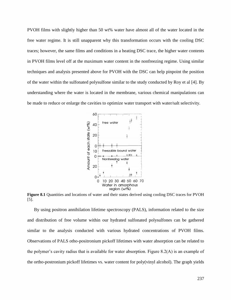
237
PVOH films with slightly higher than 50 wt% water have almost all of the water located in the
free water regime. It is still unapparent why this transformation occurs with the cooling DSC
traces; however, the same films and conditions in a heating DSC trace, the higher water contents
in PVOH films level off at the maximum water content in the nonfreezing regime. Using similar
techniques and analysis presented above for PVOH with the DSC can help pinpoint the position
of the water within the sulfonated polysulfone similar to the study conducted by Roy et al [4]. By
understanding where the water is located in the membrane, various chemical manipulations can
be made to reduce or enlarge the cavities to optimize water transport with water/salt selectivity.
Figure 8.1 Quantities and locations of water and their states derived using cooling DSC traces for PVOH
[5].
By using positron annihilation lifetime spectroscopy (PALS), information related to the size
and distribution of free volume within our hydrated sulfonated polysulfones can be gathered
similar to the analysis conducted with various hydrated concentrations of PVOH films.
Observations of PALS otho-positronium pickoff lifetimes with water absorption can be related to
the polymer’s cavity radius that is available for water absorption. Figure 8.2(A) is an example of
the ortho-postronium pickoff lifetimes vs. water content for poly(vinyl alcohol). The graph yields
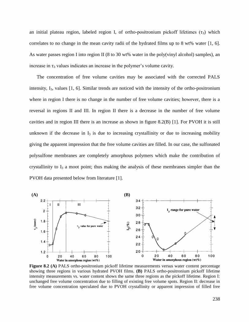
238
an initial plateau region, labeled region I, of ortho-positronium pickoff lifetimes (τ3) which
correlates to no change in the mean cavity radii of the hydrated films up to 8 wt% water [1, 6].
As water passes region I into region II (8 to 30 wt% water in the poly(vinyl alcohol) samples), an
increase in τ3 values indicates an increase in the polymer’s volume cavity.
The concentration of free volume cavities may be associated with the corrected PALS
intensity, I3, values [1, 6]. Similar trends are noticed with the intensity of the ortho-positronium
where in region I there is no change in the number of free volume cavities; however, there is a
reversal in regions II and III. In region II there is a decrease in the number of free volume
cavities and in region III there is an increase as shown in figure 8.2(B) [1]. For PVOH it is still
unknown if the decrease in I3 is due to increasing crystallinity or due to increasing mobility
giving the apparent impression that the free volume cavities are filled. In our case, the sulfonated
polysulfone membranes are completely amorphous polymers which make the contribution of
crystallinity to I3 a moot point; thus making the analysis of these membranes simpler than the
PVOH data presented below from literature [1].
(A) (B)
Figure 8.2 (A) PALS ortho-positronium pickoff lifetime measurements versus water content percentage
showing three regions in various hydrated PVOH films. (B) PALS ortho-positronium pickoff lifetime
intensity measurements vs. water content shows the same three regions as the pickoff lifetime. Region I:
unchanged free volume concentration due to filling of existing free volume spots. Region II: decrease in
free volume concentration speculated due to PVOH crystallinity or apparent impression of filled free
239
volume. Region III: increase in free volume because of ortho-positronium ability to annihilate via a
“bubbling” mechanism [1].
The same group that ran the PALS also ran solid state 13
C NMR on the PVOH films to look
at polymer mobility. The NMR spectra showed no changes in spectra broadening at water
contents lower than 30 wt% in water PVOH films. At 30 wt% and higher, there was an increase
in peak splitting and significant peak narrowing associated with carbon attached to the hydroxyl
functional groups [1]. It was also noted that the spectra of the 30 wt% water in PVOH sample
resembled that of its solution NMR spectra counterpart. The identical nature of spectral features
from the sample with 30wt% water in solid state NMR to the sample with 0 wt% water in
solution NMR indicates that the PVOH in solid state at 30 wt% has the ability to change its coil
configuration similar to a polymer coil in a solvent [1]. In addition, the sharp peaks in the spectra
indicate solution like behavior of the PVOH film containing 30 wt% water. This change in nmr
spectra was explained by water’s ability to break and replace any hydrogen bonding that might
occur within the polymer, freeing up the polymers ability to rotate.
8.2.2 Synthesis of macrocyclic nanoporouns membrane for reverse osmosis and
nanofiltration
The polymers developed in this dissertation utilize polycondensation as the means for
synthesis. However, there are many other synthetic methods to develop other types of polymers
such as free radical polymerization, anionic/cationic polymerization, atom transfer radical
polymerization, nitroxide-mediated radical polymerization, ring opening metathesis
polymerization, reversible addition-fragmentation chain transfer polymerization, etc [7-11].
Thus, there are a plethora of different chemistries that can be utilized other than sulfonated
polysulfone polycondensation techniques to achieve high performance reverse osmosis
membranes.
240
One such polymer that has been proposed includes the development of a nanoporous
membrane that utilizes the shape and cavity of cyclodextrins as the pore opening. In the last
decade many different research groups have focused on using macrocycles such as cyclodextrins
for high performance nanofiltration membranes [12-15]. Huang et al. found that by replacing the
aromatic diamine solution with per-6-amino-β-cyclodextrin and interfacially crosslinking it with
a para functional acid chloride yielded a polymer membrane that exhibited excellent polar and
nonpolar organic solvent separation [12]. In addition, more commonly known, the macrocycle
was able to discriminate compounds with similar molecular weights based off of their shape.
However, Grossi et al. found a different trend after mixing an ionic functional macrocycle
with Nafion. Grossi et al. expected higher water permeabilities because of the increased free
volume effects that that ionic cyclodextrins possessed. Instead decreases in water diffusion,
sorption, and permeability were observed, which Grossi explains by asserting that the
cyclodextrin reduces the water content within the polymer’s ionic phase.
It is commonly known within the cyclodextrin community that cyclodextrins contain both
polar and nonpolar characteristics. The polar character is found on the exterior of the
cyclodextrin, while the nonpolar character is found inside the pore of the macrocycle [16] This
characteristic of the cyclodextrin allows fragrances/odors and antimicrobial agents to form
inclusion complexes with the cyclodextrin. Hence, there use in commercial products such as
Febreze® from Proctor & Gamble [16].
It may be speculated that water or polar molecules are not expected to actually infiltrate into
cyclodextrin pores. In addition, it is possible that the Nafion from Grossi’s experiment threaded
through the cyclodextrin similar to threading a needle, which caused the cyclodextrin pore to
seal, reducing the potential cavity for mass transport.
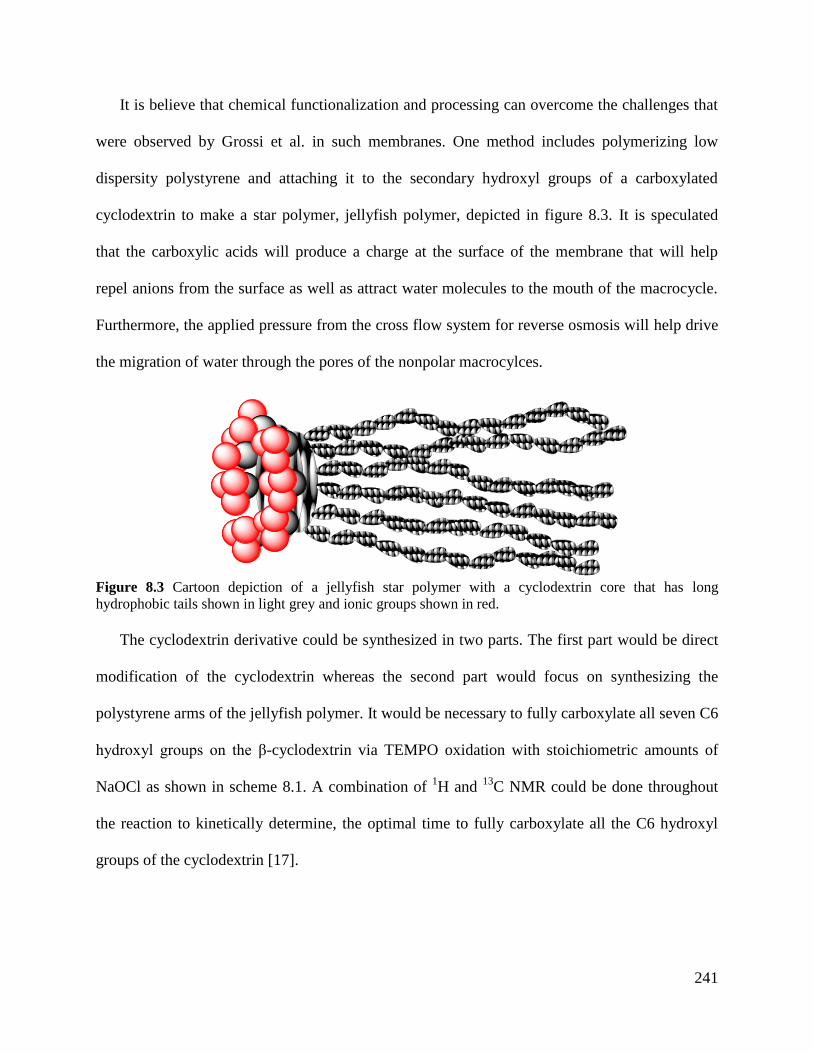
241
It is believe that chemical functionalization and processing can overcome the challenges that
were observed by Grossi et al. in such membranes. One method includes polymerizing low
dispersity polystyrene and attaching it to the secondary hydroxyl groups of a carboxylated
cyclodextrin to make a star polymer, jellyfish polymer, depicted in figure 8.3. It is speculated
that the carboxylic acids will produce a charge at the surface of the membrane that will help
repel anions from the surface as well as attract water molecules to the mouth of the macrocycle.
Furthermore, the applied pressure from the cross flow system for reverse osmosis will help drive
the migration of water through the pores of the nonpolar macrocylces.
The cyclodextrin derivative could be synthesized in two parts. The first part would be direct
modification of the cyclodextrin whereas the second part would focus on synthesizing the
polystyrene arms of the jellyfish polymer. It would be necessary to fully carboxylate all seven C6
hydroxyl groups on the β-cyclodextrin via TEMPO oxidation with stoichiometric amounts of
NaOCl as shown in scheme 8.1. A combination of 1H and
13C NMR could be done throughout
the reaction to kinetically determine, the optimal time to fully carboxylate all the C6 hydroxyl
groups of the cyclodextrin [17].
Figure 8.3 Cartoon depiction of a jellyfish star polymer with a cyclodextrin core that has long
hydrophobic tails shown in light grey and ionic groups shown in red.
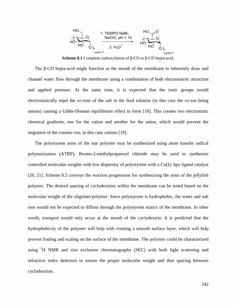
242
Scheme 8.1 Complete carboxylation of β-CD to β-CD hepta-acid.
The β-CD hepta-acid might function as the mouth of the membrane to inherently draw and
channel water flow through the membrane using a combination of both electrostactic attraction
and applied pressure. At the same time, it is expected that the ionic groups would
electrostatically repel the co-ions of the salt in the feed solution (in this case the co-ion being
anions) causing a Gibbs-Donnan equilibrium effect to form [18]. This creates two electrostatic
chemical gradients, one for the cation and another for the anion, which would prevent the
migration of the counter-ion, in this case cations [19].
The polystyrene arms of the star polymer may be synthesized using atom transfer radical
polymerization (ATRP). Bromo-2-methylpropanoyl chloride may be used to synthesize
controlled molecular weights with low dispersity of polystyrene with a Cu(I)- bpy ligand catalyst
[20, 21]. Scheme 8.2 conveys the reaction progression for synthesizing the arms of the jellyfish
polymer. The desired spacing of cyclodextrins within the membrane can be tuned based on the
molecular weight of the oligomer/polymer. Since polystyrene is hydrophobic, the water and salt
ions would not be expected to diffuse through the polystyrene matrix of the membrane. In other
words, transport would only occur at the mouth of the cyclodextrin. It is predicted that the
hydrophobicity of the polymer will help with creating a smooth surface layer, which will help
prevent fouling and scaling on the surface of the membrane. The polymer could be characterized
using 1H NMR and size exclusion chromatography (SEC) with both light scattering and
refractive index detectors to ensure the proper molecular weight and thus spacing between
cyclodextrins.
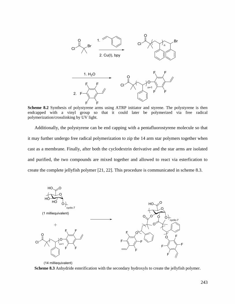
243
Scheme 8.2 Synthesis of polystyrene arms using ATRP initiator and styrene. The polystyrene is then
endcapped with a vinyl group so that it could later be polymerized via free radical
polymerization/crosslinking by UV light.
Additionally, the polystyrene can be end capping with a pentafluorostyrene molecule so that
it may further undergo free radical polymerization to zip the 14 arm star polymers together when
cast as a membrane. Finally, after both the cyclodextrin derivative and the star arms are isolated
and purified, the two compounds are mixed together and allowed to react via esterfication to
create the complete jellyfish polymer [21, 22]. This procedure is communicated in scheme 8.3.
Scheme 8.3 Anhydride esterification with the secondary hydroxyls to create the jellyfish polymer.
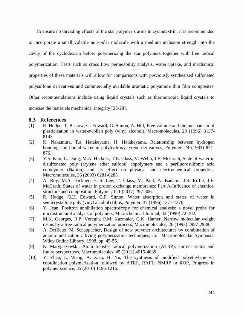
244
To ensure no threading effects of the star polymer’s arms in cyclodextrin, it is recommended
to incorporate a small volatile non-polar molecule with a medium inclusion strength into the
cavity of the cyclodextrin before polymerizing the star polymers together with free radical
polymerization. Tests such as cross flow permeability analysis, water uptake, and mechanical
properties of these materials will allow for comparisons with previously synthesized sulfonated
polysulfone derivatives and commercially available aromatic polyamide thin film composites.
Other recommendations include using liquid crystals such as thermotropic liquid crystals to
increase the materials mechanical integrity [23-28].
8.3 References [1] R. Hodge, T. Bastow, G. Edward, G. Simon, A. Hill, Free volume and the mechanism of
plasticization in water-swollen poly (vinyl alcohol), Macromolecules, 29 (1996) 8137-
8143.
[2] K. Nakamura, T.a. Hatakeyama, H. Hatakeyama, Relationship between hydrogen
bonding and bound water in polyhydroxystyrene derivatives, Polymer, 24 (1983) 871-
876.
[3] Y.S. Kim, L. Dong, M.A. Hickner, T.E. Glass, V. Webb, J.E. McGrath, State of water in
disulfonated poly (arylene ether sulfone) copolymers and a perfluorosulfonic acid
copolymer (Nafion) and its effect on physical and electrochemical properties,
Macromolecules, 36 (2003) 6281-6285.
[4] A. Roy, M.A. Hickner, H.-S. Lee, T. Glass, M. Paul, A. Badami, J.S. Riffle, J.E.
McGrath, States of water in proton exchange membranes: Part A-Influence of chemical
structure and composition, Polymer, 111 (2017) 297-306.
[5] R. Hodge, G.H. Edward, G.P. Simon, Water absorption and states of water in
semicrystalline poly (vinyl alcohol) films, Polymer, 37 (1996) 1371-1376.
[6] Y. Jean, Positron annihilation spectroscopy for chemical analysis: a novel probe for
microstructural analysis of polymers, Microchemical Journal, 42 (1990) 72-102.
[7] M.K. Georges, R.P. Veregin, P.M. Kazmaier, G.K. Hamer, Narrow molecular weight
resins by a free-radical polymerization process, Macromolecules, 26 (1993) 2987-2988.
[8] A. Deffieux, M. Schappacher, Design of new polymer architectures by combination of
anionic and cationic living polymerization techniques, in: Macromolecular Symposia,
Wiley Online Library, 1998, pp. 45-55.
[9] K. Matyjaszewski, Atom transfer radical polymerization (ATRP): current status and
future perspectives, Macromolecules, 45 (2012) 4015-4039.
[10] Y. Zhao, L. Wang, A. Xiao, H. Yu, The synthesis of modified polyethylene via
coordination polymerization followed by ATRP, RAFT, NMRP or ROP, Progress in
polymer science, 35 (2010) 1195-1216.
245
[11] S.T. Nguyen, L.K. Johnson, R.H. Grubbs, J.W. Ziller, Ring-opening metathesis
polymerization (ROMP) of norbornene by a group VIII carbene complex in protic media,
Journal of the American Chemical Society, 114 (1992) 3974-3975.
[12] T. Huang, T. Puspasari, S.P. Nunes, K.V. Peinemann, Ultrathin 2D‐layered cyclodextrin
membranes for high‐performance organic solvent nanofiltration, Advanced Functional
Materials, 30 (2020) 1906797.
[13] N. Grossi, E. Espuche, M. Escoubes, Transport properties of Nafion®/cyclodextrin
membranes, Separation and purification technology, 22 (2001) 255-267.
[14] H. Chen, L. Wu, J. Tan, C. Zhu, PVA membrane filled β-cyclodextrin for separation of
isomeric xylenes by pervaporation, Chemical Engineering Journal, 78 (2000) 159-164.
[15] R. Zhao, Y. Wang, X. Li, B. Sun, C. Wang, Synthesis of β-cyclodextrin-based
electrospun nanofiber membranes for highly efficient adsorption and separation of
methylene blue, ACS applied materials & interfaces, 7 (2015) 26649-26657.
[16] U.R. Bhaskara-Amrit, P.B. Agrawal, M. Warmoeskerken, Applications of β-
cyclodextrins in textiles, AUTEX research journal, 11 (2011) 94-101.
[17] C. Fraschini, M.R. Vignon, Selective oxidation of primary alcohol groups of β-
cyclodextrin mediated by 2, 2, 6, 6-tetramethylpiperidine-1-oxyl radical (TEMPO),
Carbohydrate research, 328 (2000) 585-589.
[18] M. Majumder, N. Chopra, B.J. Hinds, Mass transport through carbon nanotube
membranes in three different regimes: ionic diffusion and gas and liquid flow, ACS nano,
5 (2011) 3867-3877.
[19] H.P. Gregor, Gibbs-Donnan equilibria in ion exchange resin systems, Journal of the
American Chemical Society, 73 (1951) 642-650.
[20] Y. Miura, A. Narumi, S. Matsuya, T. Satoh, Q. Duan, H. Kaga, T. Kakuchi, Synthesis of
well‐defined AB20‐type star polymers with cyclodextrin‐core by combination of NMP
and ATRP, Journal of Polymer Science Part A: Polymer Chemistry, 43 (2005) 4271-
4279.
[21] P. Chmielarz, S. Park, A. Sobkowiak, K. Matyjaszewski, Synthesis of β-cyclodextrin-
based star polymers via a simplified electrochemically mediated ATRP, Polymer, 88
(2016) 36-42.
[22] K. Ohno, B. Wong, D.M. Haddleton, Synthesis of well‐defined cyclodextrin‐core star
polymers, Journal of Polymer Science Part A: Polymer Chemistry, 39 (2001) 2206-2214.
[23] T. Chen, D. Kazerooni, L. Ju, D.A. Okonski, D.G. Baird, Development of recyclable and
high-performance in situ hybrid tlcp/glass fiber composites, Journal of Composites
Science, 4 (2020) 125.
[24] T. Chen, Generation of Recyclable Liquid Crystalline Polymer Reinforced Composites
for Use in Conventional and Additive Manufacturing Processes, in, Virginia Tech, 2021.
[25] T. Chen, C.D. Mansfield, L. Ju, D.G. Baird, The influence of mechanical recycling on the
properties of thermotropic liquid crystalline polymer and long glass fiber reinforced
polypropylene, Composites Part B: Engineering, 200 (2020) 108316.
[26] T. Chen, The Influence of Recycling On Thermotropic Liquid Crystalline Polymer and
Glass Fiber Composites.
[27] T. Chen, J. Han, D.A. Okonski, D. Kazerooni, L. Ju, D.G. Baird, Thermotropic Liquid
Crystalline Polymer Reinforced Polyamide Composite for Fused Filament Fabrication,
Additive Manufacturing, (2021) 101931.
246
[28] J.Y. Han, T. Chen, Q. Mu, D.G. Baird, Thermotropic liquid crystalline polymer
reinforced polypropylene composites enhanced with carbon nanotubes for use in fused
filament fabrication, Polymer Composites, (2021).


