Embed Size (px)
Citation preview
July 2017

www.graham-mfg.com
Superior Vacuum Column PerformanceGraham Ejector Systems. No Substitute for Proven Experience.
•
•
•
•
•
•
www.graham-mfg.com/ejector-videos
Hydrocarbon Engineering
likeHydrocarbonEngineering
connect joinHydrocarbonEngineering
@HydrocarbonEngfollow CONVERSATION
JOIN THE2017 Member of ABC Audit Bureau of Circulations
Copyright© Palladian Publications Ltd 2017. All rights reserved. No part of this publication may be reproduced, stored in a retrieval system, or transmitted in any form or by any means, electronic, mechanical, photocopying,
recording or otherwise, without the prior permission of the copyright owner. All views expressed in this journal are those of the respective contributors and are not necessarily the opinions of the publisher, neither
do the publishers endorse any of the claims made in the articles or the advertisements. Printed in the UK.Uncaptioned images courtesy of www.shutterstock.com.
CONTENTS
THIS MONTH'S FRONT COVER
July 2017 Volume 22 Number 07 ISSN 1468-9340
03 Comment
05 World News
12 South of the Rio GrandeGordon Cope, Contributing Editor, examines the current state of the oil and gas industry across Latin America, and what the future has to hold.
18 Worthy investmentRixt Dijkstra, Fluor Corp., the Netherlands, highlights the importance of conducting feasibility studies during the planning stages of petrochemical projects.
23 More, more, moreDaniel B. Gillis and Theo Maesen, Chevron Lummus Global, USA, evaluate new hydroprocessing approaches to increase petrochemicals production.
30 Additive innovationMelissa Clough and Kitty Cha, BASF Corp., USA, demonstrate the benefi ts of applying SOX reduction additives for regulatory compliance, with reference to three refi nery case studies.
36 California dreamingJoe Colannino and Roberto Ruiz, ClearSign Combustion, USA, introduce an innovative piece of technology that was able to help a Californian refi nery reduce its NOX emissions.
43 The big debateOmer Yanai, Opgal, Israel, discusses the debate around oil and gas methane emissions and offers a three-pronged approach to help keep emissions under control.
45 Put a lid on itMarc Laing, NEL, UK, examines the challenges involved in measuring fl are gas and their resulting emissions.
49 Cutting energy costsG. Srivardhan, M. Rajasekhar, D. K. R. Nambiar, S. C. Gupta, S. R. Singh and V. Shukla, Engineers India Ltd, India, explore real time utility management and its role in energy effi ciency and the reduction of total energy costs.
54 Data, analytics and downstreamColin Cooper, Eka Software, UK, examines the recent developments in data handling and analytics software, and what this means for the future of the downstream sector.
59 Modelling realityAnne-Marie Walters, Bentley Systems, USA, evaluates technologies to maintain accurate engineering information over the lifecycle of an asset.
63 Laser speedJason Hayes, Trimble, USA, introduces new software solutions for storage tank inspections that deliver lower costs and higher value.
67 Curtailing contaminationBerthold Otzisk and Dr. Michael Urschey, Kurita Europe GmbH, explore safe chemical cleaning and decontamination technologies for the oil and gas industry.
73 Spotless maintenanceMike Watson, Tube Tech International Ltd, UK, explains how downstream maintenance can be carried out faster, safer, and to a higher standard.
79 Modern machineryMassimiliano Di Febo and Pasquale Paganini, IPC, Italy, present an overview of modern pump technology and how recent developments are contributing to improved processing and monitoring.
83 PUMPS, VALVES AND SEALS REVIEWHydrocarbon Engineering presents an overview of some of the recent developments and technologies in pumps, valves and seals for the downstream oil and gas industry.
104 15 facts onThis month we give you 15 facts on emissions controls!
One of four compression trains that Elliott’s Engineered Solutions and Field Service teams overhauled during a turnaround at a petrochemical facility in China. The project included the overhaul of the charge gas, ethylene and propylene trains, and the heat pump compressor, as well as the installation of upgraded cartridge seals in the charge gas compressors and actuators in the steam turbine drivers.

THINK SULPHUR THINK SANDVIK
A WORLD LEADER IN SULPHUR PROCESSING AND HANDLING
We design, manufacture and commission equipment for every aspect of sulphur processing, from upstream handling and a range of granulation options to downstream conveying, storage and bulk loading.
Engineering & consulting
Premium Rotoform® pastillation
High capacity granulation
High performance remelting
Handling, storage and loading
Global service and spare parts
Sandvik Process Systems, Division of Sandvik Materials Technology Deutschland GmbH, Salierstr. 35, 70736 Fellbach, Germany Tel: +49 711 5105-0 · Fax: +49 711 5105-152 · [email protected] · www.processsystems.sandvik.com
CONTACT INFO
MANAGING EDITOR James [email protected]
EDITOR Callum O'[email protected]
EDITORIAL ASSISTANT Francesca [email protected]
ADVERTISEMENT DIRECTOR Rod [email protected]
ADVERTISEMENT MANAGER Chris [email protected]
ADVERTISEMENT EXECUTIVE Dmitry [email protected]
DIGITAL ASSISTANT EDITOR Angharad [email protected]
PRODUCTION Ben [email protected]
WEB MANAGER Tom [email protected]
SUBSCRIPTIONS Laura [email protected]
ADMINISTRATION Nicola [email protected]
CONTRIBUTING EDITORSNancy Yamaguchi Gordon Cope
SUBSCRIPTION RATESAnnual subscription £110 UK including postage/£125 overseas (postage airmail). Two year discounted rate £176 UKincluding postage/£200 overseas (postage airmail).
SUBSCRIPTION CLAIMSClaims for non receipt of issues must be made within 3 months of publication of the issue or they will not be honoured without charge.
APPLICABLE ONLY TO USA & CANADAHydrocarbon Engineering (ISSN No: 1468-9340, USPS No: 020-998) is published monthly by Palladian Publications Ltd GBR and distributed in the USA by Asendia USA, 17B S Middlesex Ave, Monroe NJ 08831. Periodicals postage paid New Brunswick, NJ and additional mailing offi ces. POSTMASTER: send address changes to HYDROCARBON ENGINEERING, 701C Ashland Ave, Folcroft PA 19032
15 South Street, Farnham, Surrey GU9 7QU, ENGLAND Tel: +44 (0) 1252 718 999Fax: +44 (0) 1252 718 992
COMMENTCALLUM O'REILLYEDITOR
Over the last few years, we have witnessed our fair share of political gambles here in the UK. Former Prime Minister, David Cameron,
started the trend with his decision to support a referendum on Scottish independence. On that
occasion, the PM's gamble paid off. Just. The following year, during a tightly-fought general election, Cameron promised the British public a vote on its membership of the European Union, should his Conservative party be elected into government. The rest, as they say, is history. After months of campaigning for the UK to remain within the EU, Cameron duly fell on his sword just hours after the results of the referendum were announced, making way for Theresa May to take the reins of the country and, in turn, the impending Brexit negotiations.
In March, the government triggered Article 50, signalling the start of formal procedures for the UK to leave the EU. A few weeks later, the Conservative party decided to roll the dice once again; calling a snap general election. The reason? To convert the party’s overwhelming lead in the opinion polls into a stronger parliamentary majority that would ultimately strengthen Theresa May’s ability to secure the Brexit deal envisioned by her party.
The gamble did not pay off. The opinion polls narrowed throughout the short election campaign as a rejuvenated Labour party gained momentum under the leadership of Jeremy Corbyn. In the end, the Conservative party lost its overall majority, leaving the UK with a hung parliament and Theresa May’s premiership in peril. As I write this, the UK has just started its offi cial Brexit negotiations with the EU, despite the cloud of uncertainty looming back home.
Following the results of the UK general election, the UK Petroleum Industry Association’s Director General, Chris Hunt, called for “stability and clarity” over the industry’s operating environment “in order to maintain investor confi dence and drive all businesses to grow and thrive.” Michael Burns, Oil and Gas Partner at law fi rm Ashurst, added: "A hung parliament can only lead to the potential for further uncertainty for an industry that has suffered from that theme over the last few years with the fl uctuations in oil and gas prices.”
While a succession of political gambles has left the UK in a sticky situation, across the pond, the Trump administration’s recent bet on leaving the Paris climate accord threatens to have even wider implications. While experts suggest that the withdrawal will not necessarily impact US regulation of carbon emissions, it is undoubtedly a controversial move from the US President. Frank Melum from the Point Carbon team at Thomson Reuters warns: “The US could very well be the one that will lose the most from this withdrawal. Before and after the announcement [...] stakeholders have come out reiterating their support for the Paris Agreement. This includes other large emitters like China, Russia and the EU. But also large companies, including the fossil fuel industry. The strong support of the agreement highlights the investment opportunity the Paris Agreement provides.”
Emissions control is a key topic throughout this issue of Hydrocarbon
Engineering, with feature articles looking at emissions of SOX (BASF Corp., p. 30), NOX (ClearSign Combustion, p. 36), and methane (Opgal, p. 43), as well as emissions from fl aring (NEL, p. 45).
Do you need accurate heat exchanger technology for real-world situations?
Software and services to help you design equipment that performs under
the broadest range of operating conditions? IF SO, YOU CAN RELY ON US.
YOUR COMPETITIVE EDGE IN
PROCESS HEAT TRANSFER TECHNOLOGY
RESEARCH
SOFTWARE
TECHNICAL SUPPORT
PROPRIETARY CONTRACTS
TRAINING
Visit www.htri.netto learn more.
HTRI is a leading provider of products and
services that help engineers around the
world rate, simulate, design, and enhance
the performance of heat exchangers. Our
extensive expertise is the result of more than
50 years of applied research conducted in
our industrially relevant testing facilities. We
deliver research, proprietary contract services,
training, support, and software, including our
acclaimed Xchanger Suite®, to assure our
customers the highest operating confidence
in equipment designed using our technology.

WORLD NEWS
July 2017HYDROCARBONENGINEERING
5
Nigeria | Air Liquide to supply hydrogen production technology
A ir Liquide Engineering & Construction has been selected
to supply two hydrogen production steam methane reformer (SMR) units to Dangote Group, the largest manufacturing conglomerate in West Africa.
The SMR units will be fundamental to a new hydrogen generation complex producing 200 000 Nm3/hr of hydrogen and high quality steam for a new refi nery located in the Lekki free trade zone in Nigeria.
The new refi nery is part of the large industrial complex currently under development in Africa and will produce Euro V compliant low sulfur fuels among other products. Hydrogen is used today in many industrial sectors, especially in the oil refi ning process to produce sulfur-free fuels. This project will considerably improve refi ning infrastructure in Nigeria and consequently enable the country to manufacture refi ned products locally, reducing the reliance on the imported goods.
This equipment supply agreement follows an agreement that Air Liquide signed with Dangote in 2015.
USA | Braskem approves new construction
Braskem's Board of Directors has approved the fi nal investment
decision (FID) to proceed with the largest polypropylene production line in the Americas. Braskem will commit up to US$675 million in investment capital towards the design and construction of the new facility, which will be named Delta and will be located next to Braskem's
existing production facilities in La Porte, Texas.
With the engineering design phase well underway, the new production line will have a manufacturing capacity of 450 kilotons (kt). The new line will represent additional production capacity of homopolymers, random copolymers, impact copolymers, and
reactor thermoplastic olefi ns (TPOs), building upon Braskem's current polypropylene production plant in La Porte, which has a production capacity of 354 kt/y and will continue operations.
Construction is expected to begin mid-summer, with the fi nal phase of main construction targeted for 1Q20.
China | Sinopec and Linde sign JV
S inopec and The Linde Group have announced that they have
established a €145 million joint venture (JV) to supply vital industrial gases to local customers from key industries such as petrochemical, steel and electronics, within the Ningbo Chemical Industrial Zone in China's Zhejiang province.
Sinopec Zhenhai Refi ning & Chemical Co. (ZRCC) and Linde will each hold a 50% stake in the newly formed Ningbo Linde-ZRCC Gases Co. Ltd (Linde-ZRCC), the sixth consecutive JV between the companies. The agreement will see Linde-ZRCC acquire two existing air separation units (ASUs) from ZRCC
and construct a third for a combined 150 000 m3/hr of oxygen capacity. The new ASU, expected to be on stream in 2018, will incorporate Linde's intelligent solutions for remote operation, diagnostics and analytics, as well as a modular design to increase effi ciency, reduce energy requirements and enhance fl exibility of production.
These three additional ASUs will double Linde production capacity of air gases in the Ningbo cluster and will be connected to Linde's pipeline supply network across Ningbo.
Linde's Engineering Division will design and construct the new ASU.
USA | CB&I awarded EPC contract
CB&I has been awarded a contract valued at approximately
US$40 million by E. I. du Pont de Nemours and Co. to provide engineering, procurement and construction (EPC) for an ethane cracking furnace expansion project at DuPont's Sabine River Works ethylene plant in Orange, Texas.
The new cracking furnace will have an ethylene capacity of 200 million lbs/y. The facility will utilise CB&I's SRT® (Short Residence Time) pyrolysis heater technology. CB&I was previously awarded a
contract for the ethylene technology license, engineering and supply of the new furnace, which was fabricated at CB&I's facility in Thailand.
Luke V. Scorsone, Executive Vice President of CB&I's Fabrication Services operating group, said: "CB&I's ability to deliver single source supply of every phase of this project – from concept to mechanical completion – provides DuPont with a cost effective, low risk solution as they expand their ethylene copolymers capacity to meet market demand."
WORLD NEWSIN BRIEF
July 2017 HYDROCARBONENGINEERING
6
South Africa | Petredec and Bidvest to develop LPG storage facility
Petredec Ltd and Bidvest Tank Terminals have entered into an
agreement for the development of a new facility for the import and storage of LPG. The facility will be a 22 600 t storage facility at Bidvest’s existing site in Richards Bay.
The completed facility will be the region’s largest pressurised LPG import terminal, featuring four mounded tanks, each capable of storing more than 5500 t of gas, guaranteeing year-round availability. Despite growing demand in domestic and regional markets, LPG imports have historically been hampered by high costs resulting from South Africa's small coastal terminals and distance from major supply hubs.
With the breaking-of-ground planned for September 2017 and an estimated 27 month construction schedule, South African consumers can expect to be using LPG imported via the new Richards Bay terminal from 4Q19.
Petredec believes further investment in large, dedicated infrastructure is the only way to increase the fuel's popularity and bring lower prices to consumers. The company's CEO, Giles Fearn, said: "Delivering LPG to South Africa on a previously unprecedented scale brings with it fi nancial savings to our customers that will ultimately benefi t consumers with lower gas prices.”
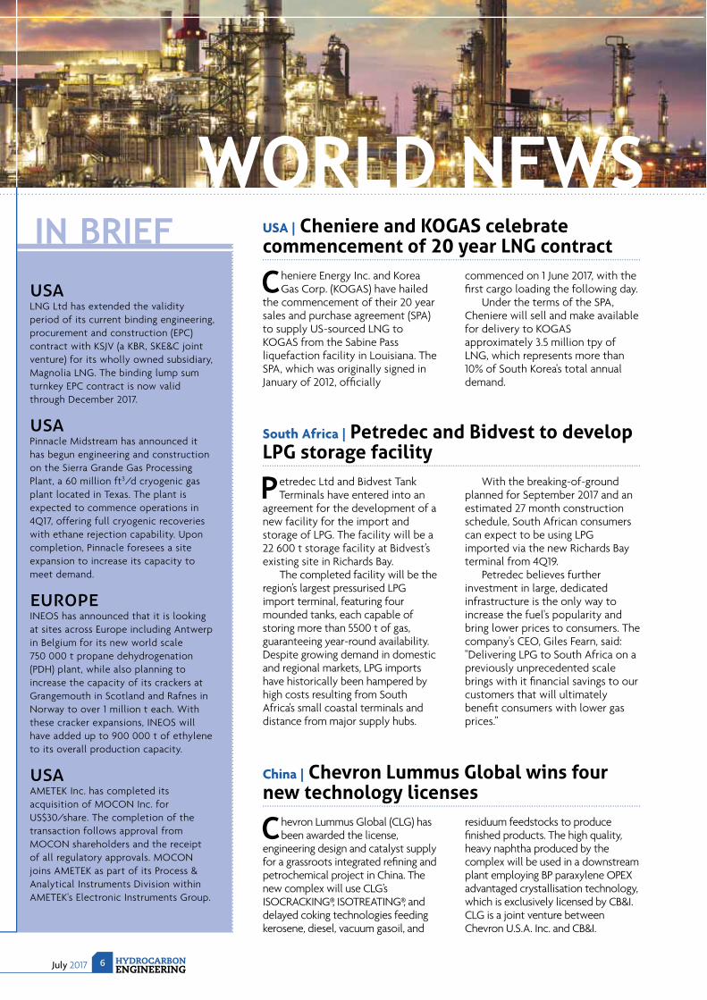
USA | Cheniere and KOGAS celebrate commencement of 20 year LNG contract
Cheniere Energy Inc. and Korea Gas Corp. (KOGAS) have hailed
the commencement of their 20 year sales and purchase agreement (SPA) to supply US-sourced LNG to KOGAS from the Sabine Pass liquefaction facility in Louisiana. The SPA, which was originally signed in January of 2012, offi cially
commenced on 1 June 2017, with the fi rst cargo loading the following day.
Under the terms of the SPA, Cheniere will sell and make available for delivery to KOGAS approximately 3.5 million tpy of LNG, which represents more than 10% of South Korea's total annual demand.
LNG Ltd has extended the validity period of its current binding engineering, procurement and construction (EPC) contract with KSJV (a KBR, SKE&C joint venture) for its wholly owned subsidiary, Magnolia LNG. The binding lump sum turnkey EPC contract is now valid through December 2017.
Pinnacle Midstream has announced it has begun engineering and construction on the Sierra Grande Gas Processing Plant, a 60 million ft3/d cryogenic gas plant located in Texas. The plant is expected to commence operations in 4Q17, offering full cryogenic recoveries with ethane rejection capability. Upon completion, Pinnacle foresees a site expansion to increase its capacity to meet demand.
INEOS has announced that it is looking at sites across Europe including Antwerp in Belgium for its new world scale 750 000 t propane dehydrogenation (PDH) plant, while also planning to increase the capacity of its crackers at Grangemouth in Scotland and Rafnes in Norway to over 1 million t each. With these cracker expansions, INEOS will have added up to 900 000 t of ethylene to its overall production capacity.
AMETEK Inc. has completed its acquisition of MOCON Inc. for US$30/share. The completion of the transaction follows approval from MOCON shareholders and the receipt of all regulatory approvals. MOCON joins AMETEK as part of its Process & Analytical Instruments Division within AMETEK's Electronic Instruments Group.
China | Chevron Lummus Global wins four new technology licenses
Chevron Lummus Global (CLG) has been awarded the license,
engineering design and catalyst supply for a grassroots integrated refi ning and petrochemical project in China. The new complex will use CLG’s ISOCRACKING®, ISOTREATING®, and delayed coking technologies feeding kerosene, diesel, vacuum gasoil, and
residuum feedstocks to produce fi nished products. The high quality, heavy naphtha produced by the complex will be used in a downstream plant employing BP paraxylene OPEX advantaged crystallisation technology, which is exclusively licensed by CB&I. CLG is a joint venture between Chevron U.S.A. Inc. and CB&I.
A World of SolutionsVisit www.CBI.com
COMPLETE SOLUTIONS FOR YOUR REFINERY CHALLENGES
Today’s Refinery Challenges
Processing tight oil
Managing stringent sulfur limits
Monetizing orphan streams
Upgrading residuals
CB&I’s Comprehensive SolutionsCB&I’s broad portfolio of both refining and petrochemical technologies,
combined with our execution expertise, will help you maximize processing
flexibility and achieve margin benefits in the widest range of scenarios.
We are with you through every stage of the process plant life cycle, from
feasibility studies to identifying plant optimization and upgrade solutions,
through technology selection, full-scope EPFC, commissioning and start-up.
PROCESS PLANNING AND DEVELOPMENT
LICENSED TECHNOLOGIES AND CATALYSTS
FULL-SCOPE EPFC SERVICES
PROJECT MANAGEMENT AND CONSULTING
AFTERMARKET SERVICES
WORLD NEWSIN BRIEF
July 2017 HYDROCARBONENGINEERING
8
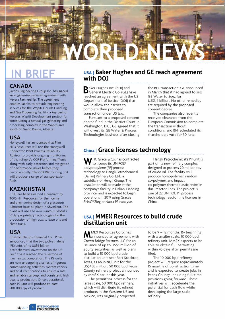
USA | Baker Hughes and GE reach agreement with DOJ
Baker Hughes Inc. (BHI) and General Electric Co. (GE) have
reached an agreement with the US Department of Justice (DOJ) that would allow the parties to complete their proposed transaction under US law.
Pursuant to a proposed consent decree filed in the District Court in Washington, D.C., GE agreed that it will divest its GE Water & Process Technologies business after closing
the BHI transaction. GE announced in March that it had agreed to sell GE Water to Suez for US$3.4 billion. No other remedies are required by the proposed consent decree.
The companies also recently received clearance from the European Commission to complete the transaction without conditions, and BHI scheduled its shareholders vote for 30 June.
Jacobs Engineering Group Inc. has signed an engineering services agreement with Keyera Partnership. The agreement enables Jacobs to provide engineering services for the Wapiti Liquids Handling and Gas Processing Facility, a key part of Keyera’s Wapiti Development project for constructing a natural gas gathering and processing complex in the Wapiti area south of Grand Prairie, Alberta.
Honeywell has announced that Flint Hills Resources will use the Honeywell Connected Plant Process Reliability Advisor to provide ongoing monitoring of the refinery's CCR PlatformingTM unit along with early detection and mitigation of performance issues before they become costly. The CCR Platforming unit will produce a range of transportation fuels.
CB&I has been awarded a contract by TOO Hill Resources for the license and engineering design of a grassroots lubricant base oil plant in Shymkent. The plant will use Chevron Lummus Global's (CLG) proprietary technologies for the production of high quality base oils and clean fuels.
Chevron Phillips Chemical Co. LP has announced that the two polyethylene (PE) units of its US$6 billion petrochemical investment on the US Gulf Coast reached the milestone of mechanical completion. The PE units are now undergoing a series of rigorous commissioning activities, system checks and final certifications to ensure a safe and reliable start-up, and consistent, high quality production. Once operational, each PE unit will produce at least 500 000 tpy of product.
China | Grace licenses technology
W . R. Grace & Co. has contracted to license its UNIPOL®
polypropylene (PP) process technology to Hengli Petrochemical (Dalian) Refi nery Co. Ltd., a subsidiary of Hengli Group. The installation will be made at the company’s facility in Dalian, Liaoning province, and is expected to begin operations in 2019 using Grace’s SHAC® Ziegler Natta PP catalysts.
Hengli Petrochemical’s PP unit is part of its new refi nery complex designed to process 20 million tpy of crude oil. The facility will produce homopolymer, random co-polymer, and impact co-polymer thermoplastic resins in dual reactor lines. The project is one of 22 UNIPOL PP process technology reactor line licenses in China.
USA | MMEX Resources to build crude distillation unit
MMEX Resources Corp. has announced an agreement with
Crown Bridge Partners LLC for an issuance of up to US$3 million of equity securities, as well as plans to build a 10 000 bpd crude distillation unit near Fort Stockton, Texas, as an initial unit for the US$450 million, 50 000 bpd Pecos County refinery project announced by MMEX earlier this year.
The permitting process for the large scale, 50 000 bpd refinery, which will distribute its refined products in the Western US and Mexico, was originally projected
to be 9 – 12 months. By beginning with a smaller scale, 10 000 bpd refinery unit, MMEX expects to be able to obtain full permitting within 45 days after permits are filed.
The 10 000 bpd refinery project will require approximately 15 months of construction time and is expected to create jobs in Pecos County, including full-time positions going forward. These initiatives will accelerate the potential for cash flow while developing the large scale refinery.
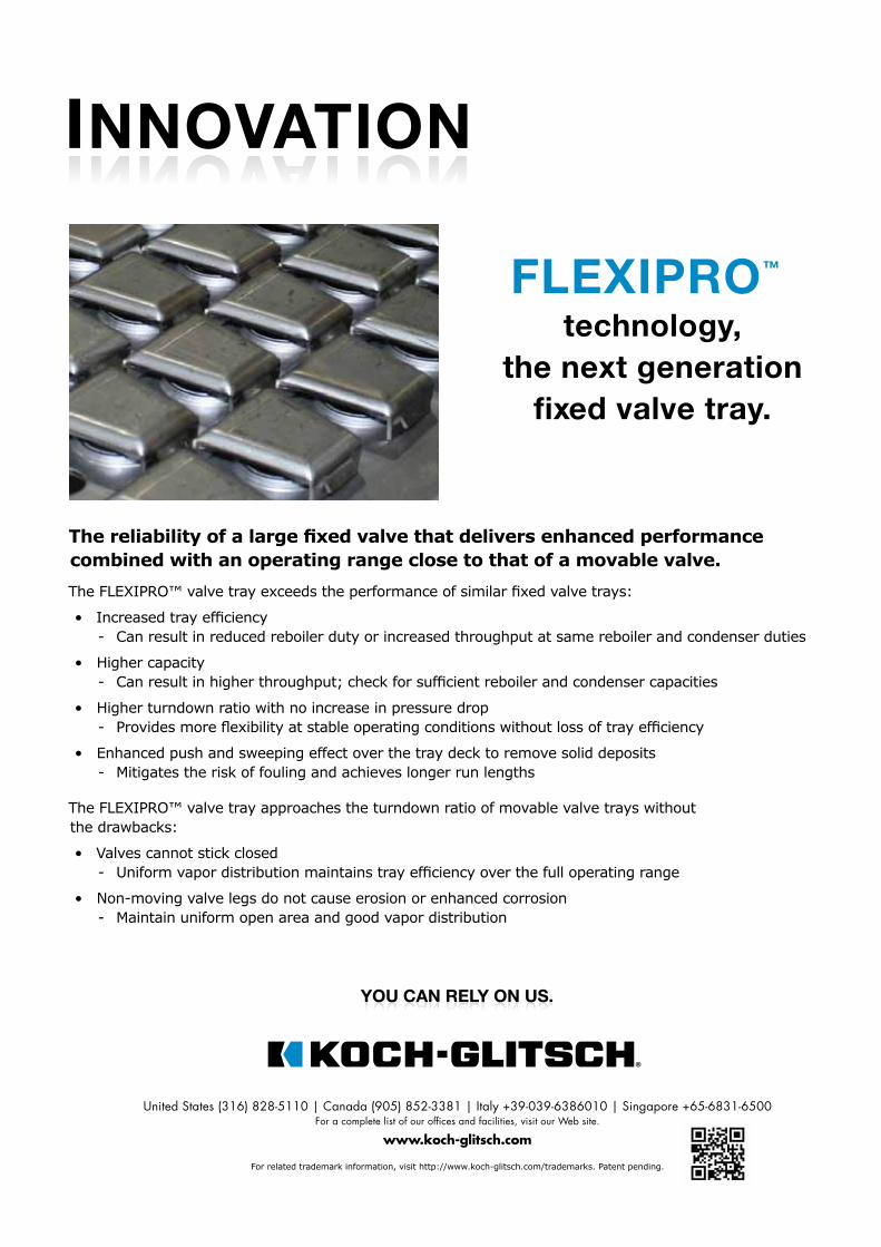
INNOVATION
FLEXIPRO™
technology,
the next generation
fixed valve tray.
United States (316) 828-5110 | Canada (905) 852-3381 | Italy +39-039-6386010 | Singapore +65-6831-6500 For a complete list of our offices and facilities, visit our Web site.
For related trademark information, visit http://www.koch-glitsch.com/trademarks. Patent pending.
www.koch-glitsch.com
• - Can result in reduced reboiler duty or increased throughput at same reboiler and condenser duties
• Higher capacity
• Higher turndown ratio with no increase in pressure drop
• Enhanced push and sweeping effect over the tray deck to remove solid deposits- Mitigates the risk of fouling and achieves longer run lengths
The FLEXIPRO™ valve tray approaches the turndown ratio of movable valve trays withoutthe drawbacks:
• Valves cannot stick closed
• Non-moving valve legs do not cause erosion or enhanced corrosion- Maintain uniform open area and good vapor distribution
YOU CAN RELY ON US.™
WORLD NEWS
July 2017 HYDROCARBONENGINEERING
10
EPRA | New president appointed
Dr Béla Kelemen has been appointed as President of the
European Petroleum Refi ners Association for the next two year term. Dr Kelemen currently holds the position of Vice President of the Center of Business Excellence at MOL Group and is in charge of process and performance improvement across the entire asset portfolio of the company.
The EPRA represents the interests of nearly all EU refi ners and actively contributes to the development of EU policies.
FuelsEurope (formerly EUROPIA), a division of the EPRA, represents the interest of 40 companies operating refi neries in the EU, including Shell, ExxonMobil, Total and BP. Members account for almost 100% of EU petroleum refi ning capacity and 75% of EU fuel sales. FuelsEurope aims to promote economically and environmentally sustainable refi ning, supply and use of petroleum products in the EU, by providing expert advice to EU institutions, governments and the wider community.
DOE | Investment in Advanced Energy Systems
The US Department of Energy (DOE) has announced the
availability of approximately US$28 million for cost-shared research and development. Three new funding opportunities will aid technologies related to advanced combustion systems, advanced turbines, and gasifi cation as part of the Offi ce of Fossil Energy’s (FE) Advanced Energy Systems programme.
US$12.8 million will be invested in small scale modularisation of gasifi cation technology components for radically engineering modular systems, US$10 million will go towards existing plant improvements and transformational technologies for advanced combustion systems, while US$5.15 million will be spent on the university turbine systems research (UTSR) programme.
EIA | US refineries running at record level
Gross inputs to US petroleum refi neries, also referred to as
refi nery runs, averaged a record high of 17.7 million bpd for the week ending 26 May, before dropping slightly to 17.5 million bpd for the week ending 2 June and 17.6 million bpd for the week ending 9 June. Product supplied to the US market, as well as inventories and exports, are also at relatively high levels.
Weekly US refi nery runs have exceeded 17 million bpd only 24 times since the US Energy Information Administration (EIA) began publishing the data series in 1990, and all of those instances have occurred since
July 2015. Despite record-high inputs, refi nery utilisation did not reach a new record, because refi nery capacity has increased in recent years. Refi nery utilisation reached 95% for the week ending 26 May, slightly lower than the levels reached in mid-July through mid-August 2015.
US refi nery capacity has increased by 659 000 bpd since mid-August 2015. Refi nery capacity represents the amount of input that a crude oil distillation unit can process in a 24 hour period under usual operating conditions (averaged over the entire year), accounting for both planned and unplanned maintenance.
DIARY DATES12 - 14 September Turbomachinery & Pump SymposiaHouston, Texas, USAtps.tamu.edu
13 - 14 SeptemberNISTM 10th Annual National Aboveground Storage Tank Conference & Trade ShowGalveston, Texas, USAwww.nistm.org
18 - 19 SeptemberAbu Dhabi International Downstream SummitAbu Dhabi, UAEadid.wraconferences.com
25 - 27 SeptemberEgypt Downstream Exhibition & SummitCairo, Egyptegypt.wraconferences.com
27 - 28 SeptemberTank Storage AsiaSingaporewww.tankstorageasia.com
28 SeptemberTank Storage Conference & ExhibitionCoventry, UKwww.tankstorage.org.uk
2 - 4 October AFPM Operations & Process Technology SummitAustin, Texas, USAwww.afpm.org/conferences
6 - 9 November Sulphur 2017Atlanta, Georgia, USAwww.sulphurconference.com
13 - 15 November ERTC Annual MeetingAthens, Greeceertc.wraconferences.com
11 - 15 June 2018ACHEMA 2018Frankfurt, Germanywww.achema.de
Legal Notice: The information contained in this publication is believed to be accurate and reliable, but is not to be construed as implying any warranty or guarantee
of performance. Sulzer Chemtech waives any liability and indemnity for effects resulting from its application.
Product Bulletin NeXRing™: covering all your random packing requirements
Why it’s better
NeXRing provides an extremely large and uniform open
area regardless of ring orientation, allowing high surface
area contact with the liquid and vapor streams. This high
performance design allows successful replacement of the
more traditional ring types for process upgrades and increases
design and operating flexibility.
More capacity
For capacity limited designs, Sulzer can offer a NeXRing
alternative which will provide higher capacity, and lower
pressure drop with no penalty in the efficiency.
Increased efficiency
When you require more efficiency without sacrificing capacity,
the expanded NeXRing family also offers the ability to increase
the number of stages while maintaining the tower’s capacity.
Concrete benefits
NeXRingTM makes it possible to reduce the capital cost for
newly constructed plants while column sizes can be further
optimized. There are significant improvements when compared
with 2nd or 3rd generation rings:
• Up to 50% increased capacity compared to P-Ring
• Up to 10% increased capacity compared to I-Ring
Typical applications for NeXRing
The operation characteristic of NeXRing is the same as
traditional rings. Applications for NeXRing include:
• Fertilizer/Acid Gas removal/Gas sweetening
• Natural Gas Liquids treatment (LNG)
• Demethanizer/Deethanizer
• Butadiene purification
• Degassing
• Liquid/Liquid Extraction
Summary
NeXRing is a patented high performance ring which provides
extremely large and uniform open area regardless of ring
orientation to vapor flow with the following benefits:
• Higher capacity
• Lesser pressure drop
• Lower investment cost
NeXRing is successfully replacing many types of older
generation packing.
Successful design of columns with high performance random
packing requires the right internals, but the payout can be
significant. Sulzer’s Application Team can help evaluate all
possible options and provide an optimal solution for your
column.
www.sulzer.com
Please check for your local contact
The Sulzer Applications Group
Sulzer has over 150 years of in-house operating
and design experience in process applications. We
understand your process and your economic drivers.
Sulzer has the know-how and the technology to design
internals with reliable, high performance.
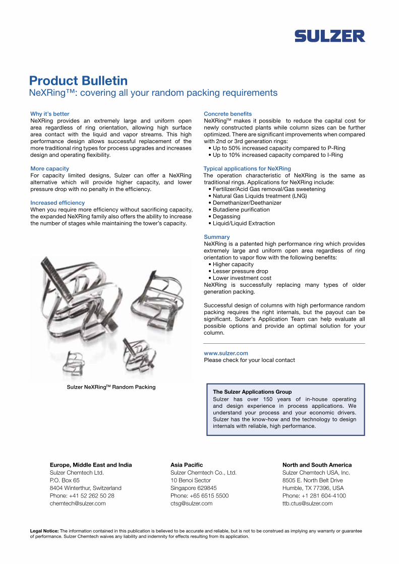
Sulzer NeXRingTM Random Packing
North and South America
Sulzer Chemtech USA, Inc.
8505 E. North Belt Drive
Humble, TX 77396, USA
Phone: +1 281 604-4100
Europe, Middle East and India
Sulzer Chemtech Ltd.
P.O. Box 65
8404 Winterthur, Switzerland
Phone: +41 52 262 50 28
Asia Pacific
Sulzer Chemtech Co., Ltd.
10 Benoi Sector
Singapore 629845
Phone: +65 6515 5500

July 2017 12 HYDROCARBONENGINEERING
Gordon Cope, Contributing Editor, examines the current state of the oil and gas industry across Latin America, and what the future has to hold.
SOUTH OF THE
HYDROCARBONENGINEERING
13 July 2017
L atin America is rich in crude. Countries in the region, including Mexico, Venezuela, Brazil, Argentina and Colombia, produce over 9 million bpd, almost 10% of global production. It
also has a bounty of natural gas, most of it produced in conjunction with crude. Yet the region imports much of its fuels and petrochemical products. While some countries are moving ahead with adding value to their hydrocarbon production, others are languishing. What makes some Latin American countries big winners – and others losers – depends on a wide range of factors.
PetrochemicalsLatin America has several signifi cant petrochemical facilities. Pemex produces 815 000 tpy of polyethylene in high density (HD), low density (LD) and linear low density (LLD) in Mexico. Braskem has 3.2 million tpy of HD, LD, LLD capacity in Brazil. Dow produces 581 000 tpy of HD,
LD and LLD in Argentina and Pequiven makes 430 000 tpy of HD, LD and LLD in Venezuela. In addition, Braskem-Idesa has recently launched a new petrochemical complex in the Gulf of Mexico port of Coatzacoalcos. The 1 million tpy facility produces HD and LD.
Growth in gross domestic product (GDP) in most of Latin America has been steady over the last decade, with standards of living rising at a significant pace. According to Platts, a consultancy, South and Central America already consume 1.5 million tpy more petrochemicals than the region produces, making a case for new facilities in the region.1 Latin America also has an abundance of natural gas feedstock; the Energy Information Administration (EIA) estimates that Argentina alone has 802 trillion ft3 of unconventional gas, and Mexico is building a pipeline infrastructure in order to import billions of cubic feet of cheap shale gas daily from Texas.2
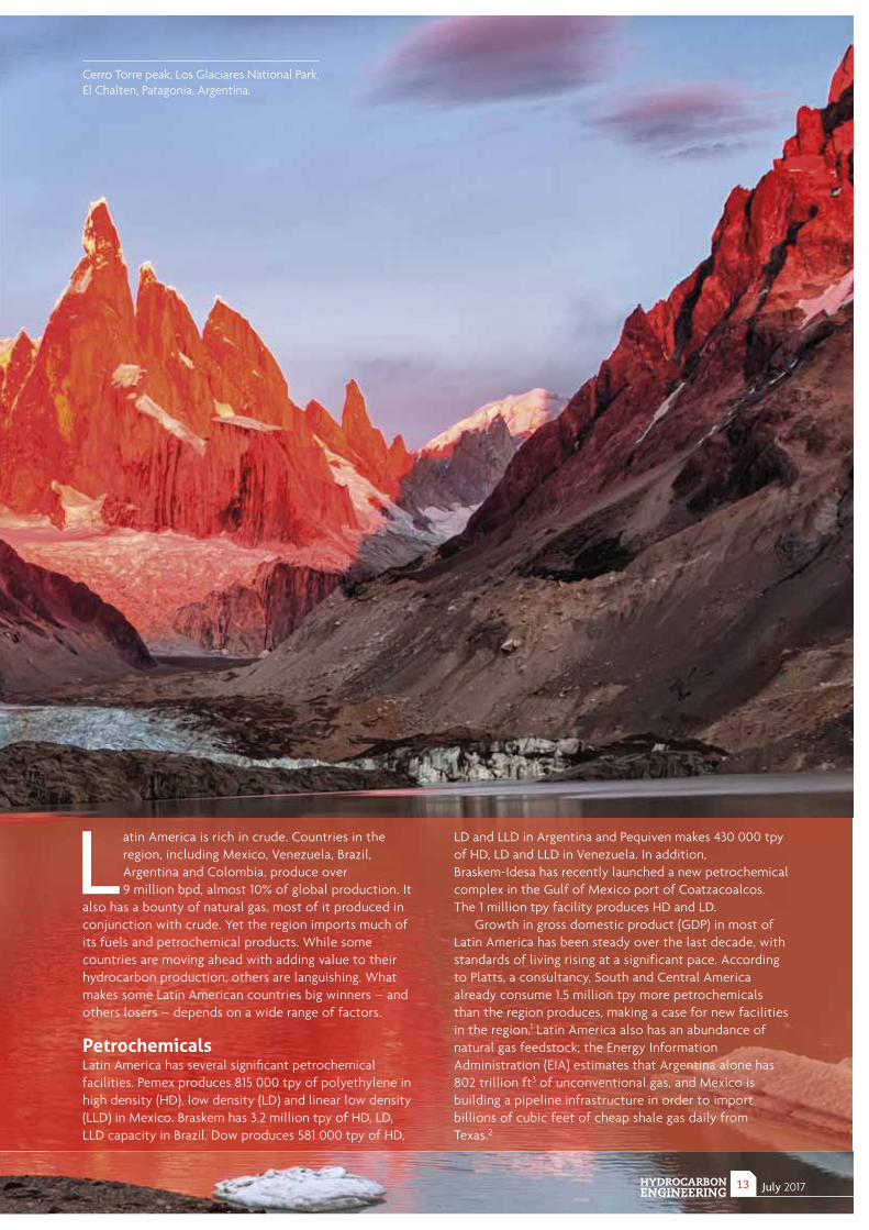
Cerro Torre peak, Los Glaciares National Park, El Chalten, Patagonia, Argentina.
July 2017 HYDROCARBONENGINEERING
14
Several companies have tentative plans to build new capacity in Brazil, Argentina and Venezuela. However, except for the Braskem-Idesa plant in Mexico, no new plants are expected to come onstream in the near future.
The reasons for lack of investment in the region are complex, but several main factors stand out. International manufacturers began repatriating facilities to the US several years ago when the shale gas revolution in North America caused regional feedstock prices to plunge. Although the pace of greenfield investment has now begun to slow, capacity in the US is now sufficiently high enough to deliver low cost petrochemicals to not only North American consumers, but to markets in Latin America as well.
North America is also more politically stable when compared to regions in Latin America. At a recent Latin American Petrochemical and Chemical Association (APLA) conference, representatives of global petrochemical companies noted that Latin America has the resources to replicate the petrochemical growth seen in the US, but key decision makers in the region must work to make sure they are creating environments where the industry can thrive.
RefineriesThere are eight major refineries in Argentina, with a total of over 600 000 bpd nameplate capacity. They include Yacimientos Petrolíferos Fiscales’ (YPF’s) La Plata refinery (189 000 bpd), Royal Dutch Shell’s Buenos Aires refinery (110 000 bpd) and the Esso Campana refinery (84 000 bpd).
Two decades ago, Argentina produced over 900 000 bpd and 4.5 billion ft3/d of gas. Under the Kirchner regimes, however, the oil and gas sector was partly re-nationalised and generally mismanaged, to the point where production fell to current levels of 523 000 bpd, and gas to 3.5 billion ft3/d. According to the CIA World Factbook, the country imports more than 100 000 bpd of fuel products to meet its needs.3
There is light at the end of the tunnel, however. The immense shale gas and oil reserves are finally being produced in significant amounts. Chevron and its joint venture (JV) partner YPF have been drilling exploratory wells in the Vaca Muerta shale in order to assay its production potential. Longer laterals, more fracture stages and increased proppant usage have helped boost individual new well production to over 2 million ft3/d; the partners have over 400 wells, and tight gas production now exceeds 500 million ft3/d.
Other sectors are also seeing investments. After Royal Dutch Shell CEO Ben van Beurden met with Argentina's President Mauricio Macri in late 2016, the company announced plans to invest US$300 million in the country over the next three years on exploration, refining, distribution and marketing. While it is still early days, the fiscal and regulatory climate under Macri is a significant improvement. In late April, Energy and Mining Minister Juan Jose Aranguren confirmed to Reuters4 that the country expects between US$6 and
US$8 billion of foreign investments in shale gas exploration and related development in 2017. The country also expects investments between US$12 and US$15 billion in 2018, and US$20 billion from 2020 onwards.
BrazilAll of Brazil’s refineries are owned and operated by Petrobras. A total of 11 plants around the country have a nameplate capacity of 2.8 million bpd. They include the REFAP refinery in Canoas (201 000 bpd), the REPLAN refinery in Paulinia (415 000 bpd) and the REDUC plant in Rio de Janeiro (242 000 bpd). The country consumes approximately 3.4 million bpd of refined fuel products; around 600 000 bpd must be imported.
Petrobras has been plagued by scandal and mismanagement over the last several years, however. In 2007, the police arrested 13 people for corruption relating to an organised scheme to take bribes in exchange for public partnership tenders from Petrobras. Since then, scores of people, including two former Petrobras directors, have been formally accused of offering and accepting approximately US$800 million in bribes and other inducements by inflating Petrobras contracts and funneling part of the money back, including to the ruling Workers’ Party.
The scandal also generated significant political fallout. Public sentiment turned against President Dilma Rousseff when allegations surfaced that she had been part of the board of directors when the graft was occurring. Although no direct evidence of her involvement emerged, calls for her impeachment led to the Senate charging her with breaking budget laws and voting to remove her from office. She was replaced by Vice President Michel Temer. In turn, Temer brought Pedro Parente, the former chief of staff to President Henrique Cardoso, out of retirement in order to lead Petrobras.
Since then, Petrobras has been overhauling its governance and management. It is also moving aggressively to lower debt and costs. In late 2016, it sold its stake in ethanol producer Guarani SA and two petrochemical facilities in northeastern Brazil for a total of US$587 million, capping off over US$13 billion in divestitures. The company has plans to sell assets and develop partnerships worth US$21 billion over the next two years.
ColombiaWith over 1 million bpd production, Colombia has five refineries capable of handling a total of 340 000 bpd, the majority of which are owned and operated by Ecopetrol. They include the Barrancabermeja-Santander refinery (252 000 bpd) and Reficar’s Cartagena refinery (80 000 bpd). Plans are underway to expand Barrancabermeja’s capacity to 300 000 bpd, and Cartagena’s to 165 000 bpd. Because Colombia consumes less than 300 000 bpd of fuel products, it is a net exporter of gasoline and diesel, as well as crude.

Latest News
EXXONMOBIL COMPLETES INSTALLATION OF PRE-ASSEMBLED RACKS AT ROTTERDAM REFINERYFollowing ExxonMobil’s latest update on the successful heavy lift of the reactors and vacuum fractionation tower, the pre-assembled racks (PARs), for the new hydrocracker, have been installed at the Rotterdam refi nery. Manufactured in Spain, the PARs were shipped by water to the Rotterdam refi nery during mid-May 2017.
TOPSOE TECHNOLOGY SELECTED FOR INDIAN REFINERYHPCL-Mittal Energy Ltd (HMEL), an Indian refi nery company, has selected Topsoe’s diesel hydrotreater unit and hydrogen generation facilities to meet its upgrading requirements. When completed in 4Q19, the revamped refi nery in Bathinda, Punjab will meet the BS VI (equivalent to Euro VI) fuel specifi cations.
SALINA CRUZ REFINERY TO RESUME OPERATIONSPemex Transformación Industrial has announced that it is currently carrying out several actions to restart operations at the Antonio Dovalí Jaime de Salina Cruz refi nery, affected by fl oods and fi re caused by tropical storm Calvin. The programme contemplates actions in three ways: resumption of operations; cleaning and rehabilitation of the affected site; and general maintenance, taking advantage of the stoppage process.
A CLEAR VIEWAnkur Pariyani, Nancy Zarrow, Ulku Oktem and Deborah Grubbe, Near-Miss Management LLC, USA, discuss methods to reduce cognitive bias in industrial operations.
For further information go to:www.hydrocarbonengineering.com
Capabilities
hexagonppm.com/cadworx
© 2017 Hexagon AB and/or its subsidiaries and affiliates. AutoCAD is a registered trademark of Autodesk, Inc. BricsCAD is a registered trademark of Bricsys. All rights reserved.
CADWorx Plant Professional makes the creation of intelligent plant designs quick and easy. It has helped firms produce the high-quality deliverables their customers have come to rely on for over fifteen years.
AutoCAD® or BricsCAD® PlatformIntelligent 3D Piping DesignOn-the-fly Collision CheckingStructural SteelEquipmentDucting/Cable TraysIsogen® IsometricsP&ID Creation and LinksLinks to Stress AnalysisDesign Review
July 2017 HYDROCARBONENGINEERING
16
The country’s oil and gas sector has made a remarkable recovery after years of civil war with FARC guerrillas had cut the country’s 990 000 bpd output in half. In 2003, however, under the Uribe government, a series of fiscal and regulatory changes opened up the sector to privatisation. Since then, international investments exceeding US$5 billion annually have resulted in a renaissance. Although former state monopoly Ecopetrol has been a significant contributor to the resurgence, international companies such as Geopark, Pacific Rubiales and Gran Tierra have also whole-heartedly entered the jurisdiction.
Peace has also largely returned to Colombia’s hinterland. In a historic step in 2016, the government of President Juan Manuel Santos reached a disarmament agreement with FARC, the main rebel group in Colombia. The half-century guerilla war, which left 250 000 dead and millions displaced, officially ended after successful negotiations in Cuba.
Other resistance groups remain a problem for the nation’s oil and gas sector, however. The Canon-Limon pipeline, running from the interior to the Caribbean port of Covenas, has a nameplate capacity of 210 000 bpd. Ecopetrol estimates that rebel attacks on the line by the ELN Army have resulted in almost 900 000 bbls of lost production in the first three months of 2017 alone. Until all rebel groups negotiate ceasefires, bombings, kidnappings and disruptions will remain a risk for the foreseeable future.
VenezuelaPetróleos de Venezuela S.A (PDVSA) operates seven refineries in Venezuela with a total of 2.5 million bpd nameplate capacity, including the Paraguana refinery complex (956 000 bpd) and the Amuay-Cardon-Bajo Grande complex (950 000 bpd). Underinvestment (and a major fire at Paraguana) means that the country produces slightly less than 1 million bpd of refined products.
Since the ascendence of Hugo Chavez and his Socialist Party, crude production has plunged from 3.5 million bpd to approximately 2.1 million bpd in 2016. According to Thomson Reuters, PDVSA’s crude exports fell from 1.82 million bpd in 1Q16 to 1.59 million bpd in 4Q16.5
The drop in exports is only part of PDVSA’s problems. In October 2016, a congressional report found that PDVSA’s former president Rafael Ramirez was responsible for mischief that cost the state oil monopoly US$11 billion. The charges involved pricing of drilling rigs and money laundering in Andorra. The Supreme Court, however, approved an injunction by Ramirez against the probe.
Because much of the alleged ill-gotten gains passed through the US financial system, several federal agencies, including Homeland Security and the FBI, are investigating activities that date back to 2005. Roberto Rincon-Fernandez, a Venezuelan national living in Houston, Texas, US, was successfully prosecuted for taking part in a US$1 billion bribery scheme. Further prosecutions are expected.
Unlike Brazil, Venezuela’s federal government (and its regulatory and judicial systems) show little inclination to clean up the mess. As a result, Venezuela is considered a high risk climate for international investment in either refining or petrochemicals.
MexicoMexico has six major refineries with a total nameplate capacity of 1.25 million bpd, all operated by Pemex. They include the Tula refinery (300 000 bpd), the Salina Cruz refinery (227 000 bpd) and the Salamanca refinery (152 000 bpd). Years of underinvestment have resulted in capacity levels falling well behind consumption; Mexico now imports over 700 000 bpd of gasoline and diesel, primarily from the US.
The majority of fuel arrives in Mexico via ship; currently, 20 – 30 tankers dock in Gulf ports each month, putting a strain on existing infrastructure. In order to alleviate import bottlenecks, TransCanada is partnering with Mexico’s Sierra Oil & Gas to expand fuel infrastructure. It recently announced a plan to spend US$800 million to construct a marine terminal near Tuxpan, Veracruz, and a 265 km, 100 000 bpd refined products pipeline that would connect to a central distribution hub north of Mexico City.
Mexico’s refining sector may be in for better times, as well. When President Enrique Peña Nieto cancelled the state monopoly in oil and gas, few could have predicted the rapid pace at which the industry has evolved. Once the sole domain for state oil company Pemex, the landscape has been transformed as open bidding on leases, JVs and divestments have attracted international investment in the upstream, midstream and downstream sectors.
Pemex is looking to build and operate a new coking plant at its Tula refinery. The US$2.1 billion project is being put out to tender, and Mitsui, Eni, Royal Dutch Shell and Chevron have all expressed interest. The Tula refinery is currently operating at 60% capacity, producing less than 200 000 bpd of refined products. The coking facility will help boost the production of gasoline from the heavy crude feedstock.
Even if Mexico does not expand its refinery base, US companies have its future needs well in hand. Raven Petroleum, based in Texas, is planning to build a 50 000 bpd refinery north of the Mexican border in Duval County. The gasoline and low-sulfur diesel facility is expected to come online in 2019. MMEX Resources also has plans for a similar-sized facility east of Laredo, Texas. Both plants will be designed to process light crude from the prolific Eagle Ford shale. "Demand for fuels in Mexico is growing at over 3% per year," said Christopher Moore, MMEX Managing Director. "A constrained market won’t be resolved internally, so it will have to import as they are doing now.”6
ConclusionWhile the expansion of petrochemical and refining capacity is warranted in many jurisdictions in

Latin America, including Mexico, Colombia and Brazil, the current low commodity price environment has constrained many country champions (such as Pemex) from investing in downstream assets. Others (such as Petrobras) are busy re-balancing their budgets and reducing debt through the sale of non-core properties. The private sector (Braskem-Idesa) has shown some initiative, but major petrochemical producers have concentrated their expansion efforts in the US, where low feedstock prices and favourable regulatory and fiscal regimes attract investment.
Latin America possesses under-served fuel and petrochemical markets; in order to attract major investment, it must take several steps. Country champions are key to inviting international investment as they offer potential JV partners existing infrastructure and access to markets. But scandals associated with executive misdeeds need to be addressed in the courts and internal governance re-organisation in order to restore confidence.
Regulatory and fiscal environments also need to be upgraded to promote transparency and independent oversight. Government monopolies should be eliminated. Internal strife must be addressed at the federal level (such as in Colombia), but also in the courts; in Mexico, Native American rights enshrined in the constitution are often given short-shrift, resulting in violent protests that have impeded the construction and operation of assets such as pipelines.
While some countries have taken admirable steps to reform, too many others remain stuck in the mire. For the foreseeable future, Latin America’s growth in fuel and plastics demand is likely to be largely met by increased imports.
References1. FERRELL, C., 'Latin America
grapples with lack of petrochemical investment', (2016), available: http://blogs.platts.com/2016/06/29/latin-america-petrochemical-investment/, (last accessed 9 May 2017).
2. ESPARZA, J., ALOULOU, F., and ESTES, A., 'Argentina seeking
increased natural gas production from shale resources to reduce imports', (2017), available: https://www.eia.gov/todayinenergy/detail.php?id=29912, (last accessed 9 May 2017).
3. 'The World Factbook: Argentina', (2017), available: https://www.cia.gov/library/publications/the-world-factbook/geos/ar.html, (last accessed 9 May 2017).
4. PARRAGA, M., 'Argentina sees Vaca Muerta investment reaching up to $8 billion this year', (2017), available: http://www.reuters.com/article/us-argentina-energy-vaca-muerta-idUSKBN17S2Q5 (last accessed 9 May 2017).
5. PARRAGA, M. and GUANIPA, M., 'Exclusive: millions of barrels of Venezuelan oil stuck at sea in dirty tankers', (2017), available: http://www.reuters.com/article/us-venezuela-pdvsa-tankers-idUSKBN15A0JA, (last accessed 9 May 2017).
6. TOBBEN, S., 'Newest Texas Refineries Plan to Turn Shale Into Fuel for Mexico', (2017), available: https://www.bloomberg.com/news/articles/2017-03-28/newest-texas-refineries-plan-to-turn-shale-into-fuel-for-mexico, (last accessed 9 May 2017).
Additional courses are available. Learn more and register at trinityconsultants.com/training or +1 (972) 661-8100. SAVE 25% on course fees with the discount code “HE25.”
> Environmental impact assessment> EHS permitting and compliance management> Air quality studies> Emissions quantification
> BREEZE® EHS modeling software> Air dispersion, fires, and explosions> Model-ready meteorological and terrain data
> EHS information management solutions> Business requirements analysis > System selection and implementation> Enterprise, custom, and mobile solutions
Consulting TechnologySoftware
Professional EHS TrainingTopics include:
We support your operations from every angle to ensure effective EHS strategy and streamlined EHS data management
Your EHS Issues are Our Issues
trinityconsultants.com | +1 (972) 661-8100North America | Europe | Middle East | Asia
> Air Quality Basics for Oil & Natural Gas Field Operators> Air Quality Permitting and Compliance for Oil & Gas Operations (location specific)> Clean Air Act Workshop for the Oil & Natural Gas Industry> Clean Air Act Workshop for the Petroleum Refining Industry> Compliance Management for Fugitive Emissions and LDAR for the Oil & Natural Gas Industry

July 2017 18 HYDROCARBONENGINEERING
Rixt Dijkstra, Fluor Corp.,
the Netherlands, highlights
the importance of
conducting feasibility studies
during the planning stages of
petrochemical projects.

July 201719HYDROCARBONENGINEERING
A lthough only a small fraction of total project expenditure is spent at the feasibility phase, most of the key decisions that determine the profi tability and successful execution of a project
are undertaken during this phase. Therefore, a properly executed feasibility study, in which a solid basis is set for subsequent project phases, is paramount to the success of a project. Sometimes this type of study is also used to benchmark the involved CAPEX, the fi nancial model and the technical concept against previously performed studies. This article explains the feasibility study methodology and some of the lessons learned while executing them.
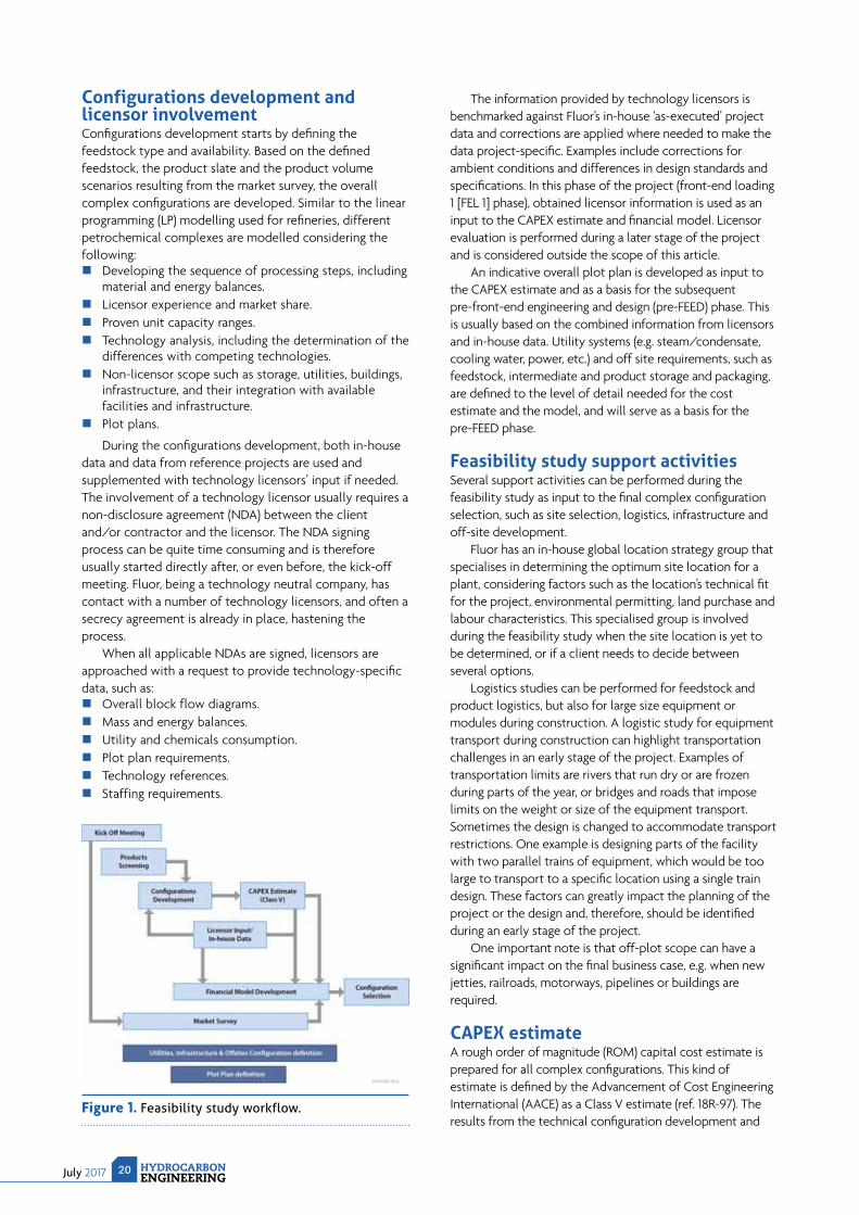
A feasibility study is generally built-up of the following activities (see Figure 1):
Kick-off meeting. Product screening. Market survey. Configurations development. Licensor input and in-house data gathering. Support activities. CAPEX estimate. Financial model development. Configuration selection.
Kick-off meetingA feasibility study starts with a kick-off meeting, where all parties involved gather to discuss the project scope. During this meeting, items such as project execution, project schedule, study scope and roles and responsibilities are defi ned. Also, more practical project execution items, such as project language and communication procedures are agreed upon. The kick-off meeting must be well prepared, perhaps more than any other meeting, to set the basis for a successful feasibility study.
Product screening and market surveyThe fi rst step in developing a new petrochemical complex is determining its product slate and product output volumes. A
feasibility study therefore usually starts with a product screening phase, in which a ‘long list’ of potential products or groups of products are evaluated and ranked based on market attractiveness, market accessibility and potential profi tability. The objective is to create a shortlist of the most attractive products, which are then subject to more detailed analysis.
Based on the results of the screening phase, the long list products are ranked on an agreed set of selection criteria, such as pricing, market volume, growth prospects or strategic considerations. Product ranking can also be infl uenced by qualitative factors. Examples of these ‘soft’ factors include: experience with the product type, confi dence in the market and/or technology, or preferences of potential partners. After ranking all products in the long list, an agreed number of products are shortlisted for further development based on, for example, the products with the best strategic fi t, demand forecast, pricing forecasts, and consideration of feedstock, products and intermediates. By reducing the product long list to a shortlist, the amount of petrochemical complex confi gurations to be investigated in detail is decreased, thereby saving time and costs during the feasibility study.
A more detailed market analysis can be performed for the shortlisted products. The market survey is usually performed in conjunction with a specialised marketing consultant, which may include a cost of production analysis and an assessment of costs for logistics and transportation to the target markets or regions. Geographical aspects are important when determining the fi nancial feasibility of a new petrochemical complex. If the new complex is to be located in a remote region, a feedstock cost advantage can be offset by high transportation costs. Some locations may lack suffi cient infrastructure for the import of feedstock or export of certain products. These (and other) parameters determine the optimum product output for the new complex. The market survey determines which markets are best targeted by the new facility and, ultimately, results in a ‘sales plan’. This sales plan then sets the constraints for the optimum products and their volumes for the new complex.
July 2017 HYDROCARBONENGINEERING
20
Configurations development and licensor involvementConfi gurations development starts by defi ning the feedstock type and availability. Based on the defi ned feedstock, the product slate and the product volume scenarios resulting from the market survey, the overall complex confi gurations are developed. Similar to the linear programming (LP) modelling used for refi neries, different petrochemical complexes are modelled considering the following:
Developing the sequence of processing steps, including material and energy balances.
Licensor experience and market share. Proven unit capacity ranges. Technology analysis, including the determination of the
differences with competing technologies. Non-licensor scope such as storage, utilities, buildings,
infrastructure, and their integration with available facilities and infrastructure.
Plot plans.
During the confi gurations development, both in-house data and data from reference projects are used and supplemented with technology licensors’ input if needed. The involvement of a technology licensor usually requires a non-disclosure agreement (NDA) between the client and/or contractor and the licensor. The NDA signing process can be quite time consuming and is therefore usually started directly after, or even before, the kick-off meeting. Fluor, being a technology neutral company, has contact with a number of technology licensors, and often a secrecy agreement is already in place, hastening the process.
When all applicable NDAs are signed, licensors are approached with a request to provide technology-specifi c data, such as:
Overall block flow diagrams. Mass and energy balances. Utility and chemicals consumption. Plot plan requirements. Technology references. Staffing requirements.
The information provided by technology licensors is benchmarked against Fluor’s in-house ‘as-executed’ project data and corrections are applied where needed to make the data project-specifi c. Examples include corrections for ambient conditions and differences in design standards and specifi cations. In this phase of the project (front-end loading 1 [FEL 1] phase), obtained licensor information is used as an input to the CAPEX estimate and fi nancial model. Licensor evaluation is performed during a later stage of the project and is considered outside the scope of this article.
An indicative overall plot plan is developed as input to the CAPEX estimate and as a basis for the subsequent pre-front-end engineering and design (pre-FEED) phase. This is usually based on the combined information from licensors and in-house data. Utility systems (e.g. steam/condensate,cooling water, power, etc.) and off site requirements, such as feedstock, intermediate and product storage and packaging, are defi ned to the level of detail needed for the cost estimate and the model, and will serve as a basis for the pre-FEED phase.
Feasibility study support activitiesSeveral support activities can be performed during the feasibility study as input to the fi nal complex confi guration selection, such as site selection, logistics, infrastructure and off-site development.
Fluor has an in-house global location strategy group that specialises in determining the optimum site location for a plant, considering factors such as the location’s technical fi t for the project, environmental permitting, land purchase and labour characteristics. This specialised group is involved during the feasibility study when the site location is yet to be determined, or if a client needs to decide between several options.
Logistics studies can be performed for feedstock and product logistics, but also for large size equipment or modules during construction. A logistic study for equipment transport during construction can highlight transportation challenges in an early stage of the project. Examples of transportation limits are rivers that run dry or are frozen during parts of the year, or bridges and roads that impose limits on the weight or size of the equipment transport. Sometimes the design is changed to accommodate transport restrictions. One example is designing parts of the facility with two parallel trains of equipment, which would be too large to transport to a specifi c location using a single train design. These factors can greatly impact the planning of the project or the design and, therefore, should be identifi ed during an early stage of the project.
One important note is that off-plot scope can have a signifi cant impact on the fi nal business case, e.g. when new jetties, railroads, motorways, pipelines or buildings are required.
CAPEX estimateA rough order of magnitude (ROM) capital cost estimate is prepared for all complex confi gurations. This kind of estimate is defi ned by the Advancement of Cost Engineering International (AACE) as a Class V estimate (ref. 18R-97). The results from the technical confi guration development and
Figure 1. Feasibility study workflow.

© 2016 Honeywell International. All rights reserved.
eMission CompleteThe Next Generation
of Flare Testing and Inspection
Introducing the only flare test facility in
the world that has a full scale radiation
fence to deliver real world test conditions
dynamics modeling and model validation
it live
Please visit www.Callidus.com
CallidusTechnologies
July 2017 HYDROCARBONENGINEERING
22
feasibility study support activities from the input to the CAPEX estimate. This includes production capacity, technologies, utility balances, required storage facilities, additional or corrective equipment data, indicative overall plot plan, and approximate project location and timing.
For a Class V estimate, Fluor applies a plant capacity-factored estimate methodology, using its in-house database of ‘as-built’ cost data from executed projects, normalised for time, location, and plant capacity.
If no reference data for a similar scope is available, an alternative cost estimating approach is used to reach a similar accuracy level. Cost values will be applied against a high level scope of facilities, taking the appropriate level of detail into account to reach the required cost estimate accuracy level. Input is based on preliminary engineering data, e.g. preliminary sized equipment lists and process fl ow diagrams (PFDs) received from the licensor. A similar approach is used for the high level scope of services. In principle, this Class V estimate is based on in-house available market pricing.
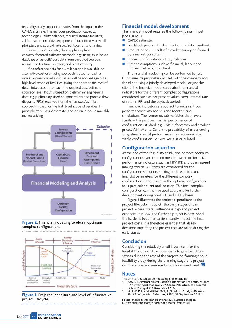
Financial model developmentThe fi nancial model requires the following main input (see Figure 2):
CAPEX estimate. Feedstock prices – by the client or market consultant. Product prices – result of a market survey performed
by a market consultant. Process configurations, utility balances. Other assumptions, such as financial, labour and
utilities cost – by the client.The fi nancial modelling can be performed by just
Fluor using its proprietary model, with the company and the client using a jointly developed model, or just the client. The fi nancial model calculates the fi nancial indicators for the different complex confi gurations considered, such as net present value (NPV), internal rate of return (IRR) and the payback period.
Financial indicators are subject to analysis. Fluor performs sensitivity analysis and Monte Carlo simulations. The former reveals variables that have a signifi cant impact on fi nancial performance of confi gurations studied, e.g. CAPEX, feedstock and product prices. With Monte Carlo, the probability of experiencing a negative fi nancial performance from economically viable confi gurations, or vice versa, is calculated.
Configuration selectionAt the end of the feasibility study, one or more optimum confi gurations can be recommended based on fi nancial performance indicators such as NPV, IRR and other agreed ranking criteria. All items are considered for the confi guration selection, ranking both technical and fi nancial parameters for the different complex confi gurations. This results in the optimal confi guration for a particular client and location. This fi nal complex confi guration can then be used as a basis for further development during pre-FEED and FEED phases.
Figure 3 illustrates the project expenditure vs the project lifecycle. It depicts the early stages of the project, where overall infl uence is high and project expenditure is low. The further a project is developed, the harder it becomes to signifi cantly impact the fi nal project costs. It is therefore essential that all key decisions impacting the project cost are taken during the early stages.
ConclusionConsidering the relatively small investment for the feasibility study and the potentially large expenditure savings during the rest of the project, performing a solid feasibility study during the planning stage of a project can therefore be considered as a viable investment.
NotesThis article is based on the following presentations:1. BAARS, F., 'Petrochemical Complex Integration Feasibility Studies
– An investment that pays out', Global Petrochemicals Summit, Lisbon, Portugal, (16 November 2016).
2. SCHIPPER, E. and MIKHAILOVA, A., 'Pre-FEED Study in Russia – Plant Configuration Selection', RPTC, (23 September 2015).
Special thanks to Aleksandra Mikhailova, Eugene Schipper, Kurt Wiederkehr, Martijn Koster and Marcel Verschuur.
Figure 2. Financial modelling to obtain optimum complex configuration.
Figure 3. Project expenditure and level of influence vs project lifecycle.

July 201723HYDROCARBONENGINEERING
Over the past several years, there has been increased interest in combining refi nery and petrochemical projects in order to maximise production of the highest value products while
meeting transportation fuel needs. To accomplish these (often competing) objectives, the hydroprocessing approaches utilised in the refi nery are critical. Both the processes and catalysts selected have a signifi cant impact on petrochemical feedstock production. Recently, Chevron Lummus Global (CLG) has been assisting several clients with identifying ways to increase project values based on the portfolio of residue hydrotreating, residue hydrocracking, and vacuum gas oil (VGO)/distillate hydrocracking technologies. This article shares some of the
new approaches available and compares their benefi ts with the traditional paths for producing petrochemical feedstocks.
A refinery’s role in petrochemical productionThe conventional roles of hydroprocessing in petrochemical production have been to pretreat fl uid catalytic cracking (FCC) – or residual FCC (RFCC) – feed to increase propylene and naphtha yields, especially heavy naphtha as it is an important reformer feedstock and a source for C8 – C10 aromatics. Other refi nery streams suitable for petrochemical production include light naphtha and LPG steam cracker feeds.
MORE, MORE, MORE
Daniel B. Gillis and Theo Maesen, Chevron Lummus Global, USA, evaluate new hydroprocessing approaches to increase petrochemicals production.
July 2017 HYDROCARBONENGINEERING
24
The manufacturing of petrochemical feedstocks frequently competes with the manufacturing of transportation fuels. This is because of the following:
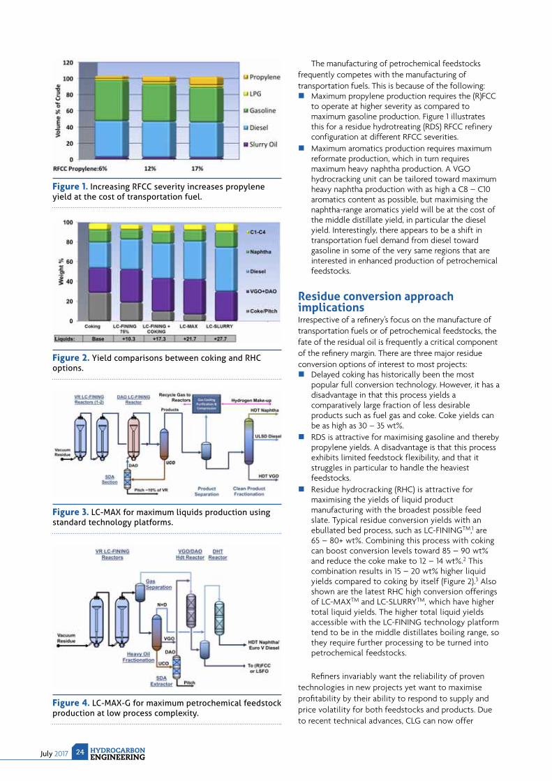
Maximum propylene production requires the (R)FCC to operate at higher severity as compared to maximum gasoline production. Figure 1 illustrates this for a residue hydrotreating (RDS) RFCC refinery configuration at different RFCC severities.
Maximum aromatics production requires maximum reformate production, which in turn requires maximum heavy naphtha production. A VGO hydrocracking unit can be tailored toward maximum heavy naphtha production with as high a C8 – C10 aromatics content as possible, but maximising the naphtha-range aromatics yield will be at the cost of the middle distillate yield, in particular the diesel yield. Interestingly, there appears to be a shift in transportation fuel demand from diesel toward gasoline in some of the very same regions that are interested in enhanced production of petrochemical feedstocks.
Residue conversion approach implicationsIrrespective of a refi nery’s focus on the manufacture of transportation fuels or of petrochemical feedstocks, the fate of the residual oil is frequently a critical component of the refi nery margin. There are three major residue conversion options of interest to most projects:
Delayed coking has historically been the most popular full conversion technology. However, it has a disadvantage in that this process yields a comparatively large fraction of less desirable products such as fuel gas and coke. Coke yields can be as high as 30 – 35 wt%.
RDS is attractive for maximising gasoline and thereby propylene yields. A disadvantage is that this process exhibits limited feedstock flexibility, and that it struggles in particular to handle the heaviest feedstocks.
Residue hydrocracking (RHC) is attractive for maximising the yields of liquid product manufacturing with the broadest possible feed slate. Typical residue conversion yields with an ebullated bed process, such as LC-FININGTM,1 are 65 – 80+ wt%. Combining this process with coking can boost conversion levels toward 85 – 90 wt% and reduce the coke make to 12 – 14 wt%.2 This combination results in 15 – 20 wt% higher liquid yields compared to coking by itself (Figure 2).3 Also shown are the latest RHC high conversion offerings of LC-MAXTM and LC-SLURRYTM, which have higher total liquid yields. The higher total liquid yields accessible with the LC-FINING technology platform tend to be in the middle distillates boiling range, so they require further processing to be turned into petrochemical feedstocks.
Refi ners invariably want the reliability of proven technologies in new projects yet want to maximise profi tability by their ability to respond to supply and price volatility for both feedstocks and products. Due to recent technical advances, CLG can now offer
Figure 1. Increasing RFCC severity increases propylene yield at the cost of transportation fuel.
Figure 2. Yield comparisons between coking and RHC options.
Figure 3. LC-MAX for maximum liquids production using standard technology platforms.
Figure 4. LC-MAX-G for maximum petrochemical feedstock production at low process complexity.

Marine Engines & Systems Power Plants Turbomachinery After Sales
Whether upgrading your equipment to meet new standards or xing an urgent problem – when you need us, we are there, no matter what! This is what we commit to 100% and this is the way we run our world class service organization for you. Your machinery’s availability, ef ciency and longevity are the sole focus of what we do and think about every day. Wherever you are in the world, we are at your disposal 24/7 through our global network of service facilities. Find out more at: primeserv.man.eu
Service with passion.Wherever you are in the world
Typ 02 - SEA-STA 2 - Service with Passion - 210x297.indd 1 2017-03-16 19:41:41
July 2017 HYDROCARBONENGINEERING
26
solutions based on LC-FINING and RDS technology platforms that expand feedstock optionality and provide the desired fl exibility to diversify product dispositions, e.g., switching emphasis from diesel to naphtha or from transportation fuel to petrochemical feedstock production. These advances include both processes and catalysts.
Advances in process technology
RDSSo as to mitigate the feedstock limitations intrinsic to RDS/RFCC and thereby expand the range of RDS applications, the company offers Upfl ow Reactor (UFRTM) technology for both new and existing units. This reactor is added in the front of the fi xed bed reactors. Since it has a very low pressure drop it is an excellent solution for revamp applications. It can be isolated from the main fi xed bed reactors and the UFR catalyst can be changed out while the main RDS reactors continue in service. The reactor has been successfully employed by several of CLG’s licensed RDS units.
Aromatics productionThe LC-MAX process can help to increase aromatics production. This is a LC-FINING-based process that fi rst hydrocracks residue at low conversion, subsequently
utilises a solvent deasphalting step to reject compounds likely to form sediment, and fi nally achieves nearly complete conversion of the desasphalted oil (DAO) and heavy VGO (HVGO) products in an additional LC-FINING step.
Figure 3 illustrates the LC-MAX process, which makes approximately 10 wt% more VGO and 13 wt% more distillates as compared to coking. Figure 2 highlights the process' yield advantage, so it has been selected for two large residue conversion projects, both in the engineering phases.
This process' VGO is a good hydrocracker feedstock, as the combination of solvent deasphalting and high conversion residue hydrocracking effectively eliminates the feed components that make high refractory VGOs.
Increased FCC feedstocksFor applications where increased FCC feedstocks are desired, a modifi ed LC-MAX-G process is available. Here, the hydrocracked residue is fractionated and only the unconverted oil is deasphalted. The VGO and DAO are subsequently combined and hydrotreated (Figure 4).4 The desired VGO/DAO hydrotreating severity depends on the desired FCC performance. High quality distillates and naphtha can be manufactured more or less independent of the VGO/DAO quality objectives.
Hydrocracking RHC distillate productCLG has pioneered the integration of RHC and both RHC product hydrotreating and RHC product hydrocracking into a shared RHC high pressure loop. The addition of an integrated product hydroprocessing option is fairly straightforward, requiring only a few additional catalyst beds or a small additional cracking reactor.
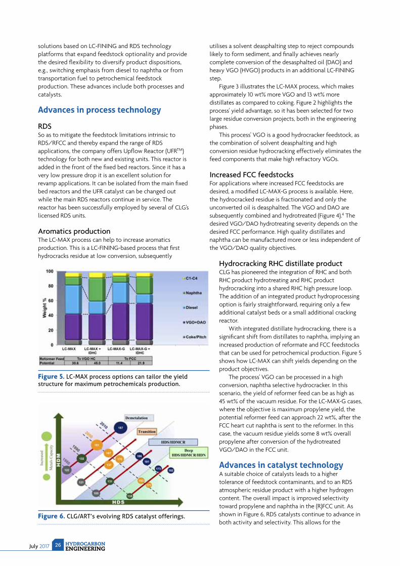
With integrated distillate hydrocracking, there is a signifi cant shift from distillates to naphtha, implying an increased production of reformate and FCC feedstocks that can be used for petrochemical production. Figure 5 shows how LC-MAX can shift yields depending on the product objectives.
The process' VGO can be processed in a high conversion, naphtha selective hydrocracker. In this scenario, the yield of reformer feed can be as high as 45 wt% of the vacuum residue. For the LC-MAX-G cases, where the objective is maximum propylene yield, the potential reformer feed can approach 22 wt%, after the FCC heart cut naphtha is sent to the reformer. In this case, the vacuum residue yields some 8 wt% overall propylene after conversion of the hydrotreated VGO/DAO in the FCC unit.
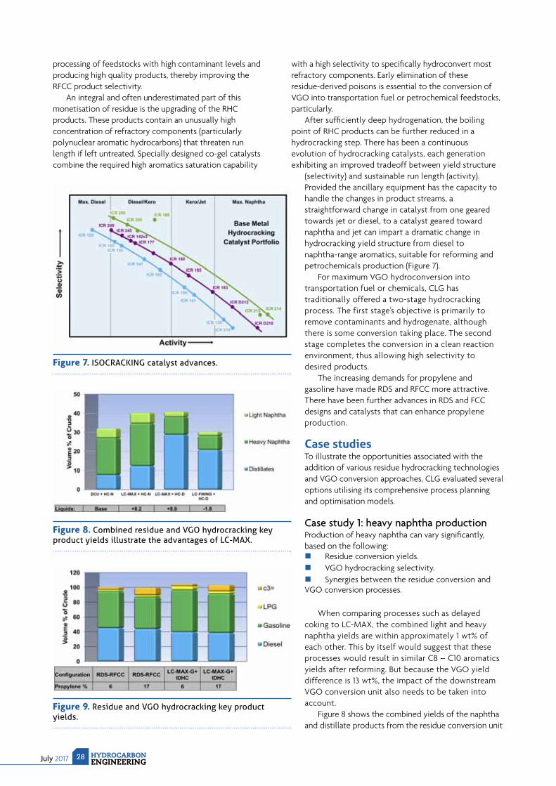
Advances in catalyst technologyA suitable choice of catalysts leads to a higher tolerance of feedstock contaminants, and to an RDS atmospheric residue product with a higher hydrogen content. The overall impact is improved selectivity toward propylene and naphtha in the (R)FCC unit. As shown in Figure 6, RDS catalysts continue to advance in both activity and selectivity. This allows for the
Figure 5. LC-MAX process options can tailor the yield structure for maximum petrochemicals production.
Figure 6. CLG/ART’s evolving RDS catalyst offerings.
Neles® NDX valve controllerdelivers performance perfected
That’s how we make the big difference, the Metso Way.
The Neles NDX has been carefully designed and manufactured to make
the big difference to our customers, regardless of end use industry or
application. Savings are created through accurate, long-lasting and
maintenance-free performance and through time saved as a result of
extremely easy installation and use. The Neles NDX provides the reli-
ability and robustness you’d expect from a valve controller by Metso,
for all valve brands in standard applications.
Find out more about the savings, safety and reliability that each
Neles NDX valve controller offers at metso.com/ndx
#TheMetsoWay
July 2017 HYDROCARBONENGINEERING
28
processing of feedstocks with high contaminant levels and producing high quality products, thereby improving the RFCC product selectivity.
An integral and often underestimated part of this monetisation of residue is the upgrading of the RHC products. These products contain an unusually high concentration of refractory components (particularly polynuclear aromatic hydrocarbons) that threaten run length if left untreated. Specially designed co-gel catalysts combine the required high aromatics saturation capability
with a high selectivity to specifi cally hydroconvert most refractory components. Early elimination of these residue-derived poisons is essential to the conversion of VGO into transportation fuel or petrochemical feedstocks, particularly.
After suffi ciently deep hydrogenation, the boiling point of RHC products can be further reduced in a hydrocracking step. There has been a continuous evolution of hydrocracking catalysts, each generation exhibiting an improved tradeoff between yield structure
(selectivity) and sustainable run length (activity). Provided the ancillary equipment has the capacity to handle the changes in product streams, a straightforward change in catalyst from one geared towards jet or diesel, to a catalyst geared toward naphtha and jet can impart a dramatic change in hydrocracking yield structure from diesel to naphtha-range aromatics, suitable for reforming and petrochemicals production (Figure 7).
For maximum VGO hydroconversion into transportation fuel or chemicals, CLG has traditionally offered a two-stage hydrocracking process. The first stage’s objective is primarily to remove contaminants and hydrogenate, although there is some conversion taking place. The second stage completes the conversion in a clean reaction environment, thus allowing high selectivity to desired products.
The increasing demands for propylene and gasoline have made RDS and RFCC more attractive. There have been further advances in RDS and FCC designs and catalysts that can enhance propylene production.
Case studiesTo illustrate the opportunities associated with the addition of various residue hydrocracking technologies and VGO conversion approaches, CLG evaluated several options utilising its comprehensive process planning and optimisation models.
Case study 1: heavy naphtha productionProduction of heavy naphtha can vary signifi cantly, based on the following:
Residue conversion yields. VGO hydrocracking selectivity. Synergies between the residue conversion and
VGO conversion processes.
When comparing processes such as delayed coking to LC-MAX, the combined light and heavy naphtha yields are within approximately 1 wt% of each other. This by itself would suggest that these processes would result in similar C8 – C10 aromatics yields after reforming. But because the VGO yield difference is 13 wt%, the impact of the downstream VGO conversion unit also needs to be taken into account.
Figure 8 shows the combined yields of the naphtha and distillate products from the residue conversion unit
Figure 8. Combined residue and VGO hydrocracking key product yields illustrate the advantages of LC-MAX.
Figure 9. Residue and VGO hydrocracking key product yields.
Figure 7. ISOCRACKING catalyst advances.
and a high conversion VGO hydrocracker operating in various modes. Because the LC-MAX case converts signifi cantly more residue into liquids as compared to coking, the resulting naphtha and distillate yields are highest in this option.
For this case, the second and third columns show the shifts in yields dependent on the VGO hydrocracker selectivity. Both heavy and light naphtha can be increased with a naphtha selective operation, resulting in more steam cracker and C8 – C10 aromatics feedstocks.
Alone, LC-FINING does not show a high naphtha and distillate yield, its unconverted oil could be processed in a delayed coker, signifi cantly augmenting these yields.
Case study 2: maximising gasoline and propyleneFigure 9 shows the overall refi nery yields for RDS, RFCC, LC-MAX-G, and FCC fl ow schemes. The respective yields from each option also depend on the operating mode of the (R)FCC unit.
For the RDS and RFCC fl ow scheme, the gasoline yield could be signifi cantly reduced when the RFCC is geared toward maximising the propylene yield. In this operation, propylene yield can be further enhanced if the C4 production – usually used for alkylate production – can be minimised.
LC-MAX-G, with the integrated distillate product hydrocracking option, can result in higher gasoline yields compared to an RDS and RFCC fl ow scheme. Although it has less (R)FCC feedstock, the FCC feed quality is higher. In addition, it produces a signifi cant amount of naphtha alone. The effective result is high overall gasoline and C8 – C10 aromatics yields. RDS and RFCC will be used if high propylene yield is preferred.
ConclusionResidue and VGO conversion are important for maximising the production of petrochemical feedstocks. CLG can help with tailoring combinations of LC-FINING or LC-MAX with VGO hydrocracking toward the maximum production of feedstocks for ethylene cracker and aromatics plants, while minimising residue byproducts. The proper integration of RDS and RFCC can maximise propylene production. Advances in RDS catalysts and a combination of UFR and traditional RDS reactors expands the feedstock range for this application. LC-MAX-G and FCC facilitates both high propylene and gasoline yields.
References1. MUKHERJEE, U., ‘LC-FINING: High Conversion Residue
Hydrocracking’, Middle East Petrotech, (2010).2. SIELI, G. and GUPTA, N., ‘Delayed Coking and LC-FINING
Technology – A Winning Combination’, ERTC Coking and Gasification conference, Rome, Italy, (2008).
3. GILLIS, D., MUKHERJEE, U. and SIELI, G., ‘Utilising Cheap Gas to Increase Refinery Profits’, AFPM, (2017).
4. SPIELER, S., MUKHERJEE, U. and DAHLBERG, A., 'Upgrading Residue to Finished Products in Integrated Hydroprocessing Platforms – Solutions and Challenges’ NPRA, Utah, US, (2006).
Together facing a brighter tomorrow
At Yokogawa, we believe the sky’s the limit.
And to reach beyond today’s horizons,
we work step-by-step with you to make
the unimagined a reality. That’s how we
move forward, through the synergy of
co-innovation partnership. Join hands with
us, and together we can sustain a brighter
future. Yokogawa: Building a better
tomorrow with you today.
Please visit www.yokogawa.com/eu

July 2017 30 HYDROCARBONENGINEERING
Melissa Clough and Kitty Cha, BASF Corp., USA, demonstrate the benefits of applying SOX reduction additives for regulatory
compliance, with reference to three refinery case studies.
ADDITIVEADDITIVE INNOVATION
July 201731HYDROCARBONENGINEERING
O il refi nery concern over sulfur oxides (SOX) emissions is steadily present. SOX emissions cause damage to both the environment through acid rain and to human health by inhalation. In the US, SOX emissions
are regulated per the National Ambient Air Quality Standards (NAAQS); globally, similar regulations are implemented on a regional basis. In oil refi ning, sulfur originates from the crude oil processed. Sour crudes (i.e. high sulfur crude oil) are especially troublesome and require sulfur mitigation strategies. In fl uid catalytic cracking (FCC), strategies include desulfurisation of the feed via a hydrotreating unit, operations, catalyst additive technology, or a combination thereof. The former two require signifi cant capital expense, whereas catalyst additive technology can be implemented with lower monetary investment. Catalyst additives aimed at reducing SOX emissions interact with SOX in the regenerator and facilitate a transformation to hydrogen sulfi de (H2S), which is released in the riser. The additive is added directly to the catalyst inventory and works immediately to combat SOX emissions. BASF offers an additive, EnviroSOx, to meet environmental regulation requirements.
The level of SOX emissions is dictated by the amount of sulfur in coke. All sulfur in coke is burned off in an FCC
regenerator as SOX, thus all sulfur that ends up in coke ends up as SOX. For non-hydrotreated feeds, 5 – 10% of feed sulfur ends up in the coke. For hydrotreated feeds, this value is higher; approximately 15 – 30% of feed sulfur ends up as coke sulfur (and ultimately SOX) since the easy-to-remove sulfur species have been taken care of in the feed hydrotreating step. Resid feeds and feeds with high aromatic content will typically generate higher SOX.
The mechanism of SOX reduction involves three main active ingredients within a catalyst additive particle: cerium, magnesium and vanadium. In the regenerator, sulfur is oxidised to form SO2and/or SO3, depending on the partial pressure of oxygen. Cerium from the additive promotes the formation of SO3 by facilitating the oxidation of SO2. Magnesium interacts with SO3 to form magnesium sulfate (MgS), which is carried over to the reactor side of the FCC. In the reactor, under reducing conditions, MgS is formed, which then interacts with vanadium oxide species of the additive to form H2S. H2S leaves with the reactor effl uent and is later separated or treated, e.g. used in the sulfur plant to produce elemental sulfur. The optimal combination of active ingredients and how they are incorporated into the fi nal additive particle dictates the additive's effi cacy in SOX reduction ability.
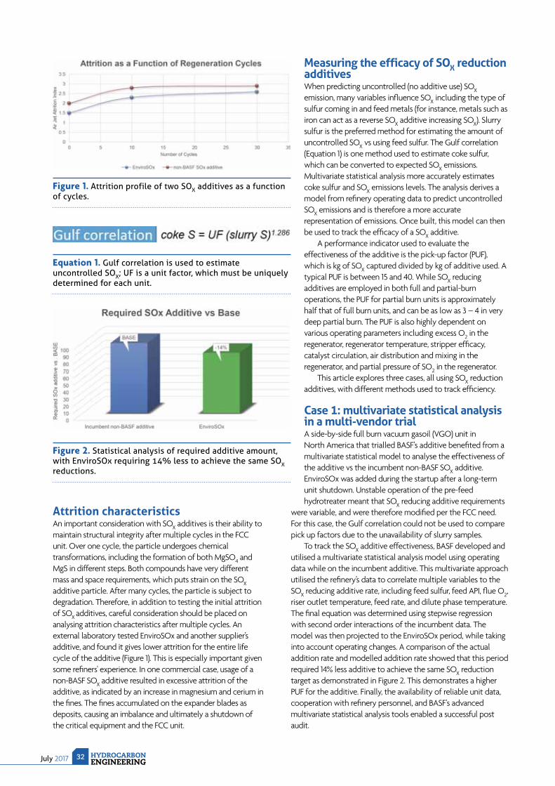
July 2017 HYDROCARBONENGINEERING
32
Measuring the efficacy of SOX reduction additivesWhen predicting uncontrolled (no additive use) SOX emission, many variables infl uence SOX including the type of sulfur coming in and feed metals (for instance, metals such as iron can act as a reverse SOX additive increasing SOX). Slurry sulfur is the preferred method for estimating the amount of uncontrolled SOX vs using feed sulfur. The Gulf correlation (Equation 1) is one method used to estimate coke sulfur, which can be converted to expected SOX emissions. Multivariate statistical analysis more accurately estimates coke sulfur and SOX emissions levels. The analysis derives a model from refi nery operating data to predict uncontrolled SOX emissions and is therefore a more accurate representation of emissions. Once built, this model can then be used to track the effi cacy of a SOX additive.
A performance indicator used to evaluate the effectiveness of the additive is the pick-up factor (PUF), which is kg of SOX captured divided by kg of additive used. A typical PUF is between 15 and 40. While SOX reducing additives are employed in both full and partial-burn operations, the PUF for partial burn units is approximately half that of full burn units, and can be as low as 3 – 4 in very deep partial burn. The PUF is also highly dependent on various operating parameters including excess O2 in the regenerator, regenerator temperature, stripper effi cacy, catalyst circulation, air distribution and mixing in the regenerator, and partial pressure of SO2 in the regenerator.
This article explores three cases, all using SOX reduction additives, with different methods used to track effi ciency.
Case 1: multivariate statistical analysis in a multi-vendor trialA side-by-side full burn vacuum gasoil (VGO) unit in North America that trialled BASF's additive benefi ted from a multivariate statistical model to analyse the effectiveness of the additive vs the incumbent non-BASF SOX additive. EnviroSOx was added during the startup after a long-term unit shutdown. Unstable operation of the pre-feed hydrotreater meant that SOX reducing additive requirements
were variable, and were therefore modifi ed per the FCC need. For this case, the Gulf correlation could not be used to compare pick up factors due to the unavailability of slurry samples.
To track the SOX additive effectiveness, BASF developed and utilised a multivariate statistical analysis model using operating data while on the incumbent additive. This multivariate approach utilised the refi nery’s data to correlate multiple variables to the SOX reducing additive rate, including feed sulfur, feed API, fl ue O2, riser outlet temperature, feed rate, and dilute phase temperature. The fi nal equation was determined using stepwise regression with second order interactions of the incumbent data. The model was then projected to the EnviroSOx period, while taking into account operating changes. A comparison of the actual addition rate and modelled addition rate showed that this period required 14% less additive to achieve the same SOX reduction target as demonstrated in Figure 2. This demonstrates a higher PUF for the additive. Finally, the availability of reliable unit data, cooperation with refi nery personnel, and BASF's advanced multivariate statistical analysis tools enabled a successful post audit.
Attrition characteristicsAn important consideration with SOX additives is their ability to maintain structural integrity after multiple cycles in the FCC unit. Over one cycle, the particle undergoes chemical transformations, including the formation of both MgSO4 and MgS in different steps. Both compounds have very different mass and space requirements, which puts strain on the SOX additive particle. After many cycles, the particle is subject to degradation. Therefore, in addition to testing the initial attrition of SOX additives, careful consideration should be placed on analysing attrition characteristics after multiple cycles. An external laboratory tested EnviroSOx and another supplier’s additive, and found it gives lower attrition for the entire life cycle of the additive (Figure 1). This is especially important given some refi ners' experience. In one commercial case, usage of a non-BASF SOX additive resulted in excessive attrition of the additive, as indicated by an increase in magnesium and cerium in the fi nes. The fi nes accumulated on the expander blades as deposits, causing an imbalance and ultimately a shutdown of the critical equipment and the FCC unit.
Figure 1. Attrition profile of two SOX additives as a function of cycles.
Figure 2. Statistical analysis of required additive amount, with EnviroSOx requiring 14% less to achieve the same SOX reductions.
Equation 1. Gulf correlation is used to estimate uncontrolled SOX; UF is a unit factor, which must be uniquely determined for each unit.

FOAMGLAS®
INSULATIONFOR INDUSTRIALAPPLICATIONSENGINEERED TO LAST
FOAMGLAS®
INSULATION ATTRIBUTES• 100% Moisture Impermeable • Resistant to Fire – Will Not Burn• Superior Compressive Strength
PITTSBURGHCORNING SERVICES
1-724-327-6100 I 800-545-5001
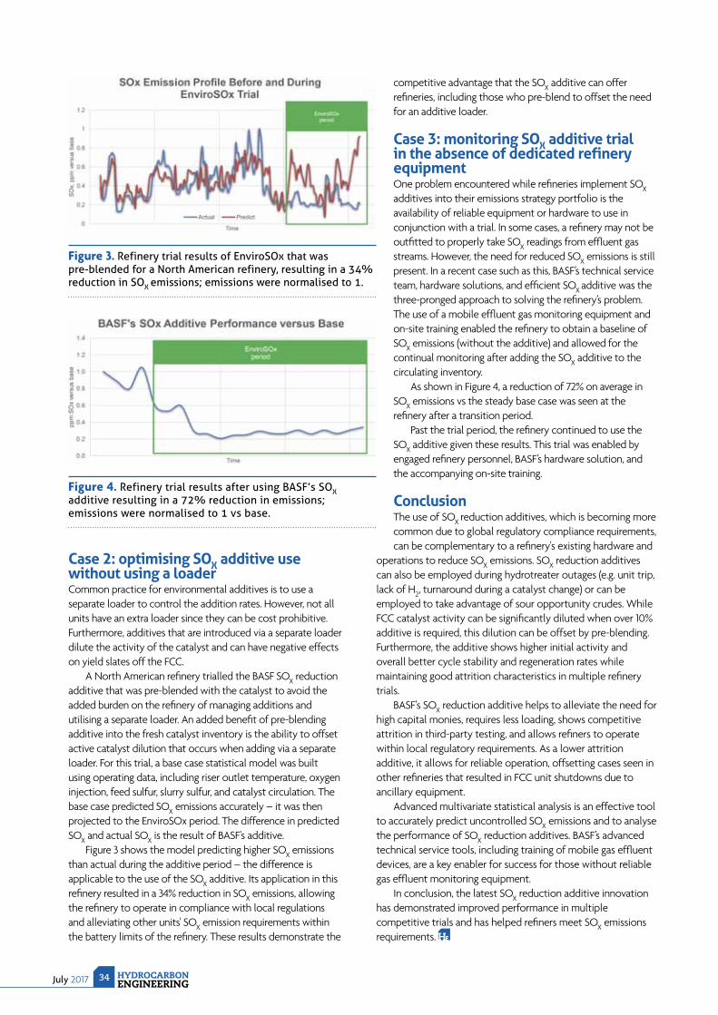
July 2017 HYDROCARBONENGINEERING
34
Case 2: optimising SOX additive use without using a loaderCommon practice for environmental additives is to use a separate loader to control the addition rates. However, not all units have an extra loader since they can be cost prohibitive. Furthermore, additives that are introduced via a separate loader dilute the activity of the catalyst and can have negative effects on yield slates off the FCC.
A North American refi nery trialled the BASF SOX reduction additive that was pre-blended with the catalyst to avoid the added burden on the refi nery of managing additions and utilising a separate loader. An added benefi t of pre-blending additive into the fresh catalyst inventory is the ability to offset active catalyst dilution that occurs when adding via a separate loader. For this trial, a base case statistical model was built using operating data, including riser outlet temperature, oxygen injection, feed sulfur, slurry sulfur, and catalyst circulation. The base case predicted SOX emissions accurately – it was then projected to the EnviroSOx period. The difference in predicted SOX and actual SOX is the result of BASF's additive.
Figure 3 shows the model predicting higher SOX emissions than actual during the additive period – the difference is applicable to the use of the SOX additive. Its application in this refi nery resulted in a 34% reduction in SOX emissions, allowing the refi nery to operate in compliance with local regulations and alleviating other units' SOX emission requirements within the battery limits of the refi nery. These results demonstrate the
competitive advantage that the SOX additive can offer refi neries, including those who pre-blend to offset the need for an additive loader.
Case 3: monitoring SOX additive trial in the absence of dedicated refinery equipmentOne problem encountered while refi neries implement SOX additives into their emissions strategy portfolio is the availability of reliable equipment or hardware to use in conjunction with a trial. In some cases, a refi nery may not be outfi tted to properly take SOX readings from effl uent gas streams. However, the need for reduced SOX emissions is still present. In a recent case such as this, BASF’s technical service team, hardware solutions, and effi cient SOX additive was the three-pronged approach to solving the refi nery’s problem. The use of a mobile effl uent gas monitoring equipment and on-site training enabled the refi nery to obtain a baseline of SOX emissions (without the additive) and allowed for the continual monitoring after adding the SOX additive to the circulating inventory.
As shown in Figure 4, a reduction of 72% on average in SOX emissions vs the steady base case was seen at the refi nery after a transition period.
Past the trial period, the refi nery continued to use the SOX additive given these results. This trial was enabled by engaged refi nery personnel, BASF’s hardware solution, and the accompanying on-site training.
ConclusionThe use of SOX reduction additives, which is becoming more common due to global regulatory compliance requirements, can be complementary to a refi nery's existing hardware and
operations to reduce SOX emissions. SOX reduction additives can also be employed during hydrotreater outages (e.g. unit trip, lack of H2, turnaround during a catalyst change) or can be employed to take advantage of sour opportunity crudes. While FCC catalyst activity can be signifi cantly diluted when over 10% additive is required, this dilution can be offset by pre-blending. Furthermore, the additive shows higher initial activity and overall better cycle stability and regeneration rates while maintaining good attrition characteristics in multiple refi nery trials.
BASF's SOX reduction additive helps to alleviate the need for high capital monies, requires less loading, shows competitive attrition in third-party testing, and allows refi ners to operate within local regulatory requirements. As a lower attrition additive, it allows for reliable operation, offsetting cases seen in other refi neries that resulted in FCC unit shutdowns due to ancillary equipment.
Advanced multivariate statistical analysis is an effective tool to accurately predict uncontrolled SOX emissions and to analyse the performance of SOX reduction additives. BASF’s advanced technical service tools, including training of mobile gas effl uent devices, are a key enabler for success for those without reliable gas effl uent monitoring equipment.
In conclusion, the latest SOX reduction additive innovation has demonstrated improved performance in multiple competitive trials and has helped refi ners meet SOX emissions requirements.
Figure 3. Refinery trial results of EnviroSOx that was pre-blended for a North American refinery, resulting in a 34% reduction in SOX emissions; emissions were normalised to 1.
Figure 4. Refinery trial results after using BASF’s SOX additive resulting in a 72% reduction in emissions; emissions were normalised to 1 vs base.

C O M P R E S S O R S T U R B I N E S G L O B A L S E R V I C E The world turns to Elliott.
Customer:Petrochemical plant, Canada.
Challenge:Anti-fouling coating for compressor rotors was being prematurely degraded by cleaning.
Result:Elliott’s replacement coating prevented fouling and extended planned outages by 2-3 years.
They turned to Elliottfor longer equipment life.The customer turned to Elliott because they learned the hard way that not all rotor coatings can handle chemical cleaning. Few companies can match Elliott’s coating expertise. Who will you turn to?

36 HYDROCARBONENGINEERINGJuly 2017
Dreaming

July 201737HYDROCARBONENGINEERING
R efi nery fuels present manifold challenges to achieving ultra-low emissions. Most refi nery heaters are natural draft rather than forced draft (as was the case with a refi ner in California, US, which is discussed later in this article). Natural draft offers minimal airside momentum for fl ame shaping.
Additionally, many ultra-low nitrogen oxide (NOX) solutions rely on fl ue gas recirculation (FGR) – an inconvenience for natural draft units. If FGR is used, a costly conversion to forced draft is often required.
Moreover, refi nery fuel is notoriously variable. Most hydrocarbons require approximately 100 ft3 of air per Btu of heating value (ft3/Btu), but hydrogen requires about 20% less air on that basis. It is not atypical for hydrogen content in a refi nery fuel to swing threefold in concentration, with occasional excursions to much higher concentrations. Hydrogen has a higher fl ame temperature than hydrocarbons. Since NOX is thermally driven, rising hydrogen content typically leads to higher NOX.
NOX formationExcept from upset conditions or maloperation, refi nery fuels typically contain no fuel-bound nitrogen.* Without fuel-bound nitrogen, the major pathway to NOX formation is actual fusion of the nitrogen (N2) and oxygen (O2) from the combustion air. This occurs primarily in the thermal (Zeldovich) NOX-formation mechanism. Thermal NOX formation may be understood as a function of the integral of time (linear), temperature (exponential), and oxygen concentration (square root). This is given in the following equation where C
NO, C
N2, and C
O2 are the concentration of
Joe Colannino and Roberto Ruiz, ClearSign
Combustion, USA, introduce an innovative
piece of technology that was able to help a
Californian refinery reduce its NOX emissions.
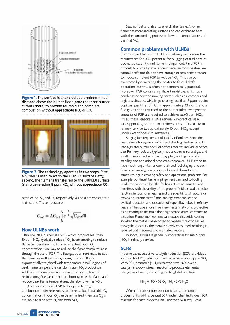
July 2017 HYDROCARBONENGINEERING
38
nitric oxide, N2, and O2, respectively; A and b are constants; tis time; and T is temperature:
How ULNBs workUltra-low NOX burners (ULNBs), which produce less than 10 ppm NOX, typically reduce NOX by attempting to reduce fl ame temperature, and to a lesser extent, local O2concentration. One way to reduce the fl ame temperature is through the use of FGR. The fl ue gas adds inert mass to cool the fl ame, as well as homogenising it. Since NOX is exponentially weighted with temperature, small regions of peak fl ame temperature can dominate NOX production. Adding additional mass and momentum in the form of recirculating fl ue gas can help to homogenise the fl ame and reduce peak fl ame temperatures, thereby lowering NOX.
Another common ULNB technique is to stage combustion in discrete zones to decrease local available O2concentration. If local O2 can be minimised, then less O2 is available to fuse with N2 and form NOX.
Staging fuel and air also stretch the fl ame. A longer fl ame has more radiating surface and can exchange heat with the surrounding process to lower its temperature and thermal NOX.
Common problems with ULNBsCommon problems with ULNBs in refi nery service are the requirement for FGR, potential for plugging of fuel nozzles, decreased stability, and fl ame impingement. First, FGR is diffi cult to come by in a refi nery because most heaters are natural draft and do not have enough excess draft pressure to induce suffi cient FGR to reduce NOX. This can be overcome by converting the heater to forced draft operation, but this is often not economically practical. Moreover, FGR contains signifi cant moisture, which can condense or corrode moving parts such as air dampers and registers. Second, UNLBs generating less than 9 ppm require copious quantities of FGR – approximately 30% of the total fl ue gas must be returned to the burner inlet. Even greater amounts of FGR are required to achieve sub-5 ppm NOX. For all these reasons, FGR is generally impractical as a sub-5 ppm NOX solution in a refi nery. This limits UNLBs in refi nery service to approximately 10 ppm NOX, except under exceptional circumstances.
Staging fuel requires a multiplicity of orifi ces. Since the heat release for a given unit is fi xed, dividing the fuel circuit into a greater number of fuel orifi ces reduces individual orifi ce size. Refi nery fuels are typically not as clean as natural gas and small holes in the fuel circuit may plug, leading to safety, stability, and operational problems. Moreover, ULNBs tend to have much longer fl ames due to air and fuel staging, and such fl ames can impinge on process tubes and downstream structures, again creating safety and operational problems. For example, continual fl ame impingement can lead to fouling inside the process tube. The fouling acts as an insulator and interferes with the ability of the process fl uid to cool the tube, resulting in local overheating and the possibility of rupture or explosion. Intermittent fl ame impingement can lead to cyclical reduction and oxidation of superalloy tubes in refi nery heaters. The superalloys in refi nery heaters rely on a protective oxide coating to maintain their high temperature resistance to oxidation. Flame impingement can reduce this oxide coating, so when the metal is re-exposed to oxygen it re-oxidises. As this cycle re-occurs, the metal is slowly consumed, resulting in reduced wall thickness and ultimately rupture.
In short, ULNBs are generally impractical for sub-5 ppm NOX in refi nery service.
SCRsIn some cases, selective catalytic reduction (SCR) provides a solution for NOX reduction that can achieve sub-5 ppm NOX. With SCR, ammonia (NH3) is reacted with NOX over a catalyst in a downstream reactor to produce elemental nitrogen and water, according to the global reaction:
NH3 + NO + ½ O2 = N2 + 3/2 H2O
Often, it makes more economic sense to control process units with a central SCR, rather than individual SCR reactors for each process unit. However, SCR requires a
Figure 1. The surface is anchored at a predetermined distance above the burner floor (note the three burner cutouts there) to provide for rapid and complete combustion without appreciable NOX or CO.
Figure 2. The technology operates in two steps. First, a burner is used to warm the DUPLEX surface (left); second, the flame is transferred to the DUPLEX surface (right) generating 5 ppm NOX without appreciable CO.

At the end of the day, you want a technology supplier who works with you.
© 2
016
Exxo
n M
obil
Cor
pora
tion.
All
right
s re
serv
ed. E
xxon
Mob
il, th
e Ex
xonM
obil
logo
, the
inte
rlock
ing
“X”
devi
ce a
nd a
ll pr
oduc
t nam
es h
erei
n ar
e tr
adem
arks
of E
xxon
Mob
il C
orpo
ratio
n.
You’re committed to progress and success. We’re committed to you. And we demonstrate our commitment through licensing world-class refining, gas, chemical technologies and specialty catalysts that drive exceptional performance. You can count on our proven technology and long-term collaboration to help you keep pace with the increasingly complex challenges of today’s evolving marketplace. From initial consultation through plant startup and beyond, our global team offers you practical guidance based on years of real-world operating experience. Our goal is your success. Learn more about how we can work together to grow your business. www.catalysts-licensing.com
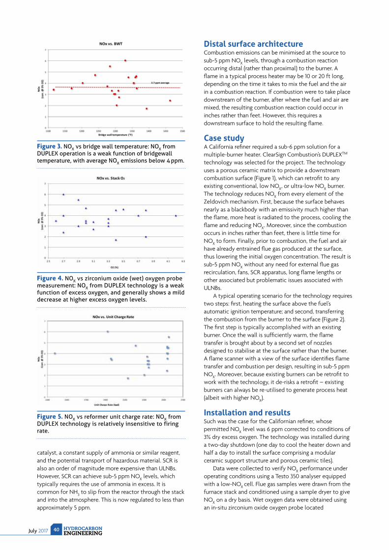
July 2017 HYDROCARBONENGINEERING
40
catalyst, a constant supply of ammonia or similar reagent, and the potential transport of hazardous material. SCR is also an order of magnitude more expensive than ULNBs. However, SCR can achieve sub-5 ppm NOX levels, which typically requires the use of ammonia in excess. It is common for NH3 to slip from the reactor through the stack and into the atmosphere. This is now regulated to less than approximately 5 ppm.
Distal surface architectureCombustion emissions can be minimised at the source to sub-5 ppm NOX levels, through a combustion reaction occurring distal (rather than proximal) to the burner. A fl ame in a typical process heater may be 10 or 20 ft long, depending on the time it takes to mix the fuel and the air in a combustion reaction. If combustion were to take place downstream of the burner, after where the fuel and air are mixed, the resulting combustion reaction could occur in inches rather than feet. However, this requires a downstream surface to hold the resulting fl ame.
Case studyA California refi ner required a sub-6 ppm solution for a multiple-burner heater. ClearSign Combustion’s DUPLEXTM technology was selected for the project. The technology uses a porous ceramic matrix to provide a downstream combustion surface (Figure 1), which can retrofi t to any existing conventional, low NOX, or ultra-low NOX burner. The technology reduces NOX from every element of the Zeldovich mechanism. First, because the surface behaves nearly as a blackbody with an emissivity much higher than the fl ame, more heat is radiated to the process, cooling the fl ame and reducing NOX. Moreover, since the combustion occurs in inches rather than feet, there is little time for NOX to form. Finally, prior to combustion, the fuel and air have already entrained fl ue gas produced at the surface, thus lowering the initial oxygen concentration. The result is sub-5 ppm NOX without any need for external fl ue gas recirculation, fans, SCR apparatus, long fl ame lengths or other associated but problematic issues associated with ULNBs.
A typical operating scenario for the technology requires two steps: fi rst, heating the surface above the fuel’s automatic ignition temperature; and second, transferring the combustion from the burner to the surface (Figure 2). The fi rst step is typically accomplished with an existing burner. Once the wall is suffi ciently warm, the fl ame transfer is brought about by a second set of nozzles designed to stabilise at the surface rather than the burner. A fl ame scanner with a view of the surface identifi es fl ame transfer and combustion per design, resulting in sub-5 ppm NOX. Moreover, because existing burners can be retrofi t to work with the technology, it de-risks a retrofi t – existing burners can always be re-utilised to generate process heat (albeit with higher NOX).
Installation and resultsSuch was the case for the Californian refi ner, whose permitted NOX level was 6 ppm corrected to conditions of 3% dry excess oxygen. The technology was installed during a two-day shutdown (one day to cool the heater down and half a day to install the surface comprising a modular ceramic support structure and porous ceramic tiles).
Data were collected to verify NOX performance under operating conditions using a Testo 350 analyser equipped with a low-NOX cell. Flue gas samples were drawn from the furnace stack and conditioned using a sample dryer to give NOX on a dry basis. Wet oxygen data were obtained using an in-situ zirconium oxide oxygen probe located
Figure 3. NOX vs bridge wall temperature: NOX from DUPLEX operation is a weak function of bridgewall temperature, with average NOX emissions below 4 ppm.
Figure 4. NOX vs zirconium oxide (wet) oxygen probe measurement: NOX from DUPLEX technology is a weak function of excess oxygen, and generally shows a mild decrease at higher excess oxygen levels.
Figure 5. NOX vs reformer unit charge rate: NOX from DUPLEX technology is relatively insensitive to firing rate.

866 367 6879 | matrixservicecompany.com
DESIGN. BUILD. MAINTAIN.
The best just got better.
Matrix acquires - the joining of two top-tier companies.
World leader in sulfur forming and handling technology
EPC services • Sulfur recovery • Sulfur formingSulfur melting • Solid sulfur handling
You’ve known us for more than 30 years as a leader in construction, fabrication, repair and maintenance and now through the acquisition, Matrix offers premier global engineering services to the gas value chain.
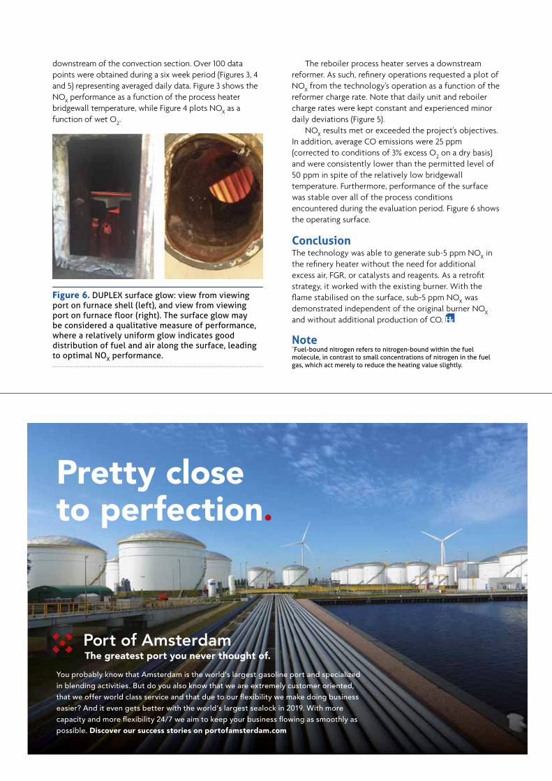
downstream of the convection section. Over 100 data points were obtained during a six week period (Figures 3, 4 and 5) representing averaged daily data. Figure 3 shows the NOX performance as a function of the process heater bridgewall temperature, while Figure 4 plots NOX as a function of wet O2.
The reboiler process heater serves a downstream reformer. As such, refi nery operations requested a plot of NOX from the technology's operation as a function of the reformer charge rate. Note that daily unit and reboiler charge rates were kept constant and experienced minor daily deviations (Figure 5).
NOX results met or exceeded the project's objectives. In addition, average CO emissions were 25 ppm (corrected to conditions of 3% excess O2 on a dry basis) and were consistently lower than the permitted level of 50 ppm in spite of the relatively low bridgewall temperature. Furthermore, performance of the surface was stable over all of the process conditions encountered during the evaluation period. Figure 6 shows the operating surface.
ConclusionThe technology was able to generate sub-5 ppm NOX in the refi nery heater without the need for additional excess air, FGR, or catalysts and reagents. As a retrofi t strategy, it worked with the existing burner. With the fl ame stabilised on the surface, sub-5 ppm NOX was demonstrated independent of the original burner NOX and without additional production of CO.
Note*Fuel-bound nitrogen refers to nitrogen-bound within the fuel molecule, in contrast to small concentrations of nitrogen in the fuel gas, which act merely to reduce the heating value slightly.
Figure 6. DUPLEX surface glow: view from viewing port on furnace shell (left), and view from viewing port on furnace floor (right). The surface glow may be considered a qualitative measure of performance, where a relatively uniform glow indicates good distribution of fuel and air along the surface, leading to optimal NOX performance.
Pretty close to perfection.
You probably know that Amsterdam is the world’s largest gasoline port and specialized in blending activities. But do you also know that we are extremely customer oriented, that we offer world class service and that due to our flexibility we make doing business easier? And it even gets better with the world’s largest sealock in 2019. With more capacity and more flexibility 24/7 we aim to keep your business flowing as smoothly as possible. Discover our success stories on portofamsterdam.com
The greatest port you never thought of.

July 201743HYDROCARBONENGINEERING
In 2016, the US Environmental Protection Agency (EPA) published the QuadOa regulations, which were designed to reduce the amount of greenhouse gases (GHG) emitted by the oil and gas industry. How these regulations will be
implemented is far less clear.However, some clarity remains. Natural gas has a reputation
as the ‘clean’ fossil fuel, a title that has been earned because it emits signifi cantly less soot and approximately half of the carbon dioxide (CO2) produced when burning coal. However, this ignores the problems caused by methane – a powerful greenhouse pollutant that has been analysed to be more than 80 times more potent than CO2.
With the shale gas boom essentially altering the shape of the US energy market, and natural gas being promoted as the link to a low-carbon future, it is an important energy source that cannot afford to be wasted. But, until methane emissions are measured, monitored, controlled and reduced, the position of natural gas as a ‘greener’ substitute for coal and oil is open to debate.
The sector’s responseDeveloping a systematic approach to reducing methane emissions is in the best interests of oil and gas operators from both a safety and cost perspective. It is also benefi cial for their
Omer Yanai, Opgal, Israel, discusses the debate around oil and gas methane emissions and offers a three-pronged approach to help keep emissions under control.
THE BIG DEBATETHE GBIGBIGDEBATE
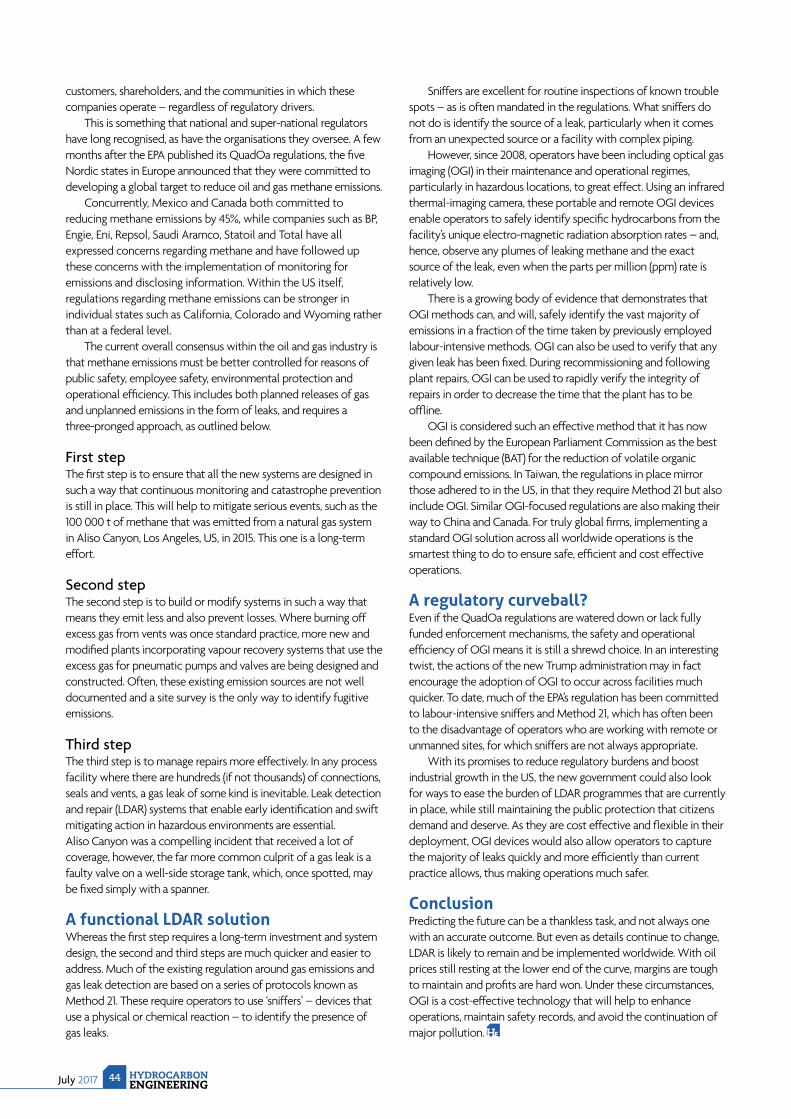
July 2017 HYDROCARBONENGINEERING
44
customers, shareholders, and the communities in which these companies operate – regardless of regulatory drivers.
This is something that national and super-national regulators have long recognised, as have the organisations they oversee. A few months after the EPA published its QuadOa regulations, the fi ve Nordic states in Europe announced that they were committed to developing a global target to reduce oil and gas methane emissions.
Concurrently, Mexico and Canada both committed to reducing methane emissions by 45%, while companies such as BP, Engie, Eni, Repsol, Saudi Aramco, Statoil and Total have all expressed concerns regarding methane and have followed up these concerns with the implementation of monitoring for emissions and disclosing information. Within the US itself, regulations regarding methane emissions can be stronger in individual states such as California, Colorado and Wyoming rather than at a federal level.
The current overall consensus within the oil and gas industry is that methane emissions must be better controlled for reasons of public safety, employee safety, environmental protection and operational effi ciency. This includes both planned releases of gas and unplanned emissions in the form of leaks, and requires a three-pronged approach, as outlined below.
First stepThe fi rst step is to ensure that all the new systems are designed in such a way that continuous monitoring and catastrophe prevention is still in place. This will help to mitigate serious events, such as the 100 000 t of methane that was emitted from a natural gas system in Aliso Canyon, Los Angeles, US, in 2015. This one is a long-term effort.
Second stepThe second step is to build or modify systems in such a way that means they emit less and also prevent losses. Where burning off excess gas from vents was once standard practice, more new and modifi ed plants incorporating vapour recovery systems that use the excess gas for pneumatic pumps and valves are being designed and constructed. Often, these existing emission sources are not well documented and a site survey is the only way to identify fugitive emissions.
Third stepThe third step is to manage repairs more effectively. In any process facility where there are hundreds (if not thousands) of connections, seals and vents, a gas leak of some kind is inevitable. Leak detection and repair (LDAR) systems that enable early identifi cation and swift mitigating action in hazardous environments are essential. Aliso Canyon was a compelling incident that received a lot of coverage, however, the far more common culprit of a gas leak is a faulty valve on a well-side storage tank, which, once spotted, may be fi xed simply with a spanner.
A functional LDAR solutionWhereas the fi rst step requires a long-term investment and system design, the second and third steps are much quicker and easier to address. Much of the existing regulation around gas emissions and gas leak detection are based on a series of protocols known as Method 21. These require operators to use ‘sniffers’ – devices that use a physical or chemical reaction – to identify the presence of gas leaks.
Sniffers are excellent for routine inspections of known trouble spots – as is often mandated in the regulations. What sniffers do not do is identify the source of a leak, particularly when it comes from an unexpected source or a facility with complex piping.
However, since 2008, operators have been including optical gas imaging (OGI) in their maintenance and operational regimes, particularly in hazardous locations, to great effect. Using an infrared thermal-imaging camera, these portable and remote OGI devices enable operators to safely identify specifi c hydrocarbons from the facility’s unique electro-magnetic radiation absorption rates – and, hence, observe any plumes of leaking methane and the exact source of the leak, even when the parts per million (ppm) rate is relatively low.
There is a growing body of evidence that demonstrates that OGI methods can, and will, safely identify the vast majority of emissions in a fraction of the time taken by previously employed labour-intensive methods. OGI can also be used to verify that any given leak has been fi xed. During recommissioning and following plant repairs, OGI can be used to rapidly verify the integrity of repairs in order to decrease the time that the plant has to be offl ine.
OGI is considered such an effective method that it has now been defi ned by the European Parliament Commission as the best available technique (BAT) for the reduction of volatile organic compound emissions. In Taiwan, the regulations in place mirror those adhered to in the US, in that they require Method 21 but also include OGI. Similar OGI-focused regulations are also making their way to China and Canada. For truly global fi rms, implementing a standard OGI solution across all worldwide operations is the smartest thing to do to ensure safe, effi cient and cost effective operations.
A regulatory curveball?Even if the QuadOa regulations are watered down or lack fully funded enforcement mechanisms, the safety and operational effi ciency of OGI means it is still a shrewd choice. In an interesting twist, the actions of the new Trump administration may in fact encourage the adoption of OGI to occur across facilities much quicker. To date, much of the EPA’s regulation has been committed to labour-intensive sniffers and Method 21, which has often been to the disadvantage of operators who are working with remote or unmanned sites, for which sniffers are not always appropriate.
With its promises to reduce regulatory burdens and boost industrial growth in the US, the new government could also look for ways to ease the burden of LDAR programmes that are currently in place, while still maintaining the public protection that citizens demand and deserve. As they are cost effective and fl exible in their deployment, OGI devices would also allow operators to capture the majority of leaks quickly and more effi ciently than current practice allows, thus making operations much safer.
ConclusionPredicting the future can be a thankless task, and not always one with an accurate outcome. But even as details continue to change, LDAR is likely to remain and be implemented worldwide. With oil prices still resting at the lower end of the curve, margins are tough to maintain and profi ts are hard won. Under these circumstances, OGI is a cost-effective technology that will help to enhance operations, maintain safety records, and avoid the continuation of major pollution.

45 July 2017HYDROCARBONENGINEERING
Greenhouse gas (GHG) emissions such as carbon dioxide (CO2) have risen signifi cantly over the past 100 years, and are thought to be the primary cause of global warming. In order to combat their effect,
many governments have agreed to reduce the amount of GHGs they release into the atmosphere through different conventions and policies, some of which are legally binding.
One of the fi rst was the United Nations Framework Convention on Climate Change (UNFCCC) – an international treaty set up at the ‘Earth Summit’ held in Rio de Janeiro, Brazil, in 1992. The objective of this treaty was to keep GHG emissions at a stable level that would not cause any permanent effects to the atmosphere or climate. As of
May 2011, 194 countries had signed up to this treaty, however, it has no real deliverables (the only convention for each member country is to reduce its GHG emissions).
The Kyoto Protocol extended this premise by holding member countries responsible for their GHG reductions. The protocol came into effect in 2005 and aims to reduce the levels of GHG emissions by 5.2% compared to the 1990 level. In total, 37 countries signed up to this legally binding agreement to reduce emissions. The majority of these countries were from the developed world. However, the number of countries signing up to the Kyoto Protocol has increased signifi cantly since then and currently sits at 192 (March 2017).
Marc Laing, NEL, UK, examines the challenges
involved in measuring flare gas and their
resulting emissions.
PUT A PUT A LID ON ITPUT A PUT A
LID ON IT
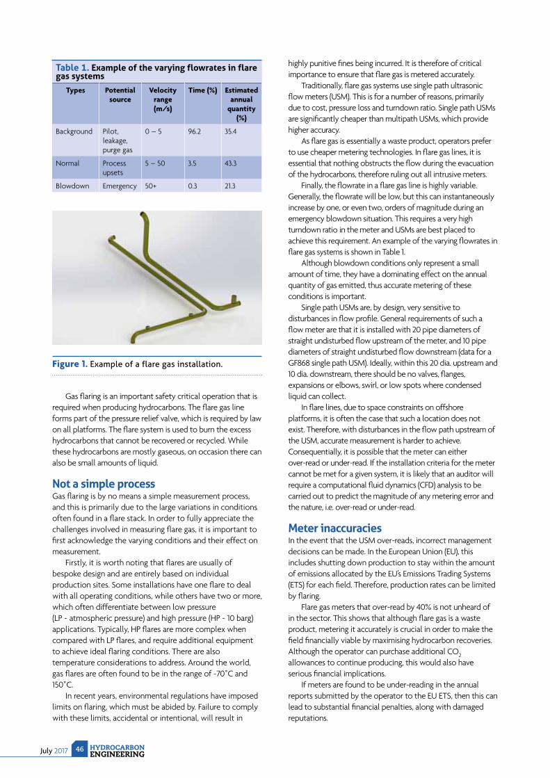
July 2017 HYDROCARBONENGINEERING
46
Gas fl aring is an important safety critical operation that is required when producing hydrocarbons. The fl are gas line forms part of the pressure relief valve, which is required by law on all platforms. The fl are system is used to burn the excess hydrocarbons that cannot be recovered or recycled. While these hydrocarbons are mostly gaseous, on occasion there can also be small amounts of liquid.
Not a simple processGas fl aring is by no means a simple measurement process, and this is primarily due to the large variations in conditions often found in a fl are stack. In order to fully appreciate the challenges involved in measuring fl are gas, it is important to fi rst acknowledge the varying conditions and their effect on measurement.
Firstly, it is worth noting that fl ares are usually of bespoke design and are entirely based on individual production sites. Some installations have one fl are to deal with all operating conditions, while others have two or more, which often differentiate between low pressure (LP ~ atmospheric pressure) and high pressure (HP ~ 10 barg) applications. Typically, HP fl ares are more complex when compared with LP fl ares, and require additional equipment to achieve ideal fl aring conditions. There are also temperature considerations to address. Around the world, gas fl ares are often found to be in the range of -70˚C and 150˚C.
In recent years, environmental regulations have imposed limits on fl aring, which must be abided by. Failure to comply with these limits, accidental or intentional, will result in
highly punitive fi nes being incurred. It is therefore of critical importance to ensure that fl are gas is metered accurately.
Traditionally, fl are gas systems use single path ultrasonic fl ow meters (USM). This is for a number of reasons, primarily due to cost, pressure loss and turndown ratio. Single path USMs are signifi cantly cheaper than multipath USMs, which provide higher accuracy.
As fl are gas is essentially a waste product, operators prefer to use cheaper metering technologies. In fl are gas lines, it is essential that nothing obstructs the fl ow during the evacuation of the hydrocarbons, therefore ruling out all intrusive meters.
Finally, the fl owrate in a fl are gas line is highly variable. Generally, the fl owrate will be low, but this can instantaneously increase by one, or even two, orders of magnitude during an emergency blowdown situation. This requires a very high turndown ratio in the meter and USMs are best placed to achieve this requirement. An example of the varying fl owrates in fl are gas systems is shown in Table 1.
Although blowdown conditions only represent a small amount of time, they have a dominating effect on the annual quantity of gas emitted, thus accurate metering of these conditions is important.
Single path USMs are, by design, very sensitive to disturbances in fl ow profi le. General requirements of such a fl ow meter are that it is installed with 20 pipe diameters of straight undisturbed fl ow upstream of the meter, and 10 pipe diameters of straight undisturbed fl ow downstream (data for a GF868 single path USM). Ideally, within this 20 dia. upstream and 10 dia. downstream, there should be no valves, fl anges, expansions or elbows, swirl, or low spots where condensed liquid can collect.
In fl are lines, due to space constraints on offshore platforms, it is often the case that such a location does not exist. Therefore, with disturbances in the fl ow path upstream of the USM, accurate measurement is harder to achieve. Consequentially, it is possible that the meter can either over-read or under-read. If the installation criteria for the meter cannot be met for a given system, it is likely that an auditor will require a computational fl uid dynamics (CFD) analysis to be carried out to predict the magnitude of any metering error and the nature, i.e. over-read or under-read.
Meter inaccuraciesIn the event that the USM over-reads, incorrect management decisions can be made. In the European Union (EU), this includes shutting down production to stay within the amount of emissions allocated by the EU’s Emissions Trading Systems (ETS) for each fi eld. Therefore, production rates can be limited by fl aring.
Flare gas meters that over-read by 40% is not unheard of in the sector. This shows that although fl are gas is a waste product, metering it accurately is crucial in order to make the fi eld fi nancially viable by maximising hydrocarbon recoveries. Although the operator can purchase additional CO2 allowances to continue producing, this would also have serious fi nancial implications.
If meters are found to be under-reading in the annual reports submitted by the operator to the EU ETS, then this can lead to substantial fi nancial penalties, along with damaged reputations.
Table 1. Example of the varying flowrates in flare gas systems
Types Potential source
Velocity range (m/s)
Time (%) Estimated annual
quantity (%)
Background Pilot, leakage, purge gas
0 – 5 96.2 35.4
Normal Process upsets
5 – 50 3.5 43.3
Blowdown Emergency 50+ 0.3 21.3
Figure 1. Example of a flare gas installation.

altairstrickland.com
800.478.6206
CRITICAL PROJECT EXECUTION FOR THE REFINERY AND PETROCHEMICAL INDUSTRIES
How can we goabove & beyond for you?
E S T 1 9 7 6
ABOVE &BEYOND
AltairStrickland has been one of the country’s premier authorities
on process unit upgrades, revamps, and turnarounds since 1976 —
and we haven’t slowed down one bit.
We average 25 turnarounds a year — rising to the occasion for projects
large and small — and a full 75% of our clients turn around and come
back for more. The reasons? Our obsessive planning and constructability
processes help ensure safety and efficiency — all with a focus and goal of
delivering highest value for clients before, during, and after.
That’s our promise — and that’s why, when projects demand the best,
more refi neries demand the high standards of AltairStrickland.
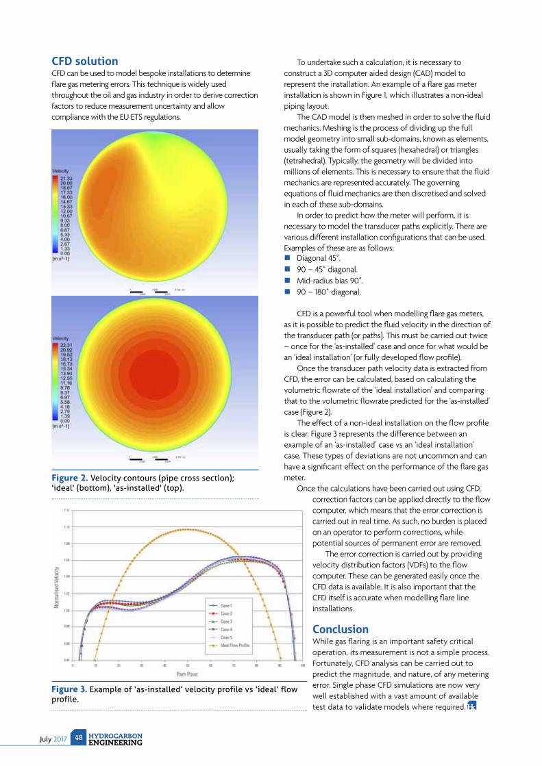
July 2017 HYDROCARBONENGINEERING
48
CFD solution CFD can be used to model bespoke installations to determine fl are gas metering errors. This technique is widely used throughout the oil and gas industry in order to derive correction factors to reduce measurement uncertainty and allow compliance with the EU ETS regulations.
To undertake such a calculation, it is necessary to construct a 3D computer aided design (CAD) model to represent the installation. An example of a fl are gas meter installation is shown in Figure 1, which illustrates a non-ideal piping layout.
The CAD model is then meshed in order to solve the fl uid mechanics. Meshing is the process of dividing up the full model geometry into small sub-domains, known as elements, usually taking the form of squares (hexahedral) or triangles (tetrahedral). Typically, the geometry will be divided into millions of elements. This is necessary to ensure that the fl uid mechanics are represented accurately. The governing equations of fl uid mechanics are then discretised and solved in each of these sub-domains.
In order to predict how the meter will perform, it is necessary to model the transducer paths explicitly. There are various different installation confi gurations that can be used. Examples of these are as follows:
Diagonal 45˚. 90 – 45˚ diagonal. Mid-radius bias 90˚. 90 – 180˚ diagonal.
CFD is a powerful tool when modelling fl are gas meters, as it is possible to predict the fl uid velocity in the direction of the transducer path (or paths). This must be carried out twice – once for the ‘as-installed’ case and once for what would be an ‘ideal installation’ (or fully developed fl ow profi le).
Once the transducer path velocity data is extracted from CFD, the error can be calculated, based on calculating the volumetric fl owrate of the ‘ideal installation’ and comparing that to the volumetric fl owrate predicted for the ‘as-installed’ case (Figure 2).
The effect of a non-ideal installation on the fl ow profi le is clear. Figure 3 represents the difference between an example of an ‘as-installed’ case vs an ‘ideal installation’ case. These types of deviations are not uncommon and can have a signifi cant effect on the performance of the fl are gas meter.
Once the calculations have been carried out using CFD, correction factors can be applied directly to the fl ow computer, which means that the error correction is carried out in real time. As such, no burden is placed on an operator to perform corrections, while potential sources of permanent error are removed.
The error correction is carried out by providing velocity distribution factors (VDFs) to the fl ow computer. These can be generated easily once the CFD data is available. It is also important that the CFD itself is accurate when modelling fl are line installations.
ConclusionWhile gas fl aring is an important safety critical operation, its measurement is not a simple process. Fortunately, CFD analysis can be carried out to predict the magnitude, and nature, of any metering error. Single phase CFD simulations are now very well established with a vast amount of available test data to validate models where required.
Figure 2. Velocity contours (pipe cross section); 'ideal' (bottom), 'as-installed' (top).
Figure 3. Example of ‘as-installed’ velocity profile vs ‘ideal’ flow profile.
July 201749HYDROCARBONENGINEERING
Energy is the single largest controllable cost for most refineries, comprising more than 60% of non-crude operating costs of which utilities consume a major part but are often neglected. A
10% reduction in net energy use, at constant other costs, will, typically, lead to an increase in refinery net margin of US$0.40 – US$0.70/bbl. This makes energy savings an important topic in refinery cost control.
Reducing energy use typically cuts CO2 and other emissions from the refi nery/petrochemical complex, making them greener, which helps in realising the mission to combat climate change. Operating conditions vary widely among different refineries based on the complexity, vintage, different crudes/blends of crudes and intermediates processed, overall production rates, and the relative amounts of the different products. The effects on
CUTTING ENERGY
COSTSG. Srivardhan, M. Rajasekhar, D. K. R. Nambiar, S. C. Gupta, S. R. Singh and
V. Shukla, Engineers India Ltd, India, explore real time utility management and its role in energy efficiency and the reduction of total energy costs.
July 2017 HYDROCARBONENGINEERING
50
the energy requirements for the refinery are twofold. The demand for the individual energy sources – fuel, steam, and power – varies significantly, and the composition of the internally generated fuel varies as the production from different sources within the refinery changes.
As refi neries are energy intensive, the better approach to reduce these unnecessary energy costs is to improve their energy effi ciency. It is diffi cult to improve energy consumption if it cannot be measured and monitored closely. Real time modelling and monitoring of the energy use in plants permits a refinery to make allocation decisions more frequently and accurately, which explains the calls for optimisation tools for combined heat and power (CHP) system optimisation.
A typical refinery/petrochemical utility systemRefineries have relatively complicated utility systems with many different fuels and utilities, as well as many sources and users. Steam and electricity are also produced internally or purchased from outside. Each utility system is a piping network that supplies or receives various utilities such as steam, air, water, lubrication oil, fuel gas, fuel oil, and electricity to and from the process units. Often only the network’s main headers and branches are instrumented, which leaves many areas unmeasured. This limited coverage may help calculate the overall consumption and identify the main supplier’s and consumer’s performance, but it does not help close the material balance or identify possible leaks or wasted use. There are multiple header steam system suppliers and consumers across the site, but many of them do not have sufficient flow measurements to know where the steam is being used. To reduce energy use significantly, it is critical that the operation of captive power plant for power generation (CPP) and boiler house for steam generation is improved.
The software tools currently available can analyse various generation/consumer units and provide information about whether steam is being used or wasted, either through broken steam traps or inefficient operation. The optimisation of steam generation among boilers and heat recovery steam generators (HRSG) can also be handled. Thus, steam balance helps to reduce header pressures, close let down valves and stop venting, resulting in an improved steam system by minimising losses.
Similarly, a power balance across the entire unit helps to identify areas of improvement. This is possible through the optimisation of power generation among individual gas turbines (GTs), between GTs and steam turbine generators (STG) with regard to steam system balance, swapping between motors and turbines, etc.
Coming to the fuel system, fuel gas headers do not have a high surge capacity, so they need to consume what is provided or the excess will be blown down to the flare stack. Incomplete measurements make it difficult to identify possible leaks, wasted use, or to optimise. So, the software tools will help to estimate the actual fuel consumption for typical steam and power
generation, thus helping to identify and minimise fuel losses.
The same is valid for other utilities, such as fuel oil, boiler feedwater (BFW), demineralised (DM) water, etc. Actual requirements for running the refi nery/petrochemical plant at that load are identifi ed and the difference measured is the anticipated loss. Monitoring this loss can help to minimise the consumption of these utilities as the pumping cost is proportional to the cubic power of fl ow.
Through optimisation, equipment is evaluated against throughput. There is a large initial component at low feed rates. At higher rates, energy use is typically proportional to throughput, often linearly, but occasionally following more of a quadratic form. This means that energy use per unit feed is non-linear. Specific energy use (energy per bbl of feed) is higher at a low capacity than at high capacities. Thus, incorporating software can help to understand the ‘present energy’ scenario of a process unit.
Software overviewThe EngCHP software can help during the optimisation of the CHP system, and can be used to develop a tailor-made model for any typical refi nery/petrochemical facility. There are various stages involved in developing a refi nery/petrochemical specifi c model, which are illustrated below:
Data collection and review: Through site visit, continuous interaction. Finalisation of base case for optimisation. Involves data reconciliation.
Preliminary model building and optimisation of the utility network: Model based on refinery/petrochemical specifications.
The model also meets all demands within constraints.
Preliminary review with clients: Review of the tailor-made refinery/petrochemical utility model.
Improvement based on the clients' suggestions. Final model development and deployment:
The model incorporates all suggestions. The software is deployed/installed at site.
Users training: Training for better hands-on experience of various users.
The model consists of individual headers for various steam levels (very high pressure [VHP], high pressure [HP], medium pressure [MP], etc.), fuels (natural gas, fuel oil, low sulfur heavystocks [LSHS], fuel gas, etc.), electricity, BFW and condensate systems, including all interactions among these systems, constraints and degrees of freedom of their operation. Other utility systems such as air, nitrogen, flare, cooling water, seawater and hydrogen networks can also be included. The model also includes sub-models of a boiler, GT-HRSG, STG, turbines, deaerators, a thermocompressor, a flash drum, pressure reducing desuperheating valve (PRDS), etc. The complete models help during the
Conv5
Conv7
Conv3
Conv4
Conv6
Conv8
Remaining Wall Thickness
Manage the risk of unplanned downtime, loss of production or a catastrophic failure in your fired heaters.Quest Integrity’s Furnace Tube Inspection System (FTISTM) is a globally proven technology
providing 100% inspection coverage of your serpentine coils, compliant with the API-573 Fired
Heater Inspection guidelines. The FTIS inspection results are processed with our LifeQuestTM
Heater engineering software, providing a comprehensive fitness-for-service and remaining life
assessment compliant with the API-579 Standard. Quest Integrity delivers a complete solution
that helps transfer your integrity and maintenance risk into reliability.
Get the information you need to confidently make decisions on your fired heaters with
plug headers.
To learn more about FTIS, visit us at the link below.
onv4
onv6
OF YOUR
QuestIntegrity.com/FTIS
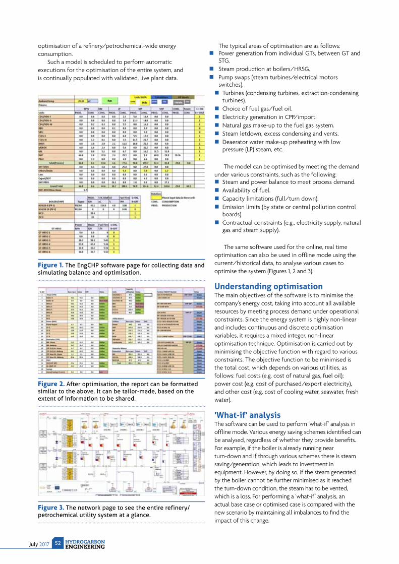
July 2017 HYDROCARBONENGINEERING
52
optimisation of a refi nery/petrochemical-wide energy consumption.
Such a model is scheduled to perform automatic executions for the optimisation of the entire system, and is continually populated with validated, live plant data.
The typical areas of optimisation are as follows: Power generation from individual GTs, between GT and
STG. Steam production at boilers/HRSG. Pump swaps (steam turbines/electrical motors
switches). Turbines (condensing turbines, extraction-condensing
turbines). Choice of fuel gas/fuel oil. Electricity generation in CPP/import. Natural gas make-up to the fuel gas system. Steam letdown, excess condensing and vents. Deaerator water make-up preheating with low
pressure (LP) steam, etc.
The model can be optimised by meeting the demand under various constraints, such as the following:
Steam and power balance to meet process demand. Availability of fuel. Capacity limitations (full/turn down). Emission limits (by state or central pollution control
boards). Contractual constraints (e.g., electricity supply, natural
gas and steam supply).
The same software used for the online, real time optimisation can also be used in offl ine mode using the current/historical data, to analyse various cases to optimise the system (Figures 1, 2 and 3).
Understanding optimisationThe main objectives of the software is to minimise the company's energy cost, taking into account all available resources by meeting process demand under operational constraints. Since the energy system is highly non-linear and includes continuous and discrete optimisation variables, it requires a mixed integer, non-linear optimisation technique. Optimisation is carried out by minimising the objective function with regard to various constraints. The objective function to be minimised is the total cost, which depends on various utilities, as follows: fuel costs (e.g. cost of natural gas, fuel oil); power cost (e.g. cost of purchased/export electricity), and other cost (e.g. cost of cooling water, seawater, fresh water).
'What-if' analysisThe software can be used to perform ‘what-if’ analysis in offl ine mode. Various energy saving schemes identifi ed can be analysed, regardless of whether they provide benefi ts. For example, if the boiler is already running near turn-down and if through various schemes there is steam saving/generation, which leads to investment in equipment. However, by doing so, if the steam generated by the boiler cannot be further minimised as it reached the turn-down condition, the steam has to be vented, which is a loss. For performing a ‘what-if’ analysis, an actual base case or optimised case is compared with the new scenario by maintaining all imbalances to fi nd the impact of this change.
Figure 1. The EngCHP software page for collecting data and simulating balance and optimisation.
Figure 2. After optimisation, the report can be formatted similar to the above. It can be tailor-made, based on the extent of information to be shared.
Figure 3. The network page to see the entire refinery/petrochemical utility system at a glance.
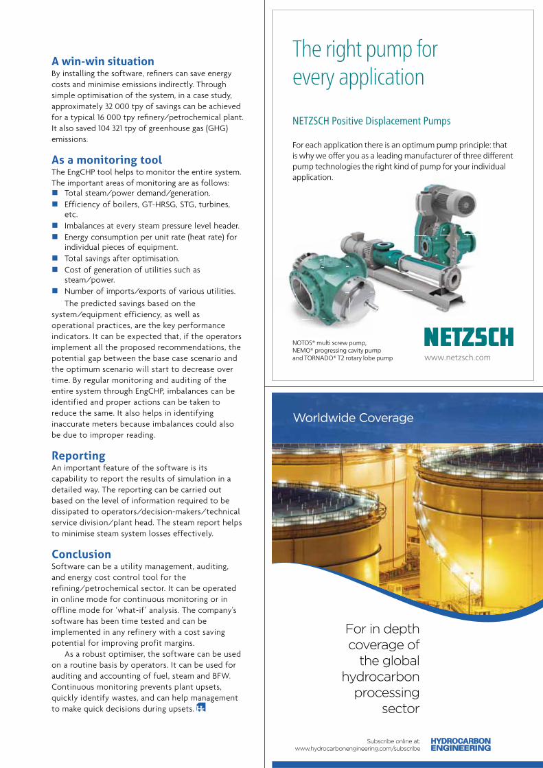
A win-win situationBy installing the software, refi ners can save energy costs and minimise emissions indirectly. Through simple optimisation of the system, in a case study, approximately 32 000 tpy of savings can be achieved for a typical 16 000 tpy refi nery/petrochemical plant. It also saved 104 321 tpy of greenhouse gas (GHG) emissions.
As a monitoring toolThe EngCHP tool helps to monitor the entire system. The important areas of monitoring are as follows:
Total steam/power demand/generation. Efficiency of boilers, GT-HRSG, STG, turbines,
etc. Imbalances at every steam pressure level header. Energy consumption per unit rate (heat rate) for
individual pieces of equipment. Total savings after optimisation. Cost of generation of utilities such as
steam/power. Number of imports/exports of various utilities.
The predicted savings based on the system/equipment efficiency, as well as operational practices, are the key performance indicators. It can be expected that, if the operators implement all the proposed recommendations, the potential gap between the base case scenario and the optimum scenario will start to decrease over time. By regular monitoring and auditing of the entire system through EngCHP, imbalances can be identified and proper actions can be taken to reduce the same. It also helps in identifying inaccurate meters because imbalances could also be due to improper reading.
ReportingAn important feature of the software is its capability to report the results of simulation in a detailed way. The reporting can be carried out based on the level of information required to be dissipated to operators/decision-makers/technical service division/plant head. The steam report helps to minimise steam system losses effectively.
ConclusionSoftware can be a utility management, auditing, and energy cost control tool for the refining/petrochemical sector. It can be operated in online mode for continuous monitoring or in offline mode for ‘what-if ’ analysis. The company's software has been time tested and can be implemented in any refinery with a cost saving potential for improving profit margins.
As a robust optimiser, the software can be used on a routine basis by operators. It can be used for auditing and accounting of fuel, steam and BFW. Continuous monitoring prevents plant upsets, quickly identify wastes, and can help management to make quick decisions during upsets.
NOTOS® multi screw pump,
NEMO® progressing cavity pump
and TORNADO® T2 rotary lobe pump
The right pump forevery application
NETZSCH Positive Displacement Pumps
For each application there is an optimum pump principle: that
is why we off er you as a leading manufacturer of three diff erent
pump technologies the right kind of pump for your individual
application.
www.netzsch.com
Worldwide Coverage
Subscribe online at:www.hydrocarbonengineering.com/subscribe
For in depth coverage of
the global hydrocarbon
processing sector

JuJuJ lyylylyy 20200002020171717171171717 54 HYDH ROCROCOCCOCARBARBARBARBA OOOONNNNNENEE GIINNNENENEEERERRERERINININININGGGGG
Colin Cooper, Eka Software, UK, examines the recent developments in data handling and analytics software, and what this means for the future of the downstream sector.

July 201755HYDROCARBONENGINEERING
W ith crude oil at a modest price, the global oil and gas industry is continuing to experience one of the toughest operational periods in recent memory. While upstream and vertically integrated operators
have deployed a variety of techniques to optimise the cost effectiveness of exploration and production – broadly defi nable as doing more with less – the role of margin preservation and loss avoidance in the downstream industry’s transporters, marketers, traders, and even refi ners, continues to be sharply highlighted.
After all, downstream is where sourcing strategies for both raw materials and refi ned product must be optimised to secure value. It is where seamless transport, storage, and logistics make a real difference to profi ts. It is where customer behaviour must be clearly understood to ensure the supply of refi ned products matches the demand. It is where traders try to understand the impact of wholesale market movements, volatility, and the consequences of international politics and economics to minimise price risk and maximise hedging strategies.
Rethinking IT investmentDownstream operations have also been the recipients of extensive investments in technology. Almost every operator rightly has a full complement of enterprise resource planning (ERP), treasury, accounting, business intelligence, customer relationship management, and, of course, energy or commodity trading and risk management systems in place.
Each of these systems certainly delivers signifi cant value in their own fi eld of specialisation. But they are not designed for the current reality of most downstream operators who must coordinate a multitude of interdependent actors, mitigate signifi cant connected risk factors, and make real time decisions with consequences that ripple out to almost every area of the business.
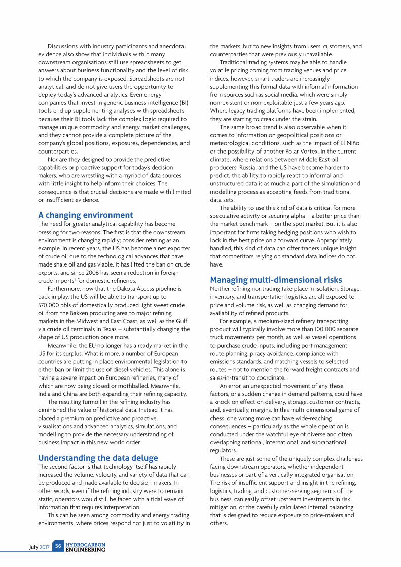
July 2017 HYDROCARBONENGINEERING
56
Discussions with industry participants and anecdotal evidence also show that individuals within many downstream organisations still use spreadsheets to get answers about business functionality and the level of risk to which the company is exposed. Spreadsheets are not analytical, and do not give users the opportunity to deploy today’s advanced analytics. Even energy companies that invest in generic business intelligence (BI) tools end up supplementing analyses with spreadsheets because their BI tools lack the complex logic required to manage unique commodity and energy market challenges, and they cannot provide a complete picture of the company’s global positions, exposures, dependencies, and counterparties.
Nor are they designed to provide the predictive capabilities or proactive support for today’s decision makers, who are wrestling with a myriad of data sources with little insight to help inform their choices. The consequence is that crucial decisions are made with limited or insuffi cient evidence.
A changing environmentThe need for greater analytical capability has become pressing for two reasons. The fi rst is that the downstream environment is changing rapidly; consider refi ning as an example. In recent years, the US has become a net exporter of crude oil due to the technological advances that have made shale oil and gas viable. It has lifted the ban on crude exports, and since 2006 has seen a reduction in foreign crude imports1 for domestic refi neries.
Furthermore, now that the Dakota Access pipeline is back in play, the US will be able to transport up to 570 000 bbls of domestically produced light sweet crude oil from the Bakken producing area to major refi ning markets in the Midwest and East Coast, as well as the Gulf via crude oil terminals in Texas – substantially changing the shape of US production once more.
Meanwhile, the EU no longer has a ready market in the US for its surplus. What is more, a number of European countries are putting in place environmental legislation to either ban or limit the use of diesel vehicles. This alone is having a severe impact on European refi neries, many of which are now being closed or mothballed. Meanwhile, India and China are both expanding their refi ning capacity.
The resulting turmoil in the refi ning industry has diminished the value of historical data. Instead it has placed a premium on predictive and proactive visualisations and advanced analytics, simulations, and modelling to provide the necessary understanding of business impact in this new world order.
Understanding the data delugeThe second factor is that technology itself has rapidly increased the volume, velocity, and variety of data that can be produced and made available to decision-makers. In other words, even if the refi ning industry were to remain static, operators would still be faced with a tidal wave of information that requires interpretation.
This can be seen among commodity and energy trading environments, where prices respond not just to volatility in
the markets, but to new insights from users, customers, and counterparties that were previously unavailable.
Traditional trading systems may be able to handle volatile pricing coming from trading venues and price indices, however, smart traders are increasingly supplementing this formal data with informal information from sources such as social media, which were simply non-existent or non-exploitable just a few years ago. Where legacy trading platforms have been implemented, they are starting to creak under the strain.
The same broad trend is also observable when it comes to information on geopolitical positions or meteorological conditions, such as the impact of El Niño or the possibility of another Polar Vortex. In the current climate, where relations between Middle East oil producers, Russia, and the US have become harder to predict, the ability to rapidly react to informal and unstructured data is as much a part of the simulation and modelling process as accepting feeds from traditional data sets.
The ability to use this kind of data is critical for more speculative activity or securing alpha – a better price than the market benchmark – on the spot market. But it is also important for fi rms taking hedging positions who wish to lock in the best price on a forward curve. Appropriately handled, this kind of data can offer traders unique insight that competitors relying on standard data indices do not have.
Managing multi-dimensional risksNeither refi ning nor trading take place in isolation. Storage, inventory, and transportation logistics are all exposed to price and volume risk, as well as changing demand for availability of refi ned products.
For example, a medium-sized refi nery transporting product will typically involve more than 100 000 separate truck movements per month, as well as vessel operations to purchase crude inputs, including port management, route planning, piracy avoidance, compliance with emissions standards, and matching vessels to selected routes – not to mention the forward freight contracts and sales-in-transit to coordinate.
An error, an unexpected movement of any these factors, or a sudden change in demand patterns, could have a knock-on effect on delivery, storage, customer contracts, and, eventually, margins. In this multi-dimensional game of chess, one wrong move can have wide-reaching consequences – particularly as the whole operation is conducted under the watchful eye of diverse and often overlapping national, international, and supranational regulators.
These are just some of the uniquely complex challenges facing downstream operators, whether independent businesses or part of a vertically integrated organisation. The risk of insuffi cient support and insight in the refi ning, logistics, trading, and customer-serving segments of the business, can easily offset upstream investments in risk mitigation, or the carefully calculated internal balancing that is designed to reduce exposure to price-makers and others.

A technology blueprintSo, what does technology for downstream operations look like in 2017, and in the future? As with all other industrial and commercial sectors, the use of mobile, Cloud and analytics are key characteristics. The adoption of the Cloud, in particular, is only set to accelerate, not least to provide the computing power required to provide real time analysis and visualisations of key data.
There has been a shift from retroactive assessment to predictive, proactive models of analysis that is set to become the standard for creating ‘what-if’ scenarios, models and simulations in the future.
Perhaps one of the most notable features is that analytics will no longer be the sole preserve of data scientists, IT experts, or system administrators. Nor will queries be limited to what can be coded or programmed into the system. Business users will be able to fi nd out what they want, when they want, and without being constrained by the availability of IT support or the functionality of the underlying database.
In terms of system capabilities, operators should look for systems that offer the most appropriate combination of the following:
Coverage of the entire lifecycle of crude and refined products, including purchase, refining, blending, storage, transportation, sales, distribution, trading, and risk management.
Artificial intelligence (AI) and machine learning algorithms to analyse bigger, more complex data and
deliver faster, more accurate results – even on a very large scale.
The ability to aggregate and analyse data from disparate systems throughout the value chain, including energy trading, transaction and risk management (ETRM) software, accounting systems, and inventory management systems.
In-memory data grids provide unprecedented processing speeds, enabling commodities managers to get the results of advanced calculations in minutes rather than hours.
Predictive analytics to run complex forecasting models and scenarios to answer essential ‘what-if’ questions.
Dynamic visualisation to present data in easy to use and understand formats.
ConclusionThe downstream environment has never been so complex, and the pressure on managers to deliver has never been so high. But the possibilities presented by IT have never been so great either. Big data and simulation techniques have come together with delivery mechanisms such as the Cloud and mobile to give downstream operators more choice, more accuracy, and more evidence for decision-making than ever before. However, to make the most of this capability, advanced analytics are key – and the critical target for the next wave of IT investment.
Reference1. US Energy Information Administration (EIA), https://www.eia.gov/
dnav/pet/hist/LeafHandler.ashx?n=PET&s=MCRIMUS2&f=A.

JuJuuuuJuJuJuJuJulylyyyyylylyylyyy 20202020202001717177759HYDYDHYDHYDROROROROCROROR ARBBBBBBBBOOONENENENGIGIGIG NENENENENENN ERIIIINNIII GGG
inking 3D models that have been created in plant design systems with the as-built record of the plant has made tremendous advances over the past few years, with most software vendors investing in laser
scanning and point-cloud technologies to capture the ‘as-built’. This enables the linking of the 3D modelling environment with other information sources to support rapid decision making around asset life extension andrevamps where more space and/or equipment replacement is required. With 90% of capital spent on existing plants, quickly accessing situations, and making confi dent decisions is a huge benefi t. However, how often do engineers revisit the complex engineering analyses they carry out when the plant is fi rst conceived? And when should they re-analyse a piping system that has been corroding for many years, to predict under what circumstances it might fail? This article looks at the technologies available to maintain accurate engineering information about assets over their lifecycle to provide decision makers with more predictable and consistent results.
Current stateSophisticated plant design technology that model plants in 2D (process fl ow diagram [PFD], process and instrument drawing [P&ID]) and 3D, prior to construction and operation, have been available for over 40 years. These
Anne-Marie Walters,Bentley Systems, USA, evaluates technologies to maintain accurate engineering information over the lifecycle of an asset.
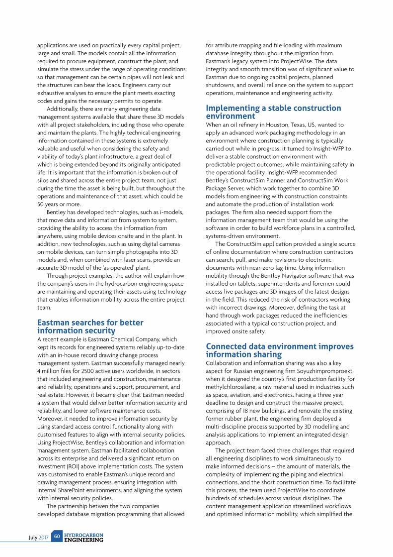
July 2017 HYDROCARBONENGINEERING
60
applications are used on practically every capital project, large and small. The models contain all the information required to procure equipment, construct the plant, and simulate the stress under the range of operating conditions, so that management can be certain pipes will not leak and the structures can bear the loads. Engineers carry out exhaustive analyses to ensure the plant meets exacting codes and gains the necessary permits to operate.
Additionally, there are many engineering data management systems available that share these 3D models with all project stakeholders, including those who operate and maintain the plants. The highly technical engineering information contained in these systems is extremely valuable and useful when considering the safety and viability of today’s plant infrastructure, a great deal of which is being extended beyond its originally anticipated life. It is important that the information is broken out of silos and shared across the entire project team, not just during the time the asset is being built, but throughout the operations and maintenance of that asset, which could be 50 years or more.
Bentley has developed technologies, such as i-models, that move data and information from system to system, providing the ability to access the information from anywhere, using mobile devices onsite and in the plant. In addition, new technologies, such as using digital cameras on mobile devices, can turn simple photographs into 3D models and, when combined with laser scans, provide an accurate 3D model of the ‘as operated’ plant.
Through project examples, the author will explain how the company’s users in the hydrocarbon engineering space are maintaining and operating their assets using technology that enables information mobility across the entire project team.
Eastman searches for better information securityA recent example is Eastman Chemical Company, which kept its records for engineered systems reliably up-to-date with an in-house record drawing change process management system. Eastman successfully managed nearly 4 million fi les for 2500 active users worldwide, in sectors that included engineering and construction, maintenance and reliability, operations and support, procurement, and real estate. However, it became clear that Eastman needed a system that would deliver better information security and reliability, and lower software maintenance costs. Moreover, it needed to improve information security by using standard access control functionality along with customised features to align with internal security policies. Using ProjectWise, Bentley’s collaboration and information management system, Eastman facilitated collaboration across its enterprise and delivered a signifi cant return on investment (ROI) above implementation costs. The system was customised to enable Eastman’s unique record and drawing management process, ensuring integration with internal SharePoint environments, and aligning the system with internal security policies.
The partnership betwen the two companies developed database migration programming that allowed
for attribute mapping and fi le loading with maximum database integrity throughout the migration from Eastman’s legacy system into ProjectWise. The data integrity and smooth transition was of signifi cant value to Eastman due to ongoing capital projects, planned shutdowns, and overall reliance on the system to support operations, maintenance and engineering activity.
Implementing a stable construction environmentWhen an oil refi nery in Houston, Texas, US, wanted to apply an advanced work packaging methodology in an environment where construction planning is typically carried out while in progress, it turned to Insight-WFP to deliver a stable construction environment with predictable project outcomes, while maintaining safety in the operational facility. Insight-WFP recommended Bentley’s ConstructSim Planner and ConstructSim Work Package Server, which work together to combine 3D models from engineering with construction constraints and automate the production of installation work packages. The fi rm also needed support from the information management team that would be using the software in order to build workforce plans in a controlled, systems-driven environment.
The ConstructSim application provided a single source of online documentation where construction contractors can search, pull, and make revisions to electronic documents with near-zero lag time. Using information mobility through the Bentley Navigator software that was installed on tablets, superintendents and foremen could access live packages and 3D images of the latest designs in the fi eld. This reduced the risk of contractors working with incorrect drawings. Moreover, defi ning the task at hand through work packages reduced the ineffi ciencies associated with a typical construction project, and improved onsite safety.
Connected data environment improves information sharingCollaboration and information sharing was also a key aspect for Russian engineering fi rm Soyuzhimpromproekt, when it designed the country’s fi rst production facility for methylchlorosilane, a raw material used in industries such as space, aviation, and electronics. Facing a three year deadline to design and construct the massive project, comprising of 18 new buildings, and renovate the existing former rubber plant, the engineering fi rm deployed a multi-discipline process supported by 3D modelling and analysis applications to implement an integrated design approach.
The project team faced three challenges that required all engineering disciplines to work simultaneously to make informed decisions – the amount of materials, the complexity of implementing the piping and electrical connections, and the short construction time. To facilitate this process, the team used ProjectWise to coordinate hundreds of schedules across various disciplines. The content management application streamlined workfl ows and optimised information mobility, which simplifi ed the
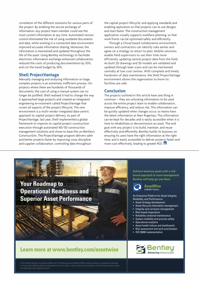
correlation of the different solutions for various parts of the project. By enabling the secure exchange of information, any project team member could see the most current information at any time. Automated version control eliminated the risk of using outdated documents and data, while working in a connected data environment improved accurate information sharing. Moreover, the information is maintained and updated throughout the life of the asset. Using Bentley technology to facilitate electronic information exchange enhanced collaboration, reduced the costs of producing documentation by 50%, and cut the travel budget by 30%.
Shell ProjectVantageManually managing and analysing information on large, complex projects is an extremely ineffi cient process. On projects where there are hundreds of thousands of documents, the cost of using a manual system can no longer be justifi ed. Shell realised it had to change the way it approached large projects and created an integrated engineering environment called ProjectVantage that covers all aspects of the project lifecycle. The new environment is a multi-vendor integrated data-centric approach to capital project delivery. As part of ProjectVantage, last year, Shell implemented a global framework to improve its capital project construction execution through automated 4D/5D construction management solutions and chose to base this on Bentley’s ConstructSim. The ProjectVantage program delivers safer and better projects faster by improving cross-discipline and supplier collaboration, controlling data throughout
the capital project lifecycle, and applying standards and enabling replication so that projects can re-use designs and start faster. The construction management application visually supports workface planning, so that work fronts can be optimised safely and effi ciently.
Through a Cloud-based collaborative environment, owners and contractors can identify risks earlier and agree on a strategy to return to plan. Mobile solutions enable field supervisors to use their time more efficiently, updating central project data from the field. As-built 2D drawings and 3D models are validated and updated through laser scans and can be maintained centrally at low-cost centres. With complete and timely handovers of data maintenance, the Shell ProjectVantage environment allows the organisation to know its facilities are safe.
ConclusionThe projects outlined in this article have one thing in common – they are unlocking information to be used across the entire project team to enable collaboration, improve effi ciency, and reduce risk. This information can be quickly updated when changes occur, so teams have the latest information at their fi ngertips. This information can be kept for decades and is easily accessible when it is time to rehabilitate or decommission an asset. The end goal with any project is to build, maintain, and reuse effectively and effi ciently. Bentley builds its business on ensuring its users have the right information at the right time, and is easily accessible to deliver projects faster and more cost effectively, leading to greater ROI.
Your Roadmap to Operational Readiness and Superior Asset Performance
© 2017 Bentley Systems, Incorporated. Bentley, the “B” Bentley logo and AssetWise APM are either registered or unregistered trademarks or service marks of Bentley Systems, Incorporated or one of its direct or indirect wholly owned subsidiaries. Other brands and product names are trademarks of their respective owners.
www.bentley.com/structural Learn more at www.bentley.com/assetwise
Achieve business goals with a risk-based approach to asset management. Bentley will help get you there.
An Enterprise Platform for Asset Integrity, Reliability, and Performance: • Asset strategy development• Asset lifecycle information management• Integrity and corrosion management• Risk-based inspections• Reliability-centered maintenance• System reliability and process safety• Operational analytics• Asset health indices and dashboards • Risk assessment and work prioritization• ISO 55000 implementation

Download the free app for Apple and Android devices:
www.hydrocarbonengineering.com/magazine/hydrocarbon-engineering/app
Hydrocarbon Engineering App
Read the latest issue on the go

July 201763HYDROCARBONENGINEERING
O il is a well-travelled commodity. Refi ned into a broad range of petroleum products, it moves from production fi elds to refi neries to distribution centres all before fi nal delivery to users. At some point on its journey from the
wellhead to the fuel tank, a barrel of crude oil will almost certainly spend some time in a storage tank. The world consumes a lot of oil, which means a lot of storage tanks.
In the US alone, storage tank capacity totals more than 1.1 billion bbls of crude and refi ned oil products, and this number is increasing.1 According to a 2016 report by the US Energy Information Administration (EIA), the global supply for crude oil has outpaced demand. As a result of, generally, rising crude oil inventories since the end of 2014, the global oil industry is building – and fi lling – more storage facilities.
While a storage tank may appear to be a simple structure, there is more than meets the eye. Large petroleum storage tanks can be more than 400 ft (120 m) in diameter and contain 1.5 million bbls. However, tanks can change over time. The volume of fl uid puts enormous stress onto tank walls and fl oors, which can result in deformation. Other issues may be induced by corrosion, subsidence and weather. In extreme cases, a tank could fail and release hazardous or toxic material into the environment.
In order to keep storage tanks working safely and effi ciently, tank owners undertake a programme of regular inspection and maintenance.
Jason Hayes, Trimble, USA, introduces new software solutions
for storage tank inspections that deliver lower costs and higher value.
LASER SPEED
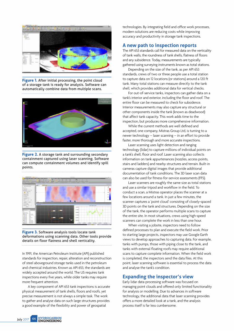
July 2017 HYDROCARBONENGINEERING
64
In 1991, the American Petroleum Institute (API) published standards for inspection, repair, alteration and reconstruction of steel aboveground storage tanks used in the petroleum and chemical industries. Known as API 653, the standards are widely accepted around the world. The US requires tank inspections every fi ve years, while older tanks may require more frequent attention.
A key component of API 653 tank inspections is accurate physical measurement of tank shells, fl oors and roofs, yet precise measurement is not always a simple task. The work to gather and analyse data on such large structures provides a good example of the fl exibility and power of geospatial
technologies. By integrating fi eld and offi ce work processes, modern solutions are reducing costs while improving accuracy and productivity in storage tank inspections.
A new path to inspection reportsThe API 653 standards call for measured data on the verticality of tank walls, the roundness of tank shells, fl atness of fl oors and any subsidence. Today, measurements are typically gathered using surveying instruments known as total stations.
Depending on the size of the tank, as per API 653 standards, crews of two or three people use a total station to capture data on 12 locations (or stations) around a 120 ft tank. Many total stations can measure directly to the tank shell, which provides additional data for vertical checks.
For out-of-service tanks, inspectors can gather data on a tank’s interior and exterior, including the fl oor and roof. The entire fl oor can be measured to check for subsidence. Interior measurements may also capture any structural or other components inside the tank (known as deadwood) that affect tank capacity. This work adds time to the inspection, but produces more comprehensive information.
While the current methods are well defi ned and accepted, one company, Mistras Group Ltd, is turning to a newer technology – laser scanning – in an effort to provide faster, more thorough and more accurate inspections.
Laser scanning uses light detection and ranging technology (lidar) to capture millions of individual points on a tank’s shell, fl oor and roof. Laser scanning also collects information on tank appurtenances (nozzles, access points, stairs and ladders) and nearby structures and terrain. Built-in cameras capture digital images that provide additional documentation of tank conditions. The 3D laser scan data can also be used for fi tness-for-service assessments (FFS).
Laser scanners are roughly the same size as total stations and use a similar tripod and workfl ow in the fi eld. To conduct a scan, a Mistras operator places the scanner at a few locations around a tank. In just a few minutes, the scanner captures a ‘point cloud’ consisting of closely-spaced 3D points on the tank and structures. Depending on the size of the tank, the operator performs multiple scans to capture the entire site. In most situations, crews using high-speed scanners can complete the work in less than one hour.
When visiting a jobsite, inspectors need to follow defi ned processes to plan and execute the fi eld work. Prior to starting large projects, inspectors may use Google Earth views to develop approaches to capturing data. For example, tanks with pumps, those with piping close to the tank, and tanks with external fl oating roofs may require additional scans to capture complete information. When the fi eld work is completed, the inspectors send the data fi les. At this point, laser scanning software is essential to process the data and analyse the tank’s condition.
Expanding the inspector’s viewEarly lidar data-processing software was focused on managing point clouds and offered only limited functionality for analysis or modelling. Due to advances in software technology, the additional data that laser scanning provides offers a more detailed look at a tank, and the analysis process itself is far less cumbersome.
Figure 1. After initial processing, the point cloud of a storage tank is ready for analysis. Software can automatically combine data from multiple scans.
Figure 2. A storage tank and surrounding secondary containment captured using laser scanning. Software can compute containment volumes and identify spill points.
Figure 3. Software analysis tools locate tank deformations using scanning data. Other tools provide details on floor flatness and shell verticality.

cricatalyst.com
choose wisely.When exploring solutions for emission reduction, the moves you make now can have a large impact on your environmental compliance and plant operations.
Our team of experts at CRI Catalyst Company, which is part of CRI/Criterion, Inc., the global catalyst
technology company of the Shell Group, offers energy-efficient solutions for catalytic reduction of
emissions. CRI’s proprietary Shell DeNOx System, Shell Dioxin Destruction System and the CRI N2O
Abatement Technology System can be designed to achieve emission reductions in excess of 99+%.
All systems feature our unique Lateral Flow Reactor design and low-temperature operation enabling
your facility to exceed clean air regulations and reduce greenhouse gas emissions. Reduction of
greenhouse gases could potentially earn valuable carbon credits.
It is all part of our commitment to delivering innovation.
CRI Catalyst refers to certain of the companies of the Royal Dutch/Shell Group which are engaged in the catalyst business. Each of the companies which make up the Royal Dutch/Shell Group of companies
is an independent entity and has its own identity.
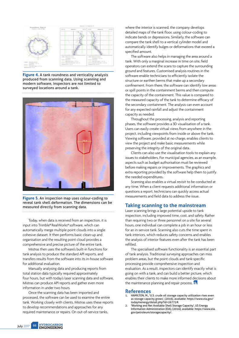
July 2017 HYDROCARBONENGINEERING
66
Today, when data is received from an inspection, it is input into Trimble® RealWorks® software, which can automatically merge multiple point clouds into a single cohesive dataset. It then performs basic clean-up and organisation and the resulting point cloud provides a comprehensive and precise picture of the entire tank.
Mistras then uses the software’s built-in functions for tank analysis to produce the standard API reports, and transfers results from the software into its in-house software for additional evaluation.
Manually analysing data and producing reports from total station data typically required approximately four hours, but with today’s laser scanning data and software, Mistras can produce API reports and gather even more information in under two hours.
Once the scanning data has been imported and processed, the software can be used to examine the entire tank. Working closely with clients, Mistras uses these reports to develop recommendations and approaches for any required maintenance or repairs. On out-of-service tanks,
where the interior is scanned, the company develops detailed maps of the tank fl oor, using colour-coding to indicate bends or depressions. Similarly, the software can compare the tank shell to a vertical cylinder model and automatically identify bulges or deformations that exceed a specifi ed amount.
The software also helps in managing the area around a tank. With only a marginal increase in time on site, fi eld operators can extend the scans to capture the surrounding ground and features. Customised analysis routines in the software enable technicians to effi ciently isolate the structure or earthen berms that make up a secondary confi nement. From there, the software can identify low areas or spill points in the containment berms and then compute the capacity of the containment. This value is compared to the measured capacity of the tank to determine effi cacy of the secondary containment. The analysis can even account for any expected rainfall and adjust the containment capacity as needed.
Throughout the processing, analysis and reporting phases, the software provides a 3D visualisation of a tank. Users can easily create virtual views from anywhere in the project, including viewpoints from inside or above the tank. Viewing software, provided at no charge, enables clients to view the project and make basic measurements while preserving the integrity of the original data.
Clients can also use the visualisation tools to explain any issues to stakeholders. For municipal agencies, as an example, aspects such as budget authorisation must be reviewed before making repairs or improvements. The graphics and extra reporting provided by the software help them to justify the needed expenditures.
Scanning also enables a virtual revisit to be conducted at any time. When a client requests additional information or questions a report, technicians can quickly access actual measurements and fi eld data to address the issue.
Taking scanning to the mainstreamLaser scanning brings a large potential upside to tank inspection, including improved time, cost, and safety. Rather than requiring two or three personnel on a site for several hours, one individual can complete a job in an hour or less for an in-service tank. Scanning also cuts the time spent in tank interiors, which reduces safety concerns and enables the analysis of interior features even after the tank has been refi lled.
The specialised software functionality is an essential part of tank analysis. Traditional surveying approaches can miss problem areas, but the point clouds and tank-specifi c processing provide comprehensive inspection and evaluation. As a result, inspectors can identify exactly what is going on with a tank, and can build a better picture, which enables their clients to make more informed decisions about the maintenance planning and repair process.
References1. HAMILTON, M., 'U.S. crude oil storage capacity utilization rises even
as storage capacity grows', (2016), available: https://www.eia.gov/todayinenergy/detail.php?id=26772#.
2. 'Working and Net Available Shell Storage Capacity', US Energy Information Administration (EIA), (2016), available: https://www.eia.gov/petroleum/storagecapacity/.
Figure 4. A tank roundness and verticality analysis produced from scanning data. Using scanning and modern software, inspectors are not limited to surveyed locations around a tank.
Figure 5. An inspection map uses colour-coding to reveal tank shell deformation. The dimensions can be measured directly from scanning data.
July 201767HYDROCARBONENGINEERING
During planned shutdowns, the equipment in refineries and petrochemical plants has to be checked. The downtime can require several weeks when tanks, vessels, distillation columns,
and pipes have to be drained and cleaned for maintenance or repair. Shutdowns are labour-intensive and require accurate scheduling and organisation between all projects, as often hundreds of workers are on-site. A variety of materials such as greases, tars, fatty oils, polymers, or coke and iron sulfide deposits have to be removed. There is a particular duty of care to protect the health of personnel when carcinogenic benzene, toxic hydrogen sulfide, volatile hydrocarbons, or other hazardous gases can be released. Senior level personnel try to minimise exposure to any situation where health risks or accidents could be initiated. This article describes chemical cleaning and decontamination technologies to achieve a significant reduction in downtime and health hazards.
Treatment programmesCoke fouling on furnace tubes can be taken off by controlled combustion with steam and air, but higher amounts of coke deposits, or polymers, have to be removed manually. Iron sulfide (FeS) is one of the most common fouling materials in oil refineries. It easily accumulates in heat exchangers, vessels, pipes or columns equipped with valve trays or packings. If FeS deposits are not removed, they must be kept wet all the time. Otherwise there is a high potential for spontaneous ignition in the presence of oxygen due to its pyrophoric iron nature. FeS oxidises exothermally
when in contact with air, so most pyrophoric iron fires occur during shutdowns as this is when distillation equipment is open for maintenance and inspection.
There are different possibilities to form FeS during operation and the term ‘iron sulfide’ covers a range of crystallographic forms, which are both non-magnetic and magnetic.
The reaction (1) describes the conversion of iron oxide to FeS in an oxygen-free atmosphere and presence of hydrogen sulfide (H2S). Reactions (2) and (3) occur as a corrosion product between iron (Fe0 or Fe2+) and hydrogen sulfide species:
Fe2O3 + 3H2S --> 2FeS + 3H2O + S (1)Fe0 + H2S --> FeS + H2 (2)Fe2+ (aq.) + H2S --> FeS + 2 H+ (aq.) (3)
Reactions (4) and (5) can occur when vessels, columns, heat exchangers or pipes are opened for maintenance and inspection. Due to its pyrophoric nature, it is a rapid exothermic oxidation process and will ignite in the presence of combustible hydrocarbons. Therefore, it is of great importance to avoid self-ignition of the accumulated fouling material that could cause a fire.
4 FeS + 3O2 --> 2Fe2O3 + 4S (4)4 FeS + 7O2 --> 2Fe2O3 + 4SO2 (5)
Chemical programmes are required when the equipment has to be cleaned as quickly as possible to minimise downtime costs. In most cases, wash water is
CURTAILING CONTAMINATION
Berthold Otzisk and Dr. Michael Urschey, Kurita Europe GmbH, explore safe chemical cleaning and decontamination technologies for the oil and gas industry.
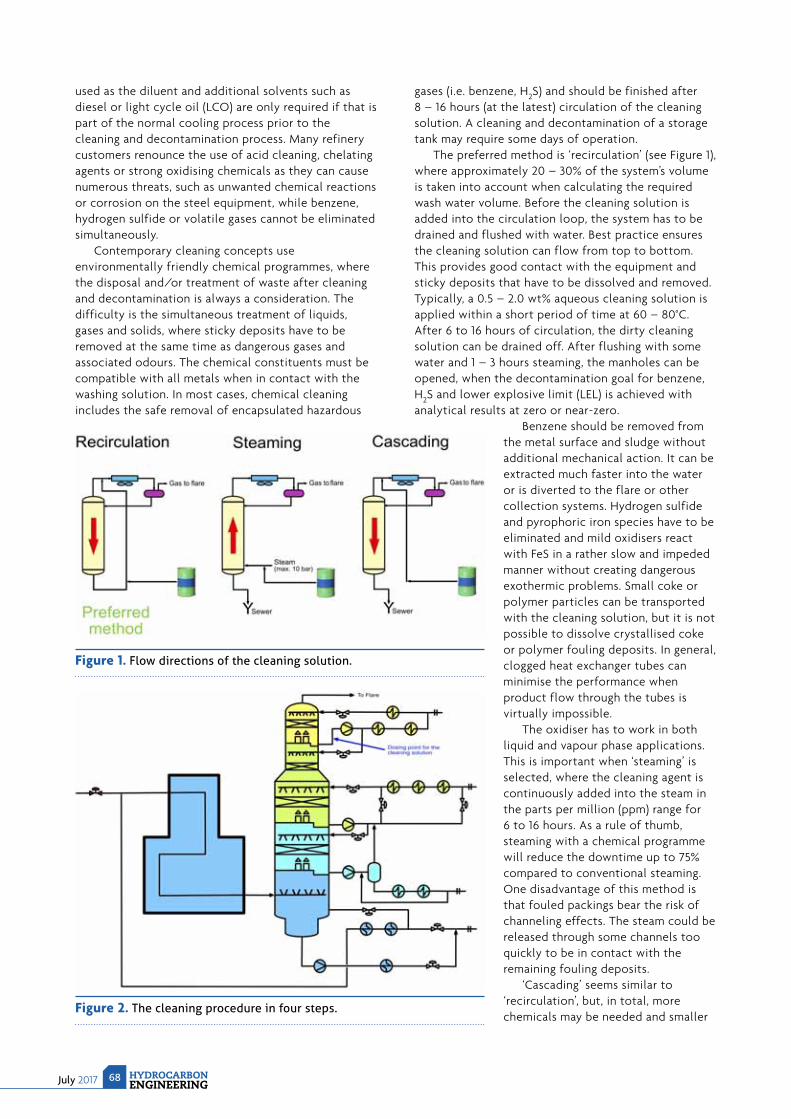
July 2017 HYDROCARBONENGINEERING
68
used as the diluent and additional solvents such as diesel or light cycle oil (LCO) are only required if that is part of the normal cooling process prior to the cleaning and decontamination process. Many refinery customers renounce the use of acid cleaning, chelating agents or strong oxidising chemicals as they can cause numerous threats, such as unwanted chemical reactions or corrosion on the steel equipment, while benzene, hydrogen sulfide or volatile gases cannot be eliminated simultaneously.
Contemporary cleaning concepts use environmentally friendly chemical programmes, where the disposal and/or treatment of waste after cleaning and decontamination is always a consideration. The difficulty is the simultaneous treatment of liquids, gases and solids, where sticky deposits have to be removed at the same time as dangerous gases and associated odours. The chemical constituents must be compatible with all metals when in contact with the washing solution. In most cases, chemical cleaning includes the safe removal of encapsulated hazardous
gases (i.e. benzene, H2S) and should be finished after 8 – 16 hours (at the latest) circulation of the cleaning solution. A cleaning and decontamination of a storage tank may require some days of operation.
The preferred method is ‘recirculation’ (see Figure 1), where approximately 20 – 30% of the system’s volume is taken into account when calculating the required wash water volume. Before the cleaning solution is added into the circulation loop, the system has to be drained and flushed with water. Best practice ensures the cleaning solution can flow from top to bottom. This provides good contact with the equipment and sticky deposits that have to be dissolved and removed. Typically, a 0.5 – 2.0 wt% aqueous cleaning solution is applied within a short period of time at 60 – 80°C. After 6 to 16 hours of circulation, the dirty cleaning solution can be drained off. After flushing with some water and 1 – 3 hours steaming, the manholes can be opened, when the decontamination goal for benzene, H2S and lower explosive limit (LEL) is achieved with analytical results at zero or near-zero.
Benzene should be removed from the metal surface and sludge without additional mechanical action. It can be extracted much faster into the water or is diverted to the flare or other collection systems. Hydrogen sulfide and pyrophoric iron species have to be eliminated and mild oxidisers react with FeS in a rather slow and impeded manner without creating dangerous exothermic problems. Small coke or polymer particles can be transported with the cleaning solution, but it is not possible to dissolve crystallised coke or polymer fouling deposits. In general, clogged heat exchanger tubes can minimise the performance when product flow through the tubes is virtually impossible.
The oxidiser has to work in both liquid and vapour phase applications. This is important when ‘steaming’ is selected, where the cleaning agent is continuously added into the steam in the parts per million (ppm) range for 6 to 16 hours. As a rule of thumb, steaming with a chemical programme will reduce the downtime up to 75% compared to conventional steaming. One disadvantage of this method is that fouled packings bear the risk of channeling effects. The steam could be released through some channels too quickly to be in contact with the remaining fouling deposits.
‘Cascading’ seems similar to ‘recirculation’, but, in total, more chemicals may be needed and smaller
Figure 1. Flow directions of the cleaning solution.
Figure 2. The cleaning procedure in four steps.
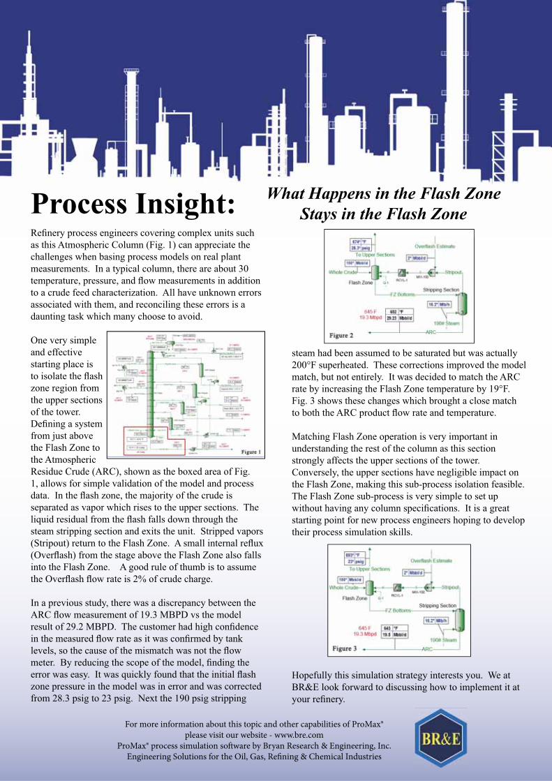
Process Insight: What Happens in the Flash Zone
Stays in the Flash Zone
For more information about this topic and other capabilities of ProMax®please visit our website - www.bre.com
ProMax® process simulation software by Bryan Research & Engineering, Inc.Engineering Solutions for the Oil, Gas, Refining & Chemical Industries
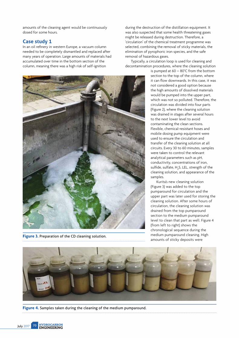
July 2017 HYDROCARBONENGINEERING
70
amounts of the cleaning agent would be continuously dosed for some hours.
Case study 1In an oil refi nery in western Europe, a vacuum column needed to be completely dismantled and replaced after many years of operation. Large amounts of materials had accumulated over time in the bottom section of the column, meaning there was a high risk of self-ignition
during the destruction of the distillation equipment. It was also suspected that some health threatening gases might be released during destruction. Therefore, a ‘circulation’ of the chemical treatment programme was selected, combining the removal of sticky materials, the elimination of pyrophoric iron species, and the safe removal of hazardous gases.
Typically, a circulation loop is used for cleaning and decontamination procedures, where the cleaning solution
is pumped at 60 – 80°C from the bottom section to the top of the column, where it can fl ow downwards. In this case, it was not considered a good option because the high amounts of dissolved materials would be pumped into the upper part, which was not so polluted. Therefore, the circulation was divided into four parts (Figure 2), where the cleaning solution was drained in stages after several hours to the next lower level to avoid contaminating the clean sections. Flexible, chemical-resistant hoses and mobile dosing pump equipment were used to ensure the circulation and transfer of the cleaning solution at all circuits. Every 30 to 60 minutes, samples were taken to control the relevant analytical parameters such as pH, conductivity, concentrations of iron, sulfi de, sulfate, H2S, LEL, strength of the cleaning solution, and appearance of the samples.
Kurita’s new cleaning solution (Figure 3) was added to the top pumparound for circulation and the upper part was later used for storing the cleaning solution. After some hours of circulation, the cleaning solution was drained from the top pumparound section to the medium pumparound level to clean that part as well. Figure 4 (from left to right) shows the chronological sequence during the medium pumparound cleaning. High amounts of sticky deposits were
Figure 3. Preparation of the CD cleaning solution.
Figure 4. Samples taken during the cleaning of the medium pumparound.
TRI-CON TRI-CHECK TRI-BLOCK
WWW.ZWICK-ARMATUREN.DE
HIGH STANDARD VALVES FOR NON-STANDARD CONDITIONS.
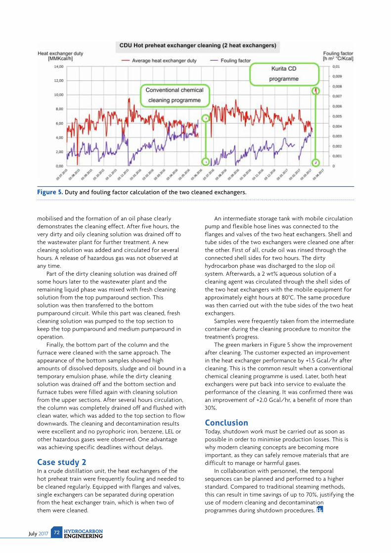
July 2017 HYDROCARBONENGINEERING
72
mobilised and the formation of an oil phase clearly demonstrates the cleaning effect. After five hours, the very dirty and oily cleaning solution was drained off to the wastewater plant for further treatment. A new cleaning solution was added and circulated for several hours. A release of hazardous gas was not observed at any time.
Part of the dirty cleaning solution was drained off some hours later to the wastewater plant and the remaining liquid phase was mixed with fresh cleaning solution from the top pumparound section. This solution was then transferred to the bottom pumparound circuit. While this part was cleaned, fresh cleaning solution was pumped to the top section to keep the top pumparound and medium pumparound in operation.
Finally, the bottom part of the column and the furnace were cleaned with the same approach. The appearance of the bottom samples showed high amounts of dissolved deposits, sludge and oil bound in a temporary emulsion phase, while the dirty cleaning solution was drained off and the bottom section and furnace tubes were filled again with cleaning solution from the upper sections. After several hours circulation, the column was completely drained off and flushed with clean water, which was added to the top section to flow downwards. The cleaning and decontamination results were excellent and no pyrophoric iron, benzene, LEL or other hazardous gases were observed. One advantage was achieving specific deadlines without delays.
Case study 2In a crude distillation unit, the heat exchangers of the hot preheat train were frequently fouling and needed to be cleaned regularly. Equipped with flanges and valves, single exchangers can be separated during operation from the heat exchanger train, which is when two of them were cleaned.
An intermediate storage tank with mobile circulation pump and flexible hose lines was connected to the flanges and valves of the two heat exchangers. Shell and tube sides of the two exchangers were cleaned one after the other. First of all, crude oil was rinsed through the connected shell sides for two hours. The dirty hydrocarbon phase was discharged to the slop oil system. Afterwards, a 2 wt% aqueous solution of a cleaning agent was circulated through the shell sides of the two heat exchangers with the mobile equipment for approximately eight hours at 80°C. The same procedure was then carried out with the tube sides of the two heat exchangers.
Samples were frequently taken from the intermediate container during the cleaning procedure to monitor the treatment’s progress.
The green markers in Figure 5 show the improvement after cleaning. The customer expected an improvement in the heat exchanger performance by +1.5 Gcal/hr after cleaning. This is the common result when a conventional chemical cleaning programme is used. Later, both heat exchangers were put back into service to evaluate the performance of the cleaning. It was confirmed there was an improvement of +2.0 Gcal/hr, a benefit of more than 30%.
ConclusionToday, shutdown work must be carried out as soon as possible in order to minimise production losses. This is why modern cleaning concepts are becoming more important, as they can safely remove materials that are difficult to manage or harmful gases.
In collaboration with personnel, the temporal sequences can be planned and performed to a higher standard. Compared to traditional steaming methods, this can result in time savings of up to 70%, justifying the use of modern cleaning and decontamination programmes during shutdown procedures.
Figure 5. Duty and fouling factor calculation of the two cleaned exchangers.

July 201773HYDROCARBONENGINEERING
A ccording to Douglas Westwood's 'World Downstream Maintenance Market Forecast 2017 – 2021' maintenance in the downstream sector is on the up, rising 7% between 2011 and
2016 and set to increase dramatically in the next fi ve years.1 With a stronger commitment than ever to staying online for longer, why is investment in new cleaning technologies still so low? Refi neries often bypass innovation in downstream cleaning technologies in favour of traditional solutions.
A 2016 article by Hala Abinader Long, Head of Energy EMEA, XL Catlin, outlined the opportunities and challenges
for downstream oil companies in a changing economy.2 The challenge, says Long, is in balancing CAPEX on maintenance budgets against expectations for prices and demand. Refi neries that are reluctant to take plants offl ine for maintenance when margins and demands are strong, are failing to create the resilience the market needs with a long-term commitment to maintenance and safety.
The industry has not evolved quickly enough to tackle the downturn in oil prices. Now that the bubble has burst, those that did not prepare for market volatility by not embracing new maintenance technologies struggle to shutdown long enough to remove fouling and inspect
Mike Watson, Tube Tech International Ltd, UK, explains how downstream maintenance can be carried out faster, safer, and to a higher standard.
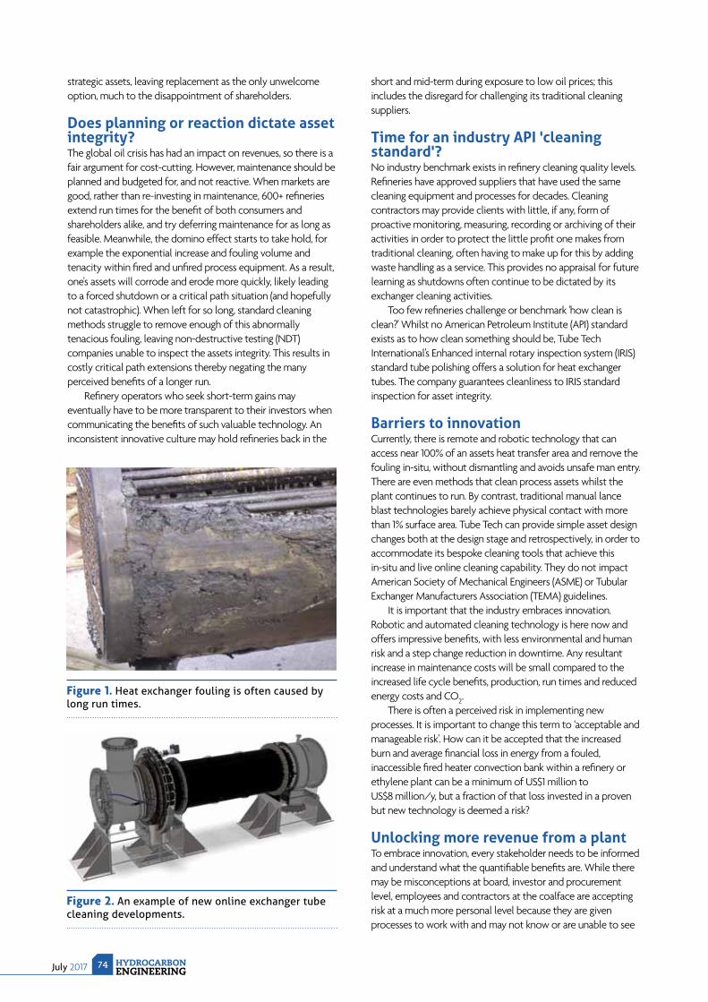
July 2017 HYDROCARBONENGINEERING
74
strategic assets, leaving replacement as the only unwelcome option, much to the disappointment of shareholders.
Does planning or reaction dictate asset integrity?The global oil crisis has had an impact on revenues, so there is a fair argument for cost-cutting. However, maintenance should be planned and budgeted for, and not reactive. When markets are good, rather than re-investing in maintenance, 600+ refi neries extend run times for the benefi t of both consumers and shareholders alike, and try deferring maintenance for as long as feasible. Meanwhile, the domino effect starts to take hold, for example the exponential increase and fouling volume and tenacity within fi red and unfi red process equipment. As a result, one's assets will corrode and erode more quickly, likely leading to a forced shutdown or a critical path situation (and hopefully not catastrophic). When left for so long, standard cleaning methods struggle to remove enough of this abnormally tenacious fouling, leaving non-destructive testing (NDT) companies unable to inspect the assets integrity. This results in costly critical path extensions thereby negating the many perceived benefi ts of a longer run.
Refi nery operators who seek short-term gains may eventually have to be more transparent to their investors when communicating the benefi ts of such valuable technology. An inconsistent innovative culture may hold refi neries back in the
short and mid-term during exposure to low oil prices; this includes the disregard for challenging its traditional cleaning suppliers.
Time for an industry API 'cleaning standard'?No industry benchmark exists in refi nery cleaning quality levels. Refi neries have approved suppliers that have used the same cleaning equipment and processes for decades. Cleaning contractors may provide clients with little, if any, form of proactive monitoring, measuring, recording or archiving of their activities in order to protect the little profi t one makes from traditional cleaning, often having to make up for this by adding waste handling as a service. This provides no appraisal for future learning as shutdowns often continue to be dictated by its exchanger cleaning activities.
Too few refi neries challenge or benchmark 'how clean is clean?' Whilst no American Petroleum Institute (API) standard exists as to how clean something should be, Tube Tech International’s Enhanced internal rotary inspection system (IRIS) standard tube polishing offers a solution for heat exchanger tubes. The company guarantees cleanliness to IRIS standard inspection for asset integrity.
Barriers to innovationCurrently, there is remote and robotic technology that can access near 100% of an assets heat transfer area and remove the fouling in-situ, without dismantling and avoids unsafe man entry. There are even methods that clean process assets whilst the plant continues to run. By contrast, traditional manual lance blast technologies barely achieve physical contact with more than 1% surface area. Tube Tech can provide simple asset design changes both at the design stage and retrospectively, in order to accommodate its bespoke cleaning tools that achieve this in-situ and live online cleaning capability. They do not impact American Society of Mechanical Engineers (ASME) or Tubular Exchanger Manufacturers Association (TEMA) guidelines.
It is important that the industry embraces innovation. Robotic and automated cleaning technology is here now and offers impressive benefi ts, with less environmental and human risk and a step change reduction in downtime. Any resultant increase in maintenance costs will be small compared to the increased life cycle benefi ts, production, run times and reduced energy costs and CO2.
There is often a perceived risk in implementing new processes. It is important to change this term to ‘acceptable and manageable risk’. How can it be accepted that the increased burn and average fi nancial loss in energy from a fouled, inaccessible fi red heater convection bank within a refi nery or ethylene plant can be a minimum of US$1 million to US$8 million/y, but a fraction of that loss invested in a proven but new technology is deemed a risk?
Unlocking more revenue from a plantTo embrace innovation, every stakeholder needs to be informed and understand what the quantifi able benefi ts are. While there may be misconceptions at board, investor and procurement level, employees and contractors at the coalface are accepting risk at a much more personal level because they are given processes to work with and may not know or are unable to see
Figure 1. Heat exchanger fouling is often caused by long run times.
Figure 2. An example of new online exchanger tube cleaning developments.
Responsive Aftermarket Support from our Advanced Facility.
www.mhicompressor.com/en
When every minute of downtime matters, you need responsive support you can rely on.
Mitsubishi Heavy Industries has established a world-scale manufacturing and service facility in
Pearland, Texas to provide rapid response for your product’s entire lifecycle. This state-of-the-art
facility, Pearland Works, offers 24/7 emergency response for MCO-I machinery and all other
manufacturers equipment, as well as advanced machine tools, field service, spare parts
support and over 50,000 sq. ft. of storage space.
OUR RAPID RESPONSE
WE PROMISE IMMEDIATE SUPPORT. THEN WE OVER DELIVER.
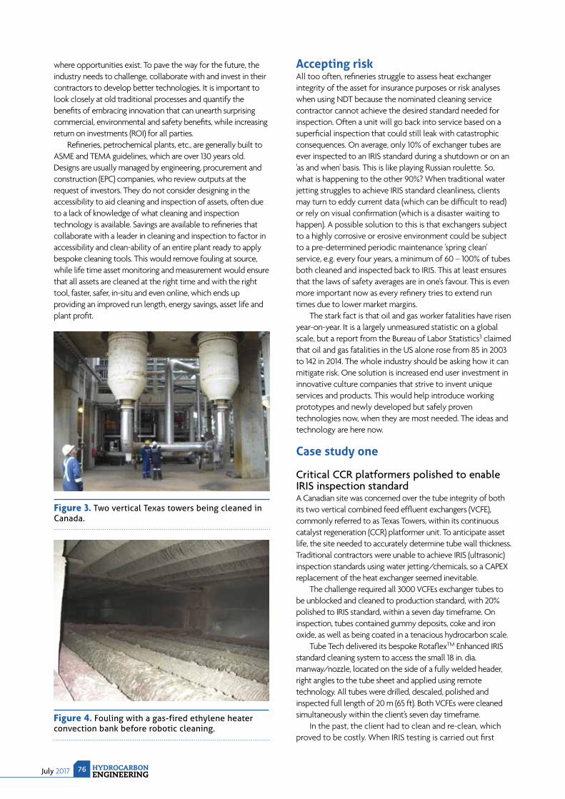
July 2017 HYDROCARBONENGINEERING
76
where opportunities exist. To pave the way for the future, the industry needs to challenge, collaborate with and invest in their contractors to develop better technologies. It is important to look closely at old traditional processes and quantify the benefi ts of embracing innovation that can unearth surprising commercial, environmental and safety benefi ts, while increasing return on investments (ROI) for all parties.
Refi neries, petrochemical plants, etc., are generally built to ASME and TEMA guidelines, which are over 130 years old. Designs are usually managed by engineering, procurement and construction (EPC) companies, who review outputs at the request of investors. They do not consider designing in the accessibility to aid cleaning and inspection of assets, often due to a lack of knowledge of what cleaning and inspection technology is available. Savings are available to refi neries that collaborate with a leader in cleaning and inspection to factor in accessibility and clean-ability of an entire plant ready to apply bespoke cleaning tools. This would remove fouling at source, while life time asset monitoring and measurement would ensure that all assets are cleaned at the right time and with the right tool, faster, safer, in-situ and even online, which ends up providing an improved run length, energy savings, asset life and plant profi t.
Accepting riskAll too often, refi neries struggle to assess heat exchanger integrity of the asset for insurance purposes or risk analyses when using NDT because the nominated cleaning service contractor cannot achieve the desired standard needed for inspection. Often a unit will go back into service based on a superfi cial inspection that could still leak with catastrophic consequences. On average, only 10% of exchanger tubes are ever inspected to an IRIS standard during a shutdown or on an 'as and when' basis. This is like playing Russian roulette. So, what is happening to the other 90%? When traditional water jetting struggles to achieve IRIS standard cleanliness, clients may turn to eddy current data (which can be diffi cult to read) or rely on visual confi rmation (which is a disaster waiting to happen). A possible solution to this is that exchangers subject to a highly corrosive or erosive environment could be subject to a pre-determined periodic maintenance 'spring clean' service, e.g. every four years, a minimum of 60 – 100% of tubes both cleaned and inspected back to IRIS. This at least ensures that the laws of safety averages are in one's favour. This is even more important now as every refi nery tries to extend run times due to lower market margins.
The stark fact is that oil and gas worker fatalities have risen year-on-year. It is a largely unmeasured statistic on a global scale, but a report from the Bureau of Labor Statistics3 claimed that oil and gas fatalities in the US alone rose from 85 in 2003 to 142 in 2014. The whole industry should be asking how it can mitigate risk. One solution is increased end user investment in innovative culture companies that strive to invent unique services and products. This would help introduce working prototypes and newly developed but safely proven technologies now, when they are most needed. The ideas and technology are here now.
Case study one
Critical CCR platformers polished to enable IRIS inspection standardA Canadian site was concerned over the tube integrity of both its two vertical combined feed effl uent exchangers (VCFE), commonly referred to as Texas Towers, within its continuous catalyst regeneration (CCR) platformer unit. To anticipate asset life, the site needed to accurately determine tube wall thickness. Traditional contractors were unable to achieve IRIS (ultrasonic) inspection standards using water jetting/chemicals, so a CAPEX replacement of the heat exchanger seemed inevitable.
The challenge required all 3000 VCFEs exchanger tubes to be unblocked and cleaned to production standard, with 20% polished to IRIS standard, within a seven day timeframe. On inspection, tubes contained gummy deposits, coke and iron oxide, as well as being coated in a tenacious hydrocarbon scale.
Tube Tech delivered its bespoke Rotafl exTM Enhanced IRIS standard cleaning system to access the small 18 in. dia. manway/nozzle, located on the side of a fully welded header, right angles to the tube sheet and applied using remote technology. All tubes were drilled, descaled, polished and inspected full length of 20 m (65 ft). Both VCFEs were cleaned simultaneously within the client’s seven day timeframe.
In the past, the client had to clean and re-clean, which proved to be costly. When IRIS testing is carried out fi rst
Figure 4. Fouling with a gas-fired ethylene heater convection bank before robotic cleaning.
Figure 3. Two vertical Texas towers being cleaned in Canada.

© 2017 by AMETEK Inc. All rights reserved.
Get accurate flare gas heat values fast, with the FlarePro™ Mass Spectrometer
With impending EPA rule changes for flare gas stack combustion, you’ll need to measure
heat value at the stack quickly, accurately, and often. AMETEK Dycor®’s FlarePro mass
spectrometer has the speed and specificity for the task, calculating make-up gas quantities
10X faster than chromatographs. It can speciate and quantify alkanes and alkenes up to
C7 and convert ASTM calculations of concentration to yield flare gas BTU values, even with
wildly changing flare gas streams. Features include:
• 24” footprint (general or C1, D2 areas)• 16-valve inlet system
• 1 to 100 amu mass range
• Easy-to-service modular design
• Low maintenance
• Modbus/OPC communications
• Environmentally controlled to
accommodate a wide range
of temperatures Learn more at www.ametekpi.com.
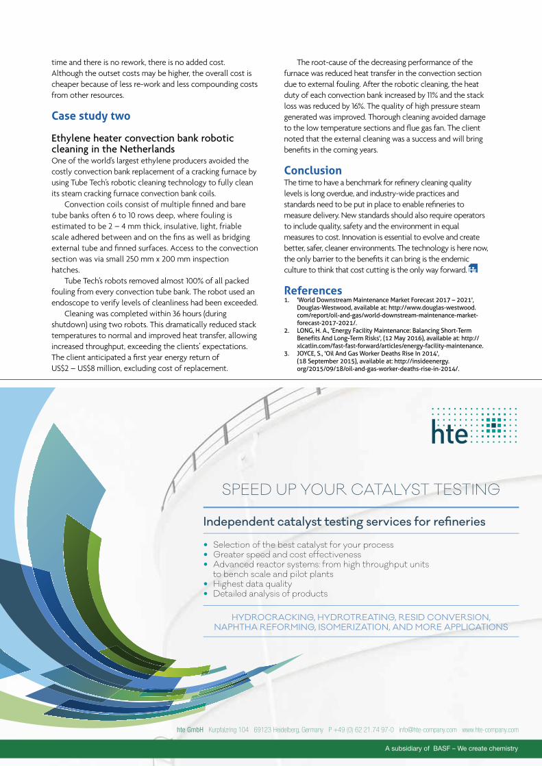
time and there is no rework, there is no added cost. Although the outset costs may be higher, the overall cost is cheaper because of less re-work and less compounding costs from other resources.
Case study two
Ethylene heater convection bank robotic cleaning in the NetherlandsOne of the world’s largest ethylene producers avoided the costly convection bank replacement of a cracking furnace by using Tube Tech’s robotic cleaning technology to fully clean its steam cracking furnace convection bank coils.
Convection coils consist of multiple fi nned and bare tube banks often 6 to 10 rows deep, where fouling is estimated to be 2 – 4 mm thick, insulative, light, friable scale adhered between and on the fi ns as well as bridging external tube and fi nned surfaces. Access to the convection section was via small 250 mm x 200 mm inspection hatches.
Tube Tech’s robots removed almost 100% of all packed fouling from every convection tube bank. The robot used an endoscope to verify levels of cleanliness had been exceeded.
Cleaning was completed within 36 hours (during shutdown) using two robots. This dramatically reduced stack temperatures to normal and improved heat transfer, allowing increased throughput, exceeding the clients’ expectations. The client anticipated a fi rst year energy return of US$2 – US$8 million, excluding cost of replacement.
The root-cause of the decreasing performance of the furnace was reduced heat transfer in the convection section due to external fouling. After the robotic cleaning, the heat duty of each convection bank increased by 11% and the stack loss was reduced by 16%. The quality of high pressure steam generated was improved. Thorough cleaning avoided damage to the low temperature sections and fl ue gas fan. The client noted that the external cleaning was a success and will bring benefi ts in the coming years.
ConclusionThe time to have a benchmark for refi nery cleaning quality levels is long overdue, and industry-wide practices and standards need to be put in place to enable refi neries to measure delivery. New standards should also require operators to include quality, safety and the environment in equal measures to cost. Innovation is essential to evolve and create better, safer, cleaner environments. The technology is here now, the only barrier to the benefi ts it can bring is the endemic culture to think that cost cutting is the only way forward.
References1. 'World Downstream Maintenance Market Forecast 2017 – 2021',
Douglas-Westwood, available at: http://www.douglas-westwood.com/report/oil-and-gas/world-downstream-maintenance-market-forecast-2017-2021/.
2. LONG, H. A., 'Energy Facility Maintenance: Balancing Short-Term Benefits And Long-Term Risks', (12 May 2016), available at: http://xlcatlin.com/fast-fast-forward/articles/energy-facility-maintenance.
3. JOYCE, S., 'Oil And Gas Worker Deaths Rise In 2014', (18 September 2015), available at: http://insideenergy.org/2015/09/18/oil-and-gas-worker-deaths-rise-in-2014/.
Independent catalyst testing services for refineries
Selection of the best catalyst for your process Greater speed and cost effectiveness Advanced reactor systems: from high throughput units
to bench scale and pilot plants Highest data quality Detailed analysis of products
HYDROCRACKING, HYDROTREATING, RESID CONVERSION,
NAPHTHA REFORMING, ISOMERIZATION, AND MORE APPLICATIONS
SPEED UP YOUR CATALYST TESTING
hte GmbH Kurpfalzring 104 69123 Heidelberg, Germany P +49 (0) 62 21.74 97-0 [email protected] www.hte-company.com
MODERN MACHINERY
T oday, the oil and gas downstream industry extends worldwide and is characterised by a large degree of technological sophistication. After its fi rst developments in the US, at the beginning of the last
century, the refi ning and gas processing industry has continued to expand. Within downstream plants, rotating machinery technology has been pushed, over decades, to continuous improvement. One of the main reasons why rotating machinery technology has been developed is due to the high impact this machinery has on overall process capabilities, performance and limitations.
Today, as in the past, the search for higher plant output effi ciencies drives the move towards more powerful machines that work at higher speeds and under more severe operating conditions. Machinery plays a primary role in the downstream industry because it is integral to the overall increase of plant and process performance. Within process machinery, centrifugal pumps play an important role, and are often critical or in downstream processes. Even when they are not considered vital, the pump’s role always remains important and a
determining factor in the full functionality of many auxiliary and ancillary services. Confi rmation of how important this kind of machine is in the downstream sector is evident by the fact that the centrifugal pump market continues to extend over a large number of process applications, with a wide range of sizes and capabilities. Over the decades, many centrifugal pumps have been developed for different applications, from single to multi-stage, axial or radial split, horizontal or vertical rotor position, covering power ranges from hundreds of kilowatts to dozens of megawatts.
The continuous search for market competitiveness has been the driver toward higher plant performance, with consequent development to centrifugal pump technology and auxiliaries able to provide performance increases, as well as reductions to the overall costs associated with running a facility.
Main developmentsThe following notes will provide an overview of some of the main developments in the pump technology arena over the last few decades.
Massimiliano Di Febo and Pasquale Paganini, IPC, Italy, present an overview of modern pump technology and how recent developments are contributing
to improved processing and monitoring.
INTRODUCTION TO THE PUMPS, VALVES AND SEALS REVIEW
July 2017HYDROCARBONENGINEERING
79
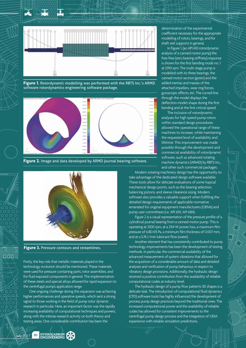
July 2017 HYDROCARBONENGINEERING
80
Firstly, the key role that metallic materials played in the technology evolution should be mentioned. These materials were used for pressure containing parts, rotor assemblies, and for fl uid exposed components in general. The implementation of these steels and special alloys allowed for rapid expansion to the centrifugal pump’s application range.
One ongoing challenge during this expansion was achieving higher performances and operative speeds, which sent a strong signal to those working in the fi eld of pump rotor dynamic research in particular. Here, an important factor was the rapidly increasing availability of computational techniques and powers, along with the intense research activity on both theory and testing areas. One considerable contribution has been the
determination of the experimental coeffi cient necessary for the appropriate modelling of rotors, bearings, and for shaft wet supports in general.
In Figure 1, (an API 610 rotordynamic analysis of a canned motor pump) the free-free (zero bearing stiffness) response is shown for the fi rst bending mode no. 1 at 1290 rpm. The multi-stage pump is modelled with its three bearings, the canned motor section (green) and the added inertias and masses of the attached impellers, wear ring forces, gyroscopic effects, etc. The curved line through the model displays the defl ection mode’s shape during the fi rst bending and at the fi rst critical speed.
The inclusion of rotordynamic analyses for high speed pump rotors within standard design procedures allowed the operational range of these machines to increase, while maintaining the requested level of availability and lifetime. This improvement was made possible through the development and commercial availability of rotordynamic software, such as advanced rotating machine dynamics (ARMD) by RBTS Inc., and other such commercial packages.
Modern rotating machinery design has the opportunity to take advantage of the dedicated design software available. These tools allow for delicate evaluations of some topical mechanical design points, such as the bearing selection, balancing pistons, and sleeve clearance sizing. Modern software also provides a valuable support when fulfi lling the detailed design requirements of applicable normative emanated for original equipment manufacturers (OEMs) and pump user committees (i.e. API 610, API 684).
Figure 2 is a visual representation of the pressure profi le of a cylindrical journal bearing from a canned-motor pump. This is operating at 3300 rpm, at a 29.4 W power loss, a maximum fi lm pressure of 6.8E+05 Pa, a minimum fi lm thickness of 0.007 mm, and at a 5.76 l/min lubricant fl ow (water).
Another element that has consistently contributed to pump technology improvements has been the development of testing methods. In particular, the commercial availability of the advanced measurement of system vibrations that allowed for the acquisition of a considerable amount of data and detailed analyses and verifi cation of pump behaviour, in respect to vibratory design provisions. Additionally, the hydraulic design received a positive contribution from the availability of reliable computational codes at industry level.
The hydraulic design of a pump fl ow pattern’s 3D shapes is a delicate task. The introduction of computational fl uid dynamics (CFD) software tools has highly infl uenced the development of process pump design practices beyond the traditional ones. The increased computational power and the availability of reliable codes has allowed for consistent improvements to the centrifugal pump design process and the integration of OEM experience with reliable simulation predictions.
Figure 1. Rotordynamic modelling was performed with the RBTS Inc.'s ARMD software rotordynamics engineering software package.
Figure 2. Image and data developed by ARMD journal bearing software.
Figure 3. Pressure contours and streamlines.
Finding the right caustic treating solution to remove impurities from hydrocarbon streams is a challenging task for any operator. Thanks to Merichem Company’s extensive experience and commitment to innovation, treating gaseous and liquid hydrocarbons can be efficient, economical and clean. Merichem Company brings 70 years of experience in the treatment and handling of spent caustic streams to the petroleum refining and petrochemical industries. Technical expertise allows us to recommend the right caustic treating process for your specific needs and handle most resulting caustic solutions in a non-waste, environmentally friendly manner utilizing a portfolio of caustic treating technologies as well as beneficial reuse channels.
The MERICON™ family of technologies processes spent caustics to control odor, reduce BOD (biological oxygen demand) and COD (chemical oxygen demand), adjust pH, and destroy phenolics and other hydrocarbons with an on-site solution.
MERICON II is a proprietary Wet Air Oxidation (WAO) technology that produces a neutral brine effluent stream for routing to waste-water treating facilities, evaporation ponds, or waterways.
Merichem’s MERICON II process enhances oxygen availability and thus performance at lower operating temperatures and pressures. This reduces capital and operating costs significantly compared to other systems. So while the MERICON II typical operating conditions range between 200C - 260C and 35 - 85kg/cm2 (low-medium severity), its performance can match that of units running at higher severity.
WHAT IS UNIQUE ABOUT THE MERICON II PROCESS?
WHAT FEEDSTOCK CAN BE TREATED WITH WAO?• Spent sulfidic, phenolic, naphthenic and ethylene caustics• Aqueous streams containing hazardous organic material• High BOD and COD wastewater• Organic sludges requiring detoxification and/or pathogen kill • Industrial liquor to economically recover metals
LPG / JET FUEL TREATING
CAUSTIC TREATING
SPENTCAUSTIC
BENEFICIALREUSE
+1 713-428-5000
WANT MORE INFO ABOUT MERICON II?
Scan the QR code or visit www.merichem.com/MERICON-II
Download a free brochure by scanning the QR code or contact a Merichem Company representative at

July 2017 HYDROCARBONENGINEERING
82
Figure 4. Velocity vectors in an impeller.
NATIONAL INSTITUTE FOR STORAGE TANK MANAGEMENTNISTM
10th ANNUALN A T I O N A L A B O V E G R O U N D S T O R A G E T A N K
C O N F E R E N C E & T R A D E S H O W
Moody Gardens | Galveston, TexasSeptember 13-14, 2017
• Conference Sessions• Free Trade Show• Free Aviation Conference• Co-Located Events• Welcome Reception• Cocktail Mixer on the Trade Show Floor• Golf Tournament
FREE TRA DE SHOW
www.NISTM.org | 800.827.3515International 011.813.600.4024
NATIONAL INSTITUTE FOR STORAGE TANK MANAGEMENTNISTM
Another discipline contributing to the increased availability of centrifugal pumps is the control system area. Today, control systems are based on physical models of machinery that may accurately predict the pump performance in every operating condition. This capability is useful for several purposes, though mainly targeted towards diagnostics. The ability to determine the performance parameters as expected and according to design, allows for the early detection of possible deviations, providing enough time to formulate a solution to the incoming upsets. A signifi cant example is the effi ciency. From fi eld reading
it is possible, in fact, to calculate the operative (actual) effi ciency. In order to evaluate if this value is acceptable or not, it is necessary to compare it to the value that the machine would have when running as if it had just left the shop (i.e. in optimal working conditions). This comparative value may be obtained by adjusting design performance to actual conditions. For the centrifugal pumps, this comparison is quite easy since the effi ciency does not have a great variation under different operating conditions.
Being able to trend deviations among measured and expected values over time, gives an up-to-date account of a machine’s health status and how it is changing. These types of features, coupled with the implementation of variable frequency drive (VFD) techniques, also contribute towards achieving effi cient machine management from an energy viewpoint, as well as reducing and containing its environmental impact.
ConclusionSumming up all the effects of these features, these systems provide a substantial contribution to machine lifetime extension, availability increases, maintenance cost reductions, and adsorbed energy reductions, all allowing for better return on investment (ROI). As a result, many other areas of pump technology improvement are currently being pursued, from hydraulics to mechanical design and auxiliary technology. The authors of this article expect that the synthesis of these capabilities will lead the industry to market the next generation of machines, fully optimised – from a global energetic and environmental standpoint – with higher performances and better ROI.
July 2017HYDROCARBONENGINEERING
83
PUMPS, VALVES
AND SEALS
REVIEWHydrocarbon Engineering presents an
overview of some of the recent developments and technologies in pumps, valves and seals
for the downstream oil and gas industry.
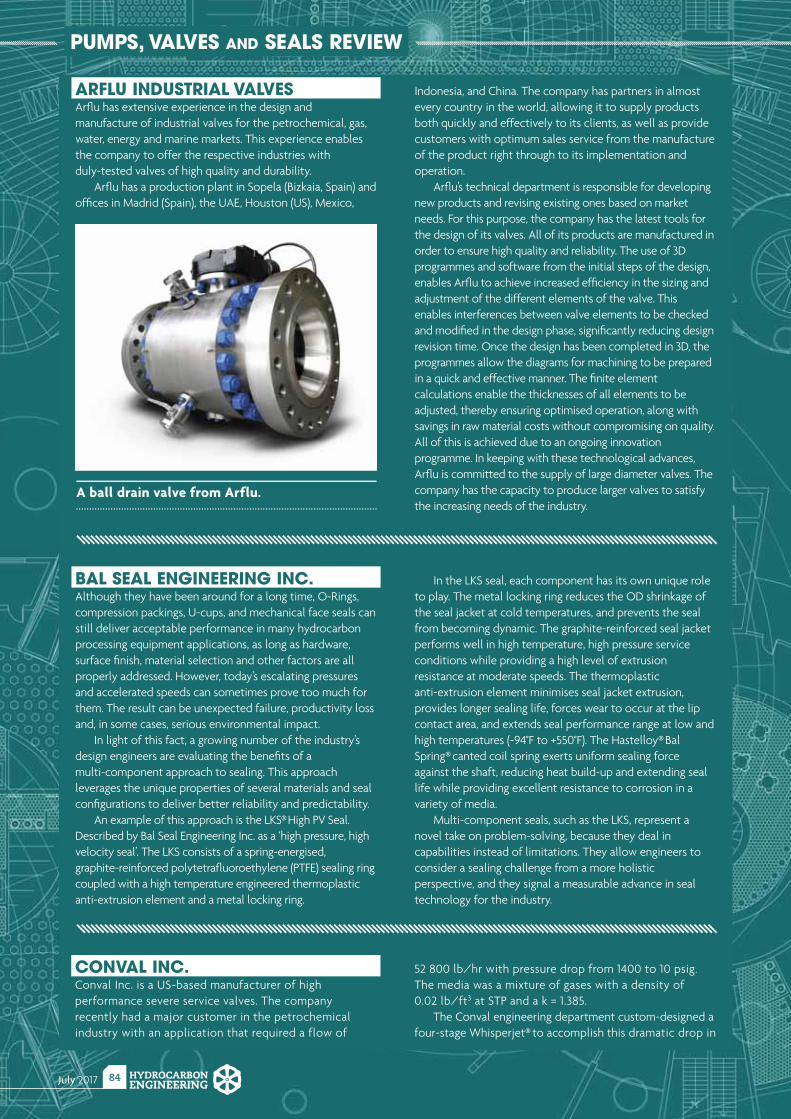
July 2017 HYDROCARBONENGINEERING
84
PUMPS, VALVES AND SEALS REVIEW
ARFLU INDUSTRIAL VALVESArfl u has extensive experience in the design and manufacture of industrial valves for the petrochemical, gas, water, energy and marine markets. This experience enables the company to offer the respective industries with duly-tested valves of high quality and durability.
Arfl u has a production plant in Sopela (Bizkaia, Spain) and offi ces in Madrid (Spain), the UAE, Houston (US), Mexico,
Indonesia, and China. The company has partners in almost every country in the world, allowing it to supply products both quickly and effectively to its clients, as well as provide customers with optimum sales service from the manufacture of the product right through to its implementation and operation.
Arfl u’s technical department is responsible for developing new products and revising existing ones based on market needs. For this purpose, the company has the latest tools for the design of its valves. All of its products are manufactured in order to ensure high quality and reliability. The use of 3D programmes and software from the initial steps of the design, enables Arfl u to achieve increased effi ciency in the sizing and adjustment of the different elements of the valve. This enables interferences between valve elements to be checked and modifi ed in the design phase, signifi cantly reducing design revision time. Once the design has been completed in 3D, the programmes allow the diagrams for machining to be prepared in a quick and effective manner. The fi nite element calculations enable the thicknesses of all elements to be adjusted, thereby ensuring optimised operation, along with savings in raw material costs without compromising on quality. All of this is achieved due to an ongoing innovation programme. In keeping with these technological advances, Arfl u is committed to the supply of large diameter valves. The company has the capacity to produce larger valves to satisfy the increasing needs of the industry.
A ball drain valve from Arflu.
BAL SEAL ENGINEERING INC.Although they have been around for a long time, O-Rings, compression packings, U-cups, and mechanical face seals can still deliver acceptable performance in many hydrocarbon processing equipment applications, as long as hardware, surface fi nish, material selection and other factors are all properly addressed. However, today’s escalating pressures and accelerated speeds can sometimes prove too much for them. The result can be unexpected failure, productivity loss and, in some cases, serious environmental impact.
In light of this fact, a growing number of the industry’s design engineers are evaluating the benefi ts of a multi-component approach to sealing. This approach leverages the unique properties of several materials and seal confi gurations to deliver better reliability and predictability.
An example of this approach is the LKS® High PV Seal. Described by Bal Seal Engineering Inc. as a ‘high pressure, high velocity seal’. The LKS consists of a spring-energised, graphite-reinforced polytetrafl uoroethylene (PTFE) sealing ring coupled with a high temperature engineered thermoplastic anti-extrusion element and a metal locking ring.
In the LKS seal, each component has its own unique role to play. The metal locking ring reduces the OD shrinkage of the seal jacket at cold temperatures, and prevents the seal from becoming dynamic. The graphite-reinforced seal jacket performs well in high temperature, high pressure service conditions while providing a high level of extrusion resistance at moderate speeds. The thermoplastic anti-extrusion element minimises seal jacket extrusion, provides longer sealing life, forces wear to occur at the lip contact area, and extends seal performance range at low and high temperatures (-94°F to +550°F). The Hastelloy® Bal Spring® canted coil spring exerts uniform sealing force against the shaft, reducing heat build-up and extending seal life while providing excellent resistance to corrosion in a variety of media.
Multi-component seals, such as the LKS, represent a novel take on problem-solving, because they deal in capabilities instead of limitations. They allow engineers to consider a sealing challenge from a more holistic perspective, and they signal a measurable advance in seal technology for the industry.
CONVAL INC.Conval Inc. is a US-based manufacturer of high performance severe service valves. The company recently had a major customer in the petrochemical industry with an application that required a flow of
52 800 lb/hr with pressure drop from 1400 to 10 psig. The media was a mixture of gases with a density of 0.02 lb/ft3 at STP and a k = 1.385.
The Conval engineering department custom-designed a four-stage Whisperjet® to accomplish this dramatic drop in
July 2017HYDROCARBONENGINEERING
85
pressure. The design was then tested using advanced engineering simulation software, custom-manufactured to exacting specifications, and subjected to rigorous quality control. Upon delivery and installation, the Whisperjets performed flawlessly.
Whisperjets are deliberately designed to reduce pressure through a combination of impingement, tortuous path and multi-stage pressure letdown. Each stage inside the Whisperjet has 4 – 6 orifices around its perimeter. The orifices discharge inwardly, which reduces the pressure without causing component wear. Pressure is reduced in stages, which prevents a critical pressure
drop. Each stage is progressively larger, allowing for expansion. The orifices are carefully sized to keep the flow below critical velocity. This gives the advantage of reduced noise.
When used in conjunction with a valve or other system components, the seat life of the valve is substantially increased and damage to piping is minimised. When used before a condenser or flash tank, baffle and tank wear are also greatly reduced.
Due to their simple, practical design and operation, Whisperjets are economical solutions to pressure drop problems.
CRANE CHEMPHARMA & ENERGYWith a vast portfolio of highly engineered valves, pipes and fi ttings, Crane ChemPharma & Energy, a business of Crane Co., has become a leading supplier of products designed for the most demanding, corrosive, erosive and high purity applications in the world. Since 1855, Crane has been an innovator and pioneer of practical fl ow control solutions, presenting the industry with new technologies and resources, including its latest offering, the Krombach® KFO 9136 Metal Seated Ball Valve (MSBV). This extreme temperature and wear-resistant MSBV features a
uni-directional single seat that permits a tight shut-off, ensuring cavity-free performance. Its optimised energising seat with low friction bearing design enables a permanent seat/ball contact under recurrent thermal cycling and offers low cost of ownership through the reduction in operating torque by over 20%. With a temperature range of -29°F to 500°F (and special temperature ranges up to 700°F and 1300°F upon request), the MSBV also features excellent fugitive emissions controls, as a result of its robust stem seal design.
The MSBV is appropriate for both upstream and downstream applications, but one process in particular
Our Bal Seal® spring-energized seals outperform similar seals
by 150% or more in the hottest, fastest, most aggressive
processing applications. Their ability to deliver reliable sealing
at longer, more predictable intervals means you’ll enjoy more
uptime and reduced environmental risk.
Call or click today and start designing for tomorrow.
We’re SO predictable.
+31 20 638 6523 www.balseal .com
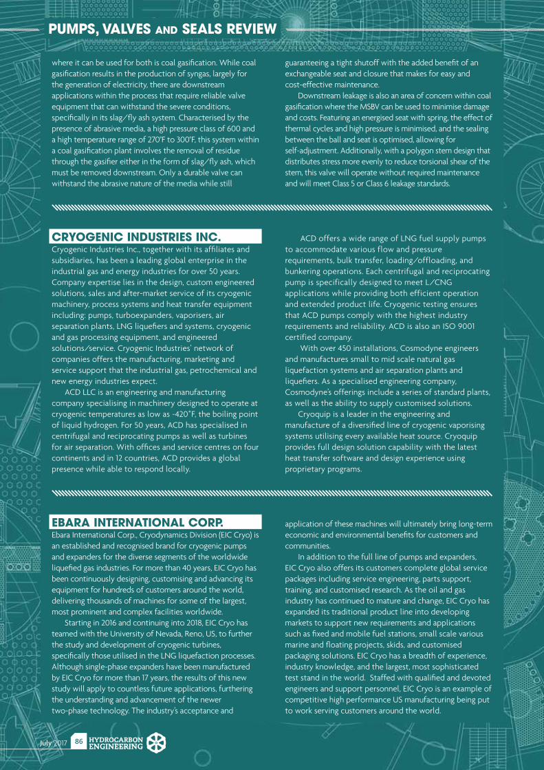
July 2017 HYDROCARBONENGINEERING
86
PUMPS, VALVES AND SEALS REVIEW
EBARA INTERNATIONAL CORP.Ebara International Corp., Cryodynamics Division (EIC Cryo) is an established and recognised brand for cryogenic pumps and expanders for the diverse segments of the worldwide liquefi ed gas industries. For more than 40 years, EIC Cryo has been continuously designing, customising and advancing its equipment for hundreds of customers around the world, delivering thousands of machines for some of the largest, most prominent and complex facilities worldwide.
Starting in 2016 and continuing into 2018, EIC Cryo has teamed with the University of Nevada, Reno, US, to further the study and development of cryogenic turbines, specifi cally those utilised in the LNG liquefaction processes. Although single-phase expanders have been manufactured by EIC Cryo for more than 17 years, the results of this new study will apply to countless future applications, furthering the understanding and advancement of the newer two-phase technology. The industry’s acceptance and
application of these machines will ultimately bring long-term economic and environmental benefi ts for customers and communities.
In addition to the full line of pumps and expanders, EIC Cryo also offers its customers complete global service packages including service engineering, parts support, training, and customised research. As the oil and gas industry has continued to mature and change, EIC Cryo has expanded its traditional product line into developing markets to support new requirements and applications such as fi xed and mobile fuel stations, small scale various marine and fl oating projects, skids, and customised packaging solutions. EIC Cryo has a breadth of experience, industry knowledge, and the largest, most sophisticated test stand in the world. Staffed with qualifi ed and devoted engineers and support personnel, EIC Cryo is an example of competitive high performance US manufacturing being put to work serving customers around the world.
CRYOGENIC INDUSTRIES INC.Cryogenic Industries Inc., together with its affi liates and subsidiaries, has been a leading global enterprise in the industrial gas and energy industries for over 50 years. Company expertise lies in the design, custom engineered solutions, sales and after-market service of its cryogenic machinery, process systems and heat transfer equipment including: pumps, turboexpanders, vaporisers, air separation plants, LNG liquefi ers and systems, cryogenic and gas processing equipment, and engineered solutions/service. Cryogenic Industries’ network of companies offers the manufacturing, marketing and service support that the industrial gas, petrochemical and new energy industries expect.
ACD LLC is an engineering and manufacturing company specialising in machinery designed to operate at cryogenic temperatures as low as -420˚F, the boiling point of liquid hydrogen. For 50 years, ACD has specialised in centrifugal and reciprocating pumps as well as turbines for air separation. With offi ces and service centres on four continents and in 12 countries, ACD provides a global presence while able to respond locally.
ACD offers a wide range of LNG fuel supply pumps to accommodate various flow and pressure requirements, bulk transfer, loading/offloading, and bunkering operations. Each centrifugal and reciprocating pump is specifically designed to meet L/CNG applications while providing both efficient operation and extended product life. Cryogenic testing ensures that ACD pumps comply with the highest industry requirements and reliability. ACD is also an ISO 9001 certified company.
With over 450 installations, Cosmodyne engineers and manufactures small to mid scale natural gas liquefaction systems and air separation plants and liquefi ers. As a specialised engineering company, Cosmodyne’s offerings include a series of standard plants, as well as the ability to supply customised solutions.
Cryoquip is a leader in the engineering and manufacture of a diversifi ed line of cryogenic vaporising systems utilising every available heat source. Cryoquip provides full design solution capability with the latest heat transfer software and design experience using proprietary programs.
where it can be used for both is coal gasifi cation. While coal gasifi cation results in the production of syngas, largely for the generation of electricity, there are downstream applications within the process that require reliable valve equipment that can withstand the severe conditions, specifi cally in its slag/fl y ash system. Characterised by the presence of abrasive media, a high pressure class of 600 and a high temperature range of 270°F to 300°F, this system within a coal gasifi cation plant involves the removal of residue through the gasifi er either in the form of slag/fl y ash, which must be removed downstream. Only a durable valve can withstand the abrasive nature of the media while still
guaranteeing a tight shutoff with the added benefi t of an exchangeable seat and closure that makes for easy and cost-effective maintenance.
Downstream leakage is also an area of concern within coal gasifi cation where the MSBV can be used to minimise damage and costs. Featuring an energised seat with spring, the effect of thermal cycles and high pressure is minimised, and the sealing between the ball and seat is optimised, allowing for self-adjustment. Additionally, with a polygon stem design that distributes stress more evenly to reduce torsional shear of the stem, this valve will operate without required maintenance and will meet Class 5 or Class 6 leakage standards.
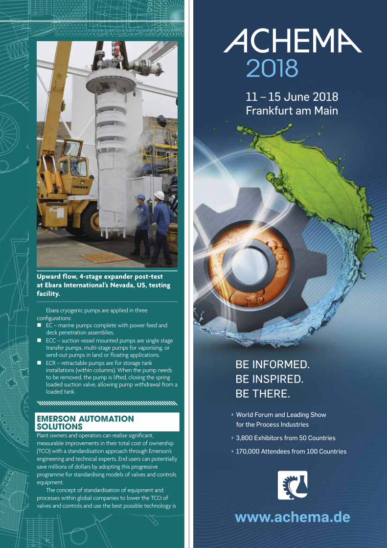
July 2017HYDROCARBONENGINEERING
87
Upward flow, 4-stage expander post-test at Ebara International’s Nevada, US, testing facility.
EMERSON AUTOMATION SOLUTIONS Plant owners and operators can realise signifi cant, measurable improvements in their total cost of ownership (TCO) with a standardisation approach through Emerson’s engineering and technical experts. End users can potentially save millions of dollars by adopting this progressive programme for standardising models of valves and controls equipment.
The concept of standardisation of equipment and processes within global companies to lower the TCO of valves and controls and use the best possible technology is
Ebara cryogenic pumps are applied in three confi gurations:
EC – marine pumps complete with power feed and deck penetration assemblies.
ECC – suction vessel mounted pumps are single stage transfer pumps, multi-stage pumps for vaporising, or send-out pumps in land or floating applications.
ECR – retractable pumps are for storage tank installations (within columns). When the pump needs to be removed, the pump is lifted, closing the spring loaded suction valve, allowing pump withdrawal from a loaded tank.
› World Forum and Leading Show for the Process Industries
› 3,800 Exhibitors from 50 Countries
› 170,000 Attendees from 100 Countries
BE INFORMED. BE INSPIRED. BE THERE.
www.achema.de
11 – 15 June 2018 Frankfurt am Main
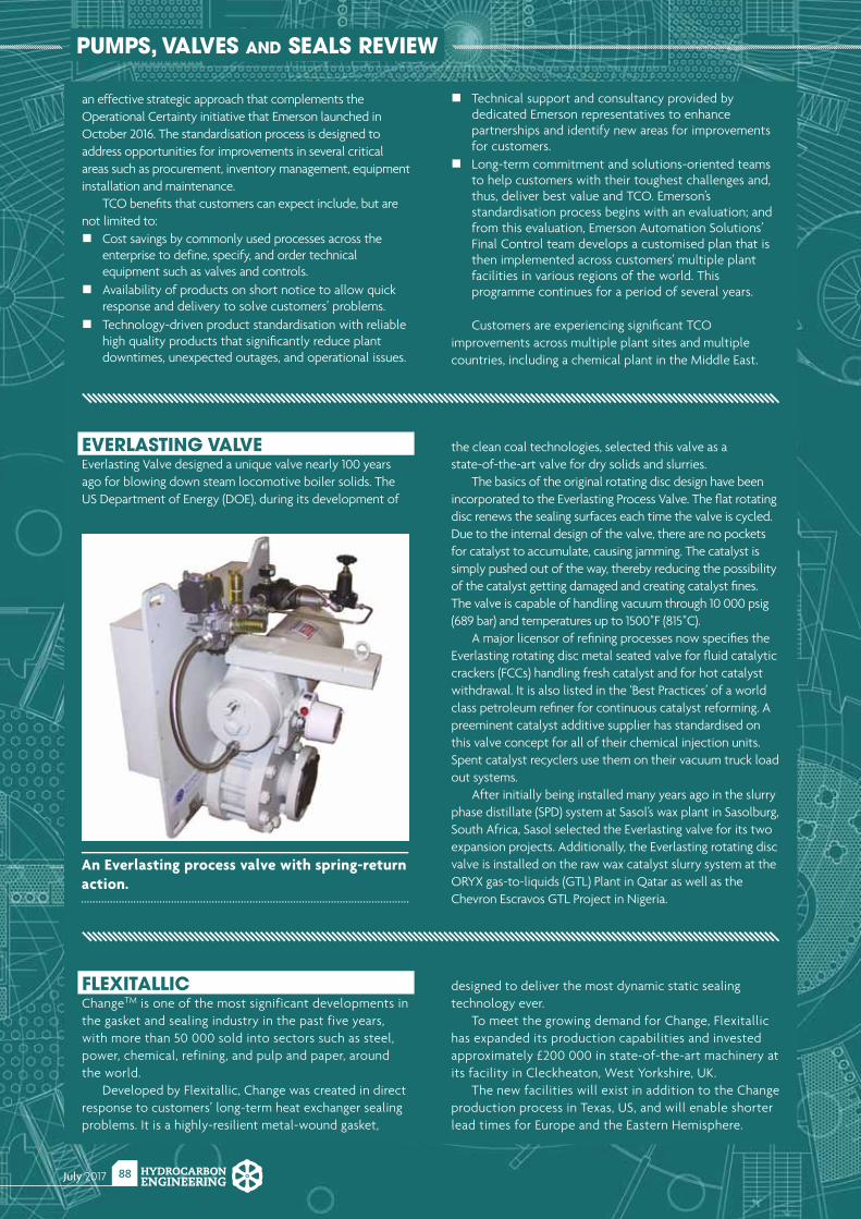
July 2017 HYDROCARBONENGINEERING
88
PUMPS, VALVES AND SEALS REVIEW
FLEXITALLICChangeTM is one of the most significant developments in the gasket and sealing industry in the past five years, with more than 50 000 sold into sectors such as steel, power, chemical, refining, and pulp and paper, around the world.
Developed by Flexitallic, Change was created in direct response to customers’ long-term heat exchanger sealing problems. It is a highly-resilient metal-wound gasket,
designed to deliver the most dynamic static sealing technology ever.
To meet the growing demand for Change, Flexitallic has expanded its production capabilities and invested approximately £200 000 in state-of-the-art machinery at its facility in Cleckheaton, West Yorkshire, UK.
The new facilities will exist in addition to the Change production process in Texas, US, and will enable shorter lead times for Europe and the Eastern Hemisphere.
EVERLASTING VALVEEverlasting Valve designed a unique valve nearly 100 years ago for blowing down steam locomotive boiler solids. The US Department of Energy (DOE), during its development of
the clean coal technologies, selected this valve as a state-of-the-art valve for dry solids and slurries.
The basics of the original rotating disc design have been incorporated to the Everlasting Process Valve. The fl at rotating disc renews the sealing surfaces each time the valve is cycled. Due to the internal design of the valve, there are no pockets for catalyst to accumulate, causing jamming. The catalyst is simply pushed out of the way, thereby reducing the possibility of the catalyst getting damaged and creating catalyst fi nes. The valve is capable of handling vacuum through 10 000 psig (689 bar) and temperatures up to 1500˚F (815˚C).
A major licensor of refi ning processes now specifi es the Everlasting rotating disc metal seated valve for fl uid catalytic crackers (FCCs) handling fresh catalyst and for hot catalyst withdrawal. It is also listed in the ‘Best Practices’ of a world class petroleum refi ner for continuous catalyst reforming. A preeminent catalyst additive supplier has standardised on this valve concept for all of their chemical injection units. Spent catalyst recyclers use them on their vacuum truck load out systems.
After initially being installed many years ago in the slurry phase distillate (SPD) system at Sasol’s wax plant in Sasolburg, South Africa, Sasol selected the Everlasting valve for its two expansion projects. Additionally, the Everlasting rotating disc valve is installed on the raw wax catalyst slurry system at the ORYX gas-to-liquids (GTL) Plant in Qatar as well as the Chevron Escravos GTL Project in Nigeria.
An Everlasting process valve with spring-return action.
an effective strategic approach that complements the Operational Certainty initiative that Emerson launched in October 2016. The standardisation process is designed to address opportunities for improvements in several critical areas such as procurement, inventory management, equipment installation and maintenance.
TCO benefi ts that customers can expect include, but are not limited to:
Cost savings by commonly used processes across the enterprise to define, specify, and order technical equipment such as valves and controls.
Availability of products on short notice to allow quick response and delivery to solve customers’ problems.
Technology-driven product standardisation with reliable high quality products that signifi cantly reduce plant downtimes, unexpected outages, and operational issues.
Technical support and consultancy provided by dedicated Emerson representatives to enhance partnerships and identify new areas for improvements for customers.
Long-term commitment and solutions-oriented teams to help customers with their toughest challenges and, thus, deliver best value and TCO. Emerson’s standardisation process begins with an evaluation; and from this evaluation, Emerson Automation Solutions’ Final Control team develops a customised plan that is then implemented across customers' multiple plant facilities in various regions of the world. This programme continues for a period of several years.
Customers are experiencing signifi cant TCO improvements across multiple plant sites and multiple countries, including a chemical plant in the Middle East.
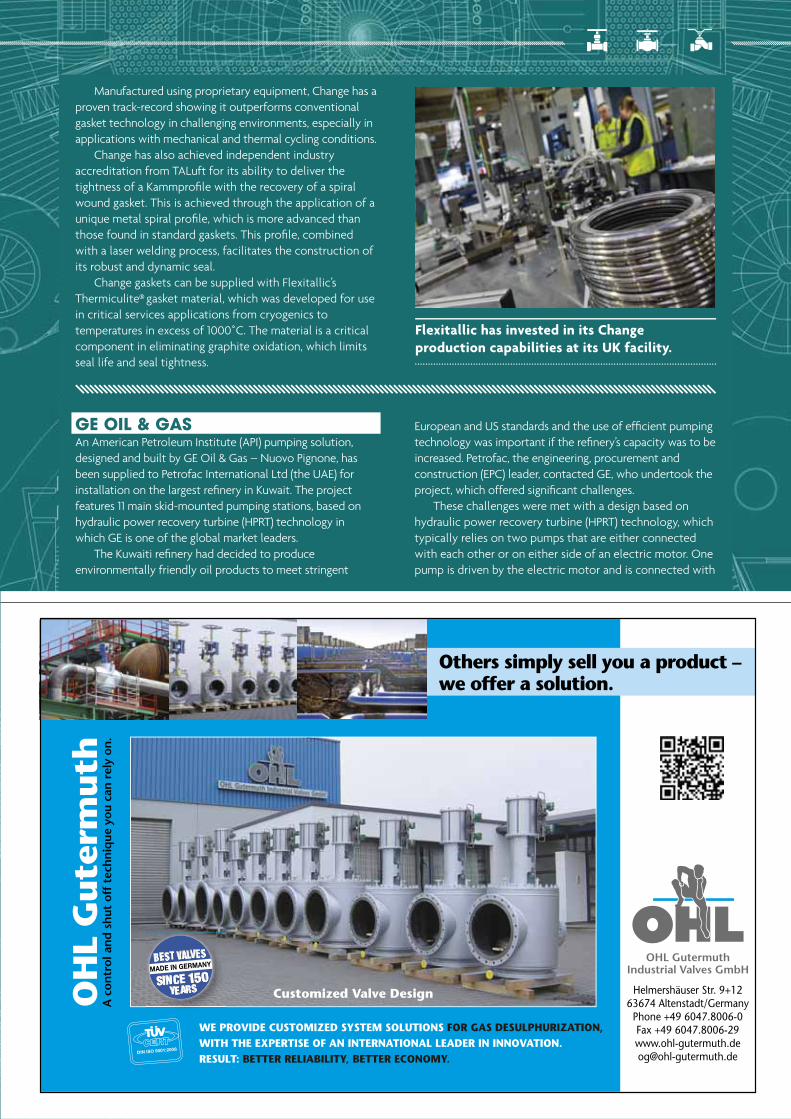
July 2017HYDROCARBONENGINEERING
89
Manufactured using proprietary equipment, Change has a proven track-record showing it outperforms conventional gasket technology in challenging environments, especially in applications with mechanical and thermal cycling conditions.
Change has also achieved independent industry accreditation from TALuft for its ability to deliver the tightness of a Kammprofi le with the recovery of a spiral wound gasket. This is achieved through the application of a unique metal spiral profi le, which is more advanced than those found in standard gaskets. This profi le, combined with a laser welding process, facilitates the construction of its robust and dynamic seal.
Change gaskets can be supplied with Flexitallic’s Thermiculite® gasket material, which was developed for use in critical services applications from cryogenics to temperatures in excess of 1000˚C. The material is a critical component in eliminating graphite oxidation, which limits seal life and seal tightness.
Flexitallic has invested in its Change production capabilities at its UK facility.
OH
L G
ute
rmuth
A c
ontr
ol a
nd
sh
ut o
ff t
ech
niq
ue y
ou c
an r
ely
on.
Customized Valve Design
Others simply sell you a product –we offer a solution.
OHL Gutermuth Industrial Valves GmbH
Helmershäuser Str. 9+1263674 Altenstadt/Germany
Phone +49 6047.8006-0Fax +49 [email protected]
WE PROVIDE CUSTOMIZED SYSTEM SOLUTIONS FOR GAS DESULPHURIZATION, WITH THE EXPERTISE OF AN INTERNATIONAL LEADER IN INNOVATION. RESULT: BETTER RELIABILITY, BETTER ECONOMY.
GE OIL & GASAn American Petroleum Institute (API) pumping solution, designed and built by GE Oil & Gas – Nuovo Pignone, has been supplied to Petrofac International Ltd (the UAE) for installation on the largest refi nery in Kuwait. The project features 11 main skid-mounted pumping stations, based on hydraulic power recovery turbine (HPRT) technology in which GE is one of the global market leaders.
The Kuwaiti refi nery had decided to produce environmentally friendly oil products to meet stringent
European and US standards and the use of effi cient pumping technology was important if the refi nery’s capacity was to be increased. Petrofac, the engineering, procurement and construction (EPC) leader, contacted GE, who undertook the project, which offered signifi cant challenges.
These challenges were met with a design based on hydraulic power recovery turbine (HPRT) technology, which typically relies on two pumps that are either connected with each other or on either side of an electric motor. One pump is driven by the electric motor and is connected with
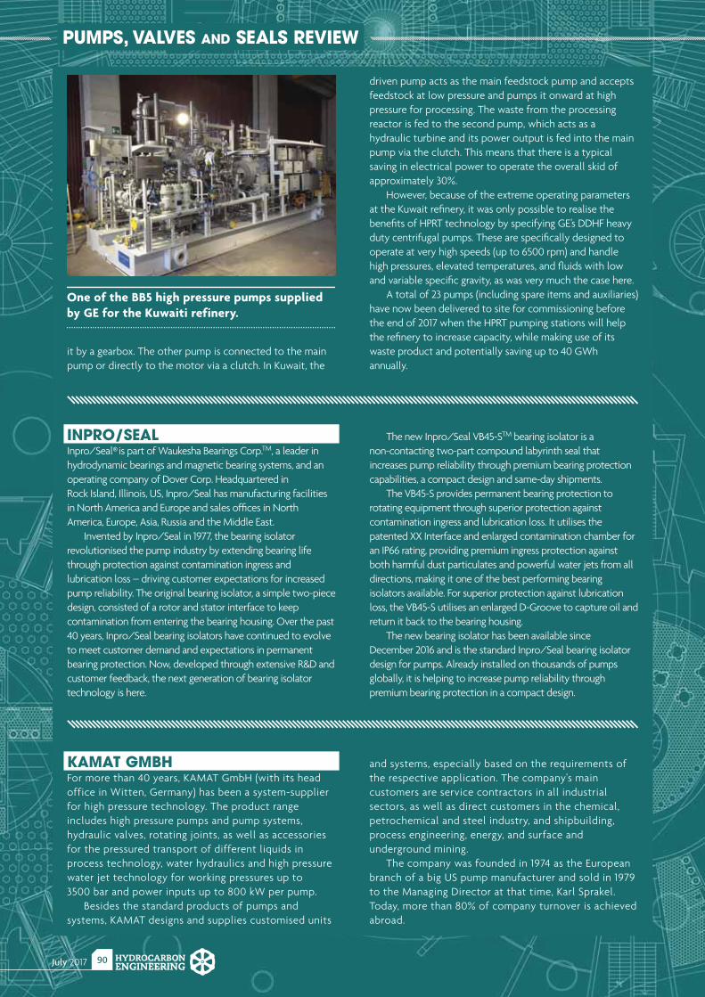
July 2017 HYDROCARBONENGINEERING
90
PUMPS, VALVES AND SEALS REVIEW
KAMAT GMBHFor more than 40 years, KAMAT GmbH (with its head office in Witten, Germany) has been a system-supplier for high pressure technology. The product range includes high pressure pumps and pump systems, hydraulic valves, rotating joints, as well as accessories for the pressured transport of different liquids in process technology, water hydraulics and high pressure water jet technology for working pressures up to 3500 bar and power inputs up to 800 kW per pump.
Besides the standard products of pumps and systems, KAMAT designs and supplies customised units
and systems, especially based on the requirements of the respective application. The company's main customers are service contractors in all industrial sectors, as well as direct customers in the chemical, petrochemical and steel industry, and shipbuilding, process engineering, energy, and surface and underground mining.
The company was founded in 1974 as the European branch of a big US pump manufacturer and sold in 1979 to the Managing Director at that time, Karl Sprakel. Today, more than 80% of company turnover is achieved abroad.
INPRO/SEALInpro/Seal® is part of Waukesha Bearings Corp.TM, a leader in hydrodynamic bearings and magnetic bearing systems, and an operating company of Dover Corp. Headquartered in Rock Island, Illinois, US, Inpro/Seal has manufacturing facilities in North America and Europe and sales offi ces in North America, Europe, Asia, Russia and the Middle East.
Invented by Inpro/Seal in 1977, the bearing isolator revolutionised the pump industry by extending bearing life through protection against contamination ingress and lubrication loss – driving customer expectations for increased pump reliability. The original bearing isolator, a simple two-piece design, consisted of a rotor and stator interface to keep contamination from entering the bearing housing. Over the past 40 years, Inpro/Seal bearing isolators have continued to evolve to meet customer demand and expectations in permanent bearing protection. Now, developed through extensive R&D and customer feedback, the next generation of bearing isolator technology is here.
The new Inpro/Seal VB45-STM bearing isolator is a non-contacting two-part compound labyrinth seal that increases pump reliability through premium bearing protection capabilities, a compact design and same-day shipments.
The VB45-S provides permanent bearing protection to rotating equipment through superior protection against contamination ingress and lubrication loss. It utilises the patented XX Interface and enlarged contamination chamber for an IP66 rating, providing premium ingress protection against both harmful dust particulates and powerful water jets from all directions, making it one of the best performing bearing isolators available. For superior protection against lubrication loss, the VB45-S utilises an enlarged D-Groove to capture oil and return it back to the bearing housing.
The new bearing isolator has been available since December 2016 and is the standard Inpro/Seal bearing isolator design for pumps. Already installed on thousands of pumps globally, it is helping to increase pump reliability through premium bearing protection in a compact design.
it by a gearbox. The other pump is connected to the main pump or directly to the motor via a clutch. In Kuwait, the
driven pump acts as the main feedstock pump and accepts feedstock at low pressure and pumps it onward at high pressure for processing. The waste from the processing reactor is fed to the second pump, which acts as a hydraulic turbine and its power output is fed into the main pump via the clutch. This means that there is a typical saving in electrical power to operate the overall skid of approximately 30%.
However, because of the extreme operating parameters at the Kuwait refi nery, it was only possible to realise the benefi ts of HPRT technology by specifying GE’s DDHF heavy duty centrifugal pumps. These are specifi cally designed to operate at very high speeds (up to 6500 rpm) and handle high pressures, elevated temperatures, and fl uids with low and variable specifi c gravity, as was very much the case here.
A total of 23 pumps (including spare items and auxiliaries) have now been delivered to site for commissioning before the end of 2017 when the HPRT pumping stations will help the refi nery to increase capacity, while making use of its waste product and potentially saving up to 40 GWh annually.
One of the BB5 high pressure pumps supplied by GE for the Kuwaiti refinery.
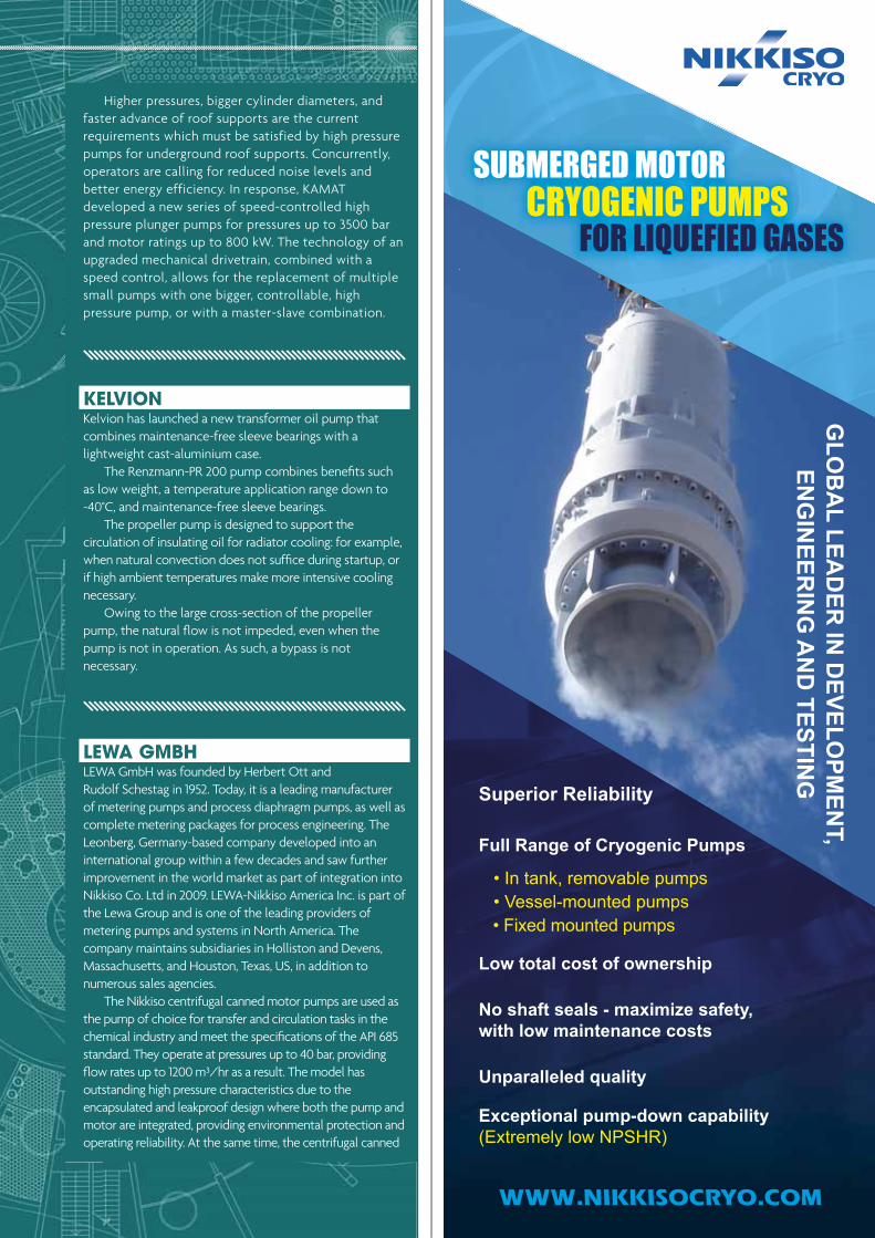
July 2017HYDROCARBONENGINEERING
91
GLO
BA
L LEAD
ER IN
DEVELO
PMEN
T, EN
GIN
EERIN
G A
ND
TESTING
Superior Reliability
Full Range of Cryogenic Pumps
Low total cost of ownership
No shaft seals - maximize safety, with low maintenance costs
Unparalleled quality
Exceptional pump-down capability
SUBMERGED MOTOR CRYOGENIC PUMPS FOR LIQUEFIED GASES
WWW.NIKKISOCRYO.COM
LEWA GMBHLEWA GmbH was founded by Herbert Ott and Rudolf Schestag in 1952. Today, it is a leading manufacturer of metering pumps and process diaphragm pumps, as well as complete metering packages for process engineering. The Leonberg, Germany-based company developed into an international group within a few decades and saw further improvement in the world market as part of integration into Nikkiso Co. Ltd in 2009. LEWA-Nikkiso America Inc. is part of the Lewa Group and is one of the leading providers of metering pumps and systems in North America. The company maintains subsidiaries in Holliston and Devens, Massachusetts, and Houston, Texas, US, in addition to numerous sales agencies.
The Nikkiso centrifugal canned motor pumps are used as the pump of choice for transfer and circulation tasks in the chemical industry and meet the specifi cations of the API 685 standard. They operate at pressures up to 40 bar, providing fl ow rates up to 1200 m³/hr as a result. The model has outstanding high pressure characteristics due to the encapsulated and leakproof design where both the pump and motor are integrated, providing environmental protection and operating reliability. At the same time, the centrifugal canned
KELVIONKelvion has launched a new transformer oil pump that combines maintenance-free sleeve bearings with a lightweight cast-aluminium case.
The Renzmann-PR 200 pump combines benefi ts such as low weight, a temperature application range down to -40°C, and maintenance-free sleeve bearings.
The propeller pump is designed to support the circulation of insulating oil for radiator cooling: for example, when natural convection does not suffi ce during startup, or if high ambient temperatures make more intensive cooling necessary.
Owing to the large cross-section of the propeller pump, the natural fl ow is not impeded, even when the pump is not in operation. As such, a bypass is not necessary.
Higher pressures, bigger cylinder diameters, and faster advance of roof supports are the current requirements which must be satisfied by high pressure pumps for underground roof supports. Concurrently, operators are calling for reduced noise levels and better energy efficiency. In response, KAMAT developed a new series of speed-controlled high pressure plunger pumps for pressures up to 3500 bar and motor ratings up to 800 kW. The technology of an upgraded mechanical drivetrain, combined with a speed control, allows for the replacement of multiple small pumps with one bigger, controllable, high pressure pump, or with a master-slave combination.
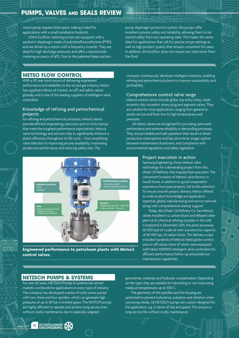
July 2017 HYDROCARBONENGINEERING
92
PUMPS, VALVES AND SEALS REVIEW
METSO FLOW CONTROLWith a 90 year track record of delivering engineered performance and reliability to the oil and gas industry, Metso has supplied millions of control, on-off, and safety valves globally, and is one of the leading suppliers of intelligent valve controllers.
Knowledge of refining and petrochemical projectsFor refi ning and petrochemical processes, Metso’s teams provide effi cient engineering, execution and on-time startup that meet the toughest performance expectations. Metso’s valve technology and services help to signifi cantly enhance a plant’s effi ciency throughout its life cycle – from simplifying valve selection to improving process availability, maximising production performance and reducing safety risks. The
company continuously develops intelligent solutions, enabling refi ning and petrochemical plants to improve sustainability and profi tability.
Comprehensive control valve rangeMetso’s control valves include globe, top entry rotary, triple eccentric disc, eccentric rotary plug and segment valves. They are suitable for most applications, ranging from general to severe service and from low to high temperatures and pressures.
All Metso valves are recognised for providing optimised performance and extreme reliability in demanding processes. They ensure reliable and safe operation that results in fewer production interruptions and less downtime, longer uptime between maintenance shutdowns, and compliance with environmental regulations and safety legislation.
Project execution in actionSamsung Engineering chose Metso’s valve technology for a demanding project from Abu Dhabi Oil Refi nery that required fast execution. The convenient location of Metso’s valve factory in South Korea, in addition to good cooperation experience from past projects, led to this selection. To ensure smooth project delivery, Metso offered its wide product knowledge and application expertise, global manufacturing and service network along with comprehensive startup support.
Today, Abu Dhabi Oil Refi nery Co. has Metso’s valves installed in a carbon black and delayed coker plant at its chemical refi ning complex in the UAE. Completed in December 2015, the plant processes 30 000 bpd of crude oil with a production capacity of 40 000 tpy of carbon black. The delivery scope included hundreds of Metso’s Neles globe control and on-off valves, most of which were equipped with Neles ND9000 intelligent valve controllers for effi cient performance follow-up and predictive maintenance capabilities.
Engineered performance to petroleum plants with Metso’s control valves.
motor pump requires little space, making it ideal for applications with a small installation footprint.
LEWA Ecofl ow metering pumps are equipped with a sandwich diaphragm made of polytetrafl uoroethylene (PTFE) and are driven by a motor with a frequency inverter. They are ideal for high discharge pressures and offer a reproducible metering accuracy of ±1%. Due to the patented deep suction
pump diaphragm protection system, the pumps offer excellent process safety and reliability, allowing them to be started safely from any operating state. This makes the series ideal for applications that call for precise recipe settings as well as high product quality that remains consistent for years. In addition, the Ecofl ow does not require any lubrication from the fl uid.
NETZSCH PUMPS & SYSTEMSFor over 60 years, NETZSCH Pumps & Systems has served markets worldwide for applications in every type of industry. The company has developed a series of multi-screw pumps with two, three and four spindles, which can generate high pressures of up to 80 bar in limited space. The NOTOS® pumps are highly effi cient to operate and achieve long service lives without costly maintenance, due to specially adapted
geometries, materials and hydraulic compensation. Depending on the type, they are suitable for lubricating or non-lubricating media at temperatures up to 300˚C.
The geometry of the spindles and the housing are optimised to prevent turbulence, pulsation and vibration when conveying media. All NETZSCH pumps are custom-designed for the application, e.g. in terms of size and speed. This ensures a long service life without costly maintenance.
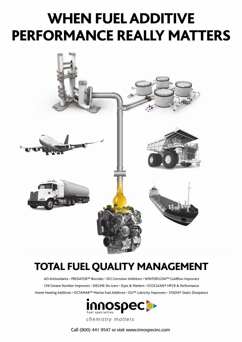
WHEN FUEL ADDITIVE PERFORMANCE REALLY MATTERS
TOTAL FUEL QUALITY MANAGEMENTAO Antioxidants • PREDATOR™ Biocides • DCI Corrosion Inhibitors • WINTERFLOW™ Coldflow Improvers
CNI Cetane Number Improvers • DIEGME De-Icers • Dyes & Markers • ECOCLEAN® HPCR & Performance
Home Heating Additives • OCTAMAR™ Marine Fuel Additives • OLI™ Lubricity Improvers • STADIS® Static Dissipators
Call (800) 441 9547 or visit www.innospecinc.com
chem i s t r y ma t t e r s
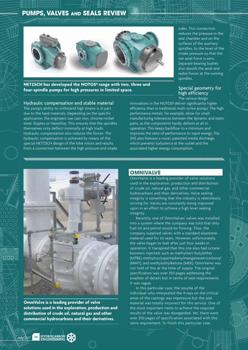
July 2017 HYDROCARBONENGINEERING
94
PUMPS, VALVES AND SEALS REVIEW
Hydraulic compensation and stable materialThe pump’s ability to withstand high strains is in part due to the hard materials. Depending on the specific application, the engineers use cast iron, chrome-nickel steel, Duplex or Hastelloy. This ensures that the spindles themselves only deflect minimally at high loads. Hydraulic compensation also reduces the forces. The hydraulic compensation is achieved by means of the special NETZSCH design of the lobe rotors and results from a connection between the high pressure and intake
sides. This connection reduces the pressure in the seal chamber and on the surfaces of the auxiliary spindles, to the level of the intake pressure so that the net axial force is zero. Separate bearing bushes also absorb the axial and radial forces at the running spindles.
Special geometry for high efficiencyThe various design
innovations in the NOTOS® deliver signifi cantly higher effi ciency than in traditional multi-screw pumps. The high performance metals, for example, allow for small manufacturing tolerances between the dynamic and static parts, as the components hardly deform at all in operation. This keeps backfl ow to a minimum and improves the ratio of performance to input energy. The 3NS also features a novel, patented media discharge, which prevents turbulence at the outlet and the associated higher energy consumption.
NETZSCH has developed the NOTOS® range with two, three and four-spindle pumps for high pressures in limited space.
OMNIVALVEOmniValve is a leading provider of valve solutions used in the exploration, production and distribution of crude oil, natural gas, and other commercial hydrocarbons and their derivatives. Valve sealing integrity is something that the industry is relentlessly striving for. Valves are constantly being improved upon in an effort to achieve a high level sealing integrity.
Recently, one of OmniValves' valves was installed into a system where the company was told that only fuel oil and petrol would be flowing. Thus, the company supplied valves with a standard elastomer material used for its seats. However, unfortunately, the valve began to leak after just four weeks in operation. It transpired that this site also had octane boosters injected, such as methyltert-butylether (MTBE), methylcyclopentadienylmanganesetricarbonyl (MMT), and methylethylketone (MEK). OmniValve was not told of this at the time of supply. The original specification was over 350 pages addressing the smallest of details but in terms of seat requirements it was vague.
In this particular case, the resume of the individual who interpreted the X-rays on the critical areas of the castings was impressive but the seal material was totally incorrect for this service. One of the most important items to achieve the required results of the valve was disregarded. Yet, there were over 350 pages of specification associated with this valve requirement. To finish this particular case,
OmniValve is a leading provider of valve solutions used in the exploration, production and distribution of crude oil, natural gas and other commercial hydrocarbons and their derivatives.

The Middle East’s premier fully integrated downstreamevent providing a meeting place for regional and
international downstream playersRegister today to meet these speakers:
This year’s highlights include:An esteemed Advisory Board including Takreer, Borouge, Sabic, Saudi Aramco, Kipic, Orpic and more!
High level conference featuring both strategic plenary sessions and technical streams.
Dedicated exhibition showcasing the latest innovation technology’s to help te Gulf region maximise its wealth of opportunities.
18 - 19 September 2017 Abu Dhabi, UAE
Why should you attend?
Receive 15%
HYDROCARBON at the online
checkout
Register at: adid.wraconferences.com/register
Ahmed Omar Abdulla
CEOBorouge
Dr. Mikael BerthodVice President TRC
Takreer
Essam Al SheibanyGM Mina Al Fahal
Orpic
Nadia B.Al-HajjiManager Optimisation
& PlanningKIPIC
Reem A. Al-GhanimDivision Head, Women
Development &
Saudi Aramco
Fuad Mohammed Mosa
General Manager Local Content Unit Innovation
& Business DevelopmentSABIC
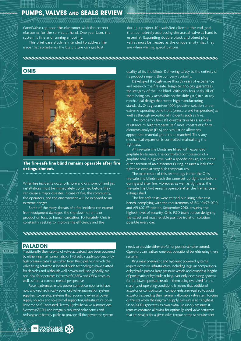
July 2017 HYDROCARBONENGINEERING
96
PUMPS, VALVES AND SEALS REVIEW
ONIS
When fi re incidents occur offshore and onshore, oil and gas installations must be immediately contained before they can cause a major disaster. In case of fi re, the community, the operators, and the environment will be exposed to an extreme danger.
Some of the many threats of a fi re incident can extend from equipment damages, the shutdown of units or production loss, to human casualties. Fortunately, Onis is constantly seeking to improve the effi ciency and the
quality of its line blinds. Delivering safety to the entirety of its product range is the company's priority.
Developed through more than 35 years of experience and research, the fi re-safe design technology guarantees the integrity of the line blind. With only four seals (all of them being easily accessible on the slide gate) in a sturdy mechanical design that meets high manufacturing standards, Onis guarantees 100% positive isolation under extreme operating conditions (pressure and temperature) as well as through exceptional incidents such as fi res.
The company's fi re-safe construction has a superior resistance to high temperature fl ames’ constraints; fi nite elements analysis (FEA) and simulation allow any appropriate material grade to be matched. Thus, any mechanical expansion is controlled, maintaining the tightness.
All fi re-safe line blinds are fi tted with expanded graphite body seals. The controlled compression of a graphite seal in a groove, with a specifi c design, and in the outer section of an elastomer O-ring, ensures a leak-free tightness even at very high temperatures.
The main result of this technology is that the Onis fi re-safe line blinds reach the same set-up tightness before, during and after fi re. Moreover, as well as tightness, the fi re-safe line blind remains operable after the fi re has been extinguished.
The fi re-safe tests were carried out using a fi re test bench, complying with the requirements of ISO 10497: 2010 and API 607 6th edition, September 2010, ensuring the highest level of security. Onis’ R&D team pursue designing the safest and most reliable positive isolation solution possible every day.
The fire-safe line blind remains operable after fire extinguishment.
OmniValve replaced the elastomer with the correct elastomer for the service at hand. One year later, the system is fine and running smoothly.
This brief case study is intended to address the issue that sometimes the big picture can get lost
during a project. If a satisfied client is the end-goal, then completely addressing the actual valve at hand is essential. Expanding double block and bleed plug valves must be treated as the unique entity that they are when writing specifications.
PALADONTraditionally, the majority of valve actuators have been powered by either ring main pneumatic or hydraulic supply sources, or by high pressure natural gas taken from the pipeline in which the valve being actuated is located. Such technologies have existed for decades and, although well proven and used globally, are not ideal for operators in terms of CAPEX and OPEX costs, as well as from an environmental perspective.
Recent advances in low power control components have now allowed technically advanced valve automation system suppliers to develop systems that require no external power supply sources and no external supporting infrastructure. Solar Powered Self-Contained Electro-Hydraulic Valve Automations Systems (SSCEH) use integrally mounted solar panels and rechargeable battery packs to provide all the power the system
needs to provide either on/off or positional valve control. Operators can realise numerous operational benefi ts using these systems.
Ring main pneumatic and hydraulic powered systems require extensive infrastructure, including large air compressors or hydraulic pumps, large pressure vessels and countless lengths of pneumatic or hydraulic tubing. Not only does sizing systems for the lowest pressure result in them being oversized for the majority of operating conditions, it means that additional actuator or control system components are required to avoid actuators exceeding the maximum allowable valve stem torques or thrusts when the ring main supply pressure is at its highest. Since SSCEH generates its own hydraulic supply pressure, it remains constant, allowing for optimally sized valve actuators that are smaller for a given valve torque or thrust requirement

TSATank Storage Associa�on
2017 TANK STORAGE CONFERENCE & EXHIBITION28TH SEPTEMBER AT THE RICOH ARENAVisit our new website at www.tankstorage.org.uk for details.
REGISTRATION NOW OPEN
Hydrocarbon Engineering Online
Visit our website today:www.hydrocarbonengineering.com
The home for the latest hydrocarbon
processing news, analysis, comment
and events
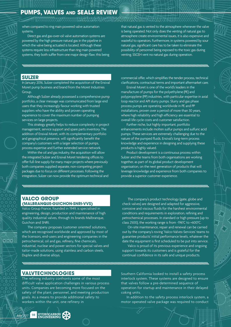
July 2017 HYDROCARBONENGINEERING
98
PUMPS, VALVES AND SEALS REVIEW
when compared to ring main powered valve automation systems.
Direct gas and gas-over-oil valve automation systems are powered by the high pressure natural gas in the pipeline in which the valve being actuated is located. Although these systems require less infrastructure than ring main powered systems, they both suffer from one major design fl aw; this being
that natural gas is vented to the atmosphere whenever the valve is being operated. Not only does the venting of natural gas to atmosphere create environmental issues, it is also expensive and wasteful to operators. Furthermore, in systems powered by sour natural gas, signifi cant care has to be taken to eliminate the possibility of personnel being exposed to the toxic gas during venting. SSCEH vent no natural gas during operation.
SULZERIn January 2016, Sulzer completed the acquisition of the Ensival Moret pump business and brand from the Moret Industries Group.
Although Sulzer already possessed a comprehensive pump portfolio, a clear message was communicated from large end users that they increasingly favour working with trusted suppliers who have the ability and proven operating experience to cover the maximum number of pumping services on large projects.
This strategy greatly helps to reduce complexity in project management, service support and spare parts inventory. The addition of Ensival Moret, with its complementary portfolio and geographical presence, will signifi cantly benefi t the company’s customers with a larger selection of pumps, process expertise and further extended service network.
Within the oil and gas industry, the acquisition will allow the integrated Sulzer and Ensival Moret tendering offi ces to offer full-line supply for many major projects where previously both companies supplied separate, non-competing project packages due to focus on different processes. Following the integration, Sulzer can now provide the optimum technical and
commercial offer, which simplifi es the tender process, technical clarifi cations, contractual terms and important aftermarket care.
Ensival Moret is one of the world’s leaders in the manufacture of pumps for the polyethylene (PE) and polypropylene (PP) industries, with particular expertise in axial loop reactor and API slurry pumps. Slurry and gas phase process pumps are operating worldwide in PE and PP installations, proven over a period of more than 30 years, where high reliability and high effi ciency are essential to overall life cycle costs and customer satisfaction.
Further niche, but highly important, portfolio enhancements include molten sulfur pumps and sulfuric acid pumps. These services are extremely challenging due to the nature of the pumped fl uids. Ensival’s long-term process knowledge and experience in designing and supplying these products is highly valued.
Product development is a continuous process within Sulzer and the teams from both organisations are working together, as part of its global product development organisation, on the next generation of products that will leverage knowledge and experience from both companies to provide a superior customer experience.
VALCO GROUP (MALBRANQUE-GUICHON-SNRI-VVS)Valco Group France, founded in 1949, is specialised in engineering, design, production and maintenance of high quality industrial valves, through its brands Malbranque, Guichon and SNRI.
The company proposes 'customer oriented' solutions, which are recognised worldwide and approved by most of the licensors, end-users and engineering companies in the petrochemical, oil and gas, refi nery, fi ne chemicals, industrial, nuclear and power sectors for special valves and tailor-made solutions, using stainless and carbon steels, Duplex and diverse alloys.
The company’s product technology (gate, globe and check valves) are designed and adapted for aggressive, corrosive and viscous fl uids for the harshest environmental conditions and requirements in exploration, refi ning and petrochemical processes. In standard or high pressure (up to class 2500), the working range is from -196°C to +600°C.
On-site maintenance, repair and renewal can be carried out by the company’s roving 'Valco-Valves-Services' teams to guarantee products' initial performance levels, whatever the date the equipment is fi rst scheduled to be put into service.
Valco is proud of its previous experience and ongoing support towards its customers and is grateful for the continual confi dence in its safe and unique products.
VALVTECHNOLOGIESThe refining industry confronts some of the most difficult valve application challenges in various process units. Companies are becoming more focused on the safety of the plant, personnel, and meeting production goals. As a means to provide additional safety to workers within the unit, one refinery in
Southern California looked to install a safety process interlock system. These systems are designed to ensure that valves follow a pre-determined sequence of operation for startup and maintenance in their delayed coking units.
In addition to the safety process interlock system, a motor operated valve package was required to conduct

2nd Annual
EGYPT DOWNSTREAM EXHIBITION & SUMMIT 201725th - 27th September Kempinski Royal Maxim Palace Cairo, Egypt
Realising Egypt’s Downstream Potential
Register to secure your space at: egypt.wraconferences.com
Sponsors
ptReceive 15%
HYDROCARBON
Need a reprint?
+44 (0)1252 [email protected]
We can tailor to your requirements,
produce 1 - 12 page formats, print colour or
mono and more
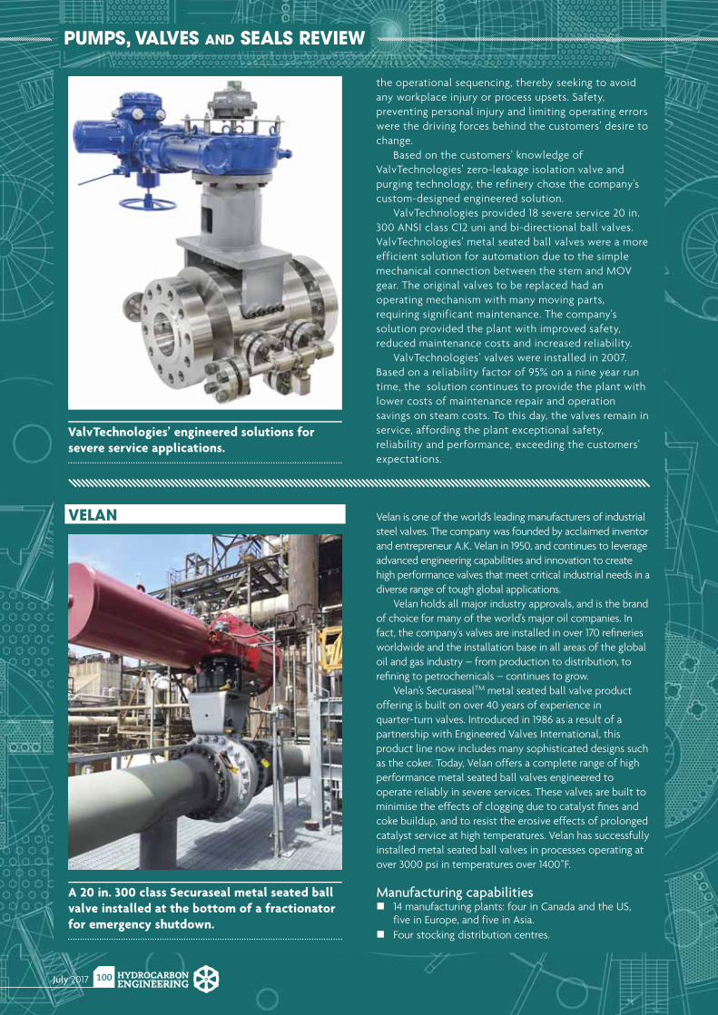
July 2017 HYDROCARBONENGINEERING
100
PUMPS, VALVES AND SEALS REVIEW
VELAN Velan is one of the world’s leading manufacturers of industrial steel valves. The company was founded by acclaimed inventor and entrepreneur A.K. Velan in 1950, and continues to leverage advanced engineering capabilities and innovation to create high performance valves that meet critical industrial needs in a diverse range of tough global applications.
Velan holds all major industry approvals, and is the brand of choice for many of the world's major oil companies. In fact, the company's valves are installed in over 170 refi neries worldwide and the installation base in all areas of the global oil and gas industry – from production to distribution, to refi ning to petrochemicals – continues to grow.
Velan’s SecurasealTM metal seated ball valve product offering is built on over 40 years of experience in quarter-turn valves. Introduced in 1986 as a result of a partnership with Engineered Valves International, this product line now includes many sophisticated designs such as the coker. Today, Velan offers a complete range of high performance metal seated ball valves engineered to operate reliably in severe services. These valves are built to minimise the effects of clogging due to catalyst fi nes and coke buildup, and to resist the erosive effects of prolonged catalyst service at high temperatures. Velan has successfully installed metal seated ball valves in processes operating at over 3000 psi in temperatures over 1400˚F.
Manufacturing capabilities14 manufacturing plants: four in Canada and the US, five in Europe, and five in Asia.
Four stocking distribution centres.
A 20 in. 300 class Securaseal metal seated ball valve installed at the bottom of a fractionator for emergency shutdown.
the operational sequencing, thereby seeking to avoid any workplace injury or process upsets. Safety, preventing personal injury and limiting operating errors were the driving forces behind the customers’ desire to change.
Based on the customers’ knowledge of ValvTechnologies’ zero-leakage isolation valve and purging technology, the refinery chose the company's custom-designed engineered solution.
ValvTechnologies provided 18 severe service 20 in. 300 ANSI class C12 uni and bi-directional ball valves. ValvTechnologies’ metal seated ball valves were a more efficient solution for automation due to the simple mechanical connection between the stem and MOV gear. The original valves to be replaced had an operating mechanism with many moving parts, requiring significant maintenance. The company's solution provided the plant with improved safety, reduced maintenance costs and increased reliability.
ValvTechnologies’ valves were installed in 2007. Based on a reliability factor of 95% on a nine year run time, the solution continues to provide the plant with lower costs of maintenance repair and operation savings on steam costs. To this day, the valves remain in service, affording the plant exceptional safety, reliability and performance, exceeding the customers’ expectations.
ValvTechnologies’ engineered solutions for severe service applications.
EXHIBITION ORGANISERS CONFERENCE ORGANISERS
SUPPORTED BY:
KUWAIT INTERNATIONAL FAIR, MISHREF
K GS3 rd Kuwait Oil & Gas Show and Conference
20
Society of Petroleum Engineers
17
kogs2017.com
Under the Patronage of
His Highness Sheikh Jaber Mubarak Al-Hamad Al-Sabah
Prime Minister of the State of Kuwait
Supported by the Ministry of Oil
State of Kuwait
Conference: 15 – 18 October 2017
Exhibition: 16 – 18 October 2017REGISTER ONLINE AT
3rd So
ciety
of P
etro
leum
Engi
neer
s Kuw
ait O
il & G
as
Show
and
Con
fere
nce
��
�
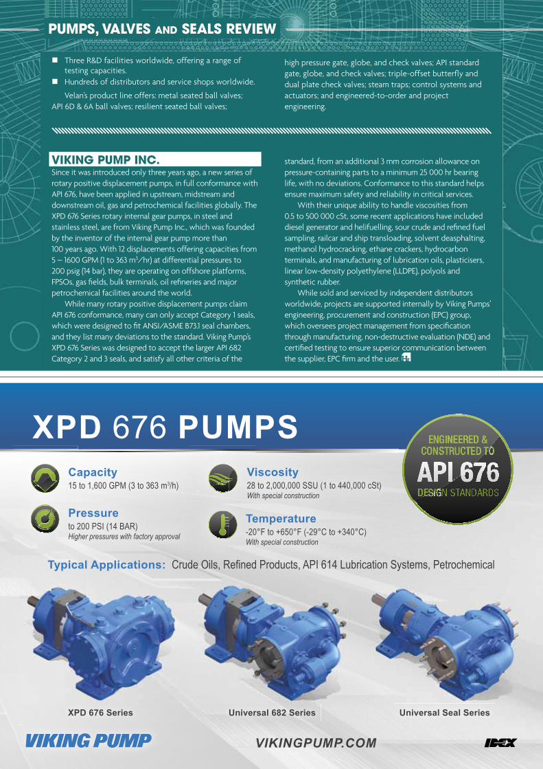
July 2017 HYDROCARBONENGINEERING
102
PUMPS, VALVES AND SEALS REVIEW
Typical Applications:
Capacity 15 to 1,600 GPM (3 to 363 m3/h)15
Pressure to 200 PSI (14 BAR)Higher pressures with factory approval
Temperature -20°F to +650°F (-29°C to +340°C) With special construction
emperatureTe
Viscosity 28 to 2,000,000 SSU (1 to 440,000 cSt)With special construction
XPD 676 PUMPS
XPD 676 Series Universal 682 Series Universal Seal Series
VIKINGPUMP.COM
VIKING PUMP INC.Since it was introduced only three years ago, a new series of rotary positive displacement pumps, in full conformance with API 676, have been applied in upstream, midstream and downstream oil, gas and petrochemical facilities globally. The XPD 676 Series rotary internal gear pumps, in steel and stainless steel, are from Viking Pump Inc., which was founded by the inventor of the internal gear pump more than 100 years ago. With 12 displacements offering capacities from 5 – 1600 GPM (1 to 363 m3/hr) at differential pressures to 200 psig (14 bar), they are operating on offshore platforms, FPSOs, gas fi elds, bulk terminals, oil refi neries and major petrochemical facilities around the world.
While many rotary positive displacement pumps claim API 676 conformance, many can only accept Category 1 seals, which were designed to fi t ANSI/ASME B73.1 seal chambers, and they list many deviations to the standard. Viking Pump’s XPD 676 Series was designed to accept the larger API 682 Category 2 and 3 seals, and satisfy all other criteria of the
standard, from an additional 3 mm corrosion allowance on pressure-containing parts to a minimum 25 000 hr bearing life, with no deviations. Conformance to this standard helps ensure maximum safety and reliability in critical services.
With their unique ability to handle viscosities from 0.5 to 500 000 cSt, some recent applications have included diesel generator and helifuelling, sour crude and refi ned fuel sampling, railcar and ship transloading, solvent deasphalting, methanol hydrocracking, ethane crackers, hydrocarbon terminals, and manufacturing of lubrication oils, plasticisers, linear low-density polyethylene (LLDPE), polyols and synthetic rubber.
While sold and serviced by independent distributors worldwide, projects are supported internally by Viking Pumps’ engineering, procurement and construction (EPC) group, which oversees project management from specifi cation through manufacturing, non-destructive evaluation (NDE) and certifi ed testing to ensure superior communication between the supplier, EPC fi rm and the user.
Three R&D facilities worldwide, offering a range of testing capacities.
Hundreds of distributors and service shops worldwide.
Velan’s product line offers: metal seated ball valves; API 6D & 6A ball valves; resilient seated ball valves;
high pressure gate, globe, and check valves; API standard gate, globe, and check valves; triple-offset butterfl y and dual plate check valves; steam traps; control systems and actuators; and engineered-to-order and project engineering.
Ad Index
www.hydrocarbonengineering.com
Have you joined yet?Join our industry directory today. Contact [email protected] for more details.
Page Number | Advertiser
97 | 2017 Tank Storage Conference & Exhibition
101 | 3rd Kuwait Oil & Gas Show and Conference
95 | Abu Dhabi International Downstream Summit
87 | ACHEMA 2018
47 | Altair Strickland, an EMCOR Industrial Services Company
77 | AMETEK Process Instruments
85 | Bal Seal Engineering, Inc.
61 | Bentley Systems, Inc.
69 | Bryan Research & Engineering, Inc.
07 | CB&I
65 | CRI Catalyst
OBC | Curtiss-Wright EST Group
99 | Egypt Downstream Exhibition & Summit 2017
OFC, 35 | Elliott Group
39 | ExxonMobil
IBC | Goodwin International Ltd
IFC | Graham Corp.
78 | hte GmbH
04 | HTRI
93 | Innospec
15 | Intergraph CADWorx
09 | Koch-Glitsch
25 | MAN Diesel & Turbo
41 | Matrix Service Company
57, 81 | Merichem Company
27 | Metso
75 | Mitsubishi Heavy Industries Compressor International
53 | NETZSCH
91 | Nikkiso Cryo
82 | NISTM
89 | OHL Gutermuth Industrial Valves GmbH
15, 53, 62, 97, 99
| Palladian Publications
33 | Pittsburgh Corning
42 | Port of Amsterdam
51 | Quest Integrity
02 | Sandvik
11 | Sulzer Chemtech
17 | Trinity Consultants
21 | UOP, Callidus Technologies
102 | Viking Pump
58 | Wattco
29 | Yokogawa
71 | Zwick Armaturen GmbH
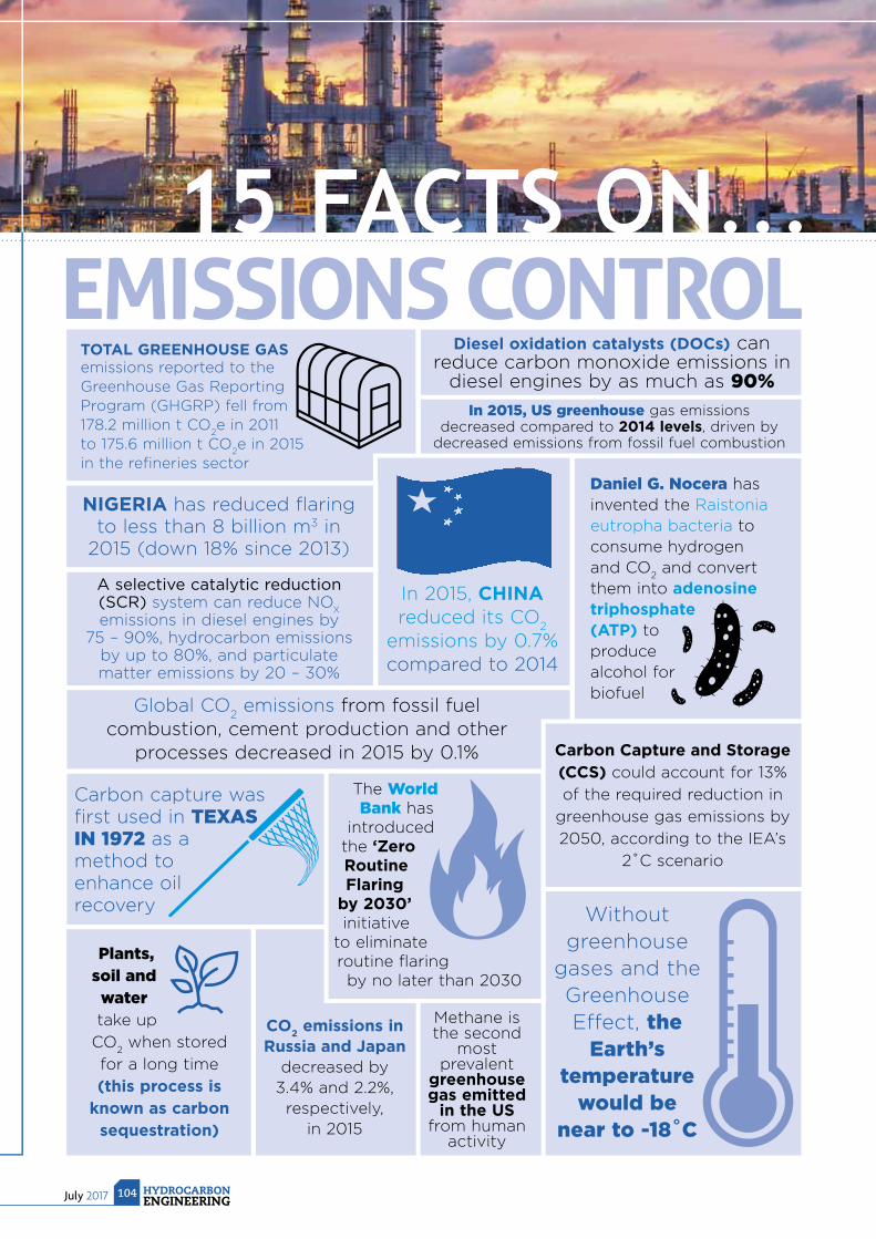
15 FACTS ON...EMISSIONS CONTROL
July 2017 HYDROCARBONENGINEERING
104
Diesel oxidation catalysts (DOCs) can reduce carbon monoxide emissions in
diesel engines by as much as 90%
In 2015, US greenhouse gas emissions decreased compared to 2014 levels, driven by
decreased emissions from fossil fuel combustion
Carbon capture was fi rst used in TEXAS IN 1972 as a method to enhance oil recovery
Daniel G. Nocera has invented the Raistonia eutropha bacteria to consume hydrogen and CO
2 and convert
them into adenosine triphosphate (ATP) to produce alcohol for biofuel
Without greenhouse
gases and the Greenhouse Effect, the
Earth’s temperature
would be near to -18˚C
Plants, soil and water take up
CO2 when stored
for a long time
(this process is known as carbon
sequestration)
Global CO2 emissions from fossil fuel
combustion, cement production and other processes decreased in 2015 by 0.1%
CO2 emissions in
Russia and Japan decreased by
3.4% and 2.2%, respectively,
in 2015
Methane is the second
most prevalent
greenhouse gas emitted
in the US from human
activity
TOTAL GREENHOUSE GAS emissions reported to the Greenhouse Gas Reporting Program (GHGRP) fell from 178.2 million t CO
2e in 2011
to 175.6 million t CO2e in 2015
in the refi neries sector
In 2015, CHINA reduced its CO
2
emissions by 0.7% compared to 2014
A selective catalytic reduction (SCR) system can reduce NO
X
emissions in diesel engines by 75 – 90%, hydrocarbon emissions
by up to 80%, and particulate matter emissions by 20 – 30%
NIGERIA has reduced fl aring to less than 8 billion m3 in
2015 (down 18% since 2013)
The World Bank has
introduced the ‘Zero Routine Flaring
by 2030’ initiative
to eliminate routine fl aring
by no later than 2030
Carbon Capture and Storage (CCS) could account for 13%
of the required reduction in
greenhouse gas emissions by
2050, according to the IEA’s
2˚C scenario

Rack-Pinion-Rack Gear Train
High Capacity Single Stage Trim
Tight Shut Off
High Pressure Drop Multi-Stage Trim
Goodwin Axial Isolation and Control Valves provide durability, reliability and
control, with the exceptional service that Goodwin is renowned for.
+44 1782 654000
www.goodwinflowcontrol.com
AXIAL ISOLATION
AXIAL CONTROL
LEARN MORE
SEE US AT...
ADIPEC UAE (ABU DHABI)13-16 NOVEMBER
HALL 8
FLOW CONTROL
EXCHANGE INDIA (NEW DELHI)
5-6 OCTOBERSTAND B27

EST Groupcw-estgroup.com/he07
Industry leading solution for leaking and degraded heat exchanger, condenser and boiler tubes. Conforms to ASME PCC-2-2015 recommended tube plugging repair methods.
Pop-A-Plug® Heat Exchanger Tube Plugging System
SAFE. RELIABLE. TRUSTED.Highly Engineered Solutions for Heat Exchanger Repair