Embed Size (px)
Citation preview
UNIVERSITY OF NIŠ
FACULTY OF OCCUPATIONAL SAFETY
Journal for Scientists and Engineers
SAFETY ENGINEERING
Naučno stručni časopis
INŽENJERSTVO ZAŠTITE
Vol. 9. N02 (2019)
Niš, December 2019.
Scientific Journal SAFETY ENGINEERING Naučni časopis INŽENJERSTVO ZAŠTITE (OPEN ACCESS JOURNAL ‐ www.safety.ni.ac.rs)
Izdavač / Publisher Fakultet zaštite na radu u Nišu / Faculty of Occupational Safety in Niš
Glavni urednik / Editor‐in‐Chief Dejan Krstić
Urednici / Editors
Ivan Krstić Srđan Glišović Vesna Nikolić
Redakcijski odbor / Editorial Board (in alphabetical order) Andres Carrnion Garcia, Technical University of Valencia, Spain
Boris Đinđić, University of Niš, Faculty of Medicine, Serbia
Branislav Anđelković, University of Niš, Faculty of Occupational Safety, Serbia
Dejan Petković, University of Niš, Faculty of Occupational Safety, Serbia
Đordje Ćosić, University of Novi Sad, Faculty of Technical Studies, Serbia
Dragan Mitić, University of Niš, Faculty of Occupational Safety, Serbia
Dragan Mlađan, The Academy of Criminalistic and Police Studies, Belgrade, Serbia
Dusan Sakulski, Faculty of Natural and Agricultural Sciences, DiMTEC, Bloemfontein, South Africa
Dušan Sokolović, University of Niš, Faculty of Medicine, Serbia
Goran Ristić, University of Niš, Faculty of Electronic Engineering, Serbia
Ivana Banković Ilić, University of Niš, Faculty of Technology in Leskovac, Serbia
Joseph Aronov, VNIIS Moscow, Russia
Jovica Jovanović, University of Niš, Faculty of Medicine, Serbia
Katarína Senderská, Technical University of Košice, Faculty of Mechanical Engineering, Slovakia
Kemal Nuri Özerkan, University of Istanbul, School of Physical Education Sports
Ljiljana Živković, University of Niš, Faculty of Occupational Safety, Serbia
Ljubiša Papić, University of Kragujevac, Technical Faculty Čačak, Serbia
Miomir Stanković, University of Niš, Faculty of Occupational Safety, Serbia
Momir Dunjić, University of Pristtina‐Kosovska Mitrovica, School of Medicine, Serbia
Mirko Marič, University of Primorska, Faculty of Management, Slovenia
Nevenka Kopjar, University of Zagreb, Institute for Medical Research and Occupational Health, Croatia
Nenad Živković, University of Niš, Faculty of Occupational Safety, Serbia
Nenad Cvetković, University of Niš, Faculty of Electronic Engineering, Serbia
Noam Lior, University of Pennsylvania, USA
Nikola Đurić, University of Novi Sad, Faculty of Technical Studies, Serbia
Rodoljub Simović, Vinca Institute of Nuclear Sciences, Serbia
Sergey Perov, Izmerov Research Institute of Occupational Health, Moscow, Russia
Susana San Matias, Technical University of Valencia, Spain
Vera Marković, University of Niš, Faculty of Electronic Engineering, Serbia
Vlada Veljković, University of Niš, Faculty of Technology in Leskovac, Serbia
Wolfgang Mathis, Institut für Theoretische Elektrotechnik, Hannover, Germany
Zoran Keković, University of Belgrade, Faculty of Security Studies, Serbia
Zoran Stajić, University of Niš, Faculty of Electronic Engineering, Serbia
Žarko Janković, University of Niš, Faculty of Occupational Safety , Serbia
Željko Hederić, Josip Juraj Strossmayer University of Osijek, FERIT Osjek, Croatia
Tehnički urednik / Technical Editor Rodoljub Avramović
Lektor / Proofreading Aleksandra Petković Nataša Šelmić‐Milosavljević
Štampa / Press „Unigraf x‐copy“ doo Niš
From Editor’s desk
“Life returns only what we give to others “.
( Ivo Andrić )
This year, Safety engineering has demonstrated its progress by obtaining a higher journal ranking position within the national framework. We are now ranked as the journal of national importance (M52), owing to the contributions of all authors who have published their findings in the previous period, and the endeavours of the editorial board and the editors themselves. We remain committed to continuously improving the quality of scientific papers that will be published in the Safety engineering journal.
Unfortunately, the world has been facing a lot of environmental challenges such as increased air pollution and the struggle to keep air quality within an acceptable level for human health. New biological hazards, such as the spread of the COVID‐19 virus in China, may become a global threat to human health. Electromagnetic radiation from wireless telecommunications devices has been scientifically proven to be significant damage or detriment to human health; therefore, the articles in this issue have dealt with the control, restriction and protection against electromagnetic waves and fields. Moreover, electric and magnetic fields can also be used as a method of removing pollutant particles from the air and improving air quality. If we have adequate knowledge, we can use any physical appearance to improve the quality of life and the environment. The permanent aim of our journal is to improve the health of employees; to that end, in this issue, occupational safety has been analyzed in terms of organizational measures of work at height, fire protection, risk assessment of biogas cogeneration and socio‐demographic characteristics of occupational injuries. The release of the latest journal issue will open up new topics and provide the answers to our readers who want to know more.
The editorial board continues to inspire all our colleagues and readers to keep recognizing this journal as a good place to introduce their research.
“Život nam vraća samo ono što mi drugima dajemo“. ( Ivo Andrić )
Napredak u radu časopisa je u toku ove godine iskazan višom kategorijom časopisa u
nacionalnim okvirima – M52 (istaknuti nacionalni časopis) što je zasluga svih autora koji su publikovali rad u prethodnom periodu, kao i uređivačkog odbora i samih urednika. Ostajemo posvećeni povećanju kvaliteta naučnih radova koji će biti publikovani u časopisu Safety engineering.
U ovoj godini su izazovi u životnoj sredini bili povećanje zagađenosti vazduha i borba da se kvalitet vazduha dovede u opseg koji se smatra prihvatljivim i zdravim. Nove biološke štetnosti kao širenje virusa COVID‐19 u Kini mogu biti globalna pretnja po zdravlje ljudi na našoj planenti. Elektromagnentna zračenja bežičnih telekomunikacionih uređaja naučno dokazano su značajna štetnost koja iskazuje svoj potencijal po zdravlje ljudi, a radovi u ovom broju pokazuju kako treba pristupiti kontroli, ograničenju i zaštiti od štetnog dejstva elektromagnentih talasa i polja. Električna i magnentna polja se mogu iskoristiti i kao način otklanjanja čestica iz vazduha i unapređenja kvaliteta vazduha. Svaku fizičku pojavu znanjem možemo iskoristiti u unapređenju kvaliteta života i životne sredine. Stalni cilj časopisa je unapređenje zdravlja zaposlenih, tako da se i u ovom broju zaštita na radu analizira sa aspeka organizacionih metra rada na visini, zaštite od požara, procene rizika pri kogeneraciji biogasa i sociodemografskih karakterisitka povreda na radu. Pred čitaocima se nalazi novi broj časopisa koji otvara nove teme i daje potrebne odgovore.
Uredništvo i dalje ohrabruje sve naše kolege i čitaoce da prepoznaju ovaj časopis kao dobro mesto za predstavljanje svojih istraživanja.
On behalf of the editors Prof. Dr. Dejan Krstić
SAFETY ENGINEERING - INŽENJERSTVO ZAŠTITE, Vol 9, No2 (2019)
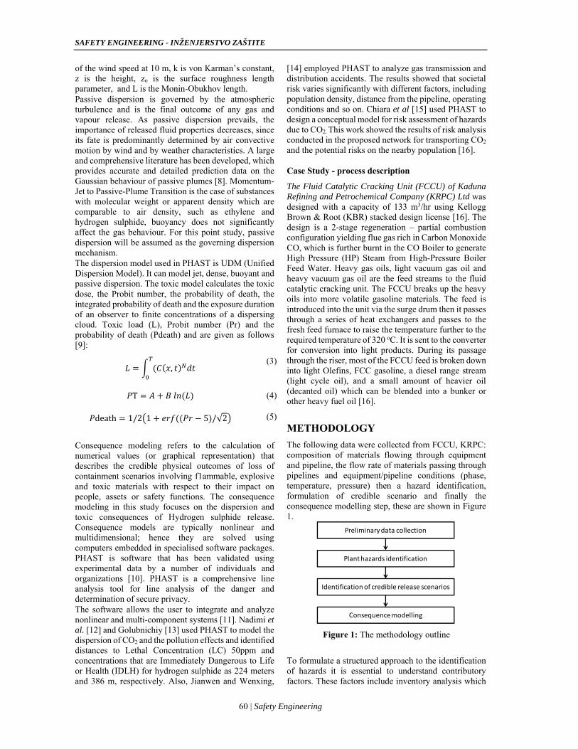
Contents S.A. Ridwan, U. Abubakar Zaria, S.M. Waziri Modelling Dispersion and Toxicity Consequences due to Accidental Release of Hydrogen Sulphide in a Crude Oil Refinery ...............................................................................59
Dejan M. Petković, Milica D. Radić, Dejan D. Krstić, Dejan N. Jovanović Performance Calculations of Electrostatic Precipitator.......65
Dragan Kljajić, Nikola Đurić, Karolina Kasaš-Lažetić The High-Frequency EMF Investigation over the Campus Area of the University of Novi Sad ......................................70
Radoje Jevtić Evacuation from a Parking Garage .....................................75
Dejan Krstić, Darko Zigar, Nenad Cvetković, Željko Hederić, Dejan Jovanović, Vladimir Stanković Electromagnetic Screening Plate in Protection Service Technicians from Base Station Antenna Systems ………….81
Miodrag Milenović, Snežana Živković, Milan Veljković Socio-Demographic Characteristics and Occupational Injuries in Miners ….............................................................87
Jasmina Radosavljević, Ana Vukadinović Worker Safety During Construction Work at Height ….......91
Gorana Milinčić Stančić, Snežana Živković Risk assessment and safety concepts for cogeneration biogas plants …..............…………………………………………..97
Reviews of publications
Amelija Đorđević, Vladica Stefanović Environmental Risk ............................................................ 103
Sadržaj S.A. Ridwan, U. Abubakar Zaria, S.M. Waziri Modeliranje posledica disperzije i toksičnosti usled slučajnog ispuštanja vodonik-sulfida u rafineriji nafte ..............................................................................................59
Dejan M. Petković, Milica D. Radić, Dejan D. Krstić, Dejan N. Jovanović Proračun performasni elekrostatičkih filtara .......................65
Dragan Kljajić, Nikola Đurić, Karolina Kasaš-Lažetić Ispitivanje EM polja visokih frekvencija u okviru kampusa univerziteta u Novom Sadu ...................................................70
Radoje Jevtić Evakuacija iz auto parking garaže ........................................75
Dejan Krstić, Darko Zigar, Nenad Cvetković, Željko Hederić, Dejan Jovanović, Vladimir Stanković Elektromagnetni ekrani kao zaštita servisnog osoblja na antenskim sistemima baznih stanica mobilne telefonije…....81
Miodrag Milenović, Snežana Živković, Milan Veljković Sociodemografske karakteristike i povređivanje na radu kod rudara …..............................................................................87
Jasmina Radosavljević, Ana Vukadinović Zaštita radnika pri izvođenju građevinskih radova na visini …………….………………………………………………..91
Gorana Milinčić Stančić, Snežana Živković procena rizika i koncepti zaštite kogenerativnih biogas postrojenja …………....................….……………….……..97
Prikazi publikacija
Amelija Đorđević, Vladica Stefanović Ekološki rizik………..…………………………………….103
UDC: 543.8:615.9 DOI: 10.7562/SE2019.9.02.01
Original article
S.A. RIDWAN 1
U. ABUBAKAR ZARIA1,* S.M. WAZIRI1
1Department of Chemical Engineering, Ahmadu Bello
University, Zaria. *Correspondence author
[email protected]@yahoo.com
[email protected]@abu.edu.ng
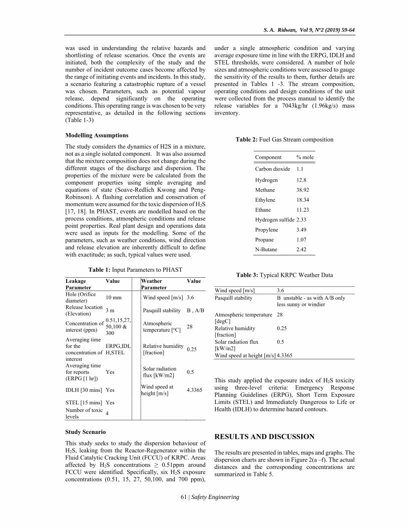
MODELLING DISPERSION AND TOXICITY CONSEQUENCES DUE TO ACCIDENTAL RELEASE OF HYDROGEN SULPHIDE IN A CRUDE OIL REFINERY Abstract: Hydrogen sulphide (H2S) is a very toxic gas and is commonly encountered in crude oil refining processes. Atmospheric concentration as low as 300ppm could be fatal. Hence the need to periodically risk-assess H2S holding facilities in the light of inherent changes due to ageing equipment, wear and obsolescence, among others. This research studies the dispersion and toxicity consequences arising from the accidental release of H2S. The Fluid Catalytic Cracking Unit (FCCU) of Kaduna Refining and Petrochemical Company (KRPC) Ltd was used as a case study. Distances to six toxic concentration levels: 0.51, 15, 27, 50,100 and 300 ppm, and an average exposure time of 15 minutes were investigated. PHAST 8.2 software was used for the modelling and the inputs were obtained from actual plant design manuals, operations records and direct field measurements. The results indicate that H2S concentrations of 0.51ppm may be seen 183m downwind of the release point, 0.51ppm H2S and higher concentrations can present a significant risk to the public. Higher concentrations were observed at shorter distances downwind. In particular, 300 ppm H2S concentration was observed 5m away from the leak source.
Keywords: hydrogen sulphide, dispersion, consequence modelling, toxicity, fatality.
INTRODUCTION
Loss of containment of hazardous materials from process vessels/pieces of equipment is a major source of concern in the petrochemical industry. Such leakages/ruptures often result in fire, explosion, toxicity and/or commercial losses. Flixborough disaster in 1974 and toxic gas release in Seveso (Italy) in 1978 are examples of accidents involving the release of toxic material [1]. The hazards that occur because of chemical substance leakage include acute exposure due to the atmospheric dispersion of toxic gases and fires from the ignition of flammable substances that have leaked. Leakages of toxic gases present danger, not only within the plant but also to communities in the surrounding area especially if the leak is on a large scale [2, 3]. The need for consequence modeling of process plant and hazardous storage facilities continues to become more prominent as a result of a global drift towards larger and more complex units that handle toxic, flammable and otherwise hazardous chemicals, operating under higher temperature and pressure conditions. The magnitude of loss containment, dispersion and consequence are governed by several factors, including material storage condition/properties, characteristics of the leak source and ambient conditions [4, 5]. Meteorology has a strong influence on the outcome of a release, as well as on the spatial distribution of plant physical components. For instance, for adiabatic
expansion of single gas through an orifice, the mass flow rate can be calculated from [6]:
2.
1
/ /
(1)
Where: is the absolute upstream pressure (Pa or N/ ; is the downstream pressure (absolute - in case the release is not to atmosphere) P N/ ; is the molecular weight / ; is the upstream temperature ; is the ideal gas constant / . ; is the ratio of the specific heats (dimensionless); is the acceleration of gravity ( / ; is the coefficient of discharge(dimensionless); is the compressibility factor (dimensionless), which is usually taken to be unity, assuming ideal gas behaviour. The wind speed is affected by the earth’s surface characteristics and increases with height above the ground according to a power function, suggesting that it is important to define a reference height always. A general equation for near-neutral and stable wind profile is given below [7]:
∗1.
04.5
(2)
Where Uw is the wind speed, U* is friction velocity constant, which is assumed as equivalent to about 10%
SAFETY ENGINEERING - INŽENJERSTVO ZAŠTITE
60 | Safety Engineering
of the wind speed at 10 m, k is von Karman’s constant, z is the height, zo is the surface roughness length parameter, and L is the Monin-Obukhov length. Passive dispersion is governed by the atmospheric turbulence and is the final outcome of any gas and vapour release. As passive dispersion prevails, the importance of released fluid properties decreases, since its fate is predominantly determined by air convective motion by wind and by weather characteristics. A large and comprehensive literature has been developed, which provides accurate and detailed prediction data on the Gaussian behaviour of passive plumes [8]. Momentum-Jet to Passive-Plume Transition is the case of substances with molecular weight or apparent density which are comparable to air density, such as ethylene and hydrogen sulphide, buoyancy does not significantly affect the gas behaviour. For this point study, passive dispersion will be assumed as the governing dispersion mechanism. The dispersion model used in PHAST is UDM (Unified Dispersion Model). It can model jet, dense, buoyant and passive dispersion. The toxic model calculates the toxic dose, the Probit number, the probability of death, the integrated probability of death and the exposure duration of an observer to finite concentrations of a dispersing cloud. Toxic load (L), Probit number (Pr) and the probability of death (Pdeath) and are given as follows [9]:
, (3)
T (4)
death 1/2 1 5 /√2 (5)
Consequence modeling refers to the calculation of numerical values (or graphical representation) that describes the credible physical outcomes of loss of containment scenarios involving f1ammable, explosive and toxic materials with respect to their impact on people, assets or safety functions. The consequence modeling in this study focuses on the dispersion and toxic consequences of Hydrogen sulphide release. Consequence models are typically nonlinear and multidimensional; hence they are solved using computers embedded in specialised software packages. PHAST is software that has been validated using experimental data by a number of individuals and organizations [10]. PHAST is a comprehensive line analysis tool for line analysis of the danger and determination of secure privacy. The software allows the user to integrate and analyze nonlinear and multi-component systems [11]. Nadimi et al. [12] and Golubnichiy [13] used PHAST to model the dispersion of CO2 and the pollution effects and identified distances to Lethal Concentration (LC) 50ppm and concentrations that are Immediately Dangerous to Life or Health (IDLH) for hydrogen sulphide as 224 meters and 386 m, respectively. Also, Jianwen and Wenxing,
[14] employed PHAST to analyze gas transmission and distribution accidents. The results showed that societal risk varies significantly with different factors, including population density, distance from the pipeline, operating conditions and so on. Chiara et al [15] used PHAST to design a conceptual model for risk assessment of hazards due to CO2. This work showed the results of risk analysis conducted in the proposed network for transporting CO2
and the potential risks on the nearby population [16]. Case Study - process description
The Fluid Catalytic Cracking Unit (FCCU) of Kaduna Refining and Petrochemical Company (KRPC) Ltd was designed with a capacity of 133 m3/hr using Kellogg Brown & Root (KBR) stacked design license [16]. The design is a 2-stage regeneration – partial combustion configuration yielding flue gas rich in Carbon Monoxide CO, which is further burnt in the CO Boiler to generate High Pressure (HP) Steam from High-Pressure Boiler Feed Water. Heavy gas oils, light vacuum gas oil and heavy vacuum gas oil are the feed streams to the fluid catalytic cracking unit. The FCCU breaks up the heavy oils into more volatile gasoline materials. The feed is introduced into the unit via the surge drum then it passes through a series of heat exchangers and passes to the fresh feed furnace to raise the temperature further to the required temperature of 320 oC. It is sent to the converter for conversion into light products. During its passage through the riser, most of the FCCU feed is broken down into light Olefins, FCC gasoline, a diesel range stream (light cycle oil), and a small amount of heavier oil (decanted oil) which can be blended into a bunker or other heavy fuel oil [16].
METHODOLOGY
The following data were collected from FCCU, KRPC: composition of materials flowing through equipment and pipeline, the flow rate of materials passing through pipelines and equipment/pipeline conditions (phase, temperature, pressure) then a hazard identification, formulation of credible scenario and finally the consequence modelling step, these are shown in Figure 1.
Figure 1: The methodology outline
To formulate a structured approach to the identification of hazards it is essential to understand contributory factors. These factors include inventory analysis which
Preliminary data collection
Plant hazards identification
Identification of credible release scenarios
Consequence modelling
S. A. Ridwan, Vol 9, No2 (2019) 59-64
61 | Safety Engineering
was used in understanding the relative hazards and shortlisting of release scenarios. Once the events are initiated, both the complexity of the study and the number of incident outcome cases become affected by the range of initiating events and incidents. In this study, a scenario featuring a catastrophic rupture of a vessel was chosen. Parameters, such as potential vapour release, depend significantly on the operating conditions. This operating range is was chosen to be very representative, as detailed in the following sections (Table 1-3) Modelling Assumptions
The study considers the dynamics of H2S in a mixture, not as a single isolated component. It was also assumed that the mixture composition does not change during the different stages of the discharge and dispersion. The properties of the mixture were be calculated from the component properties using simple averaging and equations of state (Soave-Redlich Kwong and Peng-Robinson). A flashing correlation and conservation of momentum were assumed for the toxic dispersion of H2S [17, 18]. In PHAST, events are modelled based on the process conditions, atmospheric conditions and release point properties. Real plant design and operations data were used as inputs for the modelling. Some of the parameters, such as weather conditions, wind direction and release elevation are inherently difficult to define with exactitude; as such, typical values were used.
Table 1: Input Parameters to PHAST
Leakage Parameter
Value Weather Parameter
Value
Hole (Orifice diameter)
10 mm Wind speed [m/s] 3.6
Release location (Elevation)
3 m Pasquill stability B , A/B
Concentration of interest (ppm)
0.51,15,27,50,100 & 300
Atmospheric temperature [oC]
28
Averaging time for the concentration of interest
ERPG,IDLH,STEL
Relative humidity [fraction]
0.25
Averaging time for reports (ERPG [1 hr])
Yes Solar radiation flux [kW/m2]
0.5
IDLH [30 mins] Yes Wind speed at height [m/s]
4.3365
STEL [15 mins] Yes Number of toxic levels
4
Study Scenario
This study seeks to study the dispersion behaviour of H2S, leaking from the Reactor-Regenerator within the Fluid Catalytic Cracking Unit (FCCU) of KRPC. Areas affected by H2S concentrations ≥ 0.51ppm around FCCU were identified. Specifically, six H2S exposure concentrations (0.51, 15, 27, 50,100, and 700 ppm),
under a single atmospheric condition and varying average exposure time in line with the ERPG, IDLH and STEL thresholds, were considered. A number of hole sizes and atmospheric conditions were assessed to gauge the sensitivity of the results to them, further details are presented in Tables 1 -3. The stream composition, operating conditions and design conditions of the unit were collected from the process manual to identify the release variables for a 7043kg/hr (1.96kg/s) mass inventory.
Table 2: Fuel Gas Stream composition
Component % mole
Carbon dioxide 1.1
Hydrogen 12.8
Methane 38.92
Ethylene 18.34
Ethane 11.23
Hydrogen sulfide 2.33
Propylene 3.49
Propane 1.07
N-Butane 2.42
Table 3: Typical KRPC Weather Data
Wind speed [m/s] 3.6 Pasquill stability B unstable - as with A/B only
less sunny or windier
Atmospheric temperature [degC]
28
Relative humidity [fraction]
0.25
Solar radiation flux [kW/m2]
0.5
Wind speed at height [m/s] 4.3365
This study applied the exposure index of H2S toxicity using three-level criteria: Emergency Response Planning Guidelines (ERPG), Short Term Exposure Limits (STEL) and Immediately Dangerous to Life or Health (IDLH) to determine hazard contours.
RESULTS AND DISCUSSION
The results are presented in tables, maps and graphs. The dispersion charts are shown in Figure 2(a –f). The actual distances and the corresponding concentrations are summarized in Table 5.
SAFETY ENGINEERING - INŽENJERSTVO ZAŠTITE
62 | Safety Engineering
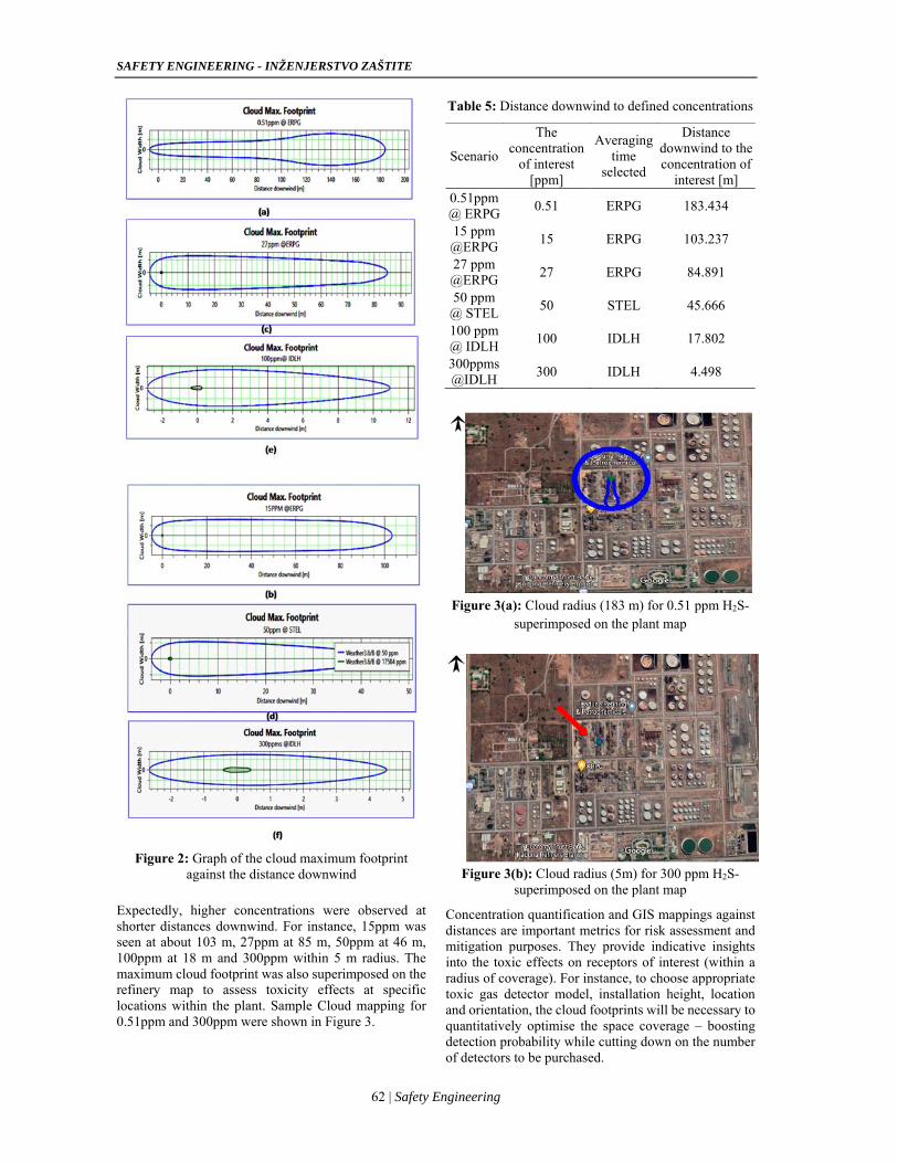
Figure 2: Graph of the cloud maximum footprint
against the distance downwind
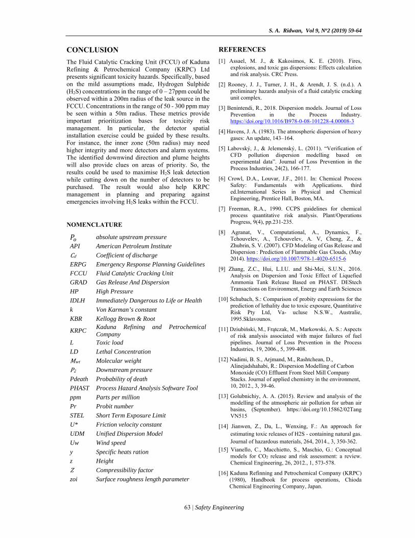
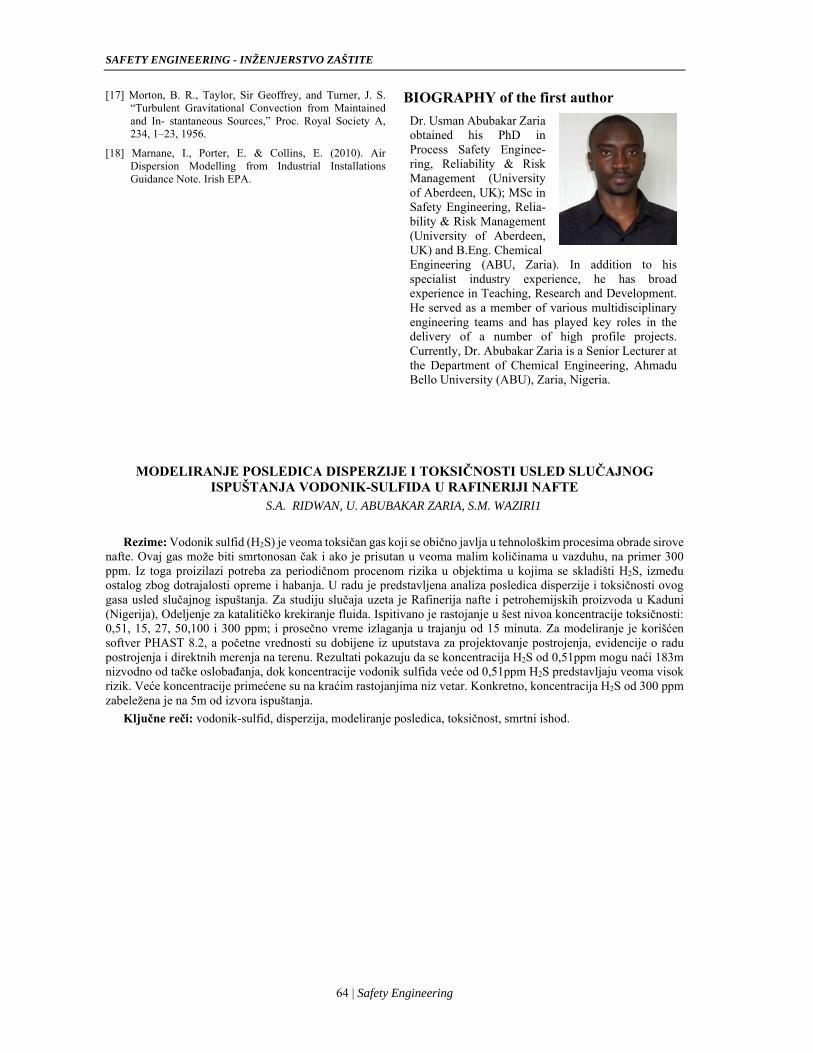
Expectedly, higher concentrations were observed at shorter distances downwind. For instance, 15ppm was seen at about 103 m, 27ppm at 85 m, 50ppm at 46 m, 100ppm at 18 m and 300ppm within 5 m radius. The maximum cloud footprint was also superimposed on the refinery map to assess toxicity effects at specific locations within the plant. Sample Cloud mapping for 0.51ppm and 300ppm were shown in Figure 3.
Table 5: Distance downwind to defined concentrations
Scenario
The concentration
of interest [ppm]
Averaging time
selected
Distance downwind to the concentration of
interest [m] 0.51ppm @ ERPG
0.51 ERPG 183.434
15 ppm @ERPG
15 ERPG 103.237
27 ppm @ERPG
27 ERPG 84.891
50 ppm @ STEL
50 STEL 45.666
100 ppm @ IDLH
100 IDLH 17.802
300ppms @IDLH
300 IDLH 4.498
Figure 3(a): Cloud radius (183 m) for 0.51 ppm H2S-
superimposed on the plant map
Figure 3(b): Cloud radius (5m) for 300 ppm H2S-
superimposed on the plant map
Concentration quantification and GIS mappings against distances are important metrics for risk assessment and mitigation purposes. They provide indicative insights into the toxic effects on receptors of interest (within a radius of coverage). For instance, to choose appropriate toxic gas detector model, installation height, location and orientation, the cloud footprints will be necessary to quantitatively optimise the space coverage – boosting detection probability while cutting down on the number of detectors to be purchased.
S. A. Ridwan, Vol 9, No2 (2019) 59-64
63 | Safety Engineering
CONCLUSION
The Fluid Catalytic Cracking Unit (FCCU) of Kaduna Refining & Petrochemical Company (KRPC) Ltd presents significant toxicity hazards. Specifically, based on the mild assumptions made, Hydrogen Sulphide (H2S) concentrations in the range of 0 – 27ppm could be observed within a 200m radius of the leak source in the FCCU. Concentrations in the range of 50 - 300 ppm may be seen within a 50m radius. These metrics provide important prioritization bases for toxicity risk management. In particular, the detector spatial installation exercise could be guided by these results. For instance, the inner zone (50m radius) may need higher integrity and more detectors and alarm systems. The identified downwind direction and plume heights will also provide clues on areas of priority. So, the results could be used to maximise H2S leak detection while cutting down on the number of detectors to be purchased. The result would also help KRPC management in planning and preparing against emergencies involving H2S leaks within the FCCU. NOMENCLATURE
absolute upstream pressure
API American Petroleum Institute
Cd Coefficient of discharge
ERPG Emergency Response Planning Guidelines
FCCU Fluid Catalytic Cracking Unit
GRAD Gas Release And Dispersion
HP High Pressure
IDLH Immediately Dangerous to Life or Health
k Von Karman’s constant
KBR Kellogg Brown & Root
KRPC Kaduna Refining and Petrochemical Company
L Toxic load
LD Lethal Concentration
Mwt Molecular weight
P2 Downstream pressure
Pdeath Probability of death
PHAST Process Hazard Analysis Software Tool
ppm Parts per million
Pr Probit number
STEL Short Term Exposure Limit
U* Friction velocity constant
UDM Unified Dispersion Model
Uw Wind speed
y Specific heats ration
z Height
Z Compressibility factor
zoi Surface roughness length parameter
REFERENCES
[1] Assael, M. J., & Kakosimos, K. E. (2010). Fires, explosions, and toxic gas dispersions: Effects calculation and risk analysis. CRC Press.
[2] Rooney, J. J., Turner, J. H., & Arendt, J. S. (n.d.). A preliminary hazards analysis of a fluid catalytic cracking unit complex.
[3] Benintendi, R., 2018. Dispersion models. Journal of Loss Prevention in the Process Industry. https://doi.org/10.1016/B978-0-08-101228-4.00008-3
[4] Havens, J. A. (1983). The atmospheric dispersion of heavy gases: An update, 143–164.
[5] Labovský, J., & Jelemenský, L. (2011). “Verification of CFD pollution dispersion modelling based on experimental data”. Journal of Loss Prevention in the Process Industries, 24(2), 166-177.
[6] Crowl, D.A., Louvar, J.F., 2011. In: Chemical Process Safety: Fundamentals with Applications. third ed.International Series in Physical and Chemical Engineering, Prentice Hall, Boston, MA.
[7] Freeman, R.A., 1990. CCPS guidelines for chemical process quantitative risk analysis. Plant/Operations Progress, 9(4), pp.231-235.
[8] Agranat, V., Computational, A., Dynamics, F., Tchouvelev, A., Tchouvelev, A. V, Cheng, Z., & Zhubrin, S. V. (2007). CFD Modeling of Gas Release and Dispersion : Prediction of Flammable Gas Clouds, (May 2014). https://doi.org/10.1007/978-1-4020-6515-6
[9] Zhang, Z.C., Hui, L.I.U. and Shi-Mei, S.U.N., 2016. Analysis on Dispersion and Toxic Effect of Liquefied Ammonia Tank Release Based on PHAST. DEStech Transactions on Environment, Energy and Earth Sciences
[10] Schubach, S.: Comparison of probity expressions for the prediction of lethality due to toxic exposure, Quantitative Risk Pty Ltd, Va- ucluse N.S.W., Australie, 1995.Sklavounos.
[11] Dziubiński, M., Frątczak, M., Markowski, A. S.: Aspects of risk analysis associated with major failures of fuel pipelines. Journal of Loss Prevention in the Process Industries, 19, 2006., 5, 399-408.
[12] Nadimi, B. S., Arjmand, M., Rashtchean, D., Alinejadshahabi, R.: Dispersion Modelling of Carbon Monoxide (CO) Effluent From Steel Mill Company Stacks. Journal of applied chemistry in the environment, 10, 2012., 3, 39-46.
[13] Golubnichiy, A. A. (2015). Review and analysis of the modelling of the atmospheric air pollution for urban air basins, (September). https://doi.org/10.15862/02Tang VN515
[14] Jianwen, Z., Da, L., Wenxing, F.: An approach for estimating toxic releases of H2S - containing natural gas. Journal of hazardous materials, 264, 2014., 3, 350-362.
[15] Vianello, C., Macchietto, S., Maschio, G.: Conceptual models for CO2 release and risk assessment: a review. Chemical Engineering, 26, 2012., 1, 573-578.
[16] Kaduna Refinning and Petrochemical Company (KRPC) (1980), Handbook for process operations, Chioda Chemical Engineering Company, Japan.
SAFETY ENGINEERING - INŽENJERSTVO ZAŠTITE
64 | Safety Engineering
[17] Morton, B. R., Taylor, Sir Geoffrey, and Turner, J. S. “Turbulent Gravitational Convection from Maintained and In- stantaneous Sources,” Proc. Royal Society A, 234, 1–23, 1956.
[18] Marnane, I., Porter, E. & Collins, E. (2010). Air Dispersion Modelling from Industrial Installations Guidance Note. Irish EPA.
BIOGRAPHY of the first author
Dr. Usman Abubakar Zaria obtained his PhD in Process Safety Enginee-ring, Reliability & Risk Management (University of Aberdeen, UK); MSc in Safety Engineering, Relia-bility & Risk Management (University of Aberdeen, UK) and B.Eng. Chemical
Engineering (ABU, Zaria). In addition to his specialist industry experience, he has broad experience in Teaching, Research and Development. He served as a member of various multidisciplinary engineering teams and has played key roles in the delivery of a number of high profile projects. Currently, Dr. Abubakar Zaria is a Senior Lecturer at the Department of Chemical Engineering, Ahmadu Bello University (ABU), Zaria, Nigeria.
MODELIRANJE POSLEDICA DISPERZIJE I TOKSIČNOSTI USLED SLUČAJNOG ISPUŠTANJA VODONIK-SULFIDA U RAFINERIJI NAFTE
S.A. RIDWAN, U. ABUBAKAR ZARIA, S.M. WAZIRI1
Rezime: Vodonik sulfid (H2S) je veoma toksičan gas koji se obično javlja u tehnološkim procesima obrade sirove nafte. Ovaj gas može biti smrtonosan čak i ako je prisutan u veoma malim količinama u vazduhu, na primer 300 ppm. Iz toga proizilazi potreba za periodičnom procenom rizika u objektima u kojima se skladišti H2S, između ostalog zbog dotrajalosti opreme i habanja. U radu je predstavljena analiza posledica disperzije i toksičnosti ovog gasa usled slučajnog ispuštanja. Za studiju slučaja uzeta je Rafinerija nafte i petrohemijskih proizvoda u Kaduni (Nigerija), Odeljenje za katalitičko krekiranje fluida. Ispitivano je rastojanje u šest nivoa koncentracije toksičnosti: 0,51, 15, 27, 50,100 i 300 ppm; i prosečno vreme izlaganja u trajanju od 15 minuta. Za modeliranje je korišćen softver PHAST 8.2, a početne vrednosti su dobijene iz uputstava za projektovanje postrojenja, evidencije o radu postrojenja i direktnih merenja na terenu. Rezultati pokazuju da se koncentracija H2S od 0,51ppm mogu naći 183m nizvodno od tačke oslobađanja, dok koncentracije vodonik sulfida veće od 0,51ppm H2S predstavljaju veoma visok rizik. Veće koncentracije primećene su na kraćim rastojanjima niz vetar. Konkretno, koncentracija H2S od 300 ppm zabeležena je na 5m od izvora ispuštanja.
Ključne reči: vodonik-sulfid, disperzija, modeliranje posledica, toksičnost, smrtni ishod.
UDC: 621.311.22 DOI: 10.7562/SE2019.9.02.02
Original article
65 | P a g e
Dejan M. Petković1
Milica D. Radić 2
Dejan D. Krstić3 Dejan N. Jovanović 4
1,3,4University of Niš,
Faculty of Occupational Safety
1 [email protected] 2 [email protected]
3dekikrs @gmail.com [email protected]
PERFORMANCE CALCULATIONS OF ELECTROSTATIC PRECIPITATORS Abstract: Electrostatic precipitator (ESP), as a device used to decrease the pollution content in a flowing gas using an electrostatic force, can be designed to run at any desired efficiency. An electrostatic precipitator is highly efficient in collecting the nanoparticles that cannot be removed with the help of mechanical separators or wet scrubbers. The particle charging, migration velocity of charged particles and collection efficiency are described in this review, to show that many factors influence these three core values, which are critical to the reliability and performance of electrostatic precipitators.
Keywords: electrostatic precipitator, collection efficiency, migration velocity, particle charging
INTRODUCTION Particles contained in gases are collected using electrostatic precipitation (ESP) after passing through a strong electric field. When particles go through the electric field, they acquire electric charges and are attracted to collection electrodes. The particles are deposited on collection plates where they lose their charge. The collected material is periodically removed by cleaning mechanisms as it accumulates [1].
COLLECTION EFFICIENCY
The schematic diagram of a dust stream flowing through an ESP is shown in Figure 1. Uniform gas velocity v throughout the cross-section is assumed. The velocity of a charged particle suspended in a gas under the influence of an electric field is known as migration (or drift, terminal, settling) velocity, w .
VxxCVxxCVxC )()2/()(
d
xx Lx0
chargingwire
outletinlet w v
collecting electrode
VxxCVxxCVxC )()2/()(
d
xx Lx0
chargingwire
outletinlet w v
w v
collecting electrode
Figure 1. Masses balance in ESP – top view
The collection efficiency of an ESP can be derived by setting the masses balance on the input and output of two-dimensional fluid flow between two parallel plates. Let )(xC denote the concentration of dust particles that
is constant in time, then
[ ( ) ( )] 22
xC x C x x h d v t C x h x w t
(1)
The total height of ESP is h , i.e. elementary volume is V hd x .
In a limiting case, when x tends to zero, (1) is reduced to the linear differential equation of the first order,
d ( ) 2( )
d
C x h wC x
x hd v . (2)
Since S and Q are an area of the collection electrode
and volumetric flow rate of a fluid, respectively,
2S h L , Q v hd , (3)
the solution of the above equation can be put in the form
0( )
wS x
Q LC x C e
,
where 0 (0)C C is the inlet concentration. Also, let
( )LC C L be the outlet concentration, then the
collection efficiency is
0
01
wS
QLC Ce
C
, (4)
which is known as Deutsch-Anderson equation [2, 3].`
THEORETICAL MIGRATION VELOCITY OF CHARGED PARTICLES The motion of a particle in fluids is an extremely complex problem. Suppose that a particle has no angular velocity. Further, suppose that forces due to collisions, wall contact, friction, diffusion can be neglected. There remain only drag force, buoyancy force and inertial force, due to particle translational
SAFETY ENGINEERING - INŽENJERSTVO ZAŠTITE
66 | P a g e
motion, and gravitational and electrostatic forces due to existing fields [4]
The theoretical value of velocity is calculated by a force balance between the electrostatic force attracting the particle toward the collecting electrode and the viscous forces impeding its travel through the gas. Note that the effect of buoyancy can be ignored because the density of particles is much greater than the density of carrier gas. For the drag force, we assume that the particles are very small spheres whose radii are a . One of the fundamental results in low Reynolds hydrodynamics is the Stokes solution for steady flow past a small sphere [5].
6DF aw (5)
where is s the dynamic viscosity. Stokes flow, also
named creeping flow, is a type of fluid flow where advective inertial forces are small compared with viscous forces. As the particle gets smaller, the medium is no longer "continuous" to the particle and each molecule is no longer invisible to the particle. Gas molecules moving around the particle may miss the particle, which is known as a "slip". When the particle size becomes comparable with the gas mean free path, slip occurs and the expression for drag must be modified accordingly [7]. The needed correction to the Stokes drag force is
6D
c
aF w
C
(6),
where
1 KncC Kn e
(7)
is dimensionless Cunningham slip correction factor [8] and / (2 )Kn a is Knudsen number defined as the
ratio of the molecular mean free path length to a radius of a particle. The constants , , are determined
experimentally. Finally, the equation of motion of a charged spherical particle in an electric field is characterised by a differential equation, [4, 6]
d 6
d c
w am w qE
t C
. (8)
Taking 0)0( w as the initial condition the solution to
the above equation can be readily found, i.e.
1 exp /q
w E tm
(9)
where is the relaxation time,
6
cmC
a
. (10)
Theoretically, after infinite time the particles are moved towards the collecting electrode with a velocity
6
cqECw
a
. (11)
Practically, the particles reach this velocity after a very short period, i.e. exponential term in (9) can be neglected. Obviously, this is the same as the inertial term ignored at the very beginning in the equation (8), i.e. as if the electric and Stokes force were immediately equalized.
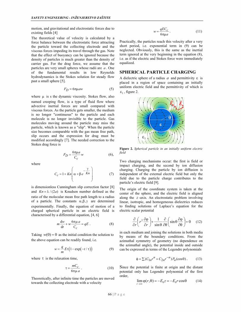
SPHERICAL PARTICLE CHARGING A dielectric sphere of a radius a and permittivity is placed in a region of space containing an initially uniform electric field and the permittivity of which is
1 , figure 2.
z
rE
E
1
z
z
rE
rE
EE
11
Figure 2. Spherical particle in an initially uniform electric field
Two charging mechanisms occur: the first is field or impact charging, and the second by ion diffusion charging. Charging the particle by ion diffusion is independent of the external electric field but only the field due to the particle charge contributes to the particle’s electric field [9].
The origin of the coordinate system is taken at the center of the sphere, and the electric field is aligned along the z -axis. An electrostatic problem involving linear, isotropic, and homogeneous dielectrics reduces to finding solutions of Laplace’s equation for the electric scalar potential
0sinsin
12
rr
r (12)
in each medium and joining the solutions in both media by means of the boundary conditions. From the azimuthal symmetry of geometry (no dependence on the azimuthal angle), the potential inside and outside can be expressed in terms of the Legendre polynomials
1 2( ) (cos )n nn n nC r C r P . (13)
Since the potential is finite at origin and the distant potential only has Legendre polynomial of the first order,
cos),(lim 00 rEzEr
r (14)
D. M. Petković, M. D. Radić , D. D. Krstić, D. N. Jovanović, Vol 9, No2 (2019) 65-69
67 | P a g e
for the potential we obtain
1
20 3
cos ,
cos ,
C r r a
CE r r a
r
. (15)
The potential itself is continuous at ar ,
arar
. (16)
There are no free charges on the surface and the normal component of the displacement vector is continuous across the surface. The normal component being the radial direction and we have
1r a r ar r
(17)
Two boundary conditions yield two equations for the two unknown coefficients which are easily solved to give
11 0
1
3
2C E
, 3
2 1 0( , )C K a E , (18)
where
11
1( , )
2K
(19)
is Clausius-Mossotti factor, also known from Lorentz- Lorentz equation. The electric potential and field in the gas, ar , in the vicinity of the charged particle, are
3
0 0 1 2
imposed induced
cos ( , ) cosa
E r E Kr
(20)
3
1 031 2 ( , ) cosr
aE K E
r r
(21)
3
1 031 ( , ) sin
aE K E
r r r
(22)
Since the potential from an electric dipole depends on 2cos / r , [10],
30
1cos
4dipolep
rr
(23)
we see that, as expected, a uniform field induces a dipole moment in the sphere.
31 1 04 ( , )p K a E
(24)
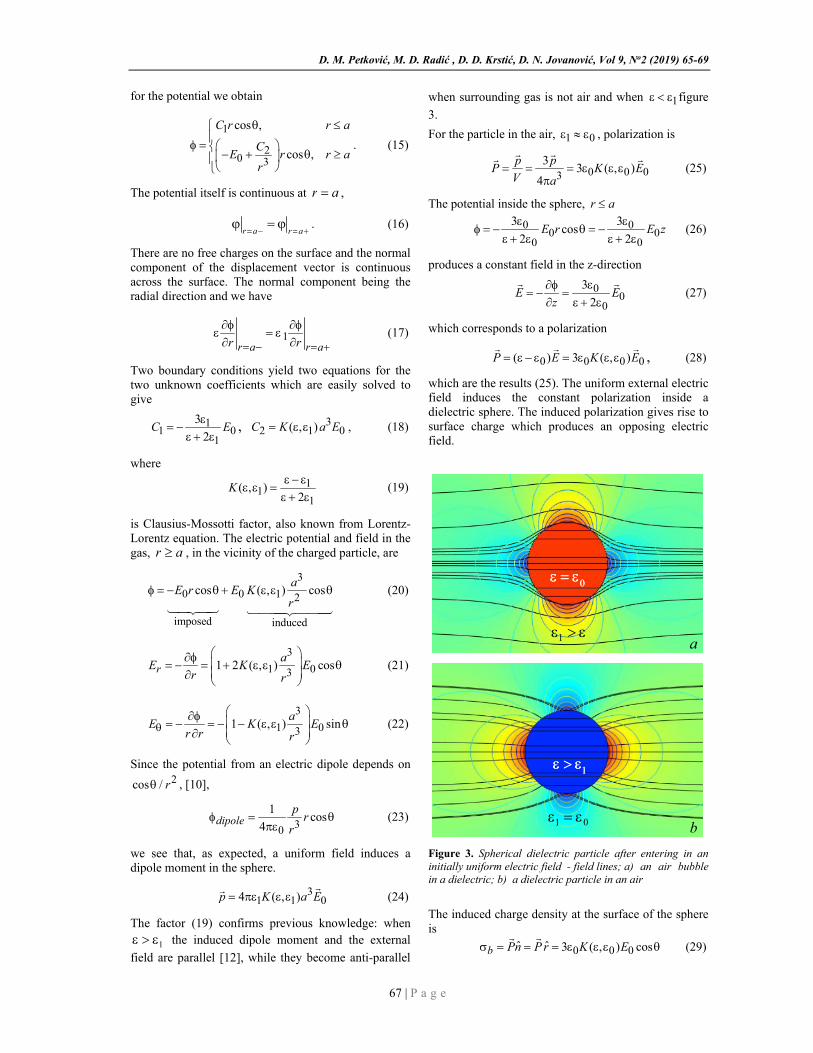
The factor (19) confirms previous knowledge: when
1 the induced dipole moment and the external
field are parallel [12], while they become anti-parallel
when surrounding gas is not air and when 1 figure
3.
For the particle in the air, 1 0 , polarization is
0 0 033
3 ( , )4
p pP K E
V a
(25)
The potential inside the sphere, r a
0 00 0
0 0
3 3cos
2 2E r E z
(26)
produces a constant field in the z-direction
00
0
3
2E E
z
(27)
which corresponds to a polarization
0 0 0 0( ) 3 ( , )P E K E
, (28)
which are the results (25). The uniform external electric field induces the constant polarization inside a dielectric sphere. The induced polarization gives rise to surface charge which produces an opposing electric field.
1 a
0
1 a
0 0
01 b
1
01 b
1 1
Figure 3. Spherical dielectric particle after entering in an initially uniform electric field - field lines; a) an air bubble in a dielectric; b) a dielectric particle in an air
The induced charge density at the surface of the sphere is
0 0 0ˆ ˆ 3 ( , ) cosb Pn P r K E
(29)
SAFETY ENGINEERING - INŽENJERSTVO ZAŠTITE
68 | P a g e
The bound charges on the one hemisphere are
/22 2
0 0 00
2 sin d 3 ( , )b bq a a K E
, (30)
and there is an equal amount of negative charge on the other hemisphere.
The external electric field also ionizes the dielectric region surrounding the sphere. Mobile charge carriers will be driven by the electric field to charge the sphere surface with an additional time-dependent charge ( )q t .
A positive charge can only be deposited on the sphere where the radial component of the electric field is negative, due to negative surface charge on the sphere, and vice versa. The additional charge is distributed uniformly on the sphere surface and its effect on the potential is found by superposition, [11].
3
0 03 20
( )1 2 ( , ) cos
4r
a q tE K E
r a
(31)
The two adjacent charging regions are connected on the sphere at a coordinate r a and c , where the
radial electric field is zero, 0rE . The critical polar
angle on the sphere is
( )
cos cs
q t
q (32)
where
20 0 04 1 2 ( , )sq a K E (32)
or
20 0
04 3
2sq a E
(33)
is a saturation charge [13] and S is the surface of the sphere. Special field line, that passes through the critical point, separates field lines which starting at infinity and terminate on the sphere, from field lines that go around the sphere.
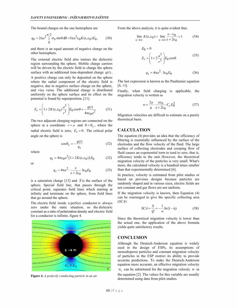
The electric field inside a perfect conductor is always zero under the static situation, so the dielectric constant as a ratio of polarization density and electric field for a conductor is infinite, figure 4.
01
c01
01
c
Figure 4. A perfectly conducting particle in an air
From the above analysis, it is quite evident that,
00
0lim ( , ) lim 1
2K
(34)
3
03
0
1 2 cosr
E
aE E
r
(35)
20 04 3sq a E (36)
The last expression is known as the Pauthenier equation [6, 13].
Finally, when field charging is applicable, the migration velocity is written as
200
0
2
2 ca
w C E
(37)
Migration velocities are difficult to estimate on a purely theoretical basis.
CALCULATION The equation (4) provides an idea that the efficiency of filtering is essentially influenced by the surface of the electrodes and the flow velocity of the fluid. The large surface of collecting electrodes and creeping flow of fluid causes an exponential term to tend to zero, that is, efficiency tends to the unit. However, the theoretical migration velocity of the particles is very small. What's more, the calculated velocity is a hundred times smaller than that experimentally determined [6].
In practice, velocity is estimated from pilot studies or based on previous designs because particles are randomly shaped and in various sizes, electric fields are not constant and gas flows are not uniform.
If the migration velocity is known, then Equation (4) can be rearranged to give the specific collecting area (SCA)
1ln (1 )
SSCA
Q w (38)
Since the theoretical migration velocity is lower than the actual one, the application of the above formula yields quite satisfactory results.
CONCLUSION Although the Deutsch-Anderson equation is widely used in the design of ESPs, its assumptions of monodisperse particles and constant migration velocity of particles in the ESP restrict its ability to provide accurate predictions. To make the Deutsch-Anderson equation more accurate, an effective migration velocity
ew can be substituted for the migration velocity w in
the equation [2]. The values for this variable are usually determined using data from pilot studies.
D. M. Petković, M. D. Radić , D. D. Krstić, D. N. Jovanović, Vol 9, No2 (2019) 65-69
69 | P a g e
REFERENCES
[1] H.J. White: Fifty Years of Electrostatic Precipitation, Journal of the Air Pollution Control Association, Vol.7, No.3, 1957, pp.166-177
[2] G.Y. Lin, T.M. Chen, C.J. Tsai: A Modified Deutsch-Anderson Equation for Predicting the Nanoparticle Collection Efficiency of Electrostatic Precipitators. Aerosol and Air Quality Research, No.12, 2012, pp.697-706.
[3] A. Mizuno: Electrostatic Precipitation, IEEE Trans. on Dielectrics and Electrical Insulation, Vol. 7 No. 5, October 2000.
[4] D.M. Petković, M.D. Radić, D.N. Zigar: Particles Charging In Tubular Electrostatic Precipitators With Polygonal Collection Electrodes, Facta Universitatis Series: Working and Living Environ-mental Protection Vol. 11, No 1, 2014, pp. 13 – 21.
[5] H. Bruus : Theoretical micro fluidics, Lecture notest third edition, Technical University of Denmark, Department of Micro and Nanotechnology, 2006.
[6] G.N. Popa, I. Şora, C.M. Diniş, S.I. Deaconu: An Analysis On the velocity of dust particles in the plate-type electrostatic precipitators used in thermoelectric power plants, Environment Protection Engineering, Vol. 40, No.1, 2014, pp.85-102.
[7] K. Parker: Electrical Operation of Electrostatic Precipitators, The Institution of Engineering and Technology, London, 2007.
ISBN: 0-85296-137-5
[8] E. Cunningham: On the velocity of steady fall of spherical particles through a fluid medium, Proc. Roy. Soc. A83, 1910, pp. 357-365
[9] J.P. Zhang et al.: A Numerical Simulation of Diffusion Charging Effect on Collection Efficiency in Wire-Plate Electrostatic Precipitators, IEEE Transactions On Plasma Science, Vol. 30, No. 9, 2011, pp.1823-1828.
[10] D.M. Petković, D.D. Krstić: Elektrostatička, treće izdanje, Fakultet zaštite na radu, Niš, 2005, ISBN: 86-80261-39-4.
[11] J. G. Hwang, M. Zahn, L. A. A. Pettersson: Bipolar charging and discharging of a perfectly conducting sphere in a lossy medium stressed by a uniform electric field, J. App. Phys, No. 109, 2011, pp.084331-1 - 084331-11.
[12] J.G. Hwang, M. Zahn, F.M. O’Sullivan, L.A.A. Pettersson, O. Hjortstam, R. Liu: Effects of nanoparticle charging on streamer development in transformer oil-based nanofluids, J. App. Phys, No. 107, 2010, pp.014310-1 - 014310-17.
[13] M. Pauthenier, M. Moreau-Hanot: La charge des particules sphériques dans un champ ionisé. J. Phys. Radium, vol. 3, No. 12, 1932, pp.590-613.
BIOGRAPHY Dejan M. Petković was born in 1952 in Niš, Serbia. He graduated from the Faculty of Electronic Engineering, University of Niš, in 1976. He received the Magister of Science and Doctor of Science degrees from the Faculty of Electrical
Engineering, University of Niš, in 1983 and 1992, respectively.After graduation, he joined the Faculty of Occupational Safety in Niš, where he worked as a professor of Electromagnetic radiation, until his retirement in October 2018. His current research interests include the theoretical and numerical modeling of electromagnetic problems. He has published two monographs and six textbooks. His list of publications contains more than one 150 scientific papers published in reviewed journals and international conferences proceedings.
PRORAČUN PERFORMASNI ELEKROSTATIČKIH FILTARA
Milica D. Radić, Dejan M. Petković, Dejan D. Krstić, Dejan N. Jovanović Rezime: Elektrostaitčki filtri (ESP) su uređaji koji se koriste za smanjenje zagađenja ukljanjajem čestica iz vazduha ili gasa korišćenjem elektrostatičke sile koji može biti dizajniran tako da radi sa željenom efikasnošću. Elektrostatički filter je visoko efikasan u sakupljanju nanočestica koje se ne mogu ukloniti uz pomoć mehaničkih separatora ili vlažnih skrubera. Naelektrisavanje čestica, brzina kretanja naelektrisanih čestica i efikasnost sakupljanja opisani su u ovom radu, kako bi pokazali da mnogi faktori utiču na ove tri osnovne vrednosti, koje su ključne za pouzdanost i performanse elektrostatičkih taložnika.
Ključne reči: elektrostatički filtar, efikasnost sakupljanja, brzina kretanja čestica, naelektrisavanje čestica.
UDC: 537.811 DOI: 10.7562/SE2019.9.02.03
Original article
70 | Safety Engineering
DRAGAN KLJAJIĆ11
NIKOLA ĐURIĆ2
KAROLINA KASAŠ-LAŽETIĆ3
1,2,3University of Novi Sad, Faculty of Technical Sciences,
Trg Dositeja Obradovica 6, 21000 Novi Sad, Serbia,
[email protected] [email protected] [email protected]
THE HIGH-FREQUENCY EMF INVESTIGATION OVER THE CAMPUS AREA OF THE UNIVERSITY OF NOVI SAD Abstract: An issue of electromagnetic field (EMF) pollution in the environment has become particularly important due to a continuous increase in the number of artificial EMF sources. Consequently, appropriate measurements and control of EMF level have been performed in different indoor and outdoor environments. This paper presents details about the broadband EMF monitoring campaign over the University of Novi Sad campus. Outdoor measurements of the high-frequency electric field were carried out in spatial and temporal domain, at frequently visited campus’ locations. Exposure assessment was performed in compliance with national legislation, showing that acquired results are far below prescribed reference levels, thus distinguishing the campus as a low exposed area.
Keywords: electromagnetic field, monitoring, radiation exposure.
INTRODUCTION
The number of artificial electromagnetic field (EMF) sources in human surroundings continuously grows, as a consequence of the rapid technological progress of the society. Those sources are an inevitable part of the living and working environment and their constant presence trigger doubt and worry of the general population, regarding possible harmful EMF effects on health [1].
In line with that, the area of EMF investigation has become particularly significant regarding the prevention and protection of the general population EMF exposure. Thus, a great number of EMF surveys and measurement campaigns on an international scale have been conducted. The measurements were being performed in various indoor/outdoor environments, at different periods, using various measuring techniques and equipment [2]-[4].
Regarding places of EMF investigation, particular attention has been paid to sensitive zones such as schools, residential areas, shopping centers, as well as other public spots [5]-[9]. The university campus areas are also classified as highly sensitive. Thus, some scientific studies deal with EMF investigation in those areas [10], [11].
Besides the fact that measurements have to be done in accordance with relevant EMF standards and recommendations [12]-[14], the recent trends suggest continuous monitoring of EMF levels on a long-term basis [15]. Following this approach, the campaign of broadband EMF monitoring was carried out over the University of Novi Sad campus during 2018. This campaign was based on the outdoor long-term monitoring of the high-frequency electric field.
1 Paper is presented in 14th International Conference on Applied Electromagnetics PES 2019, Nis, Serbia
This paper brings an analysis of the monitoring campaign’s results. In the following sections, basic details about the campus area and applied measuring procedure are given, together with an appropriate discussion of the results for the electric field strength measurements and performed exposure assessment.
MONITORING CAMPAIGN’S ACTIVITIES
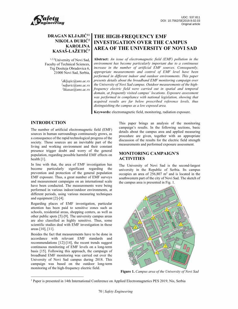
The University of Novi Sad is the second-largest university in the Republic of Serbia. Its campus occupies an area of 256,807 m2 and is located in the southwestern part of the city of Novi Sad. The sketch of the campus area is presented in Fig. 1.
Figure 1. Campus area of the University of Novi Sad
D. Kljajić, N. Đurić, K. Kasaš-Lažetić, Vol 9, No 2 (2020) 70-74
71 | Safety Engineering
A headquarters of the university is located in the campus, as well as seven out of thirteen faculties that belong to the university. Within this campus, there are four main traffic streets and several pedestrian zones. Additionally, this area is surrounded by residential buildings and a few high frequent traffic streets.
According to its position, it is clear that the constant presence of people distinguishes the campus area as highly sensitive. Moreover, people’s daily activities impose necessities for the use of different wireless communication technologies. Therefore, the presence of the high-frequency electric fields originated from a number of EMF sources, is expected in the campus area.
Those facts initiated the idea for the long-term broadband monitoring of the high-frequency electric field at campus’ locations most frequently visited by students and university staff, marked with yellow triangles in Fig. 1. The intention was to obtain information about the temporal fluctuation of the field.
Additionally, in order to achieve an insight into the spatial fluctuation of the field, monitoring campaign included the initial short-term measurements in a spatial domain. Those measurements were carried out along the campus most important pedestrian paths, labeled with red lines in Fig. 1.
A) Preliminary field scanning
The intention of a preliminary field scan over the campus was to determine the spatial changes of the electric field strength at places with large fluctuation of people. Measurements were taken in 1005 measurement points, evenly distributed at the distance of 2 m along the selected pedestrian paths.
During measurements, the instrument’s field probe was positioned at a height of 1.1 m above the ground level, according to the standard SRPS EN 50492:2010 [13].
Measurements were carried out using Narda NBM-550 handheld broadband field meter [16], equipped with the electric field probe EF 0691 [17]. The main parameters of this probe are provided in Table 1 [17].
Table 1. Electric Field Probe EF 0691 [17]
Parameter Value
Frequency range 100 kHz to 6 GHz Measurement range 0.35 V/m to 650 V/m
Linearity ±0.5 dB (2 to 400 V/m) Frequency sensitivity ±1.5 dB (1 MHz to 4 GHz)
The frequency range of the applied electric field probe covers the operating frequencies of almost all known sources of the high-frequency electric field. Therefore, information on the overall and cumulative electric field strength presented at a particular location has been provided.
B) Broadband continuous monitoring
The continuous and long-term monitoring of the electric field at ten measurement locations was performed at the most frequently visited places in the campus. Those places are in front of faculty buildings, students’ cafeterias, students’ dormitories and at the most frequent pedestrian paths.
This phase of the campaign was done applying the protocol developed in the SEMONT (Serbian Electromagnetic Field Monitoring Network) system [18]. It consisted of two parts:
Preliminary electric field spatial scanning, over the grid of 25 measurement points ‒ with the aim to determine the spatial distribution of the field strength at a particular location [12] and to find the point with the field strength maximum (so-called hot spot) [13].
Four-hours monitoring of the field strength in the hot spot ‒ setting up the instrument’s field probe at a height of 1.7 m [18]. The pedestrian access was forbidden during the monitoring, with the aim to achieve measurement conditions as in the so-called unperturbed field area.
Lastly, the exposure assessment was performed, applying the SEMONT’s boundary exposure assessment method [20], calculating the exposure boundaries according to the following expressions:
2 2
max min
,
m mlow up
ref ref
E EGER and GER
E E (1)
and obtaining the range where the real exposure is located.
In this equation, Em is the broadband measured value of the electric field strength, while Eref min and Eref max are minimal and maximal reference levels, prescribed by the legislation [19], for the frequency range of the applied field probe.
MEASUREMENT RESULTS
A short statistical analysis of the results of a preliminary electric field scan along the most important pedestrian paths in the campus is provided in Table 2.
Table 2. Actual field strength values along campus pedestrian paths
Emin [V/m] Eavg [V/m] Emax [V/m] Est. dev. [V/m]
0 0.477 2.547 40.261
These results show that the acquired values of the electric field strength are at least four times lower than the minimal reference level of Eref min = 11 V/m, prescribed by the national legislation [19]. Consequently, the campus area can be considered as a
SAFETY ENGINEERING - INŽENJERSTVO ZAŠTITE
72 | Safety Engineering
zone with a low spatial distribution of the high-frequency electric field.
A) Monitoring results
Broadband monitoring of the field was carried out from 9 A.M. until 1 P.M., which is a rush period at the university, with the high frequency of students and university staff.
A short statistical analysis of the obtained average field strength values is given in Table 3.
Table 3. Average field strength values during the four-hour monitoring
Eavg [V/m]
Location Min Avg Max Std. [%]
1 0.119 0.178 0.242 3.047 2 0.237 0.296 0.353 3.193 3 0.486 0.551 0.612 3.406 4 0.131 0.183 0.245 3.177 5 0.616 0.709 0.756 2.808 6 1.012 1.120 1.271 5.844 7 0.618 0.727 0.894 5.475 8 0.466 0.515 0.576 3.030 9 0.139 0.216 0.454 5.022 10 0.521 0.644 0.748 5.780
Additionally, a short statistical analysis of obtained maximum field strength values is offered in Table 4.
Table 4. Maximum field strength values during the four-hour monitoring
Emax [V/m]
Location Min Avg Max Std. [%]
1 0.275 0.347 0.406 3.366 2 0.433 0.507 0.637 4.831 3 0.702 0.793 0.862 3.729 4 0.250 0.383 0.694 9.409 5 0.785 0.911 1.664 13.618 6 1.342 1.468 1.695 7.795 7 0.966 1.129 1.355 8.539 8 0.794 0.905 1.020 6.690 9 0.308 0.424 2.389 32.474 10 0.851 1.024 1.181 6.717
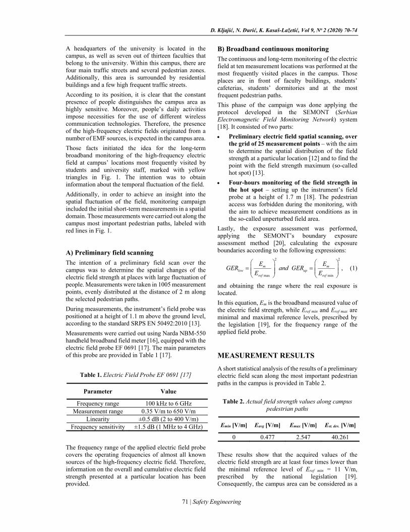
Considering the results from Tables 3 and 4, it can be observed that the highest field strength values were obtained at Location 6.
Temporal changes of the average and maximum field strength values, at this location, are graphically presented in Fig. 2.
Figure 2. Monitoring of the electric field strength at
Location 6
The analysis showed that all obtained values of Eavg and Emax are five or more times below the minimal reference level of Eref min = 11 V/m (red marked line in Fig. 2). Thus, the whole campus area can be considered as one with low intensity of the high-frequency electric field.
Additionally, low values of the standard deviation of Eavg for all locations lead to the conclusion about slow temporal changes of the high-frequency electric field over the campus area.
B) Exposure assessment results
The exposure boundaries were calculated by applying the expression (1), where Eavg values were used as Em. Besides, the minimal and maximal reference levels had values Eref min = 11 V/m and Eref max = 34.8 V/m, according to the national legislation [19] and observed broadband frequency range. A brief statistical analysis of acquired GERlow values is depicted in Table 5.
Table 5. Values of lower exposure boundaries
GERlow
Loc. Min Avg Max Std. [%]
1 1.17×10⁻⁵ 2.70×10⁻⁵ 4.84×10⁻⁵ 8.96×10⁻⁴ 2 4.63×10⁻⁵ 7.30×10⁻⁵ 1.03×10⁻⁴ 1.58×10⁻³ 3 1.95×10⁻⁴ 2.52×10⁻⁴ 3.09×10⁻⁴ 3.10×10⁻³ 4 1.41×10⁻⁵ 2.84×10⁻⁵ 4.96×10⁻⁵ 9.68×10⁻⁴ 5 3.13×10⁻⁴ 4.16×10⁻⁴ 4.72×10⁻⁴ 3.21×10⁻³ 6 8.46×10⁻⁴ 1.04×10⁻³ 1.33×10⁻³ 8.80×10⁻⁴ 7 3.16×10⁻⁴ 4.38×10⁻⁴ 6.60×10⁻⁴ 6.76×10⁻³ 8 1.79×10⁻⁴ 2.20×10⁻⁴ 2.74×10⁻⁴ 2.60×10⁻³ 9 1.60×10⁻⁵ 4.06×10⁻⁵ 1.70×10⁻⁴ 2.38×10⁻³
10 2.25×10⁻⁴ 3.45×10⁻⁴ 4.62×10⁻⁴ 6.02×10⁻³
In addition, short statistical analysis of GERupper values is given in Table 6.
D. Kljajić, N. Đurić, K. Kasaš-Lažetić, Vol 9, No 2 (2020) 70-74
73 | Safety Engineering
Table 6. Values of upper exposure boundaries
GERup
Loc. Min Avg Max Std. [%]
1 1.17×10⁻⁴ 2.70×10⁻⁴ 4.85×10⁻⁴ 8.97×10⁻³ 2 4.64×10⁻⁴ 7.31×10⁻⁴ 1.03×10⁻³ 1.58×10⁻² 3 1.95×10⁻³ 2.52×10⁻³ 3.10×10⁻³ 3.11×10⁻² 4 1.41×10⁻⁴ 2.84×10⁻⁴ 4.96×10⁻⁴ 9.69×10⁻³ 5 3.13×10⁻³ 4.16×10⁻³ 4.72×10⁻³ 3.22×10⁻² 6 8.47×10⁻³ 1.04×10⁻² 1.34×10⁻² 1.09×10⁻¹ 7 3.16×10⁻³ 4.39×10⁻³ 6.61×10⁻³ 6.77×10⁻² 8 1.79×10⁻³ 2.20×10⁻³ 2.74×10⁻³ 2.60×10⁻² 9 1.60×10⁻⁴ 4.06×10⁻⁴ 1.70×10⁻³ 2.38×10⁻²
10 2.25×10⁻³ 3.46×10⁻³ 4.62×10⁻³ 6.03×10⁻²
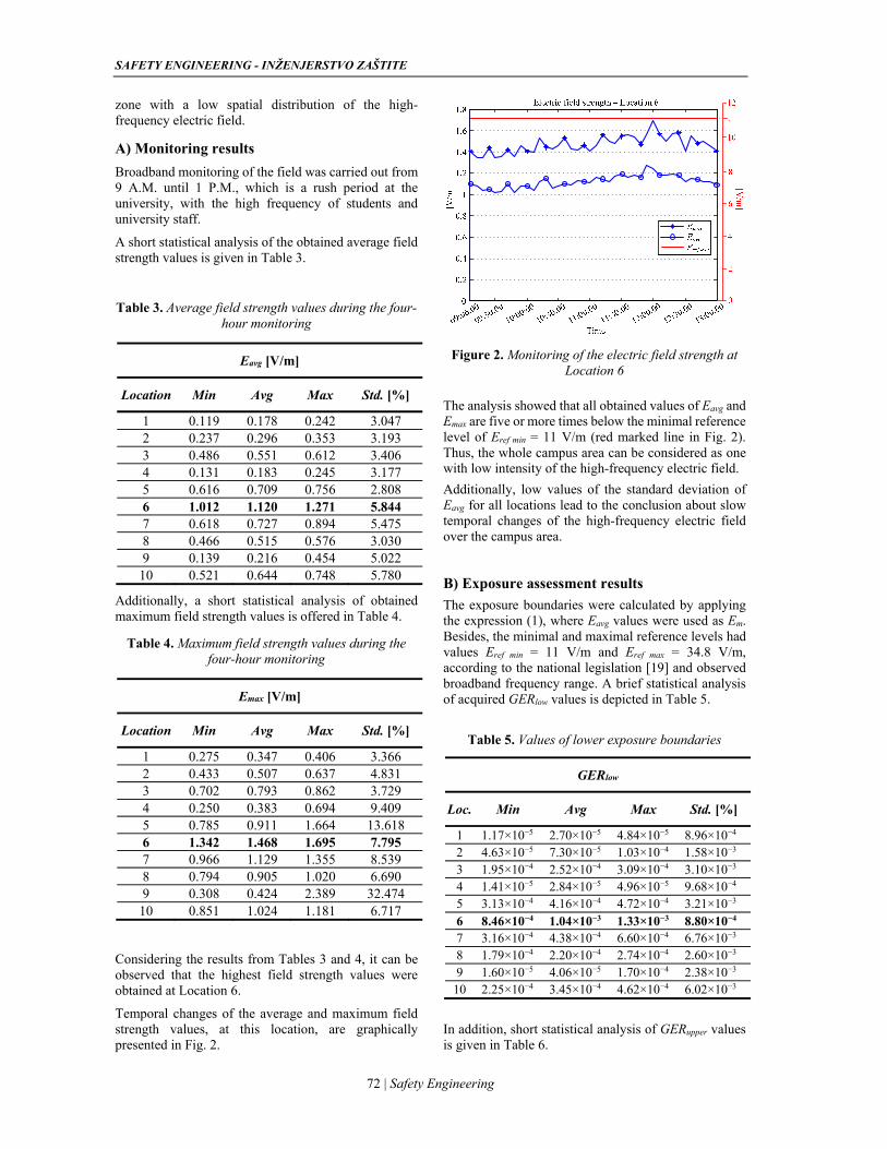
Finally, time fluctuations of exposure boundaries at Location 6, in the graphical form, are presented in Fig. 3.
Figure 3. The exposure boundaries at Location 6.
The conclusions about exposure at campus locations are similar as for the case of the electric field strength values. All values of exposure boundaries are several hundred or thousand times below the maximal allowable level of GERallowed = 1 (red marked line in Fig. 3). Thus, it was once again confirmed assertion about small spatial and temporal distribution of the electric field exposure, over the campus area.
CONCLUSION
Regarding places of EMF investigation, special emphasis should be on highly sensitive areas, where people spend a lot of time, such as the University campus area. Therefore, the outdoor broadband monitoring campaign was conducted over the campus area of the University of Novi Sad.
This campaign consisted of short-term measurements in a spatial domain, as well as of four-hour monitoring of the high-frequency electric field strength, at the campus’ most frequently visited places.
All acquired results are far below reference levels prescribed by the national legislation, suggesting the small spatial and temporal distribution of the electric field. Additionally, low values of the general population exposure distinguish the campus as a low EMF exposed area.
Despite the obtained results, further periodical monitoring campaigns over the campus will certainly be indispensable, having in mind the everyday increase of a number of EMF sources in the surrounding.
Besides, some future campaigns should be oriented toward indoor measurements into campus’ buildings.
REFERENCES [1] Eurobarometer 347, Special Eurobarometer 347,
Eurobarometer 73.3, “Electromagnetic Fields”, 2010, http://ec.europa.eu/public_opinion/archi–ves/ebs/ebs_347_en.pdf.
[2] J. T. Rowley and K. H. Joyner, “Comparative international analysis of radiofrequency exposure surveys of mobile communication radio base stations”, Journal of Exposure Science and Environmental Epidemiology, Vol. 22, Issue 3, pp. 304-315, 2012.
[3] P. Gajšek, P. Ravazzani, J. Wiart, J. Grellier, T. Samaras and G. Thuróczy, “Electromagnetic field exposure assessment in Europe radiofrequency fields (10 MHz–6 GHz)”, Journal of Exposure Science and Environmental Epidemiology, Vol. 25, Issue 1, pp. 37-44, 2015.
[4] S. Sagar, S. Dongus, A. Schoeni, K. Roser, M. Eeftens, B. Struchen, M. Foerster, N. Meier, S. Adem and M. Röösli, “Radiofrequency electromagnetic field exposure in everyday microenvironments in Europe: a systematic literature review”, Journal of Exposure Science and Environmental Epidemiology, Vol. 28, Issue 2, pp. 147-160, 2017.
[5] World Health Organization, “WHO research agenda for radiofrequency fields”, WHO research agenda for radiofrequency fields, 2010.
[6] M. Gallastegi, A. Huss, L. Santa-Marina, J. J. Aurrekoetxea, M. Guxens, L. E. Birks, J. Ibarluzea, D. Guerra, M. Röösli and A. Jiménez-Zabala, “Children's exposure assessment of radiofrequency fields: Comparison between spot and personal measurements”, Environment international, Vol. 118, pp. 60-69, 2018, https://doi.org/10.1016/j.envint.2018.05.028.
[7] K. Karipidis, S. Henderson, D. Wijayasinghe, L. Tjong and R. Tinker, “Exposure to Radiofrequency Electromagnetic Fields from Wi-Fi in Australian Schools”, Radiation Protection Dosimetry, Vol. 175, Issue 4, pp. 432-439, 2017, doi:10.1093/rpd/ncw370.
[8] J. Karpowicz, S. De Miguel-Bilbao, P. Zradzńnski, K. Gryz, F. Falcone and V. Ramos, “Comparative Study of Radiofrequency Electromagnetic Exposure in the Public Shopping Centers”, IEEE International Symposium on Electromagnetic
SAFETY ENGINEERING - INŽENJERSTVO ZAŠTITE
74 | Safety Engineering
Compatibility (EMC Europe 2018), Amsterdam, The Netherlands, 27-30 August 2018, pp. 972-975.
[9] L. van Wel, R. Vermeulen, M. van Eijsden, T. Vrijkotte, H. Kromhout and A. Huss, “Radiofrequency exposure levels in Amsterdam schools”, Bioelectromagnetics, Vol. 38, Issue 5, pp. 397-400, 2017, http:// dx.doi.org/10.1002–/bem.22053.
[10] F. C. Kunter, “Students Exposure to Radio Frequency Electromagnetic Fields in Marmara University”, Marmara Science Journal, Vol. 27, No. 1, pp. 32-36, 2015, doi:http://dx.doi.org/–10.7240/mufbed.70492.
[11] C. Kurnaz, “An Empirical Modeling of Electromagnetic Pollution on University Campus”, Applied Computational Electromagnetics Society Newsletter, Vol. 33, No. 1, pp. 111-114, 2018.
[12] Basic standard on measurement and calculation procedures for human exposure to electric, magnetic and electromagnetic fields (0 Hz – 300 GHz), SRPS EN 50413:2010, 2010.
[13] Basic standard for the in-situ measurement of electromagnetic field strength related to human exposure in the vicinity of base stations, SRPS EN 50492:2010, 2010.
[14] “Guidelines for limiting exposure to time-varying electric, magnetic, and electromagnetic fields (up to 300 GHz)”, International Commission on non-ionizing radiation protection (ICNIRP), http://www.icnirp.de/documents/emfgdl.pdf,1998
[15] ITU-T K.83, Recommendation ITU-T K.83 – Monitoring electromagnetic field, 03/2011.
[16] Narda Safety Test Solutions GmbH, NBM-550 Broadband Field Meter User’s Guide, 2006.
[17] Narda Safety Test Solutions GmbH, EF 0691 Electric Field User’s Guide, 2006.
[18] N. Djuric, D. Kljajic, K. Kasas-Lazetic and V. Bajovic, "The measurement procedure in the SEMONT monitoring system," Environmental Monitoring and Assessment, March 2014, Volume 186, Issue 3, pp. 1865-1874, 2014.
[19] “Regulation on the limits of exposure to non-ionizing radiation”, the law of the Republic of Serbia, no. 104/09.
[20] D. Kljajic and N. Djuric, “The adaptive boundary approach for exposure assessment in a broadband EMF monitoring”, Measurement, Volume 93, pp. 515–523, 2016, DOI:10.10-16/j.measurement.–2016.07.055.
ACKNOWLEDGEMENTS This work is supported by the Ministry of Education, Science and Technological Development of the Republic of Serbia, under the grant for project TR 32055.
BIOGRAPHY of the first author Dragan Kljajić was born on April 29, 1987, in Novi Sad, the Republic of Serbia. He received a Ph.D. in Electrical and Computer Engineering, at Faculty of Technical Sciences in Novi Sad, at the Department of Power, Electronic and Telecommunication Engineering. He works as an Assistant Professor at the same Department. His scientific area is theoretical electrotechnics, while his research interests are in the field of theoretical electrical engineering, theoretical and applied electromagnetics and microelectronics. He is the author or co-author of more than 50 scientific papers, published in Proceedings of international conferences and high impact factor journals. He is a member of the IEEE society.
ISPITIVANJE EM POLJA VISOKIH FREKVENCIJA U OKVIRU
KAMPUSA UNIVERZITETA U NOVOM SADU
Dragan Kljajić, Nikola Đurić, Karolina Kasaš-Lažetić Rezime: Problem zagađenosti životne sredine elektromagnetskim poljima (EMP) postao je naročito važan usled stalnog porasta broja veštačkih izvora EMP-a. Stoga se odgovarajuća merenja i kontrola nivoa EMP-a obavljaju na otvorenom i u zatvorenom prostoru. U ovom radu su predstavljeni detalji kampanje širokopojasnog merenja nivoa EMP-a u okviru kampusa Univerziteta u Novom Sadu. Merenja nivoa električnog polja visokih frekvencija na otvorenom su obavljena u prostornom i vremenskom domenu, na najfrekventnijim lokacijama u kampusu. Procena izloženosti opšte populacije je izvršena u skladu sa nacionalnim zakonodavstvom, pokazavši da su dobijene vrednosti nivoa polja daleko ispod propisanih referentnih graničnih nivoa, čime se oblast kampusa izdvaja kao oblast sa niskom EM izloženošću.
Ključne reči: elektromagnetsko polje, monitoring, izloženost zračenju.
UDC: 725.381:355.58 DOI: 10.7562/SE2019.9.02.04
Original article
75 | Safety Engineering
RADOJE JEVTIĆ
Elektrotehnička škola „ Nikola Tesla“,
Aleksandra Medvedeva 18, 18000 Niš, Serbia
EVACUATION FROM A PARKING GARAGE
Abstract: Traffic jam in large cities is a frequent problem. A lot of vehicles, the lack of parking space, and old narrow streets are just some of the reasons. Parking garages can partly solve this problem. They can be stationary and modular, with a capacity of several thousand parking lots. Although these facilities are not completely closed, there is still a possibility of fire. Parking garages are designed to be used by a large number of people at the same time; however, in case of fire, those people must leave the facility. This paper has been written to demonstrate the potential evacuation from the parking garage using simulation software. Keywords: garage, simulation, fire, evacuation.
INTRODUCTION
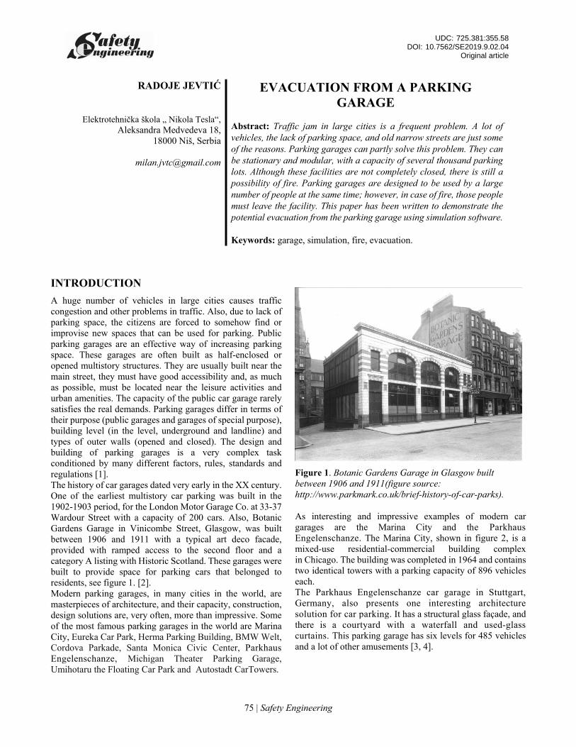
A huge number of vehicles in large cities causes traffic congestion and other problems in traffic. Also, due to lack of parking space, the citizens are forced to somehow find or improvise new spaces that can be used for parking. Public parking garages are an effective way of increasing parking space. These garages are often built as half-enclosed or opened multistory structures. They are usually built near the main street, they must have good accessibility and, as much as possible, must be located near the leisure activities and urban amenities. The capacity of the public car garage rarely satisfies the real demands. Parking garages differ in terms of their purpose (public garages and garages of special purpose), building level (in the level, underground and landline) and types of outer walls (opened and closed). The design and building of parking garages is a very complex task conditioned by many different factors, rules, standards and regulations [1]. The history of car garages dated very early in the XX century. One of the earliest multistory car parking was built in the 1902-1903 period, for the London Motor Garage Co. at 33-37 Wardour Street with a capacity of 200 cars. Also, Botanic Gardens Garage in Vinicombe Street, Glasgow, was built between 1906 and 1911 with a typical art deco facade, provided with ramped access to the second floor and a category A listing with Historic Scotland. These garages were built to provide space for parking cars that belonged to residents, see figure 1. [2]. Modern parking garages, in many cities in the world, are masterpieces of architecture, and their capacity, construction, design solutions are, very often, more than impressive. Some of the most famous parking garages in the world are Marina City, Eureka Car Park, Herma Parking Building, BMW Welt, Cordova Parkade, Santa Monica Civic Center, Parkhaus Engelenschanze, Michigan Theater Parking Garage, Umihotaru the Floating Car Park and Autostadt CarTowers.
Figure 1. Botanic Gardens Garage in Glasgow built between 1906 and 1911(figure source: http://www.parkmark.co.uk/brief-history-of-car-parks).
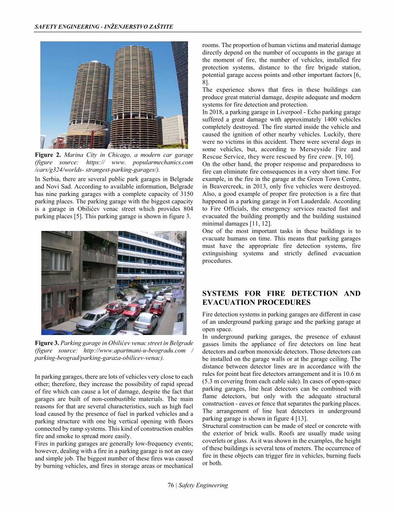
As interesting and impressive examples of modern car garages are the Marina City and the Parkhaus Engelenschanze. The Marina City, shown in figure 2, is a mixed-use residential-commercial building complex in Chicago. The building was completed in 1964 and contains two identical towers with a parking capacity of 896 vehicles each. The Parkhaus Engelenschanze car garage in Stuttgart, Germany, also presents one interesting architecture solution for car parking. It has a structural glass façade, and there is a courtyard with a waterfall and used-glass curtains. This parking garage has six levels for 485 vehicles and a lot of other amusements [3, 4].
SAFETY ENGINEERING - INŽENJERSTVO ZAŠTITE
76 | Safety Engineering
Figure 2. Marina City in Chicago, a modern car garage (figure source: https:// www. popularmechanics.com /cars/g324/worlds- strangest-parking-garages/).
In Serbia, there are several public park garages in Belgrade and Novi Sad. According to available information, Belgrade has nine parking garages with a complete capacity of 3150 parking places. The parking garage with the biggest capacity is a garage in Obilićev venac street which provides 804 parking places [5]. This parking garage is shown in figure 3.
Figure 3. Parking garage in Obilićev venac street in Belgrade (figure source: http://www.apartmani-u-beogradu.com / parking-beograd/parking-garaza-obilicev-venac).
In parking garages, there are lots of vehicles very close to each other; therefore, they increase the possibility of rapid spread of fire which can cause a lot of damage, despite the fact that garages are built of non-combustible materials. The main reasons for that are several characteristics, such as high fuel load caused by the presence of fuel in parked vehicles and a parking structure with one big vertical opening with floors connected by ramp systems. This kind of construction enables fire and smoke to spread more easily. Fires in parking garages are generally low-frequency events; however, dealing with a fire in a parking garage is not an easy and simple job. The biggest number of these fires was caused by burning vehicles, and fires in storage areas or mechanical
rooms. The proportion of human victims and material damage directly depend on the number of occupants in the garage at the moment of fire, the number of vehicles, installed fire protection systems, distance to the fire brigade station, potential garage access points and other important factors [6, 8]. The experience shows that fires in these buildings can produce great material damage, despite adequate and modern systems for fire detection and protection. In 2018, a parking garage in Liverpool - Echo parking garage suffered a great damage with approximately 1400 vehicles completely destroyed. The fire started inside the vehicle and caused the ignition of other nearby vehicles. Luckily, there were no victims in this accident. There were several dogs in some vehicles, but, according to Merseyside Fire and Rescue Service, they were rescued by fire crew. [9, 10]. On the other hand, the proper response and preparedness to fire can eliminate fire consequences in a very short time. For example, in the fire in the garage at the Green Town Centre, in Beavercreek, in 2013, only five vehicles were destroyed. Also, a good example of proper fire protection is a fire that happened in a parking garage in Fort Lauderdale. According to Fire Officials, the emergency services reacted fast and evacuated the building promptly and the building sustained minimal damages [11, 12]. One of the most important tasks in these buildings is to evacuate humans on time. This means that parking garages must have the appropriate fire detection systems, fire extinguishing systems and strictly defined evacuation procedures.
SYSTEMS FOR FIRE DETECTION AND EVACUATION PROCEDURES
Fire detection systems in parking garages are different in case of an underground parking garage and the parking garage at open space. In underground parking garages, the presence of exhaust gasses limits the appliance of fire detectors on line heat detectors and carbon monoxide detectors. Those detectors can be installed on the garage walls or at the garage ceiling. The distance between detector lines are in accordance with the rules for point heat fire detectors arrangement and it is 10.6 m (5.3 m covering from each cable side). In cases of open-space parking garages, line heat detectors can be combined with flame detectors, but only with the adequate structural construction - eaves or fence that separates the parking places. The arrangement of line heat detectors in underground parking garage is shown in figure 4 [13]. Structural construction can be made of steel or concrete with the exterior of brick walls. Roofs are usually made using coverlets or glass. As it was shown in the examples, the height of these buildings is several tens of meters. The occurrence of fire in these objects can trigger fire in vehicles, burning fuels or both.
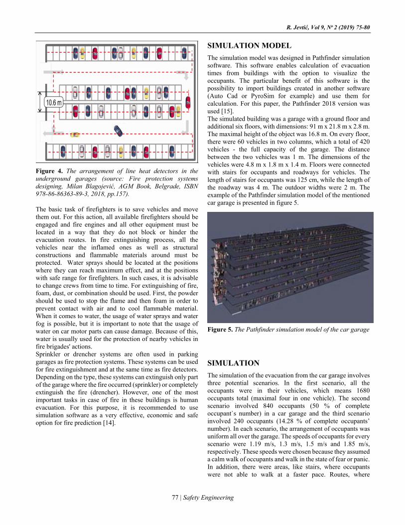
R. Jevtić, Vol 9, No 2 (2019) 75-80
77 | Safety Engineering
Figure 4. The arrangement of line heat detectors in the underground garages (source: Fire protection systems designing, Milan Blagojević, AGM Book, Belgrade, ISBN 978-86-86363-89-3, 2018, pp.157).
The basic task of firefighters is to save vehicles and move them out. For this action, all available firefighters should be engaged and fire engines and all other equipment must be located in a way that they do not block or hinder the evacuation routes. In fire extinguishing process, all the vehicles near the inflamed ones as well as structural constructions and flammable materials around must be protected. Water sprays should be located at the positions where they can reach maximum effect, and at the positions with safe range for firefighters. In such cases, it is advisable to change crews from time to time. For extinguishing of fire, foam, dust, or combination should be used. First, the powder should be used to stop the flame and then foam in order to prevent contact with air and to cool flammable material. When it comes to water, the usage of water sprays and water fog is possible, but it is important to note that the usage of water on car motor parts can cause damage. Because of this, water is usually used for the protection of nearby vehicles in fire brigades' actions. Sprinkler or drencher systems are often used in parking garages as fire protection systems. These systems can be used for fire extinguishment and at the same time as fire detectors. Depending on the type, these systems can extinguish only part of the garage where the fire occurred (sprinkler) or completely extinguish the fire (drencher). However, one of the most important tasks in case of fire in these buildings is human evacuation. For this purpose, it is recommended to use simulation software as a very effective, economic and safe option for fire prediction [14].
SIMULATION MODEL
The simulation model was designed in Pathfinder simulation software. This software enables calculation of evacuation times from buildings with the option to visualize the occupants. The particular benefit of this software is the possibility to import buildings created in another software (Auto Cad or PyroSim for example) and use them for calculation. For this paper, the Pathfinder 2018 version was used [15]. The simulated building was a garage with a ground floor and additional six floors, with dimensions: 91 m x 21.8 m x 2.8 m. The maximal height of the object was 16.8 m. On every floor, there were 60 vehicles in two columns, which a total of 420 vehicles - the full capacity of the garage. The distance between the two vehicles was 1 m. The dimensions of the vehicles were 4.8 m x 1.8 m x 1.4 m. Floors were connected with stairs for occupants and roadways for vehicles. The length of stairs for occupants was 125 cm, while the length of the roadway was 4 m. The outdoor widths were 2 m. The example of the Pathfinder simulation model of the mentioned car garage is presented in figure 5.
Figure 5. The Pathfinder simulation model of the car garage
SIMULATION
The simulation of the evacuation from the car garage involves three potential scenarios. In the first scenario, all the occupants were in their vehicles, which means 1680 occupants total (maximal four in one vehicle). The second scenario involved 840 occupants (50 % of complete occupant`s number) in a car garage and the third scenario involved 240 occupants (14.28 % of complete occupants’ number). In each scenario, the arrangement of occupants was uniform all over the garage. The speeds of occupants for every scenario were 1.19 m/s, 1.3 m/s, 1.5 m/s and 1.85 m/s, respectively. These speeds were chosen because they assumed a calm walk of occupants and walk in the state of fear or panic. In addition, there were areas, like stairs, where occupants were not able to walk at a faster pace. Routes, where
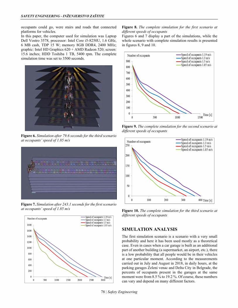
SAFETY ENGINEERING - INŽENJERSTVO ZAŠTITE
78 | Safety Engineering
occupants could go, were stairs and roads that connected platforms for vehicles. In this paper, the computer used for simulation was Laptop Dell Vostro 3578, processor: Intel Core i5-8250U, 1.6 GHz, 6 MB cash, TDP 15 W; memory 8GB DDR4, 2400 MHz; graphic: Intel HD Graphics 620 + AMD Radeon 520; screen: 15.6 inches; HDD Toshiba 1 TB, 5400 rpm. The complete simulation time was set to 3500 seconds.
Figure 6. Simulation after 79.6 seconds for the third scenario at occupants’ speed of 1.85 m/s
Figure 7. Simulation after 243.1 seconds for the first scenario at occupants’ speed of 1.85 m/s
Figure 8. The complete simulation for the first scenario at different speeds of occupants Figures 6 and 7 display a part of the simulations, while the whole scenario with complete simulation results is presented in figures 8, 9 and 10.
Figure 9. The complete simulation for the second scenario at different speeds of occupants
Figure 10. The complete simulation for the third scenario at different speeds of occupants
SIMULATION ANALYSIS
The first simulation scenario is a scenario with a very small probability and here it has been used mostly as a theoretical case. Even in cases when a car garage is built as an additional part of another building (a supermarket, an airport, etc.), there is a low probability that all people would be in their vehicles at one particular moment. According to the measurements carried out in July and August in 2018, in daily hours, at the parking garages Zeleni venac and Delta City in Belgrade, the percents of occupants present in the garages at the same moment were from 8.5 % to 19.2 %. Of course, these numbers can vary and depend on many different factors.
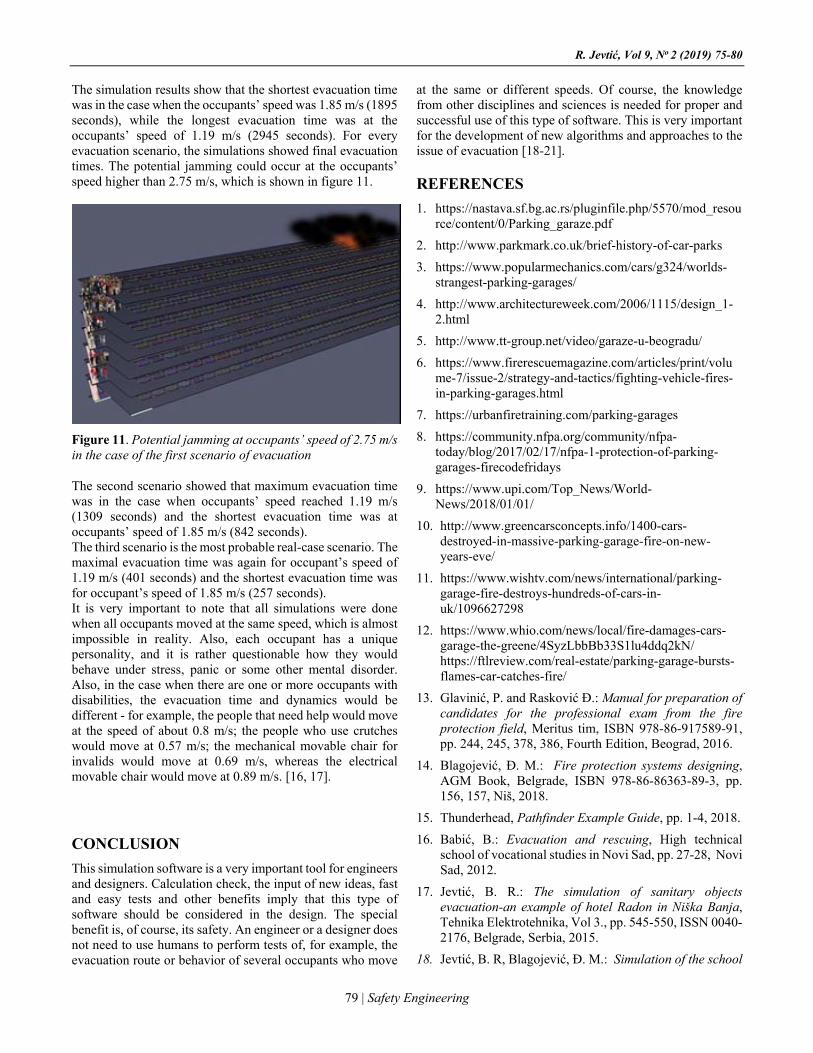
R. Jevtić, Vol 9, No 2 (2019) 75-80
79 | Safety Engineering
The simulation results show that the shortest evacuation time was in the case when the occupants’ speed was 1.85 m/s (1895 seconds), while the longest evacuation time was at the occupants’ speed of 1.19 m/s (2945 seconds). For every evacuation scenario, the simulations showed final evacuation times. The potential jamming could occur at the occupants’ speed higher than 2.75 m/s, which is shown in figure 11.
Figure 11. Potential jamming at occupants’ speed of 2.75 m/s in the case of the first scenario of evacuation
The second scenario showed that maximum evacuation time was in the case when occupants’ speed reached 1.19 m/s (1309 seconds) and the shortest evacuation time was at occupants’ speed of 1.85 m/s (842 seconds). The third scenario is the most probable real-case scenario. The maximal evacuation time was again for occupant’s speed of 1.19 m/s (401 seconds) and the shortest evacuation time was for occupant’s speed of 1.85 m/s (257 seconds). It is very important to note that all simulations were done when all occupants moved at the same speed, which is almost impossible in reality. Also, each occupant has a unique personality, and it is rather questionable how they would behave under stress, panic or some other mental disorder. Also, in the case when there are one or more occupants with disabilities, the evacuation time and dynamics would be different - for example, the people that need help would move at the speed of about 0.8 m/s; the people who use crutches would move at 0.57 m/s; the mechanical movable chair for invalids would move at 0.69 m/s, whereas the electrical movable chair would move at 0.89 m/s. [16, 17].
CONCLUSION
This simulation software is a very important tool for engineers and designers. Calculation check, the input of new ideas, fast and easy tests and other benefits imply that this type of software should be considered in the design. The special benefit is, of course, its safety. An engineer or a designer does not need to use humans to perform tests of, for example, the evacuation route or behavior of several occupants who move
at the same or different speeds. Of course, the knowledge from other disciplines and sciences is needed for proper and successful use of this type of software. This is very important for the development of new algorithms and approaches to the issue of evacuation [18-21].
REFERENCES
1. https://nastava.sf.bg.ac.rs/pluginfile.php/5570/mod_resource/content/0/Parking_garaze.pdf
2. http://www.parkmark.co.uk/brief-history-of-car-parks
3. https://www.popularmechanics.com/cars/g324/worlds-strangest-parking-garages/
4. http://www.architectureweek.com/2006/1115/design_1-2.html
5. http://www.tt-group.net/video/garaze-u-beogradu/
6. https://www.firerescuemagazine.com/articles/print/volume-7/issue-2/strategy-and-tactics/fighting-vehicle-fires-in-parking-garages.html
7. https://urbanfiretraining.com/parking-garages
8. https://community.nfpa.org/community/nfpa-today/blog/2017/02/17/nfpa-1-protection-of-parking-garages-firecodefridays
9. https://www.upi.com/Top_News/World-News/2018/01/01/
10. http://www.greencarsconcepts.info/1400-cars-destroyed-in-massive-parking-garage-fire-on-new-years-eve/
11. https://www.wishtv.com/news/international/parking-garage-fire-destroys-hundreds-of-cars-in-uk/1096627298
12. https://www.whio.com/news/local/fire-damages-cars-garage-the-greene/4SyzLbbBb33S1lu4ddq2kN/ https://ftlreview.com/real-estate/parking-garage-bursts-flames-car-catches-fire/
13. Glavinić, P. and Rasković Đ.: Manual for preparation of candidates for the professional exam from the fire protection field, Meritus tim, ISBN 978-86-917589-91, pp. 244, 245, 378, 386, Fourth Edition, Beograd, 2016.
14. Blagojević, Đ. M.: Fire protection systems designing, AGM Book, Belgrade, ISBN 978-86-86363-89-3, pp. 156, 157, Niš, 2018.
15. Thunderhead, Pathfinder Example Guide, pp. 1-4, 2018.
16. Babić, B.: Evacuation and rescuing, High technical school of vocational studies in Novi Sad, pp. 27-28, Novi Sad, 2012.
17. Jevtić, B. R.: The simulation of sanitary objects evacuation-an example of hotel Radon in Niška Banja, Tehnika Elektrotehnika, Vol 3., pp. 545-550, ISSN 0040-2176, Belgrade, Serbia, 2015.
18. Jevtić, B. R, Blagojević, Đ. M.: Simulation of the school
SAFETY ENGINEERING - INŽENJERSTVO ZAŠTITE
80 | Safety Engineering
object evacuation, Tehnika elektrotehnika , Vol 2, pp. 365-370, ISSN 0040-2176, Beograd, Serbia, 2013.
19. Jevtić, B. R.: Security in metro-an example for simulation of evacuation from subway, Facta Universitatis, Working and Environmental Protection, Vol 13, No 3, pp. 197-208, ISSN 0354-804X, Niš, Serbia, 2016.
20. Kuligowski, E. D.: Modeling Human Behavior During Building Fires, NIST National Institute of Standards and Technology, NIST Technical Note 1619, USA, 2008.
21. Galea, R.E.: The Developement and Validation of a Rail Car Evacuation Model, Proceedings of the 13th International Fire Science & Engineering Conference INTERFLAM 2013, Interscience, pp.1013-1034, 2013.
22. Walsson, Lee.: Planning for evacuating people with disability, International Fire Protection Magazine, pp. 48-50, Issue 61, 2015.
BIOGRAPHY Radoje Jevtić was born in Aleksinac, Serbia, in 1973. He received a diploma in electrical engineering for automatics and electronics from the Faculty of Electronic Engineering at the University of Niš, a diploma of Magister of Technical Sciences from Faculty of Occupational Safety, and a PhD diploma in technical sciences from Faculty of Occupational Safety, University of Niš. His main areas of research include fire and burglary protection systems, simulations, fire and burglary sensors, etc. He is currently working as a teacher of vocational subjects at Electrotechnical School “Nikola Tesla” in Niš.
EVAKUACIJA IZ AUTO PARKING GARAŽE
Radoje Jevtić
Elektrotehnička škola „ Nikola Tesla“, Aleksandra Medvedeva 18, 18000 Niš,
Sažetak: Problem zagušenja saobraćaja u velikim gradovima je veoma čest. Veći broj vozila, nedostatak prostora za parkiranje, stare uske ulice su samo neki od razloga ovog problema.Parking garaže mogu delimično rešiti ovaj problem. One mogu biti stacionarne i montažne. Kapacitet garaža može biti veći od nekoliko stotina vozila. Iako se ovi objekti realizuju kao poluotvoreni, mogućnosti za požar postoje. Broj ljudi u garaži u jednom trenutku može biti različit, ali u slučaju požara, ti ljudi moraju napustiti objekt. Ovaj rad je napisan da pokaže mogućnosti evakuacije iz auto parking garaže realizovane simulacionim softverom. Ključne reči: garaža, simulacija, požar, evakuacija.
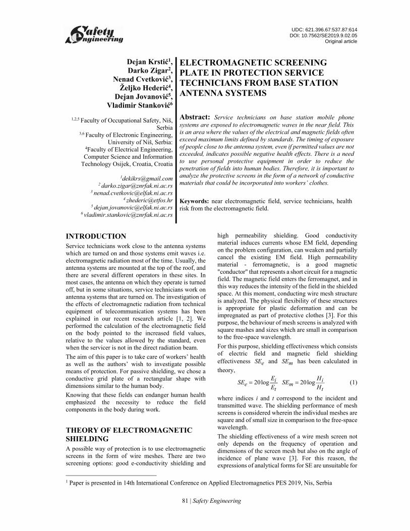
UDC: 621.396.67:537.87:614 DOI: 10.7562/SE2019.9.02.05
Original article
81 | Safety Engineering
Dejan Krstić1, Darko Zigar2,
Nenad Cvetković3, Željko Hederić4,
Dejan Jovanović5, Vladimir Stanković6
1,2,5 Faculty of Occupational Safety, Niš, Serbia
3,6 Faculty of Electronic Engineering, University of Niš, Serbia:
4Faculty of Electrical Engineering, Computer Science and Information
Technology Osijek, Croatia, Croatia
[email protected] [email protected]
3 [email protected] [email protected]
5 [email protected] [email protected]
ELECTROMAGNETIC SCREENING PLATE IN PROTECTION SERVICE TECHNICIANS FROM BASE STATION ANTENNA SYSTEMS Abstract: Service technicians on base station mobile phone systems are exposed to electromagnetic waves in the near field. This is an area where the values of the electrical and magnetic fields often exceed maximum limits defined by standards. The timing of exposure of people close to the antenna system, even if permitted values are not exceeded, indicates possible negative health effects. There is a need to use personal protective equipment in order to reduce the penetration of fields into human bodies. Therefore, it is important to analyze the protective screens in the form of a network of conductive materials that could be incorporated into workers’ clothes.
Keywords: near electromagnetic field, service technicians, health risk from the electromagnetic field.
INTRODUCTION
Service technicians work close to the antenna systems which are turned on and those systems emit waves i.e. electromagnetic radiation most of the time. Usually, the antenna systems are mounted at the top of the roof, and there are several different operators in these sites. In most cases, the antenna on which they operate is turned off, but in some situations, service technicians work on antenna systems that are turned on. The investigation of the effects of electromagnetic radiation from technical equipment of telecommunication systems has been explained in our recent research article [1, 2]. We performed the calculation of the electromagnetic field on the body pointed to the increased field values, relative to the values allowed by the standard, even when the servicer is not in the direct radiation beam.
The aim of this paper is to take care of workers’ health as well as the authors’ wish to investigate possible means of protection. For passive shielding, we chose a conductive grid plate of a rectangular shape with dimensions similar to the human body.
Knowing that these fields can endanger human health emphasized the necessity to reduce the field components in the body during work.
THEORY OF ELECTROMAGNETIC SHIELDING A possible way of protection is to use electromagnetic screens in the form of wire meshes. There are two screening options: good e-conductivity shielding and
1 Paper is presented in 14th International Conference on Applied Electromagnetics PES 2019, Nis, Serbia
high permeability shielding. Good conductivity material induces currents whose EM field, depending on the problem configuration, can weaken and partially cancel the existing EM field. High permeability material - ferromagnetic, is a good magnetic "conductor" that represents a short circuit for a magnetic field. The magnetic field enters the ferromagnet, and in this way reduces the intensity of the field in the shielded space. At this moment, conducting wire mesh structure is analyzed. The physical flexibility of these structures is appropriate for plastic deformation and can be impregnated as part of protective clothes [3]. For this purpose, the behaviour of mesh screens is analyzed with square mashes and sizes which are small in comparison to the free-space wavelength.
For this purpose, shielding effectiveness which consists of electric field and magnetic field shielding effectiveness eSE and mSE has been calculated in
theory,
20log ie
t
ESE
E 20log i
mt
HSE
H (1)
where indices i and t correspond to the incident and transmitted wave. The shielding performance of mesh screens is considered wherein the individual meshes are square and of small size in comparison to the free-space wavelength.
The shielding effectiveness of a wire mesh screen not only depends on the frequency of operation and dimensions of the screen mesh but also on the angle of incidence of plane wave [3]. For this reason, the expressions of analytical forms for SE are unsuitable for
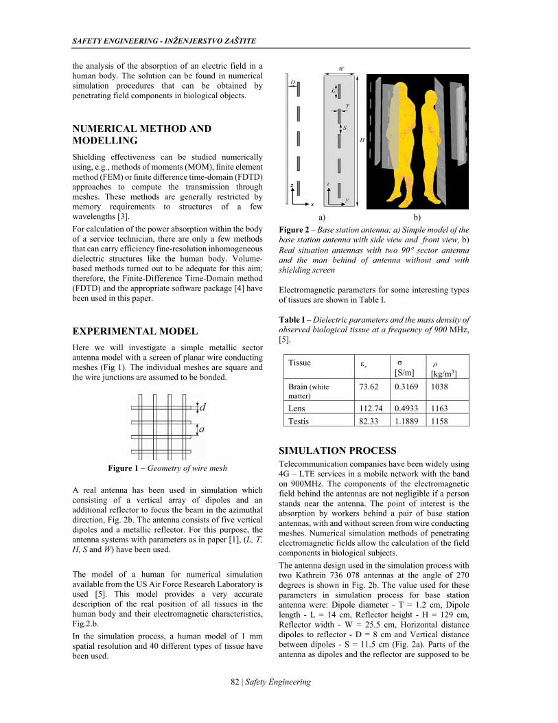
SAFETY ENGINEERING - INŽENJERSTVO ZAŠTITE
82 | Safety Engineering
the analysis of the absorption of an electric field in a human body. The solution can be found in numerical simulation procedures that can be obtained by penetrating field components in biological objects.
NUMERICAL METHOD AND MODELLING
Shielding effectiveness can be studied numerically using, e.g., methods of moments (MOM), finite element method (FEM) or finite difference time-domain (FDTD) approaches to compute the transmission through meshes. These methods are generally restricted by memory requirements to structures of a few wavelengths [3].
For calculation of the power absorption within the body of a service technician, there are only a few methods that can carry efficiency fine-resolution inhomogeneous dielectric structures like the human body. Volume-based methods turned out to be adequate for this aim; therefore, the Finite-Difference Time-Domain method (FDTD) and the appropriate software package [4] have been used in this paper.
EXPERIMENTAL MODEL
Here we will investigate a simple metallic sector antenna model with a screen of planar wire conducting meshes (Fig 1). The individual meshes are square and the wire junctions are assumed to be bonded.
Figure 1 – Geometry of wire mesh
A real antenna has been used in simulation which consisting of a vertical array of dipoles and an additional reflector to focus the beam in the azimuthal direction, Fig. 2b. The antenna consists of five vertical dipoles and a metallic reflector. For this purpose, the antenna systems with parameters as in paper [1], (L, T, H, S and W) have been used.
The model of a human for numerical simulation available from the US Air Force Research Laboratory is used [5]. This model provides a very accurate description of the real position of all tissues in the human body and their electromagnetic characteristics, Fig.2.b.
In the simulation process, a human model of 1 mm spatial resolution and 40 different types of tissue have been used.
a) b)
Figure 2 – Base station antenna; a) Simple model of the base station antenna with side view and front view, b) Real situation antennas with two 90 sector antenna and the man behind of antenna without and with shielding screen
Electromagnetic parameters for some interesting types of tissues are shown in Table I.
Table I – Dielectric parameters and the mass density of observed biological tissue at a frequency of 900 MHz, [5].
Tissue
[S/m] ρ [kg/m3]
Brain (white matter)
73.62 0.3169 1038
Lens 112.74 0.4933 1163
Testis 82.33 1.1889 1158
SIMULATION PROCESS Telecommunication companies have been widely using 4G – LTE services in a mobile network with the band on 900MHz. The components of the electromagnetic field behind the antennas are not negligible if a person stands near the antenna. The point of interest is the absorption by workers behind a pair of base station antennas, with and without screen from wire conducting meshes. Numerical simulation methods of penetrating electromagnetic fields allow the calculation of the field components in biological subjects.
The antenna design used in the simulation process with two Kathrein 736 078 antennas at the angle of 270 degrees is shown in Fig. 2b. The value used for these parameters in simulation process for base station antenna were: Dipole diameter - T = 1.2 cm, Dipole length - L = 14 cm, Reflector height - H = 129 cm, Reflector width - W = 25.5 cm, Horizontal distance dipoles to reflector - D = 8 cm and Vertical distance between dipoles - S = 11.5 cm (Fig. 2a). Parts of the antenna as dipoles and the reflector are supposed to be
εrσ
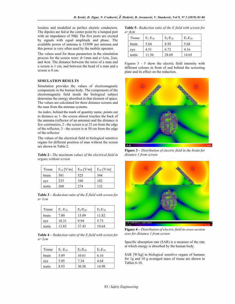
D. Krstić, D. Zigar, N. Cvetković, Ž. Hederić, D. Jovanović, V. Stanković, Vol 9, No 2 (2019) 81-86
83 | Safety Engineering
lossless and modelled as perfect electric conductors. The dipoles are fed at the center point by a lumped port with an impedance of 50Ω. The five ports are excited by signals with equal amplitude and phase. The available power of antenna is 1350W per antenna and this power is very often used by the mobile operator.
The values used for these parameters in the simulation process for the screen were: d=1mm and a=1cm, 2cm, and 4cm. The distance between the torso of a man and a screen is 1 cm, and between the head of a man and a screen is 8 cm.
SIMULATION RESULTS
Simulation provides the values of electromagnetic components in the human body. The components of the electromagnetic field inside the biological subject determine the energy absorbed in that element of space. The values are calculated for three distance screens and the man from the antenna systems.
An index, behind the mark of quantity name, points out to distance as 1- the screen almost touches the back of the antenna (reflector of an antenna) and the distance is few centimeters, 2 - the screen is at 25 cm from the edge of the reflector, 3 - the screen is at 50 cm from the edge of the reflector
The values of the electrical field in biological sensitive organs for different position of man without the screen are shown in Table 2.
Table 2 - The maximum values of the electrical field in organs without screen
Tissue E10 [V/m] E20 [V/m] E30 [V/m]
brain 581 525 344
eye 233 160 102
testis 260 274 132
Table 3 – Reduction ratio of the E field with screen for a=1cm
Tissue E1 /E10 E2/E20 E3/E30
brain 7.80 15.09 11.82
eye 10.31 9.94 5.73
testis 13.83 37.43 19.64
Table 4 – Reduction ratio of the E field with screen for a=2cm
Tissue E1 /E10 E2/E20 E3/E30
brain 5.89 10.61 6.16
eye 5.05 7.34 4.64
testis 8.93 30.58 14.98
Table 5– Reduction ratio of the E field with screen for a=4cm
Tissue E1 /E10 E2/E20 E3/E30
brain 5.64 8.50 5.68
eye 4.51 6.72 4.16
testis 11.56 28.69 14.65
Figures 3 - 5 show the electric field intensity with different colours in front of and behind the screening plate and its effect on the reduction.
Figure 3 – Distribution of electric field in the brain for distance 1 from screen
Figure 4 – Distribution of electric field in cross-section eyes for distance 1 from screen
Specific absorption rate (SAR) is a measure of the rate at which energy is absorbed by the human body.
SAR [W/kg] in biological sensitive organs of humans for 1g and 10 g averaged mass of tissue are shown in Tables 6-10.
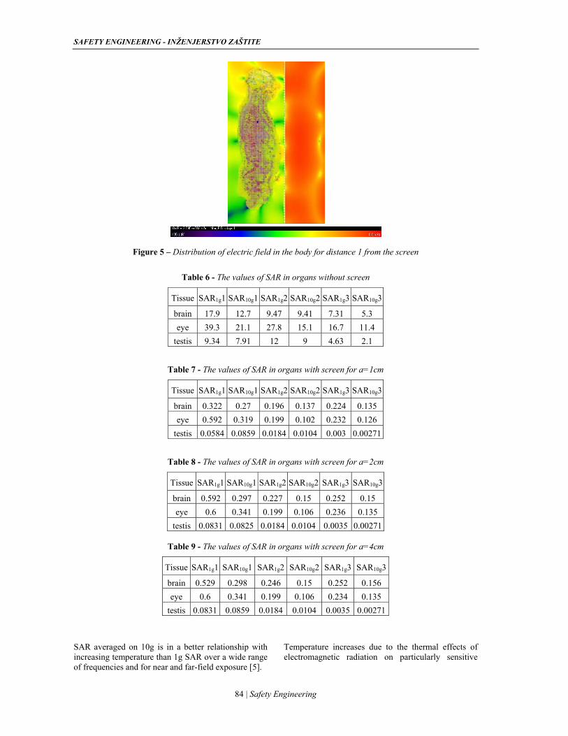
SAFETY ENGINEERING - INŽENJERSTVO ZAŠTITE
84 | Safety Engineering
Figure 5 – Distribution of electric field in the body for distance 1 from the screen
Table 6 - The values of SAR in organs without screen
Tissue SAR1g1 SAR10g1 SAR1g2 SAR10g2 SAR1g3 SAR10g3
brain 17.9 12.7 9.47 9.41 7.31 5.3
eye 39.3 21.1 27.8 15.1 16.7 11.4
testis 9.34 7.91 12 9 4.63 2.1
Table 7 - The values of SAR in organs with screen for a=1cm
Tissue SAR1g1 SAR10g1 SAR1g2 SAR10g2 SAR1g3 SAR10g3
brain 0.322 0.27 0.196 0.137 0.224 0.135
eye 0.592 0.319 0.199 0.102 0.232 0.126
testis 0.0584 0.0859 0.0184 0.0104 0.003 0.00271
Table 8 - The values of SAR in organs with screen for a=2cm
Tissue SAR1g1 SAR10g1 SAR1g2 SAR10g2 SAR1g3 SAR10g3
brain 0.592 0.297 0.227 0.15 0.252 0.15
eye 0.6 0.341 0.199 0.106 0.236 0.135
testis 0.0831 0.0825 0.0184 0.0104 0.0035 0.00271
Table 9 - The values of SAR in organs with screen for a=4cm
Tissue SAR1g1 SAR10g1 SAR1g2 SAR10g2 SAR1g3 SAR10g3
brain 0.529 0.298 0.246 0.15 0.252 0.156
eye 0.6 0.341 0.199 0.106 0.234 0.135
testis 0.0831 0.0859 0.0184 0.0104 0.0035 0.00271
SAR averaged on 10g is in a better relationship with increasing temperature than 1g SAR over a wide range of frequencies and for near and far-field exposure [5].
Temperature increases due to the thermal effects of electromagnetic radiation on particularly sensitive
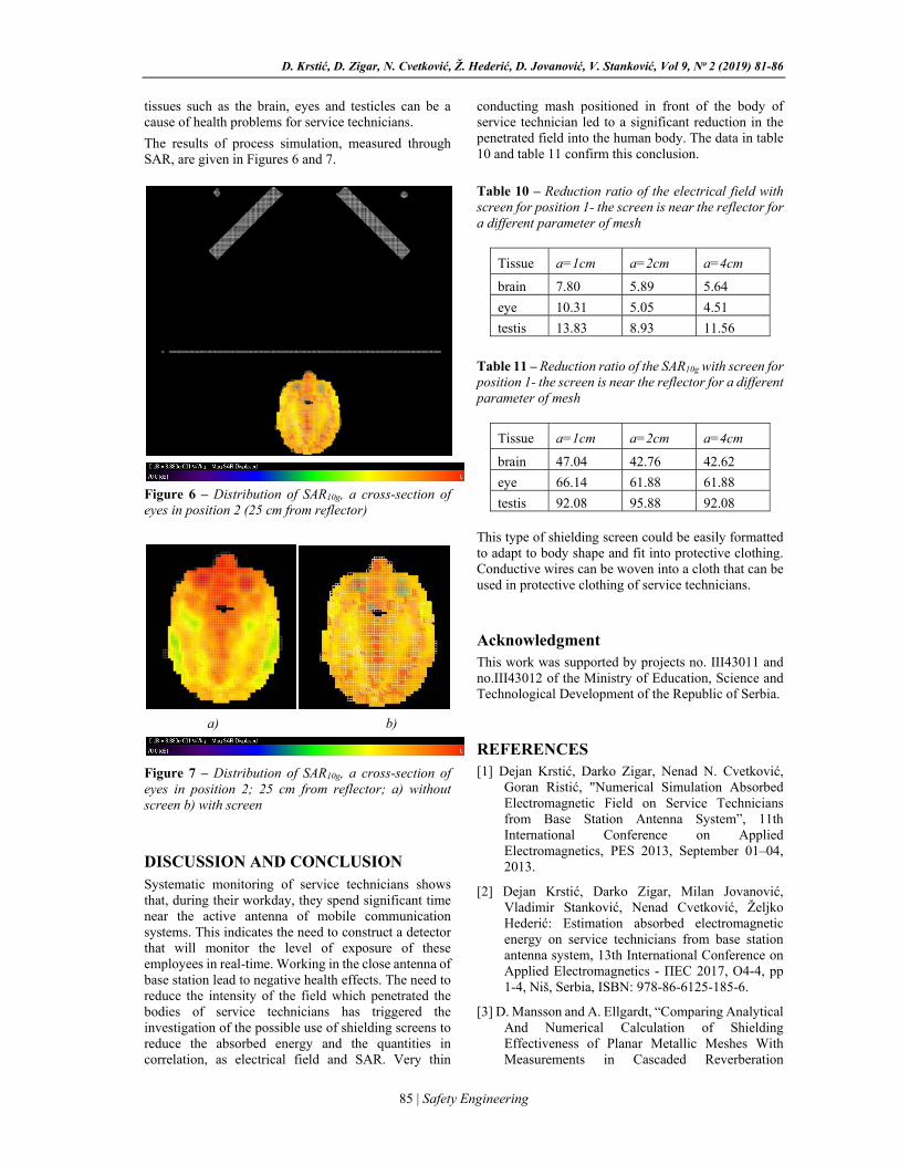
D. Krstić, D. Zigar, N. Cvetković, Ž. Hederić, D. Jovanović, V. Stanković, Vol 9, No 2 (2019) 81-86
85 | Safety Engineering
tissues such as the brain, eyes and testicles can be a cause of health problems for service technicians.
The results of process simulation, measured through SAR, are given in Figures 6 and 7.
Figure 6 – Distribution of SAR10g, a cross-section of eyes in position 2 (25 cm from reflector)
a) b)
Figure 7 – Distribution of SAR10g, a cross-section of eyes in position 2; 25 cm from reflector; a) without screen b) with screen
DISCUSSION AND CONCLUSION Systematic monitoring of service technicians shows that, during their workday, they spend significant time near the active antenna of mobile communication systems. This indicates the need to construct a detector that will monitor the level of exposure of these employees in real-time. Working in the close antenna of base station lead to negative health effects. The need to reduce the intensity of the field which penetrated the bodies of service technicians has triggered the investigation of the possible use of shielding screens to reduce the absorbed energy and the quantities in correlation, as electrical field and SAR. Very thin
conducting mash positioned in front of the body of service technician led to a significant reduction in the penetrated field into the human body. The data in table 10 and table 11 confirm this conclusion.
Table 10 – Reduction ratio of the electrical field with screen for position 1- the screen is near the reflector for a different parameter of mesh
Tissue a=1cm a=2cm a=4cm
brain 7.80 5.89 5.64
eye 10.31 5.05 4.51
testis 13.83 8.93 11.56
Table 11 – Reduction ratio of the SAR10g with screen for position 1- the screen is near the reflector for a different parameter of mesh
Tissue a=1cm a=2cm a=4cm
brain 47.04 42.76 42.62
eye 66.14 61.88 61.88
testis 92.08 95.88 92.08
This type of shielding screen could be easily formatted to adapt to body shape and fit into protective clothing. Conductive wires can be woven into a cloth that can be used in protective clothing of service technicians.
Acknowledgment This work was supported by projects no. III43011 and no.III43012 of the Ministry of Education, Science and Technological Development of the Republic of Serbia.
REFERENCES [1] Dejan Krstić, Darko Zigar, Nenad N. Cvetković,
Goran Ristić, "Numerical Simulation Absorbed Electromagnetic Field on Service Technicians from Base Station Antenna System”, 11th International Conference on Applied Electromagnetics, PES 2013, September 01–04, 2013.
[2] Dejan Krstić, Darko Zigar, Milan Jovanović, Vladimir Stanković, Nenad Cvetković, Željko Hederić: Estimation absorbed electromagnetic energy on service technicians from base station antenna system, 13th International Conference on Applied Electromagnetics - ПЕС 2017, O4-4, pp 1-4, Niš, Serbia, ISBN: 978-86-6125-185-6.
[3] D. Mansson and A. Ellgardt, “Comparing Analytical And Numerical Calculation of Shielding Effectiveness of Planar Metallic Meshes With Measurements in Cascaded Reverberation
SAFETY ENGINEERING - INŽENJERSTVO ZAŠTITE
86 | Safety Engineering
Chambers,” Progress In Electromagnetics Research C, Vol. 31, 123-135, 2012.
[4] Microwave Studio CST, www.cst.com
[5] Visible Human Project, U.S. National Library of Medicine, National Institutes of Health, Available at http://www.nlm. nih.gov/research/visible/ applications.html
[6] A. Hirata and O. Fujiwara, “The correlation between mass-averaged SAR and temperature elevation in the human head model exposed to RF near-fields from 1 to 6 GHz,” Phys Med Biol., vol 54, 2009.
[7] ICNIRP Guidelines for limiting exposure to time-varying Electric, Magnetic and Electromagnetic Fields (up to 300 GHz), Health physics 74(4):494-522;1998.
BIOGRAPHY
Dejan D. Krstić was born in Niš, Serbia, in 1969. He received a degree in Engineering and M.Sc. degrees from the Faculty of Electronic Engineering, Uni-versity of Niš in 1994 and 1999 respectively. He obtained a Ph.D. degree from the Faculty of Occupational Safety, University of Niš in 2010. He has been engaged as a lecturer at the Faculty of Occupational Safety from 1995. He is the founder of the Laboratory of Electromagnetic Radiation and Center for Technical Systems Safety. Dr. Krstić's research interests are biological effects of electromagnetic radiation, numerical methods for electromagnetic field calculation and safety of technical systems. He published 148 papers in international journals or conference proceedings, as author and co-author, as well as eight textbooks.
ELEKTROMAGNETNI EKRANI KAO ZAŠTITA SERVISNOG OSOBLJA NA ANTENSKIM SISTEMIMA BAZNIH STANICA MOBILNE
TELEFONIJE
Dejan Krstić, Darko Zigar, Nenad Cvetković, Željko Hederić, Dejan Jovanović, Vladimir Stanković Rezime: Servisni radnici na baznim stanicama mobilne telefonije su izloženi elektromagnetnom zračenju bliskog polja. Intenziteti električnog i magnetnog polja u ovom prostoru često prekoračuju dozvoljene vrednosti domaćih i međunarodnih standarda. Vreme koje ovi zaposleni provode u poljima u blizini samih antenskih sistema čak i kad su vrednosti polja blizu dozvoljenih vrednosti ukazuje da mogu biti prisutni negativni zdravstveni efekti po ove ljude. Zbog toga je potrebno korišćenje tehničkih sredstava odnosno lične zaštitne opreme da bi se redukovala prodrla polja u ljudska tela. Iz ovih razloga su predmet analize zaštitni ekrani u obliku mreže provodnika koji se mogu ugraditi u radnu odeću. .
Ključne reči: blisko elektromagnetno polje, servisno osoblje, zdravstveni rizik od elektromagnetnih polja.
UDC: 622:314.145:331.45 DOI: 0.7562/SE2019.9.02.06
Original article
87 | Safety Engineering
MIODRAG MILENOVIĆ1
SNEŽANA ŽIVKOVIĆ2
MILAN VELJKOVIĆ3
1University of Niš, Faculty of Philosophy in Niš
2University of Niš, Faculty of Occupational Safety
3University of Niš, Faculty of Occupational Safety
[email protected]@znrfak.ni.ac.rs
SOCIO-DEMOGRAPHIC CHARACTERISTICS AND OCCUPATIONAL INJURIES IN MINERS Abstract: Mining is a branch of industry with a high number of occupational injuries, including light, heavy and fatal injuries. In this study, we examined whether socio-demographic characteristics of employees have impact on the type of occupational injuries. The survey was conducted on a sample of 108 employees at the mine "Lece", who differed in terms of their age, the overall length of service, work experience in the mine, the level of education and the position. The results demonstrated that the group of factors such as the age, the overall length of service, and work experience in the mine, showed significant differences when it comes to occupational to injuries, unlike the factors such as education level and the position (workplace).
Keywords: miners, socio-demographic characteristics, occupational injuries.
INTRODUCTION
Mining is one of the industry branches with a large number of high-risk job positions. Each workday in the mine is different from the previous one and is a danger itself. Moving through cave rooms could be extremely dangerous, and despite comprehensive measures for safe work, in some situations, there is an increased risk for miners. In addition to objective risks, which can cause injuries to employees, such as the non-usage of personal protective equipment, explosive natural gases, the collapsed corridors in the pits, etc., there are many risks related to subjective factors. These risks could be classified into several categories. In this research, we introduced the category of socio-demographic factors, in an attempt to determine their association with occupational injuries. Our sample included the employees in the “Lece” mine in southern Serbia.
Occupational injuries among miners
Mining, in comparison to other industrial branches, has a high incidence of injury, including the one with the most severe outcome [1]. The record of injuries at work, especially injury statistics, is the basis for forming the necessary occupational safety measures, based on the available data [2]. Significant facts that provide information on occupational injury are: time, place and mode of occurrence, injured workers (length of service, education, occupation, age and gender), the number of injured and the injured part of the body, the nature, origin and cause of injury, and the frequency of the events of occupational injuries in individuals [3]. The most important information in mining and coal mining is the number of injuries per year and the number
of injuries per month, although the place where ore can be found and the presence of methane in the pits are also very significant. According to the report of the company "Rudnik" and the float "Rudnik doo", based on the records of occupational safety and health, the most frequent types of injuries are: negligence in the workplace, failure to comply with protective measures, irrational and unsafe work. According to the localization of injuries, the most common types are hand, arm, leg, finger and foot injuries, mainly due to the non-usage of protective equipment. The greatest number of injuries happened in the positions of mining assistant, locomotive driver, drill miner and anchor miner. The highest number of injuries happens on Tuesdays. Also, injuries often occur at the end of winter and in early spring, mainly due to the lack of concentration as a consequence of seasonal variations in the psychophysical state of the human body [4]. Gosh et al. [5], investigating the causes of injuries, concluded that miners who were very satisfied with the existing working conditions had a lower risk of injuries in the workplace. It was also confirmed that employees with no injuries had a positive opinion about the physical environment and always take the necessary precautions. In addition, the same authors concluded that elderly workers, emotional instability, poor perception of working conditions, stress at work and poor performance of procedures that are considered safe, play an important role in employee injuries. The causes of injuries at work are complex and involve various factors. Risks of occupational injuries in mining can occur due to improper use of tools and machines, negligent behavior of employees, due to failure to comply with protective measures when moving around the machines, passing between the wagons, standing under suspended loads, passing over tread on the move,
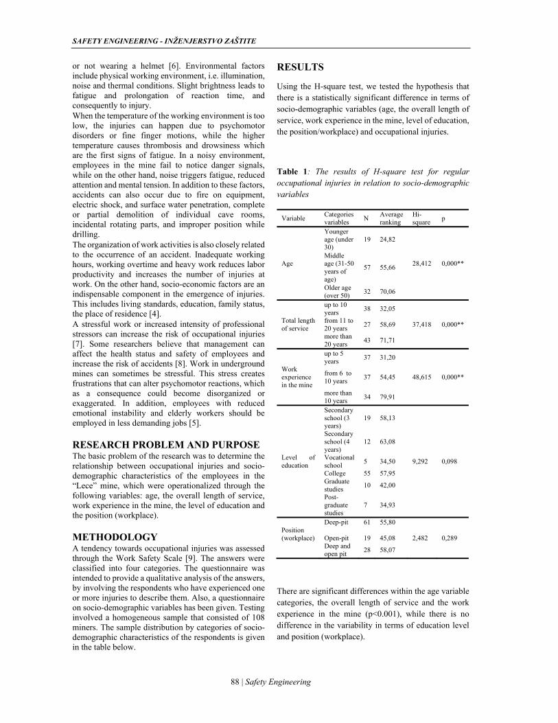
SAFETY ENGINEERING - INŽENJERSTVO ZAŠTITE
88 | Safety Engineering
or not wearing a helmet [6]. Environmental factors include physical working environment, i.e. illumination, noise and thermal conditions. Slight brightness leads to fatigue and prolongation of reaction time, and consequently to injury. When the temperature of the working environment is too low, the injuries can happen due to psychomotor disorders or fine finger motions, while the higher temperature causes thrombosis and drowsiness which are the first signs of fatigue. In a noisy environment, employees in the mine fail to notice danger signals, while on the other hand, noise triggers fatigue, reduced attention and mental tension. In addition to these factors, accidents can also occur due to fire on equipment, electric shock, and surface water penetration, complete or partial demolition of individual cave rooms, incidental rotating parts, and improper position while drilling. The organization of work activities is also closely related to the occurrence of an accident. Inadequate working hours, working overtime and heavy work reduces labor productivity and increases the number of injuries at work. On the other hand, socio-economic factors are an indispensable component in the emergence of injuries. This includes living standards, education, family status, the place of residence [4]. A stressful work or increased intensity of professional stressors can increase the risk of occupational injuries [7]. Some researchers believe that management can affect the health status and safety of employees and increase the risk of accidents [8]. Work in underground mines can sometimes be stressful. This stress creates frustrations that can alter psychomotor reactions, which as a consequence could become disorganized or exaggerated. In addition, employees with reduced emotional instability and elderly workers should be employed in less demanding jobs [5].
RESEARCH PROBLEM AND PURPOSE The basic problem of the research was to determine the relationship between occupational injuries and socio-demographic characteristics of the employees in the “Lece” mine, which were operationalized through the following variables: age, the overall length of service, work experience in the mine, the level of education and the position (workplace).
METHODOLOGY A tendency towards occupational injuries was assessed through the Work Safety Scale [9]. The answers were classified into four categories. The questionnaire was intended to provide a qualitative analysis of the answers, by involving the respondents who have experienced one or more injuries to describe them. Also, a questionnaire on socio-demographic variables has been given. Testing involved a homogeneous sample that consisted of 108 miners. The sample distribution by categories of socio-demographic characteristics of the respondents is given in the table below.
RESULTS
Using the H-square test, we tested the hypothesis that there is a statistically significant difference in terms of socio-demographic variables (age, the overall length of service, work experience in the mine, level of education, the position/workplace) and occupational injuries.
Table 1: The results of H-square test for regular occupational injuries in relation to socio-demographic variables
Variable Categories variables
N Average ranking
Hi- square
p
Age
Younger age (under 30)
19 24,82
28,412 0,000** Middle age (31-50 years of age)
57 55,66
Older age (over 50)
32 70,06
up to 10 years
38 32,05
Total length of service
from 11 to 20 years
27 58,69 37,418 0,000**
more than 20 years
43 71,71
up to 5 years
37 31,20
Work experience in the mine
from 6 to 10 years
37 54,45 48,615 0,000**
more than 10 years
34 79,91
Secondary school (3 years)
19 58,13
Secondary school (4 years)
12 63,08
Level of education
Vocational school
5 34,50 9,292 0,098
College 55 57,95
Graduate studies
10 42,00
Post-graduate studies
7 34,93
Deep-pit 61 55,80 Position (workplace)
Open-pit
19
45,08
2,482
0,289
Deep and open pit
28 58,07
There are significant differences within the age variable categories, the overall length of service and the work experience in the mine (p<0.001), while there is no difference in the variability in terms of education level and position (workplace).
M. Milenović, S. Živković, M. Veljković, Vol 9, No2 (2019) 87-90
89 | Safety Engineering
DISCUSSION AND CONCLUSION Working in the mine requires great effort when it comes to safety and associated risks. If an individual is not mentally and physically fit for mining activites, if work conditions are poor, the protective equipment is obsolete and the employees have not undergone any education in terms of the use of the equipment and behavior in dangerous situations, there is a high probability of accident occurrence. The overall aim of this study was to determine whether there are significant differences within some relevant socio-demographic characteristics of employees and injuries at work. Based on the goal, we established a hypothesis which was partially confirmed. When it comes to respondents’ age, the results of the survey show that the respondents over 50 years of age or older are more prone to injuries, whereas the incidence of injuries decreases in the case of respondents under 30. Younger workers, although not having enough experience, do not suffer so many injuries as their elderly colleagues do. The reason why the group of elderly workers is more at risk may be explained by a decline in psycho-physical properties, especially to speed and the response time. The classification of work-related injuries by age is extremely important for a better distribution of jobs. Providing better training for younger workers, and if necessary, not distributing those tasks to elderly workers which could jeopardize their safety. Table 1 shows that the highest tendency towards injuries appears among workers with more than 20 years of service, followed by the employees who have up to 10 years of service. This can be explained by the fact that workers with many years of experience have been working under stress for long periods. Consequently, they suffer from a lack of concentration, psychological and emotional exhaustion, which increases the possibility of injuries. The research conducted by [10] showed that the length of service has a significant impact on the level of stress and burnout syndrome at work.
Statistically significant differences in injuries in terms of work experience in the mine show that the employees with more than 10 years of experience are more prone to injuries. Those with the lowest risk of injuries are the employees who have up to 5 years of service in the mine. Commonly, employees with less work experience are less likely to be engaged in routine work, as their attention is focused on the proper performance and execution of tasks. When it comes to the level of education and the position (workplace), the results showed that there are no statistically significant differences in terms of injuries. This result is in favor of those theories which claim that workers with longer years of service in the same position are more likely to get injured, since they perform operations as a routine which, again, increases the injury risk - individual, i.e. subjective, than objective factors - the theory of predisposition, conditional reflexes or theories of domains [11, 12]. In addition, a qualitative analysis showed that 88% of injuries occurred due to failures in
the procedure, improper handling of work equipment, and lack of attention and concentration. Finally, bearing in mind that the research has been done on a limited number of participants, the results obtained should be checked on a larger sample of employees in another type of mines, with different types of exploitation.
REFERENCES
[1] Prosser D., Johnson S., Kuipiers E., Szmukler G., Bebbington P., Thornicroft G. (1997). Perceived sources of work stress and satisfaction among hospital and community mental health staff, and their relation to mental health, burnout, and job satisfaction. J Psychos Res 43, 51–59
[2] Malenović-Nikolić J., Spasić D., Avramović D. (2011). Povrede na radu sa smrtnim ishodom u rudarstvu Srbije. Niš: Fakultet zaštite na radu
[3] Spasić, D., Avramović D. (2007): Povrede na radu u Republici Srbiji u periodu od 1954 do 2006. godine, Monografija nacionalnog značaja, Niš: Fakultet zaštite na radu
[4] Nedeljković Z. (2014). Strategija bezbednosti i zdravlja na radu-Prevencija i rukovođenje rizikom
[5] Gosh KA., Bhattacherjee A., Chau N. (2004). Relationships of Working Conditions and Individual Characteristics to Occupational Injuries: A Case-Control Study in Coal Miners. J Occup Health, 46: 470–478
[6] Kamberović M. (2011) Rudarske nesreće u rudnicima Republike Srbije. Novi Sad: Institut za preventivu
[7] Frone MR. (1998). Predictors of work injuries among employed adolescents. J Appl Psychol 83, 565–576
[8] Hine DW., Lewko J., Blanco J.(1999). Alignment to workplace safety principles: an application to mining. J Safety Res 30, 173–185
[9] Živković S. (2008). Motivacija za zaštitu na radu. Niš: Fakultet zaštite na radu
[10] Stanetić K., Tešanović G. (2013). Uticaj životnog doba i dužine radnog staža na nivo stresa i sindroma sagorevanja na poslu. Medicinski Pregled 2013; LXVI (3-4): 153-162
[11] Jovanović J., Aranđelović M., Jovanović M. (2004). Multidisciplinar aspects of occupational accidents and injuries. Facta universitatis. Vol. 2, No 4, 2004, pp. 325 – 333
[12] Čabarkapa M. (2008). Čovek i radna okolina-Psihofiziološki i ekološki aspekti rada. Beograd: Čigoja štampa
ACKNOWLEDGMENTS
This paper is part of the project no. III 43014 which is financed by the Ministry of Education, Science and Technological Development of Republic of Serbia.
SAFETY ENGINEERING - INŽENJERSTVO ZAŠTITE
90 | Safety Engineering
BIOGRAPHY
SOCIODEMOGRAFSKE KARAKTERISTIKE I POVREĐIVANJE NA RADU KOD RUDARA
Miodrag Milenović, Snežana Živković, Milan Veljković Rezime: Rudarstvo je grana privrede sa velikim brojem povreda na radu, bilo da se radi o lakšim, težim ili o povredama sa smrtnim ishodom. U ovom istraživanju ispitivano je da li postoji razlika u povređivanju na radu u odnosu na neke relevantne sociodemografske karakteristike zaposlenih Istraživanje je sprovedeno na uzorku od 108 zaposlenih u rudniku ,,Lece” koji su se razlikovali s obzirom na: starost, ukupan radni staž, radni staž u rudniku, stepen stručne spreme i vrstu radnog mesta. Rezultati su pokazali da unutar faktora, kao što su godine starosti, ukupni radni staž i radni staž u rudniku, postoje značajne razlike u odnosu na povređivanje na radu, dok kod stepena stručne spreme i vrste radnog mesta to nije slučaj.
Ključne reči: rudari, sociodemografske karakteristike, povređivanje na radu
Miodrag Milenovic is an associate professor of the Faculty of Philosophy – Department of Psychology in Niš, Republic of Serbia. He teaches the courses in Sensory Processes, Motivation and Emotions, Psychophysiology of Work and Psychology of
Stress for students at undergraduate and master studies. His main research interests include psychophysiology of senses, the psychology of motivation and emotions, and the treatment of stress-related disorders.
UDC: 331.45:624 DOI: 0.7562/SE2019.9.02.07
Review article
91 | Safety Engineering
JASMINA RADOSAVLJEVIĆ1
ANA VUKADINOVIĆ2
1University of Niš, Faculty of Occupational Safety in Niš
2University of Niš, Faculty of Occupational Safety in Niš
2ana.vukadinovic @znrfak.ni.ac.rs
WORKER SAFETY DURING CONSTRUCTION WORK AT HEIGHT Abstract: In construction work, most severe or fatal injuries are caused by falls from a height. This paper discusses construction work at height and the personal protective measures and equipment for work-at-height construction workers, which ensure their safety. The paper also describes temporary and auxiliary structures that are used for work at height.
Keywords: construction work, work at height, occupational safety, protective equipment.
INTRODUCTION With the development of science and technology, construction became an important branch of economy, connected to numerous other economic activities. Due to the large number of participants in the overall construction sector, the complexities of their working together, and the relationships between the workers, their materials, tools, machinery, and operations, risk identification and quantification in construction is considerably more complex than in other industry branches. Construction workers are prone to a wide variety of occupational injuries, which are often severe or fatal. The large number of severe injuries, which often result in death, are due to a failure to provide safe work conditions and lacking or inadequate personal protective equipment (PPE). In construction, the majority of fatal injuries occur due to falls from heights. In Serbia, from 2013 to 2016, there was a total of 37 fatal injuries due to falls from a height, which is 58.7% of the total number of fatal injuries in the same period [1]. In 2017, there were 67 severe and fatal injuries in the construction sector, or 7.39% of the total number of injuries in other sectors [2]. Risk and hazards on construction sites during work at height are ever-present, so it is necessary to implement all available measures to ensure safe work conditions and workers’ well-being. The Regulation on Occupational Safety during Construction Activities prescribes special occupational safety measures and rules to be implemented during construction work. The Act on Occupational Safety and Health at Temporary or Mobile Construction Sites prescribes the minimum requirements that the investor, the OSH coordinators in the design and construction stages, the employer/contractor, and other parties involved have to meet in order to ensure that the safety measures are implemented at temporary or mobile construction sites. Prior to actual construction operations, the investor is
obligated to coordinate the development of a plan for preventive occupational safety and health measures to be implemented during construction [3]. According to the Regulation on Occupational Safety during Construction Activities, work at height refers to any work performed by a worker with the use of a support system at a height of 3m or more above solid ground, when the work space has no fall protection. According to the Act on Amendments to the Act on Occupational Safety and Health at Temporary or Mobile Construction Sites, work at height is any work performed by a worker with the use of a support system at a height of 2m or more above solid ground, when the work space has no fall protection [3,4]. Solid ground refers to a base with negligible deformations under a load, which does not affect its stability. Workers perform work at height using mandatory occupational safety equipment. Work at height can only be performed by experienced workers with verified knowledge and skills to perform such work. CONSTRUCTION WORK AT HEIGHT When doing construction work at height, workers might fall, which could lead to fractures, serious head trauma, severe bodily injuries, and in some cases even death. Therefore, it is essential that workers at heights be properly protected. Construction work performed at heights includes the construction of smokestacks and similar structures, such as silos, dam intake towers and spillways, brick or block masonry, roofing, installation of steel and other structures, plastering and cladding, cleaning of building façades and monuments using sandblasting or hydro-blasting, wall chasing on concrete or other walls, façade painting, certain demolition work, etc. (Figure 1). Work at height is also accompanied by hazards such as dust, hazardous materials, electricity, vibrations, as well as noise due to the nature of such work. These all require proper occupational safety measures for workers, which include the use of PPE [2].
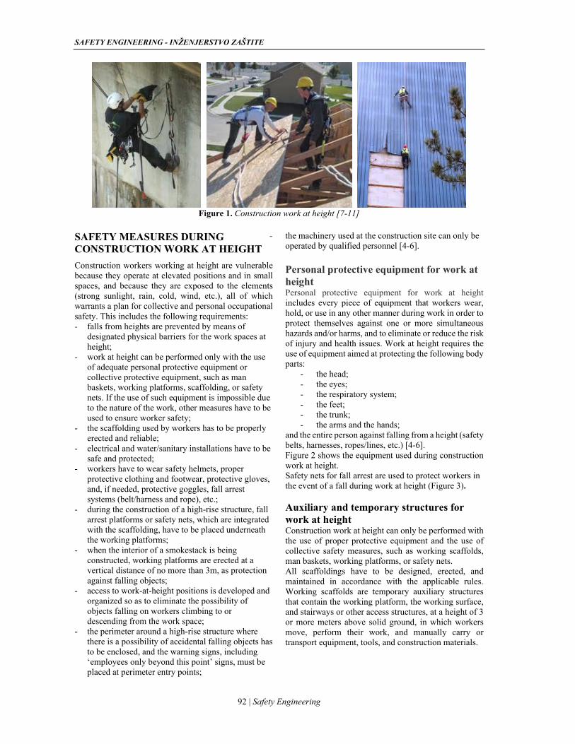
SAFETY ENGINEERING - INŽENJERSTVO ZAŠTITE
92 | Safety Engineering
Figure 1. Construction work at height [7-11]
SAFETY MEASURES DURING CONSTRUCTION WORK AT HEIGHT
Construction workers working at height are vulnerable because they operate at elevated positions and in small spaces, and because they are exposed to the elements (strong sunlight, rain, cold, wind, etc.), all of which warrants a plan for collective and personal occupational safety. This includes the following requirements: - falls from heights are prevented by means of
designated physical barriers for the work spaces at height;
- work at height can be performed only with the use of adequate personal protective equipment or collective protective equipment, such as man baskets, working platforms, scaffolding, or safety nets. If the use of such equipment is impossible due to the nature of the work, other measures have to be used to ensure worker safety;
- the scaffolding used by workers has to be properly erected and reliable;
- electrical and water/sanitary installations have to be safe and protected;
- workers have to wear safety helmets, proper protective clothing and footwear, protective gloves, and, if needed, protective goggles, fall arrest systems (belt/harness and rope), etc.;
- during the construction of a high-rise structure, fall arrest platforms or safety nets, which are integrated with the scaffolding, have to be placed underneath the working platforms;
- when the interior of a smokestack is being constructed, working platforms are erected at a vertical distance of no more than 3m, as protection against falling objects;
- access to work-at-height positions is developed and organized so as to eliminate the possibility of objects falling on workers climbing to or descending from the work space;
- the perimeter around a high-rise structure where there is a possibility of accidental falling objects has to be enclosed, and the warning signs, including ‘employees only beyond this point’ signs, must be placed at perimeter entry points;
- the machinery used at the construction site can only be operated by qualified personnel [4-6]. Personal protective equipment for work at height Personal protective equipment for work at height includes every piece of equipment that workers wear, hold, or use in any other manner during work in order to protect themselves against one or more simultaneous hazards and/or harms, and to eliminate or reduce the risk of injury and health issues. Work at height requires the use of equipment aimed at protecting the following body parts:
- the head; - the eyes; - the respiratory system; - the feet; - the trunk; - the arms and the hands;
and the entire person against falling from a height (safety belts, harnesses, ropes/lines, etc.) [4-6]. Figure 2 shows the equipment used during construction work at height. Safety nets for fall arrest are used to protect workers in the event of a fall during work at height (Figure 3). Auxiliary and temporary structures for work at height Construction work at height can only be performed with the use of proper protective equipment and the use of collective safety measures, such as working scaffolds, man baskets, working platforms, or safety nets. All scaffoldings have to be designed, erected, and maintained in accordance with the applicable rules. Working scaffolds are temporary auxiliary structures that contain the working platform, the working surface, and stairways or other access structures, at a height of 3 or more meters above solid ground, in which workers move, perform their work, and manually carry or transport equipment, tools, and construction materials.
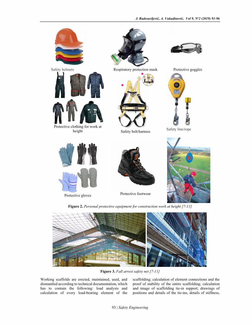
J. Radosavljević, A. Vukadinović, Vol 9, No2 (2019) 91-96
93 | Safety Engineering
Safety helmets
Respiratory protection mask
Protective goggles
Protective clothing for work at
height
Safety belt/harness
Safety line/rope
Protective gloves
Protective footwear
Figure 2. Personal protective equipment for construction work at height [7-11]
Figure 3. Fall arrest safety net [7-11]
Working scaffolds are erected, maintained, used, and dismantled according to technical documentation, which has to contain the following: load analysis and calculation of every load-bearing element of the
scaffolding; calculation of element connections and the proof of stability of the entire scaffolding; calculation and image of scaffolding tie-in support; drawings of positions and details of the tie-ins, details of stiffness,
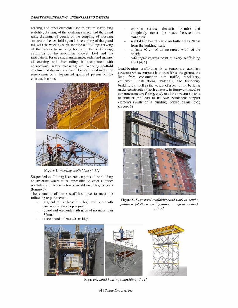
SAFETY ENGINEERING - INŽENJERSTVO ZAŠTITE
94 | Safety Engineering
bracing, and other elements used to ensure scaffolding stability; drawing of the working surface and the guard rails; drawings of details of the coupling of working surface to the scaffolding and the coupling of the guard rail with the working surface or the scaffolding; drawing of the access to working levels of the scaffolding; definition of the maximum allowed load and the instructions for use and maintenance; order and manner of erecting and dismantling in accordance with occupational safety measures; etc. Working scaffold erection and dismantling has to be performed under the supervision of a designated qualified person on the construction site.
Figure 4. Working scaffolding [7-11]
Suspended scaffolding is erected on parts of the building or structure where it is impossible to erect a tower scaffolding or where a tower would incur higher costs (Figure 5). The elements of these scaffolds have to meet the following requirements:
- a guard rail at least 1 m high with a smooth surface and no sharp edges;
- guard rail elements with gaps of no more than 35cm;
- a toe board at least 20 cm high;
- working surface elements (boards) that completely cover the space between the standards;
- scaffolding board placed no further than 20 cm from the building wall;
- at least 80 cm of uninterrupted width of the board;
- safe ingress/egress point at every scaffolding level [4, 5].
Load-bearing scaffolding is a temporary auxiliary structure whose purpose is to transfer to the ground the load from construction site traffic, machinery, equipment, installations, materials, and temporary buildings, as well as the weight of a part of the building under construction (fresh concrete in formwork, steel or concrete structure fitting, etc.), until the structure is able to transfer the load to its own permanent support elements (walls on a building, bridge pillars, etc.) (Figure 6).
Figure 5. Suspended scaffolding and work-at-height platform (platform moving along a scaffold column)
[7-11]
Figure 6. Load-bearing scaffolding [7-11]
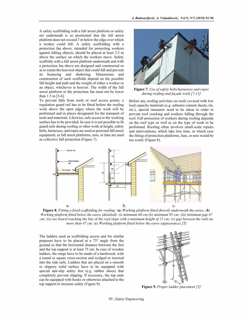
J. Radosavljević, A. Vukadinović, Vol 9, No2 (2019) 91-96
95 | Safety Engineering
A safety scaffolding with a fall arrest platform or safety net underneath is so positioned that the fall arrest platform does not exceed 3 m below the edge over which a worker could fall. A safety scaffolding with a protection fan above, intended for protecting workers against falling objects, should be placed at least 2.5 m above the surface on which the workers move. Safety scaffolds with a fall arrest platform underneath and with a protection fan above are designed and constructed so as to retain the heaviest object that could fall and prevent its bouncing and shattering. Dimensions and construction of such scaffolds depend on the possible fall height and path and the weight of either a worker or an object, whichever is heavier. The width of the fall arrest platform or the protection fan must not be lower than 1.5 m [3-6]. To prevent falls from roofs or roof access points, a regulation guard rail has to be fitted before the roofing work above the open edges where the work will be performed and in places designated for the transport of tools and materials. Likewise, safe access to the working surface has to be provided. In case it is not possible to fit guard rails during roofing or other work at height, safety belts, harnesses, and ropes are used as personal fall arrest equipment, or fall arrest platforms, nets, or fans are used as collective fall protection (Figure 7).
Figure 7. Use of safety belts/harnesses and ropes during roofing and façade work [7-11]
Before any roofing activities on roofs covered with low load capacity materials (e.g. asbestos cement sheets, tin, etc.), special measures need to be taken in order to prevent roof cracking and workers falling through the roof. Fall protection of workers during roofing depends on the roof type as well as on the type of work to be performed. Roofing often involves small-scale repairs and interventions, which take less time, in which case the fitting of protection platforms, fans, or nets would be too costly (Figure 8).
a. b. c.
Figure 8. Fitting a fixed scaffolding for roofing: (a) Working platform fitted directly underneath the eaves; (b) Working platform fitted below the eaves (detailed): (i) minimum 60 cm;(ii) minimum 95 cm; (iii) minimum gap 47 cm; (iv) toe board reaching the line of the roof slope with a minimum height of 15 cm; (v) gap between the rails no
more than 47 cm; (c) Working platform fitted below the eaves (appearance) [5]
The ladders used as scaffolding access and for similar purposes have to be placed at a 75° angle from the ground so that the horizontal distance between the feet and the top support is at least 75 cm. In case of wooden ladders, the rungs have to be made of a hardwood, with a round or square cross-section and wedged or inserted into the side rails. Ladders that are placed on a smooth or slippery solid surface have to be equipped with special anti-slip safety feet (e.g. rubber shoes) that completely prevent slipping. If necessary, the top ends can be equipped with hooks or otherwise attached to the top support to increase safety (Figure 9).
Figure 9. Proper ladder placement [5]
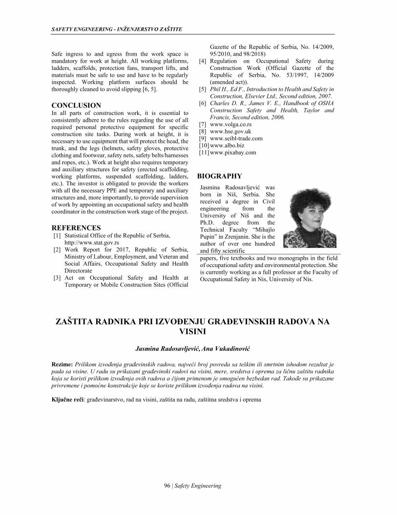
SAFETY ENGINEERING - INŽENJERSTVO ZAŠTITE
96 | Safety Engineering
Safe ingress to and egress from the work space is mandatory for work at height. All working platforms, ladders, scaffolds, protection fans, transport lifts, and materials must be safe to use and have to be regularly inspected. Working platform surfaces should be thoroughly cleaned to avoid slipping [6, 5]. CONCLUSION In all parts of construction work, it is essential to consistently adhere to the rules regarding the use of all required personal protective equipment for specific construction site tasks. During work at height, it is necessary to use equipment that will protect the head, the trunk, and the legs (helmets, safety gloves, protective clothing and footwear, safety nets, safety belts/harnesses and ropes, etc.). Work at height also requires temporary and auxiliary structures for safety (erected scaffolding, working platforms, suspended scaffolding, ladders, etc.). The investor is obligated to provide the workers with all the necessary PPE and temporary and auxiliary structures and, more importantly, to provide supervision of work by appointing an occupational safety and health coordinator in the construction work stage of the project. REFERENCES [1] Statistical Office of the Republic of Serbia,
http://www.stat.gov.rs [2] Work Report for 2017, Republic of Serbia,
Ministry of Labour, Employment, and Veteran and Social Affairs, Occupational Safety and Health Directorate
[3] Act on Occupational Safety and Health at Temporary or Mobile Construction Sites (Official
Gazette of the Republic of Serbia, No. 14/2009, 95/2010, and 98/2018)
[4] Regulation on Occupational Safety during Construction Work (Official Gazette of the Republic of Serbia, No. 53/1997, 14/2009 (amended act)).
[5] Phil H., Ed F., Introduction to Health and Safety in Construction, Elsevier Ltd., Second edition, 2007.
[6] Charles D. R., James V. E., Handbook of OSHA Construction Safety and Health, Taylor and Francis, Second edition, 2006.
[7] www.volga.co.rs [8] www.hse.gov.uk [9] www.seibl-trade.com [10] www.albo.biz [11] www.pixabay.com
BIOGRAPHY
Jasmina Radosavljević was born in Niš, Serbia. She received a degree in Civil engineering from the University of Niš and the Ph.D. degree from the Technical Faculty “Mihajlo Pupin” in Zrenjanin. She is the author of over one hundred and fifty scientific
papers, five textbooks and two monographs in the field of occupational safety and environmental protection. She is currently working as a full professor at the Faculty of Occupational Safety in Nis, University of Nis.
ZAŠTITA RADNIKA PRI IZVOĐENJU GRAĐEVINSKIH RADOVA NA
VISINI
Jasmina Radosavljević, Ana Vukadinović
Rezime: Prilikom izvođenja građevinskih radova, najveći broj povreda sa teškim ili smrtnim ishodom rezultat je pada sa visine. U radu su prikazani građevinski radovi na visini, mere, sredstva i oprema za ličnu zaštitu radnika koja se koristi prilikom izvođenja ovih radova a čijom primenom je omogućen bezbedan rad. Takođe su prikazane privremene i pomoćne konstrukcije koje se koriste prilikom izvođenja radova na visini. Ključne reči: građevinarstvo, rad na visini, zaštita na radu, zaštitna sredstva i oprema
UDC: 662.767.2:620.92:331.45:519.8 DOI: 0.7562/SE2019.9.02.08
Original / Review article
97 | Safety Engineering
GORANA MILINČIĆ STANČIĆ1
SNEŽANA ŽIVKOVIĆ2
1University of Novi Sad, Faculty of Technical Sciences, Novi
Sad2University of Niš,
Faculty of occupational safety in Niš
[email protected]@znrfak.ni.ac.rs
RISK ASSESSMENT AND SAFETY CONCEPTS FOR COGENERATION BIOGAS PLANTS Abstract: The topic of this paper is risk assessment and protection concepts for cogeneration biogas plants using functional HAZOP and FMEA methods with 5x5 AS / NZS 4360: 2004 matrix. The assessment was based on the ISO 31010 Risk Assessment Standard, Guidelines for the Safe use of Biogas Technology issued by the German Biogas Association (FNR), and Overall survey of engineering insurers for potential hazards at biogas installations issued by the German Insurance Association (GDV). The paper analyses all potential hazards that can occur during the regular operation of a biogas plant, how hazards can affect the occurrence of a harmful event, as well as how harmful events can affect all vulnerable resources. According to risk assessment and hazard analyses, a unique protection concept was proposed through a set of different measures. The final part of the paper is concerned with the development of the biogas industry and the occurrence of harmful events across Europe.
Keywords: Cogeneration biogas plant, Risk assessment, HAZOP and FMEA method, matrix 5x5 AS / NZS 4360: 2004, Safety concepts.
INTRODUCTION The production and use of biogas have been growing and developing rapidly around the world for the past twenty years. In our country, biogas production has been on the increase for the past ten years. The main aim of producing electricity from renewable resources is to reduce the dependence on the import of fossil fuels and to protect the environment.
Building a plant, obtaining the use permit, acquiring the status of the privileged producer of electricity and signing the power purchase agreement is only one stage in the business. Real challenges begin later.
The payback period for cogenerative biogas plants is at least eight years. During that period plants should be able to operate efficiently with 8200 h a year in order to earn sufficient income for regular servicing and further development. The investors are aware of the fact that this aim is not easily achieved because there are numerous problems on the way.
The production process inevitably entails hazards and their consequences. Therefore, it is extremely important to identify all risks and establish a proper protection concept that will comprise technical, organizational, financial and personal measures so that biogas plants could function safely.
COGENERATIVE BIOGAS PLANTS Biogas is produced by anaerobic digestion (decomposition of organic matter in the absence of oxygen) of different kinds of biomass. Biogas is a mixture of gases containing methane CH4 (50%-70%), carbon dioxide CO2 (20%-50%), hydrogen sulfide H2S
(0.01% to 0.04%), ammonia NH3, hydrogen H, nitrogen N and carbon monoxide CO.
A cogenerative biogas plant, i.e., a plant for combined simultaneous production of heat and power (CHP) converts the chemical energy of biogas into electrical and heat energy using an engine connected to the generator [1].
The biogas industry, as a combination of the chemical and energy industry, is prone to numerous harmful events. Managing the production process in these circumstances is an enormous challenge. Therefore, it is crucial that the plants are protected from all non-economic damage.
RISK ASSESSMENT Risk can be managed after it has been identified, analyzed and evaluated i.e. assessed [2]. Only then can it be said whether that risk is acceptable or something needs to be changed to make it acceptable.
Theoretically, a risk assessment would be more accurate if it involved more parameters [3]. On the other hand, it makes the assessment more complex and more difficult to implement, very often having a nonlinear relation between those parameters [3].
The most widely accepted theory is that risk is the probability of harmful consequences or losses resulting from a given hazard over a specified time period [2, 4-8]. A better definition could be the one which says that risk can be viewed as a function of several components: hazard, vulnerability, exposure, and resilience [3, 9].
Hazard frequency and magnitude indicate that we are
SAFETY ENGINEERING - INŽENJERSTVO ZAŠTITE
98 | Safety Engineering
talking about risk [5]. Therefore, to assess risk adequately, data about the underlying hazardous event should be collected first [3,10].
Hazard is a potentially damaging physical event, phenomenon or human activity that may cause the loss of life or injury, property damage, social and economic disruption or environmental degradation [2].
In industrial systems, hazardous events include the release of chemicals and toxic substances, radioactivity, the release of energy in the form of fires and explosions, spillage and leakage of waste. These events are the result of failures in the industrial system, that is, a technical or human error, or are the result of events in nature such as earthquakes, landslides, floods, atmospheric discharges. The redundancies are most often sudden and intense with extensive damage that is not only limited to property but also to injuries to employees, often with fatalities, as well as to disruption of their regular operations.
Risk assessment in cogenerative biogas plants
For the assessment of risk in cogenerative biogas plants, according to ISO 31010 recommendations, it is necessary to choose proper methods of risk assessment. For that purpose, the combination of functional methods HAZOP and FMEA with 5x5 AS/NZS 4360:2004 matrix was used.
HAZOP is an acronym for HAZard and OPerability method of structured and systematic evaluation of a planned or an existing product, process, procedure or system. It is a technique for detecting risks that people, equipment, property, environment or organisational goals are exposed to. Failure mode and effects analysis (FMEA) is a technique used for detecting cases where components, systems or processes cannot fulfill their purpose [11]. The assessment was performed using a 5x5 matrix with the 5x5 AS/NZS 4360:2004 matrix in which consequences for people, environment and properties, and frequencies of an event were categorised.
Based on the assessed values of consequences C and frequency of exposure F, the level of risk is calculated as the product of these two parameters:
R = C x F (1)
The levels of risk in the matrix were qualitatively determined as very high (VH), high (H), medium (M) and low (L).
The purpose of this kind of assessment is an observation of all risks, identification of the most significant risks and elimination of the less significant ones from the analysis. However, low risks with a high frequency of occurrence and significant cumulative effect should not be eliminated.
Depending on the characteristics of the technological process, facilities and equipment, a total of 49 hazards/failures were identified. The following events entail very high risk and cause extreme damage to all
categories of the vulnerable resources or individual categories of the vulnerable resources:
Formation of an explosive atmosphere as a result of putting the plant into operation, maintenance, regular release of biogas by means of overpressure valves, ruptures of the gas membrane, increased concentration of methane in the exhaust of the cogeneration or sudden failure of the burner. Coming into contact with an ignition source (spark), all these lead to explosions and fires which have a devastating effect;
Self-ignition of the raw material as a result of improper storage conditions leading to fires, as well as fires resulting from ignition of other flammable materials in the plant;
Release of hydrogen sulphide H2S as a component of biogas from the mixing pit and pre-digestion pits, small concentrations of which can be fatal;
Leakage of various biological substances.
Injuries caused by traffic accidents, by working with equipment that carries high voltage or with faulty equipment, and those caused by maintenance. Injuries happen when procedures are not followed and when protective equipment is not used or is used carelessly.
Analysis of events which cause fires
Cogenerative biogas plants store different flammable materials and explosive gases. In biogas plants, fires can occur both inside and outside the plant. Depending on the place of occurrence, fires can be medium or big. In a cogeneration biogas plant, depending on the kind and amount of combustible materials, the following classes of fire can be expected:
Class A fire is related to solid combustible materials such as corn silage, straw, wood (furniture and stationery in the administration building with the pumping station), paper and cardboard in the administration building. These fires are extinguished with water, sand, foam, halon and some kinds of powder;
Class B fires are fires in flammable liquids such as different greases for technological equipment and cogeneration unit, oils in the substation, various paints, plant oils, thinners, etc. The main extinguishers here are powder, carbon dioxide and foam;
Class C fires are fires of flammable gases such as methane CH4, hydrogen sulphide H2S and ammonia NH3. These gases are generated in the production process. The main extinguishers are powder and carbon monoxide, whereas the best way to extinguish fire in gas installations is to shut off the inflow of gas.
Class E fires are fires in electric equipment and installations (machines, electric motors, substations). The main extinguishers are powder and carbon dioxide.
G. Milinčić Stančić, S. Živković, Vol 9, No2 (2019) 97-102
99 | Safety Engineering
Analysis of events which cause explosions
An explosion is a sudden chemical reaction of an explosive, flammable matter with oxygen, during which an enormous amount of energy is released and dispersed in different ways [12], through the creation of the pressure wave, bursting of vessels, thermal radiation, physical displacement of equipment and secondary fires. An explosion occurs in an explosive atmosphere (with particular concentration and under particular pressure) in the presence of oxygen and an ignition source. There is a danger of explosion when the concentration of biogas is in the range between 6% and 22%. An explosive atmosphere is formed when gas leaks from the technological equipment or due to incomplete gas combustion which happens as the result of faulty machines or different problems with buildings where biogas is processed and stored.
Analysis of events which cause release of pollutants, dangerous and toxic substances into the environment
Activities which take place in cogenerative biogas plants can affect the environment through the release of substances into the soil, water and air. These activities include disposal of drainage water from trench silos and disposal of the biological substrate from pre-digestion pits, mixing pits and digesters.
Analysis of events which cause failures and different hazards connected to the use of technological and electrical equipment
A cogenerative biogas plant uses various kinds of equipment in the process of producing heat and power. The most frequent failures are breakdowns of mixers, pumps and CHP unit and are induced by the quality of the substrate, chemical compounds in the process and the quality of biogas - all of them damage and corrode the material of which the equipment is made. The dangers related to the technical and electrical equipment are dangers of explosion, electric arc and static electricity. These dangers occur if the equipment is not periodically controlled or maintained, or if safety procedures are not adhered to. Within the technological process, injuries occur while manipulating the raw materials all the way from trench silos to hoppers, during work at height and as a consequence of non-compliance with safety procedures.
CONCEPTS OF PROTECTION
Cogenerative biogas plants are complex systems. In order to produce biogas and convert mechanical energy into electrical energy, they need to have appropriate facilities and equipment. All facilities must have a use permit and proper equipment. Different procedures have to be followed and different protective measures considered. In order to reduce risk, it is necessary to establish a system of protection through technical,
organisational, financial and personal measures and to monitor the work of the whole plant using appropriate documentation.
Risk reduction by means of technical protective measures
Risk prevention tends to reduce the number of damages or completely eliminate them [12, 13] and primarily depends on the specific risk with which an organization may be encountered. The causes of damage, and in particular damage from fires, explosions and other accidents, fall into the categories of damage that science and the profession can predict and which can be prevented, i.e. managed.
In parts of a biogas plant in which gas is stored and transported, Ex zones must be classified. The facilities are protected using:
a hydrant network with aboveground fire hydrants (which have a specific reservoir volume and a pressure booster) aimed at fighting primary fires;
portable and transportable fire extinguishers, type S-6, S-9, S-50;
warning boards.
The equipment used for storing and transporting biogas must be checked for possible leakages and the formation of an explosive atmosphere. Devices used for this purpose are cameras and laser methane detectors. If the electricity supply goes off, the unburnt gas must not be released into the atmosphere. It has to be burnt with the burner.
Risk reduction by means of organisational and personal protective measures
Before putting the plant into operation, the operator should create a register of sources of danger and pollution that would contain information on types, amounts, way and place of entry, release and disposal of pollutants in the gaseous, liquid and solid state, or on the release of energy (noise, vibrations, heat, ionizing and non-ionizing radiation) [14]. If the environment is harmed in the process of work of a cogenerative biogas plant, the legal entity is responsible for repair and remediation [14].
It has been shown in practice that precautions against fires improve when each operator is in regular contact with the concerned fire brigade and when fire drills are practiced so that the fire brigade can take proper action in case of fire.
It is necessary to wear adequate equipment while the plant is working. Personal protective equipment includes:
safety glasses;
masks with filter;
protective helmets;
earmuffs;
SAFETY ENGINEERING - INŽENJERSTVO ZAŠTITE
100 | Safety Engineering
protective clothing and boots;
protective gloves;
safety harness for working at heights and in closed spaces.
Transfer of risk by means of financial protective measures
Financial resilience to hazards is a preventive financial measure that helps individuals or communities to quickly recover from financial shocks that hazardous event brings [9].
Insurance, as a financial instrument, ensures financial security to the affected individuals and companies [15]. By taking the risk within the insurance portfolio, the insurance company takes responsibility for damages that might arise from the risk realization [15,16].
Generally, the transfer of risk to insurance companies could mitigate the effects of natural disasters in two ways: first, the insured is motivated to take appropriate preventive measures in order to be entitled to a more acceptable insurance premium and second, the insured is compensated for the damage by insurance companies immediately after the harmful event [17,18]. This way, financial liquidity of the affected individuals and firms is achieved, contributing to the reduction of vulnerability, i.e. to increased resilience [17].
Cogenerative biogas plants are exposed to various risks: fire and explosion, gas or liquid leakages, stock self-ignition, bad weather hazards, machine breakdowns and staff injuries. Considering the above-mentioned, the best solution for these plants is the All risks insurance contract. With all risks insurance, one policy is taken out for a precisely defined number of risks where standard risks can be expanded so that the property and business activities of a company are best protected. This policy has to be carefully formulated. It has to be unambiguous so that specific property or risk would not be accidentally excluded. All risks policy should cover the following risks:
physical damage to property;
faults in electrical and mechanical parts of equipment;
lost profit (including the loss of feed-in tariffs);
fire and explosion;
accidents, illness and injuries of the employees;
decay of raw materials;
responsibility for pollution;
responsibility of managers and operators;
theft and deliberate destruction of property.
Documentation as a special measure of risk management
Documenting for cogenerative biogas plants is performed by writing:
Project technical documentation, essentially a report on danger zones and the main fire safety project;
Documentation on risk assessment;
Instructions on the safe use of equipment and work of the plant;
Instructions on the maintenance of the equipment and the plant;
A plan for preventive and regular maintenance;
Procedures in case of accidents, fires, explosions, power failures, injuries at work;
Instructions on the training of all employees by the supplier of technology before the plant are put into operation;
A record showing that putting the plant into operation was done with the supplier of technology;
Register of dangerous substances.
DEVELOPMENT OF BIOGAS INDUSTRY AND HARMFUL EVENTS
With the development of engineering and technology, the global demand for bioenergy has been on the increase during the past ten years. The projections are that the demand will be increasing until 2035, as a result of strategies aimed at reducing air pollution.
According to information and databases such as E MARS, INFOSYS and ARIA, an investigation [19] was carried out in the period from 2006 to 2016, including 208 harmful events in different European countries.
The most frequent harmful events out of these were fires - 123 (59%) and then 45 explosions (22%), 23 events harmful to the environment (11%), 11 gas leakages (5.29%) and 6 poisonings of employees (2.88%) [19]. Financial damage was recorded in 95 events and the average value of damage was 400,000€ [19]. The average financial damage caused by the fire was around 250,000 €, and the average financial damage caused by the explosion amounted to 960,000€ [19].
Between 2006 and 2016, four harmful events resulted in the loss of life [19]. There were 21 cases of accidents with severe injuries, whereas major injuries occurred in 16 cases (76%) as a result of biogas explosion [19].
Analysing the reports on the recorded harmful events from the available databases of biogas plants, it can be concluded that the data is incomplete and of questionable quality. The questionnaires were carelessly or only partially completed and not supported by photographs which captured the harmful event. Apart from this, not all harmful events were recorded in the MARS database. A considerable number of data can be found only in INFOSYS or only in the ARIA database.
G. Milinčić Stančić, S. Živković, Vol 9, No2 (2019) 97-102
101 | Safety Engineering
CONCLUSION
Although today all risks in the process of converting and generating energy are known, and specific engineering standards adopted, harmful events continue to happen. This is due to inadequate technological solutions, non-compliance with rules, poor organisation of work, lack of safety procedures, lack of adequate standards for the training of operators, and lack of awareness of the risks on the part of managers of biogas plants.
After twenty years of intensive development, it is necessary to adopt specific technical standards and rules for this industry because the process of production and conversion of biogas is unjustifiably seen as safer than classical chemical processes.
The analysis showed that it is necessary to update the information from reports on harmful events and liaise with insurance companies in order to obtain information about real damage inflicted on vulnerable resources. Only comparable results in combination with a sufficient number of analysed plants will enable a better understanding of harmful events from the whole sector and the creation of a reliable database.
Finally, the concept of safety can only be developed when both preventive engineering and a set of technical, organisational, personal and financial protective measures are applied.
REFERENCES
[1] Fachverband Biogas e.V.: “Biogas-Safety first, Smernice za bezbednu upotrebu tehnologije biogasa”, 2016, Freising, Germany.
[2] T. Novaković, J. Simić, Lj. Popović, S. Popov, M. Velemir, Đ. Ćosić, D. Sakulski: “Subject „Disaster Risk Management - Spatial Context“, ITRO - a journal for information technology, education development and teaching methods of technical and natural sciences, Vol. 3, No. 1, 2013, pp. 81-88.
[3] Đ. Ćosić, S. Popov, D. Sakulski, A. Frank: “Geo-Information Technology for Disaster Risk Assessment”, Acta Geotechnica Slovenica, Vol. 8, No. 1, 2011, pp. 65-74.
[4] S. Schneiderbauer, D. Ehrlich: “Risk, hazard and people’s vulnerability to natural hazards. a review of definitions, concepts and data”, European Commission Joint Research Centre, 2004, Brussels.
[5] S. Popov, Đ. Ćosić, T. Novaković, Lj. Popović, J. Bondžić, D, Sakulski: “Application of Geoinformation Tehnologies in Assessment of Socio-economical Vulnerability on Floods”, Proceedings of the 4. International Scientific Conference on Sustainable business and ecological integration and collaboration, University of Novi Sad, Faculty of Technical Sciences, 2018, pp. 139-154.
[6] K. Thywissen: “Components of risk, A comparative glossary”, United Nations University, Institute for Environment and Human Security, 2006, Bon, Germany.
[7] T. Novaković, M. Jevtić, J. Bondžić, Lj. Popović, Đ. Ćosić, S. Popov, M. Laban, V. Radonjanin: “Insurance and disaster risk management: reduction vulnerability and risk”, Proceedings of the 1. S-FORCE: Knowledge FOr Resilient Society Conference, University of Novi Sad, Faculty of Technical Sciences, Department of Civil Engineering and Geodesy, Novi Sad, 2018, pp. 79-86.
[8] T. Novaković, J. Bondžić, S. Popov, Đ. Ćosić: “Flood simulation for expected damage calculation”, Proceedings of the 8. ITRO - International Conference on Information Technology and Development of Education, University of Novi Sad, Technical faculty „Mihajlo Pupin”, Zrenjanin, 2017, pp. 215-219.
[9] Đ. Ćosić, Lj. Popović, T. Novaković, A. Rizaj, E. Silo: “Microfinance products as a tool for financial resilience to hazards”, Proceedings of the 2. K-FORCE: Knowledge for resilient society Conference, Epoka University, Faculty of Architecture and Engineering, Tirana, 2019, pp. 59-64.
[10] J. Bondžić, N. Medić, T. Novaković, Lj. Popović, Đ. Ćosić: “Aspects of petrol station accident modeling”, Proceedings of the iNDiS 2015, Departman za Građevinarstvo i Geodeziju, Fakultet tehničkih nauka Novi Sad, 2015, pp. 639-646.
[11] ISO: “Risk management - Risk assessment techniques“, Reference number International standard, IEC/FDIS 31010:2009 (E), 2009.
[12] M. Laban, Đ. Ćosić, J, Bondžić, T. Novaković: “Osnove upravljanja rizikom od katastrofalnih događaja i požara”, Fakultet tehničkih nauka, FTN Grafički centar GRID 2017, Novi Sad.
[13] D. Mrkšić, Đ. Ćosić: “Upravljanje rizikom i osiguranje”, Fakultet tehničkih nauka, FTN Grafički centar GRID, 2015, Novi Sad.
[14] Zakon o zaštiti životne sredine: Sl. glasnik RS", br. 135/2004, 36/2009, 36/2009 - dr. zakon, 72/2009 - dr. zakon, 43/2011 - odluka US, 14/2016, 76/2018, 95/2018 - dr. zakon i 95/2018 - dr. Zakon.
[15] T. Novaković, J. Bondžić, Đ. Ćosić, M. Miškić: “Flood risk damage assessment”, Proceedings of the 17. International Scientific Conference on Industrial Systems – IS17, University of Novi Sad, Faculty of Technical Sciences, Department for Industrial Engineering and Management, Novi Sad, 2017, pp. 410-413.
[16] V. Njegomir, Đ. Ćosić: “Ekonomske implikacije klimatskih promena na sektor osiguranja i reosiguranja”, Teme, Vol. 36, No. 2, 2012, pp. 679-701.
SAFETY ENGINEERING - INŽENJERSTVO ZAŠTITE
102 | Safety Engineering
[17] D. Cosic, S. Popov, T. Novakovic, Lj. Popovic: “Flood Damage Assessment Method: GIS-Based Approach”, Fresenius Environmental Bulletin, Vol. 28, No. 3, 2019, pp. 1896-1904.
[18] Lj. Popović, T. Novaković, J. Bondžić, Đ. Ćosić, S. Popov: “Impact of prevention measures on fire insurance premium”, 13. Međunarodna konferencija zaštita od požara i eksplozija, Visoka tehnička škola strukovnih studija u Novom Sadu, 2012, str. 43-52.
[19] P. Trávníček, L. Kotek, P. Junga, T. Vítěz, K. Drápela, J. Chovanec: “Quantitative analyses of biogas plant accidents in Europe”, Renewable energy, Vol. 122(C), 2018, pp. 89-97.
ACKNOWLEDGEMENTS The published paper is the result of research funded by the Ministry of Education, Science and Technological Development of the Republic of Serbia.
BIOGRAPHY
Gorana Milinčić Stančić was born in Čurug in 1983. She defended her master's thesis at the Faculty of Technical Sciences, Department of Engineering Management in June 2007. She has worked as an expert assistant in the SGS
company since October 2007. She has been an engineering expert witness in the field of mechanical technology – the assessment of equipment, installations and vehicles since 2014. As an employee of the SGS company, she has participated in the process of supervision of building biogas plants. She is a member of the Serbian Biogas Association.
PROCENA RIZIKA I KONCEPTI ZAŠTITE KOGENERATIVNIH BIOGAS POSTROJENJA
Gorana Milinčić Stančić, Snežana Živković Rezime: Tema ovog rada je procena rizika i koncepti zaštite za kogenerativna biogas postrojenja primenom funkcionalnih metoda HAZOP i FMEA sa matricom 5x5 AS/NZS 4360:2004.Procena je rađena na osnovu Standarda za procenu rizika ISO 31010, Smernica za bezbednu upotrebu tehnologije biogasa koje je izdalo Nemačko biogas udruženje (FNR) i Istraživanja o biogas postrojenjima i potencijalu tehničkih opasnosti koje je izdalo Nemačko udruženje za osiguranje (GDV). U radu su analizirane sve potencijalne opasnosti koje je javljaju tokom redovnog rada kogenerativnog biogas postrojenja, kako one utiču na pojavu štetnog događaja, kao i kako štetan događaj utiče na sve ranjive resurse. Po izvršenoj proceni rizika i analizi svih opasnosti dat je predlog za jedinstven koncept zaštite primenom seta različitih mera. Na kraju rada je sagledan razvoj industrije biogasa i pojava štetnih događaja na teritoriji Evrope.
Ključne reči: Kogenerativna biogas postrojenja, procena rizika, HAZOP, FMEA, matrica AS/NZS 4360:2004, koncepti zaštite.
Book review Prikaz knjige
103 | Safety Engineering
BOOK REVIEW / PRIKAZ KNJIGE
EKOLOŠKI RIZIK
Ukupan prostor u kome čovek živi, a koji je okarakterisan prirodnim i radom stvorenih vrednosti, je danas izložen degradaciji. Degradacija životne sredine je uglavnom nastala, posredno i/ili neposredno, iz želje čoveka za bržim industrijskim razvojem i sticanjem što većeg profita. Često degradacija životne sredine je bila i jeste rezultat nekontrolisanih opasnosti, hazarda, koji se u nauci definišu kao fizički događaji, procesi ili fenomeni koji mogu da izazovu štetu. Stepen nastale štete na nivo biosfere i/ili antroposfere, pri hazardu, se posmatra kroz mehanizme odbrane, adaptacije ili regeneracije (vraćanje u prethodno stanje, pre degradacije). Ovi mehanizmi su u funkciji inteziteta, vremena i učestalosti hazarda tako da poznavanje pre svega osnovnih ali i specifičnih karakteristika hazarda omogućava razumevanje rizika koji se javlja kao rezultat njegovog negativnog dejstva na životnu sredinu, to jest na formiranje ekološkog rizika.
U dvadesetom veku, izučavanje ekološkog rizika dobija primat u odnosu na druge rizike. S toga dolazi do razvoja nove naučne discipline, u okviru zaštite životne sredine, ekološki rizik.
Predmet izučavanja ekološkog rizika je usmeren na utvrđivanju uzročno-posledičnog dejstva stresora kao elementa hazarda na pojavu neželjenih ekoloških efekata. To je kompleksni proces koji obuhvata sve faktore koji uslovljavaju pojave i stanja koji ugrožavaju životnu sredinu bez obzira da li su rezultat prirodnih ili antropogenih procesa. Takođe u okviru predmeta ekološki rizik izučava se i interakcija čoveka sa okruženjem koja u sebi sadrži razmenu materije i energije, ali i procese odbrane i zaštite, adaptacije i tolerancije koji se projektuje u vezama uzajamnosti. Ove veze nisu veze prostog reciprociteta, već kompleksni procesi međudelovanja čovek- okruženje.
U savremenom društvu, sa evidentnim hemijskim zagađenjem životne sredine, infektivnih bolesti je sve manje, dok bolesti respiratornog, kardiovaskularnog, imunološkog i endokrinog sistema kao i maligne bolesti dobijaju na značaju i učestalosti sa novim karakteristikama u patologiji.
Prilagođavanje novim uslovima zagađenja životne sredine u osnovi ne postoji, već se radi o toleranciji koja je limitirana i kvalitativno i kvantitativno i vremenski. Iscrpljivanjem mehanizama adaptacije, probijanjem praga tolerancije i kapaciteta zaštitnih i odbrambenih mehanizama, dolazi do patofizioloških reakcija koje se u većoj ili manjoj meri ispoljavaju kroz različite vidove patoloških stanja, odnosno bolesti moderne civilizacije, koje se često definišu kao bolesti okruženja.
Cilj ovog udžbenika je da upozna studente sa tehnikama koje se primenjuju u cilju prepoznavanja i predikcije fizičko-hemijskih opasnosti u životnoj sredini i upozna sa načinima koji se primenjuju pri karakterizaciji ekološkog rizika i hazarda. Udžbenik je tako koncipiran da omogućava studentima da se upoznaju sa uzročno posledičnim pojavama koje dovode do rizika u životnoj sredini što je nužni uslov uspešnog sprovođenja procesa upravljanja ekološkim rizikom. U skladu sa akreditovanim studijskim programom osnovnih akademskih studija, Fakulteta zaštite na radu u Nišu, predmet Ekološki rizik se izučava kroz sledeće tematske celine: Definicija rizika, Rizik i rizični događaj, Klasifikacija rizika; Procena ekološkog rizika; Procena tehnogenog rizika i rizika po životnu sredinu; Procena rizika po zdravlje ljudi; Specifični oblici ekološkog rizika nastali dejstvom prirodnih izvora opasnosti i Globalni ekološki rizici nastali dejstvom antropogenih izvora opasnosti.
Ovako koncipiran udžbenik, može se koristiti kao osnovni ili kao pomoćni udžbenik koji je pogodan za izučavanje predmeta Ekološki rizik na osnovnim akademskim sudijama, ali i na višim nivoima studija.
INSTRUCTIONS FOR AUTHORS
SAFETY ENGINEERING Journal publishes original scientific contributions and professional papers in the field of occupational safety, environmental safety and fire protection engineering.
Scientific articles: research paper (a paper in which unpublished results of
authors' research are presented using the scientific method)
a review paper (a paper which contains an original, detailed and critical review of a research problem or a field in which the authors’ contributions can be demonstrated by self-citation)
short communication (short description of important current research findings)
scientific discussion or criticism (debate on a specific scientific topic based on scientific arguments)
Professional reports: professional paper (a paper which describes useful
experiences in professional practice, not necessarily based on a scientific method)
informative contribution (editorial, comment, etc.) review of a book, a software, a case study, a scientific
event, etc.) Papers may be written in Serbian and English and published in both hard copy and soft copy on the website of the Faculty of Occupational Safety, University of Niš.
SAFETY ENGINEERING Journal is published twice a year.
Journal subject areas are: Occupational Safety Engineering Environmental Safety Engineering Fire Protection Engineering Medical, legal, economic, sociological, psychological,
organizational, educational and linguistic aspects of safety engineering.
All papers published in the journal are subjected to peer review by the members of the Editorial Board who determine the time frame for their publication. Comments and suggestions of the editors and reviewers are submitted to the author for final revision. Manuscripts should be submitted in written and electronic form. The length of the manuscript is limited to eight A4 two-column pages. Template for papers can be found on the journal website:
www.znrfak.ni.ac.rs/SE-Journal/index.html The papers prepared according to the template should be submitted to:
If you have further questions, do not hesitate to contact us at
+381 18 529 711
UPUTSTVO ZA AUTORE Časopis SAFETY ENGINEERING objavljuje originalne naučne i stručne članke iz oblasti inženjerstva zaštite na radu, inženjerstva zaštite životne sredine i inženjerstva zaštite od požara.
Naučni članci: originalan naučni rad (rad u kome se iznose prethodno
neobjavljivani rezultati sopstvenih istraživanja naučnim metodom);
pregledni rad (rad koji sadrži originalan, detaljan i kritički prikaz istraživačkog problema ili područja u kome je autor ostvario određeni doprinos, vidljiv na osnovu autocitata);
kratko saopštenje (kratak opis najvažnijih tekućih istraživanja);
naučna kritika (rasprava na određenu naučnu temu zasnovana isključivo na naučnoj argumentaciji).
Stručni članci: stručni rad (prilog u kome se nude iskustva korisna za
unapređenje profesionalne prakse, ali koja nisu nužno zasnovana na naučnom metodu);
informativni prilog (uvodnik, komentar i sl.); prikaz (knjige, računarskog programa, slučaja, naučnog
događaja, i sl.). Radovi se pišu na srpskom i engleskom jeziku, a objavljuju se u pisanom i elektronskom formatu na sajtu Fakulteta zaštite na radu Univerziteta u Nišu.
Časopis SAFETY ENGINEERING izlazi dva puta godišnje.
Tematske oblasti časopisa su: Inženjerstvo zaštite na radu; Inženjerstvo zaštite životne sredine; Inženjerstvo zaštite od požara; Medicinski, pravni, ekonomski, sociološki, psihološki,
organizacioni, obrazovni i lingvistički aspekti u inženjerstvu zaštite.
Svi radovi koji se objavljuju u časopis podležu recenziji od strane Uređivačkog odbora koji određuje i redosled njihovog štampanja. Primedbe i sugestije urednika i recenzenata dostavljaju se autoru radi konačnog oblikovanja. Radovi se predaju u pisanom i elektronskom obliku. Obim rukopisa je ograničen na osam dvokolonskih stranica formata A4. Templejt za pisanje radova se nalazi na sajtu časopisa:
www.safety.ni.ac.rs
Radove pripremljene prema uputstvu za štampanje slati na adresu: [email protected]
Za sva dodatna pitanja obratiti se na telefon:
018/529-711
CIP - Каталогизација у публикацији Народна библиотека Србије, Београд 331.45/46 SAFETY Engineering : journal for Scientiest and Engineers = Inženjerstvo zaštite : naučno stručni časopis / glavni urednik = editor-in-chief Dejan Krstić. - 2011, No. 1 (October)- . - Niš : Fakultet zaštite na radu u Nišu = Faculty of Occupational Safety in Niš, 2011- (Niš : M KOPS Centar). - 29 cm Dva puta godišnje. - Drugo izdanje na drugom medijumu: Safety Engineering (Niš. Online) = ISSN 2406-064X ISSN 2217-7124 = Safety Engineering (Niš) COBISS.SR-ID 187159820