Embed Size (px)
Citation preview

IK2215 – ISP Project – Group 7 Page 1 of 4
IK2215 Advanced Internetworking
ISP Project
Group 7 Group Members: Magnus Stjern
Angelica Lindström Johan Svedlund Nordström Burak Kelginlioglu Adrián de Miguel Herráiz Miguel Gordo García Muntasir Alam

IK2215 – ISP Project – Group 7 Page 2 of 4
1 Detail network topology
1.1 Required equipment 4 Cisco 7301 routers 2 HP2524 switches 10 UTP straight cables 5 UTP cross cables
1.2 Network map
1.3 IP address allocation How do you divide IP addresses within your network? Give IP addresses for each hardware/interfaces if possible Allocated IPv4 and IPv6 addresses are shown in the network design. We have chosen to divide our “/20” network into 15 “/24” networks and 64 “/30” networks. The “/24” networks will be used for the hosts and servers subnets since they provide space for up to 255 devices connected. The “/30” networks will be used for the links connecting two routers in order to not waste IP addresses. We make use of 2 out of 15 “/24” networks and 3 out of “/64” networks. As the IP subnet used for the

IK2215 – ISP Project – Group 7 Page 3 of 4
private link with our AS network must be negotiated later on, we could be using one extra “/30” network. For IPv6 we have followed a similar approach, we have tried to keep our addressing notation simple but still have a practical network. To that end we have set our pointtopoint networks to a relatively small number of addresses with a /112 prefix and have set /64 prefixes for our host networks.
IPv4 Binary form IP address Subnet Mask Description
00001010.00000111.00000010.00000000 10.7.2.0/24 255.255.255.0 Servers subnet
00001010.00000111.00000011.00000000 10.7.3.0/24d 255.255.255.0 Hosts subnet
00001010.00000111.00000001.00000000 10.7.1.0/30 255.255.255.252 RTA to RTB 00001010.00000111.00000001.00000100 10.7.1.4/30 255.255.255.252 RTA to RTC 00001010.00000111.00000001.00001000 10.7.1.8/30 255.255.255.252 RTA to RTD 00001010.00000111.00000100.00000000 10.7.4/30 255.255.255.252 RTD to AS14
IPv6 IP address Subnet Mask Description
FD00:0010:0007::0001:0000 FFFF:FFFF:FFFF:FFFF:FFFF:FFFF:FFFF:0000 RTA to RTB FD00:0010:0007::0002:0000 FFFF:FFFF:FFFF:FFFF:FFFF:FFFF:FFFF:0000 RTA to RTC FD00:0010:0007::0003:0000 FFFF:FFFF:FFFF:FFFF:FFFF:FFFF:FFFF:0000 RTA to RTD FD00:0010:0007:0004::0000 FFFF:FFFF:FFFF:FFFF:0000:0000:0000:0000 Servers subnet FD00:0010:0007:0005::0000 FFFF:FFFF:FFFF:FFFF:0000:0000:0000:0000 Hosts subnet
2 Mandatory tasks
2.1 Routing functionality
2.1.1 Dynamic IP routing What routing protocol are you going to use? Motivate your reason why you choose this routing protocol for your network design and how it is better than other routing protocols. The chosen intradomain routing protocol is OSPF. OSPF performs faster convergence and robustness against routing loops at the cost of higher bandwidth and memory used. Nevertheless, as our network is rather small, the benefits of choosing OSPF instead other routing protocols like RIP, which consumes less resources, are more considerable than cons. The chosen interdomain routing protocol is BGP. BGP is the interdomain routing protocol used for the entire Internet so in this case, the decision is quite obvious. How do you design and enforce your internal routing? Motivate why you want your traffic to traverse a certain path in your network. We expect that you are able to

IK2215 – ISP Project – Group 7 Page 4 of 4
identify which path a certain traffic will traverses. For example, you should be able to identify which path a packet takes to get from a client machine to a server and viceversa. Servers and hosts will communicate through RTC primarily. HSRP has been configured to set RTC as “active” router and therefore the traffic of both subnets will travel through it. There exist two cases when RTC drops its “active” router role in favor of RTB and RTD:
1. If the link communication RTC with the subnet goes down. 2. If both the other two links of RTC go down.
In these two cases, RTB and RTD will take the role of active routers, hence taking the traffic to get a trip all around the network till its destination either at severs subnet or hosts subnet. How do you plan to achieve your BGP policy? (You need to also synchronize with the group that you will be peering with). We will set up BGP LOCAL_PREFERENCE attribute in order to give priority to paths learnt through the main link (the value of LOCAL_PREFERENCE will be set to 500 for these paths). Doing so, our outgoing traffic will flow through the main link as long as it is available. In case the main link goes down, the traffic will be automatically routed through our neighbor AS, which will represent the only available route for reaching the Internet. The incoming traffic will be controlled making use of the AS_PATH attribute. The only traffic allowed to be forwarded out of our AS is the traffic coming from our neighbor AS or destined to it. If any other AS appears in AS_PATH attribute aside from AS14 when the traffic is coming from AS14, it will be propped.
2.1.2 Faulttolerant IP routing Which protocol do you use to achieve this? Motivate why you choose this protocol. The protocol for fault tolerant IP routing that we use in our design is HSRP. HSRP and VRRP are the recommended options that we are given. The main difference between both protocols is the fact that HSRP sets just one backup router while the rest of nonactive routers just act as listeners and VRRP sets all the nonactive routers as backup routers. In our case we only have two routers per deployed faulttolerant IP routing (it is deployed in both the servers subnet and the host subnet) so the choice is technically irrelevant. We have chosen HSRP since it is a Cisco proprietary protocol and we are working with Cisco equipment. One always expect that software and hardware developed by the same owner work better together. In which part(s) of your network that you set up the faulttolerant IP routing? Motivate your reason why you choose to do it on this part of your network. Faulttolerant IP routing will be implemented in 2 subnets of our network, the first one is the servers subnet and the other one is the hosts subnet. RTC will act as backup router for both subnets. RTB and RTD will be the active routers. Setting up a faulttolerant IP routing in said subnets we add robustness to this two critical points in our network. We get a higher probability for both servers and host to stay online. RTB and RTD has been chosen as main routers in order to balance the load among two sides of the AS instead routing all the traffic through RTC and provide even more reliability to the network.
2.1.3 PIMSM IP Multicast routing How do you set up your multicast network? Motivate your reason why you choose to do it this way. For our multicast network using PIMSM we have decided to setup RTC (interface loopback0) as our Rendezvous Point. If we take into account that we don’t want to set our RP in the edges of our network, it makes sense to choose the router that is closest to the hosts but it’s not connected to another AS. This avoids unnecessary hops and possible interferences with a

IK2215 – ISP Project – Group 7 Page 5 of 4
different RP in other AS.
2.2 Internet application services
2.2.1 DNS What applications are you planning to use for this service and on what platform? Motivate why you select this particular implementation over the others. What are the functionalities you plan to implement? We are planning to use BIND 9 (Berkeley Internet Name Domain) on a laptop with a Linux operative system. We have chosen BIND because it is robust, stable and is said to be the most widely used DNS software on the Internet. BIND is also the de facto standard DNS software on Unixlike systems. The functionalities we plan to implement in our network are forward lookup and reverse lookup. We will also set up forward and reverse zones for IPv6.
Domain Names ipv6 address ipv4 address
www.isp7.lab FD00:10:7:4::5 10.7.2.5
ns.isp7.lab FD00:10:7:4::4 10.7.2.4
gwServer.isp7.lab FD00:10:7:4::3 10.7.2.3
dhcpServer.isp7.lab FD00:10:7:4::6 10.7.2.6
dhcpRelay.isp7.lab FD00:10:7:5::4 10.7.3.4
rtbgi01.isp7.lab FD00:10:7:4::1 10.7.2.1
rtbgi00.isp7.lab FD00:10:7::1:2 10.7.1.2
rtagi00.isp7.lab FD00:10:7::1:1 10.7.1.1
rtagi01.isp7.lab FD00:10:7::2:1 10.7.1.5
rtafa01.isp7.lab FD00:10:7::3:1 10.7.1.9
rtdgi00.isp7.lab FD00:10:7::3:2 10.7.1.10
rtdgi01.isp7.lab FD00:10:7:5::1 10.7.3.1
rtdfa01.isp7.lab N/A 10.7.4.2
gwClient.isp7.lab FD00:10:7:5::3 10.7.3.3
rtcgi01.isp7.lab FD00:10:7::2:2 10.7.1.6

IK2215 – ISP Project – Group 7 Page 6 of 4
rtc00.isp7.lab FD00:10:7:4::2 10.7.2.2
rtcfa01.isp7.lab FD00:10:7:5::2 10.7.2.3
2.2.2 DHCP What applications are you planning to use for this service and on what platform? Motivate why you select this particular implementation over the others. What are the functionalities you plan to implement? We are planning to use ISC DHCP on a laptop with Linux operating system. We have chosen ISC DHCP because it is a robust productiongrade software that offers a complete solution for implementing DHCP servers, relay agents, and clients for small local networks to large enterprises. The functionalities we plan to implement are IP address, netmask, broadcast address, DNS and default route assignment through this server. Web server The program XAMPP control panel will be used on a Windows 8 platform in order to provide an easy and user friendly way to configure the Apache server as well as update the hosting content. The XAMPP control panel also provides a FTP client that can be mapped to the root folder of the website so that the web content can easily be changed remotely. In order for the webpage to be reachable outside of our subnet port 80 must be port forwarded as the Apache server will listen on port 80. This implementation is chosen because of its simplicity and the functionalities provided by XAMPP control panel. It can be installed on a device and configured in minutes. The functionalities we plan to implement consist of simply hosting the ISP project report while supplying access via the HTTP protocol and port forwarding.
3 Selective tasks Our selective tasks selected for this project are IPv6 intranet routing and network monitoring. We think that both of these tasks are necessary in a real environment and that was what influenced our decision. What are the key functionalities in each task you plan to show, motivation why you choose to do this? Routing functionality: What routing protocol are you going to use? Motivate why you select this particular routing protocol over the others. Our network will use the dualstack approach to enable the entirety of our network to communicate via IPv6. The interior routing protocol used will be OSPFv3 have been chosen for the generally faster convergence and it’s scalability compared to RIPng and EIGRPv6. As described earlier our network will be divided into 3 /112 prefix networks for the links between routers and 2 /64 networks for the host networks. Routers and servers will be statically configured while clients will use SLAAC to set up global IPv6 addresses and the default gateway, default gateway router will be RTC for both server and client networks.. DNS will be set up with forward and reverse zones for IPv6 and to receive DNS service we will use DHCPv6. Internet application services: For our project we have decided to implement network monitoring on various router interfaces, more specifically, on interface fa1/1 in RTA, interface fa1/0 in RTD and interface gi0/1 in RTC. These interfaces will run a Netflow v9 exporter, and we will configure one of the hosts to act as a collector for the traffic data that is sent from the routers.

IK2215 – ISP Project – Group 7 Page 7 of 4
In order to demonstrate our task we will also set up a Network monitoring application that can interpret the .pcap files sent, and we will also implement a script to saturate one of the interfaces being monitored with traffic, so that we can see the spikes in the monitoring application running in the host. We chose Netflow because it is already builtin in Cisco routers, reducing the difficulty of deploying our own monitoring software for the purposes of this project.

Setup instructions
Setup instructions IPv4 Routing
OSPF BGP
IPfault routing HSPR
For IPv6 (untested) PIMSM Multicast Setup
For IPv6(untested) Selective tasks
Network Monitoring IPv6
General description Addressing Enable OSPFv3 Servers
DNS DHCP
SUMMARY STEPS
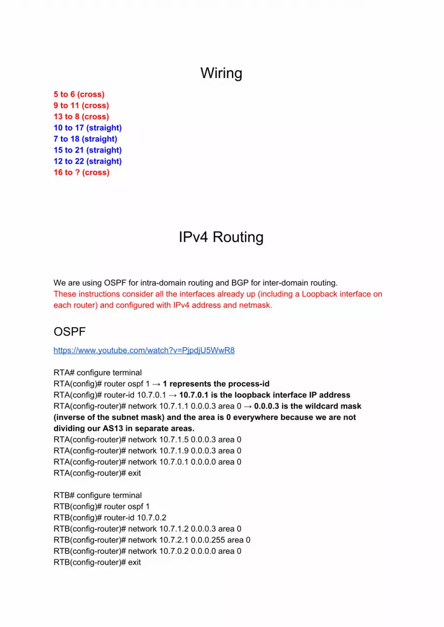
Wiring 5 to 6 (cross) 9 to 11 (cross) 13 to 8 (cross) 10 to 17 (straight) 7 to 18 (straight) 15 to 21 (straight) 12 to 22 (straight) 16 to ? (cross)
IPv4 Routing
We are using OSPF for intradomain routing and BGP for interdomain routing. These instructions consider all the interfaces already up (including a Loopback interface on each router) and configured with IPv4 address and netmask.
OSPF https://www.youtube.com/watch?v=PjpdjU5WwR8 RTA# configure terminal RTA(config)# router ospf 1 → 1 represents the processid RTA(config)# routerid 10.7.0.1 → 10.7.0.1 is the loopback interface IP address RTA(configrouter)# network 10.7.1.1 0.0.0.3 area 0 → 0.0.0.3 is the wildcard mask (inverse of the subnet mask) and the area is 0 everywhere because we are not dividing our AS13 in separate areas. RTA(configrouter)# network 10.7.1.5 0.0.0.3 area 0 RTA(configrouter)# network 10.7.1.9 0.0.0.3 area 0 RTA(configrouter)# network 10.7.0.1 0.0.0.0 area 0 RTA(configrouter)# exit RTB# configure terminal RTB(config)# router ospf 1 RTB(config)# routerid 10.7.0.2 RTB(configrouter)# network 10.7.1.2 0.0.0.3 area 0 RTB(configrouter)# network 10.7.2.1 0.0.0.255 area 0 RTB(configrouter)# network 10.7.0.2 0.0.0.0 area 0 RTB(configrouter)# exit

RTC# configure terminal RTC(config)# router ospf 1 RTC(config)# routerid 10.7.0.3 RTC(configrouter)# network 10.7.1.6 0.0.0.3 area 0 RTC(configrouter)# network 10.7.2.2 0.0.0.255 area 0 RTC(configrouter)# network 10.7.3.2 0.0.0.255 area 0 RTC(configrouter)# network 10.7.0.3 0.0.0.0 area 0 RTC(configrouter)# exit RTD# configure terminal RTD(config)# router ospf 1 RTD(config)# routerid 10.7.0.4 RTD(configrouter)# network 10.7.1.10 0.0.0.3 area 0 RTD(configrouter)# network 10.7.3.1 0.0.0.255 area 0 RTD(configrouter)# network 10.7.0.4 0.0.0.0 area 0 RTD(configrouter)# exit check
BGP https://www.youtube.com/watch?v=Wd3zNPJcUW0 https://www.youtube.com/watch?v=zqTFyuiq9bg RTA# configure terminal RTA(config)# router bgp 13 → 13 is our AS number RTA(configrouter)# bgp routerid 10.7.0.1→Loopback 0 interface IP address as routerid RTA(configrouter)# network <network we want to notify> mask <network’s mask> → Just if we want to notify any network appended to this router RTA(configrouter)# network 10.7.1.0 mask 255.255.255.252 RTA(configrouter)# network 10.7.1.4 mask 255.255.255.252 RTA(configrouter)# network 10.7.1.8 mask 255.255.255.252 RTA(configrouter)# neighbor 10.0.32.1 remoteas 2→ 10.0.32.1 is the IP address of our neighbor router’s (eBGP peer) interface facing RTA and 2 is its AS number. RTA(configrouter)# neighbor 10.7.1.2 remoteas 13 → iBGP peers RTA(configrouter)# neighbor 10.7.1.6 remoteas 13 RTA(configrouter)# neighbor 10.7.1.10 remoteas 13 RTA(configrouter)# exit RTA(config)#routemap LOCALPREF permit 10 → Configuring LOCAL_PREF attribute to set the main link as preferred gateway for traffic externally destined RTA(configroutemap)#set localpreference 500

RTA(configroutemap)#router bgp 13 RTA(configrouter)#neighbor 10.0.32.1 routemap LOCALPREF in → Routes learnt through 10.0.32.1 are set a 500 LOCALPREF value, so they are preferred over 100 value routes learnt from our neighbor AS. RTA(configrouter)#exit RTB# configure terminal RTB(config)# router bgp 13 RTB(configrouter)# bgp routerid 10.7.0.2 RTB(configrouter)# network 10.7.1.0 mask 255.255.255.252 RTB(configrouter)# network 10.7.2.0 mask 255.255.255.0 RTB(configrouter)# neighbor 10.7.1.1 remoteas 13 RTB(configrouter)# neighbor 10.7.2.2 remoteas 13 RTB(configrouter)# exit RTC# configure terminal RTC(config)# router bgp 13 RTC(configrouter)# bgp routerid 10.7.0.3 RTC(configrouter)# network 10.7.1.4 mask 255.255.255.252 RTC(configrouter)# network 10.7.2.0 mask 255.255.255.0 RTC(configrouter)# network 10.7.3.0 mask 255.255.255.0 RTC(configrouter)# neighbor 10.7.1.5 remoteas 13 RTC(configrouter)# neighbor 10.7.2.1 remoteas 13 RTC(configrouter)# neighbor 10.7.3.1 remoteas 13 RTC(configrouter)# exit RTD# configure terminal RTD(config)# router bgp 13 RTD(configrouter)# bgp routerid 10.7.0.4 RTD(configrouter)# network 10.7.1.8 mask 255.255.255.252 RTD(configrouter)# network 10.7.3.0 mask 255.255.255.0 RTD(configrouter)# neighbor 10.7.1.14 remoteas 14 → whichever IP address we have agreed with or neighbor AS14 RTD(configrouter)# neighbor 10.7.1.9 remoteas 13 RTD(configrouter)# neighbor 10.7.3.2 remoteas 13 RTD(configrouter)# exit Setting LOCAL_PREFERENCE attribute to redirect our outgoing traffic primarily through AS2: http://evilrouters.net/2009/03/07/usingbgpslocalpreferencetoinfluenceoutboundrouting/


IPfault routing We are using HSPR. These instructions consider all the interfaces already up (including a Loopback interface on each router) and configured with IPv4 address and netmask.
HSRP https://www.youtube.com/watch?v=sT9T0hla9qQ RTB#configure terminal RTB(config)#interface gigabitEthernet 0/1 → the interface facing the subnet for which we want to set the virtual router RTB(configif)#standby 1 ip 10.7.2.3 → “1” is the group number of the group of routers belonging to the virtual router and the IP address of the virtual router RTB(configif)#standby 1 priority 100 → default priority is 100 but we set it for the sake of make it more clear. RTB(configif)#standby 1 preempt → Needed for taking over the “active” router role. RTB(configif)#exit RTC#configure terminal RTC(config)#interface gigabitEthernet 0/0 RTC(configif)#standby 1 ip 10.7.2.3 RTC(configif)#standby 1 priority 115 RTC(configif)#standby 1 track gigabitEthernet 0/1 → keeps track of the state of a link. The priority is decremented by 10 if this link is found down. RTC(configif)#standby 1 track fastEthernet 1/0 RTC(configif)#standby 1 preempt RTC(configif)#exit RTC(config)#interface fastEthernet 1/0 RTC(configif)#standby 1 ip 10.7.3.3 RTC(configif)#standby 1 priority 115 RTC(configif)#standby 1 track gigabitEthernet 0/0 RTC(configif)#standby 1 track gigabitEthernet 0/1 RTC(configif)#standby 1 preempt RTC(configif)#exit RTD#configure terminal RTD(config)#interface gigabitEthernet 0/1 RTD(configif)#standby 1 ip 10.7.3.3 RTD(configif)#standby 1 priority 100 RTD(configif)#standby 1 preempt RTD(configif)#exit check?

For IPv6 (untested) http://www.cisco.com/c/en/us/td/docs/iosxml/ios/ipapp_fhrp/configuration/15sy/fhp15sybook/ip6fhrphsrp.html Enable HSPRv2 on router enable
configure terminal
interface type number
standby version 1 | 2
Enabling and verifying a HSPRv2 group
1. 1. enable 2. 2. configure terminal 3. 3. ipv6 unicastrouting 4. 4. interface type number 5. 5. standby [groupnumber] ipv6 linklocaladdress //see IPv6 section 6. 6. standby [groupnumber] preempt 7. 7. standby [groupnumber] priority priority 8. 8. exit 9. 9. show standby [type number [group]] [all | brief] 10. 10. show ipv6 interface [brief] [interfacetype interfacenumber] [prefix]
PIMSM Multicast Setup READ THE EXAMPLE: http://www.hep.ucl.ac.uk/~ytl/multicast/pimsm_01.html These instructions should be input in all internal interfaces, starting with loopback0 in RTC Also remember to setup all loopback interfaces in all routers!! Global configuration mode (X is the router): RTX(config)#no cdp lookup (CHECK!! Don’t know for certain what this does!!! May not be necessary or may destroy everything) RTX(config)# ip multicastrouting RTX(config)# interface [interface] RTX(configif)# ip pim sparsemode RTX(configif)# exit RTX(config)# ip pim rpaddress [ip of the loopback0 interface on RTC] To check if pimsim is running on the interfaces of a router:

RTX(config)# show ip pim interface To check if rp mapping is correct: RTX(config)# show ip pim rp mapping FOR TESTING: Sending vlc vvv <videofile> sout udp://<multicastaddress>:<port> ttl <ttlvalue> vlc vvv <videofile> sout udp://239.0.1.1:8989 ttl 10 Recieving vlc vvv udp://<multicastaddress>:<port> vlc vvv udp:/239.0.1.1:8989 mcast i eth0 d 10 239.0.1.1:8989mcast i eth0 d 0 239.0.1.1:8989 mcast i eth0 d 10 240.0.1.1:9000 mcast i eth0 d 0 240.0.1.1:8989 mrcv i eth0 239.0.1.1:8989
For IPv6(untested) http://www.cisco.com/c/en/us/td/docs/iosxml/ios/ipmulti_pim/configuration/xe3s/imcpimxe3sbook/ip6mcastpimsm.html http://ipv6friday.org/blog/2011/12/ipv6multicast/ Enable multicast globally on all routers enable configure terminal ipv6 multicastrouting ipv6 pim rpaddress ipv6address [groupaccesslist] end

Selective tasks
Network Monitoring RTA: (config)# interface fa1/1 (configif)# ip routecache flow (configif)# exit In global configuration mode: (config)# ip flowexport destination ipaddress | hostname [udp port] (config)# ip flowexport version 9 Default port is 2055 RTD: (config)# interface fa1/0 (configif)# ip routecache flow (configif)# exit In global configuration mode: (config)# ip flowexport destination ipaddress | hostname [udp port] (config)# ip flowexport version 9 RTC (config)# interface gi0/1 (configif)# ip routecache flow (configif)# exit In global configuration mode: (config)# ip flowexport destination ipaddress | hostname [udp port] (config)# ip flowexport version 9 In host: Use Network Analyzer to set up an alarm for too much ICMP traffic or else. Make the alarm go off at some point, switch between interfaces, etc...

IPv6
General description Configure dualstack Step 1: Activate IPv6 on router (ipv6 unicastrouting) Step 2: Set link local addresses on all router interfaces (only used locally) Step 3: Set static global addresses on all router interfaces Step 4: Set up OSPFv3 globally on every router Step 5: Set up OSPFv3 on every router interface Step 6: Statically configure servers
6.1: Global ipv6 address 6.2: Default gateway
Step 7: Clients plugandplay
RTA RTB RTC RTD
link local address fe80::1 fe80::2 fe80::3 fe80::4
router id 10.7.0.1
10.7.0.2
10.7.0.3
10.7.0.4
Addressing On every used router interface: enable configure terminal ipv6 unicastrouting interface <interface> ipv6 address <linklocal address> linklocal ipv6 address <ipv6 address/n> // n is either /64 or /112 no shutdown exit
Enable OSPFv3 On all routers globally: enable configure terminal ipv6 router ospf 1 routerid <id n> exit On every used router interface

interface <interface> ipv6 ospf 1 area 0 exit
Servers Set global address ifconfig <interface> inet6 add <ipv6address>/<prefixlength> Ex. ifconfig eth0 inet6 add 2001:0db8:0:f101::1/64 Set default gateway route A inet6 add gw <ipv6address> Ex. route A inet6 add 2000::/3 gw 2001:0db8:0:f101::1

DNS ssh to the the vm > ssh Y [email protected] navigate to the bind9 folder > cd /etc/bind create files isp7.lab(name to ip), db.10(ip to name) and db.7.0.0.0.0.1.0.0.0.0.D.F(ip to name for ipv6) We also need to alter named.conf.defaultzones aswell as named.conf.options and db.root. The contents of the files can be found in https://docs.google.com/document/d/15bu8ZuQ5q5HWNelhUuEA93Z9l5dl6Nl9jpAbBL6je_s/edit Ill explain the contents of these files..
Johan mac 52:54:00:03:01:02
DHCP 1. Configure your own static IP 10.7.2.6/24 & FD00:10:7:4::6/64
sudo ifconfig eth1 10.7.2.6/24 sudo ifconfig eth1 inet6 add FD00:10:7:4::6/64
1.1 Add default route sudo route add default gw 10.7.3.3
2. Go to the dir below and check that eth1 is in options.
sudo nano /etc/default/iscdhcpserver 2.1 Copy config file to /etc/dhcp/ 3. Restart iscdhcpserver
sudo /etc/init.d/iscdhcpserver restart 4. For IPV6 server make a new dhcpd6.conf file and a new leases file
sudo touch /etc/dhcp/dhcpd6.conf sudo touch /var/lib/dhcp/dhcpd6.leases
4.1 Copy the dhcpd6 file’s contents into it, you dont need to do anything for leases file. 5.Start IPV6 server

sudo dhcpd 6 cf /etc/dhcp/dhcpd6.conf For the relay: 1. sudo ifconfig eth1 10.7.3.4/24
sudo ifconfig eth1 inet6 add FD00:10:7:5::4/64 2. sudo dhcrelay 4 i eth1 10.7.2.6 (For ipv4)
sudo dhcrelay 6 l eth1 u eth1 (For Ipv6 ) Route Adding: sudo route add default gw 10.7.3.3 sudo route A inet6 add fd00:10:7:4::/64 gw fd00:10:7:4::3 Add IPV6 ip: sudo ifconfig eth1 inet6 add FD00:10:7:4::6/64 iscdhcpserver Configuration file location: /etc/dhcp/dhcpd.conf /etc/dhcp/dhcpd6.conf for IPv6 http://www.tldp.org/HOWTO/Linux+IPv6HOWTO/hintsdaemonsiscdhcp.html Restart the DHCP server: sudo /etc/init.d/iscdhcpserver restart See the leases:
sudo tail /var/lib/dhcp/dhcpd.leases Sample Config ipv6 defaultleasetime 600; maxleasetime 7200; logfacility local7; subnet6 2001:db8:0:1::/64 # Range for clients range6 2001:db8:0:1::129 2001:db8:0:1::254;

# Range for clients requesting a temporary address range6 2001:db8:0:1::/64 temporary; # Additional options option dhcp6.nameservers fec0:0:0:1::1; option dhcp6.domainsearch "domain.example"; # Prefix range for delegation to subrouters prefix6 2001:db8:0:100:: 2001:db8:0:f00:: /56; # Example for a fixed host address host specialclient hostidentifier option dhcp6.clientid 00:01:00:01:4a:1f:ba:e3:60:b9:1f:01:23:45; fixedaddress6 2001:db8:0:1::127; Relay Server(If needed) http://yourtoolbox.blogspot.se/2013/01/dhcpforwardingwithrelayserver.html When installing the package iscdhcprelay, the setup process will start automatically and it will modify the file /etc/default/iscdhcprelay. However, in case you might want to change something later, here's the content of the file for my example: # Defaults for iscdhcprelay initscript # sourced by /etc/init.d/iscdhcprelay # installed at /etc/default/iscdhcprelay by the maintainer scripts # What servers should the DHCP relay forward requests to? SERVERS="192.168.56.2" # On what interfaces should the DHCP relay (dhrelay) serve DHCP requests? INTERFACES="" # Additional options that are passed to the DHCP relay daemon? OPTIONS=""

start a IPV6 dhcp server: dhcpd cf /etc/dhcp/dhcpd6.conf Configuring IP Helper Service in Cisco Router: http://www.cisco.com/en/US/docs/ios/12_4t/ip_addr/configuration/guide/htdhcpre.html#wp1089957
SUMMARY STEPS
1. enable 2. configure terminal 3. interface type number 4. ip helperaddress address


