Embed Size (px)
Citation preview

Reference numberISO 15590-2:2003(E)
© ISO 2003
INTERNATIONAL STANDARD
ISO15590-2
First edition2003-12-15
Petroleum and natural gas industries — Induction bends, fittings and flanges for pipeline transportation systems — Part 2: Fittings
Industries du pétrole et du gaz naturel — Coudes d'induction, raccords et brides pour systèmes de transport par conduites —
Partie 2: Raccords
ISO 15590-2:2003(E)
PDF disclaimer This PDF file may contain embedded typefaces. In accordance with Adobe's licensing policy, this file may be printed or viewed but shall not be edited unless the typefaces which are embedded are licensed to and installed on the computer performing the editing. In downloading this file, parties accept therein the responsibility of not infringing Adobe's licensing policy. The ISO Central Secretariat accepts no liability in this area.
Adobe is a trademark of Adobe Systems Incorporated.
Details of the software products used to create this PDF file can be found in the General Info relative to the file; the PDF-creation parameters were optimized for printing. Every care has been taken to ensure that the file is suitable for use by ISO member bodies. In the unlikely event that a problem relating to it is found, please inform the Central Secretariat at the address given below.
© ISO 2003 All rights reserved. Unless otherwise specified, no part of this publication may be reproduced or utilized in any form or by any means, electronic or mechanical, including photocopying and microfilm, without permission in writing from either ISO at the address below or ISO's member body in the country of the requester.
ISO copyright office Case postale 56 • CH-1211 Geneva 20 Tel. + 41 22 749 01 11 Fax + 41 22 749 09 47 E-mail [email protected] Web www.iso.org
Published in Switzerland
ii © ISO 2003 — All rights reserved
ISO 15590-2:2003(E)
© ISO 2003 — All rights reserved iii
Contents Page
Foreword............................................................................................................................................................ iv Introduction ........................................................................................................................................................ v 1 Scope...................................................................................................................................................... 1 2 Normative references ........................................................................................................................... 1 3 Terms and definitions........................................................................................................................... 3 4 Symbols and abbreviated terms.......................................................................................................... 4 5 Designation............................................................................................................................................ 5 6 Pressure rating and design.................................................................................................................. 5 6.1 General ................................................................................................................................................... 5 6.2 Tees and headers.................................................................................................................................. 5 6.3 Extruded outlet headers ....................................................................................................................... 5 7 Information to be supplied by the purchaser..................................................................................... 6 7.1 Principal information ............................................................................................................................ 6 7.2 Supplementary information ................................................................................................................. 6 8 Manufacturing ....................................................................................................................................... 7 8.1 Manufacturing procedure specification.............................................................................................. 7 8.2 Starting material.................................................................................................................................... 7 8.3 Fitting manufacture............................................................................................................................... 8 9 Testing and inspection ....................................................................................................................... 10 9.1 General requirements ......................................................................................................................... 10 9.2 Extent of testing and inspection ....................................................................................................... 10 9.3 Chemical composition........................................................................................................................ 12 9.4 Mechanical testing .............................................................................................................................. 12 9.5 Non-destructive testing ...................................................................................................................... 17 9.6 Dimensions.......................................................................................................................................... 19 9.7 Gauging................................................................................................................................................ 20 9.8 Hydrostatic testing.............................................................................................................................. 20 10 Inspection document .......................................................................................................................... 20 11 Marking................................................................................................................................................. 20 Annex A (normative) Design calculations ..................................................................................................... 21 Annex B (normative) Proof test....................................................................................................................... 23 Bibliography ..................................................................................................................................................... 26

ISO 15590-2:2003(E)
iv © ISO 2003 — All rights reserved
Foreword
ISO (the International Organization for Standardization) is a worldwide federation of national standards bodies (ISO member bodies). The work of preparing International Standards is normally carried out through ISO technical committees. Each member body interested in a subject for which a technical committee has been established has the right to be represented on that committee. International organizations, governmental and non-governmental, in liaison with ISO, also take part in the work. ISO collaborates closely with the International Electrotechnical Commission (IEC) on all matters of electrotechnical standardization.
International Standards are drafted in accordance with the rules given in the ISO/IEC Directives, Part 2.
The main task of technical committees is to prepare International Standards. Draft International Standards adopted by the technical committees are circulated to the member bodies for voting. Publication as an International Standard requires approval by at least 75 % of the member bodies casting a vote.
Attention is drawn to the possibility that some of the elements of this document may be the subject of patent rights. ISO shall not be held responsible for identifying any or all such patent rights.
ISO 15590-2 was prepared by Technical Committee ISO/TC 67, Materials, equipment and offshore structures for petroleum, petrochemical and natural gas industries, Subcommittee SC 2, Pipeline transportation systems.
ISO 15590 consists of the following parts, under the general title Petroleum and natural gas industries — Induction bends, fittings and flanges for pipeline transportation systems:
Part 1: Induction bends
Part 2: Fittings
The following part is under preparation:
Part 3: Flanges

ISO 15590-2:2003(E)
© ISO 2003 — All rights reserved v
Introduction
Users of this part of ISO 15590 should be aware that further or differing requirements may be needed for individual applications. This part of ISO 15590 is not intended to inhibit a manufacturer from offering, or the purchaser from accepting, alternative equipment or engineering solutions for the individual application. This can be particularly applicable where there is innovative or developing technology. Where an alternative is offered, the manufacturer should identify any variations from this part of ISO 15590 and provide details.


INTERNATIONAL STANDARD ISO 15590-2:2003(E)
© ISO 2003 — All rights reserved 1
Petroleum and natural gas industries — Induction bends, fittings and flanges for pipeline transportation systems —
Part 2: Fittings
1 Scope
This part of ISO 15590 specifies the technical delivery conditions for unalloyed or low-alloy steel seamless and welded pipeline fittings for use in pipeline transportation systems for the petroleum and natural gas industries as defined in ISO 13623.
This part of ISO 15590 is applicable to welding-end fittings such as elbows, caps, tees, single or multiple extruded headers, reducers, and transition sections made from seamless and welded pipe of unalloyed or low-alloy steels.
This part of ISO 15590 specifies three classes of fitting corresponding to increasing quality requirements in accordance with the technical delivery conditions of ISO 3183 for pipe as indicated in Table 1.
Table 1 — Fitting class and corresponding pipe standard
Fitting class Corresponding pipe standard
Class A ISO 3183-1
Class B ISO 3183-2
Class C ISO 3183-3
This part of ISO 15590 is not applicable to the selection of the fitting class.
This part of ISO 15590 is not applicable to the materials for, or the attachment of, factory-welded extensions.
2 Normative references
The following referenced documents are indispensable for the application of this document. For dated references, only the edition cited applies. For undated references, the latest edition of the referenced document (including any amendments) applies.
ISO 148 (all parts), Steel — Charpy impact test (V-notch)
ISO 377:1997, Steel and steel products — Location and preparation of samples and test pieces for mechanical testing
ISO 783, Metallic materials — Tensile testing at elevated temperature
ISO 2566-1, Steel – Conversion of elongation values — Part 1: Carbon and low alloy steels
ISO 15590-2:2003(E)
2 © ISO 2003 — All rights reserved
ISO 3183-1, Petroleum and natural gas industries — Steel pipe for pipelines — Technical delivery conditions — Part 1: Pipes of requirement class A
ISO 3183-2, Petroleum and natural gas industries — Steel pipe for pipelines — Technical delivery conditions — Part 2: Pipes of requirement class B
ISO 3183-3, Petroleum and natural gas industries — Steel pipe for pipelines — Technical delivery conditions — Part 3: Pipes of requirement class C
ISO 3834-2, Quality requirements for welding — Fusion welding of metallic materials — Part 2: Comprehensive quality requirements
ISO 4885, Ferrous products — Heat treatments — Vocabulary
ISO 6507-1, Metallic materials — Vickers hardness test — Part 1: Test method
ISO 6892, Metallic materials — Tensile testing at ambient temperature
ISO 7438, Metallic materials — Bend test
ISO/TR 7705:1991, Guidelines for specifying Charpy V-notch impact prescriptions in steel specifications
ISO 9712, Non-destructive testing — Qualification and certification of personnel
ISO 10474, Steel and steel products — Inspection documents
ISO 11496, Seamless and welded steel tubes for pressure purposes — Ultrasonic testing of tube ends for the detection of laminar imperfections
ISO 12095, Seamless and welded steel tubes for pressure purposes — Liquid penetrant testing
ISO 12096, Submerged arc-welded steel tubes for pressure purposes — Radiographic testing of the weld seam for the detection of imperfections
ISO 13623, Petroleum and natural gas industries — Pipeline transportation systems
ISO 13664, Seamless and welded steel tubes for pressure purposes — Magnetic particle inspection of the tube ends for the detection of laminar imperfections
ASME1) B16.9, Factory-made wrought butt welding fittings
ASME B31.8, Gas transmission and distribution piping systems
ASME IX, Boiler and pressure vessel code, Section IX — Welding and brazing procedures, welders, brazers, and welding and brazing operators
ASTM2) E 112, Standard test methods for determining average grain size
ASTM E 709, Standard guide for magnetic particle examination
EN 287-1, Approval testing of welders — Fusion welding — Part 1: Steels
EN 288-3, Specification and approval of welding procedures for metallic materials — Part 3: Welding procedure tests for the arc welding of steels
1) American Society of Mechanical Engineers, 345 East 47th Street, NY 10017-2392, USA
2) American Society for Testing and Materials, 100 Bar Harbor Drive, West Conshohocken, PA 19428-2959, USA

ISO 15590-2:2003(E)
© ISO 2003 — All rights reserved 3
MSS3) SP-75, Specification for high test wrought butt welding fittings
EFC Publication 16:19954), Guidelines on materials requirements for carbon and low alloy steels for H2S containing environments in oil and gas production
3 Terms and definitions
For the purposes of this part of ISO 15590 the terms and definitions given in ISO 4885 and the following apply.
3.1 by agreement agreed between manufacturer and purchaser
[ISO 15590-1:2001]
3.2 extrados outer curved section of the elbow
NOTE Adapted from ISO 15590-1:2001.
3.3 heat, noun batch of steel prepared in one steel-making process
NOTE Adapted from ISO 15590-1:2001.
3.4 intrados inner curved section of the elbow
NOTE Adapted from ISO 15590-1:2001.
3.5 manufacturing procedure specification MPS document which specifies the process control parameters and the acceptance criteria to be applied for all manufacturing, inspection and testing activities performed during fitting manufacture
3.6 tangent straight section at the ends of the fitting
NOTE Adapted from ISO 15590-1:2001.
3.7 test unit fitting or test piece of the same designation, starting material wall thickness, heat, manufacturing procedure specification, and heat treatment condition
3) Manufacturers Standardization Society of the Valve & Fittings Industry, 127 Park Street, N.E., Vienna, Virginia 22180, USA
4) European Federation of Corrosion, c/o The Institute of Materials, 1 Carlton House Terrace, London SW1Y 5DB, United Kingdom
ISO 15590-2:2003(E)
4 © ISO 2003 — All rights reserved
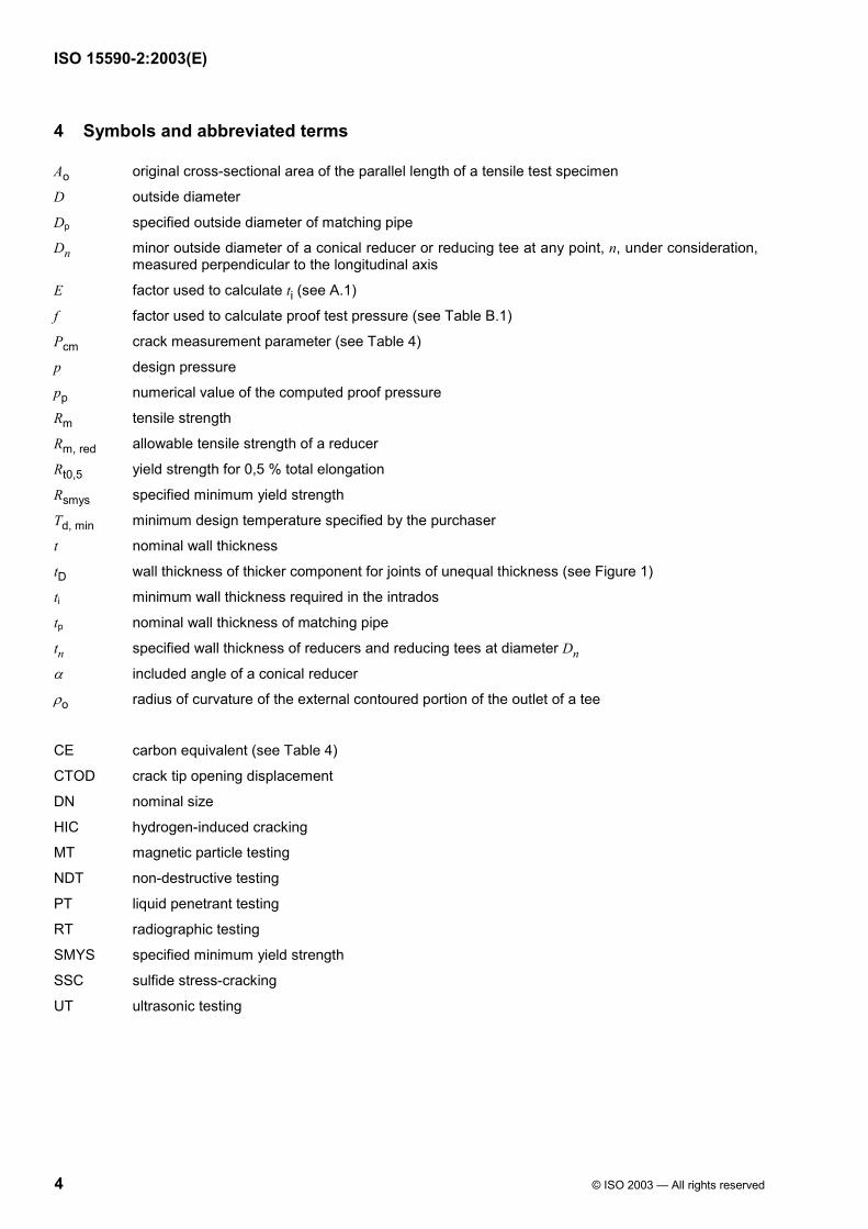
4 Symbols and abbreviated terms
Ao original cross-sectional area of the parallel length of a tensile test specimen
D outside diameter
Dp specified outside diameter of matching pipe
Dn minor outside diameter of a conical reducer or reducing tee at any point, n, under consideration, measured perpendicular to the longitudinal axis
E factor used to calculate ti (see A.1)
f factor used to calculate proof test pressure (see Table B.1)
Pcm crack measurement parameter (see Table 4)
p design pressure
pp numerical value of the computed proof pressure
Rm tensile strength
Rm, red allowable tensile strength of a reducer
Rt0,5 yield strength for 0,5 % total elongation
Rsmys specified minimum yield strength
Td, min minimum design temperature specified by the purchaser
t nominal wall thickness
tD wall thickness of thicker component for joints of unequal thickness (see Figure 1)
ti minimum wall thickness required in the intrados
tp nominal wall thickness of matching pipe
tn specified wall thickness of reducers and reducing tees at diameter Dn
α included angle of a conical reducer
ρo radius of curvature of the external contoured portion of the outlet of a tee
CE carbon equivalent (see Table 4)
CTOD crack tip opening displacement
DN nominal size
HIC hydrogen-induced cracking
MT magnetic particle testing
NDT non-destructive testing
PT liquid penetrant testing
RT radiographic testing
SMYS specified minimum yield strength
SSC sulfide stress-cracking
UT ultrasonic testing
ISO 15590-2:2003(E)
© ISO 2003 — All rights reserved 5
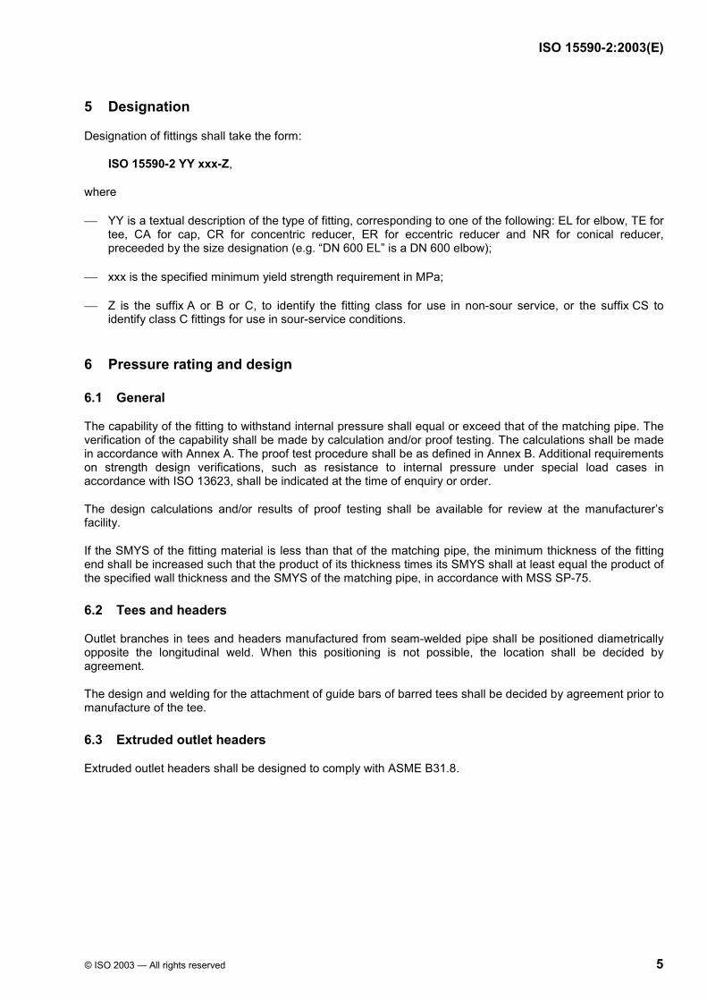
5 Designation
Designation of fittings shall take the form:
ISO 15590-2 YY xxx-Z,
where
YY is a textual description of the type of fitting, corresponding to one of the following: EL for elbow, TE for tee, CA for cap, CR for concentric reducer, ER for eccentric reducer and NR for conical reducer, preceeded by the size designation (e.g. “DN 600 EL” is a DN 600 elbow);
xxx is the specified minimum yield strength requirement in MPa;
Z is the suffix A or B or C, to identify the fitting class for use in non-sour service, or the suffix CS to identify class C fittings for use in sour-service conditions.
6 Pressure rating and design
6.1 General
The capability of the fitting to withstand internal pressure shall equal or exceed that of the matching pipe. The verification of the capability shall be made by calculation and/or proof testing. The calculations shall be made in accordance with Annex A. The proof test procedure shall be as defined in Annex B. Additional requirements on strength design verifications, such as resistance to internal pressure under special load cases in accordance with ISO 13623, shall be indicated at the time of enquiry or order.
The design calculations and/or results of proof testing shall be available for review at the manufacturer’s facility.
If the SMYS of the fitting material is less than that of the matching pipe, the minimum thickness of the fitting end shall be increased such that the product of its thickness times its SMYS shall at least equal the product of the specified wall thickness and the SMYS of the matching pipe, in accordance with MSS SP-75.
6.2 Tees and headers
Outlet branches in tees and headers manufactured from seam-welded pipe shall be positioned diametrically opposite the longitudinal weld. When this positioning is not possible, the location shall be decided by agreement.
The design and welding for the attachment of guide bars of barred tees shall be decided by agreement prior to manufacture of the tee.
6.3 Extruded outlet headers
Extruded outlet headers shall be designed to comply with ASME B31.8.
ISO 15590-2:2003(E)
6 © ISO 2003 — All rights reserved
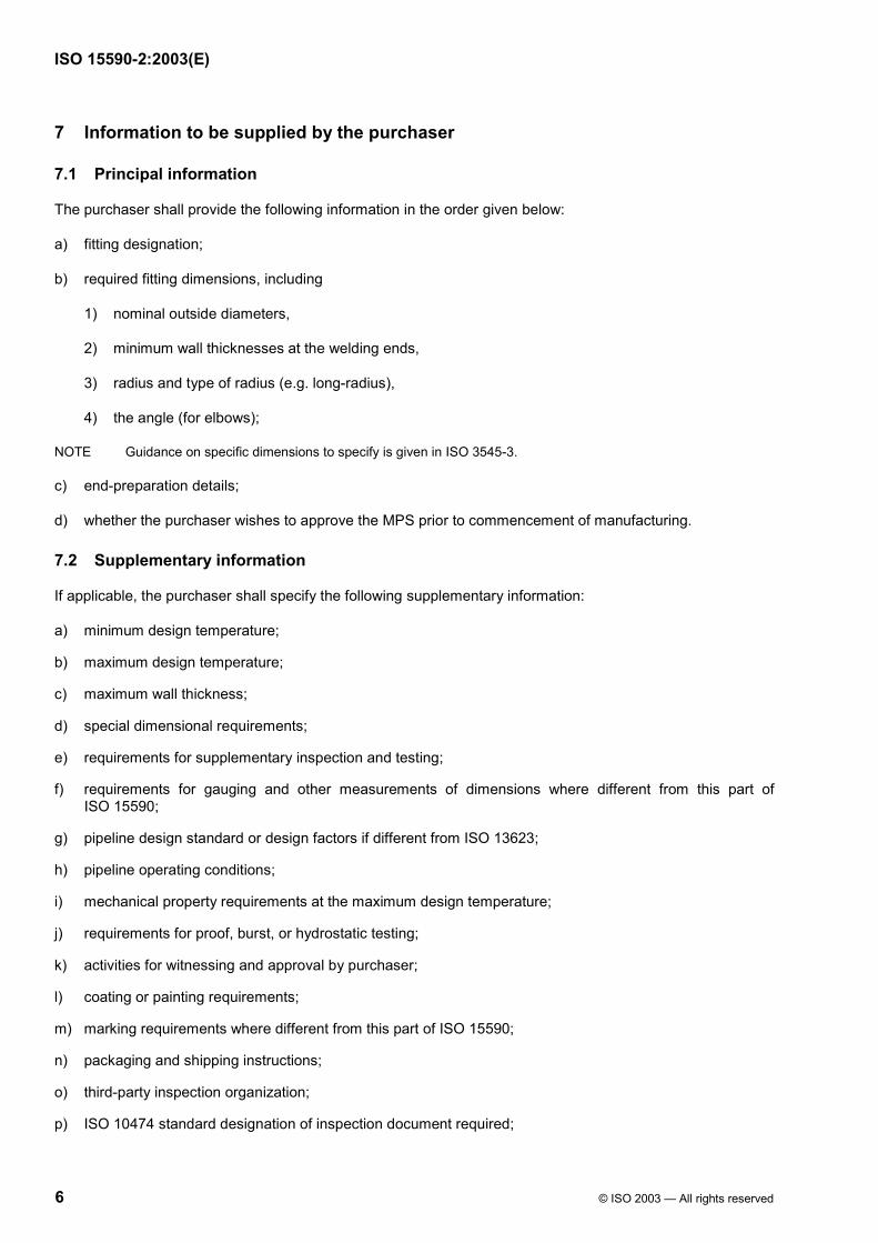
7 Information to be supplied by the purchaser
7.1 Principal information
The purchaser shall provide the following information in the order given below:
a) fitting designation;
b) required fitting dimensions, including
1) nominal outside diameters,
2) minimum wall thicknesses at the welding ends,
3) radius and type of radius (e.g. long-radius),
4) the angle (for elbows);
NOTE Guidance on specific dimensions to specify is given in ISO 3545-3.
c) end-preparation details;
d) whether the purchaser wishes to approve the MPS prior to commencement of manufacturing.
7.2 Supplementary information
If applicable, the purchaser shall specify the following supplementary information:
a) minimum design temperature;
b) maximum design temperature;
c) maximum wall thickness;
d) special dimensional requirements;
e) requirements for supplementary inspection and testing;
f) requirements for gauging and other measurements of dimensions where different from this part of ISO 15590;
g) pipeline design standard or design factors if different from ISO 13623;
h) pipeline operating conditions;
i) mechanical property requirements at the maximum design temperature;
j) requirements for proof, burst, or hydrostatic testing;
k) activities for witnessing and approval by purchaser;
l) coating or painting requirements;
m) marking requirements where different from this part of ISO 15590;
n) packaging and shipping instructions;
o) third-party inspection organization;
p) ISO 10474 standard designation of inspection document required;

ISO 15590-2:2003(E)
© ISO 2003 — All rights reserved 7
q) requirements for format and additional content of the inspection document;
r) whether testing of welding procedures, welders, or welding operators specific to the order is required;
s) whether approval of the MPS is to be by review of previous production data or by testing;
t) PWHT (see 9.1);
u) HIC testing (see 9.4.7);
v) SCC testing (see 9.4.8).
8 Manufacturing
8.1 Manufacturing procedure specification
Fittings shall be manufactured in accordance with a documented MPS. If specified by the purchaser, manufacturing shall not proceed until the MPS has been accepted by the purchaser.
The MPS shall specify the following items:
a) for the starting material:
1) name of manufacturer,
2) steel-making process,
3) steel grade,
4) product form and dimensions,
5) chemical composition, including that of the weld seam,
6) welding procedure specification;
b) for fitting manufacture:
1) forming procedure,
2) welding procedure specification and approval record,
3) heat treatment procedure including thermal cycles,
4) machining requirements,
5) inspection and test requirements,
6) traceability;
c) additional requirements such as end preparation, coating, and marking.
An approval of the MPS may be required, either by review of the manufacturer’s previous production data or by performance of the mandatory tests listed in Table 2, at the beginning of production.
8.2 Starting material
The starting material for forming into fittings shall be blooms, billets, slabs, forging quality bar, plate, fusion-welded with filler metal or seamless tubular products, produced from fully-killed steels.
ISO 15590-2:2003(E)
8 © ISO 2003 — All rights reserved
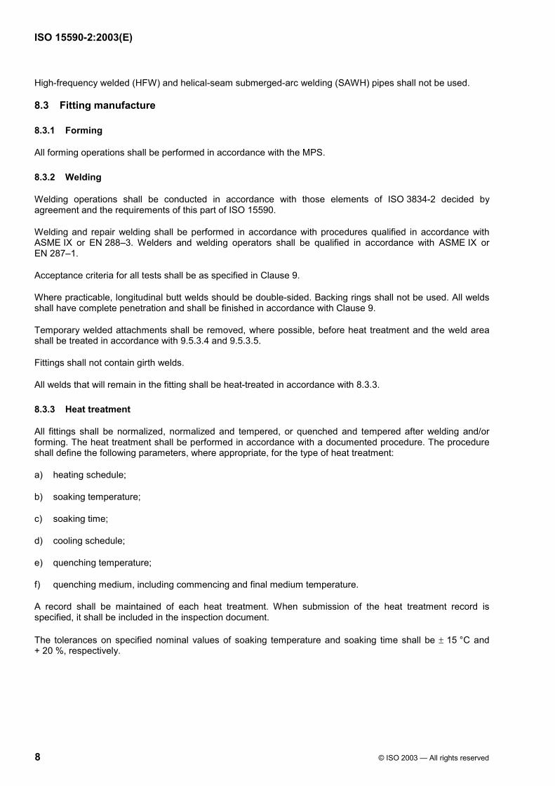
High-frequency welded (HFW) and helical-seam submerged-arc welding (SAWH) pipes shall not be used.
8.3 Fitting manufacture
8.3.1 Forming
All forming operations shall be performed in accordance with the MPS.
8.3.2 Welding
Welding operations shall be conducted in accordance with those elements of ISO 3834-2 decided by agreement and the requirements of this part of ISO 15590.
Welding and repair welding shall be performed in accordance with procedures qualified in accordance with ASME IX or EN 288–3. Welders and welding operators shall be qualified in accordance with ASME IX or EN 287–1.
Acceptance criteria for all tests shall be as specified in Clause 9.
Where practicable, longitudinal butt welds should be double-sided. Backing rings shall not be used. All welds shall have complete penetration and shall be finished in accordance with Clause 9.
Temporary welded attachments shall be removed, where possible, before heat treatment and the weld area shall be treated in accordance with 9.5.3.4 and 9.5.3.5.
Fittings shall not contain girth welds.
All welds that will remain in the fitting shall be heat-treated in accordance with 8.3.3.
8.3.3 Heat treatment
All fittings shall be normalized, normalized and tempered, or quenched and tempered after welding and/or forming. The heat treatment shall be performed in accordance with a documented procedure. The procedure shall define the following parameters, where appropriate, for the type of heat treatment:
a) heating schedule;
b) soaking temperature;
c) soaking time;
d) cooling schedule;
e) quenching temperature;
f) quenching medium, including commencing and final medium temperature.
A record shall be maintained of each heat treatment. When submission of the heat treatment record is specified, it shall be included in the inspection document.
The tolerances on specified nominal values of soaking temperature and soaking time shall be ± 15 °C and + 20 %, respectively.

ISO 15590-2:2003(E)
© ISO 2003 — All rights reserved 9
8.3.4 End preparation
For unequal wall thicknesses, the joint design shall be as shown in Figure 1.
Dimensions in millimetres
a) Internal offset
b) External offset
c) Combination
If the SMYSs of the sections to be joined are not equal, the minimum thickness, tD, shall be not less than t times the ratio of the SMYS of the pipe and fitting, but shall not exceed 1,5t.
a There is no restriction on the minimum angle if the materials joined have equal SMYS.
Figure 1 — Bevel designs for unequal wall thicknesses

ISO 15590-2:2003(E)
10 © ISO 2003 — All rights reserved
9 Testing and inspection
9.1 General requirements
Testing and inspection shall be carried out on fittings after final heat treatment.
If the pipeline installation techniques will require post-weld heat treatment (PWHT) of the fitting, additional testing may be requested to demonstrate that the mechanical properties of the fitting are also achieved after PWHT. Details of the PWHT thermal cycle to be used during pipeline installation shall be specified. The test requirements and acceptance criteria shall be by agreement.
Where the procedure requirements of 8.3.3 are not met, test pieces shall be taken from each heat treatment batch.
9.2 Extent of testing and inspection
The testing and inspection to be performed during qualification and production shall be as summarized in Table 2 for each fitting class.
Production testing shall be performed at the minimum frequency specified in Table 3.
Test pieces for mechanical testing shall be taken from one or more of the following:
extension lengths, formed and heat-treated as part of the fitting and/or test piece attached to the fitting;
starting material which has been subjected to the same forging reduction and heat treatment as the proposed fitting;
a fitting.
Locations for the test pieces to be taken from a fitting shall be established by agreement. The sample of starting material shall be heat-treated with or as part of the fittings in the same heat treatment batch in accordance with ISO 377:1997, Clause 5.
Fittings heat-treated within the tolerance requirements of 8.3.3 may be considered as being in the same heat treatment condition.

ISO 15590-2:2003(E)
© ISO 2003 — All rights reserved 11
Table 2 — Summary of testing and inspection requirements
Test Class A Class B Class C
Clause number
specifying acceptance
criteria
Chemical analysis Chemical composition M M M 9.3
Physical tests Tensile – base metal M M M 9.4.2.3
Transverse weld tensile Ma Ma Ma 9.4.2.3
Impact – fitting body O M M 9.4.3.3
Impact – weld seam O M M 9.4.3.3
Through-thickness hardness O M M 9.4.4.2
Surface hardness O O O 9.4.5
Metallography Q Q Qb 9.4.6.2
HIC N N Oc,d 9.4.7
SSC N N Oc,d 9.4.8
CTOD N N O 9.4.9
Guided bend (weld seam) Q Q Q 9.4.10.3
NDT Visual inspection M M M 9.5.3
End preparation (MT or PT) M M M 9.5.4
Fitting end (UT) N M M 9.5.4
Weld seam (RT or UT)d M M M 9.5.5
Fitting body (UT or MT)e O O O 9.5.7
Residual magnetism O M M 9.5.8
Dimensions Wall thickness M M M 9.6
Inside diameter at ends M M M 9.6
Out-of-roundness at ends M M M 9.6
Specific dimensions M M M 9.6
NOTE The abbreviations mean as follows: M = Requirement mandatory in production N = Not required O = Requirement for test or inspection at the purchaser’s option Q = Required for approval of the welding procedure only, otherwise at the purchaser’s option
a May be omitted for fittings with D < 210 mm.
b Production test which shall be performed for fittings intended for sour service. c Option need not be considered for fittings intended for non-sour service. If applied, this testing may be performed as part of the MPS qualification testing. d May be carried out on the starting material by agreement. e By agreement.

ISO 15590-2:2003(E)
12 © ISO 2003 — All rights reserved
Table 3 — Extent of testing and inspection
Type of test Number of tests
Chemical composition One per heat
Tensile — base metal One per test unit
Transverse weld tensile One per test unit
Impact — base metal One set per test unit
Impact — weld seam 37 mm thickness and above: two sets per test unit less than 37 mm: 1 set per test unit
Through-thickness hardness One per test unit
Surface hardness By agreement
Metallography By agreement
HIC By agreement
SSC By agreement
CTOD By agreement
Guided bend (weld seam) Two per qualification test
NDT Every fittinga
Dimensional inspection Every fitting
a Except for determining residual magnetism, which shall be at a frequency to be established by agreement for fittings demagnetized during production, otherwise 25 % of the fittings shall be selected at random.
9.3 Chemical composition
The product analysis shall be in accordance with Table 4.
9.4 Mechanical testing
9.4.1 Preparation of test pieces
Test pieces shall be prepared in accordance with ISO 377.
9.4.2 Tensile testing
9.4.2.1 Test pieces
Orientation of the base metal test pieces shall be as follows:
transverse to the major axis of the fitting for D W 210 mm;
longitudinal to the major axis of the fitting for D < 210 mm.
Transverse test pieces shall be cold-flattened. Round bar made from a test piece may be used. Round-bar test pieces machined from unflattened samples may be used by agreement.
Welds shall be ground flush. Local imperfections and mill scale shall be removed.
ISO 15590-2:2003(E)
© ISO 2003 — All rights reserved 13
9.4.2.2 Test method
Tensile testing at ambient temperature shall be carried out in accordance with ISO 6892. If specified, tensile testing at elevated temperatures shall be carried out in accordance with ISO 783. The frequency and acceptance criteria shall be by agreement.
For base metal, Rt0,5, Rm, and percentage elongation after fracture shall be determined. For tensile tests transverse to the weld, it is required only to determine Rm.
The percentage elongation after fracture shall be reported with reference to a gauge length of o5,65 A . If other gauge lengths are used, the elongation referred to a gauge length of o5,65 A shall be determined in accordance with ISO 2566-1.
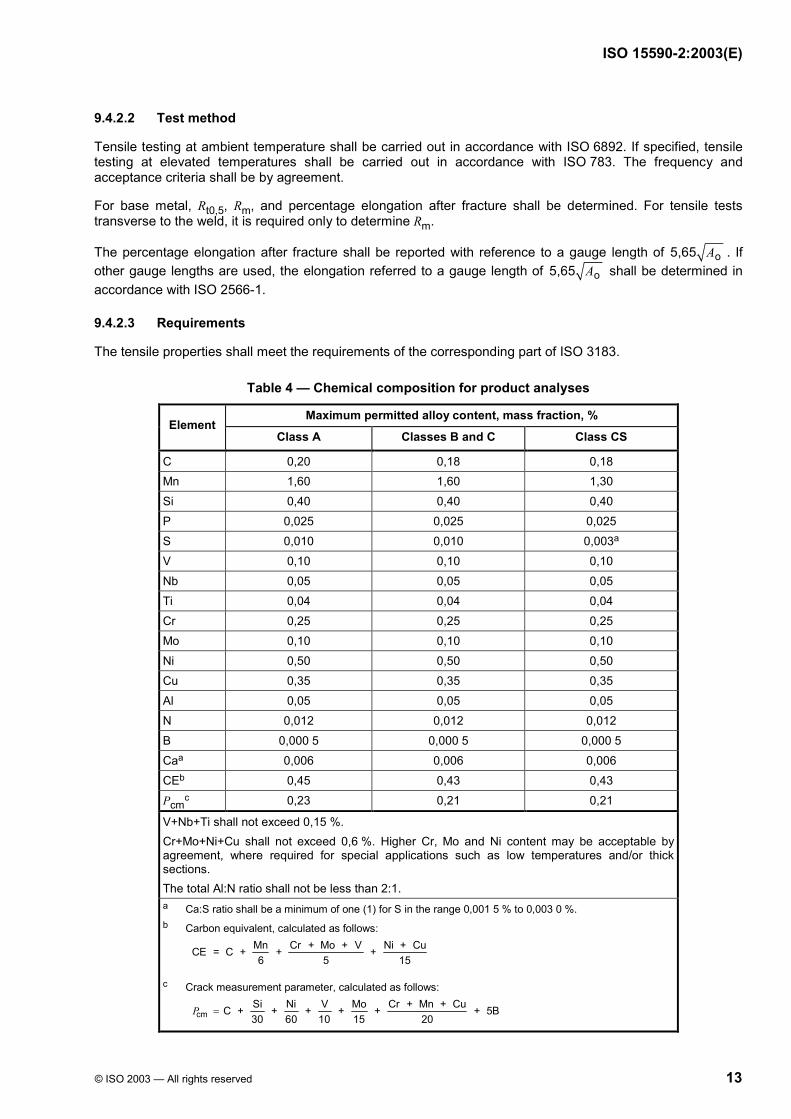
9.4.2.3 Requirements
The tensile properties shall meet the requirements of the corresponding part of ISO 3183.
Table 4 — Chemical composition for product analyses
Maximum permitted alloy content, mass fraction, % Element
Class A Classes B and C Class CS
C 0,20 0,18 0,18 Mn 1,60 1,60 1,30 Si 0,40 0,40 0,40 P 0,025 0,025 0,025 S 0,010 0,010 0,003a V 0,10 0,10 0,10 Nb 0,05 0,05 0,05 Ti 0,04 0,04 0,04 Cr 0,25 0,25 0,25 Mo 0,10 0,10 0,10 Ni 0,50 0,50 0,50 Cu 0,35 0,35 0,35 Al 0,05 0,05 0,05 N 0,012 0,012 0,012 B 0,000 5 0,000 5 0,000 5 Caa 0,006 0,006 0,006 CEb 0,45 0,43 0,43 Pcm
c 0,23 0,21 0,21
V+Nb+Ti shall not exceed 0,15 %. Cr+Mo+Ni+Cu shall not exceed 0,6 %. Higher Cr, Mo and Ni content may be acceptable by agreement, where required for special applications such as low temperatures and/or thick sections. The total Al:N ratio shall not be less than 2:1. a Ca:S ratio shall be a minimum of one (1) for S in the range 0,001 5 % to 0,003 0 %. b Carbon equivalent, calculated as follows:
Mn Cr + Mo + V Ni + CuCE = C + + +6 5 15
c Crack measurement parameter, calculated as follows:
cmSi Ni V Mo Cr + Mn + CuC + + + + + + 5B30 60 10 15 20
P =

ISO 15590-2:2003(E)
14 © ISO 2003 — All rights reserved
9.4.3 Charpy V-notch impact testing
9.4.3.1 Test pieces
Charpy V-notch test pieces shall be prepared in accordance with ISO 148, with the axis of the notch perpendicular to the fitting surface.
The orientation and size of the test pieces shall be transverse with the greatest possible width between 5 mm and 10 mm. If transverse test pieces with a minimum width of 5 mm are not possible, longitudinal test pieces with the greatest possible width between 5 mm and 10 mm shall be used.
Impact testing is not required if the fitting dimensions are insufficient to extract longitudinal base metal test pieces with a minimum width of 5 mm.
Charpy V-notch test pieces shall be taken from the sample in accordance with ISO 3183-3.
Test pieces for welds shall be taken from the weld centreline. Test pieces of the fusion line should be taken by agreement, in which case the notch location shall be as shown in Figure 2.
a) Symmetric weld b) Asymmetric weld
Key
1 weld
2 fusion line
3 test piece edges
4 Charpy notch
t is the length of Charpy V-notch
Figure 2 — Location of Charpy V-notch in weld fusion lines
9.4.3.2 Test method
Each set of impact tests shall consist of three adjacent test pieces taken from a single, non-flattened sample.
Charpy V-notch impact testing shall be in accordance with ISO 148. An additional requirement to report shear area of the fracture surface shall be by agreement.
The impact test temperature shall be established in accordance with Table 5.

ISO 15590-2:2003(E)
© ISO 2003 — All rights reserved 15
Table 5 — Maximum Charpy V-notch test temperature
Test temperature
°C
Nominal wall thickness
mm
Class A Class B Class C
t u 20 By agreement Td, min Td, min − 10
20 < t u 25 By agreement Td, min Td, min − 20
t > 25 By agreement By agreement By agreement
In no case shall the test temperature exceed 0 °C.
9.4.3.3 Requirements
The results of the Charpy V-notch impact tests shall meet the following requirements.
a) For each set of tests, the minimum average absorbed energy, in joules, in the transverse direction shall be
smys
10R
where Rsmys is the specified minimum yield strength, expressed in megapascals.
For steel grade L245, the minimum average Charpy-V absorbed energy in the transverse direction shall be 27 J.
b) The minimum individual value in any set of tests shall not be less than 75 % of the minimum required average value.
c) The minimum average and minimum individual values when testing test pieces taken in the longitudinal direction shall be 1,5 times the values stated for transverse test pieces.
d) If specified (see 9.4.3.2), the shear area shall be an average of 50 % with a minimum individual value of 40 %.
For subsize test pieces, the minimum required absorbed energy values shall be adjusted in accordance with ISO/TR 7705:1991, Clause 6.
9.4.4 Through-thickness hardness testing
9.4.4.1 Test method
Through-thickness hardness testing shall be performed using the Vickers method in accordance with ISO 6507-1, method HV 10 (i.e. with a test force of 98,07 N).
Hardness indent locations for welded fittings shall be in accordance with Figure 3. For seamless fittings, hardness indent locations shall be made at a distance of 1 mm to 2 mm from the inside and outside surfaces containing four indents spaced at 5 mm arranged similarly to Figure 3.

ISO 15590-2:2003(E)
16 © ISO 2003 — All rights reserved
Dimensions in millimetres
t is the thickness
Figure 3 — Hardness indent locations for welded fittings
9.4.4.2 Acceptance criteria
No hardness reading shall exceed
300 HV 10 for class A, B and C fittings,
250 HV 10 for class CS fittings.
9.4.5 Surface hardness testing
The test method and acceptance criteria shall be established by agreement.
9.4.6 Metallographic examination
9.4.6.1 Test method
The specimens for through-thickness hardness testing shall be examined, prior to hardness testing, at a magnification of not less than ×100. Grain-size measurement shall be performed in accordance with ASTM E 112.
The type of microstructure and actual grain size shall be recorded on the manufacturing procedure qualification test report.
9.4.6.2 Acceptance criteria
The minimum average grain size number shall be 7.
9.4.7 HIC testing
If HIC testing is specified, the test procedures and acceptance criteria shall be in accordance with EFC Publication 16:1995, Annex B.
9.4.8 SSC testing
If SSC testing is specified, test procedures and acceptance criteria shall be in accordance with EFC Publication 16.

ISO 15590-2:2003(E)
© ISO 2003 — All rights reserved 17
9.4.9 CTOD testing
CTOD testing is not required for any fitting class, except by agreement.
Test methods and requirements shall be decided by agreement.
9.4.10 Guided weld bend testing
9.4.10.1 Test pieces
The test pieces shall be in accordance with ISO 7438.
Full-thickness curved-section test pieces are required for fittings with wall thicknesses of 20 mm and above. For fittings with a wall thickness less than 20 mm, the test pieces may be machined to provide a rectangular cross-section with a thickness of 19 mm. The weld reinforcement shall be removed from both faces.
9.4.10.2 Test method
The mandrel dimensions shall be as defined in the corresponding part of ISO 3183 for the grade of fitting.
Both test pieces shall be bent through approximately 180°, one with the root of the weld and the other with the face of the weld directly under the mandrel.
9.4.10.3 Acceptance criteria
The test pieces shall
a) not fracture completely,
b) not reveal any crack or rupture in the weld metal greater than 3 mm in length, regardless of depth,
c) not reveal any crack or rupture in the parent metal, heat-affected zone or fusion line longer than 3 mm and deeper than the wall thickness tolerance of the matching pipe.
Cracks that occur at the edges of the specimen and that are less than 6 mm in length shall not be cause for rejection, regardless of their depth.
If a fracture or crack in a test piece is caused by imperfections, the test piece may be discarded and a new test piece substituted.
9.5 Non-destructive testing
9.5.1 NDT procedures and personnel
All NDT shall be conducted in accordance with documented procedures. If specified by the purchaser, NDT procedures shall be decided by agreement before commencement of fitting manufacture.
All NDT personnel shall be qualified and certified in accordance with ISO 9712 to the appropriate level of competence. The minimum level of competence for UT shall be NDT level 2.
9.5.2 Condition of fittings
Except where radiography of the weld seam of the starting material has been specified (see Table 2), all NDT for acceptance of fittings in accordance with the requirements of this part of ISO 15590 shall be performed after final heat treatment of fittings.

ISO 15590-2:2003(E)
18 © ISO 2003 — All rights reserved
The surface to be examined shall be dry and free of all dirt, grease, lint, scale, welding flux and spatter, oil or other extraneous matter that could interfere with NDT.
Fitting surfaces shall be finished so that surface imperfections can be detected by visual inspection.
9.5.3 Treatment of imperfections
9.5.3.1 Defects
Fittings shall be free of the following defects:
a) dents with sharp-bottom gouges;
b) dents, without sharp-bottom gouges, exceeding 3 mm in depth;
c) peaks exceeding 3 mm in height;
d) hard spots;
e) weld reinforcement exceeding 3 mm, for fittings with a wall thickness of 12 mm or less;
f) weld reinforcement exceeding 4 mm for fittings with a wall thickness greater than 12 mm;
g) incompletely-filled weld preparations;
h) radial offset of plate edges, or plate misalignment, exceeding 2 mm, for fittings with a wall thickness of 12 mm or less;
i) radial offset of plate edges, or plate misalignment, exceeding 3 mm, for fittings with a wall thickness greater than 12 mm;
j) laps, flats, tears, pulls and similar defects.
NOTE Definitions and visual examples of some of these imperfections can be found in ASM International's Metals Handbook.
9.5.3.2 Treatment of surface imperfections
Imperfections not classified as defects may remain in the fitting without repair. Localized grinding, however, may be performed.
9.5.3.3 Treatment of dressable surface defects
All dressable surface defects shall be dressed out by grinding. Grinding shall be carried out in such a way that the dressed area blends in smoothly with the contour of the pipe. Complete removal of defects shall be verified by local visual inspection, aided if necessary by suitable NDT methods. After grinding, the remaining wall thickness in the dressed area shall be checked for compliance with 9.6.
9.5.3.4 Treatment of non-dressable surface defects
Fittings containing non-dressable defects shall be given one of the following dispositions.
Weld defects in welded fittings shall be repaired in accordance with 9.5.3.5.
The fitting shall be rejected.

ISO 15590-2:2003(E)
© ISO 2003 — All rights reserved 19
9.5.3.5 Repair of defects by welding
Repair by welding on weld seams may be performed only by the following processes:
submerged arc welding;
manual metal-arc welding;
metal inert gas/metal active gas welding;
tungsten inert gas welding.
Weld defects separated by less than 100 mm shall be repaired as a continuous single weld repair.
Each single repair shall be carried out with a minimum of two weld passes over a minimum length of 50 mm.
The weld repair work shall be performed using procedures qualified in accordance with 8.3.2.
After weld repair, the total area of the repaired zone shall be subjected to RT in accordance with 9.5.5.
9.5.4 Fitting ends
The complete end preparation shall be subjected to MT in accordance with ISO 13664, or PT in accordance with ISO 12095. The MT technique should employ fluorescent ink.
For MT and PT, linear indications with a length less than 2 mm shall be acceptable.
For class B and C fittings, a 50-mm wide band at each end shall be inspected for laminar imperfections by UT in accordance with ISO 11496. This 50-mm band shall extend from the intersection of the weld bevel and fitting outside diameter back along the body of the fitting. Laminar imperfections shall not exceed a length of 6 mm in the circumferential direction and their area shall not exceed 100 mm2.
9.5.5 Weld seams
Weld seams shall be subjected to RT in accordance with ISO 12096. The image quality class shall be R1. The acceptance criteria shall be in accordance with ISO 12096. Instead of radiographic examination, ultrasonic examination may be substituted by agreement.
9.5.6 Guide bar attachment welds
Guide bar attachment welds shall be subjected to MT in accordance with ASTM E 709.
9.5.7 Fitting body
If specified, the methods and acceptance criteria for fitting body NDT shall be decided by agreement prior to fitting manufacture.
9.5.8 Residual magnetism
The residual magnetic flux density at the fitting ends shall not exceed 3 mT.
9.6 Dimensions
Dimensions and tolerances shall be in accordance with MSS SP-75 and, for nominal sizes less than DN 400, ASME B16.9.

ISO 15590-2:2003(E)
20 © ISO 2003 — All rights reserved
9.7 Gauging
The requirements for gauging, including pigging assessments, shall be decided by agreement.
9.8 Hydrostatic testing
Hydrostatic testing of fittings may be omitted, unless otherwise specified. If hydrostatic testing is omitted, the manufacturer shall certify that the fitting will withstand an internal pressure at least as high as that specified for the mating pipe.
10 Inspection document
The required ISO 10474 designation of inspection document, and any specific requirements for format and content of the document, shall be specified.
11 Marking
One or both ends of each fitting shall be marked with the following information:
purchase order and item number;
fitting designation, as defined in Clause 5;
nominal wall thickness at the fitting ends;
dimensions;
heat number or manufacturer’s heat identification;
manufacturer’s name or trademark;
any additional marking specified in the purchase order.
For fittings designed with a lower SMYS than the matching pipe, both the fitting designation and the intended matching pipe grade shall be marked.
Markings shall be made with indelible paint on the inside surface or, if it is not possible to mark on the inside surface (i.e. for smaller diameter fittings), on the outside.
For fittings of DN 100 and larger, markings shall be executed in block capitals of minimum height of 19 mm. For smaller fittings, the character height shall be appropriate. Identification markings shall not be applied on weld bevels.
In addition to paint-marking, the manufacturer’s unique fitting identification number shall be die-stamped on a weld bevel of each fitting.
ISO 15590-2:2003(E)
© ISO 2003 — All rights reserved 21
Annex A (normative)
Design calculations
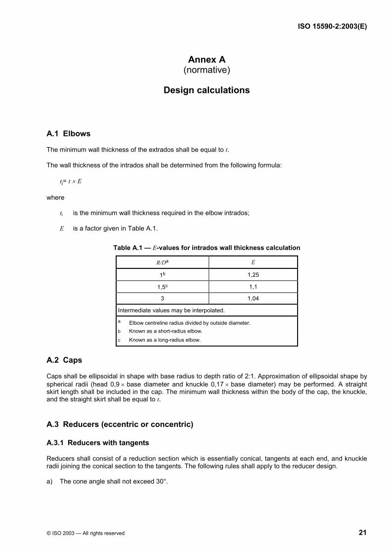
A.1 Elbows
The minimum wall thickness of the extrados shall be equal to t.
The wall thickness of the intrados shall be determined from the following formula:
ti= t × E
where
ti is the minimum wall thickness required in the elbow intrados;
E is a factor given in Table A.1.
Table A.1 — E-values for intrados wall thickness calculation
R/Da E
1b 1,25
1,5c 1,1
3 1,04
Intermediate values may be interpolated.
a Elbow centreline radius divided by outside diameter. b Known as a short-radius elbow. c Known as a long-radius elbow.
A.2 Caps
Caps shall be ellipsoidal in shape with base radius to depth ratio of 2:1. Approximation of ellipsoidal shape by spherical radii (head 0,9 × base diameter and knuckle 0,17 × base diameter) may be performed. A straight skirt length shall be included in the cap. The minimum wall thickness within the body of the cap, the knuckle, and the straight skirt shall be equal to t.
A.3 Reducers (eccentric or concentric)
A.3.1 Reducers with tangents
Reducers shall consist of a reduction section which is essentially conical, tangents at each end, and knuckle radii joining the conical section to the tangents. The following rules shall apply to the reducer design.
a) The cone angle shall not exceed 30°.

ISO 15590-2:2003(E)
22 © ISO 2003 — All rights reserved
b) The larger of DL/ tDL and Dn/tn shall not exceed 100
where
DL is the outside diameter of the larger end of the reducer;
tDL is the nominal wall thickness of the larger end of the reducer;
Dn is the outside diameter at the point, n, under consideration, measured perpendicular to the longitudinal axis;
tn is the wall thickness at diameter Dn.
c) The minimum wall thickness shall be not less than t throughout the body of the reducer, except in and immediately adjacent to the cylinder portion of the small end, where the minimum thickness shall be not less than t1.
A.3.2 Conical reducers
The included (apex) angle, α, of a concentric reducer shall not exceed 60°.
The included angle, α, of an eccentric reducer shall not exceed 30°.
The minimum thickness, tmin, of the conical shell section shall be determined by the following equation.
( )1
minm, red2cos 0,6p Dt
R pα=
−
where
p is the design pressure;
D1 is the outside diameter at the point under consideration, measured perpendicular to the longitudinal axis;
α is the included (apex) angle;
Rm, red is the allowable tensile strength of the reducer.
A.4 Tees (full outlet and reducing)
Outlets of tees shall be integral with the bodies. Tees with separately welded outlets shall not be supplied. The radius of curvature of the external contoured portion of the outlet, ρo, shall not be less than 0,05 D (except that on branch sizes larger than DN 760, ρo need not exceed 30 mm), nor shall it be larger than [(0,10 × D) + 12] mm. Machining shall not be employed in order to meet the above requirements concerning ρo. The minimum crotch thickness of the tee at the 45° plane shall be (1,5 × t).

ISO 15590-2:2003(E)
© ISO 2003 — All rights reserved 23
Annex B (normative)
Proof test
B.1 Preparation for testing
Fittings consistent with those of the products manufactured shall be selected as the test specimens. The fittings shall be inspected for compliance with the dimensional requirements of 9.6. Straight seamless or welded pipe which matches the wall designation intended to be used with the fitting in service shall be connected to the test specimen in a way that represents the intended service conditions. The matching pipe and tested fittings shall also be representative of the material to be used in service.
The length of matching pipe connected to the test specimen should be at least equal to the matching pipe nominal diameter. For a branch fitting to a header, the length of matching pipe shall be measured from the edge of the fitting. Beyond the one-diameter minimum length, the matching pipe may be capped or reinforced so the pipe will not fail prematurely. The test may be based on pressure only if the design load condition is limited to pressure, i.e. if there are no pipe forces on the fitting exceeding the end-cap force.
B.2 Test pressure
The required test pressure shall be calculated using the following equation:
m pp
p
2 f R tp
D=
where
pp is the numerical value of the computed proof pressure, expressed in megapascals;
f is the testing factor determined from Table B.1, dimensionless;
Rm is the tensile strength of the test fitting, expressed in megapascals;
tp is the nominal wall thickness of the matching pipe, expressed in metres;
Dp is the specified outside diameter of the matching pipe, expressed in metres.
Additionally, tests in various sizes within the manufacturing capability shall be performed to help develop design formulae or criteria to be used in the design of sizes not subjected to testing.
A minimum of three tests should be considered.
Table B.1 — Testing factors
Number of tests Testing factor
f
1 1,10
2 1,05
3 1
ISO 15590-2:2003(E)
24 © ISO 2003 — All rights reserved
B.3 Test method and equipment
The pressurizing medium shall be water or other suitable liquid. The test pump shall have a pressure-delivering capacity greater than 1,25 times the computed proof pressure determined from B.2. The pressure-measuring device shall be a dial-indicating type or a pressure-transducer type, with a range of pressure measurement that shall not be less than 1,5 times, nor more than 4 times, the computed or specified proof pressure. Dial-indicator graduations shall be such that accurate readings of the pressure measuring device can be made and readings shall not produce errors greater than 5 % of the actual proof pressure. The pressure-measuring device shall have been calibrated within six months of the test and shall be visible to the pump operator throughout the test.
The pressurization of the test assembly shall be in a gradual and incremental manner, not exceeding a rate of 2,75 MPa/min, until the assembly fails by loss of pressure integrity or until a pressure of 1,05 times the computed test pressure is exceeded.
B.4 Establishment of the equivalent wall or schedule
A pipe fitting configuration shall be considered adequate when the actual proof pressure achieved during the test is at least equal to the computed proof pressure. The fitting or joint shall then be considered to have an equivalent weight designation or schedule number to the matching pipe.
B.5 Applicability of results
A pressure rating for one pipe fitting may represent other pipe fittings to the extent permitted in this part of ISO 15590.
Tests for single or replicate specimens may be extrapolated to qualify geometrically-similar specimens no smaller than half, nor larger than twice, the size of the test specimen. The similarity of untested specimens shall be judged by comparison of attributes which relate to the failure mode of the specimen, such as Dp /t (pipe outside diameter divided by nominal wall thickness) or cross-sectional area.
The results of testing DN 600 pipe may be extrapolated to any larger size pipe if DN 600 is the largest pipe size possible in the proof test assembly.
The satisfactory test of a non-reducing fitting qualifies reducing fittings of the same pattern and method of manufacture.
The satisfactory test of an elbow qualifies elbows having a greater centreline radius than the test fitting, provided they meet the size and attributes requirements stated above.
B.6 Test report
A report of the test shall be prepared and shall include the following information:
a) a description of the test;
b) the instrumentation and methods of calibration used;
c) the actual proof pressures for each test;
d) the time period from test initiation to failure point;
e) the calculations performed;
f) a description of the failure mode, or modes, and a sketch or picture of the failure;

ISO 15590-2:2003(E)
© ISO 2003 — All rights reserved 25
g) the basis for any extrapolation to similar pipe fittings;
h) the equivalent pipe wall or schedule rating.
B.7 Maintenance of results
The manufacturer shall have a quality control program that verifies the manufacturing processes used and assures that the resulting geometries of the fittings manufactured are consistent with the geometries tested. The quality control program shall control the manufacturing drawings and maintain records showing conformance to these drawings.
Whenever a significant change is made in the geometry or method of manufacture, the manufacturer shall either retest a representative sample of the new production or show by analysis that the change would not alter the results of the prior test.

ISO 15590-2:2003(E)
26 © ISO 2003 — All rights reserved
Bibliography
[1] ISO 3545-3, Steel tubes and fittings — Symbols for use in specifications — Part 3: Tubular fittings with circular cross-section
[2] ASM International5), Metals Handbook, Eighth Edition, Volume 11, 1976, pp 287-329
5) American Society for Metals, ASM International, 9639 Kinsman Road, Materials Park, OH 44073-0002, USA


ISO 15590-2:2003(E)
ICS 75.200 Price based on 26 pages
© ISO 2003 — All rights reserved