Embed Size (px)
Citation preview

Introduction to Systems Engineering
Overview
This topic provides an overview of the Introduction to Systems Engineering lesson.
Overview Page 1 of 10
The topics within this lesson lay the groundwork for understanding the DoD's Systems Engineering Technical Processes and Technical Management Processes as outlined in the Defense Acquisition Guidebook (DAG).
In this lesson, divided into several topics, you will learn about:
• How Systems Engineering can be defined • Technical and Technical Management processes • Roles played by Systems Engineering standards • Technical Foundations: "V" models and their applications
• Essential Considerations: Planning and the role of the Systems Engineering Plan, robustness, open systems and Evolutionary Acquisition
• Workplace Ethic
Something to Ponder... Page 2 of 10
The two stonecutters shown here were asked, 'What are you doing?'
Select the photo of the stonecutters to view their two answers.
Take a minute and ponder what these two widely differing responses actually mean, especially that of the second stonecutter.
On the next screen you will be asked to evaluate views that others have had when asked to assess the response of the second stonecutter.
Two stonecutters on the job The first stonecutter said: 'I am cutting this stone into blocks.' The second stonecutter replied, 'I am on a team
that is building a Monument.

Response Assessment Page 3 of 10
Do any of the following responses match what
you believe is the best meaning of the second stonecutter's response?
Select one of these statements.
A. The second stonecutter is wasting time
daydreaming.
B. The second stonecutter is not paying
attention to what is being done and thus
may cause errors in the work.
C. The second stonecutter has the big
picture but that is not part of the
stonecutter's job.
D. The second stonecutter has a vision of
the finished product and his contribution
being made as part of a team.
Need for Product Vision Page 4 of 10
Why have a vision of the final product? Perhaps the person in this picture can explain to you why product vision is essential!
Unfortunately, such poorly implemented products are a common outcome when people with diverse skills work on a project but lack a common technical vision of the final product.
The discipline of Systems Engineering plays a
key role in helping to unify the technical vision of a product, to effectively manage all the diverse skills needed to develop modern defense systems, and to help ensure that
effective, supportable defense systems get fielded.

Scope of Systems Engineering Page 5 of 10
Systems Engineering is both a technical and management discipline.
Systems Engineering is performed by multidisciplinary teams to engineer and integrate systems that help ensure DoD's products meet warfighter's needs.
Systems Engineering encompasses the entire
technical effort. It ties together all aspects of a project to ensure that individual parts, subsystems, support equipment and associated
operational equipment effectively function together as intended in the operational environment.
Systems Engineering is also a logical sequence of processes and activities. These transform
operational needs into an optimal system-level configuration.
Systems Engineers and Program Managers Page 6 of 10
Systems Engineers and Program Managers are
two important 'players' in the development and production of DoD systems. They perform differing but vital roles which can be summarized as:
• Program Managers: Manage (i.e.,
plan, organize, direct, coordinate, control and approve) the activities of all aspects of program as it proceeds through the phases of the Defense
Acquisition Framework
• Systems Engineers: Integrate and balance the work of numerous
engineering and technical disciplines from the initial system design to the production and fielding of the final product
Frequently senior Systems Engineers also perform key roles as the project's 'Technical Authority'. In this role they help ensure that technical rigor is maintained across all phases of development.

Knowledge Review Page 7 of 10
Which of the following is true about the scope of Systems Engineering?
Select all of the correct answers.
A. It helps to unify the technical vision of a product
B. It is a technical discipline
C. It encompasses the entire technical effort
D. It is comprised of a logical sequence of processes and activities
How Will You Use What You Learn? Page 8 of 10
The many topics making up the lessons in this course cover the Technical Processes and the Technical Management Processes, as outlined in the Defense Acquisition Guidebook (DAG). These are the foundation processes for the DoD's approach to Systems Engineering.
Depending on your current job role--DoD in-house developer, member of a program IPT or involved in some other way doing DoD technical engineering management--you'll find direct applicability for many of the parts of this course.
Some DoD Acquisition Core careerists in their technical management oversight roles are understandably primarily interested in Systems Engineering Technical Management Processes. However, in order to successfully use them to manage the outcomes of Technical Processes, one needs a good understanding of both. So both sets of processes are covered.
Additionally, although the processes covered in this course are based on those in the DAG,
your service or agency may supplement some of them with added procedures, regulations and instructions. You'll have to seek those out on your own.
You'll learn that Systems Engineering is a vast field. Because only the core processes are covered here, a wide variety of additional, useful references are cited in Quick Reference.
Check them out!
Technical Management Processes Are used to manage the technical development of the system increments, including the supporting or enabling systems. Consist of: Technical Planning, Requirements Management, Interface Management, Risk Management, Configuration Management, Technical Data Management, Technical Assessment and Decision Analysis.
Technical Processes
Are used to design the system, subsystems, and components, including the supporting or enabling systems required to produce, support, operate, or dispose of a system. Consist of: Requirements Development, Logical Analysis, Design Solution, Implementation, Integration, Verification, Validation and Transition.

Performance Learning Model Page 9 of 10
The Defense Acquisition University (DAU) is
committed to supporting life-long learning. The AT&L Performance Learning Model (PLM) is used by the DAU and illustrated here. The PLM
shows how the DAU supplements core acquisition certification training with other learning assets. You'll find these other learning assets useful on the job and as well as throughout your career.
More information about the DAU and its many learning assets is available here.
Continuous Learning Modules (CLMs), Communities of Practice (CoPs), the AT&L Knowledge Sharing System (AKSS) and the
Acquisition Community Connection (ACC) are important life-long learning components of the PLM. Details of these relating to Systems Engineering are provided as part of Quick References as well.
Long Description Graphic of a temple labeled AT&L Performance LEarning Model. The three pillars are labeled DAWIA Core Certification, Core Plus Development, and Executive & Leadership Support. The base is labeled Training Courses.
The foundation contains Knowledge Sharing (AT&L Knowledge Sharing System, Acquisition Community Connection, and DAU Virtual Library); Continuous Learning (Continuous Learning Modules, Conferences and Symposiums); and Performance Support (Consulting, Rapid Deployment Training, Targeted Training).
Acknowledgements Page 10 of 10
Many people played key roles in developing these course materials. Their assistance is appreciated.
Additionally some portions of this course use materials from ANSI/EIA-632, 'Processes for Engineering a System'. The assistance of the EIA in this regard is gratefully acknowledged.
People Among others, these primarily included: Dr Jerry Lake, editor of ISO/IEC 19760 and editorial team member on several national and international Systems Engineering standards such as EIA 632, IEEE 1220, and ISO/IEC 15288. Dr. John Snoderly, DAU Program Director for Systems Engineering and former (2002-2004) President of the International Council of Systems Engineers (INCOSE). Mr Bob Skalamera, Director OSD AT&L Defense Systems, Enterprise Development. Col Warren Anderson, Deputy for
Systems Engineering Plans and Policy, OUSD AT&L Defense Systems. LtCol Andrew Batten, MOSA Program Office. Dr Dave Brown DAU SYS 101 Course Manager (top-down design). Mr Bill Zimmerman DAU SYS 101 Course Manager (bottom-up product realization). Dr Joel Zamkoff, DAU Instructional Systems Designer. Various course developers including private consultants: Dr Sherwin Jacobson,

John Olmstead, and Michael Findley. DAU Systems Engineering faculty course reviewers. G. Kinsorp, Cosmetic Engineer
Acknowledged
The following is used this course. Figures: 6.1.1, 6.1.2.1, 6.2, 6.2.1a, and G.1 from ANSI/EIA-632, 'Process for Engineering a System', Copyright (1999) Government Electronics and Information Technology Association, a Sector of the Electronic Industries Alliance. All Rights Reserved. Reprinted by Permission.

Description of Systems Engineering
This topic defines Systems Engineering and outlines its scope.
Contents of Topic Page 1 of 15
Approximate Length: 30 minutes
Topic Description: The phases of the DoD Acquisition Framework
essentially reflect an underlying engineering process. Bad engineering = bad products! Unless properly engineered, no affordable, effective product will ever reach the field.
A wide variety of engineering disciplines have
to be coordinated and properly utilized so that DoD systems are timely, effective and affordable. Systems Engineering helps ensure that that happens.
This topic defines Systems Engineering,
outlines its scope and gives examples of why Systems Engineering is challenging.
Topic Learning Objectives Page 2 of 15
Listed below are the objectives for this topic:
• State the DoD definition of Systems
Engineering • Summarize the scope of Systems
Engineering activities
• Distinguish DoD and industry Systems Engineering roles
• List Systems Engineering challenges
Long Description Flipchart with the following objectives: • State the DoD definition of Systems Engineering • Summarize the scope of Systems Engineering activities • Distinguish DoD and industry Systems Engineering
roles • List Systems Engineering challenges
Systems Engineering Viewpoints Page 3 of 15
There are many ways to define 'Systems Engineering.' An internet search on the phrase
'Systems Engineering Definition' returns millions of hits! One way to put this into perspective is to consider that there are essentially four broadly-based 'views' of Systems Engineering. These are outlined below:
• Job View - Systems Engineering is what a person with the titled position of 'Systems Engineer' does and has as his/her job description, responsibility and/or
role. • Organizational View - Systems Engineering is what an organization named
"Systems Engineering" does and has as its responsibility and/or role.
• Problem-Solving View - Systems Engineering is a way of thinking about any complex technical problem.
• Multi-Disciplinary View - Systems Engineering is a multi-disciplinary approach that defines the total technical effort needed to realize system products and sustain their life cycle services.
The view upon which the Systems Engineering activities described in this course are based upon is the Multi-Disciplinary View.
This viewpoint is also the basis of the definition of Systems Engineering as found in the DoD's Defense Acquisition Guidebook.
Role For example, a paper published in the International Council of Systems Engineers (INCOSE) 1996 Proceedings identified 12 different job roles, based on a variety of surveys that could be considered to constitute Systems Engineering. These job roles included: Requirements Owner; System Designer; System Analyst; Test Engineer; Logistics and Operations; System Integrator; Customer Interface; Technical Manager; Information Manager; Process Engineer; Coordinator; and Miscellaneous Software Engineering roles.
Defense Acquisition Guidebook Definition Page 4 of 15
Systems Engineering is defined in the DoD's Defense Acquisition Guidebook as:
Systems Engineering is an interdisciplinary
approach encompassing the entire
technical effort to evolve and verify an
integrated and total life cycle balanced set
of system, people, and process solutions that satisfy customer needs.
However, there is much more to Systems
Engineering than just what is stated in this definition.
Its scope is broad and can be described from a variety of perspectives including participants, total life cycle impact, and the roles played by both industry and the DoD.

Scope: DAG Viewpoint Page 5 of 15
While the scope of Systems Engineering can be
described in many ways, the DoD's Defense Acquisition Guidebook (DAG) broadly outlines it to include:
• Transforming needed operational capabilities into an integrated system
design through concurrent consideration of all life cycle needs
• Integrating the technical efforts related
to system and software development, manufacturing, verification, deployment, operations and support, disposal and user training for systems and their life
cycle supporting products and services • Developing credible and timely technical
information to support the program management decision-making process
Scope: Participants Page 6 of 15
Systems Engineering permeates design, production, test and evaluation, and system support activities.
In the DoD, Systems Engineering is typically implemented via Integrated Product and Process Development (IPPD). IPPD is done by
multi-disciplined teams, typically formally charted as Integrated Product Teams (IPTs).
While the program office may have an assigned Chief Engineer or Lead Systems Engineer, many personnel from non-systems engineering
organizations or even from outside the program management structure also perform activities related to Systems Engineering.
The defense system acquisition life cycle has as its purpose the creation of system products
including the technical support of those products throughout their service life. Accordingly, many program office and life cycle support personnel are participants in some way in the Systems Engineering effort.
Integrated Product and Process Development (IPPD) Integrated Product and Process Development (IPPD) is a management technique that simultaneously integrates all essential acquisition activities through the use of multidisciplinary teams to optimize design, manufacturing, and supportability processes. IPPD facilitates meeting cost and performance objectives. One of the key IPPD tenets is multi-disciplinary teamwork through Integrated Product Teams (IPTs).

Integrated Product Teams (IPTs)
Integrated Product Teams (IPTs) are composed of representatives from appropriate functional disciplines working together to build successful programs, identify and resolve issues, and make sound and timely recommendations to facilitate decision-making.
Scope: Total Life Cycle Page 7 of 15
In the DoD, Total Life Cycle System Management (TLCSM) is the planning for and the management of the entire acquisition life cycle of a system. Systems Engineering,
because it encompasses the entire technical effort, is a key TLCSM enabler.
Costs to implement technical changes increase dramatically as a program moves further along
the Defense Acquisition Framework. The greatest leverage exists in the early stages of development. Done then, analyses of TLCSM
issues performed as part of Systems Engineering processes, can reveal an optimum, life cycle balanced design that prevents later costly technical changes.
Systems Engineering is applied at the initial stages of program formulation. It provides the integrated technical basis for program plans
and acquisition decisions; provides for requirements management, risk, and design trade-offs; and integrates engineering, logistics, test and life cycle management efforts among all stakeholders.
Scope: Industry and DoD Page 8 of 15
An additional key consideration related to the
scope of Systems Engineering is to realize that different roles are played by industry (the developer) as well as DoD (the acquirer).
Both industry and the DoD have similar goals in product development and share key Systems Engineering processes. However the scope of
their application is fundamentally different:
• The Acquirer: DoD program offices and
agencies mainly use Systems Engineering processes and tools to manage development activities.
• The Developer: The defense industry mainly uses Systems Engineering processes and tools as part of their
approach both to manage development, as well as to create products for the acquirer.

For more information on the key role of the acquirer, click here.
Developer Although the 'developer' is cited here as reflective of the defense industry, in some situations the DoD is both the 'acquirer' as well as the 'developer.' The same disciplined Systems Engineering processes apply, no matter what role is being filled!
The Key Role of the Acquirer
Within the DoD, Systems Engineering is typically implemented through multi-disciplined teams of subject matter experts (often via an Integrated Product Team, IPT). The Systems Engineering IPT translates user-defined capabilities into operational system specifications consistent with cost, schedule, and performance constraints.
While the program office usually has a Chief Engineer or Lead Systems Engineer in charge of implementing Systems Engineering Processes, personnel from non-systems engineering organizations or from outside the program management structure may also perform key activities related to Systems Engineering.
"Front-end" Systems Engineering-like activities include defining architectures and capabilities and conducting functional analyses, etc. Planners and analysts usually complete many of these activities before a program is formally initiated within the Defense Acquisition Framework.
The Challenge: DoD Environment Page 9 of 15
There are many attributes of defense systems
that make the application of Systems Engineering challenging, both on government and industry sides. Some of these challenges include:
• The need to quickly and cost-effectively
build interoperable, enterprise-wide, software-intensive systems to meet an ever-changing variety of threats while
simultaneously integrating numerous existing DoD legacy systems
• Personnel turbulence, continuing defense industry consolidations, as well
as the impact of the "graying" of both the DoD's and industry's acquisition workforces

The Challenge: Complexity Page 10 of 15
Another challenge is the complexity of DoD
systems which continue to grow at an increasing rate over time.
The requirement to use good Systems Engineering practices by both government and industry will be even greater in the future as
the DoD develops more complex Systems-of-Systems and increasingly moves toward net-centric operations.
Systems-of-Systems A set or arrangement of interdependent systems that are related or connected to provide a given capability. The loss of any part of the system will generally significantly degrade the performance or capabilities of the whole.
Net-Centric
Net-Centric DoD systems use service-oriented information processing, networks, and data from the following perspectives: user functionality (capability to adaptively perform assigned operational roles with increasing use of system-provided intelligence/cognitive processes), interoperability (shared information and loosely coupled services), and enterprise management (net operations).
The Challenge: Technical Investment Page 11 of 15
A final example of the challenge facing Systems Engineering is documented in various studies which looked at program success as a function of how much of the program resources were invested in technical management activities.
As illustrated by the chart, programs that spent little on technical management had a higher probability of cost overruns than those programs that spent more.
Unfortunately, a lot of programs fail to
adequately invest in technical management. Failed, poorly-engineered, over-budget and inoperable systems are the likely results!
Adequately Invest Studies have been done that have attempted to quantify ideal investment levels. One identified that the optimal Systems Engineering effort should be approximately 15-20% of the project development effort whereas 3-8% or even less is typical on most projects. Other research has shown that effective use of Systems Engineering early in the life cycle can reduce project costs by over 20% and increase the likelihood of on-time delivery by 50%. Not a bad return-on-investment!

Challenges: Defense Industry Perspective Page 12 of 15
A National Defense Industrial Association
(NDIA) Task Force conducted an extensive study to identify those areas in DoD Systems Engineering requiring improvement.
The NDIA Task Force identified five top Systems Engineering issues and challenges.
Select the report cover to learn more about
these Systems Engineering issues and challenges as viewed by the US defense industry.
Folder labeled 'Top Five SE Issues In Defense Industry - NDIA Task Force' 1. Key Systems Engineering practices known to be
effective are not consistently applied across all phases of the program life cycle.
2. Insufficient Systems Engineering is applied early in the program life cycle, compromising the foundation for initial requirements and architecture development.
3. Requirements are not always well-managed, including the effective translation from capabilities statements into executable requirements to achieve successful acquisition programs.
4. The quantity and quality of Systems Engineering expertise is insufficient to meet the demands of the government and the defense industry.
5. Collaborative environments, including SE tools, are inadequate to effectively execute SE at the joint capability,
System-of-Systems (SoS) and system levels.
Knowledge Review Page 13 of 15
Which one of the following best summarizes how the DoD views Systems Engineering?
Select the correct answer.
A. Systems Engineering is what an organization named "Systems Engineering"
does and has as its responsibility and/or role.
B. Systems Engineering is a multi-disciplinary approach that defines the total
technical effort needed to realize system products and sustain their life cycle
services.
C. Systems Engineering is a way of thinking about any technical problem.
D. Systems Engineering is what a person with the titled position of "Systems
Engineer" does and has as his/her job description, responsibility and/or role.

Knowledge Review Page 14 of 15
Key parts of the DoD's definition of Systems Engineering include all of the following except:
Select the correct answer.
A. Encompasses the entire technical effort
B. Total life cycle balanced set of solutions
C. An interdisciplinary approach
D. Performed only by defense contractors
E. Involves system, people and process solutions
Review of Objectives Page 15 of 15
Systems Engineering: Is an interdisciplinary approach encompassing the entire technical effort to evolve and verify an integrated and
total life cycle balanced set of system, people and process solutions that satisfy customer needs.
The Scope of Systems Engineering: Includes transformation of needed operational
capabilities into an integrated system design; integration of technical life cycle efforts and development of technical information to support
program management decision-making. Systems Engineering, because it encompasses the entire technical effort, is a key enabler of effective Total Life Cycle System Management (TLCSM).
Challenges to Systems Engineering: Include growing system complexity, workforce turbulence, low technical management investment, inconsistent application of Systems Engineering, insufficient early use of Systems Engineering and poor initial program
formulation, insufficient tools and environments and inconsistent requirements management.

Overview of Systems Engineering Processes
This topic summarizes the various processes that comprise the
DoDs approach to Systems Engineering.
Contents of Topic Page 1 of 26
Approximate Length: 1 hour
Topic Description:
Systems Engineering is a process-oriented discipline. Technical Processes do the work of Systems Engineering while Technical Management Processes help to ensure the work gets done right.
This topic summarizes the various Technical Processes and Technical Management Processes, as outlined in the DoD's Defense
Acquisition Guidebook, that can be used to accomplish Systems Engineering.
Topic Learning Objectives Page 2 of 26
Listed below are the learning objectives for this topic:
• Identify Systems Engineering Technical Processes
• Identify Systems Engineering Technical Management Processes
• Summarize the purpose of each of them
Long Description
Flipchart with the following objectives: • Identify Systems Engineering Technical Processes • Identify Systems Engineering Technical Management
Processes • Summarize the purpose of each of them

Role of Standard Processes Page 3 of 26
Standard processes offer a consistent and
repeatable way to communicate between the acquirer and the developer regarding various Systems Engineering activities.
A process identifies 'what' has to be done but not the details of 'how' to do it. Standardized processes are essential for:
• Controlling the overall technical effort • Designing systems solutions • 'Realizing' products that make up the
system
'Realization' is a formal term used to precisely
quantify the desired end-state of Systems Engineering activities
A formal definition of 'realization' from a Systems Engineering perspective is shown here.
Process A process is a sequence of steps or activities performed for a given purpose. A process converts an input (such as requirements) to a desired output (such as defined work products) through a set of structured activities. To execute a process it takes resources such as trained people, funds, facilities, equipment, tools and methods. Processes are constrained by various management and legal and regulatory directives and requirements.
A magnifying glass, focused on the definition of the word, realization.
Realization means the physical design solution is provided in a form suitable for meeting the applicable acquisition phase exit criteria, including verifying the product form is consistent with the design-to or build-to specifications, validating that the product form satisfies stakeholder expectations, and transitioning the product form to the next level up of the system structure or to the customer.
Long Description
Definition of the word 'Realization.' It means the physical design solution is provided in a form suitable for meeting the applicable acquisition phase exit criteria, including verifying the product form is consistent with the design-to or build-to specifications, validating that the product form satisfies stakeholder expectations, and transitioning the product form to the next level up of the system structure or to the customer.
Knowledge Review Page 4 of 26
The term 'realization' as used in Systems Engineering encompasses?
Select all that apply.
A. Transitioning the product, ultimately to the customer
B. Providing the physical design solution in an appropriate form
C. Verifying and validating the product
D. None of these responses are correct

Systems Engineering Processes Page 5 of 26
The Defense Acquisition Guidebook (DAG)
supplements the DoD's 5000-series of acquisition policies. The DAG is a collection of best practices and procedures applicable across
all of the phases of the Defense Acquisition Framework.
As outlined in the DAG, the DoD's Systems Engineering processes are comprised of categories consisting of:
• Technical Processes for designing
systems • Technical Processes for product
realization • Technical Management Processes
Select the above entries to see a process listing for each of these categories.
Technical Management Processes • Technical Planning • Requirements Management • Interface Management • Risk Management • Configuration Management • Technical Data Management • Technical Assessment • Decision Analysis
Technical Processes for designing systems • Requirements Development • Logical Analysis • Design Solution
Technical Processes for product realization • Implementation • Integration • Verification • Validation • Transition

Purposes of Technical Processes Page 6 of 26
Technical Processes are used to design the
products of a system including the operational products and the supporting or enabling products required to produce, support, operate,
or dispose of a system as well as to realize these system products.
Select the Technical Processes for Designing Systems block for a summary description of these processes.
Select the Technical Processes for Realizing
System Products block for a summary description of these processes.
Technical Processes for Designing Systems • Requirements Development--To take all inputs from
users and stakeholders and translate these inputs into Technical Requirements.
• Logical Analysis--To improve understanding of the defined requirements and the relationships among the requirements (e.g., functional, behavioral, time-related).
• Design Solution--To translate the outputs of the Requirements Development and Logical Analysis process into alternative design solutions and to select a final design solution (Solution-Specified Requirements).
Technical Processes for Realizing System Products • Implementation--To make, buy or reuse low-level system elements. • Integration--To incorporate lower-level system elements into a higher-level subsystems and systems. • Verification--To confirm that a system element meets its design-to or build-to specifications. • Validation--To confirm that a system element meets its Stakeholder Requirements. • Transition--To move the system element to the next stage of development, or for the end-item system, to
the user.
Knowledge Review Page 7 of 26
Which of the following is correct concerning the various Technical Processes used in Systems Engineering?
Select the best answer.
A. They are used for designing systems and for product realization
B. They are used to manage the overall technical effort
C. "Decision Analysis" is a key Technical Process
D. Different ones are used for different types of DoD systems

Knowledge Review Page 8 of 26
Which of the following is not a Systems Engineering Technical Process used for system
design and product realization?
Select the correct answer.
A. Design Solution Process
B. Requirements Management Process
C. Requirements Development Process
D. Verification Process
E. Transition Process
Knowledge Review Page 9 of 26
Which of the following are Systems Engineering Technical Processes used for designing systems?
Select all that apply.
A. Transition Process
B. Requirements Development Process
C. Logical Analysis Process
D. Verification Process
E. Design Solution Process
F. Integration Process
Knowledge Review Page 10 of 26
Which of the following are some of the Systems Engineering Technical Processes used for realizing system products?
Select all that apply.
A. Integration Process
B. Verification Process
C. Validation Process
D. Design Solution Process
E. Requirements Development Process
F. Transition Process

Purposes of Technical Management Processes Page 11 of 26
Technical Management Processes are used to
manage the development of system products, including supporting or enabling products.
Technical Management Processes are used in tandem with Technical Processes. The latter do the work of Systems Engineering while the former ensures the work gets done right.
Select the Technical Management Processes block for a summary description of each process.
Technical Management Processes • Technical Planning--To ensure the proper application
of Systems Engineering processes. • Requirements Management--To provide traceability
ultimately back to user-defined capabilities and needs. • Interface Management--To ensure interface
definition and compliance among the elements that compose the system; as well as with other systems with which the system or system elements must interoperate.
• Risk Management--To examine the technical risks of deviating from the program plan. • Configuration Management--To establish and maintain consistency of a product's attributes with its
requirements and product configuration information. • Technical Data Management--To plan for, acquire, access, manage, protect, and use data of a technical
nature to support the total life cycle of the system. • Technical Assessment--To measure technical progress and the effectiveness of plans and requirements. Key
Technical Assessment tools include: Earned Value Management (EVM), Technical Performance Measurement (TPM), and Technical Reviews.
• Decision Analysis--To provide the basis for evaluating and selecting technical alternatives when decisions need to be made.
Knowledge Review Page 12 of 26
Which of the following is correct concerning the use of the various Technical Management Processes used in Systems Engineering?
Select the correct answer.
A. They are used extensively in system design
B. Product realization uses them to field a product
C. Design Solution is the most important of the Technical Management Processes
D. They are key to managing the overall technical effort
E. None of these responses is correct

Knowledge Review Page 13 of 26
Each of the following is a Systems Engineering Technical Process used for designing systems
except for:
Select the correct answer.
A. Requirements Development Process
B. Logical Analysis Process
C. Technical Planning Process
D. Design Solution Process
Knowledge Review Page 14 of 26
Each of the following is a Systems Engineering Technical Management Process except:
Select all the correct answers.
A. Requirements Development Process
B. Transition Process
C. Decision Analysis Process
D. Interface Management Process
E. Technical Planning Process
Knowledge Review Page 15 of 26
Which of the following best defines Requirements Management, one of the Systems Engineering Technical Management processes?
Select the correct answer.
A. To provide traceability ultimately back to user-defined capabilities
B. To plan for, acquire, access, manage, protect, and use data of a technical nature
C. To examine the technical risks of deviating from the program plan
D. To provide the basis for evaluating and selecting alternatives when decisions
need to be made

The Big Picture I: Product Design Snapshot Page 16 of 26
Let's look at a simplistic (you'll find out why later!) example of Systems Engineering
Technical Processes in action including some of the terminology used. Starting with design processes which are outlined here as:
1. Requirements Development Process: Requirements for DoD systems come from various diverse constituencies (generically categorized process-wise, as Acquirer Requirements and Other Interested Party Requirements). These requirements
comprise the set of Stakeholder Requirements which include Derived Requirements. These are ultimately transformed into Technical Requirements. The latter, when baselined, become the basis for the design. Key Measures of Effectiveness are also
initially identified.
2. Logical Analysis Process: Technical Requirements are then analyzed in various ways to determine an optimal functional architecture. Interfaces are defined. Performance parameters are allocated. Important additional Technical Requirements
(called Derived Technical Requirements) are identified. Work products are baselined.
3. Design Solution Process: Using the outcomes from the Requirements Development Process and the Logical Analysis Process, alternative design solutions
are developed. More Derived Technical Requirements may be identified as well. These design solutions are evaluated to determine which are acceptable within cost, schedule and technical constraints. A design or a physical architecture is established.
Outcomes of the Design Solution Process typically include a set of Solution-Specified Requirements, a key component of which is the System Specification. These requirements are baselined and become part of a Technical Data Package (TDP).
Acquirer Requirements May be in the form of requirement statements from a customer, user or operator; or be expressed as a set of assigned/allocated specifications developed previously.
Other Interested Party Requirements These types of requirements include those of parties who have some interest in the system such as those providing life cycle support functions; OSD management or other government agencies; and laws, regulations, treaties, policies, etc., which may affect the program or project.
Stakeholder Requirements
A requirement that represents what stakeholders of a system need or expect of the system products. They are comprised of 'Acquirer Requirements' and 'Other Interested Party Requirements.'
Derived Requirements
Derived Requirements are those that are not explicitly stated in the set of Stakeholder Requirements yet required to satisfy one or more specific Stakeholder Requirements. Derived Requirements are generated based on an operational or technical analysis of a Stakeholder Requirement in order to clarify the requirement or make it achievable. For example: • Stakeholder Requirement: A missile must have a fly-out distance of 2 kms and hit a target having a Radar
Cross Section the size of a tennis ball. • Derived Requirement: The missile shall be aimed within 2 degrees of the target so that the warhead
terminal seeker can lock on and perform the terminal intercept.
Technical Requirements A Technical Requirement is derived from analysis of stakeholder requirements. It is expressed as a confirmed and quantitative 'shall' statement. The set of Technical Requirements are inputs to the Logical Analysis Process. Technical Requirements establish the basis for system development.

Measures of Effectiveness
Measures of Effectiveness (MOEs) give definition to the operational capabilities essential to mission accomplishment. They represent the metrics by which satisfaction with products produced by the technical effort will be measured.
Functional Architecture
An arrangement of functions and their sub-functions and interfaces (internal and external) that defines the execution sequencing, conditions for control or data flow, and the performance requirements to satisfy the requirements baseline.
Derived Technical Requirements
Technical Requirements that are further refined from a primary source requirement or a higher-level derived requirement. Derived Technical Requirements are requirements that result from the analysis of Technical Requirements done as part of the Logical Analysis Process or Design Solution Process.
Work Products A work product is any artifact--material or electronic--generated during the conduct of the activities and tasks of a process, including the desired outputs.
Physical Architecture
A hierarchical arrangement of people, product and process solutions; their functional and performance requirements; their internal and external interfaces; and their physical constraints. It forms the basis of the design.
Solution-Specified Requirements
These are the requirements that characterize and specify the functions and performance of the design solution. They are expressed in System Specification, subsystem specifications, verification/validation criteria, various end product specifications and requirements for enabling products.
System Specification
A type of program-unique specification that describes the requirements and how they will be verified for a combination of elements that must function together to produce the capabilities that fulfill a mission need, including hardware, equipment and software.
Technical Data Package (TDP) A Technical Data Package (TDP) provides a comprehensive description of a given system element. The TDP is used for the Implementation Process and is retained and placed under configuration management and baselined throughout the life of the product.
The Big Picture II: Product Realization Snapshot Page 17 of 26
Realization now begins with these Technical Processes:
4. Implementation Process: If subsystems do not need to be developed, then using appropriate elements from the TDP, the product is made, bought or reused. This may involve hardware fabrication, manufacturing, software coding or purchase from
outside sources. No matter what their source, some degree of low-level verification and validation is performed to make sure that 'good' products get used for implementation. Some supporting documentation may be developed.
5. Integration Process: At some point implementation is completed. End product
components are assembled and integrated. Prior to this, implemented components are verified and validated as appropriate so as to ensure that only 'good' products actually get assembled and integrated.
6. Verification Process: Using criteria established as part of the Design Solution
Process and various plans, the end product is verified that it conforms to its 'design-to' requirements. Has it been 'built right'?

7. Validation Process: Using criteria established as part of the Design Solution Process and various plans, the end product is validated that it conforms to its
Stakeholder Requirements. Is it the 'right product'?
8. Transition Process: The end product either: (1) moves up a level (e.g., from subsystem to system) in the physical architecture of the system for more development as needed; (2) it transitions to the next Defense Acquisition Framework
phase, or (3) the End Product is delivered successfully to the user.
Simple, eh? Wait! Not so fast...
Realization Providing the physical design solution in a product form suitable for meeting the applicable acquisition phase exit criteria, including product verification and validating and transitioning the product to the next level up of the system structure or ultimately to the customer.
Various Plans
Key among these is the Test and Evaluation Master Plan (TEMP). The TEMP, one of the outcomes of the Technical Planning Process, provides top-level details of systems-level verification (Developmental Testing) and validation (Operational Testing). Specific test scenarios and scripts are provided elsewhere in more detailed test plans
Not So Fast...Fleas?? Page 18 of 26
The Technical Process snapshots, just provided, while correct from a big picture standpoint, are simplistic from several actual application perspectives:
• Non-Linear: The processes were depicted as occurring in a strict linear sequence.
This is not typical: there is a high degree of healthy interaction between them, especially among the design processes. This interaction is in the form of iteration (do it until you get it right!) and recursion (keep doing it until you are done!).
• Entire DAF: The processes were depicted as just from a later stage in the Defense Acquisition Framework (DAF). In actual practice, these Technical Processes will occur repeatedly during each acquisition phase, but with different types of realized products. Examples are illustrated on The Chart.
• Complex System Model: The processes were depicted as operating on a simple model structure. In practice, for non-trivial systems, the system structure consists of many layers and levels. Throughout this layered structure, multiple Technical Processes are occurring simultaneously.
So...a lot of things are going on at the same time in different parts of the system structure being done by many different organizations. Given this, it's all too easy to make chaos out of order!
That is why Technical Management Processes are absolutely vital complements to the Technical Processes.
Layered Structure One humorous analogy regarding this multiple layering of a system structure is reflected in this ditty by Augustus De Morgan. De Morgan was a nineteenth century English mathematician. In his book, A Budget of Paradoxes, he
wrote: Great fleas have little fleas upon their backs to bite 'em, And little fleas have lesser fleas, and so ad infinitum, And the great fleas themselves, in turn, have greater fleas to go on, While these again have greater still, and greater still, and so on.
A 'System Model' accommodates this sort of multiple levels of layering in a (much!) more formal way. More definition of a system model and discussions of its many uses are given in other topics.
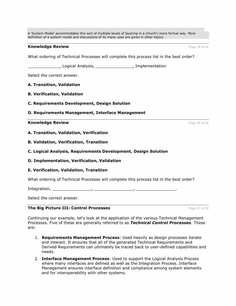
Knowledge Review Page 19 of 26
What ordering of Technical Processes will complete this process list in the best order?
_____________, Logical Analysis, _______________, Implementation
Select the correct answer.
A. Transition, Validation
B. Verification, Validation
C. Requirements Development, Design Solution
D. Requirements Management, Interface Management
Knowledge Review Page 20 of 26
A. Transition, Validation, Verification
B. Validation, Verification, Transition
C. Logical Analysis, Requirements Development, Design Solution
D. Implementation, Verification, Validation
E. Verification, Validation, Transition
What ordering of Technical Processes will complete this process list in the best order?
Integration, ________________, ________________, ________________.
Select the correct answer.
The Big Picture III: Control Processes Page 21 of 26
Continuing our example, let's look at the application of the various Technical Management Processes. Five of these are generally referred to as Technical Control Processes. These are:
1. Requirements Management Process: Used heavily as design processes iterate and interact. It ensures that all of the generated Technical Requirements and Derived Requirements can ultimately be traced back to user-defined capabilities and
needs.
2. Interface Management Process: Used to support the Logical Analysis Process where many interfaces are defined as well as the Integration Process. Interface Management ensures interface definition and compliance among system elements
and for interoperability with other systems.

3. Risk Management Process: Is a core process which underlies all others. It Identifies, Analyzes, Mitigates and Tracks program technical risks.
4. Configuration Management Process: Ensures that baselines are established, controlled and kept consistent. Configuration Management is a key player with Requirements Management, Interface Management and Technical Data Management Processes.
5. Technical Data Management Process: A wide variety of data and information is produced as outcomes of various process activities. Technical Data Management plans for it; acquires it; provides access to it; manages it; and protects data and information of a technical nature needed to support the total life cycle of a system.
Baselines Typically these include the following: • Functional Baseline: Documentation describing system and subsystem functional characteristics and the
verification required to demonstrate the achievement of those specified functional characteristics. • Allocated Baseline: Documentation that designates the Configuration Items (CIs) making up a system, and
then allocates the system function and performance requirements across the CIs (hence the term "allocated baseline").
• Product Baseline: The approved technical documentation which describes a system's Configuration Item during the production, fielding/deployment and operational support phases of its life cycle.
Data and Information The term 'data' as used in Technical Data Management includes technical data, computer software documentation, representation of facts, numbers, or datum of any nature that can be communicated, stored, and processed to form information required by a contract or agreement to be delivered, or accessed by, the Government.
Information on the other hand is generally considered as processed data. The form of the processed data is dependent on the documentation, report, review formats or templates that are applicable.
Of course, one needs wisdom to use either data or information most effectively. Unfortunately, that is not one of the by-products of Technical Data Management!
The Big Picture IV: Other Technical Management Processes Page 22 of 26
Continuing:
6. Technical Planning Process: This management process is the lynchpin of the entire Systems Engineering effort. Various key plans, such as the Systems Engineering Plan (SEP), which outlines expected activities by acquisition phase; the
Test and Evaluation Master Plan (TEMP), and various other plans, are key outcomes of the Technical Planning Process.
7. Technical Assessment Process: Gives visibility to 'where we are' and 'where we
are going' regarding the application of Technical Processes. Key tools used in Technical Assessment include Technical Reviews, Earned Value Management (EVM) and Technical Performance Measurement (TPM).
8. Decision Analysis Process: A cross-cutting process that provides a rational,
repeatable basis for evaluating and selecting alternatives when a decision must be made. Operates within the program's Trade Space.
Systems Engineering Plan (SEP)
The SEP is a detailed formulation of actions that should guide all technical aspects of an acquisition program. The SEP is intended to be a roadmap that supports program management by defining comprehensive Systems Engineering activities, addressing both government and contractor technical activities and responsibilities. The SEP should incorporate known industry 'best practices' and be used by the program office to help frame contractual technical requirements. It is prepared for each phase of a Defense Acquisition Framework.

Test and Evaluation Master Plan (TEMP)
The TEMP is an important document in that it contains the required type and amount of test and evaluation events, along with their resource requirements. The TEMP focuses on the overall structure, major elements, and objectives of the T&E program and it must be consistent with the Systems Engineering Plan (SEP).
Other Plans
A number of such 'other plans' exist. Some of them frame the actual program's implementation of Technical Management Processes. For example: Interface Management Plan; Requirements Management Plan; Risk Management Plan; Configuration Management Plan; Data Management Plan, among others. Others are so-called specialty plans which include: Electromagnetic Compatibility/ Interference (EMC/EMI) Control Plan; Human Systems Integration (HSI) Plan; Producibility Plan; Safety Plan; Security Plan; Information Support Plan; Corrosion Prevention Plan, etc.
Many of these plans are discussed in various sections of the Defense Acquisition Guidebook (DAG). In some cases specific formats are suggested and in other cases plan formats depend on local command policies and regulations. Some plans are required by statute and details about them are provided via tabular format as enclosures to the DoD 5000-series of acquisition directives.
Technical Reviews
Technical Reviews are an important oversight tool. They are used to review and evaluate the state of the system and the program, re-directing activity after the review if found necessary. Technical Reviews are key decision events used to measure technical progress and maturity in system development as well as to assess various programmatic issues.
Earned Value Management (EVM) Earned Value Management is a tool that allows visibility into contractual technical, cost, and schedule planning, performance, and progress. This visibility provides insight to contract performance, but also provides the necessary
data points to statistically estimate probable completion costs. EVM helps to ensure that cost, schedule, and technical aspects of the contract are truly integrated.
Technical Performance Measurement (TPM) The technique of predicting the future value of a key technical parameter of the higher-level end product under development, based on current assessments of products lower in the system structure. In the DoD, these key technical parameters are typically related in some way to Key Performance Parameters (KPPs).
Trade Space
Trade Space is the set of program and system parameters, attributes and characteristics required to satisfy some aspect of system performance. Decision-makers define and refine the development system by making trade-offs with regard to cost, schedule, risk and performance---all of which fall within the "trade space."

Activities, Tasks and Outcomes Page 23 of 26
The 16 Defense Acquisition Guidebook (DAG)
processes outlined previously are the foundations of the DoD's approach to Systems Engineering and technical management.
Other topics within other lessons break down each of these eight Technical Processes and
eight Technical Management Processes. They are broken down into over 90 process-specific activities, each with associated expected
outcomes. Each activity is further decomposed into more detailed sets of illustrative tasks.
These illustrative tasks put the process-specific activity into perspective. They show one possible way the activity could be accomplished and its expected outcomes used.
Processes A process is a sequence of steps performed for a given purpose. A process converts an input (such as requirements) to a desired output (such as defined work products) through a set of structured activities. To execute a process it takes resources such as trained people, funds, facilities, equipment, tools and methods. Processes are constrained by various management and legal and regulatory directives and requirements.
Process Activity Roadmap Page 24 of 26
With all these activities, tasks and expected outcomes, one can get overwhelmed without
some sort of a guide. Looking at them all from a macro level, many of the activities and associated tasks making up a process follow a
generic roadmap. The activity roadmap generally will look like some variation of the following:
• GET READY: Prepare to do the activity
• DO IT: Perform process activities
• ADJUST AND ANALYZE: As needed • BASELINE: Baseline results in some
manner • CAPTURE: Update the program's
technical management database
While this simplifies things somewhat, nevertheless, there is a lot going on and a lot that needs to go on, in Systems Engineering!
This is why numerous studies and 'lessons learned' have shown that the levels of investment in program technical management are very good predictors of later overall program success. Hint!

Hint! The processes in this course follow those in Chapter 4 of the Defense Acquisition Guidebook (DAG) but with more details. Because of this, you might want to get your own printed copy of Chapter 4 to take personal notes in as you go through the various lesson topics. If so, you can get a copy here.
Review of Objectives Page 25 of 26
Systems Engineering Technical Processes for designing systems include:
1. Requirements Development: Translating stakeholder needs into Technical
Requirements
2. Logical Analysis: To improve understanding of requirements and their relationships
3. Design Solution: To develop alternative design solutions and select a final design
(Solution-Specified Requirements)
Systems Engineering Technical Processes for realizing systems products include:
1. Implementation: Creating (making, buying or reusing) low-level system elements
2. Integration: Incorporation of lower-level system elements into higher level ones
3. Verification: Confirming system elements meet design-to or build-to specifications
4. Validation: Confirming system elements meets Stakeholder Requirements
5. Transition: Moving a system element to the next development stage or, for the End Product, to the user
Review of Objectives (Cont'd) Page 26 of 26
Systems Engineering Technical Management Processes include:
1. Technical Planning: Ensuring the proper application of Systems Engineering processes
2. Requirements Management: Providing traceability of system and subsystem
requirements ultimately back to user-defined capabilities and needs
3. Interface Management: Ensuring interface definition and compliance among system elements including other systems
4. Risk Management: Examination of the technical risk of deviating from program plans
5. Configuration Management: The establishment and maintenance of the consistency of a product's attributes with its requirements and configuration
information
6. Technical Data Management: Planning for, acquiring, accessing, managing, protecting and using data of a technical nature for supporting the total life cycle of a system

7. Technical Assessment: Measuring technical progress and the effectiveness of plans and requirements
8. Decision Analysis: Provides the basis for evaluation and selection of technical alternatives when decisions need to be made

Role of Systems Engineering Standards
This topic discusses the roles played by some of the most commonly-used Systems Engineering standards
Contents of Topic Page 1 of 12
Approximate Length: 30 minutes
Topic Description:
This topic presents an overview of current
Systems Engineering standards, important roles they can play, and how they differ from capability maturity models.
Topic Learning Objectives Page 2 of 12
Listed below are the learning objectives for this topic:
• Describe the role of Systems Engineering standards
• Identify three key Systems Engineering standards
• Distinguish between standards and maturity models
Long Description Flipchart with the following objectives: • Describe the role of Systems Engineering standards • Identify three key Systems Engineering standards • Distinguish between standards and maturity models
Role of Systems Engineering Standards Page 3 of 12
A variety of standards and models exist that describe the processes and 'best practices' that
can be used to accomplish Systems Engineering. These standards and models define various processes and establish common vocabularies between the acquirer and the developer, helping to promote consistent and effective communications. Additionally, standards play key roles in the following areas:
• Providing a baseline of the 'what's' and 'why's': From which an organization's
policies and procedures can be assessed and improved
• Used by Developers to: o Establish and standardize internal processes
o Direct usage by suppliers and subcontractors o Assess internal and supplier capabilities o Develop Systems Engineering technical plans
• Used by Acquirers to:
o Understand developer's Systems Engineering activities o Determine and assess developer capabilities
• Used by Countries to: Provide an industry set of national practices
NOTE: DoD acquirers need to be familiar with the standards developers may use. This is so they can properly evaluate the developer's proposals regarding Systems Engineering submitted as part of the contracting process. However, the DoD does not generally contractually impose any particular SE standard on developers.
Developers Although the 'developer' is cited here as reflective of the defense industry, in some situations the DoD is both the 'acquirer' as well as the 'developer.'
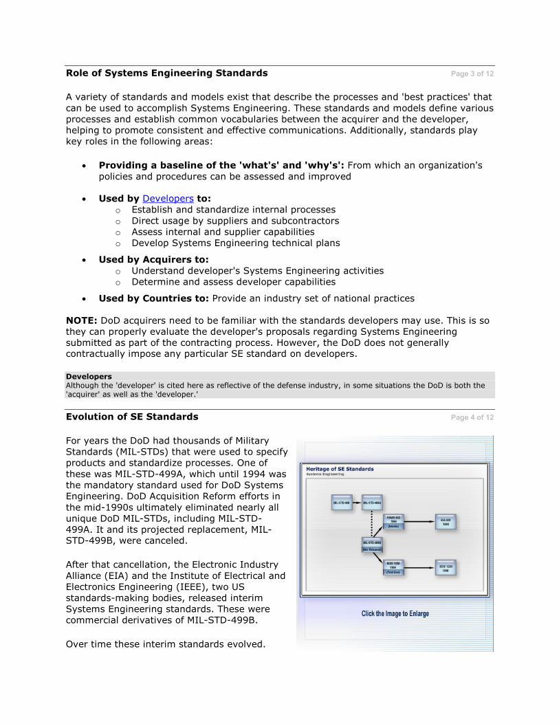
Evolution of SE Standards Page 4 of 12
For years the DoD had thousands of Military Standards (MIL-STDs) that were used to specify products and standardize processes. One of
these was MIL-STD-499A, which until 1994 was the mandatory standard used for DoD Systems Engineering. DoD Acquisition Reform efforts in
the mid-1990s ultimately eliminated nearly all unique DoD MIL-STDs, including MIL-STD-499A. It and its projected replacement, MIL-STD-499B, were canceled.
After that cancellation, the Electronic Industry
Alliance (EIA) and the Institute of Electrical and Electronics Engineering (IEEE), two US standards-making bodies, released interim Systems Engineering standards. These were commercial derivatives of MIL-STD-499B.
Over time these interim standards evolved.

Both organizations ultimately released final versions of their standards, which differed considerably from the interim ones.
Differed Considerably The EIA standard evolved to a multiple process approach such as described in the Defense Acquisition Guidebook (DAG) and in this course. Although the IEEE standard retained a single Systems Engineering process approach, it added additional scope than was originally found in the interim standard.
Long Description
Flowchart titled 'Heritage of SE Standards.' Flow begins with MIL-STD-499 to MIL-STD-499A to MIL-STD499B (Not Released), which branches to both EIA/IS-632 1994 (Interim) and IEEE 1220 1994 (Trial Use). EIA/IS-632 1994 (Interim) goes to ANSI-EIA 632 1998. IEEE 1220 1994 (Trial Use) goes to IEEE 1220 1998.

Current Key SE Standards Page 5 of 12
EIA 632 (Processes for Engineering a System)
and IEEE 1220 (Standard for Application and Management of Systems Engineering Processes) are two current US national Systems
Engineering standards. Additionally, an international Systems Engineering standard exists as well.
In 2002, the International Organization for Standardization/International Electrotechnical
Commission (ISO/IEC) released an international standard, ISO/IEC 15288, entitled Systems Engineering - System Life Cycle Processes.
Whereas ANSI/EIA 632 and IEEE 1220 focus on process requirements, ISO/IEC 15288 focuses on application of processes across the life cycle.
All three of these standards have relevance to the application of Systems Engineering processes.
Long Description Graphic titled 'Heritage of Systems Engineering Standards' with three columns: Government, Commercial, International. Under Government, MIL STD 499 flows to MIL STD 499A, which flows to MIL STD 499B. Under Commercial, EIA/IS 632 flows to EIA 632-1998. IEEE Trial Use Std-1220 flows to IEEE Std 1220-1998. Under International, there is one box, ISO-15288.
Scope of Systems Engineering Standards Page 6 of 12
The three Systems Engineering standards differ primarily in their depth and breadth of coverage.
• ISO/IEC 15288: Has the greatest breadth (24 processes including post-deployment ones) but the least depth of coverage. It is useful for top-level planning primarily at the organizational level. This standard is designed to be used by an organization, a
project within an organization, or an acquirer and a supplier via an appropriate agreement.
• EIA 632: Defines the set of requirements for engineering a system. The processes
in EIA 632 describe 'what to do' with respect to the processes for engineering a system. These are at the next level down from the ISO/IEC 15288 level of system life cycle processes.
• IEEE 1220: Defines a Systems Engineering process. It gives the next level of detail
below the process requirements described in EIA 632. The process is described more at the task or application level.
IEEE 1220 has the greatest depth of coverage for its limited scope but the least breadth. EIA-632 falls between the other two standards.

It is not necessarily a question of choosing just one standard for a program. Depending on the specific needs of a given program, all three may be employed.
The Systems Engineering processes outlined in the DoD's Defense Acquisition Guidebook (DAG) are derived in part from EIA 632.
Knowledge Review Page 7 of 12
Key commercial Systems Engineering standards include:
Select the correct answer.
A. EIA 632, IEEE 1220 and ISO/IEC 15288
B. MIL-STD 498, MIL-STD 499A and MIL-STD-499B
C. MIL-STD 1521B
D. MIL-HDBK 961 (SE Standard Practices)
E. EIA 667, IEEE 1946 and ISO/IEC 12207
F. IEEE 12207.1 and DoD-STD 2167A
Knowledge Review Page 8 of 12
True or False?
The scope, breadth and life cycle applicability of the various Systems Engineering commercial standards such as EIA 632, IEEE 1220 and ISO/IEC 15288 is consistent.
Select the correct answer.
A. True
B. False
Standards vs. Capability Maturity Models Page 9 of 12
Both capability maturity models and standards are important, but the role for each is different. The major distinction lies in their purpose.
• Standards provide a set of processes that, if done by qualified persons using appropriate tools and methods, will provide a capability to do effective and efficient engineering of systems, including their software components. Standards provide
recommended processes to apply, describe expected tasks and outcomes and describe how they all integrate to provide required inputs and outputs.
• Capability and Maturity Models are for process improvement. They are used to
assess how well an organization's standard processes are defined, understood and followed. The Capability Maturity Model, Integrated (CMMI), which combines Systems Engineering, hardware/software development and IPPD processes into

various unified models, is an example. An acquisition variant has also been developed.
More information about the CMMI is available in the Quick References section.
IPPD
Integrated Product and Process Development (IPPD) is a management technique that simultaneously integrates all essential acquisition activities through the use of multidisciplinary teams to optimize design, manufacturing, and supportability processes. IPPD facilitates meeting cost and performance objectives. One of the key IPPD tenets is multi-disciplinary teamwork through Integrated Product Teams (IPTs).
Knowledge Review Page 10 of 12
Each of the following is a possible role of a Systems Engineering standard except for:
Select the correct answer.
A. Acting as a baseline for process assessment
B. Providing a basis for more effective communications
C. Being mandated contractually for DoD projects
D. Establishing and standardizing internal processes
Review of Objectives Page 11 of 12
Roles: Systems Engineering Standards are used to:
• Providing a baseline for assessment
• Standardize internal processes
• Develop consistent engineering plans
• Gain insight into developer's Systems Engineering practices
• Promote effective communications
• Standardize vocabularies
• Provide a consistent set of practices
Review of Objectives (Cont'd) Page 12 of 12
Key Current Standards: Three commercial Systems Engineering standards exist. All have relevance to improving the practice of Systems Engineering by both acquirers and developers. These three standards are:
• ANSI/EIA 632: Processes for Engineering Systems
• IEEE 1220: Standard for Application and Management of Systems Engineering

• ISO/IEC 15288: Systems Engineering--System Life Cycle Processes
Standards vs. Maturity Models: Standards are by design useful for helping a project
implement Systems Engineering. They provide a set of processes that, if done by qualified persons using appropriate tools and methods, will provide a capability to do effective and efficient engineering of systems. Maturity models (e.g., the CMMI) are by intent useful for determining the capability and/or maturity of an organization to perform Systems
Engineering. A maturity model is used to assess, from an organizational perspective, how well processes have been established and instituted and how well they are being followed.
Technical Foundations
This topic presents key technical information that is the foundation for understanding how Systems Engineering Processes can be applied and used.
Contents of Topic Page 1 of 63
Approximate Length: 1.5 hours
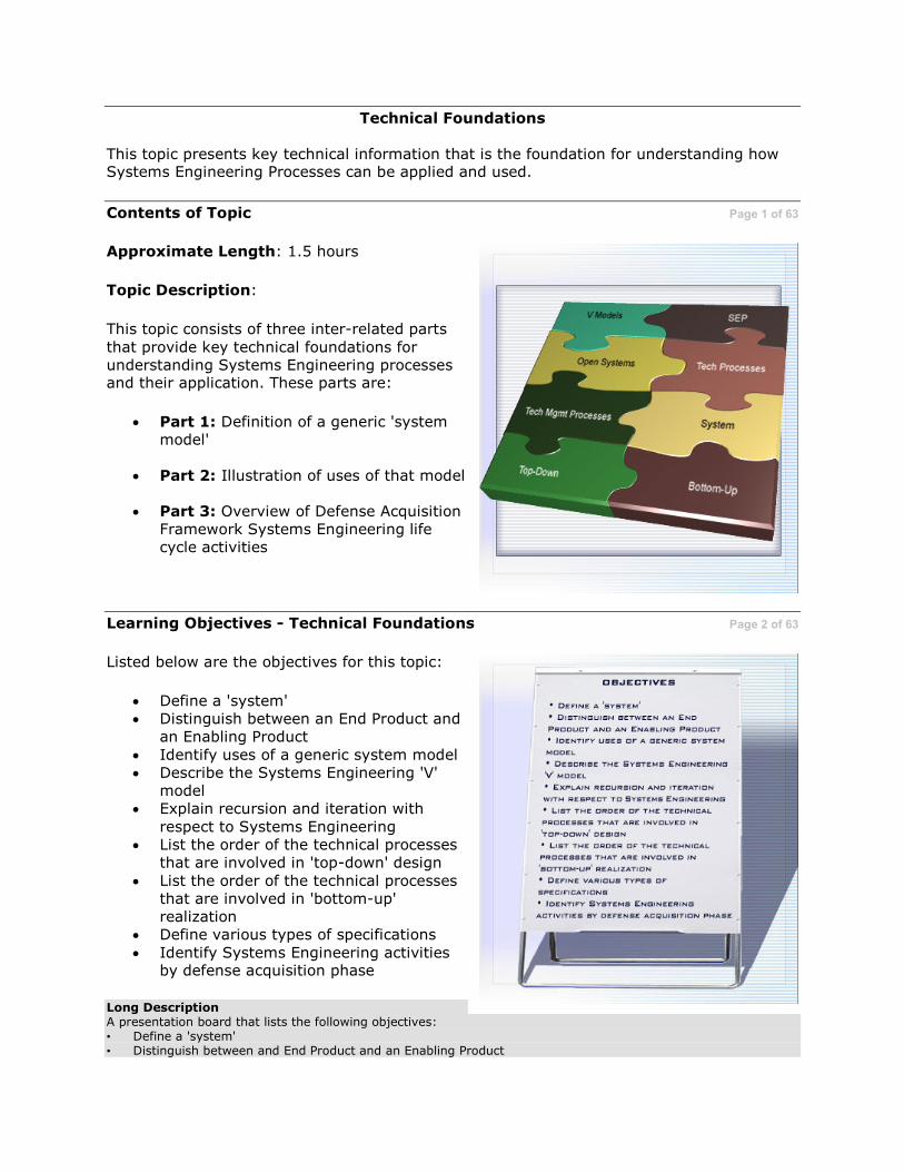
Topic Description:
This topic consists of three inter-related parts
that provide key technical foundations for understanding Systems Engineering processes and their application. These parts are:
• Part 1: Definition of a generic 'system model'
• Part 2: Illustration of uses of that model
• Part 3: Overview of Defense Acquisition Framework Systems Engineering life cycle activities
Learning Objectives - Technical Foundations Page 2 of 63
Listed below are the objectives for this topic:
• Define a 'system' • Distinguish between an End Product and
an Enabling Product
• Identify uses of a generic system model • Describe the Systems Engineering 'V'
model • Explain recursion and iteration with
respect to Systems Engineering • List the order of the technical processes
that are involved in 'top-down' design
• List the order of the technical processes that are involved in 'bottom-up' realization
• Define various types of specifications
• Identify Systems Engineering activities by defense acquisition phase
Long Description A presentation board that lists the following objectives: • Define a 'system' • Distinguish between and End Product and an Enabling Product
• Identify uses of a generic system model • Describe the Systems Engineering 'V' Model • Explain recursion and iteration with respect to Systems Engineering • List the order of the Technical Processes that are involved in 'top-down' design • List the order of the Technical Processes that are involved in 'bottom-up' realization • Define various types of specifications • Identify Systems Engineering activities by defense acquisition phase
Background and Review Page 3 of 63
Systems Engineering is all about "engineering systems." Everyone has an intuitive
understanding of what a "system" is and what "engineering" encompasses. But to understand Systems Engineering Technical Processes and Technical Management Processes, more formal and precise definitions, to include development of an illustrative "system model" are needed. This formality allows these processes to be described and applied in a consistent, repeatable way.
Some key terms you should be familiar with before continuing are: realization, Technical Processes, Technical Management Processes, the Defense Acquisition Guidebook (DAG) and the Defense Acquisition Framework.
Additionally, you should be familiar with the web-enabled version of "The Chart", especially the capability to "drill down" in each acquisition phase.
Click here to experiment with "The Chart."
Realization Providing the physical design solution in a 'product' form suitable for meeting the applicable acquisition phase exit criteria, including product verification and validating and transitioning the product to the next level up of the system structure or to the customer
Technical Processes
Are used to design the system products (e.g., subsystems, and components), including the operational/mission products and supporting or enabling systems required to produce, support, operate, or dispose of system products
Technical Management Processes
Are used to manage the technical development of the system, including its supporting or enabling products
Defense Acquisition Guidebook (DAG) The Defense Acquisition Guidebook is designed to complement acquisition policy documents by providing the
acquisition workforce with discretionary 'best practices' that should be tailored to the needs of each program. Click here for a functional viewpoint on the scope of the DAG

System Ambiguity Page 4 of 63
Both within the DoD and the defense industry,
a 'system' and its constituent parts are typically referred to in many different ways. Examples include: system, sub-system, system segment,
system increment, system component, system element, system spiral, system end-item, configuration item, software item, hardware item, end product and enabling product, among others.
This proliferation of terms is not unexpected: this is because numerous different DoD policies, handbooks and standards exist, many of which refer to a 'system' and its constituent
composition differently, sometimes even within the same publication!
However, modern defense systems consist literally of tens of thousands of different 'pieces.' To ensure consistency in describing
and applying Systems Engineering Technical Processes and Technical Management Processes, a standard definition of a 'system' and a model of its constituent entities are needed.
Key Questions Page 5 of 63
The answer to "What is a System?" is fundamental to Systems Engineering in that the Technical Processes used for design are applied
to the "system" to develop a system solution regardless of its place in the overall system structure.
Then product realization processes are applied to the defined solutions to each system's end
products to build up into the desired operational End Product needed to fulfill a desired capability.
It is essential therefore that the "right" system be engineered. The key questions are: "What is
the right system?" and "What system model is appropriate to describe the 'right system?'"
Systems and System Models Page 6 of 63
Because of differences in the way systems and
system models can be defined, without consistent definitions, projects will have problems in uniform application of Systems Engineering processes.
Three broad categories of system models include:
1. A generic dictionary type definition that provides some insight but limited usefulness for actually engineering a
particular system
2. A definition that considers the system as the operational entity
3. A model definition that encompasses
both the operational products and their related enabling (life cycle support services) products
Many definitions of a 'system' exist based around these categories. Select the bookcase to learn more about ways in which a 'system' can be characterized.
Long Description A book animates out of the bookcase, opens and displays the following text: 1. EIA/IS 731 and ANSI/EIA 632 An aggregation of end products and enabling products to achieve a given
purpose. 2. IEEE 1220 A set or arrangements of elements and processes that are related and whose behavior satisfies
customer/operational needs, and provides for life cycle sustainment of the products. 3. ISO/IEC 15288 An object consisting of interrelated or interacting elements 4. (ISO 9000:2000). 5. United Kingdom Systems Engineering Handbook by DERA A homogeneous entity that exhibits predefined
behavior in the real world and is composed of heterogeneous parts that do not individually exhibit that behavior and an integrated configuration of components and/or subsystems.
6. CMMI-SE An integrated composite of people, products, and/or process that provide a capability to satisfy a stated need or objective.
7. INCOSE An integrated set of elements to accomplish a defined objective.

Definition of a System Page 7 of 63
Review the definition of a 'system' shown in
this graphic. This definition, based on ANSI/EIA 632, is the basis for the system model that is used in this course.
It is also the basis for the DoD's Systems
Engineering processes as described in the Defense Acquisition Guidebook (DAG).
System Model Constituents Page 8 of 63
The notion behind this system model is that every system consists of:
1. One or more 'End Products' that will perform the intended operational functions expected by the customer and be within the constraints set by other
stakeholders
2. A set of 'Enabling Products' that perform life cycle service functions required for the End Product to operate effectively
Each End Product will have its unique and common set of Enabling Products that will enable the End Product to be designed,
realized, deployed, operated, maintained and, when the End Product has finished its useful life, to be properly disposed.
Enabling Products include training products that will enable the operators and maintainers of the operational End Products to perform their missions.
Long Description Chart with System at the top and branching into End Products and Enabling Products. End Products perform operational functions and Enabling Products perform life cycle service functions.
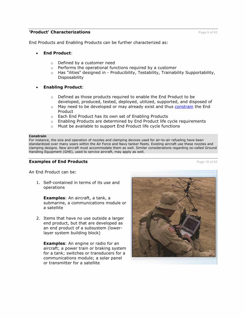
'Product' Characterizations Page 9 of 63
End Products and Enabling Products can be further characterized as:
• End Product:
o Defined by a customer need o Performs the operational functions required by a customer o Has "ilities" designed in - Producibility, Testability, Trainability Supportability,
Disposability
• Enabling Product:
o Defined as those products required to enable the End Product to be developed, produced, tested, deployed, utilized, supported, and disposed of
o May need to be developed or may already exist and thus constrain the End Product
o Each End Product has its own set of Enabling Products o Enabling Products are determined by End Product life cycle requirements
o Must be available to support End Product life cycle functions
Constrain
For instance, the size and operation of nozzles and clamping devices used for air-to-air refueling have been standardized over many years within the Air Force and Navy tanker fleets. Existing aircraft use these nozzles and clamping designs. New aircraft must accommodate them as well. Similar considerations regarding so-called Ground Handling Equipment (GHE), used to service aircraft, may apply as well.
Examples of End Products Page 10 of 63
An End Product can be:
1. Self-contained in terms of its use and operations
Examples: An aircraft, a tank, a
submarine, a communications module or a satellite
2. Items that have no use outside a larger end product, but that are developed as an end product of a subsystem (lower-layer system building block)
Examples: An engine or radio for an aircraft; a power train or braking system for a tank; switches or transducers for a communications module; a solar panel or transmitter for a satellite

Examples of Enabling Products Page 11 of 63
Enabling Products perform non-operational
functions of the system. Some examples include:
• Development: Plans and schedules; engineering policies and procedures; automated tools, models, qualified
engineering and management personnel
• Manufacturing: Policies and procedures; manufacturing facilities;
jigs, special tools and equipment; production processes; manufacturing and procurement personnel
• Test: Test plans, policies and
procedures; models and mockups; special tools and test equipment; test facilities and sites; simulation or
analytical models; inspection procedures and test personnel
An Enabling Product is illustrated here.
Enabling Product The F404-GE-400 engine, mounted on an engine test stand, is shown being tested by aviation maintenance personnel aboard the aircraft carrier, the USS George Washington. This test stand is an enabling product for both the engine end product as well as for the ultimate End Product, the F/A-18 Hornet jet fighter.
Examples of Enabling Products Page 12 of 63
Enabling Products generic examples (continued):
• Operations/Deployment: Plans, policies and procedures; packaging materials; storage facilities; special handling and transportation equipment; installation procedures; deployment instructions; and installation personnel
• Training/Utilization: Plans and schedules; simulators, training models; courses
and materials; special training facilities and trainers
• Support: Policies and procedures; tools and repair equipment; support facilities and handling equipments; maintenance manuals; maintenance management systems; special diagnostic equipment; repair personnel
• Retirement: Plans, schedules and procedures; refurbishment facilities; disposal sites; equipment for disposal of spent products; disposal personnel
Development of Enabling Products, if not already existing, is normally initiated only after
their supported End Products are fully defined. Part of this definition, done as part of the Design Solution Process, results in the identification of the requirements for any needed Enabling Products.

Knowledge Review Page 13 of 63
Which of the following is correct concerning Enabling Products?
Select all that apply.
A. They perform the operational functions required by a customer
B. Except for minor differences, they are synonymous with End Products
C. They enable end products to be realized and used
D. They may constrain the End Product in some way
E. None of these responses is correct
Knowledge Review Page 14 of 63
Which of the following is correct concerning End Products?
Select all that apply.
A. They have ilities designed-in
B. They enable enabling products to be realized and used
C. They perform the operational functions required by a customer
D. They are defined by customer need
E. All of these responses is correct
End Product: Aircraft System Page 15 of 63
Illustrated is an example of an End Product; an air vehicle with its typical subsystems and lower-level elements.
Long Description Graphic titled 'End Product' which has an airplane in the middle and six bubbles around it. They are: Life Support Subsystem, Airframe Subsystem, Propulsion Subsystem, Weapons Subsystem, Flight Control Subsystem, and Navigation Subsystem. Navigation Subsystem branches out to Display Assembly and Global Positioning Receiver Assembly.
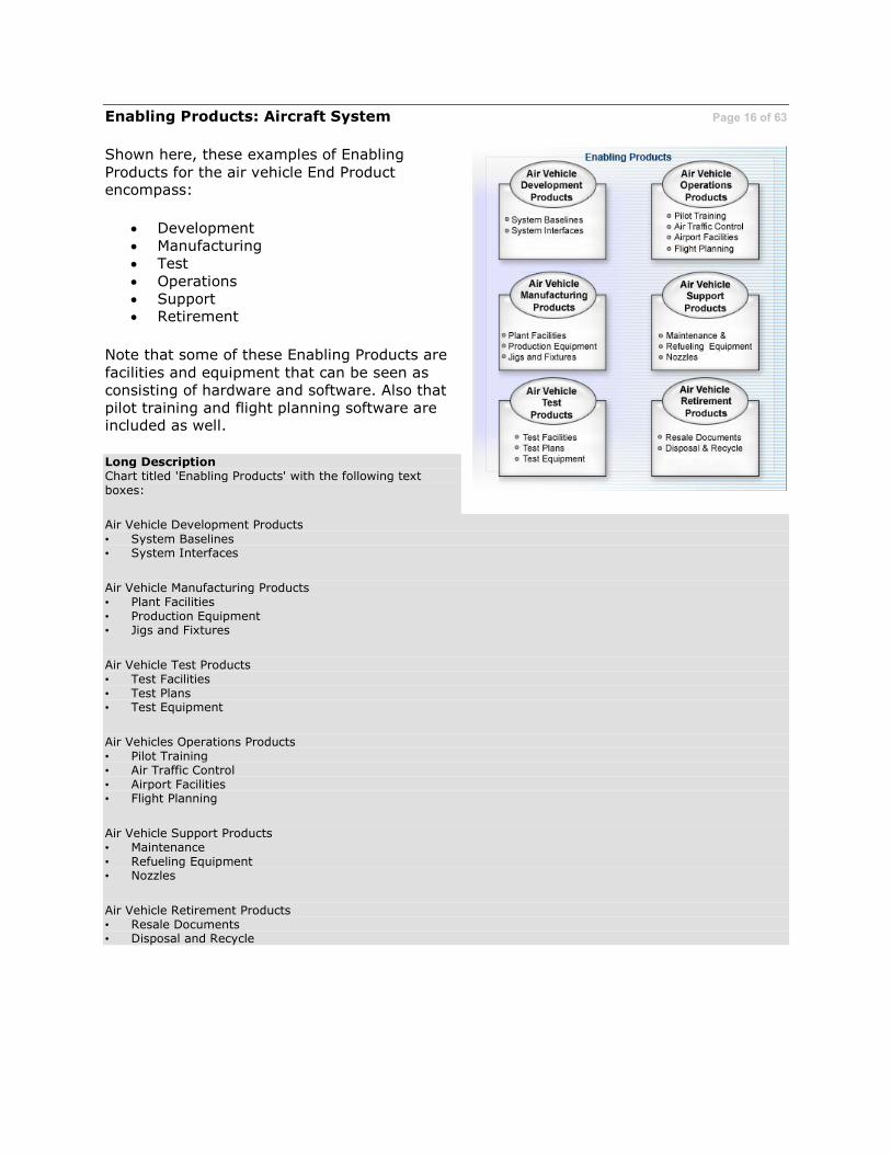
Enabling Products: Aircraft System Page 16 of 63
Shown here, these examples of Enabling
Products for the air vehicle End Product encompass:
• Development • Manufacturing • Test
• Operations • Support • Retirement
Note that some of these Enabling Products are
facilities and equipment that can be seen as consisting of hardware and software. Also that pilot training and flight planning software are included as well.
Long Description Chart titled 'Enabling Products' with the following text boxes:
Air Vehicle Development Products
• System Baselines • System Interfaces
Air Vehicle Manufacturing Products • Plant Facilities • Production Equipment • Jigs and Fixtures
Air Vehicle Test Products • Test Facilities • Test Plans • Test Equipment
Air Vehicles Operations Products • Pilot Training • Air Traffic Control • Airport Facilities • Flight Planning
Air Vehicle Support Products • Maintenance • Refueling Equipment • Nozzles
Air Vehicle Retirement Products • Resale Documents • Disposal and Recycle

Aircraft Generic System Model Page 17 of 63
The aircraft End Product example can be translated into a hierarchical model.
This hierarchical model, illustrated here, shows the relationships of the End Products and Enabling Products that were displayed in the previous two screens.
Long Description Flowchart titled 'Model of Aircraft System.' Aircraft System consists of End Products and Enabling Products. The End
Product is the Air Vehicle End Product, which consists of Airframe Subsystem, Propulsion Subsystem, Weapons Subsystem, Life Support Subsystems, Navigation Subsystem and Flight Control Subsystems. The Enabling Products are Development Enabling Products, Manufacturing and Test Enabling Products, Training Enabling Products, Maintenance Enabling Products and Other Enabling Products.

Model of Aircraft Navigation Subsystem Page 18 of 63
This aircraft system model can then be used to
illustrate the relationships among elements of one of the subsystems. The navigation subsystem is modeled here.
The Systems Engineering Technical Processes outlined in the Defense Acquisition Guidebook
would be applied to these system model products to realize subsystem and system end products and enabling products needed to sustain the desired system.
Long Description Flowchart titled 'Model of Aircraft System.' Aircraft System consists of End Products and Enabling Products. End Products consist of Air Vehicle End Product, which consist of Airframe Subsystem, Propulsion Subsystem, Weapons Subsystem, Life Support Subsystems, Navigation Subsystems and Flight Control Subsystems. Navigation Subsystems consist of Global Positioning Reference Subsystem, Display Subsystem, Radar Control Subsystem and Other Sensor Subsystems. Enabling Products consist of Development Enabling Products, Manufacturing & Test Enabling Products, Training Enabling Products, Maintenance Enabling Products and Other Enabling Products.

Knowledge Review Page 19 of 63
Each of the following items could be an
Enabling Product for an automobile except:
Select the correct answer.
A. Engine diagnostic system
B. Disk brake adjustment tool
C. Model repair manual
D. Transmission
Long Description
A car going around in circles.
Some Conventions Page 20 of 63
Both 'end products' and 'enabling products' exist at various layers in the system structure.
To distinguish them, the convention used in this course is to refer to them as follows:
• Rule 1: When referring to the realized
products that are transitioned to the end user or to the next phase of the Defense Acquisition Framework, 'End Product' and 'Enabling Product' are capitalized.
• Rule 2: When referring to them generically as part of lower layers in the system structure, 'end product' and
'enabling product' are not capitalized.
• Rule 3: When in doubt, use Rule 1.

Close-to-Home Example: System Model Page 21 of 63
Let's illustrate this system model again, but
now by using a much smaller, but close-to-home example...this course!
This DAU on-line course consists of text and optionally graphics on screens (pages) that are aggregated into topics which make up lessons
which in turn comprise this course. This particular course system model is established by DoD policy, an example of an Other Interested Party Requirement.
End Products and Enabling Products exist at these different levels of this course structure. Select each product example below to learn more.
• Screen/Page Level Products
• Topic Level Products
• Lesson Level Products
• Course Level Products
Other Interested Party Requirement
'Other Interested Party Requirements' include those of parties who have some interest in the system such as those providing life cycle support functions; OSD management or other government agencies; and laws, regulations, treaties, policies, etc., which may affect the program or project.
The Advanced Distributed Learning (ADL) Initiative was formed as a developer and implementer of learning technologies across the Department of Defense. DAU on-line courses follow the structure established by ADL DoD-wide standards.
Screen/Page Level Products
• end product: a screen comprised of text and optionally graphics • enabling products: subject-matter experts, course developers and instructional system designers; graphics
artists; course software development environment; graphics tools; QA personnel; DAU course development standards and procedures
Topic Level Products • end product: topic consisting of screens with related subject matter • enabling products: subject-matter experts, course developers; topic reviewers; course software integration
environment; test procedures; topic-related Knowledge Reviews; QA personnel
Lesson Level Products • end product: lesson comprised of related topics
• enabling products: lesson exam test banks; exam grading software; lesson reviewers; Learning Management System (LMS) development & test environment; Key Terms file; Quick References file; course Configuration Management (CM) system
Course Level Products • End Product: this course, composed of various lessons • Enabling Products: Learning Management System (LMS) and IT infrastructure for course delivery; security
software; DAU help desk personnel; DAU course instructors; course Help file; end-of-course survey software; course registration systems

System Model Uses Page 22 of 63
A system model allows for the uniform application of various Systems Engineering
processes. For typically complex DoD systems, a system model's standardized nomenclature is key to facilitating communications and to help ensure all parts of the system are considered and are addressed in a uniform way. Such a model can be used for:
• Planning and managing the Systems Engineering effort o Identifying products to be engineered
o Assignment of work packages o Making cost estimates o Assessing risks and opportunities
• Organizing IPTs and facilitating teamwork
• Orchestrating incremental reviews
• Defining and structuring specifications, including interfaces
• Creating system structure (level-by-level development and product realization)
• Enabling product identification and development
Examples of these uses of a system model are provided on subsequent screens.
System Model: Process Perspective Page 23 of 63
The system model is the target of Systems
Engineering Technical Processes. These are comprised of System Design Processes (Requirements Development, Logical Analysis and Design Solution) and Product Realization
Processes (Implementation or Integration, Verification, Validation and Transition). Specifically:
• The three System Design Processes are
used to fully define the system model in terms of Solution-Specified Requirements.
• The five Product Realization Processes
are used to generate (realize) the physical form of the end product consistent with its specified design solution.
In conjunction with these Technical Processes, Systems Engineering Technical Management Processes are used for planning, assessing and controlling the technical effort involved with defining the system model and in realizing the ultimate End Product.
Physical Form The physical form of an end product that is realized by application of the Product Realization Processes is dependent of the Defense Acquisition Framework phase in which the system model end product is realized and the phase exit criteria that must satisfied by the technical effort.

In early phases of the Defense Acquisition Framework the form may be digital as in a analytical report or simulation; a breadboard or brassboard; a scaled model or technology prototype. In later phases the physical form may be in an engineering prototype or ultimately the full scale, deployable product.
Solution-Specified Requirements
The requirements, specifications and/or other descriptive design documents that fully define system model elements (system, end product, subsystem and enabling product) at the completion of the application of the System Design Processes to that system model. Expressed in System Specifications and Item Specifications.
Long Description
Chart titled 'Generic System Model.' System flows to End Product which flows to Subsystems. System also flows to Development Enabling Products, Manufacturing & Test Enabling Products, Training Enabling Products, Maintenance Enabling Products and Other Enabling Products.

System Model: Management Examples Page 24 of 63
A systems model identifies the products that
need to be engineered or acquired to make up the 'system.' Such a model provides a structure for planning the Systems Engineering effort, for
making cost estimates and for assigning work packages for each product in the model.
The model also provides a uniform, consistent structure for identifying, analyzing and mitigating technical risks, as well as understanding their inter-relationships.
The End Product illustrated by this system model is the main deliverable. It represents the product desired by the ultimate customer.
Other product boxes (i.e., Enabling Products) will eventually be realized so that when
available, they will make up the 'system.' The system and subsystems will also be described by appropriate Solution-Specified Requirements developed as outputs of top-down design processes.
Work Packages A Work Package is a detailed, short-span task, identified by the performing contractor or an in-house IPT for accomplishing work required to complete a project. EIA Std 748 (Earned Value Management System) formally adopted by the DoD in 1999, defines a work package as: "A task or set of tasks performed within a cost control account."
End Product
• Defined by a customer need • Performs the operational functions required by a customer • Has "ilities" designed in - Producibility, Testability, Trainability, Supportability, Disposability, etc.
Enabling Products • Defined as those products required to enable the End Product to be developed, produced, tested, deployed,
utilized, supported, and disposed of • May need to be developed or may already exist and thus constrain the End Product • Each End Product has its own set of Enabling Products • Enabling Products are determined by End Product life cycle requirements • Must be available to support End Product life cycle functions
Realized Realization provides the physical design solution in a product form suitable for meeting the applicable acquisition phase exit criteria, including product verification and validating and transitioning the product to the next level up of the system structure or to the customer
Long Description
Chart titled 'Generic System Model.' System flows to End Product which flows to Subsystems. System also flows to Development Enabling Products, Manufacturing & Test Enabling Products, Training Enabling Products, Maintenance Enabling Products and Other Enabling Products

System Model: Work Products Page 25 of 63
One of the important work products resulting from system model definition is the set of requirements for the various Enabling Products which will be needed to provide life cycle support services to the End Product.
Acquisition activities may mandate use of existing Enabling Products or in some cases,
require development of unique products. If so, these Enabling Products will be developed, realized and managed using the same Systems Engineering Processes that were used for the supported End Product but now are applied to a separate system model for the appropriate Enabling Product(s).
Examples of other work products that arise from defining the system model include:
requirements baselines, configuration baselines, decision analysis recommendations and impacts, decisions made including assumptions, technical plans, work packages, technical reports, effectiveness assessments, and risk status.
Some of these work products are delivered to the customer while others are interim products used mainly by the developer; but all of them should be appropriately captured and retained in a designated program or project technical data management database.
Work Products A work product is any artifact - material or electronic - generated during the conduct of the activities and tasks of a process, including the desired outputs.
Technical Data Management Database The program's technical management database, its adequacy and protection, among other areas, is a key aspect of Technical Data Management.

One of the Systems Engineering Technical Management Processes, the Technical Data Management Process is the disciplined processes and systems used to plan for, acquire, access, manage, protect, and use data of a technical nature to support the total life cycle of the system.
System Model: Teamwork and IPTs Page 26 of 63
In the DoD environment where Integrated Product Teams (IPTs) and the use of Integrated Product and Process Development (IPPD) are key 'best practices,' system model can also
provide a basis for forming and assigning Core Teams and IPTs, so that they operate most effectively.
For example, the System Core Team is responsible for initial planning to develop their
system model and for assigning IPTs to the products at the second level of the model.
An end product team can be the leaders from their respective subsystem team. An enabling product team would include individuals
representing their respective functional disciplines. A subsystem team becomes the core team for the next lower-layer subsystem and its end and enabling products.
Integrated Product and Process Development (IPPD) Integrated Product and Process Development (IPPD) is a management technique that simultaneously integrates all essential acquisition activities through the use of multidisciplinary teams to optimize design, manufacturing, and supportability processes. IPPD facilitates meeting cost and performance objectives. One of the key IPPD tenets is multi-disciplinary teamwork through Integrated Product Teams (IPTs).
System Core Team
A System Core Team is usually composed of the project technical manager, along with members to be assigned to team lead positions on end product and associated process teams.
Long Description
A flowchart titled, 'System Model Used for Assuring Teamwork.' System Core Team flows to End Product IPT, which then flows to two Subsystem Core Team boxes. System Core Team also flows to Development & Integration Product IPT, Production Product IPT, Test Product IPT, Operations Product IPT and Logistics Products IPT.

Teamwork and IPTs Page 27 of 63
Using a system model, each Integrated Product Team is given a product element to develop and perform required Systems Engineering
activities. Using this approach, each model element can have a dedicated IPT assigned. This IPT will be able to deal with an unambiguously defined work package regarding what is to be accomplished.
Each IPT is responsible for:
• Planning their work
• Making cost estimates related to their work and the product
• Doing the work described in the team's
approved work package
• Identifying and managing the risks and opportunities associated with the development of the product, including interfaces
with other products in the model
Long Description A flowchart titled, 'System Model Used for Assuring Teamwork.' System Core Team flows to End Product IPT, which
then flows to two Subsystem Core Team boxes. System Core Team also flows to Development & Integration Product IPT, Production Product IPT, Test Product IPT, Operations Product IPT and Logistics Products IPT.

System Model: Incremental Reviews Page 28 of 63
Another advantage of using a system model is its use for efficient structuring of various In-Progress Reviews (IPRs) that can be conducted
in preparation for more formal major systems-level Technical Reviews.
The graphic illustrates several generic examples of such reviews.
Select the four boxes in the top row of the graphic to learn more about the ways in which these reviews can be used.
Technical Reviews The Technical Management Process, Technical Assessment, measures technical progress and the effectiveness of plans and requirements. An important component of Technical Assessment is the use of Technical Reviews.
Technical Reviews are an important oversight tool. They are used to review and evaluate the state of the system and the program, re-directing activity after the review if found necessary. Technical Reviews are key decision events used to measure technical progress and maturity in system development as well as to assess various programmatic issues.
Technical Reviews are discussed in depth as part of the Technical Assessment Process topic and are summarized as part of Chapter 4 of the Defense Acquisition Guidebook (DAG). Additionally check out the DAU Continuous Learning Module (CLM) on Technical Reviews available here.

Subsystem Reviews
This type review can be presented by the Subsystem IPT/Core Team with the purpose of giving the status of the subsystem development and its readiness to initiate development. The status of interface definitions is a special consideration of this type review.
Enabling Product Readiness Reviews The purpose is to demonstrate that the enabling products requirements are defined and ready for initiating development either by applying Systems Engineering Processes to the system model or by the acquisition of already available enabling products.
End Product Reviews Once the system model Subsystem and Enabling Product Reviews have been satisfactorily completed, End Product Reviews can be held. The purpose is to provide confirmation that the End Product has been adequately defined to approve initiation of development of Enabling Products and Subsystems system models.
System Review A formal systems-level review (Technical Review) is typically associated with the top-level system model in the system structure or for an identified critical end product (e.g. engine, weapon, or computer) that makes up the systems-level End Product (e.g. an aircraft, tank, or satellite).
These types of reviews should be called out in the programs Systems Engineering Plan (SEP). Examples include the Initial Technical Review (ITR); Alternative System Review (ASR); Systems Requirements Review (SRR); Systems Functional Review (SFR); Preliminary Design Review (PDR); Critical Design Review (CDR); Test Readiness Review (TRR); Production Readiness Review (PRR); System Verification Review (SVR); the In-Service Review (ISR); and audits such as the Functional Configuration Audit (FCA) and the Physical Configuration Audit (PCA).
Long Description Flowchart titled 'System Model Used for Lifecycle Reviews.' Subsystem Reviews flows to Enabling Product
Readiness Reviews, which then flows to End Product Reviews, which flows to System Review. System Review flows to End Product Review, which then flows to Subsystem Reviews. System Review also flows to Development and Integration Product Review, Production Product Review, Test Product Review, Operations Product Review and Logistics Products Review.

System Model: Structuring Specifications Page 29 of 63
An essential part of developing system models is the creation of various program-unique
specifications (large programs may have thousands of these!) including related interface specifications.
Program-unique specifications define requirements for each system model element; while interface specifications define interfaces between and among system model elements and external system products.
Specification standards for the DoD are described in MIL-STD 961 (Defense and Program-Unique Specifications Format and Content) and include the following generic categories:
• System Specification
• Performance Specification
• Detail Specification
• Item Specification
• Software Specification
More information about MIL-STD 961 is available via Quick Reference.
Program-Unique Specifications Describe a system, item (e.g., End Product), software program, process or material developed and produced (including repetitive production and spares purchase) for use within a specific program, or as part of a single system and for which there is judged to be little potential for use by other systems.
Interface Specifications
Describe physical form and fit interfaces, human interfaces (human-to-machine and human-to-human), electronic interfaces, logical or functional interfaces, etc. between various elements of a system model or products external to the system model that interact or have a potential to interact with or impact each other. May be defined via an Interface Control Document (ICD).
System Specification
A type of program-unique specification that describes the requirements and verification of the requirements for a combination of elements that must function together to produce the capabilities required to fulfill a mission need, including hardware, equipment and software.
Performance Specification A specification that states requirements in terms of the required results with criteria for verifying compliance, but without stating the methods for achieving the required results. A performance specification defines the functional requirements for the item (e.g., End Product), how well it must perform that function, the environment in which it must operate, and interface and interchangeability characteristics.
Detail Specification
A specification that specifies design requirements, such as materials to be used, how a requirement is to be achieved, or how an item is to be fabricated or constructed.
Item Specification
A type of program-unique specification that describes the form, fit and function and method for acceptance of end products (e.g., parts, components and other items that are elements of a system model)

Software Specification
A type of program-unique specification that describes the requirement and their verification for the automatic acquisition, storage, manipulation, management, movement, control, display, switching, interchange, transmission or reception of data or information.
System Model: System Structure Development Page 30 of 63
To simplify the development of a system and to make Systems Engineering Processes easier to apply, IPTs must operate the same way at each level of the system structure. Their operation
should be consistent regardless of whether developing the top-level system model or the lowest system model within the structure.
Illustrated is the conceptual relationship between a higher system model and a set of
lower system models--one for each subsystem of the higher system model.
This abstraction makes it easier for team members to work consistently on any size system, at any level of the system structure or
in any life cycle phase. The only differences expected are in the complexity of the product, the methods and tools used and the scope of the problems that must be solved.
Long Description A flowchart titled, 'System Model Used for System Structure Development.' System flows to End Product, which also flows to Subsystems. System also flows to Development & Integration Products, Production Products, Test Products, Operations Products and Logistics Products.

System Model: Enabling Products Page 31 of 63
This approach also applies to Enabling Products.
Each system model will have its own dedicated
set of Enabling Products. There is no 'direct' connection or relationship between Enabling Product sets from one system model to the next within the system structure.
Enabling products vary. For example, at the
lowest layer such enabling products as jigs, fixtures, Computer Numeric Controlled (CNC) machine tool programs and software products
such as compilers may be critical. At the ultimate End Product level, these Enabling Products are the one the users in the field will need to effectively use, maintain and support and dispose of the End Product.
Enabling Products that require development (e.g. do not already exist) will have their own system structure developed using the System Design Processes.
Enabling Products • Defined as those products required to enable the end product to be developed, realized, tested, deployed,
utilized, supported, and retired • May need to be developed or already exists and thus may constrain the end product • Each end product has its own set of enabling products • Enabling products are determined by end product life cycle requirements • Must be available to support end product life cycle functions
Compilers A compiler is a complex software tool that translates computer programs (source code) into machine language that can be actually executed by a computer.
Long Description
A graphic with three flowcharts titled, 'System Model Used for Enabling Product Development.' The first flowchart begins with System, which flows to End Product, which then flows to two Subsystems. System also flows to Development & Integration Products, Production Products, Test Products, Operations Products and Logistics Products. From Production Product, an arrow points to a new flowchart. Flowchart #2 begins with System, which flows to End Product, which then flows to two Subsystem boxes. System also flows to Development & Integration Products, Production Products, Test Products, Operations Products and Logistics Products. From Logistics Products in flowchart #1, an arrow points to a new flowchart. Flowchart #3 begins with System, which flows to End Product, which then flows to two Subsystem boxes. System also flows to Development & Integration Products, Production Products, Test Products, Operations Products and Logistics Products.

Knowledge Review Page 32 of 63
A system model can be used to assist in:
Select the correct answer.
A. Orchestrating incremental reviews
B. Structuring IPT Team assignments
C. Developing specifications
D. All of the above

What is a Work Breakdown Structure? Page 33 of 63
A Work Breakdown Structure (WBS) is a
product-oriented family tree composed of hardware, software, services, data, and facilities. A 'program' WBS displays and defines
the product(s) to be developed and/or produced by the program. It relates the elements of work to be accomplished to each other and to the End Product.
The WBS is used to generate initial cost
estimates, program plans, and to support contracting and reporting. It can also be used to help create a program schedule.
At one time, WBS formats and system structures were mandated within the DoD via a
prescriptive Military Standard. That standard has been replaced by a Military Handbook (MIL-HDBK-881A) which provides specific guidance on WBS usage.
Within the DoD, a WBS is the most common way that a system model is formally documented.
WBS: 'Program' vs. 'Contract' Linkage Page 34 of 63
The Program WBS relates the elements of work to each other and to the End Product. In the DoD, the program WBS is extended to a Contract WBS that defines the relationships
between the elements of the program and corresponding elements of the contract work statement. The Contract WBS provides the reporting structure used for DoD contract management.
Used in this way, the WBS becomes the common framework that consistently links program and technical planning, cost estimating, resource allocation, performance measurement, technical assessment, and status reporting.
Use of a WBS that follows MIL-HDBK-881A is required by DoD policies for such key programmatic items as the Contract Performance Report (CPR), Integrated Master Schedule (IMS), and Contractor Cost Data Report (CCDR).
MIL-HDBK-881A also includes several appendices that illustrate WBSs for a variety of defense system categories. These provide an initial WBS that must be further tailored and
extended to generate a complete, program-specific system model. Additionally, some agencies provide more explicit guidance on WBS structures to be used for their agency-specific products via regulations that supplement the WBS handbook.
More information about the WBS as well as a WBS Continuous Learning Module (CLM) is available via Quick Reference.

Program WBS More formally, the Program WBS defines the program in terms of hierarchically related, product-oriented elements and includes "other Government" elements (i.e., Program Office Operations, Manpower, Government Furnished Equipment (GFE), and Government Testing). Each element provides logical summary levels for assessing technical accomplishments, supporting the required event-based technical reviews, and for measuring cost and schedule performance. [MIL-HDBK-881A].
Contract WBS
More formally, the Contract WBS is the Government-approved WBS for program reporting purposes and includes all product elements (hardware, software, data, or services), which are the contractor's responsibility. It includes the contractor's discretionary extension to lower levels, in accordance with Government direction and the Contract Statement of Work (SOW). [MIL-HDBK-881A].
Contract Performance Report (CPR)
The CPR provides contract cost and schedule performance data that is used to identify problems early in the contract and forecast future contract performance. The CPR is the primary means of documenting the ongoing communication between the contractor and the program manager to report cost and schedule trends to date and to permit assessment of their effect on future performance.
A CPR (DD Form 2734) should be used on all cost or incentive contracts, subcontracts, intra-government work agreements, and other agreements valued at or greater than $20 million.
Integrated Master Schedule (IMS) The IMS is a calendar-based schedule containing the networked, detailed tasks necessary to ensure successful program/contract execution. The IMS is traceable to the Integrated Master Plan (IMP), the contract Work Breakdown Structure (WBS), and the Statement of Work. The IMS is used to verify attainability of contract objectives, to evaluate progress toward meeting program objectives, and to integrate the program schedule
activities with all related components.
An IMS should be used on all cost or incentive contracts, subcontracts, intra-government work agreements, and other agreements valued at or greater than $20 million. The IMS is applicable to development, major modification, and low rate initial production efforts; it is not typically applied to full rate production efforts. It is also not normally required for contracts valued at less than $20 million, contracts less than 12 months in duration, or Firm-Fixed Price contracts regardless of dollar value.
Contractor Cost Data Report (CCDR) The CCDR is the primary means within the Department of Defense to systematically collect data on the development and production costs incurred by contractors in performing DoD acquisition program contracts. Additionally, existing CCDR data from historical programs is used to make parametric cost estimates for future acquisition programs. CCDR reporting is required by DoD policy for certain categories of programs having specific cost thresholds.
The Defense Cost and Resource Center (DCARC) is the OSD office responsible for administering the CCDR system. Because of its sensitivity, access to CCDR data is restricted.
Defense System Categories
The categories of defense systems documented in MIL-HDBK-881A include: • Aircraft System: Applies to fixed or movable wing, rotary wing, or compound wing manned air vehicles
designed for powered or unpowered (i.e., glider) guided flight. • Electronic/Automated Software System: Applies to electronic, automated, or software system capability. • Missile System: Applies to a missile in an operational environment which produces a destructive effect on
selected targets, or has the capability for launching space systems. • Ordnance System: Applies to all munitions (nuclear, biological, chemical, psychological, and pyrotechnic) and
the means of launching or firing them. • Sea System: Applies to surface and submersible ship platforms, systems, weapons, and equipment required
for performing naval tasks at sea. • Space System: Applies to developing, delivering, and maintaining mission payloads in specific orbit
placement, operation, and recovery of manned and unmanned space systems. • Surface Vehicle System: Applies to navigation over the surface. • Unmanned Air Vehicle: Applies to fixed or movable wing, rotary wing, or compound wing unmanned air
vehicles designed for powered or unpowered (glider) guided flight.

Knowledge Review Page 35 of 63
Which of the following about a Work Breakdown Structure (WBS) is correct?
Select all that apply.
A. It is a product-oriented family tree composed of hardware, software, services,
data, and facilities
B. It is used to consistently link program and contracting reporting activities
C. It is a distinct product not at all related to a system model
D. Use of the WBS is mandated by a prescriptive Military Standard
An Engineering 'V' Model Page 36 of 63
A system structure based on a hierarchy of system models provides the basis for both Top-Down System Design and Bottom-Up Product Realization.
Concurrently with this top down design and bottom up realization, the Enabling Products for each system are being defined and developed or acquired so that they will be available when needed.
When arranged in the fashion shown here, it is referred to as a 'V' model for obvious reasons.
Top-Down System Design System Design processes (Requirements Development, Logical Analysis and Design Solution), are applied to each system model in the system structure. Upper system models must be fully defined and appropriate Technical Reviews successfully completed in order to be able to start development of a lower layer system model. This application of System Design Processes continues until all system model end products can be built (or coded), bought, or reused/off-the-shelf and are ready for realization.
Bottom-Up Product Realization
At the point when end products are ready for realization, Product Realization Processes (Implementation or Integration, Verification, Validation and Transition) are applied to each end product from the bottom up, realizing the design solution for that end product. An end product obtained from the Implementation Process is then verified, validated and transitioned for assembly and integration into its parent system model end product which in turn is verified, validated and transitioned. This sequence continues until the desired system-level End Product is realized.
This sequence occurs in each of the Defense Acquisition Framework phases with the realized End Product used to provide information to satisfy necessary phase exit criteria and transitioned between phases. Ultimately, End Products are produced and transitioned to operational customers and end users.

An Engineering 'V' Model Page 37 of 63
While technical processes along the 'V' are illustrated in a linear or serial sequence, it is important to understand that they do not necessarily have to start in the strict illustrative
sequence depicted, but to be effective, they ultimately must finish in that order.
A similar 'V' format, but with verification and validation linkages drawn between the legs of
the 'V,' can be used to structure application of Systems Engineering processes in the context of the Defense Acquisition Framework. It is used to help ensure that required technical exit
and entry criteria associated with each phase of the life cycle are met. Examples are available at The Chart.

The 'V' - Going Down! Page 38 of 63
Illustrated here is a macro view of generic outputs from Technical Process activities.
The left side of the 'V' represents various design activities 'going down' the system V.
Generated for each system model on the left side of the 'V' are:
• Sets of end product specifications and
design descriptions
• Verification and Validation plans later used to determine realized product compliance with specifications
(Verification) and Stakeholder Requirements (Validation)
• Initial Specifications that become the
flow-down requirements for the next lower system model development

Long Description
Chart titled 'The V - A Macro View.' The left side of the 'V' includes: Generate System-Level End Product Specification & Verification & Validation Plans, Generate Subsystem-Level End Product Specifications & Verification & Validation Plans, Generate Lower-Level End Product Specifications & Verification & Validation Plans, Generate Lowest-Level End Product Specifications & Verification & Validation Plans. The right side of the 'V' includes: Assemble & Integrate System-Level End Product & Verify & Validate, Assemble & Integrate Subsystem-Level End Products & Verify & Validate, Assemble & Integrate Next-Level Up End Products & Verify & Validate, Implement Lowest-Level End Products & Do Verification & Validation.
The 'V' - Coming Up! Page 39 of 63
Shown here, the right side of the 'V' represents various bottom-up Product Realization activities
'coming up' the system 'V' for each end product.
Generated for each end product on the right side of the 'V' are:
• Implemented or assembled and integrated end products for the
corresponding system model as per the left side of the "V"
• Product Verification results conducted according to the plan(s) generated
during design of the end product
• Product Validation results conducted according to the plan(s) generated during design of the end product

• Realized products which are transitioned to the next layer of the model for assembly and integration or ultimately for End Product use
Long Description A chart titled 'The V - A Macro View.' The left side of the 'V' includes: Generate System-Level End Product Specification & Verification & Validation Plans, Generate Subsystem-Level End Product Specifications & Verification & Validation Plans, Generate Lower-Level End Product Specifications & Verification & Validation Plans, Generate Lowest-Level End Product Specifications & Verification & Validation Plans. The right side of the 'V' includes: Assemble & Integrate System-Level End Product & Verify & Validate, Assemble & Integrate Subsystem-Level End Products & Verify & Validate, Assemble & Integrate Next-Level Up End Products & Verify & Validate, Implement Lowest-Level End Products & Do Verification & Validation.
Knowledge Review Page 40 of 63
Which of the following are true concerning application of the Systems Engineering 'V' model?
Select all that apply.
A. It addresses both End Products and Enabling Products
B. Verification and Validation Plans are generated as part of bottom-up product
realization activities
C. It can be used to structure Systems Engineering activities within the context of
the phases of the Defense Acquisition Framework
D. It generates specifications that are flowed down as requirements for lower
system models
E. It generates realized End Products that ultimately get transitioned to user

The 'V': Top Down Design Page 41 of 63
In a top-down system design, the same sets of
Systems Engineering processes (Requirements Development, Logical Analysis and Design Solution) are applied to each system model in
the system structure.
Feedback (iteration) can occur among the three System Design Processes being applied to any one system model. For example, Logical
Analysis or Design Solution activities may discover technical problems not identified by a prior process. If so, prior processes may need to be re-accomplished including possible re-
involvement of stakeholders.
Feedback can also occur between a lower system model and its parent model. In some
instances, System Design activities may uncover technical problems that will require resolution (e.g., clarification or modification of requirements; changes in system architecture,
etc.) at an upper level system model.
Long Description
A flowchart titled 'Top Down System Design.' Top Down Design begins with Stakeholder Requirements, which flows to three boxes titled 'System End Products Definition,' which flow to Subsystem Detailed Designs.

The 'V': Bottom Up Realization Page 42 of 63
Once the products of all system models have
been fully defined, bottom up End Product realization can be initiated. This begins by applying the Implementation Processes to buy,
build, code or reuse end products.
These implemented end products are verified against their design descriptions and specifications, validated against Stakeholder
Requirements, and then transitioned to the next higher system model for integration.
End products from the Integration Process are successively integrated upward, verified and
validated, transitioned to the next acquisition phase, or transitioned ultimately as the End Product to the user.
Realization Providing the physical design solution in a product form suitable for meeting the applicable Defense Acquisition Framework phase exit criteria, including product verification and validating and transitioning the product to the next level up of the system structure or to the customer.
Long Description Flowchart titled, 'Bottom Up Realization.' Four processes flow to the other and are each labeled Realization Processes/Subsystem Detailed Designs.

Systems Engineering and Recursion Page 43 of 63
Recursion is the repeated application of the
same Technical Processes to either: (1) successively lower system models within the system structure or (2) to End Products at
successively higher levels of the system structure.
For example, on the right side of the graphic two system models with a parent-child [system-subsystem] relationship are illustrated.
Top-Down system design processes (i.e.,
Requirements Development, Logical Analysis and Design Solution) are first applied to the parent system model. Then, based on the flow-down of subsystem initial specifications to the
child system model, the same set of three processes get applied to the child system model.
This recursion occurs at each system model within the system structure.
Long Description Chart titled Recursive Application of System Design Processes. Requirements Development Process flows to Logical Analysis Process to Design Solution Process to Requirements Development Process to Logical Analysis Process to Design Solution Process.

Systems Engineering and Iteration Page 44 of 63
Iteration is the re-application of processes
already applied to a system model based on feedback indicating a problem that needs resolution
On the right side of the illustrative graphic are two system models with a parent-child
relationship. In this case, the three system design processes (i.e., Requirements Development, Logical Analysis and Design Solution) are first applied to the system model.
As technical difficulties such as unacceptable risk, infeasible technology, or a requirement conflict is discovered, these must be resolved via process re-application. This must be done
before finalizing the design solution of the end product and subsequently flowing down specifications for the subsystems at the layer below.
Long Description Flowchart that begins with Requirements Development Process to Logical Analysis Process to Design Solution Process. These are iterative loops and are applied to System Model (Layer N). A second flow begins with
Requirements Development Process to Logical Analysis Process to Design Solution Process. These are iterative loops and are applied to Subsystem System Model (Layer N+1).

Knowledge Review Page 45 of 63
Which of the following statements is true?
Select the correct answer.
A. The design of systems should be accomplished from the bottom up so as to
capture all components.
B. Realization of system model end products should be accomplished from the
bottom up so as to find and correct problems at the lowest possible level.
C. Realization of a system should be from the top down so as to develop
requirements in a logical order.
D. None of the above is true.
Close-to-Home Example: Top Down Design Page 46 of 63
Let's return to our example (this course!) again. The earlier 'Close-to-Home' example discussed the DAU course system model. Now we illustrate some of the System Engineering processes that were used during its creation, starting with top-down design processes...
Acquirer Requirements and Other Party Requirements were analyzed as course Stakeholder Requirements via the Requirements Development Process. Additional Derived Requirements were also identified. Technical Requirements were ultimately developed and became the basis for course design.
The Logical Analysis Process evaluated several ways to partition the course technical
requirements into various lessons. Learning Objectives were allocated to lesson topics accordingly. Ultimately a course architecture was selected and a course allocated baseline established.
Design Solution evaluated various designs for the physical architecture of the course. Several lesson prototypes were developed and evaluated to assist in choosing the final
physical architecture. Requirements and various work products (e.g., course design documents) were developed and baselined as the Solution-Specified Requirements for the course.
System Model DAU on-line courses consist of lessons which are aggregations of subject-matter related topics which in turn are comprised of screens (pages) which individually consist of text and optionally graphics.
Acquirer Requirements
Acquirer Requirements for DAU courses are established by the acquisition workforce Functional Advisor (FA). The FA is assisted by a Functional Integrated Product Team (FIPT) comprised of service and agency career field representatives. Among other duties, the FIPT establishes career field competencies. For this course, 126 competencies were established as the course functional baseline.
Other Party Requirements
Some of these included DoD mandated standards for course structure; provisions for accessibility in accordance with Section 508 legislation; and Information Assurance and software security requirements, among others.

Derived Requirements
Further analysis of the career field competencies revealed the need for several additional ones to adequately cover particular areas. These were submitted to the FIPT and re-baselined accordingly.
Technical Requirements
These are traceable to the Learning Objectives for each topic that you see listed on the second screen throughout the course.
Allocated Baseline For this course, the allocated baseline is essentially the Topic Learning Objectives for each lesson/topic. They are
traceable to the functional baseline (career field competencies).
Close-to-Home Example: Bottom Up Realization Page 47 of 63
Screens (pages) were implemented: text was developed, some graphics were reused and others were newly created. Screens were coded using a distance learning course
development system (an enabling product). As part of implementation, screens were verified. Collections of screens were integrated into topics, verified again and then integrated into lessons and ultimately a course.
As part of the Verification Process, the course was verified via various Quality Assurance checks as well as an Instructor Pilot. As a result, necessary changes were made (i.e., the
Requirements Development, Logical Analysis and Design Solution processes were iterated accordingly). The course and its work products were re-baselined.
As part of the Validation Process, a Student Pilot was held to validate the course against workforce needs. Additional revisions were identified, made and the final course product baseline (the course you are taking) was established.
The course was transitioned from its development environment to the DAU Learning
Management System (called ATLAS) and made available to the acquisition workforce. Voila! A course...multiply the above by about 10,000 and you have a typical DoD system.
Nevertheless, this example illustrates that Systems Engineering Processes scale up and down quite easily. That is the whole point of consistent processes used in conjunction with a well-defined system model...they can be used at any point within the system structure for a
wide variety of systems...from this lowly course to something as complex as an aircraft carrier or a theater-level command and control system!

Defense Acquisition Framework Page 48 of 63
The 5000-series of DoD publications specifies
acquisition policies and procedures to be applied within the context of the Defense Acquisition Framework (DAF). DAF phase entry
and exit criteria determine the maturity of the system under development and whether it is ready to proceed (or transition) to the next acquisition phase.
Whatever technical work needs to be done is
governed by acquisition phase criteria as well as the information needed by a Milestone Decision Authority (MDA) to make decisions on continued system development, use or retirement.
The 'V' model described previously is a good metaphor to understand and describe key Systems Engineering activities done by both the 'acquirer' (the DoD) as well as the
'developer' (typically defense contractors) associated with each phase of the acquisition framework.
Long Description A chart titled 'Defense Acquisition Management Framework.' From Technology Opportunities & User Needs, there are three arrows pointing to three triangles labeled A, B and C (Program Initiation). Under these triangles there are five boxes: Concept Refinement, Technology Development (Pre-Systems Acquisition), System Development & Demonstration, Production & Deployment (Systems Acquisition) and Operations & Support (Sustainment). At the bottom of the graphic there is a line labeled 'Relationship to Requirements Process.' There are three documents listed for this process: Initial Capabilities Document (ICD) (Formerly MNS), Capabilities Development Document (CDD) (Formerly part of ORD), Capabilities Production Document (CPD) (Formerly part of ORD). At the top right of the graphic is the following information: Process entry at Milestones A, B or C; Entrance criteria met before entering phase; Evolutionary Acquisition or Single Step to Full Capability; IOC: Initial Operational Capability; FOC: Full Operational Capability; FRP: Full Rate Production.
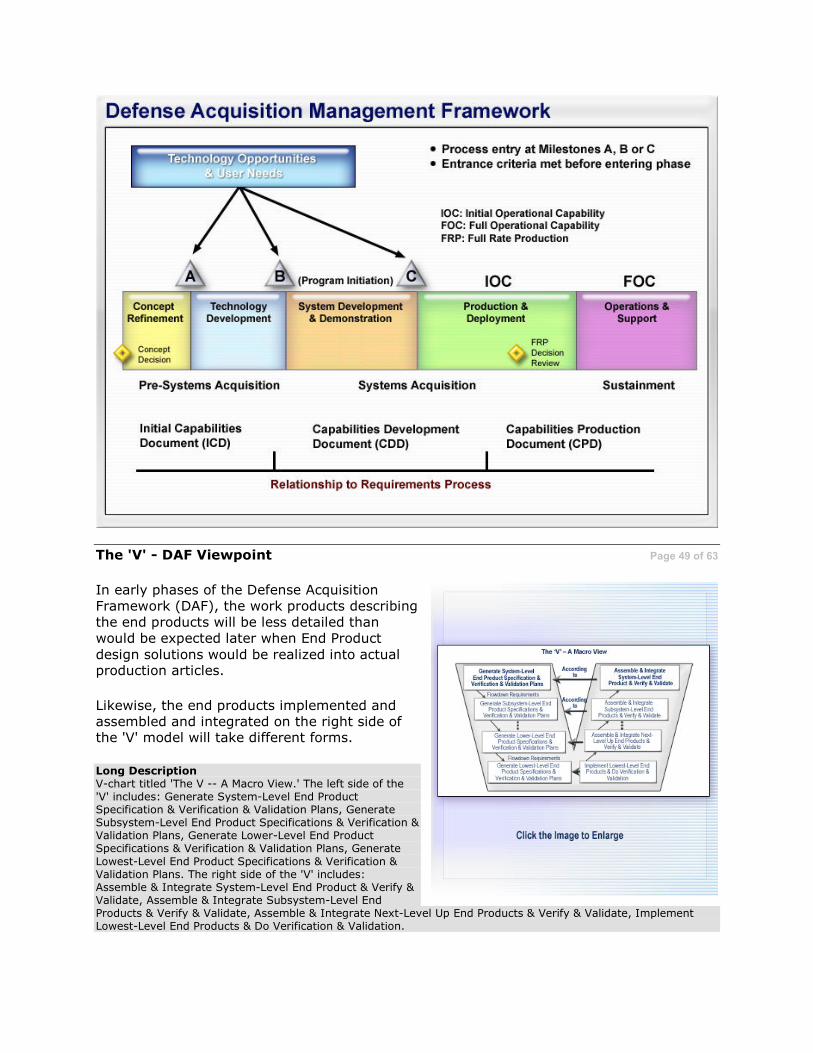
The 'V' - DAF Viewpoint Page 49 of 63
In early phases of the Defense Acquisition Framework (DAF), the work products describing the end products will be less detailed than would be expected later when End Product
design solutions would be realized into actual production articles.
Likewise, the end products implemented and assembled and integrated on the right side of the 'V' model will take different forms.
Long Description V-chart titled 'The V -- A Macro View.' The left side of the 'V' includes: Generate System-Level End Product Specification & Verification & Validation Plans, Generate Subsystem-Level End Product Specifications & Verification & Validation Plans, Generate Lower-Level End Product Specifications & Verification & Validation Plans, Generate
Lowest-Level End Product Specifications & Verification & Validation Plans. The right side of the 'V' includes: Assemble & Integrate System-Level End Product & Verify & Validate, Assemble & Integrate Subsystem-Level End Products & Verify & Validate, Assemble & Integrate Next-Level Up End Products & Verify & Validate, Implement Lowest-Level End Products & Do Verification & Validation.

The 'V' - DAF Viewpoint Page 50 of 63
For example, early lifecycle stage end products may include analytical reports, simulation results, and feasibility studies based on
analytical models, breadboards, brassboards, scaled physical models, or prototypes. During later lifecycle stages the end products would take the form of a final engineering prototype
or a production representative article or ultimately, the deliverable End Product.
While the realized products differ, it is important to understand that, independent of
DAF phase, the same Systems Engineering processes are used throughout the life cycle.
'V' model examples, tailored by acquisition phase are summarized on subsequent screens.
Breadboards An experimental device (or group of devices) used to determine feasibility and to develop technical data. It normally will be configured for laboratory use only to demonstrate the technical principles of immediate interest. It may not resemble the end item and is not intended for use as the projected end item.
Brassboards
An experimental device (or group of devices) used to determine feasibility and to develop technical and operational data. It normally will be a model sufficiently hardened for use outside of laboratory environments to demonstrate the technical and operational principles of immediate interest. It may resemble the end item, but is not intended for use as the end item.

Prototypes
An original or model on which a later system or item is formed or based.
Long Description
V-chart titled 'The V -- A Macro View.' The left side of the 'V' includes: Generate System-Level End Product Specification & Verification & Validation Plans, Generate Subsystem-Level End Product Specifications & Verification & Validation Plans, Generate Lower-Level End Product Specifications & Verification & Validation Plans, Generate Lowest-Level End Product Specifications & Verification & Validation Plans. The right side of the 'V' includes: Assemble & Integrate System-Level End Product & Verify & Validate, Assemble & Integrate Subsystem-Level End Products & Verify & Validate, Assemble & Integrate Next-Level Up End Products & Verify & Validate, Implement Lowest-Level End Products & Do Verification & Validation.
Overview: Concept Refinement Page 51 of 63
During the Concept Refinement (CR) Phase, activities are focused on trade studies to develop outputs (specifically a preliminary
System Specification) to prepare for passage into the next phase. The System Specification describes the requirements and how they will be verified for a combination of elements to
produce the capabilities required to fulfill a mission need.
Additional outputs are identification of critical and enabling technology areas that require maturation efforts during the next phase, an
overall technical risk assessment, and an initial Systems Engineering Plan (SEP). Modeling and Simulation (M&S) will be used extensively during this phase.

For a description of these activities, click here.
To see these lifecycle activities in the context of 'The Chart,' click here.
Systems Engineering Plan (SEP) The Systems Engineering Plan (SEP) is a detailed formulation of actions that should guide all technical aspects of an acquisition program. Program Managers and project Chief Systems Engineers should establish the SEP early in program formulation and update it at each subsequent milestone. It is intended to be a living document, tailored to the program, and a roadmap that supports program management by defining comprehensive systems engineering activities, addressing both government and contractor technical activities and responsibilities. The SEP should incorporate known industry 'best practices' and be used by the program office to help frame contractual technical requirements. The SEP is updated for each acquisition phase.
Long Description
A chart titled 'Concept Refinement Phase.' Boxes are labeled 'inputs' or 'outputs.' Inputs begins with ICD, AOA Plan, Exit Criteria, Alternative Maintenance & Logistics Concepts, Interpret User Needs, Analyze Operational Capabilities & Environmental Constraints, Develop Concept Performance & Constraints, Definition & Verification of Objectives, Decompose Concept Performance Into Functional Definition & Verification Objectives, Decompose Concept Functional Definition Into Concept Components & Assessment Objectives, Develop Component Concepts, i.e., Enabling Critical Technologies, Constraints & Cost/Risk Drivers. Then begins the outputs: Analyze/Assess Enabling/Critical Components Versus Capabilities, Analyze/Assess System Concept Versus Functional Capabilities, Assess/Analyze Concept & Verify System Concept's Performance, Analyze/Assess Concepts Versus Defined User Needs & Environmental Constraints. The final outputs are Preliminary System Specifications, T&E Strategy, SEP, Support & Maintenance, Concept & Technologies, Inputs to draft CDD, TD3, AOA, Cost/Manpower Estimate.

Overview: Technology Development Page 52 of 63
During the Technology Development (TD)
Phase efforts focus on continued trade studies and analyses working toward a final System Specification, risk analysis of key and enabling
technologies and risk assessments regarding their maturation.
Key outputs of this phase include such products as a final Systems Performance Specification, demonstration of technology maturity from
analyses and test results, program technical risk assessment, and a Test and Evaluation Master Plan (TEMP).
For a description of these activities, click here.
To see these lifecycle activities in the context of 'The Chart,' click here.
Test and Evaluation Master Plan (TEMP) The Test and Evaluation Master Plan (TEMP) is an important document in that it contains the required type and amount of test and evaluation events, along with their resource requirements. The TEMP focuses on the overall structure, major elements, and objectives of the T&E program and must be consistent with the Systems Engineering Plan (SEP).
Long Description
A chart titled 'Technology Development Phase.' Boxes are labeled 'inputs' or 'outputs.' Inputs begins with ICD & Draft CDD, Preferred System Concept, Exit Criteria, T&E Strategy, Support & Maintenance Concepts & Technologies, AOA - SEP TDS, Interpret User Needs, Analyze Operational Capabilities & Environmental Constraints, Develop System Performance & Constraints Spec & Enabling Critical Tech Verification Plan, Develop Functional Definitions for Enabling Critical Technologies & Associated Verification Plan, Decompose Functional Definitions into Critical Component Definition & Tech Verification Plan, Develop System Concepts, i.e., Enabling Critical Technologies, update Constraints & Cost/Risk Drivers. Then begins the outputs:Demo Enabling Critical Technology Components Versus Plan, Demo System Functionality Versus Plan, Demo/Model Integrated System Versus Performance Spec, Demo & Validate System Concepts & Technology Maturity Versus Defined User Needs, System Performance Specifications, LFT&E Waiver Request, LFT&E Waiver Request, TEMP, SEP, PESHE, PPP, TRA, Validated System Support & Requirements, Footprint Reduction, Inputs to IRR, ISP, STA, CDD (Acquisition Strategy), Affordability Assessment and Cost/Manpower Estimate.

Overview: System Development & Demonstration Page 53 of 63
During the System Development and
Demonstration (SDD) Phase, both preliminary design and critical design activities occur which culminate in products designed down to the lowest level of the system model. These
products are implemented and tested and then assembled, integrated, and tested ultimately back up to the top system model level.
The outputs of this phase include not only the prime mission product (the End Product) such
as a vehicle, aircraft or ship, but also the training, logistic support and other supporting Enabling Products needed to deploy, employ and operate the mission products. Outputs also
include the manufacturing enabling products and procedures needed for limited and/or full-rate production.

Long Description Chart titled 'System Development & Demonstration Phase.' Inputs: System Performance Specification, Exit Criteria, Validated Sys Support & Maintenance Objectives & Requirements (APB, CDD, SEP, ISP, TEMP), Interpret User Needs, Refine System Performance Specs & Environmental Constraints, Develop System Functional Specs & System Verification Plan, Evolve Functional Performance Specs into CI Functional (Design to) Specs and CI Verification Plan, Evolve CI Functional Specs into Product (Build to) Specs and CI Verification Plan, Fabricate Assemble Code to 'build to' Documentation. Outputs: Individual CI Verification (DT&E), Integrated DT&E, LFT&E & EOAs Verify Performance Compliance to Specs, System DT&E, LFT&E U OAs Verify System Functionality & Constraints Compliance to Specs, Combines DT&E/ OT&E/LFT&E, Demonstrate System to Specified User Needs & Environmental Constraints, Initial Product Baseline, Test Reports (TEMP), Elements of Products Support, Risk Assessment (SEP, TRA, PESHE), Inputs to CPD, STA, ISP (Cost/Manpower Est.).

Overview: SDD (cont'd) Page 54 of 63
Key among SDD outputs are numerous
program-unique specifications; generic types of these are:
• Item Specifications A • Detail Specifications A
Other outputs include the initial production baseline, various risk and readiness
assessments, product support assessments and test reports.
A variety of Technical Reviews, performed as part of the Technical Assessment Process, occur during SDD. Among these reviews are the
System Requirements Review (SRR), the System Functional Review (SFR), the Preliminary Design Review (PDR) and the Critical Design Review (CDR).
For a description of these activities, click here.
To see these lifecycle activities in the context of 'The Chart,' click here.
Item Specifications These describe the form, fit and function and method for acceptance of End Products (parts, components and other items that are elements of a system model)
Detail Specifications These specify design requirements, such as materials to be used, how a requirement is to be achieved, or how an item is to be fabricated or constructed
Technical Assessment Process
One of the Systems Engineering Technical Management Processes, the Technical Assessment Process measures technical process and the effectiveness of various technical plans and requirements and monitors progress against those plans.
System Requirements Review (SRR)
The SRR is a multi-functional technical review to ensure that all system and performance requirements derived from the Capability Development Document are defined and consistent with cost (budget), schedule (program schedule), risk, and other system constraints. The SRR ensures consistency between the system requirements and the preferred system solution and available technologies.
System Functional Review (SFR) The SFR assesses the system functional requirements as captured in system specifications (functional baseline), and ensures that all required system performance is fully decomposed and defined in the functional baseline. The
SFR determines whether the system functional definition is fully decomposed to a low level, and whether to start preliminary design.
Preliminary Design Review (PDR) The PDR is a multi-disciplined technical review to ensure that the system under review can proceed into detailed design, and can meet the stated performance requirements within cost (program budget), schedule (program schedule), risk, and other system constraints.

The PDR assesses the system preliminary design as captured in performance specifications for each configuration item in the system (allocated baseline), and ensures that each function in the functional baseline has been allocated to one or more system configuration items.
Critical Design Review (CDR)
The CDR is a multi-disciplined technical review to ensure that the system under review can proceed into system fabrication, demonstration, and test; and can meet the stated performance requirements within cost (program budget), schedule (program schedule), risk, and other system constraints.
The CDR assesses the system final design as captured in product specifications for each configuration item in the system (product baseline), and ensures that each product in the product baseline has been captured in the detailed design documentation.
Long Description
Chart titled 'System Development & Demonstration Phase.' Inputs: System Performance Specification, Exit Criteria, Validated Sys Support & Maintenance Objectives & Requirements (APB, CDD, SEP, ISP, TEMP), Interpret User Needs, Refine System Performance Specs & Environmental Constraints, Develop System Functional Specs & System Verification Plan, Evolve Functional Performance Specs into CI Functional (Design to) Specs and CI Verification Plan, Evolve CI Functional Specs into Product (Build to) Specs and CI Verification Plan, Fabricate Assemble Code to 'build to' Documentation. Outputs: Individual CI Verification (DT&E), Integrated DT&E, LFT&E & EOAs Verify Performance Compliance to Specs, System DT&E, LFT&E U OAs Verify System Functionality & Constraints Compliance to Specs, Combines DT&E/ OT&E/LFT&E, Demonstrate System to Specified User Needs & Environmental Constraints, Initial Product Baseline, Test Reports (TEMP), Elements of Products Support, Risk Assessment (SEP, TRA, PESHE), Inputs to CPD, STA, ISP (Cost/Manpower Est.).

Overview: Production & Deployment Page 55 of 63
During the Production and Deployment (P&D)
Phase, Low Rate Initial Production (LRIP) units are constructed using the processes and tools planned for final production. Early LRIP units
are also used for final validation of the product in the form of Operational Test and Evaluation (OT&E) in the user environment.
Activities also include ramp-up to full-rate
production and delivery to, installation at and training of the first receiving organizations.
This phase validates the manufacturing processes and confirms that End Products are
being produced in accordance with the specified manufacturing processes. A final production baseline is established.
For a description of these activities, click here.
To see these lifecycle activities in the context of 'The Chart,' click here.
Long Description
Chart titled 'Production and Deployment Phase.' Under OTR, Independent IOT&E has an arrow that points to BLRIP Report to Congress. Full-up System Level LFT&E has an arrow that points to LFTE Report to Congress. There is also JITC Interoperability Certification Testing and J-6 Interoperability & Supportability Validation. At the bottom of the chart is Inputs/Outputs flow. Inputs: Test Recruits, Exit Criteria, APB, CPD, SEP, TEMP, Product Support Package, Analyze Deficiencies to Determine Corrective Actions, Modify Configuration (Hardware/Software/Specs) to Correct Deficiencies, Verify & Validate Production Configuration, Production Baseline, Test Reports, TEMP, PESHE, SEP, Input to Cost/Manpower Est.

Overview: Operations & Support Page 56 of 63
Once deployed, the End Products must be
supported until disposal. Activities during the Operations and Support (O&S) Phase include monitoring of service use data to determine
and correct any problems with the End Products being used.
Systems Engineering related outputs from this phase include recommendations for
modifications and engineering changes in response to discovered problems, safety issues, obsolescence, changes in threat or mission, or technology refreshment.
Support of disposal or retirement activities may also be needed if there have been changes in environmental laws and/or a need to modify
the disposal Enabling Products and/or procedures.
For a description of these activities, click here.
To see these lifecycle activities in the context of 'The Chart,' click here.
Long Description Flowchart titled 'Operations and Support Phase.' Inputs: Service Use Data, User Feedback, Failure Reports, Discrepancy Reports, SEP, Monitor and Collect All Service Use Data, Analyze Data to Determine Root Cause, Determine System Risk/Hazard Severity, Develop Corrective Action. Outputs: Integrate & Test Corrective Action, Assess Risk of Improved System, Implement and Field, Input to CDD for Next Increment, Modifications/Upgrades to Fielded Systems, SEP.

Knowledge Review Page 57 of 63
Efforts are focused on continued trade studies working toward a final system specification
and maturation of key technologies during the __________________________ phase.
Select the correct answer.
A. Technology Development
B. Concept Refinement
C. System Development and Demonstration
D. Operations and Support
Knowledge Review Page 58 of 63
Which phase has outputs that include validation of the manufacturing processes and confirmation that End Products are being manufactured in accordance with the specified manufacturing processes?
Select the correct answer.
A. Production and Deployment
B. Operations and Support
C. Concept Refinement
D. System Development and Demonstration
Review of Objectives Page 59 of 63
System: An aggregation of End Products and Enabling Products that achieves a given purpose
Products: A 'system' consists of a wide variety and large number of different products. Categories of such products include:
• End Products: That actually perform the intended operational functions of the system
• Enabling Products: Those products that must be available to enable the End
Product to be developed and supported over its lifecycle
Realization: Provides, for each end product design solution, a product in a form suitable for meeting the applicable Defense Acquisition Framework phase exit criteria, including
verification and validation and transitioning the product to the parent system model for integration into another end product or to the customer.

Review of Objectives (Cont'd) Page 60 of 63
Role of Systems Models: In order to unambiguously describe various Systems
Engineering processes and activities as well as provide a framework for their application, a system model is used.
Such models are useful for:
• Planning and managing the Systems Engineering effort
o Identifying products to be engineered o Assignment of work packages
o Making cost estimates o Assessing risks and opportunities
• Organizing IPTs and facilitating teamwork
• Orchestrating incremental Technical Reviews • Defining and structuring specifications, including interfaces • Creating system structure (level-by-level development and product realization) • Enabling product identification and development
Work Breakdown Structure (WBS): Is a product-oriented family tree composed of
hardware, software, services, data and facilities. MIL-HDBK-881A provides details on use of a WBS to include illustrative WBSs for a variety of defense system categories. Within the DoD, a WBS is the most common way that a system model is formally documented.
Review of Objectives (Cont'd) Page 61 of 63
Iteration and Recursion: Are key concepts in the application of Systems Engineering processes
• Iteration: The re-application of processes already applied to a system model based on feedback indicating a problem that needs resolution
• Recursion: The repeated application of the same Technical Processes to either
successively lower system models within the system structure or to end products at successively higher levels
'V' Model: Is a structure based on a hierarchy of layered systems models which provides the basis for Top-Down System Design and Bottom-Up Product Realization
• Top-Down System Design: System Design Processes are applied to each 'systems
model' of the system structure. Upper system models must be fully defined and appropriate Technical Reviews successfully completed in order to be able to start development of a lower system model. This application of System Design Processes continues until all system model end products can be built (or coded), bought, or
reused/off-the-shelf and are ready for realization.
• Bottom-Up Product Realization: At the point when end products are ready for realization, Product Realization Processes are applied from the bottom up to realize
the design solution for that end product. An end product obtained from the

Implementation Process is then verified, validated and transitioned for assembly and integration into its parent system model end product which in turn is verified,
validated and transitioned. This sequence continues until the desired system-level End Product is realized.
Review of Objectives (Cont'd) Page 62 of 63
Specifications: A key part of Systems Engineering involves the development and management of various specifications. The system model aids in understanding which products and their interfaces need to have specifications as outputs of the System Design Processes.
MIL-STD 961 (Defense and Program-Unique Specification Format and Content) is the DoD
specification standard. It defines generic categories of specifications as: System Specification, Performance Specification, Detail Specification, Item Specification and Software Specification.
Defense Acquisition Framework: The 5000-series of DoD publications specifies acquisition policies and processes to be applied within the context of the Defense Acquisition
Framework (DAF). DAF phase entry and exit criteria are used for determining the maturity of the system under development and whether it is ready to proceed (or transition) to the next acquisition phase.
The 'V' model can be used to structure Systems Engineering activities by DAF lifecycle phase. Outputs from each phase are used to develop information as to continued system development, production and deployment, use or retirement.
Review of Objectives (Cont'd) Page 63 of 63
Summary of key Systems Engineering activities by defense acquisition phase include:
• Concept Refinement (CR) Phase: is focused on trade studies to develop key outputs (e.g., preliminary System Specification) for passage into the next phase.
• Technology Development (TD) Phase: continued trade studies and analyses working toward a final System Specification, risk analysis of key and enabling technologies and risk assessments regarding their maturation.
• System Development and Demonstration (SDD) Phase: preliminary design and
critical design activities which culminate in actual products. These products are implemented, integrated and verified.
• Production and Deployment (P&D) Phase: Low Rate Initial Production (LRIP)
units are constructed using the processes and tools planned for final production. LRIP units are also used for initial product validation. Activities also include ramp-up to full-rate production and delivery to the first receiving organizations.
• Operations and Support (O&S) Phase: includes monitoring of service use data to
determine and correct any problems with the End Products being used. Support of disposal or retirement activities may also be needed.
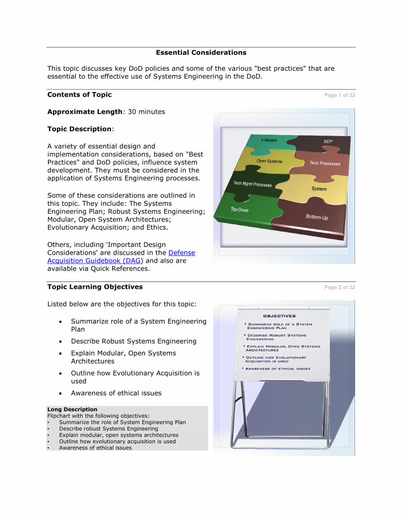
Essential Considerations
This topic discusses key DoD policies and some of the various "best practices" that are essential to the effective use of Systems Engineering in the DoD.
Contents of Topic Page 1 of 22
Approximate Length: 30 minutes
Topic Description:
A variety of essential design and
implementation considerations, based on "Best Practices" and DoD policies, influence system development. They must be considered in the application of Systems Engineering processes.
Some of these considerations are outlined in
this topic. They include: The Systems Engineering Plan; Robust Systems Engineering; Modular, Open System Architectures; Evolutionary Acquisition; and Ethics.
Others, including 'Important Design
Considerations' are discussed in the Defense Acquisition Guidebook (DAG) and also are available via Quick References.
Topic Learning Objectives Page 2 of 22
Listed below are the objectives for this topic:
• Summarize role of a System Engineering Plan
• Describe Robust Systems Engineering
• Explain Modular, Open Systems
Architectures
• Outline how Evolutionary Acquisition is used
• Awareness of ethical issues
Long Description
Flipchart with the following objectives: • Summarize the role of System Engineering Plan • Describe robust Systems Engineering • Explain modular, open systems architectures • Outline how evolutionary acquisition is used • Awareness of ethical issues

Role of the Systems Engineering Plan Page 3 of 22
Effective Systems Engineering is critical to the
successful development of defense systems. Within the DoD, a variety of initiatives have been implemented to increase overall Systems
Engineering capabilities and instill more discipline into the conduct of Systems Engineering. One of these initiatives is the mandated use of a Systems Engineering Plan
(SEP) by all programs. The emphasis is not so much on the format or existence of a SEP, but on the actual thinking, captured in the SEP, about how System Engineering will be
effectively employed within a given program.
An SEP is prepared by the Program Management Office and is one of the expected
outcomes of the Technical Planning Process. While the developer typically will produce a much more technically-detailed plan, sometimes called a Systems Engineering
Management Plan (SEMP), the SEP is a distinct government product. Ultimately the SEP, as it evolves, should be reflective of the contractor's proposed processes as well.
Developer Although the 'developer' is cited here as reflective of the defense industry, in some situations the DoD is both the 'acquirer' as well as the 'developer'. The same Systems Engineering processes apply, including the importance of an SEP, no matter what role is being filled!
Systems Engineering Planning Page 4 of 22
The initial Systems Engineering Plan (SEP) is prepared early in the Concept Refinement Phase. The SEP must be updated periodically,
at least for each new phase of development or within phases if needed. The level of fidelity and emphasis in the SEP will naturally evolve as the program progresses through its life
cycle. Program SEPs are formally assessed during milestone reviews.
The SEP should include assignment of
responsibilities to specific organizations; this allows for early identification of adequate capabilities and skill sets that will be needed to accomplish effective Systems Engineering for
the program. Once developed, the SEP must be used, including helping to frame contractual requirements. The program office should carefully monitor SEP execution and adjust as
necessary.

More detailed information about the SEP and other Systems Engineering policies and initiatives is available in the Quick References section.
Formally Assessed Key assessment areas evaluated at Milestone Reviews include the SEP's completeness in addressing the following areas: • What are the technical issues? • Who has responsibility and authority for managing the technical issues? • What processes and tools will be used to address the technical issues? • How will that process be managed and controlled? • How is that technical effort linked to the overall management of the program?
Contracting for Systems Engineering Page 5 of 22
Part of effective Systems Engineering includes motivating contractors to perform better Systems Engineering as well as make appropriate technical management investments.
Contracting approaches that can be used to aid in these efforts include:
• Making the Systems Engineering effort part of source selection (e.g., by putting formal evaluation of Systems
Engineering as part of the solicitation)
• Assessing a contractor's Systems Engineering past performance as part of source selection
• Using various contract types (e.g., incentive or award fees) to promote robust Systems Engineering
Information about contracting for Systems Engineering is in the Quick References section.
Knowledge Review Page 6 of 22
True or False?
The Systems Engineering Plan is first required at program initiation at Milestone B.
Select the correct answer.
A. True
B. False

Rules for Robust Flying Page 7 of 23
An insight as to what is meant by the term
"robust Systems Engineering" is to consider analogies with the following humorous (but true!) "Rules for Robust Flying" found posted
anonymously in a aircraft squadron ready room:
Regarding flying near the edges of the flight envelope:
1. Try to stay in the middle of the air.
2. Do not go near the edges of it.
3. The edges of the air can be recognized by the appearance of ground, buildings, sea, trees and interstellar space. It is much more difficult to fly there.
What is Robust Systems Engineering? Page 8 of 22
Robust Systems Engineering is the use of disciplined Systems Engineering processes in conjunction with robust product design. Robust Systems Engineering should be used when
developing system designs for systems for which operational performance envelopes are critical---a characteristic of most DoD systems.
A robust design is a flexible and adaptable one
that is tolerant of end product failure points and/or operating conditions. In robust design, errant excursions outside the operating 'flight envelope' of an end product do not necessarily result in catastrophic consequences.
During system design, failure modes and limits of end products are predicted. The resultant design solution should ensure that adequate margins of error for safety and survivability become an inherent part of product design.
Failure Modes and Limits An example of such a limit would be the predicted point and conditions of end product mechanical failure. A robust design would include a sensitivity analyses to ensure that catastrophic consequences do not occur within a suitable margin of error at that predicted point and for those conditions.

Robust Design Architectures Page 9 of 22
Robust Systems Engineering also helps to
generate flexible and adaptable designs. This is particularly important for DoD systems. Many of these systems have extremely long service
lives, yet must continue to be effective as technology and threats change around them.
Use of modular, open system architectures---key to flexible and adaptable designs---is another characteristic of robust Systems Engineering.
Modular design and use of open system architectures potentially allow for straight-forward replacement of critical modules in response to a changing threat, new technology
or technology obsolescence, or for different mission profiles.
Modular Design Page 10 of 22
Modular designs offer the potential for allowing critical end products to be replaced with
different ones, with equivalent interfaces and but having improved or better functionality. Over time, this allows for more flexible and timely product upgrades. Modular designs can also help to minimize total lifecycle support costs.
A necessary pre-condition to enable a modular design is that like functions are appropriately grouped together (partitioned) as part of Logical Analysis Process activities, in creating a
functional architecture. Such a functional partitioning is driven by technical considerations of maximizing cohesion while attempting to minimize coupling.
Later on these functional groupings are then synthesized into modular design elements during the Design Solution Process. Ideally, these modules should have single entry/exit points that are separately testable.
Interfaces are also defined during logical analysis and refined in design solution. Some of
these interfaces will be of particular interest and so identified as Key Interfaces. Modular designs, along with the identification of Key Interfaces, are pre-requisites for effective use of 'Open System Architectures.'
Logical Analysis Process One of the Systems Engineering Technical Processes, the Logical Analysis Process yields sets of logical solutions that improve understanding of requirements and their relationships. Using these logical solutions, performance parameters and constraints are allocated, and derived technical requirements to be used for the system design are defined.

Functional Architecture
An arrangement of functions and their sub-functions and interfaces (internal and external) that defines the execution sequencing, conditions for control or data flow, and the performance requirements to satisfy the requirements baseline.
Cohesion
A measure of the degree of encapsulation of only similar functions within a module.
Coupling A measure of the number of dependent interfaces between entities.
Design Solution Process One of the Systems Engineering Technical Processes, the Design Solution Process is used to transform the outputs of the Logical Analysis Process into a set of design solutions that are described by specifications and other design configuration descriptions.
Key Interfaces
A DoD-unique term, the DoD defines a Key Interface as a common boundary of 'interest' shared between system modules.
Key Interfaces are those that provide access to critical data, information, materiel or services; and/or are of high interest due to rapid technological change, a high rate of failure, or costliness of connected modules; or are important from an interoperability or net-centric standpoint. Some Key Interfaces are candidates for implementation via open systems.
What is an Open System Architecture? Page 11 of 22
An Open System Architecture (OSA) is appropriate for some module interfaces. An OSA uses commercial or non-proprietary (i.e., open system) standards for selected Key Interfaces. This potentially allows multiple vendors to implement different modules which may be totally different internally, but which externally function equivalently in their parent
system End Product.
The DoD defines an Open System as one with attributes of:
• Being based around a modular design, and
• Using of widely-supported and consensus-based ('open') standards for its key
interfaces, and
• Successfully verifying and validating the openness of these interfaces.
The use of open system standards for Key Interfaces may imply that a variety of open-
system commercial products are available which possess adequate capabilities and performance. Because of a wider customer base, these 'open' products may be cheaper and more supportable in many instances than equivalent custom-designed ones.
Standards
The DoD Architecture Framework (DoDAF) is mandated for use within the DoD. The DoDAF is used to formally document a program's operational, system and technical architectures via a series of highly-formatted 'views'. One of the technical architecture 'views' (TV-1) is a profile of those technical standards, implementation conventions, standards options, rules, and criteria that will be used for a system.
An extensive collection of DoD endorsed IT-related standards (many of them are open standards) has been created for consideration for use by programs. Those that are appropriate are incorporated into that program's technical architecture. Previously documented in the Joint Technical Architecture (JTA), this collection of standards is now part of the on-line Defense Information Standards Repository System (DISRonline).
More information about the DoDAF and the DISRonline is available in Quick References.

Open Systems and MOSA Page 12 of 62
Other advantages of open system designs are that they:
• Better adapt to evolving requirements and threats
• Promote easier technology transition • Facilitate system integration efforts
• Contribute to a 'robust' design • Reduce development time and lifecycle
costs
• Enhance interoperability, reuse and supportability
• Provide better access to cutting-edge technologies
• Mitigate technology obsolescence and single-supplier risks
The DoD's Modular Open System Approach (MOSA) is a business and technical strategy that can facilitate effective open system usage. More information about the MOSA is available in Quick References.
Knowledge Review Page 13 of 22
Which of the following statements about robust Systems Engineering and Open Systems are correct?
Select all that apply.
A. Key aspects of robust Systems Engineering include robust design and use of
modular, open system architectures.
B. Enablers for effective use of Open System Architectures are a modular design
and the identification of Key Interfaces.
C. The DoD has mandated the use of open systems standards for all external
system interfaces.
D. The Logical Analysis Process and the Design Solution Process play important
roles in modular design.
E. Considerations for effective functional partitioning include maximizing coupling
and minimizing cohesion.
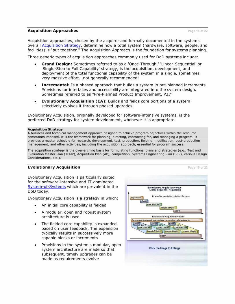
Acquisition Approaches Page 14 of 22
Acquisition approaches, chosen by the acquirer and formally documented in the system's
overall Acquisition Strategy, determine how a total system (hardware, software, people, and facilities) is "put together." The Acquisition Approach is the foundation for systems planning.
Three generic types of acquisition approaches commonly used for DoD systems include:
• Grand Design: Sometimes referred to as a 'Once-Through,' 'Linear-Sequential' or 'Single-Step to Full Capability' strategy, is the acquisition, development, and deployment of the total functional capability of the system in a single, sometimes very massive effort...not generally recommended!
• Incremental: Is a phased approach that builds a system in pre-planned increments. Provisions for interfaces and accessibility are integrated into the system design. Sometimes referred to as "Pre-Planned Product Improvement, P3I"
• Evolutionary Acquisition (EA): Builds and fields core portions of a system
selectively evolves it through phased upgrades
Evolutionary Acquisition, originally developed for software-intensive systems, is the preferred DoD strategy for system development, whenever it is appropriate.
Acquisition Strategy A business and technical management approach designed to achieve program objectives within the resource constraints imposed. It is the framework for planning, directing, contracting for, and managing a program. It provides a master schedule for research, development, test, production, fielding, modification, post-production management, and other activities, including the acquisition approach, essential for program success.
The acquisition strategy is the over-arching basis for formulating functional plans and strategies (e.g., Test and Evaluation Master Plan (TEMP), Acquisition Plan (AP), competition, Systems Engineering Plan (SEP), various Design Considerations, etc.).
Evolutionary Acquisition Page 15 of 22
Evolutionary Acquisition is particularly suited for the software-intensive and IT-dominated System-of-Systems which are prevalent in the
DoD today.
Evolutionary Acquisition is a strategy in which:
• An initial core capability is fielded
• A modular, open and robust system architecture is used
• The fielded core capability is expanded based on user feedback. The expansion
typically results in successively more capable blocks or increments
• Provisions in the system's modular, open
system architecture are made so that subsequent, timely upgrades can be made as requirements evolve

System-of-Systems
A set or arrangement of interdependent systems that are related or connected together to provide a given capability. The loss of any part of the system will generally significantly degrade the performance or capabilities of the whole.
Long Description
A diagram titled 'Evolutionary Acquisition versus Linear-Sequential Acquisition.' The linear-sequential acquisition process are Requirements, Design, Code & Unit Test, Integrate & Deploy and Support. The evolutionary acquisition process are Requirements development, experimentation, risk reduction, market analysis, etc. There are three small charts (Incr 1, Incr 2, Incr 3) that read: Design, Code & Unit Test, Integrate & Deploy. They all flow to Support.
Knowledge Review Page 16 of 22
Characteristics of Evolutionary Acquisition include:
Select all that apply.
A. The acquisition, development, and deployment of the total functional capability
of a system in a single effort
B. Dependent for success on use of a modular, open and robust system
architecture
C. Building and fielding core portions of a system by selectively evolving it through
phased upgrades
D. It is particularly suited for software-intensive and IT-dominated systems

Knowledge Review Page 17 of 22
Open Systems Architectures (OSAs) can be characterized as:
Select the correct answer.
A. Not related to "robust" system design
B. Making it difficult to accommodate future system changes
C. Facilitating technology and software upgrades over a system's life
D. Using proprietary standards for security enhancement
What are 'Ethics?' Page 18 of 22
'Ethics' are related to morality, but the two terms are not synonymous.
• Ethics: The rules or standards governing the conduct of a person or the conduct of the members of a profession
• Morality: Concern with the distinction between good and evil or right and wrong; right or good conduct
Morality can't be legislated and is considered an
individual issue. Ethics, on the other hand, can be legislated and can apply to groups.
Federal Government employees are required to follow the ethical standards promulgated by the Office of Government Ethics which are
grounded in public laws as well as those specified via organizational regulations, directives and orders.
Executive Order 12731 Page 19 of 22
This Presidential Executive Order establishes
the framework for ethical conduct by all government employees. Key points include:
• Avoiding financial conflicts impacting duty performance
• Not using information for private
financial gain • Prohibition on solicitation for financial
gain
• Not using public office for financial gain • Avoiding inappropriate outside
employment • Good faith discharge of financial
obligations • Adherence to equal opportunity laws • Disclosure of waste, fraud, abuse and
corruption to appropriate authorities • Avoidance of the appearance of non-
ethical behavior
The complete text of this Executive Order can be accessed via the Quick References section.
Ethics Resources Page 20 of 22
A Continuous Learning Module (CLM) on Ethics, which is part of the required training for all
DoD acquisition workforce employees, is available. For details on the registration process for this module, click here.
The U.S. Office of Government Ethics (OGE) Web site contains a variety of resources related to specific laws and regulations related to the ethics requirements for government employees.
Finally, The International Council on Systems Engineering (INCOSE), a not-for-profit
international body promoting the application of an interdisciplinary approach and means to enable the realization of successful systems, has developed a suggested code of ethics for engineering professionals. It is well worth reading.
Both OGE and INCOSE ethics resources can be accessed via the Quick References section.
Ethics Training Registration To register for the Ethics training module, visit the DAU Continuous Learning Center at http://clc.dau.mil and follow the directions and links provided in the 'Register' section.

Review of Objectives Page 21 of 22
Essential considerations that affect the conduct of Systems Engineering within a DoD program include:
• System Engineering Plan (SEP): A detailed formulation of actions that should guide all technical aspects of an acquisition program. It is established early in the program and updated at each subsequent milestone and as needed. It is a living document, tailored to the program, and a roadmap that supports program
management.
• Robust Systems Engineering: Refers to the use of a disciplined Systems Engineering approach in conjunction with a robust product design. A 'robust design'
is one that:
o Encompasses design and process flexibility that rapidly and affordably accommodates change
o Is tolerant of end product failure points and/or operating conditions
o Employs modular architectures with open systems standards used for selected Key Interfaces
Review of Objectives (cont'd) Page 22 of 22
• Open Systems Architectures: Use technical interface standards based on non-proprietary, "open" standards that are widely used, consensus-based, published and maintained by recognized industry standards organizations. The Modular Open
Systems Approach (MOSA) is a DoD business and technical strategy for fostering effective use of open systems.
• Evolutionary Acquisition: A type of acquisition approach used at the system level that builds and fields core portions of a system by selectively evolving it through
phased upgrades. It is the preferred DoD strategy for software-intensive system developments, especially for network-centric or information based systems. It should be used for other types of systems whenever appropriate. The flexibility inherent in modular, open system architectures facilitates effective use of Evolutionary
Acquisition.
• Ethics: Ethical behavior and conduct is required by all DoD employees. Presidential Executive Order 12731 established the framework for ethical conduct by all
government employees. The U.S. Office of Government Ethics (OGE) contains references on specific laws and regulations related to ethical behavior.

Summary - Introduction to Systems Engineering
This lesson summarizes the Introduction to Systems Engineering lesson.
Recap of Lesson Page 1 of 12
The topics that were covered in this lesson included:
• How Systems Engineering can be
described
• DoD Systems Engineering processes
• Roles played by Systems Engineering standards
• Technical Foundations: 'V' models and their applications
• Considerations regarding: Role of the
Systems Engineering Plan, robustness, open systems, Evolutionary Acquisition and Workplace Ethics
Description of Systems Engineering Page 2 of 12
There are many ways to describe the discipline of Systems Engineering. Systems Engineering as defined in the DoD Defense Acquisition Guidebook is:
Systems Engineering is an interdisciplinary approach encompassing the
entire technical effort to evolve and verify an integrated and total life cycle
balanced set of system, people, and process solutions that satisfy customer needs.
In the DoD, Systems Engineering is typically implemented via Integrated Product and
Process Development (IPPD). IPPD is done by multi-disciplined teams of subject-matter experts, typically formally charted as Integrated Product Teams (IPTs).
Because the cost to implement system changes increases dramatically as a program matures, Systems Engineering can have great impacts on Total Life Cycle Systems Management (TLCSM). Thorough analyses of TLCSM issues, done as part of the Systems
Engineering effort, can reveal an optimum, life-cycle balanced design that prevents costly later technical changes.

Definition of a System Page 3 of 12
A system consists of:
1. One or more 'End Products' that will
perform the intended operational functions expected by the customer and within constraints set by other stakeholders
2. A set of 'Enabling Products' that perform life cycle service functions
Each End Product will have its unique and
common set of Enabling Products that will enable the End Product to be designed, realized, deployed, operated, maintained and, when the End Product has completed its useful
life, to be properly disposed.
Systems Engineering Processes Page 4 of 12
Systems Engineering processes outlined in the Defense Acquisition Guidebook (DAG) consist of:
• Technical Processes: These processes are used to design the system products, including the operational/mission products and supporting or enabling products required to produce, support, operate, or dispose of system products. Technical Processes include those for:
o Top-down design: Requirements Development; Logical Analysis; and Design Solution
o Bottom-up product realization: Implementation; Integration; Verification; Validation; and Transition
• Technical Management Processes: These processes are used to manage the technical development of the system, including its supporting or enabling products.
These Technical Management Processes are: Technical Planning; Requirements
Management; Interface Management; Risk Management; Configuration Management; Technical Data Management; Technical Assessment; and Decision Analysis.

Systems Engineering Standards Page 5 of 12
At one time MIL-STD-499A was the DoD's sole Systems Engineering standard. As part of the
DoD Acquisition Reform movement, it, as well as numerous other DoD-unique standards were canceled. Relevant commercial Systems Engineering standards include:
• EIA 632: Processes for Engineering Systems
• IEEE 1220: Standard for Application and Management of Systems Engineering
• ISO/IEC 15288: Systems Engineering--Lifecycle Processes
All these standards have relevance to various parts the Systems Engineering process and are selectively used, depending on a project's needs.
DoD Systems Engineering processes are derived in part from EIA 632.
Role of the 'System Model' Page 6 of 12
Existence of a comprehensive system model is
critical. Such a model allows for the uniform application of various Systems Engineering processes and can be used to facilitate:
• Planning and managing the Systems Engineering effort by:
o Identifying products to be engineered
o Assigning of work packages
o Making cost estimates o Assessing risks and opportunities
• Organizing IPTs and facilitating team work
• Orchestrating incremental Technical Reviews
• Defining and structuring specifications, including interfaces
• Creating system structure • Enabling product identification and
development
Within the DoD, a Work Breakdown Structure (WBS) is commonly used to formally document the system model. MIL-HDBK-881A provides detailed guidance.
Long Description
Flowchart titled 'Generic System Model.' System flows to End Product, Development & Integration Products, Production Products, Test Products, Test Products, Operations Products, Logistics Products. End Product flows to two Subsystem boxes.

Engineering 'V' Model Page 7 of 12
A system structure based on a hierarchy of
layered system models provides the basis for both Top-Down System Design and Bottom-Up Product Realization.
When arranged in the fashion shown here, it is referred to as a 'V' model for obvious reasons.
A similar 'V' format can be used to structure
key Systems Engineering processes in the context of the Defense Acquisition Framework.
Used in this manner, the 'V' model helps to ensure that required technical exit and entry criteria associated with each phase of the life
cycle are met.

Systems Engineering Plan (SEP) Page 8 of 12
A Systems Engineering Plan (SEP) is a detailed
formulation of actions that should guide all technical aspects of an acquisition program. The SEP is a living document, tailored to the
program, and is a technical roadmap that supports program management as well as being the basis to help frame the program's contractual technical requirements. The government program office creates the SEP.
The initial SEP should be established early in the Concept Refinement Phase. The level of fidelity and emphasis in the SEP will evolve as the program progresses.
SEPs must be updated and submitted as part of
each milestone review over the life of the system.
Robust System Engineering Page 9 of 12
Robust Systems Engineering is the use of a disciplined Systems Engineering process in
conjunction with a robust product design. A "Robust Design" is one that encompasses design and process flexibility which allows the rapid and affordable accommodation of change over the system life cycle and which is tolerant of end product failure points.
One of the keys to robust design is modular approach and the use of open systems architectures where appropriate. Open systems architectures use technical interface
standards based on non-proprietary, "open" standards that are widely used, consensus-based, published and maintained by recognized industry standards organizations. Selected Key Interfaces in a system should use these where appropriate.
The Modular Open Systems Approach (MOSA) is the DoD business and technical strategy for fostering effective use of open systems.
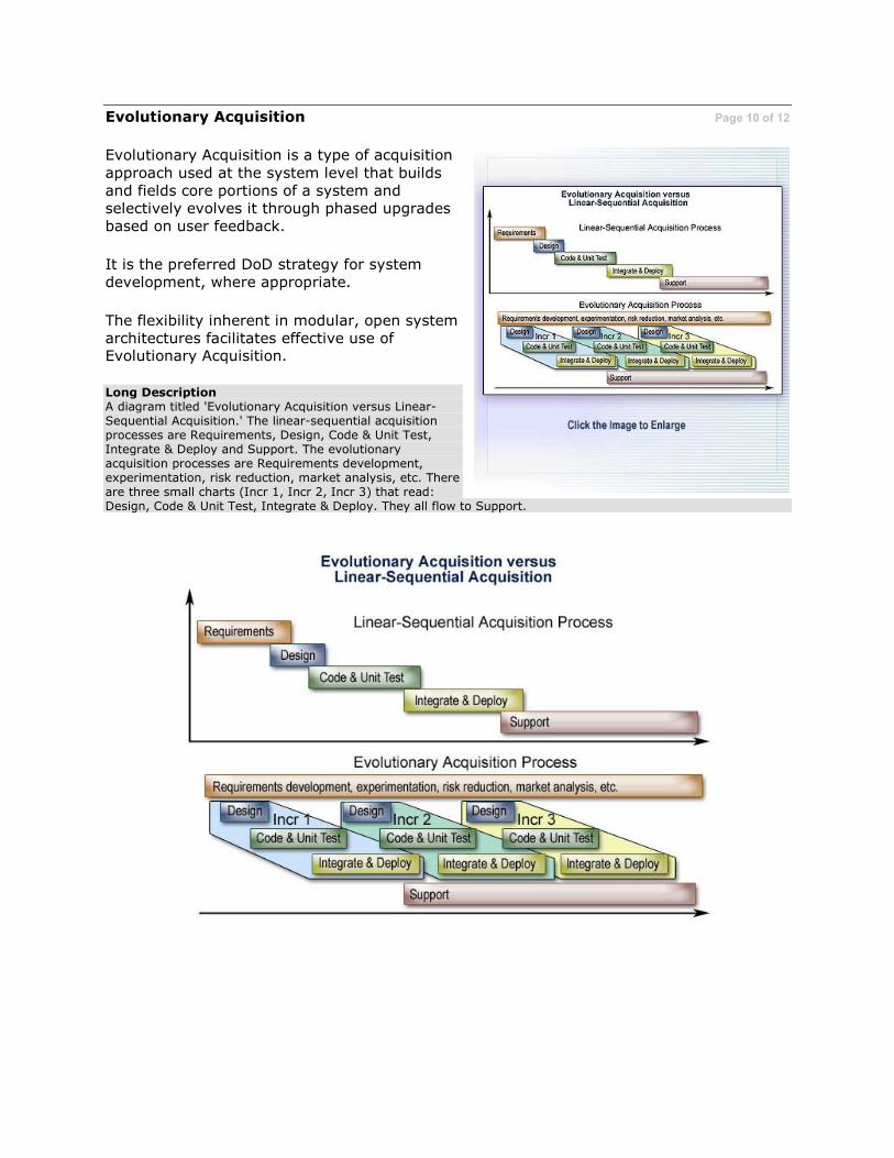
Evolutionary Acquisition Page 10 of 12
Evolutionary Acquisition is a type of acquisition
approach used at the system level that builds and fields core portions of a system and selectively evolves it through phased upgrades based on user feedback.
It is the preferred DoD strategy for system development, where appropriate.
The flexibility inherent in modular, open system architectures facilitates effective use of Evolutionary Acquisition.
Long Description A diagram titled 'Evolutionary Acquisition versus Linear-Sequential Acquisition.' The linear-sequential acquisition processes are Requirements, Design, Code & Unit Test, Integrate & Deploy and Support. The evolutionary acquisition processes are Requirements development, experimentation, risk reduction, market analysis, etc. There are three small charts (Incr 1, Incr 2, Incr 3) that read: Design, Code & Unit Test, Integrate & Deploy. They all flow to Support.

Workplace Ethics Page 11 of 12
Presidential Executive Order 12731 establishes
the framework for ethical conduct by all government employees. Key points include:
• Avoiding financial conflicts impacting duty performance
• Not using information for private
financial gain • Prohibition on solicitation for financial
gain
• Not using public office for financial gain • Avoiding inappropriate outside
employment • Good faith discharge of financial
obligations • Adherence to equal opportunity laws • Disclosure of waste, fraud, abuse and
corruption to appropriate authorities • Avoidance of the appearance of non-
ethical behavior
Lesson Summary Page 12 of 12
This lesson defined Systems Engineering and
provided foundation technical information needed to understand how DoD Systems Engineering processes are applied. These processes are:
• Technical Processes: Used in top-down design and bottom-up product realization throughout the Systems Engineering effort
• Technical Management Processes: Used to plan, control and assess the application of various Technical Processes
Careful and rigorous application of both sets of these processes is essential to Systems Engineering success. So use them both!


