Embed Size (px)
Citation preview

Curriculum Training
Introduction to Jaguar
General Information
E63055
Technical Training INTR 05 en 08/2005INTR: General Info

To the best of our knowledge, the illustrations, technical information, data and descriptions in this issue were correct at the time
of going to print. The right to change prices, specifications, equipment and maintenance instructions at any time without notice
is reserved as part of our policy of continuous development and improvement for the benefit of our customers.
No part of this publication may be reproduced, stored in a data processing system or transmitted in any form, electronic,
mechanical, photocopy, recording, translation or by any other means without prior permission of Premier Automotive Group.
No liability can be accepted for any inaccuracies in this publication, although every possible care has been taken to make it as
complete and accurate as possible.
Copyright ©2005

Please remember that our training literature has been prepared for TRAINING PURPOSES only. Repairs and
adjustments MUST always be carried out according to the instructions and specifications in the workshop literature.
Please make full use of the training offered by Technical Training to gain extensive knowledge of both theory
and practice.
1Technical Training
Preface
12/15/2005 General Information
PAGE
Lesson 1 – Introduction
6Welcome.......................................................................................................................................................
7Acronyms.....................................................................................................................................................
Lesson 2 – History
10Milestones: The 1920s and 30s..................................................................................................................
11Milestones: The 1940s and 50s..................................................................................................................
12Milestones: The 1960s................................................................................................................................
13Milestones: The 1970s................................................................................................................................
14Milestones: The 1980s................................................................................................................................
15Milestones: The 1990s................................................................................................................................
16Milestones: The New Millennium.............................................................................................................
Lesson 3 – Customer Satisfaction
17Overview......................................................................................................................................................
18Jaguar Customer Satisfaction Index (CSI)..............................................................................................
Lesson 4 – Service Training
23Jaguar Service Training.............................................................................................................................
24The Journey to Excellence.........................................................................................................................
Technical Training2
Table of Contents
General Information 12/15/2005

Lesson 5 – Technical Assistance
25Technical Service Helpline.........................................................................................................................
28Field Service Engineers..............................................................................................................................
Lesson 6 – Technical Publications
29Electrical Guides.........................................................................................................................................
33Technical Guides.........................................................................................................................................
36Diagnostic Trouble Code (DTC) Summaries............................................................................................
38Service Bulletins..........................................................................................................................................
44Parts Bulletins.............................................................................................................................................
Lesson 7 – Online Technical Resources
46Overview......................................................................................................................................................
47Global Technical Reference (GTR)...........................................................................................................
50Jaguar Cars North American Product Support......................................................................................
Lesson 8 – Tools and Equipment
55Special Tools................................................................................................................................................
56Worldwide Diagnostic System (WDS)......................................................................................................
57Integrated Diagnostic Software (IDS).......................................................................................................
58Handheld Scanners.....................................................................................................................................
Lesson 9 – Vehicle Models
59XK Models...................................................................................................................................................
3Technical Training
Table of Contents
12/15/2005 General Information

60XJ Models....................................................................................................................................................
61S-TYPE Models..........................................................................................................................................
62X-TYPE Models..........................................................................................................................................
63Vehicle Identification Numbers (VIN)......................................................................................................
Technical Training4
Table of Contents
General Information 12/15/2005

Workshop safety
This page highlights the general observations expectedwhile attending this training program, and itscontinuation upon returning to your place of work.
General
While working on all vehicles, the following itemswhere available should always be used:
• Fender covers
• Seat covers
• Floor protection
Safety
All precautions must be taken and observed at all times,to prevent injury or damage to the following:
• Yourself
• Customer's property
• Workshop equipment
• Work place colleagues
Operating guidelines
While using any piece of workshop equipment:
The manufacturer's guidelines and warning labels mustbe followed.
This will ensure correct use and application at all times.
Seek the necessary advice or training where equipmentusage is unclear.
Chemicals, Oils and Solvents
Follow all manufacturer's warnings and labels; also takeinto account local disposal regulations when workingwith chemicals, oils or solvents.
Ensure that all risks are completely minimized.
Make sure that all protective items of clothing are wornwhere required e.g.
• Eye protection
• Gloves
• Coveralls
• Footwear
System capping
Upon disconnecting components from a system, takeall precautions necessary to prevent systemcontamination or environmental leakage.
Fit relevant plugs or caps i.e. to pipes, unions andcomponent orifices etc.
Updates
Keep abreast of all relevant changes that affect yourrole within the dealership, by monitoring all factoryissued documentation.
Driving
Operating vehicle features, such as ICE, mobile phonesand CD player equipment etc., can cause a momentarydistraction while driving.
Follow all traffic regulations when operating vehiclesystems or using diagnostic equipment while on the move.
Mobile diagnostic equipment operation may requirethe use of an assistant.
5
Safety and Precautions
12/15/2005 General Information
A Welcome Message to the New JaguarTechnician
Introduction to Jaguar is intended not only to provide
you with the information you need on an ongoing basis,
but also to give a historical and cultural perspective on
the Jaguar Marque. You might have already noticed a
difference between the Jaguar training center and other
automotive training centers. The Jaguar training
environment is sophisticated yet comfortable, so that
you will enjoy your stay while you gain important
job-related skills and knowledge. Jaguar trainers are
highly experienced and prepare their classrooms and
lesson plans carefully for each class they teach. You
will find that the course presentations and student
materials are designed to respect you as a professional
and to adjust to your individual training needs.
We hope the training that your are about to experience
begins to express how Jaguar customers and their
vehicles need to be treated in your dealership. Of course,
fixing cars right the first time is important and expected
but Jaguar also offers distinction in the marketplace.
The Jaguar difference is that of individual attention to
detail and of treating customers and fellow employees
with the utmost respect.
Over the next few days, we ask that you look, listen,
and participate. If you are not already a Jaguar
enthusiast, you soon will be. Welcome to Jaguar.
The Jaguar University Team
Technical Training6
Lesson 1 – IntroductionWelcome
General Information 12/15/2005
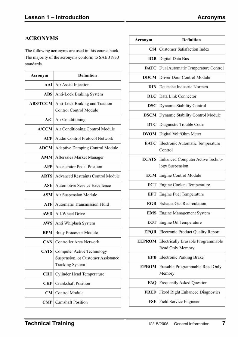
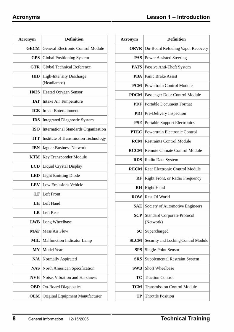
ACRONYMS
The following acronyms are used in this course book.
The majority of the acronyms conform to SAE J1930
standards.
DefinitionAcronym
Air Assist InjectionAAI
Anti-Lock Braking SystemABS
Anti-Lock Braking and Traction
Control Control Module
ABS/TCCM
Air ConditioningA/C
Air Conditioning Control ModuleA/CCM
Audio Control Protocol NetworkACP
Adaptive Damping Control ModuleADCM
Aftersales Market ManagerAMM
Accelerator Pedal PositionAPP
Advanced Restraints Control ModuleARTS
Automotive Service ExcellenceASE
Air Suspension ModuleASM
Automatic Transmission FluidATF
All-Wheel DriveAWD
Anti Whiplash SystemAWS
Body Processor ModuleBPM
Controller Area NetworkCAN
Computer Active Technology
Suspension, or Customer Assistance
Tracking System
CATS
Cylinder Head TemperatureCHT
Crankshaft PositionCKP
Control ModuleCM
Camshaft PositionCMP
DefinitionAcronym
Customer Satisfaction IndexCSI
Digital Data BusD2B
Dual Automatic Temperature ControlDATC
Driver Door Control ModuleDDCM
Deutsche Industrie NormenDIN
Data Link ConnectorDLC
Dynamic Stability ControlDSC
Dynamic Stability Control ModuleDSCM
Diagnostic Trouble CodeDTC
Digital Volt/Ohm MeterDVOM
Electronic Automatic Temperature
Control
EATC
Enhanced Computer Active Techno-
logy Suspension
ECATS
Engine Control ModuleECM
Engine Coolant TemperatureECT
Engine Fuel TemperatureEFT
Exhaust Gas RecirculationEGR
Engine Management SystemEMS
Engine Oil TemperatureEOT
Electronic Product Quality ReportEPQR
Electrically Erasable Programmable
Read Only Memory
EEPROM
Electronic Parking BrakeEPB
Erasable Programmable Read Only
Memory
EPROM
Frequently Asked QuestionFAQ
Fixed Right Enhanced DiagnosticsFRED
Field Service EngineerFSE
7Technical Training
AcronymsLesson 1 – Introduction
12/15/2005 General Information
DefinitionAcronym
General Electronic Control ModuleGECM
Global Positioning SystemGPS
Global Technical ReferenceGTR
High-Intensity Discharge
(Headlamps)
HID
Heated Oxygen SensorH02S
Intake Air TemperatureIAT
In-car EntertainmentICE
Integrated Diagnostic SystemIDS
International Standards OrganizationISO
Institute of Transmission TechnologyITT
Jaguar Business NetworkJBN
Key Transponder ModuleKTM
Liquid Crystal DisplayLCD
Light Emitting DiodeLED
Low Emissions VehicleLEV
Left FrontLF
Left HandLH
Left RearLR
Long WheelbaseLWB
Mass Air FlowMAF
Malfunction Indicator LampMIL
Model YearMY
Normally AspiratedN/A
North American SpecificationNAS
Noise, Vibration and HarshnessNVH
On-Board DiagnosticsOBD
Original Equipment ManufacturerOEM
DefinitionAcronym
On-Board Refueling Vapor RecoveryORVR
Power Assisted SteeringPAS
Passive Anti-Theft SystemPATS
Panic Brake AssistPBA
Powertrain Control ModulePCM
Passenger Door Control ModulePDCM
Portable Document FormatPDF
Pre-Delivery InspectionPDI
Portable Support ElectronicsPSE
Powertrain Electronic ControlPTEC
Restraints Control ModuleRCM
Remote Climate Control ModuleRCCM
Radio Data SystemRDS
Rear Electronic Control ModuleRECM
Right Front, or Radio FrequencyRF
Right HandRH
Rest Of WorldROW
Society of Automotive EngineersSAE
Standard Corporate Protocol
(Network)
SCP
SuperchargedSC
Security and Locking Control ModuleSLCM
Single-Point SensorSPS
Supplemental Restraint SystemSRS
Short WheelbaseSWB
Traction ControlTC
Transmission Control ModuleTCM
Throttle PositionTP
Technical Training8
Lesson 1 – IntroductionAcronyms
General Information 12/15/2005
DefinitionAcronym
Vehicle Configuration and Test
System
VCATS
Variable-Assist Power SteeringVAPS
Vanden PlasVDP
Vehicle Emergency Message SystemVEMS
Vehicle Identification NumberVIN
Vehicle Vibration AnalyzerVVA
Variable Valve TimingVVT
Worldwide Diagnostic SystemWDS
Workshop ManualWSM
Wide-Open ThrottleWOT
9Technical Training
AcronymsLesson 1 – Introduction
12/15/2005 General Information

MILESTONES: THE 1920s AND 30s
• 1922 – William Lyons and William Walmsleypartner to found the Swallow Sidecar Company
• 1928 – Swallow Sedan introduced
• 1935 – SS 100 sports car introduced
• 1935 – Jaguar name chosen for SS cars
E66663
Technical Training10
Lesson 2 – HistoryMilestones: The 1920s and 30s
General Information 12/15/2005
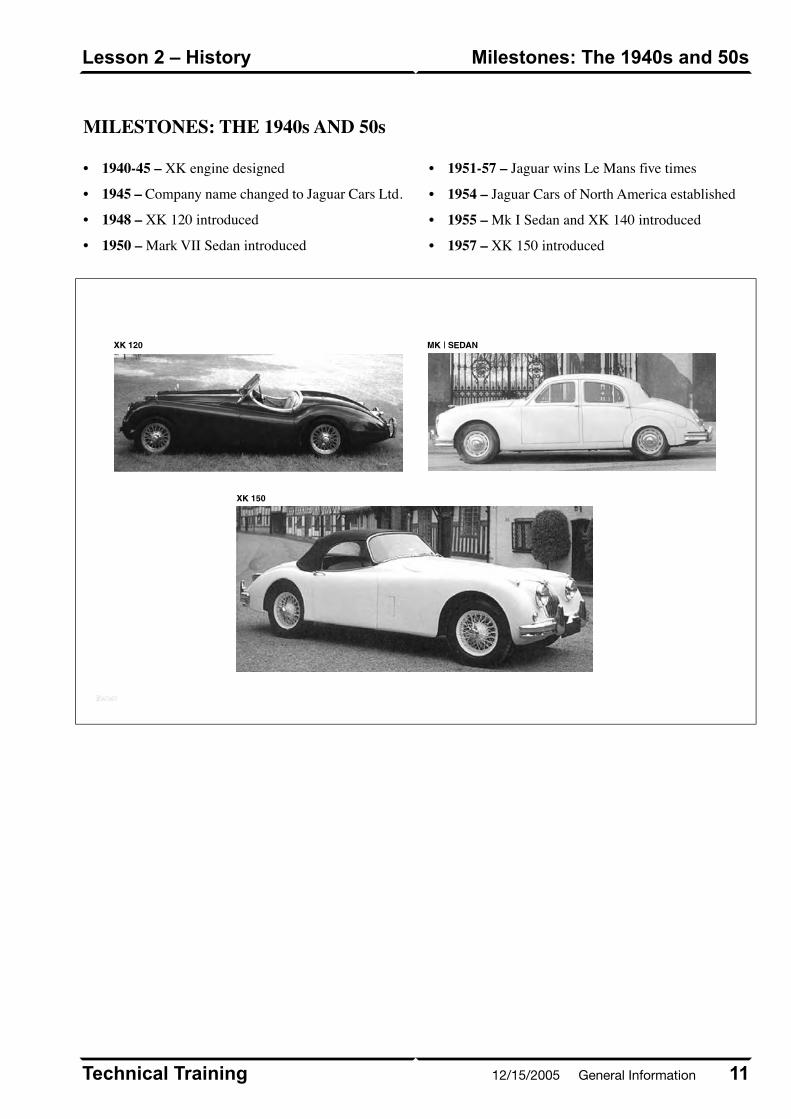
MILESTONES: THE 1940s AND 50s
• 1940-45 – XK engine designed
• 1945 – Company name changed to Jaguar Cars Ltd.
•
•
1948 – XK 120 introduced
1950 – Mark VII Sedan introduced
• 1951-57 – Jaguar wins Le Mans five times
• 1954 – Jaguar Cars of North America established
• 1955 – Mk I Sedan and XK 140 introduced
• 1957 – XK 150 introduced
EE6666666644
11Technical Training
Milestones: The 1940s and 50sLesson 2 – History
12/15/2005 General Information
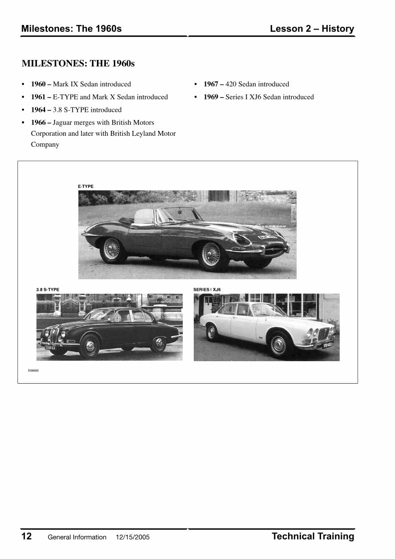
MILESTONES: THE 1960s
• 1960 – Mark IX Sedan introduced
• 1961 – E-TYPE and Mark X Sedan introduced
•
•
1964 – 3.8 S-TYPE introduced
• 1966 – Jaguar merges with British MotorsCorporation and later with British Leyland MotorCompany
• 1967 – 420 Sedan introduced
• 1969 – Series I XJ6 Sedan introduced
E66665
Technical Training12
Lesson 2 – HistoryMilestones: The 1960s
General Information 12/15/2005
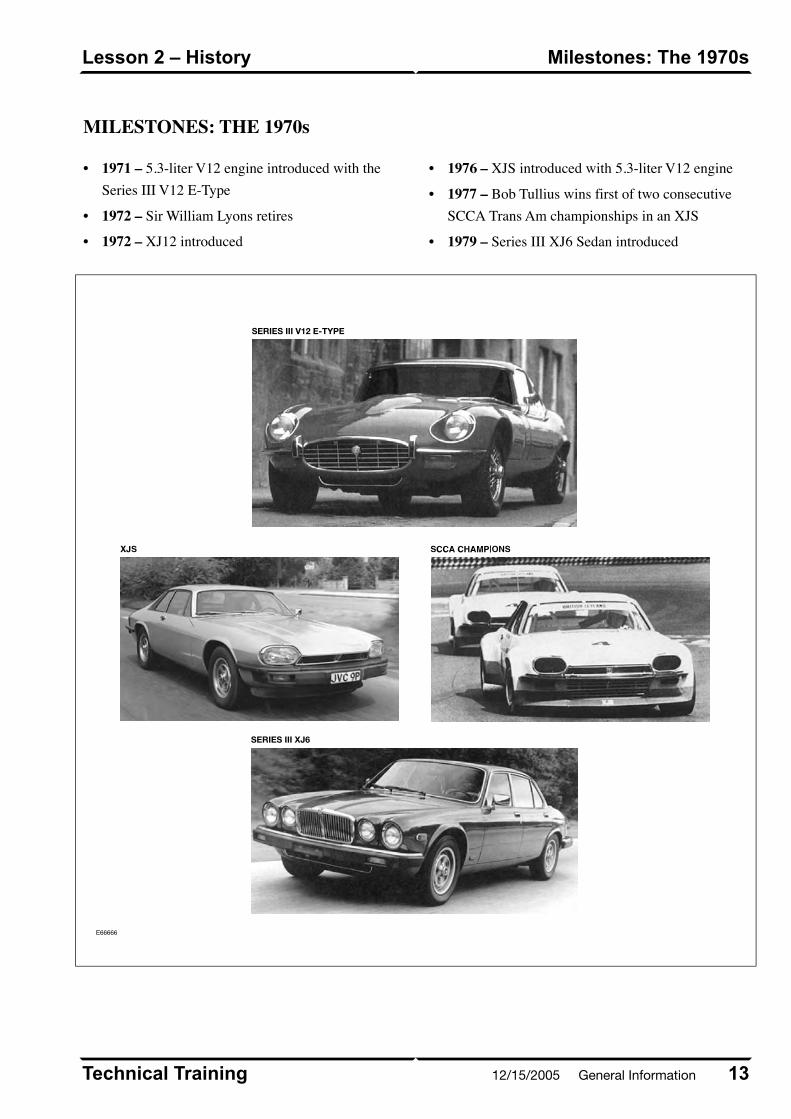
MILESTONES: THE 1970s
• 1971 – 5.3-liter V12 engine introduced with theSeries III V12 E-Type
• 1972 – Sir William Lyons retires
• 1972 – XJ12 introduced
• 1976 – XJS introduced with 5.3-liter V12 engine
• 1977 – Bob Tullius wins first of two consecutiveSCCA Trans Am championships in an XJS
• 1979 – Series III XJ6 Sedan introduced
E66666
13Technical Training
Milestones: The 1970sLesson 2 – History
SERIES III V12 E-TYPE
SERIES III XJ6
12/15/2005 General Information
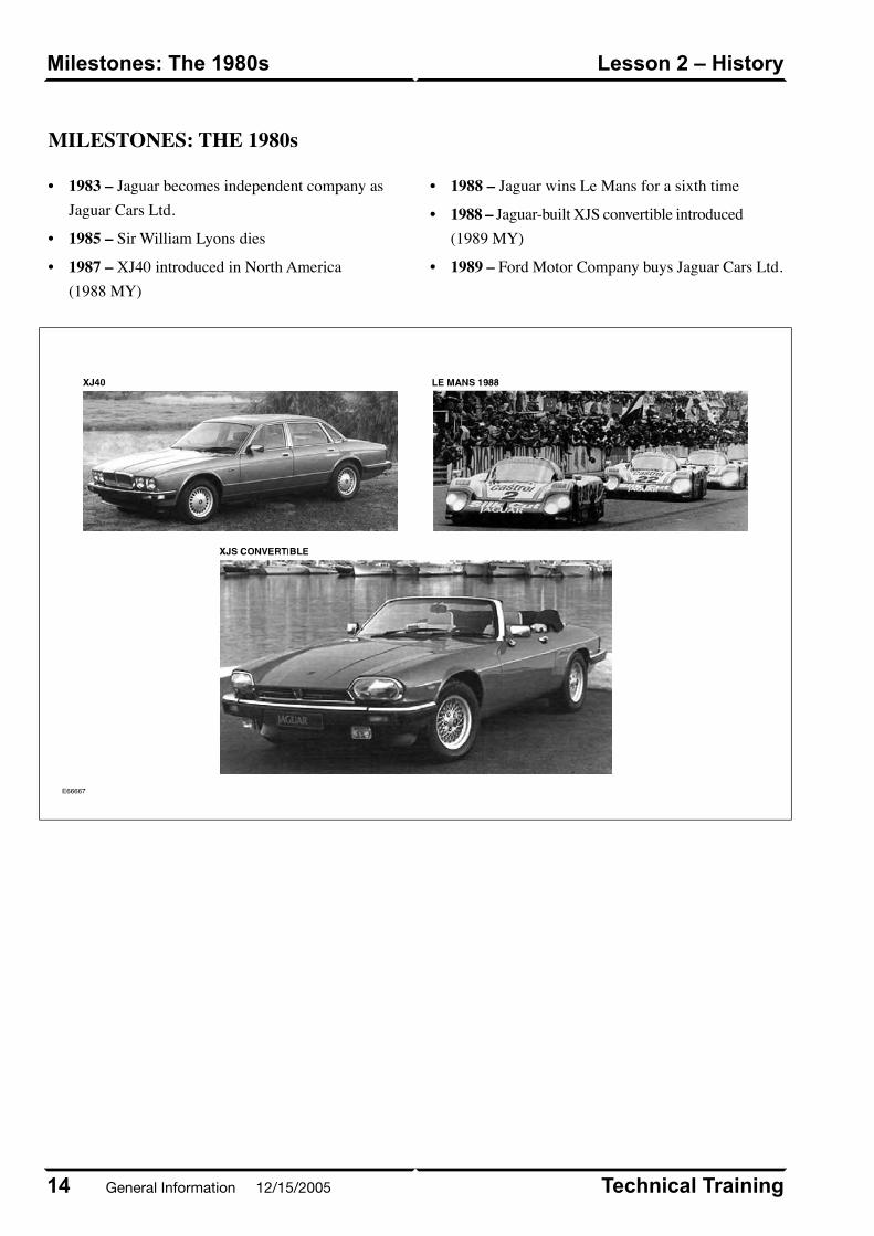
MILESTONES: THE 1980s
• 1983 – Jaguar becomes independent company asJaguar Cars Ltd.
• 1985 – Sir William Lyons dies
• 1987 – XJ40 introduced in North America(1988 MY)
• 1988 – Jaguar wins Le Mans for a sixth time
• 1988 – Jaguar-built XJS convertible introduced(1989 MY)
• 1989 – Ford Motor Company buys Jaguar Cars Ltd.
E66667
Technical Training14
Lesson 2 – HistoryMilestones: The 1980s
General Information 12/15/2005
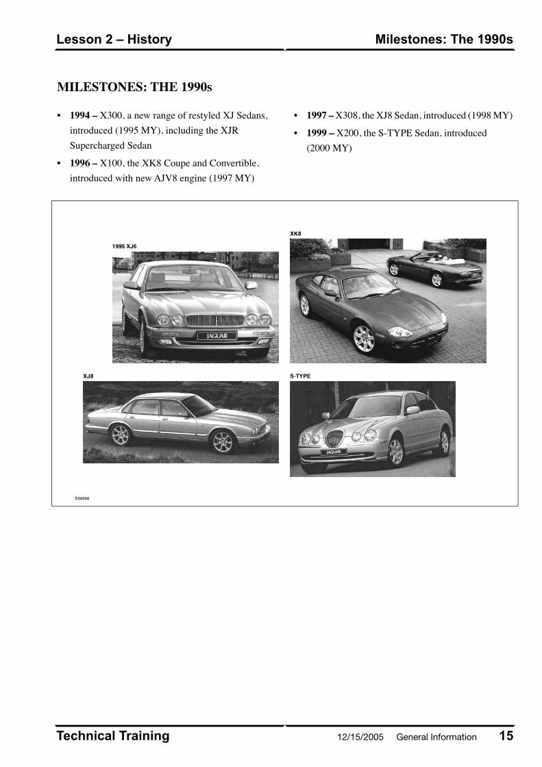
MILESTONES: THE 1990s
• 1994 – X300, a new range of restyled XJ Sedans,introduced (1995 MY), including the XJRSupercharged Sedan
• 1996 – X100, the XK8 Coupe and Convertible,introduced with new AJV8 engine (1997 MY)
• 1997 – X308, the XJ8 Sedan, introduced (1998 MY)
• 1999 – X200, the S-TYPE Sedan, introduced(2000 MY)
E66668
15Technical Training
Milestones: The 1990sLesson 2 – History
12/15/2005 General Information
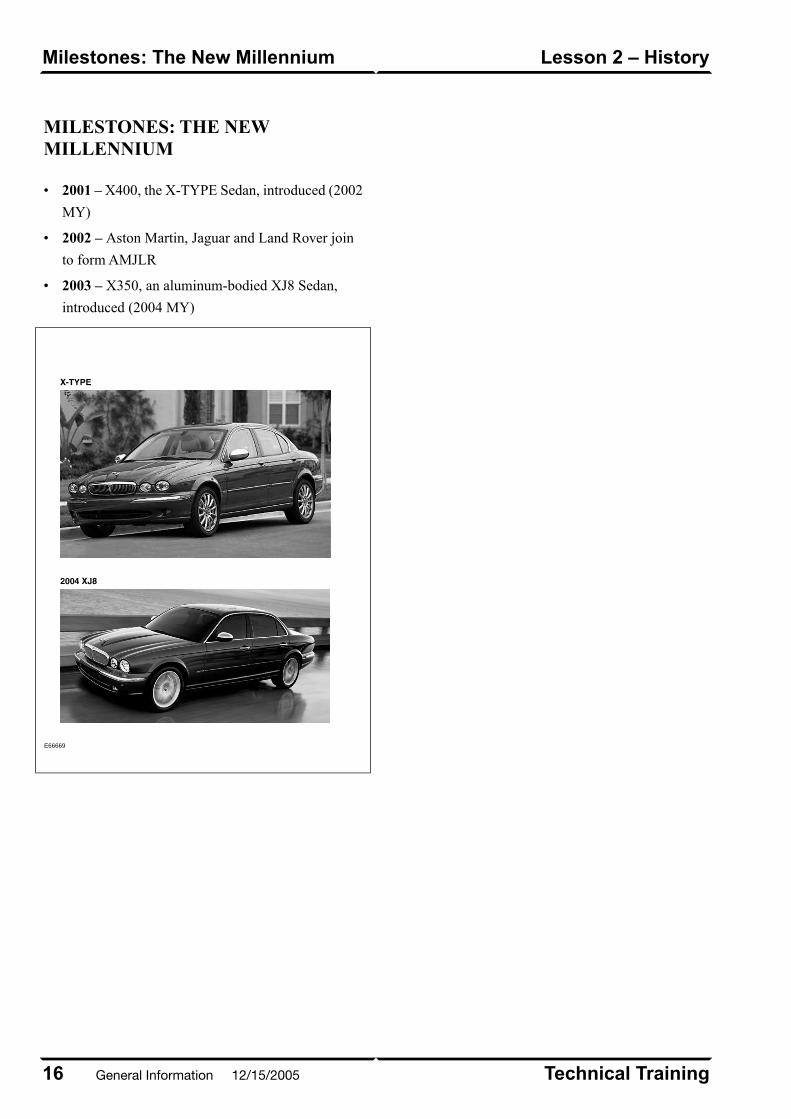
MILESTONES: THE NEWMILLENNIUM
• 2001 – X400, the X-TYPE Sedan, introduced (2002
MY)
• 2002 – Aston Martin, Jaguar and Land Rover join
to form AMJLR
• 2003 – X350, an aluminum-bodied XJ8 Sedan,
introduced (2004 MY)
E66669
Technical Training16
Lesson 2 – HistoryMilestones: The New Millennium
General Information 12/15/2005
OVERVIEW
In the increasingly competitive luxury car market, auto
manufacturers must continuously strive to maintain, and
increase, their share of that market. For Jaguar, a key
component in this effort is an attention to customer
satisfaction – satisfaction with both the quality of the
vehicles and the quality of the dealerships that sell and
service those vehicles. Understanding who those
customers are and seeking their feedback helps Jaguar
to identify both strengths and weaknesses in
manufacturer and dealership performance, and to make
improvements where necessary.
Jaguar Customers
Jaguar cars appeal to a distinctive group of people:
independent, highly successful individuals who have
achieved a substantial measure of professional and
personal accomplishment. They appreciate the refined
elegance and performance of their Jaguar automobile
and expect competent professional service and courteous
personal treatment from their Jaguar dealer.
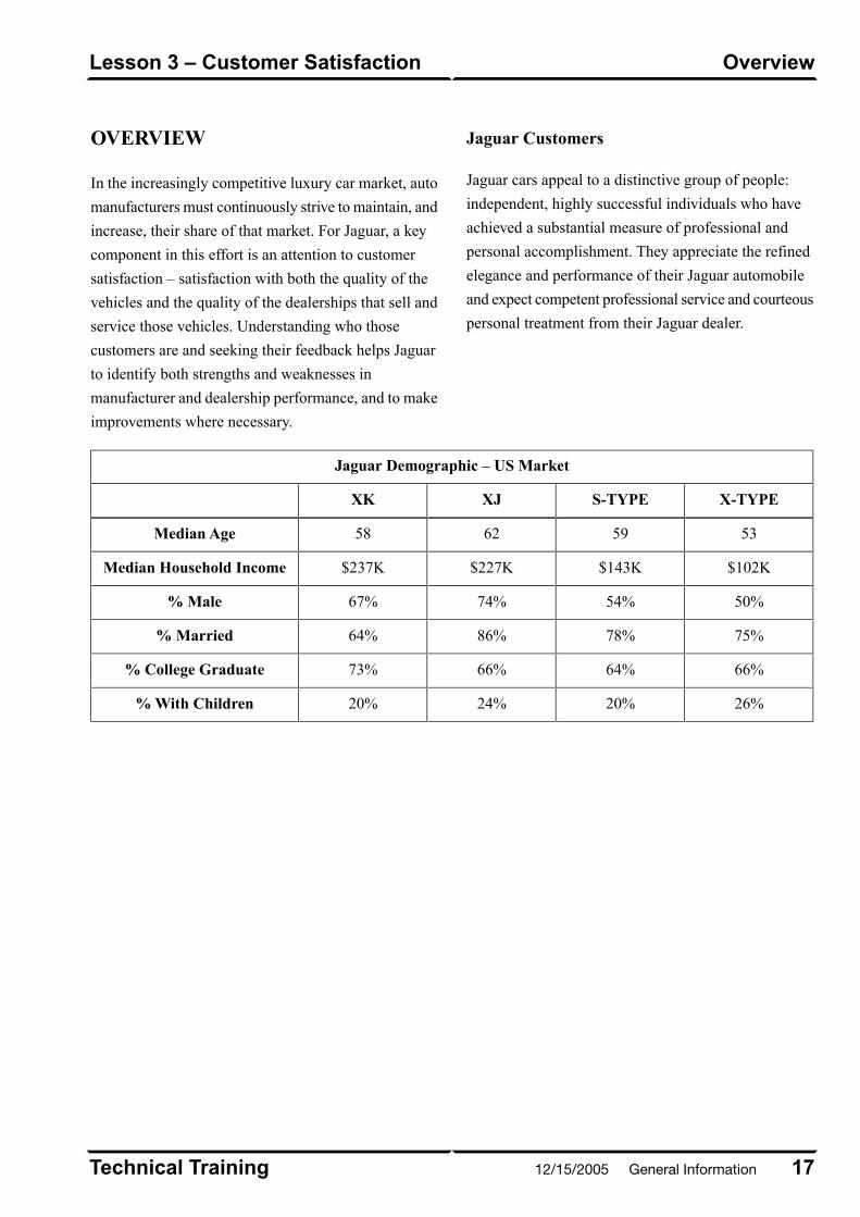
Jaguar Demographic – US Market
X-TYPES-TYPEXJXK
53596258Median Age
$102K$143K$227K$237KMedian Household Income
50%54%74%67%% Male
75%78%86%64%% Married
66%64%66%73%% College Graduate
26%20%24%20%% With Children
17Technical Training
OverviewLesson 3 – Customer Satisfaction
12/15/2005 General Information
JAGUAR CUSTOMERSATISFACTION INDEX (CSI)
Jaguar acquires dealership performance data through
customer surveys. The collected data is analyzed and
calculated into the Customer Satisfaction Index (CSI).
A summary of the CSI data is updated monthly in a
report available online.
What does the Jaguar CSI measure?
• Customer satisfaction
• Effectiveness of retail process
• Dealer diagnostics that improve customer handling
• Indications of how well we are building and
sustaining our evolving relationships with customers
Jaguar CSI Survey Process
The following outlines the survey process from the
customer experience to CSI reporting.
• Customer has a dealership experience
New vehicle purchase–
– Pre-owned vehicle purchase
– Vehicle lease
– Warranty claim is paid (service)
• Telephone call is made to the customer within seven
days to assess overall satisfaction
– If the customer cannot be contacted after 6
attempts, a survey is mailed
– Customer’s comments are posted on the CSI
website within 48 hours
• Customer will receive a survey via mail within 2
weeks of telephone call
• Customer has 6 weeks from time survey is mailed
to return survey
– Surveys returned outside the 6-week period will
be posted but will not count toward CSI score
• Month is closed on the last business day of the month
– All surveys posted by the 3rd business day of the
following month
– Monthly reports posted by 7th business day of
the following month
Technical Training18
Lesson 3 – Customer SatisfactionJaguar Customer Satisfaction Index(CSI)
General Information 12/15/2005

Sample Customer Survey
E66671
19Technical Training
Jaguar Customer Satisfaction Index(CSI)
Lesson 3 – Customer Satisfaction
12/15/2005 General Information
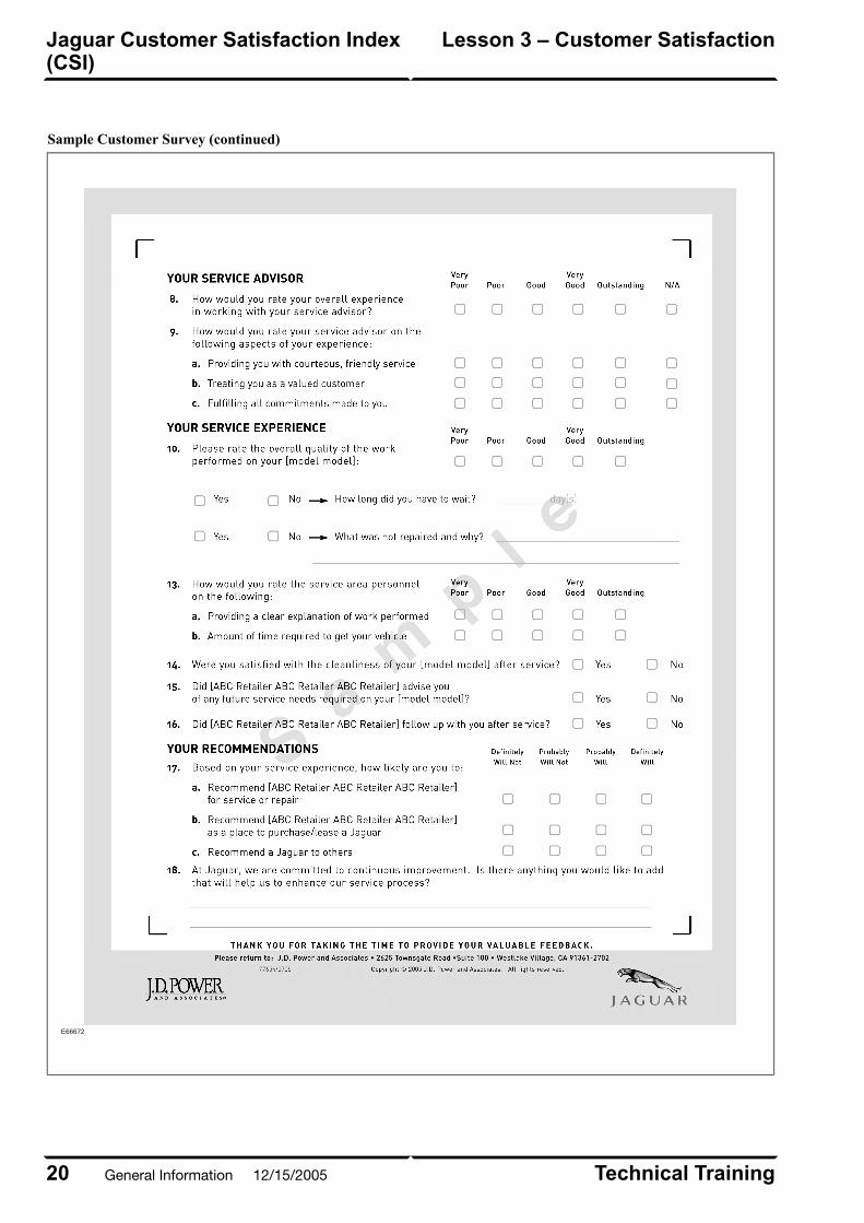
Sample Customer Survey (continued)
E66672
Technical Training20
Lesson 3 – Customer SatisfactionJaguar Customer Satisfaction Index(CSI)
General Information 12/15/2005

CSI Summary Reports
The online CSI report summarizes the overall
performance, sales performance, service performance,
and mail survey sample dispositions.
• Published monthly
• Summarizes most recent month, previous 11 months
and 12-month averages for the sales and service mail
survey
• Provides trends, graphs, and tables to make it easy
to track dealership performance.
• Provides performance scores for each sales
consultant, service advisor and service technician
• Displays dealership’s national rank based on a
12-month rolling average (Note: dealership must
have a minimum of 30 returns for the 12-month
period to be ranked; ‘N/A’ will appear instead of a
value if this is not the case)
Dealer, district, and national scores for overall CSI,
sales CSI, and service CSI are displayed.
Site Access
• Log on to the secure Jaguar Business Network (JBN)
online system using your unique user ID and
password
• Select the “Customer Satisfaction Programs: Jaguar
CSI Site” link
21Technical Training
Jaguar Customer Satisfaction Index(CSI)
Lesson 3 – Customer Satisfaction
12/15/2005 General Information
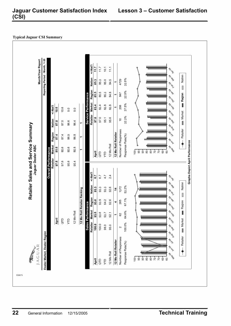
Typical Jaguar CSI Summary
E66673
Technical Training22
Lesson 3 – Customer SatisfactionJaguar Customer Satisfaction Index(CSI)
General Information 12/15/2005
JAGUAR SERVICE TRAINING
The Jaguar Service Training program is designed above
all else to increase customer satisfaction by helping the
technician to develop the specialized skills and
knowledge required to keep Jaguar vehicles operating
at peak performance levels.
Professional training is available at five strategically
located training centers in North America. Each Jaguar
training center provides an ideal learning environment
and is equipped to Jaguar dealer standards of
appearance, tools, and equipment.
Training Center Locations
• Atlanta, Georgia
• Irvine, California
• Mahwah, New Jersey
• Toronto, Ontario
• Chicago, Illinois
Instructor-Led Jaguar Training Courses
Jaguar Service Training courses are designed to offer
the optimum mix of hands-on vehicle and component
exercises combined with classroom presentation to
develop a thorough understanding of the vehicle
systems. Each course is finely tuned and concisely
presented to provide information and develop new skills
that technicians can put to work when they return to
their dealerships. For a complete listing and description
of current courses, visit the Jaguar Training and
Development System online through the Jaguar Business
Network (JBN).
Web-Based Training
A series of web-based training courses are available
online at the Jaguar Training and Development website.
The majority of these courses consist of system
fundamentals or new product introduction courses. Many
of these online courses are prerequisites for the
instructor-led courses.
Enrolling for Training Courses
Jaguar Service Training Schedules are released every
4 months and are available online at the Jaguar Training
and Development website. Shortly after a new schedule
is posted, Jaguar provides the training schedule in a
four-color PDF, from which each month's schedule can
be printed at the dealership on an as-needed basis. The
schedule shows the classes offered at each of the five
Jaguar Training Centers. There are no geographical
restrictions for participating in the training program;
dealers anywhere in North America may register their
staff at any training center depending on availability.
For New Product classes, training seats are allocated to
dealerships based on service volume and training gap
for initial enrollment. After the initial enrollment period,
there are no restrictions and requests are filled on a first
come, first served basis.
Along with each course listed on the training schedule
will be the date(s), location, spaces available, and a link
for enrollment.
Web-based training courses are also listed and are
available 24/7.
Jaguar Employee Certification Planner
The Jaguar Training and Development website includes
a Jaguar Employee Certification Planner that will guide
employees through the tasks required to gain
certification. Certification goal(s) that have been
assigned to an employee are listed on the planner. Each
goal will list the tasks required to achieve the goal.
Current status of each goal and the tasks required to
achieve each goal is displayed in the planner.
23Technical Training
Jaguar Service TrainingLesson 4 – Service Training
12/15/2005 General Information

THE JOURNEY TO EXCELLENCE
Jaguar recognizes the accomplishments of service
technicians through the Journey to Excellence Program.
Technicians are recognized by Jaguar for completion
of training with Automotive Service Excellence (ASE)
certifications at three levels:
• Bronze
• Silver
• Gold
The requirements for each level are based on completion
of Jaguar technical courses and ASE certifications.
Gold Certified Technicians can earn Jaguar Master
Status, by completing additional training courses, ASEs
1-8 and L1, meeting experience milestones, and by
participating in annual on-line quizzes known as
Information Quizzes (IQs).
Master technicians have the opportunity to compete
annually in a hands-on technical competition for two
additional levels of recognition:
• Master Technician Guild Member
• Marque of Distinction Winner
This hands-on competition is open to the Master
technicians that score highest on the IQs in their region.
Of the competitors, those that score the highest at the
competition will be named Guild Members, and the one
technician with the overall best score is named the
Marque of Distinction winner.
In order to participate in The Journey to Excellence, the
technician must be listed as an active employee in Jaguar
Training & Development.
The Journey website, accessed via JBN Online, provides
full details of the program. Included on the website are
the program criteria, a list of possible rewards, access
the online quizzes, and Personal Achievement Reports
(PARs).
Technical Training24
Lesson 4 – Service TrainingThe Journey to Excellence
General Information 12/15/2005
TECHNICAL SERVICE HELPLINE
The Jaguar Technical Service Helpline is an important
part of the Jaguar commitment to quality. The Helpline
provides, at no charge, a direct communications link
between the retailer technician and the manufacturer.
Its purpose is to give the technician additional assistance
to help quickly resolve customer and dealer technical
product concerns. In return, the helpline provides Jaguar
with immediate feedback about service problems that
may be occurring within Jaguar retailers.
The Technical Service Helpline is for designated Jaguar
technicians employed by authorized Jaguar retailers. If
customers or independent repair shop personnel wish
to contact Jaguar, they should call the Jaguar Cars
Customer Assistance Center at 1-800-4-JAGUAR
(1-800-452-4827) and select option three on their
touch-tone telephones.
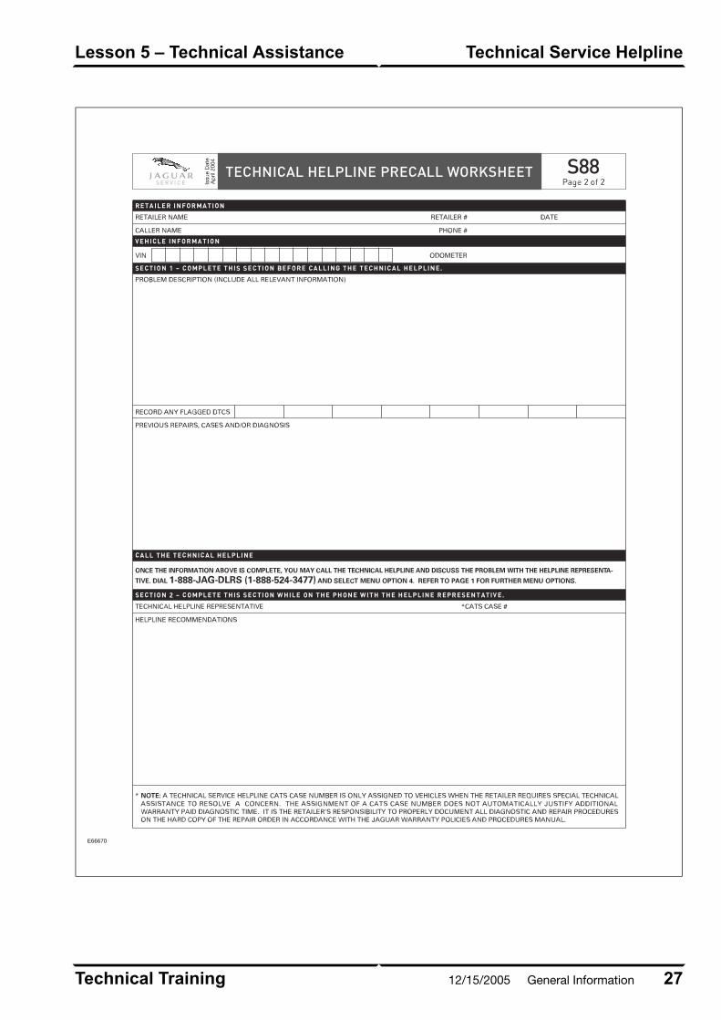
Technical Helpline Precall Worksheet (FormS88)
The Technical Helpline Precall Worksheet was designed
to help organize requests for technical assistance through
the Helpline and is necessary for repairs that require
direct Jaguar assistance.
Calling the Helpline
Before calling the Helpline to request assistance, the
following MUST be performed:
• Fill in the Retailer, Vehicle Information, and Section
1 of the Precall Worksheet
• All applicable Technical Service Manual / GTR,
Service Bulletin, and WDS diagnostics must be
performed.
• All other applicable service procedures must be
performed.
When you contact the Helpline for assistance, the
following must be at hand:
• The Precall Worksheet with the Retailer, Vehicle
Information, and Section 1 completed.
• All Service Bulletins, Electrical Guides and other
publications relevant to the concern.
Technical Helpline Telephone Menu Options
After dialing 1-888-JAG-DLRS (1-888-524-3577),
select Menu Option 2 to access the Technical Service
Helpline. Then choose from the following options:
• Press 1 to close a case
• Press 2 for ZF transmission support
• Press 3 for JATCO transmission support
• Press 4 for all other technical support
• Press 8 to repeat all options
• Press 9 to return to the main menu
NOTE: The Technical Helpline Menu options and
selections may be periodically updated without notice.
Each time you call, listen carefully to the recorded menu
before making a selection.
Record the Jaguar Cars Technical Representative’s
name, recommendations, and the CATS case number,
if one is assigned.
• Technical Service Helpline CATS Case Numbers
are only given out to dealers who require technical
assistance to resolve a concern.
• A CATS Case Number DOES NOT automatically
justify additional warranty paid diagnostic time. It
is the dealer’s responsibility to properly document
all diagnostic and repair procedures on the hard copy
of the repair order in accordance with the Jaguar
Warranty Policies and Procedures Manual.
25Technical Training
Technical Service HelplineLesson 5 – Technical Assistance
12/15/2005 General Information

The assigned technician is responsible for follow-up
with the Technical Helpline to advise them of case
progress.
• When the problem is rectified, the technician should
close the case by calling the Helpline selecting option
1 from the Technical Service Helpline main menu.
• To provide the most effective assistance it may be
necessary for the Helpline Technical Representative
to work with the technician at the vehicle. In such
cases a cordless telephone is an asset.
NOTE: Feedback and input is vital to the Helpline.
Please take the time to submit an Electronic Product
Quality Report on all Helpline cases.
Technical Training26
Lesson 5 – Technical AssistanceTechnical Service Helpline
General Information 12/15/2005
E66670
27Technical Training
Technical Service HelplineLesson 5 – Technical Assistance
12/15/2005 General Information
FIELD SERVICE ENGINEERS
Jaguar provides on-site technical assistance through
Field Service Engineers (FSE). Each FSE is “home
based” and serves multiple market areas. FSEs are
responsible for preventing reacquired vehicles by
providing technical assistance in cases where in-dealer
resources have been exhausted and the Technical
Helpline has been unable to assist in resolving the
vehicle fault. In addition to the Technical Helpline, FSEs
also have access and support of Product Investigation
and Engineering. FSEs also make routine visits to all
the dealers within their markets. During these visits,
they will analyze operational procedures utilized by
service departments and offer recommendations, which
will improve “fixed right first time” scores. When FSE
assistance is required, the dealer’s Aftersales Market
Manager (AMM), Service Manager, or Technical
Helpline can initiate the visit.
Technical Training28
Lesson 5 – Technical AssistanceField Service Engineers
General Information 12/15/2005

ELECTRICAL GUIDES
Electrical schematics and associated information are
contained in the Electrical Guides. Electrical Guides
are available in print from Helm Incorporated and online
at the Global Technical Reference (GTR) website.
Electrical Guides are specific to individual models and,
in most cases, individual model years.
Electrical Guide Format
All current Jaguar Electrical Guides are made up of two
major sections. The first section, at the front of the
guide, provides general information for and about the
use of the guide, and information and illustrations to
aid in the understanding of the vehicle
electrical/electronic systems, as well as location and
identification of components. It is STRONGLY
recommended that technicians read thoroughly through
this section of the guide to develop familiarity with the
layout and use of the guide.
The second section includes figures (wiring diagrams),
which are the basis of each Electrical Guide. Each figure
is identified by a Figure Number (i.e. Fig. 01.1) and
Title, and is accompanied by a page of data containing
information specific to that figure. The figures are
organized by major vehicle system.
Major Electrical Guide Headings
DescriptionSection
Description of Electrical Guide format, interpretation of commonly
used acronyms, description of vehicle electrical system architecture
Introduction
Listing of each wiring diagram and associated Figure numberTable of Contents
Listing of all major components with Figures in which they appearComponent Index
Detailed explanation of information on Data and Figure pagesUser Instructions
Interpretation of the many symbols used in the figures and a guide to
understanding wiring, harness and component numbering and codes
Symbols and Codes
A schematic illustration showing network connections between various
control modules
Network Configuration
Illustration of battery harness routing through vehicleMain Power Distribution
Illustration of ground point locationsGround Point Locations
Illustration of harness routing through vehicleHarness Layout
Illustration of module locationsControl Module Location
Illustration of control module connectors with detailed pin numbering
and wire color information
Control Module Pin Identification
29Technical Training
Electrical GuidesLesson 6 – Technical Publications
12/15/2005 General Information
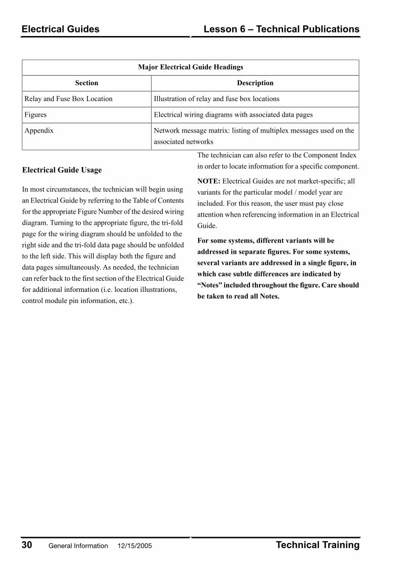
Major Electrical Guide Headings
DescriptionSection
Illustration of relay and fuse box locationsRelay and Fuse Box Location
Electrical wiring diagrams with associated data pagesFigures
Network message matrix: listing of multiplex messages used on the
associated networks
Appendix
Electrical Guide Usage
In most circumstances, the technician will begin using
an Electrical Guide by referring to the Table of Contents
for the appropriate Figure Number of the desired wiring
diagram. Turning to the appropriate figure, the tri-fold
page for the wiring diagram should be unfolded to the
right side and the tri-fold data page should be unfolded
to the left side. This will display both the figure and
data pages simultaneously. As needed, the technician
can refer back to the first section of the Electrical Guide
for additional information (i.e. location illustrations,
control module pin information, etc.).
The technician can also refer to the Component Index
in order to locate information for a specific component.
NOTE: Electrical Guides are not market-specific; all
variants for the particular model / model year are
included. For this reason, the user must pay close
attention when referencing information in an Electrical
Guide.
For some systems, different variants will be
addressed in separate figures. For some systems,
several variants are addressed in a single figure, in
which case subtle differences are indicated by
“Notes” included throughout the figure. Care should
be taken to read all Notes.
Technical Training30
Lesson 6 – Technical PublicationsElectrical Guides
General Information 12/15/2005

Typical Data Page
E66674
31Technical Training
Electrical GuidesLesson 6 – Technical Publications
12/15/2005 General Information
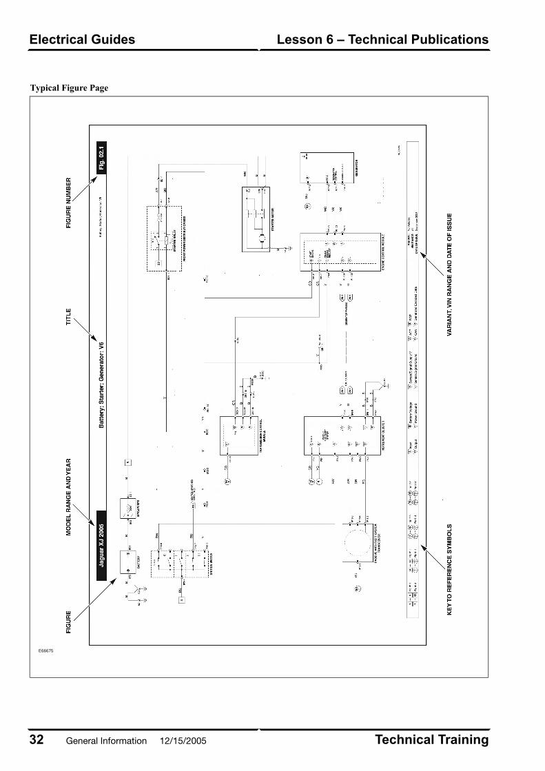
Typical Figure Page
E66675
Technical Training32
Lesson 6 – Technical PublicationsElectrical Guides
General Information 12/15/2005

TECHNICAL GUIDES
Technical Guides are publications designed to provide
technicians with product information.
Two types of Technical Guides are produced: Technical
Introductions and Model Year Updates. Technical
Introductions provide a comprehensive technical
overview of new models or powertrains while Model
Year Updates cover changes in existing models that
have undergone significant changes.
Technical Guides are available online at the Global
Technical Reference (GTR) website.
33Technical Training
Technical GuidesLesson 6 – Technical Publications
12/15/2005 General Information
Typical Technical Guide – Cover
E66676
Technical Training34
Lesson 6 – Technical PublicationsTechnical Guides
General Information 12/15/2005
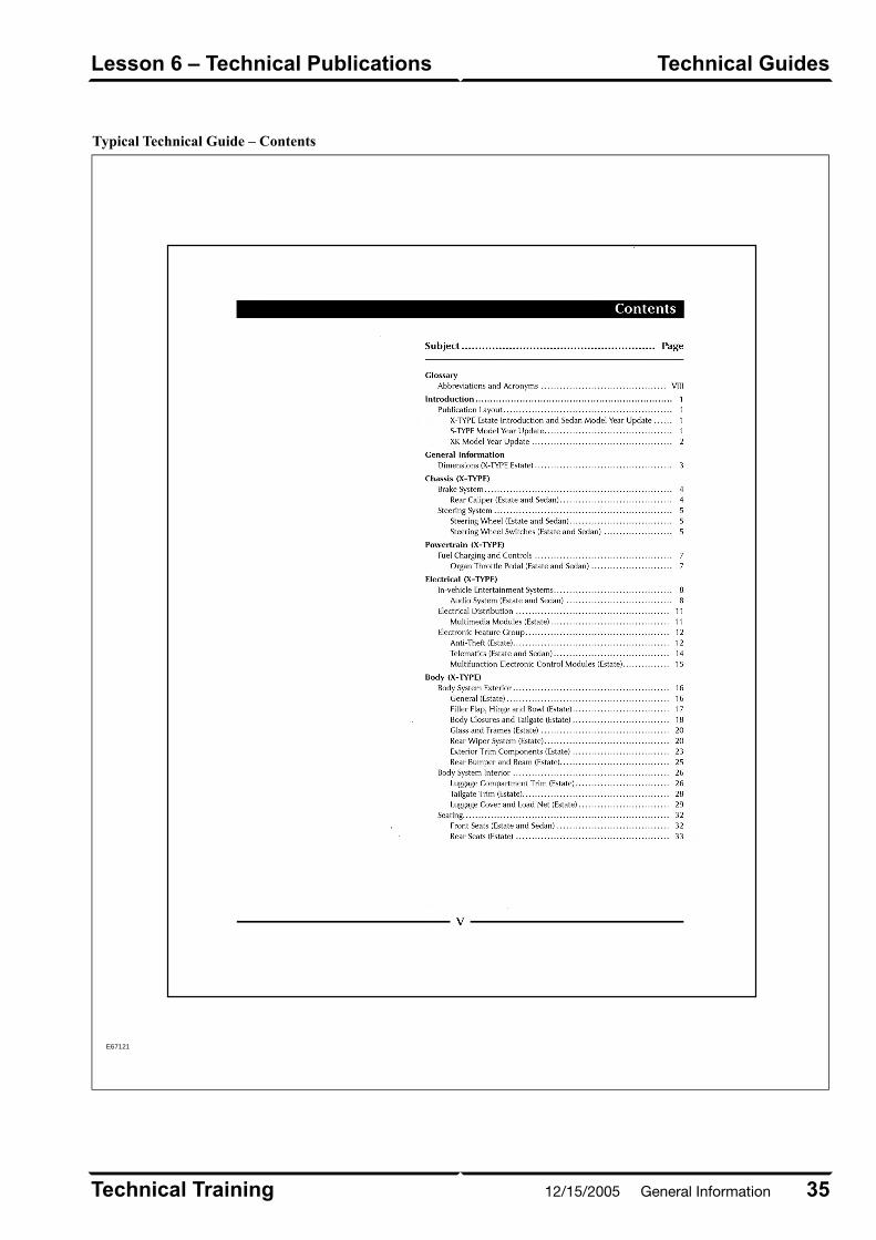
Typical Technical Guide – Contents
E67121
35Technical Training
Technical GuidesLesson 6 – Technical Publications
12/15/2005 General Information
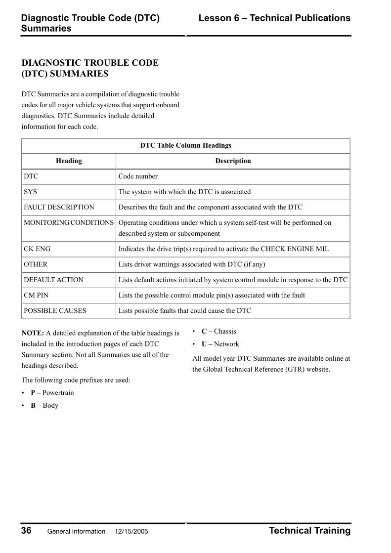
DIAGNOSTIC TROUBLE CODE(DTC) SUMMARIES
DTC Summaries are a compilation of diagnostic trouble
codes for all major vehicle systems that support onboard
diagnostics. DTC Summaries include detailed
information for each code.
DTC Table Column Headings
DescriptionHeading
Code numberDTC
The system with which the DTC is associatedSYS
Describes the fault and the component associated with the DTCFAULT DESCRIPTION
Operating conditions under which a system self-test will be performed on
described system or subcomponent
MONITORING CONDITIONS
Indicates the drive trip(s) required to activate the CHECK ENGINE MILCK ENG
Lists driver warnings associated with DTC (if any)OTHER
Lists default actions initiated by system control module in response to the DTCDEFAULT ACTION
Lists the possible control module pin(s) associated with the faultCM PIN
Lists possible faults that could cause the DTCPOSSIBLE CAUSES
NOTE: A detailed explanation of the table headings is
included in the introduction pages of each DTC
Summary section. Not all Summaries use all of the
headings described.
The following code prefixes are used:
• P – Powertrain
• B – Body
• C – Chassis
• U – Network
All model year DTC Summaries are available online at
the Global Technical Reference (GTR) website.
Technical Training36
Lesson 6 – Technical PublicationsDiagnostic Trouble Code (DTC)Summaries
General Information 12/15/2005

Typical DTC Table
E66677
37Technical Training
Diagnostic Trouble Code (DTC)Summaries
Lesson 6 – Technical Publications
12/15/2005 General Information
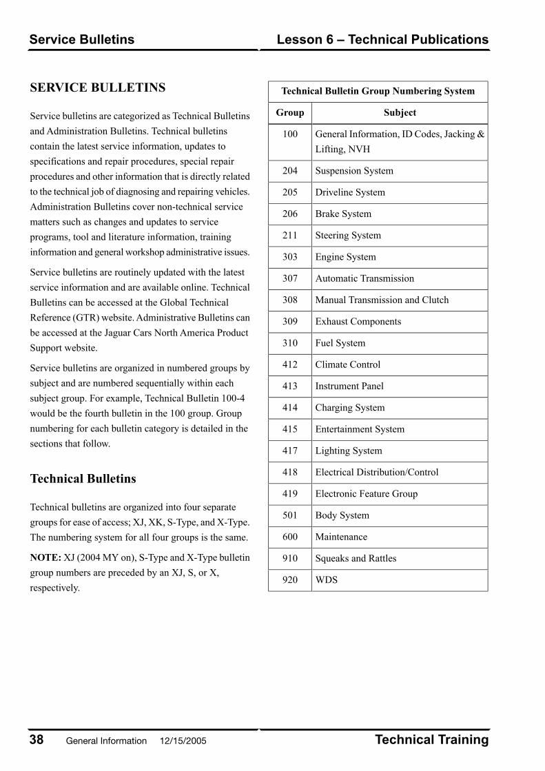
SERVICE BULLETINS
Service bulletins are categorized as Technical Bulletins
and Administration Bulletins. Technical bulletins
contain the latest service information, updates to
specifications and repair procedures, special repair
procedures and other information that is directly related
to the technical job of diagnosing and repairing vehicles.
Administration Bulletins cover non-technical service
matters such as changes and updates to service
programs, tool and literature information, training
information and general workshop administrative issues.
Service bulletins are routinely updated with the latest
service information and are available online. Technical
Bulletins can be accessed at the Global Technical
Reference (GTR) website. Administrative Bulletins can
be accessed at the Jaguar Cars North America Product
Support website.
Service bulletins are organized in numbered groups by
subject and are numbered sequentially within each
subject group. For example, Technical Bulletin 100-4
would be the fourth bulletin in the 100 group. Group
numbering for each bulletin category is detailed in the
sections that follow.
Technical Bulletins
Technical bulletins are organized into four separate
groups for ease of access; XJ, XK, S-Type, and X-Type.
The numbering system for all four groups is the same.
NOTE: XJ (2004 MY on), S-Type and X-Type bulletin
group numbers are preceded by an XJ, S, or X,
respectively.
Technical Bulletin Group Numbering System
SubjectGroup
General Information, ID Codes, Jacking &
Lifting, NVH
100
Suspension System204
Driveline System205
Brake System206
Steering System211
Engine System303
Automatic Transmission307
Manual Transmission and Clutch308
Exhaust Components309
Fuel System310
Climate Control412
Instrument Panel413
Charging System414
Entertainment System415
Lighting System417
Electrical Distribution/Control418
Electronic Feature Group419
Body System501
Maintenance600
Squeaks and Rattles910
WDS920
Technical Training38
Lesson 6 – Technical PublicationsService Bulletins
General Information 12/15/2005
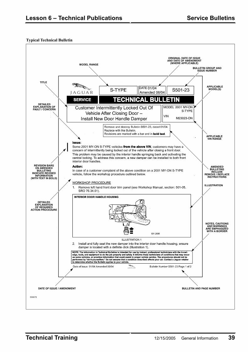
Typical Technical Bulletin
E66678
39Technical Training
Service BulletinsLesson 6 – Technical Publications
12/15/2005 General Information
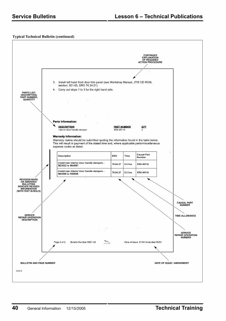
Typical Technical Bulletin (continued)
E66679
Technical Training40
Lesson 6 – Technical PublicationsService Bulletins
General Information 12/15/2005
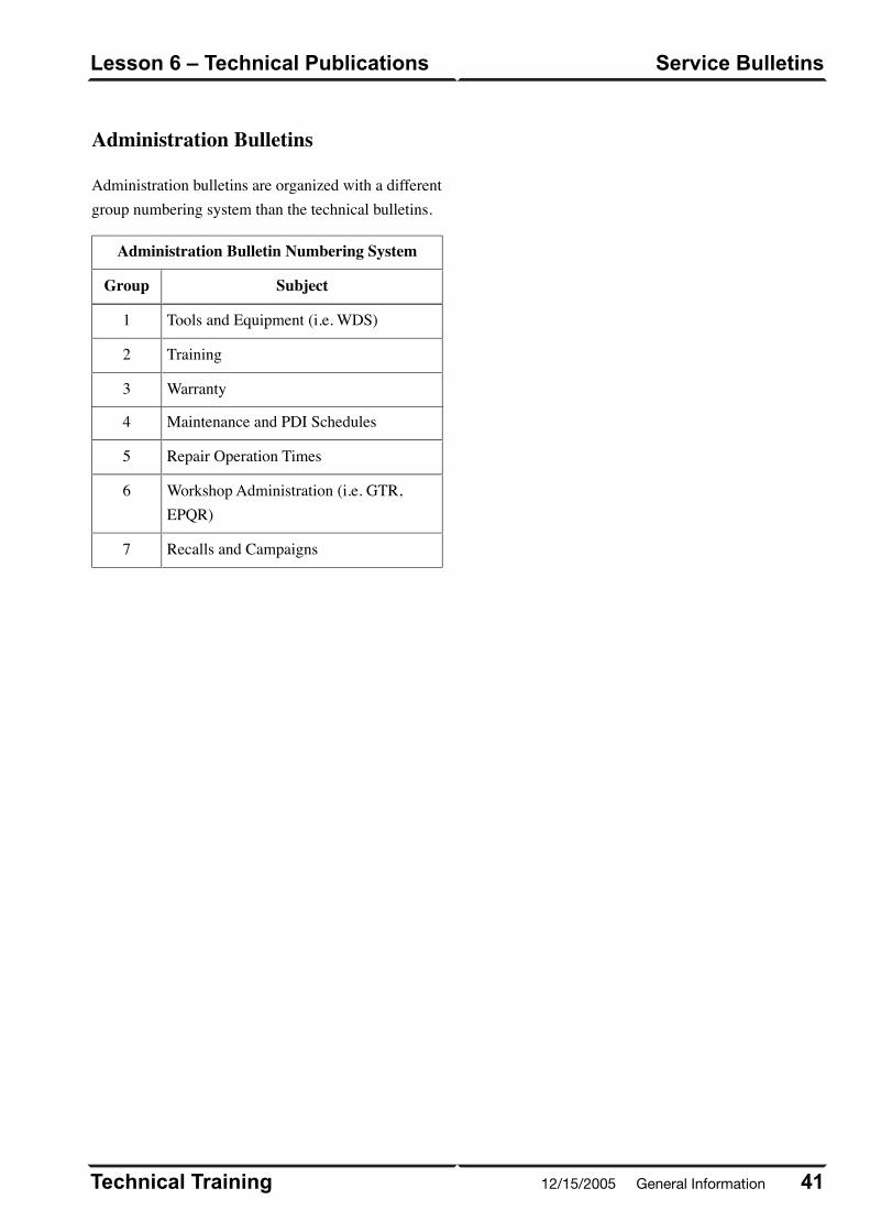
Administration Bulletins
Administration bulletins are organized with a differentgroup numbering system than the technical bulletins.
Administration Bulletin Numbering System
SubjectGroup
Tools and Equipment (i.e. WDS)1
Training2
Warranty3
Maintenance and PDI Schedules4
Repair Operation Times5
Workshop Administration (i.e. GTR,EPQR)
6
Recalls and Campaigns7
41Technical Training
Service BulletinsLesson 6 – Technical Publications
12/15/2005 General Information
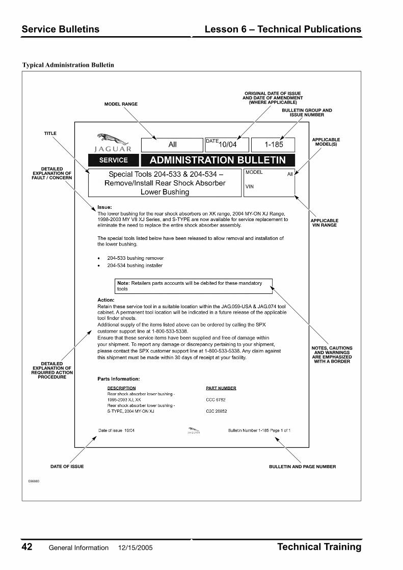
Typical Administration Bulletin
E66680
Technical Training42
Lesson 6 – Technical PublicationsService Bulletins
General Information 12/15/2005
Campaigns
A campaign is a category of warranty transaction. It is
used as in general communications around “Types of
Warranty Transactions”. There are two types of campaigns:
Service Actions and Recalls. Notification of Campaigns
is made via Administrative Bulletins – Group 7 (Recalls
and Campaigns).
Service Actions
A Service Action is a repair to a specific product
concern. There is no customer notification. A Service
Action is performed either upon a customer complaint
(the problem MAY occur) or at the first service
opportunity (the problem WILL occur sooner or later).
In time, all Service Actions will be closed. Service
Actions are claimable only while the vehicle is within
the terms of the New Vehicle Limited Warranty.
Recalls
A Recall is also a repair to specific product concerns,
although vehicle owners/drivers are notified in this case.
There will also be reporting of completion rates to
Federal agencies, State Agencies or both. Short of a
100% completion rate, Recalls are never closed. Recalls
are claimable regardless of the New Vehicle Limited
Warranty status.
43Technical Training
Service BulletinsLesson 6 – Technical Publications
12/15/2005 General Information
PARTS BULLETINS
Parts bulletins are published primarily to support the
parts department, by providing information about parts
supercession and availability. While categorized into
over 20 alphabetized groups, only one group, “X:
Accessories/Consumables” will be important resources
for technicians who are performing accessory
installations. Parts bulletins can be found on the Jaguar
Cars North American Product Support Website.
Technical Training44
Lesson 6 – Technical PublicationsParts Bulletins
General Information 12/15/2005

Typical Parts Bulletin
E68486
45Technical Training
Parts BulletinsLesson 6 – Technical Publications
12/15/2005 General Information
OVERVIEW
Jaguar provides a variety of technical information online
through the following websites:
• Global Technical Reference (GTR)
• Jaguar Cars North American Product Support
– Electronic Product Quality Report (EPQR)
– Jaguar Business Network (JBN)
Jaguar’s primary technical information website is the
Global Technical Reference (GTR) website. The Jaguar
Cars North American Product Support website provides
additional resources for the Jaguar technician. By
providing electronic documents from common websites,
Jaguar can more readily update information and monitor
access to information in a cost-effective manner.
Technicians access the Jaguar websites from the
dealership using the MyVPN portal. User names and
passwords are assigned at the dealership.
Technical Training46
Lesson 7 – Online TechnicalResources
Overview
General Information 12/15/2005

GLOBAL TECHNICAL REFERENCE(GTR)
Launched in 2003, GTR provides technicians with the
technical information necessary to properly repair and
maintain Jaguar vehicles. GTR is administered from the
UK (United Kingdom) and is accessible via the internet
(public access), extranet (dealer hub), or intranet
(manufacturer employees). Dealer access is through the
MYVPN Portal.
GTR provides 24/7 access to the following information
types:
• Workshop Manuals
• Electrical Guides
• DTC Summaries
• Technical Guides
• Maintenance Check Sheets
• Technical Bulletins – OBD II equipped vehicles
• Administration Bulletins (limited to Recalls and
Service Actions)
• Vehicle Specifications Book
• Technical Training Manuals
• Special Tools and Equipment (link to SPX website)
Using GTR
After accessing GTR, a region selection page is
displayed offering the user the choice of North America
or Rest of the World. Select North America and the
home page will be displayed. To the right of the home
page are quick links that enable the user to access pages
that provide more information about GTR.
47Technical Training
Global Technical Reference (GTR)Lesson 7 – Online TechnicalResources
12/15/2005 General Information
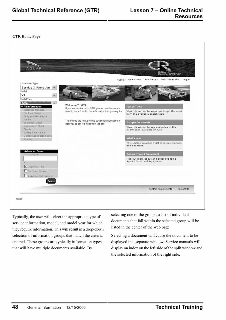
GTR Home Page
E66681
Typically, the user will select the appropriate type of
service information, model, and model year for which
they require information. This will result in a drop-down
selection of information groups that match the criteria
entered. These groups are typically information types
that will have multiple documents available. By
selecting one of the groups, a list of individual
documents that fall within the selected group will be
listed in the center of the web page.
Selecting a document will cause the document to be
displayed in a separate window. Service manuals will
display an index on the left side of the split window and
the selected information of the right side.
Technical Training48
Lesson 7 – Online TechnicalResources
Global Technical Reference (GTR)
General Information 12/15/2005

Typical Service Information Display (Workshop Manual shown)
E66682
Once information is displayed, the user has the ability
to print and, in the case of PDF (Portable Document
Format) files, save the section locally.
49Technical Training
Global Technical Reference (GTR)Lesson 7 – Online TechnicalResources
12/15/2005 General Information

JAGUAR CARS NORTH AMERICANPRODUCT SUPPORT
Based in the U.S., the Jaguar Cars North American
Product Support website provides 24/7 access to the
following information types:
• Administration Bulletins
• TechLines (monthly notes and technical tips about
Jaguar products)
• Links to:
Jaguar Service Support Partner sites (i.e.
Motorola, Helm, and SPX)
–
– Electronic Product Quality Report Website
– Jaguar Business Network (JBN Online)
• Online forms (parts, service, and warranty forms)
• Material Safety Data Sheet search engine
• Technical Bulletins – Pre-OBD II vehicles
• Job aids
Product Support Home Page
E66683
Technical Training50
Lesson 7 – Online TechnicalResources
Jaguar Cars North American ProductSupport
General Information 12/15/2005
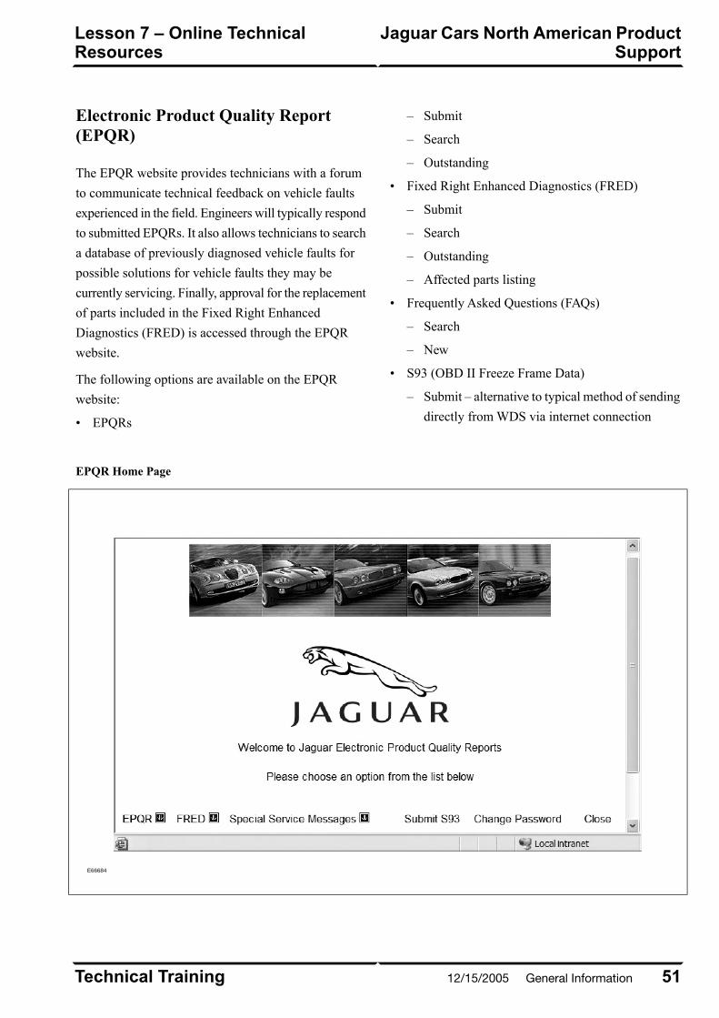
Electronic Product Quality Report(EPQR)
The EPQR website provides technicians with a forum
to communicate technical feedback on vehicle faults
experienced in the field. Engineers will typically respond
to submitted EPQRs. It also allows technicians to search
a database of previously diagnosed vehicle faults for
possible solutions for vehicle faults they may be
currently servicing. Finally, approval for the replacement
of parts included in the Fixed Right Enhanced
Diagnostics (FRED) is accessed through the EPQR
website.
The following options are available on the EPQR
website:
• EPQRs
Submit–
– Search
– Outstanding
• Fixed Right Enhanced Diagnostics (FRED)
– Submit
– Search
– Outstanding
– Affected parts listing
• Frequently Asked Questions (FAQs)
– Search
– New
• S93 (OBD II Freeze Frame Data)
– Submit – alternative to typical method of sending
directly from WDS via internet connection
EPQR Home Page
E66684
51Technical Training
Jaguar Cars North American ProductSupport
Lesson 7 – Online TechnicalResources
12/15/2005 General Information
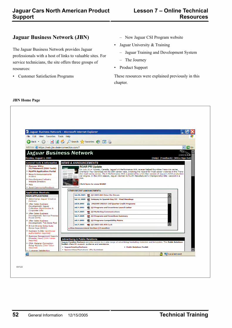
Jaguar Business Network (JBN)
The Jaguar Business Network provides Jaguar
professionals with a host of links to valuable sites. For
service technicians, the site offers three groups of
resources:
• Customer Satisfaction Programs
New Jaguar CSI Program website–
• Jaguar University & Training
– Jaguar Training and Development System
– The Journey
• Product Support
These resources were explained previously in this
chapter.
JBN Home Page
E67122
Technical Training52
Lesson 7 – Online TechnicalResources
Jaguar Cars North American ProductSupport
General Information 12/15/2005
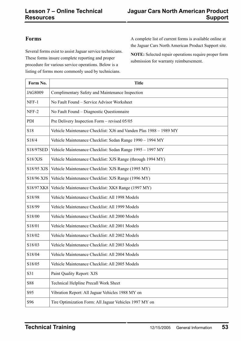
Forms
Several forms exist to assist Jaguar service technicians.
These forms insure complete reporting and proper
procedure for various service operations. Below is a
listing of forms more commonly used by technicians.
A complete list of current forms is available online at
the Jaguar Cars North American Product Support site.
NOTE: Selected repair operations require proper form
submission for warranty reimbursement.
TitleForm No.
Complimentary Safety and Maintenance InspectionJAG8009
No Fault Found – Service Advisor WorksheetNFF-1
No Fault Found – Diagnostic QuestionnaireNFF-2
Pre Delivery Inspection Form – revised 05/05PDI
Vehicle Maintenance Checklist: XJ6 and Vanden Plas 1988 – 1989 MYS18
Vehicle Maintenance Checklist: Sedan Range 1990 – 1994 MYS18/4
Vehicle Maintenance Checklist: Sedan Range 1995 – 1997 MYS18/97SED
Vehicle Maintenance Checklist: XJS Range (through 1994 MY)S18/XJS
Vehicle Maintenance Checklist: XJS Range (1995 MY)S18/95 XJS
Vehicle Maintenance Checklist: XJS Range (1996 MY)S18/96 XJS
Vehicle Maintenance Checklist: XK8 Range (1997 MY)S18/97 XK8
Vehicle Maintenance Checklist: All 1998 ModelsS18/98
Vehicle Maintenance Checklist: All 1999 ModelsS18/99
Vehicle Maintenance Checklist: All 2000 ModelsS18/00
Vehicle Maintenance Checklist: All 2001 ModelsS18/01
Vehicle Maintenance Checklist: All 2002 ModelsS18/02
Vehicle Maintenance Checklist: All 2003 ModelsS18/03
Vehicle Maintenance Checklist: All 2004 ModelsS18/04
Vehicle Maintenance Checklist: All 2005 ModelsS18/05
Paint Quality Report: XJSS31
Technical Helpline Precall Work SheetS88
Vibration Report: All Jaguar Vehicles 1988 MY onS95
Tire Optimization Form: All Jaguar Vehicles 1997 MY onS96
53Technical Training
Jaguar Cars North American ProductSupport
Lesson 7 – Online TechnicalResources
12/15/2005 General Information
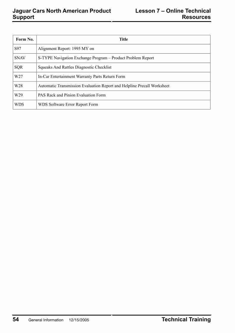
TitleForm No.
Alignment Report: 1995 MY onS97
S-TYPE Navigation Exchange Program – Product Problem ReportSNAV
Squeaks And Rattles Diagnostic ChecklistSQR
In-Car Entertainment Warranty Parts Return FormW27
Automatic Transmission Evaluation Report and Helpline Precall WorksheetW28
PAS Rack and Pinion Evaluation FormW29
WDS Software Error Report FormWDS
Technical Training54
Lesson 7 – Online TechnicalResources
Jaguar Cars North American ProductSupport
General Information 12/15/2005
SPECIAL TOOLS
Special tools are designed for service operations that
cannot be performed proficiently, properly, or safely
using general hand tools or shop equipment. Special
tools are numbered using a global numbering system.
This system utilizes a six-digit numbering system; the
first three digits are the service group, the last three
digits are the tool number within the group (i.e. 303-536
is the number for AJV8 engine lifting plates).
Special Tools Numbering System
SubjectGroup
Miscellaneous100
Suspension204
Driveline205
Brakes206
Steering211
Engine303
Transmission307
Fuel System310
Climate Control412
Electrical418
Body501
Storage and organization of most tools are facilitated
through the Jaguar Tools Storage System. This system
consists of mobile storage cabinets for XK8/XJ8,
S-Type, and X-Type special tools.
Special tools are divided into two groups: mandatory
and optional. Dealerships are required to have
mandatory tools. Mandatory special tools are
automatically sent to each dealership whenever
introduced. Additional mandatory tools and optional
special tools can also be purchased directly from the
SPX Corporation. Special tools listings and descriptions
are available via printed catalogues or online at the SPX
website (link available at GTR and Jaguar Cars North
American Product Support websites). Tools not utilizing
the global numbering system are identified by a Jaguar
part number and may be available through the Jaguar
Parts Department.
55Technical Training
Special ToolsLesson 8 – Tools and Equipment
12/15/2005 General Information
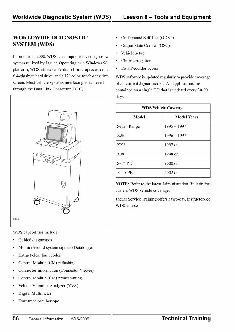
WORLDWIDE DIAGNOSTICSYSTEM (WDS)
Introduced in 2000, WDS is a comprehensive diagnostic
system utilized by Jaguar. Operating on a Windows 98
platform, WDS utilizes a Pentium II microprocessor, a
6.4-gigabyte hard drive, and a 12” color, touch-sensitive
screen. Most vehicle systems interfacing is achieved
through the Data Link Connector (DLC).
E66686
WDS capabilities include:
• Guided diagnostics
• Monitor/record system signals (Datalogger)
• Extract/clear fault codes
• Control Module (CM) reflashing
• Connector information (Connector Viewer)
• Control Module (CM) programming
• Vehicle Vibration Analyzer (VVA)
• Digital Multimeter
• Four-trace oscilloscope
• On Demand Self Test (ODST)
• Output State Control (OSC)
• Vehicle setup
• CM interrogation
• Data Recorder access
WDS software is updated regularly to provide coverage
of all current Jaguar models. All applications are
contained on a single CD that is updated every 30-90
days.
WDS Vehicle Coverage
Model YearsModel
1995 – 1997Sedan Range
1996 – 1997XJS
1997 onXK8
1998 onXJ8
2000 onS-TYPE
2002 onX-TYPE
NOTE: Refer to the latest Administration Bulletin for
current WDS vehicle coverage.
Jaguar Service Training offers a two-day, instructor-led
WDS course.
Technical Training56
Lesson 8 – Tools and EquipmentWorldwide Diagnostic System (WDS)
General Information 12/15/2005
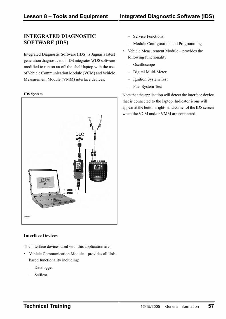
INTEGRATED DIAGNOSTICSOFTWARE (IDS)
Integrated Diagnostic Software (IDS) is Jaguar’s latest
generation diagnostic tool. IDS integrates WDS software
modified to run on an off-the-shelf laptop with the use
of Vehicle Communication Module (VCM) and Vehicle
Measurement Module (VMM) interface devices.
IDS System
E66687
Interface Devices
The interface devices used with this application are:
• Vehicle Communication Module – provides all link
based functionality including:
– Datalogger
– Selftest
– Service Functions
– Module Configuration and Programming
• Vehicle Measurement Module – provides the
following functionality:
– Oscilloscope
– Digital Multi-Meter
– Ignition System Test
– Fuel System Test
Note that the application will detect the interface device
that is connected to the laptop. Indicator icons will
appear at the bottom right-hand corner of the IDS screen
when the VCM and/or VMM are connected.
57Technical Training
Integrated Diagnostic Software (IDS)Lesson 8 – Tools and Equipment
12/15/2005 General Information
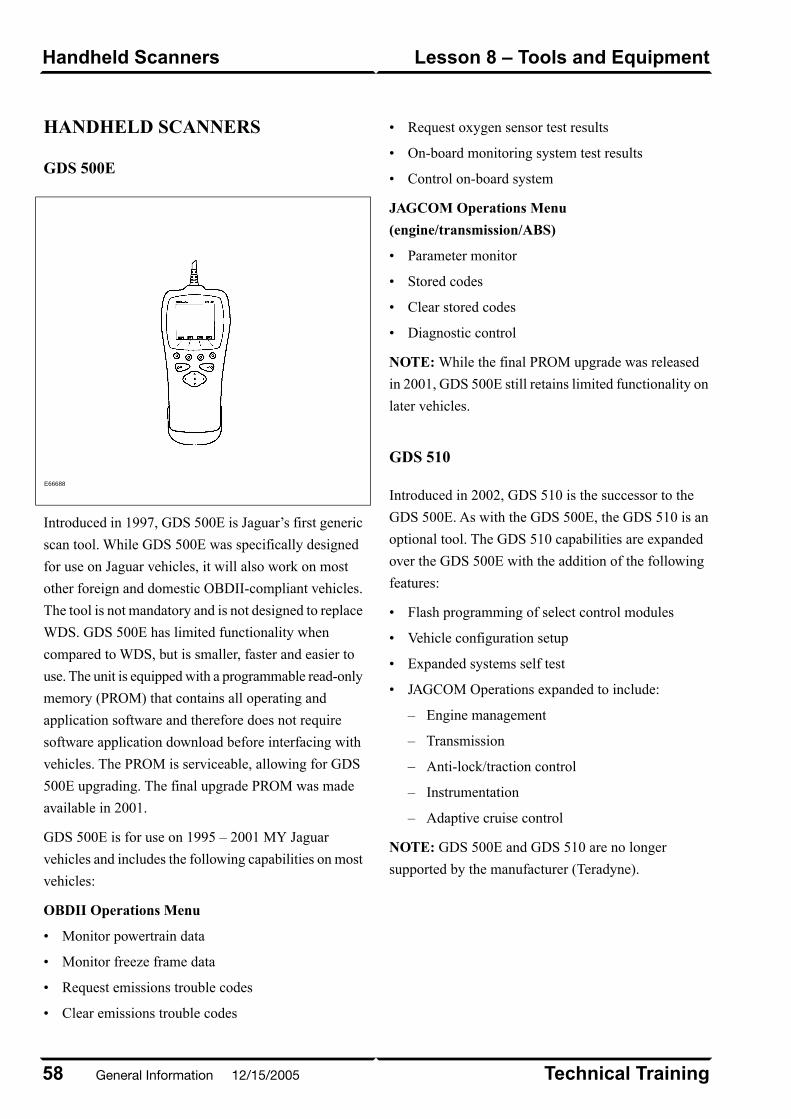
HANDHELD SCANNERS
GDS 500E
E66688
Introduced in 1997, GDS 500E is Jaguar’s first generic
scan tool. While GDS 500E was specifically designed
for use on Jaguar vehicles, it will also work on most
other foreign and domestic OBDII-compliant vehicles.
The tool is not mandatory and is not designed to replace
WDS. GDS 500E has limited functionality when
compared to WDS, but is smaller, faster and easier to
use. The unit is equipped with a programmable read-only
memory (PROM) that contains all operating and
application software and therefore does not require
software application download before interfacing with
vehicles. The PROM is serviceable, allowing for GDS
500E upgrading. The final upgrade PROM was made
available in 2001.
GDS 500E is for use on 1995 – 2001 MY Jaguar
vehicles and includes the following capabilities on most
vehicles:
OBDII Operations Menu
• Monitor powertrain data
• Monitor freeze frame data
• Request emissions trouble codes
• Clear emissions trouble codes
• Request oxygen sensor test results
• On-board monitoring system test results
• Control on-board system
JAGCOM Operations Menu
(engine/transmission/ABS)
• Parameter monitor
• Stored codes
• Clear stored codes
• Diagnostic control
NOTE: While the final PROM upgrade was released
in 2001, GDS 500E still retains limited functionality on
later vehicles.
GDS 510
Introduced in 2002, GDS 510 is the successor to the
GDS 500E. As with the GDS 500E, the GDS 510 is an
optional tool. The GDS 510 capabilities are expanded
over the GDS 500E with the addition of the following
features:
• Flash programming of select control modules
• Vehicle configuration setup
• Expanded systems self test
• JAGCOM Operations expanded to include:
– Engine management
– Transmission
– Anti-lock/traction control
– Instrumentation
– Adaptive cruise control
NOTE: GDS 500E and GDS 510 are no longer
supported by the manufacturer (Teradyne).
Technical Training58
Lesson 8 – Tools and EquipmentHandheld Scanners
General Information 12/15/2005
CURRENT MODEL HISTORY
The Jaguar brand currently offers 4 vehicle lines: theXK, XJ, S-TYPE and X-TYPE. What follows is a briefchronology of each line.
XK MODELS
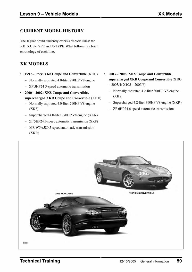
• 1997 – 1999: XK8 Coupe and Convertible (X100)
– Normally aspirated 4.0-liter 290HP V8 engine
– ZF 5HP24 5-speed automatic transmission
• 2000 – 2002: XK8 Coupe and Convertible,supercharged XKR Coupe and Convertible (X100)
Normally aspirated 4.0-liter 290HP V8 engine(XK8)
–
– Supercharged 4.0-liter 370HP V8 engine (XKR)
– ZF 5HP24 5-speed automatic transmission (XK8)
– MB W5A580 5-speed automatic transmission(XKR)
• 2003 – 2006: XK8 Coupe and Convertible,supercharged XKR Coupe and Convertible (X103– 2003/4; X105 – 2005/6)
– Normally aspirated 4.2-liter 300HP V8 engine(XK8)
– Supercharged 4.2-liter 390HP V8 engine (XKR)
– ZF 6HP24 6-speed automatic transmission
E66689
59Technical Training
XK ModelsLesson 9 – Vehicle Models
12/15/2005 General Information

XJ MODELS
• 1998: XJ8, XJ8L (LWB), Vanden Plas (LWB)(X308 [SWB], X338 [LWB])
– Normally aspirated 4.0-liter 290HP V8 engine
– ZF 5HP24 5-speed automatic transmission
• 1999 – 2003: XJ8, XJ8L (LWB), Vanden Plas(LWB), supercharged XJR (SWB) and Super V8(LWB) (X308 [SWB], X338 [LWB])
– Normally aspirated 4.0-liter 290HP V8 engine(XJ8, XJ8L and VDP)
– Supercharged 4.0-liter 370HP V8 engine (XJRand Super V8)
– ZF 5HP24 5-speed automatic transmission (XJ8,XJ8L and VDP)
– MB W5A580 5-speed automatic transmission(XJR and Super V8)
• 2004: XJ8, Vanden Plas, supercharged XJR(X350)
– Normally aspirated 4.2-liter 300HP V8 engine(XJ8 and VDP)
– Supercharged 4.2-liter 390HP V8 engine (XJR)
– ZF 6HP24 6-speed automatic transmission
• 2005 – 2006: XJ8, XJ8L (LWB), Vanden Plas(LWB), supercharged XJR (SWB) and Super V8(LWB) (X350 [SWB], X355 [LWB] – 2005; X356[All] – 2006)
– Normally aspirated 4.2-liter 300HP V8 engine(XJ8, XJ8L and VDP)
– Supercharged 4.2-liter 400HP V8 engine (XJRand Super V8)
– ZF 6HP24 6-speed automatic transmission
E66690
Technical Training60
Lesson 9 – Vehicle ModelsXJ Models
General Information 12/15/2005
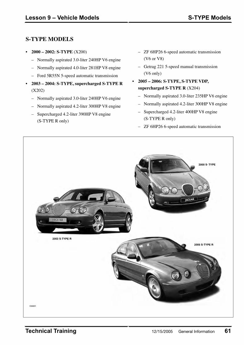
S-TYPE MODELS
• 2000 – 2002: S-TYPE (X200)
– Normally aspirated 3.0-liter 240HP V6 engine
– Normally aspirated 4.0-liter 281HP V8 engine
– Ford 5R55N 5-speed automatic transmission
• 2003 – 2004: S-TYPE, supercharged S-TYPE R(X202)
– Normally aspirated 3.0-liter 240HP V6 engine
– Normally aspirated 4.2-liter 300HP V8 engine
– Supercharged 4.2-liter 390HP V8 engine(S-TYPE R only)
– ZF 6HP26 6-speed automatic transmission(V6 or V8)
– Getrag 221 5-speed manual transmission(V6 only)
• 2005 – 2006: S-TYPE, S-TYPE VDP,supercharged S-TYPE R (X204)
– Normally aspirated 3.0-liter 235HP V6 engine
– Normally aspirated 4.2-liter 300HP V8 engine
– Supercharged 4.2-liter 400HP V8 engine(S-TYPE R only)
– ZF 6HP26 6-speed automatic transmission
E66691
61Technical Training
S-TYPE ModelsLesson 9 – Vehicle Models
12/15/2005 General Information
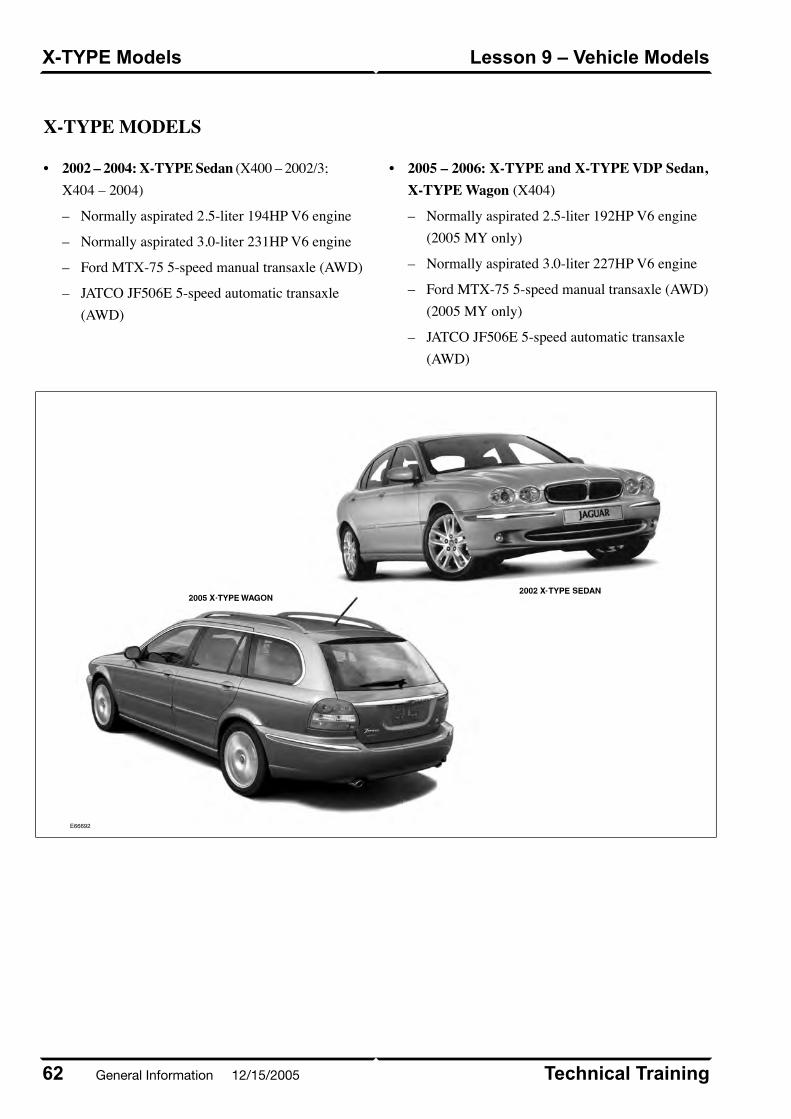
X-TYPE MODELS
• 2002 – 2004: X-TYPE Sedan (X400 – 2002/3;X404 – 2004)
– Normally aspirated 2.5-liter 194HP V6 engine
– Normally aspirated 3.0-liter 231HP V6 engine
– Ford MTX-75 5-speed manual transaxle (AWD)
– JATCO JF506E 5-speed automatic transaxle(AWD)
• 2005 – 2006: X-TYPE and X-TYPE VDP Sedan,X-TYPE Wagon (X404)
Normally aspirated 2.5-liter 192HP V6 engine(2005 MY only)
–
– Normally aspirated 3.0-liter 227HP V6 engine
– Ford MTX-75 5-speed manual transaxle (AWD)(2005 MY only)
– JATCO JF506E 5-speed automatic transaxle(AWD)
E66692
Technical Training62
Lesson 9 – Vehicle ModelsX-TYPE Models
General Information 12/15/2005
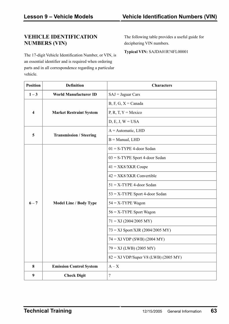
VEHICLE IDENTIFICATIONNUMBERS (VIN)
The 17-digit Vehicle Identification Number, or VIN, is
an essential identifier and is required when ordering
parts and in all correspondence regarding a particular
vehicle.
The following table provides a useful guide for
deciphering VIN numbers.
Typical VIN: SAJDA01R?4FL00001
CharactersDefinitionPosition
SAJ = Jaguar CarsWorld Manufacturer ID1 – 3
B, F, G, X = Canada
Market Restraint System4 P, R, T, Y = Mexico
D, E, J, W = USA
A = Automatic, LHDTransmission / Steering5
B = Manual, LHD
01 = S-TYPE 4-door Sedan
Model Line / Body Type6 – 7
03 = S-TYPE Sport 4-door Sedan
41 = XK8/XKR Coupe
42 = XK8/XKR Convertible
51 = X-TYPE 4-door Sedan
53 = X-TYPE Sport 4-door Sedan
54 = X-TYPE Wagon
56 = X-TYPE Sport Wagon
71 = XJ (2004/2005 MY)
73 = XJ Sport/XJR (2004/2005 MY)
74 = XJ VDP (SWB) (2004 MY)
79 = XJ (LWB) (2005 MY)
82 = XJ VDP/Super V8 (LWB) (2005 MY)
A – XEmission Control System8
?Check Digit9
63Technical Training
Vehicle Identification Numbers (VIN)Lesson 9 – Vehicle Models
12/15/2005 General Information

CharactersDefinitionPosition
X = 1999
Model Year10 Y = 2000
1 = 2001, 2 = 2002, 3 = 2003, etc.
1 = 4.2L S-TYPE R; Castle Bromwich
Model Line / Assembly Plant11
2 = 4.2L XK; Browns Lane
3 = 4.2L SC XK; Browns Lane
F = 3.0L S-TYPE; Castle Bromwich
H = 4.2L S-TYPE; Castle Bromwich
S = 4.2L XJ; Browns Lane
T = 4.2L SC XJ; Browns Lane
W = 3.0L X-TYPE; Halewood
X = 2.5L X-TYPE; Halewood
A, B = XK
Model Line12F, G, H = XJ
L, M, N, P, R = S-TYPE
C, D, E, J, K, S, T, V = X-TYPE
00001, 00002, 00003, etc.Serial Number13 – 17
Technical Training64
Lesson 9 – Vehicle ModelsVehicle Identification Numbers (VIN)
General Information 12/15/2005

Curriculum Training
Introduction to Jaguar
Introduction to XK/XJ: X100/X308
E63055
Technical Training INTR 05 en 08/2005INTR: X100/X308

To the best of our knowledge, the illustrations, technical information, data and descriptions in this issue were correct at the time
of going to print. The right to change prices, specifications, equipment and maintenance instructions at any time without notice
is reserved as part of our policy of continuous development and improvement for the benefit of our customers.
No part of this publication may be reproduced, stored in a data processing system or transmitted in any form, electronic,
mechanical, photocopy, recording, translation or by any other means without prior permission of Premier Automotive Group.
No liability can be accepted for any inaccuracies in this publication, although every possible care has been taken to make it as
complete and accurate as possible.
Copyright ©2005

Please remember that our training literature has been prepared for TRAINING PURPOSES only. Repairs and
adjustments MUST always be carried out according to the instructions and specifications in the workshop literature.
Please make full use of the training offered by Technical Training to gain extensive knowledge of both theory
and practice.
1Technical Training
Preface
12/15/2005 X100 / X308
PAGE
Lesson 1 – General Information
6Overview......................................................................................................................................................
8Identification Labels...................................................................................................................................
9Lifting and Jacking.....................................................................................................................................
Lesson 2 – Engines
11Overview......................................................................................................................................................
12Details..........................................................................................................................................................
Lesson 3 – Engine Management
15Overview......................................................................................................................................................
16Engine Control Module..............................................................................................................................
17Components.................................................................................................................................................
Lesson 4 – Transmission
21ZF 5HP24 Transmission ............................................................................................................................
23W5A 580 Transmission...............................................................................................................................
Lesson 5 – Chassis
25Power Assisted Steering.............................................................................................................................
26Front Suspension........................................................................................................................................
28Rear Suspension (XK and XJ)...................................................................................................................
Technical Training2
Table of Contents
X100 / X308 12/15/2005
29Brakes..........................................................................................................................................................
Lesson 6 – Control Modules and Networks
30Overview......................................................................................................................................................
Lesson 7 – Climate Control
36Overview......................................................................................................................................................
37Service..........................................................................................................................................................
Lesson 8 – Body Systems
39Power Windows...........................................................................................................................................
40Sunroof (XJ Only)......................................................................................................................................
41Convertible Top (XK Only)........................................................................................................................
Lesson 9 – Security System
44Remote Control Keyhead RF Transmitter...............................................................................................
45System Operation.......................................................................................................................................
49Service..........................................................................................................................................................
50Engine Immobilization...............................................................................................................................
Lesson 10 – Supplemental Restraint System
53XK Electromechanical SRS: 1997 – 2000 MY.........................................................................................
55XK Adaptive Restraints System: 2001/02 MY.........................................................................................
58XJ Single-Point Sensor Airbag / SRS........................................................................................................
3Technical Training
Table of Contents
12/15/2005 X100 / X308
Lesson 11 – Infotainment
60In-Car Entertainment (ICE).....................................................................................................................
61Navigation System......................................................................................................................................
Technical Training4
Table of Contents
X100 / X308 12/15/2005
Workshop safety
This page highlights the general observations expectedwhile attending this training program, and itscontinuation upon returning to your place of work.
General
While working on all vehicles, the following itemswhere available should always be used:
• Fender covers
• Seat covers
• Floor protection
Safety
All precautions must be taken and observed at all times,to prevent injury or damage to the following:
• Yourself
• Customer's property
• Workshop equipment
• Work place colleagues
Operating guidelines
While using any piece of workshop equipment:
The manufacturer's guidelines and warning labels mustbe followed.
This will ensure correct use and application at all times.
Seek the necessary advice or training where equipmentusage is unclear.
Chemicals, Oils and Solvents
Follow all manufacturer's warnings and labels; also takeinto account local disposal regulations when workingwith chemicals, oils or solvents.
Ensure that all risks are completely minimized.
Make sure that all protective items of clothing are wornwhere required e.g.
• Eye protection
• Gloves
• Coveralls
• Footwear
System capping
Upon disconnecting components from a system, takeall precautions necessary to prevent systemcontamination or environmental leakage.
Fit relevant plugs or caps i.e. to pipes, unions andcomponent orifices etc.
Updates
Keep abreast of all relevant changes that affect yourrole within the dealership, by monitoring all factoryissued documentation.
Driving
Operating vehicle features, such as ICE, mobile phonesand CD player equipment etc., can cause a momentarydistraction while driving.
Follow all traffic regulations when operating vehiclesystems or using diagnostic equipment while on the move.
Mobile diagnostic equipment operation may requirethe use of an assistant.
5
Safety and Precautions
12/15/2005 X100 / X308
OVERVIEW
XK Overview
E64172
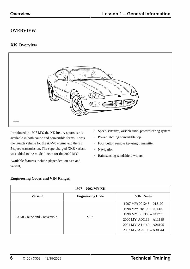
Introduced in 1997 MY, the XK luxury sports car is
available in both coupe and convertible forms. It was
the launch vehicle for the AJ-V8 engine and the ZF
5-speed transmission. The supercharged XKR variant
was added to the model lineup for the 2000 MY.
Available features include (dependent on MY and
variant):
• Speed-sensitive, variable ratio, power steering system
• Power latching convertible top
• Four button remote key-ring transmitter
• Navigation
• Rain sensing windshield wipers
Engineering Codes and VIN Ranges
1997 – 2002 MY XK
VIN RangeEngineering CodeVariant
1997 MY: 001246 – 018107
1998 MY: 018108 – 031302
1999 MY: 031303 – 042775
2000 MY: A00116 – A11139
2001 MY: A11140 – A24195
2002 MY: A25196 – A30644
X100XK8 Coupe and Convertible
Technical Training6
Lesson 1 – General InformationOverview
X100 / X308 12/15/2005
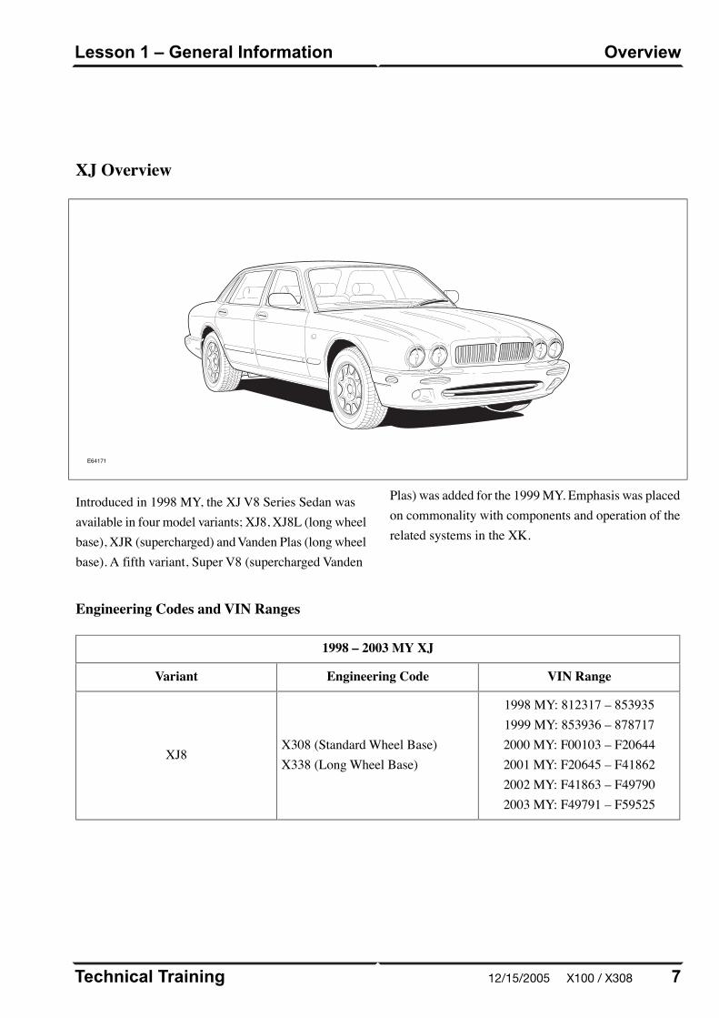
XJ Overview
E64171
Introduced in 1998 MY, the XJ V8 Series Sedan wasavailable in four model variants; XJ8, XJ8L (long wheelbase), XJR (supercharged) and Vanden Plas (long wheelbase). A fifth variant, Super V8 (supercharged Vanden
Plas) was added for the 1999 MY. Emphasis was placedon commonality with components and operation of therelated systems in the XK.
Engineering Codes and VIN Ranges
1998 – 2003 MY XJ
VIN RangeEngineering CodeVariant
1998 MY: 812317 – 8539351999 MY: 853936 – 8787172000 MY: F00103 – F206442001 MY: F20645 – F418622002 MY: F41863 – F497902003 MY: F49791 – F59525
X308 (Standard Wheel Base)X338 (Long Wheel Base)
XJ8
7Technical Training
OverviewLesson 1 – General Information
12/15/2005 X100 / X308
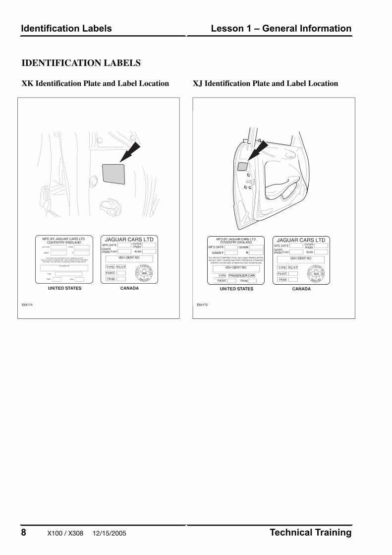
IDENTIFICATION LABELS
XK Identification Plate and Label Location
E64174
XJ Identification Plate and Label Location
E64173
Technical Training8
Lesson 1 – General InformationIdentification Labels
X100 / X308 12/15/2005

LIFTING AND JACKING
CAUTIONS:
Do not allow the hoist adapters to contact the
steering linkage, suspension arms, stabilizer
bar, or rear subframe stabilizer brackets, or to
compress the lower suspension arm stabilizer
bar insulator. Damage to the suspension,
exhaust and steering linkage components may
occur if care is not exercised when positioning
the hoist adapters of two-post hoists prior to
lifting the vehicle.
Never use the differential housing as a lift point.
Damage to the differential housing and cover
may occur.
When using a floor jack, a cushioned pad must
be used to avoid body damage.
On XK models, the aluminum suspension cross
beam should not be used for jacking the front
of the car. Use only the car jacking points or
the steel cross member below the radiator
package.
XK Vehicle Jacking Points
E67045
9Technical Training
Lifting and JackingLesson 1 – General Information
12/15/2005 X100 / X308
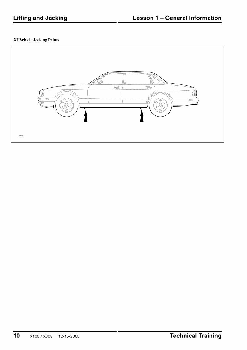
XJ Vehicle Jacking Points
E64177
Technical Training10
Lesson 1 – General InformationLifting and Jacking
X100 / X308 12/15/2005
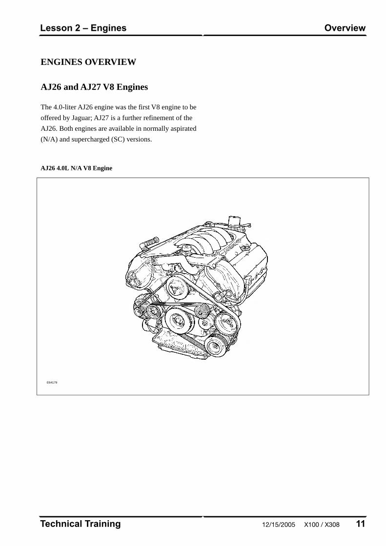
ENGINES OVERVIEW
AJ26 and AJ27 V8 Engines
The 4.0-liter AJ26 engine was the first V8 engine to be
offered by Jaguar; AJ27 is a further refinement of the
AJ26. Both engines are available in normally aspirated
(N/A) and supercharged (SC) versions.
AJ26 4.0L N/A V8 Engine
E64179
11Technical Training
OverviewLesson 2 – Engines
12/15/2005 X100 / X308

DETAILS
Engine Specifications
AJ26 and AJ27 4.0L SCAJ26 and AJ27 4.0L N/A
90° V890° V8Configuration
– Dual overhead camshafts
– 4 valves per cylinder
– Dual overhead camshafts
– 4 valves per cylinder
Cylinder Head
Intake: 0.18 – 0.22 mm (0.007 –
0.009 in.)
Exhaust: 0.23 – 0.27 mm (0.009 –
0.011 in.)
Intake: 0.18 – 0.22 mm (0.007 –
0.009 in.)
Exhaust: 0.23 – 0.27 mm (0.009 –
0.011 in.)
Valve Clearances (cold)
86 mm (3.386 in.)86 mm (3.386 in.)Bore
86 mm (3.386 in.)86 mm (3.386 in.)Stroke
3.996 liters (244 in³)3.996 liters (244 in³)Displacement
10.75 : 110.75 : 1Compression Ratio
258 BHP at 6150 rpm280 BHP at 6100 rpmMaximum Power (DIN)
372 lb. ft. at 3600 rpm276 lb. ft. at 4250 rpmMaximum Torque (DIN)
Up to VIN A00366 (XK), F00463
(XJ): 6.0 liters (6.4 qt.)
From VIN A00367 (XK), F00464
(XJ): 7.0 liters (7.4 qt.)
Up to VIN A00366 (XK), F00463
(XJ): 6.0 liters (6.4 qt.)
From VIN A00367 (XK), F00464
(XJ): 7.0 liters (7.4 qt.)
Engine Oil Capacity
10 liters (10.6 qt.)10 liters (10.6 qt.)Coolant Capacity (approx.)
Technical Training12
Lesson 2 – EnginesDetails
X100 / X308 12/15/2005
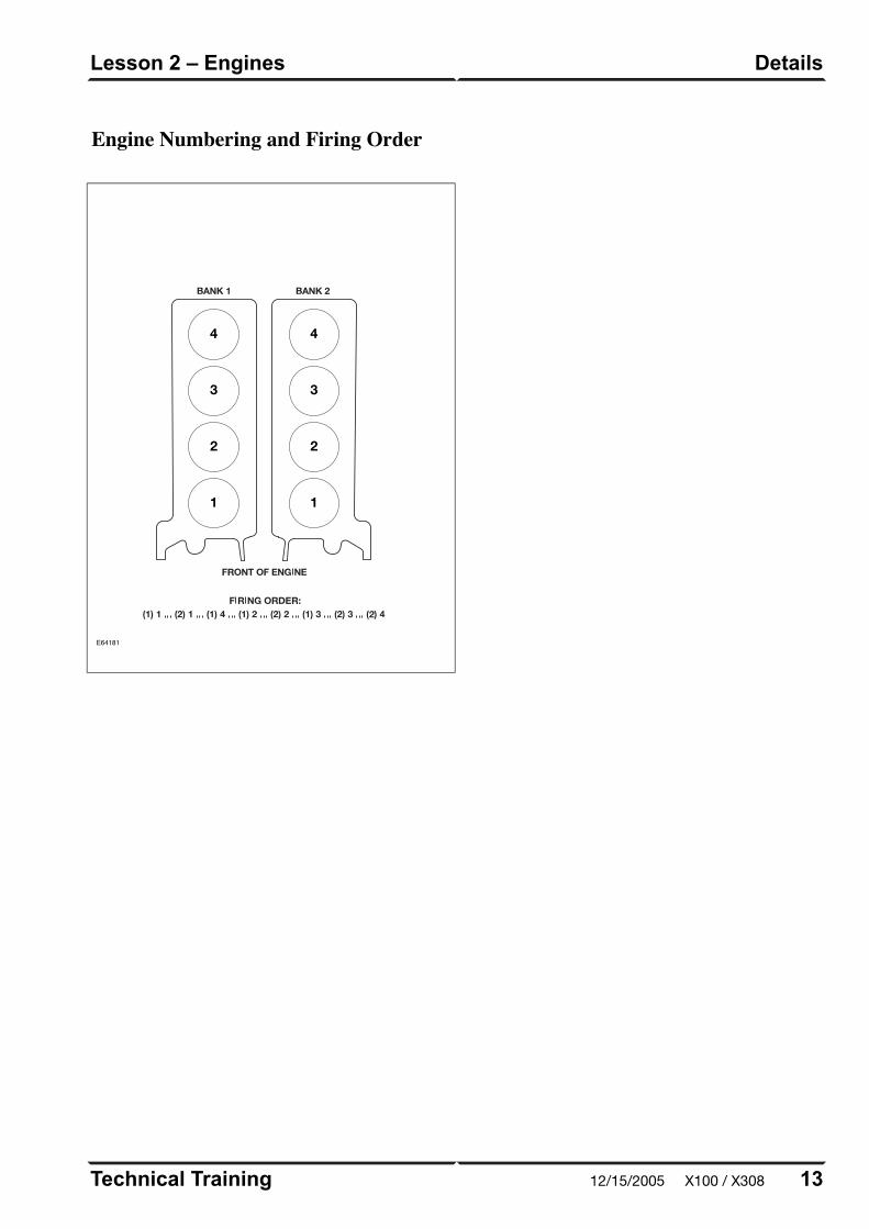
Engine Numbering and Firing Order
E64181
4
3
2
1
4
3
2
1
13Technical Training
DetailsLesson 2 – Engines
12/15/2005 X100 / X308

Engine Data Locations
E64182
Technical Training14
Lesson 2 – EnginesDetails
X100 / X308 12/15/2005
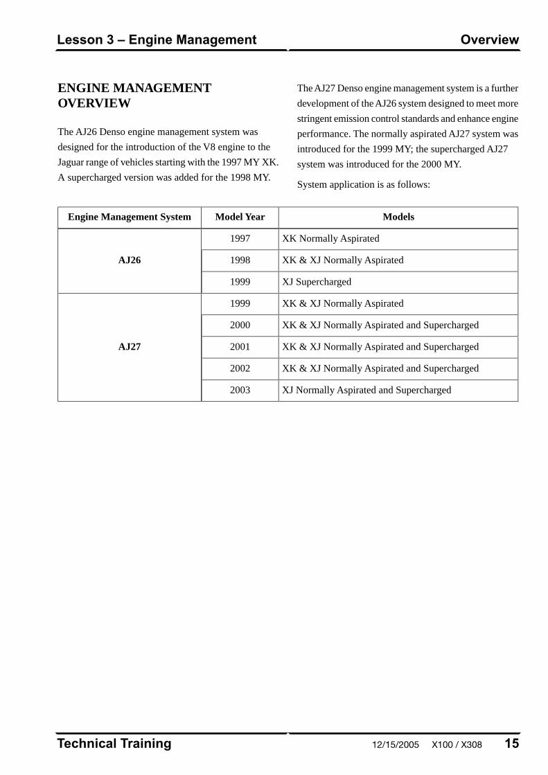
ENGINE MANAGEMENTOVERVIEW
The AJ26 Denso engine management system was
designed for the introduction of the V8 engine to the
Jaguar range of vehicles starting with the 1997 MY XK.
A supercharged version was added for the 1998 MY.
The AJ27 Denso engine management system is a further
development of the AJ26 system designed to meet more
stringent emission control standards and enhance engine
performance. The normally aspirated AJ27 system was
introduced for the 1999 MY; the supercharged AJ27
system was introduced for the 2000 MY.
System application is as follows:
ModelsModel YearEngine Management System
XK Normally Aspirated1997
AJ26 XK & XJ Normally Aspirated1998
XJ Supercharged1999
XK & XJ Normally Aspirated1999
AJ27
XK & XJ Normally Aspirated and Supercharged2000
XK & XJ Normally Aspirated and Supercharged2001
XK & XJ Normally Aspirated and Supercharged2002
XJ Normally Aspirated and Supercharged2003
15Technical Training
OverviewLesson 3 – Engine Management
12/15/2005 X100 / X308

ENGINE CONTROL MODULE
Both systems are built around a dual microprocessor
Engine Control Module (ECM). The ECM is linked to
and communicates with other powertrain control
modules and other vehicle systems via the Controller
Area Network (CAN).
The ECM governs all operating functions including:
• Air induction via an electronically controlled throttle
• Fuel delivery
• Sequential fuel injection
• Ignition via on-plug ignition coils
• Idle speed control
• Emission control
• Evaporative emission control
• Intake valve timing
• Exhaust gas recirculation (certain variants only)
• Cooling system radiator fan control
• Air conditioning compressor control
• Cruise control
• Engine speed limiting
• Engine torque reduction to aid transmission shift
quality and enhance traction / stability control
• EMS and OBD II diagnostics
• Default operating modes including engine speed and
throttle limits
ECM Location
E69679
Technical Training16
Lesson 3 – Engine ManagementEngine Control Module
X100 / X308 12/15/2005
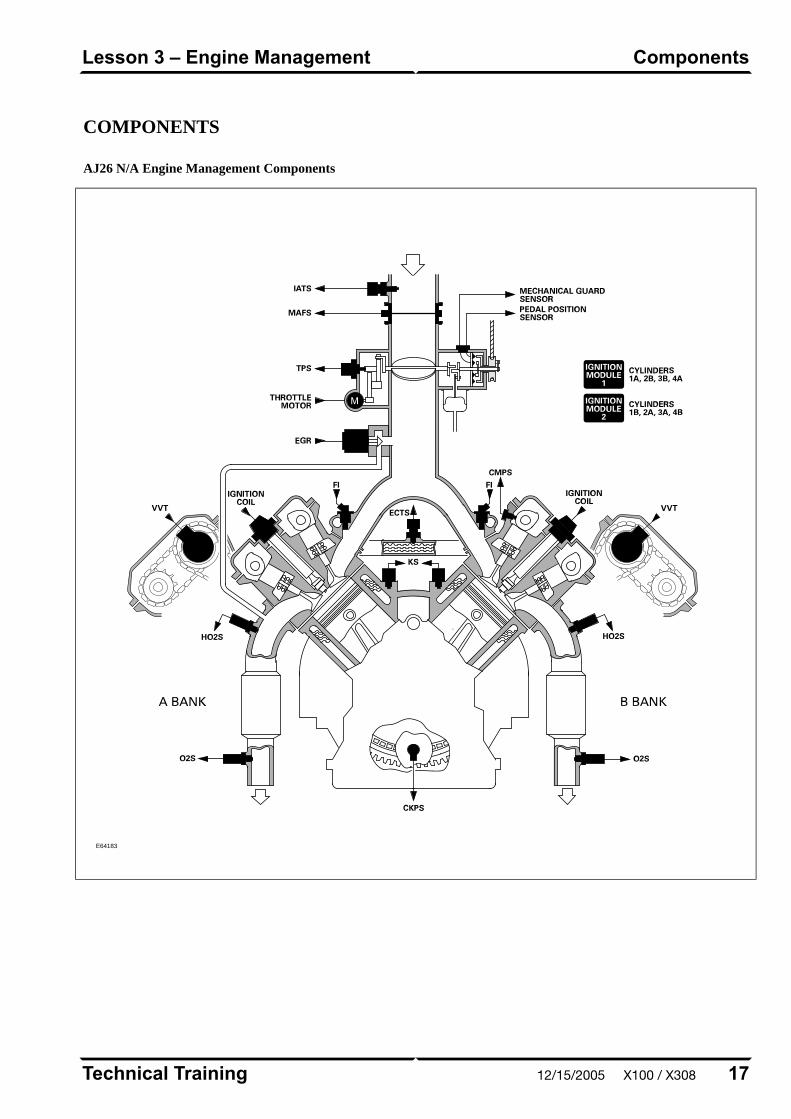
COMPONENTS
AJ26 N/A Engine Management Components
E64183
17Technical Training
ComponentsLesson 3 – Engine Management
12/15/2005 X100 / X308
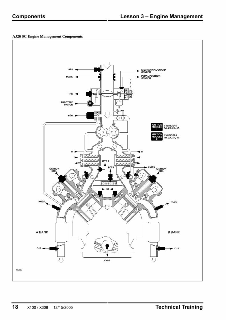
AJ26 SC Engine Management Components
E64184
Technical Training18
Lesson 3 – Engine ManagementComponents
X100 / X308 12/15/2005
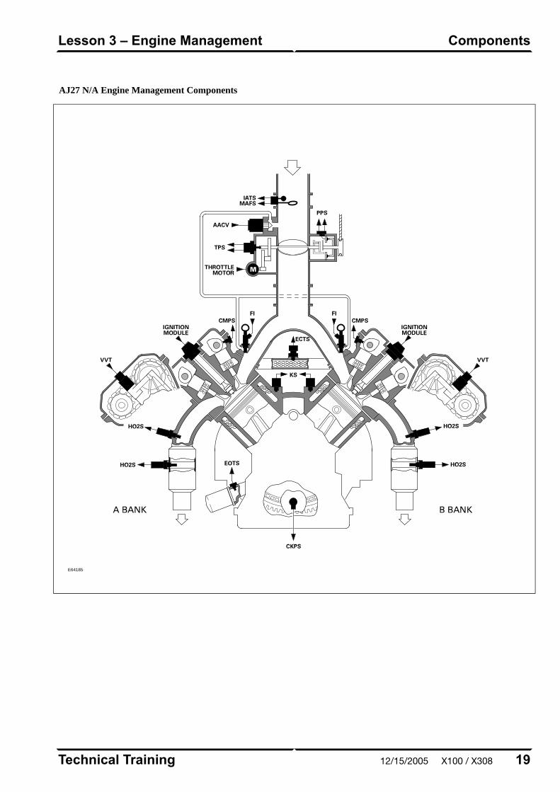
AJ27 N/A Engine Management Components
E64185
19Technical Training
ComponentsLesson 3 – Engine Management
12/15/2005 X100 / X308
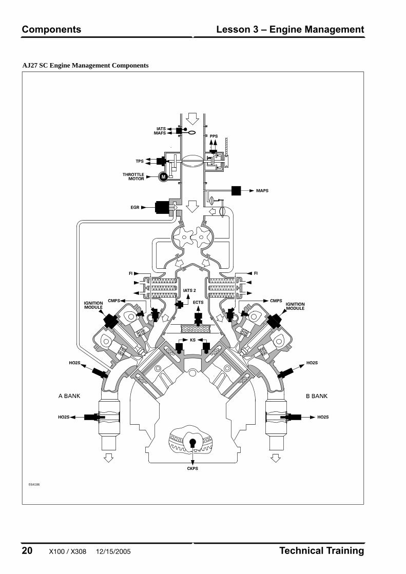
AJ27 SC Engine Management Components
E64186
Technical Training20
Lesson 3 – Engine ManagementComponents
X100 / X308 12/15/2005
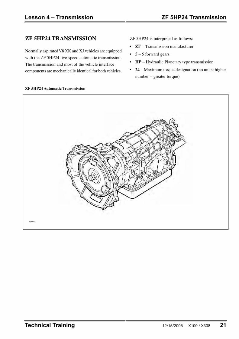
ZF 5HP24 TRANSMISSION
Normally aspirated V8 XK and XJ vehicles are equippedwith the ZF 5HP24 five-speed automatic transmission.The transmission and most of the vehicle interfacecomponents are mechanically identical for both vehicles.
ZF 5HP24 is interpreted as follows:
• ZF – Transmission manufacturer
• 5 – 5 forward gears
• HP – Hydraulic Planetary type transmission
• 24 – Maximum torque designation (no units; highernumber = greater torque)
ZF 5HP24 Automatic Transmission
E58083
21Technical Training
ZF 5HP24 TransmissionLesson 4 – Transmission
12/15/2005 X100 / X308

ZF 5HP24 Specifications
95 kg (210 lb.) with torque converter and fluidTransmission weight
Transmission case in three sections – torque converter housing, main case and
rear extension housing
Torque converter with single-plate controlled slip lock-up clutch
Planetary gear train (no brake bands)
Mechanical features
Capacity – 10 liters (10.6 quarts); filled for life
Type – Esso ATF LT7114
Transmission fluid
External liquid-to-liquid cooler integral with the left hand side radiator tankTransmission fluid cooler
There is no stall test specification for the 5HP24 transmissionStall Test
Reverse5th4th3rd2nd1stGear ratios
4.100.801.001.512.203.57
Service
There are no provisions for owners to verify the
transmission fluid level, as the ZF 5HP24 transmission
is not equipped with a transmission fluid dipstick. Fluid
level is checked using a special dipstick tool while the
engine is running; fluid temperature must be monitored
during the procedure. To inspect the fluid level and
integrity, carefully follow the inspection procedure
found in the Transmission section of the WSM, available
on the GTR website.
NOTE: There are no scheduled fluid level inspections
required for ZF 5HP24. Fluid level should only be
checked if there are signs of an external fluid leak, or
as part of the diagnostic process for customer complaint
of poor shift quality.
Technical Training22
Lesson 4 – TransmissionZF 5HP24 Transmission
X100 / X308 12/15/2005

W5A 580 TRANSMISSION
Supercharged V8 XJ and XK vehicles are equipped with
the W5A 580 five-speed automatic transmission. The
transmission and most of the vehicle interface
components are mechanically identical for both vehicles.
W5A580 is interpreted as follows:
• W – Wandler (German, means 'Torque Converter')
• 5 – 5 forward gears
• A – Version
• 580 – Maximum torque, in Nm
W5A 580 Automatic Transmission
E58107
23Technical Training
W5A 580 TransmissionLesson 4 – Transmission
12/15/2005 X100 / X308

W5A 580 Specifications
81 kg (179 lb) with torque converterTransmission weight
Transmission case in two sections – torque converter housing and main case
Torque converter with two-plate, controlled slip lock-up clutch
Planetary gear train (no brake bands)
Mechanical features
Capacity – 9.4 liters (10 quarts); Filled for life
Type – Shell LA, Jaguar Part Number JLM 20292 (1 liter)
Transmission fluid
External liquid-to-liquid cooler integral with the left hand side radiator tankTransmission fluid cooler
Due to throttle limitation at low vehicle speed, a stall test cannot be performed
on the W5A580 system
Stall test
Maximum 30 miles (50 km) at less than 30 mph (50 km/h)Towing
Reverse5th4th3rd2nd1stGear ratios
1.93 (Normal)
3.16 (Sport)0.831.001.412.193.59
Service
There are no provisions for owners to verify the
transmission fluid level, as the W5A 580 transmission
is not equipped with a transmission fluid dipstick. Fluid
level is checked using a special dipstick tool while the
engine is running; fluid temperature must be monitored
during the procedure. To inspect the fluid level and
integrity, carefully follow the inspection procedure
found in the Transmission section of the WSM, available
on the GTR website.
NOTE: There are no scheduled fluid level inspections
required for W5A 580. Fluid level should only be
checked if there are signs of an external fluid leak, or
as part of the diagnostic process for customer complaint
of poor shift quality.
Technical Training24
Lesson 4 – TransmissionW5A 580 Transmission
X100 / X308 12/15/2005
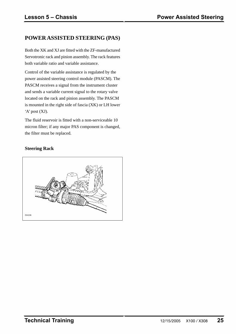
POWER ASSISTED STEERING (PAS)
Both the XK and XJ are fitted with the ZF-manufactured
Servotronic rack and pinion assembly. The rack features
both variable ratio and variable assistance.
Control of the variable assistance is regulated by the
power assisted steering control module (PASCM). The
PASCM receives a signal from the instrument cluster
and sends a variable current signal to the rotary valve
located on the rack and pinion assembly. The PASCM
is mounted in the right side of fascia (XK) or LH lower
‘A’ post (XJ).
The fluid reservoir is fitted with a non-serviceable 10
micron filter; if any major PAS component is changed,
the filter must be replaced.
Steering Rack
E64196
25Technical Training
Power Assisted SteeringLesson 5 – Chassis
12/15/2005 X100 / X308

FRONT SUSPENSION
XK Front Suspension
The front suspension is a double-wishbone designassembled on an aluminum subframe. Control arms andvertical links are manufactured from steel. The wheelbearing is a sealed cartridge assembly.
CAUTION: Do not jack the vehicle on the frontsubframe. Do not attempt to weld or repair thesubframe; if the subframe is damaged, it mustbe replaced.
XK Front Suspension Components
E67052
Front Wheel Alignment
Camber can be minimally adjusted with the installationof a non-factory-fitted eccentric camber bolt in the rearmounting of the lower control arm. Caster can beadjusted by transferring shims between the two shimpacks at each upper control arm mounting. Toe isadjusted via threaded tie rod ends.
CAUTION: Upper control arm shims cannotbe added or removed, only transferred betweenthe front and rear shim packs.
Technical Training26
Lesson 5 – ChassisFront Suspension
X100 / X308 12/15/2005

XJ Front Suspension System: Right Front View
E64187
Front Wheel Alignment
Camber is adjustable via an eccentric bolt located in therear mounting of the lower control arm. Caster isadjustable via an eccentric bolt located in the frontmounting of the lower control arm. Toe is adjusted viathreaded tie rod ends.
27Technical Training
Front SuspensionLesson 5 – Chassis
XJ Front Suspension
The XJ8 front suspension maintains the Jaguar patternof unequal-length ‘A’ arms mounted to a subframe.
12/15/2005 X100 / X308

REAR SUSPENSION (XK and XJ)
The independent rear suspension incorporates co-axial
spring and shock absorber units, a steel subframe,
monostrut, cast iron wishbones and aluminum hub
carriers.
Rear Suspension Components (XK Shown)
E67053
Rear Wheel Alignment
Camber is adjustable by exchanging the
selectable-thickness shim located between the
differential output flange and the axle with one of a
different thickness. Toe is adjustable via an eccentric
fulcrum bolt fitted to the bottom of the hub carrier
assembly.
Technical Training28
Lesson 5 – ChassisRear Suspension (XK and XJ)
X100 / X308 12/15/2005
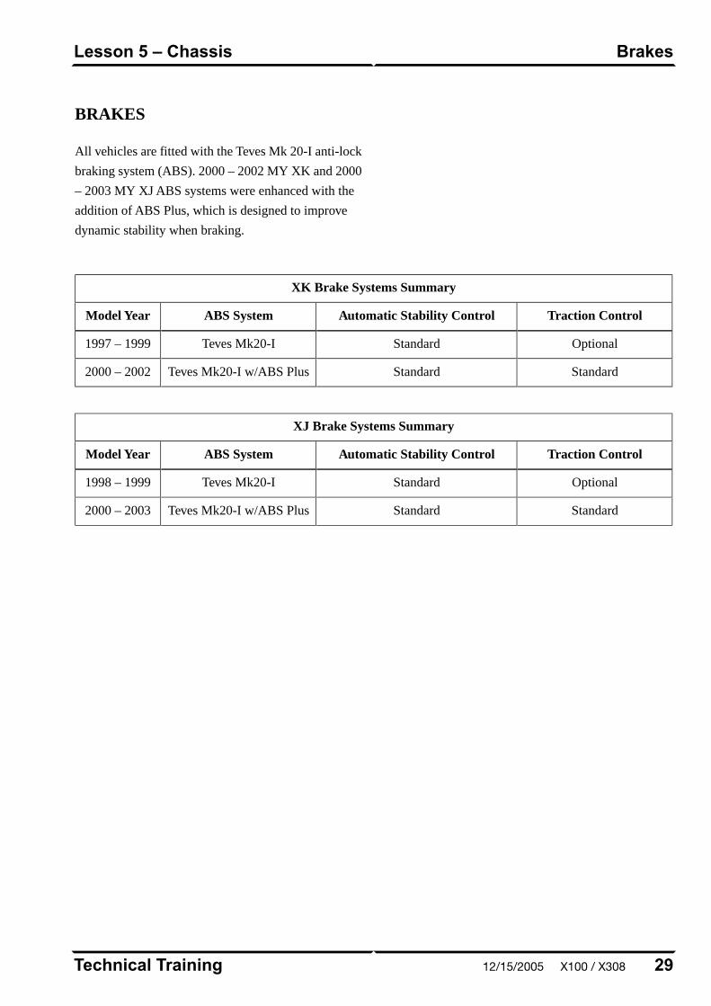
BRAKES
All vehicles are fitted with the Teves Mk 20-I anti-lock
braking system (ABS). 2000 – 2002 MY XK and 2000
– 2003 MY XJ ABS systems were enhanced with the
addition of ABS Plus, which is designed to improve
dynamic stability when braking.
XK Brake Systems Summary
Traction ControlAutomatic Stability ControlABS SystemModel Year
OptionalStandardTeves Mk20-I1997 – 1999
StandardStandardTeves Mk20-I w/ABS Plus2000 – 2002
XJ Brake Systems Summary
Traction ControlAutomatic Stability ControlABS SystemModel Year
OptionalStandardTeves Mk20-I1998 – 1999
StandardStandardTeves Mk20-I w/ABS Plus2000 – 2003
29Technical Training
BrakesLesson 5 – Chassis
12/15/2005 X100 / X308
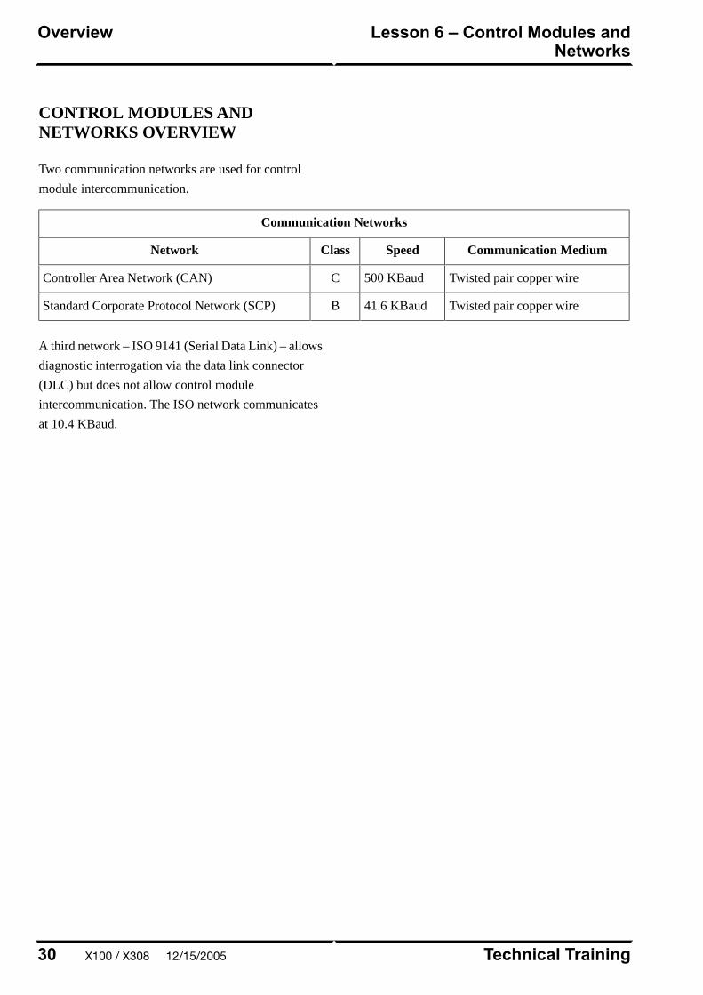
CONTROL MODULES ANDNETWORKS OVERVIEW
Two communication networks are used for control
module intercommunication.
Communication Networks
Communication MediumSpeedClassNetwork
Twisted pair copper wire500 KBaudCController Area Network (CAN)
Twisted pair copper wire41.6 KBaudBStandard Corporate Protocol Network (SCP)
A third network – ISO 9141 (Serial Data Link) – allows
diagnostic interrogation via the data link connector
(DLC) but does not allow control module
intercommunication. The ISO network communicates
at 10.4 KBaud.
Technical Training30
Lesson 6 – Control Modules andNetworks
Overview
X100 / X308 12/15/2005
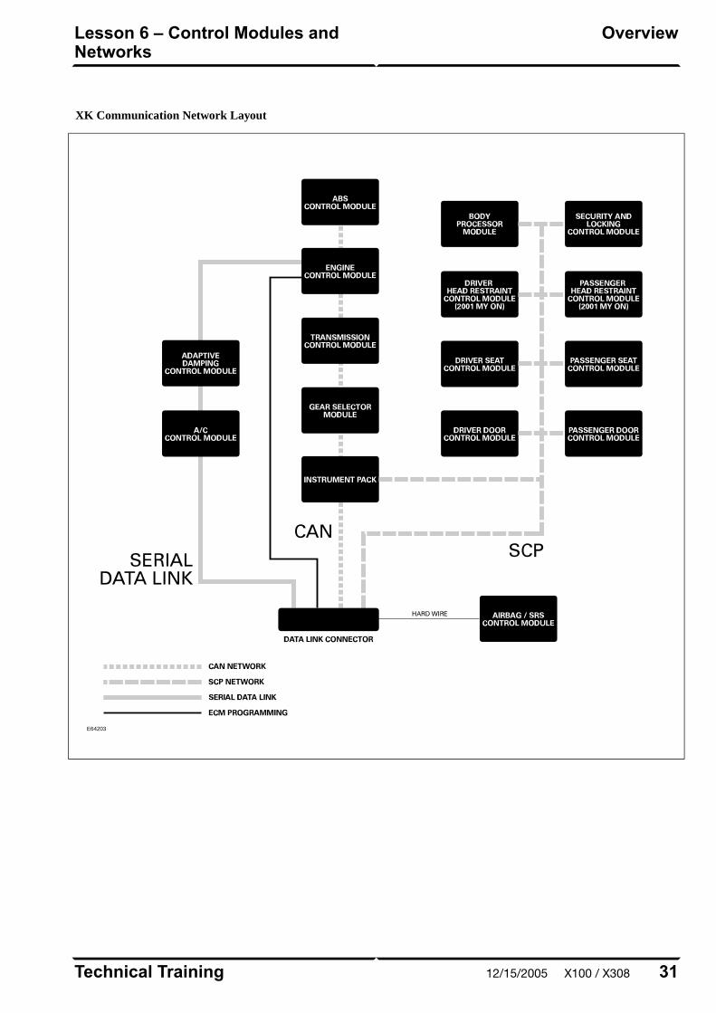
XK Communication Network Layout
E64203
31Technical Training
OverviewLesson 6 – Control Modules andNetworks
12/15/2005 X100 / X308
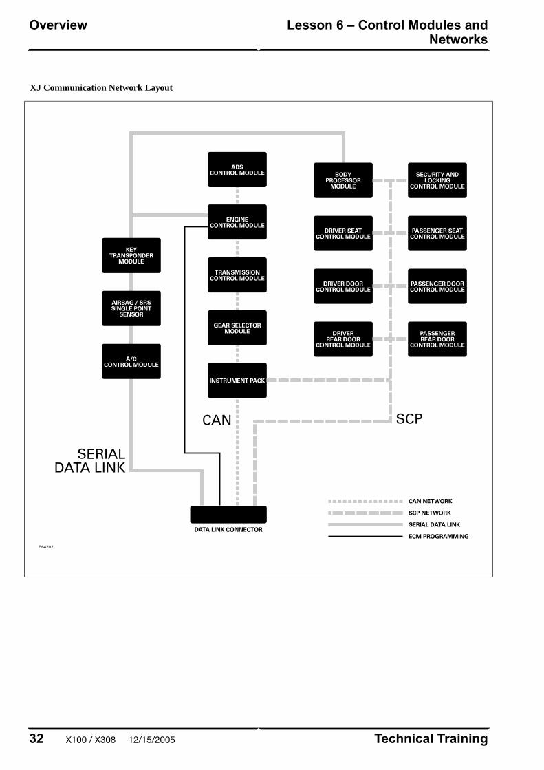
XJ Communication Network Layout
E64202
Technical Training32
Lesson 6 – Control Modules andNetworks
Overview
X100 / X308 12/15/2005
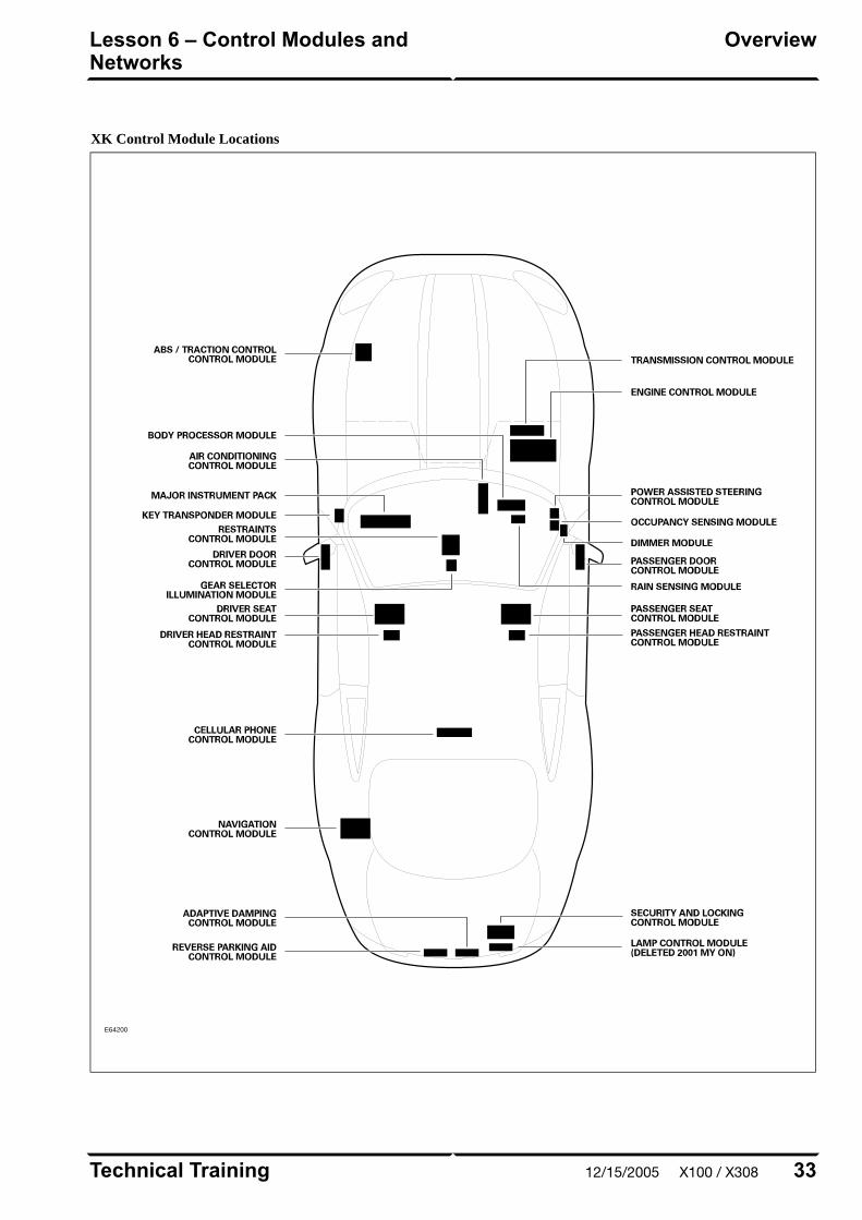
XK Control Module Locations
E64200
33Technical Training
OverviewLesson 6 – Control Modules andNetworks
12/15/2005 X100 / X308
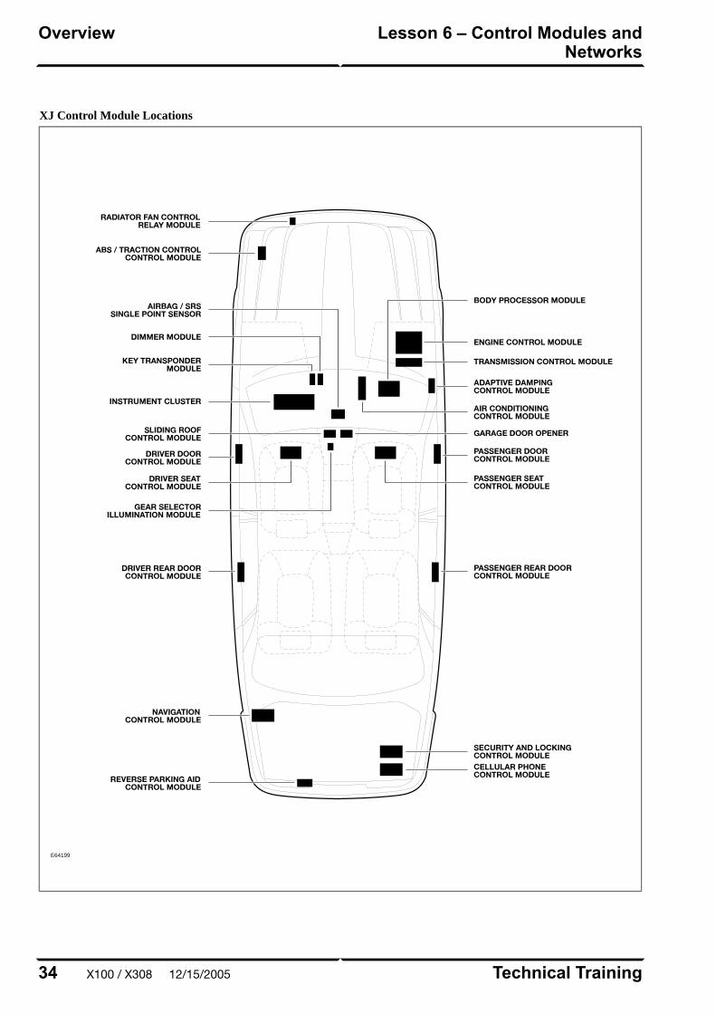
XJ Control Module Locations
E64199
Technical Training34
Lesson 6 – Control Modules andNetworks
Overview
X100 / X308 12/15/2005
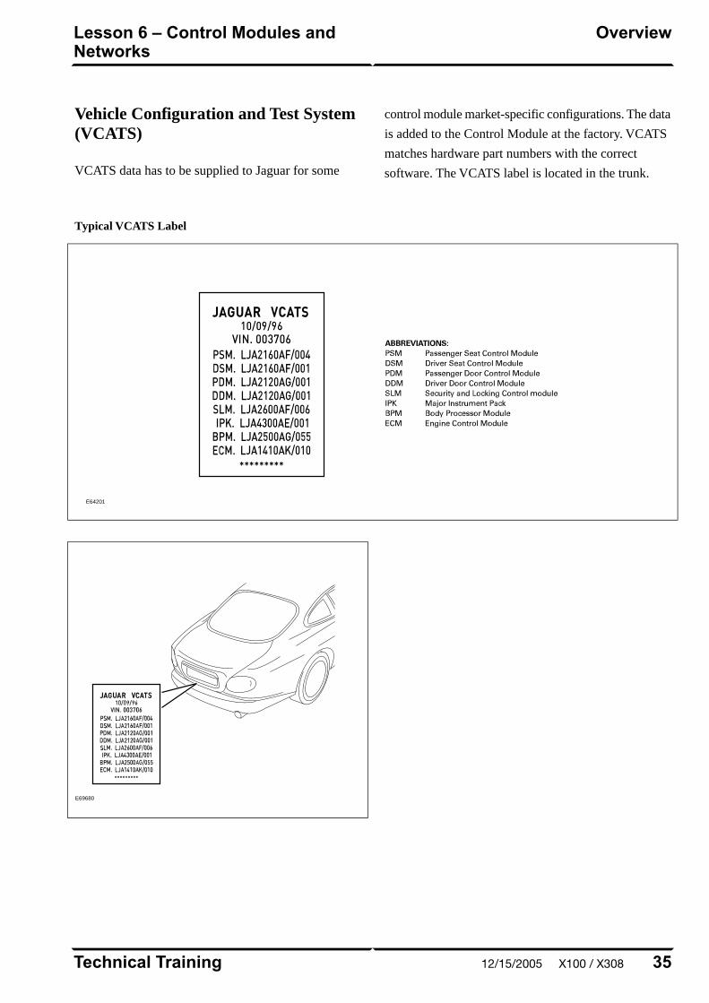
Vehicle Configuration and Test System(VCATS)
VCATS data has to be supplied to Jaguar for some
control module market-specific configurations. The data
is added to the Control Module at the factory. VCATS
matches hardware part numbers with the correct
software. The VCATS label is located in the trunk.
Typical VCATS Label
E64201
E69680
35Technical Training
OverviewLesson 6 – Control Modules andNetworks
12/15/2005 X100 / X308

CLIMATE CONTROL OVERVIEW
The Jaguar Denso Climate Control System is standard
equipment on XK and XJ models. The system is
controlled through a microprocessor-based electronic
control module and a microprocessor-based control
panel. To control cabin temperature, the system uses a
heater valve to regulate the heater matrix temperature.
The windshield, rear window, and mirror heater circuits
are integral with the climate control system. Diagnostic
routines and fault code extraction are available through
control panel diagnostics.
Climate Control Components (XK shown)
E67056
Technical Training36
Lesson 7 – Climate ControlOverview
X100 / X308 12/15/2005

SERVICE
Refrigerant Service Ports
The high-pressure service port is located on the
receiver-dryer assembly. The low-pressure service port
is located near the evaporator end of the
evaporator-to-compressor hose/pipe assembly.
XK Refrigeration System
E67057
37Technical Training
ServiceLesson 7 – Climate Control
12/15/2005 X100 / X308
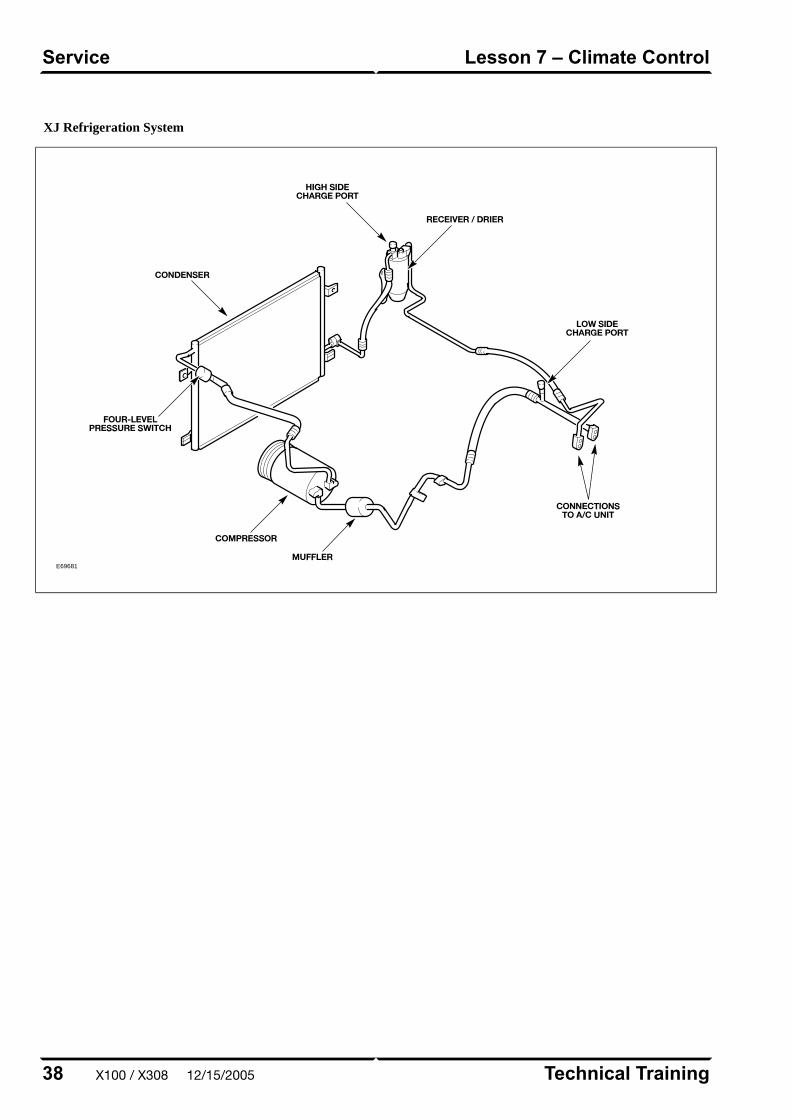
XJ Refrigeration System
E69681
Technical Training38
Lesson 7 – Climate ControlService
X100 / X308 12/15/2005

POWER WINDOWS
XK Power Windows
All windows are equipped with one-touch down
functionality. A brief press of a window switch will
fully lower the respective window. A brief press of the
ROOF switch will lower both rear quarter windows.
The ROOF switch and the door window switches must
be held throughout the duration of their respective
window closings.
To provide for proper seating of the frameless door glass
into the roof/convertible top seal, each door glass is also
equipped with a window drop feature. This feature
lowers the window 15 mm (0.060 in.) when the door is
opened (provided the window was fully raised). Closing
the door will cause the window to return to the fully
raised position, provided it was fully raised when the
door was opened.
If the vehicle power supply is disrupted, the window
drop feature will not function correctly. To restore
proper operation the door windows will need to be
re-programmed.
Door Window Re-programming
1. Close both doors
2. On convertible vehicles, fully close the convertible
top.
3. Press and hold the lower part of the window switch;
when the window is fully lowered, continue to hold
the switch for 5 seconds.
4. Release the switch.
5. Press and hold the upper part of the window switch;
when the window is fully raised, continue to hold
the switch for 5 seconds.
6. Carry out this procedure for driver and passenger
windows.
NOTE: This procedure can be carried out either from
the individual window switches or from the driver’s
switch pack. Quarter windows do not require
programming.
CAUTION: Disconnect the battery before
servicing internal door components or
inadvertent glass movement may occur.
XJ Power Windows
All windows are equipped with one-touch down
functionality. A brief press of a window switch will
fully lower the corresponding window. Windows are
not equipped with a window drop feature or one-touch
up functionality. If the vehicle power supply is
disrupted, normal operation will resume when power is
restored; no initialization is required.
39Technical Training
Power WindowsLesson 8 – Body Systems
12/15/2005 X100 / X308
SUNROOF (XJ ONLY)
The XJ sunroof is equipped with one-touch open and
one-touch close. If an obstruction blocks the sunroof
during one-tough closing, the sunroof will reverse
direction and continue to the fully opened position. If
the vehicle power supply is disrupted, normal operation
will resume when power is restored; no initialization is
required.
Technical Training40
Lesson 8 – Body SystemsSunroof (XJ Only)
X100 / X308 12/15/2005
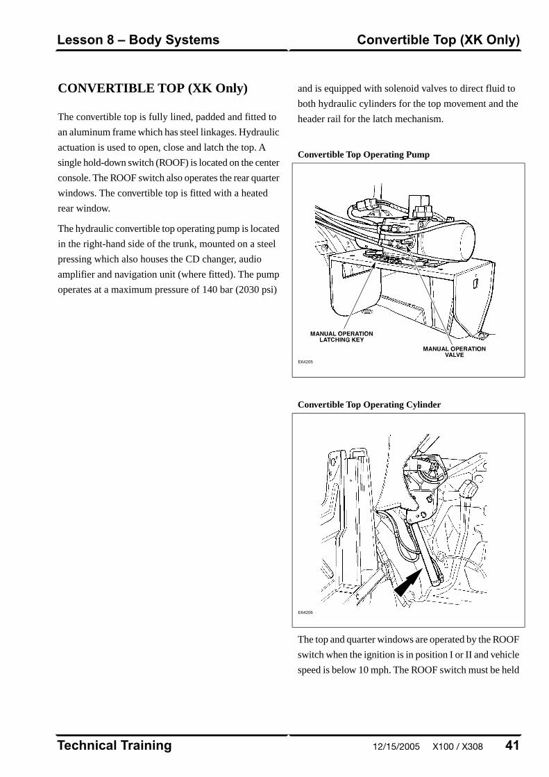
CONVERTIBLE TOP (XK Only)
The convertible top is fully lined, padded and fitted to
an aluminum frame which has steel linkages. Hydraulic
actuation is used to open, close and latch the top. A
single hold-down switch (ROOF) is located on the center
console. The ROOF switch also operates the rear quarter
windows. The convertible top is fitted with a heated
rear window.
The hydraulic convertible top operating pump is located
in the right-hand side of the trunk, mounted on a steel
pressing which also houses the CD changer, audio
amplifier and navigation unit (where fitted). The pump
operates at a maximum pressure of 140 bar (2030 psi)
and is equipped with solenoid valves to direct fluid to
both hydraulic cylinders for the top movement and the
header rail for the latch mechanism.
Convertible Top Operating Pump
E64205
Convertible Top Operating Cylinder
E64206
The top and quarter windows are operated by the ROOF
switch when the ignition is in position I or II and vehicle
speed is below 10 mph. The ROOF switch must be held
41Technical Training
Convertible Top (XK Only)Lesson 8 – Body Systems
12/15/2005 X100 / X308
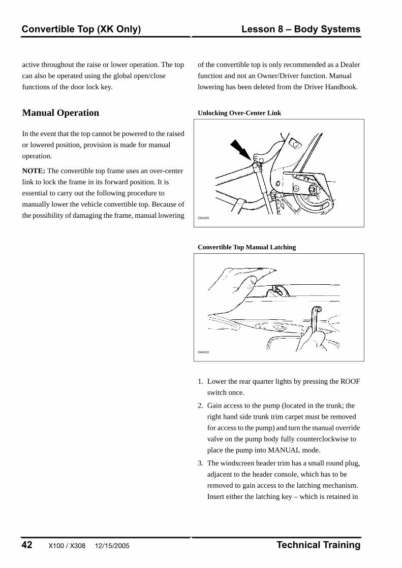
active throughout the raise or lower operation. The top
can also be operated using the global open/close
functions of the door lock key.
Manual Operation
In the event that the top cannot be powered to the raised
or lowered position, provision is made for manual
operation.
NOTE: The convertible top frame uses an over-center
link to lock the frame in its forward position. It is
essential to carry out the following procedure to
manually lower the vehicle convertible top. Because of
the possibility of damaging the frame, manual lowering
of the convertible top is only recommended as a Dealer
function and not an Owner/Driver function. Manual
lowering has been deleted from the Driver Handbook.
Unlocking Over-Center Link
E64209
Convertible Top Manual Latching
E64210
1. Lower the rear quarter lights by pressing the ROOF
switch once.
2. Gain access to the pump (located in the trunk; the
right hand side trunk trim carpet must be removed
for access to the pump) and turn the manual override
valve on the pump body fully counterclockwise to
place the pump into MANUAL mode.
3. The windscreen header trim has a small round plug,
adjacent to the header console, which has to be
removed to gain access to the latching mechanism.
Insert either the latching key – which is retained in
Technical Training42
Lesson 8 – Body SystemsConvertible Top (XK Only)
X100 / X308 12/15/2005
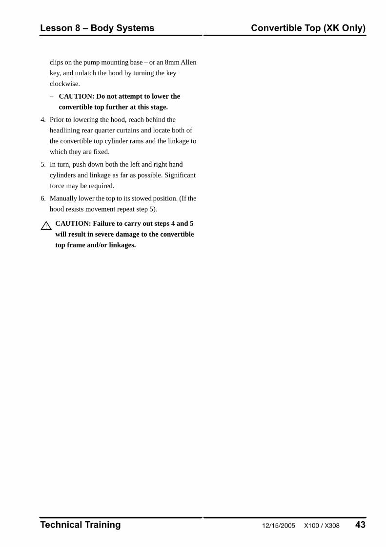
clips on the pump mounting base – or an 8mm Allen
key, and unlatch the hood by turning the key
clockwise.
– CAUTION: Do not attempt to lower the
convertible top further at this stage.
4. Prior to lowering the hood, reach behind the
headlining rear quarter curtains and locate both of
the convertible top cylinder rams and the linkage to
which they are fixed.
5. In turn, push down both the left and right hand
cylinders and linkage as far as possible. Significant
force may be required.
6. Manually lower the top to its stowed position. (If the
hood resists movement repeat step 5).
CAUTION: Failure to carry out steps 4 and 5
will result in severe damage to the convertible
top frame and/or linkages.
43Technical Training
Convertible Top (XK Only)Lesson 8 – Body Systems
12/15/2005 X100 / X308

REMOTE CONTROL KEYHEAD RFTRANSMITTER
The radio frequency (RF) transmitter is operational only
when the key is removed from the ignition barrel. The
RF transmitter allows remote control of the following
features:
• Security system arming/disarming
• Door locking/unlocking
• Headlight convenience
• Panic alarm
• Trunk lid release
• Valet mode (deactivation only)
Remote Control Keyhead RF Transmitter
E64213
RF transmitter button functions are as follows (numbers
correspond to the illustration):
1. Lock
2. Unlock
3. Headlamp convenience / panic alarm
4. Trunk lid release
Technical Training44
Lesson 9 – Security SystemRemote Control Keyhead RFTransmitter
X100 / X308 12/15/2005
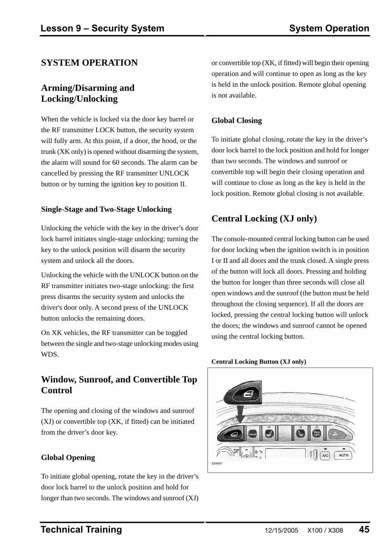
SYSTEM OPERATION
Arming/Disarming andLocking/Unlocking
When the vehicle is locked via the door key barrel or
the RF transmitter LOCK button, the security system
will fully arm. At this point, if a door, the hood, or the
trunk (XK only) is opened without disarming the system,
the alarm will sound for 60 seconds. The alarm can be
cancelled by pressing the RF transmitter UNLOCK
button or by turning the ignition key to position II.
Single-Stage and Two-Stage Unlocking
Unlocking the vehicle with the key in the driver’s door
lock barrel initiates single-stage unlocking: turning the
key to the unlock position will disarm the security
system and unlock all the doors.
Unlocking the vehicle with the UNLOCK button on the
RF transmitter initiates two-stage unlocking: the first
press disarms the security system and unlocks the
driver's door only. A second press of the UNLOCK
button unlocks the remaining doors.
On XK vehicles, the RF transmitter can be toggled
between the single and two-stage unlocking modes using
WDS.
Window, Sunroof, and Convertible TopControl
The opening and closing of the windows and sunroof
(XJ) or convertible top (XK, if fitted) can be initiated
from the driver’s door key.
Global Opening
To initiate global opening, rotate the key in the driver’s
door lock barrel to the unlock position and hold for
longer than two seconds. The windows and sunroof (XJ)
or convertible top (XK, if fitted) will begin their opening
operation and will continue to open as long as the key
is held in the unlock position. Remote global opening
is not available.
Global Closing
To initiate global closing, rotate the key in the driver’s
door lock barrel to the lock position and hold for longer
than two seconds. The windows and sunroof or
convertible top will begin their closing operation and
will continue to close as long as the key is held in the
lock position. Remote global closing is not available.
Central Locking (XJ only)
The console-mounted central locking button can be used
for door locking when the ignition switch is in position
I or II and all doors and the trunk closed. A single press
of the button will lock all doors. Pressing and holding
the button for longer than three seconds will close all
open windows and the sunroof (the button must be held
throughout the closing sequence). If all the doors are
locked, pressing the central locking button will unlock
the doors; the windows and sunroof cannot be opened
using the central locking button.
Central Locking Button (XJ only)
E69687
45Technical Training
System OperationLesson 9 – Security System
12/15/2005 X100 / X308
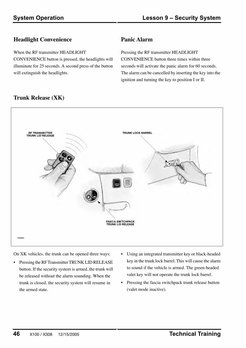
Headlight Convenience
When the RF transmitter HEADLIGHTCONVENIENCE button is pressed, the headlights willilluminate for 25 seconds. A second press of the buttonwill extinguish the headlights.
Panic Alarm
Pressing the RF transmitter HEADLIGHTCONVENIENCE button three times within threeseconds will activate the panic alarm for 60 seconds.The alarm can be cancelled by inserting the key into theignition and turning the key to position I or II.
Trunk Release (XK)
E69683
On XK vehicles, the trunk can be opened three ways:
Technical Training46
Lesson 9 – Security SystemSystem Operation
• Pressing the RF Transmitter TRUNK LID RELEASEbutton. If the security system is armed, the trunk willbe released without the alarm sounding. When thetrunk is closed, the security system will resume inthe armed state.
• Using an integrated transmitter key or black-headedkey in the trunk lock barrel. This will cause the alarmto sound if the vehicle is armed. The green-headedvalet key will not operate the trunk lock barrel.
• Pressing the fascia switchpack trunk release button(valet mode inactive).
X100 / X308 12/15/2005
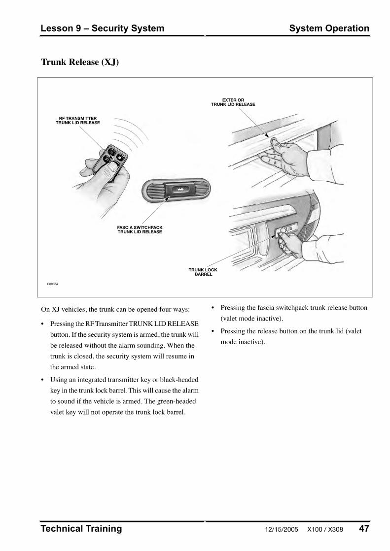
Trunk Release (XJ)
E69684
On XJ vehicles, the trunk can be opened four ways:
• Pressing the RF Transmitter TRUNK LID RELEASEbutton. If the security system is armed, the trunk willbe released without the alarm sounding. When thetrunk is closed, the security system will resume inthe armed state.
• Using an integrated transmitter key or black-headedkey in the trunk lock barrel. This will cause the alarmto sound if the vehicle is armed. The green-headedvalet key will not operate the trunk lock barrel.
• Pressing the fascia switchpack trunk release button(valet mode inactive).
• Pressing the release button on the trunk lid (valetmode inactive).
47Technical Training
System OperationLesson 9 – Security System
12/15/2005 X100 / X308

(message will only appear if the key is in position II).When in valet mode, trunk opening from the fascia andtrunk-mounted release buttons is inhibited. Locking theglove compartment with the black-headed key willfurther minimize valet driver access.
XK Valet Button
E69685
XJ Valet Button
E69686
If the vehicle is in valet mode and a green-headed keyis given to the valet driver, the driver will only be ableto:
• Unlock (disarm) and Lock (arm) the vehicle via thedriver’s door lock barrel.
• Start and drive the car.
Valet mode can be cancelled by:
• Using a remote to unlock (disarm) the vehicle.
• Using a black-headed or remote-control key to openthe trunk via the trunk lock barrel.
Technical Training48
Lesson 9 – Security SystemSystem Operation
Valet Mode
Valet mode is activated when the fascia VALET buttonis pressed. A valet mode chime will sound and a valetmode message will be displayed in the message center
X100 / X308 12/15/2005
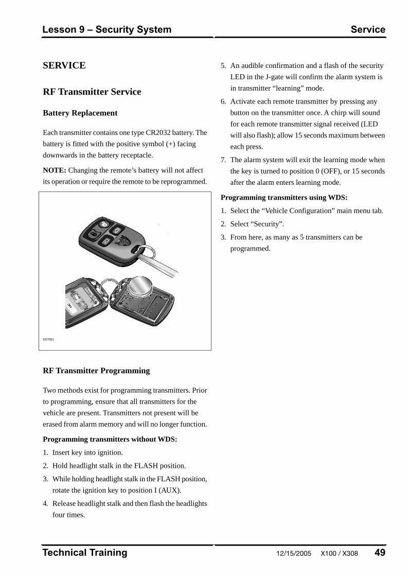
SERVICE
RF Transmitter Service
Battery Replacement
Each transmitter contains one type CR2032 battery. The
battery is fitted with the positive symbol (+) facing
downwards in the battery receptacle.
NOTE: Changing the remote’s battery will not affect
its operation or require the remote to be reprogrammed.
E67061
RF Transmitter Programming
Two methods exist for programming transmitters. Prior
to programming, ensure that all transmitters for the
vehicle are present. Transmitters not present will be
erased from alarm memory and will no longer function.
Programming transmitters without WDS:
1. Insert key into ignition.
2. Hold headlight stalk in the FLASH position.
3. While holding headlight stalk in the FLASH position,
rotate the ignition key to position I (AUX).
4. Release headlight stalk and then flash the headlights
four times.
5. An audible confirmation and a flash of the security
LED in the J-gate will confirm the alarm system is
in transmitter “learning” mode.
6. Activate each remote transmitter by pressing any
button on the transmitter once. A chirp will sound
for each remote transmitter signal received (LED
will also flash); allow 15 seconds maximum between
each press.
7. The alarm system will exit the learning mode when
the key is turned to position 0 (OFF), or 15 seconds
after the alarm enters learning mode.
Programming transmitters using WDS:
1. Select the “Vehicle Configuration” main menu tab.
2. Select “Security”.
3. From here, as many as 5 transmitters can be
programmed.
49Technical Training
ServiceLesson 9 – Security System
12/15/2005 X100 / X308

ENGINE IMMOBILIZATION
The engine immobilization system ensures that the
engine can only be started using a valid ignition key.
Key Transponder Module System
Engine immobilization is achieved through the use of
a key transponder module (KTM) which “reads” a code
transmitted by a transponder in the key head. The engine
starting sequence is as follows:
• KTM receives a signal from the ignition switch
position I as key is turned
• KTM energizes the reader/exciter which causes the
key transponder to broadcast its security code
• If the key transponder code matches the programmed
KTM code, the KTM outputs an OK TO START
signal to the ECM via a serial data link
• ECM receives the OK TO START signal and P/N
signal (hardwired from the transmission), and enables
fueling and ignition
• ECM outputs a SECURITY ACKNOWLEDGE
signal to the body processor module (BPM) via a
serial data link
• BPM receives a park signal from the gear selector
not-in-park switch and enables cranking (provided
the security system has been disarmed)
Technical Training50
Lesson 9 – Security SystemEngine Immobilization
X100 / X308 12/15/2005
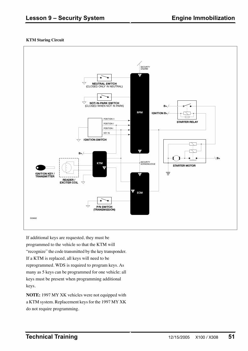
KTM Staring Circuit
E69682
If additional keys are requested, they must beprogrammed to the vehicle so that the KTM will“recognize” the code transmitted by the key transponder.If a KTM is replaced, all keys will need to bereprogrammed. WDS is required to program keys. Asmany as 5 keys can be programmed for one vehicle; allkeys must be present when programming additionalkeys.
NOTE: 1997 MY XK vehicles were not equipped witha KTM system. Replacement keys for the 1997 MY XKdo not require programming.
51Technical Training
Engine ImmobilizationLesson 9 – Security System
12/15/2005 X100 / X308
3. Select “Security System Setup”.
4. Select “Program New Transponders”.
5. Follow the onscreen prompts to program each of thekeys.
Technical Training52
Lesson 9 – Security SystemEngine Immobilization
Key Transponder Programming Using WDS
Key transponders can only be programmed using WDS.
Ensure that all of the vehicle’s keys are available forthis procedure. Ensure that only the key beingprogrammed is in or near the ignition; if the othervehicle keys are near the reader/exciter, they may alsobe detected, causing the KTM to interpret an invalidsignal.
1. Load the latest software for the vehicle into WDS.
2. Access “Vehicle Setup”.
X100 / X308 12/15/2005

XK ELECTROMECHANICAL SRS:1997 – 2000 MY
Jaguar XK vehicles from 1997 – 2000 MY are equippedwith an electromechanical supplemental restraint system(SRS).
An airbag is fitted to both the steering wheel and thepassenger side fascia. In addition, the front seat beltretractors include pyrotechnic pre-tensioners. 1997 –
1999 MY XK vehicles are equipped with mechanicallytriggered pre-tensioners; 2000 MY vehicles useelectrically triggered pre-tensioners which are activatedby the pre-tensioner control module. Side airbags arenot fitted.
In a frontal impact of sufficient force, both frontalairbags will be deployed. Each pre-tensioning seat beltwill be deployed if the seat belt(s) are in use at the timeof impact.
XK SRS Component Locations
E69688
53Technical Training
XK Electromechanical SRS: 1997 –2000 MY
Lesson 10 – Supplemental RestraintSystem
12/15/2005 X100 / X308

fully retracted (not in use). When the seat belt is pulledfrom the retractor reel, the safety lever moves and theunit is ready to activate if an impact occurs.
Front Seat Belt Pre-Tensioner: 1997 – 99 MY
E64231
WARNINGS:
When handling the retractor unit, the pistonmust always be pointed down and away fromanyone. Keep fingers away from the retractorreel mechanism.
If a pre-tensioning unit is dropped from a heightgreater than 0.3 m (12 in.), it must not be fittedto a vehicle.
Technical Training54
Lesson 10 – Supplemental RestraintSystem
XK Electromechanical SRS: 1997 –2000 MY
Mechanically Triggered Pre-Tensioners
The pre-tensioner is armed at installation by screwingin the arming pin to fully depress the red arming button.Once installed, a safety lever prevents the impact sensorfrom activating the pre-tensioner when the seat belt is
X100 / X308 12/15/2005
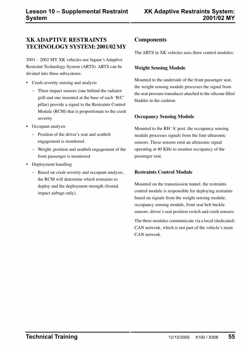
XK ADAPTIVE RESTRAINTSTECHNOLOGY SYSTEM: 2001/02 MY
2001 – 2002 MY XK vehicles use Jaguar’s AdaptiveRestraint Technology System (ARTS). ARTS can bedivided into three subsystems:
• Crash severity sensing and analysis
– Three impact sensors (one behind the radiatorgrill and one mounted at the base of each ‘B/C’pillar) provide a signal to the Restraints ControlModule (RCM) that is proportionate to the crashseverity
• Occupant analysis
– Position of the driver’s seat and seatbeltengagement is monitored
– Weight, position and seatbelt engagement of thefront passenger is monitored
• Deployment handling
– Based on crash severity and occupant analysis,the RCM will determine which restraints todeploy and the deployment strength (frontalimpact airbags only).
Components
The ARTS in XK vehicles uses three control modules:
Weight Sensing Module
Mounted to the underside of the front passenger seat,the weight sensing module processes the signal fromthe seat pressure transducer attached to the silicone filledbladder in the cushion.
Occupancy Sensing Module
Mounted to the RH ‘A’ post, the occupancy sensingmodule processes signals from the four ultrasonicsensors. These sensors emit an ultrasonic signaloperating at 40 KHz to monitor occupancy of thepassenger seat.
Restraints Control Module
Mounted on the transmission tunnel, the restraintscontrol module is responsible for deploying restraintsbased on signals from the weight sensing module,occupancy sensing module, front seat belt bucklesensors, driver’s seat position switch and crash sensors.
The three modules communicate via a local (dedicated)CAN network, which is not part of the vehicle’s mainCAN network.
55Technical Training
XK Adaptive Restraints System:2001/02 MY
Lesson 10 – Supplemental RestraintSystem
12/15/2005 X100 / X308
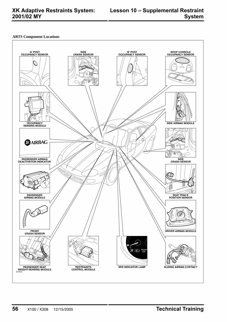
ARTS Component Locations
E67062
Technical Training56
Lesson 10 – Supplemental RestraintSystem
XK Adaptive Restraints System:2001/02 MY
X100 / X308 12/15/2005
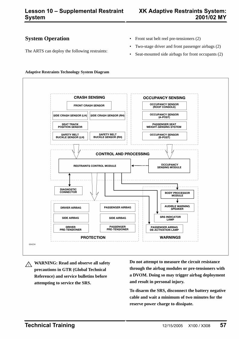
System Operation
The ARTS can deploy the following restraints:
• Front seat belt reel pre-tensioners (2)
• Two-stage driver and front passenger airbags (2)
• Seat-mounted side airbags for front occupants (2)
Adaptive Restraints Technology System Diagram
E64234
WARNING: Read and observe all safety
precautions in GTR (Global Technical
Reference) and service bulletins before
attempting to service the SRS.
Do not attempt to measure the circuit resistance
through the airbag modules or pre-tensioners with
a DVOM. Doing so may trigger airbag deployment
and result in personal injury.
To disarm the SRS, disconnect the battery negative
cable and wait a minimum of two minutes for the
reserve power charge to dissipate.
57Technical Training
XK Adaptive Restraints System:2001/02 MY
Lesson 10 – Supplemental RestraintSystem
12/15/2005 X100 / X308
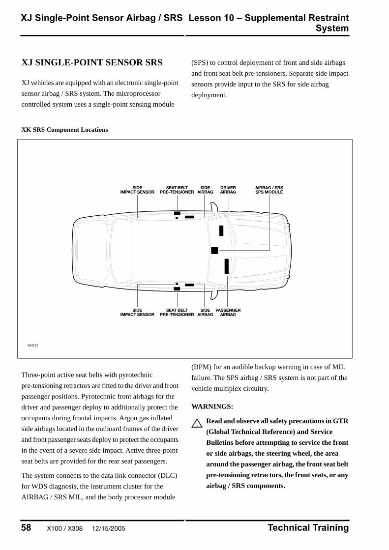
XJ SINGLE-POINT SENSOR SRS
XJ vehicles are equipped with an electronic single-point
sensor airbag / SRS system. The microprocessor
controlled system uses a single-point sensing module
(SPS) to control deployment of front and side airbags
and front seat belt pre-tensioners. Separate side impact
sensors provide input to the SRS for side airbag
deployment.
XK SRS Component Locations
E64222
Three-point active seat belts with pyrotechnic
pre-tensioning retractors are fitted to the driver and front
passenger positions. Pyrotechnic front airbags for the
driver and passenger deploy to additionally protect the
occupants during frontal impacts. Argon gas inflated
side airbags located in the outboard frames of the driver
and front passenger seats deploy to protect the occupants
in the event of a severe side impact. Active three-point
seat belts are provided for the rear seat passengers.
The system connects to the data link connector (DLC)
for WDS diagnosis, the instrument cluster for the
AIRBAG / SRS MIL, and the body processor module
(BPM) for an audible backup warning in case of MIL
failure. The SPS airbag / SRS system is not part of the
vehicle multiplex circuitry.
WARNINGS:
Read and observe all safety precautions in GTR
(Global Technical Reference) and Service
Bulletins before attempting to service the front
or side airbags, the steering wheel, the area
around the passenger airbag, the front seat belt
pre-tensioning retractors, the front seats, or any
airbag / SRS components.
Technical Training58
Lesson 10 – Supplemental RestraintSystem
XJ Single-Point Sensor Airbag / SRS
X100 / X308 12/15/2005
Observe all safety precautions when handling
or transporting airbag modules.
Do not attempt to measure circuit resistance
through the airbag modules or the seat belt
pre-tensioning retractor units with a DVOM.
Doing so may trigger deployment and result in
personal injury.
Do not attempt to replace the airbag / SRS
battery power fuse unless the system is
disarmed.
To disarm the SRS system, disconnect the
negative battery cable and wait a minimum of
TWO minutes for the reserve power charge to
dissipate.
59Technical Training
XJ Single-Point Sensor Airbag / SRSLesson 10 – Supplemental RestraintSystem
12/15/2005 X100 / X308
IN-CAR ENTERTAINMENT (ICE)
Selectable Features
Simultaneously pressing and holding the AM/FM and
EJECT button will display the audio system selectable
features on the radio display or navigation screen (if
fitted). The following options are selectable through the
following preset buttons:
• Preset 1 – Toggles Radio Broadcast Data System
(RBDS) on/off.
• Preset 2 – Toggles the TAPE CLEAN reminder
on/off.
• Preset 3 – Toggles the AERIAL CLEAN reminder
on/off.
• Preset 4 – Toggles the automatic mute facility
on/off. This should be ON if the vehicle is fitted with
a telephone.
• Preset 5 – Toggles the automatic tape eject when
key is turned OFF.
• Preset 6 – Not used.
• Preset 7 – Toggles the diversity antenna on/off. This
should be OFF, as the diversity antenna was not fitted
to X100 or X308 vehicles.
• Preset 8 – Toggles the Alternate Frequency (AF)
on/off. Used when reception problems occur with
RBDS stations. Toggling AF ON/OFF will eliminate
drop-out on RBDS channels.
• Preset 9 – Not used.
• Preset 0 – Not used.
Setting the Clock
XK vehicles without navigation and all XJ vehicles are
fitted with an analog clock. The time can be adjusted
by pressing the ‘+’ and ‘-’ buttons on the front of the
dial.
On XK vehicles fitted with navigation, time is displayed
via digital clock in the lower left of the navigation
screen. The correct time is maintained automatically
from the GPS satellite signals and no manual adjustment
is required. Ensure that the proper time zone and
summer time (Daylight Savings Time) settings are
correct for the current location and time of year. These
options are accessible by pressing the MENU button
while the navigation map is displayed. Select SETUP
from the on-screen menu.
Technical Training60
Lesson 11 – InfotainmentIn-Car Entertainment (ICE)
X100 / X308 12/15/2005
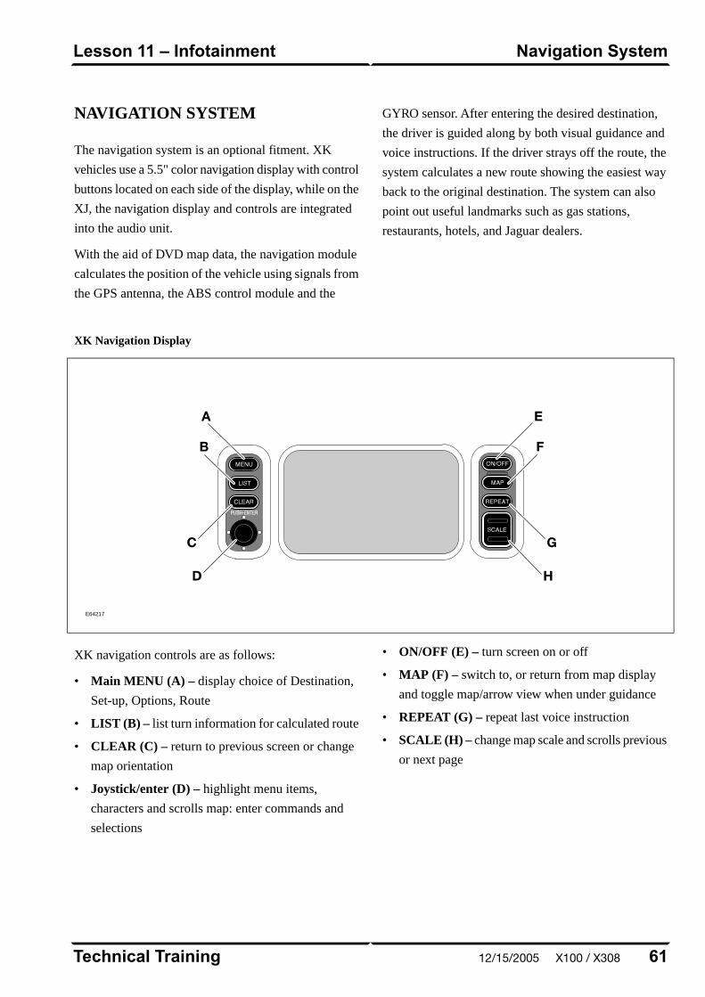
NAVIGATION SYSTEM
The navigation system is an optional fitment. XK
vehicles use a 5.5" color navigation display with control
buttons located on each side of the display, while on the
XJ, the navigation display and controls are integrated
into the audio unit.
With the aid of DVD map data, the navigation module
calculates the position of the vehicle using signals from
the GPS antenna, the ABS control module and the
GYRO sensor. After entering the desired destination,
the driver is guided along by both visual guidance and
voice instructions. If the driver strays off the route, the
system calculates a new route showing the easiest way
back to the original destination. The system can also
point out useful landmarks such as gas stations,
restaurants, hotels, and Jaguar dealers.
XK Navigation Display
E64217
XK navigation controls are as follows:
• Main MENU (A) – display choice of Destination,
Set-up, Options, Route
• LIST (B) – list turn information for calculated route
• CLEAR (C) – return to previous screen or change
map orientation
• Joystick/enter (D) – highlight menu items,
characters and scrolls map: enter commands and
selections
• ON/OFF (E) – turn screen on or off
• MAP (F) – switch to, or return from map display
and toggle map/arrow view when under guidance
• REPEAT (G) – repeat last voice instruction
• SCALE (H) – change map scale and scrolls previous
or next page
61Technical Training
Navigation SystemLesson 11 – Infotainment
12/15/2005 X100 / X308

XJ Audio Unit with Navigation Controls
E64216
XJ navigation controls are as follows:
• Volume control (A) – adjusts audio system volume
and audio/navigation voice guidance balance
• MODE button (B) – select navigation volume adjust
• CLEAR (C) – return to previous menu, character
or text; clear screen at end of route
• Cruciform scroll keys (D) – move cursor up/down
and left/right
• ENTER (E) – enter command for selected menu,
character of prompt acknowledge
• RPT (F) – repeat last voice instruction
• NAV (G) – activate navigation system
The navigation module is mounted in the trunk between
the CD changer and audio power amplifier. The Global
Positioning System (GPS) antenna is located below the
parcel shelf trim (coupe/sedan) or convertible top recess
(convertible).
Navigation System DVD Reader (XK Shown)
E64218
Technical Training62
Lesson 11 – InfotainmentNavigation System
X100 / X308 12/15/2005
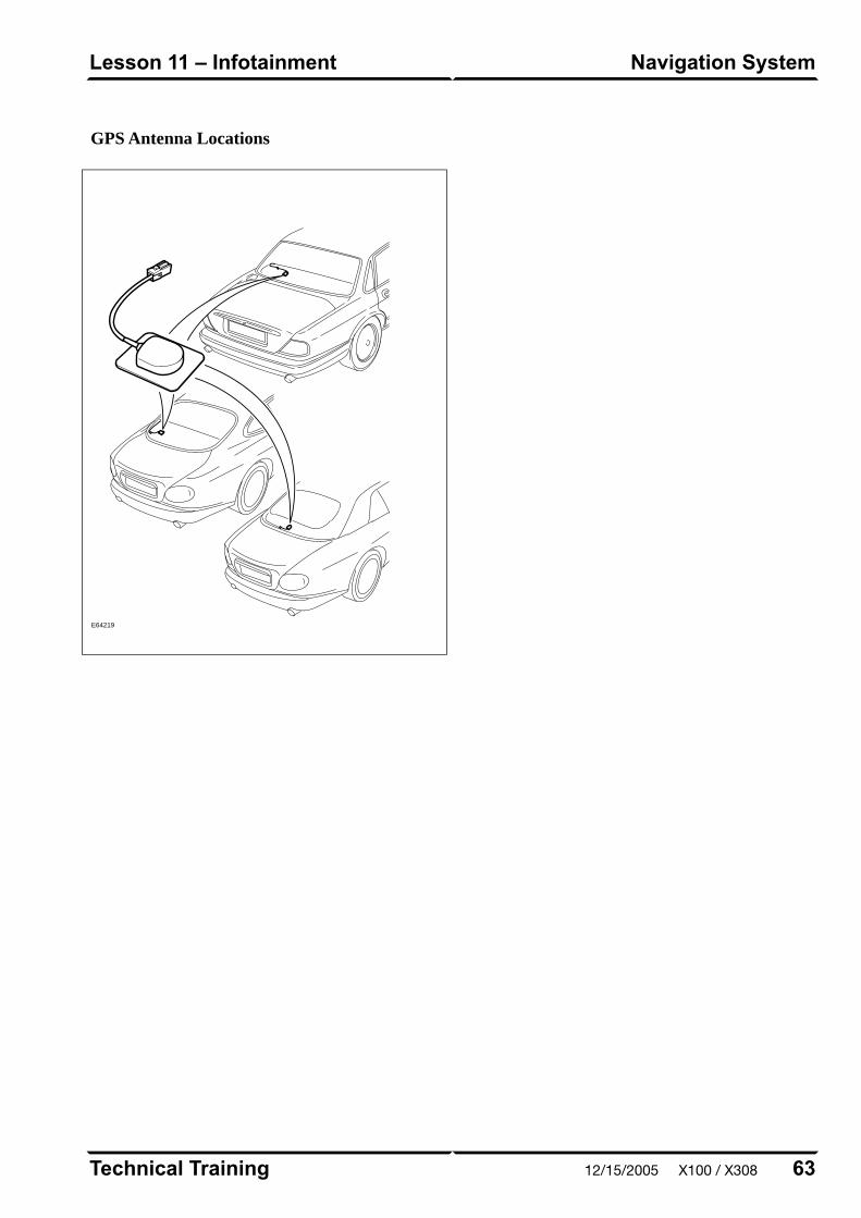
GPS Antenna Locations
E64219
63Technical Training
Navigation SystemLesson 11 – Infotainment
12/15/2005 X100 / X308

Curriculum Training
Introduction to Jaguar
Introduction to XK: X103/X105
E63055
Technical Training INTR 05 en 08/2005INTR: X103/X105

To the best of our knowledge, the illustrations, technical information, data and descriptions in this issue were correct at the time
of going to print. The right to change prices, specifications, equipment and maintenance instructions at any time without notice
is reserved as part of our policy of continuous development and improvement for the benefit of our customers.
No part of this publication may be reproduced, stored in a data processing system or transmitted in any form, electronic,
mechanical, photocopy, recording, translation or by any other means without prior permission of Premier Automotive Group.
No liability can be accepted for any inaccuracies in this publication, although every possible care has been taken to make it as
complete and accurate as possible.
Copyright ©2005
Please remember that our training literature has been prepared for TRAINING PURPOSES only. Repairs and
adjustments MUST always be carried out according to the instructions and specifications in the workshop literature.
Please make full use of the training offered by Technical Training to gain extensive knowledge of both theory
and practice.
1Technical Training
Preface
12/15/2005 X103 / X105

PAGE
Lesson 1 – General Information
5Overview......................................................................................................................................................
7Identification Labels...................................................................................................................................
8Lifting and Jacking.....................................................................................................................................
Lesson 2 – Engines
9Overview......................................................................................................................................................
11Details..........................................................................................................................................................
Lesson 3 – Engine Management
13Overview......................................................................................................................................................
14Engine Control Module..............................................................................................................................
15Components.................................................................................................................................................
Lesson 4 – Transmission
17Overview......................................................................................................................................................
Lesson 5 – Chassis
19Power Assisted Steering.............................................................................................................................
20Front Suspension........................................................................................................................................
21Rear Suspension..........................................................................................................................................
22Brakes..........................................................................................................................................................
Technical Training2
Table of Contents
X103 / X105 12/15/2005
Lesson 6 – Control Modules and Networks
23Overview......................................................................................................................................................
Lesson 7 – Climate Control
26Overview......................................................................................................................................................
27Service..........................................................................................................................................................
Lesson 8 – Body Systems
28Power Windows...........................................................................................................................................
29Convertible Top...........................................................................................................................................
Lesson 9 – Security System
32Remote Control Keyhead RF Transmitter...............................................................................................
33System Operation.......................................................................................................................................
36Service..........................................................................................................................................................
Lesson 10 – Supplemental Restraint System
37Overview......................................................................................................................................................
38Components.................................................................................................................................................
40System Operation.......................................................................................................................................
Lesson 11 – Infotainment
41In-Car Entertainment (ICE).....................................................................................................................
42Navigation....................................................................................................................................................
3Technical Training
Table of Contents
12/15/2005 X103 / X105
4
Safety and Precautions
Workshop safety
This page highlights the general observations expectedwhile attending this training program, and itscontinuation upon returning to your place of work.
General
While working on all vehicles, the following itemswhere available should always be used:
• Fender covers
• Seat covers
• Floor protection
Safety
All precautions must be taken and observed at all times,to prevent injury or damage to the following:
• Yourself
• Customer's property
• Workshop equipment
• Work place colleagues
Operating guidelines
While using any piece of workshop equipment:
The manufacturer's guidelines and warning labels mustbe followed.
This will ensure correct use and application at all times.
Seek the necessary advice or training where equipmentusage is unclear.
Chemicals, Oils and Solvents
Follow all manufacturer's warnings and labels; also takeinto account local disposal regulations when workingwith chemicals, oils or solvents.
Ensure that all risks are completely minimized.
Make sure that all protective items of clothing are wornwhere required e.g.
• Eye protection
• Gloves
• Coveralls
• Footwear
System capping
Upon disconnecting components from a system, takeall precautions necessary to prevent systemcontamination or environmental leakage.
Fit relevant plugs or caps i.e. to pipes, unions andcomponent orifices etc.
Updates
Keep abreast of all relevant changes that affect yourrole within the dealership, by monitoring all factoryissued documentation.
Driving
Operating vehicle features, such as ICE, mobile phonesand CD player equipment etc., can cause a momentarydistraction while driving.
Follow all traffic regulations when operating vehiclesystems or using diagnostic equipment while on the move.
Mobile diagnostic equipment operation may requirethe use of an assistant.
X103 / X105 12/15/2005
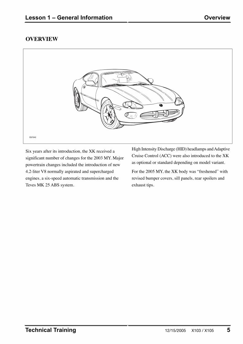
OVERVIEW
E67043
Six years after its introduction, the XK received asignificant number of changes for the 2003 MY. Majorpowertrain changes included the introduction of new4.2-liter V8 normally aspirated and superchargedengines, a six-speed automatic transmission and theTeves MK 25 ABS system.
High Intensity Discharge (HID) headlamps and AdaptiveCruise Control (ACC) were also introduced to the XKas optional or standard depending on model variant.
For the 2005 MY, the XK body was “freshened” withrevised bumper covers, sill panels, rear spoilers andexhaust tips.
5Technical Training
OverviewLesson 1 – General Information
12/15/2005 X103 / X105
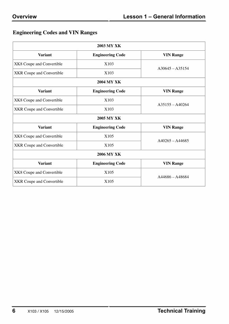
A40265 – A44685X105XK8 Coupe and Convertible
X105XKR Coupe and Convertible
2006 MY XK
VIN RangeEngineering CodeVariant
A44686 – A48684X105XK8 Coupe and Convertible
X105XKR Coupe and Convertible
Technical Training6
Lesson 1 – General InformationOverview
Engineering Codes and VIN Ranges
2003 MY XK
VIN RangeEngineering CodeVariant
A30645 – A35154X103XK8 Coupe and Convertible
X103XKR Coupe and Convertible
2004 MY XK
VIN RangeEngineering CodeVariant
A35155 – A40264X103XK8 Coupe and Convertible
X103XKR Coupe and Convertible
2005 MY XK
VIN RangeEngineering CodeVariant
X103 / X105 12/15/2005
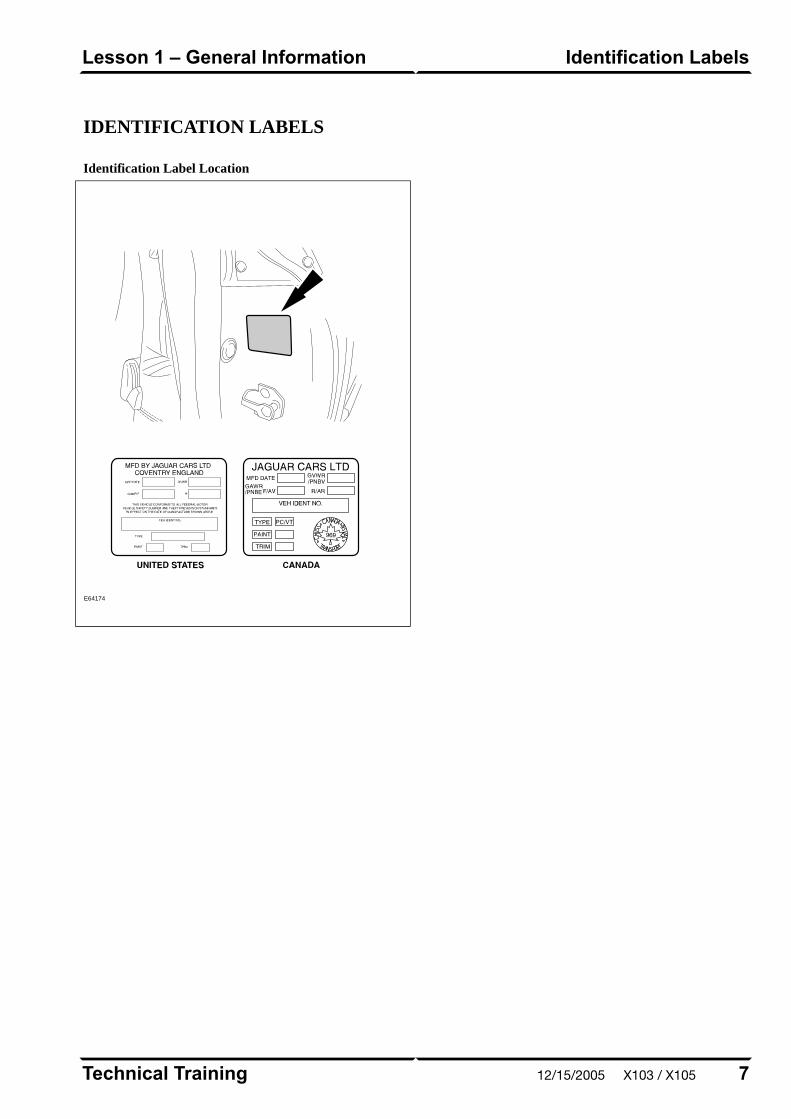
IDENTIFICATION LABELS
Identification Label Location
E64174
7Technical Training
Identification LabelsLesson 1 – General Information
12/15/2005 X103 / X105
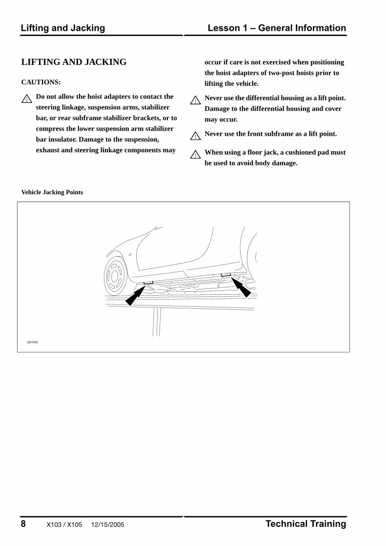
LIFTING AND JACKING
CAUTIONS:
Do not allow the hoist adapters to contact the
steering linkage, suspension arms, stabilizer
bar, or rear subframe stabilizer brackets, or to
compress the lower suspension arm stabilizer
bar insulator. Damage to the suspension,
exhaust and steering linkage components may
occur if care is not exercised when positioning
the hoist adapters of two-post hoists prior to
lifting the vehicle.
Never use the differential housing as a lift point.
Damage to the differential housing and cover
may occur.
Never use the front subframe as a lift point.
When using a floor jack, a cushioned pad must
be used to avoid body damage.
Vehicle Jacking Points
E67045
Technical Training8
Lesson 1 – General InformationLifting and Jacking
X103 / X105 12/15/2005
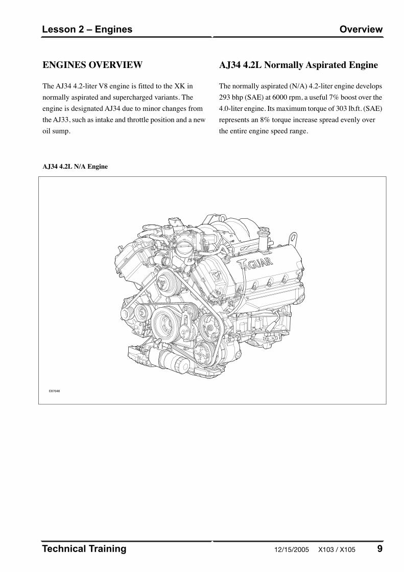
ENGINES OVERVIEW
The AJ34 4.2-liter V8 engine is fitted to the XK innormally aspirated and supercharged variants. Theengine is designated AJ34 due to minor changes fromthe AJ33, such as intake and throttle position and a newoil sump.
AJ34 4.2L Normally Aspirated Engine
The normally aspirated (N/A) 4.2-liter engine develops293 bhp (SAE) at 6000 rpm, a useful 7% boost over the4.0-liter engine. Its maximum torque of 303 lb.ft. (SAE)represents an 8% torque increase spread evenly overthe entire engine speed range.
AJ34 4.2L N/A Engine
E67046
9Technical Training
OverviewLesson 2 – Engines
12/15/2005 X103 / X105
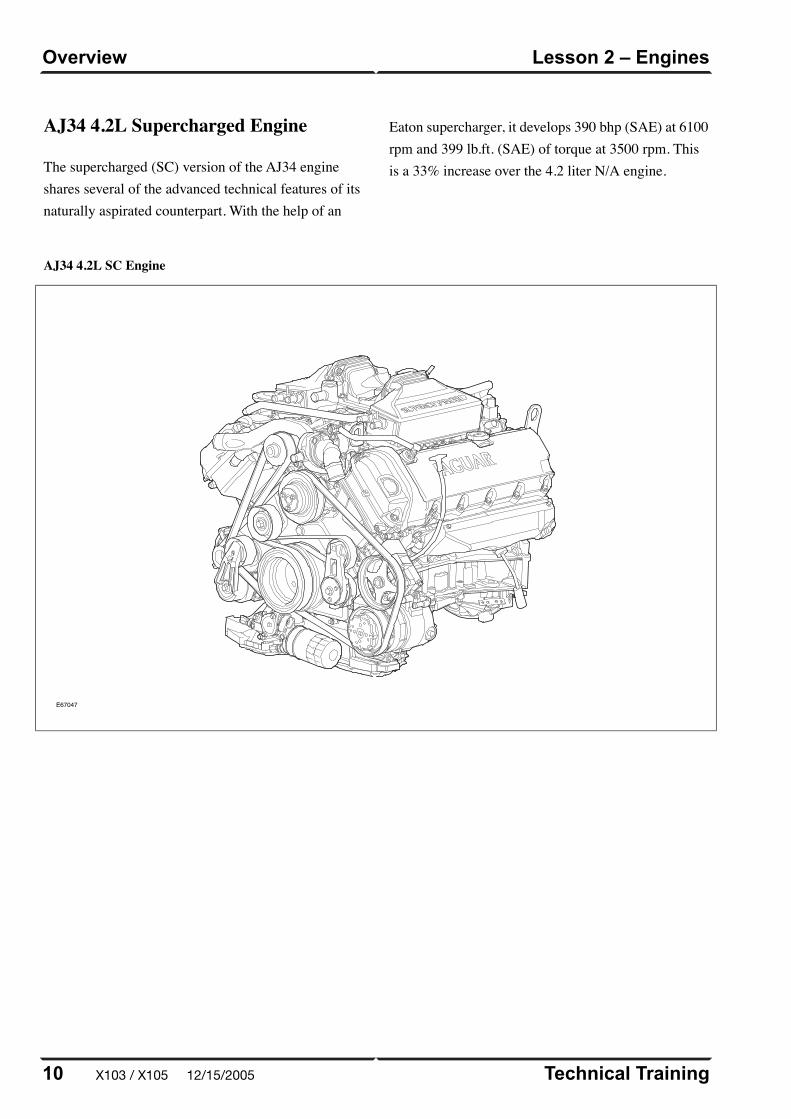
AJ34 4.2L SC Engine
E67047
Technical Training10
Lesson 2 – EnginesOverview
AJ34 4.2L Supercharged Engine
The supercharged (SC) version of the AJ34 engineshares several of the advanced technical features of itsnaturally aspirated counterpart. With the help of an
Eaton supercharger, it develops 390 bhp (SAE) at 6100rpm and 399 lb.ft. (SAE) of torque at 3500 rpm. Thisis a 33% increase over the 4.2 liter N/A engine.
X103 / X105 12/15/2005
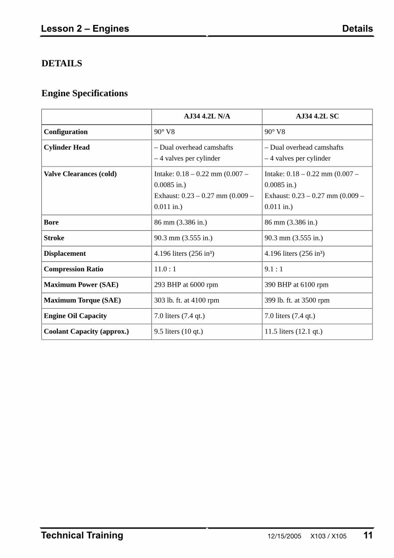
DETAILS
Engine Specifications
AJ34 4.2L SCAJ34 4.2L N/A
90° V890° V8Configuration
– Dual overhead camshafts
– 4 valves per cylinder
– Dual overhead camshafts
– 4 valves per cylinder
Cylinder Head
Intake: 0.18 – 0.22 mm (0.007 –
0.0085 in.)
Exhaust: 0.23 – 0.27 mm (0.009 –
0.011 in.)
Intake: 0.18 – 0.22 mm (0.007 –
0.0085 in.)
Exhaust: 0.23 – 0.27 mm (0.009 –
0.011 in.)
Valve Clearances (cold)
86 mm (3.386 in.)86 mm (3.386 in.)Bore
90.3 mm (3.555 in.)90.3 mm (3.555 in.)Stroke
4.196 liters (256 in³)4.196 liters (256 in³)Displacement
9.1 : 111.0 : 1Compression Ratio
390 BHP at 6100 rpm293 BHP at 6000 rpmMaximum Power (SAE)
399 lb. ft. at 3500 rpm303 lb. ft. at 4100 rpmMaximum Torque (SAE)
7.0 liters (7.4 qt.)7.0 liters (7.4 qt.)Engine Oil Capacity
11.5 liters (12.1 qt.)9.5 liters (10 qt.)Coolant Capacity (approx.)
11Technical Training
DetailsLesson 2 – Engines
12/15/2005 X103 / X105
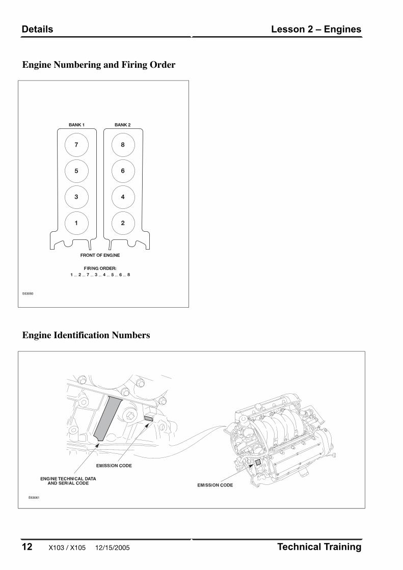
Engine Numbering and Firing Order
E63060
Engine Identification Numbers
E63061
Technical Training12
Lesson 2 – EnginesDetails
X103 / X105 12/15/2005

ENGINE MANAGEMENTOVERVIEW
The Jaguar/Denso 32-bit Engine Management System
(EMS) was designed as a generic system applicable to
all Jaguar engines in use across the model ranges. The
system is built around a dual-processor Engine Control
Module (ECM). One microprocessor is dedicated to
throttle control and diagnostics; the other microprocessor
handles all other ECM functions, controls and
diagnostics.
13Technical Training
OverviewLesson 3 – Engine Management
12/15/2005 X103 / X105
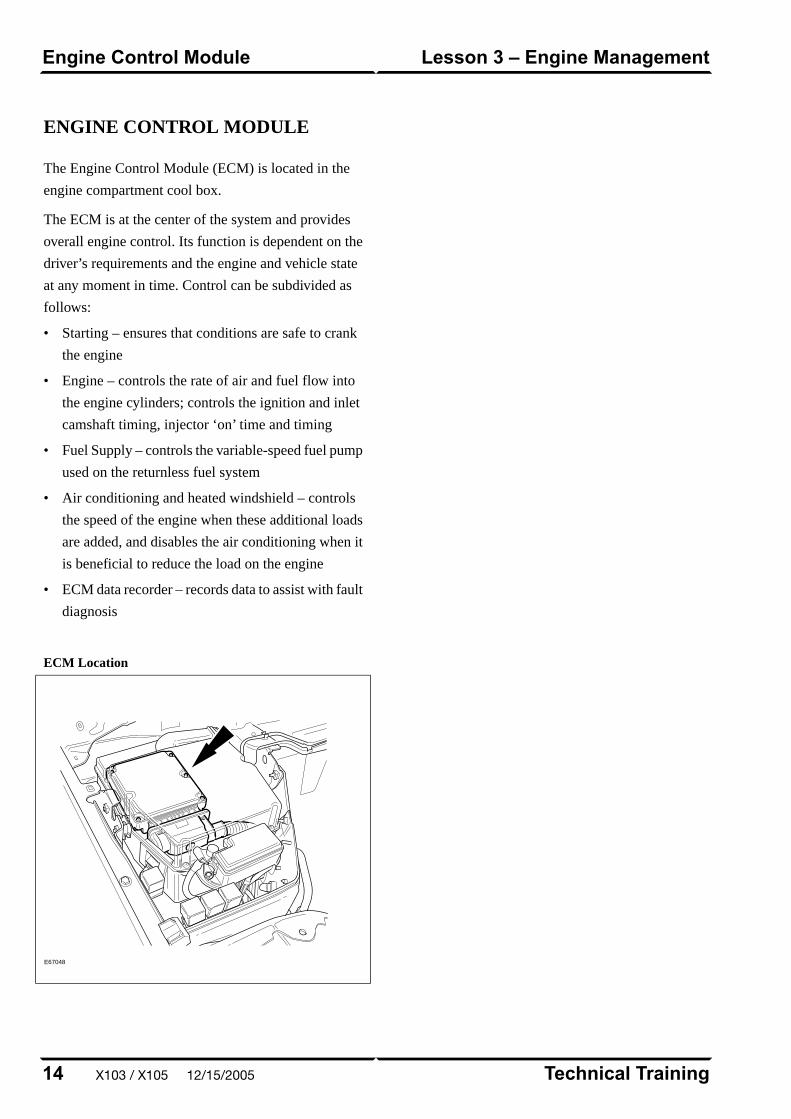
ENGINE CONTROL MODULE
The Engine Control Module (ECM) is located in the
engine compartment cool box.
The ECM is at the center of the system and provides
overall engine control. Its function is dependent on the
driver’s requirements and the engine and vehicle state
at any moment in time. Control can be subdivided as
follows:
• Starting – ensures that conditions are safe to crank
the engine
• Engine – controls the rate of air and fuel flow into
the engine cylinders; controls the ignition and inlet
camshaft timing, injector ‘on’ time and timing
• Fuel Supply – controls the variable-speed fuel pump
used on the returnless fuel system
• Air conditioning and heated windshield – controls
the speed of the engine when these additional loads
are added, and disables the air conditioning when it
is beneficial to reduce the load on the engine
• ECM data recorder – records data to assist with fault
diagnosis
ECM Location
E67048
Technical Training14
Lesson 3 – Engine ManagementEngine Control Module
X103 / X105 12/15/2005
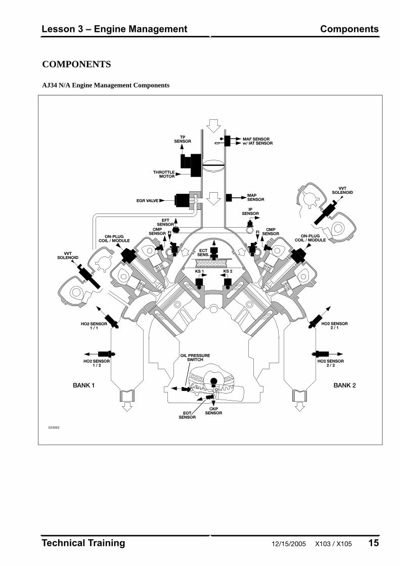
COMPONENTS
AJ34 N/A Engine Management Components
E63063
15Technical Training
ComponentsLesson 3 – Engine Management
12/15/2005 X103 / X105
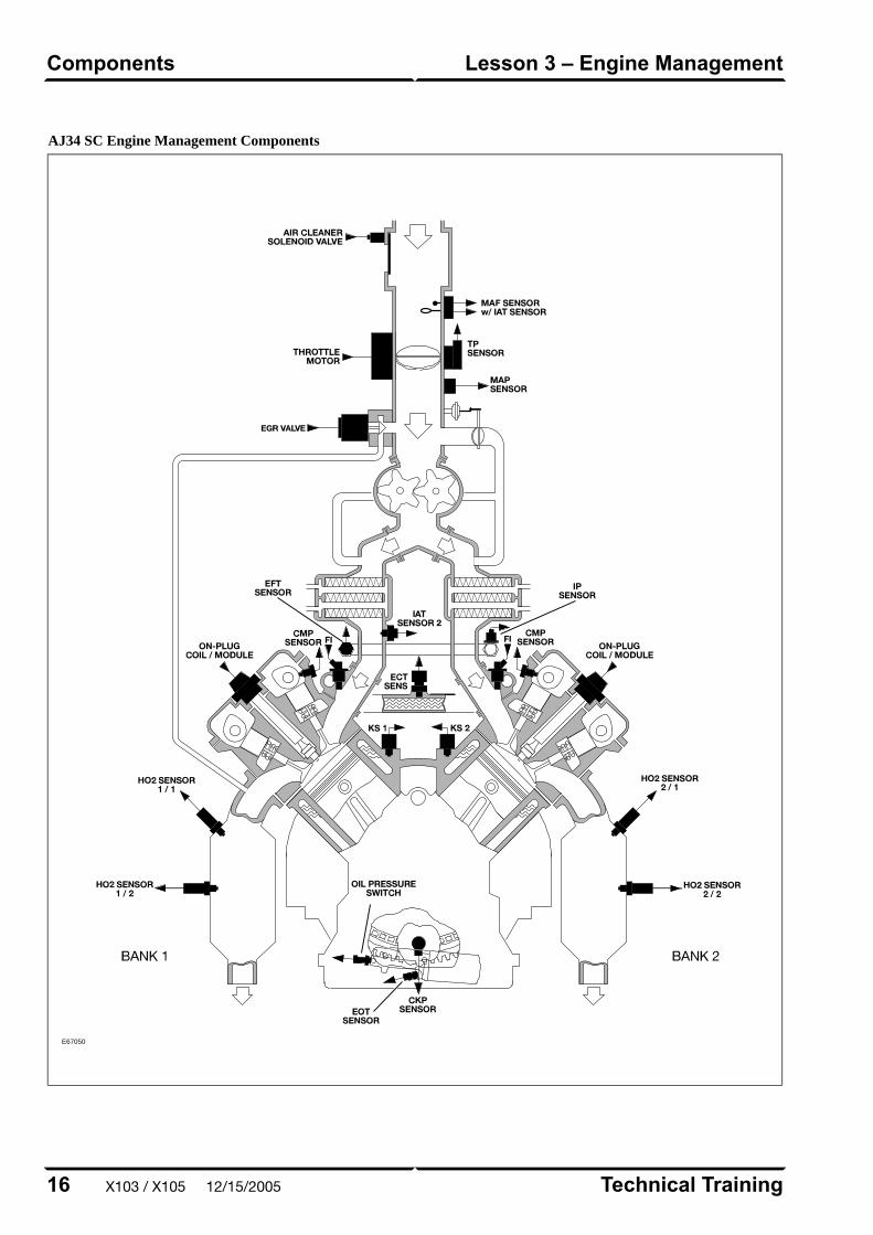
AJ34 SC Engine Management Components
E67050
Technical Training16
Lesson 3 – Engine ManagementComponents
X103 / X105 12/15/2005
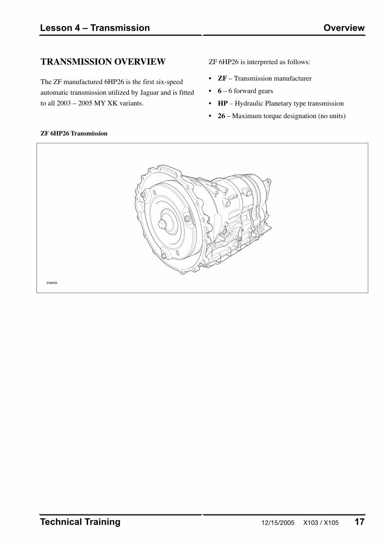
TRANSMISSION OVERVIEW
The ZF manufactured 6HP26 is the first six-speedautomatic transmission utilized by Jaguar and is fittedto all 2003 – 2005 MY XK variants.
ZF 6HP26 is interpreted as follows:
• ZF – Transmission manufacturer
• 6 – 6 forward gears
• HP – Hydraulic Planetary type transmission
• 26 – Maximum torque designation (no units)
ZF 6HP26 Transmission
E58459
17Technical Training
OverviewLesson 4 – Transmission
12/15/2005 X103 / X105
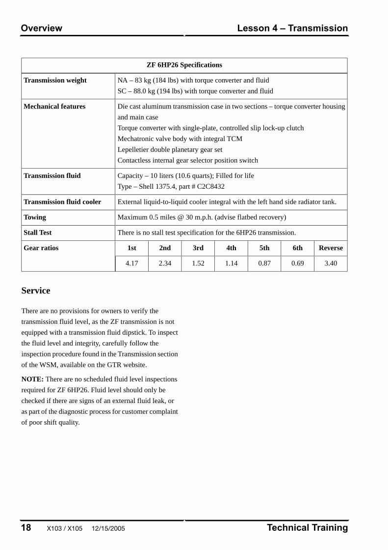
ZF 6HP26 Specifications
NA – 83 kg (184 lbs) with torque converter and fluid
SC – 88.0 kg (194 lbs) with torque converter and fluid
Transmission weight
Die cast aluminum transmission case in two sections – torque converter housing
and main case
Torque converter with single-plate, controlled slip lock-up clutch
Mechatronic valve body with integral TCM
Lepelletier double planetary gear set
Contactless internal gear selector position switch
Mechanical features
Capacity – 10 liters (10.6 quarts); Filled for life
Type – Shell 1375.4, part # C2C8432
Transmission fluid
External liquid-to-liquid cooler integral with the left hand side radiator tank.Transmission fluid cooler
Maximum 0.5 miles @ 30 m.p.h. (advise flatbed recovery)Towing
There is no stall test specification for the 6HP26 transmission.Stall Test
Reverse6th5th4th3rd2nd1stGear ratios
3.400.690.871.141.522.344.17
Service
There are no provisions for owners to verify the
transmission fluid level, as the ZF transmission is not
equipped with a transmission fluid dipstick. To inspect
the fluid level and integrity, carefully follow the
inspection procedure found in the Transmission section
of the WSM, available on the GTR website.
NOTE: There are no scheduled fluid level inspections
required for ZF 6HP26. Fluid level should only be
checked if there are signs of an external fluid leak, or
as part of the diagnostic process for customer complaint
of poor shift quality.
Technical Training18
Lesson 4 – TransmissionOverview
X103 / X105 12/15/2005
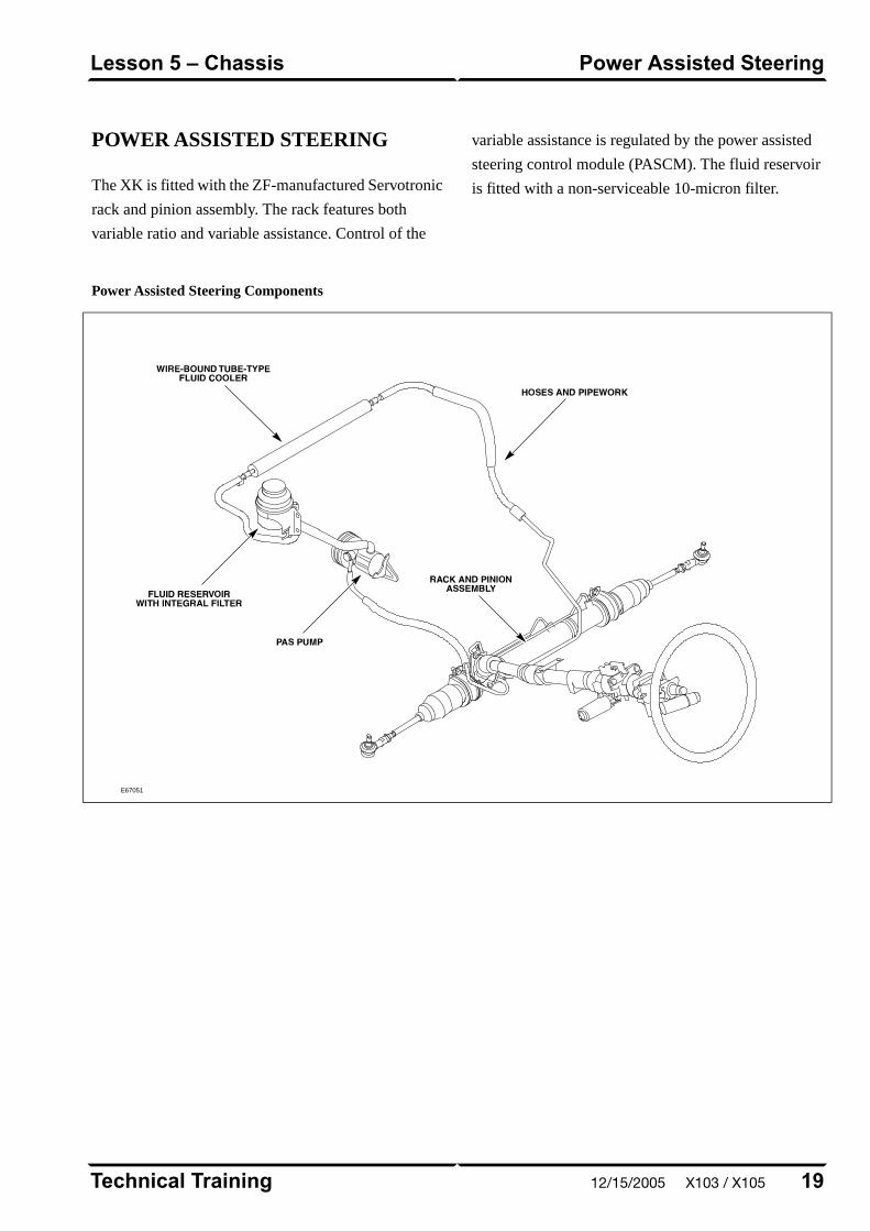
POWER ASSISTED STEERING
The XK is fitted with the ZF-manufactured Servotronic
rack and pinion assembly. The rack features both
variable ratio and variable assistance. Control of the
variable assistance is regulated by the power assisted
steering control module (PASCM). The fluid reservoir
is fitted with a non-serviceable 10-micron filter.
Power Assisted Steering Components
E67051
19Technical Training
Power Assisted SteeringLesson 5 – Chassis
12/15/2005 X103 / X105
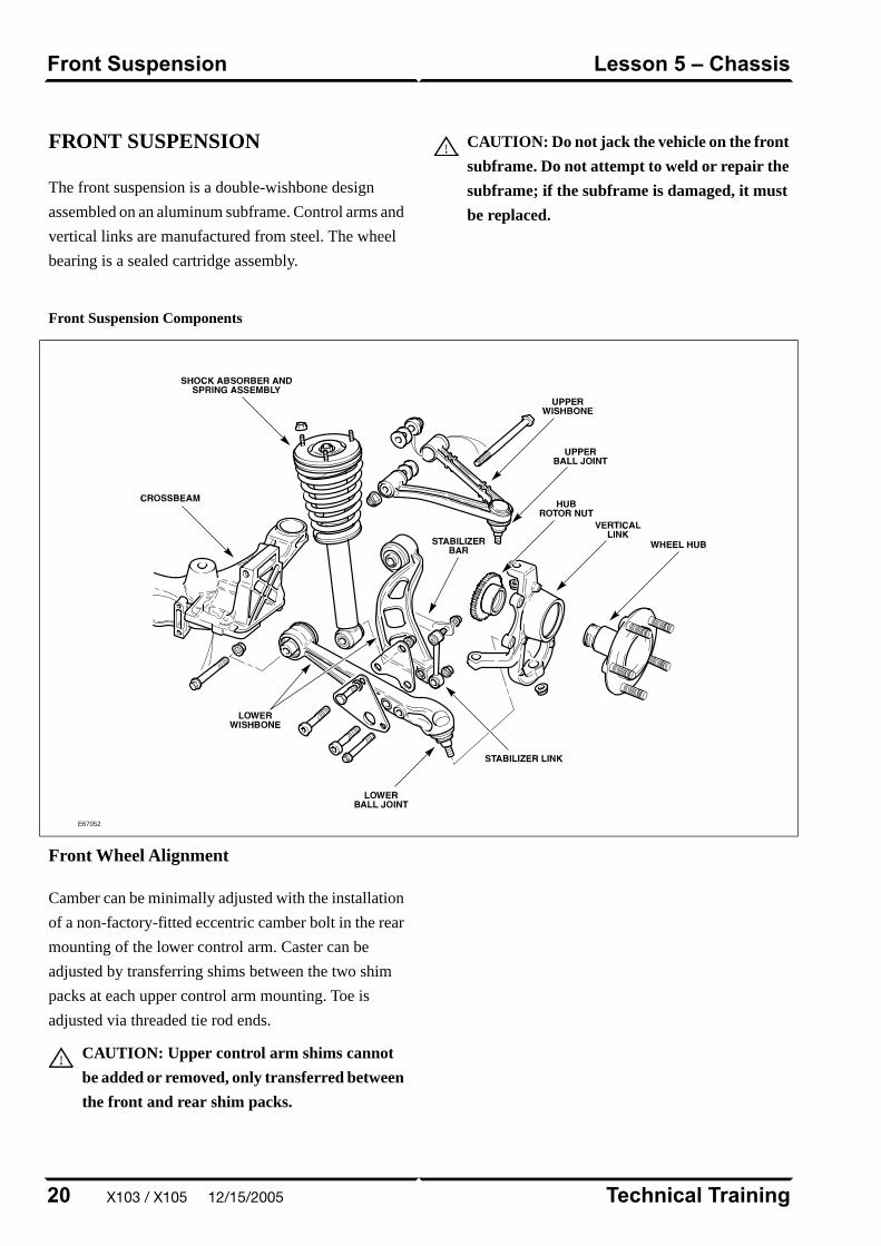
FRONT SUSPENSION
The front suspension is a double-wishbone design
assembled on an aluminum subframe. Control arms and
vertical links are manufactured from steel. The wheel
bearing is a sealed cartridge assembly.
CAUTION: Do not jack the vehicle on the front
subframe. Do not attempt to weld or repair the
subframe; if the subframe is damaged, it must
be replaced.
Front Suspension Components
E67052
Front Wheel Alignment
Camber can be minimally adjusted with the installation
of a non-factory-fitted eccentric camber bolt in the rear
mounting of the lower control arm. Caster can be
adjusted by transferring shims between the two shim
packs at each upper control arm mounting. Toe is
adjusted via threaded tie rod ends.
CAUTION: Upper control arm shims cannot
be added or removed, only transferred between
the front and rear shim packs.
Technical Training20
Lesson 5 – ChassisFront Suspension
X103 / X105 12/15/2005
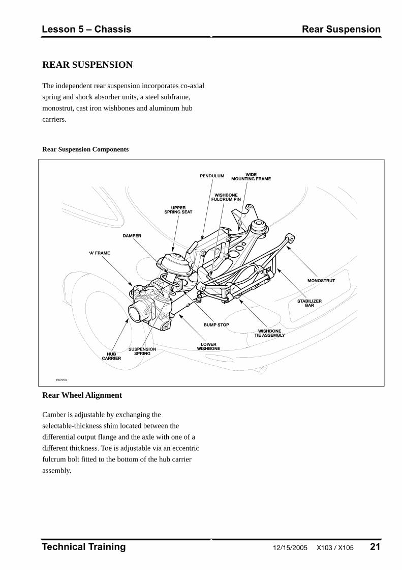
REAR SUSPENSION
The independent rear suspension incorporates co-axial
spring and shock absorber units, a steel subframe,
monostrut, cast iron wishbones and aluminum hub
carriers.
Rear Suspension Components
E67053
Rear Wheel Alignment
Camber is adjustable by exchanging the
selectable-thickness shim located between the
differential output flange and the axle with one of a
different thickness. Toe is adjustable via an eccentric
fulcrum bolt fitted to the bottom of the hub carrier
assembly.
21Technical Training
Rear SuspensionLesson 5 – Chassis
12/15/2005 X103 / X105
BRAKES
All 2003-2005 MY XK vehicles are fitted with the Teves
MK25 ABS system. The main system components are
as follows:
• Teves MK25 modulator and control module
• Active wheel speed sensors
• High resolution steering angle sensor
• Yaw rate sensor
• Teves active brake booster
The Teves MK25 ABS system has the following features
as standard equipment:
• Anti-lock Braking (ABS)
• Traction Control System (TCS)
• Dynamic Stability Control System (DSC)
• Panic Brake Assist (PBA)
Normally aspirated variants are fitted with steel floating
calipers. Supercharged (XKR) vehicles are fitted with
Brembo high-performance fixed aluminum brake
calipers and larger discs.
Technical Training22
Lesson 5 – ChassisBrakes
X103 / X105 12/15/2005

CONTROL MODULES ANDNETWORKS OVERVIEW
Two communication networks are used for control
module intercommunication.
Communication Networks
Communication MediumSpeedClassNetwork
Twisted pair copper wire500 KBaudCController Area Network (CAN)
Twisted pair copper wire41.6 KBaudBStandard Corporate Protocol Network (SCP)
A third network – ISO 9141 (Serial Data Link) – allows
diagnostic interrogation via the data link connector
(DLC) but does not allow control module
intercommunication. The ISO network communicates
at 10.4 KBaud.
23Technical Training
OverviewLesson 6 – Control Modules andNetworks
12/15/2005 X103 / X105
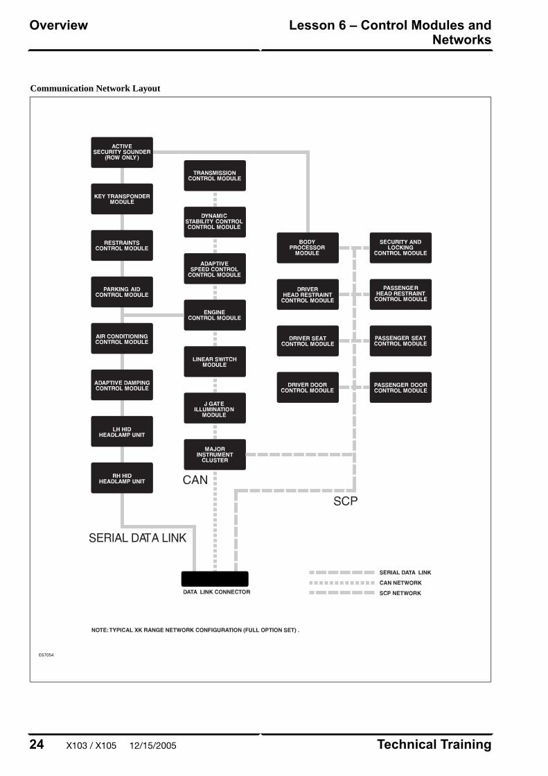
Communication Network Layout
E67054
Technical Training24
Lesson 6 – Control Modules andNetworks
Overview
X103 / X105 12/15/2005
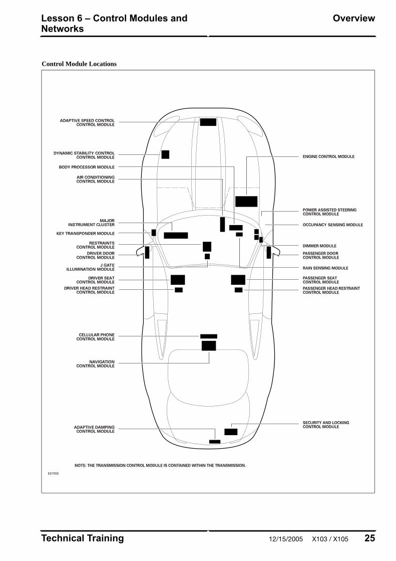
Control Module Locations
E67055
25Technical Training
OverviewLesson 6 – Control Modules andNetworks
12/15/2005 X103 / X105
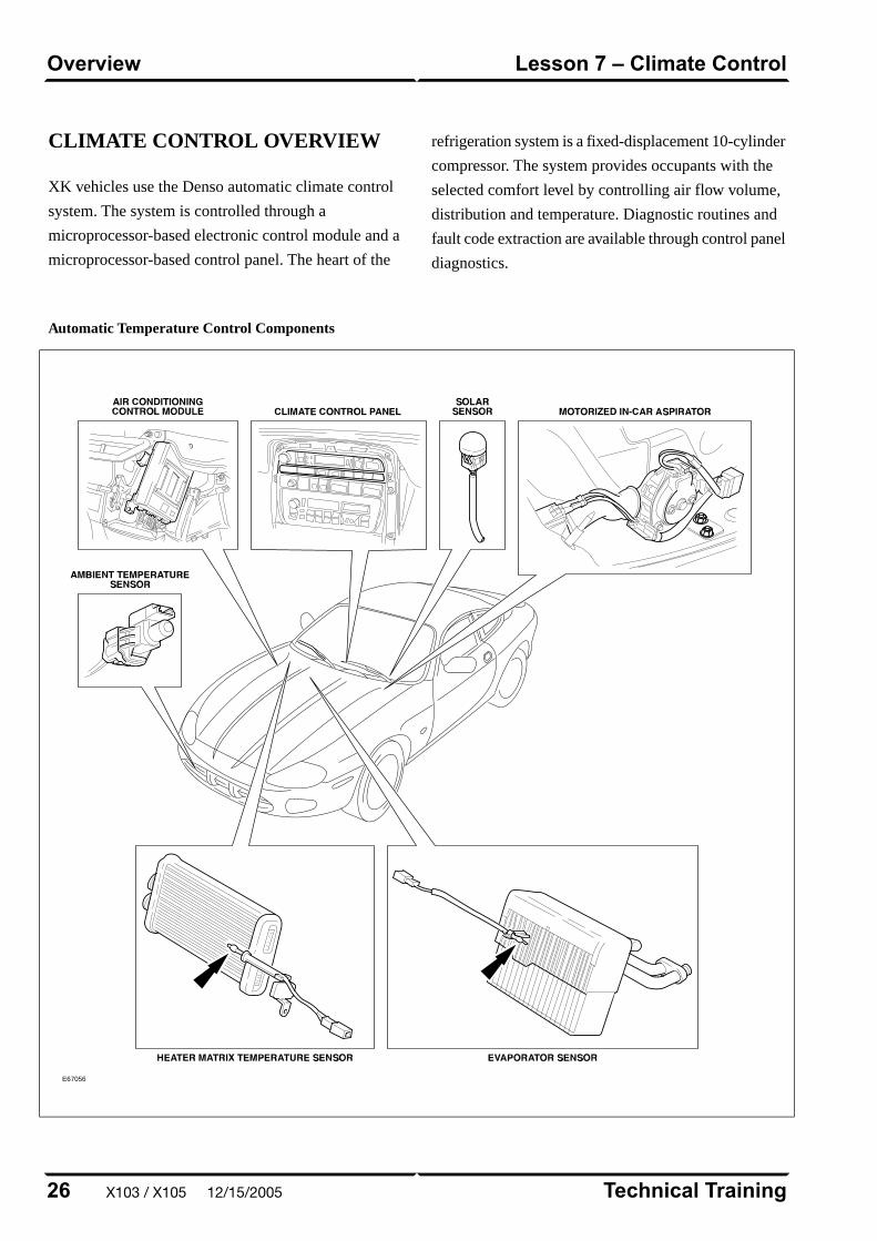
CLIMATE CONTROL OVERVIEW
XK vehicles use the Denso automatic climate control
system. The system is controlled through a
microprocessor-based electronic control module and a
microprocessor-based control panel. The heart of the
refrigeration system is a fixed-displacement 10-cylinder
compressor. The system provides occupants with the
selected comfort level by controlling air flow volume,
distribution and temperature. Diagnostic routines and
fault code extraction are available through control panel
diagnostics.
Automatic Temperature Control Components
E67056
Technical Training26
Lesson 7 – Climate ControlOverview
X103 / X105 12/15/2005

SERVICE
Refrigerant Service Ports
The high-pressure service port is located on the
receiver-dryer assembly. The low pressure service port
is located near the evaporator end of the
evaporator-to-compressor hose/pipe assembly.
E67057
27Technical Training
ServiceLesson 7 – Climate Control
12/15/2005 X103 / X105
POWER WINDOWS
All windows are equipped with one-touch down
functionality. A brief press of a window switch will
fully lower the respective window. A brief press of the
ROOF switch will lower both rear quarter windows.
The ROOF switch and the door window switches must
be held throughout the duration of their respective
window closings.
To provide for proper seating of the frameless door glass
into the roof/convertible top seal, each door glass is also
equipped with a window drop feature. This feature
lowers the window 15 mm (0.060 in.) when the door is
opened (provided the window was fully raised). Closing
the door will cause the window to return to the fully
raised position, provided it was fully raised when the
door was opened.
If the vehicle power supply is disrupted, the window
drop feature will not function correctly. To restore
proper operation the door windows will need to be
re-programmed.
Door Window Re-programming
1. Close both doors
2. On convertible vehicles, fully close the convertible
top.
3. Press and hold the lower part of the window switch;
when the window is fully lowered, continue to hold
the switch for 5 seconds.
4. Release the switch.
5. Press and hold the upper part of the window switch;
when the window is fully raised, continue to hold
the switch for 5 seconds.
6. Carry out this procedure for driver and passenger
windows.
NOTE: This procedure can be carried out either from
the individual window switches or from the driver’s
switch pack. Quarter windows do not require
programming.
Technical Training28
Lesson 8 – Body SystemsPower Windows
X103 / X105 12/15/2005

CONVERTIBLE TOP
The convertible top is fully lined, padded and fitted to
an aluminum frame which has steel linkages. Hydraulic
actuation is used to open, close and latch the top. A
single hold-down switch (ROOF) is located on the center
console. The ROOF switch also operates the rear quarter
windows. The convertible top is fitted with a heated
rear window.
The hydraulic convertible top operating pump is located
in the right-hand side of the trunk, mounted on a steel
pressing which also houses the CD changer, audio
amplifier and navigation unit (where fitted). The pump
operates at a maximum pressure of 140 bar (2030 psi)
and is equipped with solenoid valves to direct fluid to
both hydraulic cylinders for the top movement and the
header rail for the latch mechanism.
Convertible Top Operating Pump
E64205
Convertible Top Operating Cylinder
E64206
The top and quarter windows are operated by the ROOF
switch when the ignition is in position I or II and vehicle
speed is below 10 mph. The ROOF switch must be held
29Technical Training
Convertible TopLesson 8 – Body Systems
12/15/2005 X103 / X105
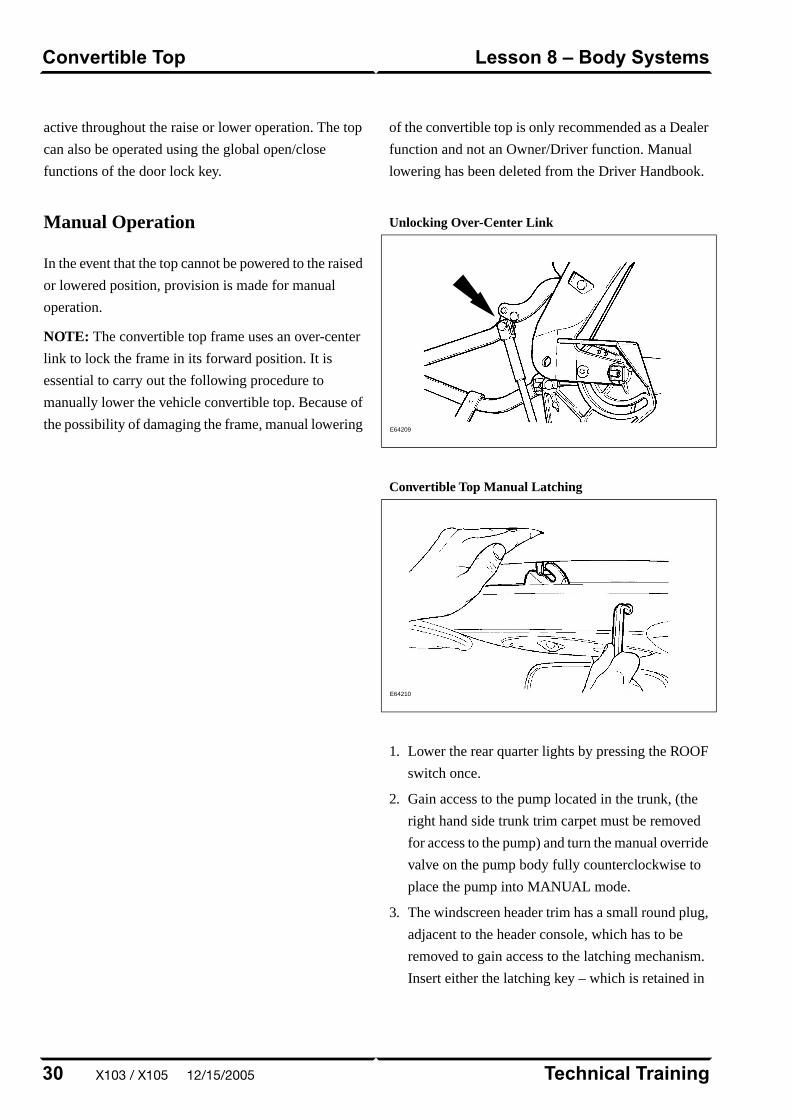
active throughout the raise or lower operation. The top
can also be operated using the global open/close
functions of the door lock key.
Manual Operation
In the event that the top cannot be powered to the raised
or lowered position, provision is made for manual
operation.
NOTE: The convertible top frame uses an over-center
link to lock the frame in its forward position. It is
essential to carry out the following procedure to
manually lower the vehicle convertible top. Because of
the possibility of damaging the frame, manual lowering
of the convertible top is only recommended as a Dealer
function and not an Owner/Driver function. Manual
lowering has been deleted from the Driver Handbook.
Unlocking Over-Center Link
E64209
Convertible Top Manual Latching
E64210
1. Lower the rear quarter lights by pressing the ROOF
switch once.
2. Gain access to the pump located in the trunk, (the
right hand side trunk trim carpet must be removed
for access to the pump) and turn the manual override
valve on the pump body fully counterclockwise to
place the pump into MANUAL mode.
3. The windscreen header trim has a small round plug,
adjacent to the header console, which has to be
removed to gain access to the latching mechanism.
Insert either the latching key – which is retained in
Technical Training30
Lesson 8 – Body SystemsConvertible Top
X103 / X105 12/15/2005

clips on the pump mounting base – or an 8mm Allen
key, and unlatch the hood by turning the key
clockwise.
– CAUTION: Do not attempt to lower the
convertible top further at this stage.
4. Prior to lowering the hood, reach behind the
headlining rear quarter curtains and locate both of
the convertible top cylinder rams and the linkage to
which they are fixed.
5. In turn, push down both the left and right hand
cylinders and linkage as far as possible. Significant
force may be required.
6. Manually lower the top to its stowed position. (If the
hood resists movement repeat step 5).
CAUTION: Failure to carry out steps 4 and 5
will result in severe damage to the convertible
top frame and/or linkages.
31Technical Training
Convertible TopLesson 8 – Body Systems
12/15/2005 X103 / X105
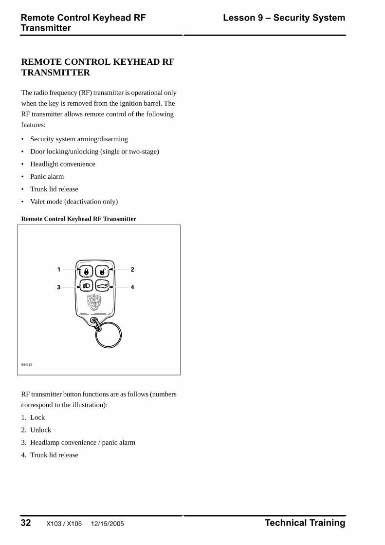
REMOTE CONTROL KEYHEAD RFTRANSMITTER
The radio frequency (RF) transmitter is operational only
when the key is removed from the ignition barrel. The
RF transmitter allows remote control of the following
features:
• Security system arming/disarming
• Door locking/unlocking (single or two-stage)
• Headlight convenience
• Panic alarm
• Trunk lid release
• Valet mode (deactivation only)
Remote Control Keyhead RF Transmitter
E64213
RF transmitter button functions are as follows (numbers
correspond to the illustration):
1. Lock
2. Unlock
3. Headlamp convenience / panic alarm
4. Trunk lid release
Technical Training32
Lesson 9 – Security SystemRemote Control Keyhead RFTransmitter
X103 / X105 12/15/2005
SYSTEM OPERATION
Arming/Disarming andLocking/Unlocking
When the vehicle is locked via the door key barrel or
the RF transmitter LOCK button, the security system
will fully arm. At this point, if a door, the hood, or the
trunk is opened without disarming the system, the alarm
will sound for 60 seconds. The alarm can be cancelled
by pressing the RF transmitter UNLOCK button or by
turning the ignition key to position II.
Single-Stage and Two-Stage Unlocking
With the alarm system in single-stage unlocking mode,
a single rotation of the door lock barrel to the unlock
position or a single press of the RF transmitter
UNLOCK button will unlock both doors.
With the alarm system in two-stage unlocking mode, a
single rotation of the door lock barrel to the unlock
position or a single press of the RF transmitter
UNLOCK button will unlock the driver’s door. A
second rotation of the door lock barrel to the unlock
position or a second press of the RF transmitter
UNLOCK button will unlock the passenger’s door.
Selecting Unlocking Modes
The alarm system can be toggled between the single
and two-stage unlocking modes using WDS. Select the
unlocking mode from the “Dealer Options” submenu
within the “Vehicle Configuration” main menu.
Window and Convertible Top Control
The opening and closing of the windows and convertible
top (if fitted) can be initiated from the driver’s door key.
Remote opening and closing of the driver and passenger
door windows can be enabled/disabled using WDS.
Remote global opening and closing is not available.
Global Opening
To initiate global opening, rotate the key in the driver’s
door lock barrel to the unlock position and hold for
longer than two seconds. The windows and convertible
top will begin their opening operation and will continue
to open as long as the key is held in the unlock position.
Global Closing
To initiate global closing, rotate the key in the driver’s
door lock barrel to the lock position and hold for longer
than two seconds. The windows and convertible top will
begin their closing operation and will continue to close
as long as the key is held in the lock position.
Headlight Convenience
When the RF transmitter HEADLIGHT
CONVENIENCE button is pressed, the headlights will
illuminate for 25 seconds. A second press of the button
will extinguish the headlights.
Panic Alarm
Pressing the RF transmitter HEADLIGHT
CONVENIENCE button three times within three
seconds will activate the panic alarm for 60 seconds.
The alarm can be cancelled by inserting the key into the
ignition and turning the key to position I or II.
33Technical Training
System OperationLesson 9 – Security System
12/15/2005 X103 / X105
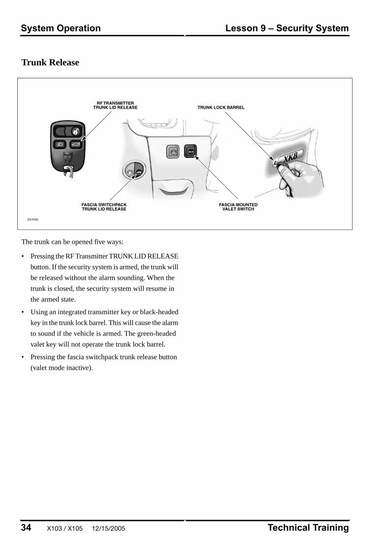
Trunk Release
E67058
The trunk can be opened five ways:
• Pressing the RF Transmitter TRUNK LID RELEASE
button. If the security system is armed, the trunk will
be released without the alarm sounding. When the
trunk is closed, the security system will resume in
the armed state.
• Using an integrated transmitter key or black-headed
key in the trunk lock barrel. This will cause the alarm
to sound if the vehicle is armed. The green-headed
valet key will not operate the trunk lock barrel.
• Pressing the fascia switchpack trunk release button
(valet mode inactive).
Technical Training34
Lesson 9 – Security SystemSystem Operation
X103 / X105 12/15/2005

• Pulling the internal trunk release handle.
• Pressing the release button on the trunk lid (valet
mode inactive).
Internal Trunk Release Handle
E67059
Trunk Lid Release Button
E67060
Valet Mode
Valet mode is activated when the fascia VALET button
is pressed. A valet mode chime will sound and a valet
mode message will be displayed in the message center
(message will only appear if the key is in position II –
RUN). When in valet mode, trunk opening from the
fascia and trunk-mounted release buttons is inhibited.
Locking the glove compartment with the black-headed
key will further minimize valet driver access.
If the vehicle is in valet mode and a green-headed key
is given to the valet driver, the driver will only be able
to:
• Unlock (disarm) and Lock (arm) the vehicle via the
driver’s door lock barrel.
• Start and drive the car.
Valet mode can be cancelled by:
• Using a remote to unlock (disarm) the vehicle.
• Using a black-headed or remote-control key to open
the trunk via the trunk lock barrel.
35Technical Training
System OperationLesson 9 – Security System
12/15/2005 X103 / X105

SERVICE
RF Transmitter Service
Battery Replacement
Each transmitter contains one type CR2032 battery. The
battery is fitted with the positive symbol (+) facing
downwards in the battery receptacle.
NOTE: Changing the remote’s battery will not affect
its operation or require the remote to be reprogrammed.
E67061
RF Transmitter and Key TransponderProgramming
Two methods exist for programming transmitters. Prior
to programming, ensure that all transmitters for the
vehicle are present. Transmitters not present will be
erased from alarm memory and will no longer function.
Key transponders can only be programmed using WDS.
Programming transmitters without WDS:
1. Insert key into ignition.
2. Hold headlight stalk in the FLASH position.
3. While holding headlight stalk in the FLASH position,
rotate the ignition key to position I (AUX).
4. Release headlight stalk and then flash the headlights
four times.
5. An audible confirmation and a flash of the security
LED in the J-gate will confirm the alarm system is
in transmitter “learning” mode.
6. Activate each remote transmitter by pressing any
button on the transmitter once. A chirp will sound
for each remote transmitter signal received (LED
will also flash); allow 15 seconds maximum between
each press.
7. The alarm system will exit the learning mode when
the key is turned to position 0 (OFF), or 15 seconds
after the alarm enters learning mode.
Programming transmitters and key transponders
using WDS:
1. Select the “Vehicle Configuration” main menu tab.
2. Select “Security”.
3. From here, as many as 5 key transponders and
transmitters can be programmed.
Technical Training36
Lesson 9 – Security SystemService
X103 / X105 12/15/2005

SUPPLEMENTAL RESTRAINTSYSTEM OVERVIEW
The XK uses Jaguar’s Adaptive Restraint Technology
System (ARTS). ARTS can be divided into three
subsystems:
• Crash severity sensing and analysis
– Three impact sensors (one behind the radiator
grill and one mounted at the base of each ‘B/C’
pillar) provide a signal to the Restraints Control
Module (RCM) that is proportionate to the crash
severity
• Occupant analysis
– Position of the driver’s seat and seatbelt
engagement is monitored
– Weight, position and seatbelt engagement of the
front passenger is monitored
• Deployment handling
– Based on crash severity and occupant analysis,
the RCM will determine which restraints to
deploy and the deployment strength (frontal
impact airbags only).
37Technical Training
OverviewLesson 10 – Supplemental RestraintSystem
12/15/2005 X103 / X105
COMPONENTS
The ARTS in XK vehicles uses three control modules:
Weight Sensing Module
Mounted to the underside of the front passenger seat,
the weight sensing module processes the signal from
the seat pressure transducer attached to the silicone filled
bladder in the cushion.
Occupancy Sensing Module
Mounted to the RH ‘A’ post, the occupancy sensing
module processes signals from the four ultrasonic
sensors. These sensors emit an ultrasonic signal
operating at 40 KHz to monitor occupancy of the
passenger seat.
Restraints Control Module
Mounted on the transmission tunnel, the restraints
control module is responsible for deploying restraints
based on signals from the weight sensing module,
occupancy sensing module, front seat belt buckle
sensors, driver’s seat position switch and crash sensors.
The three modules communicate via a local (dedicated)
CAN network, which is not part of the vehicle’s main
CAN network.
Technical Training38
Lesson 10 – Supplemental RestraintSystem
Components
X103 / X105 12/15/2005
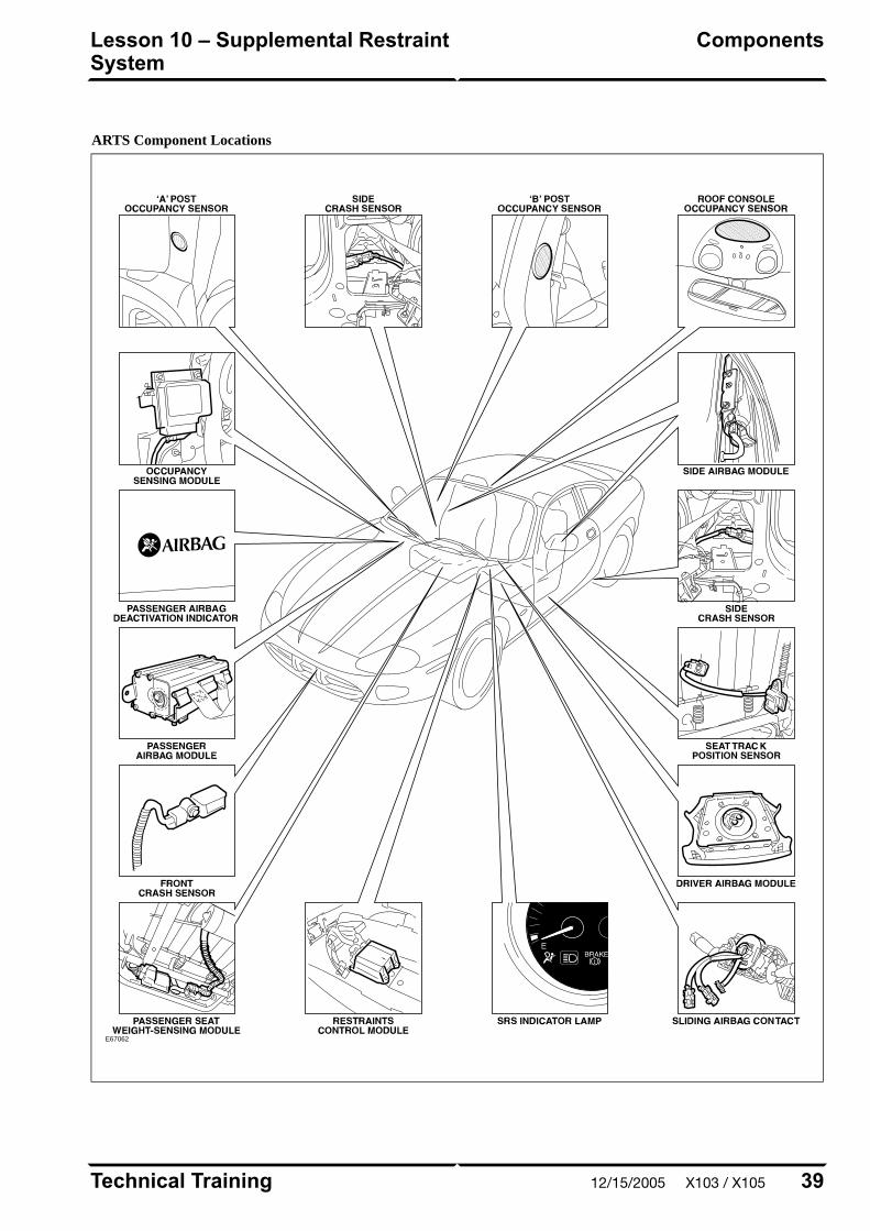
ARTS Component Locations
E67062
39Technical Training
ComponentsLesson 10 – Supplemental RestraintSystem
12/15/2005 X103 / X105
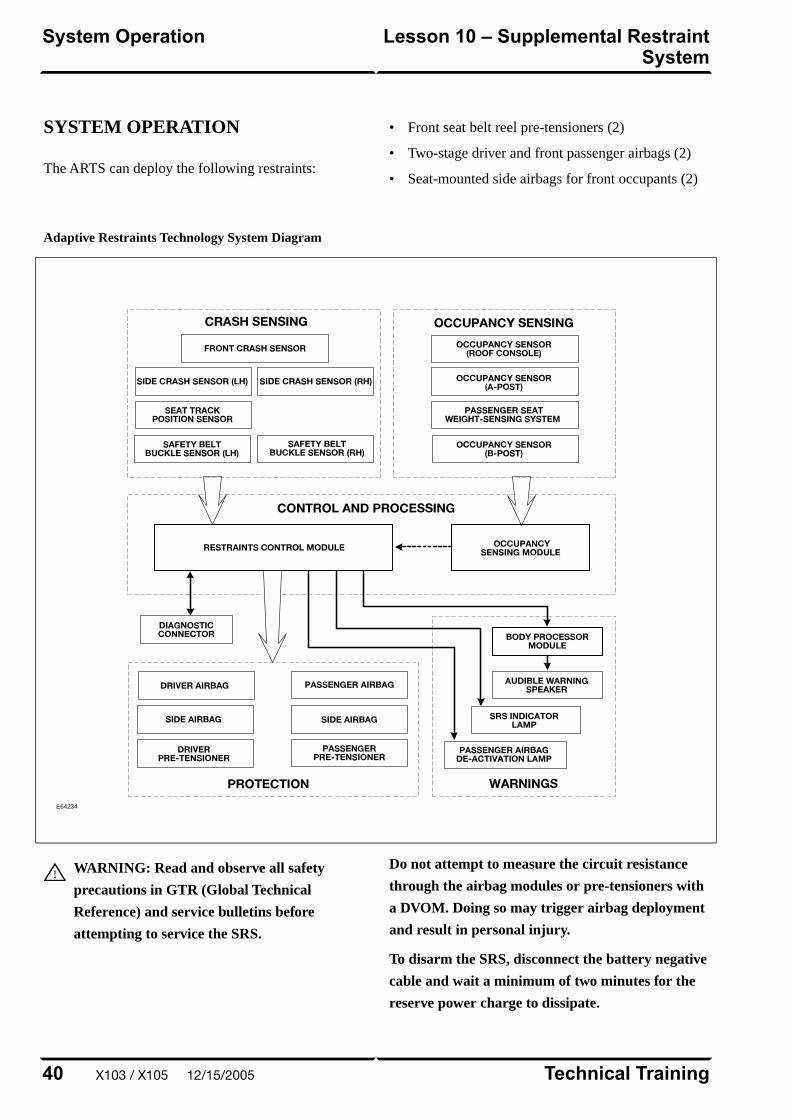
SYSTEM OPERATION
The ARTS can deploy the following restraints:
• Front seat belt reel pre-tensioners (2)
• Two-stage driver and front passenger airbags (2)
• Seat-mounted side airbags for front occupants (2)
Adaptive Restraints Technology System Diagram
E64234
WARNING: Read and observe all safety
precautions in GTR (Global Technical
Reference) and service bulletins before
attempting to service the SRS.
Do not attempt to measure the circuit resistance
through the airbag modules or pre-tensioners with
a DVOM. Doing so may trigger airbag deployment
and result in personal injury.
To disarm the SRS, disconnect the battery negative
cable and wait a minimum of two minutes for the
reserve power charge to dissipate.
Technical Training40
Lesson 10 – Supplemental RestraintSystem
System Operation
X103 / X105 12/15/2005

IN-CAR ENTERTAINMENT (ICE)
Selectable Features
Simultaneously pressing and holding the AM/FM and
EJECT button will display the audio system selectable
features on the radio display or navigation screen (if
fitted). The following options are selectable through the
following preset buttons:
• Preset 1 – Toggles Radio Broadcast Data System
(RBDS) on/off.
• Preset 2 – Toggles the TAPE CLEAN reminder
on/off.
• Preset 3 – Toggles the AERIAL CLEAN reminder
on/off.
• Preset 4 – Toggles the automatic mute facility
on/off. This should be ON if the vehicle is fitted with
a telephone.
• Preset 5 – Toggles the automatic tape eject when
key is turned OFF.
• Preset 6 – Not used.
• Preset 7 – Toggles the Alternate Frequency (AF)
on/off. Used when reception problems occur with
RBDS stations. Toggling AF ON/OFF will eliminate
drop-out on RBDS channels.
• Preset 8 – Not used.
• Preset 9 – Toggles FADE ENABLE/DISABLE.
Disabling fade removes FADE from the MODE
button menu.
• Preset 0 – Toggles radio between markets (USA,
Europe, Japan…).
Setting the Clock
On vehicles without navigation, an analog clock is fitted
to the minor instrument panel. The time can be adjusted
by pressing the ‘+’ and ‘-’ buttons on the front of the
dial.
On vehicles fitted with navigation, the start-up screen
shows a large analog clock. The correct time is
maintained automatically from the GPS satellite signals
and no manual adjustment is required. Ensure that the
proper time zone and summer time (Daylight Savings
Time) settings are correct for the current location and
time of year. These options are accessible by pressing
the MENU button while the navigation map is displayed.
Select SETUP from the on-screen menu.
41Technical Training
In-Car Entertainment (ICE)Lesson 11 – Infotainment
12/15/2005 X103 / X105
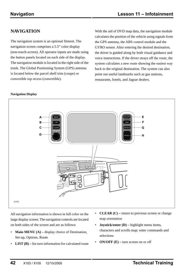
NAVIGATION
The navigation system is an optional fitment. The
navigation screen comprises a 5.5” color display
(non-touch-screen). All operator inputs are made using
the button panels located on each side of the display.
The navigation module is located in the right side of the
trunk. The Global Positioning System (GPS) antenna
is located below the parcel shelf trim (coupe) or
convertible top recess (convertible).
With the aid of DVD map data, the navigation module
calculates the position of the vehicle using signals from
the GPS antenna, the ABS control module and the
GYRO sensor. After entering the desired destination,
the driver is guided along by both visual guidance and
voice instructions. If the driver strays off the route, the
system calculates a new route showing the easiest way
back to the original destination. The system can also
point out useful landmarks such as gas stations,
restaurants, hotels, and Jaguar dealers.
Navigation Display
E67063
All navigation information is shown in full color on the
large display screen. The navigation controls are located
on both sides of the screen and are as follows:
• Main MENU (A) – display choice of Destination,
Set-up, Options, Route
• LIST (B) – list turn information for calculated route
• CLEAR (C) – return to previous screen or change
map orientation
• Joystick/enter (D) – highlight menu items,
characters and scrolls map: enter commands and
selections
• ON/OFF (E) – turn screen on or off
Technical Training42
Lesson 11 – InfotainmentNavigation
X103 / X105 12/15/2005
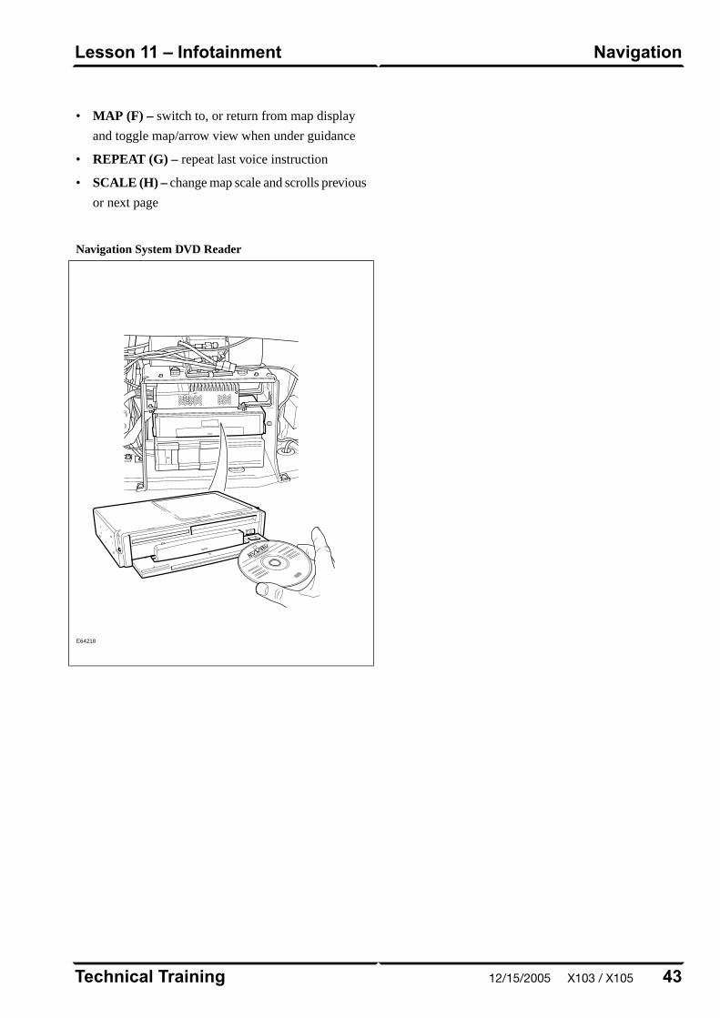
• MAP (F) – switch to, or return from map display
and toggle map/arrow view when under guidance
• REPEAT (G) – repeat last voice instruction
• SCALE (H) – change map scale and scrolls previous
or next page
Navigation System DVD Reader
E64218
43Technical Training
NavigationLesson 11 – Infotainment
12/15/2005 X103 / X105

Curriculum Training
Introduction to Jaguar
Introduction to S-TYPE: X200
E63055
Technical Training INTR 05 en 08/2005INTR: X200

To the best of our knowledge, the illustrations, technical information, data and descriptions in this issue were correct at the time
of going to print. The right to change prices, specifications, equipment and maintenance instructions at any time without notice
is reserved as part of our policy of continuous development and improvement for the benefit of our customers.
No part of this publication may be reproduced, stored in a data processing system or transmitted in any form, electronic,
mechanical, photocopy, recording, translation or by any other means without prior permission of Premier Automotive Group.
No liability can be accepted for any inaccuracies in this publication, although every possible care has been taken to make it as
complete and accurate as possible.
Copyright ©2005
Please remember that our training literature has been prepared for TRAINING PURPOSES only. Repairs and
adjustments MUST always be carried out according to the instructions and specifications in the workshop literature.
Please make full use of the training offered by Technical Training to gain extensive knowledge of both theory
and practice.
1Technical Training
Preface
12/15/2005 X200
PAGE
Technical Training2
Table of Contents
X200 12/15/2005
Lesson 1 – General Information
5Overview......................................................................................................................................................
7Identification Plates and Labels................................................................................................................
8Lifting and Jacking.....................................................................................................................................
Lesson 2 – Engines
9Overview......................................................................................................................................................
10Details..........................................................................................................................................................
Lesson 3 – Engine Management
13Overview......................................................................................................................................................
14Components.................................................................................................................................................
Lesson 4 – Transmission
16Overview .....................................................................................................................................................
Lesson 5 – Chassis
18Power Assisted Steering (PAS)..................................................................................................................
19Front Suspension........................................................................................................................................
20Rear Suspension..........................................................................................................................................
21Brakes..........................................................................................................................................................
Lesson 6 – Control Modules and Networks
22Overview......................................................................................................................................................
Lesson 7 – Climate Control
25Overview......................................................................................................................................................
28Refrigeration System..................................................................................................................................
29System Details.............................................................................................................................................
Lesson 8 – Body Systems
30Overview......................................................................................................................................................
Lesson 9 – Security System
31Overview......................................................................................................................................................
32Passive Anti-Theft System..........................................................................................................................
Lesson 10 – Supplemental Restraint System
34Overview......................................................................................................................................................
36Airbags.........................................................................................................................................................
Lesson 11 – Infotainment
38In-Car Entertainment (ICE).....................................................................................................................
39Navigation System......................................................................................................................................
3Technical Training
Table of Contents
12/15/2005 X200
4
Safety and Precautions
Workshop safety
This page highlights the general observations expectedwhile attending this training program, and itscontinuation upon returning to your place of work.
General
While working on all vehicles, the following itemswhere available should always be used:
• Fender covers
• Seat covers
• Floor protection
Safety
All precautions must be taken and observed at all times,to prevent injury or damage to the following:
• Yourself
• Customer's property
• Workshop equipment
• Work place colleagues
Operating guidelines
While using any piece of workshop equipment:
The manufacturer's guidelines and warning labels mustbe followed.
This will ensure correct use and application at all times.
Seek the necessary advice or training where equipmentusage is unclear.
Chemicals, Oils and Solvents
Follow all manufacturer's warnings and labels; also takeinto account local disposal regulations when workingwith chemicals, oils or solvents.
Ensure that all risks are completely minimized.
Make sure that all protective items of clothing are wornwhere required e.g.
• Eye protection
• Gloves
• Coveralls
• Footwear
System capping
Upon disconnecting components from a system, takeall precautions necessary to prevent systemcontamination or environmental leakage.
Fit relevant plugs or caps i.e. to pipes, unions andcomponent orifices etc.
Updates
Keep abreast of all relevant changes that affect yourrole within the dealership, by monitoring all factoryissued documentation.
Driving
Operating vehicle features, such as ICE, mobile phonesand CD player equipment etc., can cause a momentarydistraction while driving.
Follow all traffic regulations when operating vehiclesystems or using diagnostic equipment while on the move.
Mobile diagnostic equipment operation may requirethe use of an assistant.
X200 12/15/2005
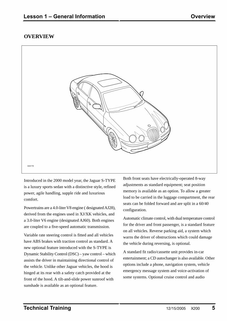
OVERVIEW
E64778
Introduced in the 2000 model year, the Jaguar S-TYPE
is a luxury sports sedan with a distinctive style, refined
power, agile handling, supple ride and luxurious
comfort.
Powertrains are a 4.0-liter V8 engine ( designated AJ28),
derived from the engines used in XJ/XK vehicles, and
a 3.0-liter V6 engine (designated AJ60). Both engines
are coupled to a five-speed automatic transmission.
Variable rate steering control is fitted and all vehicles
have ABS brakes with traction control as standard. A
new optional feature introduced with the S-TYPE is
Dynamic Stability Control (DSC) – yaw control – which
assists the driver in maintaining directional control of
the vehicle. Unlike other Jaguar vehicles, the hood is
hinged at its rear with a safety catch provided at the
front of the hood. A tilt-and-slide power sunroof with
sunshade is available as an optional feature.
Both front seats have electrically-operated 8-way
adjustments as standard equipment; seat position
memory is available as an option. To allow a greater
load to be carried in the luggage compartment, the rear
seats can be folded forward and are split in a 60/40
configuration.
Automatic climate control, with dual temperature control
for the driver and front passenger, is a standard feature
on all vehicles. Reverse parking aid, a system which
warns the driver of obstructions which could damage
the vehicle during reversing, is optional.
A standard fit radio/cassette unit provides in-car
entertainment; a CD autochanger is also available. Other
options include a phone, navigation system, vehicle
emergency message system and voice-activation of
some systems. Optional cruise control and audio
5Technical Training
OverviewLesson 1 – General Information
12/15/2005 X200

switches are fitted to the steering wheel. All vehicles
have a trip computer system and a vehicle information
message center in the instrument cluster.
Security features are an engine immobilizer and alarm
system. A 4-button key-ring transmitter has a radio
frequency operation with an encrypted rolling code to
help prevent theft of the vehicle.
The Standard Corporate Protocol (SCP) Network is the
primary network used for control module
communication; CAN is not used.
Engineering Codes and VIN Ranges
2000 MY S-TYPE
VIN RangeEngineering CodeVariant
L00001 – L77677X200S-TYPE Sedan
2001 MY S-TYPE
VIN RangeEngineering CodeVariant
L77678 – L86901X200S-TYPE Sedan
2002 MY S-TYPE
VIN RangeEngineering CodeVariant
L86902 – M44997X200S-TYPE Sedan
Technical Training6
Lesson 1 – General InformationOverview
X200 12/15/2005
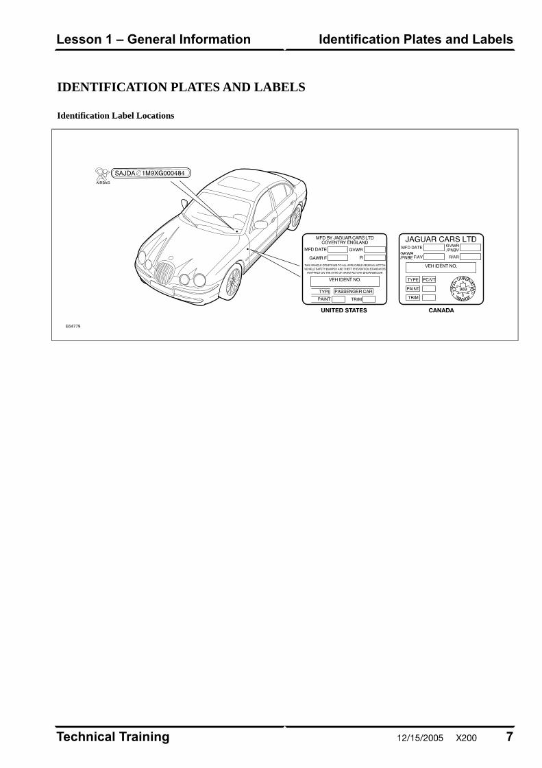
IDENTIFICATION PLATES AND LABELS
Identification Label Locations
E64779
7Technical Training
Identification Plates and LabelsLesson 1 – General Information
12/15/2005 X200
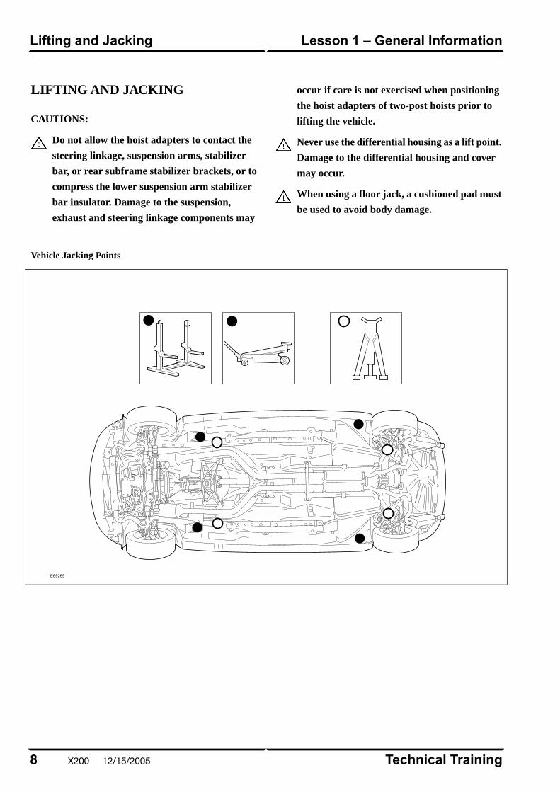
LIFTING AND JACKING
CAUTIONS:
Do not allow the hoist adapters to contact the
steering linkage, suspension arms, stabilizer
bar, or rear subframe stabilizer brackets, or to
compress the lower suspension arm stabilizer
bar insulator. Damage to the suspension,
exhaust and steering linkage components may
occur if care is not exercised when positioning
the hoist adapters of two-post hoists prior to
lifting the vehicle.
Never use the differential housing as a lift point.
Damage to the differential housing and cover
may occur.
When using a floor jack, a cushioned pad must
be used to avoid body damage.
Vehicle Jacking Points
E69269
Technical Training8
Lesson 1 – General InformationLifting and Jacking
X200 12/15/2005

OVERVIEW
The S-TYPE sedan has a longitudinal powertrain
providing rear-wheel drive. The vehicle is available
with either a 3.0-liter V6 or a 4.0-liter V8 engine, both
normally aspirated. The V6 engine, designated AJ60,
was introduced to the Jaguar range with the S-TYPE.
The engine is of a lightweight but rigid design with
particular attention paid to minimizing noise and
vibration. A major innovation is the use of a variable
geometry air intake manifold, which provides various
combinations of tuned plenum volumes and flow paths.
Two valves are controlled by the engine management
system to fully open or fully close, dependent on engine
speed, to the combination which maximizes volumetric
efficiency. A two-stage variable valve timing system is
also fitted. These two systems work together to achieve
high torque delivery across a wide engine speed range.
AJ60 3.0L V6 Engine
E64780
The V8 engine, designated AJ28, is a development of
the established V8 engine fitted to XJ and XK vehicles.
The AJ28 incorporates the latest modifications fitted to
the AJ27 variant – in particular the continuously-variable
valve timing system and air-assisted fuel injection.
Both the V6 and the V8 engine are fitted with a common
electronic throttle which does not require a mechanical
cable. Another feature, common to both engines, is the
returnless fuel system, which reduces the formation of
fuel vapor (evaporative emissions).
9Technical Training
OverviewLesson 2 – Engines
12/15/2005 X200
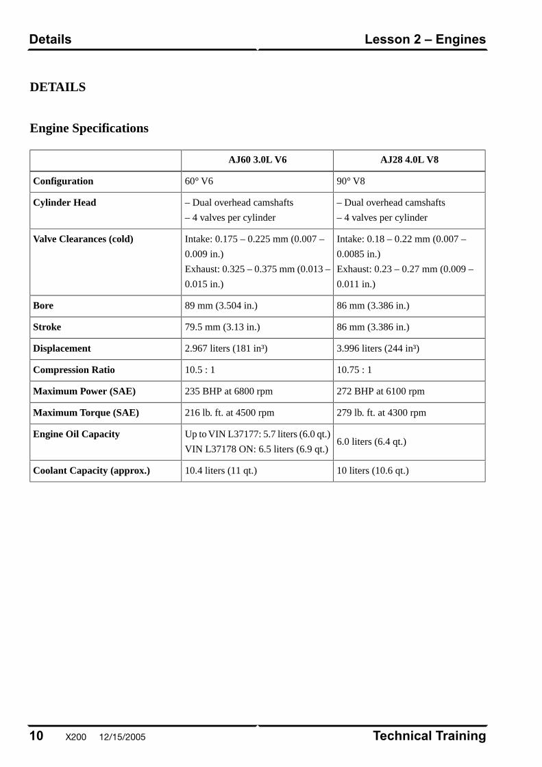
DETAILS
Engine Specifications
AJ28 4.0L V8AJ60 3.0L V6
90° V860° V6Configuration
– Dual overhead camshafts
– 4 valves per cylinder
– Dual overhead camshafts
– 4 valves per cylinder
Cylinder Head
Intake: 0.18 – 0.22 mm (0.007 –
0.0085 in.)
Exhaust: 0.23 – 0.27 mm (0.009 –
0.011 in.)
Intake: 0.175 – 0.225 mm (0.007 –
0.009 in.)
Exhaust: 0.325 – 0.375 mm (0.013 –
0.015 in.)
Valve Clearances (cold)
86 mm (3.386 in.)89 mm (3.504 in.)Bore
86 mm (3.386 in.)79.5 mm (3.13 in.)Stroke
3.996 liters (244 in³)2.967 liters (181 in³)Displacement
10.75 : 110.5 : 1Compression Ratio
272 BHP at 6100 rpm235 BHP at 6800 rpmMaximum Power (SAE)
279 lb. ft. at 4300 rpm216 lb. ft. at 4500 rpmMaximum Torque (SAE)
6.0 liters (6.4 qt.)Up to VIN L37177: 5.7 liters (6.0 qt.)
VIN L37178 ON: 6.5 liters (6.9 qt.)
Engine Oil Capacity
10 liters (10.6 qt.)10.4 liters (11 qt.)Coolant Capacity (approx.)
Technical Training10
Lesson 2 – EnginesDetails
X200 12/15/2005
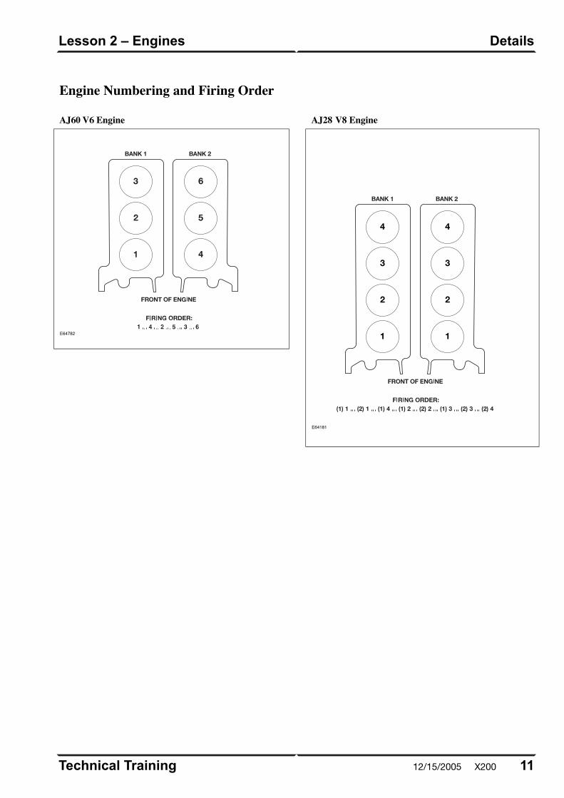
Engine Numbering and Firing Order
AJ60 V6 Engine
E64782
AJ28 V8 Engine
E64181
4
3
2
1
4
3
2
1
11Technical Training
DetailsLesson 2 – Engines
12/15/2005 X200
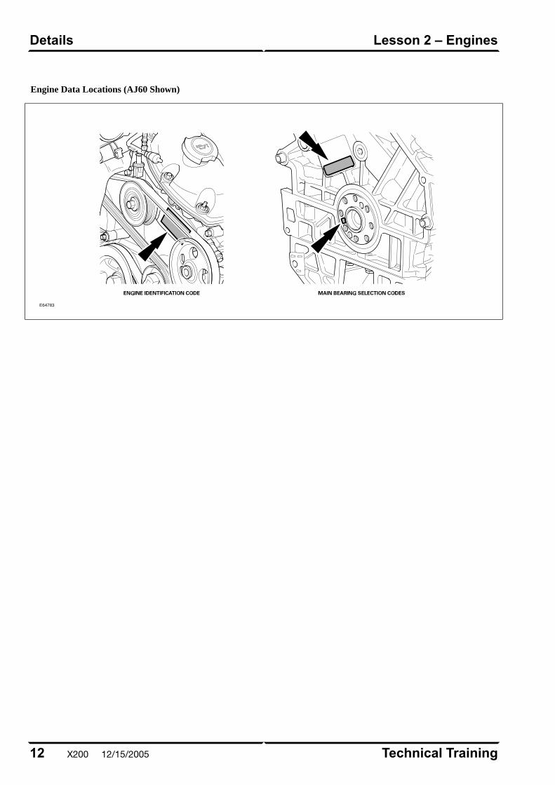
Engine Data Locations (AJ60 Shown)
E64783
Technical Training12
Lesson 2 – EnginesDetails
X200 12/15/2005
OVERVIEW
The Powertrain Electronic Control (PTEC) system is a
comprehensive combined engine and transmission
control system. The system is used on both the AJ60
3.0L V6 and the AJ28 4.0L V8 engine installed in the
Jaguar S-TYPE. There are detailed sensor and control
differences between V6 and V8, however the majority
of the system is identical in its functions. PTEC
complies with OBD II.
PTEC has several features that are unique from other
Jaguar engine management systems:
• Single control module
– A single Powertrain Control Module (PCM)
performs both engine and transmission control
functions.
• SCP Network
– PTEC communicates only on the vehicle SCP
(Standard Corporate Protocol) multiplex network.
• Returnless fuel system
– The fuel delivery system is a supply-only system
with no provision for returning unused fuel from
the fuel rail to the fuel tank.
• Full authority throttle
– PTEC employs a full authority electronic throttle
assembly with no cable connection between the
accelerator pedal and the throttle. The throttle
assembly incorporates a separate control module
with diagnostic capabilities.
• Variable intake system (V6)
– V6 engines are equipped with a variable length
air intake manifold that optimizes engine torque
across the entire speed/load range.
• Fail safe cooling (V6)
– V6 engines have a PCM “fail safe cooling”
strategy that allows for limited engine operation
with low or no coolant.
Control Summary
The engine management systems for the AJ60 3.0L V6
engine and the AJ28 4.0L V8 engine vehicles are
virtually identical in function with differences in the
control module parameters and the location of some
components.
The major differences between the two systems are as
follows:
• AJ60 V6
– Two-position variable valve timing (VVT)
– Variable air intake system
– EGR (exhaust gas recirculation) – 2000 MY only
• AJ28 V8
– Continuously variable VVT
– AAI (air assisted injection)
13Technical Training
OverviewLesson 3 – Engine Management
12/15/2005 X200
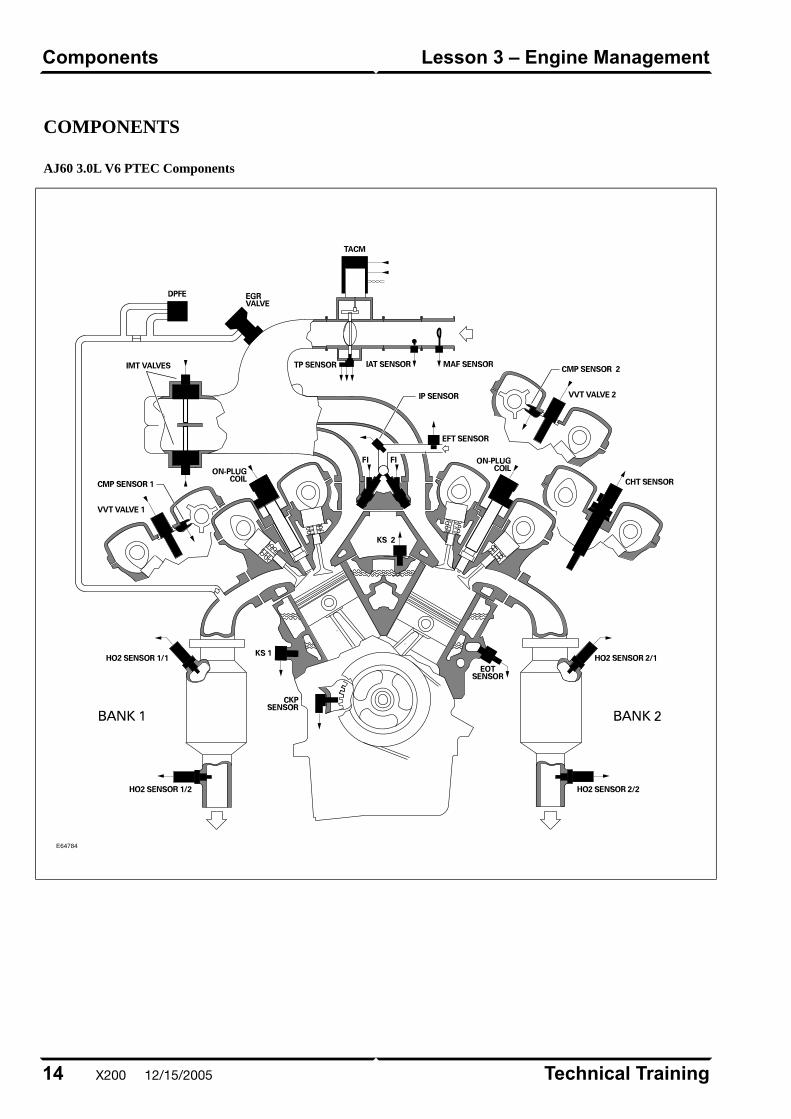
COMPONENTS
AJ60 3.0L V6 PTEC Components
E64784
Technical Training14
Lesson 3 – Engine ManagementComponents
X200 12/15/2005
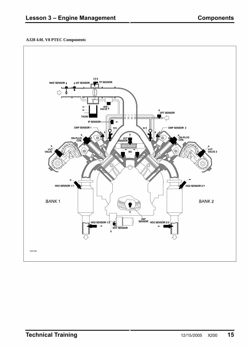
AJ28 4.0L V8 PTEC Components
E64786
15Technical Training
ComponentsLesson 3 – Engine Management
12/15/2005 X200
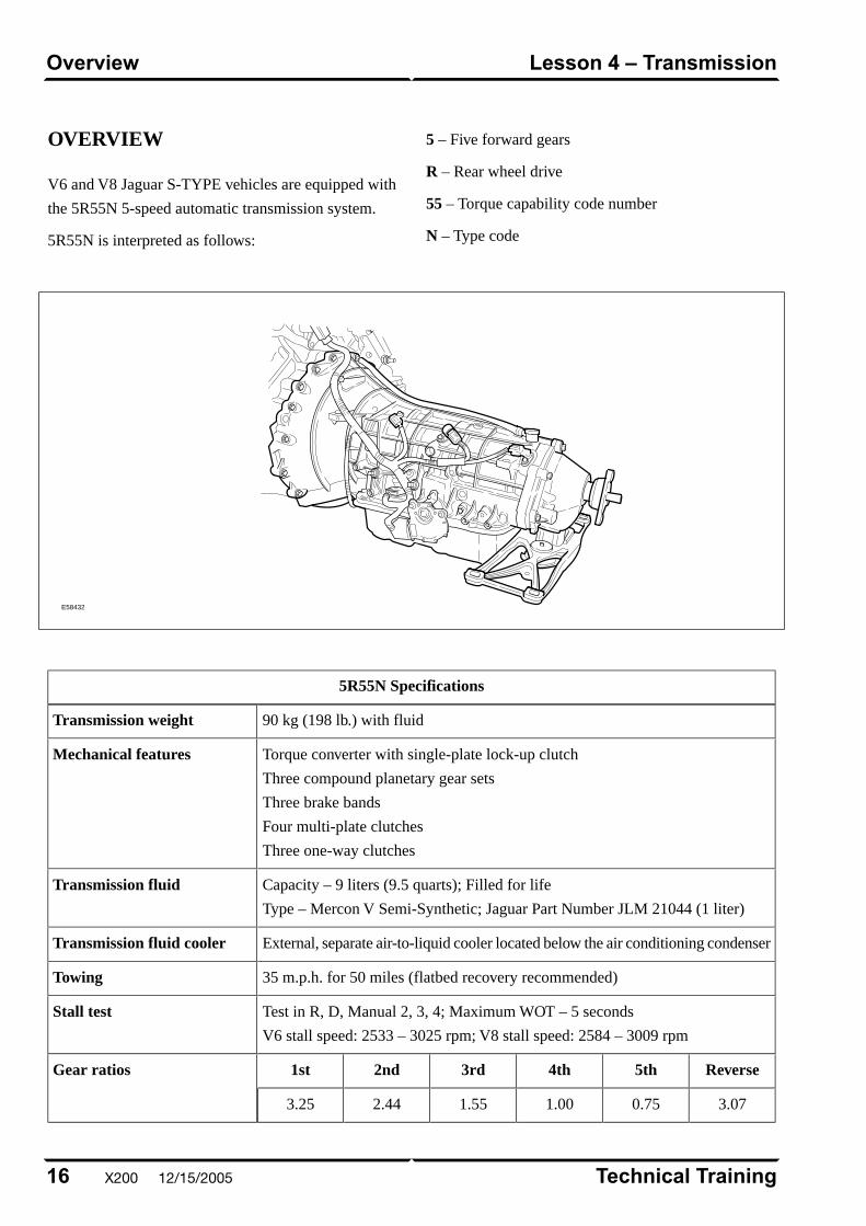
OVERVIEW
V6 and V8 Jaguar S-TYPE vehicles are equipped with
the 5R55N 5-speed automatic transmission system.
5R55N is interpreted as follows:
5 – Five forward gears
R – Rear wheel drive
55 – Torque capability code number
N – Type code
E58432
5R55N Specifications
90 kg (198 lb.) with fluidTransmission weight
Torque converter with single-plate lock-up clutch
Three compound planetary gear sets
Three brake bands
Four multi-plate clutches
Three one-way clutches
Mechanical features
Capacity – 9 liters (9.5 quarts); Filled for life
Type – Mercon V Semi-Synthetic; Jaguar Part Number JLM 21044 (1 liter)
Transmission fluid
External, separate air-to-liquid cooler located below the air conditioning condenserTransmission fluid cooler
35 m.p.h. for 50 miles (flatbed recovery recommended)Towing
Test in R, D, Manual 2, 3, 4; Maximum WOT – 5 seconds
V6 stall speed: 2533 – 3025 rpm; V8 stall speed: 2584 – 3009 rpm
Stall test
Reverse5th4th3rd2nd1stGear ratios
3.070.751.001.552.443.25
Technical Training16
Lesson 4 – TransmissionOverview
X200 12/15/2005

Service
There are no provisions for owners to verify the
transmission fluid level, as the 5R55N transmission is
not equipped with a transmission fluid dipstick. To
inspect the fluid level and integrity, carefully follow the
inspection procedure found in the Transmission section
of the WSM, available on the GTR website.
NOTE: There are no scheduled fluid level inspections
required for 5R55N. Fluid level should only be checked
if there are signs of an external fluid leak, or as part of
the diagnostic process for customer complaint of poor
shift quality.
17Technical Training
OverviewLesson 4 – Transmission
12/15/2005 X200
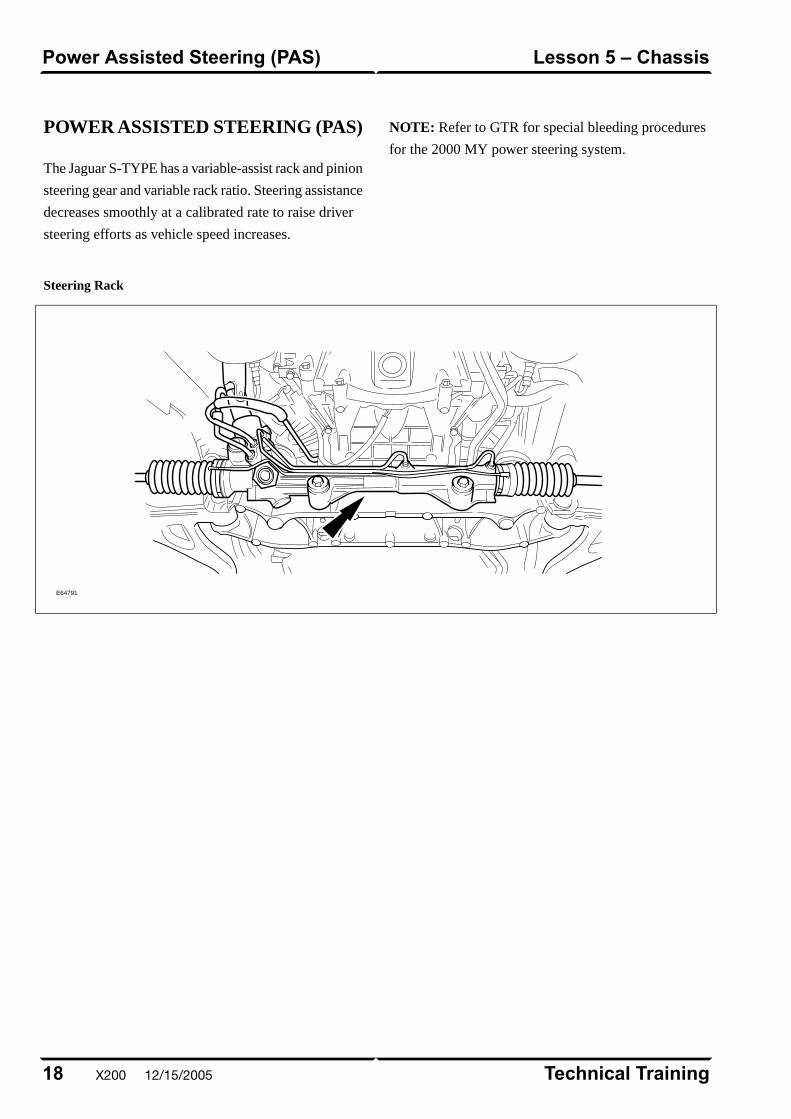
POWER ASSISTED STEERING (PAS)
The Jaguar S-TYPE has a variable-assist rack and pinion
steering gear and variable rack ratio. Steering assistance
decreases smoothly at a calibrated rate to raise driver
steering efforts as vehicle speed increases.
NOTE: Refer to GTR for special bleeding procedures
for the 2000 MY power steering system.
Steering Rack
E64791
Technical Training18
Lesson 5 – ChassisPower Assisted Steering (PAS)
X200 12/15/2005

FRONT SUSPENSION
The independent front wheel suspension is a double
wishbone axle arrangement with aluminum control arms.
The two arms are of different lengths, which minimizes
the changes in track and camber. Inclination of the upper
control arm axis provides anti-dive front suspension
action. There are two front cross members, known as
Number 1 and Number 2.
E64788
Number 1, the forward cross member, is a steel
fabrication, non-isolated, which locates the lower control
arm front mounting, the anti-roll bar and the cooling
module.
The rear cross member, Number 2, is an aluminum
casting, non-isolated and it locates the lower control
arm rear mounting, the power steering rack and the
engine hydro-mounts.
No attempt should be made to weld or repair the
aluminum crossmember. If it is damaged, a new one
must be installed.
Front Wheel Alignment
Special tool 501 F006 has been designed to enable
correct alignment of the suspension to the body.
Service adjustments for caster and camber can be made
to the lower control arm geometry with the addition of
cam bolts (not supplied with the vehicle).
19Technical Training
Front SuspensionLesson 5 – Chassis
12/15/2005 X200
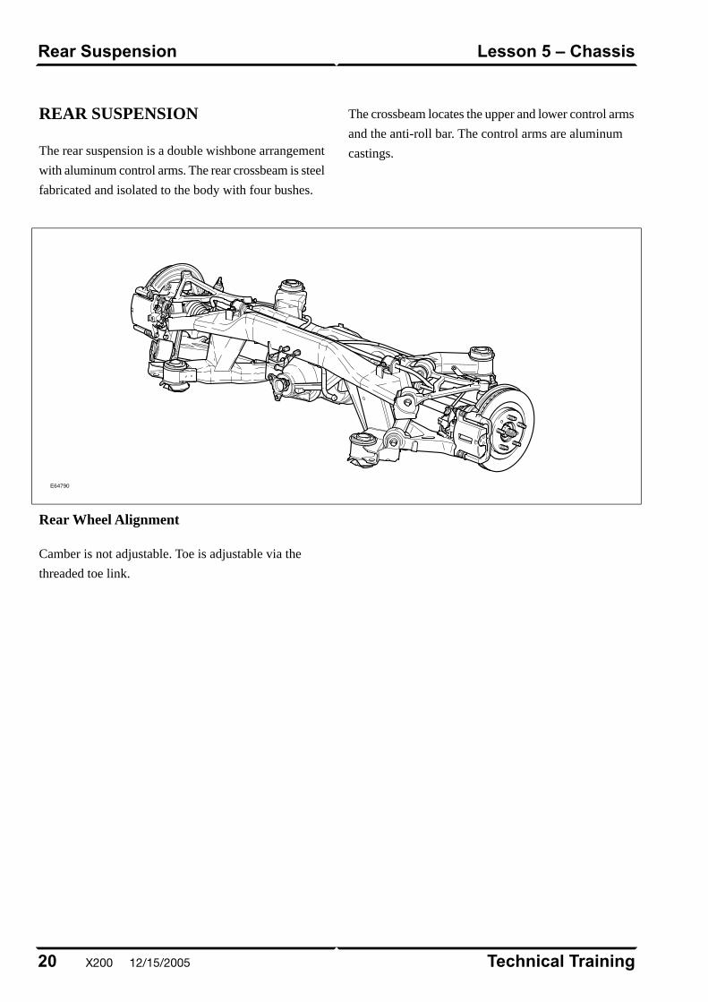
REAR SUSPENSION
The rear suspension is a double wishbone arrangement
with aluminum control arms. The rear crossbeam is steel
fabricated and isolated to the body with four bushes.
The crossbeam locates the upper and lower control arms
and the anti-roll bar. The control arms are aluminum
castings.
E64790
Rear Wheel Alignment
Camber is not adjustable. Toe is adjustable via the
threaded toe link.
Technical Training20
Lesson 5 – ChassisRear Suspension
X200 12/15/2005
BRAKES
All X200 vehicles are equipped with the Teves Mk 20E
anti-lock braking system (ABS).
21Technical Training
BrakesLesson 5 – Chassis
12/15/2005 X200
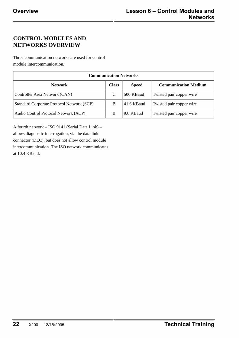
CONTROL MODULES ANDNETWORKS OVERVIEW
Three communication networks are used for control
module intercommunication.
Communication Networks
Communication MediumSpeedClassNetwork
Twisted pair copper wire500 KBaudCController Area Network (CAN)
Twisted pair copper wire41.6 KBaudBStandard Corporate Protocol Network (SCP)
Twisted pair copper wire9.6 KBaudBAudio Control Protocol Network (ACP)
A fourth network – ISO 9141 (Serial Data Link) –
allows diagnostic interrogation, via the data link
connector (DLC), but does not allow control module
intercommunication. The ISO network communicates
at 10.4 KBaud.
Technical Training22
Lesson 6 – Control Modules andNetworks
Overview
X200 12/15/2005
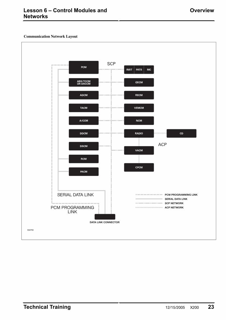
Communication Network Layout
E64793
23Technical Training
OverviewLesson 6 – Control Modules andNetworks
12/15/2005 X200
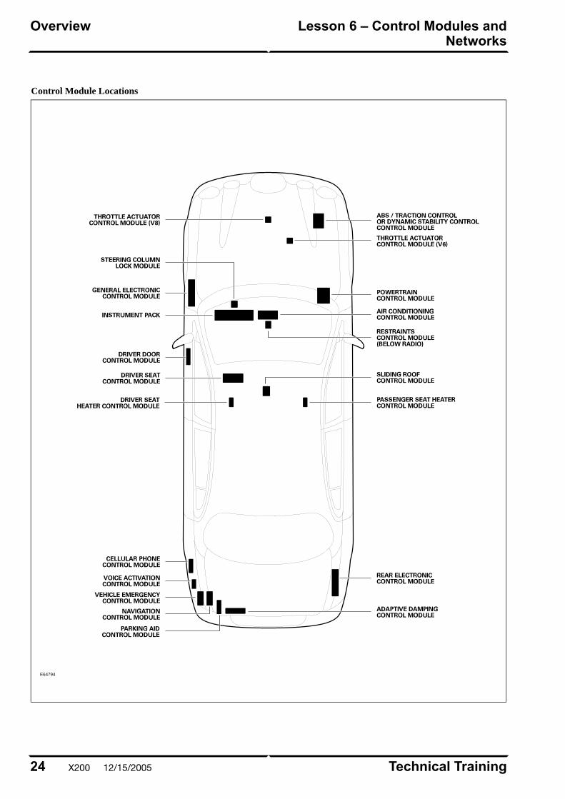
Control Module Locations
E64794
Technical Training24
Lesson 6 – Control Modules andNetworks
Overview
X200 12/15/2005

CLIMATE CONTROL OVERVIEW
The Dual Automatic Temperature Control (DATC)
climate control system is a compact system that provides
a complete selection of driver controlled functions and
additional automatic functions. The system was designed
by Visteon for the Jaguar S-TYPE; most of the DATC
functions and controls are similar to the existing Jaguar
systems.
25Technical Training
OverviewLesson 7 – Climate Control
12/15/2005 X200
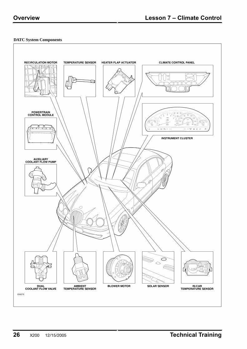
DATC System Components
E69270
Technical Training26
Lesson 7 – Climate ControlOverview
X200 12/15/2005

Control Summary
The A/CCM automatically maintains the selected driver
and passenger interior temperatures and regulates the
volume of airflow between the various system outlets.
Separate driver and passenger discharge temperatures
are made possible by the heater system that incorporates
a partitioned dual zone heater core and dual coolant
flow control valve.
Discharge Air Temperature
The A/CCM attempts to provide both the driver and the
passenger with their selected air temperature. If both of
the selected temperatures cannot be achieved, the system
is biased in favor of the driver. The rear seat passengers
receive the air temperature selected for the person seated
directly in front. Fan speed and air distribution are
centrally controlled. Pressing and holding the AUTO
button for two seconds equalizes the driver and
passenger temperature selections.
27Technical Training
OverviewLesson 7 – Climate Control
12/15/2005 X200
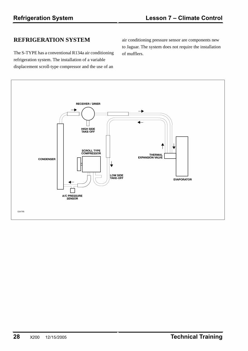
REFRIGERATION SYSTEM
The S-TYPE has a conventional R134a air conditioning
refrigeration system. The installation of a variable
displacement scroll-type compressor and the use of an
air conditioning pressure sensor are components new
to Jaguar. The system does not require the installation
of mufflers.
E64795
Technical Training28
Lesson 7 – Climate ControlRefrigeration System
X200 12/15/2005
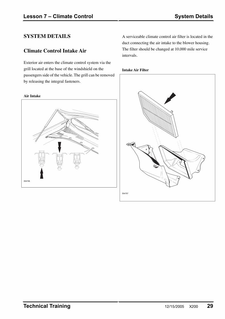
SYSTEM DETAILS
Climate Control Intake Air
Exterior air enters the climate control system via thegrill located at the base of the windshield on thepassengers side of the vehicle. The grill can be removedby releasing the integral fasteners.
Air Intake
E64796
A serviceable climate control air filter is located in theduct connecting the air intake to the blower housing.The filter should be changed at 10,000 mile serviceintervals.
Intake Air Filter
E64797
29Technical Training
System DetailsLesson 7 – Climate Control
12/15/2005 X200
Power Windows
Only the drivers door window is equipped with
one-touch down function. No initialization is required
should the vehicle power supply be disrupted.
Sunroof
The sunroof has the following features:
• One-touch open
• Tilt open
Technical Training30
Lesson 8 – Body SystemsOverview
X200 12/15/2005
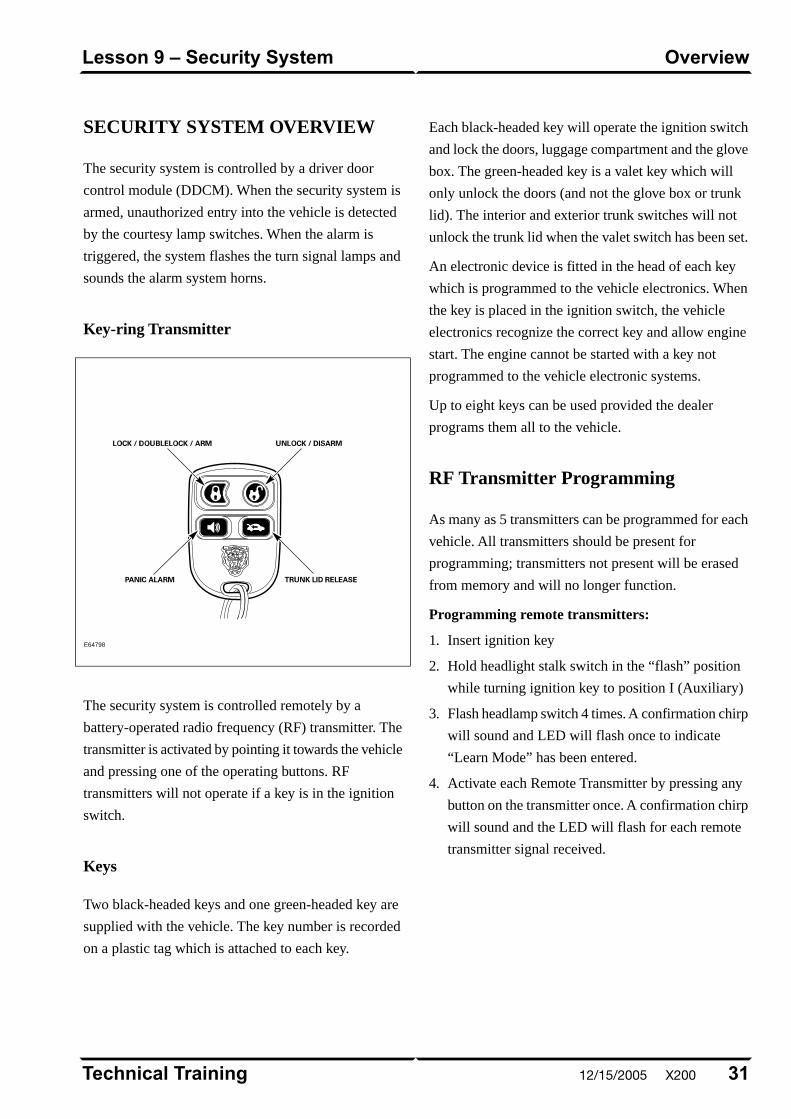
SECURITY SYSTEM OVERVIEW
The security system is controlled by a driver door
control module (DDCM). When the security system is
armed, unauthorized entry into the vehicle is detected
by the courtesy lamp switches. When the alarm is
triggered, the system flashes the turn signal lamps and
sounds the alarm system horns.
Key-ring Transmitter
E64798
The security system is controlled remotely by a
battery-operated radio frequency (RF) transmitter. The
transmitter is activated by pointing it towards the vehicle
and pressing one of the operating buttons. RF
transmitters will not operate if a key is in the ignition
switch.
Keys
Two black-headed keys and one green-headed key are
supplied with the vehicle. The key number is recorded
on a plastic tag which is attached to each key.
Each black-headed key will operate the ignition switch
and lock the doors, luggage compartment and the glove
box. The green-headed key is a valet key which will
only unlock the doors (and not the glove box or trunk
lid). The interior and exterior trunk switches will not
unlock the trunk lid when the valet switch has been set.
An electronic device is fitted in the head of each key
which is programmed to the vehicle electronics. When
the key is placed in the ignition switch, the vehicle
electronics recognize the correct key and allow engine
start. The engine cannot be started with a key not
programmed to the vehicle electronic systems.
Up to eight keys can be used provided the dealer
programs them all to the vehicle.
RF Transmitter Programming
As many as 5 transmitters can be programmed for each
vehicle. All transmitters should be present for
programming; transmitters not present will be erased
from memory and will no longer function.
Programming remote transmitters:
1. Insert ignition key
2. Hold headlight stalk switch in the “flash” position
while turning ignition key to position I (Auxiliary)
3. Flash headlamp switch 4 times. A confirmation chirp
will sound and LED will flash once to indicate
“Learn Mode” has been entered.
4. Activate each Remote Transmitter by pressing any
button on the transmitter once. A confirmation chirp
will sound and the LED will flash for each remote
transmitter signal received.
31Technical Training
OverviewLesson 9 – Security System
12/15/2005 X200
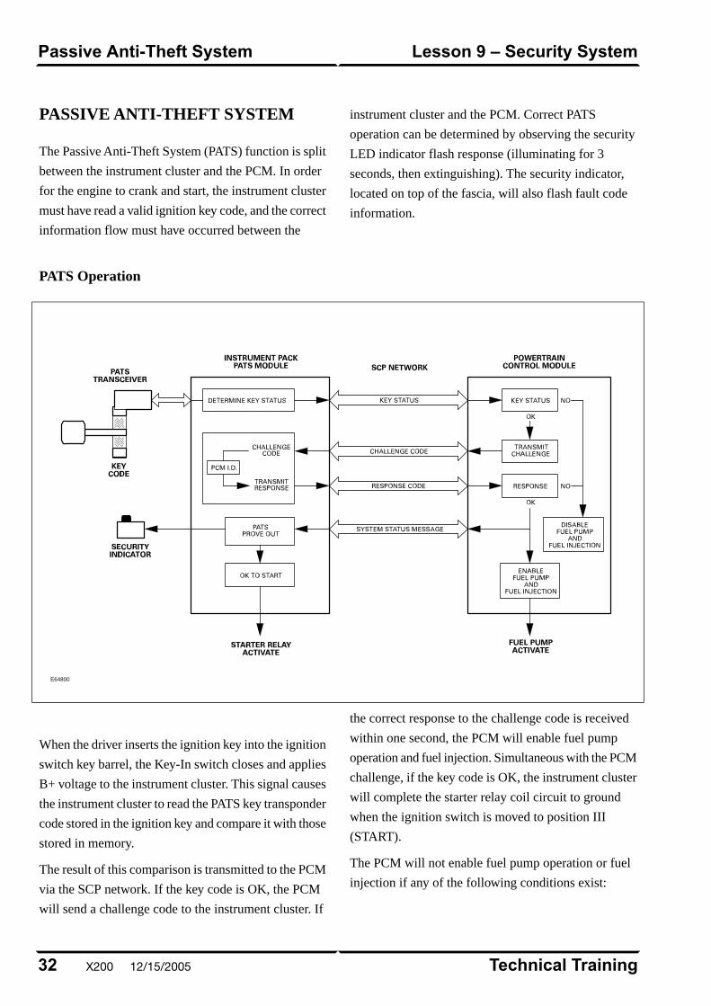
PASSIVE ANTI-THEFT SYSTEM
The Passive Anti-Theft System (PATS) function is split
between the instrument cluster and the PCM. In order
for the engine to crank and start, the instrument cluster
must have read a valid ignition key code, and the correct
information flow must have occurred between the
instrument cluster and the PCM. Correct PATS
operation can be determined by observing the security
LED indicator flash response (illuminating for 3
seconds, then extinguishing). The security indicator,
located on top of the fascia, will also flash fault code
information.
PATS Operation
E64800
When the driver inserts the ignition key into the ignition
switch key barrel, the Key-In switch closes and applies
B+ voltage to the instrument cluster. This signal causes
the instrument cluster to read the PATS key transponder
code stored in the ignition key and compare it with those
stored in memory.
The result of this comparison is transmitted to the PCM
via the SCP network. If the key code is OK, the PCM
will send a challenge code to the instrument cluster. If
the correct response to the challenge code is received
within one second, the PCM will enable fuel pump
operation and fuel injection. Simultaneous with the PCM
challenge, if the key code is OK, the instrument cluster
will complete the starter relay coil circuit to ground
when the ignition switch is moved to position III
(START).
The PCM will not enable fuel pump operation or fuel
injection if any of the following conditions exist:
Technical Training32
Lesson 9 – Security SystemPassive Anti-Theft System
X200 12/15/2005
• The ignition key code is not recognized (theft signal).
• A response to a challenge code has not been receivedwithin one second.
• An incorrect response to a challenge code has beenreceived.
Key Transponder Programming
At least two functional keys must be present to programup to 6 additional key transponders, for a total of 8functional key transponders. ALL keys intended for usemust be present for programming sequence with orwithout WDS.
Programming additional transponders without WDS:
1. Insert the first key and switch the ignition to II(RUN). Remove the key within 5 seconds.
2. Within 5 seconds from removing the first key, insertthe second key and switch the ignition to II (RUN).
3. If additional keys are to be programmed, insert oneof the remaining keys within 10 seconds from thepreceding key removal. Switch the ignition to II(RUN). Remove the key within 5 seconds.
Repeat step 3 with each key to be programmed. All keysmust be programmed within a 30-second window, fromthe first to the last key.
Programming additional transponders with WDS:
1. Select “Guided Diagnostics” from the Main WDSMenu, then select “Vehicle Setup”.
2. Select “Vehicle CM Set Up/Configuration”. Followthe on-screen prompts for key programming.
33Technical Training
Passive Anti-Theft SystemLesson 9 – Security System
12/15/2005 X200
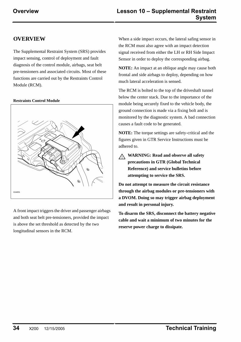
OVERVIEW
The Supplemental Restraint System (SRS) provides
impact sensing, control of deployment and fault
diagnosis of the control module, airbags, seat belt
pre-tensioners and associated circuits. Most of these
functions are carried out by the Restraints Control
Module (RCM).
Restraints Control Module
E64805
A front impact triggers the driver and passenger airbags
and both seat belt pre-tensioners, provided the impact
is above the set threshold as detected by the two
longitudinal sensors in the RCM.
When a side impact occurs, the lateral safing sensor in
the RCM must also agree with an impact detection
signal received from either the LH or RH Side Impact
Sensor in order to deploy the corresponding airbag.
NOTE: An impact at an oblique angle may cause both
frontal and side airbags to deploy, depending on how
much lateral acceleration is sensed.
The RCM is bolted to the top of the driveshaft tunnel
below the center stack. Due to the importance of the
module being securely fixed to the vehicle body, the
ground connection is made via a fixing bolt and is
monitored by the diagnostic system. A bad connection
causes a fault code to be generated.
NOTE: The torque settings are safety-critical and the
figures given in GTR Service Instructions must be
adhered to.
WARNING: Read and observe all safety
precautions in GTR (Global Technical
Reference) and service bulletins before
attempting to service the SRS.
Do not attempt to measure the circuit resistance
through the airbag modules or pre-tensioners with
a DVOM. Doing so may trigger airbag deployment
and result in personal injury.
To disarm the SRS, disconnect the battery negative
cable and wait a minimum of two minutes for the
reserve power charge to dissipate.
Technical Training34
Lesson 10 – Supplemental RestraintSystem
Overview
X200 12/15/2005
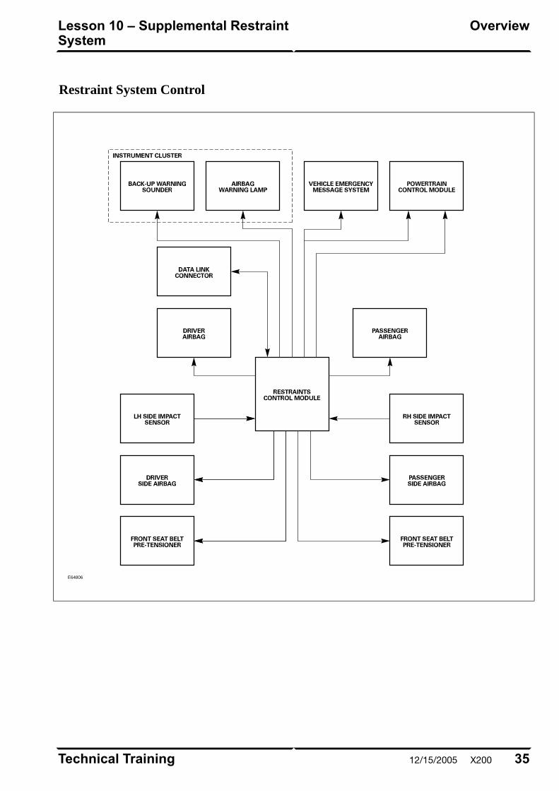
Restraint System Control
E64806
35Technical Training
OverviewLesson 10 – Supplemental RestraintSystem
12/15/2005 X200
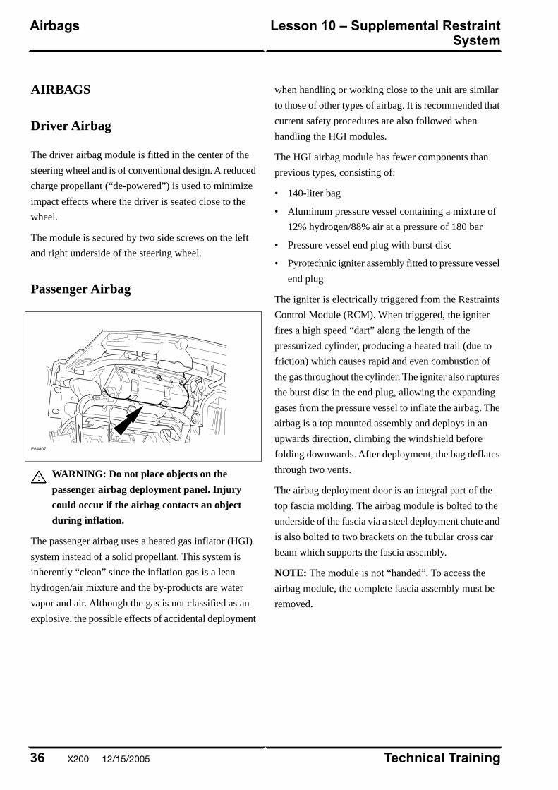
AIRBAGS
Driver Airbag
The driver airbag module is fitted in the center of the
steering wheel and is of conventional design. A reduced
charge propellant (“de-powered”) is used to minimize
impact effects where the driver is seated close to the
wheel.
The module is secured by two side screws on the left
and right underside of the steering wheel.
Passenger Airbag
E64807
WARNING: Do not place objects on the
passenger airbag deployment panel. Injury
could occur if the airbag contacts an object
during inflation.
The passenger airbag uses a heated gas inflator (HGI)
system instead of a solid propellant. This system is
inherently “clean” since the inflation gas is a lean
hydrogen/air mixture and the by-products are water
vapor and air. Although the gas is not classified as an
explosive, the possible effects of accidental deployment
when handling or working close to the unit are similar
to those of other types of airbag. It is recommended that
current safety procedures are also followed when
handling the HGI modules.
The HGI airbag module has fewer components than
previous types, consisting of:
• 140-liter bag
• Aluminum pressure vessel containing a mixture of
12% hydrogen/88% air at a pressure of 180 bar
• Pressure vessel end plug with burst disc
• Pyrotechnic igniter assembly fitted to pressure vessel
end plug
The igniter is electrically triggered from the Restraints
Control Module (RCM). When triggered, the igniter
fires a high speed “dart” along the length of the
pressurized cylinder, producing a heated trail (due to
friction) which causes rapid and even combustion of
the gas throughout the cylinder. The igniter also ruptures
the burst disc in the end plug, allowing the expanding
gases from the pressure vessel to inflate the airbag. The
airbag is a top mounted assembly and deploys in an
upwards direction, climbing the windshield before
folding downwards. After deployment, the bag deflates
through two vents.
The airbag deployment door is an integral part of the
top fascia molding. The airbag module is bolted to the
underside of the fascia via a steel deployment chute and
is also bolted to two brackets on the tubular cross car
beam which supports the fascia assembly.
NOTE: The module is not “handed”. To access the
airbag module, the complete fascia assembly must be
removed.
Technical Training36
Lesson 10 – Supplemental RestraintSystem
Airbags
X200 12/15/2005

Side Airbag
E64808
Side airbags are incorporated into the driver and front
passenger seat squabs and are similar to those fitted to
the XJ Series, using compressed argon to provide the
inflation gas. The bag has a capacity of 19 liters and
provides protection to both the head and chest regions.
The side airbag module is fixed to the outer seat frame
and is located within a fabric deployment pocket. The
pocket is stitched to the seat cover seam and when the
module is triggered, this length of seam bursts to provide
the deployment exit for the airbag.
If a damaged seat cover is to be replaced, the side airbag
module must be removed and re-located in the
deployment pocket of the new seat cover.
The complete seat must be replaced if the airbag has
been deployed.
37Technical Training
AirbagsLesson 10 – Supplemental RestraintSystem
12/15/2005 X200
IN-CAR ENTERTAINMENT (ICE)
Selectable Features
The selectable features menu can be accessed by
depressing and holding the menu button for 2 seconds.
The following options are available:
• 12/24 hour clock
• Traffic Announcement (TA)
• Alt Frequency (radio tunes to odd (for U.S. market)
or even digits)
• Radio Data System (RDS) Time ON / OFF
Setting the Clock
1. Press and hold the MENU button for at least two
seconds
2. Press button 1 to adjust clock hours
3. Press button 2 to adjust clock minutes
Technical Training38
Lesson 11 – InfotainmentIn-Car Entertainment (ICE)
X200 12/15/2005
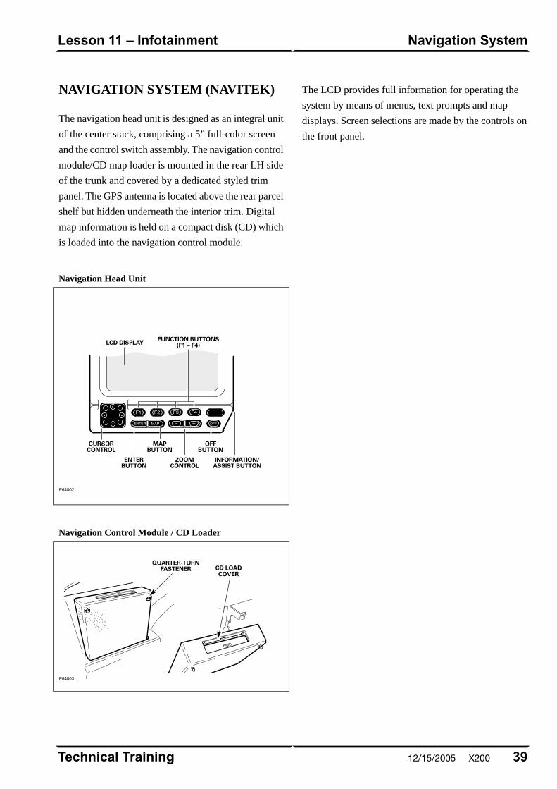
NAVIGATION SYSTEM (NAVITEK)
The navigation head unit is designed as an integral unit
of the center stack, comprising a 5” full-color screen
and the control switch assembly. The navigation control
module/CD map loader is mounted in the rear LH side
of the trunk and covered by a dedicated styled trim
panel. The GPS antenna is located above the rear parcel
shelf but hidden underneath the interior trim. Digital
map information is held on a compact disk (CD) which
is loaded into the navigation control module.
Navigation Head Unit
E64802
Navigation Control Module / CD Loader
E64803
The LCD provides full information for operating the
system by means of menus, text prompts and map
displays. Screen selections are made by the controls on
the front panel.
39Technical Training
Navigation SystemLesson 11 – Infotainment
12/15/2005 X200

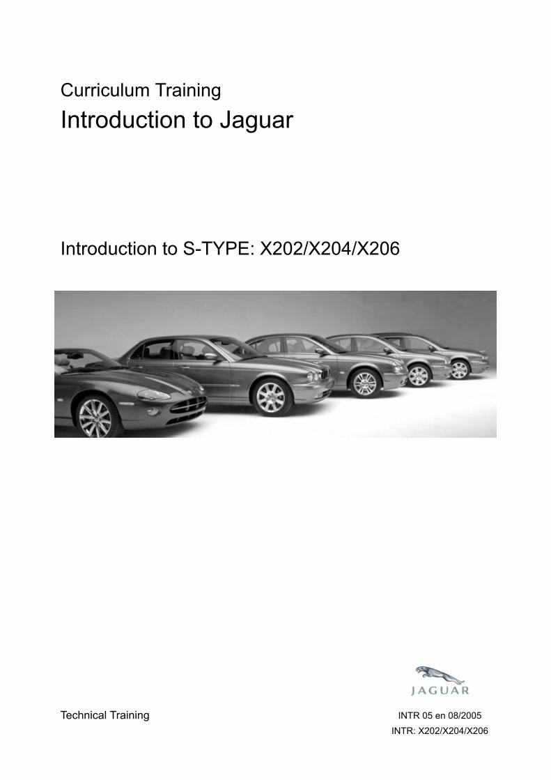
Curriculum Training
Introduction to Jaguar
Introduction to S-TYPE: X202/X204/X206
E63055
Technical Training INTR 05 en 08/2005INTR: X202/X204/X206

To the best of our knowledge, the illustrations, technical information, data and descriptions in this issue were correct at the time
of going to print. The right to change prices, specifications, equipment and maintenance instructions at any time without notice
is reserved as part of our policy of continuous development and improvement for the benefit of our customers.
No part of this publication may be reproduced, stored in a data processing system or transmitted in any form, electronic,
mechanical, photocopy, recording, translation or by any other means without prior permission of Premier Automotive Group.
No liability can be accepted for any inaccuracies in this publication, although every possible care has been taken to make it as
complete and accurate as possible.
Copyright ©2005

Please remember that our training literature has been prepared for TRAINING PURPOSES only. Repairs and
adjustments MUST always be carried out according to the instructions and specifications in the workshop literature.
Please make full use of the training offered by Technical Training to gain extensive knowledge of both theory
and practice.
1Technical Training
Preface
12/15/2005 X202 / X204 / X206
PAGE
Lesson 1 – General Information
6Overview......................................................................................................................................................
8Identification Labels...................................................................................................................................
9Lifting and Jacking.....................................................................................................................................
Lesson 2 – Engines
10Overview......................................................................................................................................................
13Details
Lesson 3 – Engine Management
16Overview......................................................................................................................................................
17Engine Control Module..............................................................................................................................
18Components.................................................................................................................................................
Lesson 4 – Transmission
21ZF 6HP26 Automatic Transmission..........................................................................................................
23Getrag 221 Manual Transmission.............................................................................................................
Lesson 5 – Chassis
25Power Assisted Steering.............................................................................................................................
26Front Suspension........................................................................................................................................
27Rear Suspension..........................................................................................................................................
Technical Training2
Table of Contents
X202 / X204 / X206 12/15/2005
28Brakes..........................................................................................................................................................
..........................................................................................................................................................
Lesson 6 – Control Modules and Networks
30Overview......................................................................................................................................................
Lesson 7 – Climate Control
33Overview......................................................................................................................................................
34Service..........................................................................................................................................................
Lesson 8 – Body Systems
36Power Windows...........................................................................................................................................
37Sunroof........................................................................................................................................................
Lesson 9 – Security System
38Remote Control Keyhead RF Transmitter...............................................................................................
39System Operation.......................................................................................................................................
43Service..........................................................................................................................................................
44Passive Anti-Theft System (PATS)............................................................................................................
Lesson 10 – Supplemental Restraint System
45Overview......................................................................................................................................................
46Components.................................................................................................................................................
48System Operation.......................................................................................................................................
3Technical Training
Table of Contents
12/15/2005 X202 / X204 / X206

51Navigation System......................................................................................................................................
Technical Training4
Table of Contents
X202 / X204 / X206 12/15/2005
Lesson 11 – Infotainment
50In-Car Entertainment (ICE).....................................................................................................................

Workshop safety
This page highlights the general observations expectedwhile attending this training program, and itscontinuation upon returning to your place of work.
General
While working on all vehicles, the following itemswhere available should always be used:
• Fender covers
• Seat covers
• Floor protection
Safety
All precautions must be taken and observed at all times,to prevent injury or damage to the following:
• Yourself
• Customer's property
• Workshop equipment
• Work place colleagues
Operating guidelines
While using any piece of workshop equipment:
The manufacturer's guidelines and warning labels mustbe followed.
This will ensure correct use and application at all times.
Seek the necessary advice or training where equipmentusage is unclear.
Chemicals, Oils and Solvents
Follow all manufacturer's warnings and labels; also takeinto account local disposal regulations when workingwith chemicals, oils or solvents.
Ensure that all risks are completely minimized.
Make sure that all protective items of clothing are wornwhere required e.g.
• Eye protection
• Gloves
• Coveralls
• Footwear
System capping
Upon disconnecting components from a system, takeall precautions necessary to prevent systemcontamination or environmental leakage.
Fit relevant plugs or caps i.e. to pipes, unions andcomponent orifices etc.
Updates
Keep abreast of all relevant changes that affect yourrole within the dealership, by monitoring all factoryissued documentation.
Driving
Operating vehicle features, such as ICE, mobile phonesand CD player equipment etc., can cause a momentarydistraction while driving.
Follow all traffic regulations when operating vehiclesystems or using diagnostic equipment while on the move.
Mobile diagnostic equipment operation may requirethe use of an assistant.
5
Safety and Precautions
12/15/2005 X202 / X204 / X206
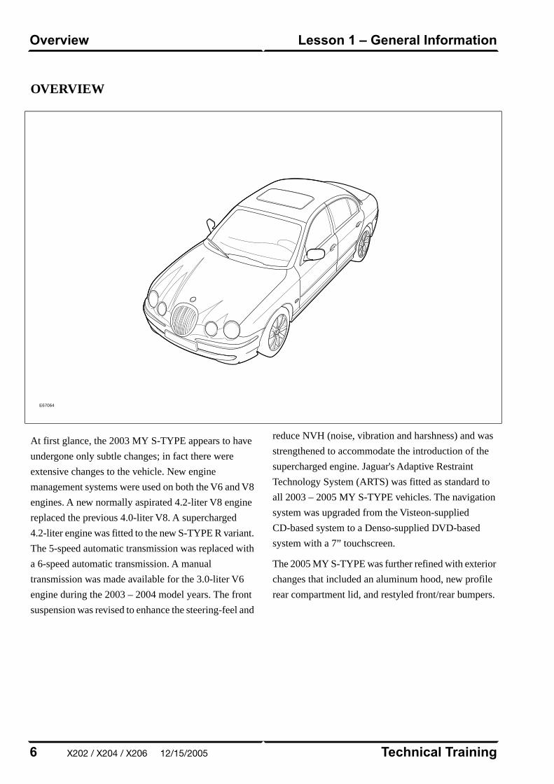
OVERVIEW
E67064
At first glance, the 2003 MY S-TYPE appears to have
undergone only subtle changes; in fact there were
extensive changes to the vehicle. New engine
management systems were used on both the V6 and V8
engines. A new normally aspirated 4.2-liter V8 engine
replaced the previous 4.0-liter V8. A supercharged
4.2-liter engine was fitted to the new S-TYPE R variant.
The 5-speed automatic transmission was replaced with
a 6-speed automatic transmission. A manual
transmission was made available for the 3.0-liter V6
engine during the 2003 – 2004 model years. The front
suspension was revised to enhance the steering-feel and
reduce NVH (noise, vibration and harshness) and was
strengthened to accommodate the introduction of the
supercharged engine. Jaguar's Adaptive Restraint
Technology System (ARTS) was fitted as standard to
all 2003 – 2005 MY S-TYPE vehicles. The navigation
system was upgraded from the Visteon-supplied
CD-based system to a Denso-supplied DVD-based
system with a 7” touchscreen.
The 2005 MY S-TYPE was further refined with exterior
changes that included an aluminum hood, new profile
rear compartment lid, and restyled front/rear bumpers.
Technical Training6
Lesson 1 – General InformationOverview
X202 / X204 / X206 12/15/2005
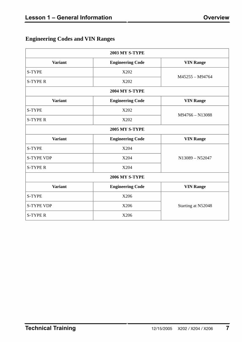
Engineering Codes and VIN Ranges
2003 MY S-TYPE
VIN RangeEngineering CodeVariant
M45255 – M94764X202S-TYPE
X202S-TYPE R
2004 MY S-TYPE
VIN RangeEngineering CodeVariant
M94766 – N13088X202S-TYPE
X202S-TYPE R
2005 MY S-TYPE
VIN RangeEngineering CodeVariant
N13089 – N52047
X204S-TYPE
X204S-TYPE VDP
X204S-TYPE R
2006 MY S-TYPE
VIN RangeEngineering CodeVariant
Starting at N52048
X206S-TYPE
X206S-TYPE VDP
X206S-TYPE R
7Technical Training
OverviewLesson 1 – General Information
12/15/2005 X202 / X204 / X206
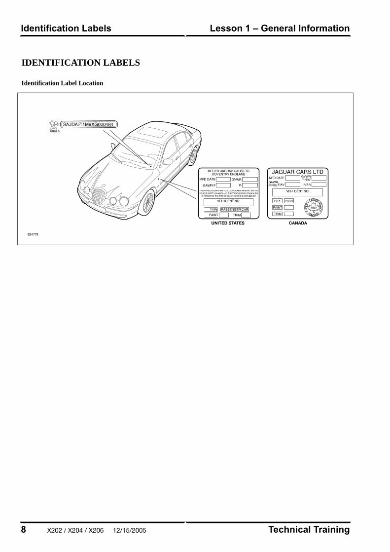
IDENTIFICATION LABELS
Identification Label Location
E64779
Technical Training8
Lesson 1 – General InformationIdentification Labels
X202 / X204 / X206 12/15/2005
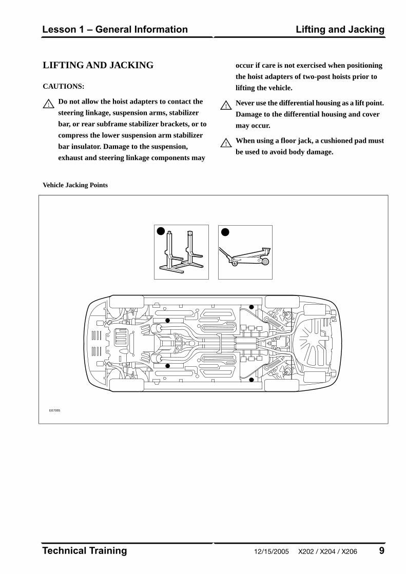
LIFTING AND JACKING
CAUTIONS:
Do not allow the hoist adapters to contact the
steering linkage, suspension arms, stabilizer
bar, or rear subframe stabilizer brackets, or to
compress the lower suspension arm stabilizer
bar insulator. Damage to the suspension,
exhaust and steering linkage components may
occur if care is not exercised when positioning
the hoist adapters of two-post hoists prior to
lifting the vehicle.
Never use the differential housing as a lift point.
Damage to the differential housing and cover
may occur.
When using a floor jack, a cushioned pad must
be used to avoid body damage.
Vehicle Jacking Points
E67065
9Technical Training
Lifting and JackingLesson 1 – General Information
12/15/2005 X202 / X204 / X206
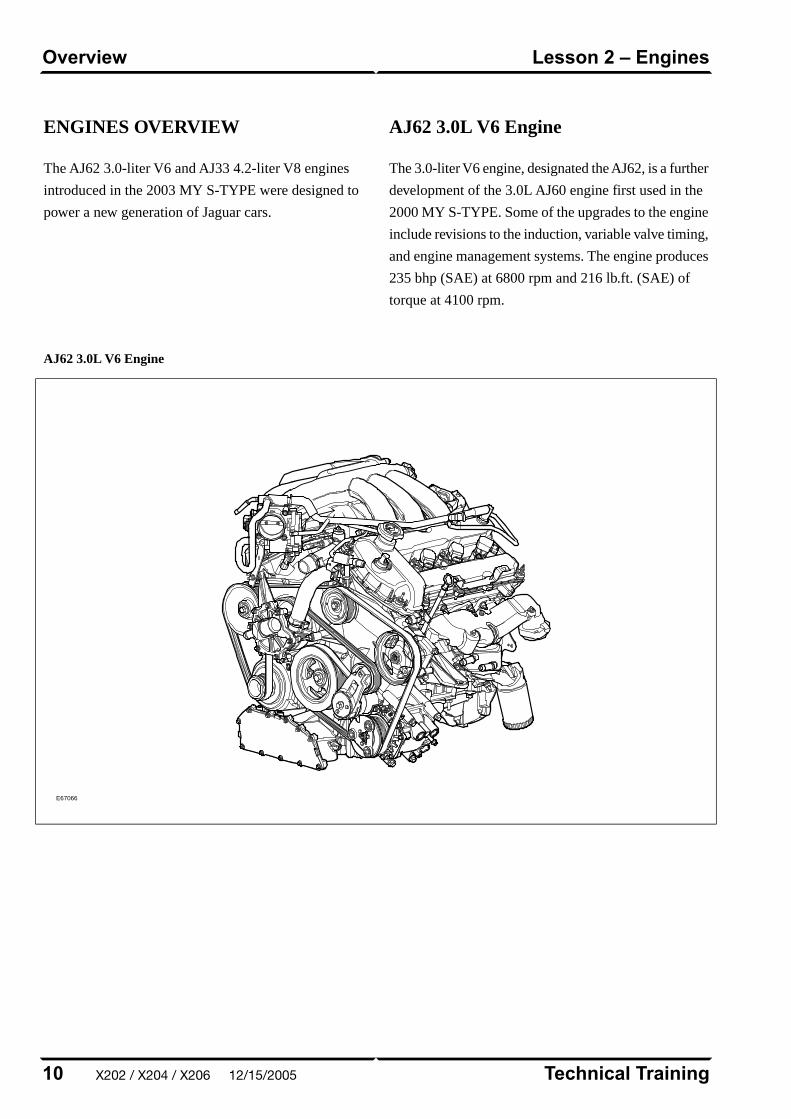
ENGINES OVERVIEW
The AJ62 3.0-liter V6 and AJ33 4.2-liter V8 engines
introduced in the 2003 MY S-TYPE were designed to
power a new generation of Jaguar cars.
AJ62 3.0L V6 Engine
The 3.0-liter V6 engine, designated the AJ62, is a further
development of the 3.0L AJ60 engine first used in the
2000 MY S-TYPE. Some of the upgrades to the engine
include revisions to the induction, variable valve timing,
and engine management systems. The engine produces
235 bhp (SAE) at 6800 rpm and 216 lb.ft. (SAE) of
torque at 4100 rpm.
AJ62 3.0L V6 Engine
E67066
Technical Training10
Lesson 2 – EnginesOverview
X202 / X204 / X206 12/15/2005
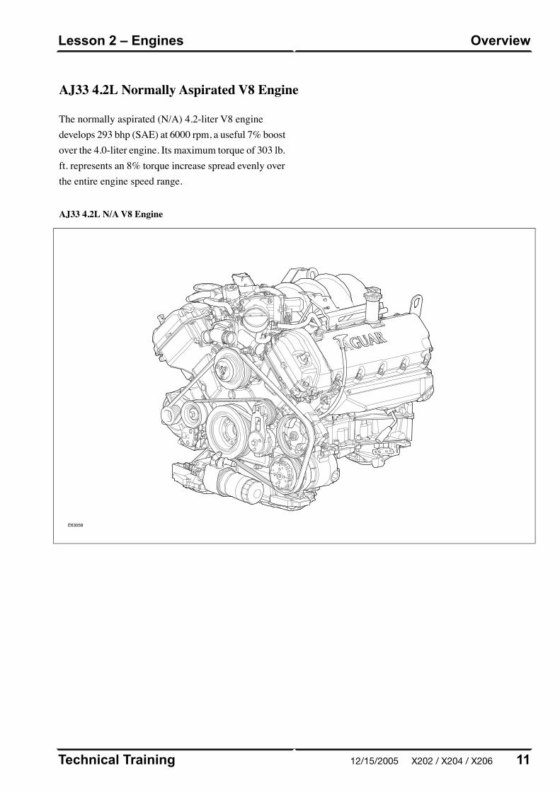
AJ33 4.2L Normally Aspirated V8 Engine
The normally aspirated (N/A) 4.2-liter V8 enginedevelops 293 bhp (SAE) at 6000 rpm, a useful 7% boostover the 4.0-liter engine. Its maximum torque of 303 lb.ft. represents an 8% torque increase spread evenly overthe entire engine speed range.
AJ33 4.2L N/A V8 Engine
E63058
11Technical Training
OverviewLesson 2 – Engines
12/15/2005 X202 / X204 / X206
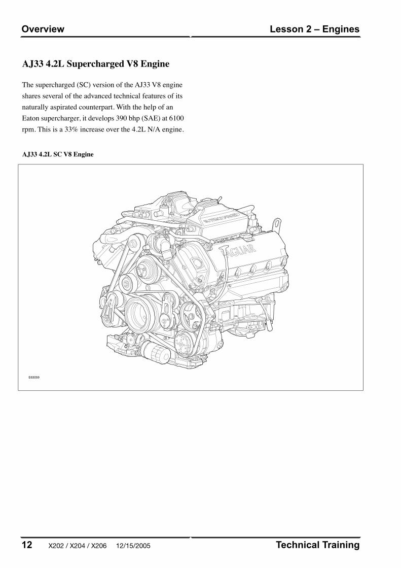
AJ33 4.2L SC V8 Engine
E63059
Technical Training12
Lesson 2 – EnginesOverview
AJ33 4.2L Supercharged V8 Engine
The supercharged (SC) version of the AJ33 V8 engineshares several of the advanced technical features of itsnaturally aspirated counterpart. With the help of anEaton supercharger, it develops 390 bhp (SAE) at 6100rpm. This is a 33% increase over the 4.2L N/A engine.
X202 / X204 / X206 12/15/2005
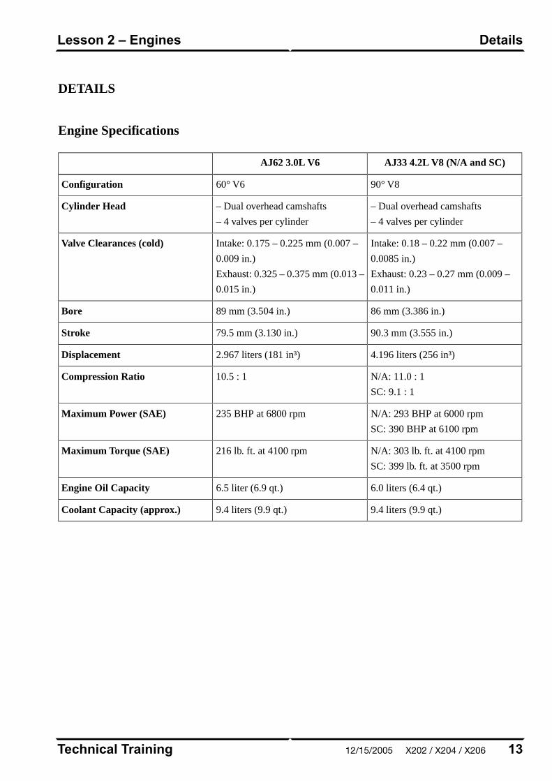
DETAILS
Engine Specifications
AJ33 4.2L V8 (N/A and SC)AJ62 3.0L V6
90° V860° V6Configuration
– Dual overhead camshafts
– 4 valves per cylinder
– Dual overhead camshafts
– 4 valves per cylinder
Cylinder Head
Intake: 0.18 – 0.22 mm (0.007 –
0.0085 in.)
Exhaust: 0.23 – 0.27 mm (0.009 –
0.011 in.)
Intake: 0.175 – 0.225 mm (0.007 –
0.009 in.)
Exhaust: 0.325 – 0.375 mm (0.013 –
0.015 in.)
Valve Clearances (cold)
86 mm (3.386 in.)89 mm (3.504 in.)Bore
90.3 mm (3.555 in.)79.5 mm (3.130 in.)Stroke
4.196 liters (256 in³)2.967 liters (181 in³)Displacement
N/A: 11.0 : 1
SC: 9.1 : 1
10.5 : 1Compression Ratio
N/A: 293 BHP at 6000 rpm
SC: 390 BHP at 6100 rpm
235 BHP at 6800 rpmMaximum Power (SAE)
N/A: 303 lb. ft. at 4100 rpm
SC: 399 lb. ft. at 3500 rpm
216 lb. ft. at 4100 rpmMaximum Torque (SAE)
6.0 liters (6.4 qt.)6.5 liter (6.9 qt.)Engine Oil Capacity
9.4 liters (9.9 qt.)9.4 liters (9.9 qt.)Coolant Capacity (approx.)
13Technical Training
DetailsLesson 2 – Engines
12/15/2005 X202 / X204 / X206
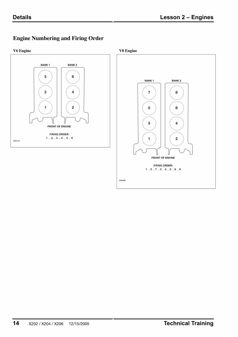
Engine Numbering and Firing Order
V6 Engine
E65142
V8 Engine
E63060
Technical Training14
Lesson 2 – EnginesDetails
X202 / X204 / X206 12/15/2005
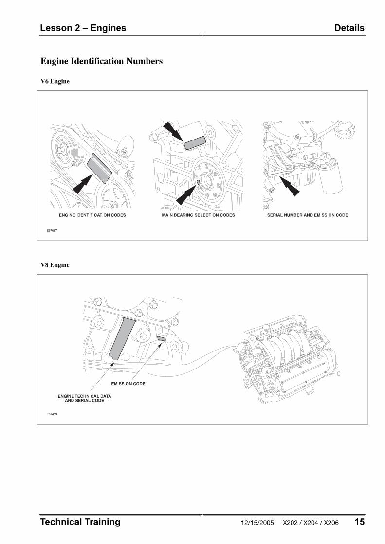
V8 Engine
E67413
15Technical Training
DetailsLesson 2 – Engines
Engine Identification Numbers
V6 Engine
E67067
12/15/2005 X202 / X204 / X206
ENGINE MANAGEMENTOVERVIEW
The Jaguar/Denso 32-bit Engine Management System
(EMS) was designed as a generic system applicable to
all Jaguar engines in use across the model ranges. The
system is built around a dual processor Engine Control
Module (ECM). One microprocessor is dedicated to
throttle control and diagnostics; the other microprocessor
handles all other ECM functions, controls and
diagnostics.
Technical Training16
Lesson 3 – Engine ManagementOverview
X202 / X204 / X206 12/15/2005
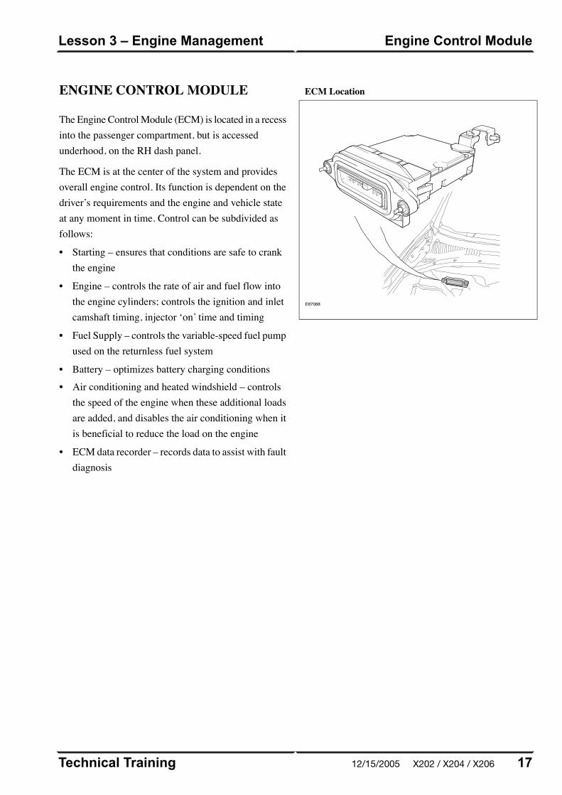
ENGINE CONTROL MODULE
The Engine Control Module (ECM) is located in a recessinto the passenger compartment, but is accessedunderhood, on the RH dash panel.
The ECM is at the center of the system and providesoverall engine control. Its function is dependent on thedriver’s requirements and the engine and vehicle stateat any moment in time. Control can be subdivided asfollows:
• Starting – ensures that conditions are safe to crankthe engine
• Engine – controls the rate of air and fuel flow intothe engine cylinders; controls the ignition and inletcamshaft timing, injector ‘on’ time and timing
• Fuel Supply – controls the variable-speed fuel pumpused on the returnless fuel system
• Battery – optimizes battery charging conditions
• Air conditioning and heated windshield – controlsthe speed of the engine when these additional loadsare added, and disables the air conditioning when itis beneficial to reduce the load on the engine
• ECM data recorder – records data to assist with faultdiagnosis
ECM Location
E67068
17Technical Training
Engine Control ModuleLesson 3 – Engine Management
12/15/2005 X202 / X204 / X206
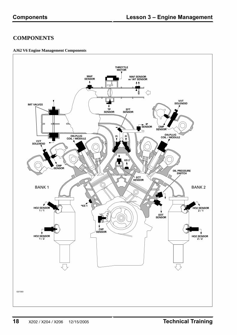
COMPONENTS
AJ62 V6 Engine Management Components
E67069
Technical Training18
Lesson 3 – Engine ManagementComponents
X202 / X204 / X206 12/15/2005

AJ33 V8 N/A Engine Management Components
E63063
19Technical Training
ComponentsLesson 3 – Engine Management
12/15/2005 X202 / X204 / X206

AJ33 V8 SC Engine Management Components
E63064
Technical Training20
Lesson 3 – Engine ManagementComponents
X202 / X204 / X206 12/15/2005
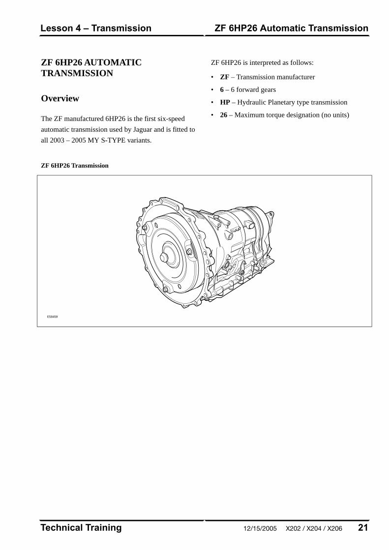
ZF 6HP26 AUTOMATICTRANSMISSION
Overview
The ZF manufactured 6HP26 is the first six-speed
automatic transmission used by Jaguar and is fitted to
all 2003 – 2005 MY S-TYPE variants.
ZF 6HP26 is interpreted as follows:
• ZF – Transmission manufacturer
• 6 – 6 forward gears
• HP – Hydraulic Planetary type transmission
• 26 – Maximum torque designation (no units)
ZF 6HP26 Transmission
E58459
21Technical Training
ZF 6HP26 Automatic TransmissionLesson 4 – Transmission
12/15/2005 X202 / X204 / X206
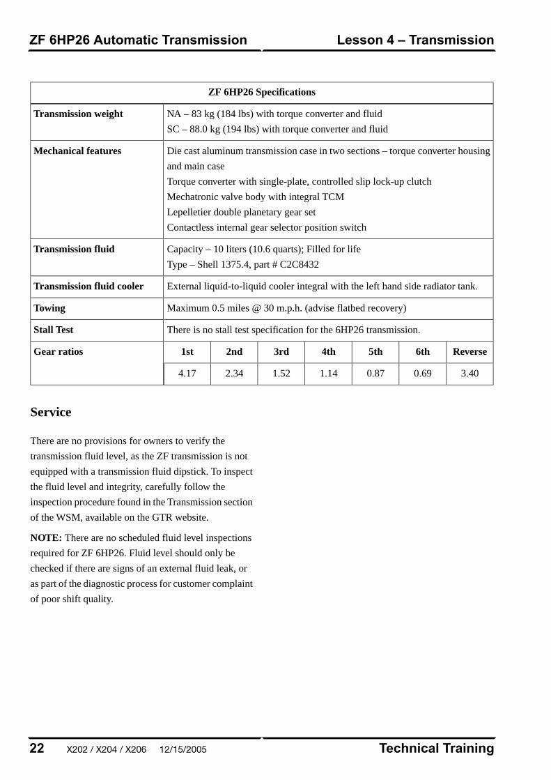
ZF 6HP26 Specifications
NA – 83 kg (184 lbs) with torque converter and fluid
SC – 88.0 kg (194 lbs) with torque converter and fluid
Transmission weight
Die cast aluminum transmission case in two sections – torque converter housing
and main case
Torque converter with single-plate, controlled slip lock-up clutch
Mechatronic valve body with integral TCM
Lepelletier double planetary gear set
Contactless internal gear selector position switch
Mechanical features
Capacity – 10 liters (10.6 quarts); Filled for life
Type – Shell 1375.4, part # C2C8432
Transmission fluid
External liquid-to-liquid cooler integral with the left hand side radiator tank.Transmission fluid cooler
Maximum 0.5 miles @ 30 m.p.h. (advise flatbed recovery)Towing
There is no stall test specification for the 6HP26 transmission.Stall Test
Reverse6th5th4th3rd2nd1stGear ratios
3.400.690.871.141.522.344.17
Service
There are no provisions for owners to verify the
transmission fluid level, as the ZF transmission is not
equipped with a transmission fluid dipstick. To inspect
the fluid level and integrity, carefully follow the
inspection procedure found in the Transmission section
of the WSM, available on the GTR website.
NOTE: There are no scheduled fluid level inspections
required for ZF 6HP26. Fluid level should only be
checked if there are signs of an external fluid leak, or
as part of the diagnostic process for customer complaint
of poor shift quality.
Technical Training22
Lesson 4 – TransmissionZF 6HP26 Automatic Transmission
X202 / X204 / X206 12/15/2005
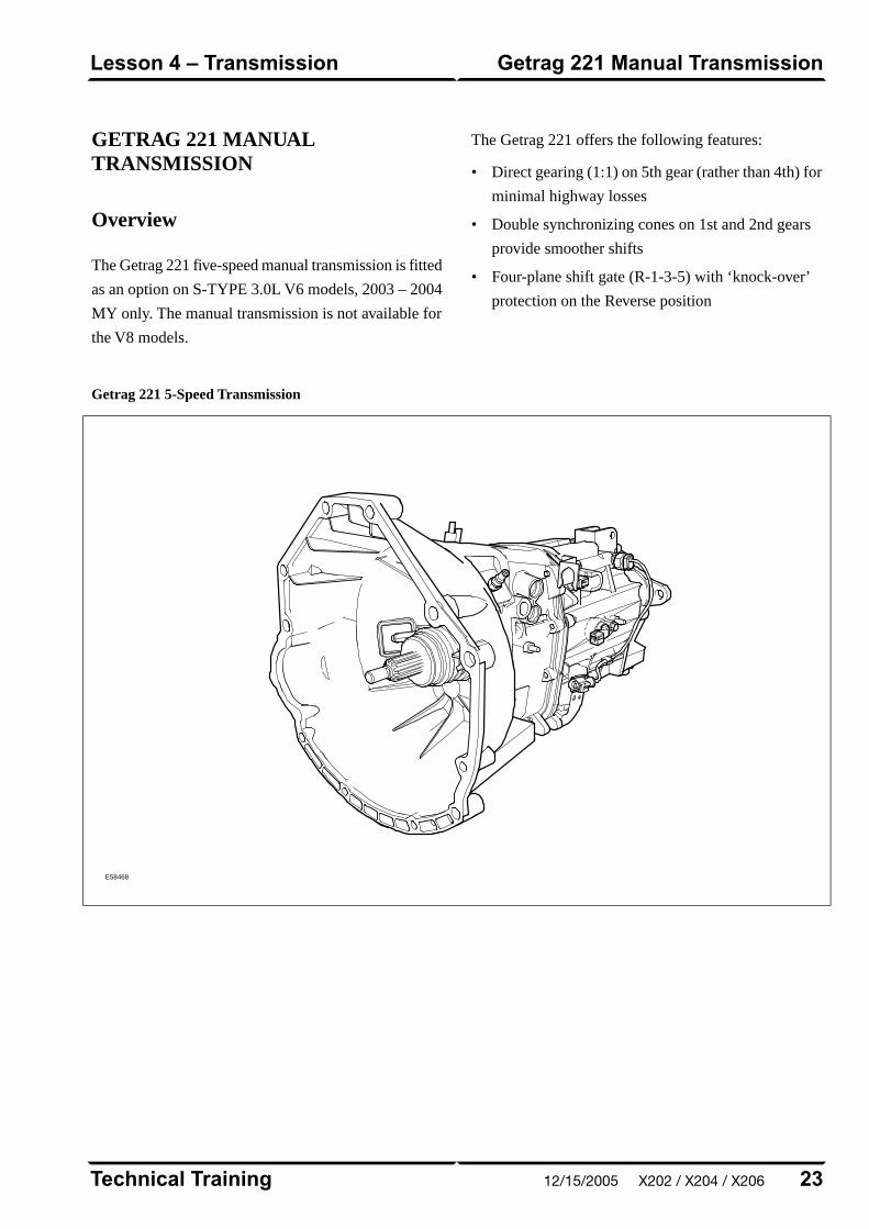
GETRAG 221 MANUALTRANSMISSION
Overview
The Getrag 221 five-speed manual transmission is fitted
as an option on S-TYPE 3.0L V6 models, 2003 – 2004
MY only. The manual transmission is not available for
the V8 models.
The Getrag 221 offers the following features:
• Direct gearing (1:1) on 5th gear (rather than 4th) for
minimal highway losses
• Double synchronizing cones on 1st and 2nd gears
provide smoother shifts
• Four-plane shift gate (R-1-3-5) with ‘knock-over’
protection on the Reverse position
Getrag 221 5-Speed Transmission
E58468
23Technical Training
Getrag 221 Manual TransmissionLesson 4 – Transmission
12/15/2005 X202 / X204 / X206
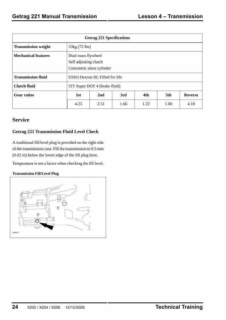
Getrag 221 Specifications
33kg (72 lbs)Transmission weight
Dual mass flywheel
Self adjusting clutch
Concentric slave cylinder
Mechanical features
ESSO Dexron III; Filled for lifeTransmission fluid
ITT Super DOT 4 (brake fluid)Clutch fluid
Reverse5th4th3rd2nd1stGear ratios
4.181.001.221.662.514.23
Service
Getrag 221 Transmission Fluid Level Check
A traditional fill/level plug is provided on the right side
of the transmission case. Fill the transmission to 0.5 mm
(0.02 in) below the lower edge of the fill plug bore.
Temperature is not a factor when checking the fill level.
Transmission Fill/Level Plug
E58472
Technical Training24
Lesson 4 – TransmissionGetrag 221 Manual Transmission
X202 / X204 / X206 12/15/2005

POWER ASSISTED STEERING
2003 – 2005 MY S-TYPE vehicles are fitted with the
ZF-manufactured Servotronic II rack and pinion
assembly. The rack features both variable ratio and
variable assistance. Control of the variable assistance
is integrated into the general electronic control module
(GECM). The fluid reservoir is fitted with a
non-serviceable 10-micron filter.
Power Assisted Steering Components
E67070
25Technical Training
Power Assisted SteeringLesson 5 – Chassis
12/15/2005 X202 / X204 / X206
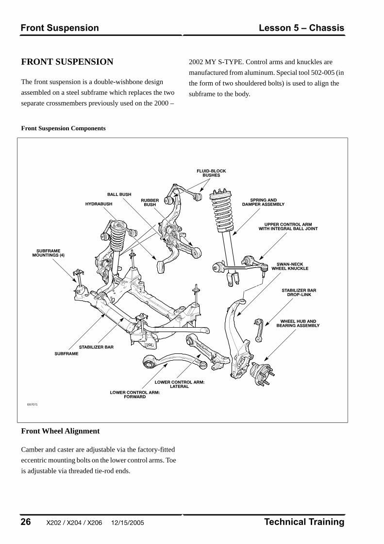
FRONT SUSPENSION
The front suspension is a double-wishbone design
assembled on a steel subframe which replaces the two
separate crossmembers previously used on the 2000 –
2002 MY S-TYPE. Control arms and knuckles are
manufactured from aluminum. Special tool 502-005 (in
the form of two shouldered bolts) is used to align the
subframe to the body.
Front Suspension Components
E67071
Front Wheel Alignment
Camber and caster are adjustable via the factory-fitted
eccentric mounting bolts on the lower control arms. Toe
is adjustable via threaded tie-rod ends.
Technical Training26
Lesson 5 – ChassisFront Suspension
X202 / X204 / X206 12/15/2005
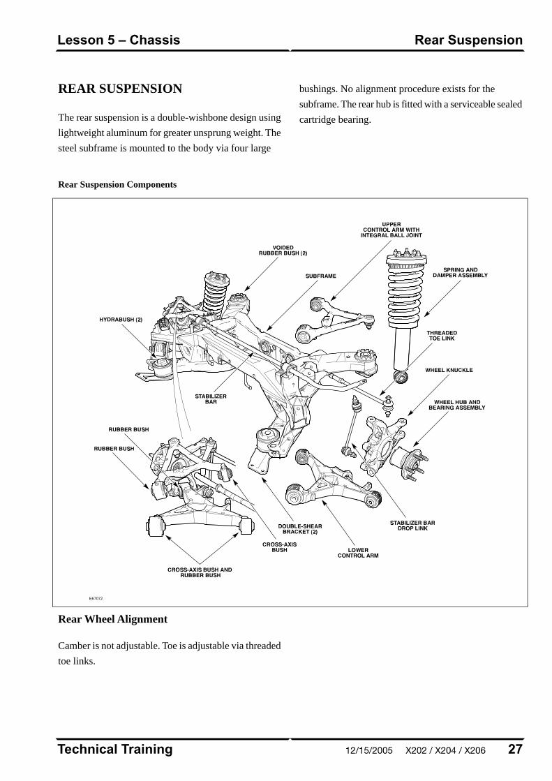
REAR SUSPENSION
The rear suspension is a double-wishbone design using
lightweight aluminum for greater unsprung weight. The
steel subframe is mounted to the body via four large
bushings. No alignment procedure exists for the
subframe. The rear hub is fitted with a serviceable sealed
cartridge bearing.
Rear Suspension Components
E67072
Rear Wheel Alignment
Camber is not adjustable. Toe is adjustable via threaded
toe links.
27Technical Training
Rear SuspensionLesson 5 – Chassis
12/15/2005 X202 / X204 / X206
BRAKES
All 2003-2005 MY S-TYPE vehicles are fitted with the
Teves MK25 ABS system. The main system components
are as follows:
• Teves MK25 modulator and control module
• Active wheel speed sensors
• High resolution steering angle sensor
• Yaw rate sensor
• Teves active brake booster
The Teves MK25 ABS system has the following features
as standard equipment:
• Anti-lock Braking (ABS)
• Traction Control System (TCS)
• Dynamic Stability Control System (DSC)
• Panic Brake Assist (PBA)
Normally aspirated variants are fitted with floating
calipers. Supercharged vehicles (S-TYPE R) are fitted
with Brembo high-performance brake calipers and larger
discs.
Electronic Parking Brake
The Electronic Parking Brake (EPB) system fitted to
S-TYPE vehicles offers the following benefits:
• Increased interior space (formerly occupied by a
traditional parking brake handle)
• Fully automatic activation/deactivation
• Driver strength plays no part in parking brake
activation
The system comprises the following components:
• Parking Brake Actuator
– Located above the rear subframe, the actuator
consists of a motor, hall-effect position sensor,
gearbox mechanism and linkage.
• Electronic Parking Brake Control Module
– Fitted in the trunk by the right quarter panel, the
EPB module controls the actuator based on
vehicle and driver inputs.
• Center Console Switch
– A three-way switch is mounted rearward of the
J-gate.
Technical Training28
Lesson 5 – ChassisBrakes
X202 / X204 / X206 12/15/2005

EPB Actuator and Calipers
E67073
29Technical Training
BrakesLesson 5 – Chassis
12/15/2005 X202 / X204 / X206
CONTROL MODULES ANDNETWORKS OVERVIEW
Three communication networks are used for control
module intercommunication.
Communication Networks
Communication MediumSpeedClassNetwork
Twisted pair copper wire500 KBaudCController Area Network (CAN)
Twisted pair copper wire41.6 KBaudBStandard Corporate Protocol Network (SCP)
Fiber optic cable5.6 MBaudn/aDigital Data Bus (D2B)
A fourth network – ISO 9141 (Serial Data Link) –
allows diagnostic interrogation via the data link
connector (DLC), but does not allow control module
intercommunication. The ISO network communicates
at 10.4 KBaud.
Technical Training30
Lesson 6 – Control Modules andNetworks
Overview
X202 / X204 / X206 12/15/2005
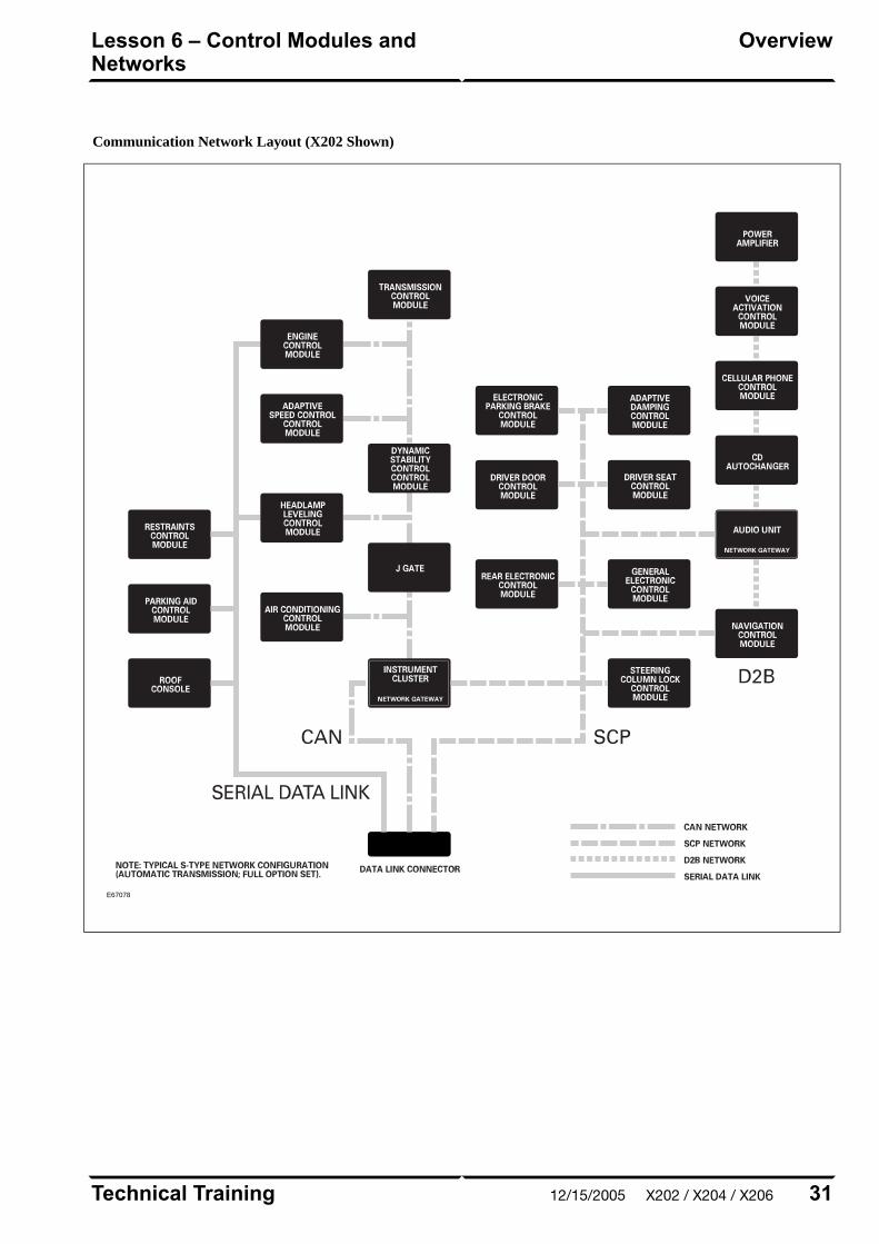
Communication Network Layout (X202 Shown)
E67078
31Technical Training
OverviewLesson 6 – Control Modules andNetworks
12/15/2005 X202 / X204 / X206
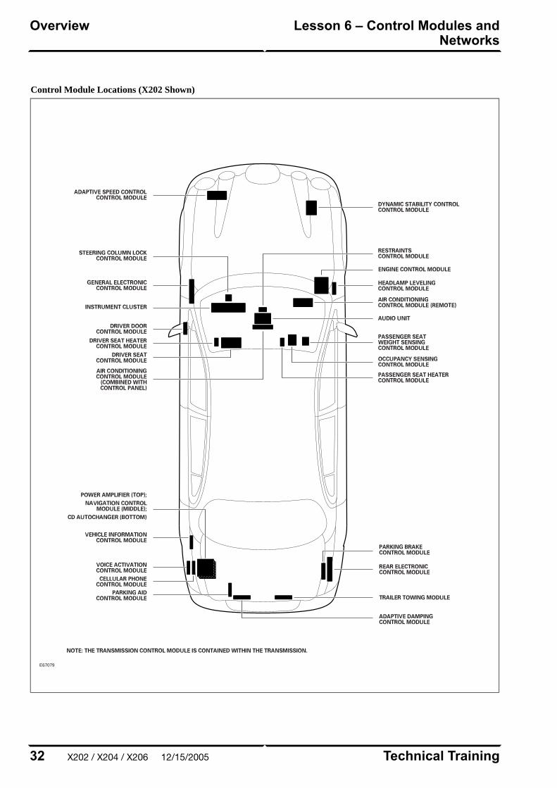
Control Module Locations (X202 Shown)
E67079
Technical Training32
Lesson 6 – Control Modules andNetworks
Overview
X202 / X204 / X206 12/15/2005
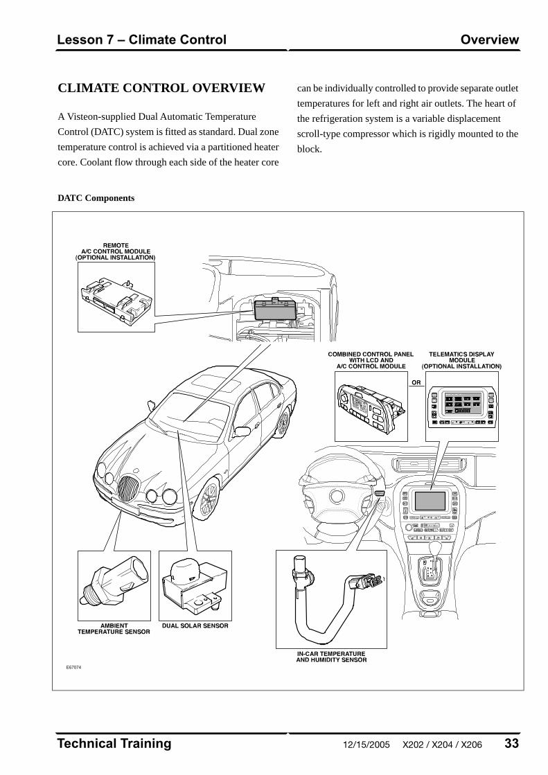
CLIMATE CONTROL OVERVIEW
A Visteon-supplied Dual Automatic Temperature
Control (DATC) system is fitted as standard. Dual zone
temperature control is achieved via a partitioned heater
core. Coolant flow through each side of the heater core
can be individually controlled to provide separate outlet
temperatures for left and right air outlets. The heart of
the refrigeration system is a variable displacement
scroll-type compressor which is rigidly mounted to the
block.
DATC Components
E67074
33Technical Training
OverviewLesson 7 – Climate Control
12/15/2005 X202 / X204 / X206
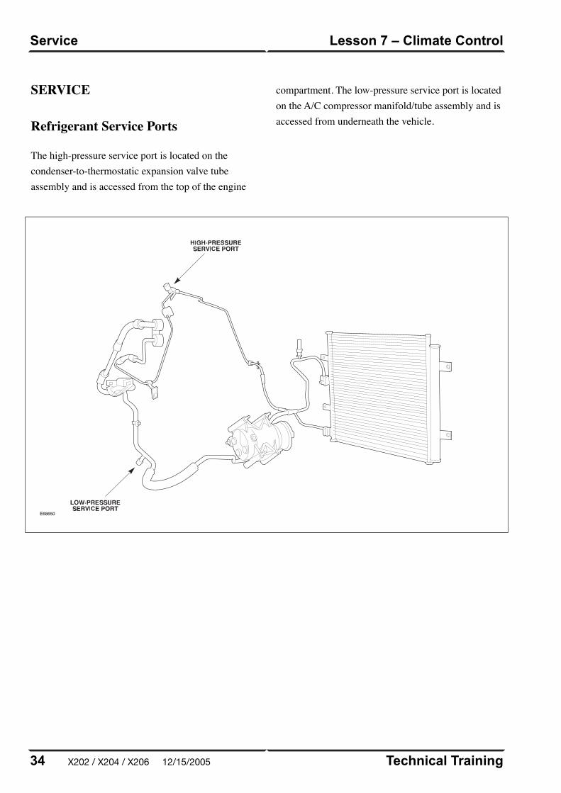
SERVICE
Refrigerant Service Ports
The high-pressure service port is located on thecondenser-to-thermostatic expansion valve tubeassembly and is accessed from the top of the engine
compartment. The low-pressure service port is locatedon the A/C compressor manifold/tube assembly and isaccessed from underneath the vehicle.
E68650
Technical Training34
Lesson 7 – Climate ControlService
X202 / X204 / X206 12/15/2005
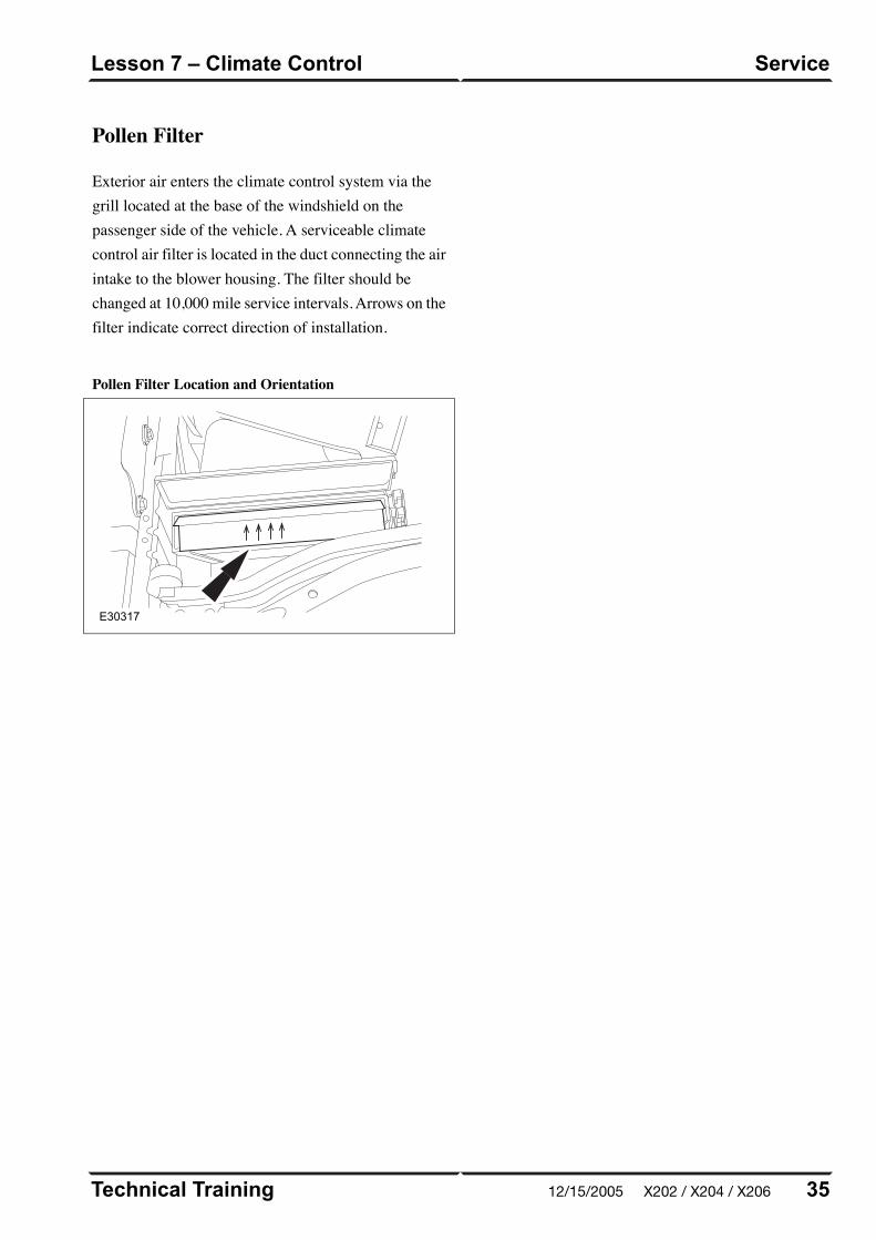
intake to the blower housing. The filter should bechanged at 10,000 mile service intervals. Arrows on thefilter indicate correct direction of installation.
Pollen Filter Location and Orientation
E30317
35Technical Training
ServiceLesson 7 – Climate Control
Pollen Filter
Exterior air enters the climate control system via thegrill located at the base of the windshield on thepassenger side of the vehicle. A serviceable climatecontrol air filter is located in the duct connecting the air
12/15/2005 X202 / X204 / X206
POWER WINDOWS
All windows are equipped with one-touch down and
one-touch up functionality. The one-touch up
functionality incorporates anti-trap capabilities. Utilizing
internal position sensors, the door motor can determine
when normal travel is restricted. If an obstruction is
detected when raising the window, the motor’s internal
electronics will reverse the direction of the window.
If the vehicle power supply is disrupted, the one-touch
up feature will no longer function when the power
supply is restored. The initialization procedure must be
carried out to restore operation.
Power Window Initialization
1. Lift and hold the window switch in the up direction
until the window seats completely. Continue to hold
the switch for a further two seconds.
2. Release switch and then lift and hold it again for a
further two seconds. This ensures the window is fully
seated into the seal.
3. Press the window switch to lower the window to its
fully open position.
4. Verify the operation of the anti-trap and one-touch
up operation.
NOTE: This procedure can be carried out either from
the individual window switches or from the driver’s
switch pack.
Technical Training36
Lesson 8 – Body SystemsPower Windows
X202 / X204 / X206 12/15/2005
SUNROOF
The sunroof has the following features:
• One-touch open and close operation
• Tilt open
• Anti-trap safety
• Memory retention if the battery is disconnected
The sunroof memory is not affected by battery
disconnection and will not require re-initializing upon
reconnection. However, if power is disconnected while
the sunroof is actually being operated, then the memory
will be lost and the following initialization procedure
will have to be carried out. This procedure will also
have to be carried out if the roof motor is replaced.
Sunroof Initialization
1. Turn the ignition switch to either position I or II.
2. Press the roof switch in the tilt position until the
sunroof moves to the fully tilted position and stops.
3. Release the switch.
4. Press and hold the switch in the tilt up position for
at least 20 seconds. The roof panel will make a small
movement to indicate that the roof has been
de-initialized.
5. Release the switch.
6. Within five seconds of releasing the switch, press
and hold the switch in the tilt position again. The
sunroof will travel automatically to the fully open
position, back to the fully closed position, and stop.
7. Verify the operation of the anti-trap and one-touch
up feature.
37Technical Training
SunroofLesson 8 – Body Systems
12/15/2005 X202 / X204 / X206
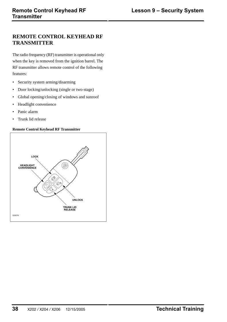
REMOTE CONTROL KEYHEAD RFTRANSMITTER
The radio frequency (RF) transmitter is operational only
when the key is removed from the ignition barrel. The
RF transmitter allows remote control of the following
features:
• Security system arming/disarming
• Door locking/unlocking (single or two-stage)
• Global opening/closing of windows and sunroof
• Headlight convenience
• Panic alarm
• Trunk lid release
Remote Control Keyhead RF Transmitter
E63076
Technical Training38
Lesson 9 – Security SystemRemote Control Keyhead RFTransmitter
X202 / X204 / X206 12/15/2005
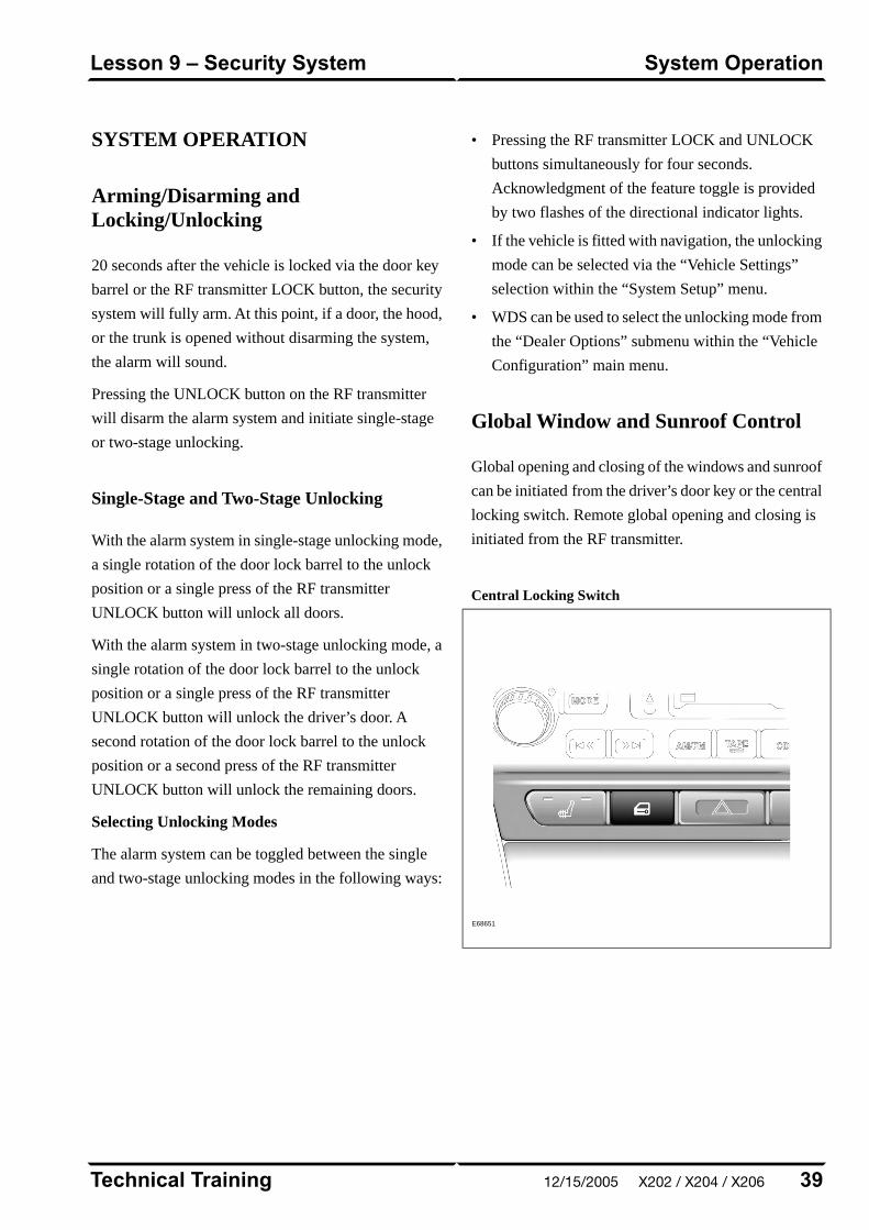
SYSTEM OPERATION
Arming/Disarming andLocking/Unlocking
20 seconds after the vehicle is locked via the door key
barrel or the RF transmitter LOCK button, the security
system will fully arm. At this point, if a door, the hood,
or the trunk is opened without disarming the system,
the alarm will sound.
Pressing the UNLOCK button on the RF transmitter
will disarm the alarm system and initiate single-stage
or two-stage unlocking.
Single-Stage and Two-Stage Unlocking
With the alarm system in single-stage unlocking mode,
a single rotation of the door lock barrel to the unlock
position or a single press of the RF transmitter
UNLOCK button will unlock all doors.
With the alarm system in two-stage unlocking mode, a
single rotation of the door lock barrel to the unlock
position or a single press of the RF transmitter
UNLOCK button will unlock the driver’s door. A
second rotation of the door lock barrel to the unlock
position or a second press of the RF transmitter
UNLOCK button will unlock the remaining doors.
Selecting Unlocking Modes
The alarm system can be toggled between the single
and two-stage unlocking modes in the following ways:
• Pressing the RF transmitter LOCK and UNLOCK
buttons simultaneously for four seconds.
Acknowledgment of the feature toggle is provided
by two flashes of the directional indicator lights.
• If the vehicle is fitted with navigation, the unlocking
mode can be selected via the “Vehicle Settings”
selection within the “System Setup” menu.
• WDS can be used to select the unlocking mode from
the “Dealer Options” submenu within the “Vehicle
Configuration” main menu.
Global Window and Sunroof Control
Global opening and closing of the windows and sunroof
can be initiated from the driver’s door key or the central
locking switch. Remote global opening and closing is
initiated from the RF transmitter.
Central Locking Switch
E68651
39Technical Training
System OperationLesson 9 – Security System
12/15/2005 X202 / X204 / X206

Global Opening/Remote Global Opening
To initiate global opening, rotate the key in the driver’s
door lock barrel to the unlock position and hold for
longer than two seconds. The windows and sunroof will
begin their opening operation and will continue to open
as long as the key is held in the unlock position.
Global opening can be initiated from within the car
using the central locking switch. To initiate global
opening from the central locking switch, the ignition
switch must be in the run position and the central
locking switch held for longer than two seconds. The
doors will centrally unlock and the windows and sunroof
will start to open. Global opening will cease if the switch
is released.
To initiate remote global opening, press and hold the
RF transmitter UNLOCK button for longer than two
seconds. This will initiate an automatic opening of the
windows and sunroof. Once initiated, the button can be
released and the windows and sunroof will continue to
their fully opened position. To stop the remote global
opening sequence, press any button on the RF
transmitter.
The remote global opening feature can be
enabled/disabled via WDS.
Global Closing/Remote Global Closing
To initiate global closing, rotate the key in the driver’s
door lock barrel to the unlock position and hold for
longer than two seconds. The windows and sunroof will
begin their closing operation and will continue to close
as long as the key is held in the lock position.
To initiate remote global closing, press and hold the RF
transmitter LOCK button for longer than two seconds.
This will initiate an automatic closing of the windows and
sunroof. Once initiated, the button can be released and
the windows and sunroof will continue to their fully
closed position. To stop the remote global closing
sequence, press any button on the RF transmitter.
The remote global closing feature can be
enabled/disabled via WDS.
NOTE: Global closing and remote global closing will
not close the windows if the windows have not been
initialized.
Headlight Convenience
When the RF transmitter HEADLIGHT
CONVENIENCE button is pressed, the headlights will
illuminate for 25 seconds. A second press of the button
or inserting the key into the ignition switch will
extinguish the headlights.
Panic Alarm
Pressing the RF transmitter HEADLIGHT
CONVENIENCE button three times within three
seconds will activate the panic alarm. To disable the
panic alarm, the key must be inserted into the ignition
switch and turned to position II (RUN).
Technical Training40
Lesson 9 – Security SystemSystem Operation
X202 / X204 / X206 12/15/2005

Trunk Release
E67080
The trunk can be opened five ways:
• Pressing the RF Transmitter TRUNK LID RELEASEbutton.
• Using an integrated transmitter key or black-headedkey in the trunk lock barrel. This will cause the alarmto sound if the vehicle is armed. The green-headedvalet key will not operate the trunk lock barrel.
• Pressing the release button on the trunk lid (valetmode inactive).
• Pressing the fascia switchpack trunk release button(valet mode inactive).
• Pulling the internal trunk release handle.
Internal Trunk Release Handle
E63078
41Technical Training
System OperationLesson 9 – Security System
12/15/2005 X202 / X204 / X206
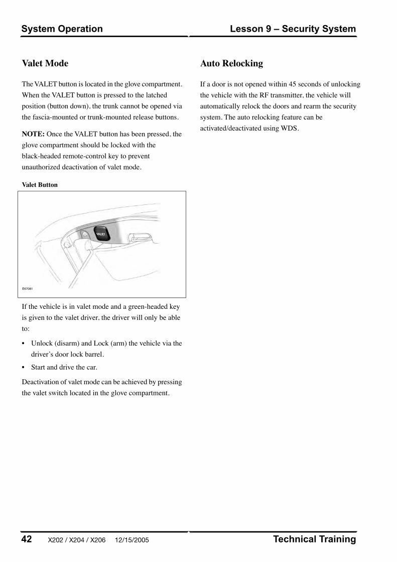
NOTE: Once the VALET button has been pressed, theglove compartment should be locked with theblack-headed remote-control key to preventunauthorized deactivation of valet mode.
Valet Button
E67081
If the vehicle is in valet mode and a green-headed keyis given to the valet driver, the driver will only be ableto:
• Unlock (disarm) and Lock (arm) the vehicle via thedriver’s door lock barrel.
• Start and drive the car.
Deactivation of valet mode can be achieved by pressingthe valet switch located in the glove compartment.
Auto Relocking
If a door is not opened within 45 seconds of unlockingthe vehicle with the RF transmitter, the vehicle willautomatically relock the doors and rearm the securitysystem. The auto relocking feature can beactivated/deactivated using WDS.
Technical Training42
Lesson 9 – Security SystemSystem Operation
Valet Mode
The VALET button is located in the glove compartment.When the VALET button is pressed to the latchedposition (button down), the trunk cannot be opened viathe fascia-mounted or trunk-mounted release buttons.
X202 / X204 / X206 12/15/2005
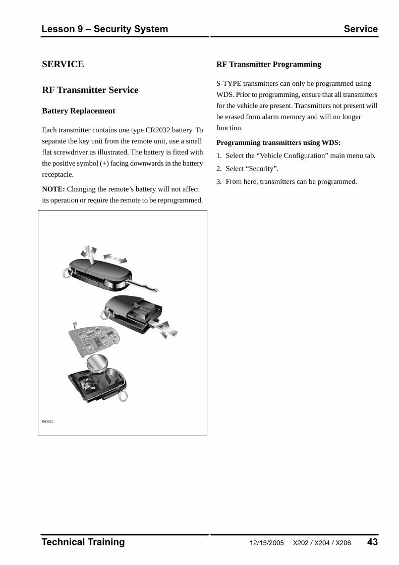
SERVICE
RF Transmitter Service
Battery Replacement
Each transmitter contains one type CR2032 battery. To
separate the key unit from the remote unit, use a small
flat screwdriver as illustrated. The battery is fitted with
the positive symbol (+) facing downwards in the battery
receptacle.
NOTE: Changing the remote’s battery will not affect
its operation or require the remote to be reprogrammed.
E63301
RF Transmitter Programming
S-TYPE transmitters can only be programmed using
WDS. Prior to programming, ensure that all transmitters
for the vehicle are present. Transmitters not present will
be erased from alarm memory and will no longer
function.
Programming transmitters using WDS:
1. Select the “Vehicle Configuration” main menu tab.
2. Select “Security”.
3. From here, transmitters can be programmed.
43Technical Training
ServiceLesson 9 – Security System
12/15/2005 X202 / X204 / X206
PASSIVE ANTI-THEFT SYSTEM
The Passive Anti-Theft System (PATS) is centered
around the instrument cluster (IC) and the engine control
module (ECM). The engine starting sequence is as
follows:
1. Key in ignition
2. Data transfer between the IC and the key transponder
to confirm a valid key
3. Ignition turned to position II (RUN)
4. “Key valid” message sent from the IC to the ECM
5. Data transfer between the ECM and IC to confirm
encrypted code is correct
6. Engine start
If this sequence is successfully completed, the PATS
LED located on top of the fascia will illuminate for three
seconds then extinguish.
PATS Fault Diagnostics
If a fault is detected, the engine will not crank and the
PATS LED located on top of the fascia will flash at 4Hz
for 60 seconds. At the end of this period, the LED will
flash a two-digit code for the current fault. The code
will be flashed 10 times. Refer to GTR for code
interpretation.
NOTE: NOTE: Corresponding DTCs may exist along
with PATS codes that may further explain the root cause
of a fault. Check for DTCs whenever diagnosing a PATS
fault.
Key Transponder Programming
Programming additional transponders without WDS:
1. To enter the manual programming process, all keys
for the vehicle will need to be present and two
pre-programmed keys will be required.
2. Insert the first customer key into the ignition switch
and turn to the position II (RUN) for a maximum of
five seconds. Remove the key.
3. Within 10 seconds of removing the first key, insert
the second customer key and turn to position II
(RUN) for a maximum of five seconds. Remove the
key.
4. To program the third key, insert the new key and
turn to position II (RUN) within 20 seconds of
removing the second key. Allow the PATS LED to
prove out for three seconds to confirm storage of the
new key.
Programming transponders using WDS:
1. Select the “Vehicle Configuration” main menu tab.
2. Select “Security”.
3. From here, key transponders can be programmed.
Technical Training44
Lesson 9 – Security SystemPassive Anti-Theft System (PATS)
X202 / X204 / X206 12/15/2005
SUPPLEMENTAL RESTRAINTSYSTEM OVERVIEW
The S-TYPE uses Jaguar’s Adaptive Restraint
Technology System (ARTS). ARTS can be divided into
three subsystems:
• Crash severity sensing and analysis
– Five impact sensors (one behind the radiator grill
and one mounted at the base of each ‘B/C’ and
‘D/E’ pillar) provide a signal to the Restraints
Control Module (RCM) that is proportionate to
the crash severity
• Occupant analysis
– Position of the driver’s seat and seatbelt
engagement is monitored
– Weight, position and seatbelt engagement of the
front passenger is monitored
• Deployment handling
– Based on crash severity and occupant analysis,
the RCM will determine which restraints to
deploy and the deployment strength (frontal
impact airbags only).
45Technical Training
OverviewLesson 10 – Supplemental RestraintSystem
12/15/2005 X202 / X204 / X206
COMPONENTS
The ARTS in S-TYPE vehicles uses three control
modules:
Weight Sensing Module
Mounted to the underside of the front passenger seat,
the weight sensing module processes the signal from
the seat pressure transducer attached to the silicone filled
bladder in the cushion.
Occupancy Sensing Module
Also mounted to the underside of the front passenger
seat, the occupancy sensing module processes signals
from the four ultrasonic sensors. These sensors emit an
ultrasonic signal operating at 40 KHz to monitor
occupancy of the front passenger seat.
Restraints Control Module
Mounted below the radio on the transmission tunnel,
the restraints control module is responsible for deploying
restraints based on signals from the weight sensing
module, occupancy sensing module, front seat belt
buckle sensors, driver’s seat position switch and crash
sensors.
The three modules communicate via a local (dedicated)
CAN network, which is not part of the vehicle’s main
CAN network.
Technical Training46
Lesson 10 – Supplemental RestraintSystem
Components
X202 / X204 / X206 12/15/2005
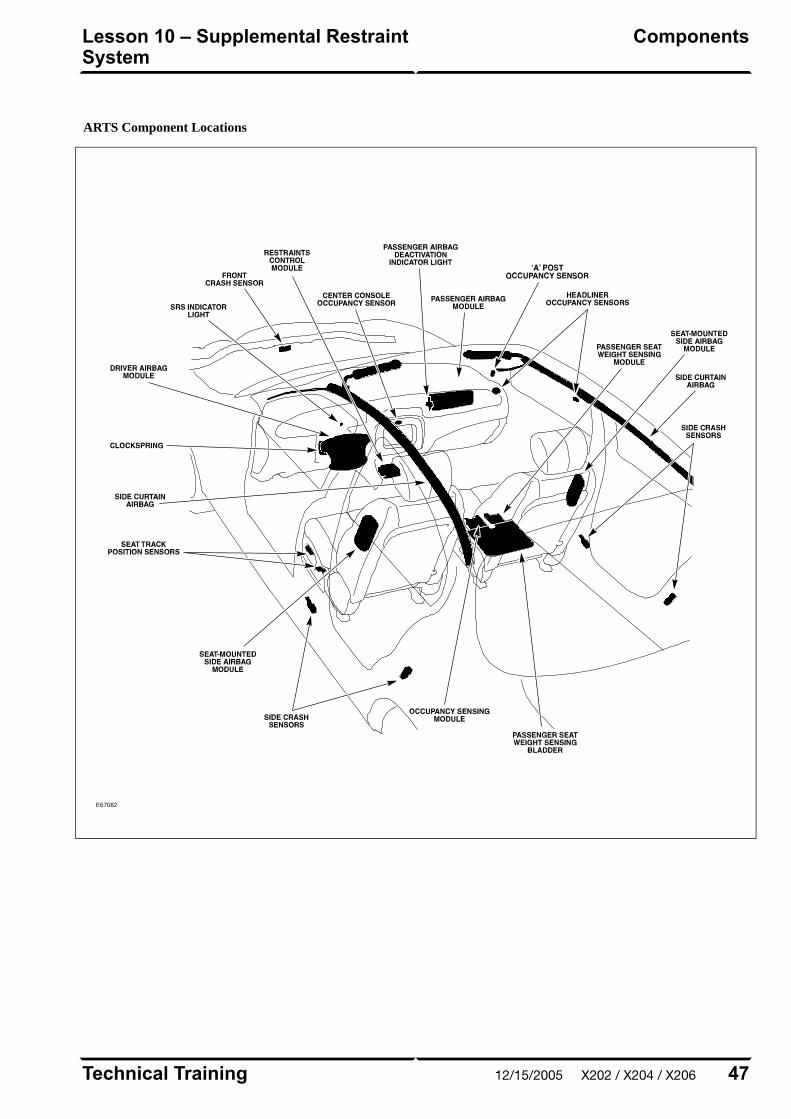
ARTS Component Locations
E67082
47Technical Training
ComponentsLesson 10 – Supplemental RestraintSystem
12/15/2005 X202 / X204 / X206
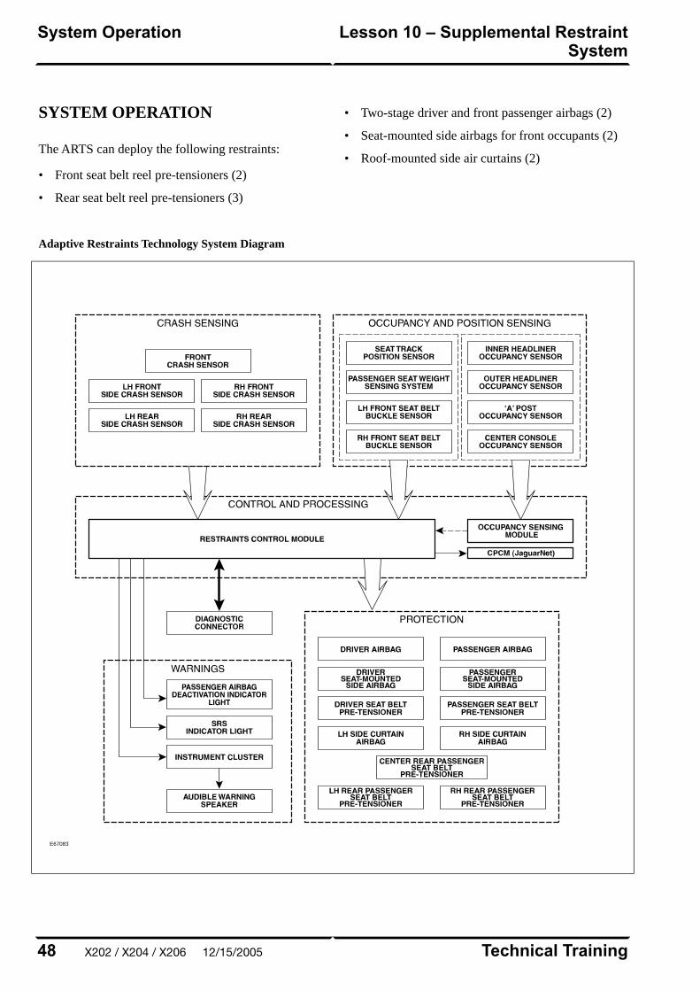
SYSTEM OPERATION
The ARTS can deploy the following restraints:
• Front seat belt reel pre-tensioners (2)
• Rear seat belt reel pre-tensioners (3)
• Two-stage driver and front passenger airbags (2)
• Seat-mounted side airbags for front occupants (2)
• Roof-mounted side air curtains (2)
Adaptive Restraints Technology System Diagram
E67083
Technical Training48
Lesson 10 – Supplemental RestraintSystem
System Operation
X202 / X204 / X206 12/15/2005
WARNING: Read and observe all safety
precautions in GTR (Global Technical
Reference) and service bulletins before
attempting to service the SRS.
Do not attempt to measure the circuit resistance
through the airbag modules or pre-tensioners with
a DVOM. Doing so may trigger airbag deployment
and result in personal injury.
To disarm the SRS, disconnect the battery negative
cable and wait a minimum of two minutes for the
reserve power charge to dissipate.
49Technical Training
System OperationLesson 10 – Supplemental RestraintSystem
12/15/2005 X202 / X204 / X206
IN-CAR ENTERTAINMENT (ICE)
Selectable Features
Simultaneously pressing and holding the AM/FM and
EJECT buttons will display the audio system selectable
features on the navigation screen (if fitted). The
following options are available:
• Market (toggled with preset button 1 on vehicles not
fitted with navigation)
– US (no security code function, radio tunes to odd
digits i.e. 90.1, 90.3, 90.5 etc.)
– EU
– JPN
– AUS
• RDS/RBDS (Radio Data System/Radio Broadcast
Data System) (toggled with preset button 0 on
vehicles not fitted with navigation)
– ON (when tuned to a RDS station, the radio will
display station call letters and (depending on
station) station name, current song title and artist)
– OFF (only the radio station frequency is
displayed)
Setting the Clock
Vehicles without navigation:
1. Press and hold the MODE button until TA VOLUME
is displayed
2. Repeatedly press the MODE button until CLOCK
SET is displayed
3. To select the 12 or 24 hour format, press the SEEK
UP/DOWN buttons
4. Press the MODE button to continue
5. If 12 hour is selected, use the # button to denote AM
or PM
6. Use the keypad to enter the time in four-digit format
7. To exit, press and hold the MODE button until the
display reverts to audio mode
Vehicles with navigation:
1. Press the MENU button on the touch screen control
panel – the system menu screen will be displayed
2. Touch the SYSTEM SETUP button on the MENU
screen
3. Touch the SET CLOCK button on the SYSTEM
SETUP screen
4. Clock adjustment is made by touching the hour or
minute, up or down arrow buttons
5. Touch the 12/24 button to select twelve or
twenty-four hour display
6. Confirm the setting by touching the SET button
Technical Training50
Lesson 11 – InfotainmentIn-Car Entertainment (ICE)
X202 / X204 / X206 12/15/2005

NAVIGATION SYSTEM
The navigation system is an optional fitment. The
navigation screen comprises a 7" color touch screen
which also provides control of the phone, audio system,
climate control, and voice control. The navigation
module is located in the left side of the trunk. The
Global Positioning System (GPS) antenna is located
below the parcel shelf trim.
With the aid of DVD map data, the navigation module
calculates the position of the vehicle using signals from
the GPS antenna, the ABS control module and the
GYRO sensor. After entering the desired destination,
the driver is guided along by both visual guidance and
voice instructions. If the driver strays off the route, the
system calculates a new route showing the easiest way
back to the original destination. The system can also
point out useful landmarks such as gas stations,
restaurants, hotels, and Jaguar dealers.
Navigation System Components
E67084
51Technical Training
Navigation SystemLesson 11 – Infotainment
12/15/2005 X202 / X204 / X206

Curriculum Training
Introduction to Jaguar
Introduction to XJ: X350/X355/X356
E63055
Technical Training INTR 05 en 08/2005INTR: X350/X355/X356

To the best of our knowledge, the illustrations, technical information, data and descriptions in this issue were correct at the time
of going to print. The right to change prices, specifications, equipment and maintenance instructions at any time without notice
is reserved as part of our policy of continuous development and improvement for the benefit of our customers.
No part of this publication may be reproduced, stored in a data processing system or transmitted in any form, electronic,
mechanical, photocopy, recording, translation or by any other means without prior permission of Premier Automotive Group.
No liability can be accepted for any inaccuracies in this publication, although every possible care has been taken to make it as
complete and accurate as possible.
Copyright ©2005

Please remember that our training literature has been prepared for TRAINING PURPOSES only. Repairs and
adjustments MUST always be carried out according to the instructions and specifications in the workshop literature.
Please make full use of the training offered by Technical Training to gain extensive knowledge of both theory
and practice.
1Technical Training
Preface
12/15/2005 X350 / X355 / X356
PAGE
Lesson 1 – General Information
6Overview......................................................................................................................................................
8Identification Labels...................................................................................................................................
9Lifting and Jacking.....................................................................................................................................
Lesson 2 – Engines
11Overview......................................................................................................................................................
13Details..........................................................................................................................................................
Lesson 3 – Engine Management
15Overview......................................................................................................................................................
16Engine Control Module..............................................................................................................................
17Components.................................................................................................................................................
Lesson 4 – Transmission
19Overview......................................................................................................................................................
Lesson 5 – Chassis
21Power Assisted Steering.............................................................................................................................
22Front Suspension........................................................................................................................................
23Rear Suspension..........................................................................................................................................
24Driveline......................................................................................................................................................
Technical Training2
Table of Contents
X350 / X355 / X356 12/15/2005

25Air Suspension............................................................................................................................................
30Brakes..........................................................................................................................................................
Lesson 6 – Control Modules and Networks
32Overview......................................................................................................................................................
Lesson 7 – Climate Control
35Overview......................................................................................................................................................
36Service..........................................................................................................................................................
Lesson 8 – Body Systems
37Power Windows...........................................................................................................................................
38Sunroof........................................................................................................................................................
Lesson 9 – Security System
39Remote Control Keyhead RF Transmitter...............................................................................................
40System Operation.......................................................................................................................................
44Service..........................................................................................................................................................
45Passive Anti-Theft System (PATS)............................................................................................................
Lesson 10 – Supplemental Restraint System
46Overview......................................................................................................................................................
47Components.................................................................................................................................................
49System Operation.......................................................................................................................................
3Technical Training
Table of Contents
12/15/2005 X350 / X355 / X356
Lesson 11 – Infotainment
51In-Car Entertainment (ICE).....................................................................................................................
52Navigation System......................................................................................................................................
Technical Training4
Table of Contents
X350 / X355 / X356 12/15/2005

Workshop safety
This page highlights the general observations expectedwhile attending this training program, and itscontinuation upon returning to your place of work.
General
While working on all vehicles, the following itemswhere available should always be used:
• Fender covers
• Seat covers
• Floor protection
Safety
All precautions must be taken and observed at all times,to prevent injury or damage to the following:
• Yourself
• Customer's property
• Workshop equipment
• Work place colleagues
Operating guidelines
While using any piece of workshop equipment:
The manufacturer's guidelines and warning labels mustbe followed.
This will ensure correct use and application at all times.
Seek the necessary advice or training where equipmentusage is unclear.
Chemicals, Oils and Solvents
Follow all manufacturer's warnings and labels; also takeinto account local disposal regulations when workingwith chemicals, oils or solvents.
Ensure that all risks are completely minimized.
Make sure that all protective items of clothing are wornwhere required e.g.
• Eye protection
• Gloves
• Coveralls
• Footwear
System capping
Upon disconnecting components from a system, takeall precautions necessary to prevent systemcontamination or environmental leakage.
Fit relevant plugs or caps i.e. to pipes, unions andcomponent orifices etc.
Updates
Keep abreast of all relevant changes that affect yourrole within the dealership, by monitoring all factoryissued documentation.
Driving
Operating vehicle features, such as ICE, mobile phonesand CD player equipment etc., can cause a momentarydistraction while driving.
Follow all traffic regulations when operating vehiclesystems or using diagnostic equipment while on the move.
Mobile diagnostic equipment operation may requirethe use of an assistant.
5
Safety and Precautions
12/15/2005 X350 / X355 / X356
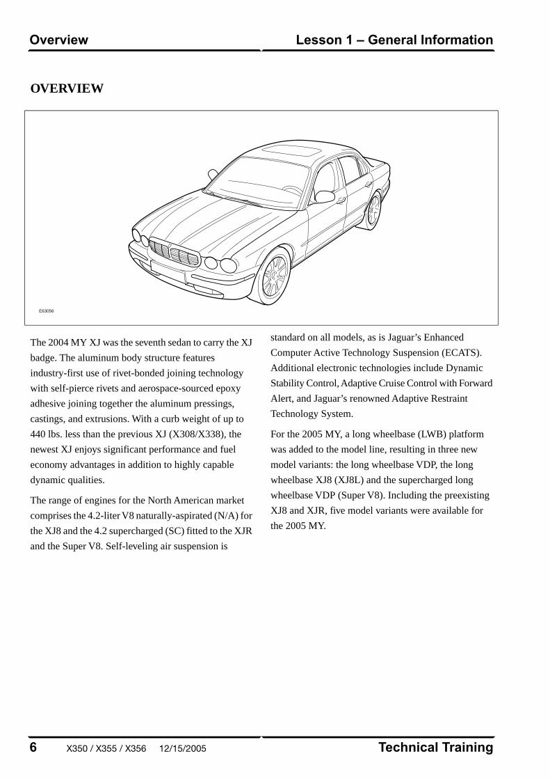
OVERVIEW
E63056
The 2004 MY XJ was the seventh sedan to carry the XJ
badge. The aluminum body structure features
industry-first use of rivet-bonded joining technology
with self-pierce rivets and aerospace-sourced epoxy
adhesive joining together the aluminum pressings,
castings, and extrusions. With a curb weight of up to
440 lbs. less than the previous XJ (X308/X338), the
newest XJ enjoys significant performance and fuel
economy advantages in addition to highly capable
dynamic qualities.
The range of engines for the North American market
comprises the 4.2-liter V8 naturally-aspirated (N/A) for
the XJ8 and the 4.2 supercharged (SC) fitted to the XJR
and the Super V8. Self-leveling air suspension is
standard on all models, as is Jaguar’s Enhanced
Computer Active Technology Suspension (ECATS).
Additional electronic technologies include Dynamic
Stability Control, Adaptive Cruise Control with Forward
Alert, and Jaguar’s renowned Adaptive Restraint
Technology System.
For the 2005 MY, a long wheelbase (LWB) platform
was added to the model line, resulting in three new
model variants: the long wheelbase VDP, the long
wheelbase XJ8 (XJ8L) and the supercharged long
wheelbase VDP (Super V8). Including the preexisting
XJ8 and XJR, five model variants were available for
the 2005 MY.
Technical Training6
Lesson 1 – General InformationOverview
X350 / X355 / X356 12/15/2005
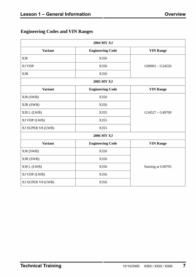
Engineering Codes and VIN Ranges
2004 MY XJ
VIN RangeEngineering CodeVariant
G00001 – G34526
X350XJ8
X350XJ VDP
X350XJR
2005 MY XJ
VIN RangeEngineering CodeVariant
G34527 – G49700
X350XJ8 (SWB)
X350XJR (SWB)
X355XJ8 L (LWB)
X355XJ VDP (LWB)
X355XJ SUPER V8 (LWB)
2006 MY XJ
VIN RangeEngineering CodeVariant
Starting at G49701
X356XJ8 (SWB)
X356XJR (SWB)
X356XJ8 L (LWB)
X356XJ VDP (LWB)
X356XJ SUPER V8 (LWB)
7Technical Training
OverviewLesson 1 – General Information
12/15/2005 X350 / X355 / X356
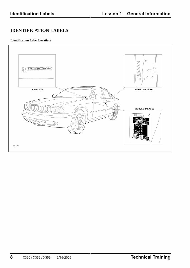
IDENTIFICATION LABELS
Identification Label Locations
E63057
Technical Training8
Lesson 1 – General InformationIdentification Labels
X350 / X355 / X356 12/15/2005
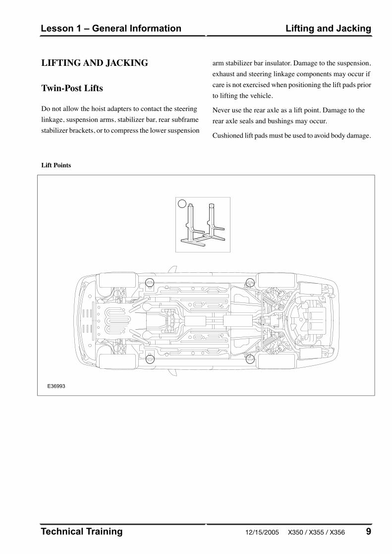
LIFTING AND JACKING
Twin-Post Lifts
Do not allow the hoist adapters to contact the steeringlinkage, suspension arms, stabilizer bar, rear subframestabilizer brackets, or to compress the lower suspension
arm stabilizer bar insulator. Damage to the suspension,exhaust and steering linkage components may occur ifcare is not exercised when positioning the lift pads priorto lifting the vehicle.
Never use the rear axle as a lift point. Damage to therear axle seals and bushings may occur.
Cushioned lift pads must be used to avoid body damage.
Lift Points
E36993
9Technical Training
Lifting and JackingLesson 1 – General Information
12/15/2005 X350 / X355 / X356
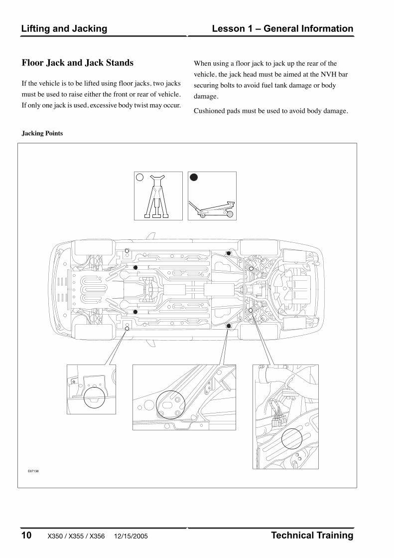
Jacking Points
E67138
Technical Training10
Lesson 1 – General InformationLifting and Jacking
Floor Jack and Jack Stands
If the vehicle is to be lifted using floor jacks, two jacksmust be used to raise either the front or rear of vehicle.If only one jack is used, excessive body twist may occur.
When using a floor jack to jack up the rear of thevehicle, the jack head must be aimed at the NVH barsecuring bolts to avoid fuel tank damage or bodydamage.
Cushioned pads must be used to avoid body damage.
X350 / X355 / X356 12/15/2005
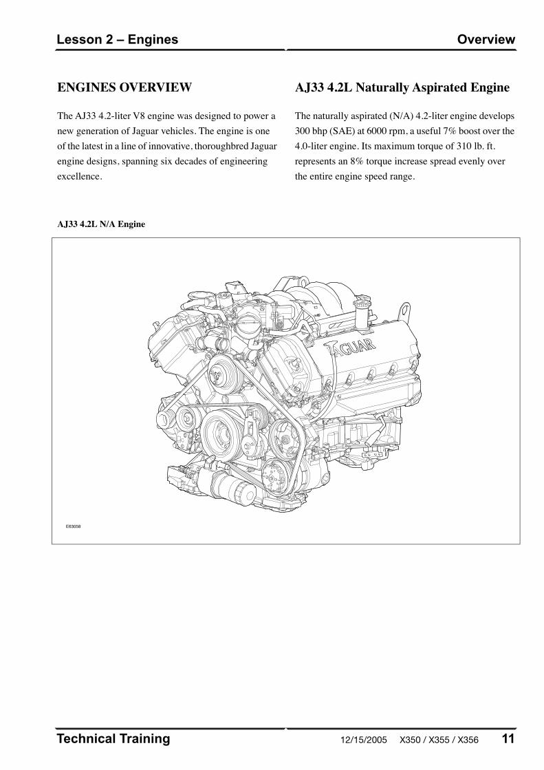
ENGINES OVERVIEW
The AJ33 4.2-liter V8 engine was designed to power anew generation of Jaguar vehicles. The engine is oneof the latest in a line of innovative, thoroughbred Jaguarengine designs, spanning six decades of engineeringexcellence.
AJ33 4.2L Naturally Aspirated Engine
The naturally aspirated (N/A) 4.2-liter engine develops300 bhp (SAE) at 6000 rpm, a useful 7% boost over the4.0-liter engine. Its maximum torque of 310 lb. ft.represents an 8% torque increase spread evenly overthe entire engine speed range.
AJ33 4.2L N/A Engine
E63058
11Technical Training
OverviewLesson 2 – Engines
12/15/2005 X350 / X355 / X356
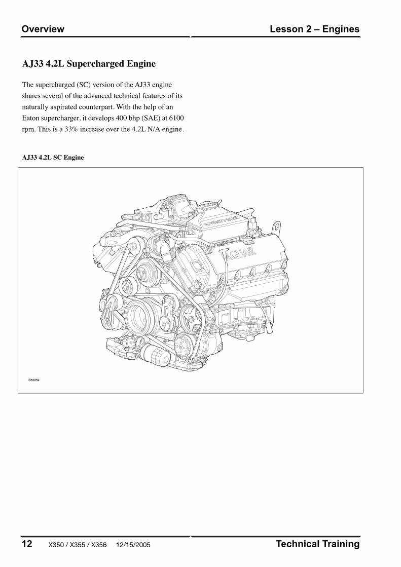
AJ33 4.2L SC Engine
E63059
Technical Training12
Lesson 2 – EnginesOverview
AJ33 4.2L Supercharged Engine
The supercharged (SC) version of the AJ33 engineshares several of the advanced technical features of itsnaturally aspirated counterpart. With the help of anEaton supercharger, it develops 400 bhp (SAE) at 6100rpm. This is a 33% increase over the 4.2L N/A engine.
X350 / X355 / X356 12/15/2005

DETAILS
Engine Specifications
AJ33 4.2L SCAJ33 4.2L N/A
90° V890° V8Configuration
– Dual overhead camshafts
– 4 valves per cylinder
– Dual overhead camshafts
– 4 valves per cylinder
Cylinder Head
Intake: 0.18 – 0.22 mm (0.007 – 0.0085
in.)
Exhaust: 0.23 – 0.27 mm (0.009 – 0.011
in.)
Intake: 0.18 – 0.22 mm (0.007 – 0.0085
in.)
Exhaust: 0.23 – 0.27 mm (0.009 – 0.011
in.)
Valve Clearances (cold)
86 mm (3.386 in.)86 mm (3.386 in.)Bore
90.3 mm (3.555 in.)90.3 mm (3.555 in.)Stroke
4.196 liters (256 in³)4.196 liters (256 in³)Displacement
9.1 : 111.0 : 1Compression Ratio
390 BHP at 6100 rpm293 BHP at 6000 rpmMaximum Power (SAE)
399 lb. ft. at 3500 rpm303 lb. ft. at 4100 rpmMaximum Torque (SAE)
6.0 liters (6.4 qt.)6.0 liters (6.4 qt.)Engine Oil Capacity
2-zone: 12.35 liters (13.05 qt.)
4-zone: 13.15 liters (13.89 qt.)
2-zone: 9.45 liters (9.98 qt.)
4-zone: 10.25 liters (10.83 qt.)
Coolant Capacity
(approx.)
13Technical Training
DetailsLesson 2 – Engines
12/15/2005 X350 / X355 / X356

Engine Numbering and Firing Order
E63060
Engine Identification Numbers
E63061
Technical Training14
Lesson 2 – EnginesDetails
X350 / X355 / X356 12/15/2005
ENGINE MANAGEMENTOVERVIEW
The Jaguar/Denso 32-bit Engine Management System
(EMS) was designed as a generic system applicable to
all Jaguar engines in use across the model ranges. The
system is built around a dual processor Engine Control
Module (ECM). One microprocessor is dedicated to
throttle control and diagnostics; the other microprocessor
handles all other ECM functions, controls and
diagnostics.
15Technical Training
OverviewLesson 3 – Engine Management
12/15/2005 X350 / X355 / X356
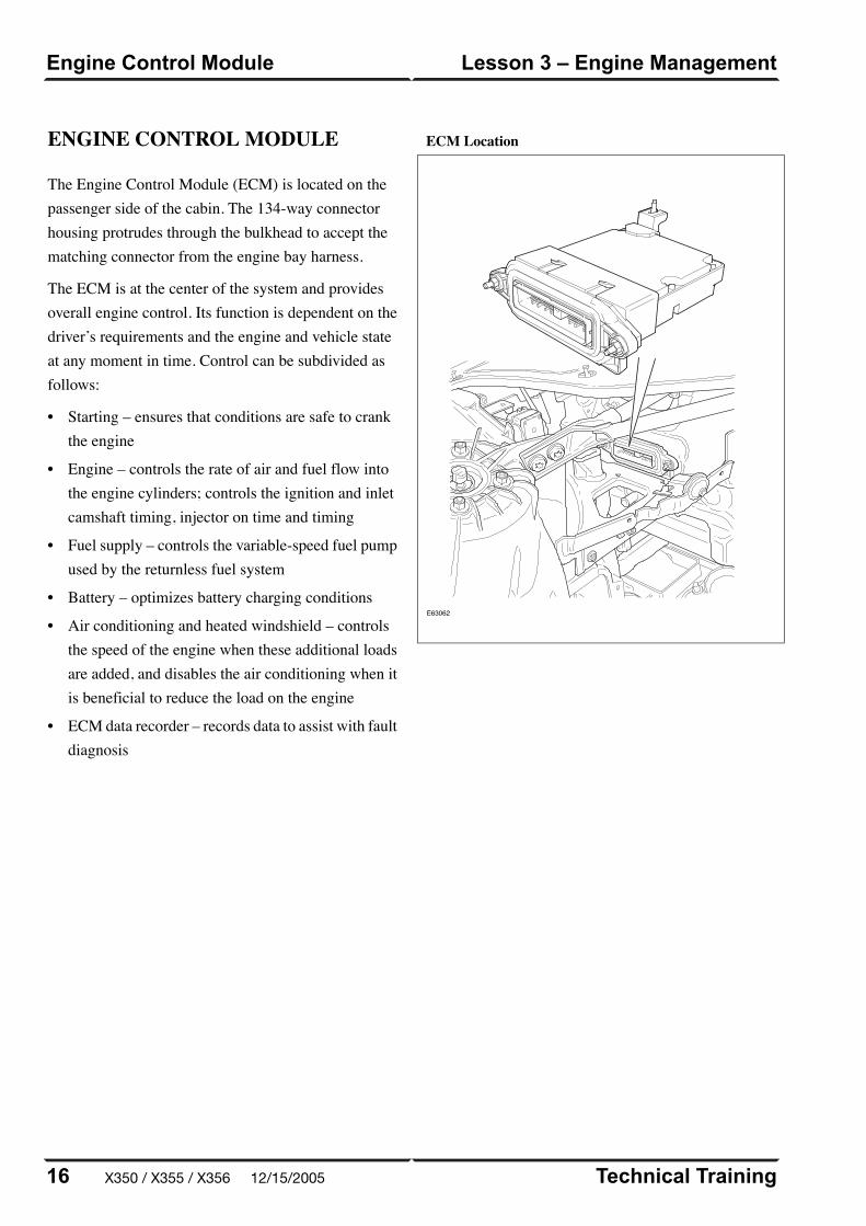
ENGINE CONTROL MODULE
The Engine Control Module (ECM) is located on thepassenger side of the cabin. The 134-way connectorhousing protrudes through the bulkhead to accept thematching connector from the engine bay harness.
The ECM is at the center of the system and providesoverall engine control. Its function is dependent on thedriver’s requirements and the engine and vehicle stateat any moment in time. Control can be subdivided asfollows:
• Starting – ensures that conditions are safe to crankthe engine
• Engine – controls the rate of air and fuel flow intothe engine cylinders; controls the ignition and inletcamshaft timing, injector on time and timing
• Fuel supply – controls the variable-speed fuel pumpused by the returnless fuel system
• Battery – optimizes battery charging conditions
• Air conditioning and heated windshield – controlsthe speed of the engine when these additional loadsare added, and disables the air conditioning when itis beneficial to reduce the load on the engine
• ECM data recorder – records data to assist with faultdiagnosis
ECM Location
E63062
Technical Training16
Lesson 3 – Engine ManagementEngine Control Module
X350 / X355 / X356 12/15/2005
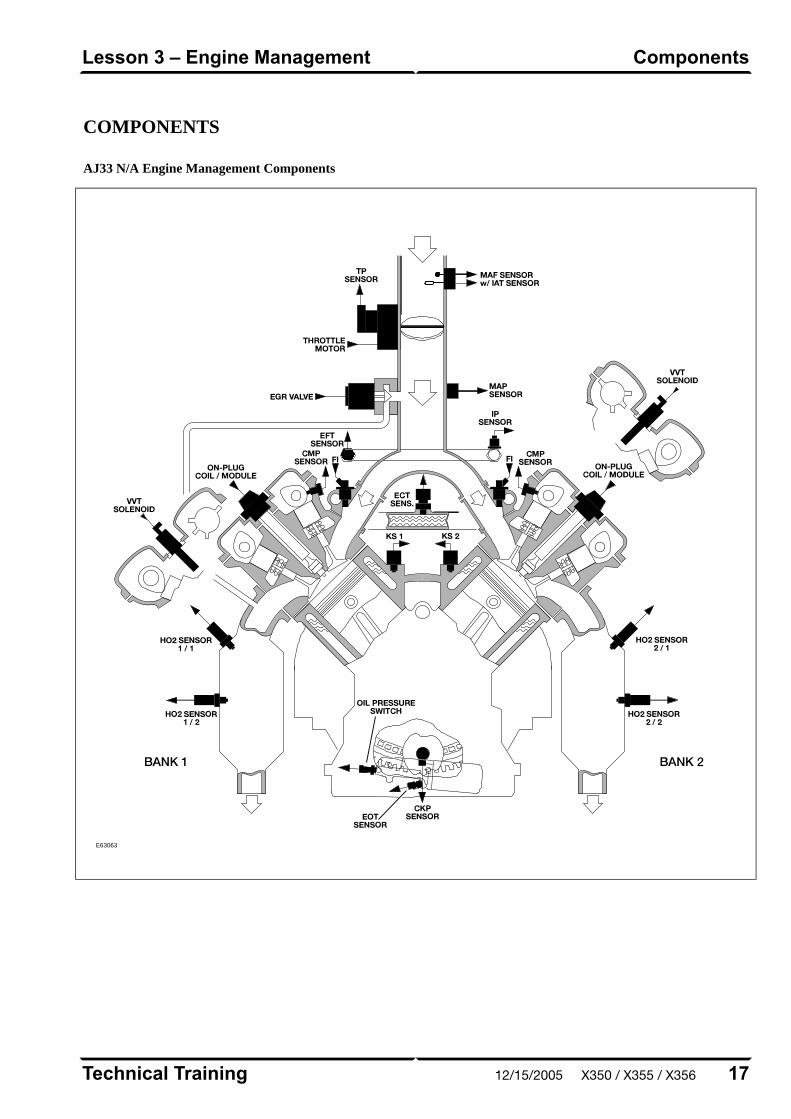
COMPONENTS
AJ33 N/A Engine Management Components
E63063
17Technical Training
ComponentsLesson 3 – Engine Management
12/15/2005 X350 / X355 / X356

AJ33 SC Engine Management Components
E63064
Technical Training18
Lesson 3 – Engine ManagementComponents
X350 / X355 / X356 12/15/2005
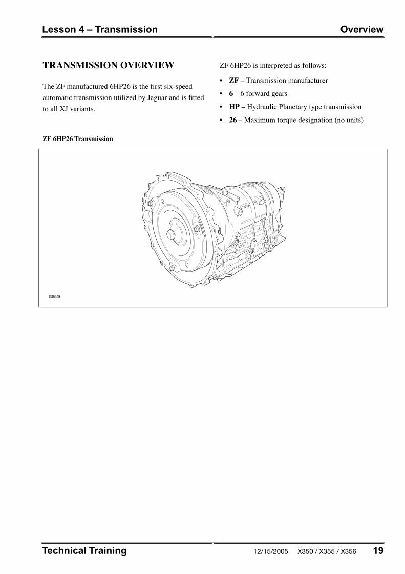
TRANSMISSION OVERVIEW
The ZF manufactured 6HP26 is the first six-speedautomatic transmission utilized by Jaguar and is fittedto all XJ variants.
ZF 6HP26 is interpreted as follows:
• ZF – Transmission manufacturer
• 6 – 6 forward gears
• HP – Hydraulic Planetary type transmission
• 26 – Maximum torque designation (no units)
ZF 6HP26 Transmission
E58459
19Technical Training
OverviewLesson 4 – Transmission
12/15/2005 X350 / X355 / X356
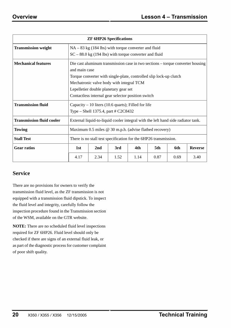
ZF 6HP26 Specifications
NA – 83 kg (184 lbs) with torque converter and fluid
SC – 88.0 kg (194 lbs) with torque converter and fluid
Transmission weight
Die cast aluminum transmission case in two sections – torque converter housing
and main case
Torque converter with single-plate, controlled slip lock-up clutch
Mechatronic valve body with integral TCM
Lepelletier double planetary gear set
Contactless internal gear selector position switch
Mechanical features
Capacity – 10 liters (10.6 quarts); Filled for life
Type – Shell 1375.4, part # C2C8432
Transmission fluid
External liquid-to-liquid cooler integral with the left hand side radiator tank.Transmission fluid cooler
Maximum 0.5 miles @ 30 m.p.h. (advise flatbed recovery)Towing
There is no stall test specification for the 6HP26 transmission.Stall Test
Reverse6th5th4th3rd2nd1stGear ratios
3.400.690.871.141.522.344.17
Service
There are no provisions for owners to verify the
transmission fluid level, as the ZF transmission is not
equipped with a transmission fluid dipstick. To inspect
the fluid level and integrity, carefully follow the
inspection procedure found in the Transmission section
of the WSM, available on the GTR website.
NOTE: There are no scheduled fluid level inspections
required for ZF 6HP26. Fluid level should only be
checked if there are signs of an external fluid leak, or
as part of the diagnostic process for customer complaint
of poor shift quality.
Technical Training20
Lesson 4 – TransmissionOverview
X350 / X355 / X356 12/15/2005
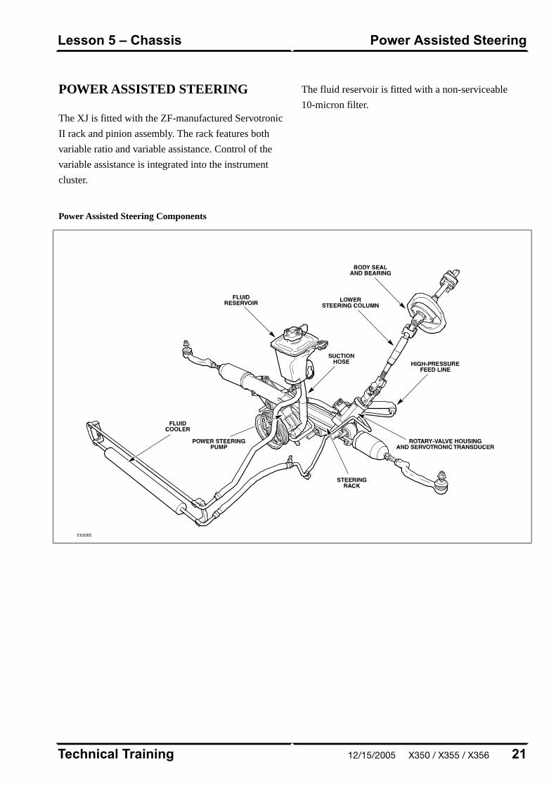
POWER ASSISTED STEERING
The XJ is fitted with the ZF-manufactured Servotronic
II rack and pinion assembly. The rack features both
variable ratio and variable assistance. Control of the
variable assistance is integrated into the instrument
cluster.
The fluid reservoir is fitted with a non-serviceable
10-micron filter.
Power Assisted Steering Components
E63065
21Technical Training
Power Assisted SteeringLesson 5 – Chassis
12/15/2005 X350 / X355 / X356
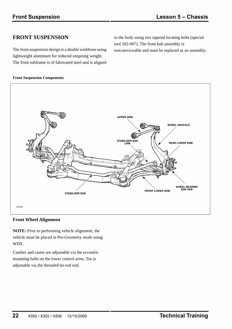
FRONT SUSPENSION
The front suspension design is a double wishbone using
lightweight aluminum for reduced unsprung weight.
The front subframe is of fabricated steel and is aligned
to the body using two tapered locating bolts (special
tool 502-007). The front hub assembly is
non-serviceable and must be replaced as an assembly.
Front Suspension Components
E63066
Front Wheel Alignment
NOTE: Prior to performing vehicle alignment, the
vehicle must be placed in Pre-Geometry mode using
WDS.
Camber and caster are adjustable via the eccentric
mounting bolts on the lower control arms. Toe is
adjustable via the threaded tie-rod end.
Technical Training22
Lesson 5 – ChassisFront Suspension
X350 / X355 / X356 12/15/2005
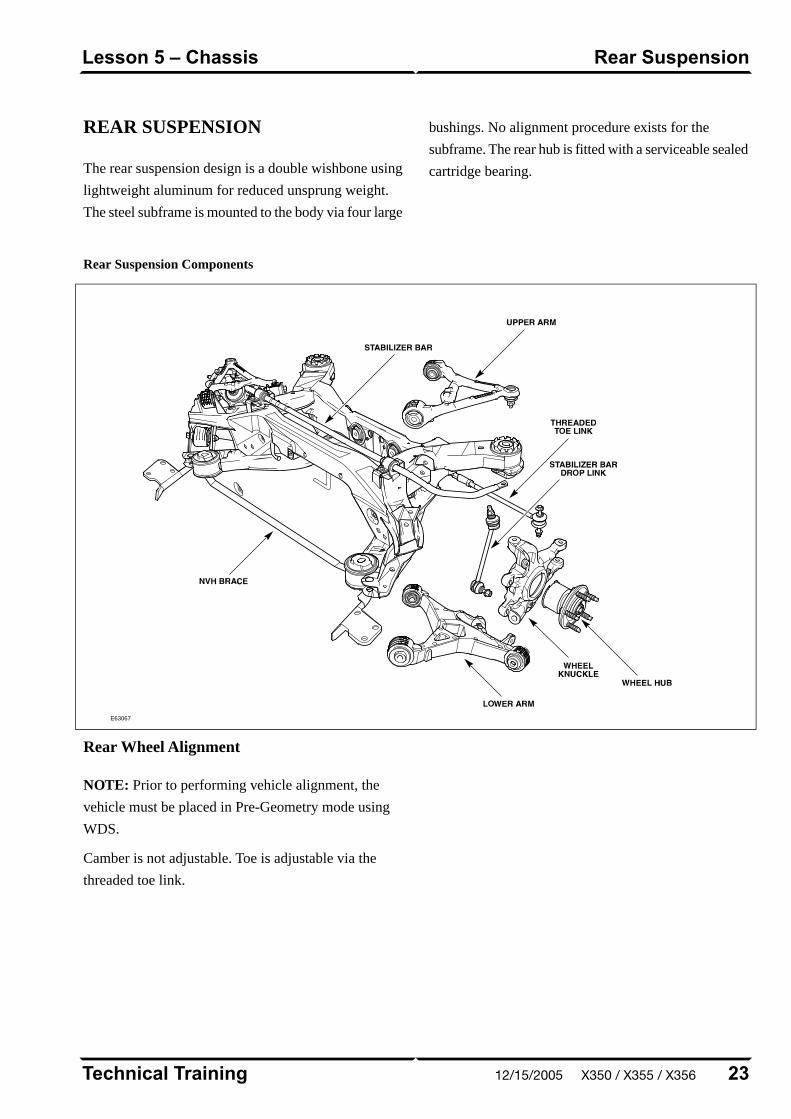
REAR SUSPENSION
The rear suspension design is a double wishbone using
lightweight aluminum for reduced unsprung weight.
The steel subframe is mounted to the body via four large
bushings. No alignment procedure exists for the
subframe. The rear hub is fitted with a serviceable sealed
cartridge bearing.
Rear Suspension Components
E63067
Rear Wheel Alignment
NOTE: Prior to performing vehicle alignment, the
vehicle must be placed in Pre-Geometry mode using
WDS.
Camber is not adjustable. Toe is adjustable via the
threaded toe link.
23Technical Training
Rear SuspensionLesson 5 – Chassis
12/15/2005 X350 / X355 / X356
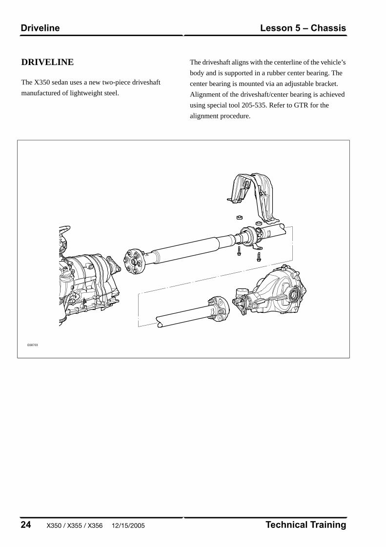
DRIVELINE
The X350 sedan uses a new two-piece driveshaft
manufactured of lightweight steel.
The driveshaft aligns with the centerline of the vehicle’s
body and is supported in a rubber center bearing. The
center bearing is mounted via an adjustable bracket.
Alignment of the driveshaft/center bearing is achieved
using special tool 205-535. Refer to GTR for the
alignment procedure.
E68703
Technical Training24
Lesson 5 – ChassisDriveline
X350 / X355 / X356 12/15/2005

AIR SUSPENSION
The new air suspension system – which replaces coil
springs and shock absorbers with air spring shock
absorber assemblies – offers the best ride and handling
characteristics, and assists in reducing ride float. This
system is standard on all XJ vehicles.
The low weight of the XJ means its payload is a higher
percentage of the total vehicle weight. To manage a
large payload, a coil-sprung vehicle would need either
a high spring rate or an increase in unladen ride height.
The compromises in ride height needed by conventional
steel sprung suspension systems do not exist with the
XJ air suspension system.
25Technical Training
Air SuspensionLesson 5 – Chassis
12/15/2005 X350 / X355 / X356
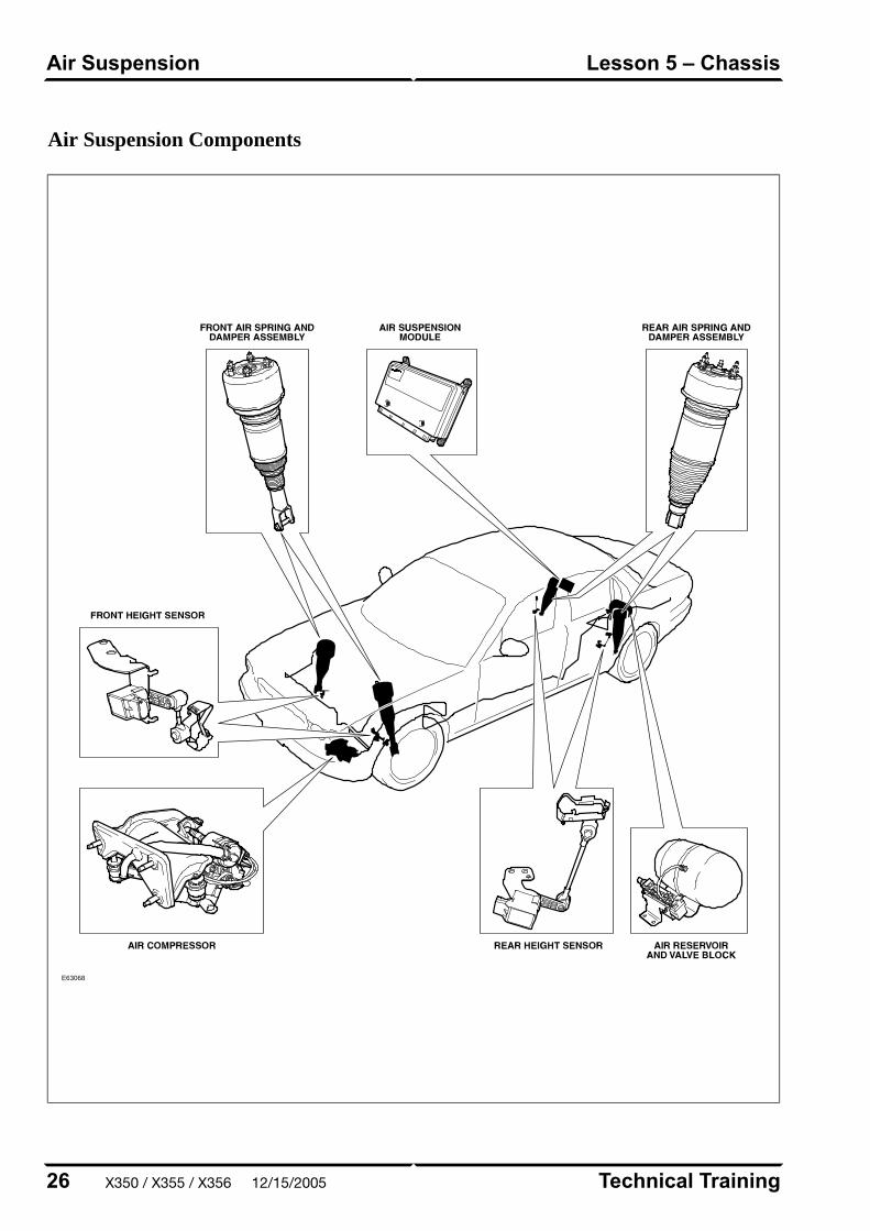
Air Suspension Components
E63068
Technical Training26
Lesson 5 – ChassisAir Suspension
X350 / X355 / X356 12/15/2005
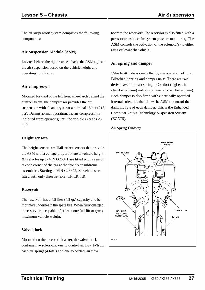
The air suspension system comprises the following
components:
Air Suspension Module (ASM)
Located behind the right rear seat back, the ASM adjusts
the air suspension based on the vehicle height and
operating conditions.
Air compressor
Mounted forward of the left front wheel arch behind the
bumper beam, the compressor provides the air
suspension with clean, dry air at a nominal 15 bar (218
psi). During normal operation, the air compressor is
inhibited from operating until the vehicle exceeds 25
mph.
Height sensors
The height sensors are Hall-effect sensors that provide
the ASM with a voltage proportionate to vehicle height.
XJ vehicles up to VIN G26871 are fitted with a sensor
at each corner of the car at the front/rear subframe
assemblies. Starting at VIN G26872, XJ vehicles are
fitted with only three sensors: LF, LR, RR.
Reservoir
The reservoir has a 4.5 liter (4.8 qt.) capacity and is
mounted underneath the spare tire. When fully charged,
the reservoir is capable of at least one full lift at gross
maximum vehicle weight.
Valve block
Mounted on the reservoir bracket, the valve block
contains five solenoids: one to control air flow to/from
each air spring (4 total) and one to control air flow
to/from the reservoir. The reservoir is also fitted with a
pressure transducer for system pressure monitoring. The
ASM controls the activation of the solenoid(s) to either
raise or lower the vehicle.
Air spring and damper
Vehicle attitude is controlled by the operation of four
Bilstein air spring and damper units. There are two
derivatives of the air spring – Comfort (higher air
chamber volume) and Sport (lower air chamber volume).
Each damper is also fitted with electrically operated
internal solenoids that allow the ASM to control the
damping rate of each damper. This is the Enhanced
Computer Active Technology Suspension System
(ECATS).
Air Spring Cutaway
E63069
27Technical Training
Air SuspensionLesson 5 – Chassis
12/15/2005 X350 / X355 / X356
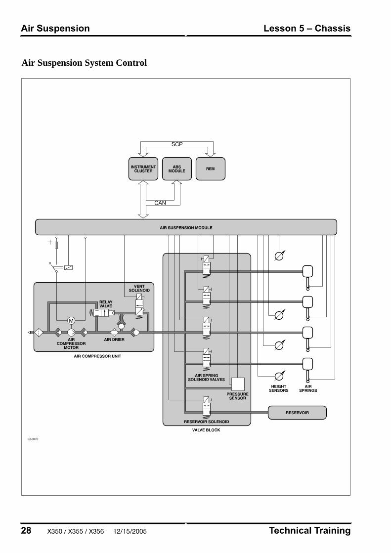
Air Suspension System Control
E63070
Technical Training28
Lesson 5 – ChassisAir Suspension
X350 / X355 / X356 12/15/2005
Air Suspension Service Notes
• Depressurization using WDS is required prior to
opening the pneumatic system.
• Care must be taken to prevent twisting between the
top and bottom mounts of the air spring, as this may
damage the internal air bladder.
• Ride height must be calibrated any time suspension
components such as air springs, height sensors, or
control arms are replaced.
• Vehicles are shipped from the factory in
‘Transportation’ (or ‘Transit’) mode, which must be
disabled by removing the transit relay before delivery
to the customer.
• While in transit mode, the air suspension fault
message will illuminate and a DTC will be logged.
29Technical Training
Air SuspensionLesson 5 – Chassis
12/15/2005 X350 / X355 / X356
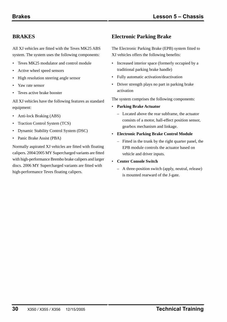
BRAKES
All XJ vehicles are fitted with the Teves MK25 ABS
system. The system uses the following components:
• Teves MK25 modulator and control module
• Active wheel speed sensors
• High resolution steering angle sensor
• Yaw rate sensor
• Teves active brake booster
All XJ vehicles have the following features as standard
equipment:
• Anti-lock Braking (ABS)
• Traction Control System (TCS)
• Dynamic Stability Control System (DSC)
• Panic Brake Assist (PBA)
Normally aspirated XJ vehicles are fitted with floating
calipers. 2004/2005 MY Supercharged variants are fitted
with high-performance Brembo brake calipers and larger
discs. 2006 MY Supercharged variants are fitted with
high-performance Teves floating calipers.
Electronic Parking Brake
The Electronic Parking Brake (EPB) system fitted to
XJ vehicles offers the following benefits:
• Increased interior space (formerly occupied by a
traditional parking brake handle)
• Fully automatic activation/deactivation
• Driver strength plays no part in parking brake
activation
The system comprises the following components:
• Parking Brake Actuator
– Located above the rear subframe, the actuator
consists of a motor, hall-effect position sensor,
gearbox mechanism and linkage.
• Electronic Parking Brake Control Module
– Fitted in the trunk by the right quarter panel, the
EPB module controls the actuator based on
vehicle and driver inputs.
• Center Console Switch
– A three-position switch (apply, neutral, release)
is mounted rearward of the J-gate.
Technical Training30
Lesson 5 – ChassisBrakes
X350 / X355 / X356 12/15/2005
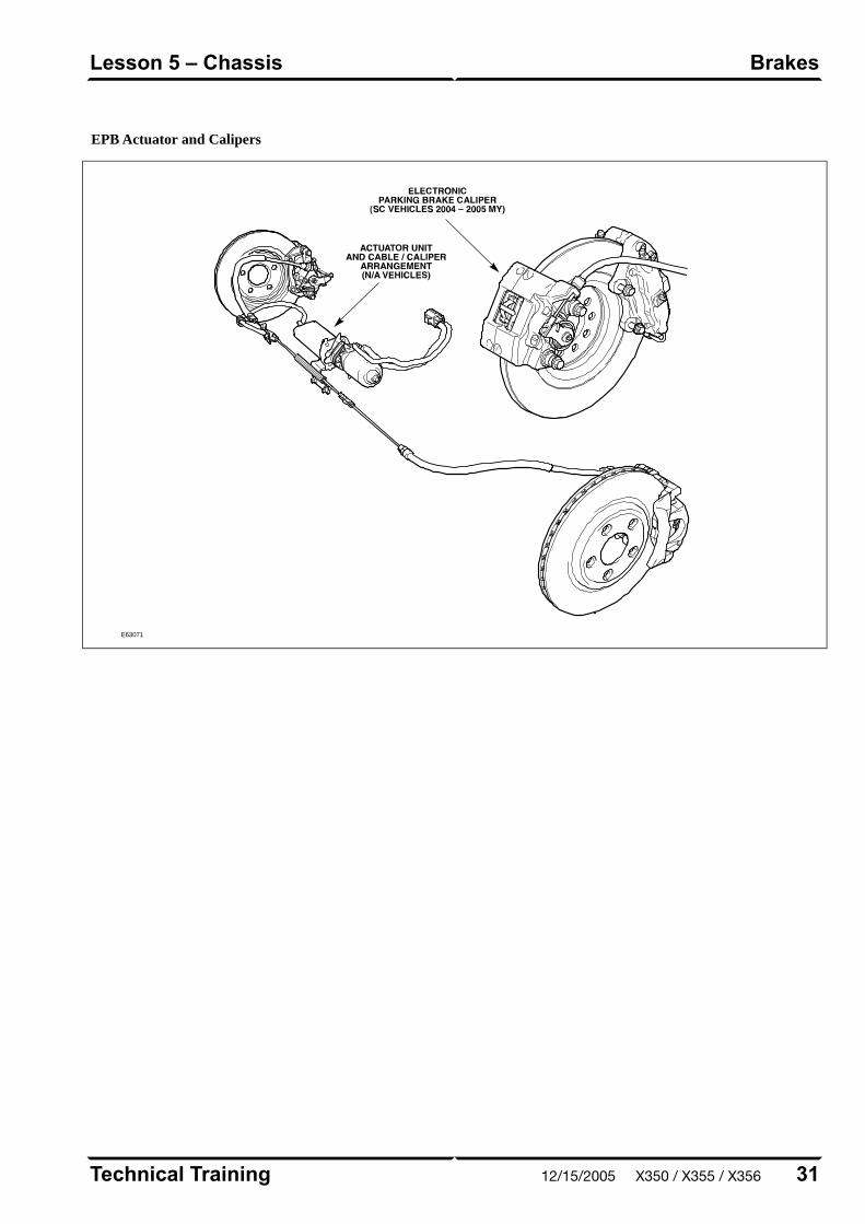
EPB Actuator and Calipers
E63071
31Technical Training
BrakesLesson 5 – Chassis
12/15/2005 X350 / X355 / X356

CONTROL MODULES ANDNETWORKS OVERVIEW
Three communication networks are used for control
module intercommunication.
Communication Networks
Communication MediumSpeedClassNetwork
Twisted pair copper wire500 KBaudCController Area Network (CAN)
Twisted pair copper wire41.6 KBaudBStandard Corporate Protocol Network (SCP)
Fiber optic cable5.6 MBaudn/aDigital Data Bus (D2B)
A fourth network – ISO 9141 (Serial Data Link) –
allows diagnostic interrogation, via the data link
connector (DLC), but does not allow control module
intercommunication. The ISO network communicates
at 10.4 KBaud.
Technical Training32
Lesson 6 – Control Modules andNetworks
Overview
X350 / X355 / X356 12/15/2005

Communication Network Layout
E63072
33Technical Training
OverviewLesson 6 – Control Modules andNetworks
12/15/2005 X350 / X355 / X356

Control Module Locations
E63073
Technical Training34
Lesson 6 – Control Modules andNetworks
Overview
X350 / X355 / X356 12/15/2005

CLIMATE CONTROL OVERVIEW
A Denso-supplied 2-zone automatic climate control
system is fitted as standard, with the availability of an
optional 4-zone climate control (rear climate control).
2-zone temperature control is achieved via separate
heater/cooler unit flaps for the left and right side of the
vehicle, while 4-zone is achieved by adding a dedicated
2-zone heater core and evaporator for the rear passenger
area.
A unique feature of the air conditioning system is its
use of a clutchless compressor. Displacement of the
compressor is variable and controlled by the remote
climate control module (RCCM).
Dual Automatic Temperature Control Components
E63074
35Technical Training
OverviewLesson 7 – Climate Control
12/15/2005 X350 / X355 / X356
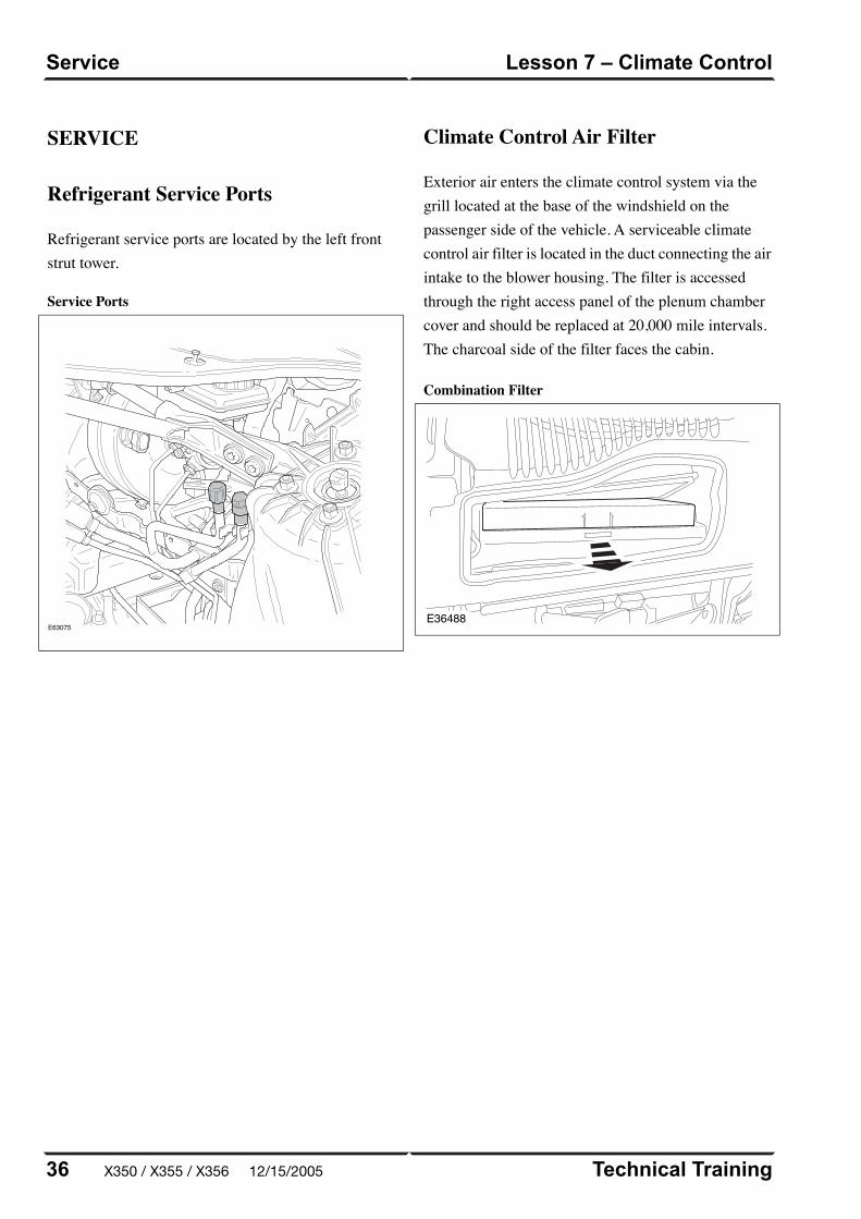
SERVICE
Refrigerant Service Ports
Refrigerant service ports are located by the left frontstrut tower.
Service Ports
E63075
Climate Control Air Filter
Exterior air enters the climate control system via thegrill located at the base of the windshield on thepassenger side of the vehicle. A serviceable climatecontrol air filter is located in the duct connecting the airintake to the blower housing. The filter is accessedthrough the right access panel of the plenum chambercover and should be replaced at 20,000 mile intervals.The charcoal side of the filter faces the cabin.
Combination Filter
E36488
Technical Training36
Lesson 7 – Climate ControlService
X350 / X355 / X356 12/15/2005

POWER WINDOWS
All windows are equipped with one-touch down and
one-touch up functionality. The one-touch up
functionality incorporates anti-trap capabilities. Utilizing
internal position sensors, the door motor can determine
when normal travel is restricted. If an obstruction is
detected when raising the window, the motor’s internal
electronics will reverse the direction of the window.
If the vehicle power supply is disrupted, the one-touch
up feature will no longer function when the power
supply is restored. The initialization procedure must be
carried out to restore operation.
Power Window Initialization
1. Lift and hold the window switch in the up direction
until the window seats completely. Continue to hold
the switch for a further two seconds.
2. Release switch and then lift and hold it again for a
further two seconds. This ensures the window is fully
seated into the seal.
3. Press the window switch to lower the window to its
fully open position.
4. Verify the operation of the anti-trap and one-touch
up operation.
NOTE: This procedure can be carried out either from
the individual window switches or from the driver’s
switch pack.
37Technical Training
Power WindowsLesson 8 – Body Systems
12/15/2005 X350 / X355 / X356

SUNROOF
The sunroof has the following features:
• One-touch open and close operation
• Tilt open
• Anti-trap safety
• Memory retention if the battery is disconnected
The sunroof memory is not affected by battery
disconnection and will not require re-initializing upon
reconnection. However, if power is disconnected while
the sunroof is actually being operated, then the memory
will be lost and the following initialization procedure
will have to be carried out. This procedure will also
have to be carried out if the roof motor is replaced.
Sunroof Initialization
1. Turn the ignition switch to either position I or II.
2. Press the roof switch in the tilt position until the
sunroof moves to the fully tilted position and stops.
3. Release the switch.
4. Press and hold the switch in the tilt up position for
at least 20 seconds. The roof panel will make a small
movement to indicate that the roof has been
de-initialized.
5. Release the switch.
6. Within five seconds of releasing the switch, press
and hold the switch in the tilt position again. The
sunroof will travel automatically to the fully open
position, back to the fully closed position, and stop.
7. Verify the operation of the anti-trap and one-touch
up feature.
Technical Training38
Lesson 8 – Body SystemsSunroof
X350 / X355 / X356 12/15/2005
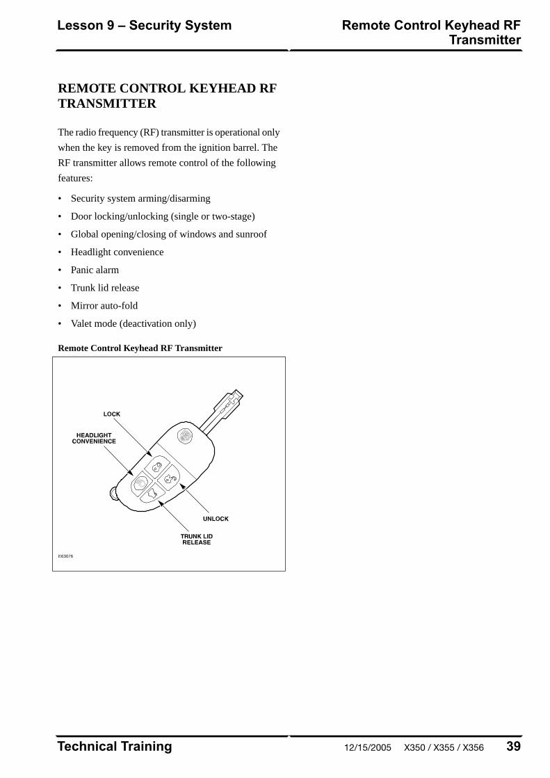
REMOTE CONTROL KEYHEAD RFTRANSMITTER
The radio frequency (RF) transmitter is operational only
when the key is removed from the ignition barrel. The
RF transmitter allows remote control of the following
features:
• Security system arming/disarming
• Door locking/unlocking (single or two-stage)
• Global opening/closing of windows and sunroof
• Headlight convenience
• Panic alarm
• Trunk lid release
• Mirror auto-fold
• Valet mode (deactivation only)
Remote Control Keyhead RF Transmitter
E63076
39Technical Training
Remote Control Keyhead RFTransmitter
Lesson 9 – Security System
12/15/2005 X350 / X355 / X356
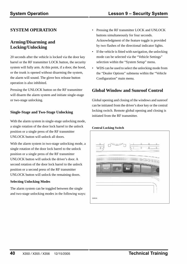
SYSTEM OPERATION
Arming/Disarming andLocking/Unlocking
20 seconds after the vehicle is locked via the door key
barrel or the RF transmitter LOCK button, the security
system will fully arm. At this point, if a door, the hood,
or the trunk is opened without disarming the system,
the alarm will sound. The glove box release button
operation is also inhibited.
Pressing the UNLOCK button on the RF transmitter
will disarm the alarm system and initiate single-stage
or two-stage unlocking.
Single-Stage and Two-Stage Unlocking
With the alarm system in single-stage unlocking mode,
a single rotation of the door lock barrel to the unlock
position or a single press of the RF transmitter
UNLOCK button will unlock all doors.
With the alarm system in two-stage unlocking mode, a
single rotation of the door lock barrel to the unlock
position or a single press of the RF transmitter
UNLOCK button will unlock the driver’s door. A
second rotation of the door lock barrel to the unlock
position or a second press of the RF transmitter
UNLOCK button will unlock the remaining doors.
Selecting Unlocking Modes
The alarm system can be toggled between the single
and two-stage unlocking modes in the following ways:
• Pressing the RF transmitter LOCK and UNLOCK
buttons simultaneously for four seconds.
Acknowledgment of the feature toggle is provided
by two flashes of the directional indicator lights.
• If the vehicle is fitted with navigation, the unlocking
mode can be selected via the “Vehicle Settings”
selection within the “System Setup” menu.
• WDS can be used to select the unlocking mode from
the “Dealer Options” submenu within the “Vehicle
Configuration” main menu.
Global Window and Sunroof Control
Global opening and closing of the windows and sunroof
can be initiated from the driver’s door key or the central
locking switch. Remote global opening and closing is
initiated from the RF transmitter.
Central Locking Switch
E68536
Technical Training40
Lesson 9 – Security SystemSystem Operation
X350 / X355 / X356 12/15/2005

Global Opening/Remote Global Opening
To initiate global opening, rotate the key in the driver’s
door lock barrel to the unlock position and hold for
longer than two seconds. The windows and sunroof will
begin their opening operation and will continue to open
as long as the key is held in the unlock position.
Global opening can be initiated from within the car
using the central locking switch. To initiate global
opening from the central locking switch, the ignition
switch must be in the run position and the central
locking switch held for longer than two seconds. The
doors will centrally unlock and the windows and sunroof
will start to open. Global opening will cease if the switch
is released.
To initiate remote global opening, press and hold the
RF transmitter UNLOCK button for longer than two
seconds. This will initiate an automatic opening of the
windows and sunroof. Once initiated, the button can be
released as the windows and sunroof will continue to
their fully opened position. To stop the remote global
opening sequence, press any button on the RF
transmitter.
The remote global opening feature can be
enabled/disabled via WDS.
Global Closing/Remote Global Closing
To initiate global closing, rotate the key in the driver’s
door lock barrel to the lock position and hold for longer
than two seconds. The windows and sunroof will begin
their closing operation and will continue to close as long
as the key is held in the lock position.
To initiate remote global closing, press and hold the RF
transmitter LOCK button for longer than two seconds.
This will initiate an automatic closing of the windows
and sunroof. Once initiated, the button can be released
and the windows and sunroof will continue to their fully
closed position. To stop the remote global closing
sequence, press any button on the RF transmitter or
press the central locking switch.
The remote global closing feature can be
enabled/disabled via WDS.
NOTE: Global closing and remote global closing will
not close the windows if the windows have not been
initialized.
Headlight Convenience
When the RF transmitter HEADLIGHT
CONVENIENCE button is pressed, the headlights will
illuminate for 25 seconds. A second press of the button
or inserting the key into the ignition switch will
extinguish the headlights.
Panic Alarm
Pressing the RF transmitter HEADLIGHT
CONVENIENCE button three times within three
seconds will activate the panic alarm. To disable the
panic alarm, the key must be inserted into the ignition
switch and turned to position II (RUN).
41Technical Training
System OperationLesson 9 – Security System
12/15/2005 X350 / X355 / X356

Trunk Release
E63077
The trunk can be opened five ways:
• Pressing the RF Transmitter TRUNK LID RELEASE
button.
• Using an integrated transmitter key or black-headed
key in the trunk lock barrel. This will cause the alarm
to sound if the vehicle is armed. The green-headed
valet key will not operate the trunk lock barrel.
• Pressing the release button on the trunk lid (valet
mode inactive).
• Pressing the fascia switchpack trunk release button
(valet mode inactive).
• Pulling the internal trunk release handle.
Internal Trunk Release Handle
E63078
Mirror Auto Fold
Pressing the RF transmitter LOCK button twice within
three seconds will active the door mirrors to fold flat.
Any unlocking command (key or remote) will unfold
the door mirrors.
Technical Training42
Lesson 9 – Security SystemSystem Operation
X350 / X355 / X356 12/15/2005
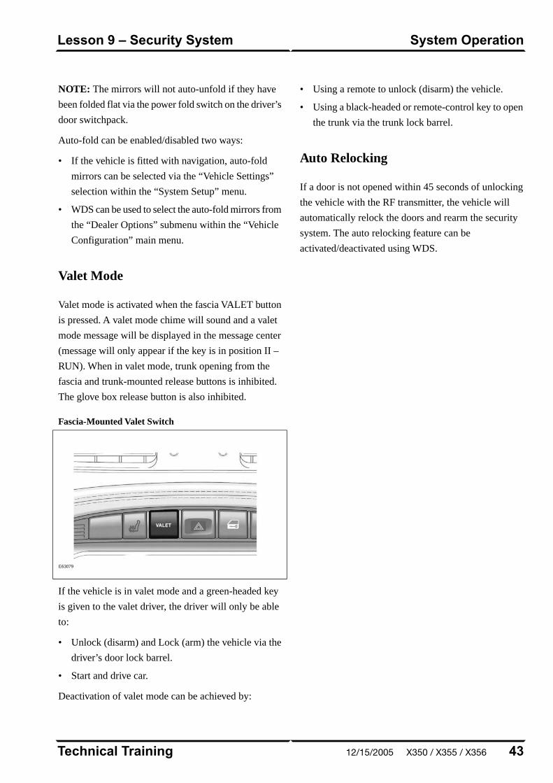
NOTE: The mirrors will not auto-unfold if they have
been folded flat via the power fold switch on the driver’s
door switchpack.
Auto-fold can be enabled/disabled two ways:
• If the vehicle is fitted with navigation, auto-fold
mirrors can be selected via the “Vehicle Settings”
selection within the “System Setup” menu.
• WDS can be used to select the auto-fold mirrors from
the “Dealer Options” submenu within the “Vehicle
Configuration” main menu.
Valet Mode
Valet mode is activated when the fascia VALET button
is pressed. A valet mode chime will sound and a valet
mode message will be displayed in the message center
(message will only appear if the key is in position II –
RUN). When in valet mode, trunk opening from the
fascia and trunk-mounted release buttons is inhibited.
The glove box release button is also inhibited.
Fascia-Mounted Valet Switch
E63079
If the vehicle is in valet mode and a green-headed key
is given to the valet driver, the driver will only be able
to:
• Unlock (disarm) and Lock (arm) the vehicle via the
driver’s door lock barrel.
• Start and drive car.
Deactivation of valet mode can be achieved by:
• Using a remote to unlock (disarm) the vehicle.
• Using a black-headed or remote-control key to open
the trunk via the trunk lock barrel.
Auto Relocking
If a door is not opened within 45 seconds of unlocking
the vehicle with the RF transmitter, the vehicle will
automatically relock the doors and rearm the security
system. The auto relocking feature can be
activated/deactivated using WDS.
43Technical Training
System OperationLesson 9 – Security System
12/15/2005 X350 / X355 / X356
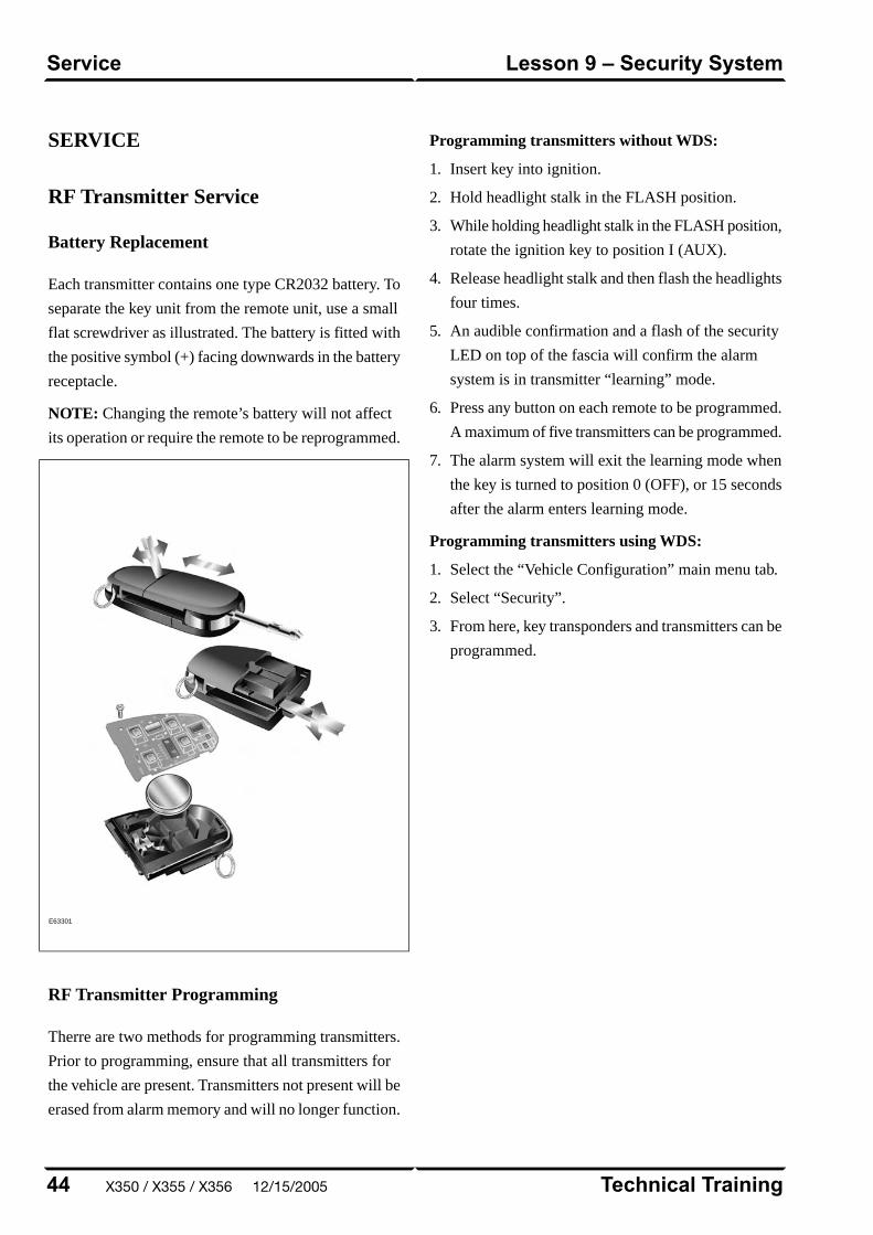
SERVICE
RF Transmitter Service
Battery Replacement
Each transmitter contains one type CR2032 battery. To
separate the key unit from the remote unit, use a small
flat screwdriver as illustrated. The battery is fitted with
the positive symbol (+) facing downwards in the battery
receptacle.
NOTE: Changing the remote’s battery will not affect
its operation or require the remote to be reprogrammed.
E63301
RF Transmitter Programming
Therre are two methods for programming transmitters.
Prior to programming, ensure that all transmitters for
the vehicle are present. Transmitters not present will be
erased from alarm memory and will no longer function.
Programming transmitters without WDS:
1. Insert key into ignition.
2. Hold headlight stalk in the FLASH position.
3. While holding headlight stalk in the FLASH position,
rotate the ignition key to position I (AUX).
4. Release headlight stalk and then flash the headlights
four times.
5. An audible confirmation and a flash of the security
LED on top of the fascia will confirm the alarm
system is in transmitter “learning” mode.
6. Press any button on each remote to be programmed.
A maximum of five transmitters can be programmed.
7. The alarm system will exit the learning mode when
the key is turned to position 0 (OFF), or 15 seconds
after the alarm enters learning mode.
Programming transmitters using WDS:
1. Select the “Vehicle Configuration” main menu tab.
2. Select “Security”.
3. From here, key transponders and transmitters can be
programmed.
Technical Training44
Lesson 9 – Security SystemService
X350 / X355 / X356 12/15/2005
PASSIVE ANTI-THEFT SYSTEM
The Passive Anti-Theft System (PATS) is centered
around the instrument cluster (IC) and the engine control
module (ECM). The engine starting sequence is as
follows:
1. Key in ignition
2. Data transfer between the IC and the key transponder
to confirm a valid key
3. Ignition turned to position II (RUN)
4. “Key valid” message sent from the IC to the ECM
5. Data transfer between the ECM and IC to confirm
encrypted code is correct
6. Engine start
If this sequence is successfully completed, the PATS
LED located on top of the fascia will illuminate for three
seconds then extinguish.
PATS Fault Diagnostics
If a fault is detected, the engine will not crank and the
PATS LED located on top of the fascia will flash at 4Hz
for 60 seconds. At the end of this period, the LED will
flash a two-digit code for the current fault. The code
will be flashed 10 times. Refer to GTR for code
interpretation.
NOTE: Corresponding DTCs may exist along with
PATS codes that may further explain the root cause of
a fault. Check for DTCs whenever diagnosing a PATS
fault.
Key Transponder Programming
As many as 8 transponders can be programmed for one
vehicle, but they must all be present at the time of
programming.
Programming additional transponders without WDS:
1. To enter the manual programming process, all keys
for the vehicle will need to be present and two
pre-programmed keys will be required.
2. Insert the first customer key into the ignition switch
and turn to the position II (RUN) for a maximum of
five seconds. Remove key.
3. Within 10 seconds of removing the first key, insert
the second customer key and turn to position II
(RUN) for a maximum of five seconds. Remove key.
4. To program the third key, insert the new key and
turn to position II (RUN) within 20 seconds of
removing the second key. Allow the PATS LED to
prove out for three seconds to confirm storage of the
new key.
Programming transponders using WDS:
1. Select the “Vehicle Configuration” main menu tab.
2. Select “Security”.
3. From here, key transponders and transmitters can be
programmed.
45Technical Training
Passive Anti-Theft System (PATS)Lesson 9 – Security System
12/15/2005 X350 / X355 / X356
SUPPLEMENTAL RESTRAINTSYSTEM OVERVIEW
The XJ uses Jaguar’s Adaptive Restraint Technology
System (ARTS). ARTS can be divided into three
subsystems:
• Crash severity sensing and analysis
– Five impact sensors (one behind the radiator grill
and one mounted at the base of each ‘B/C’ and
‘D/E’ pillar) provide a signal to the Restraints
Control Module (RCM) that is proportionate to
the crash severity
• Occupant analysis
– Position of the driver’s seat and seatbelt
engagement is monitored
– Weight, position and seatbelt engagement of the
front passenger is monitored
• Deployment handling
– Based on crash severity and occupant analysis,
the RCM will determine which restraints to
deploy and the deployment strength (frontal
impact airbags only).
Technical Training46
Lesson 10 – Supplemental RestraintSystem
Overview
X350 / X355 / X356 12/15/2005

COMPONENTS
The ARTS in XJ vehicles uses three control modules:
Weight Sensing Module
Mounted to the underside of the front passenger seat,
the weight sensing module processes the signal from
the seat pressure transducer attached to the silicone filled
bladder in the cushion.
Occupancy Sensing Module
Also mounted to the underside of the front passenger
seat, the occupancy sensing module processes signals
from the four ultrasonic sensors. These sensors emit an
ultrasonic signal operating at 40 KHz to monitor
occupancy of the front passenger seat.
Restraints Control Module
Mounted below the radio on the transmission tunnel,
the restraints control module is responsible for deploying
restraints based on signals from the weight sensing
module, occupancy sensing module, front seat belt
buckle sensors, driver’s seat position switch and crash
sensors.
The three modules communicate via a local (dedicated)
CAN network, which is not part of the vehicle’s main
CAN network.
47Technical Training
ComponentsLesson 10 – Supplemental RestraintSystem
12/15/2005 X350 / X355 / X356

ARTS Component Locations
E63080
Technical Training48
Lesson 10 – Supplemental RestraintSystem
Components
X350 / X355 / X356 12/15/2005

SYSTEM OPERATION
The ARTS can deploy the following restraints:
• Front seat belt reel pre-tensioners (2)
• Rear seat belt reel pre-tensioners (3)
• Two-stage driver and front passenger airbags (2)
• Seat-mounted side airbags for front occupants (2)
• Roof-mounted side air curtains (2)
Adaptive Restraints Technology System Diagram
E63081
49Technical Training
System OperationLesson 10 – Supplemental RestraintSystem
12/15/2005 X350 / X355 / X356
WARNING: Read and observe all safety
precautions in GTR (Global Technical
Reference) and service bulletins before
attempting to service the SRS.
Do not attempt to measure the circuit resistance
through the airbag modules or pre-tensioners with
a DVOM. Doing so may trigger airbag deployment
and result in personal injury.
To disarm the SRS, disconnect the battery negative
cable and wait a minimum of two minutes for the
reserve power charge to dissipate.
Technical Training50
Lesson 10 – Supplemental RestraintSystem
System Operation
X350 / X355 / X356 12/15/2005
IN-CAR ENTERTAINMENT (ICE)
Selectable Features
Simultaneously pressing and holding the AM/FM and
EJECT buttons will display the audio system selectable
features on the navigation screen. The following options
are available:
• Market
– US (no security code function, radio tunes to odd
digits i.e. 90.1, 90.3, 90.5 etc.)
– EU
– JPN
– AUS
• RDS/RBDS (Radio Data System/Radio Broadcast
Data System)
– ON (when tuned to a RDS station, the radio will
display station call letters and (depending on
station) station name, current song title and artist)
– OFF (only the radio station frequency is
displayed)
Setting Clock
All XJ vehicles are fitted with an analog clock located
between the center fascia air outlets. The time can be
adjusted by pressing the plus (+) and minus (-) buttons.
51Technical Training
In-Car Entertainment (ICE)Lesson 11 – Infotainment
12/15/2005 X350 / X355 / X356
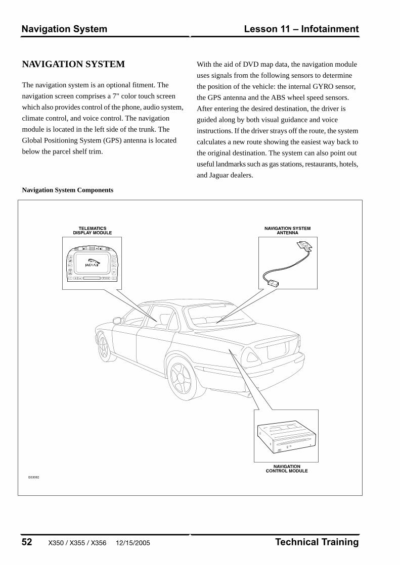
NAVIGATION SYSTEM
The navigation system is an optional fitment. The
navigation screen comprises a 7" color touch screen
which also provides control of the phone, audio system,
climate control, and voice control. The navigation
module is located in the left side of the trunk. The
Global Positioning System (GPS) antenna is located
below the parcel shelf trim.
With the aid of DVD map data, the navigation module
uses signals from the following sensors to determine
the position of the vehicle: the internal GYRO sensor,
the GPS antenna and the ABS wheel speed sensors.
After entering the desired destination, the driver is
guided along by both visual guidance and voice
instructions. If the driver strays off the route, the system
calculates a new route showing the easiest way back to
the original destination. The system can also point out
useful landmarks such as gas stations, restaurants, hotels,
and Jaguar dealers.
Navigation System Components
E63082
Technical Training52
Lesson 11 – InfotainmentNavigation System
X350 / X355 / X356 12/15/2005

Curriculum Training
Introduction to Jaguar
Introduction to X-TYPE: X400/X404
E63055
Technical Training INTR 05 en 08/2005INTR: X400/X404

To the best of our knowledge, the illustrations, technical information, data and descriptions in this issue were correct at the time
of going to print. The right to change prices, specifications, equipment and maintenance instructions at any time without notice
is reserved as part of our policy of continuous development and improvement for the benefit of our customers.
No part of this publication may be reproduced, stored in a data processing system or transmitted in any form, electronic,
mechanical, photocopy, recording, translation or by any other means without prior permission of Premier Automotive Group.
No liability can be accepted for any inaccuracies in this publication, although every possible care has been taken to make it as
complete and accurate as possible.
Copyright ©2005

Please remember that our training literature has been prepared for TRAINING PURPOSES only. Repairs and
adjustments MUST always be carried out according to the instructions and specifications in the workshop literature.
Please make full use of the training offered by Technical Training to gain extensive knowledge of both theory
and practice.
1Technical Training
Preface
12/15/2005 X400 / X404
PAGE
Lesson 1 – General Information
5Overview......................................................................................................................................................
7Identification Plates and Labels................................................................................................................
8Vehicle Jacking and Towing.......................................................................................................................
Lesson 2 – Engines
9Overview......................................................................................................................................................
10Details..........................................................................................................................................................
Lesson 3 – Engine Management
12Overview......................................................................................................................................................
Lesson 4 – Transmission
13Automatic Transaxle...................................................................................................................................
15Manual Transaxle.......................................................................................................................................
Lesson 5 – Chassis
19Power Assisted Steering (PAS)..................................................................................................................
20Front Suspension........................................................................................................................................
21Rear Suspension..........................................................................................................................................
22Driveline......................................................................................................................................................
24Brakes..........................................................................................................................................................
Technical Training2
Table of Contents
X400 / X404 12/15/2005
Lesson 6 – Control Modules and Networks
25Overview......................................................................................................................................................
Lesson 7 – Climate Control
28Overview......................................................................................................................................................
30Refrigeration System..................................................................................................................................
Lesson 8 – Body Systems
31Power Windows...........................................................................................................................................
32Sunroof........................................................................................................................................................
Lesson 9 – Security System
33Remote Control Keyhead RF Transmitter...............................................................................................
34System Operation.......................................................................................................................................
36Service..........................................................................................................................................................
37Passive Anti-Theft System (PATS)............................................................................................................
Lesson 10 – Supplemental Restraint System
38Overview......................................................................................................................................................
39Components.................................................................................................................................................
41System Operation.......................................................................................................................................
Lesson 11 – Infotainment
43In-Car Entertainment (ICE).....................................................................................................................
44Navigation System......................................................................................................................................
3Technical Training
Table of Contents
12/15/2005 X400 / X404
4
Safety and Precautions
Workshop safety
This page highlights the general observations expectedwhile attending this training program, and itscontinuation upon returning to your place of work.
General
While working on all vehicles, the following itemswhere available should always be used:
• Fender covers
• Seat covers
• Floor protection
Safety
All precautions must be taken and observed at all times,to prevent injury or damage to the following:
• Yourself
• Customer's property
• Workshop equipment
• Work place colleagues
Operating guidelines
While using any piece of workshop equipment:
The manufacturer's guidelines and warning labels mustbe followed.
This will ensure correct use and application at all times.
Seek the necessary advice or training where equipmentusage is unclear.
Chemicals, Oils and Solvents
Follow all manufacturer's warnings and labels; also takeinto account local disposal regulations when workingwith chemicals, oils or solvents.
Ensure that all risks are completely minimized.
Make sure that all protective items of clothing are wornwhere required e.g.
• Eye protection
• Gloves
• Coveralls
• Footwear
System capping
Upon disconnecting components from a system, takeall precautions necessary to prevent systemcontamination or environmental leakage.
Fit relevant plugs or caps i.e. to pipes, unions andcomponent orifices etc.
Updates
Keep abreast of all relevant changes that affect yourrole within the dealership, by monitoring all factoryissued documentation.
Driving
Operating vehicle features, such as ICE, mobile phonesand CD player equipment etc., can cause a momentarydistraction while driving.
Follow all traffic regulations when operating vehiclesystems or using diagnostic equipment while on the move.
Mobile diagnostic equipment operation may requirethe use of an assistant.
X400 / X404 12/15/2005

OVERVIEW
E65138
The Jaguar X-TYPE was introduced for the 2002 model
year as an all-wheel drive (AWD), elegant, small luxury
sedan combining the contemporary expression of
traditional Jaguar product attributes with excellent
driving dynamics, package and functionality. A wagon
version was added to the model line for the 2005.5
model year.
The powertrain comprises a 2.5-liter or 3.0-liter
transversely-mounted V6 engine, derived from the
engine used in S-TYPE, coupled with a five-speed
automatic transmission or a five-speed manual
transmission.
Optional features, which vary depending on vehicle
specification, include:
• Dynamic stability control, which assists the driver
in maintaining directional control of the vehicle
• Xenon (high-intensity discharge) headlights, supplied
with automatic headlight leveling and headlight
powerwash
As with other current Jaguar vehicles, the X-TYPE is
fitted with variable ratio power steering and ABS brakes
as standard.
Security features include an engine immobilizer and
alarm; intrusion sensors and the inclination sensor are
available as options. The remote keyring transmitter has
radio frequency operation with an encrypted rolling
code to help prevent theft of the vehicle.
5Technical Training
OverviewLesson 1 – General Information
12/15/2005 X400 / X404

Engineering Codes and VIN Ranges
2002 MY X-TYPE
VIN RangeEngineering CodeVariant
C00001 – C86114X400X-TYPE Sedan
2003 MY X-TYPE
VIN RangeEngineering CodeVariant
D01088 – D55321X400X-TYPE Sedan
2004 MY X-TYPE
VIN RangeEngineering CodeVariant
D56272 – E19615X404X-TYPE Sedan
2005 MY X-TYPE
VIN RangeEngineering CodeVariant
E19616 – E66743
X404X-TYPE Sedan
X404X-TYPE Wagon
(Introduced for 2005.5 MY)
2006 MY X-TYPE
VIN RangeEngineering CodeVariant
Starting at E67744X404X-TYPE Sedan
X404X-TYPE Wagon
Technical Training6
Lesson 1 – General InformationOverview
X400 / X404 12/15/2005
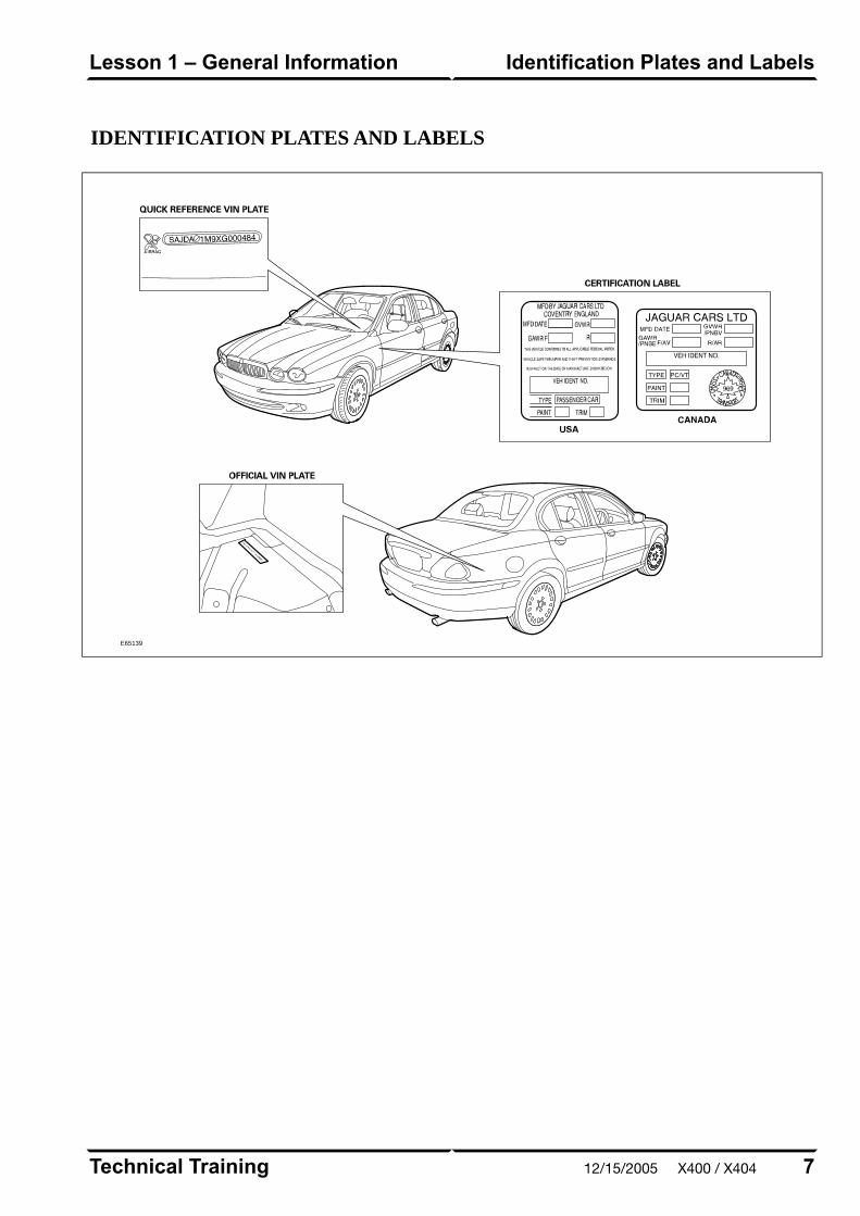
IDENTIFICATION PLATES AND LABELS
E65139
7Technical Training
Identification Plates and LabelsLesson 1 – General Information
12/15/2005 X400 / X404

VEHICLE JACKING AND TOWING
There are four jacking points, two on each side of the
vehicle on the underside of the floor. Two indented
triangular jack location points are provided on each sill
cover.
CAUTIONS:
Jacking and lifting points are critical.
Vehicle support stands should only be used in
conjunction with cushioned pads.
Refer to GTR for detailed information.
Vehicle Jacking Points
E65140
Technical Training8
Lesson 1 – General InformationVehicle Jacking and Towing
X400 / X404 12/15/2005
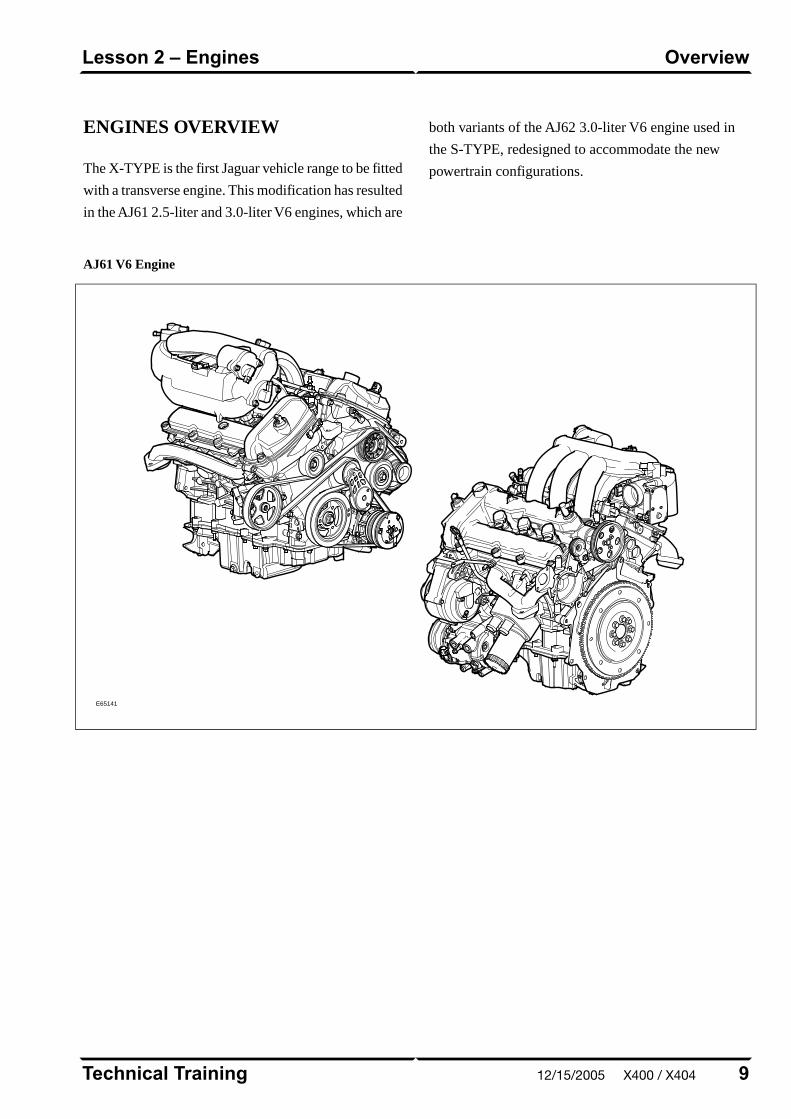
ENGINES OVERVIEW
The X-TYPE is the first Jaguar vehicle range to be fitted
with a transverse engine. This modification has resulted
in the AJ61 2.5-liter and 3.0-liter V6 engines, which are
both variants of the AJ62 3.0-liter V6 engine used in
the S-TYPE, redesigned to accommodate the new
powertrain configurations.
AJ61 V6 Engine
E65141
9Technical Training
OverviewLesson 2 – Engines
12/15/2005 X400 / X404
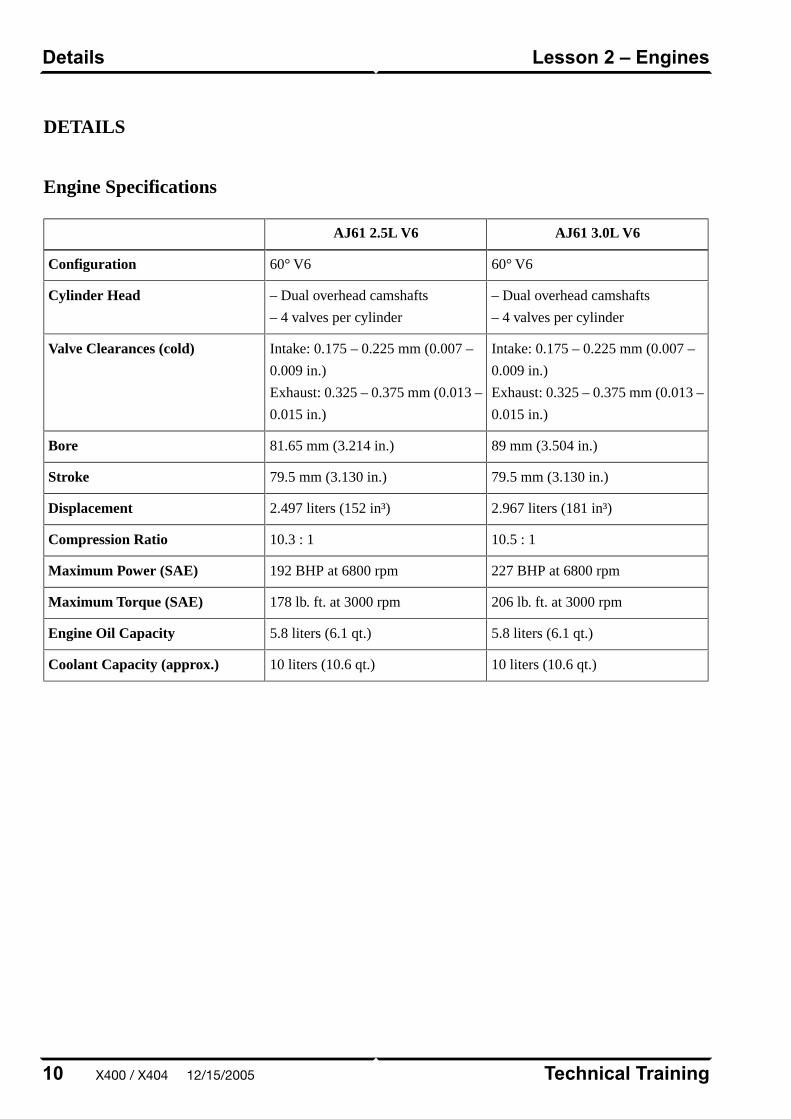
DETAILS
Engine Specifications
AJ61 3.0L V6AJ61 2.5L V6
60° V660° V6Configuration
– Dual overhead camshafts
– 4 valves per cylinder
– Dual overhead camshafts
– 4 valves per cylinder
Cylinder Head
Intake: 0.175 – 0.225 mm (0.007 –
0.009 in.)
Exhaust: 0.325 – 0.375 mm (0.013 –
0.015 in.)
Intake: 0.175 – 0.225 mm (0.007 –
0.009 in.)
Exhaust: 0.325 – 0.375 mm (0.013 –
0.015 in.)
Valve Clearances (cold)
89 mm (3.504 in.)81.65 mm (3.214 in.)Bore
79.5 mm (3.130 in.)79.5 mm (3.130 in.)Stroke
2.967 liters (181 in³)2.497 liters (152 in³)Displacement
10.5 : 110.3 : 1Compression Ratio
227 BHP at 6800 rpm192 BHP at 6800 rpmMaximum Power (SAE)
206 lb. ft. at 3000 rpm178 lb. ft. at 3000 rpmMaximum Torque (SAE)
5.8 liters (6.1 qt.)5.8 liters (6.1 qt.)Engine Oil Capacity
10 liters (10.6 qt.)10 liters (10.6 qt.)Coolant Capacity (approx.)
Technical Training10
Lesson 2 – EnginesDetails
X400 / X404 12/15/2005

Engine Numbering and Firing Order
E65142
Engine Identification Numbers
E65143
Engine Identification by VIN
The eleventh digit of the VIN indicates which engineis fitted on the vehicle. An ‘X’ indicates that the vehicleis fitted with a 2.5-liter engine; a ‘W’ indicates that thevehicle is fitted with a 3.0-liter engine.
For example:
• SAJEB53D52XC000236 = 2.5 liter engine
• SAJEA51CX2WC000235 = 3.0 liter engine.
11Technical Training
DetailsLesson 2 – Engines
12/15/2005 X400 / X404
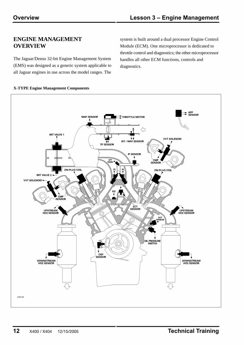
ENGINE MANAGEMENTOVERVIEW
The Jaguar/Denso 32-bit Engine Management System
(EMS) was designed as a generic system applicable to
all Jaguar engines in use across the model ranges. The
system is built around a dual processor Engine Control
Module (ECM). One microprocessor is dedicated to
throttle control and diagnostics; the other microprocessor
handles all other ECM functions, controls and
diagnostics.
X-TYPE Engine Management Components
E65149
Technical Training12
Lesson 3 – Engine ManagementOverview
X400 / X404 12/15/2005
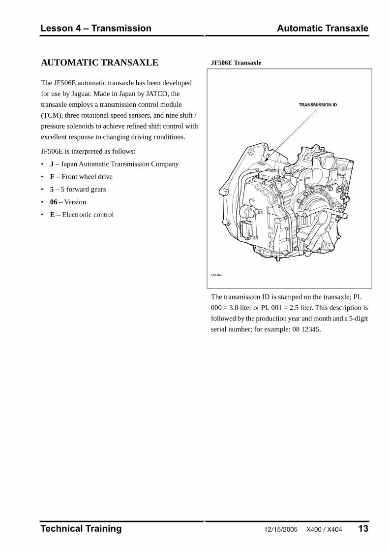
AUTOMATIC TRANSAXLE
The JF506E automatic transaxle has been developed
for use by Jaguar. Made in Japan by JATCO, the
transaxle employs a transmission control module
(TCM), three rotational speed sensors, and nine shift /
pressure solenoids to achieve refined shift control with
excellent response to changing driving conditions.
JF506E is interpreted as follows:
• J – Japan Automatic Transmission Company
• F – Front wheel drive
• 5 – 5 forward gears
• 06 – Version
• E – Electronic control
JF506E Transaxle
E65162
The transmission ID is stamped on the transaxle; PL
000 = 3.0 liter or PL 001 = 2.5 liter. This description is
followed by the production year and month and a 5-digit
serial number; for example: 08 12345.
13Technical Training
Automatic TransaxleLesson 4 – Transmission
12/15/2005 X400 / X404
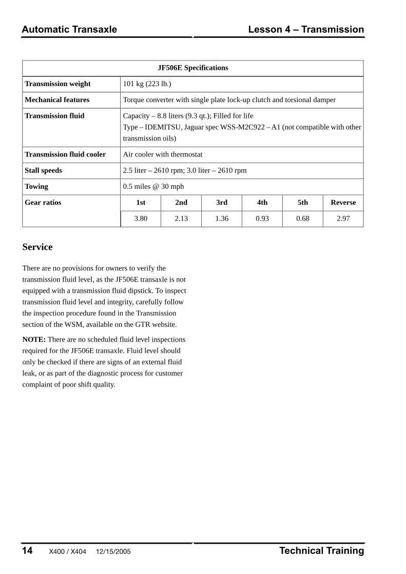
JF506E Specifications
101 kg (223 lb.)Transmission weight
Torque converter with single plate lock-up clutch and torsional damperMechanical features
Capacity – 8.8 liters (9.3 qt.); Filled for life
Type – IDEMITSU, Jaguar spec WSS-M2C922 – A1 (not compatible with other
transmission oils)
Transmission fluid
Air cooler with thermostatTransmission fluid cooler
2.5 liter – 2610 rpm; 3.0 liter – 2610 rpmStall speeds
0.5 miles @ 30 mphTowing
Reverse5th4th3rd2nd1stGear ratios
2.970.680.931.362.133.80
Service
There are no provisions for owners to verify the
transmission fluid level, as the JF506E transaxle is not
equipped with a transmission fluid dipstick. To inspect
transmission fluid level and integrity, carefully follow
the inspection procedure found in the Transmission
section of the WSM, available on the GTR website.
NOTE: There are no scheduled fluid level inspections
required for the JF506E transaxle. Fluid level should
only be checked if there are signs of an external fluid
leak, or as part of the diagnostic process for customer
complaint of poor shift quality.
Technical Training14
Lesson 4 – TransmissionAutomatic Transaxle
X400 / X404 12/15/2005
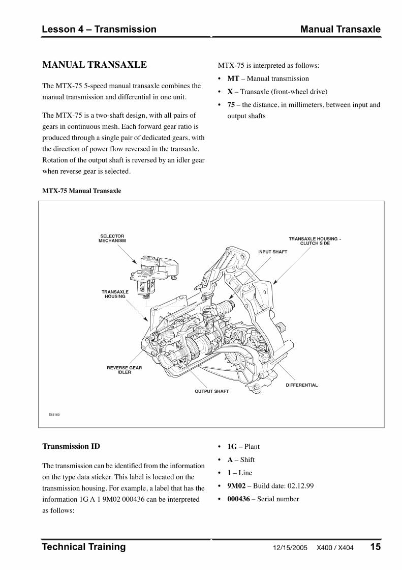
MANUAL TRANSAXLE
The MTX-75 5-speed manual transaxle combines themanual transmission and differential in one unit.
MTX-75 Manual Transaxle
E65163
The MTX-75 is a two-shaft design, with all pairs ofgears in continuous mesh. Each forward gear ratio isproduced through a single pair of dedicated gears, withthe direction of power flow reversed in the transaxle.Rotation of the output shaft is reversed by an idler gearwhen reverse gear is selected.
MTX-75 is interpreted as follows:
• MT – Manual transmission
• X – Transaxle (front-wheel drive)
• 75 – the distance, in millimeters, between input andoutput shafts
15Technical Training
Manual TransaxleLesson 4 – Transmission
Transmission ID
The transmission can be identified from the informationon the type data sticker. This label is located on thetransmission housing. For example, a label that has theinformation 1G A 1 9M02 000436 can be interpretedas follows:
• 1G – Plant
• A – Shift
• 1 – Line
• 9M02 – Build date: 02.12.99
• 000436 – Serial number
12/15/2005 X400 / X404

MTX-75 Specifications
48.6 kg (107.1 lb)Transmission weight
Transversely-mounted unit with combined transmission /differentialTwo-part aluminum housing with reinforcing ribs
Mechanical features
Capacity – 1.75 liters (1.85 qt)Type – ESD-M2C186-A
Transmission fluid
ITT Super DOT 4 (brake fluid)Clutch fluid
30 miles @ 30 mph (flatbed)Towing
Reverse5th4th3rd2nd1stGear ratios
3.470.771.031.452.143.42
Technical Training16
Lesson 4 – TransmissionManual Transaxle
X400 / X404 12/15/2005

Clutch Components
E58476
The system employs a concentric slave cylinder, locatedon the transaxle input shaft behind the pressure plate.The concentric slave cylinder eliminates the need for arelease lever mechanism and improves operatingefficiency.
At the transmission end, the cable housings are securedto a bracket on the transmission housing by means ofquick connect clips; they are attached to the shift shaftby means of an end fitting with a ball socket. Theinternal shaft mechanism is operated through the shiftshaft.
17Technical Training
Manual TransaxleLesson 4 – Transmission
Clutch
The clutch is a hydraulically-operated, self-adjustingsystem which improves operation and driver comfortby enabling a constant pedal pressure to be applied asthe friction faces of the clutch plate wear.
12/15/2005 X400 / X404
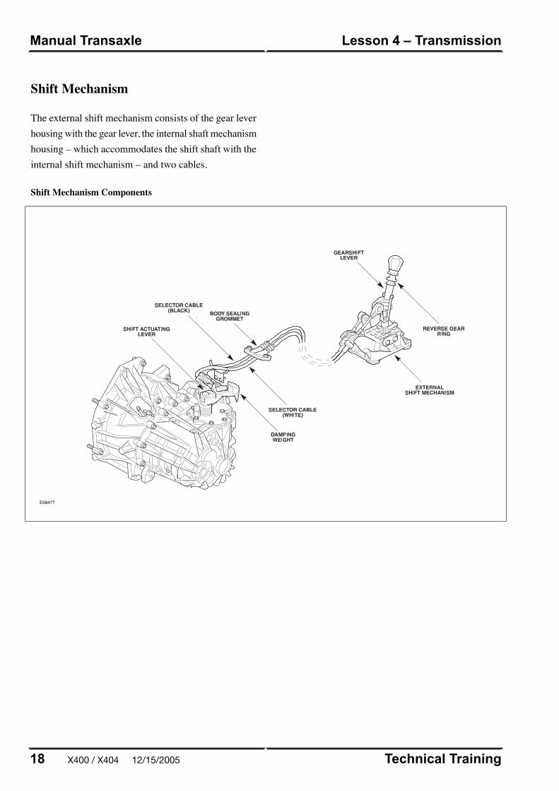
Shift Mechanism Components
E58477
Technical Training18
Lesson 4 – TransmissionManual Transaxle
Shift Mechanism
The external shift mechanism consists of the gear leverhousing with the gear lever, the internal shaft mechanismhousing – which accommodates the shift shaft with theinternal shift mechanism – and two cables.
X400 / X404 12/15/2005
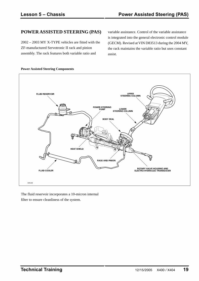
POWER ASSISTED STEERING (PAS)
2002 – 2003 MY X-TYPE vehicles are fitted with the
ZF-manufactured Servotronic II rack and pinion
assembly. The rack features both variable ratio and
variable assistance. Control of the variable assistance
is integrated into the general electronic control module
(GECM). Revised at VIN D83513 during the 2004 MY,
the rack maintains the variable ratio but uses constant
assist.
Power Assisted Steering Components
E65168
The fluid reservoir incorporates a 10-micron internal
filter to ensure cleanliness of the system.
19Technical Training
Power Assisted Steering (PAS)Lesson 5 – Chassis
12/15/2005 X400 / X404
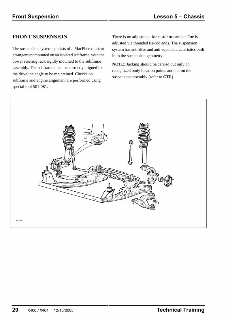
FRONT SUSPENSION
The suspension system consists of a MacPherson strut
arrangement mounted on an isolated subframe, with the
power steering rack rigidly mounted to the subframe
assembly. The subframe must be correctly aligned for
the driveline angle to be maintained. Checks on
subframe and engine alignment are performed using
special tool 501-081.
There is no adjustment for castor or camber. Toe is
adjusted via threaded tie-rod ends. The suspension
system has anti-dive and anti-squat characteristics built
in to the suspension geometry.
NOTE: Jacking should be carried out only on
recognized body location points and not on the
suspension assembly (refer to GTR).
E65166
Technical Training20
Lesson 5 – ChassisFront Suspension
X400 / X404 12/15/2005
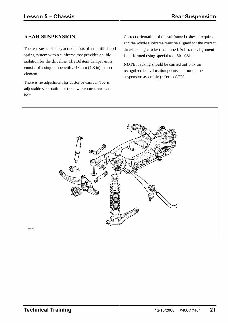
REAR SUSPENSION
The rear suspension system consists of a multilink coil
spring system with a subframe that provides double
isolation for the driveline. The Bilstein damper units
consist of a single tube with a 46 mm (1.8 in) piston
element.
There is no adjustment for castor or camber. Toe is
adjustable via rotation of the lower control arm cam
bolt.
Correct orientation of the subframe bushes is required,
and the whole subframe must be aligned for the correct
driveline angle to be maintained. Subframe alignment
is performed using special tool 501-081.
NOTE: Jacking should be carried out only on
recognized body location points and not on the
suspension assembly (refer to GTR).
E65167
21Technical Training
Rear SuspensionLesson 5 – Chassis
12/15/2005 X400 / X404
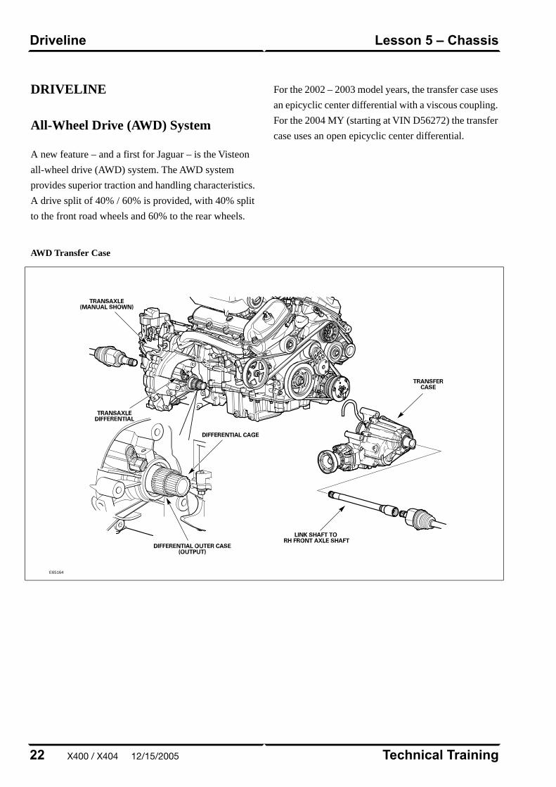
DRIVELINE
All-Wheel Drive (AWD) System
A new feature – and a first for Jaguar – is the Visteon
all-wheel drive (AWD) system. The AWD system
provides superior traction and handling characteristics.
A drive split of 40% / 60% is provided, with 40% split
to the front road wheels and 60% to the rear wheels.
For the 2002 – 2003 model years, the transfer case uses
an epicyclic center differential with a viscous coupling.
For the 2004 MY (starting at VIN D56272) the transfer
case uses an open epicyclic center differential.
AWD Transfer Case
E65164
Technical Training22
Lesson 5 – ChassisDriveline
X400 / X404 12/15/2005
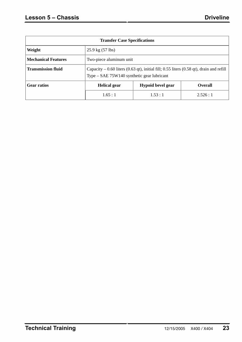
Transfer Case Specifications
25.9 kg (57 lbs)Weight
Two-piece aluminum unitMechanical Features
Capacity – 0.60 liters (0.63 qt), initial fill; 0.55 liters (0.58 qt), drain and refill
Type – SAE 75W140 synthetic gear lubricant
Transmission fluid
OverallHypoid bevel gearHelical gearGear ratios
2.526 : 11.53 : 11.65 : 1
23Technical Training
DrivelineLesson 5 – Chassis
12/15/2005 X400 / X404
BRAKES
All X-TYPE vehicles are equipped with a
Bosch-supplied 4-channel anti-lock brake system (ABS)
which uses independent inputs from the four wheel
speed sensors.
The ABS provides self-diagnosis; any malfunction
within the system is indicated to the driver by
illumination of the anti-lock warning light. Should a
fault develop within ABS, the brake system will operate
conventionally and with the same standard of
performance as a vehicle not equipped with ABS.
ABS with Dynamic Stability Control (DSC) is also
available as an option. Starting with the 2005 MY, panic
brake assist (PBA) is featured on vehicles equipped with
DSC.
Technical Training24
Lesson 5 – ChassisBrakes
X400 / X404 12/15/2005
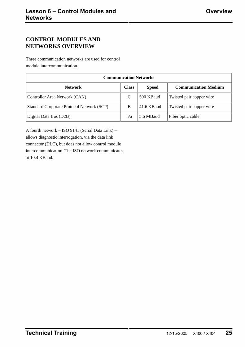
CONTROL MODULES ANDNETWORKS OVERVIEW
Three communication networks are used for control
module intercommunication.
Communication Networks
Communication MediumSpeedClassNetwork
Twisted pair copper wire500 KBaudCController Area Network (CAN)
Twisted pair copper wire41.6 KBaudBStandard Corporate Protocol Network (SCP)
Fiber optic cable5.6 MBaudn/aDigital Data Bus (D2B)
A fourth network – ISO 9141 (Serial Data Link) –
allows diagnostic interrogation, via the data link
connector (DLC), but does not allow control module
intercommunication. The ISO network communicates
at 10.4 KBaud.
25Technical Training
OverviewLesson 6 – Control Modules andNetworks
12/15/2005 X400 / X404
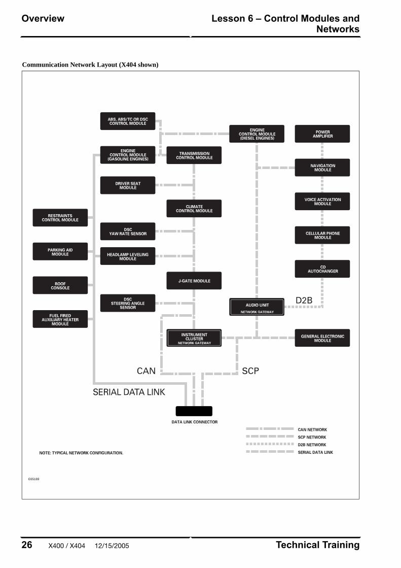
Communication Network Layout (X404 shown)
E65169
Technical Training26
Lesson 6 – Control Modules andNetworks
Overview
X400 / X404 12/15/2005
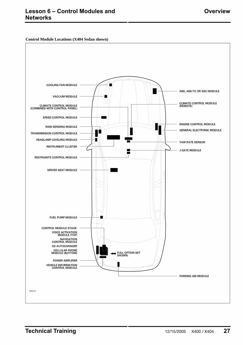
Control Module Locations (X404 Sedan shown)
E65171
27Technical Training
OverviewLesson 6 – Control Modules andNetworks
12/15/2005 X400 / X404

OVERVIEW
The Electronic Automatic Temperature Control (EATC)
climate control system is an air-blend single-zone
system, with the majority of components made by
Visteon. Two versions of the EATC system are used –
non-telematics or telematics – depending on vehicle
options.
The basics of the refrigeration system remain the same
as on previous systems, except for refrigerant control,
which is handled by a fixed orifice tube and suction
accumulator instead of the expansion valve and
receiver/drier used previously.
Technical Training28
Lesson 7 – Climate ControlOverview
X400 / X404 12/15/2005
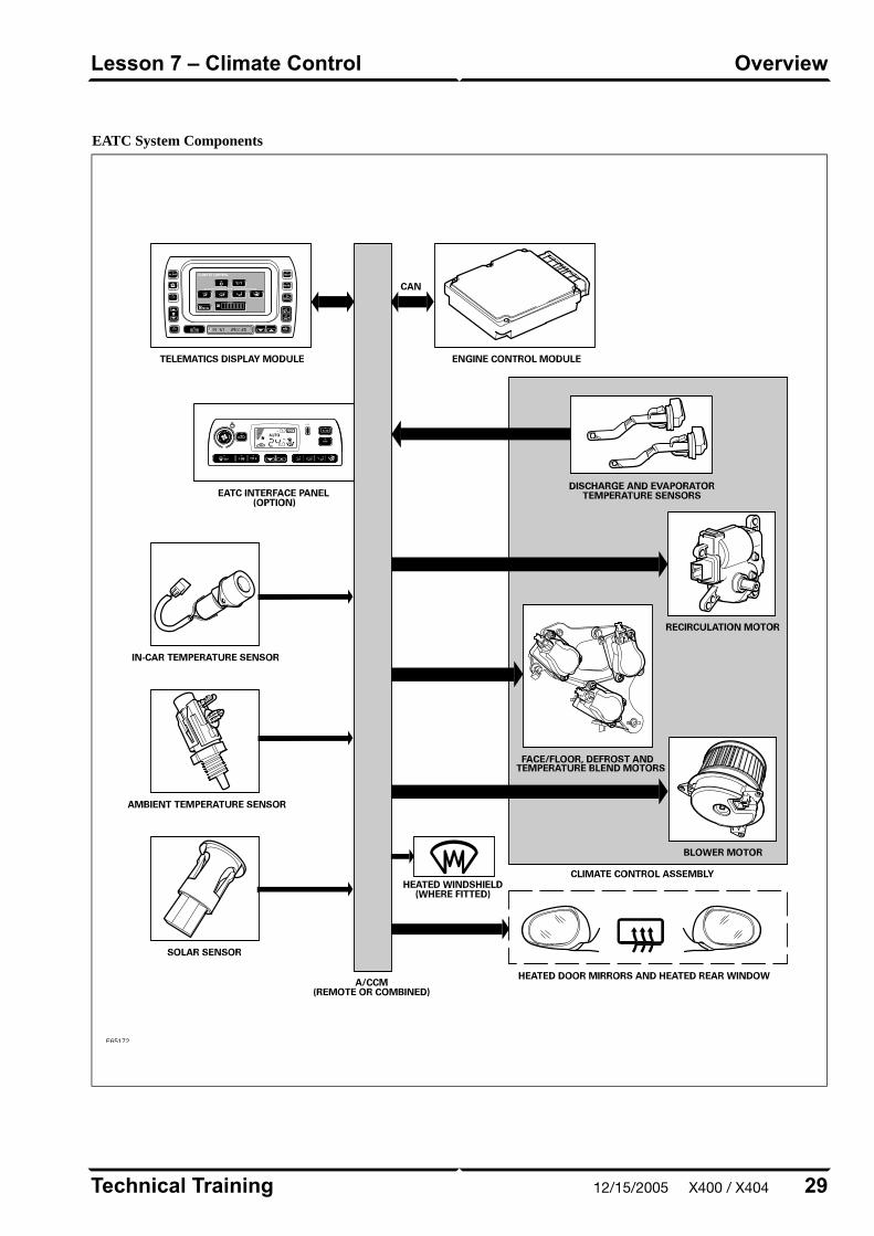
EATC System Components
E65172
29Technical Training
OverviewLesson 7 – Climate Control
12/15/2005 X400 / X404
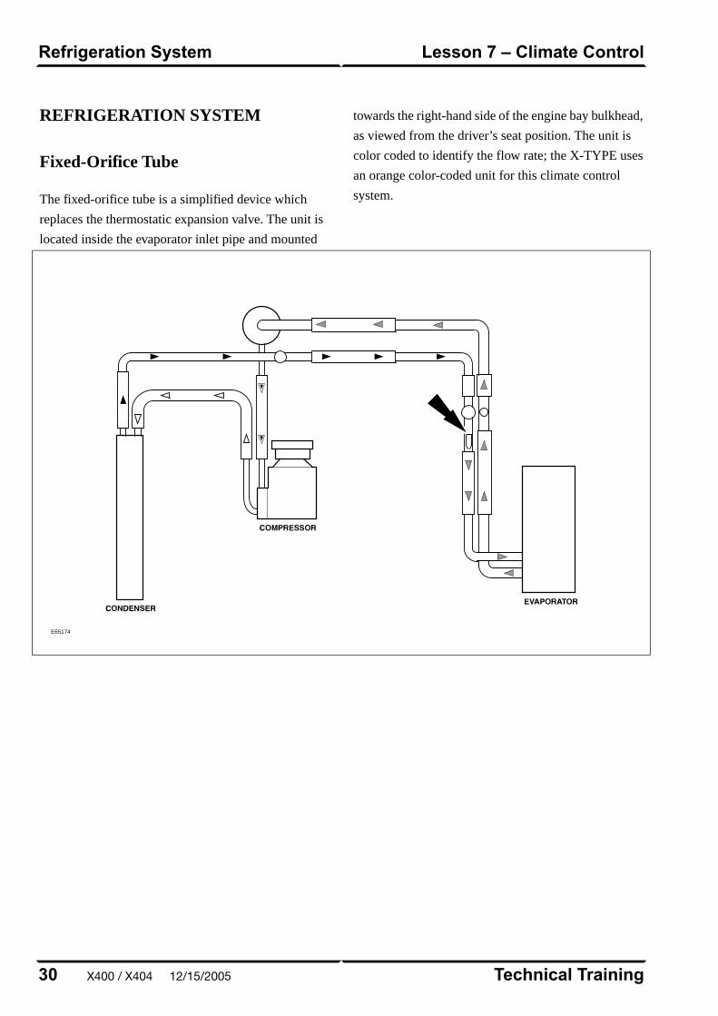
REFRIGERATION SYSTEM
Fixed-Orifice Tube
The fixed-orifice tube is a simplified device which
replaces the thermostatic expansion valve. The unit is
located inside the evaporator inlet pipe and mounted
towards the right-hand side of the engine bay bulkhead,
as viewed from the driver’s seat position. The unit is
color coded to identify the flow rate; the X-TYPE uses
an orange color-coded unit for this climate control
system.
E65174
Technical Training30
Lesson 7 – Climate ControlRefrigeration System
X400 / X404 12/15/2005
POWER WINDOWS
All windows are equipped with one-touch down and
one-touch up functionality. The one-touch up
functionality incorporates anti-trap capabilities. Utilizing
internal position sensors, the door motor can determine
when normal travel is restricted. If an obstruction is
detected when raising the window, the motor’s internal
electronics will reverse the direction of the window.
If the vehicle power supply is disrupted, the one-touch
up feature will no longer function when the power
supply is restored. The initialization procedure must be
carried out to restore operation.
Power Window Initialization
1. Lift and hold the window switch in the up direction
until the window seats completely. Continue to hold
the switch for a further two seconds.
2. Release switch and then lift and hold it again for a
further two seconds. This ensures the window is fully
seated into the seal.
3. Press the window switch to lower the window to its
fully open position.
4. Verify the operation of the anti-trap and one-touch
up operation.
NOTE: This procedure can be carried out either from
the individual window switches or from the driver’s
switch pack.
31Technical Training
Power WindowsLesson 8 – Body Systems
12/15/2005 X400 / X404
SUNROOF
The sunroof has the following features:
• One-touch open and close operation
• Tilt open
• Anti-trap safety
• Memory retention if the battery is disconnected
The sunroof memory is not affected by battery
disconnection and will not require re-initializing upon
reconnection. However, if power is disconnected while
the sunroof is actually being operated, then the memory
will be lost and the following initialization procedure
will have to be carried out. This procedure will also
have to be carried out if the roof motor is replaced.
Sunroof Initialization
1. Turn the ignition switch to either position I or II.
2. Press the roof switch in the tilt position until the
sunroof moves to the fully tilted position and stops.
3. Release the switch.
4. Press and hold the switch in the tilt up position for
at least 20 seconds. The roof panel will make a small
movement to indicate that the roof has been
de-initialized.
5. Release the switch.
6. Within five seconds of releasing the switch, press
and hold the switch in the tilt position again. The
sunroof will travel automatically to the fully open
position, back to the fully closed position, and stop.
7. Verify the operation of the anti-trap and one-touch
up feature.
Technical Training32
Lesson 8 – Body SystemsSunroof
X400 / X404 12/15/2005
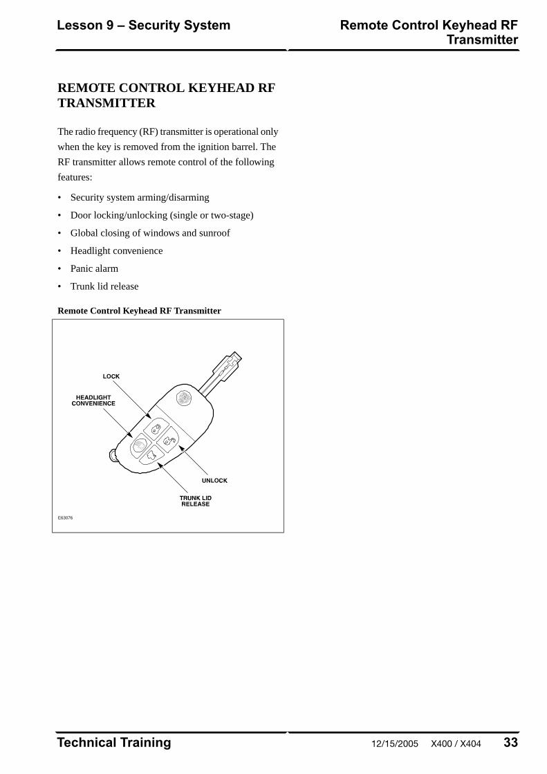
REMOTE CONTROL KEYHEAD RFTRANSMITTER
The radio frequency (RF) transmitter is operational only
when the key is removed from the ignition barrel. The
RF transmitter allows remote control of the following
features:
• Security system arming/disarming
• Door locking/unlocking (single or two-stage)
• Global closing of windows and sunroof
• Headlight convenience
• Panic alarm
• Trunk lid release
Remote Control Keyhead RF Transmitter
E63076
33Technical Training
Remote Control Keyhead RFTransmitter
Lesson 9 – Security System
12/15/2005 X400 / X404
SYSTEM OPERATION
Arming/Disarming andLocking/Unlocking
The vehicle can be locked in one of three ways:
• Rotating the key in the driver's door lock barrel tothe lock position
• Pressing the RF transmitter LOCK button once
• Moving the front interior door handle to the lockposition
The vehicle is also equipped with auto (drive-away)locking. When the vehicle is driven at a speed greaterthan 7 km/h (approx. 4.5 mph), the system willautomatically lock all the doors.
20 seconds after the vehicle is locked, the securitysystem will fully arm. At this point, if a door, the hood,or the trunk is opened without disarming the system,the alarm will sound.
Rotating the key in the driver's door lock barrel to theunlock position or pressing the UNLOCK button on theRF transmitter will disarm the alarm system and initiatesingle-stage or two-stage unlocking.
Single-Stage and Two-Stage Unlocking
With the alarm system in single-stage unlocking mode,a single rotation of the door lock barrel to the unlockposition or a single press of the RF transmitterUNLOCK button will unlock all doors.
With the alarm system in two-stage unlocking mode, asingle rotation of the door lock barrel to the unlockposition or a single press of the RF transmitterUNLOCK button will unlock the driver’s door. Asecond rotation of the door lock barrel to the unlockposition or a second press of the RF transmitterUNLOCK button will unlock the remaining doors.
Selecting Unlocking Modes
The alarm system can be toggled between the singleand two-stage unlocking modes by pressing the RFtransmitter LOCK and UNLOCK buttonssimultaneously for four seconds.
Global Window and Sunroof Control
Closing of the windows and sunroof can be initiatedfrom the driver’s door key (global closing) or the RFtransmitter (remote global closing).
To initiate global closing, rotate the key in the driver’sdoor lock barrel to the lock position and hold for longerthan two seconds. The windows and sunroof will begintheir closing operation and will continue to close as longas the key is held in the lock position.
To initiate remote global closing, press and hold the RFtransmitter LOCK button for longer than two seconds.This will initiate an automatic closing of the windowsand sunroof. Once initiated, the button can be releasedand the windows and sunroof will continue to their fullyclosed position. To stop the remote global closingsequence, press any button on the RF transmitter orpress the central locking switch.
The remote global closing feature can beenabled/disabled via WDS.
NOTE: Global closing and remote global closing willnot close the windows if the windows have not beeninitialized.
Headlight Convenience
When the RF transmitter HEADLIGHTCONVENIENCE button is pressed, the headlights willilluminate for 30 seconds. A second press of the buttonor inserting the key into the ignition switch willextinguish the headlights.
Technical Training34
Lesson 9 – Security SystemSystem Operation
X400 / X404 12/15/2005

Panic Alarm
Pressing the RF transmitter HEADLIGHT
CONVENIENCE button three times within three
seconds will activate the panic alarm. The alarm will
continue until the normal alarm cycle is complete or
until the HEADLIGHT CONVENIENCE button is
pressed again three times within three seconds.
Trunk Release
The trunk can be opened two ways:
• Pressing the RF Transmitter TRUNK LID RELEASE
button.
• Pressing the exterior trunk release button (when the
car is unlocked and the security system is disarmed).
Exterior Trunk Release Button
E69238
Auto Relocking
If a door is not opened within 45 seconds of unlocking
the vehicle with the RF transmitter, the vehicle will
automatically relock the doors and rearm the security
system. The auto relocking feature can be
activated/deactivated using WDS.
35Technical Training
System OperationLesson 9 – Security System
12/15/2005 X400 / X404

SERVICE
RF Transmitter Service
Battery Replacement
Each transmitter contains one type CR2032 battery. To
separate the key unit from the remote unit, use a small
flat screwdriver as illustrated. The battery is fitted with
the positive symbol (+) facing downwards in the battery
receptacle.
NOTE: Changing the remote’s battery will not affect
its operation or require the remote to be reprogrammed.
E63301
RF Transmitter Programming
There are two methods for programming transmitters.
Prior to programming, ensure that all transmitters for
the vehicle are present. Transmitters not present will be
erased from alarm memory and will no longer function.
Programming transmitters without WDS:
1. Insert key into ignition.
2. Hold headlight stalk in the FLASH position.
3. While holding headlight stalk in the FLASH position,
rotate the ignition key to position I (AUX).
4. Release headlight stalk and then flash the headlights
four times.
5. An audible confirmation and a flash of the security
LED on top of the fascia will confirm the alarm
system is in transmitter “learning” mode.
6. Press any button on each remote to be programmed.
A maximum of five transmitters can be programmed.
7. The alarm system will exit the learning mode when
the key is turned to position 0 (OFF), or 15 seconds
after the alarm enters learning mode.
Programming transmitters using WDS:
1. Select the “Vehicle Configuration” main menu tab.
2. Select “Security”.
3. From here, key transponders and transmitters can be
programmed.
Technical Training36
Lesson 9 – Security SystemService
X400 / X404 12/15/2005

PASSIVE ANTI-THEFT SYSTEM
The Passive Anti-Theft System (PATS) is centered
around the instrument cluster (IC) and the engine control
module (ECM). The engine starting sequence is as
follows:
1. Key in ignition
2. Data transfer between the IC and the key transponder
to confirm a valid key
3. Ignition turned to position II (RUN)
4. “Key valid” message sent from the IC to the ECM
5. Data transfer between the ECM and IC to confirm
encrypted code is correct
6. Engine start
If this sequence is successfully completed, the PATS
LED located on top of the fascia will illuminate for three
seconds then extinguish.
PATS Fault Diagnostics
If a fault is detected, the engine will not crank and the
PATS LED located on top of the fascia will flash at 4Hz
for 60 seconds. At the end of this period, the LED will
flash a two-digit code for the current fault. The code
will be flashed 10 times. Refer to GTR for code
interpretation.
NOTE: Corresponding DTCs may exist along with
PATS codes that may further explain the root cause of
a fault. Check for DTCs whenever diagnosing a PATS
fault.
Key Transponder Programming
As many as 4 transponders can be programmed for one
vehicle, but they must all be present at the time of
programming.
Programming additional transponders without WDS:
1. To enter the manual programming process, all keys
for the vehicle will need to be present and two
pre-programmed keys will be required.
2. Insert the first customer key into the ignition switch
and turn to the position II (RUN) for a maximum of
five seconds. Remove key.
3. Within 10 seconds of removing the first key, insert
the second customer key and turn to position II
(RUN) for a maximum of five seconds. Remove key.
4. To program the third key, insert the new key and
turn to position II (RUN) within 20 seconds of
removing the second key. Allow the PATS LED to
prove out for three seconds to confirm storage of the
new key.
5. To program a fourth key, follow the sequence as
above, but continue as follows: After removing the
third key, insert key 1 or 2, turn to position II (RUN)
and then remove the key.
6. Insert the fourth key, turn to position II (RUN) and
back to off, then remove key.
Programming transponders using WDS:
1. Select the “Vehicle Configuration” main menu tab.
2. Select “Security”.
3. From here, key transponders and transmitters can be
programmed.
37Technical Training
Passive Anti-Theft System (PATS)Lesson 9 – Security System
12/15/2005 X400 / X404
SUPPLEMENTAL RESTRAINTSSYSTEM OVERVIEW
The X-TYPE uses Jaguar’s Adaptive Restraint
Technology System (ARTS). ARTS can be divided into
three subsystems:
• Crash severity sensing and analysis
– Five impact sensors (one behind the radiator grill
and one mounted at the base of each ‘B/C’ and
‘D/E’ pillar) provide a signal to the Restraints
Control Module (RCM) that is proportionate to
the crash severity
• Occupant analysis
– Position of the driver’s seat and seatbelt
engagement is monitored – Weight, seat track
position and seatbelt engagement of the front
passenger is monitored
• Deployment handling
– Based on crash severity and occupant analysis,
the RCM will determine which restraints to
deploy and the deployment strength (frontal
impact airbags only).
X404 Updates
Starting at VIN D88099, the X404 SRS was updated
with the following:
• Revised passenger weight sensing system with the
"Gen 2" sensor
• Revised side curtain airbags
• Addition of a passenger belt tension sensor
• Addition of seat belt reel pretensioners for front
occupants
• Addition of a driver's knee bolster airbag
Technical Training38
Lesson 10 – Supplemental RestraintSystem
Overview
X400 / X404 12/15/2005
COMPONENTS
The ARTS in X-TYPE vehicles uses two control
modules. The two modules communicate via a local
(dedicated) CAN network, which is not part of the
vehicle’s main CAN network.
Weight Sensing Module
Mounted to the underside of the front passenger seat,
the weight sensing module processes the signal from
the seat pressure transducer attached to the silicone filled
bladder in the cushion.
Restraints Control Module
Mounted below the radio on the transmission tunnel,
the restraints control module is responsible for deploying
restraints based on signals from the weight sensing
module, front seat belt buckle sensors, front seat position
switches and crash sensors.
39Technical Training
ComponentsLesson 10 – Supplemental RestraintSystem
12/15/2005 X400 / X404
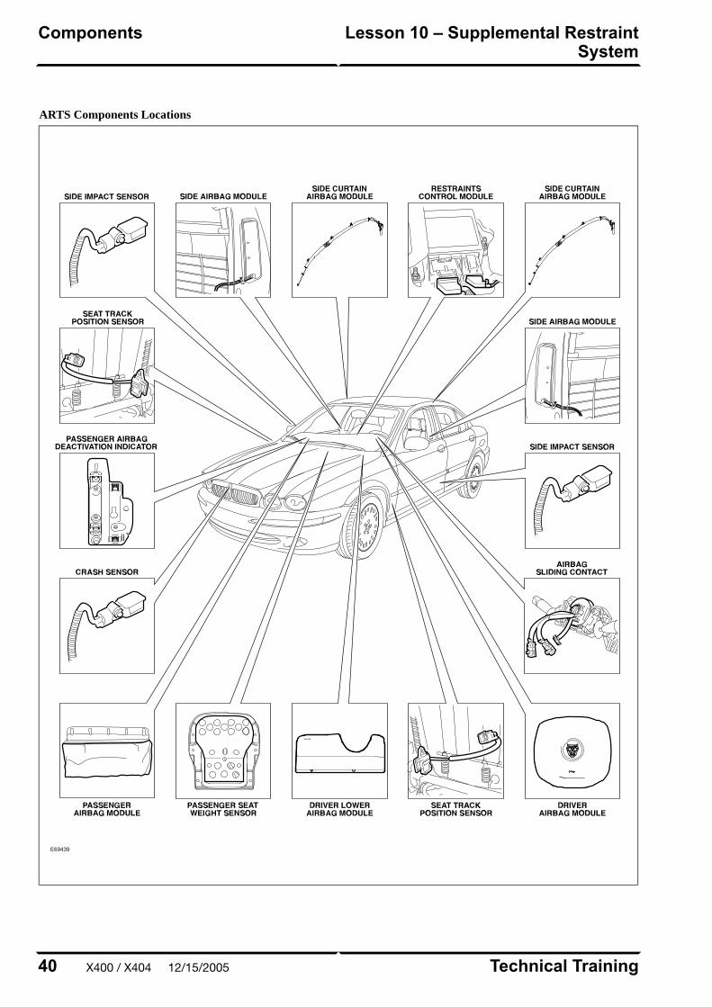
ARTS Components Locations
E69439
Technical Training40
Lesson 10 – Supplemental RestraintSystem
Components
X400 / X404 12/15/2005
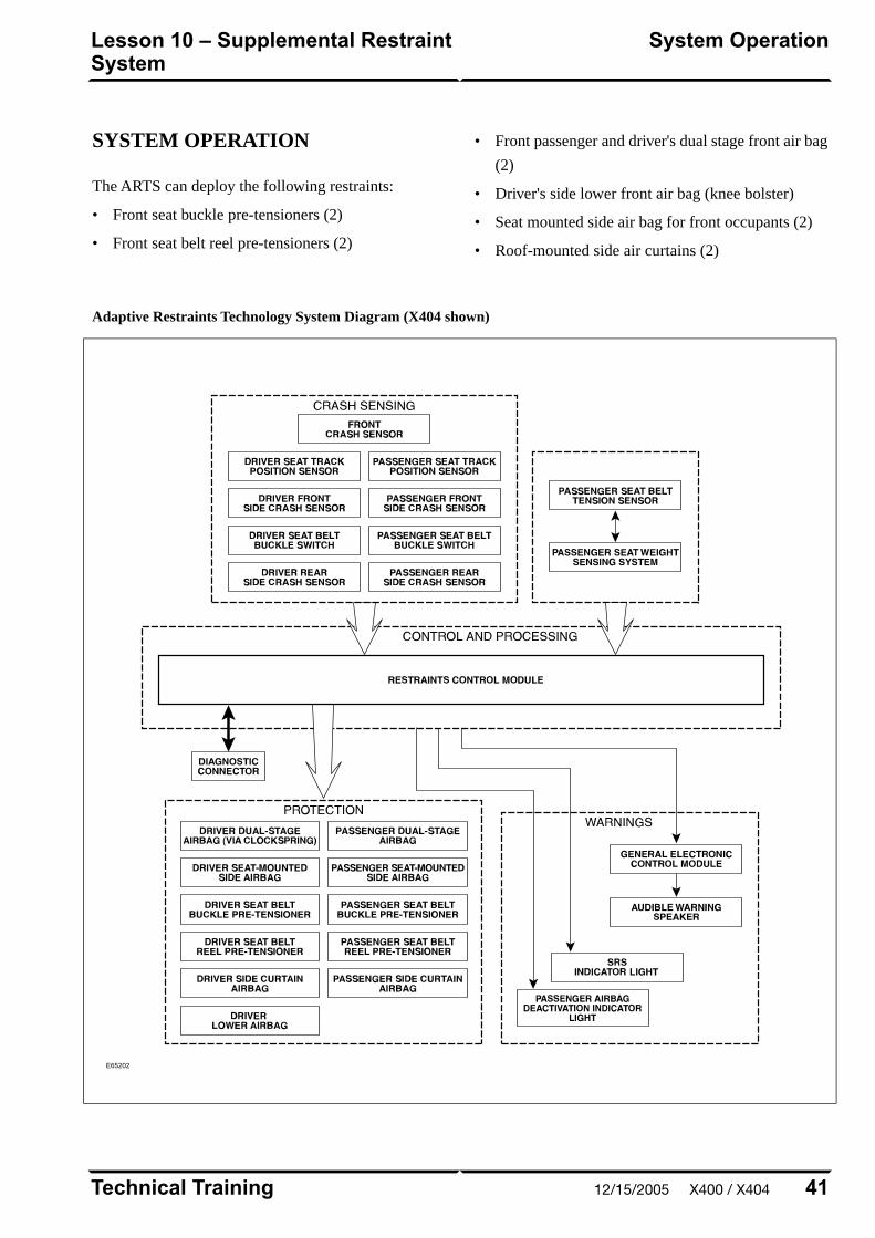
SYSTEM OPERATION
The ARTS can deploy the following restraints:
• Front seat buckle pre-tensioners (2)
• Front seat belt reel pre-tensioners (2)
• Front passenger and driver's dual stage front air bag
(2)
• Driver's side lower front air bag (knee bolster)
• Seat mounted side air bag for front occupants (2)
• Roof-mounted side air curtains (2)
Adaptive Restraints Technology System Diagram (X404 shown)
E65202
41Technical Training
System OperationLesson 10 – Supplemental RestraintSystem
12/15/2005 X400 / X404

WARNING: Read and observe all safety
precautions in GTR (Global Technical
Reference) and service bulletins before
attempting to service the SRS.
Do not attempt to measure the circuit resistance
through the airbag modules or pre-tensioners with
a DVOM. Doing so may trigger airbag deployment
and result in personal injury.
To disarm the SRS, disconnect the battery negative
cable and wait a minimum of two minutes for the
reserve power charge to dissipate.
Technical Training42
Lesson 10 – Supplemental RestraintSystem
System Operation
X400 / X404 12/15/2005
IN-CAR ENTERTAINMENT (ICE)
Selectable Features
Simultaneously pressing and holding the AM/FM and
EJECT buttons will display the audio system selectable
features on the navigation screen (if fitted). The
following options are available:
• Market (toggled with preset button 1 on vehicles not
fitted with navigation)
– US (no security code function, radio tunes to odd
digits i.e. 90.1, 90.3, 90.5 etc.)
– EU
– JPN
– AUS
• RDS/RBDS (Radio Data System/Radio Broadcast
Data System) (toggled with preset button 0 on
vehicles not fitted with navigation)
– ON (when tuned to a RDS station, the radio will
display station call letters and (depending on
station) station name, current song title and artist)
– OFF (only the radio station frequency is
displayed)
Setting the Clock
Vehicles without navigation:
1. Press and hold the MODE button until TA VOLUME
is displayed
2. Repeatedly press the MODE button until CLOCK
SET is displayed
3. To select the 12 or 24 hour format, press the SEEK
UP/DOWN buttons
4. Press the MODE button to continue
5. If 12 hour is selected, use the # button to denote AM
or PM
6. Use the keypad to enter the time in four-digit format
7. To exit, press and hold the MODE button until the
display reverts to audio mode
Vehicles with navigation:
1. Press the MENU button on the touch screen control
panel – the system menu screen will be displayed
2. Touch the SYSTEM SETUP button on the MENU
screen
3. Touch the SET CLOCK button on the SYSTEM
SETUP screen
4. Clock adjustment is made by touching the hour or
minute, up or down arrow buttons
5. Touch the 12/24 button to select twelve or
twenty-four hour display
6. Confirm the setting by touching the SET button
43Technical Training
In-Car Entertainment (ICE)Lesson 11 – Infotainment
12/15/2005 X400 / X404
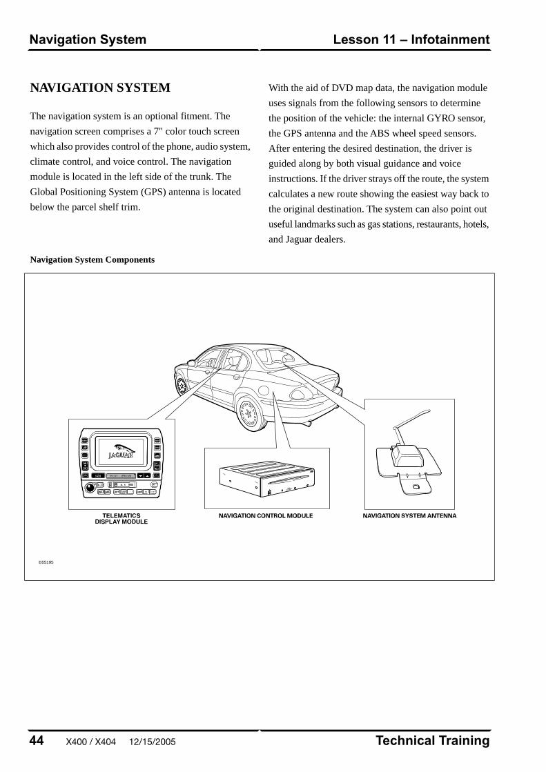
NAVIGATION SYSTEM
The navigation system is an optional fitment. The
navigation screen comprises a 7" color touch screen
which also provides control of the phone, audio system,
climate control, and voice control. The navigation
module is located in the left side of the trunk. The
Global Positioning System (GPS) antenna is located
below the parcel shelf trim.
With the aid of DVD map data, the navigation module
uses signals from the following sensors to determine
the position of the vehicle: the internal GYRO sensor,
the GPS antenna and the ABS wheel speed sensors.
After entering the desired destination, the driver is
guided along by both visual guidance and voice
instructions. If the driver strays off the route, the system
calculates a new route showing the easiest way back to
the original destination. The system can also point out
useful landmarks such as gas stations, restaurants, hotels,
and Jaguar dealers.
Navigation System Components
E65195
Technical Training44
Lesson 11 – InfotainmentNavigation System
X400 / X404 12/15/2005


