Embed Size (px)
Citation preview
Introduction
Prestressed Concrete Design
(SAB 4323)
Introduction
Assoc. Prof. Baderul Hisham Ahmad
What is Prestressing?
• The application of a force to the
structure, other than the applied
2
structure, other than the applied
load, which assists the performance
of the structure
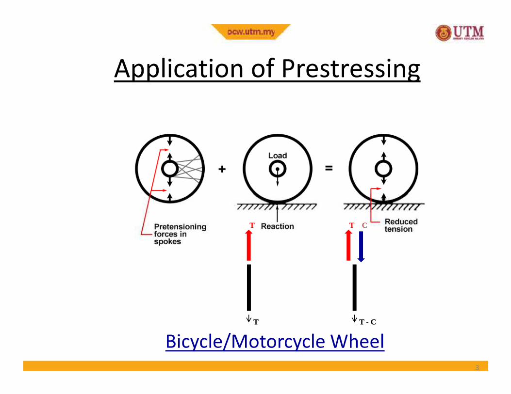
Application of Prestressing
3
Bicycle/Motorcycle Wheel
T
T T - C
T C
What is Prestressed Concrete?
• It is simply ‘pre-compressed concrete’
• i.e. a pre-compressive force is applied to
the concrete member before it is put into
service
4
service
• The position and magnitude of this
prestress force can be chosen so as to
suppress any tensile stresses that are
expected under working load
• Why do we pre-compress concrete?
• We know that concrete is strong in compression
but weak in tension???
• Because of this weakness in tension!
Fundamental Principle of
Prestressing
• Because of this weakness in tension!
• Where do we pre-compress the concrete?
• Wherever we expect tensile stresses under
working load
• How is this achieved?
• Pre-tensioning & Post-tensioning (Details later!)
5
Applications
Prestressed concrete is used in
• buildings
• underground structures
• towers• towers
• water storage
• offshore structures
• numerous types of bridge system including cable-stayed and segmental bridges
• nuclear reactor vessels
6
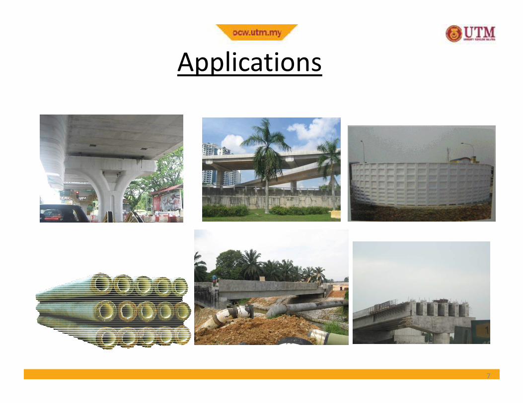
Applications
7
Play VideoPlay Video
Introduction to Prestressed Concrete
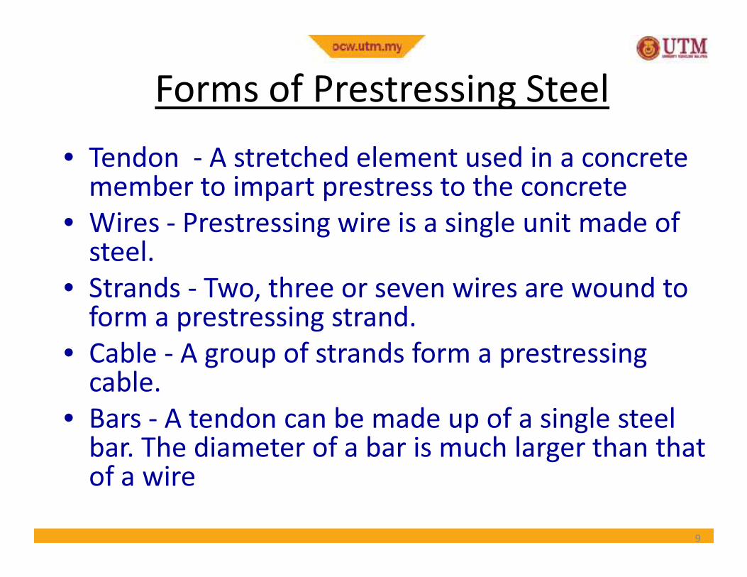
Forms of Prestressing Steel
• Tendon - A stretched element used in a concrete member to impart prestress to the concrete
• Wires - Prestressing wire is a single unit made of steel.
• Strands - Two, three or seven wires are wound to • Strands - Two, three or seven wires are wound to form a prestressing strand.
• Cable - A group of strands form a prestressingcable.
• Bars - A tendon can be made up of a single steel bar. The diameter of a bar is much larger than that of a wire
9
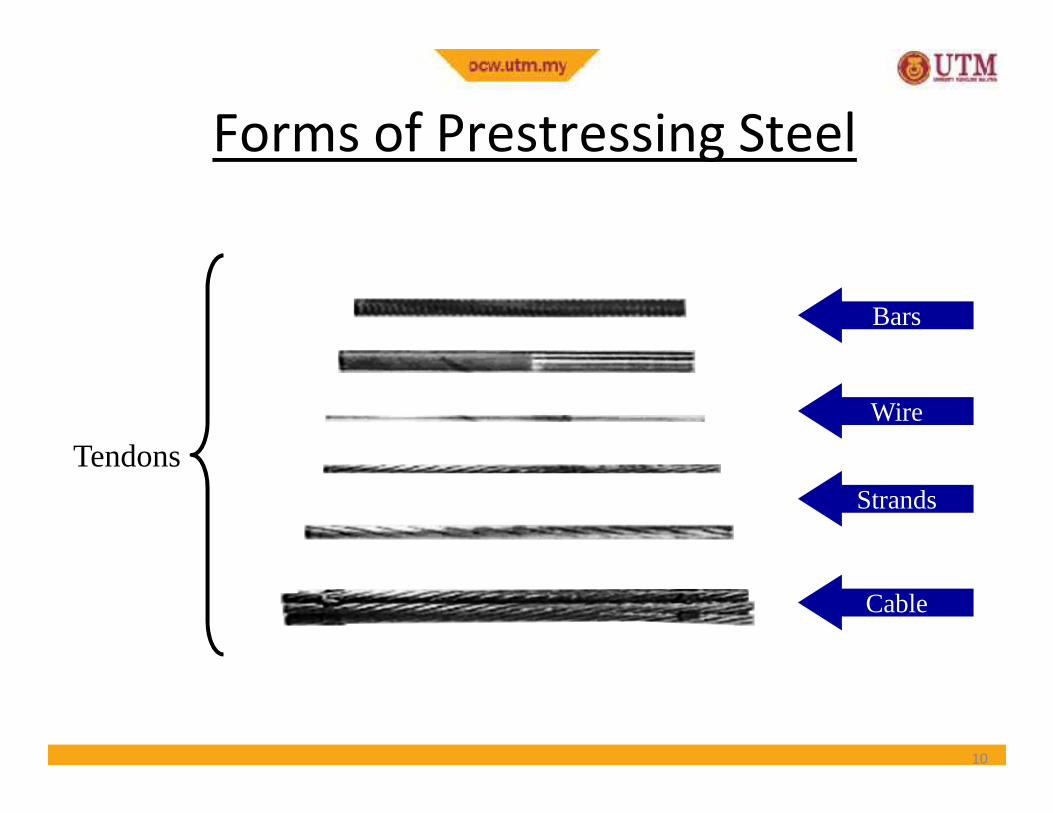
Wire
Bars
Forms of Prestressing Steel
Wire
Strands
Cable
Tendons
10
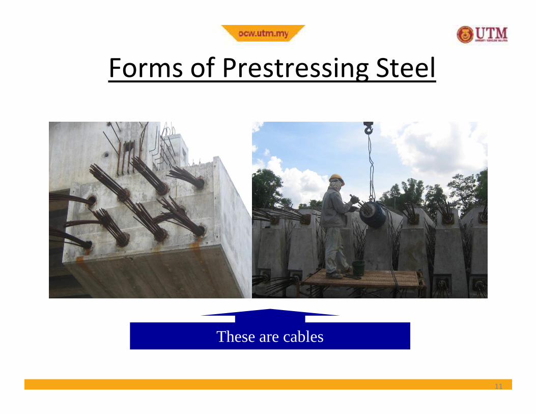
Forms of Prestressing Steel
These are cables
11
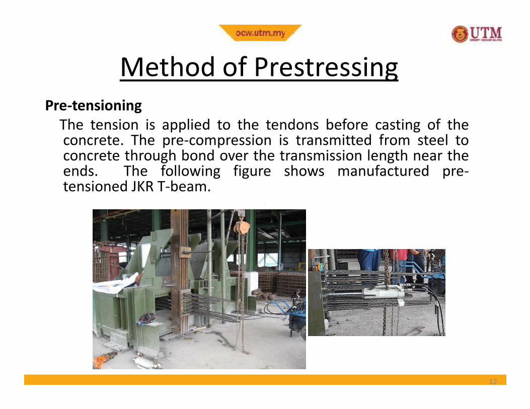
Method of Prestressing
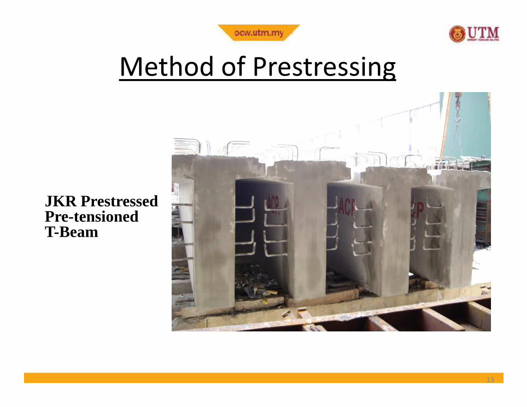
Pre-tensioning
The tension is applied to the tendons before casting of theconcrete. The pre-compression is transmitted from steel toconcrete through bond over the transmission length near theends. The following figure shows manufactured pre-tensioned JKR T-beam.
12
JKR Prestressed
Method of Prestressing
JKR PrestressedPre-tensionedT-Beam
13
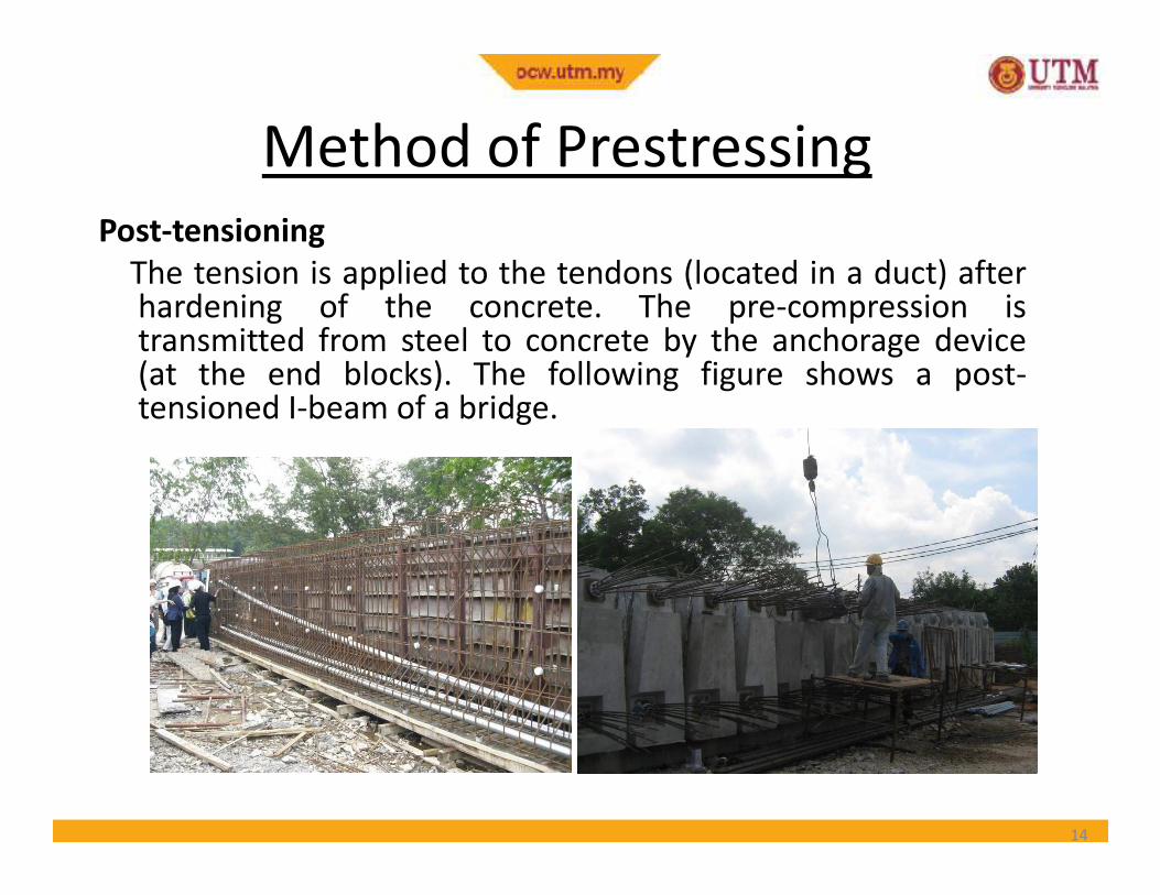
Post-tensioning
The tension is applied to the tendons (located in a duct) afterhardening of the concrete. The pre-compression istransmitted from steel to concrete by the anchorage device(at the end blocks). The following figure shows a post-tensioned I-beam of a bridge.
Method of Prestressing
14
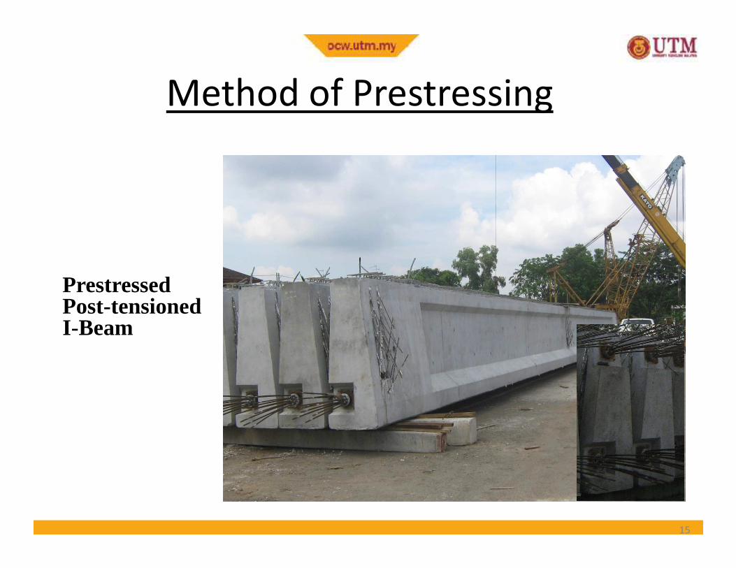
Prestressed
Method of Prestressing
PrestressedPost-tensionedI-Beam
15
Nature of Concrete-Steel Interface
• Bonded tendon - when there is adequatebond between the prestressing tendon andconcrete, it is called a bonded tendon. Pre-tensioned and grouted post-tensionedtendons are bonded tendons.tensioned and grouted post-tensionedtendons are bonded tendons.
• Unbonded tendon - when there is no bondbetween the prestressing tendon andconcrete, it is called unbonded tendon. Whengrout is not applied after post-tensioning, thetendon is an unbonded tendon.
16
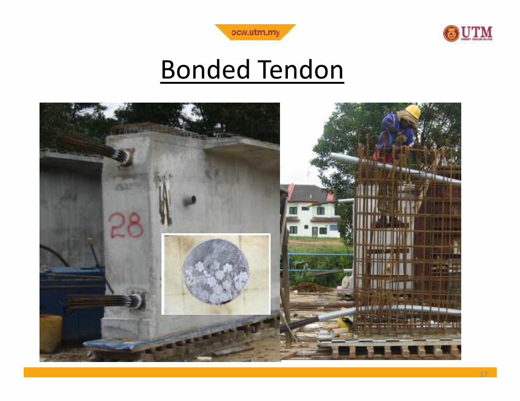
Bonded Tendon
17
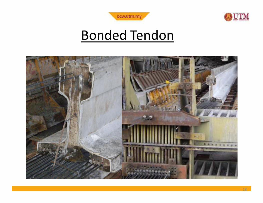
Bonded Tendon
18
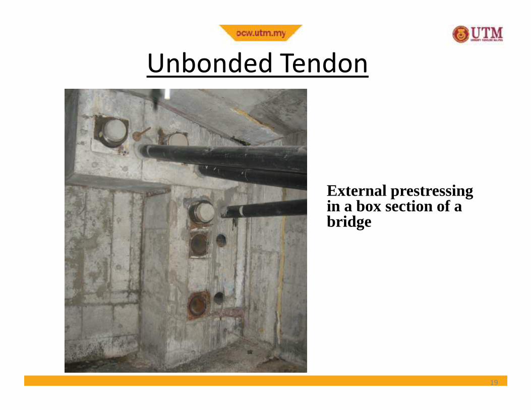
Unbonded Tendon
External prestressingin a box section of a
19
in a box section of a bridge
Read the following Prestressing
Systems
Freyssinet K Range PT SystemFreyssinet K Range PT System
Freyssinet C Range PT System
VSL Construction System
CCL Pretensioning System
20
Prestressing Systems
• Prestressing systems have developed over the
years and various companies have patented their
products. Detailed information of the systems is
given in the product catalogues and brochures
published by companiespublished by companies
• Example of Prestressing Contractors in Malaysia
– Freyssinet PSC (M) Sdn Bhd
– VSL Engineers (M) Sdn Bhd
– BBR Construction System (M) Sdn Bhd
21
• In pre-tensioning system, the high-strength steeltendons are pulled between two end abutmentsprior to the casting of concrete.
• The abutments are fixed at the ends of a
Prestressing Systems
• The abutments are fixed at the ends of aprestressing bed.
• Once the concrete attains the desired strength forprestressing, the tendons are cut loose from theabutments.
22
• The prestress is transferred to the concrete fromthe tendons, due to the bond between them.During the transfer of prestress, the memberundergoes elastic shortening.
Prestressing Systems
undergoes elastic shortening.
• If the tendons are located eccentrically, themember is likely to bend and deflect
23
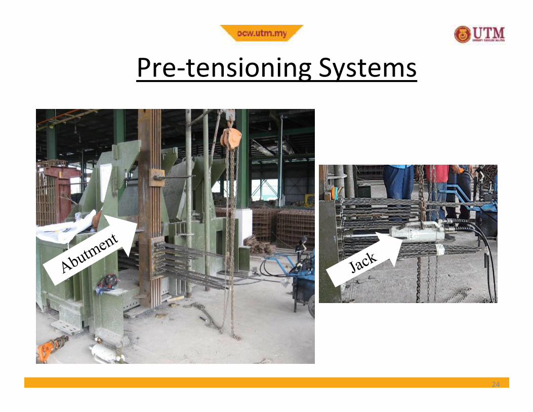
Pre-tensioning Systems
24
• Anchoring of tendons against the end
abutments
• Placing of jacks
Stages of Pre-tensioning
• Placing of jacks
• Applying tension to the tendons
• Casting of concrete
• Cutting of the tendons
25
Post-tensioning Systems
• In post-tensioning systems, the ducts for the
tendons (or strands) are placed along with the
reinforcement before the casting of concrete.
• The tendons are placed in the ducts after the• The tendons are placed in the ducts after the
casting of concrete. The duct prevents contact
between concrete and the tendons during the
tensioning operation.
• Unlike pre-tensioning, the tendons are pulled
with the reaction acting against the hardened
concrete.26
• If the ducts are filled with grout, then it is
known as bonded post-tensioning.
• In unbonded post-tensioning, as the name
suggests, the ducts are never grouted and the
Post-tensioning SystemsPost-tensioning Systems
suggests, the ducts are never grouted and the
tendon is held in tension solely by the end
anchorages.
27
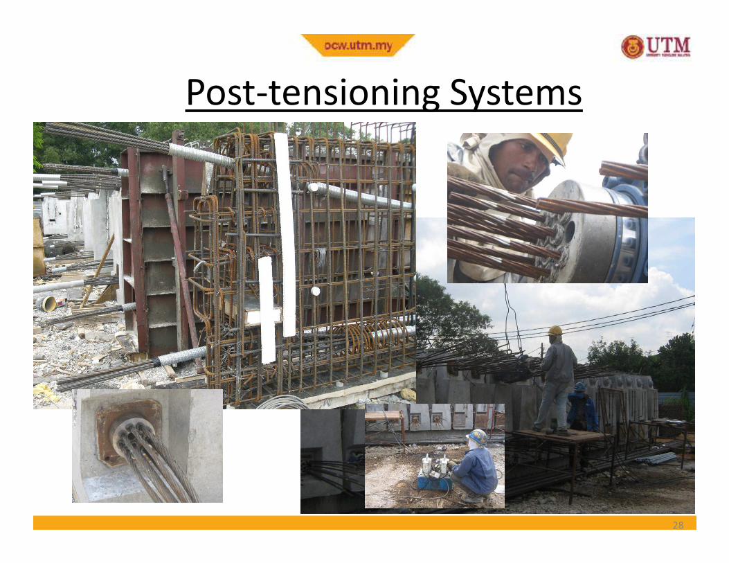
Post-tensioning SystemsPost-tensioning Systems
28
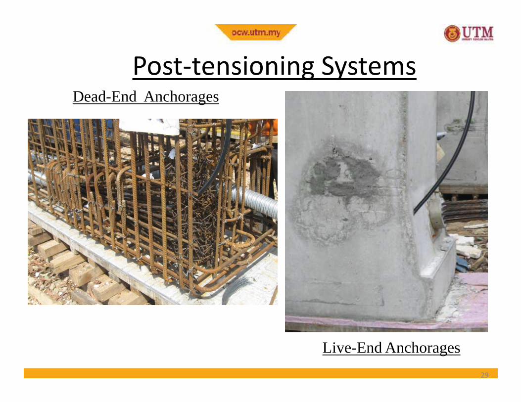
Post-tensioning SystemsPost-tensioning SystemsDead-End Anchorages
29
Live-End Anchorages
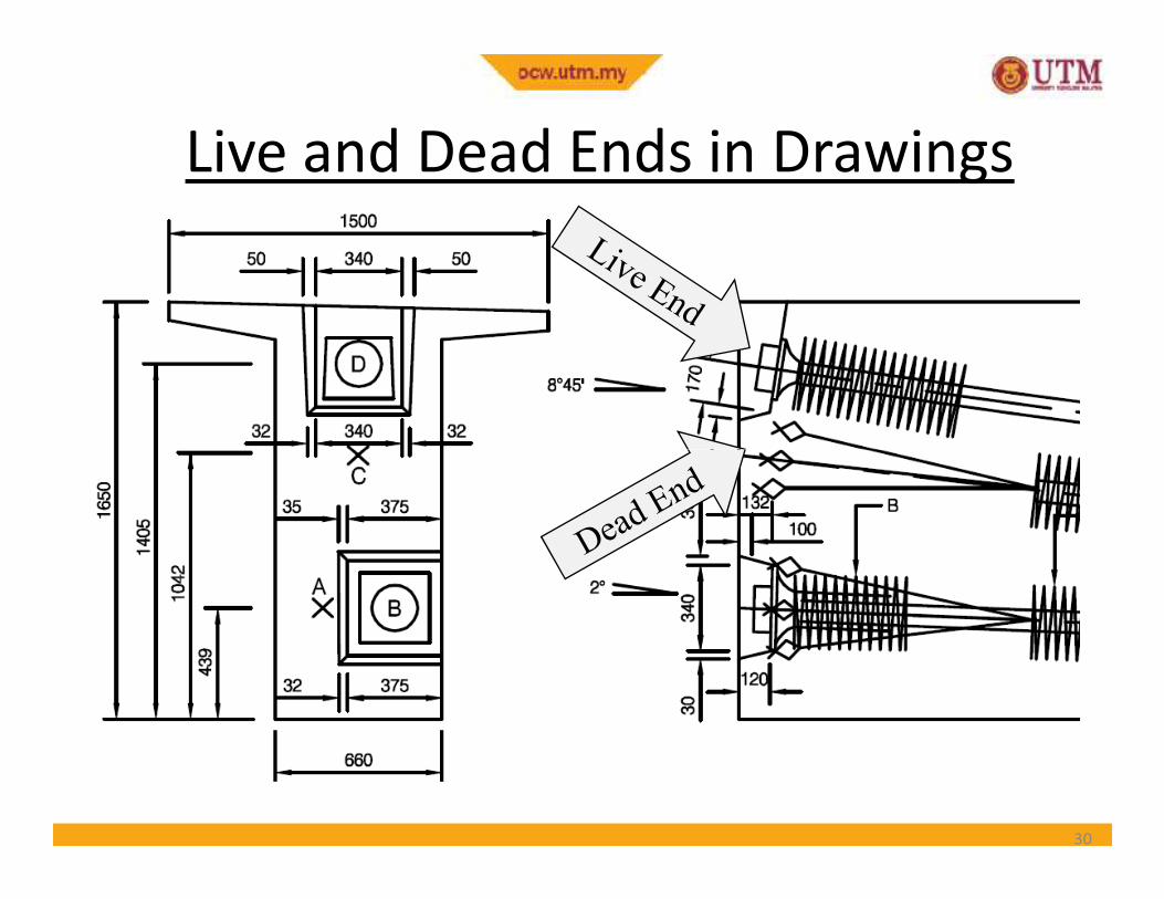
Live and Dead Ends in Drawings
30
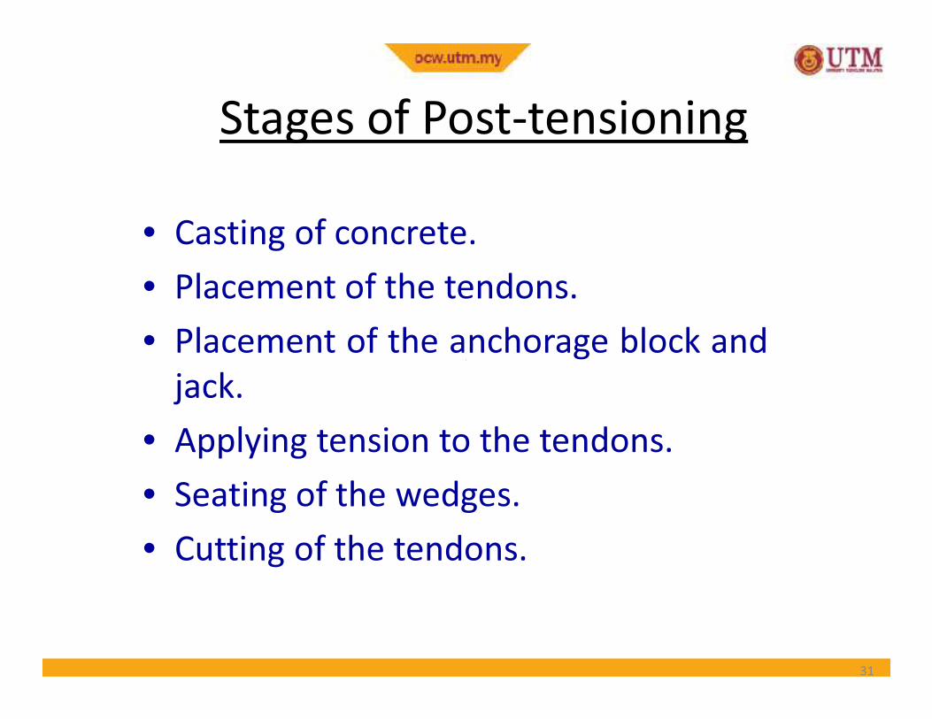
Stages of Post-tensioning
• Casting of concrete.
• Placement of the tendons.
• Placement of the anchorage block and• Placement of the anchorage block and
jack.
• Applying tension to the tendons.
• Seating of the wedges.
• Cutting of the tendons.
31
• The prestressing of concrete has several advantages as compared to traditional reinforced concrete (RC) without prestressing.
• A fully prestressed concrete member is
Advantages of PSC
• A fully prestressed concrete member is usually subjected to compression during service life. This rectifies several deficiencies of concrete.
32
1. Section remains uncracked under serviceloads
• Reduction of steel corrosion� Increase in durability
• Full section is utilised
Advantages of PSCAdvantages of PSC
• Full section is utilised� Higher moment of inertia (higher stiffness)
� Less deformations (improved serviceability)
• Increase in shear capacity
• Suitable for use in pressure vessels, liquid retainingstructures
• Improved performance (resilience) under dynamicand fatigue loading
33
2. High span-to-depth ratios• Larger spans possible with prestressing (bridges,
buildings with large column-free spaces)
• For the same span, less depth compared to RC
Advantages of PSCAdvantages of PSC
• For the same span, less depth compared to RCmember� Reduction in self weight
�More aesthetic appeal due to slender sections
�More economical sections
34
3. Suitable for precast construction - advantagesas follows:
• Rapid construction
• Better quality control
• Reduced maintenance
Advantages of PSCAdvantages of PSC
• Reduced maintenance
• Suitable for repetitive construction
• Multiple use of formwork� Reduction of formwork
• Availability of standard shapes
35
Limitations of PSC
• Prestressing needs skilled technology.Hence, it is not as common as reinforcedconcrete.
• The use of high strength materials iscostly.
Disadvantages of PSC
• The use of high strength materials iscostly.
• There is additional cost in auxiliary equipments.
• There is need for quality control andinspection
36
Properties of Materials
• Prestressed concrete requires the use of highstrength materials, both concrete andprestressing steel
• Ordinary reinforcing steel is commonly used in• Ordinary reinforcing steel is commonly used inprestressed concrete structures as– transverse reinforcement
– shear reinforcement (stirrup/links)
– supplementary longitudinal reinforcement foranchorage of links and in regions of high localstresses and deformation.
37
• Production of high strength concrete requires proper selection and proportioning of the ingredients, careful mixing, placement and curing
• Higher cement content, low water-cement ratio
ConcreteProperties of Materials
• Higher cement content, low water-cement ratio and good quality aggregates are necessary
• A variety of mineral and chemical admixtures are often added to the mix to modify the properties of fresh and/or hardened concrete for achieving some desired effects (expedite strength development, higher strength & longer life span)
38
• BS 8110 : Part 1 : 1997 Clause 4.1.8.1
• Minimum characteristic strength of concrete
(fcu)
ConcreteProperties of Materials
(fcu)
– 40 N/mm2 for pre-tensioned
– 35 N/mm2 for post-tensioned
• Minimum concrete strength at transfer (fci)
– 25 N/mm2 for pre-tensioned & post-tensioned
39
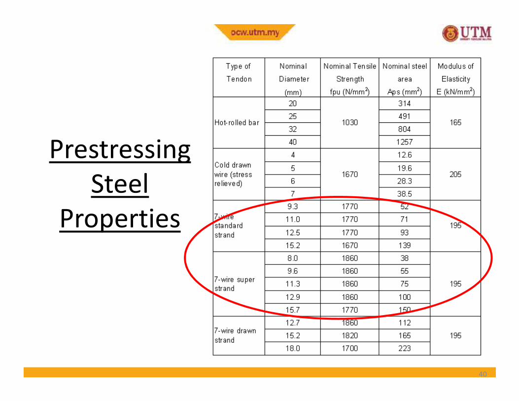
Prestressing
Steel
PropertiesProperties
40
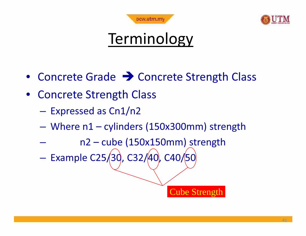
Terminology
• Concrete Grade � Concrete Strength Class
• Concrete Strength Class
– Expressed as Cn1/n2
– Where n1 – cylinders (150x300mm) strength
– n2 – cube (150x150mm) strength
– Example C25/30, C32/40, C40/50
41
Cube Strength
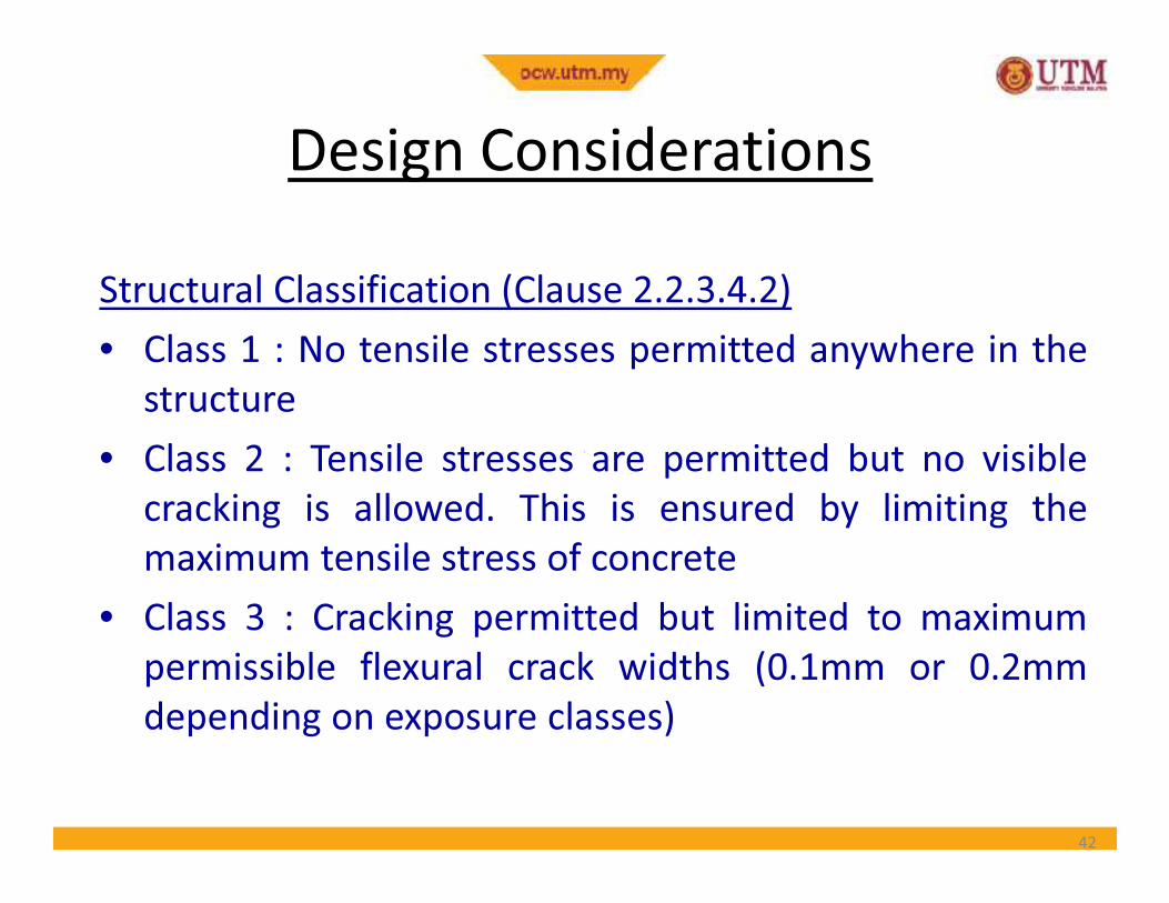
Design Considerations
Structural Classification (Clause 2.2.3.4.2)
• Class 1 : No tensile stresses permitted anywhere in the
structure
• Class 2 : Tensile stresses are permitted but no visible• Class 2 : Tensile stresses are permitted but no visible
cracking is allowed. This is ensured by limiting the
maximum tensile stress of concrete
• Class 3 : Cracking permitted but limited to maximum
permissible flexural crack widths (0.1mm or 0.2mm
depending on exposure classes)
42
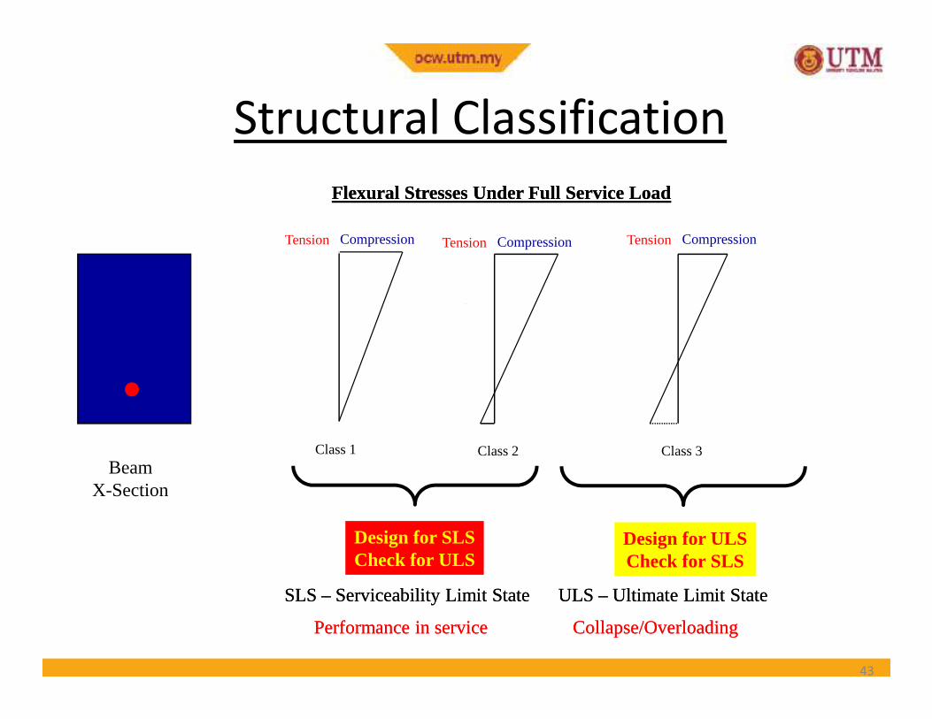
Structural Classification
Tension Compression Tension Compression Tension Compression
Flexural Stresses Under Full Service LoadFlexural Stresses Under Full Service Load
43
BeamX-Section
Class 1 Class 2 Class 3
Design for SLSCheck for ULS
Design for ULSCheck for SLS
SLS SLS –– Serviceability Limit State ULS Serviceability Limit State ULS –– Ultimate Limit StateUltimate Limit State
Performance in service Collapse/OverloadingPerformance in service Collapse/Overloading
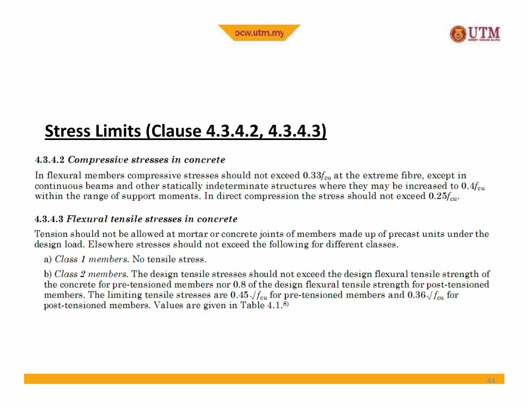
Stress Limits (Clause 4.3.4.2, 4.3.4.3)
44
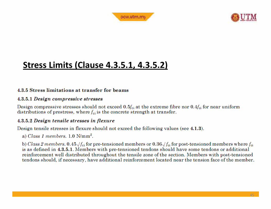
Stress Limits (Clause 4.3.5.1, 4.3.5.2)
Structural Classification
45
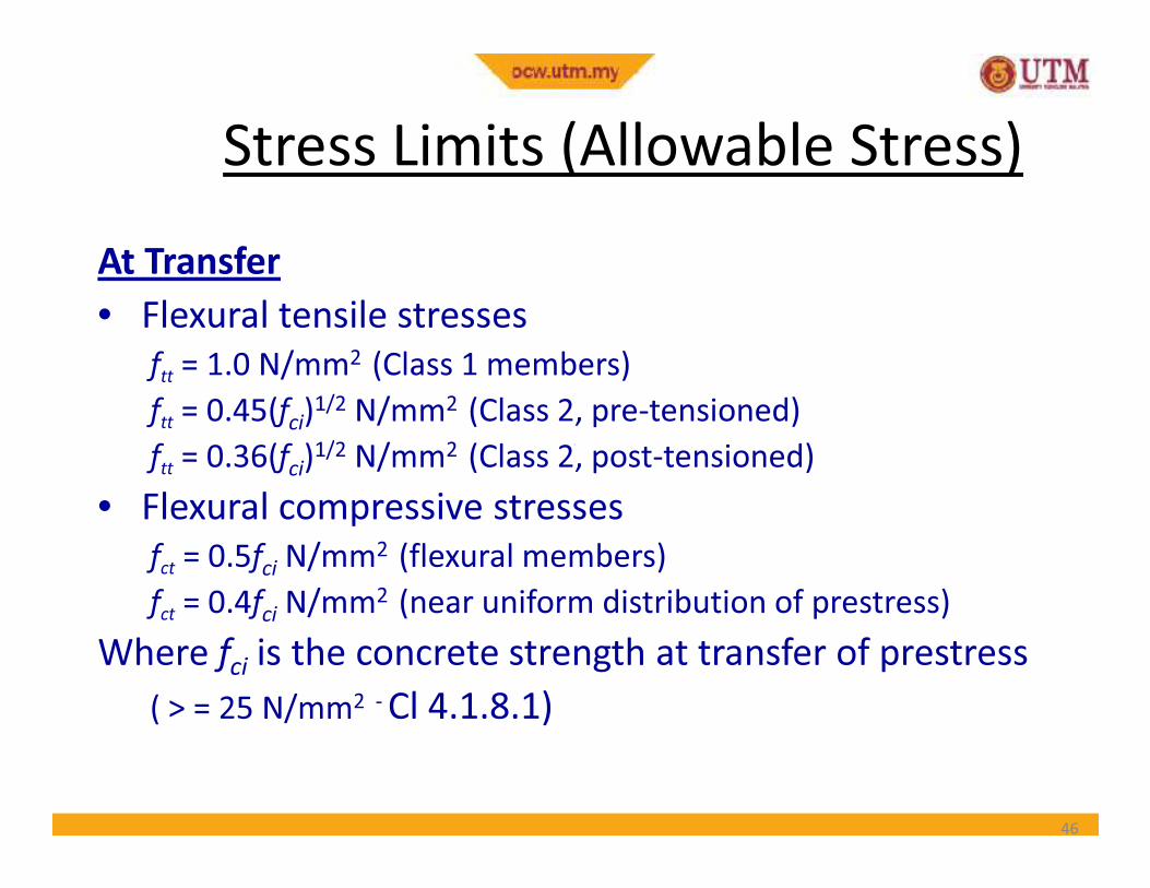
Stress Limits (Allowable Stress)
At Transfer
• Flexural tensile stresses
ftt= 1.0 N/mm2 (Class 1 members)
ftt= 0.45(f
ci)1/2 N/mm2 (Class 2, pre-tensioned)
f = 0.36(f )1/2 N/mm2 (Class 2, post-tensioned)ftt= 0.36(f
ci)1/2 N/mm2 (Class 2, post-tensioned)
• Flexural compressive stresses
fct= 0.5f
ciN/mm2 (flexural members)
fct= 0.4f
ciN/mm2 (near uniform distribution of prestress)
Where fciis the concrete strength at transfer of prestress
( > = 25 N/mm2 -Cl 4.1.8.1)
46
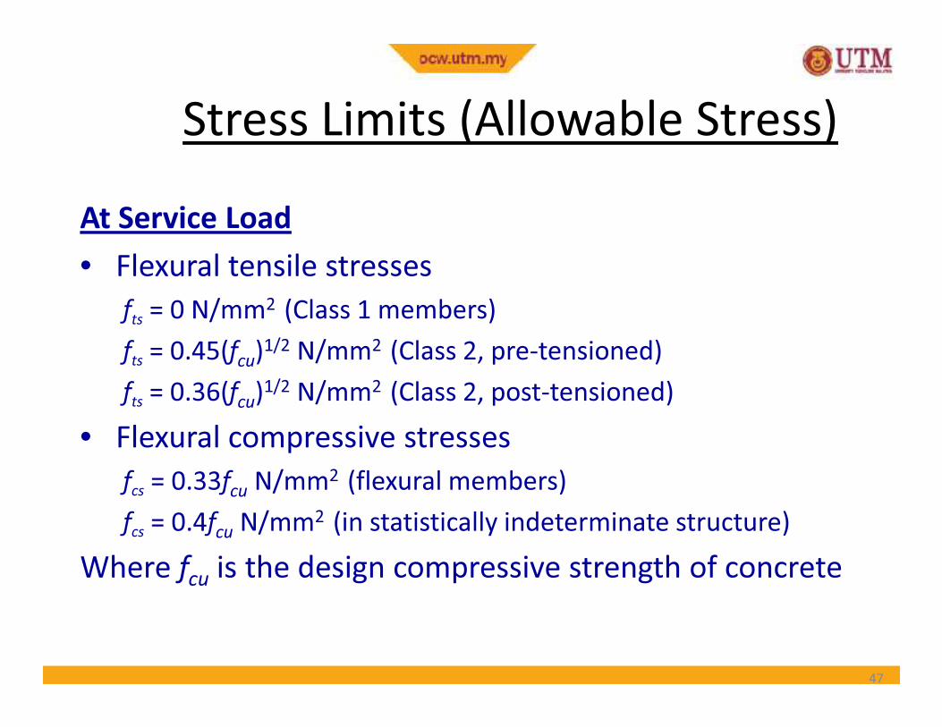
At Service Load
• Flexural tensile stresses
fts= 0 N/mm2 (Class 1 members)
fts= 0.45(f
cu)1/2 N/mm2 (Class 2, pre-tensioned)
Stress Limits (Allowable Stress)Stress Limits (Allowable Stress)
fts= 0.45(f
cu) N/mm (Class 2, pre-tensioned)
fts= 0.36(f
cu)1/2 N/mm2 (Class 2, post-tensioned)
• Flexural compressive stresses
fcs= 0.33f
cuN/mm2 (flexural members)
fcs= 0.4f
cuN/mm2 (in statistically indeterminate structure)
Where fcuis the design compressive strength of concrete
47
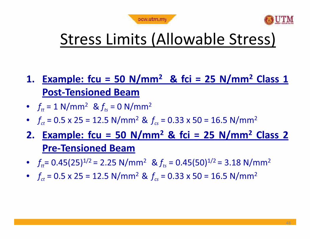
1. Example: fcu = 50 N/mm2 & fci = 25 N/mm2 Class 1
Post-Tensioned Beam
• ftt= 1 N/mm2 & f
ts= 0 N/mm2
• f = 0.5 x 25 = 12.5 N/mm2 & f = 0.33 x 50 = 16.5 N/mm2
Stress Limits (Allowable Stress)
• fct= 0.5 x 25 = 12.5 N/mm2 & f
cs= 0.33 x 50 = 16.5 N/mm2
2. Example: fcu = 50 N/mm2 & fci = 25 N/mm2 Class 2
Pre-Tensioned Beam
• ftt= 0.45(25)1/2 = 2.25 N/mm2 & f
ts= 0.45(50)1/2 = 3.18 N/mm2
• fct= 0.5 x 25 = 12.5 N/mm2 & f
cs= 0.33 x 50 = 16.5 N/mm2
48
Loss of Prestress
• The prestressing force does not remain constant
• Some losses are immediate while others occurgradually with time
• Short term losses• Short term losses
– Elastic shortening, Anchorage draw-in & Friction
• Long term losses
– Concrete Shrinkage and Creep & Steel Relaxation
• Details will be dealt with later
49
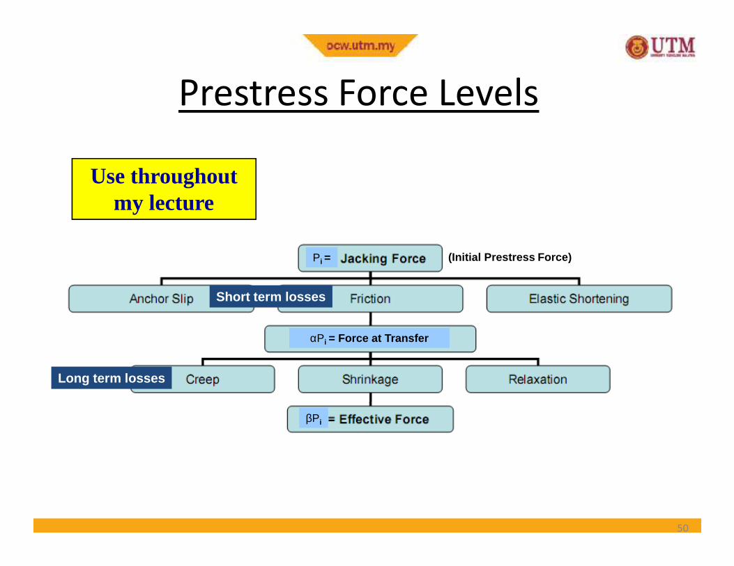
Prestress Force Levels
Pi =
Use throughout my lecture
(Initial Prestress Force)
50
αPi = Force at Transfer
βPi
Short term losses
Long term losses


