Embed Size (px)
Citation preview
Progress In Electromagnetics Research, PIER 79, 475–497, 2008
INTERFERENCE SUPPRESSION OF LINEARANTENNA ARRAYS BY AMPLITUDE-ONLY CONTROLUSING A BACTERIAL FORAGING ALGORITHM
K. Guney
Department of Electrical and Electronics EngineeringFaculty of EngineeringErciyes UniversityKayseri 38039, Turkey
S. Basbug
Department of Industrial ElectronicsVocational CollegeNevsehir UniversityNevsehir, Turkey
Abstract—This paper presents a bacterial foraging algorithm (BFA)for null steering of linear antenna arrays by controlling only the elementamplitudes. The BFA is a new evolutionary computing technique basedon the foraging behavior of Escherichia (E.) coli bacteria in humanintestine. To show the accuracy and flexibility of the proposed BFA,several examples of Chebyshev array pattern with the imposed single,multiple and broad nulls are given. It is found that the nulling methodbased on BFA is capable of steering the array nulls precisely to theundesired interference directions.
1. INTRODUCTION
Antenna arrays have been widely used in mobile, wireless, satelliteand radar communications systems to improve signal quality, therebyincreasing system coverage, capacity and link quality. The performanceof these systems depends firmly on the antenna array design. Theprocess of determining the parameters of an antenna array to obtainthe required antenna radiation pattern is known as pattern synthesis.Due to the increasing pollution of the electromagnetic environment,the antenna array, which allows placing nulls in the far field pattern at
476 Guney and Basbug
specified directions, is becoming important in communication systems,sonar, and radar applications for maximizing signal-to-interferenceratio [1–26]. Methods of null steering, which have been studiedextensively in the past [1–26], include controlling the amplitude-only,the phase-only, the position-only, and the complex weights (both theamplitude and phase) of the array elements. These methods havebeen used with their own benefits and limitations. In spite of the largevariety of nulling methods, it appears that none of them completelysatisfies the requirement of a general and flexible solution for thepattern synthesis problem.
Interference suppression with complex weights is the most effectivesince it has the larger solution alternatives [1, 13, 16, 21]. However, itis also the most expensive considering the cost of the controllers usedfor phase shifters and variable attenuators for each array element.Moreover, when the number of elements in the array increases, thecomputational time to find the values of element amplitudes and phaseswill also increase. The amplitude-only control [3, 4, 13, 14, 19, 23, 25]uses a set of variable attenuators to adjust the element amplitudes.If the element amplitudes have even symmetry about the center ofthe array, the number of attenuators and the computational time arehalved. Without any approximation, the problem for the phase-onlyand position-only nulling methods is inherently nonlinear and, it cannot be solved by analytical methods in a direct way. The phase-onlycontrol [5, 6, 9, 17, 22, 24] utilizes the phase shifters while the position-only control [7–11, 15, 26] needs a mechanical driving system suchas servomotors to move the array elements. By assuming that thephase perturbations are small, the nulling equations can be linearized,but it makes impossible to place nulls at symmetric location withrespect to the main beam [1]. In null synthesizing with small phaseperturbations, there is an unavoidable sidelobe level increase in thedirection symmetric to nulling direction with respect to the main beam.In order to steer the nulls symmetrically with respect to the mainbeam, the methods based on nonlinear optimization techniques havebeen proposed [5, 6], however, the resultant patterns of these methodshave considerable pattern distortion because the phase perturbationsused are large. Phase-only null synthesizing is less complicated andattractive for the phased arrays since the required controls are availableat no extra cost, but it has still common problem.
In recent years, the methods [4, 6, 8, 9, 12–21, 23, 25–52] basedon the genetic algorithm, ant colony optimization, particle swarmoptimization, tabu search, bees algorithm, differential evolution, andclonal selection have become more popular, and they have been used insolving antenna array pattern synthesis problems. The performances
Progress In Electromagnetics Research, PIER 79, 2008 477
of these methods are found to be better than those of the classicaloptimization techniques and the conventional analytical techniques.Each of these methods has its specific advantages and disadvantages.
In this paper, an alternative method based on the bacterialforaging algorithm (BFA) [53] is presented for linear antenna arraypattern synthesis with prescribed nulls. The array element amplitudesare the only controlling parameters, and the main aim is to synthesizearray patterns with nulls imposed on directions of interferences.
The BFA is a new evolutionary computation technique basedon the foraging behavior of Escherichia (E.) coli bacteria in humanintestine [53]. It was successfully used to solve various kinds ofengineering problems [54–63]. It has been shown by Lin and Liu [56]that the BFA is better than the particle swarm optimization in theidentification of the Hammerstein model in terms of convergence,robustness and precision. Niu et al. [58] proposed a methodologyfor optimal design of classical proportional-integral-derivative (PID)controllers based on BFA. The design, implementation, and testingof BFA-PID were compared with those of genetic algorithm (GA)-PID. It was illustrated in [58] that a faster settling time, less or noovershoot and higher robustness are obtained with BFA-PID controller.A nonlinear channel equalizer using BFA was presented in [60]. Therecovery performance of the equalizer was obtained through computersimulation study using nonlinear channels. It was shown in [60] thatthe BFA based equalizer offers superior performance both in termsof bit-error-rate and convergence speed compared to the GA basedequalizers. In addition it requires substantially less computationduring training. BFA was used in optimizing the coefficients ofproportional plus integral controllers [63]. It was demonstrated in [63]that BFA converges faster than the GA.
The remainder of the paper is organized as follows. Section 2explains formulation of the problem. Section 3 gives an overview of theBFA. In Section 4, the numerical examples are provided and discussed.Finally, the conclusion is given in Section 5.
2. PROBLEM FORMULATION
Let us assume that the array elements are symmetrically situated andexcited around the center of the linear array. The far field array factorof such an array with an even number of isotropic elements (2M) isdefined as
AF (θ) = 2M∑
n=1
an cos(
2π
λdn sin θ
)(1)
478 Guney and Basbug
where an is the amplitude of the nth element, θ is the angle frombroadside, and dn is the distance between position of the nth elementand the array center. Generally, the main beam of the array patternis required to be directed to the desired signal and the undesiredinterference signals from other directions to be suppressed as muchas possible. To find an appropriate set of required element amplitudes(an) that achieve interference suppression, the BFA is used to minimizethe following cost function.
J =90◦∑
θ=−90◦[W (θ) |AFo(θ) − AFd(θ)| + ESL(θ)] (2)
where AFo(θ) and AFd(θ) are, respectively, the pattern obtainedby using the BFA and the desired pattern. W (θ) and ESL(θ)are employed to control the null depth level and maximum sidelobelevel, respectively. The values of W (θ) and ESL(θ) are selected byexperience such that the cost function is capable of guiding potentialsolutions to obtain satisfactory array pattern performance with desiredproperties. The factors W (θ) and ESL(θ) give the antenna designergreater flexibility and control over the actual pattern. The trade-offof the relative importance between null depth and sidelobe level caneasily be obtained by changing the values of these factors.
3. BACTERIAL FORAGING ALGORITHM (BFA)
3.1. Bacterial Foraging
Natural selection has a tendency to eliminate animals having poorforaging strategies and favor the ones with successful foragingstrategies to propagate their genes as these are more likely to reach asuccessful reproduction. Poor foraging strategies are either completelyeliminated or transformed into good ones after many generations areproduced. This activity of foraging inspired the researchers to utilizeit as a novel optimization tool. The E. coli bacteria present in ourintestines also practice a foraging strategy. The control system ofthese bacteria governing their foraging process can be subdividedinto four sections, which are chemotaxis, swarming, reproduction andelimination and dispersal [53–55].Chemotaxis: The chemotaxis process in the control system isattained by swimming and tumbling via flagella. As viewed from thefree end of the flagellum looking toward the cell, each flagellum is aleft-handed helix that is configured so as to rotate the base of theflagellum in counterclockwise direction to produce a force against the
Progress In Electromagnetics Research, PIER 79, 2008 479
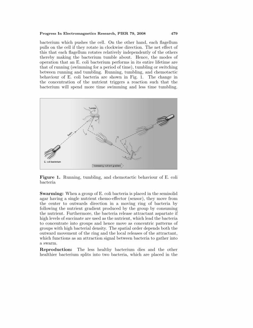
bacterium which pushes the cell. On the other hand, each flagellumpulls on the cell if they rotate in clockwise direction. The net effect ofthis that each flagellum rotates relatively independently of the othersthereby making the bacterium tumble about. Hence, the modes ofoperation that an E. coli bacterium performs in its entire lifetime arethat of running (swimming for a period of time), tumbling or switchingbetween running and tumbling. Running, tumbling, and chemotacticbehaviour of E. coli bacteria are shown in Fig. 1. The change inthe concentration of the nutrient triggers a reaction such that thebacterium will spend more time swimming and less time tumbling.
Figure 1. Running, tumbling, and chemotactic behaviour of E. colibacteria
Swarming: When a group of E. coli bacteria is placed in the semisolidagar having a single nutrient chemo-effector (sensor), they move fromthe center to outwards direction in a moving ring of bacteria byfollowing the nutrient gradient produced by the group by consumingthe nutrient. Furthermore, the bacteria release attractant aspartate ifhigh levels of succinate are used as the nutrient, which lead the bacteriato concentrate into groups and hence move as concentric patterns ofgroups with high bacterial density. The spatial order depends both theoutward movement of the ring and the local releases of the attractant,which functions as an attraction signal between bacteria to gather intoa swarm.Reproduction: The less healthy bacterium dies and the otherhealthier bacterium splits into two bacteria, which are placed in the
480 Guney and Basbug
same location. This method of reproduction keeps the population ofthe bacteria constant.Elimination and Dispersal: In the local environment of thebacteria, the lives of a bacteria population may change either gradually(e.g., via consumption of the nutrients) or suddenly as a result of someother influence. All the bacteria in a local region may be killed or agroup may be dispersed into a new location in the environment. It ispossible that they destroy the chemotactic progress. It is also possiblethat they assist the chemotaxis if the dispersal places the bacteria neargood food source.
3.2. Bacterial Foraging Algorithm
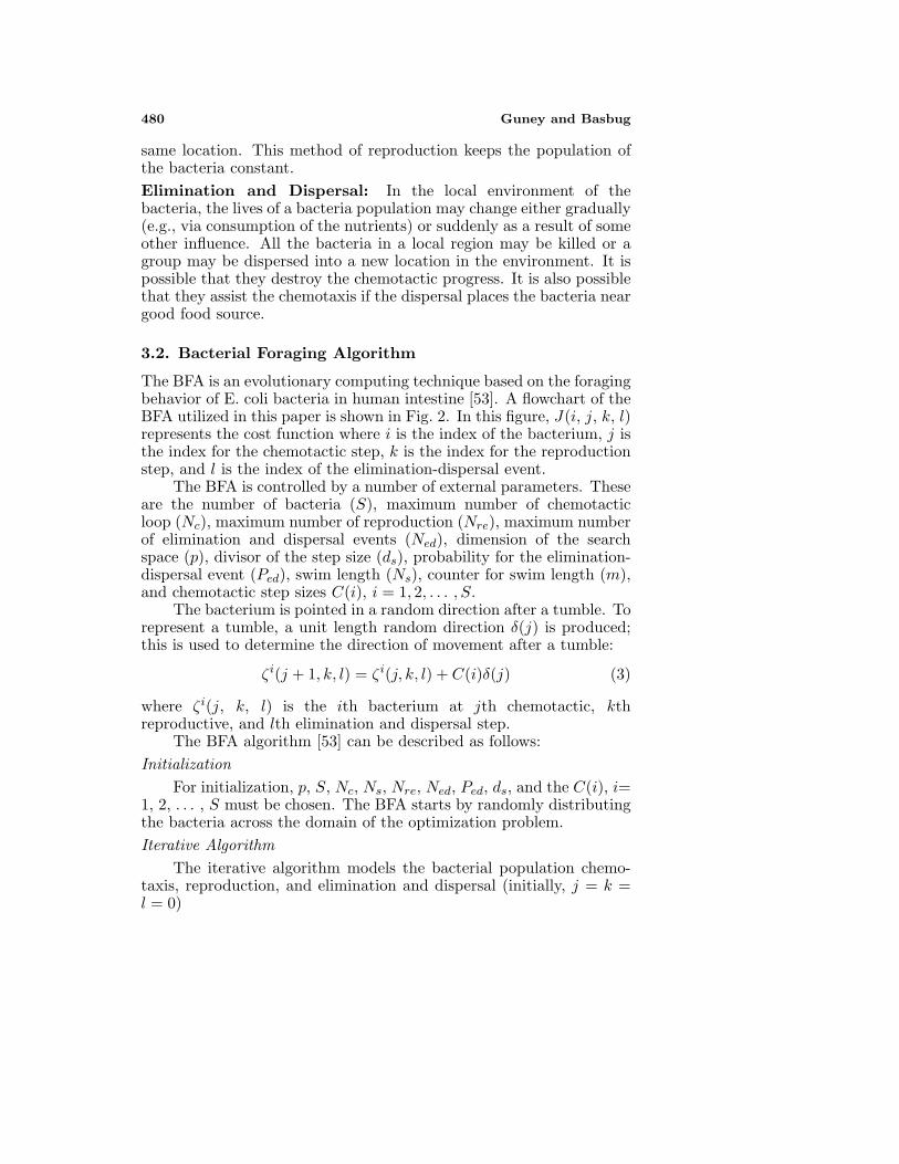
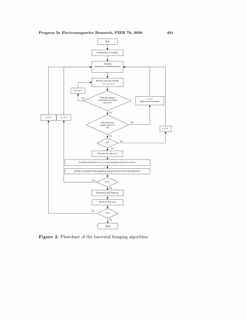
The BFA is an evolutionary computing technique based on the foragingbehavior of E. coli bacteria in human intestine [53]. A flowchart of theBFA utilized in this paper is shown in Fig. 2. In this figure, J(i, j, k, l)represents the cost function where i is the index of the bacterium, j isthe index for the chemotactic step, k is the index for the reproductionstep, and l is the index of the elimination-dispersal event.
The BFA is controlled by a number of external parameters. Theseare the number of bacteria (S), maximum number of chemotacticloop (Nc), maximum number of reproduction (Nre), maximum numberof elimination and dispersal events (Ned), dimension of the searchspace (p), divisor of the step size (ds), probability for the elimination-dispersal event (Ped), swim length (Ns), counter for swim length (m),and chemotactic step sizes C(i), i = 1, 2, . . . , S.
The bacterium is pointed in a random direction after a tumble. Torepresent a tumble, a unit length random direction δ(j) is produced;this is used to determine the direction of movement after a tumble:
ζi(j + 1, k, l) = ζi(j, k, l) + C(i)δ(j) (3)
where ζi(j, k, l) is the ith bacterium at jth chemotactic, kthreproductive, and lth elimination and dispersal step.
The BFA algorithm [53] can be described as follows:Initialization
For initialization, p, S, Nc, Ns, Nre, Ned, Ped, ds, and the C(i), i=1, 2, . . . , S must be chosen. The BFA starts by randomly distributingthe bacteria across the domain of the optimization problem.Iterative Algorithm
The iterative algorithm models the bacterial population chemo-taxis, reproduction, and elimination and dispersal (initially, j = k =l = 0)
Progress In Electromagnetics Research, PIER 79, 2008 481
Start
Initialization of variables
(Tumble) Determine a random direction
Run one step and calculate
J (i, j+1, k, l)
Does the nutrient concentration increase
and m<Ns
Did all bacteria tumble and swim
i<S
j<Nc
Calculate total fitness (Jhealth) of each bacterium and sort in reverse.
Kill the second half of the population and split the first half of the population.
k<Nre
Elimination and Dispersal
l<Ned
Stop
Decrease the step sizes
Yes
Yes
No
No
No
Yes
Yes
No
Yes
No
i = i+1 (Select next bacterium)
j = j+1
k = k+1l = l+1
Reset the step sizes
m = m+1
Figure 2. Flowchart of the bacterial foraging algorithm.
482 Guney and Basbug
1) Elimination-dispersal loop: l = l + 12) Reproduction loop: k = k + 13) Chemotaxis loop: j = j + 1
a) For i = 1, 2, . . . , S, take a chemotactic step for bacterium ias follows.
b) Compute J(i, j, k, l).c) Let Jlast = J(i, j, k, l) to save this value since we may find a
better cost via a run.d) Tumble: Generate a random vector ∆(i) ∈ �p with each
element ∆m(i), m= 1, 2, . . . , p, a random number on [−1,1].
e) Move: Let
ζi(j + 1, k, l) = ζi(j, k, l) + C(i)∆(i)√
∆T (i)∆(i)
This results in a step of size C(i) in the direction of the tumblefor bacterium i.
f) Calculate J(i, j+1, k, l).g) Swim (note that we use an approximation since we decide
swimming behavior of each cell as if the bacteria numbered{1, 2, . . . , i} have moved and {i+1, i+2, . . . , S} have not;this is much simpler to simulate than simultaneous decisionsabout swimming and tumbling by all bacteria at the sametime):i) Let m = 0 (counter for swim length).ii) While m < Ns (if have not climbed down too long)
• Let m = m + 1• If J(i, j+1, k, l) < Jlast (if doing better), let Jlast =
J(i, j+1, k, l) and let
ζi(j + 1, k, l) = ζi(j + 1, k, l) + C(i)∆(i)√
∆T (i)∆(i)
and use this ζi(j + 1, k, l) to compute the new J(i,j+1, k, l) as we did in f).
• Else, let m = Ns. This is the end of the whilestatement.
h) Go to next bacterium (i+1) if i �= S (i.e., go to b) to processthe next bacterium).
4) If j < Nc, go to step 3. In this case, continue chemotaxis, sincethe life of the bacteria is not over.
5) Decrease the step sizes C(i), i = 1, 2, . . . , S by dividing ds
Progress In Electromagnetics Research, PIER 79, 2008 483
6) Reproduction:a) For the given k and l, and for each i = 1, 2, . . . , S, let
J ihealth =
Nc+1∑j=1
J(i, j, k, l)
be the health of bacterium i (a measure of how manynutrients it got over its lifetime and how successful it was atavoiding noxious substances). Sort bacteria and chemotacticparameters C(i) in order of ascending cost Jhealth.
b) The Sr bacteria with the highest Jhealth values die and theother Sr bacteria with the best values split (and the copiesthat are made are placed at the same locations as theirparent).
7) If k < Nre, go to step 2. In this case, we have not reachedthe number of specified reproduction steps, so we start the nextgeneration in the chemotactic loop.
8) Elimination-dispersal: For i = 1, 2, . . . , S, with probability Ped,eliminate and disperse each bacterium (this keeps the number ofbacteria in the population constant). To do this, if you eliminatea bacterium, simply disperse one to a random location on theoptimization domain.
9) Reset the step sizes C(i), i = 1, 2, . . . , S to the initial values.10) If l < Ned then go to step 1; otherwise end.
The details on the BFA can be found in [53]. In this paper, theBFA described above is successfully used to optimize the antenna arrayelement amplitudes to exhibit an array pattern with the imposed single,multiple and broad nulls.
4. NUMERICAL RESULTS
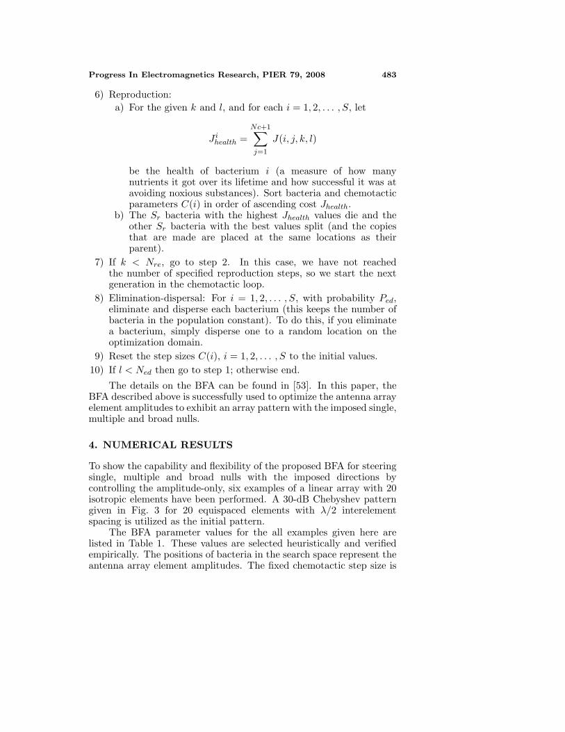
To show the capability and flexibility of the proposed BFA for steeringsingle, multiple and broad nulls with the imposed directions bycontrolling the amplitude-only, six examples of a linear array with 20isotropic elements have been performed. A 30-dB Chebyshev patterngiven in Fig. 3 for 20 equispaced elements with λ/2 interelementspacing is utilized as the initial pattern.
The BFA parameter values for the all examples given here arelisted in Table 1. These values are selected heuristically and verifiedempirically. The positions of bacteria in the search space represent theantenna array element amplitudes. The fixed chemotactic step size is
484 Guney and Basbug
θ (degree)
-90 -80 -70 -60 -50 -40 -30 -20 -10 0 10 20 30 40 50 60 70 80 90
Arr
ay P
atte
rn (
dB)
-110
-100
-90
-80
-70
-60
-50
-40
-30
-20
-10
0
Figure 3. The initial 30-dB Chebyshev pattern.
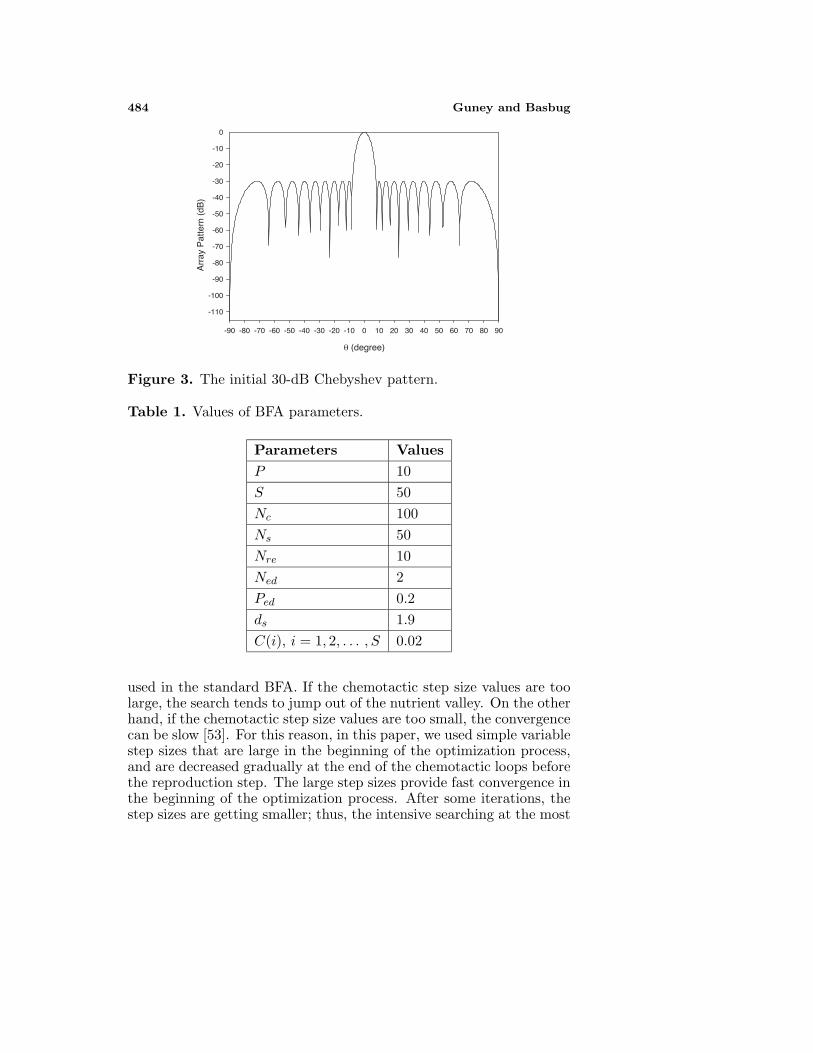
Table 1. Values of BFA parameters.
Parameters ValuesP 10S 50Nc 100Ns 50Nre 10Ned 2Ped 0.2ds 1.9C(i), i = 1, 2, . . . , S 0.02
used in the standard BFA. If the chemotactic step size values are toolarge, the search tends to jump out of the nutrient valley. On the otherhand, if the chemotactic step size values are too small, the convergencecan be slow [53]. For this reason, in this paper, we used simple variablestep sizes that are large in the beginning of the optimization process,and are decreased gradually at the end of the chemotactic loops beforethe reproduction step. The large step sizes provide fast convergence inthe beginning of the optimization process. After some iterations, thestep sizes are getting smaller; thus, the intensive searching at the most
Progress In Electromagnetics Research, PIER 79, 2008 485
promising region of the search space can be done.The simulation results are obtained within 1–2 minutes on a
personal computer with a Core Duo processor running at 1600 MHzwith 1 GB RAM. This is sufficient to produce satisfactory patterns withthe desired performance on the average. The computation time can besignificantly reduced by using faster computer systems. The BFA canalso be implemented in real time by using state-of-the art hardwaredevices, such as FPGAs (Field Programmable Gate Array). In thisway, the computation time of the system is limited only by the responsetime of the FPGA, which is in the order of a few microseconds. C++programming language was used for implementation of the algorithm.We have run the program for two times to obtain the best result.
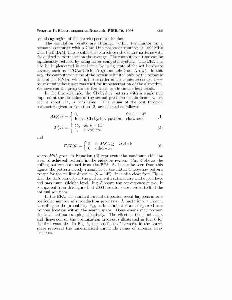
In the first example, the Chebyshev pattern with a single nullimposed at the direction of the second peak from main beam, whichoccurs about 14◦, is considered. The values of the cost functionparameters given in Equation (2) are selected as follows:
AFd(θ) ={
0, for θ = 14◦Initial Chebyshev pattern, elsewhere (4)
W (θ) ={
55, for θ = 14◦1, elsewhere (5)
and
ESL(θ) ={
5, if MSL ≥ −28.4 dB0, otherwise (6)
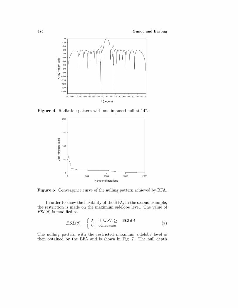
where MSL given in Equation (6) represents the maximum sidelobelevel of achieved pattern in the sidelobe region. Fig. 4 shows thenulling pattern obtained from the BFA. As it can be seen from thisfigure, the pattern closely resembles to the initial Chebyshev patternexcept for the nulling direction (θ = 14◦). It is also clear from Fig. 4that the BFA can obtain the pattern with satisfactory null depth leveland maximum sidelobe level. Fig. 5 shows the convergence curve. Itis apparent from this figure that 2000 iterations are needed to find theoptimal solutions.
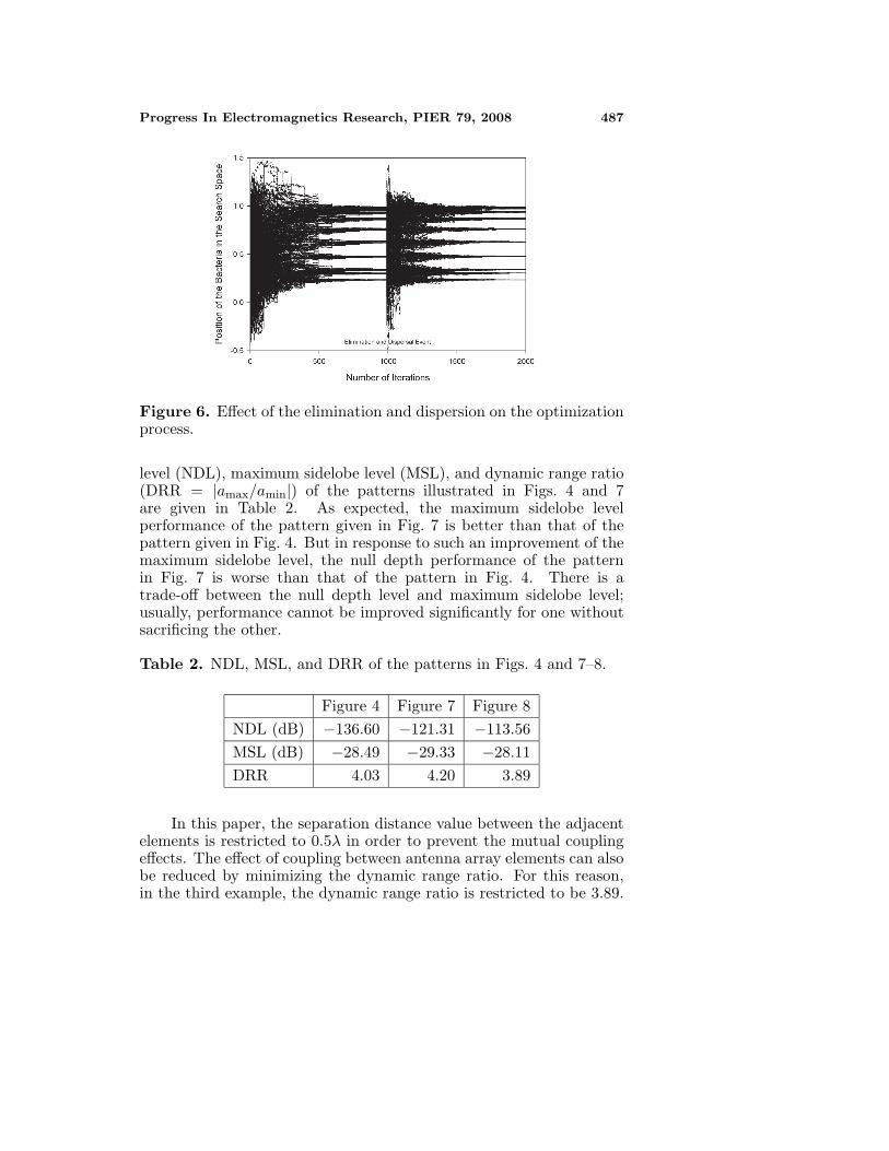
In the BFA, the elimination and dispersion event happens after aparticular number of reproduction processes. A bacterium is chosen,according to the probability Ped, to be eliminated and dispersed to arandom location within the search space. These events may preventthe local optima trapping effectively. The effect of the eliminationand dispersion on the optimization process is illustrated in Fig. 6 forthe first example. In Fig. 6, the positions of bacteria in the searchspace represent the unnormalized amplitude values of antenna arrayelements.
486 Guney and Basbug
θ (degree)
-90 -80 -70 -60 -50 -40 -30 -20 -10 0 10 20 30 40 50 60 70 80 90
Arr
ay P
atte
rn (
dB)
-140
-130
-120
-110
-100
-90
-80
-70
-60
-50
-40
-30
-20
-10
0
Figure 4. Radiation pattern with one imposed null at 14◦.
Number of Iterations
0 500 1000 1500 2000
Cos
t Fun
ctio
n V
alue
0
50
100
150
200
Figure 5. Convergence curve of the nulling pattern achieved by BFA.
In order to show the flexibility of the BFA, in the second example,the restriction is made on the maximum sidelobe level. The value ofESL(θ) is modified as
ESL(θ) ={
5, if MSL ≥ −29.3 dB0, otherwise (7)
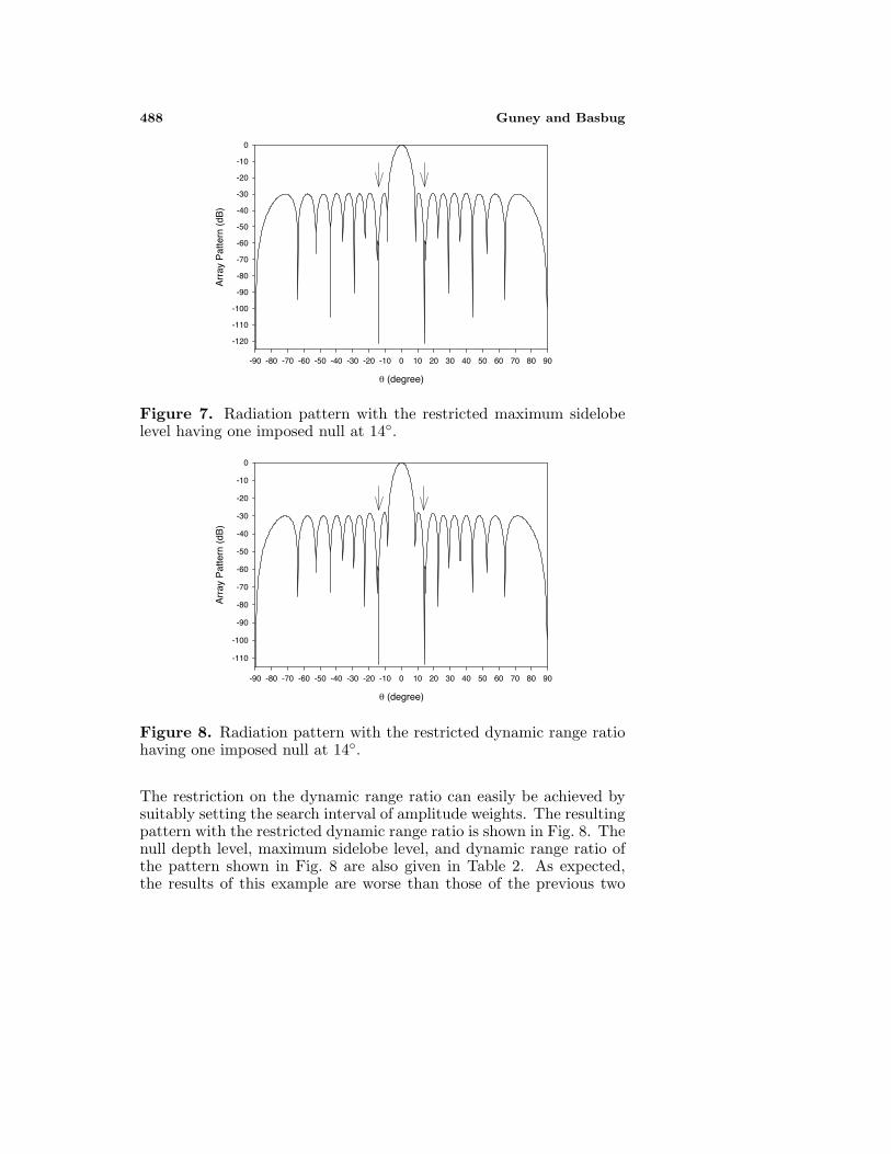
The nulling pattern with the restricted maximum sidelobe level isthen obtained by the BFA and is shown in Fig. 7. The null depth
Progress In Electromagnetics Research, PIER 79, 2008 487
Figure 6. Effect of the elimination and dispersion on the optimizationprocess.
level (NDL), maximum sidelobe level (MSL), and dynamic range ratio(DRR = |amax/amin|) of the patterns illustrated in Figs. 4 and 7are given in Table 2. As expected, the maximum sidelobe levelperformance of the pattern given in Fig. 7 is better than that of thepattern given in Fig. 4. But in response to such an improvement of themaximum sidelobe level, the null depth performance of the patternin Fig. 7 is worse than that of the pattern in Fig. 4. There is atrade-off between the null depth level and maximum sidelobe level;usually, performance cannot be improved significantly for one withoutsacrificing the other.
Table 2. NDL, MSL, and DRR of the patterns in Figs. 4 and 7–8.
Figure 4 Figure 7 Figure 8NDL (dB) −136.60 −121.31 −113.56MSL (dB) −28.49 −29.33 −28.11DRR 4.03 4.20 3.89
In this paper, the separation distance value between the adjacentelements is restricted to 0.5λ in order to prevent the mutual couplingeffects. The effect of coupling between antenna array elements can alsobe reduced by minimizing the dynamic range ratio. For this reason,in the third example, the dynamic range ratio is restricted to be 3.89.
488 Guney and Basbug
θ (degree)
-90 -80 -70 -60 -50 -40 -30 -20 -10 0 10 20 30 40 50 60 70 80 90
Arr
ay P
atte
rn (
dB)
-120
-110
-100
-90
-80
-70
-60
-50
-40
-30
-20
-10
0
Figure 7. Radiation pattern with the restricted maximum sidelobelevel having one imposed null at 14◦.
θ (degree)
-90 -80 -70 -60 -50 -40 -30 -20 -10 0 10 20 30 40 50 60 70 80 90
Arr
ay P
atte
rn (
dB)
-110
-100
-90
-80
-70
-60
-50
-40
-30
-20
-10
0
Figure 8. Radiation pattern with the restricted dynamic range ratiohaving one imposed null at 14◦.
The restriction on the dynamic range ratio can easily be achieved bysuitably setting the search interval of amplitude weights. The resultingpattern with the restricted dynamic range ratio is shown in Fig. 8. Thenull depth level, maximum sidelobe level, and dynamic range ratio ofthe pattern shown in Fig. 8 are also given in Table 2. As expected,the results of this example are worse than those of the previous two
Progress In Electromagnetics Research, PIER 79, 2008 489
examples because the smaller amplitude range means smaller degreesof freedom for the solution space hence worse sidelobe and null depthperformance. The results obtained here illustrate that the null depthlevel, maximum sidelobe level, and dynamic range ratio of the nullingpattern can easily be controlled by using BFA. The antenna designershould make a trade-off between the achievable and the desired pattern.
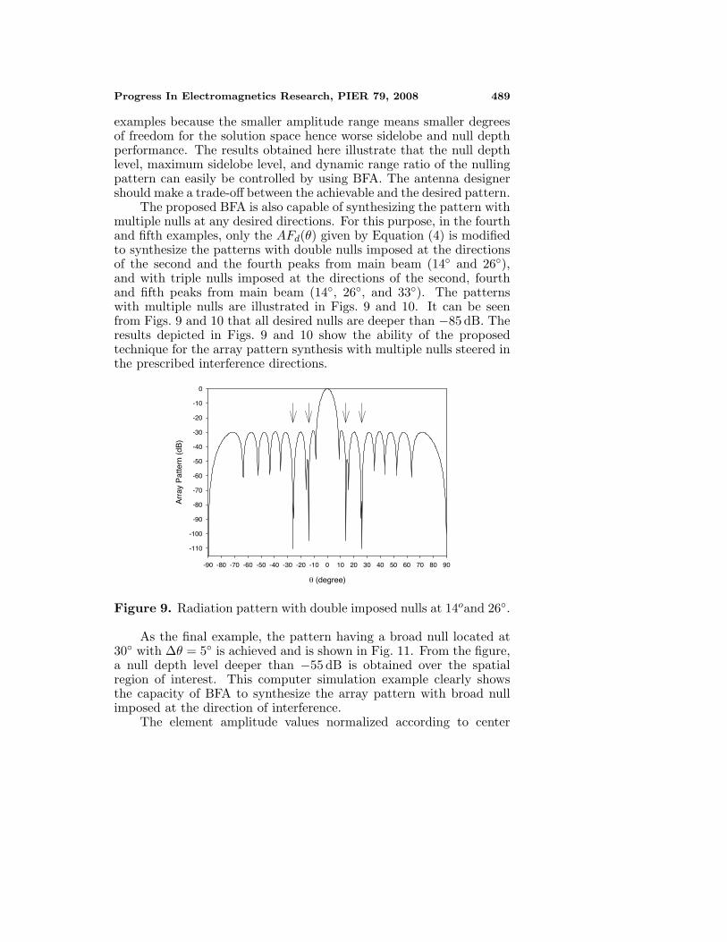
The proposed BFA is also capable of synthesizing the pattern withmultiple nulls at any desired directions. For this purpose, in the fourthand fifth examples, only the AFd(θ) given by Equation (4) is modifiedto synthesize the patterns with double nulls imposed at the directionsof the second and the fourth peaks from main beam (14◦ and 26◦),and with triple nulls imposed at the directions of the second, fourthand fifth peaks from main beam (14◦, 26◦, and 33◦). The patternswith multiple nulls are illustrated in Figs. 9 and 10. It can be seenfrom Figs. 9 and 10 that all desired nulls are deeper than −85 dB. Theresults depicted in Figs. 9 and 10 show the ability of the proposedtechnique for the array pattern synthesis with multiple nulls steered inthe prescribed interference directions.
θ (degree)
-90 -80 -70 -60 -50 -40 -30 -20 -10 0 10 20 30 40 50 60 70 80 90
Arr
ay P
atte
rn (
dB)
-110
-100
-90
-80
-70
-60
-50
-40
-30
-20
-10
0
Figure 9. Radiation pattern with double imposed nulls at 14oand 26◦.
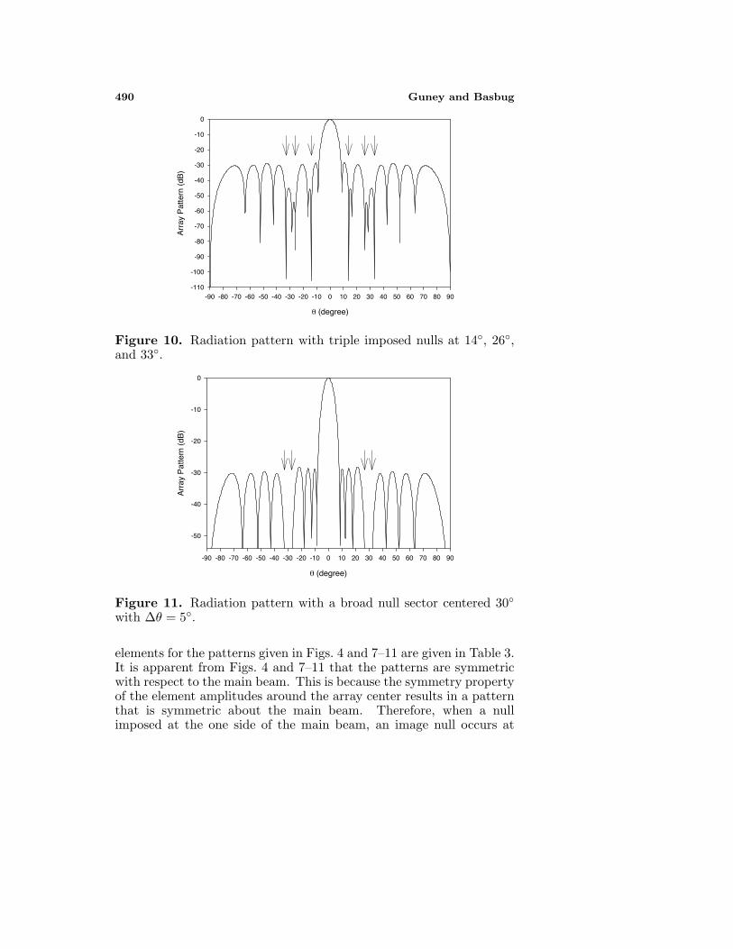
As the final example, the pattern having a broad null located at30◦ with ∆θ = 5◦ is achieved and is shown in Fig. 11. From the figure,a null depth level deeper than −55 dB is obtained over the spatialregion of interest. This computer simulation example clearly showsthe capacity of BFA to synthesize the array pattern with broad nullimposed at the direction of interference.
The element amplitude values normalized according to center
490 Guney and Basbug
θ (degree)
-90 -80 -70 -60 -50 -40 -30 -20 -10 0 10 20 30 40 50 60 70 80 90
Arr
ay P
atte
rn (
dB)
-110
-100
-90
-80
-70
-60
-50
-40
-30
-20
-10
0
Figure 10. Radiation pattern with triple imposed nulls at 14◦, 26◦,and 33◦.
θ (degree)
-90 -80 -70 -60 -50 -40 -30 -20 -10 0 10 20 30 40 50 60 70 80 90
Arr
ay P
atte
rn (
dB)
-50
-40
-30
-20
-10
0
Figure 11. Radiation pattern with a broad null sector centered 30◦with ∆θ = 5◦.
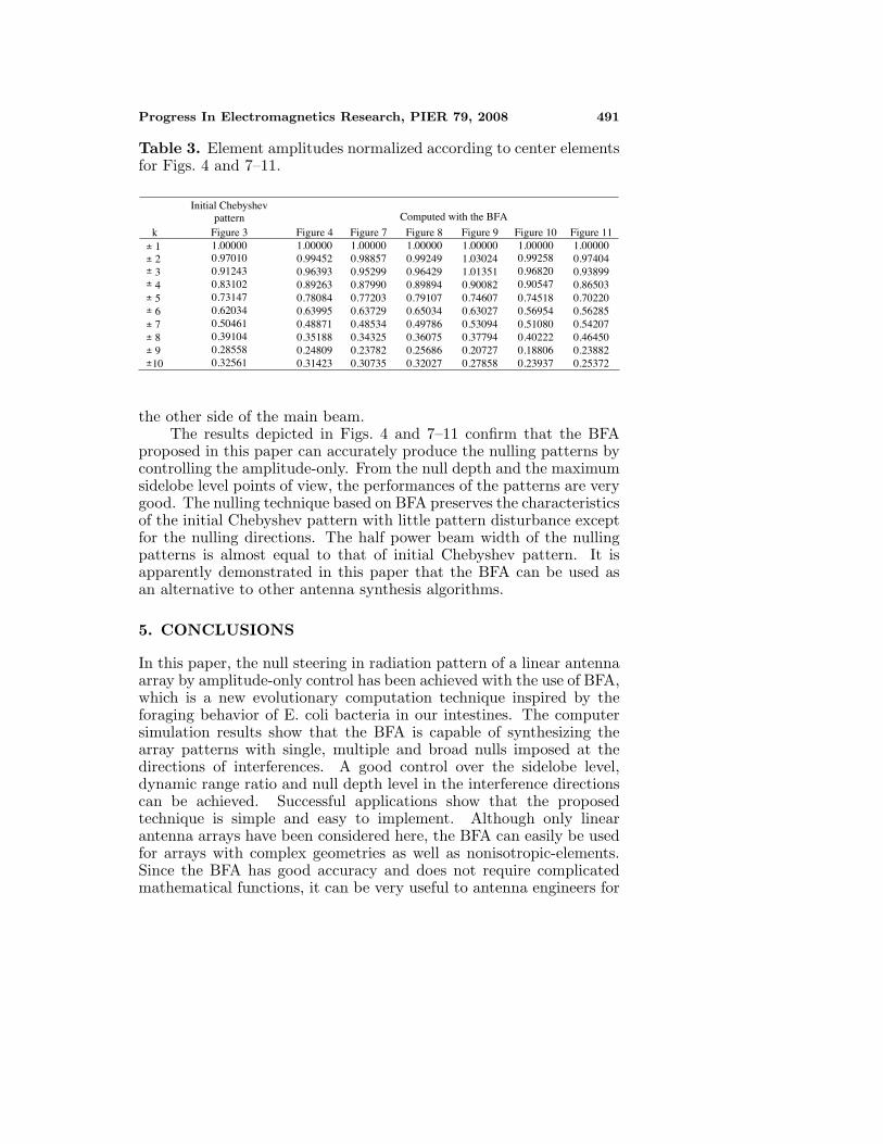
elements for the patterns given in Figs. 4 and 7–11 are given in Table 3.It is apparent from Figs. 4 and 7–11 that the patterns are symmetricwith respect to the main beam. This is because the symmetry propertyof the element amplitudes around the array center results in a patternthat is symmetric about the main beam. Therefore, when a nullimposed at the one side of the main beam, an image null occurs at
Progress In Electromagnetics Research, PIER 79, 2008 491
Table 3. Element amplitudes normalized according to center elementsfor Figs. 4 and 7–11.
Initial Chebyshev pattern Computed with the BFA
k Figure 3 Figure 4 Figure 7 Figure 8 Figure 9 Figure 10 Figure 11 1 1.00000 1.00000 1.00000 1.00000 1.00000 1.00000 1.00000 2 0.97010 0.99452 0.98857 0.99249 1.03024 0.99258 0.97404 3 0.91243 0.96393 0.95299 0.96429 1.01351 0.96820 0.93899 4 0.83102 0.89263 0.87990 0.89894 0.90082 0.90547 0.86503 5 0.73147 0.78084 0.77203 0.79107 0.74607 0.74518 0.70220 6 0.62034 0.63995 0.63729 0.65034 0.63027 0.56954 0.56285 7 0.50461 0.48871 0.48534 0.49786 0.53094 0.51080 0.54207 8 0.39104 0.35188 0.34325 0.36075 0.37794 0.40222 0.46450 9 0.28558 0.24809 0.23782 0.25686 0.20727 0.18806 0.23882
10 0.32561 0.31423 0.30735 0.32027 0.27858 0.23937 0.25372
±±±±±±±±±±
the other side of the main beam.The results depicted in Figs. 4 and 7–11 confirm that the BFA
proposed in this paper can accurately produce the nulling patterns bycontrolling the amplitude-only. From the null depth and the maximumsidelobe level points of view, the performances of the patterns are verygood. The nulling technique based on BFA preserves the characteristicsof the initial Chebyshev pattern with little pattern disturbance exceptfor the nulling directions. The half power beam width of the nullingpatterns is almost equal to that of initial Chebyshev pattern. It isapparently demonstrated in this paper that the BFA can be used asan alternative to other antenna synthesis algorithms.
5. CONCLUSIONS
In this paper, the null steering in radiation pattern of a linear antennaarray by amplitude-only control has been achieved with the use of BFA,which is a new evolutionary computation technique inspired by theforaging behavior of E. coli bacteria in our intestines. The computersimulation results show that the BFA is capable of synthesizing thearray patterns with single, multiple and broad nulls imposed at thedirections of interferences. A good control over the sidelobe level,dynamic range ratio and null depth level in the interference directionscan be achieved. Successful applications show that the proposedtechnique is simple and easy to implement. Although only linearantenna arrays have been considered here, the BFA can easily be usedfor arrays with complex geometries as well as nonisotropic-elements.Since the BFA has good accuracy and does not require complicatedmathematical functions, it can be very useful to antenna engineers for
492 Guney and Basbug
the pattern synthesis of antenna arrays. As an evolutionary algorithm,the BFA will most likely be an increasingly attractive alternative, inthe electromagnetics and antennas community, to other evolutionaryalgorithms.
REFERENCES
1. Steyskal, H., R. A. Shore, and R. L. Haupt, “Methods for nullcontrol and their effects on the radiation pattern,” IEEE Trans.Antennas Propagat., Vol. 34, 404–409, 1986.
2. Er, M. H., “Linear antenna array pattern synthesis with prescribedbroad nulls,” IEEE Trans. Antennas Propagat., Vol. 38, 1496–1498, 1990.
3. Ibrahim, H. M., “Null steering by real-weight control — A methodof decoupling the weights,” IEEE Trans. Antennas Propagat.,Vol. 39, 1648–1650, 1991.
4. Liao, W. P. and F. L. Chu, “Array pattern synthesis with nullsteering using genetic algorithms by controlling only the currentamplitudes,” Int. J. Electronics, Vol. 86, 445–457, 1999.
5. Shore, R. A., “Nulling at symmetric pattern location with phase-only weight control,” IEEE Trans. Antennas Propagat., Vol. 32,530–533, 1984.
6. Haupt, R. L., “Phase-only adaptive nulling with a geneticalgorithm,” IEEE Trans. Antennas Propagat., Vol. 45, 1009–1015,1997.
7. Ismail, T. H. and M. M. Dawoud, “Null steering in phased arraysby controlling the element positions,” IEEE Trans. AntennasPropagat., Vol. 39, 1561–1566, 1991.
8. Tennant, A., M. M. Dawoud, and A. P. Anderson, “Arraypattern nulling by element position perturbations using a geneticalgorithm,” Electronics Letters, Vol. 30, 174–176, 1994.
9. Liao, W. P. and F. L. Chu, “Array pattern nulling by phase andposition perturbations with the use of the genetic algorithm,”Microwave and Optical Technology Letters, Vol. 15, 251–256, 1997.
10. Hejres, J. A., “Null steering in phased arrays by controlling thepositions of selected elements,” IEEE Trans. Antennas Propagat.,Vol. 52, 2891–2895, 2004.
11. Abu-Al-Nadi, D. I., T. H. Ismail, and M. J. Mismar, “Interferencesuppression by element position control of phased arrays using LMalgorithm,” Int. J. Electron. Commun., Vol. 60, 151–158, 2006.
12. Ares, F., J. A. Rodriguez, E. Villanueva, and S. R. Rengarajan,
Progress In Electromagnetics Research, PIER 79, 2008 493
“Genetic algorithms in the design and optimization of antennaarray patterns,” IEEE Trans. Antennas Propagat., Vol. 47, 506–510, 1999.
13. Guney, K. and A. Akdagli, “Null steering of linear antennaarrays using modified tabu search algorithm,” Progress InElectromagnetics Research, PIER 33, 167–182, 2001.
14. Karaboga, N., K. Guney, and A. Akdagli, “Null steering of linearantenna arrays by using modified touring ant colony optimizationalgorithm,” Int. J. RF and Microwave Computer Aided Eng.,Vol. 12, 375–383, 2002.
15. Akdagli, A., K. Guney, and D. Karaboga, “Pattern nulling oflinear antenna arrays by controlling only the element positionswith the use of improved touring ant colony optimizationalgorithm,” Journal of Electromagnetic Waves and Applications,Vol. 16, 1423–1441, 2002.
16. Karaboga, D., K. Guney, and A. Akdagli, “Antenna array patternnulling by controlling both the amplitude and the phase usingmodified touring ant colony optimisation algorithm,” Int. J.Electronics, Vol. 91, 241–251, 2004.
17. Akdagli, A. and K. Guney, “Null steering of linear antenna arraysby phase perturbations using modified tabu search algorithm,”J. Communications Technology and Electronics, Vol. 49, 37–42,2004.
18. Khodier, M. M. and C. G. Christodoulou, “Linear array geometrysynthesis with minimum sidelobe level and null control usingparticle swarm optimization,” IEEE Trans. Antennas Propagat.,Vol. 53, 2674–2679, 2005.
19. Yang, S. W., Y. B. Gan, and A. Y. Qing, “Antenna-array patternnulling using a differential evolution algorithm,” Int. J. RF andMicrowave Computer Aided Eng., Vol. 14, 57–63, 2004.
20. Chung, Y. C. and R. L. Haupt, “Amplitude and phase adaptivenulling with a genetic algorithm,” Journal of ElectromagneticWaves and Applications, Vol. 14, 631–649, 2000.
21. Lu, Y. and B. K. Yeo, “Adaptive wide null steering for digitalbeamforming array with the complex coded genetic algorithm,”IEEE Int. Conf. Phased Array Systems and Technology, 557–560,Dana Point CA, USA, 2000.
22. Mouhamadou, M., P. Vaudon, and M. Rammal, “Smartantenna array patterns synthesis: Null steering and multi-userbeamforming by phase control,” Progress In ElectromagneticsResearch, PIER 60, 95–106, 2006.
494 Guney and Basbug
23. Babayigit, B., A. Akdagli, and K. Guney, “A clonal selectionalgorithm for null synthesizing of linear antenna arrays byamplitude control,” Journal of Electromagnetic Waves andApplications, Vol. 20, 1007–1020, 2006.
24. Mouhamadou, M., P. Armand, P. Vaudon, and M. Rammal,“Interference supression of the linear antenna arrays controlled byphase with use of SQP algorithm,” Progress In ElectromagneticsResearch, PIER 59, 251–265, 2006.
25. Guney, K. and M. Onay, “Amplitude-only pattern nulling oflinear antenna arrays with the use of bees algorithm,” ProgressIn Electromagnetics Research, PIER 70, 21–36, 2007.
26. Guney, K. and M. Onay, “Bees algorithm for null synthesizing oflinear antenna arrays by controlling only the element positions,”Neural Network World, Vol. 16, 153–169, 2007.
27. Yan, K. K. and Y. L. Lu, “Sidelobe reduction in array-pattern synthesis using genetic algorithm,” IEEE Trans. AntennasPropagat., Vol. 45, 1117–1122, 1997.
28. Baskar, S., A. Alphones, and P. N. Suganthan, “Genetic-algorithm-based design of a reconfigurable antenna array withdiscrete phase shifters,” Microwave and Optical TechnologyLetters, Vol. 45, 461–465, 2005.
29. Mitilineos, S. A., S. C. A. Thomopoulos, and C. N. Capsalis,“Genetic design of dual-band, switched-beam dipole arrays,with elements failure correction, retaining constant excitationcoefficients,” J. Electromagnetic Waves and Applications, Vol. 20,1925–1942, 2006.
30. Ayestaran, R. G., J. Laviada, and F. Las-Heras, “Synthesis ofpassive-dipole arrays with a genetic-neural hybrid method,” J.Electromagnetic Waves and Applications, Vol. 20, 2123–2135,2006.
31. Jin, J., H. L. Wang, W. M. Zhu, and Y. Z. Liu, “Arraypatterns synthesizing using genetic algorithm,” Progress InElectromagnetics Research Symposium, 64–68, Cambridge, USA,March 2006.
32. Mahanti, G. K., S. Das, and A. Chakraborty, “Design ofphase-differentiated reconfigurable array antennas with minimumdynamic range ratio,” IEEE Antennas and Wireless Propagat.Letters, Vol. 5, 262–264, 2006.
33. Tonn, D. A. and R. Bansal, “Reduction of sidelobe levelsin interrupted phased array antennas by means of a geneticalgorithm,” Int. J. RF and Microwave Computer Aided Eng.,Vol. 17, 134–141, 2007.
Progress In Electromagnetics Research, PIER 79, 2008 495
34. Mahanti, G. K., N. Pathak, and P. Mahanti, “Synthesis ofthinned linear antenna arrays with fixed sidelobe level using real-coded genetic algorithm,” Progress In Electromagnetics Research,PIER 75, 319–328, 2007.
35. Mahanti, G. K., A. Chakrabarty, and S. Das, “Phase-onlyand amplitude-phase synthesis of dual-pattern linear antennaarrays using floating-point genetic algorithms,” Progress InElectromagnetics Research, PIER 68, 247–259, 2007.
36. Mahanti, G. K., A. Chakrabarty, and S. Das, “Design offully digital controlled reconfigurable array antennas with fixeddynamic range ratio,” Journal of Electromagnetic Waves andApplications, Vol. 21, 97–106, 2007.
37. Xu, Z., H. Li, Q. Z. Liu, and J. Y. Li, “Pattern synthesisof conformal antenna array by the hybrid genetic algorithm,”Progress In Electromagnetics Research, PIER 79, 75–90, 2008.
38. Akdagli, A., K. Guney, and D. Karaboga, “Touring ant colonyoptimization algorithm for shaped-beam pattern synthesis oflinear antenna arrays,” Electromagnetics, Vol. 26, 615–628, 2006.
39. Hosseini, S. A. and Z. Atlasbaf, “Optimization of side lobe leveland fixing quasi-nulls in both of the sum and difference patternsby using continuous ant colony optimization (ACO) method,”Progress In Electromagnetics Research, PIER 79, 321–337, 2008.
40. Gies, D. and Y. Rahmat-Samii, “Particle swarm optimization forreconfigurable phase-differentiated array design,” Microwave andOptical Technology Letters, Vol. 38, 168–175, 2003.
41. Boeringer, D. W. and D. H. Werner, “Particle swarm optimizationversus genetic algorithms for phased array synthesis,” IEEETrans. Antennas Propagat., Vol. 52, 771–779, 2004.
42. Lee, K. C. and J. Y. Jhang, “Application of particle swarmalgorithm to the optimization of unequally spaced antennaarrays,” Journal of Electromagnetic Waves and Applications,Vol. 20, 2001–2012, 2006.
43. Chen, T. B., Y. L. Dong, Y. C. Jiao, and F. S. Zhang, “Synthesis ofcircular antenna array using crossed particle swarm optimizationalgorithm,” Journal of Electromagnetic Waves and Applications,Vol. 20, 1785–1795, 2006.
44. Mahmoud, K. R., M. El-Adawy, S. M. M. Ibrahem, R. Bansal, andS. H. Zainud-Deen, “A comparison between circular and hexagonalarray geometries for smart antenna systems using particle swarmoptimization algorithm,” Progress In Electromagnetics Research,PIER 72, 75–90, 2007.
496 Guney and Basbug
45. Jin, N. B. and Y. Rahmat-Samii, “Advances in particle swarmoptimization for antenna designs: Real-number, binary, single-objective and multiobjective implementations,” IEEE Trans.Antennas Propagat., Vol. 55, 556–567, 2007.
46. Mikki, S. M. and A. A. Kishk, “Physical theory for particle swarmoptimization,” Progress In Electromagnetics Research, PIER 75,171–207, 2007.
47. Akdagli, A. and K. Guney, “Shaped-beam pattern synthesisof equally and unequally spaced linear antenna arrays usinga modified tabu search algorithm,” Microwave and OpticalTechnology Letters, Vol. 36, 16–20, 2003.
48. Yang, S. W., Y. B. Gan, and A. Y. Qing, “Sideband suppressionin time-modulated linear arrays by the differential evolutionalgorithm,” IEEE Antennas and Wireless Propagation Lett.,Vol. 1, 173–175, 2002.
49. Kurup, D. G., M. Himdi, and A. Rydberg, “Synthesis of uniformamplitude unequally spaced antenna arrays using the differentialevolution algorithm,” IEEE Trans. Antennas Propagat., Vol. 51,2210–2217, 2003.
50. Yang, S. W., Z. P. Nie, and Y. J. Wu, “A practical arraypattern synthesis approach including mutual coupling effects,”Electromagnetics, Vol. 27, 53–63, 2007.
51. Guney, K., A. Akdagli, and B. Babayigit, “Shaped-beam patternsynthesis of linear antenna arrays with the use of a clonal selectionalgorithm,” Neural Network World, Vol. 16, 489–501, 2006.
52. Akdagli, A., K. Guney, and B. Babayigit, “Clonal selectionalgorithm for design of reconfigurable antenna array withdiscrete phase shifters,” Journal of Electromagnetic Waves andApplications, Vol. 21, 215–227, 2007.
53. Passino, K. M., “Biomimicry of bacterial foraging,” IEEE ControlSystems Magazine, Vol. 22, 52–67, 2002.
54. Mishra, S., “Hybrid least-square adaptive bacterial foragingstrategy for harmonic estimation,” IEE Proc. - GenerationTransmission and Distribution, Vol. 152, 379–389, 2005.
55. Mishra, S., “A hybrid least square-fuzzy bacterial foragingstrategy for harmonic estimation,” IEEE Trans. EvolutionaryComputation, Vol. 9, 61–73, 2005.
56. Lin, W. and P. X. Liu, “Hammerstein model identification basedon bacterial foraging,” Electronics Letters, Vol. 42, 1332–1334,2006.
Progress In Electromagnetics Research, PIER 79, 2008 497
57. Kim, D. H. and J. H. Cho, “A biologically inspired intelligent PIDcontroller tuning for AVR systems,” Int. J. Control Automationand Systems, Vol. 4, 624–636, 2006.
58. Niu, B., Y. Zhu, X. He, and X. Zeng, “Optimum design of PIDcontrollers using only a germ of intelligence,” 6th World Congresson Intelligent Control and Automation, 3584–3588, Dalian, China,June 2006.
59. Tang, W. J., M. S. Li, S. He, Q. H. Wu, and J. R. Saunders,“Optimal power flow with dynamic loads using bacterial foragingalgorithm,” 2006 Int. Conf. on Power System Technology, 1–5,Chongqing, China, October 2006.
60. Majhi, B. and G. Panda, “Recovery of digital informationusing bacterial foraging optimization based nonlinear channelequalizers,” First Int. Conf. on Digital Information Management,367–372, Bangalore, India, Dec. 2006.
61. Ulagammai, M., P. Venkatesh, P. S. Kannan, and N. P. Padhy,“Application of bacterial foraging technique trained artificial andwavelet neural networks in load forecasting,” Neurocomputing,Vol. 70, 2659–2667, 2007.
62. Kim, D. H., A. Abraham, and J. H. Cho, “A hybridgenetic algorithm and bacterial foraging approach for globaloptimization,” Information Sciences, Vol. 177, 3918–3937, 2007.
63. Mishra, S. and C. N. Bhende, “Bacterial foraging technique-basedoptimized active power filter for load compensation,” IEEE Trans.Power Delivery, Vol. 22, 457–465, 2007.


