Embed Size (px)
Citation preview
Mobile Netw Appl (2011) 16:35–45DOI 10.1007/s11036-009-0214-1
On the Deployment of Antenna Elements in GeneralizedMulti-User Distributed Antenna Systems
Wei Feng · Yunzhou Li · Jiansong Gan ·Shidong Zhou · Jing Wang · Minghua Xia
Published online: 3 October 2009© Springer Science + Business Media, LLC 2009
Abstract In this paper, we focus on a generalized multi-user distributed antenna system (DAS), where the an-tenna elements (AEs) are divided into antenna clustersand the antenna clusters are randomly deployed in thecoverage area. The mobile terminals equipped with MAEs each are supposed to be uniformly distributedin the coverage area. We are motivated to study theimpact of the deployment of antenna elements on thesystem performance. In the model of consideration,the deployment of antenna elements is characterizedby the antenna cluster size V, i.e., the number of AEswithin each antenna cluster, and the distribution of theantenna clusters. With the assumption that the antennaclusters are uniformly deployed in the coverage area,the impact of the antenna cluster size V on the uplinksum rate capacity is particularly investigated. The meansquare access distance (MSAD), a function of V, isproposed as a reasonable metric instead of the uplinksum rate capacity. From the analysis of the asymptotic
This work is partially supported by China Nature ScienceFoundation (90204001) and Tsinghua-ETRI of Koreacollaborative research project and China’s 863Project (2006AA01Z282) and Program for New CenturyExcellent Talents in University (NCET).
W. Feng (B) · Y. Li · J. Gan · S. Zhou · J. WangState Key Laboratory on Microwave and DigitalCommunications, Tsinghua National Laboratoryfor Information Science and Technology, Departmentof Electronic Engineering, Tsinghua University, Beijing100084, People’s Republic of Chinae-mail: [email protected]
M. XiaETRI Beijing R&D Center, Beijing 100027,People’s Republic of China
behavior of MSAD, we derive an approximate closed-form expression for the expectation of MSAD oversystem topologies. Then, it is concluded that the ergodicuplink sum rate capacity can be improved due to accessdistance reduction by scattering AEs further only whenV > M. An approximate closed-form expression forthe relative variance of MSAD is also derived. Andwe conclude that the outage uplink sum rate capacitycan be improved due to macro-diversity by scatteringAEs further only when V ≤ M. In other words, whenV ≤ M, the ergodic uplink sum rate capacity can not beimproved by scattering AEs further, when V > M, theoutage uplink sum rate capacity can not be improvedby scattering AEs further. Finally, our analysis is wellverified by Monte Carlo simulations.
Keywords distributed antenna systems (DAS) ·antenna cluster size · mean square access distance(MSAD) · access distance reduction · macro-diversity
1 Introduction
The future wireless networks should provide data ser-vices at a high bit rate for a large number of users.Distributed antenna system (DAS), as a promisingtechnique, has attracted worldwide research inter-est [1–6]. In a DAS, the antenna elements (AEs) arescattered around in the coverage area, the optical fiberis employed to transfer information and signaling be-tween the distributed AEs and a central processor,where all signals are jointly processed. The concept ofDAS was originally introduced to simply cover the deadspots in indoor wireless communications [7]. Recent
36 Mobile Netw Appl (2011) 16:35–45
studies have identified other potential advantages ofDASs in terms of access distance reduction and macro-diversity [8–10] in addition to coverage improvement.As a consequence, the ergodic system capacity and theoutage system capacity can be markedly improved dueto DAS techniques [11–13].
In a DAS, the deployment of distributed AEs hasgreat impact on the system performance. Many recentstudies have focused on this topic, which can be roughlysorted into two kinds: works for single user scenariosand works for multi-user scenarios.
H. Zhuang [8] proposed a single user DAS withrandom antenna layout, where the AEs were randomlyand absolutely scattered in the coverage area aroundthe mobile terminal. H. Zhuang then investigated thedownlink capacity of the proposed system and con-cluded that an A-DAS1 outperformed a correspondingco-located antenna system (CAS) due to the accessdistance reduction and macro-diversity. W. Roh [9,10] defined the concept of generalized distributed an-tenna systems (GDAS) with the single user assumption,where the distributed AEs were deployed as antennaclusters. W. Roh further identified the advantage ofDASs in terms of macro-diversity, which could enor-mously reduce the outage probability of the system.
These works have characterized quantitatively theadvantages of single user DASs, which were quite help-ful for the studies on DASs in multi-user scenarios.Moreover, since the demand for high bit rate serviceswill be dominant in the multi-user environment infuture wireless networks, the multi-user assumptionshould be almost the essential constraint for futureacademic research on DASs.
In [13], J. Gan proposed a multi-user circular an-tenna layout DAS (CL-DAS), where the distributedAEs were randomly and absolutely scattered on a cir-cle in the coverage area. The uplink sum capacity ofthe system was analytically derived, and the optimalradius of the circle to deploy AEs was obtained in[13]. However, J. Gan did not consider the per-usertransmit power constraints and adopted a quite specialpower control scheme. Subsequently, as a developedstudy, in [14], the authors provided the analysis of theuplink sum capacity of the multi-user CL-DAS withper-user power constraints and derived the updatedoptimal radius of the circle to deploy distributed AEs.However, CL-DAS is quite special, the discussions onthe deployment of AEs based on this model are tooparticular to be generalized to other DASs. In [15], a
1In this paper, we denote the DAS where the distributed AEs areabsolutely scattered as “A-DAS”.
multi-user DAS with random antenna layout (RAL-DAS) was proposed, where the AEs were dividedinto clusters and the antenna clusters were assumed tobe randomly deployed in the coverage area. A goodapproximation for the uplink sum capacity of RAL-DAS was analytically derived in [15]. This model canbe regarded as the most general model of multi-userDASs, Since any other DAS can be treated as a specialsample of RAL-DAS. In [16], the DAS with randomantenna layout was studied in a multi-cell environment,which is more practical. Then, a good approximationfor the downlink capacity was analytically derived in[16]. These two results are important for the more prac-tical and more general research about multi-user DASs.However, these achievements are too complicated to beused to derive further conclusions on the deployment ofAEs.
1.1 Motivation
Based on the aforementioned studies, we can find thatfrom CAS to A-DAS, the ergodic system capacity isimproved due to the access distance reduction and theoutage system capacity is improved due to the macro-diversity for both the single user scenario and themulti-user scenario. But most current studies directlyfocused on the ideal DAS model (say A-DAS), andthen characterized the advantages of the correspondingA-DAS with different system topologies such as thesingle user DAS with random antenna layout [8] andthe multi-user DAS with circular antenna layout [13].On the other hand, there are few studies on the DASswith intermediate states2 between the two extremes(CAS and A-DAS). Though [9, 10] began to discussthe GDAS and argued the antenna cluster size, butin those works the distances between the consideredmobile terminal and the distributed AEs were assumedto be fixed , which can not be generalized to multi-user scenarios. For a multi-user scenario, some studieshave proposed more general and more practical DASmodels and derived the system performance evaluationresults [15, 16], however the general study on the de-ployment of distributed AEs is still vacant.
From CAS to GDAS, and finally to A-DAS, weshould find out whether the ergodic system capacitycan be improved all along due to the access distancereduction, and whether the outage system capacity canbe improved all along due to the macro-diversity. In
2The AEs are scattered around to some extent, but not scat-tered absolutely as an“A-DAS”. The antenna cluster size is animportant parameter to characterize the DASs with intermediatestates.
Mobile Netw Appl (2011) 16:35–45 37
other words, we should pursue the detailed benefitsfrom scattering distributed AEs from CAS toward A-DAS.
1.2 Contribution
In this paper, we focus on a generalized multi-userDAS, and study the impact of the deployment of dis-tributed AEs on the system performance. Our maincontributions can be summarized as follows.
• A generalized system model is proposed, where thedeployment of antenna elements is characterizedby the antenna cluster size V, i.e., the number ofAEs within each antenna cluster,3 and the distribu-tion of the antenna clusters. The mobile terminalswith M AEs each are assumed to be uniformlydistributed in the coverage area.
• With the assumption that the antenna clusters aredeployed with uniform distribution in the coveragearea, the impact of the antenna cluster size V onthe uplink sum rate capacity is particularly investi-gated. The mean square access distance (MSAD),a function of V, is proposed as a reasonable metricinstead of the system uplink sum rate capacity.
• From the analysis of the asymptotic behavior ofMSAD, we derive an approximate closed-form ex-pression for the expectation of MSAD over systemtopologies. Then, it is concluded that the ergodicuplink sum rate capacity can be improved due toaccess distance reduction by scattering AEs furtheronly when V > M. An approximate closed-formexpression for the relative variance of MSAD isalso derived. And we conclude that the outageuplink sum rate capacity can be improved dueto macro-diversity by scattering AEs further onlywhen V ≤ M. In other words, when V ≤ M, the er-godic uplink sum rate capacity can not be improvedby scattering AEs further, when V > M, the outageuplink sum rate capacity can not be improved byscattering AEs further.
1.3 Organization
The rest of this paper is organized as follows. Thesystem model is described in the next section. The dis-cussions on the impact of antenna cluster size on the
3If V is maximized, i.e., all the antenna elements are deployedtogether, we can obtain a traditional co-located antenna system(CAS). If V = 1, we can obtain an absolute DAS (A-DAS),where the antenna elements are absolutely scattered.
system performance are carried out in Section 3. Thesimulation results are shown in Section 4. Finally, con-clusions are given in Section 5.
1.4 Notation
Lower case and upper case boldface symbols denotevectors and matrices, respectively. (.)T and (.)H denotethe transpose and the transpose conjugate, respectively.C
M×N represents the complex matrix space composedby all M × N matrices and CN denotes a complexgaussian distribution. E(.) represents the expectationoperator and RV(.) denotes the relative variance op-erator. In is an identity matrix with the dimension equalto n.
2 System model
2.1 Generalized multi-user DAS
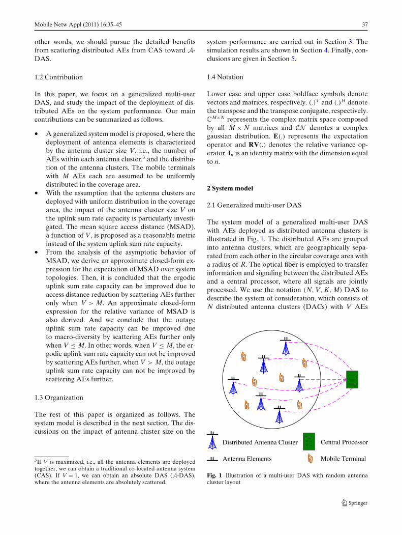
The system model of a generalized multi-user DASwith AEs deployed as distributed antenna clusters isillustrated in Fig. 1. The distributed AEs are groupedinto antenna clusters, which are geographically sepa-rated from each other in the circular coverage area witha radius of R. The optical fiber is employed to transferinformation and signaling between the distributed AEsand a central processor, where all signals are jointlyprocessed. We use the notation (N, V, K, M) DAS todescribe the system of consideration, which consists ofN distributed antenna clusters (DACs) with V AEs
Distributed Antenna Cluster
Mobile TerminalAntenna Elements
Central Processor
Fig. 1 Illustration of a multi-user DAS with random antennacluster layout

38 Mobile Netw Appl (2011) 16:35–45
Distributed Antenna Cluster
Mobile Terminal
Antenna Elements
Fig. 2 Illustration of the antenna selection scheme for (10, 2, 5,4) DAS. Since the number of AEs per MT is 4, the 4 nearest AEsshould be selected, thus, the 2 nearest DACs are selected to servethe corresponding MT
each4 and K mobile terminals (MTs) with M AEs each.The DACs and the MTs are randomly deployed in thecoverage area with uniform distribution, respectively.Thus, any other DAS can be regarded as a specialsample of this model, which implies that this study isapplicable for any DAS with different system topolo-gies. The distributed AE density λa and the MT densityλu can be obtained
λa = NVπ R2
, (1)
λu = Kπ R2
. (2)
2.2 Assumptions
As to describe the advantages of DASs as clear as pos-sible, we consider the uplink and assume ideal multi-user joint signal processing at the central processor.Thus, the interference from and to other MTs can beeliminated absolutely. As shown in Fig. 2, in orderto maximize the spacial multiplexing of the MTs, weadopt a simple antenna selection scheme, where theM nearest AEs are selected to serve the corresponding
4V is the antenna cluster size.
MT. At the same time, in order to maximize the spacialmultiplexing of the whole network, we can set
NV = KM. (3)
The channel state information (CSI) is assumed to beonly perfectly available at the receiver (CSIR). Hence,equal power allocation is employed at the MTs withper-MT power constraints.
2.3 Signal model
For an arbitrary MT indexed with i, based on theproposed antenna selection scheme, the received sig-nal vector at the selected AEs in the uplink can beexpressed as
yi = Hi,iP1/2i xi +
K∑
k=1,k�=i
Hk,iP1/2k xk + ni, (4)
where Hi,i ∈ CM×M, is the channel matrix between the
MT i and its M selected AEs, Hk,i ∈ CM×M, denotes
the channel matrix between the kth MT and the Mselected AEs for MT i, the diagonal matrix Pk ∈ C
M×M,denotes the transmit power matrix of the kth MT,and xk ∈ C
M×1 is the transmitted signal vector of thekth MT, ni ∈ C
M×1, denotes the white noise vectorwith Gaussian distribution CN (0, σ 2
n,iIM). Without lossof generality, we assume σ 2
n,1 = σ 2n,2 = · · · = σ 2
n,K = σ 2n .
Since equal power allocation is employed at the MTswith per-MT power constraints, we have
Pk = Pk
MIM, k = 1, 2, · · · , K, (5)
where Pk is the transmit power constraint of the kthMT.
Encompassing not only small-scale fading but alsolarge-scale fading, the channel matrix Hk,i can be mod-eled as [13]
Hk,i = Lk,iHk,iw =
⎡
⎢⎢⎣
dk,i1
−γ /2
. . .
dk,iM
−γ /2
⎤
⎥⎥⎦
×⎡
⎢⎣hk,i
11 . . . hk,i1M
.... . .
...
hk,iM1 . . . hk,i
MM
⎤
⎥⎦ , k = 1, 2, · · · , K, (6)
where Hk,iw reflects the small-scale fading, whose en-
tries are independent and identically distributed (i.i.d.)complex Gaussian variables with zero mean and unitvariance, and Lk,i represents the large-scale fading, i.e.,the path loss, {dk,i
m }Mm=1 denote the distances between the
Mobile Netw Appl (2011) 16:35–45 39
kth MT and the selected AEs for MT i, γ is the path lossexponent, which usually takes value from 3 to 6.
Especially, we have
Hi,i = Li,iHi,iw
=
⎡
⎢⎢⎣
di,i1
−γ /2
. . .
di,iM
−γ /2
⎤
⎥⎥⎦
⎡
⎢⎣hi,i
11 . . . hi,i1M
.... . .
...
hi,iM1 . . . hi,i
MM
⎤
⎥⎦ , (7)
where {di,im}M
m=1 denote the access distances between MTi and its M selected AEs.5 Thus, {di,i
m}Mm=1 are the M
shortest distances between MT i to all the distributedAEs. We can set
dk,k1 ≤ dk,k
2 ≤ · · · ≤ dk,kM , k = 1, 2, · · · , K. (8)
3 Discussions on antenna cluster size
In order to analyze the impact of the antenna clustersize on the system performance, we should characterizethe system performance at first, or at least present afungible metric. In this section, the mean square accessdistance (MSAD) is proposed as a reasonable metric in-stead of the system uplink sum rate capacity. And basedon the study on MSAD, the discussions on the impactof antenna cluster size on the system performance arecarried out.
3.1 MSAD
The essential system performance should be sum ratecapacity. With the assumption of CSIR, the sum ratecapacity in the uplink is expressed as [17]
C = log2 det
(INV + 1
σ 2n
HPHH)
, (9)
where C denotes the instantaneous uplink sum ratecapacity, H is the total channel matrix between all theMTs and all the AEs, and P represents the total trans-mit power matrix. Based on C, we can further derivethe ergodic uplink sum rate capacity and the outageuplink sum rate capacity. However, by summarizing thecurrent works, we can observe that it is difficult to find acompact expression for the sum rate capacity and thenobtain the relationship between the antenna cluster sizeand the sum rate capacity.
5The M nearest AEs of MT i.
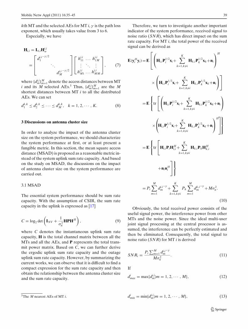
Therefore, we turn to investigate another importantindicator of the system performance, received signal tonoise ratio (SNR), which has direct impact on the sumrate capacity. For MT i, the total power of the receivedsignal can be derived as
E(yHi yi)=E
⎡
⎢⎣
⎛
⎝Hi,iP1/2i xi+
K∑
k=1,k�=i
Hk,iP1/2k xk+ni
⎞
⎠H
×⎛
⎝Hi,iP1/2i xi+
K∑
k=1,k�=i
Hk,iP1/2k xk+ni
⎞
⎠
⎤
⎦
=E
⎧⎨
⎩tr
⎡
⎣
⎛
⎝Hi,iP1/2i xi+
K∑
k=1,k�=i
Hk,iP1/2k xk+ni
⎞
⎠
×⎛
⎝Hi,iP1/2i xi+
K∑
k=1,k�=i
Hk,iP1/2k xk+ni
⎞
⎠H⎤
⎥⎦
⎫⎪⎬
⎪⎭
=E
⎧⎨
⎩tr
⎡
⎣Hi,iPiHHi,i +
K∑
k=1,k�=i
Hk,iPkHHk,i
+ninHi
⎤
⎦
⎫⎬
⎭
= Pi
M∑
m=1
di,im
−γ +K∑
k=1,k�=i
Pk
M∑
m=1
dk,im
−γ +Mσ 2n .
(10)
Obviously, the total received power consists of theuseful signal power, the interference power from otherMTs and the noise power. Since the ideal multi-userjoint signal processing at the central processor is as-sumed, the interference can be perfectly estimated andthen be eliminated. Consequently, the total signal tonoise ratio (SNR) for MT i is derived
SNRi = Pi∑M
m=1 di,im
−γ
Mσ 2n
. (11)
If
dimax = max{di,i
m|m = 1, 2, · · · , M}, (12)
dimin = min{di,i
m|m = 1, 2, · · · , M}, (13)
40 Mobile Netw Appl (2011) 16:35–45
we directly have the upper bound and the lower boundof the SNRi as
SNRupperi = Pidi
min−γ
σ 2n
, (14)
SNRloweri = Pidi
max−γ
σ 2n
. (15)
Define the mean square access distance of MT i(MSAD-i) as
d̄2i = 1
M
M∑
m=1
(di,im)2, (16)
and the corresponding SNR∗i can be obtained
SNR∗i = Pid̄
−γ
i
σ 2n
. (17)
From Eqs. 12, 13 and 16, we can find
dimin ≤ d̄i ≤ di
max, (18)
as a consequence, we have
SNRloweri ≤ SNR∗
i ≤ SNRupperi . (19)
Intuitively, we can directly use SNR∗i to evaluate the
received SNR for MT i. Since SNR∗i is a monotone
decreasing function with respect to d̄i, we can use d̄i toindicate the performance of MT i.
As to the whole system, by averaging all the single-MT MSADs, we can define the network MSADd̄2(N, V, K, M) as
d̄2(N, V, K, M) = 1
K
K∑
k=1
[MSAD-k
]. (20)
By plugging Eqs. 16 to 20, we have
d̄2(N, V, K, M) = 1
K
K∑
k=1
[ 1
M
M∑
m=1
(dk,km )2
]. (21)
And dk,km is the mth shortest distance from the kth MT
to the distributed AEs.Because the distributed AEs are deployed as an-
tenna clusters, it is more straightforward to calculatethe distances from the MTs to their respective nearestDACs. For an arbitrary MT, the number of nearestDACs to be selected can be derived
Mc =⌈
Mmin(M, V)
⌉, (22)
where � · � is the integer ceiling operator. The selectedDACs should totally include M AEs based on theproposed antenna selection scheme.
Hence, by focusing on the distances from the MTsto their respective nearest DACs, an approximation forEq. 21 can be derived
d̄2(N, V, K, M) ≈ 1
K
K∑
k=1
[ 1
Mc
Mc∑
m=1
(dk,km )2
], (23)
where dk,km represents the mth shortest distance from
the kth MT to the DACs.
3.2 Statistics of MSAD
Because the topology of the considered system is arandom variable, the system MSAD in (23) is also arandom variable. Therefore, we are interested in thefirst-order and the second-order statistics of the MSAD.
Defining the single-MT MSAD as
D2k = 1
Mc
Mc∑
m=1
(dk,km )2, k = 1, 2, · · · , K, (24)
we have
d̄2(N, V, K, M) ≈ 1
K
K∑
k=1
D2k. (25)
For an arbitrary MT i, while keeping the distributedAE density λa as a finite constant, as R goes to infinity,we derive the asymptotic probability density function(PDF) [8] of di,i
1 as
fdii1(x) = 2πλax
Ve− πλa x2
V , 0 < x ≤ R. (26)
Similarly, we can derive the conditional PDF ofdi,i
m (m ≥ 2) as
fdi,im(x | di,i
m−1) = 2πλaxV
e− πλa(x2−(di,im−1)2)
V , di,im−1 ≤ x ≤ R,
2 ≤ m ≤ M. (27)
Since D2i is a function with respect to di,i
1 , di,i2 , · · · ,
and di,iM, with some further algebraic manipulations, the
following asymptotic expectation and relative varianceof D2
i can be obtained
E(D2i ) = V(Mc + 1)
2πλa, (28)
RV(D2i ) = 2(2Mc + 1)
3Mc(Mc + 1). (29)
Based on the assumptions of the considered systemmodel, we can find that {D2
k|k = 1, 2, · · · , K} can beregarded as i.i.d. random variables. Thus, from Eqs. 25,
Mobile Netw Appl (2011) 16:35–45 41
28 and 29, the expectation and relative variance of thesystem MSAD d̄2(N, V, K, M) can be derived
E(d̄2) = V(� Mmin(M,V)
� + 1)
2πλa, (30)
RV(d̄2) = 2(2� Mmin(M,V)
� + 1)
3K� Mmin(M,V)
�(� Mmin(M,V)
� + 1). (31)
Utilizing the symmetry characteristics of the DACs andMTs in the proposed system model, by ignoring theinteger ceiling operator, we can further have
E(d̄2) ≈M
min(M,V)λuV + λa
2πλaλu, (32)
RV(d̄2) ≈ 2(2 Mmin(M,V)
λuV + λa)
3π R2λuM
min(M,V)( M
min(M,V)λuV + λa)
. (33)
3.3 Impact of antenna cluster size on systemperformance
In order to observe the relationship between V and thetwo obtained statistics of MSAD, we first derive thedifference of the expectation with respect to V as
V [E(d̄2)] =
⎧⎪⎨
⎪⎩
0, V ≤ M;1
2πλa, V > M.
(34)
And then the difference of the relative variance withrespect to V is derived as
V[RV(d̄2)]
=
⎧⎪⎪⎨
⎪⎪⎩
1
6π R2λu
[2Mλu + λa
MV (Mλu + λa)
− 2Mλu + λaM
V−1 (Mλu + λa)
]
0
=
⎧⎪⎨
⎪⎩
2Mλu + λa
6π R2 Mλu(Mλu + λa), V ≤ M;
0, V > M.
(35)
From Eqs. 34 and 35, the following remarks can begiven with the same AE density and the same MTdensity.
• When V ≤ M, the relative variance decreases withthe decreasing of V, while the expectation remainsa constant that equals to the value at V = M.
• When V > M, the expectation decreases with thedecreasing of V, while the relative variance remainsa constant that equals to the value at V = M.
Intuitively, with consideration of the relationshipbetween MSAD and the system SNR, and theuplink sum rate capacity of the system, we canconclude as follows.
• When V ≤ M, the outage uplink sum rate capacitycan be improved due to macro-diversity by scatter-ing AEs further.
• When V ≤ M, the ergodic uplink sum rate capacitycan not be improved by scattering AEs further.
• When V > M, the ergodic uplink sum rate capacitycan be improved due to access distance reductionby scattering AEs further.
• When V > M, the outage uplink sum rate capacitycan not be improved by scattering AEs further.
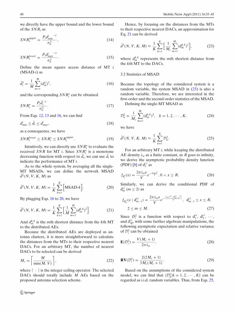
Accordingly, as illustrated in Fig. 3, when V ≤ M,benefiting from only the macro-diversity, a DAS out-performs a CAS in terms of outage system perfor-mance; when V > M, benefiting from only the accessdistance reduction, a DAS outperforms a CAS in termsof ergodic system performance.
4 Simulation results
In this section, we will verify our analysis via MonteCarlo simulations. The sum rate capacity normalized bythe number of MTs in the uplink will be presented toillustrate the system performance.
( )V M< ( )V M= ( )V M> V
Mean access distanceMacro-diversityOutage system capacityErgodic system capacity
Fig. 3 Illustration of the impact of V on system performance
42 Mobile Netw Appl (2011) 16:35–45
1 2 4 8 160.4
0.6
0.8
1
1.2
1.4
1.6
1.8
2
2.2
2.4x 10⁶
Antenna cluster size
Exp
ecta
tion
of M
SA
D (
m2 )
Analytical ResultSimulation Result
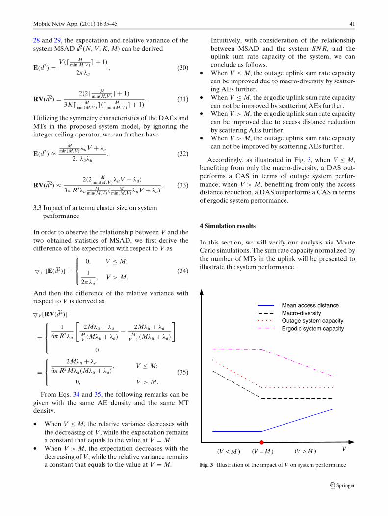
Fig. 4 The expectation of MSAD (NV = 128, K = 32, M = 4)
In our simulations, a circular coverage area with aradius of 6000m is considered. The path loss expo-nent is set to be 4 [18], and the noise power σ 2
n isassumed to be −107 dBm given 5 MHz bandwidthand −174 dBm/Hz thermal noise as in the universalmobile telecommunications system (UMTS). NV andKM are both assumed to be 128. The antenna clustersize V takes value in {1, 2, 4, 8, 16}, thus, the number ofDACs N takes value in {128,64,32,16,8}. Without loss ofgenerality, the same transmit power constraint of MTsare assumed, which takes value from 0dBm to 30dBmin our simulations.
1 2 4 8 161
2
3
4
5
6
7
8
9x 10⁻³
Analytical ResultSimulation Result
Antenna cluster size
Rel
ativ
e va
rianc
e of
MS
AD
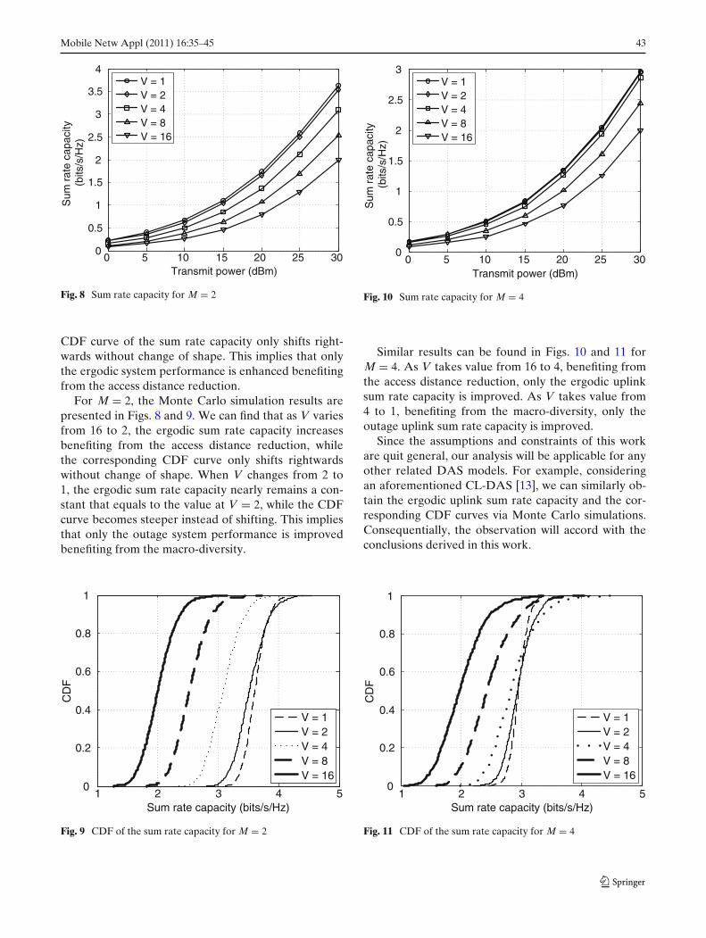
Fig. 5 The relative variance of MSAD (NV = 128, K = 32,
M = 4)
0 5 10 15 20 25 300
1
2
3
4
5V = 1V = 2V = 4V = 8V = 16
Transmit power (dBm)
Sum
rat
e ca
paci
ty (
bits
/s/H
z)
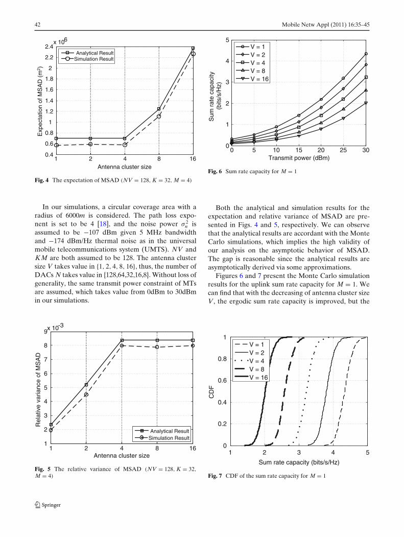
Fig. 6 Sum rate capacity for M = 1
Both the analytical and simulation results for theexpectation and relative variance of MSAD are pre-sented in Figs. 4 and 5, respectively. We can observethat the analytical results are accordant with the MonteCarlo simulations, which implies the high validity ofour analysis on the asymptotic behavior of MSAD.The gap is reasonable since the analytical results areasymptotically derived via some approximations.
Figures 6 and 7 present the Monte Carlo simulationresults for the uplink sum rate capacity for M = 1. Wecan find that with the decreasing of antenna cluster sizeV, the ergodic sum rate capacity is improved, but the
1 2 3 4 50
0.2
0.4
0.6
0.8
1V = 1V = 2V = 4V = 8V = 16
Sum rate capacity (bits/s/Hz)
CD
F
Fig. 7 CDF of the sum rate capacity for M = 1
Mobile Netw Appl (2011) 16:35–45 43
0 5 10 15 20 25 300
0.5
1
1.5
2
2.5
3
3.5
4V = 1V = 2V = 4V = 8V = 16
Transmit power (dBm)
Sum
rat
e ca
paci
ty (
bits
/s/H
z)
Fig. 8 Sum rate capacity for M = 2
CDF curve of the sum rate capacity only shifts right-wards without change of shape. This implies that onlythe ergodic system performance is enhanced benefitingfrom the access distance reduction.
For M = 2, the Monte Carlo simulation results arepresented in Figs. 8 and 9. We can find that as V variesfrom 16 to 2, the ergodic sum rate capacity increasesbenefiting from the access distance reduction, whilethe corresponding CDF curve only shifts rightwardswithout change of shape. When V changes from 2 to1, the ergodic sum rate capacity nearly remains a con-stant that equals to the value at V = 2, while the CDFcurve becomes steeper instead of shifting. This impliesthat only the outage system performance is improvedbenefiting from the macro-diversity.
1 2 3 4 50
0.2
0.4
0.6
0.8
1
V = 1V = 2V = 4V = 8V = 16
Sum rate capacity (bits/s/Hz)
CD
F
Fig. 9 CDF of the sum rate capacity for M = 2
0 5 10 15 20 25 300
0.5
1
1.5
2
2.5
3V = 1V = 2V = 4V = 8V = 16
Transmit power (dBm)
Sum
rat
e ca
paci
ty (
bits
/s/H
z)
Fig. 10 Sum rate capacity for M = 4
Similar results can be found in Figs. 10 and 11 forM = 4. As V takes value from 16 to 4, benefiting fromthe access distance reduction, only the ergodic uplinksum rate capacity is improved. As V takes value from4 to 1, benefiting from the macro-diversity, only theoutage uplink sum rate capacity is improved.
Since the assumptions and constraints of this workare quit general, our analysis will be applicable for anyother related DAS models. For example, consideringan aforementioned CL-DAS [13], we can similarly ob-tain the ergodic uplink sum rate capacity and the cor-responding CDF curves via Monte Carlo simulations.Consequentially, the observation will accord with theconclusions derived in this work.
1 2 3 4 50
0.2
0.4
0.6
0.8
1
V = 1V = 2V = 4V = 8V = 16
Sum rate capacity (bits/s/Hz)
CD
F
Fig. 11 CDF of the sum rate capacity for M = 4
44 Mobile Netw Appl (2011) 16:35–45
5 Conclusions
In this work, we focus on the impact of the deploy-ment of AEs on the system performance for a multi-user DAS. A generalized system model is proposed,where the AEs are divided into antenna clusters andthe antenna clusters are randomly deployed in thecoverage area. We characterize the deployment of AEswith two parameters: the antenna cluster size V andthe distribution of the antenna clusters. Without lossof generality, the antenna clusters are assumed to bedeployed with uniform distribution. Thus, the impactof the antenna cluster size on the system performanceis particularly studied. With some algebraic manipu-lations, the MSAD, a function of the antenna clustersize, is proposed as a reasonable metric instead of thesystem uplink sum rate capacity. Then, we put ouremphasis on the impact of the antenna cluster sizeon the MSAD. From the analysis of the asymptoticbehavior of the MSAD, we derive approximate closed-form expressions for the first-order and the second-order statistics of the MSAD, respectively. Moreover,we find out the semi-quantitative relationship betweenthe antenna cluster size and the statistics of the MSAD,which can directly indicate the impact of the antennacluster size on the system uplink sum rate capacity.
The conclusions can be summarized as follows.
• (1) when V ≤ M, the outage uplink sum rate ca-pacity can be improved by scattering AEs further,benefiting from the macro-diversity.
• (2) when V ≤ M, the ergodic uplink sum ratecapacity can not be improved by scattering AEsfurther.
• (3) when V > M, the ergodic uplink sum rate ca-pacity can be improved by scattering AEs further,benefiting from the access distance reduction.
• (4) when V > M, the outage uplink sum rate capac-ity can not be improved by scattering AEs further.
Therefore, when V ≤ M, benefiting from only themacro-diversity, a DAS outperforms a CAS in termsof outage system performance; when V > M, benefitingfrom only the access distance reduction, a DAS outper-forms a CAS in terms of ergodic system performance.
As to realistic networks, if we only care about the er-godic system performance, then, based on our remarks,it is enough to configure the nework with V = M. Weneed not scatter the AEs absolutely into an A-DAS,
which will occupy more geographical cites and increasethe system penalty.
Finally, it is worth mentioning that the results de-rived here are applicable for other related DAS models.In addition, the issues of optimizing the deploymentof AEs with the given MTs equipped with differentnumber of antennas, as well as optimizing the deploy-ment of AEs with consideration of nerwork hotspotsare interesting possible future extension directions.
Acknowledgements The authors gratefully acknowledge theanonymous reviewers for their helpful suggestions. We wouldalso like to thank the input from Jingyao Zhang (Tsinghua Uni-versity) and Nan Hua (Georgia Institute of Technology).
References
1. Zhang J, Andrews JG (2008) Distributed antenna systemswith randomness. IEEE Trans Wirel Commun 7(9):3636–3646
2. Andrews JG, Choi W, Heath RW Jr (2007) Overcoming in-terference in spatial multiplexing MIMO cellular networks.IEEE Wirel Commun 14(6):95–104
3. Ni Z, Li D (2004) Effect of fading correlation on capacityof distributed MIMO. In: Proc. IEEE Personal, Indoor andMobile Radio Commun., vol 3, pp 1637–1641
4. Xiao L, Dai L, Zhuang H, Zhou S, Yao Y (2003) Information-theoretic capacity analysis in MIMO distributed antenna sys-tem. In: Proc. IEEE Veh. Technol. Conf., pp 779–782
5. Hasegawa R, Shirakabe M, Esmailzadeh R, Nakagawa M(2003) Downlink performance of a CDMA system with dis-tributed base station. In: Proc. IEEE Veh. Technol. Conf.,pp 882–886
6. Feng W, Li Y, Gan J, Zhou S, Wang J, Xia M (2008) Onthe size of antenna cluster in multi-user distributed antennasystems. In: Commun. Networking in China, 2008, pp 1101–1105
7. Saleh AAM, Rustako AJ, Roman RS (1987) Distributed an-tennas for indoor radio communications. IEEE Trans Com-mun 35(12):1245–1251
8. Zhuang H, Dai L, Xiao L, Yao Y (2003) Spectral efficiencyof distributed antenna systems with random antenna layout.IET Electron Lett 39(6):495–496
9. Roh W, Paulraj A (2002) Outage performance of the distrib-uted antenna systems in a composite fading channel. In: Proc.IEEE 56rd Veh. Technol. Conf., pp 1520–1524
10. Roh W, Paulraj A (2002) MIMO channel capacity for thedistributed antenna systems. In: Proc. IEEE Veh. Technol.Conf., pp 706–709
11. Clark MV, Willis TM III, Greenstein LJ et al (2001) Distrib-uted versus centralized antenna arrays in broadband wirelessnetworks. In: Proc. IEEE 53rd Veh. Technol. Conf., vol 1,pp 33–37
12. Choi W, Andrews JG (2007) Downlink performance and ca-pacity of distributed antenna systems in a multicell environ-ment. IEEE Trans Wirel Commun 6(1):69–73
Mobile Netw Appl (2011) 16:35–45 45
13. Gan J, Li Y, Xiao L, Zhou S, Wang J (2007) On sum-rate and power consumption of multi-user distributed an-tenna system with circular antenna layout. ERASIP Trans.WCN., vol 2007, Article ID 89780, 9 pp. doi:10.1155/2007/89780
14. Feng W, Li Y, Zhou S, Wang J, Xia M (2009) On the optimalradius to deploy antennas in multi-user distributed antennasystem with circular antenna layout. In: Proc. Inter. Conf.Commun. Mobile Computing, pp 56–59
15. Feng W, Li Y, Zhou S, Wang J, Xia M (2009) Uplink sum ca-pacity evaluation of multi-user distributed antenna systems.
Int J Electron Commun. Online in Science Direct. doi:10.1016/j.aeue.2008.11.008
16. Feng W, Li Y, Zhou S, Wang J, Xia M (2009) Down-link capacity of distributed antenna systems in a multi-cell environment. In: Proc. IEEE Conf. Wireless Commun.Networking, pp 1–5
17. Telatar E (1999) Capacity of multi-antenna Gaussian chan-nels. Eur Trans Telecommun ETT 10(6):585–596
18. Goldsmith AJ, Greenstein LJ (1993) Measurement-basedmodel for predicting coverage areas of urbanmicrocells.IEEE J Sel Areas Commun 11(7):1013–1023


