Embed Size (px)
Citation preview

Interactive Virtual Relighting and Remodeling of Real
Scenes
Celine Loscos, Marie-Claude Frasson, George Drettakis, Bruce Walter, Xavier
Granier, Pierre Poulin
To cite this version:
Celine Loscos, Marie-Claude Frasson, George Drettakis, Bruce Walter, Xavier Granier, et al..Interactive Virtual Relighting and Remodeling of Real Scenes. [Research Report] RT-0230,1999, pp.16. <inria-00069942>
HAL Id: inria-00069942
https://hal.inria.fr/inria-00069942
Submitted on 19 May 2006
HAL is a multi-disciplinary open accessarchive for the deposit and dissemination of sci-entific research documents, whether they are pub-lished or not. The documents may come fromteaching and research institutions in France orabroad, or from public or private research centers.
L’archive ouverte pluridisciplinaire HAL, estdestinee au depot et a la diffusion de documentsscientifiques de niveau recherche, publies ou non,emanant des etablissements d’enseignement et derecherche francais ou etrangers, des laboratoirespublics ou prives.
ISS
N 0
249-
0803
ap por t t e ch n i qu e
INSTITUT NATIONAL DE RECHERCHE EN INFORMATIQUE ET EN AUTOMATIQUE
Interactive Virtual Relighting and Remodelingof Real Scenes
Celine Loscos�, Marie-Claude Frasson
���, George Drettakis
�,
Bruce Walter�, Xavier Granier
�, Pierre Poulin
�
�iMAGIS-GRAVIR/IMAG-INRIA
B.P. 53, F-38041 Grenoble, Cedex 9, France�Departement d’informatique et de recherche operationnelle, Universite de Montreal
No 0230
Avril 1999
THEME 3


Interactive Virtual Relighting and Remodelingof Real Scenes
Céline Loscos � , Marie-Claude Frasson ��� , George Drettakis � ,Bruce Walter � , Xavier Granier � , Pierre Poulin �
� iMAGIS-GRAVIR/IMAG-INRIAB.P. 53, F-38041 Grenoble, Cedex 9, France
� Département d’informatique et de recherche opérationnelle, Université deMontréal
Thème 3 — Interaction homme-machine,images, données, connaissances
Projet iMAGIS
Rapport technique n˚0230 — Avril 1999 — 16 pages
Abstract: Lighting design is tedious due to the required physical manipulation of real light sourcesand objects. As an alternative, we present an interactive system to virtually modify the lighting andgeometry of scenes with both real and synthetic objects, including mixed real/virtual lighting andshadows.
In our method real scene geometry is first approximatively reconstructed from photographs. Ad-ditional images are taken with a real light in different positions from the same viewpoint to estimatereflectance. A filtering process is used to compensate for modeling errors, and per image reflectancesare averaged to generate an approximate reflectance image for the given viewpoint, removing shadowsin the process. This estimate is used to initialise a global illumination hierarchical radiosity system,representing real-world secondary illumination; the system is optimized for interactive updates. Di-rect illumination from lights is calculated separately using ray-casting and a table for efficient reusewhere appropriate.
Our system allows interactive modification of light emission and object positions, all with mixedreal/virtual illumination effects. Real objects can also be virtually removed using texture-filling algo-rithms for reflectance estimation.
Key-words: Image synthesis, computer augmented reality, virtual reality, reflectance estimation,common illumination, virtual relighting, virtual removal of real objects, hierarchical radiosity, globalillumination, interactivity.
(Résumé : tsvp)
Unit e de recherche INRIA Rhone-Alpes655, avenue de l’Europe, 38330 MONTBONNOT ST MARTIN (France)
T el ephone : 04 76 61 52 00 - International: +33 4 76 61 52 00T el ecopie : 04 76 61 52 52 - International: +33 4 76 61 52 52

Rééclairage/Remodélisation Virtuels et Interactifsdes Scènes Réelles
Résumé : Le design de l’éclairage d’interieur est un travail laborieux, notamment à cause de lamanipulation “physique” des lampes et des objets. En solution alternative, nous proposons un systèmeinteractif pour modifier virtuellement l’éclairage et la géometrie des scènes, comprenant à la fois desobjets réels et virtuels, en tenant compte des éclairages mixtes (réels / virtuels) et des ombres.
Dans notre méthode, la géométrie de la scène réelle est d’abord approximativement reconstruiteà partir de photos. Puis de nouvelles photos sont prises depuis le même point de vue, mais sousdes éclairages différents, et servent à estimer la reflectance des objets réels. Un processus de filtrageest appliqué pour compenser les erreurs de modélisation. La moyenne des reflectances calculéespour chaque image, permet d’obtenir une image de reflectance pour le point de vue donné, enlevantainsi les ombres. Cette estimation est utilisée pour initialiser un systéme de radiosité hiérarchiquede simulation d’illumination globale, afin de représenter l’illumination indirecte réelle. Le systèmeest optimisé pour favoriser des mises à jour interactives. L’éclairage direct dû aux lampes est calculéséparément par du lancer de rayon et une table est maintenue pour une réutilisation aux endroitsapropriés.
Notre système permet une modification interactive de l’intensité des lampes et de la position desobjets, en tenant compte des effets lumineux mixtes entre objets réels et virtuels. Les objets réelspeuvent aussi être enlevés virtuellement en utilisant des algorithmes de remplissage de textures pourl’estimation de la reflectance.
Mots-clé : Synthèse d’images, réalité augmentée assistée par ordinateur, réalité virtuelle, estimationde la reflectance, éclairage commun, rééclairage virtuel, enlèvement d’objets réels, radiosité hiérar-chique, éclairage global, interactivité.

Interactive Virtual Relighting and Remodeling of Real Scenes 3
1 Introduction
Designing the illumination of real environments has always been a difficult task. Lighting design forhome interiors for example, is a complex undertaking, requiring much time and effort with the manip-ulation of physical light sources, shades, reflectors, etc. to create the right ambiance. In addition otherphysical objects may need to be moved or otherwise changed. The problem is even more complex onmovie sets or exterior lighting design. The fundamental trial-and-error nature of the relighting pro-cess makes it painful and often frustrating; more importantly, the requirements of constructing andmoving real objects and light sources make testing many different potential designs often impossible.
Ideally, we would like to perform such processes entirely synthetically. The lighting designerwould simply photograph the environment to be relit and/or remodeled, and then create the differentconditions by computer simulation so they can be evaluated appropriately.
Evidently, such a goal is very hard to accomplish. In this paper we provide first solutions to asubset of this goal, inspired by techniques developed for computer augmented reality, and commonillumination between the real and the synthetic scenes [2, 10].
Our method starts with a preprocess, in which real geometry is reconstructed from a series ofphotos [20], taken from several different viewpoints. A second set of images (which we call radianceimages) are taken from a fixed viewpoint with a real light source in different positions. The geometryand the images are used to extract an approximate reflectance at each pixel for the given point ofview. Intuitively, we attempt to have an unoccluded view of the light source at each pixel in atleast one radiance image, which gives a good reflectance estimate; we compensate for geometricand photometric imprecision using a filtering step on individual radiance images before performing aweighted average. The result of this new approach is an acceptable estimate of reflectance, called areflectance image; in the process, shadows are removed in a satisfactory manner.
Our main goal is to provide interactive manipulation of mixed real and virtual environments withcommon illumination. To achieve this we have separated the calculation of direct and indirect illu-mination. The reflectance image is used to initialise a hierarchical radiosity system with clustering[23], optimized for dynamic updates [6]. This structure is used for rapid updates of indirect light,while direct light is computed on a pixel-by-pixel basis. For direct light many components can bepre-computed and stored in a table for rapid modification, and in other cases the changes are limitedto small regions of screen space, permitting interactive updates. Working on a pixel-by-pixel basisresults in high quality direct shadows and also facilitates the removal of real objects, since we simplymanipulate the reflectance image using texture generation methods.
It is important to note outright that we do not attempt to extract accurate reflectance values. Thegoal of our method is to achieve convincing relighting at interactive rates. To this end we can ignoreinaccuracies and small artifacts, if the overall effect is believable.
2 Previous work
A large body of literature exists in computer vision on reconstructing 3D scenes from photos[8].However the quality of the extracted 3D models has only recently become satisfactory for computergraphics applications with the presentation of interactive systems such as Photomodeler[19], RE-ALISE[9, 15], Façade[4], and others[20]. While they all include some form of texture extraction andmapping, none treat the extraction of surface properties and re-illumination. Sato et al.[21] present asystem to extract 3D geometry, texture, and surface reflectance, but it is limited to a very controlledenvironment.
RT n˚0230

4 C. Loscos, M.C. Frasson, G. Drettakis, B. Walter, X. Granier, P. Poulin
With the development of an ever increasing number of computer augmented reality applications,it becomes important to handle the common illumination between real and synthetic scenes. Whilesome previous papers [10, 5] present preliminary solutions, they all require significant user interven-tion and are limited in different ways in the lighting or geometric conditions they can treat. Recentdevelopments to Façade[2] include surfaces property extraction, but rendering times of the Radi-ance[24] system used for image-generation are far from interactive.
Nakamae et al. [18] developed a solution for merging virtual objects into background photographs,and estimated the sun location to simulate common illumination effects in outdoor environments.More recently Yu and Malik [27] proposed a solution to virtually modify the illumination with differ-ent virtual positions of the sun in outdoor scenes.
Loscos and Drettakis [16, 17] have developed an approach to remove shadows, thus enablingsynthetic relighting. This technique attempts to remove shadows by computing the best possible ap-proximation using a single image. Despite successful results for certain cases, certain visual artifactsremain in the shadow regions.
In our method, as mentioned in the introduction, we separate direct lighting, which can be easilycomputed for each pixel, from indirect, or global lighting. Since we will be interactively modifyingthe scene, we need to be able to update the global illumination rapidly. To do this, we have used someof the ideas developed by Shaw [22] and Drettakis and Sillion [6].
Removal of real objects from a reconstructed scene requires some form of hole-filling in the realimages/textures containing the real objects being removed. Heeger and Bergen [13] have developeda method to synthesize texture images given a texture sample. They use a series of linear filtersto analyse the sample and create a texture that matches the sample appearance. Their method issuccessful on “stochastic” textures (e.g. stucco) but fails on “deterministic” textures (e.g. bricks).El-Maraghi [7] has provided a public domain implementation of their algorithm.
Igehy and Pereira [14] integrate a composition step into Heeger and Bergen algorithm in order to“erase” flaws (e.g. stains or undesired features) from images. They manually create a mask whichindicates which part of the image is to be covered by the synthesized texture and which part keeps itsoriginal texture.
3 Overview of the Method
Our goal is to allow interactive synthetic relighting and remodeling of real environments includingboth removing real lights or objects, and adding virtual ones. To accomplish this, we need to build ap-proximate geometric and reflectance models of the environment and quickly estimate the illuminationin modified configurations. We also want our method to be tolerant of measurement and modeling er-rors in order to work on a broad class of environments. Our process consists of several preprocessingsteps followed by an interactive relighting session.
We begin by taking two sets of photographs of the target environment. The first is taken frommultiple viewpoints under normal lighting conditions and is used to build an approximate geometricmodel of the model using our photomodeling system[20]. The second set is taken from the fixedviewpoint that will be used during the interactive editing session. These photos use controlled lightingwhich consists of a single known light source that is moved between photos. We typically use between5 and 7 such photos such as those in Figure 1. This second set, which we will refer to as the radianceimages, is used to estimate the reflectance on all the visible surfaces.
The geometric and reflectance models are used to initialize an optimized hierarchical radiositysystem that is used to dynamically simulate the indirect lighting in the environment. To recreate
INRIA

Interactive Virtual Relighting and Remodeling of Real Scenes 5
Figure 1: The 7 radiance images used for the example presented in this paper.
y
x
object ID
3D point
V1
R1
F1
K1
V2
R2
K2
V3
R3
F3
K3
F2
radianceimage 1
radianceimage 2
radianceimage 3
B
R
Figure 2: A per pixel data structure is stored for the interactive view as well as for each radianceimage. The visibility to each source Vi, the form factor to each light Fi, and the estimated reflectanceat this pixel R. The interactive view also stores the surface id and 3D point corresponding to eachpixel.
sharp shadows, the direct lighting is estimated on a per pixel basis from the fixed viewpoint using raycasting. For each pixel we store its corresponding 3D point and surface, its estimated local reflectance,and its visibility and form factors to each light. This structure is illustrated in Figure 2.
Each single radiance image is used to estimate all the pixel reflectances, but may be unreliablein some regions such as shadows. We generate a more robust reflectance estimator by assigningconfidence in each estimate and combining them from the multiple images accordingly.
After approximating reflectance in visible regions, we also estimate the reflectance in regionsthat might become visible due to object removal. This is accomplished by adapting a texture-fillingalgorithm. Once the radiosity and per pixel data structures have been initialized, we are ready tointeractively remodel and relight our scene.
4 Preprocessing
The main goal of the preprocessing steps is to initialize the data structures that will be used during theinteractive session. First surface reflectance at each pixel is estimated, and a pixel-based data structurefor precomputed direct lighting quantities is initialized. Finally the hierarchical radiosity system issetup for rapid indirect lighting updates.
The process begins by building a geometric model of the environment using our photomodelingsystem [20]. The user specifies a set of corresponding points in the set of photographs taken frommultiple viewpoints. The system uses these to solve for the camera parameters and 3D positions of
RT n˚0230
6 C. Loscos, M.C. Frasson, G. Drettakis, B. Walter, X. Granier, P. Poulin
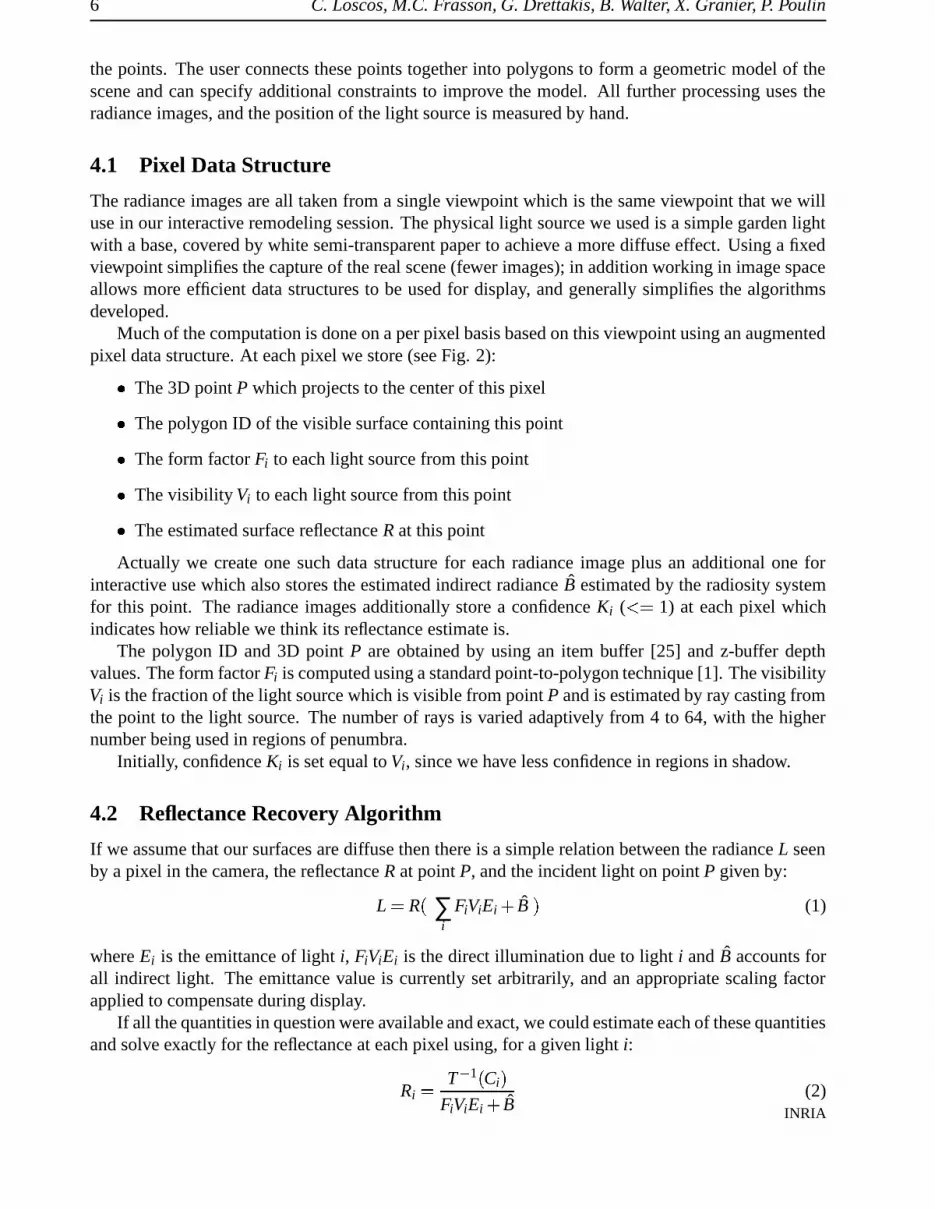
the points. The user connects these points together into polygons to form a geometric model of thescene and can specify additional constraints to improve the model. All further processing uses theradiance images, and the position of the light source is measured by hand.
4.1 Pixel Data Structure
The radiance images are all taken from a single viewpoint which is the same viewpoint that we willuse in our interactive remodeling session. The physical light source we used is a simple garden lightwith a base, covered by white semi-transparent paper to achieve a more diffuse effect. Using a fixedviewpoint simplifies the capture of the real scene (fewer images); in addition working in image spaceallows more efficient data structures to be used for display, and generally simplifies the algorithmsdeveloped.
Much of the computation is done on a per pixel basis based on this viewpoint using an augmentedpixel data structure. At each pixel we store (see Fig. 2):
� The 3D point P which projects to the center of this pixel
� The polygon ID of the visible surface containing this point
� The form factor Fi to each light source from this point
� The visibility Vi to each light source from this point
� The estimated surface reflectance R at this point
Actually we create one such data structure for each radiance image plus an additional one forinteractive use which also stores the estimated indirect radiance B estimated by the radiosity systemfor this point. The radiance images additionally store a confidence Ki ( ��� 1) at each pixel whichindicates how reliable we think its reflectance estimate is.
The polygon ID and 3D point P are obtained by using an item buffer [25] and z-buffer depthvalues. The form factor Fi is computed using a standard point-to-polygon technique [1]. The visibilityVi is the fraction of the light source which is visible from point P and is estimated by ray casting fromthe point to the light source. The number of rays is varied adaptively from 4 to 64, with the highernumber being used in regions of penumbra.
Initially, confidence Ki is set equal to Vi, since we have less confidence in regions in shadow.
4.2 Reflectance Recovery Algorithm
If we assume that our surfaces are diffuse then there is a simple relation between the radiance L seenby a pixel in the camera, the reflectance R at point P, and the incident light on point P given by:
L � R�∑
iFiViEi � B � (1)
where Ei is the emittance of light i, FiViEi is the direct illumination due to light i and B accounts forall indirect light. The emittance value is currently set arbitrarily, and an appropriate scaling factorapplied to compensate during display.
If all the quantities in question were available and exact, we could estimate each of these quantitiesand solve exactly for the reflectance at each pixel using, for a given light i:
Ri� T � 1 � Ci �
FiViEi � B(2)
INRIA

Interactive Virtual Relighting and Remodeling of Real Scenes 7
View 1 Reflectance 1 Confidence 1
View 2 Reflectance 2 Confidence 2
Merged Reflectance
Figure 3: Two of the seven radiance image views, the confidence (visibility) images, and the resultingreflectance, extracted using Eq.(2). The merged reflectance is shown at the bottom.
where Ci is the pixel color recorded by the camera and T� � is the response function of the camera.
This function was unavailable for our camera1 so we have used a simple scaling, though it could beaccurately estimated using the method of Debevec and Malik[3].
As a first approximation to indirect lighting B, we have used an ambient term equal to the averageimage color times a user specified average reflectance [10]. The resulting reflectance gives satisfactoryresults for our test cases; nonetheless, it is clear that more involved indirect lighting calculationsare necessary in other contexts, where accurate reflectance is paramount. Some experiments wereperformed with an iterative approach to reflectance estimation using our radiosity solution, withoutmuch improvement in the reflectance estimate. Nonetheless, this is clearly a topic of future work.
Because of the many approximations in our system including the geometry, indirect light, anddiffuse assumption, we know that our reflectance estimates will sometimes be quite inaccurate (e.g.,in shadow regions where the indirect term dominates). We compensate for this by combining thereflectance estimates from multiple radiance images to form a much more robust reflectance estimator.
For each radiance image i, we also estimate our confidence Ki for each pixel reflectance esti-mate. The merged pixel reflectance is can be formed by a weighted average of individual reflectance
1A Kodak DC260 digital camera.
RT n˚0230

8 C. Loscos, M.C. Frasson, G. Drettakis, B. Walter, X. Granier, P. Poulin
(a) (b) (c)
Figure 4: The filtering process for the confidence images. (a) The original radiance image for givenscene and lighting conditions. (b) The original confidence image (= visibility) (c) The final filteredconfidence image.
estimates:
R � ∑i � 0 ��� n Ki� Ri
∑Ki(3)
Due to inaccuracies of both the geometric reconstruction and the lighting parameter estimation,this reflectance estimate is not as accurate as required for our purposes. Since we have used Ki
� Vi
(visibility) initially, we filter the confidence values Ki to compensate for these inaccuracies (see nextsection). Eq. (3) will then be re-applied with the new confidence values to obtain an improved mergedreflectance.
4.3 Filtering Confidence Values
When combining the reflectances, we take into account the confidence we have in each pixel re-flectance estimate R of Eq. (3). As we saw, this can be achieved by using the visibility computedas an initial confidence value estimate. Near shadow boundaries however, the visibility V dependsheavily on the exact geometry configuration and thus may be unreliable due to inaccuracies in ourreconstructed model. Reflectance estimates in regions of partial or total shadow are also much lessreliable. In addition, the original light source images might contain the image of the (moving) lightsource fixture. We want to remove this geometry from the images.
The problem of shadow boundary accuracy and the light source fixture geometry is addressedby applying successive filter operations on the confidence images (i.e., an “image” of the Ki
�x � y � ).
The choice of filters and their domain sizes was based on the requirements of each process; we usestandard filters such as min, smoothing and outlier.
The first two filters aim at extending shadow boundaries, so that the regions of low confidencebecome larger. To do this a 5x5 min filter is applied: at each pixel
�x � y � , a 5x5 window is examined,
and the value of K�x � y � is replaced with the minimum. We then apply a 5x5 smoothing filter, to
ensure smooth transitions in the shadow regions. An average κ of the 5x5 window of confidencevalues is computed. If κ is lower than the current confidence, K
�x � y � is replaced with κ. This results
in smoothing the transitions between the images used in the merge, since the weighted average isperformed with the (smoothed) K values.
To remove the lighting fixtures we apply an outlier filter on the radiance images for each lightsource position. For each pixel, a table is constructed with the values of reflectance for each imagewhich have been computed using Eq. (2) (we only consider values which have a Ki
� ε, where εis typically around .75). The median µ of this table is computed, and if
�Ri � µ
� � ε2, (where ε2 isanother user defined threshold, typically around 0.3), then Ki
�x � y � is set to 0. A 3x3 smoothing filter
is then applied, again so that transitions between each image during the merge will occur smoothly.
INRIA

Interactive Virtual Relighting and Remodeling of Real Scenes 9
An example of this process is shown in Figure 4. In Figure 4(b), the original confidence image(initialised to Vi ) is shown for the scene with lighting conditions shown in 4(a). In Figure 4(c),the min, smoothing, outlier and second smoothing filters have been applied. Notice that the view-dependent highlight on the laptop screen has been given very low confidence.
Once the filters have been applied, we perform a new merging operation, again using Eq (3).Since we have smoothed and expanded shadow borders, the transitions are less pronounced, and thereflectance computed has fewer artifacts. An example of the merged reflectance is shown in Figure 3(bottom image).
4.4 Texture Filling for Real Object Removal
In order to be able to remove a real object from the scene, we integrated El-Maraghi’s [7] implemen-tation of Heeger and Bergen’s [13] texture synthesis into our system. By using a technique similarto Igehy and Pereira [14], we are able to fill the gaps left in the image when an object from thereconstructed scene is chosen for removal.
To synthesize the textures needed, we extract a texture sample from the reflectance image fromevery polygon that now covers the region to fill. The extraction of the sample is currently donemanually, but we are experimenting with automatic extraction procedures. This sample is fed to thesynthesis algorithm which generates a synthesized texture of the same size as the region to fill. Thegenerated texture is correctly applied to the reflectance using a masking process, described in Section5.3. The generated textures are stored for objects marked as “removable” accelerating the interactiveremodeling operations.
It should be noted that texture generation is performed on the reflectance image and is thus nothindered by shadows or lighting variations during the object removal. The reprojection of the shadowswith the new scene will generate a correct image of the scene without the real object.
4.5 Initializing the Hierarchical Radiosity System
To bootstrap the hierarchical radiosity system, the reflectance values recovered by Eq. (3) are re-projected onto the corresponding polygons, initialising the reflectance values. For the polygons notvisible in the image used for the interactive session, we take a sample of the texture during the thephotomodeling session and use the average value using Eq. (2). This also true for the hidden parts ofpolygons which are actually visible.
With this approximation, a first radiosity solution is computed by our system, using an implemen-tation of hierarchical radiosity with clustering [23]. The subdivision is set to a relatively coarse levelsince such a level is sufficient for indirect light only, which varies slowly. An example mesh is shownin Figure 5(b).
Recall that direct effects, including direct shadows, are treated separately for display. Directlight is however computed by the radiosity system, but simply ignored for display. The subdivisionis fixed at the beginning of the process to a minimum area threshold. Nonetheless, we maintainthe hierarchical nature of the radiosity algorithm, since links are established at different levels of thehierarchy, using a “standard” BF refiner [12]. Thus we will only need to update links and the radiosityvalues when performing interactive modifications.
RT n˚0230

10 C. Loscos, M.C. Frasson, G. Drettakis, B. Walter, X. Granier, P. Poulin
(a) (b)
Figure 5: (a) The original view of the scene and (b) the corresponding radiosity mesh used to simulateindirect light and dynamic updates; note the coarse subdivision.
5 Interactive Modification of Scene Properties
Once the reflectance has been computed for each pixel and the radiosity system set up, we can performinteractive modification of scene properties. The modifications which our system permits are relatedto lighting and geometry. The former includes changing a real light or adding virtual lights; the latterincludes adding and moving virtual objects and removing real objects.
All the results described below are best appreciated by watching the accompanying videotapeof an interactive virtual relighting/remodeling session. All timing results reported below have beentaken on a SGI R10000 195Mhz processor. The web page2 contains better images and additionalcompanion information.
5.1 Modifying Illumination
When we modify a light source emittance, two operations need to be performed:
� For indirect illumination, we need to compute a new radiosity solution. Given that the subdivi-sion and the link structure is fixed after the initial solution, updating indirect illumination simplyrequires a few successive sweeps of the hierarchy to “gather” and “push-pull” [12] radiosity andis very fast (less than .05 seconds in our test scenes).
� For display, the direct lighting component is recomputed at each pixel. Indirect illumination isdisplayed using hardware smooth-shading of the elements of the hierarchical radiosity subdi-vision, which are then blended into the final image. This results in the addition of B at eachpixel.
In the pixel structure, we have stored the visibility and form factor with respect to each light source.Thus the computation of the direct component is very rapid.
When displaying an image, we compute the following color at each pixel:
C � R�
∑s � 0 � � ns
FsVsEs � B � (4)
for the ns (real or virtual) light sources in the scene. Thus shadows are reprojected due to the visibilityterm Vs, since they have been removed from the reflectance.
An example is shown in Figure 6. The original photo is shown in (a), reprojected initial lightingconditions in (b), and we show the addition of a virtual light source in (c). The entire update for adding
2http://www-imagis.imag.fr/Membres/Celine.Loscos/relight.html
INRIA

Interactive Virtual Relighting and Remodeling of Real Scenes 11
(a) (b) (c)
Figure 6: (a) The original radiance image (photo) (b) original reprojected lighting conditions, dis-played using the recomputed direct and indirect components, (c) a virtual light has been inserted intothe scene adding the light took 3.1 seconds (for 400x300 resolution).
the virtual light takes 3.1 seconds broken down as follows: visibility 2.5s, shaft/radiosity operations0.4s., indirect light blending and other 0.2s. Recall that in the case of the light source insertion, weare required to update all the pixels of the image. During dynamic updates, we cast a small numberof rays to the light sources, resulting in aliased shadows. An additional “shadow clean-up” could beperformed when the user stops modifying the scene, with a higher shadow sampling rate.
5.2 Modifying Scene Geometry
To allow interactivity when adding, removing or moving objects and lights, we maintain a shaft datastructure [11], inspired from the work of Drettakis and Sillion [6]. Updating the entire table requiresin the order of a few minutes for visibilities, especially when using many rays per light source; usingthe method described below reduces this time to fractions of a second.
A hierarchical shaft [11] data structure is constructed from the first radiosity solution, correspond-ing to each link. When we add an object it is first attached to the root cluster of the scene; linksare established to the light sources as appropriate, based on the refinement criterion, and visibilityinformation is computed.
The hierarchy of shafts is used for two purposes: (a) to identify the pixels for which direct illu-mination has changed (i.e., the shadow regions of the new object); and (b) to identify the links forwhich the form-factor needs to be modified (i.e., all links whose shaft is cut by the new object), forboth direct and indirect light transfers.
To achieve the above, we descend the hierarchy of shafts, finding those intersected by the newobject. The hierarchical elements attached to the end of a shaft originating at a light source aremarked as “changed”. While descending, the form-factors of the modified links are updated (i.e.,a visibility calculation is performed). With all necessary links updated, we recompute a radiositysolution with only gather and push-pull steps.
The pixel data structure is then updated and displayed. The bounding box of the initial and finalposition of the moving object are first projected onto the image-plane, limiting the region of the screendirectly affected by the motion. For this region an new item buffer is performed, and the pixels underthe previous object position are found as well as those under the new position, since the polygon IDswill have changed. For these pixels, a reflectance is updated to the original value for the “uncovered”pixels and to that of the virtual object for the newly covered pixels. New form-factors and visibilityvalues are then computed for all the pixels changed in the modified region.
For the pixels associated with patches tagged as “changed”, visibility with respect to the source isrecomputed. These are not as localized as the directly affected pixels, but their number is often small.
RT n˚0230

12 C. Loscos, M.C. Frasson, G. Drettakis, B. Walter, X. Granier, P. Poulin
(a) (b)
Figure 7: (a) A virtual object has been inserted into the scene with both lights on; adding the objectrequired 1 sec. (b) moving the virtual object requires 1.1 sec.
The entire pixel table is then traversed to update the indirect illumination value at each pixel,based on the new global illumination calculation; again, this is performed with hardware rendering ofthe hierarchical radiosity patches.
When inserting a new light source, the form-factor and visibility with respect to the source needto be computed for every pixel.
When removing an object, we perform a similar process. We first remove every link of the re-moved object, then delete all the corresponding shaft structures.
When moving an object, the process is equivalent, but we do not have to delete the links. We justhave to update the information (form factors and visibilities). Shafts due to the moving object aredeleted and reconstructed with its new position.
In Figure 7(a) we show the insertion of a virtual object, which requires 1 sec, of which visibilityaccounts for .5 sec, shafts .1 sec and the rest .4 sec. When moving the virtual object, we achieveupdate rates of about 1 sec per frame, with a similar breakdown to that of the object insertion (Figure7(b)).
5.3 Removing Real Objects
When the user chooses to remove an object, she indicates the object to the system. Similarly to virtualobjects, since the correspondences between polygons and pixels are known through the polygon IDsstored in the pixel data structures, we know exactly which region of screen will have to be filled. Weautomatically create two masks corresponding to this region: a weight mask and a texture mask [14].At first, each contains “1” over the region to fill and “0” elsewhere. We extend the weight mask afew pixels to compensate for inaccuracies in the removed object geometry (to avoid leaving any colorfrom the removed object in the image).
The object is then removed from the scene and a new item buffer is performed to update thepolygon IDs. The polygon IDs present in the region to be filled indicate from which polygons wehave to extract textures. The texture mask is filled with these new IDs and the weight mask is blurredaround its “0/1” borders. This allows the composition of the synthesized texture with the texture fromthe image: when the mask is 0, the color of the pixel will be the color in the reflectance image, whenthe mask is 1 the color will be taken from the synthesized texture and a fractional weight will allow asmooth transition from the synthesized texture to the original image (e.g. the original colors presentin the image).
The reflectance is then updated for the pixels affected, as well as the visibility and form-factors,as in the case of virtual object motion/removal. Results of object removal are shown in Figure 8.
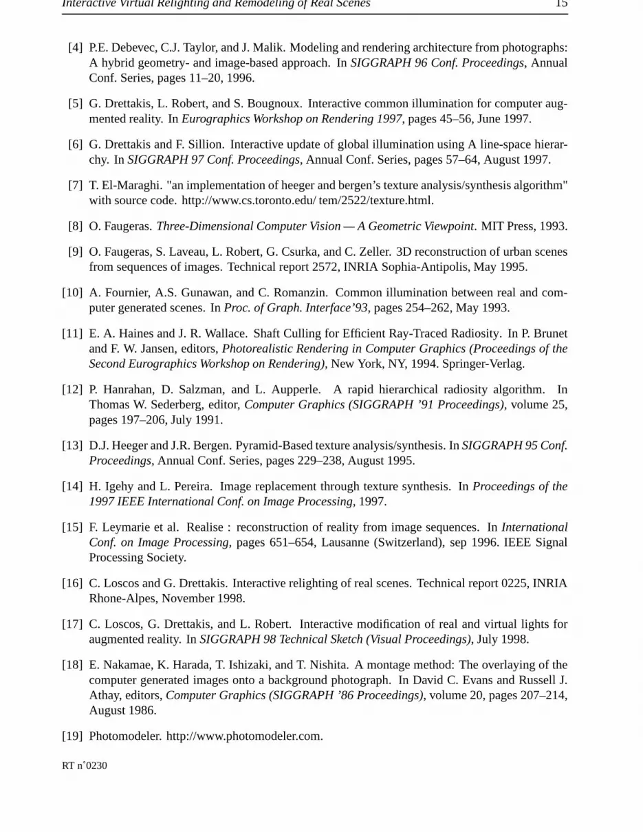
A second example of real object removal is shown in Figure 9. In the context of an interiorredesign, we may want to remove doors for example, which is hard to do in the real world. This is
INRIA
Interactive Virtual Relighting and Remodeling of Real Scenes 13
(a) (b) (c) (d)
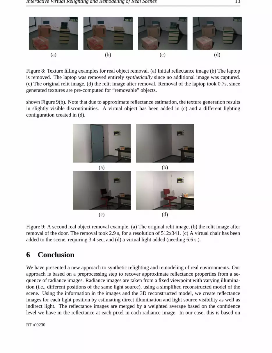
Figure 8: Texture filling examples for real object removal. (a) Initial reflectance image (b) The laptopis removed. The laptop was removed entirely synthetically since no additional image was captured.(c) The original relit image, (d) the relit image after removal. Removal of the laptop took 0.7s, sincegenerated textures are pre-computed for “removable” objects.
shown Figure 9(b). Note that due to approximate reflectance estimation, the texture generation resultsin slightly visible discontinuities. A virtual object has been added in (c) and a different lightingconfiguration created in (d).
(a) (b)
(c) (d)
Figure 9: A second real object removal example. (a) The original relit image, (b) the relit image afterremoval of the door. The removal took 2.9 s, for a resolution of 512x341. (c) A virtual chair has beenadded to the scene, requiring 3.4 sec, and (d) a virtual light added (needing 6.6 s.).
6 Conclusion
We have presented a new approach to synthetic relighting and remodeling of real environments. Ourapproach is based on a preprocessing step to recover approximate reflectance properties from a se-quence of radiance images. Radiance images are taken from a fixed viewpoint with varying illumina-tion (i.e., different positions of the same light source), using a simplified reconstructed model of thescene. Using the information in the images and the 3D reconstructed model, we create reflectanceimages for each light position by estimating direct illumination and light source visibility as well asindirect light. The reflectance images are merged by a weighted average based on the confidencelevel we have in the reflectance at each pixel in each radiance image. In our case, this is based on
RT n˚0230

14 C. Loscos, M.C. Frasson, G. Drettakis, B. Walter, X. Granier, P. Poulin
visibility (points in shadow have low confidence); a filtering step is applied to compensate for errorsin geometric reconstruction and illumination computation.
After the reconstruction has been performed we can interactively modify scene properties. This isachieved by efficiently identifying regions of the screen which need updating, and performing a pixel-by-pixel update for direct light. Indirect lighting is treated separately with an efficient hierarchicalradiosity structure, optimized for dynamic updates.
In our implementation we can virtually modify real light intensity, insert and move virtual objects,and even remove real objects interactively. Despite inevitable artifacts, the quality of the images issufficient for the purposes of interactive lighting design and limited remodeling.
Independently to our work, Yu, Debevec and Malik [26], have developed more robust techniquesfor reflectance estimation, including specular effects in particular. These are based on capturing im-ages of the entire scene, and using radiosity to estimate the reflectance using clever iterative methodsand high-dynamic range images. We believe that our approach can benefit from such improved re-flectance estimation (for example to remove the artifacts in texture generation in Figure 9) as well asfor the reflectance of objects which are not visible in the radiance image. On the other hand, we be-lieve that both our interactive approach, especially for global illumination, as well as our confidencemaps could be useful for such approaches.
In future work, using the high dynamic range radiance images of Debevec and Malik [3] will allowus to achieve more accurate reflectance extraction. Once we have more confidence in the originalradiance most of the error in the reflectance estimation will be due to indirect light. The hierarchicalradiosity framework has the added advantage that it can be used to bound indirect illumination errorsand thus should allow us to achieve better results.
We also need to investigate ways to allow motion of the viewpoint, which is currently an importantlimitation of our approach. Also, the texture generation approaches we have used are limited tostochastic textures. With some user intervention, it may be possible to achieve satisfactory resultswith deterministic textures also.
From a more practical point of view, we can add the synthetic motion of real objects simply intoour system. A view-independent texture of the real object is required, which can be provided by ourphotomodeling system, as well as a modified rendering routine. As was discussed in the results, thelargest expense in the updates is the calculation of visibility for direct lighting. These calculationscan be easily parallelized, and we hope to achieve good speedups in a parallel version, enhancinginteractivity.
References
[1] D. R. Baum, H. E. Rushmeier, and J. M. Winget. Improving radiosity solutions through theuse of analytically determined form-factors. In Jeffrey Lane, editor, Computer Graphics (SIG-GRAPH ’89 Proceedings), volume 23, pages 325–334, July 1989.
[2] P.E. Debevec. Rendering synthetic objects into real scenes: Bridging traditional and image-based graphics with global illumination and high dynamic range photography. In SIGGRAPH98 Conf. Proceedings, Annual Conf. Series, pages 189–198, July 1998.
[3] P.E. Debevec and J. Malik. Recovering high dynamic range radiance maps from photographs.In SIGGRAPH 97 Conf. Proceedings, Annual Conf. Series, pages 369–378, August 1997.
INRIA
Interactive Virtual Relighting and Remodeling of Real Scenes 15
[4] P.E. Debevec, C.J. Taylor, and J. Malik. Modeling and rendering architecture from photographs:A hybrid geometry- and image-based approach. In SIGGRAPH 96 Conf. Proceedings, AnnualConf. Series, pages 11–20, 1996.
[5] G. Drettakis, L. Robert, and S. Bougnoux. Interactive common illumination for computer aug-mented reality. In Eurographics Workshop on Rendering 1997, pages 45–56, June 1997.
[6] G. Drettakis and F. Sillion. Interactive update of global illumination using A line-space hierar-chy. In SIGGRAPH 97 Conf. Proceedings, Annual Conf. Series, pages 57–64, August 1997.
[7] T. El-Maraghi. "an implementation of heeger and bergen’s texture analysis/synthesis algorithm"with source code. http://www.cs.toronto.edu/ tem/2522/texture.html.
[8] O. Faugeras. Three-Dimensional Computer Vision — A Geometric Viewpoint. MIT Press, 1993.
[9] O. Faugeras, S. Laveau, L. Robert, G. Csurka, and C. Zeller. 3D reconstruction of urban scenesfrom sequences of images. Technical report 2572, INRIA Sophia-Antipolis, May 1995.
[10] A. Fournier, A.S. Gunawan, and C. Romanzin. Common illumination between real and com-puter generated scenes. In Proc. of Graph. Interface’93, pages 254–262, May 1993.
[11] E. A. Haines and J. R. Wallace. Shaft Culling for Efficient Ray-Traced Radiosity. In P. Brunetand F. W. Jansen, editors, Photorealistic Rendering in Computer Graphics (Proceedings of theSecond Eurographics Workshop on Rendering), New York, NY, 1994. Springer-Verlag.
[12] P. Hanrahan, D. Salzman, and L. Aupperle. A rapid hierarchical radiosity algorithm. InThomas W. Sederberg, editor, Computer Graphics (SIGGRAPH ’91 Proceedings), volume 25,pages 197–206, July 1991.
[13] D.J. Heeger and J.R. Bergen. Pyramid-Based texture analysis/synthesis. In SIGGRAPH 95 Conf.Proceedings, Annual Conf. Series, pages 229–238, August 1995.
[14] H. Igehy and L. Pereira. Image replacement through texture synthesis. In Proceedings of the1997 IEEE International Conf. on Image Processing, 1997.
[15] F. Leymarie et al. Realise : reconstruction of reality from image sequences. In InternationalConf. on Image Processing, pages 651–654, Lausanne (Switzerland), sep 1996. IEEE SignalProcessing Society.
[16] C. Loscos and G. Drettakis. Interactive relighting of real scenes. Technical report 0225, INRIARhone-Alpes, November 1998.
[17] C. Loscos, G. Drettakis, and L. Robert. Interactive modification of real and virtual lights foraugmented reality. In SIGGRAPH 98 Technical Sketch (Visual Proceedings), July 1998.
[18] E. Nakamae, K. Harada, T. Ishizaki, and T. Nishita. A montage method: The overlaying of thecomputer generated images onto a background photograph. In David C. Evans and Russell J.Athay, editors, Computer Graphics (SIGGRAPH ’86 Proceedings), volume 20, pages 207–214,August 1986.
[19] Photomodeler. http://www.photomodeler.com.
RT n˚0230

16 C. Loscos, M.C. Frasson, G. Drettakis, B. Walter, X. Granier, P. Poulin
[20] P. Poulin, M. Ouimet, and M.-C. Frasson. Interactively modeling with photogrammetry. InEurographics Workshop on Rendering, pages 93–104, June 1998.
[21] Y. Sato, M.D. Wheeler, and K. Ikeuchi. Object shape and reflectance modeling from observation.In SIGGRAPH 97 Conf. Proceedings, Annual Conf. Series, pages 379–387, August 1997.
[22] E. Shaw. Hierarchical radiosity for dynamic environments. Computer Graphics Forum,16(2):107–118, 1997.
[23] F. X. Sillion. A unified hierarchical algorithm for global illumination with scattering volumesand object clusters. IEEE Transactions on Visualization and Computer Graphics, 1(3):240–254,September 1995. ISSN 1077-2626.
[24] G.J. Ward. The RADIANCE lighting simulation and rendering system. In Proceedings ofSIGGRAPH ’94, Annual Conf. Series, pages 459–472, July 1994.
[25] H. Weghorst, G. Hooper, and D. P. Greenberg. Improved computational methods for ray tracing.ACM Transactions on Graphics, 3(1):52–69, January 1984.
[26] Y. Yu, P.E. Debevec, J. Malik, and T. Hawkins. Inverse global illumination: Recovering re-flectance models of real scenes from photographs. In to appear at SIGGRAPH ’99, August1999.
[27] Y. Yu and J. Malik. Recovering photometric properties of architectural scenes from photographs.In Computer Graphics (ACM SIGGRAPH ’98 Proceedings), 1998.
INRIA

Unit e de recherche INRIA Lorraine, Technop ole de Nancy-Brabois, Campus scientifique,615 rue du Jardin Botanique, BP 101, 54600 VILLERS LES NANCY
Unit e de recherche INRIA Rennes, Irisa, Campus universitaire de Beaulieu, 35042 RENNES CedexUnit e de recherche INRIA Rh one-Alpes, 655, avenue de l’Europe, 38330 MONTBONNOT ST MARTIN
Unit e de recherche INRIA Rocquencourt, Domaine de Voluceau, Rocquencourt, BP 105, 78153 LE CHESNAY CedexUnit e de recherche INRIA Sophia-Antipolis, 2004 route des Lucioles, BP 93, 06902 SOPHIA-ANTIPOLIS Cedex
EditeurINRIA, Domaine de Voluceau, Rocquencourt, BP 105, 78153 LE CHESNAY Cedex (France)
http://www.inria.frISSN 0249-6399


