Embed Size (px)
Citation preview

MPEG-4’scomplicated formatmakes developingscenes from scratchall but impossible fornovice users. Byconverting MPEG-4’stext-baseddescription intographical form, theauthors’ proposedtool exploits all ofMPEG-4’s 3Dfunctionalities whileeasing the authoringburden.
In addition to efficient compression,MPEG-4 offers multimedia contentauthors many novel capabilities, such asletting them code audio-visual objects
rather than frames. It also integrates 2D and 3Dcontent and human face- and body-specificfeatures and separates elementary stream trans-mission for individual audio-visual objects. Imple-menting these capabilities is complicated,requiring that authors use several functionalities,from encoding audio and visual scene descriptionsto implementing different delivery scenarios.
History teaches us that however powerful theunderlying technologies, the success of multi-media computing systems depends on their easeof authoring. As the “MPEG-4 Tools” sidebarexplains, existing MPEG-4 authoring tools helpusers create 2D scenes, but if authors want to cre-ate 3D scenes, they have few options.
To address this, we’ve developed an authoringtool that fully exploits MPEG-4’s 3D functionali-ties, integrating unique features such as updatecommands and facial animation. Our tool helpseven MPEG-4 novices create scenes that are total-ly MPEG-4 compliant, which are almost impos-sible for nonexperts to build from scratch usingonly text. Using our tool, authors can insert basic3D objects, such as boxes, spheres, cones, cylin-ders, and text, and modify their attributes. Ourtool also lets authors:
❚ create or insert and modify generic 3D mod-
els using the IndexedFaceSet node;
❚ control object behavior using various sensors(time, touch, cylinder, sphere, and plane) andinterpolators (color, position, and orientation);
❚ texture map static images and video on 3Dobjects;
❚ modify the scene’s temporal behavior byadding, deleting, or replacing nodes over timeusing the Update commands; and
❚ add and animate synthetic faces.
Our tool is based on an open and modulararchitecture that can progress with MPEG-4 ver-sions and is easily adaptable to newly emerging,higher-level authoring features. The tool is avail-able for download at http://media.iti.gr/MPEG4/.
MPEG-4 overview MPEG-4 is an audio-visual representation
standard with two primary objectives: to supportnew ways of communication, access, and inter-action with digital audio-visual data, and to offera common technical solution to various serviceparadigms—such as telecommunications, broad-cast, and interactive applications—whose bordersare rapidly disappearing. MPEG-4 builds on digi-tal television’s success,1 as well as that of syn-thetic content development from interactivegraphics applications2 and content distributionand access methods from interactive multimediasuch as the World Wide Web.3
MPEG-4 addresses application needs in sever-al fields, including Internet video, multimediabroadcasting, content-based audio-visual data-base access, games, advanced audio-visual com-munications (notably over mobile networks),and remote monitoring and control.
MPEG-4 audio-visual scenes are composed ofseveral media objects organized hierarchically. Atthe hierarchy’s leaves, we find primitive mediaobjects including still images (a fixed back-ground, for example), video objects (a talkingperson without the background), audio objects(the voice associated with this person), and soon. Apart from natural objects, MPEG-4 letsauthors code objects that are 2D and 3D, syn-thetic and hybrid, and audio and visual. AsFigure 1 shows, this object coding enables con-tent-based interactivity and scalability.4
In MPEG-4 systems, these audio-visual objects
58 1070-986X/04/$20.00 © 2004 IEEE Published by the IEEE Computer Society
An MPEG-4 Toolfor Composing3D Scenes
Petros Daras, Ioannis Kompatsiaris, and Theodoros RaptisInformatics and Telematics Institute
Michael G. StrintzisAristotle University of Thessaloniki
Feature Article

are decoded from elementary streams and orga-nized into a presentation.5 The coded streamdescribing the spatial-temporal relationshipsbetween the coded audio-visual objects is calledthe scene description, or binary format for scenes(BIFS) stream. MPEG-4 extends Virtual Reality
Modeling Language (VRML)6 scene description toinclude coding and streaming, timing, and 2D and3D object integration. Furthermore, the ExtensibleMPEG-4 Textual format (XMT)7 provides anexchangeable format among content authors,while also preserving the authors’ intentions in a
59
Compoundinfo
Audio-visual objects codedAudio-visual objects coded
Audio-visual objects coded
Audio stream
Audio
Video streams
Decoder
Decoder
BIFSdecoder
Decoder
Encoder
Encoder
BIFSencoder
Encoder
Complexvisual
content
Com
pos
itor
Dem
ulti
ple
xer
Syn
chro
niz
ers
and
mul
tip
lexe
rs
Figure 1. MPEG-4
systems overview.
MPEG-4 authoring is undoubtedly a challenge.Far from the relative simplicity of MPEG-2’s one-video-plus-two-audio-streams, MPEG-4 lets con-tent creators spatially and temporally composenumerous objects of many different types, includ-ing rectangular video, arbitrarily shaped video,still image, speech synthesis, voice, music, text,and 2D and 3D graphics. MPEG-Pro,1 the mostwell-known MPEG-4 authoring tool, includes auser interface, binary format for scenes (BIFS)update, and a timeline, but can handle only 2Dscenes. Another MPEG-4-compliant authoringtool2 also composes only 2D scenes.
Other MPEG-4-related algorithms segment andgenerate video objects, but don’t provide a com-plete MPEG-4 authoring suite.3-6 Commercial mul-timedia authoring tools, such as IBM Hotmedia(http://www-4.ibm.com/software/net.media) andVeon (http://www.veon.com), are based on pro-prietary formats rather than widely acceptablestandards.
References1. S. Boughoufalah, J.C. Dufourd, and F.
Bouilhaguet, “MPEG-Pro, an Authoring System
for MPEG-4,” IEEE Int’l Symp. Circuits and Systems
(ISCAS 2000), IEEE Press, 2000, pp. 175-178.
2. V.K. Papastathis, I. Kompatsiaris, and M.G.
Strintzis, “Authoring Tool for the Composition of
MPEG-4 Audiovisual Scenes,” Int’l Workshop on
Synthetic Natural Hybrid Coding and 3D Imaging,
1999; available at http://uranus.ee.auth.gr/
IWSNHC3DI99/proceedings.html.
3. H. Luo and A. Eleftheriadis, “Designing an Inter-
active Tool for Video Object Segmentation and
Annotation,” ACM Multimedia, ACM Press, 1999,
pp. 265-269.
4. P. Correia and F. Pereira, “The Role of Analysis in
Content-Based Video Coding and Interaction,” Sig-
nal Processing J., 1998, vol. 26, no. 2, pp. 125-142.
5. B. Erol and F. Kossentini, “Automatic Key Video
Object Plane Selection Using the Shape Informa-
tion in the MPEG-4 Compressed Domain,” IEEE
Trans. Multimedia, vol. 2, no. 2, June 2000, pp.
129-138.
6. B. Erol, S. Shirani, and F. Kossentini, “A Conceal-
ment Method for Shape Information in MPEG-4
Coded Video Sequences,” IEEE Trans. Multimedia,
vol. 2, no. 3, Aug. 2000, pp. 185-190.
MPEG-4 Tools
high-level text format. In addition to providing asuitable, author-friendly abstraction of the under-lying MPEG-4 technologies, XMT also respectsexisting author practices including HTML andWeb3D’s Extensible 3D (X3D). Other 3D scenedescription and authoring frameworks, such as theX3D Graphics specification (http://www.web3d.org), are in development.
MPEG-4 provides a large, rich toolset for cod-ing audio-visual objects.8 To ensure that the stan-dard is effectively implemented, subsets of theMPEG-4 systems, visual, and audio toolsets havebeen identified for use with specific applications.These profiles limit the tool set a decoder mustimplement. For each profile, the standard setsone or more levels that restrict the computation-al complexity. Profiles exist for various types ofmedia content (audio, visual, and graphics) andfor scene descriptions. Our tool is compliant withthe following profile types: the simple facial ani-mation visual profile, the scalable texture visualprofile, the hybrid visual profile, the naturalaudio profile, the complete graphics profile, thecomplete scene graph profile, and the objectdescriptor profile, which includes the objectdescriptor tool.
Binary format for scenes (BIFS) The BIFS description language9 extends the
VRML 2.0 specification,6 which was designed foruse on the Internet, intranets, and local client sys-tems. Authors can use VRML in various applicationareas, including engineering and scientific visual-ization, multimedia presentations, entertainmentand educational titles, Web pages, and shared vir-tual worlds. Advanced BIFS (version 2.0, which willbe included in MPEG-4 2.0) will be a VRML super-set that authors can use to compress VRML scenes.MPEG-4 Systems 2.0 supports all VRML nodes.
BIFS extends the base VRML specification inseveral ways. First, it offers new media capabili-ties in the scene. Among these are 2D nodes con-taining 2D graphics and 2D scene graphdescription, and the ability to mix 2D and 3Dgraphics. Also, its new audio nodes supportadvanced audio features including source mix-ing, streaming audio interface, and syntheticaudio content creation. BIFS also offers face- andbody-specific nodes to link to specific animationstreams and nodes that link to the streamingclient-server environment, including media timesensors and back channel messages.
Second, BIFS offers binary scene encoding,which permits efficient scene transmission.
Finally, as we describe in more detail below, BIFSsupports two specific protocols to stream sceneand animation data:
❚ The BIFS-Command protocol lets authors sendsynchronized scene modifications with astream.
❚ The BIFS-Anim protocol permits continuousstreaming of the scene’s animation.
BIFS information typesBIFS contains the following four information
types:
❚ media object attributes that define an object’saudio-visual properties;
❚ the structure of the scene graph that containsthese objects;
❚ the objects’ predefined spatio-temporalchanges, independent of user input; and
❚ the spatio-temporal changes that user inter-action triggers.
Audio-visual objects have both temporal andspatial extent. Temporally, all objects have a sin-gle dimension: time. Spatially, objects can be 2Dor 3D. Each object has a local coordinate system,in which it has a fixed spatio-temporal locationand scale (size and orientation). Authors positionobjects in the scene by specifying a coordinatetransformation from the object-local coordinatesystem into another coordinate system definedby a parent node. The coordinate transformationthat locates an object in a scene is a sceneattribute, rather than an object attribute.Therefore, the system must send the scenedescription as a separate elementary stream.
Elementary streams are a key notion in MPEG-4. A complete MPEG-4 presentation transportseach media/object in a different elementarystream. Such streams are composed of access units(such as a video object frame) that are packetizedinto sync layer packets. Some objects might betransported in several elementary streams, suchas when scalability is involved. This is an impor-tant feature for bitstream editing, which is one ofMPEG-4’s content-based functionalities.
Scene description structureAs Figure 2 shows, we can represent the scene
60
IEEE
Mul
tiM
edia

description’s hierarchical structure as a tree. Eachnode of the tree is an audio-visual object.Complex objects are constructed using appropri-ate scene description nodes.
The tree structure is not necessarily static.The relationships can evolve over time andauthors can delete, add, or modify nodes.Individual scene description nodes expose a setof parameters that let users control severalaspects of the nodes’ behavior. Examplesinclude a sound’s pitch, a synthetic visualobject’s color, and a video sequence’s speed.The scene description structure makes a cleardistinction between the audio-visual objectitself, the attributes that enable control of itsposition and behavior, and any elementarystreams that contain coded information repre-senting object attributes.
The scene description doesn’t directly refer toelementary streams when specifying a media
object; instead it uses the concept of object descrip-tors (ODs). The OD framework identifies and prop-erly associates elementary streams with the scenedescription’s media objects. This often requireselementary stream data to point to an OD using anumeric identifier—an OD ID. Typically, however,these pointers aren’t to remote hosts, but to ele-mentary streams that the client is receiving. ODsalso contain additional information, such as qual-ity-of-service parameters.
Each OD contains one or more ES descriptors,which describe the elementary streams compris-ing a single media object. An ES descriptor identi-fies a single stream with a numeric identifier—anES ID. In the simplest case, an OD contains justone ES descriptor that identifies, for example, anaudio stream that belongs to the AudioSourcenode by which this OD is referenced.10 That sameOD could be referenced from two distinct scenedescription nodes. A single OD might also contain
61
Ap
ril–June 2004
Multiplexed downstreamcontrol/data
Media Naturalaudio/video
2D background2D text
3D object
3D object3D text
Segmentedvideo/audio
…News at MEDIA channel…
(a)
(b)
Voice
DeskSegmentedvideo
2D text
Logo 3D text
Scene
Newscaster Natural audio/video2D background Channel logo
Figure 2. Scene
description structure.
(a) An example MPEG-
4 scene, and (b) the
corresponding scene
tree.
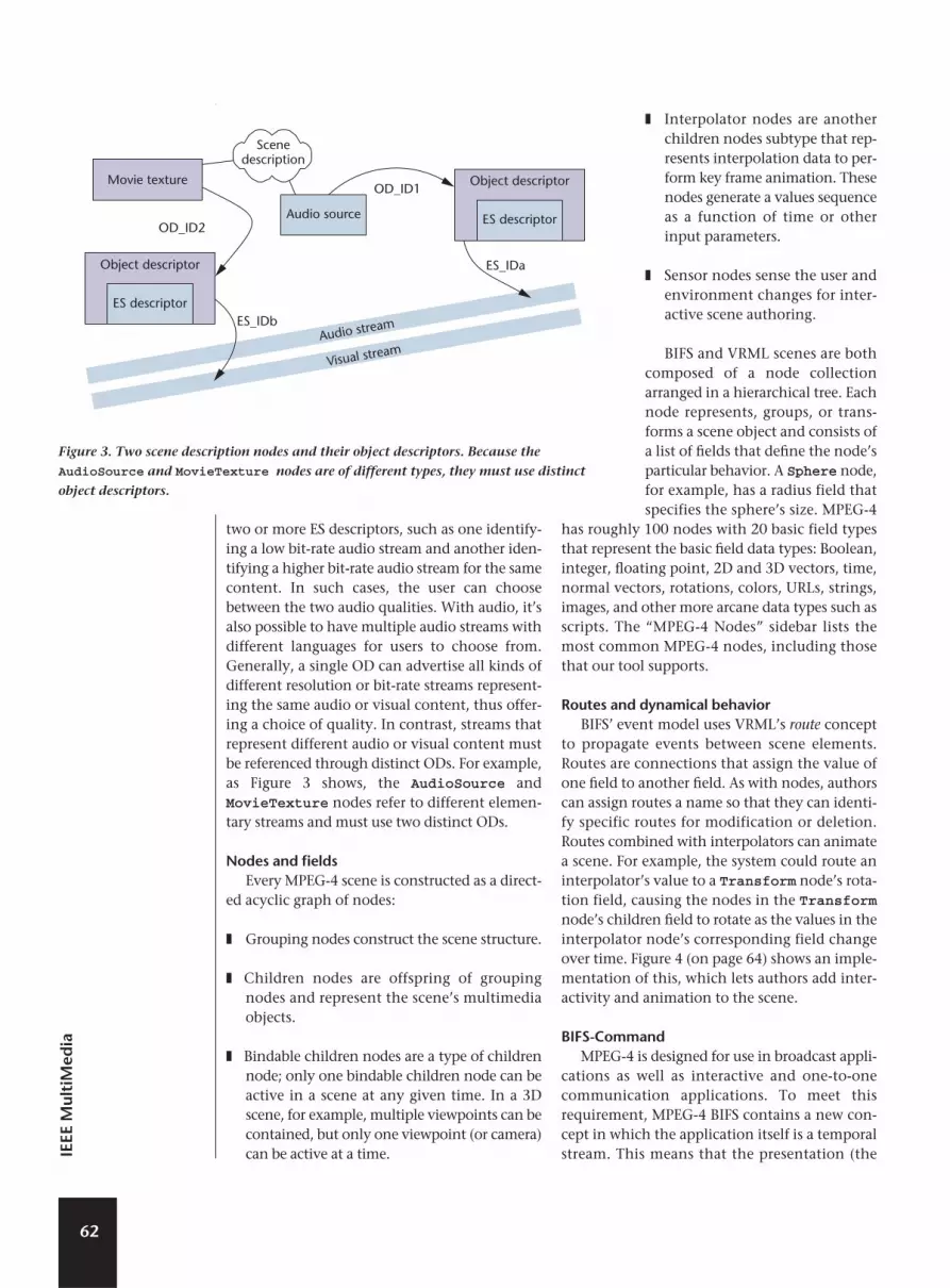
two or more ES descriptors, such as one identify-ing a low bit-rate audio stream and another iden-tifying a higher bit-rate audio stream for the samecontent. In such cases, the user can choosebetween the two audio qualities. With audio, it’salso possible to have multiple audio streams withdifferent languages for users to choose from.Generally, a single OD can advertise all kinds ofdifferent resolution or bit-rate streams represent-ing the same audio or visual content, thus offer-ing a choice of quality. In contrast, streams thatrepresent different audio or visual content mustbe referenced through distinct ODs. For example,as Figure 3 shows, the AudioSource andMovieTexture nodes refer to different elemen-tary streams and must use two distinct ODs.
Nodes and fields Every MPEG-4 scene is constructed as a direct-
ed acyclic graph of nodes:
❚ Grouping nodes construct the scene structure.
❚ Children nodes are offspring of groupingnodes and represent the scene’s multimediaobjects.
❚ Bindable children nodes are a type of childrennode; only one bindable children node can beactive in a scene at any given time. In a 3Dscene, for example, multiple viewpoints can becontained, but only one viewpoint (or camera)can be active at a time.
❚ Interpolator nodes are anotherchildren nodes subtype that rep-resents interpolation data to per-form key frame animation. Thesenodes generate a values sequenceas a function of time or otherinput parameters.
❚ Sensor nodes sense the user andenvironment changes for inter-active scene authoring.
BIFS and VRML scenes are bothcomposed of a node collectionarranged in a hierarchical tree. Eachnode represents, groups, or trans-forms a scene object and consists ofa list of fields that define the node’sparticular behavior. A Sphere node,for example, has a radius field thatspecifies the sphere’s size. MPEG-4
has roughly 100 nodes with 20 basic field typesthat represent the basic field data types: Boolean,integer, floating point, 2D and 3D vectors, time,normal vectors, rotations, colors, URLs, strings,images, and other more arcane data types such asscripts. The “MPEG-4 Nodes” sidebar lists themost common MPEG-4 nodes, including thosethat our tool supports.
Routes and dynamical behaviorBIFS’ event model uses VRML’s route concept
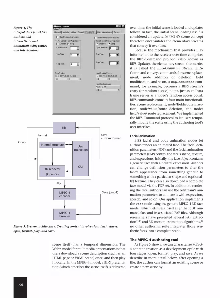
to propagate events between scene elements.Routes are connections that assign the value ofone field to another field. As with nodes, authorscan assign routes a name so that they can identi-fy specific routes for modification or deletion.Routes combined with interpolators can animatea scene. For example, the system could route aninterpolator’s value to a Transform node’s rota-tion field, causing the nodes in the Transformnode’s children field to rotate as the values in theinterpolator node’s corresponding field changeover time. Figure 4 (on page 64) shows an imple-mentation of this, which lets authors add inter-activity and animation to the scene.
BIFS-CommandMPEG-4 is designed for use in broadcast appli-
cations as well as interactive and one-to-onecommunication applications. To meet thisrequirement, MPEG-4 BIFS contains a new con-cept in which the application itself is a temporalstream. This means that the presentation (the
62
IEEE
Mul
tiM
edia
Audio stream
Visual stream
Scenedescription
Movie texture
Object descriptor
ES descriptor
Object descriptor
ES descriptorAudio sourceOD_ID2
ES_IDb
ES_IDa
OD_ID1
Figure 3. Two scene description nodes and their object descriptors. Because the
AudioSource and MovieTexture nodes are of different types, they must use distinct
object descriptors.
63
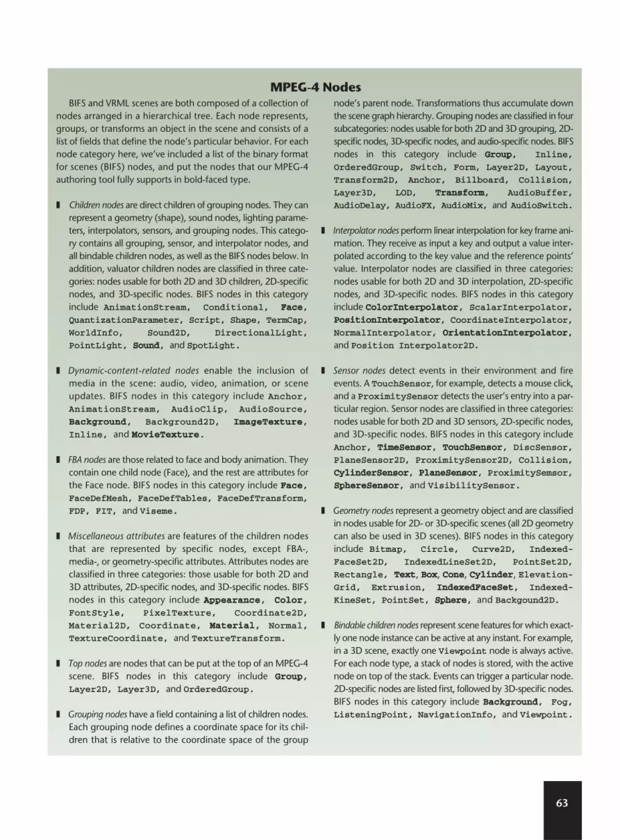
BIFS and VRML scenes are both composed of a collection ofnodes arranged in a hierarchical tree. Each node represents,groups, or transforms an object in the scene and consists of alist of fields that define the node’s particular behavior. For eachnode category here, we’ve included a list of the binary formatfor scenes (BIFS) nodes, and put the nodes that our MPEG-4authoring tool fully supports in bold-faced type.
❚ Children nodes are direct children of grouping nodes. They canrepresent a geometry (shape), sound nodes, lighting parame-ters, interpolators, sensors, and grouping nodes. This catego-ry contains all grouping, sensor, and interpolator nodes, andall bindable children nodes, as well as the BIFS nodes below. Inaddition, valuator children nodes are classified in three cate-gories: nodes usable for both 2D and 3D children, 2D-specificnodes, and 3D-specific nodes. BIFS nodes in this categoryinclude AnimationStream, Conditional, FFaaccee,
QuantizationParameter, Script, Shape, TermCap,
WorldInfo, Sound2D, DirectionalLight,
PointLight, SSoouunndd, and SpotLight.
❚ Dynamic-content-related nodes enable the inclusion ofmedia in the scene: audio, video, animation, or sceneupdates. BIFS nodes in this category include Anchor,AnimationStream, AudioClip, AudioSource,
BBaacckkggrroouunndd, Background2D, IImmaaggeeTTeexxttuurree,
Inline, and MMoovviieeTTeexxttuurree.
❚ FBA nodes are those related to face and body animation. Theycontain one child node (Face), and the rest are attributes forthe Face node. BIFS nodes in this category include FFaaccee,FaceDefMesh, FaceDefTables, FaceDefTransform,
FDP, FIT, and Viseme.
❚ Miscellaneous attributes are features of the children nodesthat are represented by specific nodes, except FBA-,media-, or geometry-specific attributes. Attributes nodes areclassified in three categories: those usable for both 2D and3D attributes, 2D-specific nodes, and 3D-specific nodes. BIFSnodes in this category include AAppppeeaarraannccee, CCoolloorr,FontStyle, PixelTexture, Coordinate2D,
Material2D, Coordinate, MMaatteerriiaall, Normal,
TextureCoordinate, and TextureTransform.
❚ Top nodes are nodes that can be put at the top of an MPEG-4scene. BIFS nodes in this category include GGrroouupp,Layer2D, Layer3D, and OrderedGroup.
❚ Grouping nodes have a field containing a list of children nodes.Each grouping node defines a coordinate space for its chil-dren that is relative to the coordinate space of the group
node’s parent node. Transformations thus accumulate downthe scene graph hierarchy. Grouping nodes are classified in foursubcategories: nodes usable for both 2D and 3D grouping, 2D-specific nodes, 3D-specific nodes, and audio-specific nodes. BIFSnodes in this category include GGrroouupp, Inline,
OrderedGroup, Switch, Form, Layer2D, Layout,
Transform2D, Anchor, Billboard, Collision,
Layer3D, LOD, TTrraannssffoorrmm, AudioBuffer,
AudioDelay, AudioFX, AudioMix, and AudioSwitch.
❚ Interpolator nodes perform linear interpolation for key frame ani-mation. They receive as input a key and output a value inter-polated according to the key value and the reference points’value. Interpolator nodes are classified in three categories:nodes usable for both 2D and 3D interpolation, 2D-specificnodes, and 3D-specific nodes. BIFS nodes in this categoryinclude CCoolloorrIInntteerrppoollaattoorr, ScalarInterpolator,PPoossiittiioonnIInntteerrppoollaattoorr, CoordinateInterpolator,
NormalInterpolator, OOrriieennttaattiioonnIInntteerrppoollaattoorr,
and Position Interpolator2D.
❚ Sensor nodes detect events in their environment and fireevents. A TouchSensor, for example, detects a mouse click,and a ProximitySensor detects the user’s entry into a par-ticular region. Sensor nodes are classified in three categories:nodes usable for both 2D and 3D sensors, 2D-specific nodes,and 3D-specific nodes. BIFS nodes in this category includeAnchor, TTiimmeeSSeennssoorr, TToouucchhSSeennssoorr, DiscSensor,
PlaneSensor2D, ProximitySensor2D, Collision,
CCyylliinnddeerrSSeennssoorr, PPllaanneeSSeennssoorr, ProximitySemsor,
SSpphheerreeSSeennssoorr, and VisibilitySensor.
❚ Geometry nodes represent a geometry object and are classifiedin nodes usable for 2D- or 3D-specific scenes (all 2D geometrycan also be used in 3D scenes). BIFS nodes in this categoryinclude Bitmap, Circle, Curve2D, Indexed-
FaceSet2D, IndexedLineSet2D, PointSet2D,
Rectangle, TTeexxtt, BBooxx, CCoonnee, CCyylliinnddeerr, Elevation-Grid, Extrusion, IInnddeexxeeddFFaacceeSSeett, Indexed-
KineSet, PointSet, SSpphheerree, and Backgound2D.
❚ Bindable children nodes represent scene features for which exact-ly one node instance can be active at any instant. For example,in a 3D scene, exactly one Viewpoint node is always active.For each node type, a stack of nodes is stored, with the activenode on top of the stack. Events can trigger a particular node.2D-specific nodes are listed first, followed by 3D-specific nodes.BIFS nodes in this category include BBaacckkggrroouunndd, Fog,ListeningPoint, NavigationInfo, and Viewpoint.
MPEG-4 Nodes
scene itself) has a temporal dimension. TheWeb’s model for multimedia presentations is thatusers download a scene description (such as anHTML page or VRML scene) once, and then playit locally. In the MPEG-4 model, a BIFS presenta-tion (which describes the scene itself) is delivered
over time: the initial scene is loaded and updatesfollow. In fact, the initial scene loading itself isconsidered an update. MPEG-4’s scene concepttherefore encapsulates the elementary streamsthat convey it over time.
Because the mechanism that provides BIFSinformation to the receiver over time comprisesthe BIFS-Command protocol (also known asBIFS-Update), the elementary stream that carriesit is called the BIFS-Command stream. BIFS-Command conveys commands for scene replace-ment, node addition or deletion, fieldmodification, and so on. A ReplaceScene com-mand, for example, becomes a BIFS stream’sentry (or random access) point, just as an Intraframe serves as a video’s random access point.BIFS commands come in four main functionali-ties: scene replacement, node/field/route inser-tion, node/value/route deletion, and node/field/value/ route replacement. We implementedthe BIFS-Command protocol to let users tempo-rally modify the scene using the authoring tool’suser interface.
Facial animationBIFS facial and body animation nodes let
authors render an animated face. The facial defi-nition parameters (FDP) and the facial animationparameters (FAP) control the face’s shape, texture,and expressions. Initially, the face object containsa generic face with a neutral expression. Authorscan change definition parameters to alter theface’s appearance from something generic tosomething with a particular shape and (optional-ly) texture. They can also download a completeface model via the FDP set. In addition to render-ing the face, authors can use the bitstream’s ani-mation parameters to animate it with expression,speech, and so on. Our application implementsthe Face node using the generic MPEG-4 3D facemodel, which lets users insert a synthetic 3D ani-mated face and its associated FAP files. Althoughresearchers have presented several FAP extrac-tion11-13 and 3D motion-estimation algorithms,14
no other authoring suite integrates those syn-thetic faces into a complete scene.
The MPEG-4 authoring toolAs Figure 5 shows, we can characterize MPEG-
4 content creation as a development cycle withfour stages: open, format, play, and save. As wedescribe in more detail below, after opening afile, the author can format an existing scene orcreate a new scene by
64
IEEE
Open
Savecustom format
Save (.mp4)
File
MPEG-4encoder
MPEG-4browser
Format
Play
Internal structure
3D renderer
(OpenGI)
Userinteraction
GUI
Figure 5. System architecture. Creating content involves four basic stages:
open, format, play, and save.
Figure 4. The
interpolators panel lets
authors add
interactivity and
animation using routes
and interpolators.

❚ clicking the appropriate icon to insert 3Dobjects, such as spheres, cones, cylinders, text,boxes, and background (see Figure 6);
❚ deleting objects or modifying their attributes,such as 3D position, size, color, and so on;
❚ adding realism to the scene by associatingimage and video textures with the insertedobjects;
❚ duplicating inserted objects using the copy-and-paste functionality;
❚ grouping objects to simultaneously changetheir attributes;
❚ inserting sound and video streams;
❚ adding interactivity using interpolators (forobject motion, periodic color changes, and soon) and sensors (for interactivity betweenobjects; for example, when one object isclicked, a new one is inserted);
❚ controlling the scene dynamically using theBIFS-Command protocol (such as indicatingthat a specific scene segment, or object group,appears 10 seconds after the initial sceneloads); and
❚ using the IndexedFaceSet node to create orinsert generic 3D models and modify them.
During the creation process, authors store theBIFS-defined object attributes and commands inan internal program structure, which is continu-ously updated depending on the user’s actions. Atthe same time, the author can view a real-time,3D scene preview in an integrated OpenGL win-dow (see Figure 6). OpenGL (http://www.opengl.org) is a software interface to graphicshardware that renders 2D and 3D objects into aframe buffer. OpenGL describes these objects assequences of vertices (for geometric objects) orpixels (for images) and converts the data to pixelsto create the final desired image in the buffer.
Once the scene is formatted, the tool plays thecreated content by interpreting the commandsissued in the editing phase. This lets the authorcheck the current description’s final presenta-tion. The author can then save the file in eithera custom format or, after encoding/multiplexingand packaging it, in an MP4 file8 (the standard
MPEG-4 file format). The MP4 file format storesan MPEG-4 presentation’s media information ina flexible, extensible format that facilitates themedia’s interchange, management, editing, andpresentation.
User interfaceTo improve the creation process, authors need
powerful tools.15 Multimedia applications’ tem-poral dependence and variability can hinderauthors from obtaining an accurate view of whatthey’re editing. To address this, we used OpenGLto create an environment with multiple, syn-chronized views. As Figure 6 shows, the interfaceis composed of three main views: edit/preview,scene tree, and object details.
The edit/preview window integrates the pre-sentation and editing phases in the same view,which presents authors with a partial result oftheir created objects in an OpenGL window. Ifthey insert a new object into the scene, the win-dow displays it immediately in the exact 3Dposition specified. However, if authors assign aparticular behavior to an object (such as assign-ing a video a texture), the preview windowshows only the first frame (they can see the fullvideo only when they play the scene). If anobject already has one texture (such as a videotexture) and an author tries to add another tex-ture (such as an image texture), a warning mes-sage appears.
The scene tree view (the bottom right box inFigure 6) provides a structural view of the scene
65
Ap
ril–June 2004
Figure 6. The tool’s main window. The buttons on the right let
authors insert 3D objects (shown), change texture, and update
commands.
as a tree (although a BIFS scene is a graph, we dis-play it as a tree for ease of presentation). Thescene tree view gives authors more detailed infor-mation on object behaviors, which can’t be dis-played in the edit view. Authors can also usedrag-and-drop and copy-paste operations in thisview.
In the object details window (the top right boxin Figure 6), authors can use object properties toassign values to an object beyond those offeredby default. These properties include 3D position,rotation, and scale; color (diffuse, specular, andemission); shine and texture; video and audiostreams (transmitted as two separate elementarystreams, according to the OD mechanism); cylin-der and cone radius and height; text style andfonts; sky and ground background and texture;and, to add interactivity and animation, inter-polators (color, position, orientation) and sensors(sphere, cylinder, plane, touch, and time).
Furthermore, this view also lets authors insert,create, and manipulate generic 3D models usingthe IndexedFaceSet node. Authors can easilyinsert simple VRML files and, using the Facenode, synthetically animated 3D faces. Theauthor must provide a FAP file15 and the corre-sponding encoder parameter file (EPF), whichgives the FAP encoder all the information relat-ed to the corresponding FAP file (such as I and Pframes, masks, frame rate, quantization scalingfactor, and so on). The tool then creates a binaryformat for animation (BIFA) file for the scenedescription and OD files to use.
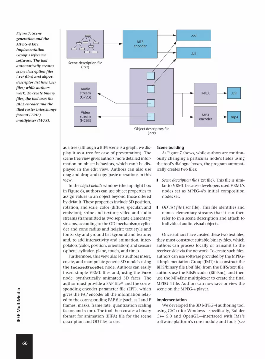
Scene buildingAs Figure 7 shows, while authors are continu-
ously changing a particular node’s fields usingthe tool’s dialogue boxes, the program automat-ically creates two files:
❚ Scene description file (.txt file). This file is simi-lar to VRML because developers used VRML’snodes set as MPEG-4’s initial compositionnodes set.
❚ OD list file (.scr file). This file identifies andnames elementary streams that it can thenrefer to in a scene description and attach toindividual audio-visual objects.
Once authors have created these two text files,they must construct suitable binary files, whichauthors can process locally or transmit to thereceiver side via the network. To create such files,authors can use software provided by the MPEG-4 Implementation Group (IM1): to construct theBIFS/binary file (.bif file) from the BIFS/text file,authors use the BifsEncoder (BifsEnc), and thenuse the MP4Enc multiplexer to create the finalMPEG-4 file. Authors can now save or view thescene on the MPEG-4 player.
Implementation We developed the 3D MPEG-4 authoring tool
using C/C++ for Windows—specifically, BuilderC++ 5.0 and OpenGL—interfaced with IM1’ssoftware platform’s core module and tools (see
66
IEEE
Mul
tiM
edia
BIFSencoder
.od
.bif
.trif
.mp4
Scene description file(.txt)
Object descriptors file(.scr)
Videostream(H263)
Audiostream(G723)
MP4encoder
MUX
Figure 7. Scene
generation and the
MPEG-4 IM1
Implementation
Group’s reference
software. The tool
automatically creates
scene description files
(.txt files) and object-
descriptor list files (.scr
files) while authors
work. To create binary
files, the tool uses the
BIFS encoder and the
tiled raster interchange
format (TRIF)
multiplexer (MUX).

Figure 7). IM1’s 3D player is a software imple-mentation of an MPEG-4 systems player.16 Theplayer is built on top of IM1’s core framework,which includes tools to encode and multiplextest scenes. The player aims to be compliant withthe complete 3D profile.
The core module provides the infrastructurefor full implementation of MPEG-4 players.17 Itincludes support for all functionalities (demulti-plexing, BIFS and OD decoding, scene construc-tion, update, and so on). The modules usedecoding and composition buffers to managesynchronized data flow between the multiplex-er, the decoders, and the compositor. The mod-ule supports plug-ins for the decoder’s API, theDelivery Multimedia Integration Framework (theMPEG layer that delivers content over variousnetworks and media), and intellectual propertymanagement and protection (IPMP). It also pro-vides functionality for MediaObject, which isthe base class for all specific node types.
The core module is the foundation layer for cus-tomized MPEG-4 applications. It contains hooksfor plugging all kinds of decoders (including JPEG,Advanced Audio Coding, H.263, and G.723) andcustomized compositors. Written in C++, the coremodule’s code is platform independent and devel-opers have used it as the infrastructure for applica-tions that run on Windows or Unix. The moduleincludes a Windows “console” test application thatreads a multiplexed file—output by the tiled rasterinterchange format (TRIF) multiplexer, describedbelow—which contains scene description andmedia streams. The test application then producestwo files. One shows each composition unit’s pre-sentation time—that is, the time when a plug-incompositor would receive the composition unit(CU) for presentation, compared to the composi-tion time stamp attached to the encoded unit. Theother file shows textual presentation of the decod-ed BIFS and OD. The software tools include aBifsEnc and TRIF multiplexer.
The BifsEnc reads a textual scene description,scene updates, and OD stream commands (whichmight include OD and IPMP objects), and pro-duces two binary files—BIFS file and an ODstream.18 We used the BifsEnc to encode the tex-tual output of our authoring tool. It also pro-duces two files; both have the same name as theinput file, but one has the .bif extension and theother has the .od extension. It also produces atext file with the input file’s name and the .lstextension. This file lists all the input lines, eachfollowed by error descriptions (if any) and a tex-
tual description of the binary encoding. The TRIF multiplexer is a software tool devel-
oped by Zvi Lifshitz that reads a set of filescontaining an MPEG-4 elementary stream, andmultiplexes them into one bitstream according toTRIF specifications. The TRIF multiplexer can alsoencode a bootstrap OD (InitialObject-Descriptor) and place it at the beginning of themultiplexed file. The MP4Enc multiplexer readsMPEG-4 elementary streams and multiplexes theminto a single MP4 file, which is based on the TRIFmultiplexer and the MP4 file format API libi-somp4.lib. To verify compliance with MPEG-4bitstreams,19 we use Im1Player (for 2D scenes) and3D player (for 3D scenes). These tools input MP4files and produce text files that describe the file’scontent. The tools’ output includes full textdescriptions of all elementary streams (BIFS, OD)that the tool processes.
Our authoring tool provides a front-end userinterface to the MPEG-4 IM1 software and pro-duces the .txt and .scr files that IM1 uses asinputs to the BIFS and MPEG-4 (and MUX)encoders, respectively (see Figure 7).
Examples: Creating scenesTo show how our tool works, we’ll create two
scenes: an ancient Greek temple and a virtualstudio.
Building a temple Figure 8 (next page) shows the construction of
an example scene: an ancient Greek temple—made up of several groups of cylinders andboxes—that continuously rotates around its y-axis.We can create this temple through several rela-tively simple steps.
Creating the temple’s facade. We first createa vertical cylinder, changing its position and scal-ing to make it similar to a temple column. Wethen use a copy-paste operation in the scene treeview to create a second identical column andreposition it in the desired place (we’ll createmore columns later, when the temple’s facade iscomplete). Next, we build the temple’s roof: wecreate a box and reposition it on top of the twocolumns, making the box’s z-dimension equal tothe column’s diameter. We then create a secondbox, resize and rotate it, and place it on top of thefirst box. We rotate this second box about 45degrees around its z-axis, then duplicate it; bychanging its z-axis rotation vector with a sym-metric negative value, we create two similar anti-
67
Ap
ril–June 2004

symmetric boxes. The roof now looks like theextrusion of an isosceles triangle. The front of thetemple is complete (see Figure 8a).
Duplicating scene portions. The temple’sfacade is an important part of the building’sgeometry, and by duplicating it twice we can cre-ate the temple’s back and middle sections. Giventhis, we create a group object using a drag-and-drop operation in the scene tree view, includingall items from the temple’s facade. Grouping theobjects makes them easier to manipulate as a set.We can then easily create the remaining templeportions by copying and pasting the object groupseveral times, taking care to adjust the groups’ z-positions so that the z-values of the front andback sections are symmetrical.
Final details. At this point, we must fill inthe roof’s gaps. To do this, we create identicalboxes and place them between the roof’s frontand middle portions and its middle and backportions. We can either do this from scratch orby slightly duplicating parts of the roof (wecould duplicate the roof’s front part, for exam-ple, and then reposition and scale it toward itsz-aspect).
The temple now needs only a floor, which wecreate using a stretched box. We can then add
more specific details to the created objects,including texture and color.
Adding gradual presentation. To demon-strate the historic process of temple construction,we want to use a gradual presentation. Toachieve this, we use BIFS-Commands (updates) asfollows:
1. We select the Insert command on theUpdates tab (see Figure 8b).
2. In the scene tree’s main window, we selectthe object groups that we defined earlier forgradual presentation and copy them (seeFigure 8c).
3. We select the General tab on the UpdateCommand Details panel (see Figure 9) andpaste the object group. We then specify thegroup using the Set Target button and speci-fy the timing using the Time of Action button(in this case, 500 milliseconds).
4. Finally, we press Play to see the results in a 3DMPEG-4 player.
Adding movement. We can animate thescene using interpolators. First, we group all the
68
IEEE
Mul
tiM
edia
Figure 8. An ancient
Greek temple. (a) The
temple’s facade is
created using copy-
paste operations in the
scene tree view. (b) To
achieve a gradual
presentation, the
author selects the
Insert command on the
Updates tab, then, in
the scene tree’s main
window (c) selects the
object groups defined
earlier and copies them.
(d) The temple as
viewed through the
MPEG player.
(a) (b)
(c) (d)

objects in a global group object, then set it inmotion by activating its interpolator properties.In the Interpolators menu, we check theOrientation Interpolator property and then makeselections to rotate the object around its y-axis.We can achieve more complicated movements asneeded by placing group nodes inside each otherand activating each one’s interpolator properties.
To view our results, we can either select thePreview/Play button in the interface’s toolbar, orsave the scene so we can view it externally witha MPEG-4 player. Every scene that our tool pro-duces is fully compatible with the MPEG-4 BIFSstandard and can be presented by any MPEG-4player capable of reproducing BIFS.
Building a virtual studioOur second scene represents a virtual studio.
The scene contains several groups of syntheticobjects, including a synthetic face, boxes withtextures, text objects, and indexedfacesets(see Figure 10). The logo group, located in thestudio’s upper left corner, is comprised of a rotat-ing box and a text object that describes the chan-nel’s name. The background contains four boxeswith image textures (the left and right sides, thefloor, and the back side). We created the desk
using another two boxes. A box with video tex-ture is in the scene’s upper right corner. Weloaded an H.263 video on this box. The news-caster’s body is an indexedfaceset importedfrom a VRML 3D model; we inserted the 3D faceusing the Insert button. Finally, we inserted arolling text of headlines. After we selected an FAPfile and audio stream (for the saxophone in theupper left corner), we configured the face to ani-mate according to the FAP file. The tool transmitsthe video stream (H.263) and audio stream(G.723) as two separate elementary streamsaccording to the OD mechanism.
We implemented all the animation (except theface) using interpolator nodes. Figure 11 (nextpage) shows a major part of the scene descriptiontext file.
The AnimationStream node reads the FAP filefrom an external source. We inserted a Transformnode before the Face node to control the animat-ed face’s position in the scene. The Face nodeinserts the animated face and connects it with theFAP file defined earlier. To create the logo in theupper left corner (and, more specifically, the tex-tured rotating box) we first define the box’s posi-tion (Transform node) and then the textureimage (appearance and texture fields). We thendefine the object’s geometry and dimensions(Geometry node). In our case, the object is a box.To create the rotating motion, we first define themotion period (how fast the box will rotate) andwhether the rotation speed will be constant. Thisis controlled by the TimeSensor node and theloop and cycleInterval fields. The Orientation-Interpolator node defines the motion’s inter-mediate positions. Finally, the Route nodes
69
Ap
ril–June 2004
Figure 10. The virtual studio scene in the authoring
tool. The scene includes several object groups,
including textured boxes and a synthetic face.
Figure 9. The General tab on the Updates
Command Details Panel lets authors select an
object group and specify its time of play.

connect the movement’s defined parameters to thetextured object. The tool’s definition (DEF) nodesuniquely characterize the object. For example, thetexture box is object T120661744. Figure 12 showsthe completed scene.
ConclusionWe found that while content developers were
satisfied with the tool’s efficiency and effective-ness, users who were unfamiliar with MPEG-4had problems understanding the terminology weused. We thus need to further develop and refinethe tool for large-scale deployment.
Because our authoring tool produces MPEG-4-compliant scenes, users can visualize themusing the IM1-3D player without modifications.Users can thus use the tool to create MPEG-4-compliant applications without introducing pro-prietary features.
Our tool can help MPEG-4 algorithm and sys-tem developers integrate their algorithms andmake them available through a user-friendlyinterface. It can also serve as a beginning fordeveloping new tools. Finally, our authoring toolcan be a benchmark for comparing other or pro-prietary authoring tools with a tool that hasMPEG-4 system capabilities.
In all, 2,000 visitors have accessed our tool’sWeb page (averaging eight visitors a day). Morethan 60 visitors have also registered to use thetool and have provided useful feedback about itsfunctionality. Most visitors seem to be associat-ed with research laboratories that deal withMPEG-4, including Deutsche Telecom, Norway’sTelenor, France Telecom, British Telecom,Telecom Italia Lab, Sony Semiconductors andDevices Europe, and Philips Digital BroadcastSystems Group. MM
References1. C. Herpel and A. Eleftheriadis, “Tutorial issue on
MPEG-4,” Signal Processing: Image Communication,
vol. 15, nos. 4-5, 2000.
2. R. Koenen, “MPEG-4 Multimedia for our Time,”
IEEE Spectrum, vol. 36, no. 2, Feb. 1999, pp. 26-33.
3. L. Chiariglione, “MPEG and Multimedia Communica-
tions,” IEEE Trans. Circuits and Systems for Video Tech-
70
IEEE
Mul
tiM
edia
Figure 12. The complete virtual studio, viewed
through an IM1 3D player.
DEF ID_014 AnimationStream #fap animation stream{
url 50}
Transform {translation 0.000 1.529 1.690rotation 0.000 0.000 0.000 0.000scale 0.013 0.013 0.013
Children Face #face node{
fap DEF ID_104 FAP{}renderedFace
}}
DEF T120661744 Transform {translation 0.000 0.000 0.000rotation 1.786 1.014 0.000 0.911children Shape {
appearance Appearance {texture ImageTexture {
url 10}
textureTransform TextureTransform {}
}geometry Box { #box with image texture
size 0.796 0.796 0.694}
}}
DEF OrientTS120658180 TimeSensor {stopTime -1startTime 0loop TRUE # time sensor for interpolation
# purposescycleInterval 15
}
DEF ORI120658180 OrientationInterpolator {key0, 1keyValue0.000 0.000 0.000 0.000 ,0.000 0.200 0.000 3.143
}. . .ROUTE OrientTS120658180 .fraction_changed TO ORI120658180.set_fractionROUTE ORI120658180 .value_changed TO T120661744 .rotation
Figure 11. The scene description text file for the virtual studio.
nology, vol. 7, no. 1, Feb. 1997, pp. 5-18.
4. F. Pereira, “MPEG-4: Why, What, How, and When,”
Signal Processing: Image Communication, vol. 15,
2000, pp. 271-279.
5. MPEG-4 Systems, “ISO/IEC 14496-1: Coding of
Audio-Visual Objects: Systems, Final Draft Interna-
tional Standard,” ISO/IEC JTC1/SC29/WG11
N2501, Oct. 1998.
6. ISO/IEC 14472-1, “The Virtual Reality Modeling
Language,” http://www.vrml.org/, 1997.
7. M. Kim, S. Wood, and L.T. Cheok, “Extensible
MPEG-4 Textual Format (XMT),” ACM Multimedia-
2000; available at http://www.acm.org/sigs/
sigmm/MM2000/ep/michelle/index.html.
8. R. Koenen, “MPEG-4 Overview (V.16 La BauleVer-
sion),” ISO/IEC JTC1/SC29/WG11 N3747, Int’l
Standards Organization, Oct. 2000.
9. J. Signæes, Y. Fisher, and A. Eleftheriadis, “MPEG-
4’s Binary Format for Scene Description,” Signal
Processing: Image Communication, vol. 15, nos. 4-5,
2000, pp. 321-345.
10. E.D. Shreirer, R. Vaananen, and J. Huopaniemi,
“AudioBIFS: Describing Audio Scenes with the
MPEG-4 Multimedia Standard,” IEEE Trans. Multi-
media, vol. 1, no. 3, June 1999, pp. 237-250.
11. F. Lavagetto and R. Pockaj, “The Facial Animation
Engine: Toward a High-Level Interface for the
Design of MPEG-4 Compliant Animated Faces,”
IEEE Trans. Circuits and Systems for Video Technology,
vol. 9, no. 3, Mar. 1999, pp. 277-289.
12. G.A. Abrantes and F. Pereira, “MPEG-4 Facial Ani-
mation Technology: Survey, Implementation, and
Results,” IEEE Trans. Circuits and Systems for Video
Technology, vol. 9, no. 3, Mar. 1999, pp. 290-305.
13. H. Tao et al., “Compression of MPEG-4 Facial Ani-
mation Parameters for Transmission of Talking
Heads,” IEEE Trans. Circuits and Systems for Video
Technology, vol. 9, no. 3, Mar. 1999, pp. 264-276.
14. I. Kompatsiaris, D. Tzovaras, and M.G. Strintzis,
“3D Model-Based Segmentation of
Videoconference Image Sequences,” IEEE Trans. Cir-
cuits and Systems for Video Technology, vol. 8, no. 5,
Sept. 1998, pp. 547-561.
15. B. MacIntyre and S. Feiner, “Future Multimedia
User Interfaces,” Multimedia Systems, vol. 4, no. 5,
Oct. 1996, pp. 250-268.
16. Z. Lifshitz, Status of the Systems Version 1, 2, 3 Soft-
ware Implementation, tech. rep., ISO/IEC
JTC1/SC29/WG11 N3564, Int’l Standards Organi-
zation, July 2000.
17. Z. Lifshitz, Part 5 Reference Software Systems
(ISO/IEC 14496-5 Systems), tech. rep., ISO/IEC
JTC1/SC29/WG11 MPEG2001, Int’l Standards
Organization, Mar. 2001.
18. Z. Lifshitz, BIFS/OD Encoder, tech. rep., ISO/IEC
JTC1/SC29/WG11, Int’l Standards Organization,
Mar. 2001.
19. Z. Lifshitz, “IM1 Player: A Bitstream Verification
Tool,” tech. rep., ISO/IEC JTC1/SC29/WG11, Int’l
Standards Organization, Mar. 2001.
Petros Daras is an associate
researcher at the Informatics and
Telematics Institute, Thessaloniki,
Greece, and is pursuing a PhD in
multimedia from the Aristotle
University of Thessaloniki. His
main research interests include the MPEG-4 standard,
streaming, 3D object search and retrieval, and medical
informatics applications. He is a member of the
Technical Chamber of Greece.
Ioannis Kompatsiaris is a senior
researcher with the Informatics
and Telematics Institute,
Thessaloniki. His research inter-
ests include computer vision, 3D-
model-based monoscopic and
multiview image sequence analysis and coding, med-
ical image processing, standards (MPEG-4, MPEG-7),
and content-based indexing and retrieval. He is a mem-
ber of the IEEE and the Technical Chamber of Greece.
Theodoros Raptis is an MBA postgraduate student at the
Economic University of Athens. His scientific interest is
centered around investment analysis in the field of free
energy markets. Raptis received a diploma in electrical
engineering from Aristotle University of Thessaloniki in
2001; his thesis was on MPEG-4 and the development of
the MPEG-4 authoring tool. He is a member of the
Technical Chamber of Greece.
Michael G. Strintzis is a professor
of electrical and computer engi-
neering at the University of
Thessaloniki, and director of the
Informatics and Telematics
Research Institute, Thessaloniki.
His current research interests include 2D and 3D image
coding, image processing, biomedical signal and image
processing, and DVD and Internet data authentication
and copy protection. In 1984, he was awarded one of
the Centennial Medals of the IEEE.
71
Ap
ril–June 2004


