Embed Size (px)
Citation preview

INSTALLATION MANUAL
INTEGRATED VOICE EVACUATION SYSTEMVX-3000 SERIES
Thank you for purchasing TOA’s Integrated Voice Evacuation System. Please carefully follow the instructions in this manual to ensure long, trouble-free use of your equipment.
1134TOA Electronics Europe GmbH
Suederstrasse 282, 20537 Hamburg, Germany1134-CPR-195
EN 54-16: 2008Fire Detection and fire alarm systems - part 16: Voice alarm control and indication system for fire detection and fire alarm systems for buildings
Options:Manual silencing of voice alarm condition
manual reset of voice alarm conditionvoice alarm condition output
indication of a fault related to voice alarm zonesvoice alarm manual controlemergency microphones
redundant power amplifiers
16DOP 16-004
When an EN 54-16 compliant VX-3000 system has to be installed, then carefully read the separate manual titled "APPENDIX: ADDITIONAL INSTALLATION INSTRUCTIONS FOR AN EN 54-16 COMPLIANT SYSTEM" and follow up the installation and configuration requirements explained therein. This APPENDIX contains the basic description of settings and installations, so please refer to the general instruction sections in this document for more details.

2
TABLE OF CONTENTS
Chapter 1 : NOTE
1. SAFETY PRECAUTIONS .......................................................................... 1-2
2. GENERAL DESCRIPTION ....................................................................... 1-6
3. SYSTEM FEATURES ................................................................................... 1-6
4. SYSTEM EXAMPLE ..................................................................................... 1-6
Chapter 2 : NOMENCLATURE AND FUNCTIONS
1. VX-3004F/3008F/VX-3016F VOICE EVACUATION FRAME ............................................................... 2-2
2. VX-015DA/030DA/050DA DIGITAL POWER AMPLIFIER MODULE ....................................... 2-9
3. RM-200SF FIREMAN'S MICROPHONE ........................................ 2-11
4. RM-320F FIREMAN'S MICROPHONE EXTENSION ............ 2-14
5. RM-300X REMOTE MICROPHONE ................................................. 2-15
6. RM-210F REMOTE MICROPHONE EXTENSION ................... 2-18
7. RM-200RJ TERMINAL UNIT ................................................................. 2-19
8. SX-200EL END OF LINE UNIT ............................................................ 2-20
9. VM-300SV END OF LINE UNIT .......................................................... 2-20
Chapter 3 : INSTALLATION AND SETTING PROCEDURES (HARDWARE)
1. VX-015DA, VX-030DA, AND VX-050DA DIGITAL POWER AMPLIFIER MODULE ....................................... 3-2
1.1. Changing the Speaker Line Voltage .................................................................. 3-21.2. Replacing the Blade Fuse ................................................................................. 3-2
2. VX-3004F, VX-3008F, AND VX-3016F VOICE EVACUATION FRAME .............................................................. 3-3
2.1. Installing VX-015DA/030DA/050DA Digital Power Amplifier Module ................ 3-32.2. The Zones Allocation Setting ............................................................................ 3-52.3. The ID Number Setting ...................................................................................... 3-72.4. Setting the IP Address ...................................................................................... 3-8
3
3. RM-200SF AND RM-300X MICROPHONES ............................... 3-93.1. The ID Number Settings (Switches 1 – 3 operation) ......................................... 3-93.2. Adjusting Microphone Sensitivity (RM-200SF: Switch 5 operation or RM-300X: Switch 4 operation) ................. 3-113.3. CPU Off Function (All-Zone Emergency Broadcast) Settings (RM-200SF: Switch 6 operation or RM-300X: Switch 5 operation) ................. 3-133.4. Termination Setting (RM-200SF: Switch 8 operation) ...................................................................... 3-143.5. Using an External Microphone (RM-300X Only) ............................................. 3-153.6. Using an Auxiliary Input (RM-300X Only) ........................................................ 3-173.7. Compressor Function Setting ........................................................................... 3-193.8. Microphone Fault Detection Function Setting (RM-300X Only) ....................... 3-213.9. Installing the RM-200SF on a Wall ................................................................. 3-223.10. Installing the RM-320F on a Wall (RM-200SF only) ...................................... 3-263.11. RM-300X Extension with the Addition of the RM-210F (Installed on a Flat Surface) .......................................................................... 3-283.12. Installing the RM-300X on a Wall .................................................................. 3-293.13. Installing the RM-210F on a Wall (RM-300X Only) ....................................... 3-303.14. Creating Remote Microphone Name Labels ................................................. 3-323.15. Rack Mounting .............................................................................................. 3-353.16. Affixing Declaration of Compliance (EN 54-16 Standard) ............................. 3-36
4. CONNECTIONS ........................................................................................... 3-374.1. Removable Terminal Plug Connection ............................................................ 3-374.2. Input Equipment Connections ......................................................................... 3-384.3. Speaker Connection ....................................................................................... 3-544.4. Control Output Terminal Connections ............................................................. 3-574.5. Control Input Terminal Connections ............................................................... 3-584.6. Emergency Control Input Terminal Connections ............................................ 3-59
5. VX-3000F CONNECTION ...................................................................... 3-605.1. LAN Link Connector Connections ................................................................... 3-605.2. Sharing Standby Amplifier .............................................................................. 3-665.3. Speaker Selector Extension ........................................................................... 3-675.4. Analog Link Terminal Connections ................................................................. 3-68
6. SPEAKER LINE INITIAL SETTING ................................................. 3-696.1. Setting Items ................................................................................................... 3-696.2. OPEN/SHORT Criterion by Comparing the Current Value with the Initial Value ........................................................................................ 3-696.3. Setting Procedures .......................................................................................... 3-70
Chapter 4 : APPENDIX
1. THE FIRMWARE VERSION CONFIRMATION ............................ 4-2
2. SPECIFICATIONS ......................................................................................... 4-42.1. VX-3004F Voice Evacuation Frame 4AB .......................................................... 4-42.2. VX-3008F Voice Evacuation Frame 8SS ........................................................... 4-72.3. VX-3016F Voice Evacuation Frame 16SS ....................................................... 4-102.4. VX-015DA Digital Power Amplifier Module 150 W ........................................... 4-132.5. VX-030DA Digital Power Amplifier Module 300 W .......................................... 4-14

4
2.6. VX-050DA Digital Power Amplifier Module 500 W .......................................... 4-152.7. RM-200SF Fireman's Microphone ................................................................... 4-162.8. RM-320F Fireman's Microphone Extension .................................................... 4-172.9. RM-300X Remote Microphone ....................................................................... 4-182.10. RM-210F Remote Microphone Extension ...................................................... 4-192.11. RM-200RJ Terminal Unit ................................................................................ 4-192.12. VM-300SV End Of Line Unit ........................................................................ 4-20

Chapter 1
NOTE
1-2
Chapter 1 NOTE
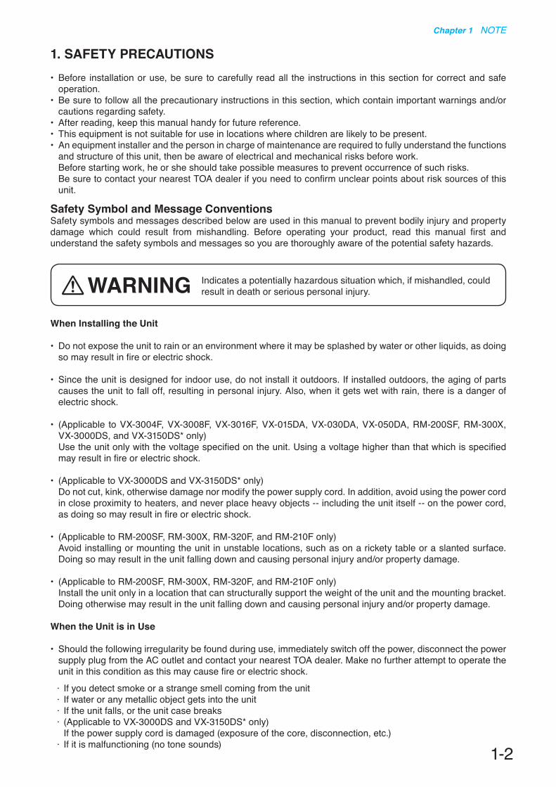
1. SAFETY PRECAUTIONS• Before installation or use, be sure to carefully read all the instructions in this section for correct and safe
operation.• Be sure to follow all the precautionary instructions in this section, which contain important warnings and/or
cautions regarding safety.• After reading, keep this manual handy for future reference.• This equipment is not suitable for use in locations where children are likely to be present.• An equipment installer and the person in charge of maintenance are required to fully understand the functions
and structure of this unit, then be aware of electrical and mechanical risks before work. Before starting work, he or she should take possible measures to prevent occurrence of such risks. Be sure to contact your nearest TOA dealer if you need to confirm unclear points about risk sources of this
unit.
Safety Symbol and Message Conventions Safety symbols and messages described below are used in this manual to prevent bodily injury and property damage which could result from mishandling. Before operating your product, read this manual first and understand the safety symbols and messages so you are thoroughly aware of the potential safety hazards.
When Installing the Unit
• Do not expose the unit to rain or an environment where it may be splashed by water or other liquids, as doing so may result in fire or electric shock.
• Since the unit is designed for indoor use, do not install it outdoors. If installed outdoors, the aging of parts causes the unit to fall off, resulting in personal injury. Also, when it gets wet with rain, there is a danger of electric shock.
• (Applicable to VX-3004F, VX-3008F, VX-3016F, VX-015DA, VX-030DA, VX-050DA, RM-200SF, RM-300X, VX-3000DS, and VX-3150DS* only)
Use the unit only with the voltage specified on the unit. Using a voltage higher than that which is specified may result in fire or electric shock.
• (Applicable to VX-3000DS and VX-3150DS* only) Do not cut, kink, otherwise damage nor modify the power supply cord. In addition, avoid using the power cord
in close proximity to heaters, and never place heavy objects -- including the unit itself -- on the power cord, as doing so may result in fire or electric shock.
• (Applicable to RM-200SF, RM-300X, RM-320F, and RM-210F only) Avoid installing or mounting the unit in unstable locations, such as on a rickety table or a slanted surface.
Doing so may result in the unit falling down and causing personal injury and/or property damage.
• (Applicable to RM-200SF, RM-300X, RM-320F, and RM-210F only) Install the unit only in a location that can structurally support the weight of the unit and the mounting bracket.
Doing otherwise may result in the unit falling down and causing personal injury and/or property damage.
When the Unit is in Use
• Should the following irregularity be found during use, immediately switch off the power, disconnect the power supply plug from the AC outlet and contact your nearest TOA dealer. Make no further attempt to operate the unit in this condition as this may cause fire or electric shock.
· If you detect smoke or a strange smell coming from the unit· If water or any metallic object gets into the unit · If the unit falls, or the unit case breaks · (Applicable to VX-3000DS and VX-3150DS* only) If the power supply cord is damaged (exposure of the core, disconnection, etc.)· If it is malfunctioning (no tone sounds)
Indicates a potentially hazardous situation which, if mishandled, could result in death or serious personal injury. WARNING

1-3
Chapter 1 NOTE
• To prevent a fire or electric shock, never open nor remove the unit case as there are high voltage components inside the unit.
(Applicable to RM-200SF and RM-300X only) Refer all servicing to qualified service personnel.
• Do not place cups, bowls, or other containers of liquid or metallic objects on top of the unit. If they accidentally spill into the unit, this may cause a fire or electric shock.
• (Applicable to VX-3004F, VX-3008F, VX-3016F, VX-015DA, VX-030DA, VX-050DA, VX-3000DS, and VX-3150DS* only)
Do not insert nor drop metallic objects or flammable materials in the ventilation slots of the unit’s cover, as this may result in fire or electric shock.
• (Applicable to VX-3000DS and VX-3150DS* only) Do not touch a power supply plug during thunder and lightning, as this may result in electric shock.
• When replacing the fuse, be sure to use the supplied one. Using any other fuse than supplied may cause fire or electric shock.
VX-015DA: Blade 10 AVX-030DA: Blade 20 AVX-050DA: Blade 30 AVX-3000DS and VX-3150DS*: AC T8A H, AC T6.3A L, and Blade 35 A
• Be sure to switch off the amplifier's power when replacing the fuse. Inserting or removing the fuse with the amplifier's power on may cause personal injury.
• (Applicable to VX-3000DS and VX-3150DS* only) Handle or use the batteries properly. Doing otherwise may cause leakage or explosion of the batteries, resulting in a fire, personal injury, damage
to peripheral equipment, or contamination of environment.
When Installing the Unit
• (Applicable to VX-3000DS and VX-3150DS* only) Never plug in nor remove the power supply plug with wet hands, as doing so may cause electric shock.
• (Applicable to VX-3000DS and VX-3150DS* only) When unplugging the power supply cord, be sure to grasp the power supply plug; never pull on the cord itself.
Operating the unit with a damaged power supply cord may cause a fire or electric shock.
• (Applicable to VX-3004F, VX-3008F, VX-3016F, VX-015DA, VX-030DA, VX-050DA, VX-3000DS, and VX-3150DS* only)
Do not block the ventilation slots in the unit’s cover. Doing so may cause heat to build up inside the unit and result in fire.
(Applicable to VX-015DA, VX-030DA, and VX-050DA only) Also, periodically clean the ventilation slots of dust.
• Avoid installing the unit in humid or dusty locations, in locations exposed to the direct sunlight, near the heaters, or in locations generating sooty smoke or steam as doing otherwise may result in fire or electric shock.
• (Applicable to VX-3004F, VX-3008F, VX-3016F, VX-015DA, VX-030DA, VX-050DA, RM-200SF, RM-300X, VX-3000DS, and VX-3150DS* only)
Note correct polarity (positive and negative orientation) when connecting the power supply cord. Reversed polarity connections will cause damage to the unit.
Indicates a potentially hazardous situation which, if mishandled, could result in moderate or minor personal injury, and/or property damage.CAUTION

1-4
Chapter 1 NOTE
• (Applicable to VX-015DA, VX-030DA, and VX-050DA only) To avoid electric shocks, be sure to switch off the VX-3000F’s power when connecting the unit.
• (Applicable to VX-3004F, VX-3008F, VX-3016F, VX-3000DS, and VX-3150DS* only) System units (except remote microphones) are designed exclusively to be mounted in an equipment rack.
Be sure observe the following instructions when rack-mounting the unit. Failure to do so may cause a fire or personal injury.
· Install the equipment rack on a stable, hard floor. Fix it with anchor bolts or take other arrangements to prevent it from falling down.
· (Applicable to VX-3004F, VX-3008F, and VX-3016F only) The supplied rack-mounting screws can be used for the TOA equipment rack only. Do not use them for other
racks.· (Applicable to VX-3000DS and VX-3150DS* only) Rack-mounting screws are not supplied with the unit. Prepare them that are appropriate for the equipment rack.· (Applicable to VX-3000DS and VX-3150DS* only) When connecting the unit’s power cord to an AC outlet, use the AC outlet with current capacity allowable to
the unit.
• (Applicable to VX-3000DS and VX-3150DS* only) When connecting multiple appliances to a single power socket through a multi-outlet power strip, a total
current consumption of the appliances must not exceed the allowable current capacity of the power socket. Failure to observe this instruction may result in a fire or electric shock.
• (Applicable to VX-3000DS and VX-3150DS* only) When 2 or more AC power cords are connected to a multi-outlet power strip, never remove the power strip
from a power source.
When the Unit is in Use
• (Applicable to VX-3004F, VX-3008F, VX-3016F, VX-015DA, VX-030DA, and VX-050DA only) Do not operate the unit for an extended period of time with the sound distorting. Doing so may cause the
connected speakers to heat, resulting in a fire.
• (Applicable to RM-200SF and RM-300X only) Use the specified AC adapter for the unit. Note that the use of other adapter may cause a fire.
• (Applicable to VX-015DA, VX-030DA, and VX-050DA only) Contact your TOA dealer as to the cleaning. If dust is allowed to accumulate in the unit over a long period of
time, a fire or damage to the unit may result.
• (Applicable to VX-3000DS and VX-3150DS* only) Make sure to observe the following handling precautions so that a fire or personal injury does not result from
leakage or explosion of the battery.
· Do not short, disassemble, heat nor put the battery into a fire.· Avoid using both new and old batteries together.· Never charge batteries of the type which are not rechargeable. · Do not solder a battery directly.· Be sure to use the specified type of batteries.· Note correct polarity (positive and negative orientation) when connecting a battery to the unit.· Avoid locations exposed to the direct sunlight, high temperature and high humidity when storing batteries.
• (Applicable to RM-200SF, RM-300X, RM-320F, and RM-210F only) Have the unit checked periodically by the shop from where it was purchased. Failure to do so may result
in corrosion or damage to the unit or its mounting bracket that could cause the unit to fall, possibly causing personal injury.
* VX-3150DS: Power Supply Manager, equivalent of the VX-3000DS, sold only in Europe

1-5
Chapter 1 NOTE
Warning: This equipment is compliant with Class A of CISPR 32. In a residential environment this equipment may cause radio interference.

1-6
Chapter 1 NOTE
2. GENERAL DESCRIPTIONThe TOA VX-3000 Series Integrated Voice Evacuation System is designed for both general and emergency purpose broadcasts.It is comprised of the Voice Evacuation Frame, Digital Power Amplifier modules, Power Supply unit, Emergency Power Supply, and a user-specified number of Remote Microphones. The system complies with the EN54-16 Standard and its failure detection circuitry operates continuously to check components and speaker lines for any irregularities. If detected, failure warnings are provided by way of an LED indicator and a buzzer.The VX-3000 system allows 4 types of broadcasts to be made: General-purpose broadcast such as general paging and BGM, Emergency warning broadcast that can be broadcast with priority over the Emergency broadcast, Emergency broadcast that the emergency messages are to be broadcast by an automatic announcement device or remote microphone, All-zone emergency broadcast* that is to be made available even during system malfunctions or failures.Two patterns of the Emergency broadcast can be activated simultaneously.The dedicated software is used to perform all necessary settings related to the entire system operation and functions including system configurations, input-to-output signal routing, function assignment to the operation keys, operation of the control terminals, and selection of the failure detection points.
* Available when an analog link is connected.
3. SYSTEM FEATURES• VX-3000 system is a voice evacuation system. • Decentralized configuration is possible via network. • VX-3000 system is constructed up to 160 AB zones or 640 zones as system. • Speaker Selector function is implemented, then VX-3000 system is able to cover many zones. • A general broadcast for a sound quality regulating function is possible to digitalize all sound. • A general broadcasting is possible by latitude setting of control input/output and priorities.
4. SYSTEM EXAMPLE
LAN
VX-3000 System
VX-3000 System
1A
1B
4A
4B
VX-3004F
BGM unit
RM-300X RM-210F RM-200SF RM-320F
VX-015DA/030DA/050DA
VX-3000DS

Chapter 2
NOMENCLATURE AND FUNCTIONS
2-2
Chapter 2 NOMENCLATURE AND FUNCTIONS
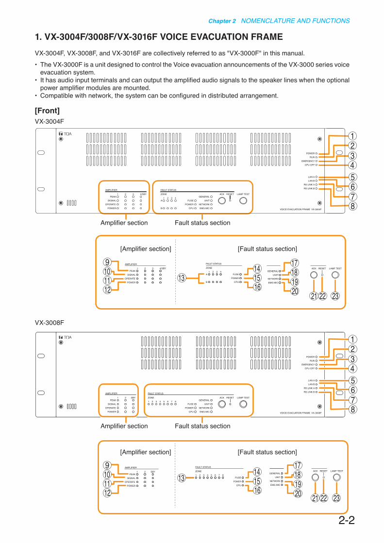
1. VX-3004F/3008F/VX-3016F VOICE EVACUATION FRAMEVX-3004F, VX-3008F, and VX-3016F are collectively referred to as "VX-3000F" in this manual.• The VX-3000F is a unit designed to control the Voice evacuation announcements of the VX-3000 series voice
evacuation system.• It has audio input terminals and can output the amplified audio signals to the speaker lines when the optional
power amplifier modules are mounted.• Compatible with network, the system can be configured in distributed arrangement.
[Front]
Amplifier section Fault status section
[Amplifier section] [Fault status section]
9101112
13141516
17181920 21 22 23
123
5678
4
VX-3004F
VX-3008F
Amplifier section Fault status section
123
5678
[Amplifier section] [Fault status section]
9101112
13141516
17181920 21 22 23
4

2-3
Chapter 2 NOMENCLATURE AND FUNCTIONS
1. Power indicator (Green)Lights when the power is supplied.Flashes in standby state.
2. RUN indicator (Green)Normally flashes continuously. Goes off while in a CPU off state (p. 3-13). Also goes off while in standby state*1.*1 A state during power failures or a state that the
unit is internally initialized after power-on
3. Emergency indicator (Red)Lights when the VX-3000 system is in an emergency condition or while in a CPU off state (p. 3-13).
4. CPU off indicator (Red)Lights while in a CPU off state (p. 3-13).
5. LAN A indicator (Green)Lights when the LAN link A connector (49) on the rear panel is connected, and flashes during LAN communications.
6. LAN B indicator (Green)Lights when the LAN link B connector (49) on the rear panel is connected, and flashes during LAN communications.
7. RS link A indicator (Green)Lights when the RS link A connector (50) on the rear panel is connected, and flashes while communications are being performed via the RS link A connector.
8. RS link B indicator (Green)Lights when the RS link B connector (50) on the rear panel is connected, and flashes while communications are being performed via the RS link B connector.
9.Amplifierpeakindicators(Red)Show the input signal state to the power amplifier when the power amplifier module is installed.The indicator corresponding to the module slot port will light if the input signal level exceeds +0.5 dB*2.It remains unlit when no power amplifier module is installed.
10.Amplifiersignalindicators(Green)Show the input signal state to the power amplifier when the power amplifier module is installed.The indicator corresponding to the module slot port will light if the input signal level exceeds -25 dB*2.It remains unlit when no power amplifier module is installed.
VX-3016F
[Amplifier section] [Fault status section]
9101112
13141516
17181920 21 22 23
123
5678
4
Amplifier section Fault status section
*2 0 dB = 1 V
2-4
Chapter 2 NOMENCLATURE AND FUNCTIONS
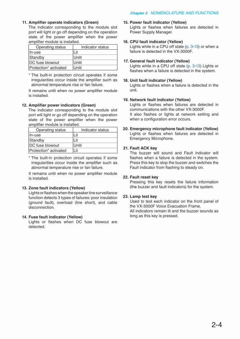
11.Amplifieroperateindicators(Green)The indicator corresponding to the module slot port will light or go off depending on the operation state of the power amplifier when the power amplifier module is installed.
Operating status Indicator statusIn-use LitStandby UnlitDC fuse blowout UnlitProtection* activated Unlit
* The built-in protection circuit operates if some irregularities occur inside the amplifier such as abnormal temperature rise or fan failure.
It remains unlit when no power amplifier module is installed.
12.Amplifierpowerindicators(Green)The indicator corresponding to the module slot port will light or go off depending on the operation state of the power amplifier when the power amplifier module is installed.
Operating status Indicator statusIn-use LitStandby LitDC fuse blowout UnlitProtection* activated Lit
* The built-in protection circuit operates if some irregularities occur inside the amplifier such as abnormal temperature rise or fan failure.
It remains unlit when no power amplifier module is installed.
13. Zone fault indicators (Yellow)Lights or flashes when the speaker line surveillance function detects 3 types of failures: poor insulation (ground fault), overload (line short), and cable disconnection.
14. Fuse fault indicator (Yellow)Lights or flashes when DC fuse blowout are detected.
15. Power fault indicator (Yellow)Lights or flashes when failures are detected in Power Supply Manager.
16. CPU fault indicator (Yellow)Lights while in a CPU off state (p. 3-13) or when a failure is detected in the VX-3000F.
17. General fault indicator (Yellow)Lights while in a CPU off state (p. 3-13) Lights or flashes when a failure is detected in the system.
18. Unit fault indicator (Yellow)Lights or flashes when a failure is detected in the unit.
19. Network fault indicator (Yellow)Lights or flashes when failures are detected in communications with the other VX-3000F. It also flashes or lights at network setting and when a configuration error occurs.
20. Emergency microphone fault indicator (Yellow)Lights or flashes when failures are detected in Emergency Microphone.
21. Fault ACK keyThe buzzer will sound and Fault indicator will flashes when a failure is detected in the system. Press this key to stop the buzzer and switches the Fault indicator from flashing to steady on.
22. Fault reset keyPressing this key resets the failure information (the buzzer and fault indicators) for the system.
23. Lamp test keyUsed to test each indicator on the front panel of the VX-3000F Voice Evacuation Frame.All indicators remain lit and the buzzer sounds as long as this key is pressed.

2-5
Chapter 2 NOMENCLATURE AND FUNCTIONS
24. Audio input volume controlsAdjust the input volume of each input channel. Rotating the control fully counterclockwise mutes the input sound source connected to that channel.
25. Module slotsAccommodate the VX-015DA, VX-030DA, or VX-050DA, Digital Power Amplifier Module. Up to 4 modules can be installed to the VX-3004F, up to 3 to the VX-3008F, and up to 2 to the VX-3016F.
26. Reset keyPressing this key reactivates the VX-3000F.
27. ID switchSets the VX-3000F's ID number (device number).
28. DA control link connectorConnect this connector to the DA control link connector of the installed digital power amplifier module.
29. DIP switch[VX-3004F]• Switches 1 – 6
These switches are not used.• Switch 7
Used when confirming the firmware version. (See p. 4-2.)
• Switch 8Used to set the IP address. (See p. 3-8.)
[VX-3008F]• Switches 1 – 3
Used to allocate speaker lines. (See p. 3-5.)
• Switches 4 – 6These switches are not used.
• Switch 7Used when confirming the firmware version. (See p. 4-2.)
• Switch 8Used to set the IP address. (See p. 3-8.)
[VX-3016F]• Switch 1
Used to place the unit in 2 channel mode operation. (See p. 3-5.)
• Switches 2 – 6These switches are not used.
• Switch 7Used when confirming the firmware version. (See p. 4-2.)
• Switch 8Used to set the IP address. (See p. 3-8.)
NoteBy default, switches 1 – 7 are set to OFF, and switch 8 to ON.
30. Impedance initialize keyPress this key to acquire the initial value of the speaker line impedance as failure detection is executed on the basis of the impedance change.
31. DA output link connectorConnect this connector to the DA output link connector of the installed digital power amplifier module.
This is an electric hazard mark.There is the possibility of an electric shock when connecting cables.Make connections when power is not supplied to the Digital Power Amplifier Modules VX-015DA, VX-030DA, and VX-050DA.
24 25
26 27 28 28 28 2829 30 31 313131
[Front panel detached]

2-6
Chapter 2 NOMENCLATURE AND FUNCTIONS
[Rear]
VX-3004F
VX-3008F
VX-3016F
90 W
32 33 33 3334 34 34 343335 3535 35 36
37 38 39 40 41 4342
44 45 46
47 48 49 50
90 W
4445
3632 33 35 33 35 33 3534 34 34
37 3839
46
47 48 49 5051 52
42
41 4340
90 W
4544
37 3839 51 52
42 3632 33 35 33 3534 34
46
47 48 49 5041 41 4340

2-7
Chapter 2 NOMENCLATURE AND FUNCTIONS
32. DC power input terminalConnect an optional DC power supply unit to this terminal. Select the DC power supply source with consideration given to the current power consumption of the system the VX-3000F is to be connected to. (See the Instruction Manual attached to the VX-3000DS or the VX-3150DS.)
33. FuseWhen an amplifier module is installed, its fuse can be checked.You can replace the fuse with the amplifier module installed to the VX-3000F. (See p. 2-10.)
34.AmplifiermodelnumberindicationwindowWhen a power amplifier module is installed, you can check its model number.
35.AmplifierDCpowerinputterminalWhen a power amplifier module is installed, you can check its power input terminals. (See p. 2-10.)
36. Audio input terminalsElectronically-balanced 47 kΩ, –20 dB*/–60 dB*, Terminal connectors. LINE or MIC input can be selected, and the phantom power supply turned on and off. (See the separate Setting Software Instructions, "Unit Configuration Setting.")* 0 dB = 1 V
37. Signal ground terminalHum noise may be generated when external equipment is connected to the unit. Connecting this terminal to the signal ground terminal of the external equipment may reduce the hum noise.Note: This terminal is not for protective ground.
38.StandbyamplifieroutputconnectorWhen a standby amplifier is shared by multiple VX-3000F units, connect this connector to the standby amplifier input connector of other VX-3000F.
39.StandbyamplifierinputconnectorWhen making the VX-3000F with no standby amplifier share the standby amplifier installed to other VX-3000F, connect this connector to other VX-3000F's standby amplifier output connector.
40. MAC addressThis is the MAC address* for the unit. Since the relationship of each unit location to its MAC address is established when setting the network attributes, keep track of this relationship for later use.* The unit’s MAC address consists of 12
hyphenated alphanumeric characters.
41. Speaker output terminals Connect speakers to these outputs.
42. ATT/Control output terminalsThese terminals permit the VX-3000 system to control other connected external equipment.Alternatively, these terminals become attenuator control outputs by setting.
43. Emergency control input terminalConnect to an automatic fire alarm system and activate emergency broadcasts, play back/stop automatic emergency announcements and reset emergency broadcasts.Two isolated voltage inputs which activates when the polarity of the applied voltage (24 V DC is kept applied to this terminal under normal condition) is reversed.
44. DS link connectorsConnects this connector to the DS LINK IN connector of the VX-3000DS (or the VX-3150DS).
45. Analog link output connector Connect this connector to the analog link input connector of the other VX-3000F.
46. Analog link input connector Connect this connector to the analog link output connector of the other VX-3000F.
47. Control output connectorsThese RJ45 connectors permit the VX-3000 system to control other connected external equipment.
48. Control input connectorsThese RJ45 connectors receive activation signals from external equipment to enable external VX-3000 system control.Alternatively, these connectors become EOL inputs by setting.
33 34 35
2-8
Chapter 2 NOMENCLATURE AND FUNCTIONS
49. LAN link connectorsUse switching hubs to connect between the LAN link connector of the VX-3000F. Connect each of the LAN Links A and B to the same switching hub*, or to different switching hubs* that have been connected in star configuration.Also, it is possible to interconnect the VX-3000F units directly using the LAN link connectors A and B without using switching hubs.* Contact your TOA dealer for more information
on switching hubs.Notes• Be sure to connect both connectors of A and B.• After connection completion, press the Reset
key to reactivate the VX-3000F.
50. RS link connectorsConnect the RM-200SF Fireman's Microphone or RM-300X Remote Microphone to these connectors.NoteOnly one RM-200SF can be connected to each connector if the system is required to comply with EN54-16.
51. Extension output connectorsConnect these connectors to the Extension input connector of the VX-3000F in SS mode (with no built-in Digital Power Amplifier) for zone number expansion by the VX-3008F or VX-3016F.
52. Extension input connectorsConnect these connectors of the VX-3008F or VX-3016F set to SS mode to the Extension output connector of the VX-3000F in normal mode.

2-9
Chapter 2 NOMENCLATURE AND FUNCTIONS
2. VX-015DA/030DA/050DA DIGITAL POWER AMPLIFIER MODULE• The VX-015DA, VX-030DA, and VX-050DA are Digital power amplifier modules used for the VX-3000 system.• They are module types with 1 channel of class-D digital power amplifier, which contributes to energy-saving
and light weight design.• The VX-015DA, VX-030DA, and VX-050DA also feature standby mode to be set for reducing standby power
consumption.• They require VX-3000F control unit and VX-3000DS (or VX-3150DS) power supply unit.
Module lineup includes the following 3 models different in rated output.VX-015DA : 150 WVX-030DA : 300 WVX-050DA : 500 W
1. DA control link connectorConnect this connector to the DA control link connector of the VX-3000F to which this module is installed using the supplied harness.
2. Fixing screwFixes the module to the VX-3000F.
3. Model number indication
4. DA output link connectorConnect this connector to the DA output link connector of the VX-3000F to which this module is installed using the supplied harness.
5. FilterDustproof filter.Remove and clean the filter periodically.If the filter becomes clogged, heat will be trapped inside the module.
12
3 4
Appearance with a filter detached
Appearance with a filter attached
5
This is an electric hazard mark.There is the possibility of an electric shock when connecting cables.Make connections when power is not supplied to the Digi tal Power Ampli f ier Modules VX-015DA, VX-030DA, and VX-050DA.
[Front]

2-10
Chapter 2 NOMENCLATURE AND FUNCTIONS
[Left Side]
8
6. FuseUse a blade fuse described below depending on the power amplifier's rated output.
VX-015DA : 10 AVX-030DA : 20 AVX-050DA : 30 A
7. DC power input terminalConnect an optional DC power supply unit to this terminal. (See the Instruction Manual attached to the VX-3000DS or the VX-3150DS.)
[Rear]
6 7
8. Output voltage selection switchUsed to select power amplifier's rated output voltage.
2-11
Chapter 2 NOMENCLATURE AND FUNCTIONS
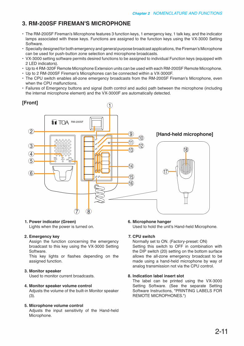
3. RM-200SF FIREMAN'S MICROPHONE• The RM-200SF Fireman’s Microphone features 3 function keys, 1 emergency key, 1 talk key, and the indicator
lamps associated with these keys. Functions are assigned to the function keys using the VX-3000 Setting Software.
• Specially designed for both emergency and general purpose broadcast applications, the Fireman’s Microphone can be used for push-button zone selection and microphone broadcasts.
• VX-3000 setting software permits desired functions to be assigned to individual Function keys (equipped with 2 LED indicators).
• Up to 4 RM-320F Remote Microphone Extension units can be used with each RM-200SF Remote Microphone.• Up to 2 RM-200SF Fireman’s Microphones can be connected within a VX-3000F.• The CPU switch enables all-zone emergency broadcasts from the RM-200SF Fireman’s Microphone, even
when the CPU malfunctions.• Failures of Emergency buttons and signal (both control and audio) path between the microphone (including
the internal microphone element) and the VX-3000F are automatically detected.
[Front]
1. Power indicator (Green)Lights when the power is turned on.
2. Emergency key Assign the function concerning the emergency broadcast to this key using the VX-3000 Setting Software.This key lights or flashes depending on the assigned function.
3. Monitor speakerUsed to monitor current broadcasts.
4. Monitor speaker volume controlAdjusts the volume of the built-in Monitor speaker (3).
5. Microphone volume controlAdjusts the input sensitivity of the Hand-held Microphone.
6. Microphone hanger Used to hold the unit's Hand-held Microphone.
7. CPU switch Normally set to ON. (Factory-preset: ON) Setting this switch to OFF in combination with the DIP switch (20) setting on the bottom surface allows the all-zone emergency broadcast to be made using a hand-held microphone by way of analog transmission not via the CPU control.
8. Indication label insert slotThe label can be printed using the VX-3000 Setting Software. (See the separate Setting Software Instructions, "PRINTING LABELS FOR REMOTE MICROPHONES.")
RM-200SF
MIC SP CPUOFF ON
1
2
345
6
7 8
910
11 1213
14
1516
17
[Hand-held microphone]
18
2-12
Chapter 2 NOMENCLATURE AND FUNCTIONS
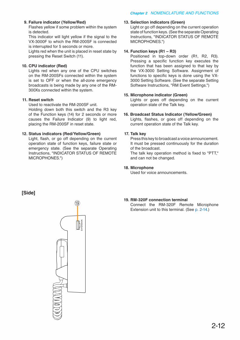
9. Failure indicator (Yellow/Red)Flashes yellow if some problem within the system is detected. This indicator will light yellow if the signal to the VX-3000F to which the RM-200SF is connected is interrupted for 5 seconds or more. Lights red when the unit is placed in reset state by pressing the Reset Switch (11).
10. CPU indicator (Red)Lights red when any one of the CPU switches on the RM-200SFs connected within the system is set to OFF or when the all-zone emergency broadcasts is being made by any one of the RM-300Xs connected within the system.
11. Reset switchUsed to reactivate the RM-200SF unit.Holding down both this switch and the R3 key of the Function keys (14) for 2 seconds or more causes the Failure Indicator (9) to light red, placing the RM-200SF in reset state.
12. Status indicators (Red/Yellow/Green)Light, flash, or go off depending on the current operation state of function keys, failure state or emergency state. (See the separate Operating Instructions, "INDICATOR STATUS OF REMOTE MICROPHONES.")
13. Selection indicators (Green)Light or go off depending on the current operation state of function keys. (See the separate Operating Instructions, "INDICATOR STATUS OF REMOTE MICROPHONES.")
14. Function keys (R1 – R3)Positioned in top-down order (R1, R2, R3). Pressing a specific function key executes the function that has been assigned to that key by the VX-3000 Setting Software. Assignment of functions to specific keys is done using the VX-3000 Setting Software. (See the separate Setting Software Instructions, "RM Event Settings.")
15. Microphone indicator (Green)Lights or goes off depending on the current operation state of the Talk key.
16. Broadcast Status Indicator (Yellow/Green)Lights, flashes, or goes off depending on the current operation state of the Talk key.
17. Talk keyPress this key to broadcast a voice announcement. It must be pressed continuously for the duration of the broadcast.The talk key operation method is fixed to "PTT," and can not be changed.
18. MicrophoneUsed for voice announcements.
EXTE
NSI
ON
19 19. RM-320F connection terminal Connect the RM-320F Remote Microphone Extension unit to this terminal. (See p. 2-14.)
[Side]

2-13
Chapter 2 NOMENCLATURE AND FUNCTIONS
[Wall mount bracket unit (Accessory)]
2324
[Rear]
87654321
TERMINATION
CPU OFFLEVEL METERCOMMUNICATION
UNIT ID
OnOffDIP SWITCH
20 21 22
20. DIP switchUsed for setting the RM-200SF unit.• Switches 1 – 3 [UNIT ID] Set the RM-200SF's device number (ID number).
(See p. 3-9.)• Switch 4 [COMMUNICATION] Sets the RM communication function. (See
p. 3-14.)• Switch 5 [LEVEL METER] Changes a broadcast status indicator (12) into
an output signal level indicator. (See p. 3-11.)• Switch 6 [CPU off] Sets whether the CPU off function (all-zone
emergency broadcasts) is enabled or disabled. (See p. 3-13.)
• Switch 7 Not used. Normally set to OFF .• Switch 8 [TERMINATION] Sets the termination of the RM communication
line (Control communication lines between the VX-3000F and the RM-200SF). Normally set to OFF.
NoteBy default, switches 1 – 5 and 7 are set to OFF, and switches 6 and 8 to ON.
21. USB terminalNot used.
22. Extension connectorConnect this connector to the extension connector (23) of the Wall Mount Bracket Unit (accessory). (See p. 3-25.)
23. Extension connectorConnect the cable extending from the RM-200SF to this connector. (See p. 3-25.)
24. Screw terminal block• Audio monitor line [MONITOR IN]
Connect the audio monitor input line from the VX-3000F to the RM-200SF.
• RM communication line [DATA]Connect the control communication line between the VX-3000F and the RM-200SF.
• Audio output line [AUDIO OUT]Connect the audio signal output line from the RM-200SF to the VX-3000F.
• DC power input [DC IN 24 V]Used to supply DC power from the VX-3000F to the RM-200SF.
• Shield [SHIELD]Used for the control line through which the VX-3000F system confirms the RM-200SF's connection.Be sure to connect at least one of two terminals to the VX-3000F.

2-14
Chapter 2 NOMENCLATURE AND FUNCTIONS
4. RM-320F FIREMAN'S MICROPHONE EXTENSIONEach connected RM-320F Extension unit adds 20 Function keys to the base RM-200SF.
[Front]
56
1
23
45
23
4
1. Connection cableUsed for connection to the RM-200SF or other RM-320F.
2. Indication label insert slotThe label can be printed using the VX-3000 Setting Software. (See the separate Setting Software Instructions, "PRINTING LABELS FOR REMOTE MICROPHONES.")
3. Status indicators (Red/Yellow/Green)Light, flash, or go off depending on the current operation state of function keys.
4. Selection indicators (Green)Light or go off depending on the current operation state of function keys.
5. Function keys (1 – 20)Keys are numbered from 1 to 10 from upper left to bottom and from 11 to 20 from upper right to bottom.Pressing a specific function key executes the function that has been assigned to that key by the VX-3000 Setting Software. Assignment of functions to specific keys is done using the VX-3000 Setting Software. (See the separate Setting Software Instructions, "RM Event Settings.")
6. RM connection terminal [EXTENSION]Connect the other RM-320F to this terminal.
[Side]
2-15
Chapter 2 NOMENCLATURE AND FUNCTIONS
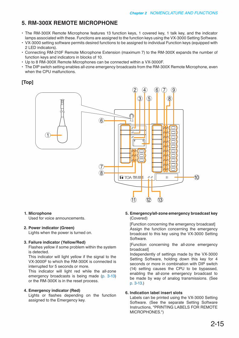
5. RM-300X REMOTE MICROPHONE• The RM-300X Remote Microphone features 13 function keys, 1 covered key, 1 talk key, and the indicator
lamps associated with these. Functions are assigned to the function keys using the VX-3000 Setting Software.• VX-3000 setting software permits desired functions to be assigned to individual Function keys (equipped with
2 LED indicators).• Connecting RM-210F Remote Microphone Extension (maximum 7) to the RM-300X expands the number of
function keys and indicators in blocks of 10.• Up to 8 RM-300X Remote Microphones can be connected within a VX-3000F.• The DIP switch setting enables all-zone emergency broadcasts from the RM-300X Remote Microphone, even
when the CPU malfunctions.
[Top]
1
3 5
6
7
8
810
2 4 6 7 9
11 12 13
1. MicrophoneUsed for voice announcements.
2. Power indicator (Green)Lights when the power is turned on.
3. Failure indicator (Yellow/Red)Flashes yellow if some problem within the system is detected. This indicator will light yellow if the signal to the VX-3000F to which the RM-300X is connected is interrupted for 5 seconds or more. This indicator will light red while the all-zone emergency broadcasts is being made (p. 3-13) or the RM-300X is in the reset process.
4. Emergency indicator (Red)Lights or flashes depending on the function assigned to the Emergency key.
5. Emergency/all-zone emergency broadcast key(Covered)[Function concerning the emergency broadcast]Assign the function concerning the emergency broadcast to this key using the VX-3000 Setting Software.[Function concerning the all-zone emergency broadcast]Independently of settings made by the VX-3000 Setting Software, holding down this key for 4 seconds or more in combination with DIP switch (14) setting causes the CPU to be bypassed, enabling the all-zone emergency broadcast to be made by way of analog transmissions. (See p. 3-13.)
6. Indication label insert slotsLabels can be printed using the VX-3000 Setting Software. (See the separate Setting Software Instructions, "PRINTING LABELS FOR REMOTE MICROPHONES.")

2-16
Chapter 2 NOMENCLATURE AND FUNCTIONS
7. Status indicators (Red/Yellow/Green)Light, flash, or go off depending on the current operation state of function keys, failure state or emergency state. (See the separate Operating Instructions, "INDICATOR STATUS OF REMOTE MICROPHONES.")
8. Selection indicators (Green)Light or go off depending on the current operation state of function keys. (See the separate Operating Instructions, "INDICATOR STATUS OF REMOTE MICROPHONES.")
9. Function keys (R1 – R10)Positioned in top-down order (R1, R2 ... R10). Pressing a specific function key executes the function that has been assigned to that key by the VX-3000 Setting Software. Assignment of functions to specific keys is done using the VX-3000 Setting Software. (See the separate Setting Software Instructions, "RM Event Settings.")
10. Talk KeyPress this key to broadcast a voice announcement. If the Talk key is set to "PTT " ("press-to-talk") mode, then it must be pressed continuously for the duration of the broadcast.
If the Talk key is set to "Lock" mode, then it must be pressed once to turn the microphone on at the beginning of a broadcast, then pressed again to turn the microphone off once the broadcast is finished. The microphone can also be set to sound a chime at the beginning and/or end of each broadcast. The Talk key mode ("PTT" or "Lock") and the chime function are set using the VX-3000 Setting Software. (See the separate Setting Software Instructions, "Unit Configuration Setting.")
11. Function keys (L1 – L3)Positioned in top-down order (L1, L2, L3). These keys operate in the same manner as the Function keys (R1 – R10) (9).
12. Broadcast status indicator (Yellow/Green)Lights, flashes, or goes off depending on the current operation state of the Talk key.
13. Microphone indicator (Green)Lights or goes off depending on the current operation state of the Talk key. Flashes while the chime is being activated.
[Side]
14 15
14. DIP switchUsed for setting the RM-300X unit.• Switches 1 – 3
Sets the RM-300X's device number (ID number). (See p. 3-9.)
• Switch 4Changes a broadcast status indicator (12) into an output signal level indicator. (See p. 3-11.)
• Switch 5Sets whether the CPU off function (all-zone emergency broadcasts) is enabled or disabled. (See p. 3-13.)
• Switch 6Not used.
NoteBy default, switches 1 – 4 and 6 are set to OFF and switch 5 to ON.
15. RM-210F connection terminal [EXTENSION]Directly connect the RM-210F Remote Microphone Extension unit to this terminal. (See p. 3-28.)
2-17
Chapter 2 NOMENCLATURE AND FUNCTIONS
[Rear]
2116 18 1917 20
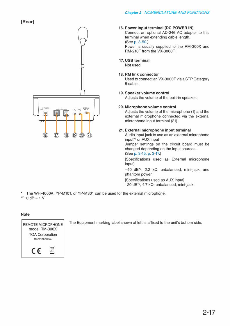
16. Power input terminal [DC POWER IN]Connect an optional AD-246 AC adapter to this terminal when extending cable length.(See p. 3-50.)Power is usually supplied to the RM-300X and RM-210F from the VX-3000F.
17. USB terminalNot used.
18. RM link connector Used to connect an VX-3000F via a STP Category 5 cable.
19. Speaker volume control Adjusts the volume of the built-in speaker.
20. Microphone volume controlAdjusts the volume of the microphone (1) and the external microphone connected via the external microphone input terminal (21).
21. External microphone input terminal Audio input jack to use as an external microphone input*1 or AUX inputJumper settings on the circuit board must be changed depending on the input sources. (See p. 3-15, p. 3-17.)[Specifications used as External microphone input] –40 dB*2, 2.2 kΩ, unbalanced, mini-jack, and phantom power.[Specifications used as AUX input] –20 dB*2, 4.7 kΩ, unbalanced, mini-jack.
*1 The WH-4000A, YP-M101, or YP-M301 can be used for the external microphone.*2 0 dB = 1 V
Note
The Equipment marking label shown at left is affixed to the unit's bottom side.
2-18
Chapter 2 NOMENCLATURE AND FUNCTIONS
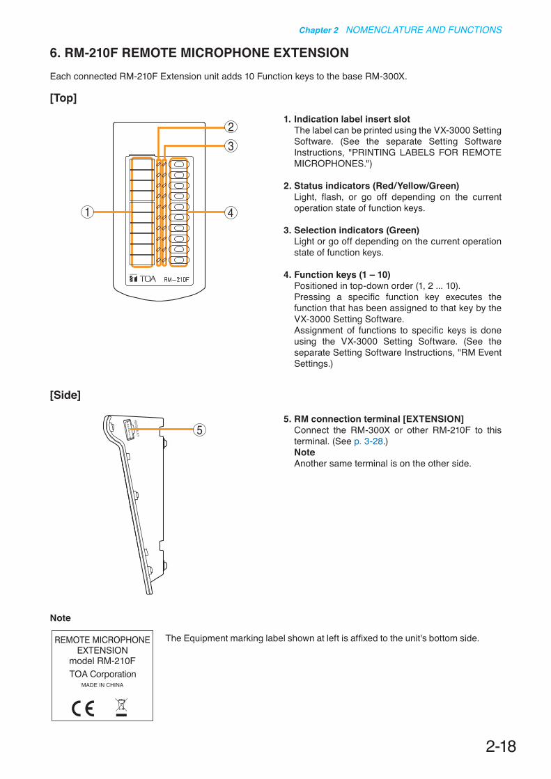
6. RM-210F REMOTE MICROPHONE EXTENSIONEach connected RM-210F Extension unit adds 10 Function keys to the base RM-300X.
[Top]
1
32
4
1. Indication label insert slotThe label can be printed using the VX-3000 Setting Software. (See the separate Setting Software Instructions, "PRINTING LABELS FOR REMOTE MICROPHONES.")
2. Status indicators (Red/Yellow/Green)Light, flash, or go off depending on the current operation state of function keys.
3. Selection indicators (Green)Light or go off depending on the current operation state of function keys.
4. Function keys (1 – 10)Positioned in top-down order (1, 2 ... 10). Pressing a specific function key executes the function that has been assigned to that key by the VX-3000 Setting Software. Assignment of functions to specific keys is done using the VX-3000 Setting Software. (See the separate Setting Software Instructions, "RM Event Settings.)
5
[Side]
5. RM connection terminal [EXTENSION]Connect the RM-300X or other RM-210F to this terminal. (See p. 3-28.)NoteAnother same terminal is on the other side.
Note
The Equipment marking label shown at left is affixed to the unit's bottom side.

2-19
Chapter 2 NOMENCLATURE AND FUNCTIONS
7. RM-200RJ TERMINAL UNITConvert the RJ45 connector into a screw terminal block. It is used to connect between a trunk cable (such as CPEV cable) and a feeder cable (such as LAN cable) in wiring a remote microphone.
[Front]
1
2
3
4
1. RM link terminalConnect to the RM link terminal of the RM-300X or VX-3000F.
2. Power monitor switchSet to ON to enable the Power monitor indicator. (Factory-preset: ON)
3. Power monitor indicator (Green)Lights if the source voltage of the DC power input exceeds the minimum operating voltage of the RM-300X when the Power Monitor Switch is set to ON.
4. Screw terminal blockThe Screw terminal block and RM link terminal are internally connected in parallel. Numbers 1 through 8 indicated beside each terminal correspond to the pin numbers of the RJ45 connector to be connected to the RM link terminal (1).• Audio monitor terminals [MONITOR H/C]
Connect the audio monitor line from the VX-3000F to the RM-300X.
• Audio output terminals [AUDIO H/C]Connect the audio output line from the RM-300X to the VX-3000F.
• RM communication terminals [DATA +/–]Connect the control communication line between the VX-3000F and the RM-300X.
• DC power input terminals [DC 24 V +/–]Used to supply DC power from the VX-3000F to the RM-300X.
• Shield terminals [SHIELD]Connect the shield wires for noise reduction or for system control.Be sure to connect at least one shield wire.
2-20
Chapter 2 NOMENCLATURE AND FUNCTIONS
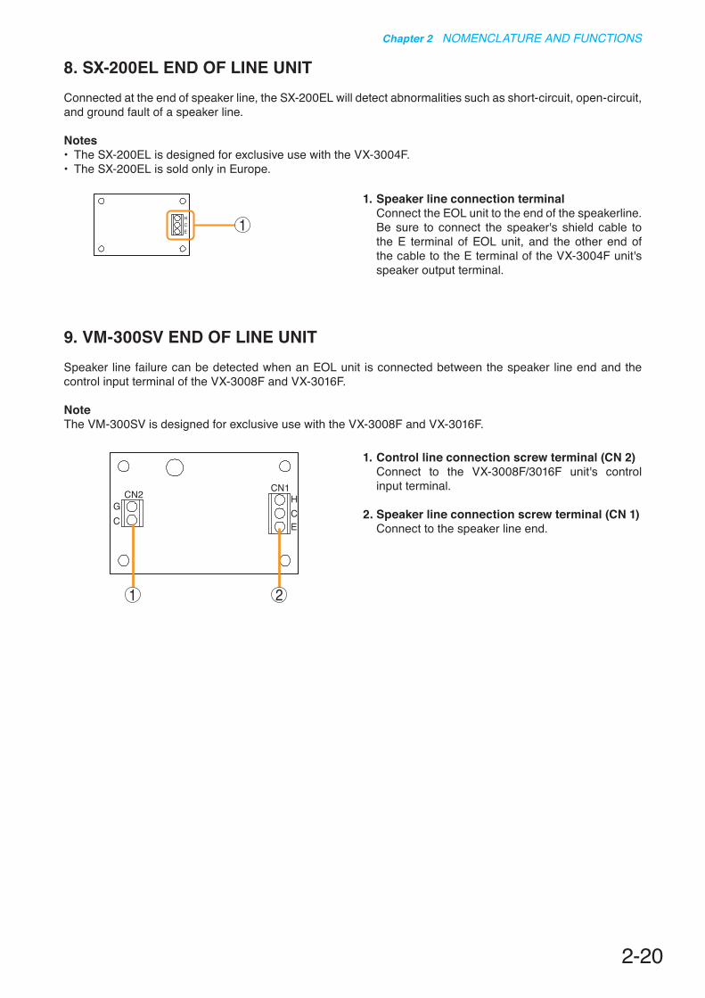
8. SX-200EL END OF LINE UNITConnected at the end of speaker line, the SX-200EL will detect abnormalities such as short-circuit, open-circuit, and ground fault of a speaker line.
Notes• The SX-200EL is designed for exclusive use with the VX-3004F.• The SX-200EL is sold only in Europe.
9. VM-300SV END OF LINE UNITSpeaker line failure can be detected when an EOL unit is connected between the speaker line end and the control input terminal of the VX-3008F and VX-3016F.
NoteThe VM-300SV is designed for exclusive use with the VX-3008F and VX-3016F.
HCE 1
1. Speaker line connection terminalConnect the EOL unit to the end of the speakerline. Be sure to connect the speaker's shield cable to the E terminal of EOL unit, and the other end of the cable to the E terminal of the VX-3004F unit's speaker output terminal.
1. Control line connection screw terminal (CN 2)Connect to the VX-3008F/3016F unit's control input terminal.
2. Speaker line connection screw terminal (CN 1)Connect to the speaker line end.
GC
CN2 CN1HCE
1 2
Chapter 3
INSTALLATION AND SETTING PROCEDURES (HARDWARE)

3-2
Chapter 3 INSTALLATION AND SETTING PROCEDURES (HARDWARE)
1. VX-015DA, VX-030DA, AND VX-050DA DIGITAL POWER AMPLIFIER MODULE
1.1. Changing the Speaker Line Voltage
Though the speaker line voltage of the VX-015DA, VX-030DA, and VX-050DA is factory-preset to 100 V, you can change it to 50 V or 70 V with the output voltage selection switch on the power amplifier's side.
NoteThe speaker line failure detection functions are designed to perform on a 100-volt line of speaker. For the methods using a 70- or 50-volt line, please consult your TOA dealer.
1.2. Replacing the Blade Fuse
When the blade fuse blew, replace it with new one following the procedures below.
Step : Replace the blade fuse on the rear panel.
TipYou can replace the fuse with the amplifier module installed in the VX-3000F.
[Capacity]Model No. CapacityVX-015DA Blade-Type Fuse 10 AVX-030DA Blade-Type Fuse 20 AVX-050DA Blade-Type Fuse 30 A
VX-015DA/030DA/050DA side
Output voltage selection switch
Fuse
VX-015DA/030DA/050DA rear
Be sure to switch off the amplifier's power when replacing the fuse. Inserting or removing the fuse with the amplifier's power on may cause personal injury.
WARNING
3-3
Chapter 3 INSTALLATION AND SETTING PROCEDURES (HARDWARE)
2. VX-3004F, VX-3008F, AND VX-3016F VOICE EVACUATION FRAME2.1. Installing VX-015DA/030DA/050DA Digital Power Amplifier Module
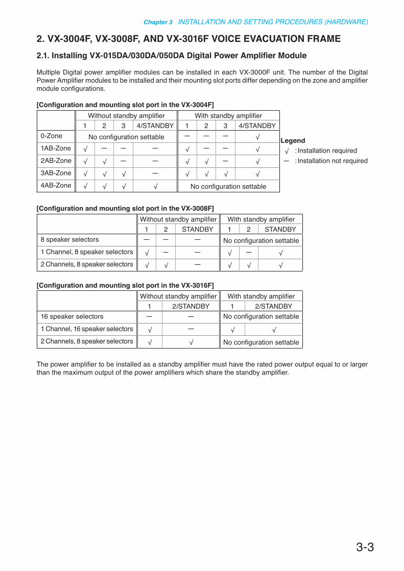
Multiple Digital power amplifier modules can be installed in each VX-3000F unit. The number of the Digital Power Amplifier modules to be installed and their mounting slot ports differ depending on the zone and amplifier module configurations.
[Configuration and mounting slot port in the VX-3004F]Without standby amplifier With standby amplifier
1 2 3 4/STANDBY 1 2 3 4/STANDBY0-Zone No configuration settable �
1AB-Zone � � �
2AB-Zone � � � � �
3AB-Zone � � � � � � �
4AB-Zone � � � � No configuration settable
[Configuration and mounting slot port in the VX-3008F]Without standby amplifier With standby amplifier
1 2 STANDBY 1 2 STANDBY8 speaker selectors No configuration settable1 Channel, 8 speaker selectors � � �
2 Channels, 8 speaker selectors � � � � �
[Configuration and mounting slot port in the VX-3016F]Without standby amplifier With standby amplifier
1 2/STANDBY 1 2/STANDBY16 speaker selectors No configuration settable
1 Channel, 16 speaker selectors � � �
2 Channels, 8 speaker selectors � � No configuration settable
The power amplifier to be installed as a standby amplifier must have the rated power output equal to or larger than the maximum output of the power amplifiers which share the standby amplifier.
Legend� : Installation required
: Installation not required

3-4
Chapter 3 INSTALLATION AND SETTING PROCEDURES (HARDWARE)
Step 1. Shut off the power.Shut off the power when the power is supplied to the VX-3000F unit.
Step 2. Detach the front panel.Remove 4 fixing screws for front panel and detach the front panel.
Step 3. Install the digital power amplifier module.Insert the power amplifier module along the supporting runner until it will not go any further, then secure it using a power amplifier module fixing screw.NoteUse a #2 bit Philips screwdriver to tighten the fixing screw.
Step 4. Lift the lower portion of the filter, then connect cables.
4-1. Connect both the power amplifier module's DA control link connector and DA output link connector to the VX-3000F's corresponding connectors. Use the cables supplied with the power amplifier module.NoteAfter the cable connection is complete, be sure to push the cables against the amplifier side to prevent them from protruding so that the front panel can be easily mounted without obstructing its work.
4-2. Replace the filter.
Step 5. When installing two or more power amplifier modules, repeat Steps 3 and 4.
Step 6. Replace the front panel. Secure it using 4 fixing screws for front panel.
VX-3000F
Fixing screws for front panel2
3
Fixing screw
VX-3000Ffront
VX-015DA/030DA/050DA
[Power amplifier installation procedure]
There is a high voltage section inside the power amplifier's filter. Never insert your finger or metallic objects inside the unit. When attaching or detaching the connector, never touch the internal components other than connectors.
WARNING
4
DA control link connector DA output link connector
Filter

3-5
Chapter 3 INSTALLATION AND SETTING PROCEDURES (HARDWARE)
2.2. The Zones Allocation Setting
For the VX-3008F and VX-3016F units, the preset relationship between broadcast zones and power amplifiers can be changed by the settings of the DIP switch inside the front panel.VX-3008F: You can perform the zone allocation settings for all-zone emergency broadcast at CPU off state. Note For normal broadcasts, use the VX-3000 Setting Software to perform this setting.VX-3016F: You can perform the zone allocation settings for normal broadcasts, and all-zone emergency
broadcast at CPU off state.[Power amplifier modules inside the VX-3008F and output zone configuration]
Switch Figure Power amplifier module and output zone configuration1 2 3OFF OFF OFF Allocates the Slot 1's amplifier output to Zones 1 through 8.
ON OFF OFF Allocates the Slot 1's amplifier output to Zones 1 through 7 and the Slot 2's amplifier output to Zone 8.
OFF ON OFF Allocates the Slot 1's amplifier output to Zones 1 through 6 and the Slot 2's amplifier output to Zones 7 and 8.
ON ON OFF Allocates the Slot 1's amplifier output to Zones 1 through 5 and the Slot 2's amplifier output to Zones 6 through 8.
OFF OFF ON Allocates the Slot 1's amplifier output to Zones 1 through 4 and the Slot 2's amplifier output to Zones 5 through 8.
ON OFF ON Allocates the Slot 1's amplifier output to Zones 1 through 3 and the Slot 2's amplifier output to Zones 4 through 8.
OFF ON ON Allocates the Slot 1's amplifier output to Zones 1 and 2 and the Slot 2's amplifier output to Zones 3 through 8.
ON ON ON Allocates the Slot 1's amplifier output to Zone 1 and the Slot 2's amplifier output to Zones 2 through 8.
1 2 3 4
ON
1 2 3 4
ON
1 2 3 4
ON
1 2 3 4
ON
1 2 3 4
ON
1 2 3 4
ON
1 2 3 4
ON
1 2 3 4
ON
[Power amplifier modules inside the VX-3016F and output zone configuration]Switch Figure Power amplifier module and output zone configuration1OFF Allows to allocate the Slot 1's amplifier output to Zones 1 through 16
(1 channel, 16 speaker selectors)
ON Allows to allocate the Slot 1's amplifier output to Zones 1 through 8 and the Slot 2's amplifier output to Zones 9 through 16. (2 channels, 8 speaker selectors)
1 2 3 4
ON
1 2 3 4
ON

3-6
Chapter 3 INSTALLATION AND SETTING PROCEDURES (HARDWARE)
Step 1. Detach the front panel.Remove 4 fixing screws for front panel and detach the front panel.
Step 2. Set the DIP switch.Set the DIP switch so that power amplifier modules and Zone configurations are obtained as intended.
Step 3. Replace the front panel. Secure it using 4 fixing screws for front panel.
VX-3000F front
Fixing screws for front panel1
2 VX-3000F front (Front panel detached)
DIP switch
WARNINGThere is a high voltage section inside the power amplifier's filter. Never insert your finger or metallic objects inside the unit.
[DIP Switch setting]

3-7
Chapter 3 INSTALLATION AND SETTING PROCEDURES (HARDWARE)
Step 1. Detach the front panel.Remove 4 fixing screws for front panel and detach the front panel.
Notes• When setting the ID number for multiple VX-3000F units, assign different numbers to each unit. The ID
number that can be used must not exceed the actual number of VX-3000F units set using the VX-3000 Setting Software.
• If an ID number is duplicated, then the VX-3000F units assigned that number cannot be controlled by the VX-3000F system.
• The VX-3000F set to ID "0" plays a role of a leader in the whole system, displaying the "GENERAL FAULT" indication and outputting its signal when malfunction occurs within the system.
• In a single VX-3000F configuration, set the ID number to "0."
[ID number setting]
Note: The ID number is set to No. 0 by default.
ID switch A 0
B 0 1 2 3 4 5 6 7 8 9 A B C D E F
ID number 0 1 2 3 4 5 6 7 8 9 10 11 12 13 14 15
Arrowhead
ID NUMBER
A
B
ID switch A 1
B 0 1 2 3 4 5 6 7 8 9 A B C D E F
ID number 16 17 18 19 20 21 22 23 24 25 26 27 28 29 30 31
Arrowhead
ID NUMBER
A
B
VX-3000F front
Fixing screws for front panel1
2 ID SwitchVX-3000F front(Front panel detached)
WARNINGThere is a high voltage section inside the power amplifier's filter. Never insert your finger or metallic objects inside the unit.
Step 3. Replace the front panel. Secure it using 4 fixing screws for front panel .
2.3. The ID Number Setting
Step 2. Set the ID switches.

3-8
Chapter 3 INSTALLATION AND SETTING PROCEDURES (HARDWARE)
Step 1. Detach the front panel.Remove 4 fixing screws for front panel and detach the front panel.
Step 2. Set the switch 8 of the DIP switch to OFF.
Step 3. Press the reset key. The VX-3000F is reactivated.
Step 4. Replace the front panel. Secure it using 4 fixing screws for front panel.
2.4. Setting the IP Address
VX-3000F's IP address is automatically determined depending on the ID switch setting as follows when the switch 8 of the DIP switch inside the front panel is set to the ON position (default setting).
IP address : 192.168.14.xx ("xx" is one larger than ID Number.)Subnet mask : 255.255.255.0Default gateway : 0.0.0.0
To change the above IP address of the VX-3000F, change the DIP switch setting and reactivate the VX-3000F following the procedures below. NoteWhen the switch 8 is set to the ON position, even if you change and upload the IP address using the VX-3000 Setting software, it will not be changed, remaining as set by default.
VX-3000F front
Fixing screws for front panel1
2
3
VX-3000F front (Front panel detached)
Switch 8
Reset key
WARNINGThere is a high voltage section inside the power amplifier's filter. Never insert your finger or metallic objects inside the unit.
ON

3-9
Chapter 3 INSTALLATION AND SETTING PROCEDURES (HARDWARE)
3. RM-200SF AND RM-300X MICROPHONES3.1. The ID Number Settings (Switches 1 – 3 operation)
Set ID numbers (device numbers) using switches 1 – 3 of the DIP switch located on the rear panel of the RM-200SF and the side panel of the RM-300X.
87654321
TERMINATION
CPU OFFLEVEL METERCOMMUNICATION
UNIT ID
OnOffDIP SWITCH
RM-200SF rear RM-300X side
12
ON
345678
123456
• A total of up to 8 RM-200SF and RM-300X microphones can be connected per system. If the system is required to comply with EN54-16, only a total of up to 2 RM-200SF and/or RM-300M units of
the 8 are allowed for connection. (See p. 3-38.)• An ID Number must be set for each connected Remote microphone. The ID Number must be identical to
that which is set by the PC software. On the PC screen, the ID Number appears at the left of the Remote microphone symbol.
[Remote microphone on the PC screen]
ID Number
• The ID Number is factory-preset to "0."

3-10
Chapter 3 INSTALLATION AND SETTING PROCEDURES (HARDWARE)
123456
123456
123456
123456
123456
123456
123456
123456
12
ON
345678
12
ON
345678
12
ON
345678
12
ON
345678
12
ON
345678
12
ON
345678
12
ON
345678
12
ON
345678
Device number Switch 3 Switch 2 Switch 1 RM-200SF RM-300X
0 OFF OFF OFF
1 OFF OFF ON
2 OFF ON OFF
3 OFF ON ON
4 ON OFF OFF
5 ON OFF ON
6 ON ON OFF
7 ON ON ON
(Default setting)
3-11
Chapter 3 INSTALLATION AND SETTING PROCEDURES (HARDWARE)
3.2. Adjusting Microphone Sensitivity (RM-200SF: Switch 5 operation or RM-300X: Switch 4 operation)
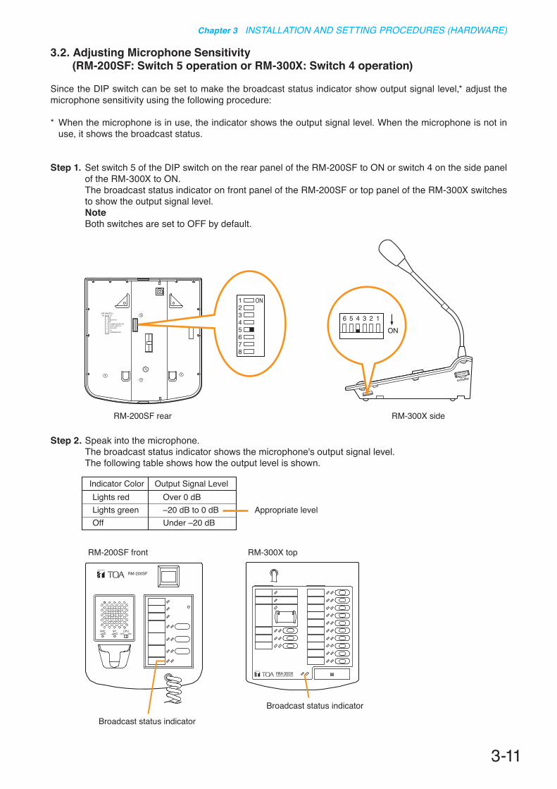
Since the DIP switch can be set to make the broadcast status indicator show output signal level,* adjust the microphone sensitivity using the following procedure:
* When the microphone is in use, the indicator shows the output signal level. When the microphone is not in use, it shows the broadcast status.
Step 1. Set switch 5 of the DIP switch on the rear panel of the RM-200SF to ON or switch 4 on the side panel of the RM-300X to ON.The broadcast status indicator on front panel of the RM-200SF or top panel of the RM-300X switches to show the output signal level.NoteBoth switches are set to OFF by default.
87654321
TERMINATION
CPU OFFLEVEL METERCOMMUNICATION
UNIT ID
OnOffDIP SWITCH
RM-200SF rear RM-300X side
12
ON
345678
123456
Step 2. Speak into the microphone. The broadcast status indicator shows the microphone's output signal level. The following table shows how the output level is shown.
Indicator ColorLights redLights greenOff
Output Signal LevelOver 0 dB–20 dB to 0 dB Appropriate levelUnder –20 dB
RM-300X topRM-200SF front
RM-200SF
MIC SP CPUOFF ON
Broadcast status indicator
Broadcast status indicator
3-12
Chapter 3 INSTALLATION AND SETTING PROCEDURES (HARDWARE)
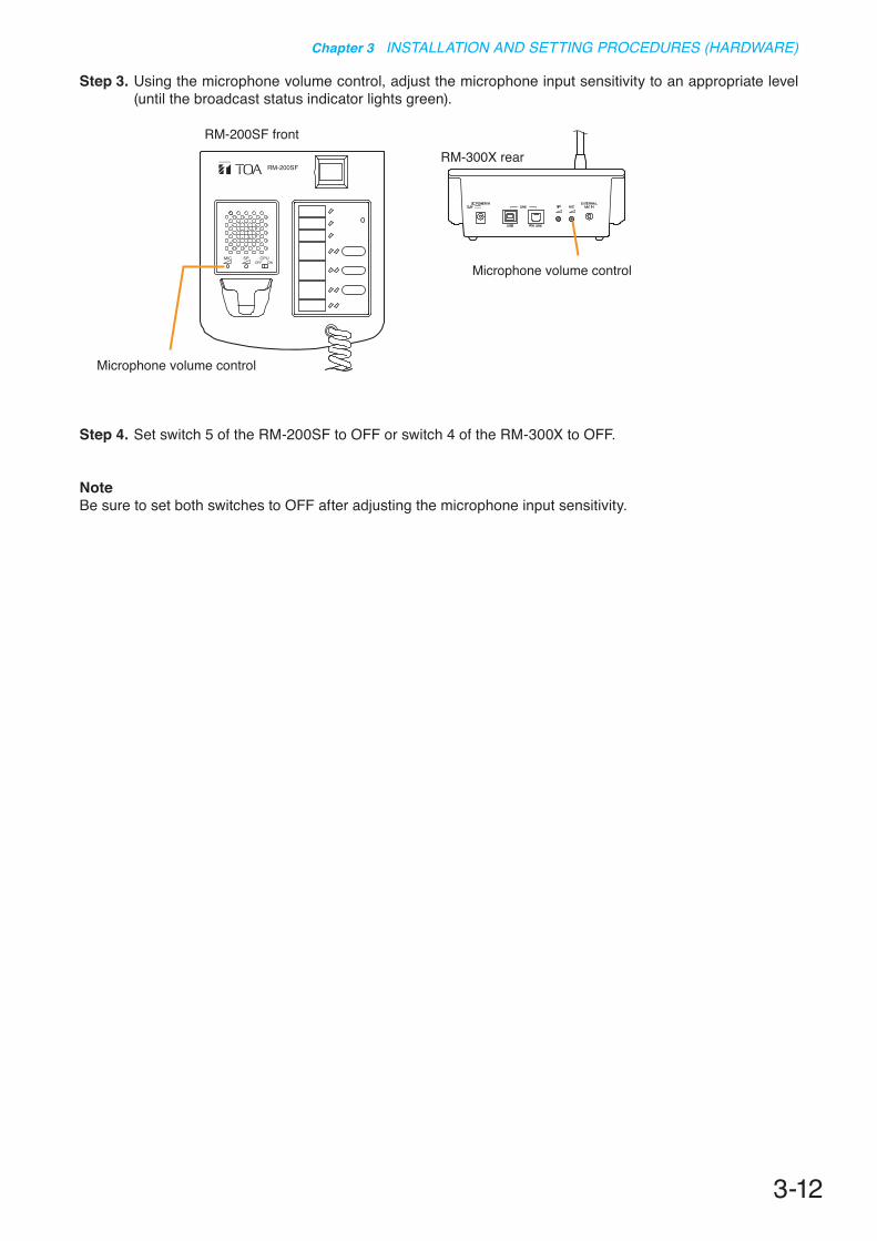
Step 3. Using the microphone volume control, adjust the microphone input sensitivity to an appropriate level (until the broadcast status indicator lights green).
Step 4. Set switch 5 of the RM-200SF to OFF or switch 4 of the RM-300X to OFF.
NoteBe sure to set both switches to OFF after adjusting the microphone input sensitivity.
RM-300X rearRM-200SF
MIC SP CPUOFF ON
Microphone volume control
Microphone volume control
RM-200SF front
3-13
Chapter 3 INSTALLATION AND SETTING PROCEDURES (HARDWARE)
3.3. CPU Off Function (All-Zone Emergency Broadcast) Settings (RM-200SF: Switch 6 operation or RM-300X: Switch 5 operation)
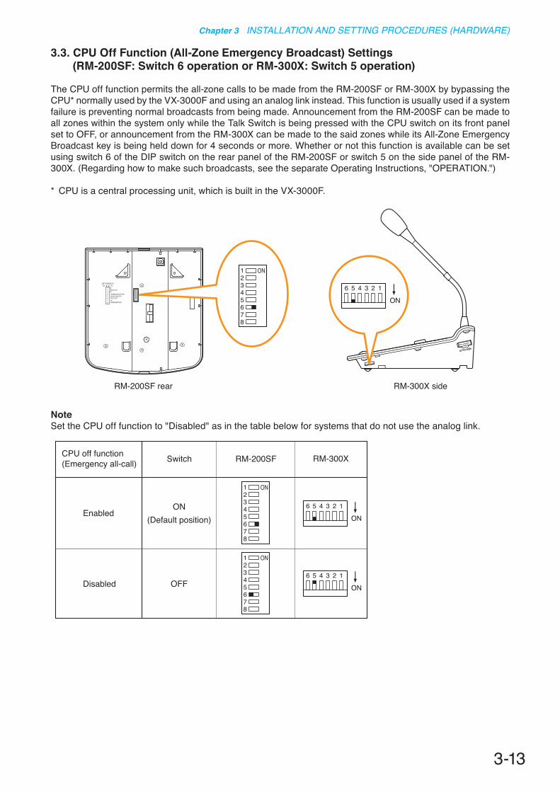
The CPU off function permits the all-zone calls to be made from the RM-200SF or RM-300X by bypassing the CPU* normally used by the VX-3000F and using an analog link instead. This function is usually used if a system failure is preventing normal broadcasts from being made. Announcement from the RM-200SF can be made to all zones within the system only while the Talk Switch is being pressed with the CPU switch on its front panel set to OFF, or announcement from the RM-300X can be made to the said zones while its All-Zone Emergency Broadcast key is being held down for 4 seconds or more. Whether or not this function is available can be set using switch 6 of the DIP switch on the rear panel of the RM-200SF or switch 5 on the side panel of the RM-300X. (Regarding how to make such broadcasts, see the separate Operating Instructions, "OPERATION.")
* CPU is a central processing unit, which is built in the VX-3000F.
87654321
TERMINATION
CPU OFFLEVEL METERCOMMUNICATION
UNIT ID
OnOffDIP SWITCH
RM-200SF rear RM-300X side
12
ON
345678
123456
NoteSet the CPU off function to "Disabled" as in the table below for systems that do not use the analog link.
Disabled
Enabled
OFF
ON(Default position)
SwitchCPU off function(Emergency all-call) RM-300XRM-200SF
123456
123456
12
ON
345678
12
ON
345678

3-14
Chapter 3 INSTALLATION AND SETTING PROCEDURES (HARDWARE)
3.4. Termination Setting (RM-200SF: Switch 8 operation)
Set the termination of the RM communication line. Normally set to OFF.
RM-200SF rear
87654321
TERMINATION
CPU OFFLEVEL METERCOMMUNICATION
UNIT ID
OnOffDIP SWITCH
12
ON
345678
OFF
ON
OFF
ON(Default position)
SwitchTerminal function RM-200SF
12
ON
345678
12
ON
345678
3-15
Chapter 3 INSTALLATION AND SETTING PROCEDURES (HARDWARE)
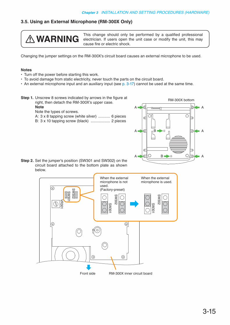
3.5. Using an External Microphone (RM-300X Only)
Changing the jumper settings on the RM-300X's circuit board causes an external microphone to be used.
Notes• Turn off the power before starting this work. • To avoid damage from static electricity, never touch the parts on the circuit board. • An external microphone input and an auxiliary input (see p. 3-17) cannot be used at the same time.
Step 1. Unscrew 8 screws indicated by arrows in the figure at right, then detach the RM-300X's upper case.NoteNote the types of screws.A: 3 x 8 tapping screw (white silver) ........... 6 piecesB: 3 x 10 tapping screw (black) .................. 2 pieces
Step 2. Set the jumper's position (SW301 and SW302) on the circuit board attached to the bottom plate as shown below.
This change should only be performed by a qualified professional electrician. If users open the unit case or modify the unit, this may cause fire or electric shock.
WARNING
RM-300X bottom
A
A B
BA
A
A
ASW
301VR301
SW302
SW301
SW302 SW
301SW
302
RM-300X inner circuit board
When the external microphone is not used. (Factory-preset)
When the external microphone is used.
Front side

3-16
Chapter 3 INSTALLATION AND SETTING PROCEDURES (HARDWARE)
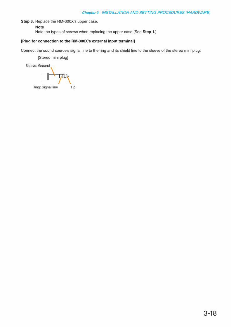
Step 3. Replace the RM-300X's upper case.NoteNote the types of screws when replacing the upper case (See Step 1.)
[Plug for connection to the RM-300X's external input terminal]
Connect the microphone's signal line to the tip and its shield line to the sleeve of the stereo mini plug or monaural mini plug.
Sleeve: Ground
Tip: Signal lineRing
Sleeve: Ground
Tip: Signal line
[Monaural mini plug][Stereo mini plug]
Tip: The WH-4000A, YP-M101, or YP-M301 can be used for the external microphone.
3-17
Chapter 3 INSTALLATION AND SETTING PROCEDURES (HARDWARE)
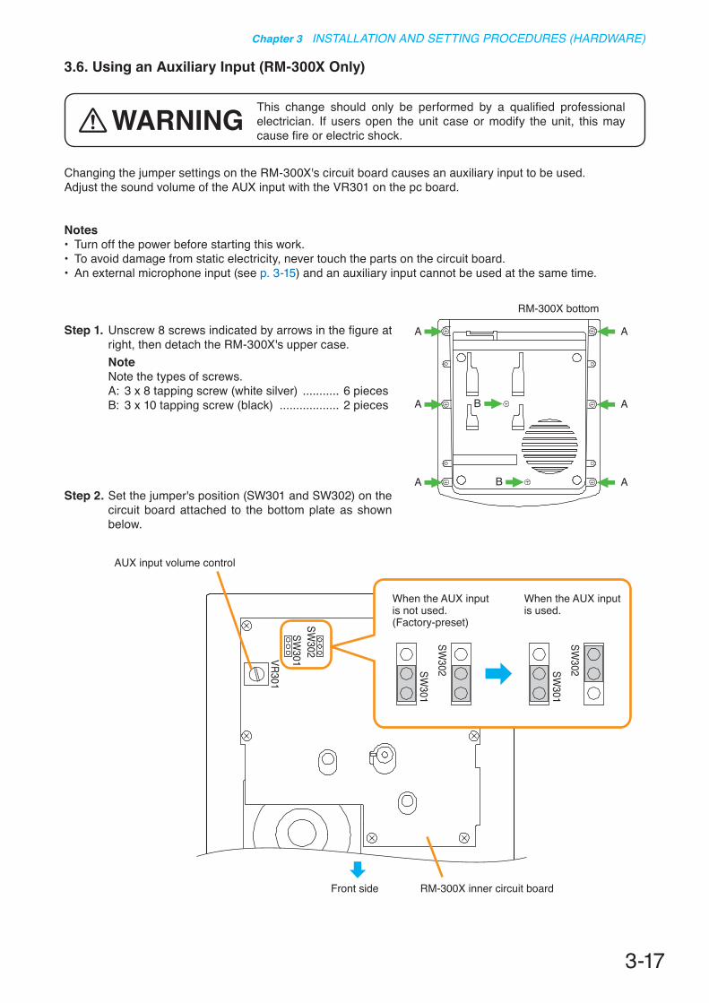
3.6. Using an Auxiliary Input (RM-300X Only)
Changing the jumper settings on the RM-300X's circuit board causes an auxiliary input to be used. Adjust the sound volume of the AUX input with the VR301 on the pc board.
Notes• Turn off the power before starting this work. • To avoid damage from static electricity, never touch the parts on the circuit board. • An external microphone input (see p. 3-15) and an auxiliary input cannot be used at the same time.
Step 1. Unscrew 8 screws indicated by arrows in the figure at right, then detach the RM-300X's upper case.NoteNote the types of screws.A: 3 x 8 tapping screw (white silver) ........... 6 piecesB: 3 x 10 tapping screw (black) .................. 2 pieces
Step 2. Set the jumper's position (SW301 and SW302) on the circuit board attached to the bottom plate as shown below.
This change should only be performed by a qualified professional electrician. If users open the unit case or modify the unit, this may cause fire or electric shock.
WARNING
RM-300X bottom
A
A B
BA
A
A
A
SW301VR301
SW302
SW301
SW302 SW
301SW
302
RM-300X inner circuit board
AUX input volume control
Front side
When the AUX input is not used. (Factory-preset)
When the AUX input is used.
3-18
Chapter 3 INSTALLATION AND SETTING PROCEDURES (HARDWARE)
Step 3. Replace the RM-300X's upper case.NoteNote the types of screws when replacing the upper case (See Step 1.)
[Plug for connection to the RM-300X's external input terminal]
Connect the sound source's signal line to the ring and its shield line to the sleeve of the stereo mini plug.
Sleeve: Ground
TipRing: Signal line
[Stereo mini plug]

3-19
Chapter 3 INSTALLATION AND SETTING PROCEDURES (HARDWARE)
87654321
TERMINATION
CPU OFFLEVEL METERCOMMUNICATION
UNIT ID
OnOffDIP SWITCH
RM-200SF rear
Inch screw (combination drive) No.6-32 x 1/4 (1)Tooth lock washer (1)
Tapping screw (Phillips) 3 x 8 (4)
3.7. Compressor Function Setting
This change should only be performed by a qualified professional electrician. If users open the unit case or modify the unit, this may cause fire or electric shock.
WARNINGThe compressor function enables even large signals to be broadcast without distortion. (This function is factory-preset to ON.)
Notes• Turn off the power before starting this work.• To avoid damage from static electricity, never touch the parts on the circuit board.
[RM-200SF]
Step 1. Unscrew 5 screws in the figure at right, then detach the RM -200SF's rear plate.NoteNote the specific shapes of the different screws.
Step 2. Set the jumper's position (JP301) on the circuit board attached to the front case as shown below.
Step 3. Replace the RM-200SF's rear plate.Note: Note the specific shapes of the different screws when replacing the rear plate. (See Step 1.)
JP301
RM-200SF inner circuit boardJP301
When the compressor function is used.(Factory-preset)
When the compressor function is not used.
JP301
3-20
Chapter 3 INSTALLATION AND SETTING PROCEDURES (HARDWARE)
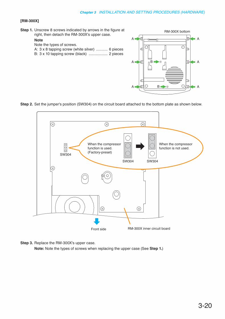
[RM-300X]
Step 1. Unscrew 8 screws indicated by arrows in the figure at right, then detach the RM-300X's upper case.NoteNote the types of screws.A: 3 x 8 tapping screw (white silver) ........... 6 piecesB: 3 x 10 tapping screw (black) .................. 2 pieces
RM-300X bottom
A
A B
BA
A
A
A
Step 2. Set the jumper's position (SW304) on the circuit board attached to the bottom plate as shown below.
Step 3. Replace the RM-300X's upper case.Note: Note the types of screws when replacing the upper case (See Step 1.)
SW304
RM-300X inner circuit boardFront side
SW304
When the compressor function is used.(Factory-preset)
When the compressor function is not used.
SW304

3-21
Chapter 3 INSTALLATION AND SETTING PROCEDURES (HARDWARE)
3.8. Microphone Fault Detection Function Setting (RM-300X Only)
This work should only be performed by a qualified professional electrician. If users open the unit case or modify the unit, this may cause fire or electric shock.
WARNINGThe RM-300X is equipped with the microphone fault detection function, which can be set to OFF . (Factory-preset to ON)
Notes• Turn off the power before starting this work.• To avoid damage from static electricity, never touch the parts on the circuit board.
Step 1. Unscrew 8 screws indicated by arrows in the figure at right, then detach the RM-300X's upper case.NoteNote the types of screws.A: 3 x 8 tapping screw (white silver) ........... 6 piecesB: 3 x 10 tapping screw (black) .................. 2 pieces
RM-300X bottom
A
A B
BA
A
A
A
Step 2. Set the jumper's position (SW303) on the circuit board attached to the bottom plate as shown below.
SW303
RM-300X inner circuit boardFront side
SW303
When setting the microphone fault detection function to ON.(Factory-preset)
When setting the microphone fault detection function to OFF.
SW303
Step 3. Replace the RM-300X's upper case.Note: Note the types of screws when replacing the upper case (See Step 1.)

3-22
Chapter 3 INSTALLATION AND SETTING PROCEDURES (HARDWARE)
3.9. Installing the RM-200SF on a Wall
The RM-200SF is designed for on-wall installation.
[Mounting hardware]
To mount the RM-200SF on the wall, the following parts are required.
Wall mount bracket unit .............................................................. 1 (supplied with the RM-200SF)Wall mounting screws 4 x 25 tapping screw for wooden wall ................................... 2 (supplied with the RM-200SF) M3.5 x 20 screw for electrical box ......................................... 2 (supplied with the RM-200SF)
[Ferrite cable clamp attachment]
The supplied ferrite clamp needs to be attached to the Link cable as illustrated below.As its mounting timing differs depending on the installation way of the RM-200SF, mount the clamp in the appropriate installation step.
Mount the ferrite clamp (supplied with the RM-200SF) on the cable in a way that the cable is looped one turn as illustrated. (This countermeasure is for complying with the CE marking.)
RM-200SFFerrite clamp(Supplied with the RM-200SF)
Loop the cable one turn.Link cable

3-23
Chapter 3 INSTALLATION AND SETTING PROCEDURES (HARDWARE)
[Installation]
Step 1. Install the wall mount bracket unit supplied with the RM-200SF on the wall. 1-1. Installing directly on the wall
Install the unit on the wall using 2 screws or more depending on the installation location.The RM-200SF comes with 2 tapping screws 4 x 25 for direct wall mounting.
• Install the unit only in a location that can structurally support the weight of the unit and the mounting bracket. Doing otherwise may result in the unit falling down and causing personal injury and/or property damage.
• Be sure to install the bracket on the wall using 2 or more screws.
WARNING
Wall mount bracket unit for the RM-200SF
Wall mount bracket unit (supplied with the RM-200SF)
RM-200SF
5-ø4.5
7-4.5 x 6.5
Wall mount bracket unit's center line
RM-200SF's center line
9.7
46
10092
ø60
83.5
107.
621
5
Notes• Six mounting holes indicated by arrows in
the figure below can be used for securing.• When securing the unit with 2 screws, be
sure to use a pair of holes located in the middle of the Bracket A.
Unit: mm
1-2. Installing to a 1-gang electrical box(1) Unscrew 3 screws (indicated by arrows in the figure at right)
that fix the Bracket A to the Bracket B of the wall mount bracket unit.
Wall mount bracket unit (supplied with the RM-200SF)
Bracket ABracket B

3-24
Chapter 3 INSTALLATION AND SETTING PROCEDURES (HARDWARE)
(2) Slide the Bracket A as show below to detach it from the Bracket B.
(3) Attach the Bracket B to the electrical box using 2 screws M3.5 x 20 supplied with the RM-200SF.
(4) Replace the Bracket A. Reverse the procedures (1) and (2) above. Note Take care not to pinch the routed link cable between the Brackets A and B.
Bracket A
Bracket B
Slide the Bracket A upward, then pull it toward you.
Screw holes for mounting to the electrical box (2 places)
Unit: mm
Bracket B
83.5ø60
Step 2. Connect the link cable to the screw terminal block.
Wall mount bracket unit (supplied with the RM-200SF)
Link cable
Bracket A
Bracket B
NotePut the link cable inside the Bracket A after connection completion.Do not allow the link cable to protrude.The cable may be damaged if it protrudes when the bracket unit is installed onto the wall.

3-25
Chapter 3 INSTALLATION AND SETTING PROCEDURES (HARDWARE)
Step 3. Plug the RM-200SF's extension connector into the connector port on the wall mount bracket unit.
Step 4. Attach the RM-200SF unit to the wall mount bracket unit.
Connection cable
RM-200SF
Wall mount bracket unit (supplied with the RM-200SF)
3
4
NoteWhen attaching the RM-200SF unit, check that the connection cable is not pinched.
[When the RM-200SF is installed in a wall box]
When the RM-200SF is installed in a wall box (prepare separately), the box should measure at least 300 mm wide x 315 mm high as illustrated below.
300 min.50 min.50 min.
50 m
in.
50 m
in.
315
min
.
Effective depth: 100 min.
Mounting base surface
Rear surface of the front door
Inside dimension of the box
Unit: mm
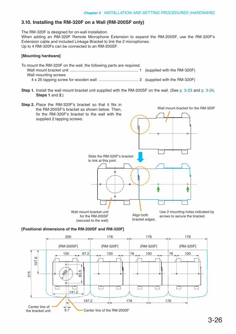
3-26
Chapter 3 INSTALLATION AND SETTING PROCEDURES (HARDWARE)
3.10. Installing the RM-320F on a Wall (RM-200SF only)
The RM-320F is designed for on-wall installation.When adding an RM-320F Remote Microphone Extension to expand the RM-200SF, use the RM-320F's Extension cable and included Linkage Bracket to link the 2 microphones.Up to 4 RM-320Fs can be connected to an RM-200SF.
[Mounting hardware]
To mount the RM-320F on the wall, the following parts are required.Wall mount bracket unit .............................................................. 1 (supplied with the RM-320F)Wall mounting screws 4 x 25 tapping screw for wooden wall .................................... 2 (supplied with the RM-320F)
Step 1. Install the wall mount bracket unit supplied with the RM-200SF on the wall. (See p. 3-23 and p. 3-24, Steps 1 and 2.)
Step 2. Place the RM-320F's bracket so that it fits in the RM-200SF's bracket as shown below. Then, fix the RM-320F's bracket to the wall with the supplied 2 tapping screws.
Slide the RM-320F’s bracket to link at this joint.
Align both bracket edges.
Wall mount bracket for the RM-320F
Wall mount bracket unitfor the RM-200SF
(secured to the wall)
Use 2 mounting holes indicated by arrows to secure the bracket.
[Positional dimensions of the RM-200SF and RM-320F]
200
100
141.2
100 76 100 76 10097.2
215
107.
6
83.5
ø60
176
176197.2
Center line of the RM-200SFCenter line of
the bracket unit 9.7
176
[RM-200SF] [RM-320F]
176
[RM-320F]
176
[RM-320F]

3-27
Chapter 3 INSTALLATION AND SETTING PROCEDURES (HARDWARE)
Step 3. Attach the RM-200SF to its wall mount bracket unit. (See p. 3-25, Steps 3 and 4.)
Step 4. Connect the RM-320F's cable to the extension connector on the RM-200SF's side.
Step 5. Install the RM-320F to its wall mount bracket sliding it in close contact with the RM-200SF as shown below.
[RM-200SF]
[RM-320F]
Slide in close contact with the RM-200SF.
Connect to the extension connector on the RM-200SF’s side.
Wall mount bracketfor the RM-320F
4
5
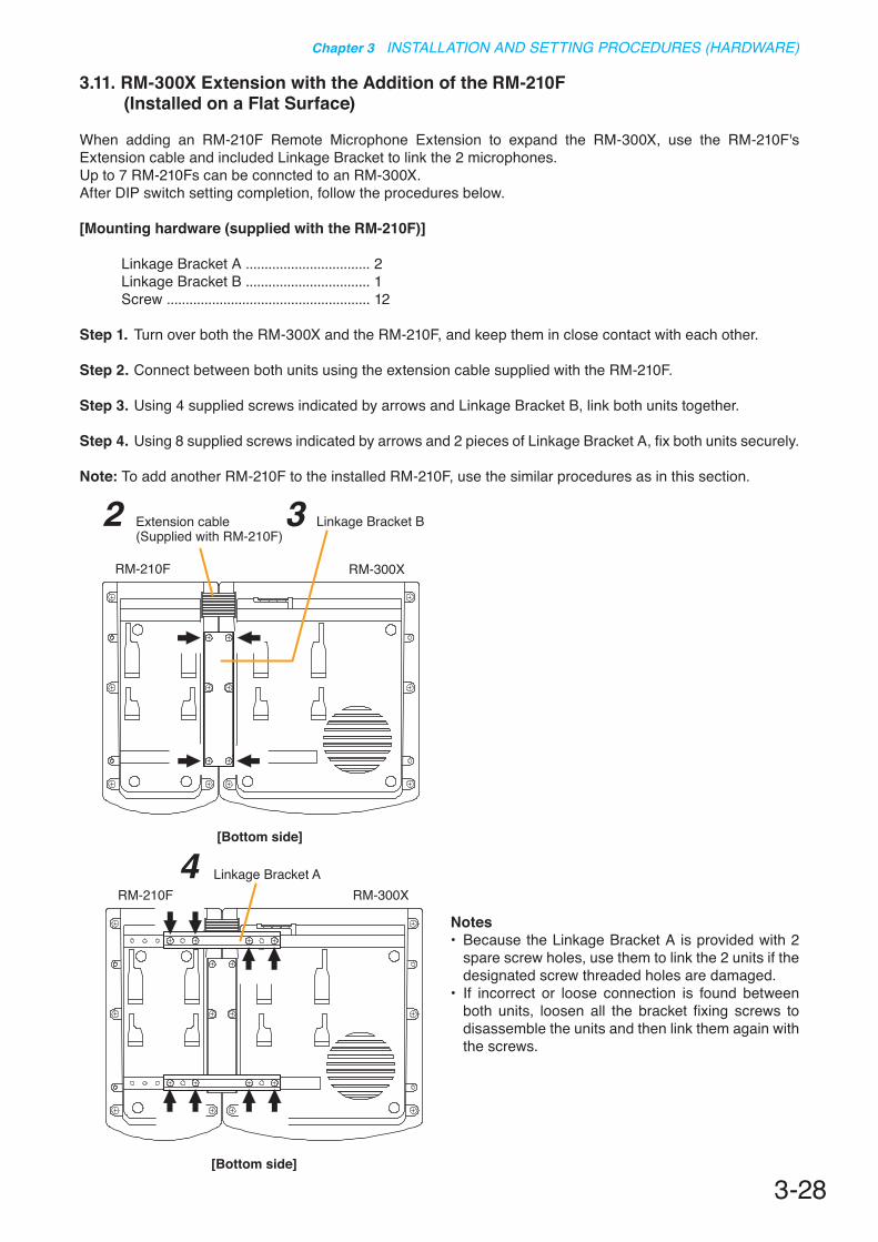
3-28
Chapter 3 INSTALLATION AND SETTING PROCEDURES (HARDWARE)
3.11. RM-300X Extension with the Addition of the RM-210F (Installed on a Flat Surface)
When adding an RM-210F Remote Microphone Extension to expand the RM-300X, use the RM-210F's Extension cable and included Linkage Bracket to link the 2 microphones.Up to 7 RM-210Fs can be conncted to an RM-300X.After DIP switch setting completion, follow the procedures below.
[Mounting hardware (supplied with the RM-210F)]
Linkage Bracket A ................................. 2Linkage Bracket B ................................. 1Screw ...................................................... 12
Step 1. Turn over both the RM-300X and the RM-210F, and keep them in close contact with each other.
Step 2. Connect between both units using the extension cable supplied with the RM-210F.
Step 3. Using 4 supplied screws indicated by arrows and Linkage Bracket B, link both units together.
Step 4. Using 8 supplied screws indicated by arrows and 2 pieces of Linkage Bracket A, fix both units securely.
Note: To add another RM-210F to the installed RM-210F, use the similar procedures as in this section.
Extension cable(Supplied with RM-210F)
RM-210F RM-300X
Linkage Bracket B32
[Bottom side]
Linkage Bracket ARM-210F RM-300X
[Bottom side]
4Notes• Because the Linkage Bracket A is provided with 2
spare screw holes, use them to link the 2 units if the designated screw threaded holes are damaged.
• If incorrect or loose connection is found between both units, loosen all the bracket fixing screws to disassemble the units and then link them again with the screws.

3-29
Chapter 3 INSTALLATION AND SETTING PROCEDURES (HARDWARE)
3.12. Installing the RM-300X on a Wall
[Mounting hardware]
To mount the RM-300X on the wall, the following parts are required.Wall mounting bracket for the RM-300X (model WB-RM200) .... 1 (option)M3.5 x 20 screw for electrical box ............................................... 2 (supplied with the WB-RM200)4 x 25 tapping screw for wooden wall ......................................... 2 (supplied with the WB-RM200)
Step 1. Attach the WB-RM200 Wall-Mounting Bracket on the wall.In this case, leave the LINK cable out of the notch in the bracket.NoteSince there are 2 types of mounting screws for an electrical box and for wall. Select ones according to the mounting method. 60
.883
.5
220.
3
28
RM-300X
WB-RM200(option)
Unit: mm
[WB-RM200 mounting dimensions]
• Install the unit only in a location that can structurally support the weight of the unit and the mounting bracket. Doing otherwise may result in the unit falling down and causing personal injury and/or property damage.
• Be sure to use 2 screws when mounting the bracket to the wall.
WARNING
Step 2. Hook the bottom surface of the RM-300X onto the WB-RM200.
Step 3. Plug the LINK cable into the RM-300X's RM link connector.
RM-300X
LINK
1
2
3
Wall mounting bracketWB-RM200 (option)
Wall mounting screw(supplied with the WB-RM200)
LINK cable
Notch
RM LINK
RM LINK
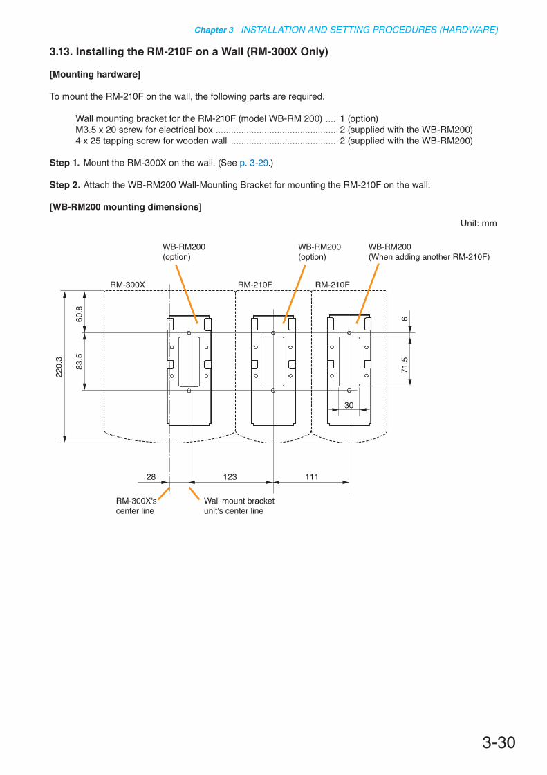
3-30
Chapter 3 INSTALLATION AND SETTING PROCEDURES (HARDWARE)
3.13. Installing the RM-210F on a Wall (RM-300X Only)
[Mounting hardware]
To mount the RM-210F on the wall, the following parts are required.
Wall mounting bracket for the RM-210F (model WB-RM 200) .... 1 (option)M3.5 x 20 screw for electrical box ............................................... 2 (supplied with the WB-RM200)4 x 25 tapping screw for wooden wall ......................................... 2 (supplied with the WB-RM200)
Step 1. Mount the RM-300X on the wall. (See p. 3-29.)
Step 2. Attach the WB-RM200 Wall-Mounting Bracket for mounting the RM-210F on the wall.
[WB-RM200 mounting dimensions]
60.8
83.5
220.
3
123 111
30
28
71.5
6
RM-300X RM-210F RM-210F
WB-RM200(option)
WB-RM200(option)
WB-RM200(When adding another RM-210F)
RM-300X's center line
Wall mount bracket unit's center line
Unit: mm
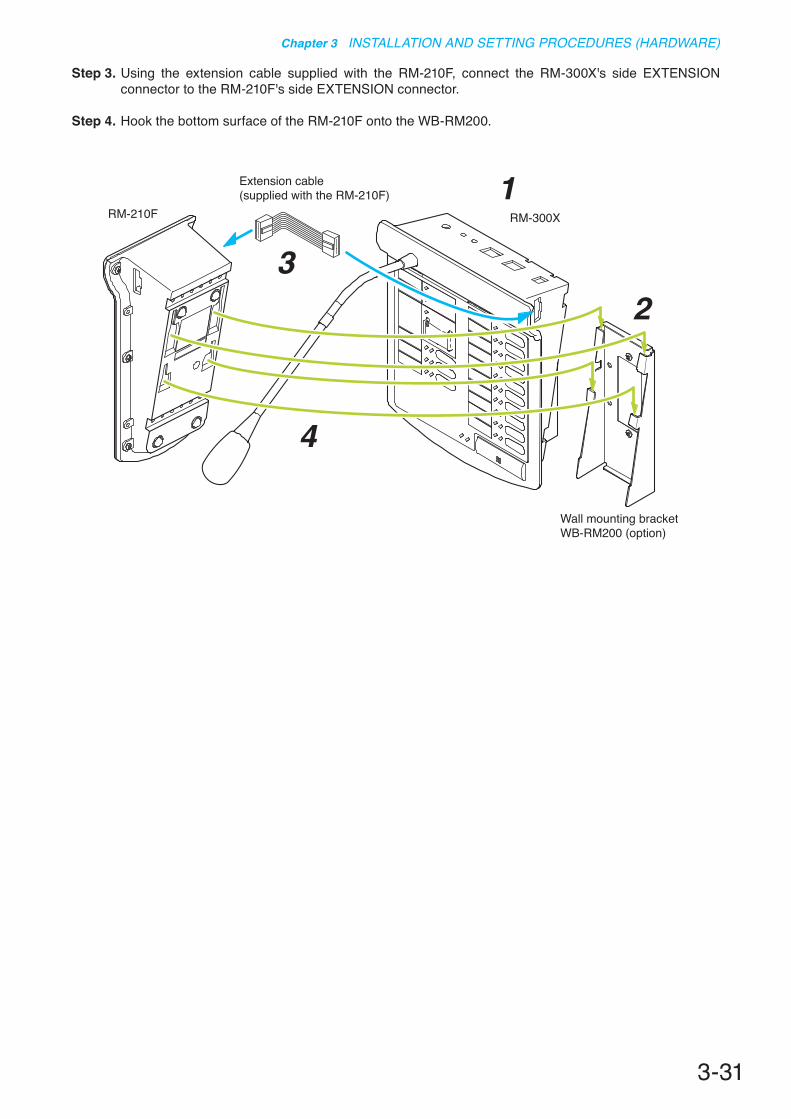
3-31
Chapter 3 INSTALLATION AND SETTING PROCEDURES (HARDWARE)
Step 3. Using the extension cable supplied with the RM-210F, connect the RM-300X's side EXTENSION connector to the RM-210F's side EXTENSION connector.
Step 4. Hook the bottom surface of the RM-210F onto the WB-RM200.
RM-300XRM-210F
4
32
1Extension cable(supplied with the RM-210F)
Wall mounting bracketWB-RM200 (option)
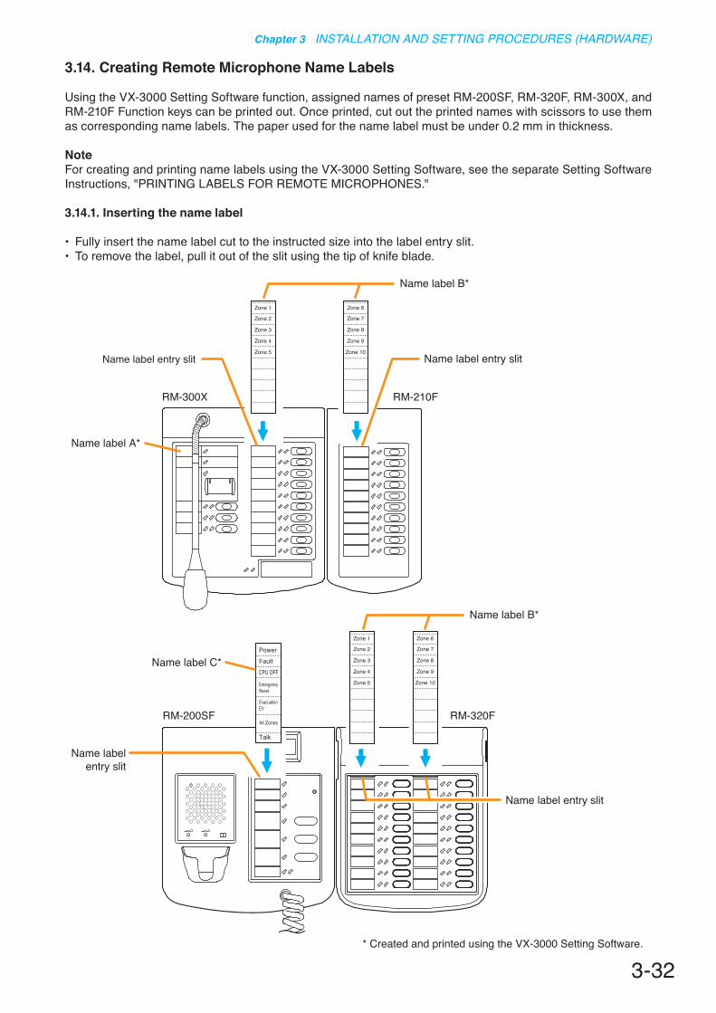
3-32
Chapter 3 INSTALLATION AND SETTING PROCEDURES (HARDWARE)
3.14. Creating Remote Microphone Name Labels
Using the VX-3000 Setting Software function, assigned names of preset RM-200SF, RM-320F, RM-300X, and RM-210F Function keys can be printed out. Once printed, cut out the printed names with scissors to use them as corresponding name labels. The paper used for the name label must be under 0.2 mm in thickness.
NoteFor creating and printing name labels using the VX-3000 Setting Software, see the separate Setting Software Instructions, "PRINTING LABELS FOR REMOTE MICROPHONES."
3.14.1. Inserting the name label
• Fully insert the name label cut to the instructed size into the label entry slit.• To remove the label, pull it out of the slit using the tip of knife blade.
PowerFaultCPU OFF
EmergencyReset
EvacuationEV
All Zones
Talk
Zone 6
Zone 7
Zone 8
Zone 9
Zone 10
Zone 1
Zone 2
Zone 3
Zone 4
Zone 5
Zone 1
Zone 2
Zone 3
Zone 4
Zone 5
Zone 6
Zone 7
Zone 8
Zone 9
Zone 10
Name label entry slit
Name label entry slit Name label entry slit
Name label entry slit
RM-300X RM-210F
RM-200SF RM-320F
Name label B*
Name label B*
Name label C*
Name label A*
* Created and printed using the VX-3000 Setting Software.

3-33
Chapter 3 INSTALLATION AND SETTING PROCEDURES (HARDWARE)
3.14.2. If the name label is not printed correctly
The name label created using the VX-3000 Setting Software may not be printed in correct size depending on the configuration environment of your PC. In such cases, try one of the methods described below.
(1) Preparation by hand Copy the "Pattern paper for hand writing" on the next page. After writing a name, cut out the pattern paper
aligning it with the cutting guidelines.(2) Preparation by using a PC or word processor Prepare and print according to the instructions given in the "Dimensional diagram for printing devices.” Then
cut out to the instructed size.
3.14.3. Dimensional diagram for printing devices
Name label ACutting size: 30 x 110 mm
Name label BCutting size: 30 x 136 mm
Name label CCutting size: 30 x 118 mm
30
1313
1313
118
2121
21
1313
1313
13
13.5
13.5
136
13 x
9 (=
117)
39
110
30 30
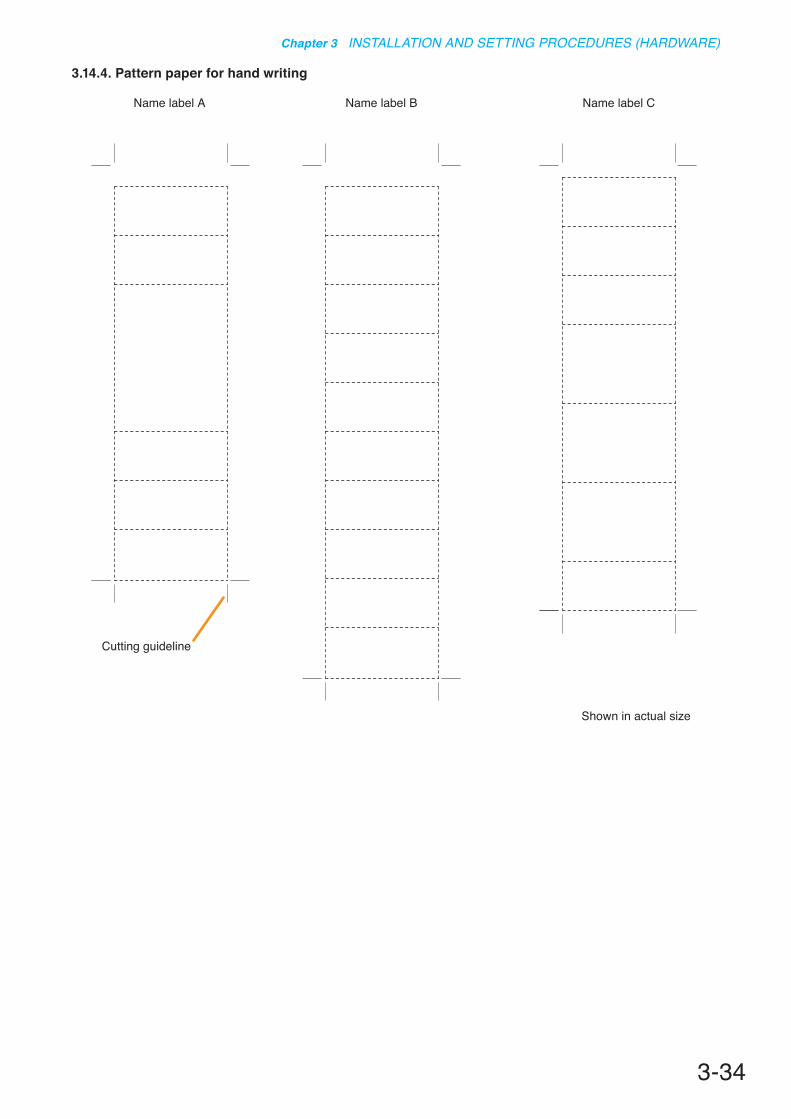
3-34
Chapter 3 INSTALLATION AND SETTING PROCEDURES (HARDWARE)
3.14.4. Pattern paper for hand writing
Name label A Name label B
Shown in actual size
Cutting guideline
Name label C

3-35
Chapter 3 INSTALLATION AND SETTING PROCEDURES (HARDWARE)
3.15. Rack Mounting
Rack-mounting screw 5 x 12 (accessory)
Rack-mounting screw
VX-3000F
• (Applicable to VX-3000F only) The supplied rack-mounting screws can be
used for the TOA equipment rack only. Do not use them for other racks.
• (Applicable to VX-3000DS and VX-3150DS* only)
Rack-mounting screws are not supplied with the unit. Prepare them that are appropriate for the equipment rack.
CAUTION
[Perforated panel mounting]
Be sure to mount the PF-013B (1U) to the locations described below.• Above the 2 installed VX-3000F units• Above and below the 1 installed VX-3000DS (or VX-3150DS) unit• At the uppermost and the lowermost positions of the cabinet rack
[Supporting runner installation]
Be sure to install the supporting runner to the locations described below.• Underside of the 2 installed VX-3000F
units• Underside of the 1 installed VX-3000DS
(or VX-3150DS) unit
Supportingrunner
Supportingrunner
Supportingrunner
Supportingrunner
Supportingrunner
VX-3004F
VX-3004F
VX-3008F
VX-3008F
VX-3016F
VX-3016F
VX-3000DS
PF-013B
PF-013B
1
56789
101112131415161718192021222324252627282930
41
PF-013B
PF-013B
PF-013B
PF-013B
PF-013B
Rack(Example)

3-36
Chapter 3 INSTALLATION AND SETTING PROCEDURES (HARDWARE)
3.16. Affixing Declaration of Compliance (EN 54-16 Standard)
To declare that the VX-3000F complies with EN 54-16, affix the sticker supplied with the VX-3000F visible to the front panel of the equipment (e.g. at the upper right side as shown below).
RackEN 54-16
EN 54-16
Sticker (supplied with the VX-3000F)Affix only the upper part of the sticker to the equipment rack.
Paste this sticker on the outsideof the cabinet rack containing the so certified equipment.
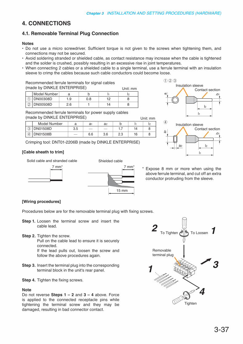
3-37
Chapter 3 INSTALLATION AND SETTING PROCEDURES (HARDWARE)
4. CONNECTIONS4.1. Removable Terminal Plug Connection
Notes• Do not use a micro screwdriver. Sufficient torque is not given to the screws when tightening them, and
connections may not be secured.• Avoid soldering stranded or shielded cable, as contact resistance may increase when the cable is tightened
and the solder is crushed, possibly resulting in an excessive rise in joint temperatures.• When connecting 2 cables or a shielded cable to a single terminal, use a ferrule terminal with an insulation
sleeve to crimp the cables because such cable conductors could become loose.
Recommended ferrule terminals for signal cables (made by DINKLE ENTERPRISE) Unit: mm
Model Number a b l1 l2DN00308D 1.9 0.8 12 8DN00508D 2.6 1 14 8
Recommended ferrule terminals for power supply cables (made by DINKLE ENTERPRISE) Unit: mm
Model Number a a1 a2 b l1 l2DN01508D 3.5 - - 1.7 14 8DN01508B - 6.6 3.6 2.3 16 8
Crimping tool: DNT01-2206B (made by DINKLE ENTERPRISE)
[Cable sheath to trim]
Insulation sleeveContact section
Insulation sleeveContact section
a
l2
a1
a2
l1
l2
l1
bb
Solid cable and stranded cable Shielded cable7 mm* 7 mm*
15 mm
* Expose 8 mm or more when using the above ferrule terminal, and cut off an extra conductor protruding from the sleeve.
[Wiring procedures]
Procedures below are for the removable terminal plug with fixing screws.
Step 1. Loosen the terminal screw and insert the cable lead.
Step 2. Tighten the screw. Pull on the cable lead to ensure it is securely connected.If the lead pulls out, loosen the screw and follow the above procedures again.
Step 3. Insert the terminal plug into the corresponding terminal block in the unit's rear panel.
Step 4. Tighten the fixing screws.
NoteDo not reverse Steps 1 – 2 and 3 – 4 above. Force is applied to the connected receptacle pins while tightening the terminal screw and they may be damaged, resulting in bad connector contact.
Removableterminal plug
1
1
2
3
To Tighten To Loosen
Tighten
4
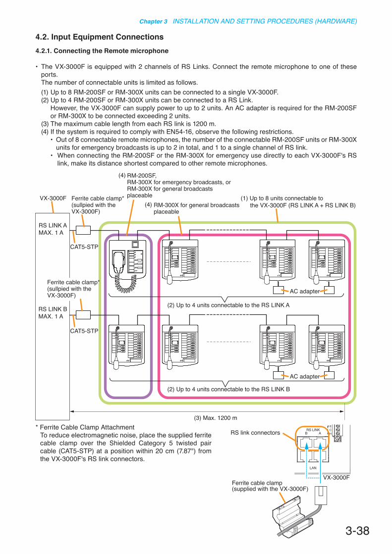
3-38
Chapter 3 INSTALLATION AND SETTING PROCEDURES (HARDWARE)
4.2. Input Equipment Connections4.2.1. Connecting the Remote microphone
• The VX-3000F is equipped with 2 channels of RS Links. Connect the remote microphone to one of these ports.
The number of connectable units is limited as follows.(1) Up to 8 RM-200SF or RM-300X units can be connected to a single VX-3000F. (2) Up to 4 RM-200SF or RM-300X units can be connected to a RS Link.
However, the VX-3000F can supply power to up to 2 units. An AC adapter is required for the RM-200SF or RM-300X to be connected exceeding 2 units.
(3) The maximum cable length from each RS link is 1200 m.(4) If the system is required to comply with EN54-16, observe the following restrictions.
• Out of 8 connectable remote microphones, the number of the connectable RM-200SF units or RM-300X units for emergency broadcasts is up to 2 in total, and 1 to a single channel of RS link.
• When connecting the RM-200SF or the RM-300X for emergency use directly to each VX-3000F's RS link, make its distance shortest compared to other remote microphones.
(3) Max. 1200 m
RS LINK AMAX. 1 A
RS LINK BMAX. 1 A
AC adapter
AC adapter
VX-3000F Ferrite cable clamp*(sullpied with the VX-3000F)
CAT5-STP
RM-200SF, RM-300X for emergency broadcasts, or RM-300X for general broadcasts placeable
RM-300X for general broadcasts placeable
(1) Up to 8 units connectable to the VX-3000F (RS LINK A + RS LINK B)
(2) Up to 4 units connectable to the RS LINK A
(2) Up to 4 units connectable to the RS LINK B
CAT5-STP
Ferrite cable clamp*(sullpied with the VX-3000F)
(4)
(4)
* Ferrite Cable Clamp AttachmentTo reduce electromagnetic noise, place the supplied ferrite cable clamp over the Shielded Category 5 twisted pair cable (CAT5-STP) at a position within 20 cm (7.87") from the VX-3000F's RS link connectors.
RS link connectors
VX-3000FFerrite cable clamp(supplied with the VX-3000F)
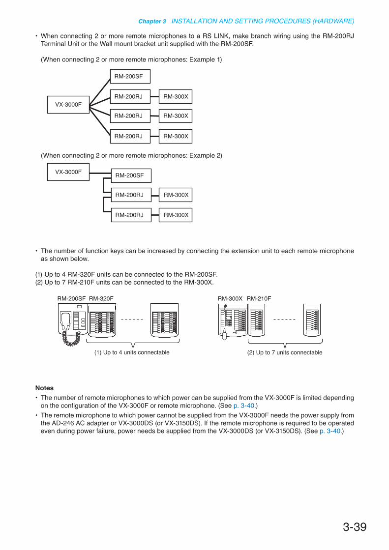
3-39
Chapter 3 INSTALLATION AND SETTING PROCEDURES (HARDWARE)
• The number of function keys can be increased by connecting the extension unit to each remote microphone as shown below.
(1) Up to 4 RM-320F units can be connected to the RM-200SF.(2) Up to 7 RM-210F units can be connected to the RM-300X.
Notes• The number of remote microphones to which power can be supplied from the VX-3000F is limited depending
on the configuration of the VX-3000F or remote microphone. (See p. 3-40.)• The remote microphone to which power cannot be supplied from the VX-3000F needs the power supply from
the AD-246 AC adapter or VX-3000DS (or VX-3150DS). If the remote microphone is required to be operated even during power failure, power needs be supplied from the VX-3000DS (or VX-3150DS). (See p. 3-40.)
RM-200SF RM-320F
(1) Up to 4 units connectable
RM-300X RM-210F
(2) Up to 7 units connectable
• When connecting 2 or more remote microphones to a RS LINK, make branch wiring using the RM-200RJ Terminal Unit or the Wall mount bracket unit supplied with the RM-200SF.
(When connecting 2 or more remote microphones: Example 1)
(When connecting 2 or more remote microphones: Example 2)
VX-3000FRM-300X
RM-300X
RM-300X
RM-200RJ
RM-200SF
RM-200RJ
RM-200RJ
VX-3000F
RM-300X
RM-300XRM-200RJ
RM-200SF
RM-200RJ
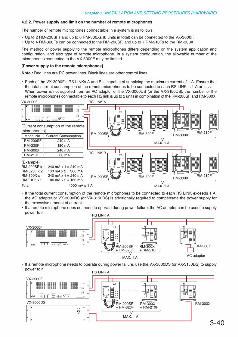
3-40
Chapter 3 INSTALLATION AND SETTING PROCEDURES (HARDWARE)
4.2.2. Power supply and limit on the number of remote microphones
The number of remote microphones connectable in a system is as follows.• Up to 2 RM-200SFs and up to 6 RM-300Xs (8 units in total) can be connected to the VX-3000F. • Up to 4 RM-320Fs can be connected to the RM-200SF, and up to 7 RM-210Fs to the RM-300X. The method of power supply to the remote microphones differs depending on the system application and configuration, and also type of remote microphone. In a system configuration, the allowable number of the microphones connected to the VX-3000F may be limited.[Power supply to the remote microphones]Note : Red lines are DC power lines. Black lines are other control lines.
• Each of the VX-3000F's RS LINKs A and B is capable of supplying the maximum current of 1 A. Ensure that the total current consumption of the remote microphones to be connected to each RS LINK is 1 A or less.
When power is not supplied from an AC adaptor or the VX-3000DS (or the VX-3150DS), the number of the remote microphones connectable to each RS link is up to 2 units in combination of the RM-200SF and RM-300X.
• If the total current consumption of the remote microphones to be connected to each RS LINK exceeds 1 A, the AC adapter or VX-3000DS (or VX-3150DS) is additionally required to compensate the power supply for the excessive amount of current.
• If a remote microphone does not need to operate during power failure, the AC adapter can be used to supply power to it.
VX-3000F
RM-200SF+ RM-320F
RM-300X+ RM-210F
RM-300X
MAX. 1 A
RS LINK A
AC adapter
VX-3000F
RM-300X
MAX. 1 A
RS LINK A
VX-3000DS RM-200SF+ RM-320F
RM-300X+ RM-210F
• If a remote microphone needs to operate during power failure, use the VX-3000DS (or VX-3150DS) to supply power to it.
VX-3000F
RM-200SF RM-320F RM-300X RM-210F
RM-200SF RM-320F RM-300X RM-210F
MAX. 1 A
MAX. 1 A
RS LINK B
RS LINK A
[Current consumption of the remote microphones]
Model No. Current ConsumptionRM-200SF 240 mARM-320F 180 mARM-300X 240 mARM-210F 80 mA
(Example)RM-200SF x 1 240 mA x 1 = 240 mARM-320F x 2 180 mA x 2 = 360 mARM-300X x 1 240 mA x 1 = 240 mARM-210F x 2 80 mA x 2 = 160 mATotal 1000 mA ≤ 1 A
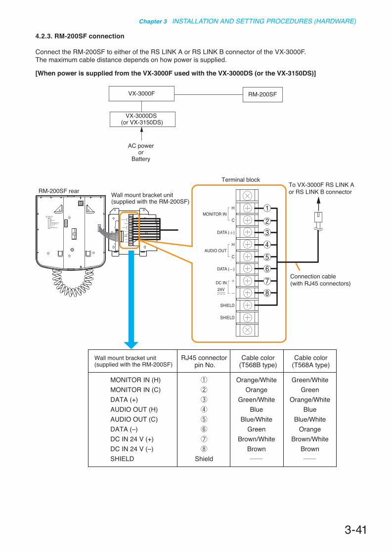
3-41
Chapter 3 INSTALLATION AND SETTING PROCEDURES (HARDWARE)
4.2.3. RM-200SF connection
Connect the RM-200SF to either of the RS LINK A or RS LINK B connector of the VX-3000F.The maximum cable distance depends on how power is supplied.
[When power is supplied from the VX-3000F used with the VX-3000DS (or the VX-3150DS)]
87654321
TERMINATION
CPU OFFLEVEL METERCOMMUNICATION
UNIT ID
OnOffDIP SWITCH
MONITOR IN (H)MONITOR IN (C)DATA (+)AUDIO OUT (H)AUDIO OUT (C)DATA (–)DC IN 24 V (+)DC IN 24 V (–)SHIELD Shield
Orange/WhiteOrange
Green/WhiteBlue
Blue/WhiteGreen
Brown/WhiteBrown
Green/WhiteGreen
Orange/WhiteBlue
Blue/WhiteOrange
Brown/WhiteBrown
Wall mount bracket unit (supplied with the RM-200SF)
RJ45 connector pin No.
Cable color(T568B type)
Cable color(T568A type)
RM-200SF rear Wall mount bracket unit (supplied with the RM-200SF)
Terminal blockTo VX-3000F RS LINK A or RS LINK B connector
Connection cable(with RJ45 connectors)
12345678
VX-3000F RM-200SF
VX-3000DS (or VX-3150DS)
AC poweror
Battery

3-42
Chapter 3 INSTALLATION AND SETTING PROCEDURES (HARDWARE)
To make longer cable lengths than those shown in the above table, use over 4-pair shielded CPEV cable.The relationship of the CPEV cable conductor diameter to the maximum cable distance is as follows.
CableRM-200SF
aloneRM-200SF +RM-320F x 1
RM-200SF +RM-320F x 2
RM-200SF +RM-320F x 3
RM-200SF +RM-320F x 4
STP Category 5 336 m 191 m 132 m 101 m 81 m
No. of extension units
CableRM-200SF
aloneRM-200SF +RM-320F x 1
RM-200SF +RM-320F x 2
RM-200SF +RM-320F x 3
RM-200SF +RM-320F x 4
ø0.65 mm 555 m 315 m 219 m 167 m 135 mø0.9 mm 1081 m 613 m 426 m 326 m 263 mø1.2 mm 1200 m 1086 m 755 m 577 m 465 m
No. of extension units
• When the VX-3000DS (or the VX-3150DS) is operating on AC power
The following table shows the maximum cable distance when STP Category 5 straight cable (with RJ45 connectors) is used.
To make longer cable lengths than those shown in the above table, use over 4-pair shielded CPEV cable.The relationship of the CPEV cable conductor diameter to the maximum cable distance is as follows.
CableRM-200SF
aloneRM-200SF +RM-320F x 1
RM-200SF +RM-320F x 2
RM-200SF +RM-320F x 3
RM-200SF +RM-320F x 4
STP Category 5 92 m 51 m 35 m 26 m 20 m
No. of extension units
CableRM-200SF
aloneRM-200SF +RM-320F x 1
RM-200SF +RM-320F x 2
RM-200SF +RM-320F x 3
RM-200SF +RM-320F x 4
ø0.65 mm 152 m 85 m 58 m 43 m 34 mø0.9 mm 296 m 165 m 112 m 84 m 66 mø1.2 mm 524 m 292 m 199 m 149 m 118 m
No. of extension units
• When the VX-3000DS (or the VX-3150DS) is operating on battery
The following table shows the maximum cable distance when STP Category 5 straight cable (with RJ45 connectors) is used.

3-43
Chapter 3 INSTALLATION AND SETTING PROCEDURES (HARDWARE)
87654321
TERMINATION
CPU OFFLEVEL METERCOMMUNICATION
UNIT ID
OnOffDIP SWITCH
RM-200SF rear
9 mm
25 mm
(+)(–)
123456
AC adapter AD-246 or equivalent unitAC adapter AD-246
Cut off the DC plug of the AD-246 AC Adapter, and treat the tip of cable as follows.
(Use when no back up power supply is required.)
(–)(+)
Cut off
Connection cable(with RJ45 connectors)
To VX-3000F RS LINK A or RS LINK B connector
Terminal block
Usable AC adapter: 24 V DC/over 200 mA (Operation range: 14 – 28 V DC)
When a STP category 5 straight cable or over 4-pair shielded CPEV cable is used as communication cable (excluding power line) between the RM-200SF and the VX-3000F, the maximum cable distance in a system is 1200 m in total.
[When power is supplied from the AC adapter]
VX-3000F RM-200SF
AC adapter

3-44
Chapter 3 INSTALLATION AND SETTING PROCEDURES (HARDWARE)
[When power is supplied from the VX-3000DS (or the VX-3150DS)]
87654321
TERMINATION
CPU OFFLEVEL METERCOMMUNICATION
UNIT ID
OnOffDIP SWITCH
RM-200SF rear Wall mount bracket unit (supplied with the RM-200SF) 1
23456
VX-3000DS’ (or VX-3150DS’)DC POWER OUT terminal
(–)(+)
Connection cable(with RJ45 connectors)
To VX-3000F RS LINK A or RS LINK B connector
Terminal block
VX-3000F RM-200SF
VX-3000DS(or VX-3150DS)
AC poweror
Battery
When a STP Category 5 straight cable is used as communication cable (excluding power line) between the RM-200SF and the VX-3000F, the maximum cable distance in a system is 1200 m in total.
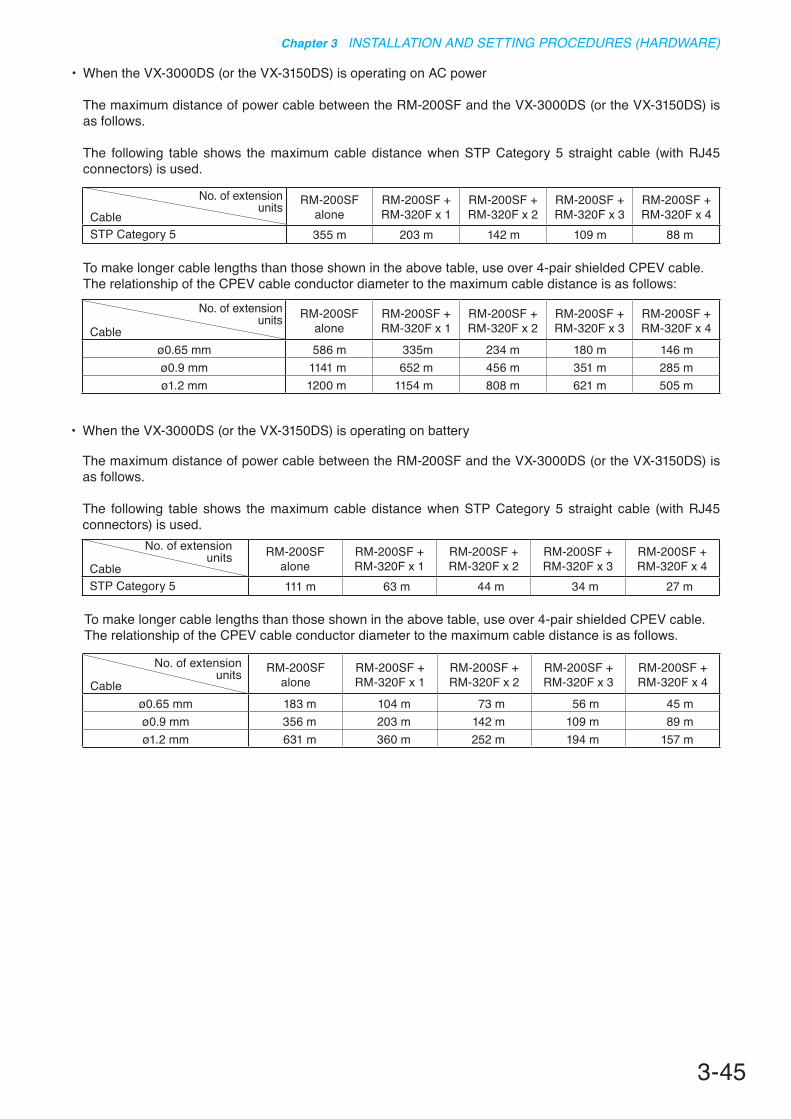
3-45
Chapter 3 INSTALLATION AND SETTING PROCEDURES (HARDWARE)
• When the VX-3000DS (or the VX-3150DS) is operating on AC power
The maximum distance of power cable between the RM-200SF and the VX-3000DS (or the VX-3150DS) is as follows.
The following table shows the maximum cable distance when STP Category 5 straight cable (with RJ45 connectors) is used.
To make longer cable lengths than those shown in the above table, use over 4-pair shielded CPEV cable.The relationship of the CPEV cable conductor diameter to the maximum cable distance is as follows:
CableRM-200SF
aloneRM-200SF +RM-320F x 1
RM-200SF +RM-320F x 2
RM-200SF +RM-320F x 3
RM-200SF +RM-320F x 4
STP Category 5 355 m 203 m 142 m 109 m 88 m
No. of extension units
CableRM-200SF
aloneRM-200SF +RM-320F x 1
RM-200SF +RM-320F x 2
RM-200SF +RM-320F x 3
RM-200SF +RM-320F x 4
ø0.65 mm 586 m 335m 234 m 180 m 146 mø0.9 mm 1141 m 652 m 456 m 351 m 285 mø1.2 mm 1200 m 1154 m 808 m 621 m 505 m
No. of extension units
To make longer cable lengths than those shown in the above table, use over 4-pair shielded CPEV cable.The relationship of the CPEV cable conductor diameter to the maximum cable distance is as follows.
CableRM-200SF
aloneRM-200SF +RM-320F x 1
RM-200SF +RM-320F x 2
RM-200SF +RM-320F x 3
RM-200SF +RM-320F x 4
STP Category 5 111 m 63 m 44 m 34 m 27 m
No. of extension units
CableRM-200SF
aloneRM-200SF +RM-320F x 1
RM-200SF +RM-320F x 2
RM-200SF +RM-320F x 3
RM-200SF +RM-320F x 4
ø0.65 mm 183 m 104 m 73 m 56 m 45 mø0.9 mm 356 m 203 m 142 m 109 m 89 mø1.2 mm 631 m 360 m 252 m 194 m 157 m
No. of extension units
• When the VX-3000DS (or the VX-3150DS) is operating on battery
The maximum distance of power cable between the RM-200SF and the VX-3000DS (or the VX-3150DS) is as follows.
The following table shows the maximum cable distance when STP Category 5 straight cable (with RJ45 connectors) is used.

3-46
Chapter 3 INSTALLATION AND SETTING PROCEDURES (HARDWARE)
CableRM-300X alone RM-300X +
RM-210F x 1RM-300X +RM-210F x 2
RM-300X +RM-210F x 3
STP Category 5 336 m 251 m 200 m 166 m
CableRM-300X +RM-210F x 4
RM-300X +RM-210F x 5
RM-300X +RM-210F x 6
RM-300X +RM-210F x 7
STP Category 5 142 m 124 m 110 m 98 m
No. of extension units
No. of extension units
4.2.4. RM-300X connection
RM-300X rear Connection cable(with RJ45 connectors)
To VX-3000F
• When VX-3000DS (or VX-3150DS) is operating on AC power
The following table shows the maximum cable distance when STP Category 5 straight cable (with RJ45 connectors) is used.
To make longer cable lengths than those shown in the above table, use over 4-pair shielded CPEV cable. (For the cable connection, see p. 3-48.)The relationship of the CPEV cable conductor diameter to the maximum cable distance is as follows:
CableRM-300X alone RM-300X +
RM-210F x 1RM-300X +RM-210F x 2
RM-300X +RM-210F x 3
ø0.65 mm 555 m 415 m 331 m 275 mø0.9 mm 1081 m 808 m 644 m 535 mø1.2 mm 1200 m 1200 m 1141 m 948 m
CableRM-300X +RM-210F x 4
RM-300X +RM-210F x 5
RM-300X +RM-210F x 6
RM-300X +RM-210F x 7
ø0.65 mm 235 m 205 m 182 m 163 mø0.9 mm 457 m 399 m 354 m 317 mø1.2 mm 810 m 707 m 626 m 562 m
No. of extension units
No. of extension units
Connect the RM-300X to either of the RS LINK A or RS LINK B connector of the VX-3000F.The maximum cable distance depends on how power is supplied.
[When power is supplied from the VX-3000F used with the VX-3000DS (or the VX-3150DS)]
VX-3000F RM-300X
VX-3000DS (or VX-3150DS)
AC poweror
Battery

3-47
Chapter 3 INSTALLATION AND SETTING PROCEDURES (HARDWARE)
To make longer cable lengths than those shown in the above table, use over 4-pair shielded CPEV cable. (For the cable connection, see p. 3-48.)The relationship of the CPEV cable conductor diameter to the maximum cable distance is as follows:
CableRM-300X alone RM-300X +
RM-210F x 1RM-300X +RM-210F x 2
RM-300X +RM-210F x 3
STP Category 5 92 m 68 m 54 m 44 m
CableRM-300X +RM-210F x 4
RM-300X +RM-210F x 5
RM-300X +RM-210F x 6
RM-300X +RM-210F x 7
STP Category 5 37 m 32 m 28 m 25 m
No. of extension units
No. of extension units
CableRM-300X alone RM-300X +
RM-210F x 1RM-300X +RM-210F x 2
RM-300X +RM-210F x 3
ø0.65 mm 152 m 113 m 89 m 73 mø0.9 mm 296 m 220 m 174 m 143 mø1.2 mm 524 m 389 m 308 m 253 m
CableRM-300X +RM-210F x 4
RM-300X +RM-210F x 5
RM-300X +RM-210F x 6
RM-300X +RM-210F x 7
ø0.65 mm 62 m 54 m 47 m 42 mø0.9 mm 121 m 105 m 92 m 82 mø1.2 mm 215 m 186 m 163 m 145 m
No. of extension units
No. of extension units
• When the VX-3000DS (or the VX-3150DS) is operating on battery
The following table shows the maximum cable distance when STP Category 5 straight cable (with RJ45 connectors) is used.

3-48
Chapter 3 INSTALLATION AND SETTING PROCEDURES (HARDWARE)
Tips• When using a shielded CPEV cable, it is recommended to use an optional RM-200RJ Terminal Unit that
serves wiring conversion between the CPEV cable and STP Category 5 straight cable (with RJ45 connectors). Connect the CPEV cable between the same terminals of both RM-200RJ units pairing cables 1 with 2, 4 with 5, 3 with 6, and 7 with 8 as shown below.
Over 4-pair shielded CPEV cable (main cable)
STP Category 5 straight cable (with RJ45 connectors)
TipThe RM-200RJ can be installed on a desk or to a wall.
RM-300X rear
44.5
116
44.5
13.5
7584
[RM-200RJ Mounting dimensions]
RM-200RJ
RM-200RJ
12
5
63
4
78Shield
12
5
63
4
78ShieldSTP Category 5 straight cable
(with RJ45 connectors)
VX-3000F
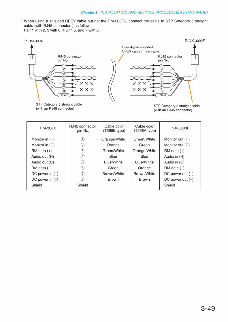
3-49
Chapter 3 INSTALLATION AND SETTING PROCEDURES (HARDWARE)
• When using a shielded CPEV cable but not the RM-200RJ, connect the cable to STP Category 5 straight cable (with RJ45 connectors) as follows.
Pair 1 with 2, 3 with 6, 4 with 5, and 7 with 8.
Monitor in (H)Monitor in (C)RM data (+)Audio out (H)Audio out (C)RM data (–)DC power in (+)DC power in (–)Shield Shield
Orange/WhiteOrange
Green/WhiteBlue
Blue/WhiteGreen
Brown/WhiteBrown
Green/WhiteGreen
Orange/WhiteBlue
Blue/WhiteOrange
Brown/WhiteBrown
Monitor out (H)Monitor out (C)RM data (+)Audio in (H)Audio in (C)RM data (–)DC power out (+)DC power out (–)Shield
RM-300X RJ45 connector pin No.
Cable color(T568B type)
Cable color(T568A type) VX-3000F
Over 4-pair shielded CPEV cable (main cable)
STP Category 5 straight cable (with an RJ45 connector)
STP Category 5 straight cable (with an RJ45 connector)
RJ45 connectorpin No.
RJ45 connectorpin No.
To VX-3000FTo RM-300X
12
56
34
78
Shield
12
56
34
78
Shield

3-50
Chapter 3 INSTALLATION AND SETTING PROCEDURES (HARDWARE)
RM-300X rear
AC adapter AD-246 orequivalent unit*
To AC power
Use when no backup power supply is required.
[When power is supplied from the AC adapter]
* Usable AC adapter 24 V DC/over 200 mA (Operation range: 14 – 28 V DC) Usable power output plug: Non-polarity type (Any polarity can be used.) (5.5 mm outer diameter, 2.1 mm inner diameter, and 9.5 mm long)
NotePlugging a DC plug into the RM-300X's power input terminal automatically switches the RM-300X's DC power input to this terminal, disconnecting the unit's power supply from the RM link connector.Be sure to firmly secure the DC plug by fixing the power cable onto the RM-300X's bottom-mounted cable hook.If the DC plug is pulled out, the RM link connector takes over the unit's power supply and is connected to the system power line. This may cause the voltage drop of power supply and increase the current consumption from the VX-3000F, resulting in the system malfunction.
When supplying power to the RM-300X from the optional AD-246 AC Adapter using an STP category 5 straight cable or over 4-pair shielded CPEV cable, the maximum length of connection cable (excluding power line) is 1200 m regardless of the type of cable and the number of remote microphone extension units.NoteTo power the remote microphones even during power failures, a battery backup is also needed for the AC adapter.Or supply power to the remote microphones from the VX-3000DS (or the VX-3150DS) without using the AC adapter.
VX-3000F RM-300X
AC adapter

3-51
Chapter 3 INSTALLATION AND SETTING PROCEDURES (HARDWARE)
[When power is supplied from the VX-3000DS (or the VX-3150DS)]
RM-300X rear
12
5
63
4
78Shield
12
5
63
4
78Shield
VX-3000DS’ (or VX-3150DS’)DC Power out terminal
(+)(-)
VX-3000F
Over 4-pair shielded CPEV cable (main cable)
STP Category 5 straight cable (with RJ45 connectors)
RM-200RJ
RM-200RJ
STP Category 5 straight cable (with RJ45 connectors)
VX-3000F RM-300X
VX-3000DS (or the VX-3150DS)
AC poweror
Battery
When a STP Category 5 straight cable is used as communication cable (excluding power line) between the RM-300X and the VX-3000F, the maximum cable distance in a system is 1200 m in total.

3-52
Chapter 3 INSTALLATION AND SETTING PROCEDURES (HARDWARE)
To make longer cable lengths than those shown in the above table, use over 4-pair shielded CPEV cable. (For the cable connection, see p. 3-48.)The relationship of the CPEV cable conductor diameter to the maximum cable distance is as follows:
CableRM-300X alone RM-300X +
RM-210F x 1RM-300X +RM-210F x 2
RM-300X +RM-210F x 3
STP Category 5 355 m 266 m 213 m 177 m
CableRM-300X +RM-210F x 4
RM-300X +RM-210F x 5
RM-300X +RM-210F x 6
RM-300X +RM-210F x 7
STP Category 5 152 m 133 m 118 m 106 m
No. of extension units
No. of extension units
CableRM-300X alone RM-300X +
RM-210F x 1RM-300X +RM-210F x 2
RM-300X +RM-210F x 3
ø0.65 mm 586 m 440 m 352 m 293 mø0.9 mm 1141 m 856 m 684 m 570 mø1.2 mm 1200 m 1200 m 1200 m 1010 m
CableRM-300X +RM-210F x 4
RM-300X +RM-210F x 5
RM-300X +RM-210F x 6
RM-300X +RM-210F x 7
ø0.65 mm 251 m 220 m 195 m 176 mø0.9 mm 489 m 428 m 380 m 342 mø1.2 mm 865 m 757 m 673 m 606 m
No. of extension units
No. of extension units
• When the VX-3000DS (or the VX-3150DS) is operating on AC power
To make longer cable lengths than those shown in the above table, use over 4-pair shielded CPEV cable. (For the cable connection, see p. 3-48.)The relationship of the CPEV cable conductor diameter to the maximum cable distance is as follows:
CableRM-300X alone RM-300X +
RM-210F x 1RM-300X +RM-210F x 2
RM-300X +RM-210F x 3
STP Category 5 111 m 83 m 66 m 55 m
CableRM-300X +RM-210F x 4
RM-300X +RM-210F x 5
RM-300X +RM-210F x 6
RM-300X +RM-210F x 7
STP Category 5 47 m 41 m 37 m 33 m
No. of extension units
No. of extension units
CableRM-300X alone RM-300X +
RM-210F x 1RM-300X +RM-210F x 2
RM-300X +RM-210F x 3
ø0.65 mm 183 m 137 m 110 m 91 mø0.9 mm 356 m 267 m 214 m 178 mø1.2 mm 631 m 473 m 378 m 315 m
CableRM-300X +RM-210F x 4
RM-300X +RM-210F x 5
RM-300X +RM-210F x 6
RM-300X +RM-210F x 7
ø0.65 mm 78 m 68 m 61 m 55 mø0.9 mm 152 m 133 m 118 m 107 mø1.2 mm 270 m 236 m 210 m 189 m
No. of extension units
No. of extension units
• When the VX-3000DS (or the VX-3150DS) is operating on battery
The maximum distance of power cable between the RM-300X and the VX-3000DS (or the VX-3150DS) is as follows.
The following table shows the maximum cable distance when STP Category 5 straight cable (with RJ45 connectors) is used.
The maximum distance of power cable between the RM-300X and the VX-3000DS (or the VX-3150DS) is as follows.
The following table shows the maximum cable distance when STP Category 5 straight cable (with RJ45 connectors) is used.
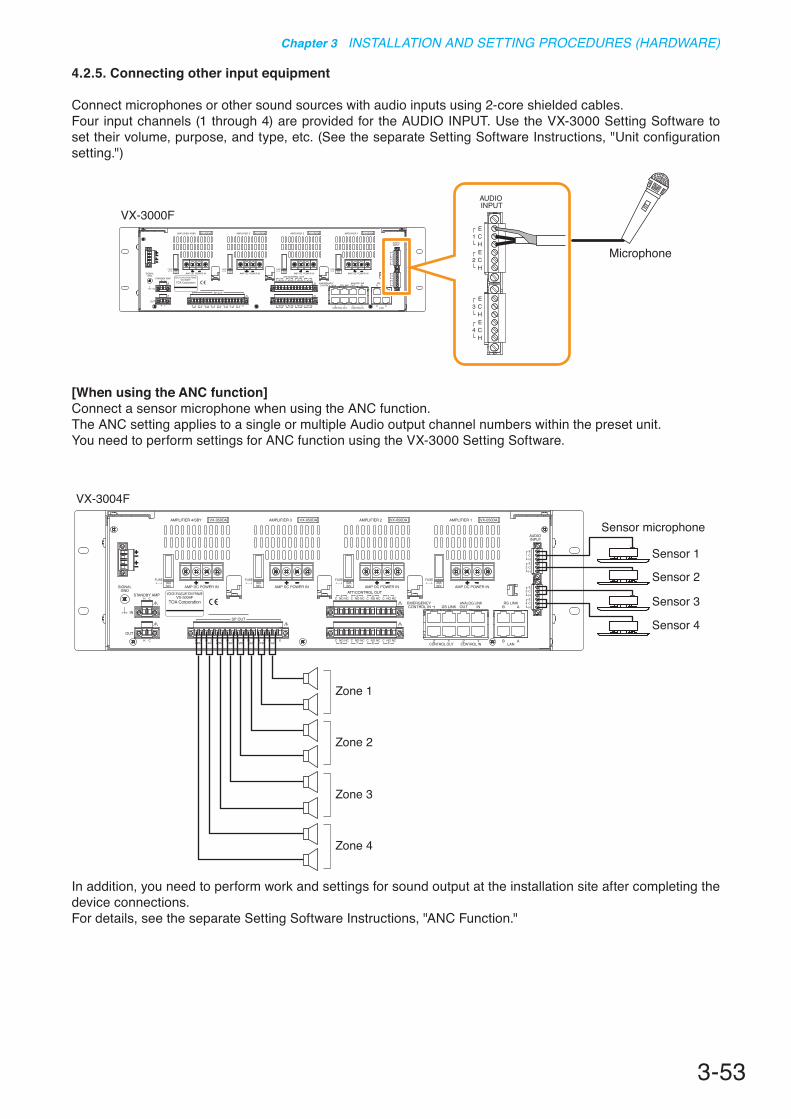
3-53
Chapter 3 INSTALLATION AND SETTING PROCEDURES (HARDWARE)
4.2.5. Connecting other input equipment
Connect microphones or other sound sources with audio inputs using 2-core shielded cables.Four input channels (1 through 4) are provided for the AUDIO INPUT. Use the VX-3000 Setting Software to set their volume, purpose, and type, etc. (See the separate Setting Software Instructions, "Unit configuration setting.")
VX-3000F
Microphone
[When using the ANC function]Connect a sensor microphone when using the ANC function.The ANC setting applies to a single or multiple Audio output channel numbers within the preset unit. You need to perform settings for ANC function using the VX-3000 Setting Software.
VX-3004F
Sensor 1
Sensor microphone
Zone 1
Sensor 2
Sensor 3
Sensor 4
Zone 2
Zone 3
Zone 4
In addition, you need to perform work and settings for sound output at the installation site after completing the device connections.For details, see the separate Setting Software Instructions, "ANC Function."

3-54
Chapter 3 INSTALLATION AND SETTING PROCEDURES (HARDWARE)
4.3.2. 3-wire system connection
4.3. Speaker Connection
Connect speakers to the speaker output terminal.Following 3 types of wiring systems are available: 2-wire system where no attenuator is connected, and 3-wire and 4-wire systems where attenuators are connected.Failure detection is available if the EOL unit is connected.Set the use of attenuator and EOL unit on the VX-3000 Setting Software.(See the separate Setting Software Instructions, "Unit configuration setting.")
4.3.1. 2-wire system connection
H
VX-3000F
Shield
Speaker
H C
Speaker
H C
RN
H H C C NO NCC
SP
Speaker
H
CAttenuator (e.g. AT-603P)
VX-3000F
NoteWhen initializing the surveillance settings, the total speaker wattage per line should be 20 W (500 Ω) or more.Lighter speaker load may cause false detection.

3-55
Chapter 3 INSTALLATION AND SETTING PROCEDURES (HARDWARE)
4.3.3. 4-wire system connection
Two types of attenuators are connectable to this unit, one to be bypassed when 24 V DC is applied to the attenuator, and the other to be bypassed when the 24 V DC being normally applied to is cut off (in no voltage mode). Connections of the unit's attenuator control output and 24 V DC power supply's terminals differ depending on the types as shown below.
[Example 1]Bypassed when 24 V DC is applied to the attenuator.
H
C
C
(+)
DC Power supply
(–)
N C SP
Speaker
(+)
Relay Control
(–)
HAttenuator
VX-3000F
H C
(+)
DC Power supply
(–)
Attenuator
CN C SP
Speaker
(+)
Relay Control
(–)
H
VX-3000F
[Example 2]Bypassed when the 24 V DC being normally applied to is cut off.
NoteThe system in Example 2 is more fail-safe than that in Example 1.
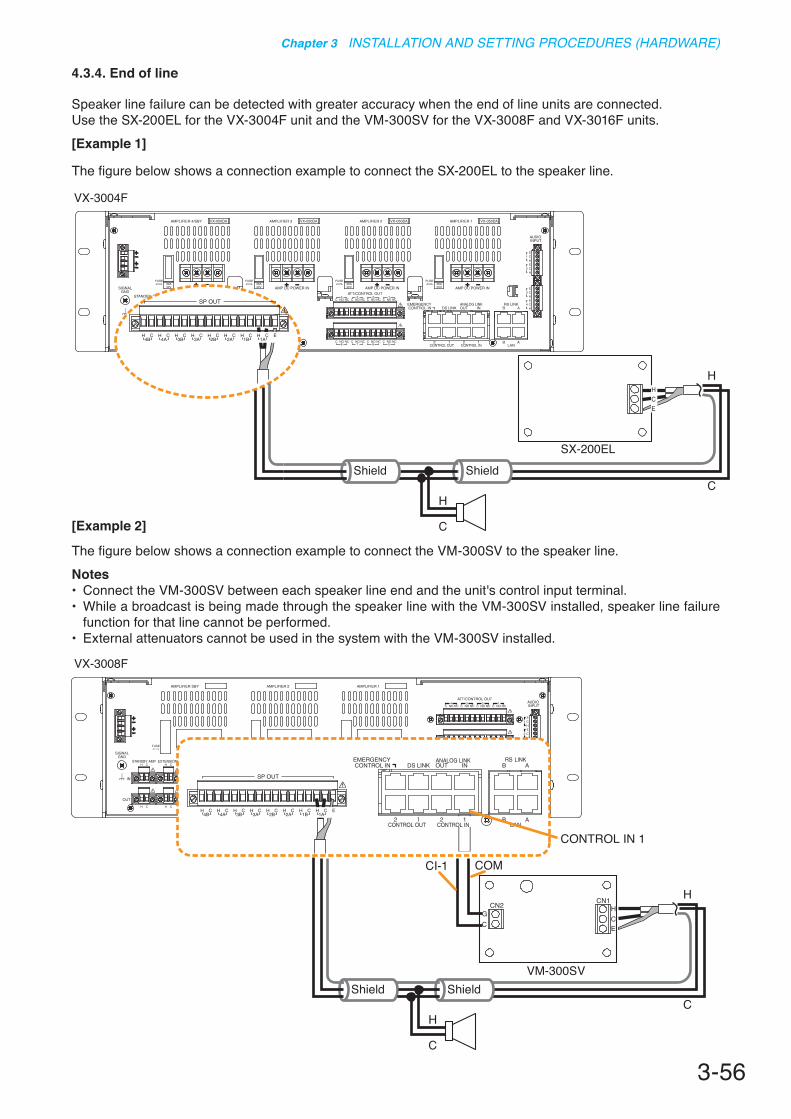
3-56
Chapter 3 INSTALLATION AND SETTING PROCEDURES (HARDWARE)
4.3.4. End of line
Speaker line failure can be detected with greater accuracy when the end of line units are connected.Use the SX-200EL for the VX-3004F unit and the VM-300SV for the VX-3008F and VX-3016F units.[Example 1]
The figure below shows a connection example to connect the SX-200EL to the speaker line.
GC
CN2 CN1HCE
VM-300SVShield Shield
C
CI-1 COM
H
VX-3008F
CONTROL IN 1
H
C
ShieldShield
H
C
H
C
SX-200EL
HCE
VX-3004F
[Example 2]
The figure below shows a connection example to connect the VM-300SV to the speaker line.Notes• Connect the VM-300SV between each speaker line end and the unit's control input terminal.• While a broadcast is being made through the speaker line with the VM-300SV installed, speaker line failure
function for that line cannot be performed.• External attenuators cannot be used in the system with the VM-300SV installed.
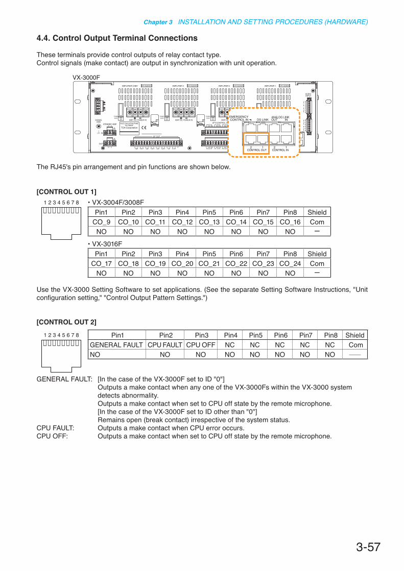
3-57
Chapter 3 INSTALLATION AND SETTING PROCEDURES (HARDWARE)
[CONTROL OUT 1]
Use the VX-3000 Setting Software to set applications. (See the separate Setting Software Instructions, "Unit configuration setting," "Control Output Pattern Settings.")
[CONTROL OUT 2]
GENERAL FAULT: [In the case of the VX-3000F set to ID "0"] Outputs a make contact when any one of the VX-3000Fs within the VX-3000 system
detects abnormality. Outputs a make contact when set to CPU off state by the remote microphone. [In the case of the VX-3000F set to ID other than "0"] Remains open (break contact) irrespective of the system status.CPU FAULT: Outputs a make contact when CPU error occurs.CPU OFF: Outputs a make contact when set to CPU off state by the remote microphone.
4.4. Control Output Terminal Connections
These terminals provide control outputs of relay contact type.Control signals (make contact) are output in synchronization with unit operation.
87654321
87654321
The RJ45's pin arrangement and pin functions are shown below.
VX-3000F
Pin1 Pin2 Pin3 Pin4 Pin5 Pin6 Pin7 Pin8 ShieldGENERAL FAULT CPU FAULT CPU OFF NC NC NC NC NC ComNO NO NO NO NO NO NO NO
• VX-3004F/3008FPin1 Pin2 Pin3 Pin4 Pin5 Pin6 Pin7 Pin8 Shield
CO_9 CO_10 CO_11 CO_12 CO_13 CO_14 CO_15 CO_16 ComNO NO NO NO NO NO NO NO -
• VX-3016FPin1 Pin2 Pin3 Pin4 Pin5 Pin6 Pin7 Pin8 Shield
CO_17 CO_18 CO_19 CO_20 CO_21 CO_22 CO_23 CO_24 ComNO NO NO NO NO NO NO NO -
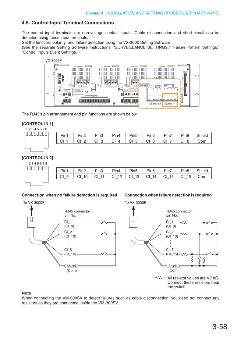
3-58
Chapter 3 INSTALLATION AND SETTING PROCEDURES (HARDWARE)
The RJ45's pin arrangement and pin functions are shown below.
[CONTROL IN 1]
[CONTROL IN 2]
4.5. Control Input Terminal Connections
The control input terminals are non-voltage contact inputs. Cable disconnection and short-circuit can be detected using these input terminals.Set the function, polarity, and failure detection using the VX-3000 Setting Software.(See the separate Setting Software Instructions, "SURVEILLANCE SETTINGS," "Failure Pattern Settings," "Control Inputs Event Settings.")
VX-3000F
(Com)
RJ45 connectorpin No.
To VX-3000F
Shield
Cl_1(Cl_9)Cl_2(Cl_10)
Cl_8(Cl_16)
(Com)
RJ45 connectorpin No.
To VX-3000F
Shield
Cl_1(Cl_9)Cl_2(Cl_10)
Cl_8(Cl_16)
Connection when no failure detection is required Connection when failure detection is required
NoteWhen connecting the VM-300SV to detect failures such as cable disconnection, you need not connect any resistors as they are connected inside the VM-300SV.
: All resistor values are 4.7 kΩ. Connect these resistors near the switch.
87654321
87654321
Pin1 Pin2 Pin3 Pin4 Pin5 Pin6 Pin7 Pin8 ShieldCI_1 CI_2 CI_3 CI_4 CI_5 CI_6 CI_7 CI_8 Com
Pin1 Pin2 Pin3 Pin4 Pin5 Pin6 Pin7 Pin8 ShieldCI_9 CI_10 CI_11 CI_12 CI_13 CI_14 CI_15 CI_16 Com

3-59
Chapter 3 INSTALLATION AND SETTING PROCEDURES (HARDWARE)
4.6. Emergency Control Input Terminal Connections
The Emergency control input terminals are voltage inputs. Cable disconnection and short-circuit can be detected using these input terminals.Use the VX-3000 Setting Software to set the function and polarity. (See the separate Setting Software Instructions, "SURVEILLANCE SETTINGS," "Failure Pattern Settings," "Control Inputs Event Settings.")
The RJ45's pin arrangement and pin functions are shown below.
[EMERGENCY CONTROL IN]
Connection example A
VX-3000F
87654321
RJ45 connectorpin No.
To VX-3000F
FDS_A+
FDS_A–
Shield(Com)
FDS_B–
FDS_B+
RJ45 connectorpin No.
To VX-3000F
FDS_A+
FDS_A–
Shield(Com)
FDS_B–
FDS_B+
FDSDC 24 V (–)
DC 24 V (+)
DC 24 V (–)
DC 24 V (+)
FDSGND_A
DC 24 V
GND_B
DC 24 VNoteWhen Connection example B is selected, set the Surveillance function corresponding to the CIN17 (Pins 1 and 2) or CIN18 (Pins 4 and 5) to OFF. (See the separate Setting Software Instructions, "SURVEILLANCE SETTINGS.")
Pin1 Pin2 Pin3 Pin4 Pin5 Pin6 Pin7 Pin8 ShieldFDS_A+ FDS_A– NC FDS_B+ FDS_B– NC NC NC Com
CIN17 CIN18
Connection example B

3-60
Chapter 3 INSTALLATION AND SETTING PROCEDURES (HARDWARE)
5. VX-3000F CONNECTION
5.1. LAN Link Connector Connections
Connect the LAN link connectors of all VX-3000F units within the system to each other via switching hubs. Connect each of LAN link connectors A and B to the same switching hub or different switching hubs connected in star configuration.Also, since the VX-3000F has a HUB function compatible with RSTP (Rapid Spanning Tree Protocol), loop connection is allowed between the VX-3000F units without the use of switching hubs.
Notes• Make the LAN link connectors completely independent from other LAN.• Be sure to use STP Category 5 straight cable (with R45 connectors) for connecting LAN link connectors.• The distance between each of VX-3000F and a switching hub, and between switching hubs is less than 100 m.• Be sure to make connections of both terminals A and B.• When using multiple switching hubs, make a star connection as shown in the connection examples 4.
[Connectionexample1:Redundantconfigurationofnon-RSTP-compliantswitchinghubs]
SW-HUB
SW-HUB
VX-3000F
VX-3000F
SW-HUBSW-HUB
VX-3000F
SW-HUB
SW-HUB SW-HUBSW-HUB
LAN link B
LAN link B
LAN link A
LAN link A (Operating)
LAN link B (Operating)
LAN link A
A method of connecting a single unit's LAN Link A and B terminals to each different switching hub to prevent the system from going down when a cable is broken or power fails.
[Connectionexample2:RedundantconfigurationofRSTP-compliantswitchinghubs]
LAN link A LAN link B
SW-HUB (RSTP) SW-HUB (RSTP) SW-HUB (RSTP) SW-HUB (RSTP)
LAN link A LAN link B
VX-3000F
VX-3000F
LAN link A LAN link B
LAN link A LAN link B
VX-3000F
VX-3000F
[Connection example 3: Redundant configuration when no switching hubs are used]
LAN link B LAN link AVX-3000F
LAN link B LAN link AVX-3000F
LAN link B LAN link AVX-3000F
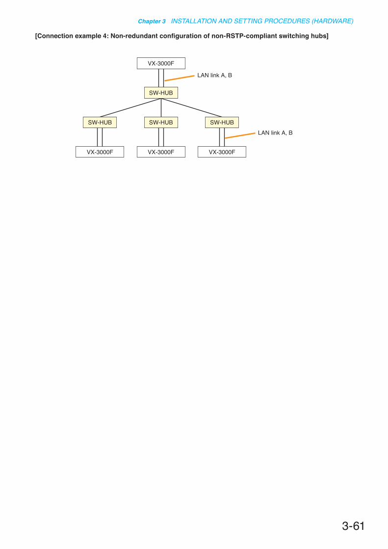
3-61
Chapter 3 INSTALLATION AND SETTING PROCEDURES (HARDWARE)
[Connectionexample4:Non-redundantconfigurationofnon-RSTP-compliantswitchinghubs]
VX-3000F
VX-3000F
SW-HUB
SW-HUB
VX-3000F
SW-HUB
VX-3000F
SW-HUB
LAN link A, B
LAN link A, B
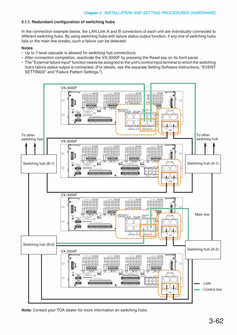
3-62
Chapter 3 INSTALLATION AND SETTING PROCEDURES (HARDWARE)
To other switching hub
To other switching hub
Main line
: LAN: Control line
VX-3000F
VX-3000F
VX-3000F
VX-3000F
Switching hub (B-2)
Switching hub (B-1)
Switching hub (A-2)
Switching hub (A-1)
5.1.1. Redundant configuration of switching hubs
In the connection example below, the LAN Link A and B connectors of each unit are individually connected to different switching hubs. By using switching hubs with failure status output function, if any one of switching hubs fails or the main line breaks, such a failure can be detected.Notes• Up to 7-level cascade is allowed for switching hub connections.• After connection completion, reactivate the VX-3000F by pressing the Reset key on its front panel.• The "External failure input" function needs be assigned to the unit's control input terminal to which the switching
hub's failure status output is connected. (For details, see the separate Setting Software Instructions, "EVENT SETTINGS" and "Failure Pattern Settings.")
Note: Contact your TOA dealer for more information on switching hubs.
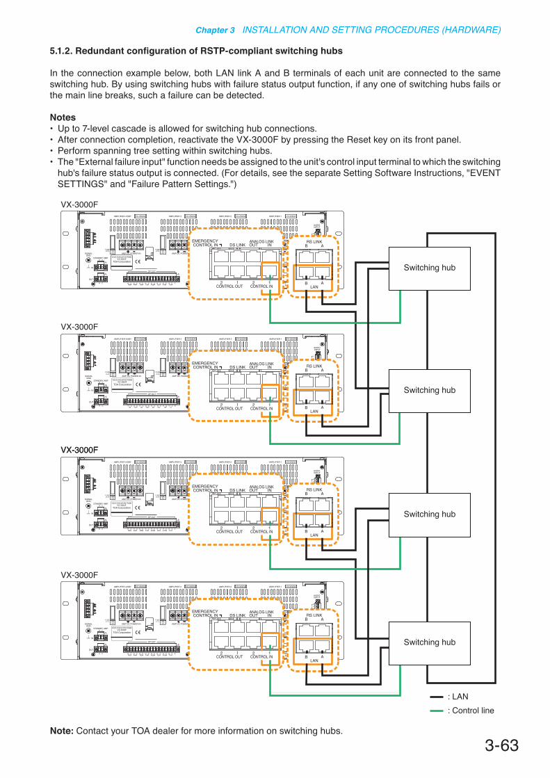
3-63
Chapter 3 INSTALLATION AND SETTING PROCEDURES (HARDWARE)
5.1.2. RedundantconfigurationofRSTP-compliantswitchinghubs
In the connection example below, both LAN link A and B terminals of each unit are connected to the same switching hub. By using switching hubs with failure status output function, if any one of switching hubs fails or the main line breaks, such a failure can be detected.
Notes• Up to 7-level cascade is allowed for switching hub connections.• After connection completion, reactivate the VX-3000F by pressing the Reset key on its front panel.• Perform spanning tree setting within switching hubs. • The "External failure input" function needs be assigned to the unit's control input terminal to which the switching
hub's failure status output is connected. (For details, see the separate Setting Software Instructions, "EVENT SETTINGS" and "Failure Pattern Settings.")
VX-3000F
VX-3000F
VX-3000FVX-3000F
VX-3000F
: LAN: Control line
Switching hub
Switching hub
Switching hub
Switching hub
Note: Contact your TOA dealer for more information on switching hubs.

3-64
Chapter 3 INSTALLATION AND SETTING PROCEDURES (HARDWARE)
5.1.3. Redundant configuration when no switching hubs are used
In the connection example below, both LAN link A and B terminals of each unit are connected to another VX-3000F.
Notes• Up to 8 VX-3000Fs can be connected.• After connection completion, reactivate the VX-3000F by pressing the Reset key on its front panel.
VX-3000F
VX-3000F
VX-3000F
VX-3000F
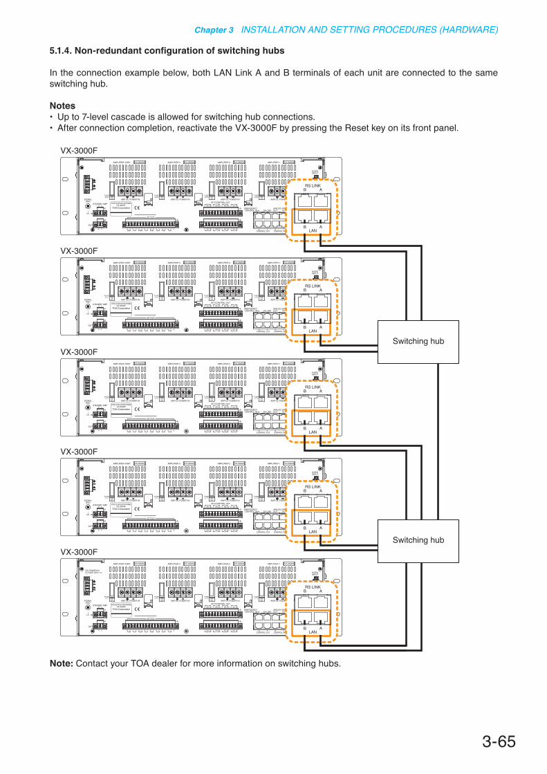
3-65
Chapter 3 INSTALLATION AND SETTING PROCEDURES (HARDWARE)
5.1.4. Non-redundant configuration of switching hubs
In the connection example below, both LAN Link A and B terminals of each unit are connected to the same switching hub.
Notes• Up to 7-level cascade is allowed for switching hub connections.• After connection completion, reactivate the VX-3000F by pressing the Reset key on its front panel.
VX-3000F
VX-3000F
VX-3000F
VX-3000F
VX-3000F
Switching hub
Switching hub
Note: Contact your TOA dealer for more information on switching hubs.
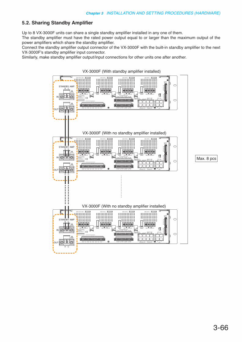
3-66
Chapter 3 INSTALLATION AND SETTING PROCEDURES (HARDWARE)
5.2. Sharing Standby Amplifier
Up to 8 VX-3000F units can share a single standby amplifier installed in any one of them.The standby amplifier must have the rated power output equal to or larger than the maximum output of the power amplifiers which share the standby amplifier.Connect the standby amplifier output connector of the VX-3000F with the built-in standby amplifier to the next VX-3000F's standby amplifier input connector. Similarly, make standby amplifier output/input connections for other units one after another.
VX-3000F (With standby amplifier installed)
VX-3000F (With no standby amplifier installed)
VX-3000F (With no standby amplifier installed)
Max. 8 pcs

3-67
Chapter 3 INSTALLATION AND SETTING PROCEDURES (HARDWARE)
5.3. Speaker Selector Extension
The VX-3008F or VX-3016F can be used as speaker selector that extends the number of speaker lines without having a built-in power amplifier.Up to 3 VX-3000F units for broadcast zone extension use can be connected to a single VX-3008F or VX-3016F.Connect the extension output connector of the VX-3008F or the VX-3016F with the built-in amplifier module to the next VX-3008F's or VX-3016F's extension input connector. Similarly, make extension input/output connector connections for other units one after another.Use EXTENSION 1 and 2 for VX-3008F connections, and EXTENSION 1 for VX-3016F connections.
Notes• Only the VX-3008F can be used for the zone extension of the VX-3008F, and only the VX-3016F unit for the
zone extension of the VX-3016F. But Zone extension is not available when the VX-3016F is used in "2 channels, 8 speaker selectors" mode.• Be sure to ground the Signal ground terminal. Otherwise, a ground fault cannot be detected.
VX-3008F (With amplifier installed)
VX-3008F (With no amplifier installed)
VX-3008F (With no amplifier installed)
Extension unit: Max. 3 pcs
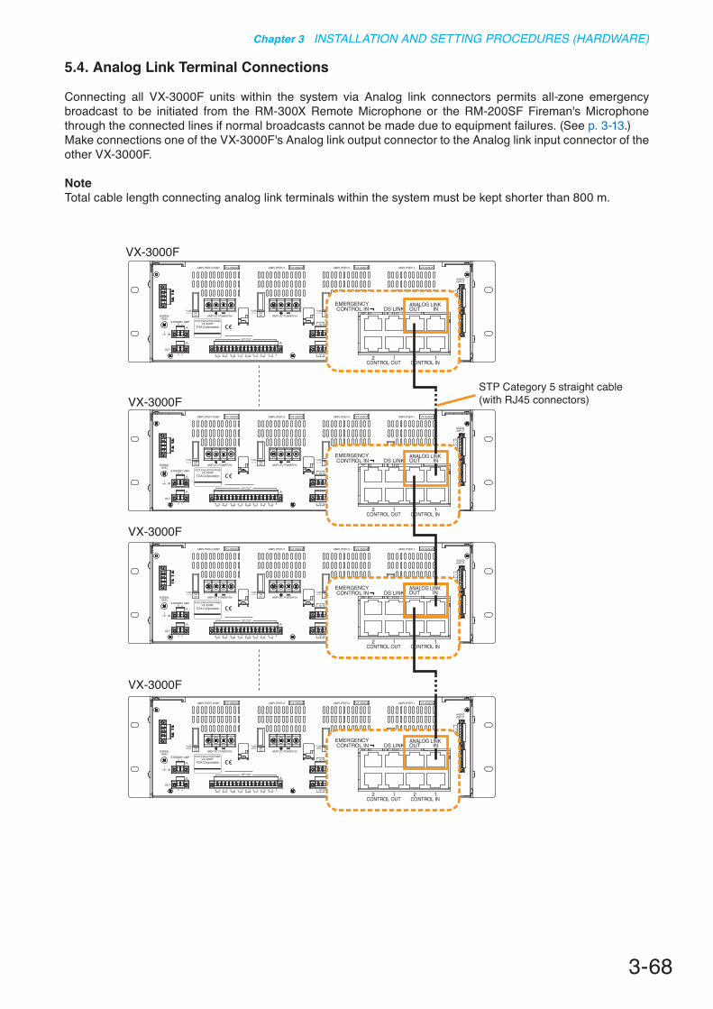
3-68
Chapter 3 INSTALLATION AND SETTING PROCEDURES (HARDWARE)
5.4. Analog Link Terminal Connections
Connecting all VX-3000F units within the system via Analog link connectors permits all-zone emergency broadcast to be initiated from the RM-300X Remote Microphone or the RM-200SF Fireman's Microphone through the connected lines if normal broadcasts cannot be made due to equipment failures. (See p. 3-13.)Make connections one of the VX-3000F's Analog link output connector to the Analog link input connector of the other VX-3000F.
NoteTotal cable length connecting analog link terminals within the system must be kept shorter than 800 m.
VX-3000F
VX-3000F
VX-3000F
VX-3000F
STP Category 5 straight cable (with RJ45 connectors)

3-69
Chapter 3 INSTALLATION AND SETTING PROCEDURES (HARDWARE)
6. SPEAKER LINE INITIAL SETTING
To perform Speaker Line Surveillance, be sure to make the initial settings for the VX-3000F as follows after connection completion of the VX-3000 system.
6.1. Setting Items
[Initial impedance value setting]
The VX-3000F determines whether the speaker line is open or shorted using this initial value as reference value (normal impedance value).
ImportantWhen using the surveillance function, be sure to set the initial impedance value.
[Speaker line OPEN sensitivity adjustment]
The sensitivity can be adjusted so that the VX-3000F can judge the speaker line open on the basis of the initial value.
[Speaker line SHORT sensitivity adjustment]
The sensitivity can be adjusted so that the VX-3000F can judge the speaker line shorted on the basis of the initial value.
6.2. OPEN/SHORT Criterion by Comparing the Current Value with the Initial Value
The set sensitivity values and the current value are expressed as rations to the initial value (defined as100 %).If OPEN and SHORT sensitivities remain factory-preset, the speaker line is judged shorted when the current value is less than half the initial value, and open when it is more than twice the initial value.
5 %1 %
9999 %
SHORT
NORMAL
OPEN
100 %Initial value (Reference value)
SHORT sensitivity set value(5 – 50 variable, Default: 50)
OPEN sensitivity set value(101 – 800 variable, Default: 200)
Impedance ratio(Sensitivity adjustable range) (Current value)
(Judgment)
800 %
5 %
25 %
150 %
1 %
9999 %
SHORT
NORMAL
OPEN
100 %
[Sensitivity setting example]
(Judgment)
When the SHORT sensitivity is set to 25 %, and OPEN sensitivity to 150 %.
800 %

3-70
Chapter 3 INSTALLATION AND SETTING PROCEDURES (HARDWARE)
6.3. Setting Procedures
6.3.1. Setting an initial impedance value
Step 1. Detach the front panel.Remove 4 fixing screws for front panel and detach the front panel.
VX-3000F front
Fixing screws for front panel1
RUN indicator
VX-3000F(Front panel detached)
Per 1 sec. Per 5 sec.
Impedance initialize key
2
2
3
WARNINGThere is a high voltage section inside the power amplifier's filter. Never insert your finger or metallic objects inside the unit.
Notes• Be sure to perform this setting after completion of connection work.• Be sure to reset the initial impedance value if any wiring or connection has been changed after completion of
the setting.• When measuring the speaker line impedance, be sure to stop the broadcast in advance. Measuring cannot be made correctly when audio signals are being output.
Step 2. Press the Impedance initialize key.Impedance measurement starts. Blinking cycle of the RUN indicator (the second LED from the top of the 8 LEDs arranged vertically on the right side) changes from 1-second intervals to 5-second intervals.
Step 3. Wait until the RUN indicator returns to normal state (flashing in 1-second intervals).
Step 4. Replace the front panel. Secure it using 4 fixing screws for front panel .
3-71
Chapter 3 INSTALLATION AND SETTING PROCEDURES (HARDWARE)
6.3.2. Adjusting the speaker line's OPEN sensitivity
Open sensitivity is expressed as the ratio to the initial value (defined as 100 %) and can be adjusted in the range of 101 % to 800 %. It is set to "200" for all the channels by default.Perform this setting using the VX-3000 Setting Software.NoteMoving the setting closer to 101 % increases the OPEN sensitivity, and thus improves the accuracy of "OPEN" detection. Moving the setting closer to 800 % decreases the OPEN sensitivity, and thereby stabilizes the operation of the "OPEN" detection.
6.3.3. Adjusting the speaker line's SHORT sensitivity
SHORT sensitivity is expressed as the ratio to the initial value (defined as 100 %) and can be adjusted in the range of 5 % to 50 %. It is set to "50" for all the channels by default.Perform this setting using the VX-3000 Setting Software.NoteMoving the setting closer to 5% decreases the SHORT sensitivity, and thereby stabilizes the operation of the "SHORT" detection.
ImportantAdjust the SHORT sensitivity within the range not exceeding two times the power amplifier's rated load, as doing otherwise may cause damage to the power amplifier.(Example) • When the speakers with the rated load are connected: Set to "50."• When the speakers with 1/2 rated load are connected: Set in the range of "25" to "50."

Chapter 4
APPENDIX

4-2
Chapter 4 APPENDIX
Step 1. Detach the front panel.Remove 4 fixing screws for front panel and detach the front panel.
Step 2. Set the switch 7 of the DIP switch to ON.
Step 3. Replace the front panel. Secure it using 4 fixing screws for front panel.
Step 4. Confirm the firmware version by checking the indicators on the front panel.(See p. 4-3.)
Step 5. Detach the front panel again, and return the switch 7 of the DIP switch to OFF, restoring the unit to the original state.
VX-3000F front
Fixing screws for front panel1
2 VX-3000F front (Front panel detached)
Switch 7
WARNINGThere is a high voltage section inside the power amplifier's filter. Never insert your finger or metallic objects inside the unit.
ON
1. THE FIRMWARE VERSION CONFIRMATIONYou can confirm the firmware version with the front-mounted indicators by setting the DIP switch inside the VX-3000F's front panel.
[Front-mounted indicators]
This figure shows VX-3004F.

4-3
Chapter 4 APPENDIX
[How to confirm the firmware version]
• Firmware version indication The VX-3000's firmware version is expressed as shown in the following example. Here, the individual numbers are denoted by (A) to (E).
Example :
• Each digit is defined by the indicator status of from (A) to (E) as shown below. [VX-3004F]
V e r . 1 . 2 3 . 4 5(A) (B)(C) (D)(E)
(A) (B) (C) (D)
(E)
[VX-3008F]
(A) (B) (C)
(D) (E)
[VX-3016F]
(A) (B)
(C) (D)
(E)
• The firmware version number is expressed in binary scale (0 = Unlit, 1 = Lit) by the 4 indicators of from (A) to (E). Convert the binary number shown by the indicators to the decimal number referring to the table below.
Decimal number 0 1 2 3 4 5 6 7 8 9Indicator status 4
321
The 4th digit in binary scale 4•••
1•••The 1st digit in binary scale2•••The 2nd digit in binary scale3•••The 3rd digit in binary scale
The 4th digit in binary scale 4•••
1•••The 1st digit in binary scale2•••The 2nd digit in binary scale3•••The 3rd digit in binary scale
: Unlit : Lit
[VX-3004F] [VX-3008F] [VX-3016F](Display example of Ver. 1.23.45)
(In the case of the vertically arranged indicators) (In the case of the horizontally arranged indicators)

4-4
Chapter 4 APPENDIX
Power Source 20 − 33 V DC, removable terminal block (4 pins)Power Consumption 24 W (frame only) at 33 V DC input, 90 W (RS LINK: 2 A output) at 33 V DC inputLAN A, B Number of Connectors: 2 (LAN A, LAN B)
Network I/F: 100BASE-TXNetwork Protocol: TCP, UDP, ARP, ICMP, RTP, IGMP, FTP, HTTPSpanning tree Protocol: RSTPAudio Transmission System: TOA Packet Audio*1
Audio Encoding Method: PCMAudio Sampling Frequency: 48 kHzAudio Quantifying Bit Number: 16 bitsConnection Device: VX-3004F, VX-3008F, VX-3016F, NX-300, Switching
HUBConnector: RJ45 connectorConnection Cable: Category 5 twisted pair cable (CAT5) or greaterNumber of Stages of Cascade connection: Up to 7Maximum Cable Distance: 100 m (328.08 ft)
RS Link A, B Number of Connectors: 2 (RS LINK A, RS LINK B)Audio input level: 0 dB *2
Power feed: Max. 1 A per connectorConnector: RJ45 connectorConnection Cable: Shielded Category 5 twisted pair cable (CAT5-STP)
or greaterMaximum Cable Distance: 1200 m (3937.01 ft)
DS Link Connection Device: DS LINK of Power supply unitsConnector: RJ45 connectorConnection Cable: Shielded Category 5 twisted pair cable (CAT5-STP)
or greaterMaximum Cable Distance: 5 m (16.4 ft)
Analog Link Number of Connectors: 1 input, 1 outputConnection Device: VX-3004F, VX-3008F, VX-3016FConnector: RJ45 connectorConnection Cable: Shielded Category 5 twisted pair cable (CAT5-STP)
or greaterMaximum Cable Distance: 800 m (2624.67 ft)
Control Input 1, 2 16 inputs, no-voltage make contact input, open voltage: 24 V DC, short-circuit current: 2 mAFault Detection System: Short circuit, Open circuit, Method: Voltage detectConnector: RJ45 connectorConnection Cable: Shielded Category 5 twisted pair cable (CAT5-STP)
or greaterEmergency Control IN Input 2: Isolated voltage input, −24 to +24 V
Connector: RJ45 connectorConnection Cable: Category 5 twisted pair cable (CAT5) or greater
VOX Function Threshold: –60 to 0 dB (1 dB steps)Hysteresis: 0 to +10 dBHold time: 10 ms – 10 sSettable for each audio input
2. SPECIFICATIONS2.1. VX-3004F Voice Evacuation Frame 4AB

4-5
Chapter 4 APPENDIX
Control Output 1, 2 General outputs : 8 with CONTROL OUTPUT 1Exclusive outputs : 3 with CONTROL OUTPUT 2 GENERAL FAULT, CPU FAULT, CPU OFFNo-voltage make contact, electrical contact output, control current: 10 mA, withstand voltage: 28 V DCConnector: RJ45 connectorConnection Cable: Shielded Category 5 twisted pair cable (CAT5-STP) or
greaterATT/Control Output 8 outputs, no-voltage make contact, relay contact (NC, NO, C),
control current: 2 mA to 5 A, withstand voltage: 125 V AC, 40 V DCConnector: Removable terminal block (12 pins) ... 2
Audio Input 1, 2, 3, 4 4 inputsSensitivity: LINE: −20 dB*2, MIC: −60 dB*2
LINE/MIC/ANC Sensor (changeable with setting software)Gain Control: Volume adjustable with volume control (internal front panel) −∞ to 0 dBInput Impedance: 47 kΩ, electronically-balancedFrequency Response: 40 Hz to 20 kHz ±1 dB (at DA CONTROL LINK, 0 dB output)Distortion: 1% or less (at DA CONTROL LINK, 0 dB output, 1 kHz)Signal to Noise Ratio: 60 dB or more (at DA CONTROL LINK, A-weighted)Phantom Power Supply: 24 V DC, can be set with setting softwareConnector: Removable terminal block (6 pins) ... 2
Digital Signal ProcessingFeedback Suppression Function (FBS)
7 filters (auto),Settable for each audio input and RS LINK (A/B)
Equalizer/Filter 3 bands for each audio input and RS LINK (A/B), 6 bands for each amplifier outputParametric equalizer: 20 Hz – 20 kHz, ±15 dB, Q: 0.267 – 69.249Filtering: High-pass filter 20 Hz – 20 kHz, 6 dB/oct, 12 dB/oct Low-pass filter 20 Hz – 20 kHz, 6 dB/oct, 12 dB/oct High shelving filter 6 – 20 kHz, ±15 dB Low shelving filter 20 – 500 Hz, ±15 dB Notch filter (amplifier output only) 20 Hz – 20 kHz, Q: 8.651 – 69.249 All-pass filter (amplifier output only) 20 Hz – 20 kHz, Q: 0.267 – 69.249 Horn equalizer (amplifier output only) 20 kHz, 0 to +18 dB (0.5 dB steps)
Compressor Threshold: –20 to 0 dB (1 dB steps)Ratio: 1:1, 1.1:1, 1.2:1, 1.3:1, 1.5:1, 1.7:1, 2:1, 2.3:1, 2.6:1, 3:1, 4:1, 5:1, 7:1,
8:1, 10:1, 12:1, 20:1, ∞:1Attack time: 0.2 ms – 5 sRelease time: 10 ms – 5 sGain: –∞ to +10 dBKnee type: hard knee, middle knee, soft knee
Delay For each amplifier output, 0 – 2730 ms (0.021 ms steps)ANC (Ambient Noise Control)
Amplifier output level control, Automatic sensor input reference level measuring, Sensor input reference level fine adjustmentMaximum output signal level control: –15 to 0 dBMinimum output signal level control: –18 to –3 dBSample time setting: 10 s, 20 s, 30 s, 1 min, 5 minGain ratio setting: (Ambient noise: Output signal level) 6:3, 5:3, 4:3, 3:3, 3:4, 3:5, 3:6Ambient noise measuring frequency setting: 20 Hz – 20 kHz, 3 points
Program Timer Weekly program methodDaily program: 50 events, 10 typesHoliday program: 50 types
Time Adjustment Control input, NTP

4-6
Chapter 4 APPENDIX
*1 TOA's unique technology which makes it possible to transmit high-quality audio signals in real time over an IP network
*2 0 dB = 1 V
Note: The design and specifications are subject to change without notice for improvement.
• AccessoriesRack mounting bracket (preinstalled on the unit) ............................ 2Rack mounting screw 5 x 12 ..................... 4CD (PC setting software) ........................... 1Removable terminal plug (2 pins) ............. 2Removable terminal plug (4 pins) .............. 1Removable terminal plug (6 pins) .............. 2Removable terminal plug (12 pins) ............ 2Removable terminal plug (17 pins) ............ 1Ferrite cable clamp .................................... 2
Speaker Line 4 channels (with A/B LINE speaker output), 1 Earth terminalMaximum Voltage/Current: 100 Vrms, 5 ArmsConnector: Removable terminal block (17 pins) ... 1Fault Detection System: Short circuit, Open circuit, Ground fault, Method: Impedance or End of line
Standby Amplifier Input/Output
Input: 1, Output: 1Maximum Voltage/Current: 100 Vrms, 5 ArmsConnector: Removable terminal block (2 pins) ... 2
Power Amplifier Number of Amplifiers: 4Connector: DA CONTROL LINK ... 4, DA OUTPUT LINK ... 4
Indicators POWER (green) ... 1, RUN (green) ... 1, EMERGENCY (red) ... 1, CPU OFF (red) ... 1, LAN A (green) ... 1, LAN B (green) ... 1, RS LINK A (green) ... 1, RS LINK B (green) ... 1FAULT STATUS (yellow):
GENERAL ... 1, UNIT ... 1, NETWORK ... 1, EMG MIC ... 1, FUSE ... 1, POWER ... 1, CPU ... 1, ZONE ... 8
AMPLIFIER: PEAK (red) ... 4, SIGNAL (green) ... 4, OPERATE (green) ... 4, POWER (green) ... 4
Operation Fault Control Switch ... 2 (ACK/RESET)Test Switch ... 1 (LAMP TEST)Setting Switch: ID NUMBER, RESET, IMPEDANCE, Setting (internal front panel)
Operating Temperature −5 to +45 C° (23 to 113 °F)Operating Humidity 90% RH or less (no condensation)Finish Panel: Surface-treated steel plate, black, 30% gloss, paintDimensions 483 (w) x 132.6 (h) x 345 (d) mm (19.02" x 5.22" x 13.58")Weight 7.6 kg (16.75 lb)
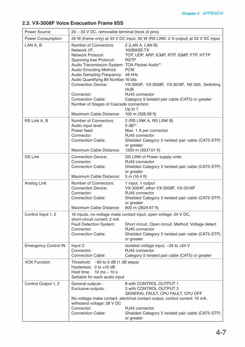
4-7
Chapter 4 APPENDIX
Power Source 20 – 33 V DC, removable terminal block (4 pins)Power Consumption 24 W (frame only) at 33 V DC input, 90 W (RS LINK: 2 A output) at 33 V DC inputLAN A, B Number of Connectors: 2 (LAN A, LAN B)
Network I/F: 100BASE-TXNetwork Protocol: TCP, UDP, ARP, ICMP, RTP, IGMP, FTP, HTTPSpanning tree Protocol: RSTPAudio Transmission System: TOA Packet Audio*1
Audio Encoding Method: PCMAudio Sampling Frequency: 48 kHzAudio Quantifying Bit Number: 16 bitsConnection Device: VX-3004F, VX-3008F, VX-3016F, NX-300, Switching
HUBConnector: RJ45 connectorConnection Cable: Category 5 twisted pair cable (CAT5) or greaterNumber of Stages of Cascade connection: Up to 7Maximum Cable Distance: 100 m (328.08 ft)
RS Link A, B Number of Connectors: 2 (RS LINK A, RS LINK B)Audio input level: 0 dB*2
Power feed: Max. 1 A per connectorConnector: RJ45 connectorConnection Cable: Shielded Category 5 twisted pair cable (CAT5-STP)
or greaterMaximum Cable Distance: 1200 m (3937.01 ft)
DS Link Connection Device: DS LINK of Power supply unitsConnector: RJ45 connectorConnection Cable: Shielded Category 5 twisted pair cable (CAT5-STP)
or greaterMaximum Cable Distance: 5 m (16.4 ft)
Analog Link Number of Connectors: 1 input, 1 outputConnection Device: VX-3004F, other VX-3008F, VX-3016FConnector: RJ45 connectorConnection Cable: Shielded Category 5 twisted pair cable (CAT5-STP)
or greaterMaximum Cable Distance: 800 m (2624.67 ft)
Control Input 1, 2 16 inputs, no-voltage make contact input, open voltage: 24 V DC, short-circuit current: 2 mAFault Detection System: Short circuit, Open circuit, Method: Voltage detectConnector: RJ45 connectorConnection Cable: Shielded Category 5 twisted pair cable (CAT5-STP)
or greaterEmergency Control IN Input 2: Isolated voltage input, −24 to +24 V
Connector: RJ45 connectorConnection Cable: Category 5 twisted pair cable (CAT5) or greater
VOX Function Threshold: –60 to 0 dB (1 dB steps)Hysteresis: 0 to +10 dBHold time: 10 ms – 10 sSettable for each audio input
Control Output 1, 2 General outputs : 8 with CONTROL OUTPUT 1Exclusive outputs : 3 with CONTROL OUTPUT 2 GENERAL FAULT, CPU FAULT, CPU OFFNo-voltage make contact, electrical contact output, control current: 10 mA, withstand voltage: 28 V DCConnector: RJ45 connectorConnection Cable: Shielded Category 5 twisted pair cable (CAT5-STP)
or greater
2.2. VX-3008F Voice Evacuation Frame 8SS

4-8
Chapter 4 APPENDIX
ATT/Control Output 8 outputs, no-voltage make contact, relay contact (NC, NO, C), control current: 2 mA to 5 A, withstand voltage: 125 V AC, 40 V DCConnector: Removable terminal block (12 pins) ...2
Audio Input 1, 2, 3, 4 4 inputsSensitivity: LINE: −20 dB*2, MIC: −60 dB*2
LINE/MIC/ANC Sensor (changeable with setting software)Gain Control: Volume adjustable with volume control (internal front panel) −∞ to 0 dBInput Impedance: 47 kΩ, electronically-balancedFrequency Response: 40 Hz to 20 kHz ±1 dB (at DA CONTROL LINK, 0 dB output)Distortion: 1% or less (at DA CONTROL LINK, 0 dB output, 1 kHz)Signal to Noise Ratio: 60 dB or more (at DA CONTROL LINK, A-weighted)Phantom Power Supply: 24 V DC, can be set with setting softwareConnector: Removable terminal block (6 pins) ... 2
Digital Signal ProcessingFeedback Suppression Function (FBS)
7 filters (auto),Settable for each audio input and RS LINK (A/B)
Equalizer/Filter 3 bands for each audio input and RS LINK (A/B), 6 bands for each amplifier outputParametric equalizer: 20 Hz – 20 kHz, ±15 dB, Q: 0.267 – 69.249Filtering: High-pass filter 20 Hz – 20 kHz, 6 dB/oct, 12 dB/oct Low-pass filter 20 Hz – 20 kHz, 6 dB/oct, 12 dB/oct High shelving filter 6 – 20 kHz, ±15 dB Low shelving filter 20 – 500 Hz, ±15 dB Notch filter (amplifier output only) 20 Hz – 20 kHz, Q: 8.651 – 69.249 All-pass filter (amplifier output only) 20 Hz – 20 kHz, Q: 0.267 – 69.249 Horn equalizer (amplifier output only) 20 kHz, 0 to +18 dB (0.5 dB steps)
Compressor Threshold: –20 to 0 dB (1 dB steps)Ratio: 1:1, 1.1:1, 1.2:1, 1.3:1, 1.5:1, 1.7:1, 2:1, 2.3:1, 2.6:1, 3:1, 4:1, 5:1, 7:1,
8:1, 10:1, 12:1, 20:1, ∞:1Attack time: 0.2 ms – 5 sRelease time: 10 ms – 5 sGain: –∞ to +10 dBKnee type: hard knee, middle knee, soft knee
Delay For each amplifier output, 0 – 2730 ms (0.021 ms steps)ANC (Ambient Noise Control)
Amplifier output level control, Automatic sensor input reference level measuring, Sensor input reference level fine adjustmentMaximum output signal level control: –15 to 0 dBMinimum output signal level control: –18 to –3 dBSample time setting: 10 s, 20 s, 30 s, 1 min, 5 minGain ratio setting: (Ambient noise: Output signal level) 6:3, 5:3, 4:3, 3:3, 3:4, 3:5, 3:6Ambient noise measuring frequency setting: 20 Hz – 20 kHz, 3 points
Program Timer Weekly program methodDaily program: 50 events, 10 typesHoliday program: 50 types
Time Adjustment Control input, NTPSpeaker Line 8 channels, 1 Earth terminal
Maximum Voltage/Current: 100 Vrms, 5 ArmsConnector: Removable terminal block (17 pins) ... 1Fault Detection System: Short circuit, Open circuit, Ground fault, Method: Impedance or End of line
Standby Amplifier Input/Output
Input: 1, Output: 1Maximum Voltage/Current: 100 Vrms, 5 ArmsConnector: Removable terminal block (2 pins) ... 2
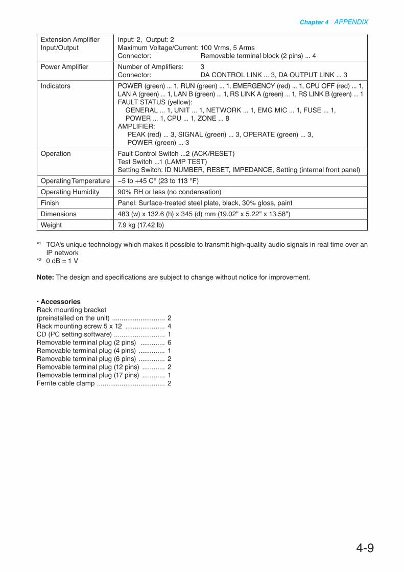
4-9
Chapter 4 APPENDIX
*1 TOA's unique technology which makes it possible to transmit high-quality audio signals in real time over an IP network
*2 0 dB = 1 V
Note: The design and specifications are subject to change without notice for improvement.
• AccessoriesRack mounting bracket(preinstalled on the unit) ............................ 2Rack mounting screw 5 x 12 ..................... 4CD (PC setting software) ........................... 1Removable terminal plug (2 pins) ............. 6Removable terminal plug (4 pins) .............. 1Removable terminal plug (6 pins) .............. 2Removable terminal plug (12 pins) ............ 2Removable terminal plug (17 pins) ............ 1Ferrite cable clamp .................................... 2
Extension Amplifier Input/Output
Input: 2, Output: 2Maximum Voltage/Current: 100 Vrms, 5 ArmsConnector: Removable terminal block (2 pins) ... 4
Power Amplifier Number of Amplifiers: 3Connector: DA CONTROL LINK ... 3, DA OUTPUT LINK ... 3
Indicators POWER (green) ... 1, RUN (green) ... 1, EMERGENCY (red) ... 1, CPU OFF (red) ... 1, LAN A (green) ... 1, LAN B (green) ... 1, RS LINK A (green) ... 1, RS LINK B (green) ... 1FAULT STATUS (yellow):
GENERAL ... 1, UNIT ... 1, NETWORK ... 1, EMG MIC ... 1, FUSE ... 1, POWER ... 1, CPU ... 1, ZONE ... 8
AMPLIFIER: PEAK (red) ... 3, SIGNAL (green) ... 3, OPERATE (green) ... 3, POWER (green) ... 3
Operation Fault Control Switch ...2 (ACK/RESET)Test Switch ...1 (LAMP TEST)Setting Switch: ID NUMBER, RESET, IMPEDANCE, Setting (internal front panel)
Operating Temperature −5 to +45 C° (23 to 113 °F)Operating Humidity 90% RH or less (no condensation)Finish Panel: Surface-treated steel plate, black, 30% gloss, paintDimensions 483 (w) x 132.6 (h) x 345 (d) mm (19.02" x 5.22" x 13.58")Weight 7.9 kg (17.42 lb)

4-10
Chapter 4 APPENDIX
Power Source 20 – 33 V DC, removable terminal block (4 pins)Power Consumption 90 W (frame only) at 31 V DC input, 95 W (RS LINK: 2 A output) at 33 V DC inputLAN A, B Number of Connectors: 2 (LAN A, LAN B)
Network I/F: 100BASE-TXNetwork Protocol: TCP, UDP, ARP, ICMP, RTP, IGMP, FTP, HTTPSpanning tree Protocol: RSTPAudio Transmission System: TOA Packet Audio*1
Audio Encoding Method: PCMAudio Sampling Frequency: 48 kHzAudio Quantifying Bit Number: 16 bitsConnection Device: VX-3004F, VX-3008F, VX-3016F, NX-300, Switching
HUBConnector: RJ45 connectorConnection Cable: Category 5 twisted pair cable (CAT5) or greaterNumber of Stages of Cascade connection: Up to 7Maximum Cable Distance: 100 m (328.08 ft)
RS Link A, B Number of Connectors: 2 (RS LINK A, RS LINK B)Audio input level: 0 dB *2
Power feed: Max. 1 A per connectorConnector: RJ45 connectorConnection Cable: Shielded Category 5 twisted pair cable (CAT5-STP)
or greaterMaximum Cable Distance: 1200 m (3937.01 ft)
DS Link Connection Device: DS LINK of Power supply unitsConnector: RJ45 connectorConnection Cable: Shielded Category 5 twisted pair cable (CAT5-STP)
or greaterMaximum Cable Distance: 5 m (16.4 ft)
Analog Link Number of Connectors: 1 input, 1 outputConnection Device: VX-3004F, VX-3008F, other VX-3016FConnector: RJ45 connectorConnection Cable: Shielded Category 5 twisted pair cable (CAT5-STP)
or greaterMaximum Cable Distance: 800 m (2624.67 ft)
Control Input 1, 2 16 inputs, no-voltage make contact input, open voltage: 24 V DC, short-circuit current: 2 mAFault Detection System: Short circuit, Open circuit, Method: Voltage detectConnector: RJ45 connectorConnection Cable: Shielded Category 5 twisted pair cable (CAT5-STP)
or greaterEmergency Control IN Input 2: Isolated voltage input, −24 to +24 V
Connector: RJ45 connectorConnection Cable: Category 5 twisted pair cable (CAT5) or greater
VOX Function Threshold: –60 to 0 dB (1 dB steps)Hysteresis: 0 to +10 dBHold time: 10 ms – 10 sSettable for each audio input
Control Output 1, 2 General outputs : 8 with CONTROL OUTPUT 1Exclusive outputs : 3 with CONTROL OUTPUT 2 GENERAL FAULT, CPU FAULT, CPU OFFNo-voltage make contact, electrical contact output, control current: 10 mA, withstand voltage: 28 V DCConnector: RJ45 connectorConnection Cable: Shielded Category 5 twisted pair cable (CAT5-STP)
or greater
2.3. VX-3016F Voice Evacuation Frame 16SS

4-11
Chapter 4 APPENDIX
ATT/Control Output 16 outputs, no-voltage make contact, relay contact (NC, NO, C), control current: 2 mA to 5 A, withstand voltage: 125 V AC, 40 V DCConnector: Removable terminal block (12 pins) ... 4
Audio Input 1, 2, 3, 4 4 inputsSensitivity: LINE: −20 dB*2, MIC: −60 dB*2
LINE/MIC/ANC Sensor (changeable with setting software)Gain Control: Volume adjustable with volume control (internal front panel) −∞ to 0 dBInput Impedance: 47 kΩ, electronically-balancedFrequency Response: 40 Hz to 20 kHz ±1 dB (at DA CONTROL LINK, 0 dB output)Distortion: 1% or less (at DA CONTROL LINK, 0 dB output, 1 kHz)Signal to Noise Ratio: 60 dB or more (at DA CONTROL LINK, A-weighted)Phantom Power Supply: 24 V DC, can be set with setting softwareConnector: Removable terminal block (6 pins) ... 2
Digital Signal ProcessingFeedback Suppression Function (FBS)
7 filters (auto),Settable for each audio input and RS LINK (A/B)
Equalizer/Filter 3 bands for each audio input and RS LINK (A/B), 6 bands for each amplifier outputParametric equalizer: 20 Hz – 20 kHz, ±15 dB, Q: 0.267 – 69.249Filtering: High-pass filter 20 Hz – 20 kHz, 6 dB/oct, 12 dB/oct Low-pass filter 20 Hz – 20 kHz, 6 dB/oct, 12 dB/oct High shelving filter 6 – 20 kHz, ±15 dB Low shelving filter 20 – 500 Hz, ±15 dB Notch filter (amplifier output only) 20 Hz – 20 kHz, Q: 8.651 – 69.249 All-pass filter (amplifier output only) 20 Hz – 20 kHz, Q: 0.267 – 69.249 Horn equalizer (amplifier output only) 20 kHz, 0 to +18 dB (0.5 dB steps)
Compressor Threshold: –20 to 0 dB (1 dB steps)Ratio: 1:1, 1.1:1, 1.2:1, 1.3:1, 1.5:1, 1.7:1, 2:1, 2.3:1, 2.6:1, 3:1, 4:1, 5:1, 7:1,
8:1, 10:1, 12:1, 20:1, ∞:1Attack time: 0.2 ms – 5 sRelease time: 10 ms – 5 sGain: –∞ to +10 dBKnee type: hard knee, middle knee, soft knee
Delay For each amplifier output, 0 – 2730 ms (0.021 ms steps)ANC (Ambient Noise Control)
Amplifier output level control, Automatic sensor input reference level measuring, Sensor input reference level fine adjustmentMaximum output signal level control: –15 to 0 dBMinimum output signal level control: –18 to –3 dBSample time setting: 10 s, 20 s, 30 s, 1 min, 5 minGain ratio setting: (Ambient noise: Output signal level) 6:3, 5:3, 4:3, 3:3, 3:4, 3:5, 3:6Ambient noise measuring frequency setting: 20 Hz – 20 kHz, 3 points
Program Timer Weekly program methodDaily program: 50 events, 10 typesHoliday program: 50 types
Time Adjustment Control input, NTPSpeaker Line 16 channels, 2 Earth terminals
Maximum Voltage/Current: 100 Vrms, 5 ArmsConnector: Removable terminal block (17 pins) ... 2Fault Detection System: Short circuit, Open circuit, Ground fault, Method: Impedance or End of line
Standby Amplifier Input/Output
Input: 1, Output: 1Maximum Voltage/Current: 100 Vrms, 5 ArmsConnector: Removable terminal block (2 pins) ... 2

4-12
Chapter 4 APPENDIX
*1 TOA's unique technology which makes it possible to transmit high-quality audio signals in real time over an IP network
*2 0 dB = 1 V
Note: The design and specifications are subject to change without notice for improvement.
• AccessoriesRack mounting bracket (preinstalled on the unit) ............................ 2Rack mounting screw 5 x 12 ..................... 4CD (PC setting software) ........................... 1Removable terminal plug (2 pins) ............. 4Removable terminal plug (4 pins) .............. 1Removable terminal plug (6 pins) .............. 2Removable terminal plug (12 pins) ............ 4Removable terminal plug (17 pins) ............ 2Ferrite cable clamp .................................... 2
Extension Amplifier Input/Output
Input: 1, Output: 1Maximum Voltage/Current: 100 Vrms, 5 ArmsConnector: Removable terminal block (2 pins) ... 2
Power Amplifier Number of Amplifiers: 2Connector: DA CONTROL LINK ... 2, DA OUTPUT LINK ... 2
Indicators POWER (green) ... 1, RUN (green) ... 1, EMERGENCY (red) ... 1, CPU OFF (red) ... 1, LAN A (green) ... 1, LAN B (green) ... 1, RS LINK A (green) ... 1, RS LINK B (green) ... 1FAULT STATUS (yellow):
GENERAL ... 1, UNIT ... 1, NETWORK ... 1, EMG MIC ... 1, FUSE ... 1, POWER ... 1, CPU ... 1, ZONE ... 16
AMPLIFIER: PEAK (red) ... 2, SIGNAL (green) ... 2, OPERATE (green) ... 2, POWER (green) ... 2
Operation Fault Control Switch ...2 (ACK/RESET)Test Switch ...1 (LAMP TEST)Setting Switch: ID NUMBER, RESET, IMPEDANCE, Setting (internal front panel)
Operating Temperature −5 to +45 C° (23 to 113 °F)Operating Humidity 90% RH or less (no condensation)Finish Panel: Surface-treated steel plate, black, 30% gloss, paintDimensions 483 (w) x 132.6 (h) x 345 (d) mm (19.02" x 5.22" x 13.58")Weight 7.9 kg (17.42 lb)

4-13
Chapter 4 APPENDIX
2.4. VX-015DA Digital Power Amplifier Module 150 W
Power Source 31 V DC (operating range: 20 to 33 V DC)DC power in: M4 screw terminal, distance between barriers: 11 mm (0.43")
Amplification System Class DPower Consumption 1.3 W (standby mode), 14 W (no audio input), 40 W (1/8 rated output), 190 W
(rated output) at 31 V DC, output voltage selection switch: 100 VRated Output Power 150 W (at 100 V line and min. impedance and max. capacitive load)
105 W (at 70 V line and min. impedance and max. capacitive load)75 W (at 50 V line and min. impedance and max. capacitive load)(at AC Mains VX-3000DS or VX-3150DS: 187 to 253 V)
Output Voltage 100 V (70 V, 50 V: selectable)Minimum Impedance Load 67 Ω (at 100 V line), 47 Ω (at 70 V line), 33 Ω (at 50 V line)Maximum Capacitive Load 0.5 µF Number of Channels 1Input DA CONTROL LINK: Nylon connector (15 pins)Output DA OUTPUT LINK: Nylon connector (2 pins)Frequency Response 40 Hz to 20 kHz: −5 to +1 dB (at 100 V line, 30 dB* output)Distortion 1% or less (at 100 V line, rated output, 1 kHz)Signal to Noise Ratio 100 dB or more (at 100 V line, A-weighted)Operating Temperature −5 to +45 °C (23 to 113 °F)Operating Humidity 90% RH or less (no condensation)Finish Surface-treated steel plateDimensions 82.8 (w) x 91 (h) x 358.2 (d) mm (3.26" x 3.58" x 14.1")Weight 1.3 kg (2.87 lb)
* 0 dB = 1 V
Note: The design and specifications are subject to change without notice for improvement.
• AccessoriesDA control link Cable ................................. 1DA output link Cable .................................. 1DC FUSE (10 A) ........................................ 1
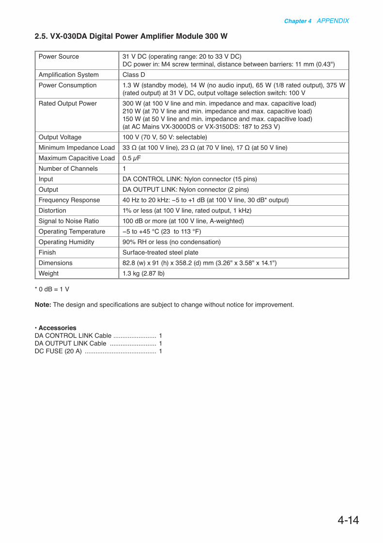
4-14
Chapter 4 APPENDIX
2.5. VX-030DA Digital Power Amplifier Module 300 W
Power Source 31 V DC (operating range: 20 to 33 V DC)DC power in: M4 screw terminal, distance between barriers: 11 mm (0.43")
Amplification System Class DPower Consumption 1.3 W (standby mode), 14 W (no audio input), 65 W (1/8 rated output), 375 W
(rated output) at 31 V DC, output voltage selection switch: 100 VRated Output Power 300 W (at 100 V line and min. impedance and max. capacitive load)
210 W (at 70 V line and min. impedance and max. capacitive load)150 W (at 50 V line and min. impedance and max. capacitive load)(at AC Mains VX-3000DS or VX-3150DS: 187 to 253 V)
Output Voltage 100 V (70 V, 50 V: selectable)Minimum Impedance Load 33 Ω (at 100 V line), 23 Ω (at 70 V line), 17 Ω (at 50 V line)Maximum Capacitive Load 0.5 µF Number of Channels 1Input DA CONTROL LINK: Nylon connector (15 pins)Output DA OUTPUT LINK: Nylon connector (2 pins)Frequency Response 40 Hz to 20 kHz: −5 to +1 dB (at 100 V line, 30 dB* output)Distortion 1% or less (at 100 V line, rated output, 1 kHz)Signal to Noise Ratio 100 dB or more (at 100 V line, A-weighted)Operating Temperature −5 to +45 °C (23 to 113 °F)Operating Humidity 90% RH or less (no condensation)Finish Surface-treated steel plateDimensions 82.8 (w) x 91 (h) x 358.2 (d) mm (3.26" x 3.58" x 14.1")Weight 1.3 kg (2.87 lb)
* 0 dB = 1 V
Note: The design and specifications are subject to change without notice for improvement.
• AccessoriesDA CONTROL LINK Cable ........................ 1DA OUTPUT LINK Cable .......................... 1DC FUSE (20 A) ........................................ 1

4-15
Chapter 4 APPENDIX
2.6. VX-050DA Digital Power Amplifier Module 500 W
Power Source 31 V DC (operating range: 20 to 33 V DC)DC power in: M4 screw terminal, distance between barriers: 11 mm (0.43")
Amplification System Class DPower Consumption 1.3 W (standby mode), 16 W (no audio input), 100 W (1/8 rated output), 590 W
(rated output) at 31 V DC, output voltage selection switch: 100 VRated Output Power 500 W (at 100 V line and min. impedance and max. capacitive load)
350 W (at 70 V line and min. impedance and max. capacitive load)250 W (at 50 V line and min. impedance and max. capacitive load)(at AC Mains VX-3000DS or VX-3150DS: 187 to 253 V)
Output Voltage 100 V (70 V, 50 V: selectable)Minimum Impedance Load 20 Ω (at 100 V line), 14 Ω (at 70 V line), 10 Ω (at 50 V line)Maximum Capacitive Load 0.5 µF Number of Channels 1Input DA CONTROL LINK: Nylon connector (15 pins)Output DA OUTPUT LINK: Nylon connector (2 pins)Frequency Response 40 Hz to 20 kHz: −5 to +1 dB (at 100 V line, 30 dB* output)Distortion 1% or less (at 100 V line, rated output, 1 kHz)Signal to Noise Ratio 100 dB or more (at 100 V line, A-weighted)Operating Temperature −5 to +45 °C (23 to 113 °F)Operating Humidity 90% RH or less (no condensation)Finish Surface-treated steel plateDimensions 82.8 (w) x 91 (h) x 358.2 (d) mm (3.26" x 3.58" x 14.1")Weight 1.4 kg (3.09 lb)
* 0 dB = 1 V
Note: The design and specifications are subject to change without notice for improvement.
• AccessoriesDA control link Cable ................................. 1DA output link Cable .................................. 1DC fuse (30 A) ........................................... 1
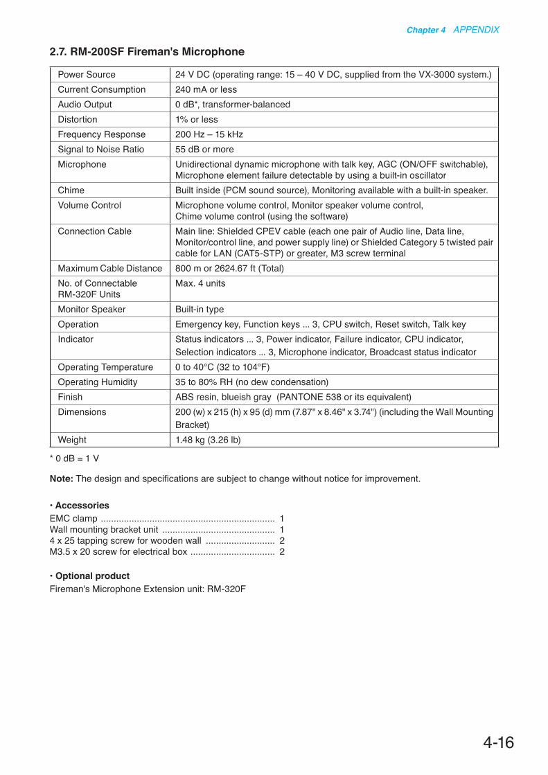
4-16
Chapter 4 APPENDIX
2.7. RM-200SF Fireman's Microphone
* 0 dB = 1 V
Note: The design and specifications are subject to change without notice for improvement.
• Optional productFireman's Microphone Extension unit: RM-320F
• AccessoriesEMC clamp .................................................................... 1Wall mounting bracket unit ............................................ 14 x 25 tapping screw for wooden wall ........................... 2M3.5 x 20 screw for electrical box ................................. 2
Power Source 24 V DC (operating range: 15 – 40 V DC, supplied from the VX-3000 system.)Current Consumption 240 mA or lessAudio Output 0 dB*, transformer-balancedDistortion 1% or lessFrequency Response 200 Hz – 15 kHzSignal to Noise Ratio 55 dB or moreMicrophone Unidirectional dynamic microphone with talk key, AGC (ON/OFF switchable),
Microphone element failure detectable by using a built-in oscillatorChime Built inside (PCM sound source), Monitoring available with a built-in speaker.Volume Control Microphone volume control, Monitor speaker volume control,
Chime volume control (using the software)Connection Cable Main line: Shielded CPEV cable (each one pair of Audio line, Data line,
Monitor/control line, and power supply line) or Shielded Category 5 twisted pair cable for LAN (CAT5-STP) or greater, M3 screw terminal
Maximum Cable Distance 800 m or 2624.67 ft (Total)No. of Connectable RM-320F Units
Max. 4 units
Monitor Speaker Built-in typeOperation Emergency key, Function keys ... 3, CPU switch, Reset switch, Talk keyIndicator Status indicators ... 3, Power indicator, Failure indicator, CPU indicator,
Selection indicators ... 3, Microphone indicator, Broadcast status indicatorOperating Temperature 0 to 40°C (32 to 104°F)Operating Humidity 35 to 80% RH (no dew condensation)Finish ABS resin, blueish gray (PANTONE 538 or its equivalent)Dimensions 200 (w) x 215 (h) x 95 (d) mm (7.87" x 8.46" x 3.74") (including the Wall Mounting
Bracket) Weight 1.48 kg (3.26 lb)
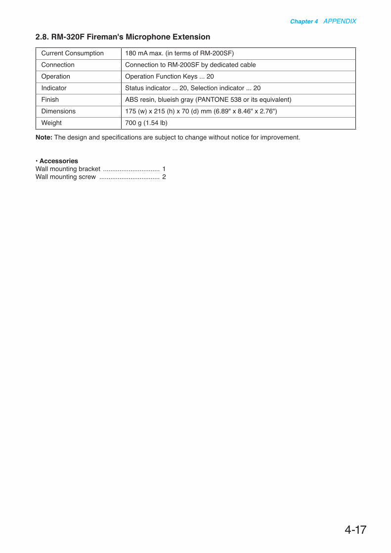
4-17
Chapter 4 APPENDIX
Current Consumption 180 mA max. (in terms of RM-200SF)Connection Connection to RM-200SF by dedicated cableOperation Operation Function Keys ... 20Indicator Status indicator ... 20, Selection indicator ... 20Finish ABS resin, blueish gray (PANTONE 538 or its equivalent)Dimensions 175 (w) x 215 (h) x 70 (d) mm (6.89" x 8.46" x 2.76")Weight 700 g (1.54 lb)
2.8. RM-320F Fireman's Microphone Extension
Note: The design and specifications are subject to change without notice for improvement.
• AccessoriesWall mounting bracket ............................... 1Wall mounting screw ................................. 2
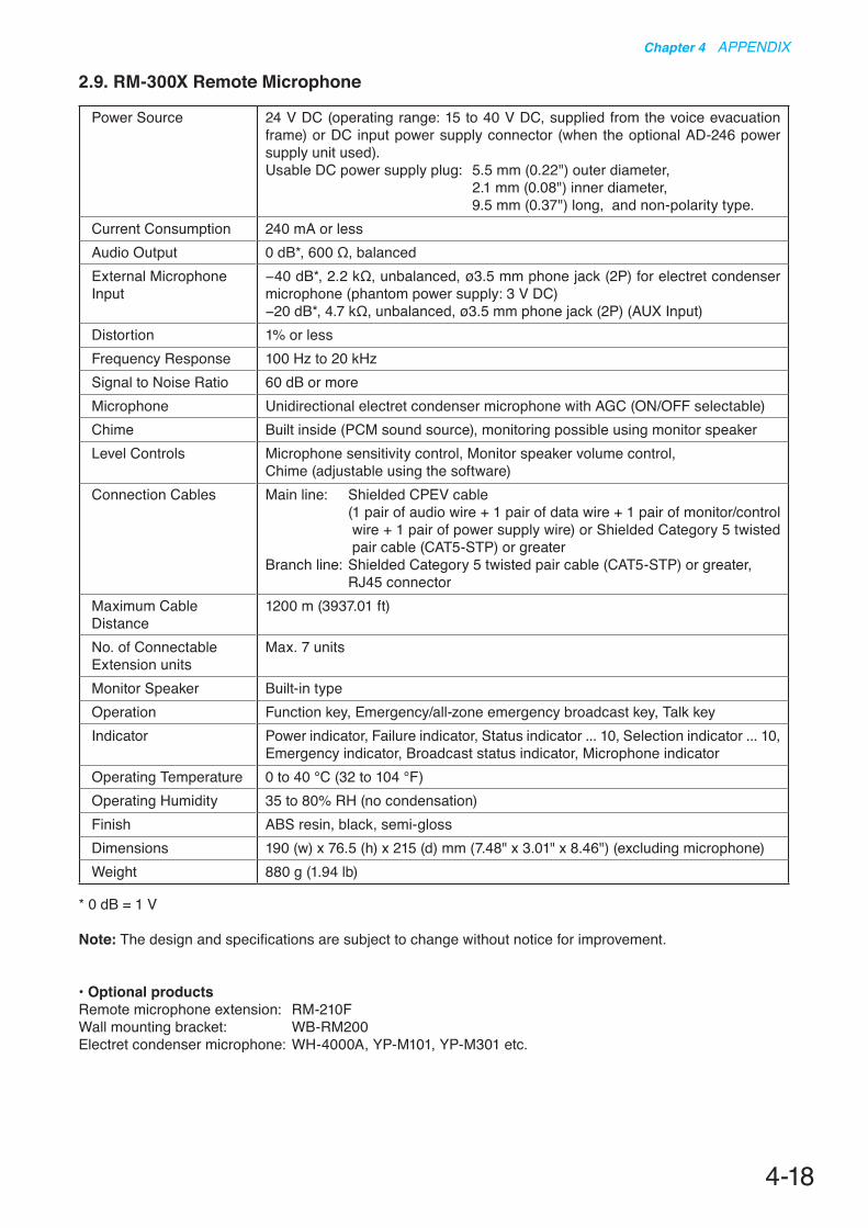
4-18
Chapter 4 APPENDIX
Power Source 24 V DC (operating range: 15 to 40 V DC, supplied from the voice evacuation frame) or DC input power supply connector (when the optional AD-246 power supply unit used).Usable DC power supply plug: 5.5 mm (0.22") outer diameter, 2.1 mm (0.08") inner diameter, 9.5 mm (0.37") long, and non-polarity type.
Current Consumption 240 mA or lessAudio Output 0 dB*, 600 Ω, balancedExternal Microphone Input
−40 dB*, 2.2 kΩ, unbalanced, ø3.5 mm phone jack (2P) for electret condenser microphone (phantom power supply: 3 V DC)−20 dB*, 4.7 kΩ, unbalanced, ø3.5 mm phone jack (2P) (AUX Input)
Distortion 1% or lessFrequency Response 100 Hz to 20 kHzSignal to Noise Ratio 60 dB or moreMicrophone Unidirectional electret condenser microphone with AGC (ON/OFF selectable)Chime Built inside (PCM sound source), monitoring possible using monitor speakerLevel Controls Microphone sensitivity control, Monitor speaker volume control,
Chime (adjustable using the software)Connection Cables Main line: Shielded CPEV cable
( 1 pair of audio wire + 1 pair of data wire + 1 pair of monitor/control wire + 1 pair of power supply wire) or Shielded Category 5 twisted pair cable (CAT5-STP) or greater
Branch line: Shielded Category 5 twisted pair cable (CAT5-STP) or greater, RJ45 connector
Maximum Cable Distance
1200 m (3937.01 ft)
No. of Connectable Extension units
Max. 7 units
Monitor Speaker Built-in typeOperation Function key, Emergency/all-zone emergency broadcast key, Talk keyIndicator Power indicator, Failure indicator, Status indicator ... 10, Selection indicator ... 10,
Emergency indicator, Broadcast status indicator, Microphone indicatorOperating Temperature 0 to 40 °C (32 to 104 °F)Operating Humidity 35 to 80% RH (no condensation)Finish ABS resin, black, semi-glossDimensions 190 (w) x 76.5 (h) x 215 (d) mm (7.48" x 3.01" x 8.46") (excluding microphone)Weight 880 g (1.94 lb)
2.9. RM-300X Remote Microphone
* 0 dB = 1 V
Note: The design and specifications are subject to change without notice for improvement.
• Optional productsRemote microphone extension: RM-210FWall mounting bracket: WB-RM200Electret condenser microphone: WH-4000A, YP-M101, YP-M301 etc.

4-19
Chapter 4 APPENDIX
2.10. RM-210F Remote Microphone Extension
Power Source Supplied from the optional RM-300XAC Power Consumption 2.4 W (including power supply loss of the Emergency power panel)
0.4 W (standby, including power supply loss of the Emergency power panel)Current Consumption 80 mA or less (increase in power input at the optional RM-300X)Operation Function key ... 10Indicator Status indicator ... 10, Selection indicator ... 10Operating Temperature 0 to 40 °C (32 to 104 °F)Operating Humidity 35 to 80% RH (no condensation)Finish ABS resin, black, semi-glossDimensions 110 (w) x 76.5 (h) x 215 (d) mm (4.33" x 3.01" x 8.46")Weight 350 g (0.77 lb)Applicable unit Remote microphone: RM-300X
Note: The design and specifications are subject to change without notice for improvement.
• AccessoriesConnection cable (8 pins, 8 cm or 3.15") ... 1Joint bracket A ........................................... 2Joint bracket B ........................................... 1Screw for joint bracket ............................. 12
• Optional productWall mounting bracket: WB-RM200
2.11. RM-200RJ Terminal Unit
Applied Voltage 40 V or lessWithstand Current 1 ADC Voltage Monitoring Section
Monitor terminals: Terminal No. 7 (+) and Terminal No. 8 (–), Extinguish voltage: 14 V or less, Lighting voltage: 21 V or more, Indicator ON/OFF switchable
Connector RJ45 connector x 1Terminal Block M3 screw terminal (10P), Barrier spacing: 6.62 mm (0.26")Operating Temperature 0 to 40°C (32 to 104 °F)Operating Humidity 35 to 80% RH (no condensation)Finish Surface-treated steel plate, black, paintDimensions 84 (w) x 116 (h) x 25.7 (d) mm (3.31" x 4.57" x 1.01")Weight 250 g (0.55 lb)
Note: The design and specifications are subject to change without notice for improvement.

Power Source Supplied from the VX-3000 systemPower Consumption 0.2 WSpeaker Line Input (CN1) Screw connector, Applicable cable diameter: AWG 24 – AWG 19Contact Output (CN2) Connected to the emergency contact input of VX-3004F/3008F/3016F
Connection cable: Twisted pair cable (shielded type is recommended)Screw connector, Applicable cable diameter: AWG 24 – AWG 19
Speaker Line Max. load: 100 WNote: applicable only for 100 V speaker line
Dimensions 70 (w) x 18 (h) x 45 (d) mm (2.76" x 0.71" x 1.77")Weight 20 g (0.04 lb)
Note: The design and specifications are subject to change without notice for improvement.
Traceability Information for EuropeManufacturer:
TOA Corporation7-2-1, Minatojima-Nakamachi, Chuo-ku, Kobe, Hyogo, Japan
Authorized representative:TOA Electronics Europe GmbHSuederstrasse 282, 20537 Hamburg,Germany
URL: https://www.toa.jp/201910
2.12. VM-300SV End Of Line Unit


![TYY^VX UW[Z\] RQQS - HKEXnews](https://img.dokumen.tips/doc/110x75/631fbdfc22afa78a130f335b/tyyvx-uwz-rqqs-hkexnews.jpg)


