Embed Size (px)
Citation preview

Series 3000
System Software Manual
2
70-16310-02Revision B — March 1999
Symbol Technologies, Inc. One Symbol Plaza, Holtsville N.Y. 11742
Series 3000 System Software Manual

Series 3000 System Software Manual
70-16310-02
March, 1999
iv
1996-1999
by Symbol Technologies, Inc. All rights reserved.
No part of this publication may be reproduced or used in any form, or by any electrical or mechanical means, without permission in writing from Symbol. This includes electronic or mechanical means, such as photocopying, recording, or information storage and retrieval systems. The material in this manual is subject to change without notice.
The software is provided strictly on an “as is” basis. All software, including firmware, furnished to the user is on a licensed basis. Symbol grants to the user a non-transferable and non-exclusive license to use each software or firmware program delivered hereunder (licensed program). Except as noted below, such license may not be assigned, sublicensed, or otherwise transferred by the user without prior written consent of Symbol. No right to copy a licensed program in whole or in part is granted, except as permitted under copyright law. The user shall not modify, merge, or incorporate any form or portion of a licensed program with other program material, create a derivative work from a licensed program, or use a licensed program in a network without written permission from Symbol. The user agrees to maintain Symbol’s copyright notice on the licensed programs delivered hereunder, and to include the same on any authorized copies it makes, in whole or in part. The user agrees not to decompile, disassemble, decode, or reverse engineer any licensed program delivered to the user or any portion thereof.
Symbol reserves the right to make changes to any software or product to improve reliability, function, or design.
Symbol does not assume any product liability arising out of, or in connection with, the application or use of any product, circuit, or application described herein.
No license is granted, either expressly or by implication, estoppel, or otherwise under any Symbol Technologies, Inc., intellectual property rights. An implied license only exists for equipment, circuits, and subsystems contained in Symbol products.
Symbol and Spectrum One are registered trademarks of Symbol Technologies, Inc.Other product names mentioned in this manual may be trademarks or registered trademarks of their respective companies and are hereby acknowledged.
Symbol Technologies, Inc.One Symbol PlazaHoltsville, N.Y. 11742http://www.symbol.com
Contents
About This ManualIntroduction . . . . . . . . . . . . . . . . . . . . . . . . . . . . . . . . . . . . . . . . . . . . . . . . . . . . . . . . . . . . . . . . . . . . . .viiHow to Use This Manual . . . . . . . . . . . . . . . . . . . . . . . . . . . . . . . . . . . . . . . . . . . . . . . . . . . . . . . . . . .viiNotational Conventions . . . . . . . . . . . . . . . . . . . . . . . . . . . . . . . . . . . . . . . . . . . . . . . . . . . . . . . . . . . . ixRelated Documentation. . . . . . . . . . . . . . . . . . . . . . . . . . . . . . . . . . . . . . . . . . . . . . . . . . . . . . . . . . . . . . x
Chapter 1. IntroductionOverview. . . . . . . . . . . . . . . . . . . . . . . . . . . . . . . . . . . . . . . . . . . . . . . . . . . . . . . . . . . . . . . . . . . . . . . . 1-3Series 3000 Terminals . . . . . . . . . . . . . . . . . . . . . . . . . . . . . . . . . . . . . . . . . . . . . . . . . . . . . . . . . . . . . 1-3
Firmware . . . . . . . . . . . . . . . . . . . . . . . . . . . . . . . . . . . . . . . . . . . . . . . . . . . . . . . . . . . . . . . . . . . . 1-3
Chapter 2.ROM BIOSIntroduction . . . . . . . . . . . . . . . . . . . . . . . . . . . . . . . . . . . . . . . . . . . . . . . . . . . . . . . . . . . . . . . . . . . . . 2-3Video Services . . . . . . . . . . . . . . . . . . . . . . . . . . . . . . . . . . . . . . . . . . . . . . . . . . . . . . . . . . . . . . . . . . 2-14Standard Video Services . . . . . . . . . . . . . . . . . . . . . . . . . . . . . . . . . . . . . . . . . . . . . . . . . . . . . . . . . . 2-23Extended Video Services. . . . . . . . . . . . . . . . . . . . . . . . . . . . . . . . . . . . . . . . . . . . . . . . . . . . . . . . . . 2-36Equipment List . . . . . . . . . . . . . . . . . . . . . . . . . . . . . . . . . . . . . . . . . . . . . . . . . . . . . . . . . . . . . . . . . . 2-55Memory Services . . . . . . . . . . . . . . . . . . . . . . . . . . . . . . . . . . . . . . . . . . . . . . . . . . . . . . . . . . . . . . . . 2-59EMS Support. . . . . . . . . . . . . . . . . . . . . . . . . . . . . . . . . . . . . . . . . . . . . . . . . . . . . . . . . . . . . . . . . . . . 2-70EEPROM Memory Services . . . . . . . . . . . . . . . . . . . . . . . . . . . . . . . . . . . . . . . . . . . . . . . . . . . . . . . 2-80Diskette Services . . . . . . . . . . . . . . . . . . . . . . . . . . . . . . . . . . . . . . . . . . . . . . . . . . . . . . . . . . . . . . . . 2-85Serial I/O Services . . . . . . . . . . . . . . . . . . . . . . . . . . . . . . . . . . . . . . . . . . . . . . . . . . . . . . . . . . . . . . . 2-92Keyboard Services . . . . . . . . . . . . . . . . . . . . . . . . . . . . . . . . . . . . . . . . . . . . . . . . . . . . . . . . . . . . . . 2-128Standard Keyboard Services . . . . . . . . . . . . . . . . . . . . . . . . . . . . . . . . . . . . . . . . . . . . . . . . . . . . . 2-130Extended Keyboard Services . . . . . . . . . . . . . . . . . . . . . . . . . . . . . . . . . . . . . . . . . . . . . . . . . . . . . 2-134Printer Services. . . . . . . . . . . . . . . . . . . . . . . . . . . . . . . . . . . . . . . . . . . . . . . . . . . . . . . . . . . . . . . . . 2-146Time-of-Day Services. . . . . . . . . . . . . . . . . . . . . . . . . . . . . . . . . . . . . . . . . . . . . . . . . . . . . . . . . . . . 2-151Timer Services . . . . . . . . . . . . . . . . . . . . . . . . . . . . . . . . . . . . . . . . . . . . . . . . . . . . . . . . . . . . . . . . . 2-161Sound Generation . . . . . . . . . . . . . . . . . . . . . . . . . . . . . . . . . . . . . . . . . . . . . . . . . . . . . . . . . . . . . . 2-172Power Management. . . . . . . . . . . . . . . . . . . . . . . . . . . . . . . . . . . . . . . . . . . . . . . . . . . . . . . . . . . . . 2-177Scanner Services . . . . . . . . . . . . . . . . . . . . . . . . . . . . . . . . . . . . . . . . . . . . . . . . . . . . . . . . . . . . . . . . 2-189Cradle Control Services. . . . . . . . . . . . . . . . . . . . . . . . . . . . . . . . . . . . . . . . . . . . . . . . . . . . . . . . . . 2-193Miscellaneous Services . . . . . . . . . . . . . . . . . . . . . . . . . . . . . . . . . . . . . . . . . . . . . . . . . . . . . . . . . . 2-199
Chapter 3. DR DOS Operating SystemIntroduction . . . . . . . . . . . . . . . . . . . . . . . . . . . . . . . . . . . . . . . . . . . . . . . . . . . . . . . . . . . . . . . . . . . . . 3-3DR DOS . . . . . . . . . . . . . . . . . . . . . . . . . . . . . . . . . . . . . . . . . . . . . . . . . . . . . . . . . . . . . . . . . . . . . . . . . 3-3
i
Chapter 4. Clock Device DriverIntroduction . . . . . . . . . . . . . . . . . . . . . . . . . . . . . . . . . . . . . . . . . . . . . . . . . . . . . . . . . . . . . . . . . . . . . 4-3Device Driver Functions . . . . . . . . . . . . . . . . . . . . . . . . . . . . . . . . . . . . . . . . . . . . . . . . . . . . . . . . . . . 4-3Data Formats. . . . . . . . . . . . . . . . . . . . . . . . . . . . . . . . . . . . . . . . . . . . . . . . . . . . . . . . . . . . . . . . . . . . . 4-5
Chapter 5.Line Printer Device DriverIntroduction . . . . . . . . . . . . . . . . . . . . . . . . . . . . . . . . . . . . . . . . . . . . . . . . . . . . . . . . . . . . . . . . . . . . . 5-3
Printer Ports . . . . . . . . . . . . . . . . . . . . . . . . . . . . . . . . . . . . . . . . . . . . . . . . . . . . . . . . . . . . . . . . . 5-3Flow Control . . . . . . . . . . . . . . . . . . . . . . . . . . . . . . . . . . . . . . . . . . . . . . . . . . . . . . . . . . . . . . . . . 5-3
Line Printer Device Driver Functions . . . . . . . . . . . . . . . . . . . . . . . . . . . . . . . . . . . . . . . . . . . . . . . . 5-4IOCTL Write Subfunctions . . . . . . . . . . . . . . . . . . . . . . . . . . . . . . . . . . . . . . . . . . . . . . . . . . . . . . . . . 5-6
Subfunction 0: Reset . . . . . . . . . . . . . . . . . . . . . . . . . . . . . . . . . . . . . . . . . . . . . . . . . . . . . . . . . . 5-6Subfunction 1: Eject Page . . . . . . . . . . . . . . . . . . . . . . . . . . . . . . . . . . . . . . . . . . . . . . . . . . . . . . 5-6Subfunction 2: Set Top of Page. . . . . . . . . . . . . . . . . . . . . . . . . . . . . . . . . . . . . . . . . . . . . . . . . . 5-7Subfunction 3: Set Page Parameters . . . . . . . . . . . . . . . . . . . . . . . . . . . . . . . . . . . . . . . . . . . . . 5-7Subfunction 4: Set Terminator String . . . . . . . . . . . . . . . . . . . . . . . . . . . . . . . . . . . . . . . . . . . . 5-8Subfunction 5: Set Redirection Parameters . . . . . . . . . . . . . . . . . . . . . . . . . . . . . . . . . . . . . . . 5-9Subfunction 6: Restore Context . . . . . . . . . . . . . . . . . . . . . . . . . . . . . . . . . . . . . . . . . . . . . . . . . 5-9Subfunction 7: Enable/Disable DOS Critical Error Reporting . . . . . . . . . . . . . . . . . . . . . . 5-10
IOCTL Read Subfunctions . . . . . . . . . . . . . . . . . . . . . . . . . . . . . . . . . . . . . . . . . . . . . . . . . . . . . . . . 5-11Subfunction 0: Undefined. . . . . . . . . . . . . . . . . . . . . . . . . . . . . . . . . . . . . . . . . . . . . . . . . . . . . 5-11Subfunction 1: Get Line Number. . . . . . . . . . . . . . . . . . . . . . . . . . . . . . . . . . . . . . . . . . . . . . . 5-11Subfunction 2: Undefined. . . . . . . . . . . . . . . . . . . . . . . . . . . . . . . . . . . . . . . . . . . . . . . . . . . . . 5-11Subfunction 3: Get Page Parameters . . . . . . . . . . . . . . . . . . . . . . . . . . . . . . . . . . . . . . . . . . . . 5-11Subfunction 4: Get Terminator String. . . . . . . . . . . . . . . . . . . . . . . . . . . . . . . . . . . . . . . . . . . 5-12Subfunction 5: Get Redirection Parameters . . . . . . . . . . . . . . . . . . . . . . . . . . . . . . . . . . . . . . 5-12Subfunction 6: Save Context. . . . . . . . . . . . . . . . . . . . . . . . . . . . . . . . . . . . . . . . . . . . . . . . . . . 5-12Subfunction 7: Get Print Driver Status . . . . . . . . . . . . . . . . . . . . . . . . . . . . . . . . . . . . . . . . . . 5-13
Error Reporting . . . . . . . . . . . . . . . . . . . . . . . . . . . . . . . . . . . . . . . . . . . . . . . . . . . . . . . . . . . . . . . . . 5-14DOS Critical Errors . . . . . . . . . . . . . . . . . . . . . . . . . . . . . . . . . . . . . . . . . . . . . . . . . . . . . . . . . . 5-14IOCTL Error Codes . . . . . . . . . . . . . . . . . . . . . . . . . . . . . . . . . . . . . . . . . . . . . . . . . . . . . . . . . . 5-15Generic Error Codes . . . . . . . . . . . . . . . . . . . . . . . . . . . . . . . . . . . . . . . . . . . . . . . . . . . . . . . . . 5-16Error Trapping . . . . . . . . . . . . . . . . . . . . . . . . . . . . . . . . . . . . . . . . . . . . . . . . . . . . . . . . . . . . . . 5-16
Chapter 6. Console/Scanner Device DriverIntroduction . . . . . . . . . . . . . . . . . . . . . . . . . . . . . . . . . . . . . . . . . . . . . . . . . . . . . . . . . . . . . . . . . . . . . 6-3Console Device Driver . . . . . . . . . . . . . . . . . . . . . . . . . . . . . . . . . . . . . . . . . . . . . . . . . . . . . . . . . . . . 6-3
Setting Up the Console Device Driver . . . . . . . . . . . . . . . . . . . . . . . . . . . . . . . . . . . . . . . . . . . 6-3The Scanning System. . . . . . . . . . . . . . . . . . . . . . . . . . . . . . . . . . . . . . . . . . . . . . . . . . . . . . . . . . . . . . 6-5
Running the Scanning Program. . . . . . . . . . . . . . . . . . . . . . . . . . . . . . . . . . . . . . . . . . . . . . . . . 6-5Controlling Scanning Functions . . . . . . . . . . . . . . . . . . . . . . . . . . . . . . . . . . . . . . . . . . . . . . . . 6-5
Scanner Commands. . . . . . . . . . . . . . . . . . . . . . . . . . . . . . . . . . . . . . . . . . . . . . . . . . . . . . . . . . . . . . . 6-6
ii
Chapter 7. RAM Disk Device DriverIntroduction . . . . . . . . . . . . . . . . . . . . . . . . . . . . . . . . . . . . . . . . . . . . . . . . . . . . . . . . . . . . . . . . . . . . . 7-3RAM Disk Device Driver . . . . . . . . . . . . . . . . . . . . . . . . . . . . . . . . . . . . . . . . . . . . . . . . . . . . . . . . . . 7-3
Configuring the RAM Disk . . . . . . . . . . . . . . . . . . . . . . . . . . . . . . . . . . . . . . . . . . . . . . . . . . . . 7-3RAM Disk Driver Functions. . . . . . . . . . . . . . . . . . . . . . . . . . . . . . . . . . . . . . . . . . . . . . . . . . . . . . . . 7-4
The Device Header . . . . . . . . . . . . . . . . . . . . . . . . . . . . . . . . . . . . . . . . . . . . . . . . . . . . . . . . . . . 7-4Link to Next Driver . . . . . . . . . . . . . . . . . . . . . . . . . . . . . . . . . . . . . . . . . . . . . . . . . . . . . . . . . . . 7-4Device Attributes . . . . . . . . . . . . . . . . . . . . . . . . . . . . . . . . . . . . . . . . . . . . . . . . . . . . . . . . . . . . . 7-4Strategy Offset . . . . . . . . . . . . . . . . . . . . . . . . . . . . . . . . . . . . . . . . . . . . . . . . . . . . . . . . . . . . . . . 7-5Interrupt Offset. . . . . . . . . . . . . . . . . . . . . . . . . . . . . . . . . . . . . . . . . . . . . . . . . . . . . . . . . . . . . . . 7-5Number of Units . . . . . . . . . . . . . . . . . . . . . . . . . . . . . . . . . . . . . . . . . . . . . . . . . . . . . . . . . . . . . 7-5
The Strategy Routine . . . . . . . . . . . . . . . . . . . . . . . . . . . . . . . . . . . . . . . . . . . . . . . . . . . . . . . . . . . . . . 7-6Data Structures . . . . . . . . . . . . . . . . . . . . . . . . . . . . . . . . . . . . . . . . . . . . . . . . . . . . . . . . . . . . . . . 7-6Code Routines . . . . . . . . . . . . . . . . . . . . . . . . . . . . . . . . . . . . . . . . . . . . . . . . . . . . . . . . . . . . . . . 7-6
Interrupt Routine . . . . . . . . . . . . . . . . . . . . . . . . . . . . . . . . . . . . . . . . . . . . . . . . . . . . . . . . . . . . . . . . . 7-6The Request Header . . . . . . . . . . . . . . . . . . . . . . . . . . . . . . . . . . . . . . . . . . . . . . . . . . . . . . . . . . . . . . 7-7Command-Code Routines . . . . . . . . . . . . . . . . . . . . . . . . . . . . . . . . . . . . . . . . . . . . . . . . . . . . . . . . . 7-9
Chapter 8. Expanded Memory ManagerIntroduction . . . . . . . . . . . . . . . . . . . . . . . . . . . . . . . . . . . . . . . . . . . . . . . . . . . . . . . . . . . . . . . . . . . . . 8-5Page Frame, Physical Page, and Logical Page . . . . . . . . . . . . . . . . . . . . . . . . . . . . . . . . . . . . . . . . . 8-5Loading the Expanded Memory Driver . . . . . . . . . . . . . . . . . . . . . . . . . . . . . . . . . . . . . . . . . . . . . . 8-7Writing Programs That Use Expanded Memory . . . . . . . . . . . . . . . . . . . . . . . . . . . . . . . . . . . . . . 8-7Advanced Programming . . . . . . . . . . . . . . . . . . . . . . . . . . . . . . . . . . . . . . . . . . . . . . . . . . . . . . . . . . 8-9
Saving the State of Mapping Hardware . . . . . . . . . . . . . . . . . . . . . . . . . . . . . . . . . . . . . . . . . . 8-9Retrieving Handle and Page Counts. . . . . . . . . . . . . . . . . . . . . . . . . . . . . . . . . . . . . . . . . . . . . 8-9Mapping and Unmapping Multiple Pages . . . . . . . . . . . . . . . . . . . . . . . . . . . . . . . . . . . . . . . 8-9Reallocating Pages . . . . . . . . . . . . . . . . . . . . . . . . . . . . . . . . . . . . . . . . . . . . . . . . . . . . . . . . . . . . 8-9Using Handles and Assigning Names to Handles . . . . . . . . . . . . . . . . . . . . . . . . . . . . . . . . 8-10Using Handle Attributes. . . . . . . . . . . . . . . . . . . . . . . . . . . . . . . . . . . . . . . . . . . . . . . . . . . . . . 8-10Altering Page Maps and Jumping/Calling . . . . . . . . . . . . . . . . . . . . . . . . . . . . . . . . . . . . . . 8-10Moving or Exchanging Memory Regions. . . . . . . . . . . . . . . . . . . . . . . . . . . . . . . . . . . . . . . . 8-11Getting the Amount of Mappable Memory . . . . . . . . . . . . . . . . . . . . . . . . . . . . . . . . . . . . . . 8-11Operating System Functions . . . . . . . . . . . . . . . . . . . . . . . . . . . . . . . . . . . . . . . . . . . . . . . . . . 8-12
Programming Guidelines . . . . . . . . . . . . . . . . . . . . . . . . . . . . . . . . . . . . . . . . . . . . . . . . . . . . . . . . . 8-14Example 1 . . . . . . . . . . . . . . . . . . . . . . . . . . . . . . . . . . . . . . . . . . . . . . . . . . . . . . . . . . . . . . . . . . 8-15Example 2 . . . . . . . . . . . . . . . . . . . . . . . . . . . . . . . . . . . . . . . . . . . . . . . . . . . . . . . . . . . . . . . . . . 8-19
Expanded Memory Functions . . . . . . . . . . . . . . . . . . . . . . . . . . . . . . . . . . . . . . . . . . . . . . . . . . . . . 8-22Function 1 - Get Status . . . . . . . . . . . . . . . . . . . . . . . . . . . . . . . . . . . . . . . . . . . . . . . . . . . . . . . 8-25Function 3 - Get Unallocated Page Count . . . . . . . . . . . . . . . . . . . . . . . . . . . . . . . . . . . . . . . 8-28Function 4 - Allocate Pages. . . . . . . . . . . . . . . . . . . . . . . . . . . . . . . . . . . . . . . . . . . . . . . . . . . . 8-29Function 5 - Map/Unmap Handle Pages . . . . . . . . . . . . . . . . . . . . . . . . . . . . . . . . . . . . . . . . 8-31Function 6 - Deallocate Pages. . . . . . . . . . . . . . . . . . . . . . . . . . . . . . . . . . . . . . . . . . . . . . . . . . 8-33
iii
Function 7 - Get Version . . . . . . . . . . . . . . . . . . . . . . . . . . . . . . . . . . . . . . . . . . . . . . . . . . . . . . 8-35Function 8 - Save Page Map . . . . . . . . . . . . . . . . . . . . . . . . . . . . . . . . . . . . . . . . . . . . . . . . . . . 8-37Function 9 - Restore Page Map . . . . . . . . . . . . . . . . . . . . . . . . . . . . . . . . . . . . . . . . . . . . . . . . 8-39Function 12 - Get Handle Count . . . . . . . . . . . . . . . . . . . . . . . . . . . . . . . . . . . . . . . . . . . . . . . 8-41Function 13 - Get Handle Pages. . . . . . . . . . . . . . . . . . . . . . . . . . . . . . . . . . . . . . . . . . . . . . . . 8-42Function 14 - Get All Handles Pages . . . . . . . . . . . . . . . . . . . . . . . . . . . . . . . . . . . . . . . . . . . 8-44Function 15 - Get/Set Page Map Get Page Map Subfunction . . . . . . . . . . . . . . . . . . . . . . . 8-47Function 15 - Get/Set Page Map Set Page Map Subfunction . . . . . . . . . . . . . . . . . . . . . . . 8-49Function 15 - Get/Set Page Map Get & Set Page Map Subfunction. . . . . . . . . . . . . . . . . . 8-51Function 15 - Get/Set Page Map Get Size of Page Map Save Array Subfunction . . . . . . 8-54Function 16 - Get/Set Partial Page Map Get Partial Page Map Subfunction . . . . . . . . . . 8-56Function 16 - Get/Set Partial Page Map Set Partial Page Map Subfunction. . . . . . . . . . . 8-59Function 16 - Get/Set Partial Page Map Get Size of Partial Page Map Save Array Subfunction . . . . . . . . . . . . . . . . . . . . . . . . . . . . . . . . . . . . . . . . . . . . . . . . . . . . . . 8-61Function 17 - Map/Unmap Multiple Handle Pages. . . . . . . . . . . . . . . . . . . . . . . . . . . . . . . 8-63Function 17 - Map/Unmap Multiple Handle Pages Logical Page/Segment Address Method . . . . . . . . . . . . . . . . . . . . . . . . . . . . . . . . . . . . . . . . 8-67Function 18 - Reallocate Pages . . . . . . . . . . . . . . . . . . . . . . . . . . . . . . . . . . . . . . . . . . . . . . . . . 8-70Function 19 - Get/Set Handle AttributeGet and Set Handle Attribute Subfunctions . . . . . . . . . . . . . . . . . . . . . . . . . . . . . . . . . . . . . 8-73Function 19 - Get/Set Handle AttributeGet Attribute Capability Subfunction. . . . . . . . . . . . . . . . . . . . . . . . . . . . . . . . . . . . . . . . . . . 8-74Function 20 - Get/Set Handle Name Get Handle Name Subfunction. . . . . . . . . . . . . . . . 8-75Function 20 - Get/Set Handle Name Set Handle Name Subfunction . . . . . . . . . . . . . . . . 8-77Function 21 - Get Handle Directory Get Handle Directory Subfunction . . . . . . . . . . . . . 8-79Function 21 - Get Handle Directory Search for Named Handle Subfunction . . . . . . . . . 8-81Function 21 - Get Handle Directory Get Total Handles Subfunction . . . . . . . . . . . . . . . . 8-83Function 22 - Alter Page Map & Jump . . . . . . . . . . . . . . . . . . . . . . . . . . . . . . . . . . . . . . . . . . 8-84Function 23 - Alter Page Map & Call Alter Page Map and Call Subfunction . . . . . . . . . . 8-88Function 23 - Alter Page Map & Call Get Page Map Stack Space Size Subfunction . . . . 8-93Function 24 - Move/Exchange Memory Region Move Memory Region Subfunction. . 8-95Function 24 - Move/Exchange Memory Region Exchange Memory Region Subfunction . . . . . . . . . . . . . . . . . . . . . . . . . . . . . . . . . . . . . . . . 8-101Function 25 - Get Mappable Physical Address Array Get Mappable Physical Address Array Subfunction . . . . . . . . . . . . . . . . . . . . . . . . . . . . . 8-107Function 25 - Get Mappable Physical Address ArrayGet Mappable Physical Address Array Entries Subfunction . . . . . . . . . . . . . . . . . . . . . . 8-109Function 26 - Get Expanded Memory Hardware InformationGet Hardware Configuration Array Subfunction. . . . . . . . . . . . . . . . . . . . . . . . . . . . . . . . 8-111Function 26 - Get Expanded Memory Hardware InformationGet Unallocated Raw Page Count Subfunction. . . . . . . . . . . . . . . . . . . . . . . . . . . . . . . . . . 8-114Function 27 - Allocate Standard/Raw PagesAllocate Standard Pages Subfunction. . . . . . . . . . . . . . . . . . . . . . . . . . . . . . . . . . . . . . . . . . 8-115Function 27 - Allocate Standard/Raw Pages
iv

Allocate Raw Pages Subfunction . . . . . . . . . . . . . . . . . . . . . . . . . . . . . . . . . . . . . . . . . . . . . . 8-117Function 28 - Alternate Map Register Set. . . . . . . . . . . . . . . . . . . . . . . . . . . . . . . . . . . . . . . 8-119Function 28 - Alternate Map Register SetGet Alternate Map Register Set Subfunction . . . . . . . . . . . . . . . . . . . . . . . . . . . . . . . . . . . . 8-120Function 28 - Alternate Map Register SetSet Alternate Map Register Set Subfunction . . . . . . . . . . . . . . . . . . . . . . . . . . . . . . . . . . . . 8-122Function 28 - Alternate Map Register SetGet Alternate Map Save Array Size Subfunction . . . . . . . . . . . . . . . . . . . . . . . . . . . . . . . . 8-126Function 28 - Alternate Map Register SetAllocate Alternate Map Register Set Subfunction. . . . . . . . . . . . . . . . . . . . . . . . . . . . . . . . 8-128Function 28 - Alternate Map Register SetDeallocate Alternate Map Register Set Subfunction. . . . . . . . . . . . . . . . . . . . . . . . . . . . . . 8-129Function 28 - Alternate Map Register SetAllocate DMA Register Set Subfunction. . . . . . . . . . . . . . . . . . . . . . . . . . . . . . . . . . . . . . . . 8-131Function 28 - Alternate Map Register SetEnable DMA ON Alternate Map Register Set Subfunction. . . . . . . . . . . . . . . . . . . . . . . . 8-132Function 28 - Alternate Map Register SetDisable DMA ON Alternate Map Register Set Subfunction . . . . . . . . . . . . . . . . . . . . . . . 8-134Function 28 - Alternate Map Register SetDeallocate DMA Register Set Subfunction. . . . . . . . . . . . . . . . . . . . . . . . . . . . . . . . . . . . . . 8-136Function 29 - Prepare Expanded Memory Hardware to Warmboot . . . . . . . . . . . . . . . . 8-138Function 30 - Enable/Disable OS/E Function Set Function Enable OS/E Function Set Subfunction . . . . . . . . . . . . . . . . . . . . . . . . . . . . . . . . . . . . . . . . 8-139Function 30 - Enable/Disable OS/E Function Set Function Disable OS/E Function Set Subfunction. . . . . . . . . . . . . . . . . . . . . . . . . . . . . . . . . . . . . . . . 8-143Results . . . . . . . . . . . . . . . . . . . . . . . . . . . . . . . . . . . . . . . . . . . . . . . . . . . . . . . . . . . . . . . . . . . . 8-143Function 30 - Enable/Disable OS/E Function Set Function Return Access Key Subfunction. . . . . . . . . . . . . . . . . . . . . . . . . . . . . . . . . . . . . . . . . . . . . . . 8-146
Function and Status Code Cross Reference . . . . . . . . . . . . . . . . . . . . . . . . . . . . . . . . . . . . . . . . . 8-148Testing for the Presence of EMM. . . . . . . . . . . . . . . . . . . . . . . . . . . . . . . . . . . . . . . . . . . . . . . . . . 8-151
Which Method Should Your Program Use? . . . . . . . . . . . . . . . . . . . . . . . . . . . . . . . . . . . . 8-152The “Open Handle” Technique . . . . . . . . . . . . . . . . . . . . . . . . . . . . . . . . . . . . . . . . . . . . . . . 8-152The Get Interrupt Vector Technique . . . . . . . . . . . . . . . . . . . . . . . . . . . . . . . . . . . . . . . . . . . 8-156
Chapter 9. Communication Device DriverIntroduction . . . . . . . . . . . . . . . . . . . . . . . . . . . . . . . . . . . . . . . . . . . . . . . . . . . . . . . . . . . . . . . . . . . . . 9-3
Multi-Protocol Communication Device Driver . . . . . . . . . . . . . . . . . . . . . . . . . . . . . . . . . . . . 9-3Attachable Protocol Drivers . . . . . . . . . . . . . . . . . . . . . . . . . . . . . . . . . . . . . . . . . . . . . . . . . . . . 9-3
DOS Communications Driver Services. . . . . . . . . . . . . . . . . . . . . . . . . . . . . . . . . . . . . . . . . . . . . . . 9-3A Sample Communications Session . . . . . . . . . . . . . . . . . . . . . . . . . . . . . . . . . . . . . . . . . . . . . 9-4Open/Close Communications Line . . . . . . . . . . . . . . . . . . . . . . . . . . . . . . . . . . . . . . . . . . . . . 9-5Passing Device Control Information . . . . . . . . . . . . . . . . . . . . . . . . . . . . . . . . . . . . . . . . . . . . . 9-6DOS I/O Status . . . . . . . . . . . . . . . . . . . . . . . . . . . . . . . . . . . . . . . . . . . . . . . . . . . . . . . . . . . . . . 9-6
v
Binary Processing Mode . . . . . . . . . . . . . . . . . . . . . . . . . . . . . . . . . . . . . . . . . . . . . . . . . . . . . . . 9-7Communications Driver Load Status . . . . . . . . . . . . . . . . . . . . . . . . . . . . . . . . . . . . . . . . . . . . 9-7
Using Protocol Drivers . . . . . . . . . . . . . . . . . . . . . . . . . . . . . . . . . . . . . . . . . . . . . . . . . . . . . . . . . . . . 9-8Attaching a Protocol Driver . . . . . . . . . . . . . . . . . . . . . . . . . . . . . . . . . . . . . . . . . . . . . . . . . . . . 9-8
IOCTL Error Codes . . . . . . . . . . . . . . . . . . . . . . . . . . . . . . . . . . . . . . . . . . . . . . . . . . . . . . . . . . . . . . . 9-9Protocol Driver Interface. . . . . . . . . . . . . . . . . . . . . . . . . . . . . . . . . . . . . . . . . . . . . . . . . . . . . . . . . . 9-11
Writing Protocol Drivers. . . . . . . . . . . . . . . . . . . . . . . . . . . . . . . . . . . . . . . . . . . . . . . . . . . . . . 9-12Attaching the Protocol Device Drivers . . . . . . . . . . . . . . . . . . . . . . . . . . . . . . . . . . . . . . . . . . 9-12
Application Program/Comm Driver Interface . . . . . . . . . . . . . . . . . . . . . . . . . . . . . . . . . . . . . . . 9-15Interface Parameters . . . . . . . . . . . . . . . . . . . . . . . . . . . . . . . . . . . . . . . . . . . . . . . . . . . . . . . . . 9-15
Chapter 10. 2WAY3000 Protocol Device DriverIntroduction . . . . . . . . . . . . . . . . . . . . . . . . . . . . . . . . . . . . . . . . . . . . . . . . . . . . . . . . . . . . . . . . . . . . 10-32WAY3000 Protocol Description . . . . . . . . . . . . . . . . . . . . . . . . . . . . . . . . . . . . . . . . . . . . . . . . . . . 10-3
Synchronization and Character Structure . . . . . . . . . . . . . . . . . . . . . . . . . . . . . . . . . . . . . . . 10-3Block Length . . . . . . . . . . . . . . . . . . . . . . . . . . . . . . . . . . . . . . . . . . . . . . . . . . . . . . . . . . . . . . . . 10-3Character Code Set . . . . . . . . . . . . . . . . . . . . . . . . . . . . . . . . . . . . . . . . . . . . . . . . . . . . . . . . . . 10-3Master/Slave Status. . . . . . . . . . . . . . . . . . . . . . . . . . . . . . . . . . . . . . . . . . . . . . . . . . . . . . . . . . 10-4Establishment . . . . . . . . . . . . . . . . . . . . . . . . . . . . . . . . . . . . . . . . . . . . . . . . . . . . . . . . . . . . . . . 10-4Message Transfer Procedure . . . . . . . . . . . . . . . . . . . . . . . . . . . . . . . . . . . . . . . . . . . . . . . . . . 10-4Replies . . . . . . . . . . . . . . . . . . . . . . . . . . . . . . . . . . . . . . . . . . . . . . . . . . . . . . . . . . . . . . . . . . . . . 10-5Termination Procedure . . . . . . . . . . . . . . . . . . . . . . . . . . . . . . . . . . . . . . . . . . . . . . . . . . . . . . . 10-7Control Characters . . . . . . . . . . . . . . . . . . . . . . . . . . . . . . . . . . . . . . . . . . . . . . . . . . . . . . . . . . . 10-7
DOS I/O Functions . . . . . . . . . . . . . . . . . . . . . . . . . . . . . . . . . . . . . . . . . . . . . . . . . . . . . . . . . . . . . . 10-9IOCTL COMMANDS . . . . . . . . . . . . . . . . . . . . . . . . . . . . . . . . . . . . . . . . . . . . . . . . . . . . . . . . . . . 10-11
2WAY3000 Category 2 Functions . . . . . . . . . . . . . . . . . . . . . . . . . . . . . . . . . . . . . . . . . . . . . 10-112WAY3000 Category 3 Functions . . . . . . . . . . . . . . . . . . . . . . . . . . . . . . . . . . . . . . . . . . . . . 10-13
Loading the 2WAY3000 Device Driver. . . . . . . . . . . . . . . . . . . . . . . . . . . . . . . . . . . . . . . . . . . . . 10-18
Chapter 11. Acoustic Coupler Device DriverIntroduction . . . . . . . . . . . . . . . . . . . . . . . . . . . . . . . . . . . . . . . . . . . . . . . . . . . . . . . . . . . . . . . . . . . . 11-3
Attaching the Acoustic Coupler Device Driver. . . . . . . . . . . . . . . . . . . . . . . . . . . . . . . . . . . 11-3Acoustic Coupler User Interface . . . . . . . . . . . . . . . . . . . . . . . . . . . . . . . . . . . . . . . . . . . . . . . 11-5Embedded Commands . . . . . . . . . . . . . . . . . . . . . . . . . . . . . . . . . . . . . . . . . . . . . . . . . . . . . . . 11-61350 Baud 5-Bit Transmissions . . . . . . . . . . . . . . . . . . . . . . . . . . . . . . . . . . . . . . . . . . . . . . . . 11-6
IOCTL Commands. . . . . . . . . . . . . . . . . . . . . . . . . . . . . . . . . . . . . . . . . . . . . . . . . . . . . . . . . . . . . . . 11-7
Index
vi
About This Manual
IntroductionThis manual provides low-level reference information for the Series 3000 terminals. The information is generally intended for the system programmer who needs to know what lies behind the functions provided in the C interface libraries.
The audience for this manual is the application programmer or software engineer who, while writing applications for a Series 3000 terminal, must use low-level function calls in order to:
• develop or modify higher level structures
• access special features of the Series 3000 terminal that are available only through these low level functions
How to Use This ManualThis manual is the system programmer's reference book for Series 3000 terminal system level software. Except for Chapter 1, which is a general overview of the terminal hardware, firmware, software and accessories, the chapters are set up for rapid information access.
The following brief chapter descriptions will help you focus on your area of interest.
Chapter 1, Introduction, provides an overview of the Series 3000 terminals and this manual.
Chapter 2, ROM BIOS, provides descriptions of Series 3000 ROM BIOS services in order of interrupt designator. To facilitate locating specific services, Table2-1 lists the interrupts in functional groups.
vii

Series 3000 System Software Manual
Chapter 3, DR DOS Operating System, is a brief description of DR DOS, the operating system supplied with Series 3000 terminals.
Chapter 4, Clock Device Driver, is a brief desciption of the functions associated with the Device Driver, including the command-code DOS functions.
Chapter 5, Line Printer Device Driver, describes the Line Printer Driver Functions, IOCTL Write Subfunctions, IOCTL Read Subfunctions, Error Handling, and data structures for IOCTL Calls.
Chapter 6, Console/Scanner Device Driver, discribes the setting up of the Console Device Driver, the running and controlling of the scanning system, and the various scanner commands.
Chapter 7, RAM Disk Device Driver, describes the RAM Disk Device Driver, RAM Disk Device Driver functions, and the Command Code routines.
Chapter 8, Expanded Memory Manager, reviews loading the Expanded Memory Manager and writing programs which use Expanded Memory. It also lists and describes the Advanced Operating System functions.
Chapter 9, Communication Device Driver, describes the use of protocol drivers, provides definitions and descriptions of IOCTL commands, lists the IOCTL error codes, describes the Series 3000 Communication Architecture, and discusses the Application Program/Comm Driver Interface.
Chapter 10, 2WAY3000 Protocol Device Driver, provides information for the application programmer who is using the 2WAY3000 Protocol Device Driver for one of the Series 3000 16-Bit Family of Symbol Technologies terminals.
Chapter 11, Acoustic Coupler Device Driver, describes the attachment of the Acoustic Coupler Device Driver and the parameters available for this protocol and lists the DOS IOCTL commands.
viii
About This Manual
Notational ConventionsThe following conventions are used in this manual:
• Italics highlight notes.
• PC Command Line Syntax: Program names are printed in bold, mandatory parameters are italicized without brackets, optional parameters are italicized with brackets.
• PC Commands are indented.
• Bullets indicate action items or lists of related items.
• “PC” refers to the IBM personal computer or compatible system that is running the development software.
• “Terminal” refers to a Symbol Technologies Series 3000 portable data terminal.
• “Operator” refers to the terminal operator.
• “You” refers to the application programmer.
• <Key> - Keystrokes in angle brackets indicate Series 3000 terminal keys.
• An arrow (⇒ ) is used as a line continuation character in a function prototype to indicate that code continued from one line to the next all belongs on one line.
ix
Series 3000 System Software Manual
Related DocumentationThe following related manuals are available for the Series 3000 terminals:
• Series 3000 Application Programmer's Guide (70-16308-xx)
This manual introduces the special procedures and tools involved in developing an application program for Series 3000 terminals.
• Series 3000 Application Programmer's Reference Manual (70-16309-xx)
This manual provides complete reference information about the libraries and utilities included in the ADK.
• Series 3000 Application Developer’s Library (70-16311-xx)
• Spectrum One Development System Application Programmer's Guide (59044-00-92)
This manual describes how to include Spectrum One radio communications in your application.
• Series 3100/3500 Product Reference Guide (70-16645-xx)
• Series 3300 System Administration Manual (59040-00-90)
• Series 3800 Product Reference Guide (70-32230-xx)
• Series 3900 System Administration Manual (61068-00-90)
• PDT 6100 Product Reference Guide (70-33222-xx)
• PDT 6800 Product Reference Guide (70-32645-xx)
• WSS 1000 Product Reference Guide (70-16192-xx)
These manuals describe a number of procedures you need to be familiar with for programming Series 3000 terminals.
x
Chapter 1 Introduction
Chapter ContentsOverview. . . . . . . . . . . . . . . . . . . . . . . . . . . . . . . . . . . . . . . . . . . . . . . . . . . . . . . . . . . . . . . . . . . . . . . . 1-3Series 3000 Terminals . . . . . . . . . . . . . . . . . . . . . . . . . . . . . . . . . . . . . . . . . . . . . . . . . . . . . . . . . . . . . 1-3
Firmware . . . . . . . . . . . . . . . . . . . . . . . . . . . . . . . . . . . . . . . . . . . . . . . . . . . . . . . . . . . . . . . . . . . . 1-3
1-1

Series 3000 System Software Manual
1-2
Introduction
OverviewThe Series 3000 System Software Manual provides low-level software reference information for programming Series 3000 terminals. This information is provided as a supplement to the higher level information included in the Series 3000 Application Programmer's Reference Manual.
The intended audience for this manual is the programmer who must use low-level function calls, usually for the purpose of developing or modifying higher level structures, such as those described in the Series 3000 Application Programmer's Reference Manual, or to access special features available only through low-level functions. For instance, in some applications it may be necessary to understand precisely what the higher level structures are doing or to change values set by those structures.
Series 3000 TerminalsSeries 3000 terminals are compact, handheld, portable data collection devices. All models include a keyboard which may be used for manual entry of data. Depending on the specific model and options, the terminals may include integrated laser scanners or other bar code reading devices, radio frequency (RF) transmitters, and/or modems. When a terminal is configured with a radio transmitter, it may serve as a component of a Spectrum One Network.
Terminals are programmed and configured by downloading a program that has been developed on a host (usually a PC) into the terminal’s memory.
Data collected by a terminal is stored in RAM until it is either uploaded to the host computer via a communications link or transmitted via RF or modem.
FirmwareThe Series 3000 system EPROM contains the following programs:
• BIOS
• DR DOS Version 3.41
• The Clock Device Driver
• The Line Printer Device Driver
1-3

Series 3000 System Software Manual
• The Communication Device Driver
• The Console/Scanner Device Driver
• The RAM Disk Device Driver
• The Command Shell (1k)
The Non-Volatile Memory (NVM) is an EEPROM. Files and programs contained in the NVM facilitate loading programs into the terminal and provide an environment for subsequent program execution. The default NVM contains the following files and programs:
• COMMAND.COM
• CONFIG.SYS
• AUTOEXEC.BAT
• TDREM.EXE - Borland Turbo Remote Debugger
• Scanning System (SCAN3000.EXE)
• ETA3000.SYS - Version 3.0 System EPROM driver
• INIT.EXE - system initialization program
• SCANPARM.EXE - utility program for setting parameters inside SCAN 3000
• Demonstration programs:
- DEMO.BAT - demo program selector batch file
- ORDER.EXE - sample order entry program
- SCAN.EXE - sample scanning program
- DEMO.INI - input to Batcher
- BATCHER.EXE - batch file menu manager for system
The Series 3000 terminal has many sophisticated and flexible software options. For example, the terminal may be configured to load DOS or to run one or more custom application programs. Programs and data may be located in drive B (NVM), or drive D (RAM disk).
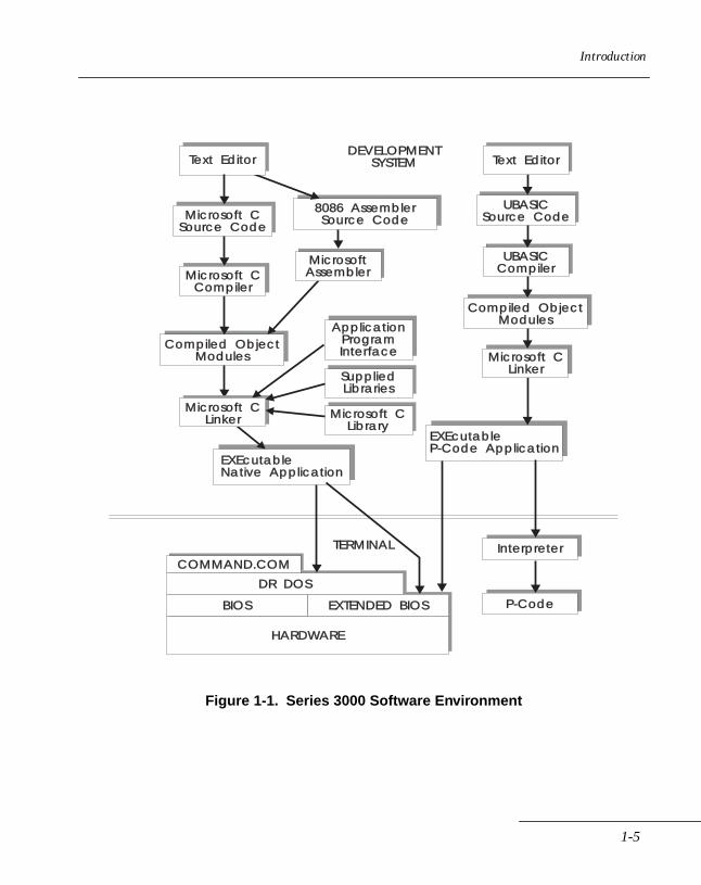
Figure 1-1 is a block diagram of the Series 3000 system software environment.
1-4
Introduction
Figure 1-1. Series 3000 Software Environment
DR DOS
EXTENDED BIOSBIOS
HARDWARE
COMMAND.COMInterpreter
P-Code
EXEcutableNative Application
EXEcutableP-Code Application
Compiled ObjectModules
Compiled ObjectModules
Microsoft CSource Code
UBASICSource Code
DEVELOPMENTSYSTEM
TERMINAL
Microsoft CCompiler
ApplicationProgramInterface
SuppliedLibraries
Microsoft CLibrary
Microsoft CLinker
Text Editor
Microsoft CLinker
UBASICCompiler
Text Editor
8086 AssemblerSource Code
MicrosoftAssembler
1-5
Series 3000 System Software Manual
DR DOSSeries 3000 terminals use DR DOS (a product of Digital Research, Inc.) for the operating system. DR DOS is feature-compatible with Microsoft DOS (MS-DOS ) version 3.3.
High-level features of the DOS platform are proprietary system software. DOS developers should find them useful. For systems programming, DOS function IOCTLNT 21h Function 44h) provides a general entry point to device-specific commands. Various routines are accessible to programs written in the C language. The following programs, running under DR DOS, employ advanced technologies:
• EMM, the Expanded Memory Manager, conforms to the Lotus /Intel /Microsoft Expanded Memory Specification (LIM EMS 4.0).
• Scanning functions, standard for Symbol Technologies bar code scanners and decoders, are called using the DOS IOCTL (INT 44h) Read and Write functions (3Dh and 3Fh and 40h) and their associated subfunctions. Scanning procedures are documented in the Series 3000 Application Programmer's Reference Manual.
• Communications protocol modules in the Series 3000 system software include standard Symbol Technologies and DOS protocols. Additional protocols, such as 2WAY3000 (ACK/NAK), can be added by attaching separated protocol drivers. Available protocols are described in the chapter on the 2WAY3000 Protocol Device Driver in this manual.
1-6
Introduction
ROM BIOSROM BIOS services comprise a set of programs that are accessed to provide low-level control and supervision operations. These routines are accessible to programs written in the C language. You can also request BIOS services from other DOS-compatible languages via user-written interfaces. The BIOS is responsible for:
• the Start-Up routines
• all direct hardware control
• servicing any hardware needs
• isolation of all other programs from the details of how the hardware works
Current release of the System EPROM provides greater PC compatibility at the BIOS level by supporting PC-XT BIOS software interrupt vectors, as well as the original proprietary vectors. Restrictions apply when using the new vectors, as described in Chapter 2, ROM BIOS.
Device DriversDevice drivers provide the interface to standard Symbol Technologies devices as well as DOS devices: Scanners, Decoders, Console/Keyboard, Communications, Expanded Memory, RAM Disk, Clock, Printer, etc. Device drivers are resident (in the operating system). The following device drivers are built into the DR DOS operating system:
• RAM Disk Device Driver
• Console/Scanner Device Driver
• Communication Device Driver
• Line Printer Device Driver
• Clock Device Driver
1-7

Series 3000 System Software Manual
1-8
Chapter 2 ROM BIOS
Chapter ContentsIntroduction . . . . . . . . . . . . . . . . . . . . . . . . . . . . . . . . . . . . . . . . . . . . . . . . . . . . . . . . . . . . . . . . . . . . . 2-3Video Services . . . . . . . . . . . . . . . . . . . . . . . . . . . . . . . . . . . . . . . . . . . . . . . . . . . . . . . . . . . . . . . . . . 2-14Standard Video Services . . . . . . . . . . . . . . . . . . . . . . . . . . . . . . . . . . . . . . . . . . . . . . . . . . . . . . . . . . 2-23Extended Video Services. . . . . . . . . . . . . . . . . . . . . . . . . . . . . . . . . . . . . . . . . . . . . . . . . . . . . . . . . . 2-36Equipment List . . . . . . . . . . . . . . . . . . . . . . . . . . . . . . . . . . . . . . . . . . . . . . . . . . . . . . . . . . . . . . . . . . 2-55Memory Services . . . . . . . . . . . . . . . . . . . . . . . . . . . . . . . . . . . . . . . . . . . . . . . . . . . . . . . . . . . . . . . . 2-59EMS Support. . . . . . . . . . . . . . . . . . . . . . . . . . . . . . . . . . . . . . . . . . . . . . . . . . . . . . . . . . . . . . . . . . . . 2-70EEPROM Memory Services . . . . . . . . . . . . . . . . . . . . . . . . . . . . . . . . . . . . . . . . . . . . . . . . . . . . . . . 2-80Diskette Services . . . . . . . . . . . . . . . . . . . . . . . . . . . . . . . . . . . . . . . . . . . . . . . . . . . . . . . . . . . . . . . . 2-85Serial I/O Services . . . . . . . . . . . . . . . . . . . . . . . . . . . . . . . . . . . . . . . . . . . . . . . . . . . . . . . . . . . . . . . 2-92Keyboard Services . . . . . . . . . . . . . . . . . . . . . . . . . . . . . . . . . . . . . . . . . . . . . . . . . . . . . . . . . . . . . . 2-128Standard Keyboard Services . . . . . . . . . . . . . . . . . . . . . . . . . . . . . . . . . . . . . . . . . . . . . . . . . . . . . 2-130Extended Keyboard Services . . . . . . . . . . . . . . . . . . . . . . . . . . . . . . . . . . . . . . . . . . . . . . . . . . . . . 2-134Printer Services. . . . . . . . . . . . . . . . . . . . . . . . . . . . . . . . . . . . . . . . . . . . . . . . . . . . . . . . . . . . . . . . . 2-146Time-of-Day Services. . . . . . . . . . . . . . . . . . . . . . . . . . . . . . . . . . . . . . . . . . . . . . . . . . . . . . . . . . . . 2-151Timer Services . . . . . . . . . . . . . . . . . . . . . . . . . . . . . . . . . . . . . . . . . . . . . . . . . . . . . . . . . . . . . . . . . 2-161Sound Generation . . . . . . . . . . . . . . . . . . . . . . . . . . . . . . . . . . . . . . . . . . . . . . . . . . . . . . . . . . . . . . 2-172Power Management. . . . . . . . . . . . . . . . . . . . . . . . . . . . . . . . . . . . . . . . . . . . . . . . . . . . . . . . . . . . . 2-177Scanner Services . . . . . . . . . . . . . . . . . . . . . . . . . . . . . . . . . . . . . . . . . . . . . . . . . . . . . . . . . . . . . . . . 2-189Cradle Control Services. . . . . . . . . . . . . . . . . . . . . . . . . . . . . . . . . . . . . . . . . . . . . . . . . . . . . . . . . . 2-193Miscellaneous Services . . . . . . . . . . . . . . . . . . . . . . . . . . . . . . . . . . . . . . . . . . . . . . . . . . . . . . . . . . 2-199
2-1

Series 3000 System Software Manual
2-2
ROM BIOS
IntroductionThis chapter presents details of the Series 3000 terminal ROM BIOS (Basic Input/Output System) operations. A description of each individual BIOS service is also presented with regard to function, calling sequence, input parameters, and output parameters. The descriptions are provided in order of interrupt and function numbers.
The BIOS is a set of programs built into the Series 3000 terminal that perform the most basic, low-level and intimate control and supervision operations. Software performs most efficiently when it operates in layers; each layer performs a particular range of tasks and relieves the layers above it of any concern for operational details within this particular range of tasks. The BIOS is the bottom-most layer and is responsible for:
• the start-up routines
• all direct hardware control
• servicing for any hardware needs
• isolation of all other programs from the details of how the hardware works
The BIOS, DOS, and several resident system utilities are the major components of the Series 3000 system software.
The Series 3000 terminal BIOS is based on the IBM PC ROM BIOS. Current BIOS versions provide increased compatibility with the PC BIOS over earlier versions by numbering the BIOS software interrupt services just as they are in the IBM PC BIOS. The earlier, proprietary interrupt values are also supported in order to support software written for the earlier BIOS.
A cross reference of the PC compatible vectors to the the earlier proprietary vectors is provided in Table 2-2. Also, the original (proprietary) interrupt number is included, enclosed in parentheses, in the heading line of the description of each ROM BIOS service included in this chapter.
2-3

Series 3000 System Software Manual
Some IBM PC services support hardware that is nonexistent on the Series 3000 terminal. These are null operations on Series 3000 terminals and are not included here. Two good sources for additional information on the PC BIOS are The MS-DOS Encyclopedia and The New Peter Norton Programmer's Guide to the IBM PC & PS/2, both published by Microsoft Press. The following are also standard references for ROM BIOS services and functions:
• The Peter Norton PC Programmer's Bible, Third Edition, Peter Norton, Peter Aiken, Richard Wilton, 1993, Microsoft Press
• Inside the IBM PC and PS/2, Peter Norton, 1991, Brady Publishing
• PC Programmer’s Guide to Low-Level Functions and Interrupts, Marcus Johnson, 1994, Sams Publishing
The Series 3000 BIOS also includes extensions which provide support for special features, such as bar code scanning. BIOS extensions are so noted in the following text.
PC BIOS CompatibilityCurrent system EPROMs employ a PC compatible BIOS software interrupt vector scheme in addition to the proprietary vector scheme employed in earlier releases. The proprietary scheme continues to be supported, providing support for applications written for earlier EPROM releases.
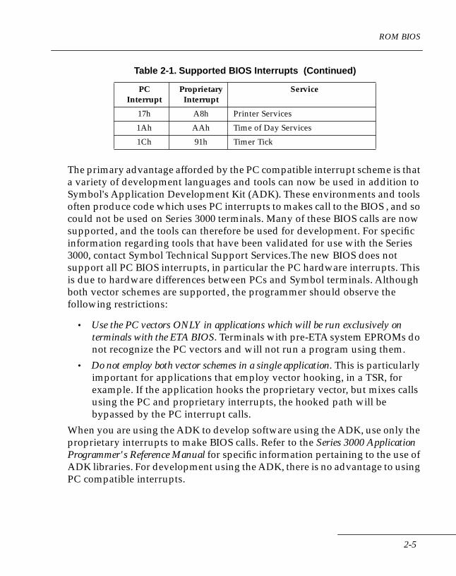
Table 2-1 lists the BIOS interrupts that are supported by the new BIOS and their proprietary equivalents.
Table 2-1. Supported BIOS Interrupts
PCInterrupt
ProprietaryInterrupt
Service
05h A0h Print Screen
10h A1h Video Services
11h A2h Equipment Check
12h A3h Memory Services
13h A4h Disk I/O
14h A5h Serial Communications
16h A7h Keyboard Services
2-4
ROM BIOS
The primary advantage afforded by the PC compatible interrupt scheme is that a variety of development languages and tools can now be used in addition to Symbol's Application Development Kit (ADK). These environments and tools often produce code which uses PC interrupts to makes call to the BIOS , and so could not be used on Series 3000 terminals. Many of these BIOS calls are now supported, and the tools can therefore be used for development. For specific information regarding tools that have been validated for use with the Series 3000, contact Symbol Technical Support Services.The new BIOS does not support all PC BIOS interrupts, in particular the PC hardware interrupts. This is due to hardware differences between PCs and Symbol terminals. Although both vector schemes are supported, the programmer should observe the following restrictions:
• Use the PC vectors ONLY in applications which will be run exclusively on terminals with the ETA BIOS. Terminals with pre-ETA system EPROMs do not recognize the PC vectors and will not run a program using them.
• Do not employ both vector schemes in a single application. This is particularly important for applications that employ vector hooking, in a TSR, for example. If the application hooks the proprietary vector, but mixes calls using the PC and proprietary interrupts, the hooked path will be bypassed by the PC interrupt calls.
When you are using the ADK to develop software using the ADK, use only the proprietary interrupts to make BIOS calls. Refer to the Series 3000 Application Programmer's Reference Manual for specific information pertaining to the use of ADK libraries. For development using the ADK, there is no advantage to using PC compatible interrupts.
17h A8h Printer Services
1Ah AAh Time of Day Services
1Ch 91h Timer Tick
Table 2-1. Supported BIOS Interrupts (Continued)
PCInterrupt
ProprietaryInterrupt
Service
2-5
Series 3000 System Software Manual
In general, the PC vectors should be used only if you are developing software using tools that require the PC vectors, and only if the application is to be run on terminals with the ETA BIOS.
The descriptions of ROM BIOS functions in this chapter specify both the new PC compatible vectors and the proprietary vectors, where applicable. The proprietary vectors are enclosed in parentheses.
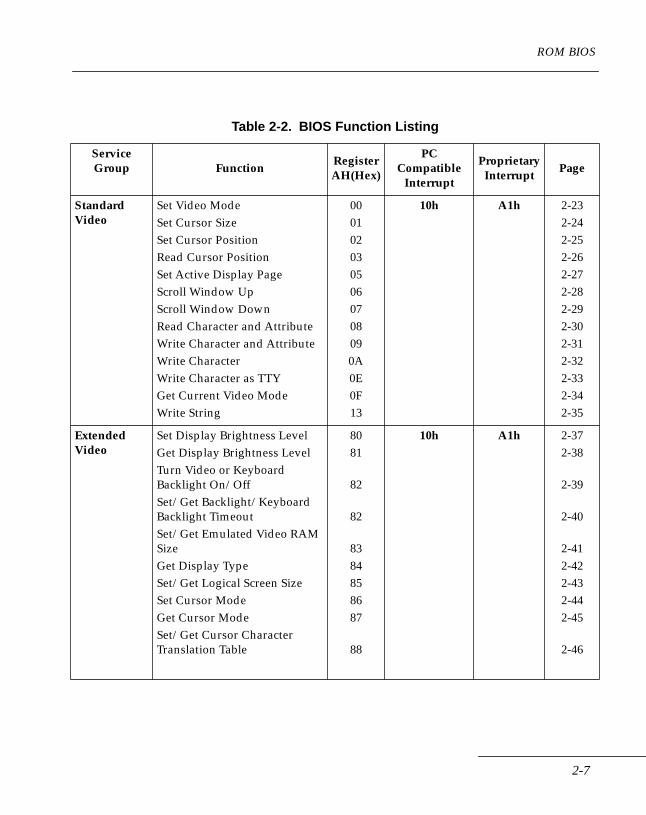
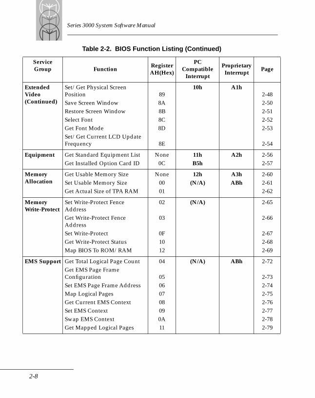
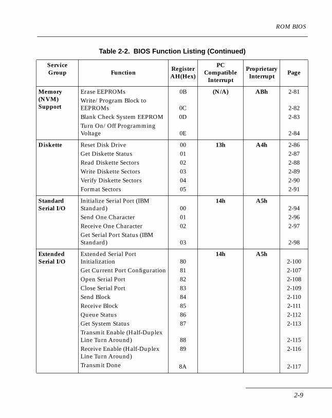
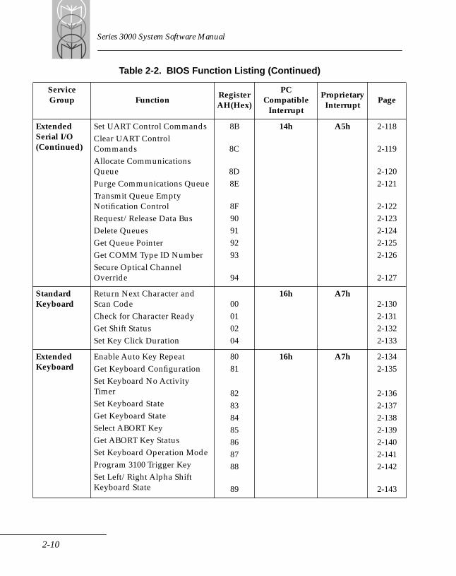
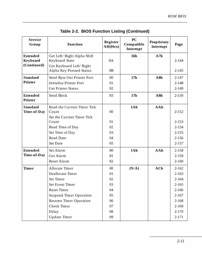
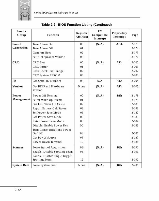
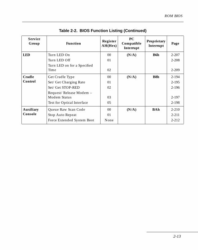
Table 2-2, BIOS Function Listing, which begins at the top of the next page, summarizes the Service Group/Subgroup interrupt designations and AH register values (in HEX) that are required to call the associated function (service). Where applicable, Table 2-2 specifies both the PC compatible and the earlier (proprietary) Series 3000 BIOS service interrupt numbers. Descriptions of the services listed in Table 2-2 are provided in this chapter on the pages specified in the “page” column.
2-6
ROM BIOS
Table 2-2. BIOS Function Listing
Service Group Function
RegisterAH(Hex)
PC Compatible
Interrupt
Proprietary Interrupt
Page
Standard Video
Set Video ModeSet Cursor SizeSet Cursor PositionRead Cursor PositionSet Active Display PageScroll Window UpScroll Window DownRead Character and AttributeWrite Character and AttributeWrite CharacterWrite Character as TTYGet Current Video ModeWrite String
0001020305060708090A0E0F13
10h A1h 2-232-242-252-262-272-282-292-302-312-322-332-342-35
Extended Video
Set Display Brightness LevelGet Display Brightness LevelTurn Video or Keyboard Backlight On/OffSet/Get Backlight/Keyboard Backlight TimeoutSet/Get Emulated Video RAM SizeGet Display TypeSet/Get Logical Screen SizeSet Cursor ModeGet Cursor ModeSet/Get Cursor Character Translation Table
8081
82
82
8384858687
88
10h A1h 2-372-38
2-39
2-40
2-412-422-432-442-45
2-46
2-7
Series 3000 System Software Manual
Extended Video (Continued)
Set/Get Physical Screen PositionSave Screen WindowRestore Screen WindowSelect FontGet Font ModeSet/Get Current LCD Update Frequency
898A8B8C8D
8E
10h A1h2-482-502-512-522-53
2-54
Equipment Get Standard Equipment ListGet Installed Option Card ID
None0C
11hB5h
A2h 2-562-57
Memory Allocation
Get Usable Memory SizeSet Usable Memory SizeGet Actual Size of TPA RAM
None0001
12h(N/A)
A3hABh
2-602-612-62
Memory Write-Protect
Set Write-Protect Fence AddressGet Write-Protect Fence AddressSet Write-ProtectGet Write-Protect StatusMap BIOS To ROM/RAM
02
03
0F1012
(N/A) 2-65
2-66
2-672-682-69
EMS Support Get Total Logical Page CountGet EMS Page Frame ConfigurationSet EMS Page Frame AddressMap Logical PagesGet Current EMS ContextSet EMS ContextSwap EMS ContextGet Mapped Logical Pages
04
05060708090A11
(N/A) ABh 2-72
2-732-742-752-762-772-782-79
Table 2-2. BIOS Function Listing (Continued)
Service Group Function
RegisterAH(Hex)
PC Compatible
Interrupt
Proprietary Interrupt
Page
2-8
ROM BIOS
Memory (NVM) Support
Erase EEPROMsWrite/Program Block to EEPROMsBlank Check System EEPROMTurn On/Off Programming Voltage
0B
0C0D
0E
(N/A) ABh 2-81
2-822-83
2-84
Diskette Reset Disk DriveGet Diskette StatusRead Diskette SectorsWrite Diskette SectorsVerify Diskette SectorsFormat Sectors
000102030405
13h A4h 2-862-872-882-892-902-91
Standard Serial I/O
Initialize Serial Port (IBM Standard)Send One CharacterReceive One CharacterGet Serial Port Status (IBM Standard)
000102
03
14h A5h2-942-962-97
2-98
Extended Serial I/O
Extended Serial Port InitializationGet Current Port ConfigurationOpen Serial PortClose Serial PortSend BlockReceive BlockQueue StatusGet System StatusTransmit Enable (Half-Duplex Line Turn Around)Receive Enable (Half-Duplex Line Turn Around)Transmit Done
8081828384858687
8889
8A
14h A5h2-1002-1072-1082-1092-1102-1112-1122-113
2-1152-116
2-117
Table 2-2. BIOS Function Listing (Continued)
Service Group Function
RegisterAH(Hex)
PC Compatible
Interrupt
Proprietary Interrupt
Page
2-9
Series 3000 System Software Manual
Extended Serial I/O (Continued)
Set UART Control CommandsClear UART Control CommandsAllocate Communications QueuePurge Communications QueueTransmit Queue Empty Notification ControlRequest/Release Data BusDelete QueuesGet Queue PointerGet COMM Type ID NumberSecure Optical Channel Override
8B
8C
8D8E
8F90919293
94
14h A5h 2-118
2-119
2-1202-121
2-1222-1232-1242-1252-126
2-127
Standard Keyboard
Return Next Character and Scan CodeCheck for Character ReadyGet Shift StatusSet Key Click Duration
00010204
16h A7h2-1302-1312-1322-133
Extended Keyboard
Enable Auto Key RepeatGet Keyboard ConfigurationSet Keyboard No Activity TimerSet Keyboard StateGet Keyboard StateSelect ABORT KeyGet ABORT Key StatusSet Keyboard Operation ModeProgram 3100 Trigger KeySet Left/Right Alpha Shift Keyboard State
8081
82838485868788
89
16h A7h 2-1342-135
2-1362-1372-1382-1392-1402-1412-142
2-143
Table 2-2. BIOS Function Listing (Continued)
Service Group Function
RegisterAH(Hex)
PC Compatible
Interrupt
Proprietary Interrupt
Page
2-10
ROM BIOS
Extended Keyboard (Continued)
Get Left/Right Alpha Shift Keyboard StateGet Keyboard Left/Right Alpha Key Pressed Status
8A
8B
16h A7h2-144
2-145
Standard Printer
Send Byte Out Printer PortInitialize Printer PortGet Printer Status
000102
17h A8h 2-1472-1482-149
Extended Printer
Send Block 83 17h A8h 2-150
Standard Time-of-Day
Read the Current Timer Tick CountSet the Current Timer Tick CountRead Time of DaySet Time of DayRead DateSet Date
00
0102030405
1Ah AAh2-152
2-1532-1542-1552-1562-157
Extended Time-of-Day
Set AlarmGet AlarmReset Alarm
808182
1Ah AAh 2-1582-1592-160
Timer Allocate TimerDeallocate TimerSet TimerSet Event TimerReset TimerSuspend Timer OperationResume Timer OperationCheck TimerDelayUpdate Timer
00010203040506 070809
(N/A) ACh 2-1622-1632-1642-1652-1662-1672-1682-1692-1702-171
Table 2-2. BIOS Function Listing (Continued)
Service Group Function
RegisterAH(Hex)
PC Compatible
Interrupt
Proprietary Interrupt
Page
2-11
Series 3000 System Software Manual
Sound Generation
Turn Alarm OnTurn Alarm OffGenerate BeepSet/Get Speaker Volume
00010203
(N/A) ADh 2-1732-1742-1752-176
CRC CRC ByteCRC BufferCRC Check User ImageCRC System EPROM
00010203
(N/A) AEh 2-2002-2012-2022-203
ID Get Serial ID Number 08 N/A AEh 2-204
Version Get BIOS and Hardware Version
None (N/A) AFh 2-205
Power Management
Power Off TerminalSelect Wake Up EventsGet Last Wake Up CauseReport Battery Cell StatusSet Power Save ModeGet Power Save ModeEnter Power Save ModeDisable/Enable Power KeyTurn Communications Power On/OffGet Power SourcePower Down Terminal
000102030506090C
0E0F10
(N/A) B1h 2-1782-1792-1802-1812-1822-1832-1842-185
2-1862-1872-188
Scanner Force Start of AcquisitionEnable/Disable Spotting BeamEanble/Disable Single Trigger Spotting Beam
0B0E
12
(N/A) B3h 2-1902-191
2-192
System Boot Force System Boot None (N/A) B4h 2-206
Table 2-2. BIOS Function Listing (Continued)
Service Group Function
RegisterAH(Hex)
PC Compatible
Interrupt
Proprietary Interrupt
Page
2-12
ROM BIOS
LED Turn LED OnTurn LED OffTurn LED on for a Specified Time
0001
02
(N/A) B6h 2-2072-208
2-209
Cradle Control
Get Cradle TypeSet/Get Charging RateSet/Get STOP-REDRequest/Release Modem – Modem StatusTest for Optical Interface
000102
0305
(N/A) B8h 2-1942-1952-196
2-1972-198
Auxiliary Console
Queue Raw Scan CodeStop Auto RepeatForce Extended System Boot
0001
None
(N/A) BAh 2-2102-2112-212
Table 2-2. BIOS Function Listing (Continued)
Service Group Function
RegisterAH(Hex)
PC Compatible
Interrupt
Proprietary Interrupt
Page
2-13
Series 3000 System Software Manual
Video ServicesEach of the Video Services (standard and extended) provided by BIOS is presented in this section. These screen control services comprise the Low-level Display Driver. The Series 3000 displays require different interfaces than the CRT controllers used on PCs. Therefore, not all PC video services are supported on Series 3000 terminals.
The Series 3000 terminals implement Physical, Virtual, and Logical display screens. The standard and extended BIOS Video Services control the size and position of these screens. Definitions for each type of screen are as follows:
Physical ScreenThe Physical Screen size specifies the number of rows and columns supported by the display hardware. The physical screen sizes currently employed on Series 3000 terminals are:
• 8-line by 20-character, 64 by 120 pixels, on Series 3100, 3300, 3800, and 6100 terminals.
• 8-line by 40-character display on Series 3900 terminals.
• 4-line by 20-character display on Series 3100, Series 6100, and WSS 1000 terminals.
• 16-line by 21-character, 102 x 112 pixels on Series 3500 and Series 6800 terminals.
Note: When using fonts with varying sizes and expansion attributes (e.g., double high/double wide), the number of displayable rows and characters may change, but the number of pixels stays the same.
The BIOS determines the screen size upon cold boot by first reading the installed display's associated code. The BIOS uses this code to look up the display characteristics in a table of display sizes and controller types.
2-14
ROM BIOS
Virtual ScreenThe Virtual Screen is defined as the amount of memory required to write data to the installed LCD display (i.e., Video RAM). A buffer is required to emulate Video RAM for standard LCD controllers. Therefore, at system cold boot, the BIOS must allocate enough RAM to emulate video RAM for the installed display. The amount of RAM allocated, and its dimensions, default to the physical screen size. However, the programmer can allocate more Video RAM (see service INT 10h (A1h) function 83h) in order to emulate a larger virtual screen or to provide for multiple display pages.
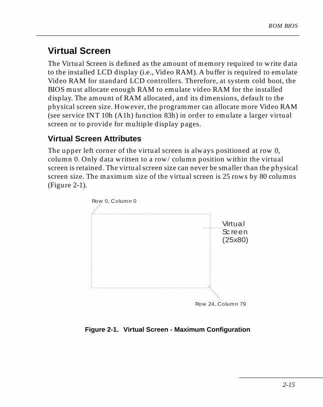
Virtual Screen AttributesThe upper left corner of the virtual screen is always positioned at row 0, column 0. Only data written to a row/column position within the virtual screen is retained. The virtual screen size can never be smaller than the physical screen size. The maximum size of the virtual screen is 25 rows by 80 columns (Figure 2-1).
Figure 2-1. Virtual Screen - Maximum Configuration
VirtualScreen(25x80)
Row 0, Column 0
Row 24, Column 79
2-15

Series 3000 System Software Manual
Displaying Virtual Screen Segments Series 3000 terminals can only display data from the virtual screen that is within the current boundaries of the physical screen size. However, the physical screen can be moved to display any part of the virtual screen (the physical screen is considered a moveable item in the context of Series 3000 operations—see Figure 2-2).
Figure 2-2. Movable Physical Screen
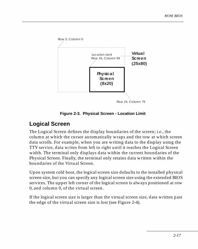
The physical screen can be positioned by specifying the row and column coordinates of the upper left hand corner (origin) of the physical screen relative to the virtual screen (see BIOS service 10h (A1h) function 89h). However, an edge of the physical screen cannot extend past the edge of the virtual screen. For example, if using a virtual screen size of 25 rows by 80 columns and an 8 by 20 physical screen, the upper left coordinates of the physical screen cannot be positioned past row 16 or column 59 (Figure 2-3).
VirtualScreen(25x80)
Row 0, Column 0
Row 24, Column 79
Physical Screen(8x20)
2-16
ROM BIOS
Figure 2-3. Physical Screen - Location Limit
Logical ScreenThe Logical Screen defines the display boundaries of the screen; i.e., the column at which the cursor automatically wraps and the row at which screen data scrolls. For example, when you are writing data to the display using the TTY service, data writes from left to right until it reaches the Logical Screen width. The terminal only displays data within the current boundaries of the Physical Screen. Finally, the terminal only retains data written within the boundaries of the Virtual Screen.
Upon system cold boot, the logical screen size defaults to the installed physical screen size, but you can specify any logical screen size using the extended BIOS services. The upper left corner of the logical screen is always positioned at row 0, and column 0, of the virtual screen.
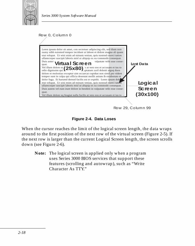
If the logical screen size is larger than the virtual screen size, data written past the edge of the virtual screen size is lost (see Figure 2-4).
VirtualScreen(25x80)
Row 0, Column 0
Row 24, Column 79
Location LimitRow 16, Column 59
Physical Screen(8x20)
2-17
Series 3000 System Software Manual
Figure 2-4. Data Loses
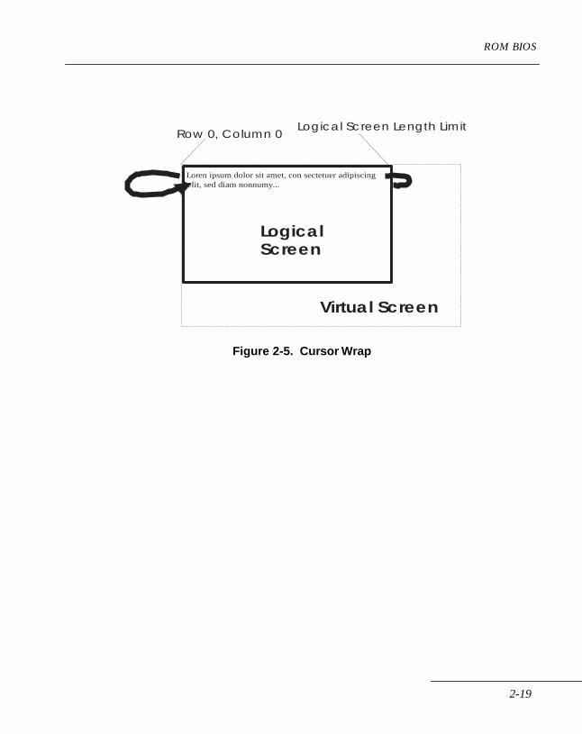
When the cursor reaches the limit of the logical screen length, the data wraps around to the first position of the next row of the virtual screen (Figure 2-5). If the next row is larger than the current Logical Screen length, the screen scrolls down (see Figure 2-6).
Note: The logical screen is applied only when a program uses Series 3000 BIOS services that support these features (scrolling and autowrap), such as “Write Character As TTY.”
LogicalScreen
(30x100)
Row 0, Column 0
Row 29, Column 99
Loren ipsum dolor sit amet, con sectetuer adipiscing elit, sed diam nonnumy nibh euismod tempor incidunt ut labore et dolore magna ali quametat volupat. Ut wisi enim ad minum venian, quis nostrud exerci tationullamcorper suscipit laboris misl ut aliquip ex ea commodo consequat. Duis autem vel eum irure dolore in hendirit in vulputate velit esse conse-quat.Vel illum dolore eq feugiat nulla facilis at vero eos et accusam et ius toodio dignissim qui blandit prae sent luptatum zzril delenit aiguq duosdolore et molestias exceptur sint occaecat cupidtat non simil pro videnttempor sunt in culpa qui officia deserunt mollit anium ib estaborum etdolor fuga. Et harumd dereud facilis est er expidit. Loren ipsum doloretat volupat. Ut wisi enim ad minum venian, quis nostrud exerci tationullamcorper suscipit laboris misl ut aliquip ex ea commodo consequat. Duis autem vel eum irure dolore in hendirit in vulputate velit esse conse-quat.Vel illum dolore eq feugiat nulla facilis at vero eos et accusam et ius to
Lost DataVirtual Screen(25x80)
2-18
ROM BIOS
Figure 2-5. Cursor Wrap
Row 0, Column 0
Loren ipsum dolor sit amet, con sectetuer adipiscing
Virtual Screen
LogicalScreen
elit, sed diam nonnumy...
Logical Screen Length Limit
2-19

Series 3000 System Software Manual
Figure 2-6. Logical Screen Scrolling
Virtual Screen
Loren ipsum dolor sit amet, con sectetuer adipiscing elit,sed diam nonnumy nibh euismod tempor incidunt ut labore et dolore magna ali quam etat volupat. Ut wisi enimad minum venian, quis nostrud exerci tation ullamcorpersuscipit laboris misl ut aliquip ex ea commodo consequat.Duis autem vel eum irure dolore in henderit in vulputatevelit esse consequat.Vel illum dolore eq feugiat nulla facilis at vero eos et accusam et ius to odio dignissim qui blandit prae sent luptatum zzril delenit aigue duos dolore et molestias exceptursint occaecat cupidtat non simil pro vident tempor sunt in culpa qui officia deserunt mollit anium ib estaborum et dolor fuga suscipit.
A
Virtual Screen
Loren ipsum dolor sit amet, con sectetuer adipiscing elit,sed diam nonnumy nibh euismod tempor incidunt ut labore et dolore magna ali quam etat volupat. Ut wisi enimad minum venian, quis nostrud exerci tation ullamcorpersuscipit laboris misl ut aliquip ex ea commodo consequat.Duis autem vel eum irure dolore in henderit in vulputatevelit esse consequat.Vel illum dolore eq feugiat nulla facilis at vero eos et accusam et ius to odio dignissim qui blandit prae sent luptatum zzril delenit aigue duos dolore et molestias exceptursint occaecat cupidtat non simil pro vident tempor sunt in culpa qui officia deserunt mollit anium ib estaborumet dolor fuga suscipit.
... and the text getswrapped to the nextrow.
B
The Virtual Screenscrolls up one line ...
LogicalScreen
LogicalScreen
Text row largerthan LogicalScreen length.
...wordwrap breaksthe text here, ...
2-20
ROM BIOS
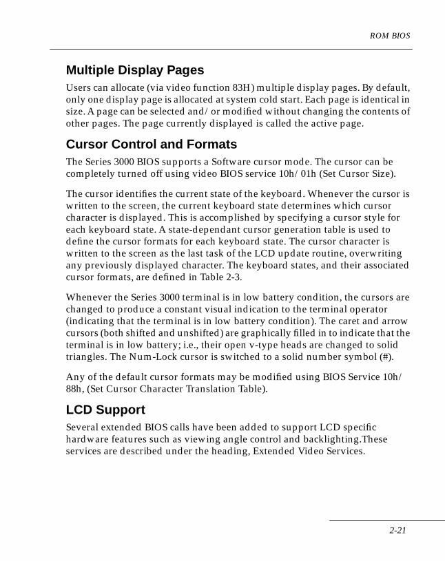
Multiple Display PagesUsers can allocate (via video function 83H) multiple display pages. By default, only one display page is allocated at system cold start. Each page is identical in size. A page can be selected and/or modified without changing the contents of other pages. The page currently displayed is called the active page.
Cursor Control and FormatsThe Series 3000 BIOS supports a Software cursor mode. The cursor can be completely turned off using video BIOS service 10h/01h (Set Cursor Size).
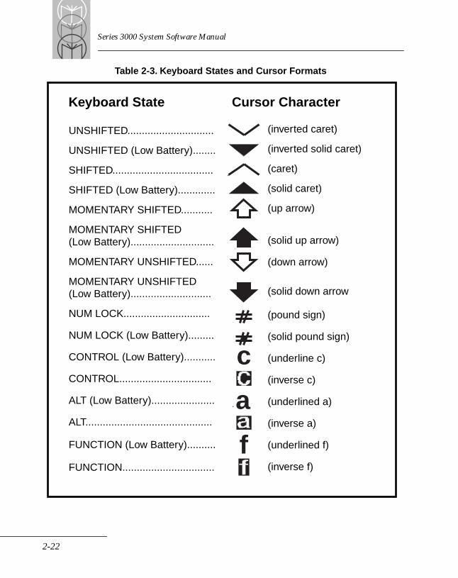
The cursor identifies the current state of the keyboard. Whenever the cursor is written to the screen, the current keyboard state determines which cursor character is displayed. This is accomplished by specifying a cursor style for each keyboard state. A state-dependant cursor generation table is used to define the cursor formats for each keyboard state. The cursor character is written to the screen as the last task of the LCD update routine, overwriting any previously displayed character. The keyboard states, and their associated cursor formats, are defined in Table 2-3.
Whenever the Series 3000 terminal is in low battery condition, the cursors are changed to produce a constant visual indication to the terminal operator (indicating that the terminal is in low battery condition). The caret and arrow cursors (both shifted and unshifted) are graphically filled in to indicate that the terminal is in low battery; i.e., their open v-type heads are changed to solid triangles. The Num-Lock cursor is switched to a solid number symbol (#).
Any of the default cursor formats may be modified using BIOS Service 10h/88h, (Set Cursor Character Translation Table).
LCD SupportSeveral extended BIOS calls have been added to support LCD specific hardware features such as viewing angle control and backlighting.These services are described under the heading, Extended Video Services.
2-21
Series 3000 System Software Manual
Table 2-3. Keyboard States and Cursor Formats
Keyboard State Cursor Character
UNSHIFTED.......................................
UNSHIFTED (Low Battery).............
SHIFTED.............................................
SHIFTED (Low Battery)...................
MOMENTARY SHIFTED..................
MOMENTARY SHIFTED(Low Battery).....................................
MOMENTARY UNSHIFTED............
MOMENTARY UNSHIFTED(Low Battery).....................................
NUM LOCK........................................
NUM LOCK (Low Battery)..............
CONTROL..........................................
CONTROL (Low Battery)................
ALT......................................................
ALT (Low Battery).............................
FUNCTION.........................................
FUNCTION (Low Battery)...............
c
a
f
(inverted caret)
(inverted solid caret)
(caret)
(solid caret)
(up arrow)
(solid up arrow)
(down arrow)
(solid down arrow)
(pound sign)
(solid pound sign)
(underline c)
(inverse c)
(underlined a)
(inverse a)
(underlined f)
(inverse f)
UNSHIFTED..............................
UNSHIFTED (Low Battery)........
SHIFTED...................................
SHIFTED (Low Battery).............
MOMENTARY SHIFTED...........
MOMENTARY SHIFTED (Low Battery).............................
MOMENTARY UNSHIFTED......
MOMENTARY UNSHIFTED (Low Battery)............................
NUM LOCK..............................
NUM LOCK (Low Battery).........
CONTROL (Low Battery)...........
CONTROL................................
ALT (Low Battery)......................
ALT............................................
FUNCTION (Low Battery)..........
FUNCTION................................
Keyboard State
(inverted caret)
(inverted solid caret)
(caret)
(solid caret)
(up arrow)
(solid up arrow)
(down arrow)
(solid down arrow
(pound sign)
(solid pound sign)
(underline c)
(inverse c)
(underlined a)
(inverse a)
(underlined f)
(inverse f)
Cursor Character
2-22
ROM BIOS
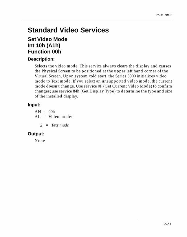
Standard Video ServicesSet Video ModeInt 10h (A1h)Function 00hDescription:
Selects the video mode. This service always clears the display and causes the Physical Screen to be positioned at the upper left hand corner of the Virtual Screen. Upon system cold start, the Series 3000 initializes video mode to Text mode. If you select an unsupported video mode, the current mode doesn't change. Use service 0F (Get Current Video Mode) to confirm changes; use service 84h (Get Display Type) to determine the type and size of the installed display.
Input:AH = 00hAL = Video mode:
2 = Text mode
Output:None
2-23

Series 3000 System Software Manual
Set Cursor SizeInt 10h (A1h)Function 01hDescription:
Allows you to turn the cursor on or off.
Input:AH = 01hCH = Cursor is turned off if bit 5 is set.
Output:None
2-24
ROM BIOS
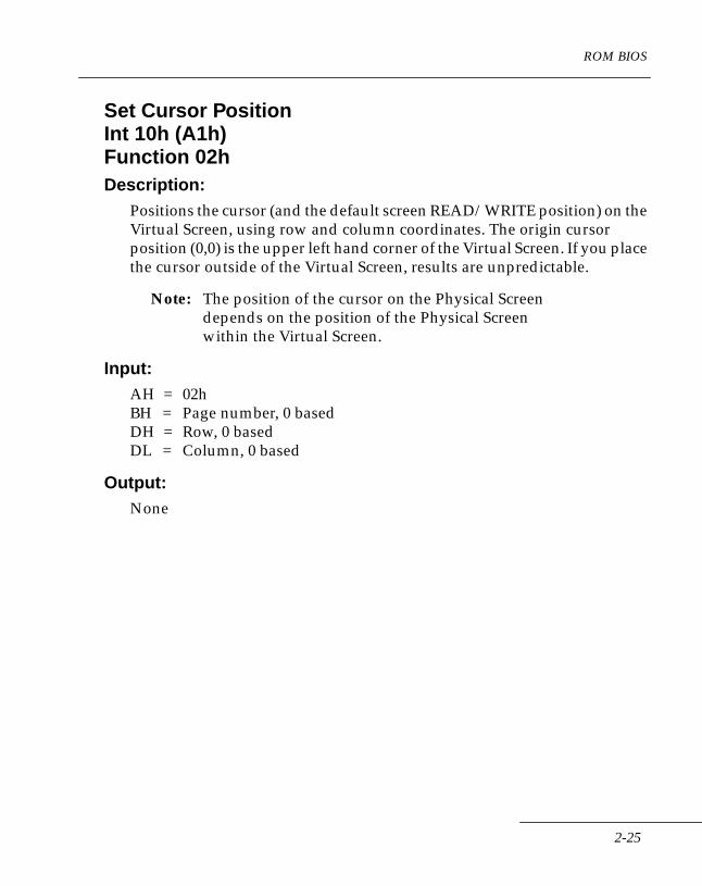
Set Cursor PositionInt 10h (A1h)Function 02hDescription:
Positions the cursor (and the default screen READ/WRITE position) on the Virtual Screen, using row and column coordinates. The origin cursor position (0,0) is the upper left hand corner of the Virtual Screen. If you place the cursor outside of the Virtual Screen, results are unpredictable.
Note: The position of the cursor on the Physical Screen depends on the position of the Physical Screen within the Virtual Screen.
Input:AH = 02hBH = Page number, 0 basedDH = Row, 0 basedDL = Column, 0 based
Output:None
2-25
Series 3000 System Software Manual
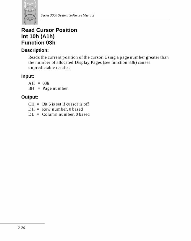
Read Cursor PositionInt 10h (A1h)Function 03hDescription:
Reads the current position of the cursor. Using a page number greater than the number of allocated Display Pages (see function 83h) causes unpredictable results.
Input:AH = 03hBH = Page number
Output:CH = Bit 5 is set if cursor is offDH = Row number, 0 basedDL = Column number, 0 based
2-26
ROM BIOS
Set Active Display PageInt 10h (A1h)Function 05hDescription:
Selects the active Display Page, causing the contents of the selected page to be displayed. If an invalid page number is selected, page zero is used.
Input:AH = 05hAL = Page number, 0 based
Output:None
2-27

Series 3000 System Software Manual
Scroll Window UpInt 10h (A1h)Function 06hDescription:
Scrolls the delimited Virtual Screen window (of the active page) up the specified number (AL) of lines. Inserts blank lines at the bottom of the window. The blank lines have the attribute specified in BH. If the value in AL equals zero, the service clears the specified window.
Note: The effect on the physical display depends on the position of the Physical Screen within the Virtual Screen. If the upper left corner of the current window is outside the Virtual Screen, no scrolling occurs. If the lower right corner of the window is outside the Virtual Screen, the lower right corner is set equal to the lower right corner of the Virtual Screen.
Input:AH = 06hAL = Lines to scroll upBH = Filler attributeCH = Upper row, 0 basedCL = Left column, 0 basedDH = Lower row, 0 basedDL = Right column, 0 based
Output:None
2-28
ROM BIOS
Scroll Window DownInt 10h (A1h)Function 07hDescription:
Scrolls the delimited Virtual Screen window (of the active page) down a specified number (AL) of lines. Inserts blank lines at the top of the window. The blank lines have the attribute specified in BH. If the value in AL equals zero, the service clears the specified window.
Note: The effect on the physical display depends on the position of the Physical Screen within the Virtual Screen. If the upper left corner of the current window is outside the Virtual Screen, no scrolling occurs. If the lower right corner of the window is outside the Virtual Screen, the lower right corner is set equal to the lower right corner of the Virtual Screen.
Input:AH = 07hAL = Lines to scroll downBH = Filler attributeCH = Upper row, 0 basedCL = Left column, 0 basedDH = Lower row, 0 basedDL = Right column, 0 based
Output:None
2-29

Series 3000 System Software Manual
Read Character and AttributeInt 10h (A1h)Function 08hDescription:
In Text modes, reads a character and its attribute directly from the Virtual Screen (Video RAM) at the current cursor position. Using a page number greater than the number of allocated Display Pages (see function 83h) causes unpredictable results. If the cursor is currently off the Virtual Page, the returned character is always an ASCII space (20h) with attribute 7.
Input:AH = 08hBH = Page number
Output:AL = Character at cursor positionAH = Attribute
2-30
ROM BIOS
Write Character and AttributeInt 10h (A1h)Function 09hDescription:
Writes one or more copies of the specified character and its attribute to the Virtual Screen, starting at the current cursor position. The displayed characters wrap at the Logical Screen size. In Graphics modes, no wrapping occurs. Any characters written past the right edge of the Virtual Screen are lost. No scrolling occurs and the cursor position does not change.
Note: The effect on the physical display depends on the position of the Physical Screen within the Virtual Screen. Using a page number greater than the number of allocated Display Pages (see function 83h) causes unpredictable results.
Input:AH = 09hAL = CharacterBH = Page number (0 - 7)BL = AttributeCX = Number of characters to repeat
Output:None
2-31
Series 3000 System Software Manual
Write CharacterInt 10h (A1h)Function 0AhDescription:
Writes one or more copies of the specified character to the Virtual Screen, starting at the current cursor position. The displayed characters wrap at the Logical Screen size. In Graphics modes, no wrapping occurs. Any characters written past the right edge of the Virtual Screen are lost. No scrolling occurs and the cursor position does not change.
Note: The actual effect on the physical display depends on the position of the Physical Screen within the Virtual Screen. Using a page number greater than the number of allocated display pages (see function 83h) causes unpredictable results.
Input:AH = 0AhAL = CharacterBH = Page numberCX = Count of characters
Output:None
2-32
ROM BIOS
Write Character as TTYInt 10h (A1h)Function 0EhDescription:
Writes the specified character to the default cursor position of the currently active page. Advances the cursor, wrapping to new lines and scrolling the screen as necessary. In Graphics modes, no wrapping occurs. Any characters written past the right edge of the Virtual Screen are lost. The BIOS properly handles the ASCII backspace, carriage return, line feed, and bell characters.
Note: The effect on the physical display depends on the position of the Physical Screen within the Virtual Screen.
Input:AH = 0EhAL = Character
Output:None
2-33
Series 3000 System Software Manual
Get Current Video ModeInt 10h (A1h)Function 0FhDescription:
Returns the current Video mode, active Display Page number, and the width of the Virtual Screen.
Input:AH = 0Fh
Output:AH = Virtual Screen width, in charactersAL = Video mode (see Service 00h)BH = Active Display Page or Page Number
2-34

ROM BIOS
Write StringInt 10h (A1h)Function 13hDescription:
Writes a string to the Virtual Screen, starting at the specified cursor position. Sub-services 0 and 2 leave the cursor at the location specified by DX; sub-services 1 and 3 move the cursor to the position after the last character of the string. The character attribute for sub-services 0 and 1 is specified in BL; for sub-services 2 and 3, each character is the string is followed by its attribute. The character or cursor position automatically wraps and scrolls at the Logical Screen limits.
In Graphics modes, no wrapping occurs. Any characters written past the right edge of the Virtual Screen are lost. The effect on the physical display depends on the position of the Physical Screen within the Virtual Screen. Using a page number greater than the number of allocated display pages (see function 83h) causes unpredictable results.
Input:AH = 13hAL = Sub-service:
00 = Leave cursor, attribute in BL01 = Move cursor, attribute in BL02 = Leave cursor, attribute in string03 = Move cursor, attribute in string
BL = Character attribute (for AL = 00 and 01 only)BH = Page numberDH = Starting text row positionDL = Starting text column positionCX = String lengthES:BP = Pointer to start of string
Output:None
2-35
Series 3000 System Software Manual
Extended Video ServicesThe Extended Video Services control special features of the Series 3000 display. These features fall into two categories: additional logical features or hardware features of Series 3000 displays.
The logical features include:
• Virtual and Logical Screen size control
• Physical Screen positioning
• keyboard state cursor annunciators
The hardware features include:
• LCD viewing angle control
• backlighting
• custom cursor character generation
AccessAll of the Extended Video Services are accessed through software Int 10h; register AH contains the function code.
2-36
ROM BIOS
Set Display Brightness LevelInt 10h (A1h)Function 80hDescription:
Sets the brightness of the display. On 3100, 3300, and 3800 terminals, the brightness level determines the contrast level, which also affects the optimal viewing angle. On 3900 terminals, the brightness level determines the luminance level.
Input:AH = 80hAL = 0 - 7
3100/3300/3800
0 = Lowest (brightest)7 = Highest (dimmest)
3900
0 = Lowest (dimmest)1 = Highest (brightest)
Output:AL = Actual viewing angle
2-37

Series 3000 System Software Manual
Get Display Brightness LevelInt 10h (A1h)Function 81hDescription:
Returns the brightness level of the display. On 3100, 3300, and 3800 terminals, the brightness level determines the contrast level, which also affects the optimal viewing angle. On 3900 terminals, the brightness level determines the luminance level.
Input:AH = 81h
Output:AL = 0 - 7
3100/3300/3800
0 = Lowest (brightest)7 = Highest (dimmest)
3900
0 = Lowest (dimmest)1 = Highest (brightest)
2-38
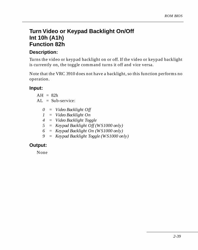
ROM BIOS
Turn Video or Keypad Backlight On/Off Int 10h (A1h)Function 82hDescription:Turns the video or keypad backlight on or off. If the video or keypad backlight is currently on, the toggle command turns it off and vice versa.
Note that the VRC 3910 does not have a backlight, so this function performs no operation.
Input:AH = 82hAL = Sub-service:
0 = Video Backlight Off1 = Video Backlight On4 = Video Backlight Toggle5 = Keypad Backlight Off (WS1000 only)6 = Keypad Backlight On (WS1000 only)9 = Keypad Backlight Toggle (WS1000 only)
Output:None
2-39
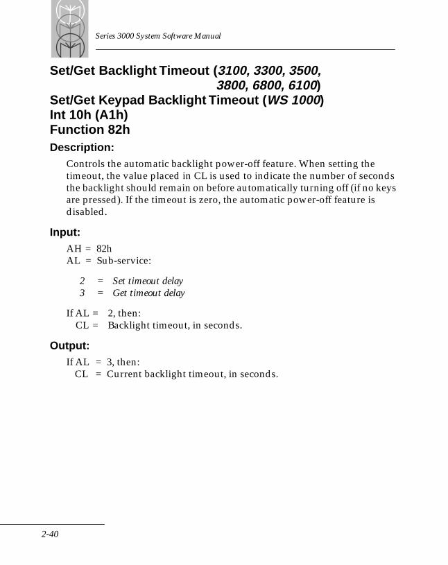
Series 3000 System Software Manual
Set/Get Backlight Timeout (3100, 3300, 3500,3800, 6800, 6100)
Set/Get Keypad Backlight Timeout (WS 1000)Int 10h (A1h)Function 82hDescription:
Controls the automatic backlight power-off feature. When setting the timeout, the value placed in CL is used to indicate the number of seconds the backlight should remain on before automatically turning off (if no keys are pressed). If the timeout is zero, the automatic power-off feature is disabled.
Input:AH = 82hAL = Sub-service:
2 = Set timeout delay3 = Get timeout delay
If AL = 2, then:CL = Backlight timeout, in seconds.
Output:If AL = 3, then:
CL = Current backlight timeout, in seconds.
2-40
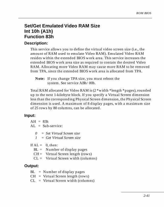
ROM BIOS
Set/Get Emulated Video RAM SizeInt 10h (A1h)Function 83hDescription:
This service allows you to define the virtual video screen size (i.e., the amount of RAM used to emulate Video RAM). Emulated Video RAM resides within the extended BIOS work area. This service increases the extended BIOS work area size as required to contain the desired Video RAM. Allocating more Video RAM may cause more RAM to be removed from TPA, since the extended BIOS work area is allocated from TPA.
Note: If you change TPA size, you must reboot the system. See service ABh/00h.
Total RAM allocated for Video RAM is (2 * width * length * pages), rounded up to the next 1-kilobyte block. If you specify a Virtual Screen dimension less than the corresponding Physical Screen dimension, the Physical Screen dimension is used. A maximum of 8 display pages, with a maximum size of 25 rows by 80 columns, can be allocated.
Input:AH = 83hAL = Sub-service:
0 = Set Virtual Screen size1 = Get Virtual Screen size
If AL = 0, then:BL = Number of display pagesCH = Virtual Screen length (rows)CL = Virtual Screen width (columns)
Output:BL = Number of display pagesCH = Virtual Screen length (rows)CL = Virtual Screen width (columns)
2-41
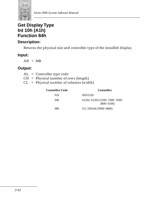
Series 3000 System Software Manual
Get Display TypeInt 10h (A1h)Function 84hDescription:
Returns the physical size and controller type of the installed display.
Input:AH = 84h
Output:AL = Controller type codeCH = Physical number of rows (length)CL = Physical number of columns (width)
Controller Code Controller
01h SED1520
04h 61202/61203 (3100/3300/3500/3800/6100)
08h GU 256x64 (3900/6800)
2-42
ROM BIOS
Set/Get Logical Screen SizeInt 10h (A1h)Function 85hDescription:
In Text modes, the Logical Screen size defines the screen positions where video output wraps and scrolls (this applies only to services that support automatic generation of new lines and screen scrolling). The logical width specifies the column, starting from the left edge of the Virtual Screen, where automatic generation of new lines occurs. Similarly, the logical length specifies the row where automatic screen scrolling occurs. Data starts at the top edge of the Virtual Screen. The left column of the display is column 1; the top row is row 1. On a system cold start, the system sets the Logical Screen size equal to the Physical Screen size.
Input:AH = 85hAL = Sub-command:
0 = Set logical size1 = Get logical size
If AL = 0, then:CL = Logical widthCH = Logical length
Output:CL = Logical widthCH = Logical length
2-43
Series 3000 System Software Manual
Set Cursor ModeInt 10h (A1h)Function 86hDescription:
Selects hardware or software cursor mode. In hardware mode, the cursor displayed is the block-style cursor; in software mode, the displayed cursor reflects the current keyboard state. Hardware mode allows the operator to see the character “under” the cursor; the software mode does not. The cursor is set to the software mode at system cold start.
Input:AH = 86hAL = Mode:
0 = Hardware1 = Software
Output:None
2-44

ROM BIOS
Get Cursor ModeInt 10h (A1h)Function 87hDescription:
Returns the current cursor mode.
Input:AH = 87h
Output:AL = Mode:
0 = Hardware1 = Software
2-45
Series 3000 System Software Manual
Set/Get Cursor Character Translation TableInt 10h (A1h)Function 88hDescription:
Sets the cursor characters that are displayed in various keyboard states using the supplied buffer. The following illustrates the default cursor character buffer.
;;;; Good battery cursors;cur_table_2 LABEL WORDDW 780h ; Unshifted cursorDW 781h ; Caps Lock cursorDW 782h ; Momentary shiftedDW 783h ; Momentary unshiftedDW 784h ; Num Lock cursorDW 785h ; Control cursorDW 786h ; Alt cursorDW 787h ; Function cursor;; Low battery cursors;DW 788h ; Unshifted cursorDW 789h ; Caps Lock cursorDW 78Ah ; Momentary shiftedDW 78Bh ; Momentary unshiftedDW 78Ch ; Num Lock cursorDW 78Dh ; Control cursorDW 78Eh ; Alt cursorDW 78Fh ; Function cursor
The first digit indicates the attribute; the second two digits indicate the character. For example:
2-46
ROM BIOS
DW 766h attribute: 7character: 66h
Input:AH = 88hAL = Sub-service:
0 = Set Cursor Translation Table1 = Get Cursor Translation Table
if AL = 0, then:ES:BX = Address of Cursor Character Translation Table
Output:ES:BX = Address of Cursor Character Translation Table
2-47
Series 3000 System Software Manual
Set/Get Physical Screen PositionInt 10h (A1h)Function 89hDescription:
Controls the position of the Physical Screen within the Virtual Screen. Using virtual RAM, the Series 3000 can store more data in its “video” RAM area than it can display on the Physical LCD screen at one time. This service allows you to “move” the Physical Screen within the Virtual Screen. This lets you emulate a larger display than is actually installed on the terminal.
The “Set/Get Logical Screen Size” service (85h), however, controls how the Series 3000 BIOS services write to much of the Virtual Screen. BIOS services that support automatic scrolling and wrapping only write data from the left edge of the Physical Screen to the Logical Screen width and from the top edge of the Physical Screen to the Logical Screen length. In any case, only the data covered by the Physical Screen is actually displayed.
Note: If you specify a starting row or column position that would cause the Physical Screen to extend past the edge of the virtual display page, the system automatically adjusts the starting row or column value so that the entire Physical Screen is within the virtual display page boundary at the maximum in the exceeded direction.
When you use the “Set Video Mode” service (00h), the system automatically resets the Physical Screen position to 0,0.
Input:AH = 89hAL = Sub-service:
0 = Set position1 = Get position
2-48

ROM BIOS
If AL = 0, then:CL = Left columnCH = Upper row
Output:CL = Left columnCH = Upper row
2-49
Series 3000 System Software Manual
Save Screen WindowInt 10h (A1h)Function 8AhDescription:
Copies the specified window of the display to a user-supplied buffer. Using a page number greater than the number of allocated display pages (see function 83h) causes unpredictable results.
Input:AH = 8AhBH = Page number (0 - 7)CH = Top row of windowCL = Left column of windowDH = Bottom row of windowDL = Right column of windowES:DI = Address of destination buffer
Output:None
2-50
ROM BIOS
Restore Screen WindowInt 10h (A1h)Function 8BhDescription:
Writes the contents of a user-supplied buffer to the display window specified. Using a page number greater than the number of allocated display pages (see function 83h) causes unpredictable results.
Input:AH = 8BhBH = Page number (0 - 7)CH = Top row of windowCL = Left column of windowDH = Bottom row of windowDL = Right column of windowES:DI = Address of source buffer
Output:None
2-51
Series 3000 System Software Manual
Select FontInt 10h (A1h)Function 8ChDescription:
Selects the font to be used.
Input:AH = 8CHAL = Font Mode:
00 = Default Font (display dependent)01 = Select Soft Font02 = External Hard Font (68130)
If AL = 1DH = Row Scale:
0 = Normal1 = Double High
DL = Column Scale:
0 = Normal1 = Double Wide
ES:BX = FAR Pointer to Font Table
Output:None
2-52
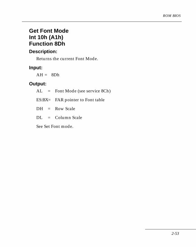
ROM BIOS
Get Font ModeInt 10h (A1h)Function 8DhDescription:
Returns the current Font Mode.
Input:AH = 8Dh
Output:AL = Font Mode (see service 8Ch)
ES:BX= FAR pointer to Font table
DH = Row Scale
DL = Column Scale
See Set Font mode.
2-53

Series 3000 System Software Manual
Set/Get Current LCD Update FrequencyInt 10h (A1h)Function 8EhDescription:
Sets or gets the current LCD update frequency.
Input:AH = 8EhAL = 0 - Get update frequency 1 - Set update frequency
Output:BL = 0 - Fast UpdateBL = 1 - Medium Fast UpdateBL = 2 - Medium Slow UpdateBL = 3 - Slow Update
For Set, BL returns the update frequency if the set is successful; otherwise, the current rate is reported.
2-54
ROM BIOS
Equipment ListThe Equipment List BIOS category contains only one service. This service returns information about the physical configuration of the terminal. The terminal determines this information at system cold start and stores it in memory. If the physical configuration of the terminal is changed, a cold start must be performed to update this information. This service is provided mainly for IBM PC compatibility.
2-55
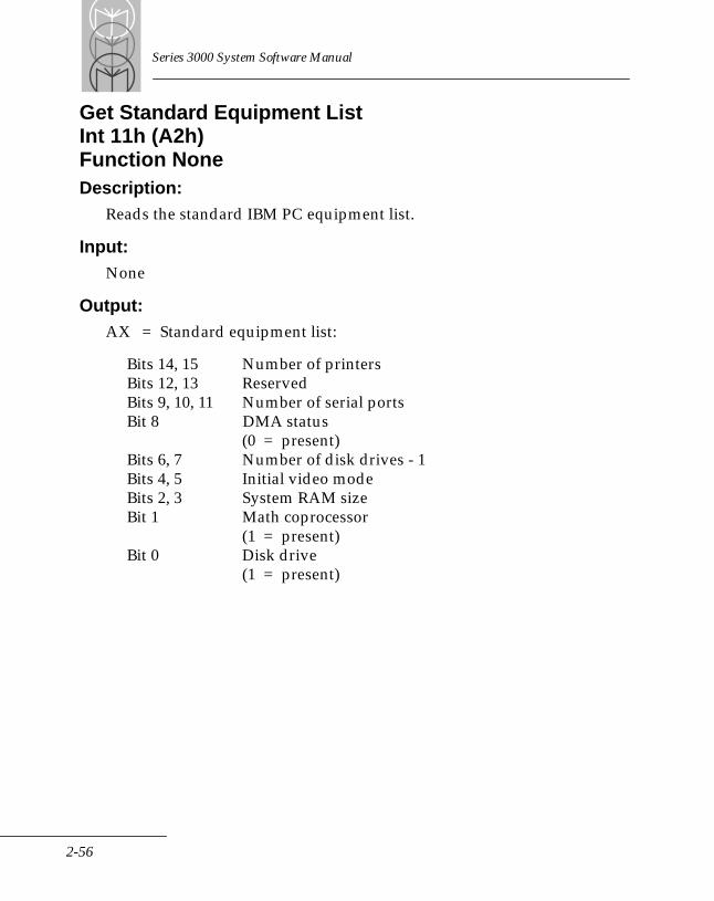
Series 3000 System Software Manual
Get Standard Equipment ListInt 11h (A2h)Function NoneDescription:
Reads the standard IBM PC equipment list.
Input:None
Output:AX = Standard equipment list:
Bits 14, 15 Number of printersBits 12, 13 ReservedBits 9, 10, 11 Number of serial portsBit 8 DMA status
(0 = present)Bits 6, 7 Number of disk drives - 1Bits 4, 5 Initial video modeBits 2, 3 System RAM sizeBit 1 Math coprocessor
(1 = present)Bit 0 Disk drive
(1 = present)
2-56

ROM BIOS
Get Installed Option Card IDInt B5hFunction 0CHDescription:
Indentifies installed option cards.
Note: This option is only available if the user has loaded the INTB50C.EXE BIOS Extension TSR found on the Series 3000 Application Development Kit INTB50C.EXE should be installed in the user NVM image as a resident file (for more information, see the the section entitled ‘ NVM Configuration’ in the Series 3000 Application Programmer’s Guide). When loaded, INTB50C.EXE displays its version number and the ID of the installed option board (if any). It also pauses long enough to allow the user to read the displayed ID code.
Input:AH=0CH
Output:AL = Attached Device:
0 No option board found1 Nexus Radio2 Spectrum 1 R23 open4 open5 open6 Narrow Band7 open8 open9 open10 open
2-57
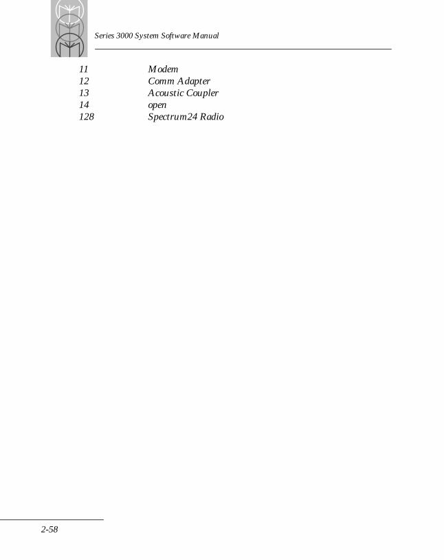
Series 3000 System Software Manual
11 Modem12 Comm Adapter13 Acoustic Coupler14 open128 Spectrum24 Radio
2-58

ROM BIOS
Memory ServicesThis group of BIOS services controls Standard and Extended Memory functions, including memory write protection, Expanded Memory Specification (EMS), and EEPROM programming.
This BIOS category includes the standard IBM PC-XT ROM BIOS “Get Usable Memory Size” service and also implements a “Set Usable Memory Size” service. This allows device drivers to reserve a section of RAM from the Transient Program Area (TPA) for their use (from the end of TPA down).
AccessExtended Series 3000 BIOS memory services are accessed through software interrupt ABh; register AH contains the service code.
Memory AllocationMemory Allocation services remove RAM from the end of TPA for use by drivers, mainly the RAM disk driver. Memory must always be allocated in 1-kilobyte blocks.
2-59
Series 3000 System Software Manual
Get Usable Memory SizeInt 12h (A3h)Function NoneDescription:
Returns the current size of the Transient Program Area (TPA). This is, in effect, the end address of the RAM area available to the operating system or an application.
Input:None
Output:AX = TPA memory size (in kilobytes)
2-60
ROM BIOS
Set Usable Memory SizeInt ABhFunction 00hDescription:
Sets the usable Transient Program Area (TPA) size, allowing you to reserve a block of RAM in the top portion of conventional RAM for use by a driver or application. The amount of RAM specified is the total amount of RAM to allocate to TPA. Thus, this service can both allocate and deallocate system RAM.
Input:AH = 00hBX = Size of TPA RAM in kilobytes
Output:CF is set if the size of TPA is set past the installed RAM size; otherwise reset.AX = Segment address of first byte of allocated space.
Note: If using DOS, a warm boot must be performed after changing the size of TPA.
2-61
Series 3000 System Software Manual
Get Actual Size of RAMInt ABhFunction 01hDescription:
Returns the total amount of RAM installed in the terminal. The actual system RAM size is returned, regardless of where the usable size is set, thus allowing users to determine where the actual top of RAM is and how much RAM is currently removed from the Transient Program Area (TPA). It also returns the total amount of permanently installed Expanded RAM, and the maximum size of the removable media card. All sizes are given in kilobytes.
Input:AH = 01h
Output:AX = System RAM size in kilobytesBX = Fixed EMS RAM size in kilobytesCX = Maximum size of removable
EMS RAM in kilobytes
2-62
ROM BIOS
Memory Write-ProtectThe V25 microprocessor's 1 Mbyte of logical memory is divided into eight 128-kilobyte sectors, numbered from 0 to 7 (see Table 2-3). Sectors 0-5 are further divided into 64 2-kilobyte blocks. Write-Protect is invoked by specifying the number of contiguous memory blocks to protect in each sector, along with the direction of write protection (i.e., to start at the top or bottom of the sector). Write-Protect is disabled by selecting zero blocks for protection. The entire sector is protected if all 64 blocks are selected.
A Non-Maskable Interrupt (NMI) is generated if a hardware write to protected memory is attempted. The BIOS identifies the NMI as a write fault and dispatches vector 92h; a program can redefine the associated interrupt vector. Sector 7 is always write-protected. Non-Volatile Memory (NVM), located in sector 6, is also write-protected, unless the Expanded Memory Specification (EMS) Page Frame is mapped to that sector. In that case, Write-Protect works as above for the Page Frame area only. Sectors 0 through 5 are always unprotected on a system cold start.
Memory SectorsV25 Memory Divisions
Sector Starting Ending MemoryNumber Address
0 00000h 1FFFFh (RAM)1 20000h 3FFFFh (RAM)2 40000h 5FFFFh (RAM)3 60000h 7FFFFh (RAM)4 80000h 9FFFFh (RAM)5 A0000h BFFFFh (EMS or NVM)6 C0000h DFFFFh (NVM)7 E0000h FFFFFh (ROM)
Note: Sector control services 02h and 03h are used to designate the areas of the memory map to Write-Protect. Service 0Fh is used to globally turn Write-Protect on or off. On a cold start, Write- Protect is enabled, but no sectors are protected. This means
2-63

Series 3000 System Software Manual
that an application program need only select a sector through service 02h to protect it. All Write-Protect services should only be used by a system programmer.
AccessAll Write-Protect services are accessed through Int ABh; register AH contains the service code.
2-64
ROM BIOS
Set Write-Protect Fence AddressInt ABhFunction 02hDescription:
Sets the Write-Protect fence for the selected memory sector.
Input:AH = 02hAL = 128K sector number (0 - 5)BH = Control flags
Bit 0 = direction
0 = Protect BL 2K blocks, starting from the top of the sector (block 64), and going down.
1 = Protect BL 2K blocks, starting from the bottom of the sector (block 1), and going up.
BL = Number of 2K blocks to protect (0 - 64)
0 = None64 = All
Output:Same as service 03h.
2-65
Series 3000 System Software Manual
Get Write-Protect Fence AddressInt ABhFunction 03hDescription:
Gets the Write-Protect fence for the selected memory sector.
Input:AH = 03hAL = Sector number (0 - 5)
Output:BH = Direction:
0 = Protect BL 2K blocks, starting from the top of the sector (block 64), and going down.
1 = Protect BL 2K blocks, starting from the bottom of the sector (block 1), and going up.
BL = Number of protected 2K blocks
2-66
ROM BIOS
Set Write-ProtectInt ABhFunction 0FhDescription:
Globally turns on or off the entire Write-Protect feature. Write-Protect is turned on by default on a system cold start. A driver that has allocated and protected memory can use this service to enable writes to protected memory without having to identify and unprotect each sector individually.
Input:AH = 0FhAL = Write-Protect mode:
0 = Disable Write-Protect1 = Enable Write-Protect
Output:AL = Current status:
0 = Write-Protect Disabled1 = Write-Protect Enabled
2-67
Series 3000 System Software Manual
Get Write-Protect StatusInt ABhFunction 10hDescription:
Returns the current global Write-Protect status (whether it is enabled or disabled).
Input:AH = 10h
Output:AL = Current status
0 = Write-Protect Disabled1 = Write-Protect Enabled
2-68
ROM BIOS
Map BIOS to ROM/RAM (WS1000)Int ABhFunction 12hDescription:Selects BIOS mapping to ROM or RAM. Prior to loading an NVM image into flash, Subfunction 1 is used to switch the BIOS to RAM, enabling the loader to execute out of RAM. After the loader operation is complete, Subfunction 0 is used to switch the BIOS back to ROM.
Input:AH = 12hAL = Mapping selection:
0 = Map to ROM1 = Map to RAM
Output:None
2-69

Series 3000 System Software Manual
EMS SupportExpanded Memory Specification (EMS) is a bank switching scheme that extends the 1-Mbyte physical address space of the 8086 family of microprocessors. The BIOS contains the physical hardware driver for EMS; an Expanded Memory Manager (EMM) is required to use EMS from an application.
In Series 3000 terminals, Expanded Memory is accessed through banks of Logical Pages. The maximum size of each bank is 4 Mbytes. Expanded Memory is fixed, permanently installed and is accessible by any application (generally through an EMM driver) as additional working RAM. By default, Series 3000 terminals locate the EMS page frame at A0000h - AFFFFh. Note, however, that this overlaps the user Flash EEPROM space. Since EMS page frame and application ROM cannot coexist in the same address space, this implies that either the size of the user image must be limited when using EMS or EMS cannot be used with user images larger than 192K. Series 3000 BIOS solves this problem by moving the EMS page frame to 90000h - 9FFFFh when a user image larger than 192K is loaded into a terminal with EMS. Since the page frame also can’t coexist with the conventional memory at the same locations, the BIOS reduces the reported TPA size by the size of the page frame (64K); this memory is essentially unused.
Each bank of Expanded Memory (fixed or removable) is divided into a maximum of 256 16-kilobyte Logical Pages. Each Expanded Memory page is identified by a unique 9-bit Logical Page Number. Pages in a bank are consecutively numbered (from zero to the number of pages minus 1) and are selected using the lower eight bits of the Logical Page Number. Banks are selected by the ninth bit of the Logical Page Number. Currently, only one bank is supported by the hardware.
2-70
ROM BIOS
Any Logical Page can be mapped into one of four Physical Pages. Each Physical Page is 16 kilobytes in size. The Physical Pages are contained in a page frame. The Page Frame is an area of the processor's physical address space where the Logical Pages can be mapped in for access. The following services are used to control which Logical Pages, if any, are mapped into a given Physical Page. Note that there are no restrictions on mapping the same page into multiple Physical Pages. Also, the programmer of these services is responsible for saving and restoring the context of EMS if multiple applications are using EMS.
2-71
Series 3000 System Software Manual
Get Total Logical Page CountInt ABhFunction 04hDescription:
Returns the number of Logical Pages in Expanded Memory.
Input:AH = 04h
Output:BX = Fixed Logical PagesCX = Maximum removable Logical Pages
2-72
ROM BIOS
Get EMS Page Frame ConfigurationInt ABhFunction 05hDescription:
This function returns the total number of Physical Pages usable for mapping. These pages are subsequently referred to using Physical Page numbers from zero to page count minus 1. A returned value of zero indicates that Expanded Memory is not supported. Function 06h also returns the starting segment address of the Page Frame and the required size of the Context Save buffer.
Input:AH = 05h
Output:BX = Segment address of EMS Page FrameCX = Number of Physical PagesDX = Required size of context buffer
2-73
Series 3000 System Software Manual
Set EMS Page Frame AddressInt ABhFunction 06hDescription:
Locates the EMS Page Frame within the physical address space. The default page frame address is A0000h. A Page Frame address must be aligned on a 64k boundary at or above 80000h, but below E0000h.
Input:AH = 06hBX = Segment address of Page Frame
Output:CF is set if an illegal Page Frame address is specified; otherwise CF is reset.
2-74
ROM BIOS
Map Logical PagesInt ABhFunction 07hDescription:
Maps the specified Logical Page(s) into the specified Physical Page(s). From one to four pages can be mapped by one call, if both the Logical and Physical Pages are consecutive. If the starting Logical Page number is 0FFFFh (-1), then the Physical Pages from AL to (AL plus CX) are disabled until subsequently re-enabled by mapping a valid Logical Page into the Physical Page.
Input:AH = 07hAL = Physical pageCX = Number of consecutive Logical PagesDX = Starting Logical Page number
Output:CF is set if either Physical or Logical Page goes out of range; otherwise CF is reset.
2-75
Series 3000 System Software Manual
Get Current EMS ContextInt ABhFunction 08hDescription:
Saves the current EMS mapping context in a buffer provided by the caller. The caller specifies the buffer location, the first Physical Page number, and the count of Physical Pages to save.
Input:AH = 08hAL = Starting Physical Page numberCX = Number of Physical Pages to saveES:BX = Address of Context Save buffer
Output:CF is set if the starting page number or page count is out of range; otherwise reset.
2-76
ROM BIOS
Set EMS ContextInt ABhFunction 09hDescription:
Restores a previously saved EMS mapping context from a buffer. The saved context contains the information specifying which Physical Pages to restore.
Input:AH = 09hES:BX = Address of Context Save buffer
Output:CF is set if the buffer contains an invalid save image; otherwise reset.
2-77
Series 3000 System Software Manual
Swap EMS ContextInt ABhFunction 0AhDescription:
Swaps the current EMS mapping context with the contents of a previously saved context. Physical Pages not contained in the saved context are not affected.
Input:AH = 0AhES:BX = Address of user-supplied Context Save buffer
Output:CF is set if the buffer contains an invalid save image; otherwise reset.
2-78

ROM BIOS
Get Mapped Logical PagesInt ABhFunction 11hDescription:
Get the Logical Page(s) mapped into the specified Physical Page(s). Each Physical Page requires one word in the read buffer to return the corresponding Logical Page number. Logical Page numbers have the same format as in service 07h.
Input:AH = 11hAL = Starting Physical Page numberCX = Number of Physical Pages to readES:BX = Address of read buffer
Output:CF is set if the Physical Page goes out of range; otherwise resetCX = Number of Physical Pages not read (0 if CF is reset)
2-79
Series 3000 System Software Manual
EEPROM Memory ServicesNVM Programming SupportThe Series 3000 terminal contains either 128 or 256 kilobytes of Non-Volatile Memory (NVM). The NVM contains user-replaceable system or application code. Physically, the NVM consists of an Electronically Erasable Programmable Read Only Memory (EEPROM) IC chip.
Using the following services, this IC chip can be erased and reprogrammed while installed in the terminal. However, for the erase and programming services to work, the terminal must be connected to an external 12-volt power supply. Depending on the terminal, this may be provided by placing the terminal in a charging cradle or my connecting a power adapter. Refer to the Series 3000 System Administration Manual for the specific terminal for further instructions.
Normal procedure to program or erase NVM:
1. Turn on programming voltage (Service AB/0E with AL = 1).
2. Perform operations (erase and/or write blocks).
3. Turn off programming voltage (Service AB/0E with AL = 0).
2-80

ROM BIOS
Erase EEPROMInt ABhFunction 0BhDescription:
Erases the EEPROM chips that comprise the system Non-Volatile Memory (NVM).
Input:AH = 0Bh
Output:ZF is set if the chip is erased; otherwise reset.
2-81
Series 3000 System Software Manual
Write/Program Block to EEPROMInt ABhFunction 0ChDescription:
Programs the EEPROM at the specified location with the data in the passed block. Programming voltage must be turned on before this service is called (see service 0Eh).
Input:AH = 0ChCX = Number of bytes to writeDX:SI = Source address of data to writeES:DI = Destination address in NVM
Output:ZF is set if the chip is programmed correctly; otherwise, it is reset.
2-82
ROM BIOS
Blank Check System EEPROMInt ABhFunction 0DhDescription:
Checks to see if the installed EEPROMs are erased.
Note: This service does not require the external connector nor that programming voltage be turned on.
Input:AH = 0Dh
Output:ZF is set if the EEPROM is blank; otherwise clear.
2-83
Series 3000 System Software Manual
Turn On/Off Programming VoltageInt ABhFunction 0EhDescription:
Internally switches on/off the programming voltage required to enable writing to NVM (EEPROM). The programming voltage must be turned on before writing the first data block to NVM and should be turned off after NVM is programmed. External voltage must also be present to actually program the NVM.
Input:AH = 0EhAL = Sub-code:
0 = Off1 = On
Output:ZF = Reset if the service fails to turn power on within 20 seconds.
2-84
ROM BIOS
Diskette ServicesIn order to boot and run DOS, the Series 3000 BIOS must emulate at least one disk drive. Disk emulation is performed by configuring the EPROM and/or Non-Volatile Memory chips to appear as one or more write-protected disks. Therefore, all terminal-resident (system and user) files appear to reside on disk, allowing DOS to boot normally.
Data storage, however, uses an installed RAM disk driver, instead of the BIOS diskette services. This is necessary to allow the user to specify the amount of system RAM to allocate for the RAM disk, using the CONFIG.SYS file. Also, this approach permits greater portability of software, because the same drive name could reference a RAM disk in either TPA or EMS memory.
AccessAll diskette services are accessed through Int 13h; register AH contains the service code.
2-85

Series 3000 System Software Manual
Reset Disk DriveInt 13h (A4h)Function 00hDescription:
Resets the disk controller.
Input:AH = 00h
Output:None
2-86
ROM BIOS
Get Diskette StatusInt 13h (A4h)Function 01hDescription:
Returns the result of the last disk operation.
Input:AH = 01h
Output:AH = Status code
bits0 = Bad or unsupported command1 = Bad address mark2 = Write-protect error3 = Sector not found4 = Bad CRC5 = Controller failed6 = Bad seek: move to track failed7 = Time out: drive did not respond
2-87
Series 3000 System Software Manual
Read Diskette SectorsInt 13h (A4h)Function 02hDescription:
Transfers the data on the specified sector(s) to the associated data buffer. Sectors from multiple tracks cannot be read on the same disk access. Read works for drives 0 and 1 (A: and B:).
Input:AH = 02hAL = Number of sectorsCH = Track numberCL = Sector numberDH = Head numberDL = Drive numberES:BX = Pointer to buffer
Output:CF = Success/Failure flagAH = Status code (see Service 01h)AL = Number of sectors read
2-88

ROM BIOS
Write Diskette SectorsInt 13h (A4h)Function 03hDescription:
Writes the data in the specified data buffer to one or more specified tracks. Sectors on multiple tracks cannot be written on the same disk access. This service exists for compatibility purposes only and will always return an error on Series 3000 terminals.
Input:AH = 03hAL = Number of sectorsCH = Track numberCL = Sector numberDH = Head numberDL = Drive numberES:BX = Pointer to buffer
Output:CF = Success/Failure flagAH = Status code (see Service 01h)AL = Number of sectors written
2-89
Series 3000 System Software Manual
Verify Diskette SectorsInt 13h (A4h)Function 04hDescription:
Verifies the contents of one or more sectors. The verification performed checks that the sector(s) can be found and read and that the Cyclical Redundancy Check (CRC) is correct.
Input:AH = 04hAL = Number of sectorsCH = Track numberCL = Sector numberDH = Head numberDL = Drive number
Output:CF = Success/Failure flagAH = Status code (see Service 01h)
2-90

ROM BIOS
Format SectorsInt 13h (A4h)Function 05hDescription:
Formats a track on the selected “disk drive.” Currently for these controllers, WRITE, only, works for drive 2, and only when a PLM with RAM or magnetic media is present. This service exists for compatibility purposes only and will always return an error on Series 3000 terminals.
Input:AH = 05hAL = Number of sectors on trackCH = Track numberDH = Head numberDL = Drive numberES:BX =Pointer to format data buffer
Output:CF = Success/Failure flagAH = Status code (see Service 01h)AL = Number of sectors formatted
2-91
Series 3000 System Software Manual
Serial I/O ServicesThis section describes the Series 3000 terminal BIOS asynchronous serial communications port services (RS-232-C and internal modem). The BIOS supports the standard IBM PC BIOS Serial I/O services and expands them to better support communications drivers and hardware. These extended services are more speed efficient and consume less power than the standard PC BIOS serial I/O services. All Symbol Technologies-supplied DR DOS device drivers use the extended services; the standard auxiliary I/O devices use the standard IBM BIOS services.
Serial I/O is performed differently when using the extended services versus the standard services. The standard services are polled, rather than interrupt driven; I/O is performed a character at a time, waiting for each character transfer to complete before continuing. This is the standard IBM PC ROM BIOS Serial I/O method. Because the BIOS waits for completion of each I/O operation, polled mode is relatively inefficient.
The Extended BIOS services, however, are interrupt-driven. Ring Queues (FIFO's) are used to buffer data to or from the UART (Universal Asynchronous Receiver/Transmitter); characters are read from or written to the UART by interrupt handlers. This allows Serial I/O to occur while the system is performing other tasks, making the extended services more efficient than the standard services.
The Series 3000 BIOS supports two Serial I/O ports on 3300 terminals, and one port on 3100, 3500, 3800, and 3900 terminals. If a 3300 has the optical endcap option, it also has only COM1, and generally behaves like a 3800. The 3800, and 3300 if equipped with an optical endcap, are connected optically to an external Charging and Communications Module (CCM), or cradle.
Ports are numbered 0 and 1, corresponding to DOS devices COM1 and COM2.
Optical connections consist of two bidirectional serial channels. One channel is used to exchange data with a host device; the other is used to exchange status and control information with the CCM. These exchanges allow the terminal to control and read the signals at the CCM's RS-232 connector, enabling the terminal to function exactly as if the port has a physical RS-232 connector rather than an optical connector.
2-92
ROM BIOS
Note: Use either the extended services or service B1/0E to turn the Baud clocks on or off. If you use the standard serial I/O services, the first instruction in or out causes a 200-ms delay to allow the Baud clocks to be enabled. From then on (until the terminal is either warm or cold booted) the Baud clocks remain on. This draws extra power from the batteries.
AccessAll Serial I/O services are accessed through INT 14h (A5h); register AH contains the service code.
2-93
Series 3000 System Software Manual
Standard Serial I/O ServicesInitialize Serial Port (IBM Standard)Int 14h (A5h)Function 00hDescription:
Sets the parameters for the specified serial channel. Returns the same status as Service 03h. For IBM PC compatibility, reports no error if you select an invalid parameter value for the specified port.
Input:AH = 00hAL = Port configuration:
Bits 7,6,5 = Baud
0 0 0 = 110 0 0 1 = 150 0 1 0 = 300 0 1 1 = 600 1 0 0 = 1200 1 0 1 = 2400 1 1 0 = 4800 1 1 1 = 9600
Bits 4,3 = Parity
0 0 = None 0 1 = Odd 1 0 = None 1 1 = Even
Bit 2 = Stop bits
0 = 1 bit 1 = 2 bits
2-94
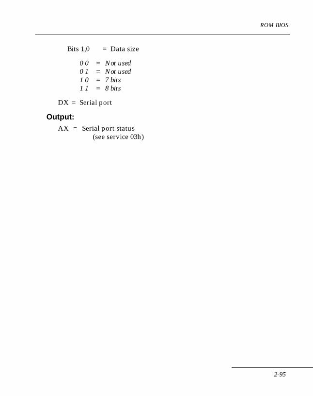
ROM BIOS
Bits 1,0 = Data size
0 0 = Not used 0 1 = Not used 1 0 = 7 bits 1 1 = 8 bits
DX = Serial port
Output:AX = Serial port status
(see service 03h)
2-95

Series 3000 System Software Manual
Send One CharacterInt 14h (A5h)Function 01hDescription:
This service either transmits a single character to the selected serial port's UART or queues a single character into the output FIFO queue, depending on whether the port has been opened using service 82h. If used in polled mode, this service waits until the UART transmit register is empty before writing the new character; if used in interrupt mode, this service waits for space in the FIFO queue before returning. In either case, the status returned is identical to that returned by Service 03h.
In polled mode, this service always raises RTS and DTR and waits for DSR and CTS before sending the character. If either modem control line (DSR and CTS) does not go active in the current timeout value, an error is reported.
Note: Communications power is automatically turned on by the Send and Receive Character services (1 and 2) if not already on.
If the port was opened using service 82h and the last operation was a receive, the port is automatically enabled for transmit, if the port is in Half-duplex operation mode (see services 80h, 82h, 88h, and 89h).
Input:AH = 01hAL = CharacterDX = Port number
Output:AL =Last character sentAH =Line Status register (see service 03h for status)
2-96

ROM BIOS
Receive One CharacterInt 14h (A5h)Function 02hDescription:
This service either reads one character from the selected serial port's UART or dequeues a character from the input FIFO queue, depending on whether the port was opened using Service 82h. This service waits until a character is received or a timeout error occurs before returning. The Status Byte returned is identical to that returned by service 03h.
In polled mode, this service raises DTR, drops RTS, and waits for DSR to go active before reading the UART. If no character (or DSR) is received in the standard timeout period, an error is reported.
Note: Communications power is automatically turned on by the Send and Receive Character services (1 and 2) if not already on.
If the port was opened using Service 82h and the last operation was a transmit, the port is automatically enabled for receive, if the port is in Half-duplex operation mode (see Services 80h, 82h, 88h, and 89h).
Input:AH = 02hDX = Port number
Output:AL = CharacterAH = High byte of serial port status (see Service 03h for status)
2-97
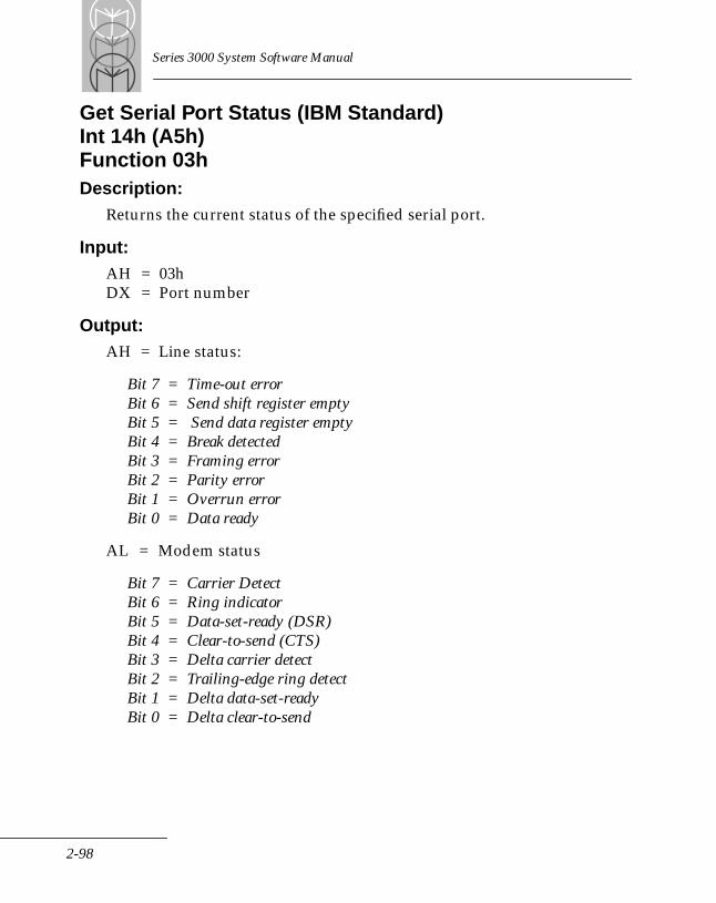
Series 3000 System Software Manual
Get Serial Port Status (IBM Standard)Int 14h (A5h)Function 03hDescription:
Returns the current status of the specified serial port.
Input:AH = 03hDX = Port number
Output:AH = Line status:
Bit 7 = Time-out errorBit 6 = Send shift register emptyBit 5 = Send data register emptyBit 4 = Break detectedBit 3 = Framing errorBit 2 = Parity errorBit 1 = Overrun errorBit 0 = Data ready
AL = Modem status
Bit 7 = Carrier DetectBit 6 = Ring indicatorBit 5 = Data-set-ready (DSR)Bit 4 = Clear-to-send (CTS)Bit 3 = Delta carrier detectBit 2 = Trailing-edge ring detectBit 1 = Delta data-set-readyBit 0 = Delta clear-to-send
2-98
ROM BIOS
Extended Serial I/O ServicesThe Extended Serial I/O Services always return the current error status in the AX register. The Carry flag is set if an error occurs; otherwise, it is reset.
The Extended Serial I/O Services are interrupt driven. Ring queues (FIFO's) are used to buffer data to or from the UART; characters are read from or written to the UART by interrupt handlers. This allows Serial I/O to occur while the system is performing other tasks, making the Extended Serial I/O services more efficient than the Standard Serial I/O services.
AccessThe Extended Serial I/O services are accessed through Int 14h; register AH contains the service code.
2-99
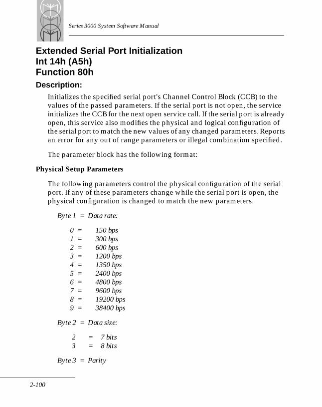
Series 3000 System Software Manual
Extended Serial Port InitializationInt 14h (A5h)Function 80hDescription:
Initializes the specified serial port's Channel Control Block (CCB) to the values of the passed parameters. If the serial port is not open, the service initializes the CCB for the next open service call. If the serial port is already open, this service also modifies the physical and logical configuration of the serial port to match the new values of any changed parameters. Reports an error for any out of range parameters or illegal combination specified.
The parameter block has the following format:
Physical Setup Parameters
The following parameters control the physical configuration of the serial port. If any of these parameters change while the serial port is open, the physical configuration is changed to match the new parameters.
Byte 1 = Data rate:
0 = 150 bps 1 = 300 bps 2 = 600 bps 3 = 1200 bps 4 = 1350 bps 5 = 2400 bps 6 = 4800 bps 7 = 9600 bps 8 = 19200 bps 9 = 38400 bps
Byte 2 = Data size:
2 = 7 bits3 = 8 bits
Byte 3 = Parity
2-100
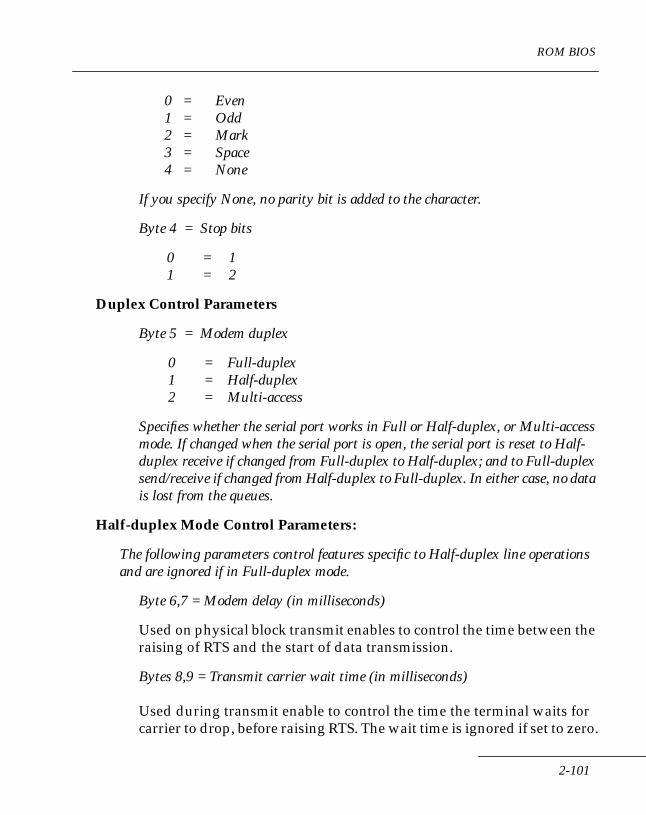
ROM BIOS
0 = Even 1 = Odd 2 = Mark 3 = Space 4 = None
If you specify None, no parity bit is added to the character.
Byte 4 = Stop bits
0 = 11 = 2
Duplex Control Parameters
Byte 5 = Modem duplex
0 = Full-duplex1 = Half-duplex2 = Multi-access
Specifies whether the serial port works in Full or Half-duplex, or Multi-access mode. If changed when the serial port is open, the serial port is reset to Half-duplex receive if changed from Full-duplex to Half-duplex; and to Full-duplex send/receive if changed from Half-duplex to Full-duplex. In either case, no data is lost from the queues.
Half-duplex Mode Control Parameters:
The following parameters control features specific to Half-duplex line operations and are ignored if in Full-duplex mode.
Byte 6,7 = Modem delay (in milliseconds)
Used on physical block transmit enables to control the time between the raising of RTS and the start of data transmission.
Bytes 8,9 = Transmit carrier wait time (in milliseconds)
Used during transmit enable to control the time the terminal waits for carrier to drop, before raising RTS. The wait time is ignored if set to zero.
2-101

Series 3000 System Software Manual
Bit 15 = Controls error reporting if carrier does not go inactive within the specified time. If set, an error is posted if the timer expires. In either case (set or reset), the line-turnaround procedure continues.
Bytes 10,11 = Receive carrier wait time (in milliseconds)
Used during receive enable to control the time the terminal waits for carrier to go active, before enabling receive. The wait time is ignored if set to zero.
Bit 15 = Controls error reporting if carrier does not go active within the specified time. If set, an error is posted if the timer expires. In either case (set or reset), the line-turnaround procedure continues.
Full-duplex Mode Control Parameters:
These parameters control features specific to Full-duplex modems and are ignored if in Half-duplex mode.
Bytes 12, 13 = Carrier loss detect time (in milliseconds)Selects the length of time that carrier must be continuously inactive before a loss of carrier error is posted.
Multi-access Mode Control Parameters:
The Multi-access mode supports single-point to multiple-point protocols. It is used when the terminal is installed in a Charging and Communications Module (CCM). This mode does not have control parameters in the same sense as the other two modes. The terminal requests control of the data bus using INT 14h/90h. Control is granted by the CCM, which can interleave data transmissions from multiple terminals to the Host computer. The user can verify that the terminal has control over the data bus by using status service INT 14h/03h. The terminal releases the data bus (INT 14h/90h) when its transmit queue is empty.
2-102
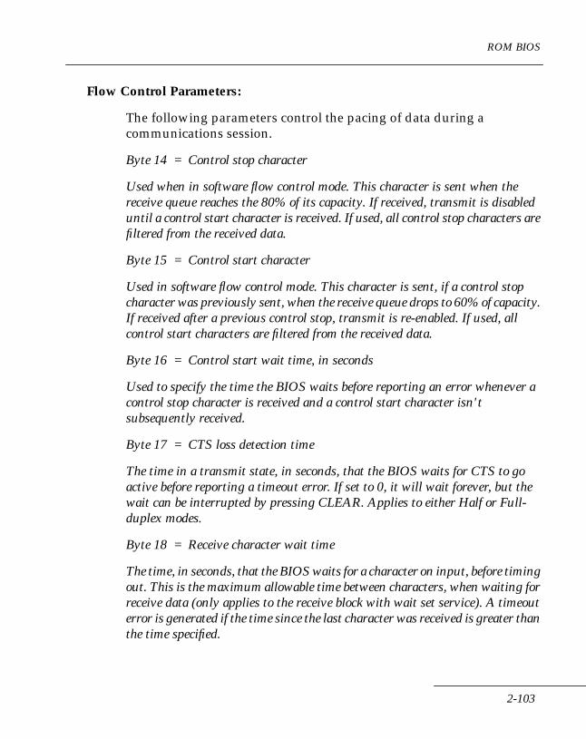
ROM BIOS
Flow Control Parameters:
The following parameters control the pacing of data during a communications session.
Byte 14 = Control stop character
Used when in software flow control mode. This character is sent when the receive queue reaches the 80% of its capacity. If received, transmit is disabled until a control start character is received. If used, all control stop characters are filtered from the received data.
Byte 15 = Control start character
Used in software flow control mode. This character is sent, if a control stop character was previously sent, when the receive queue drops to 60% of capacity. If received after a previous control stop, transmit is re-enabled. If used, all control start characters are filtered from the received data.
Byte 16 = Control start wait time, in seconds
Used to specify the time the BIOS waits before reporting an error whenever a control stop character is received and a control start character isn't subsequently received.
Byte 17 = CTS loss detection time
The time in a transmit state, in seconds, that the BIOS waits for CTS to go active before reporting a timeout error. If set to 0, it will wait forever, but the wait can be interrupted by pressing CLEAR. Applies to either Half or Full-duplex modes.
Byte 18 = Receive character wait time
The time, in seconds, that the BIOS waits for a character on input, before timing out. This is the maximum allowable time between characters, when waiting for receive data (only applies to the receive block with wait set service). A timeout error is generated if the time since the last character was received is greater than the time specified.
2-103
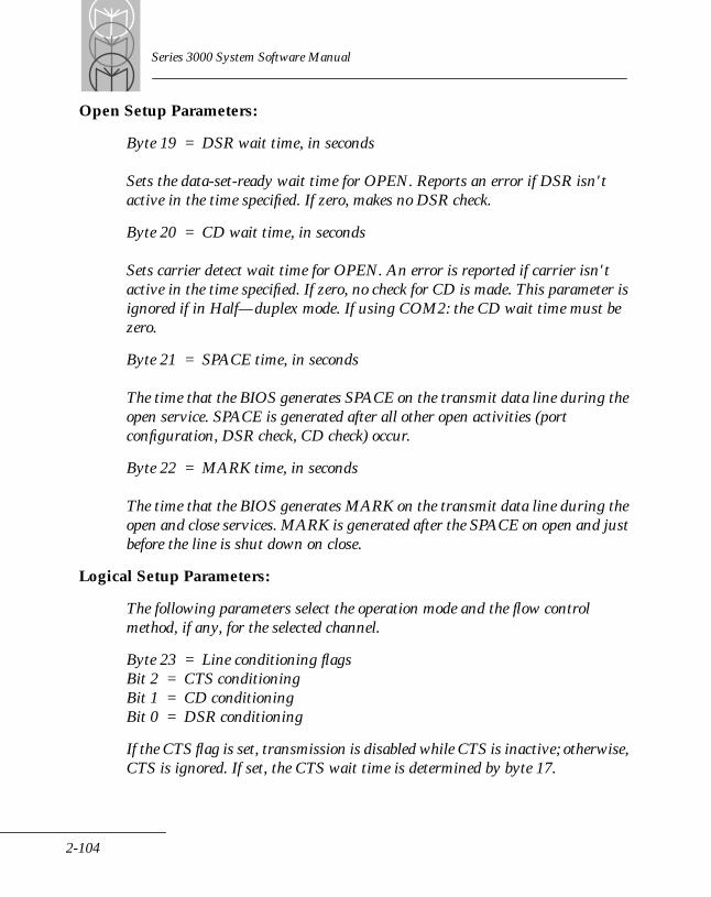
Series 3000 System Software Manual
Open Setup Parameters:
Byte 19 = DSR wait time, in seconds
Sets the data-set-ready wait time for OPEN. Reports an error if DSR isn't active in the time specified. If zero, makes no DSR check.
Byte 20 = CD wait time, in seconds
Sets carrier detect wait time for OPEN. An error is reported if carrier isn't active in the time specified. If zero, no check for CD is made. This parameter is ignored if in Half—duplex mode. If using COM2: the CD wait time must be zero.
Byte 21 = SPACE time, in seconds
The time that the BIOS generates SPACE on the transmit data line during the open service. SPACE is generated after all other open activities (port configuration, DSR check, CD check) occur.
Byte 22 = MARK time, in seconds
The time that the BIOS generates MARK on the transmit data line during the open and close services. MARK is generated after the SPACE on open and just before the line is shut down on close.
Logical Setup Parameters:
The following parameters select the operation mode and the flow control method, if any, for the selected channel.
Byte 23 = Line conditioning flagsBit 2 = CTS conditioningBit 1 = CD conditioningBit 0 = DSR conditioning
If the CTS flag is set, transmission is disabled while CTS is inactive; otherwise, CTS is ignored. If set, the CTS wait time is determined by byte 17.
2-104

ROM BIOS
If the CD flag is set, reception is disabled if CD is inactive. This flag has no effect on the CD open wait time, the CD loss detection time, or the transmit and receive enable CD wait times. Do not set CD conditioning flag if using COM2.
If the DSR flag is set, an error is reported if DSR is lost during the communications session. This flag has no effect on the DSR open wait time. Do not set DSR conditioning flag if using COM2.
Byte 24 = Operation mode:: 0 = No flow control 1 = Software flow control 2 = Hardware flow control
Selects the flow control method, if any, for the specified serial port. If flow control is selected, the remote transmitter is disabled when the input queue reaches 80% of capacity; when the input queue is reduced to 60% of capacity, the remote transmitter is enabled. Software flow control uses data characters (control start/stop) to enable/disable transmission and reception of data. Hardware flow control raises/lowers RTS do this.
In hardware flow control, CTS line conditioning (see above) must be enabled so that the remote receiver can disable transmit by dropping CTS to the Series 3000.
Byte 25 = Line Status Error MaskBit 4 = Break detectBit 3 = FramingBit 2 = ParityBit 1 = Overrun
This mask enables or disables the handling of line status errors from the UART. If a line status error occurs, and the error flag is reset, the error is ignored. See below for the action taken if the error is enabled.
Byte 26 = Error Insertion Character
The character is inserted into the data stream if an enabled line status error occurs. If this character is null, an error is Bytes 27,28 = DTR Settling Time (milliseconds)
2-105
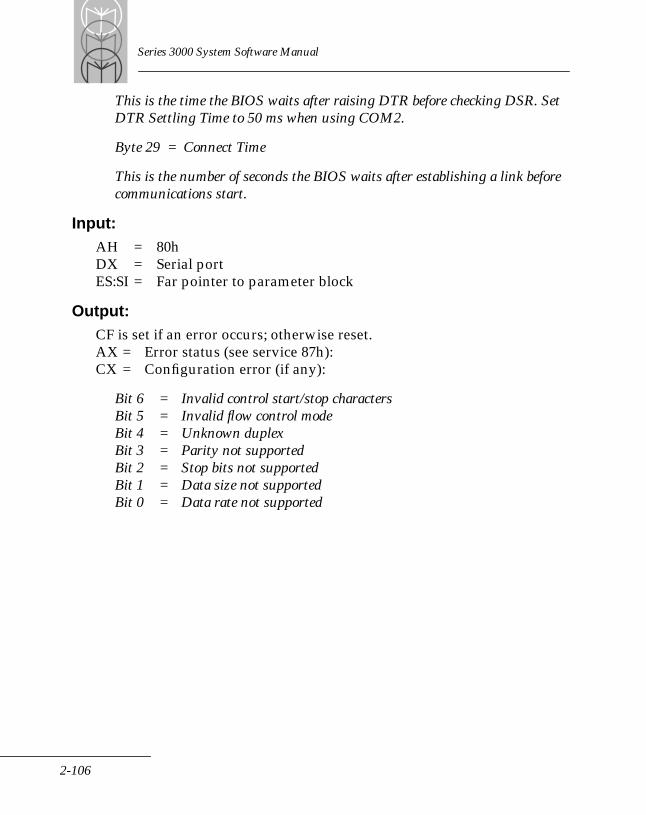
Series 3000 System Software Manual
This is the time the BIOS waits after raising DTR before checking DSR. Set DTR Settling Time to 50 ms when using COM2.
Byte 29 = Connect Time
This is the number of seconds the BIOS waits after establishing a link before communications start.
Input:AH = 80hDX = Serial portES:SI = Far pointer to parameter block
Output:CF is set if an error occurs; otherwise reset.AX = Error status (see service 87h):CX = Configuration error (if any):
Bit 6 = Invalid control start/stop charactersBit 5 = Invalid flow control modeBit 4 = Unknown duplexBit 3 = Parity not supportedBit 2 = Stop bits not supportedBit 1 = Data size not supportedBit 0 = Data rate not supported
2-106
ROM BIOS
Get Current Port ConfigurationInt 14h (A5h)Function 81hDescription:
Returns either the current configuration or the size of the BIOS parameter block of the specified serial port. If only the size is requested, ES:DI need not be specified. If the configuration is requested, it is copied to the buffer specified by ES:DI in the same format as described in Service 80h.
Input:AH = 81hAL = Sub-service:
0 = Return parameter block and size1 = Return only parameter block size
DX = Serial portES:DI = Address of parameter block buffer
Output:CF is set if any error occurs; otherwise resetAX = Error status (see service 87h)CX = Parameter block size
2-107
Series 3000 System Software Manual
Open Serial PortInt 14h (A5h)Function 82hDescription:
Used to power up and initialize the selected serial port to the configuration stored in the CCB. See Service 80h for information on serial port configuration. Consecutive opens are allowed; each call performs all open tasks, including purging the queues, waiting for DSR and CD, and generating the SPACE and MARK tones. (Note that DTR is not lost on subsequent opens.) The queues must be initialized (using Service 8Dh) before the first open.
Input:AH = 82hDX = Serial port
Output:CF is set if any error occurs; otherwise resetAX = Error status (see service 87h)
2-108
ROM BIOS
Close Serial PortInt 14h (A5h)Function 83hDescription:
Closes a communications port. This service generates MARK tone for the time specified in the last configuration call, then terminates the communications session, and powers down the selected serial port.
Input:AH = 83hDX = Serial port
Output:CF is set if any error occurs; otherwise resetAX = Error status (see service 87h)
2-109
Series 3000 System Software Manual
Send BlockInt 14h (A5h)Function 84hDescription:
The specified data block is moved into the transmit queue until the queue is full or the entire data block is queued. Reports an error if the specified serial port is not open. If wait mode (0) is specified and if a communications error occurs, this service may terminate before all data is queued. If in Half-duplex receive, the line is automatically enabled for transmit (see Service 88h).
Input:AH = 84hAL = Mode:
0 = Wait for all data to be queued1 = Don't wait
CX = Length of dataDX = Serial portES:SI = Address of data block
Output:CF is set if an error occurs; otherwise resetAX = Error status (see service 87h)CX = Number of bytes not sentDX = Number of bytes sentES:SI = Address of first byte not sent
2-110
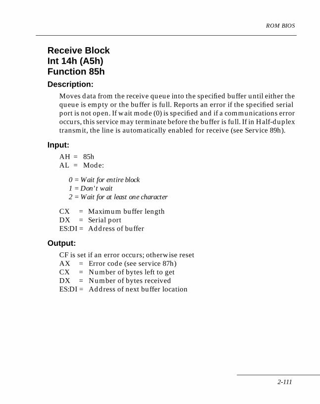
ROM BIOS
Receive BlockInt 14h (A5h)Function 85hDescription:
Moves data from the receive queue into the specified buffer until either the queue is empty or the buffer is full. Reports an error if the specified serial port is not open. If wait mode (0) is specified and if a communications error occurs, this service may terminate before the buffer is full. If in Half-duplex transmit, the line is automatically enabled for receive (see Service 89h).
Input:AH = 85hAL = Mode:
0 = Wait for entire block1 = Don't wait2 = Wait for at least one character
CX = Maximum buffer lengthDX = Serial portES:DI = Address of buffer
Output:CF is set if an error occurs; otherwise resetAX = Error code (see service 87h)CX = Number of bytes left to getDX = Number of bytes receivedES:DI = Address of next buffer location
2-111
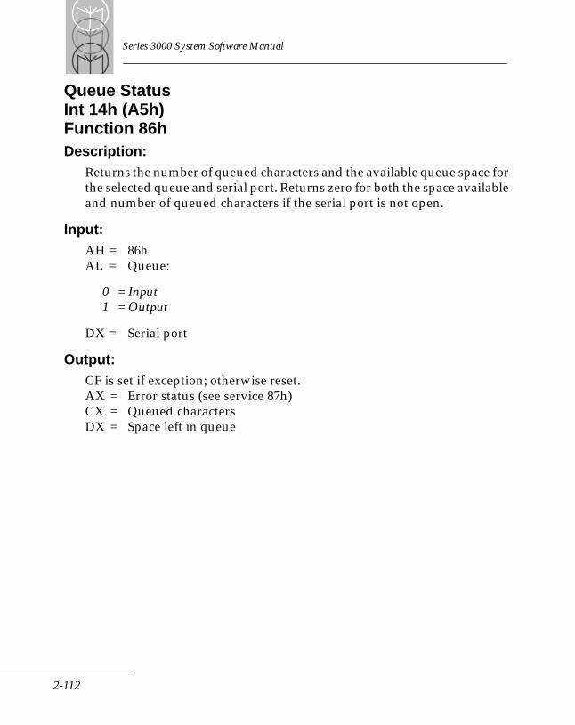
Series 3000 System Software Manual
Queue StatusInt 14h (A5h)Function 86hDescription:
Returns the number of queued characters and the available queue space for the selected queue and serial port. Returns zero for both the space available and number of queued characters if the serial port is not open.
Input:AH = 86hAL = Queue:
0 = Input1 = Output
DX = Serial port
Output:CF is set if exception; otherwise reset.AX = Error status (see service 87h)CX = Queued charactersDX = Space left in queue
2-112
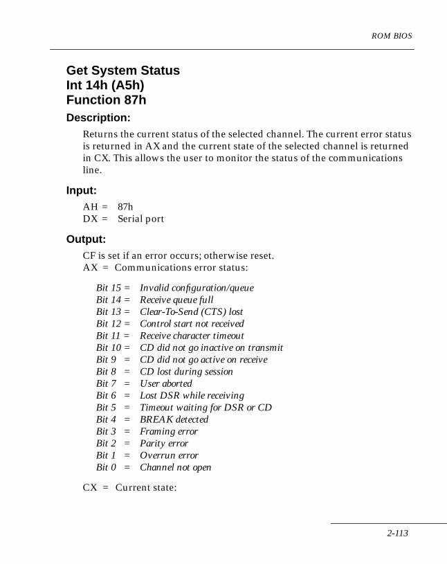
ROM BIOS
Get System StatusInt 14h (A5h)Function 87hDescription:
Returns the current status of the selected channel. The current error status is returned in AX and the current state of the selected channel is returned in CX. This allows the user to monitor the status of the communications line.
Input:AH = 87hDX = Serial port
Output:CF is set if an error occurs; otherwise reset.AX = Communications error status:
Bit 15 = Invalid configuration/queueBit 14 = Receive queue fullBit 13 = Clear-To-Send (CTS) lostBit 12 = Control start not receivedBit 11 = Receive character timeoutBit 10 = CD did not go inactive on transmitBit 9 = CD did not go active on receiveBit 8 = CD lost during sessionBit 7 = User abortedBit 6 = Lost DSR while receivingBit 5 = Timeout waiting for DSR or CDBit 4 = BREAK detectedBit 3 = Framing errorBit 2 = Parity errorBit 1 = Overrun errorBit 0 = Channel not open
CX = Current state:
2-113
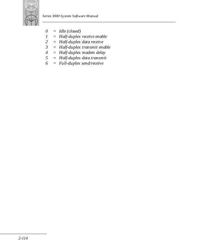
Series 3000 System Software Manual
0 = Idle (closed) 1 = Half-duplex receive enable 2 = Half-duplex data receive 3 = Half-duplex transmit enable 4 = Half-duplex modem delay 5 = Half-duplex data transmit 6 = Full-duplex send/receive
2-114
ROM BIOS
Transmit Enable (Half-Duplex Line Turn Around)Int 14h (A5h)Function 88hDescription:
Causes the BIOS to perform a physical line turn around when using Half-duplex modems (ignored when using Full-duplex modems). This service causes the BIOS to disable Receive, wait a specified time for CD to drop, raise RTS, wait modem delay time, then enable Transmit. Note that all or most of these actions are performed by the BIOS after the call returns; i.e., this call starts the line turn around procedure. It usually does not wait for it to complete.
Input:AH = 88hDX = Serial Port
Output:CF is set if any error occurs; otherwise resetAX = Error status (see service 87h)
Note: This call is added for completeness; if a send block or character call is issued while in Half-duplex receive, a Transmit Enable call is automatically performed.
2-115
Series 3000 System Software Manual
Receive Enable (Half-Duplex Line Turn Around)Int 14h (A5h)Function 89hDescription:
Causes the BIOS to perform a physical line turn around when using Half-duplex modems (ignored when using Full-duplex modems). This service causes the BIOS to wait until the transmit queue and UART are empty, then drop RTS, disable Transmit, wait a specified time for CD to go active, and finally enable Receive. Note that all or most of these actions are performed by the BIOS after the call returns; i.e., this call starts the line turn around procedure. It usually does not wait for it to complete.
Input:AH = 89hDX = Serial port
Output:CF is set if any error occurs; otherwise resetAX = Error status (see service 87h)
Note: This call is added for completeness; if in Half-duplex transmit and a receive character or block service is performed, this function is automatically performed.
2-116
ROM BIOS
Transmit DoneInt 14h (A5h)Function 8AhDescription:
Waits until the transmit queue and UART for the specified serial port are empty.
Input:AH = 8AhDX = Serial port
Output:CF is set if any error occurs; otherwise resetAX = Error status (see service 87h)
2-117
Series 3000 System Software Manual
Set UART Control CommandsInt 14h (A5h)Function 8BhDescription:
Controls serial port services and control line.
Input:AH = 8BhAL = Control mask:
Bit 0 = Enable DTRBit 1 = Enable RTSBit 6 = Enable BREAK
DX = Serial port
Output:CF is set if an error occurs; otherwise resetAX = Error status (see service 87h)
2-118
ROM BIOS
Clear UART Control CommandsInt 14h (A5h)Function 8ChDescription:
Controls serial port services and control line.
Input:AH = 8ChAL = Control mask:
Bit 0 = Disable DTRBit 1 = Disable RTSBit 6 = Disable BREAK
DX = Serial port
Output:CF is set if an error occurs; otherwise resetAX = Error status (see service 87h)
2-119
Series 3000 System Software Manual
Allocate Communications QueuesInt 14h (A5h)Function 8DhDescription:
Sets up the FIFO transmit and receive queues for the selected serial port. This service must be called before the initial open of the communications session or an error occurs on the subsequent open.
Queues must be paragraph aligned and the passed segment address must point to the first location of the queue.
The actual queue size is the passed size minus 8 bytes of queue overhead. The minimum passed size is 32 bytes (queue size = 24 bytes). The default is 256 bytes (queue size = 248 bytes).
Input:AH = 8DhDX = Serial portES:SI = Queue parameter block:
Word 1 = Size of input queueWord 2 = Segment address of input queueWord 3 = Size of output queueWord 4 = Segment address of output queue
Output:CF is set if any error occurs; otherwise resetAX = Error status (see service 87h)
2-120
ROM BIOS
Purge Communications QueueInt 14h (A5h)Function 8EhDescription:
Re-initializes the specified queue(s), causing any queued data to be discarded.
Input:AH = 8EhAL = Queue select
Bit 1 = Receive queueBit 0 = Transmit queue
DX = Serial port
Output:CF is set if any error occurs; otherwise resetAX = Error status (see service 87h)
2-121
Series 3000 System Software Manual
Transmit Queue Empty Notification ControlInt 14h (A5h)Function 8FhDescription:
Dispatches an event (through a FAR call) when the transmit queue goes empty. The dispatch routine must be a far procedure and must save all registers it uses. The routine is not invoked immediately; instead, a flag is set when the queue goes empty. The channel background timer checks every 27.45 ms to see if this flag is set and that the dispatch routine is enabled. If these conditions are met, the routine is then dispatched.
Input:AH = 8FhDX = Serial PortAL = Enable/Disable flag:
0 = Disable1 = Enable
If AL = 1, then:ES:BX = Address of routine
Output:CF set if error.AX = Error Code
2-122
ROM BIOS
Request/Release Data BusInt 14h (A5h)Function 90hDescription:
Used with Multi-access mode to request and release the data bus. Used mainly with the Charging and Communications Module (CCM).
Note: The DX register must be set to zero to request or release the shared data bus (CCM).
Input:AH = 90hDX = 0
AL = Function:
0 = Request1 = Release
Output:CF set if error.AX = Error CodeBL = Result Code:
0 = Don't have data bus control1 = Have data bus control
2-123
Series 3000 System Software Manual
Delete QueuesInt 14h (A5h)Function 91hDescription:
Deletes the current communications queues. Subsequent Opens fail if new queues are not allocated.
Input:AH = 91hDX = Serial port
Output:CF set if error.AX = Error Code
2-124
ROM BIOS
Get Queue PointerInt 14h (A5h)Function 92hDescription:
Returns the segment addresses and sizes of the FIFO communications queues.
Input:AH = 92hDX = Serial portES:DI = Address of transfer buffer
Output:CF set and AX = 8000h if no queues are currently allocated for the selected port, else CF is reset and AX = 0.
If CF is reset, the block pointed to by ES:DI contains the segment addresses and sizes of the queues as defined in Service 8Dh.
2-125
Series 3000 System Software Manual
Get COMM Type ID NumberInt 14h (A5h)Function 93hDescription:
Returns an ID number identifying the type of comm board attached to the terminal.
Input:AH = 93hDX = 0 (COM1)
1 (COM2)
Output:If CF is set and AX = 8000h, then the requested port does not exist.
If CF is clear and AX = 0000, then BL indicates the type of board attached to the port:
00 = None01 = Primary Serial channel02 = COMM adaptor board03 = Internal modem04 = Comm adaptor board with acoustic coupler
Note: On the PDT 3100, PDT 3500, PDT 6100, PDT 6800, LRT 3800, LDT 3805, and VRC 3910 terminals there is no COMM2 port, so an error will always be returned for COMM2.
2-126
ROM BIOS
Secure Optical Channel OverrideInt 14h (A5h)Function 94hDescription:
This service sets a flag to unconditionally turn ON optical communications at the next OPEN PORT command on COM1. This overrides the default, which leaves the optics powered down when the terminal is not in its cradle (to protect against interference from sunlight).
The flag is reset on each CLOSE PORT on COM1, so the call must be issued prior to each open requiring the override.
This service provides support for optical cradles that do not have the contacts required to indicate to the terminal when it is in a cradle. When such a cradle is in use, the service forces the optical elements to be powered up for communications through the cradle.
The service only applies to the COM1 port, regardless of the value of DX.
Note: This service can be called only if COM1 is closed. If COM1 is open when called, the service returns an error.
Input:AH = 94hDX = 0 or 1 (either value)
Output:CF is set if an error occurs and AX = 8000h.
2-127
Series 3000 System Software Manual
Keyboard ServicesSeries 3000 terminals implement the standard IBM-XT keyboard services, along with some IBM-AT keyboard services.
Key scanning is performed by the microprocessor. Each keyboard supports a unique subset of PC scan codes. Scan codes greater than the current maximum PC scan code are used for new keys and to indicate non-key events. These codes are called Keyboard Metacodes.
Several additional keyboard services have been added to handle extended features. For example, keys can be dedicated to special terminal functions; and, the keyboard is completely redefinable.
Received scan codes can be redefined to either another scan code or a system metacode. The BIOS uses a look-up table and the current keyboard state to redefine received scan codes. The redefinition tables consist of a sub-table for each keyboard state. The programmer need only specify in each sub-table those keys he wishes to redefine. If the scan code is in the sub-table, its redefined value is passed to the next key processing step; otherwise, the received scan code is passed. Vector 82h points to the redefinition table; programmers redefine the keyboard by loading the address of a new table into this vector. For further information regarding the format of the redefinition table and the redefinition process, see the Series 3000 Application Programmer's Reference Manual.
The next phase of key processing is System Metacode detection. System Metacodes are trapped by the BIOS and perform special functions (e.g., turn the backlight on or off, power off the terminal, etc.). A special System Metacode, called Null Key, is used to pass raw scan code data to the user; this metacode is translated to a main byte value of FFh and the original scan code is placed in the auxiliary byte. System Metacodes are removed from the Key Data Input Stream after processing.
2-128
ROM BIOS
The final phase of key processing is the normal translation of the scan codes into key values. Generally, this process produces ASCII key values, although special keys are also generated. For further information regarding this translation process, see the Series 3000 Application Programmer's Reference Manual or refer to an IBM PC programmer's guide. When waiting for keyboard entry, the Series 3000 terminal automatically powers down if no key is pressed for a user-specified time. This feature is performed when service 00h is invoked; if no key is already queued, the BIOS signals the keyboard processor to start the keyboard timeout timer and enters Sleep mode. If a key is not pressed before the timer expires, the main processor generates a metacode, indicating that the timeout condition has occurred.
The Series 3000 terminals have the ability to detect the current status of the [ABORT] key. The BIOS provides a service to return the [ABORT] key status.
AccessAll keyboard services are accessed through INT 16h; register AH contains the service code.
2-129
Series 3000 System Software Manual
Standard Keyboard ServicesReturn Next Character And Scan CodeInt 16h (A7h)Function 00hDescription:
Inputs the next scan code from the software key queue. If no key is currently queued, this service waits for key input for the time specified in Service 82h.
Input:AH = 00h
Output:AL = Character codeAH = Scan code
2-130

ROM BIOS
Check For Character ReadyInt 16h (A7h)Function 01hDescription:
Gets the next scan code from the software key queue, but does not remove it from the key queue (allows keyboard look-ahead).
Input:AH = 01h
Output:ZF is set if no key is in the queue; otherwise:AL = Character code, if ZF is resetAH = Scan code, if ZF is reset
2-131
Series 3000 System Software Manual
Get Shift StatusInt 16h (A7h)Function 02hDescription:
Returns command key status.
Input:AH = 02h
Output:AL = Keyboard status:
Bit 7 = Function/Insert state activeBit 6 = Caps Lock activeBit 5 = Num Lock activeBit 4 = Scroll Lock activeBit 3 = Alt pressedBit 2 = Ctrl pressedBit 1 = left Shift pressedBit 0 = right Shift pressed
2-132
ROM BIOS
Set Key Click DurationInt 16h (A7h)Function 04hDescription:
Sets duration of key click. The resolution of the system timer is approximately one millisecond.
Input:AH = 04hAL = Key click function:
0 = Enable key clicks1 = Disable key clicks
80h = Set Key Click Time81h = Get Key Click Time
If AL = 80h, then:DX = Time (in milliseconds)
Output:DX = Time (in milliseconds)AL = Status Key Click:
0 = Off1 = On
2-133

Series 3000 System Software Manual
Extended Keyboard ServicesEnable Auto Key RepeatInt 16h (A7h)Function 80hDescription:
Enables Auto Key Repeat and selects the repeat rate. Auto Key Repeat is disabled if the initial delay is set to zero.
Input:AH = 80hAL = Subcommand:
0 = Set1 = Get
If AL = 0, then:CX = Initial Delay (in milliseconds)DX = Repeat Delay (in milliseconds)
Output:CX = Initial Delay (in milliseconds)DX = Repeat Delay (in milliseconds)
2-134
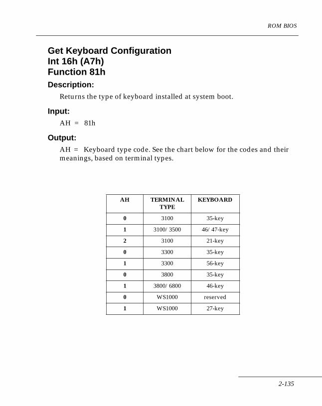
ROM BIOS
Get Keyboard ConfigurationInt 16h (A7h)Function 81hDescription:
Returns the type of keyboard installed at system boot.
Input:AH = 81h
Output:AH = Keyboard type code. See the chart below for the codes and their meanings, based on terminal types.
AH TERMINAL TYPE
KEYBOARD
0 3100 35-key
1 3100/3500 46/47-key
2 3100 21-key
0 3300 35-key
1 3300 56-key
0 3800 35-key
1 3800/6800 46-key
0 WS1000 reserved
1 WS1000 27-key
2-135
Series 3000 System Software Manual
Set Keyboard No Activity TimerInt 16h (A7h)Function 82hDescription:
Sets the time the keyboard waits for key entry before it generates the timeout metacode.
Input:AH = 82hCX = Time (in seconds)AL = Subcommand:
0 = Set 1 = Get
If AL = 0, then:CX = Time (in seconds)
Output:CX = Time (in seconds)
2-136
ROM BIOS
Set Keyboard StateInt 16h (A7h)Function 83hDescription:
Forces the keyboard into a given state.
Input:AH = 83hAL = Keyboard state:
Bit 0 = right ShiftBit 1 = left ShiftBit 2 = CtrlBit 3 = AltBit 4 = Scroll LockBit 5 = Num LockBit 6 = Caps LockBit 7 = Function shift
Output:AH = Current keyboard state
2-137

Series 3000 System Software Manual
Get Keyboard StateInt 16h (A7h)Function 84hDescription:
Returns the current keyboard state.
Input:AH = 84h
Output:See service 83h.AH = Current state.
2-138
ROM BIOS
Select ABORT KeyInt 16h (A7h)Function 85hDescription:
Selects the scan code to use for the ABORT key. When the BIOS detects this scan code (after redefinition), it sets the ABORT flag. The flag remains set until Service 86h is called, after the system receives the corresponding break code for that scan code.
The ABORT key allows the operator to terminate communications, delay, and beeps.
Input:AH = 85hAL = Scan code
Output:None
2-139
Series 3000 System Software Manual
Get ABORT Key StatusInt 16h (A7h)Function 86hDescription:
Gets the current status of the ABORT key.
Input:AH = 86h
Output:CF is set if ABORT was pressed; otherwise reset.AL = Abort key status
Bit 0 set if key down now; else resetBit 1 set if key down previously; else reset
2-140
ROM BIOS
Set Keyboard Operation ModeInt 16h (A7h)Function 87hDescription:
Sets Keyboard Operation Mode (default = One-finger Keyboard mode).
Input:AH = 87hAL = Subcommand:
0 = Set One-finger Keyboard mode. 1 = Set PC Keyboard mode. (not supported by WS 1000)
Output:None
2-141
Series 3000 System Software Manual
Program Trigger KeyInt 16h (A7h)Function 88hDescription:
Programs the Series 3100 or Series 3500 terminal trigger key to be either the right or the left side key. This service is supported only on the Series 3100/3500/6100.
AH = 88hAL = Trigger selector:
00 = Left side key01 = Right side key
Output:None
2-142
ROM BIOS
Set Left/Right Alpha Shift Keyboard State (WS1000)Int 16h (A7h)Function 89hDescription:
Forces the keyboard left/right alpha shift to a given state.
Input:AH= 89hAL = Keyboard alpha shift state
Bit 0 = right alpha shiftBit 1 = left alpha shift
Note: Both bits cannot be set at the same time.
Output:AH = Current keyboard alpha shift state.
2-143
Series 3000 System Software Manual
Get Left/Right Alpha Shift Keyboard State (WS1000)Int 16h (A7h)Function 8AhDescription:
Returns the current keyboard left/right alpha shift state.
Input:AH = 8Ah
Output:AH = Current keyboard alpha shift state (See Int 16h function 89h.)
2-144

ROM BIOS
Get Keyboard Left/Right Alpha Key Pressed Status (WS1000)Int 16h (A7h)Function 8BhDescription:
Returns the current keyboard left/right alpha pressed status.
Input:AH = 8Bh
Output:AL = Left/right key pressed status:
Bit 0 = Right alpha key pressed.Bit 1 = Left alpha key pressed.
2-145
Series 3000 System Software Manual
Printer ServicesThe Printer Services include the standard IBM PC BIOS parallel printer services. In addition, the Series 3000 BIOS has been extended to allow block transfers. Data is transmitted serially.
Series 3800 terminals do not support a parallel port. The Printer Services actually support the Printer Interface Module (PIM) that accesses Symbol Technologies' family of PS1000 bar code printers. Printer Services only output data if connected to such a printer via the PIM.
PIMs do not exist for Series 3100/3500; however, printer services are available for the Series 3100/3500 terminals through the use of a tethered PS 200 printer.
On Series 3300 and 3900 terminals, output is redirected to the RS-232 port (Port 0, Com1).
AccessAll available Printer Services are accessed through Int 17h; register AH contains the service code.
2-146
ROM BIOS
Send Byte Out Printer PortInt 17h (A8h)Function 00hDescription:
Outputs the specified character to the printer port. Posts an error if the BIOS times out during this operation.
Input:AH = 00hAL = Character
Output:AH = Printer status (see Service 02h)
2-147
Series 3000 System Software Manual
Initialize Printer PortInt 17h (A8h)Function 01hDescription:
This function performs no operation, but returns the current printer status.
Input:AH = 01h
Output:AH = Printer status (see Service 02h)
2-148

ROM BIOS
Get Printer StatusInt 17h (A8h)Function 02hDescription:
Returns the current printer status.
Input:AH = 02hDX = Printer port
Output:AH = Printer status:
Bit 7 = Printer not busy *Bit 6 = AcknowledgeBit 5 = Out of paperBit 4 = Printer selected *Bit 3 = I/O errorBit 2 = ReservedBit 1 = ReservedBit 0 = Timed out *
* Only these flags are supported
2-149
Series 3000 System Software Manual
Send Block To PrinterInt 17h (A8h)Function 83hDescription:
Sends a data block to the printer port.
Input:AH = 83hCX = Number of characters to sendES:SI = Address of data block
Output:CX = Number of characters left to sendAH = Printer status (see Service 02h)
2-150
ROM BIOS
Time-of-Day ServicesThe Time-of-Day services are a combination of standard IBM PC-XT, IBM PC-AT, and Symbol Technologies Extended BIOS Services.
The Series 3000 real time clock maintains the Timer Tick count and the current time and date. The BIOS services provide an interface to the real time clock. All time and date fields are encoded in packed BCD format. An additional feature of the Series 3000 is the ability to dispatch a routine when the real time clock matches the alarm time. If the terminal is turned off when the alarm trips, the terminal is powered up before this routine is dispatched.
AccessThe Time-of-Day services are accessed through software interrupt Int 1Ah; register AH contains the service code.
2-151
Series 3000 System Software Manual
Read the Current Timer Tick CountInt 1Ah (AAh)Function 00hDescription:
Reads the current Timer Tick count.
Input:AH = 00h
Output:AL = Midnight signalCX = Tick count, high portionDX = Tick count, low portion
2-152
ROM BIOS
Set the Current Timer Tick CountInt 1Ah (AAh)Function 01hDescription:
Sets the current Timer Tick count.
Input:AH = 01hCX = Tick count, high portionDX = Tick count, low portion
Output:None
2-153
Series 3000 System Software Manual
Read Time of DayInt 1Ah (AAh)Function 02hDescription:
Reads the Time-of-Day from the real time clock. All times are returned in packed BCD.
Input:AH = 02h
Output:CH = Hours (0 - 23)CL = Minutes (0 - 59)DH = Seconds (0 - 59)
2-154
ROM BIOS
Set Time of DayInt 1Ah (AAh)Function 03hDescription:
Sets the Time-of-Day. All times are sent in packed BCD.
Input:AH = 03hCH = Hours (0 - 23)CL = Minutes (0 - 59)DH = Seconds (0 - 59)DL = 1 - Daylight savings time
0 - Standard time
Output:None
2-155
Series 3000 System Software Manual
Read DateInt 1Ah (AAh)Function 04hDescription:
Returns the current date. All times are returned in packed BCD.
Register AL is undefined in the IBM PC-AT BIOS.
Input:AH = 04h
Output:AL = Day of week (0 = Sun, 6 = Sat)DL = Day of month (1 - 31)DH = Month (1 - 12)CL = Year (0 - 99)CH = Century (19 or 20)
2-156
ROM BIOS
Set DateInt 1Ah (AAh)Function 05hDescription:
Sets the date. All times are sent in packed BCD.
Register AL is undefined in the IBM PC-AT BIOS.
Note: The “Day of Week” setting is used to tell the real tme clock what day of the week the date being set falls on, as the real time clock hardware does not know that information. The convention is to use dat “0” as Sunday.
Input:AH = 05hAL = Day of week (0 - 6)DL = Day of month (1 - 31)DH = Month (1 - 12)CL = Year (0 - 99)CH = Century (19 or 20)
Output:None
Note: The terminal does not accept dates beyond the year 2080.
2-157
Series 3000 System Software Manual
Set AlarmInt 1Ah (AAh)Function 80hDescription:
Sets the Real Time Clock Alarm. Setting a field to -1 (FFh) causes the field to be treated as a wild card for alarm comparisons.
All times are sent in packed BCD. Register AL is undefined in the IBM PC-AT BIOS. Also, the IBM PC-AT passes seconds in DH.
Input:AH = 80hAL = Seconds (0 - 59)CL = Minutes (0 - 59)CH = Hours (0 - 23)DL = Day of week (0 - 6) *DH = Day of month (1 - 31) *
* Can be specified as wild cards for alarm comparisons.
Output:None
Note: The terminal does not accept dates beyond the year 2080.
2-158
ROM BIOS
Get AlarmInt 1Ah (AAh)Function 81hDescription:
Gets the Real Time Clock Alarm setting. All times are returned in packed BCD.
Input:AH = 81h
Output:AH = Alarm status:
0 = Reset1 = Active2 = Occurred
AL = Seconds (0 - 59)CL = Minutes (0 - 59)CH = Hours (0 - 23)DL = Day of week (0 - 6)DH = Day of month (1 - 31)
2-159
Series 3000 System Software Manual
Reset AlarmInt 1Ah (AAh)Function 82hDescription:
Disables the Real Time Clock Alarm function.
Input:AH = 82h
Output:None
2-160
ROM BIOS
Timer ServicesThe system maintains a pool of timers, allocating them to applications as requested. The Timer Services allow primitive multi-tasking, mainly at the device driver level.
Each timer consists of two status bytes, a word count, and a far (long word) address. The timers are decremented on every system Timer Tick. When a timer expires, the system passes program control to the address stored in its timer vector, if any. (Actually, the system dispatches routines after all timers are serviced. This is done on a round-robin priority basis, and avoids locking out the Timer Ticks if a dispatched routine takes longer than 27 ms to execute. Thus, each timer contains a pending status that indicates if a timer has expired without its associated routine being executed.) Any routine executed through this mechanism must follow all programming rules applicable to interrupt handlers, since the routine is being executed at interrupt time.
Timers are always referenced by their number, which is returned by the allocate service.
The resolution of the system timers is approximately 27 milliseconds, or one full Timer Tick. The system is set up so that any non-zero timer setting requires a minimum of one Timer Tick to count down. But there is no way to ensure that a timer will start at the beginning of a Timer Tick period. Therefore, a timer set for between 1 and 53 ms would actually expire in from 1 to 27 ms. With a 54 ms through 80 ms timer setting, a second Timer Tick would be required to count the timer down to zero. The timer duration would be from 28 to 55 msec.
The vector 90h (and vector 1CH in PC compatible BIOS) contains the address of the Timer Tick dispatch chain. After the system timer tasks are completed, control is passed to the address loaded in this vector. Any programmer can redefine this vector; however, he must make sure to chain to the previous contents of this vector after executing his code.
Note: The maximum time for all timer and event calls is 30 minutes (1,800,000 milliseconds). Times greater than this are truncated to 30 minutes. If less than 27 ms is specified, 27 ms is used.
2-161
Series 3000 System Software Manual
Allocate TimerInt AChFunction 00hDescription:
Allocates a timer from the system timer pool. Sets the timer status to “allocated”; zeros the count and the dispatch address.
Input:AH = 00h
Output:CF is set if no timer is available.CF is reset if a timer was allocated.AL = Timer number, if CF is reset.
2-162
ROM BIOS
Deallocate TimerInt AChFunction 01hDescription:
Returns the specified timer to the system timer pool.
Note: To avoid allocating more timers than exist, all applications, drivers, etc., should deallocate any timers when they have finished using them. This does not mean that a timer has to be allocated and deallocated every instance it is used, but it should be deallocated after each driver or application is finished with it. For example, if an application requires a dead man timer, it can allocate it on invocation. It should then deallocate any and all timers on termination.
Input:AH = 01hAL = Timer number
Output:CF is set if the timer index is out of range; otherwise reset.
2-163

Series 3000 System Software Manual
Set TimerInt AChFunction 02hDescription:
Activates the specified timer, loading its count from the caller specified value. No execution address is set.
Input:AH = 02hAL = Timer numberDL = MSB of timeCX = Time (in milliseconds)
Output:CF is set if the timer index is out of range; otherwise reset.
2-164
ROM BIOS
Set Event TimerInt AChFunction 03hDescription:
Activates the specified timer and loads its count and execution address from the caller-specified values.
Input:AH = 03hAL = Timer numberDL = MSB of time (in milliseconds)CX = Time (in milliseconds)ES:BP = Address of routine to execute
Output:CF is set if the timer index is out of range; otherwise reset.
Note: The maximum event value is 1,800,000 milliseconds (30 minutes).
2-165
Series 3000 System Software Manual
Reset TimerInt AChFunction 04hDescription:
Deactivates the specified timer, clearing the timer count and address.
Input:AH = 04hAL = Timer number
Output:CF is set if the timer index is out of range; otherwise reset.
2-166
ROM BIOS
Suspend Timer OperationInt AChFunction 05hDescription:
Sets the timer status to suspended, but does not clear the timer count or address. This service simply stops decrementing the timer.
Input:AH = 05hAL = Timer number
Output:CF is set if the timer index is out of range; otherwise reset.
2-167
Series 3000 System Software Manual
Resume Timer OperationInt AChFunction 06hDescription:
Sets the timer status to active but does not change the count or address. Use this service to restart a timer stopped by Service 05h.
Input:AH = 06hAL = Timer number
Output:CF is set if the timer index is out of range; otherwise reset.
2-168

ROM BIOS
Check TimerInt AChFunction 07hDescription:
Returns the current status of the specified timer but does not change the status.
Input:AH = 07hAL = Timer number
Output:CF is set if the timer index is out of range; otherwise reset.
ZF is set if the timer expires; otherwise reset.
AL = Timer status:
0 = Deallocated1 = Active2 = Expired3 = Allocated (inactive)4 = Pending5 = Suspended
AH = Timer type
0 = Timer1 = Event timer
CX = Current Timer TicksES:BP = Dispatch address (if AH = 1)
Note: To convert Current Timer Ticks to milliseconds, multiply CX by 27 (CX x 27 = millisecond value).
2-169
Series 3000 System Software Manual
DelayInt AChFunction 08hDescription:
Delays for the time specified. This service does not return until after the elapsed time. All active interrupts and DMA transfers will continue. Power Save mode is used whenever possible.
Input:AH = 08hDL = MSB of delayCX = Delay (in milliseconds)
Output:None
2-170
ROM BIOS
Update TimerInt AChFunction 09hDescription:
Restarts the system software timer by loading its count and setting its status to Active. The timer type is not changed. This service can be used to restart a background event timer without having to specify the dispatch event address.
Input:AH = 09hAL = System Timer NumberDL = MSB of timeCX = Time (msec)
Output:CF is set if the timer index is out of range; else reset.
2-171

Series 3000 System Software Manual
Sound GenerationSound generation is included in the Series 3000 BIOS as a Symbol Technologies extension. Currently, on an IBM PC, sound generation is performed by the application program. These services, therefore, enable greater software portability. Also, these services help isolate the application programmer from the hardware.
AccessAll sound generation services (except acoustic communications) are accessed through Int ADh; register AH contains the service code.
2-172

ROM BIOS
Turn Alarm OnInt ADhFunction 00hDescription:
Turns on the sound generator at the specified frequency.
Input:AH = 00hBX = Alarm tone frequency, in Hertz.
Note: If BX is set to zero (0), the BIOS selects the default (loudest) frequency.
Output:None
2-173
Series 3000 System Software Manual
Turn Alarm OffInt ADhFunction 01hDescription:
Turns off the alarm tone.
Input:AH = 01h
Output:None
2-174
ROM BIOS
Generate BeepInt ADhFunction 02hDescription:
Turns on the alarm for a specified time. The beep can be generated as a foreground or a background task. If you specify “Foreground” mode, this service call does not return until the specified time has elapsed. If you specify “Background” mode, an event timer is started to turn the alarm off after the specified time, and the service returns immediately. The resolution of the system timers is approximately 27 milliseconds.
Input:AH = 02hAL = Mode:
0 = Foreground1 = Background
BX = Alarm tone frequency, in HertzDL = MSB of delay timeCX = Delay time in milliseconds
Output:None
2-175
Series 3000 System Software Manual
Set/Get Speaker VolumeInt ADhFunction 03hDescription:
Allows the application to select speaker volume.
Input:AH = 03hAL = Subfunction:
0 = Get Volume1 = Set Volume
BL = Desired volume (if AL = 1):
0 = Low 1 = High 2 = Low (WS1000)3 = Medium (WS1000)4 = High (WS1000)
Output:BL = Current volume:
0 = Low1 = High
2-176
ROM BIOS
Power ManagementThis group of services allows a programmer to control various hardware features of the Series 3000 terminal. Of main concern to the programmer are the services controlling the terminal's power consumption. Using these services can conserve the terminal's power and extend battery life.
AccessAll power management services are accessed through software Int B1h; register AH contains the service code.
2-177
Series 3000 System Software Manual
Power Off TerminalInt B1hFunction 00hDescription:Powers down the terminal. If a warm start is performed following the power-down, the system returns control to the caller after the terminal powers up.
To power down the terminal from a background process, use Int B1h, Function 10h.
Input:AH = 00h
Output:AL = Power-up method code:
0 = Port 0 ring1 = Port 1 ring2 = Laser trigger3 = Alarm4 = Power key5 = Other key
Note: Power Down Interrupt vector is called by this service.
Note: The trigger may report 2 or 5 for the Series 3100/3500/6100 terminals.
2-178
ROM BIOS
Select Wake Up EventsInt B1hFunction 01hDescription:
Selects which wake-up events can power up the terminal. For all bits in the mask, a one (1) enables the associated feature, a zero (0) disables it. The power key can never be disabled.
Input:AH = 01hCL = Enabled events after normal power offCH = Enabled events after keyboard timeout
Event enable mask:
Bit 4 = Laser triggerBit 3 = Port 1 ringBit 2 = Port 0 ringBit 1 = RTC alarmBit 0 = Any key wake up
Output:None
Note: The triggers are also keys that work with Bit 0 or 4 in the Series 3100/3500/6100 terminals.
2-179

Series 3000 System Software Manual
Get Last Wake Up CauseInt B1hFunction 02hDescription:
Returns a code indicating the cause of the last power-up sequence.
Input:AH = 02h
Output:AL = Wake-up cause:
0 = Port 0 ring1 = Port 1 ring2 = Laser trigger3 = Alarm4 = Power key5 = Other key6 = Warm boot7 = Cold boot8 = Command mode entry9 = Diagnostics mode (Not applicable on EPROM version 3.0 and above)
Note: Same as Function 00.
2-180
ROM BIOS
Report Battery Cell StatusInt B1hFunction 03hDescription:
Returns the current status of the cells.
Input:AH = 03h
Output:AL = Main cell status:
0 = Good1 = Low2 = Dead
AH = Lithium cell status:
0 = Dead1 = Good2 = Lithium not supported
2-181
Series 3000 System Software Manual
Set Power Save ModeInt B1hFunction 05hDescription:
Enables or disables Sleep mode when the Power Save service is called.
Note: Generally, Power Save should not be disabled. It is used mainly by system wand device drivers.
Input:AH = 05hAL = Mode:
0 = Disable power save mode1 = Enable power save mode
Output:AX = Number of disable requests
2-182

ROM BIOS
Get Power Save ModeInt B1hFunction 06hDescription:
Returns the current Power Save mode.
Input:AH = 06h
Output:AX = Number of disable requests
If AX = 0, then power save mode is enabled.If AX > 0, then power save mode is disabled.
2-183
Series 3000 System Software Manual
Enter Power Save ModeInt B1hFunction 09hDescription:
Enters Sleep mode if the current number of Disable Power Save requests is zero (i.e., Power Save is enabled). Any interrupt causes the terminal to exit Power Save mode and this service to return. The application is responsible for verifying whether the result of the interrupt should cause the delay loop to terminate or to reenter Power Save mode. Applications should use Power Save mode whenever possible in any Wait/Delay loops.
Input:AH = 09h
Output:None
2-184
ROM BIOS
Disable/Enable Power KeyInt B1hFunction 0ChDescription:
Disables or enables the Power key and keyboard timeout metacode. If the Power key was pressed (or the timeout metacode received) while disabled, the terminal is powered down when the enable command is issued. These services allow the user to temporarily prevent the terminal from powering down during critical routines.
Input:AH = 0ChAL = Sub-service:
0 = Disable1 = Enable
Output:AX = Number of Power key disable requests (the number must be 0
(zero)to enable the power key)
2-185

Series 3000 System Software Manual
Turn Communications Power OnInt B1hFunction 0EhDescription:
Powers up any hardware needed to perform communications. Only necessary if NOT using the BIOS serial I/O services.
Input:AH = 0EhAL = Switch:
0 = Off1 = On
Output:None
2-186
ROM BIOS
Get Power SourceInt B1hFunction 0FhDescription:
Returns the source currently powering the terminal. This service can be used to determine if the terminal is in the Charging and Communications Module (CCM).
Input:AH = 0Fh
Output:AL = Power Source:
0 = Battery1 = CCM2 = Charger
2-187
Series 3000 System Software Manual
Power Down TerminalInt B1hFunction 10hDescription:
This service requests the BIOS to power down the terminal. This permits a background process to power down the terminal in an orderly manner. A foreground process can safely power down the terminal using Int B1h, Function 00h.
When the terminal is powered up again, processing continues at the next step of the program.
Input:AH = 10h
Output:None
2-188
ROM BIOS
Scanner ServicesThis group of services allows a programmer to control various scanner operations.
AccessThese scanner services are accessed through software Int B3h; register AH contains the service code.
2-189
Series 3000 System Software Manual
Force Start of AcquisitionInt B3hFunction 0BhDisplay
This function overrides the “wait for trigger” or “pulse for white” states, causing the raw data acquisition process to start. If the terminal is currently in the wait for trigger or pulse for white state, this function ends the wait.
This service works with any scanning device, but is intended for use with software controlled “soft trigger” scanners, such as the Integrated Laser Scan Module on the PDT 3300.
If the laser is enabled and a decode occurs, then the laser automatically disables.
InputAL = 0 - Disable soft trigger
1 - Enable soft trigger
OutputNone
2-190
ROM BIOS
Enable/Disable Spotting BeamInt B3hFunction 0EhDescription:
This function enables/disables the scanner spotting beam, activating/deactivating the dual trigger feature available on some scanners. On a scanner with a dual trigger, the first position turns on the spotting beam and the second position activates scanning.
When the spotting beam is enabled, power is constantly provided to the scanning device. When the spotting beam is disabled, power is removed from the scanning device except when scanning.
Input:AH = 0EhAL = 1 - Enabled
0 - Disabled
Output:None
2-191
Series 3000 System Software Manual
Enable/Disable Single Trigger Spotting BeamInt B3hFunction 12hDescription:This function enables/disables the scanner spotting beam, activating/deactivating the single trigger push-to-aim, release-to-scan feature available with some scanners (e.g., the WS 1200). On scanners with this feature, pressing and holding the trigger turns on the spotting beam. When the trigger is released, scanning is activated and continues until the laser timeout is reached or a decode occurs.
This function must be called before scanning is enabled thorugh SCAN3000; otherwise, results may be unpredictable.
Input:AH = 12hAL = 1 - Enabled
0 - Diabled
Output:None
2-192

ROM BIOS
Cradle Control ServicesThe Cradle Control services enable the programmer to control some of the interactions between the terminal and the cradle. When the terminal is installed in a cradle, the terminal can determine what type of cradle it is installed in, control its charging rate, and request the modem.
AccessAll cradle control services are accessed through software Int B8h; register AH contains the service code.
2-193

Series 3000 System Software Manual
Get Cradle TypeInt B8hFunction 00hDescription:
Gets the ID number of the cradle type.
Input:AH = 00h
Output:AL = ID number of the cradle into which the terminal is inserted.
00 = Terminal not in cradle01 = PIM02 = PC Adapter (Zero-Slot Cradle)03 = Old-style multi-slot cradle04 = Single-slot cradle05 = Single-slot cradle with modem06 = New-style multi-slot cradle07 = New-style multi-slot cradle with modem
Note: This service is available with System EPROM version 2.0 and later.
2-194
ROM BIOS
Set/Get Charging RateInt B8hFunction 01hDescription:
Controls the charging rate of a terminal when it is inserted in a cradle (this works with all terminals).
The charging rate can be set while the terminal is out of the cradle, but the terminal must be in the cradle to get the charging rate.
Input:AH = 01hAL = 0 - Get current charging rateAL = 1 - Set current charging rateDL = 0 - Set slow charging rateDL = 1 - Set fast charging rate
Output*:DL = 0 - Not chargingDL = 1 - Slow charging rate setDL = 2 - Fast charging rate setDL = 3 - Not supported by current cradle
*Only valid with AL = 0
Note: If DL is invalid on input, set charging rate is ignored and DL returns the current charging rate if the terminal is inserted in a cradle that supports this service.
This service is available with System EPROM version 2.0 and later.
2-195
Series 3000 System Software Manual
Set/Get Stop-Red LEDInt B8hFunction 02hDescription
Controls the red LED on the cradle. Gets or sets the state of the STOP-RED bit in the extended cradle control byte. This can turn the LED off but not on. The RED LED is not always red, it is also the ___ LED on the cradle.
Input:AH = 02hAL = 0 - Get current state of the STOP-RED bitAL = 1 - Set state of the STOP-RED bitDL = 0 - Disable STOP-RED (red LED on)DL = 1 - Enable STOP-RED (red LED off)
Output*:DL = 0 - STOP-RED LED bit is reset (red LED on)DL = 1 - STOP-RED LED bit is set (red LED off)
*Only valid with AL = 0
Note: This service is available with System EPROM version 2.0 and later.
Note: This does not work with all cradles. It only works with the ___ cradles.
2-196
ROM BIOS
Request/Release Modem – Modem Status Int B8hFunction 03hDescription:
Requests or releases the modem in the cradle; also returns the status of the modem.
The terminal must be in the cradle to get the modem grant status (AL = 0). The Request/release modem operation (AL = 1) can be performed while the terminal is either in or out of the cradle.
Input:AH = 03hAL = 0 - Get modem grant statusAL = 1 - Request/release modem
DL = 0 - Release modemDL = 1 - Request modem
Output*:DL = 0 - Modem not grantedDL = 1 - Modem grantedDL = 2 - Not supported by current cradle
*Only valid with AL = 0
Note: This service is available with System EPROM version 2.0 and later.
2-197
Series 3000 System Software Manual
Test for Optical InterfaceInt B8hFunction 05hDescription:
This service tests to determine if the terminal is equipped with an optical interface. The optical interface is required for the terminal to use a cradle.
Input:AH = 05h
Output:AL = 0 - No optical interface
1 - Terminal has an optical interface
Note: This service is available with System EPROM version 2.02 and later.
2-198
ROM BIOS
Miscellaneous ServicesThe ROM BIOS services described in this section are those identified in the following “Service Groups” in Table 2-2:
CRC IDVersionSystem BootLEDAuxiliary Console
2-199
Series 3000 System Software Manual
CRC ByteInt AEhFunction 00hDescription:
Calculates a running CRC-16 on the passed byte.
Input:AH = 00hAL = ByteDX = Running CRC-16
Output:DX = Updated CRC-16.
2-200
ROM BIOS
CRC BufferInt AEhFunction 01hDescription:
Calculates a running CRC-16 on the specified buffer. If a buffer size of 0 is specified, the function exits immediately.
Input:AH = 01hCX = Size of bufferDX = Running CRC-16ES:SI = Address of buffer to CRC
Output:DX = Buffer CRC-16
2-201
Series 3000 System Software Manual
CRC Check User ImageInt AEhFunction 02hDescription:
Verifies that the user and system image loaded in the Non-Volatile Memory (NVM) chips is correctly loaded and intact. This is done by performing a CRC-16 on each section of the system image and comparing the result to each section's stored CRC-16.
Input:AH = 02h
Output:CF is set if an error occurs; otherwise clears.AL = NVM Status:
Bit0 = System Image (1 = Not found)Bit1 = System Image (1 = Bad)Bit2 = User Image (1 = Not found)Bit3 = User Image (1 = Bad)
Note: Bit 0 is always set to 1 if the nullsys.hex file is loaded. Loading this file indicates that the system is running from EPROM rather than from the system image area. Refer to the Series 3000 Application Programmer's Reference Manual for additional information.
2-202
ROM BIOS
CRC System EPROMInt AEhFunction 03hDescription:
Verifies that the contents of the system EPROM are intact. This is done by performing a CRC-16 on each section and comparing the result with each section’s stored CRC-16.
Input:AH = 03h
Output:CF is set if an error occurs; otherwise clearsAL = ROM status:
Bit2 = BIOS(0 = Good/1 = Bad)
Bit1 = EPROM image(0 = Good/1 = Bad)
Bit0 = EPROM image(1 = Not found)
2-203
Series 3000 System Software Manual
Get Serial ID Number (WS1000)Int AEhFunction 08hDescription:
Performs a CRC check and returns the unit’s serial ID number.
Input:AH = 08h
ES:DI = Destination address of return buffer (7 bytes long).
Output:ID number returned in buffer pointed to by ES:DI.
Note: Carry flag is set if check sum is bad and no serial ID is returned.
Note: This works with the WS 1000 only.
2-204
ROM BIOS
Get BIOS and Hardware VersionInt AFhFunction NoneDescription:
Returns the address of the BIOS revision string.
Note: To uniquely indentify the PDT 3500, use this interrupt service in conjunction with interrupt 10H function 84H (Get Display Type) for 21-columns by 16-rows.
Input:None
Output:AH = Gate Array RevisionAL = Terminal Class:
0 = not used1 = LRT 38xx/LDT 38xx2 = PDT 33xx/PRC33xx/VRC 39xx3 = PDT 31xx/35xx4 = RFM 3010/WS10005 = PDT 68006 = PDT 6100
ES:DI = Copyright message, null terminatedES:BX = Version string address, null terminatedCX = Length of version string
2-205

Series 3000 System Software Manual
Force System BootInt B4hFunction NoneDescription:
Forces the system to perform a cold boot and does not return to the caller.
Input:None
Output:None
2-206
ROM BIOS
Turn LED OnInt B6hFunction 00hDescription:
Turns on the decode LED.
Input:AH = 00h
Output:None
2-207
Series 3000 System Software Manual
Turn LED OffInt B6hFunction 01hDescription:
Turns off the decode LED.
Input:AH = 01h
Output:None
2-208
ROM BIOS
Turn LED On for a Specified TimeInt B6hFunction 02hDescription:
Turns on the decode LED for a specified time.
Input:AH = 02hCX = LED On time in milliseconds (hex)
Output:None
2-209

Series 3000 System Software Manual
Queue Raw Scan CodeInt BAhFunction 00hDescription
This function inserts the passed scan code into the FIFO action queue for processing by the BIOS keyboard handler. It is used to pass scan codes received from an auxiliary input device, such as the APS 3395, to the BIOS for processing.
InputAH = 0AL = scan code (make or break)BL = source:
0 = main 1 = auxiliary
OutputNone
2-210

ROM BIOS
Stop Auto-RepeatInt BAhFunction 01hDescription
This function resets (stops) the keyboard auto-repeat timer. (Refer also to Int 16 Function 80.)
InputAH= 1
OutputNo
2-211
Series 3000 System Software Manual
Force Extended System Boot (WS 1000 only)Int BChFunction NoneDescriptionForces the system to perform the specified boot and does not return to the caller.
Input:AL = Boot type:
0 = Warm boot (RAM disk is preserved)1 = Cold boot (RAM disk is initialized)2 = Cold boot with the amount of system RAM preset to specified value.
CX = number of kbytes of RAM (128 to 640)
Output:None
2-212
Chapter 3 DR DOS Operating System
Chapter ContentsIntroduction . . . . . . . . . . . . . . . . . . . . . . . . . . . . . . . . . . . . . . . . . . . . . . . . . . . . . . . . . . . . . . . . . . . . . 3-3DR DOS . . . . . . . . . . . . . . . . . . . . . . . . . . . . . . . . . . . . . . . . . . . . . . . . . . . . . . . . . . . . . . . . . . . . . . . . . 3-3
3-1

Series 3000 System Software Manual
3-2
DR DOS Operating System
IntroductionThe task of an operating system (OS) is essentially to manage the operation of the computer: to supervise the array of events that take place during the computer's operation. DOS also controls the use of disk drives for storing and retrieving programs and data.
DR DOSThe Series 3000 terminals use Digital Research Corporation’s DR DOS, an operating system designed for ROM-based systems and feature-compatible with MS-DOS™ version 3.3x.
DR DOS was selected for use on Series 3000 terminals because of its features and memory efficiency.
• DR DOS can be stored and executed while in ROM. MS-DOS is stored in ROM but must be copied to RAM for execution.
• By running DR DOS from ROM, programmers have more system RAM available for applications than with MS-DOS.
Compatibility between DR DOS and MS-DOS lies in the DOS software interrupt vector interface (Int 21). Applications may use the same Int 21 function calls to request DOS services.
3-3

Series 3000 System Software Manual
3-4

Chapter 4 Clock Device Driver
Chapter ContentsIntroduction . . . . . . . . . . . . . . . . . . . . . . . . . . . . . . . . . . . . . . . . . . . . . . . . . . . . . . . . . . . . . . . . . . . . . 4-3Device Driver Functions . . . . . . . . . . . . . . . . . . . . . . . . . . . . . . . . . . . . . . . . . . . . . . . . . . . . . . . . . . . 4-3Data Formats. . . . . . . . . . . . . . . . . . . . . . . . . . . . . . . . . . . . . . . . . . . . . . . . . . . . . . . . . . . . . . . . . . . . . 4-5
4-1

Series 3000 System Software Manual
4-2
Clock Device Driver
IntroductionThe Clock Device Driver is used to access the time and date. The device name is CLOCK$. The Real Time Clock device is used to get and set time and to allow non-standard intervals to be programmed for the Timer Tick interrupt.
Device Driver FunctionsListed below are the 13 command-code functions standard to DOS. The Clock Device Driver and DOS use the command codes when communicating with each other through the request header.
Function 0 Initialization This function is called to install the Clock Device Driver. It returns the address of the end of the driver RAM space.
Function 1 Media Check This command is not supported. The driver will return an unknown command error when this function is called.
Function 2 Build BPB This command is not supported. The driver will return an unknown command error when this function is called.
Function 3 IOCTL Read This command is not supported. The driver will return an unknown command error when this function is called.
Function 4 Read Function This function returns the current time and date in the buffer provided. The Timer Tick count is read to reset the midnight flag, but the time and date are obtained from the Real Time Clock device. The date and time format are described in the following section, Data Formats.
Function 5 Nondestructive Read This command is not supported. The driver will return an unknown command error when this function is called.
4-3
Series 3000 System Software Manual
Function 6 Input Status This command is not supported. The driver will return an unknown command error when this function is called.
Function 7 Flush Input BuffersThis command is not supported. The driver will return an unknown command error when this function is called.
Function 8 Write This function is used to set the time and date in the Real Time Clock device. The new time and date are provided in a buffer. The format for the time and date are described in the following section, Data Formats.
Function 9 Write with Verify This command is not supported. The driver will return an unknown command error when this function is called.
Function 10 Output Status This command is not supported. The driver will return an unknown command error when this function is called.
Function 11 Flush Output Buffers This command is not supported. The driver will return an unknown command error when this function is called.
Function 12 IOCTL Write This command is not supported. The driver will return an unknown command error when this function is called.
4-4
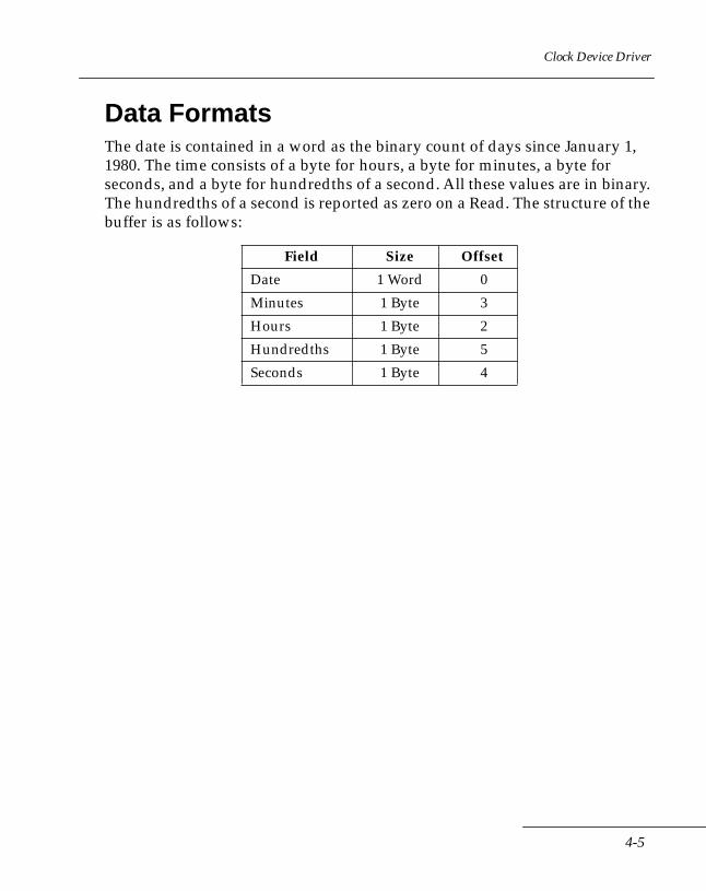
Clock Device Driver
Data FormatsThe date is contained in a word as the binary count of days since January 1, 1980. The time consists of a byte for hours, a byte for minutes, a byte for seconds, and a byte for hundredths of a second. All these values are in binary. The hundredths of a second is reported as zero on a Read. The structure of the buffer is as follows:
Field Size Offset
Date 1 Word 0
Minutes 1 Byte 3
Hours 1 Byte 2
Hundredths 1 Byte 5
Seconds 1 Byte 4
4-5

Series 3000 System Software Manual
4-6
Chapter 5 Line Printer Device Driver
Chapter ContentsIntroduction . . . . . . . . . . . . . . . . . . . . . . . . . . . . . . . . . . . . . . . . . . . . . . . . . . . . . . . . . . . . . . . . . . . . . 5-3
Printer Ports . . . . . . . . . . . . . . . . . . . . . . . . . . . . . . . . . . . . . . . . . . . . . . . . . . . . . . . . . . . . . . . . . 5-3Flow Control . . . . . . . . . . . . . . . . . . . . . . . . . . . . . . . . . . . . . . . . . . . . . . . . . . . . . . . . . . . . . . . . . 5-3
Line Printer Device Driver Functions . . . . . . . . . . . . . . . . . . . . . . . . . . . . . . . . . . . . . . . . . . . . . . . . 5-4IOCTL Write Subfunctions . . . . . . . . . . . . . . . . . . . . . . . . . . . . . . . . . . . . . . . . . . . . . . . . . . . . . . . . . 5-6
Subfunction 0: Reset . . . . . . . . . . . . . . . . . . . . . . . . . . . . . . . . . . . . . . . . . . . . . . . . . . . . . . . . . . 5-6Subfunction 1: Eject Page . . . . . . . . . . . . . . . . . . . . . . . . . . . . . . . . . . . . . . . . . . . . . . . . . . . . . . 5-6Subfunction 2: Set Top of Page. . . . . . . . . . . . . . . . . . . . . . . . . . . . . . . . . . . . . . . . . . . . . . . . . . 5-7Subfunction 3: Set Page Parameters . . . . . . . . . . . . . . . . . . . . . . . . . . . . . . . . . . . . . . . . . . . . . 5-7Subfunction 4: Set Terminator String . . . . . . . . . . . . . . . . . . . . . . . . . . . . . . . . . . . . . . . . . . . . 5-8Subfunction 5: Set Redirection Parameters . . . . . . . . . . . . . . . . . . . . . . . . . . . . . . . . . . . . . . . 5-9Subfunction 6: Restore Context . . . . . . . . . . . . . . . . . . . . . . . . . . . . . . . . . . . . . . . . . . . . . . . . . 5-9Subfunction 7: Enable/Disable DOS Critical Error Reporting . . . . . . . . . . . . . . . . . . . . . . 5-10
IOCTL Read Subfunctions . . . . . . . . . . . . . . . . . . . . . . . . . . . . . . . . . . . . . . . . . . . . . . . . . . . . . . . . 5-11Subfunction 0: Undefined. . . . . . . . . . . . . . . . . . . . . . . . . . . . . . . . . . . . . . . . . . . . . . . . . . . . . 5-11Subfunction 1: Get Line Number. . . . . . . . . . . . . . . . . . . . . . . . . . . . . . . . . . . . . . . . . . . . . . . 5-11Subfunction 2: Undefined. . . . . . . . . . . . . . . . . . . . . . . . . . . . . . . . . . . . . . . . . . . . . . . . . . . . . 5-11Subfunction 3: Get Page Parameters . . . . . . . . . . . . . . . . . . . . . . . . . . . . . . . . . . . . . . . . . . . . 5-11Subfunction 4: Get Terminator String. . . . . . . . . . . . . . . . . . . . . . . . . . . . . . . . . . . . . . . . . . . 5-12Subfunction 5: Get Redirection Parameters . . . . . . . . . . . . . . . . . . . . . . . . . . . . . . . . . . . . . . 5-12Subfunction 6: Save Context. . . . . . . . . . . . . . . . . . . . . . . . . . . . . . . . . . . . . . . . . . . . . . . . . . . 5-12Subfunction 7: Get Print Driver Status . . . . . . . . . . . . . . . . . . . . . . . . . . . . . . . . . . . . . . . . . . 5-13
Error Reporting . . . . . . . . . . . . . . . . . . . . . . . . . . . . . . . . . . . . . . . . . . . . . . . . . . . . . . . . . . . . . . . . . 5-14DOS Critical Errors . . . . . . . . . . . . . . . . . . . . . . . . . . . . . . . . . . . . . . . . . . . . . . . . . . . . . . . . . . 5-14IOCTL Error Codes . . . . . . . . . . . . . . . . . . . . . . . . . . . . . . . . . . . . . . . . . . . . . . . . . . . . . . . . . . 5-15Generic Error Codes . . . . . . . . . . . . . . . . . . . . . . . . . . . . . . . . . . . . . . . . . . . . . . . . . . . . . . . . . 5-16Error Trapping . . . . . . . . . . . . . . . . . . . . . . . . . . . . . . . . . . . . . . . . . . . . . . . . . . . . . . . . . . . . . . 5-16
5-1

Series 3000 System Software Manual
5-2
Line Printer Device Driver
IntroductionThe line printer device driver controls data output to parallel and serial ports. The driver supports output to the PRN, LPT1, LPT2, and LPT3 DOS devices. Data can be redirected to serial ports COM1 and COM2.
The driver supports limited page formatting, allowing the application to define page length, line length, header lengths and footer lengths.
The following topics are covered in this chapter:
• Line Printer Device Driver functions
• IOCTL Write Subfunctions
• IOCTL Read Subfunctions
• Error Handling
• Data structures for IOCTL Calls
The next paragraphs address some special characteristics of printing on Series 3000 terminals.
Printer PortsWhile the printer driver by default prints to PRN (aka LPT1), the parallel printer port, not all terminals have parallel ports. The Series 3300 has only serial ports. In the latter case, the printer driver defaults to redirecting printing to the first serial port, COM1.
Flow ControlOn Series 3300 terminals, a time-out error will occur if a printer pauses for longer than 5 seconds between accepting data. For example, the PS1000, which can print multiple copies of each label, may pause longer than 5 seconds before accepting data for the next label.
To prevent the time-out error, it is necessary to set the time-out to a value large enough for the anticipated delay. The appropriate time-out value depends on the printer and the application.
Set the time out value using the Extended Serial Port Initialization BIOS call (14h, 80h):
5-3
Series 3000 System Software Manual
• When using software flow control, set the control start wait time parameter (byte 16 in the control block).
• When using hardware flow control, set CTS Loss Detect Time (byte 17 in the control block).
Line Printer Device Driver FunctionsDOS and the line printer device driver pass commands and data back and forth using the request header structure in the driver. The command code, or function number, included in the request header specifies the routine to be executed when an application makes a DOS call.
The thirteen DOS standard device driver command codes are used by the line printer driver as follows:
Function 0: InitializationThis function is called only once, by the operating system, while the device driver is loading to initialize the device. This function must not be called by an application.
Function 1: Media Check This function performs no operation. It always returns a function completed status.
Function 2: Build BPB This function performs no operation. It always returns a function completed status.
Function 3: IOCTL Read This function allows access to the extended subfunctions of the printer driver. Refer to IOCTL Read Subfunctions later in this chapter.
Function 4: Read Not supported. The driver returns an unknown command error when this function is called.
5-4
Line Printer Device Driver
Function 5: Nondestructive Read Not supported. The driver returns an unknown command error when this function is called.
Function 6: Input Status Not supported. The driver returns an unknown command error when this function is called.
Function 7: Flush Input BuffersNot supported. The driver returns an unknown command error when this function is called.
Function 8: Write This function outputs the specified character string to the proper printer port. If the printer has been internally redirected, the string is output to the selected serial port. All internal formatting is performed before output.
Note that binary mode should be selected to allow output of entire strings. Otherwise, the operating system calls the driver for each character, greatly increasing the amount of overhead involved.
Function 9: Write with Verify This function performs exactly the same as the ‘Write’ function.
Function 10: Output Status This function returns the current output status of the selected port. For the parallel port, the “printer not ready” bit indicates the current status (see Chapter 2, Int 17h, function 02h). For a serial port, the “send data register empty” bit indicates the current status (see Chapter 2, Int 14h, function 03h).
Function 11: Flush Output Buffers This function performs no operation. A function completed status is returned.
Function 12: IOCTL Write This function allows access to the extended subfunctions of the printer driver. Refer to IOCTL Write Subfunctions later in this chapter.
5-5
Series 3000 System Software Manual
IOCTL Write SubfunctionsSubfunction 0: Reset The reset function puts the line printer driver in a known state, as follows:
• Page parameters are set to zero (ignore the parameters)
• Terminator string is set to null
• Redirection parameters are set to defaults (COM1 for the Series 3100, 3300 and 3900, LPT1 for the Series 3800)
• Baud rate and time-out are set to -1 (use current settings)
• If the communications port has been opened by line printer driver redirection, the port is closed
• DOS critical error reporting is enabled
All errors reported by this function are related to closing the redirected serial port.
Any saved printer driver context is unaffected by this function.
The control string for this command contains only the command and status bytes:
Subfunction 1: Eject Page The Eject Page routine advances the paper to the top of the next page, based on the page length and current index to determine remaining lines. The terminator string is printed that many times.
Note that if the page length is set to zero, the command is ignored. Also, if the terminator string has not been defined, the function performs no operation.
Byte Description
0 Command (00)
1 Status
5-6
Line Printer Device Driver
The control string for this command contains only the command and status bytes:
Subfunction 2: Set Top of Page Sets the line number index to zero, indicating start of page. The index value is updated each time the terminator string is printed.
No errors are reported by this function
The control string for this command contains only the command and status bytes:
Subfunction 3: Set Page Parameters This command sets the various page format parameters. There are four one-byte parameter values in this structure, in addition to the command byte and status byte: line length (in number of characters), page length, top margin, and bottom margin (all in number of lines). A parameter value of zero inhibits that type of formatting.
All of these parameters are initialized to zero when the line printer driver is loaded.
DOS critical error reporting is suppressed by this function.
Byte Description
0 Command (01)
1 Status
Byte Description
0 Command (02)
1 Status
5-7
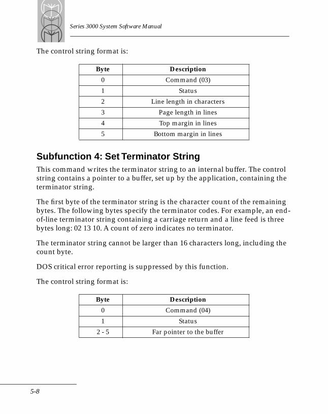
Series 3000 System Software Manual
The control string format is:
Subfunction 4: Set Terminator StringThis command writes the terminator string to an internal buffer. The control string contains a pointer to a buffer, set up by the application, containing the terminator string.
The first byte of the terminator string is the character count of the remaining bytes. The following bytes specify the terminator codes. For example, an end-of-line terminator string containing a carriage return and a line feed is three bytes long: 02 13 10. A count of zero indicates no terminator.
The terminator string cannot be larger than 16 characters long, including the count byte.
DOS critical error reporting is suppressed by this function.
The control string format is:
Byte Description
0 Command (03)
1 Status
2 Line length in characters
3 Page length in lines
4 Top margin in lines
5 Bottom margin in lines
Byte Description
0 Command (04)
1 Status
2 - 5 Far pointer to the buffer
5-8
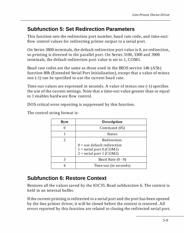
Line Printer Device Driver
Subfunction 5: Set Redirection ParametersThis function sets the redirection port number, baud rate code, and time-out/flow control values for redirecting printer output to a serial port.
On Series 3800 terminals, the default redirection port value is 0, no redirection, so printing is directed to the parallel port. On Series 3100, 3300 and 3900 terminals, the default redirection port value is set to 1, COM1.
Baud rate codes are the same as those used in the BIOS service 14h (A5h) function 80h (Extended Serial Port Initialization), except that a value of minus one (-1) can be specified to use the current baud rate.
Time-out values are expressed in seconds. A value of minus one (-1) specifies the use of the current settings. Note that a time-out value greater than or equal to 1 enables hardware flow control.
DOS critical error reporting is suppressed by this function.
The control string format is:
Subfunction 6: Restore ContextRestores all the values saved by the IOCTL Read subfunction 6. The context is held in an internal buffer.
If the current printing is redirected to a serial port and the port has been opened by the line printer driver, it will be closed before the context is restored. All errors reported by this function are related to closing the redirected serial port.
Byte Description
0 Command (05)
1 Status
2 Redirection:0 = use default redirection1 = serial port 0 (COM1)2 = serial port 1 (COM2)
3 Baud Rate (0 - 9)
4 Time-out (in seconds)
5-9

Series 3000 System Software Manual
The control string for this command contains only the command and status bytes:
Subfunction 7: Enable/Disable DOS Critical Error ReportingThis function allows the application to enable or disable DOS critical error reporting for the line printer driver.
The third byte of the control string is the CE flag, and sets critical error reporting as indicated below. The format of the control string is:
Byte Description
0 Command (06)
1 Status
Byte Description
0 Command (07)
1 Status
2 New DOS CE error state (0 = disable; 1 = enable)
5-10
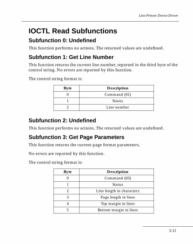
Line Printer Device Driver
IOCTL Read SubfunctionsSubfunction 0: Undefined This function performs no actions. The returned values are undefined.
Subfunction 1: Get Line Number This function returns the current line number, reported in the third byte of the control string. No errors are reported by this function.
The control string format is:
Subfunction 2: Undefined This function performs no actions. The returned values are undefined.
Subfunction 3: Get Page Parameters This function returns the current page format parameters.
No errors are reported by this function.
The control string format is:
Byte Description
0 Command (01)
1 Status
2 Line number
Byte Description
0 Command (03)
1 Status
2 Line length in characters
3 Page length in lines
4 Top margin in lines
5 Bottom margin in lines
5-11
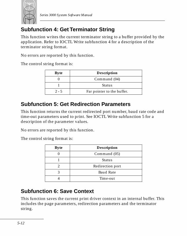
Series 3000 System Software Manual
Subfunction 4: Get Terminator StringThis function writes the current terminator string to a buffer provided by the application. Refer to IOCTL Write subfunction 4 for a description of the terminator string format.
No errors are reported by this function.
The control string format is:
Subfunction 5: Get Redirection ParametersThis function returns the current redirected port number, baud rate code and time-out parameters used to print. See IOCTL Write subfunction 5 for a description of the parameter values.
No errors are reported by this function.
The control string format is:
Subfunction 6: Save ContextThis function saves the current print driver context in an internal buffer. This includes the page parameters, redirection parameters and the terminator string.
Byte Description
0 Command (04)
1 Status
2 - 5 Far pointer to the buffer.
Byte Description
0 Command (05)
1 Status
2 Redirection port
3 Baud Rate
4 Time-out
5-12
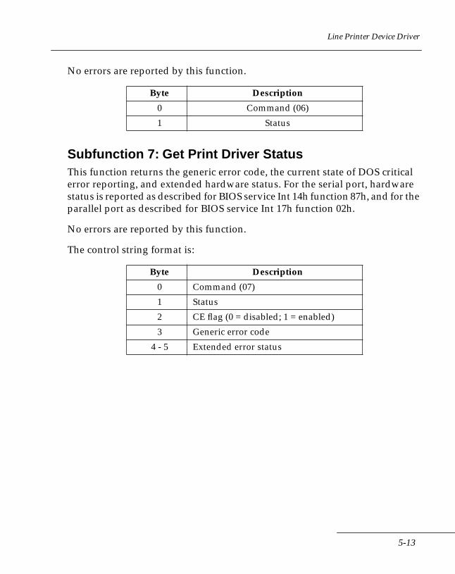
Line Printer Device Driver
No errors are reported by this function.
Subfunction 7: Get Print Driver StatusThis function returns the generic error code, the current state of DOS critical error reporting, and extended hardware status. For the serial port, hardware status is reported as described for BIOS service Int 14h function 87h, and for the parallel port as described for BIOS service Int 17h function 02h.
No errors are reported by this function.
The control string format is:
Byte Description
0 Command (06)
1 Status
Byte Description
0 Command (07)
1 Status
2 CE flag (0 = disabled; 1 = enabled)
3 Generic error code
4 - 5 Extended error status
5-13

Series 3000 System Software Manual
Error ReportingThe line printer device driver returns error information in three ways: DOS critical errors, IOCTL error codes, and generic error codes.
Due to the use of buffers and interrupts for data output, which improves performance, errors may be reported asynchronously to the application. For example, an error that occurs while transmitting data will be reported on the next command that accesses the BIOS status, and this command may have nothing to do with the error returned. An application must trap any error on all commands and realize the actual error may apply to an earlier command.
DOS Critical ErrorsUnless suppressed by the application or command, any error will result in the “Retry, Abort or Fail” error prompt. The following errors can occur.
Write Protect ViolationA bad port number, probably indicates that the driver's internal structures are corrupted. A cold boot is probably necessary.
Unknown Unit ErrorThe most probable cause is that another application has closed the communications port the print driver was redirected to. If there is no other application, then the driver's internal structures are probably corrupted. A cold boot is probably necessary.
Device Not ReadyWhen using the parallel printer port, this indicates a Timed-out condition. When redirected to a serial port, this indicates an error occurred on the communications line.
Printer Out of PaperThe printer cannot continue until paper is loaded.
5-14
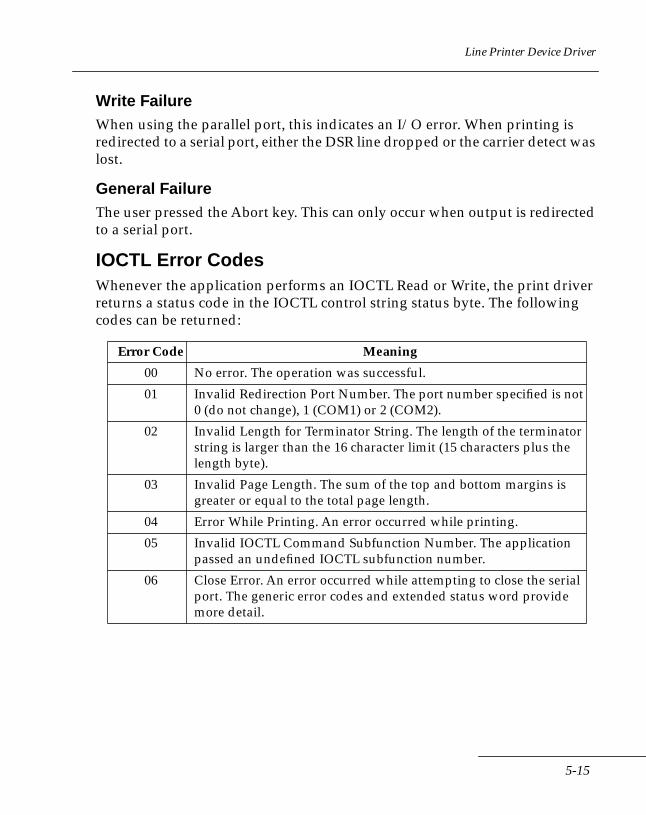
Line Printer Device Driver
Write FailureWhen using the parallel port, this indicates an I/O error. When printing is redirected to a serial port, either the DSR line dropped or the carrier detect was lost.
General FailureThe user pressed the Abort key. This can only occur when output is redirected to a serial port.
IOCTL Error CodesWhenever the application performs an IOCTL Read or Write, the print driver returns a status code in the IOCTL control string status byte. The following codes can be returned:
Error Code Meaning
00 No error. The operation was successful.
01 Invalid Redirection Port Number. The port number specified is not 0 (do not change), 1 (COM1) or 2 (COM2).
02 Invalid Length for Terminator String. The length of the terminator string is larger than the 16 character limit (15 characters plus the length byte).
03 Invalid Page Length. The sum of the top and bottom margins is greater or equal to the total page length.
04 Error While Printing. An error occurred while printing.
05 Invalid IOCTL Command Subfunction Number. The application passed an undefined IOCTL subfunction number.
06 Close Error. An error occurred while attempting to close the serial port. The generic error codes and extended status word provide more detail.
5-15
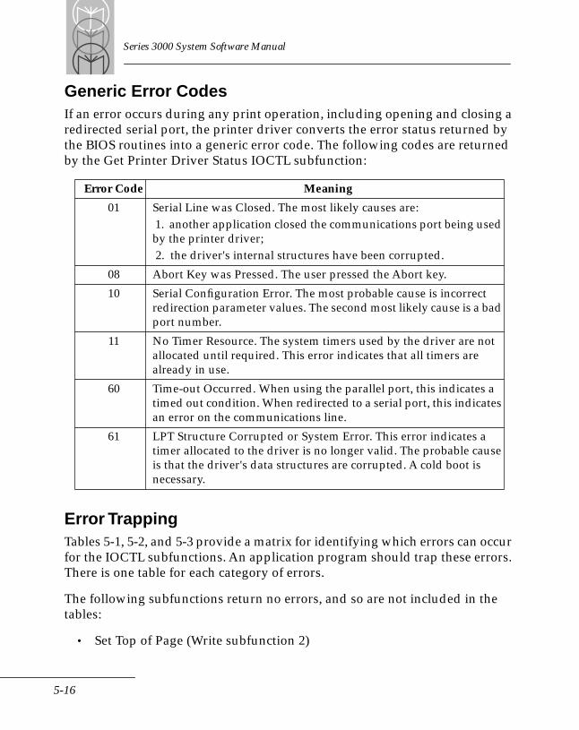
Series 3000 System Software Manual
Generic Error CodesIf an error occurs during any print operation, including opening and closing a redirected serial port, the printer driver converts the error status returned by the BIOS routines into a generic error code. The following codes are returned by the Get Printer Driver Status IOCTL subfunction:
Error TrappingTables 5-1, 5-2, and 5-3 provide a matrix for identifying which errors can occur for the IOCTL subfunctions. An application program should trap these errors. There is one table for each category of errors.
The following subfunctions return no errors, and so are not included in the tables:
• Set Top of Page (Write subfunction 2)
Error Code Meaning
01 Serial Line was Closed. The most likely causes are: 1. another application closed the communications port being used by the printer driver; 2. the driver's internal structures have been corrupted.
08 Abort Key was Pressed. The user pressed the Abort key.
10 Serial Configuration Error. The most probable cause is incorrect redirection parameter values. The second most likely cause is a bad port number.
11 No Timer Resource. The system timers used by the driver are not allocated until required. This error indicates that all timers are already in use.
60 Time-out Occurred. When using the parallel port, this indicates a timed out condition. When redirected to a serial port, this indicates an error on the communications line.
61 LPT Structure Corrupted or System Error. This error indicates a timer allocated to the driver is no longer valid. The probable cause is that the driver's data structures are corrupted. A cold boot is necessary.
5-16
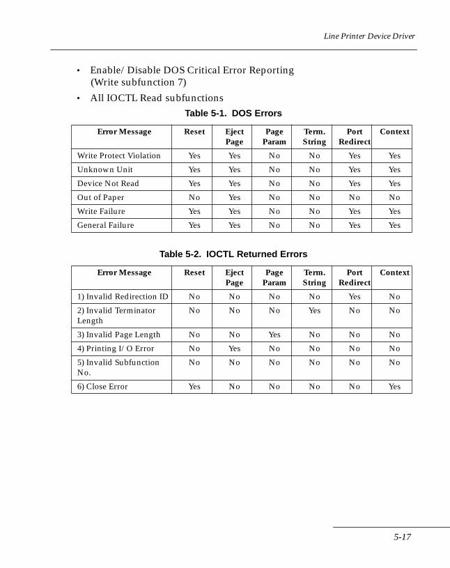
Line Printer Device Driver
• Enable/Disable DOS Critical Error Reporting(Write subfunction 7)
• All IOCTL Read subfunctionsTable 5-1. DOS Errors
Table 5-2. IOCTL Returned Errors
Error Message Reset EjectPage
Page Param
Term.String
PortRedirect
Context
Write Protect Violation Yes Yes No No Yes Yes
Unknown Unit Yes Yes No No Yes Yes
Device Not Read Yes Yes No No Yes Yes
Out of Paper No Yes No No No No
Write Failure Yes Yes No No Yes Yes
General Failure Yes Yes No No Yes Yes
Error Message Reset EjectPage
Page Param
Term.String
PortRedirect
Context
1) Invalid Redirection ID No No No No Yes No
2) Invalid Terminator Length
No No No Yes No No
3) Invalid Page Length No No Yes No No No
4) Printing I/O Error No Yes No No No No
5) Invalid Subfunction No.
No No No No No No
6) Close Error Yes No No No No Yes
5-17
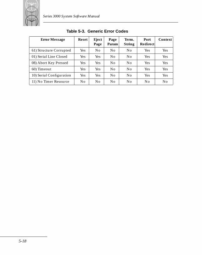
Series 3000 System Software Manual
Table 5-3. Generic Error Codes
Error Message Reset EjectPage
Page Param
Term.String
PortRedirect
Context
61) Structure Corrupted Yes No No No Yes Yes
01) Serial Line Closed Yes Yes No No Yes Yes
08) Abort Key Pressed Yes Yes No No Yes Yes
60) Timeout Yes Yes No No Yes Yes
10) Serial Configuration Yes Yes No No Yes Yes
11) No Timer Resource No No No No No No
5-18
Chapter 6 Console/Scanner Device Driver
Chapter ContentsIntroduction . . . . . . . . . . . . . . . . . . . . . . . . . . . . . . . . . . . . . . . . . . . . . . . . . . . . . . . . . . . . . . . . . . . . . 6-3Console Device Driver . . . . . . . . . . . . . . . . . . . . . . . . . . . . . . . . . . . . . . . . . . . . . . . . . . . . . . . . . . . . 6-3
Setting Up the Console Device Driver . . . . . . . . . . . . . . . . . . . . . . . . . . . . . . . . . . . . . . . . . . . 6-3The Scanning System. . . . . . . . . . . . . . . . . . . . . . . . . . . . . . . . . . . . . . . . . . . . . . . . . . . . . . . . . . . . . . 6-5
Running the Scanning Program. . . . . . . . . . . . . . . . . . . . . . . . . . . . . . . . . . . . . . . . . . . . . . . . . 6-5Controlling Scanning Functions . . . . . . . . . . . . . . . . . . . . . . . . . . . . . . . . . . . . . . . . . . . . . . . . 6-5
Scanner Commands. . . . . . . . . . . . . . . . . . . . . . . . . . . . . . . . . . . . . . . . . . . . . . . . . . . . . . . . . . . . . . . 6-6
6-1

Series 3000 System Software Manual
6-2
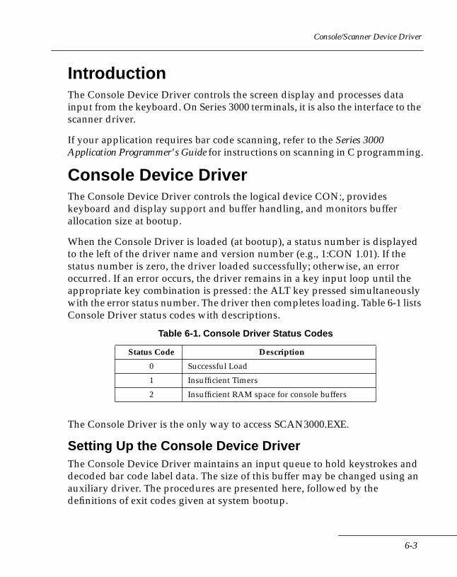
Console/Scanner Device Driver
IntroductionThe Console Device Driver controls the screen display and processes data input from the keyboard. On Series 3000 terminals, it is also the interface to the scanner driver.
If your application requires bar code scanning, refer to the Series 3000 Application Programmer's Guide for instructions on scanning in C programming.
Console Device DriverThe Console Device Driver controls the logical device CON:, provides keyboard and display support and buffer handling, and monitors buffer allocation size at bootup.
When the Console Driver is loaded (at bootup), a status number is displayed to the left of the driver name and version number (e.g., 1:CON 1.01). If the status number is zero, the driver loaded successfully; otherwise, an error occurred. If an error occurs, the driver remains in a key input loop until the appropriate key combination is pressed: the ALT key pressed simultaneously with the error status number. The driver then completes loading. Table 6-1 lists Console Driver status codes with descriptions.
The Console Driver is the only way to access SCAN3000.EXE.
Setting Up the Console Device DriverThe Console Device Driver maintains an input queue to hold keystrokes and decoded bar code label data. The size of this buffer may be changed using an auxiliary driver. The procedures are presented here, followed by the definitions of exit codes given at system bootup.
Table 6-1. Console Driver Status Codes
Status Code Description
0 Successful Load
1 Insufficient Timers
2 Insufficient RAM space for console buffers
6-3
Series 3000 System Software Manual
The Console Device Driver is part of the operating system. There is no resident driver configuration entry in the CONFIG.SYS file. Refer to the section on Running BLDINIT.EXE in the Terminal Initialization chapter in the Series 3000 Application Programmer's Guide for information on setting buffer sizes.
Estimating Input Buffer SizeKeystrokes are represented in either standard ASCII code or extended ASCII code. Any keystroke or keystroke combination that cannot be represented in standard ASCII code is assigned an extended ASCII code. The extension is the second byte of a two-byte string, the first byte always being zero.
For example:
• key A is expressed in standard ASCII code 65.
• left arrow key is represented by the string 0;75.
The expression 0;75 means the standard scan code is always 0 and the extended ASCII code is 75.
Therefore, in programming, if the ASCII value returned is zero, the second byte is examined to obtain the extended ASCII code.
For estimating how many keystrokes a buffer can hold, use these units of measure:
• three bytes for standard ASCII code keys.
• six bytes for extended ASCII code keys.
6-4
Console/Scanner Device Driver
The Scanning SystemRunning the Scanning ProgramTo implement scanning on a terminal, run the SCAN3000.EXE program. This is a TSR program which controls bar code scanning and decodes bar code data.
To run the scanner program, enter this command in the terminal's AUTOEXEC.BAT file:
DRIVE:\PATH\SCAN3000.EXE XXXX ZZZZ
The parameters are optional, but position sensitive. Both are expressed as hexadecimal values. The parameters are:
XXXX The size, in bytes, of the Raw Data Buffer. This buffer holds undecoded data acquired by the bar code scanner. The default value is 0800 hex. Each bar or space (transition) requires two bytes, so the default value allows for 1024 transitions.
ZZZZ The size, in bytes, of the Label Buffer. This buffer holds the decoded label being passed to the console's input queue. The default value is 0024 hex. There are four bytes of overhead per label, so a buffer size of 36 bytes (24 hex) allows a maximum label length of 32 bytes (maximum of 55 plus 4 overhead).
Controlling Scanning FunctionsApplication programs must use IOCTL function calls to request scanning and decoding operations. Calls are directed to the console driver (AH=0) which is the system interface to SCAN3000.EXE. Various parameters used with the IOCTL commands and subcommands may be used by the application to acquire fine control over the actual scanning process.
The following categories of items can be controlled by the program. The specific parameters are described with the applicable command:
• Scanner Characteristics - These parameters specify characteristics that a bar code scanner does or does not have. For example, a laser scanner usually has a trigger but a contact wand does not.
6-5

Series 3000 System Software Manual
• Scanning Device Parameters - These parameters determine the timing and the logic levels used in the scanner. For example, the Settling Time is the amount of time the laser requires to power up and become operable.
• Scan Operation Parameters - These parameters specify how the scan process will operate. For example, Beep On Decode may be enabled to provide audio feedback to the user upon successful decode.
• Scan Mode - This is set according to the particular type of scanning device connected to the Series 3000 terminal. The various modes describe sets of scanner characteristics.
• Decoder Parameters - These parameters set enable/disable functions of individual bar code symbologies.
• PDF 417 Parameters - These parameters control functions related to PDF 417 only.
The flexibility of the SCAN3000.EXE program allows the application programmer to maintain precise control of the bar code reading process.
Scanner CommandsThe application program controls scanning by issuing DOS IOCTL Read and Write commands (INT21h, Function 44h, subfunctions 2 and 3) to SCAN3000.EXE.
IOCTL Read commands return either scanned data or information about the scanner itself. The information requested is described in the data transfer block. The first byte of the block specifies a subcommand number, and is followed by any additional parameters required by the subcommand.
IOCTL Write commands send instructions to the scanner to set scanning parameters in preparation for scanning. The setup information is described in the data transfer block. The first byte of the block specifies a subcommand number, and is followed by the additional parameters required by the subcommand.
To execute an IOCTL read or write command, load the following registers with the indicated values, fill the memory address indicated by DS:DX (starting address) and CX (data length) with the data block string, and then issue the interrupt 21 call.
6-6
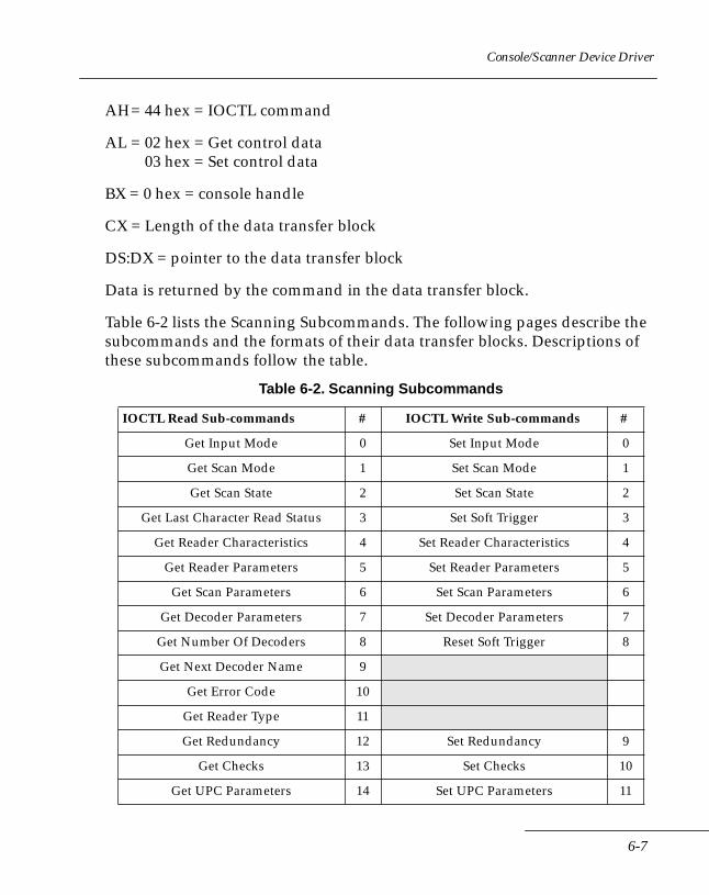
Console/Scanner Device Driver
AH= 44 hex = IOCTL command
AL = 02 hex = Get control data 03 hex = Set control data
BX = 0 hex = console handle
CX = Length of the data transfer block
DS:DX = pointer to the data transfer block
Data is returned by the command in the data transfer block.
Table 6-2 lists the Scanning Subcommands. The following pages describe the subcommands and the formats of their data transfer blocks. Descriptions of these subcommands follow the table.
Table 6-2. Scanning Subcommands
IOCTL Read Sub-commands # IOCTL Write Sub-commands #
Get Input Mode 0 Set Input Mode 0
Get Scan Mode 1 Set Scan Mode 1
Get Scan State 2 Set Scan State 2
Get Last Character Read Status 3 Set Soft Trigger 3
Get Reader Characteristics 4 Set Reader Characteristics 4
Get Reader Parameters 5 Set Reader Parameters 5
Get Scan Parameters 6 Set Scan Parameters 6
Get Decoder Parameters 7 Set Decoder Parameters 7
Get Number Of Decoders 8 Reset Soft Trigger 8
Get Next Decoder Name 9
Get Error Code 10
Get Reader Type 11
Get Redundancy 12 Set Redundancy 9
Get Checks 13 Set Checks 10
Get UPC Parameters 14 Set UPC Parameters 11
6-7
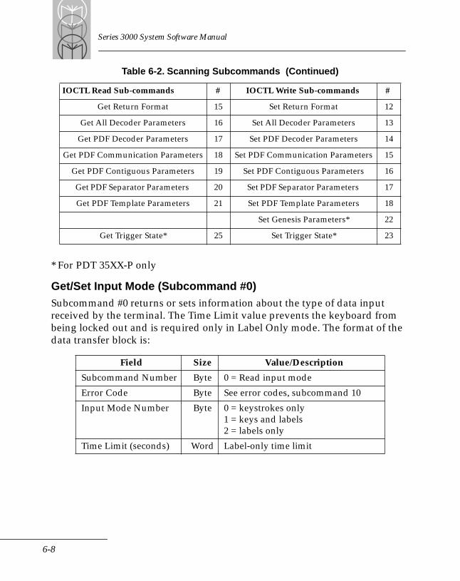
Series 3000 System Software Manual
* For PDT 35XX-P only
Get/Set Input Mode (Subcommand #0)Subcommand #0 returns or sets information about the type of data input received by the terminal. The Time Limit value prevents the keyboard from being locked out and is required only in Label Only mode. The format of the data transfer block is:
Get Return Format 15 Set Return Format 12
Get All Decoder Parameters 16 Set All Decoder Parameters 13
Get PDF Decoder Parameters 17 Set PDF Decoder Parameters 14
Get PDF Communication Parameters 18 Set PDF Communication Parameters 15
Get PDF Contiguous Parameters 19 Set PDF Contiguous Parameters 16
Get PDF Separator Parameters 20 Set PDF Separator Parameters 17
Get PDF Template Parameters 21 Set PDF Template Parameters 18
Set Genesis Parameters* 22
Get Trigger State* 25 Set Trigger State* 23
Field Size Value/Description
Subcommand Number Byte 0 = Read input mode
Error Code Byte See error codes, subcommand 10
Input Mode Number Byte 0 = keystrokes only1 = keys and labels2 = labels only
Time Limit (seconds) Word Label-only time limit
Table 6-2. Scanning Subcommands (Continued)
IOCTL Read Sub-commands # IOCTL Write Sub-commands #
6-8
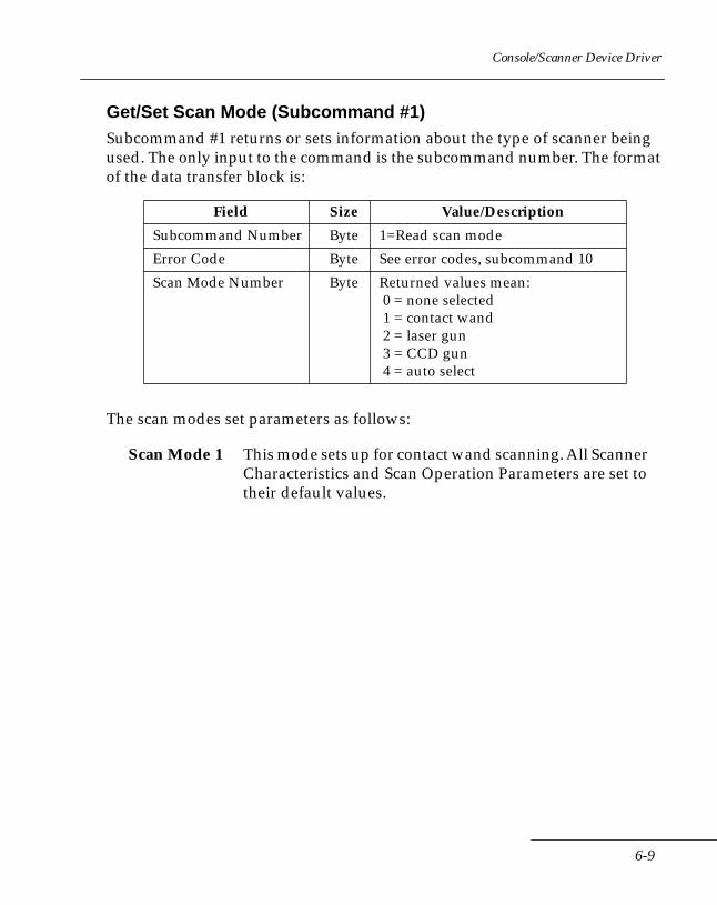
Console/Scanner Device Driver
Get/Set Scan Mode (Subcommand #1)Subcommand #1 returns or sets information about the type of scanner being used. The only input to the command is the subcommand number. The format of the data transfer block is:
The scan modes set parameters as follows:
Field Size Value/Description
Subcommand Number Byte 1=Read scan mode
Error Code Byte See error codes, subcommand 10
Scan Mode Number Byte Returned values mean: 0 = none selected 1 = contact wand 2 = laser gun 3 = CCD gun 4 = auto select
Scan Mode 1 This mode sets up for contact wand scanning. All Scanner Characteristics and Scan Operation Parameters are set to their default values.
6-9
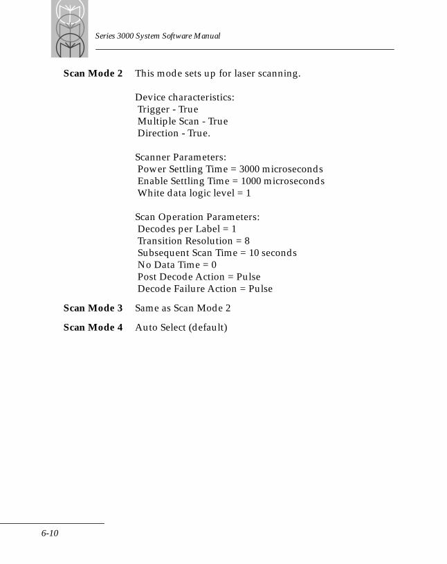
Series 3000 System Software Manual
Scan Mode 2 This mode sets up for laser scanning.
Device characteristics: Trigger - True Multiple Scan - True Direction - True.
Scanner Parameters: Power Settling Time = 3000 microseconds Enable Settling Time = 1000 microseconds White data logic level = 1
Scan Operation Parameters: Decodes per Label = 1 Transition Resolution = 8 Subsequent Scan Time = 10 seconds No Data Time = 0 Post Decode Action = Pulse Decode Failure Action = Pulse
Scan Mode 3 Same as Scan Mode 2
Scan Mode 4 Auto Select (default)
6-10
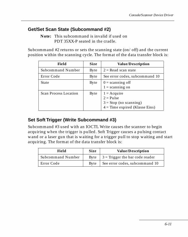
Console/Scanner Device Driver
Get/Set Scan State (Subcommand #2)Note: This subcommand is invalid if used on
PDT 35XX-P seated in the cradle.
Subcommand #2 returns or sets the scanning state (on/off) and the current position within the scanning cycle. The format of the data transfer block is:
Set Soft Trigger (Write Subcommand #3)Subcommand #3 used with an IOCTL Write causes the scanner to begin acquiring when the trigger is pulled. Soft Trigger causes a pulsing contact wand or a laser gun that is waiting for a trigger pull to stop waiting and start acquiring. The format of the data transfer block is:
Field Size Value/Description
Subcommand Number Byte 2 = Read scan state
Error Code Byte See error codes, subcommand 10
State Byte 0 = scanning off1 = scanning on
Scan Process Location Byte 1 = Acquire2 = Pulse3 = Stop (no scanning)4 = Time expired (Klasse Eins)
Field Size Value/Description
Subcommand Number Byte 3 = Trigger the bar code reader
Error Code Byte See error codes, subcommand 10
6-11
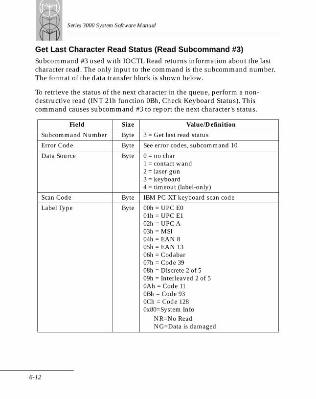
Series 3000 System Software Manual
Get Last Character Read Status (Read Subcommand #3)Subcommand #3 used with IOCTL Read returns information about the last character read. The only input to the command is the subcommand number. The format of the data transfer block is shown below.
To retrieve the status of the next character in the queue, perform a non-destructive read (INT 21h function 0Bh, Check Keyboard Status). This command causes subcommand #3 to report the next character's status.
Field Size Value/Definition
Subcommand Number Byte 3 = Get last read status
Error Code Byte See error codes, subcommand 10
Data Source Byte 0 = no char1 = contact wand2 = laser gun3 = keyboard4 = timeout (label-only)
Scan Code Byte IBM PC-XT keyboard scan code
Label Type Byte 00h = UPC E001h = UPC E102h = UPC A03h = MSI04h = EAN 805h = EAN 1306h = Codabar07h = Code 3908h = Discrete 2 of 509h = Interleaved 2 of 50Ah = Code 110Bh = Code 930Ch = Code 1280x80=System Info
NR=No ReadNG=Data is damaged
6-12
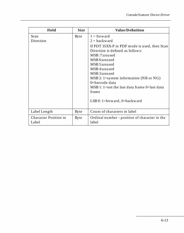
Console/Scanner Device Driver
Scan Direction
Byte 1 = forward2 = backwardIf PDT 35XX-P in PDF mode is used, then Scan Direction is defined as follows:MSB :7:unusedMSB 6:unusedMSB 5:unusedMSB 4:unusedMSB 3:unusedMSB 2: 1=system information (NR or NG) 0=barcode dataMSB 1: 1=not the last data frame 0=last data frame
LSB 0: 1=forward, 0=backward
Label Length Byte Count of characters in label
Character Position in Label
Byte Ordinal number - position of character in the label
Field Size Value/Definition
6-13
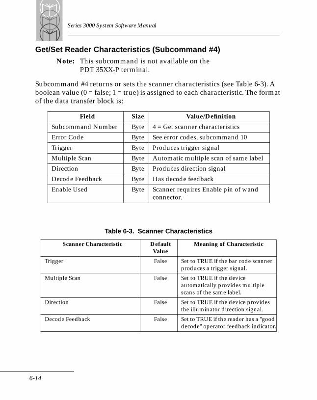
Series 3000 System Software Manual
Get/Set Reader Characteristics (Subcommand #4)Note: This subcommand is not available on the
PDT 35XX-P terminal.
Subcommand #4 returns or sets the scanner characteristics (see Table 6-3). A boolean value (0 = false; 1 = true) is assigned to each characteristic. The format of the data transfer block is:
Field Size Value/Definition
Subcommand Number Byte 4 = Get scanner characteristics
Error Code Byte See error codes, subcommand 10
Trigger Byte Produces trigger signal
Multiple Scan Byte Automatic multiple scan of same label
Direction Byte Produces direction signal
Decode Feedback Byte Has decode feedback
Enable Used Byte Scanner requires Enable pin of wand connector.
Table 6-3. Scanner Characteristics
Scanner Characteristic Default Value
Meaning of Characteristic
Trigger False Set to TRUE if the bar code scanner produces a trigger signal.
Multiple Scan False Set to TRUE if the device automatically provides multiple scans of the same label.
Direction False Set to TRUE if the device provides the illuminator direction signal.
Decode Feedback False Set to TRUE if the reader has a "good decode" operator feedback indicator.
6-14
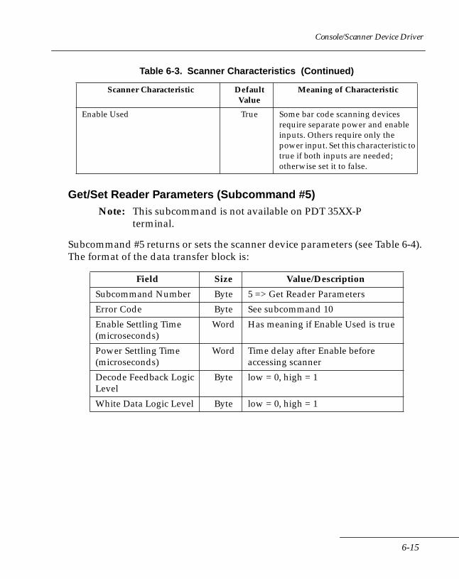
Console/Scanner Device Driver
Get/Set Reader Parameters (Subcommand #5)Note: This subcommand is not available on PDT 35XX-P
terminal.
Subcommand #5 returns or sets the scanner device parameters (see Table 6-4). The format of the data transfer block is:
Enable Used True Some bar code scanning devices require separate power and enable inputs. Others require only the power input. Set this characteristic to true if both inputs are needed; otherwise set it to false.
Field Size Value/Description
Subcommand Number Byte 5 => Get Reader Parameters
Error Code Byte See subcommand 10
Enable Settling Time (microseconds)
Word Has meaning if Enable Used is true
Power Settling Time (microseconds)
Word Time delay after Enable before accessing scanner
Decode Feedback Logic Level
Byte low = 0, high = 1
White Data Logic Level Byte low = 0, high = 1
Table 6-3. Scanner Characteristics (Continued)
Scanner Characteristic Default Value
Meaning of Characteristic
6-15

Series 3000 System Software Manual
Table 6-4. Scanner Device Parameters
Scanner Device Parameter Explanation
Enable Settling Time Default = 1000 microseconds
Sets the delay, in microseconds, between the scanner's Enable On and valid operation signal, if the "Enable Used" Scanner Characteristic is true; otherwise, this parameter is unused. NOTE: Scanner power is always turned on and allowed to settle before Enable On is activated.
Power Settling Time Default = 3000 microseconds
If "Enable Used" is true, this sets the delay, in microseconds, between scanner power on and Enable On. If "Enable Used" is false, this sets the delay between power on and valid operation.
Decode Feed Back Logic Level Default = 1 (high)
Signal level (high = 1, low = 0) that indicates to the operator that a successful decode of the current label data has taken place.
White Data Logic Level Default = 0 (38xx) 1 (31xx, 33xx, 39xx)
Sets the black/white logic level for white (1 = high, 0 = low).
6-16
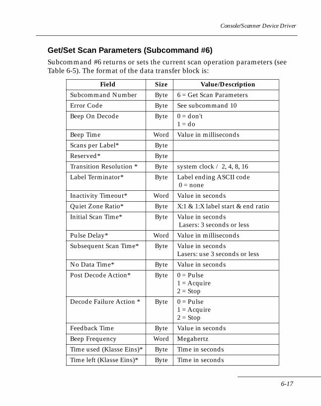
Console/Scanner Device Driver
Get/Set Scan Parameters (Subcommand #6)Subcommand #6 returns or sets the current scan operation parameters (see Table 6-5). The format of the data transfer block is:
Field Size Value/Description
Subcommand Number Byte 6 = Get Scan Parameters
Error Code Byte See subcommand 10
Beep On Decode Byte 0 = don't1 = do
Beep Time Word Value in milliseconds
Scans per Label* Byte
Reserved* Byte
Transition Resolution * Byte system clock / 2, 4, 8, 16
Label Terminator* Byte Label ending ASCII code 0 = none
Inactivity Timeout* Word Value in seconds
Quiet Zone Ratio* Byte X:1 & 1:X label start & end ratio
Initial Scan Time* Byte Value in seconds Lasers: 3 seconds or less
Pulse Delay* Word Value in milliseconds
Subsequent Scan Time* Byte Value in secondsLasers: use 3 seconds or less
No Data Time* Byte Value in seconds
Post Decode Action* Byte 0 = Pulse1 = Acquire2 = Stop
Decode Failure Action * Byte 0 = Pulse1 = Acquire2 = Stop
Feedback Time Byte Value in seconds
Beep Frequency Word Megahertz
Time used (Klasse Eins)* Byte Time in seconds
Time left (Klasse Eins)* Byte Time in seconds
6-17
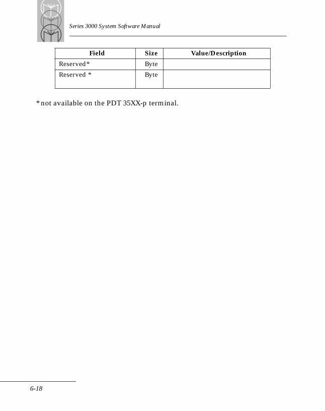
Series 3000 System Software Manual
* not available on the PDT 35XX-p terminal.
Reserved* Byte
Reserved * Byte
Field Size Value/Description
6-18
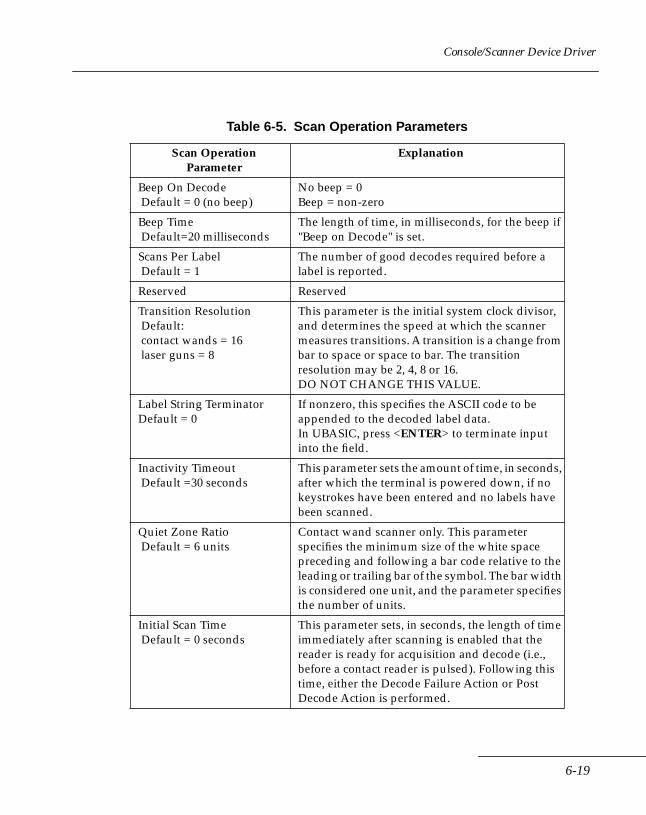
Console/Scanner Device Driver
Table 6-5. Scan Operation Parameters
Scan OperationParameter
Explanation
Beep On Decode Default = 0 (no beep)
No beep = 0Beep = non-zero
Beep Time Default=20 milliseconds
The length of time, in milliseconds, for the beep if "Beep on Decode" is set.
Scans Per Label Default = 1
The number of good decodes required before a label is reported.
Reserved Reserved
Transition Resolution Default: contact wands = 16 laser guns = 8
This parameter is the initial system clock divisor, and determines the speed at which the scanner measures transitions. A transition is a change from bar to space or space to bar. The transition resolution may be 2, 4, 8 or 16. DO NOT CHANGE THIS VALUE.
Label String Terminator Default = 0
If nonzero, this specifies the ASCII code to be appended to the decoded label data.In UBASIC, press <ENTER> to terminate input into the field.
Inactivity Timeout Default =30 seconds
This parameter sets the amount of time, in seconds, after which the terminal is powered down, if no keystrokes have been entered and no labels have been scanned.
Quiet Zone Ratio Default = 6 units
Contact wand scanner only. This parameter specifies the minimum size of the white space preceding and following a bar code relative to the leading or trailing bar of the symbol. The bar width is considered one unit, and the parameter specifies the number of units.
Initial Scan Time Default = 0 seconds
This parameter sets, in seconds, the length of time immediately after scanning is enabled that the reader is ready for acquisition and decode (i.e., before a contact reader is pulsed). Following this time, either the Decode Failure Action or Post Decode Action is performed.
6-19

Series 3000 System Software Manual
Pulse Delay Default= 45 milliseconds
This parameter specifies the delay between pulses, in milliseconds. If the Trigger scanner characteristic is set to false, indicating a contact scanner, the scanner will pulse. Pulsing is a power-save feature used with contact scanners. A longer delay increases battery life, but also causes the scanner to respond to label data more slowly.
Subsequent Scan Time Default = 10 seconds for wand 3 seconds for laser
This is the length of time that the scanner is ready for acquisition and decode for subsequent scan attempts. Following this time, either the Decode Failure Action or Post Decode Action is performed. (3 second maximum for lasers.)
No Data Time Default =3 seconds
If "Subsequent Scan Time" is zero, and the reader does not see a black to white or white to black transition within this amount of time, the Decode Failure Action is performed. (3 second maximum for lasers.)
Post Decode Action Default =0 (Pulse)
Action to take following a successful decode: PULSE=0 ACQUIRE=1 STOP=2
Decode Failure Action Default =0 (Pulse)
Action to take after a failed decode within the allotted time: PULSE=0 ACQUIRE=1 STOP=2
FeedbackTime Number of seconds to wait for feedback
Table 6-5. Scan Operation Parameters (Continued)
Scan OperationParameter
Explanation
6-20
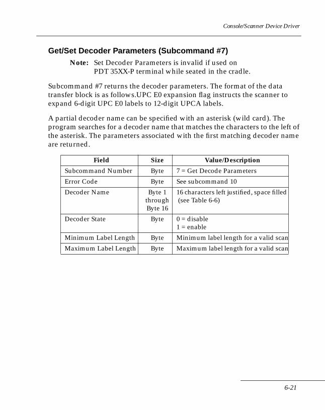
Console/Scanner Device Driver
Get/Set Decoder Parameters (Subcommand #7)Note: Set Decoder Parameters is invalid if used on
PDT 35XX-P terminal while seated in the cradle.
Subcommand #7 returns the decoder parameters. The format of the data transfer block is as follows.UPC E0 expansion flag instructs the scanner to expand 6-digit UPC E0 labels to 12-digit UPCA labels.
A partial decoder name can be specified with an asterisk (wild card). The program searches for a decoder name that matches the characters to the left of the asterisk. The parameters associated with the first matching decoder name are returned.
Field Size Value/Description
Subcommand Number Byte 7 = Get Decode Parameters
Error Code Byte See subcommand 10
Decoder Name Byte 1throughByte 16
16 characters left justified, space filled (see Table 6-6)
Decoder State Byte 0 = disable1 = enable
Minimum Label Length Byte Minimum label length for a valid scan
Maximum Label Length Byte Maximum label length for a valid scan
6-21
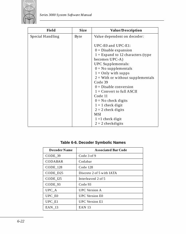
Series 3000 System Software Manual
Special Handling Byte Value dependent on decoder:
UPC-E0 and UPC-E1: 0 = Disable expansion 1 = Expand to 12 characters (type becomes UPC-A)UPC Supplementals: 0 = No supplementals 1 = Only with supps 2 = With or without supplementalsCode 39 0 = Disable conversion 1 = Convert to full ASCIICode 11 0 = No check digits 1 = 1 check digit 2 = 2 check digitsMSI 1 =1 check digit 2 = 2 checkdigits
Table 6-6. Decoder Symbolic Names
Decoder Name Associated Bar Code
CODE_39 Code 3 of 9
CODABAR Codabar
CODE_128 Code 128
CODE_D25 Discrete 2 of 5 with IATA
CODE_I25 Interleaved 2 of 5
CODE_93 Code 93
UPC_A UPC Version A
UPC_E0 UPC Version E0
UPC_E1 UPC Version E1
EAN_13 EAN 13
Field Size Value/Description
6-22
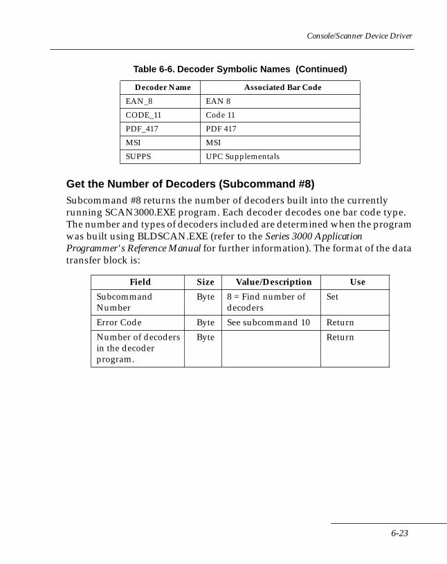
Console/Scanner Device Driver
Get the Number of Decoders (Subcommand #8)Subcommand #8 returns the number of decoders built into the currently running SCAN3000.EXE program. Each decoder decodes one bar code type. The number and types of decoders included are determined when the program was built using BLDSCAN.EXE (refer to the Series 3000 Application Programmer's Reference Manual for further information). The format of the data transfer block is:
EAN_8 EAN 8
CODE_11 Code 11
PDF_417 PDF 417
MSI MSI
SUPPS UPC Supplementals
Field Size Value/Description Use
Subcommand Number
Byte 8 = Find number of decoders
Set
Error Code Byte See subcommand 10 Return
Number of decoders in the decoder program.
Byte Return
Table 6-6. Decoder Symbolic Names (Continued)
Decoder Name Associated Bar Code
6-23
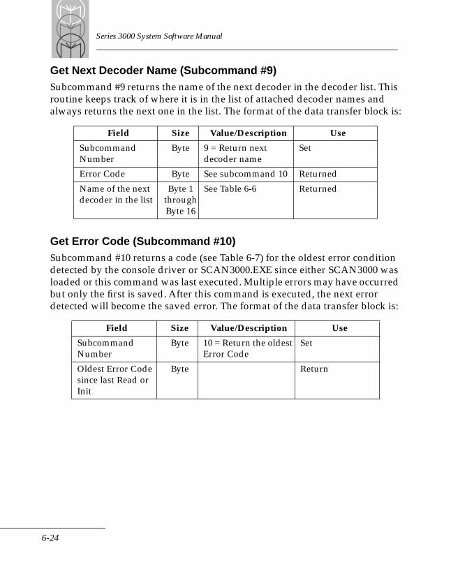
Series 3000 System Software Manual
Get Next Decoder Name (Subcommand #9)Subcommand #9 returns the name of the next decoder in the decoder list. This routine keeps track of where it is in the list of attached decoder names and always returns the next one in the list. The format of the data transfer block is:
Get Error Code (Subcommand #10)Subcommand #10 returns a code (see Table 6-7) for the oldest error condition detected by the console driver or SCAN3000.EXE since either SCAN3000 was loaded or this command was last executed. Multiple errors may have occurred but only the first is saved. After this command is executed, the next error detected will become the saved error. The format of the data transfer block is:
Field Size Value/Description Use
Subcommand Number
Byte 9 = Return next decoder name
Set
Error Code Byte See subcommand 10 Returned
Name of the next decoder in the list
Byte 1throughByte 16
See Table 6-6 Returned
Field Size Value/Description Use
Subcommand Number
Byte 10 = Return the oldest Error Code
Set
Oldest Error Code since last Read or Init
Byte Return
6-24
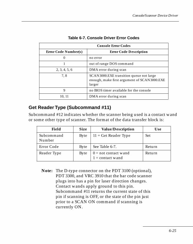
Console/Scanner Device Driver
Get Reader Type (Subcommand #11)Subcommand #12 indicates whether the scanner being used is a contact wand or some other type of scanner. The format of the data transfer block is:
Note: The D-type connector on the PDT 3100 (optional), PDT 3300, and VRC 3910 that the bar code scanner plugs into has a pin for laser direction changes. Contact wands apply ground to this pin. Subcommand #11 returns the current state of this pin if scanning is OFF, or the state of the pin just prior to a SCAN ON command if scanning is currently ON.
Table 6-7. Console Driver Error Codes
Console Error Codes
Error Code Number(s) Error Code Description
0 no error
1 out of range DOS command
2, 3, 4, 5, 6 DMA error during scan
7, 8 SCAN3000.EXE transition queue not large enough, make first argument of SCAN3000.EXE larger
9 no BIOS timer available for the console
10, 11 DMA error during scan
Field Size Value/Description Use
Subcommand Number
Byte 11 = Get Reader Type Set
Error Code Byte See Table 6-7. Return
Reader Type Byte 0 = not contact wand1 = contact wand
Return
6-25
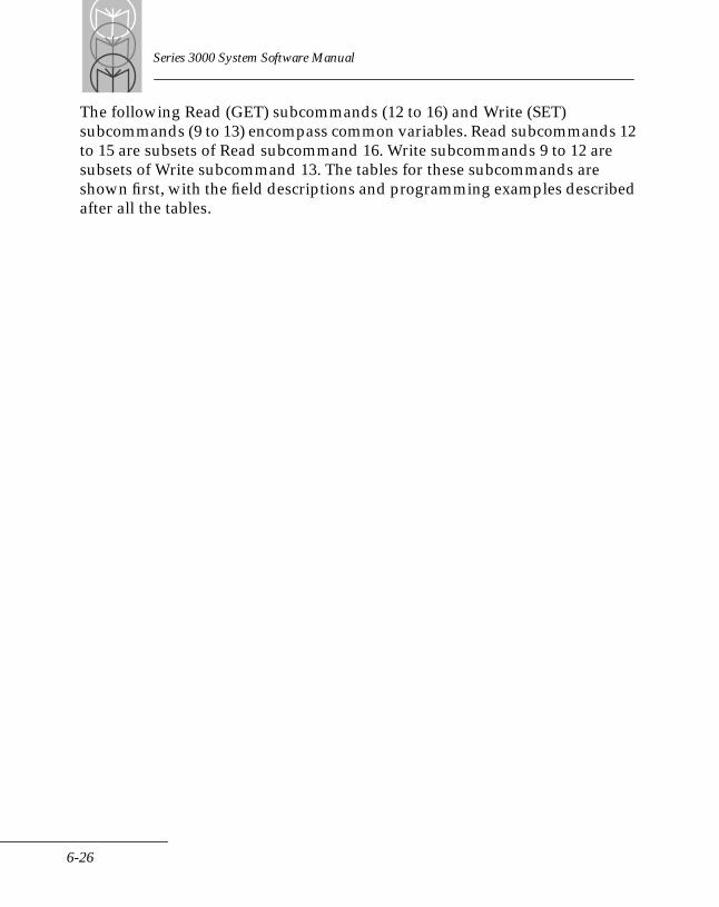
Series 3000 System Software Manual
The following Read (GET) subcommands (12 to 16) and Write (SET) subcommands (9 to 13) encompass common variables. Read subcommands 12 to 15 are subsets of Read subcommand 16. Write subcommands 9 to 12 are subsets of Write subcommand 13. The tables for these subcommands are shown first, with the field descriptions and programming examples described after all the tables.
6-26
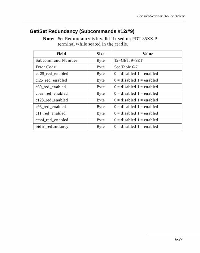
Console/Scanner Device Driver
Get/Set Redundancy (Subcommands #12/#9)Note: Set Redundancy is invalid if used on PDT 35XX-P
terminal while seated in the cradle.
Field Size Value
Subcommand Number Byte 12=GET, 9=SET
Error Code Byte See Table 6-7.
cd25_red_enabled Byte 0 = disabled 1 = enabled
ci25_red_enabled Byte 0 = disabled 1 = enabled
c39_red_enabled Byte 0 = disabled 1 = enabled
cbar_red_enabled Byte 0 = disabled 1 = enabled
c128_red_enabled Byte 0 = disabled 1 = enabled
c93_red_enabled Byte 0 = disabled 1 = enabled
c11_red_enabled Byte 0 = disabled 1 = enabled
cmsi_red_enabled Byte 0 = disabled 1 = enabled
bidir_redundancy Byte 0 = disabled 1 = enabled
6-27

Series 3000 System Software Manual
Get/Set Checks (Subcommands #13/#10)Note: Set Checks is invalid if used on PDT 35XX-P
terminal while seated in the cradle.
Field Size Value
Subcommand Number Byte 13=GET, 10=SET
Error Code Byte See Table 6-7.
code39_chk_b Byte 0 = disabled 1 = enabled
c11_chk_dgt Byte 0, 1, or 2 check digits
report_c11_chk Byte 0 = disabled 1 = enabled
msi_chk_dgt Byte 1 or 2 check digits
report_msi_chk Byte 0 = disabled 1 = enabled
upc_a_chk_b Byte 0 = disabled 1 = enabled
upc_e_chk_b Byte 0 = disabled 1 = enabled
upc_e1_chk_b Byte 0 = disabled 1 = enabled
6-28
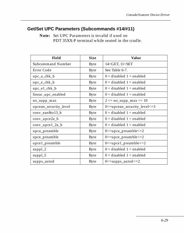
Console/Scanner Device Driver
Get/Set UPC Parameters (Subcommands #14/#11)Note: Set UPC Parameters is invalid if used on
PDT 35XX-P terminal while seated in the cradle.
Field Size Value
Subcommand Number Byte 14=GET, 11=SET
Error Code Byte See Table 6-7.
upc_a_chk_b Byte 0 = disabled 1 = enabled
upc_e_chk_b Byte 0 = disabled 1 = enabled
upc_e1_chk_b Byte 0 = disabled 1 = enabled
linear_upc_enabled Byte 0 = disabled 1 = enabled
no_supp_max Byte 2 <= no_supp_max <= 10
upcean_security_level Byte 0<=upcean_security_level<=3
conv_ean8to13_b Byte 0 = disabled 1 = enabled
conv_upce2a_b Byte 0 = disabled 1 = enabled
conv_upce1_2a_b Byte 0 = disabled 1 = enabled
upca_preamble Byte 0<=upca_preamble<=2
upce_preamble Byte 0<=upce_preamble<=2
upce1_preamble Byte 0<=upce1_preamble<=2
suppl_2 Byte 0 = disabled 1 = enabled
suppl_5 Byte 0 = disabled 1 = enabled
supps_autod Byte 0<=supps_autod<=2
6-29
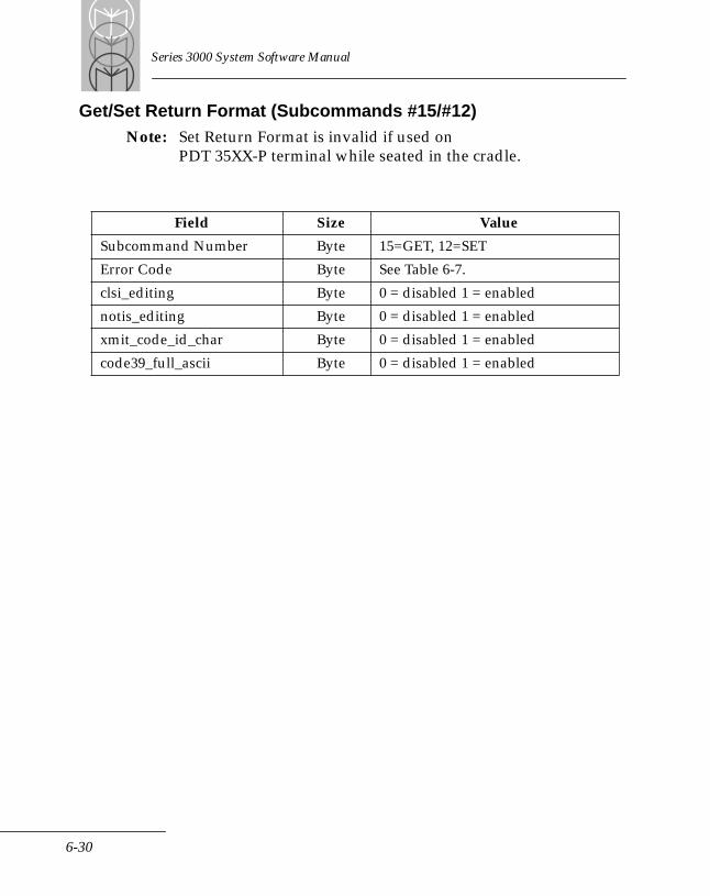
Series 3000 System Software Manual
Get/Set Return Format (Subcommands #15/#12)Note: Set Return Format is invalid if used on
PDT 35XX-P terminal while seated in the cradle.
Field Size Value
Subcommand Number Byte 15=GET, 12=SET
Error Code Byte See Table 6-7.
clsi_editing Byte 0 = disabled 1 = enabled
notis_editing Byte 0 = disabled 1 = enabled
xmit_code_id_char Byte 0 = disabled 1 = enabled
code39_full_ascii Byte 0 = disabled 1 = enabled
6-30
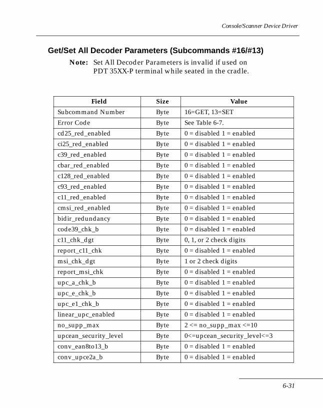
Console/Scanner Device Driver
Get/Set All Decoder Parameters (Subcommands #16/#13)Note: Set All Decoder Parameters is invalid if used on
PDT 35XX-P terminal while seated in the cradle.
Field Size Value
Subcommand Number Byte 16=GET, 13=SET
Error Code Byte See Table 6-7.
cd25_red_enabled Byte 0 = disabled 1 = enabled
ci25_red_enabled Byte 0 = disabled 1 = enabled
c39_red_enabled Byte 0 = disabled 1 = enabled
cbar_red_enabled Byte 0 = disabled 1 = enabled
c128_red_enabled Byte 0 = disabled 1 = enabled
c93_red_enabled Byte 0 = disabled 1 = enabled
c11_red_enabled Byte 0 = disabled 1 = enabled
cmsi_red_enabled Byte 0 = disabled 1 = enabled
bidir_redundancy Byte 0 = disabled 1 = enabled
code39_chk_b Byte 0 = disabled 1 = enabled
c11_chk_dgt Byte 0, 1, or 2 check digits
report_c11_chk Byte 0 = disabled 1 = enabled
msi_chk_dgt Byte 1 or 2 check digits
report_msi_chk Byte 0 = disabled 1 = enabled
upc_a_chk_b Byte 0 = disabled 1 = enabled
upc_e_chk_b Byte 0 = disabled 1 = enabled
upc_e1_chk_b Byte 0 = disabled 1 = enabled
linear_upc_enabled Byte 0 = disabled 1 = enabled
no_supp_max Byte 2 <= no_supp_max <=10
upcean_security_level Byte 0<=upcean_security_level<=3
conv_ean8to13_b Byte 0 = disabled 1 = enabled
conv_upce2a_b Byte 0 = disabled 1 = enabled
6-31
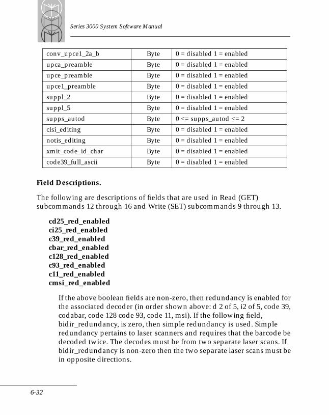
Series 3000 System Software Manual
Field Descriptions.
The following are descriptions of fields that are used in Read (GET) subcommands 12 through 16 and Write (SET) subcommands 9 through 13.
cd25_red_enabledci25_red_enabledc39_red_enabledcbar_red_enabledc128_red_enabledc93_red_enabledc11_red_enabledcmsi_red_enabled
If the above boolean fields are non-zero, then redundancy is enabled for the associated decoder (in order shown above: d 2 of 5, i2 of 5, code 39, codabar, code 128 code 93, code 11, msi). If the following field, bidir_redundancy, is zero, then simple redundancy is used. Simple redundancy pertains to laser scanners and requires that the barcode be decoded twice. The decodes must be from two separate laser scans. If bidir_redundancy is non-zero then the two separate laser scans must be in opposite directions.
conv_upce1_2a_b Byte 0 = disabled 1 = enabled
upca_preamble Byte 0 = disabled 1 = enabled
upce_preamble Byte 0 = disabled 1 = enabled
upce1_preamble Byte 0 = disabled 1 = enabled
suppl_2 Byte 0 = disabled 1 = enabled
suppl_5 Byte 0 = disabled 1 = enabled
supps_autod Byte 0 <= supps_autod <= 2
clsi_editing Byte 0 = disabled 1 = enabled
notis_editing Byte 0 = disabled 1 = enabled
xmit_code_id_char Byte 0 = disabled 1 = enabled
code39_full_ascii Byte 0 = disabled 1 = enabled
6-32

Console/Scanner Device Driver
bidir_redundancy
If this boolean field is non-zero, then the simple redundancy above has the added requirement that the two decodes of the barcode must be in opposite laser sweep directions. bidir_redundancy being TRUE has no affect unless one of the above simple redundancy fields is true. It simply modifies the type of redundancy the above fields represent.
code39_chk_b
Some Code 39 bar codes contain a check digit character. If code39_chk_b is non-zero, then the decoder will require that the check digit be present and correct. If it is zero, then the check digit character (or the character in the check digit position) is simply sent to the application with the other data characters.
c11_chk_dgt
Code 11 may have zero, one, or two check digits. Values other then these will cause unpredictable operation. The number of check digits verified (the last character is considered the first check digit and the next-to-last character the second check digit) is c11_chk_dgt. Do not include the number of check digits in the Code 11 length specification even if they are to be reported back to the application.
report_c11_chk
If it is desired to have the check digit(s) returned to the application, then this field is set to a non-zero value. If it is zero, the check digits are not reported. This field has no affect on the length specification. Only data characters should be accounted for in the length specification, not check digits.
6-33

Series 3000 System Software Manual
msi_chk_dgt
MSI Code may have one, or two check digits. Values other than these will cause unpredictable operation (if zero the decoder defaults to one check digit). The number of check digits verified (the last character is considered the first check digit and the next-to-last character the second check digit) is msi_chk_dgt. Do not include the number of check digits in the MSI length specification even if they are to be reported back to the application.
report_msi_chk
If it is desired to have the check digit(s) returned to the application, then this field is set to a non-zero value. If it is zero, the check digits are not reported. This field has no affect on the length specification. Only data characters should be accounted for in the length specification, not check digits.
upc_a_chk_bupc_e_chk_bupc_e1_chk_b
If the above fields are true, then the check digit is reported to the application. The check digit is always verified for UPC. This simply determines whether it is reported.
linear_upc_enabled
UPC labels can be divided into left and right blocks (manufacturer and item numbers). The UPC decoder has the capability to take a block from a partially decoded UPC label and combine it with a block decoded in an earlier scan (providing it matches in type and the check digit test passes) to create a decoded label. This increases the aggressiveness of the decoder. It does not usually cause a problem unless there are multiple labels in the laser field that may have potentially interchangeable blocks. If this is the case, the decoder can be forced to require that all of a labels’ blocks are decoded in the same sweep. If linear_upc_enabled is TRUE (non-zero), then the UPC blocks must be
6-34
Console/Scanner Device Driver
decoded this way. If it is zero, the decoder can decode the blocks in separate scans.
no_supp_max
UPC labels sometimes have small bar codes called supplementals appended to the end of them. The UPC decoder can be configured to recognize the presence or absence of these supplementals and report them. If labels with and without supplementals are being returned to the application, then the supplemental auto discrimination mode is active. No_supp_max determines how many times the decoder will attempt to decode the UPC label before it is satisfied that there are no supplementals. Range is from 2 to 10.
upcean_security_level
This parameter aids in decoding poor labels by preventing against misdecodes. The variable determines how stringent the decode algorithm used for UPC and EAN bar codes is. The higher the level, the more stringent, but the less aggressive the decoder is. The lower the level the less stringent but the more aggressive the decoding. A higher security level provides greater insurance against misdecodes.
conv_ean8to13_b
If this field is non-zero, then EAN8 bar codes will be zero padded to 13 characters. This is useful when reading both EAN13 labels and EAN8 labels and the input field is fixed at 13 characters.
conv_upce2a_b
UPC E0 labels are zero-suppressed UPCA labels. If a UPCA label contains enough zeros, then it can be condensed to a 6 character UPC label. If conv_upce2a_b is non-zero, then UPC E0 labels will be expanded from 6 characters to the equivalent 12 character UPCA label. The label type indicator will also change to UPCA.
6-35

Series 3000 System Software Manual
conv_upce1_2a_b
UPC E1 labels are derived in the same way as UPC E0 labels. The only difference is the parity pattern of the UPC characters in the label. UPC E1 is non-standard and is only used in custom applications. If this variable is non-zero, then the UPC E1 labels will be expanded from 6 characters to the equivalent 12 character UPCA label. The label type indicator will also change to UPCA.
upca_preambleupce_preambleupce1_preamble
EAN13 labels have a number system and country code associated with them. UPC has no country code, but it is number system zero. If both UPC and EAN bar codes are being scanned, it may be desired to have a the UPC number system character, along with a place holder for the country code, prefix a decoded UPC label. These two characters are always reported for EAN labels. This allows compatibility with EAN input fields. If the preamble field (upca_preamble, upce_preamble or upce1_preamble) is zero, then no characters will prefix the label data. If it is one, then the number system character for the code type will prefix the data (a one for upce1 because its number system is 1, zero for all other UPC types). If it is 2, then a zero will prefix the number system character and the label data as a place holder for the country code.
suppl_2
If this value is non-zero, then supplemental UPC bar codes of length 2 may be decoded if the supplemental decoding mode (supps_autod) is non-zero.
6-36
Console/Scanner Device Driver
suppl_5
If this value is non-zero, then supplemental UPC bar codes of length 5 may be decoded if the supplemental decoding mode (supps_autod) is non-zero.
supps_autod
This field indicates the method of handling supplemental bar codes. If it is zero, supplemental bar codes are ignored. If it is one, then the UPC label must have a supplemental attached. The supplemental must match the enabled lengths. For instance, if suppl_2 and suppl_5 are TRUE then either a length 2 or length 5 supplemental barcode must be present. If suppl_5 is TRUE and suppl_2 is FALSE, then only bar codes with a length 5 supplemental are valid. If supps_autod is 2, then the decoder is in the auto discriminate mode. This means that if the decoder determines that there is a supplemental of any length, it is reported. Suppl_2 and suppl_5 have no affect in this mode.
clsi_editing
This field is used to change a 14 character codabar symbol (not including stop/start chars) into a special format. In this format, the start and stop chars are removed and spaces are added after the first, fifth and tenth digits. For example, the symbol “a12345678901234” is changed into “1 2345 67890 1234”.
notis_editing
This field is used to remove the start and stop characters from the codabar symbol.
6-37
Series 3000 System Software Manual
xmit_code_id_char
If this value is non-zero, then depending on the code type one of the following ASCII characters will prefix the data characters returned to the application:
'A'= UPC,UPCE,UPCE1,EAN13,EAN8'B'= Code 39'C'= Codabar'D'= Code 128'E'= Code 93'F''= I 2 of 5'G'= D 2 of 5'G'= IATA'H'= Code 11'J'= MSI
code39_full_ascii
Full ASCII is a feature of Code 39 that allows full representation of the ASCII character set by combining certain pairs of Code 39 characters. When this option is active, characters that are not in the standard Code 39 set are created by TWO standard Code 39 characters being encoded in the label. In Full ASCII mode, only the character represented by this combination is returned. If Full ASCII is not selected, and the labels that are being used contain Full ASCII representations, then the two character combinations will be returned to the application instead. If this value is non-zero, FULL ASCII is selected.
6-38

Console/Scanner Device Driver
Get/Set PDF Decoder Parameters (Subcommands #17/#14)Note: This subcommand is not available on PDT 35XX-P
terminal.
Field Descriptions.
mode
Current mode of the PDF decoders as follows:
0 = PDF off 1-D scanning with standard scanners allowed
1 = PDF mode 1 - 2-D & 1-D scanning with PDF 1000 scanner data is passed on to application based on current datamode
scandir
Scan direction value that is to be reported to application
reader
Reader type that is to be reported to application
datamode
Data mode for PDF mode 1
Field Size Value
Subcommand Number byte 17=GET, 14=SET
Error Code byte See Table 6-7.
mode byte 0 = PDF_MODE_1D1 =PDF_MODE_1
scandir byte 1 = SCANDIR_FORWARD2 = SCANDIR_BACKWARD
reader byte 1 = SOURCE_CONTACT2 = SOURCE_LASER
datamode byte 0 = PDF_MODE_CONTIGUOUS1 = PDF_MODE_SEPARATOR2 = PDF_MODE_TEMPLATE
6-39
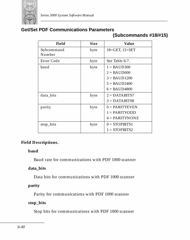
Series 3000 System Software Manual
Get/Set PDF Communications Parameters (Subcommands #18/#15)
Field Descriptions.
baud
Baud rate for communications with PDF 1000 scanner
data_bits
Data bits for communications with PDF 1000 scanner
parity
Parity for communications with PDF 1000 scanner
stop_bits
Stop bits for communications with PDF 1000 scanner
Field Size Value
SubcommandNumber
byte 18=GET, 15=SET
Error Code byte See Table 6-7.
baud byte 1 = BAUD300 2 = BAUD600 3 = BAUD12005 = BAUD24006 = BAUD4800
data_bits byte 2 = DATABITS73 = DATABITS8
parity byte 0 = PARITYEVEN1 = PARITYODD 4 = PARITYNONE
stop_bits byte 0 = STOPBITS11 = STOPBITS2
6-40
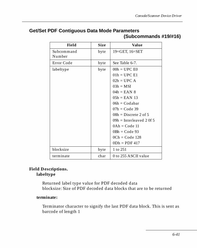
Console/Scanner Device Driver
Get/Set PDF Contiguous Data Mode Parameters(Subcommands #19/#16)
Field Descriptions. labeltype
Returned label type value for PDF decoded datablocksize: Size of PDF decoded data blocks that are to be returned
terminate:
Terminator character to signify the last PDF data block. This is sent as barcode of length 1
Field Size Value
Subcommand Number
byte 19=GET, 16=SET
Error Code byte See Table 6-7.
labeltype byte 00h = UPC E001h = UPC E102h = UPC A03h = MSI04h = EAN 805h = EAN 1306h = Codabar07h = Code 3908h = Discrete 2 of 509h = Interleaved 2 0f 50Ah = Code 110Bh = Code 930Ch = Code 1280Dh = PDF 417
blocksize byte 1 to 251
terminate char 0 to 255 ASCII value
6-41
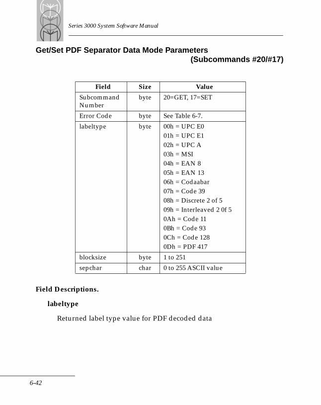
Series 3000 System Software Manual
Get/Set PDF Separator Data Mode Parameters(Subcommands #20/#17)
Field Descriptions.
labeltype
Returned label type value for PDF decoded data
Field Size Value
Subcommand Number
byte 20=GET, 17=SET
Error Code byte See Table 6-7.
labeltype byte 00h = UPC E001h = UPC E102h = UPC A03h = MSI04h = EAN 805h = EAN 1306h = Codaabar07h = Code 3908h = Discrete 2 of 509h = Interleaved 2 0f 50Ah = Code 110Bh = Code 930Ch = Code 1280Dh = PDF 417
blocksize byte 1 to 251
sepchar char 0 to 255 ASCII value
6-42

Console/Scanner Device Driver
blocksize
Maximum size of PDF decoded separator blocks. If data that is terminated by sepchar is larger than blocksize, it is broken up into data blocks with maximum length blocksize.
sepchar
Data separator character to signify the end of the current data block.
6-43
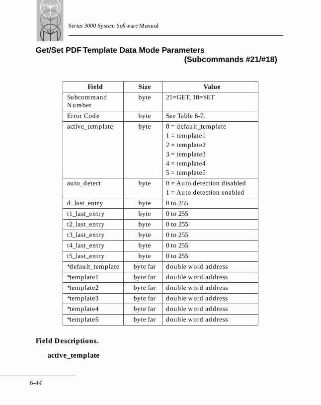
Series 3000 System Software Manual
Get/Set PDF Template Data Mode Parameters(Subcommands #21/#18)
Field Descriptions.
active_template
Field Size Value
Subcommand Number
byte 21=GET, 18=SET
Error Code byte See Table 6-7.
active_template byte 0 = default_template1 = template12 = template23 = template34 = template45 = template5
auto_detect byte 0 = Auto detection disabled1 = Auto detection enabled
d_last_entry byte 0 to 255
t1_last_entry byte 0 to 255
t2_last_entry byte 0 to 255
t3_last_entry byte 0 to 255
t4_last_entry byte 0 to 255
t5_last_entry byte 0 to 255
*default_template byte far double word address
*template1 byte far double word address
*template2 byte far double word address
*template3 byte far double word address
*template4 byte far double word address
*template5 byte far double word address
6-44
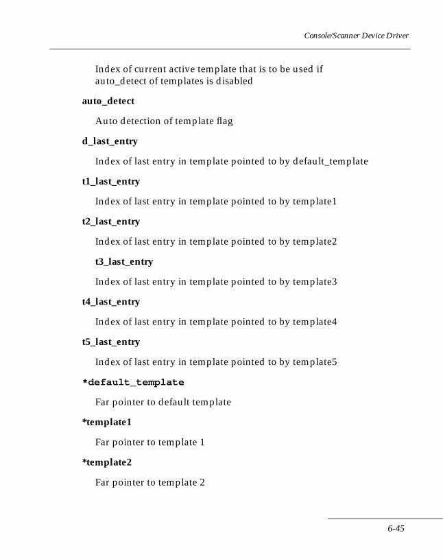
Console/Scanner Device Driver
Index of current active template that is to be used if auto_detect of templates is disabled
auto_detect
Auto detection of template flag
d_last_entry
Index of last entry in template pointed to by default_template
t1_last_entry
Index of last entry in template pointed to by template1
t2_last_entry
Index of last entry in template pointed to by template2
t3_last_entry
Index of last entry in template pointed to by template3
t4_last_entry
Index of last entry in template pointed to by template4
t5_last_entry
Index of last entry in template pointed to by template5
*default_template
Far pointer to default template
*template1
Far pointer to template 1
*template2
Far pointer to template 2
6-45

Series 3000 System Software Manual
*template3
Far pointer to template 3
*template4
Far pointer to template 4
*template5
Far pointer to template 5
6-46
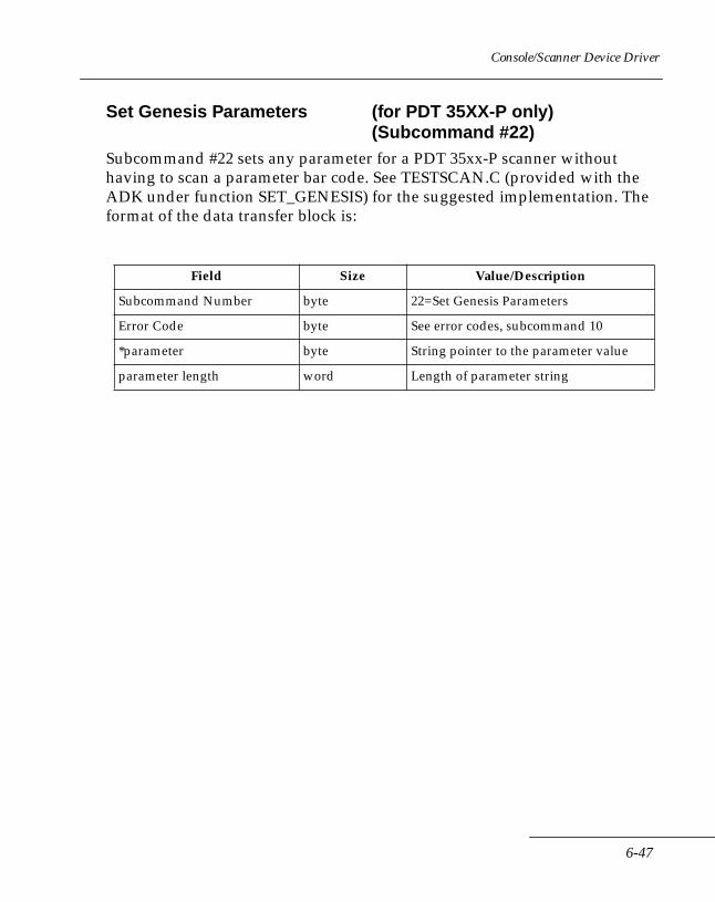
Console/Scanner Device Driver
Set Genesis Parameters (for PDT 35XX-P only)(Subcommand #22)
Subcommand #22 sets any parameter for a PDT 35xx-P scanner without having to scan a parameter bar code. See TESTSCAN.C (provided with the ADK under function SET_GENESIS) for the suggested implementation. The format of the data transfer block is:
Field Size Value/Description
Subcommand Number byte 22=Set Genesis Parameters
Error Code byte See error codes, subcommand 10
*parameter byte String pointer to the parameter value
parameter length word Length of parameter string
6-47
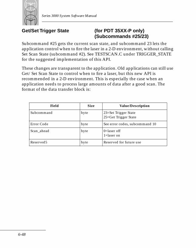
Series 3000 System Software Manual
Get/Set Trigger State (for PDT 35XX-P only)(Subcommands #25/23)
Subcommand #25 gets the current scan state, and subcommand 23 lets the application control when to fire the laser in a 2-D environment, without calling Set Scan State (subcommand #2). See TESTSCAN.C under TRIGGER_STATE for the suggested implementation of this API.
These changes are transparent to the application. Old applications can still use Get/Set Scan State to control when to fire a laser, but this new API is recommended in a 2-D environment. This is especially the case when an application needs to process large amounts of data after a good scan. The format of the data transfer block is:
Field Size Value/Description
Subcommand byte 23=Set Trigger State25=Get Trigger State
Error Code byte See error codes, subcommand 10
Scan_ahead byte 0=laser off1=laser on
Reserved5 byte Reserved for future use
6-48
Chapter 7 RAM Disk Device Driver
Chapter ContentsIntroduction . . . . . . . . . . . . . . . . . . . . . . . . . . . . . . . . . . . . . . . . . . . . . . . . . . . . . . . . . . . . . . . . . . . . . 7-3RAM Disk Device Driver . . . . . . . . . . . . . . . . . . . . . . . . . . . . . . . . . . . . . . . . . . . . . . . . . . . . . . . . . . 7-3
Configuring the RAM Disk . . . . . . . . . . . . . . . . . . . . . . . . . . . . . . . . . . . . . . . . . . . . . . . . . . . . 7-3RAM Disk Driver Functions. . . . . . . . . . . . . . . . . . . . . . . . . . . . . . . . . . . . . . . . . . . . . . . . . . . . . . . . 7-4
The Device Header . . . . . . . . . . . . . . . . . . . . . . . . . . . . . . . . . . . . . . . . . . . . . . . . . . . . . . . . . . . 7-4Link to Next Driver . . . . . . . . . . . . . . . . . . . . . . . . . . . . . . . . . . . . . . . . . . . . . . . . . . . . . . . . . . . 7-4Device Attributes . . . . . . . . . . . . . . . . . . . . . . . . . . . . . . . . . . . . . . . . . . . . . . . . . . . . . . . . . . . . . 7-4Strategy Offset . . . . . . . . . . . . . . . . . . . . . . . . . . . . . . . . . . . . . . . . . . . . . . . . . . . . . . . . . . . . . . . 7-5Interrupt Offset. . . . . . . . . . . . . . . . . . . . . . . . . . . . . . . . . . . . . . . . . . . . . . . . . . . . . . . . . . . . . . . 7-5Number of Units . . . . . . . . . . . . . . . . . . . . . . . . . . . . . . . . . . . . . . . . . . . . . . . . . . . . . . . . . . . . . 7-5
The Strategy Routine . . . . . . . . . . . . . . . . . . . . . . . . . . . . . . . . . . . . . . . . . . . . . . . . . . . . . . . . . . . . . . 7-6Data Structures . . . . . . . . . . . . . . . . . . . . . . . . . . . . . . . . . . . . . . . . . . . . . . . . . . . . . . . . . . . . . . . 7-6Code Routines . . . . . . . . . . . . . . . . . . . . . . . . . . . . . . . . . . . . . . . . . . . . . . . . . . . . . . . . . . . . . . . 7-6
Interrupt Routine . . . . . . . . . . . . . . . . . . . . . . . . . . . . . . . . . . . . . . . . . . . . . . . . . . . . . . . . . . . . . . . . . 7-6The Request Header . . . . . . . . . . . . . . . . . . . . . . . . . . . . . . . . . . . . . . . . . . . . . . . . . . . . . . . . . . . . . . 7-7Command-Code Routines . . . . . . . . . . . . . . . . . . . . . . . . . . . . . . . . . . . . . . . . . . . . . . . . . . . . . . . . . 7-9
Function 00H Init . . . . . . . . . . . . . . . . . . . . . . . . . . . . . . . . . . . . . . . . . . . . . . . . . . . . . . . . . . . . . 7-9Function 01h: Media Check . . . . . . . . . . . . . . . . . . . . . . . . . . . . . . . . . . . . . . . . . . . . . . . . . . . 7-10Function O2h: Build BPB . . . . . . . . . . . . . . . . . . . . . . . . . . . . . . . . . . . . . . . . . . . . . . . . . . . . . 7-10Function 03h: IOCTL Read . . . . . . . . . . . . . . . . . . . . . . . . . . . . . . . . . . . . . . . . . . . . . . . . . . . . 7-10Function 04h: Read . . . . . . . . . . . . . . . . . . . . . . . . . . . . . . . . . . . . . . . . . . . . . . . . . . . . . . . . . . 7-12Function 05h: Non-destructive Read . . . . . . . . . . . . . . . . . . . . . . . . . . . . . . . . . . . . . . . . . . . 7-12Function 06h: Input Status . . . . . . . . . . . . . . . . . . . . . . . . . . . . . . . . . . . . . . . . . . . . . . . . . . . . 7-12Function 07h: Input Flush. . . . . . . . . . . . . . . . . . . . . . . . . . . . . . . . . . . . . . . . . . . . . . . . . . . . . 7-12Function 08h: Write . . . . . . . . . . . . . . . . . . . . . . . . . . . . . . . . . . . . . . . . . . . . . . . . . . . . . . . . . . 7-12Function 09h: Write With Verify . . . . . . . . . . . . . . . . . . . . . . . . . . . . . . . . . . . . . . . . . . . . . . . 7-12Function 0Ah: Output Status . . . . . . . . . . . . . . . . . . . . . . . . . . . . . . . . . . . . . . . . . . . . . . . . . . 7-12Function 0Bh: Output Flush . . . . . . . . . . . . . . . . . . . . . . . . . . . . . . . . . . . . . . . . . . . . . . . . . . . 7-12Function 0Ch: IOCTL Write . . . . . . . . . . . . . . . . . . . . . . . . . . . . . . . . . . . . . . . . . . . . . . . . . . . 7-12
7-1

Series 3000 System Software Manual
7-2
RAM Disk Device Driver
IntroductionThe primary use of the RAM disk driver is to emulate the disk drive function in the Series 3000 terminal. Conventional Memory and Expanded Memory can be used for the RAM disk.
The following topics are presented in this chapter:
• RAM Disk Device Driver
• The RAM Disk Device Driver Functions
• Command Code Routines
Note: The RAM Disk Driver and the Expanded Memory Manager (EMM) are not co-operative. Either may be used, but not both.
RAM Disk Device DriverFor terminals running under DR DOS, the RAM disk driver is built into the operating system and serves as resident driver. You have use of the following disk drives:
• Drive A: (floppy type drive)
• Drive B: (floppy type drive)
• Drive D: (RAM disk)
Configuring the RAM DiskWhen the driver is enabled, it checks for an existing valid RAM disk. If one is present, it does not alter the existing disk size.
If there is no existing RAM disk, the RAM disk driver determines the amount of memory to use for the RAM disk as follows:
1. It checks for the presence of Expanded memory. If Expanded Memory is present, the RAM disk driver uses all of Expanded Memory for the RAM disk.
2. If there is no Expanded Memory, the RAM disk driver sets aside approximately 1/4 of Conventional Memory for the RAM disk.
7-3

Series 3000 System Software Manual
This default may be altered using the new Configuration Tool provided with the ADK software. Please refer to the Series 3000 Application Programmer's Reference Manual for information on using this tool.
RAM Disk Driver FunctionsThe RAM disk device driver is structured into three main sections: the Request Header, the Strategy Routine and the Interrupt Routine.
The Device Header holds the addressing information which DOS requires. The Strategy Interface provides the pointer to the data structure called the Request Header which DOS uses whenever an application program requests RAM Disk I/O operations. The Interrupt Routine implements the I/O functions and returns status and other information in the Request Header.
The most important piece of information passed to the Request Header is a Command-Code, or function number, to select a driver subfunction. The driver performs that particular Command-Code Routine based on the Request Header's information.
On the following pages, the RAM disk device driver Interface Routines are presented. These routines define the fields of the DOS interface structure called the Request Header, and describe the collection of driver subfunctions in the section Command-Code Routines.
The Device HeaderThe Device Header contains the device (either character device or block device) attributes, the linkage to the next driver in the chain, and the entry points to the Strategy Interface and interrupt routines for the device.
Link to Next DriverThe RAM disk device driver initializes this word field to -1. DOS uses this field to point to the next installed driver.
Device AttributesThe RAM disk device driver sets this word field to 4000h. The word value is determined by combining the individual bit fields described in Table 7-1.
7-4

RAM Disk Device Driver
Strategy OffsetThis word field contains the address offset of the first instruction of the device Strategy Routine.
Interrupt OffsetThis word field contains the address offset of the first instruction of the device Interrupt Routine.
Number of UnitsThe first byte in this eight byte field contains the value:
• 02h to indicate installable device.
• 04h to indicate resident device.
The other seven bytes are not initialized.
Table 7-1. RAM Disk Device Attributes
Attribute Bit Number Set To:
Device Type 15 zero - to indicate block device.
IOCTL Support 14 one - to indicate that support for IOCTL functions does exist.
IBM Format 13 zero - to indicate IBM format block device.
Open/CloseRM Support
11 zero - to indicate no support for open, close, and removable media functions. (This bit must be set to zero for DOS versions before 3.0.)
Current Clock Device 3 zero - since this is not a clock device.
Current NUL Device 2 zero - since this is not the NUL device.
Current Standard Output Device
1 zero - since this is not the standard output device.
Current Standard Input Device
0 zero - since this is not the standard input device.
Undefined Bits 4 through 10 and 12 are currently undefined; must be set to zero for compatibility.
7-5
Series 3000 System Software Manual
The Strategy RoutineThis routine is the queue manager for the RAM disk device driver function requests. When called by the operating system, this routine queues a double word pointer to a Request Header for Interrupt Routine service. At present, the queue is only large enough to hold one double word entry. Therefore, each call to the Strategy Routine must be followed by a call to the Interrupt Routine, or the Request Header pointer will be lost.
Data StructuresThe Strategy Routine requires two words of permanent storage to save a double word pointer to the Request Header.
Code RoutinesThe Strategy Routine's code consists of a FAR subroutine that receives the double word pointer in ES:BX and writes it to the fixed location described above.
Interrupt RoutineThe Interrupt Routine performs the actual functions requested of the RAM disk device driver. It consists of a FAR subroutine that receives no register parameters. All information about the request is obtained from the Request Header pointed to by the value in the Strategy Routine's queue.
Entry This section of code saves the machine context to allow use of the registers by the subsequent routines.
Dispatch This section of code locates the Request Header and extracts the command code. After ensuring the code is valid, the proper command subroutine is called.
Commands The actual RAM disk device driver functions are performed by the command subroutines. Additional data is obtained from the Request Header as required. Results are returned to the caller by writing to pre-defined fields in the Request Header.
Exit This section of the code restores the machine context to the state upon entry from the OS, then performs a FAR return.
7-6

RAM Disk Device Driver
The Request HeaderThe Request Header defines RAM disk device driver functions, provides additional information needed to perform the function, and contains fields used by the driver to return data to the caller. The caller is responsible for allocating, initializing, and deallocating the Request Header. The first 13 bytes of the Request Header are common to all functions. The number and the definitions of subsequent bytes are dependent on the function requested. Table 7-2 defines the fields and their applicable commands.
Table 7-2. Request Header Definitions
Field Bytes Applies To:
Length 0-0 All commands.Contains byte count of Request Header.Not used by the RAM disk device driver.
Unit Number 1-1 All commands.Contains the unit number for this request. Used by the RAM disk device driver to select proper device (A:, D:, etc.) to access.
Command 2-2 All commands.Contains the command code for this request. Used by the RAM disk device driver to select proper subroutine to execute.
Status 3-4 All commands.Used by the RAM disk device driver to return a status word indicating request function results.
Reserved 5-12 All commands.Several bytes are reserved for future use and are not used by the RAM disk device driver.
Units 13-13 Command 0.Used to return the number of units to the caller. If initialization is successful, the RAM disk device driver returns: two for installable four for residentotherwise, a zero is returned.
7-7
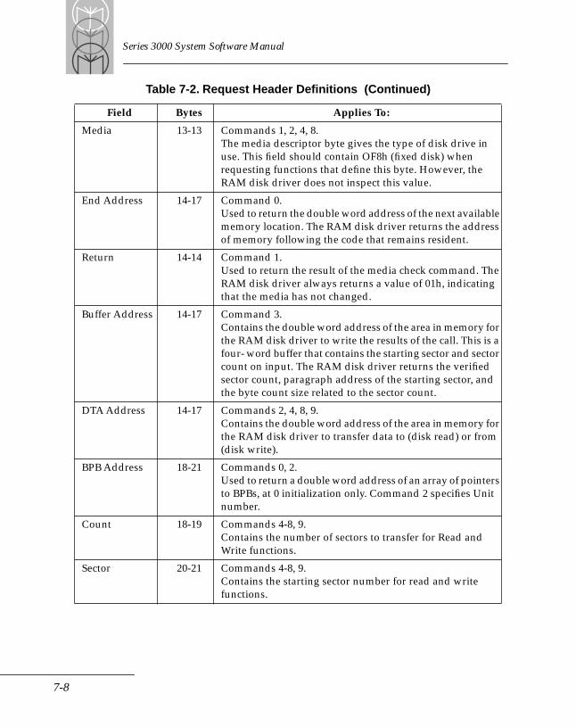
Series 3000 System Software Manual
Media 13-13 Commands 1, 2, 4, 8.The media descriptor byte gives the type of disk drive in use. This field should contain OF8h (fixed disk) when requesting functions that define this byte. However, the RAM disk driver does not inspect this value.
End Address 14-17 Command 0.Used to return the double word address of the next available memory location. The RAM disk driver returns the address of memory following the code that remains resident.
Return 14-14 Command 1.Used to return the result of the media check command. The RAM disk driver always returns a value of 01h, indicating that the media has not changed.
Buffer Address 14-17 Command 3.Contains the double word address of the area in memory for the RAM disk driver to write the results of the call. This is a four- word buffer that contains the starting sector and sector count on input. The RAM disk driver returns the verified sector count, paragraph address of the starting sector, and the byte count size related to the sector count.
DTA Address 14-17 Commands 2, 4, 8, 9.Contains the double word address of the area in memory for the RAM disk driver to transfer data to (disk read) or from (disk write).
BPB Address 18-21 Commands 0, 2.Used to return a double word address of an array of pointers to BPBs, at 0 initialization only. Command 2 specifies Unit number.
Count 18-19 Commands 4-8, 9.Contains the number of sectors to transfer for Read and Write functions.
Sector 20-21 Commands 4-8, 9.Contains the starting sector number for read and write functions.
Table 7-2. Request Header Definitions (Continued)
Field Bytes Applies To:
7-8
RAM Disk Device Driver
Command-Code RoutinesThis section describes the RAM disk driver Command-Code Routines that perform the various I/O operations.
Function 00H InitInitialization begins by obtaining and verifying the RAM disk parameters. All parameters use default values when no values are specified. Some parameters may be modified (from their specified or default values) in order to allow the driver to 'fit' into the current machine configuration. It is possible to fail during this phase and abort the installation of the RAM disk.
Next, a check is made to determine if there is an existing RAM disk. If none exists, initialization of a new RAM disk can take place. Otherwise, the existing RAM disk is verified. If the parameter values of the existing RAM disk match those computed in the first phase of initialization, then the existing RAM disk is valid, and its contents are maintained. However, if the parameter values do not match, then the old RAM disk is removed, and the new RAM disk is installed. The current method for moving the old RAM disk is to execute the BIOS cold boot code at FFFF:0000. This routine does not return directly, but indirectly by processing the CONFIG.SYS file during the new boot.
Initialization for a new disk proceeds as follows:
• the BIOS Ram work area is moved in memory to make room for the new disk
• the boot sector is loaded with the ID string and a copy of the BPB
• one copy of the FAT is built
• the root directory is built
• the new top of TPA memory is set
• the assigned vectors are initialized
At this point, a warm boot is executed (by executing an 'INT 19' instruction) to allow DOS to become aware of the new top of memory. This causes the CONFIG.SYS file to be executed once again, this time with a valid RAM disk already installed.
7-9
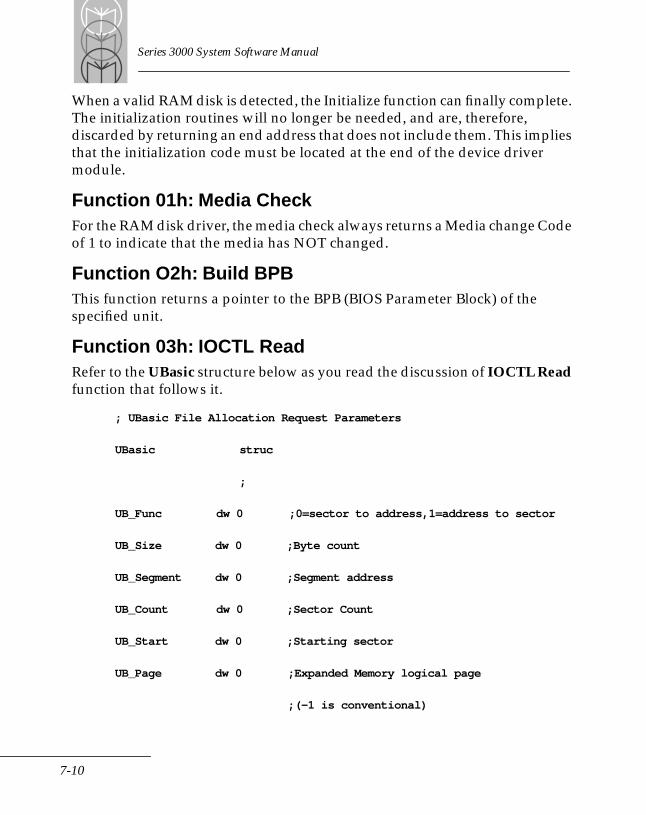
Series 3000 System Software Manual
When a valid RAM disk is detected, the Initialize function can finally complete. The initialization routines will no longer be needed, and are, therefore, discarded by returning an end address that does not include them. This implies that the initialization code must be located at the end of the device driver module.
Function 01h: Media CheckFor the RAM disk driver, the media check always returns a Media change Code of 1 to indicate that the media has NOT changed.
Function O2h: Build BPB This function returns a pointer to the BPB (BIOS Parameter Block) of the specified unit.
Function 03h: IOCTL ReadRefer to the UBasic structure below as you read the discussion of IOCTL Read function that follows it.
; UBasic File Allocation Request Parameters
UBasic struc
;
UB_Func dw 0 ;0=sector to address,1=address to sector
UB_Size dw 0 ;Byte count
UB_Segment dw 0 ;Segment address
UB_Count dw 0 ;Sector Count
UB_Start dw 0 ;Starting sector
UB_Page dw 0 ;Expanded Memory logical page
;(-1 is conventional)
7-10
RAM Disk Device Driver
;
UBasic ends
The IOCTL Control Read function receives a pointer to a buffer containing a control string. A subfunction code determines the operation being requested. Subfunction 0 translates the sector range to an address ; conversely, subfunction 1 translates the address into sector number. (See the member UB_Func in UBasic structure above.)
Subfunction 0 — translate sector range to address
Subfunction 0 uses the starting sector number and the sector count provided by the caller. The starting sector number is returned unchanged. The sector count is returned as the number of sectors available to the caller. This value may be less than the number requested due to boundary conditions. Also returned are the segment address of the starting sector, and the byte count (minus 1) of the range returned.
If the sector range resides in Expanded Memory, the Logical Page number of the sector range is returned. This Logical Page must be mapped into the Physical Page frame before attempting access to these sectors. The segment address returned assumes physical page 0 will be used.
If the sector range resides in Conventional Memory, this pointer value is minus one (-1), indicating no mapping is required.
Subfunction 1 — translate address into sector number
Subfunction 1 uses the segment address and the Logical Page number provided by the caller. These values are returned unchanged. Also returned is the starting sector number that corresponds to the provided segment address. Since all sectors in Expanded Memory have the same segment address (the same as the page frame), the starting segment for a sector range in Expanded Memory is determined using the Logical Page number and Offset. If an error occurs in this function, the count will be set to -1.
7-11
Series 3000 System Software Manual
Function 04h: ReadThis function transfers a requested number of sectors, starting with a specified sector, to the Data Transfer Area indicated by an address in the request.
Function 05h: Non-destructive ReadNot supported. Returns a command error status.
Function 06h: Input StatusNot supported. Returns a command error status.
Function 07h: Input FlushNot supported. Returns a command error status.
Function 08h: Write Reverse of READ (04h)
Function 09h: Write With Verify Same as WRITE (08h)
Function 0Ah: Output StatusNot supported. Returns a command error status.
Function 0Bh: Output FlushNot supported. Returns a command error status.
Function 0Ch: IOCTL WriteNot supported. Returns a command error status.
7-12
Chapter 8 Expanded Memory Manager
Chapter ContentsIntroduction . . . . . . . . . . . . . . . . . . . . . . . . . . . . . . . . . . . . . . . . . . . . . . . . . . . . . . . . . . . . . . . . . . . . . 8-5Page Frame, Physical Page, and Logical Page . . . . . . . . . . . . . . . . . . . . . . . . . . . . . . . . . . . . . . . . . 8-5Loading the Expanded Memory Driver . . . . . . . . . . . . . . . . . . . . . . . . . . . . . . . . . . . . . . . . . . . . . . 8-7Writing Programs That Use Expanded Memory . . . . . . . . . . . . . . . . . . . . . . . . . . . . . . . . . . . . . . 8-7Advanced Programming . . . . . . . . . . . . . . . . . . . . . . . . . . . . . . . . . . . . . . . . . . . . . . . . . . . . . . . . . . 8-9
Saving the State of Mapping Hardware . . . . . . . . . . . . . . . . . . . . . . . . . . . . . . . . . . . . . . . . . . 8-9Retrieving Handle and Page Counts. . . . . . . . . . . . . . . . . . . . . . . . . . . . . . . . . . . . . . . . . . . . . 8-9Mapping and Unmapping Multiple Pages . . . . . . . . . . . . . . . . . . . . . . . . . . . . . . . . . . . . . . . 8-9Reallocating Pages . . . . . . . . . . . . . . . . . . . . . . . . . . . . . . . . . . . . . . . . . . . . . . . . . . . . . . . . . . . . 8-9Using Handles and Assigning Names to Handles . . . . . . . . . . . . . . . . . . . . . . . . . . . . . . . . 8-10Using Handle Attributes. . . . . . . . . . . . . . . . . . . . . . . . . . . . . . . . . . . . . . . . . . . . . . . . . . . . . . 8-10Altering Page Maps and Jumping/Calling . . . . . . . . . . . . . . . . . . . . . . . . . . . . . . . . . . . . . . 8-10Moving or Exchanging Memory Regions. . . . . . . . . . . . . . . . . . . . . . . . . . . . . . . . . . . . . . . . 8-11Getting the Amount of Mappable Memory . . . . . . . . . . . . . . . . . . . . . . . . . . . . . . . . . . . . . . 8-11Operating System Functions . . . . . . . . . . . . . . . . . . . . . . . . . . . . . . . . . . . . . . . . . . . . . . . . . . 8-12
Programming Guidelines . . . . . . . . . . . . . . . . . . . . . . . . . . . . . . . . . . . . . . . . . . . . . . . . . . . . . . . . . 8-14Example 1 . . . . . . . . . . . . . . . . . . . . . . . . . . . . . . . . . . . . . . . . . . . . . . . . . . . . . . . . . . . . . . . . . . 8-15Example 2 . . . . . . . . . . . . . . . . . . . . . . . . . . . . . . . . . . . . . . . . . . . . . . . . . . . . . . . . . . . . . . . . . . 8-19
Expanded Memory Functions . . . . . . . . . . . . . . . . . . . . . . . . . . . . . . . . . . . . . . . . . . . . . . . . . . . . . 8-22Function 1 - Get Status . . . . . . . . . . . . . . . . . . . . . . . . . . . . . . . . . . . . . . . . . . . . . . . . . . . . . . . 8-25Function 3 - Get Unallocated Page Count . . . . . . . . . . . . . . . . . . . . . . . . . . . . . . . . . . . . . . . 8-28Function 4 - Allocate Pages. . . . . . . . . . . . . . . . . . . . . . . . . . . . . . . . . . . . . . . . . . . . . . . . . . . . 8-29Function 5 - Map/Unmap Handle Pages . . . . . . . . . . . . . . . . . . . . . . . . . . . . . . . . . . . . . . . . 8-31Function 6 - Deallocate Pages. . . . . . . . . . . . . . . . . . . . . . . . . . . . . . . . . . . . . . . . . . . . . . . . . . 8-33Function 7 - Get Version . . . . . . . . . . . . . . . . . . . . . . . . . . . . . . . . . . . . . . . . . . . . . . . . . . . . . . 8-35Function 8 - Save Page Map . . . . . . . . . . . . . . . . . . . . . . . . . . . . . . . . . . . . . . . . . . . . . . . . . . . 8-37Function 9 - Restore Page Map . . . . . . . . . . . . . . . . . . . . . . . . . . . . . . . . . . . . . . . . . . . . . . . . 8-39Function 12 - Get Handle Count . . . . . . . . . . . . . . . . . . . . . . . . . . . . . . . . . . . . . . . . . . . . . . . 8-41Function 13 - Get Handle Pages. . . . . . . . . . . . . . . . . . . . . . . . . . . . . . . . . . . . . . . . . . . . . . . . 8-42Function 14 - Get All Handles Pages . . . . . . . . . . . . . . . . . . . . . . . . . . . . . . . . . . . . . . . . . . . 8-44Function 15 - Get/Set Page Map Get Page Map Subfunction . . . . . . . . . . . . . . . . . . . . . . . 8-47Function 15 - Get/Set Page Map Set Page Map Subfunction . . . . . . . . . . . . . . . . . . . . . . . 8-49Function 15 - Get/Set Page Map Get & Set Page Map Subfunction. . . . . . . . . . . . . . . . . . 8-51
8-1
Series 3000 System Software Manual
Function 15 - Get/Set Page Map Get Size of Page Map Save Array Subfunction. . . . . . 8-54Function 16 - Get/Set Partial Page Map Get Partial Page Map Subfunction . . . . . . . . . . 8-56Function 16 - Get/Set Partial Page Map Set Partial Page Map Subfunction. . . . . . . . . . . 8-59Function 16 - Get/Set Partial Page Map Get Size of Partial Page Map Save Array Subfunction. . . . . . . . . . . . . . . . . . . . . . . . . . . . . 8-61Function 17 - Map/Unmap Multiple Handle Pages. . . . . . . . . . . . . . . . . . . . . . . . . . . . . . . 8-63Function 17 - Map/Unmap Multiple Handle PagesLogical Page/Segment Address Method . . . . . . . . . . . . . . . . . . . . . . . . . . . . . . . . . . . . . . . . 8-67Function 18 - Reallocate Pages . . . . . . . . . . . . . . . . . . . . . . . . . . . . . . . . . . . . . . . . . . . . . . . . . 8-70Function 19 - Get/Set Handle Attribute Get and Set Handle Attribute Subfunctions . . . . . . . . . . . . . . . . . . . . . . . . . . . . . . . . . . . . . 8-73Function 19 - Get/Set Handle Attribute Get Attribute Capability Subfunction . . . . . . . 8-74Function 20 - Get/Set Handle Name Get Handle Name Subfunction. . . . . . . . . . . . . . . . 8-75Function 20 - Get/Set Handle Name Set Handle Name Subfunction . . . . . . . . . . . . . . . . 8-77Function 21 - Get Handle Directory Get Handle Directory Subfunction . . . . . . . . . . . . . 8-79Function 21 - Get Handle Directory Search for Named Handle Subfunction . . . . . . . . . 8-81Function 21 - Get Handle Directory Get Total Handles Subfunction . . . . . . . . . . . . . . . . 8-83Function 22 - Alter Page Map & Jump . . . . . . . . . . . . . . . . . . . . . . . . . . . . . . . . . . . . . . . . . . 8-84Function 23 - Alter Page Map & Call Alter Page Map and Call Subfunction . . . . . . . . . . 8-88Function 23 - Alter Page Map & Call Get Page Map Stack Space Size Subfunction . . . . 8-93Function 24 - Move/Exchange Memory Region Move Memory Region Subfunction . . 8-95Function 24 - Move/Exchange Memory Region Exchange Memory Region Subfunction . . . . . . . . . . . . . . . . . . . . . . . . . . . . . . . . . . . . . . . . 8-101Function 25 - Get Mappable Physical Address ArrayGet Mappable Physical Address Array Subfunction . . . . . . . . . . . . . . . . . . . . . . . . . . . . . 8-107Function 25 - Get Mappable Physical Address ArrayGet Mappable Physical Address Array Entries Subfunction . . . . . . . . . . . . . . . . . . . . . . 8-109Function 26 - Get Expanded Memory Hardware InformationGet Hardware Configuration Array Subfunction. . . . . . . . . . . . . . . . . . . . . . . . . . . . . . . . 8-111Function 26 - Get Expanded Memory Hardware InformationGet Unallocated Raw Page Count Subfunction. . . . . . . . . . . . . . . . . . . . . . . . . . . . . . . . . . 8-114Function 27 - Allocate Standard/Raw PagesAllocate Standard Pages Subfunction. . . . . . . . . . . . . . . . . . . . . . . . . . . . . . . . . . . . . . . . . . 8-115Function 27 - Allocate Standard/Raw Pages Allocate Raw Pages Subfunction. . . . . . . 8-117Function 28 - Alternate Map Register Set. . . . . . . . . . . . . . . . . . . . . . . . . . . . . . . . . . . . . . . 8-119Function 28 - Alternate Map Register Set Get Alternate Map Register Set Subfunction 8-120Function 28 - Alternate Map Register Set Set Alternate Map Register Set Subfunction . . . . . . . . . . . . . . . . . . . . . . . . . . . . . . . . . . . . 8-122Function 28 - Alternate Map Register Set Get Alternate Map Save Array Size Subfunction . . . . . . . . . . . . . . . . . . . . . . . . . . . . . . . . 8-126Function 28 -Alternate Map Register SetAllocate Alternate Map Register Set Subfunction. . . . . . . . . . . . . . . . . . . . . . . . . . . . . . . . 8-128Function 28 - Alternate Map Register SetDeallocate Alternate Map Register Set Subfunction. . . . . . . . . . . . . . . . . . . . . . . . . . . . . . 8-129
8-2
Expanded Memory Manager
Function 28 - Alternate Map Register Set Allocate DMA Register Set Subfunction. . . . . . . . . . . . . . . . . . . . . . . . . . . . . . . . . . . . . . . . 8-131Function 28 - Alternate Map Register SetEnable DMA ON Alternate Map Register Set Subfunction. . . . . . . . . . . . . . . . . . . . . . . . 8-132Function 28 - Alternate Map Register SetDisable DMA ON Alternate Map Register Set Subfunction . . . . . . . . . . . . . . . . . . . . . . . 8-134Function 28 - Alternate Map Register Set Deallocate DMA Register Set Subfunction. . . . . . . . . . . . . . . . . . . . . . . . . . . . . . . . . . . . . . 8-136Function 29 - Prepare Expanded Memory Hardware to Warmboot . . . . . . . . . . . . . . . . 8-138Function 30 - Enable/Disable OS/E Function Set Function Enable OS/E Function Set Subfunction . . . . . . . . . . . . . . . . . . . . . . . . . . . . . . . . . . . . . . . . 8-139Function 30 - Enable/Disable OS/E Function Set Function Disable OS/E Function Set Subfunction. . . . . . . . . . . . . . . . . . . . . . . . . . . . . . . . . . . . . . . . 8-143Results . . . . . . . . . . . . . . . . . . . . . . . . . . . . . . . . . . . . . . . . . . . . . . . . . . . . . . . . . . . . . . . . . . . . 8-143Function 30 - Enable/Disable OS/E Function Set Function Return Access Key Subfunction. . . . . . . . . . . . . . . . . . . . . . . . . . . . . . . . . . . . . . . . . . . . . . . 8-146
Function and Status Code Cross Reference . . . . . . . . . . . . . . . . . . . . . . . . . . . . . . . . . . . . . . . . 8-148Testing for the Presence of EMM. . . . . . . . . . . . . . . . . . . . . . . . . . . . . . . . . . . . . . . . . . . . . . . . . . 8-151
Which Method Should Your Program Use? . . . . . . . . . . . . . . . . . . . . . . . . . . . . . . . . . . . . 8-151The “Open Handle” Technique . . . . . . . . . . . . . . . . . . . . . . . . . . . . . . . . . . . . . . . . . . . . . . . 8-152The Get Interrupt Vector Technique . . . . . . . . . . . . . . . . . . . . . . . . . . . . . . . . . . . . . . . . . . . 8-156
8-3

Series 3000 System Software Manual
8-4
Expanded Memory Manager
IntroductionExpanded memory is memory beyond DOS's 640-Kbyte limit. The Series 3000 expanded memory driver supports the Lotus /Intel /Microsoft Expanded Memory Specification (LIM EMS 4.0) providing access to up to 8 Mbytes of expanded memory. Because the microprocessor can physically address only 1 Mbyte of memory, it accesses expanded memory through a window in its physical address range.
Expanded memory is different from extended memory, which encompasses the 15-Mbyte address range between 100000h and FFFFFFh. Extended memory is not supported on Series 3000 systems.
Page Frame, Physical Page, and Logical PageExpanded memory is divided into segments called logical pages. Each page is 16 kbytes of memory. Your computer accesses logical pages through a physical block of memory called a page frame. The page frame contains multiple physical pages, pages that the microprocessor can address directly. Physical pages are also 16 kbytes of memory. This page frame serves as a window into expanded memory.
A logical page of expanded memory can be mapped into (made to appear in) any one of the physical pages in the page frame. Thus, a Read or Write to the physical page actually becomes a Read or Write to the associated logical page. One logical page can be mapped into the page frame for each physical page.
Figure 8-1 illustrates the relationships among the page frame, physical pages, and logical pages.
The page frame is usually located above 640 kbytes. If the system has 256 KB of NVM, the page frame is located below 640 KB, at address 9000h.
8-5
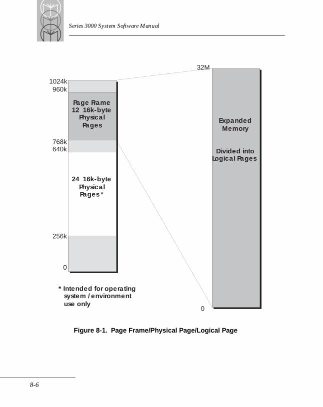
Series 3000 System Software Manual
Figure 8-1. Page Frame/Physical Page/Logical Page
Page Frame12 16k-byte
PhysicalPages
24 16k-bytePhysicalPages *
256k
0
768k640k
1024k960k
ExpandedMemory
Divided intoLogical Pages
32M
0
* Intended for operatingsystem /environmentuse only
8-6
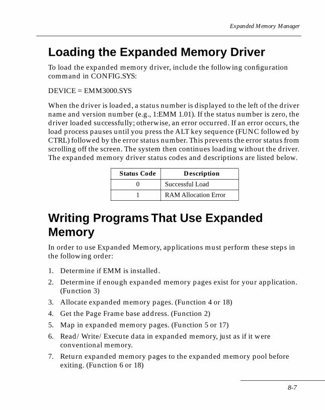
Expanded Memory Manager
Loading the Expanded Memory DriverTo load the expanded memory driver, include the following configuration command in CONFIG.SYS:
DEVICE = EMM3000.SYS
When the driver is loaded, a status number is displayed to the left of the driver name and version number (e.g., 1:EMM 1.01). If the status number is zero, the driver loaded successfully; otherwise, an error occurred. If an error occurs, the load process pauses until you press the ALT key sequence (FUNC followed by CTRL) followed by the error status number. This prevents the error status from scrolling off the screen. The system then continues loading without the driver. The expanded memory driver status codes and descriptions are listed below.
Writing Programs That Use Expanded MemoryIn order to use Expanded Memory, applications must perform these steps in the following order:
1. Determine if EMM is installed.
2. Determine if enough expanded memory pages exist for your application. (Function 3)
3. Allocate expanded memory pages. (Function 4 or 18)
4. Get the Page Frame base address. (Function 2)
5. Map in expanded memory pages. (Function 5 or 17)
6. Read/Write/Execute data in expanded memory, just as if it were conventional memory.
7. Return expanded memory pages to the expanded memory pool before exiting. (Function 6 or 18)
Status Code Description
0 Successful Load
1 RAM Allocation Error
8-7
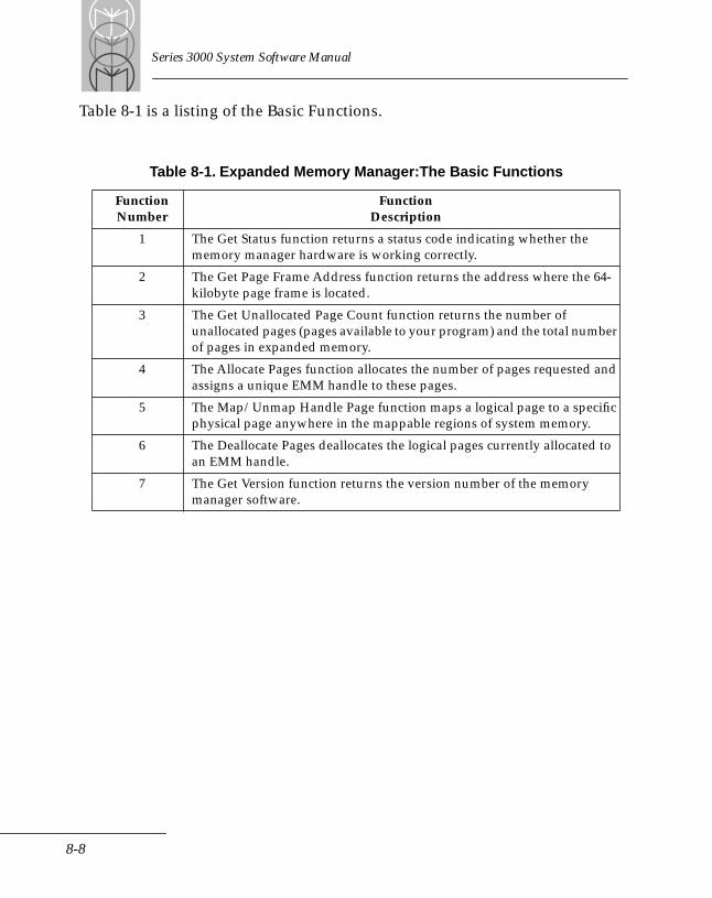
Series 3000 System Software Manual
Table 8-1 is a listing of the Basic Functions.
Table 8-1. Expanded Memory Manager:The Basic Functions
FunctionNumber
FunctionDescription
1 The Get Status function returns a status code indicating whether the memory manager hardware is working correctly.
2 The Get Page Frame Address function returns the address where the 64-kilobyte page frame is located.
3 The Get Unallocated Page Count function returns the number of unallocated pages (pages available to your program) and the total number of pages in expanded memory.
4 The Allocate Pages function allocates the number of pages requested and assigns a unique EMM handle to these pages.
5 The Map/Unmap Handle Page function maps a logical page to a specific physical page anywhere in the mappable regions of system memory.
6 The Deallocate Pages deallocates the logical pages currently allocated to an EMM handle.
7 The Get Version function returns the version number of the memory manager software.
8-8
Expanded Memory Manager
Advanced ProgrammingIn addition to the basic functions, the Lotus/Intel/Microsoft Expanded Memory Specification provides several advanced functions that enhance the capabilities of software that uses expanded memory.
Saving the State of Mapping HardwareSome software (such as interrupt service routines, device drivers, and resident software) must save the current state of the mapping hardware, switch mapping contexts, manipulate sections of expanded memory, and restore the original context of memory mapping hardware. Use Functions 8 and 9 or 15 and 16 to save the state of the hardware.
Retrieving Handle and Page CountsSome utility programs need to keep track of how expanded memory is being used; use Functions 12 through 14 to do this.
Mapping and Unmapping Multiple PagesMapping multiple pages reduces the overhead an application must perform during mapping. Function 17 lets a program map (or unmap) multiple pages at one time.
In addition, you can map pages using segment addresses instead of physical pages. For example, if the page frame base address is set to A000, you can map to either physical page 0 or segment A000. Function 25 (Get Mappable Physical Address Array) returns a cross reference between all expanded memory physical pages and their corresponding segment values.
Reallocating PagesReallocating pages (Function 18) lets applications dynamically allocate expanded memory pages without acquiring another handle or obtain a handle without allocating pages. Reallocating pages is an efficient means for applications to obtain and release expanded memory pages.
8-9

Series 3000 System Software Manual
Using Handles and Assigning Names to HandlesThis specification lets you associate a name with a handle, so a family of applications can share information in expanded memory. For example, a software package consisting of a word processor, spreadsheet, and print spooler can share the same data among the different applications. The print spooler could use a handle name to reference data that either the spreadsheet or word processor put in expanded memory and could check for data in a particular handle name's expanded memory pages.
Use Function 20 (Set Handle Name subfunction) to assign a handle name to an EMM handle or Function 21 (Search for Named Handle subfunction) to obtain the EMM handle associated with the handle name. In addition, you can use Function 14 (Get Handles Pages) to determine the number of expanded memory pages allocated to an EMM Handle.
Using Handle AttributesIn addition to naming a handle, you can use Function 19 to associate an attribute (volatile or non-volatile) with a handle name. A non-volatile attribute enables expanded memory pages to preserve their data through a warm boot. With a volatile attribute, the data is not preserved. The default attribute for handles is volatile.
Because using this function depends on the capabilities of the expanded memory hardware installed in the system, you should use the Get Attribute Capability subfunction before attempting to assign an attribute to a handle's pages.
Altering Page Maps and Jumping/CallingYou can use Functions 22 (Alter Page Map and Jump) and 23 (Alter Page Map and Call) to map a new set of values into the map registers and transfer program control to a specified address within expanded memory. These functions can be used to load and execute code in expanded memory. An application using this feature can significantly reduce the amount of conventional memory it requires. Programs can load needed modules into expanded memory at run time and use Function 22 to transfer control to these modules.
8-10
Expanded Memory Manager
Using expanded memory to store code can improve program execution in many ways. For example, sometimes programs need to be divided into small overlays because of conventional memory size limitations. Overlays targeted for expanded memory can be large because the Series 3000 implementation of LIM EMS 4.0 supports up to 8 Mbytes of expanded memory. This method of loading overlays improves overall system performance by conserving conventional memory and eliminating conventional memory allocation errors.
Moving or Exchanging Memory RegionsFunction 24 (Move/Exchange Memory Region) enables easy movement and exchange of data between conventional and expanded memory. Function 24 can manipulate up to one megabyte of data with one function call. Although applications can perform this operation without this function, having the expanded memory manager do it reduces the amount of overhead for the application.
In addition, this function checks for overlapping regions and performs all the necessary mapping, preserving the mapping context from before the Exchange/Move call.
Getting the Amount of Mappable MemoryFunction 25 enables applications to determine the total amount of mappable memory the hardware/system currently supports. Not all expanded memory boards supply the same number of physical pages (map registers).
The Get Mappable Physical Address Array Entries subfunction returns the total number of physical pages the expanded memory hardware/system is capable of supporting. Get Mappable Physical Address Array subfunction returns a cross reference between physical page numbers and the actual segment address for each of the physical pages.
8-11
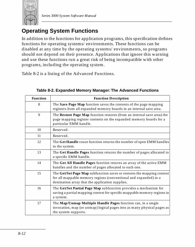
Series 3000 System Software Manual
Operating System FunctionsIn addition to the functions for application programs, this specification defines functions for operating systems/environments. These functions can be disabled at any time by the operating systems/environments, so programs should not depend on their presence. Applications that ignore this warning and use these functions run a great risk of being incompatible with other programs, including the operating system.
Table 8-2 is a listing of the Advanced Functions.
Table 8-2. Expanded Memory Manager: The Advanced Functions
Function Function Description
8 The Save Page Map function saves the contents of the page mapping registers from all expanded memory boards in an internal save area.
9 The Restore Page Map function restores (from an internal save area) the page mapping register contents on the expanded memory boards for a particular EMM handle.
10 Reserved.
11 Reserved.
12 The Get Handle count function returns the number of open EMM handles in the system.
13 The Get Handle Pages function returns the number of pages allocated to a specific EMM handle.
14 The Get All Handle Pages function returns an array of the active EMM handles and the number of pages allocated to each one.
15 The Get/Set Page Map subfunction saves or restores the mapping context for all mappable memory regions (conventional and expanded) in a destination array that the application supplies.
16 The Get/Set Partial Page Map subfunction provides a mechanism for saving a partial mapping context for specific mappable memory regions in a system.
17 The Map/Unmap Multiple Handle Pages function can, in a single invocation, map (or unmap) logical pages into as many physical pages as the system supports.
8-12
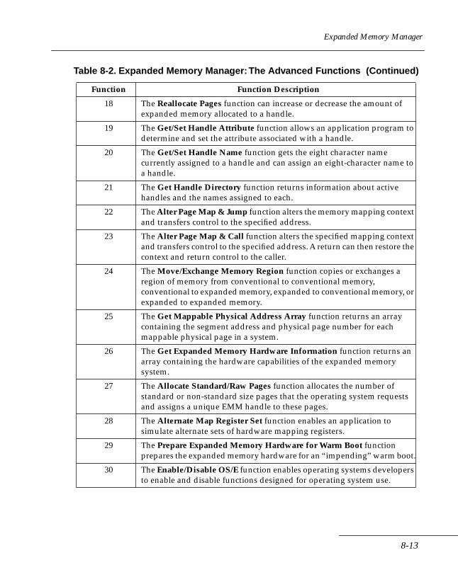
Expanded Memory Manager
18 The Reallocate Pages function can increase or decrease the amount of expanded memory allocated to a handle.
19 The Get/Set Handle Attribute function allows an application program to determine and set the attribute associated with a handle.
20 The Get/Set Handle Name function gets the eight character name currently assigned to a handle and can assign an eight-character name to a handle.
21 The Get Handle Directory function returns information about active handles and the names assigned to each.
22 The Alter Page Map & Jump function alters the memory mapping context and transfers control to the specified address.
23 The Alter Page Map & Call function alters the specified mapping context and transfers control to the specified address. A return can then restore the context and return control to the caller.
24 The Move/Exchange Memory Region function copies or exchanges a region of memory from conventional to conventional memory, conventional to expanded memory, expanded to conventional memory, or expanded to expanded memory.
25 The Get Mappable Physical Address Array function returns an array containing the segment address and physical page number for each mappable physical page in a system.
26 The Get Expanded Memory Hardware Information function returns an array containing the hardware capabilities of the expanded memory system.
27 The Allocate Standard/Raw Pages function allocates the number of standard or non-standard size pages that the operating system requests and assigns a unique EMM handle to these pages.
28 The Alternate Map Register Set function enables an application to simulate alternate sets of hardware mapping registers.
29 The Prepare Expanded Memory Hardware for Warm Boot function prepares the expanded memory hardware for an “impending” warm boot.
30 The Enable/Disable OS/E function enables operating systems developers to enable and disable functions designed for operating system use.
Table 8-2. Expanded Memory Manager: The Advanced Functions (Continued)
Function Function Description
8-13
Series 3000 System Software Manual
Programming Guidelines The following guidelines are for programmers writing applications that utilize EMM:
• Do not put a program's stack in expanded memory.
• Do not replace Interrupt 67h. This is the interrupt vector the EMM uses. Replacing interrupt 67h could result in disabling the expanded memory manager.
• Do not map into conventional memory address space your application doesn't own. Applications that use the EMM to swap into conventional memory space must first allocate this space from the operating system. If the operating system is not aware that a region of memory it manages is in use, it will think the memory is available. This could result, for example, in the application attempting to use data written into the area by the operating system. EMM should not be used to 'allocate' conventional memory. DOS is the proper manager of conventional memory space. EMM should only be used to swap data in conventional memory space previously allocated from DOS.
• Applications should always return expanded memory pages to the expanded memory manager upon termination. These pages will be made available for other applications. If unneeded pages are not returned to the expanded memory manager, the system could 'run out' of expanded memory pages or expanded memory handles.
• Terminate, Stay Resident programs (TSR's) should ALWAYS save the state of the map registers before changing them. Since TSR's may interrupt other programs that may be using expanded memory, they must not change the state of the page mapping registers without first saving them. Before exiting, TSR's must restore the state of the map registers.
The following three methods save and restore the state of the map registers.
1. Save Page Map and Restore Page Map (Functions 8 and 9). This is the simplest of the three methods. The EMM saves the map register contents in its own data structures -- the application does not need to provide extra storage locations for the mapping context. The last mapping context to be
8-14
Expanded Memory Manager
saved, under a particular Handle, will be restored when a call to Restore Page Map is issued with the same handle. This method is limited to one mapping context for each handle and saves the context for only LIM standard 64-kbyte page frames.
2. Get/Set Page Map (Function 15). This method requires the application to allocate space for the storage array. The EMM saves the mapping context in an array whose address is passed to the EMM. When restoring the mapping context with this method, an application passes the address of an array that contains a previously stored mapping context.
This method is preferable if an application needs to do more than one save before a restore. It provides a mechanism for switching between more than one mapping context.
3. Get/Set Partial Page Map (Function 16). This method enables the saving of a partial mapping context. It should be used when the application does not need to save the context of all mappable memory. This function also requires that the storage array be part of the application's data. All functions using pointers to data structures must have those data structures in memory that will not be mapped out. Function 22 is the only exception.
Example 1This program is written in Microsoft's Macro Assembler.
CODE SEGMENT
ASSUME CS:CODE, DS:CODE
MOV AX, CS
MOV DS, AX
.
.
.
check_em_installed:
8-15
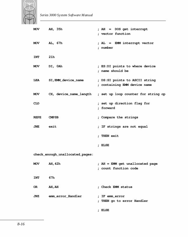
Series 3000 System Software Manual
MOV AH, 35h ; AH = DOS get interrupt
; vector function
MOV AL, 67h ; AL = EMM interrupt vector
; number
INT 21h
MOV DI, 0Ah ; ES:DI points to where device
; name should be
LEA SI,EMM_device_name ; DS:SI points to ASCII string
; containing EMM device name
MOV CX, device_name_length ; set up loop counter for string op
CLD ; set up direction flag for
; forward
REPE CMPSB ; Compare the strings
JNE exit ; IF strings are not equal
; THEN exit
; ELSE
check_enough_unallocated_pages:
MOV AH,42h ; AH = EMM get unallocated page
; count function code
INT 67h
OR AH,AH ; Check EMM status
JNZ emm_error_Handler ; IF emm_error
; THEN go to error Handler
; ELSE
8-16
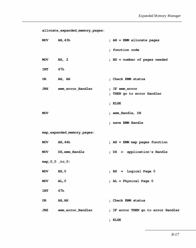
Expanded Memory Manager
allocate_expanded_memory_pages:
MOV AH,43h ; AH = EMM allocate pages
; function code
MOV BX, 2 ; BX = number of pages needed
INT 67h
OR AH, AH ; Check EMM status
JNX emm_error_Handler ; IF emm_error
; THEN go to error Handler
; ELSE
MOV ; emm_Handle, DX
; save EMM Handle
map_expanded_memory_pages:
MOV AH,44h ; AH = EMM map pages function
MOV DX,emm_Handle ; DX = application's Handle
map_0_0 _to_0:
MOV BX,0 ; BX = Logical Page 0
MOV AL,0 ; AL = Physical Page 0
INT 67h
OR AH,AH ; Check EMM status
JNZ emm_error_Handler ; IF error THEN go to error Handler
; ELSE
8-17
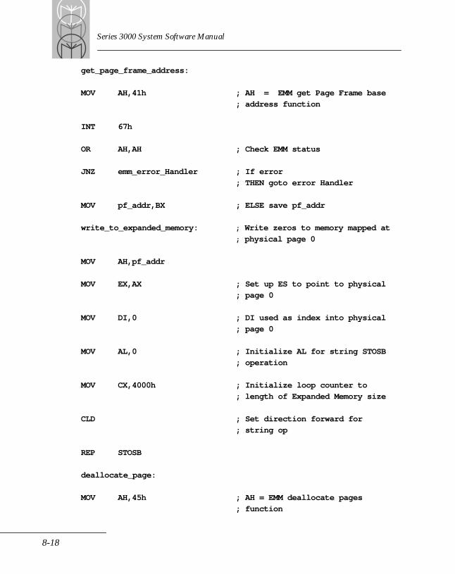
Series 3000 System Software Manual
get_page_frame_address:
MOV AH,41h ; AH = EMM get Page Frame base
; address function
INT 67h
OR AH,AH ; Check EMM status
JNZ emm_error_Handler ; If error
; THEN goto error Handler
MOV pf_addr,BX ; ELSE save pf_addr
write_to_expanded_memory: ; Write zeros to memory mapped at
; physical page 0
MOV AH,pf_addr
MOV EX,AX ; Set up ES to point to physical
; page 0
MOV DI,0 ; DI used as index into physical
; page 0
MOV AL,0 ; Initialize AL for string STOSB
; operation
MOV CX,4000h ; Initialize loop counter to
; length of Expanded Memory size
CLD ; Set direction forward for
; string op
REP STOSB
deallocate_page:
MOV AH,45h ; AH = EMM deallocate pages
; function
8-18
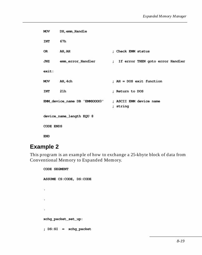
Expanded Memory Manager
MOV DX,emm_Handle
INT 67h
OR AH,AH ; Check EMM status
JNZ emm_error_Handler ; If error THEN goto error Handler
exit:
MOV AH,4ch ; AH = DOS exit function
INT 21h ; Return to DOS
EMM_device_name DB 'EMMXXXX0' ; ASCII EMM device name
; string
device_name_length EQU 8
CODE ENDS
END
Example 2This program is an example of how to exchange a 25-kbyte block of data from Conventional Memory to Expanded Memory.
CODE SEGMENT
ASSUME CS:CODE, DS:CODE
.
.
.
xchg_packet_set_up:
; DS:SI = xchg_packet
8-19

Series 3000 System Software Manual
MOV AX, xchg_packet
MOV DS,AX xchg_packet
; Moving 256K of data from Conventional Memory to Expanded
; Memory
MOV WORD PTR[SI].region_length[0],0
MOV WORD PTR[SI].region_length[2],4
MOV [SI].src_mem_type, 0
MOV [SI].dest_mem_type, 1
; starting at segment:4000h,offset:0
MOV [SI].src_init_seg_page, 4000h
MOV [SI].src_init_offset, 0
; Move data into Expanded Memory Logical Page 0, offset 0.
MOV [SI].dest_init_seg_page, 0
MOV [SI].dest_init_offset, 0
; Initialize for future compatibility; Compare the strings
MOV [SI].src_Handle, 0
; Need Handle for Expanded Memory destination.
MOV [DX],emm_Handle
MOV [SI].dest_Handle, DX
; AX = EMM Exchange Memory function
MOV AX,5F01h
8-20
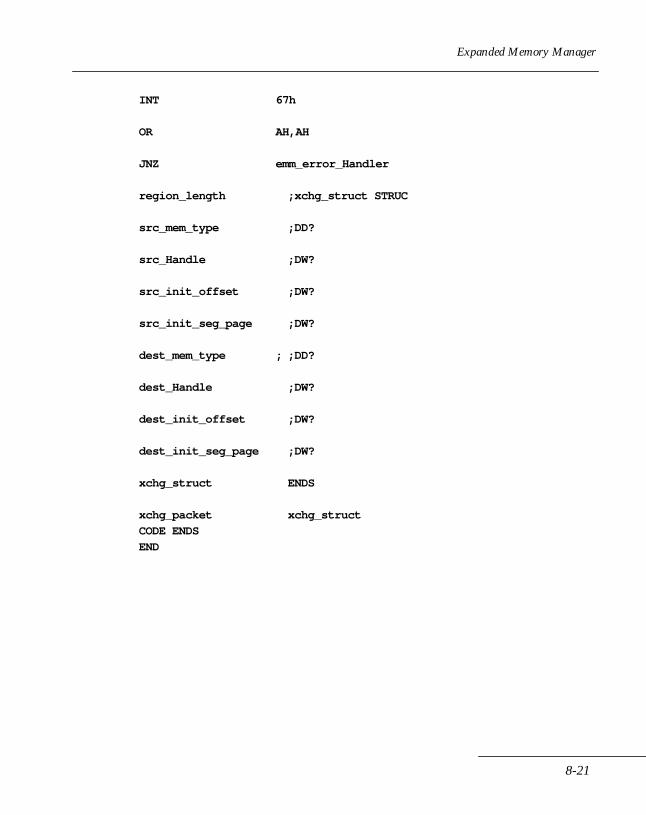
Expanded Memory Manager
INT 67h
OR AH,AH
JNZ emm_error_Handler
region_length ;xchg_struct STRUC
src_mem_type ;DD?
src_Handle ;DW?
src_init_offset ;DW?
src_init_seg_page ;DW?
dest_mem_type ; ;DD?
dest_Handle ;DW?
dest_init_offset ;DW?
dest_init_seg_page ;DW?
xchg_struct ENDS
xchg_packet xchg_struct
CODE ENDS
END
8-21

Series 3000 System Software Manual
Expanded Memory FunctionsThis section presents the standardized set of expanded memory functions. Because they are standardized, you avoid potential compatibility problems with other expanded memory programs that also adhere to the memory manager specification. Programs that deal directly with hardware that doesn't adhere to this specification will be incompatible. Table 8-3 is a complete listing of the expanded memory functions. The “Hex Value” provided in the third column is the value passed in the AH (or AX) register when the associated function is called. More detailed descriptions of these functions are provided in order of function number on the pages that follow .
Table 8-3. Expanded Memory Functions
FunctionNumber
FunctionDescription
HexValue
1 Get Status 40h
2 Get Page Frame Segment Address 41h
3 Get Unallocated Page Count 42h
4 Allocate Pages 43h
5 Map/Unmap Handle Page 44h
6 Deallocate Pages 45h
7 Get Version 46h
8 Save Page Map 47h
9 Restore Page Map 48h
10 Reserved 49h
11 Reserved 4Ah
12 Get Handle Count 4Bh
13 Get Handle Pages 4Ch
14 Get All Handle Pages 4Dh
15 Get Page MapSet Page MapGet & Set Page MapGet Size of Page Map Save Array
4E00h4E01h4E02h4E03h
8-22
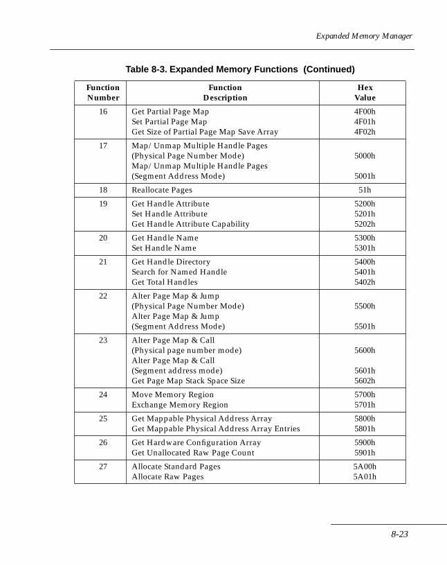
Expanded Memory Manager
16 Get Partial Page MapSet Partial Page MapGet Size of Partial Page Map Save Array
4F00h4F01h4F02h
17 Map/Unmap Multiple Handle Pages(Physical Page Number Mode)Map/Unmap Multiple Handle Pages(Segment Address Mode)
5000h
5001h
18 Reallocate Pages 51h
19 Get Handle AttributeSet Handle AttributeGet Handle Attribute Capability
5200h5201h5202h
20 Get Handle NameSet Handle Name
5300h5301h
21 Get Handle DirectorySearch for Named HandleGet Total Handles
5400h5401h5402h
22 Alter Page Map & Jump(Physical Page Number Mode)Alter Page Map & Jump(Segment Address Mode)
5500h
5501h
23 Alter Page Map & Call(Physical page number mode)Alter Page Map & Call(Segment address mode)Get Page Map Stack Space Size
5600h
5601h5602h
24 Move Memory RegionExchange Memory Region
5700h5701h
25 Get Mappable Physical Address ArrayGet Mappable Physical Address Array Entries
5800h5801h
26 Get Hardware Configuration ArrayGet Unallocated Raw Page Count
5900h5901h
27 Allocate Standard PagesAllocate Raw Pages
5A00h5A01h
Table 8-3. Expanded Memory Functions (Continued)
FunctionNumber
FunctionDescription
HexValue
8-23

Series 3000 System Software Manual
28 Get Alternate Map Register SetSet Alternate Map Register SetGet Alternate Map Save Array SizeAllocate Alternate Map Register SetDeallocate Alternate Map Register SetAllocate DMA Register SetEnable DMA on Alternate Map Register SetDisable DMA on Alternate Map Register SetDeallocate DMA Register Set
5B00h5B01h5B02h5B03h5B04h5B05h5B06h5B07h5B08h
29 Prepare Expanded Memory Hardware for Warmboot
5Ch
30 Enable OS/E Function SetDisable OS/E Function SetReturn OS/E Access Key
5D00h5D01h5D02h
Table 8-3. Expanded Memory Functions (Continued)
FunctionNumber
FunctionDescription
HexValue
8-24
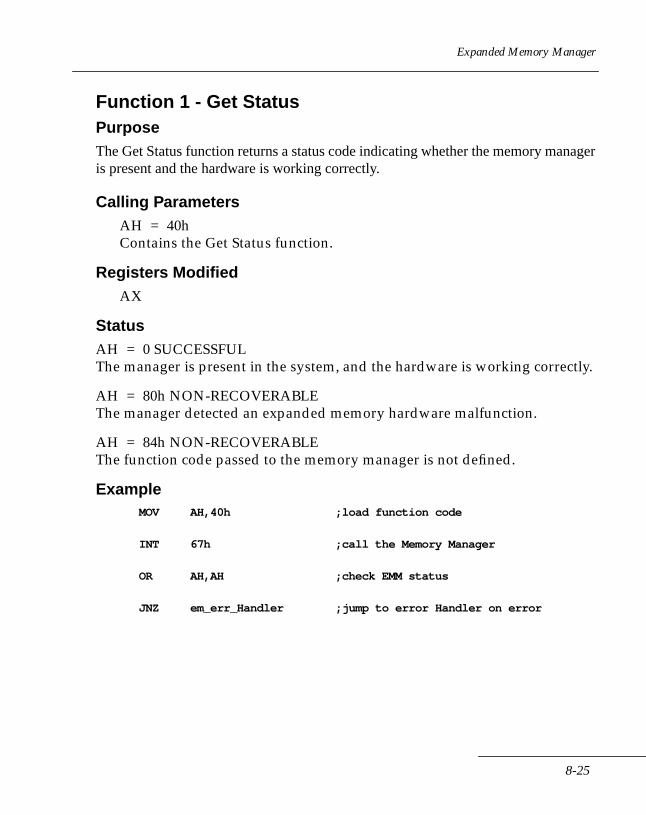
Expanded Memory Manager
Function 1 - Get StatusPurposeThe Get Status function returns a status code indicating whether the memory manager is present and the hardware is working correctly.
Calling ParametersAH = 40hContains the Get Status function.
Registers ModifiedAX
StatusAH = 0 SUCCESSFULThe manager is present in the system, and the hardware is working correctly.
AH = 80h NON-RECOVERABLEThe manager detected an expanded memory hardware malfunction.
AH = 84h NON-RECOVERABLEThe function code passed to the memory manager is not defined.
ExampleMOV AH,40h ;load function code
INT 67h ;call the Memory Manager
OR AH,AH ;check EMM status
JNZ em_err_Handler ;jump to error Handler on error
8-25

Series 3000 System Software Manual
Function 2 - Get Page Frame AddressNote: Always use the Get Page Frame Address function
to determine the starting page frame address. This ensures that your application is portable. Assuming a fixed or default starting address can result in non-recoverable errors.
PurposeThe Get Page Frame Address function returns the segment address where the page frame is located.
Calling ParametersAH = 41hContains the Get Page Frame function.
ResultsThese results are valid only if the status returned is zero:
BX = Page Frame segment addressContains the segment address of the page frame.
Registers ModifiedAX, BX
StatusAH = 0 SUCCESSFULThe manager returned the page frame address in the BX register.
AH = 80h NON-RECOVERABLEThe manager detected a memory manager software malfunction.
AH = 81h NON-RECOVERABLEThe manager detected a malfunction in the expanded memory hardware.
AH = 84h NON-RECOVERABLEThe function code passed to the memory manager is not defined.
8-26
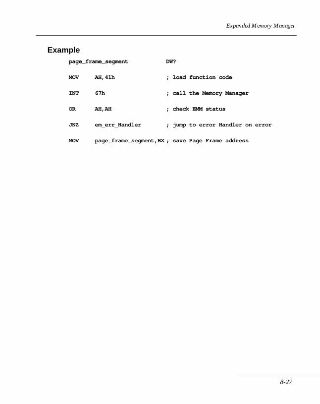
Expanded Memory Manager
Examplepage_frame_segment DW?
MOV AH,41h ; load function code
INT 67h ; call the Memory Manager
OR AH,AH ; check EMM status
JNZ em_err_Handler ; jump to error Handler on error
MOV page_frame_segment,BX ; save Page Frame address
8-27
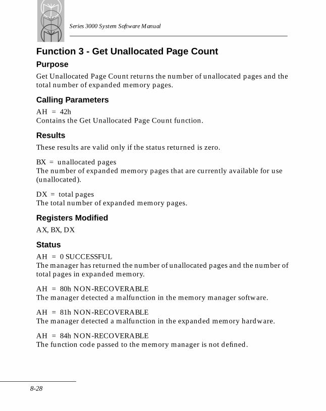
Series 3000 System Software Manual
Function 3 - Get Unallocated Page CountPurposeGet Unallocated Page Count returns the number of unallocated pages and the total number of expanded memory pages.
Calling ParametersAH = 42hContains the Get Unallocated Page Count function.
ResultsThese results are valid only if the status returned is zero.
BX = unallocated pagesThe number of expanded memory pages that are currently available for use (unallocated).
DX = total pagesThe total number of expanded memory pages.
Registers ModifiedAX, BX, DX
StatusAH = 0 SUCCESSFULThe manager has returned the number of unallocated pages and the number of total pages in expanded memory.
AH = 80h NON-RECOVERABLEThe manager detected a malfunction in the memory manager software.
AH = 81h NON-RECOVERABLEThe manager detected a malfunction in the expanded memory hardware.
AH = 84h NON-RECOVERABLEThe function code passed to the memory manager is not defined.
8-28
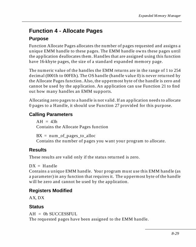
Expanded Memory Manager
Function 4 - Allocate Pages PurposeFunction Allocate Pages allocates the number of pages requested and assigns a unique EMM handle to these pages. The EMM handle owns these pages until the application deallocates them. Handles that are assigned using this function have 16-kbyte pages, the size of a standard expanded memory page.
The numeric value of the handles the EMM returns are in the range of 1 to 254 decimal (0001h to 00FEh). The OS handle (handle value 0) is never returned by the Allocate Pages function. Also, the uppermost byte of the handle is zero and cannot be used by the application. An application can use Function 21 to find out how many handles an EMM supports.
Allocating zero pages to a handle is not valid. If an application needs to allocate 0 pages to a Handle, it should use Function 27 provided for this purpose.
Calling ParametersAH = 43hContains the Allocate Pages function
BX = num_of_pages_to_allocContains the number of pages you want your program to allocate.
ResultsThese results are valid only if the status returned is zero.
DX = HandleContains a unique EMM handle. Your program must use this EMM handle (as a parameter) in any function that requires it. The uppermost byte of the handle will be zero and cannot be used by the application.
Registers ModifiedAX, DX
StatusAH = 0h SUCCESSFULThe requested pages have been assigned to the EMM handle.
8-29

Series 3000 System Software Manual
AH = 80h NON-RECOVERABLEThe manager detected a malfunction in the memory manager software.
AH = 81h NON-RECOVERABLEThe manager detected a malfunction in the expanded memory hardware.
AH = 84h NON-RECOVERABLEThe function code passed to the memory manager is not defined.
AH = 85h RECOVERABLE.All EMM handles are being used.
AH = 87h RECOVERABLEThere aren't enough expanded memory pages present in the system to satisfy your program's request.
AH = 88h RECOVERABLEThere aren't enough unallocated pages to satisfy your program's request.
Examplenum_of_pages_to_alloc DW?
emm_Handle DW?
MOV BX, num_of_pages_to_alloc
;load number of pages
MOV AH, 43h ;load function code
INT 67h ; call the Memory Manager
OR AH,AH ; check EMM status
JNZ emm_err_Handler ; jump to error Handler
; on error
MOV emm_Handle, DX ; save EMM Handle
8-30
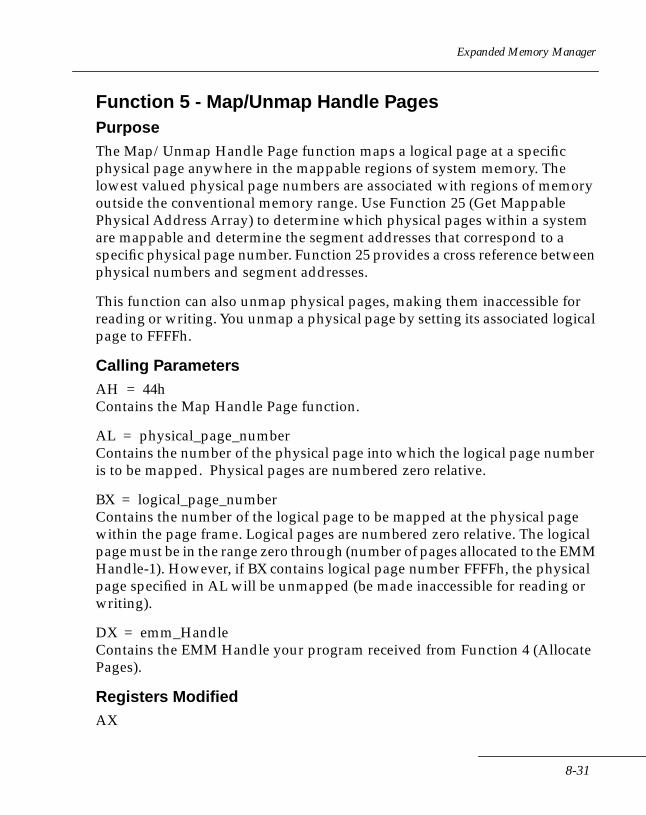
Expanded Memory Manager
Function 5 - Map/Unmap Handle Pages PurposeThe Map/Unmap Handle Page function maps a logical page at a specific physical page anywhere in the mappable regions of system memory. The lowest valued physical page numbers are associated with regions of memory outside the conventional memory range. Use Function 25 (Get Mappable Physical Address Array) to determine which physical pages within a system are mappable and determine the segment addresses that correspond to a specific physical page number. Function 25 provides a cross reference between physical numbers and segment addresses.
This function can also unmap physical pages, making them inaccessible for reading or writing. You unmap a physical page by setting its associated logical page to FFFFh.
Calling ParametersAH = 44hContains the Map Handle Page function.
AL = physical_page_numberContains the number of the physical page into which the logical page number is to be mapped. Physical pages are numbered zero relative.
BX = logical_page_numberContains the number of the logical page to be mapped at the physical page within the page frame. Logical pages are numbered zero relative. The logical page must be in the range zero through (number of pages allocated to the EMM Handle-1). However, if BX contains logical page number FFFFh, the physical page specified in AL will be unmapped (be made inaccessible for reading or writing).
DX = emm_HandleContains the EMM Handle your program received from Function 4 (Allocate Pages).
Registers ModifiedAX
8-31
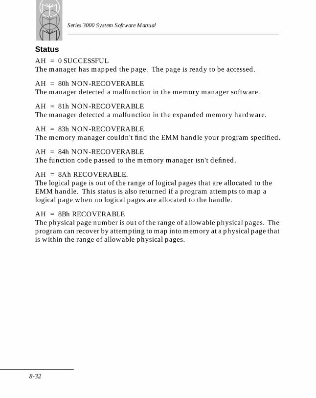
Series 3000 System Software Manual
StatusAH = 0 SUCCESSFULThe manager has mapped the page. The page is ready to be accessed.
AH = 80h NON-RECOVERABLEThe manager detected a malfunction in the memory manager software.
AH = 81h NON-RECOVERABLEThe manager detected a malfunction in the expanded memory hardware.
AH = 83h NON-RECOVERABLEThe memory manager couldn't find the EMM handle your program specified.
AH = 84h NON-RECOVERABLEThe function code passed to the memory manager isn't defined.
AH = 8Ah RECOVERABLE.The logical page is out of the range of logical pages that are allocated to the EMM handle. This status is also returned if a program attempts to map a logical page when no logical pages are allocated to the handle.
AH = 8Bh RECOVERABLEThe physical page number is out of the range of allowable physical pages. The program can recover by attempting to map into memory at a physical page that is within the range of allowable physical pages.
8-32
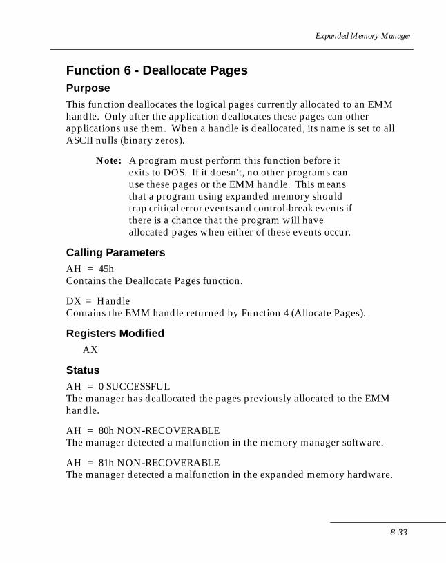
Expanded Memory Manager
Function 6 - Deallocate PagesPurposeThis function deallocates the logical pages currently allocated to an EMM handle. Only after the application deallocates these pages can other applications use them. When a handle is deallocated, its name is set to all ASCII nulls (binary zeros).
Note: A program must perform this function before it exits to DOS. If it doesn't, no other programs can use these pages or the EMM handle. This means that a program using expanded memory should trap critical error events and control-break events if there is a chance that the program will have allocated pages when either of these events occur.
Calling ParametersAH = 45hContains the Deallocate Pages function.
DX = HandleContains the EMM handle returned by Function 4 (Allocate Pages).
Registers ModifiedAX
StatusAH = 0 SUCCESSFULThe manager has deallocated the pages previously allocated to the EMM handle.
AH = 80h NON-RECOVERABLEThe manager detected a malfunction in the memory manager software.
AH = 81h NON-RECOVERABLEThe manager detected a malfunction in the expanded memory hardware.
8-33
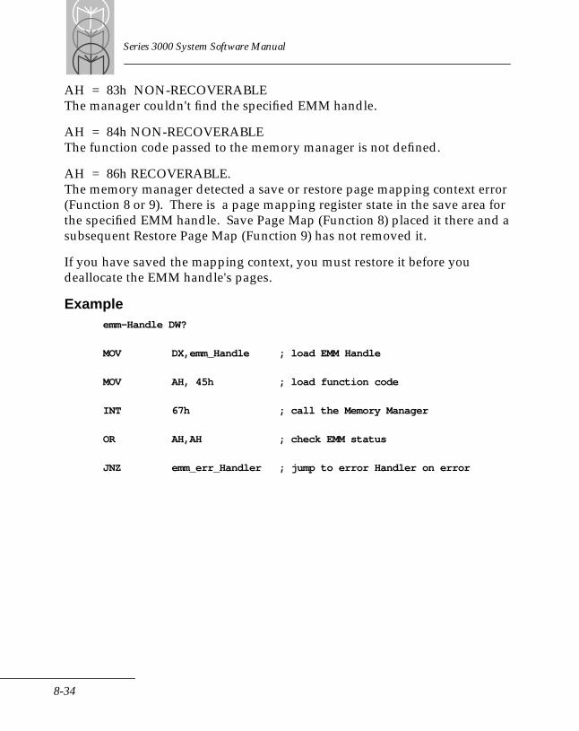
Series 3000 System Software Manual
AH = 83h NON-RECOVERABLEThe manager couldn't find the specified EMM handle.
AH = 84h NON-RECOVERABLEThe function code passed to the memory manager is not defined.
AH = 86h RECOVERABLE.The memory manager detected a save or restore page mapping context error (Function 8 or 9). There is a page mapping register state in the save area for the specified EMM handle. Save Page Map (Function 8) placed it there and a subsequent Restore Page Map (Function 9) has not removed it.
If you have saved the mapping context, you must restore it before you deallocate the EMM handle's pages.
Exampleemm-Handle DW?
MOV DX,emm_Handle ; load EMM Handle
MOV AH, 45h ; load function code
INT 67h ; call the Memory Manager
OR AH,AH ; check EMM status
JNZ emm_err_Handler ; jump to error Handler on error
8-34

Expanded Memory Manager
Function 7 - Get VersionPurposeThe Get Version function returns the version number of the memory manager software.
Calling ParametersAH = 46hContains the Get Version function.
ResultsThese results are valid only if the status returned is zero.
AL = version numberContains the memory manager's version number in binary coded decimal (BCD) format. The upper four bits contain the integer digit of the version number. The lower four bits contain the fractional digit of version number. For example, version 4.0 is represented like this:0100 0000
When checking for a version number, an application should check for a minimum, not an exact version number This includes both the integer and the fractional number. Vendors often use the fractional digit to indicate enhancements or corrections to their memory managers. Therefore, to enable operation with future versions of memory managers, an application shouldn't depend on an exact version number.
Registers ModifiedAX
StatusAH = 0 SUCCESSFULThe manager is present in the system and hardware is working correctly.
AH = 80h NON-RECOVERABLEThe manager detected a malfunction in the memory manager software.
8-35
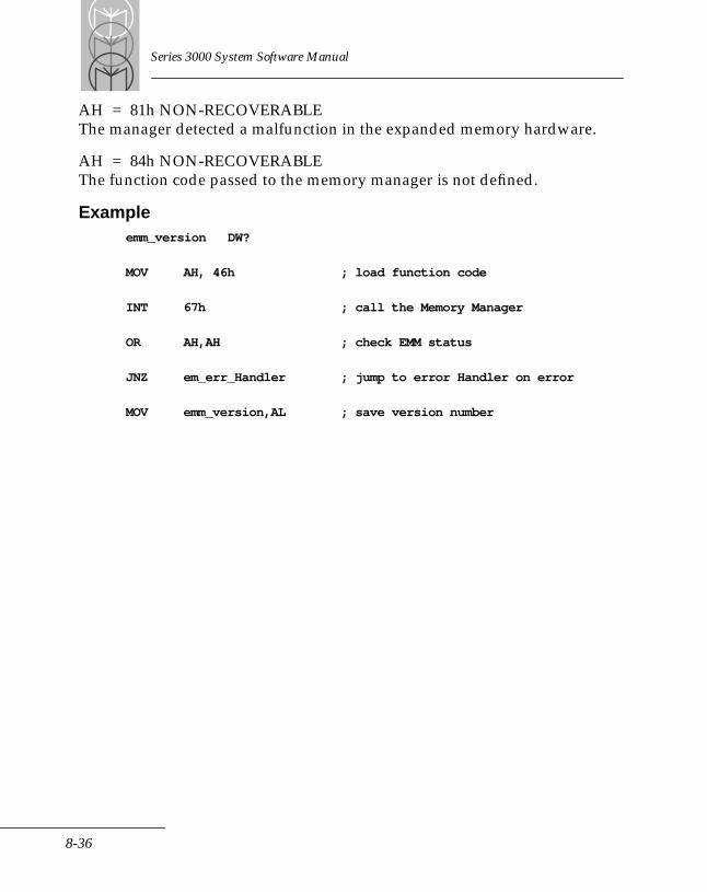
Series 3000 System Software Manual
AH = 81h NON-RECOVERABLEThe manager detected a malfunction in the expanded memory hardware.
AH = 84h NON-RECOVERABLEThe function code passed to the memory manager is not defined.
Exampleemm_version DW?
MOV AH, 46h ; load function code
INT 67h ; call the Memory Manager
OR AH,AH ; check EMM status
JNZ em_err_Handler ; jump to error Handler on error
MOV emm_version,AL ; save version number
8-36
Expanded Memory Manager
Function 8 - Save Page MapPurposeSave Page Map saves the contents of the page mapping registers on all expanded memory boards in an internal save area. The function is typically used to save the memory mapping context of the EMM handle that is active when a software or hardware interrupt occurs. (See Function 9, Restore Page Map.)
If you're writing a resident program, an interrupt service routine, or a device driver that uses expanded memory, you must save the state of the mapping hardware because application software using expanded memory may be running when your program is invoked by a hardware interrupt, a software interrupt, or DOS.
The Save Page Map function requires the EMM handle that was assigned to your resident program, interrupt service routine, or device driver at the time it was initialized. This is not the EMM handle that the application software is using when your software interrupts it.
The Save Page Map function saves the state of the map registers for only the 64-kbyte page frame defined in versions 3.x of this specification. Since all applications written to LIM versions 3.x require saving the map register state of only this 64-kbyte page frame, saving the entire mapping state for a large number of mappable pages would be inefficient use of memory. Applications that use a mappable memory region outside the LIM 3.x page frame should use Function 15 or 16 to save and restore the state of the map registers.
Calling ParametersAH = 47hContains the Save Page Map function.
DX = HandleContains the EMM handle assigned to the interrupt service routine that's servicing the software or hardware interrupt. The interrupt service routine needs to save the state of the page mapping hardware before mapping any pages.
8-37

Series 3000 System Software Manual
Registers ModifiedAX
StatusAH = 0 SUCCESSFULThe manager has saved the state of the page mapping hardware.
AH = 80h NON-RECOVERABLEThe manager detected a malfunction in the memory manager software.
AH = 81h NON-RECOVERABLEThe manager detected a malfunction in the expanded memory hardware.
AH = 83h NON-RECOVERABLE The memory manager couldn't find the EMM handle your program specified.
AH = 84h NON-RECOVERABLEThe function code passed to the memory manager is not defined.
AH = 8Ch NON-RECOVERABLEThere is no room in the save area to store the state of the page mapping registers. The state of the map registers has not been saved.
AH = 8Dh CONDITIONALLY-RECOVERABLEThe save area already contains the page mapping register state for the EMM handle your program specified.
Exampleemm_Handle DW?
MOV DX, emm_Handle ; load EMM Handle
MOV AH, 47h ; load function code
INT 67h ; call the Memory Manager
OR AH,AH ; check EMM status
JNZ em_err_Handler ; jump to error Handler on error
8-38
Expanded Memory Manager
Function 9 - Restore Page MapPurposeThe Restore Page Map function restores the page mapping register contents on the expanded memory boards for a particular EMM handle. The function lets your program restore the contents of the mapping registers its EMM handle saved. (See Function 8, Save Page Map for the save operation.)
If you're writing a resident program, an interrupt service routine, or a device driver that uses expanded memory, you must restore the mapping hardware to the state it was in before your program took over. You must save this state because application software using expanded memory might have been running when your program was invoked.
The Restore Page Map function requires the EMM handle that was assigned to your resident program, interrupt service routine, or device driver at the time it was initialized. This is not the EMM handle that the application software is using when your software interrupts it.
The Restore Page Map function restores the state of the map registers for only the 64-kbyte page frame defined in versions 3.x of this specification. Since all applications written to LIM versions 3.x require restoring the map register state of only this 64-kbyte page frame, restoring the entire mapping state for a large number of mappable pages would be an inefficient use of memory. Applications that use a mappable memory region outside the LIm 3.x page frame should use Function 15 or 16 to save and restore the state of the map registers.
Calling ParametersAH = 48hContains the Restore Page Map function.
DX = emm_HandleContains the EMM handle assigned to the interrupt service routine that's servicing the software or hardware interrupt. The interrupt service routine needs to restore the state of the page mapping hardware.
8-39
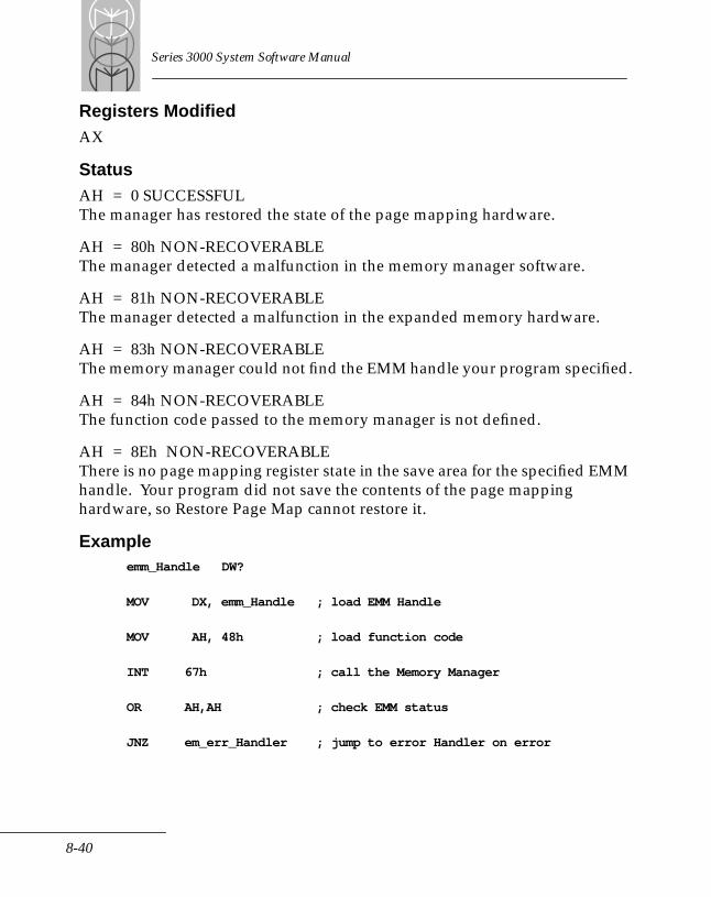
Series 3000 System Software Manual
Registers ModifiedAX
StatusAH = 0 SUCCESSFULThe manager has restored the state of the page mapping hardware.
AH = 80h NON-RECOVERABLEThe manager detected a malfunction in the memory manager software.
AH = 81h NON-RECOVERABLEThe manager detected a malfunction in the expanded memory hardware.
AH = 83h NON-RECOVERABLE The memory manager could not find the EMM handle your program specified.
AH = 84h NON-RECOVERABLEThe function code passed to the memory manager is not defined.
AH = 8Eh NON-RECOVERABLEThere is no page mapping register state in the save area for the specified EMM handle. Your program did not save the contents of the page mapping hardware, so Restore Page Map cannot restore it.
Exampleemm_Handle DW?
MOV DX, emm_Handle ; load EMM Handle
MOV AH, 48h ; load function code
INT 67h ; call the Memory Manager
OR AH,AH ; check EMM status
JNZ em_err_Handler ; jump to error Handler on error
8-40
Expanded Memory Manager
Function 12 - Get Handle Count PurposeThe Get Handle Count function returns the number of Open EMM handles [including the operating system Handle (0)] in the system.
Calling ParametersAH = 4BhContains the Get Handle Count function.
ResultsThese results are valid only if the status returned is zero.
BX = total_open_emm_HandlesContains the number of open EMM handles [including the operating system Handle (0)]. This number will not exceed 255.
Registers ModifiedAX, BX
StatusAH = 0 SUCCESSFULThe manager has returned the number of active EMM handles.
AH = 80h NON-RECOVERABLEThe manager detected a malfunction in the memory manager software.
AH = 81h NON-RECOVERABLEThe manager detected a malfunction in the expanded memory hardware.
AH = 84h NON-RECOVERABLEThe function code passed to the memory manager is not defined.
8-41

Series 3000 System Software Manual
Function 13 - Get Handle PagesPurposeThe Get Handle Pages function returns the number of pages allocated to a specific EMM handle.
Calling ParametersAH = 4ChContains the Get Handle Pages function.
DX = emm_HandleContains the EMM handles.
ResultsThese results are valid only if the status returned is zero.
BX = num_pages_alloc_to_emm_HandleContains the number of logical pages allocated to the specified EMM handle. This number never exceeds 512 because the memory manager allows a maximum of 512 pages (8 Mbyte) of expanded memory.
Registers ModifiedAX, BX
StatusAH = 0 SUCCESSFULThe manager has returned the page frame address in the BX register.
AH = 80h NON-RECOVERABLEThe manager detected a malfunction in the memory manager software.
AH = 81h NON-RECOVERABLEThe manager detected a malfunction in the expanded memory hardware.
AH = 83h NON-RECOVERABLE.The memory manager couldn't find the EMM handle your program specified.
AH = 84h NON-RECOVERABLEThe function code passed to the memory manager is not defined.
8-42
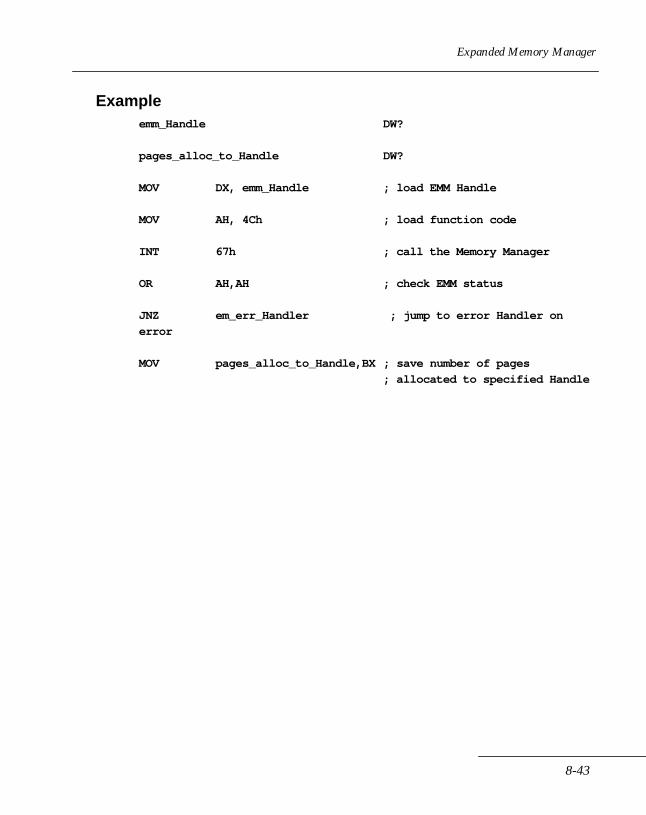
Expanded Memory Manager
Exampleemm_Handle DW?
pages_alloc_to_Handle DW?
MOV DX, emm_Handle ; load EMM Handle
MOV AH, 4Ch ; load function code
INT 67h ; call the Memory Manager
OR AH,AH ; check EMM status
JNZ em_err_Handler ; jump to error Handler on
error
MOV pages_alloc_to_Handle,BX ; save number of pages
; allocated to specified Handle
8-43
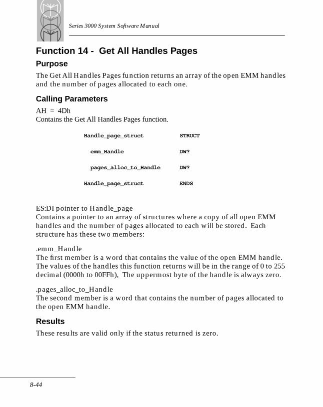
Series 3000 System Software Manual
Function 14 - Get All Handles PagesPurposeThe Get All Handles Pages function returns an array of the open EMM handles and the number of pages allocated to each one.
Calling ParametersAH = 4DhContains the Get All Handles Pages function.
Handle_page_struct STRUCT
emm_Handle DW?
pages_alloc_to_Handle DW?
Handle_page_struct ENDS
ES:DI pointer to Handle_pageContains a pointer to an array of structures where a copy of all open EMM handles and the number of pages allocated to each will be stored. Each structure has these two members:
.emm_HandleThe first member is a word that contains the value of the open EMM handle. The values of the handles this function returns will be in the range of 0 to 255 decimal (0000h to 00FFh), The uppermost byte of the handle is always zero.
.pages_alloc_to_HandleThe second member is a word that contains the number of pages allocated to the open EMM handle.
ResultsThese results are valid only if the status returned is zero.
8-44
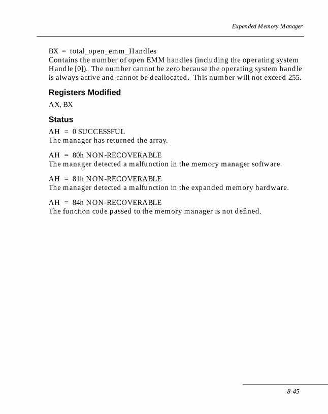
Expanded Memory Manager
BX = total_open_emm_HandlesContains the number of open EMM handles (including the operating system Handle [0]). The number cannot be zero because the operating system handle is always active and cannot be deallocated. This number will not exceed 255.
Registers ModifiedAX, BX
StatusAH = 0 SUCCESSFULThe manager has returned the array.
AH = 80h NON-RECOVERABLEThe manager detected a malfunction in the memory manager software.
AH = 81h NON-RECOVERABLEThe manager detected a malfunction in the expanded memory hardware.
AH = 84h NON-RECOVERABLEThe function code passed to the memory manager is not defined.
8-45
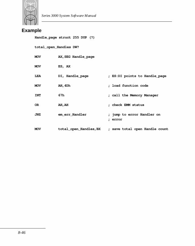
Series 3000 System Software Manual
ExampleHandle_page struct 255 DUP (?)
total_open_Handles DW?
MOV AX,SEG Handle_page
MOV ES, AX
LEA DI, Handle_page ; ES:DI points to Handle_page
MOV AH,4Dh ; load function code
INT 67h ; call the Memory Manager
OR AH,AH ; check EMM status
JNZ em_err_Handler ; jump to error Handler on
; error
MOV total_open_Handles,BX ; save total open Handle count
8-46
Expanded Memory Manager
Function 15Get/Set Page MapGet Page Map SubfunctionPurposeThe Get Page Map subfunction saves the mapping context for all mappable memory regions (Conventional and Expanded) by copying the contents of the mapping registers from each expanded memory board to a destination array. The application must pass a pointer to a destination array. This subfunction doesn't require an EMM handle.
Use this function instead of Functions 8 and 9 if you need to save or restore the mapping context but don't want (or have) to use a handle.
Calling ParametersAX = 4E00hContains the Get Page Map subfunction.
ES:DI = dest_page_mapContains a pointer to the destination array address in segment: offset format. Use the Get Size of Page Map Save Array subfunction to determine the size of the desired array.
ResultsThese results are valid only if the status returned is zero.
dest_page_mapThe array contains the state of all the mapping registers on all boards in the system. It also contains any additional information necessary to restore the boards to their original state when the program invokes a Set subfunction.
Registers ModifiedAX
StatusAH = 0 SUCCESSFULThe manager has returned the array.
8-47

Series 3000 System Software Manual
AH = 80h NON-RECOVERABLEThe manager detected a memory manager software malfunction.
AH = 81h NON-RECOVERABLEThe manager detected an expanded memory hardware malfunction.
AH = 84h NON-RECOVERABLEThe function code passed to the memory manager is not defined.
AH = 8Fh NON-RECOVERABLEThe subfunction parameter is invalid.
Exampledest_page_map DB? DUP (?)
MOV AX,SEG dest_page_map
MOV ES,AX
LEA DI,dest_page_map ; ES:DI points to dest_page_map
MOV AX,4E00h ; load function code
INT 67h ; call the Memory Manager
OR AH,AH ; check EMM status
JNZ em_err_Handler ; jump to error Handler on error
8-48
Expanded Memory Manager
Function 15Get/Set Page Map Set Page Map SubfunctionPurposeThe Set Page Map subfunction restores the mapping context for all mappable memory regions (conventional and expanded) by copying the contents of a source array into the mapping registers on each system expanded memory board. The application must pass a pointer to the source array. This subfunction does not require an EMM handle.
Use this function instead of Functions 8 and 9 if you need to save or restore the mapping context but don't want (or have) to use a handle.
Calling ParametersAX = 4E01hContains the Set Page Map subfunction.
DS:SI = source_page_mapContains a pointer to the source array address in segment: offset format. The application must point to an array which contains the mapping register state. Use the Get Size of Page Map Save Array subfunction to determine the size of the desired array.
Registers ModifiedAX
StatusAH = 0 SUCCESSFULThe manager has passed the array.
AH = 80h NON-RECOVERABLEThe manager detected a memory manager software malfunction.
AH = 81h NON-RECOVERABLEThe manager detected an expanded memory hardware malfunction.
8-49
Series 3000 System Software Manual
AH = 84h NON-RECOVERABLEThe function code passed to the memory manager is not defined.
AH = 8Fh NON-RECOVERABLEThe subfunction parameter is invalid.
AH = 12h NON-RECOVERABLEThe contents of the source array have been corrupted, or the pointer passed to the subfunction is invalid.
Examplesource_page_map DB? DUP (?)
MOV AX,SEG source_page_map
MOV DS,AX
LEA SI,source_page_map ; DS:DI points to source_page_map
MOV AX,4E01h ; load function code
INT 67h ; call the Memory Manager
OR AH,AH ; check EMM status
JNZ em_err_Handler ; jump to error Handler on error
8-50
Expanded Memory Manager
Function 15Get/Set Page MapGet & Set Page Map SubfunctionPurposeThis subfunction simultaneously saves a current mapping context and restores a previous mapping context for all mappable memory regions (both conventional and expanded). It first copies the mapping register contents from each system expanded memory board into a destination array. (The application must pass a pointer to the destination array.) Then, the subfunction copies the source array contents into the mapping registers on each of the expanded memory boards. (The application must pass a pointer to the source array.)
Use this function instead of Functions 8 and 9 if you need to save or restore the mapping context but don't want to use a handle.
Calling ParametersAX = 4E02hContains the Get & Set Page Map subfunction.
ES:DI = dest_page_mapContains a pointer to the destination array address in segment:offset format. The current contents of the map registers are saved in this array.
DS:SI = source_page_mapContains a pointer to the source array address in segment:offset format. The contents of this array will be copied into the map registers. The application must point to an array which contains the mapping register state. This address is required only for the Set or Get & Set subfunctions.
ResultsThese results are valid only if the status returned is zero.
dest_page_mapThe array contains the mapping state. It also contains any additional information necessary to restore the original state when the program invokes a Set subfunction.
8-51
Series 3000 System Software Manual
Registers ModifiedAX
StatusAH = 0 SUCCESSFULThe manager has returned and passed both arrays.
AH = 80h NON-RECOVERABLEThe manager detected a malfunction in the memory manager software.
AH = 81h NON-RECOVERABLEThe manager detected a malfunction in the expanded memory hardware.
AH = 84h NON-RECOVERABLEThe function code passed to the memory manager is not defined.
AH = 8Fh NON-RECOVERABLEThe subfunction parameter is invalid.
AH = 12h NON-RECOVERABLEThe contents of the source array have been corrupted, or the pointer passed to the subfunction is invalid.
Exampledest_page_map DB? DUP (?)
source_page_map DB? DUP (?)
MOV AX,SEG dest_page_map
MOV ES,AX
MOV AX,SEG source_page_map
MOV DS,AX
LEA DI,dest_page_map ; ES:DI points to dest_page_map
LEA SI,source_page_map ; DS:DI points to source_page_map
8-52
Expanded Memory Manager
MOV AX,4E02h ; load function code
INT 67h ; call the Memory Manager
OR AH,AH ; check EMM status
JNZ em_err_Handler ; jump to error Handler on error
8-53
Series 3000 System Software Manual
Function 15Get/Set Page Map Get Size of Page Map Save Array SubfunctionPurposeThe Get Size of Page Map Save Array subfunction returns the storage requirements for the array passed by the other three subfunctions. This subfunction doesn't require an EMM handle.
Calling ParametersAX = 4E03hContains the Get Size of Page Map Save Array subfunction. The size of this array depends on how the expanded memory system is configured and how the expanded memory manager is implemented. Therefore, the size must be determined after the memory manager is loaded.
ResultsThese results are valid only if the status returned is zero.
AL = size_of_arrayContains the number of bytes that are transferred to the memory area an application supplies whenever a program requests the Get, Set or Get and Set subfunctions.
Registers ModifiedAX
StatusAH = 0 SUCCESSFULThe manager has returned the array size.
AH = 80h NON-RECOVERABLEThe manager detected a malfunction in the memory manager software.
AH = 81h NON-RECOVERABLEThe manager detected a malfunction in the expanded memory hardware.
8-54
Expanded Memory Manager
AH = 84h NON-RECOVERABLEThe function code passed to the memory manager is not defined.
AH = 8Fh NON-RECOVERABLEThe subfunction parameter is invalid.
Examplesize_of_array DB
MOV AX, 4E03h ;load function code
INT 67h ;call the Memory Manager
OR AH,AH ;check EMM status
JNZ emm_err_Handler ;jump to error Handler
; on error
MOV size_of_array, DX ;save array size
8-55
Series 3000 System Software Manual
Function 16Get/Set Partial Page MapGet Partial Page Map SubfunctionPurposeThe Get Partial Page Map subfunction saves a partial mapping context for specific mappable memory regions in a system. Because this function saves only a subset of the entire mapping context, it uses less memory for the save area and may be faster than Function 15. The subfunction does this by copying the contents of selected mapping registers from each expanded memory board to a destination array.
The application must pass a pair of pointers. The first points to a structure which specifies which mappable segments to save; the second points to the destination array.
Use this function instead of Functions 8 and 9 if you need to save or restore the mapping context but don't want (or have) to use a handle.
Calling ParametersAX = 4F00hContains the Get Partial Page Map subfunction.
partial_page_map_struct STRUC
mappable_segment_count DW?
mappable_segment DW? DUP (?)
partial_page_map_struct ENDS
DS:SI = partial_page_mapContains a pointer to a structure which specifies only those mappable memory regions are to have their mapping context saved. The structure members are described below.
8-56
Expanded Memory Manager
.mappable_segment_countThe first member is a word which specifies the number of members in the word array that immediately follows it. This number should not exceed the number of mappable segments in the system.
.mappable_segmentThe second member is a word array which contains the segment addresses of the mappable memory regions whose mapping contexts are to be saved. Use Function 25 to determine which segments are mappable.
ES:DI = dest_arrayContains a pointer to the destination array address in Segment:Offset format. To determine the size of the required array, see Get Size of Partial Page Map Save Array.
ResultsThese results are valid only if the status returned is zero.
dest_arrayThe array contains the partial mapping context and any additional information necessary to restore this context to its original state when the program invokes a Set subfunction.
Registers ModifiedAX
StatusAH = 0 SUCCESSFULThe manager has saved the partial map context.
AH = 80h NON-RECOVERABLEThe manager detected a malfunction in the memory manager software.
AH = 81h NON-RECOVERABLEThe manager detected a malfunction in the expanded memory hardware.
AH = 84h NON-RECOVERABLEThe function code passed to the memory manager isn't defined.
8-57
Series 3000 System Software Manual
AH = 8Bh NON-RECOVERABLE.One of the specified segments is not a mappable segment.
AH = 8Fh NON-RECOVERABLE.The subfunction parameter is invalid.
AH = 12h NON-RECOVERABLEThe contents of the partial page map structure have been corrupted, the pointer passed to the subfunction is invalid, or the mappable_segment_count exceeds the number of mappable segments in the system.
8-58
Expanded Memory Manager
Function 16Get/Set Partial Page MapSet Partial Page Map SubfunctionPurposeThe Set Partial Page Map subfunction provides a mechanism for restoring the mapping context for a partial mapping context for specific mappable memory regions in a system. Because this function restores only a subset of the entire system’s mapping context, it uses much less memory for the save area and is potentially faster than Function 15. The subfunction does this by copying the contents of the source array to selected mapping registers on each expanded memory board. The application passes a pointer to the source array.
Use this function instead of Functions 8 and 9 if you need to save or restore the mapping context but don't want (or have) to use a handle.
Calling ParametersAX = 4F01hContains the Set Partial Page Map subfunction.
source_array DB? DUP (?)
DS:SI = source_arrayContains a pointer to the source array in segment:offset format. The application must point to an array that contains the partial mapping register state. To determine the size of the required array, see the Get Size of Partial Page Map Save Array subfunction.
Registers ModifiedAX
StatusAH = 0 SUCCESSFULThe manager has restored the partial mapping context.
AH = 80h NON-RECOVERABLEThe manager detected a malfunction in the memory manager software.
8-59
Series 3000 System Software Manual
AH = 81h NON-RECOVERABLEThe manager detected a malfunction in the expanded memory hardware.
AH = 84h NON-RECOVERABLEThe function code passed to the memory manager is not defined.
AH = 8Fh NON-RECOVERABLEThe subfunction parameter is invalid.
AH = 12h NON-RECOVERABLE.The contents of the source array have been corrupted, or the pointer passed to the sub-function is invalid.
ExampleMOV AX,SEG source array
MOV DS,AX
LEA SI,source_array ; DS:SI points to source_array
MOV AX, 4F01h ; load function code
INT 67h ; call the Memory Manager
OR AH,AH ; check EMM status
JNZ emm_err_Handler ; jump to error Handler on error
8-60
Expanded Memory Manager
Function 16Get/Set Partial Page MapGet Size of Partial Page Map Save Array SubfunctionPurposeThe Return Size subfunction returns the storage requirements for the array passed by the other two subfunctions. This subfunction doesn't require an EMM handle.
Calling ParametersAX = 4F02hContains the Get Size of Partial Page Map Save Array subfunction. The size of this array depends on the expanded memory system configuration and the implementation of the expanded memory manager. Therefore, it will vary between hardware configurations and implementations and must be determined after a specific memory manager is loaded.
BX = number of pages in the partial arrayContains the number of pages in the partial map to be saved by the Get/Set Partial Page Map subfunctions. This number should be the same as the mappable_segment_count in the Get/Set Partial Page Map subfunction.
ResultsThese results are valid only if the status returned is zero.
AL = size_of_partial_save_arrayContains the number of bytes that are transferred to the memory area supplied by an application whenever a program requests the Get or Set subfunction.
Registers ModifiedAX
StatusAH = 0 SUCCESSFULThe manager returned the array size.
8-61

Series 3000 System Software Manual
AH = 80h NON-RECOVERABLEThe manager detected a memory manager software malfunction.
AH = 81h NON-RECOVERABLEThe manager detected an expanded memory hardware malfunction.
AH = 84h NON-RECOVERABLEThe function code passed to the memory manager is not defined.
AH = 8Bh NON-RECOVERABLEThe number of pages in the partial array is outside the range of physical pages in the system.
AH = 8Fh NON-RECOVERABLEThe subfunction parameter is invalid.
Examplenumber_of_pages_to_map DW?
size_of_partial_save_array DB?
MOV BX, number_of_pages_to_map
MOV AX,4F02h ;load function code
INT 67h ;call the Memory Manager
OR AH,AH ; check EMM status
JNZ em_err_Handler ; jump to error Handler on
; error
MOV size_of_partial_save_array,AL ; save array size
8-62

Expanded Memory Manager
Function 17 - Map/Unmap Multiple Handle Pages PurposeThis function can, in a single invocation, map (or unmap) logical pages into as many physical pages as the system supports. Consequently, it has less execution overhead than mapping pages one at a time. For applications that do a lot of page mapping, this is the preferred mapping method.
Mapping Multiple PagesThe handle passed to this function determines what type of logical pages are being mapped. Logical pages that Function 4 and Function 27 (Allocate Standard Pages subfunction) allocate are referred to as pages and are 16 kbytes. Logical pages that Function 27 (Allocate Raw Pages subfunction) allocates are referred to as raw pages and might not be the same size as the pages Function 4 and Function 27 (Allocate Standard Pages subfunction) allocate.
Unmapping Multiple PagesThis function can make specific physical pages unavailable for reading or writing. A logical page that is unmapped from a specific physical page cannot be read or written from that physical page. The logical page that is unavailable (unmapped) can be made available again by mapping it, or a new logical page, at the physical page that was unmapped. Unmapping a physical page is accomplished by setting the associated logical page to FFFFh.
You might unmap an entire set of mapped pages, for example, before loading and executing a program. This ensures that the loaded program won't be able to access the pages your program has mapped. However, you must save the mapping context before you unmap the physical pages. This enables you to restore it later so that you may access the memory you had mapped there. You can save the mapping context with functions 8, 15, or 16. You can restore the mapping context with Functions 9, 15, or 16.
Mapping and Unmapping Multiple Pages SimultaneouslyBoth mapping and unmapping pages can be done in the same invocation.
Mapping or unmapping no pages is not considered an error. If a request to map or unmap zero pages is made, nothing is done and no error is returned.
8-63
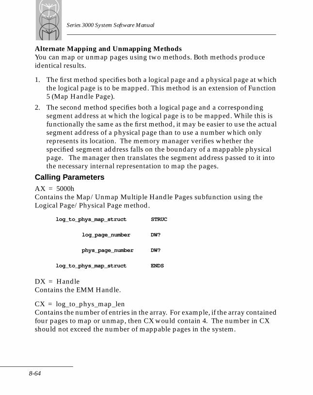
Series 3000 System Software Manual
Alternate Mapping and Unmapping MethodsYou can map or unmap pages using two methods. Both methods produce identical results.
1. The first method specifies both a logical page and a physical page at which the logical page is to be mapped. This method is an extension of Function 5 (Map Handle Page).
2. The second method specifies both a logical page and a corresponding segment address at which the logical page is to be mapped. While this is functionally the same as the first method, it may be easier to use the actual segment address of a physical page than to use a number which only represents its location. The memory manager verifies whether the specified segment address falls on the boundary of a mappable physical page. The manager then translates the segment address passed to it into the necessary internal representation to map the pages.
Calling ParametersAX = 5000hContains the Map/Unmap Multiple Handle Pages subfunction using the Logical Page/Physical Page method.
log_to_phys_map_struct STRUC
log_page_number DW?
phys_page_number DW?
log_to_phys_map_struct ENDS
DX = HandleContains the EMM Handle.
CX = log_to_phys_map_lenContains the number of entries in the array. For example, if the array contained four pages to map or unmap, then CX would contain 4. The number in CX should not exceed the number of mappable pages in the system.
8-64
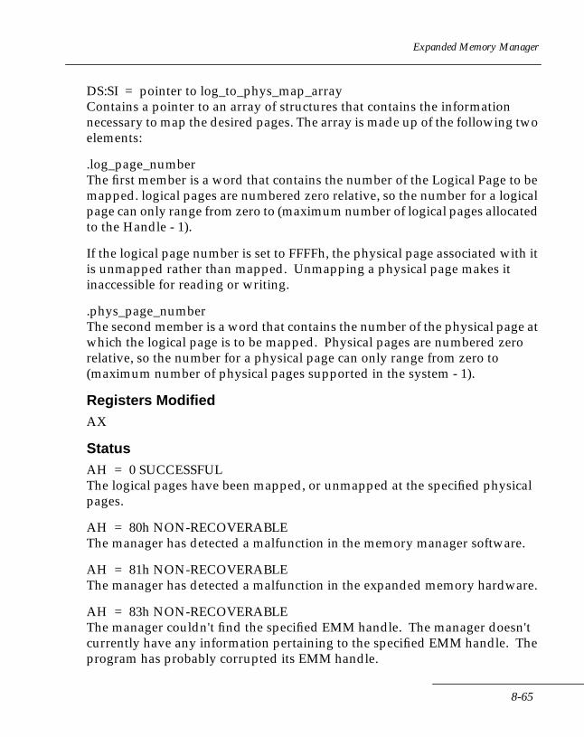
Expanded Memory Manager
DS:SI = pointer to log_to_phys_map_arrayContains a pointer to an array of structures that contains the information necessary to map the desired pages. The array is made up of the following two elements:
.log_page_numberThe first member is a word that contains the number of the Logical Page to be mapped. logical pages are numbered zero relative, so the number for a logical page can only range from zero to (maximum number of logical pages allocated to the Handle - 1).
If the logical page number is set to FFFFh, the physical page associated with it is unmapped rather than mapped. Unmapping a physical page makes it inaccessible for reading or writing.
.phys_page_numberThe second member is a word that contains the number of the physical page at which the logical page is to be mapped. Physical pages are numbered zero relative, so the number for a physical page can only range from zero to (maximum number of physical pages supported in the system - 1).
Registers ModifiedAX
StatusAH = 0 SUCCESSFULThe logical pages have been mapped, or unmapped at the specified physical pages.
AH = 80h NON-RECOVERABLEThe manager has detected a malfunction in the memory manager software.
AH = 81h NON-RECOVERABLEThe manager has detected a malfunction in the expanded memory hardware.
AH = 83h NON-RECOVERABLE The manager couldn't find the specified EMM handle. The manager doesn't currently have any information pertaining to the specified EMM handle. The program has probably corrupted its EMM handle.
8-65
Series 3000 System Software Manual
AH = 84h NON-RECOVERABLEThe function code passed to the memory manager is not defined.
AH = 8Ah RECOVERABLE
One or more of the mapped logical pages is out of the range of logical pages allocated to the EMM handle. The program can recover by attempting to map a logical page which is within the bounds for the specified EMM handle. When this error occurs, the only pages mapped were the ones valid up to the point that the error occurred.
AH = 8Bh RECOVERABLEOne or more of the physical pages is out of the range of mapped physical pages, or the log_to_phy_map_len exceeds the number of mappable pages in the system. The program can recover from this condition by attempting to map into memory at a physical page which is in the range of the physical handle numbers supported by the system. When this error occurs, the only pages mapped were the ones valid up to the point that the error occurred.
AH = 8Fh NON-RECOVERABLEThe subfunction parameter is invalid.
8-66
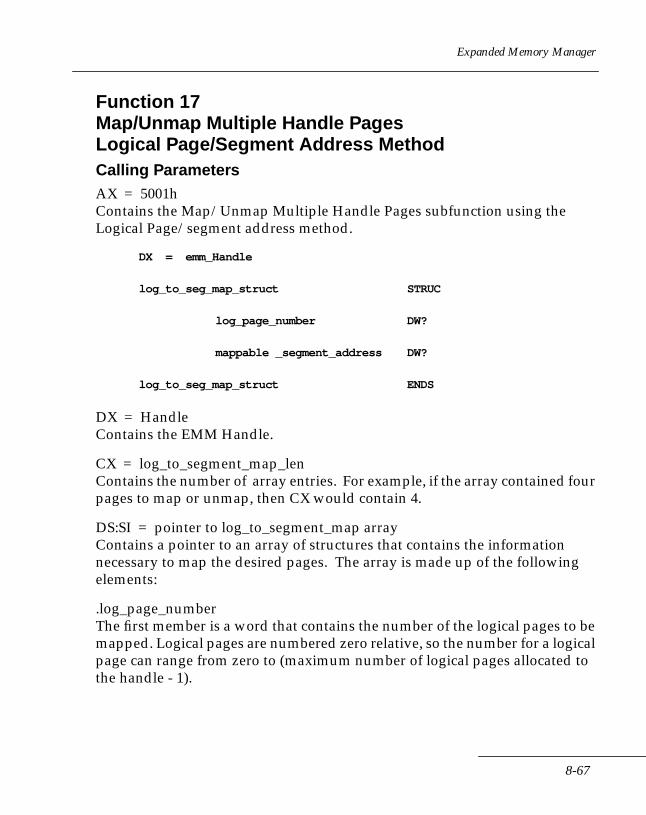
Expanded Memory Manager
Function 17Map/Unmap Multiple Handle PagesLogical Page/Segment Address Method Calling ParametersAX = 5001hContains the Map/Unmap Multiple Handle Pages subfunction using the Logical Page/segment address method.
DX = emm_Handle
log_to_seg_map_struct STRUC
log_page_number DW?
mappable _segment_address DW?
log_to_seg_map_struct ENDS
DX = HandleContains the EMM Handle.
CX = log_to_segment_map_lenContains the number of array entries. For example, if the array contained four pages to map or unmap, then CX would contain 4.
DS:SI = pointer to log_to_segment_map arrayContains a pointer to an array of structures that contains the information necessary to map the desired pages. The array is made up of the following elements:
.log_page_numberThe first member is a word that contains the number of the logical pages to be mapped. Logical pages are numbered zero relative, so the number for a logical page can range from zero to (maximum number of logical pages allocated to the handle - 1).
8-67
Series 3000 System Software Manual
If the logical page number is set to FFFFh, the physical page associated with it is unmapped rather than mapped. Unmapping a physical page makes it inaccessible for reading or writing.
.mappable_segment_addressThe second member is a word which contains the segment address at which the logical page is to be mapped. This segment address must correspond exactly to a mappable segment address. The mappable segment addresses are available with Function 25 (Get Mappable Physical Address Array).
Registers ModifiedAX
StatusAH = 0 SUCCESSFULThe logical pages have been mapped (or unmapped), at the specified physical pages.
AH = 80h NON-RECOVERABLEThe manager has detected a malfunction in the memory manager software.
AH = 81h NON-RECOVERABLEThe manager has detected a malfunction in the expanded memory hardware.
AH = 83h NON-RECOVERABLE The manager could not find the specified EMM handle. The manager doesn't have any information pertaining to the specified EMM handle. The program has probably corrupted its EMM handle.
AH = 84h NON-RECOVERABLEThe function code passed to the manager is not defined.
AH = 8Ah NON-RECOVERABLEOne or more of the logical pages to be mapped is out of the range of logical pages allocated to the EMM handle. The program can recover from this condition by mapping a logical page that is within the bounds for the specified EMM handle. When this error occurs, the only pages mapped or unmapped were the ones valid up to the point that the error occurred.
8-68
Expanded Memory Manager
AH = 8Bh RECOVERABLEOne or more of the mappable segment addresses specified is not mappable, the segment address doesn't fall exactly on a mappable address boundary, or the log_to_segment_map_len exceeds the number of mappable segments in the system. The program can recover from this condition by mapping into memory on an exact mappable segment address. When this error occurs, the only pages mapped were the ones valid up to the point that the error occurred.
AH = 8Fh NON-RECOVERABLEThe subfunction parameter is invalid.
8-69
Series 3000 System Software Manual
Function 18 - Reallocate PagesPurposeThis function allows an application program to increase or decrease (reallocate) the number of logical pages allocated to an EMM handle. There are four reallocation cases of interest:
1. A reallocation count of zero. The handle assigned to application remains assigned and is still available for use by the application. The memory manager won't reassign the handle to any other application. However, any currently allocated pages are returned to the memory manager. The application must invoke the Deallocate Pages function (Function 6) before returning to DOS, or the handle remains assigned and no other application is able to use it.
2. A reallocation count equal to the current allocation count. This is not treated as an error, and a successful status is returned.
3. A reallocation count greater than the current allocation count. The memory manager attempts to add new pages to those pages already allocated to the specified EMM handle. The number of new pages added is the difference between the reallocation count and the current allocation count. The sequence of logical pages allocated to the EMM handle remains continuous after this operation. The newly allocated pages have logical page numbers that begin where the previously allocated pages end, and continue in ascending sequence.
4. A reallocation count less than the current allocation count. The memory manager attempts to subtract some of the currently allocated pages and return them to the memory manager. The number of old pages subtracted is the difference between the current allocation count and the re-allocation count. The pages are subtracted from the end of the sequence of pages currently allocated to the specified EMM handle. The sequence of logical pages allocated to the EMM handle remains continuous after this operation.
The handle determines what type of logical pages are being reallocated. Logical pages that were originally allocated with Function 4 are called pages and are 16 kbytes long. Logical pages that were allocated with
8-70
Expanded Memory Manager
Function 27 are called raw pages and might not be the same size as pages allocated with Function 4.
Calling ParametersAH = 51hContains the Reallocate Handle Pages function.
DX = HandleContains the EMM handle.
BX = reallocation_countContains the total number of pages this handle should have allocated to it after this function is invoked.
ResultsThese results are valid only if the status returned is zero.
BX = number of pages allocated to handle after reallocation Contains the number of pages now allocated to the EMM handle after the pages are added or subtracted. If the status returned is not zero, the value in BX is equal to the number of pages allocated to the handle prior to the invocation of this function. This information can be used to verify that the request generated the expected results.
Registers ModifiedAX, BX
StatusAH = 0 SUCCESSFULThe pages specified have been added or subtracted to or from the handle specified.
AH = 80h NON-RECOVERABLEThe manager detected a memory manager software malfunction.
AH = 81h NON-RECOVERABLEThe manager detected an expanded memory hardware malfunction.
8-71
Series 3000 System Software Manual
AH = 83h NON-RECOVERABLEThe manager could not find the specified EMM handle. The manager doesn't have any information pertaining to the specified EMM handle. The program may have corrupted its EMM handle.
AH = 84h NON-RECOVERABLEThe function code passed to the memory manager is not defined.
AH = 87h RECOVERABLEThe number of pages that are available in the system is insufficient for the new allocation request. The program can recover from this condition by specifying few pages allocated to the EMM handle.
AH = 88h RECOVERABLEThe number of unallocated pages is insufficient for the new allocation request. The program can recover from this condition by either requesting again when additional pages are available or specifying fewer pages.
8-72
Expanded Memory Manager
Function 19Get/Set Handle AttributeGet and Set Handle Attribute SubfunctionsPurposeThese subfunctions are not supported on Series 3000 terminals. All handles are volatile.
8-73

Series 3000 System Software Manual
Function 19Get/Set Handle AttributeGet Attribute Capability SubfunctionPurposeThis subfunction can be used to determine whether the memory manager can support the non-volatile attribute.
Calling ParametersAX = 5202hContains the Get Attribute Capability subfunction.
ResultsThese results are valid only if the status returned is zero.
AL = attribute capabilityContains the attribute capability. A value of zero is returned, indicating that the memory manager and hardware support only volatile handles.
Registers ModifiedAX
StatusAH = 0 SUCCESSFULThe attribute capability has been returned.
AH = 80h NON-RECOVERABLEThe manager has detected a malfunction in the memory manager software.
AH = 81h NON-RECOVERABLEThe manager detected an expanded memory hardware malfunction.
AH = 84h NON-RECOVERABLEThe function code passed to the memory manager is undefined.
AH = 8Fh NON-RECOVERABLEThe subfunction parameter is invalid.
8-74
Expanded Memory Manager
Function 20Get/Set Handle NameGet Handle Name SubfunctionPurposeGets the current eight-character handle name. Any character may be used in the handle name (that is, anything from 00h through FFh).
The handle name is initialized to ASCII nulls (binary zeros) three times: when the memory manager is installed, when a handle is allocated, and when a Handle is deallocated. A handle with a name that is all ASCII nulls, by definition, has no name. When a handle is assigned a name, at least one character in the name must be a non-null character in order to distinguish it from a handle without a name.
Calling ParametersAX = 5300hContains the Get Handle Name function.
DX = Handle numberContains the EMM handle.
ES:DI = pointer to Handle_name arrayContains a pointer to an eight-byte array into which the name currently assigned to the handle will be copied.
ResultsThese results are valid only if the status returned is zero.
Handle_name arrayContains the name associated with the specified Handle.
Registers ModifiedAX
StatusAH = 0 SUCCESSFULThe handle name has been returned.
8-75

Series 3000 System Software Manual
AH = 80h NON-RECOVERABLEThe manager has detected a malfunction in the memory manager software.
AH = 81h NON-RECOVERABLEThe manager has detected a malfunction in the expanded memory hardware.
AH = 83h NON-RECOVERABLEThe manager could not find the specified EMM handle. The manager does not have any information on the specified EMM handle. The program may have corrupted its EMM handle.
AH = 84h NON-RECOVERABLEThe function code passed to the memory manager is not defined.
AH = 8Fh NON-RECOVERABLEThe subfunction parameter is invalid.
ExampleHandle_name DB? DUP (?)
emm_Handle DB? DUP (?)
MOV AX,SEG Handle_name
MOV ES,AX
LEA DI,Handle__name ; ES:DI points to Handle_name
MOV DX,emm_Handle ; specify EMM Handle
MOV AX,5300h ; load function code
INT 67h ; call the Memory Manager
OR AH,AH ; check EMM status
JNZ em_err_Handler ; jump to error Handler on error
8-76
Expanded Memory Manager
Function 20Get/Set Handle NameSet Handle Name SubfunctionPurposeThis subfunction assigns an eight-character name to a handle. There is no restriction on the characters that may be used in the Handle name. The full range of values may be assigned to each character in a name (that is, 00h through FFh).
At installation, all handles have their names initialized to ASCII nulls (binary zeros). A handle with a name consisting of all ASCII nulls has no name. When a handle is assigned a name, at least one character in the name must be a non-null character in order to distinguish it from a handle without a name. No two Handles may have the same name.
A handle can be renamed at any time by setting the handles names to a new value. A handle can have its name removed by setting the handle's name to all ASCII nulls. When a handle is deallocated, its name is removed (set to ASCII nulls).
Calling ParametersAH = 5301hContains the Set Handle Name function.
DX = Handle numberContains the EMM handle.
DS:DI = pointer to Handle_nameContains a pointer to a byte array that contains the name that is to be assigned to the handle. The handle name must be padded with nulls if the name is less than eight characters long.
Registers ModifiedAX
8-77
Series 3000 System Software Manual
StatusAH = 0 SUCCESSFULThe handle name has been assigned.
AH = 80h NON-RECOVERABLEThe manager detected a memory manager software malfunction.
AH = 81h NON-RECOVERABLEThe manager detected an expanded memory hardware malfunction.
AH = 83h NON-RECOVERABLEThe manager couldn't find the specified EMM handle. The manager doesn't currently have any information pertaining to the specified EMM handle. The program may have corrupted its EMM handle.
AH = 84h NON-RECOVERABLEThe function code passed to the manager is not defined.
AH = 8Fh NON-RECOVERABLEThe subfunction parameter is invalid.
AH = 10h NON-RECOVERABLEA handle with this name already exists. The specified handle was not assigned a name.
8-78
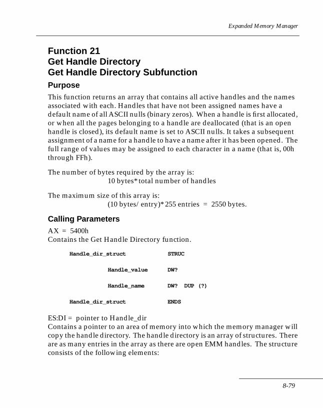
Expanded Memory Manager
Function 21Get Handle DirectoryGet Handle Directory SubfunctionPurposeThis function returns an array that contains all active handles and the names associated with each. Handles that have not been assigned names have a default name of all ASCII nulls (binary zeros). When a handle is first allocated, or when all the pages belonging to a handle are deallocated (that is an open handle is closed), its default name is set to ASCII nulls. It takes a subsequent assignment of a name for a handle to have a name after it has been opened. The full range of values may be assigned to each character in a name (that is, 00h through FFh).
The number of bytes required by the array is:10 bytes* total number of handles
The maximum size of this array is:(10 bytes/entry)* 255 entries = 2550 bytes.
Calling ParametersAX = 5400hContains the Get Handle Directory function.
Handle_dir_struct STRUC
Handle_value DW?
Handle_name DW? DUP (?)
Handle_dir_struct ENDS
ES:DI = pointer to Handle_dirContains a pointer to an area of memory into which the memory manager will copy the handle directory. The handle directory is an array of structures. There are as many entries in the array as there are open EMM handles. The structure consists of the following elements:
8-79
Series 3000 System Software Manual
.Handle_valueThe first member is a word that contains the value of the open EMM handle.
.Handle_nameThe second member is an 8-byte array that contains the ASCII name associated with the EMM handle. If there is no name currently associated with the handle, it has a value of all zeros (ASCII nulls).
ResultsThese results are valid only if the status returned is zero.
Handle_dirContains the handle values and handle names associated with each handle value.
AL = number of entries in the Handle_dir arrayContains the number of entries in the handle directory array. This is also the same as the number of open handles. For example, if only one Handle is active, AL will contain a one.
Registers ModifiedAX
StatusAH = 0 SUCCESSFULThe handle directory has been returned.
AH = 80h NON-RECOVERABLEThe manager detected a memory manager software malfunction.
AH = 81h NON-RECOVERABLEThe manager detected a malfunction in the expanded memory hardware.
AH = 84h NON-RECOVERABLEThe function code passed to the memory manager is not defined.
AH = 8Fh NON-RECOVERABLEThe subfunction parameter is invalid.
8-80
Expanded Memory Manager
Function 21Get Handle DirectorySearch for Named Handle SubfunctionPurposeThis subfunction searches the handle name directory for a handle with a particular name. If the named handle is found, this subfunction returns the handle number associated with the name. At the time of installation, all handles have their names initialized to ASCII nulls. A handle with a name that is all ASCII nulls has, by definition, no name. When a handle is assigned a name, at least one character in the name must be a non-null character in order to distinguish it from a handle without a name.
Calling ParametersAX = 5401hContains the Search for Named Handle subfunction.
DS:SI = Handle_nameContains a pointer to an 8-byte string that contains the name of the handle be searched for.
ResultsThese results are valid only if the status returned is zero.
DX = value of named HandleThe value of the Handle that matches the handle name specified.
Registers ModifiedAX, DX
StatusAH = 0 SUCCESSFULThe Handle value for named handle has been found.
AH = 80h NON-RECOVERABLEThe manager has detected a malfunction in the memory manager software.
8-81

Series 3000 System Software Manual
AH = 81h NON-RECOVERABLEThe manager has detected a malfunction in the expanded memory hardware.
AH = 84h NON-RECOVERABLEThe function code passed to the manager is not defined.
AH = 8Fh NON-RECOVERABLE.The subfunction parameter is invalid.
AH = 05h RECOVERABLE.No corresponding Handle could be found for the handle name specified.
AH = 10h NON-RECOVERABLEA handle found had no name (all ASCII nulls).
8-82
Expanded Memory Manager
Function 21Get Handle Directory Get Total Handles SubfunctionPurposeThis subfunction returns the total number of handles the memory manager supports, including the OS Handle (Handle value 0).
Calling ParametersAX = 5402hContains the Get Total Handles subfunction.
ResultsThese results are valid only if the status returned is zero.
BX = total_HandlesThe values returned, including the OS handle, represents the maximum number of handles a program may request the memory manager to allocate memory to.
Registers ModifiedAX, BX
StatusAH = 0 SUCCESSFULThe total number of Handles supported has been returned.
AH = 80h NON-RECOVERABLEThe manager detected a memory manager software malfunction.
AH = 81h NON-RECOVERABLEThe manager detected an expanded memory hardware malfunction.
AH = 84h NON-RECOVERABLEThe function code passed to the memory manager is undefined.
AH = 8Fh NON-RECOVERABLEThe subfunction parameter is invalid.
8-83

Series 3000 System Software Manual
Function 22Alter Page Map & JumpPurposeThis function alters the memory mapping context and transfers control to the specified address. It is analogous to the FAR JUMP in the 8086 family architecture. The memory mapping context that existed before the invocation of this function is lost.
Mapping no pages and jumping is not considered an error. If a request to map zero pages and jump is made, control is transferred to the target address, and this function performs a far jump.
Calling ParametersAH = 55hContains the Alter Page Map & Jump function.
log_phys_map_struct STRUC
log_page_number DW?
phys_page_number_seg DW?
log_phys_map_struct ENDS
map_and_jump_struct STRUC
target address DD?
log_phys_map_len DB?
log_phys_map_ptr DD?
map_and_jump_struct ENDS
8-84
Expanded Memory Manager
AL = Physical Page number/segment selectorContains a code that indicates whether the value contained in the .log_phys_map.phys_page_number_segmembers are physical page numbers or are the segment address representation of the physical page numbers. A zero in AL indicates that the values are physical page numbers. A one in AL indicates that the values in these members are the segment address representations of the physical page numbers.
DX = Handle numberContains the EMM handle.
DS:SI = pointer to map_and_jump structureContains a pointer to a structure that contains the information necessary to map the desired physical pages and jump to the target address. The structure consists of the following elements:
.target_addressThe first member is an FAR pointer that contains the target address to which control is to be transferred. The address is represented in segment:offset format. The offset portion of the address is stored in the low portion of the double word.
.log_phys_map_lenThe second member is a byte that contains the number of entries in the array of structures that immediately follows it. The array is as long as the application developer needs to map the desired logical pages into physical pages. The number of entries cannot exceed the number of mappable pages in the system.
.log_phys_map_ptrThe third member is a pointer to an array of structures that contain the logical page numbers and physical pages or segment address at which they are to be mapped. Each entry in the array of structures contains the following two elements:
.log_page_numberThe first member of this structure is a word that contains number of the logical page to be mapped.
8-85
Series 3000 System Software Manual
.phys_page_number_segThe second member of this structure is a word that contains either the physical page number or the segment address representation of the physical page number at that the previous logical page number is to be mapped. The value passed in AL determines the type of representation.
Registers ModifiedAX
Note: Values in registers that do not contain required parameters retain their values across the jump. The values in registers (except AX) and the flag state at the beginning of the function are still in the registers and flags when the target address is reached.
StatusAH = 0 SUCCESSFULControl has been transferred to the target address.
AH = 80h NON-RECOVERABLEThe manager detected a memory manager software malfunction.
AH = 81h NON-RECOVERABLEThe manager detected an expanded memory hardware malfunction.
AH = 83h NON-RECOVERABLEThe manager could not find the specified EMM handle. The manager has no information pertaining to the specified EMM handle. The program may have corrupted its EMM handle.
AH = 84h NON-RECOVERABLEThe function code passed to the memory manager is not defined.
AH = 8Ah RECOVERABLEOne or more of the logical pages to map into a corresponding physical page is out of the range of logical pages that are allocated to the EMM handle. The program can recover from this condition by mapping a logical page that is within the EMM handle range.
8-86

Expanded Memory Manager
AH = 8Bh RECOVERABLEAt least one physical page is out of the range of allowable physical pages, or log_phys_map_len exceeds the number of mappable pages in the system. Physical page numbers are numbered zero relative. The program can recover from this condition by mapping into a physical page within the range of supported physical pages.
AH = 8Fh RECOVERABLEThe subfunction parameter is invalid.
Examplelog_phys_map log_phys_map_struct (?) DUP (?)
map_and_jump map_and_jump_struct (?)
emm_Handle DW?
phys_page_or_seg_mode DB?
MOV AX, SEG map_and_jump
MOV DX,AX
LEA SI,map_and_jump
MOV DS,AX
LEA SI,map_and_jump ;DS:SI points to
;map_and_jump
MOV DX, emm_Handle
MOV AH,55h ; load function code
MOV AL, phys_page_or_seg_mode ; specify Physical Page
; or segment mode
INT 67h ; call the Memory Manager
OR AH,AH ; check EMM status
JNZ em_err_Handler ; jump to error Handler on
; error
8-87

Series 3000 System Software Manual
Function 23Alter Page Map & CallAlter Page Map and Call SubfunctionPurposeThis subfunction saves the current memory mapping context, alters the specified memory mapping context, and transfers control to the specified address. It is analogous to the FAR CALL in the 8086 family architecture. Just as a return from a FAR CALL restores the original value in the code segment register, this subfunction restores the state of the specified mapping context after the return.
There is no explicit expanded memory subfunction which emulates a return from a FAR CALL. However, this facility is implicitly available through the standard return from a FAR CALL. The following paragraphs describe how this works.
After this function is invoked, unless an error is detected, the memory manager transfers control to the address specified. If an error occurs, the memory manager returns immediately with the error code in the AH register. Otherwise, the memory manager pushes on the stack information which enables it to restore the mapping context after the return.
When the called procedure wants to return to the calling procedure, it simply issues a standard FAR RETURN. The memory manager traps this return, restores the specified mapping context, and returns to the calling procedure. The memory manager also returns a status from a successful return just as it does for all functions.
Developers using this subfunction must make allowances for the additional stack space this subfunction will use.
8-88

Expanded Memory Manager
Difference from LIM 4.0The expanded memory driver uses the memory specified by the old mapping structure pointer as a BIOS EMS context save area, not as a mapping structure as defined by the LIM EMS 4.0 specification. The developer should call the Get Page Map Stack Space Size subfunction to obtain the amount of memory required for the old mapping structure. It is expected that the value of DS:SI will be preserved by the routine that is being called so that the context can be restored after returning.
Calling ParametersAH = 56hContains the Alter Page Map & Call function.
log_phys_map_struct STRUCT
log_page_number DW?
phys_page_number_seg DW?
log_phys_map_stuct ENDS
map_and_call_struct STRUCT
target_address DD?
new_page_map_len DB?
new_page_map_ptr DD?
old_page_map_len DB?
old_page_map_ptr DD?
reserved DW 4 DUP(?)
map_and_call_struct ENDS
8-89
Series 3000 System Software Manual
AL = physical page number/segment selectorContains a code which indicates whether the value contained in the
.new_page_map.phys_page_number_seg
.old_page_map.phys_page_number_seg
members are physical page numbers or are the segment address representation of the physical page numbers. A value of zero in AL indicates that the values in these members are physical page numbers. A value of one in AL indicates that the values in these members are the segment address representations of the physical page numbers.
DX = handle numberContains the EMM handle.
DS:SI = pointer to map_and_call structure
Note: Do not change the value of DS:SI in the called procedure. The value is used on the Series 3000 to restore the context after returning.
Registers ModifiedAX
Note: Values in registers which don't contain required parameters maintain the values across the call. The values in registers (with the exception of AX) and the flag state at the beginning of the function are still in the registers and flags when the target address is reached.
StatusAH = 0 SUCCESSFULControl has been transferred to the target address.
AH = 80h NON-RECOVERABLEThe manager has detected a malfunction in the memory manager software. Context save area was corrupted.
8-90

Expanded Memory Manager
AH = 81h NON-RECOVERABLEThe manager has detected a malfunction in the expanded memory hardware. Context save area was corrupted.
AH = 83h NON-RECOVERABLEThe manager couldn't find the specified EMM handle. The manager does not have any information pertaining to the specified EMM handle. The program may have corrupted its EMM handle.
AH = 84h RECOVERABLEOne or more of the logical pages to map into a corresponding physical page is out of the range of logical pages which are allocated to the EMM handle. The program can recover from this condition by mapping a logical page which is within the bounds for the EMM handle.
AH = 8Bh RECOVERABLEOne or more of the physical pages is out of the range of allowable physical pages, or you've specified more physical pages than exist in the system. Physical page numbers are numbered zero relative. The program can recover from this condition by mapping a physical page which is in the range from zero to three.
AH = 8Fh NON-RECOVERABLEThe subfunction parameter is invalid.
Examplenew_page_map log_phys_map_struct (?) DUP (?)
old_page_map log_phys_map_struct (?) DUP (?)
map_and_call map_and_call_struct (?)
emm_handle DW?
phys_page_or_seg_mode DB?
MOV AX,SEG map_and_call
MOV DS,AX
8-91
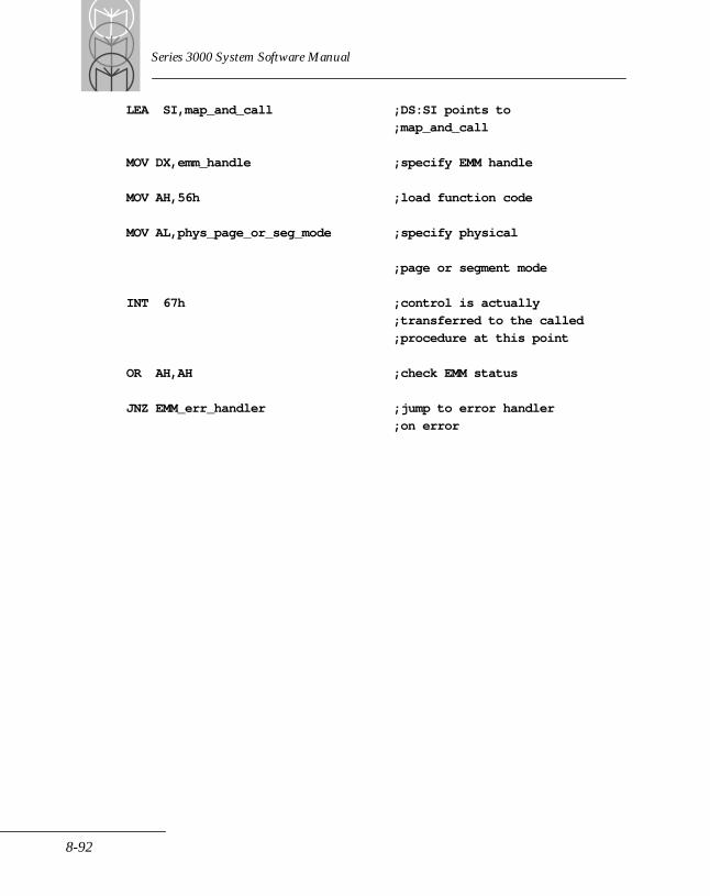
Series 3000 System Software Manual
LEA SI,map_and_call ;DS:SI points to
;map_and_call
MOV DX,emm_handle ;specify EMM handle
MOV AH,56h ;load function code
MOV AL,phys_page_or_seg_mode ;specify physical
;page or segment mode
INT 67h ;control is actually
;transferred to the called
;procedure at this point
OR AH,AH ;check EMM status
JNZ EMM_err_handler ;jump to error handler
;on error
8-92
Expanded Memory Manager
Function 23Alter Page Map & CallGet Page Map Stack Space Size SubfunctionPurposeSince the Alter Page Map & Call function pushes additional information onto the stack, this subfunction returns the number of bytes of stack space the function requires.
Calling ParametersAX = 5602hContains the Get Page Map Stack Space Size subfunction.
ResultsThese results are valid only if the status returned is zero.BX = stack space required
Contains the number of bytes which the Alter Page Map & Call function will require. In other words, BX contains the number (including the return address) which has to be added to the stack pointer to remove all elements from the stack.
Registers ModifiedAX, BX
StatusAH = 0 SUCCESSFULAH = 80h NON-RECOVERABLEThe manager has detected a malfunction in the memory manager software.
AH = 81h NON-RECOVERABLEThe manager has detected a malfunction in the expanded memory hardware.
AH = 84h NON-RECOVERABLEThe function code passed to the manager is not defined.
AH = 8Fh NON-RECOVERABLEThe subfunction parameter is invalid.
8-93
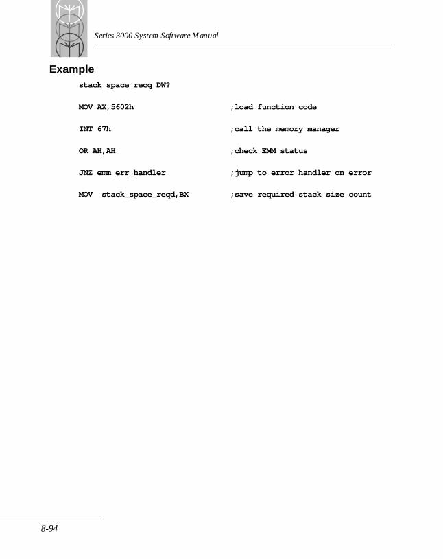
Series 3000 System Software Manual
Examplestack_space_recq DW?
MOV AX,5602h ;load function code
INT 67h ;call the memory manager
OR AH,AH ;check EMM status
JNZ emm_err_handler ;jump to error handler on error
MOV stack_space_reqd,BX ;save required stack size count
8-94
Expanded Memory Manager
Function 24Move/Exchange Memory RegionMove Memory Region SubfunctionPurposeThis subfunction copies a region of memory in the following memory source/destination combinations.
• Conventional Memory to Conventional Memory
• Conventional Memory to Expanded Memory
• Expanded Memory to Conventional Memory
• Expanded Memory to Expanded Memory
You do not have to save and restore the expanded memory mapping context to perform these move operations. The current mapping context is maintained throughout this operation.
The length of the region is limited by the amount of expanded memory allocated to the handles specified. However, in most practical applications, the region length will be considerably smaller. A region length of zero is not an error, and no move will be performed.
A region length that exceeds 16 kbytes is not an error. In this case the function assumes that a group of logical pages is the target for the move. The logical page specified represents the first logical page in which the move will take place. If the region length exceeds 16 kbytes, or if the region is less than 16 kbytes but spans logical pages, there must be sufficient logical pages remaining after the first logical page for the entire region to fit.
If your application needs to save a region of conventional memory in expanded memory, you can move it without having to perform a save or restore of the current mapping context. The memory manager maintains the context. A move of up to 1 Mbyte may be performed, although practical lengths are substantially less than this value.
8-95
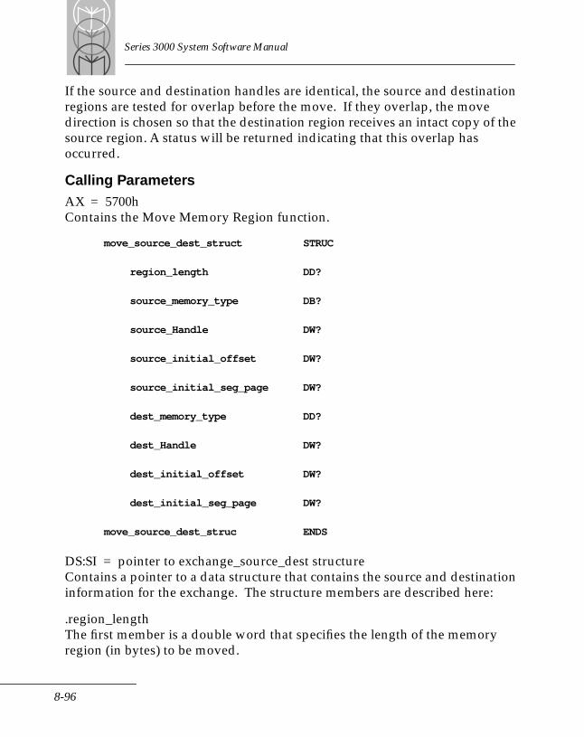
Series 3000 System Software Manual
If the source and destination handles are identical, the source and destination regions are tested for overlap before the move. If they overlap, the move direction is chosen so that the destination region receives an intact copy of the source region. A status will be returned indicating that this overlap has occurred.
Calling ParametersAX = 5700hContains the Move Memory Region function.
move_source_dest_struct STRUC
region_length DD?
source_memory_type DB?
source_Handle DW?
source_initial_offset DW?
source_initial_seg_page DW?
dest_memory_type DD?
dest_Handle DW?
dest_initial_offset DW?
dest_initial_seg_page DW?
move_source_dest_struc ENDS
DS:SI = pointer to exchange_source_dest structureContains a pointer to a data structure that contains the source and destination information for the exchange. The structure members are described here:
.region_lengthThe first member is a double word that specifies the length of the memory region (in bytes) to be moved.
8-96
Expanded Memory Manager
.source_memory_typeThe second member is a byte that specifies the type of memory where the source region resides. A value of zero indicates that the source region resides in conventional memory (excluding the page frame segment). A value of one indicates that the source region resides in expanded memory.
.source_HandleIf the source region resides in expanded memory, the third member is a word that specifies the handle number associated with the source memory region. If the source region resides in conventional memory, this variable has no meaning and should be set to zero for future compatibility.
.source_initial_offsetThe fourth member is a word that specifies the offset within the source region from which to begin the move.
If the source region resides in expanded memory, the source_initial_offset is relative to the beginning of the 16-kbyte logical page. Because the offset is relative to the beginning of a 16-kbyte expanded memory page, it may only take on values between 0000h and 3FFFh.
If the source region resides in conventional memory, the source_initial_offset is a word that specifies the offset, relative to the beginning of the source segment, from which to begin the move. Because the offset is relative to the beginning of a 64-kbyte conventional memory segment, it may take on values between 0000h and FFFFh.
.source_initial_seg_pageThe fifth member is a word that specifies the initial segment or logical page number within the source region from which to begin the move.
If the source region resides in expanded memory, the value specifies the logical page within the source region from which to begin the move.
If the source region resides in conventional memory, the source_initial_seg_page specifies the initial segment address within conventional memory from which to begin the move.
8-97
Series 3000 System Software Manual
.dest_memory_typeThe sixth member is a byte that specifies the type of memory where the destination region resides. A value of zero indicates conventional memory; a value of one indicates expanded memory.
.dest_HandleIf the destination region resides in expanded memory, the seventh member is a word that specifies the handle number associated with the destination memory region. If the destination region resides in conventional memory, this variable has no meaning and should be set to zero for future compatibility.
.dest_initial_offsetThe eight member is a word that specifies the offset within the destination region from which to begin the move. If the destination region is in expanded memory, dest_initial_offset is relative to the beginning of the 16-kbyte logical page. Because the offset is relative to the beginning of a 16-kbyte expanded memory page, it may take on values between 0000h and 3FFFh.
.dest_initial_seg_pageThe ninth member is a word that specifies the initial segment or logical page number within the destination region from which to begin the move.
If the destination region resides in expanded memory then the value specifies the logical page within the destination region from which to begin the exchange.
If the destination region resides in conventional memory, the dest_initial_seg_page specifies the initial segment address within conventional memory from which to begin the move.
Registers ModifiedAX
StatusAH = 0 SUCCESSFULThe memory regions have been moved.
AH = 80h NON-RECOVERABLEThe manager has detected a malfunction in the memory manager software.
8-98

Expanded Memory Manager
AH = 81h NON-RECOVERABLEThe manager has detected a malfunction in the expanded memory hardware.
AH = 83h NON-RECOVERABLE The manager couldn't find either the source or destination EMM handles. The memory manager doesn't have any information on the handle specified. The program may have corrupted its EMM handle.
AH = 84h NON-RECOVERABLEThe function code passed to the memory manager is not defined.
AH = 8Ah RECOVERABLEOne or more of the mapped logical pages is out of the range of logical pages allocated to the source/destination handle.
AH = 8Fh RECOVERABLEThe subfunction parameter is invalid.
AH = 92h SUCCESSFULThe source and destination expanded memory regions have the same handle and overlap. This is valid for a move. The move has been completed and the destination region has a full copy of the source region. However, some of the source region has been overwritten by the move. Source and destination expanded memory regions with different handles never physically overlap because the different handles specify different regions of expanded memory.
AH = 93h CONDITIONALLY-RECOVERABLEThe length of the source or destination expanded memory region specified exceeds the length of the expanded memory region allocated either the source or destination handle. Insufficient pages are allocated to this handle to move a region of the size specified. The program can recover from this condition by allocating additional pages to the destination or source handle and attempting to execute the function again. However, if the application allocated as much expanded memory as it thought it needed, this may be a program error and is not recoverable.
8-99
Series 3000 System Software Manual
AH = 94 NON-RECOVERABLEThe conventional memory region and expanded memory region overlap. This is invalid, the conventional memory region cannot overlap the expanded memory region.
AH = 95 NON-RECOVERABLEThe offset within the logical page exceeds the length of the logical page. The initial source or destination offsets within an expanded memory region must be between 0000h and 3FFFh [(16383 or (length of a logical page - 1)]
AH = 96 NON-RECOVERABLERegion length exceeds 1 Mbyte.
AH = 98 NON-RECOVERABLEThe memory source and destination types are undefined.
AH = 11h NON-RECOVERABLEAn attempt was made to wrap around the 1-Mbyte address space of conventional memory during the move. The combination of source/destination starting address and length of the region to be moved exceeds 1 Mbyte. No data was moved.
8-100

Expanded Memory Manager
Function 24Move/Exchange Memory RegionExchange Memory Region Subfunction PurposeThis subfunction exchanges (using a string move) a region of memory in any of the following memory source/destination combinations:
• Conventional Memory to Conventional Memory
• Conventional Memory to Expanded Memory
• Expanded Memory to Conventional Memory
• Expanded Memory to Expanded Memory
The term expanded memory region refers only to the area of memory above 640 kbytes (9FFFh). If a system provides mappable conventional memory, this function treats the mappable conventional memory regions as ordinary conventional memory. The contents of the source region and the destination region are exchanged.
The exchange operation can be performed without having to save and restore the expanded memory mapping context. The current mapping context is maintained throughout this operation. Region length is limited to the amount of expanded memory allocated to the specified EMM handles. A length of zero is not an error; however, no exchange will be performed. A region length that exceeds 16 kbytes is not an error. In this case the function assumes that a group of logical pages is the target for the exchange. The logical page specified represents the first logical page in which the exchange will take place. If the region length exceeds 16 kbytes, or if the region is less than 16 kbytes but spans logical pages, there must be sufficient logical pages remaining after the first logical page for the entire region to fit.
8-101
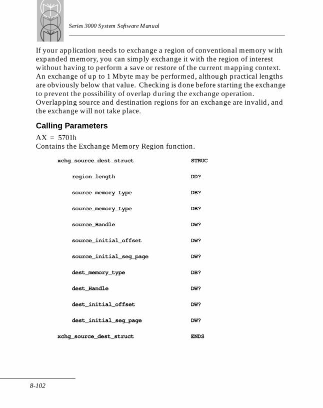
Series 3000 System Software Manual
If your application needs to exchange a region of conventional memory with expanded memory, you can simply exchange it with the region of interest without having to perform a save or restore of the current mapping context. An exchange of up to 1 Mbyte may be performed, although practical lengths are obviously below that value. Checking is done before starting the exchange to prevent the possibility of overlap during the exchange operation. Overlapping source and destination regions for an exchange are invalid, and the exchange will not take place.
Calling ParametersAX = 5701hContains the Exchange Memory Region function.
xchg_source_dest_struct STRUC
region_length DD?
source_memory_type DB?
source_memory_type DB?
source_Handle DW?
source_initial_offset DW?
source_initial_seg_page DW?
dest_memory_type DB?
dest_Handle DW?
dest_initial_offset DW?
dest_initial_seg_page DW?
xchg_source_dest_struct ENDS
8-102

Expanded Memory Manager
DS:SI = pointer to mov_source_dest structureContains a pointer to the data structure that contains the source & destination information for the exchange. The structure members are described here:
.region_lengthThe first member is a double word that specifies the length of the memory region to be exchanged.
.source_memory_typeThe second member is a byte that specifies the type of memory where the source region resides. A value of zero indicates that the source region resides in conventional memory. A value of one indicates that the source region resides in expanded memory.
.source_HandleIf the source region resides in expanded memory, the third member is a word that specifies the handle number associated with the source memory region. If the source region resides in conventional memory, this variable has no meaning and should be set to zero for future compatibility.
.source_initial_offsetThe fourth member is a word that specifies the offset within the source region from which to begin the exchange.
If the source region resides in expanded memory, the source_initial_offset is relative to the beginning of the 16-kbyte logical page. Because the offset is relative to the beginning of a 16-kbyte expanded memory page, it may only take on values between 0000h and 3FFFh.
If the source region resides in conventional memory, the source_initial_offset is a word that specifies the offset, relative to the beginning of the source segment, to begin the exchange at. Because the offset is relative to the beginning of a 64-kbyte conventional memory segment, it may only take on values between 0000h and FFFFh.
.source_initial_seg_pageThe fifth member is a word that specifies the initial segment or logical page number within the source region from which to begin the exchange.
8-103

Series 3000 System Software Manual
If the source region resides in expanded memory then the value specifies the logical page within the source region from which to begin the exchange.
If the source region resides in conventional memory, the source_initial_seg_page specifies the initial segment address within conventional memory from which to begin the exchange.
.dest_memory_typeThe sixth member is a byte that specifies the type of memory where the destination region resides. A value of zero indicates that the destination region resides in conventional memory (excluding the Page Frame segment). A value of one indicates that the destination region resides in expanded memory.
.dest_HandleIf the destination region resides in expanded memory, the seventh member is a word that specifies the handle number associated with the destination memory region. If the destination region resides in conventional memory, then this variable has no meaning and should be set to zero for future compatibility.
.dest_initial_offsetThe eighth member is a word that specifies the offset within the destination region from which to begin the exchange.
If the destination region resides in expanded memory, the dest_initial_offset is relative to the beginning of the 16-kbyte logical page. Because the offset is relative to the beginning of a 16-kbyte expanded memory page, it may only take on values between 0000h and 3FFFh.
If the destination region resides in conventional memory, the dest_initial_offset is a word that specifies the offset, relative to the beginning of the destination segment, to begin the exchange at. Because the offset is relative to the beginning of a 64-kbyte conventional memory segment, it may only take on values between 0000h and FFFFh.
.dest_initial_seg_pageThe ninth member is a word that specifies the initial segment or Logical Page number within the destination region from which to begin the exchange.
If the destination region resides in expanded memory, the value specifies the logical page within the destination region from which to begin the exchange.
8-104
Expanded Memory Manager
If the destination region resides in conventional memory, the dest_initial_seg_page specifies the initial segment address within conventional memory from which to begin the exchange.
Registers ModifiedAX
StatusAH = 0 SUCCESSFULThe memory regions have been exchanged.
AH = 80h NON-RECOVERABLEThe manager detected a memory manager software malfunction.
AH = 81h NON-RECOVERABLEThe manager detected an expanded memory hardware malfunction.
AH = 83h NON-RECOVERABLE The manager could not find either the source or the destination EMM handles. The memory manager does not currently have any information pertaining to the handles specified. The program may have corrupted its EMM handles.
AH = 84h NON-RECOVERABLEThe function code passed to the manager is not defined.
AH = 8Ah NON-RECOVERABLEOne or more of the logical pages to be mapped is out of the range of logical pages allocated to the source/destination handle.
AH = 8Fh NON-RECOVERABLEThe subfunction parameter is invalid.
8-105
Series 3000 System Software Manual
AH = 93h CONDITIONALLY-RECOVERABLEThe length of the source or destination expanded memory region specified exceeds the length of the expanded memory region allocated to the source or destination specified EMM handle. There are insufficient pages allocated to this handle to exchange a region of the size specified. The program can recover from this condition by attempting to allocate additional pages to the destination or source handle and attempting to execute the function again. However, if the application program was allocated as much expanded memory as it thought it needed, this may be a program error and is therefore not recoverable.
AH = 94h NON-RECOVERABLEThe conventional memory region and expanded memory region overlap. This is invalid; the conventional memory region cannot overlap the expanded memory region.
AH = 95h NON-RECOVERABLEThe offset within the logical page exceeds the length of the logical page. The initial source or destination expanded memory regions cannot have the same Handle and overlap when they are being exchanged. Note that the source and destination expanded memory regions that have different handles will never physically overlap because the different handles specify totally different regions of expanded memory.
AH = 98h NON-RECOVERABLEThe memory source and destination types are undefined.
AH = 11h NON-RECOVERABLEAn attempt was made to wrap around the 1-Mbyte address space of conventional memory during the exchange. The source starting address together with the length of the region to be exchanged exceeds 1 Mbyte. No data was exchanged.
8-106
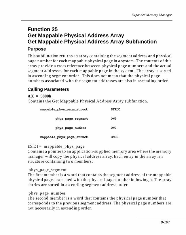
Expanded Memory Manager
Function 25Get Mappable Physical Address ArrayGet Mappable Physical Address Array SubfunctionPurposeThis subfunction returns an array containing the segment address and physical page number for each mappable physical page in a system. The contents of this array provide a cross reference between physical page numbers and the actual segment addresses for each mappable page in the system. The array is sorted in ascending segment order. This does not mean that the physical page numbers associated with the segment addresses are also in ascending order.
Calling ParametersAX = 5800hContains the Get Mappable Physical Address Array subfunction.
mappable_phys_page_struct STRUC
phys_page_segment DW?
phys_page_number DW?
mappable_phys_page_struct ENDS
ES:DI = mappable_phys_pageContains a pointer to an application-supplied memory area where the memory manager will copy the physical address array. Each entry in the array is a structure containing two members:
.phys_page_segmentThe first member is a word that contains the segment address of the mappable physical page associated with the physical page number following it. The array entries are sorted in ascending segment address order.
.phys_page_numberThe second member is a word that contains the physical page number that corresponds to the previous segment address. The physical page numbers are not necessarily in ascending order.
8-107
Series 3000 System Software Manual
ExampleThe application determines (via Get Page Frame Address Function 2) that the page frame starting address is A000h and there is no mappable conventional memory. For this configuration, physical page 0 corresponds to segment address A000h, physical page 1 corresponds to segment address A400h, etc. The array would contain the following data (in this order):
A000h, 00hA400h, 01hA800h, 02hAC00h, 03h
ResultsThese results are valid only if the status returned is zero.
CX = number of entries in the mappable_phys_page Multiply this number by (SIZE mappable_phys_page_struct) to determine the number of bytes the physical page address array requires.
Registers ModifiedAX, BX
StatusAH = 0 SUCCESSFULThe hardware configuration array has been returned.
AH = 80h NON-RECOVERABLEThe manager has detected a malfunction in the memory manager software.
AH = 81h NON-RECOVERABLEThe manager detected a malfunction in the expanded memory hardware.
AH = 84h NON-RECOVERABLEThe function code passed to the memory manager is not defined.
AH = 8Fh RECOVERABLEThe subfunction parameter is invalid.
8-108

Expanded Memory Manager
Function 25Get Mappable Physical Address ArrayGet Mappable Physical Address Array Entries SubfunctionPurposeThe subfunction gets the number of entries that will be required for the array the first subfunction returns.
Calling ParametersAX = 5801hContains the Get Physical Page Address Array Entry Count subfunction. This subfunction returns a word representing the number of entries in the array returned by the previous subfunction. This value also gives the number of mappable physical pages in a system.
ResultsThese results are valid only if the status returned is zero.
CX = number of entries in the mappable_phys_pageMultiply this number by (SIZE mappable_phys_page_struct) to get the number of bytes the Physical Page address array will require.
Registers ModifiedAX
StatusAH = 0 SUCCESSFULThe physical page address array has been returned.
AH = 80h NON-RECOVERABLEThe manager detected a memory manager software malfunction.
AH = 81h NON-RECOVERABLEThe manager detected an expanded memory hardware malfunction.
8-109
Series 3000 System Software Manual
AH = 84h NON-RECOVERABLEThe function code passed to the memory manager is not defined.
AH = 8Fh NON-RECOVERABLEThe subfunction parameter is invalid.
8-110

Expanded Memory Manager
Function 26Get Expanded Memory Hardware InformationGet Hardware Configuration Array Subfunction
Note: Function 26 is for use by operating systems only. This function can be disabled at any time by the operating system. Refer to Function 30 for a description of how an operating system does this.
PurposeThis subfunction returns an array containing expanded memory hardware configuration information for use by an operating system/environment.
Calling ParametersAX = 5900hContains the Get Hardware Configuration Array subfunction.
hardware_info_struct STRUC
raw_page_size DW?
alternate_register_sets DW?
context_save_area_size DW?
DMA_register_sets DW?
DMA_channel_operation DW?
hardware_info_struct ENDS
ES:DI = hardware_infoContains a pointer to a memory area that the operating system supplies where the memory manager will copy expanded memory hardware information. The structure contains these five members:
.raw_page_size The first member is a word that contains the size of a raw mappable physical page in paragraphs (16 bytes).
8-111
Series 3000 System Software Manual
.alternate_register_setsThe second member is a word that specifies the number of alternate mapping register sets. The additional mapping register sets are termed alternate mapping register sets in this document. Since the expanded memory card has only one set of mapping registers (that is, no alternate mapping register sets) this member has a value of zero.
.context_save_area_sizeThe third member is a word that contains the storage requirements for the array required to save a mapping context. The value returned in this member is the same as that returned by Function 15 (Get Size of Page Map Save Array subfunction).
.DMA_channelsThe fourth member is a word that contains the number of register sets that can be assigned to DMA channels. The Series 3000 does not support these, so the value is always 0.
.DMA_channels_operationThe fifth member is a word that specifies a special case for the DMA register sets. A value of zero specifies that the DMA register sets behave as described in Function 28. For the Series 3000, this value is zero.
ResultsThese results are valid only if the status returned is zero.
hardware_infoContains the expanded memory hardware specific information described above.
Registers ModifiedAX
StatusAH = 0 SUCCESSFULThe hardware configuration array has been returned.
8-112
Expanded Memory Manager
AH = 80h NON-RECOVERABLEThe manager has detected a malfunction in the memory manager software.
AH = 81h NON-RECOVERABLEThe manager has detected a malfunction in the expanded memory hardware.
AH = 84h NON-RECOVERABLEThe function code passed to the manager is not defined.
AH = 8Fh NON-RECOVERABLEThe subfunction parameter is invalid.
AH = 13h NON-RECOVERABLEAccess to this function has been denied by the operating system. The function cannot be used at this time.
8-113
Series 3000 System Software Manual
Function 26Get Expanded Memory Hardware InformationGet Unallocated Raw Page Count SubfunctionPurposeRaw Pages are not supported on Series 3000 terminals. This function returns the total number of standard pages and the number of free pages. Functionally, it is the same as Function 3 (Get Unallocated Page Count).
Calling ParametersAX = 5901hContains the Get Unallocated Raw Page Count subfunction.
ResultsThese results are valid only if the status returned is zero.
BX = unallocated pagesThe number of pages that are currently available for use.
DX = total pagesThe total number of pages in expanded memory.
Registers ModifiedAX, BX, DX
StatusAH = 0 SUCCESSFULThe manager has returned the number of unallocated pages and the number of total pages in expanded memory.
AH = 80h NON-RECOVERABLEThe manager detected a memory manager software malfunction.
AH = 81h NON-RECOVERABLEThe manager detected an expanded memory hardware malfunction.
AH = 84h NON-RECOVERABLEThe function code passed to the manager is not defined.
AH = 8Fh NON-RECOVERABLEThe subfunction parameter is invalid.
8-114
Expanded Memory Manager
Function 27Allocate Standard/Raw PagesAllocate Standard Pages SubfunctionPurposeThe Allocate Standard Pages subfunction allocates the number of standard size (16 kbytes) pages that the operating system requests and assigns a unique EMM handle to these pages. The EMM handle owns these pages until the operating system deallocates them. This subfunction allows you to allocate zero pages to a handle, unlike Function 4 (Allocate Pages).
Calling ParametersAX = 5A00hContains the Allocate Standard Pages subfunction.
BX = num_of_standard_pages_to_allocContains the number of standard pages the operating system wants to allocate.
ResultsThese results are valid only if the status returned is zero.
DX = handleContains a unique EMM handle. The operating system must use this EMM handle as a parameter in any function that requires it. Up to 255 handles may be obtained. (Both Function 27 and Function 4 must share the same 255 Handles.)
For all functions using this handle, the length of the physical and logical pages allocated to it are standard length (that is, 16 kbytes).
Registers ModifiedAX, DX
StatusAH = 0 SUCCESSFULThe manager allocated the pages to an assigned EMM raw handle.
8-115
Series 3000 System Software Manual
AH = 80h NON-RECOVERABLEThe manager detected a memory manager software malfunction.
AH = 81h NON-RECOVERABLEThe manager detected an expanded memory hardware malfunction.
AH = 84h NON-RECOVERABLEThe function code passed to the manager is not defined.
AH = 85h RECOVERABLEAll EMM handles are being used.
AH = 87h RECOVERABLEThere aren't enough expanded memory pages present in the system to satisfy the operating system's request.
AH = 88h RECOVERABLENot enough unallocated pages to satisfy operating system's request.
AH = 8Fh NON-RECOVERABLEThe subfunction parameter is invalid.
8-116
Expanded Memory Manager
Function 27Allocate Standard/Raw PagesAllocate Raw Pages SubfunctionPurposeAllocate Raw Pages subfunction works the same as the Allocate Standard Pages subfunction since 'raw' pages are 16 kbytes.
Calling ParametersAX = 5A01hContains the Allocate Raw Pages subfunction.
BX = num_of_raw_pages_to_allocContains the number of raw pages the operating system wants to allocate.
ResultsThese results are valid only if the status returned is zero.
DX = raw HandleContains a unique EMM handle. The operating system must use this EMM handle as a parameter in any function that requires it. Up to 255 handles may be obtained. (Both Function 4 and Function 27 must share the same 255 Handles.)
For all functions using this handle, the length of the physical and logical pages allocated to it are standard length (that is, 16 kbytes).
Registers ModifiedAX, DX
StatusAH = 0 SUCCESSFULThe manager has allocated the raw pages to an assigned EMM raw handle.
AH = 80h NON-RECOVERABLEThe manager detected a memory manager software malfunction.
8-117
Series 3000 System Software Manual
AH = 81h NON-RECOVERABLEThe manager detected an expanded memory hardware malfunction.
AH = 84h NON-RECOVERABLEThe function code passed to the memory manager is not defined.
AH = 85h RECOVERABLEAll EMM handles are being used.
AH = 87h RECOVERABLEThere aren't enough expanded memory raw pages present in the system to satisfy the operating system's request.
AH = 88h RECOVERABLEThere aren't enough unallocated pages to satisfy the operating system's request.
AH = 8Fh NON-RECOVERABLEThe subfunction parameter is invalid.
8-118
Expanded Memory Manager
Function 28 - Alternate Map Register Set Note: Function 28 is for use by operating systems only.
Operating systems can disable this function at any time. See Function 30 for how an operating system can enable or disable this Function.
Design ConsiderationsHardware support for this set of subfunctions is not present on Series 3000 terminals.
System DMA Capabilities & Expanded Memory Support of DMAWhile DMA is in progress into a region of mappable memory, the memory mapping context cannot be changed. That is, all DMA action must be complete before any remapping of pages can be done.
8-119
Series 3000 System Software Manual
Function 28Alternate Map Register SetGet Alternate Map Register Set Subfunction
Note: Function 28 has no application on the Series 3000, since only one register set is supported.
PurposeThis subfunction returns the context save area pointer (saved within EMM by the Set Alternate Map Register Set subfunction).
If the preceding Set Alternate Map Register Set call was done with the Alternate Map Register Set equal to zero (BL = 0), these points apply:
1. If the context save area pointer returned is not equal to zero, this subfunction copies the contents of the mapping registers on each system expanded memory board into the pointer-specified save area. The format of this save area is the same as that returned by Function 15 (Get Page Map subfunction). This simulates getting an Alternate Map Register Set. Note that the memory manager does not allocate the space for the context; the operating system must do so.
2. If the context save area pointer returned is equal to zero, this subfunction does not copy the contents of the mapping registers on each expanded memory board in the system into the save area specified by the pointer.
3. The context save area pointer must have been initialized by a previous Set Alternate Map Register Set call. Note that the value of the context save area pointer saved within EMM is zero immediately after installation.
4. The context save area must be initialized by a previous Get Page Map call (Function 15).
Calling ParametersAX = 5B00hContains the Get Alternate Map Register Set subfunction.
ResultsThese results are valid only if the status returned is zero.
8-120

Expanded Memory Manager
BL is always 0ES:DI = pointer to a map register context save areaContains a pointer to an operating system supplied context save area. The pointer is in standard segment:offset format.
The operating system first passes this pointer to the memory manager whenever it invokes a Set Alternate Map Register Set subfunction (the description follows). If the OS/E invokes this function before invoking a Set Alternate Map Register Set subfunction, this function returns a pointer value of zero. The OS/E must have allocated the space for the save area. However, the OS must request that the memory manager initialize the contents of this save area before it contains any useful information.
The OS/E must initialize the save area it has allocated by invoking Function 15 (Get Page Map subfunction). After the OS/E has done this, the save area will contain the state of all the map registers on all boards in the system. The save area will also contain any additional information necessary to restore the boards to their original state when the operating system invokes a Set Alternate Map Register Set subfunction.
Registers ModifiedAX, BX, ES:DI
StatusAH = 0 SUCCESSFULThe manager got the Alternate Map Register Set.
AH = 80h NON-RECOVERABLEThe manager detected a memory manager software malfunction.
AH = 81h NON-RECOVERABLEThe manager detected an expanded memory hardware malfunction.
AH = 84h NON-RECOVERABLEThe function code passed to the manager is not defined.
AH = 8Fh NON-RECOVERABLEThe subfunction parameter is invalid.
AH = 13h NON-RECOVERABLEThe operating system denied access to this function. The function cannot be used at this time.
8-121
Series 3000 System Software Manual
Function 28Alternate Map Register SetSet Alternate Map Register Set Subfunction
Note: This function is for use by operating systems only. Operating systems can disable this function at any time. Refer to Function 30 for how an operating system can enable or disable this function.
PurposeThis subfunction does one of two things, depending on the map register set specified:
1. If the alternate map register set specified is zero, map register set zero is activated. If the map register context restore area pointer is not equal to zero, the contents of the restore area pointed to be ES:DI are copied into register set zero on each expanded memory board in the system. If the pointer is equal to zero, the contents are not copied.
Regardless of its value, the map register context restore area pointer is saved within the memory manager. It will be used during the Get Alternate Map Register Set subfunction.
The operating system must supply the pointer to the area. This subfunction is intended to simulate setting an alternate map register set. Note that the operating system must allocate the space for the context. The memory manager saves the context save area pointer internally.
2. If the alternate map register set specified is not zero, the alternate map register set specified is activated. The restore area, which the operating system is pointing to, is not used.
Calling ParametersAX = 5B01hContains the Set Alternate Map subfunction.
BL = new alternate map register set numberContains the number of the alternate map register set which is to be activated.
8-122
Expanded Memory Manager
If BL = 0A pointer to a map register context restore area is not required and the contents of ES:DI are unaffected and ignored. The alternate map register set specified in BL is activated if the board supports it.
If BL = 0A pointer to an area which contains the state of all the map registers on all boards in the system, and any additional information necessary to restore the boards to their original state, has been passed in ES:DI.
ES:DI = pointer to a map register context restore areaContains a pointer to an OS/E supplied map register context restore area. The pointer is in standard segment:offset format. This pointer must always be passed if the expanded memory hardware does not supply alternate mapping register sets.
The memory manager must save this pointer whenever the OS/E invokes this function. The OS/E must have allocated the space for the restore area. Additionally, the contents of this restore area must have been initialized by the memory manager before it will contain any useful information. The OS/E initializes the restore area it has allocated by invoking Function 15 (Get Page Map subfunction). After the OS/E has done this, the restore area will contain the state of the map registers on all boards in the system, and any additional information necessary to restore the boards to their original state when the operating system invokes a Set Alternate Map Register Set subfunction.
Registers ModifiedAX
StatusAH = 0 SUCCESSFULThe manager set the alternate map register set.
AH - 80h NON-RECOVERABLEThe manager detected a malfunction in the memory manager software.
AH = 81h NON-RECOVERABLEThe manager detected a malfunction in the expanded memory hardware.
8-123
Series 3000 System Software Manual
AH = 84h NONRECOVERABLEThe function code passed to the memory manager is not defined.
AH - 8Fh NON-RECOVERABLEThe subfunction parameter is invalid.
AH - 9Ch NON-RECOVERABLEAlternate map register sets are not supported, and the alternate map register set specified is not zero.
AH = 13h NON-RECOVERABLEThe operating system denied access to this function. The function cannot be used at this time.
AH = A3h NON-RECOVERABLEThe contents of the source array have been corrupted, or the pointer passed to the subfunction is invalid.
AH = A4h NON-RECOVERABLEThe operating system has denied access to this function. The function cannot be used at this time.
Examplealt_map_reg_set DB?
context_restore_area_ptr_seg DW?
context_restore_area_ptr_offset DW?
MOV AX,5B01h ; load function code
MOV BL,alt_map_reg_set
TEST BL,BL
JZ no_ptr_passed
MOV ES,context_restore_area_ptr_seg
MOV DI context_restore_area_ptr_offset
8-124
Expanded Memory Manager
no_ptr_passed:
INT 67h ; call the memory manager
OR AH,AH ; check EMM status
JNZ emm_err_handler ; jump to error handler on
; error
8-125

Series 3000 System Software Manual
Function 28Alternate Map Register SetGet Alternate Map Save Array Size Subfunction
Note: This function is for use by operating systems only. Operating systems can disable this function at any time. Refer to Function 30 for how an operating system can enable or disable this function.
PurposeThis subfunction returns the storage requirements for the map register context save area referenced by the other subfunctions.
Calling ParametersAX = 5B02hContains the Get Alternate Map Save Array Size subfunction.
ResultsThese results are valid only if the status returned is zero.
DX = size_of_arrayContains the number of bytes that will be transferred to the memory area supplied by an operating system whenever an operating system requests the Get, Set, or Get and Set subfunction.
Registers ModifiedAX, DX
StatusAH = 0 SUCCESSFULThe manager has returned the array size.
AH = 80h NON-RECOVERABLEThe manager detected a memory manager software malfunction.
AH = 81h NON-RECOVERABLEThe manager detected an expanded memory hardware malfunction.
8-126
Expanded Memory Manager
AH = 84h NON-RECOVERABLEThe function code passed to the manager is not defined.
AH = 8Fh NON-RECOVERABLEThe subfunction parameter is invalid.
AH = 13h NON-RECOVERABLEThe operating system has denied access to this function. The function cannot be used at this time.
8-127
Series 3000 System Software Manual
Function 28Alternate Map Register SetAllocate Alternate Map Register Set Subfunction
Note: Function 28 is for use by operating systems only. Operating systems can disable this function at any time. Refer to Function 30 for how an operating system can enable or disable this Function 28.
PurposeThis subfunction gets the Alternate Map Register Set number for an operating system if an Alternate Map Register Set is currently available for use. Since the hardware doesn't support Alternate Map Register Sets, an Alternate Map Register Set number of zero is returned.
This function is not used on the Series 3000.
Calling ParametersAX = 5B03hContains the Allocate Map Register Set subfunction.
ResultsThese results are valid only if the status returned is zero.BL = 0
Registers ModifiedAX, DX
StatusAH = 0 SUCCESSFULThe manager has returned the array size.
AH = 81h NON-RECOVERABLEThe manager detected an expanded memory hardware malfunction.
AH = 84h NON-RECOVERABLEThe function code passed to the manager is not defined.
AH = 13h NON-RECOVERABLEThe operating system has denied access to this function. The function cannot be used at this time.
8-128
Expanded Memory Manager
Function 28Alternate Map Register SetDeallocate Alternate Map Register Set Subfunction
Note: Function 28 is for use by operating systems only. An operating system can disable this function at any time using Function 30.
PurposeThe Deallocate Alternate Map Register Set subfunction returns the Alternate Map Register Set to the memory manager for future use. The memory manager may reallocate the Alternate Map Register Set when needed.
This function is not used on the Series 3000.
Calling ParametersAX = 5B04hContains the Deallocate Map Register Set subfunction.
BL = must be 0
Registers ModifiedAX
StatusAH = 0 SUCCESSFULThe manager has returned the array size.
AH = 80h NON-RECOVERABLEThe manager detected a Memory Manager software malfunction.
AH = 81h NON-RECOVERABLEThe manager detected an Expanded Memory hardware malfunction.
AH = 84h NON-RECOVERABLEThe function code passed to the manager is not defined.
AH = 8Fh NON-RECOVERABLEThe subfunction parameter is invalid.
8-129
Series 3000 System Software Manual
AH = 9Ch NON-RECOVERABLEAlternate map register sets are supported but the Alternate Map Register Set specified is either not defined or not allocated.
AH = 13h NON-RECOVERABLEThe operating system has denied access to this function. The function cannot be used at this time.
8-130

Expanded Memory Manager
Function 28Alternate Map Register SetAllocate DMA Register Set Subfunction
Note: Function 28 is for use by operating systems only. The operating system can enable or disable this function at any time using Function 30.
PurposeThis function is not used on the Series 3000.
Calling ParametersAX = 5B05hContains the Allocate DMA Register Set subfunction.
Results These results are valid only if the status returned is zero.BL = 0
Registers ModifiedAX, BX
StatusAH = 0 SUCCESSFULThe manager has allocated the DMA register set.
AH = 80h NON-RECOVERABLEThe manager detected a memory manager software malfunction.
AH = 81h NON-RECOVERABLEThe manager detected an expanded memory hardware malfunction.
AH = 84h NON-RECOVERABLEThe function code passed to the manager is not defined.
AH = 8Fh NON-RECOVERABLEThe subfunction parameter is invalid.
AH = 13h NON-RECOVERABLEThe operating system has denied access to this function. The function cannot be used at this time.
8-131
Series 3000 System Software Manual
Function 28Alternate Map Register SetEnable DMA ON Alternate Map Register Set Subfunction
Note: Function 28 is for use by operating systems only. The operating system can disable this function at any time. An operating system can enable or disable Function 28 using Function 30.
PurposeThis function is not used on the Series 3000.
Calling ParametersAX = 5B06hContains the Enable DMA on Alternate Map Register Set subfunctions.
BL = 0DL = DMA Channel number Contains the DMA channel that is to be associated with the DMA Map Register set specified in BL.
Registers ModifiedAX
StatusAH = 0 SUCCESSFULThe manager has enabled DMA on the DMA register set and the DMA channel specified.
AH = 80h NON-RECOVERABLEThe manager detected a malfunction in the memory manager software.
AH = 81h NON-RECOVERABLEThe manager detected a malfunction in the expanded memory hardware.
AH = 84h NON-RECOVERABLEThe function code passed to the manager is not defined.
8-132
Expanded Memory Manager
AH = 8Fh NON-RECOVERABLEThe subfunction parameter is invalid.
AH = 9Ch NON-RECOVERABLEAlternate DMA register sets are not supported, and the DMA register set specified is not zero.
AH = 13h NON-RECOVERABLEThe operating system has denied access to this function. The function cannot be used at this time.
8-133
Series 3000 System Software Manual
Function 28Alternate Map Register SetDisable DMA ON Alternate Map Register Set Subfunction
Note: This function is for use by operating systems only. The operating system can disable this function at any time. Refer to Function 30 for a description of how an operating system can enable or disable this function.
PurposeThis subfunction disables DMA for all DMA channels that were associated with a specific Alternate Map Register Set.
This function is not used on the Series 3000.
Calling ParametersAX = 5B07hContains the Disable DMA on Alternate Map Register Set subfunction.
BL = alternate register set number
Contains the number of the DMA register set for which all operations are to be disabled. If the Alternate Map Register Set specified is zero, no special action will be taken.
Registers ModifiedAX
StatusAH = 0 SUCCESSFULThe manager has returned the array size.
AH = 80h NON-RECOVERABLEThe manager detected a memory manager software malfunction.
AH = 81h NON-RECOVERABLEThe manager detected an expanded memory hardware malfunction.
8-134
Expanded Memory Manager
AH = 84h NON-RECOVERABLEThe function code passed to the manager is not defined.
AH = 8Fh NON-RECOVERABLEThe subfunction parameter is invalid.
AH = 9Ah NON-RECOVERABLEAlternate DMA register sets are supported, but the alternate DMA register set specified is not supported.
AH = 9Ch NON-RECOVERABLEAlternate DMA register sets are not supported, and the DMA register set specified is not zero.
AH = 9Dh NON-RECOVERABLEDMA register sets are supported, but the DMA register set specified is either not defined or not allocated.
AH = 9Fh NON-RECOVERABLEDedicated DMA channels are supported, but the DMA channel specified is not supported.
AH = 13h NON-RECOVERABLEThe operating system has denied access to this function. The function cannot be used at this time.
8-135
Series 3000 System Software Manual
Function 28Alternate Map Register SetDeallocate DMA Register Set Subfunction
Note: Function 28 is for use by operating systems only. The operating system can enable or disable this function at any time using Function 28.
PurposeThe Deallocate DMA Register Set subfunction deallocates the specified DMA register set.
This function is not used on the Series 3000.
Calling ParametersAX = 5B08hContains the Deallocate DMA Register Set subfunction.
BL = DMA Register set number
Contains the number of the DMA register set that should not be used for DMA operations any longer. The DMA register set would have been previously allocated and enabled for DMA operations on a specific DMA channel. If the DMA register set specified is zero, no action will be taken.
Registers ModifiedAX
StatusAH = 0 SUCCESSFULThe manager has deallocated the DMA register set.
AH = 80h NON-RECOVERABLEThe manager detected a memory manager software malfunction.
AH = 81h NON-RECOVERABLEThe manager detected an expanded memory hardware malfunction.
8-136
Expanded Memory Manager
AH = 84h NON-RECOVERABLEThe function code passed to the manager is not defined.
AH = 8Fh NON-RECOVERABLEThe subfunction parameter is invalid.
AH = 9Ch NON-RECOVERABLEDMA register sets are not supported, and the DMA register set specified is not zero.
AH = 13h NON-RECOVERABLEThe operating system has denied access to this function. The function cannot be used at this time.
8-137
Series 3000 System Software Manual
Function 29Prepare Expanded Memory Hardware to Warmboot PurposeThis function is not used on the Series 3000.
This function prepares the expanded memory hardware for an impending warm boot. It assumes that the next operating system action is a system warm boot. In general, this function affects the current mapping context, the alternate register set in use, and any other expanded memory hardware dependencies that are initialized at boot time. If an application decides to map memory below 640k, the application must trap all possible conditions leading to a warm boot and invoke this function before performing the warm boot itself.
Calling ParametersAH = 5ChContains the Prepare for Warmboot function.
Registers ModifiedAX
StatusAH = 0 SUCCESSFULThe manager has prepared the expanded memory hardware for a warm boot.
AH = 80h NON-RECOVERABLEThe manager detected a memory manager software malfunction.
AH = 81h NON-RECOVERABLEThe manager detected an expanded memory hardware malfunction.
AH = 84h NON-RECOVERABLEThe function code passed to the manager is not defined.
8-138

Expanded Memory Manager
Function 30Enable/Disable OS/E Function Set Function Enable OS/E Function Set Subfunction
Note: Function 30 is for use by operating systems only. The operating system can disable this function at any time.
PurposeThis subfunction provides an OS/E (Operating System Environment) with the ability to enable all programs or device drivers to use the OS/E specific functions. The capability is provided only for an OS/E that manages regions of mappable conventional memory and cannot permit programs to use any of the functions that affect mappable conventional memory regions, but must be able to use these functions itself. When an OS/E disables these functions and a program attempts to use them, the memory manager returns a status to the program indicating that the OS/E has denied the program access to the function. In other words, the functions will not work when disabled. However, all programs may use them when enabled.
The OS/E (Operating System Environment) functions this subfunction enables are:
Function 26. Get Expanded Memory Hardware Information.
Function 28. Alternate Map Register Sets.
Function 30. Enable/Disable Operating System Functions
It appears contradictory that the OS/E can re-enable these functions when the function that re-enables them is itself disabled. An overview of the process follows.
The memory manager enables all the OS/E specific functions, including this one, when it is loaded. The OS/E gets exclusive access to these functions by invoking either of the Enable/Disable OS/E Function Set subfunctions before any other software does.
8-139
Series 3000 System Software Manual
On the first invocation of either of these subfunctions, the memory manager returns an access_key that the OS/E must use in all future invocations of either of these subfunctions. The memory manager does not require the access_key on the first invocation of the Enable/Disable OS/E Function Set subfunctions.
On all subsequent invocations, the access_key is required for either the Enable or Disable OS/E Function Set subfunctions. Since the access_key is returned only on the first invocation of the Enable/Disable OS/E Function Set subfunctions, and presumably the OS/E is the first software to invoke this function, only the OS/E obtains a copy of this key. The memory manager must return an access key with a random value; a fixed value key defeats the purpose of providing this level of security for an OS/E.
Calling ParametersAX = 5D00hContains the Enable OS/E Function Set subfunction.
ResultsThese results are valid only if the status returned is zero.
BX, CX = access_keyReturned only on the first function invocation, the memory manager returns a random valued key that will be required thereafter for the execution of this function. On all invocations after the first, this key is not returned. Neither BX or CX is affected after the first time this function is invoked.
Registers ModifiedAX, BX, CX
StatusAH = 0 SUCCESSFULThe operating system function set has been enabled.
AH = 80h NON-RECOVERABLEThe manager has detected a malfunction in the memory manager software.
AH = 81h NON-RECOVERABLEThe manager has detected a malfunction in the expanded memory hardware.
8-140
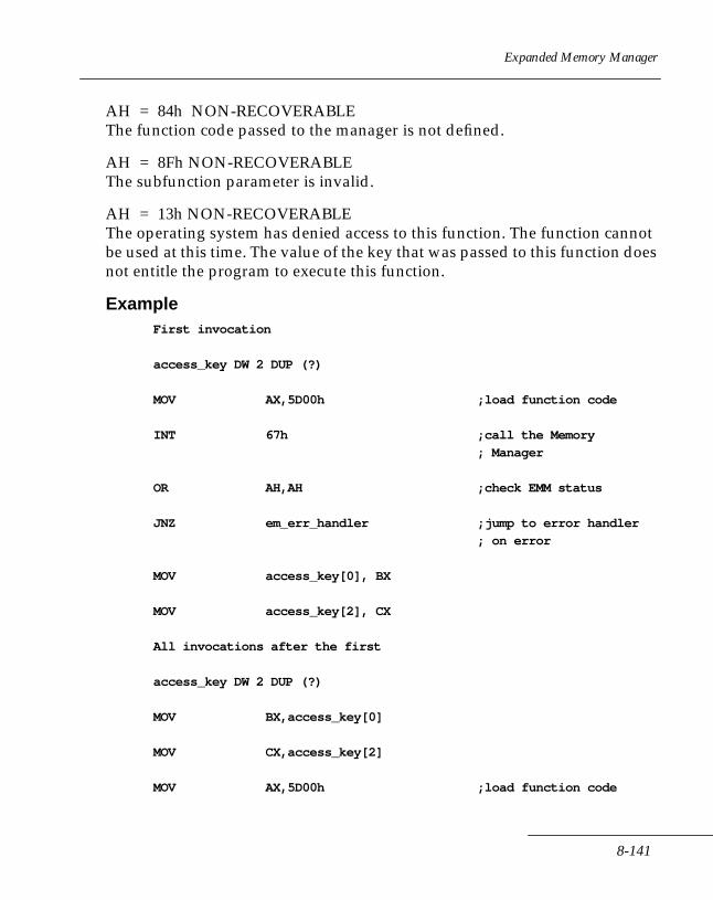
Expanded Memory Manager
AH = 84h NON-RECOVERABLEThe function code passed to the manager is not defined.
AH = 8Fh NON-RECOVERABLEThe subfunction parameter is invalid.
AH = 13h NON-RECOVERABLEThe operating system has denied access to this function. The function cannot be used at this time. The value of the key that was passed to this function does not entitle the program to execute this function.
ExampleFirst invocation
access_key DW 2 DUP (?)
MOV AX,5D00h ;load function code
INT 67h ;call the Memory
; Manager
OR AH,AH ;check EMM status
JNZ em_err_handler ;jump to error handler
; on error
MOV access_key[0], BX
MOV access_key[2], CX
All invocations after the first
access_key DW 2 DUP (?)
MOV BX,access_key[0]
MOV CX,access_key[2]
MOV AX,5D00h ;load function code
8-141
Series 3000 System Software Manual
INT 67h ;call the Memory
; Manager
OR AH,AH ;check EMM status
JNZ em_err_handler ;jump to error handler
; on error
8-142

Expanded Memory Manager
Function 30Enable/Disable OS/E Function Set Function Disable OS/E Function Set Subfunction
Note: Function 30 is for use by operating systems only. The operating system can disable this function at any time.
PurposeThis subfunction enables an OS/E to prevent all programs or device drivers from using the OS/E specific functions. The capability is provided only for an OS/E that manages regions of mappable conventional memory and cannot permit programs to use any of the functions that would affect mappable conventional memory regions. When an OS/E disables these functions and a program attempts to use them, the memory manager returns a status to the program indicating that the OS/E has denied the program access to the function. In other words, the functions will not work when disabled.
The OS/E (Operating System/Environment) functions that are disabled by this subfunction are:
Function 26. Get Expanded Memory Hardware Information.
Function 28. Alternate Map Register Sets.
Function 30. Enable/Disable Operating System Functions
Calling ParametersAX = 5D01hContains the Disable OS/E Function Set subfunction.
BX, CX = access_keyRequired on all function invocations after the first. The access_key value returned by the first function invocation is required.
ResultsThese results are valid only if the status returned is zero.
8-143
Series 3000 System Software Manual
BX, CX = access_keyReturned only on the first function invocation, the memory manager returns a random valued key that will be required thereafter for the execution of this function. On all invocations after the first, this key is not returned. Neither BX or CX is affected after the first time this function is invoked.
Registers ModifiedAX, BX, CX
StatusAH = 0 SUCCESSFULThe operating system function set has been disabled.
AH = 80h NON-RECOVERABLEThe manager detected a memory manager software malfunction.
AH = 81h NON-RECOVERABLEThe manager detected an expanded memory hardware malfunction.
AH = 84h NON-RECOVERABLEThe function code passed to the manager is not defined.
AH = 8Fh NON-RECOVERABLEThe subfunction parameter is invalid.
AH = 13h NON-RECOVERABLEThe operating system has denied access to this function. The function cannot be used at this time. The value of the key that was passed to this function does not entitle the program to execute this function.
ExampleFirst invocation
access_key DW 2 DUP (?)
MOV AX,5D01h ; load function code
INT 67h ; call the Memory Manager
8-144
Expanded Memory Manager
OR AH,AH ; check EMM status
JNZ em_err_handler ; jump to error handler on
; error
MOV access_key[0], BX
MOV access_key[2], CX
All invocations after the first
access_key DW 2 DUP (?)
MOV BX,access_key[0]
MOV CX,access_key[2]
MOV AX,5D01h ; load function code
INT 67h ; call the Memory Manager
OR AH,AH ; check EMM status
JNZ em_err_handler ;jump to error handler on
; error
8-145

Series 3000 System Software Manual
Function 30Enable/Disable OS/E Function Set Function Return Access Key Subfunction
Note: Function 30 is for use by operating systems only. The operating system can disable this function at any time.
PurposeThis subfunction enables an OS/E to return the access key to the memory manager. Returning the access key to the memory manager places the memory manager in the state it is in at installation time (regarding the use of the OS/E function set and the access key). That is, access to the OS/E function set is enabled. Upon execution of the next enable/disable OS/E function set subfunction, the access key will once again be returned.
Calling ParametersAX = 5D02hContains the Return Access Key subfunction.
BX, CX = access_keyRequired on all function invocations after the first. The access_key value returned by the first function invocation of the enable or disable subfunctions is required.
Registers ModifiedAX
StatusAH = 0 SUCCESSFULThe access key has been returned to the memory manager.
AH = 80h NON-RECOVERABLEThe manager detected a memory manager software malfunction.
AH = 81h NON-RECOVERABLEThe manager detected an expanded memory hardware malfunction.
8-146
Expanded Memory Manager
AH = 84h NON-RECOVERABLEThe function code passed to the manager is not defined.
AH = 8Fh NON-RECOVERABLEThe subfunction parameter is invalid.
AH = 13h NON-RECOVERABLEThe operating system has denied access to this function. The function cannot be used at this time. The key value passed to this function does not entitle the program to execute this function.
Exampleaccess_key DW 2 DUP (?)
MOV BX,access_key[0]
MOV CX,access_key[2]
MOV AX,5D02h ;load function code
INT 67h ;call the Memory Manager
OR AH,AH ;check EMM status
JNZ em_err_handler ;jump to error handler on
; error
8-147
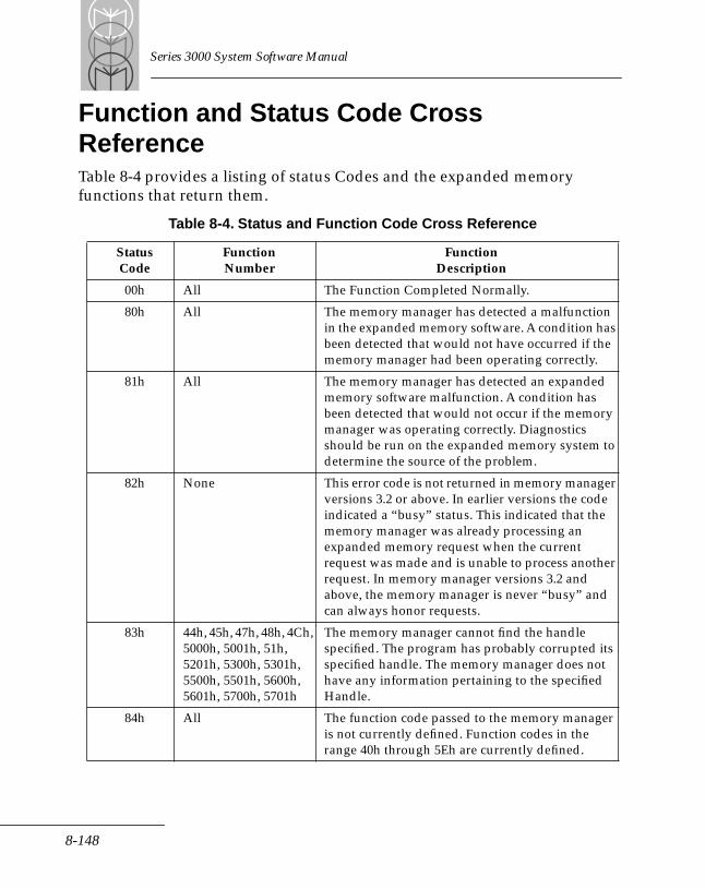
Series 3000 System Software Manual
Function and Status Code Cross Reference Table 8-4 provides a listing of status Codes and the expanded memory functions that return them.
Table 8-4. Status and Function Code Cross Reference
StatusCode
FunctionNumber
FunctionDescription
00h All The Function Completed Normally.
80h All The memory manager has detected a malfunction in the expanded memory software. A condition has been detected that would not have occurred if the memory manager had been operating correctly.
81h All The memory manager has detected an expanded memory software malfunction. A condition has been detected that would not occur if the memory manager was operating correctly. Diagnostics should be run on the expanded memory system to determine the source of the problem.
82h None This error code is not returned in memory manager versions 3.2 or above. In earlier versions the code indicated a “busy” status. This indicated that the memory manager was already processing an expanded memory request when the current request was made and is unable to process another request. In memory manager versions 3.2 and above, the memory manager is never “busy” and can always honor requests.
83h 44h, 45h, 47h, 48h, 4Ch, 5000h, 5001h, 51h, 5201h, 5300h, 5301h, 5500h, 5501h, 5600h, 5601h, 5700h, 5701h
The memory manager cannot find the handle specified. The program has probably corrupted its specified handle. The memory manager does not have any information pertaining to the specified Handle.
84h All The function code passed to the memory manager is not currently defined. Function codes in the range 40h through 5Eh are currently defined.
8-148
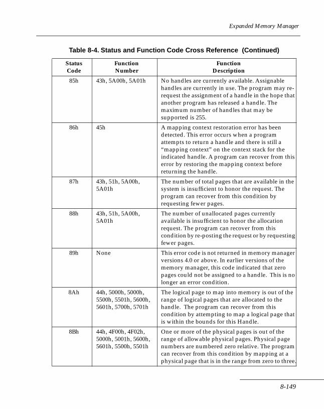
Expanded Memory Manager
85h 43h, 5A00h, 5A01h No handles are currently available. Assignable handles are currently in use. The program may re-request the assignment of a handle in the hope that another program has released a handle. The maximum number of handles that may be supported is 255.
86h 45h A mapping context restoration error has been detected. This error occurs when a program attempts to return a handle and there is still a “mapping context” on the context stack for the indicated handle. A program can recover from this error by restoring the mapping context before returning the handle.
87h 43h, 51h, 5A00h, 5A01h
The number of total pages that are available in the system is insufficient to honor the request. The program can recover from this condition by requesting fewer pages.
88h 43h, 51h, 5A00h, 5A01h
The number of unallocated pages currently available is insufficient to honor the allocation request. The program can recover from this condition by re-posting the request or by requesting fewer pages.
89h None This error code is not returned in memory manager versions 4.0 or above. In earlier versions of the memory manager, this code indicated that zero pages could not be assigned to a handle. This is no longer an error condition.
8Ah 44h, 5000h, 5000h, 5500h, 5501h, 5600h, 5601h, 5700h, 5701h
The logical page to map into memory is out of the range of logical pages that are allocated to the handle. The program can recover from this condition by attempting to map a logical page that is within the bounds for this Handle.
8Bh 44h, 4F00h, 4F02h, 5000h, 5001h, 5600h, 5601h, 5500h, 5501h
One or more of the physical pages is out of the range of allowable physical pages. Physical page numbers are numbered zero relative. The program can recover from this condition by mapping at a physical page that is in the range from zero to three.
Table 8-4. Status and Function Code Cross Reference (Continued)
StatusCode
FunctionNumber
FunctionDescription
8-149
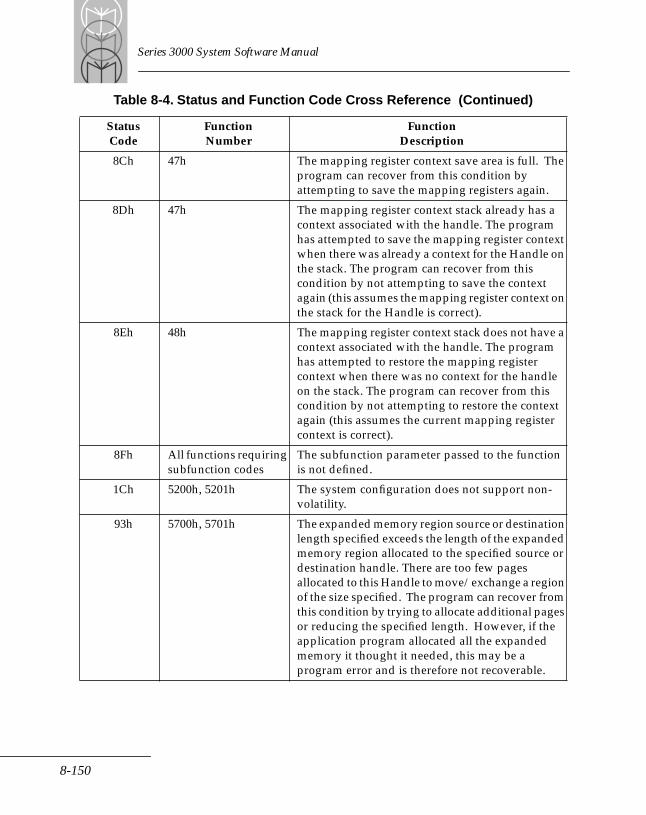
Series 3000 System Software Manual
8Ch 47h The mapping register context save area is full. The program can recover from this condition by attempting to save the mapping registers again.
8Dh 47h The mapping register context stack already has a context associated with the handle. The program has attempted to save the mapping register context when there was already a context for the Handle on the stack. The program can recover from this condition by not attempting to save the context again (this assumes the mapping register context on the stack for the Handle is correct).
8Eh 48h The mapping register context stack does not have a context associated with the handle. The program has attempted to restore the mapping register context when there was no context for the handle on the stack. The program can recover from this condition by not attempting to restore the context again (this assumes the current mapping register context is correct).
8Fh All functions requiring subfunction codes
The subfunction parameter passed to the function is not defined.
1Ch 5200h, 5201h The system configuration does not support non-volatility.
93h 5700h, 5701h The expanded memory region source or destination length specified exceeds the length of the expanded memory region allocated to the specified source or destination handle. There are too few pages allocated to this Handle to move/exchange a region of the size specified. The program can recover from this condition by trying to allocate additional pages or reducing the specified length. However, if the application program allocated all the expanded memory it thought it needed, this may be a program error and is therefore not recoverable.
Table 8-4. Status and Function Code Cross Reference (Continued)
StatusCode
FunctionNumber
FunctionDescription
8-150
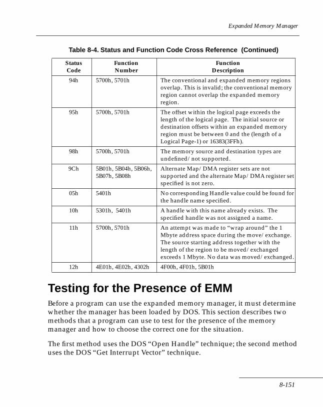
Expanded Memory Manager
Testing for the Presence of EMMBefore a program can use the expanded memory manager, it must determine whether the manager has been loaded by DOS. This section describes two methods that a program can use to test for the presence of the memory manager and how to choose the correct one for the situation.
The first method uses the DOS “Open Handle” technique; the second method uses the DOS “Get Interrupt Vector” technique.
94h 5700h, 5701h The conventional and expanded memory regions overlap. This is invalid; the conventional memory region cannot overlap the expanded memory region.
95h 5700h, 5701h The offset within the logical page exceeds the length of the logical page. The initial source or destination offsets within an expanded memory region must be between 0 and the (length of a Logical Page-1) or 16383(3FFh).
98h 5700h, 5701h The memory source and destination types are undefined/not supported.
9Ch 5B01h, 5B04h, 5B06h, 5B07h, 5B08h
Alternate Map/DMA register sets are not supported and the alternate Map/DMA register set specified is not zero.
05h 5401h No corresponding Handle value could be found for the handle name specified.
10h 5301h, 5401h A handle with this name already exists. The specified handle was not assigned a name.
11h 5700h, 5701h An attempt was made to “wrap around” the 1 Mbyte address space during the move/exchange. The source starting address together with the length of the region to be moved/exchanged exceeds 1 Mbyte. No data was moved/exchanged.
12h 4E01h, 4E02h, 4302h 4F00h, 4F01h, 5B01h
Table 8-4. Status and Function Code Cross Reference (Continued)
StatusCode
FunctionNumber
FunctionDescription
8-151
Series 3000 System Software Manual
Which Method Should Your Program Use?The majority of application programs can use either the open handle or the get interrupt vector method. However, if your program is a device driver or if it interrupts DOS during file system operations, you must use only the get interrupt vector method.
Device drivers execute from within DOS and can't access the DOS file system; programs that interrupt DOS during file system operations have a similar restriction. During their interrupt processing procedures, they can't access the DOS file system because another program may be using the system. Since the get interrupt vector method doesn't require the DOS file system, you must use it for these types of programs.
The “Open Handle” TechniqueMost application programs can use the DOS “Open Handle” technique to test for the presence of the memory manager. This section describes how to use the technique and also provides an example.
Note: Don't use this technique if your program is a device driver or if it interrupts DOS during file system operations. Use the Get Interrupt Vector technique described later in this chapter.
Using the Open Handle Technique Follow these steps in order to use the DOS Open Handle technique to test for the presence of the memory manager.
1. Issue an open handle command (DOS function 3Dh) in “read only” access mode (register AL = 0). This function requires your program to point to an ASCII string that contains the path name of the file or device in which you're interested (register set DS:DX contains the pointer). In this case the file is actually the name of the memory manager.
You should format the ASCII string as follows:
8-152

Expanded Memory Manager
ASCII_device_name DB "EMMXXXX0",0
The ASCII codes for the capital letters EMMXXXX0 are terminated by a byte containing a value of zero.
2. If DOS returns no error status code, skip Steps 3 and 4 and go to Step 5. If DOS returns a “Too Many Open Files” error status code, go to Step 3. If DOS returns a “File/Path not found” error status code skip Step 3 and go to Step 4.
3. If DOS returns a “Too Many Open Files” (not enough Handles) status code, your program should invoke the “open file” command before it opens any other files. This will guarantee that at least one file handle will be available to perform the function without causing the error.
After the program performs the “Open File” command, it should perform the test described in Step 6 and close the “file Handle” (DOS function 3Eh). Don't keep the manager “open” after this status test is performed since “manager” functions are not available through DOS. Go to Step 6.
4. If DOS returns a “File/Path Not Found”, the memory manager is not installed. If your application requires the memory manager, the user will have to reboot the system with a disk containing the memory manager and the appropriate CONFIG.SYS file before proceeding.
5. If DOS doesn't return an error status code you can assume that either a device with the name EMMXXXX0 is resident in the system, or a file with this name is on disk in the current disk drive. Go to Step 6.
6. Issue an “I/O Control for Device” command (DOS function 44h) with a “get device information” command (register AL = 0h). DOS function 44h determines whether EMMXXXX0 is a device or a file.
You must use the file Handle (register BX) that you obtained in Step 1 to access the “EMM device. This function returns the “device information” in a word (register DX). Go to step 7.
7. If DOS returns any error status code, you should assume that the memory manager device driver is not installed. If your application requires the memory manager, the user must reboot the system with a disk containing the memory manager and the appropriate CONFIG.SYS file before proceeding.
8-153

Series 3000 System Software Manual
8. If DOS didn't return an error status, test the contents of a bit 7 (counting from 0) of the “device information” word (register DX) the function returned. Go to Step 9.
9. If bit 7 of the “device information” word contains a zero, then EMMXXXX0 is a file, and the memory manager device driver is not present. If your application requires its presence, the user must reboot the system with a disk containing the memory manager and the appropriate CONFIG.SYS file before proceeding.
If bit 7 contains a 1, then EMMXXXX0 is a device. Go to Step 10.
10. Issue an “I/O Control for Device” command (DOS function 44h) with a “get output status” command (register AL = 7h).
11. You must use the file handle you obtained in Step 1 to access the “EMM device (register BX). Go to Step 11.
12. If the expanded memory device driver is “ready,” the memory manager passes a status value of “00h”; if the device driver is “not ready,” the status value is non-zero.
If the memory manager device driver is “not ready” and your application requires its presence, the user must reboot the system with a disk containing the memory manager and the appropriate CONFIG.SYS file before proceeding. If the memory manager device driver is “ready”, go to Step 12.
13. Issue a “Close File Handle” command (DOS function 3Eh) to close the expanded memory device driver. You must use the file Handle you obtained in Step 1 to close the “EMM” device (register BX).
An example of the open handle techniqueThe following procedure is an example of the open handle technique outlined in the previous section.
The following procedure tests for the presence of the EMM in the system. It returns the CARRY FLAG SET if the EMM is present. If the EMM is not present, this procedure returns the CARRY FLAG CLEAR.
first_test_for EMM PROC NEAR
8-154

Expanded Memory Manager
PUSH DS
PUSH CS
POP DS
MOV AX,3D00H ; issue "device open" in read
; only mode
LEA DX,ASCII_device_name
; "read only" mode
INT 21h
JC first_test_for_EMM_error_exit
; test for error
; during "device open"
MOV BX,AX ; get the "file Handle" ; returned by DOS
MOV AX,4400h ; issue "IOCTL"INT 21h ; "get device info"
JC first_test_for_EMM_err_exit
;test for error
TEST DX,0080h ; test to determine
JZ first_test_for_EMM_err_exit
; ASCII_device_name
; is a device or a file
MOV AX,4407h ; issue "IOCTL"
INT 21h
JC first_test_for_EMM_error_exit
; test for error
; during "IOCTL"
PUSH AX ; save "IOCTL" status
MOV AH,3Eh ; issue close
8-155
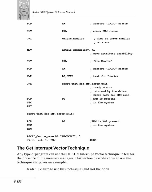
Series 3000 System Software Manual
POP AX ; restore "IOCTL" status
INT 21h ; check EMM status
JNZ em_err_Handler ; jump to error Handler
; on error
MOV attrib_capability, AL
; save attribute capability
INT 21h ; file Handle"
POP AX ; restore "IOCTL" status
CMP AL,0FFH ; test for "device
JNE first_test_for_EMM_error_exit
; ready status
; returned by the driver
; first_test_for_EMM_exit:
POP DS ; EMM is present
STC ; in the system
RET
first_test_for_EMM_error_exit:
POP DS ;EMM is NOT present
CLC ; in the system
RET
ASCII_device_name DB "EMMXXXX0", 0
first_test_for_EMM ENDP
The Get Interrupt Vector TechniqueAny type of program can use the DOS Get Interrupt Vector technique to test for the presence of the memory manager. This section describes how to use the technique and gives an example.
Note: Be sure to use this technique (and not the open
8-156
Expanded Memory Manager
handle technique) if your program is a device driver or it interrupts DOS during file system operations.
Using the Get Interrupt Vector TechniqueFollow these steps to use the DOS Get Interrupt Vector technique to test for the presence of the memory manager:
1. Issue a “get vector” command (DOS function 35h) to obtain the contents of interrupt vector array entry number 67h (addresses 0000:019C through 0000:019F).
The memory manager uses this interrupt vector to perform all manager functions. The Offset portion of this interrupt service routine address is stored in the word located at address 0000:019Ch; the segment portion is stored in the word located at address 0000:019Eh.
2. Compare the “device name field” with the contents of the ASCII string that starts at the address specified by the segment portion of the contents of interrupt vector address 67h and a fixed offset of 000Ah. If DOS loaded the memory manager at boot time, this name field will have the name of the device in it.
Since the memory manager is implemented as a character device driver, its program origin is 0000h. Device drivers are required to have a “device header” located at the program origin. Within the “device header” is an 8-byte “device name field.” For a character mode device driver this name field is always located at offset 000Ah within the device header. The device name field contains the name of the device that DOS uses when it references the device.
If the result of the “string compare” in this technique is positive, the memory manager driver is present.
Example of the Get Interrupt Vector techniqueThe following procedure is an example of the Get Interrupt Vector technique outlined in the previous section.It tests for the presence of the EMM in the system. It returns the CARRY FLAG SET if the EMM is present. If the EMM is not present, this procedure returns the CARRY FLAG CLEAR.
8-157
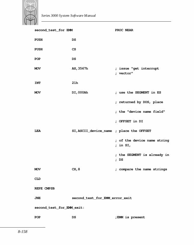
Series 3000 System Software Manual
second_test_for EMM PROC NEAR
PUSH DS
PUSH CS
POP DS
MOV AX,3567h ; issue "get interrupt
; vector"
INT 21h
MOV DI,000Ah ; use the SEGMENT in ES
; returned by DOS, place
; the "device name field"
; OFFSET in DI
LEA SI,ASCII_device_name ; place the OFFSET
; of the device name string
; in SI,
; the SEGMENT is already in
; DS
MOV CX,8 ; compare the name strings
CLD
REPE CMPSB
JNE second_test_for_EMM_error_exit
second_test_for_EMM_exit:
POP DS ;EMM is present
8-158
Expanded Memory Manager
STC ; in the system
RET
second_test_for_EMM_exit:
POP DS ;EMM is present
STC ; in the system
RET
second_test_for_EMM_error_exit
POP DS ;EMM is NOT present
CLC ;in the system
RET
ASCII_device_name DB "EMMXXXX0"
second_test_for_EMM ENDP
8-159

Series 3000 System Software Manual
8-160

Chapter 9 Communication Device Driver
Chapter ContentsIntroduction . . . . . . . . . . . . . . . . . . . . . . . . . . . . . . . . . . . . . . . . . . . . . . . . . . . . . . . . . . . . . . . . . . . . . 9-3
Multi-Protocol Communication Device Driver . . . . . . . . . . . . . . . . . . . . . . . . . . . . . . . . . . . . 9-3Attachable Protocol Drivers . . . . . . . . . . . . . . . . . . . . . . . . . . . . . . . . . . . . . . . . . . . . . . . . . . . . 9-3
DOS Comm Driver Services . . . . . . . . . . . . . . . . . . . . . . . . . . . . . . . . . . . . . . . . . . . . . . . . . . . . . . . . 9-3A Sample Communications Session . . . . . . . . . . . . . . . . . . . . . . . . . . . . . . . . . . . . . . . . . . . . . 9-4Open/Close Communications Line . . . . . . . . . . . . . . . . . . . . . . . . . . . . . . . . . . . . . . . . . . . . . 9-5Passing Device Control Information . . . . . . . . . . . . . . . . . . . . . . . . . . . . . . . . . . . . . . . . . . . . . 9-6DOS I/O Status . . . . . . . . . . . . . . . . . . . . . . . . . . . . . . . . . . . . . . . . . . . . . . . . . . . . . . . . . . . . . . 9-6Binary Processing Mode . . . . . . . . . . . . . . . . . . . . . . . . . . . . . . . . . . . . . . . . . . . . . . . . . . . . . . . 9-7Comm Driver Load Status . . . . . . . . . . . . . . . . . . . . . . . . . . . . . . . . . . . . . . . . . . . . . . . . . . . . . 9-7
Using Protocol Drivers . . . . . . . . . . . . . . . . . . . . . . . . . . . . . . . . . . . . . . . . . . . . . . . . . . . . . . . . . . . . 9-8Attaching a Protocol Driver . . . . . . . . . . . . . . . . . . . . . . . . . . . . . . . . . . . . . . . . . . . . . . . . . . . . 9-8
IOCTL Error Codes . . . . . . . . . . . . . . . . . . . . . . . . . . . . . . . . . . . . . . . . . . . . . . . . . . . . . . . . . . . . . . . 9-9Protocol Driver Interface. . . . . . . . . . . . . . . . . . . . . . . . . . . . . . . . . . . . . . . . . . . . . . . . . . . . . . . . . . 9-11
Writing Protocol Drivers. . . . . . . . . . . . . . . . . . . . . . . . . . . . . . . . . . . . . . . . . . . . . . . . . . . . . . 9-12Attaching the Protocol Device Drivers . . . . . . . . . . . . . . . . . . . . . . . . . . . . . . . . . . . . . . . . . . 9-12
Application Program/Comm Driver Interface . . . . . . . . . . . . . . . . . . . . . . . . . . . . . . . . . . . . . . . 9-15Interface Parameters . . . . . . . . . . . . . . . . . . . . . . . . . . . . . . . . . . . . . . . . . . . . . . . . . . . . . . . . . 9-15
9-1

Series 3000 System Software Manual
9-2

Communication Device Driver
IntroductionMulti-Protocol Communication Device Driver The Communication Device Driver (Comm Driver) is an internal driver built into DOS, and provides all of the basic DOS device driver functions for devices COM1, COM2 and AUX. The driver has been enhanced to support extended serial communications capabilities on COM1 and COM2 for Series 3000 terminals.
The Comm Driver acts as the interface for optional protocol drivers. When a protocol driver is selected and enabled for a port, all instructions to the Comm driver for that port are processed by the protocol driver. In this way, the specific requirements of a protocol are transparent to the application program.
Attachable Protocol DriversA protocol driver is a program that conditions data transmissions so that they conform to the requirements of a specific communications protocol. Employing attachable protocol drivers relieves the application programmer from the burden of accounting for each protocol within the application. Instead, the application can be written generically, to issue commands to the Comm driver. The Comm driver then invokes the selected protocol driver.
The Comm Driver keeps track of all attached protocol drivers using the Driver Control Block (DCB) data structure. Two protocol drivers are integral to the Comm driver: DOSSTD and MSISTD. Additional protocol drivers must be linked to these.
For additional information on attaching and using protocol drivers, refer to Using Protocol Drivers later in this chapter.
DOS Communications Driver ServicesThe following DOS Function Calls are used by the application program to access the Comm Driver:
• OPEN (Int 21h, AH=3Dh)
• CLOSE (Int 21h, AH=3Eh)
9-3
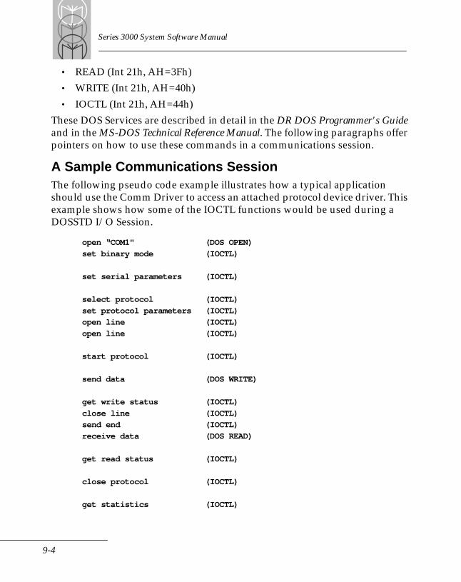
Series 3000 System Software Manual
• READ (Int 21h, AH=3Fh)
• WRITE (Int 21h, AH=40h)
• IOCTL (Int 21h, AH=44h)
These DOS Services are described in detail in the DR DOS Programmer's Guide and in the MS-DOS Technical Reference Manual. The following paragraphs offer pointers on how to use these commands in a communications session.
A Sample Communications SessionThe following pseudo code example illustrates how a typical application should use the Comm Driver to access an attached protocol device driver. This example shows how some of the IOCTL functions would be used during a DOSSTD I/O Session.
open “COM1" (DOS OPEN)
set binary mode (IOCTL)
set serial parameters (IOCTL)
select protocol (IOCTL)
set protocol parameters (IOCTL)
open line (IOCTL)
open line (IOCTL)
start protocol (IOCTL)
send data (DOS WRITE)
get write status (IOCTL)
close line (IOCTL)
send end (IOCTL)
receive data (DOS READ)
get read status (IOCTL)
close protocol (IOCTL)
get statistics (IOCTL)
9-4
Communication Device Driver
close line (IOCTL)
close (COM1) (DOS CLOSE)
Open/Close Communications LineDOS versions earlier than 3.0 do not pass OPEN or CLOSE function calls to the Comm Driver. Since the driver is not aware that an OPEN or CLOSE has occurred, it does not open or close the communications line. IOCTL calls are needed to complete the task. When using DOS 3.x versions, OPEN and CLOSE calls passed to the Comm Driver perform no operation.
Note: A DOS OPEN or CLOSE Function Call to COMn alone does not open or close a communications line.
To properly open a communications line, the application must do an IOCTL Open Line (function code 30h) and Start Protocol (function code 40h) after a DOS OPEN call (Int 21, AH=3Dh).
To properly close a comm line, the application must do an IOCTL Close Protocol (function code 43h) and an IOCTL CLOSE Line (function 31h) before issuing the DOS CLOSE call (Int 21h, AH=3Eh).
Reference CountersThe DOSSTD and MSISTD protocols each maintain reference counters for the Open Line and Start Protocol IOCTL commands for each comm line. When one of these is the selected protocol, each reference counter keeps track of the number of current OPENs for a line or protocol, as follows:
• Each time an Open Line command is issued, its counter is incremented, even if the line is already open.
• The Start Protocol command only starts the protocol if the reference count is zero when it is called, but it increments the counter every time it is called.
• The Close Line command decrements the Open Line reference counter each time it is called. It closes the line when the count reaches zero.
• The Close Protocol function decrements the Start Protocol reference
9-5
Series 3000 System Software Manual
counter each time it is called. It closes the protocol when the reference counter reaches zero.
If a category 2 protocol (defined later) is selected, these commands are passed through to, and are processed by, that protocol driver. Keeping reference counters is the responsibility of the protocol driver.
Passing Device Control InformationThe DOS IOCTL function call is used to write control information to, and read status information from, the Comm Driver. Due to the nature of DOS, a DOS OPEN call must be made to a communications port before the first IOCTL call can be made to that port.
Control information is passed to the Comm Driver via the IOCTL Read/Write control string, which consists of commands and command parameters. Commands request some hardware or protocol-specific action. Command parameters provide either setup or operational information, such as Baud Rate, Line Timeout values, Protocol-specific parameters, etc., and are dependent on the specific communications device.
Status information is available to the application program through the control string to determine the success or failure of a command.
The IOCTL commands are described later in this chapter.
DOS I/O StatusWhen the DOSSTD protocol driver is selected, the Comm driver returns the status of a DOS READ or WRITE call to DOS in the Request Header Status Word. The status codes that are returned are limited and DOS considers any unsuccessful status a Critical Error.
When any other protocol is selected, the Comm Driver always returns a successful status for READ and WRITE function calls. The actual status of the communication is reported via the IOCTL function call: Get Read Status (45h) or Get Write Status (46h).
9-6
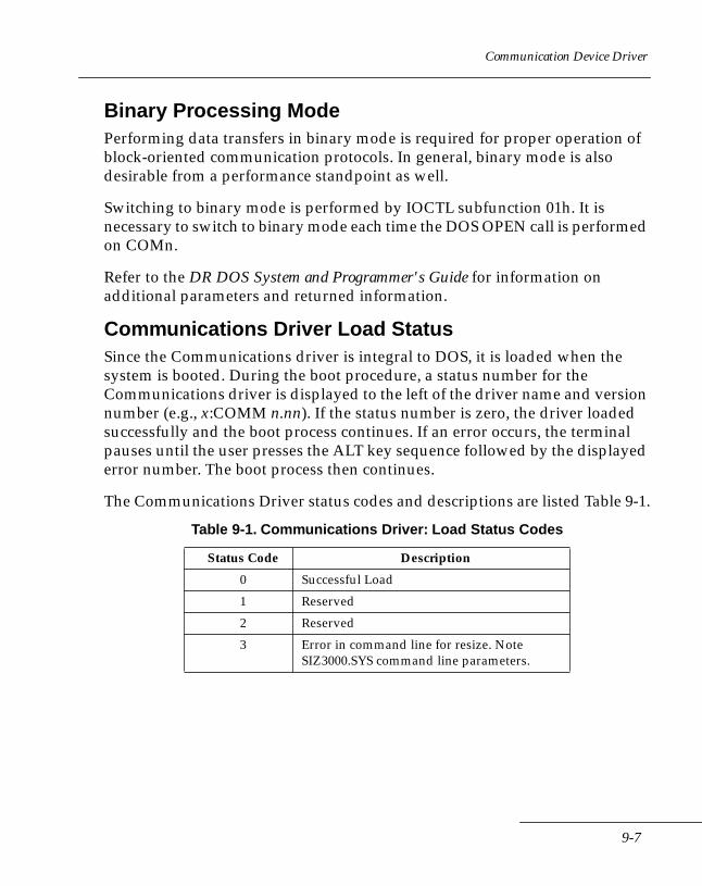
Communication Device Driver
Binary Processing ModePerforming data transfers in binary mode is required for proper operation of block-oriented communication protocols. In general, binary mode is also desirable from a performance standpoint as well.
Switching to binary mode is performed by IOCTL subfunction 01h. It is necessary to switch to binary mode each time the DOS OPEN call is performed on COMn.
Refer to the DR DOS System and Programmer's Guide for information on additional parameters and returned information.
Communications Driver Load StatusSince the Communications driver is integral to DOS, it is loaded when the system is booted. During the boot procedure, a status number for the Communications driver is displayed to the left of the driver name and version number (e.g., x:COMM n.nn). If the status number is zero, the driver loaded successfully and the boot process continues. If an error occurs, the terminal pauses until the user presses the ALT key sequence followed by the displayed error number. The boot process then continues.
The Communications Driver status codes and descriptions are listed Table 9-1.
Table 9-1. Communications Driver: Load Status Codes
Status Code Description
0 Successful Load
1 Reserved
2 Reserved
3 Error in command line for resize. Note SIZ3000.SYS command line parameters.
9-7
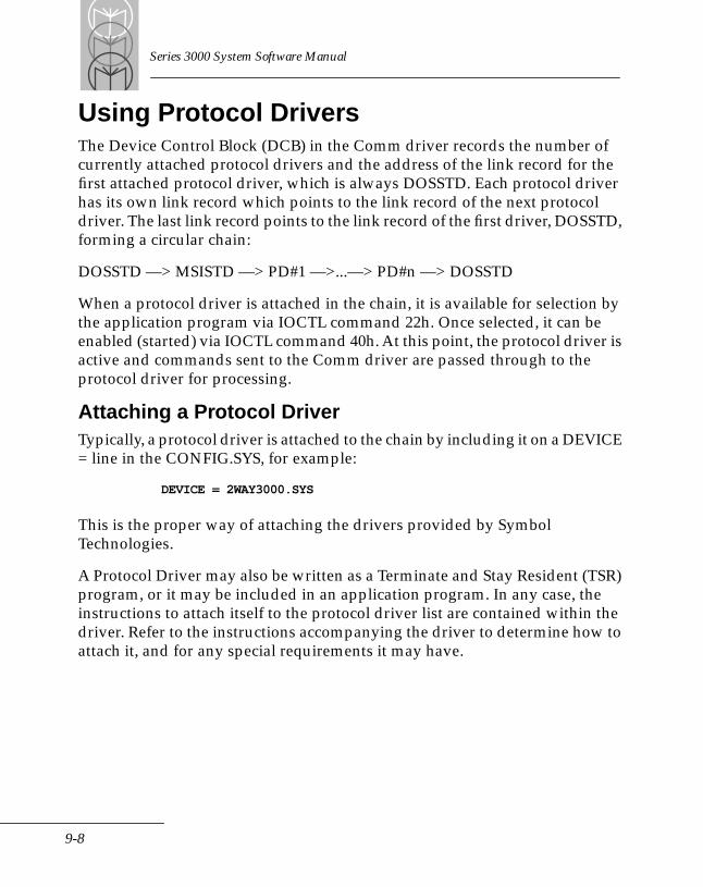
Series 3000 System Software Manual
Using Protocol DriversThe Device Control Block (DCB) in the Comm driver records the number of currently attached protocol drivers and the address of the link record for the first attached protocol driver, which is always DOSSTD. Each protocol driver has its own link record which points to the link record of the next protocol driver. The last link record points to the link record of the first driver, DOSSTD, forming a circular chain:
DOSSTD —> MSISTD —> PD#1 —>...—> PD#n —> DOSSTD
When a protocol driver is attached in the chain, it is available for selection by the application program via IOCTL command 22h. Once selected, it can be enabled (started) via IOCTL command 40h. At this point, the protocol driver is active and commands sent to the Comm driver are passed through to the protocol driver for processing.
Attaching a Protocol DriverTypically, a protocol driver is attached to the chain by including it on a DEVICE = line in the CONFIG.SYS, for example:
DEVICE = 2WAY3000.SYS
This is the proper way of attaching the drivers provided by Symbol Technologies.
A Protocol Driver may also be written as a Terminate and Stay Resident (TSR) program, or it may be included in an application program. In any case, the instructions to attach itself to the protocol driver list are contained within the driver. Refer to the instructions accompanying the driver to determine how to attach it, and for any special requirements it may have.
9-8
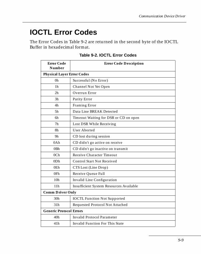
Communication Device Driver
IOCTL Error CodesThe Error Codes in Table 9-2 are returned in the second byte of the IOCTL Buffer in hexadecimal format.
Table 9-2. IOCTL Error Codes
Error Code Number
Error Code Description
Physical Layer Error Codes
0h Successful (No Error)
1h Channel Not Yet Open
2h Overrun Error
3h Parity Error
4h Framing Error
5h Data Line BREAK Detected
6h Timeout Waiting for DSR or CD on open
7h Lost DSR While Receiving
8h User Aborted
9h CD lost during session
0Ah CD didn't go active on receive
0Bh CD didn't go inactive on transmit
0Ch Receive Character Timeout
0Dh Control Start Not Received
0Eh CTS Lost (Line Drop)
0Fh Receive Queue Full
10h Invalid Line Configuration
11h Insufficient System Resources Available
Comm Driver Only
30h IOCTL Function Not Supported
31h Requested Protocol Not Attached
Generic Protocol Errors
40h Invalid Protocol Parameter
41h Invalid Function For This State
9-9
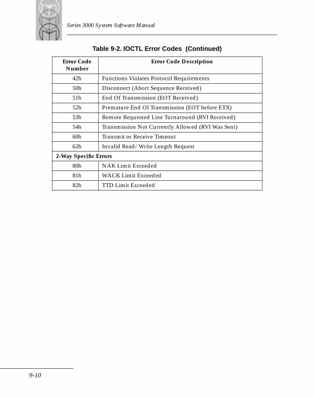
Series 3000 System Software Manual
42h Functions Violates Protocol Requirements
50h Disconnect (Abort Sequence Received)
51h End Of Transmission (EOT Received)
52h Premature End Of Transmission (EOT before ETX)
53h Remote Requested Line Turnaround (RVI Received)
54h Transmission Not Currently Allowed (RVI Was Sent)
60h Transmit or Receive Timeout
62h Invalid Read/Write Length Request
2-Way Specific Errors
80h NAK Limit Exceeded
81h WACK Limit Exceeded
82h TTD Limit Exceeded
Table 9-2. IOCTL Error Codes (Continued)
Error Code Number
Error Code Description
9-10
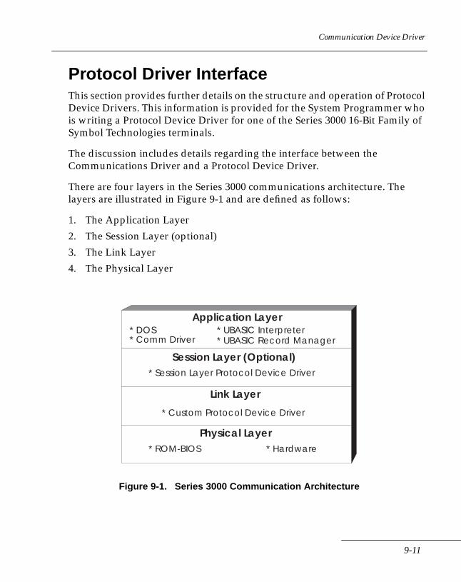
Communication Device Driver
Protocol Driver InterfaceThis section provides further details on the structure and operation of Protocol Device Drivers. This information is provided for the System Programmer who is writing a Protocol Device Driver for one of the Series 3000 16-Bit Family of Symbol Technologies terminals.
The discussion includes details regarding the interface between the Communications Driver and a Protocol Device Driver.
There are four layers in the Series 3000 communications architecture. The layers are illustrated in Figure 9-1 and are defined as follows:
1. The Application Layer
2. The Session Layer (optional)
3. The Link Layer
4. The Physical Layer
Figure 9-1. Series 3000 Communication Architecture
Application Layer
Session Layer (Optional)
Link Layer
Physical Layer
* UBASIC Interpreter* UBASIC Record Manager
* DOS* Comm Driver
* Session Layer Protocol Device Driver
* Custom Protocol Device Driver
* ROM-BIOS * Hardware
9-11

Series 3000 System Software Manual
The Application Layer contains the user's application program, the UBasic Interpreter, the UBasic Record Manager (URM), DOS, and The Comm Driver. The Session Layer, an optional layer, consists of a Session Layer Protocol Device Driver. The Link Layer consists of a custom Protocol Device Driver that attaches to the Comm Driver. The Physical Layer consists of the BIOS and the specific physical configuration of the hardware.
Writing Protocol DriversA protocol driver may be written as a device driver (loaded with a DEVICE= line in CONFIG.SYS), as a Terminate and Stay Resident program (TSR), or as a routine contained within an application program. There are advantages and disadvantages to each approach.
If a protocol driver is installed as a device in CONFIG.SYS, it remains in memory until the terminal is rebooted. Accordingly, that memory cannot be freed. On the other hand, it is available to any program run on the terminal.
If the protocol driver is run as a TSR program, it may be removed from memory by explicit command. The driver remains available to any application running until the driver is ended and removed from memory. On the other hand, it can be stopped and removed in order to free memory.
If the driver is included in the application, it is available only to that application. When the application program is finished, the memory it occupies, including that of the protocol driver included in it, is returned for system use.
Attaching the Protocol Device DriversA Protocol Device Driver must be “attached” to the Comm Driver Protocol Chain before an application program is able to make use of it. The Protocol Device Driver is attached to the Protocol Chain by calling Interrupt 0F8h. Information is passed to the interrupt from the Protocol Device Driver by the Link Record Data Structure. The Protocol Device Driver can be disconnected from the Protocol Chain in the same manner. The attach process can be performed by the protocol Initialize function when the protocol driver is initially loaded.
Interrupt 0F8h requires ES:DI to point to the Protocol Device Driver Link Record Data structure. The Link Record Data Structure is defined as follows:
9-12
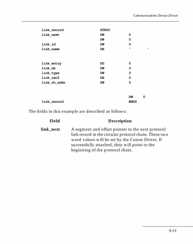
Communication Device Driver
link_record STRUC
link_next DW 0
DW 0
link_id DW 0
link_name DB ' '
link_entry DD 0
link_ds DW 0
link_type DW 0
link_cat2 DB 0
link_rh_addr DW 0
DW 0
link_record ENDS
The fields in this example are described as follows:
Field Description
link_next A segment and offset pointer to the next protocol link record in the circular protocol chain. These two word values will be set by the Comm Driver. If successfully attached, they will point to the beginning of the protocol chain.
9-13

Series 3000 System Software Manual
link_id A number identifying a specific Protocol Device Driver. The following is a list of reserved identification numbers for MSI protocols:
00h = “DOSSTD ” 30h = “MSISTD ” 31h = “2WAY3000”32h - 35h = Reserved for UBASIC Compatibility 36h = “XMODEM+Y” 37h = “KERMIT “ 38h = “SLP “ (Session Layer Protocol) 39h = “SPCTRM1 “ (Spectrum One Network Protocol)3Ah - 3Eh = Reserved for future protocols 3Fh = Reserved (formerly for “MDM3000 “)
link_name An eight-character name for the Protocol Device Driver. See above for reserved names.
link_entry Pointer to the Protocol Device Driver entry point.
link_ds DS register value of the driver.
link_type Protocol request for Attach or Disconnect.0 = attach, 1= disconnect.
link_cat2 Tells the Comm Driver that the Category 2 functions are to be used by the Protocol Device Driver.
link_rh_addr Request header address at the Protocol Device Driver.
Field Description
9-14
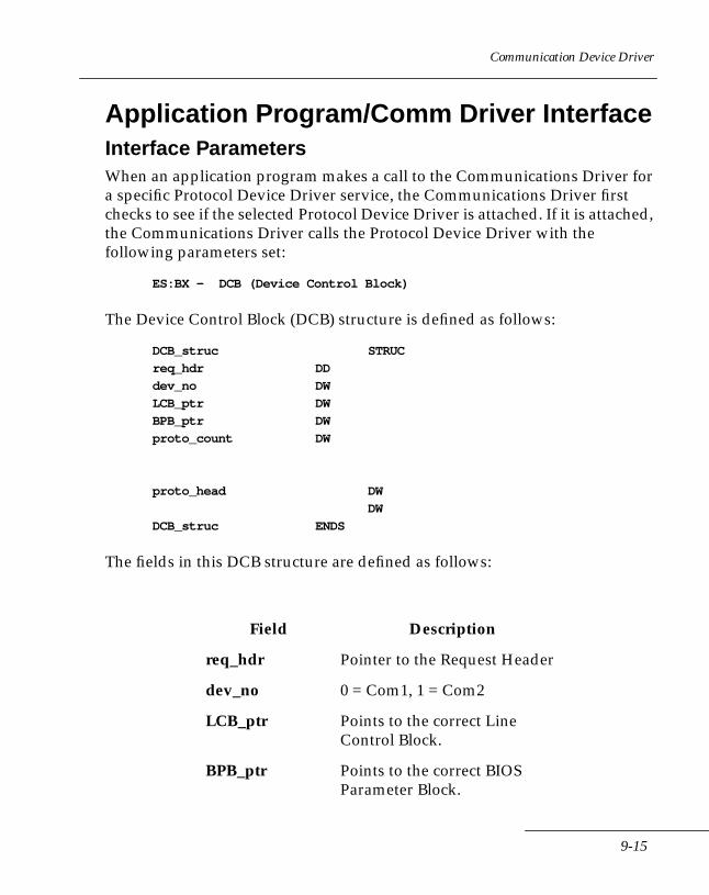
Communication Device Driver
Application Program/Comm Driver InterfaceInterface ParametersWhen an application program makes a call to the Communications Driver for a specific Protocol Device Driver service, the Communications Driver first checks to see if the selected Protocol Device Driver is attached. If it is attached, the Communications Driver calls the Protocol Device Driver with the following parameters set:
ES:BX - DCB (Device Control Block)
The Device Control Block (DCB) structure is defined as follows:
DCB_struc STRUC
req_hdr DD
dev_no DW
LCB_ptr DW
BPB_ptr DW
proto_count DW
proto_head DW
DW
DCB_struc ENDS
The fields in this DCB structure are defined as follows:
Field Description
req_hdr Pointer to the Request Header
dev_no 0 = Com1, 1 = Com2
LCB_ptr Points to the correct Line Control Block.
BPB_ptr Points to the correct BIOS Parameter Block.
9-15
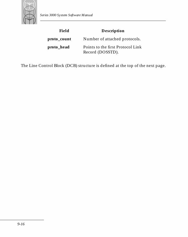
Series 3000 System Software Manual
The Line Control Block (DCB) structure is defined at the top of the next page.
proto_count Number of attached protocols.
proto_head Points to the first Protocol Link Record (DOSSTD).
Field Description
9-16
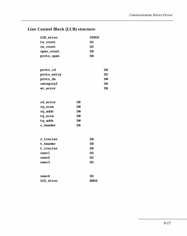
Communication Device Driver
Line Control Block (LCB) structure:
LCB_struc STRUC
tx_count DD
rx_count DD
open_count DB
proto_open DB
proto_id DB
proto_entry DD
proto_ds DW
category2 DB
wr_error DB
rd_error DB
rq_size DW
rq_addr DW
tq_size DW
tq_addr DW
r_header DB
r_trailer DB
t_header DB
t_trailer DB
user1 DD
user2 DD
user3 DD
user4 DD
LCD_struc ENDS
9-17
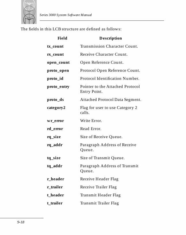
Series 3000 System Software Manual
The fields in this LCB structure are defined as follows:
Field Description
tx_count Transmission Character Count.
rx_count Receive Character Count.
open_count Open Reference Count.
proto_open Protocol Open Reference Count.
proto_id Protocol Identification Number.
proto_entry Pointer to the Attached Protocol Entry Point.
proto_ds Attached Protocol Data Segment.
category2 Flag for user to use Category 2 calls.
wr_error Write Error.
rd_error Read Error.
rq_size Size of Receive Queue.
rq_addr Paragraph Address of Receive Queue.
tq_size Size of Transmit Queue.
tq_addr Paragraph Address of Transmit Queue.
r_header Receive Header Flag
r_trailer Receive Trailer Flag
t_header Transmit Header Flag
t_trailer Transmit Trailer Flag
9-18
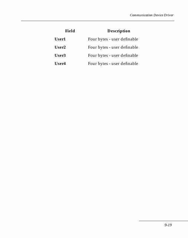
Communication Device Driver
User1 Four bytes - user definable
User2 Four bytes - user definable
User3 Four bytes - user definable
User4 Four bytes - user definable
Field Description
9-19

Series 3000 System Software Manual
9-20
Chapter 10 2WAY3000 Protocol Device Driver
Chapter ContentsIntroduction . . . . . . . . . . . . . . . . . . . . . . . . . . . . . . . . . . . . . . . . . . . . . . . . . . . . . . . . . . . . . . . . . . . . 10-32WAY3000 Protocol Description . . . . . . . . . . . . . . . . . . . . . . . . . . . . . . . . . . . . . . . . . . . . . . . . . . . 10-3
Synchronization and Character Structure . . . . . . . . . . . . . . . . . . . . . . . . . . . . . . . . . . . . . . . 10-3Block Length . . . . . . . . . . . . . . . . . . . . . . . . . . . . . . . . . . . . . . . . . . . . . . . . . . . . . . . . . . . . . . . . 10-3Character Code Set . . . . . . . . . . . . . . . . . . . . . . . . . . . . . . . . . . . . . . . . . . . . . . . . . . . . . . . . . . 10-3Master/Slave Status. . . . . . . . . . . . . . . . . . . . . . . . . . . . . . . . . . . . . . . . . . . . . . . . . . . . . . . . . . 10-4Establishment . . . . . . . . . . . . . . . . . . . . . . . . . . . . . . . . . . . . . . . . . . . . . . . . . . . . . . . . . . . . . . . 10-4Message Transfer Procedure . . . . . . . . . . . . . . . . . . . . . . . . . . . . . . . . . . . . . . . . . . . . . . . . . . 10-4Replies . . . . . . . . . . . . . . . . . . . . . . . . . . . . . . . . . . . . . . . . . . . . . . . . . . . . . . . . . . . . . . . . . . . . . 10-5Termination Procedure . . . . . . . . . . . . . . . . . . . . . . . . . . . . . . . . . . . . . . . . . . . . . . . . . . . . . . . 10-7Control Characters . . . . . . . . . . . . . . . . . . . . . . . . . . . . . . . . . . . . . . . . . . . . . . . . . . . . . . . . . . . 10-7
DOS I/O Functions . . . . . . . . . . . . . . . . . . . . . . . . . . . . . . . . . . . . . . . . . . . . . . . . . . . . . . . . . . . . . . 10-9IOCTL COMMANDS . . . . . . . . . . . . . . . . . . . . . . . . . . . . . . . . . . . . . . . . . . . . . . . . . . . . . . . . . . . 10-11
2WAY3000 Category 2 Functions . . . . . . . . . . . . . . . . . . . . . . . . . . . . . . . . . . . . . . . . . . . . . 10-112WAY3000 Category 3 Functions . . . . . . . . . . . . . . . . . . . . . . . . . . . . . . . . . . . . . . . . . . . . . 10-13
Loading the 2WAY3000 Device Driver. . . . . . . . . . . . . . . . . . . . . . . . . . . . . . . . . . . . . . . . . . . . . 10-18
10-1

Series 3000 System Software Manual
10-2
2WAY3000 Protocol Device Driver
IntroductionThe information in this chapter is provided for the application programmer who is using the 2WAY3000 Protocol Device Driver for one of the Series 3000 16-Bit Family of Symbol Technologies terminals.
2WAY3000 Protocol DescriptionThis protocol was developed using the following guidelines:
• ANSI standard X3.28 establishment and termination control procedure subcategory 2.2 (two-way alternate, switched point-to-point with establishment (identification procedure)).
• Transfer control procedure subcategory D1 (Message Independent Blocking, with cyclic checking, alternating acknowledgments with transparent heading and text).
• IBM General Binary Synchronous Communications Manual #GA27-3004-2.
• IBM 3780 Component Information Manual #GA27-3063-3.
Synchronization and Character StructureCharacters are transmitted asynchronously in compliance with ANSI standard X3.16, paragraph 3.2.1.
Block LengthThe transmitted block length is variable up to a maximum of 512 characters.
Character Code SetTo facilitate an easy transition from an asynchronous synchronization method to a synchronous synchronization method and maintain a general compatibility, the EBCDIC code set is used.
10-3
Series 3000 System Software Manual
Master/Slave StatusInitially, the calling station is the master station and the called station is the slave station. Master status indicates that the station assumes control of the data link for transmission of data. After transmission from the master (calling) station to the slave (called) station is completed, the calling station may relinquish master status to the called station. If the new master station has traffic to send, it performs the establishment procedure and then proceeds with the transmission of message data. Messages may be interchanged between the two stations, until at some point the master station disconnects after sending a DLE EOT or a 20-second timeout occurs after sending an EOT.
EstablishmentAn establishment procedure is required to establish a connection between the stations. The master station requests the status of the slave station by sending an ENQ. If the slave station is ready, it sends an ACK0. At this point, the master (calling) station may immediately ask the slave (called) station to transmit first by sending an EOT. If the master station receives no reply after one second, it retransmits its initial line bid ENQ 15 times.
Message Transfer ProcedureAll message blocks are sent in a transparent mode. That is, all 256 combinations of an 8-bit character may be transmitted.
The master (calling) station sends each transmission block to a single slave (called) station and waits for a reply. If the reply indicates that the block was accepted, the master station may send another block or terminate. If the reply is negative, the master station retransmits the block of data four times before termination. If, at any point after entering the message transfer procedure, the master station is not immediately ready to transmit data, it may send a TTD sequence (STX, ENQ) after waiting for two seconds. Upon detecting the TTD sequence, the slave station sends an NAK. If the master station is now ready to transmit data, it begins or continues the transmission with the next data block starting with DLE STX or SOH. If the master station is not ready to transmit data, it may repeat the TTD sequence. If the master station cannot continue, it sends an EOT.
10-4
2WAY3000 Protocol Device Driver
The master station begins the transmission with an SOH to transmit its header information. The header block is terminated with an ETB or ETX, CRC.
After an appropriate reply, and dependent on the information contained in the transmitted header, the master station may immediately relinquish master status by transmitting an EOT or start the transmission of data with a DLE STX.
An intermediate block that continues a heading is started by an SOH. An intermediate block that either begins or continues a text is started with a DLE STX. A block that ends at an intermediate point within a text message is ended with a DLE ETB. A block that ends at the end of a text message is ended with a DLE ETX. A block that ends at an intermediate point within a heading message is ended with an ETB. A block that ends at the end of a heading message is ended with an ETX. The ETB or ETX is immediately followed by two CRC characters. After the ETB or ETX characters are sent, the master station waits three seconds for a reply.
Control characters are distinguished from data characters by the recognition of a DLE, except for header messages. Control character sequences must always be started with a DLE, except for header messages. When a DLE appears as a data character, the master station inserts an additional DLE so that the data transmitted on the line contains two successive DLE characters.
RepliesThe slave station, upon receiving the ETB or ETX for the headers followed by the CRC or the DLE ETB or DLE ETX for the text data followed by the CRC, sends one of six replies:
If the transmission block was accepted and the slave station is ready to receive another block of data, it sends a DLE, ACKN. An ACK1 is used as a reply to the first block received and an ACK0 is used as the reply to the second block received. Subsequent positive acknowledgments alternate between an ACK1 and an ACK0. Upon detecting the appropriate ACKN, the master station may either transmit the next data block or initiate termination if the last block ended in a DLE, ETX, CRC for text data or an ETX, CRC for headers.
10-5
Series 3000 System Software Manual
If the transmission block was not accepted and the slave station is ready to receive another block of data, it sends an NAK. Upon detecting an NAK, the master station initiates retransmission of the last transmission block. The master station attempts four data block retransmissions before aborting.
If the alternating reply indicates that the slave station missed the outstanding block (receipt of an ACK1 instead of an ACK0 or vice versa), the master station initiates retransmission of the outstanding block.
If the transmission block was accepted and the slave station is not ready to receive the next block of data, it sends a WACK after waiting for two seconds. Upon detecting a WACK, the master station responds by sending an ENQ. When the slave station detects an ENQ in response to a WACK, it either sends the ACKN required for the last received data block or waits another two seconds and repeats the WACK sequence.
If the transmission block is accepted and the slave station has an urgent need to transmit data, it sends an RVI. Upon detecting an RVI, the master station responds by sending an EOT to relinquish master status and allow the slave station to gain master status to transmit its message. The RVI is a positive acknowledgment of the data.
If the master station received an invalid or no reply to a transmission block, it responds with an ENQ after waiting three seconds as a reply request. Upon receipt of the ENQ reply request, the slave station repeats its last reply. If a valid reply is not received after seven retries, the master station exits to a termination procedure.
10-6

2WAY3000 Protocol Device Driver
Termination ProcedureUpon completion of the establishment procedure or message transfer procedure, the master station may send a DLE EOT and disconnect the line if the master station does not want to allow the line to turn around. Upon completion of the establishment procedure or message transfer procedure, the master station then assumes slave status and the slave station, upon detecting an EOT, assumes master status. If the new master station has data to send, it proceeds to the establishment procedure and the process is repeated. If the new master has no data to send, it disconnects from the line after sending a DLE EOT. If a transmit, receive, or close protocol prevents proper termination, call an Abort Protocol (44h).
Control CharactersTable 10-1 lists the data link control characters and their meaning.
Table 10-1. Data Link Control Characters
Character MeaningControl State
MessageTransfer State
EBCDIC
(ENQ) Enquiry Can you accept transmission?
Repeat last response. X'2D'
(ACK0) Even Acknowledge
I can accept transmission.
Even block received successfully. X'1070'
(ACK1) Odd Acknowledge ————————
Odd block received successfully. X'1061'
(STX) Start of Text
Change to message transfer state.
Start computing. Check sum. X'02'
(SOH) Start of Header
Change to message transfer state.
Start computing. Check sum. X'01'
(NAK) Negative Acknowledge
I cannot accept transmission.
Retransmit last block.X'3D'
(TTD) Temporary Text Delay
Transmission will begin presently (wait).
Transmission will begin presently (wait). X'022D'
10-7

Series 3000 System Software Manual
(WACK) Wait Acknowledge
Enquire again later, delay transmission.
Enquire again later, delay transmission. X'106B'
(DLE) Data Link Escape —————————-
Distinguish control characters from data. X'10'
(ETB) End of Text Block —————————
CRC follows, another block to follow. X'26'
(ETX) End of Text —————————
CRC follows, last block of this text, maintain data link.
X'03'
(EOT) End of Transmission ————————— Return to control state. X'37'
(RVI) Reverse Interrupt —————————
Slave station wants master to relinquish line.
X'107C'
Table 10-1. Data Link Control Characters (Continued)
Character MeaningControl State
MessageTransfer State
EBCDIC
10-8
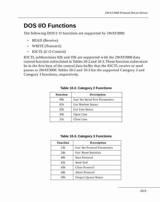
2WAY3000 Protocol Device Driver
DOS I/O FunctionsThe following DOS I/O functions are supported by 2WAY3000:
• READ (Receive)
• WRITE (Transmit)
• IOCTL (I/O Control)
IOCTL subfunctions 02h and 03h are supported with the 2WAY3000 data control function codes listed in Tables 10-2 and 10-3. These function codes must be in the first byte of the control data buffer that the IOCTL receive or send passes to 2WAY3000. Tables 10-2 and 10-3 list the supported Category 2 and Category 3 functions, respectively.
Table 10-2. Category 2 Functions
Function Description
00h Get/Set Serial Port Parameters
01h Get Modem Status
02h Get Line Status
30h Open Line
31h Close Line
Table 10-3. Category 3 Functions
Function Description
23h Get/Set Protocol Parameters
24h Get/Reset Statistics
40h Start Protocol
42h Send End
43h Close Protocol
44h Abort Protocol
50h Output Queue Status
10-9
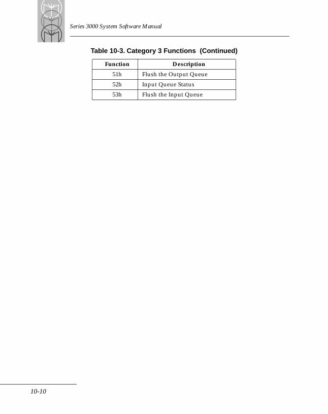
Series 3000 System Software Manual
51h Flush the Output Queue
52h Input Queue Status
53h Flush the Input Queue
Table 10-3. Category 3 Functions (Continued)
Function Description
10-10
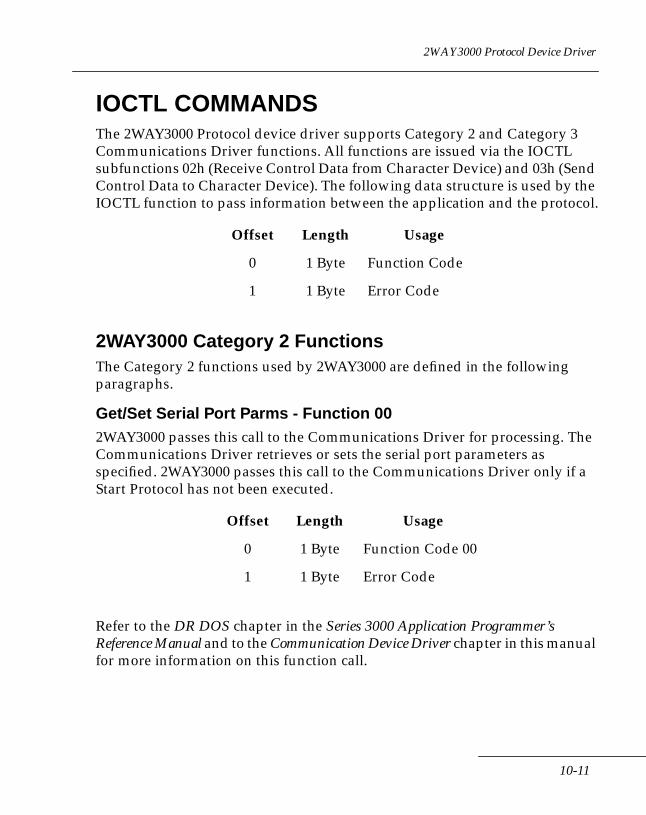
2WAY3000 Protocol Device Driver
IOCTL COMMANDSThe 2WAY3000 Protocol device driver supports Category 2 and Category 3 Communications Driver functions. All functions are issued via the IOCTL subfunctions 02h (Receive Control Data from Character Device) and 03h (Send Control Data to Character Device). The following data structure is used by the IOCTL function to pass information between the application and the protocol.
2WAY3000 Category 2 FunctionsThe Category 2 functions used by 2WAY3000 are defined in the following paragraphs.
Get/Set Serial Port Parms - Function 002WAY3000 passes this call to the Communications Driver for processing. The Communications Driver retrieves or sets the serial port parameters as specified. 2WAY3000 passes this call to the Communications Driver only if a Start Protocol has not been executed.
Refer to the DR DOS chapter in the Series 3000 Application Programmer’s Reference Manual and to the Communication Device Driver chapter in this manual for more information on this function call.
Offset Length Usage
0 1 Byte Function Code
1 1 Byte Error Code
Offset Length Usage
0 1 Byte Function Code 00
1 1 Byte Error Code
10-11
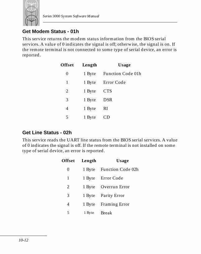
Series 3000 System Software Manual
Get Modem Status - 01hThis service returns the modem status information from the BIOS serial services. A value of 0 indicates the signal is off; otherwise, the signal is on. If the remote terminal is not connected to some type of serial device, an error is reported.
Get Line Status - 02hThis service reads the UART line status from the BIOS serial services. A value of 0 indicates the signal is off. If the remote terminal is not installed on some type of serial device, an error is reported.
Offset Length Usage
0 1 Byte Function Code 01h
1 1 Byte Error Code
2 1 Byte CTS
3 1 Byte DSR
4 1 Byte RI
5 1 Byte CD
Offset Length Usage
0 1 Byte Function Code 02h
1 1 Byte Error Code
2 1 Byte Overrun Error
3 1 Byte Parity Error
4 1 Byte Framing Error
5 1 Byte Break
10-12
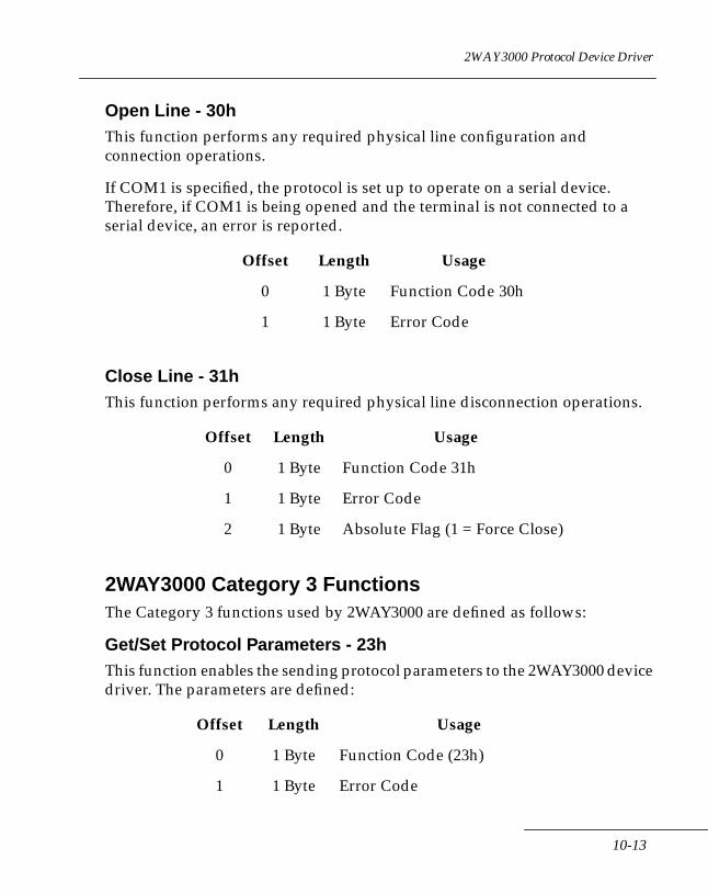
2WAY3000 Protocol Device Driver
Open Line - 30hThis function performs any required physical line configuration and connection operations.
If COM1 is specified, the protocol is set up to operate on a serial device. Therefore, if COM1 is being opened and the terminal is not connected to a serial device, an error is reported.
Close Line - 31hThis function performs any required physical line disconnection operations.
2WAY3000 Category 3 FunctionsThe Category 3 functions used by 2WAY3000 are defined as follows:
Get/Set Protocol Parameters - 23hThis function enables the sending protocol parameters to the 2WAY3000 device driver. The parameters are defined:
Offset Length Usage
0 1 Byte Function Code 30h
1 1 Byte Error Code
Offset Length Usage
0 1 Byte Function Code 31h
1 1 Byte Error Code
2 1 Byte Absolute Flag (1 = Force Close)
Offset Length Usage
0 1 Byte Function Code (23h)
1 1 Byte Error Code
10-13
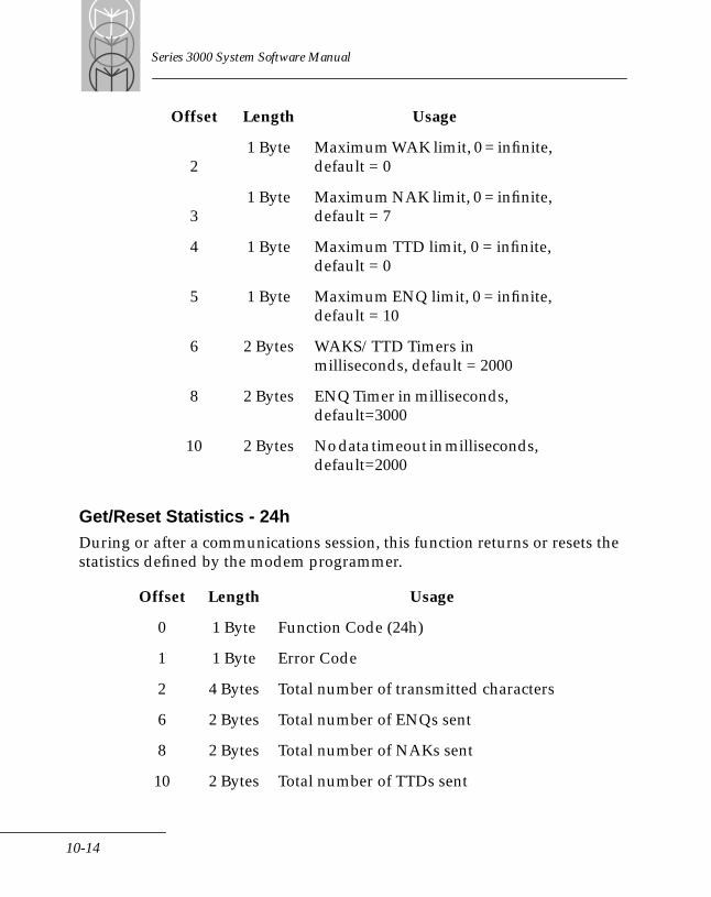
Series 3000 System Software Manual
Get/Reset Statistics - 24hDuring or after a communications session, this function returns or resets the statistics defined by the modem programmer.
21 Byte Maximum WAK limit, 0 = infinite,
default = 0
31 Byte Maximum NAK limit, 0 = infinite,
default = 7
4 1 Byte Maximum TTD limit, 0 = infinite, default = 0
5 1 Byte Maximum ENQ limit, 0 = infinite, default = 10
6 2 Bytes WAKS/TTD Timers in milliseconds, default = 2000
8 2 Bytes ENQ Timer in milliseconds, default=3000
10 2 Bytes No data timeout in milliseconds, default=2000
Offset Length Usage
0 1 Byte Function Code (24h)
1 1 Byte Error Code
2 4 Bytes Total number of transmitted characters
6 2 Bytes Total number of ENQs sent
8 2 Bytes Total number of NAKs sent
10 2 Bytes Total number of TTDs sent
Offset Length Usage
10-14
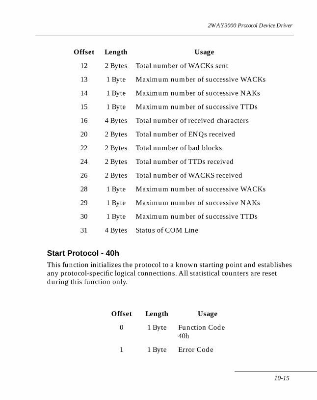
2WAY3000 Protocol Device Driver
Start Protocol - 40hThis function initializes the protocol to a known starting point and establishes any protocol-specific logical connections. All statistical counters are reset during this function only.
12 2 Bytes Total number of WACKs sent
13 1 Byte Maximum number of successive WACKs
14 1 Byte Maximum number of successive NAKs
15 1 Byte Maximum number of successive TTDs
16 4 Bytes Total number of received characters
20 2 Bytes Total number of ENQs received
22 2 Bytes Total number of bad blocks
24 2 Bytes Total number of TTDs received
26 2 Bytes Total number of WACKS received
28 1 Byte Maximum number of successive WACKs
29 1 Byte Maximum number of successive NAKs
30 1 Byte Maximum number of successive TTDs
31 4 Bytes Status of COM Line
Offset Length Usage
0 1 Byte Function Code 40h
1 1 Byte Error Code
Offset Length Usage
10-15
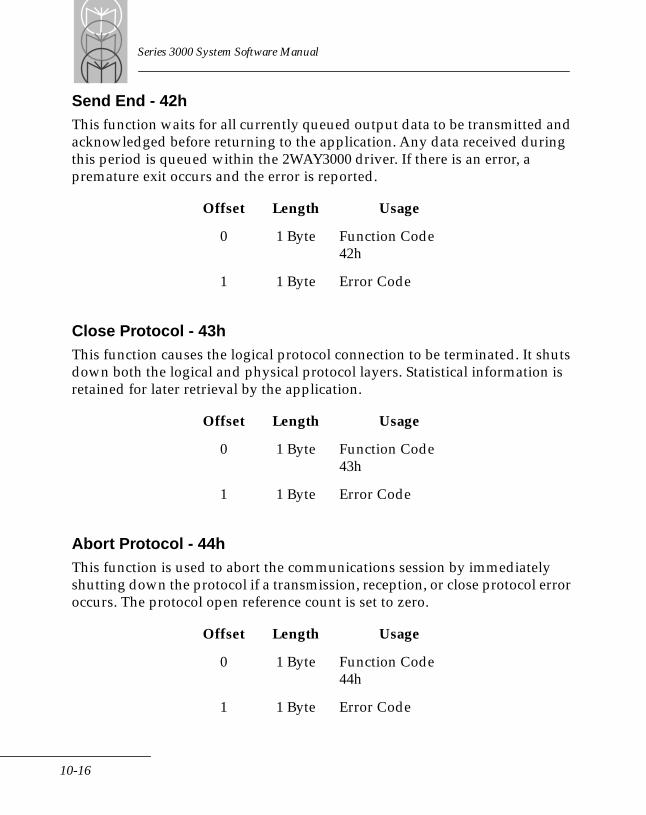
Series 3000 System Software Manual
Send End - 42hThis function waits for all currently queued output data to be transmitted and acknowledged before returning to the application. Any data received during this period is queued within the 2WAY3000 driver. If there is an error, a premature exit occurs and the error is reported.
Close Protocol - 43hThis function causes the logical protocol connection to be terminated. It shuts down both the logical and physical protocol layers. Statistical information is retained for later retrieval by the application.
Abort Protocol - 44hThis function is used to abort the communications session by immediately shutting down the protocol if a transmission, reception, or close protocol error occurs. The protocol open reference count is set to zero.
Offset Length Usage
0 1 Byte Function Code 42h
1 1 Byte Error Code
Offset Length Usage
0 1 Byte Function Code 43h
1 1 Byte Error Code
Offset Length Usage
0 1 Byte Function Code 44h
1 1 Byte Error Code
10-16
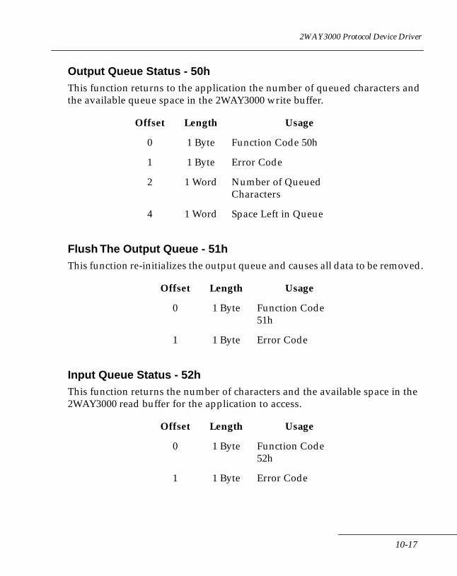
2WAY3000 Protocol Device Driver
Output Queue Status - 50hThis function returns to the application the number of queued characters and the available queue space in the 2WAY3000 write buffer.
Flush The Output Queue - 51hThis function re-initializes the output queue and causes all data to be removed.
Input Queue Status - 52hThis function returns the number of characters and the available space in the 2WAY3000 read buffer for the application to access.
Offset Length Usage
0 1 Byte Function Code 50h
1 1 Byte Error Code
2 1 Word Number of Queued Characters
4 1 Word Space Left in Queue
Offset Length Usage
0 1 Byte Function Code 51h
1 1 Byte Error Code
Offset Length Usage
0 1 Byte Function Code 52h
1 1 Byte Error Code
10-17

Series 3000 System Software Manual
Flush the Input Queue - 53hThis function re-initializes the input queue and causes all data to be removed.
Loading the 2WAY3000 Device DriverThe Symbol Technologies 2WAY3000 device driver is loaded by including the following command in the CONFIG.SYS file:
DEVICE=2WAY3000.SYS switch
The switch enables you to modify the size of the COM1 and COM2 internal buffers as follows:
where nnn = hex value.
Offset Length Usage
0 1 Byte Function Code 53h
1 1 Byte Error Code
No Switch (default) 256 bytes for both COM1 and COM2 buffer
/b = nnn nnn bytes for both COM1 and COM2 buffer
/b1 = nnn nnn bytes for COM1 buffer, default for COM2
/b2 = nnn nnn bytes for COM2 buffer, default for COM1
10-18
Chapter 11 Acoustic Coupler Device Driver
Chapter ContentsIntroduction . . . . . . . . . . . . . . . . . . . . . . . . . . . . . . . . . . . . . . . . . . . . . . . . . . . . . . . . . . . . . . . . . . . . 11-3
Attaching the Acoustic Coupler Device Driver. . . . . . . . . . . . . . . . . . . . . . . . . . . . . . . . . . . 11-3Acoustic Coupler User Interface . . . . . . . . . . . . . . . . . . . . . . . . . . . . . . . . . . . . . . . . . . . . . . . 11-5Embedded Commands . . . . . . . . . . . . . . . . . . . . . . . . . . . . . . . . . . . . . . . . . . . . . . . . . . . . . . . 11-61350 Baud 5-Bit Transmissions . . . . . . . . . . . . . . . . . . . . . . . . . . . . . . . . . . . . . . . . . . . . . . . . 11-6
IOCTL Commands. . . . . . . . . . . . . . . . . . . . . . . . . . . . . . . . . . . . . . . . . . . . . . . . . . . . . . . . . . . . . . . 11-7
11-1
Series 3000 System Software Manual
11-2
Acoustic Coupler Device Driver
IntroductionThe Acoustic Coupler device driver is a DOS compatible driver that allows one way transmit operation through an acoustic coupler. Baud rates of 300, 600, 1200, and 1350 are supported. If the baud rate of 1350 is used, then the data word size will ignore the preset data size and instead will automatically set up a 4 bit data word with either odd or even parity. The number of stop bits are programmable to be either 1 or 2. The other supported baud rates will allow normal communication settings as defined by the Series 3000 BIOS. This driver is a generic protocol driver that will attach itself to the internal DOS COMM driver. This driver is assigned the protocol ID code 3FH. Commands may be passed within the data stream, which the driver will intercept and process, e.g., pause for an inter-block gap.
Attaching the Acoustic Coupler Device DriverTo install the device driver, modify the CONFIG.SYS file to include the command:
DEVICE=X:ACC.SYS options
where: X=Drive Letter
options = /SY (smart modem) or /SN (dumb modem)
This initializes the device driver and adds the protocol to the attached protocol list of the internal communications driver. If the driver cannot detect the acoustic modem installed in the terminal, it will abort the driver load with an error. Certain parameters for this protocol will be set up using the DOS IOCTL write commands and read using the DOS IOCTL read commands. These parameters include, but are not restricted to:
• Smart versus Dumb Modem Flag
• Modem Type
• Mark/Space Boost Flag
• Flat Signal Flag
• Gain
• Amplitude modulation mode
11-3
Series 3000 System Software Manual
• Embedded Commands Enable Flag
• Interblock Gap Time
• RTS/CTS Delay Time
To initiate communications, an open line must be called which will power up the acoustic hardware and perform any programmed pre-space and pre-mark functions. A close line command is performed to send a post-mark signal and to power down the acoustic hardware.
Depending upon the Smart versus Dumb modem flag, the application may parameterize the driver via either DOS IOCTL calls or a limited set of ’AT’ commands. Note, however, that modification of certain parameters will only be available through DOS IOCTL calls.
The baud rate, data size, parity, stop bits, pre-space time, and pre (post)-mark time will be extracted from the Serial Port parameters. Thus, the application must use the extended serial port initialization prior to performing an Open line function. Prior to opening the line, the application may use either the Set Serial Port Parameters DOS ICOTL through the COMM driver or the Extended Serial Port Initialization (int 14h, function 80h) of the BIOS. Once the driver is in the Open Line mode, the application must use the DOS IOCTL call to change any Serial Port Parameters.
To transmit a character or block of characters, a DOS write is called. The characters will be either ’AT’ commands, data to be transmitted, or a special ’Embedded command’ to inform the protocol driver that some action is required.
The driver may need a delay (wait time), selectable by the application, on when the CTS signal will be valid after the RTS signal is raised during the open. The current time delay is fixed at 100 milliseconds. This appears to be too short a delay time for some hosts. This time may need to be set to a value of up to one second in duration. The following method has been implemented by the driver: Use a separate parameter in the Protocol Parameter block and allow register S26 in the Smart Modem Mode.
11-4
Acoustic Coupler Device Driver
Since the BIOS parameters only have a single Mark time, the current method used by applications to generate a Post Mark is to modify the Mark time just before closing the line. This is accomplished via the DOS IOCTL Set Serial Parameter Block function.
Acoustic Coupler User InterfaceThe only direct user interface is through the DOS IOCTL read and write commands. These commands are used to set the various parameters required for the acoustic driver to operate. The other commands built into the driver are used directly by DOS when read and write commands are issued to DOS. Indirect commands will be available as standard ’AT’ modem commands when the ’Smart Modem’ option is selected and when the Embedded Commands Flag is not zero (currently, only the Insert Interblock Gap is defined).
Smart Versus Dumb ModemThe acoustic driver will allow two modes of operation: either the emulation of a Symbol smart modem, or that of a dumb modem. This is accomplished through a parameter passed using the DOS IOCTL function or the /SY (Smart) or /SN (Dumb) switch option during the loading of the acoustic driver.
Smart Modem InterfaceA limited set of ’AT’ style commands will be recognized and acted upon by the acoustic driver. This limited set will be those commands issued by URM. Refer to Chapter 7 of the Series 3000 Application Programmer’s Reference Manual. The applicable commands are described in the section on the ’IM7 Commands.’
Dumb Modem Interface This method will not go into and out of an On-line mode as defined for the Smart modem. It is the responsibility of the application to communicate the actual modem setup to the driver with the DOS IOCTL commands. The format of the IOCTL buffers and commands is defined in the IOCTL commands section.
11-5
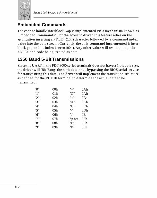
Series 3000 System Software Manual
Embedded CommandsThe code to handle Interblock Gap is implemented via a mechanism known as ’Embedded Commands’. For the acoustic driver, this feature relies on the application inserting a <DLE> (10h) character followed by a command index value into the data stream. Currently, the only command implemented is inter-block gap and its index is zero (00h). Any other value will result in both the <DLE> and code being treated as data.
1350 Baud 5-Bit TransmissionsSince the UART in the PDT 3000 series terminals does not have a 5-bit data size, the driver will ’Bit-Bang’ the 4-bit data, thus bypassing the BIOS serial service for transmitting this data. The driver will implement the translation structure as defined for the PDT III terminal to determine the actual data to be transmitted:
"0" 00h "=" 0Ah"1" 01h "C" 0Ah"2" 02h "+" 0Bh"3" 03h "A" 0Ch"4" 04h "H" 0Ch"5" 05h "-" 0Dh"6" 06h "." 0Eh"7" 07h Space 0Fh"8" 08h "E" 0Fh"9" 09h "F" 0Fh
11-6
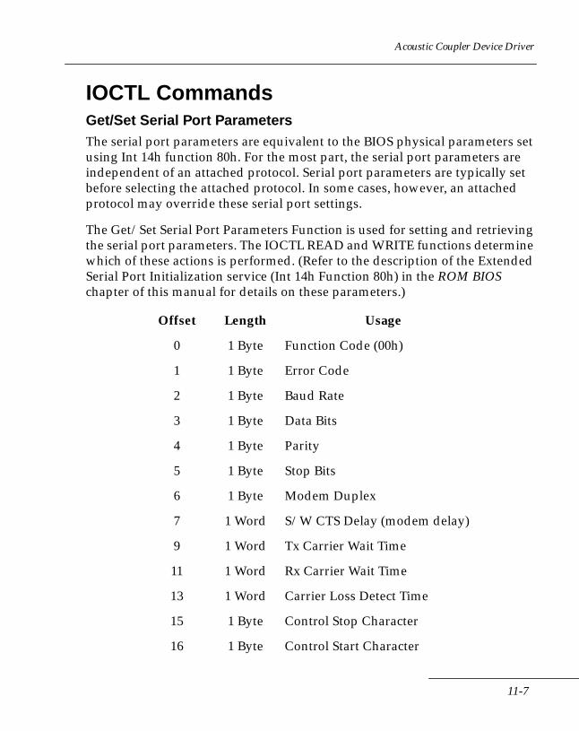
Acoustic Coupler Device Driver
IOCTL CommandsGet/Set Serial Port ParametersThe serial port parameters are equivalent to the BIOS physical parameters set using Int 14h function 80h. For the most part, the serial port parameters are independent of an attached protocol. Serial port parameters are typically set before selecting the attached protocol. In some cases, however, an attached protocol may override these serial port settings.
The Get/Set Serial Port Parameters Function is used for setting and retrieving the serial port parameters. The IOCTL READ and WRITE functions determine which of these actions is performed. (Refer to the description of the Extended Serial Port Initialization service (Int 14h Function 80h) in the ROM BIOS chapter of this manual for details on these parameters.)
Offset Length Usage
0 1 Byte Function Code (00h)
1 1 Byte Error Code
2 1 Byte Baud Rate
3 1 Byte Data Bits
4 1 Byte Parity
5 1 Byte Stop Bits
6 1 Byte Modem Duplex
7 1 Word S/W CTS Delay (modem delay)
9 1 Word Tx Carrier Wait Time
11 1 Word Rx Carrier Wait Time
13 1 Word Carrier Loss Detect Time
15 1 Byte Control Stop Character
16 1 Byte Control Start Character
11-7

Series 3000 System Software Manual
17 1 Byte Control Start Wait Time
18 1 Byte CTS Loss Detection Time
19 1 Byte Rx Character Wait Time
20 1 Byte DSR Wait Time
21 1 Byte CD Wait Time
22 1 Byte Space Time
23 1 Byte Mark Time
24 1 Byte Line Conditioning Flags
25 1 Byte Operation Mode
26 1 Byte Line Status Error Mask
27 1 Byte Error Insertion Character
28 1 Word DTR Settling Time
30 1 Byte Connect Time
Offset Length Usage
11-8
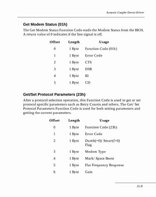
Acoustic Coupler Device Driver
Get Modem Status (01h)The Get Modem Status Function Code reads the Modem Status from the BIOS. A return value of 0 indicates if the line signal is off.
Get/Set Protocol Parameters (23h)After a protocol selection operation, this Function Code is used to get or set protocol specific parameters such as Retry Counts and others. The Get/Set Protocol Parameters Function Code is used for both setting parameters and getting the current parameters.
Offset Length Usage
0 1 Byte Function Code (01h)
1 1 Byte Error Code
2 1 Byte CTS
3 1 Byte DSR
4 1 Byte RI
5 1 Byte CD
Offset Length Usage
0 1 Byte Function Code (23h)
1 1 Byte Error Code
2 1 Byte Dumb(=0)/Smart(!=0) Flag
3 1 Byte Modem Type
4 1 Byte Mark/Space Boost
5 1 Byte Flat Frequency Response
6 1 Byte Gain
11-9
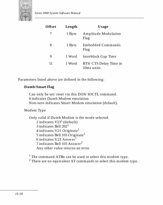
Series 3000 System Software Manual
Parameters listed above are defined in the following:
Dumb/Smart Flag
Can only be set/reset via this DOS/IOCTL command.0 indicates Dumb Modem emulationNon-zero indicates Smart Modem emulation (default).
Modem Type
Only valid if Dumb Modem is the mode selected. 2 indicates V231 (default)3 indicates Bell 2021.
4 indicates V.21 Originate1
5 indicates Bell 103 Originate1
6 indicates V.21 Answer1
7 indicates Bell 103 Answer2
Any other value returns an error
1 The command ATBn can be used to select this modem type.2 There are no equivalent AT commands to select this modem type.
7 1 Byte Amplitude Modulation Flag
8 1 Byte Embedded Commands Flag
9 1 Word Interblock Gap Time
11 1 Word RTS/CTS Delay Time in 10ms units
Offset Length Usage
11-10
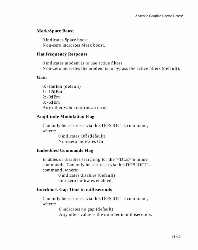
Acoustic Coupler Device Driver
Mark/Space Boost
0 indicates Space boostNon-zero indicates Mark boost.
Flat Frequency Response
0 indicates modem is to use active filtersNon-zero indicates the modem is to bypass the active filters (default).
Gain
0: -15dBm (default)1: -12dBm2: -9dBm3: -6dBmAny other value returns an error.
Amplitude Modulation Flag
Can only be set/reset via this DOS IOCTL command,where:
0 indicates Off (default)Non-zero indicates On
Embedded Commands Flag
Enables or disables searching for the ’<DLE>’n inlinecommands. Can only be set/reset via this DOS IOCTLcommand, where:
0 indicates disables (default)non-zero indicates enabled.
Interblock Gap Time in milliseconds
Can only be set/reset via this DOS IOCTL command,where:
0 indicates no gap (default)Any other value is the number in milliseconds.
11-11
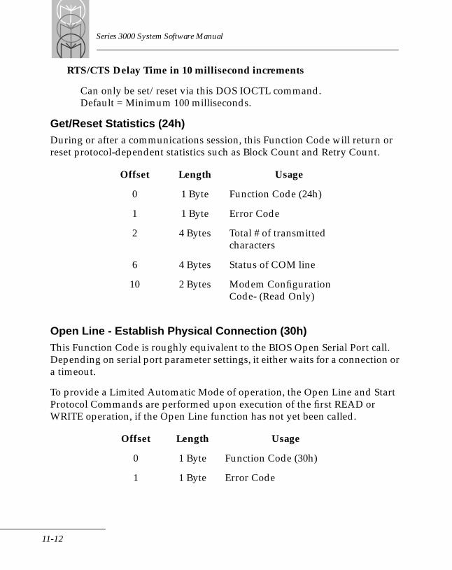
Series 3000 System Software Manual
RTS/CTS Delay Time in 10 millisecond increments
Can only be set/reset via this DOS IOCTL command.Default = Minimum 100 milliseconds.
Get/Reset Statistics (24h)During or after a communications session, this Function Code will return or reset protocol-dependent statistics such as Block Count and Retry Count.
Open Line - Establish Physical Connection (30h)This Function Code is roughly equivalent to the BIOS Open Serial Port call. Depending on serial port parameter settings, it either waits for a connection or a timeout.
To provide a Limited Automatic Mode of operation, the Open Line and Start Protocol Commands are performed upon execution of the first READ or WRITE operation, if the Open Line function has not yet been called.
Offset Length Usage
0 1 Byte Function Code (24h)
1 1 Byte Error Code
2 4 Bytes Total # of transmitted characters
6 4 Bytes Status of COM line
10 2 Bytes Modem Configuration Code- (Read Only)
Offset Length Usage
0 1 Byte Function Code (30h)
1 1 Byte Error Code
11-12
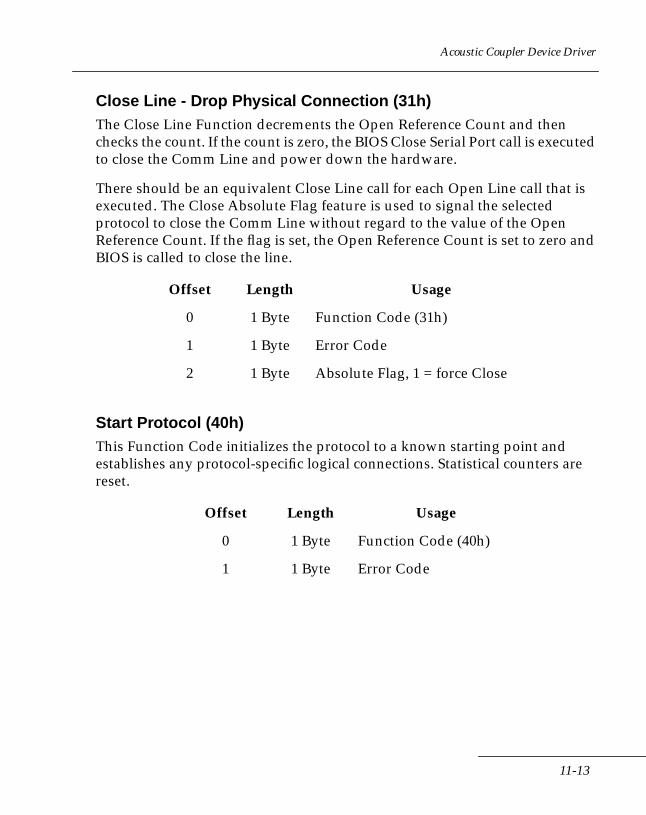
Acoustic Coupler Device Driver
Close Line - Drop Physical Connection (31h)The Close Line Function decrements the Open Reference Count and then checks the count. If the count is zero, the BIOS Close Serial Port call is executed to close the Comm Line and power down the hardware.
There should be an equivalent Close Line call for each Open Line call that is executed. The Close Absolute Flag feature is used to signal the selected protocol to close the Comm Line without regard to the value of the Open Reference Count. If the flag is set, the Open Reference Count is set to zero and BIOS is called to close the line.
Start Protocol (40h)This Function Code initializes the protocol to a known starting point and establishes any protocol-specific logical connections. Statistical counters are reset.
Offset Length Usage
0 1 Byte Function Code (31h)
1 1 Byte Error Code
2 1 Byte Absolute Flag, 1 = force Close
Offset Length Usage
0 1 Byte Function Code (40h)
1 1 Byte Error Code
11-13
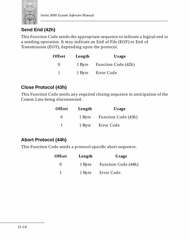
Series 3000 System Software Manual
Send End (42h)This Function Code sends the appropriate sequence to indicate a logical end to a sending operation. It may indicate an End of File (EOF) or End of Transmission (EOT), depending upon the protocol.
Close Protocol (43h)This Function Code sends any required closing sequence in anticipation of the Comm Line being disconnected.
Abort Protocol (44h)This Function Code sends a protocol-specific abort sequence.
Offset Length Usage
0 1 Byte Function Code (42h)
1 1 Byte Error Code
Offset Length Usage
0 1 Byte Function Code (43h)
1 1 Byte Error Code
Offset Length Usage
0 1 Byte Function Code (44h)
1 1 Byte Error Code
11-14

Acoustic Coupler Device Driver
Output Queue Status (50h)This Function Code returns the number of queued characters and the available queue space in the Output Queue.
Flush Output Queue (51h)This Function Code re-initializes and removes all data from the Output Queue.
Input Queue Status (52h)The Input Queue Status Function Code returns the number of queued characters and the available queue space in the Input Queue.
Offset Length Usage
0 1 Byte Function Code (50h)
1 1 Byte Error Code
2 1 Word Number of Queued Characters
4 1 Word Space Left in Queue
Offset Length Usage
0 1 Byte Function Code (51h)
1 1 Byte Error Code
Offset Length Usage
0 1 Byte Function Code (52h)
1 1 Byte Error Code
2 1 Word Number of Queued Characters
4 1 Word Space Left in Queue
11-15
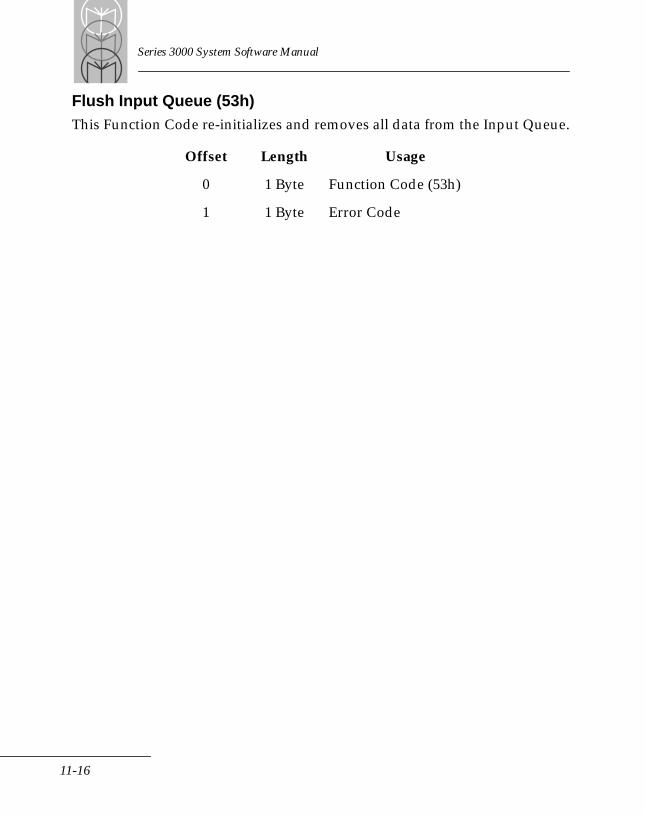
Series 3000 System Software Manual
Flush Input Queue (53h)This Function Code re-initializes and removes all data from the Input Queue.
Offset Length Usage
0 1 Byte Function Code (53h)
1 1 Byte Error Code
11-16
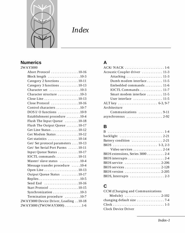
Index
merics A
Nu2WAY3000Abort Protocol . . . . . . . . . . . . . . . . 10-16Block length . . . . . . . . . . . . . . . . . . . 10-3Category 2 functions . . . . . . . . . . . 10-11Category 3 functions . . . . . . . . . . . 10-13Character set . . . . . . . . . . . . . . . . . . 10-3Character structure . . . . . . . . . . . . . 10-3Close Line . . . . . . . . . . . . . . . . . . . . 10-13Close Protocol . . . . . . . . . . . . . . . . 10-16Control characters . . . . . . . . . . . . . . 10-7DOS I/O functions . . . . . . . . . . . . . 10-9Establishment procedure . . . . . . . . 10-4Flush The Input Queue . . . . . . . . 10-18Flush The Output Queue . . . . . . . 10-17Get Line Status . . . . . . . . . . . . . . . . 10-12Get Modem Status . . . . . . . . . . . . . 10-12Get statistics . . . . . . . . . . . . . . . . . . 10-14Get/Set protocol parameters . . . . 10-13Get/Set Serial Port Parms . . . . . . 10-11Input Queue Status . . . . . . . . . . . . 10-17IOCTL commands . . . . . . . . . . . . . 10-11Master/slave status . . . . . . . . . . . . 10-4Message transfer procedure . . . . . 10-4Open Line . . . . . . . . . . . . . . . . . . . . 10-13Output Queue Status . . . . . . . . . . 10-17Replies . . . . . . . . . . . . . . . . . . . . . . . . 10-5Send End . . . . . . . . . . . . . . . . . . . . 10-16Start Protocol . . . . . . . . . . . . . . . . . 10-15Synchronization . . . . . . . . . . . . . . . . 10-3Termination procedure . . . . . . . . . 10-7
2WAY3000 Device Driver, Loading . . 10-182WAY3000 (TWOWAY3000) . . . . . . . . . . 1-6
ACK/NACK . . . . . . . . . . . . . . . . . . . . . . . 1-6Acoustic Coupler driver . . . . . . . . . . . . 11-3
Attaching . . . . . . . . . . . . . . . . . . . . . 11-3Dumb modem interface . . . . . . . . . 11-5Embedded commands . . . . . . . . . . 11-6IOCTL Commands . . . . . . . . . . . . . 11-7Smart modem interface . . . . . . . . . 11-5User interface . . . . . . . . . . . . . . . . . 11-5
ALT key . . . . . . . . . . . . . . . . . . . . . . . 6-3, 9-7Architecture
Communications . . . . . . . . . . . . . . 9-11asynchronous . . . . . . . . . . . . . . . . . . . . . 2-92
BB . . . . . . . . . . . . . . . . . . . . . . . . . . . . . . . . . 1-4backlight . . . . . . . . . . . . . . . . . . . . . . . . . 2-21Battery condition . . . . . . . . . . . . . . . . . . 2-21BIOS . . . . . . . . . . . . . . . . . . . . . . . . . . 1-3, 2-3
Video services . . . . . . . . . . . . . . . . . 2-14BIOS extensions, Series 3000 . . . . . . . . . . 2-4BIOS interrupts . . . . . . . . . . . . . . . . . . . . . 2-4BIOS service . . . . . . . . . . . . . . . . . . . . . 2-206BIOS services . . . . . . . . . . . . . . . . . . . . . 2-128BIOS version . . . . . . . . . . . . . . . . . . . . . 2-205BIOS, Interrupts . . . . . . . . . . . . . . . . . . . . 2-3
CCCM (Charging and Communications Module) . . . . . . . . . . . . . . . . . . . . . 2-102changing default size . . . . . . . . . . . . . . . . 7-4Clock . . . . . . . . . . . . . . . . . . . . . . . . . . . . . . 1-3Clock Device Driver
Index-1

Series 3000 System Software Manual
Data formats . . . . . . . . . . . . . . . . . . . 4-5Clock device driver
Functions . . . . . . . . . . . . . . . . . . . . . . 4-3Clock Driver . . . . . . . . . . . . . . . . . . . . . . . . 1-3Clock driver . . . . . . . . . . . . . . . . . . . . . . . . 1-7CLOCK$ . . . . . . . . . . . . . . . . . . . . . . . . . . . 4-3Code sample
Communications session . . . . . . . . . 9-4COM1 . . . . . . . . . . . . . . . . . . . . . . . . 2-92, 9-3COM2 . . . . . . . . . . . . . . . . . . . . . . . . . . . . . 9-3Command shell . . . . . . . . . . . . . . . . . . . . . 1-4COMMAND.COM . . . . . . . . . . . . . . . . . . 1-4Communications . . . . . . . . . . . . . . . . . . . 2-92communications . . . . . . . . . . . . . . . . . . . 2-92Communications driver . . . 1-4, 1-7, 9-5, 9-9
Application interface . . . . . . . . . . . 9-15Application interface parameters .9-15Application layer . . . . . . . . . . . . . . . 9-11Attachable protocols . . . . . . . . . . . . . 9-3Attaching protocols . . . . . . . . . . . . 9-12Binary vs ASCII modes . . . . . . . . . . 9-7Communication architecture . . . . . 9-11Device Control Block . . . . . . . . . . . 9-15Device control information . . . . . . . 9-6DOS I/O status . . . . . . . . . . . . . . . . . 9-6DOS services . . . . . . . . . . . . . . . . . . . 9-3Error status . . . . . . . . . . . . . . . . . . . . . 9-7IOCTL Subfunctions . . . . . . . . . . . . . 9-5Line Control Block . . . . . . . . . . . . . 9-16Link layer . . . . . . . . . . . . . . . . . . . . . 9-11Load Status . . . . . . . . . . . . . . . . . . . . . 9-7Passing control and status . . . . . . . . 9-5Physical layer . . . . . . . . . . . . . . . . . . 9-11Protocol driver interface . . . . . . . . 9-11Protocol selection . . . . . . . . . . . . . . . 9-8Protocol support . . . . . . . . . . . . . . . . 9-3Sample driver . . . . . . . . . . . . . . . . . . 9-4Session layer . . . . . . . . . . . . . . . . . . . 9-11
communications driver interface . . . . . 9-11Communications services . . . . . . . . . . . 2-92Compatibility . . . . . . . . . . . . . . . . . . . 2-3, 3-3
Compatibility, PC BIOS . . . . . . . . . . . . . . 2-4Configuration
Terminal . . . . . . . . . . . . . . . . . . . . . . 2-55CONFIG.SYS . . . . . . . . . . . . . . . . . . 1-4, 2-85Console Driver . . . . . . . . . . . . . . 1-4, 6-3, 6-4
Error numbers . . . . . . . . . . . . . . . . . . 6-3Estimating input buffer size . . . . . . 6-4Setting up . . . . . . . . . . . . . . . . . . . . . . 6-3
Console driver . . . . . . . . . . . . . . . . . 1-7, 6-3Console Driver error codes . . . . . . . . . . 6-22contrast . . . . . . . . . . . . . . . . . . . . . . . . . . . 2-21Contrast level . . . . . . . . . . . . . . . . . . . . . 2-37Cradle control services . . . . . . . . . . . . 2-193
Get cradle type . . . . . . . . . . . . . . . 2-194Request/Release modem - modem status . . . . . . . . . . . . . 2-197Set/Get charging rate . . . . . . . . . 2-195Set/Get Stop-Red LED . . . . . . . . 2-196Test for Optical Interface . . . . . . . 2-198
CRC servicesCheck disk image(s) in NVM . . . 2-202CRC BIOS ROM . . . . . . . . . . . . . . 2-203CRC buffer . . . . . . . . . . . . . . . . . . . 2-201CRC byte . . . . . . . . . . . . . . . . . . . . 2-200CRC Check User Image . . . . . . . . 2-202CRC System EPROM . . . . . . . . . . 2-203
Cursor . . . . . . . . . . . . . . . . . . . . . . . . . . . 2-21Cursor control . . . . . . . . . . . . . . . . . . . . . 2-21Cursor control and formats . . . . . . . . . 2-21Cursor formats . . . . . . . . . . . . . . . . . . . . 2-22Cursor translation . . . . . . . . . . . . . . . . . 2-46Cursor, Low battery condition . . . . . . . 2-21
DD . . . . . . . . . . . . . . . . . . . . . . . . . . . . . . . . . 1-4Debugger . . . . . . . . . . . . . . . . . . . . . . . . . . 1-4Decoder names . . . . . . . . . . . . . . . . . . . . 6-20Demonstration programs. See Sample programs.Device Control Block (DCB) . . . . . . . . . 9-15Device Drivers . . . . . . . . . . . . . . 1-3, 1-4, 1-7
Index-2

Index
Device drivers . . . . . . . . . . . . . . . . . . 1-7, 6-3Clock . . . . . . . . . . . . . . . . . . . . . . . . . . 1-7Communications . . . . . . . . . . . . 1-4, 1-7Console . . . . . . . . . . . . . . . . 1-4, 1-7, 6-3EMM . . . . . . . . . . . . . . . . . . . . . . . . . 2-70EMM3000.SYS . . . . . . . . . . . . . . . . . . 8-7Line Printer . . . . . . . . . . . . . . . . 1-3, 1-7RAM Disk . . . . . . . . . . . . . . . . . . 1-4, 1-7Scanner . . . . . . . . . . . . . . . . . . . . 1-4, 1-7
Disk drives . . . . . . . . . . . . . . . . . . . . . . . . . 1-4B . . . . . . . . . . . . . . . . . . . . . . . . . . . . . . 1-4D . . . . . . . . . . . . . . . . . . . . . . . . . . . . . 1-4
Diskette services . . . . . . . . . . . . . . . . . . . 2-85Disk emulation . . . . . . . . . . . . . . . . 2-85Format sectors . . . . . . . . . . . . . . . . . 2-91Get diskette status . . . . . . . . . . . . . . 2-87Read diskette sectors . . . . . . . . . . . 2-88Reset disk drive . . . . . . . . . . . . . . . . 2-86Verify diskette sectors . . . . . . . . . . 2-90Write diskette sectors . . . . . . . . . . . 2-89
Display . . . . . . . 2-14, 2-15, 2-17, 2-21, 2-207Multiple pages . . . . . . . . . . . . . . . . . 2-21Scrolling . . . . . . . . . . . . . . . . . 2-17, 2-20Video services . . . . . . . . . . . . . . . . . 2-23View angle . . . . . . . . . . . . . . . . . . . . 2-21
Display driver . . . . . . . . . . . . . . . . . . . . . 2-14Display fonts . . . . . . . . . . . . . . . . . . . . . . 2-14display segments . . . . . . . . . . . . . . . . . . . 2-16DISSTD . . . . . . . . . . . . . . . . . . . . . . . . . . . . 9-5DOS . . . . . . . . . . . . . . . . . . . . . . . . . . . . . . . 1-6DOS communications driver . . . . . . . . . . 9-3DOS functions
Int 3Dh . . . . . . . . . . . . . . . . . . . . . . . . 1-6Int 3Fh . . . . . . . . . . . . . . . . . . . . . . . . . 1-6Int 40h . . . . . . . . . . . . . . . . . . . . . . . . . 1-6IOCTL (Int 21h Function 44h) . . . . . 1-6
DOSSTD . . . . . . . . . . . . . . . . . . . . . . . . . . . 9-5DR DOS . . . . . . . . . . . . . . . . 1-3, 1-6, 3-3, 7-3Drives . . . . . . . . . . . . . . . . . . . . . . . . . . . . . 1-4dual trigger . . . . . . . . . . . . . . . . . . . . . . 2-191
EEEPROM . . . . . . . . . . . . . . . . . . . . . . . . . . 1-4EMM. See Expanded Memory Manager.EMS . . . . . . . . . . . . . . . . . . . . . . . . 2-63, 2-70
Bank of expanded memory . . . . . . 2-70EMM driver . . . . . . . . . . . . . . . . . . . 2-70Logical pages . . . . . . . . . . . . . . . . . . 2-70Support services . . . . . . . . . . . . . . . 2-70
EMS programmingAdvanced functions . . . . . . . . . . . . 8-12Basic functions . . . . . . . . . . . . . . . . . 8-8EMS functions . . . . . . . . . . . . . . . . . 8-22Get mappable memory . . . . . . . . . 8-11Guidelines . . . . . . . . . . . . . . . . . . . . 8-14Handle attributes . . . . . . . . . . . . . . 8-10Map registers . . . . . . . . . . . . . . . . . 8-14Mapping pages . . . . . . . . . . . . . . . . . 8-9Moving memory regions . . . . . . . . 8-11Operating system functions . . . . . 8-12Page maps and jumping . . . . . . . . 8-10Reallocating pages . . . . . . . . . . . . . . 8-9Retrieving handle . . . . . . . . . . . . . . . 8-9Sample program 8-15, 8-19, 8-154, 8-157Save mapping . . . . . . . . . . . . . . . . . . 8-9Using handle names . . . . . . . . . . . . 8-10
EMS support servicesGet current EMS context . . . . . . . . 2-76Get EMS page frame configuration 2-73Get mapped logical pages . . . . . . . 2-79Get total logical page count . . . . . 2-72Map logical pages . . . . . . . . . . . . . . 2-75Set EMS context . . . . . . . . . . . . . . . 2-77Set EMS page frame configuration 2-74Swap EMS context . . . . . . . . . . . . . 2-78
Emulation, disk . . . . . . . . . . . . . . . . . . . . 2-85Enable auto key repeat . . . . . . . . . . . . 2-134Environment, system software . . . . . . . . 1-4EPROM, system . . . . . . . . . . . . . . . . . . . . 1-3Equipment list . . . . . . . . . . . . . . . . . . . . . 2-55Equipment list services
Get Installed Option Card ID . . . . 2-57
Index-3
Series 3000 System Software Manual
Get standard equipment list . . . . . 2-56Error codes
Communications driver . . . . . . . . . . 9-7Console device driver . . . . . . . . . . . . 6-3Console Driver . . . . . . . . . . . . . . . . . 6-22Expanded Memory . . . . . . . . . . . . . . 8-7Line Printer Driver . . . . . . . . 5-14, 5-16Line printer driver . . . . . . . . . . . . . 5-15
error codes . . . . . . . . . . . . . . . . . . . . . . . . . 8-7Error trapping . . . . . . . . . . . . . . . . . . . . . 5-16ETA3000.SYS . . . . . . . . . . . . . . . . . . . . . . . 1-4Expanded memory . . . . . . . . . . . . . . . . . . 8-5Expanded memory functions
Allocate Alternate Map Register Set (AX = 5B03h) . . . . . . . . . . . . . . 8-128Allocate DMA Register Set (AX = 5B05h) . . . . . . . . . . . . . . 8-131Allocate pages (AH = 43h) . . . . . . . 8-29Allocate raw pages (AX =5A01h) 8-117Allocate standard pages (AX = 5A00h) . . . . . . . . . . . . . 8-115Alter page map & call (AH = 56h) 8-88Alter page map & jump (AH = 55h) 8-84Alternate map register set . . . . . . 8-119Deallocate Alternate Map Register Set (AX = 5B04h) . . . . . . . . . . . 8-129Deallocate DMA register set (AX = 5B08h) . . . . . . . . . . . . . . 8-136Deallocate pages (AH = 45h) . . . . . 8-33Disable DMA ON Alternate Map Register Set (AX = 5B07h) . . . 8-134Disable OS/E Function Set (AX = 5D01h) . . . . . . . . . . . . . 8-143Enable DMA ON Alternate Map Register Set (AX = 5B06h) . . . 8-132Enable OS/E function set (AX =5D00h) . . . . . . . . . . . . . . 8-139Exchange memory region (AX = 5701h) . . . . . . . . . . . . . . 8-101Get all handle pages (AH = 4Dh) . 8-44Get Alternate Map Register Set
(AX = 5B00h) . . . . . . . . . . . . . 8-120Get Alternate Map Save Array Size (AX = 5B02h) . . . . . . . . . . . . . 8-126Get expanded hardware configuration
array (AX = 5900h) . . . . 8-111Get handle attribute capability (AX = 5202h) . . . . . . . . . . . . . . . 8-74Get handle count (AH = 4Bh) . . . . 8-41Get handle directory (AX = 5400h) 8-79Get handle name (AX = 5300) . . . . 8-75Get handle pages (AH = 4Ch) . . . 8-42Get mappable physical address array entries (AX = 5801h) . . . . . . . 8-109Get mappable physical address array (AX = 5800h) . . . . . . . . 8-107Get page frame address (AH = 41h) 8-26Get Page Map Stack Space Size (AX = 5602h) . . . . . . . . . . . . . . . 8-93Get page map (AX = 4E00h) . . . . . 8-47Get Partial Page Map (AX = 4F00h) 8-56Get Size of Page Map Save Array (AX = 4E03h) . . . . . . . . . . . . . . 8-54Get Size of Partial Page Map Save Array (AX = 4F02h) . . . . . . . . . 8-61Get status (AH = 40h) . . . . . . . . . . 8-25Get total handles (AX = 5402h) . . 8-83Get unallocated page count (AH = 42) . . . . . . . . . . . . . . . . . 8-28Get unallocated raw page count (AX = 5901h) . . . . . . . . . . . . . . 8-114Get version (AH = 46h) . . . . . . . . . 8-35Get & Set Page Map (AH = 4E02h) 8-51Get/Set handle attribute . . . . . . . . 8-73Map/Unmap handle pages (AH = 44h)
8-31Map/Unmap multiple handle pages
(AX = 5000h) . . . . . . . . . . 8-63Map/Unmap multiple handle pages
(AX = 5001h) . . . . . . . . . . 8-67Move memory region (AX = 5700h) 8-95
Index-4
Index
Prepare expanded memory hardware to warmboot (AH = 5Ch) . . . 8-138Reallocate pages (AH = 51h) . . . . . 8-70Restore page map (AH = 48h) . . . . 8-39Return Access Key (AX = 5D02h) 8-146Save page map (AH = 47) . . . . . . . 8-37Search for Named Handle (AX = 5401h) . . . . . . . . . . . . . . . 8-81Set Alternate Map Register (AX = 5B01h) . . . . . . . . . . . . . . 8-122Set handle name (AH = 5301h) . . . 8-77Set Page Map (AX = 4E01h) . . . . . . 8-49Set Partial Page Map (AX = 4F01h) 8-59Status codes . . . . . . . . . . . . . . . . . . 8-148
Expanded Memory Manager . . . . . 8-5, 8-7Advanced functions . . . . . . . . . . . . 8-12EMM3000.SYS . . . . . . . . . . . . . . . . . . 8-7Functions . . . . . . . . . . . . . . . . . . . . . 8-22Loading the driver . . . . . . . . . . . . . . 8-7Logical pages . . . . . . . . . . . . . . . . . . . 8-5Page frame . . . . . . . . . . . . . . . . . . . . . 8-5Physical page . . . . . . . . . . . . . . . . . . . 8-5Programming . . . . . . . . . . . . . . . . . . . 8-7Testing for presence of . . . . . . . . . 8-151
Expanded Memory Manager (EMM) . . . 1-6Expanded memory, Page frame . . . . . . . 8-5Extended . . . . . . . . . . . . . . . 2-36, 2-99, 2-134Extended keyboard services . . . . . . . . 2-134
Get ABORT key status . . . . . . . . . 2-140Get keyboard configuration . . . . 2-135Get keyboard left/right alpha key pressed status . . . . 2-145Get keyboard state . . . . . . . . . . . . 2-138Get left/right alpha shift keyboard state . . . . . . . . . . . . . . . . . . . . . 2-144Program Trigger Key . . . . . . . . . . 2-142Select ABORT key . . . . . . . . . . . . . 2-139Set keyboard no activity timer . . 2-136Set keyboard operation mode . . . 2-141Set keyboard state . . . . . . . . . . . . . 2-137Set left/right alpha shift
keyboard state . . . . . . . . . . . . 2-143Extended serial I/O services . . . . . . . . 2-99
Allocate communications queues 2-120Clear UART control commands . 2-119Close serial port . . . . . . . . . . . . . . 2-109Delete queues . . . . . . . . . . . . . . . . 2-124Duplex control parameters . . . . . 2-101Extended serial port initialization 2-100Flow control parameters . . . . . . . 2-103Full-duplex mode control parameters . . . . . . . . . . . . . . . 2-102Get COMM Type ID number . . . 2-126Get current port configuration . . 2-107Get queue pointer . . . . . . . . . . . . . 2-125Get system status . . . . . . . . . . . . . 2-113Half-duplex line turn around . . . . . . . . . . . . . . . . . . . . 2-115, 2-116Half-duplex mode control parameters . . . . . . . . . . . . . . . 2-101Logical setup parameters . . . . . . 2-104Multi-access mode control parameters . . . . . . . . . . . . . . . 2-102Open serial port . . . . . . . . . . . . . . 2-108Open setup parameters . . . . . . . . 2-104Physical setup parameters . . . . . 2-100Purge communications queue . . 2-121Queue status . . . . . . . . . . . . . . . . . 2-112Receive block . . . . . . . . . . . . . . . . . 2-111Receive enable . . . . . . . . . . . . . . . . 2-116Request/release data bus . . . . . . 2-123Secure optical channel override . 2-127Send block . . . . . . . . . . . . . . . . . . . 2-110Set UART control commands . . . 2-118Transmit done . . . . . . . . . . . . . . . . 2-117Transmit enable . . . . . . . . . . . . . . 2-115Transmit queue empty notification . . . . . . . . . . . . . . 2-122
extended services . . . . . . . . . . . . . . . . . . 2-21Extended video services . . . . . . . 2-36, 2-42
Get cursor mode . . . . . . . . . . . . . . . 2-45Get font mode . . . . . . . . . . . . . . . . . 2-53
Index-5
Series 3000 System Software Manual
Get LCD viewing angle . . . . . . . . . 2-38Restore screen window . . . . . . . . . 2-51Save screen window . . . . . . . . . . . . 2-50Select font . . . . . . . . . . . . . . . . . . . . . 2-52Set cursor character translation table . . . . . . . . . . . . . . . . . . . . . . 2-46Set cursor mode . . . . . . . . . . . . . . . . 2-44Set LCD viewing angle . . . . . . . . . . 2-37Set/get backlight timeout . . . . . . . 2-40Set/get emulated video RAM size 2-41Set/Get LCD update frequency . . 2-54Set/get logical screen size . . . . . . . 2-43Set/Get Physical Screen Position .2-48Turn backlight on/off . . . . . . . . . . . 2-39
Extensions, BIOS . . . . . . . . . . . . . . . . . . . . 2-4
FFeatures . . . . . . . . . . . . . . . . . . . . . . . . . . . 3-3firmware . . . . . . . . . . . . . . . . . . . . . . . . . . . 1-3Firmware, Series 3000 . . . . . . . . . . . . . . . . 1-3Force system warm boot . . . . . . . . . . . 2-206Formats . . . . . . . . . . . . . . . . . . . . . . . . . . . 2-21Frame, page . . . . . . . . . . . . . . . . . . . . . . . 2-63function list . . . . . . . . . . . . . . . . . . . . . . . . 2-6
Ggeneral . . . . . . . . . . . . . . . . . . . . . . . . . . . . 1-7Get display type . . . . . . . . . . . . . . . . . . . 2-42
HHardware version . . . . . . . . . . . . . . . . . 2-205Hardware, Series 3000 . . . . . . . . . . . . . . . 1-3
IINIT.EXE (SystemInitialization program) 1-4input queue . . . . . . . . . . . . . . . . . . . . . . 2-210Int ABh . . . . . . . . . . . . . . . . . . . . . . . . . . . 2-84Int B1h . . . . . . . . . . . . . . . . . . . . . . . . . . . 2-188Int B8h . . . . . . . . . . . . . . . . . . . . . . . . . . . 2-198integrated scanner . . . . . . . . . . . . . . . . . 2-190
Interrupt vectors . . . . . . . . . . . . . . . . . . . . 1-7interrupts . . . . . . . . . . . . . . . . . . . . . . . . . . 3-3Interrupts, BIOS . . . . . . . . . . . . . . . . . . . . 2-3IOCTL . . . . . . . . . . . . . . . . . . . . . . . . . . . . 1-6IOCTL error codes . . . . . . . . . . . . . . . . . . 9-9
KKeyboard . . . . . . . . . . . . . . . . . . . . . . . . 2-128
Auxiliary input . . . . . . . . . . . . . . . 2-210Key processing . . . . . . . . . . . . . . . 2-128Scan codes . . . . . . . . . . . . . . . . . . . 2-128Stop auto-repeat . . . . . . . . . . . . . . 2-211
Keyboard services . . . . . . . . . . 2-128, 2-134Standard . . . . . . . . . . . . . . . . . . . . . 2-130System metacodes . . . . . . . . . . . . 2-128
Keyboard services, extended . . . . . . . 2-134Keyboard services, standard . . . . . . . 2-130Keyboard states . . . . . . . . . . . . . . . . . . . 2-22
LLCD . . . . . . . . . . . . . . . . . . . . . . . . . . . . . 2-21LCD control . . . . . . . . . . . . . . . . . . . . . . . 2-21LCD display . . . . . . . . . . . . . . . . . . . . . . 2-21LED services
Turn LED Off . . . . . . . . . . . . . . . . 2-208Turn LED On . . . . . . . . . . . . . . . . 2-207Turn LED on for a specified time 2-209
LIM EMS . . . . . . . . . . . . . . . . . . . . . . . . . . 8-5Line Control Block (LCB) . . . . . . . . . . . 9-16Line printer device . . . . . . . . . . . . . . . . . . 5-3Line Printer Driver
Error reporting . . . . . . . . . . . . . . . . 5-14Error trapping . . . . . . . . . . . . . . . . . 5-16Functions . . . . . . . . . . . . . . . . . . . . . . 5-4Generic Error Codes . . . . . . . . . . . . 5-16IOCTL Error Codes . . . . . . . . . . . . 5-15IOCTL Read subfunctions . . . . . . . 5-11IOCTL subfunctions . . . . . . . . . . . . 5-16IOCTL Write subfunctions . . . . . . . 5-6
Line Printer driver . . . . . . . . . . . . . . 1-3, 1-7
Index-6
Index
logical . . . . . . . . . . . . . . . . . . . . . . . . . . . . . 1-4logical drives . . . . . . . . . . . . . . . . . . . . . . . 1-4Logical page number . . . . . . . . . . . . . . . 2-70Logical pages . . . . . . . . . . . . . . . . . . . . . . 2-70Logical pages, Expanded memory . . . . . 8-5Logical screen . . . . . . . . . . . . . . . . 2-17, 2-43
Mmaximum virtual screen size . . . . . . . . 2-15Memory . . . . . . . . . . . . . . . . . . . . . . 2-15, 8-7memory . . . . . . . . . . . . . . . . . . . . . . . . . . . 2-15Memory allocation . . . . . . . . . . . . . . . . . 2-59Memory allocation services
Get actual size of RAM . . . . . . . . . . 2-62Get usable memory size . . . . . . . . . 2-60Set usable memory size . . . . . . . . . 2-61
Memory divisions, V25 . . . . . . . . . . . . . 2-63Memory Efficiency . . . . . . . . . . . . . . . . . . 3-3Memory sectors . . . . . . . . . . . . . . . . . . . . 2-63Memory write-protect . . . . . . . . . . . . . . 2-63Memory write-protect services . . . . . . . 2-63
Get write-protect fence address . . 2-66Get write-protect status . . . . . . . . . 2-68Map BIOS to ROM/RAM (WS1000) . . . . . . . . . . . . . . . . . . 2-69Set write-protect . . . . . . . . . . . . . . . 2-67Set write-protect fence address . . . 2-65
Miscellaneous BIOS services . . 2-199, 2-206CRC BIOS ROM . . . . . . . . . . . . . . . 2-203CRC buffer . . . . . . . . . . . . . . . . . . . 2-201CRC byte . . . . . . . . . . . . . . . . . . . . 2-200CRC disk image(s) in NVM . . . . . 2-202Force system boot . . . . . . . . . . . . . 2-206Get BIOS and hardware version .2-205Get Serial ID Number . . . . . . . . . . 2-204Queue Raw Scan Code . . . . . . . . . 2-210Stop auto-repeat . . . . . . . . . . . . . . 2-211Turn LED off . . . . . . . . . . . . . . . . . 2-208Turn LED on . . . . . . . . . . . . . . . . . 2-207Turn LED on for a specified time 2-209
Modem control
Request/release modem - modem status . . . . . . . . . . . . . 2-197
Monitoring Bootstrap . . . . . . . . . . . . . . . 6-4MS-DOS . . . . . . . . . . . . . . . . . . . . . . . 1-6, 3-3MS-DOS™ version 3.3x . . . . . . . . . . . . . . 3-3MSISTD . . . . . . . . . . . . . . . . . . . . . . . . . . . 9-5multiple pages . . . . . . . . . . . . . . . . . . . . 2-21
NNon-Volatile Memory (NVM) . . . . . . . . 1-4Notational conventions . . . . . . . . . . . . . . . ixNVM
BIOS services . . . . . . . . . . . . . . . . . . 2-80NVM programming . . . . . . . . . . . . . . . . 2-80NVM programming support services
Blank check system EEPROM . . . 2-83Erase system EEPROM . . . . . . . . . 2-81Program Block to EEPROM . . . . . 2-82Turn on/off programming voltage 2-84
Ooptical . . . . . . . . . . . . . . . . . . . . . . . . . . . . 2-92Optical communications . . . . . . . . . . . 2-127
Test for interface . . . . . . . . . . . . . . 2-198optical connection . . . . . . . . . . . . . . . . . 2-92Optical interface . . . . . . . . . . . . . . . . . . 2-198Optical ports . . . . . . . . . . . . . . . . . . . . . . 2-92
PPage frame . . . . . . . . . . . . . . . . . . . 2-63, 2-71parallel . . . . . . . . . . . . . . . . . . . . . . . . . . . . 5-3Parallel I/O Services . . . . . . . . . . . . . . 2-146Parallel I/O services
Get printer status . . . . . . . . . . . . . 2-149Initialize parallel port . . . . . . . . . 2-148Send block . . . . . . . . . . . . . . . . . . . 2-150Send byte out parallel port . . . . . 2-147
PC compatibility . . . . . . . . . . . . . . . . 1-7, 2-4Physical pages . . . . . . . . . . . . . . . . . . . . . 2-71Physical screen . . . . . . . . . . . . . . . . . . . . 2-14
Index-7
Series 3000 System Software Manual
Ports . . . . . . . . . . . . . . . . . . . . . 2-92, 5-3, 9-3ports . . . . . . . . . . . . . . . . . . . . . . . . . . . . . 2-92Power Down Terminal . . . . . . . . . . . . . 2-188Power management . . . 2-177, 2-178, 2-188
Disable/Enable power key . . . . . 2-185Enter power save mode . . . . . . . . 2-184Get last wake up cause . . . . . . . . . 2-180Get power save mode . . . . . . . . . . 2-183Get power source . . . . . . . . . . . . . 2-187Report battery cell status . . . . . . . 2-181Select wake up events . . . . . . . . . . 2-179Set power save mode . . . . . . . . . . 2-182Turn communications power on 2-186
Power management servicesPower down terminal . . . . . . . . . . 2-188
Power off terminal . . . . . . . . . . . . . . . . 2-178power save . . . . . . . . . . . . . . . . . . . . . . . . 6-18Printer . . . . . . . . . . . . . . . . . . . . . . . . . . . . . 5-3
Flow control . . . . . . . . . . . . . . . . . . . . 5-3Printer Ports . . . . . . . . . . . . . . . . . . . . . . . . 5-3Printer services . . . . . . . . . . . . . . . . . . . 2-146Printer services. See Parallel I/O Services.programming for EMS . . . . . . . . . . . . . . . 8-7Protocol drivers . . . . . . . . . . . . . . . . . . . . . 9-5Protocols . . . . . . . . . . . . . . . . . . . . . . . . . . 9-11
2WAY3000 (TWOWAY3000) . . . . . . 1-6ACK/NACK . . . . . . . . . . . . . . . . . . . 1-6
pulsing . . . . . . . . . . . . . . . . . . . . . . . . . . . 6-18
RRAM . . . . . . . . . . . . . . . . . . . . . . . . . . . . . 2-15RAM Disk Driver
Strategy offset . . . . . . . . . . . . . . . . . . 7-5RAM Disk driver . . . . . . . . . . . . . . . . 1-4, 1-7RAM disk driver . . . . . . . . . . . 2-85, 7-3, 7-4
Command-code routines . . . . . . . . . 7-9Configuring . . . . . . . . . . . . . . . . . . . . 7-3Device attributes . . . . . . . . . . . . . . . . 7-4Device header . . . . . . . . . . . . . . . . . . 7-4Interrupt offset . . . . . . . . . . . . . . . . . . 7-5Interrupt routine . . . . . . . . . . . . . . . . 7-6
Link to next driver . . . . . . . . . . . . . . 7-4Number of units . . . . . . . . . . . . . . . . 7-5Request header . . . . . . . . . . . . . . . . . 7-7Strategy routine . . . . . . . . . . . . . . . . 7-6
Real Time Clock . . . . . . . . . . . . . . . . . . . . 4-3ROM BIOS . . . . . . . . . . . . . . . . . . . . . . . . . 2-3
Cradle control services . . . . . . . . 2-193Diskette services . . . . . . . . . . . . . . . 2-85EMS support services . . . . . . . . . . 2-70Equipment list . . . . . . . . . . . . . . . . . 2-55Extended keyboard services . . . . 2-134Extended serial I/O services . . . . 2-99Extended video services . . . . . . . . 2-36Int 10h . . . . . . . . . . . . . . . . . . 2-23, 2-53Int 11h . . . . . . . . . . . . . . . . . . . . . . . 2-56Int 12h . . . . . . . . . . . . . . . . . . . . . . . 2-60Int 13h . . . . . . . . . . . . . . . . . . 2-86, 2-91Int 14h . . . . . . . . . . . . . . . . . 2-94, 2-125INT 16h . . . . . . . . . . . . . . . . . . . . . 2-129Int 16h . . . . . . . . . . . . . . . . 2-130, 2-141Int 17h . . . . . . . . . . . . . . . . . . . . . . 2-147Int 1Ah . . . . . . . . . . . . . . . . . . . . . . 2-152Int ABh . . . . . . . . . . . . . . . . . . . . . . . 2-61Int ACh . . . . . . . . . . . . . . . . . . . . . 2-162Int ADh . . . . . . . . . . . . . . . . . . . . . 2-173Int AEh . . . . . . . . . . . . . . . . 2-200, 2-204Int AFh . . . . . . . . . . . . . . . . . . . . . . 2-205Int B1h . . . . . . . . . . . . . . . . . . . . . . 2-178Int B3h . . . . . . . . . . . . . . . . . . . . . . 2-190Int B4h . . . . . . . . . . . . . . . . . . . . . . 2-206Int B5h . . . . . . . . . . . . . . . . . . . . . . . 2-57Int B6h . . . . . . . . . . . . . . . . . . . . . . 2-207Int B8h . . . . . . . . . . . . . . . . . . . . . . 2-194Int BA . . . . . . . . . . . . . . . . . . . . . . . 2-210Keyboard services . . . . . . . . . . . . 2-128Memory allocation . . . . . . . . . . . . . 2-59Memory services . . . . . . . . . . . . . . 2-59Miscellaneous services . . . . . . . . . 2-199Parallel I/O ServicesPower management . . . . . . . . . . . 2-177Printer services
Index-8
Index
Scanner services . . . . . . . . . . . . . . 2-189Serial I/O services . . . . . . . . . . . . . . 2-92Sound generation services . . . . . . 2-172Standard keyboard services . . . . . 2-130Standard serial I/O services . . . . . 2-94Standard video services . . . . . . . . . 2-23Time-of-day services . . . . . . . . . . . 2-151Timer services . . . . . . . . . . . . . . . . 2-161Video services . . . . . . . . . . . . . . . . . 2-14
ROM-BIOS 1-7, 2-6, 2-21, 2-59, 2-63, 2-84, 2-188, . . . . . . . . . . . . . . . . . . . . . . 2-198
RS-232-C . . . . . . . . . . . . . . . . . . . . . . . . . . 2-92
SSample code
EMS program . . . . . . . . . . . 8-154, 8-157EMS programming . . . . . . . . 8-15, 8-19
Scan codes . . . . . . . . . . . . . . . . . 2-128, 2-210Translation . . . . . . . . . . . . . . . . . . . 2-129
SCAN3000.EXE . . . . . . . . . . . . . 6-3, 6-5, 6-6SCAN3000.SYS . . . . . . . . . . . . . . . . . . . . . 1-4Scanner . . . . . . . . . . . . . . . . . . . . . . . . 1-4, 1-7scanner . . . . . . . . . . . . . . . . . . . . . . . . . . . . 6-3Scanner Driver . . . . . . . . . . . . . . . . . . 1-4, 1-7Scanner driver . . . . . . . . . . . . . . . . . . 1-4, 6-5Scanner services . . . . . . . . . . . . . . . . . . 2-189
Enable/Disable Spotting Beam . . 2-191Force Start of Acquisition . . . . . . 2-190
Scanning . . . . . 2-190, 2-191, 2-206, 6-5, 6-18Console Driver error codes . . . . . . 6-22Decoder Symbolic Names . . . . . . . 6-20Device parameters . . . . . . . . . . . . . 6-15Field descriptions 6-28, 6-35, 6-36, 6-37,
6-38, . . . . . . . . . . . . . . . . . . 6-40IOCTL commands . . . . . . . . . . . . . . . 6-6IOCTL functions . . . . . . . . . . . . . . . . 6-5Operation parameters . . . . . . . . . . . 6-17scanner characteristics . . . . . . . . . . 6-13Starting . . . . . . . . . . . . . . . . . . . . . . . . 6-5Subcommand listing . . . . . . . . . . . . . 6-7TSR . . . . . . . . . . . . . . . . . . . . . . . . . . . 6-5
Scanning driver . . . . . . . . . . . . . . . . . . . . . 6-3Scanning subcommands
Field descriptions 6-28, 6-35, 6-36, 6-37, 6-38, . . . . . . . . . . . . . . . . . 6-40
Get Error Code (Subcommand #10) 6-22Get Last Character Read Status (Read Subcommand #3) . . . . . 6-11Get Next Decoder Name (Subcommand #9) . . . . . . . . . . 6-21Get Reader Type (Subcommand #11) . . . . . . . . . 6-23Get the Number of Decoders (Subcommand #8) . . . . . . . . . . 6-21Get/Set Decoder Parameters (Subcommand #7 . . . . . . . . . . 6-19Get/Set Input Mode (Subcommand #0) . . . . . . . . . . . 6-8Get/Set PDF Communications Parameters (Subcommands #18/#15) . . . . . . . . . . . . . . . . . . 6-36Get/Set PDF Contiguous Data Mode Parameters (Subcommands #19/#16) . . . . . . . . . . . . . . . . . . 6-37Get/Set PDF Decoder Parameters (Subcommands #17/#14) . . . . 6-35Get/Set PDF Separator Data Mode Parameters (Subcommands #20/#17) . . . . . . . . . . . . . . . . . . 6-38Get/Set PDF Template Data Mode Parameters (Subcommands #21/#18) . . . . . . . . . . . . . . . . . . 6-39Get/Set Reader Characteristics (Subcommand #4) . . . . . . . . . . 6-13Get/Set Scan Mode (Subcommand #1) . . . . . . . . . . . 6-9Get/Set Scan Parameters (Subcommand
#6) . . . . . . . . . . . . . . . . . . . 6-15Get/Set Scan State (Subcommand #2) . . . . . . . . . . 6-10List of . . . . . . . . . . . . . . . . . . . . . . . . . 6-7
Index-9
Series 3000 System Software Manual
Set Soft Trigger (Write Subcommand #3) . . . . . . . . . . . 6-11
SCANPARM.EXE . . . . . . . . . . . . . . . . . . . 1-4Screen . . . . . . . . . . . . . . . . . . . . . . . . . . . . 2-16
Logical . . . . . . . . . . . . . . . . . . . 2-17, 2-43Multiple display pages . . . . . . . . . . 2-21Physical . . . . . . . . . . . . . . . . . . . . . . . 2-14Virtual . . . . . . . . . . . . . . . . . . . . . . . . 2-15
Screen size . . . . . . . . . . . . . . . . . . . . . . . . 2-14Screen, physical . . . . . . . . . . . . . . . . . . . . 2-48serial . . . . . . . . . . . . . . . . . . . . . . . . . . . . . . 5-3Serial I/O . . . . . . . . . . . . . . . . . . . . . . . . . 2-92Serial I/O services . . . . . . . . . . . . . 2-92, 2-99Serial I/O services, extended . . . . . . . . 2-99Serial I/O services, standard . . . . . . . . . 2-94Series 3000 firmware . . . . . . . . . . . . . . . . . 1-3Series 3000 terminal overview . . . . . . . . . 1-3Series 3800 . . . . . . . . . . . . . . . . . . . . . . . . . 1-3Software . . . . . . . . . . . . . . . . . . . . . . . . . . 2-21Software cursor . . . . . . . . . . . . . . . . . . . . 2-21Sound generation services . . . . 2-172, 2-173
Generate beep . . . . . . . . . . . . . . . . 2-175Set/get speaker volume . . . . . . . . 2-176Turn alarm off . . . . . . . . . . . . . . . . 2-174Turn Alarm On . . . . . . . . . . . . . . . 2-173
Spectrum One network . . . . . . . . . . . . . . 1-3spotting beam . . . . . . . . . . . . . . . . . . . . 2-191Standard keyboard services . . . . . . . . . 2-130
Check for character ready . . . . . . 2-131Get shift status . . . . . . . . . . . . . . . . 2-132Return next character and scan code . . . . . . . . . . . . . . . . . . . . . 2-130Set key click duration . . . . . . . . . . 2-133
Standard serial I/O services . . . . . . . . . 2-94Get serial port status . . . . . . . . . . . . 2-98Initialize serial port . . . . . . . . . . . . . 2-94Receive one character . . . . . . . . . . . 2-97Send one character . . . . . . . . . . . . . 2-96
Standard video servicesGet current video mode . . . . . . . . . 2-34Read character and attribute . . . . . 2-30
Read cursor position . . . . . . . . . . . 2-26Scroll window down . . . . . . . . . . . 2-29Scroll window up . . . . . . . . . . . . . . 2-28Set active display page . . . . . . . . . 2-27Set cursor position . . . . . . . . . . . . . 2-25Set cursor size . . . . . . . . . . . . . . . . . 2-24Set video mode . . . . . . . . . . . . . . . . 2-23Write character . . . . . . . . . . . . . . . . 2-32Write character and attribute . . . . 2-31Write character as TTY . . . . . . . . . 2-33Write string . . . . . . . . . . . . . . . . . . . 2-35
start acquistion . . . . . . . . . . . . . . . . . . . 2-206Status codes
Communications driver . . . . . . . . . 9-7Status codes, Expanded memory functions . . . . . . . . . . . . . . . . . . . . . 8-148Support . . . . . . . . . . . . . . . . . . . . . . . . . . 2-70Symbolic names, decoder . . . . . . . . . . . 6-20System boot . . . . . . . . . . . . . . . . . . . . . . 2-206System EPROM . . . . . . . . . . . . . 1-3, 1-7, 2-4System EPROM driver (ETA3000.SYS) . 1-4System initialization (INIT.EXE) . . . . . . 1-4System metacodes . . . . . . . . . . . . . . . . 2-128System software environment . . . . . . . . 1-4
TTime-of-day services . . . . . . . . . . . . . . 2-151
Get alarm . . . . . . . . . . . . . . . . . . . . 2-159Read date . . . . . . . . . . . . . . . . . . . . 2-156Read the current timer tick count 2-152Read time of day . . . . . . . . . . . . . . 2-154Reset alarm . . . . . . . . . . . . . . . . . . 2-160Set alarm . . . . . . . . . . . . . . . . . . . . 2-158Set date . . . . . . . . . . . . . . . . . . . . . . 2-157Set the current timer tick count . 2-153Set time of day . . . . . . . . . . . . . . . 2-155
Timer services . . . . . . . . . . . . . . . . . . . . 2-161Allocate timer . . . . . . . . . . . . . . . . 2-162Check timer . . . . . . . . . . . . . . . . . . 2-169Deallocate timer . . . . . . . . . . . . . . 2-163Delay . . . . . . . . . . . . . . . . . . . . . . . 2-170
Index-10
Index
Reset timer . . . . . . . . . . . . . . . . . . . 2-166Resume timer operation . . . . . . . . 2-168Set event timer . . . . . . . . . . . . . . . . 2-165Set timer . . . . . . . . . . . . . . . . . . . . . 2-164Suspend timer operation . . . . . . . 2-167Update timer . . . . . . . . . . . . . . . . . 2-171
TPA . . . . . . . . . . . . . . . . . . . . . . . . . . . . . . 2-59TTY service . . . . . . . . . . . . . . . . . . . . . . . . 2-17Turbo Remote Debugger . . . . . . . . . . . . . 1-4Turbo Remote debugger (TDREM.EXE) 1-4Turn alarm on . . . . . . . . . . . . . . . . . . . . 2-173turn LED on . . . . . . . . . . . . . . . . . . . . . . 2-207TWOWAY3000 (2WAT3000) . . . . . . . . . . 1-6TWOWAY3000. See 2WAY3000.
UUART control . . . . . . . . . . . . . . . 2-118, 2-119
VVideo . . . . . . . . . . . . . . . . . . . . . . . . . . . . . 2-15video . . . . . . . . . . . . . . . . . . . . . . . . . . . . . 2-15Video services . . . . . . . . . . . 2-14, 2-23, 2-36Virtual screen . . . . . . . . . . . . . . . . . . . . . . 2-15
Attributes . . . . . . . . . . . . . . . . . . . . . 2-15Displaying segments . . . . . . . . . . . 2-16Maximum size . . . . . . . . . . . . . . . . . 2-15
Wwith EMM driver . . . . . . . . . . . . . . . . . . . 7-3
Index-11

Series 3000 System Software Manual
Index-12

We’d like to know what you think about this Manual. Please take a moment to fill out this questionaire and fax this form to: (516) 738-3318, or mail to:
Symbol Technologies, Inc. One Symbol Plaza M/S B-4Holtsville, NY 11742-1300 Attn: Technical Publications Manager
IMPORTANT: If you need product support, please call the appropriate customer support number provided. Unfortunately, we cannot provide customer support at the fax number above.
User’s Manual Title:(please include revision level)
How familiar were you with this product before using this manual?
Did this manual meet your needs? If not, please explain.
What topics need to be added to the index?, if applicable
What topics do you feel need to be better discussed? Please be specific.
What can we do to further improve our manuals?
Very familiar Slightly familiar Not at all familiar
Tell Us What You Think...
Thank you for your input—We value your comments.

Series 3000 System Software Manual


