Embed Size (px)
Citation preview

FROM:
Engr Rana Muhammad [email protected]://www.facebook.com/EngnrShakeelplz like my page:https://www.facebook.com/Electrical4Electronics
For MORE PROJECTS:http://electro-technolgy.blogspot.com
ACKNOWLEDGEMENT
A part from our efforts, the success of this project depends
largely on the encouragement and guidelines of many others. I
take this opportunity to express my gratitude to the people
who have been instrumental in the successful completion of
this project.
We would like to show my greatest appreciation to Prof.
P.S. TOPANNAVAR & Prof. V.B RASKAR. We can’t say thank you
enough for their tremendous support and help. We feel
motivated and encouraged every time. Without his encouragement
and guidance this project would not have materialized.

We are also grateful to Prof. P.R.BADADAPURE (H.O.D E&TC)
for his kind cooperation offered to us every time regarding
the designing and working of the hardware system. We would
also like to thank to all the staff members and the laboratory
in charges for keeping the labs open and having a number of
instruments necessary in the development of the project.
The guidance and support received from all the group
members who contributed and are contributing to this project,
was vital for the success of the project. We are grateful for
their constant support and help.
ABSTRACT
Temperature dependent workplaces are the
heart of industrial civilization. Powerful and controllable
energy source are the most important demand of an industry.
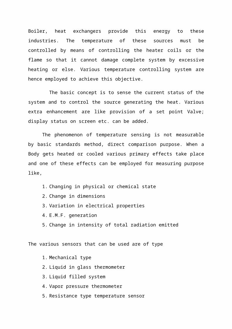
Boiler, heat exchangers provide this energy to these
industries. The temperature of these sources must be
controlled by means of controlling the heater coils or the
flame so that it cannot damage complete system by excessive
heating or else. Various temperature controlling system are
hence employed to achieve this objective.
The basic concept is to sense the current status of the
system and to control the source generating the heat. Various
extra enhancement are like provision of a set point Valve;
display status on screen etc. can be added.
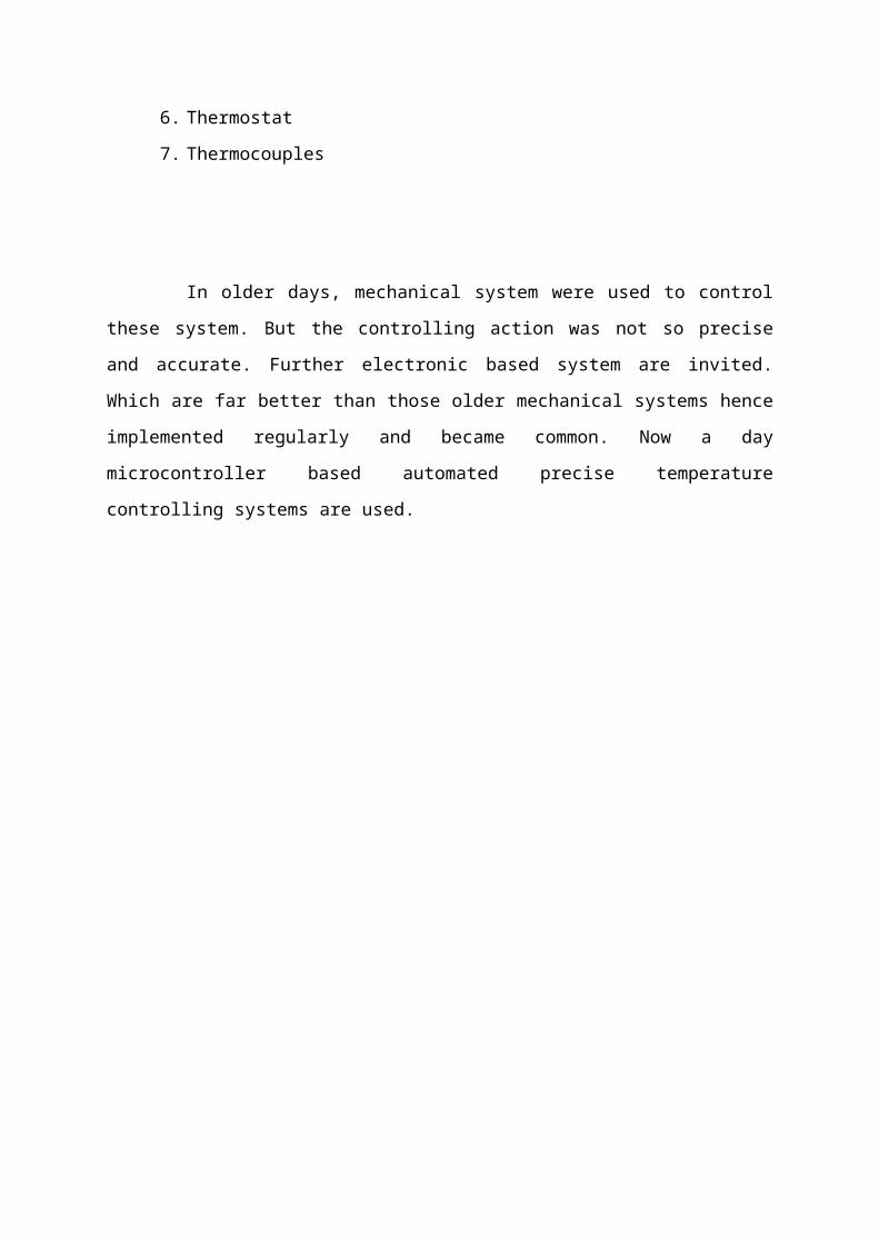
The phenomenon of temperature sensing is not measurable
by basic standards method, direct comparison purpose. When a
Body gets heated or cooled various primary effects take place
and one of these effects can be employed for measuring purpose
like,
1. Changing in physical or chemical state
2. Change in dimensions
3. Variation in electrical properties
4. E.M.F. generation
5. Change in intensity of total radiation emitted
The various sensors that can be used are of type
1. Mechanical type
2. Liquid in glass thermometer
3. Liquid filled system
4. Vapor pressure thermometer
5. Resistance type temperature sensor
6. Thermostat
7. Thermocouples
In older days, mechanical system were used to control
these system. But the controlling action was not so precise
and accurate. Further electronic based system are invited.
Which are far better than those older mechanical systems hence
implemented regularly and became common. Now a day
microcontroller based automated precise temperature
controlling systems are used.
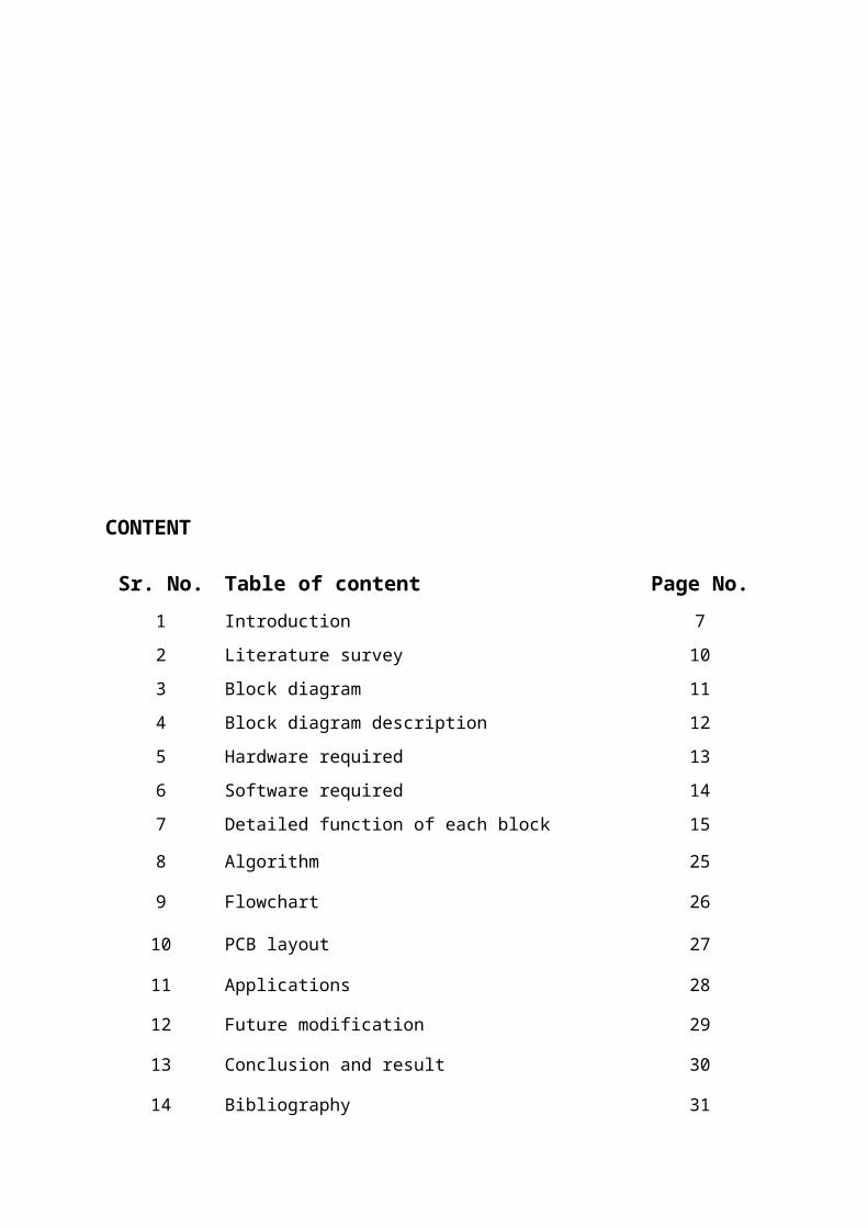
CONTENT
Sr. No. Table of content Page No.1 Introduction 72 Literature survey 103 Block diagram 114 Block diagram description 125 Hardware required 136 Software required 147 Detailed function of each block 15
8 Algorithm 25
9 Flowchart 26
10 PCB layout 27
11 Applications 28
12 Future modification 29
13 Conclusion and result 30
14 Bibliography 31
INTRODUCTION
The temperature of substance or medium is a phenomenon
expressing its degree of hotness or coldness and it related
with reference to its power of commenting heat to surrounding.
It is one of the fundamental parameters , denoting physical
conditions of matters ,similar to mass ,length and time.
However temperature denotes basically an intensive property of
matters .it is measure of the mean kinetic energy of molecules
of substance & represents the potential of heat flow.
Temperature sensing based on methods of measuring energy
radiation from a hot body.
Heat exchangers , boilers, room temperature controller, warmer
controller are very known type of some temperature controlling
systems. These temperature controlling system are often used
in industries whereas in day to day life too. The very basic
step evolved in such systems is controlling the temperature of
the device which causes the heating action, which in turn
helps regulating the system temperature at some predefined
value.
Now a day’s various analog and digital temperature controllers
are used , which helps to maintain the required temperature of
system by means of some controlling action and provide precise
temperature control.
Below are some examples of temperature controlling systems
discussed in brief :-
1. Warmer control system:-
This system is used to maintain a temperature of
glass chamber (incubator) Where pre born babies are kept ,
these pre –born babies are very sensitive to environment & can
be infected easily by various bacteria’s if kept open at room
temperature . hence they are kept in such chambers for
protection .the temperature of this chamber is kept at precise
37°C .
2. Medicine storing units:-
In medical fields where some medicines has to be
stored at precise temperature hence are kept in such medicine
storing units whose temperature is controlled by standard
temperature controlling .In our temperature controlling system
we are controlling the Heater’s heating action maintain the
temperature. A transducer is used to sense the current
temperature of the system, which is further compared with the
reference set temperature .a proper controlling action is
taken by controlling switching system used to on or off the
heater.
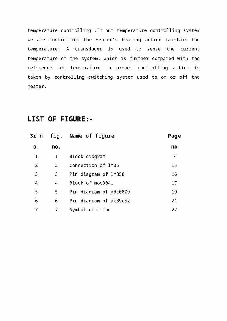
LIST OF FIGURE:-
Sr.n
o.
fig.
no.
Name of figure Page
no1 1 Block diagram 72 2 Connection of lm35 153 3 Pin diagram of lm358 164 4 Block of moc3041 175 5 Pin diagram of adc0809 196 6 Pin diagram of at89c52 217 7 Symbol of triac 22
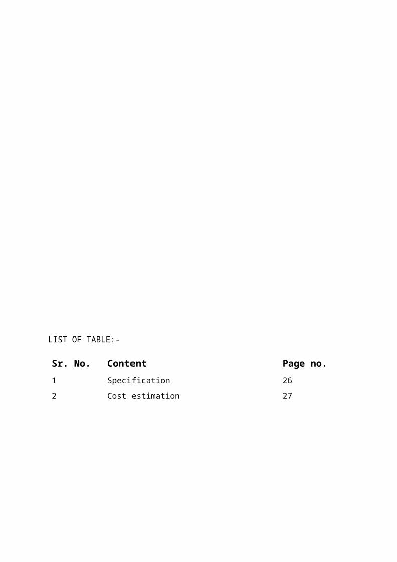
LIST OF TABLE:-
Sr. No. Content Page no.1 Specification 262 Cost estimation 27
LITERATURE SURVEY:
Various temperature controlling systems available in
market are:
1. Discrete type ( semi-automatic) :-
In this type a comparator schematic of an op-amp is
used for comparing and controls action. Lowest 1 star rated
system. Low in efficiency, No extra protections such as
leakage, over-current, Overheat, power loses, provided.
2. Discrete type ( automatic) :-
In this type a regulating pulse width modulator IC is
used for taking controlling action. Moderately 3 star rated
systems.Moderate in efficiency. Some extra protections such as
over-current, overheat, are provided.
3. Microcontroller based ( fully automatic ) :-
This is most significant type, contains a
microcontroller based fully Automatic digital controlling
system. Highly 5 star rated systems.Highly efficient, all
extra protections such as leakage, over- Current, overheat,
power loses are provided.
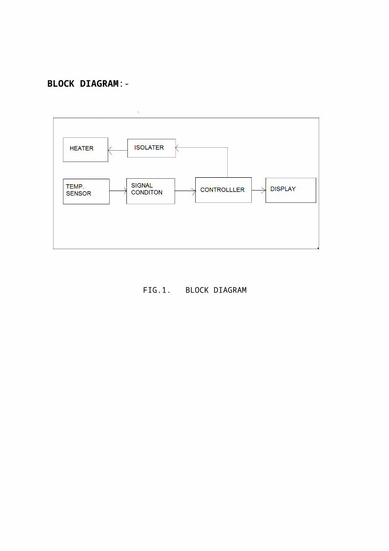
BLOCK DIAGRAM:-
FIG.1. BLOCK DIAGRAM
BLOCK DIAGRAM DESCRIPTION:
1. Heater:-
Heater is used as i/p to system .The heater should be such
that heat delivered to the system can be precisely controlled
by the controlling network.
2. Temperature sensor:-
The surrounding temperature of heater is sense by sensor and
corresponding output is produced (in mv).
3. Signal conditioning circuit:-
The electrical signal o/p available from sensor is normally
very low in terms of signal voltage .hence to provide standard
o/p voltage signal conditioning circuit is used .The
disadvantages of signals conditioning circuit is very low
noise pickup and high SNRAnd ease of use from system designer
point of view.
4. Buffer:-
Buffer is nothing but non-inverting unity gain amplifier which
is used to avoid loading effect on o/p side, it also increases
driving capacity of circuit.
5. Controller:-
The required set point temperature is given to controller and
output of signal conditioning circuit is also given to
controller by comprising this two, controlling feedback is
given to heater through feedback network.
6 Display:-
The required set point temperature and current temperature of
system is displayed on LCD display.
HARDWARE REQUIRED:-
1. Transducer:-
Required temperature range: 27°C to 38°C
Devicechosen: LM35
2. Signal conditioning:-
Required parameter: high i/p impedance, low noise pickup, high
SNR
Device chosen: LM358
3. Controller:-
Voltage range: 4v to5.5v
Devicechosen: 89c52
4. Feedback network:-
Required feedback network: isolation between circuit and ac
line.
Smooth switching between loads.
Device chosen: MOC 3041
5. Display:-
Required display digit range.
Devicechosen: 16*2 LCD display
SOFTWARE REQUIRED:-
MIDE-51, FLASH MAGIC
DETAILED FUNCTION OF EACH BLOCK:-
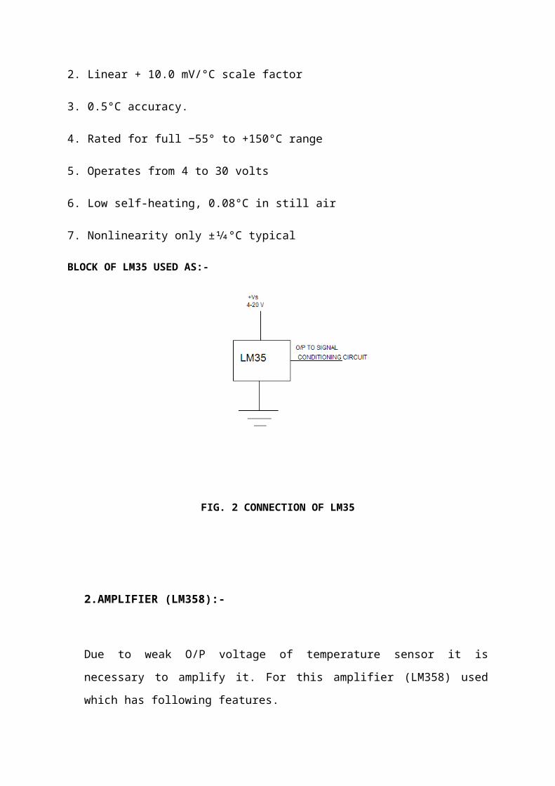
1. TRANSDUCER (LM35):-
It is nothing but temperature sensor. It is used to sense the
temperature of heater and produce O/P in terms of voltage.
This is linearly proportional to the temperature.
Feature of LM35:-
1. Calibrated directly in ° Celsius (Centigrade)
2. Linear + 10.0 mV/°C scale factor
3. 0.5°C accuracy.
4. Rated for full −55° to +150°C range
5. Operates from 4 to 30 volts
6. Low self-heating, 0.08°C in still air
7. Nonlinearity only ±1⁄4°C typical
BLOCK OF LM35 USED AS:-
FIG. 2 CONNECTION OF LM35
2.AMPLIFIER (LM358):-
Due to weak O/P voltage of temperature sensor it is
necessary to amplify it. For this amplifier (LM358) used
which has following features.
1. High I/P impedance.
2. Very low O/P impedance.
3. Accurate , stable & adjustable high gain
4. Extreme high C.M.R.R.
5. Adequate bandwidth
6. High linearity
7. Facility for span adjusting for calibration purpose
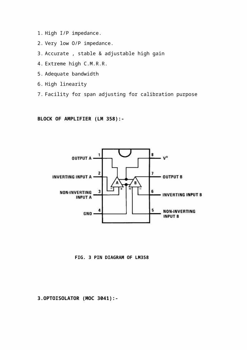
BLOCK OF AMPLIFIER (LM 358):-
FIG. 3 PIN DIAGRAM OF LM358
3.OPTOISOLATOR (MOC 3041):-
It is 6 –pin zero –crossing detector,optoisolatortriac
driver IC. It consist of arsenide infrared light emitting
diode optically coupled to monolithic silicon detector
performing function of zero voltage crossing bilateral triac
driver hence , dependingOn duty cycle of (%D) PWM wave , it
drives triac by selecting corresponding firing angle of
triac.
Advantages of optoisolator are:-
1. it is electrically isolating PWM controller from high
power device i.e. heater
2. due to unidirectional signal transfer to output side i.e.
to PWM controller
3. it is small in size & light weight device
4.
Features:-
1. Simplified logic control of 115V power.
2. Zero voltage crossing.
3. DV/dtof 2000V/μstypically, 1000v/ μsguaranteed.
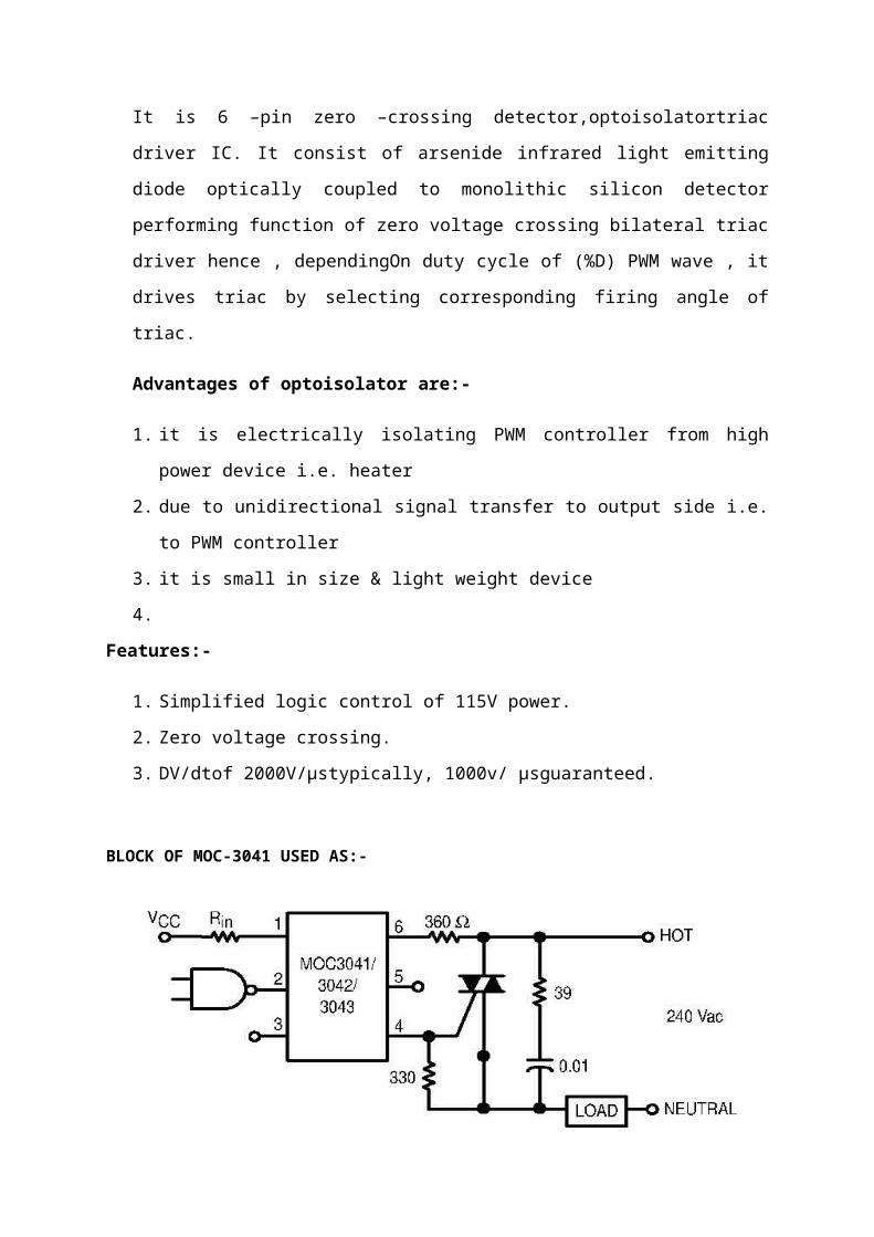
BLOCK OF MOC-3041 USED AS:-
FIG. 4 BLOCK OF MOC3041
Pin no.1 is connected to Vcc& pin no.2 is connected to 180
phase shift of PWM wave i.e. Inverted wave of PWM O/P. When
voltage pin 1&2 is present, corresponding diode emits infrared
producing gate current to triac to turn it on. Depending gate
current values it select firing angle & as heater & supply is
connected in series with Triac , heater gets supply only for
this firing angle and controlling is achieved.
To pin no. 2 inverted PWM O/P is connected if Di% of duty
cycle is at O/P then we have to send gate current proportional
to Di% of cycle.
Gate current α V1- V2
As V1=Vcc=constant
Gate current α-V2
I.e. Gate current α 1/V2
But V2 is inverted PWM O/P
Therefore, V2 =1/D1
Therefore, gate current α 1/(1/D1)
Therefore, gate current α D1
For MOC 3041 input current should not exceed to 15ma, for 100%
duty cycle. But in our circuit maximum duty cycle is
Therefore, Rin = Vc/If
=5/35
=0.2 × 10³
Therefore, Rin=200Ω
Ci capacitor is used for snubbing of Triac
4.ANALOG TO DIGITAL CONVERTER(ADC0809):-
The ADC0808, ADC0809 data acquisition component is amonolithic
CMOS device with an 8-bit analog-to-digital converter,8-
channel multiplexer and microprocessor compatiblecontrol
logic. The 8-bit A/D converter uses successive approximationas
the conversion technique. The converter features high
impedance chopper stabilized comparator, a256R voltage divider
with analog switch tree and a successiveapproximation
register. The 8-channel multiplexer candirectly access any of
8-single-ended analog signals.
The device eliminates the need for external zero andfull-scale
adjustments. Easy interfacing to microprocessorsis provided by
the latched and decoded multiplexer addressinputs and latched
TTL TRI-STATE® outputs.
Features:-
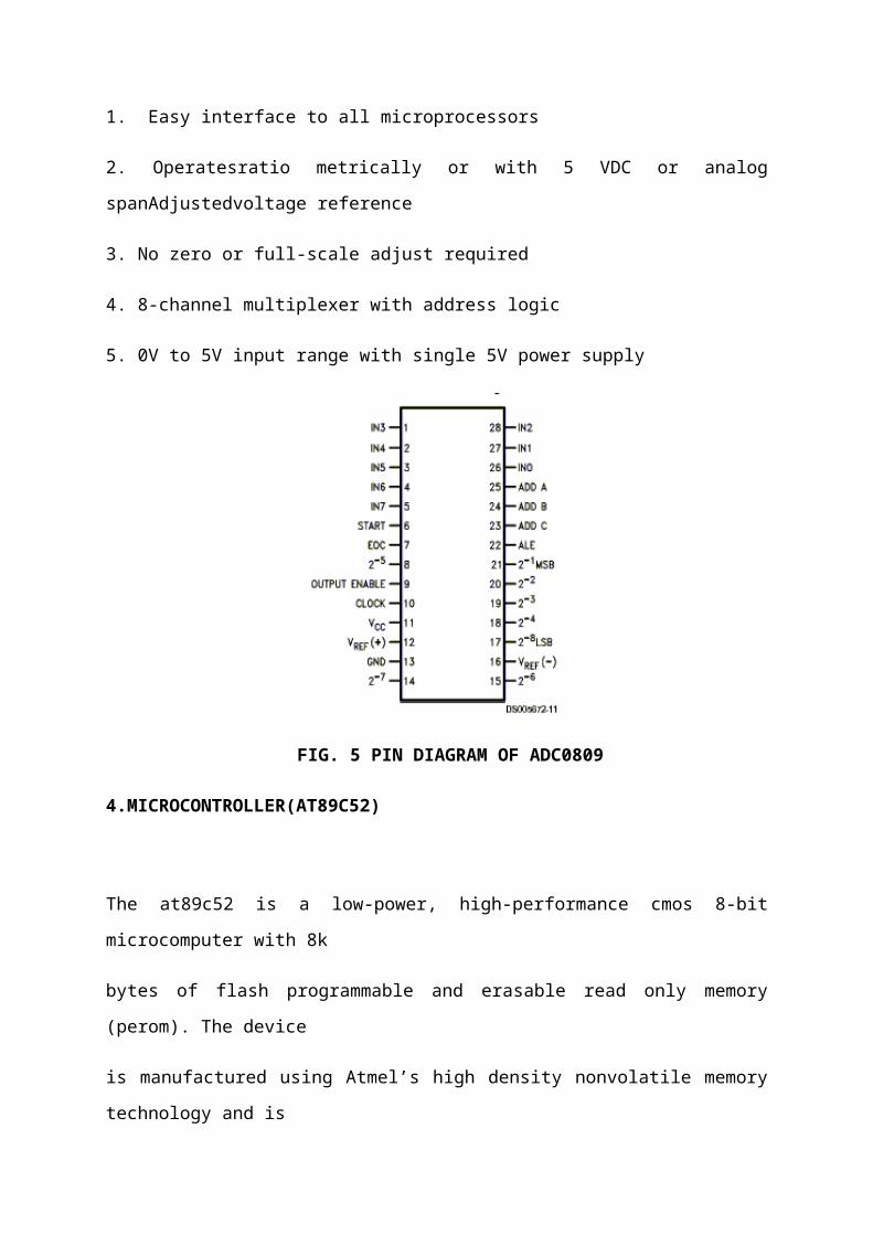
1. Easy interface to all microprocessors
2. Operatesratio metrically or with 5 VDC or analog
spanAdjustedvoltage reference
3. No zero or full-scale adjust required
4. 8-channel multiplexer with address logic
5. 0V to 5V input range with single 5V power supply
FIG. 5 PIN DIAGRAM OF ADC0809
4.MICROCONTROLLER(AT89C52)
The at89c52 is a low-power, high-performance cmos 8-bit
microcomputer with 8k
bytes of flash programmable and erasable read only memory
(perom). The device
is manufactured using Atmel’s high density nonvolatile memory
technology and is

compatible with the industry standard 80c51 and 80c52
instruction set and pin out.
The on-chip flash allows the program memory to be reprogrammed
in-system or by a
conventional nonvolatile memory programmer. By combining a
versatile 8-bit CPU
with flash on a monolithic chip, the Atmel at89c52 is a
powerful microcomputer
which provides a highly flexible and cost effective solution
to many embedded control
applications.
Features:-
1. Compatible with MCS-51™ Products
2. 8K Bytes of In-System Reprogrammable Flash Memory
– Endurance: 1,000 Write/Erase Cycles
3. Fully Static Operation: 0 Hz to 24 MHz
4. Three-Level Program Memory Lock
5. 256 x 8-Bit Internal RAM
6. 32 Programmable I/O Lines
7. Three 16-Bit Timer/Counters
8. Eight Interrupt Sources
9. Programmable Serial Channel
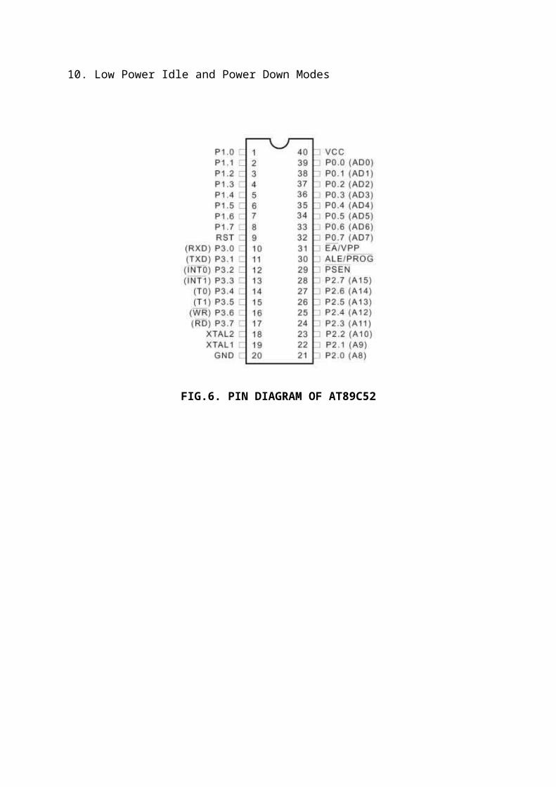
10. Low Power Idle and Power Down Modes
FIG.6. PIN DIAGRAM OF AT89C52
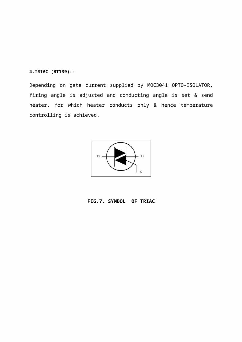
4.TRIAC (BT139):-
Depending on gate current supplied by MOC3041 OPTO-ISOLATOR,
firing angle is adjusted and conducting angle is set & send
heater, for which heater conducts only & hence temperature
controlling is achieved.
FIG.7. SYMBOL OF TRIAC
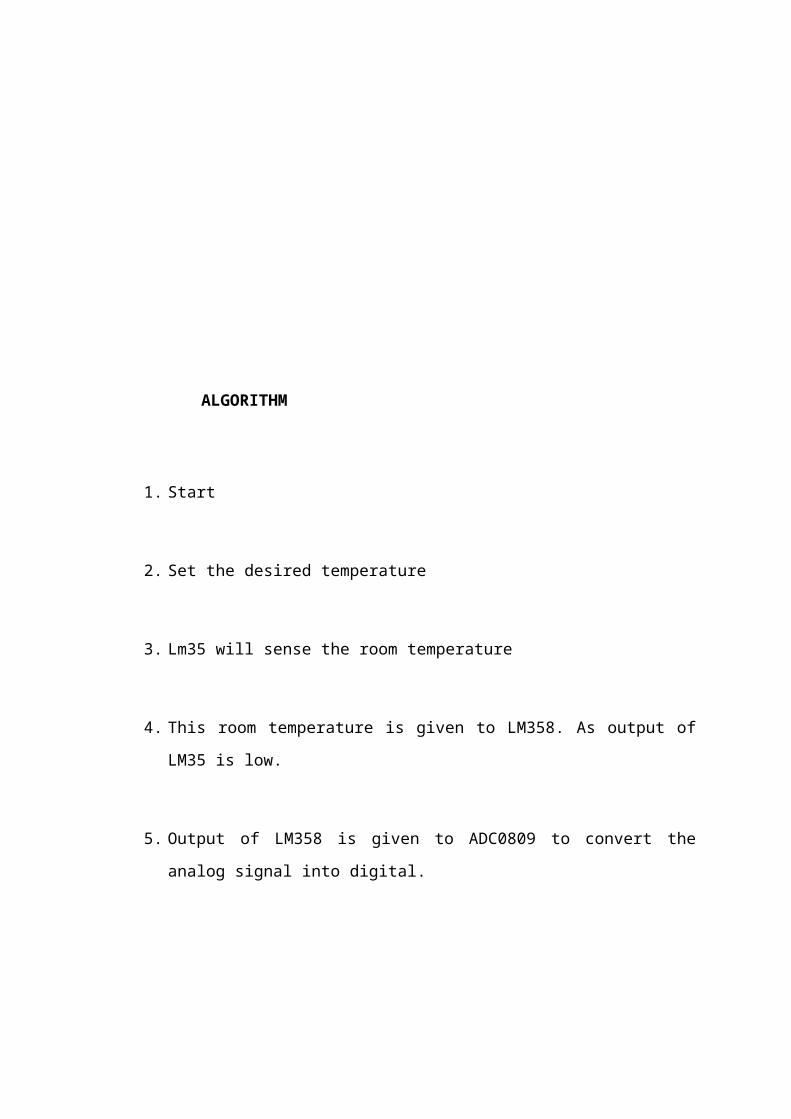
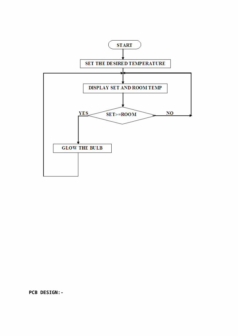
ALGORITHM
1. Start
2. Set the desired temperature
3. Lm35 will sense the room temperature
4. This room temperature is given to LM358. As output of
LM35 is low.
5. Output of LM358 is given to ADC0809 to convert the
analog signal into digital.
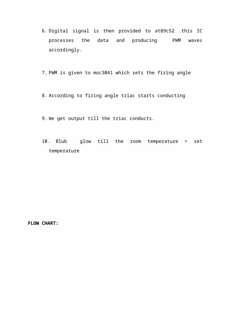
6. Digital signal is then provided to at89c52 .this IC
processes the data and producing PWM waves
accordingly.
7. PWM is given to moc3041 which sets the firing angle
8. According to firing angle triac starts conducting
9. We get output till the triac conducts.
10. Blub glow till the room temperature > set
temperature
FLOW CHART:
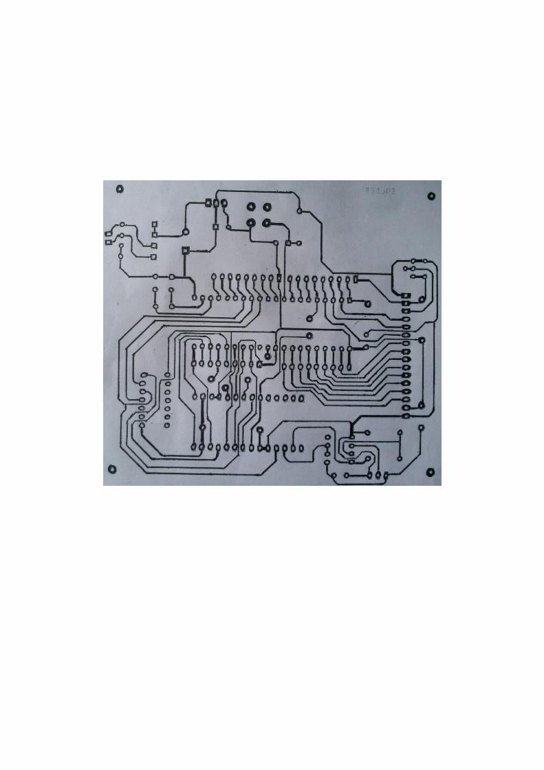
PCB DESIGN:-
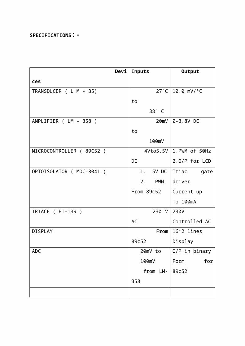
SPECIFICATIONS:-
Devi
ces
Inputs Output
TRANSDUCER ( L M - 35) 27˚C
to
38˚ C
10.0 mV/°C
AMPLIFIER ( LM – 358 ) 20mV
to
100mV
0-3.8V DC
MICROCONTROLLER ( 89C52 ) 4Vto5.5V
DC
1.PWM of 50Hz
2.O/P for LCD
OPTOISOLATOR ( MOC-3041 ) 1. 5V DC
2. PWM
From 89c52
Triac gate
driver
Current up
To 100mATRIACE ( BT-139 ) 230 V
AC
230V
Controlled ACDISPLAY From
89c52
16*2 lines
DisplayADC 20mV to
100mV
from LM-
358
O/P in binary
Form for
89c52
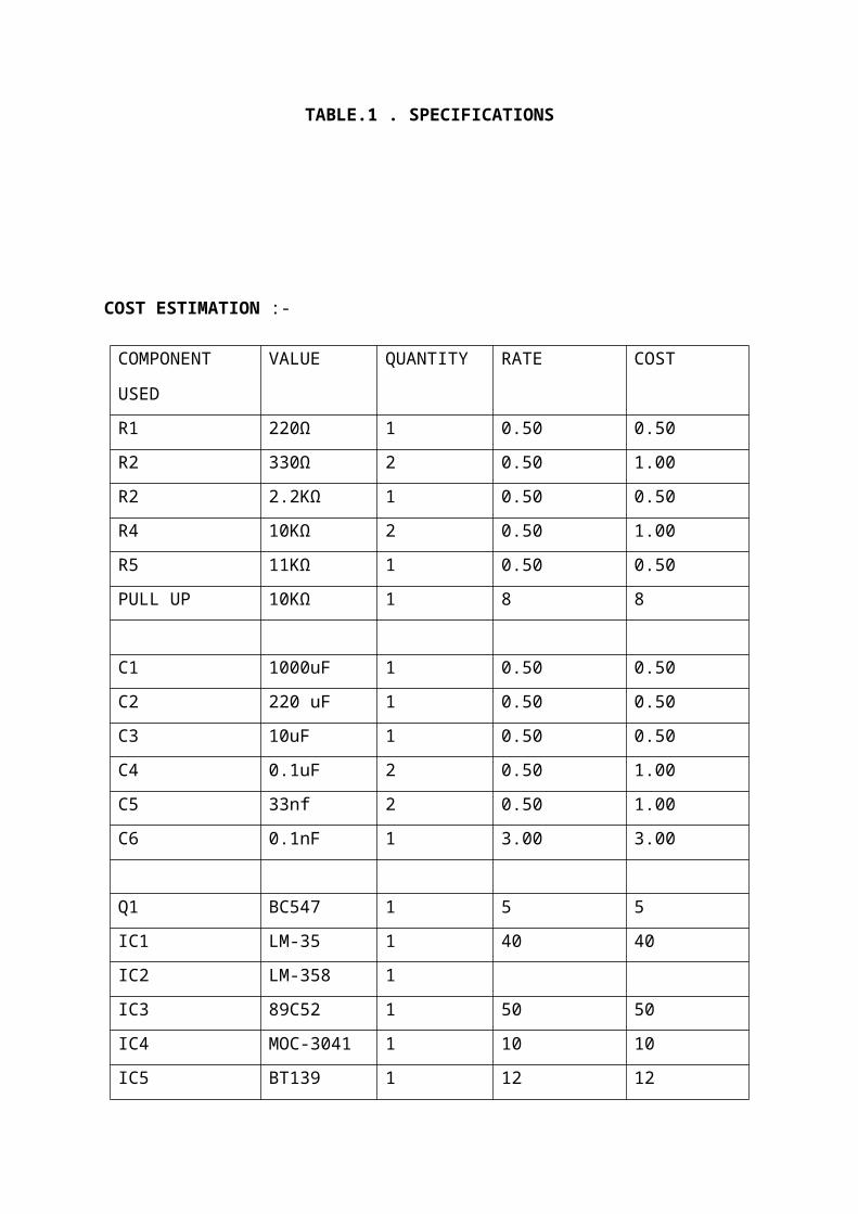
TABLE.1 . SPECIFICATIONS
COST ESTIMATION :-
COMPONENT
USED
VALUE QUANTITY RATE COST
R1 220Ω 1 0.50 0.50R2 330Ω 2 0.50 1.00R2 2.2KΩ 1 0.50 0.50R4 10KΩ 2 0.50 1.00R5 11KΩ 1 0.50 0.50PULL UP 10KΩ 1 8 8
C1 1000uF 1 0.50 0.50C2 220 uF 1 0.50 0.50C3 10uF 1 0.50 0.50C4 0.1uF 2 0.50 1.00C5 33nf 2 0.50 1.00C6 0.1nF 1 3.00 3.00
Q1 BC547 1 5 5IC1 LM-35 1 40 40IC2 LM-358 1IC3 89C52 1 50 50IC4 MOC-3041 1 10 10IC5 BT139 1 12 12
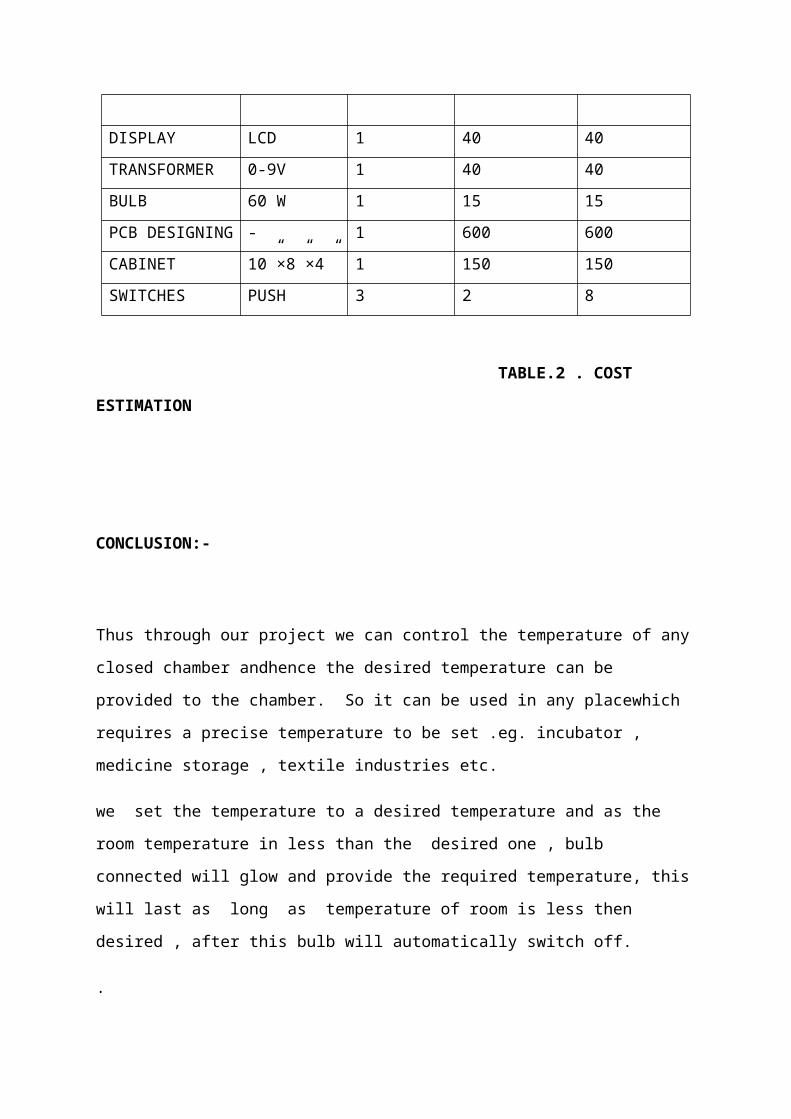
DISPLAY LCD 1 40 40TRANSFORMER 0-9V 1 40 40BULB 60 W 1 15 15PCB DESIGNING - 1 600 600CABINET 10”×8”×4” 1 150 150SWITCHES PUSH 3 2 8
TABLE.2 . COST
ESTIMATION
CONCLUSION:-
Thus through our project we can control the temperature of any
closed chamber andhence the desired temperature can be
provided to the chamber. So it can be used in any placewhich
requires a precise temperature to be set .eg. incubator ,
medicine storage , textile industries etc.
we set the temperature to a desired temperature and as the
room temperature in less than the desired one , bulb
connected will glow and provide the required temperature, this
will last as long as temperature of room is less then
desired , after this bulb will automatically switch off.
.

APPLICATIONS :-
1. Warmer Controller Systems.( Controlling parameters of
incubator )
2. In domestic applications like controlling room
temperature and humidity.
3. As water Heating system for aquarium.
4. To control precise temperature in medicine and chemical
industries.
5. In textile industries ( for silk production )
6. In air conditioning and water cooler system to make
system automatic and independent.
FUTURE MODIFICATION :-

1. Improved temperature range.
2. Can also be used I in controlling temperature of
different liquids.
3. Parameters can be operated by remote control.
4. Compact design
BIBLIOGRAPHY:-
[1] RamakantGaikwad “Op-Amp And Linear I ntegrated
Circuits”, Pearson Prentice Hall 4th edition 2000
[2] Muhammad Ali Mazidi “The 8051 Microcontroller And
EmbededSystems”,PrenticeHall Of India 2nd Edition2008
[3] A.chakrabarti “power Electronics And Devices”
DhanpatRai publications Second Edition 200 3
[4] H.S.Kalsi “Electronic Instumentation” ,Tata-McGraw
Hill Publications Second Edition
[5] www.alldatasheet.com/view.jsp?searchword=lm358
[6] www.alldatasheet.com/view.jsp?searchword= at89c52
[7] www.alldatasheet.com/view.jsp?searchword=lm35
[8] www.wikipedia.org.wiki/powersupply