Embed Size (px)
Citation preview
Factory AutomationPLC (XGT) / HMI (XGT Panel) / Motion Controller (XMC) / Servo Drive & Motor (Xmotion) / Gearbox
| 0302
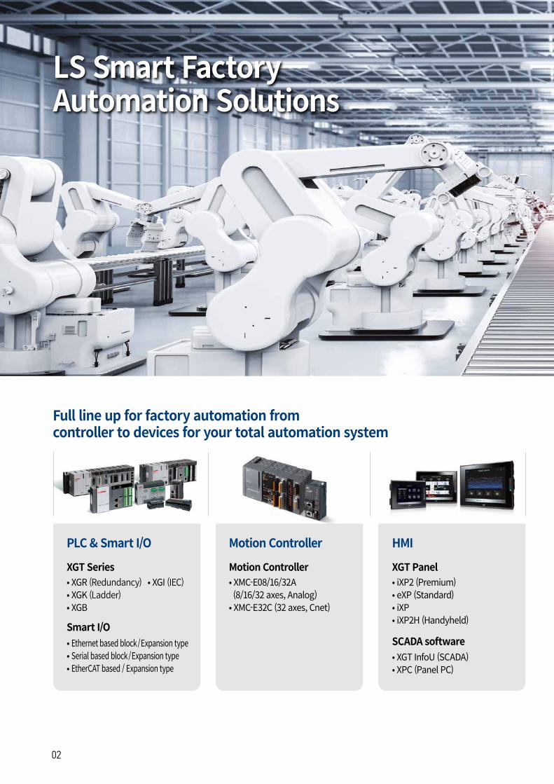
PLC & Smart I/O
XGT Series
Smart I/O
• XGR (Redundancy)• XGK (Ladder)• XGB
• XGI (IEC)
HMI
XGT Panel• iXP2 (Premium)• eXP (Standard) • iXP• iXP2H (Handyheld)
Motion Controller
Motion Controller• XMC-E08/16/32A (8/16/32 axes, Analog)• XMC-E32C (32 axes, Cnet)
• Ethernet based block/Expansion type• Serial based block/Expansion type• EtherCAT based / Expansion type
Full line up for factory automation fromcontroller to devices for your total automation system
LS Smart Factory Automation Solutions
SCADA software• XGT InfoU (SCADA)• XPC (Panel PC)
| 0302
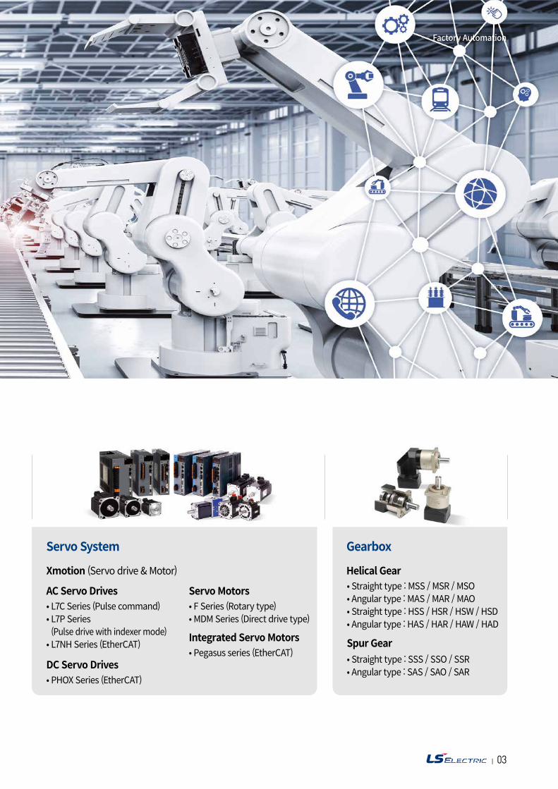
Servo System Gearbox
Xmotion (Servo drive & Motor)
AC Servo Drives
Helical Gear
DC Servo Drives
Spur Gear
Servo Motors
Integrated Servo Motors
• F Series (Rotary type)• MDM Series (Direct drive type)
• Pegasus series (EtherCAT)
• L7C Series (Pulse command)• L7P Series (Pulse drive with indexer mode)
• L7NH Series (EtherCAT)
• Straight type : MSS / MSR / MSO• Angular type : MAS / MAR / MAO• Straight type : HSS / HSR / HSW / HSD• Angular type : HAS / HAR / HAW / HAD
• PHOX Series (EtherCAT)
• Straight type : SSS / SSO / SSR• Angular type : SAS / SAO / SAR
LS Smart Factory Automation Solutions
Factory Automation
| 0504
Features
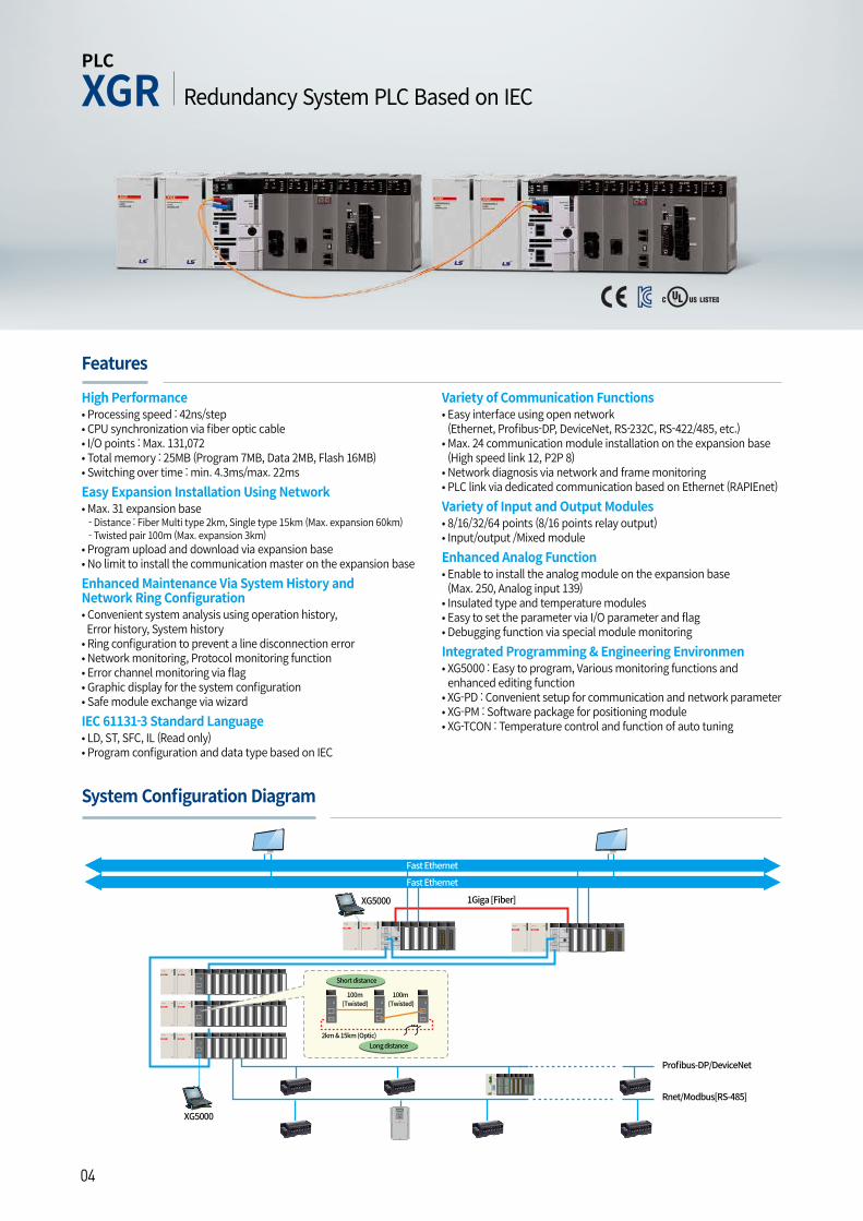
System Configuration Diagram
PLC
Redundancy System PLC Based on IECXGR
High Performance• Processing speed : 42ns/step• CPU synchronization via fiber optic cable• I/O points : Max. 131,072• Total memory : 25MB (Program 7MB, Data 2MB, Flash 16MB) • Switching over time : min. 4.3ms/max. 22msEasy Expansion Installation Using Network• Max. 31 expansion base - Distance : Fiber Multi type 2km, Single type 15km (Max. expansion 60km) - Twisted pair 100m (Max. expansion 3km)• Program upload and download via expansion base• No limit to install the communication master on the expansion baseEnhanced Maintenance Via System History andNetwork Ring Configuration• Convenient system analysis using operation history, Error history, System history• Ring configuration to prevent a line disconnection error • Network monitoring, Protocol monitoring function• Error channel monitoring via flag• Graphic display for the system configuration• Safe module exchange via wizardIEC 61131-3 Standard Language• LD, ST, SFC, IL (Read only) • Program configuration and data type based on IEC
Variety of Communication Functions• Easy interface using open network(Ethernet, Profibus-DP, DeviceNet, RS-232C, RS-422/485, etc.)
• Max. 24 communication module installation on the expansion base (High speed link 12, P2P 8)
• Network diagnosis via network and frame monitoring• PLC link via dedicated communication based on Ethernet (RAPIEnet)Variety of Input and Output Modules• 8/16/32/64 points (8/16 points relay output)• Input/output /Mixed moduleEnhanced Analog Function• Enable to install the analog module on the expansion base (Max. 250, Analog input 139)
• Insulated type and temperature modules• Easy to set the parameter via I/O parameter and flag • Debugging function via special module monitoringIntegrated Programming & Engineering Environmen• XG5000 : Easy to program, Various monitoring functions and enhanced editing function
• XG-PD : Convenient setup for communication and network parameter • XG-PM : Software package for positioning module• XG-TCON : Temperature control and function of auto tuning
| 0504
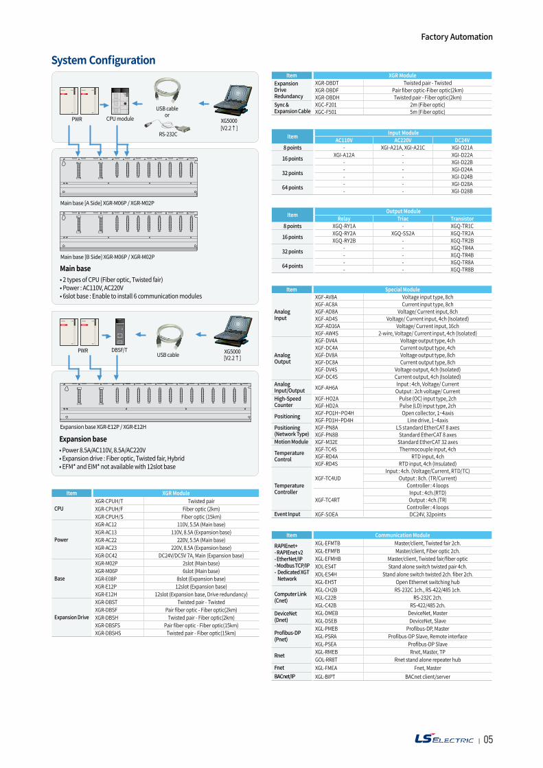
System Configuration
PWR CPUmodule XG5000[V2.2↑]
USBcableor
Mainbase[ASide]XGR-M06P/XGR-M02P
RS-232C
Mainbase[BSide]XGR-M06P/XGR-M02P
Main base•2typesofCPU(Fiberoptic,Twistedfair)•Power:AC110V,AC220V•6slotbase:Enabletoinstall6communicationmodules
ExpansionbaseXGR-E12P/XGR-E12H
Expansion base•Power8.5A/AC110V,8.5A/AC220V•Expansiondrive:Fiberoptic,Twistedfair,Hybrid•EFM*andEIM*notavailablewith12slotbase
PWR DBSF/T XG5000[V2.2↑]USBcable
Item Input ModuleAC110V AC220V DC24V
8 points - XGI-A21A, XGI-A21C XGI-D21A
16 points XGI-A12A - XGI-D22A- - XGI-D22B
32 points - - XGI-D24A- - XGI-D24B
64 points - - XGI-D28A- - XGI-D28B
Item Output ModuleRelay Triac Transistor
8 points XGQ-RY1A - XGQ-TR1C
16 points XGQ-RY2A XGQ-SS2A XGQ-TR2AXGQ-RY2B - XGQ-TR2B
32 points - - XGQ-TR4A- - XGQ-TR4B
64 points - - XGQ-TR8A- - XGQ-TR8B
Item Special Module
AnalogInput
XGF-AV8A Voltage input type, 8chXGF-AC8A Current input type, 8chXGF-AD8A Voltage/ Current input, 8chXGF-AD4S Voltage/ Current input, 4ch (Isolated)XGF-AD16A Voltage/ Current input, 16chXGF-AW4S 2-wire, Voltage/ Current input, 4ch (Isolated)
AnalogOutput
XGF-DV4A Voltage output type, 4chXGF-DC4A Current output type, 4chXGF-DV8A Voltage output type, 8chXGF-DC8A Current output type, 8chXGF-DV4S Voltage output, 4ch (Isolated)XGF-DC4S Current output, 4ch (Isolated)
AnalogInput/Output XGF-AH6A Input : 4ch, Voltage/ Current
Output : 2ch voltage/ CurrentHigh-SpeedCounter
XGF-HO2A Pulse (OC) input type, 2chXGF-HD2A Pulse (LD) input type, 2ch
Positioning XGF-PO1H~PO4H Open collector, 1~4axisXGF-PD1H~PD4H Line drive, 1~4axis
Positioning(Network Type)
XGF-PN8A LS standard EtherCAT 8 axesXGF-PN8B Standard EtherCAT 8 axes
Motion Module XGF-M32E Standard EtherCAT 32 axes
TemperatureControl
XGF-TC4S Thermocouple input, 4chXGF-RD4A RTD input, 4chXGF-RD4S RTD input, 4ch (Insulated)
TemperatureController
XGF-TC4UDInput : 4ch. (Voltage/Current, RTD/TC)
Output : 8ch. (TR/Current)Controller : 4 loops
XGF-TC4RTInput : 4ch.(RTD)Output : 4ch.(TR)
Controller : 4 loopsEvent Input XGF-SOEA DC24V, 32points
Item XGR ModuleExpansionDriveRedundancy
XGR-DBDT Twisted pair - TwistedXGR-DBDF Pair fiber optic-Fiber optic(2km)XGR-DBDH Twisted pair - Fiber optic(2km)
Sync &Expansion Cable
XGC-F201 2m (Fiber optic)XGC-F501 5m (Fiber optic)
Item XGR Module
CPUXGR-CPUH/T Twisted pairXGR-CPUH/F Fiber optic (2km)XGR-CPUH/S Fiber optic (15km)
Power
XGR-AC12 110V, 5.5A (Main base)XGR-AC13 110V, 8.5A (Expansion base)XGR-AC22 220V, 5.5A (Main base)XGR-AC23 220V, 8.5A (Expansion base)XGR-DC42 DC24V/DC5V 7A, Main (Expansion base)
Base
XGR-M02P 2slot (Main base)XGR-M06P 6slot (Main base)XGR-E08P 8slot (Expansion base)XGR-E12P 12slot (Expansion base)XGR-E12H 12slot (Expansion base, Drive redundancy)
Expansion Drive
XGR-DBST Twisted pair - TwistedXGR-DBSF Pair fiber optic - Fiber optic(2km)XGR-DBSH Twisted pair - Fiber optic(2km)XGR-DBSFS Pair fiber optic - Fiber optic(15km)XGR-DBSHS Twisted pair - Fiber optic(15km)
Factory Automation
Item Communication Module
RAPIEnet+- RAPIEnet v2- EtherNet/IP- Modbus TCP/IP- Dedicated XGT
Network
XGL-EFMTB Master/client, Twisted fair 2ch.XGL-EFMFB Master/client, Fiber optic 2ch.XGL-EFMHB Master/client, Twisted fair/fiber opticXOL-ES4T Stand alone switch twisted pair 4ch.XOL-ES4H Stand alone switch twisted 2ch. fiber 2ch.XGL-EH5T Open Ethernet switching hub
Computer Link (Cnet)
XGL-CH2B RS-232C 1ch., RS-422/485 1ch.XGL-C22B RS-232C 2ch.XGL-C42B RS-422/485 2ch.
DeviceNet (Dnet)
XGL-DMEB DeviceNet, MasterXGL-DSEB DeviceNet, Slave
Profibus-DP (Pnet)
XGL-PMEB Profibus-DP, MasterXGL-PSRA Profibus-DP Slave, Remote interfaceXGL-PSEA Profibus-DP Slave
Rnet XGL-RMEB Rnet, Master, TPGOL-RR8T Rnet stand alone repeater hub
Fnet XGL-FMEA Fnet, MasterBACnet/IP XGL-BIPT BACnet client/server
| 0706
Expansion ModulesPower ModulesWith AC free voltage, 220V and DC 24 V power supply
Base ModulesWith 4/6/8/12 main and expansion base
Digital Input /Output ModulesFrom 8 to 64 of transistor, Relay and triac switches
Analog Input /Output ModulesWith 4 or 8 ch current/Voltage signals
Temperature Input ModulesWith 4 ch Pt100/JPt100 resistance thermometer and thermocouple
High Speed Counter ModuleFor connection with incremental encoder (2 channels of open collector or line driver type)
Motion/Positioning moduleEtherCAT based motion / positioningfor servo and motor (1~32 axes)
Network ModulesFast Ethernet ModulesEthernet Network with TCP/IP protocol
Profibus-DP ModulesProfibus-DP fieldbus protocol forconnection between LS PLC and different manufacturers
DeviceNet ModulesDeviceNet fieldbus protocol for connection between LS PLC and different manufacturers
Rnet ModulesDedicated network for remote I/O control (LS Smart I/O)
Cnet ModuleSerial communication module with RS-232C/422/485
RAPIEnet Module Dedicated network based on Ethernet
Features
Modules
PLC
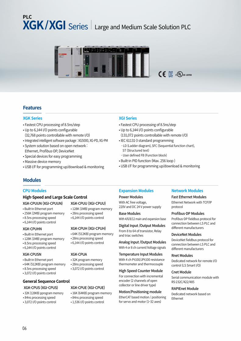
Large and Medium Scale Solution PLCXGK/XGI Series
CPU ModulesHigh-Speed and Large Scale Control
General Sequence Control
XGK-CPUUN (XGI-CPUUN)• Built-in Ethernet port• 256K (2MB) program memory • 8.5ns processing speed • 6,144 I/O points control
XGK-CPUHN• Built-in Ethernet port• 128K (1MB) program memory • 8.5ns processing speed • 6,144 I/O points control
XGK-CPUSN• Built-in Ethernet port• 64K (512KB) program memory • 8.5ns processing speed • 3,072 I/O points control
XGK-CPUS (XGI-CPUS)• 32K (128KB) pprogram memory • 84ns processing speed • 3,072 I/O points control
XGK-CPUE (XGI-CPUE)• 16K (64KB) program memory • 84ns processing speed • 1,536 I/O points control
XGK-CPUU (XGI-CPUU)• 128K (1MB) program memory • 28ns processing speed • 6,144 I/O points control
XGK-CPUH (XGI-CPUH)• 64K (512KB) program memory • 28ns processing speed • 6,144 I/O points control
XGK-CPUA • 32K program memory • 28ns processing speed • 3,072 I/O points control
XGK Series XGI Series• Fastest CPU processing of 8.5ns/step• Up to 6,144 I/O points configurable (32,768 points controllable with remote I/O)
• Integrated intelligent software package : XG5000, XG-PD, XG-PM• System solution based on open network : Ethernet, Profibus-DP, DeviceNet
• Special devices for easy programming• Massive device memory• USB I/F for programming up/download & monitoring
• Fastest CPU processing of 8.5ns/step• Up to 6,144 I/O points configurable (131,072 points controllable with remote I/O)
• IEC 61131-3 standard programming - LD (Ladder diagram), SFC (Sequential function chart), ST (Structured text) - User defined FB (Function block)• Built-in PID function (Max. 256 loop )• USB I/F for programming up/download & monitoring
| 0706
XG5000 Cable (RS-232C)
Mainbase(XGB-MA)
Expansionbase(XGB-EA)
Expansioncable(XGC-E)
USBcableor
RS-232CXG5000
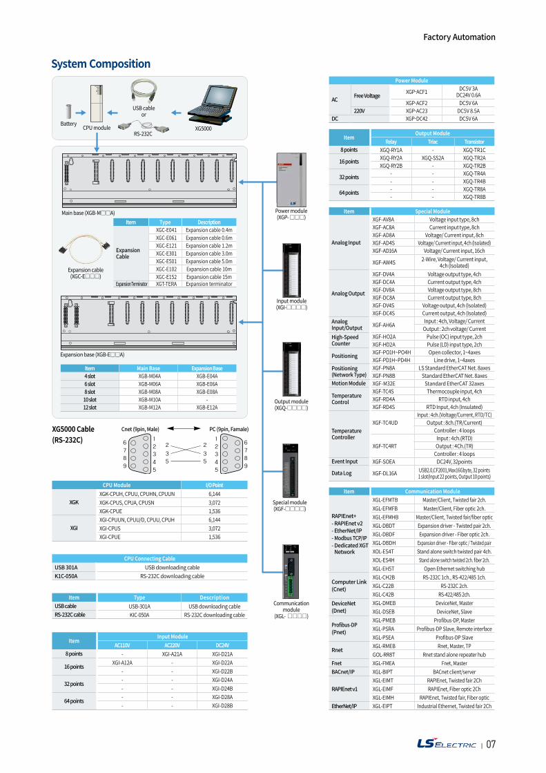
System Composition
Powermodule(XGP-)
Inputmodule(XGI-)
Outputmodule(XGQ-)
Specialmodule(XGF-)
Cnet (9pin, Male) PC (9pin, Famale)
Communicationmodule
(XGL-)
BatteryCPUmodule
Item Type Description
Expansion Cable
XGC-E041 Expansion cable 0.4mXGC-E061 Expansion cable 0.6mXGC-E121 Expansion cable 1.2mXGC-E301 Expansion cable 3.0mXGC-E501 Expansion cable 5.0mXGC-E102 Expansion cable 10mXGC-E152 Expansion cable 15m
Expansion Terminator XGT-TERA Expansion terminator
Item Main Base Expansion Base4 slot XGB-M04A XGB-E04A6 slot XGB-M06A XGB-E06A8 slot XGB-M08A XGB-E08A10 slot XGB-M10A -12 slot XGB-M12A XGB-E12A
CPU Module I/O Point
XGKXGK-CPUH, CPUU, CPUHN, CPUUN 6,144XGK-CPUS, CPUA, CPUSN 3,072XGK-CPUE 1,536
XGIXGI-CPUUN, CPUU/D, CPUU, CPUH 6,144XGI-CPUS 3,072XGI-CPUE 1,536
ItemInput Module
AC110V AC220V DC24V8 points - XGI-A21A XGI-D21A
16 points XGI-A12A - XGI-D22A- - XGI-D22B
32 points - - XGI-D24A- - XGI-D24B
64 points - - XGI-D28A- - XGI-D28B
Item Type DescriptionUSB cable USB-301A USB downloading cableRS-232C cable KIC-050A RS-232C downloading cable
CPU Connecting CableUSB 301A USB downloading cableK1C-050A RS-232C downloading cable
ItemOutput Module
Relay Triac Transistor8 points XGQ-RY1A - XGQ-TR1C
16 points XGQ-RY2A XGQ-SS2A XGQ-TR2AXGQ-RY2B - XGQ-TR2B
32 points - - XGQ-TR4A- - XGQ-TR4B
64 points - - XGQ-TR8A- - XGQ-TR8B
Item Special Module
Analog Input
XGF-AV8A Voltage input type, 8chXGF-AC8A Current input type, 8chXGF-AD8A Voltage/ Current input, 8chXGF-AD4S Voltage/ Current input, 4ch (Isolated)XGF-AD16A Voltage/ Current input, 16ch
XGF-AW4S 2-Wire, Voltage/ Current input,4ch (Isolated)
Analog Output
XGF-DV4A Voltage output type, 4chXGF-DC4A Current output type, 4chXGF-DV8A Voltage output type, 8chXGF-DC8A Current output type, 8chXGF-DV4S Voltage output, 4ch (Isolated)XGF-DC4S Current output, 4ch (Isolated)
AnalogInput/Output XGF-AH6A Input : 4ch, Voltage/ Current
Output : 2ch voltage/ CurrentHigh-SpeedCounter
XGF-HO2A Pulse (OC) input type, 2chXGF-HD2A Pulse (LD) input type, 2ch
Positioning XGF-PO1H~PO4H Open collector, 1~4axesXGF-PD1H~PD4H Line drive, 1~4axes
Positioning(Network Type)
XGF-PN8A LS Standard EtherCAT Net. 8axesXGF-PN8B Standard EtherCAT Net. 8axes
Motion Module XGF-M32E Standard EtherCAT 32axes
TemperatureControl
XGF-TC4S Thermocouple input, 4chXGF-RD4A RTD input, 4chXGF-RD4S RTD Input, 4ch (Insulated)
TemperatureController
XGF-TC4UDInput : 4ch.(Voltage/Current, RTD/TC)
Output : 8ch.(TR/Current)Controller : 4 loops
XGF-TC4RTInput : 4ch.(RTD)Output : 4Ch.(TR)
Controller : 4 loopsEvent Input XGF-SOEA DC24V, 32points
Data Log XGF-DL16A USB2.0,CF2001,Max16Gbyte, 32 points1 slot(Input 22 points, Output 10 points)
Power Module
AC Free Voltage XGP-ACF1 DC5V 3ADC24V 0.6A
XGP-ACF2 DC5V 6A220V XGP-AC23 DC5V 8.5A
DC XGP-DC42 DC5V 6A
Factory Automation
Item Communication Module
RAPIEnet+- RAPIEnet v2- EtherNet/IP- Modbus TCP/IP- Dedicated XGT Network
XGL-EFMTB Master/Client, Twisted fair 2ch.XGL-EFMFB Master/Client, Fiber optic 2ch.XGL-EFMHB Master/Client, Twisted fair/fiber opticXGL-DBDT Expansion driver - Twisted pair 2ch.XGL-DBDF Expansion driver - Fiber optic 2ch.XGL-DBDH Expansion driver - Fiber optic / Twisted pairXOL-ES4T Stand alone switch twisted pair 4ch.XOL-ES4H Stand alone switch twisted 2ch. fiber 2ch.XGL-EH5T Open Ethernet switching hub
Computer Link (Cnet)
XGL-CH2B RS-232C 1ch., RS-422/485 1ch.XGL-C22B RS-232C 2ch.XGL-C42B RS-422/485 2ch.
DeviceNet (Dnet)
XGL-DMEB DeviceNet, MasterXGL-DSEB DeviceNet, Slave
Profibus-DP(Pnet)
XGL-PMEB Profibus-DP, MasterXGL-PSRA Profibus-DP Slave, Remote interfaceXGL-PSEA Profibus-DP Slave
Rnet XGL-RMEB Rnet, Master, TPGOL-RR8T Rnet stand alone repeater hub
Fnet XGL-FMEA Fnet, MasterBACnet/IP XGL-BIPT BACnet client/server
RAPIEnet v1XGL-EIMT RAPIEnet, Twisted fair 2ChXGL-EIMF RAPIEnet, Fiber optic 2ChXGL-EIMH RAPIEnet, Twisted fair, Fiber optic
EtherNet/IP XGL-EIPT Industrial Ethernet, Twisted fair 2Ch
| 0908
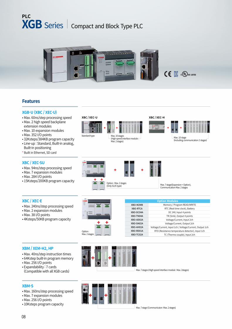
XBM-S• Max. 160ns/step processing speed• Max. 7 expansion modules• Max. 256 I/O points • 10Ksteps program capacity
XBC / XEC-SU• Max. 94ns/step processing speed• Max. 7 expansion modules• Max. 284 I/O points • 15Ksteps/200KB program capacity
XBC / XEC-E• Max. 240ns/step processing speed• Max. 2 expansion modules• Max. 38 I/O points • 4Ksteps/50KB program capacity
Features
XGB-U (XBC / XEC-U)• Max. 60ns/step processing speed• Max. 2 high speed backplane extension modules
• Max. 10 expansion modules• Max. 352 I/O points • 32Ksteps/384KB program capacity • Line-up : Standard, Built-in analog, Built-in positioning
* Built in Ethernet, SD card
Max. 10 stages (High speed interface module : Max. 2 stages)
Max. 10 stage(Including communication 2 stages)
Standard type
XBC / XEC-U XBC / XEC-H
Option : Max. 2 stages(Only SU/E type) Max. 7 stage(Expansion + Option),
Communication Max. 2 stages
Max. 7 stage (Communicaion Max. 2 stages)
Option : Max. 2 stages
XBO-M2MBXBO-RTCA
XBO-DC04AXBO-TN04AXBO-AD02AXBO-DA02AXBO-AH02AXBO-RD01AXBO-TC02A
Memory / Program READ/WRITERTC (Real time clock), Battery
DC 24V, Input 4 pointsTR (Sink), Output 4 pointsVoltage/Current, Input 2ch
Voltage/Current, Output 2chVoltage/Current, Input 1ch / Voltage/Current, Output 1ch
RTD (Resistance temperature detector), Input 1chTC (Thermo couple), Input 2ch
Option Modules
PLC
Compact and Block Type PLCXGB Series
XBM / XEM-H2, HP • Max. 40ns/step instruction times• 64Kstep built-in program memory• Max. 256 I/O points• Expandability : 7 cards (Compatible with all XGB cards) Max. 7 stages (High speed interface module : Max. 2stages)
| 0908
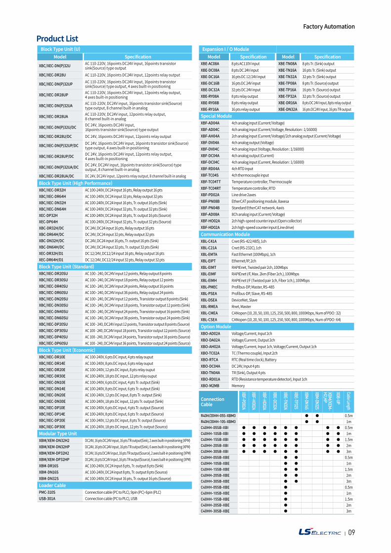
Product ListBlock Type Unit (U)
Model Specification
XBC/XEC-DN(P)32U AC 110-220V, 16points DC24V input, 16points transistor sink(Source) type output
XBC/XEC-DR28U AC 110-220V, 16points DC24V input, 12points relay output
XBC/XEC-DN(P)32UP AC 110-220V, 16points DC24V input, 16points transistor sink(Source) type output, 4 axes built-in positioning
XBC/XEC-DR28UP AC 110-220V, 16points DC24V input, 12points relay output, 4 axes built-in positioning
XBC/XEC-DN(P)32UA AC 110-220V, DC24V input, 16points transistor sink(Source) type output, 8 channel built-in analog
XBC/XEC-DR28UA AC 110-220V, DC24V input, 12points relay output, 8 channel built-in analog
XBC/XEC-DN(P)32U/DC DC 24V, 16points DC24V input, 16points transistor sink(Source) type output
XBC/XEC-DR28U/DC DC 24V, 16points DC24V input, 12points relay output
XBC/XEC-DN(P)32UP/DC DC 24V, 16points DC24V input, 16points transistor sink(Source) type output, 4 axes built-in positioning
XBC/XEC-DR28UP/DC DC 24V, 16points DC24V input, 12points relay output, 4 axes built-in positioning
XBC/XEC-DN(P)32UA/DC DC 24V, DC24V input, 16points transistor sink(Source) type output, 8 channel built-in analog
XBC/XEC-DR28UA/DC DC 24V, DC24V input, 12points relay output, 8 channel built-in analog
Block Type Unit (High Performance)XBC/XEC-DR32H AC 100-240V, DC24 input 16 pts, Relay output 16 ptsXBC/XEC-DR64H AC 100-240V, DC24 input 32 pts, Relay output 32 ptsXBC/XEC-DN32H AC 100-240V, DC24 input 16 pts, Tr. output 16 pts (Sink) XBC/XEC-DN64H AC 100-240V, DC24 input 32 pts, Tr. output 32 pts (Sink) XEC-DP32H AC 100-240V, DC24 input 16 pts, Tr. output 16 pts (Source) XEC-DP64H AC 100-240V, DC24 input 32 pts, Tr. output 32 pts (Source) XBC-DR32H/DC DC 24V, DC24 input 16 pts, Relay output 16 ptsXBC-DR64H/DC DC 24V, DC24 input 32 pts, Relay output 32 ptsXBC-DN32H/DC DC 24V, DC24 input 16 pts, Tr. output 16 pts (Sink)XBC-DN64H/DC DC 24V, DC24 input 32 pts, Tr. output 32 pts (Sink)XEC-DR32H/D1 DC 12/24V, DC12/24 input 16 pts, Relay output 16 ptsXEC-DR64H/D1 DC 12/24V, DC12/24 input 32 pts, Relay output 32 pts Block Type Unit (Standard)XBC/XEC-DR20SU AC 100 - 240, DC24V input 12 points, Relay output 8 pointsXBC/XEC-DR30SU AC 100 - 240, DC24V input 18 points, Relay output 12 pointsXBC/XEC-DR40SU AC 100 - 240, DC24V input 24 points, Relay output 16 pointsXBC/XEC-DR60SU AC 100 - 240, DC24V input 36 points, Relay output 24 pointsXBC/XEC-DN20SU AC 100 - 240, DC24V input 12 points, Transistor output 8 points (Sink)XBC/XEC-DN30SU AC 100 - 240, DC24V input 18 points, Transistor output 12 points (Sink)XBC/XEC-DN40SU AC 100 - 240, DC24V input 24 points, Transistor output 16 points (Sink)XBC/XEC-DN60SU AC 100 - 240, DC24V input 36 points, Transistor output 24 points (Sink)XBC/XEC-DP20SU AC 100 - 240, DC24V input 12 points, Transistor output 8 points (Source)XBC/XEC-DP30SU AC 100 - 240, DC24V input 18 points, Transistor output 12 points (Source)XBC/XEC-DP40SU AC 100 - 240, DC24V input 24 points, Transistor output 16 points (Source)XBC/XEC-DP60SU AC 100 - 240, DC24V input 36 points, Transistor output 24 points (Source)Block Type Unit (Economic)XBC/XEC-DR10E AC 100-240V, 6 pts DC input, 4 pts relay ouputXBC/XEC-DR14E AC 100-240V, 8 pts DC input, 6 pts relay ouputXBC/XEC-DR20E AC 100-240V, 12 pts DC input, 8 pts relay ouputXBC/XEC-DR30E AC 100-240V, 18 pts DC input, 12 pts relay ouputXBC/XEC-DN10E AC 100-240V, 6 pts DC input, 4 pts Tr. output (Sink)XBC/XEC-DN14E AC 100-240V, 8 pts DC input, 6 pts Tr. output (Sink)XBC/XEC-DN20E AC 100-240V, 12 pts DC input, 8 pts Tr. output (Sink)XBC/XEC-DN30E AC 100-240V, 18 pts DC input, 12 pts Tr. output (Sink) XBC/XEC-DP10E AC 100-240V, 6 pts DC input, 4 pts Tr. output (Source) XBC/XEC-DP14E AC 100-240V, 8 pts DC input, 6 pts Tr. output (Source) XBC/XEC-DP20E AC 100-240V, 12 pts DC input, 8 pts Tr. output (Source) XBC/XEC-DP30E AC 100-240V, 18 pts DC input, 12 pts Tr. output (Source) Modular Type UnitXBM/XEM-DN32H2 DC24V, 16 pts DC24V input, 16 pts TR output(Sink), 2 axes built-in positioning (XPM)XBM/XEM-DN32HP DC24V, 16 pts DC24V input, 16 pts TR output(Sink), 6 axes built-in positioning (XPM)XBM/XEM-DP32H2 DC24V, 16 pts DC24V input, 16 pts TR output(Source), 2 axes built-in positioning (XPM)XBM/XEM-DP32HP DC24V, 16 pts DC24V input, 16 pts TR output(Source), 6 axes built-in positioning (XPM)XBM-DR16S AC 100-240V, DC24 input 8 pts, Tr. output 8 pts (Sink) XBM-DN16S AC 100-240V, DC24 input 8 pts, Tr. output 8 pts (Source) XBM-DN32S AC 100-240V, DC24 input 16 pts, Tr. output 16 pts (Source) Loader CablePMC-310S Connection cable (PC to PLC), 9pin (PC)-6pin (PLC) USB-301A Connection cable (PC to PLC), USB
Connection Cable
R40H/20HH-05S-XBM3 0.5mR40H/20HH-10S-XBM3 1mC40HH-05SB-XBI 0.5mC40HH-10SB-XBI 1mC40HH-15SB-XBI 1.5mC40HH-20SB-XBI 2mC40HH-30SB-XBI 3mC40HH-05SB-XBE 0.5mC40HH-10SB-XBE 1mC40HH-15SB-XBE 1.5mC40HH-20SB-XBE 2mC40HH-30SB-XBE 3mC40HH-05SB-XBE 0.5mC40HH-10SB-XBE 1mC40HH-15SB-XBE 1.5mC40HH-20SB-XBE 2mC40HH-30SB-XBE 3m
XBM/XEM
-H2,HP
XGB-UP
Cable Length
XBF-PD02A
XBF-HO02A
XBE-DC32A
XBF-HD02A
XBE-TN32A
XBE-TP32S
XBM-DN32S
XBM-DN16S
Expansion I / O ModuleModel Specification
XBE-AC08A 8 pts AC110V inputXBE-DC08A 8 pts DC 24V inputXBE-DC16A 16 pts DC 12/24V inputXBE-DC16B 16 pts DC 24V inputXBE-DC32A 32 pts DC 24V inputXBE-RY08A 8 pts relay outputXBE-RY08B 8 pts relay outputXBE-RY16A 16 pts relay output
Model SpecificationXBE-TN08A 8 pts Tr. (Sink) outputXBE-TN16A 16 pts Tr. (Sink) outputXBE-TN32A 32 pts Tr. (Sink) outputXBE-TP08A 8 pts Tr. (Source) outputXBE-TP16A 16 pts Tr. (Source) outputXBE-TP32A 32 pts Tr. (Source) outputXBE-DR16A 8 pts DC 24V input, 8pts relay output XBE-DN32A 16 pts DC24V input, 16 pts TR output
Special ModuleXBF-AD04A 4ch analog input (Current/Voltage) XBF-AD04C 4ch analog input (Current/Voltage, Resolution : 1/16000) XBF-AH04A 2ch analog input (Current/Voltage)/2ch analog output (Current/Voltage) XBF-DV04A 4ch analog output (Voltage)XBF-DV04C 4ch analog input (Voltage, Resolution : 1/16000) XBF-DC04A 4ch analog output (Current)XBF-DC04C 4ch analog input (Current, Resolution : 1/16000) XBF-RD04A 4ch RTD inputXBF-TC04S 4ch thermocouple inputXBF-TC04TT Temperature controller, Thermocouple XBF-TC04RT Temperature controller, RTDXBF-PD02A Line drive 2axesXBF-PN08B EtherCAT positioning module, 8axesaXBF-PN04B Standard EtherCAT network, 4axisXBF-AD08A 8Ch analog input (Current/Voltage)XBF-HO02A 2ch high-speed counter input (Open collector) XBF-HD02A 2ch high-speed counter input (Line drive) Communication ModuleXBL-C41A Cnet (RS-422/485), 1chXBL-C21A Cnet (RS-232C), 1chXBL-EMTA Fast Ethernet (100Mbps), 1chXBL-EIPT Ethernet/IP, 2chXBL-EIMT RAPIEnet, Twisted pair 2ch, 100MbpsXBL-EIMF RAPIEnet I/F, Max. 2km (Fiber 2ch.), 100MbpsXBL-EIMH RAPIEnet I/F (Twisted pair 1ch, Fiber 1ch.), 100MbpsXBL-PMEC Profibus-DP, Master, RS-485XBL-PSEA Profibus-DP, Slave, RS-485XBL-DSEA DeviceNet, SlaveXBL-RMEA Rnet, MasterXBL-CMEA CANopen (10, 20, 50, 100, 125, 250, 500, 800, 1000Kbps, Num of PDO : 32) XBL-CSEA CANopen (10, 20, 50, 100, 125, 250, 500, 800, 1000Kbps, Num of PDO : 64) Option ModuleXBO-AD02A Voltage/Current, Input 2chXBO-DA02A Voltage/Current, Output 2chXBO-AH02A Voltage/Current, Input 1ch, Voltage/Current, Output 1ch XBO-TC02A TC (Thermo couple), Input 2chXBO-RTCA RTC (Real time clock), BatteryXBO-DC04A DC 24V, Input 4 ptsXBO-TN04A TR (Sink), Output 4 ptsXBO-RD01A RTD (Resistance temperature detector), Input 1ch XBO-M2MB Memory
Factory Automation
| 1110
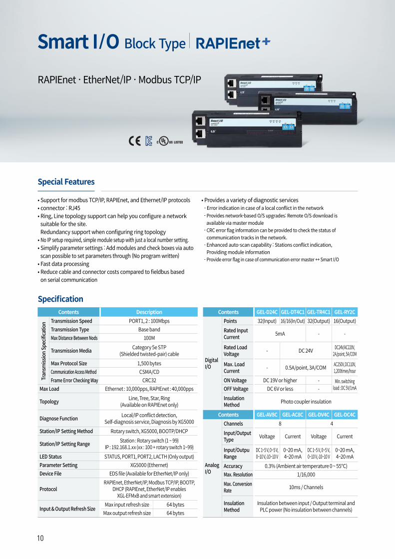
Smart I/O Block Type
Specification
• Support for modbus TCP/IP, RAPIEnet, and Ethernet/IP protocols• connector : RJ45• Ring, Line topology support can help you configure a network suitable for the site. Redundancy support when configuring ring topology
• No IP setup required, simple module setup with just a local number setting.• Simplify parameter settings : Add modules and check boxes via auto scan possible to set parameters through (No program written)
• Fast data processing • Reduce cable and connector costs compared to fieldbus based on serial communication
Contents DescriptionTransmission Speed PORT1, 2 : 100MbpsTransmission Type Base bandMax Distance Between Nods 100M
Transmission Media Category 5e STP (Shielded twisted-pair) cable
Max Protocol Size 1,500 bytesCommunication Access Method CSMA/CDFrame Error Checking Way CRC32
Max Load Ethernet : 10,000pps, RAPIEnet : 40,000pps
Topology Line, Tree, Star, Ring (Available on RAPIEnet only)
Diagnose Function Local/IP conflict detection, Self-diagnosis service, Diagnosis by XG5000
Station/IP Setting Method Rotary switch, XG5000, BOOTP/DHCP
Station/IP Setting Range Station : Rotary switch (1 ~ 99)IP : 192.168.1.xx (xx : 100 + rotary switch 1~99)
LED Status STATUS, PORT1, PORT2, LACTH (Only output)Parameter Setting XG5000 (Ethernet)Device File EDS file (Available for EtherNet/IP only)
ProtocolRAPIEnet, EtherNet/IP, Modbus TCP/IP, BOOTP,
DHCP (RAPIEnet, EtherNet/IP enables XGL-EFMxB and smart extension)
Input & Output Refresh SizeMax input refresh size 64 bytes
Max output refresh size 64 bytes
RAPIEnet · EtherNet/IP · Modbus TCP/IP
Special Features
Tran
smiss
ion
Spec
ificat
ion
• Provides a variety of diagnostic services- Error indication in case of a local conflict in the network- Provides network-based O/S upgrades: Remote O/S download is available via master module
- CRC error flag information can be provided to check the status of communication tracks in the network.
- Enhanced auto-scan capability : Stations conflict indication, Providing module information
- Provide error flag in case of communication error master ↔ Smart I/O
Contents GEL-D24C GEL-DT4C1 GEL-TR4C1 GEL-RY2C
Digital I/O
Points 32(Input) 16/16(In/Out) 32(Output) 16(Output)Rated Input Current 5mA - -
Rated Load Voltage - DC 24V DC24V/AC220V,
2A/point, 5A/COM
Max. Load Current - 0.5A/point, 3A/COM AC250V, DC110V,
1,200times/hourON Voltage DC 19V or higher - Min. switching
load : DC 5V/1mAOFF Voltage DC 6V or less -Insulation Method Photo coupler insulation
Contents GEL-AV8C GEL-AC8C GEL-DV4C GEL-DC4C
Analog I/O
Channels 8 4Input/Output Type Voltage Current Voltage Current
Input/Outpu Range
DC 1~5 V, 0~5 V,0~10 V,-10~10 V
0~20 mA, 4~20 mA
DC 1~5 V, 0~5 V,0~10 V,-10~10 V
0~20 mA, 4~20 mA
Accuracy 0.3% (Ambient air temperature 0 ~ 55)Max. Resolution 1/16,000Max. Conversion Rate 10ms / Channels
Insulation Method
Insulation between input / Output terminal and PLC power (No insulation between channels)
| 1110
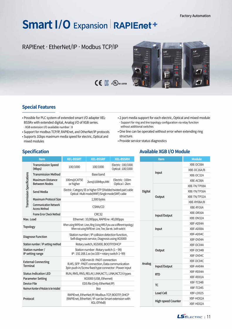
Smart I/O Expansion
• Possible for PLC system of extended smart I/O adapter XEL-BSSRx with extended digital, Analog I/O of XGB series.- XGB extension I/O available number : 8
• Support for modbus TCP/IP, RAPIEnet, and OtherNet/IP protocols• Supports 1Gbps maximum media speed for electric, Optical and mixed modules
Item Module
Digital
Input
XBE-DC08AXBE-DC16A/BXBE-DC32AXBE-AC08A
Output
XBE-TN/TP08AXBE-TN/TP16AXBE-TN/TP32AXBE-RY08A/BXBE-RY16A
Input/OutputXBE-DR16AXBE-DN32A
Analog
InputXBF-AD04AXBF-AD08AXBF-AD04C
Output
XBF-DV04AXBF-DC04AXBF-DC04BXBF-DV04CXBF-DC04C
Input/Output XBF-AH04A
RTDXBF-RD04AXBF-RD01A
TCXBF-TC04BXBF-TC04S
Load Cell XBF-LD02S
High-speed CounterXBF-HO02AXBF-HD02A
• 2 port media support for each electric, Optical and mixed module- Support for ring and line topology configuration via relay function without additional switches
• One line can be operated without error when extending ring structure.
• Provide service-status diagnostics
RAPIEnet · EtherNet/IP · Modbus TCP/IP
Specification Available XGB I/O ModuleItem XEL-BSSRT XEL-BSSRF XEL-BSSRH
Transmission Speed(Mbps) 100/1000 100/1000 Electric : 100/1000
Optical : 100/1000Transmission Method Base bandMaximum Distance Between Nodes
100m@CAT5E or higher [email protected] Electric : 100m
Optica l : 2km
Send Media Electric : Category 5E or higher STP (Shielded twisted-pair) cableOptical : Multi mode(MMF)/Single mode(SMF) cable
Maximum Protocol Size 1,500 bytesCommunication Network Access Method CSMA/CD
Frame Error Check Method CRC32Max. Load Ethernet : 10,000pps, RAPIEne : 40,000pps
Topology When using RAPIEnet : Lines, Ring (Using MRS if you use a different topology)When not using RAPIEnet : Line, Tree, Star etc. (with switch)
Diagnose Function Station number / IP collision detection function, Self-diagnosis service, Diagnosis using XG5000
Station number / IP setting method Rotary switch, XG5000, BOOTP/DHCPStation number / IP setting range
Station number : Rotary switch (1 ~ 99)IP : 192.168.1.xx (xx:100 + rotary switch 1~99)
External Connecting Terminal
USB mini B : PADT connectionRJ45, SFP : PADT connection, Data communication
3pin push in/Screw fixed type connector : Power input
Status Indication LED RUN, RMS, RNS, RELAY, LINK/ACT1, LINK/ACT2 6 typesParameter Setting XG5000 (USB, Ethernet)Device File EDS file (Only EtherNet/IP)Maximum Number of Modules to be Installed 8ea
ProtocolRAPIEnet, EtherNet/IP, Modbus-TCP, BOOTP, DHCP
(RAPIEnet, EtherNet / IP can be Smart extension with XGL-EFMxB)
Special Features
Tran
smiss
ion
Spec
ificat
ions
Factory Automation
| 1312
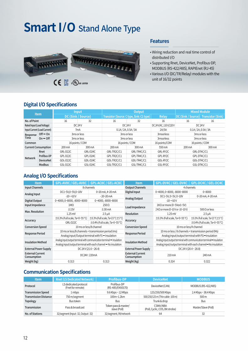
Smart I/O Stand Alone Type
• Wiring reduction and real time control of distributed I/O
• Supporting Rnet, DeviceNet, Profibus-DP, MODBUS (RS-422/485), RAPIEnet (RJ-45)
• Various I/O (DC/TR/Relay) modules with the unit of 16/32 points
Features
Item Input Output Mixed ModuleDC (Sink / Source) Transistor (Source: C type, Sink: C1 type) Relay DC (Sink / Source) Transistor (Sink)
No. of Point 16 32 16 32 16 16 16Rated Input (Load Voltage) DC 24 V DC 24 V DC 24 V/AC, 110 V/220 V DC 24 VInput Current (Load Current) 7mA 0.1A / 2A, 0.5A / 3A 2A/5A 0.1A / 2A, 0.5A / 3AResponse Time
Off On 3ms or less 3ms or less 3msorless 3ms or lessOn Off 3ms or less 3ms or less 3msorless 3ms or less
Common 16 points / COM 16 points / COM 16 points/COM 16 points / COMCurrent Consumption 200 mA 300 mA 200 mA 300 mA 550 mA 200 mA 300 mA
Network
Rnet GRL-D22C GRL-D24C GRL-TR2C/C1 GRL-TR4C/C1 GRL-RY2C GRL-DT4C/C1Profibus-DP GPL-D22C GPL-D24C GPL-TR2C/C1 GPL-TR4C/C1 GPL-RY2C GPL-DT4C/C1DeviceNet GDL-D22C GDL-D24C GDL-TR2C/C1 GDL-TR4C/C1 GDL-RY2C GDL-DT4C/C1Modbus GSL-D22C GSL-D24C GSL-TR2C/C1 GSL-TR4C/C1 GSL-RY2C GSL-DT4C/C1
Item GPL-AV8C / GEL-AV8C GPL-AC8C / GEL-AC8C Item GPL-DV4C / GEL-DV4C GPL-DC4C / GEL-DC4CInput Channels 8 channels Output Channels 4 channels
Analog InputDC1~5V,0~5V,0~10V 0~20 mA, 4~20 mA Digital Input 0~4000, 0~8000, -8000~8000 0~8000
-10~+10 V - 20~20 mAAnalog Output
DC1~5V, 0~5V, 0~10V 0~20 mA, 4~20 mADigital Output 0~4000, 0~8000, -8000~8000 0~4000, -8000~8000 -10~+10 VInput Impedance 1MΩ 250 Ω
Load Impedance1KΩ or more (0~5Vor1~5V)
Max. Resolution±15V ±30 mA 2 KΩ or more (0~10 V or -10~10 V) 500 Ω or less
1.25 mV 2.5 μA Resolution 1.25 mV 2.5 μA
Accuracy±0.3% (Full scale, Ta=0~55 °C) ±0.3% (Full scale, Ta=23 °C±5 °C)
Accuracy±0.3% (Full scale, Ta=0~55 °C) ±0.3% (Full scale, Ta=23 °C±5 °C)
GRL-D22C ±0.4% (Full scale, Ta=0~55 °C) ±0.4% (Full scale, Ta=0~55 °C)Conversion Speed 10 ms or less/8 channel Conversion Speed 10 ms or less/4 channel
Response Period10 ms or less/8 channels + transmission period (ms)
Response Period10 ms or less / 8 channels + transmission period (Ms)
Analog input/Output terminal with FG Insulation Analog input/output terminal with FGinsulation
Insulation MethodAnalog input/output terminal with communication terminal Insulation
Insulation MethodAnalog input/output terminal with communication terminalInsulation
Analog input/output terminal with each channel No insulation Analog input/output terminal with each channelNo insulationExternal Power Supply DC 24 V (21.6 ~ 26.4) External Power Supply DC 24 V (20.4 ~ 28.8)External Current Consumption DC24V : 220mA External Current
Consumption 210 mA 240 mA
Weight (kg) 0.313 0.313 Weight (kg) 0.314 0.322
Item Rnet (LS Dedicated Network) Profibus-DP DeviceNet MODBUS
Protocol LS dedicated protocol (Fnet for remote)
Profibus-DP (RS-485/EN50170) DeviceNet (CAN) MODBUS (RS-422/485)
Transmission Speed 1 mbps 9.6 Kbps ~ 12 Mbps 125/250/500 Kbps 2.4 Kbps ~ 38.4 KbpsTransmission Distance 750 m/segment 100m~1.2km 500/250/125 m (Thin cable : 100 m) 500 mTopology Bus token Bus Trunk & drop Bus
Transmission Pass & broadcast Token pass & master/slave (Poll)
CSMA/NBA(Poll, Cyclic, COS, Bit strobe) Master/Slave (Poll)
No. of Stations 32/segment (Input : 32, Output : 32) 32/segment, 99/network 64 32
Digital I/O Specifications
Analog I/O Specifications
Communication Specifications
| 1312
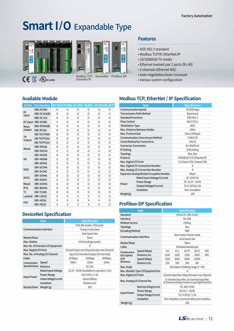
• IEEE 802.3 standard• Modbus TCP/IP, EtherNet/IP• 10/100BASE-TX media• Ethernet twisted pair 2 ports (RJ-45)• 2 channels Ethernet MAC • Auto-negotiation/Auto-crossover• Various system configuration
Smart I/O Expandable TypeFeatures
In/Out Part Number XDL-BSSA XPL-BSSA XEL-BSSA XEL-BSSB XRL-BSSA XEL-BSSCT
DC Input
XBE-DC08A O O O O O OXBE-DC16A(B) O O O O O OXBE-DC32A O O O O O O
AC Input XBE-AC08A X O O O O ORelay Output
XBE-RY08A(B) O O O O O OXBE-RY16A O O O O O O
TR Output
XBE-TN(TP)08A O O O O O OXBE-TN(TP)16A O O O O O OXBE-TN(TP)32A O O O O O O
MixedXBE-DR16A O O O O O OXBE-DN32A X X O O X O
ADXBF-AD04A O O O O O OXBF-AD08A X O O O O OXBF-AD04C X O O O O O
DA(I)XBF-DC04A O O O O O OXBF-DC04C X O O O O O
DA(V)XBF-DV04A O O O O O OXBF-DV04C X O O O O O
Mixed XBF-AH04A O O O O O ORTD XBF-RD04A O O O O O OTC XBF-TC04S O O O O O OLoadcell XBF-LD02S X X X X X O
HSCXBF-HO2A X X X X X OXBF-HD2A X X X X X O
Item SpecificationCommunication Speed 10/100mbps Transmission Path Method Base band Standard Functions IEEE 802.3 Flow Control HALF/FULL Modulation Type NRZI Max. Distance Between Nodes 100mMax. Protocol Size Data 1500byte Communication Zone Access Method CSMA/CDCheck Method for Frame Error CRC32 Connector Connection RJ-45(2Port)IP Setting S/W settingTopology Bus, Star Protocol MODBUS/TCP, EtherNet/IP Max. Digital I/O Point 512 (Input 256, Output 256) Max. Digital I/O Connection Number 8Max. Analog I/O Connection Number 8Expansion Analog Module Occupation Number 8byte
Power
Rated Input Voltage/Current DC 24V/0.7APower Range DC 19.2V ~ 28.8V Output Voltage/Current 5V (±20%)/1.5A Insulation Non-insulation
Weight(g) 100
Item SpecificationStandard EN50170 / DIN 19245 Interface RS-485 Medium Access Polling Topology Bus Encoding Method NRZ
Communication Interface Sink mode, Freeze mode Auto baud rate
Master/Slave SlaveCable Shielded twisted pair
Communica- tion Speed and Distance
Speed (Kbps) 9.6 19.2 93.75 187.5 500Distance (m) 1200 1200 1200 1000 400Speed (Kbps) 1500 3000 6000 12000 -Distance (m) 200 100 100 100 -
Max. Node 100 station (Setting range: 0 ~ 99 )Max. Modular Type I/O Equipment No. 8Max. Digital I/O Point 512point (Input Max.256point/output max.256point)
Max. Analog I/O Channel No. 32 channels (Input Max. 16 channels/output Max. 16 channels) (Analog module occupy Digital 64 point)
Input Power
Rated Input Voltage/Current DC 24V/ 0.55APower Range DC19.2 ~ 28.8VOutput Voltage/Current 5V (±20%) / 1.5AInsulation Non-insulation, Communication part insulation
Weight (g) 100
Item Specification
Communication InterfacePoll, Bit-strobe, COS/cyclic
Group 2 only slaveAuto baud rate
Master/Slave SlaveMax. Station 64 (Including master)Max. No. of Extension I/O Equipment 8Max. Digital I/O Point 512 point (Input max 256 point/output max 256 point)Max. No. of Analog I/O Channel Input 16 channels (Output 16 channels)Cable 125kbps 250kbps 500kbpsCommunication Speed & Distance
Speed 500m 250m 100mDistance DC 24V
Input Power
Rated Input Voltage 19.2V ~ 28.8V (Available to operate in 11V)Power Range 5V(±20%) /1.5AOutput Voltage/Current Speed (Kbps)Insulation Distance (m)
BasicSpecification Weight (g) 100
Available Module Modbus TCP, EtherNet / IP Specification
Profibus-DP Specification
DeviceNet Specification
Modbus TCP,EtherNet/IP
DeviceNet Profibus-DP
Factory Automation
| 1514
High speed counter module
Analog moduleUSB
Input/Output module
Master_XMC or others Temperature module
EtherCAT I/OServo & motor
Inverter
Loadcell module
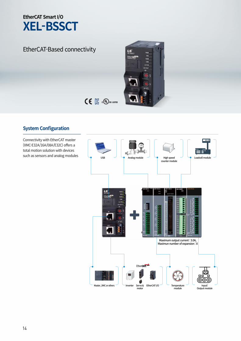
Maximum output current : 3.0A, Maximun number of expansion : 8
XEL-BSSCTEtherCAT Smart I/O
System Configuration
Connectivity with EtherCAT master (XMC-E32A/16A/08A/E32C) offers a total motion solution with devices such as sensors and analog modules
EtherCAT-Based connectivity
| 1514
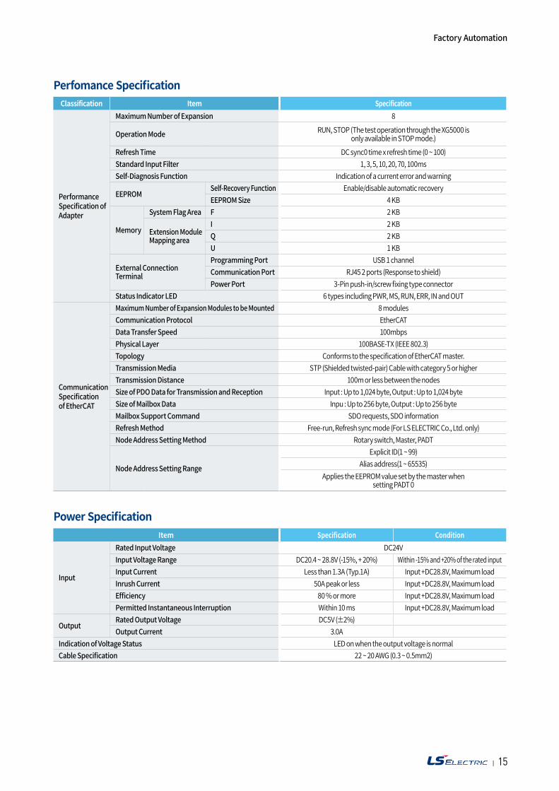
Perfomance Specification
Power Specification
Classification Item Specification
Performance Specification of Adapter
Maximum Number of Expansion 8
Operation Mode RUN, STOP (The test operation through the XG5000 is only available in STOP mode.)
Refresh Time DC sync0 time x refresh time (0 ~ 100)Standard Input Filter 1, 3, 5, 10, 20, 70, 100ms Self-Diagnosis Function Indication of a current error and warning
EEPROMSelf-Recovery Function Enable/disable automatic recoveryEEPROM Size 4 KB
Memory
System Flag Area F 2 KB
Extension Module Mapping area
I 2 KBQ 2 KBU 1 KB
External Connection Terminal
Programming Port USB 1 channelCommunication Port RJ45 2 ports (Response to shield)Power Port 3-Pin push-in/screw fixing type connector
Status Indicator LED 6 types including PWR, MS, RUN, ERR, IN and OUT
Communication Specification of EtherCAT
Maximum Number of Expansion Modules to be Mounted 8 modulesCommunication Protocol EtherCATData Transfer Speed 100mbpsPhysical Layer 100BASE-TX (IEEE 802.3)Topology Conforms to the specification of EtherCAT master.Transmission Media STP (Shielded twisted-pair) Cable with category 5 or higherTransmission Distance 100m or less between the nodesSize of PDO Data for Transmission and Reception Input : Up to 1,024 byte, Output : Up to 1,024 byteSize of Mailbox Data Inpu : Up to 256 byte, Output : Up to 256 byteMailbox Support Command SDO requests, SDO informationRefresh Method Free-run, Refresh sync mode (For LS ELECTRIC Co., Ltd. only)Node Address Setting Method Rotary switch, Master, PADT
Node Address Setting Range
Explicit ID(1 ~ 99)Alias address(1 ~ 65535)
Applies the EEPROM value set by the master when setting PADT 0
Item Specification Condition
Input
Rated Input Voltage DC24VInput Voltage Range DC20.4 ~ 28.8V (-15%, + 20%) Within -15% and +20% of the rated inputInput Current Less than 1.3A (Typ.1A) Input +DC28.8V, Maximum loadInrush Current 50A peak or less Input +DC28.8V, Maximum loadEfficiency 80 % or more Input +DC28.8V, Maximum loadPermitted Instantaneous Interruption Within 10 ms Input +DC28.8V, Maximum load
OutputRated Output Voltage DC5V (±2%)Output Current 3.0A
Indication of Voltage Status LED on when the output voltage is normalCable Specification 22 ~ 20 AWG (0.3 ~ 0.5mm2)
Factory Automation
| 1716
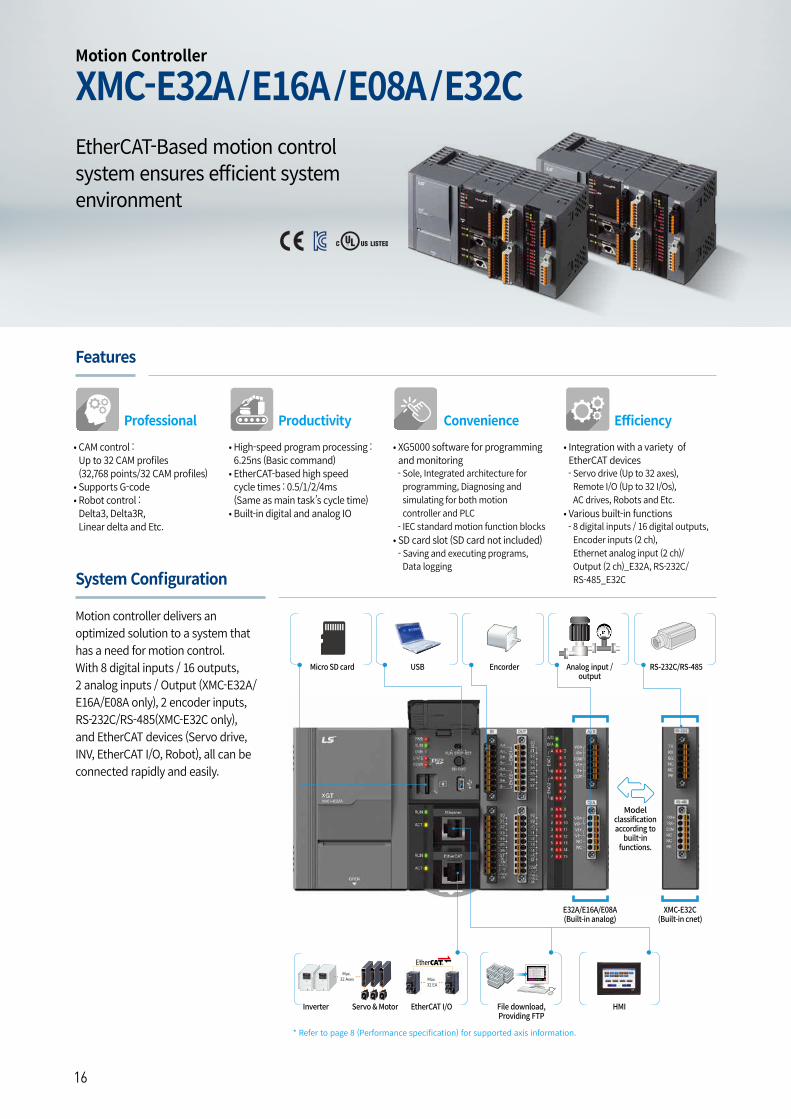
EtherCAT-Based motion control system ensures efficient system environment
• CAM control : Up to 32 CAM profiles(32,768 points/32 CAM profiles)
• Supports G-code• Robot control : Delta3, Delta3R, Linear delta and Etc.
Professional
• High-speed program processing : 6.25ns (Basic command)
• EtherCAT-based high speed cycle times : 0.5/1/2/4ms (Same as main task’s cycle time)
• Built-in digital and analog IO
Productivity
• Integration with a variety of EtherCAT devices- Servo drive (Up to 32 axes), Remote I/O (Up to 32 I/Os), AC drives, Robots and Etc.
• Various built-in functions- 8 digital inputs / 16 digital outputs, Encoder inputs (2 ch), Ethernet analog input (2 ch)/Output (2 ch)_E32A, RS-232C/RS-485_E32C
Efficiency
• XG5000 software for programming and monitoring - Sole, Integrated architecture for programming, Diagnosing and simulating for both motion controller and PLC
- IEC standard motion function blocks• SD card slot (SD card not included)- Saving and executing programs, Data logging
Convenience
HMIFile download,Providing FTP
EtherCAT I/OServo & MotorInverter
Encorder Analog input / output
RS-232C/RS-485USBMicro SD card
E32A/E16A/E08A(Built-in analog)
XMC-E32C(Built-in cnet)
* Refer to page 8 (Performance specification) for supported axis information.
System Configuration
Motion controller delivers an optimized solution to a system that has a need for motion control.With 8 digital inputs / 16 outputs, 2 analog inputs / Output (XMC-E32A/E16A/E08A only), 2 encoder inputs, RS-232C/RS-485(XMC-E32C only), and EtherCAT devices (Servo drive, INV, EtherCAT I/O, Robot), all can be connected rapidly and easily.
Model classificationaccording to
built-in functions.
Motion Controller
XMC-E32A/E16A/E08A/E32C
Features
| 1716
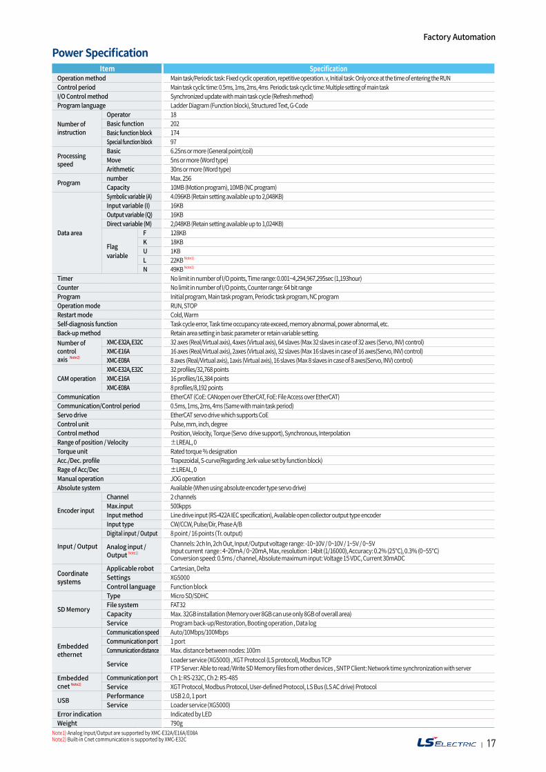
Power Specification Factory Automation
Item Specification Operation method Main task/Periodic task: Fixed cyclic operation, repetitive operation. v, Initial task: Only once at the time of entering the RUN Control period Main task cyclic time: 0.5ms, 1ms, 2ms, 4ms Periodic task cyclic time: Multiple setting of main taskI/O Control method Synchronized update with main task cycle (Refresh method) Program language Ladder Diagram (Function block), Structured Text, G-Code
Number of instruction
Operator 18Basic function 202Basic function block 174Special function block 97
Processing speed
Basic 6.25ns or more (General point/coil) Move 5ns or more (Word type) Arithmetic 30ns or more (Word type)
Program number Max. 256 Capacity 10MB (Motion program), 10MB (NC program)
Data area
Symbolic variable (A) 4.096KB (Retain setting available up to 2,048KB) Input variable (I) 16KB Output variable (Q) 16KB Direct variable (M) 2,048KB (Retain setting available up to 1,024KB)
Flag variable
F 128KBK 18KBU 1KBL 22KB Note1)
N 49KB Note1)
Timer No limit in number of I/O points, Time range: 0.001~4,294,967,295sec (1,193hour) Counter No limit in number of I/O points, Counter range: 64 bit range Program Initial program, Main task program, Periodic task program, NC program Operation mode RUN, STOP Restart mode Cold, Warm Self-diagnosis function Task cycle error, Task time occupancy rate exceed, memory abnormal, power abnormal, etc.Back-up method Retain area setting in basic parameter or retain variable setting. Number of control axis Note2)
XMC-E32A, E32C 32 axes (Real/Virtual axis), 4axes (Virtual axis), 64 slaves (Max 32 slaves in case of 32 axes (Servo, INV) control)XMC-E16A 16 axes (Real/Virtual axis), 2axes (Virtual axis), 32 slaves (Max 16 slaves in case of 16 axes(Servo, INV) control)XMC-E08A 8 axes (Real/Virtual axis), 1axis (Virtual axis), 16 slaves (Max 8 slaves in case of 8 axes(Servo, INV) control)
CAM operation XMC-E32A, E32C 32 profiles/32,768 pointsXMC-E16A 16 profiles/16,384 pointsXMC-E08A 8 profiles/8,192 points
Communication EtherCAT (CoE: CANopen over EtherCAT, FoE: File Access over EtherCAT) Communication/Control period 0.5ms, 1ms, 2ms, 4ms (Same with main task period) Servo drive EtherCAT servo drive which supports CoE Control unit Pulse, mm, inch, degree Control method Position, Velocity, Torque (Servo drive support), Synchronous, Interpolation Range of position / Velocity ±LREAL, 0 Torque unit Rated torque % designation Acc./Dec. profile Trapezoidal, S-curve(Regarding Jerk value set by function block)Rage of Acc/Dec ±LREAL, 0 Manual operation JOG operation Absolute system Available (When using absolute encoder type servo drive)
Encoder input
Channel 2 channelsMax.input 500kpps Input method Line drive input (RS-422A IEC specification), Available open collector output type encoder Input type CW/CCW, Pulse/Dir, Phase A/B
Input / Output
Digital input / Output 8 point / 16 points (Tr. output)
Analog input / Output Note1)
Channels: 2ch In, 2ch Out, Input / Output voltage range: -10~10V / 0~10V / 1~5V / 0~5V Input current range : 4~20mA / 0~20mA, Max, resolution : 14bit (1/16000), Accuracy: 0.2% (25), 0.3% (0~55)Conversion speed: 0.5ms / channel, Absolute maximum input: Voltage 15 VDC, Current 30mADC
Coordinate systems
Applicable robot Cartesian, DeltaSettings XG5000Control language Function block
SD Memory
Type Micro SD/SDHCFile system FAT32Capacity Max. 32GB installation (Memory over 8GB can use only 8GB of overall area) Service Program back-up/Restoration, Booting operation , Data log
Embedded ethernet
Communication speed Auto/10Mbps/100MbpsCommunication port 1 portCommunication distance Max. distance between nodes: 100m
Service Loader service (XG5000) , XGT Protocol (LS protocol), Modbus TCPFTP Server: Able to read / Write SD Memory files from other devices , SNTP Client: Network time synchronization with server
Embedded cnet Note2)
Communication port Ch 1: RS-232C, Ch 2: RS-485Service XGT Protocol, Modbus Protocol, User-defined Protocol, LS Bus (LS AC drive) Protocol
USB Performance USB 2.0, 1 portService Loader service (XG5000)
Error indication Indicated by LEDWeight 790g
Note1) Analog Input/Output are supported by XMC-E32A/E16A/E08ANote2) Built-in Cnet communication is supported by XMC-E32C
| 1918
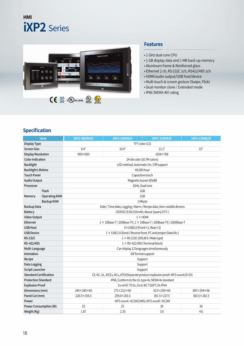
iXP2 SeriesHMI
• 1 GHz dual core CPU• 1 GB display data and 1 MB back-up memory • Aluminum frame & Reinforced glass • Ethernet 2 ch, RS-232C 1ch, RS422/485 1ch. • HDMI/audio output/USB host/device• Multi touch & screen gesture (Swipe, Flick) • Dual monitor clone / Extended mode• IP66 (NEMA 4X) rating
Features
Item iXP2-0800A/D iXP2-1000A/D iXP2-1200A/D iXP2-1500A/DDisplay Type TFT color LCDScreen Size 8.4" 10.4" 12.1" 15"Display Resolution 800×600 1024×768Color Indication 24-bit color (16.7M colors)Backlight LED method, Automatic On / Off supportBacklight Lifetime 40,000 hourTouch Panel Capacitive touchAudio Output Magnetic buzzer (85dB)Processor 1GHz, Dual core
MemoryFlash 1GBOperating RAM 1GBBackup RAM 1 Mbyte
Backup Data Date / Time data, Logging / Alarm / Recipe data, Non-volatile devices Battery CR2032 (3.0V/210mAh, About 3years/25°C )Video Output 1 × HDMIEthernet 1 × 10Base-T / 100Base-TX, 1 × 10Base-T / 100Base-TX / 1000Base-T USB Host 3×USB2.0 (Front×1, Rear×2)USB Device 1 × USB 2.0 (Send / Receive front, PC and project Data Etc.)RS-232C 1 × RS-232C (DSUB 9 / Male type)RS-422/485 1 × RS-422/485 (Terminal block)Multi-Language Can display 12 languages simultaneouslyAnimation GIF format supportRecipe SupportData Logging SupportScript Launcher SupportStandard Certification CE, KC, UL, IECEx, KCs, ATEX(Separate product explosion proof: iXP2-xxxxA/D-EX)Protection Standard IP66, Conform to the UL type 4x, NEMA 4x standardExplosion Proof Ex nA IIC T5 Gc, Ex tc IIIC T100°C Dc IP64 Dimensions (mm) 240×180×60 271×212×60 313×239×60 395×294×66Panel Cut (mm) 228.5×158.5 259.0×201.0 301.5×227.5 383.5×282.5Power iXP2-xxxxA : AC100/240V, iXP2-xxxxD : DC24VPower Consumption (W) 25 25 30 30Weight (Kg) 1.87 2.35 3.0 4.6
Specification
| 1918
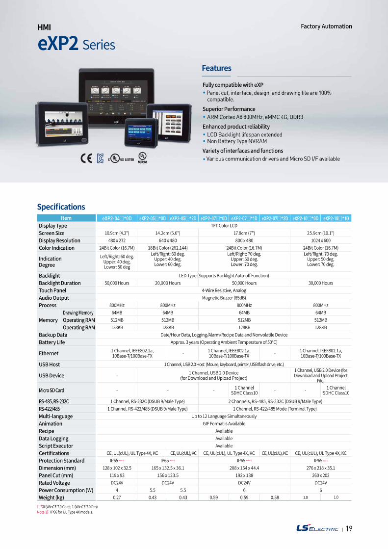
eXP2 Series HMI
Features
Specifications
Fully compatible with eXPPanel cut, interface, design, and drawing file are 100% compatible.
Superior PerformanceARM Cortex A8 800MHz, eMMC 4G, DDR3
Enhanced product reliabilityLCD Backlight lifespan extended Non Battery Type NVRAM
Variety of interfaces and functionsVarious communication drivers and Micro SD I/F available
Item eXP2-04*0D eXP2-05*0D eXP2-05*2D eXP2-07*0D eXP2-07*1D eXP2-07*2D eXP2-10*0D eXP2-10*1DDisplay Type TFT Color LCDScreen Size 10.9cm (4.3") 14.2cm (5.6") 17.8cm (7") 25.9cm (10.1")Display Resolution 480 x 272 640 x 480 800 x 480 1024 x 600Color Indication 24Bit Color (16.7M) 18Bit Color (262,144) 24Bit Color (16.7M) 24Bit Color (16.7M)
Indication Degree
Left/Right: 60 deg.Upper: 40 deg.Lower: 50 deg
Left/Right: 60 deg.Upper: 40 deg.Lower: 60 deg.
Left/Right: 70 deg.Upper: 50 deg.Lower: 70 deg.
Left/Right: 70 deg.Upper: 50 deg.Lower: 70 deg.
Backlight LED Type (Supports Backlight Auto-off Function)Backlight Duration 50,000 Hours 20,000 Hours 50,000 Hours 30,000 HoursTouch Panel 4-Wire Resistive, AnalogAudio Output Magnetic Buzzer (85dB)Process 800MHz 800MHz 800MHz 800MHz
MemoryDrawing Memory 64MB 64MB 64MB 64MBOperating RAM 512MB 512MB 512MB 512MBOperating RAM 128KB 128KB 128KB 128KB
Backup Data Date/Hour Data, Logging/Alarm/Recipe Data and Nonvolatile DeviceBattery Life Approx. 3 years (Operating Ambient Temperature of 50)
Ethernet 1 Channel, IEEE802.1a,10Base-T/100Base-TX - 1 Channel, IEEE802.1a,
10Base-T/100Base-TX - 1 Channel, IEEE802.1a,10Base-T/100Base-TX
USB Host 1 Channel, USB 2.0 Host (Mouse, keyboard, printer, USB flash drive, etc.)
USB Device - 1 Channel, USB 2.0 Device (for Download and Upload Project)
1 Channel, USB 2.0 Device (for Download and Upload Project
File)
Micro SD Card - - - 1 Channel SDHC Class10 - - 1 Channel
SDHC Class10
RS-485, RS-232C 1 Channel, RS-232C (DSUB 9/Male Type) 2 Channels, RS-485, RS-232C (DSUB 9/Male Type)RS-422/485 1 Channel, RS-422/485 (DSUB 9/Male Type) 1 Channel, RS-422/485 Mode (Terminal Type)Multi-language Up to 12 Language SimultaneouslyAnimation GIF Format is AvailableRecipe AvailableData Logging AvailableScript Executor AvailableCertifications CE, UL(cUL), UL Type 4X, KC CE, UL(cUL), KC CE, UL(cUL), UL Type 4X, KC CE, UL(cUL), KC CE, UL(cUL), UL Type 4X, KCProtection Standard IP65 Note 1) IP65 Note 1) IP65 Note 1) IP65 Note 1)
Dimension (mm) 128 x 102 x 32.5 165 x 132.5 x 36.1 208 x 154 x 44.4 276 x 218 x 35.1Panel Cut (mm) 119 x 93 156 x 123.5 192 x 138 260 x 202Rated Voltage DC24V DC24V DC24V DC24VPower Consumption (W) 4 5.5 5.5 6 6Weight (kg) 0.27 0.43 0.43 0.59 0.59 0.58 1.0 1.0
*:0 (WinCE 7.0 Core), 1 (WinCE 7.0 Pro)Note 1): IP66 for UL Type 4X models.
Factory Automation
| 2120
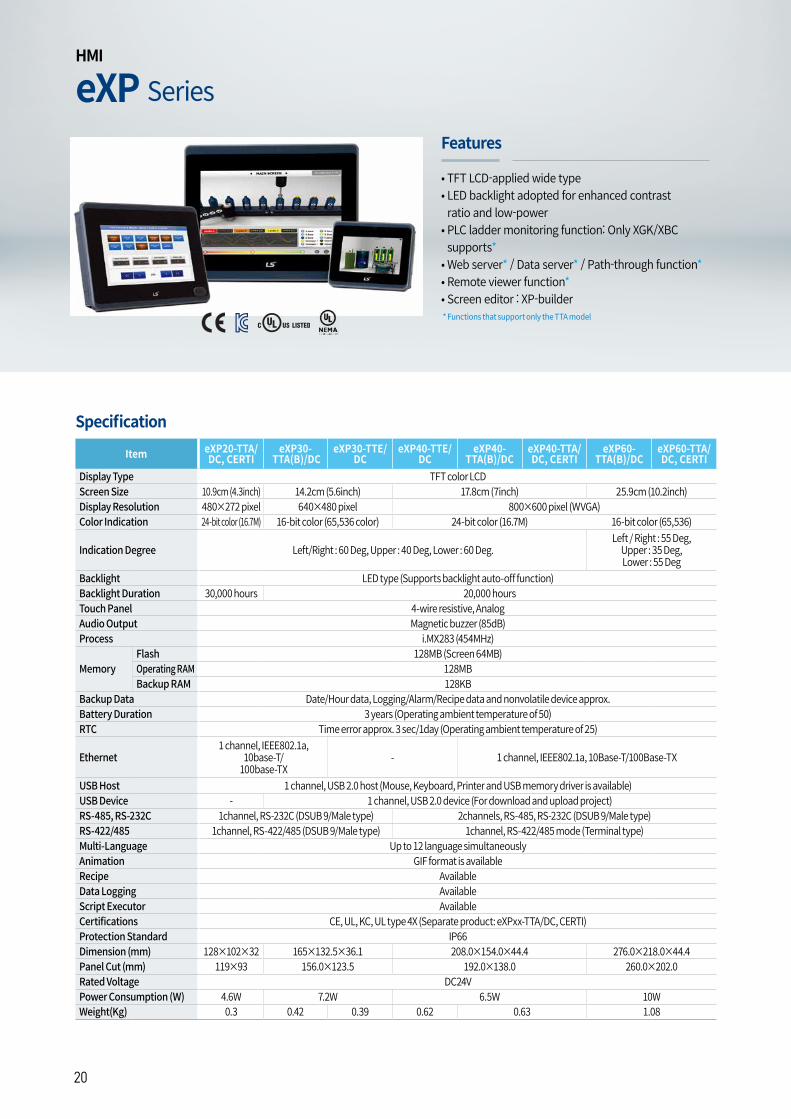
eXP SeriesHMI
• TFT LCD-applied wide type• LED backlight adopted for enhanced contrast ratio and low-power
• PLC ladder monitoring function: Only XGK/XBC supports*
• Web server* / Data server* / Path-through function*• Remote viewer function*• Screen editor : XP-builder*FunctionsthatsupportonlytheTTAmodel
Features
Item eXP20-TTA/DC, CERTI
eXP30- TTA(B)/DC
eXP30-TTE/DC
eXP40-TTE/DC
eXP40- TTA(B)/DC
eXP40-TTA/DC, CERTI
eXP60- TTA(B)/DC
eXP60-TTA/DC, CERTI
Display Type TFT color LCDScreen Size 10.9cm (4.3inch) 14.2cm (5.6inch) 17.8cm (7inch) 25.9cm (10.2inch)Display Resolution 480×272 pixel 640×480 pixel 800×600 pixel (WVGA)Color Indication 24-bit color (16.7M) 16-bit color (65,536 color) 24-bit color (16.7M) 16-bit color (65,536)
Indication Degree Left/Right : 60 Deg, Upper : 40 Deg, Lower : 60 Deg.Left / Right : 55 Deg,
Upper : 35 Deg, Lower : 55 Deg
Backlight LED type (Supports backlight auto-off function)Backlight Duration 30,000 hours 20,000 hoursTouch Panel 4-wire resistive, AnalogAudio Output Magnetic buzzer (85dB)Process i.MX283 (454MHz)
MemoryFlash 128MB (Screen 64MB)Operating RAM 128MBBackup RAM 128KB
Backup Data Date/Hour data, Logging/Alarm/Recipe data and nonvolatile device approx. Battery Duration 3 years (Operating ambient temperature of 50)RTC Time error approx. 3 sec/1day (Operating ambient temperature of 25)
Ethernet1 channel, IEEE802.1a,
10base-T/100base-TX
- 1 channel, IEEE802.1a, 10Base-T/100Base-TX
USB Host 1 channel, USB 2.0 host (Mouse, Keyboard, Printer and USB memory driver is available)USB Device - 1 channel, USB 2.0 device (For download and upload project)RS-485, RS-232C 1channel, RS-232C (DSUB 9/Male type) 2channels, RS-485, RS-232C (DSUB 9/Male type)RS-422/485 1channel, RS-422/485 (DSUB 9/Male type) 1channel, RS-422/485 mode (Terminal type)Multi-Language Up to 12 language simultaneously Animation GIF format is available Recipe AvailableData Logging AvailableScript Executor AvailableCertifications CE, UL, KC, UL type 4X (Separate product: eXPxx-TTA/DC, CERTI)Protection Standard IP66Dimension (mm) 128×102×32 165×132.5×36.1 208.0×154.0×44.4 276.0×218.0×44.4Panel Cut (mm) 119×93 156.0×123.5 192.0×138.0 260.0×202.0Rated Voltage DC24VPower Consumption (W) 4.6W 7.2W 6.5W 10WWeight(Kg) 0.3 0.42 0.39 0.62 0.63 1.08
Specification
| 2120
iXP SeriesHMI
Features
Specification
Factory Automation
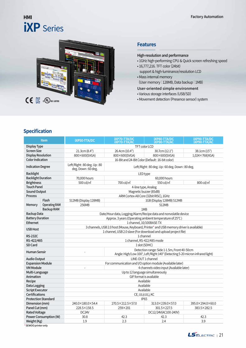
High-resolution and performance• 1GHz high-performing CPU & Quick screen refreshing speed • 16,777,216. TFT color (24bit) support & high-luminance/resolution LCD • Mass internal memory (User memory : 128MB, Data backup : 1MB)User-oriented simple environment• Various storage interfaces (USB/SD)• Movement detection (Presence sensor) system
Item iXP50-TTA/DC iXP70-TTA/DCiXP70-TTA/AC
iXP80-TTA/DCiXP80-TTA/AC
iXP90-TTA/DCiXP90-TTA/AC
Display Type TFT color LCDScreen Size 21.3cm (8.4″) 26.4cm (10.4″) 30.7cm (12.1″) 38.1cm (15″)Display Resolution 800×600(SVGA) 800×600(SVGA) 800×600(SVGA) 1,024×768(XGA)Color Indication 16-Bit and 24-Bit Color (Default : 16-bit color)
Indication Degree Left/Right : 80 deg. Up : 80 deg. Down : 60 deg. Left/Right : 80 deg. Up : 60 deg. Down : 80 deg.
Backlight LED typeBacklight Duration 70,000 hours 60,000 hoursBrightness 500 cd/ 700 cd/ 550 cd/ 800 cd/Touch Panel 4-line type, AnalogSound Output Magnetic buzzer (85dB)Process ARM Cortex-A8 Core (32bit RISC), 1GHz
MemoryFlash 512MB (Display 128MB) 1GB (Display 128MB) 512MBOperating RAM 256MB 512MBBackup RAM 1MB
Backup Data Date/Hour data, Logging/Alarm/Recipe data and nonvolatile deviceBattery Duration Approx. 3 years (Operating ambient temperature of 25°C )Ethernet 1 channel, 10/100BASE-TX
USB Host 3 channels, USB 2.0 host (Mouse, Keyboard, Printer* and USB memory driver is available)1 channel, USB 2.0 slave (For download and upload project file)
RS-232C 1 channelRS-422/485 1 channel, RS-422/485 modeSD Card 1 slot (SDHC)
Human Sensir - Detection range: Side 1-1.5m, Front 40-50cmAngle: High/Low 100°, Left/Right 140° (Detecting 5-20 micron infrared light)
Audio Output LINE-OUT 1 channelExpansion Module For communication and I/O option module (Available later)VM Module - 4 channels video input (Available later)Multi-Language Up to 12 language simultaneouslyAnimation GIF format is availableRecipe AvailableData Logging AvailableScript Executor AvailableCertifications CE, UL(cUL), KCProtection Standard IP65Dimension (mm) 240.0×180.0×54.4 270.5×212.5×57.0 313.0×239.0×57.0 395.0×294.0×60.0Panel Cut (mm) 228.5×158.5 259×201 301.5×227.5 383.5×282.5Rated Voltage DC24V DC12/24V(AC100-240V)Power Consumption (W) 30.8 42.3 42.3 42.3Weight (Kg) 1.9 2.3 2.4 3.9
* SEWOO printer only
| 2322
iXP2H SeriesNew Handyheld HMI
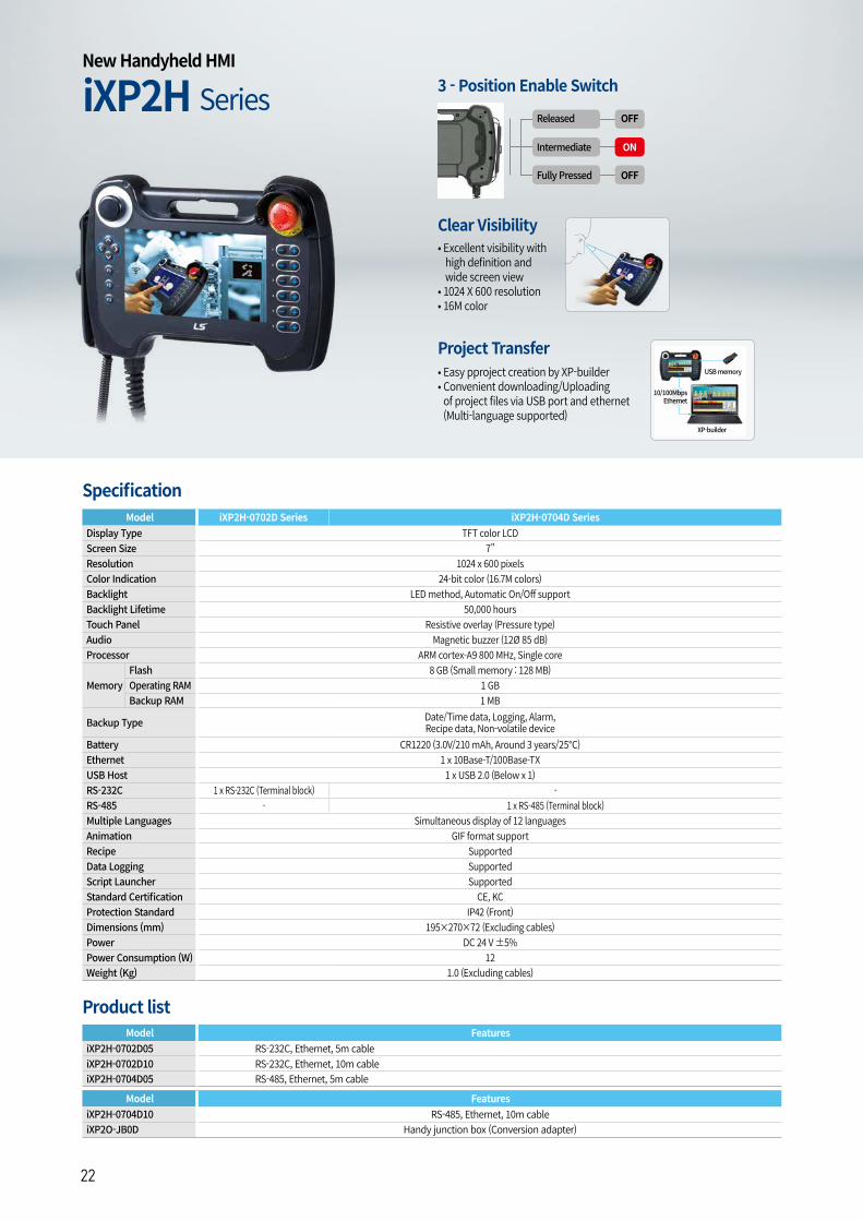
Model iXP2H-0702D Series iXP2H-0704D SeriesDisplay Type TFT color LCDScreen Size 7”Resolution 1024 x 600 pixelsColor Indication 24-bit color (16.7M colors)Backlight LED method, Automatic On/Off supportBacklight Lifetime 50,000 hoursTouch Panel Resistive overlay (Pressure type)Audio Magnetic buzzer (12Ø 85 dB)Processor ARM cortex-A9 800 MHz, Single core
MemoryFlash 8 GB (Small memory : 128 MB)Operating RAM 1 GBBackup RAM 1 MB
Backup Type Date/Time data, Logging, Alarm, Recipe data, Non-volatile device
Battery CR1220 (3.0V/210 mAh, Around 3 years/25)Ethernet 1 x 10Base-T/100Base-TXUSB Host 1 x USB 2.0 (Below x 1)RS-232C 1 x RS-232C (Terminal block) -RS-485 - 1 x RS-485 (Terminal block)Multiple Languages Simultaneous display of 12 languagesAnimation GIF format supportRecipe SupportedData Logging SupportedScript Launcher SupportedStandard Certification CE, KCProtection Standard IP42 (Front)Dimensions (mm) 195×270×72 (Excluding cables)Power DC 24 V ±5%Power Consumption (W) 12Weight (Kg) 1.0 (Excluding cables)
Model FeaturesiXP2H-0702D05 RS-232C, Ethernet, 5m cableiXP2H-0702D10 RS-232C, Ethernet, 10m cableiXP2H-0704D05 RS-485, Ethernet, 5m cable
Model FeaturesiXP2H-0704D10 RS-485, Ethernet, 10m cableiXP2O-JB0D Handy junction box (Conversion adapter)
Specification
Product list
3 - Position Enable Switch
Fully Pressed OFF
Intermediate ON
Released OFF
Project Transfer • Easy pproject creation by XP-builder • Convenient downloading/Uploadingof project files via USB port and ethernet(Multi-language supported)
Clear Visibility• Excellent visibility with high definition and wide screen view• 1024 X 600 resolution• 16M color
USB memory
XP-builder
10/100Mbps Ethernet
| 2322
Factory Automation
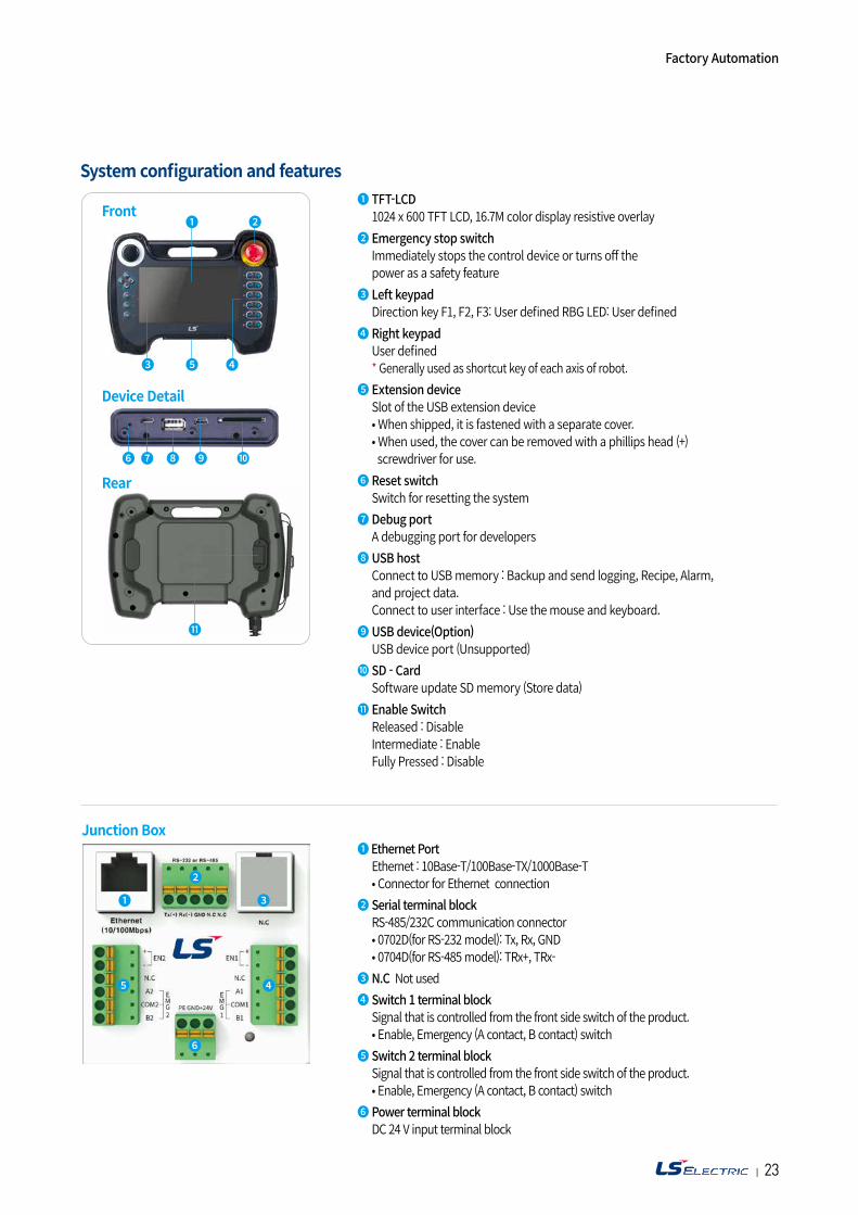
System configuration and features❶ TFT-LCD 1024 x 600 TFT LCD, 16.7M color display resistive overlay❷ Emergency stop switch Immediately stops the control device or turns off the power as a safety feature❸ Left keypad Direction key F1, F2, F3: User defined RBG LED: User defined❹ Right keypad User defined * Generally used as shortcut key of each axis of robot.❺ Extension device Slot of the USB extension device • When shipped, it is fastened with a separate cover. • When used, the cover can be removed with a phillips head (+) screwdriver for use.❻ Reset switch Switch for resetting the system❼ Debug port A debugging port for developers❽ USB host Connect to USB memory : Backup and send logging, Recipe, Alarm, and project data. Connect to user interface : Use the mouse and keyboard.❾ USB device(Option) USB device port (Unsupported) ❿ SD - Card Software update SD memory (Store data)⓫ Enable Switch Released : Disable Intermediate : Enable Fully Pressed : Disable
Front❶ ❷
❹❺❸
❻ ❼ ❽ ❾ ❿
Device Detail
⓫
Rear
❶ Ethernet Port Ethernet : 10Base-T/100Base-TX/1000Base-T • Connector for Ethernet connection❷ Serial terminal block RS-485/232C communication connector • 0702D(for RS-232 model): Tx, Rx, GND • 0704D(for RS-485 model): TRx+, TRx-❸ N.C Not used❹ Switch 1 terminal block Signal that is controlled from the front side switch of the product. • Enable, Emergency (A contact, B contact) switch❺ Switch 2 terminal block Signal that is controlled from the front side switch of the product. • Enable, Emergency (A contact, B contact) switch❻ Power terminal block DC 24 V input terminal block
Junction Box
❷
❻
❸
❺ ❹
❶
| 2524
System Configuration
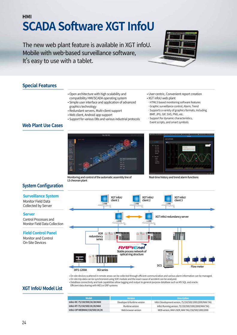
Special Features• Open architecture with high scalability and compatibility HMI/SCADA operating system
• Simple user interface and application of advanced graphics technology
• Redundant servers, Multi-client support• Web client, Android app support• Support for various DBs and various industrial protocols
• User-centric, Convenient report creation• XGT infoU web plant- HTML5 based monitoring software features- Graphic surveillance control, Alarm, Trend- Supports a variety of graphics formats, Including BMP, JPG, GIF, SVG, PNG, etc.
- Support for dynamic characteristics, Event scripts, and smart symbols
HMI
SCADA Software XGT InfoU
• On-site devices scattered in remote areas can be collected through efficient communication and various alarm information can be managed.• On-site trip data can be synchronized using SOE module and the exact cause of accident can be analyzed.• DataBase connectivity and task capabilities allow tagging and output to general-purpose dataBase such as MS SQL and oracle.Efficient data sharing with MES or ERP systems
XGT infoU client 1
XGT infoU client 2
XGT infoU client 3
XGT infoU redundancy server
XGR redundancy
series
iXP2-1200A XGI seriesFlow meterDCS
Stable process network of optical ring structure
Surveillance SystemMonitor Field Data Collected by Server
ServerControl Processes and Monitor Field Data Collection
Field Control PanelMonitor and Control On-Site Devices
The new web plant feature is available in XGT infoU.Mobile with web-based surveillance software,It's easy to use with a tablet.
Web Plant Use Cases
Monitoring and control of the automatic assembly line of LS cheonan plant
Real-time history and trend alarm functions
XGT InfoU Model List
Model Version DescriptionInfoU-RC-75/150/500/1K/2K/MAX Developer & Runtime version InfoU Development version, 75/150/500/1000/2000/MAX TAGInfoU-RT-75/150/500/1K/2K/MAX Runtime version InfoU Running version, 75/150/500/1000/2000/MAX TAGInfoU-OP-WEBMAX/150/500/1K/2K Web browser version WEB version, MAX USER, MAX TAG/150/500/1000/2000
| 2524
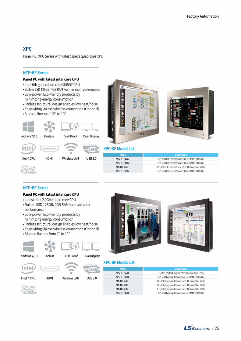
XPC
Panel PC with latest intel core CPU• Intel 6th generation core i3/i5/i7 CPU • Built-in SSD 128GB, 4GB RAM For maximum performance• Low-power, Eco-friendly products by minimizing energy consumption
• Fanless structural design enables low heat/noise• Easy wiring via the wireless connection (Optional)• A broad lineup of 12" to 19"
Panel PC with latest intel core CPU• Latest intel 2.0GHz quad core CPU • Built-in SSD 128GB, 4GB RAM for maximum performance
• Low-power, Eco-friendly products by minimizing energy consumption
• Fanless structural design enables low heat/noise• Easy wiring via the wireless connection (Optional)• 6 broad lineups from 7" to 19"
Panel PC, XPC Series with latest specs quad core CPU
NTP-KF Series
NTP-BF Series
XPC-BF Model ListModel Description
XPC-NTP07BF 7", Intel baytrail-D quad core, 4G RAM, SSD 128GXPC-NTP10BF 10", Intel baytrail-D quad core, 4G RAM, SSD 128GXPC-NTP12BF 10", Intel baytrail-D quad core, 4G RAM, SSD 128GXPC-NTP15BF 15", Intel baytrail-D quad core, 4G RAM, SSD 128GXPC-NTP17BF 17", Intel baytrail-D quad core, 4G RAM, SSD 128GXPC-NTP19BF 19", Intel baytrail-D quad core, 4G RAM, SSD 128G
XPC-KF Model ListModel Description
XPC-NTP12KF 12", Intel 6th core i3/i5/i7 CPU, 4G RAM, SSD 128GXPC-NTP15KF 15", Intel 6th core i3/i5/i7 CPU, 4G RAM, SSD 128GXPC-NTP17KF 17", Intel 6th core i3/i5/i7 CPU, 4G RAM, SSD 128GXPC-NTP19KF 19", Intel 6th core i3/i5/i7 CPU, 4G RAM, SSD 128G
Factory Automation
| 2726
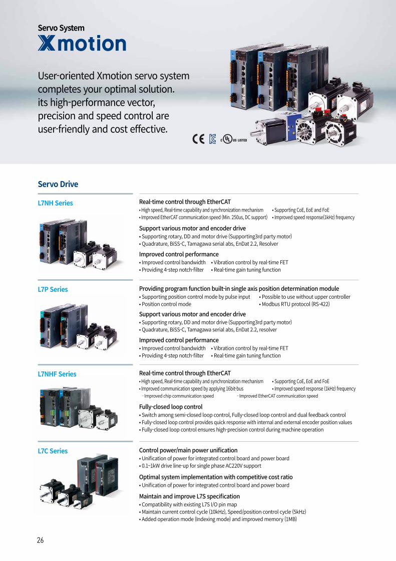
Servo Drive
L7NH Series
L7P Series
L7C Series
L7NHF Series
Real-time control through EtherCAT
Control power/main power unification
Providing program function built-in single axis position determination module
Real-time control through EtherCAT
Fully-closed loop control
Support various motor and encoder drive
Improved control performance
Optimal system implementation with competitive cost ratio
Maintain and improve L7S specification
• High speed, Real-time capability and synchronization mechanism• Improved EtherCAT communication speed (Min. 250us, DC support)
• Supporting CoE, EoE and FoE• Improved speed response(1kHz) frequency
• Unification of power for integrated control board and power board• 0.1~1kW drive line-up for single phase AC220V support
• Supporting position control mode by pulse input• Position control mode
• Possible to use without upper controller• Modbus RTU protocol (RS-422)
• High speed, Real-time capability and synchronization mechanism• Improved communication speed by applying 16bit-bus - Improved chip communication speed - Improved EtherCAT communication speed
• Switch among semi-closed loop control, Fully-closed loop control and dual feedback control• Fully-closed loop control provides quick response with internal and external encoder position values• Fully-closed loop control ensures high-precision control during machine operation
• Supporting rotary, DD and motor drive (Supporting3rd party motor)• Quadrature, BiSS-C, Tamagawa serial abs, EnDat 2.2, resolver
• Improved control bandwidth• Providing 4-step notch-filter
• Vibration control by real-time FET• Real-time gain tuning function
Support various motor and encoder drive• Supporting rotary, DD and motor drive (Supporting3rd party motor)• Quadrature, BiSS-C, Tamagawa serial abs, EnDat 2.2, Resolver
Improved control performance• Improved control bandwidth• Providing 4-step notch-filter
• Vibration control by real-time FET• Real-time gain tuning function
• Unification of power for integrated control board and power board
• Compatibility with existing L7S I/O pin map• Maintain current control cycle (10kHz), Speed/position control cycle (5kHz)• Added operation mode (Indexing mode) and improved memory (1MB)
Servo System
User-oriented Xmotion servo system completes your optimal solution. its high-performance vector, precision and speed control are user-friendly and cost effective.
• Supporting CoE, EoE and FoE• Improved speed response (1kHz) frequency
| 2726
Enhanced efficiency integrated servo system
Real-time control through EtherCAT
Real-time control through EtherCAT
Variable switching frequency
Progamming function including single axis position module
• Cost effective from installation by integrated system of motor, encoder cable and drive• Maximization for useful space when installed at limited and small space• High effectiveness for application of multi axis because there is no limitation for space of installation
• High speed, Real-time capability and synchronization mechanism• Improved EtherCAT communication speed• Supporting CoE, EoE and FoE
• High speed, Real-time capability and synchronization mechanism• Improved communication speed by applying 16Bit-bus - Improved chip communication speed - Improved EtherCAT communication speed• Supports CoE, EoE and FoE• Improved speed response (1kHz) frequency
• 16 / 32 / 48kHz
• Positioning control mode with pulse inputs• Supports the indexing mode
• Provides position control through I/O or HMI without the position control module
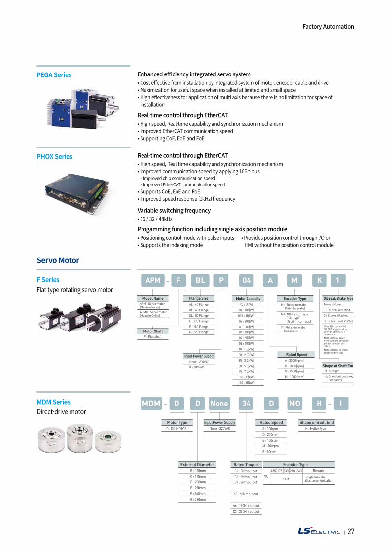
Servo Motor
PEGA Series
F SeriesFlat type rotating servo motor
PHOX Series
MDM SeriesDirect-drive motor
MDM NoneD D 34 D NO H I
D : DD MOTOR
F : Flat shaft
APM : Servo motor(Made in korea)APMC : Servo motor(Made in China)
M : 19bit s-turn abs(16bit turn abs)
M8 : 18bit s-turn abs[FAL type](16bit m-turn abs)
Y : 17bit s-turn abs(magnetic)
N : Straight
K : One side round key(standard)
None : None
1 : Oil seal attached
2 : Brake attached
3 : Oil seal, Brake attached
Note 1) In case of 40, 60, 80 flange product, you can apply 200V drive only.Note 2) If you applynonstandard encoder,please contact ouroffice.Note 3) Refer to brakeoperating voltage
B : 135mm
C : 175mm
D : 230mm
E : 290mm
F : 360mm
G : 380mm
NO
Remark135 175 230
20Bit
290 360
A : 300rpm
D : 200rpm
G : 150rpm
M : 100rpm
S : 50rpm
None : 220VAC
Motor Type Input Power Supply
External Diameter Rated Troque Encoder Type
Rated Speed Shape of Shaft EndH : Hollow type
Single turn abs,Biss communication
03 : 3Nm output
06 : 6Nm output
09 : 9Nm output
…
60 : 60Nm output
…
A6 : 160Nm output
C3 : 330Nm output
Factory Automation
| 2928
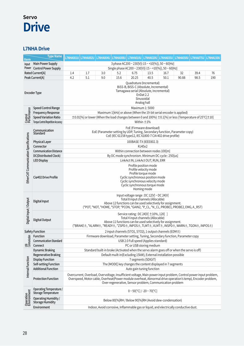
Item Type Name L7NHA001U L7NHA002U L7NHA004U L7NHA008U L7NHA010U L7NHA020U L7NHA035U L7NHA050U L7NHA075U L7NHA150U
Input Power
Main Power Supply 3 phase AC200 ~ 230[V](-15 ~ +10[%]), 50 ~ 60[Hz]Control Power Supply Single phase AC200 ~ 230[V](-15 ~ +10[%]), 50 ~ 60[Hz]
Rated Current[A] 1.4 1.7 3.0 5.2 6.75 13.5 16.7 32 39.4 76Peak Current[A] 4.2 5.1 9.0 15.6 20.25 40.5 50.1 90.88 98.5 190
Encoder Type
Quadrature (Incremental)BiSS-B, BiSS-C (Absolute, Incremental)
Tamagawa serial (Absolute, Incremental)EnDat 2.2SinusoidalAnalog hall
Speed Control Range Maximum 1: 5000Frequency Response Maximum 1[kHz] or above (When the 19-bit serial encoder is applied)Speed Variation Ratio ±0.01[%] or lower (When the load changes between 0 and 100%) ±0.1[%] or less (Temperature of 25°C[±10]Torque Control Repetition Accuracy Within ±1%
Communication Standard
FoE (Firmware download)EoE (Parameter setting by UDP, Tuning, Secondary function, Parameter copy)
CoE (IEC 61158 type12, IEC 61800-7 CIA 402 drive profile)Physical Layer 100BASE-TX (IEEE802.3)Connector RJ45x2Communication Distance Within connection between nodes 100[m]DC(Distributed Clock) By DC mode synchronism. Minimum DC cycle : 250[us]LED Display LinkAct IN, LinkAct OUT, RUN, ERR
Cia402 Drive Profile
Profile position modeProfile velocity modeProfile torque mode
Cyclic synchronous position modeCyclic synchronous velocity modeCyclic synchronous torque mode
Homing mode
Digital InputInput voltage range : DC 12[V] ~ DC 24[V]
Total 8 input channels (Allocable)Above 12 functions can be used selectively for assignment.
(*POT, *NOT, *HOME, *STOP, *PCON, *GAIN2, *P_CL, *N_CL, PROBE1, PROBE2, EMG, A_RST)
Digital OutputService rating : DC 24[V] ±10%, 120[ ]
Total 4 input channels (Allocable)Above 11 functions can be used selectively for assignment.
(*BRAKE±, *ALARM±, *READY±, *ZSPD±, INPOS±, TLMT±, VLMT±, INSPD±, WARN±, TGON±, INPOS±)Safety Function 2 input channels (STO1, STO2), 1 output channels (EDM±)
Function Firmware download, Parameter setting, Tuning, Secondary function, Parameter copyCommunication Standard USB 2.0 Full speed (Applies standard)Connect PC or USB storing mediumDynamic Braking Standard built-in brake (Activated when the servo alarm goes off or when the servo is off)Regenerative Braking Default muilt-in(Excluding 15kW), External installation possibleDisplay Function 7 segments (5DIGIT)Self-setting Function The [MODE] key changes the content displayed in 7 segmentsAdditional Function Auto gain tuning function
Protection FunctionOvercurrent, Overload, Overvoltage, Insufficient voltage, Main power input problem, Control power input problem, Overspeed, Motor cable, Overheat(Power module overheat, Abnormal drive operation’s temp), Encoder problem,
Over-regenerative, Sensor problem, Communication problem
Operating Temperature / Storage Temperature 0 ~ 50[°C] / -20 ~ 70[°C]
Operating Humidity / Storage Humidity Below 80[%]RH / Below 90[%]RH (Avoid dew-condensation)
Environment Indoor, Avoid corrosive, Inflammable gas or liquid, and electrically conductive dust.
L7NHA Drive
Cont
rol
Perfo
rman
ceOp
erat
ionEn
viron
men
tUSB Com
munica
tionEt
herC
AT Co
mm
unica
tion S
pecif
icatio
nsDi
gital
Inpu
t / O
utpu
tIn
tern
al Fu
nctio
nDriveServo
28
| 2928
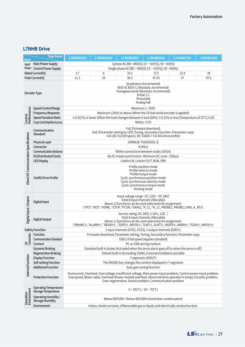
Item Type Name L7NHB010U L7NHB020U L7NHB035U L7NHB050U L7NHB075U L7NHB150U
Input Power
Main Power Supply 3 phase AC380 ~480[V](-15 ~ +10[%]), 50 ~ 60[Hz]Control Power Supply Single phase AC380 ~ 480[V](-15 ~ +10[%]), 50 ~ 60[Hz]
Rated Current[A] 3.7 8 10.1 17.5 22.8 39Peak Current[A] 11.1 24 30.3 47.25 57 97.5
Encoder Type
Quadrature (Incremental)BiSS-B, BiSS-C (Absolute, Incremental)
Tamagawa serial (Absolute, Incremental)EnDat 2.2SinusoidalAnalog hall
Speed Control Range Maximum 1 : 5000Frequency Response Maximum 1[kHz] or above (When the 19-bait serial encoder is applied)Speed Variation Ratio ±0.01[%] or lower (When the load changes between 0 and 100%) ±0.1[%] or less(Temperature of 25°C[±10]Torque Control Repetition Accuracy Within ±1%
Communication Standard
FoE (Firmware download)EoE (Parameter setting by UDP, Tuning, Secondary function, Parameter copy)
CoE (IEC 61158 type12, IEC 61800-7 CIA 402 drive profile)
Physical Layer 100BASE-TX(IEEE802.3)Connector RJ45x2Communication distance Within connection between nodes 100[m]DC(Distributed Clock) By DC mode synchronism. Minimum DC cycle : 250[us]LED Display LinkAct iN, LinkAct OUT, RUN, ERR
Cia402 Drive Profile
Profile position modeProfile velocity modeProfile torque mode
Cyclic synchronous position modeCyclic synchronous velocity modeCyclic synchronous torque mode
Homing mode
Digital InputInput voltage range : DC 12[V] ~ DC 24[V]
Total 8 input channels (Allocable)Above 12 functions can be used selectively for assignment.
(*POT, *NOT, *HOME, *STOP, *PCON, *GAIN2, *P_CL, *N_CL, PROBE1, PROBE2, EMG, A_RST)
Digital OutputService rating: DC 24[V] ±10%, 120[ ]
Total 4 input channels (Allocable)Above 11 functions can be used selectively for assignment.
(*BRAKE±, *ALARM±, *READY±, *ZSPD±, INPOS±, TLMT±, VLMT±, INSPD±, WARN±, TGON±, INPOS±)Safety Function 2 input channels (STO1, STO2), 1 output channels (EDM±)
Function Firmware download, Parameter setting, Tuning, Secondary function, Parameter copyCommunication Standard USB 2.0 full speed (Applies standard)Connect PC or USB storing mediumDynamic Braking Standard built-in brake (Activated when the servo alarm goes off or when the servo is off).Regenerative Braking Default built-in (Excluding 15kW), External installation possibleDisplay Function 7 segments (5DIGIT)Self-setting Function The [MODE] key changes the content displayed in 7 segmentsAdditional Function Auto gain tuning function
Protection FunctionOvercurrent, Overload, Overvoltage, Insufficient voltage, Main power input problem, Control power input problem, Overspeed, Motor cable, Overheat (Power module overheat, Abnormal drive operation’s temp), Encoder problem,
Over-regenerative, Sensor problem, Communication problem
Operating Temperature / Storage Temperature 0 ~ 50[°C] / -20 ~ 70[°C]
Operating Humidity / Storage Humidity Below 80[%]RH / Below 90[%]RH (Avoid dew-condensation)
Environment Indoor, Avoid corrosive, Inflammable gas or liquid, and electrically conductive dust.
L7NHB Drive
Cont
rol
Perfo
rman
ceOp
erat
ion
Envir
onm
ent
USB Commu
nication
Ethe
rCAT
Com
mun
icatio
n Spe
cifica
tions
Digit
al In
put /
Out
put
Inte
rnal
Func
tion
Factory Automation
| 29
| 3130
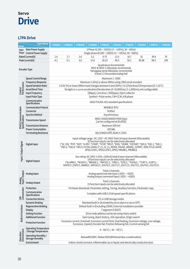
Item Type Name L7PA001U L7PA002U L7PA004U L7PA008U L7PA010U L7PA020U L7PA035U L7PA050U L7PA075U L7PA150U
Input Power
Main Power Supply 3 Phase AC200 ~ 230[V](-15 ~ +10[%]), 50 ~ 60[Hz]Control Power Supply Single phase AC200 ~ 230[V](-15 ~ +10[%]), 50 ~ 60[Hz]
Rated Current[A] 1.4 1.7 3.0 5.2 6.75 13.5 16.7 32 39.4 76Peak Current[A] 4.2 5.1 9.0 15.6 20.25 40.5 50.1 90.88 98.5 190
Encoder TypeQuadrature (Incremental)
BiSS-B, BiSS-C (Absolute, Incremental)Tamagawa serial (Absolute, Incremental)
EnDat 2.2 Sinusoidal analog hall
Speed Control Range Maximum 1 : 5000Frequency Response Maximum 1 [kHz] or above (When using 19bit serial encoder)Speed Variation Ratio ±0.01 [%] or lower [When load changes between 0 and 100%] ±0.1[%]orlower[Temperature25 ±10°C]Accel/Decel Time Straight or s-curve acceleration/Deceleration (0~10,000[ms], 0~1,000[ms] unit configurable)Input Frequency 1[Mpps], Line drive / 200[kpps], Open collectorInput Pulse Type Symbol + Pulse series, CW+CCW, A/B phaseCommunication Specifications ANSI/TIA/EIA-422 standard specifications
Communication Protocol MODBUS-RTUConnector RJ45x2Synchro Method Asynchronous
Transmission Speed 9600 /19200/38400/57600 [bps]Can be configured at [0x3002]
Transmission Distance Maximum 200 [m]Power Consumption 100 []Terminating Resistance Dip S/W(On/Off), Built-in 120Ω
Digital Input
Input voltage range : DC 12[V] ~ DC 24[V] Total 16 input channel (Allocatable)32 function inputs can be selectively allocated
(*SV_ON, *POT, *NOT, *A-RST, *START, *STOP, *REGT, *EMG, *HOME, *HSTART, *ISEL0, *ISEL1, *ISEL2, *ISEL3, *ISEL4, *ISEL5, PCON, GAIN2, P_CL, N_CL, MODE, PAUSE, ABSRQ, JSTART, JDIR, PCLR, AOVR,
SPD1/LVSF1, SPD2/LVSF2, SPD3, PROBE1, PROBE2)
Digital OutputUse rating: DC 24[V] ±10%, 120[mA] total 8 input channel (Allocatable)
19 function inputs can be selectively allocated(*ALARM±, *READY±, *BRAKE±, *INPOS1±, *ORG±, *EOS±, *TGON±, *TLMT±, VLMT±,
INSPD±,ZSPD±, WARN±, INPOS2±, IOUT0±, IOUT1±, IOUT2±, IOUT3±, IOUT4±, IOUT5±)
Analog InputTotal 2 channels
Analog speed override input (-10[V) ~ +10[V))Analog torque command input (-10[V) ~ +10[V))
Analog Output Total 2 channels15 function inputs can be selectively allocated
Protection Firmware download, Parameter setting, Tuning, Auxiliary function, Parameter copyCommunication Specifications Complies with USB 2.0 full speed specifications
Connection Device PC or USB storage mediaDynamic Braking Standard built-in (Activated by servo alarm or servo OFF)Regenerative Braking Default built-in (Excluding 15kW), External installation possibleDisplay 7 segment (5 DIGIT)Setting Function Drive node address can be set using rotary switchAdditional Function Gain tuning, Alarm history, JOG operation, Origin search
Protective Function Excessive current, Overload, Excessive current limit, Overheating, Excessive voltage, Low voltage, Excessive, Zspeed, Encoder fail, Position following Fail, Current sensing fail
Operating Temperature / Storage Temperature 0 ~ 50[°C] / -20 ~ 70[°C]
Operating Humidity / Storage Humidity Below80[%]RH / Below 90[%]RH(Avoid dew-condensation)
Environment Indoor, Avoid corrosive, Inflammable cas or liquid, and electrically conductive dust.Oper
ation
Envir
onm
ent
USB
Comm
unica
tion
Analo
gIn
put /
Out
put
RS42
2 Com
mun
icatio
n Sp
ecific
ation
sCo
ntro
l Pe
rform
ance
Inpu
t / O
utpu
t Sign
alBu
ilt-in
Func
tions
L7PA Drive
DriveServo
30
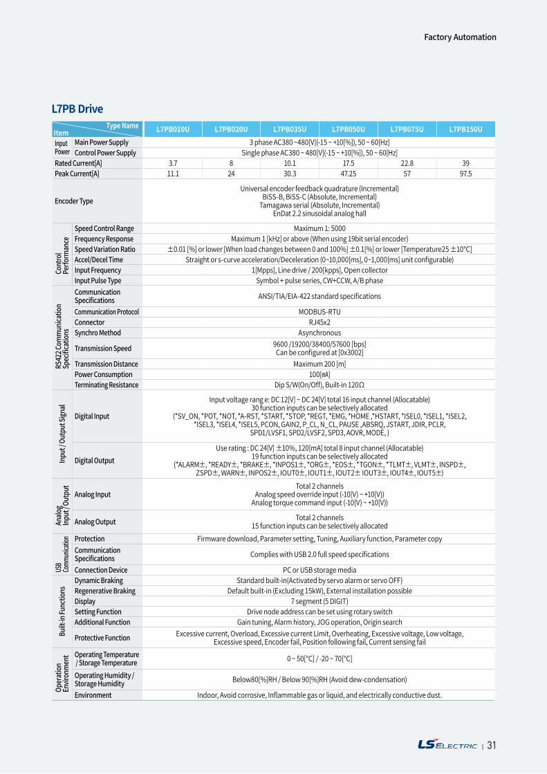
| 3130
Item Type Name L7PB010U L7PB020U L7PB035U L7PB050U L7PB075U L7PB150U
Input Power
Main Power Supply 3 phase AC380 ~480[V](-15 ~ +10[%]), 50 ~ 60[Hz]Control Power Supply Single phase AC380 ~ 480[V](-15 ~ +10[%]), 50 ~ 60[Hz]
Rated Current[A] 3.7 8 10.1 17.5 22.8 39Peak Current[A] 11.1 24 30.3 47.25 57 97.5
Encoder TypeUniversal encoder feedback quadrature (Incremental)
BiSS-B, BiSS-C (Absolute, Incremental)Tamagawa serial (Absolute, Incremental)
EnDat 2.2 sinusoidal analog hall
Speed Control Range Maximum 1: 5000Frequency Response Maximum 1 [kHz] or above (When using 19bit serial encoder)Speed Variation Ratio ±0.01 [%] or lower [When load changes between 0 and 100%] ±0.1[%] or lower [Temperature25 ±10°C]Accel/Decel Time Straight or s-curve acceleration/Deceleration (0~10,000[ms], 0~1,000[ms] unit configurable)Input Frequency 1[Mpps], Line drive / 200[kpps], Open collectorInput Pulse Type Symbol + pulse series, CW+CCW, A/B phaseCommunication Specifications ANSI/TIA/EIA-422 standard specifications
Communication Protocol MODBUS-RTUConnector RJ45x2Synchro Method Asynchronous
Transmission Speed 9600 /19200/38400/57600 [bps] Can be configured at [0x3002]
Transmission Distance Maximum 200 [m]Power Consumption 100[]Terminating Resistance Dip S/W(On/Off), Built-in 120Ω
Digital Input
Input voltage rang e: DC 12[V] ~ DC 24[V] total 16 input channel (Allocatable)30 function inputs can be selectively allocated
(*SV_ON, *POT, *NOT, *A-RST, *START, *STOP, *REGT, *EMG, *HOME ,*HSTART, *ISEL0, *ISEL1, *ISEL2, *ISEL3, *ISEL4, *ISEL5, PCON, GAIN2, P_CL, N_CL, PAUSE ,ABSRQ, JSTART, JDIR, PCLR,
SPD1/LVSF1, SPD2/LVSF2, SPD3, AOVR, MODE, )
Digital OutputUse rating : DC 24[V] ±10%, 120[mA] total 8 input channel (Allocatable)
19 function inputs can be selectively allocated(*ALARM±, *READY±, *BRAKE±, *INPOS1±, *ORG±, *EOS±, *TGON±, *TLMT±, VLMT±, INSPD±,
ZSPD±, WARN±, INPOS2±, IOUT0±, IOUT1±, IOUT2± IOUT3±, IOUT4±, IOUT5±)
Analog InputTotal 2 channels
Analog speed override input (-10[V) ~ +10[V))Analog torque command input (-10[V) ~ +10[V))
Analog Output Total 2 channels15 function inputs can be selectively allocated
Protection Firmware download, Parameter setting, Tuning, Auxiliary function, Parameter copyCommunication Specifications Complies with USB 2.0 full speed specifications
Connection Device PC or USB storage mediaDynamic Braking Standard built-in(Activated by servo alarm or servo OFF)Regenerative Braking Default built-in (Excluding 15kW), External installation possibleDisplay 7 segment (5 DIGIT)Setting Function Drive node address can be set using rotary switchAdditional Function Gain tuning, Alarm history, JOG operation, Origin search
Protective Function Excessive current, Overload, Excessive current Limit, Overheating, Excessive voltage, Low voltage, Excessive speed, Encoder fail, Position following fail, Current sensing fail
Operating Temperature / Storage Temperature 0 ~ 50[°C] / -20 ~ 70[°C]
Operating Humidity / Storage Humidity Below80[%]RH / Below 90[%]RH (Avoid dew-condensation)
Environment Indoor, Avoid corrosive, Inflammable gas or liquid, and electrically conductive dust.
Cont
rol
Perfo
rman
ceOp
erat
ionEn
viron
men
tUS
BCo
mmun
icatio
nAn
alog
Inpu
t / O
utpu
tRS
422 C
omm
unica
tion
Spec
ificat
ions
Inpu
t / O
utpu
t Sign
alBu
ilt-in
Func
tions
L7PB Drive
Factory Automation
| 31
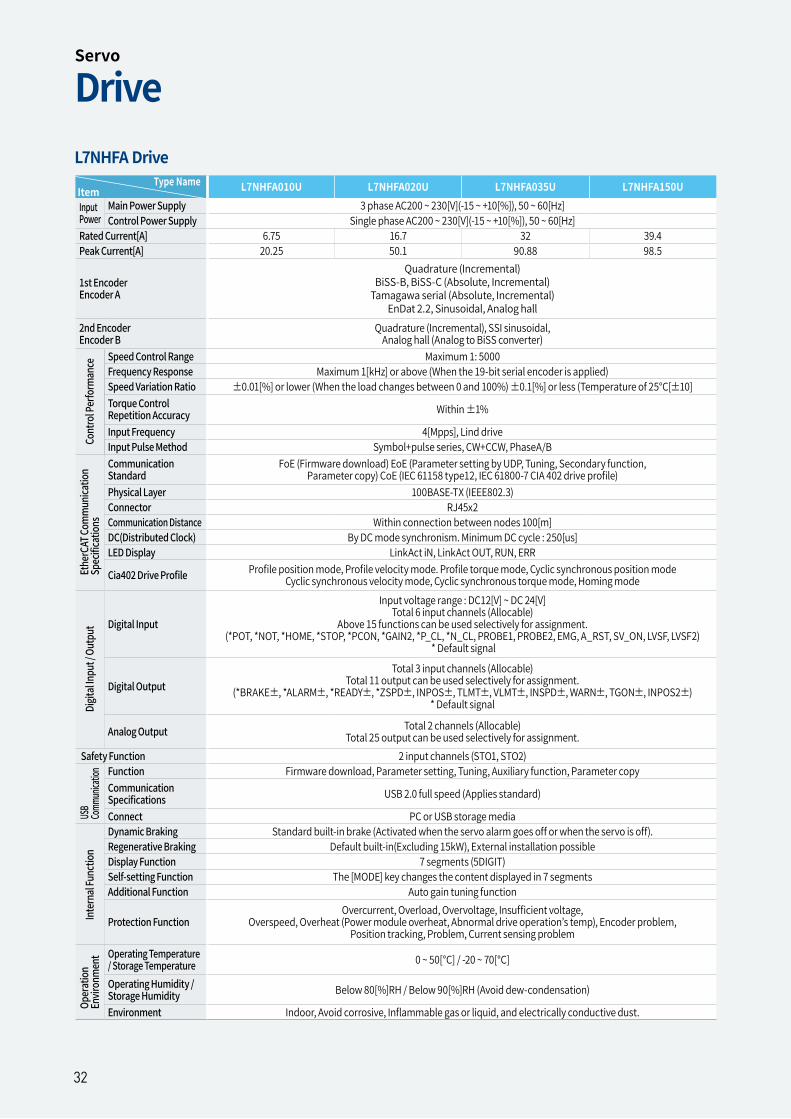
| 3332
Item Type Name L7NHFA010U L7NHFA020U L7NHFA035U L7NHFA150U
Input Power
Main Power Supply 3 phase AC200 ~ 230[V](-15 ~ +10[%]), 50 ~ 60[Hz]Control Power Supply Single phase AC200 ~ 230[V](-15 ~ +10[%]), 50 ~ 60[Hz]
Rated Current[A] 6.75 16.7 32 39.4Peak Current[A] 20.25 50.1 90.88 98.5
1st Encoder Encoder A
Quadrature (Incremental)BiSS-B, BiSS-C (Absolute, Incremental)
Tamagawa serial (Absolute, Incremental) EnDat 2.2, Sinusoidal, Analog hall
2nd Encoder Encoder B
Quadrature (Incremental), SSI sinusoidal, Analog hall (Analog to BiSS converter)
Speed Control Range Maximum 1: 5000Frequency Response Maximum 1[kHz] or above (When the 19-bit serial encoder is applied)Speed Variation Ratio ±0.01[%] or lower (When the load changes between 0 and 100%) ±0.1[%] or less (Temperature of 25°C[±10]Torque Control Repetition Accuracy Within ±1%
Input Frequency 4[Mpps], Lind driveInput Pulse Method Symbol+pulse series, CW+CCW, PhaseA/BCommunication Standard
FoE (Firmware download) EoE (Parameter setting by UDP, Tuning, Secondary function, Parameter copy) CoE (IEC 61158 type12, IEC 61800-7 CIA 402 drive profile)
Physical Layer 100BASE-TX (IEEE802.3)Connector RJ45x2Communication Distance Within connection between nodes 100[m]DC(Distributed Clock) By DC mode synchronism. Minimum DC cycle : 250[us]LED Display LinkAct iN, LinkAct OUT, RUN, ERR
Cia402 Drive Profile Profile position mode, Profile velocity mode. Profile torque mode, Cyclic synchronous position mode Cyclic synchronous velocity mode, Cyclic synchronous torque mode, Homing mode
Digital Input
Input voltage range : DC12[V] ~ DC 24[V]Total 6 input channels (Allocable)
Above 15 functions can be used selectively for assignment.(*POT, *NOT, *HOME, *STOP, *PCON, *GAIN2, *P_CL, *N_CL, PROBE1, PROBE2, EMG, A_RST, SV_ON, LVSF, LVSF2)
* Default signal
Digital OutputTotal 3 input channels (Allocable)
Total 11 output can be used selectively for assignment.(*BRAKE±, *ALARM±, *READY±, *ZSPD±, INPOS±, TLMT±, VLMT±, INSPD±, WARN±, TGON±, INPOS2±)
* Default signal
Analog Output Total 2 channels (Allocable)Total 25 output can be used selectively for assignment.
Safety Function 2 input channels (STO1, STO2)Function Firmware download, Parameter setting, Tuning, Auxiliary function, Parameter copyCommunication Specifications USB 2.0 full speed (Applies standard)
Connect PC or USB storage mediaDynamic Braking Standard built-in brake (Activated when the servo alarm goes off or when the servo is off).Regenerative Braking Default built-in(Excluding 15kW), External installation possibleDisplay Function 7 segments (5DIGIT)Self-setting Function The [MODE] key changes the content displayed in 7 segmentsAdditional Function Auto gain tuning function
Protection FunctionOvercurrent, Overload, Overvoltage, Insufficient voltage,
Overspeed, Overheat (Power module overheat, Abnormal drive operation’s temp), Encoder problem, Position tracking, Problem, Current sensing problem
Operating Temperature / Storage Temperature 0 ~ 50[°C] / -20 ~ 70[°C]
Operating Humidity / Storage Humidity Below 80[%]RH / Below 90[%]RH (Avoid dew-condensation)
Environment Indoor, Avoid corrosive, Inflammable gas or liquid, and electrically conductive dust.
Cont
rol P
erfo
rman
ceOp
erat
ionEn
viron
men
tUS
BCo
mmun
icatio
nEt
herC
AT Co
mm
unica
tion
Spec
ificat
ions
Digit
al In
put /
Out
put
Inte
rnal
Func
tion
L7NHFA Drive
DriveServo
32
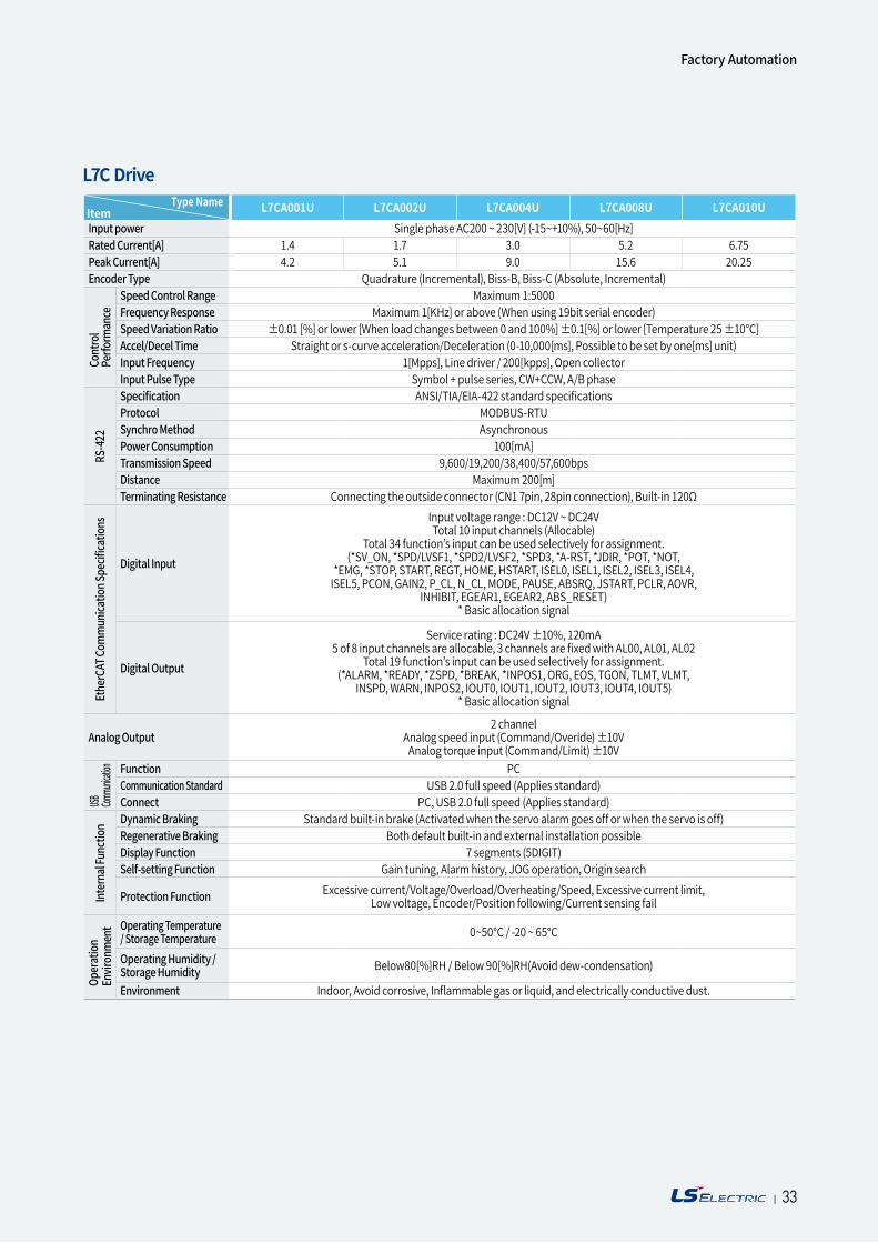
| 3332
Item Type Name L7CA001U L7CA002U L7CA004U L7CA008U L7CA010U
Input power Single phase AC200 ~ 230[V] (-15~+10%), 50~60[Hz]Rated Current[A] 1.4 1.7 3.0 5.2 6.75Peak Current[A] 4.2 5.1 9.0 15.6 20.25Encoder Type Quadrature (Incremental), Biss-B, Biss-C (Absolute, Incremental)
Speed Control Range Maximum 1:5000Frequency Response Maximum 1[KHz] or above (When using 19bit serial encoder)Speed Variation Ratio ±0.01 [%] or lower [When load changes between 0 and 100%] ±0.1[%] or lower [Temperature 25 ±10°C] Accel/Decel Time Straight or s-curve acceleration/Deceleration (0-10,000[ms], Possible to be set by one[ms] unit) Input Frequency 1[Mpps], Line driver / 200[kpps], Open collectorInput Pulse Type Symbol + pulse series, CW+CCW, A/B phaseSpecification ANSI/TIA/EIA-422 standard specificationsProtocol MODBUS-RTUSynchro Method AsynchronousPower Consumption 100[mA]Transmission Speed 9,600/19,200/38,400/57,600bpsDistance Maximum 200[m]Terminating Resistance Connecting the outside connector (CN1 7pin, 28pin connection), Built-in 120Ω
Digital Input
Input voltage range : DC12V ~ DC24VTotal 10 input channels (Allocable)
Total 34 function’s input can be used selectively for assignment. (*SV_ON, *SPD/LVSF1, *SPD2/LVSF2, *SPD3, *A-RST, *JDIR, *POT, *NOT,
*EMG, *STOP, START, REGT, HOME, HSTART, ISEL0, ISEL1, ISEL2, ISEL3, ISEL4, ISEL5, PCON, GAIN2, P_CL, N_CL, MODE, PAUSE, ABSRQ, JSTART, PCLR, AOVR,
INHIBIT, EGEAR1, EGEAR2, ABS_RESET)* Basic allocation signal
Digital Output
Service rating : DC24V ±10%, 120mA5 of 8 input channels are allocable, 3 channels are fixed with AL00, AL01, AL02
Total 19 function’s input can be used selectively for assignment. (*ALARM, *READY, *ZSPD, *BREAK, *INPOS1, ORG, EOS, TGON, TLMT, VLMT,
INSPD, WARN, INPOS2, IOUT0, IOUT1, IOUT2, IOUT3, IOUT4, IOUT5)* Basic allocation signal
Analog Output2 channel
Analog speed input (Command/Overide) ±10V Analog torque input (Command/Limit) ±10V
Function PCCommunication Standard USB 2.0 full speed (Applies standard)Connect PC, USB 2.0 full speed (Applies standard)Dynamic Braking Standard built-in brake (Activated when the servo alarm goes off or when the servo is off)Regenerative Braking Both default built-in and external installation possibleDisplay Function 7 segments (5DIGIT)Self-setting Function Gain tuning, Alarm history, JOG operation, Origin search
Protection Function Excessive current/Voltage/Overload/Overheating/Speed, Excessive current limit, Low voltage, Encoder/Position following/Current sensing fail
Operating Temperature / Storage Temperature 0~50°C / -20 ~ 65°C
Operating Humidity / Storage Humidity Below80[%]RH / Below 90[%]RH(Avoid dew-condensation)
Environment Indoor, Avoid corrosive, Inflammable gas or liquid, and electrically conductive dust.
Cont
rol
Perfo
rman
ceOp
erat
ionEn
viron
men
tUSB Com
munica
tionEt
herC
AT Co
mm
unica
tion S
pecif
icatio
nsRS
-422
Inte
rnal
Func
tion
L7C Drive
Factory Automation
| 33
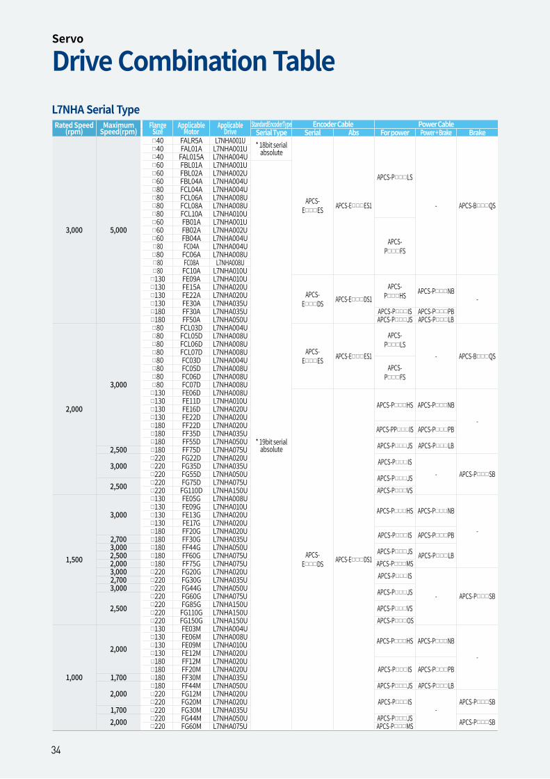
| 3534
Rated Speed (rpm)
Maximum Speed(rpm)
Flange Size
Applicable Motor
Applicable Drive
StandardEncoderType Encoder Cable Power CableSerial Type Serial Abs For power Power + Brake Brake
3,000 5,000
40 FALR5A L7NHA001U * 18bit serial absolute
APCS-EES APCS-EES1
APCS-PLS
- APCS-BQS
40 FAL01A L7NHA001U40 FAL015A L7NHA004U60 FBL01A L7NHA001U
* 19bit serial absolute
60 FBL02A L7NHA002U60 FBL04A L7NHA004U80 FCL04A L7NHA004U80 FCL06A L7NHA008U80 FCL08A L7NHA008U80 FCL10A L7NHA010U60 FB01A L7NHA001U
APCS-PFS
60 FB02A L7NHA002U60 FB04A L7NHA004U80 FC04A L7NHA004U80 FC06A L7NHA008U80 FC08A L7NHA008U80 FC10A L7NHA010U
130 FE09A L7NHA010U
APCS-EDS APCS-EDS1
APCS-PHS APCS-PNB
-130 FE15A L7NHA020U130 FE22A L7NHA020U130 FE30A L7NHA035U180 FF30A L7NHA035U APCS-PIS APCS-PPB180 FF50A L7NHA050U APCS-PJS APCS-PLB
2,000
3,000
80 FCL03D L7NHA004U
APCS-EES APCS-EES1
APCS-PLS
- APCS-BQS
80 FCL05D L7NHA008U80 FCL06D L7NHA008U80 FCL07D L7NHA008U80 FC03D L7NHA004U
APCS-PFS
80 FC05D L7NHA008U80 FC06D L7NHA008U80 FC07D L7NHA008U
130 FE06D L7NHA008U
APCS-EDS APCS-EDS1
APCS-PHS APCS-PNB
-
130 FE11D L7NHA010U130 FE16D L7NHA020U130 FE22D L7NHA020U180 FF22D L7NHA020U APCS-PPIS APCS-PPB180 FF35D L7NHA035U180 FF55D L7NHA050U APCS-PJS APCS-PLB2,500 180 FF75D L7NHA075U
3,000220 FG22D L7NHA020U APCS-PIS
- APCS-PSB220 FG35D L7NHA035U220 FG55D L7NHA050U APCS-PJS
2,500 220 FG75D L7NHA075U220 FG110D L7NHA150U APCS-PVS
1,500
3,000
130 FE05G L7NHA008UAPCS-PHS APCS-PNB
-
130 FE09G L7NHA010U130 FE13G L7NHA020U130 FE17G L7NHA020U180 FF20G L7NHA020U APCS-PIS APCS-PPB2,700 180 FF30G L7NHA035U
3,000 180 FF44G L7NHA050U APCS-PJS APCS-PLB2,500 180 FF60G L7NHA075U2,000 180 FF75G L7NHA075U APCS-PMS3,000 220 FG20G L7NHA020U APCS-PIS
- APCS-PSB
2,700 220 FG30G L7NHA035U3,000 220 FG44G L7NHA050U APCS-PJS
2,500220 FG60G L7NHA075U220 FG85G L7NHA150U APCS-PVS220 FG110G L7NHA150U220 FG150G L7NHA150U APCS-POS
1,000
2,000
130 FE03M L7NHA004UAPCS-PHS APCS-PNB
-
130 FE06M L7NHA008U130 FE09M L7NHA010U130 FE12M L7NHA020U180 FF12M L7NHA020U
APCS-PIS APCS-PPB180 FF20M L7NHA020U1,700 180 FF30M L7NHA035U
2,000180 FF44M L7NHA050U APCS-PJS APCS-PLB220 FG12M L7NHA020U
APCS-PIS-
APCS-PSB220 FG20M L7NHA020U1,700 220 FG30M L7NHA035U2,000 220 FG44M L7NHA050U APCS-PJS APCS-PSB220 FG60M L7NHA075U APCS-PMS
L7NHA Serial Type
Drive Combination TableServo
34
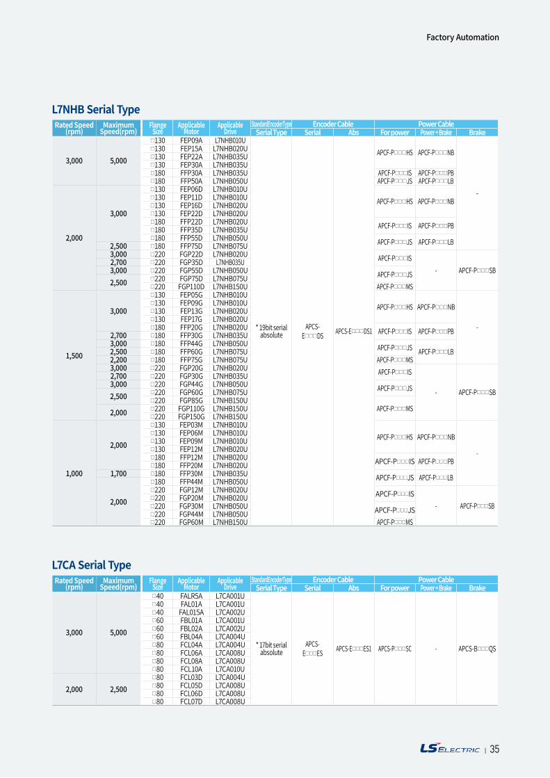
| 3534
Rated Speed (rpm)
Maximum Speed(rpm)
Flange Size
Applicable Motor
Applicable Drive
StandardEncoderType Encoder Cable Power CableSerial Type Serial Abs For power Power + Brake Brake
3,000 5,000
130 FEP09A L7NHB010U
* 19bit serial absolute
APCS-EDS APCS-EDS1
APCF-PHS APCF-PNB
-
130 FEP15A L7NHB020U130 FEP22A L7NHB035U130 FEP30A L7NHB035U180 FFP30A L7NHB035U APCF-PIS APCF-PPB180 FFP50A L7NHB050U APCF-PJS APCF-PLB
2,000
3,000
130 FEP06D L7NHB010UAPCF-PHS APCF-PNB130 FEP11D L7NHB010U
130 FEP16D L7NHB020U130 FEP22D L7NHB020U180 FFP22D L7NHB020U APCF-PIS APCF-PPB180 FFP35D L7NHB035U180 FFP55D L7NHB050U APCF-PJS APCF-PLB2,500 180 FFP75D L7NHB075U
3,000 220 FGP22D L7NHB020U APCF-PIS- APCF-PSB
2,700 220 FGP35D L7NHB035U3,000 220 FGP55D L7NHB050U APCF-PJS2,500 220 FGP75D L7NHB075U
220 FGP110D L7NHB150U APCF-PMS
1,500
3,000
130 FEP05G L7NHB010UAPCF-PHS APCF-PNB
-
130 FEP09G L7NHB010U130 FEP13G L7NHB020U130 FEP17G L7NHB020U180 FFP20G L7NHB020U APCF-PIS APCF-PPB2,700 180 FFP30G L7NHB035U
3,000 180 FFP44G L7NHB050U APCF-PJS APCF-PLB2,500 180 FFP60G L7NHB075U2,200 180 FFP75G L7NHB075U APCF-PMS3,000 220 FGP20G L7NHB020U APCF-PIS
- APCF-PSB
2,700 220 FGP30G L7NHB035U3,000 220 FGP44G L7NHB050U APCF-PJS2,500 220 FGP60G L7NHB075U
220 FGP85G L7NHB150UAPCF-PMS2,000 220 FGP110G L7NHB150U
220 FGP150G L7NHB150U
1,000
2,000
130 FEP03M L7NHB010UAPCF-PHS APCF-PNB
-
130 FEP06M L7NHB010U130 FEP09M L7NHB010U130 FEP12M L7NHB020U180 FFP12M L7NHB020U APCF-PIS APCF-PPB180 FFP20M L7NHB020U
1,700 180 FFP30M L7NHB035U APCF-PJS APCF-PLB
2,000
180 FFP44M L7NHB050U220 FGP12M L7NHB020U APCF-PIS
- APCF-PSB220 FGP20M L7NHB020U220 FGP30M L7NHB050U APCF-PJS220 FGP44M L7NHB050U220 FGP60M L7NHB150U APCF-PMS
Rated Speed (rpm)
Maximum Speed(rpm)
Flange Size
Applicable Motor
Applicable Drive
StandardEncoderType Encoder Cable Power CableSerial Type Serial Abs For power Power + Brake Brake
3,000 5,000
40 FALR5A L7CA001U
* 17bit serial absolute
APCS-EES APCS-EES1 APCS-PSC - APCS-BQS
40 FAL01A L7CA001U40 FAL015A L7CA002U60 FBL01A L7CA001U60 FBL02A L7CA002U60 FBL04A L7CA004U80 FCL04A L7CA004U80 FCL06A L7CA008U80 FCL08A L7CA008U80 FCL10A L7CA010U
2,000 2,50080 FCL03D L7CA004U80 FCL05D L7CA008U80 FCL06D L7CA008U80 FCL07D L7CA008U
L7CA Serial Type
L7NHB Serial Type
Factory Automation
| 35
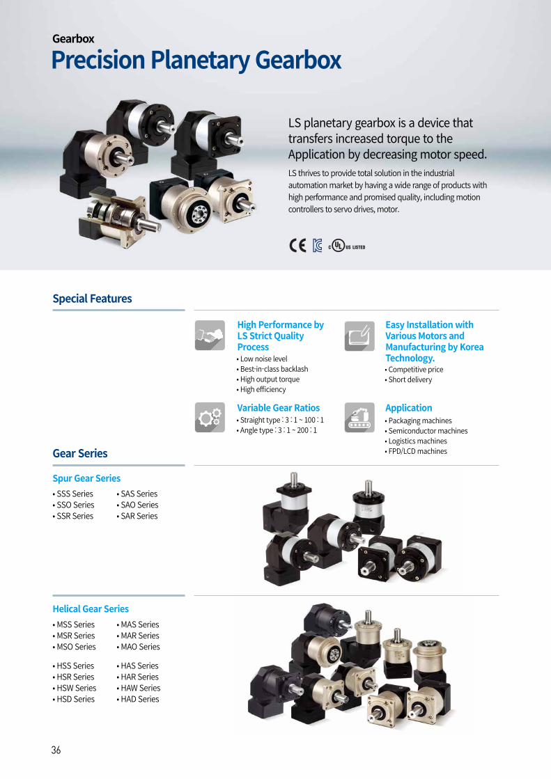
| 3736
LS thrives to provide total solution in the industrial automation market by having a wide range of products with high performance and promised quality, including motion controllers to servo drives, motor.
High Performance by LS Strict Quality Process
Easy Installation with Various Motors and Manufacturing by Korea Technology.
Variable Gear Ratios Application
• Low noise level• Best-in-class backlash• High output torque• High efficiency
• Competitive price• Short delivery
• Packaging machines• Semiconductor machines• Logistics machines• FPD/LCD machines
• Straight type : 3 : 1 ~ 100 : 1• Angle type : 3 : 1 ~ 200 : 1
Special Features
• SSS Series• SSO Series• SSR Series
• SAS Series• SAO Series• SAR Series
Spur Gear Series
Gear Series
• MSS Series • MSR Series • MSO Series
• HSS Series• HSR Series• HSW Series• HSD Series
• MAS Series • MAR Series • MAO Series
• HAS Series• HAR Series• HAW Series• HAD Series
Helical Gear Series
Precision Planetary GearboxGearbox
LS planetary gearbox is a device that transfers increased torque to the Application by decreasing motor speed.
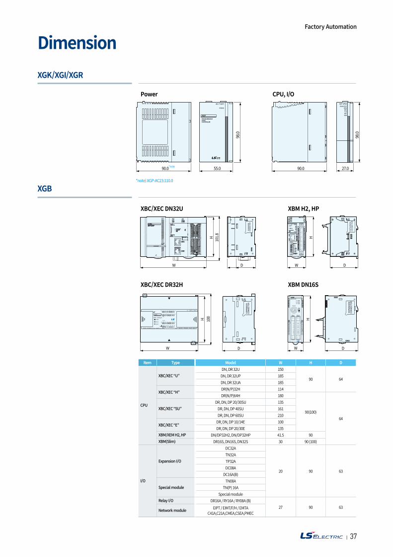
| 3736
XGK/XGI/XGR
XGB
Dimension
Item Type Model W H D
CPU
XBC/XEC “U”DN, DR 32U 150
90 64DN, DR 32UP 185DN, DR 32UA 185
XBC/XEC “H”DR(N/P)32H 114DR(N/P)64H 180
90(100)64
XBC/XEC “SU”DR, DN, DP 20/30SU 135
DR, DN, DP 40SU 161DR, DN, DP 60SU 210
XBC/XEC “E”DR, DN, DP 10/14E 100DR, DN, DP 20/30E 135
XBM/XEM H2, HP DN/DP32H2, DN/DP32HP 41.5 90XBM(Slim) DR16S, DN16S, DN32S 30 90 (100)
I/O
Expansion I/O
DC32A
20 90 63
TN32ATP32ADC08A
DC16A(B)
Special moduleTN08A
TN(P) 16ASpecial module
Relay I/O DR16A / RY16A / RY08A (B)27 90 63
Network module EIPT / EIMT/F/H / EMTAC41A,C21A,CMEA,CSEA,PMEC
Power
XBC/XEC DN32U
XBC/XEC DR32H
CPU, I/O
XBM H2, HP
XBM DN16S
Factory Automation
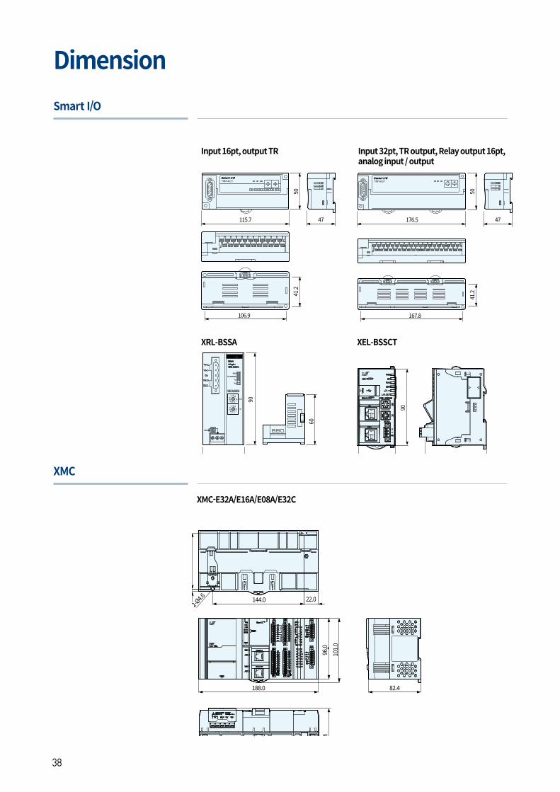
| 3938
Smart I/O
XMC
Dimension
XMC-E32A/E16A/E08A/E32C
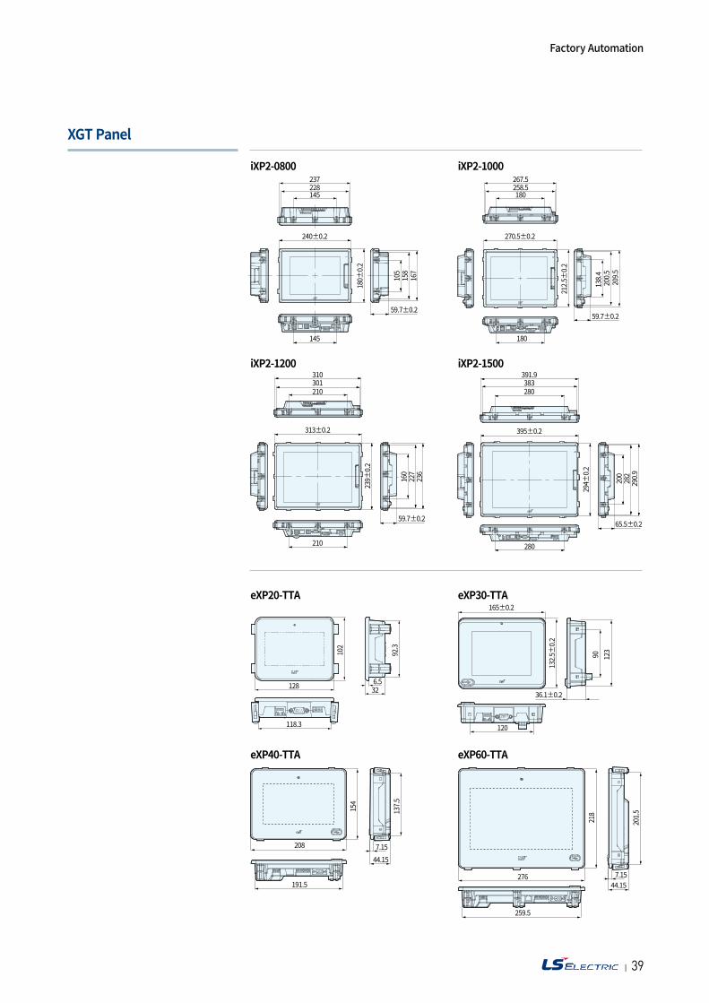
| 3938
XGT Panel
Factory Automation
2020. 04 LS ELECTRIC Co.,Ltd. All rights reserved. / (05) 2021. 11 Human Power2021. 11
• For your safety, please read user's manual thoroughly before operating.
• Contact the nearest authorized service facility for examination, repair, or adjustment.
• Please contact qualified service technician when you need maintenance. Do not disassemble or repair by yourself!
• Any maintenance and inspection shall be performed by the personnel having expertise concerned.
• According to The WEEE Directive, please do not discard the device with your household waste.
Safety Instructions
Overseas Subsidiaries• LS ELECTRIC Japan Co., Ltd. (Tokyo, Japan) Tel: 81-3-6268-8241 E-Mail: [email protected]
• LS ELECTRIC (Dalian) Co., Ltd. (Dalian, China) Tel: 86-411-8730-6495 E-Mail: [email protected]
•LS ELECTRIC (Wuxi) Co., Ltd. (Wuxi, China) Tel: 86-510-6851-6666 E-Mail: [email protected]
• LS ELECTRIC Middle East FZE (Dubai, U.A.E.) Tel: 971-4-886-5360 E-Mail: [email protected]
• LS ELECTRIC Europe B.V. (Hoofddorp, Netherlands) Tel: 31-20-654-1424 E-Mail: [email protected]
• LS ELECTRIC America Inc. (Chicago, USA) Tel: 1-800-891-2941 E-Mail: [email protected]
• LS ELECTRIC Turkey Co., Ltd. Tel: 90-212-806-1225 E-Mail: [email protected]
Seoul OfficeLS Yongsan Tower, 92, Hangang-daero, Yongsan-gu, Seoul, 04386, KoreaTel: 82-2-2034-4033, 4888, 4703 Fax: 82-2-2034-4588 E-mail: [email protected]
HeadquarterLS-ro 127(Hogye-dong) Dongan-gu, Anyang-si, Gyeonggi-Do, 14119, Korea
Overseas Branches• LS ELECTRIC Tokyo Office (Japan) Tel: 81-3-6268-8241 E-Mail: [email protected]
• LS ELECTRIC Beijing Office (China) Tel: 86-10-5095-1631 E-Mail: [email protected]
• LS ELECTRIC Shanghai Office (China) Tel: 86-21-5237-9977 E-Mail: [email protected]
• LS ELECTRIC Guangzhou Office (China) Tel: 86-20-3818-2883 E-Mail: [email protected]
• LS ELECTRIC Chengdu Office (China) Tel: 86-28-8670-3201 E-Mail: [email protected]
• LS ELECTRIC Qingdao Office (China) Tel: 86-532-8501-2065 E-Mail: [email protected]
• LS ELECTRIC Nanjing Office (China) Tel: 86-25-8467-0005 E-Mail: [email protected]
• LS ELECTRIC Bangkok Office (Thailand) Tel: 66-90-950-9683 E-Mail: [email protected]
• LS ELECTRIC Jakarta Office (Indonesia) Tel: 62-21-2933-7614 E-Mail: [email protected]
• LS ELECTRIC Moscow Office (Russia) Tel: 7-499-682-6130 E-Mail: [email protected]
• LS ELECTRIC America Western Office (Irvine, USA) Tel: 1-949-333-3140 E-Mail: [email protected]
• LS ELECTRIC Italy office (Italy) Tel: 39-030-8081-833 E-Mail: [email protected]
www.ls-electric.com