Embed Size (px)
Citation preview
energies
Article
Induction Heating of Gear Wheels in Consecutive ContourHardening Process †
Jerzy Barglik , Adrian Smagór , Albert Smalcerz * and Debela Geneti Desisa
�����������������
Citation: Barglik, J.; Smagór, A.;
Smalcerz, A.; Desisa, D.G. Induction
Heating of Gear Wheels in
Consecutive Contour Hardening
Process. Energies 2021, 14, 3885.
https://doi.org/10.3390/en14133885
Academic Editor: William G. Dunford
Received: 31 May 2021
Accepted: 23 June 2021
Published: 28 June 2021
Publisher’s Note: MDPI stays neutral
with regard to jurisdictional claims in
published maps and institutional affil-
iations.
Copyright: © 2021 by the authors.
Licensee MDPI, Basel, Switzerland.
This article is an open access article
distributed under the terms and
conditions of the Creative Commons
Attribution (CC BY) license (https://
creativecommons.org/licenses/by/
4.0/).
Department of Industrial Informatics, Silesian University of Technology, 40-019 Katowice, Poland;[email protected] (J.B.); [email protected] (A.S.); [email protected] (D.G.D.)* Correspondence: [email protected]; Tel.: +48-32-603-4133† This paper is an extended version of our paper published in 19th International Symposium on Electromagnetic
Fields in Mechatronics, Electrical and Electronic Engineering (ISEF 2019), Nancy, France, 29–31 August 2019;pp. 1–2.
Abstract: Induction contour hardening of gear wheels belongs to effective heat treatment technolo-gies especially recommended for high-tech applications in machinery, automotive and aerospaceindustries. In comparison with long term, energy consuming conventional heat treatment (carburiz-ing and consequent quenching), its main positive features are characterized by high total efficiency,short duration and relatively low energy consumption. However, modeling of the process is relativelycomplicated. The numerical model should contain both multi-physic and non-linear formulation ofthe problem. The paper concentrates on the modeling of rapid induction heating being the first stageof the contour induction hardening process which is the time consuming part of the computations. Itis taken into consideration that critical temperatures and consequently the hardening temperatureare dependent on the velocity of the induction heating. Numerical modeling of coupled non-linearelectromagnetic and temperature fields are shortly presented. Investigations are provided for gearwheels made of a special quality steel AISI 300M. In order to evaluate the accuracy of the proposedapproach, exemplary computations of the full induction contour hardening process are provided.The exemplary results are compared with the measurements and a satisfactory accordance betweenthem is achieved.
Keywords: induction heating; contour hardening; energy efficiency; coupled problems; critical tem-peratures
1. Introduction
Induction Contour Hardening (ICH) of gear wheels is an innovative technologicalprocess making it possible to obtain a thin hardened zone along the whole workingsurface of teeth. The result is a hard microstructure in the contour zone and less-hardmicrostructure in the transition zone [1,2]. The microstructure of the internal part of the gearwheel remains practically unchanged [3]. Such an environment-friendly heat treatmentprocess is very effective. It is characterized by large productivity and low-specific energyconsumption. It is more effective than a long term, energy consuming conventional heattreatment process of gear wheels consisting of carburizing and consequent quenching [4,5].In many high-tech, industrial applications the crucial quality condition is the fully uniformshape of the hardened contour zone. For the ICH of big gear wheels, such an expectedresult could be easily achieved by means of Tooth-by-Tooth Induction Hardening (TTIH)method [6,7]. However, for small gear wheels such a method cannot be applied, andit is not so easy to obtain the uniform thickness of the hardened contour zone alongthe whole tooth by ICH methods. The paper describes the full hardening process. Theinduction heating stage of the ICH process can be realized mostly in one or two cycles.The one cycle heating process consists of Single Frequency Induction Hardening (SFIH) or,more often, Simultaneous Dual Frequency Induction Hardening (SDFIH) in the medium
Energies 2021, 14, 3885. https://doi.org/10.3390/en14133885 https://www.mdpi.com/journal/energies
Energies 2021, 14, 3885 2 of 14
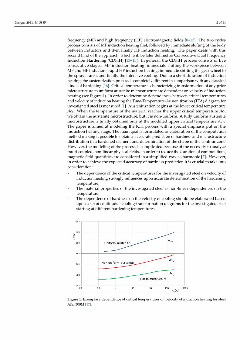
frequency (MF) and high frequency (HF) electromagnetic fields [8–12]. The two cyclesprocess consists of MF induction heating first, followed by immediate shifting of the bodybetween inductors and then finally HF induction heating. The paper deals with thissecond kind of the approach, which will be later defined as Consecutive Dual FrequencyInduction Hardening (CDFIH) [13–15]. In general, the CDFIH process consists of fiveconsecutive stages: MF induction heating, immediate shifting the workpiece betweenMF and HF inductors, rapid HF induction heating, immediate shifting the gear wheel tothe sprayer area, and finally the intensive cooling. Due to a short duration of inductionheating, the austenitization process is completely different in comparison with any classicalkinds of hardening [16]. Critical temperatures characterizing transformation of any priormicrostructure to uniform austenite microstructure are dependent on velocity of inductionheating (see Figure 1). In order to determine dependences between critical temperaturesand velocity of induction heating the Time-Temperature-Austenitization (TTA) diagram forinvestigated steel is measured [1]. Austenitization begins at the lower critical temperatureAc1. When the temperature of the material reaches the upper critical temperature Ac3we obtain the austenite microstructure, but it is non-uniform. A fully uniform austenitemicrostructure is finally obtained only at the modified upper critical temperature Acm.The paper is aimed at modeling the ICH process with a special emphasis put on theinduction heating stage. The main goal is formulated as elaboration of the computationmethod making it possible to obtain an accurate prediction of hardness and microstructuredistribution in a hardened element and determination of the shape of the contour zone.However, the modeling of the process is complicated because of the necessity to analyzemulti-coupled, non-linear physical fields. In order to reduce the duration of computations,magnetic field quantities are considered in a simplified way as harmonic [7]. However,in order to achieve the expected accuracy of hardness prediction it is crucial to take intoconsideration:
- The dependence of the critical temperatures for the investigated steel on velocity ofinduction heating strongly influences upon accurate determination of the hardeningtemperature;
- The material properties of the investigated steel as non-linear dependences on thetemperature;
- The dependence of hardness on the velocity of cooling should be elaborated basedupon a set of continuous-cooling-transformation diagrams for the investigated steelstarting at different hardening temperatures.
Energies 2021, 14, x FOR PEER REVIEW 2 of 15
or, more often, Simultaneous Dual Frequency Induction Hardening (SDFIH) in the me-dium frequency (MF) and high frequency (HF) electromagnetic fields [8–12]. The two cy-cles process consists of MF induction heating first, followed by immediate shifting of the body between inductors and then finally HF induction heating. The paper deals with this second kind of the approach, which will be later defined as Consecutive Dual Frequency Induction Hardening (CDFIH) [13–15]. In general, the CDFIH process consists of five con-secutive stages: MF induction heating, immediate shifting the workpiece between MF and HF inductors, rapid HF induction heating, immediate shifting the gear wheel to the sprayer area, and finally the intensive cooling. Due to a short duration of induction heat-ing, the austenitization process is completely different in comparison with any classical kinds of hardening [16]. Critical temperatures characterizing transformation of any prior microstructure to uniform austenite microstructure are dependent on velocity of induc-tion heating (see Figure 1). In order to determine dependences between critical tempera-tures and velocity of induction heating the Time-Temperature-Austenitization (TTA) di-agram for investigated steel is measured [1]. Austenitization begins at the lower critical temperature Ac1. When the temperature of the material reaches the upper critical temper-ature Ac3 we obtain the austenite microstructure, but it is non-uniform. A fully uniform austenite microstructure is finally obtained only at the modified upper critical tempera-ture Acm. The paper is aimed at modeling the ICH process with a special emphasis put on the induction heating stage. The main goal is formulated as elaboration of the computa-tion method making it possible to obtain an accurate prediction of hardness and micro-structure distribution in a hardened element and determination of the shape of the con-tour zone. However, the modeling of the process is complicated because of the necessity to analyze multi-coupled, non-linear physical fields. In order to reduce the duration of computations, magnetic field quantities are considered in a simplified way as harmonic [7]. However, in order to achieve the expected accuracy of hardness prediction it is crucial to take into consideration: - The dependence of the critical temperatures for the investigated steel on velocity of
induction heating strongly influences upon accurate determination of the hardening temperature;
- The material properties of the investigated steel as non-linear dependences on the temperature;
- The dependence of hardness on the velocity of cooling should be elaborated based upon a set of continuous-cooling-transformation diagrams for the investigated steel starting at different hardening temperatures.
Figure 1. Exemplary dependence of critical temperatures on velocity of induction heating for steel AISI 300M [17].
Figure 1. Exemplary dependence of critical temperatures on velocity of induction heating for steelAISI 300M [17].
Energies 2021, 14, 3885 3 of 14
In order to obtain uniform austenite microstructure, the average hardening temper-ature Th in the contour zone should be slightly higher than the modified upper criticaltemperature Acm.
Th ≥ Acm(vih) = Acm + ∆T, (1)
where: ∆T = 20–30 K.
2. Mathematical Model of ICH process2.1. Induction Heating for CDFIH Approach
The mathematical model of the ICH process for electromagnetic computations hasbeen represented by the non-linear partial differential equation for the magnetic vectorpotential A [7]:
curl(
1µ· curl A
)+ γ
∂A∂t
= JS, (2)
where: µ—denotes the magnetic permeability, γ—the electric conductivity, JS—vector offield current density.
The solving of the Equation (2) in the 3D configuration has to be simplified assumingthat the magnetic field quantities are harmonic [18]. The main reason of such a simplifica-tion is a distinct disproportion between period of field current and time constant of thermalphenomena. Equation (2) is transformed to the following Equation (3) for phasor of themagnetic vector potential A:
curl(curl A) + j ·ωγµA = µJS, (3)
where: j denotes the imaginary unity and ω—angular frequency.The continuous mathematical model of the ICH process for temperature computations
has been represented by the non-linear Fourier–Kirchhoff Equation [19]:
div (λ · gradT)− ρ · cp ·∂T∂t
= −pV, (4)
where: λ—thermal conductivity, ρ—specific mass, cp—specific heat at constant pressure, pV—volumetric power density as external heat source taken from electromagnetic computations.
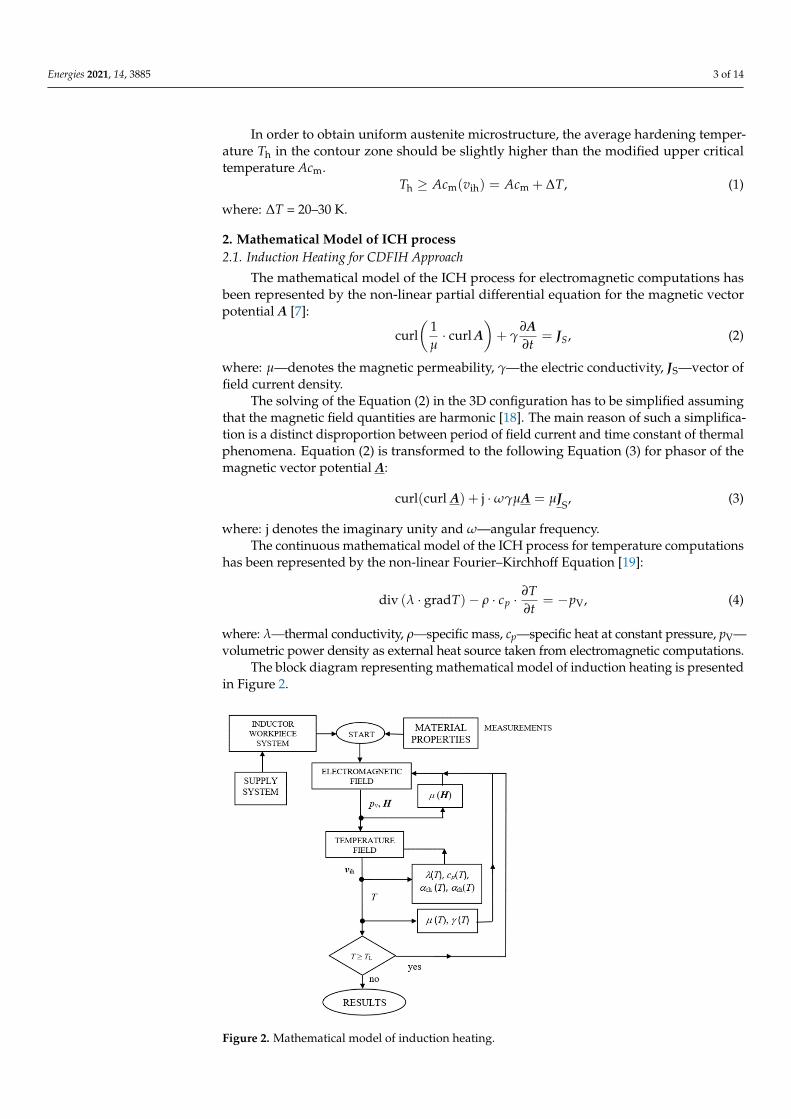
The block diagram representing mathematical model of induction heating is presentedin Figure 2.
Energies 2021, 14, x FOR PEER REVIEW 4 of 15
Figure 2. Mathematical model of induction heating.
Input data for electromagnetic computations contain: - Electric supply parameters: Inductor current or voltage and its frequency; - Geometry of inductor-gear wheel system; - Material properties of investigated steel and their dependences on field quantities
(magnetic field intensity H, temperature T); Average volumetric power density pv consists of two components connected respec-
tively with Joule Jp and hysteresis Hp phenomena:
2 2V J Hp p p fγ μ= + = ⋅ + ⋅ ⋅E H (5)
where: E—phasor of electric field density, f—frequency of field current, H—phasor of magnetic field density.
However, for the analyzed case the hysteresis components are significantly smaller than the Joule phenomenon one and it could be neglected [20]. Finally volumetric power density has only one component and it depends on induced current density indJ :
22 ind
V ind jp γ ω γγ
= ⋅ = = − ⋅ ⋅ ⋅ ,J
E J A (6)
The magnetic permeability of the investigated steel AISI 300M and other ferromag-netic parts like magnetic core depends on magnetic field density and temperature. In or-der to take into account a non-linear dependence of magnetic permeability on magnetic field intensity, its local values in each cell of the discretization mesh are determined. De-pendence of the magnetic permeability on temperature is considered by means of ((Equa-tions (7) and (8)):
( ) ( )( )r 0, 1 , 1T T f Tμ μ0 = μ + − ⋅ ( ) ,H H (7)
( )
C
CC
C10 for
1 e for
e
T TC
T TC
T T
T Tf T
−
−≈
− <=
( ) ,
(8)
Figure 2. Mathematical model of induction heating.
Energies 2021, 14, 3885 4 of 14
Input data for electromagnetic computations contain:
- Electric supply parameters: Inductor current or voltage and its frequency;- Geometry of inductor-gear wheel system;- Material properties of investigated steel and their dependences on field quantities
(magnetic field intensity H, temperature T);
Average volumetric power density pv consists of two components connected respec-tively with Joule pJ and hysteresis pH phenomena:
pV = pJ + pH = γ · |E|2 + µ · f · |H|2 (5)
where: E—phasor of electric field density, f —frequency of field current, H—phasor ofmagnetic field density.
However, for the analyzed case the hysteresis components are significantly smallerthan the Joule phenomenon one and it could be neglected [20]. Finally volumetric powerdensity has only one component and it depends on induced current density Jind:
pV = γ · |E|2 =
∣∣∣Jind
∣∣∣2γ
Jind = −j ·ω · γ ·A, (6)
The magnetic permeability of the investigated steel AISI 300M and other ferromagneticparts like magnetic core depends on magnetic field density and temperature. In order to takeinto account a non-linear dependence of magnetic permeability on magnetic field intensity,its local values in each cell of the discretization mesh are determined. Dependence of themagnetic permeability on temperature is considered by means of ((Equations (7) and (8)):
µ(H, T) = µ0[1 + (µr(H, T0)− 1) · f (T)], (7)
f (T) =
1− eT−TC
C for < TC
e10(TC−T)
C for T≈ TC, (8)
where: µ0—the magnetic permeability of vacuum, µr—relative magnetic permeability,T0—ambient temperature, TC—temperature of the Curie point, C—constant dependent onkind of steel.
For ambient temperature, the magnetic permeability is determined by measurements.However, a dependence of the magnetic permeability of the investigated steel on the fieldcurrent frequency is neglected [20]. The non-linear dependence of the electric conductivityon temperature is taken into consideration.
Input data for temperature computations contain:
- Distribution of volumetric power density in the heated element;- Dependence of specific heat, thermal conductivity, convection and radiation heat
transfer coefficients on temperature;- Time-temperature-austenitization diagram for the investigated steel;- Expected hardening temperature guaranteeing uniform austenite microstructure.
For temperature field calculations convection and radiation heat transfer phenomenaare considered. The boundary condition along the external surface of the workpiece isgiven in the Equation (9):
− λ∂T∂n
= αch(T − Tac) + σ0 · ε ·(
T4 − T4ar
), (9)
where: n denotes outwards normal to the external border of the domain, αch—convectionheat transfer coefficient (heating), Tac, Tar—temperature of convection and radiation envi-ronment respectively, σ0—Boltzmann constant, ε—total emissivity of radiation surface.

Energies 2021, 14, 3885 5 of 14
Analysis of the multiple reflection phenomena required special numerical proce-dure [21]. For this problem they are neglected. Taking into account non-linear dependencesof material properties and heat transfer parameters on temperature makes possible to avoidinaccuracy in modeling which could reach an order even of about 100 K [22–24]. As a resultof temperature computations, we obtain temperature as a function of time and velocityof induction heating. Computations are provided by means of the Flux 3D software forhard coupled electromagnetic and temperature field during induction heating and somesingle-owned procedures elaborated by the authors [25]. For CDFIH process modeling ofinduction heating stage consists of three consecutive stages:
- MF heating—time tMF;- Short break for shifting workpiece between inductors—time tb;- HF heating—time tHF.
Total time of induction heating:
tih = tMF + tb + tHF, (10)
MF heating terminates when average temperature in contour zone reaches the level ofthe lower critical temperature Ac1(vih)
Tav|t= tMF= TL ≈ Ac1(vih), (11)
Computations of HF induction heating terminate when the average hardening tem-perature exceeds the modified critical temperature Acm(vih).
Tav|t=tih= Th ≥ Acm(vih), (12)
2.2. Cooling
Input data for cooling computations contain:
- Geometry of sprayer-gear wheel system;- Cooling parameters (parameters of cooling medium, its pressure, flow-rate and tem-
perature);- Initial temperature distribution in the workpiece;- CCT (Continuous-Cooling-Transformation) diagram for investigated steel;- Convection heating transfer coefficient for intensive cooling.
Block diagram of numerical model for cooling is presented in Figure 3.Time of a break between heating and cooling could be neglected because the cooling
practically starts immediately when the HF inductor is switched off. Temperature fieldis determined based upon Equation (4) (pV = 0). Radiation is neglected. Convection heattransfer coefficient for cooling αcc depends on temperature, but in practice it is analyzed in asimplified way by putting different values on all boundaries of the domain. For the coolingstage as well the Flux 3D software for temperature field coupled with the modified QT steelsupported by several own numerical procedures for hardness and microstructure fieldsare applied [26]. A special numerical procedure making possible to couple directly Flux3D and QT steel codes is elaborated. Taking into consideration that when the inductionheating is terminated, the non-uniform temperature within the tooth, highest at the surfaceand lower inside the material is observed. The velocity of cooling vc is determined basedupon several measured Continuous-Cooling-Transformation (CCT) diagrams starting ofdifferent hardening temperatures Th. For the analyzed problem hardening temperature Thchanges between (850–1050 ◦C). Based upon these diagrams, dependences of the hardnesson the velocity of cooling in different points of tooth are elaborated. Exemplary dependenceof hardness on velocity of cooling for the hardening temperature Th = 960 ◦C is presentedin Figure 4.
Energies 2021, 14, 3885 6 of 14
Energies 2021, 14, x FOR PEER REVIEW 6 of 15
2.2. Cooling Input data for cooling computations contain:
- Geometry of sprayer-gear wheel system; - Cooling parameters (parameters of cooling medium, its pressure, flow-rate and tem-
perature); - Initial temperature distribution in the workpiece; - CCT (Continuous-Cooling-Transformation) diagram for investigated steel; - Convection heating transfer coefficient for intensive cooling.
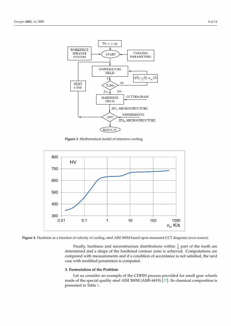
Block diagram of numerical model for cooling is presented in Figure 3.
Figure 3. Mathematical model of intensive cooling.
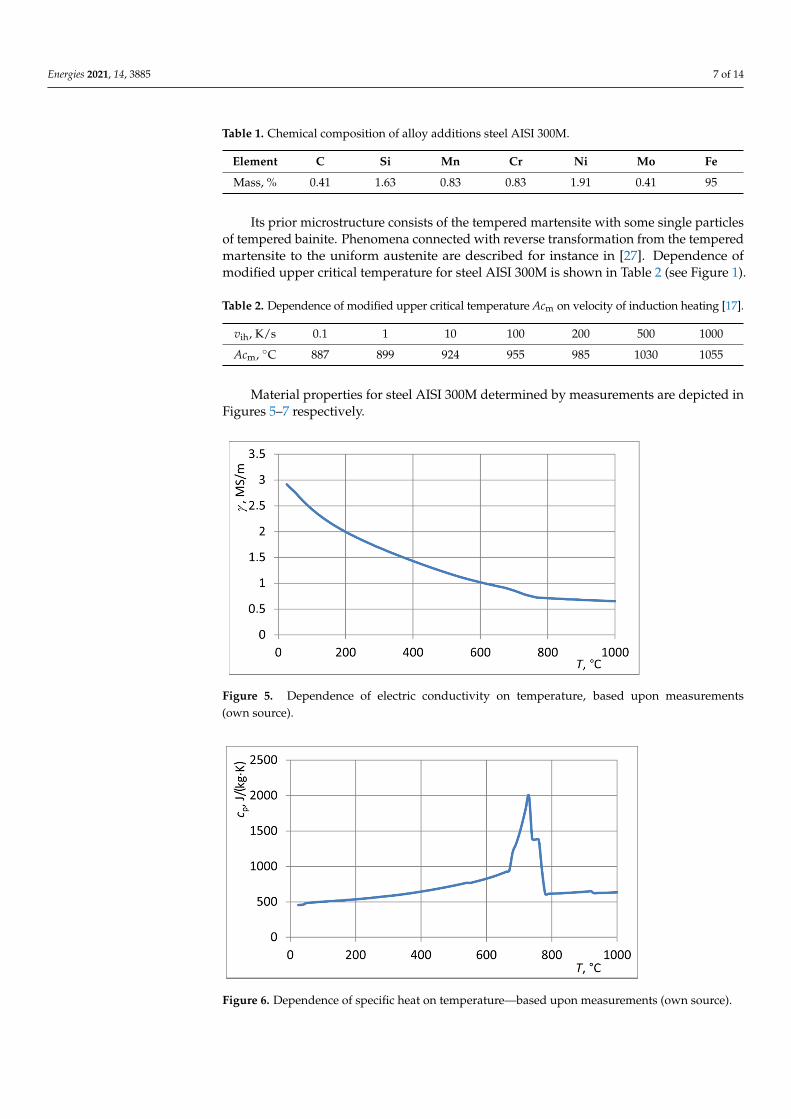
Time of a break between heating and cooling could be neglected because the cooling practically starts immediately when the HF inductor is switched off. Temperature field is determined based upon Equation (4) (pV = 0). Radiation is neglected. Convection heat transfer coefficient for cooling αcc depends on temperature, but in practice it is analyzed in a simplified way by putting different values on all boundaries of the domain. For the cooling stage as well the Flux 3D software for temperature field coupled with the modified QT steel supported by several own numerical procedures for hardness and microstructure fields are applied [26]. A special numerical procedure making possible to couple directly Flux 3D and QT steel codes is elaborated. Taking into consideration that when the induc-tion heating is terminated, the non-uniform temperature within the tooth, highest at the surface and lower inside the material is observed. The velocity of cooling vc is determined based upon several measured Continuous-Cooling-Transformation (CCT) diagrams start-ing of different hardening temperatures Th. For the analyzed problem hardening temper-ature hT changes between (850–1050 °C). Based upon these diagrams, dependences of the hardness on the velocity of cooling in different points of tooth are elaborated. Exem-plary dependence of hardness on velocity of cooling for the hardening temperature
hT = 960 °C is presented in Figure 4.
Figure 3. Mathematical model of intensive cooling.Energies 2021, 14, x FOR PEER REVIEW 7 of 15
Figure 4. Hardness as a function of velocity of cooling, steel AISI 300M based upon measured CCT diagrams (own source).
Finally, hardness and microstructure distributions within ¼ part of the tooth are de-termined and a shape of the hardened contour zone is achieved. Computations are com-pared with measurements and if a condition of accordance is not satisfied, the next case with modified parameters is computed.
3. Formulation of the Problem Let us consider an example of the CDFIH process provided for small gear wheels
made of the special quality steel AISI 300M (AMS 6419) [17]. Its chemical composition is presented in Table 1.
Table 1. Chemical composition of alloy additions steel AISI 300M.
Element C Si Mn Cr Ni Mo Fe Mass, % 0.41 1.63 0.83 0.83 1.91 0.41 95
Its prior microstructure consists of the tempered martensite with some single parti-cles of tempered bainite. Phenomena connected with reverse transformation from the tem-pered martensite to the uniform austenite are described for instance in [27]. Dependence of modified upper critical temperature for steel AISI 300M is shown in Table 2 (see Figure 1).
Table 2. Dependence of modified upper critical temperature Acm on velocity of induction heating [17].
ih ,v K/s 0.1 1 10 100 200 500 1000 Acm, °C 887 899 924 955 985 1030 1055
Material properties for steel AISI 300M determined by measurements are depicted in Figures 5–7 respectively.
Figure 4. Hardness as a function of velocity of cooling, steel AISI 300M based upon measured CCT diagrams (own source).
Finally, hardness and microstructure distributions within 14 part of the tooth are
determined and a shape of the hardened contour zone is achieved. Computations arecompared with measurements and if a condition of accordance is not satisfied, the nextcase with modified parameters is computed.
3. Formulation of the Problem
Let us consider an example of the CDFIH process provided for small gear wheelsmade of the special quality steel AISI 300M (AMS 6419) [17]. Its chemical composition ispresented in Table 1.
Energies 2021, 14, 3885 7 of 14
Table 1. Chemical composition of alloy additions steel AISI 300M.
Element C Si Mn Cr Ni Mo Fe
Mass, % 0.41 1.63 0.83 0.83 1.91 0.41 95
Its prior microstructure consists of the tempered martensite with some single particlesof tempered bainite. Phenomena connected with reverse transformation from the temperedmartensite to the uniform austenite are described for instance in [27]. Dependence ofmodified upper critical temperature for steel AISI 300M is shown in Table 2 (see Figure 1).
Table 2. Dependence of modified upper critical temperature Acm on velocity of induction heating [17].
vih, K/s 0.1 1 10 100 200 500 1000
Acm, ◦C 887 899 924 955 985 1030 1055
Material properties for steel AISI 300M determined by measurements are depicted inFigures 5–7 respectively.
Energies 2021, 14, x FOR PEER REVIEW 8 of 15
Figure 5. Dependence of electric conductivity on temperature, based upon measurements (own source).
Figure 6. Dependence of specific heat on temperature—based upon measurements (own source).
Figure 7. Dependence of thermal conductivity on temperature—based upon measurements (own source).
Main dimensions and parameters of the inductor gear wheel systems are as follow [28]: • Gear wheel: teeth number—16, width of the tooth ring—6 mm, top diameter—35.6
mm, root diameter—26.9 mm, hole diameter—16 mm.
Figure 5. Dependence of electric conductivity on temperature, based upon measurements(own source).
Energies 2021, 14, x FOR PEER REVIEW 8 of 15
Figure 5. Dependence of electric conductivity on temperature, based upon measurements (own source).
Figure 6. Dependence of specific heat on temperature—based upon measurements (own source).
Figure 7. Dependence of thermal conductivity on temperature—based upon measurements (own source).
Main dimensions and parameters of the inductor gear wheel systems are as follow [28]: • Gear wheel: teeth number—16, width of the tooth ring—6 mm, top diameter—35.6
mm, root diameter—26.9 mm, hole diameter—16 mm.
Figure 6. Dependence of specific heat on temperature—based upon measurements (own source).
Energies 2021, 14, 3885 8 of 14
Energies 2021, 14, x FOR PEER REVIEW 8 of 15
Figure 5. Dependence of electric conductivity on temperature, based upon measurements (own source).
Figure 6. Dependence of specific heat on temperature—based upon measurements (own source).
Figure 7. Dependence of thermal conductivity on temperature—based upon measurements (own source).
Main dimensions and parameters of the inductor gear wheel systems are as follow [28]: • Gear wheel: teeth number—16, width of the tooth ring—6 mm, top diameter—35.6
mm, root diameter—26.9 mm, hole diameter—16 mm.
Figure 7. Dependence of thermal conductivity on temperature—based upon measurements (ownsource).
Main dimensions and parameters of the inductor gear wheel systems are as follow [28]:
• Gear wheel: teeth number—16, width of the tooth ring—6 mm, top diameter—35.6 mm, root diameter—26.9 mm, hole diameter—16 mm.
• MF inductor: external diameter—54 mm, internal diameter—39.5 mm, height—7 mm.• HF inductor: external diameter—61 mm, internal diameter—39.5 mm, height—21 mm,
flux concentrator made of Fluxtrol 50: its external diameter—81.5 mm, its internaldiameter 39 mm, thickness of upper and lower cylinder—5 mm.
• Sprayer: distance between inductor and sprayer—20 mm, external diameter—85 mm,internal diameter—61 mm.
Several computations are provided in order to make a correct selection of the processparameters. Due to symmetry and periodicity of the system computations are provided for14 part of tooth only. Based upon these computations following parameters for experimentsof the CDFIH process are finally determined:
• MF induction heating: current—1450 A, heating time—4.4 s, frequency—36 kHz.• Break between MF and HF heating: —0.1 s.• HF induction heating: current—520 A, time—0.4 s, frequency—242 kHz.• Parameters of cooling: quenchant—polymer solution Aqua Quench 140, concentration—
10%, temperature—25 ◦C, pressure—89 kPa, flow-rate—2·10−5 m3/s, convection heattransfer coefficient at external surface—400 W/(m2·K).
• Heating rate and critical temperatures: velocity of induction heating—205 K/s, modi-fied upper critical temperature—993 ◦C, hardening temperature—1010 ◦C.
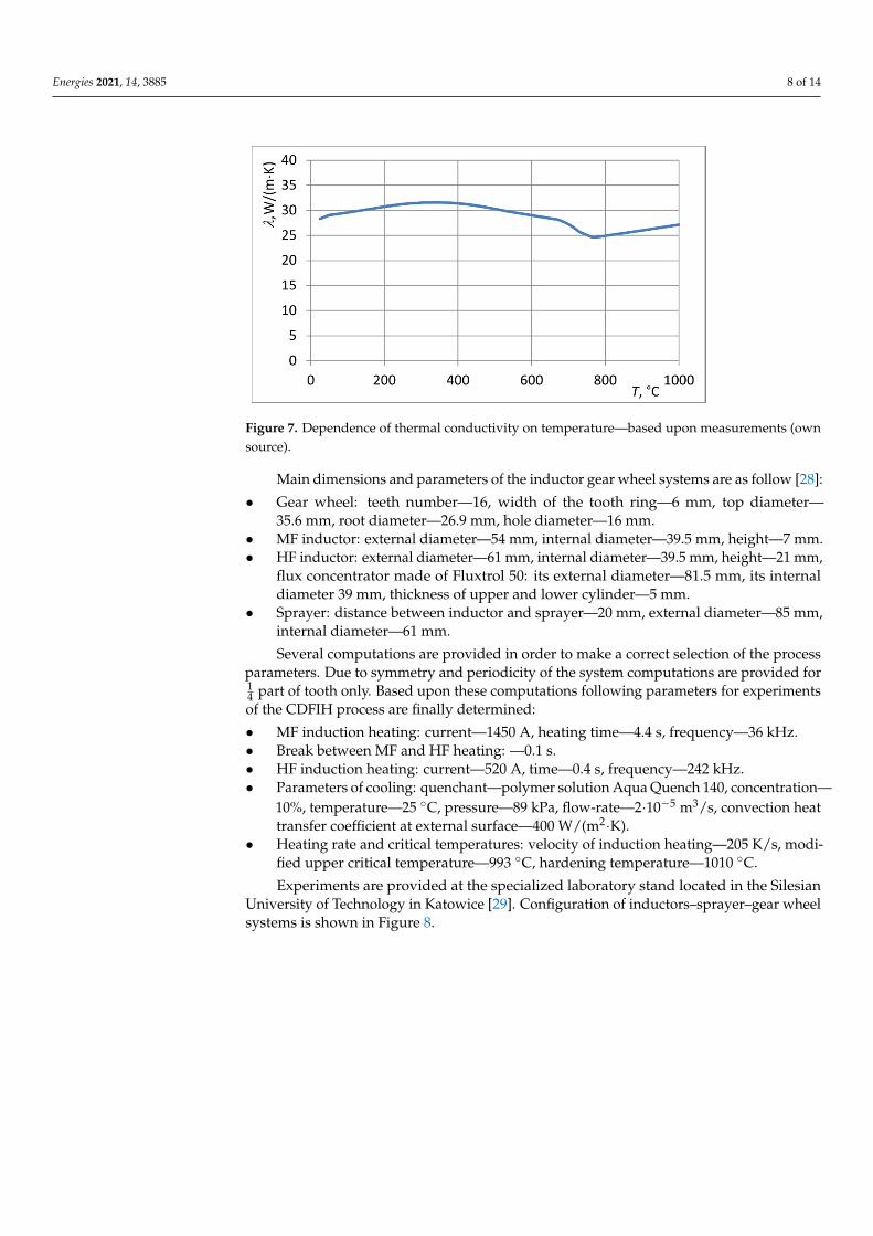
Experiments are provided at the specialized laboratory stand located in the SilesianUniversity of Technology in Katowice [29]. Configuration of inductors–sprayer–gear wheelsystems is shown in Figure 8.
Energies 2021, 14, 3885 9 of 14
Energies 2021, 14, x FOR PEER REVIEW 9 of 15
• MF inductor: external diameter—54 mm, internal diameter—39.5 mm, height—7 mm.
• HF inductor: external diameter—61 mm, internal diameter—39.5 mm, height—21 mm, flux concentrator made of Fluxtrol 50: its external diameter—81.5 mm, its inter-nal diameter 39 mm, thickness of upper and lower cylinder—5 mm.
• Sprayer: distance between inductor and sprayer—20 mm, external diameter—85 mm, internal diameter—61 mm. Several computations are provided in order to make a correct selection of the process
parameters. Due to symmetry and periodicity of the system computations are provided for ¼ part of tooth only. Based upon these computations following parameters for exper-iments of the CDFIH process are finally determined: • MF induction heating: current—1450 A, heating time—4.4 s, frequency—36 kHz. • Break between MF and HF heating: —0.1 s. • HF induction heating: current—520 A, time—0.4 s, frequency—242 kHz. • Parameters of cooling: quenchant—polymer solution Aqua Quench 140, concentra-
tion—10%, temperature—25 °C, pressure—89 kPa, flow-rate—2.10-5 m3/s, convection heat transfer coefficient at external surface—400 W/(m2.K).
• Heating rate and critical temperatures: velocity of induction heating—205 K/s, mod-ified upper critical temperature—993 °C, hardening temperature—1010 °C. Experiments are provided at the specialized laboratory stand located in the Silesian
University of Technology in Katowice [29]. Configuration of inductors–sprayer–gear wheel systems is shown in Figure 8.
Figure 8. Configuration of the CDFIH system.
Both inductors have a ring shape. They are water cooled. The HF inductor is equipped in the magnetic flux concentrator made of Fluxtrol 50 [30].
4. Results and Discussion Comparison between computations and measurements is done for hardness distri-
bution along the line A…G at the working surface of the tooth, while point A is located in
Figure 8. Configuration of the CDFIH system.
Both inductors have a ring shape. They are water cooled. The HF inductor is equippedin the magnetic flux concentrator made of Fluxtrol 50 [30].
4. Results and Discussion
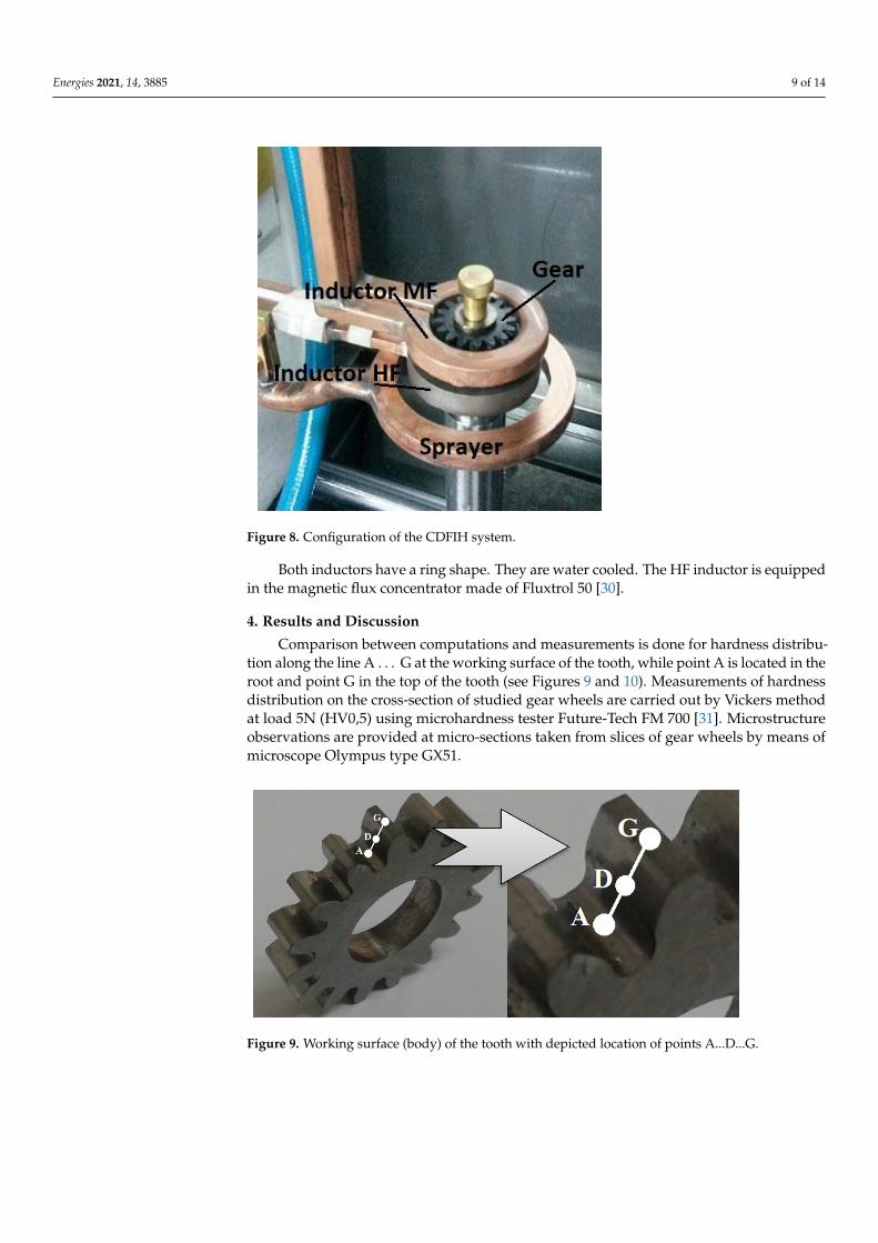
Comparison between computations and measurements is done for hardness distribu-tion along the line A . . . G at the working surface of the tooth, while point A is located in theroot and point G in the top of the tooth (see Figures 9 and 10). Measurements of hardnessdistribution on the cross-section of studied gear wheels are carried out by Vickers methodat load 5N (HV0,5) using microhardness tester Future-Tech FM 700 [31]. Microstructureobservations are provided at micro-sections taken from slices of gear wheels by means ofmicroscope Olympus type GX51.
Energies 2021, 14, x FOR PEER REVIEW 10 of 15
the root and point G in the top of the tooth (see Figures 9 and 10). Measurements of hard-ness distribution on the cross-section of studied gear wheels are carried out by Vickers method at load 5N (HV0,5) using microhardness tester Future-Tech FM 700 [31]. Micro-structure observations are provided at micro-sections taken from slices of gear wheels by means of microscope Olympus type GX51.
Figure 9. Working surface (body) of the tooth with depicted location of points A...D...G.
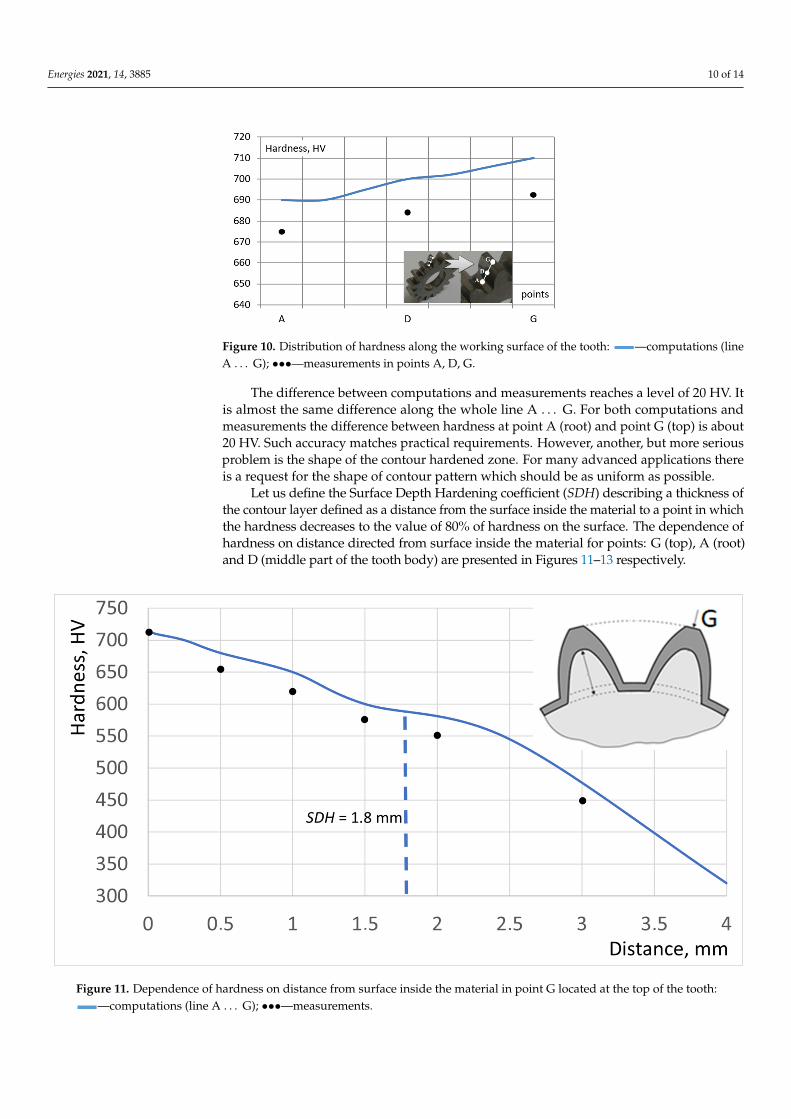
Figure 10. Distribution of hardness along the working surface of the tooth: —computations (line A…G); •••—measurements in points A, D, G.
The difference between computations and measurements reaches a level of 20 HV. It is almost the same difference along the whole line A…G. For both computations and measurements the difference between hardness at point A (root) and point G (top) is about 20 HV. Such accuracy matches practical requirements. However, another, but more seri-ous problem is the shape of the contour hardened zone. For many advanced applications there is a request for the shape of contour pattern which should be as uniform as possible.
Let us define the Surface Depth Hardening coefficient (SDH) describing a thickness of the contour layer defined as a distance from the surface inside the material to a point in which the hardness decreases to the value of 80% of hardness on the surface. The de-pendence of hardness on distance directed from surface inside the material for points: G (top), A (root) and D (middle part of the tooth body) are presented in Figures 11–13 re-spectively.
Figure 9. Working surface (body) of the tooth with depicted location of points A...D...G.
Energies 2021, 14, 3885 10 of 14
Energies 2021, 14, x FOR PEER REVIEW 10 of 15
the root and point G in the top of the tooth (see Figures 9 and 10). Measurements of hard-ness distribution on the cross-section of studied gear wheels are carried out by Vickers method at load 5N (HV0,5) using microhardness tester Future-Tech FM 700 [31]. Micro-structure observations are provided at micro-sections taken from slices of gear wheels by means of microscope Olympus type GX51.
Figure 9. Working surface (body) of the tooth with depicted location of points A...D...G.
Figure 10. Distribution of hardness along the working surface of the tooth: —computations (line A…G); •••—measurements in points A, D, G.
The difference between computations and measurements reaches a level of 20 HV. It is almost the same difference along the whole line A…G. For both computations and measurements the difference between hardness at point A (root) and point G (top) is about 20 HV. Such accuracy matches practical requirements. However, another, but more seri-ous problem is the shape of the contour hardened zone. For many advanced applications there is a request for the shape of contour pattern which should be as uniform as possible.
Let us define the Surface Depth Hardening coefficient (SDH) describing a thickness of the contour layer defined as a distance from the surface inside the material to a point in which the hardness decreases to the value of 80% of hardness on the surface. The de-pendence of hardness on distance directed from surface inside the material for points: G (top), A (root) and D (middle part of the tooth body) are presented in Figures 11–13 re-spectively.
Figure 10. Distribution of hardness along the working surface of the tooth:
Energies 2021, 14, x FOR PEER REVIEW 10 of 15
of hardness distribution on the cross-section of studied gear wheels are carried out by Vickers method at load 5N (HV0,5) using microhardness tester Future-Tech FM 700 [31]. Microstructure observations are provided at micro-sections taken from slices of gear wheels by means of microscope Olympus type GX51.
Figure 9. Working surface (body) of the tooth with depicted location of points A...D...G.
Figure 10. Distribution of hardness along the working surface of the tooth: —computations (line A…G); •••—measurements in points A, D, G.
The difference between computations and measurements reaches a level of 20 HV. It is almost the same difference along the whole line A…G. For both computations and measurements the difference between hardness at point A (root) and point G (top) is about 20 HV. Such accuracy matches practical requirements. However, another, but more serious problem is the shape of the contour hardened zone. For many advanced applications there is a request for the shape of contour pattern which should be as uniform as possible.
Let us define the Surface Depth Hardening coefficient (SDH) describing a thickness of the contour layer defined as a distance from the surface inside the material to a point in which the hardness decreases to the value of 80% of hardness on the surface. The dependence of hardness on distance directed from surface inside the material for points: G (top), A (root) and D (middle part of the tooth body) are presented in Figures 11–13 respectively.
—computations (lineA . . . G); •••—measurements in points A, D, G.
The difference between computations and measurements reaches a level of 20 HV. Itis almost the same difference along the whole line A . . . G. For both computations andmeasurements the difference between hardness at point A (root) and point G (top) is about20 HV. Such accuracy matches practical requirements. However, another, but more seriousproblem is the shape of the contour hardened zone. For many advanced applications thereis a request for the shape of contour pattern which should be as uniform as possible.
Let us define the Surface Depth Hardening coefficient (SDH) describing a thickness ofthe contour layer defined as a distance from the surface inside the material to a point in whichthe hardness decreases to the value of 80% of hardness on the surface. The dependence ofhardness on distance directed from surface inside the material for points: G (top), A (root)and D (middle part of the tooth body) are presented in Figures 11–13 respectively.
Energies 2021, 14, x FOR PEER REVIEW 11 of 15
Figure 11. Dependence of hardness on distance from surface inside the material in point G located at the top of the tooth:
—computations (line A….G); •••—measurements.
Figure 12. Dependence of computed hardness on distance from surface inside the material in point D located in a middle part of the tooth body.
Figure 11. Dependence of hardness on distance from surface inside the material in point G located at the top of the tooth:
Energies 2021, 14, x FOR PEER REVIEW 10 of 15
of hardness distribution on the cross-section of studied gear wheels are carried out by Vickers method at load 5N (HV0,5) using microhardness tester Future-Tech FM 700 [31]. Microstructure observations are provided at micro-sections taken from slices of gear wheels by means of microscope Olympus type GX51.
Figure 9. Working surface (body) of the tooth with depicted location of points A...D...G.
Figure 10. Distribution of hardness along the working surface of the tooth: —computations (line A…G); •••—measurements in points A, D, G.
The difference between computations and measurements reaches a level of 20 HV. It is almost the same difference along the whole line A…G. For both computations and measurements the difference between hardness at point A (root) and point G (top) is about 20 HV. Such accuracy matches practical requirements. However, another, but more serious problem is the shape of the contour hardened zone. For many advanced applications there is a request for the shape of contour pattern which should be as uniform as possible.
Let us define the Surface Depth Hardening coefficient (SDH) describing a thickness of the contour layer defined as a distance from the surface inside the material to a point in which the hardness decreases to the value of 80% of hardness on the surface. The dependence of hardness on distance directed from surface inside the material for points: G (top), A (root) and D (middle part of the tooth body) are presented in Figures 11–13 respectively.
—computations (line A . . . G); •••—measurements.
Energies 2021, 14, 3885 11 of 14
Energies 2021, 14, x FOR PEER REVIEW 11 of 15
Figure 11. Dependence of hardness on distance from surface inside the material in point G located at the top of the tooth:
—computations (line A….G); •••—measurements.
Figure 12. Dependence of computed hardness on distance from surface inside the material in point D located in a middle part of the tooth body.
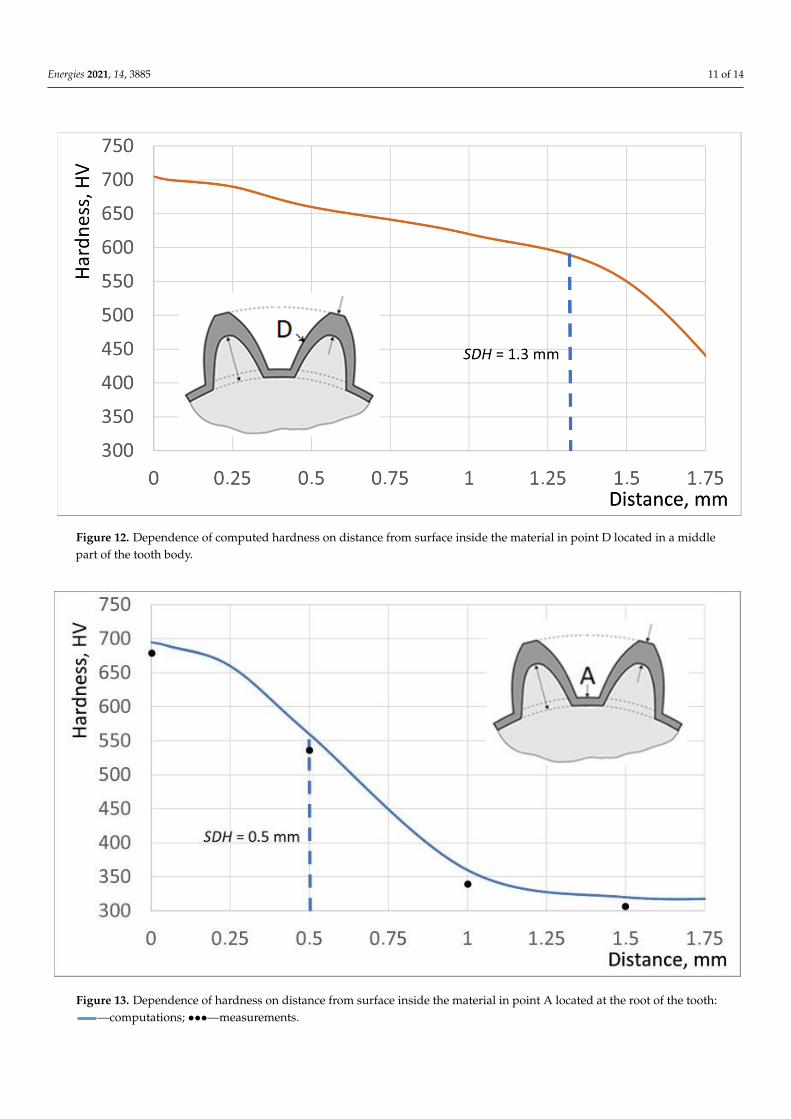
Figure 12. Dependence of computed hardness on distance from surface inside the material in point D located in a middlepart of the tooth body.
Energies 2021, 14, x FOR PEER REVIEW 12 of 15
Figure 13. Dependence of hardness on distance from surface inside the material in point A located at the root of the tooth:
—computations; •••—measurements. For point G at top SDH = 1.8 mm and thickness of the hardened zone is the biggest.
A minimal value of the SDH coefficient is noticed in point A at the root (SDH = 0.5 mm). Distribution of the SDH coefficient along the line A…G is presented in Figure 14.
Figure 14. Distribution of the SDH coefficient along the line A…G.
The obtained SDH coefficient changes from 1.8 mm at the top of the tooth to 0.5 mm at the root. It means a reasonable (less than 5%) difference between computations and measurements. Microstructure of the contour zone creates acicular martensite with some single particles of bainite (Figure 15).
Figure 13. Dependence of hardness on distance from surface inside the material in point A located at the root of the tooth:
Energies 2021, 14, x FOR PEER REVIEW 10 of 15
of hardness distribution on the cross-section of studied gear wheels are carried out by Vickers method at load 5N (HV0,5) using microhardness tester Future-Tech FM 700 [31]. Microstructure observations are provided at micro-sections taken from slices of gear wheels by means of microscope Olympus type GX51.
Figure 9. Working surface (body) of the tooth with depicted location of points A...D...G.
Figure 10. Distribution of hardness along the working surface of the tooth: —computations (line A…G); •••—measurements in points A, D, G.
The difference between computations and measurements reaches a level of 20 HV. It is almost the same difference along the whole line A…G. For both computations and measurements the difference between hardness at point A (root) and point G (top) is about 20 HV. Such accuracy matches practical requirements. However, another, but more serious problem is the shape of the contour hardened zone. For many advanced applications there is a request for the shape of contour pattern which should be as uniform as possible.
Let us define the Surface Depth Hardening coefficient (SDH) describing a thickness of the contour layer defined as a distance from the surface inside the material to a point in which the hardness decreases to the value of 80% of hardness on the surface. The dependence of hardness on distance directed from surface inside the material for points: G (top), A (root) and D (middle part of the tooth body) are presented in Figures 11–13 respectively.
—computations; •••—measurements.
Energies 2021, 14, 3885 12 of 14
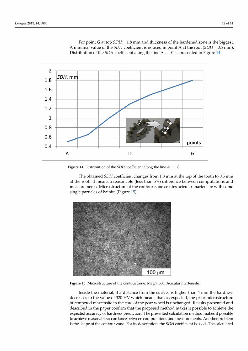
For point G at top SDH = 1.8 mm and thickness of the hardened zone is the biggest.A minimal value of the SDH coefficient is noticed in point A at the root (SDH = 0.5 mm).Distribution of the SDH coefficient along the line A . . . G is presented in Figure 14.
Energies 2021, 14, x FOR PEER REVIEW 12 of 15
Figure 13. Dependence of hardness on distance from surface inside the material in point A located at the root of the tooth:
—computations; •••—measurements. For point G at top SDH = 1.8 mm and thickness of the hardened zone is the biggest.
A minimal value of the SDH coefficient is noticed in point A at the root (SDH = 0.5 mm). Distribution of the SDH coefficient along the line A…G is presented in Figure 14.
Figure 14. Distribution of the SDH coefficient along the line A…G.
The obtained SDH coefficient changes from 1.8 mm at the top of the tooth to 0.5 mm at the root. It means a reasonable (less than 5%) difference between computations and measurements. Microstructure of the contour zone creates acicular martensite with some single particles of bainite (Figure 15).
Figure 14. Distribution of the SDH coefficient along the line A . . . G.
The obtained SDH coefficient changes from 1.8 mm at the top of the tooth to 0.5 mmat the root. It means a reasonable (less than 5%) difference between computations andmeasurements. Microstructure of the contour zone creates acicular martensite with somesingle particles of bainite (Figure 15).
Energies 2021, 14, x FOR PEER REVIEW 13 of 15
Figure 15. Microstructure of the contour zone. Mag× 500. Acicular martensite.
Inside the material, if a distance from the surface is higher than 4 mm the hardness decreases to the value of 320 HV which means that, as expected, the prior microstructure of tempered martensite in the core of the gear wheel is unchanged. Results presented and described in the paper confirm that the proposed method makes it possible to achieve the expected accuracy of hardness prediction. The presented calculation method makes it pos-sible to achieve reasonable accordance between computations and measurements. An-other problem is the shape of the contour zone. For its description, the SDH coefficient is used. The calculated non-uniform shape of the contour zone is validated by the measure-ments. In order to achieve a more uniform shape of the contour hardened zone it is nec-essary to decrease heating time and increase the delivered power. Another solution is to apply the SDFIH process, and in this case short heating duration and large delivery of power are expected.
5. Conclusions The CDFIH process described in the paper is successfully applied for the energy-
efficient contour hardening of gear wheels. The proposed mathematical model could be the effective tool for the design of such processes. It makes it possible to predict hardness and microstructure distributions with a reasonable accuracy of about 20 HV. In order to minimize the computation time, magnetic field quantities are considered in a simplified way as harmonic. The model should contain additional numerical procedures based upon specialized measurements for the investigated steel (TTA and CCT diagrams), making it possible to determine hardening temperature as a function of velocity of induction heat-ing and hardness as a function of velocity of cooling and hardening temperature. The next paper in this area will be aimed at improvement of the described process in order to obtain the uniform shape of the contour zone.
Author Contributions: Conceptualization, J.B.; methodology, A.S. (Albert Smalcerz); software, D.G.D.; validation, A.S. (Albert Smalcerz), J.B. and A.S. (Adrian Smagór); formal analysis, A.S. (Al-bert Smalcerz); investigation, A.S. (Adrian Smagór); resources, D.G.D.; data curation, A.S. (Adrian Smagór); writing—original draft preparation, J.B.; writing—review and editing, A.S. (Albert Smal-cerz); visualization, A.S. (Adrian Smagór); supervision, J.B.; project administration, A.S. (Albert Smalcerz); funding acquisition, A.S. (Albert Smalcerz) All authors have read and agreed to the pub-lished version of the manuscript.
Funding: This research was funded by National Centre for Research and Development, grant num-ber PBS2/A5/41/2014 This research was supported by the Silesian University of Technology, grants No. 11/040/BK_21/0023 and 11/040/BKM21/0025.
Institutional Review Board Statement: Not applicable.
Figure 15. Microstructure of the contour zone. Mag× 500. Acicular martensite.
Inside the material, if a distance from the surface is higher than 4 mm the hardnessdecreases to the value of 320 HV which means that, as expected, the prior microstructureof tempered martensite in the core of the gear wheel is unchanged. Results presented anddescribed in the paper confirm that the proposed method makes it possible to achieve theexpected accuracy of hardness prediction. The presented calculation method makes it possibleto achieve reasonable accordance between computations and measurements. Another problemis the shape of the contour zone. For its description, the SDH coefficient is used. The calculated
Energies 2021, 14, 3885 13 of 14
non-uniform shape of the contour zone is validated by the measurements. In order to achievea more uniform shape of the contour hardened zone it is necessary to decrease heating timeand increase the delivered power. Another solution is to apply the SDFIH process, and in thiscase short heating duration and large delivery of power are expected.
5. Conclusions
The CDFIH process described in the paper is successfully applied for the energy-efficient contour hardening of gear wheels. The proposed mathematical model could bethe effective tool for the design of such processes. It makes it possible to predict hardnessand microstructure distributions with a reasonable accuracy of about 20 HV. In order tominimize the computation time, magnetic field quantities are considered in a simplifiedway as harmonic. The model should contain additional numerical procedures based uponspecialized measurements for the investigated steel (TTA and CCT diagrams), making itpossible to determine hardening temperature as a function of velocity of induction heatingand hardness as a function of velocity of cooling and hardening temperature. The nextpaper in this area will be aimed at improvement of the described process in order to obtainthe uniform shape of the contour zone.
Author Contributions: Conceptualization, J.B.; methodology, A.S. (Albert Smalcerz); software,D.G.D.; validation, A.S. (Albert Smalcerz), J.B. and A.S. (Adrian Smagór); formal analysis, A.S.(Albert Smalcerz); investigation, A.S. (Adrian Smagór); resources, D.G.D.; data curation, A.S. (AdrianSmagór); writing—original draft preparation, J.B.; writing—review and editing, A.S. (Albert Smal-cerz); visualization, A.S. (Adrian Smagór); supervision, J.B.; project administration, A.S. (AlbertSmalcerz); funding acquisition, A.S. (Albert Smalcerz) All authors have read and agreed to thepublished version of the manuscript.
Funding: This research was funded by National Centre for Research and Development, grant numberPBS2/A5/41/2014 This research was supported by the Silesian University of Technology, grants No.11/040/BK_21/0023 and 11/040/BKM21/0025.
Institutional Review Board Statement: Not applicable.
Informed Consent Statement: Not applicable.
Data Availability Statement: The data that support the findings of this study are available from thecorresponding author upon reasonable request.
Conflicts of Interest: The authors declare no conflict of interest.
References1. Rudnev, V.; Totten, G. Induction Heating and Heat Treatment 4C; ASM International: Materials Park, OH, USA, 2014.2. Jones, K.T.; Newsome, M.; Carter, D. Gas carburizing vs. contour induction hardening on bevel gears. Gear Solut. 2010, 8, 38–54.3. Chatterjee, M. Comparative Study of Carburizing vs. Induction Hardening of Gear Wheels. 2003. Available online:
https://www.heattreattoday.com/processes/carburizing/carburizing-technical-content/comparative-study-of-carburizing-vs-induction-hardening-of-gears/ (accessed on 15 May 2021).
4. Schwenck, M.; Schwenck, W. Substitution of case hardening gearbox components in the automotive as well as aeronauticalindustry through contour induction hardening. In Proceedings of the International Conference on Heating by ElectromagneticSources, HES-07, Padova, Italy, 20–22 June 2007; pp. 175–182.
5. Rudnev, V. Induction hardening of gear wheels and critical components Part 1. Gear Technol. 2008, 1, 58–63.6. Rudnev, V.; Loveless, D.; Cook, R. Handbook of Induction Heating; CRC Press: London, UK; Taylor and Francis Group: Abingdon,
UK, 2018.7. Lupi, S. Fundamentals of Electroheat, Electrical Technologies for Process Heating; Springer: Cham, Switzerland, 2017.8. Rudnev, V.; Loveless, D.; Cook, R.; Black, M. Induction Hardening of Gear. Heat Treat. Met. 2004, 1, 11–15.9. Pleshcheva, Y.; Baldan, N.; Popov, A.; Nikanorov, A.; Rapaport, E.; Nacke, B. Effective methods for optimal design of induction
coils on example of surface hardening. COMPEL Int. J. Comput. Math. Electr. Electron. Eng. 2019, 39, 90–99.10. Kwang-Hyung, C.; Chang-Tae, J.; Rae-Young, K. Analysis and evaluation of WBG power device in high frequency induction
heating application. Energies 2020, 13, 5351.11. Goldstein, R.; Nemkov, V. Design Principles for Induction Heating and Hardening. In Handbook of Metallurgical Process Design;
Marcel Dekker: New York, NY, USA, 2004; pp. 591–640.
Energies 2021, 14, 3885 14 of 14
12. Szychta, E.; Szychta, L. Comparative Analysis of Effectiveness of Resistance and Induction Turnout Heating. Energies 2020, 13,5262. [CrossRef]
13. Rudnev, V. Induction hardening of gear wheels and critical components Part 2. Gear Technol. 2008, 2, 47–53.14. Buglaliero, N.; Zimmerman, C.; Richardson, S.; Perkins, R.; McCurdy, D.; Giessel, B. Heat Treatment Processes for Gear Wheels—
Gear Solutions. 2010. Available online: https://gearsolutions.com/features/heat-treat-processes-for-gears/ (accessed on 15 May2021).
15. Spezzapria, M.; Forzan, M.; Dughiero, F. Numerical Simulation of Solid-Solid Phase Transformations During Induction Hardening.IEEE Trans. Magn. 2016, 52, 740–743. [CrossRef]
16. Barglik, J. Mathematical modelling of induction surface hardening. COMPEL Int. J. Comput. Math. Electr. Electron. Eng. 2016, 35,1403–1417. [CrossRef]
17. Barglik, J. Induction contour hardening of gear wheels made of steel 300M. IOP Conf. Ser. Mater. Sci. Eng. 2018, 424, 012062.[CrossRef]
18. Lupi, S.; Forzan, M.; Alifierov, A. Induction and Direct Resistance Heating: Theory and Numerical Modelling; Springer:Berlin/Heidelberg, Germany, 2015.
19. Holman, P. Heat Transfer; Mc Graw Hill: New York, NY, USA, 2009.20. Barglik, J.; Smalcerz, A. Influence of the magnetic permeability on modelling of induction surface hardening. COMPEL Int. J.
Comput. Math. Electr. Electron. Eng. 2017, 36, 555–564. [CrossRef]21. Barglik, J.; Czerwinski, M.; Hering, M.; Wesołowski, M. Radiation in Modelling of Induction Heating Systems; IOS Press: Amsterdam,
The Netherlands, 2008; pp. 202–211.22. Barglik, J.; Smalcerz, A.; Przylucki, R.; Dolezel, I. 3D modeling of induction hardening of gear wheels. J. Comput. Appl. Math.
2014, 270, 231–240. [CrossRef]23. Zgraja, J.; Lisowski, G.; Kucharski, J. Autonomous Energy Matching Control in an LLC Induction Heating Generator. Energies
2020, 13, 1860. [CrossRef]24. Barglik, J. Induction hardening of steel elements with complex shapes. Przeglad Elektrotechniczny 2018, 94, 51–54. [CrossRef]25. WinSite. Cedrat Flux Software. Available online: https://www.winsite.com/cedrat/cedrat+flux/ (accessed on 15 May 2021).26. ITA Technology and Software. QTSteel Software. Available online: http://www.ita-tech.cz/en/products-services/heat-
treatment/software-qtsteel (accessed on 15 May 2021).27. Shinozaki, T.; Tomota, Y.; Fukino, T.; Suzuki, T. Microstructure evolution during reverse transformation of austenite from
tempered martensite in low alloy steel. ISIJ Int. 2017, 57, 740–743. [CrossRef]28. Barglik, J. Induction heating of small gear wheels in the contour hardening process. In Proceedings of the 19th International
Symposium on Electromagnetic Fields in Mechatronics, Electrical and Electronic Engineering (ISEF 2019), Nancy, France, 29–31August 2019; pp. 1–2.
29. Barglik, J.; Smalcerz, A.; Smagor, A.; Kopec, G. Experimental Stand for Investigation of Induction Hardening of Steel Elements.Metalurgija 2018, 57, 341–344.
30. Centre for Induction Technology. Fluxtrol 50. Available online: https://fluxtrol.com/inc/pdf/Fluxtrol-50-Specs.pdf (accessed on15 May 2021).
31. Wróbel, T.; Przyszlak, N.; Dulska, A. Technology of Alloy Layers on Surface of Castings. Int. J. Met. 2019, 13, 604–610. [CrossRef]


