Embed Size (px)
Citation preview

2
AUGUST 2020
3
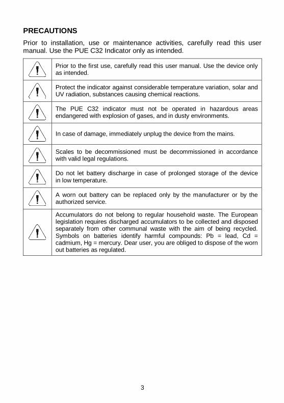
PRECAUTIONS
Prior to installation, use or maintenance activities, carefully read this user manual. Use the PUE C32 Indicator only as intended.
Prior to the first use, carefully read this user manual. Use the device only as intended.
Protect the indicator against considerable temperature variation, solar and UV radiation, substances causing chemical reactions.
The PUE C32 indicator must not be operated in hazardous areas endangered with explosion of gases, and in dusty environments.
In case of damage, immediately unplug the device from the mains.
Scales to be decommissioned must be decommissioned in accordance with valid legal regulations.
Do not let battery discharge in case of prolonged storage of the device in low temperature.
A worn out battery can be replaced only by the manufacturer or by the authorized service.
Accumulators do not belong to regular household waste. The European legislation requires discharged accumulators to be collected and disposed separately from other communal waste with the aim of being recycled. Symbols on batteries identify harmful compounds: Pb = lead, Cd = cadmium, Hg = mercury. Dear user, you are obliged to dispose of the worn out batteries as regulated.
4
Contents 1. INTENDED USE ................................................................................................................................................. 5 2. WARRANTY CONDITIONS ............................................................................................................................... 5 3. MAINTENANCE ACTIVITIES ............................................................................................................................ 5
3.1. Cleaning ABS Components......................................................................................................................... 6 3.2. Cleaning Stainless Steel Components ........................................................................................................ 6
4. MECHANICAL DESIGN ..................................................................................................................................... 6 4.1. Dimensions .................................................................................................................................................. 6 4.2. Connectors Arrangement ............................................................................................................................ 7 4.3. RS232 Connectors ...................................................................................................................................... 7 4.4. Inputs / Outputs ........................................................................................................................................... 7
4.4.1. Technical Specifications ................................................................................................................... 8 4.4.2. I/O Schematic Diagrams .................................................................................................................. 8
4.5. Operation Panel........................................................................................................................................... 9 4.6. Technical Specifications ............................................................................................................................ 10
5. INDICATOR INSTALLATION .......................................................................................................................... 10 5.1. Unpacking and Installation ........................................................................................................................ 10 5.2. Start-Up ..................................................................................................................................................... 11 5.3. Battery Status ............................................................................................................................................ 11
6. HOME SCREEN ............................................................................................................................................... 12 6.1. Top Bar ...................................................................................................................................................... 12 6.2. Weighing Result Window .......................................................................................................................... 13 6.3. Workspace ................................................................................................................................................. 13 6.4. Pictograms ................................................................................................................................................. 13
7. OPERATING THE MENU ................................................................................................................................. 13 7.1. Entering the Menu ..................................................................................................................................... 13 7.2. Menu Keys ................................................................................................................................................. 14 7.3. Entering Numbers / Text ........................................................................................................................... 15
7.3.1. Numerical Box ................................................................................................................................ 15 7.3.2. Text Box.......................................................................................................................................... 16 7.3.3. Diacritical Sign Table ...................................................................................................................... 18 7.3.4. Special Sign Table.......................................................................................................................... 18
7.4. Return to Weighing .................................................................................................................................... 19 8. INSTALLER INSTRUCTION ............................................................................................................................ 19
8.1. Connecting 6-Wire Load Cell .................................................................................................................... 19 8.2. Connecting 4-Wire Load Cell .................................................................................................................... 20 8.3. Load Cell Shield Connection ..................................................................................................................... 21
9. FACTORY SETUP ............................................................................................................................................ 21 9.1. Factory Setup Access ............................................................................................................................... 21 9.2. Global Parameters..................................................................................................................................... 22 9.3. Factory Parameters ................................................................................................................................... 23 9.4. Return to Weighing .................................................................................................................................... 25 9.5. Factory Adjustment.................................................................................................................................... 25
9.5.1. External Adjustment ....................................................................................................................... 25 9.5.2. Start Mass Determination ............................................................................................................... 25
9.6. Linearity Correction ................................................................................................................................... 25 9.6.1. Linearity Determination .................................................................................................................. 25 9.6.2. Corrections ..................................................................................................................................... 26 9.6.3. Deleting Linearity ............................................................................................................................ 27
9.7. Gravitational Coefficient ............................................................................................................................ 27 10. DIAGRAMS OF CONNECTION CABLES ..................................................................................................... 27
5
1. INTENDED USE
The PUE C32 weighing indicator is a part of construction of industrial scales operating on the basis of load cells. The indicator features an ABS plastic housing and a 5'' colour graphic display ensuring perfect readability. It is operated using 22-key membrane keypad equipped with programmable function keys.
Standard design offers two RS232 interfaces, USB type A, USB type B, Ethernet, wireless communication, 2 proximity sensors, 4 I/O. The indicator can be operated in areas where there is no access to the mains. It can optionally be supplied by NiMH battery (nickel-metal-hydride) of 1800 - 2800 mAh capacity. The device integrates with receipt and label printers, barcode scanners and PC accessories (mouse, keyboard, USB flash drive).
2. WARRANTY CONDITIONS
A. RADWAG feels obliged to repair or exchange all elements that appear to be faulty by production or by construction.
B. Defining defects of unclear origin and means of their elimination can only be realized with the assistance of the manufacturer and the user representatives.
C. RADWAG does not bear any responsibility for damage or losses resulting from unauthorized or inadequate performing of production or service processes.
D. The warranty does not cover:
mechanical damage caused by product exploitation other than intended, damage of thermal and chemical origin, damage caused by lightning, overvoltage in the power network or other random event,
inappropriate cleaning habits. E. Loss of warranty takes place if:
a repair is carried out outside RADWAG authorized service point,
service claims intrusion into mechanical or electronic construction by unauthorized people,
the scale does not bear security seal stickers. F. Warranty conditions outline the warranty period for rechargeable
batteries attached to the device for 12 months. G. For detailed warranty conditions read the warranty certificate. H. Contact with the central authorized service: +48 (48) 386 63 30.
3. MAINTENANCE ACTIVITIES
In order to ensure safety in the course of cleaning, it is necessary to disconnect the device from the mains. With this condition met, uninstall the weighing pan and other detachable components.
6
Cleaning the weighing pan while still installed may cause damage of the measuring system.
3.1. Cleaning ABS Components
To clean dry surfaces and avoid smudging, use clean non-colouring cloths made of cellulose or cotton. You can use a solution of water and detergent (soap, dishwashing detergent, glass cleaner). Gently rub the cleaned surface and let it dry. Repeat the cleaning process if needed.
In the case of hard to remove contamination, e.g. residues of adhesive, rubber, resin, polyurethane foam etc., you can use a special cleaning agents based on a mixture of aliphatic hydrocarbons that do not dissolve plastics. Before using the cleanser for all surfaces we recommend carrying out tests. Do not use cleansers containing abrasive substances.
3.2. Cleaning Stainless Steel Components
Avoid using cleansers containing any corrosive chemicals, e.g. bleach (containing chlorine). Do not use cleansers containing abrasive substances. Always remove the dirt using microfiber cloth to avoid damage of protective coating. Daily cleaning routine (removal of small stains): 1. Remove the dirt using cloth dipped in warm water. 2. For best results, add a little bit of dishwashing detergent.
4. MECHANICAL DESIGN
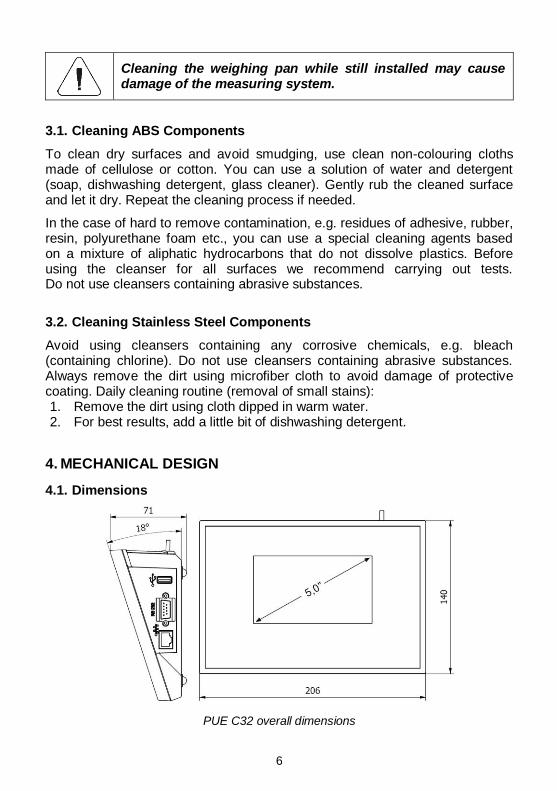
4.1. Dimensions
PUE C32 overall dimensions
7
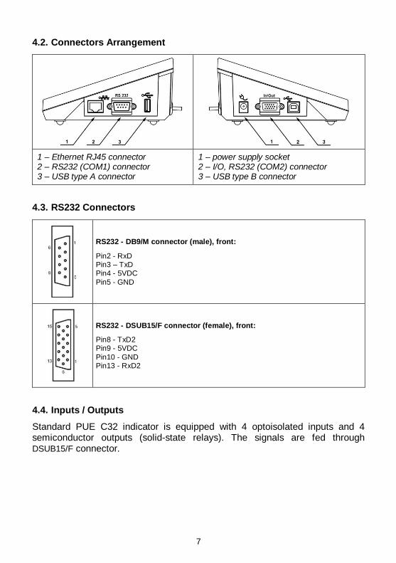
4.2. Connectors Arrangement
1 – Ethernet RJ45 connector 2 – RS232 (COM1) connector 3 – USB type A connector
1 – power supply socket 2 – I/O, RS232 (COM2) connector 3 – USB type B connector
4.3. RS232 Connectors
RS232 - DB9/M connector (male), front:
Pin2 - RxD Pin3 – TxD Pin4 - 5VDC
Pin5 - GND
RS232 - DSUB15/F connector (female), front:
Pin8 - TxD2 Pin9 - 5VDC
Pin10 - GND Pin13 - RxD2
4.4. Inputs / Outputs
Standard PUE C32 indicator is equipped with 4 optoisolated inputs and 4 semiconductor outputs (solid-state relays). The signals are fed through DSUB15/F connector.
8
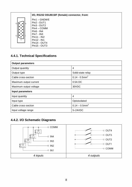
I/O, RS232 DSUB15/F (female) connector, front:
Pin1 – GNDWE
Pin2 - OUT1 Pin3 - OUT2 Pin4 – COMM
Pin6 - IN4 Pin7 - IN3 Pin11 - IN2
Pin12 - IN1 Pin14 - OUT4 Pin15 - OUT3
4.4.1. Technical Specifications
Output parameters
Output quantity 4
Output type Solid-state relay
Cable cross-section 0.14 - 0.5mm2
Maximum output current 0.5A DC
Maximum output voltage 30VDC
Input parameters
Input quantity 4
Input type Optoisolated
Cable cross-section 0.14 – 0.5mm2
Input voltage range 524VDC
4.4.2. I/O Schematic Diagrams
4 inputs 4 outputs
9
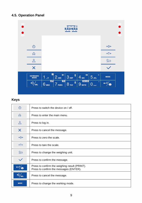
4.5. Operation Panel
Keys
Press to switch the device on / off.
Press to enter the main menu.
Press to log in.
Press to cancel the message.
Press to zero the scale.
Press to tare the scale.
Press to change the weighing unit.
Press to confirm the message.
Press to confirm the weighing result (PRINT).
Press to confirm the messages (ENTER).
Press to cancel the message.
Press to change the working mode.
10
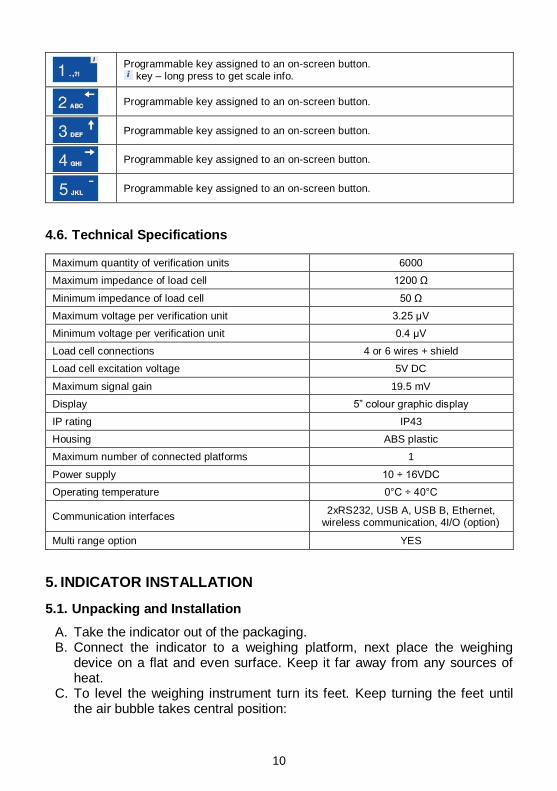
Programmable key assigned to an on-screen button. key – long press to get scale info.
Programmable key assigned to an on-screen button.
Programmable key assigned to an on-screen button.
Programmable key assigned to an on-screen button.
Programmable key assigned to an on-screen button.
4.6. Technical Specifications
Maximum quantity of verification units 6000
Maximum impedance of load cell 1200 Ω
Minimum impedance of load cell 50 Ω
Maximum voltage per verification unit 3.25 µV
Minimum voltage per verification unit 0.4 µV
Load cell connections 4 or 6 wires + shield
Load cell excitation voltage 5V DC
Maximum signal gain 19.5 mV
Display 5” colour graphic display
IP rating IP43
Housing ABS plastic
Maximum number of connected platforms 1
Power supply 10 ÷ 16VDC
Operating temperature 0°C ÷ 40°C
Communication interfaces 2xRS232, USB A, USB B, Ethernet,
wireless communication, 4I/O (option)
Multi range option YES
5. INDICATOR INSTALLATION
5.1. Unpacking and Installation
A. Take the indicator out of the packaging. B. Connect the indicator to a weighing platform, next place the weighing
device on a flat and even surface. Keep it far away from any sources of heat.
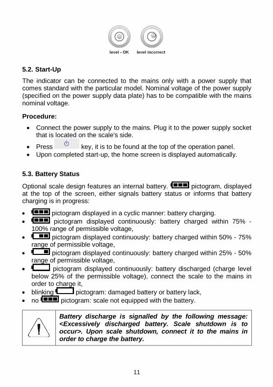
C. To level the weighing instrument turn its feet. Keep turning the feet until the air bubble takes central position:
11
5.2. Start-Up
The indicator can be connected to the mains only with a power supply that comes standard with the particular model. Nominal voltage of the power supply (specified on the power supply data plate) has to be compatible with the mains nominal voltage.
Procedure:
Connect the power supply to the mains. Plug it to the power supply socket that is located on the scale's side.
Press key, it is to be found at the top of the operation panel.
Upon completed start-up, the home screen is displayed automatically.
5.3. Battery Status
Optional scale design features an internal battery. pictogram, displayed at the top of the screen, either signals battery status or informs that battery charging is in progress:
pictogram displayed in a cyclic manner: battery charging.
pictogram displayed continuously: battery charged within 75% - 100% range of permissible voltage,
pictogram displayed continuously: battery charged within 50% - 75% range of permissible voltage,
pictogram displayed continuously: battery charged within 25% - 50% range of permissible voltage,
pictogram displayed continuously: battery discharged (charge level below 25% of the permissible voltage), connect the scale to the mains in order to charge it,
blinking pictogram: damaged battery or battery lack,
no pictogram: scale not equipped with the battery.
Battery discharge is signalled by the following message: <Excessively discharged battery. Scale shutdown is to occur>. Upon scale shutdown, connect it to the mains in order to charge the battery.
12
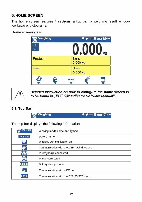
6. HOME SCREEN
The home screen features 4 sections: a top bar, a weighing result window, workspace, pictograms.
Home screen view:
Detailed instruction on how to configure the home screen is to be found in „PUE C32 Indicator Software Manual”.
6.1. Top Bar
The top bar displays the following information:
Working mode name and symbol.
Device name.
Wireless communication on.
Communication with the USB flash drive on.
PC keyboard connected.
Printer connected.
Battery charge status.
Communication with a PC on.
Communication with the E2R SYSTEM on.
13
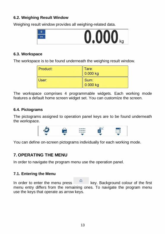
6.2. Weighing Result Window
Weighing result window provides all weighing-related data.
6.3. Workspace
The workspace is to be found underneath the weighing result window.
The workspace comprises 4 programmable widgets. Each working mode features a default home screen widget set. You can customize the screen.
6.4. Pictograms
The pictograms assigned to operation panel keys are to be found underneath the workspace.
You can define on-screen pictograms individually for each working mode.
7. OPERATING THE MENU
In order to navigate the program menu use the operation panel.
7.1. Entering the Menu
In order to enter the menu press key. Background colour of the first menu entry differs from the remaining ones. To navigate the program menu use the keys that operate as arrow keys.
14
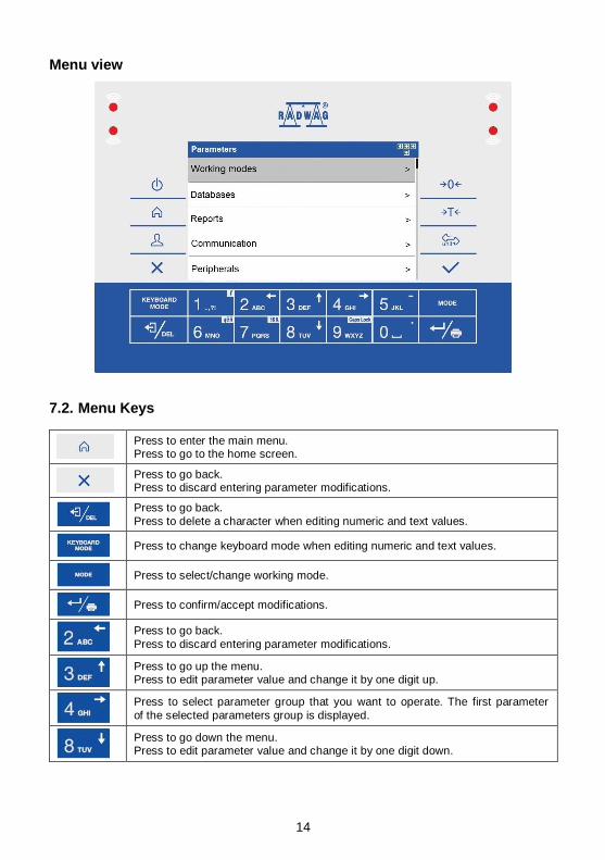
Menu view
7.2. Menu Keys
Press to enter the main menu. Press to go to the home screen.
Press to go back. Press to discard entering parameter modifications.
Press to go back.
Press to delete a character when editing numeric and text values.
Press to change keyboard mode when editing numeric and text values.
Press to select/change working mode.
Press to confirm/accept modifications.
Press to go back.
Press to discard entering parameter modifications.
Press to go up the menu. Press to edit parameter value and change it by one digit up.
Press to select parameter group that you want to operate. The first parameter
of the selected parameters group is displayed.
Press to go down the menu. Press to edit parameter value and change it by one digit down.
15
7.3. Entering Numbers / Text
The software features two different edit boxes:
numerical box (for entering part mass values, tare values, etc.).
text box (for entering printout template, universal variable value, etc.). Button functions change depending on the edit box type.
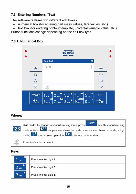
7.3.1. Numerical Box
Where:
Digit mode. To change keyboard working mode press key. Keyboard working
mode options: - upper-case character mode, - lower-case character mode, - digit
mode, - arrow keys operation, - bottom bar operation.
Press to clear box content.
Keys
Press to enter digit 1.
Press to enter digit 2.
Press to enter digit 3.
16
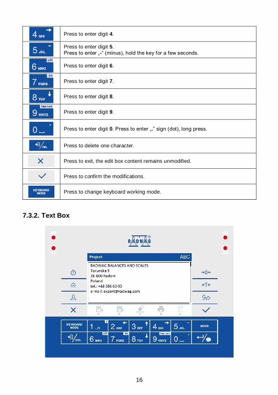
Press to enter digit 4.
Press to enter digit 5.
Press to enter „-” (minus), hold the key for a few seconds.
Press to enter digit 6.
Press to enter digit 7.
Press to enter digit 8.
Press to enter digit 9.
Press to enter digit 0. Press to enter „.” sign (dot), long press.
Press to delete one character.
Press to exit, the edit box content remains unmodified.
Press to confirm the modifications.
Press to change keyboard working mode.
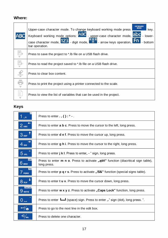
7.3.2. Text Box
17
Where:
Upper-case character mode. To change keyboard working mode press key.
Keyboard working mode options: - upper-case character mode, - lower-
case character mode, - digit mode, - arrow keys operation, - bottom
bar operation.
Press to save the project to *.lb file on a USB flash drive.
Press to read the project saved to *.lb file on a USB flash drive.
Press to clear box content.
Press to print the project using a printer connected to the scale.
Press to view the list of variables that can be used in the project.
Keys
Press to enter . , { } : - .
Press to enter a b c. Press to move the cursor to the left, long press.
Press to enter d e f. Press to move the cursor up, long press.
Press to enter g h i. Press to move the cursor to the right, long press.
Press to enter j k l. Press to enter„ - ” sign, long press.
Press to enter m n o. Press to activate „ąëñ” function (diacritical sign table),
long press.
Press to enter p q r s. Press to activate „!$&” function (special signs table).
Press to enter t u v. Press to move the cursor down, long press.
Press to enter w x y z. Press to activate „Caps Lock” function, long press.
Press to enter (space) sign. Press to enter „.” sign (dot), long press. ”.
Press to go to the next line in the edit box.
Press to delete one character.
18
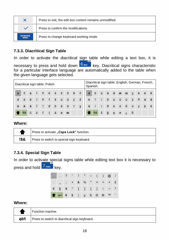
Press to exit, the edit box content remains unmodified.
Press to confirm the modifications.
Press to change keyboard working mode.
7.3.3. Diacritical Sign Table
In order to activate the diacritical sign table while editing a text box, it is
necessary to press and hold down key. Diacritical signs characteristic for a particular interface language are automatically added to the table when the given language gets selected.
Diacritical sign table: Polish. Diacritical sign table: English, German, French,
Spanish.
Where:
Press to activate „Caps Lock” function.
!$& Press to switch to special sign keyboard.
7.3.4. Special Sign Table
In order to activate special signs table while editing text box it is necessary to
press and hold key.
Where:
Function inactive.
ąëñ Press to switch to diacritical sign keyboard.
19
7.4. Return to Weighing
Introduced modifications are automatically recorded upon return to the home screen. To return to the home screen:
press key repeatedly, keep pressing the key until you see the home screen,
press key, the home screen is displayed immediately.
8. INSTALLER INSTRUCTION
The PUE C32 indicator serves as basis of load cell scales.
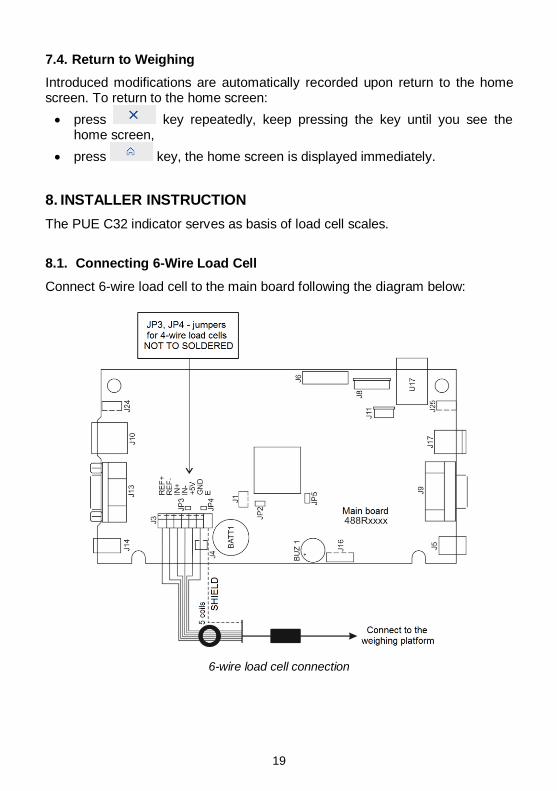
8.1. Connecting 6-Wire Load Cell
Connect 6-wire load cell to the main board following the diagram below:
6-wire load cell connection
20
On RADWAG board Load cell signal Notes
E SHIELD See section 9.3
REF+ SENSE + JP3 not soldered
REF- SENSE - JP4 not soldered
IN+ OUTPUT+
IN- OUTPUT-
+5V INPUT+
AGND INPUT-
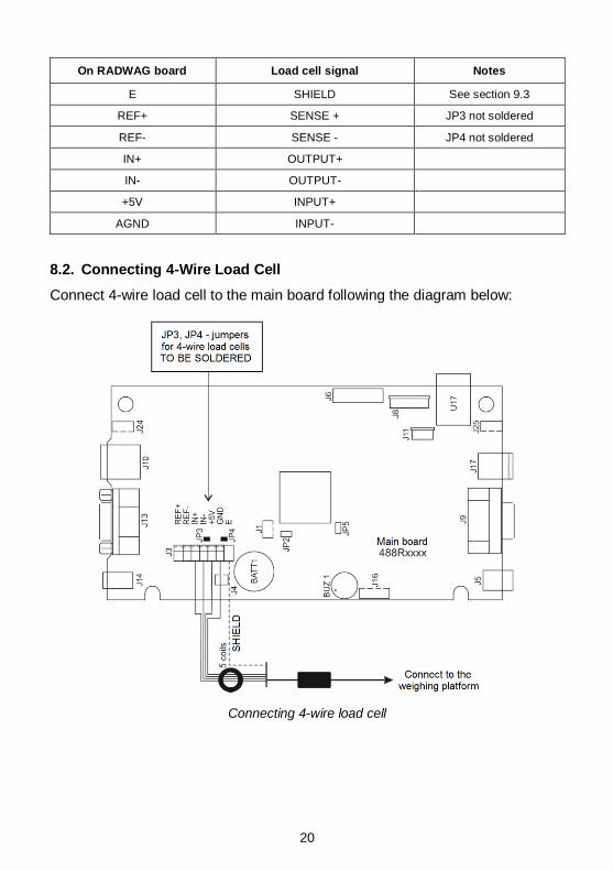
8.2. Connecting 4-Wire Load Cell
Connect 4-wire load cell to the main board following the diagram below:
Connecting 4-wire load cell
21
On RADWAG board Load cell signal Notes
E SHIELD See section 9.3
REF+ - JP3 soldered
REF- - JP4 soldered
IN+ OUTPUT+
IN- OUTPUT-
+5V INPUT+
AGND INPUT-
8.3. Load Cell Shield Connection
Load cell with galvanically connected shield of the
signal cable.
Load cell w/o galvanically connected shield of the
signal cable.
Scale with an indicator in an ABS housing connected with a platform via a load cell signal cable.
DO NOT connect E
Compact scale design (scale with
an ABS indicator on a post, etc.) DO NOT connect E
E – Soldering spot on the main board and on the additional A/D converter boards.
9. FACTORY SETUP
To access and modify factory settings and parameters that are made available for a user, run Factory Setup mode. Running Factory Setup mode enables the technician to define the scale.
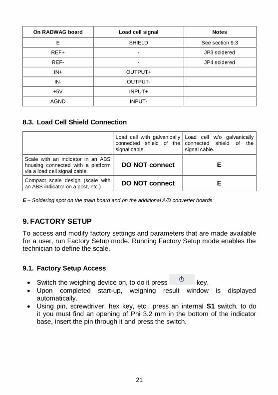
9.1. Factory Setup Access
Switch the weighing device on, to do it press key.
Upon completed start-up, weighing result window is displayed automatically.
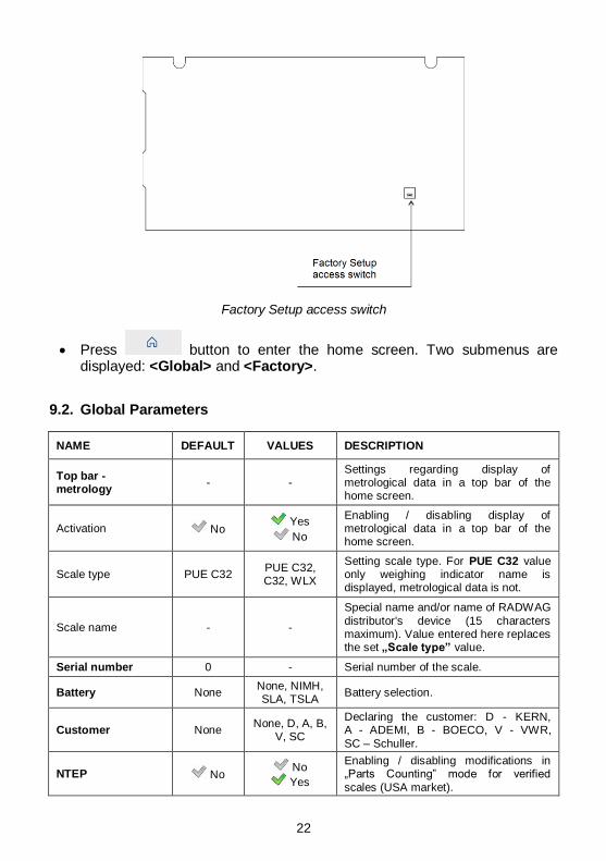
Using pin, screwdriver, hex key, etc., press an internal S1 switch, to do it you must find an opening of Phi 3.2 mm in the bottom of the indicator base, insert the pin through it and press the switch.
22
Factory Setup access switch
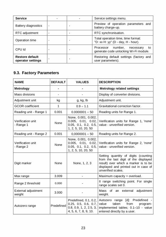
Press button to enter the home screen. Two submenus are displayed: <Global> and <Factory>.
9.2. Global Parameters
NAME DEFAULT VALUES DESCRIPTION
Top bar - metrology
- - Settings regarding display of metrological data in a top bar of the home screen.
Activation No Yes
No
Enabling / disabling display of metrological data in a top bar of the home screen.
Scale type PUE C32 PUE C32, C32, WLX
Setting scale type. For PUE C32 value only weighing indicator name is displayed, metrological data is not.
Scale name - -
Special name and/or name of RADWAG
distributor's device (15 characters maximum). Value entered here replaces the set „Scale type” value.
Serial number 0 - Serial number of the scale.
Battery None None, NIMH, SLA, TSLA
Battery selection.
Customer None None, D, A, B,
V, SC
Declaring the customer: D - KERN, A - ADEMI, B - BOECO, V - VWR,
SC – Schuller.
NTEP No No
Yes
Enabling / disabling modifications in „Parts Counting” mode for verified
scales (USA market).
23
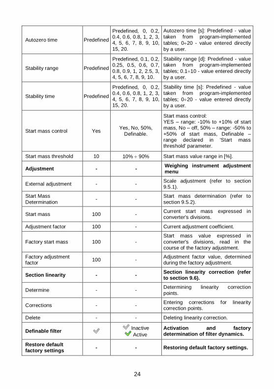
Service - - Service settings menu.
Battery diagnostics - - Preview of operation parameters and battery charge-up.
RTC adjustment - - RTC synchronisation.
Operation time - - Total operation time, time format: "D: xx H: yy" (D - day, H - hour).
CPU Id - - Processor number, necessary to
generate code unlocking Wi-Fi module.
Restore default operator settings
- - Restoring default settings (factory and user parameters).
9.3. Factory Parameters
NAME DEFAULT VALUES DESCRIPTION
Metrology - - Metrology related settings
Mass divisions - - Display of converter divisions.
Adjustment unit kg g, kg, lb Adjustment unit.
GCOR coefficient 1 0.9 1.1 Gravitational correction factor.
Reading unit - Range 1 0.001 0.0000001 50 Reading units for Range 1.
Verification unit - Range 1
None
None, 0.001, 0.002,
0.005, 0.01, 0.02, 0.05, 0.1, 0.2, 0.5, 1, 2, 5, 10, 20, 50
Verification units for Range 1, 'none' value - unverified version.
Reading unit - Range 2 0.001 0,0000001 50 Reading units for Range 2.
Verification unit
- Range 2 None
None, 0.001, 0.002, 0.005, 0.01, 0.02,
0.05, 0.1, 0.2, 0.5, 1, 2, 5, 10, 20, 50
Verification units for Range 2, 'none'
value - unverified version.
Digit marker None None, 1, 2, 3
Setting quantity of digits (counting from the last digit of the displayed
result) over which a marker is to be displayed and printed out in case of unverified scales.
Max range 3.009 - Maximum capacity + overload.
Range 2 threshold 0.000 - II range switching point. For single
range scales set 0.
External adjustment weight
3.000 - Mass of an external adjustment weight.
Autozero range Predefined
Predefined, 0.1, 0.2, 0.25, 0.5, 0.6, 0.7, 0.8, 0.9, 1, 2, 2.5, 3,
4, 5, 6, 7, 8, 9, 10.
Autozero range [d]: Predefined -
value taken from program-
implemented tables; 0.110 - value
entered directly by a user.
24
Autozero time Predefined
Predefined, 0, 0.2, 0.4, 0.6, 0.8, 1, 2, 3, 4, 5, 6, 7, 8, 9, 10,
15, 20.
Autozero time [s]: Predefined - value
taken from program-implemented
tables; 020 - value entered directly
by a user.
Stability range Predefined
Predefined, 0.1, 0.2, 0.25, 0.5, 0.6, 0.7,
0.8, 0.9, 1, 2, 2.5, 3, 4, 5, 6, 7, 8, 9, 10.
Stability range [d]: Predefined - value taken from program-implemented
tables; 0.110 - value entered directly
by a user.
Stability time Predefined
Predefined, 0, 0.2,
0.4, 0.6, 0.8, 1, 2, 3, 4, 5, 6, 7, 8, 9, 10, 15, 20.
Stability time [s]: Predefined - value
taken from program-implemented
tables; 020 - value entered directly
by a user.
Start mass control Yes Yes, No, 50%,
Definable.
Start mass control: YES – range: -10% to +10% of start mass, No – off, 50% – range: -50% to
+50% of start mass, Definable – range declared in 'Start mass threshold' parameter.
Start mass threshold 10 10% 90% Start mass value range in [%].
Adjustment - - Weighing instrument adjustment menu
External adjustment - - Scale adjustment (refer to section 9.5.1).
Start Mass
Determination - -
Start mass determination (refer to
section 9.5.2).
Start mass 100 - Current start mass expressed in converter's divisions.
Adjustment factor 100 - Current adjustment coefficient.
Factory start mass 100 -
Start mass value expressed in
converter's divisions, read in the course of the factory adjustment.
Factory adjustment factor
100 - Adjustment factor value, determined during the factory adjustment.
Section linearity - - Section linearity correction (refer to section 9.6).
Determine - - Determining linearity correction
points.
Corrections - - Entering corrections for linearity correction points.
Delete - - Deleting linearity correction.
Definable filter Inactive
Active
Activation and factory determination of filter dynamics.
Restore default factory settings
- - Restoring default factory settings.
25
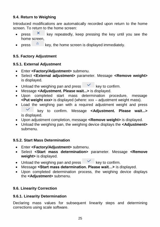
9.4. Return to Weighing
Introduced modifications are automatically recorded upon return to the home screen. To return to the home screen:
press key repeatedly, keep pressing the key until you see the home screen,
press key, the home screen is displayed immediately.
9.5. Factory Adjustment
9.5.1. External Adjustment
Enter <Factory/Adjustment> submenu.
Select <External adjustment> parameter. Message <Remove weight> is displayed.
Unload the weighing pan and press key to confirm.
Message <Adjustment. Please wait...> is displayed.
Upon completed start mass determination procedure, message <Put weight xxx> is displayed (where: xxx – adjustment weight mass).
Load the weighing pan with a required adjustment weight and press
key to confirm. Message <Adjustment. Please wait...> is displayed.
Upon adjustment completion, message <Remove weight> is displayed.
Unload the weighing pan, the weighing device displays the <Adjustment> submenu.
9.5.2. Start Mass Determination
Enter <Factory/Adjustment> submenu.
Select <Start mass determination> parameter. Message <Remove weight> is displayed.
Unload the weighing pan and press key to confirm. Message <Start mass determination. Please wait…> is displayed.
Upon completed determination process, the weighing device displays the <Adjustment> submenu.
9.6. Linearity Correction
9.6.1. Linearity Determination
Declaring mass values for subsequent linearity steps and determining corrections using scale software.
26
Procedure:
Enter <Factory/Section linearity> submenu and select <Determine> parameter. Message <Continue?> is displayed.
Press key to confirm. <Mass> edit box is displayed.
Unload the weighing pan.
Enter the required mass value (the first linearity correction point) and
press key to confirm. Message <Put weight xxx> is displayed (where: xxx – entered mass value) is displayed.
Load the weighing pan remembering that the load mass must equal weight value specified for the first linearity correction point (it is possible to preview the weighing result in the displayed window).
Upon result stabilization, press key to confirm. <Mass> edit box is displayed again (second linearity correction point).
Linearity correction process for the 2nd point is analogous to the linearity correction process for the 1st point.
Upon declaring requested quantity of linearity correction points, press
key when <Mass> edit box is displayed again.
<Section linearity> submenu is displayed automatically.
Upon pressing key to confirm zero value for linearity correction, message: <Value too low> is displayed.
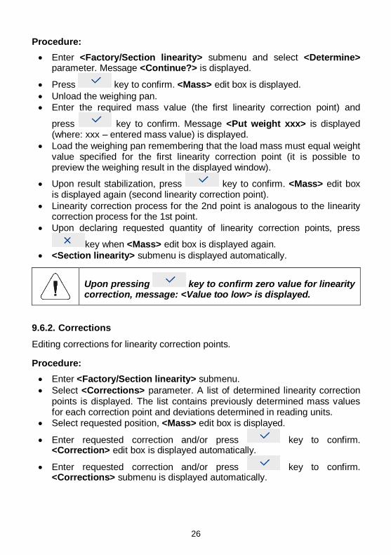
9.6.2. Corrections
Editing corrections for linearity correction points.
Procedure:
Enter <Factory/Section linearity> submenu.
Select <Corrections> parameter. A list of determined linearity correction points is displayed. The list contains previously determined mass values for each correction point and deviations determined in reading units.
Select requested position, <Mass> edit box is displayed.
Enter requested correction and/or press key to confirm. <Correction> edit box is displayed automatically.
Enter requested correction and/or press key to confirm. <Corrections> submenu is displayed automatically.
27
9.6.3. Deleting Linearity
Enter <Factory/Section linearity> submenu.
Select <Delete> parameter. Message <Delete?> is displayed.
Press key to confirm.
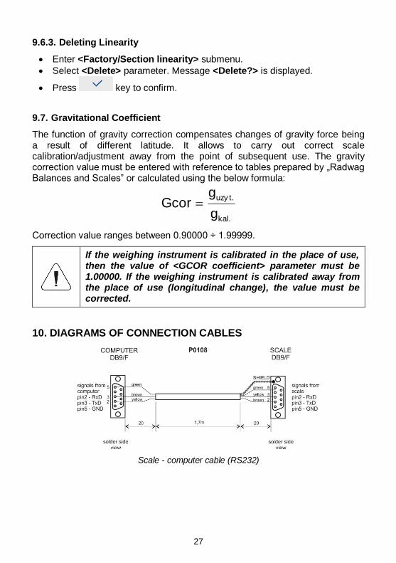
9.7. Gravitational Coefficient
The function of gravity correction compensates changes of gravity force being a result of different latitude. It allows to carry out correct scale calibration/adjustment away from the point of subsequent use. The gravity correction value must be entered with reference to tables prepared by „Radwag Balances and Scales” or calculated using the below formula:
kal.
uzy t.
g
gGcor
Correction value ranges between 0.90000 ÷ 1.99999.
If the weighing instrument is calibrated in the place of use, then the value of <GCOR coefficient> parameter must be 1.00000. If the weighing instrument is calibrated away from the place of use (longitudinal change), the value must be corrected.
10. DIAGRAMS OF CONNECTION CABLES
Scale - computer cable (RS232)
28
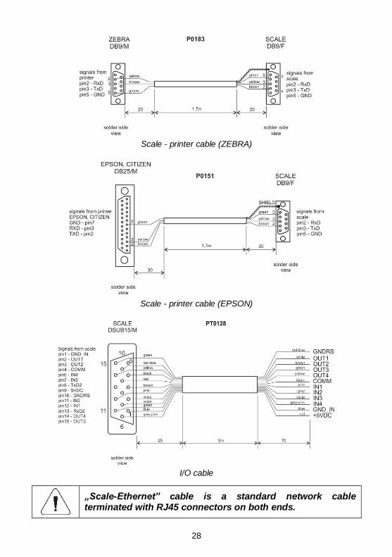
Scale - printer cable (ZEBRA)
Scale - printer cable (EPSON)
I/O cable
„Scale-Ethernet” cable is a standard network cable terminated with RJ45 connectors on both ends.
29


