Embed Size (px)
Citation preview
6532 -ISSN: 2347 Volume 2, Issue 11 IJESR __________________________________________________________
A Monthly Double-Blind Peer Reviewed Refereed Open Access International e-Journal - Included in the International Serial Directories Cabell’s Directories of Publishing Opportunities, U.S.A.as well as in Gage-Open J, , U.S.A.©Indexed & Listed at: Ulrich's Periodicals Directory
International Journal of Engineering & Scientific Research http://www.ijmra.us
41
November 2014
Improvement and Performance Evaluation
of Stationary Combine Thresher
*
Mohammed Ahmed AbdElmowla
**Mohamed Hassan Dahab
***ahman Ahmed EL MahieRFatah El
**Farid Eltoum, A.E
Abstract:
This study was conducted at the Faculty of Agriculture, Nile Valley University, Darmali, North
of Atbara. The main objective of this study was to develop and improve the stationary threshing
machine by adding a diesel engine 49 hp and gearbox to become self operated. The diesel engine
and gearbox were installed in the rear side of the thresher. Three iron frames were used to link
the diesel engine and gearbox. The power was transmitted from the installed diesel engine
through pulleys and belts to the threshing unit. The improved machine was evaluated and
compared with the convention one through threshing two crops, faba bean and wheat. The time
of linking thresher to the tractor, field efficiency, field capacity, fuel consumption and weight of
seed and straw were measurement in all plots with three replications.
The results indicated Low field operation time (0.03 hr) for improved thresher compared to (0.25
hr) for the conventional thresher. Higher field efficiency and capacity were observed for the
improved thresher. They were 85% and 1.43 fed/ hr for the improved machine compared to 25%
and 1.0 fed/hr for the conventional one respectively. Low fuel consumption of 3.5 liter/hr for the
improved threshing machine compared to 7.57 litter/hr forthe conventional one.
Statistical analysis showed highly significant difference (at p >0.01) between the improved
thresher and conventional threshing machine for the time taken for linking, field efficiency, field
* Dept. of Agricultural Engineering, Faculty of Agriculture, Nile Valley University, Atbara,
Sudan.
** Dept. of Agricultural Engineering, Faculty of Agriculture, Shambat, P.O. Box 32, Sudan.
*** Department of Mechanical Engineering Faculty of Engineering, Nile Valley University.
6532 -ISSN: 2347 Volume 2, Issue 11 IJESR __________________________________________________________
A Monthly Double-Blind Peer Reviewed Refereed Open Access International e-Journal - Included in the International Serial Directories Cabell’s Directories of Publishing Opportunities, U.S.A.as well as in Gage-Open J, , U.S.A.©Indexed & Listed at: Ulrich's Periodicals Directory
International Journal of Engineering & Scientific Research http://www.ijmra.us
42
November 2014
capacity and Fuel consumption. No significant difference was observed between the two
threshers for the weight of seed and straw output.
The improved threshing machine is durable, portable, easy to operate and of Low maintain costs,
All components of the machine were fabricated from local materials and total cost for the design
and improvement of the threshing machine was only SDG (2500).
Keywords: Stationary thresher, power, diesel engine, gearbox,performance
INTRODUCTION
Agricultural engineering is the science and art of engineering, mathematical and physical
theories application to solve some agricultural problems and to increase production beside good
work environment for farmers (Elsanoberi 1993). Power source in agricultural farms is of great
importance in determining the level of agricultural mechanization and development, there are
three sources of power for carrying out operations, the human power (about 0.07 – 0.1 kw) l,
animal power and mechanical power (Grossly andKilgour1983). Mechanical power through
tractors will continue to be an absolute necessity for agricultural production (Hunt 1983). The
tractor engine can be used as a prime mover for active (moving) tools or stationary farm
machinery through the power take off shaft (PTO) or belt pulley (Rodicher and Rodicheva
1984).
Transmitting of power from its source to the points of use is one of the important variables to the
farm equipment designers. Krutzet. al. (1984) cited that the selection of proper power
transmission systems on mobile agricultural machinery must take into account the customer
requirements, cost constraints, field usage, operator safety and reliability. The primary function
of the transmission member is to affect the change in speed between the two shafts as well as in
linking them. It is generally required that the transmission system should have adequate
reliability, service life, simple in construction, little resistance to motion, produce little noise,
offers substantial resistance to vibration and easy to control. There are many power transmission
systems used, but the most extensively used in agricultural machinery applications are V-belts
(Kepneret. al., 1982, Krutzet. al (1984). Shigley and Mitchell (1983) stated that, the efficiency of
V-belts ranges from 70 – 95 %. Gears and chains are also widely used for power transmission as
linear or rotary motion (Hunt and Garver 1973, Spotts 1978, Crouse 1980, Liljedahlet. al. 1984).
6532 -ISSN: 2347 Volume 2, Issue 11 IJESR __________________________________________________________
A Monthly Double-Blind Peer Reviewed Refereed Open Access International e-Journal - Included in the International Serial Directories Cabell’s Directories of Publishing Opportunities, U.S.A.as well as in Gage-Open J, , U.S.A.©Indexed & Listed at: Ulrich's Periodicals Directory
International Journal of Engineering & Scientific Research http://www.ijmra.us
43
November 2014
Other power transmission systems included bearings, shafts and universal joints. Rotating shafts
are of various lengths, diameters and types and they may be subjected to bending, tension,
compression or torsion loads, acting singly or in combination with one another (Shigley and
Mitchell.1983,). Therefore it is important to locate the PTO shaft of the tractor with respect to
the draw bar because of the telescoping action of the drive member.
The goal of good crops harvesting is to ensure maximum grain yield through minimizing grain
loss and the prevention of quality deterioration. A wide variety of tools is used in harvesting,
such as knives, sickles, animals, stationary threshing machines, tractor-mounted harvesters, and
self-propelled combine harvesters.Stationary threshers which are drawn and operated by tractors
PTO are now of great important in the Sudan for threshing many crops. Since stationary
threshers are tractor engine operated, it was important to improve the operational performance of
threshers to make the harvesting operation more efficient and economical. Therefore, the
objectives of this present study are:
1- to install a diesel engine and conveyor belt on a stationary thresher as a technical and
economic improvement.
2- to evaluation e the field performance of the improved threshing machine and to compare with
the conventional thresher.
MATERIALS AND METHODS
The study was carried out in Darmally village, 13 km north of Atbara city and 325 km north of
Khartoum city.
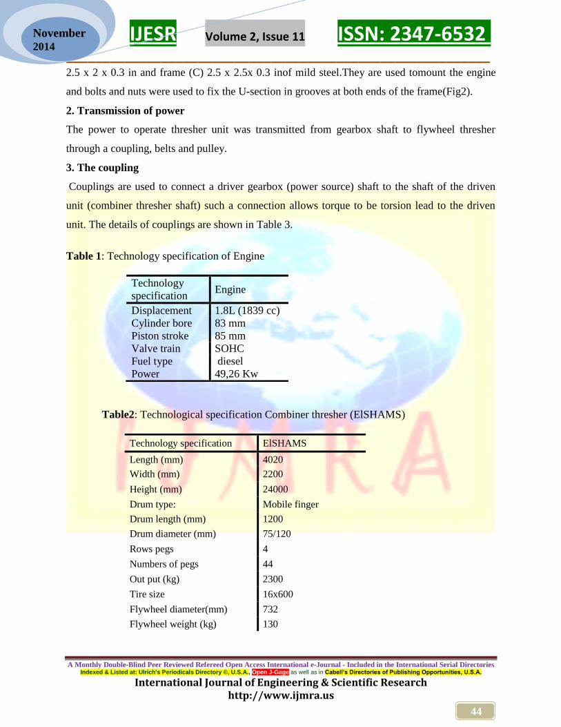
Diesel engine (49,26hp), with technical specifications given in (Table1),and gearboxand Massey
Fergeson (290) tractor of 74.8 hp (maximum PTO),were used as source of power for a stationary
combiner thresher (Elshams) improvement. The technical specifications of the thresher are
shown in (Table2). Other materials and tools used to carry out the installation included, iron
sheets, iron angles, iron flanges, fixing bolts, nuts, shims, pulleys and other workshop equipment.
1. The Frame
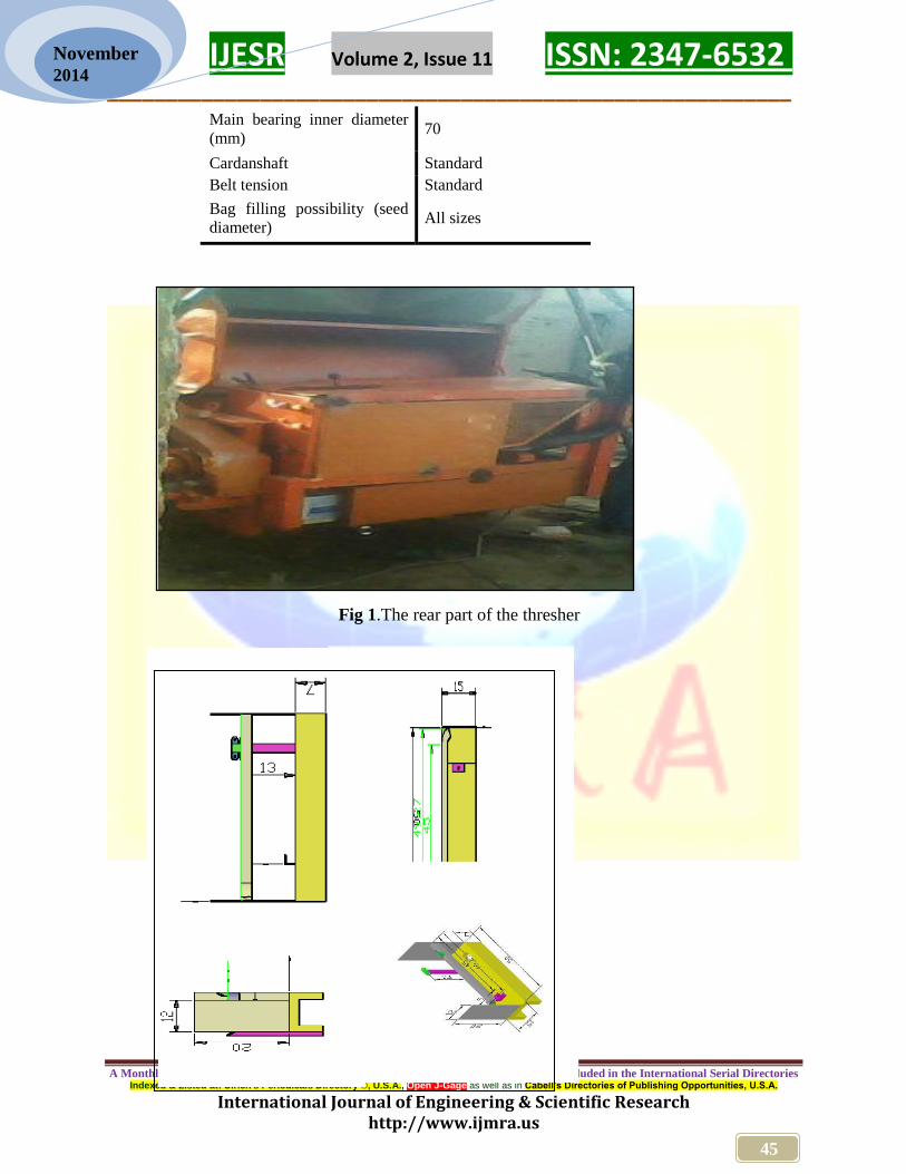
A metal engine and gearbox frame was fixed in the rear part of the thresher (Fig 1). All design
criteria were considered when fixing the frame strongly with fixing bolts. The frame is composed
of three components: The main frame (A) made of mild steel U -sections angles 15 x7 x 0.5 in.
The main frame supports are frame (B) and frame (C). Farm (B) stands made of mild steel angle
6532 -ISSN: 2347 Volume 2, Issue 11 IJESR __________________________________________________________
A Monthly Double-Blind Peer Reviewed Refereed Open Access International e-Journal - Included in the International Serial Directories Cabell’s Directories of Publishing Opportunities, U.S.A.as well as in Gage-Open J, , U.S.A.©Indexed & Listed at: Ulrich's Periodicals Directory
International Journal of Engineering & Scientific Research http://www.ijmra.us
44
November 2014
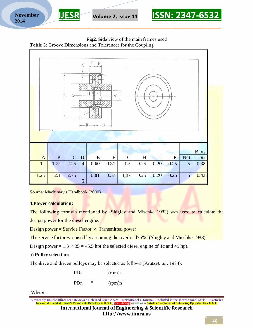
2.5 x 2 x 0.3 in and frame (C) 2.5 x 2.5x 0.3 inof mild steel.They are used tomount the engine
and bolts and nuts were used to fix the U-section in grooves at both ends of the frame(Fig2).
2. Transmission of power
The power to operate thresher unit was transmitted from gearbox shaft to flywheel thresher
through a coupling, belts and pulley.
3. The coupling
Couplings are used to connect a driver gearbox (power source) shaft to the shaft of the driven
unit (combiner thresher shaft) such a connection allows torque to be torsion lead to the driven
unit. The details of couplings are shown in Table 3.
Table 1: Technology specification of Engine
Table2: Technological specification Combiner thresher (ElSHAMS)
Technology
specification Engine
Displacement 1.8L (1839 cc)
Cylinder bore 83 mm
Piston stroke 85 mm
Valve train SOHC
Fuel type diesel
Power 49,26 Kw
Technology specification ElSHAMS
Length (mm) 4020
Width (mm) 2200
Height (mm) 24000
Drum type: Mobile finger
Drum length (mm) 1200
Drum diameter (mm) 75/120
Rows pegs 4
Numbers of pegs 44
Out put (kg) 2300
Tire size 16x600
Flywheel diameter(mm) 732
Flywheel weight (kg) 130
6532 -ISSN: 2347 Volume 2, Issue 11 IJESR __________________________________________________________
A Monthly Double-Blind Peer Reviewed Refereed Open Access International e-Journal - Included in the International Serial Directories Cabell’s Directories of Publishing Opportunities, U.S.A.as well as in Gage-Open J, , U.S.A.©Indexed & Listed at: Ulrich's Periodicals Directory
International Journal of Engineering & Scientific Research http://www.ijmra.us
45
November 2014
Fig 1.The rear part of the thresher
Main bearing inner diameter
(mm) 70
Cardanshaft Standard
Belt tension Standard
Bag filling possibility (seed
diameter) All sizes
6532 -ISSN: 2347 Volume 2, Issue 11 IJESR __________________________________________________________
A Monthly Double-Blind Peer Reviewed Refereed Open Access International e-Journal - Included in the International Serial Directories Cabell’s Directories of Publishing Opportunities, U.S.A.as well as in Gage-Open J, , U.S.A.©Indexed & Listed at: Ulrich's Periodicals Directory
International Journal of Engineering & Scientific Research http://www.ijmra.us
46
November 2014
Fig2. Side view of the main frames used
Table 3: Groove Dimensions and Tolerances for the Coupling
Source: Machinery's Handbook (2000)
4.Power calculation:
The following formula mentioned by (Shigley and Mischke 1983) was used to calculate the
design power for the diesel engine:
Design power = Service Factor Transmitted power
The service factor was used by assuming the overload75% ((Shigley and Mischke 1983).
Design power = 1.3 35 = 45.5 hp( the selected diesel engine of 1c and 49 hp).
a) Pulley selection:
The drive and driven pulleys may be selected as follows (Krutzet. at., 1984):
Where:
Blots
K
J
H
G
F
E
D
C
B
A Dia NO
0.38 5 0.25
0.20 0.25 1.5 0.31 0.60 4 2.25 1.72 1
0.43 5 0.25
0.20 0.25 1,87 0.37 0.81
5
2.75 2.1 1.25
PDr
=
(rpm)r
PDn (rpm)n
6532 -ISSN: 2347 Volume 2, Issue 11 IJESR __________________________________________________________
A Monthly Double-Blind Peer Reviewed Refereed Open Access International e-Journal - Included in the International Serial Directories Cabell’s Directories of Publishing Opportunities, U.S.A.as well as in Gage-Open J, , U.S.A.©Indexed & Listed at: Ulrich's Periodicals Directory
International Journal of Engineering & Scientific Research http://www.ijmra.us
47
November 2014
PDr = pitch diameter for the driver pulley (inch).
PDn = pitch diameter for the driven pulley (inch), proposed 8 inch.
(rpm)r = driver pulley speed (1000rpm).
(rpm)n = driven pulley speed (1000rpm).
Then:
PDr = 10008
= 8 inch (Table5 ) 1000
b) V-Belts selection:
For V-belts design and selection the computations made follows the methodology mentioned by
Shigley and Mischke (1983). The center distance between drive and driven pulleys was 29 inch
and this was found to fulfill the following equation:
C 3 (d + D)
Where:
C = center distance.
D = large pulley diameter.
d = small pulley diameter
Therefore from Table (4), a V- belt section A- was selected.
The pitch length of the belt calculated as follows:
Lp = 2C + 1.57(D +
d) +
(D - d)2
4C
Where:
C = center distance.
D = pitch diameter large pulley.
d = pitch diameter small pulley.
Lp = pitch length of belt.
= 2 × (29) +25.12 = 83.12 in
6532 -ISSN: 2347 Volume 2, Issue 11 IJESR __________________________________________________________
A Monthly Double-Blind Peer Reviewed Refereed Open Access International e-Journal - Included in the International Serial Directories Cabell’s Directories of Publishing Opportunities, U.S.A.as well as in Gage-Open J, , U.S.A.©Indexed & Listed at: Ulrich's Periodicals Directory
International Journal of Engineering & Scientific Research http://www.ijmra.us
48
November 2014
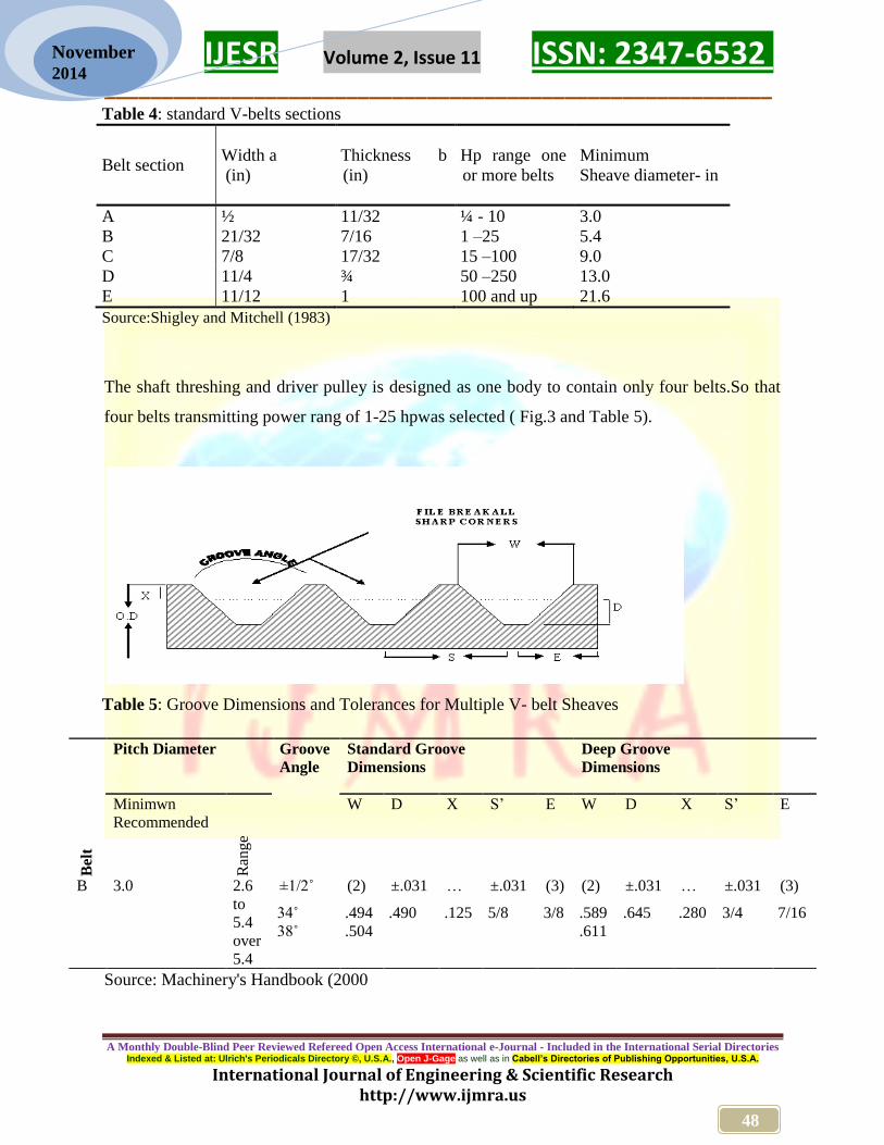
Table 4: standard V-belts sections
Belt section Width a
(in)
Thickness b
(in)
Hp range one
or more belts
Minimum
Sheave diameter- in
A ½ 11/32 ¼ - 10 3.0
B 21/32 7/16 1 –25 5.4
C 7/8 17/32 15 –100 9.0
D 11/4 ¾ 50 –250 13.0
E 11/12 1 100 and up 21.6
Source:Shigley and Mitchell (1983)
The shaft threshing and driver pulley is designed as one body to contain only four belts.So that
four belts transmitting power rang of 1-25 hpwas selected ( Fig.3 and Table 5).
Table 5: Groove Dimensions and Tolerances for Multiple V- belt Sheaves
Source: Machinery's Handbook (2000
Bel
t
Pitch Diameter Groove
Angle
Standard Groove
Dimensions
Deep Groove
Dimensions
Minimwn
Recommended
Ran
ge
W D X S’ E W D X S’ E
B 3.0 2.6
to
5.4
over
5.4
±1/2˚ (2) ±.031 … ±.031 (3) (2) ±.031 … ±.031 (3)
34˚
38˚
.494
.504
.490 .125 5/8 3/8 .589
.611
.645 .280 3/4 7/16
6532 -ISSN: 2347 Volume 2, Issue 11 IJESR __________________________________________________________
A Monthly Double-Blind Peer Reviewed Refereed Open Access International e-Journal - Included in the International Serial Directories Cabell’s Directories of Publishing Opportunities, U.S.A.as well as in Gage-Open J, , U.S.A.©Indexed & Listed at: Ulrich's Periodicals Directory
International Journal of Engineering & Scientific Research http://www.ijmra.us
49
November 2014
RESULTS AND DISCUSSION
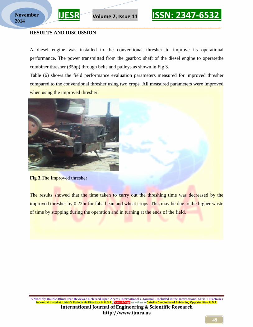
A diesel engine was installed to the conventional thresher to improve its operational
performance. The power transmitted from the gearbox shaft of the diesel engine to operatethe
combiner thresher (35hp) through belts and pulleys as shown in Fig.3.
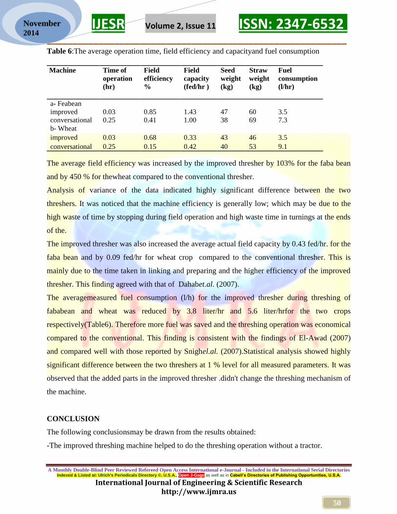
Table (6) shows the field performance evaluation parameters measured for improved thresher
compared to the conventional thresher using two crops. All measured parameters were improved
when using the improved thresher.
Fig 3.The Improved thresher
The results showed that the time taken to carry out the threshing time was decreased by the
improved thresher by 0.22hr for faba bean and wheat crops. This may be due to the higher waste
of time by stopping during the operation and in turning at the ends of the field.
6532 -ISSN: 2347 Volume 2, Issue 11 IJESR __________________________________________________________
A Monthly Double-Blind Peer Reviewed Refereed Open Access International e-Journal - Included in the International Serial Directories Cabell’s Directories of Publishing Opportunities, U.S.A.as well as in Gage-Open J, , U.S.A.©Indexed & Listed at: Ulrich's Periodicals Directory
International Journal of Engineering & Scientific Research http://www.ijmra.us
50
November 2014
Table 6:The average operation time, field efficiency and capacityand fuel consumption
The average field efficiency was increased by the improved thresher by 103% for the faba bean
and by 450 % for thewheat compared to the conventional thresher.
Analysis of variance of the data indicated highly significant difference between the two
threshers. It was noticed that the machine efficiency is generally low; which may be due to the
high waste of time by stopping during field operation and high waste time in turnings at the ends
of the.
The improved thresher was also increased the average actual field capacity by 0.43 fed/hr. for the
faba bean and by 0.09 fed/hr for wheat crop compared to the conventional thresher. This is
mainly due to the time taken in linking and preparing and the higher efficiency of the improved
thresher. This finding agreed with that of Dahabet.al. (2007).
The averagemeasured fuel consumption (l/h) for the improved thresher during threshing of
fababean and wheat was reduced by 3.8 liter/hr and 5.6 liter/hrfor the two crops
respectively(Table6). Therefore more fuel was saved and the threshing operation was economical
compared to the conventional. This finding is consistent with the findings of El-Awad (2007)
and compared well with those reported by Snighel.al. (2007).Statistical analysis showed highly
significant difference between the two threshers at 1 % level for all measured parameters. It was
observed that the added parts in the improved thresher .didn't change the threshing mechanism of
the machine.
CONCLUSION
The following conclusionsmay be drawn from the results obtained:
-The improved threshing machine helped to do the threshing operation without a tractor.
Fuel
consumption
(l/hr)
Straw
weight
(kg)
Seed
weight
(kg)
Field
capacity
(fed/hr )
Field
efficiency
%
Time of
operation
(hr)
Machine
a- Feabean
3.5 60 47 1.43 0.85 0.03 improved
7.3 69 38 1.00 0.41 0.25 conversational
b- Wheat
3.5 46 43 0.33 0.68 0.03 improved
9.1 53 40 0.42 0.15 0.25 conversational
6532 -ISSN: 2347 Volume 2, Issue 11 IJESR __________________________________________________________
A Monthly Double-Blind Peer Reviewed Refereed Open Access International e-Journal - Included in the International Serial Directories Cabell’s Directories of Publishing Opportunities, U.S.A.as well as in Gage-Open J, , U.S.A.©Indexed & Listed at: Ulrich's Periodicals Directory
International Journal of Engineering & Scientific Research http://www.ijmra.us
51
November 2014
-The Field efficiency and effective field capacity of the improved thresher were increased
resulting in time and cost saving of the threshing operation.
-The installed and designed parts of the improved thresher were found of low energy
consumption and low production costs.
- Further work is neededto make the thresher more efficient by developing and fixing front cutter
and pickup reel.
REFERENCES
[1] Crouse, W. H. (1980). Automotive Mechanics. Eighth Edition. McGraw Hill Book Company.
[2] Dahab M.H, Hassan .E.H. Naye, M.H. (2007) Modification of Power Transmission System to
the Stationary Combine Thresher. Agricultural Mechanization in Asia, Africa and Latin
America 38(.3), 1-9
[3] El-Awad, Sh. A, A. E. S and M. A. A (2007). Improvement of the Modified Grain Thresher
for Groundnut Threshing. Agricultural Mechanization in Asia, Africa and Latin America
38(3): 67-72
[4] Elsanoberi, B. (1993). Principles of agricultural machinery. University of Al-Gods
Almaftoha. Philistine.
[5] Grossley, P. and kilgour, J. (1983). Small farm mechanization for developing countries.
Silsoe, England, pp. 59-70.
[6] Hassan .E.H. 2002. Modification of Power Transmission System to the Stationary Combine
Thresher. Unpublished M. Sc. Thesis, Taculty of Agriculture., Nile Valley University,
Sudan.
[7] Hunt, D. R. and Gaiver, L. W. (1973) Farm Machinery Mechanisms. The Iowa State
University Press Ames, Iowa.
[8] Hunt,D.R. (1983). Farm Power and Machinery Management.8th
edition. Iowa StateUniversity
Press. P(3-25, 129-148).
[9] Kepner R. A., Roy Bainer, and Barger E. L. (1982). Principle of Farm Machinery 3rd
edition.
Avi Publishing Company. Inc. West port Connecticut.
[10] Krutz, G., Thompson, L. and Claar, P. (1984). Design of agricultural machinery. John Wiley
& Sons, New York. Pp. 222-270.
[11] Liljedahl,J. B; Carleton, W. M; Turnquist, P. K. and Smith,D. W. (1979). Tractors and Their
Power Units, 3rd
edition. John Willey and Sons New York.
[12] Rodicher, V. and Rodicheva (1984). Agricultural Machines. Theory of operation
computation of controlling Parameter and the conditions of operation.
[13] Shigley J.E., and Mischke L.D. (1989). Mechanical Engineering Design. 5th Edition.
McGraw-Hill Book Company.
[14] Spotts, M. F. (1978). Design of machine elements. 5th
edition, Prentice-Hall, Inc.,
Englewood Cliffs, New Jersey, pp. 269, 396-425.