Embed Size (px)
Citation preview

IOSR Journal of Electrical and Electronics Engineering (IOSR-JEEE)
e-ISSN: 2278-1676,p-ISSN: 2320-3331, Volume 10, Issue 1 Ver. III (Jan – Feb. 2015), PP 27-36 www.iosrjournals.org
DOI: 10.9790/1676-10132736 www.iosrjournals.org 27 | Page
Implementation of an Improved Microcontroller Based Moving
Message Display System
Bakare B. I1and Odeyemi F. M
2
1,2(Department of Electrical/Computer Engineering Rivers State University of Science and
Technology , Port Harcourt, Nigeria)
Abstract: The implementation of a Light Emitting Diodes (LEDs) dot matrix moving message display system
which show a text containing 23 characters (i.e., GREAT DEPT. OF ELECT. ENGRG) is achieved in this work
using a PIC16F648A Microcontroller, The microcontroller is programmed using Assembly language, with
MPLAB software and a PIC Programmer .The LEDs are controlled by signals from the microcontroller and
decade counters in a sequential manner which results in the moving message. In this work, we make use of a
49*8 dot matrix display made up of 392 low power Light Emitting Diodes (LEDs). The connection is done in
such a way that the cathodes of all the LEDs on a particular column are connected together while the anodes of
all the LEDs on a particular row are also connected together. This gives each row and column a separate line
and allows the LEDs on each of these rows or columns to be powered by the same line. A limiting resistor for
the eight (8) output lines of the microcontroller to the LEDs on the dot matrix is used. and a dynamic display
scheme is also employed.. In this system, the LEDs is not lit continuously but is sequentially lit by scanning in a “vertical strobe” or “horizontal strobe”. In the vertical strobe mode, information is addressed to the display
by selecting a single row at a time, energizing the appropriate LED(s) in that row and proceeding to the next
row. In the horizontal strobe mode, a single column is chosen at a time The dynamic display scheme employed
in this work helped to improved the brightness of the display and also save energy consumed by the
hardware .
Keywords: Decade counter, Flow-chat , LED Display ,Microcontroller ,Programming.
I. Introduction The use of Light Emitting Diodes (LEDs) dot matrix for creating a text display system is quite common
with its usage expanding greatly in recent time. Such displays can be found in airports, where they are used to display flight information, in stock exchanges and banks to display share prices and exchange rate respectively.
The wide usage of LED displays is as a result of its ability to convey information to large audiences quickly and
efficiently. As LED displays are often controlled by digital technology the information can swiftly and easily be
updated. This feature of LED displays has led to a great flexibility of such products in countless applications.
An additional benefit of using this form of display is that LEDs are a very efficient form of illumination. Unlike
incandescent bulbs, LEDs do not generate a large amount of wasted energy in the form of heat. [1]
This paper, therefore, presents the design and implementation of a moving message display system
using Light emitting diode (LED) dot matrix display and a microcontroller with the following objectives:
Designing and realizing the moving message display panel.
Using a PIC Microcontroller to input, store, control and display the data for the message characters on a dot
matrix. The figure below is the Building blocks diagram of a Moving Message Display System.
Figure. 1: Block diagram of a moving message display system
Implementation of an Improved Microcontroller Based Moving Message Display System
DOI: 10.9790/1676-10132736 www.iosrjournals.org 28 | Page
1.1 Power Supply Unit
In order to operate the system, Power. Supply is required as shown in figure 1 . The mode of
application of such power will form the basis for the design of the power supply unit and it’s characteristic. A dc Power Supply is needed to power the microcontroller and all the other modules .
1.2 Control Circuit
The microcontroller is the brain behind the moving message display system. It is the meeting point for
all the other units. The microcontroller controls the decade counters and the rows of the dot matrix display to
produce the desired alphanumeric character.
1.3 Counting Unit
In this unit, the decade counter is used. it produces the shifting action of the alphanumeric characters on
the dot matrix display.
1.4 Display Unit
The display unit makes use of dot matrix to display information. The light emitting diodes are arranged
properly to make an array of rows and columns [2]
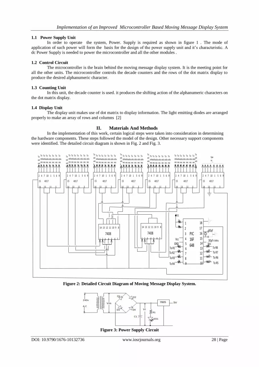
II. Materials And Methods In the implementation of this work, certain logical steps were taken into consideration in determining
the hardware components. These steps followed the model of the design. Other necessary support components
were identified. The detailed circuit diagram is shown in Fig. 2 and Fig. 3.
Figure 2: Detailed Circuit Diagram of Moving Message Display System.
Figure 3: Power Supply Circuit
2 4 7 10 1 5 6 9
15
14 13 11 3
2 4 7 10 1 5 6 9
15
14 13 11 3
2 4 7 10 1 5 6 9
14 13 11 3
2 4 7 10 1 5 6 9
15
14 13 11 3
2 4 7 10 1 5 6 9
15
14 13 11 3
2 4 7 10 1 5 6 9
15
14 13 11 3
2 4 7 10 1 5 6 9
15
14 13 11 3
1 2 3 4 5 6 7
7408
14 13 12 11 10 9 8
1 2 3 4 5 6 7
7408
14 13 12 11 10 9 8
4017 4017 4017 4017 4017 4017 4017
101112131415
16
17
18
9
87654
3
2
1
4 MHz30pfGND
VccVcc
Vcc
To R8
To R7
To R6
To R51k
1k
1k
1k1k
1k
1k
1k
To R1
To R2
To R3
To R4
PIC 16F648
To column 1
To
column 2
To
column 3
To column 4
To column 5
To column 6
To column 7
To column 8
To
column 9
To colu
mn 10
To
colu
mn 11
To
column 12
To
column 13
To
column 14
To
column 15
To
column 16
To
column
17
To column 18
To colu
mn 19
To colu
mn 20
To colu
mn 21
To colu
mn 22
To colu
mn 23
To colu
mn 24
To
column
25
To column 26
To column 27
To column 28
To column 29
To column 30
To column 31
To column 32
To
column
33
To colu
mn 34
To
column 35
To column 36
To column 37
To column 38
To column 39
To column 40
To column 41
To colu
mn 42
To colu
mn 43
To colu
mn 44
To colu
mn 45
To colu
mn 46
To colu
mn 47
To
column
48
Spare
15
1k
1k
30pf

Implementation of an Improved Microcontroller Based Moving Message Display System
DOI: 10.9790/1676-10132736 www.iosrjournals.org 29 | Page
2.1 Working Principle:
The microcontroller used is the PIC16F648A shown in fig. 4. It comes with a wide variety of special
features which makes it useful for a wide range of applications. The features are;
It has a maximum frequency of operation of 20MHz
It has 4096 words of flash program memory
It has 256 bytes of RAM Data memory it has 256 bytes of EEPROM Data memory
3 timer module- TMRO, TMRI, TMR2
2 comparators
USART
Internal voltage reference
10 interrupt sources
16 1/0 pins
Voltage range of 2.0 – 5.5 volts
Comes in an 18-pin dual- in-line package (DIP)
Stand – by current – 100nA (a) 2.0v, typical
Operating current - 12A (a) 32KHz , 2.0V, typical - 120A (a)1MHz , 2.0V, typical
Watching timer current - 1A (a) 2.0V, typical
Timer 1 oscillator current - 1.2A (a) 32KHz, 2.0V, typical
Dual speed internal oscillator Run- time selectable b/w 4MHz and 3.7KHz
4s wake-up from sleep, 3.0V, typical
Pins 1 and 2 (i.e VREF & CMPI) are connected in a pull up manner to VCC through 1k resistors while pin 3 is not used. Pin 4 is connected directly to VCC. Pin 5 goes to ground. Pin 6 through 13 are input/output pins. In this
project, they function as output pins that carry the code data in term of Os (zero) and 1s (ones) from the
microcontroller and pass these signals to the 8 rows of the dot matrix display.
Pin 14 goes to VCC. Pins 15 and 16 are connected to an external oscillator (4MHz) that controls the timing sequence
of the microcontroller’s operation. Pin 7 is connected to pin 14 of the 1st 4017 decade counter. It activates the
clocking of the 1st decade counter. [3],[4]
Pin 18 is connected to ground.
Figure 4: Pin Configuration of PIC16F648A
2.2 Peripheral Features:
• 16 I/O pins with individual direction control
• High current sink/source for direct LED drive
• Analogue comparator module with:
- Two analogue comparators
- Programmable on-chip voltage reference (VREF) module
- Selectable internal or external reference
- Comparator outputs are externally accessible
• Timer0: 8-bit timer/counter with 8-bit programmable prescaler
• Timer1: 16-bit timer/counter with external crystal/ clock capability • Timer2: 8-bit timer/counter with 8-bit period register, prescaler and postscaler
• Capture, Compare, PWM module
- 16-bit Capture/Compare

Implementation of an Improved Microcontroller Based Moving Message Display System
DOI: 10.9790/1676-10132736 www.iosrjournals.org 30 | Page
- 10-bit PWM
• Addressable Universal Synchronous/Asynchronous Receiver/Transmitter USART
For the CPU to execute an instruction, it takes a certain number of clock cycles. The frequency of the crystal connected to the PIC16FXX family varies from 4MHz to 37MHz, depending on the chip rating.[3], [4]
III. Hardware Design And Analysis
3.1 Size Of Transformer
peakVrVmViVCC (1)
Where voltagerectifiedDC
V
.
.max
1
voltageripplepeakVr
voltageCAimumorpeakVm
recgulatorCtoinputVi
But, Vr (peak) = smrVr ..3 (2)
Where, Vr (r.m.s) is the root mean square value of the ripple voltage. The rectified signal,
fc
CAsmrVr34
.1
)..( (3)
Where f = frequency in Hertz
C = filter capacitor
To maintain regulation
Vr (peak) Vm - Vi (min) (4) For IC regulator 7805:
Vi (min) = 7.5v
From equation (4), for regulation to be maintained, then:
Vm Vi (min) (5) For the choice of transformer
Vm = 12v
Also,
ID.C = 0.62 IA.C (6)
Were 1 D.C is the total dc load in amperes drawn by the display circuit at which regulation is to be maintained.
IA.C is the A.C current capacity of the transform
From eqn 6
IA.C = 62.0
.CDI (7)
Now, for the message display circuit, total bad in amperes is given as
mA
mCDI
CAI
242
62.0
150
62.0.
.
Hence, the current size or capacity of the transformer should be
mAI CA 242.
Let mAI CA 300.
Also,
Since 12 7.5, equations (4) and (5) are satisfied, hence; regulation is possible Therefore, the size of transformer is 240v/12v, 300mA, 50Hz A.C [5]
Implementation of an Improved Microcontroller Based Moving Message Display System
DOI: 10.9790/1676-10132736 www.iosrjournals.org 31 | Page
3.2 Size of Filter Capacitor
Using equation (3)
fc
smrVr CD
34
1.. .
smrfVrC CD
..34
11 . (8)
From equation (2):
smrVrpeakVr ..3
3..
peakVrsmrVr (9)
Putting equation (9) into (8)
peakfVr
IC CD
34
31 .
peak
CD
fVr
IC
41 .
Where f = 50Hz
peak
CD
Vr
IC
2001 .
peak
CD
Vr
IC .
31051
(10)
Now, from equation (4)
minViVmpeakVr
Where vVivVm 5.7min;12
VViVm 5.47512min
Hence,
vpeakVr 5.4
Let vpeakVr 7.0
But mAI CD 150.
7.0
1501051
3 mC
7.0
105.7 4
f
f
1051
1005.1 3
Choosing closest standard value,
fC 10001
With fC 10001
C
IV CD
peakr.
3105
1000
150105 3 m
Implementation of an Improved Microcontroller Based Moving Message Display System
DOI: 10.9790/1676-10132736 www.iosrjournals.org 32 | Page
v75.0
Hence, peakVrVmVi min
75.012
V25.11
Since 11.25 > 7.5v, the regulation is very possible.
Now, the maximum operating voltage Vw of the capacitor C1 is given by
Vw = 1.4 VD.C (11)
Where peakrCD VVmViV .
25.1175.012
25.1114 Vw
v75.15
Let vVw 16
Thus, the size of the filter capacitor is
vfC 16,10001
3.3 Voltage Regulation
The output voltage of the power supply unit is regulated by means of a positive IC voltage regulator:
7805
For regulation to be maintained:
peakVrVmVi min
Where minVi is the minimum input voltage to the IC voltage regulator.
For 7805
cdvVout
cdvVi
.5
.5.7min
Thus; to maintain the regulated +5v dc supply from the output of the IC regulator 7805,
vVi 5.7min
Now, ;12vVm
vV peakr 75.0
vVi 25.1175.012min
Hence, since + 11.25 > +7.5v, regulation is possible. Thus, a regulated output of +15v d.c is supplied to the
moving message display by the power supply unit.
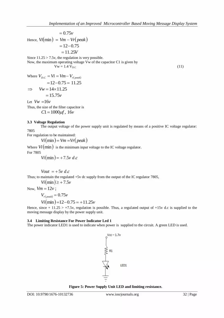
3.4 Limiting Resistance For Power Indicator Led 1
The power indicator LED1 is used to indicate when power is supplied to the circuit. A green LED is used.
Figure 5: Power Supply Unit LED and limiting resistance.
Implementation of an Improved Microcontroller Based Moving Message Display System
DOI: 10.9790/1676-10132736 www.iosrjournals.org 33 | Page
L
D
I
VR
7.11
Where mAIVV LD 22,25.11
m
R22
7.125.111
1.434
Let 4701R
In summary, the list of rated components value for the power supply unit is as follows:
Transformer = 240v / 12v, 300mA, 50Hz A.C
D1− D4 = 1N4001
C1 = 1000f, 16v IC Regulator = 7805
LED1 = Green
Battery = 9v d.c
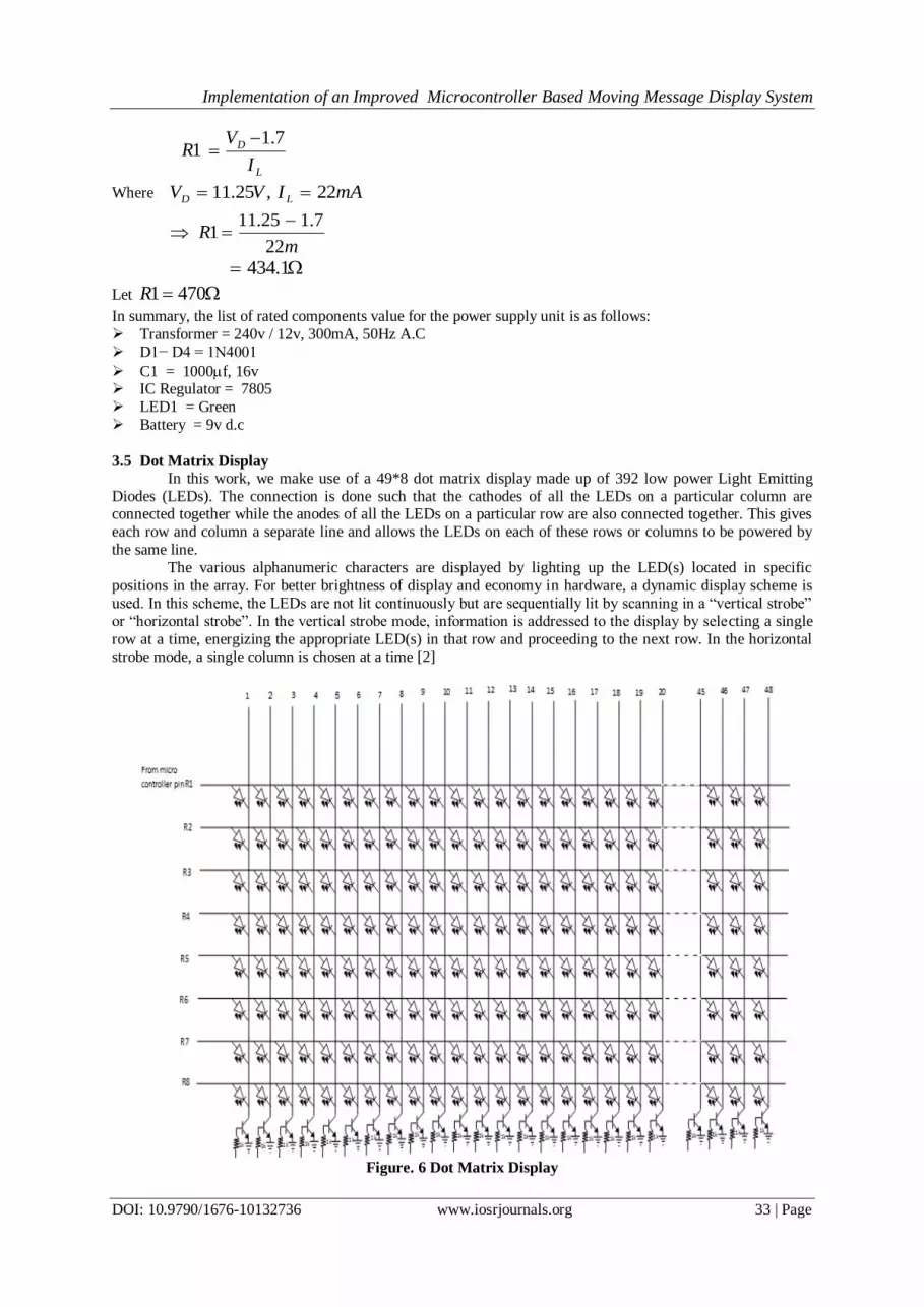
3.5 Dot Matrix Display
In this work, we make use of a 49*8 dot matrix display made up of 392 low power Light Emitting
Diodes (LEDs). The connection is done such that the cathodes of all the LEDs on a particular column are connected together while the anodes of all the LEDs on a particular row are also connected together. This gives
each row and column a separate line and allows the LEDs on each of these rows or columns to be powered by
the same line.
The various alphanumeric characters are displayed by lighting up the LED(s) located in specific
positions in the array. For better brightness of display and economy in hardware, a dynamic display scheme is
used. In this scheme, the LEDs are not lit continuously but are sequentially lit by scanning in a “vertical strobe”
or “horizontal strobe”. In the vertical strobe mode, information is addressed to the display by selecting a single
row at a time, energizing the appropriate LED(s) in that row and proceeding to the next row. In the horizontal
strobe mode, a single column is chosen at a time [2]
Figure. 6 Dot Matrix Display

Implementation of an Improved Microcontroller Based Moving Message Display System
DOI: 10.9790/1676-10132736 www.iosrjournals.org 34 | Page
IV. Software Design & Analysis 4.1 Assembly Language Program
. "Assembly language" and "assembler" are two different notions. The first represents a set of rules used in
writing a program for a microcontroller, and the other is a program on the personal computer which translates
assembly language into a language of zeros and ones. A program that is translated into "zeros" and "ones" is
also called "machine language"
4.2 Representation of numbers in assembly Language
In assembly language MPLAB, numbers can be represented in decimal, hexadecimal or binary form.
Table 1: Representation of Numbers in Assembly Language Instruction Format Numerical Class
.240 Decimal
0Xf0 Hexadecimal
b'11110000' Binary
Decimal numbers start with a dot, hexadecimal with 0x, and binary start with b with the number itself
under quotes.
4.3 Instruction Set Description Of PIC16series Microcontroller
The Microcontroller is not like any other integrated circuit. In order to "make" a microcontroller
perform a task, it has to be told exactly what to do, in other words we must write the program that the
microcontroller will execute. This contains instructions, which make up the assembler or lower-level program
language for PIC microcontrollers. [6]
Letters are used to represent the following parts of the instruction.
w = working register
k = Literal data, constant or variable
f = file registers
d = destination bit
b = bit position in 'f' register
4.4 The Character Map Design
The character map describes or defines the look of each character that will be displayed on the dot matrix. We
have;
Table 2: Dot Matrix Display Character Map
Figure. 7 Dot Matrix Display
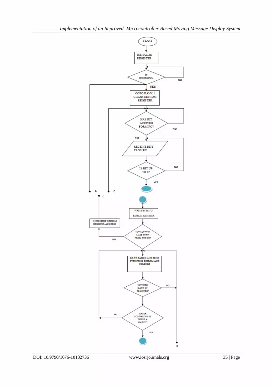
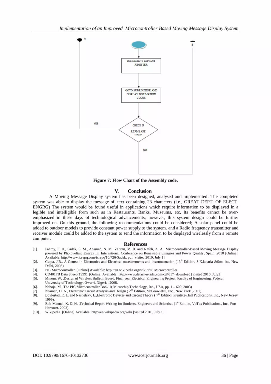
4.5 Flow Chart Design
The Flow Chart of the Assembly code is shown below.
Implementation of an Improved Microcontroller Based Moving Message Display System
DOI: 10.9790/1676-10132736 www.iosrjournals.org 35 | Page
Implementation of an Improved Microcontroller Based Moving Message Display System
DOI: 10.9790/1676-10132736 www.iosrjournals.org 36 | Page
Figure 7: Flow Chart of the Assembly code.
V. Conclusion A Moving Message Display system has been designed, analysed and implemented. The completed
system was able to display the message of. text containing 23 characters (i.e., GREAT DEPT. OF ELECT.
ENGRG) The system would be found useful in applications which require information to be displayed in a legible and intelligible form such as in Restaurants, Banks, Museums, etc. Its benefits cannot be over-
emphasized in these days of technological advancements; however, this system design could be further
improved on. On this ground, the following recommendations could be considered; A solar panel could be
added to outdoor models to provide constant power supply to the system. and a Radio frequency transmitter and
receiver module could be added to the system to send the information to be displayed wirelessly from a remote
computer.
References [1]. Fahmy, F. H., Sadek, S. M., Ahamed, N. M., Zahran, M. B. and Nafeh, A. A., Microcontroller-Based Moving Message Display
powered by Photovoltaic Energy In: International Conference on Renewable Energies and Power Quality, Spain .2010 [Online],
Available: http://www.icrepq.com/icrepq'10/726-Sadek. pdf[ visited 2010, July 1]
[2]. Gupta, J.B., A Course in Electronics and Electrical measurements and instrumentation (13th Edition, S.K.kataria &Son, inc, New
Delhi, 2008)
[3]. PIC Microcontroller. [Online] Available: http://en.wikipedia.org/wiki/PIC Microcontroller
[4]. CD4017B Data Sheet (1999). [Online] Available: http://www.datasheetsdir.com/cd4017+download [visited 2010, July1]
[5]. Mmom, W. ,Design of Wireless Bulletin Board, Final year Electrical Engineering Project, Faculty of Engineering, Federal
University of Technology, Owerri, Nigeria, 2008.
[6]. Neboja, M., The PIC Microcontroller Book 1( Microchip Technology, Inc., USA, pp. 1 – 600. 2003)
[7]. Neamen, D. A., Electronic Circuit Analysis and Design ( 2nd
Edition, McGraw-Hill, Inc., New York.,2001)
[8]. Boylestad, R. L. and Nashelsky, L.,Electronic Devices and Circuit Theory ( 7th Edition, Prentice-Hall Publications, Inc., New Jersey
1999).
[9]. Bob-Manuel, K. D. H. ,Technical Report Writing for Students, Engineers and Scientists (1st Edition, VoTex Publications, Inc., Port-
Harcourt. 2003)
[10]. Wikipedia. [Online] Available: http://en.wikipedia.org/wiki [visited 2010, July 1.