Embed Size (px)
Citation preview
Federal Highway Administration Turner-Fairbank Highway Research Center
6300 Georgetown Pike, McLean, VA 22101
Identification of Human Factors Research Needs - Final Report Publication No.: FHWA-RD-98-178 June 1998
2
The original format of this document was an active HTML page(s). The Federal Highway Administration converted the HTML page(s) into an Adobe® Acrobat® PDF file to preserve and support reuse of the information it contained. The intellectual content of this PDF is an authentic capture of the original HTML file. Hyperlinks and other functions of the HTML webpage may have been lost, and this version of the content may not fully work with screen reading software.
3
Foreword
This report summarizes the activities and results of a preliminary human factors review for the Intelligent Vehicle Initiative (IVI) program. The objective of the project was to help the U.S. Department of Transportation identify human factors work that needs to be done early in the life cycle of the IVI program to ensure safe and well–engineered vehicles.
Copies of this report can be obtained from the Research and Technology Report Center, 9701 Philadelphia Court, Unit Q, Lanham, Maryland 20706; telephone: (301) 577–0818; fax: (301) 577–1421; or the National Technical Information Service (NTIS), 5285 Port Royal Road, Springfield, Virginia 22161; telephone: (703) 487–4650; fax: (703) 321–8547.
A. George Ostensen Director Office of Safety and Traffic Operations Research and Development
NOTICE
This document is disseminated under the sponsorship of the Department of Transportation in the interest of information exchange. The United States Government assumes no liability for its contents or use thereof. This report does not constitute a standard, specification, or regulation.
The United States Government does not endorse products or manufacturers. Trade and manufacturers' names appear in this report only because they are considered essential to the object of the document.
4
Technical Report Documentation Page
1. Report No.
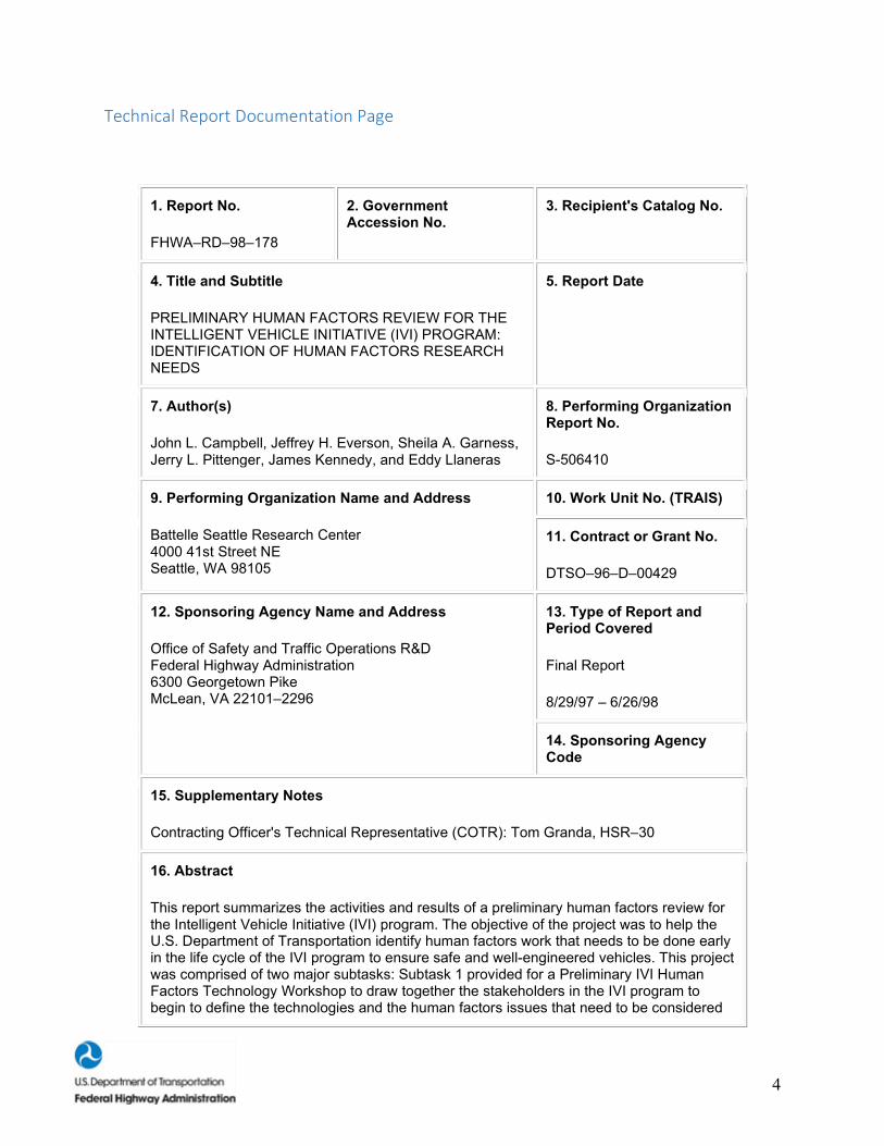
FHWA–RD–98–178
2. Government Accession No.
3. Recipient's Catalog No.
4. Title and Subtitle
PRELIMINARY HUMAN FACTORS REVIEW FOR THE INTELLIGENT VEHICLE INITIATIVE (IVI) PROGRAM: IDENTIFICATION OF HUMAN FACTORS RESEARCH NEEDS
5. Report Date
7. Author(s)
John L. Campbell, Jeffrey H. Everson, Sheila A. Garness, Jerry L. Pittenger, James Kennedy, and Eddy Llaneras
8. Performing Organization Report No.
S-506410
9. Performing Organization Name and Address
Battelle Seattle Research Center 4000 41st Street NE Seattle, WA 98105
10. Work Unit No. (TRAIS)
11. Contract or Grant No.
DTSO–96–D–00429
12. Sponsoring Agency Name and Address
Office of Safety and Traffic Operations R&D Federal Highway Administration 6300 Georgetown Pike McLean, VA 22101–2296
13. Type of Report and Period Covered
Final Report
8/29/97 – 6/26/98
14. Sponsoring Agency Code
15. Supplementary Notes
Contracting Officer's Technical Representative (COTR): Tom Granda, HSR–30
16. Abstract
This report summarizes the activities and results of a preliminary human factors review for the Intelligent Vehicle Initiative (IVI) program. The objective of the project was to help the U.S. Department of Transportation identify human factors work that needs to be done early in the life cycle of the IVI program to ensure safe and well-engineered vehicles. This project was comprised of two major subtasks: Subtask 1 provided for a Preliminary IVI Human Factors Technology Workshop to draw together the stakeholders in the IVI program to begin to define the technologies and the human factors issues that need to be considered

5
in developing an IVI. Subtask 2 investigated the preliminary infrastructure and human factors in-vehicle requirements for alternative configurations of an IVI. The data collected in the Human Factors Technology Workshop in subtask 1 served as a basis and starting point for the research performed to identify human factors research needs that exist. The following conclusions were developed during the conduct of this project: (1) human factors research needs for the Generation I IVI focus on the need to integrate and manage the information presented to the driver; (2) no publicly available human factors research has examined the effects of integrating multiple Intelligent Transportation Systems (ITS) devices into a vehicle as envisioned by the IVI; (3) considerable human factors research has been conducted to support the development of individual User Services within the IVI; (4) a broad range of ITS technologies are available to support the development of a Generation I IVI prototype; and (5) for the Generation II and III IVI especially, extensive algorithm/software, infrastructure, and specific technologies are needed.
17. Key Words
Intelligent Vehicle Initiative, Human Factors, Driver-Vehicle Interface, Collision Avoidance Systems, Advanced Traveler Information Systems.
18. Distribution Statement
No restrictions. This document is available to the public through the National Technical Information Service, Springfield, Virginia, 22161.
19. Security Classif. (of this report)
Unclassified
20. Security Classif. (of this page)
Unclassified
21. No. of Pages
126
22. Price
Form DOT F 1700.7 (8-72) Reproduction of completed page authorized
6
Table of Contents Foreword ..................................................................................................................................... 3
NOTICE ...................................................................................................................................... 3
Technical Report Documentation Page ...................................................................................... 4
LIST OF FIGURES .................................................................................................................... 8
LIST OF TABLES ...................................................................................................................... 8
SUMMARY .................................................................................................................................... 9
INTRODUCTION ........................................................................................................................ 11
BACKGROUND ...................................................................................................................... 11
Importance of Human Factors to the IVI .............................................................................. 12
PROJECT OBJECTIVES ......................................................................................................... 12
PROJECT STATEMENT OF WORK...................................................................................... 13
SUMMARY OF TASK 1: CONDUCT HUMAN FACTORS WORKSHOP FOR THE IVI . 13
Summary of Research Statements Developed During the Workshop .................................. 15
Workshop Summary and Conclusions .................................................................................. 17
SUBTASK 2. PRELIMINARY INFRASTRUCTURE AND HUMAN FACTORS IN–VEHICLE REQUIREMENTS AND IDENTIFICATION OF HUMAN FACTORS NEEDS 18
ORGANIZATION OF THIS REPORT .................................................................................... 19
METHOD ..................................................................................................................................... 20
OVERVIEW ............................................................................................................................. 20
DEVELOPMENT OF THE USER SERVICES SUMMARIES, TECHNOLOGY MODULES, AND IVI CANDIDATE CONFIGURATIONS ....................................................................... 20
Sources of Technology References for User Services Tables .............................................. 20
Determining the Availability of the IVI User Services ........................................................ 20
Development of Human Factors Research To–Date and Research Needs ........................... 21
RESULTS ..................................................................................................................................... 25
OVERVIEW ............................................................................................................................. 25
Introduction to the IVI User Services, Technology Modules, and Candidate Configurations............................................................................................................................................... 26
DESCRIPTION OF USER SERVICES FOR THE IVI ........................................................... 30
USER SERVICE 1: REAR–END COLLISION AVOIDANCE .......................................... 33
USER SERVICE 2: ROAD–DEPARTURE COLLISION AVOIDANCE .......................... 35
USER SERVICE 3: LANE–CHANGE AND MERGE COLLISION AVOIDANCE ......... 37
USER SERVICE 4: INTERSECTION COLLISION AVOIDANCE .................................. 39
USER SERVICE 5: RAILROAD CROSSING COLLISION AVOIDANCE ..................... 41
7
USER SERVICE 6: VISION ENHANCEMENT ................................................................ 43
USER SERVICE 7: LOCATION–SPECIFIC ALERT AND WARNING .......................... 45
USER SERVICE 8: AUTOMATIC COLLISION NOTIFICATION .................................. 47
USER SERVICE 9: SMART RESTRAINTS AND OCCUPANT PROTECTION SYSTEMS............................................................................................................................. 49
USER SERVICE 10: NAVIGATION/ROUTING ............................................................... 50
USER SERVICE 11: REAL–TIME TRAFFIC AND TRAVELER INFORMATION ....... 52
USER SERVICE 12: DRIVER COMFORT AND CONVENIENCE ................................. 54
USER SERVICE 13: VEHICLE STABILITY WARNING AND ASSISTANCE .............. 56
USER SERVICE 14: DRIVER CONDITION WARNING ................................................. 58
USER SERVICE 15: VEHICLE DIAGNOSTICS ............................................................... 59
USER SERVICE 16: CARGO IDENTIFICATION............................................................. 60
USER SERVICE 17: AUTOMATED TRANSACTIONS ................................................... 61
USER SERVICE 18: SAFETY EVENT RECORDER ........................................................ 63
USER SERVICE 19: OBSTACLE/PEDESTRIAN DETECTION ...................................... 65
USER SERVICE 20: TIGHT MANEUVER/PRECISION DOCKING ............................... 66
USER SERVICE 21: TRANSIT PASSENGER MONITORING ........................................ 68
USER SERVICE 22: TRANSIT PASSENGER INFORMATION ...................................... 69
USER SERVICE 23: FULLY AUTOMATED CONTROL AT CERTAIN FACILITIES . 71
USER SERVICE 24: LOW–FRICTION WARNING AND CONTROL ASSIST .............. 72
USER SERVICE 25: LONGITUDINAL CONTROL ......................................................... 73
USER SERVICE 26: LATERAL CONTROL ..................................................................... 75
Infrastructure Requirements for the User Service ................................................................ 77
TECHNOLOGY MODULES FOR THE GENERATION I IVI .............................................. 78
MODULE A: BASIC COLLISION WARNING TECHNOLOGIES .................................. 80
MODULE B: ADVANCED COLLISION WARNING TECHNOLOGIES ....................... 81
MODULE C: BASIC TRAVELER INFORMATION DEVICES ....................................... 82
MODULE D: DRIVER CONVENIENCE DEVICES ......................................................... 83
MODULE E: ITS COLLISION WARNING SYSTEMS FOR HEAVY VEHICLES ........ 83
CANDIDATE CONFIGURATIONS FOR THE GENERATION I IVI .................................. 85
GENERAL HUMAN FACTORS RESEARCH ISSUES FOR THE IVI ................................ 86
Overview ............................................................................................................................... 86
Baseline Driver Behavior ...................................................................................................... 86
System Standardization and Guidelines................................................................................ 86
IVI Message Modality and Design ....................................................................................... 87
8
Timing of Messages .............................................................................................................. 89
False Alarms ......................................................................................................................... 89
Driver Response Time to Alerts ........................................................................................... 89
Stimulus–Response (SR) Compatibility of Alerts ................................................................ 89
Control Requirements by Drivers ......................................................................................... 90
Training ................................................................................................................................. 91
Older Drivers ........................................................................................................................ 91
Driver Acceptance ................................................................................................................ 91
Driver Performance ............................................................................................................... 92
Effects of Automation ........................................................................................................... 92
Inappropriate Levels of Driver Trust in the System ............................................................. 92
Functional Allocation............................................................................................................ 93
CONCLUSIONS........................................................................................................................... 94
REFERENCES ............................................................................................................................. 96
BACKGROUND NOTES .......................................................................................................... 108
LIST OF FIGURES Figure 1. Key steps and development issues in subtask 2. .......................................................... 24 Figure 2. Sequence of subtask 2 activities and relationship between User Services, Technology Modules and Candidate Configurations........................................................................................ 26 Figure 3. Schematic of IVI Candidate Configuration #1. ............................................................ 27 Figure 4. Schematic of IVI Candidate Configuration #2. ............................................................ 27 Figure 5. Schematic of IVI Candidate Configuration #3. ............................................................ 28 Figure 6. Schematic of IVI Candidate Configuration #4. ............................................................ 28 Figure 7. Schematic of IVI Candidate Configuration #5. ............................................................ 29 Figure 8. Nested hierarchical relations among frames, rules, and response tendencies as sources of stimulus-reponse compatibilities. ............................................................................................. 90 LIST OF TABLES Table 1. Summary of the strategy used for database searches. ..................................................... 22 Table 2. Summary of the IVI User Services. ................................................................................ 30 Table 4. General guidelines for the selection of auditory vs. visual forms of information presentation (from Deatherage, 1972). ......................................................................................... 88
9
SUMMARY
As part of the U.S. Department of Transportation's (U.S. DOT's) Intelligent Vehicle Initiative (IVI) program, the Federal Highway Administration (FHWA) investigated the human factors research needs for integrating in–vehicle safety and driver information technologies into usable systems that provide manageable information to the driver. The objective of the project was to help the U.S. DOT identify human factors issues that need to be resolved early in the life cycle of the IVI program to ensure safe and well–engineered vehicles.
The IVI has the potential to provide drivers with useful information for many driving conditions and situations; to improve driving performance; and, ultimately, to increase the mobility and safety of the entire driving public. The IVI clearly represents an increase in the number of displays and controls for the in–vehicle environment, with a concurrent increase in the amount and complexity of information presented to the driver. If human factors integration and design issues are not addressed throughout the development process for the Generation I IVI, there is a risk that this increase in information will lead to information overload, driver confusion, and actual decreases in driver performance and safety.
This project was comprised of two major activities: First, a Preliminary IVI Human Factors Technology Workshop was held in December 1997 to draw together the stakeholders in the IVI program (e.g., universities, automotive manufacturers, vendors, and contractors) to begin to define the technologies and the human factors issues that need to be considered in developing an IVI. Second, the project team investigated the preliminary infrastructure and human factors in–vehicle requirements for alternative configurations of an IVI. This paper addresses the data collected during the Human Factors IVI Workshop that served as a basis for the human factors research needs that were identified.
Summaries of the identified human factors research to–date and research needs were developed to reflect the current literature as well as the general consensus of human factors professionals' expert opinions. Current literature was acquired from: (1) the Battelle Human Factors Transportation Center's collection of literature, including books, journal articles, and conference proceedings; (2) publications lists from the FHWA and the National Highway Traffic Safety Administration (NHTSA); and (3) literature searches using national databases. Expert opinions from human factors experts and other members of the Intelligent Transportation Systems (ITS) community were obtained at the Human Factors IVI Workshop.
To allow analysis of more complex IVI alternatives, the functional subsystems identified for the 26 User Services specified in the U.S. DOT Request for Information for the IVI program were combined into 7 Technology Modules. Each module was analyzed to determine high–priority human factors research that was needed to produce a safe–operating IVI. Previous human factors work applicable to each Technology Module was identified. Gaps in the previous human factors work for each Technology Module were identified as early human factors research needs for the IVI.
Five Candidate IVI Configurations were developed based on logical combinations of the seven Technology Modules. These Candidate Configurations represent basic and advanced safety and driver information functions in passenger cars, commercial trucks, and transit vehicles such as buses. Each Candidate Configuration was meant to provide clear safety benefits to the driver as well as a solid technical foundation for the system configurations for the IVI.
The five configurations are listed below:
• Basic Collision Warning and Driver Information Systems. • Full-Coverage (360o) Collision Warning. • Advanced Traveler Information System (ATIS) Capabilities. • Integrated ITS Capabilities for Heavy Vehicles.

10
• Integrated ITS Capabilities for Transit Vehicles.
The following conclusions were developed from this project:
• Human factors research for the Generation I IVI should focus on the need to integrate and manage the information presented to the driver.
• No publicly available human factors research has examined the effects of integrating multiple ITS devices into a vehicle as envisioned by the IVI.
• Considerable human factors research has been conducted to support the development of individual User Services within the IVI.
• A broad range of ITS technologies are available to support the development of a Generation I IVI prototype.
• For the Generation II and III IVI, extensive algorithm/software, infrastructure, and specific technologies are needed.
11
INTRODUCTION
This report summarizes the activities and results of a preliminary human factors review for the Intelligent Vehicle Initiative (IVI) program. The IVI program is a major Intelligent Transportation Systems (ITS)-related program to address the advancement of introducing advanced technologies into a wide range of vehicle classes. "The primary goal of the IVI is, jointly with the motor vehicle and trucking industries, State and local DOT's, and other stakeholders, to accelerate the development, introduction, and commercialization of driver assistance products to reduce motor vehicle crashes and incidents. The IVI will emphasize the development of industry-wide architectures and standards, integrated system prototyping, and field test evaluations such that the government and industry participants can assess benefits, define the performance requirements, and accelerate the deployment of incremental driver assistance products."(1)
With the introduction of advanced technologies ranging from advanced collision avoidance systems (CAS) to comprehensive driver information systems, it is recognized that careful thought must be given as to how these systems interact with the human driver. Some work has been accomplished in this area, but much work remains to be done. This research performed by Battelle Memorial Institute provides a preliminary look at where additional human factors research might be needed to ensure that safe and useful IVI prototypes are developed.
BACKGROUND
The Intelligent Transportation System (ITS) program continues to sustain momentum in the United States. Over the past 10 years, work has focused on identifying and testing advanced technologies that could improve the transportation systems in this country. Work has also focused on developing a National ITS Architecture that would allow deployment of a compatible infrastructure and standards that would result in nationwide compatibility. Much of the research done has focused on the vehicle. Significant advancements have been made in developing ITS systems that provide increased safety and convenience for drivers. For example, collision avoidance radar systems can detect objects in the vicinity of the vehicle. Smart cruise control systems are about to be introduced that continually look ahead of the vehicle and automatically maintain a safe headway distance. Route guidance systems are available with integrated maps that are aware of the detailed roadway network in a city to help the driver manipulate around problem areas caused by incidents or construction. Automated vehicle location (AVL) systems have been installed in public transit systems along with advanced scheduling algorithms to help transit operations provide reliable service to their customers. The possibilities are far reaching and the personality and functionality of our automobiles are changing.
However, there is a need to build several cars, trucks, buses, and emergency vehicles that include selected technologies for testing and demonstration purposes. It is essential to ensure that the technologies selected for inclusion on the vehicles are safe and engineered correctly. The vehicles will be used to test the interfaces to the human drivers, as well as all other systems in the vehicles. The vehicles will also be used to demonstrate to stakeholders the benefits that can be achieved. This work is being performed under the program title "Intelligent Vehicle Initiative" or IVI. This program has the primary objective of keeping the vehicles and associated vehicle technologies at pace with the other ITS work. The intent of the IVI is to improve significantly the safety and efficiency of motor vehicle operations by reducing the probability of motor vehicle crashes.
The IVI program is currently researching four classes of vehicles, including: (1) passenger vehicles, (2) commercial vehicles (i.e., trucks), (3) transit vehicles, and (4) specialty vehicles (i.e., fire trucks, ambulances, and police vehicles). The program has also introduced the concept of developing different generations of vehicles, each with more advanced technologies made possible by the experience gained from previous generations.
12
As part of the IVI program, the Federal Highway Administration (FHWA) funded a project with Battelle Memorial Institute, with significant support from ITS America,(1) to investigate the human factors issues for an IVI and identify human factors research needs that currently exist. The objective of the project was to help the United States Department of Transportation (U.S. DOT) identify human factors work that needs to be done early in the life cycle of the IVI program to ensure safe and well–engineered vehicles. This report summarizes the technical approach used and the results of this research.
Importance of Human Factors to the IVI
There are three distinct types of human factors integration that should be considered for the Generation I IVI: First, there is the integration that takes place between the driver–vehicle interface (DVI) components of a User Service (or User Services) and the DVI components of an existing vehicle. An example of this type of integration is the need to implement driver messages, display formats, and display locations for both the Real–Time Traffic and Traveler information system and existing displays in order to increase the usability and comprehension of the entire suite of in–vehicle displays and to avoid driver overload. Second, there are integration requirements between similar IVI User Services. For example, if an IVI vehicle is equipped with Rear–End, Lane–Change/Merge, and Intersection CAS, the controls and information displays associated with these devices must be integrated in a manner that supports rapid driver understanding and response when collision warning messages are presented. Third, there are integration requirements between different IVI User Services. For example, if an IVI vehicle is equipped with both an Obstacle/Pedestrian Detection CAS as well as a Routing/Navigation device, design issues such as display type and location as well as message priority, timing, and formats will be particularly important for the Generation I IVI.
The IVI has the potential to provide drivers with useful information on many driving conditions and situations; to improve driving performance; and, ultimately, to increase the mobility and safety of the entire driving public. The IVI clearly represents an increase in the number of displays and controls for the in–vehicle environment, with a concurrent increase in the amount and complexity of information presented to the driver. If human factors integration and design issues are not addressed throughout the development process for the Generation I IVI, there is a risk that this increase in information will lead to information overload, driver confusion, and actual decreases in driver performance and safety.
(1) ITS America provided significant support for facilitating a key workshop in the project and summarizing the workshop results. ITS America also provided valuable engineering support in execution of the program through the participation of Dr. Eddy Llaneras in all aspects of the project.
PROJECT OBJECTIVES
Safety on our highways is "Priority One" in the U.S. DOT. In recent years, significant gains have been made to improve safety, but opportunities exist to do more. These opportunities center around the IVI program. The IVI program is thought to provide the maximum public benefit at a reasonable cost and in the shortest time. The IVI program is a human–centered program that emphasizes the introduction of technologies that not only help drivers to achieve better control of their vehicles, but also provide convenience–type driver information in order to make traveling a more enjoyable and less stressful activity. To accomplish these IVI goals, interfaces between the driver and IVI systems are essential, whether the systems are included in the vehicle or in the supporting highway infrastructure. The Generation I IVI is expected to focus on in–vehicle technologies. However, the Generation II and III IVI's are expected to include more advanced technologies to better integrate the vehicles with the infrastructure components of our transportation system.
13
The strong emphasis on DVI components within the IVI calls for human factors involvement in all phases of IVI development. Attention to human factors issues will help ensure that information is presented clearly and in ways that elicit appropriate driver response. Much work has been done to study human factors issues of drivers, but this work focused on more traditional driver–vehicle interfaces. However, more human factors work is needed with the new technologies being introduced into a vehicle by the IVI. The primary objective of this project is to identify human factors research needs that must be addressed to ensure safe operation of an IVI. A secondary objective of the project is to solicit consensus among the stakeholders for an IVI to move the program forward in a coordinated and synergistic way.
PROJECT STATEMENT OF WORK
This project was comprised of two major subtasks:
Subtask 1 provided for a Preliminary IVI Human Factors Technology Workshop to draw together the stakeholders in the IVI program to begin to define the technologies and the human factors issues that need to be considered in developing an IVI. Due to resource constraints, primary emphasis in the research focused on the Generation I vehicle. However, information generated in the research that encompassed more advanced generations of an IVI was documented in the project reports. The primary purpose of the workshop was to identify state–of–the–art technologies that can be applied to IVI vehicles; human factors issues with each technology; and, ultimately, the identification of human factors research needs. The workshop was also used to solicit input from the ITS community as a whole and to build consensus of the stakeholders as to what an IVI should be.
Subtask 2 investigated the preliminary infrastructure and human factors in–vehicle requirements for alternative configurations of an IVI. The data collected in the Human Factors Technology Workshop in subtask 1 served as a basis and starting point for the research performed to identify human factors research needs that exist. The results of the subtask 2 research are documented in this report.
The following information summarizes the work performed in each of the two subtasks as well as major conclusions derived from each. A more comprehensive summary of the conduct and results from subtask 1 is provided in the workshop proceedings published by ITS America (ITS America, 1997).
SUMMARY OF TASK 1: CONDUCT HUMAN FACTORS WORKSHOP FOR THE IVI
On December 10–11, 1997, an IVI Human Factors Technology Workshop was held in Troy, Michigan. The following objective statement was prepared to provide focused direction in organizing the meeting:
"The objective of the IVI Human Factors Technology Workshop is to provide invited transportation professionals the early opportunity to provide inputs to the development and establishment of human factors requirements for the Generation I intelligent vehicles. The workshop will be used to solicit input from stakeholders and build consensus. Vehicle classes to be addressed will include preliminarily cars and, to the lesser extent, buses, trucks, and emergency/special vehicles. Information to be discussed by the group will include:
• Candidate in–vehicle technologies for inclusion and integration for a Generation I IVI vehicle. • The status of development and availabilityof each technology. • Functional descriptions and architecture requirements for the Generation I IVI vehicle. • Roadway infrastructure requirements to deploy the technology.

14
• The human factors issues that need to be addressed for each identified technology. • Completed or ongoing research that has addressed identified human factors issues. • New human factors research that needs to be completed prior to introduction of the technology
into an IVI vehicle.
The information will be used to determine needed human factors research needs for candidate technologies and systems. The information obtained from the workshop will also be used to document a set of requirements for supporting infrastructure, vehicle, and human factors research."
To accomplish the objectives defined for the workshop, the attendance was restricted to invitation only. Careful selection was done to include qualified stakeholders from the public and private sector as well as academia that would be impacted by an IVI program. Emphasis was also placed on selecting people who had a human factors perspective. The participation in the workshop was excellent, with more than 70 people attending.
The workshop began with several presentations to introduce participants to the subject topic and to raise some of the issues to be addressed during the 2–day session. The presentations, in order, were as follows:
• Dr. Samuel Tignor (FHWA) and Dr. Duane Perrin (National Highway Traffic Safety Administration [NHTSA]) opened the workshop with presentations on the direction of the IVI program and how the Driver–Vehicle Interface (DVI) program related to the objectives of IVI.
• Dr. Jeffrey Everson of Battelle provided an overview of international work that had been done to–date that was related to the U.S. IVI program. Dr. Everson's presentation included several examples of integrated, multi–functional vehicle prototypes incorporating active safety, navigation, and convenience systems that were contiguous with the 26 User Services identified in the U.S. DOT–published Request for Information (RFI).
• Dr. Ian Noy of Transport Canada provided a presentation that stressed the importance of incorporating IVI considerations into an ITS development program such as the IVI to achieve "usable, suitable, and acceptable" systems. He discussed how human factors principles and research–based design can greatly enhance system safety by reducing human error. He emphasized the need to design and develop any IVI prototype from a system perspective as opposed to individual technologies.
• Dr. John Campbell of Battelle presented the results of a survey that was sent to selected participants prior to the workshop. The survey was intended to provide a baseline for breakout group discussions by identifying the availability of the 26 User Services listed in the U.S. DOT RFI for a Generation I IVI, associated infrastructure requirements, and human factors research needs. Key survey findings presented included:
1. Belief that most systems/User Services will be available for operational test rather than as commercial products (at least within the near term).
2. Emphasis on navigation and collision avoidance services rather than convenience–based information systems.
3. Evolution of infrastructure elements. Some concerns exist for completely autonomous systems (e.g., lengthy deployment lead times and system robustness).
4. Emphasis on simpler and more narrow near–term solutions. 5. A wide range of platform–independent human factors research needs.
• The final presentation was given by Greg Barbato of the U.S. Air Force Research Laboratory at Wright Patterson Air Force Base. This presentation discussed some of the human factors–related lessons learned from a different, but similar, system development program (i.e., pilot crew system design program for a new aircraft cockpit). Barbato made the following three recommendations to the workshop participants:
15
1. Identify the system requirements early in the development process. 2. Understand the user population and how they think. 3. Design/evaluate systems using a structured objective process such as a methodology used by
the U.S. Air Force to design aircraft cockpits. He stated that the methodology could be adapted for automotive applications such as an IVI.
Following the introductory presentations, the participants were divided into six breakout groups. Each breakout group had a focus, but some groups focused on the same topics. Specifically, two groups addressed Collision Avoidance and two groups addressed Navigation Systems. Also, two groups addressed Information Systems, but one group focused on convenience–type systems, while the other focused on safety–type systems. Each group was asked to emphasize the work needed for light vehicles, but also to consider issues for heavy vehicles (i.e., commercial trucks), transit vehicles (i.e., buses), and specialty vehicles (i.e., ambulances). The groups were also requested to prioritize the Generation I vehicle, which was defined as a vehicle available in the next 4 to 5 years that could be controlled by the driver. The final instructions given to each breakout group were to develop human factors research statements that, in their combined opinion, were needed to deploy the functional areas being emphasized by their breakout group. Each group was asked to specify the following information for each research statement identified:
1. Why the research needs to be performed. 2. Key objectives of the research. 3. General technical approach. 4. Estimated period of performance. 5. Estimated costs.
Each breakout group held two sessions during the workshop. The first session focused on defining the candidate functions to be included in an IVI and associated issues of each as an independent subsystem. The second session focused on the integration concerns that needed to be addressed when the candidate subsystems were combined in an IVI.
Summary of Research Statements Developed During the Workshop
A total of 48 research statements were developed during the 2–day workshop. Each contained a title, a reason why the research should be performed, key research objectives, a general technical approach, an estimated period of performance, and an estimated cost. Forty–three of these 48 research statements were described to the assembled workshop participants and rated with respect to perceived priority.
The research statements covered a broad range of human factors issues relevant to a near–term IVI. A preliminary review of the research statements and priority ratings provided by the workshop participants was conducted. Our review suggests that the majority of the research statements can be placed into one of four broad categories of human factors research needs. These four categories, along with the titles of the research statements from the workshop, are summarized below. More detailed descriptions of the research statements can be found in the proceedings developed for the workshop by ITS America (ITS America, 1997).
Identify the IVI's Implications for the Driver–Vehicle Interface (DVI). Many research statements focused on the need to examine critical interactions between the driver and the vehicle. For the most part, these research statements represented an expansion of traditional DVI issues to the new IVI.
Specific titles of research topics in this area were:
• Investigate Haptic and Kinesthetic Warnings. • Driver Tolerance to System False/Nuisance Alarms.
16
• Evaluation of Voice Recognition for IVI. • Define the Nature of the Human System Dialogue. • Define the Nature of the Adaptive Interface. • Information Display Assignment and Modality Assignment. • Requirements for Display Devices. • Basic Input Modality Research. • Methods for Comparing Workload in Different Conditions. • When Should the Navigation/Route Guidance Information System Be Interrupted, Turned Off,
Superceded? • Voice Systems in the Vehicle for IVI. • Screen Size/Resolution. • Driver Condition Warning.
Characterize Baseline Driver Behavior and Develop Driver Models for IVI. A number of research statements identified the need to characterize baseline driving behavior across a range of driving situations and conditions. Another theme was the need to develop computational theories and models of driver behavior, and to use these tools to support IVI development. These are related and synergistic research needs, with the data obtained during studies of baseline driver behavior being used as input to the process of developing robust and useful driver models.
Specific titles of research topics in this area were:
• Baseline Driver Behavior and Performance for Each Crash Type. • Relating Man–Machine Interface (MMI) Elements Quantitatively to Visual Demand Measures. • Acquisition of Driver Behavior/Driving Environment Data. • Integration and Development of Human Factors Driver Models for IVI. • The Driver as a Decisionmaker: Decisions and Decision Processes. • Describing Normative Driver Behavior Using Quantitative Models. • Driver Baseline for IVI.
Provide Industry With Human Factors Design Guidelines and Standards for IVI. The need to develop human factors guidelines and standards was identified as a high–priority research need by most of the breakout groups.
Specific titles of research topics in this area were:
• CAS Warning/Alert Standardization. • Standardization of CAS Warning Criteria. • Guidelines of CAS Warning Type, Location, and Priority. • Prioritization of In–Vehicle Information Systems (IVIS) Message Delivery. • Standardization of Navigation Messages for IVI. • IVI Messages: How Much and How Often. • IVI Information Display Prioritization.
Determine the Feasibility and Optimum Design Approach for the Integration of IVIS Devices. A subset of research statements focused on the integration of multiple in–vehicle devices. Specifically, what are the human performance implications of having multiple (vs. single) sources of information for navigation and/or collision avoidance?
Specific titles of research topics in this area were:
• Estimate Benefits of Stand–Alone and Integrated CAS.
17
• IVI Integration and Multi–Task Performance: Effects on Driving Performance and Behavior. • Integration - IVI, Current Dash, and Roadside–Based Information. • IVI Field Infrastructure Requirements. • Integration of Navigation With Collision Warning, Collision Avoidance. • Comparative Feasibility of Unitary vs. Multiple Collision Warning Systems, All Systems.
Additional Research Topics. There were many additional research topics identified by the workshop participants. These included:
• Driver Mental Model. • Field Test of Stand–Alone CAS Scheduled for Generation I Vehicles. • Contextual Assessment for System Optimization. • Establish Caution Levels for Infrastructure Road Traffic Database Static/Dynamic. • Loss of Skill and Negative Transfer. • IVI Market Research Evaluation. • Multi–Task Requirements of Driving: Attention, Perception, and Cognition. • Driving Condition/State Functional Constraints. • Defining Situational Awareness. • Driver Understanding of System Functioning. • Comparison of the Effectiveness of In–Vehicle Warnings to Extra–Vehicle Warnings. • Alternative Steering Control Devices as an Enabler of Information System Packaging Space. • How to Ensure Effective Driver Knowledge and Skill (Performance) Levels for Safe Operation and
Use of Advanced, Information–Driven Vehicle Technologies. • Development of Experimental Methodologies for Assessing Risk Compensation Behaviors. • Build Prototype IVI Vehicles for Human Factors Research.
Workshop Summary and Conclusions
Dr. Sam Tignor and Dr. Duane Perrin provided the following general observations and conclusions for the IVI Human Factors Workshop.
IVI Program Direction:
• Don't lose sight of the big picture. • Beware of technologies looking for an application. • Consider system feasibility vs. commercial viability. Systems must be acceptable to customers in
all respects, including cost. • Place commercial vehicle applications ahead of those for passenger cars. • Develop an organized methodology for prioritization of projects. The scope of the program is
potentially huge, encompassing an almost infinite number of possibilities (4 vehicle types, 26 User Services, 3 generations, various types of drivers, etc.). One potential criterion for prioritizing is benefits.
Benefits Estimation:
• Consider both benefits and risks (both direct and indirect). • Consider more traditional alternatives. Hi–tech solutions may not be necessary or cost–effective. • Remember older vehicles. • Present situation is not the baseline; systems will need to interact in future environments (5 to 6
years) with more advanced cars and heavier traffic. • Benefits depend on driver acceptance. Acceptance depends on the driver's perception of benefits
(perception does not necessarily equal reality).
18
• Evaluation must consider behavioral adaptation effects. • Optimizing safety or efficiency at the individual vehicle level may not necessarily translate into
greater safety and efficiency at the global level (risk migration).
Major Human Factors Research Needs:
• Incorporate theoretical structures into system development and evaluation (need a method of ranking system "goodness").
• Good understanding of baseline (normative driving behavior). Need to understand how drivers operate under different situations and conditions.
• Measure overall net effect (long term, involving behavior adaptation). • Determine the feasibility of driver training.
General Conclusions:
• Understand normal driver behavior (with and without systems). • Model driver mental decisions. • Apply scientific process to IVI design. • Don't use the "black box" approach. Consider how the system relates to other components
(including the driver). • Understand integration issues. Electronic components (computers, stereos, televisions, etc.) work
together only because thought was devoted to the issue upfront. • Consider the numerous research issues addressed by breakouts, including:
– Display location and types. – Icon usage. – System integration. – Standards for system compatibility. – Sensor fusion. – Information prioritization. – Estimates of benefits. – False alarms. – Training.
SUBTASK 2. PRELIMINARY INFRASTRUCTURE AND HUMAN FACTORS IN–VEHICLE REQUIREMENTS AND IDENTIFICATION OF HUMAN FACTORS NEEDS
The objective of subtask 2 was to analyze the potential in–vehicle requirements and associated infrastructure needed to identify the human factors research needs that currently exist to develop an IVI. These human factors research needs can serve as a foundation for defining the human factors research that must be done to deploy safe IVI systems for the four platforms currently being considered.
To determine human factors research needed for any IVI platform requires definition of systems or subsystems that are to be incorporated in the IVI vehicle. Without a fairly precise definition of how IVI technologies will be implemented, resulting human factors research issues run the real risk of being vague and of little value. Identification of human factors research needs should reflect both the needs of individual technologies as well as the issues associated with the integration of multiple technologies. The systems and/or subsystems needed in any IVI configuration are determined by the User Services that are
19
provided in the vehicle. The User Services considered in subtask 2 were defined by the RFI published by the U.S. DOT in December 1997.
ORGANIZATION OF THIS REPORT
There are four sections in this report: Introduction, Method, Results, and Conclusions. This section, the Introduction, provides a discussion of the purpose and objectives of this project and summarizes project activities to–date. The Method section describes the specific tasks and activities that have been performed by the project team in order to meet the project objectives and to provide useful and meaningful findings from this project. The Results section presents our results from subtask 2 of this effort. It includes a summary of each of the 26 IVI User Services and also presents 7 Technology Modules for the IVI, as well as 5 IVI Candidate Configurations. The results for Subtask 1 are presented in the Workshop Proceedings Report (ITS America, 1997). In keeping with the primary objective of this effort, human factors research needs are presented for each of the User Services, Technology Modules, and IVI Candidate Configurations. The Results section concludes with a summary and discussion of 15 human factors design issues that will be crucial to the successful development of the IVI. A Conclusions section summarizes the key findings from this effort, as well as the recommendations for future human factors research for the IVI. References are also provided at the end of this report.
20
METHOD OVERVIEW
This section of the report describes the specific tasks and activities that have been performed during this effort. It focuses on the subtask 2 activities, since the methods and results associated with subtask 1 (conducting the human factors workshop) have been described in the workshop proceedings that were assembled and distributed by ITS America (ITS America, 1997).
The activities and development procedures associated with: (1) the summaries of the 26 IVI User Services, (2) the 7 Technology Modules, and (3) the 5 Candidate Configurations for the IVI are described below.
DEVELOPMENT OF THE USER SERVICES SUMMARIES, TECHNOLOGY MODULES, AND IVI CANDIDATE CONFIGURATIONS Sources of Technology References for User Services Tables
The references used to substantiate the IVI User Services tables have been derived from several past and ongoing project activities at Battelle. For example, Battelle currently supports two specification development countermeasure programs funded by NHTSA. These are Single–Vehicle Roadway–Departure and Intersection Crash Avoidance applications. Also, we were recently under contract to a commercial client for the development of a lane–departure prevention system based on both infrastructure and in–vehicle technologies. Finally, Battelle is currently sponsoring an internal research and development program regarding roadside safety. This project seeks to integrate ITS technologies embedded in the roadside with other in–vehicle ITS technologies. Previous Battelle programs relevant to this effort include the analysis of crash causal factors (Volpe National Transportation Systems Center) and a precursor study for the Automated Highway System (AHS). Battelle is actively involved with ITS America and was a founding member of that organization.
From these programs, Battelle personnel have compiled an extensive library of books, journals, and technical papers that were used in this project. A partial list includes:
1. SAE publications. 2. Intelligent vehicle proceedings. 3. Web sites. 4. Literature search, Battelle library resources. 5. Technical specifications and brochures from manufacturers. 6. Participation on ITS America committees and subcommittees.
Determining the Availability of the IVI User Services
The three generations of IVI vehicles were defined in terms of their capabilities:
• Generation I: driver warning + information. • Generation II: Generation I + limited control + driver assistance functions. • Generation III: Generation II + automation of some or all functions.
The distinction between limited control and driver assistance functions could be somewhat ambiguous. For example, limited control could be referred to by some as autonomous cruise control systems (ACC),
21
while driver assistance functions could imply, say, low–level steering input supplied by a lane–departure prevention system.
The time periods when these generations of IVI vehicles will become available were estimated to be:
• Generation I: in 5 years. • Generation II: in 6 to 10 years. • Generation III: in 11 to 15 years.
In developing the User Services summaries, we exercised our best engineering and marketing judgment regarding the capabilities (e.g., rear–end collision avoidance) of specific vehicle platforms (e.g., light vehicles) during a particular time period (e.g., Generations I, II, or III). In our discussions of the User Services, an "available" subfunction refers to availability for implementation as a prototype system, not necessarily availability for mass production. The completed User Services tables are most accurate for the "As–Is" category and become less certain over longer periods of time. Our best judgment is based on an extrapolation of current progress, although references have been cited to support our conclusions. The references provided are not meant to be indicative of an exhaustive search of the literature, but are given to substantiate the entries in the table cells.
One of our first tasks was to assess the subfunctions that could be included under each of the 26 User Services defined in the RFI. Each User Service was therefore decomposed into subfunctions and an assessment was made as to the availability of each (i.e., existing, or available for use on a Generation I, II, or III IVI). This technology identification and availability analysis are presented in detail in the Results section of this final report.
Examples of User Services tables are given where particular subfunctions are stated in the descriptions of the User Services provided by the Joint Program Office (JPO). All entries in the table cells are based on references for systems that have either prototype or production status. Our definition of prototype includes relatively mature systems that could be ready, more or less, for production. This definition is in keeping with a goal of the IVI program to accelerate the deployment of vehicles with advanced safety features. We recognize that this definition of a prototype may conflict with the definition held by others. However, it was adopted in order to focus on the relatively mature systems that are not part of a larger "laboratory on wheels." Examples of the latter include the Delco SSC (Safety, Security, and Communications), the Daimler–Benz Vita II, the French ProLab II, and several vehicles from the Japanese Advanced Safety Vehicle (ASV) program. These latter safety systems are impressive, but it is unlikely that they would ever be manufactured as production–type vehicles at their current level of complexity.
Development of Human Factors Research To–Date and Research Needs
The human factors research to–date summaries reflect concise overviews of the current literature as well as the general consensus of human factors professionals' expert opinions. Current literature was acquired from: (1) the Battelle Human Factors Transportation Center's collection of literature, including books, journal articles, and conference proceedings; (2) publication lists from the FHWA and NHTSA; and (3) literature searches using national databases. Expert opinions from human factors experts and other members of the ITS community were obtained at the Human Factors IVI Workshop held in December 1997 (see ITS America, 1997).
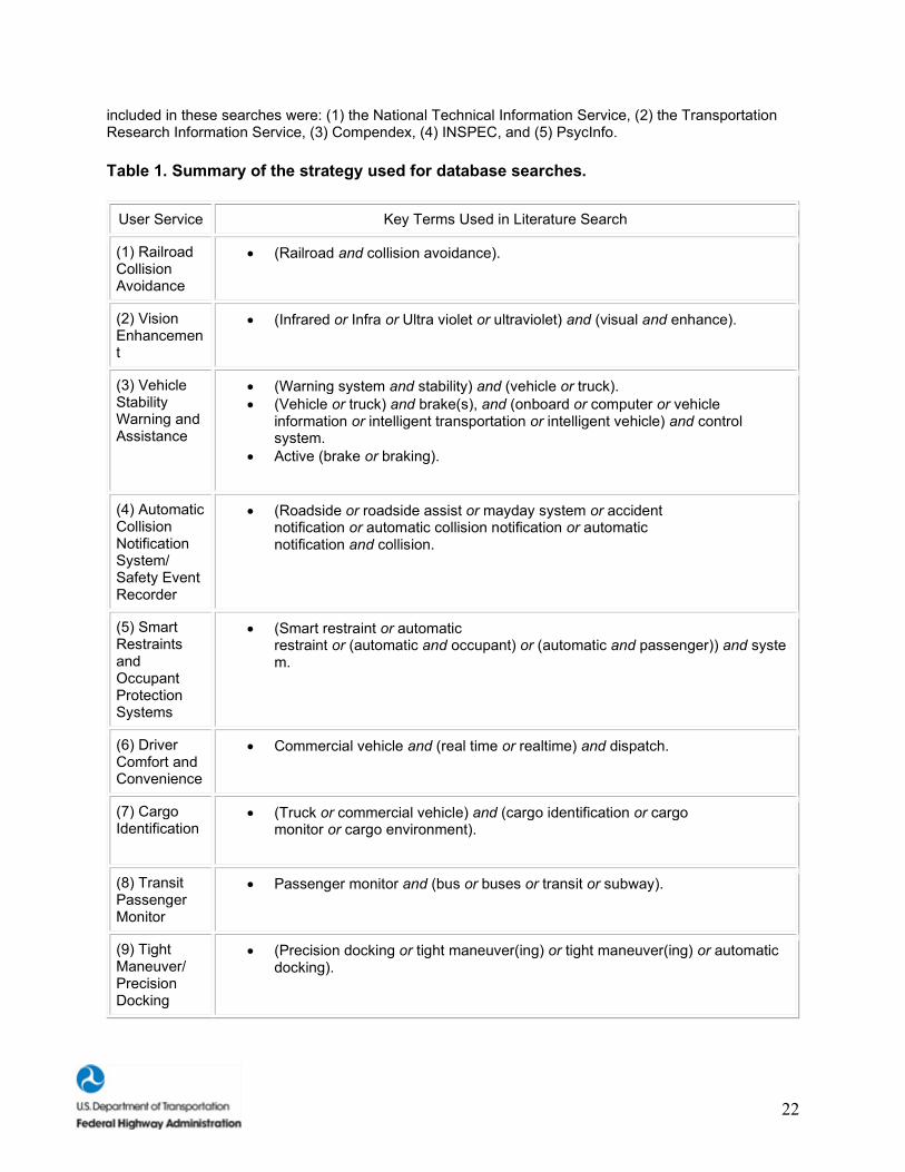
Literature searches were conducted on the User Services if: (1) Battelle did not possess a current and representative set of literature, (2) data sources were not found in FHWA and NHTSA publication lists, or (3) it was a very new technology that had not been addressed by the transportation research community. The literature searches were conducted using the User Service title and appropriate derivations as key terms (see table 1). The key terms listed in the table were all used separately first, and then combined (as shown in the table) to produce the most useful, yet representative, list of literature. The databases
22
included in these searches were: (1) the National Technical Information Service, (2) the Transportation Research Information Service, (3) Compendex, (4) INSPEC, and (5) PsycInfo.
Table 1. Summary of the strategy used for database searches.
User Service Key Terms Used in Literature Search
(1) Railroad Collision Avoidance
• (Railroad and collision avoidance).
(2) Vision Enhancement
• (Infrared or Infra or Ultra violet or ultraviolet) and (visual and enhance).
(3) Vehicle Stability Warning and Assistance
• (Warning system and stability) and (vehicle or truck). • (Vehicle or truck) and brake(s), and (onboard or computer or vehicle
information or intelligent transportation or intelligent vehicle) and control system.
• Active (brake or braking).
(4) Automatic Collision Notification System/ Safety Event Recorder
• (Roadside or roadside assist or mayday system or accident notification or automatic collision notification or automatic notification and collision.
(5) Smart Restraints and Occupant Protection Systems
• (Smart restraint or automatic restraint or (automatic and occupant) or (automatic and passenger)) and system.
(6) Driver Comfort and Convenience
• Commercial vehicle and (real time or realtime) and dispatch.
(7) Cargo Identification
• (Truck or commercial vehicle) and (cargo identification or cargo monitor or cargo environment).
(8) Transit Passenger Monitor
• Passenger monitor and (bus or buses or transit or subway).
(9) Tight Maneuver/ Precision Docking
• (Precision docking or tight maneuver(ing) or tight maneuver(ing) or automatic docking).
23
All of the literature was systematically reviewed by first quickly reviewing the data sources and sorting them into one of three categories: (1) relevant, (2) moderately relevant, and (3) not relevant. The articles deemed relevant were read thoroughly, while the moderately relevant articles were reviewed with the objective of identifying two or three key research issues that have been well–documented in the literature. The IVI workshop proceedings (ITS America, 1997) were evaluated as well as a way of verifying the key research issues identified in other data sources. Projects from NHTSA (i.e., the CAS specification programs) and FHWA (the human factors DVI work) were evaluated to determine whether the selected key research issues had been involved in completed or current projects. Finally, research findings and conclusions relevant to human factors issues were documented.
The literature and the proceedings from the IVI workshop were reviewed again to determine if several literature sources cited similar future research directions and/or needs. If more than one source cited a specific research issue, then that issue was determined to have a greater likelihood of being a useful research issue for the IVI than if the issue was mentioned in only one data source. Other evaluation criteria included the quality, applicability, and date of the data source, with data sources having higher quality, greater applicability, and more recent publication dates assigned more weight in the data source evaluation process. The NHTSA Report to Congress (1997) was also evaluated to determine if any of the designated future research needs were already planned future projects. These human factors research needs were then presented and discussed in the Human Factors Research Needs section of the User Services Summary. The original strategy in the Project Plan was to obtain the alternative IVI vehicle configurations and associated infrastructure requirements from the December 1997 workshop described above. However, this information did not materialize in the workshop. Workshop attendees tended to focus on defining a comprehensive list of potential technologies that could go into an IVI to accomplish the User Services, but time did not permit identifying specific technology mixes to define alternative IVI configurations. Also, due to limited time, very little attention was given to any infrastructure issues. Therefore, the strategy to accomplish the subtask 2 objectives was revised. It was essential to have alternative IVI subsystem configurations defined for the different vehicle platforms to identify the human factors research that needed to be done. But the IVI program has not matured to a point that the U.S. DOT or stakeholders have defined exactly what systems comprise a Generation I IVI for any of the four platforms. Therefore, the project team was forced to be proactive in defining alternative IVI scenarios that could be used for identifying the human factors research needs. All of the information obtained from the subtask 1 workshop was used as a basis for this research.
To allow analysis of more complex IVI alternatives, the functional subsystems identified for various User Services were combined into "Modules." For this research, seven modules were defined as follows:
1. Module A. Basic Collision Warning Technologies. 2. Module B. Advanced Collision Warning Technologies. 3. Module C. Basic Traveler Information Devices. 4. Module D. Driver Convenience Devices. 5. Module E. ITS Collision Warning Systems for Heavy Vehicles. 6. Module F. ITS Information Systems for Heavy Vehicles. 7. Module G. ITS Technologies for Transit.
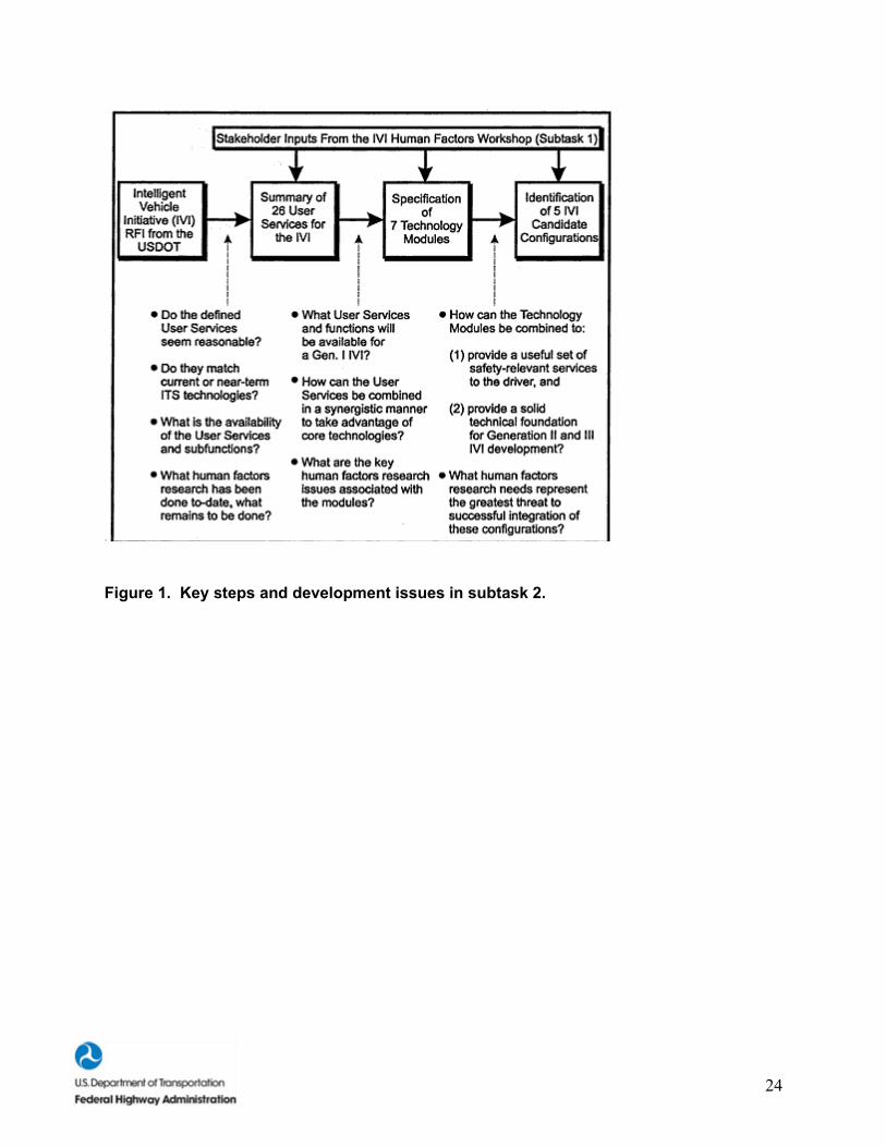
Each module was analyzed to determine high–priority human factors research that was needed to obtain a safe–operating IVI. Any human factors work that had already been completed and is applicable to the module being analyzed was identified. Needed human factors work that could not be found was identified as a potential research need to be considered in early human factors research for the IVI. Key steps and development issues associated with subtask 2 are summarized in figure 1.
24
Figure 1. Key steps and development issues in subtask 2.
25
RESULTS OVERVIEW
This section of the report includes a summary of each of the 26 IVI User Services, and also presents 7 Technology Modules for the IVI and 5 IVI Candidate Configurations. In keeping with the primary objective of this effort, human factors research needs are presented for each of the User Services, Technology Modules, and IVI Candidate Configurations.
Descriptions for the User Services have been taken directly from the IVI RFI published in the Federal Register in December 1997. We have defined the Technology Modules and the Candidate Configurations below as part of our efforts. In short, related User Services have been combined to form Technology Modules, which have, in turn, been combined to produce the Candidate IVI Configurations. Both the Technology Modules and the Candidate Configurations: (1) reflect core ITS technologies, (2) provide for a "growth path" or evolution of ITS technologies as the Generation II and Generation III IVI become technologically feasible, and (3) provide specific safety and convenience benefits to the driver.
The Technology Modules were developed as a "first step" towards developing an approach to the IVI. While we had initially considered simply combining selected User Services to form preliminary IVI Candidate Configurations, we decided that some intermediate step was required. The most useful basis for this intermediate step was deemed to be the technologies themselves. That is, we decided to identify core ITS technologies that could be used to form groups of functionally related or technology–dependent User Services.
The development of the Technology Modules and Candidate Configurations reflects our belief that the specification of precise and useful human factors research issues requires specific definitions of ITS technologies and implementations of IVI User Services. While very general human factors issues can be specified without such definitions, these tend to be somewhat vague and typically reflect "motherhood" concerns for human factors.
With respect to safety benefits, many of the IVI User Services have the potential to improve driver safety. The key distinction between collision avoidance devices and information systems is when and how such safety benefits are provided to the driver. While CAS provide immediate benefits by warning the driver of a potential crash or near–term safety hazard, information systems improve situational awareness and safety by helping the driver to avoid hazardous situations or conditions through information related to routing, navigation, traffic conditions, and vehicle state.
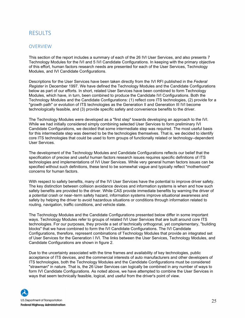
The Technology Modules and the Candidate Configurations presented below differ in some important ways. Technology Modules refer to groups of related IVI User Services that are built around core ITS technologies. For our purposes, they provide a set of technically orthogonal, yet complementary, "building blocks" that we have combined to form the IVI Candidate Configurations. The IVI Candidate Configurations, therefore, represent combinations of Technology Modules that provide an integrated set of User Services for the Generation I IVI. The links between the User Services, Technology Modules, and Candidate Configurations are shown in figure 2.
Due to the uncertainty associated with the time frames and availability of key technologies, public acceptance of ITS devices, and the commercial interests of auto manufacturers and other developers of ITS technologies, both the Technology Modules and the Candidate Configurations must be considered "strawman" in nature. That is, the 26 User Services can logically be combined in any number of ways to form IVI Candidate Configurations. As noted above, we have attempted to combine the User Services in ways that seem technically feasible, logical, and useful from the driver's point of view.
26
Figure 2. Sequence of subtask 2 activities and relationship between User Services, Technology Modules and Candidate Configurations.
Introduction to the IVI User Services, Technology Modules, and Candidate Configurations
Each of the 26 User Services, 7 Technology Modules, and 5 Candidate Configurations discussed below is presented in a specific format. These three presentation formats are described below.
27
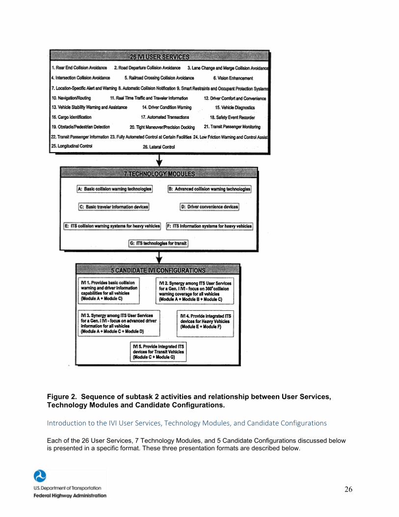
Figure 3. Schematic of IVI Candidate Configuration #1.
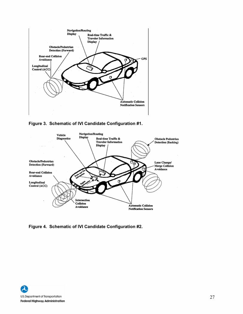
Figure 4. Schematic of IVI Candidate Configuration #2.
28
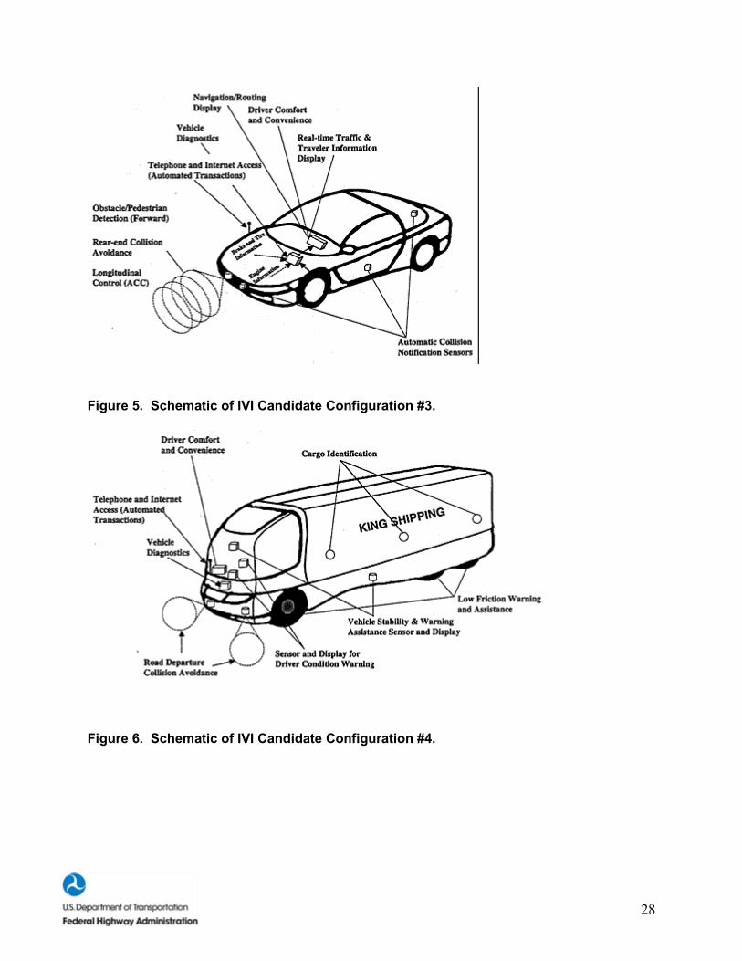
Figure 5. Schematic of IVI Candidate Configuration #3.
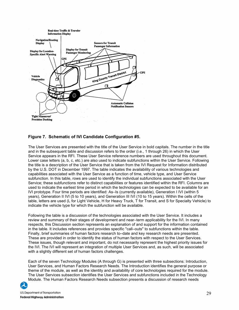
Figure 6. Schematic of IVI Candidate Configuration #4.
29
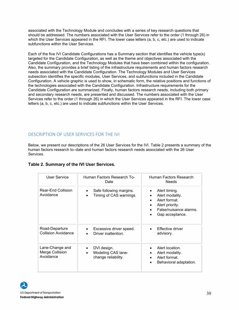
Figure 7. Schematic of IVI Candidate Configuration #5.
The User Services are presented with the title of the User Service in bold capitals. The number in the title and in the subsequent table and discussion refers to the order (i.e., 1 through 26) in which the User Service appears in the RFI. These User Service reference numbers are used throughout this document. Lower case letters (a, b, c, etc.) are also used to indicate subfunctions within the User Service. Following the title is a description of the User Service that is taken from the IVI Request for Information distributed by the U.S. DOT in December 1997. The table indicates the availability of various technologies and capabilities associated with the User Service as a function of time, vehicle type, and User Service subfunction. In this table, rows are used to identify the individual subfunctions associated with the User Service; these subfunctions refer to distinct capabilities or features identified within the RFI. Columns are used to indicate the earliest time period in which the technologies can be expected to be available for an IVI prototype. Four time periods are identified: As–Is (currently available), Generation I IVI (within 5 years), Generation II IVI (5 to 10 years), and Generation III IVI (10 to 15 years). Within the cells of the table, letters are used (L for Light Vehicle, H for Heavy Truck, T for Transit, and S for Specialty Vehicle) to indicate the vehicle type for which the subfunction will be available.
Following the table is a discussion of the technologies associated with the User Service. It includes a review and summary of their stages of development and near–term applicability for the IVI. In many respects, this Discussion section represents an explanation of and support for the information contained in the table. It includes references and provides specific "call–outs" to subfunctions within the table. Finally, brief summaries of human factors research to–date and key research needs are presented. These are provided in order to identify the status of human factors with respect to the User Services. These issues, though relevant and important, do not necessarily represent the highest priority issues for the IVI. The IVI will represent an integration of multiple User Services and, as such, will be associated with a slightly different set of human factors challenges.
Each of the seven Technology Modules (A through G) is presented with three subsections: Introduction, User Services, and Human Factors Research Needs. The Introduction identifies the general purpose or theme of the module, as well as the identity and availability of core technologies required for the module. The User Services subsection identifies the User Services and subfunctions included in the Technology Module. The Human Factors Research Needs subsection presents a discussion of research needs
30
associated with the Technology Module and concludes with a series of key research questions that should be addressed. The numbers associated with the User Services refer to the order (1 through 26) in which the User Services appeared in the RFI. The lower case letters (a, b, c, etc.) are used to indicate subfunctions within the User Services.
Each of the five IVI Candidate Configurations has a Summary section that identifies the vehicle type(s) targeted for the Candidate Configuration, as well as the theme and objectives associated with the Candidate Configuration, and the Technology Modules that have been combined within the configuration. Also, the summary provides a brief listing of the infrastructure requirements and human factors research needs associated with the Candidate Configuration. The Technology Modules and User Services subsection identifies the specific modules, User Services, and subfunctions included in the Candidate Configuration. A vehicle graphic is used to show, in schematic form, the relative positions and functions of the technologies associated with the Candidate Configuration. Infrastructure requirements for the Candidate Configuration are summarized. Finally, human factors research needs, including both primary and secondary research needs, are presented and discussed. The numbers associated with the User Services refer to the order (1 through 26) in which the User Services appeared in the RFI. The lower case letters (a, b, c, etc.) are used to indicate subfunctions within the User Services.
DESCRIPTION OF USER SERVICES FOR THE IVI
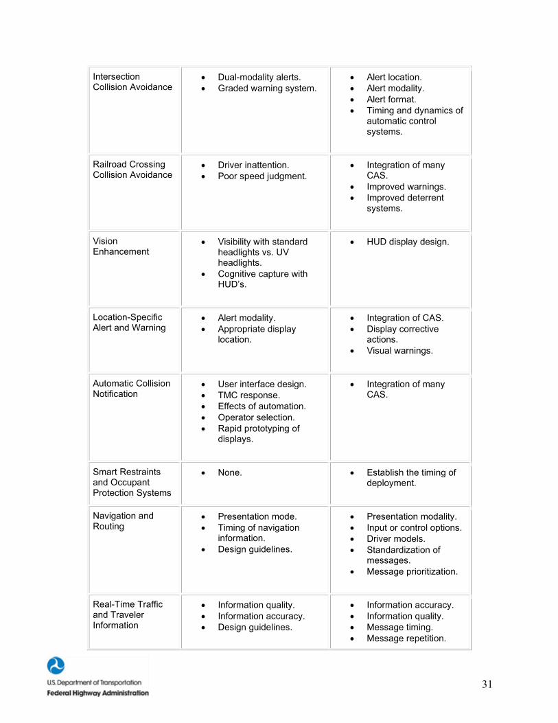
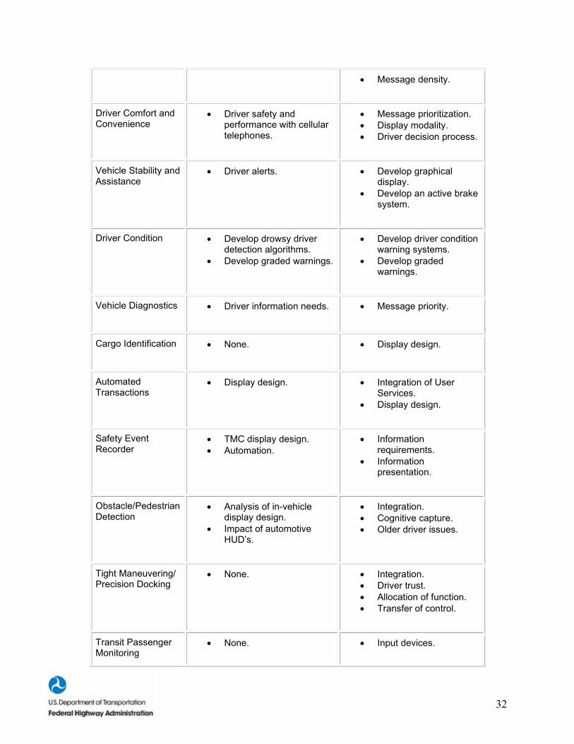
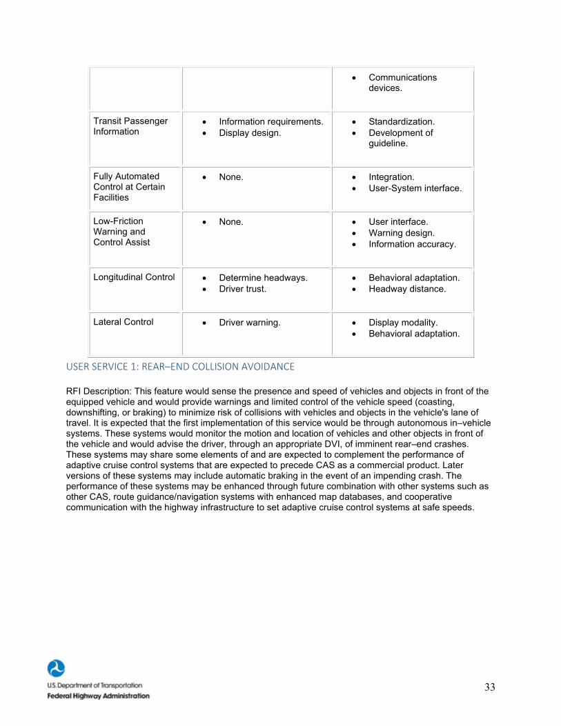
Below, we present our descriptions of the 26 User Services for the IVI. Table 2 presents a summary of the human factors research to–date and human factors research needs associated with the 26 User Services.
Table 2. Summary of the IVI User Services.
User Service Human Factors Research To-Date
Human Factors Research Needs
Rear-End Collision Avoidance
• Safe following margins. • Timing of CAS warnings.
• Alert timing. • Alert modality. • Alert format. • Alert priority. • False/nuisance alarms. • Gap acceptance.
Road-Departure Collision Avoidance
• Excessive driver speed. • Driver inattention.
• Effective driver advisory.
Lane-Change and Merge Collision Avoidance
• DVI design. • Modeling CAS lane-
change reliability.
• Alert location. • Alert modality. • Alert format. • Behavioral adaptation.
31
Intersection Collision Avoidance
• Dual-modality alerts. • Graded warning system.
• Alert location. • Alert modality. • Alert format. • Timing and dynamics of
automatic control systems.
Railroad Crossing Collision Avoidance
• Driver inattention. • Poor speed judgment.
• Integration of many CAS.
• Improved warnings. • Improved deterrent
systems.
Vision Enhancement
• Visibility with standard headlights vs. UV headlights.
• Cognitive capture with HUD’s.
• HUD display design.
Location-Specific Alert and Warning
• Alert modality. • Appropriate display
location.
• Integration of CAS. • Display corrective
actions. • Visual warnings.
Automatic Collision Notification
• User interface design. • TMC response. • Effects of automation. • Operator selection. • Rapid prototyping of
displays.
• Integration of many CAS.
Smart Restraints and Occupant Protection Systems
• None. • Establish the timing of deployment.
Navigation and Routing
• Presentation mode. • Timing of navigation
information. • Design guidelines.
• Presentation modality. • Input or control options. • Driver models. • Standardization of
messages. • Message prioritization.
Real-Time Traffic and Traveler Information
• Information quality. • Information accuracy. • Design guidelines.
• Information accuracy. • Information quality. • Message timing. • Message repetition.
32
• Message density.
Driver Comfort and Convenience
• Driver safety and performance with cellular telephones.
• Message prioritization. • Display modality. • Driver decision process.
Vehicle Stability and Assistance
• Driver alerts. • Develop graphical display.
• Develop an active brake system.
Driver Condition • Develop drowsy driver detection algorithms.
• Develop graded warnings.
• Develop driver condition warning systems.
• Develop graded warnings.
Vehicle Diagnostics • Driver information needs. • Message priority.
Cargo Identification • None. • Display design.
Automated Transactions
• Display design. • Integration of User Services.
• Display design.
Safety Event Recorder
• TMC display design. • Automation.
• Information requirements.
• Information presentation.
Obstacle/Pedestrian Detection
• Analysis of in-vehicle display design.
• Impact of automotive HUD’s.
• Integration. • Cognitive capture. • Older driver issues.
Tight Maneuvering/ Precision Docking
• None. • Integration. • Driver trust. • Allocation of function. • Transfer of control.
Transit Passenger Monitoring
• None. • Input devices.
33
• Communications devices.
Transit Passenger Information
• Information requirements. • Display design.
• Standardization. • Development of
guideline.
Fully Automated Control at Certain Facilities
• None. • Integration. • User-System interface.
Low-Friction Warning and Control Assist
• None. • User interface. • Warning design. • Information accuracy.
Longitudinal Control • Determine headways. • Driver trust.
• Behavioral adaptation. • Headway distance.
Lateral Control • Driver warning. • Display modality. • Behavioral adaptation.
USER SERVICE 1: REAR–END COLLISION AVOIDANCE
RFI Description: This feature would sense the presence and speed of vehicles and objects in front of the equipped vehicle and would provide warnings and limited control of the vehicle speed (coasting, downshifting, or braking) to minimize risk of collisions with vehicles and objects in the vehicle's lane of travel. It is expected that the first implementation of this service would be through autonomous in–vehicle systems. These systems would monitor the motion and location of vehicles and other objects in front of the vehicle and would advise the driver, through an appropriate DVI, of imminent rear–end crashes. These systems may share some elements of and are expected to complement the performance of adaptive cruise control systems that are expected to precede CAS as a commercial product. Later versions of these systems may include automatic braking in the event of an impending crash. The performance of these systems may be enhanced through future combination with other systems such as other CAS, route guidance/navigation systems with enhanced map databases, and cooperative communication with the highway infrastructure to set adaptive cruise control systems at safe speeds.
34
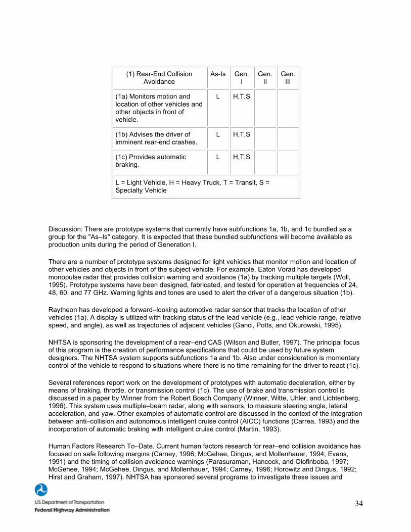
(1) Rear-End Collision Avoidance
As-Is Gen. I
Gen. II
Gen. III
(1a) Monitors motion and location of other vehicles and other objects in front of vehicle.
L H,T,S
(1b) Advises the driver of imminent rear-end crashes.
L H,T,S
(1c) Provides automatic braking.
L H,T,S
L = Light Vehicle, H = Heavy Truck, T = Transit, S = Specialty Vehicle
Discussion: There are prototype systems that currently have subfunctions 1a, 1b, and 1c bundled as a group for the "As–Is" category. It is expected that these bundled subfunctions will become available as production units during the period of Generation I.
There are a number of prototype systems designed for light vehicles that monitor motion and location of other vehicles and objects in front of the subject vehicle. For example, Eaton Vorad has developed monopulse radar that provides collision warning and avoidance (1a) by tracking multiple targets (Woll, 1995). Prototype systems have been designed, fabricated, and tested for operation at frequencies of 24, 48, 60, and 77 GHz. Warning lights and tones are used to alert the driver of a dangerous situation (1b).
Raytheon has developed a forward–looking automotive radar sensor that tracks the location of other vehicles (1a). A display is utilized with tracking status of the lead vehicle (e.g., lead vehicle range, relative speed, and angle), as well as trajectories of adjacent vehicles (Ganci, Potts, and Okurowski, 1995).
NHTSA is sponsoring the development of a rear–end CAS (Wilson and Butler, 1997). The principal focus of this program is the creation of performance specifications that could be used by future system designers. The NHTSA system supports subfunctions 1a and 1b. Also under consideration is momentary control of the vehicle to respond to situations where there is no time remaining for the driver to react (1c).
Several references report work on the development of prototypes with automatic deceleration, either by means of braking, throttle, or transmission control (1c). The use of brake and transmission control is discussed in a paper by Winner from the Robert Bosch Company (Winner, Witte, Uhler, and Lichtenberg, 1996). This system uses multiple–beam radar, along with sensors, to measure steering angle, lateral acceleration, and yaw. Other examples of automatic control are discussed in the context of the integration between anti–collision and autonomous intelligent cruise control (AICC) functions (Carrea, 1993) and the incorporation of automatic braking with intelligent cruise control (Martin, 1993).
Human Factors Research To–Date. Current human factors research for rear–end collision avoidance has focused on safe following margins (Carney, 1996; McGehee, Dingus, and Mollenhauer, 1994; Evans, 1991) and the timing of collision avoidance warnings (Parasuraman, Hancock, and Olofinboba, 1997; McGehee, 1994; McGehee, Dingus, and Mollenhauer, 1994; Carney, 1996; Horowitz and Dingus, 1992; Hirst and Graham, 1997). NHTSA has sponsored several programs to investigate these issues and
35
develop design guidelines. One NHTSA study is currently investigating driver acceptance, performance, and behavior in situations where the headway (following margin) is fixed. Safe following margins are an important feature of rear–end CAS because drivers generally follow too closely behind lead vehicles (Evans, 1991). Research investigating rear–end CAS suggests that presenting a graded warning to drivers results in drivers slowing down and backing away from the lead vehicle (Carney, 1996; McGehee, Dingus, and Horowitz, 1994). Effective timing of collision avoidance warnings depends on human factors design to accomplish two goals: (1) the system must alert the driver quickly, but not startle him, while it is orienting the driver's attention toward the location of the hazard; and (2) while the system must identify every potential collision, it must not produce alarms that the driver considers "false alarms" (Landau, 1996). Recent rear–end CAS displays research conducted by NHTSA suggests that subjects first prefer a head–up display (HUD) combined with tactile displays, and, secondly, a HUD combined with an auditory tone in both simulator and on–road studies. Tactile displays were preferred to auditory displays because they were judged to be less annoying even though the tactile displays were also less effective in getting the subject's attention. International and national standards are being developed by the ISO TC/204 WG14 (Forward Vehicle Collision Warning System: Performance Requirements and Test Procedure [NP144]) and by the Society of Automotive Engineers (SAE) (Human Factors in Front Collision Warning Systems: Operating Characteristics and User Interface [SAE J2400]) for rear–end CAS.
Human Factors Research Needs. The results of the recent IVI Human Factors Workshop (ITS America, 1997) suggest that future efforts in collision avoidance will focus on such issues as the timing, modality, format, and priority of CAS alerts and warnings. Additional issues may include the impact of false/nuisance alarms on system use and driver acceptance of CAS devices. For rear–end CAS devices in particular, gap acceptance will continue to be a key issue as designers establish "trigger" criteria for the presentation of alerts and warnings.
USER SERVICE 2: ROAD–DEPARTURE COLLISION AVOIDANCE
RFI Description: This feature would provide warning and control assistance to the driver through lane or road–edge tracking and by determining the safe speed for road geometry in front of the vehicle. It is expected that the first implementation of this service would be through autonomous in–vehicle systems. These systems would monitor the lane position, motion relative to the road edge, and vehicle speed relative to road geometry and road conditions, and would advise the driver, through an appropriate DVI, of an imminent unintentional road departure. Later versions of these systems may include cooperative communication with the highway infrastructure to automatically provide safe speeds for upcoming road geometries and conditions. The performance of these systems may be enhanced through future combination with other systems, such as other CAS, drowsy driver advisory systems, and route guidance/navigation systems with enhanced map databases.
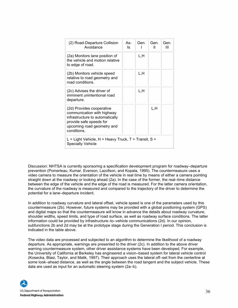
36
(2) Road-Departure Collision Avoidance
As-Is
Gen. I
Gen. II
Gen. III
(2a) Monitors lane position of the vehicle and motion relative to edge of road.
L,H
(2b) Monitors vehicle speed relative to road geometry and road conditions.
L,H
(2c) Advises the driver of imminent unintentional road departure.
L,H
(2d) Provides cooperative communication with highway infrastructure to automatically provide safe speeds for upcoming road geometry and conditions.
L,H
L = Light Vehicle, H = Heavy Truck, T = Transit, S = Specialty Vehicle
Discussion: NHTSA is currently sponsoring a specification development program for roadway–departure prevention (Pomerleau, Kumar, Everson, Lazofson, and Kopala, 1995). The countermeasure uses a video camera to measure the orientation of the vehicle in real time by means of either a camera pointing straight down at the roadway or looking ahead (2a). In the case of the former, the real–time distance between the edge of the vehicle and the edge of the road is measured. For the latter camera orientation, the curvature of the roadway is measured and compared to the trajectory of the driver to determine the potential for a lane–departure incident.
In addition to roadway curvature and lateral offset, vehicle speed is one of the parameters used by this countermeasure (2b). However, future systems may be provided with a global positioning system (GPS) and digital maps so that the countermeasure will know in advance the details about roadway curvature, shoulder widths, speed limits, and type of road surface, as well as roadway surface conditions. The latter information could be provided by infrastructure–to–vehicle communications (2d). In our opinion, subfunctions 2b and 2d may be at the prototype stage during the Generation I period. This conclusion is indicated in the table above.
The video data are processed and subjected to an algorithm to determine the likelihood of a roadway departure. As appropriate, warnings are presented to the driver (2c). In addition to the above driver warning countermeasure system, other driver assistance systems have been developed. For example, the University of California at Berkeley has engineered a vision–based system for lateral vehicle control (Kosecka, Blasi, Taylor, and Malik, 1997). Their approach uses the lateral off–set from the centerline at some look–ahead distance, as well as the angle between the road tangent and the subject vehicle. These data are used as input for an automatic steering system (2a–b).
37
In between the extremes of pure warning to automatic control, there are prototypes that provide constant low–level steering input, as well as steering input only when needed to avoid a lane–departure incident. An example of the former is the OSCAR countermeasure (2a–b) developed by Daimler–Benz that provides steering input to overcome driver errors, such as inattention or drowsiness (Franke, Mehring, Suissa, and Hahn, 1994). The latter is illustrated by a countermeasure developed at the University of Minnesota (Shankwitz, Donath, Morellas, and Johnson, 1995) that uses GPS and digital maps to prevent lane departures, especially by fatigued truck drivers. This system learns a particular route by having previously recorded vehicle position along the route by means of GPS and digital maps. The position of the truck during subsequent trips along the same route is compared against previous position measurements. For this reason, this system is considered to be infrastructure–based and is so noted in the above table (2d).
Human Factors Research To–Date. Two important issues involved in current road–departure collision avoidance research are excessive driver speed (Dingus, Jahns, Horowitz, and Knipling, 1998; Mironer and Hendricks, 1994; Evans, 1991) and driver inattention (Schlegel, 1993; Mironer and Hendricks, 1994; McGehee, Dingus, and Mollenhauer, 1994; Senders, Kristofferson, Levison, and Dietrich, 1967). Landau (1996) suggests that a first–stage cautionary cue in a CAS would not disturb the driver and would allow the driver to avoid many emergency situations. Given that a large number of rear–end accidents are caused by driver inattention, a correctly designed gentle cue at the cautionary stage could be as, or more, effective in providing information for the driver to act on. This cautionary cue could also be used to warn drivers of excessive speeds around curves. The ISO TC/204 is developing an international standard (Lane Departure Warning Systems [N123]) for this system.
Human Factors Research Needs. A key research issue will be determining the most effective means of advising the driver of an imminent, unintentional road departure. Although both audio and haptic methods have been investigated (Pomerleau, Thorpe, and Emery, 1997), this issue has not been resolved. Future NHTSA–sponsored research projects will also investigate the use of longitudinal and lateral motion sensors integrated with road geometry databases to alert drivers if their speed is excessive when approaching a curve (NHTSA, 1997).
USER SERVICE 3: LANE–CHANGE AND MERGE COLLISION AVOIDANCE
RFI Description: It is expected that the first implementation of this service would be through in–vehicle systems that may be augmented with vehicle–to–vehicle communications. These systems would monitor the lane position, relative speed, and position of vehicles, including motorcycles, beside and to the rear of the vehicle, and would advise the driver during the decision phase of a lane–change maneuver, through an appropriate DVI, of the potential for a collision. Later versions of these systems may provide additional advice about an imminent crash to the driver during the action phase of the lane–change or entry/exit maneuver. The performance of these systems may be enhanced through future combination with other systems, such as other CAS and roadside communications and sensing systems.
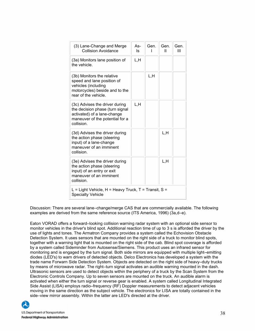
38
(3) Lane-Change and Merge Collision Avoidance
As-Is
Gen. I
Gen. II
Gen. III
(3a) Monitors lane position of the vehicle.
L,H
(3b) Monitors the relative speed and lane position of vehicles (including motorcycles) beside and to the rear of the vehicle.
L,H
(3c) Advises the driver during the decision phase (turn signal activated) of a lane-change maneuver of the potential for a collision.
L,H
(3d) Advises the driver during the action phase (steering input) of a lane-change maneuver of an imminent collision.
L,H
(3e) Advises the driver during the action phase (steering input) of an entry or exit maneuver of an imminent collision.
L,H
L = Light Vehicle, H = Heavy Truck, T = Transit, S = Specialty Vehicle
Discussion: There are several lane–change/merge CAS that are commercially available. The following examples are derived from the same reference source (ITS America, 1996) (3a,d–e).
Eaton VORAD offers a forward–looking collision warning radar system with an optional side sensor to monitor vehicles in the driver's blind spot. Additional reaction time of up to 3 s is afforded the driver by the use of lights and tones. The Armatron Company provides a system called the Echovision Obstacle Detection System. It uses sensors that are mounted on the right side of a truck to monitor blind spots, together with a warning light that is mounted on the right side of the cab. Blind spot coverage is afforded by a system called Sideminder from Autosense/Siemens. This product uses an infrared sensor for monitoring and is engaged by the turn signal. Both side mirrors are equipped with multiple light–emitting diodes (LED's) to warn drivers of detected objects. Delco Electronics has developed a system with the trade name Forwarn Side Detection System. Objects are detected on the right side of heavy–duty trucks by means of microwave radar. The right–turn signal activates an audible warning mounted in the dash. Ultrasonic sensors are used to detect objects within the periphery of a truck by the Scan System from the Electronic Controls Company. Up to seven sensors are mounted on the truck. An audible alarm is activated when either the turn signal or reverse gear is enabled. A system called Longitudinal Integrated Side Assist (LISA) employs radio–frequency (RF) Doppler measurements to detect adjacent vehicles moving in the same direction as the subject vehicle. The electronics for LISA are totally contained in the side–view mirror assembly. Within the latter are LED's directed at the driver.
39
NHTSA is sponsoring a specification development program for lane–change, merge, and backing crashes (Young, 1995). Since the inception of this program, several sensor types have been tested, including acoustic, radar, and electro–optical. A number of tests were conducted in a laboratory; on a test track; and on city streets, arterial roadways, and interstate highways. DVI's were tested, ranging from sophisticated, commercially available types to more simplistic units (3a,d–e).
Human Factors Research To–Date. A significant portion of the current human factors research on lane–change/merge CAS (also referred to as Side–Object Detection Systems [SODS]) investigates design of the driver–vehicle interface (Campbell, Hooey, Carney, Hanowski, Gore, Kantowitz, and Mitchell, 1996; Mazzae, Garrott, and Flick, 1995; Hyland, 1995). The NHTSA–sponsored studies investigating display design of SODS found that drivers preferred displays that were simple, obtained their attention, and provided directional information in terms of a potential collision (Campbell et al., 1996). Mazzae and Garrott (1995) and Mazzae et al. (1995) examined the utility of using SODS and evaluated several SODS prototypes using an established human factors design checklist. These two studies found that SODS will potentially aid drivers in monitoring the right–hand lane as long as key human factors design principles are followed (Mazzae and Garrott; Mazzae et al.). The authors suggested design guidelines as well as an improved human factors checklist. Another NHTSA study examined drivers' preferences for lane–change CAS display modalities. Subjects preferred icons presented in the side–view mirrors (indicating direction of threat) combined with an auditory alert. Other key human factors research involved modeling lane–change CAS reliability to estimate the level of accuracy necessary to improve driver performance (Tijerina, 1997). The model developed suggests that CAS reliability must be high (99 percent) as well as designed so as to promote parallel or redundant use along with safe driving practices.
Human Factors Research Needs. Additional research is needed to determine the optimal location, modality, and format for driver alerts. Other issues include long–term driver behavior and performance associated with these devices. For example, will long–term use of lane–change and merge collision avoidance devices lead to drivers neglecting to use their turn signals? Will drivers neglect mirror glances?
USER SERVICE 4: INTERSECTION COLLISION AVOIDANCE
RFI Description: It is expected that the first implementation of this service would be through in–vehicle systems that are augmented by information from enhanced map databases or from cooperative communication with the highway infrastructure. These systems would monitor position relative to intersection geometry, relative speed, and position of other vehicles in the vicinity of the intersection and would advise the driver, through an appropriate DVI, of appropriate action to avoid a violation of right–of–way or to avoid an impending collision. Complexities of providing this service include the need to sense the position and motion of vehicles and to determine the intent of these vehicles to turn, slow down, stop, or violate right–of–way. A fully autonomous in–vehicle system would probably not be capable of providing this service.
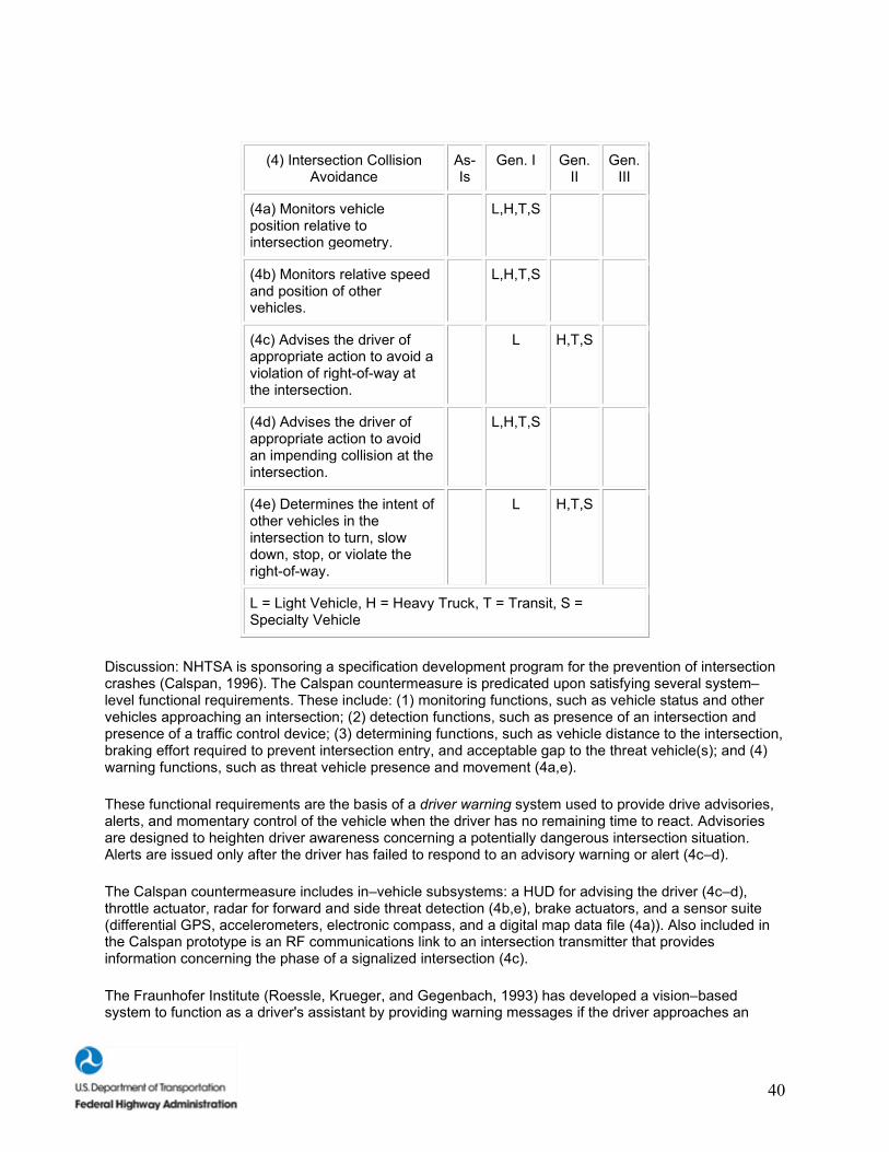
40
(4) Intersection Collision Avoidance
As-Is
Gen. I Gen. II
Gen. III
(4a) Monitors vehicle position relative to intersection geometry.
L,H,T,S
(4b) Monitors relative speed and position of other vehicles.
L,H,T,S
(4c) Advises the driver of appropriate action to avoid a violation of right-of-way at the intersection.
L H,T,S
(4d) Advises the driver of appropriate action to avoid an impending collision at the intersection.
L,H,T,S
(4e) Determines the intent of other vehicles in the intersection to turn, slow down, stop, or violate the right-of-way.
L H,T,S
L = Light Vehicle, H = Heavy Truck, T = Transit, S = Specialty Vehicle
Discussion: NHTSA is sponsoring a specification development program for the prevention of intersection crashes (Calspan, 1996). The Calspan countermeasure is predicated upon satisfying several system–level functional requirements. These include: (1) monitoring functions, such as vehicle status and other vehicles approaching an intersection; (2) detection functions, such as presence of an intersection and presence of a traffic control device; (3) determining functions, such as vehicle distance to the intersection, braking effort required to prevent intersection entry, and acceptable gap to the threat vehicle(s); and (4) warning functions, such as threat vehicle presence and movement (4a,e).
These functional requirements are the basis of a driver warning system used to provide drive advisories, alerts, and momentary control of the vehicle when the driver has no remaining time to react. Advisories are designed to heighten driver awareness concerning a potentially dangerous intersection situation. Alerts are issued only after the driver has failed to respond to an advisory warning or alert (4c–d).
The Calspan countermeasure includes in–vehicle subsystems: a HUD for advising the driver (4c–d), throttle actuator, radar for forward and side threat detection (4b,e), brake actuators, and a sensor suite (differential GPS, accelerometers, electronic compass, and a digital map data file (4a)). Also included in the Calspan prototype is an RF communications link to an intersection transmitter that provides information concerning the phase of a signalized intersection (4c).
The Fraunhofer Institute (Roessle, Krueger, and Gegenbach, 1993) has developed a vision–based system to function as a driver's assistant by providing warning messages if the driver approaches an
41
intersection too quickly (4a,c). There is no provision for the detection of threat vehicles within the vicinity of the intersection.
For the intersection crash application, there are few prototypes that address all facets of the problem: geometrical (e.g., location of the intersection), traffic control device, and presence of threat vehicles within the intersection.
Human Factors Research To–Date. Most intersection collisions occur because drivers are inattentive or misjudge the speed of an oncoming vehicle (Tijerina, 1996). Human factors research on collision avoidance alerting systems suggests that dual–modality alerts (specifically, a visual HUD with a tactile warning present in the steering wheel or braking system) may provide the best source of collision avoidance information (Lloyd, Bittner, and Pierowicz, 1996). Tactile displays are important because: (1) they are omni–directional and intrusive without being startling, (2) drivers are sensitive and respond quickly to tactile information, and (3) the information can be presented with the same device that the driver will use to correct the situation (i.e., the steering wheel and/or brake) (Lloyd et al.). Visual HUD displays are important because: (1) they provide the driver with detailed information about the environment, (2) visual information will facilitate integration with other CAS User Services, and (3) older drivers will benefit from a display in the forward field–of–view (FOV) (Lloyd et al.). Drivers' misperceptions of oncoming vehicle speed may be solved by using a graded system of warnings: first, the use of auditory and visual warnings to alert the inattentive driver to a potentially dangerous situation; second, a partially automated control system involving soft braking or resistance in the steering wheel if the driver has not responded to the first warning; and third, a fully automated control system involving hard braking with steering control. This last step (full automation) would only be activated in the event of an imminent collision (Chovan, Tijerina, Everson, Pierowicz, and Hendricks, 1994).
Human Factors Research Needs. The modality, location, and format of intersection collision avoidance alerts continue to be key research needs (ITS America News, 1998). For example, the warning must be able to get the driver's attention immediately, in a manner that facilitates the driver's ability to associate the warning with the nature of the situation and the appropriate response. In addition, the timing and dynamics of automatic control countermeasures should be investigated with respect to both driver performance and user acceptance.
USER SERVICE 5: RAILROAD CROSSING COLLISION AVOIDANCE
RFI Description: This feature would provide in–vehicle warnings to drivers when they approach a railroad crossing that is unsafe to enter due to approaching or present rail traffic. Initial implementation of this feature is anticipated for buses and trucks carrying hazardous cargo. This service, which would share many onboard vehicle components with intersection CAS, is dependent on communications and the deployment of infrastructure components.
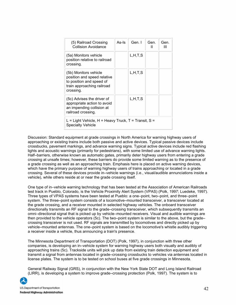
42
(5) Railroad Crossing Collision Avoidance
As-Is Gen. I Gen. II
Gen. III
(5a) Monitors vehicle position relative to railroad crossing.
L,H,T,S
(5b) Monitors vehicle position and speed relative to position and speed of train approaching railroad crossing.
L,H,T,S
(5c) Advises the driver of appropriate action to avoid an impending collision at railroad crossing.
L,H,T,S
L = Light Vehicle, H = Heavy Truck, T = Transit, S = Specialty Vehicle
Discussion: Standard equipment at grade crossings in North America for warning highway users of approaching or existing trains include both passive and active devices. Typical passive devices include crossbucks, pavement markings, and advance warning signs. Typical active devices include red flashing lights and acoustic warnings (primarily for pedestrians), with some limited use of advance warning lights. Half–barriers, otherwise known as automatic gates, primarily deter highway users from entering a grade crossing at unsafe times; however, these barriers do provide some limited warning as to the presence of a grade crossing as well as an approaching train. Emphasis here is placed on active warning devices, which have the primary purpose of warning highway users of trains approaching or located in a grade crossing. Several of these devices provide in–vehicle warnings (i.e., visual/audible annunciations inside a vehicle), while others reside at or near the grade crossing itself.
One type of in–vehicle warning technology that has been tested at the Association of American Railroads test track in Pueblo, Colorado, is the Vehicle Proximity Alert System (VPAS) (Polk, 1997; Luedeke, 1997). Three types of VPAS systems have been tested at Pueblo: a one–point, two–point, and three–point system. The three–point system consists of a locomotive–mounted transceiver, a transceiver located at the grade crossing, and a receiver mounted in selected highway vehicles. The onboard transceiver directionally transmits an RF signal to the grade–crossing transceiver, which subsequently transmits an omni–directional signal that is picked up by vehicle–mounted receivers. Visual and audible warnings are then provided to the vehicle operators (5c). The two–point system is similar to the above, but the grade–crossing transceiver is not used. RF signals are transmitted by locomotives and directly picked up by vehicle–mounted antennas. The one–point system is based on the locomotive's whistle audibly triggering a receiver inside a vehicle, thus announcing a train's presence.
The Minnesota Department of Transportation (DOT) (Polk, 1997), in conjunction with three other companies, is developing an in–vehicle system for warning highway users both visually and audibly of approaching trains (5c). Trackside units will pick up data from existing train detection equipment and transmit a signal from antennas located in grade–crossing crossbucks to vehicles via antennas located in license plates. The system is to be tested on school buses at five grade crossings in Minnesota.
General Railway Signal (GRS), in conjunction with the New York State DOT and Long Island Railroad (LIRR), is developing a system to improve grade–crossing protection (Polk, 1997). The system is to
43
include the use of variable message signs that will provide increased information to highway users about approaching trains (e.g., in the case of multiple tracks, identifying the track on which a train is approaching). Oregon State University is also examining the use of variable message signs on the Oregon High–Speed Rail Corridor (5c).
Human Factors Research To–Date. Human factors issues involved in railroad intersection collision avoidance include driver inattention and poor speed judgment. The Federal Railroad Administration (FRA) supported a comprehensive evaluation of collisions and collision avoidance technologies for use on high–speed guided ground transportation systems (HSGGTS) (Harrison, 1993). Driver inattention and poor speed judgment is exacerbated in cases where trains are traveling in excess of 201 km/h (125 mi/h). Harrison evaluated warnings, timing of warnings, effective barriers, and infrastructure requirements for railroad grade crossings and developed design guidelines. General human factors research has shown that drivers misjudge the speed of large objects (i.e., locomotives), judging them to be going slower than their actual speed (DeLucia and Warren, 1994), which is a direct cause of many vehicle/train collisions. Other human factors research has shown that: (1) the use of tactile warnings and visual HUD's can effectively direct a driver's attention to potentially dangerous situations and (2) autonomous control of braking can be used to slow the vehicle when the driver fails to do so (Lloyd, Bittner, and Pierowicz, 1996; Chovan, Tijerina, Everson, Pierowicz, and Hendricks, 1994).
Human Factors Research Needs. Future research needs include the integration of a railroad crossing CAS with other collision avoidance and autonomous control IVI User Services. Drivers not only need to be warned of potentially dangerous situations, they also require: (1) possible collision avoidance alternatives and (2) autonomous vehicular control in situations where the driver is too slow to respond or is not cognizant of the dangerous situation. Research investigating driver mental models would provide much needed guidance in the development of design guidelines and industry standards (ITS America, 1997). More human factors research is also required to design improved warnings and deterrent systems at railroad grade crossings where elevated structures (e.g., overpasses) are not feasible. The Federal Railroad Administration (FRA) plans to support research to develop new warning systems for unsignalized railroad grade crossings (NHTSA, 1997).
USER SERVICE 6: VISION ENHANCEMENT
RFI Description: It is expected that the first implementation of this service would be through autonomous in–vehicle systems. These systems would use infrared radiation from pedestrians and roadside features to provide the driver with an enhanced view of the road ahead. Later versions of these systems may include additional information from improvements in the highway infrastructure, such as infrared reflective lane–edge markings.
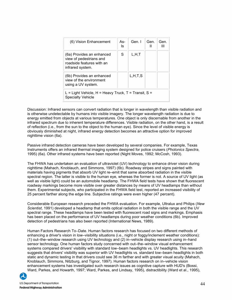
44
(6) Vision Enhancement As-Is
Gen. I Gen. II
Gen. III
(6a) Provides an enhanced view of pedestrians and roadside features with an infrared system.
S L,H,T
(6b) Provides an enhanced view of the environment using a UV system.
L,H,T,S
L = Light Vehicle, H = Heavy Truck, T = Transit, S = Specialty Vehicle
Discussion: Infrared sensors can convert radiation that is longer in wavelength than visible radiation and is otherwise undetectable by humans into visible imagery. The longer wavelength radiation is due to energy emitted from objects at various temperatures. One object is only discernable from another in the infrared spectrum due to inherent temperature differences. Visible radiation, on the other hand, is a result of reflection (i.e., from the sun to the object to the human eye). Since the level of visible energy is obviously diminished at night, infrared energy detection becomes an attractive option for improved nighttime vision (6a).
Passive infrared detection cameras have been developed by several companies. For example, Texas Instruments offers an infrared thermal imaging system designed for police cruisers (Photonics Spectra, 1995) (6a). Other infrared systems have been reported (Night Moves, 1992; McCosh, 1993).
The FHWA has undertaken an evaluation of ultraviolet (UV) technology to enhance driver vision during nighttime (Mahach, Knoblauch, and Simmons, 1997) (6b). Roadway stripes and signs painted with materials having pigments that absorb UV light re–emit that same absorbed radiation in the visible spectral region. The latter is visible to the human eye, whereas the former is not. A source of UV light (as well as visible light) could be an automobile headlamp. The FHWA field tests have shown that fluorescent roadway markings become more visible over greater distances by means of UV headlamps than without them. Experimental subjects, who participated in the FHWA field test, reported an increased visibility of 25 percent farther along the edge line. Subjective ratings were even higher (47 percent).
Considerable European research preceded the FHWA evaluation. For example, Ultralux and Philips (New Scientist, 1991) developed a headlamp that emits optical radiation in both the visible range and the UV spectral range. These headlamps have been tested with fluorescent road signs and markings. Emphasis has been placed on the performance of UV headlamps during poor weather conditions (6b). Improved detection of pedestrians has also been reported (International News, 1989).
Human Factors Research To–Date. Human factors research has focused on two different methods of enhancing a driver's vision in low–visibility situations (i.e., night or foggy/inclement weather conditions): (1) out–the–window research using UV technology and (2) in–vehicle display research using in–hand sensor technology. One human factors study concerned with out–the–window visual enhancement systems compared drivers' visibility with standard low–beam headlights vs. UV headlights. This research suggests that drivers' visibility was superior with UV headlights vs. standard low–beam headlights in both static and dynamic testing in that drivers could see 36 m farther and with greater visual acuity (Mahach, Knoblauch, Simmons, Nitzburg, and Tignor, 1997). Human factors research on in–vehicle vision enhancement systems has investigated such research issues as cognitive capture with HUD's (Bossi, Ward, Parkes, and Howarth, 1997; Ward, Parkes, and Lindsay, 1995), distractibility (Ward et al., 1995),
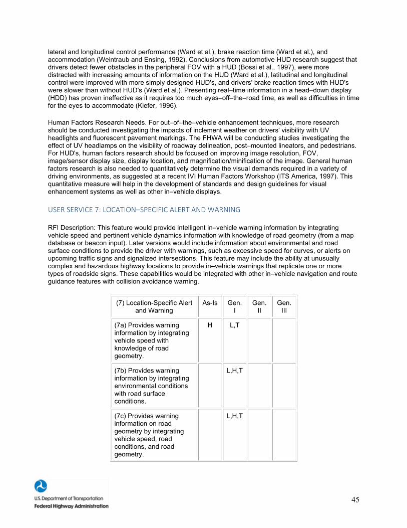
45
lateral and longitudinal control performance (Ward et al.), brake reaction time (Ward et al.), and accommodation (Weintraub and Ensing, 1992). Conclusions from automotive HUD research suggest that drivers detect fewer obstacles in the peripheral FOV with a HUD (Bossi et al., 1997), were more distracted with increasing amounts of information on the HUD (Ward et al.), latitudinal and longitudinal control were improved with more simply designed HUD's, and drivers' brake reaction times with HUD's were slower than without HUD's (Ward et al.). Presenting real–time information in a head–down display (HDD) has proven ineffective as it requires too much eyes–off–the–road time, as well as difficulties in time for the eyes to accommodate (Kiefer, 1996).
Human Factors Research Needs. For out–of–the–vehicle enhancement techniques, more research should be conducted investigating the impacts of inclement weather on drivers' visibility with UV headlights and fluorescent pavement markings. The FHWA will be conducting studies investigating the effect of UV headlamps on the visibility of roadway delineation, post–mounted lineators, and pedestrians. For HUD's, human factors research should be focused on improving image resolution, FOV, image/sensor display size, display location, and magnification/minification of the image. General human factors research is also needed to quantitatively determine the visual demands required in a variety of driving environments, as suggested at a recent IVI Human Factors Workshop (ITS America, 1997). This quantitative measure will help in the development of standards and design guidelines for visual enhancement systems as well as other in–vehicle displays.
USER SERVICE 7: LOCATION–SPECIFIC ALERT AND WARNING
RFI Description: This feature would provide intelligent in–vehicle warning information by integrating vehicle speed and pertinent vehicle dynamics information with knowledge of road geometry (from a map database or beacon input). Later versions would include information about environmental and road surface conditions to provide the driver with warnings, such as excessive speed for curves, or alerts on upcoming traffic signs and signalized intersections. This feature may include the ability at unusually complex and hazardous highway locations to provide in–vehicle warnings that replicate one or more types of roadside signs. These capabilities would be integrated with other in–vehicle navigation and route guidance features with collision avoidance warning.
(7) Location-Specific Alert and Warning
As-Is Gen. I
Gen. II
Gen. III
(7a) Provides warning information by integrating vehicle speed with knowledge of road geometry.
H L,T
(7b) Provides warning information by integrating environmental conditions with road surface conditions.
L,H,T
(7c) Provides warning information on road geometry by integrating vehicle speed, road conditions, and road geometry.
L,H,T
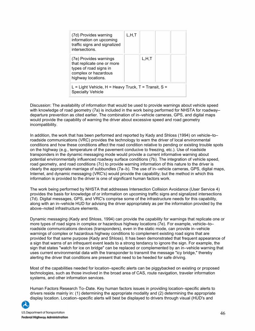
46
(7d) Provides warning information on upcoming traffic signs and signalized intersections.
L,H,T
(7e) Provides warnings that replicate one or more types of road signs in complex or hazardous highway locations.
L,H,T
L = Light Vehicle, H = Heavy Truck, T = Transit, S = Specialty Vehicle
Discussion: The availability of information that would be used to provide warnings about vehicle speed with knowledge of road geometry (7a) is included in the work being performed for NHSTA for roadway–departure prevention as cited earlier. The combination of in–vehicle cameras, GPS, and digital maps would provide the capability of warning the driver about excessive speed and road geometry incompatibility.
In addition, the work that has been performed and reported by Kady and Shloss (1994) on vehicle–to–roadside communications (VRC) provides the technology to warn the driver of local environmental conditions and how these conditions affect the road condition relative to pending or existing trouble spots on the highway (e.g., temperature of the pavement conducive to freezing, etc.). Use of roadside transponders in the dynamic messaging mode would provide a current informative warning about potential environmentally influenced roadway surface conditions (7b). The integration of vehicle speed, road geometry, and road conditions (7c) to provide warning information of this nature to the driver is clearly the appropriate marriage of subbundles (7a–b). The use of in–vehicle cameras, GPS, digital maps, Internet, and dynamic messaging (VRC's) would provide the capability; but the method in which this information is provided to the driver is one of significant human factors work.
The work being performed by NHSTA that addresses Intersection Collision Avoidance (User Service 4) provides the basis for knowledge of or information on upcoming traffic signs and signalized intersections (7d). Digital messages, GPS, and VRC's comprise some of the infrastructure needs for this capability, along with an in–vehicle HUD for advising the driver appropriately as per the information provided by the above–noted infrastructure elements.
Dynamic messaging (Kady and Shloss, 1994) can provide the capability for warnings that replicate one or more types of road signs in complex or hazardous highway locations (7e). For example, vehicle–to–roadside communications devices (transponders), even in the static mode, can provide in–vehicle warnings of complex or hazardous highway conditions to complement existing road signs that are provided for that same purpose (Kady and Shloss). It has been demonstrated that frequent appearance of a sign that warns of an infrequent event leads to a strong tendancy to ignore the sign. For example, the sign that states "watch for ice on bridge" can be replaced or complemented by an in–vehicle warning that uses current environmental data with the transponder to transmit the message "icy bridge," thereby alerting the driver that conditions are present that need to be heeded for safe driving.
Most of the capabilities needed for location–specific alerts can be piggybacked on existing or proposed technologies, such as those involved in the broad area of CAS, route navigation, traveler information systems, and other information services.
Human Factors Research To–Date. Key human factors issues in providing location–specific alerts to drivers reside mainly in: (1) determining the appropriate modality and (2) determining the appropriate display location. Location–specific alerts will best be displayed to drivers through visual (HUD's and
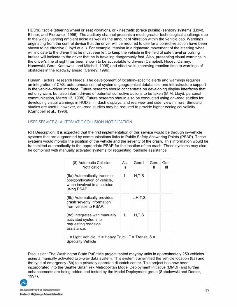
47
HDD's), tactile (steering wheel or seat vibration), or kinesthetic (brake pulsing) sensory systems (Lloyd, Bittner, and Pierowicz, 1996). The auditory channel presents a much greater technological challenge due to the widely varying ambient noise as well as the amount of vibration within the vehicle cab. Warnings originating from the control device that the driver will be required to use for a corrective action have been shown to be effective (Lloyd et al.). For example, tension in a rightward movement of the steering wheel will indicate to the driver that he must veer left to keep the vehicle in the field of safe travel or pulsing brakes will indicate to the driver that he is traveling dangerously fast. Also, presenting visual warnings in the driver's line of sight has been shown to be acceptable to drivers (Campbell, Hooey, Carney, Hanowski, Gore, Kantowitz, and Mitchell, 1996) and effective in improving reaction time to warnings of obstacles in the roadway ahead (Carney, 1996).
Human Factors Research Needs. The development of location–specific alerts and warnings requires an integration of CAS, autonomous control systems, geographical databases, and infrastructure support in the vehicle–driver interface. Future research should concentrate on developing display interfaces that not only warn, but also inform drivers of potential corrective actions to be taken (M.M. Lloyd, personal communication, March 13, 1998). Future research should also be conducted using on–road studies for developing visual warnings in HUD's, in–dash displays, and rearview and side–view mirrors. Simulator studies are useful; however, on–road studies may be required to provide higher ecological validity (Campbell et al., 1996).
USER SERVICE 8: AUTOMATIC COLLISION NOTIFICATION
RFI Description: It is expected that the first implementation of this service would be through in–vehicle systems that are augmented by communications links to Public Safety Answering Points (PSAP). These systems would monitor the position of the vehicle and the severity of the crash. This information would be transmitted automatically to the appropriate PSAP for the location of the crash. These systems may also be combined with manually activated systems for requesting roadside assistance.
(8) Automatic Collision Notification
As-Is
Gen. I Gen. II
Gen. III
(8a) Automatically transmits position/location of vehicle, when involved in a collision, using PSAP.
L H,T,S
(8b) Automatically provides crash severity information from vehicle to PSAP.
L,H,T,S
(8c) Integrates with manually activated systems for requesting roadside assistance.
L H,T,S
L = Light Vehicle, H = Heavy Truck, T = Transit, S = Specialty Vehicle
Discussion: The Washington State PuSHMe project tested mayday units in approximately 250 vehicles using a manually activated two–way data system. This system transmitted the vehicle location (8a) and the type of emergency (8b) to a privately operated dispatch center. This project has now been incorporated into the Seattle SmarTrek Metropolitan Model Deployment Initiative (MMDI) and further enhancements are being added and tested by the Model Deployment group (Sobolewski and Deeter, 1997).

48
A Field Operational Test, conducted by New York DOT/Calspan SRL/Johns Hopkins involved focused demonstrations of the critical Automated Collision Notification (ACN) system functions. The test integrated crash sensors, cellular communications equipment, GPS satellite position location devices, and automated map display technologies into an ACN system that will potentially reduce Emergency Medical Services (EMS) response times for victims of motor vehicle accidents using PSAP's. The ACN system (8a–b) will accomplish this requirement by automatically sensing that a crash has occurred (using in–vehicle equipment) and immediately relaying information on the crash, severity, and location to the emergency 911 system (Sobolewski and Deeter, 1997).
The Mayday Plus program is a $2.5–million public–private partnership to develop and test an integrated emergency response infrastructure capable of accepting data and voice messages from various Mayday systems. Mayday Plus integrates global positioning, in–vehicle sensors, satellite and cellular telephone technology, and emergency response systems to provide automatic notification of crash location and severity to 9–1–1 professionals who need it (8a–b). Mayday Plus is an extension of equipment developed during federally funded ACN field tests in New York State (Sobolewski and Deeter, 1997).
The GM/Cadillac OnStar System uses new on–vehicle communications technology to integrate advanced vehicle electronics architecture with GPS satellite technology and a cellular telephone. The technologies link a driver and the vehicle with the OnStar Customer Assistance Center, where advisors instantly provide real–time, person–to–person help using the latest computer databases to offer personalized information and service, the company said (Puentes, 1998).
Ford RESCU System is a personal security system offered on the Lincoln Continental. The system uses GPS satellite technology and the existing U.S. cellular network. A cellular telephone call is initiated to the Westinghouse Emergency Response Center in Irving, Texas when the motorist pushes one of two buttons marked with either a tow truck (for roadside assistance) or an ambulance (for emergency services). Lincoln security is then able to speak with the motorist, confirm the location, and determine what assistance is needed. The security agent establishes a three–way conference call to the appropriate public emergency or roadside dispatch service and follows through to confirm that the problem is solved (Puentes, 1998).
Human Factors Research To–Date. Human factors work in this area has focused on: (1) user interface design and (2) a Traffic Management Center (TMC) response to an automatic collision message. Based on established human factors design principles, Calspan designed an ACN prototype system. This system display was designed using the following objectives: (1) intuitive enough not to require training, (2) usable by injured occupants, (3) provides an understandable interface in a wide variety of lumination and noise conditions, and (4) takes into account wide variations of individual differences (Benz, Blatt, Bollman, Donnely, Funke, Kelly, Lloyd, McClellan, Schabel, Wachob, and Wilson, 1997). These criteria resulted in a user interface that utilizes redundant auditory and visual displays; provides clear, simple messages; builds on existing population stereotypes; uses maximum display intensity; and locates the visual display below the dashboard to reduce glare and avoid bright ambient luminance (Benz et al.). Mitta, Folds, and Fain (1996) investigated how altering the level of automated support would impact the ability of traffic analysts to detect, verify, and manage an incident. In this experiment, separate groups of subjects operated four different automated support systems, each with varying levels of automation. The results suggest that automated systems supporting a high detection rate and a short response time are superior so long as the system also allows errors to be easily corrected. Other human factors work has been done on general TMC design and control room display design, investigating more general issues, such as the effects of automation, operator selection, rapid prototyping of displays, etc. (Kelly and Folds, 1998). All of these issues impact how well a TMC analyst will manage and make split–second decisions in accident situations.
Human Factors Research Needs. There are many issues involved in the continuing human factors research of automatic collision notification systems. M.M. Lloyd (personal communication, March 13, 1998) suggests that the ACN system should be integrated with other key IVI User Services, such as CAS and autonomous vehicle control systems. NHTSA plans to sponsor research in the area of integration of
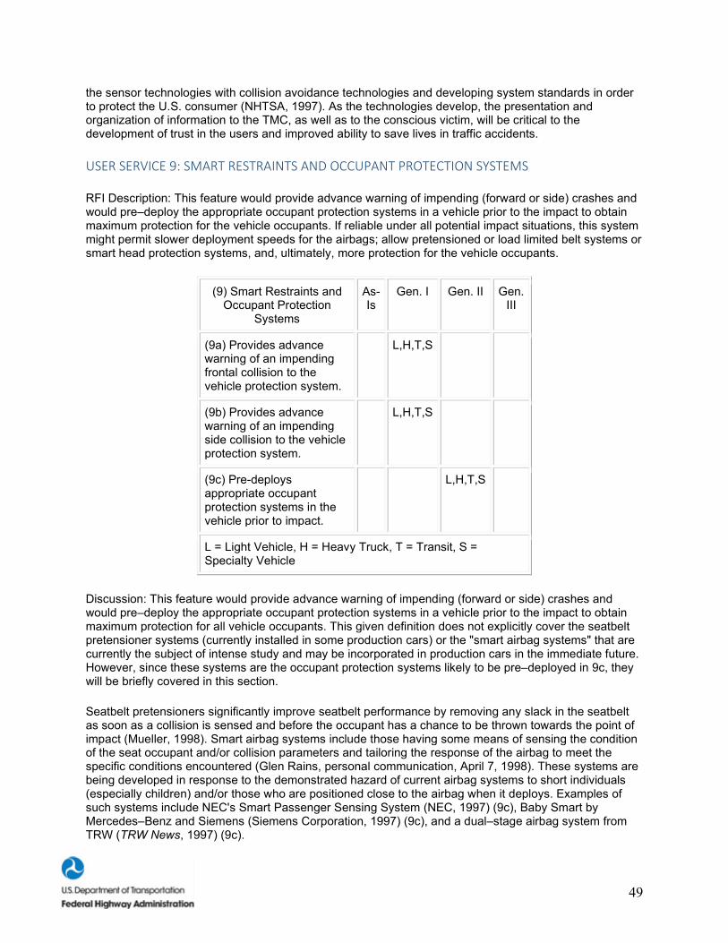
49
the sensor technologies with collision avoidance technologies and developing system standards in order to protect the U.S. consumer (NHTSA, 1997). As the technologies develop, the presentation and organization of information to the TMC, as well as to the conscious victim, will be critical to the development of trust in the users and improved ability to save lives in traffic accidents.
USER SERVICE 9: SMART RESTRAINTS AND OCCUPANT PROTECTION SYSTEMS
RFI Description: This feature would provide advance warning of impending (forward or side) crashes and would pre–deploy the appropriate occupant protection systems in a vehicle prior to the impact to obtain maximum protection for the vehicle occupants. If reliable under all potential impact situations, this system might permit slower deployment speeds for the airbags; allow pretensioned or load limited belt systems or smart head protection systems, and, ultimately, more protection for the vehicle occupants.
(9) Smart Restraints and Occupant Protection
Systems
As-Is
Gen. I Gen. II Gen. III
(9a) Provides advance warning of an impending frontal collision to the vehicle protection system.
L,H,T,S
(9b) Provides advance warning of an impending side collision to the vehicle protection system.
L,H,T,S
(9c) Pre-deploys appropriate occupant protection systems in the vehicle prior to impact.
L,H,T,S
L = Light Vehicle, H = Heavy Truck, T = Transit, S = Specialty Vehicle
Discussion: This feature would provide advance warning of impending (forward or side) crashes and would pre–deploy the appropriate occupant protection systems in a vehicle prior to the impact to obtain maximum protection for all vehicle occupants. This given definition does not explicitly cover the seatbelt pretensioner systems (currently installed in some production cars) or the "smart airbag systems" that are currently the subject of intense study and may be incorporated in production cars in the immediate future. However, since these systems are the occupant protection systems likely to be pre–deployed in 9c, they will be briefly covered in this section.
Seatbelt pretensioners significantly improve seatbelt performance by removing any slack in the seatbelt as soon as a collision is sensed and before the occupant has a chance to be thrown towards the point of impact (Mueller, 1998). Smart airbag systems include those having some means of sensing the condition of the seat occupant and/or collision parameters and tailoring the response of the airbag to meet the specific conditions encountered (Glen Rains, personal communication, April 7, 1998). These systems are being developed in response to the demonstrated hazard of current airbag systems to short individuals (especially children) and/or those who are positioned close to the airbag when it deploys. Examples of such systems include NEC's Smart Passenger Sensing System (NEC, 1997) (9c), Baby Smart by Mercedes–Benz and Siemens (Siemens Corporation, 1997) (9c), and a dual–stage airbag system from TRW (TRW News, 1997) (9c).
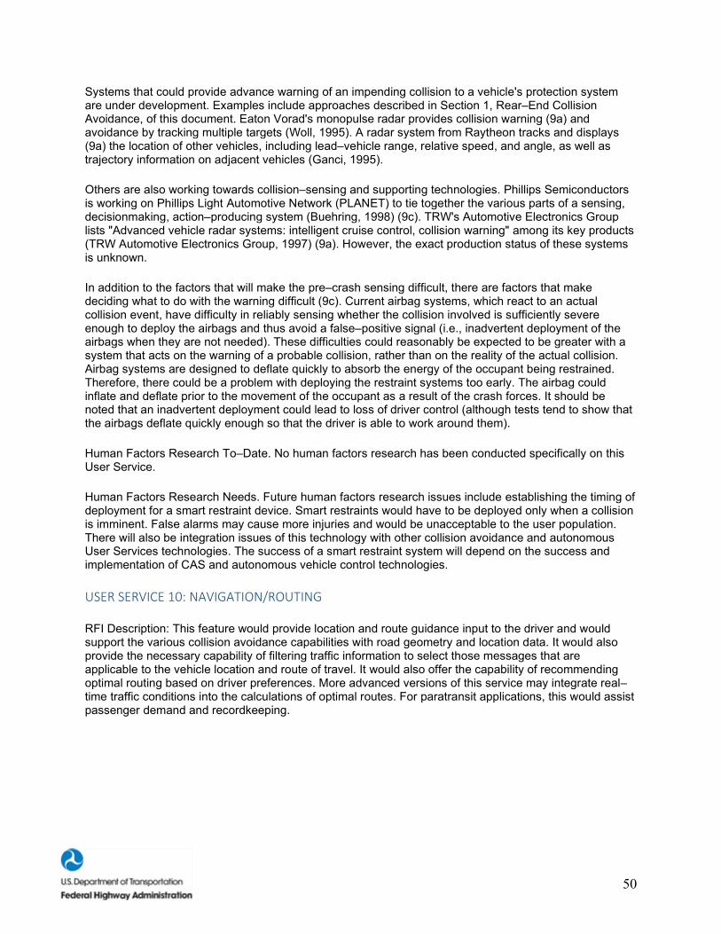
50
Systems that could provide advance warning of an impending collision to a vehicle's protection system are under development. Examples include approaches described in Section 1, Rear–End Collision Avoidance, of this document. Eaton Vorad's monopulse radar provides collision warning (9a) and avoidance by tracking multiple targets (Woll, 1995). A radar system from Raytheon tracks and displays (9a) the location of other vehicles, including lead–vehicle range, relative speed, and angle, as well as trajectory information on adjacent vehicles (Ganci, 1995).
Others are also working towards collision–sensing and supporting technologies. Phillips Semiconductors is working on Phillips Light Automotive Network (PLANET) to tie together the various parts of a sensing, decisionmaking, action–producing system (Buehring, 1998) (9c). TRW's Automotive Electronics Group lists "Advanced vehicle radar systems: intelligent cruise control, collision warning" among its key products (TRW Automotive Electronics Group, 1997) (9a). However, the exact production status of these systems is unknown.
In addition to the factors that will make the pre–crash sensing difficult, there are factors that make deciding what to do with the warning difficult (9c). Current airbag systems, which react to an actual collision event, have difficulty in reliably sensing whether the collision involved is sufficiently severe enough to deploy the airbags and thus avoid a false–positive signal (i.e., inadvertent deployment of the airbags when they are not needed). These difficulties could reasonably be expected to be greater with a system that acts on the warning of a probable collision, rather than on the reality of the actual collision. Airbag systems are designed to deflate quickly to absorb the energy of the occupant being restrained. Therefore, there could be a problem with deploying the restraint systems too early. The airbag could inflate and deflate prior to the movement of the occupant as a result of the crash forces. It should be noted that an inadvertent deployment could lead to loss of driver control (although tests tend to show that the airbags deflate quickly enough so that the driver is able to work around them).
Human Factors Research To–Date. No human factors research has been conducted specifically on this User Service.
Human Factors Research Needs. Future human factors research issues include establishing the timing of deployment for a smart restraint device. Smart restraints would have to be deployed only when a collision is imminent. False alarms may cause more injuries and would be unacceptable to the user population. There will also be integration issues of this technology with other collision avoidance and autonomous User Services technologies. The success of a smart restraint system will depend on the success and implementation of CAS and autonomous vehicle control technologies.
USER SERVICE 10: NAVIGATION/ROUTING
RFI Description: This feature would provide location and route guidance input to the driver and would support the various collision avoidance capabilities with road geometry and location data. It would also provide the necessary capability of filtering traffic information to select those messages that are applicable to the vehicle location and route of travel. It would also offer the capability of recommending optimal routing based on driver preferences. More advanced versions of this service may integrate real–time traffic conditions into the calculations of optimal routes. For paratransit applications, this would assist passenger demand and recordkeeping.
51
(10) Navigation/Routing As-Is Gen. I Gen. II
Gen. III
(10a) Provides location information to the driver.
L,H,T,S
(10b) Provides route guidance information to the driver.
L,H,T,S
(10c) Provides road geometry data to CAS.
L,H,T,S
(10d) Provides location data to CAS.
L,H,T,S
(10e) Displays only the traffic information that is applicable to vehicle location and route.
L,H,T,S
(10f) Provides optimal routing based on driver preferences.
L,H,T,S
(10g) Uses real-time traffic information in calculations of optimal routes.
L,H,T,S
L = Light Vehicle, H = Heavy Truck, T = Transit, S = Specialty Vehicle
Discussion: In general, the navigation/routing component of this User Service is an existing technology, available today on the commercial market. These systems have much greater market penetration in Japan and Europe than in the United States. As vehicle systems become more complex and more numerous, convergence (combining multiple systems into one master controller/system) will become a key issue. As the Generation I vehicle is developed, this convergence trend is likely to continue.
The GPS has been used in several devices (Lappin, 1997) in the calculation of vehicle position (10a,d). These range from stand–alone GPS receivers that are relatively inexpensive to fully integrated, navigation devices and applications. In–vehicle navigation systems are available today on the commercial market (Lappin) that provide driver location information using GPS and other location–referencing technologies (inertial gyroscope, dead reckoning) (10a); turn–by–turn navigation directions (10b); and the ability to make routing preference selections (10f), such as maximize use of highways, minimize use of highways, or fastest route (typically based on posted speed limits and "category" of road).
Siemens Corporation (Hancock, Judd, Novak, Rickard, and Gorr, 1997) has undertaken a brief demonstration of automatic vehicle location (AVL) technologies (10a–b) that " demonstrate that vehicle position can be recognized from the surroundings simply and cheaply, using a very small computer." This system relies primarily on dead reckoning with: (1) pre–storing sensory maps of the environment and (2)
52
running a very simple real–time tracking algorithm to correct for the accumulation of odometer errors from the dead–reckoning system (10a,d).
The Traveler Information Showcase (Pittenger and Williams, 1997) provided real–time traffic information to in–vehicle navigation devices using FM subcarrier technology. Traffic information (travel speed, incidents, road construction, etc.) was broadcast to the in–vehicle units (IVU) and graphically displayed on the navigation map. This information was not used in the calculation of the desired route (10g) or filtered, and only provided information on a particular route (10e). The TravTek project in Orlando, Florida (Inman and Peters, 1996) was one of the first test locations for providing real–time, dynamic route guidance capabilities (10e,g) directly to an IVU. FAST–TRAC (Wieck, 1997), a field operational test in Oakland County, Michigan, began to disseminate dynamic route guidance (10g) to the vehicle in May 1996. Though not integrated into the navigation systems today, road geometry (10c) type functions will become integrated into the overall vehicle system, included with the navigation device.
Human Factors Research To–Date. Research to–date has focused on issues such as the presentation mode of navigation/routing information (e.g., Streeter, Vitello, and Wonsiewicz, 1985; Walker, Alicandri, Sedney, and Roberts, 1990; Srinivasan and Jovanis, 1997), as well on the timing of navigation information (Ross, Vaughan, and Nicolle, 1997; Green and George, 1995). The Streeter et al. (1985) and Walker et al. (1990) studies indicated that auditory messages could lead to fewer navigation errors. However, the auditory channel is limited in its ability to present complex navigation information (e.g., see Deatherage, 1972) and, typically, a mix of auditory and visual information will be required. Various types of visual mode options have been studied, including head–up displays (HUD) vs. head–down displays (HDD) and comparisons between HUD, HDD, and paper maps. Hooey and Gore (1998) did not demonstrate any advantages associated with a HUD over an HDD presentation for route guidance information. Srinivasan and Jovanis found additional support for auditory messages and also lower reaction times for drivers responding to turn–by–turn information with a HUD vs. an HDD. More recently, Campbell, Carney, and Kantowitz (1998) have produced human factors design guidelines for Advanced Traveler Information Systems (ATIS), with suggestions for the display type, trip status, and display format of navigation and routing information. SAE is developing function accessibility (Navigation and Route Guidance Function Accessibility While Driving [J2364]) and interface standards (Navigation and Route Guidance Man–Machine Interface [J2365]) for the navigation and route guidance systems.
Human Factors Research Needs. Due to the complex and varied nature of navigation/routing information, future research will continue to examine the effects of presentation modes on driver performance and acceptance. Also, little research has been conducted on input or control options for these systems, including the use of voice recognition systems. In this regard, the recent NHTSA study on cellular telephones (Goodman, Bents, Tijerina, Wierwille, Lerner, and Benel, 1997) may be a useful starting point. Results from the recent Human Factors IVI Workshop (ITS America, 1997) suggested that key research issues in this area are the development of driver models, the need for standardization of navigation messages, and a need to establish priorities for driver messages.
USER SERVICE 11: REAL–TIME TRAFFIC AND TRAVELER INFORMATION
RFI Description: These IVI systems would have capabilities to access in–vehicle databases and receive travel–related information from the infrastructure (roadside or wide–area transmissions). Information categories would include items such as vehicle location and route guidance instructions; motorist and traveler services information; safety and advisory information; and other real–time updates on conditions such as congestion, work zones, and environmental and road surface conditions. This feature would provide an integrated approach to the presentation of information to the driver for safety warnings and other advisories related to the driving task. More advanced system capabilities would include the ability to react to dynamic information on environmental and road conditions, thereby augmenting information contained in the static map databases.
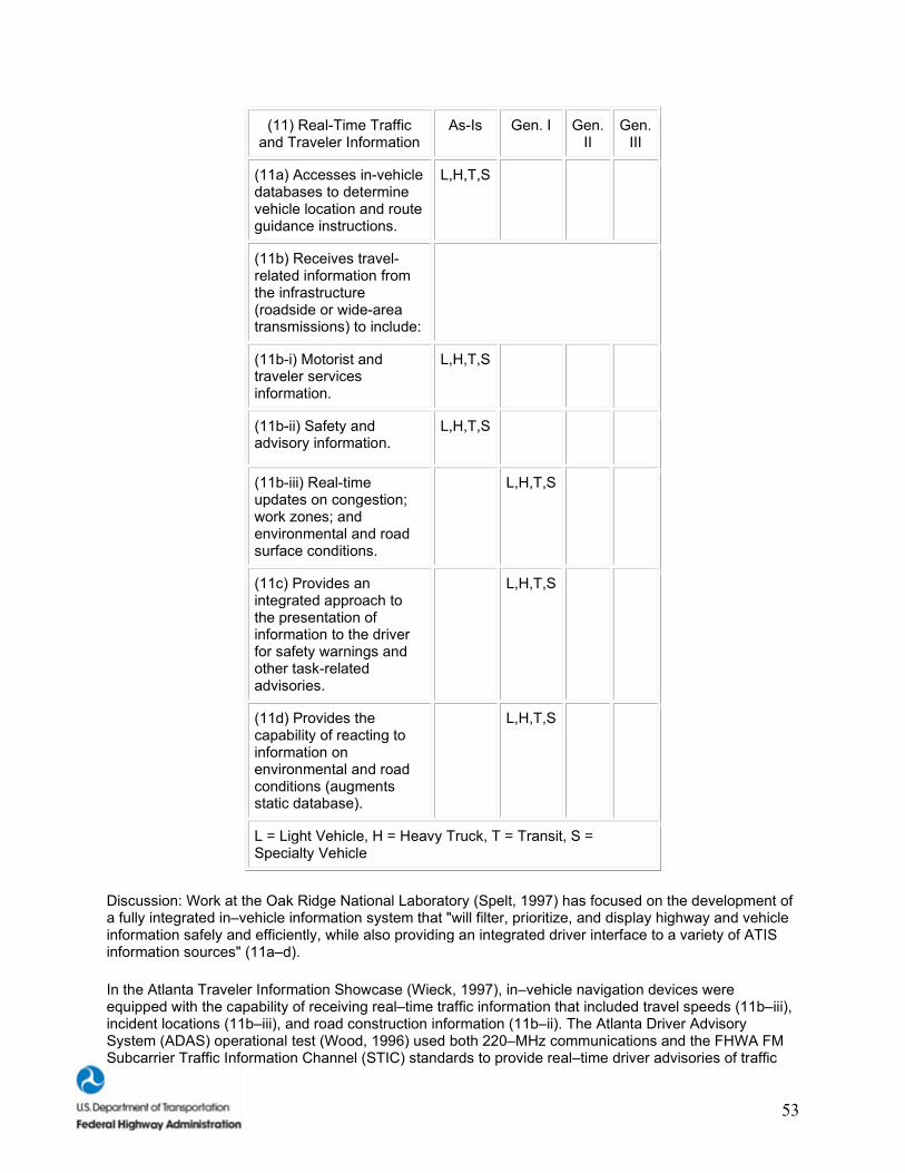
53
(11) Real-Time Traffic and Traveler Information
As-Is Gen. I Gen. II
Gen. III
(11a) Accesses in-vehicle databases to determine vehicle location and route guidance instructions.
L,H,T,S
(11b) Receives travel-related information from the infrastructure (roadside or wide-area transmissions) to include:
(11b-i) Motorist and traveler services information.
L,H,T,S
(11b-ii) Safety and advisory information.
L,H,T,S
(11b-iii) Real-time updates on congestion; work zones; and environmental and road surface conditions.
L,H,T,S
(11c) Provides an integrated approach to the presentation of information to the driver for safety warnings and other task-related advisories.
L,H,T,S
(11d) Provides the capability of reacting to information on environmental and road conditions (augments static database).
L,H,T,S
L = Light Vehicle, H = Heavy Truck, T = Transit, S = Specialty Vehicle
Discussion: Work at the Oak Ridge National Laboratory (Spelt, 1997) has focused on the development of a fully integrated in–vehicle information system that "will filter, prioritize, and display highway and vehicle information safely and efficiently, while also providing an integrated driver interface to a variety of ATIS information sources" (11a–d).
In the Atlanta Traveler Information Showcase (Wieck, 1997), in–vehicle navigation devices were equipped with the capability of receiving real–time traffic information that included travel speeds (11b–iii), incident locations (11b–iii), and road construction information (11b–ii). The Atlanta Driver Advisory System (ADAS) operational test (Wood, 1996) used both 220–MHz communications and the FHWA FM Subcarrier Traffic Information Channel (STIC) standards to provide real–time driver advisories of traffic

54
incidents, construction delays, and other traffic events (11b–ii,–iii). The ADAS system also had the capability of broadcasting traveler services information to the in–vehicle devices (11b–i).
Researchers at Daimler–Benz Research and Technology in North America have developed an "Internet in the Car" prototype vehicle (Jameel, 1997). By providing this Internet access, customer service centers can be continuously connected to the car, providing support such as remote door unlocking; warning of bad road conditions, weather, and accidents; and remote diagnostics, adding to the safety and security of the cars (11b–i,–ii,–iii; 11c–d).
In–vehicle signing research conducted by the Georgia Tech Research Institute (Greneker, 1997) uses a mobile transmitter unit to broadcast safety warning messages (11b–ii) and existing commercially available radar detectors to receive the message and display the contents to the driver. The transmitter can be mounted on police or emergency vehicles, or could be a roadside unit capable of remote activation. The message could be picked up by any vehicle equipped with a police radar detector (11c–d).
In France, a public/private consortium (Valade, 1997) has an operational test underway using beacons, in–vehicle read–write transponders, and an in–vehicle display terminal. This test uses the roadside–to–vehicle communications Dedicated Short–Range Communication (DSRC) to send travel advisory information to the driver (11b–c). The primary focus is on providing more safety to the drivers, offering information on traffic conditions (accidents, roadwork, heavy traffic) (11b–iii), weather conditions (11b–ii), incident–related messages from other drivers (11c), and emergency call–related information (11d). However, the system is also designed to provide traveler services information (11b–i) such as distance to next exit, estimated time of travel, alternative routes (11a), available facilities at next exit (gas, lodging, dining), and tourist information.
Human Factors Research To–Date. Research into traffic and traveler information has focused on issues such as quality (Bonsall and Parry, 1991) and accuracy (Kantowitz, Hanowski, and Kantowitz, 1997). Bonsall and Parry used an artificial traffic network and found reductions in user acceptance with lower quality advice in an unfamiliar network. Kantowitz et al. found that while 100–percent accurate traffic–density information led to the best driver performance and acceptance, 71 percent was still accepted. Overall, drivers were more critical of the information provided by the system (Kantowitz et al.) and less likely to accept the advice (Bonsall and Parry) as familiarity with a traffic network increased. More recently, Campbell, Carney, and Kantowitz (1998) have produced human factors design guidelines for ATIS, with suggestions for the display type, trip status, and display format of traffic and traveler information.
Human Factors Research Needs. Issues such as accuracy and quality will continue to be important and should be studied under more representative conditions such as operational tests and field studies. Also key is the need to develop messages that do not confuse or overwhelm the driver. For example, results from the recent Human Factors IVI Workshop (ITS America, 1997) suggested that key research issues in this area are the timing, repetition, and density of messages.
USER SERVICE 12: DRIVER COMFORT AND CONVENIENCE
RFI Description: This service is included in the IVI program to ensure that the increasing number of comfort and convenience features in vehicles, such as cellular telephones and fax machines, do not distract the driver or increase the complexity of the driving task. This service would integrate these features into the DVI to permit prioritization of information sources and reduce distractions. Real–time dispatching for fleet operations is included in this category.
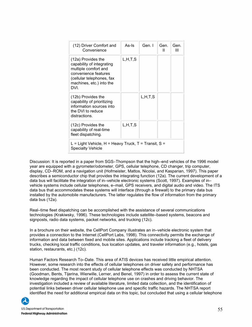
55
(12) Driver Comfort and Convenience
As-Is Gen. I Gen. II
Gen. III
(12a) Provides the capability of integrating multiple comfort and convenience features (cellular telephones, fax machines, etc.) into the DVI.
L,H,T,S
(12b) Provides the capability of prioritizing information sources into the DVI to reduce distractions.
L,H,T,S
(12c) Provides the capability of real-time fleet dispatching.
L,H,T,S
L = Light Vehicle, H = Heavy Truck, T = Transit, S = Specialty Vehicle
Discussion: It is reported in a paper from SGS–Thompson that the high–end vehicles of the 1996 model year are equipped with a gyrometer/odometer, GPS, cellular telephone, CD changer, trip computer, display, CD–ROM, and a navigation unit (Hofmeister, Mattos, Nicolai, and Kasparian, 1997). This paper describes a semiconductor chip that provides the integrating function (12a). The current development of a data bus will facilitate the integration of in–vehicle electronic systems (Scott, 1997). Examples of in–vehicle systems include cellular telephones, e–mail, GPS receivers, and digital audio and video. The ITS data bus that accommodates these systems will interface (through a firewall) to the primary data bus installed by the automobile manufacturers. The latter regulates the flow of information from the primary data bus (12a).
Real–time fleet dispatching can be accomplished with the assistance of several communications technologies (Krakiwsky, 1996). These technologies include satellite–based systems, beacons and signposts, radio data systems, packet networks, and trucking (12c).
In a brochure on their website, the CellPort Company illustrates an in–vehicle electronic system that provides a connection to the Internet (CellPort Labs, 1998). This connectivity permits the exchange of information and data between fixed and mobile sites. Applications include tracking a fleet of delivery trucks, checking local traffic conditions, bus location updates, and traveler information (e.g., hotels, gas station, restaurants, etc.) (12c).
Human Factors Research To–Date. This area of ATIS devices has received little empirical attention. However, some research into the effects of cellular telephones on driver safety and performance has been conducted. The most recent study of cellular telephone effects was conducted by NHTSA (Goodman, Bents, Tijerina, Wierwille, Lerner, and Benel, 1997) in order to assess the current state of knowledge regarding the impact of cellular telephone use on crashes and driving behavior. The investigation included a review of available literature, limited data collection, and the identification of potential links between driver cellular telephone use and specific traffic hazards. The NHTSA report identified the need for additional empirical data on this topic, but concluded that using a cellular telephone
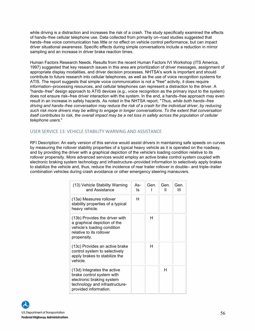
56
while driving is a distraction and increases the risk of a crash. The study specifically examined the effects of hands–free cellular telephone use. Data collected from primarily on–road studies suggested that hands–free voice communication has little or no effect on vehicle control performance, but can impact driver situational awareness. Specific effects during simple conversations include a reduction in mirror sampling and an increase in driver brake reaction times.
Human Factors Research Needs. Results from the recent Human Factors IVI Workshop (ITS America, 1997) suggested that key research issues in this area are prioritization of driver messages, assignment of appropriate display modalities, and driver decision processes. NHTSA's work is important and should contribute to future research into cellular telephones, as well as the use of voice recognition systems for ATIS. The report suggests that simple voice communication is not a "free" activity, it does require information–processing resources, and cellular telephones can represent a distraction to the driver. A "hands–free" design approach to ATIS devices (e.g., voice recognition as the primary input to the system) does not ensure risk–free driver interaction with the system. In the end, a hands–free approach may even result in an increase in safety hazards. As noted in the NHTSA report, "Thus, while both hands–free driving and hands–free conversation may reduce the risk of a crash for the individual driver, by reducing such risk more drivers may be willing to engage in longer conversations. To the extent that conversation itself contributes to risk, the overall impact may be a net loss in safety across the population of cellular telephone users."
USER SERVICE 13: VEHICLE STABILITY WARNING AND ASSISTANCE
RFI Description: An early version of this service would assist drivers in maintaining safe speeds on curves by measuring the rollover stability properties of a typical heavy vehicle as it is operated on the roadway, and by providing the driver with a graphical depiction of the vehicle's loading condition relative to its rollover propensity. More advanced services would employ an active brake control system coupled with electronic braking system technology and infrastructure–provided information to selectively apply brakes to stabilize the vehicle and, thus, reduce the incidence of rear trailer rollover in double– and triple–trailer combination vehicles during crash avoidance or other emergency steering maneuvers.
(13) Vehicle Stability Warning and Assistance
As-Is
Gen. I
Gen. II
Gen. III
(13a) Measures rollover stability properties of a typical heavy vehicle.
H
(13b) Provides the driver with a graphical depiction of the vehicle’s loading condition relative to its rollover propensity.
H
(13c) Provides an active brake control system to selectively apply brakes to stabilize the vehicle.
H
(13d) Integrates the active brake control system with electronic braking system technology and infrastructure-provided information.
H
57
L = Light Vehicle, H = Heavy Truck, T = Transit, S = Specialty Vehicle
Discussion: For this User Service, a few prototype systems exist and some are still held proprietary by the companies involved. Where appropriate, in lieu of actual prototypes, some of the current literature in the area has been outlined.
Work is ongoing in the development of a rollover proximity measurement sensor at the University of Michigan Transportation Research Institute (UMTRI) and is sponsored by NHTSA (Ervin, Winkler, Fancher, Krishnaswamy, and Karamihas, 1997) (13a). The method involves determining rollover tendencies of heavy trucks using accelerometers and load cells. Several researchers have looked into the area of roll detection and roll instability effects for heavy–duty trucks (Steiner, Weidel, Kublbeck, Steurer, and Hora, 1997) and trucks carrying cargo such as liquid, which will significantly affect roll response of the vehicle (Sankar, Ranganathan, and Rakheja, 1992).
Pertinent work in this area relates to active tilt control of trains and automotive vehicles, and involves measurement of roll angle or lateral acceleration. Some of this technology may be directly applicable to detection of incipient rollover instabilities (Romei, 1991) (13a).
Driver–assist graphical aids, such as vehicle loading condition relative to its stability (13b), are, however, still in their infancy. One of the goals of the UMTRI project (Ervin et al., 1997), is, however, aimed at providing such aids.
Even though driver–assist systems for vehicle rollover stability are still being researched, the field of active stabilizing control, such as active roll control (13c), has been widely researched. The power requirements of active roll control of trucks and tractor–trailer systems are prohibitive. An interconnected Hydragas system that transfers fluid laterally and longitudinally to hydro–pneumatic suspensions at each corner of the vehicle is used to actively control the roll of the Rover 100 series vehicle (Rosam and Darling, 1997; Dymcock, 1994). Citroen has also developed active anti–roll bars. Active roll control for trucks and tractor–trailer combinations, using active anti–roll bars with low–bandwidth hydraulic actuators, has been under study in Europe for the past several years (Broos, 1993). Other related work has been listed in Williams, Best, and Crawford (1993).
Human Factors Research To–Date. The vehicle stability of heavy/commercial vehicles is a dynamic variable that is dependent on such factors as weight of load, the manner in which a load is placed on the trailer, type of load, and the characteristics of the trailer. Because these factors are constantly changing, the main human factors research issue is how to alert drivers when they are approaching rollover threshold (Wheeler, Campbell, and Kinghorn, 1998). Some human factors research has been conducted in this area, investigating methods of presenting rollover threshold to the driver. One study investigated three possible displays and found that an out–of–vehicle dynamic road sign that flashed the tractor–trailer's speed and alerted the driver if he was nearing rollover threshold proved to be the most useful and economical method (McGee, Joshua, Hughes, Strickland, and Bareket, 1992). Most research in this area is still being conducted on technology rather than on human factors issues.
Human Factors Research Needs. NHTSA considers the vehicle stability warning and assistance technology a high priority and will be supporting research in two main areas. The first area will focus on developing an in–vehicle graphical depiction of the roll stability of the tractor–trailer to the driver. This graphical interface will help increase the driver's situational awareness of the vehicle's dynamics and handling capabilities, which will result in safer driving. The second area will develop an active braking system coupled with an electronic braking system that will selectively apply brakes to wheels to stabilize the vehicle and reduce the incidence of rollover (NHTSA, 1997).
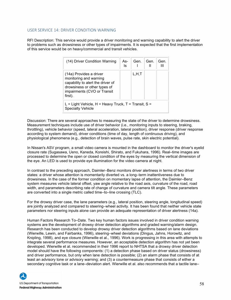
58
USER SERVICE 14: DRIVER CONDITION WARNING
RFI Description: This service would provide a driver monitoring and warning capability to alert the driver to problems such as drowsiness or other types of impairments. It is expected that the first implementation of this service would be on heavy/commercial and transit vehicles.
(14) Driver Condition Warning As-Is
Gen. I
Gen. II
Gen. III
(14a) Provides a driver monitoring and warning capability to alert the driver of drowsiness or other types of impairments (CVO or Transit first).
L,H,T
L = Light Vehicle, H = Heavy Truck, T = Transit, S = Specialty Vehicle
Discussion: There are several approaches to measuring the state of the driver to determine drowsiness. Measurement techniques include use of driver behavior (i.e., monitoring inputs to steering, braking, throttling), vehicle behavior (speed, lateral acceleration, lateral position), driver response (driver response according to system demand), driver conditions (time of day, length of continuous driving), and physiological phenomena (e.g., detection of brain waves, pulse rate, skin electric potential).
In Nissan's ASV program, a small video camera is mounted in the dashboard to monitor the driver's eyelid closure rate (Sugasawa, Ueno, Kaneda, Koreishi, Shirato, and Fukuhara, 1996). Real–time images are processed to determine the open or closed condition of the eyes by measuring the vertical dimension of the eye. An LED is used to provide eye illumination for the video camera at night.
In contrast to the preceding approach, Daimler–Benz monitors driver alertness in terms of two driver states: a driver whose attention is momentarily diverted vs. a long–term inattentiveness due to drowsiness. In the case of the former condition on momentary lapse of attention, the Daimler–Benz system measures vehicle lateral offset, yaw angle relative to the road axis, curvature of the road, road width, and parameters describing rate of change of curvature and camera tilt angle. These parameters are converted into a single metric called time–to–line crossing (TLC).
For the drowsy driver case, the lane parameters (e.g., lateral position, steering angle, longitudinal speed) are jointly analyzed and compared to steering–wheel activity. It has been found that neither vehicle state parameters nor steering inputs alone can provide an adequate representation of driver alertness (14a).
Human Factors Research To–Date. Two key human factors issues involved in driver condition warning systems are the development of drowsy driver detection algorithms and graded warning/alarm design. Research has been conducted to develop drowsy driver detection algorithms based on lane deviations (Wierwille, Lewin, and Fairbanks, 1996), steering–wheel deviations (Dingus, Jahns, Horowitz, and Knipling, 1998), and eye closure (Wierwille et al., 1996). Work is progressing in this area with attempts to integrate several performance measures. However, an acceptable detection algorithm has not yet been developed. Wierwille et al. recommended in their 1996 report to NHTSA that a drowsy driver detection model should have the following components: (1) a detection phase based on driver status (drowsiness) and driver performance, but only when lane detection is possible; (2) an alarm phase that consists of at least an advisory tone or advisory warning; and (3) a countermeasure phase that consists of either a secondary cognitive task or a lane–deviation alert. Wierwille et al. also recommends that a tactile lane–
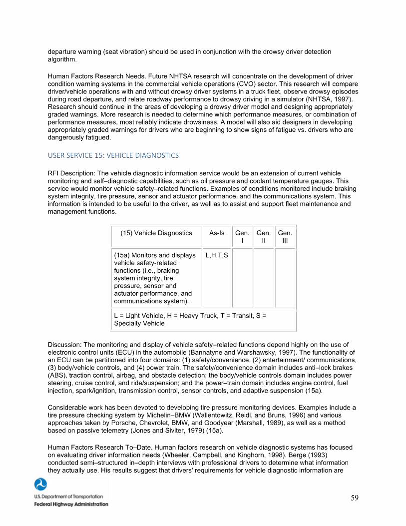
59
departure warning (seat vibration) should be used in conjunction with the drowsy driver detection algorithm.
Human Factors Research Needs. Future NHTSA research will concentrate on the development of driver condition warning systems in the commercial vehicle operations (CVO) sector. This research will compare driver/vehicle operations with and without drowsy driver systems in a truck fleet, observe drowsy episodes during road departure, and relate roadway performance to drowsy driving in a simulator (NHTSA, 1997). Research should continue in the areas of developing a drowsy driver model and designing appropriately graded warnings. More research is needed to determine which performance measures, or combination of performance measures, most reliably indicate drowsiness. A model will also aid designers in developing appropriately graded warnings for drivers who are beginning to show signs of fatigue vs. drivers who are dangerously fatigued.
USER SERVICE 15: VEHICLE DIAGNOSTICS
RFI Description: The vehicle diagnostic information service would be an extension of current vehicle monitoring and self–diagnostic capabilities, such as oil pressure and coolant temperature gauges. This service would monitor vehicle safety–related functions. Examples of conditions monitored include braking system integrity, tire pressure, sensor and actuator performance, and the communications system. This information is intended to be useful to the driver, as well as to assist and support fleet maintenance and management functions.
(15) Vehicle Diagnostics As-Is Gen. I
Gen. II
Gen. III
(15a) Monitors and displays vehicle safety-related functions (i.e., braking system integrity, tire pressure, sensor and actuator performance, and communications system).
L,H,T,S
L = Light Vehicle, H = Heavy Truck, T = Transit, S = Specialty Vehicle
Discussion: The monitoring and display of vehicle safety–related functions depend highly on the use of electronic control units (ECU) in the automobile (Bannatyne and Warshawsky, 1997). The functionality of an ECU can be partitioned into four domains: (1) safety/convenience, (2) entertainment/ communications, (3) body/vehicle controls, and (4) power train. The safety/convenience domain includes anti–lock brakes (ABS), traction control, airbag, and obstacle detection; the body/vehicle controls domain includes power steering, cruise control, and ride/suspension; and the power–train domain includes engine control, fuel injection, spark/ignition, transmission control, sensor controls, and adaptive suspension (15a).
Considerable work has been devoted to developing tire pressure monitoring devices. Examples include a tire pressure checking system by Michelin–BMW (Wallentowitz, Reidl, and Bruns, 1996) and various approaches taken by Porsche, Chevrolet, BMW, and Goodyear (Marshall, 1989), as well as a method based on passive telemetry (Jones and Siviter, 1979) (15a).
Human Factors Research To–Date. Human factors research on vehicle diagnostic systems has focused on evaluating driver information needs (Wheeler, Campbell, and Kinghorn, 1998). Berge (1993) conducted semi–structured in–depth interviews with professional drivers to determine what information they actually use. His results suggest that drivers' requirements for vehicle diagnostic information are
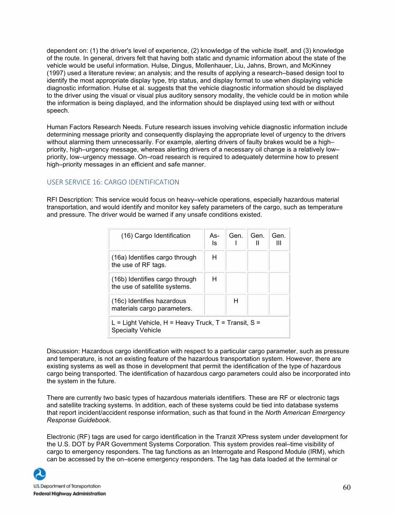
60
dependent on: (1) the driver's level of experience, (2) knowledge of the vehicle itself, and (3) knowledge of the route. In general, drivers felt that having both static and dynamic information about the state of the vehicle would be useful information. Hulse, Dingus, Mollenhauer, Liu, Jahns, Brown, and McKinney (1997) used a literature review; an analysis; and the results of applying a research–based design tool to identify the most appropriate display type, trip status, and display format to use when displaying vehicle diagnostic information. Hulse et al. suggests that the vehicle diagnostic information should be displayed to the driver using the visual or visual plus auditory sensory modality, the vehicle could be in motion while the information is being displayed, and the information should be displayed using text with or without speech.
Human Factors Research Needs. Future research issues involving vehicle diagnostic information include determining message priority and consequently displaying the appropriate level of urgency to the drivers without alarming them unnecessarily. For example, alerting drivers of faulty brakes would be a high–priority, high–urgency message, whereas alerting drivers of a necessary oil change is a relatively low–priority, low–urgency message. On–road research is required to adequately determine how to present high–priority messages in an efficient and safe manner.
USER SERVICE 16: CARGO IDENTIFICATION
RFI Description: This service would focus on heavy–vehicle operations, especially hazardous material transportation, and would identify and monitor key safety parameters of the cargo, such as temperature and pressure. The driver would be warned if any unsafe conditions existed.
(16) Cargo Identification As-Is
Gen. I
Gen. II
Gen. III
(16a) Identifies cargo through the use of RF tags.
H
(16b) Identifies cargo through the use of satellite systems.
H
(16c) Identifies hazardous materials cargo parameters.
H
L = Light Vehicle, H = Heavy Truck, T = Transit, S = Specialty Vehicle
Discussion: Hazardous cargo identification with respect to a particular cargo parameter, such as pressure and temperature, is not an existing feature of the hazardous transportation system. However, there are existing systems as well as those in development that permit the identification of the type of hazardous cargo being transported. The identification of hazardous cargo parameters could also be incorporated into the system in the future.
There are currently two basic types of hazardous materials identifiers. These are RF or electronic tags and satellite tracking systems. In addition, each of these systems could be tied into database systems that report incident/accident response information, such as that found in the North American Emergency Response Guidebook.
Electronic (RF) tags are used for cargo identification in the Tranzit XPress system under development for the U.S. DOT by PAR Government Systems Corporation. This system provides real–time visibility of cargo to emergency responders. The tag functions as an Interrogate and Respond Module (IRM), which can be accessed by the on–scene emergency responders. The tag has data loaded at the terminal or

61
warehouse. If an incident occurs, the emergency responders access the data through a radar gun, which activates the system to transmit data to a radio receiver in the response vehicle (16a).
Sandia National Laboratories has developed a similar concept that would specifically be designed to transmit information on radioactive materials shipments and would use an RF tag (16a). The tag, in their concept, would provide the first responder with information about the type of material being shipped, pressure levels, and the radiation field (Glenn Hohnstreiter, personal communication, April 6, 1998).
Railroads use tags for identifying ownership of freight cars. The same tags could be used to report such data as temperature and pressure, as well as any cargo impacts, to the engineer in the locomotive. A similar system could also be used for trucks (Kromberg, 1992). The tags used by the railroads are programmable and were developed by AMTECH (16a).
Automatic identification of cargo is practiced at European ports through the use of RF tags (16a). Both Automatic Equipment Identification (AEI) and Automatic Vehicular Identification (AVI) are being used for truck shipments at ports in four European countries (Warnecke, 1997).
Hazardous materials can be identified through a rigorous satellite tracking system (16b) that alerts emergency responders and other officials about the location and contents of a hazardous materials container. QUALCOMM Corporation has developed a system that provides satellite tracking for trucks through a network management system in San Diego, CA. The system has hardware mounted on the vehicle that allows the driver to send and receive messages. The system is planned for use with the shipments of radioactive waste to the Waste Isolation Pilot Plant (WIPP) in New Mexico (QUALCOMM, 1998). Through Trailer Trac, QUALCOMM provides a monitoring option used for refrigerated vehicles to get data on set point, mode of operation, and alarm conditions (16c). This system could be modified for hazardous cargo, where sensors would read the temperature and could probably be modified by adding sensors for outputting other parameters, such as pressure.
Human Factors Research To–Date. Cargo identification systems for CVO are in use in some areas of the country. No human factors research has been completed for this User Service. The FHWA is currently investigating various Intelligent Transportation Systems (ITS) technologies, including cargo identification, to determine its feasibility and usefulness in improving the flow of traffic at border crossings (Hill and Harris, 1996).
Human Factors Research Needs. Future human factors research of Cargo Identification User Services should include an investigation of the simplest and most intuitive methods of displaying cargo identification to the heavy/commercial vehicle dispatch or regulatory agencies. This information must be integrated with other information to facilitate quick decisionmaking by both dispatch and regulatory agencies. If the interface does not support the user's decisionmaking processes, traffic flow will not achieve the potentially high levels of efficiency (Lee, 1997).
USER SERVICE 17: AUTOMATED TRANSACTIONS
RFI Description: This feature would implement capabilities for electronic transactions, such as electronic toll collection (ETC), parking fee payment, transit fare payment, and additional heavy/commercial vehicle–related functions such as credentials and permit verification, using such technology as transponders and "Smart Cards."
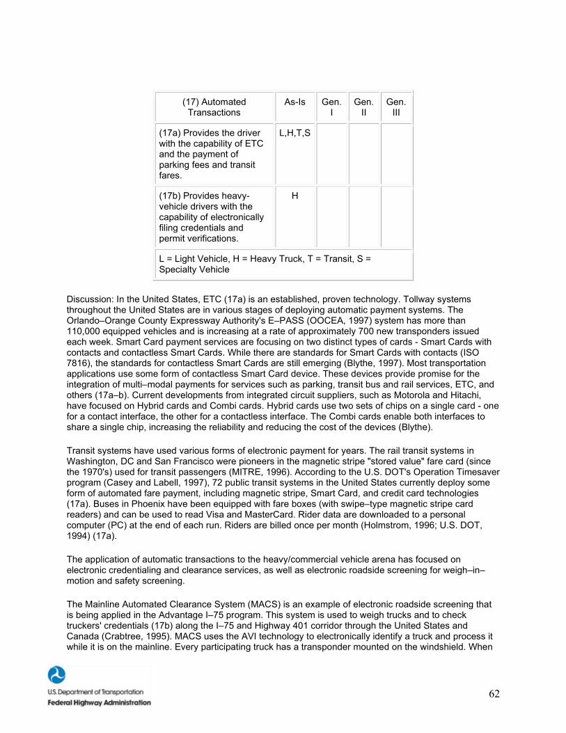
62
(17) Automated Transactions
As-Is Gen. I
Gen. II
Gen. III
(17a) Provides the driver with the capability of ETC and the payment of parking fees and transit fares.
L,H,T,S
(17b) Provides heavy-vehicle drivers with the capability of electronically filing credentials and permit verifications.
H
L = Light Vehicle, H = Heavy Truck, T = Transit, S = Specialty Vehicle
Discussion: In the United States, ETC (17a) is an established, proven technology. Tollway systems throughout the United States are in various stages of deploying automatic payment systems. The Orlando–Orange County Expressway Authority's E–PASS (OOCEA, 1997) system has more than 110,000 equipped vehicles and is increasing at a rate of approximately 700 new transponders issued each week. Smart Card payment services are focusing on two distinct types of cards - Smart Cards with contacts and contactless Smart Cards. While there are standards for Smart Cards with contacts (ISO 7816), the standards for contactless Smart Cards are still emerging (Blythe, 1997). Most transportation applications use some form of contactless Smart Card device. These devices provide promise for the integration of multi–modal payments for services such as parking, transit bus and rail services, ETC, and others (17a–b). Current developments from integrated circuit suppliers, such as Motorola and Hitachi, have focused on Hybrid cards and Combi cards. Hybrid cards use two sets of chips on a single card - one for a contact interface, the other for a contactless interface. The Combi cards enable both interfaces to share a single chip, increasing the reliability and reducing the cost of the devices (Blythe).
Transit systems have used various forms of electronic payment for years. The rail transit systems in Washington, DC and San Francisco were pioneers in the magnetic stripe "stored value" fare card (since the 1970's) used for transit passengers (MITRE, 1996). According to the U.S. DOT's Operation Timesaver program (Casey and Labell, 1997), 72 public transit systems in the United States currently deploy some form of automated fare payment, including magnetic stripe, Smart Card, and credit card technologies (17a). Buses in Phoenix have been equipped with fare boxes (with swipe–type magnetic stripe card readers) and can be used to read Visa and MasterCard. Rider data are downloaded to a personal computer (PC) at the end of each run. Riders are billed once per month (Holmstrom, 1996; U.S. DOT, 1994) (17a).
The application of automatic transactions to the heavy/commercial vehicle arena has focused on electronic credentialing and clearance services, as well as electronic roadside screening for weigh–in–motion and safety screening.
The Mainline Automated Clearance System (MACS) is an example of electronic roadside screening that is being applied in the Advantage I–75 program. This system is used to weigh trucks and to check truckers' credentials (17b) along the I–75 and Highway 401 corridor through the United States and Canada (Crabtree, 1995). MACS uses the AVI technology to electronically identify a truck and process it while it is on the mainline. Every participating truck has a transponder mounted on the windshield. When

63
a truck begins a trip on the I–75 corridor and is processed through a weigh station, specific information about the truck and the transaction is collected and stored in the transponder.
Electronic Roadside Screening (17b) has been demonstrated through the Commercial Vehicle Information Systems Networks (CVISN) (McCall and Kuntemeyer, 1997). For roadside screening, the carrier is identified through a DSRC transponder and standard messages. Fixed–site screening is implemented at stationary roadside inspection sites.
Human Factors Research To–Date. Presently, automated transactions in intelligent vehicles cover electronic toll collection (ETC) and electronic filing of permits and administrative paperwork for CVO applications. ETC is an intelligent–vehicle User Service designed specifically to increase traffic throughput and improve safety on highways. Many of these systems are in use around the country, with most research focusing on development rather than human factors. Some human factors research issues that have been investigated involve display design of the electronic toll booth. Abe, Hori, and Ofuchi (1996) investigated two possible methods of notifying drivers of a completed electronic toll transaction: (1) an auditory beep sounded from an in–vehicle display and (2) a visual out–of–vehicle LED display. The results suggested that the auditory beep was more efficient. Drivers were able to move through the ETC booth without stopping, thus saving 1.9 s of driving time over the visual LED display. Hulse, Dingus, Mollenhauer, Liu, Jahns, Brown, and McKinney (1997) used a literature review, an analysis, and the results of the application of a research–based design tool to determine the various features of an automated transaction display for CVO applications. This display would allow drivers to complete administrative paperwork electronically and to look up regulatory information. Hulse et al.'s research suggests that an in–vehicle automated transaction display should be presented: (1) in visual modality, (2) when the vehicle is in park, and (3) in a textual format.
Human Factors Research Needs. Future research needs for ETC involve the integration of many IVI User Services. A holistic design of IVI User Services would involve integrating electronic toll information with crash avoidance systems (CAS) and autonomous vehicle control systems to achieve smoother and safer passage through the toll collection areas. Research needs with electronic filing include display design issues at regulatory agencies. These agencies would then compile the electronic forms, weigh–in–motion data, and identification tags of the vehicles. All of this information must be presented to regulatory agencies in a simple, efficient manner to decrease travel time and to improve the safety of CVO vehicles.
USER SERVICE 18: SAFETY EVENT RECORDER
RFI Description: This feature would record selected driver and vehicle parameters to support the reconstruction of conditions leading to a critical safety event. Data from this recorder could provide input to the crash notification subsystem for transmission of collision data to the emergency service provider.
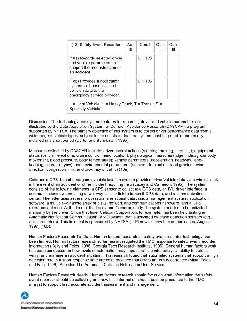
64
(18) Safety Event Recorder As-Is
Gen. I Gen. II
Gen. III
(18a) Records selected driver and vehicle parameters to support the reconstruction of an accident.
L,H,T,S
(18b) Provides a notification system for transmission of collision data to the emergency service provider.
L,H,T,S
L = Light Vehicle, H = Heavy Truck, T = Transit, S = Specialty Vehicle
Discussion: The technology and system features for recording driver and vehicle parameters are illustrated by the Data Acquisition System for Collision Avoidance Research (DASCAR), a program supported by NHTSA. The primary objective of this system is to collect driver performance data from a wide range of vehicle types, subject to the constraint that the system must be portable and readily installed in a short period (Carter and Barickman, 1995).
Measures collected by DASCAR include: driver control actions (steering, braking, throttling); equipment status (cellular telephone, cruise control, hand location); physiological measures (fidget index/gross body movement, blood pressure, body temperature); vehicle parameters (acceleration, headway, lane–keeping, pitch, roll, yaw); and environmental parameters (ambient illumination, road gradient, wind direction, congestion, mix, and proximity of traffic) (18a).
Colorado's GPS–based emergency vehicle location system provides driver/vehicle data via a wireless link in the event of an accident or other incident requiring help (Lacey and Cameron, 1995). The system consists of the following elements: a GPS sensor to collect raw GPS data, an IVU driver interface, a communications system using a two–way cellular link to transmit GPS data, and a communications center. The latter uses several processors, a relational database, a management system, application software, a multiple–gigabyte array of disks, network and communications hardware, and a GPS reference antenna. At the time of the Lacey and Cameron study, the system needed to be activated manually by the driver. Since that time, Calspan Corporation, for example, has been field testing an Automatic Notification Communication (ANC) system that is activated by crash detection sensors (e.g., accelerometers). This field test is sponsored by NHTSA (J. Pierowicz, private communication, August 1997) (18b).
Human Factors Research To–Date. Human factors research on safety event recorder technology has been limited. Human factors research so far has investigated the TMC response to safety event recorder information (Kelly and Folds, 1998; Georgia Tech Research Institute, 1996). General human factors work has been conducted on how levels of automation may impact traffic center analysts' ability to detect, verify, and manage an accident situation. This research found that automated systems that support a high detection rate in a short response time are best, provided that errors are easily corrected (Mitta, Folds, and Fain, 1996). See also The Automatic Collision Notification User Service.
Human Factors Research Needs. Human factors research should focus on what information the safety event recorder should be collecting and how this information should best be presented to the TMC analyst to support fast, accurate accident assessment and management.
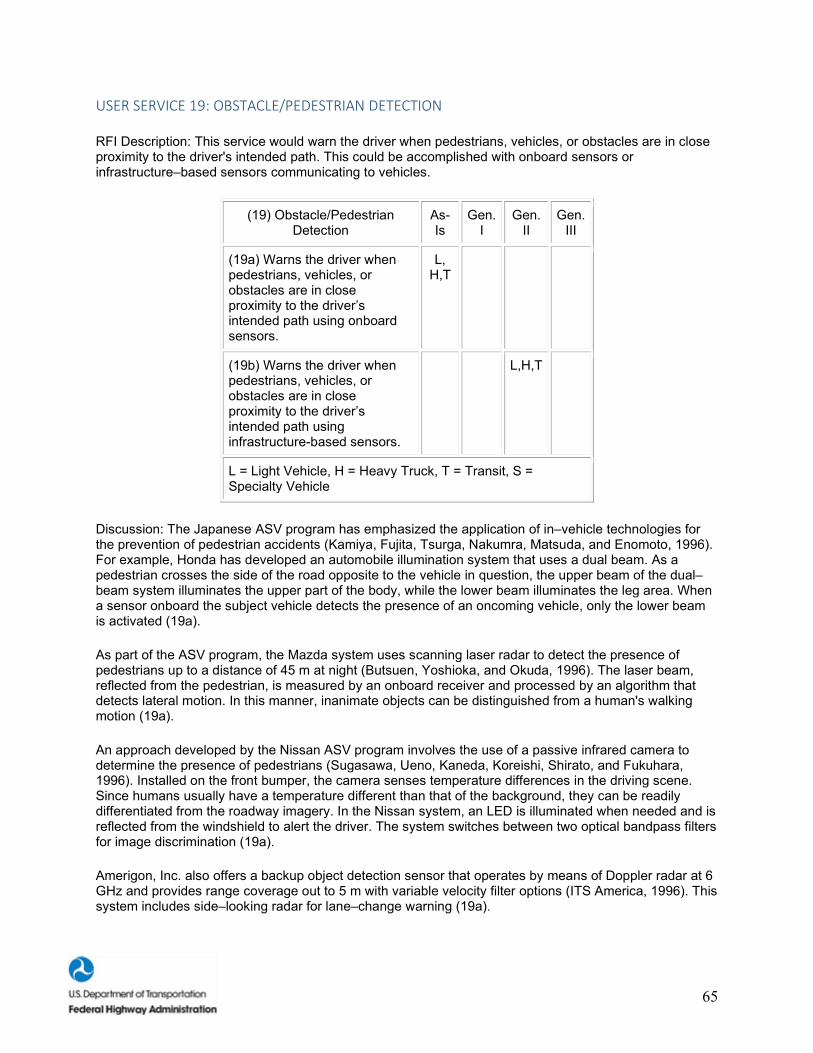
65
USER SERVICE 19: OBSTACLE/PEDESTRIAN DETECTION
RFI Description: This service would warn the driver when pedestrians, vehicles, or obstacles are in close proximity to the driver's intended path. This could be accomplished with onboard sensors or infrastructure–based sensors communicating to vehicles.
(19) Obstacle/Pedestrian Detection
As-Is
Gen. I
Gen. II
Gen. III
(19a) Warns the driver when pedestrians, vehicles, or obstacles are in close proximity to the driver’s intended path using onboard sensors.
L, H,T
(19b) Warns the driver when pedestrians, vehicles, or obstacles are in close proximity to the driver’s intended path using infrastructure-based sensors.
L,H,T
L = Light Vehicle, H = Heavy Truck, T = Transit, S = Specialty Vehicle
Discussion: The Japanese ASV program has emphasized the application of in–vehicle technologies for the prevention of pedestrian accidents (Kamiya, Fujita, Tsurga, Nakumra, Matsuda, and Enomoto, 1996). For example, Honda has developed an automobile illumination system that uses a dual beam. As a pedestrian crosses the side of the road opposite to the vehicle in question, the upper beam of the dual–beam system illuminates the upper part of the body, while the lower beam illuminates the leg area. When a sensor onboard the subject vehicle detects the presence of an oncoming vehicle, only the lower beam is activated (19a).
As part of the ASV program, the Mazda system uses scanning laser radar to detect the presence of pedestrians up to a distance of 45 m at night (Butsuen, Yoshioka, and Okuda, 1996). The laser beam, reflected from the pedestrian, is measured by an onboard receiver and processed by an algorithm that detects lateral motion. In this manner, inanimate objects can be distinguished from a human's walking motion (19a).
An approach developed by the Nissan ASV program involves the use of a passive infrared camera to determine the presence of pedestrians (Sugasawa, Ueno, Kaneda, Koreishi, Shirato, and Fukuhara, 1996). Installed on the front bumper, the camera senses temperature differences in the driving scene. Since humans usually have a temperature different than that of the background, they can be readily differentiated from the roadway imagery. In the Nissan system, an LED is illuminated when needed and is reflected from the windshield to alert the driver. The system switches between two optical bandpass filters for image discrimination (19a).
Amerigon, Inc. also offers a backup object detection sensor that operates by means of Doppler radar at 6 GHz and provides range coverage out to 5 m with variable velocity filter options (ITS America, 1996). This system includes side–looking radar for lane–change warning (19a).
66
Sense Technologies markets a product called Guardian Back Warning System that operates by microwave radar (ITS America, 1996). It detects the presence of persons or objects behind a vehicle during backing and warns the driver. Both audio and visual alarms are activated if there is an object within a preset range. Small objects, such as pets, can be detected out to 7.6 m (25 ft). The system is enabled when the vehicle is in reverse gear (19a).
A review of the literature concerning enhanced pedestrian safety suggests that active infrastructure systems are not generally well known. Much more attention has focused on the use of passive systems, such as improved roadway lighting and well–delineated walk areas. This approach does not involve active driver warning per se, but does improve pedestrian visibility. A recent passive innovation, using UV headlamps, fluorescent pavement markings, signs, and, indirectly, many types of pedestrian clothing has shown considerable promise for pedestrian safety (Mahach, Knoblauch, Simmons, Nitzburg, Areans, and Tignor, 1997). Headlamps can be made to radiate in both the visible and UV spectral regions. The visible portion of the emitted light will illuminate a pedestrian and cause him/her to be seen by reflection. UV light, invisible to the eye, can be absorbed by certain pigments contained in roadway markings, signs, and clothing and will be re–radiated as visible light (i.e., through the fluorescence process). It has been shown that this re–radiated light will improve the driver's visibility range considerably (19b).
Human Factors Research To–Date. The key human factors research studies to–date include: (1) the analysis of a pedestrian detection in–vehicle display and (2) the impact of automotive HUD's on obstacle detection. Two pedestrian detection system displays designed for a school bus application were investigated by Johnston, Mazzae, and Garrott (1996). Johnston et al. (1996) conducted human factors display design evaluations (using the COMSIS Preliminary Human Factors Guidelines for Crash Avoidance Warning Devices) and analyzed drivers' subjective ratings after using each system for 1 day. Generally, the human factors evaluations found the systems to be well–designed as corroborated by seven out of eight drivers who reported checking the display before pulling away from bus stops. Johnston et al. concluded that a properly designed radar–based display was a useful tool for bus drivers. Bossi, Ward, Parkes, and Howarth (1993) performed a study investigating drivers' ability to detect obstacles in the near periphery while driving with an automotive HUD. Drivers did not detect or identify as many peripheral targets when using the HUD, suggesting that the HUD caused cognitive capture in drivers. These two key research studies imply that heavy/commercial vehicle pedestrian detection systems may significantly improve drivers' ability to detect pedestrians, while automotive HUD's have been shown to reduce drivers' ability to detect obstacles in the near periphery. These results should be a warning to automotive display designers.
Human Factors Research Needs. Research is needed on improving the sensor ranges of in–vehicle pedestrian detection systems and integrating obstacle/pedestrian detection systems with other IVI user systems. The sensor range must provide coverage of all driver blind spots without creating false alarms (Johnston et al., 1996). Future human factors research also needs to address the issues of integrating pedestrian/detection systems with other CAS, automated vehicular control systems, and information systems to not only warn drivers of dangerous situations, but to provide corrective information as well (M.M. Lloyd, personal communication, March 13, 1998). Automotive HUD future research should address the issues of cognitive capture and the limited FOV provided by HUD's, paying close attention to the performance of older drivers (Bossi et al., 1997).
USER SERVICE 20: TIGHT MANEUVER/PRECISION DOCKING
RFI Description: This service would position the bus or heavy/commercial vehicle very precisely relative to the curb or loading platform. The driver would maneuver the bus into the loading area and then turn it over to automation. Sensors would continually determine the lateral distance to the curb, front and rear, and the longitudinal distance to the end of the vehicle loading area. The driver would be able to override it at any time by operating brakes or steering, and would be expected to monitor the situation and take emergency action if necessary (for example, if a pedestrian steps in front of the vehicle). When the
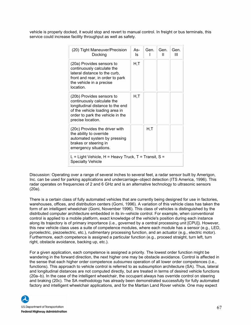
67
vehicle is properly docked, it would stop and revert to manual control. In freight or bus terminals, this service could increase facility throughput as well as safety.
(20) Tight Maneuver/Precision Docking
As-Is
Gen. I
Gen. II
Gen. III
(20a) Provides sensors to continuously calculate the lateral distance to the curb, front and rear, in order to park the vehicle in a precise location.
H,T
(20b) Provides sensors to continuously calculate the longitudinal distance to the end of the vehicle loading area in order to park the vehicle in the precise location.
H,T
(20c) Provides the driver with the ability to override automated system by pressing brakes or steering in emergency situations.
H,T
L = Light Vehicle, H = Heavy Truck, T = Transit, S = Specialty Vehicle
Discussion: Operating over a range of several inches to several feet, a radar sensor built by Amerigon, Inc. can be used for parking applications and undercarriage–object detection (ITS America, 1996). This radar operates on frequencies of 2 and 6 GHz and is an alternative technology to ultrasonic sensors (20a).
There is a certain class of fully automated vehicles that are currently being designed for use in factories, warehouses, offices, and distribution centers (Gomi, 1996). A variation of this vehicle class has taken the form of an intelligent wheelchair (Gomi, November 1996). This class of vehicles is distinguished by the distributed computer architecture embedded in its in–vehicle control. For example, when conventional control is applied to a mobile platform, exact knowledge of the vehicle's position during each instance along its trajectory is of primary importance (i.e., governed by a central processing unit [CPU]). However, this new vehicle class uses a suite of competence modules, where each module has a sensor (e.g., LED, pyroelectric, piezoelectric, etc.), rudimentary processing function, and an actuator (e.g., electric motor). Furthermore, each competence is assigned a particular function (e.g., proceed straight, turn left, turn right, obstacle avoidance, backing up, etc.).
For a given application, each competence is assigned a priority. The lowest order function might be wandering in the forward direction, the next higher one may be obstacle avoidance. Control is affected in the sense that each higher order competence subsumes operation of all lower order competences (i.e., functions). This approach to vehicle control is referred to as subsumption architecture (SA). Thus, lateral and longitudinal distances are not computed directly, but are treated in terms of desired vehicle functions (20a–b). In the case of the intelligent wheelchair, the occupant always has override control on steering and braking (20c). The SA methodology has already been demonstrated successfully for fully automated factory and intelligent wheelchair applications, and for the Martian Land Rover vehicle. One may expect
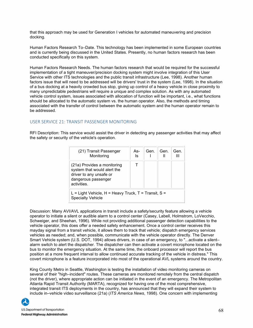
68
that this approach may be used for Generation I vehicles for automated maneuvering and precision docking.
Human Factors Research To–Date. This technology has been implemented in some European countries and is currently being discussed in the United States. Presently, no human factors research has been conducted specifically on this system.
Human Factors Research Needs. The human factors research that would be required for the successful implementation of a tight maneuver/precision docking system might involve integration of this User Service with other ITS technologies and the public transit infrastructure (Lee, 1998). Another human factors issue that will need to be addressed will be drivers' trust in the system (Lee, 1998). In the situation of a bus docking at a heavily crowded bus stop, giving up control of a heavy vehicle in close proximity to many unpredictable pedestrians will require a unique and complex solution. As with any automated vehicle control system, issues associated with allocation of function will be important, i.e., what functions should be allocated to the automatic system vs. the human operator. Also, the methods and timing associated with the transfer of control between the automatic system and the human operator remain to be addressed.
USER SERVICE 21: TRANSIT PASSENGER MONITORING
RFI Description: This service would assist the driver in detecting any passenger activities that may affect the safety or security of the vehicle's operation.
(21) Transit Passenger Monitoring
As-Is
Gen. I
Gen. II
Gen. III
(21a) Provides a monitoring system that would alert the driver to any unsafe or dangerous passenger activities.
T
L = Light Vehicle, H = Heavy Truck, T = Transit, S = Specialty Vehicle
Discussion: Many AVI/AVL applications in transit include a safety/security feature allowing a vehicle operator to initiate a silent or audible alarm to a control center (Casey, Labell, Holmstrom, LoVecchio, Schweiger, and Sheehan, 1996). While not providing additional passenger detection capabilities to the vehicle operator, this does offer a needed safety enhancement. Once a control center receives this mayday signal from a transit vehicle, it allows them to track that vehicle; dispatch emergency services vehicles as needed; and, when possible, communicate with the vehicle operator directly. The Denver Smart Vehicle system (U.S. DOT, 1994) allows drivers, in case of an emergency, to "...activate a silent–alarm switch to alert the dispatcher. The dispatcher can then activate a covert microphone located on the bus to monitor the emergency situation. At the same time, the onboard processor will report the bus position at a more frequent interval to allow continued accurate tracking of the vehicle in distress." This covert microphone is a feature incorporated into most of the operational AVL systems around the country.
King County Metro in Seattle, Washington is testing the installation of video monitoring cameras on several of their "high–incident" routes. These cameras are monitored remotely from the central dispatch (not the driver), where appropriate action can be initiated in the event of an emergency. The Metropolitan Atlanta Rapid Transit Authority (MARTA), recognized for having one of the most comprehensive, integrated transit ITS deployments in the country, has announced that they will expand their system to include in–vehicle video surveillance (21a) (ITS America News, 1998). One concern with implementing
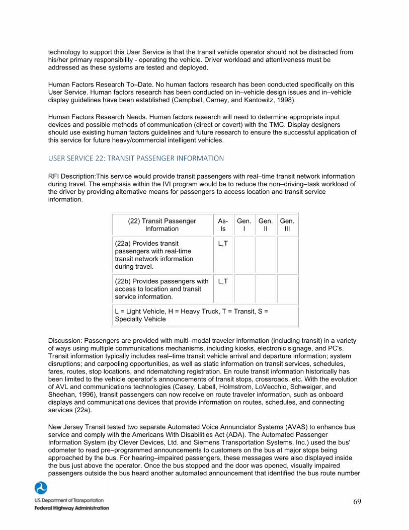
69
technology to support this User Service is that the transit vehicle operator should not be distracted from his/her primary responsibility - operating the vehicle. Driver workload and attentiveness must be addressed as these systems are tested and deployed.
Human Factors Research To–Date. No human factors research has been conducted specifically on this User Service. Human factors research has been conducted on in–vehicle design issues and in–vehicle display guidelines have been established (Campbell, Carney, and Kantowitz, 1998).
Human Factors Research Needs. Human factors research will need to determine appropriate input devices and possible methods of communication (direct or covert) with the TMC. Display designers should use existing human factors guidelines and future research to ensure the successful application of this service for future heavy/commercial intelligent vehicles.
USER SERVICE 22: TRANSIT PASSENGER INFORMATION
RFI Description:This service would provide transit passengers with real–time transit network information during travel. The emphasis within the IVI program would be to reduce the non–driving–task workload of the driver by providing alternative means for passengers to access location and transit service information.
(22) Transit Passenger Information
As-Is
Gen. I
Gen. II
Gen. III
(22a) Provides transit passengers with real-time transit network information during travel.
L,T
(22b) Provides passengers with access to location and transit service information.
L,T
L = Light Vehicle, H = Heavy Truck, T = Transit, S = Specialty Vehicle
Discussion: Passengers are provided with multi–modal traveler information (including transit) in a variety of ways using multiple communications mechanisms, including kiosks, electronic signage, and PC's. Transit information typically includes real–time transit vehicle arrival and departure information; system disruptions; and carpooling opportunities, as well as static information on transit services, schedules, fares, routes, stop locations, and ridematching registration. En route transit information historically has been limited to the vehicle operator's announcements of transit stops, crossroads, etc. With the evolution of AVL and communications technologies (Casey, Labell, Holmstrom, LoVecchio, Schweiger, and Sheehan, 1996), transit passengers can now receive en route traveler information, such as onboard displays and communications devices that provide information on routes, schedules, and connecting services (22a).
New Jersey Transit tested two separate Automated Voice Annunciator Systems (AVAS) to enhance bus service and comply with the Americans With Disabilities Act (ADA). The Automated Passenger Information System (by Clever Devices, Ltd. and Siemens Transportation Systems, Inc.) used the bus' odometer to read pre–programmed announcements to customers on the bus at major stops being approached by the bus. For hearing–impaired passengers, these messages were also displayed inside the bus just above the operator. Once the bus stopped and the door was opened, visually impaired passengers outside the bus heard another automated announcement that identified the bus route number
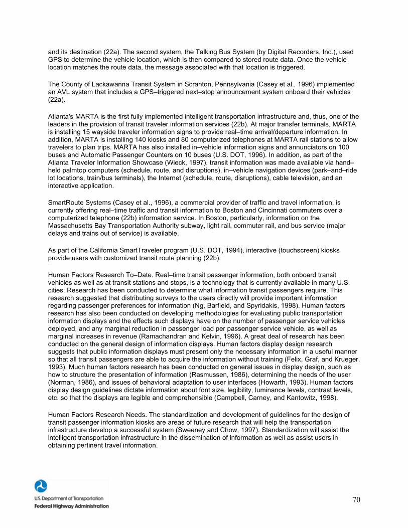
70
and its destination (22a). The second system, the Talking Bus System (by Digital Recorders, Inc.), used GPS to determine the vehicle location, which is then compared to stored route data. Once the vehicle location matches the route data, the message associated with that location is triggered.
The County of Lackawanna Transit System in Scranton, Pennsylvania (Casey et al., 1996) implemented an AVL system that includes a GPS–triggered next–stop announcement system onboard their vehicles (22a).
Atlanta's MARTA is the first fully implemented intelligent transportation infrastructure and, thus, one of the leaders in the provision of transit traveler information services (22b). At major transfer terminals, MARTA is installing 15 wayside traveler information signs to provide real–time arrival/departure information. In addition, MARTA is installing 140 kiosks and 80 computerized telephones at MARTA rail stations to allow travelers to plan trips. MARTA has also installed in–vehicle information signs and annunciators on 100 buses and Automatic Passenger Counters on 10 buses (U.S. DOT, 1996). In addition, as part of the Atlanta Traveler Information Showcase (Wieck, 1997), transit information was made available via hand–held palmtop computers (schedule, route, and disruptions), in–vehicle navigation devices (park–and–ride lot locations, train/bus terminals), the Internet (schedule, route, disruptions), cable television, and an interactive application.
SmartRoute Systems (Casey et al., 1996), a commercial provider of traffic and travel information, is currently offering real–time traffic and transit information to Boston and Cincinnati commuters over a computerized telephone (22b) information service. In Boston, particularly, information on the Massachusetts Bay Transportation Authority subway, light rail, commuter rail, and bus service (major delays and trains out of service) is available.
As part of the California SmartTraveler program (U.S. DOT, 1994), interactive (touchscreen) kiosks provide users with customized transit route planning (22b).
Human Factors Research To–Date. Real–time transit passenger information, both onboard transit vehicles as well as at transit stations and stops, is a technology that is currently available in many U.S. cities. Research has been conducted to determine what information transit passengers require. This research suggested that distributing surveys to the users directly will provide important information regarding passenger preferences for information (Ng, Barfield, and Spyridakis, 1998). Human factors research has also been conducted on developing methodologies for evaluating public transportation information displays and the effects such displays have on the number of passenger service vehicles deployed, and any marginal reduction in passenger load per passenger service vehicle, as well as marginal increases in revenue (Ramachandran and Kelvin, 1996). A great deal of research has been conducted on the general design of information displays. Human factors display design research suggests that public information displays must present only the necessary information in a useful manner so that all transit passengers are able to acquire the information without training (Felix, Graf, and Krueger, 1993). Much human factors research has been conducted on general issues in display design, such as how to structure the presentation of information (Rasmussen, 1986), determining the needs of the user (Norman, 1986), and issues of behavioral adaptation to user interfaces (Howarth, 1993). Human factors display design guidelines dictate information about font size, legibility, luminance levels, contrast levels, etc. so that the displays are legible and comprehensible (Campbell, Carney, and Kantowitz, 1998).
Human Factors Research Needs. The standardization and development of guidelines for the design of transit passenger information kiosks are areas of future research that will help the transportation infrastructure develop a successful system (Sweeney and Chow, 1997). Standardization will assist the intelligent transportation infrastructure in the dissemination of information as well as assist users in obtaining pertinent travel information.
71
USER SERVICE 23: FULLY AUTOMATED CONTROL AT CERTAIN FACILITIES
RFI Description: This service would enhance efficiency and productivity by providing automated movement of vehicles in dedicated facilities. Initial applications may include automated bus movement in maintenance areas and automated container movement within a terminal area. The transit bus application could be a preliminary use of automation in a low–speed, controlled environment. The automated container movement application would consist of using vehicle automation technologies to move containers within rail–, truck–, or shipyards, or other centralized facilities.
(23) Fully Automated Control at Certain Facilities
As-Is
Gen. I
Gen. II
Gen. III
(23a) Provides automated movement of transit buses in a low-speed, controlled environment (i.e., maintenance areas or in terminals).
T
(23b) Provides automated movement in rail-,
truck-, or shipyards or other centralized facilities.
H
L = Light Vehicle, H = Heavy Truck, T = Transit, S = Specialty Vehicle
Discussion: An analysis of transit operations has been conducted regarding routine maintenance operations that include fueling, fluids check, and washing (Hopkins and Larson, 1997). This report noted that automating the movement of buses through these areas could reduce operating expenses. Automation could be achieved by means of self–guided vehicles that are now used for the movement of large containers (up to 40,824 kg [45 tons]) within the confines of a shipping area (see below). To the best of our knowledge, the automated movement of buses in a service area has not yet occurred. However, the feasibility of this method is clearly evident and would be a candidate for a Generation I system (23a).
The subject of automating the movement of trucks and trailers in shipping areas (e.g., truck terminals, railroad yards, and port areas) has been addressed (Hopkins, 1996). It was noted, for example, that the port of Rotterdam uses more than 50 unmanned automated guided vehicles (AGV) to transport containers from ships to stacking areas. Since the first terminal at Rotterdam was successful in terms of reducing wage costs, a second terminal was under construction when the preceding reference was published.
Designed and built by Gottwald of Germany, the AGV in use at Rotterdam weighs 11,794 kg (13 tons) and can transport up to 40,824 kg (45 tons). The navigation system, Free–Ranging on Grid (FROG), is based on a ground–based grid with transponders at node intersections. The transponders provide data with identification and positional information to be combined with the dead–reckoning module onboard the AGV (23b).
The Thamesport intermodal facility in England is another example of using an automated guided vehicle. In this case, a single AGV is used to transport containers from ship to stack. Guidance was provided by millimeter wave radar, which initially encountered operational problems due to signal clutter from
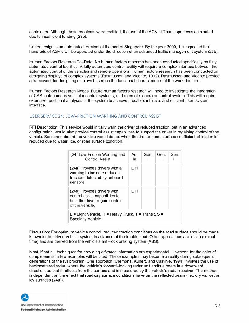
72
containers. Although these problems were rectified, the use of the AGV at Thamesport was eliminated due to insufficient funding (23b).
Under design is an automated terminal at the port of Singapore. By the year 2000, it is expected that hundreds of AGV's will be operated under the direction of an advanced traffic management system (23b).
Human Factors Research To–Date. No human factors research has been conducted specifically on fully automated control facilities. A fully automated control facility will require a complex interface between the automated control of the vehicles and remote operators. Human factors research has been conducted on designing displays of complex systems (Rasmussen and Vicente, 1992). Rasmussen and Vicente provide a framework for designing displays based on the functional characteristics of the work domain.
Human Factors Research Needs. Future human factors research will need to investigate the integration of CAS, autonomous vehicular control systems, and a remote–operator control system. This will require extensive functional analyses of the system to achieve a usable, intuitive, and efficient user–system interface.
USER SERVICE 24: LOW–FRICTION WARNING AND CONTROL ASSIST
RFI Description: This service would initially warn the driver of reduced traction, but in an advanced configuration, would also provide control assist capabilities to support the driver in regaining control of the vehicle. Sensors onboard the vehicle would detect when the tire–to–road–surface coefficient of friction is reduced due to water, ice, or road surface condition.
(24) Low-Friction Warning and Control Assist
As-Is
Gen. I
Gen. II
Gen. III
(24a) Provides drivers with a warning to indicate reduced traction, detected by onboard sensors.
L,H
(24b) Provides drivers with control assist capabilities to help the driver regain control of the vehicle.
L,H
L = Light Vehicle, H = Heavy Truck, T = Transit, S = Specialty Vehicle
Discussion: For optimum vehicle control, reduced traction conditions on the road surface should be made known to the driver–vehicle system in advance of the trouble spot. Other approaches are in situ (or real time) and are derived from the vehicle's anti–lock braking system (ABS).
Most, if not all, techniques for providing advance information are experimental. However, for the sake of completeness, a few examples will be cited. These examples may become a reality during subsequent generations of the IVI program. One approach (Cremona, Kunert, and Castinie, 1994) involves the use of backscattered radar, where the vehicle's forward–looking radar unit emits a beam in a downward direction, so that it reflects from the surface and is measured by the vehicle's radar receiver. The method is dependent on the effect that roadway surface conditions have on the reflected beam (i.e., dry vs. wet or icy surfaces (24a)).

73
Another method for providing advance driver information could be achieved by means of sensors embedded in the roadway to measure temperature, as well as percentage of ice, percentage of chemical solution, and depth of the solution (Surface Systems, Inc., 1997). These embedded roadway sensors could be connected to a roadway communications link to broadcast surface conditions to drivers (24a).
Real–time measurements of road surface conditions can be accomplished by using a vehicle's ABS sensors (General Motors, 1991). The latter guards against wheel lockup by measuring the difference in wheel rotation rates. After detecting a variation, the system passes sensor signals to the ABS computer, which then applies a command to the braking control system in the hydraulic line. Detection of such variations could result in the issuance of an alert to the driver (24a).
There are several electronic systems now under development that will assist the driver (King, 1997). For example, General Motors Delphi Systems has engineered an electronic brake that eliminates the need for a hydraulic system to actuate the brakes. This brake "by wire" approach provides an assisted boost during panic stops. By measuring the velocity of the driver brake depression, the system is able to determine the need for additional braking, which the driver would be unable to otherwise supply during an emergency (24b). Cadillac makes an integrated chassis control system that measures how well the driver is maneuvering the steering wheel compared to how well the vehicle is responding. If the response is inadequate, the system applies individual front brakes to return the vehicle to its intended path (24b).
Human Factors Research To–Date. No human factors research has been conducted on low–friction warning and control assist systems.
Human Factors Research Needs. Future human factors research will be required to: (1) provide easily interpretable visual and auditory displays, (2) design warnings that will capture the driver's attention while at the same time conveying the appropriate level of urgency, and (3) determine the level of accuracy required for drivers to use the system and maintain its usefulness (Lee, 1997). The success of this system will depend upon simple and intuitive displays that will appropriately alert drivers that their tires are slipping and guide their control actions to promote safe, vehicular control.
USER SERVICE 25: LONGITUDINAL CONTROL
RFI Description: Longitudinal control would range from normal cruise control to advanced cooperative cruise control and applications that permit full automatic braking. Intelligent cruise control senses the presence and relative velocity of moving vehicles ahead of the equipped vehicle and adjusts the speed of travel to maintain a safe separation between vehicles. Vehicle speed is adjusted either by allowing the vehicle to coast or by transmission downshifting. More advanced longitudinal control systems would be capable of detecting a vehicle ahead in the same lane that may be traveling at any speed or may be fully stopped. A full range of braking capabilities and operating speeds would be available to the equipped vehicle, including stop–and–go traffic operations. This service can be provided by autonomous in–vehicle systems or with assistance from vehicle–to–vehicle and vehicle–infrastructure cooperation.
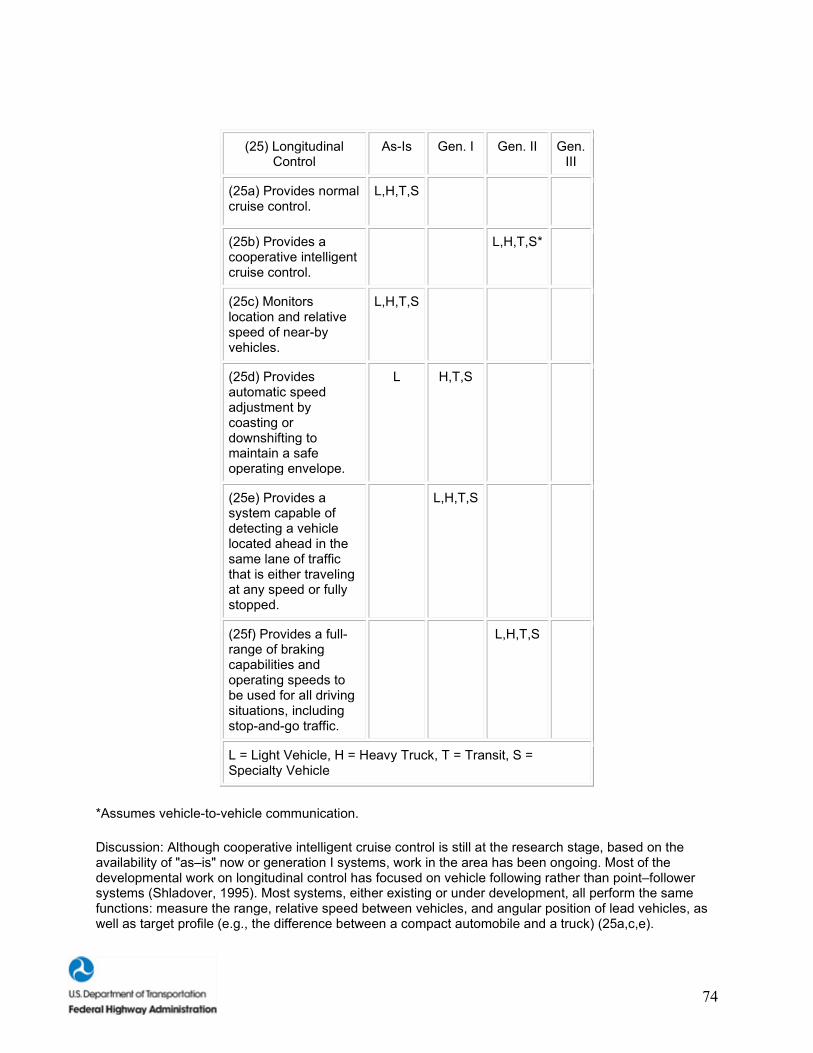
74
(25) Longitudinal Control
As-Is Gen. I Gen. II Gen. III
(25a) Provides normal cruise control.
L,H,T,S
(25b) Provides a cooperative intelligent cruise control.
L,H,T,S*
(25c) Monitors location and relative speed of near-by vehicles.
L,H,T,S
(25d) Provides automatic speed adjustment by coasting or downshifting to maintain a safe operating envelope.
L H,T,S
(25e) Provides a system capable of detecting a vehicle located ahead in the same lane of traffic that is either traveling at any speed or fully stopped.
L,H,T,S
(25f) Provides a full-range of braking capabilities and operating speeds to be used for all driving situations, including stop-and-go traffic.
L,H,T,S
L = Light Vehicle, H = Heavy Truck, T = Transit, S = Specialty Vehicle
*Assumes vehicle-to-vehicle communication.
Discussion: Although cooperative intelligent cruise control is still at the research stage, based on the availability of "as–is" now or generation I systems, work in the area has been ongoing. Most of the developmental work on longitudinal control has focused on vehicle following rather than point–follower systems (Shladover, 1995). Most systems, either existing or under development, all perform the same functions: measure the range, relative speed between vehicles, and angular position of lead vehicles, as well as target profile (e.g., the difference between a compact automobile and a truck) (25a,c,e).
75
There are numerous examples of automotive radar systems. Radar operating at 35 GHz is electronically scanned at 2 degrees/s in the horizontal direction with an angular sweep of ±16 degrees (Daniels, 1988). Another unit operates at 94 GHz using a fixed antenna pattern to define the radar beam (Stove, 1992). Still another microwave radar has a receiving antenna that is scanned electronically to generate three receiver beams (Williams, 1992) (25a,c,e). Also, a laser radar system has been developed that uses knowledge of the vehicle state and object recognition to minimize the effect of alarms due to roadside objects (Maretzke and Jacob, 1992). A fuzzy logic algorithm controls the distance setting (Mueller and Noecker, 1992) (25f). According to a review paper (Martin, 1993), a millimeter wave radar provides the option of allowing the driver to select the vehicle to be followed in order to set the headway.
Several references report work on the development of prototypes with automatic deceleration, either by means of braking, throttle, or transmission control (25d,f). The use of brake and transmission control is discussed in a paper by Winner et al. from the Robert Bosch company (Winner, Witte, Uhler, and Lichtenberg, 1996). Other examples of automatic control are discussed in the context of the integration between anti–collision and AICC functions (Carrea, 1993), and the incorporation of automatic braking with intelligent cruise control (Martin, 1993) (25d,f).
Technical issues and algorithm requirements have been described in terms of platoon–type systems, where each vehicle in the platoon receives data from the leading and preceding vehicles via a communications link (Asher and Galler, 1996) (25b).
Human Factors Research To–Date. The human factors research to–date has focused on determining the appropriate headways between preceding vehicles in automated highway systems and unautomated highway systems. In unautomated highway systems, research has suggested that a time–to–collision (TTC) of 4 s, with an added counterforce to speed control, successfully reduces close following behavior while not increasing overall speed (Janssen and Thomas, 1997; Godthelp and Schumann, 1993). Longitudinal control research in automated highway systems suggests that drivers will accept high ranges of speed (up to 153 km/h [95 mi/h]). However, they will not accept gap distances of less than 1.8 m, 2.2 m, and 2.7 m at vehicle speeds of 104.7 km/h (65 mi/h), 128.8 km/h (80 mi/h), and 153.0 km/h (95 mi/h), respectively (Levitan and Bloomfield, 1998). Drivers in simulation experiments indicated that they were more interested in the safety aspects of intelligent cruise control/CAS and less interested in increasing highway efficiency. Drivers did not exhibit a lot of trust in automated systems because they doubt the reliability of automated technologies and the ability of these technologies to respond to novel situations (Turrentine, Sperling, and Hungerford, 1991).
Human Factors Research Needs. Future research issues should include investigating the effects of a longitudinal control system on driver performance. More long–term studies with habitual AICC users need to be conducted to determine the long–term effects on the driving population. Secondly, the driver's psychological comfort of inter–vehicle distances must be better understood to develop guidelines that enhance user trust in the system. In particular, drivers may want the ability to adjust headway distances, given the larger individual differences associated with headway comfort zones.
USER SERVICE 26: LATERAL CONTROL
RFI Description: This service would sense the center of the lane and continually actuate the steering to keep the vehicle in the center of its lane. For the service to dependably detect the lane boundaries, some infrastructure cooperation may be required, such as accurately painted lane–marker stripes, embedded magnetic nails, or radar–reflective stripes. The driver would be able to assume control at any time.
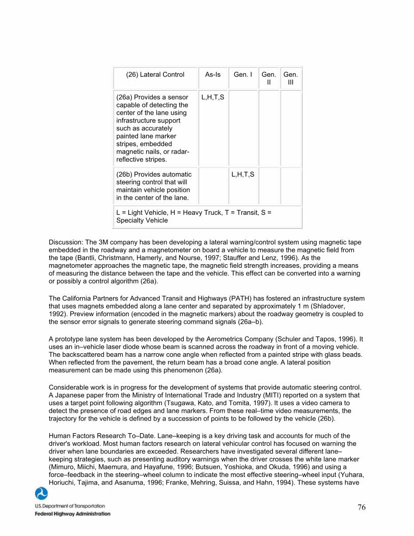
76
(26) Lateral Control As-Is Gen. I Gen. II
Gen. III
(26a) Provides a sensor capable of detecting the center of the lane using infrastructure support such as accurately painted lane marker stripes, embedded magnetic nails, or radar-reflective stripes.
L,H,T,S
(26b) Provides automatic steering control that will maintain vehicle position in the center of the lane.
L,H,T,S
L = Light Vehicle, H = Heavy Truck, T = Transit, S = Specialty Vehicle
Discussion: The 3M company has been developing a lateral warning/control system using magnetic tape embedded in the roadway and a magnetometer on board a vehicle to measure the magnetic field from the tape (Bantli, Christmann, Hamerly, and Nourse, 1997; Stauffer and Lenz, 1996). As the magnetometer approaches the magnetic tape, the magnetic field strength increases, providing a means of measuring the distance between the tape and the vehicle. This effect can be converted into a warning or possibly a control algorithm (26a).
The California Partners for Advanced Transit and Highways (PATH) has fostered an infrastructure system that uses magnets embedded along a lane center and separated by approximately 1 m (Shladover, 1992). Preview information (encoded in the magnetic markers) about the roadway geometry is coupled to the sensor error signals to generate steering command signals (26a–b).
A prototype lane system has been developed by the Aerometrics Company (Schuler and Tapos, 1996). It uses an in–vehicle laser diode whose beam is scanned across the roadway in front of a moving vehicle. The backscattered beam has a narrow cone angle when reflected from a painted stripe with glass beads. When reflected from the pavement, the return beam has a broad cone angle. A lateral position measurement can be made using this phenomenon (26a).
Considerable work is in progress for the development of systems that provide automatic steering control. A Japanese paper from the Ministry of International Trade and Industry (MITI) reported on a system that uses a target point following algorithm (Tsugawa, Kato, and Tomita, 1997). It uses a video camera to detect the presence of road edges and lane markers. From these real–time video measurements, the trajectory for the vehicle is defined by a succession of points to be followed by the vehicle (26b).
Human Factors Research To–Date. Lane–keeping is a key driving task and accounts for much of the driver's workload. Most human factors research on lateral vehicular control has focused on warning the driver when lane boundaries are exceeded. Researchers have investigated several different lane–keeping strategies, such as presenting auditory warnings when the driver crosses the white lane marker (Mimuro, Miichi, Maemura, and Hayafune, 1996; Butsuen, Yoshioka, and Okuda, 1996) and using a force–feedback in the steering–wheel column to indicate the most effective steering–wheel input (Yuhara, Horiuchi, Tajima, and Asanuma, 1996; Franke, Mehring, Suissa, and Hahn, 1994). These systems have
77
used one or a combination of the following technologies: closed–circuit digital cameras (CCDC), differential GPS, and magnetic lane markers buried underneath the highway. Research has indicated that drivers respond easily and quickly to tactile feedback in the steering column, and that such feedback control will reduce drivers' workload (Franke et al., 1994). While preliminary research suggests that auditory warnings are effective and keep the drivers alert, other research indicates that auditory warnings, over time, become an annoyance and may cause higher levels of perceived workload (King and Corso, 1993).
Human Factors Research Needs. On–road driving studies investigating lateral control technologies need to be conducted to: (1) test the auditory and tactile warnings in real–life situations and (2) test the system's effect on driving performance over time. Auditory and tactile warnings may prove effective in simulators; however, new problems may develop when the ambient noise level or the driving situations are not controlled. Lateral control systems may also cause problems if drivers rely too heavily on them for safe navigation.
Infrastructure Requirements for the User Services
Because there are a significant number of the 26 User Services that do not require infrastructure support, a general discussion of infrastructure requirements will be presented in this section. Where appropriate, the discussion will identify those User Services that are or are not expected to be dependent on infrastructure support.
As noted in each of the 26 User Services discussions, there are already many ITS technologies that have been deployed or will be deployed for in–vehicle use. The intention is to take advantage of these in–vehicle technologies to enhance roadside safety and other driver–enhanced capabilities. As noted in earlier discussions, current in–vehicle technologies include: (1) transponders for ETC, parking garage admittance, heavy/commercial vehicle operations, transit operations, and vehicle–to–roadside communications; (2) digital maps; (3) GPS; (4) audio/visual displays; (5) Internet; and (6) magnetic tape.
Transponders are experiencing accelerated deployment for use in toll plazas (ETC, etc.) (User Service 17a), heavy/commercial vehicle operations (CVO, for electronic transfer of driver, vehicle, and cargo data) (User Service 17b), parking garages (User Service 17a), and transit operations (User Service 17b). The transponders listed above are generally referred to as dedicated short–range communication (DSRC) devices. There is a considerable body of work in progress to standardize these transponder technologies and make them suitable for multiple applications.
Working in concert with the above in–vehicle technologies, other transponders located by the roadside (electronic messaging that uses vehicle–to–roadside communications [VRC]) can be used to broadcast information about potentially dangerous road conditions before those conditions are actually encountered by an oncoming motorist (User Services 7c–f) (Kady and Schloss, 1994). Furthermore, in–pavement sensors, a mature technology, can be coupled to a VRC to provide advance warning about unsafe roadway conditions (User Services 11b–d). The output of the in–vehicle transponder would be applied to a display (visual, audio) for the benefit of the driver. The display would be in use for other purposes, such as route guidance or electronic yellow pages (User Services 10a–g). Dynamic messaging (i.e., systems that have the ability to instantaneously change the content of the sign information based on sensor inputs) can be used to inform the driver of current conditions. For example, a dynamic sign can monitor ice on the roadway and transmit the message "icy bridge" only when there is ice present rather than the words "watch for ice on bridge." Dynamic messages can also be of value in providing convenience information (User Service 12a). Freeway exit signs for stadium and other high–traffic areas can be dynamically changed to direct traffic from one exit to another. This dynamic rerouting can help even–out traffic flow on the adjoining streets.
The in–vehicle dynamic messaging would employ a user interface for both audio and visual displays to provide a control, allowing various levels of sign messages to be enabled. Selective information control
78
reduces the possibility of information overload and driver frustration, especially over routinely traveled routes (User Service 12b).
The infrastructure required to support the VRC one–way broadcast scheme is minimal. A typical installation includes a roadside electronics (VRC transmitter) box, a solar cell or power–line connection, and a simple low–cost log periodic antenna (Kady and Shloss, 1997). Alternatively, for dynamic messaging, the roadside hardware would include the VRC transmitter and an application processor. The VRC transmitter is designed to transmit fixed and/or variable messages to the transponders. The application processor acts as a local controller, providing the fixed or variable sign message data to the VRC transmitter as well as interfacing to sensors. These sensors may be used to detect ice, deer crossings, high winds, etc. for use as dynamic sign information. The application processor can be programmed to include such logic as message priorities, message formatting and coding, and system status checking.
Infrastructure is also available by means other than technologies physically embedded by the roadside. For example, digital maps and GPS technologies are currently used for route guidance and navigation (Getting, 1993). These maps, available on a CD–ROM, could be embedded with infrastructure information, such as curves, their design speeds, intersections, railroad grade crossings, and locations of other dangerous roadway conditions (User Services 4a,5a). The CD–ROM storage of map data and the use of GPS satellite signals for position detection are technologies that have been incorporated in navigation systems now on the market (Nakayama, Tsuda, Itoh, and Ishikawa, 1993). When combined with GPS, a digital map would indicate the location of a vehicle with respect to potentially hazardous roadside conditions (User Services 7a,e).
NHTSA is sponsoring collision avoidance specification development programs, where the use of such embedded digital data is integrated within the context of a CAS (Wilson and Butler, 1997). This data resource could be expanded to include roadside safety data. The inclusion of infrastructure information for in–vehicle use could happen along parallel developmental paths now, both for future collision avoidance applications and for near–term roadside safety requirements.
Several computer companies are currently developing in–vehicle computer systems to provide passenger entertainment and integrated business capabilities. The latter includes e–mail, cellular telephones, and fax machines. In the near future, a wireless connection from a vehicle to the Internet will be available. When that event happens, a revolutionary new source of technology will be available to provide considerable infrastructure information to the motorist (User Service 12a).
In addition to infrastructure information derived from roadside transponders or digital maps, magnetic tape embedded in the roadway can be used. For example, preventing snowplows from running off the road is a concern being addressed by the FHWA and commercial interests. One approach for the avoidance of such roadway departures is to embed magnetic tape in the pavement. The magnetic field from this tape can be measured by a magnetometer onboard the snowplow. As the snowplow nears the lane edge, the measured magnetic field increases. This effect can be converted into an in–vehicle warning. The same system can be used for lane–departure warnings for a large class of vehicles. Furthermore, infrastructure information can be implanted in the tape to include static data, such as forthcoming roadway geometry (curves, intersections, etc.) (User Service 7e).
TECHNOLOGY MODULES FOR THE GENERATION I IVI
In this subsection of the report, we present our descriptions of the seven Technology Modules identified for the Generation I IVI. Summaries of each module are provided below:

79
Module A: Basic Collision Warning Technologies. This module provides integrated collision warning information to the driver for forward objects. All of the User Services contained in Module A are projected to be available for a Generation I IVI (1 to 5 years). The adaptive cruise control sensors in Module A provide the core technology for the other collision warning functions.
Module B: Advanced Collision Warning Technologies. This module provides integrated collision warning information to the driver for a range of driving situations and conditions. It is intended to address a number of "non–forward" situations where crashes occur frequently enough to warrant collision warning systems that aid the driver. All of the User Services contained in Module B are projected to be available for a Generation I IVI (1 to 5 years). Module B does not rely on any core sensor technology; rather, information from a number of sensors (front, side, and back) must be integrated in order to provide the driver with consistent, timely collision warning information.
Module C: Basic Traveler Information Devices. This module provides basic traveler information to the driver in the form of integrated real–time navigation and routing information, as well as automatic collision notification. A GPS device provides the core technology for the User Services contained in Module C. All of the User Services contained in Module C are projected to be available for a Generation I IVI (1 to 5 years).
Module D: Driver Convenience Devices. This module provides convenience devices for the driver, such as integrated cellular telephone and fax systems, as well as a range of diagnostic information and the ability to automatically pay fees associated with tolls and parking. All of the User Services contained in Module D are projected to be available for a Generation I IVI (1 to 5 years).
Module E: ITS Collision Warning Systems for Heavy Vehicles. This module provides a range of collision warning information to drivers of heavy vehicles. These include User Services that would be especially valuable in the CVO environment, such as lane–departure collision avoidance, warnings for vehicle rollover, and a system to detect and warn the drowsy driver. All of the User Services contained in Module E are projected to be available for a Generation I IVI (1 to 5 years).
Module F: ITS Information Systems for Heavy Vehicles. This module provides a range of convenience devices for the heavy–vehicle driver, such as integrated cellular telephone and fax systems, cargo identification displays, vehicle diagnostic information, and the ability to automatically pay various tolls and fees. These include User Services that would be especially valuable in the CVO environment, given the CVO goals of maintaining the safe and efficient movement of goods on the highway. All of the User Services contained in Module F are projected to be available for a Generation I IVI (1 to 5 years).
Module G: ITS Technologies for Transit. This module provides a range of safety and information systems for the transit driver, such as parking aids, devices that monitor transit passengers, and devices that provide information about upcoming traffic control devices. All of the User Services contained in Module G are projected to be available for a Generation I IVI (1 to 5 years).
The seven Technology Modules (A through G) are presented in three subsections: Introduction, User Services, and Human Factors Research Needs. The Introduction identifies the general purpose or theme of the module, as well as the identity and availability of core technologies required for the module. The User Services subsection identifies the User Services and subfunctions included in the Technology Module. The Human Factors Research Needs subsection presents a discussion of research needs associated with the Technology Module and concludes with a series of key research questions that should be addressed. The numbers associated with the User Services refer to the order (1 through 26) in which the User Services appeared in the RFI. The lower case letters (a, b, c, etc.) are used to indicate subfunctions within the User Services.
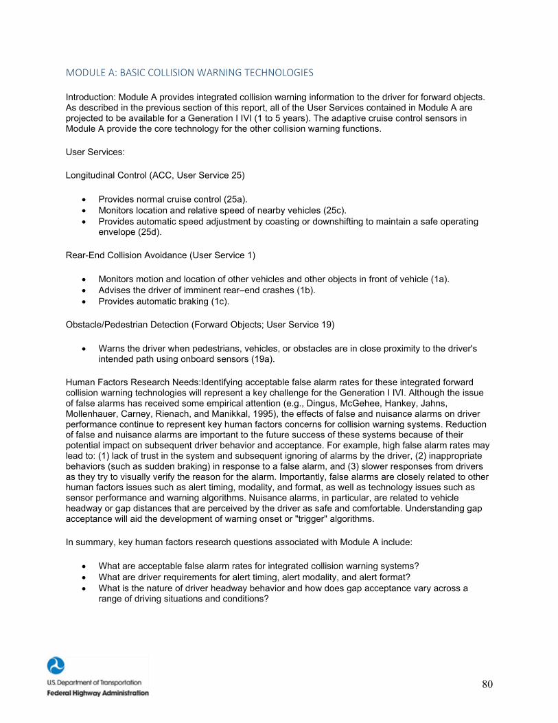
80
MODULE A: BASIC COLLISION WARNING TECHNOLOGIES
Introduction: Module A provides integrated collision warning information to the driver for forward objects. As described in the previous section of this report, all of the User Services contained in Module A are projected to be available for a Generation I IVI (1 to 5 years). The adaptive cruise control sensors in Module A provide the core technology for the other collision warning functions.
User Services:
Longitudinal Control (ACC, User Service 25)
• Provides normal cruise control (25a). • Monitors location and relative speed of nearby vehicles (25c). • Provides automatic speed adjustment by coasting or downshifting to maintain a safe operating
envelope (25d).
Rear-End Collision Avoidance (User Service 1)
• Monitors motion and location of other vehicles and other objects in front of vehicle (1a). • Advises the driver of imminent rear–end crashes (1b). • Provides automatic braking (1c).
Obstacle/Pedestrian Detection (Forward Objects; User Service 19)
• Warns the driver when pedestrians, vehicles, or obstacles are in close proximity to the driver's intended path using onboard sensors (19a).
Human Factors Research Needs:Identifying acceptable false alarm rates for these integrated forward collision warning technologies will represent a key challenge for the Generation I IVI. Although the issue of false alarms has received some empirical attention (e.g., Dingus, McGehee, Hankey, Jahns, Mollenhauer, Carney, Rienach, and Manikkal, 1995), the effects of false and nuisance alarms on driver performance continue to represent key human factors concerns for collision warning systems. Reduction of false and nuisance alarms are important to the future success of these systems because of their potential impact on subsequent driver behavior and acceptance. For example, high false alarm rates may lead to: (1) lack of trust in the system and subsequent ignoring of alarms by the driver, (2) inappropriate behaviors (such as sudden braking) in response to a false alarm, and (3) slower responses from drivers as they try to visually verify the reason for the alarm. Importantly, false alarms are closely related to other human factors issues such as alert timing, modality, and format, as well as technology issues such as sensor performance and warning algorithms. Nuisance alarms, in particular, are related to vehicle headway or gap distances that are perceived by the driver as safe and comfortable. Understanding gap acceptance will aid the development of warning onset or "trigger" algorithms.
In summary, key human factors research questions associated with Module A include:
• What are acceptable false alarm rates for integrated collision warning systems? • What are driver requirements for alert timing, alert modality, and alert format? • What is the nature of driver headway behavior and how does gap acceptance vary across a
range of driving situations and conditions?

81
MODULE B: ADVANCED COLLISION WARNING TECHNOLOGIES
Introduction:Module B provides integrated collision warning information to the driver for a range of driving situations and conditions. It is intended to address a number of "non–forward" situations where crashes occur frequently enough to warrant collision warning systems that aid the driver. As described in the previous section of this report, all of the User Services contained in Module B are projected to be available for a Generation I IVI (1 to 5 years). Module B does not rely on any core sensor technology. Rather, information from a number of sensors (front, side, and back) must be integrated in order to provide the driver with consistent, timely collision warning information.
User Services:
Lane–Change/Merge Collision Avoidance (User Service 3)
• Monitors lane position of the vehicle (3a). • Advises the driver during the decision phase (turn signal activated) of a lane–change maneuver
of the potential for a collision (3c).
Intersection Collision Avoidance (User Service 4)
• Monitors vehicle position relative to intersection geometry (4a). • Monitors relative speed and position of other vehicles (4b). • Advises driver of appropriate action to avoid an impending collision at the intersection (4b).
Obstacle/Pedestrian Detection (Backing; User Service 19)
• Warns the driver when pedestrians, vehicles, or obstacles are in close proximity to the driver's intended path using onboard sensors (19a).
Vehicle Diagnostics (User Service 15)
• Monitors and displays vehicle safety–related functions (i.e., braking system integrity, tire pressure, sensor and actuator performance, and communications system; 15a).
Human Factors Research Needs:A key human factors challenge associated with Module B is to develop an integrated standard approach to providing collision alerts to the driver (ITS America, 1997). Module B provides collision warning information from multiple sources, representing potential threats from all sides of the vehicle. Importantly, the correct driving maneuver in response to the warning (e.g., brake, turn left, turn right, continue straight ahead) will depend on the exact nature of the potential collision. Identifying the nature of the potential crash (e.g., location and severity of the collision) as well as the appropriate response to the crash will be important for the Generation I IVI.
In summary, key human factors research questions associated with Module B include:
• What is the best approach to integrating alerts from these collision warning devices? • What are driver requirements for alert timing, alert modality, and alert format? • How can these systems best convey to the driver the nature and appropriate response
associated with a potential collision?
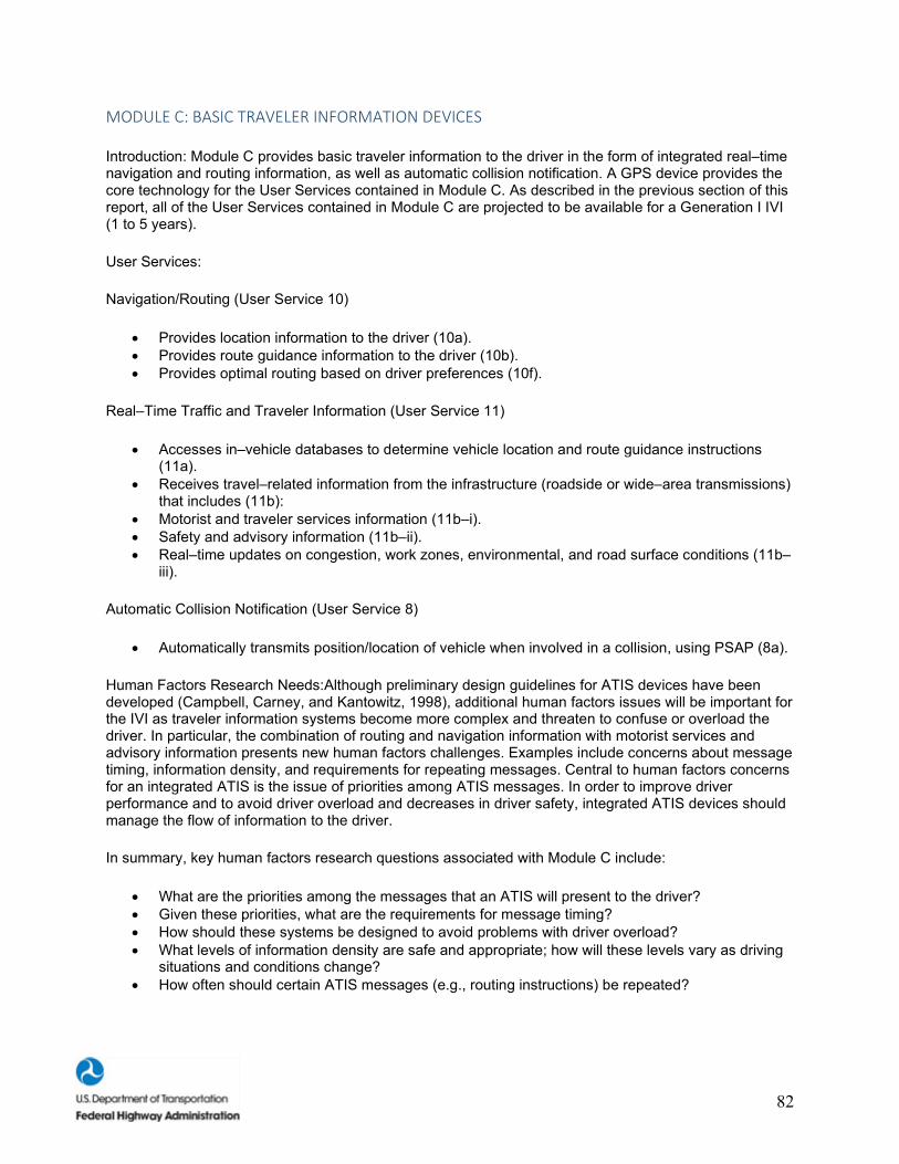
82
MODULE C: BASIC TRAVELER INFORMATION DEVICES
Introduction: Module C provides basic traveler information to the driver in the form of integrated real–time navigation and routing information, as well as automatic collision notification. A GPS device provides the core technology for the User Services contained in Module C. As described in the previous section of this report, all of the User Services contained in Module C are projected to be available for a Generation I IVI (1 to 5 years).
User Services:
Navigation/Routing (User Service 10)
• Provides location information to the driver (10a). • Provides route guidance information to the driver (10b). • Provides optimal routing based on driver preferences (10f).
Real–Time Traffic and Traveler Information (User Service 11)
• Accesses in–vehicle databases to determine vehicle location and route guidance instructions (11a).
• Receives travel–related information from the infrastructure (roadside or wide–area transmissions) that includes (11b):
• Motorist and traveler services information (11b–i). • Safety and advisory information (11b–ii). • Real–time updates on congestion, work zones, environmental, and road surface conditions (11b–
iii).
Automatic Collision Notification (User Service 8)
• Automatically transmits position/location of vehicle when involved in a collision, using PSAP (8a).
Human Factors Research Needs:Although preliminary design guidelines for ATIS devices have been developed (Campbell, Carney, and Kantowitz, 1998), additional human factors issues will be important for the IVI as traveler information systems become more complex and threaten to confuse or overload the driver. In particular, the combination of routing and navigation information with motorist services and advisory information presents new human factors challenges. Examples include concerns about message timing, information density, and requirements for repeating messages. Central to human factors concerns for an integrated ATIS is the issue of priorities among ATIS messages. In order to improve driver performance and to avoid driver overload and decreases in driver safety, integrated ATIS devices should manage the flow of information to the driver.
In summary, key human factors research questions associated with Module C include:
• What are the priorities among the messages that an ATIS will present to the driver? • Given these priorities, what are the requirements for message timing? • How should these systems be designed to avoid problems with driver overload? • What levels of information density are safe and appropriate; how will these levels vary as driving
situations and conditions change? • How often should certain ATIS messages (e.g., routing instructions) be repeated?
83
MODULE D: DRIVER CONVENIENCE DEVICES
Introduction: Module D provides convenience devices for the driver such as integrated cellular telephone and fax systems, as well as a range of diagnostic information and the ability to automatically pay fees associated with tolls and parking. As described in the previous section of this report, all of the User Services contained in Module D are projected to be available for a Generation I IVI (1 to 5 years).
User Services:
Driver Comfort and Convenience (User Service 12)
• Provides the capability of integrating multiple comfort and convenience features (cellular telephones, fax machines, etc.) into the DVI (12a).
• Provides the capability of prioritizing information sources into the DVI to reduce distractions (12b).
Provides the capability of real–time fleet dispatching (12c).
Vehicle Diagnostics (User Service 15)
• Monitors and displays vehicle safety–related functions (i.e., braking system integrity, tire pressure, sensor and actuator performance, and communications system) (15a).
Automated Transactions (User Service 17)
• Provides driver with the capability of ETC and the payment of parking fees and transit fares (17a). • Provides heavy–vehicle drivers with the capability of electronically filing credentials and permit
verifications (17b).
Human Factors Research Needs:A key human factors challenge for Module D is to develop design guidelines for the prioritization (e.g., timing, modality, and conspicuity) of convenience information relative to other types of ITS information such as navigation/routing or collision warning messages. Without guidelines describing these priorities, drivers may attend to the wrong messages or assign higher priority to non–safety–related messages (e.g., new e–mail messages) than to safety–critical messages (e.g., collision potential ahead). Human factors empirical data on the effects of convenience devices are scarce, but existing research into the effects of cellular telephones (e.g., Goodman, Bents, Tijerina, Wierwille, Lerner, and Benel, 1997) suggests that such devices may be a distraction to the driver and increase crash risk.
In summary, key human factors research questions associated with Module D include:
• What are the relative priorities among the messages associated with Module D relative to other information types within the Generation I IVI?
• How do these priorities translate into design guidelines for the location, timing, modality, and format for the Module D messages?
MODULE E: ITS COLLISION WARNING SYSTEMS FOR HEAVY VEHICLES
Introduction:Module E provides a range of collision warning information to drivers of heavy vehicles. These include User Services that would be especially valuable in the CVO environment, such as lane–departure collision avoidance, warnings for vehicle rollover, and a system to detect and warn the drowsy driver. As described in the previous section of this report, all of the User Services contained in Module E are projected to be available for a Generation I IVI (1 to 5 years).
84
User Services:
Road–Departure Collision Warning/Avoidance (User Service 2)
• Monitors lane position of the vehicle and motion relative to edge of road (2a). • Monitors vehicle speed relative to road geometry and road conditions (2b). • Advises driver of imminent unintentional road departure (2c).
Vehicle Stability and Warning Assistance (User Service 13)
• Measures rollover stability properties of a typical heavy vehicle (13a). • Provides the driver with a graphical depiction of the vehicle's loading condition relative to its
rollover propensity (13b). • Provides an active brake control system to selectively apply brakes to stabilize the vehicle (13c).
Driver Condition Warning (User Service 14)
• Provides a driver monitoring and warning capability to alert the driver of drowsiness or other types of impairments (CVO or Transit first) (14a).
Low–Friction Warning and Control Assistance (User Service 24)
• Provides driver with a warning to indicate reduced traction detected by onboard sensors (24a). • Provides driver with control assist capabilities to help driver regain control of vehicle (24b).
Human Factors Research Needs:The key human factors challenge for Module E is to develop clear and effective methods of presenting integrated collision warning information to the heavy/commercial–vehicle driver. As noted earlier, each of the User Services in this module is associated with special challenges with respect to information displays. For lane–departure information, both haptic and auditory displays have been investigated (Pomerleau, Thorpe, and Emery, 1997) with inconclusive results. Vehicle stability and low–friction warnings should convey complex vehicle states in real time to the driver in a manner that accurately conveys the level of urgency associated with the emerging situation, increases the driver's awareness of the situation, and supports correct decisionmaking in response to the situation. Driver condition warning systems, in particular, may benefit from a graded warning system that warns the driver before an emergency situation arises. As of yet, these complex issues of information management and display have not been addressed.
In summary, key human factors research questions associated with Module E include:
• How can safety–critical factors be presented to drivers in a manner that accuarately reflects the driving situation, improves driver awareness of the situation and supports a proper response to the situation?

85
CANDIDATE CONFIGURATIONS FOR THE GENERATION I IVI
Five Candidate Configurations for the IVI are presented in this subsection. As noted earlier, these Candidate Configurations represent combinations of Technology Modules that provide an integrated set of User Services for the Generation I IVI. Table 3 shows those Technology Modules that have been combined to form each of the five Candidate Configurations.
The five Candidate Configurations developed during this effort are briefly summarized below:
Candidate Configuration #1: Provides basic collision warning and driver information capabilities for all vehicles. Modules A and C are combined to provide an IVI vehicle with an integrated set of forward CAS capabilities and real–time navigation and routing information. There are no infrastructure requirements associated with this configuration. Human factors research needs include:
• Joint use of visual, auditory, and tactile information (primary issue). • Driver acceptance (secondary issue). • Driver workload (secondary issue).
Candidate Configuration #2: Promotes synergy among a number of IVI User Services and provides drivers with 360o collision warning coverage for all vehicles. Modules A, B, and C are combined to provide an IVI vehicle with both real–time navigation and routing information, as well as an integrated suite of collision avoidance/warning systems. Infrastructure requirements are associated with the Intersection Collision Avoidance capability and include transmitters, computers, and antennas at "IVI–capable" intersections. Human factors research needs include:
• Human factors design guidelines for multiple CAS devices (primary issue). • Integration of ATIS and CAS information (primary issue). • Driver tolerance for false alarms (secondary issue).
Candidate Configuration #3: Promotes synergy among a number of IVI User Services and provides drivers with ATIS capabilities for all vehicles. Modules A, C, and D are combined to provide an IVI vehicle with both avoidance/warning information, as well as an integrated suite of driver information systems. Infrastructure requirements include transponders and associated processors for automated transactions. Human factors research needs include:
• Assess how an integrated information system that includes both routing and convenience devices affects driver performance and behavior (primary issue).
• Special design requirements of older drivers (secondary issue).
Candidate Configuration #4: In this configuration, Modules E and F are combined to provide an integrated set of ITS capabilities for drivers of heavy vehicles. Both information systems and collision avoidance/warning devices are included. Infrastructure requirements associated with this configuration include: (1) dynamic messaging to support the Low–Friction Warning and Control Assistance User Service and (2) data concerning road curvature, design speed for curvatures, shoulder widths, and surface friction are needed to assist road–departure collision avoidance. Human factors research needs include:
• Determine the most effective methods of integrating IVI information with existing dashboard displays and roadside signs (primary issue).
• Determine information priorities within the CVO environment (secondary issue).
86
GENERAL HUMAN FACTORS RESEARCH ISSUES FOR THE IVI Overview
In this report, we have identified a number of human factors research needs for the 26 individual IVI User Services, 7 Technology Modules, and 5 Candidate IVI Configurations. These human factors research needs were developed through a process involving analysis of existing human factors research and system design data sources for ITS devices, reviews of the research statements developed during the 2–day IVI Human Factors Workshop (ITS America, 1997), and the judgment of the Battelle project team.
To some extent, however, the determination of the highest priority human factors research issues remains a complex and somewhat subjective process. During the 2–day IVI Human Factors Workshop, workshop attendees rated the perceived priority of 43 research statements on a scale from 1 to 5, with a "1" representing "high priority" and a "5" representing "low priority." A summary of these ratings is contained in the proceedings developed from this workshop by ITS America. Interestingly, 41 of the 43 research statements were given mean ratings between 1.5 and 3.5, suggesting that most research issues identified during the workshop and rated by the group were perceived as having moderate to high priority. Thus, by consensus of the human factors research community, as well as representatives from industry, academia, and government, there appears to be a great many high–priority human factors research needs for the IVI.
In our formulations of human factors research needs for the 26 individual IVI User Services, 7 Technology Modules, and 5 Candidate IVI Configurations, we have matched known research needs with specific implementation of ITS technology. However, recognizing that there is variability and room for differences in what represents the highest priority research issues, we have summarized a number of general human factors research issues for the IVI in the sections below. This list is not exhaustive and the individual issues are presented in summary form. However, the section below represents the range of human factors design concerns most relevant to the Generation I IVI and beyond. Extended discussion of these issues can be found in sources such as Parasuraman and Mouloua (1996); Noy (1998); Wickens (1992); Campbell, Carney, and Kantowitz (1998); and Barfield and Dingus (1998).
Baseline Driver Behavior
Despite the great advances in ITS devices that can be incorporated into vehicles and used by drivers, relatively little is known about typical driver behaviors and performance across a great number of driving situations, conditions, and driving populations. During the 2–day IVI Human Factors Workshop, a number of research statements focused on the need to characterize baseline driver behavior and develop driver models for IVI.
Currently available driver models are generally limited to simplistic representations of driver steering and speed control. They do not take into account the probabilistic or variable nature of driving performance and do not include cognitive activities such as perception and decisionmaking. Thus, a key need is to develop computational theories and models of driver behavior and to use these tools to support IVI development. These are related and synergistic research needs, with the data obtained during studies of baseline driver behavior being used as input to the process of developing robust and useful driver models.
System Standardization and Guidelines
At the recent workshop on the IVI, human factors researchers stated that a successful IVI prototype would require the development of system standards and design guidelines. IVI system designers need assistance and direction in creating complex in–vehicle displays to ensure that the systems are intuitive,
87
useful, and acceptable to drivers. The standards will also ensure that in–vehicle systems are universal across vehicles. Without system uniformity, problems with driver confusion and negative transfer may occur, causing higher accident and fatality rates. The development of standards in other disciplines caused great concern, with some researchers arguing that standards may be developed prematurely, resulting in poor design. Parkes (1997) argued that standards do not mean mandatory compliance and need to remain specific enough to be useful, but general enough to apply across many systems without restricting design. Some design guideline documents have been developed to assist display designers (Campbell, Carney, and Kantowitz, 1998; Boff and Lincoln, 1988). The ISO TC/204 WG14 and SAE have been developing system standards for rear–end and road–departure CAS (ISO NP144 and SAE J2400) as well as for navigation and routing systems (SAE J2364 and J2365). Work needs to continue in the area of system standardization and guideline development to ensure the development of intuitive, useful displays that will be acceptable to all drivers.
IVI Message Modality and Design
Driver messages for an IVI may be auditory, visual, tactile, or some combination of these three modalities. Within the driving environment, each of these three modalities is associated with some advantages and disadvantages. The auditory channel can have an advantage over the visual channel due to its attention–getting qualities (McCormick and Sanders, 1982). The use of auditory messages might allow better time–sharing of limited processing resources, i.e., bi–modal time–sharing may be superior to intra–modal time–sharing (Wickens, 1984). In particular, auditory alerts reduce the visual load on the driver (Wolf, 1987) and are well–suited to a collision warning situation in which immediate action is required. However, their attention–getting abilities can become annoying to a driver if the alerts occur frequently or are associated with a high false alarm rate. Furthermore, the ambient noise levels within the cab of a heavy/commercial vehicle can approach 100 decibels, leading to concerns about required intensity levels of the alerts and possible auditory masking of the alerts for CVO applications (McCormick and Sanders). While components of sounds such as speed, fundamental frequency, repetition units, and inharmonicity have been successfully manipulated to vary the perceived urgency of sounds (Hellier, Edworthy, and Dennis, 1993), relative urgency is but one aspect of obstacle detection/collision avoidance messages that might be presented using auditory displays. In addition, auditory displays are frequently disabled by users, apparently because of increases in subjective workload (King and Corso, 1993).
Visual alerts are generally less intrusive than auditory alerts and the location of the display in a vehicle can be used as a cue to the direction of the impending collision (e.g., co–located with a side–view mirror). Nonetheless, the visual channel is the more traditional mode for presentation of driving information, and is associated with relatively higher information rates (Sorkin, 1987) than the auditory channel. However, driving requires a great deal of visual scanning just to maintain proper lane position and situational awareness of surrounding traffic conditions. Using a visual display to present collision avoidance alerts introduces yet another visual task at precisely the same time that drivers' attention should be external to the vehicle.
Although the selection of auditory vs. visual forms of information display will depend on a number of situation–specific variables, Deatherage (1972, p. 124) developed general guidelines for selecting auditory vs. visual display modalities. These guidelines are presented in table 4.
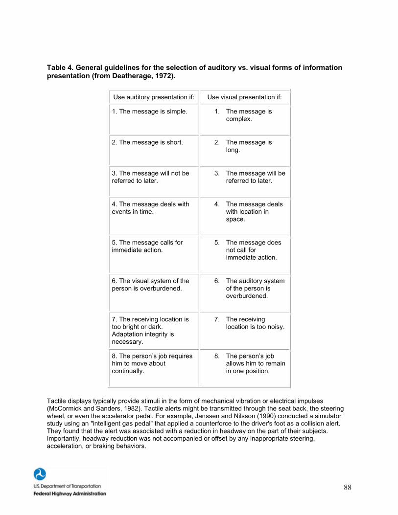
88
Table 4. General guidelines for the selection of auditory vs. visual forms of information presentation (from Deatherage, 1972).
Use auditory presentation if: Use visual presentation if:
1. The message is simple. 1. The message is complex.
2. The message is short. 2. The message is long.
3. The message will not be referred to later.
3. The message will be referred to later.
4. The message deals with events in time.
4. The message deals with location in space.
5. The message calls for immediate action.
5. The message does not call for immediate action.
6. The visual system of the person is overburdened.
6. The auditory system of the person is overburdened.
7. The receiving location is too bright or dark. Adaptation integrity is necessary.
7. The receiving location is too noisy.
8. The person’s job requires him to move about continually.
8. The person’s job allows him to remain in one position.
Tactile displays typically provide stimuli in the form of mechanical vibration or electrical impulses (McCormick and Sanders, 1982). Tactile alerts might be transmitted through the seat back, the steering wheel, or even the accelerator pedal. For example, Janssen and Nilsson (1990) conducted a simulator study using an "intelligent gas pedal" that applied a counterforce to the driver's foot as a collision alert. They found that the alert was associated with a reduction in headway on the part of their subjects. Importantly, headway reduction was not accompanied or offset by any inappropriate steering, acceleration, or braking behaviors.
89
Timing of Messages
Another common issue is the timing of messages, including alerts and warnings. Aside from nuisance alarms, timing of system messages can significantly contribute to the efficacy of a system. For example, in the case of a rear–end CAS, the driver must confirm with their own eyes that there is a hazard ahead before reacting, so alerts presented very early may go unheeded or cause a distraction at the last moment. All CAS alerting may share this same trend. Drivers, for the most part, avoid most crashes and do so daily - not necessarily in an extreme manner, but in the normal context of traffic interaction. It should be noted that CAS systems could also increase drivers' situational awareness and thus make them more aware of traffic–light state, static headway, etc. Although not directly related to warning timing, such status information may provide the driver with additional information.
False Alarms
A false alarm occurs when a signal or target is said to be present when, in fact, no such signal or target is present. In the context of CAS, two types of false alarms are relevant. First, a "real" false alarm occurs when a collision alert is presented to the driver in the absence of any crash–relevant obstacle or event. Second, a "nuisance" false alarm occurs under circumstances in which the driver feels that the alert itself, or the urgency associated with the alert, is incorrect or inappropriate. In either case, false alarms will reduce the trust and confidence that the driver places in the system, thus reducing system effectiveness. In general, users are most reluctant to rely on equipment they do not trust (Lee and Moray, 1992). When trust in the device is too low and an alarm is presented, drivers may spend additional time verifying the problem, thus slowing appropriate collision avoidance actions. Alternatively, they may choose to ignore the alarm, thus completely defeating the purpose of the system.
Driver Response Time to Alerts
A key issue in the development and design of IVI in–vehicle devices is the perception–reaction times of drivers to warnings and alerts. Although this issue has been extensively studied within the human factors community, a range of findings have been reported. Wortman and Matthias (1983) measured the nighttime braking response times of 839 drivers to the onset of an amber signal at an intersection and reported mean values ranging from 1.09 to 1.55 s. Chang, Messer, and Santiago (1985) conducted a similar study, but in daytime as well and on both dry and wet roadways, and reported mean response times of 1.3 s and 95th percentile values of 2.5 s. Lerner (1993) measured the perception–response times of both younger and older drivers to a simulated on–the–road emergency and reported a mean reaction time of 1.5 s and an 85th percentile value of 1.9 s. AASHTO (1984; see also Taoka, 1990) uses a design reaction time of 2.5 s to determine stopping distance when designing roadway elements such as signs, road curvatures, and traffic signal visibility and timing. Fundamentally, warnings and alerts must be presented early enough in the total time frame of the potential collision event for the driver to perceive and understand the message and to take appropriate action. Thus, assumptions made about driver capabilities to perceive and to respond to collision alerts or other urgent system messages affect virtually every design parameter of a Side–Object Detection System (SODS) - from requirements for sensor range and scanning rate to limits on system processing time and the optimum modality for the information.
Stimulus–Response (SR) Compatibility of Alerts
Stimulus–response compatibility is another key concept in human factors design (Kantowitz, Triggs, and Barnes, 1990). It refers to the relationship, both geometric and conceptual, between a stimulus (such as a display) and a response (such as a control action). For example, the debate in aviation about the relative merits of outside–in (moving airplane) vs. inside–out (moving horizon) artificial horizon indicators is actually an argument about stimulus–response compatibility.
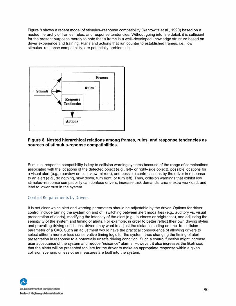
90
Figure 8 shows a recent model of stimulus–response compatibility (Kantowitz et al., 1990) based on a nested hierarchy of frames, rules, and response tendencies. Without going into fine detail, it is sufficient for the present purposes merely to note that a frame is a well–developed knowledge structure based on driver experience and training. Plans and actions that run counter to established frames, i.e., low stimulus–response compatibility, are potentially problematic.
Figure 8. Nested hierarchical relations among frames, rules, and response tendencies as sources of stimulus-reponse compatibilities.
Stimulus–response compatibility is key to collision warning systems because of the range of combinations associated with the locations of the detected object (e.g., left– or right–side object), possible locations for a visual alert (e.g., rearview or side–view mirrors), and possible control actions by the driver in response to an alert (e.g., do nothing, slow down, turn right, or turn left). Thus, collision warnings that exhibit low stimulus–response compatibility can confuse drivers, increase task demands, create extra workload, and lead to lower trust in the system.
Control Requirements by Drivers
It is not clear which alert and warning parameters should be adjustable by the driver. Options for driver control include turning the system on and off, switching between alert modalities (e.g., auditory vs. visual presentation of alerts), modifying the intensity of the alert (e.g., loudness or brightness), and adjusting the sensitivity of the system and timing of alerts. For example, in order to better reflect their own driving styles and prevailing driving conditions, drivers may want to adjust the distance setting or time–to–collision parameter of a CAS. Such an adjustment would have the practical consequence of allowing drivers to select either a more or less conservative timing logic for the system, thus changing the timing of alert presentation in response to a potentially unsafe driving condition. Such a control function might increase user acceptance of the system and reduce "nuisance" alarms. However, it also increases the likelihood that the alerts will be presented too late for the driver to make an appropriate response within a given collision scenario unless other measures are built into the system.
91
Training
Given the increased levels of automation proposed for an IVI prototype, the driving task will be altered significantly. Automation will alter the driving task from a continuous manual control task into a continuous monitoring task (Campbell, Hooey, Carney, Hanowski, Gore, Kantowitz, and Mitchell, 1996). These changes require that the driver be knowledgeable about the function and goals of the system, be able to obtain necessary information, be sensitive to warning signs, and be comfortable with the general layout of the controls and function switches. Drivers will need to be comfortable and knowledgeable with the automated system on all of these levels in order for the system to provide increased safety and efficiency on the highways. This issue was examined by Mazzae and Garrott in the context of Side–Object Detection Systems (SODS). Mazzae and Garrott (1995) compared performance and subjective opinions of CVO drivers using a new side–object detection system and using standard mirrors. Performance was similar for both groups; however, the drivers reported that the SODS system was beneficial. Mazzae and Garrott speculated that performance may have been superior with the SODS system had the drivers been given more time to become familiar with the new system. Allowing drivers time to become familiar with a new system may require the widespread use of simulators as training devices to avoid dangerous and life–threatening situations.
Older Drivers
Older drivers present a unique problem to the overall development and deployment of intelligent vehicle technologies. Dingus, Hulse, and Barfield (1998) cite several sources of literature outlining empirical evidence that older drivers have longer glance times at in–vehicle displays, drive more slowly with more lateral error, have longer reaction times, veer into different lanes when making turns, and were more likely to make navigation errors than younger drivers. Warnes, Fraser, Hawken, and Sievey (1993) reported that cognitive and motor impairments characteristic of the older driver population increased during cognitively complex situations (i.e., left–turn maneuvers). The human factors research community has been aware of older driver issues and much research has been done in this area. Hanowski, Bittner, Knipling, Byrne, and Parasuraman (1995) presented a taxonomy of safety interventions and outlined areas of safety research needs for older drivers. Their efforts resulted in the identification of five primary research needs: (1) HUD guidelines for older drivers; (2) in–vehicle warnings, guidance, and collision avoidance aids; (3) driving–related perceptual and motor variability in the older driver; (4) older driver vehicle illustrative guidelines and prototype development; and (5) vehicle conspicuity and lighting. Given that future intelligent vehicles will result in more cognitively complex environments and older drivers perform worse in complex environments, the older driver population presents a greater challenge to IVI designers. Future vehicles must be designed to accommodate older driver limitations and needs.
Driver Acceptance
Developing an acceptable, usable, affordable intelligent vehicle system is vital to the overall success of IVI. Drivers will not be willing to pay for technologies that they do not consider to be useful or valuable. Dingus et al. (1998) cited various studies that measured drivers' attitudes toward intelligent automotive technologies. These studies solicited drivers' attitudes on general ITS issues, navigation systems, and front–to–rear–end CAS. Drivers indicated that they felt ITS was a plausible solution to traffic problems, that navigation displays were better for unfamiliar drivers to use, and that CAS were a good idea and would be used by the driving population. These surveys suggest that drivers want solutions to our traffic problems, would use in–vehicle technology, and appreciate the safety benefits that newer technology may provide. Driver acceptance of the technology determines how well the driver interacts and uses the system (Lee and Kantowitz, 1998). As technology develops, drivers' attitudes and acceptance of advanced in–vehicle technology must be evaluated in the design process or the ITS technologies will fail. This failure may not result because the technology does not work, but because drivers find the system tedious or difficult to use, or do not feel the benefits outweigh the costs.
92
Driver Performance
A successful design of an IVI prototype should enhance the drivers' strengths and support their weaknesses in performing the tasks of safe driving. To achieve this goal, designers must possess knowledge of the cognitive and motor skills involved in driving. Drivers' situational awareness, workload, attention, and decisionmaking have all been defined as important to understanding driver performance. Situational awareness has been defined by Endsley (cited by Ward, 1996) as an awareness of environmental information relevant to successful task performance, the meaning and context of that information, and the predictive future state of these conditions. Driver situational awareness is not a serious problem in current vehicles; however, it will become an issue as more automation is introduced into the vehicle (Ward, 1996). Driver workload is defined as the extent of the resources required for the driving task (Dingus et al., 1998). Measuring workload will assist designers in determining what tasks will require excessive attentional resources, resulting in unsafe driving behavior. As intelligent vehicles add more information displays in the vehicles, the ability to assess driver workload and safe driving vs. driver overload (i.e., too much information) and unsafe driving will be critical to the overall success of intelligent driving systems. Integrated in the complex web of situational awareness, workload, and attention is the ability of drivers to make split–second decisions in high–stress emergency situations. As situational awareness and attention decreases and workload increases, a speed/accuracy trade–off occurs where bad decisions will be made quickly and good decisions will be acted on too late. Much more research is needed on these issues in order to create an intelligent vehicle that will enhance and support the driver appropriately.
Effects of Automation
Sixteen of the 26 User Services specified for an IVI include some level of automation. The human factors research community has suggested several issues that require further research in order to avoid the possible pitfalls that automation may create. One issue, out–of–the–loop familiarity, presents a set of problems stemming from the driver being removed from the driving task. When problems occur, research in other domains suggests that the user will be slower to detect the problem as well as slower to respond with the corrective action (Wickens, 1992). The issue of transfer of control from the automated system to the driver presents delicate issues, such as: How does the driver inform the system of their readiness to resume control? and How can we ensure that the driver is alert and aware of a critical situation? (Levitan and Bloomfield, 1998). Behavioral adaptation is another issue that refers to any change in behavior that serves some need of the driver other than the intended purpose of the intervention (Ward, 1996). For example, when AICC has been introduced in vehicles, some researchers have warned that drivers will lose the skills necessary to react in emergency situations. Others warn that automation will cause drivers to lose situational awareness of the driving task. Finally, partially automated systems may produce reckless driving behaviors. Drivers may place too much trust in such an automated system and find it more acceptable to follow other vehicles too closely and at faster speeds. All of these research issues represent problems that must be addressed before the implementation of automated systems in vehicles or the safety and efficiency of our highway systems may be compromised.
Inappropriate Levels of Driver Trust in the System
Just as having too little trust in a CAS can reduce system effectiveness, having too much trust in the system can lead to a host of other performance concerns. For example, putting too much trust in an imperfect system may lead to a false sense of security on the part of the driver. Similar problems have occurred in comparable domains. In the aircraft environment, for example, inappropriately high levels of trust in automated flight systems can cause pilots to ignore other sources of flight data or to forego established and prudent flight procedures. In general, when trust in the device is too high, drivers may: (1) assume that the system will detect any "target" obstacle or impending collision and, therefore, reduce their own vigilance levels, or (2) be willing to accept higher levels of driving risk and, for example, neglect typical safety or collision avoidance behaviors such as checking rearview and side–view mirrors before changing lanes.

93
Functional Allocation
Function allocation refers to how specific driver functions are allocated with regard to automation. For instance, there are some operations that are assigned to manual operation only - where the driver has complete control at all times, some functions that combine manual and automatic functions, and those that are fully automatic. For example, a manual–only function would be that of normal vehicle operation where the driver is responsible for all lateral and longitudinal control. An example of a combination of automatic and manual functions is that of an ACC system where longitudinal control is assigned to the system and lateral control is by the driver.

94
CONCLUSIONS
The following presents the conclusions that were developed during the conduct of this project:
• Human factors research needs for the Generation I IVI focus on the need to integrate and manage the information presented to the driver.
• No publicly available human factors research has examined the effects of integrating multiple ITS devices into a vehicle as envisioned by the IVI.
• Considerable human factors research has been conducted to support the development of individual User Services within the IVI.
• A broad range of ITS technologies are available to support the development of a Generation I IVI prototype.
• For the Generation II and III IVI especially, extensive algorithm/software, infrastructure, and specific technologies are needed.
A discussion of each conclusion follows:
Human factors research needs for the Generation I IVI focus on the need to integrate and manage the information presented to the driver.From the IVI Human Factors Workshop to the review and analysis activities associated with this support, effective information integration and management emerged as a consistent human factors research need. More than 50 percent of the 48 research statements generated by 70 experts at the IVI Human Factors Workshop dealt with this topic. This reflects the belief that, for the driver, the IVI represents new sources of information regarding the vehicle, the vehicle environment, and relevant traffic conditions. Not surprisingly, information management represents a common theme for the human factors research needs among the IVI Candidate Configurations that were developed as part of this effort. This broad research need encompasses recommended IVI human factors research topics such as:
• Selection of effective display modalities for the IVI. • Driver acceptance issues surrounding multi–function displays. • Driver workload associated with IVI displays and controls. • Design guidelines for multiple collision avoidance/warning devices. • Driver tolerance for false alarms generated by CAS devices. • Integration of IVI information with existing CVO information sources. • Guidelines for the frequency, density, and timing of transit information.
No publicly available human factors research has examined the effects of integrating multiple ITS devices into a vehicle as envisioned by the IVI. All of our activities during this project - our Subject Matter Expert survey of human factors research issues of the IVI, the human factors IVI workshop, the reviews of ITS technology and human factors literature, and our discussions with professionals around the country - have examined this issue and have found no human factors research efforts that have investigated issues directly relevant to an integrated Generation I IVI. While much research has examined individual ITS devices (see below), existing research is insufficient to support an integrated, safe, human–centered IVI. The Generation I IVI represents an increase in the number of displays and controls in the in–vehicle environment; however, more importantly, it represents a significant increase in the amount and complexity of information presented to the driver. If human factors integration and design issues are not addressed throughout the development process for the Generation I IVI, there is a risk that this increase in information will lead to information overload, driver confusion, and actual decreases in driver performance and safety.
Considerable human factors research has been conducted to support the development of individual User Services within the IVI. The development of 16 of the 26 User Services has been supported by directly relevant human factors research. While most of the research reviewed as part of
95
this effort has been funded by the FHWA and NHTSA, more research, undoubtedly, has been funded by industry and remains outside the public domain. While there is little human factors research that can be used to support the development of the IVI (see above), existing research has provided a solid foundation for continuing human factors research on the IVI.
A broad range of ITS technologies are available to support the development of a Generation I IVI prototype. Our review activities have documented the considerable technological progress that has been made on ITS devices globally by auto manufacturers and the electronics industry. Both display and sensor technologies, in particular, are mature enough to support the Generation I IVI.
For the Generation II and III IVI especially, extensive algorithm/software, infrastructure, and specific technologies are need. Two technical areas require additional research and development for the Generation II and III IVI in particular. First, additional software development is needed to develop effective algorithms for information management. These algorithms may be developed with the aid of some form of artificial intelligence (e.g., fuzzy logic, neural networks, or expert systems). Such algorithms are needed to manage, organize, and control the flow of data obtained from vehicle sensors, in–vehicle databases, and the transportation infrastructure. These data provide the basis for key decisions regarding the status of conditions and events external to the vehicle (e.g., crash potential), as well as the IVI information that is displayed to the driver. As the emphasis within the IVI program shifts from full manual control of the vehicle to automatic assist, this issue will become even more critical.
Second, there is little or no infrastructure in place to support the Generation II and III IVI. This is not surprising, yet key IVI User Services require certain infrastructure components and will not be implemented until such infrastructure is available. For example, certain technologies, such as DSRC devices, must be embedded in the infrastructure in order to support User Services such as Location–Specific Alert and Warning. In addition, the capability of these devices needs to be expanded to treat what will most likely be multi–function applications (e.g., ETC, parking garage assignment, and roadside–to–vehicle communications for advanced motorist warnings). Another related technology is a digital map, which could contain data about curves, intersections, railroad crossings, and speed limits. These data could support several User Services, such as Intersection and Road–Departure Crash Avoidance, and perhaps would require additional infrastructure components. Importantly, this additional information is not available in today's digital maps.
96
REFERENCES
Abe, A.; Hori, T.; and Ofuchi, K. (1996). "Observations of the Effect on Drivers of Lane Guidance Function Employing In–Vehicle Voice Guidance and Display Units" (CD–ROM). Proceedings of the Third Annual World Congress on Intelligent Transport Systems. Orlando, FL.
American Association of State Highway and Transportation Officials. (1984). A Policy on Geometric Design of Highways and Streets. Washington, DC: Author.
Asher, H.J. and Galler, B.A. (1996). "Collision Warning Using Neighboring Vehicle Information." Proceedings of the 1996 Annual Meeting of ITS America, Washington, DC, pp. 674–684.
Bannatyne, R. and Warshawsky, E. (1997). "The Changing World of Automotive Electronic Control Units" (SAE Paper 972638). Proceedings of the Future Transportation Technology Conference. Warrendale, PA: Society of Automotive Engineers.
Bantli, H.; Christmann, A.; Hamerly, M.; and Nourse, G. (1997). "Characterization of Ambient Magnetic Fields: Signal Processing Requirements for a Magnetic Lateral Driver Assist or Guidance System." Proceedings of the 4th World Congress on Intelligent Transport Systems. Berlin: ICC.
Barfield, W. and Dingus, T.A. (Eds.). (1998). Human Factors in Intelligent Transportation Systems. Mahwah, NJ: Lawrence Erlbaum Associates.
Benz, D.; Blatt, A.; Bollman, E.; Donnely, B.; Funke, D.; Kelly, O.; Lloyd, M.; McClellan, R.; Schabel, D.; Wachob, C.; and Wilson, G. (1997). Automated Collision Notification (ACN) (Interim Report). Washington, DC: U.S. DOT, NHTSA.
Berge, G. (1993). "Special Information Needs Among Professional Drivers." In A.M. Parkes and S. Franzen (Eds.), Driving Future Vehicles. London: Taylor and Francis.
Blythe, P.T. (1997). "Implementing Smart Card Technology to Transform Transport Payment and Customer Information." Proceedings of the 4th World Congress on Intelligent Transport Systems. Berlin: ICC.
Boff, K.R. and Lincoln, J.E. (1988). Engineering Data Compendium: Human Perception and Performance (Volumes 1–3). Wright–Patterson Air Force Base, Ohio: Harry G. Armstrong Aerospace Medical Research Laboratory.
Bonsall, P. and Parry, T. (1991). "Using an Interactive Route–Choice Simulator to Investigate Drivers' Compliance With Route Guidance Advice." Transportation Research Record, 1306, pp. 59–68.
Bossi, L.L.; Ward, N.J.; Parkes, A.M.; and Howarth, P.A. (1997). "The Effect of Vision Enhancement Systems on Driver Peripheral Visual Performance." In Y.I. Noy (Ed.), Ergonomics and Safety of Intelligent Driver Interfaces. Mahwah, NJ: Lawrence Erlbaum Associates.
Broos, P. (1993). "Keeping an Even Keel." Delft Outlook: Research and Education at Delft University of Technology.
Buehring, P. (1998). "Fault–Tolerant Networking of Squibs and Sensors in Advanced Passenger Restraint Systems" (SAE Paper No. 980353). Warendale, PA: Society of Automotive Engineers.
97
Butsuen, T.; Yoshioka, T.; and Okuda, K. (1996). "Introduction of the Mazda Advanced Safety Vehicle." Proceedings of the 1996 IEEE Intelligent Vehicles Symposium, Tokyo, pp. 242–247.
Calspan/SRL Corporation. (1996). Intersection Collision Avoidance Using IVHS Countermeasures. Task 4: Draft Interim Report. State of the Art Technology Review, Vol. I (Report No. 8149–7). Buffalo, NY: Author.
Campbell, J.L.; Carney, C.; and Kantowitz, B.H. (1998, in process). Human Factors Design Guidelines for Advanced Traveler Information Systems (ATIS) and Commercial Vehicle Operations (CVO) (FHWA–RD–98–057). Washington, DC: FHWA.
Campbell, J.L.; Hooey, B.L.; Carney, C.; Hanowski, R.J.; Gore, B.F.; Kantowitz, B.H.; and Mitchell, E. (1996). Investigation of Alternative Displays for Side Collision Avoidance Systems (Final Report). Seattle, WA: Battelle Seattle Research Center.
Carney, C. (1996). The Effect of Sensor Range and Timing on Drivers' Ability to Use Collision Warning Systems. Unpublished Master's Thesis, University of Iowa, Iowa City.
Carrea, P. (1993). "Integration Between Anticollision and AICC Functions: The Alert Project." Proceedings of the Intelligent Vehicles '93 Symposium. Tokyo: IEEE.
Carter, R. and Barickman, F. (1995). "Data Acquisition System for Crash Avoidance Research." Peer Review of the National Highway Traffic Safety Administration, Workshop Proceedings. Baltimore, MD: U.S. DOT, NHTSA.
Casey, R.F. and Labell, L.N. (1997). Advanced Public Transportation Systems Deployment in the United States (Report No. DOT–VNTSC–FTA–96–6). Washington, DC: U.S. DOT.
Casey, R.F.; Labell, L.N.; Holmstrom, R.; LoVecchio, J.A.; Schweiger, C.L.; and Sheehan, T. (1996). Advanced Public Transportation Systems: The State of the Art Update '96 (Report No. FTA–MA–26–7007–96–1). Washington, DC: Federal Transit Authority.
CellPort Labs. (1998). CP CONNECT (On–Line). Retrieved April 27, 1998:
Chang, M.S.; Messer, C.J.; and Santiago, A.J. (1985). "Timing Traffic Signal Change Intervals Based on Driver Behavior." Transportation Research Record 1027, pp. 20–30.
Chovan, J.D.; Tijerina, L.; Everson, J.H.; Pierowicz, J.A.; and Hendricks, D.L. (1994). Examination of Intersection, Left Turn Across Path Crashes and Potential IVHS Countermeasures (Tech Report No. DOT–VNTSC–NHTSA–94–4). Washington, DC: U.S. DOT, NHTSA.
Crabtree, J. (1995). "Advantage I–75 Prepares to Cut Ribbon on Electronic Clearance." Public Roads, pp. 16–21.
Cremona, P.; Kunert, M.; and Castinie, F. (1994). "Parametric Spectrum Analysis for Target Characterization." Proceedings of the Intelligent Vehicles '94 Symposium. Paris: IEEE.
Daniels, D.J. (1988). "Radar for Hazard Warning." 18th International Symposium on Automotive Technology & Automation, Florence, Italy, 19P.
Deatherage, B.H. (1972). "Auditory and Other Sensory Forms of Information Presentation." In H.P. Van Cott and R.G. Kinkade (Eds.), Human Engineering Guide to Equipment Design (Rev. Ed.). Washington, DC: U.S. Government Printing Office, pp. 123–160.
98
DeLucia, P.R. and Warren, R. (1994). "Pictorial and Motion–Based Depth Information During Active Control of Self–Motion: Size–Arrival Effects on Collision Avoidance." Journal of Experimental Psychology: Human Perception and Performance, 20, pp. 783–798.
Dingus, T.A.; Hulse, M.C.; and Barfield, W. (1998). "Human–System Interface Issues in the Design and Use of Advanced Traveler Information Systems." In W. Barfield and T.A. Dingus (Eds.), Human Factors in Intelligent Transportation Systems. Mahwah, NJ: Lawrence Erlbaum Associates.
Dingus, T.A.; Jahns, S.K.; Horowitz, A.D.; and Knipling, R. (1998). "Human Factors Design Issues for Crash Avoidance Systems." In W. Barfield and T.A. Dingus (Eds.), Human Factors in Intelligent Transportation Systems. Mahwah, NJ: Lawrence Erlbaum Associates.
Dymock, E. (September 25, 1994). "Citroen Corners the Market in Suspension." The Sunday Times, Feature Section.
Edworthy, J.; Loxley, S.; and Dennis, I. (1991). "Improving Auditory Warning Design: Relationship Between Warning Sound Parameters and Perceived Urgency." Human Factors, 33, pp. 205–231.
Ervin, R.; Winkler, C.; Fancher, P.; Krishnaswamy, V.; and Karamihas, S. (1997). Cooperative Agreement to Foster the Development of a Heavy Vehicle Intelligent Dynamic Stability Enhancement System (Interim Report, NHTSA No. DTNH22–95–H–07002). Ann Arbor, MI: UMTRI.
Evans, L. (1991). Traffic Safety and the Driver. New York: Van Nostrand Reinhold.
Felix, D.; Graf, W.; and Krueger, H. (1991). "User Interfaces for Public Information Systems." Proceedings of the Fourth International Conference on Human–Computer Interaction. Amsterdam: Elsevier, pp. 621–624.
Franke, U.; Mehring, S.; Suissa, A.; and Hahn, S. (1994). "The Daimler–Benz Steering Assistant: A Spin–Off From Autonomous Driving." Proceedings of the Intelligent Vehicles '94 Symposium. Paris: IEEE, pp. 120–124.
Ganci, P.; Potts, S.; and Okurowski, F. (1995). "Forward–Looking Automotive Radar Sensor." Proceedings/SPIE - The International Society for Optical Engineering, 2592, pp. 60–65.
General Motors. (1991). An Introduction to Delco Chassis ABS VI (Brochure). Detroit, MI: Author.
Georgia Tech Research Institute. (1996). Human Factors Handbook for Advanced Traffic Management Center Design (First Edition). Atlanta, GA: Georgia Institute of Technology.
Getting, I. (1993). "The Global Positioning System." IEEE Spectrum, Vol. 30 (12), pp. 36–47.
Godthelp, H. and Schumann, J. (1993). "Intelligent Accelerator: An Element of Driver Support." In A.M. Parkes and S. Franzen (Eds.), Driving Future Vehicles. London: Taylor and Francis.
Gomi, T. (1996). "Fully Autonomous Ground Vehicle (FAGV) for Industrial Applications." Proceedings of the International Conference on Robotics, Vision and Parallel Processing for Industrial Applications (ROVPIA 96). Malaysia.
Gomi, T. (November 1996). "The TAO Project: Intelligent Wheelchairs for the Handicapped." Paper presented at the AAAI Fall Symposium, Boston, MA.
99
Goodman, M.; Bents, F.D.; Tijerina, L.; Wierwille, W.; Lerner, N.; and Benel, D. (1997). An Investigation of the Safety Implications of Wireless Communications in Vehicles (Report No. DOT–HS–808–635). Washington, DC: U.S. DOT, NHTSA.
Green, P. and George, K. (1995). "When Should Auditory Guidance Systems Tell Drivers to Turn?" Proceedings of the Human Factors and Ergonomics Society 39th Annual Meeting, Santa Monica, CA, pp. 1072–1076.
Greneker, E. (1997). "The Safety Warning System - An In–Vehicle Signing System Using an Existing Infrastructure of 10 to 20 Million Vehicular Receivers" (CD–ROM). Proceedings of the ITS America Seventh Annual Meeting. Washington, DC: ITS America.
Groeger, J.A.; Alm, H.; Haller, R.; and Michon, J.A. (1993). "Impact and Acceptance." In J.A. Michon (Ed.), Generic Intelligent Driver Support: A Comprehensive Report on GIDS. London: Taylor and Francis, pp. 217–227.
Hancock, T.R.; Judd, J.S.; Novak, C.L.; Rickard, S.T.; and Gorr, R.E. (1997). "Automatic Vehicle Location Using Sensory Maps: A Brief Demonstration." Proceedings of the 4th World Congress on Intelligent Transport Systems. Berlin: ICC.
Hanowski, R.J.; Bittner Jr., A.C.; Knipling, R.R.; Byrne, E.A.; and Parasuraman, R. (1995). "Analysis of Older Driver Safety Interventions: A Human Factors Taxonomic Approach." Proceedings of the 1995 Annual Meeting of ITS America, Washington, DC, Vol. 2, pp. 955–965.
Harrison, J. (1993). Safety of High–Speed Guided Ground Transportation Systems (Technical Report No. DOT–VNTSC–FRA–93–2.II). Washington, DC: U.S. DOT, Federal Railroad Administration.
Hellier, E.J.; Edworthy, J.; and Dennis, I. (1993). "Improving Auditory Warning Design: Quantifying and Predicting the Effects of Different Warning Parameters on Perceived Urgency." Human Factors, 35 (4), pp. 693–706.
Hill, C.J. and Harris, M. (1996). "Planning for the Addition of New Technologies at National Border Crossings" (CD–ROM). Proceedings of the Third World Congress on Intelligent Transport Systems. Orlando, FL.
Hirst, S. and Graham, R. (1997). "The Format and Presentation of Collision Warnings." In Y.I. Noy (Ed.), Ergonomics and Safety of Intelligent Driver Interfaces. Mahwah, NJ: Lawrence Erlbaum Associates.
Hofmeister, A.; Mattos, P.; Nicolai, J.; and Kasparian, M. (1997). "The Driver Information System for the Rest of Us" (SAE Paper 970171). Warrendale, PA: Society of Automotive Engineers.
Holmstrom, R. (1996). TechBrief: "Smart Fare Payment Systems for Public Transit" (Brief #10) (On–Line). Retrieved April 29, 1998:
Hooey, B.L. and Gore, B.F. (1998). Development of Human Factors Guidelines for Advanced Traveler Information Systems and Commercial Vehicle Operations: Head–Up Displays and Driver Attention for Navigation Information (FHWA–RD–96–153). Washington, DC: FHWA.
Hopkins, J. (1996). "Advanced Control Systems for Commercial Vehicles." ITS Quarterly, IV (4), pp. 63–74.
Hopkins, J. and Larson, R. (1997). Opportunities for Advanced Vehicle Control Systems in Commercial Vehicle Operations and Public Transport Systems (FHWA–RD–96–139). Washington, DC: FHWA.
100
Horowitz, A.D. and Dingus, T.A. (1992). "Warning Signal Design: A Key Human Factors Issue in an In–Vehicle Front–to–Rear–End Collision Avoidance System." Proceedings of the 36th Annual Meeting of the Human Factors Society, Santa Monica, CA, pp. 1011–1013.
Hulse, M.C.; Dingus, T.A.; Mollenhauer, M.A.; Liu, Y.; Jahns, S.K.; Brown, T.Y.; McKinney, B. (1997). Development of Human Factors Guidelines for Advanced Traveler Information Systems and Commercial Vehicle Operations: Identify Strengths and Weaknesses of Alternative Information Display Formats (FHWA–RD–96–142). Washington, DC: FHWA.
Hyland, W. (1995). "Blind–Spot Systems–Design Issues" (SAE Technical Paper No. 952618). Warrendale, PA: Society of Automotive Engineers.
Inman, V.W. and Peters, J.I. (1996). TravTek Evaluation: Global Evaluation Study (Preliminary Final Report) (FHWA–RD–96–031). Washington, DC: FHWA.
Photonics Spectra. (1989). "International News: UV Headlights Offer Safer Night–Driving. Sweden: Safer Automobile Headlights Based on Invisible UV Light Are Being Developed." May, 68.
ITS America. (1996). "Institute for Education and Training Fact Sheet No. 3." Washington, DC: Author.
ITS America. (1997). Intelligent Vehicle Initiative Human Factors Workshop Proceedings. Washington, DC: Author.
ITS America News. (1998). "NAVIGATOR Is Launched in Georgia" (On–Line). Retrieved April 27, 1998:
Jameel, A. (1997). "Internet Multimedia on Wheels: Connectiong Cars to Cyberspace." Proceedings of the 1997 IEEE Intelligent Transportation Systems Conference. Boston: IEEE.
Janssen, W.H. and Nilsson, L. (1990). An Experimental Evaluation of In–Vehicle Collision Avoidance Systems. (Drive Project V1041). The Netherlands: Traffic Research Center.
Janssen, W. and Thomas, H. (1998). "In–Vehicle Collision Avoidance Support Under Adverse Visibility Conditions." In Y.I. Noy (Ed.), Ergonomics and Safety of Intelligent Driver Interfaces. Mahwah, NJ: Lawrence Erlbaum Associates.
Johnston, S.A.; Mazzae, E.N.; and Garrott, W.R. (1996). "An Evaluation of Electronic Pedestrian Detection Systems for School Buses" (SAE Report No. 960518). Warrendale, PA: Society of Automotive Engineers.
Jones, B.E. and Siviter, P.J. (1979). "Continuous Monitoring of the Safety Limits of Tyre Pressure Using a Non–Contact Method of Passive Telemetry." Second International Conference on Automotive Electronics, London, pp. 258–262.
Kady, M. and Shloss, P. (1997). "Safety, Security, Communications Vehicle" (Brochure). Kokomo, IN: Delco Electronics.
Kady, M. and Shloss, P. (1994). "Electronic Messaging Using VRC (Vehicle–to–Roadside Communication)." Proceedings of the 1994 Annual Meeting of ITS America, Washington, DC, pp. 209–215.
Kamiya, H.; Fujita, Y.; Tsurga, T.; Nakumra, Y.; Matsuda, S.; and Enomoto, K. (1996). "Intelligent Technologies of Honda ASV." Proceedings of the 1996 IEEE Intelligent Vehicles Symposium, Tokyo, pp. 236–241.
101
Kantowitz, B.H.; Hanowski, R.J.; and Kantowitz, S.C. (1997). "Driver Acceptance of Unreliable Traffic Information in Familiar and Unfamiliar Settings." Human Factors, 39 (2), pp. 164–176.
Kantowitz, B.H.; Triggs, T.J.; and Barnes, V. (1990). "Stimulus–Response Compatibility and Human Factors." In R.W. Proctor and T. Reeves (Eds.), Stimulus–Response Compatibility. Amsterdam, The Netherlands: North Holland, pp. 365–388.
Kelly, M.J. and Folds, D.J. (1998). "The Advanced Traffic Management Center." In W. Barfield and T.A. Dingus (Eds.), Human Factors in Intelligent Transportation Systems. Mahwah, NJ: Lawrence Erlbaum Associates.
Kiefer, R.J. (1996). "A Review of Driver Performance With Head–Up Displays" (CD–ROM). Proceedings of the Third Annual World Congress on Intelligent Transport Systems. Orlando, FL.
King, J. (1997). "Auto Makers Place New Intelligence in This Year's Cars." ITS International, 8, pp. 70–71.
King, R.A. and Corso, G.M. (1993). "Auditory Displays: If They Are So Useful, Why Are They Turned Off?" Proceedings of the Human Factors and Ergonomics Society 37th Annual Meeting, Santa Monica, CA, pp. 549–553.
Kosecka, J.; Blasi, R.; Taylor, C.; and Malik, J. (1997). "Vision–Based Lateral Control of Vehicles." IEEE Conference on Intelligent Transportation Systems. Boston: IEEE.
Krakiwsky, E.J. (1996). "Navigation and Tracking Systems." ITS World, 1 (1), pp. 32–36.
Kromberg, P. (1992). Overview of Dynamic Automatic Equipment Identification (AEI) Tags. AEI Dynamic Tag Subcommittee, Association of American Railroads.
Lacey, N. and Cameron, M. (1995). "Mayday in the Rockies: Colorado's GPS–Based Emergency Vehicle Location System." GPS World, 6 (10), pp. 40–47.
Landau, F.H. (1996). "Human Factors Design of Collision Warning Systems." Proceedings of the Second World Congress on Intelligent Transport Systems, Yokohama, Japan, 3, pp. 1223–1228.
Lappin, J. (1997). An Update of the Commercial ATIS Market. Appendix A: A Compilation of Consumer ITS Products and Services. Cambridge, MA: Volpe National Transportation Systems Center.
Lee, J.D. (1997). "A Functional Description of ATIS/CVO Systems." In Y.I. Noy (Ed.), Ergonomics and Safety of Intelligent Driver Interfaces. Mahwah, NJ: Lawrence Erlbaum Associates.
Lee, J.D. and Kantowitz, B.H. (1998). "Perceptual and Cognitive Aspects of Intelligent Transportation Systems." In W. Barfield and T.A. Dingus (Eds.), Human Factors in Intelligent Transportation Systems. Mahwah, NJ: Lawrence Erlbaum Associates.
Lee, J. and Moray, N. (1992). "Trust and the Allocation of Function in the Control of Automatic Systems." Ergonomics, 35, pp. 1243–1270.
Lerner, N.D. (1993). "Brake Perception–Reaction Times of Older and Younger Drivers." Proceedings of the Human Factors and Ergonomics Society Annual Meeting, pp. 206–210.
Lerner, N.D.; Kotwal, B.M.; Lyons, R.D.; and Gardner–Bonneau, D.J. (1993). Preliminary Human Factors Design Guidelines for Crash Avoidance Warning Devices (Draft Document). Washington, DC: NHTSA.

102
Levitan, L. and Bloomfield, J.R. (1998). "Human Factors Design of Automated Highway Systems." In W. Barfield and T.A. Dingus (Eds.), Human Factors of Intelligent Transportation Systems. Mahwah, NJ: Lawrence Erlbaum Associates.
Levitan, L.; Bloomfield, J.R.; and Plocher, T.A. (1998). Develop Preliminary Driver–Based Automated Highway System Human Factors System and Development Guidelines (Contract No. DTFH61–92–C–00100). Washington, DC: FHWA.
Lloyd, M.M.; Bittner Jr., A.C.; and Pierowicz, J.A. (1996). "Driver–Vehicle Interface (DVI) Design Issues of an Intersection Collision Avoidance (ICA) System" (CD–ROM). Proceedings of the Third Annual World Congress on Intelligent Transport Systems. Orlando, FL.
Luedeke, J. (1997). Highway Railroad Grade–Crossing Warning Device and Barrier System Technologies for High–Speed Applications, Volume III (Draft Report). Columbus, OH: Battelle Memorial Institute.
Mahach, K.; Knoblauch, R.; and Simmons, C. (1997). A Preliminary Field Evaluation Test of Ultraviolet–Activated Fluorescent Roadway Delineation (FHWA–RD–97–082). Washington, DC: FHWA.
Mahach, K.; Knoblauch, R.; Simmons, C.; Nitzburg, M.; Areans, J.; and Tignor, S. (1997). "A Preliminary Field Evaluation of Ultraviolet–Activated Fluorescent Roadway Delineation." Public Roads, 61 (1), pp. 2–7.
Mahach, K.; Knoblauch, R.; Simmons, C.; Nitzburg, M.; and Tignor, S. (1997). Safety Evaluation of Ultraviolet–Activated Fluorescent Roadway Delineation: Preliminary Field Experiments (FHWA–RD–97–033). Washington, DC: FHWA.
Maretzke, J. and Jacob, U. (1992). "Distance Warning and Control as a Means of Increasing Road Safety and Ease of Operation" (Paper No. 925214). XXIV FISITA Congress, 1, pp. 105–114.
Marshall, S. (1989). "Keeping an Eye on Tyre Pressure." European Rubber Journal, 171 (10), p. 36.
Martin, P. (1993). "Autonomous Intelligent Cruise Control Incorporating Automatic Braking" (SAE Technical Paper No. 930510). Warrendale, PA: Society of Automotive Engineers.
Mazzae, E.N. and Garrott, W.R. (1995). "Human Performance Evaluation of Heavy Truck Side–Object Detection Systems" (SAE Technical Paper No. 951011). Warrendale, PA: Society of Automotive Engineers.
Mazzae, E.N.; Garrott, W.R.; and Flick, M.A. (1995). "Human Factors Evaluation of Existing Side Collision Avoidance System Driver Interfaces" (SAE Technical Paper No. 952659). Warrendale, PA: Society of Automotive Engineers.
McCall, B. and Kuntemeyer, M. (1997). "Commercial Vehicle Operations (CVO) Electronic Screening System for the State of Missouri: Implementation Through Current ITS Technologies" (CD–ROM). Proceedings of the ITS America Seventh Annual Meeting. Washington, DC: ITS America.
McCormick, E.J. and Sanders, M.S. (1982). Human Factors in Engineering and Design. New York: McGraw–Hill.
McCosh, D. (1993). "The Extrasensory Car." Popular Science, 243 (1), pp. 76–80.
McGee, H.; Joshua, S.; Hughes, W.; Strickland, R.; and Bareket, Z. (1997). Feasibility of an Automatic Truck Warning System (FHWA–RD–93–039). McLean, VA: FHWA.
103
McGehee, D.V. (1994). The Design, Field–Test and Evaluation of an Automotive Front–to–Rear–End Collision Warning System. Unpublished Master's Thesis, University of Idaho, Moscow.
McGehee, D.V.; Dingus, T.A.; and Horowitz, A.D. (1994). "An Experimental Field Test of Automotive Headway Maintenance/Collision Warning Visual Displays." Proceedings of the Human Factors and Ergonomics Society 38th Annual Meeting. Santa Monica, CA: Human Factors and Ergonomics Society, pp. 1099–1103.
McGehee, D.V.; Dingus, T.A.; and Mollenhauer, M.A. (1994). A Review of Human Factors Studies in the Design of Rear–End Crash Intervention Systems (DTNH22–93–V–07326). Washington, DC: U.S. DOT.
Mimuro, T.; Miichi, Y.; Maemura, T.; and Hayafune, K. (1996). "Functions and Devices of Mitsubishi Active Safety ASV." Proceedings of the 1996 IEEE Intelligent Vehicles Symposium, Tokyo, pp. 248–253.
Mironer, M. and Hendricks, D. (1994). Examination of Single–Vehicle Roadway Departure Crashes and Potential IVHS Countermeasures (NHTSA Report No. DOT–HS–808–144). Washington, DC: NHTSA.
MITRE Corporation. (1996). Intelligent Transportation Infrastructure Benefits: Expected and Experienced (FHWA Report). Washington, DC: FHWA.
Mitta, D.A.; Folds, D.J.; and Fain, W.B. (1996). "Human Factors Issues in the Design of Incident Detection Support Systems" (CD–ROM). Proceedings of the Third Annual World Congress on Intelligent Transport Systems. Orlando, FL.
Mollenhauer, M.A.; Hulse, M.C.; Dingus, T.A.; Jahns, S.K.; and Carney, C. (1997). "Design Decision Aids and Human Factors Guidelines for ATIS Displays." In Y.I. Noy (Ed.), Ergonomics and Safety of Intelligent Driver Interfaces. Mahwah, NJ: Lawrence Erlbaum Associates.
Mueller, H. (1998). "Seat Belt Pre–Tensioners" (SAE Paper 980557). Warrendale, PA: Society of Automotive Engineers.
Mueller, R. and Noecker, G. (1992). "Intelligent Cruise Control With Fuzzy Logic." Proceedings of the Intelligent Vehicles '92 Symposium. Detroit, MI: IEEE.
Nakayama, O.; Tsuda, H.; Itoh, T.; and Ishikawa, S. (1993). "Research and Development Work on Navigation Systems at Nissan." Vehicle Systems for Roads: Seventh International Pacific Conference and Exposition on Automotive Engineering (SAE SP–989). Warrendale, PA: Society of Automotive Engineers.
National Highway Traffic Safety Administration (NHTSA). (1997). Report to Congress on the National Highway Traffic Safety Administration ITS Program. Washington, DC: Author.
NEC. (1997). Smart Passenger Sensing (On–Line). Retrieved April 27, 1998:
New Scientist. (1991). "Things That Glow in the Dark in Sweden: Ultralux and Philips Develop Automobile Headlight That Emits UV Light." January, 32.
Ng, L.; Barfield, W.; and Spyridakis, J.H. (1998). "Survey Methodologies for Defining User Information Requirements." In W. Barfield and T. Dingus (Eds.), Human Factors in Intelligent Transportation Systems. Mahwah, NJ: Lawrence Erlbaum Associates.
Night Moves. (1992) Chilton's Automotive Industries,172 (12), p. 15.
104
Norman, D.A. (1986). "Cognitive Engineering." In D.A. Norman and S.W. Draper (Eds.), User–Centered System Design. Mahwah, NJ: Lawrence Erlbaum Associates.
Noy, Y.I. (1998). Ergonomics and Safety of Intelligent Driver Interfaces. Mahwah, NJ: Lawrence Erlbaum Associates.
Orlando–Orange County Expressway Authority. (1997). Annual Report. Orlando, FL: Author.
Parkes, A. (1997). "The Role of Standards for In–Vehicle MMI." In Y.I. Noy (Ed.), Ergonomics and Safety of Intelligent Driver Interfaces. Mahwah, NJ: Lawrence Erlbaum Associates.
Parasuraman, R.; Hancock, P.A.; and Olofinboba, O. (1997). "Alarm Effectiveness in Driver–Centered Collision Warning Systems." Ergonomics, 40, pp. 390–399.
Parasuraman, R. and Mouloua, M. (Eds.). (1996). Automation and Human Performance: Theory and Applications. Mahwah, NJ: Lawrence Erlbaum Associates.
Photonics Spectra. (1995). "Thermal Imagers Move From Military to Marketplace: Developing Thermal Imaging Systems for Use in Security and Police Work." March, 103.
Pittenger, J. and Williams, D. (1997). Traveler Information Showcase (Final Report). Columbus, OH: Battelle Memorial Institute.
Polk, A.E. (1997). "ITS Applications to Railroad Crossing Safety: A Summary of U.S. Activities" (CD–ROM). Proceedings of the ITS America Seventh Annual Meeting. Washington, DC: ITS America.
Pomerleau, D.; Kumar, P.; Everson J.; Lazofson, L.; and Kopala, E. (1995). Run–Off–Road Collision Avoidance Using IVHS Countermeasures (Task 3 Draft Report, Volume I). Pittsburgh, PA: Carnegie Mellon University.
Pomerleau, D.; Thorpe, C.; and Emery, L. (1997). "Performance Specification Development for Roadway Departure Collision Avoidance Systems." Proceedings of the 4th World Congress on Intelligent Transport Systems. Berlin: ICC.
Puentes, R. (1998). Mayday and Collision Notification Systems Fact Sheet. Wshington, DC: ITS America.
QUALCOMM (1998). Internet Information Sheet: TrailerTRACS Trailer Monitoring System (On–Line). Retrieved April 27, 1998:
Ramachandran, S. and Kelvin, A. (1995). "Strategic Deployment and Quantitative Evaluation" (CD–ROM). Proceedings of the Third Annual World Congress on Intelligent Transport Systems. Orlando, FL.
Rasmussen, J. (1986). Information Processing and Human–Machine Interaction: An Approach to Cognitive Engineering. New York: North Holland.
Rasmussen, J. and Vicente, K.J. (1989). "Coping With Human Errors Through System Design: Implications for Ecological Interface Design." International Journal of Man–Machine Studies, 31 (5), pp. 517–534.
Roessle, S.; Krueger, W.; and Gegenbach, V. (1993). "Real–Time Vision–Based Intersection Detection for a Driver's Warning Assistant." Proceedings of the Intelligent Vehicles '93 Symposium. Tokyo: IEEE.
105
Romei, I. (1991). "Second–Generation Pendolino Builds." Railway Gazette International, 147 (11), pp. 810–811.
Rosam, N. and Darling, J. (1997). "Development and Simulation of a Novel Roll Control System for the Interconnected Hydragas Suspension." Vehicle System Dynamics, 27 (1), pp. 1–18.
Ross, T.; Vaughan, G.; and Nicolle, C. (1997). "Design Guidelines for Route Guidance Systems: Development Process and an Empirical Example for Timing of Guidance Instructions." In Y.I. Noy (Ed.), Ergonomics and Safety of Intelligent Driver Interfaces. Mahwah, NJ: Lawrence Erlbaum Associates, pp. 139–152.
Sankar, S.; Ranganathan, R.; and Rakheja, S. (1992). "Impact of Dynamic Fluid Slosh Loads on the Directional Response of Tank Vehicles." Vehicle System Dynamics, 21 (6), pp. 385–404.
Schlegel, R.E. (1993). "Driver Mental Workload." In B. Peacock and W. Karwowski (Eds.), Automotive Ergonomics. Washington, DC: Taylor and Francis.
Schuler, C. and Tapos, M. (1996). "Aerometrics Laser–Based Lane–Tracker Sensor: Engineering and On–the–Road Evaluation of Advanced Prototypes." Proceedings of the Conference on Transportation Sensors and Controls: Collision Avoidance, Traffic Management, and ITS. Boston, MA: SPIE.
Scott, S. (1997). "Close to the Wire: As Cars Become More and More Complex, So Does the Task of Integrating In–Vehicle ITS Systems." ITS International, 11, pp. 67–69.
Senders, J.W.; Kristofferson, A.B.; Levison, W.H.; and Dietrich, C.W. (1967). "The Attentional Demand of Automobile Driving." Highway Research Record, 195, pp. 15–33.
Shankwitz, C.; Donath, M.; Morellas, V.; and Johnson, D. (1995). "Sensing and Control to Enhance the Safety of Heavy Vehicles." Proceedings of the Second World Congress on Intelligent Transport Systems. Yokohama, Japan.
Shladover, S. (1995). "Review of the State of Development of Advanced Vehicle Control Systems (AVCS)." Vehicle System Dynamics, 24 (6–7), pp. 551–595.
Shladover, S. (1992). "The California PATH Program of IVHS Research and Its Approach to Vehicle Highway Automation." Proceedings of the Intelligent Vehicles '92 Symposium. Detroit, MI: IEEE.
Siemens Corporation. (1997). "Siemens Automotive News Releases" (On–Line). Retrieved April 27, 1998:
Sobolewski, M. and Deeter, D. (1997). "Multi–Jurisdictional Mayday (MJM) - Adding Value to Existing Operational Tests" (CD–ROM). Proceedings of the ITS America Seventh Annual Meeting. Washington, DC: ITS America.
Sorkin, R.D. (1987). "Design of Auditory and Tactile Displays." In G. Salvendy (Ed.), Handbook of Human Factors. New York: Wiley.
Spelt, P. (1997). "Development and Evaluation of an In–Vehicle Information System" (CD–ROM). Proceedings of the ITS America Seventh Annual Meeting. Washington, DC: ITS America.
Spyridakis, J.H.; Miller, A.E.; and Barfield, W. (1998). "Usability Evaluation for Intelligent Transportation Systems." In W. Barfield and T.A. Dingus (Eds.), Human Factors in Intelligent Transportation Systems. Mahwah, NJ: Lawrence Erlbaum Associates.
106
Srinivasan, R. and Jovanis, P. (1997). "Effect of Selected In–Vehicle Route Guidance Systems on Driver Reaction Times." Human Factors, 39 (2), pp. 200–215.
Stauffer, D. and Lenz, J. (1996). "Electronic Rumble Strips." Proceedings of the Conference on Transportation Sensors and Controls: Collision Avoidance, Traffic Management, and ITS. Boston, MA: SPIE.
Steiner, P.; Weidel, P.; Kublbeck, H.; Steurer, H.; and Hora, P. (1997). "Roll–Over Detection" (SAE Paper No. 970606). Warrendale, PA: Society of Automotive Engineers.
Stove, A. (1992). "80–GHz Radar for Cars." XXIV FISITA Congress, 1, pp. 115–122.
Streeter, L.A.; Vitello, D.; and Wonsiewicz, S.A. (1985). "How to Tell People Where to Go: Comparing Navigation Aids." International Journal of Man–Machine Studies, 22, pp. 549–562.
Sugasawa, F.; Ueno, H.; Kaneda, M.; Koreishi, J.; Shirato, R.; and Fukuhara, N. (1996). "Development of Nissan's ASV." Proceedings of the 1996 IEEE Intelligent Vehicles Symposium, Tokyo, pp. 254–259.
Surface Systems, Inc. (1997). "Surface Condition Analyzer (SCAN) Roadway/Runway Weather Information Systems" (Brochure). St. Louis, MO: Author.
Sweeney Jr., L.E. and Chow Sr., W. (1997). "Simultaneous Distribution of Drivers' Real–Time Information to Diverse User Devices" (CD–ROM). Proceedings of ITS America Seventh Annual Meeting. Washington, DC: ITS America.
Taoka, G.T. (1990). "An Analytical Model for Driver Response." Transportation Research Record, 1213, pp. 1–3.
Tijerina, L. (1997). "Recommended Performance of a Lane–Change Crash Avoidance System (CAS) Driver Interface, With Special Reference to System Reliability" (CD–ROM). Proceedings of the 4th World Congress on Intelligent Transport Systems. Berlin: ICC.
Tijerina, L. (1996). "A Taxonomic Analysis of Crash Contributing Factors and Prospects for ITS Crash Countermeasures" (CD–ROM). Proceedings of the Third Annual World Congress on Intelligent Transport Systems. Orlando, Florida.
Transportation Research Board. (1994). "Driver Performance Data Book Update: Older Drivers and IVHS" (Circular #419). Washington, DC: Author.
TRW Automotive Electronics Group. (1997). "Key Products" (On–Line). Retrieved April 27, 1998:
TRW News. (1997). "TRW Begins Production of Industry's First Dual–Stage Airbag Inflator, Another First After Complete Occupant Restraint System" (On–Line). Retrieved April 27, 1998:
Tsugawa, S.; Kato, S.; and Tomita, K. (1997). "A Lateral Control Algorithm for Vision–Based Vehicles Applicable to Various Maneuvers." Proceedings of the 4th World Congress on Intelligent Transport Systems. Berlin: ICC.
Turrentine, T.; Sperling, D.; and Hungerford, D. (1991). "Consumer Acceptance of Adaptive Cruise Control and Collision Avoidance Systems." Transportation Research Record, 1318, pp. 118–121.
107
Ulmer, B. (1994). "Active Collision Avoidance in Real Traffic." Proceedings of the Intelligent Vehicles '94 Symposium. Paris: IEEE.
U.S. Department of Transportation. (1996). An Intelligent Transportation System for Atlanta for the 1996 Olympics, Technical Assistance Brief (Brief #11) (On–Line). Retrieved April 29, 1998:
U.S. Department of Transportation. (1994). "California Advanced Public Transportation Systems, Technical Assistance Brief" (Brief #4) (On–Line). Retrieved April 29, 1998:
U.S. Department of Transportation. (1994). "Denver Smart Vehicle System, Technical Assistance Brief" (Brief #7) (On–Line). Retrieved April 29, 1998:
U.S. Department of Transportation. (1991). Tilt Train Technology: A State of the Art Survey. Washington, DC: Author.
Valade, J.M. (1997) "AIDA — An On–Board Information System for More Safety and Comfort on the Highway." Proceedings of the 4th World Congress on Intelligent Transport Systems. Berlin: ICC.
Walker, J.; Alicandri, E.; Sedney, C.; and Roberts, K. (May 1990). In–Vehicle Navigation Devices: Effects on the Safety of Driving Performance (FHWA–RD–90–053). McLean, VA: FHWA.
Wallentowicz, H.; Riedl, H.; and Bruns, H. (1990). "The Michelin–BMW Tire Pressure Checking System: The First Step Towards the Development of an Active Tire" (SAE Paper 905223). Warrendale, PA: Society of Automotive Engineers.
Ward, N.J. (1996). "Interactions With Intelligent Transport Systems (ITS): Effects of Task Automation and Behavioural Adaptation." Proceedings of ITS Focus Workshop: Intelligent Transport Systems and Safety. London: ITS Focus, Ltd.
Ward, N.J.; Parkes, A.; and Lindsay, P. (1995). "The Effect of Automotive Head–Up Displays on Attention to Critical Events in Traffic." International Conference on Experimental Analysis and Measurement of Situation Awareness. Daytona Beach, FL: Embry Riddle Aeronautical University, pp. 375–382.
Warnecke, C. (1997). "Automatic Identification of Unitised Cargo in Port Terminals." Proceedings of the 4th World Congress on Intelligent Transport Systems. Berlin: ICC.
Warnes, A.M.; Frasier, D.A.; Hawken, R.E.; and Sievey, V. (1993). "Elderly Drivers and New Transport Technology." In Parkes and Franzen (Eds.), Driving Future Vehicles. London: Taylor and Francis.
Weintraub, D.J. and Ensing, M. (1992). Human Factors in Head–Up Display Design: The Book of HUD. Dayton, OH: CSERIAC, Wright Patterson Air Force Base.
Wheeler, W.A.; Campbell, J.L.; and Kinghorn, R.A. (1998). "Commercial Vehicle–Specific Aspects of Intelligent Transportation Systems." In W. Barfield and T.A. Dingus (Eds.), Human Factors in Intelligent Transportation Systems. Mahwah, NJ: Lawrence Erlbaum, Associates.
Wickens, C.D. (1992). Engineering Psychology and Human Performance (2nd Edition). New York: Harper–Collins Publishers.
Wickens, C. (1984). Engineering Psychology and Human Performance. Columbus, OH: Merrill.
108
Wieck, M. (1997). "FAST–TRAC - A Success for Dynamic Route Guidance" (CD–ROM). Proceedings of the ITS America Seventh Annual Meeting. Washington, DC: ITS America.
Wierwille, W.W.; Lewin, M.G.; and Fairbanks, R.J. (1996). Research on Vehicle–Based Driver Status/Performance Monitoring, Part III (Final Report) (NHTSA Tech Report No. DOT–HS–808–638). U.S. DOT, NHTSA.
Williams, D. (1992). "Millimeter Wave Radars for Automotive Applications." IEEE MTT–S International Microwave Symposium Digest, 2, pp. 721–724.
Williams, R.A.; Best, A.; and Crawford, I.L. (1993). "Refined Low–Frequency Active Suspension." International Conference on Vehicle Ride and Handling, Birmingham, United Kingdom, ImechE Conference Publications, 9, pp. 285–300.
Wilson, T. and Bulter, W. (1997). "Forward–Looking Collision Warning Systems Performance Guidelines." Intelligent Transportation Systems - 1997: SAE International Congress & Exposition (SAE SP–1230). Warrendale, PA: Society of Automotive Engineers.
Winner, H.; Witte, S.; Uhler, W.; and Lichtenberg, B. (1996). "Adaptive Cruise Control System Aspects and Development Trends" (SAE Technical Paper No. 961010). Warrendale, PA: Society of Automotive Engineers.
Wolf, L.D. (1987). "The Investigation of Auditory Displays for Automotive Applications." Society for Information Display Symposium of Technical Papers, XVIII, pp. 49–51.
Woll, J. (1995). "Monopulse Doppler Radar for Vehicle Applications." Proceedings of the Intelligent Vehicles '95 Symposium. Detroit, MI: IEEE.
Wood, S. (1996). Scientific–Atlanta Coordinates Driver–Advisory System (On–Line). Retrieved April 27, 1998:
Wortman, R.H. and Matthias, J.S. (1983). "Evaluation of Driver Behavior at Signalized Intersections." Transportation Research Record 904, pp. 10–20.
Young, S. (1995). "Collision Avoidance System Performance Specification for Lane–Change, Merge, and Backing: Phase I Results and Future Plans." Proceedings of the Peer Review Workshop of the National Highway Traffic Safety Administration Program. Washington, DC: U.S. DOT, NHTSA.
Yuhara, N.; Horiuchi, S.; Iijima, T.; Tajima, J.; and Asanuma, N. (1996). "Synthesis and Evaluations of Driver Assistance System for Vehicle Lateral Guidance and Control" (CD–ROM). Proceedings of the Third Annual World Congress on Intelligent Transport Systems. Orlando, FL.
BACKGROUND NOTES
1. This information was extracted from the Statement of Work (SOW) for the subject contract as developed by the U.S. Department of Transportation.
2. ITS America provided significant support for facilitating a key workshop in the project and summarizing the workshop results. ITS America also provided valuable engineering support in execution of the program through the participation of Dr. Eddy Llaneras in all aspects of the project.


