Embed Size (px)
Citation preview
DOCKETED Docket Number: 08-AFC-08A
Project Title: Hydrogen Energy Center Application for Certification
Amendment
TN #: 233603-1
Document Title: Hydrogen Energy AFC Amended Application for Certification
Volume I and II
Description:
*** These documents supersedes TN 65049 which was just the
cover letter due to the fact the Amended AFC was too large to
docket at the time. *** - Document was on proceeding
webpage and is now moved over to the docket log.
Filer: Raquel Rodriguez
Organization: California Energy Commission
Submitter Role: Commission Staff
Submission Date: 6/22/2020 12:59:32 PM
Docketed Date: 6/22/2020
Prepared for:Hydrogen Energy California LLC
Submitted to:
California Energy Commission
U.S. Department of Energy
Prepared by:
Volume I
May 2012
Amended Application for CertificationforHYDROGEN ENERGY CALIFORNIA(08-AFC-8)Kern County, California
h!::Jdrogen energy california
URS
Prepared for:Hydrogen Energy California LLC
Submitted to:
California Energy Commission
U.S. Department of Energy
Prepared by:
Volume II: Appendices A and B
May 2012
Amended Application for CertificationforHYDROGEN ENERGY CALIFORNIA(08-AFC-8)Kern County, California
h!::Jdrogen energy california
URS
TABLE OF CONTENTS
R:\12 HECA\AFC Amd\1_0 Ex Sum.docx 1-i
1 Introduction ...................................................................................................... 1-1 1.1 Introduction .............................................................................................. 1-1 1.2 Project Overview ..................................................................................... 1-2
1.2.1 Location ....................................................................................... 1-2 1.2.2 Terminology ................................................................................. 1-3 1.2.3 History.......................................................................................... 1-3 1.2.4 U.S. Department of Energy Funding ........................................... 1-3 1.2.5 Permitting and Environmental Review ........................................ 1-4 1.2.6 Schedule ....................................................................................... 1-4
1.3 Project Design Improvements .................................................................. 1-4 1.4 Environmental Considerations ................................................................. 1-6
1.4.1 Air Quality ................................................................................... 1-6 1.4.2 Biological Resources ................................................................... 1-7 1.4.3 Cultural Resources ....................................................................... 1-7 1.4.4 Land Use ...................................................................................... 1-8 1.4.5 Noise ............................................................................................ 1-8 1.4.6 Public Health ................................................................................ 1-9 1.4.7 Worker Safety and Health ............................................................ 1-9 1.4.8 Socioeconomics ........................................................................... 1-9 1.4.9 Soils............................................................................................ 1-11 1.4.10 Traffic and Transportation ......................................................... 1-11 1.4.11 Visual Resources ........................................................................ 1-12 1.4.12 Hazardous Materials Handling .................................................. 1-12 1.4.13 Waste Management .................................................................... 1-12 1.4.14 Water Resources ........................................................................ 1-13 1.4.15 Geologic Hazards and Resources ............................................... 1-13 1.4.16 Paleontological Resources ......................................................... 1-14
1.5 Project Alternatives ................................................................................ 1-14
Tables
Table 1-1 Projected Emissions (tons/yr)
Figures
Figure 1-1 Project Vicinity Figure 1-2 Project Location Map Figure 1-3 Project Site – Existing Conditions Figure 1-4 Project Site – Project Rendering
URS

TABLE OF CONTENTS
1-ii R:\12 HECA\AFC Amd\1_0 Ex Sum.docx
This page intentionally left blank.
URS
SECTIONONE Introduction
R:\12 HECA\AFC Amd\1_0 Ex Sum.docx 1-1
1 Section 4 Introduction
1.1 INTRODUCTION
The Hydrogen Energy California Project, also known as HECA, will be a first-of-its-kind, state- of-the-art facility that will produce electricity and other useful products for California, and that will have dramatically lower carbon emissions compared to traditional facilities.
According to the U.S. Department of Energy:
The project will be among the cleanest of any commercial solid fuel power plant built or under construction and will significantly exceed the emission reduction targets for 2020 established under the Energy Policy Act of 2005. In addition, emissions from the project plant will be well below the California regulation requiring baseload plants to emit less greenhouse gases than comparably-sized natural gas combined cycle power plants (U.S. Department of Energy, HECA Project Facts, November 2011)..
HECA will achieve these important environmental objectives by capturing carbon from its processes and transporting the carbon dioxide for storage, also known as sequestration, in secure geologic formations within the earth.
The U.S. Department of Energy recognizes HECA’s importance in advancing carbon capture and sequestration:
A need exists to further develop carbon management technologies that capture and store or beneficially reuse carbon dioxide (CO2) that would otherwise be emitted into the atmosphere from coal-based electric power generating facilities. Carbon capture and storage (CCS) technologies offer great potential for reducing CO2 emissions and mitigating global climate change, while minimizing the economic impacts of the solution. Once demonstrated, the technologies can be readily considered in the commercial market-place by the electric power industry (U.S. Department of Energy, HECA Project Facts, November 2011).
HECA will provide numerous local, state, regional, national, and global benefits, including the following:
Promoting energy security by converting abundant and inexpensive solid fuels – coal and petroleum coke (petcoke) – to clean hydrogen fuel to produce electricity and other useful products.
Advancing a hydrogen-based transportation system in California by increasing the supply of available hydrogen.
Improving the reliability of California’s electrical grid by generating a nominal 300 megawatts (MW) of new, low-carbon baseload electricity – enough electricity to power over 160,000 homes.
Supporting California’s agricultural, industrial, and transportation industries by producing over 1 million tons per year of low-carbon fertilizer and other useful products.
URS
SECTIONONE Introduction
1-2 R:\12 HECA\AFC Amd\1_0 Ex Sum.docx
Reducing greenhouse gas (GHG) emissions by capturing approximately 3 million tons of CO2 per year – equivalent to eliminating 650,000 automobiles from the road – and transporting it for use in enhanced oil recovery (EOR), resulting in permanent sequestration.
Demonstrating the commercial viability of carbon capture and sequestration as a viable method for reducing the carbon footprint of power generation and manufacturing.
Promoting energy independence by increasing California’s production of oil through EOR, extracting an otherwise unrecoverable 5 million barrels of oil each year.
Improving local groundwater quality and agricultural production by extracting, treating, and using degraded groundwater.
Providing local jobs to an estimated 2,500 construction workers at peak construction, and to 200 fulltime employees during Project operations.
Boosting the local and California economy through direct investment and the resulting economic activity and tax revenues in the billions of dollars.
1.2 PROJECT OVERVIEW
HECA is an Integrated Gasification Combined Cycle (IGCC) electrical power plant with an integrated Manufacturing Complex that will produce fertilizer and other low-carbon nitrogen-based products. HECA uses solid feedstock – coal and petcoke – to produce clean hydrogen fuel. The hydrogen fuel is then used to generate electricity and produce other useful products. Because it produces multiple products, HECA is sometimes referred to as a “polygeneration” project.
HECA will produce:
300 MW of low-carbon baseload electrical power low-carbon nitrogen-based products, including fertilizer CO2 for use in EOR
The power and products produced by HECA have a lower carbon footprint compared to power and products produced from more traditional fossil fuel facilities. This low-carbon footprint is achieved by capturing more than 90 percent of the CO2 in the production of the hydrogen fuel and transporting it for use in EOR, which results in simultaneous sequestration (storage) of the CO2 in a secure geologic formation. CO2 from HECA will be used in EOR in the adjacent Elk Hills Oil Field (EHOF), which is owned and operated by Occidental of Elk Hills, Inc. (OEHI).
1.2.1 Location
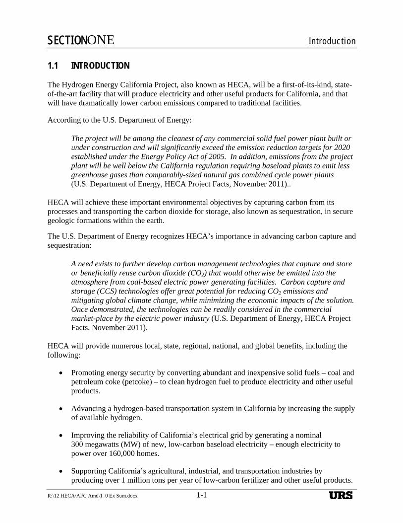
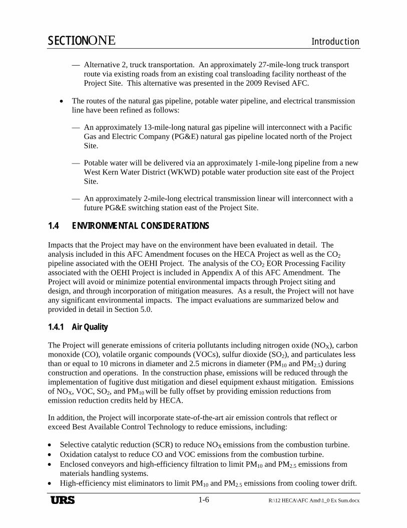
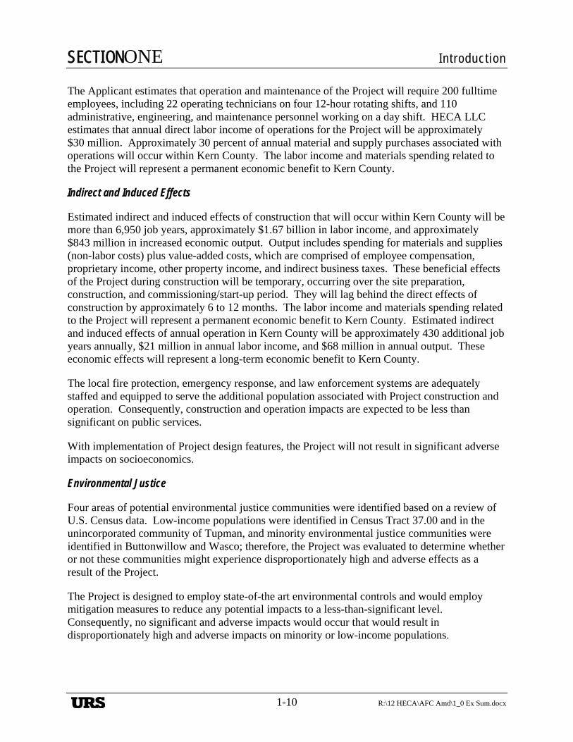
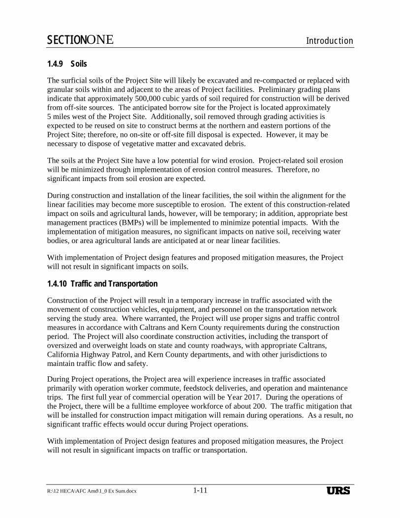
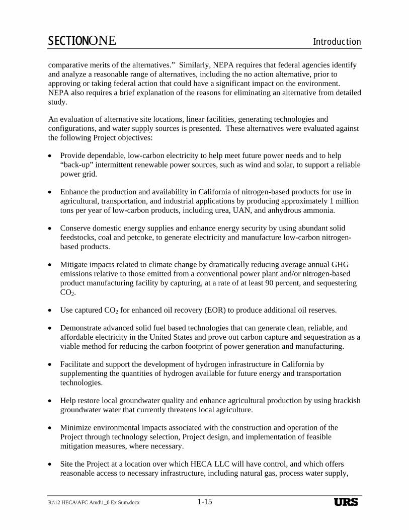
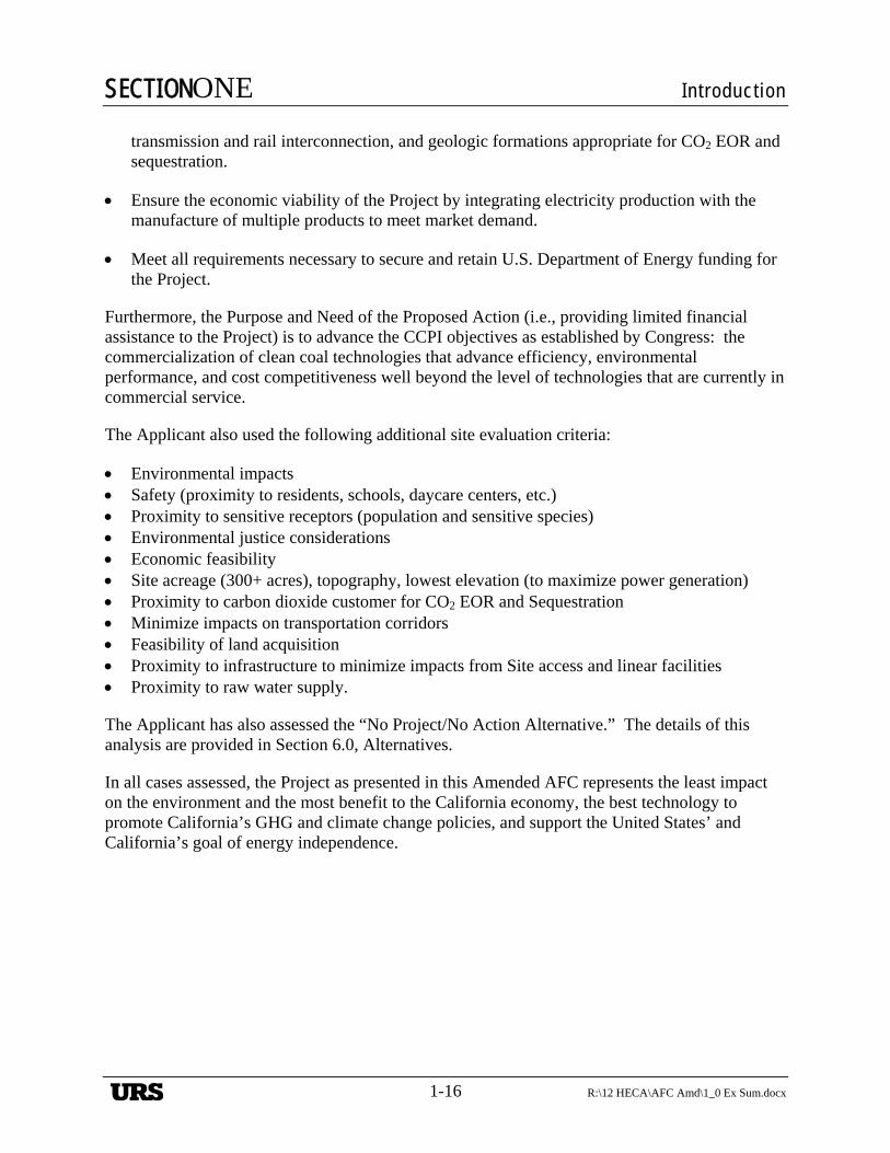
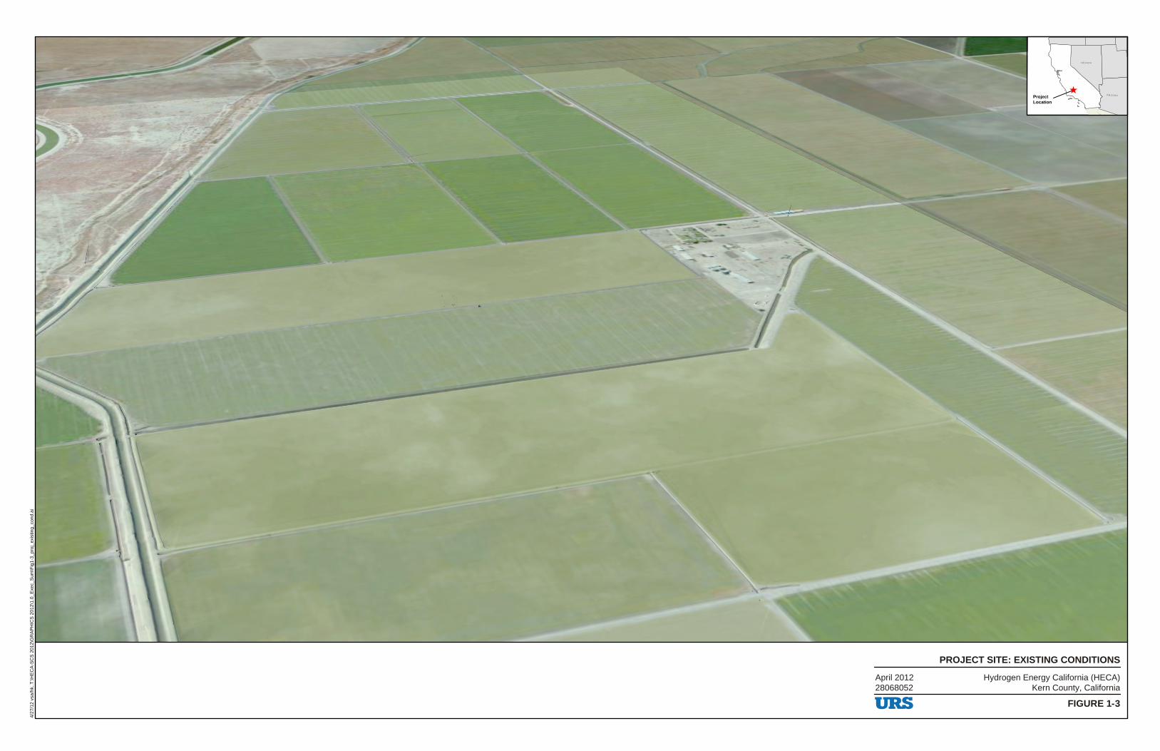
HECA will be located on a 453-acre Project Site approximately 7 miles west of the outermost edge of the city of Bakersfield and 1.5 miles northwest of the unincorporated community of Tupman in western Kern County, California. The site is shown in Figure 1-1, Project Vicinity
URS
SECTIONONE Introduction
R:\12 HECA\AFC Amd\1_0 Ex Sum.docx 1-3
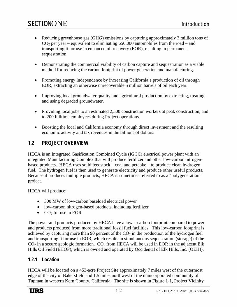
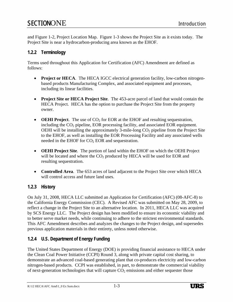
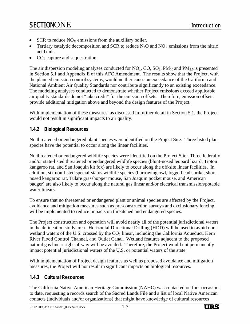
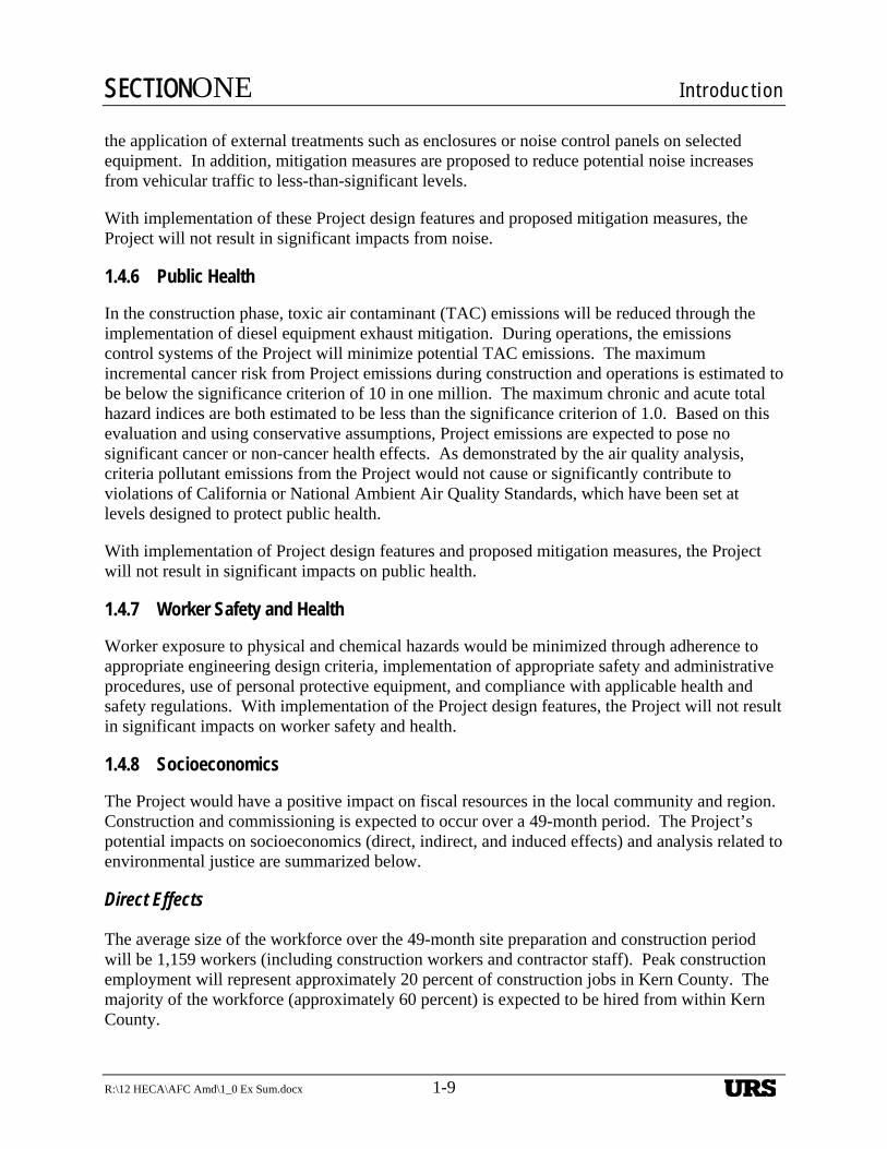
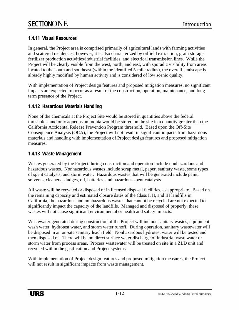
and Figure 1-2, Project Location Map. Figure 1-3 shows the Project Site as it exists today. The Project Site is near a hydrocarbon-producing area known as the EHOF.
1.2.2 Terminology
Terms used throughout this Application for Certification (AFC) Amendment are defined as follows:
Project or HECA. The HECA IGCC electrical generation facility, low-carbon nitrogen-based products Manufacturing Complex, and associated equipment and processes, including its linear facilities.
Project Site or HECA Project Site. The 453-acre parcel of land that would contain the HECA Project. HECA has the option to purchase the Project Site from the property owner.
OEHI Project. The use of CO2 for EOR at the EHOF and resulting sequestration, including the CO2 pipeline, EOR processing facility, and associated EOR equipment. OEHI will be installing the approximately 3-mile-long CO2 pipeline from the Project Site to the EHOF, as well as installing the EOR Processing Facility and any associated wells needed in the EHOF for CO2 EOR and sequestration.
OEHI Project Site. The portion of land within the EHOF on which the OEHI Project will be located and where the CO2 produced by HECA will be used for EOR and resulting sequestration.
Controlled Area. The 653 acres of land adjacent to the Project Site over which HECA will control access and future land uses.
1.2.3 History
On July 31, 2008, HECA LLC submitted an Application for Certification (AFC) (08-AFC-8) to the California Energy Commission (CEC). A Revised AFC was submitted on May 28, 2009, to reflect a change in the Project Site to an alternative location. In 2011, HECA LLC was acquired by SCS Energy LLC. The Project design has been modified to ensure its economic viability and to better serve market needs, while continuing to adhere to the strictest environmental standards. This AFC Amendment describes and analyzes the changes to the Project design, and supersedes previous application materials in their entirety, unless noted otherwise.
1.2.4 U.S. Department of Energy Funding
The United States Department of Energy (DOE) is providing financial assistance to HECA under the Clean Coal Power Initiative (CCPI) Round 3, along with private capital cost sharing, to demonstrate an advanced coal-based generating plant that co-produces electricity and low-carbon nitrogen-based products. CCPI was established, in part, to demonstrate the commercial viability of next-generation technologies that will capture CO2 emissions and either sequester those
URS
SECTIONONE Introduction
1-4 R:\12 HECA\AFC Amd\1_0 Ex Sum.docx
emissions or beneficially reuse them. Once demonstrated, the technologies can be readily considered in the commercial marketplace by the electric power industry.
1.2.5 Permitting and Environmental Review
The CEC has exclusive permitting authority over thermal power plants of 50 MW or more, and acts as the lead agency for such power plants under the California Environmental Quality Act (CEQA). As a federal agency, DOE must comply with the National Environmental Policy Act of 1969 (NEPA) (42 U.S.C. §§ 4321 et seq.) by considering potential environmental issues associated with its actions prior to deciding whether to undertake these actions. The DOE will work with the CEC to develop a joint CEQA/NEPA review. As such, this Amended AFC, including the information provided in Appendix B (i.e., Purpose and Need), was prepared to meet the requirements of both CEQA and elements of NEPA. Both CEQA and NEPA require the Applicant to address any potential impacts or effects resulting from the construction and operation of the Project. The OEHI EOR Project will be separately permitted by OEHI through the Department of Conservation, Division of Oil, Gas, and Geothermal Resources (DOGGR). However the environmental impacts associated with the OEHI EOR Project will be analyzed in the joint CEQA/NEPA analysis being conducted by the CEC and DOE.
1.2.6 Schedule
Construction and commissioning of the Project is expected to take approximately 49 months. Commencement of pre-construction and construction activities is expected to begin in June 2013, with site activities and truck deliveries beginning in August 2013. Construction is expected to be completed by February 2017. Commercial operation is expected to commence in September 2017.
1.3 PROJECT DESIGN IMPROVEMENTS
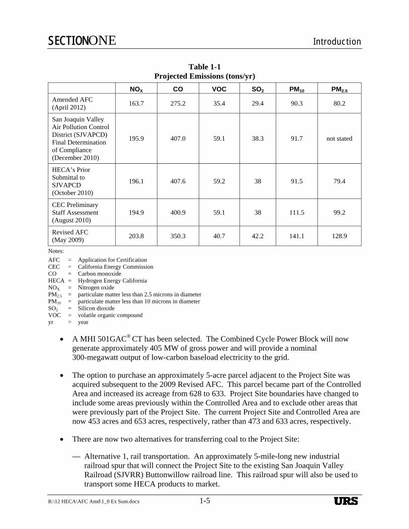
Throughout the Project design and permitting process, HECA has strived continually to improve the design of the Project and to maximize its environmental performance. The Project modifications proposed and analyzed in this AFC Amendment represent a continuation of that effort. For example, Table 1-1 illustrates the success that has been achieved in continually working to reduce the anticipated criteria pollutant emissions from the Project.
The following are some of the notable Project design improvements that are further described and analyzed in this AFC Amendment:
A Manufacturing Complex to produce approximately 1 million tons per year of low-carbon nitrogen-based products (including urea, urea ammonium nitrate (UAN) and anhydrous ammonia) to be used in agricultural, transportation, and industrial applications has been integrated into the Project design.
Mitsubishi Heavy Industries (MHI) oxygen-blown dry feed gasification technology has been selected. The gasifier preheaters are no longer needed due to the change in design of the gasifier.
URS
SECTIONONE Introduction
R:\12 HECA\AFC Amd\1_0 Ex Sum.docx 1-5
Table 1-1 Projected Emissions (tons/yr)
NOX CO VOC SO2 PM10 PM2.5
Amended AFC (April 2012)
163.7 275.2 35.4 29.4 90.3 80.2
San Joaquin Valley Air Pollution Control District (SJVAPCD) Final Determination of Compliance (December 2010)
195.9 407.0 59.1 38.3 91.7 not stated
HECA’s Prior Submittal to SJVAPCD (October 2010)
196.1 407.6 59.2 38 91.5 79.4
CEC Preliminary Staff Assessment (August 2010)
194.9 400.9 59.1 38 111.5 99.2
Revised AFC (May 2009)
203.8 350.3 40.7 42.2 141.1 128.9
Notes:
AFC = Application for Certification CEC = California Energy Commission CO = Carbon monoxide HECA = Hydrogen Energy California NOX = Nitrogen oxide PM2.5 = particulate matter less than 2.5 microns in diameter PM10 = particulate matter less than 10 microns in diameter SO2 = Silicon dioxide VOC = volatile organic compound yr = year
A MHI 501GAC® CT has been selected. The Combined Cycle Power Block will now generate approximately 405 MW of gross power and will provide a nominal 300-megawatt output of low-carbon baseload electricity to the grid.
The option to purchase an approximately 5-acre parcel adjacent to the Project Site was acquired subsequent to the 2009 Revised AFC. This parcel became part of the Controlled Area and increased its acreage from 628 to 633. Project Site boundaries have changed to include some areas previously within the Controlled Area and to exclude other areas that were previously part of the Project Site. The current Project Site and Controlled Area are now 453 acres and 653 acres, respectively, rather than 473 and 633 acres, respectively.
There are now two alternatives for transferring coal to the Project Site:
— Alternative 1, rail transportation. An approximately 5-mile-long new industrial railroad spur that will connect the Project Site to the existing San Joaquin Valley Railroad (SJVRR) Buttonwillow railroad line. This railroad spur will also be used to transport some HECA products to market.
URS
SECTIONONE Introduction
1-6 R:\12 HECA\AFC Amd\1_0 Ex Sum.docx
— Alternative 2, truck transportation. An approximately 27-mile-long truck transport route via existing roads from an existing coal transloading facility northeast of the Project Site. This alternative was presented in the 2009 Revised AFC.
The routes of the natural gas pipeline, potable water pipeline, and electrical transmission line have been refined as follows:
— An approximately 13-mile-long natural gas pipeline will interconnect with a Pacific Gas and Electric Company (PG&E) natural gas pipeline located north of the Project Site.
— Potable water will be delivered via an approximately 1-mile-long pipeline from a new West Kern Water District (WKWD) potable water production site east of the Project Site.
— An approximately 2-mile-long electrical transmission linear will interconnect with a future PG&E switching station east of the Project Site.
1.4 ENVIRONMENTAL CONSIDERATIONS
Impacts that the Project may have on the environment have been evaluated in detail. The analysis included in this AFC Amendment focuses on the HECA Project as well as the CO2 pipeline associated with the OEHI Project. The analysis of the CO2 EOR Processing Facility associated with the OEHI Project is included in Appendix A of this AFC Amendment. The Project will avoid or minimize potential environmental impacts through Project siting and design, and through incorporation of mitigation measures. As a result, the Project will not have any significant environmental impacts. The impact evaluations are summarized below and provided in detail in Section 5.0.
1.4.1 Air Quality
The Project will generate emissions of criteria pollutants including nitrogen oxide (NOX), carbon monoxide (CO), volatile organic compounds (VOCs), sulfur dioxide (SO2), and particulates less than or equal to 10 microns in diameter and 2.5 microns in diameter (PM10 and PM2.5) during construction and operations. In the construction phase, emissions will be reduced through the implementation of fugitive dust mitigation and diesel equipment exhaust mitigation. Emissions of NOX, VOC, SO2, and PM10 will be fully offset by providing emission reductions from emission reduction credits held by HECA.
In addition, the Project will incorporate state-of-the-art air emission controls that reflect or exceed Best Available Control Technology to reduce emissions, including:
Selective catalytic reduction (SCR) to reduce NOX emissions from the combustion turbine. Oxidation catalyst to reduce CO and VOC emissions from the combustion turbine. Enclosed conveyors and high-efficiency filtration to limit PM10 and PM2.5 emissions from
materials handling systems. High-efficiency mist eliminators to limit PM10 and PM2.5 emissions from cooling tower drift.
URS
SECTIONONE Introduction
R:\12 HECA\AFC Amd\1_0 Ex Sum.docx 1-7
SCR to reduce NOX emissions from the auxiliary boiler. Tertiary catalytic decomposition and SCR to reduce N2O and NOX emissions from the nitric
acid unit. CO2 capture and sequestration.
The air dispersion modeling analyses conducted for NOx, CO, SO2, PM10 and PM2.5 is presented in Section 5.1 and Appendix E of this AFC Amendment. The results show that the Project, with the planned emission control systems, would neither cause an exceedance of the California and National Ambient Air Quality Standards nor contribute significantly to an existing exceedance. The modeling analyses conducted to demonstrate whether Project emissions exceed applicable air quality standards do not “take credit” for the emission offsets. Therefore, emission offsets provide additional mitigation above and beyond the design features of the Project.
With implementation of these measures, as discussed in further detail in Section 5.1, the Project would not result in significant impacts to air quality.
1.4.2 Biological Resources
No threatened or endangered plant species were identified on the Project Site. Three listed plant species have the potential to occur along the linear facilities.
No threatened or endangered wildlife species were identified on the Project Site. Three federally and/or state-listed threatened or endangered wildlife species (blunt-nosed leopard lizard, Tipton kangaroo rat, and San Joaquin kit fox) are likely to occur along the off-site linear facilities. In addition, six non-listed special-status wildlife species (burrowing owl, loggerhead shrike, short-nosed kangaroo rat, Tulare grasshopper mouse, San Joaquin pocket mouse, and American badger) are also likely to occur along the natural gas linear and/or electrical transmission/potable water linears.
To ensure that no threatened or endangered plant or animal species are affected by the Project, avoidance and mitigation measures such as pre-construction surveys and exclusionary fencing will be implemented to reduce impacts on threatened and endangered species.
The Project construction and operation will avoid nearly all of the potential jurisdictional waters in the delineation study area. Horizontal Directional Drilling (HDD) will be used to avoid non-wetland waters of the U.S. crossed by the CO2 linear, including the California Aqueduct, Kern River Flood Control Channel, and Outlet Canal. Wetland features adjacent to the proposed natural gas linear right-of-way will be avoided. Therefore, the Project would not permanently impact potential jurisdictional waters of the U.S. or potential waters of the state.
With implementation of Project design features as well as proposed avoidance and mitigation measures, the Project will not result in significant impacts on biological resources.
1.4.3 Cultural Resources
The California Native American Heritage Commission (NAHC) was contacted on four occasions to date, requesting a records search of the Sacred Lands File and a list of local Native American contacts (individuals and/or organizations) that might have knowledge of cultural resources
URS

SECTIONONE Introduction
1-8 R:\12 HECA\AFC Amd\1_0 Ex Sum.docx
within the Project study area and various linear alignments. According to the NAHC, the searches were negative for the presence of Native American cultural resources in the archaeological resource survey areas comprised of the Project Site as well as the various linear alignment alternatives. The responses from the Native American contacts did not contain any information on additional cultural resources.
Pedestrian surveys were performed of the Project Site and linear corridors. Thirty-seven archaeological resource sites were identified in the records search area. Of the archaeological resource sites, one is in the archeological resource study area (ARSA), five others are in close proximity to the ARSA (within 200 feet), and the remainder are only within the records search area. Twenty-four archaeological resources were identified within the archaeological resources area of potential effect (APE), as defined for the Project during the course of the current investigation. Of these, 16 were previously recorded sites, while the remaining 8 sites contained newly discovered resources. All buildings (built environment resources) constructed before 1964 within the study area were recorded and evaluated. No buildings in the study area appear to be significant historic properties.
With implementation of Project design features and proposed mitigation measures, the Project will not result in significant impacts on cultural resources.
1.4.4 Land Use
The majority of the Project Site is currently used for agricultural purposes, and is designated Prime Farmland. The entire Project Site is also under Williamson Act contract. Williamson Act restrictions on the Project Site will need to be cancelled pursuant to California Government Code Section 51280(b).
Operation of the Project is not expected to conflict with existing land uses within the vicinity of the Project Site, which include farming, the Tule Elk State Natural Reserve, and a few scattered single-family dwellings. The Project Site is included in the Intensive Agriculture land use designation; permitted uses in the designation include public utility uses. The Project Site is included in the Exclusive Agriculture (A) zone; electrical power generating plants are permitted under Zoning Ordinance with a Conditional Use Permit. Therefore, the Project is consistent with the Kern County’s General Plan and zoning designations.
With implementation of Project design features, the Project will not result in significant impacts on land use.
1.4.5 Noise
Noise impacts on sensitive receptors were evaluated for construction, commissioning, operations, ground-borne vibrations, and vehicle traffic. In addition, worker exposure noise impacts were evaluated.
Given the intermittent and temporary nature of construction activities, potential noise impacts during construction are considered to be less than significant. To ensure compliance with applicable LORS during ongoing Project operations, extensive noise-reduction features were incorporated into the Project design, including low-noise designs for some equipment items and
URS
SECTIONONE Introduction
R:\12 HECA\AFC Amd\1_0 Ex Sum.docx 1-9
the application of external treatments such as enclosures or noise control panels on selected equipment. In addition, mitigation measures are proposed to reduce potential noise increases from vehicular traffic to less-than-significant levels.
With implementation of these Project design features and proposed mitigation measures, the Project will not result in significant impacts from noise.
1.4.6 Public Health
In the construction phase, toxic air contaminant (TAC) emissions will be reduced through the implementation of diesel equipment exhaust mitigation. During operations, the emissions control systems of the Project will minimize potential TAC emissions. The maximum incremental cancer risk from Project emissions during construction and operations is estimated to be below the significance criterion of 10 in one million. The maximum chronic and acute total hazard indices are both estimated to be less than the significance criterion of 1.0. Based on this evaluation and using conservative assumptions, Project emissions are expected to pose no significant cancer or non-cancer health effects. As demonstrated by the air quality analysis, criteria pollutant emissions from the Project would not cause or significantly contribute to violations of California or National Ambient Air Quality Standards, which have been set at levels designed to protect public health.
With implementation of Project design features and proposed mitigation measures, the Project will not result in significant impacts on public health.
1.4.7 Worker Safety and Health
Worker exposure to physical and chemical hazards would be minimized through adherence to appropriate engineering design criteria, implementation of appropriate safety and administrative procedures, use of personal protective equipment, and compliance with applicable health and safety regulations. With implementation of the Project design features, the Project will not result in significant impacts on worker safety and health.
1.4.8 Socioeconomics
The Project would have a positive impact on fiscal resources in the local community and region. Construction and commissioning is expected to occur over a 49-month period. The Project’s potential impacts on socioeconomics (direct, indirect, and induced effects) and analysis related to environmental justice are summarized below.
Direct Effects
The average size of the workforce over the 49-month site preparation and construction period will be 1,159 workers (including construction workers and contractor staff). Peak construction employment will represent approximately 20 percent of construction jobs in Kern County. The majority of the workforce (approximately 60 percent) is expected to be hired from within Kern County.
URS
SECTIONONE Introduction
1-10 R:\12 HECA\AFC Amd\1_0 Ex Sum.docx
The Applicant estimates that operation and maintenance of the Project will require 200 fulltime employees, including 22 operating technicians on four 12-hour rotating shifts, and 110 administrative, engineering, and maintenance personnel working on a day shift. HECA LLC estimates that annual direct labor income of operations for the Project will be approximately $30 million. Approximately 30 percent of annual material and supply purchases associated with operations will occur within Kern County. The labor income and materials spending related to the Project will represent a permanent economic benefit to Kern County.
Indirect and Induced Effects
Estimated indirect and induced effects of construction that will occur within Kern County will be more than 6,950 job years, approximately $1.67 billion in labor income, and approximately $843 million in increased economic output. Output includes spending for materials and supplies (non-labor costs) plus value-added costs, which are comprised of employee compensation, proprietary income, other property income, and indirect business taxes. These beneficial effects of the Project during construction will be temporary, occurring over the site preparation, construction, and commissioning/start-up period. They will lag behind the direct effects of construction by approximately 6 to 12 months. The labor income and materials spending related to the Project will represent a permanent economic benefit to Kern County. Estimated indirect and induced effects of annual operation in Kern County will be approximately 430 additional job years annually, $21 million in annual labor income, and $68 million in annual output. These economic effects will represent a long-term economic benefit to Kern County.
The local fire protection, emergency response, and law enforcement systems are adequately staffed and equipped to serve the additional population associated with Project construction and operation. Consequently, construction and operation impacts are expected to be less than significant on public services.
With implementation of Project design features, the Project will not result in significant adverse impacts on socioeconomics.
Environmental Justice
Four areas of potential environmental justice communities were identified based on a review of U.S. Census data. Low-income populations were identified in Census Tract 37.00 and in the unincorporated community of Tupman, and minority environmental justice communities were identified in Buttonwillow and Wasco; therefore, the Project was evaluated to determine whether or not these communities might experience disproportionately high and adverse effects as a result of the Project.
The Project is designed to employ state-of-the art environmental controls and would employ mitigation measures to reduce any potential impacts to a less-than-significant level. Consequently, no significant and adverse impacts would occur that would result in disproportionately high and adverse impacts on minority or low-income populations.
URS
SECTIONONE Introduction
R:\12 HECA\AFC Amd\1_0 Ex Sum.docx 1-11
1.4.9 Soils
The surficial soils of the Project Site will likely be excavated and re-compacted or replaced with granular soils within and adjacent to the areas of Project facilities. Preliminary grading plans indicate that approximately 500,000 cubic yards of soil required for construction will be derived from off-site sources. The anticipated borrow site for the Project is located approximately 5 miles west of the Project Site. Additionally, soil removed through grading activities is expected to be reused on site to construct berms at the northern and eastern portions of the Project Site; therefore, no on-site or off-site fill disposal is expected. However, it may be necessary to dispose of vegetative matter and excavated debris.
The soils at the Project Site have a low potential for wind erosion. Project-related soil erosion will be minimized through implementation of erosion control measures. Therefore, no significant impacts from soil erosion are expected.
During construction and installation of the linear facilities, the soil within the alignment for the linear facilities may become more susceptible to erosion. The extent of this construction-related impact on soils and agricultural lands, however, will be temporary; in addition, appropriate best management practices (BMPs) will be implemented to minimize potential impacts. With the implementation of mitigation measures, no significant impacts on native soil, receiving water bodies, or area agricultural lands are anticipated at or near linear facilities.
With implementation of Project design features and proposed mitigation measures, the Project will not result in significant impacts on soils.
1.4.10 Traffic and Transportation
Construction of the Project will result in a temporary increase in traffic associated with the movement of construction vehicles, equipment, and personnel on the transportation network serving the study area. Where warranted, the Project will use proper signs and traffic control measures in accordance with Caltrans and Kern County requirements during the construction period. The Project will also coordinate construction activities, including the transport of oversized and overweight loads on state and county roadways, with appropriate Caltrans, California Highway Patrol, and Kern County departments, and with other jurisdictions to maintain traffic flow and safety.
During Project operations, the Project area will experience increases in traffic associated primarily with operation worker commute, feedstock deliveries, and operation and maintenance trips. The first full year of commercial operation will be Year 2017. During the operations of the Project, there will be a fulltime employee workforce of about 200. The traffic mitigation that will be installed for construction impact mitigation will remain during operations. As a result, no significant traffic effects would occur during Project operations.
With implementation of Project design features and proposed mitigation measures, the Project will not result in significant impacts on traffic or transportation.
URS
SECTIONONE Introduction
1-12 R:\12 HECA\AFC Amd\1_0 Ex Sum.docx
1.4.11 Visual Resources
In general, the Project area is comprised primarily of agricultural lands with farming activities and scattered residences; however, it is also characterized by oilfield extraction, grain storage, fertilizer production activities/industrial facilities, and electrical transmission lines. While the Project will be clearly visible from the west, north, and east, with sporadic visibility from areas located to the south and southeast (within the identified 5-mile radius), the overall landscape is already highly modified by human activity and is considered of low scenic quality.
With implementation of Project design features and proposed mitigation measures, no significant impacts are expected to occur as a result of the construction, operation, maintenance, and long-term presence of the Project.
1.4.12 Hazardous Materials Handling
None of the chemicals at the Project Site would be stored in quantities above the federal thresholds, and only aqueous ammonia would be stored on the site in a quantity greater than the California Accidental Release Prevention Program threshold. Based upon the Off-Site Consequence Analysis (OCA), the Project will not result in significant impacts from hazardous materials and handling with implementation of Project design features and proposed mitigation measures.
1.4.13 Waste Management
Wastes generated by the Project during construction and operation include nonhazardous and hazardous wastes. Nonhazardous wastes include scrap metal, paper, sanitary waste, some types of spent catalysts, and storm water. Hazardous wastes that will be generated include paint, solvents, cleaners, sludges, oil, batteries, and hazardous spent catalysts.
All waste will be recycled or disposed of in licensed disposal facilities, as appropriate. Based on the remaining capacity and estimated closure dates of the Class I, II, and III landfills in California, the hazardous and nonhazardous wastes that cannot be recycled are not expected to significantly impact the capacity of the landfills. Managed and disposed of properly, these wastes will not cause significant environmental or health and safety impacts.
Wastewater generated during construction of the Project will include sanitary wastes, equipment wash water, hydrotest water, and storm water runoff. During operation, sanitary wastewater will be disposed in an on-site sanitary leach field. Nonhazardous hydrotest water will be tested and then disposed of. There will be no direct surface water discharge of industrial wastewater or storm water from process areas. Process wastewater will be treated on site in a ZLD unit and recycled within the gasification and Project systems.
With implementation of Project design features and proposed mitigation measures, the Project will not result in significant impacts from waste management.
URS

SECTIONONE Introduction
R:\12 HECA\AFC Amd\1_0 Ex Sum.docx 1-13
1.4.14 Water Resources
The Project will use approximately 6.6 million gallons a day (mgd) of brackish water on a calendar year average basis, or approximately 7,427 acre-feet per year for process water needs. Water usage in the Project can be divided into six categories: power block cooling tower, process cooling tower, Air Separation Unit cooling tower, Manufacturing Complex, gasification solids, and heat recovery steam generator stack.
The Project will use local brackish groundwater that is treated on site to meet Project standards. The brackish groundwater will be supplied from Buena Vista Water Storage District (BVWSD), as part of BVWSD’s Brackish Groundwater Remediation Project (BGRP), which is designed to remediate brackish groundwater that is considered to be unsuitable for agricultural or drinking uses. Implementation of the BGRP, which includes Project-specific pumping, is seen as a benefit to BVWSD in that it remove salts from the aquifer, impedes eastward flow of poor-quality groundwater, and enhances westward flow of good-quality groundwater. Project consumption of these impaired sources will beneficially affect local agriculture. Therefore, the proposed use of the brackish groundwater will beneficially affect local groundwater quality, and the Project’s impacts on water supplies and water quality will be less than significant.
Potable water will be supplied by the WKWD. Potable water will be consumed for drinking and sanitary purposes only. The Project will use a small amount of potable water (approximately 2 acre-foot per year), which is a very small amount of water compared to the overall water usage within WKWD's service area. Therefore, the impact on potable water supplies in the area will be less than significant.
During construction, BMPs will be implemented to minimize the potential for erosion and minimize impacts on off-site areas, including the nearby canals. For portions of the CO2 pipeline that cross the Outlet Canal, the Kern River Flood Control Channel, and the California Aqueduct, the HDD installation method and appropriate BMPs will be implemented; therefore, the Project's impacts on surface waters will be less than significant.
The Project Site is not located in a designated floodplain. Pipelines that cross floodplain areas will be buried or installed using HDD technology at canal crossings; therefore, there will be no impacts on floodplains.
With implementation of Project design features and proposed mitigation measures, the Project will not result in significant impacts on water resources.
1.4.15 Geologic Hazards and Resources
There are no known active or potentially active faults at the Project Site or crossing the Project linears. The closest known major faults classified as active by the California Geological Survey are the San Andreas Fault, located approximately 21 miles to the west; the White Wolf fault, located approximately 23 miles to the southeast; and the Pleito Thrust, located approximately 27 miles south of the Project Site.
URS
SECTIONONE Introduction
1-14 R:\12 HECA\AFC Amd\1_0 Ex Sum.docx
The primary geologic hazards at the Project Site and linear facilities include ground motion from a seismic event centered on one of several nearby active faults and the potential for expansive soils due to high clay content in surface soils.
Project facilities will be designed in accordance with applicable building code seismic design criteria. To reduce the potential for adverse differential settlement beneath heavily loaded settlement-sensitive structures, removal of the susceptible soils and replacement with engineered fill have been recommended for structures constructed on shallow foundations. Settlement design criteria can be provided by a design-level geotechnical investigation.
To reduce the potential for adverse differential settlement beneath heavily loaded structures, landsliding, lateral spreading, and adverse expansion, the removal of the susceptible soils and their replacement with engineered fill have been recommended.
With implementation of Project design features and proposed mitigation measures, the Project will not be adversely impacted by geologic hazards and will not result in significant impacts on geologic resources.
1.4.16 Paleontological Resources
Project construction could impact paleontological resources within the Quaternary alluvium and the Plio-Pleistocene Tulare Formation. Therefore, mitigation measures will be implemented to reduce potential adverse impacts on paleontological resources resulting from Project construction. The paleontological resources impact mitigation program will reduce direct, indirect, and cumulative adverse environmental impacts on paleontological resources that could result from Project construction to a less-than-significant level. The mitigation measures will allow for the salvage of fossil remains and associated specimen data and corresponding geologic and geographic site data that otherwise might be lost to earth-moving and to unauthorized fossil collecting.
With implementation of Project design features and proposed mitigation measures, the Project will not result in significant impacts on paleontological resources.
1.5 PROJECT ALTERNATIVES
The Project will demonstrate a combination of proven technologies at commercial scale that can provide baseload low-carbon power that is fully consistent with California's expressed clean energy policies. The Project will thus make an essential contribution to California’s long-term environmental, economic, and energy security objectives. The Project will play a significant role in California’s goal of addressing climate change and leading the world in production of low-carbon energy. The Project and its environmental benefits may be implemented elsewhere in the world in an effort to combat climate change.
As required by CEQA and CEC regulations, this AFC Amendment provides a detailed discussion “on the range of reasonable alternatives to the Project, including the no project alternative which would feasibly attain most of the basic objectives of the project, but would avoid or substantially lessen any of the significant effects of the project, and an evaluation of the
URS
SECTIONONE Introduction
R:\12 HECA\AFC Amd\1_0 Ex Sum.docx 1-15
comparative merits of the alternatives.” Similarly, NEPA requires that federal agencies identify and analyze a reasonable range of alternatives, including the no action alternative, prior to approving or taking federal action that could have a significant impact on the environment. NEPA also requires a brief explanation of the reasons for eliminating an alternative from detailed study.
An evaluation of alternative site locations, linear facilities, generating technologies and configurations, and water supply sources is presented. These alternatives were evaluated against the following Project objectives:
Provide dependable, low-carbon electricity to help meet future power needs and to help “back-up” intermittent renewable power sources, such as wind and solar, to support a reliable power grid.
Enhance the production and availability in California of nitrogen-based products for use in agricultural, transportation, and industrial applications by producing approximately 1 million tons per year of low-carbon products, including urea, UAN, and anhydrous ammonia.
Conserve domestic energy supplies and enhance energy security by using abundant solid feedstocks, coal and petcoke, to generate electricity and manufacture low-carbon nitrogen-based products.
Mitigate impacts related to climate change by dramatically reducing average annual GHG emissions relative to those emitted from a conventional power plant and/or nitrogen-based product manufacturing facility by capturing, at a rate of at least 90 percent, and sequestering CO2.
Use captured CO2 for enhanced oil recovery (EOR) to produce additional oil reserves.
Demonstrate advanced solid fuel based technologies that can generate clean, reliable, and affordable electricity in the United States and prove out carbon capture and sequestration as a viable method for reducing the carbon footprint of power generation and manufacturing.
Facilitate and support the development of hydrogen infrastructure in California by supplementing the quantities of hydrogen available for future energy and transportation technologies.
Help restore local groundwater quality and enhance agricultural production by using brackish groundwater water that currently threatens local agriculture.
Minimize environmental impacts associated with the construction and operation of the Project through technology selection, Project design, and implementation of feasible mitigation measures, where necessary.
Site the Project at a location over which HECA LLC will have control, and which offers reasonable access to necessary infrastructure, including natural gas, process water supply,
URS
SECTIONONE Introduction
1-16 R:\12 HECA\AFC Amd\1_0 Ex Sum.docx
transmission and rail interconnection, and geologic formations appropriate for CO2 EOR and sequestration.
Ensure the economic viability of the Project by integrating electricity production with the manufacture of multiple products to meet market demand.
Meet all requirements necessary to secure and retain U.S. Department of Energy funding for the Project.
Furthermore, the Purpose and Need of the Proposed Action (i.e., providing limited financial assistance to the Project) is to advance the CCPI objectives as established by Congress: the commercialization of clean coal technologies that advance efficiency, environmental performance, and cost competitiveness well beyond the level of technologies that are currently in commercial service.
The Applicant also used the following additional site evaluation criteria:
Environmental impacts Safety (proximity to residents, schools, daycare centers, etc.) Proximity to sensitive receptors (population and sensitive species) Environmental justice considerations Economic feasibility Site acreage (300+ acres), topography, lowest elevation (to maximize power generation) Proximity to carbon dioxide customer for CO2 EOR and Sequestration Minimize impacts on transportation corridors Feasibility of land acquisition Proximity to infrastructure to minimize impacts from Site access and linear facilities Proximity to raw water supply.
The Applicant has also assessed the “No Project/No Action Alternative.” The details of this analysis are provided in Section 6.0, Alternatives.
In all cases assessed, the Project as presented in this Amended AFC represents the least impact on the environment and the most benefit to the California economy, the best technology to promote California’s GHG and climate change policies, and support the United States’ and California’s goal of energy independence.
URS
OA KLAND
FRES NO
LOS ANGE LES
SAN DI EGO
SAN F RANCIS CO
N E V A D A
A R I Z O N A
U T A H
P A C I F I C
O C E A N
I N Y O
K E R N
S A N B E R N A R D I N O
F R E S N O
R I V E R S I D E
T U L A R E
M O N O
M O N T E R E Y
L O S A N G E L E S
M A D E R AM E R C E D
K I N G S
V E N T U R A
T U O L U M N E
S A N L U I S O B I S P O
S A N TA B A R B A R A
M A R I P O S A
S TA N I S L A U S
S A N B E N I TO
S A N J O A Q U I N
S A N TA
C L A R A
A L A M E D A
C O N T R A C O S TA
S A N TA C R U Z
S A N
M AT E O
BAKERSF IEL D
S A N D I E G O
I M P E R I A L
OR A N G E
M E X I C O
99
101
40
15
10
5
8
80
April 201228068052
Hydrogen Energy California (HECA)Kern County, California
FIGURE 1-1
PROJECT VICINITY MAP
Project SiteProject SiteProject Site
vsa_
4/18
/12.
..U:\G
IS\H
EC
A\P
roje
cts\
HE
CA
_201
2\Ill
ustr
ator
_File
s\F
ig1-
1_pr
oj v
icin
ity.a
i
Major Cities
Major Highways
State Boundaries
County Boundaries0 4020
MILES
ProjectLocation
NEVADA
ARI ZONA
■
CJ
.,,_. __________ T ______________ _________ _
! I i ( ! I
!
URS
§̈¦5
MCKITTRICK HWY
STATION RD
ENOS
LN
STOCKDALE HWY
SEVENTH STANDARD RD
WASC
O WY
S ENO
S LN
ADOHR RD
TUPM
AN RD
ZACH
ARY A
V
MORR
IS RD
DAIRY
RD
TUPMAN RD
WASC
O WY
§̈¦5
|ÿ119
|ÿ58
|ÿ58ROSEDALE HWY
$Source: USGS (30'x60' quads: Taft 1982, Delano 1982). Created using TOPO!, ©2006 National Geographic Maps, All Rights Reserved. Kern County and State of California (proposed and approved projects).
Project Site
Construction Staging Area
Controlled Area
PROJECT LOCATION MAPHydrogen Energy California (HECA)
Kern County, CaliforniaApril 201228068052
ProjectLocation
^
NE V A D AUTA H
A RI Z ON A
0 21 Miles FIGURE 1-2
ed U
:\GIS
\HE
CA
\Pro
ject
s\H
EC
A_
2012
\SU
BM
ITT
AL
\Fig
1_2
_Pro
ject
_lo
catio
n_m
ap_
sim
ple
.mxd
4/
30/
201
2 1
1:3
3:5
7 A
M
URS
Hydrogen Energy California (HECA)Kern County, California
FIGURE 1-3
PROJECT SITE: EXISTING CONDITIONS
4/27
/12
vsa/
hk..T
:\HE
CA
-SC
S 2
012\
GR
AP
HIC
S 2
012\
1.0_
Exe
c_S
um\F
ig1-
3_pr
oj_e
xist
ing_
cond
.ai
April 201228068052
ProjectLocation
NEVADA
ARI ZONA
URS

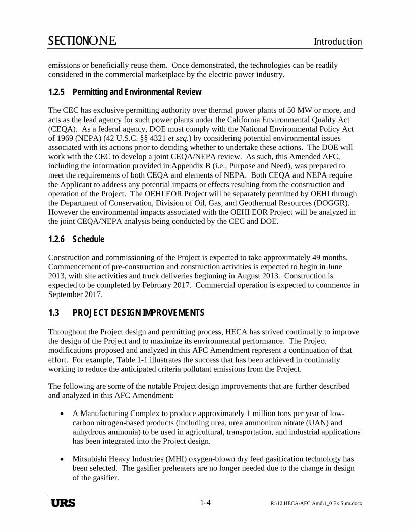
Hydrogen Energy California (HECA)Kern County, California
FIGURE 1-4
PROJECT SITE: PROJECT RENDERING
4/27
/12
vsa/
hk..T
:\HE
CA
-SC
S 2
012\
GR
AP
HIC
S 2
012\
1.0_
Exe
c_S
um\F
ig1-
4_pr
oj_s
ite_r
ende
ring.
ai
April 201228068052
ProjectLocation
NEVADA
ARI ZONA
''
.--d~¢~~~,~~6~~ - -~
URS
TABLE OF CONTENTS
R:\12 HECA\AFC Amd\2_0 Proj Desc.docx 2-i
2. Project Description ............................................................................... 2-1
2.1 Introduction and Project Overview .......................................................... 2-1 2.1.1 Project Background ...................................................................... 2-2 2.1.2 Project Permitting ........................................................................ 2-4
2.1.2.1 California Energy Commission Role ............................ 2-4 2.1.2.2 Division of Oil, Gas, and Geothermal Resources ......... 2-4 2.1.2.3 Department of Energy ................................................... 2-6
2.1.3 Project Terminology .................................................................... 2-6 2.1.4 Project Benefits ............................................................................ 2-7 2.1.5 Project Objectives ...................................................................... 2-10 2.1.6 Project Ownership ...................................................................... 2-11 2.1.7 Schedule ..................................................................................... 2-11 2.1.8 Location ..................................................................................... 2-11 2.1.9 Affected Study Areas ................................................................. 2-12 2.1.10 Site Plan and Access .................................................................. 2-14 2.1.11 Resource Inputs .......................................................................... 2-14
2.1.11.1 Petcoke and Western Sub-Bituminous Coal ............... 2-15 2.1.11.2 Western Sub-Bituminous Coal ................................... 2-15 2.1.11.3 Petcoke ........................................................................ 2-16 2.1.11.4 Feedstock Quality and Plant Operations ..................... 2-16 2.1.11.5 Transportation and Logistics ....................................... 2-16 2.1.11.6 Natural Gas ................................................................. 2-17 2.1.11.7 Water ........................................................................... 2-18 2.1.11.8 Oxygen and Nitrogen .................................................. 2-18
2.1.12 Product Output ........................................................................... 2-19 2.1.12.1 Electricity and Transmission Line .............................. 2-19 2.1.12.2 Carbon Dioxide ........................................................... 2-19 2.1.12.3 Sulfur........................................................................... 2-19 2.1.12.4 Gasification Solids ...................................................... 2-20 2.1.12.5 Low-Carbon Nitrogen-Based Products ....................... 2-20 2.1.12.6 Wastewater Discharge ................................................ 2-21
2.1.13 Plant Performance Summary ..................................................... 2-21 2.2 Solids Handling, Gasification, and Gas Treatment ................................ 2-21
2.2.1 Overview of Gasification Technology ....................................... 2-21 2.2.2 Feedstock Delivery, Handling and Storage ............................... 2-22
2.2.2.1 Rail Unloading and Transfer Systems ........................ 2-22 2.2.2.2 Truck Unloading and Transfer Systems ..................... 2-22 2.2.2.3 Feedstock Blending and Handling .............................. 2-23
2.2.3 Gasification ................................................................................ 2-23 2.2.3.1 Feedstock Grinding and Drying .................................. 2-23 2.2.3.2 Gasifier ........................................................................ 2-23 2.2.3.3 Gasification Solids and Water Handling ..................... 2-24
2.2.4 Syngas Scrubbing, Sour Shift, Low-Temperature Gas Cooling, and Sour Water Treatment .......................................... 2-24
2.2.5 Mercury Removal ...................................................................... 2-25
URS
TABLE OF CONTENTS
2-ii R:\12 HECA\AFC Amd\2_0 Proj Desc.docx
2.2.6 Acid Gas Removal ..................................................................... 2-25 2.2.6.1 Rectisol® Process Description .................................... 2-25
2.3 Power Generation ................................................................................... 2-26 2.3.1 Summary .................................................................................... 2-26 2.3.2 Major Power Block Equipment Description .............................. 2-26
2.3.2.1 Combustion Turbine and Heat Recovery Steam Generator ................................................................... 2-26
2.3.2.2 Emissions Controls Systems ....................................... 2-27 2.3.2.3 Oxidation System ........................................................ 2-27 2.3.2.4 Continuous Emissions Monitoring System ................. 2-28 2.3.2.5 Steam Turbine ............................................................. 2-28 2.3.2.6 Heat Rejection System ................................................ 2-28
2.3.3 Major Electrical Equipment and Systems .................................. 2-28 2.4 Manufacturing Complex ........................................................................ 2-29
2.4.1 Pressure Swing Adsorption Unit ................................................ 2-29 2.4.2 Ammonia Synthesis Unit ........................................................... 2-29 2.4.3 Urea Unit .................................................................................... 2-30 2.4.4 Urea Pastillation Unit ................................................................. 2-31
2.4.4.1 Urea Pastille Handling ................................................ 2-31 2.4.5 Urea Ammonium Nitrate Complex ............................................ 2-32
2.4.5.1 Nitric Acid Unit .......................................................... 2-32 2.4.5.2 Ammonium Nitrate Unit ............................................. 2-32 2.4.5.3 Urea Ammonium Nitrate Unit .................................... 2-33
2.4.6 UAN Solution Storage and Handling ........................................ 2-33 2.5 Supporting Process Systems .................................................................. 2-33
2.5.1 Natural Gas Fuel System ........................................................... 2-33 2.5.1.1 Natural Gas Metering Station ..................................... 2-33 2.5.1.2 High-Pressure Natural Gas ......................................... 2-33 2.5.1.3 Low-Pressure Natural Gas .......................................... 2-33
2.5.2 Air Separation Unit .................................................................... 2-33 2.5.3 Sulfur Recovery and Tail Gas Compression Unit...................... 2-34
2.5.3.1 Sulfur Storage and Handling ....................................... 2-35 2.5.4 Raw Water and Plant Wastewater Treatment Unit .................... 2-35 2.5.5 Cooling Tower Blowdown and Demineralized Water
Treatment Unit ........................................................................... 2-35 2.5.6 Carbon Dioxide Compression and Pipeline ............................... 2-36
2.5.6.1 Compression and Pipeline........................................... 2-36 2.5.6.2 Carbon Dioxide Compression and Purification .......... 2-36
2.5.7 Heat Rejection Systems ............................................................. 2-36 2.5.7.1 Power Block Cooling Tower ...................................... 2-37 2.5.7.2 Process Cooling Tower ............................................... 2-37 2.5.7.3 Air Separation Unit Cooling Tower ............................ 2-37
2.5.8 Auxiliary Boiler ......................................................................... 2-38 2.5.9 Flares .......................................................................................... 2-38
2.5.9.1 Gasification Flare ........................................................ 2-38 2.5.9.2 Sulfur Recovery Unit Flare ......................................... 2-39
URS
TABLE OF CONTENTS
R:\12 HECA\AFC Amd\2_0 Proj Desc.docx 2-iii
2.5.9.3 Rectisol® Flare ............................................................ 2-39 2.5.9.4 Carbon Dioxide Vent .................................................. 2-39
2.5.10 Emergency Engines ................................................................... 2-39 2.5.10.1 Emergency Diesel Generator ...................................... 2-39 2.5.10.2 Diesel Firewater Pump ................................................ 2-40
2.5.11 Fire Protection ............................................................................ 2-40 2.5.11.1 Fire Protection Program .............................................. 2-40 2.5.11.2 Firewater Storage and Distribution System ................ 2-41 2.5.11.3 Automatic Fire-Suppression System ........................... 2-41
2.5.12 Plant and Instrument Air ............................................................ 2-41 2.5.13 Emissions Monitoring System ................................................... 2-42 2.5.14 Hazardous Material Management .............................................. 2-42 2.5.15 Hazardous Waste Management .................................................. 2-43 2.5.16 Storm Water Management ......................................................... 2-44 2.5.17 Control System........................................................................... 2-45 2.5.18 Project Buildings ........................................................................ 2-45 2.5.19 Security Systems ........................................................................ 2-45
2.6 Plant Operating Scenarios and Emissions .............................................. 2-46 2.6.1 Operations .................................................................................. 2-46 2.6.2 Start-Up ...................................................................................... 2-46 2.6.3 Transient Operations .................................................................. 2-51 2.6.4 Commissioning .......................................................................... 2-52
2.6.4.1 Power Block Commissioning on Natural Gas ............ 2-52 2.6.4.2 Gasification Block and Balance of Plant
Commissioning .......................................................... 2-53 2.6.4.3 Power Block Commissioning on Hydrogen-Rich
Fuel ............................................................................ 2-53 2.6.4.4 Manufacturing Complex Commissioning ................... 2-54
2.6.5 Plant Staffing ............................................................................. 2-54 2.6.6 Materials and Equipment Delivery during Operations .............. 2-55
2.7 Project Construction............................................................................... 2-56 2.7.1 Project Site Construction ........................................................... 2-56
2.7.1.1 Construction Planning ................................................. 2-56 2.7.1.2 Mobilization ................................................................ 2-56 2.7.1.3 Construction Offices, Parking, Warehouse, and
Laydown Areas .......................................................... 2-56 2.7.1.4 Emergency Facilities ................................................... 2-57 2.7.1.5 Construction Utilities and Site Services ..................... 2-57 2.7.1.6 Construction Materials and Heavy Equipment
Deliveries................................................................... 2-58 2.7.1.7 Hazardous Materials Storage ...................................... 2-58 2.7.1.8 Construction Disturbance Area ................................... 2-58 2.7.1.9 Storm Water Runoff Prevention Plan ......................... 2-59 2.7.1.10 Linear Construction and Maintenance ........................ 2-59
2.7.2 Combined Construction Workforce ........................................... 2-65 2.7.3 Combined Construction Equipment Requirements ................... 2-65
URS
TABLE OF CONTENTS
2-iv R:\12 HECA\AFC Amd\2_0 Proj Desc.docx
2.7.4 Combined Construction Traffic ................................................. 2-66 2.7.4.1 Traffic Control Plan during Construction ................... 2-67
2.8 Facility Safety Design ............................................................................ 2-68 2.8.1 Natural Hazards ......................................................................... 2-69 2.8.2 Emergency Systems and Safety Precautions ............................. 2-70
2.8.2.1 Community and Stakeholder Awareness .................... 2-70 2.8.2.2 Emergency Preparedness ............................................ 2-70 2.8.2.3 Specific Project Emergency Systems.......................... 2-70
2.9 Technology Selection and Facility Reliability ....................................... 2-73 2.9.1 Technology Selection ................................................................. 2-73 2.9.2 Facility Reliability ..................................................................... 2-74
2.10 References .............................................................................................. 2-75
Tables
Table 2-1 Disturbed Acreage Table 2-2 Site Characteristics Table 2-3 Project Linear Tie-in Location on Plot Plan Table 2-4 Typical Analysis for Petcoke Table 2-5 Typical Analysis of Sub-Bituminous Coal Table 2-6 Typical Natural Gas Composition Table 2-7 Electrical Specification Table 2-8 Sulfur Specifications Table 2-9 Example Composition of Gasification Solids Table 2-10 Representative Heat and Material Balances Table 2-11 Maximum Feeds and Products Table 2-12 Primary Gasification Reactions Table 2-13 Components of Syngas from Oxygen-Blown Gasification Table 2-14 Combustion Turbine Generator Table 2-15 Hazardous Materials Usage and Storage During Operations Based on Title 22
Hazardous Characterization Table 2-16 Hazardous Materials Usage and Storage During Operations Based on Material
Properties Table 2-17 Summary of Construction Waste Streams and Management Methods Table 2-19 Maximum Fuel Energy Table 2-20 HECA Total Combined Annual Criteria Pollutant Emissions Table 2-21 Material Delivery Table 2-22 Estimated Construction Water Use Table 2-23 Hazardous Materials Usage and Storage during Construction Based on Title 22
Hazardous Characterization Table 2-24 Hazardous Materials Usage and Storage During Construction Based on Material
Properties Table 2-25 Preliminary Estimate of Monthly Construction Labor Power by Craft Table 2-26 Construction Equipment Estimate
URS
TABLE OF CONTENTS
R:\12 HECA\AFC Amd\2_0 Proj Desc.docx 2-v
Figures
Figure 2-1 Project Vicinity Figure 2-2 Project Rendering Looking Northwest Figure 2-3 Overall Block Flow Diagram Figure 2-4 Site Plan Figure 2-5 Preliminary Plot Plan Figure 2-6 Project Elevations Figure 2-7 Project Location Map Figure 2-8 Project Location Details Figure 2-9 Preliminary Temporary Construction Facilities Plan Figure 2-10 Water Usage Figure 2-11 Flow Diagram Raw Water/Wastewater/Demin Water Treatment Plant Figure 2-12 Overall Single Line Diagram Figure 2-13 HECA Overall Component Balances Figure 2-14 Flow Diagram Gasification Process Figure 2-15 Flow Diagram Feedstock Handling and Storage Figure 2-16 Flow Diagram Sour Shift System Figure 2-17 Flow Diagram Low Temperature Gas Cooling Figure 2-18 Flow Diagram Wash Column and Mercury Removal Figure 2-19 Flow Diagram Rectisol® Acid Gas Removal Figure 2-20 Flow Diagram Power Block Systems Figure 2-21 Electrical Overall One-Line Diagram (1) Figure 2-22 Electrical Overall One-Line Diagram (2) Figure 2-23 Electrical Overall One-Line Diagram (3) Figure 2-24 Electrical Overall One-Line Diagram (4) Figure 2-25 Electrical Overall One-Line Diagram (5) Figure 2-26 Electrical Overall One-Line Diagram (6) Figure 2-27 Electrical Overall One-Line Diagram (7) Figure 2-28 Flow Diagram PSA and Off-Gas Compression Systems Figure 2-29 Flow Diagram Ammonia Synthesis Unit Figure 2-30 Flow Diagram Urea Unit Synthesis Figure 2-31 Flow Diagram Urea Unit Concentration Figure 2-32 Flow Diagram Nitric Acid Unit Figure 2-33 Flow Diagram Ammonium Nitrate/UAN Units Figure 2-34 Flow Diagram Natural Gas System Figure 2-35 Flow Diagram Air Separation Unit Figure 2-36 Flow Diagram Sulfur Recovery Unit Figure 2-37 Flow Diagram Tail Gas Treating Unit Figure 2-38 Flow Diagram Scrubber Bottoms Sour Water Stripper Figure 2-39 Flow Diagram CO2 Compression and Purification Systems Figure 2-40 Flow Diagram Power Block Cooling Water System Figure 2-41 Flow Diagram Gasification and Rectisol® Flare System Figure 2-42 Flow Diagram SRU Flare System Figure 2-43 Flow Diagram Firewater System Figure 2-44 Preliminary Hazardous Material Location Plan Figure 2-45 Preliminary Storm Water Drainage Plan
URS
TABLE OF CONTENTS
2-vi R:\12 HECA\AFC Amd\2_0 Proj Desc.docx
Figure 2-46 Control System Block Diagram Figure 2-47 Preliminary Emissions Sources Plot Plan Figure 2-48 Overall Block Flow Diagram with Emission Sources Figure 2-49 Preliminary Paving Plan Figure 2-50 Preliminary Grading Plan
URS
SECTIONTWO Project Description
R:\12 HECA\AFC Amd\2_0 Proj Desc.docx
2-1
2. Section 2 Project Description
2.1 INTRODUCTION AND PROJECT OVERVIEW
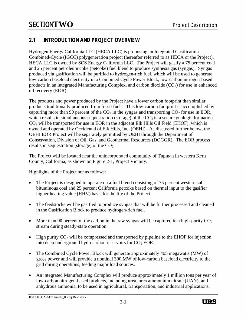
Hydrogen Energy California LLC (HECA LLC) is proposing an Integrated Gasification Combined-Cycle (IGCC) polygeneration project (hereafter referred to as HECA or the Project). HECA LLC is owned by SCS Energy California LLC. The Project will gasify a 75 percent coal and 25 percent petroleum coke (petcoke) fuel blend to produce synthesis gas (syngas). Syngas produced via gasification will be purified to hydrogen-rich fuel, which will be used to generate low-carbon baseload electricity in a Combined Cycle Power Block, low-carbon nitrogen-based products in an integrated Manufacturing Complex, and carbon dioxide (CO2) for use in enhanced oil recovery (EOR).
The products and power produced by the Project have a lower carbon footprint than similar products traditionally produced from fossil fuels. This low-carbon footprint is accomplished by capturing more than 90 percent of the CO2 in the syngas and transporting CO2 for use in EOR, which results in simultaneous sequestration (storage) of the CO2 in a secure geologic formation. CO2 will be transported for use in EOR in the adjacent Elk Hills Oil Field (EHOF), which is owned and operated by Occidental of Elk Hills, Inc. (OEHI). As discussed further below, the OEHI EOR Project will be separately permitted by OEHI through the Department of Conservation, Division of Oil, Gas, and Geothermal Resources (DOGGR). The EOR process results in sequestration (storage) of the CO2.
The Project will be located near the unincorporated community of Tupman in western Kern County, California, as shown on Figure 2-1, Project Vicinity.
Highlights of the Project are as follows:
The Project is designed to operate on a fuel blend consisting of 75 percent western sub-bituminous coal and 25 percent California petcoke based on thermal input to the gasifier higher heating value (HHV) basis for the life of the Project.
The feedstocks will be gasified to produce syngas that will be further processed and cleaned in the Gasification Block to produce hydrogen-rich fuel.
More than 90 percent of the carbon in the raw syngas will be captured in a high-purity CO2 stream during steady-state operation.
High purity CO2 will be compressed and transported by pipeline to the EHOF for injection into deep underground hydrocarbon reservoirs for CO2 EOR.
The Combined Cycle Power Block will generate approximately 405 megawatts (MW) of gross power and will provide a nominal 300 MW of low-carbon baseload electricity to the grid during operations, feeding major load sources.
An integrated Manufacturing Complex will produce approximately 1 million tons per year of low-carbon nitrogen-based products, including urea, urea ammonium nitrate (UAN), and anhydrous ammonia, to be used in agricultural, transportation, and industrial applications.
URS
SECTIONTWO Project Description
2-2 R:\12 HECA\AFC Amd\2_0 Proj Desc.docx
The power and nitrogen-based products produced by the Project will have a significantly lower carbon emission profile relative to similar power and products traditionally generated from fossil fuels, such as natural gas or coal. Natural gas is the fuel source predominantly used for power generation in California.
The Sulfur Recovery Unit (SRU) will convert sulfur compounds into a saleable sulfur product.
The process water source for the Project will be brackish groundwater from the Buena Vista Water Storage District (BVWSD) Brackish Groundwater Remediation Project. The water will be supplied via an approximately 15-mile pipeline from northwest of the Project Site by BVWSD and will be treated on site to meet Project specifications. Potable water will be supplied by West Kern Water District (WKWD) for drinking and sanitary purposes.
There will be no direct surface water discharge of industrial wastewater or storm water. Process wastewater will be treated on site and recycled for reuse within the Project. Other wastewaters (e.g., from cooling tower blowdown and the wastewater treatment unit) will be collected and directed to on-site zero liquid discharge (ZLD) unit. Water recovered by the ZLD unit is recycled for reuse within the facility.
The Project is designed with state-of-the-art emission control technology to achieve minimal air emissions through the use of Best Available Control Technology (BACT). The Project is designed to avoid flaring during steady-state operation, and to minimize flaring during start-up and shut-down operations.
Project greenhouse gas (GHG) emissions (e.g., CO2) will be reduced through carbon capture and CO2 EOR, resulting in simultaneous sequestration.
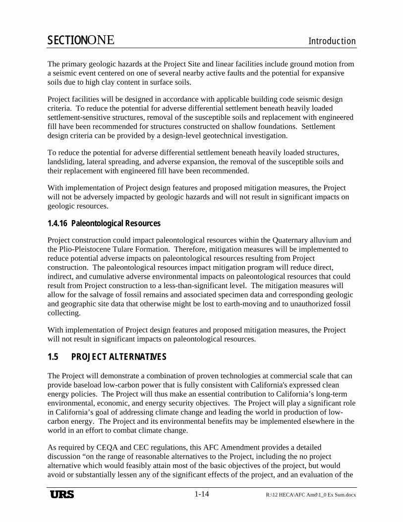
This Project Description section of this Application for Certification (AFC) Amendment describes the Project information summarized above in detail. A computer rendering of the Project is shown on Figure 2-2, Project Rendering Looking Northwest. A block flow diagram of the Project is shown on Figure 2-3, Overall Block Flow Diagram.
2.1.1 Project Background
SCS Energy California LLC acquired 100 percent ownership of HECA LLC in September 2011.
The previous owner of the Project submitted an AFC (08 AFC-8) to the California Energy Commission (CEC) on July 31, 2008, which proposed the Project on a different site. The previous owner subsequently decided to move the Project when it discovered the existence of sensitive biological resources at that site. A Revised AFC was submitted on May 28, 2009 for the current site, and deemed data adequate on August 26, 2009. An Informational Hearing and Site Visit were conducted on September 16, 2009. In addition, multiple staff workshops were held and responses to six sets of Data Requests were submitted between 2009 and 2011.
HECA LLC modified the Project design to ensure economic viability and better serve market needs, while continuing to adhere to the strictest environmental standards. HECA LLC
URS
SECTIONTWO Project Description
R:\12 HECA\AFC Amd\2_0 Proj Desc.docx
2-3
respectfully submits this AFC Amendment for the modified Project design. This AFC Amendment supersedes previous application materials in their entirety, unless noted otherwise.
Several basic Project components remain unchanged, including the following:
The Project Site location remains the same.
The Project continues to use IGCC technology.
More than 90 percent of the carbon in the syngas is captured during steady state operation.
CO2 is transported to the adjacent EHOF for use in EOR resulting in sequestration.
State-of-the-art emission controls are included in the design.
Process water consisting of brackish groundwater will be supplied by the BVWSD.
ZLD technology is used in the Project design.
The following are some of the notable Project changes proposed in this AFC Amendment:
The option to purchase an approximately 5-acre parcel adjacent to the Project Site was acquired subsequent to the 2009 Revised AFC. This parcel became part of the Controlled Area and increased its acreage from 628 to 633. Project Site boundaries have changed to include some areas previously within the Controlled Area and to exclude other areas that were previously part of the Project Site. The current Project Site and Controlled Area are now 453 acres and 653 acres, respectively, rather than the sizes of 473 and 628 acres that were presented in the 2009 Revised AFC.
Mitsubishi Heavy Industries (MHI) oxygen-blown dry feed gasification technology has been selected.
The gasifier preheaters are no longer needed, due to the change in design of the gasifier.
A MHI 501GAC® CT has been selected.
Tail gas from the SRU will be recycled back to the Gas Treating Area to minimize sulfur dioxide emissions.
Coal transportation. HECA proposes two alternatives for transferring coal to the Project Site:
— Alternative 1, rail transportation. An approximately 5-mile new industrial railroad spur that would connect the Project Site to the existing San Joaquin Valley Railroad (SJVRR) Buttonwillow railroad line, north of the Project Site. This railroad spur would also be used to transport some HECA products to customers.
URS
SECTIONTWO Project Description
2-4 R:\12 HECA\AFC Amd\2_0 Proj Desc.docx
— Alternative 2, truck transportation. Truck transport would be via existing roads from an existing coal transloading facility northeast of the Project Site. The truck route distance is approximately 27 miles. This alternative was presented in the 2009 Revised AFC.
A new, integrated Manufacturing Complex will produce approximately 1 million tons per year of low-carbon nitrogen-based products, including urea, UAN and anhydrous ammonia, to be used in agricultural, transportation and industrial applications.
The routes of the natural gas pipeline, potable water pipeline, and electrical transmission have been refined as follows:
— An approximately 13-mile new natural gas pipeline will interconnect with an existing Pacific Gas and Electric Company (PG&E) natural gas pipeline located north of the Project Site.
— Potable water will be delivered via an approximately 1-mile pipeline from a new WKWD potable water production site east of the Project Site.
— An approximately 2-mile electrical transmission linear will interconnect with a future PG&E switching station east of the Project Site.
Details regarding these Project modifications are provided below.
2.1.2 Project Permitting
The CEC is responsible for reviewing and approving the HECA Project under the Warren–Alquist Act, Cal. Pub. Res. Code § 25500 et seq. The OEHI EOR Project will be separately permitted by DOGGR.
2.1.2.1 California Energy Commission Role
In addition to issuing a license for the HECA Project, the CEC will act as lead agency under the California Environmental Quality Act (CEQA) for the environmental review of the “whole of the Project,” including the HECA Project and the OEHI EOR Project. The CEC conducts this review in accordance with the administrative adjudication provisions of the Administrative Procedure Act, Cal. Gov’t Code § 11400 et seq., and its own regulations governing site certification proceedings, 20 California Code of Regulations § 1701, et seq. These provisions require the CEC staff to conduct an independent analysis of applications for certification and prepare an independent assessment of a project’s potential environmental impacts, feasible mitigation measures, and alternatives as part of this process. In preparing this analysis, the staff consults with interested local, regional, state, and federal agencies and Native American tribes.
2.1.2.2 Division of Oil, Gas, and Geothermal Resources
DOGGR will separately permit the OEHI EOR Project. DOGGR has statutory responsibility under Division 3 of the Public Resources Code to regulate all oilfield operations in the State of California. DOGGR is authorized by law to approve the injection and extraction wells and
URS
SECTIONTWO Project Description
R:\12 HECA\AFC Amd\2_0 Proj Desc.docx
2-5
associated well facilities, to regulate downhole operations, and to be responsible for appropriate regulation of surface activities relating to the OEHI CO2 EOR. The wells to be used for injection of the CO2 are Class II injection wells under the Underground Injection Control (UIC) program in the Federal Safe Drinking Water Act (SWDA), 42 United States Code § 300h-4. DOGGR has primacy to approve Class II injection wells in the state of California under Section 1425 of the SDWA, see U.S. Environmental Protection Agency (USEPA, 1983). The wells and associated well facilities for the OEHI CO2 EOR will be approved pursuant to authority provided to DOGGR in the Public Resources Code and the SWDA and in accordance with applicable DOGGR regulations.
CO2 from HECA will be compressed and transported via pipeline to the EHOF, where it will be injected for CO2 EOR. The CO2 EOR process involves the injection and reinjection of CO2 to reduce the viscosity and enhance other properties of the trapped oil, thus allowing it to flow through the reservoir and improve extraction. The injection and re-injection of CO2 is a closed-loop process that results in the additional oil recovery. Over time, virtually all of the injected CO2 becomes trapped or sequestered underground (occupying the pore space left after the oil is produced), sequestered in a secure geologic formation.
OEHI will be installing the CO2 pipeline from the Project Site to the EHOF, as well as the EOR processing facility and associated wells needed in the EHOF for CO2 EOR. OEHI completed the following environmental evaluations and corresponding reports regarding the CO2 line and CO2 EOR facilities.
Project Supplemental Environmental Information, Occidental of Elk Hills Inc., CO2 Enhanced Oil Recovery Project, dated April 2012, prepared by Stantec
Modified CO2 Supply Line Alignment Data Gap Analysis, dated April 2012, prepared by Stantec
These documents are provided in Appendix A-1 and A-2 of this AFC Amendment. The environmental evaluation related to the OEHI CO2 EOR facilities, including injection wells, is included entirely within the Supplemental Environmental Information document provided in Appendix A. The environmental evaluation related to the CO2 pipeline is covered in Appendix A and this AFC Amendment. This information and analysis is based upon an average annual CO2 output of 107 million standard cubic feet per day (mmscfd) and a maximum daily CO2 output of 145 mmscfd. HECA LLC and OEHI are engaged in discussions regarding an increased average annual CO2 output of 135 mmscfd and a maximum daily CO2 output of 162 mmscfd. Such an increase in CO2 would not be expected to materially alter the information and analysis contained herein and in Appendix A. In the event that HECA LLC and OEHI agree upon an increased CO2 output, any required additional information and analysis will be provided to the CEC at that time.
This section provides Project description details regarding the HECA facility and the OEHI CO2 pipeline. Appendix A provides Project Description details regarding the OEHI CO2 EOR.
URS
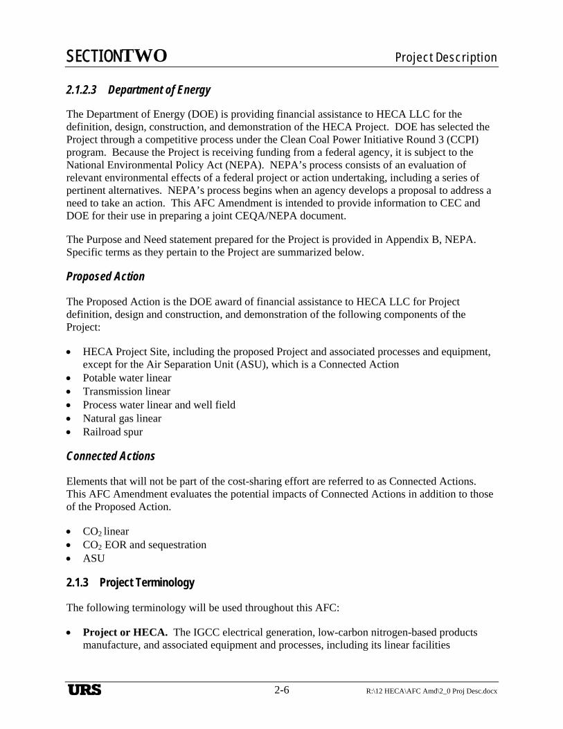
SECTIONTWO Project Description
2-6 R:\12 HECA\AFC Amd\2_0 Proj Desc.docx
2.1.2.3 Department of Energy
The Department of Energy (DOE) is providing financial assistance to HECA LLC for the definition, design, construction, and demonstration of the HECA Project. DOE has selected the Project through a competitive process under the Clean Coal Power Initiative Round 3 (CCPI) program. Because the Project is receiving funding from a federal agency, it is subject to the National Environmental Policy Act (NEPA). NEPA’s process consists of an evaluation of relevant environmental effects of a federal project or action undertaking, including a series of pertinent alternatives. NEPA’s process begins when an agency develops a proposal to address a need to take an action. This AFC Amendment is intended to provide information to CEC and DOE for their use in preparing a joint CEQA/NEPA document.
The Purpose and Need statement prepared for the Project is provided in Appendix B, NEPA. Specific terms as they pertain to the Project are summarized below.
Proposed Action
The Proposed Action is the DOE award of financial assistance to HECA LLC for Project definition, design and construction, and demonstration of the following components of the Project:
HECA Project Site, including the proposed Project and associated processes and equipment, except for the Air Separation Unit (ASU), which is a Connected Action
Potable water linear Transmission linear Process water linear and well field Natural gas linear Railroad spur
Connected Actions
Elements that will not be part of the cost-sharing effort are referred to as Connected Actions. This AFC Amendment evaluates the potential impacts of Connected Actions in addition to those of the Proposed Action.
CO2 linear CO2 EOR and sequestration ASU
2.1.3 Project Terminology
The following terminology will be used throughout this AFC:
Project or HECA. The IGCC electrical generation, low-carbon nitrogen-based products manufacture, and associated equipment and processes, including its linear facilities
URS
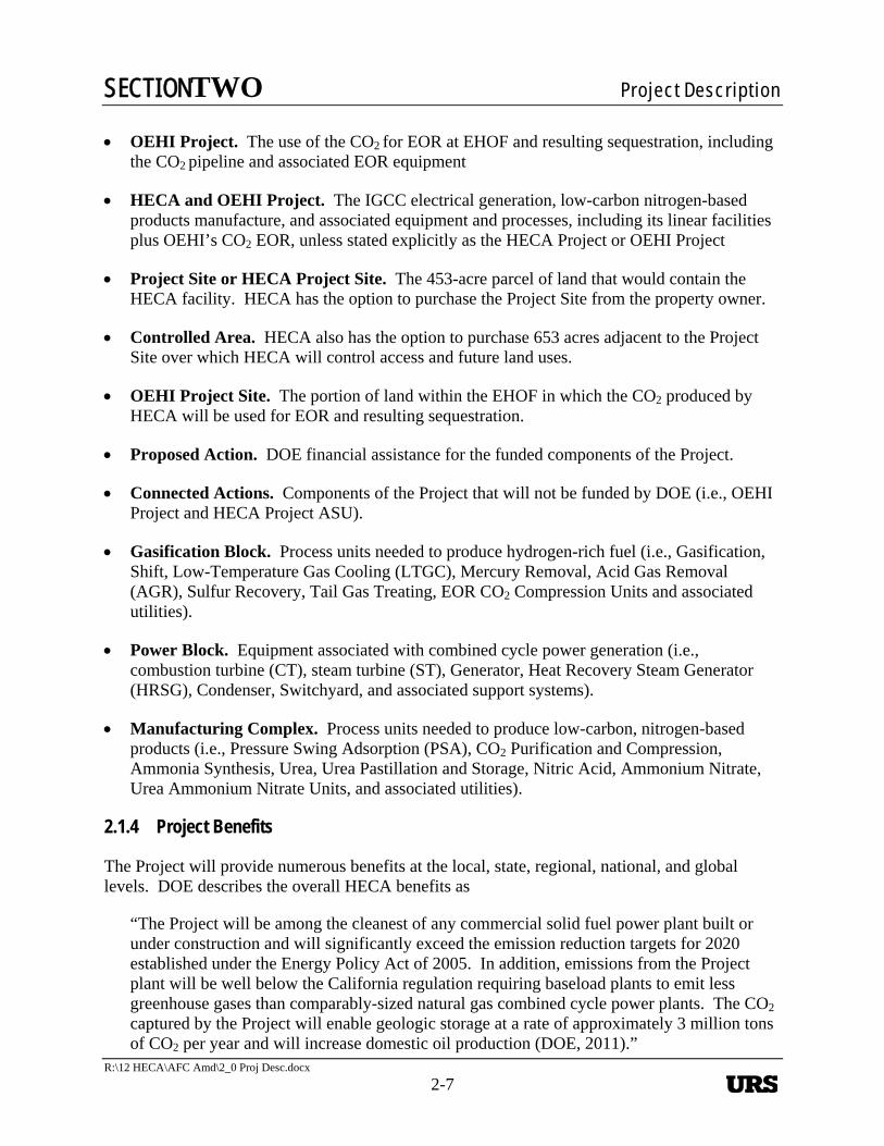
SECTIONTWO Project Description
R:\12 HECA\AFC Amd\2_0 Proj Desc.docx
2-7
OEHI Project. The use of the CO2 for EOR at EHOF and resulting sequestration, including the CO2 pipeline and associated EOR equipment
HECA and OEHI Project. The IGCC electrical generation, low-carbon nitrogen-based products manufacture, and associated equipment and processes, including its linear facilities plus OEHI’s CO2 EOR, unless stated explicitly as the HECA Project or OEHI Project
Project Site or HECA Project Site. The 453-acre parcel of land that would contain the HECA facility. HECA has the option to purchase the Project Site from the property owner.
Controlled Area. HECA also has the option to purchase 653 acres adjacent to the Project Site over which HECA will control access and future land uses.
OEHI Project Site. The portion of land within the EHOF in which the CO2 produced by HECA will be used for EOR and resulting sequestration.
Proposed Action. DOE financial assistance for the funded components of the Project.
Connected Actions. Components of the Project that will not be funded by DOE (i.e., OEHI Project and HECA Project ASU).
Gasification Block. Process units needed to produce hydrogen-rich fuel (i.e., Gasification, Shift, Low-Temperature Gas Cooling (LTGC), Mercury Removal, Acid Gas Removal (AGR), Sulfur Recovery, Tail Gas Treating, EOR CO2 Compression Units and associated utilities).
Power Block. Equipment associated with combined cycle power generation (i.e., combustion turbine (CT), steam turbine (ST), Generator, Heat Recovery Steam Generator (HRSG), Condenser, Switchyard, and associated support systems).
Manufacturing Complex. Process units needed to produce low-carbon, nitrogen-based products (i.e., Pressure Swing Adsorption (PSA), CO2 Purification and Compression, Ammonia Synthesis, Urea, Urea Pastillation and Storage, Nitric Acid, Ammonium Nitrate, Urea Ammonium Nitrate Units, and associated utilities).
2.1.4 Project Benefits
The Project will provide numerous benefits at the local, state, regional, national, and global levels. DOE describes the overall HECA benefits as
“The Project will be among the cleanest of any commercial solid fuel power plant built or under construction and will significantly exceed the emission reduction targets for 2020 established under the Energy Policy Act of 2005. In addition, emissions from the Project plant will be well below the California regulation requiring baseload plants to emit less greenhouse gases than comparably-sized natural gas combined cycle power plants. The CO2 captured by the Project will enable geologic storage at a rate of approximately 3 million tons of CO2 per year and will increase domestic oil production (DOE, 2011).”
URS
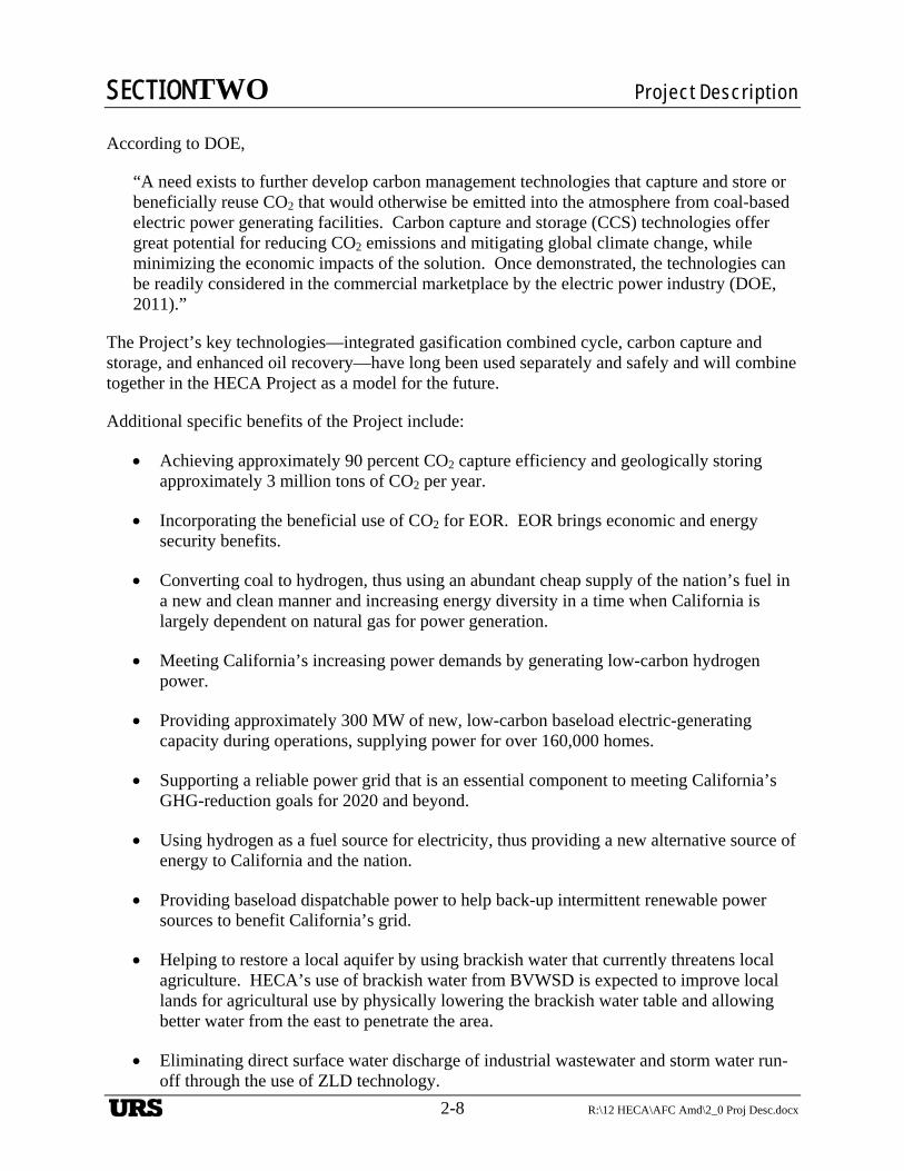
SECTIONTWO Project Description
2-8 R:\12 HECA\AFC Amd\2_0 Proj Desc.docx
According to DOE,
“A need exists to further develop carbon management technologies that capture and store or beneficially reuse CO2 that would otherwise be emitted into the atmosphere from coal-based electric power generating facilities. Carbon capture and storage (CCS) technologies offer great potential for reducing CO2 emissions and mitigating global climate change, while minimizing the economic impacts of the solution. Once demonstrated, the technologies can be readily considered in the commercial marketplace by the electric power industry (DOE, 2011).”
The Project’s key technologies—integrated gasification combined cycle, carbon capture and storage, and enhanced oil recovery—have long been used separately and safely and will combine together in the HECA Project as a model for the future.
Additional specific benefits of the Project include:
Achieving approximately 90 percent CO2 capture efficiency and geologically storing approximately 3 million tons of CO2 per year.
Incorporating the beneficial use of CO2 for EOR. EOR brings economic and energy security benefits.
Converting coal to hydrogen, thus using an abundant cheap supply of the nation’s fuel in a new and clean manner and increasing energy diversity in a time when California is largely dependent on natural gas for power generation.
Meeting California’s increasing power demands by generating low-carbon hydrogen power.
Providing approximately 300 MW of new, low-carbon baseload electric-generating capacity during operations, supplying power for over 160,000 homes.
Supporting a reliable power grid that is an essential component to meeting California’s GHG-reduction goals for 2020 and beyond.
Using hydrogen as a fuel source for electricity, thus providing a new alternative source of energy to California and the nation.
Providing baseload dispatchable power to help back-up intermittent renewable power sources to benefit California’s grid.
Helping to restore a local aquifer by using brackish water that currently threatens local agriculture. HECA’s use of brackish water from BVWSD is expected to improve local lands for agricultural use by physically lowering the brackish water table and allowing better water from the east to penetrate the area.
Eliminating direct surface water discharge of industrial wastewater and storm water run-off through the use of ZLD technology.
URS
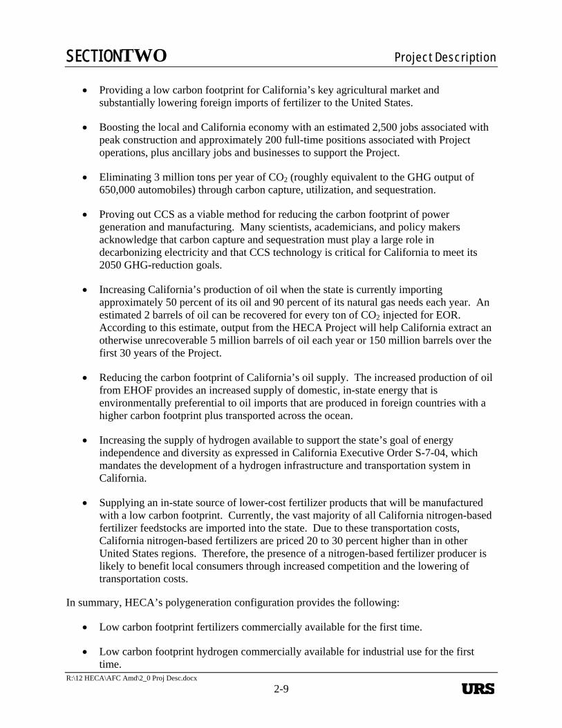
SECTIONTWO Project Description
R:\12 HECA\AFC Amd\2_0 Proj Desc.docx
2-9
Providing a low carbon footprint for California’s key agricultural market and substantially lowering foreign imports of fertilizer to the United States.
Boosting the local and California economy with an estimated 2,500 jobs associated with peak construction and approximately 200 full-time positions associated with Project operations, plus ancillary jobs and businesses to support the Project.
Eliminating 3 million tons per year of CO2 (roughly equivalent to the GHG output of 650,000 automobiles) through carbon capture, utilization, and sequestration.
Proving out CCS as a viable method for reducing the carbon footprint of power generation and manufacturing. Many scientists, academicians, and policy makers acknowledge that carbon capture and sequestration must play a large role in decarbonizing electricity and that CCS technology is critical for California to meet its 2050 GHG-reduction goals.
Increasing California’s production of oil when the state is currently importing approximately 50 percent of its oil and 90 percent of its natural gas needs each year. An estimated 2 barrels of oil can be recovered for every ton of CO2 injected for EOR. According to this estimate, output from the HECA Project will help California extract an otherwise unrecoverable 5 million barrels of oil each year or 150 million barrels over the first 30 years of the Project.
Reducing the carbon footprint of California’s oil supply. The increased production of oil from EHOF provides an increased supply of domestic, in-state energy that is environmentally preferential to oil imports that are produced in foreign countries with a higher carbon footprint plus transported across the ocean.
Increasing the supply of hydrogen available to support the state’s goal of energy independence and diversity as expressed in California Executive Order S-7-04, which mandates the development of a hydrogen infrastructure and transportation system in California.
Supplying an in-state source of lower-cost fertilizer products that will be manufactured with a low carbon footprint. Currently, the vast majority of all California nitrogen-based fertilizer feedstocks are imported into the state. Due to these transportation costs, California nitrogen-based fertilizers are priced 20 to 30 percent higher than in other United States regions. Therefore, the presence of a nitrogen-based fertilizer producer is likely to benefit local consumers through increased competition and the lowering of transportation costs.
In summary, HECA’s polygeneration configuration provides the following:
Low carbon footprint fertilizers commercially available for the first time.
Low carbon footprint hydrogen commercially available for industrial use for the first time.
URS
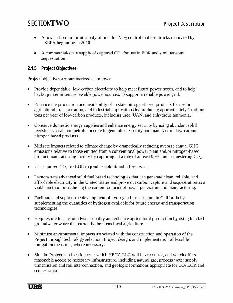
SECTIONTWO Project Description
2-10 R:\12 HECA\AFC Amd\2_0 Proj Desc.docx
A low carbon footprint supply of urea for NOX control in diesel trucks mandated by USEPA beginning in 2010.
A commercial-scale supply of captured CO2 for use in EOR and simultaneous sequestration.
2.1.5 Project Objectives
Project objectives are summarized as follows:
Provide dependable, low-carbon electricity to help meet future power needs, and to help back-up intermittent renewable power sources, to support a reliable power grid.
Enhance the production and availability of in state nitrogen-based products for use in agricultural, transportation, and industrial applications by producing approximately 1 million tons per year of low-carbon products, including urea, UAN, and anhydrous ammonia.
Conserve domestic energy supplies and enhance energy security by using abundant solid feedstocks, coal, and petroleum coke to generate electricity and manufacture low-carbon nitrogen based products.
Mitigate impacts related to climate change by dramatically reducing average annual GHG emissions relative to those emitted from a conventional power plant and/or nitrogen-based product manufacturing facility by capturing, at a rate of at least 90%, and sequestering CO2..
Use captured CO2 for EOR to produce additional oil reserves.
Demonstrate advanced solid fuel based technologies that can generate clean, reliable, and affordable electricity in the United States and prove out carbon capture and sequestration as a viable method for reducing the carbon footprint of power generation and manufacturing.
Facilitate and support the development of hydrogen infrastructure in California by supplementing the quantities of hydrogen available for future energy and transportation technologies.
Help restore local groundwater quality and enhance agricultural production by using brackish groundwater water that currently threatens local agriculture.
Minimize environmental impacts associated with the construction and operation of the Project through technology selection, Project design, and implementation of feasible mitigation measures, where necessary.
Site the Project at a location over which HECA LLC will have control, and which offers reasonable access to necessary infrastructure, including natural gas, process water supply, transmission and rail interconnection, and geologic formations appropriate for CO2 EOR and sequestration.
URS
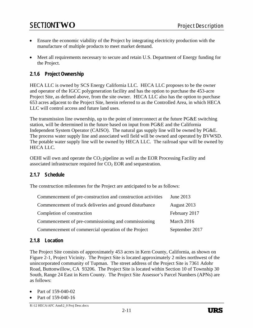
SECTIONTWO Project Description
R:\12 HECA\AFC Amd\2_0 Proj Desc.docx
2-11
Ensure the economic viability of the Project by integrating electricity production with the manufacture of multiple products to meet market demand.
Meet all requirements necessary to secure and retain U.S. Department of Energy funding for the Project.
2.1.6 Project Ownership
HECA LLC is owned by SCS Energy California LLC. HECA LLC proposes to be the owner and operator of the IGCC polygeneration facility and has the option to purchase the 453-acre Project Site, as defined above, from the site owner. HECA LLC also has the option to purchase 653 acres adjacent to the Project Site, herein referred to as the Controlled Area, in which HECA LLC will control access and future land uses.
The transmission line ownership, up to the point of interconnect at the future PG&E switching station, will be determined in the future based on input from PG&E and the California Independent System Operator (CAISO). The natural gas supply line will be owned by PG&E. The process water supply line and associated well field will be owned and operated by BVWSD. The potable water supply line will be owned by HECA LLC. The railroad spur will be owned by HECA LLC.
OEHI will own and operate the CO2 pipeline as well as the EOR Processing Facility and associated infrastructure required for CO2 EOR and sequestration.
2.1.7 Schedule
The construction milestones for the Project are anticipated to be as follows:
Commencement of pre-construction and construction activities June 2013
Commencement of truck deliveries and ground disturbance August 2013
Completion of construction February 2017
Commencement of pre-commissioning and commissioning March 2016
Commencement of commercial operation of the Project September 2017
2.1.8 Location
The Project Site consists of approximately 453 acres in Kern County, California, as shown on Figure 2-1, Project Vicinity. The Project Site is located approximately 2 miles northwest of the unincorporated community of Tupman. The street address of the Project Site is 7361 Adohr Road, Buttonwillow, CA 93206. The Project Site is located within Section 10 of Township 30 South, Range 24 East in Kern County. The Project Site Assessor’s Parcel Numbers (APNs) are as follows:
Part of 159-040-02 Part of 159-040-16
URS
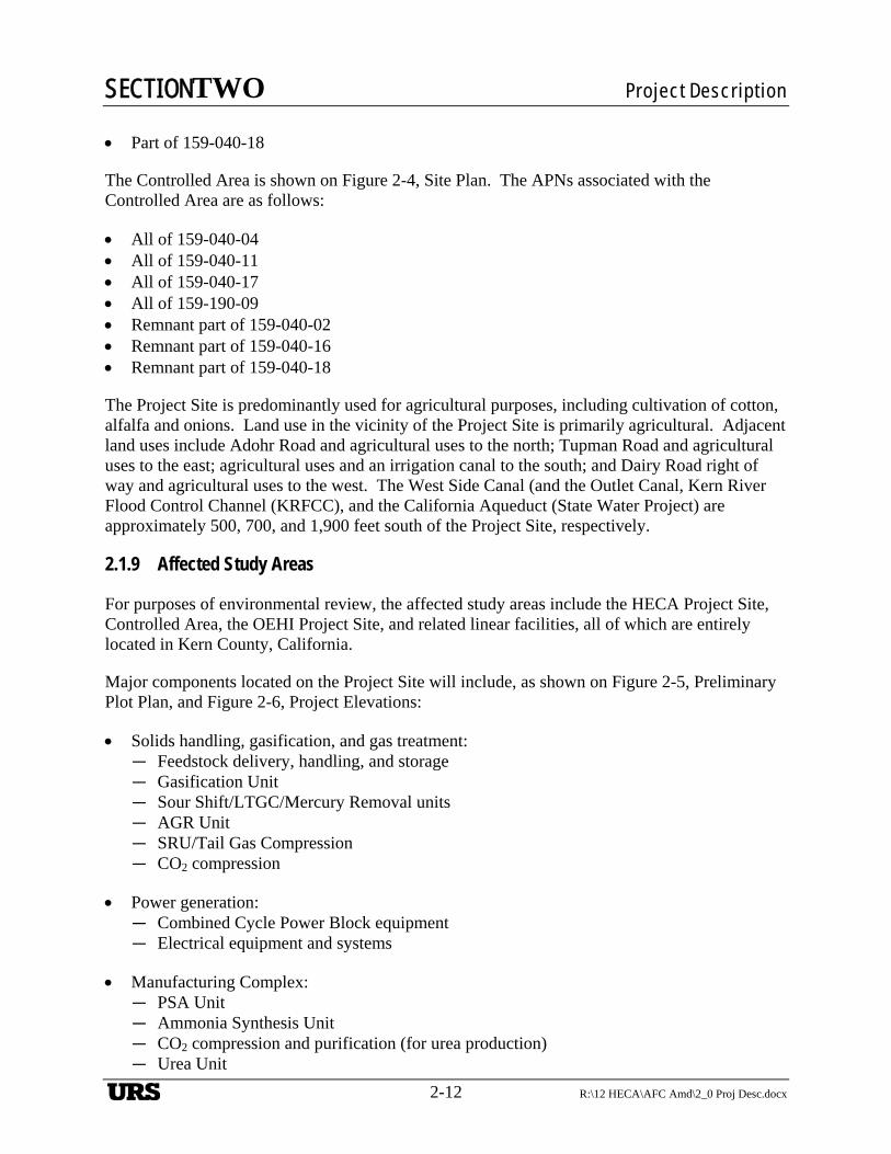
SECTIONTWO Project Description
2-12 R:\12 HECA\AFC Amd\2_0 Proj Desc.docx
Part of 159-040-18
The Controlled Area is shown on Figure 2-4, Site Plan. The APNs associated with the Controlled Area are as follows:
All of 159-040-04 All of 159-040-11 All of 159-040-17 All of 159-190-09 Remnant part of 159-040-02 Remnant part of 159-040-16 Remnant part of 159-040-18
The Project Site is predominantly used for agricultural purposes, including cultivation of cotton, alfalfa and onions. Land use in the vicinity of the Project Site is primarily agricultural. Adjacent land uses include Adohr Road and agricultural uses to the north; Tupman Road and agricultural uses to the east; agricultural uses and an irrigation canal to the south; and Dairy Road right of way and agricultural uses to the west. The West Side Canal (and the Outlet Canal, Kern River Flood Control Channel (KRFCC), and the California Aqueduct (State Water Project) are approximately 500, 700, and 1,900 feet south of the Project Site, respectively.
2.1.9 Affected Study Areas
For purposes of environmental review, the affected study areas include the HECA Project Site, Controlled Area, the OEHI Project Site, and related linear facilities, all of which are entirely located in Kern County, California.
Major components located on the Project Site will include, as shown on Figure 2-5, Preliminary Plot Plan, and Figure 2-6, Project Elevations:
Solids handling, gasification, and gas treatment: — Feedstock delivery, handling, and storage — Gasification Unit — Sour Shift/LTGC/Mercury Removal units — AGR Unit — SRU/Tail Gas Compression — CO2 compression
Power generation: — Combined Cycle Power Block equipment — Electrical equipment and systems
Manufacturing Complex: — PSA Unit — Ammonia Synthesis Unit — CO2 compression and purification (for urea production) — Urea Unit
URS
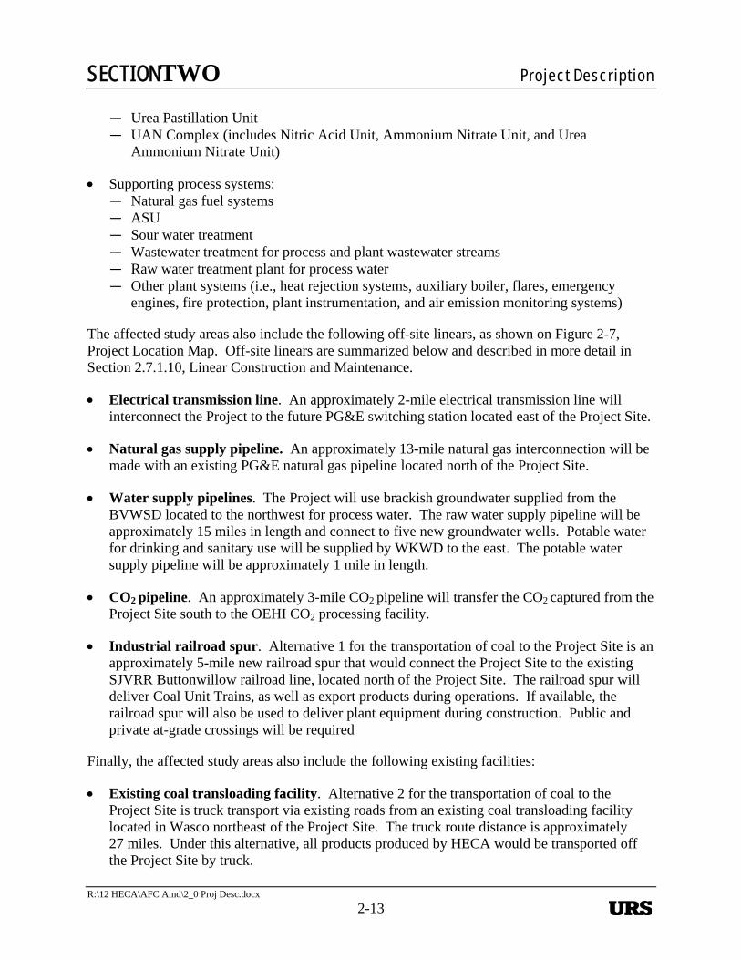
SECTIONTWO Project Description
R:\12 HECA\AFC Amd\2_0 Proj Desc.docx
2-13
— Urea Pastillation Unit — UAN Complex (includes Nitric Acid Unit, Ammonium Nitrate Unit, and Urea
Ammonium Nitrate Unit)
Supporting process systems: — Natural gas fuel systems — ASU — Sour water treatment — Wastewater treatment for process and plant wastewater streams — Raw water treatment plant for process water — Other plant systems (i.e., heat rejection systems, auxiliary boiler, flares, emergency
engines, fire protection, plant instrumentation, and air emission monitoring systems)
The affected study areas also include the following off-site linears, as shown on Figure 2-7, Project Location Map. Off-site linears are summarized below and described in more detail in Section 2.7.1.10, Linear Construction and Maintenance.
Electrical transmission line. An approximately 2-mile electrical transmission line will interconnect the Project to the future PG&E switching station located east of the Project Site.
Natural gas supply pipeline. An approximately 13-mile natural gas interconnection will be made with an existing PG&E natural gas pipeline located north of the Project Site.
Water supply pipelines. The Project will use brackish groundwater supplied from the BVWSD located to the northwest for process water. The raw water supply pipeline will be approximately 15 miles in length and connect to five new groundwater wells. Potable water for drinking and sanitary use will be supplied by WKWD to the east. The potable water supply pipeline will be approximately 1 mile in length.
CO2 pipeline. An approximately 3-mile CO2 pipeline will transfer the CO2 captured from the Project Site south to the OEHI CO2 processing facility.
Industrial railroad spur. Alternative 1 for the transportation of coal to the Project Site is an approximately 5-mile new railroad spur that would connect the Project Site to the existing SJVRR Buttonwillow railroad line, located north of the Project Site. The railroad spur will deliver Coal Unit Trains, as well as export products during operations. If available, the railroad spur will also be used to deliver plant equipment during construction. Public and private at-grade crossings will be required
Finally, the affected study areas also include the following existing facilities:
Existing coal transloading facility. Alternative 2 for the transportation of coal to the Project Site is truck transport via existing roads from an existing coal transloading facility located in Wasco northeast of the Project Site. The truck route distance is approximately 27 miles. Under this alternative, all products produced by HECA would be transported off the Project Site by truck.
URS
SECTIONTWO Project Description
2-14 R:\12 HECA\AFC Amd\2_0 Proj Desc.docx
OEHI Project Site. This is the portion of land in the EHOF in which CO2 produced by HECA will be used for EOR and resulting sequestration.
The components described above are shown on Figure 2-8, Project Location Details, which depicts the region, the vicinity, the Project Site, the OEHI Project Site, and their immediate surroundings.
Temporary construction equipment laydown and parking, including construction parking, offices, and construction laydown areas, will be located within the Project Site and the Controlled Area. Figure 2-9, Preliminary Temporary Construction Facilities Plan, illustrates the locations of these facilities.
The purpose of the Controlled Area is to ensure ownership and control by HECA LLC over public access and land use adjacent to the Project Site. With the exception of temporary construction impacts for linears and laydown, current plans are to continue to use the Controlled Area for agricultural purposes during construction and operations. As indicated on Figure 2-4, the transmission linear and potable water linear would cross the northeastern edge of the Controlled Area. The CO2 pipeline linear would cross the southwest and southern portions of the Controlled Area. The process water line would cross the southwest portion of the Controlled Area. The railroad spur would enter the northwest corner of the Project Site without intersecting the Controlled Area. The natural gas supply would cross the west portion of the Controlled Area.
The Controlled Area is under Williamson Act contract, except for parcel 159-040-11-001, which is the 1.23-acre area including and surrounding an irrigation canal to the south of the Project Site. The Controlled Area will be fenced.
The disturbed acreage associated with the Project is summarized in Table 2-1, Project Disturbed Acreage.
Table 2-2, Site Characteristics, summarizes site meteorology and other characteristics upon which the Project design has been based.
2.1.10 Site Plan and Access
Figure 2-5, Preliminary Plot Plan, presents a scaled, overall plot plan for the Project. The Overall Plot Plan identifies the primary site access, which will be from Dairy Road on the western side of the Project Site for personnel access, and Station Road for feedstock and other deliveries. The Overall Plot Plan also identifies the railroad entrance, which is located at the northwest corner of the Project Site. Elevations are shown on Figure 2-6, Project Elevations.
Table 2-3, Project Linear Tie-In Location on Plot Plan, provides a list of the currently anticipated Project pipelines, communication, and electrical interfaces at the site boundaries.
2.1.11 Resource Inputs
The feedstocks for the Project include the following and are discussed below in more detail:
URS
SECTIONTWO Project Description
R:\12 HECA\AFC Amd\2_0 Proj Desc.docx
2-15
California petroleum coke and western sub-bituminous coal Natural gas Water Oxygen Nitrogen
2.1.11.1 Petcoke and Western Sub-Bituminous Coal
Coal is an abundant, domestic feedstock exhibiting stable supply compared to oil and natural gas resources. Securing a domestically available long-term, stable feedstock will enable the Project to provide dependable low-carbon hydrogen-generated electricity and to assist in meeting future electrical power needs and supporting a reliable power grid.
The Project expects to obtain its western sub-bituminous coal from New Mexico. Based on the design plant production rate, the Project will consume 4,580 stpd of coal (nominally 1.6 million short tons per year [stpy]). Several western sub-bituminous coal mines that can supply coal meeting Project technology requirements in terms of ash composition and other characteristics have been identified. The Project is in the process of discussing contractual terms with relevant entities.
Petcoke most likely will be supplied from refineries in the Los Angeles or Santa Maria areas. The petcoke that will be used for the Project is a byproduct from the oil refining process. Currently, petcoke is trucked from California refineries to ports for export to other nations, where it is burned in conventional furnaces and boilers that release CO2 and other air pollutants directly into the air. In contrast, HECA will capture more than 90 percent of the CO2 and sell this commodity to OEHI where it will be used for EOR and effectively sequestered in a closed-loop process.
Transportation of coal to the Project Site will occur via one of two alternatives. Alternative 1 is the use of a new railroad spur that will deliver the coal to the Project Site. Alternative 2 involves the transfer of the coal onto trucks at the existing coal transloading facility in Wasco. Trucks would then transport the coal to the Project Site. Petcoke transportation to the Project Site will occur via truck. Coal and petcoke deliveries to the Project Site will be unloaded and stored at the Project Site in the coal/petcoke barn designed to contain feedstock sufficient for 30 days of operation (approximately 172,000 tons of coal and petcoke). The rail and truck unloading systems, feedstock reclaiming and blending system, and pre-crushing system will have dust collection systems to minimize particulate emissions. The grinding mill feed bins will be totally enclosed and will include baghouses. Petcoke and coal will be transported from the unloading systems to the enclosed barn, the pre-crushing system, and the grinding mill feed bins in enclosed conveyors with dust collection systems.
2.1.11.2 Western Sub-Bituminous Coal
HECA LLC expects to obtain its western sub-bituminous coal from New Mexico. Based on the design plant production rate, the Project will consume 4,580 stpd of coal (nominally 1.6 million short tons per year [stpy]). Several western sub-bituminous coal mines that can supply coal
URS
SECTIONTWO Project Description
2-16 R:\12 HECA\AFC Amd\2_0 Proj Desc.docx
meeting Project technology requirements in terms of ash composition and other characteristics have been identified. The Project is in the process of discussing contractual terms with relevant entities. The coal hauls will require rail shipments. Railcars will either be delivered to the Project Site via the railroad spur per Alternative 1 or the coal will be transferred onto trucks at the existing coal transloading facility in Wasco, then transported to the Project Site per Alternative 2.
2.1.11.3 Petcoke
Petcoke is expected to be readily available to the Project. Approximately 16,000 stpd (6.0 million stpy) of fuel-grade petcoke are produced by major California refineries. Five of these refineries are located in the Los Angeles area, and one is in central California. At steady-state operation feeding 25 percent petcoke, the Project would consume about 7 percent of this total in-state production (around 1,140 stpd, or 400,000 stpy).
Hauling distances for petcoke are short enough to favor truck movements. These truck shipments can be delivered directly to the Project Site for unloading.
2.1.11.4 Feedstock Quality and Plant Operations
Feedstock Flexibility
The ability of the Project to accept a variety of petcoke and coal feedstocks will enable it to increase the number of potential fuel suppliers and to minimize fuel costs.
Sulfur Content
Potential sources of coal investigated for the Project have an average sulfur content of approximately 1 percent. Petcoke sulfur levels may be variable over time as heavier crudes are processed at a number of California refineries. However, the Project’s sulfur recovery system is able to handle feedstock blends with variable sulfur levels and therefore will accommodate both current and expected future sulfur levels in California petcokes. Higher-sulfur petcoke generally costs less than lower-sulfur petcoke in the marketplace, and the ability to process higher-sulfur feedstocks will help minimize fuel costs.
2.1.11.5 Transportation and Logistics
Trucking
A number of trucking firms with petcoke-handling experience (and coal-handling experience for Alternative 2) have been identified and engaged in preliminary discussions. All have expressed interest in serving the Project. The use of Los Angeles and central California area petcoke would minimize truck shipments, thus minimizing emissions and transportation costs.
URS
SECTIONTWO Project Description
R:\12 HECA\AFC Amd\2_0 Proj Desc.docx
2-17
Rail Shipments
Because of the distances involved and desire to minimize truck traffic, western sub-bituminous coal procured for the Project will be transported by railroad to Kern County. Alternative 1 would further minimize truck traffic by delivering the coal to the Project Site via a new railroad spur. The railroad spur will also be used to transport products from the Project Site during operations. Under Alternative 2, the coal would be transferred to trucks at the existing coal transloading facility in Wasco, then delivered to the Project Site.
Storage
The Project will provide 30 days of feedstock storage (based on anticipated usage rates) on site, in an enclosed barn.
Feedstock Characteristics
A representative feedstock analysis is provided below for each feedstock. The representative feedstock analysis for petcoke is provided in Table 2-4, Typical Analysis for Petcoke. The representative feedstock analysis for western sub-bituminous coal is provided in Table 2-5, Typical Analysis of Sub-Bituminous Coal.
2.1.11.6 Natural Gas
Natural gas is required for operation during start-ups, shut-downs, and equipment outages. Natural gas is also used to fuel the auxiliary boiler, flare pilots, start-up the SRU, and as support fuel for the SRU tail gas thermal oxidizer. The natural gas supply metering station will be located within the Project Site, near the southwestern corner.
An interconnection with a PG&E pipeline is available to supply natural gas to the Project. The pipeline length will be approximately 13 miles. The interconnect will consist of one tap off the existing natural gas line and one metering station at the beginning of the natural gas linear adjacent to the PG&E Inlet. The metering station will be up to 100 feet by 100 feet and will be surrounded by a chain link fence. In addition, there will be a metering station at the end of the natural gas linear, located near the southwestern corner of the Project Site, and a pressure limiting station located on the Project Site.
The pipeline route is shown on Figure 2-7, Project Location Map. See Project location details on Figure 2-8 Project Location Details (sheets 4 through 7).
The estimated delivery pressure of the PG&E line is a minimum of 335 pounds per square inch gauge (psig). The Project includes a natural gas compressor to provide sufficient pressure for start-up and natural gas operation.
Typical yearly averages for the natural gas composition and physical properties are given in Table 2-6, Typical Natural Gas Composition.
URS
SECTIONTWO Project Description
2-18 R:\12 HECA\AFC Amd\2_0 Proj Desc.docx
2.1.11.7 Water
It is estimated that the Project will use approximately 4,600 gallons per minute (gpm) of brackish water on an average annual basis. This increases to approximately 5,150 gpm during average summer afternoon conditions. These raw water requirement rates are greater than those presented in the 2009 AFC because of the following two main factors:
Project design changes resulted in an approximately 50 percent increase in syngas production. Increased syngas production drives a need for more water, which is consumed in the shift reaction to produce more hydrogen.
Project design addition of the Manufacturing Complex, which increased the process cooling tower duty, thereby increasing its water evaporation rate.
The Project will use local brackish groundwater treated on site to meet Project requirements. The brackish groundwater will be supplied from the BVWSD, which is a local water district with impaired groundwater sources not suitable for agricultural or potable use. BVWSD has stated that it will be able to provide brackish groundwater with an average total dissolved solids concentration of approximately 2,000 milligrams per liter (mg/L), with an acceptable range from about 1,000 to 4,000 mg/L, to the Project for the estimated life of the Project. Potable water will be supplied by WKWD located east of the Project Site, along Morris Road north of Station Road.
Water usage in the Project can be divided into six categories: Power Block cooling tower, process cooling tower, ASU cooling tower, Manufacturing Complex, gasification solids, and HRSG stack. Figure 2-10, Water Usage, and Figure 2-11, Flow Diagram Raw Water/Wastewater/Demin Water Treatment Plant, depict the water usage allocated by category.
Water is used for heat rejection in the form of evaporation from cooling towers. The process cooling tower and the ASU cooling tower are associated with the gasification process and syngas treatment. The other cooling tower (the Power Block cooling tower) serves the Combined Cycle Power Block, with the majority of the cooling duty consumed by the condenser.
Other major areas of water usage are associated with the production of hydrogen. Water is converted to hydrogen in the Gasification Unit and the Sour Shift Unit. The hydrogen is used as a fuel at the combustion turbine/HRSG and as a feedstock for the low-carbon nitrogen products. Water is also used in the processing of gasification solids.
The HECA Project has been designed to minimize wastewater. Water losses from the Plant Wastewater Treatment Unit are very small due to the incorporation of ZLD technology. Plant wastewater (including cooling tower blowdown, water treatment reject, evaporative cooler blowdown, and other miscellaneous drains) is evaporated and concentrated using a conventional mechanical vapor recompression brine concentrator followed by a brine crystallizer.
2.1.11.8 Oxygen and Nitrogen
The gasification process requires high-pressure, high-purity (99.5 volume percent) oxygen (O2). The O2 is supplied from the ASU, which separates and purifies O2 and nitrogen from the ambient
URS
SECTIONTWO Project Description
R:\12 HECA\AFC Amd\2_0 Proj Desc.docx
2-19
air. The ambient air is filtered, compressed, dried, and cooled to cryogenic temperatures. High-purity O2 created in this process is pumped to the required pressure, vaporized, and sent to the Gasification Unit. In addition, low-pressure, high-purity O2 is used in the SRU. The ASU also supplies high-purity, compressed nitrogen for use in the CT, the Ammonia Synthesis Unit, and various uses within the Gasification Unit. In the CT, nitrogen is used as a diluent to reduce the thermal nitrogen oxide (NOX) produced when hydrogen-rich fuel is combusted. The ASU also provides high-purity nitrogen for purging equipment, piping, and instrumentation.
2.1.12 Product Output
As a polygeneration facility, the Project is designed to produce several types of products. These products include the following, which are discussed below in more detail:
Electricity CO2 Degassed liquid sulfur Gasification solids Low-carbon nitrogen-based products
2.1.12.1 Electricity and Transmission Line
An approximately 2-mile electrical transmission line will interconnect the Project Site to the future PG&E switching station. The power generated by the Project will be connected to the PG&E system by a new single-tower, 230-kV transmission line. This single-circuit line will be connected to a new switchyard at the Project Site. The proposed transmission route exits the Project Site, crosses Tupman Road and runs in an easterly direction, crosses Morris Road and continues east to enter the PG&E switching station.
Table 2-7, Electrical Specification, describes the general specification for electricity delivery.
Figure 2-12, Overall Single-Line Diagram, presents the one-line diagram for the future PG&E switching station after the interconnection of the Project.
2.1.12.2 Carbon Dioxide
CO2 will be compressed and transported by an approximately 3-mile pipeline to the OEHI CO2 Processing Facility to be used for CO2 EOR and sequestration in the EHOF. Appendix A of this AFC Amendment discusses CO2 EOR and resulting sequestration.
2.1.12.3 Sulfur
The selection and integration of pre-combustion capture and sulfur recovery technologies allows the Project to minimize sulfur emissions. Sulfur found in feedstocks is removed from the syngas by the AGR and delivered to the Sulfur Recovery Unit where it is converted into a saleable product. Unconverted, residual sulfur compounds (SRU tail gas) are recycled back into the gas treatment section for subsequent capture. Most of the sulfur will be transported by truck to off-takers but some may also be transported by rail. It is estimated that sulfur product export would
URS
SECTIONTWO Project Description
2-20 R:\12 HECA\AFC Amd\2_0 Proj Desc.docx
be approximately 75 percent by truck and 25 percent by rail. The planned production rate would be 100 stpd and Table 2-8, Sulfur Specification, describes the sulfur product specification.
2.1.12.4 Gasification Solids
Gasification solids are comprised of the silica, alumina, and other constituents found in coal and petcoke. The high temperature in the gasifier produces a glassy vitrified solid that is suitable for reuse. Most of the gasifier solids will be transported by rail for beneficial reuse by regional industries. A smaller portion can be transported to nearby industries by truck. It is estimated that gasification solids export would be approximately 75 percent by rail and 25 percent by truck. The planned production rate would be about 840 stpd on a dry basis. The composition of the gasification solids has been estimated based on the anticipated feedstock composition. Table 2-9, Example Composition of Gasification Solids, represents a projected composition of the gasification solids.
Gasification solids are dewatered, and the solids are accumulated for shipment. Upon exiting the gasifier, the liquids are recovered and returned for reuse in the process. The dewatered gasification solids will be retained in on-site storage until sufficient quantities are accumulated to facilitate their economical transportation. On-site gasification solids storage has the capacity for seven days of production.
HECA has studied the beneficial reuse of gasification solids in a variety of industrial applications. Areas currently being evaluated include reuse for the production of cement, roofing granules and sandblast grit.
2.1.12.5 Low-Carbon Nitrogen-Based Products
The Project will produce low-carbon nitrogen-based products, including, but not necessarily limited to:
Ammonia. The ammonia unit capacity is approximately 2,000 stpd, with a daily average production rate of 1,500 stpd. The ammonia is an intermediate for the on-site production of urea pastilles and UAN. The Project has been designed with flexibility to allow for the option of directly selling ammonia product, rather than using it for urea or UAN production, and it is estimated that this amount could be up to 500 tons/day. Estimated ammonia export is 25 percent by rail and 75 percent by truck (under Alternative 1).
Urea pastilles. Urea pastilles are small solid pellets of urea. The urea pastilles unit capacity is 1,700 stpd, which is also the planned production rate. Estimated urea export is 75 percent by rail and 25 percent by truck (under Alternative 1).
UAN. The UAN unit capacity is 1,500 stpd, with a planned production rate of 1,400 stpd. The estimated movements are 50 percent by rail and 50 percent by truck.
URS
SECTIONTWO Project Description
R:\12 HECA\AFC Amd\2_0 Proj Desc.docx
2-21
2.1.12.6 Wastewater Discharge
The Project has been designed for ZLD and therefore will not discharge storm water or wastewater off site. Project wastewater will primarily result from cooling tower blowdown, gasification solids removal and Shift/LTGC process condensate blowdown. The cooling tower circulation water and the process condensate from Shift/LTGC will be recycled to the maximum practical extent to minimize water usage and the size of the wastewater treatment equipment. Cooling tower blowdown and all process wastewater streams are treated with softening, reverse osmosis and evaporation/crystallization. All water is recovered for reuse within the plant. Solids from the softeners and evaporation/crystallization unit are composed almost entirely of the minerals concentrated from the plant’s water supply. The solids from the softeners and evaporation/crystallization unit are not a hazardous waste. Solids will be tested and disposed of Sanitary wastewater from the Project restrooms, showers, and kitchens will be conveyed by an underground gravity collection system and discharged to a private on-site sewage disposal system consisting of a conventional septic tank and leach field. No municipal system is available in the immediate area to serve the Project.
2.1.13 Plant Performance Summary
Table 2-10, Representative Heat and Material Balances, presents typical heat and material balances. Figure 2-13, HECA Overall Component Balances, provides additional illustration of the carbon and sulfur material balances. Table 2-11, Maximum Feeds and Products, shows the maximum feed and product rates anticipated for the Project.
2.2 SOLIDS HANDLING, GASIFICATION, AND GAS TREATMENT
2.2.1 Overview of Gasification Technology
Gasification is a chemical conversion process that can be used to convert solid feedstocks into syngas (see Table 2-12, Primary Gasification Reactions). Figure 2-14, Flow Diagram Gasification Process provides an illustration. The primary components of syngas are CO and H2, and syngas is further processed in a gas treatment unit to produce hydrogen-rich fuel. See Table 2-13, Components of Syngas from Oxygen-Blown Gasification. The treatment of syngas is classified as a pre-combustion treatment process and has advantages over a post combustion treatment process used for pulverized coal power plants. The treatment and removal of CO2 and sulfur in syngas occurs at higher pressures and lower volumetric flowrates and this increases the capture efficiency in comparison to post combustion treatment of exhaust gas in a conventional power plant. The Project uses MHI oxygen-blown dry-feed gasification technology. The MHI gasifier incorporates a two-stage reaction that increases conversion of feedstocks to syngas and improves efficiency. MHI also uses a water wall to provide thermal protection for the vessel wall instead of a refractory lining. This increases the run length and availability of the equipment and reduces the amount of time required to start up the unit.
IGCC generally refers to the use of gasification technology to generate electricity in a combined cycle power block. Products other than power may be co-produced in an IGCC plant. This Project will use a blend of 75 percent coal and 25 percent petcoke on a thermal basis to produce
URS
SECTIONTWO Project Description
2-22 R:\12 HECA\AFC Amd\2_0 Proj Desc.docx
electricity, low-carbon nitrogen-based products, and CO2. The CO2 will then be sold to OEHI where it will be used for EOR and be effectively sequestered in a closed-loop process.
The Project will achieve the strictest air emissions controls available for this type of equipment. In addition to providing a platform for efficient and cost-effective CO2 removal, IGCC plants also minimize other air pollutants. Because the coal is not actually combusted, an IGCC plant can more effectively eliminate criteria air pollutants. In an IGCC plant, the air emissions controls remove pollutants from the syngas stream at a point in the process where the pollutants are dense and easily removed, instead of trying to eliminate them from the stack emissions where a much greater stream of dilute flue gas would need to be treated.
2.2.2 Feedstock Delivery, Handling and Storage
2.2.2.1 Rail Unloading and Transfer Systems
Under Alternative 1, the Project Site would be equipped with a rail unloading and transfer system to unload coal from unit trains and convey it to the storage barn. The system accomplishes the following objectives.
Unloads coal from unit trains Conveys the coal to storage in the coal barn
The transfer conveyor is fully enclosed for weather protection and to control fugitive dust. The conveyor is provided with belt scales, magnetic separators, metal detectors, and safety switches, as required. Figure 2-15, Flow Diagram Feedstock Handling and Storage, presents an illustration of the process.
All related coal feedstock buildings are fully enclosed. Dust suppression spray systems, dust collection systems, and/or transfer design are used to control fugitive dust.
2.2.2.2 Truck Unloading and Transfer Systems
Petcoke will be delivered to the Project Site via over-the-road bottom dump haul trucks. At the Project Site, petcoke will be unloaded at the truck dump unloading station. The truck dump has a single hopper located below each unloading station. Petcoke from these hoppers is sent to the petcoke storage via belt feeders, unloading conveyor, and transfer conveyors. An as-received sample system is provided with the petcoke transfer conveyors. Under Alternative 2, the coal would also be delivered to the Project Site and unloaded as described above for petcoke.
The concrete floor under the truck unloading system slopes to a sump. This sump is equipped with an installed sump pump to recycle water back to the wash down system or to forward it to the IGCC water reclaim system.
Once trucks have unloaded the petcoke (or coal, under Alternative 2), each vehicle exits and passes through a truck wash system. This truck wash system sprays the entire truck with wash-down water (no soap added) and a specific spray system cleans the wheels. This is done to minimize or eliminate any dust and debris from being deposited on the roads both inside the
URS
SECTIONTWO Project Description
R:\12 HECA\AFC Amd\2_0 Proj Desc.docx
2-23
Project Site and on public roads. The wastewater collected under the truck wash is routed to a sump that sends the wastewater back to the IGCC water reclaim system.
2.2.2.3 Feedstock Blending and Handling
Coal and petcoke will be stored in a storage building with separate coal and petcoke storage piles. The coal and petcoke will be reclaimed at a set rate and blended as they are placed on conveyors for transfer from the storage building. This coal and petcoke blend will then flow to Gasification for further processing.
The transfer conveyor is fully enclosed for weather protection and to control fugitive dust. The conveyor is provided with belt scales, magnetic separators, metal detectors, and safety switches, as required.
2.2.3 Gasification
2.2.3.1 Feedstock Grinding and Drying
The MHI gasification system includes equipment to grind and dry the feedstock. The blended feedstock is stored in intermediate storage bins. The feedstock then flows to the grinding mills where the particle size is reduced to that required for transport into the gasifier and simultaneously dried. The heat source for feedstock drying is hot gas turbine exhaust gas from the heat recovery steam generator. After drying the feedstock, the drying gases flow through a dust collection system before being vented through the coal dryer stack.
2.2.3.2 Gasifier
The MHI oxygen-blown gasifier is a pressurized, upflow, entrained-flow slagging reactor with a two-stage operation. The MHI gasifier is a dry-feed system and the reactor internals are protected by a membrane wall.
The reactor consists of two sections (or stages): a first stage and a second stage. The coal/feed enters the gasifier at two separate points, with one portion being fed into the lower stage together with O2 where it is gasified at high temperature to produce carbon monoxide and CO2, in addition to water vapor. The temperature generated is sufficiently high to melt the coal ash. The molten coal ash flows down the membrane wall to the bottom of the gasifier, where it is quenched in a water bath and then removed using a lock hopper system.
The gas produced in the first stage rises to the second stage, where the remaining petcoke/feed is added without any additional O2. In this fuel-rich reducing environment, the key reactions that take place are the gasification of char to CO and the shifting of CO and water to hydrogen and CO2. In the second stage, heat provided by the hot gas from the first stage is used to drive these endothermic gasification reactions. As a result, the second stage operates at a lower temperature than the first stage. Completing the gasification reactions at a lower temperature reduces the O2 required and improves the efficiency of the gasifier. The syngas produced exits the second stage through a syngas cooler, generating steam in the process. This steam is used for power generation. A cyclone and a filter are used downstream of the syngas cooler to collect the char
URS
SECTIONTWO Project Description
2-24 R:\12 HECA\AFC Amd\2_0 Proj Desc.docx
and recycle it to the lower section to increase the overall carbon conversion efficiency. The raw syngas leaving the second stage of the gasifier is typically at a temperature of approximately 2,200°F, hot enough that negligible hydrocarbon gases and liquids are formed.
2.2.3.3 Gasification Solids and Water Handling
Gasification solids are comprised of vitrified (glass-like) material produced by melting the mineral matter in the coal and petcoke and small amounts of unconverted carbon.
In the collection sump, the gasification solids are separated from the water. The gasification solids are accumulated for off-site transportation by rail or truck.
2.2.4 Syngas Scrubbing, Sour Shift, Low-Temperature Gas Cooling, and Sour Water Treatment
Hot, raw syngas from the gasifier is treated in the syngas Scrubber to remove chlorides. Removal of chlorides in the syngas Scrubber minimizes the potential to precipitate ammonium chloride in downstream equipment as the syngas is further cooled. The bottoms stream from the syngas Scrubber along with sour water streams from the SRU is sent to a sour water stripper. The sour gas from the stripper overhead is sent as a feed to the SRU. The stripper bottoms stream is sent to the Wastewater Treatment Unit for additional processing. A simplified process flow sketch of the Sour Water Stripper is included on Figure 2-38, Flow Diagram: Scrubber Bottoms Sour Water Stripper.
Scrubbed syngas entering the Sour Shift Unit is rich in carbon monoxide and water. The Sour Shift Unit employs the water-gas shift (WGS) reaction to convert carbon monoxide and water to CO2 and hydrogen. The WGS reaction proceeds as shown below:
CO + H2O ↔ CO2 + H2
The heat from the exothermic shift reaction is used to generate steam or to heat other process streams via cross-exchange, thereby improving overall plant efficiency. A simplified process flow sketch of the Sour Shift unit is included on Figure 2-16, Flow Diagram: Sour Shift System.
The WGS reaction is carried out in a two-stage process. Each of the reactors has a sulfur-tolerant catalyst bed composed of cobalt and molybdenum oxides. This catalyst also promotes the hydrolysis of carbonyl sulfide (COS) to hydrogen sulfide (H2S).
Hydrogenated tail gas from the SRU is recycled to the Sour Shift Unit. This configuration eliminates a need to remove H2S from the hydrogenated tail gas and also eliminates the need for atmospheric tail gas emissions.
Hot syngas from the sour shift reaction section is cooled and sent to the ammonia wash column. In the ammonia wash column, the syngas is washed with clean boiler feed water to remove any ammonia present in the syngas. Cooled, shifted, ammonia-free syngas exits the wash column and is sent to the Mercury Removal Unit. The bottoms stream from the ammonia wash column is sent to a separate sour water stripper. Most of the ammonia is concentrated in the stripper overhead stream, which is sent as a feed to the SRU. The stripper bottoms stream is recycled
URS
SECTIONTWO Project Description
R:\12 HECA\AFC Amd\2_0 Proj Desc.docx
2-25
back to the syngas Scrubber. A simplified process flow sketch of the LTGC unit is presented on Figure 2-17, Flow Diagram Low-Temperature Gas Cooling.
2.2.5 Mercury Removal
In order to minimize potential mercury emissions, the Project has incorporated mercury capture technology. Tests of petcoke sources show occasional trace levels of mercury in the elemental analyses. Western sub-bituminous coals typically contain trace levels of mercury as well. Mercury is removed downstream of the Sour Shift and LTGC units and at the coal dryer using activated carbon. After mercury removal, the product syngas is treated in the AGR Unit. A simplified sketch of the syngas-activated carbon bed is presented on Figure 2-18, Flow Diagram Wash Column and Mercury Removal. These controls will reduce mercury emissions to a level that will comply with the new National Emission Standards for Hazardous Air Pollutants (NESHAP) for IGCC Electric Generating Units.
2.2.6 Acid Gas Removal
The term “acid gas” refers to vapor containing significant concentrations of acidic gases such as H2S and CO2. This section describes how acid gases are removed from the shifted syngas to produce a hydrogen-rich fuel that feeds the Combined Cycle Power Block. A portion of the hydrogen-rich fuel is used to generate a high-purity hydrogen stream that serves as a feedstock to the Ammonia Synthesis Unit.
2.2.6.1 Rectisol® Process Description
The Rectisol® process is shown on Figure 2-19, Flow Diagram Rectisol® Acid Gas Removal. The shifted sour syngas feed is chilled prior to entering the pre-wash section, in which condensed or dissolved impurities are removed. The gas then flows to the absorber column, where it is contacted with methanol solvent for absorption of H2S, other sulfur compounds, and CO2.
Clean, hydrogen-rich fuel (very low in sulfur compounds and CO2) exits the top of the absorber column. The clean, hydrogen-rich fuel is heated and sent to the Combined Cycle Power Block for use as fuel or to the PSA Unit for further purification.
The hydrogen-sulfide-laden solvent is withdrawn from the absorber column and flashed, with the flash gas being recycled to the absorber column and the separated liquid solvent sent to CO2-separation columns. Carbon-dioxide-laden solvent from the absorber column is also sent to the CO2-separation columns.
Separated CO2 exits the top of the CO2-separation columns and flows to CO2 compression equipment. After compression, the CO2 is transported to the OEHI CO2 Processing Facility for CO2 EOR.
CO2-free solvent exiting the bottom of the CO2-separation columns flows to the hot regenerator where H2S and other sulfur compounds are released from the solvent by increasing the temperature and stripping with methanol vapor generated in a reboiler. The separated acid gas
URS
SECTIONTWO Project Description
2-26 R:\12 HECA\AFC Amd\2_0 Proj Desc.docx
exiting the top of the hot regenerator undergoes further processing in the SRU to recover liquid sulfur as a product.
The regenerated methanol solvent exiting the bottom of the hot regenerator, now CO2 and H2S-free, is cooled and returned to the absorber column for reuse.
A small portion of the regenerated solvent is sent to the methanol-water column for separation of water and impurities from the methanol by distillation. The methanol-rich overhead stream from the methanol-water column is returned to the hot regenerator. The separated column bottoms water is cooled and sent to the Wastewater Treatment Unit.
2.3 POWER GENERATION
2.3.1 Summary
Combined cycle power generation is one of the most efficient commercial electricity generation technologies available. The power generation equipment used for the Project is similar to a conventional natural gas combined cycle plant, with the notable exception that substantial heat integration with the gasification process is included to maximize the recovery of useful energy both for internal and external process use and power generation. The Combined Cycle Power Block will include one single-shaft nominal 405 MW MHI 501GAC® G-class, air-cooled advanced CT/ST/generator configured to use hydrogen-rich fuel, one HRSG, and a water cooled surface condenser. The CT, HRSG, and ST will convert chemical energy contained in the syngas fuel to electricity through the shaft power developed by the CT/ST/generator and through the thermal energy recovered from the CT exhaust. This exhaust gas is converted to high-energy steam in the HRSG and combined with the high-energy steam recovered in the gasification process to generate additional electricity in the ST. The G-class machine is arranged in a single shaft configuration where the CT and ST share a common shaft/generator.
Electrical power generation is distributed in the switchyard for transmission to the grid and for satisfying the auxiliary loads within the facility.
2.3.2 Major Power Block Equipment Description
The major equipment is described in the following sections. An overall sketch of the Power Block system is shown on Figure 2-20, Flow Diagram Power Block Systems.
2.3.2.1 Combustion Turbine and Heat Recovery Steam Generator
The MHI 501GAC® CT and ST generator will produce 405 MW of gross output. Exhaust gas from the turbine section is ducted through the HRSG to generate high-energy steam which produces additional electricity in the ST. Some of the exhaust gas is also ducted from the HRSG to Gasification to dry the feed and will be discharged at the stack in that process block. Remaining exhaust gas at the HRSG is discharged through the HRSG stack. The combustion system is designed for operation on hydrogen-rich fuel. The combustion system is also equipped with separate fuel nozzles for natural gas-firing during start-up, shut-down and equipment outages. The combustion system is designed to achieve low-NOX emissions while injecting
URS
SECTIONTWO Project Description
R:\12 HECA\AFC Amd\2_0 Proj Desc.docx
2-27
nitrogen diluent and combusting hydrogen-rich fuels. When operating on natural gas, water is injected for NOX control. Natural gas is used during start-up and , of the CT and during periods of unplanned equipment outages (up to 2 weeks per year), but not during operations. Table 2-14, Combustion Turbine Generator, presents additional information.
The CT exhaust gas, supplemental hydrogen-rich fuel and PSA off-gas for duct-firing are used as energy input into the HRSG.
2.3.2.2 Emissions Controls Systems
The Project is designed with state-of-the-art emission-control technology. HRSG emissions control systems are designed to meet BACT levels of NOX, carbon monoxide, sulfur dioxide, and VOCs, based on the most current industry data and manufacturers’ information. HRSG emission control systems are described in detail below.
A selective catalytic reduction (SCR) system is installed in the HRSG to reduce emissions of NOX to meet BACT requirements. An oxidation catalyst is also installed in the HRSG to reduce CO and volatile organic compound (VOC) emissions to permit requirements. The HRSG stack is provided with a continuous emissions monitoring system (CEMS) to verify compliance with applicable air permit requirements.
The SCR system reduces NOX emissions from the HRSG stack gases. Vaporized ammonia is mixed with dilution air and injected into the CT exhaust gas upstream of a catalytic system that converts NOX and ammonia to nitrogen and water. This vaporized ammonia will come from the on-site ammonia plant storage tank.
The components in the SCR system are as follows:
Dilution air blower. The blower delivers fresh air to be combined with the vaporized ammonia.
Ammonia injection grid. The diluted ammonia is sent to an injection grid where the ammonia stream is divided into various injection points upstream of a catalyst. The flow of ammonia to each injection point can be balanced to provide optimum NOX reduction.
SCR catalyst. The SCR catalyst provides the surface area and the catalyst for ammonia and NOX to react and form nitrogen and water. The SCR catalyst is installed in a reactor housing located within the HRSG at the proper flue gas temperature-point for good NOX conversion.
2.3.2.3 Oxidation System
An oxidation catalyst is installed in the HRSG casing upstream of the SCR ammonia injection location to reduce carbon monoxide emissions. The carbon monoxide catalyst oxidizes the carbon monoxide and VOCs produced from the CT and duct burners.
URS
SECTIONTWO Project Description
2-28 R:\12 HECA\AFC Amd\2_0 Proj Desc.docx
2.3.2.4 Continuous Emissions Monitoring System
The CEMS records the emissions out of the HRSG stack to comply with local, state, and federal emission requirements. The CEMS typically monitors the NOX, O2, and CO levels. The monitored emissions will be determined by the San Joaquin Valley Air Pollution Control District. It uses control system signals for CT power output and fuel gas to the CT to calculate the total mass rate of emissions released, and may also be used as part of the ammonia injection controls for the SCR system. The CEMS is designed, installed, and certified in accordance with the applicable San Joaquin Valley Air Pollution Control District and U.S. Environmental Protection Agency standards for analyzer performance, data acquisition, and data reporting.
2.3.2.5 Steam Turbine
The ST for the Project is a MHI reheat turbine. The ST is coupled to the generator through a clutch along with the CT on a single shaft, and the ST exhaust steam is condensed in a water-cooled condenser.
2.3.2.6 Heat Rejection System
The excess thermal energy in the steam exhausted to the condenser is dissipated in the heat rejection system. This system is comprised of a condenser, a circulating water system, and a multi-cell cooling tower.
The condenser is a shell and tube heat exchanger with the steam condensing on the shell side under a vacuum and the cooling water flowing through the tubes in a single or double pass design. The condensate collects in the condenser hotwell, where it supplies the condensate pumps that feed the HRSG.
The heat in the condenser is picked up by the circulating water system and transferred to the cooling tower. The cooling water system also transfers heat to the cooling tower from the hydrogen-cooled generator and other power and gasification equipment.
During start-up, a separate set of auxiliary cooling pumps supply water from the cooling tower basin and pump it through plate type closed cooling water (CCW) exchangers and return the water to the cooling tower fill material. The CCW pumps circulate higher purity water through the CCW exchangers that cool the water before it removes heat from the closed-circuit cooling water users. The use of a separate closed cooling water system also reduces the electric power load by enabling the shut-down of the large, main circulating pumps when the Power Block is in standby mode, ready to start, or following a ST shut-down.
2.3.3 Major Electrical Equipment and Systems
The Project electrical distribution system configuration is shown on Figures 2-21 through 2-27, Electrical Overall One-Line Diagrams.
URS
SECTIONTWO Project Description
R:\12 HECA\AFC Amd\2_0 Proj Desc.docx
2-29
The Project will have a 230-kV air-insulated switchyard for interconnection to a future PG&E switching station. The 230-kV transmission line is sized for the total plant output. Revenue metering is provided in the Project Switchyard on the transmission line to PG&E.
Start-up power for the Project is obtained by back feeding from the 230-kV grid through the main transformer to the unit auxiliary transformers.
The Project’s auxiliary loads are served by various Power Distribution Centers (PDCs). PDC-1 serves major 13.8-kV loads including downstream 4160-V and 480-V PDCs and large motor drivers. Each of the 4,160-volt (V) and 480-V PDCs have a double-ended substation configuration with two 100 percent sized transformers.
Dual 1.5-MW standby diesel generators provide emergency power to essential services in the event of a grid failure.
Medium-voltage (MV) and low-voltage (LV) switchgear, MV and LV motor control centers, 125 Vdc batteries, chargers, uninterruptable power supply, and Distributed Control System (DCS) I/O racks are located indoors in pre-fabricated electrical PDCs with redundant heating, ventilation, air conditioning units. The Major Electrical Equipment will be in accordance with American National Standards Institute/Institute of Electrical and Electronic Engineers (IEEE)/National Electrical Manufacturers Association/American Society for Testing and Materials standards. The electrical system design and installation are in accordance with the National Electrical Code.
2.4 MANUFACTURING COMPLEX
2.4.1 Pressure Swing Adsorption Unit
A portion of clean hydrogen-rich fuel from the AGR Unit is sent to the PSA Unit to generate a high-purity hydrogen gas stream for use as a feedstock to the Ammonia Synthesis Unit. The off-gas from the PSA unit is compressed and sent to the HRSG for use as duct-burner fuel. Two PSA Units in series are used to maximize hydrogen recovery. Refer to Figure 2-28, Flow Diagram PSA and Off-Gas Compression Systems, for illustration.
2.4.2 Ammonia Synthesis Unit
The high-purity hydrogen stream from the PSA Unit and a nitrogen stream from the ASU are the two primary feedstocks for the Ammonia Synthesis Unit. Figure 2-29, Flow Diagram Ammonia Synthesis Unit, provides an illustration. The major steps in the process are described below.
The hydrogen and nitrogen feed streams are first compressed to a high pressure and then mixed with recycle gas in the syngas compressor. The combined mixture is then further compressed, heated, and fed to the ammonia (NH3) synthesis converter where the exothermic conversion to ammonia takes place over an iron-based catalyst as follows:
3 H2 + N2 ↔ 2 NH3
URS
SECTIONTWO Project Description
2-30 R:\12 HECA\AFC Amd\2_0 Proj Desc.docx
The hot ammonia synthesis converter effluent is first cooled by generating steam in the waste heat boiler. The converter effluent is then further cooled in a series of exchangers to condense the ammonia product and separate it from the vapor stream in the primary separator. The vapor stream from the primary separator is recycled to the syngas compressor while the liquid ammonia product is first processed for the removal of inert substances and then it is routed to storage.
The cold liquid ammonia storage system uses two vertical cylindrical steel tanks, each housed in its own unique second vessel with double integrity, elevated above ground on a concrete pedestal, surrounded by a concrete barrier. Additional details are provided in Section 5.12, Hazardous Materials. A vapor recovery system is included to prevent any product losses. The tanks have sufficient storage capacity to support a cold start-up of the Ammonia Synthesis Unit. Additionally, the capacity of the tanks enables the production rate of urea pastilles and UAN solution to remain relatively constant as the IGCC plant undergoes on-peak and off-peak operations. The liquid ammonia is pumped from the tanks to the various users within the facility.
Ammonia is intended to be used on site to produce urea pastilles and UAN solution. However, the plant has also been designed with facilities to load liquid ammonia onto railcars or into trucks for off-site shipment to allow for future operational flexibility.
A natural gas-fired start-up heater is provided in the Ammonia Synthesis Unit to raise the catalyst bed temperatures during initial plant commissioning or during start-up after plant maintenance outage.
The Ammonia Synthesis Unit also contains an ammonia refrigeration system to provide the chilling required for cooling the converter effluent stream and the ammonia product stream and to recover and condense ammonia vapor from the ammonia storage tanks.
2.4.3 Urea Unit
Figure 2-30, Flow Diagram Urea Unit Synthesis, provides a general illustration of the urea synthesis process.
CO2 recovered in the AGR Unit is compressed and treated in the CO2 Purification Unit to remove any trace sulfur compounds and produce very high purity CO2 for urea synthesis. Liquid ammonia from the upstream Ammonia Synthesis Unit is pumped and combined with this CO2 in the Urea Reactor. The following exothermic reaction proceeds quickly:
2 NH3 + CO2 ↔ NH2-CO-ONH4 (ammonium carbamate)
Ammonium carbamate is then dissociated to urea and water through the application of heat. The reaction kinetics for urea production are slower than those for the ammonium carbamate reaction.
NH2-CO-ONH4 ↔ NH2-CO-NH2 (urea) + H2O
URS
SECTIONTWO Project Description
R:\12 HECA\AFC Amd\2_0 Proj Desc.docx
2-31
Since the above reaction does not proceed to completion, additional steps are necessary to produce the desired urea product. Various combinations of dissociation, condensation, recycle of uncoverted reactants, and stripping are used to complete the conversion to urea.
Finally, the intermediate urea solution is concentrated to provide the required feeds to the UAN Complex and to the Urea Pastillation Unit. Vacuum evaporator/separator systems are used to produce the required urea solutions. A single stage unit can provide approximately 80 weight percent urea feed to the UAN complex, and a multistage system is required to provide the approximately 99 weight percent urea melt for the pastillation unit. These solutions are then pumped to the final stage in their respective production process. Vapors from the vacuum system are scrubbed in an absorber using process condensates. The treated vapors (inert substances) are vented. The process condensates are recycled within the Urea Unit. Figure 2-31, Flow Diagram Urea Unit Concentration, provides an illustration of the process.
The capacity of the Urea Unit is sufficient to provide the combined urea product for both downstream UAN and pastillation production requirements. An intermediate urea solution surge tank is provided to enable continuous production should operations of either the upstream or downstream systems be briefly interrupted.
2.4.4 Urea Pastillation Unit
Pastillation technology converts the urea melt into high-quality pastilles. Pastillation is selected due to its ability to minimize emissions of particulate matter and ammonia. A drop former deposits uniform droplets onto a moving belt. These droplets solidify on the belt to produce a uniform pastille product. The heat of crystallization is removed by spraying the underside of the belt with cooling water. At no point in the process does the cooling water contact the urea product. After they have cooled and solidified, the urea pastilles are removed from the belt by an oscillating scraper. The section above the moving steel belt is enclosed with a hood and vented.
2.4.4.1 Urea Pastille Handling
The urea pastille handling system collects urea pastilles from the Urea Pastillation Unit and conveys them to the bulk storage/rail and truck loadout facility.
The system accomplishes the following objectives:
Receives urea pastilles from the Urea Pastillation Unit Conveys the urea pastilles to the urea storage domes Maintains a low-humidity atmosphere inside the storage domes to prevent the urea pastille,
which is hygroscopic, from absorbing moisture Reclaims the urea pastilles Conveys the urea pastilles to the urea loadout system
All conveyors are fully enclosed in tubular galleries for weather protection and for control of fugitive dust. All urea handling buildings are fully enclosed with roofing and siding. Dust collection systems, and/or transfer system design, are used to control dusting and fugitive dust emissions.
URS
SECTIONTWO Project Description
2-32 R:\12 HECA\AFC Amd\2_0 Proj Desc.docx
2.4.5 Urea Ammonium Nitrate Complex
In order to produce UAN solution, it is necessary to produce several intermediate products. These include nitric acid (HNO3), ammonium nitrate (NH4NO3), and urea (NH2-CO-NH2). The following sections provide a brief overview of each of these processes.
2.4.5.1 Nitric Acid Unit
Nitric acid production is a three-step process consisting of ammonia (NH3) oxidation, nitric oxide (NO) oxidation, and absorption. Figure 2-32, Flow Diagram Nitric Acid Unit, provides an illustration of the process.
In the ammonia oxidation step, ammonia from the Ammonia Synthesis Unit is oxidized by air at high temperatures as it passes over a platinum-based catalyst. The exothermic oxidation reaction proceeds as shown below:
4 NH3 + 5 O2 → 4 NO + 6 H2O
The hot effluent from the reactor is cooled via steam generation or cross-exchange with another process stream. Nitric oxide formed during the ammonia oxidation step must also be oxidized. In order to accomplish this, the process stream is cooled. Nitric oxide reacts non-catalytically with O2 to form nitrogen dioxide (NO2):
2 NO + O2 → 2 NO2
Next, the nitrogen dioxide is further cooled and introduced into an absorption tower along with water. Nitric acid is formed via the following reaction:
3 NO2 + H2O → 2 HNO3 + NO
An additional air stream is introduced to re-oxidize the nitric oxide formed in the above reaction. This air stream also helps to remove any dissolved nitrous oxide present from the acid product.
Tail gas from the absorber column is cleaned before being vented. Catalytic decomposition and reduction of both nitrous oxide (N2O) and NOX are used to control emissions. The tail gas abatement unit complies with the application of Best Available Control Technology (BACT).
2.4.5.2 Ammonium Nitrate Unit
Ammonium nitrate (NH4NO3) solution is produced via a neutralization reaction between gaseous ammonia (NH3) and aqueous nitric acid (HNO3). The exothermic reaction proceeds as follows:
NH3 + HNO3 → NH4NO3
The water produced in the aqueous phase neutralization reaction is reused in the process.
URS
SECTIONTWO Project Description
R:\12 HECA\AFC Amd\2_0 Proj Desc.docx
2-33
Ammonium nitrate is produced and stored as a water solution (rather than in the solid form) to enhance process safety. Figure 2-33, Flow Diagram Ammonium Nitrate/UAN Units, provides an illustration of this process, as well as the process described in the section below.
2.4.5.3 Urea Ammonium Nitrate Unit
The ammonium nitrate solution and the urea solution are metered, mixed, and cooled. Depending upon the concentration of the feedstock solutions and the desired product specifications, water may be added in as well. The final product is UAN, an aqueous UAN solution.
2.4.6 UAN Solution Storage and Handling
The UAN solution is stored in tanks, and then loaded into railcars or tank trucks for shipment.
2.5 SUPPORTING PROCESS SYSTEMS
2.5.1 Natural Gas Fuel System
2.5.1.1 Natural Gas Metering Station
The natural gas fuel system provides natural gas to all the Project components at the required pressure, temperature, and flow rates. The natural gas system is shown on Figure 2-34, Flow Diagram Natural Gas System. The natural gas underground pipeline enters the Project Site at the Natural Gas Metering Station. The metering station is provided by the gas supplier and contains the gas revenue meters and gas analyzers. The gas metering station also contains a knock out (KO) drum and filter. The Project takes custody of the natural gas at the outlet of the metering station.
2.5.1.2 High-Pressure Natural Gas
High-pressure natural gas is provided to the gasifier for start-up and to the CT. If the natural gas pressure is below the minimum required then the natural gas compressor is placed in operation. The natural gas to the CT passes through a KO drum, is heated with an electrical heater, and is filtered before entering the CT fuel control skid.
2.5.1.3 Low-Pressure Natural Gas
Low-pressure reduction stations and a KO drum are provided to supply the Project’s other low-pressure natural gas users (i.e., flares, Auxiliary Boiler, Tail Gas Thermal Oxidizer, and the Ammonia Plant Start-Up Heater).
2.5.2 Air Separation Unit
The ASU is a third-party design, build, own, and operate facility. It produces high-pressure, high-purity O2 for use in the gasifier as well as low-pressure, high-purity O2 for use in the SRU.
URS
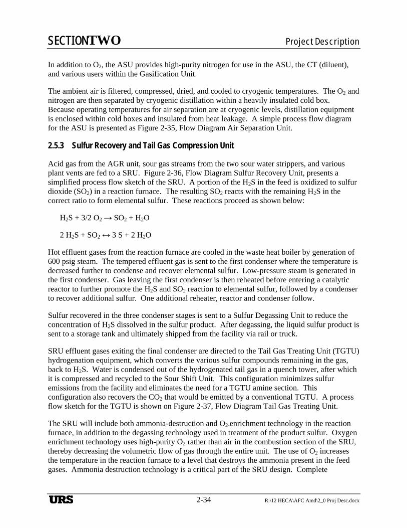
SECTIONTWO Project Description
2-34 R:\12 HECA\AFC Amd\2_0 Proj Desc.docx
In addition to O2, the ASU provides high-purity nitrogen for use in the ASU, the CT (diluent), and various users within the Gasification Unit.
The ambient air is filtered, compressed, dried, and cooled to cryogenic temperatures. The O2 and nitrogen are then separated by cryogenic distillation within a heavily insulated cold box. Because operating temperatures for air separation are at cryogenic levels, distillation equipment is enclosed within cold boxes and insulated from heat leakage. A simple process flow diagram for the ASU is presented as Figure 2-35, Flow Diagram Air Separation Unit.
2.5.3 Sulfur Recovery and Tail Gas Compression Unit
Acid gas from the AGR unit, sour gas streams from the two sour water strippers, and various plant vents are fed to a SRU. Figure 2-36, Flow Diagram Sulfur Recovery Unit, presents a simplified process flow sketch of the SRU. A portion of the H2S in the feed is oxidized to sulfur dioxide (SO2) in a reaction furnace. The resulting SO2 reacts with the remaining H2S in the correct ratio to form elemental sulfur. These reactions proceed as shown below:
H2S + 3/2 O2 → SO2 + H2O
2 H2S + SO2 ↔ 3 S + 2 H2O
Hot effluent gases from the reaction furnace are cooled in the waste heat boiler by generation of 600 psig steam. The tempered effluent gas is sent to the first condenser where the temperature is decreased further to condense and recover elemental sulfur. Low-pressure steam is generated in the first condenser. Gas leaving the first condenser is then reheated before entering a catalytic reactor to further promote the H2S and SO2 reaction to elemental sulfur, followed by a condenser to recover additional sulfur. One additional reheater, reactor and condenser follow.
Sulfur recovered in the three condenser stages is sent to a Sulfur Degassing Unit to reduce the concentration of H2S dissolved in the sulfur product. After degassing, the liquid sulfur product is sent to a storage tank and ultimately shipped from the facility via rail or truck.
SRU effluent gases exiting the final condenser are directed to the Tail Gas Treating Unit (TGTU) hydrogenation equipment, which converts the various sulfur compounds remaining in the gas, back to H2S. Water is condensed out of the hydrogenated tail gas in a quench tower, after which it is compressed and recycled to the Sour Shift Unit. This configuration minimizes sulfur emissions from the facility and eliminates the need for a TGTU amine section. This configuration also recovers the CO2 that would be emitted by a conventional TGTU. A process flow sketch for the TGTU is shown on Figure 2-37, Flow Diagram Tail Gas Treating Unit.
The SRU will include both ammonia-destruction and O2-enrichment technology in the reaction furnace, in addition to the degassing technology used in treatment of the product sulfur. Oxygen enrichment technology uses high-purity O2 rather than air in the combustion section of the SRU, thereby decreasing the volumetric flow of gas through the entire unit. The use of O2 increases the temperature in the reaction furnace to a level that destroys the ammonia present in the feed gases. Ammonia destruction technology is a critical part of the SRU design. Complete
URS
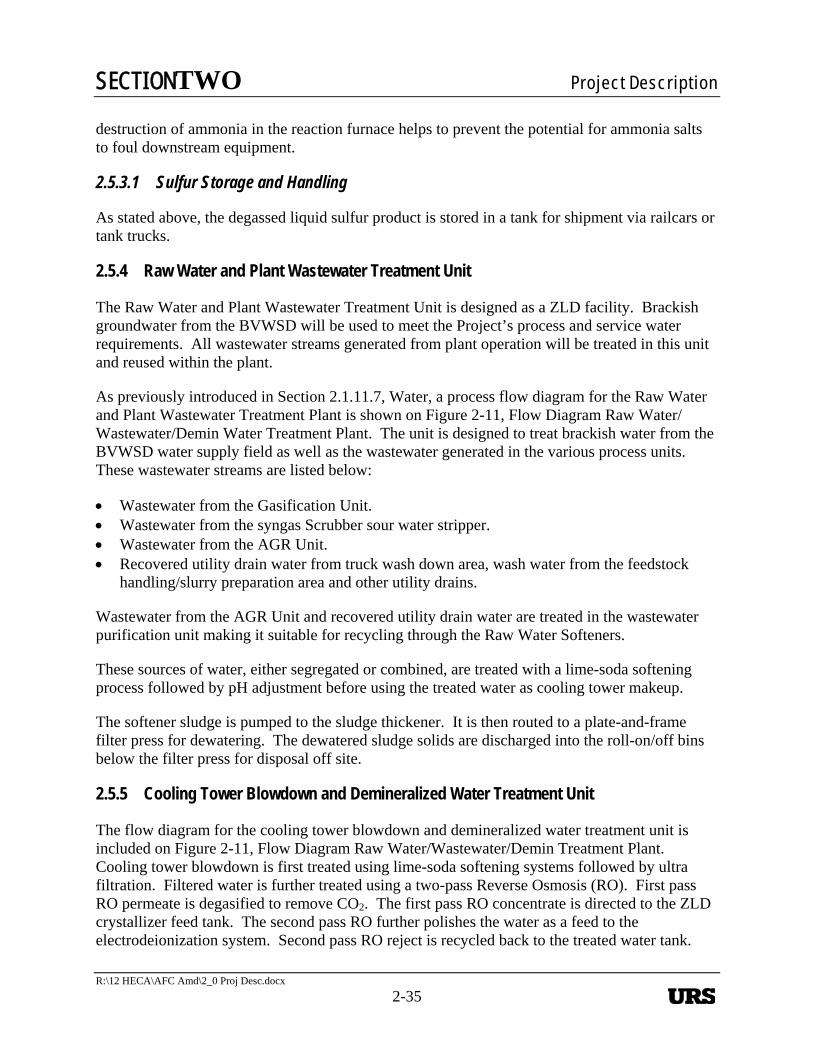
SECTIONTWO Project Description
R:\12 HECA\AFC Amd\2_0 Proj Desc.docx
2-35
destruction of ammonia in the reaction furnace helps to prevent the potential for ammonia salts to foul downstream equipment.
2.5.3.1 Sulfur Storage and Handling
As stated above, the degassed liquid sulfur product is stored in a tank for shipment via railcars or tank trucks.
2.5.4 Raw Water and Plant Wastewater Treatment Unit
The Raw Water and Plant Wastewater Treatment Unit is designed as a ZLD facility. Brackish groundwater from the BVWSD will be used to meet the Project’s process and service water requirements. All wastewater streams generated from plant operation will be treated in this unit and reused within the plant.
As previously introduced in Section 2.1.11.7, Water, a process flow diagram for the Raw Water and Plant Wastewater Treatment Plant is shown on Figure 2-11, Flow Diagram Raw Water/Wastewater/Demin Water Treatment Plant. The unit is designed to treat brackish water from the BVWSD water supply field as well as the wastewater generated in the various process units. These wastewater streams are listed below:
Wastewater from the Gasification Unit. Wastewater from the syngas Scrubber sour water stripper. Wastewater from the AGR Unit. Recovered utility drain water from truck wash down area, wash water from the feedstock
handling/slurry preparation area and other utility drains.
Wastewater from the AGR Unit and recovered utility drain water are treated in the wastewater purification unit making it suitable for recycling through the Raw Water Softeners.
These sources of water, either segregated or combined, are treated with a lime-soda softening process followed by pH adjustment before using the treated water as cooling tower makeup.
The softener sludge is pumped to the sludge thickener. It is then routed to a plate-and-frame filter press for dewatering. The dewatered sludge solids are discharged into the roll-on/off bins below the filter press for disposal off site.
2.5.5 Cooling Tower Blowdown and Demineralized Water Treatment Unit
The flow diagram for the cooling tower blowdown and demineralized water treatment unit is included on Figure 2-11, Flow Diagram Raw Water/Wastewater/Demin Treatment Plant. Cooling tower blowdown is first treated using lime-soda softening systems followed by ultra filtration. Filtered water is further treated using a two-pass Reverse Osmosis (RO). First pass RO permeate is degasified to remove CO2. The first pass RO concentrate is directed to the ZLD crystallizer feed tank. The second pass RO further polishes the water as a feed to the electrodeionization system. Second pass RO reject is recycled back to the treated water tank.
URS
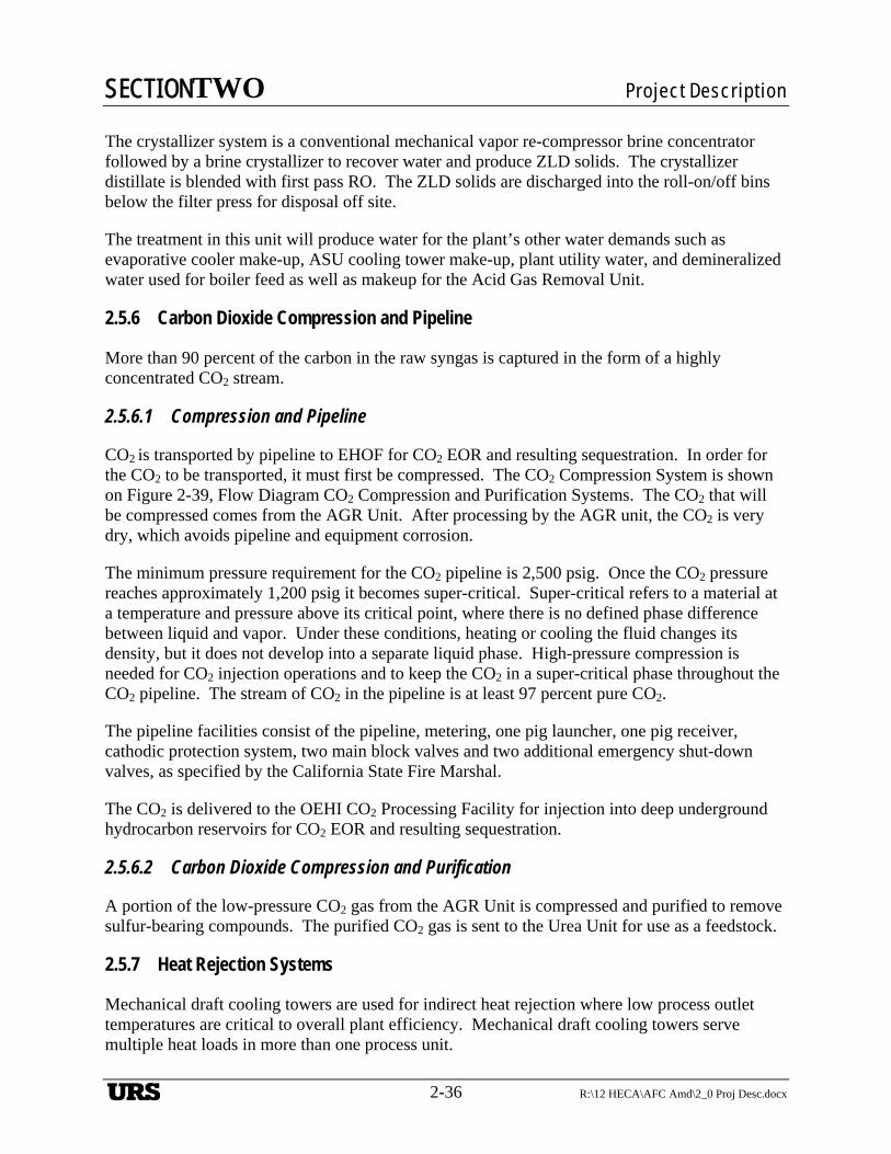
SECTIONTWO Project Description
2-36 R:\12 HECA\AFC Amd\2_0 Proj Desc.docx
The crystallizer system is a conventional mechanical vapor re-compressor brine concentrator followed by a brine crystallizer to recover water and produce ZLD solids. The crystallizer distillate is blended with first pass RO. The ZLD solids are discharged into the roll-on/off bins below the filter press for disposal off site.
The treatment in this unit will produce water for the plant’s other water demands such as evaporative cooler make-up, ASU cooling tower make-up, plant utility water, and demineralized water used for boiler feed as well as makeup for the Acid Gas Removal Unit.
2.5.6 Carbon Dioxide Compression and Pipeline
More than 90 percent of the carbon in the raw syngas is captured in the form of a highly concentrated CO2 stream.
2.5.6.1 Compression and Pipeline
CO2 is transported by pipeline to EHOF for CO2 EOR and resulting sequestration. In order for the CO2 to be transported, it must first be compressed. The CO2 Compression System is shown on Figure 2-39, Flow Diagram CO2 Compression and Purification Systems. The CO2 that will be compressed comes from the AGR Unit. After processing by the AGR unit, the CO2 is very dry, which avoids pipeline and equipment corrosion.
The minimum pressure requirement for the CO2 pipeline is 2,500 psig. Once the CO2 pressure reaches approximately 1,200 psig it becomes super-critical. Super-critical refers to a material at a temperature and pressure above its critical point, where there is no defined phase difference between liquid and vapor. Under these conditions, heating or cooling the fluid changes its density, but it does not develop into a separate liquid phase. High-pressure compression is needed for CO2 injection operations and to keep the CO2 in a super-critical phase throughout the CO2 pipeline. The stream of CO2 in the pipeline is at least 97 percent pure CO2.
The pipeline facilities consist of the pipeline, metering, one pig launcher, one pig receiver, cathodic protection system, two main block valves and two additional emergency shut-down valves, as specified by the California State Fire Marshal.
The CO2 is delivered to the OEHI CO2 Processing Facility for injection into deep underground hydrocarbon reservoirs for CO2 EOR and resulting sequestration.
2.5.6.2 Carbon Dioxide Compression and Purification
A portion of the low-pressure CO2 gas from the AGR Unit is compressed and purified to remove sulfur-bearing compounds. The purified CO2 gas is sent to the Urea Unit for use as a feedstock.
2.5.7 Heat Rejection Systems
Mechanical draft cooling towers are used for indirect heat rejection where low process outlet temperatures are critical to overall plant efficiency. Mechanical draft cooling towers serve multiple heat loads in more than one process unit.
URS
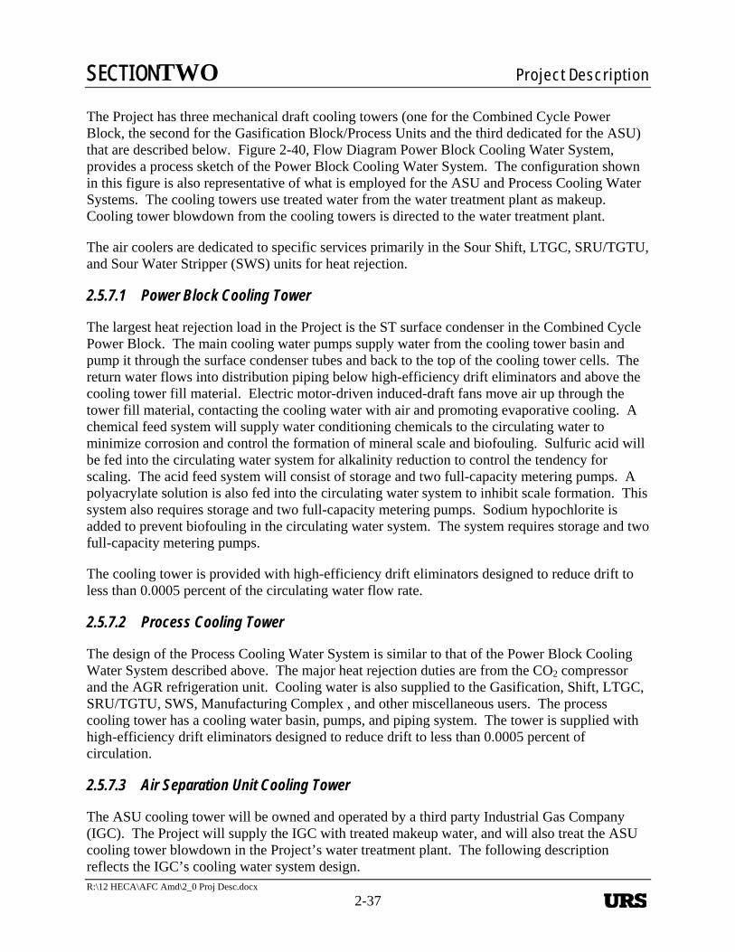
SECTIONTWO Project Description
R:\12 HECA\AFC Amd\2_0 Proj Desc.docx
2-37
The Project has three mechanical draft cooling towers (one for the Combined Cycle Power Block, the second for the Gasification Block/Process Units and the third dedicated for the ASU) that are described below. Figure 2-40, Flow Diagram Power Block Cooling Water System, provides a process sketch of the Power Block Cooling Water System. The configuration shown in this figure is also representative of what is employed for the ASU and Process Cooling Water Systems. The cooling towers use treated water from the water treatment plant as makeup. Cooling tower blowdown from the cooling towers is directed to the water treatment plant.
The air coolers are dedicated to specific services primarily in the Sour Shift, LTGC, SRU/TGTU, and Sour Water Stripper (SWS) units for heat rejection.
2.5.7.1 Power Block Cooling Tower
The largest heat rejection load in the Project is the ST surface condenser in the Combined Cycle Power Block. The main cooling water pumps supply water from the cooling tower basin and pump it through the surface condenser tubes and back to the top of the cooling tower cells. The return water flows into distribution piping below high-efficiency drift eliminators and above the cooling tower fill material. Electric motor-driven induced-draft fans move air up through the tower fill material, contacting the cooling water with air and promoting evaporative cooling. A chemical feed system will supply water conditioning chemicals to the circulating water to minimize corrosion and control the formation of mineral scale and biofouling. Sulfuric acid will be fed into the circulating water system for alkalinity reduction to control the tendency for scaling. The acid feed system will consist of storage and two full-capacity metering pumps. A polyacrylate solution is also fed into the circulating water system to inhibit scale formation. This system also requires storage and two full-capacity metering pumps. Sodium hypochlorite is added to prevent biofouling in the circulating water system. The system requires storage and two full-capacity metering pumps.
The cooling tower is provided with high-efficiency drift eliminators designed to reduce drift to less than 0.0005 percent of the circulating water flow rate.
2.5.7.2 Process Cooling Tower
The design of the Process Cooling Water System is similar to that of the Power Block Cooling Water System described above. The major heat rejection duties are from the CO2 compressor and the AGR refrigeration unit. Cooling water is also supplied to the Gasification, Shift, LTGC, SRU/TGTU, SWS, Manufacturing Complex , and other miscellaneous users. The process cooling tower has a cooling water basin, pumps, and piping system. The tower is supplied with high-efficiency drift eliminators designed to reduce drift to less than 0.0005 percent of circulation.
2.5.7.3 Air Separation Unit Cooling Tower
The ASU cooling tower will be owned and operated by a third party Industrial Gas Company (IGC). The Project will supply the IGC with treated makeup water, and will also treat the ASU cooling tower blowdown in the Project’s water treatment plant. The following description reflects the IGC’s cooling water system design.
URS
SECTIONTWO Project Description
2-38 R:\12 HECA\AFC Amd\2_0 Proj Desc.docx
The ASU Cooling Water System design is also similar to that of the Power Block Cooling Water System. The major heat rejection duties are from the main air compressor intercooler and aftercooler, the booster air compressor intercooler, and the nitrogen compressor intercooler. The ASU cooling tower is located in the ASU near the cooling loads. The ASU cooling tower has separate pumps and piping systems and is operated independently of the other cooling water systems. The ASU cooling tower is supplied with high-efficiency drift eliminators designed to reduce drift to less than 0.0005 percent of circulation.
2.5.8 Auxiliary Boiler
The auxiliary boiler is a pre-engineered shop fabricated package boiler that will provide steam for pre-start-up equipment warm-up and for other miscellaneous purposes when steam from the Gasification Block or HRSG is not available. During typical operation, the auxiliary boiler may be kept in warm standby (steam sparged, no firing) or cold standby (no sparging), and will not have emissions. The boiler will produce a maximum of about 150,000 pounds per hour of steam and will be fueled by natural gas. The boiler will be equipped with low-NOX burners and SCR to minimize emissions.
2.5.9 Flares
Flaring will occur only during start-up of the plant, from outages or during emergencies. The previous design necessitated regular rotation of three gasifiers into and out of service to facilitate periodic maintenance of the gasifier refractory and other critical gasifier system components. The rotation of each gasifier into service after maintenance required flaring of syngas from the time of light-off until the syngas was up to pressure and within specification. The new design uses a single 100-percent capacity MHI gasifier with an internal membrane wall that requires significantly less maintenance, eliminates rotations, and requires less syngas flaring events than a refractory-lined gasifier.
Although the plant is designed to avoid flaring during steady-state operations, flares are needed to protect the plant operators and equipment. The plant employs three pressure relief systems and their corresponding flares (Gasification, Rectisol®, and SRU) for this purpose. All three flares are conventional elevated flares and will be provided with natural gas assist as required. Vessels, towers, heat exchangers, and other equipment are connected to piping systems that will discharge gases and vapors to a relief system in order to prevent excessive pressure from building up in the equipment during upsets and emergencies. The flares also allow safe venting of equipment during routine start-up and shut-down operations.
During non-start-up plant operation, the three flares will be operated in a standby mode with only minimal emissions from the natural gas pilot flames. As explained below, the Gasifier and SRU flares will be also be used to occasionally flare excess start-up gases in a safe manner.
2.5.9.1 Gasification Flare
The Gasification Unit is provided with an elevated flare to safely flare excess gas during gasifier start-up operations or during upset conditions. Syngas sent to the flare during planned flaring events is filtered, water-scrubbed and sulfur-free. Flaring of untreated syngas or other streams
URS
SECTIONTWO Project Description
R:\12 HECA\AFC Amd\2_0 Proj Desc.docx
2-39
within the plant will only occur as an emergency safety measure during unplanned plant upsets or equipment failures. A simplified flow sketch is shown on Figure 2-41, Flow Diagram Gasification and Rectisol® Flare System.
2.5.9.2 Sulfur Recovery Unit Flare
An SRU Flare will be used to safely flare gas streams containing sulfur during start-up and shut-down (as described further in this section) and gas streams containing sulfur during unplanned upsets or emergency events. Acid gas derived from the AGR, and SWS overhead is routed to the SRU for recovery as elemental sulfur. During cold plant start-up of the Gasification, AGR, and Shift Units, these acid gas streams will be diverted to the SRU Flare header for a short time. To reduce the emissions of sulfur compounds during SRU or TGTU shut-down, the acid gas is routed to the emergency caustic scrubber, where the sulfur compounds are absorbed with caustic solution. After scrubbing, the gas is then routed to the elevated SRU Flare stack via the SRU Flare KO drum. Fresh and spent caustic tanks and pumps are provided to allow delivery of fresh caustic and disposal of spent caustic. A simplified process flow sketch of the SRU flare system is shown on Figure 2-42, Flow Diagram SRU Flare System.
2.5.9.3 Rectisol® Flare
Cold reliefs and vents from the AGR Unit and its associated Refrigeration Unit, and the Ammonia Synthesis Unit are collected in the Rectisol® Flare header. The Rectisol® Flare header is used only in start-up, shut-down, emergencies or plant upsets and contains gases that can be below the freezing point of water. For this reason, the Rectisol® Flare header gases are segregated from the wet gases in the Gasification Flare header. A simplified process flow sketch of the Rectisol® Flare system is shown on Figure 2-41, Flow Diagram of Gasification and Rectisol® Flare System.
2.5.9.4 Carbon Dioxide Vent
The CO2 Venting System consists of a CO2 vent header, vent KO drum and a CO2 vent stack. The system is used to vent incombustible, high-purity CO2. The vent gas is generated from reliefs, start-up/shut-down vents and venting when the CO2 compression, transportation, or injection system is unavailable.
2.5.10 Emergency Engines
The following is a description of the emergency engines required for the Project. These engines are fueled using ultra-low sulfur diesel fuel.
2.5.10.1 Emergency Diesel Generator
Two 2,000-kW standby diesel generators in an outdoor enclosure will be connected via stepdown transformers to supply emergency essential service power to critical lube oil and cooling pumps, gasification and auxiliary steam systems, station battery chargers, uninterruptible power supply, heat tracing, control room, emergency exit lighting, and other critical plant loads.
URS
SECTIONTWO Project Description
2-40 R:\12 HECA\AFC Amd\2_0 Proj Desc.docx
A Local Control Panel will be located on the diesel generator with standard microprocessor-based engine and generator controls, interlocks, metering, alarms, and synchronizing system. Remote control of the diesel generator shall be from DCS operators via a fiber optic cable to the control system.
2.5.10.2 Diesel Firewater Pump
One approximately 600-horsepower standby diesel-driven firewater pump will be located adjacent to the firewater tank.
2.5.11 Fire Protection
2.5.11.1 Fire Protection Program
The Project Fire Protection Program includes both fire prevention and protection measures. Fire prevention and suppression measures will include employment of conservative equipment layouts, segregation of critical components, and the remote location of non-essential resources as applicable.
Conservative equipment spacing and segregation of potentially hazardous activities from the balance of the Project will be employed as appropriate to protect personnel and property. Flammable gas monitors will be provided to detect and alarm hazardous levels. Oil containment sumps and firewalls, as appropriate, will be erected to isolate large transformers using combustible heat transfer fluids from adjacent facilities. Structural steel will be protected with fire-proofing materials in areas subject to direct fire exposure. Process liquid drains will be configured to contain liquid spills within the unit of origin. An extensive plant grounding system will be installed to dissipate static electrical charges. Emergency lighting is provided to illuminate egress lanes.
Fire suppression will be provided by various means. A dedicated firewater storage and site-wide loop distribution system will be provided to serve automatic fire suppression systems and manual firewater fighting equipment (monitors and hydrants). Inert gas or other special agents will be provided for the protection of equipment and structures where the use of water-based suppression systems is not appropriate. CO2 fire-suppression systems will be provided in the CT enclosures. Provisions for the deployment of aqueous fire-fighting foam will be included with the methanol storage tanks. Steam may be used to smother fires originating in hot equipment that may otherwise be further damaged by the application of firewater.
The Project Site will be subdivided into discrete fire areas to identify potential hazards, protect personnel, control a fire incident within a defined area, limit the spread of fire to other areas, and minimize the possibility of consequential fire damage in other areas of the Project. Fire area boundaries will be based on:
The type, quantity, density, and locations of each fire hazard (solid, liquid, and gas) Location and configuration of critical plant equipment Consequence of damage to plant equipment Location of fire detection alarm panels, firewater storage, and pumping systems
URS
SECTIONTWO Project Description
R:\12 HECA\AFC Amd\2_0 Proj Desc.docx
2-41
The capacity of the firewater storage, supply, and distribution system described below was sized based on the demand of the largest fire risk area.
The following overview describes the main features of the Project’s fire detection and suppression plan.
2.5.11.2 Firewater Storage and Distribution System
The Firewater Distribution System is shown on Figure 2-43, Flow Diagram Firewater System. The Firewater Storage and Distribution System would provide firewater to all plant areas. The firewater source would be the service water/firewater storage tank. The tank nozzle drawoff point for the service water and firewater supply would provide a dedicated water supply for fire protection. A 100 percent capacity electric motor-driven fire pump and a 100 percent capacity diesel-driven fire pump would be provided to supply the required flow rate and pressure of firewater for the plant. An electric-motor-driven pressure maintenance (jockey) pump would maintain pressure in the firewater system. The fire pump enclosure would be protected by an automatic sprinkler system. The firewater pumps would be located inside a prefabricated enclosure that would have heating and lighting. A fire loop with hydrants spaced in accordance with National Fire Protection Association recommendations would be located about the Project Site.
2.5.11.3 Automatic Fire-Suppression System
The Automatic Fire-Suppression System would use firewater as the primary fire-fighting medium. The under-floor spaces in Control Room and Rack Room areas will be provided with inert gas suppression systems. The type of inert gas and deployment method would be selected to minimize personnel exposure and plant equipment damage. The CT enclosure would be flooded with CO2 or some other suitable fire suppressant to suppress fires. Wherever an inert gas is used for fire suppression, a pre-release alarm annunciates to inform any personnel working in the area to leave immediately. Personnel will receive training on the meaning of these pre-alarms (tone, duration, etc.) and the time allotted for personnel to leave an area.
Automatic Fire-Sprinkler Systems, Pre-Action Fire-Sprinkler Systems, and Water-Spray Systems are planned to be used for the protection of structures and equipment, as appropriate.
2.5.12 Plant and Instrument Air
Utility and instrument air for the entire plant is supplied by the ASU. Backup air is provided by an air compressor/dryer skid.
Primary plant service and instrument air is extracted from the ASU air-compression equipment and cooled. This air is clean and dry and is fed directly to the plant and instrument air distribution system without further conditioning.
Secondary backup plant and instrument air is supplied from a stand-alone package air compressor/dryer/accumulator skid. The quality and quantity of air provided from this source is similar to that of the primary air system.
URS
SECTIONTWO Project Description
2-42 R:\12 HECA\AFC Amd\2_0 Proj Desc.docx
Both primary and secondary air sources are integrated and piped to the plant-wide distribution systems. The instrument air piping distribution system is sized to ensure that adequate quantities are supplied to the various instrument and control air consumers. Accumulators/volume bottles are installed near large intermittent air consumers (i.e., fast-acting control valves) to make certain that the required response times are attained.
Project service air system utility stations are positioned throughout the facility to provide plant air for maintenance activities. The source of the air to these utility air users is automatically shut off on low instrument air pressure. This feature ensures that priority is given to the instrument air system to make certain that adequate volumes are available to safely operate and control the facility.
2.5.13 Emissions Monitoring System
The CEMS will be installed to measure emissions from stacks as required by applicable regulations and permit conditions. These analyzers are designed, installed, certified, and calibrated. These systems sample, analyze, and record stack emission data for several specified pollutants. CEMS incorporates data handling and acquisition systems to automatically generate emissions data logs and compliance documentation. Alarms alert operators if stack emissions exceed specified limits. Each CEMS undergoes periodic calibration, audits, and testing to verify accuracy.
In addition to continuous monitoring, the Project performs periodic stack emission tests to verify compliance as required.
2.5.14 Hazardous Material Management
The Project will store and use hazardous materials in conjunction with construction and operation and maintenance (O&M) of the Project. In general, the type and character of these materials will be the same as those for other IGCC and polygeneration projects.
Hazardous materials used during the construction of the Project would mainly be limited to fuels and construction materials, including:
Gasoline, diesel fuel, and motor oil for construction equipment Compressed gas cylinders containing O2, acetylene, and argon for welding Paint and cleaning solvents Concrete form release Miscellaneous lubricants, adhesives, and sealants
Each construction contractor will be responsible for maintaining a set of Material Safety Data Sheets (MSDSs) for each on-site chemical it controls, and construction workers will be made aware of the location and content of these MSDSs. Similar information and training will be provided during operations.
Hazardous materials that may be routinely stored in bulk and used in conjunction with the Project operations include but are not limited to methanol, petroleum products, flammable and/or
URS
SECTIONTWO Project Description
R:\12 HECA\AFC Amd\2_0 Proj Desc.docx
2-43
compressed gases, acids and caustics, ammonia, water treatment and cleaning chemicals, paints, and solvents. Table 2-15, Hazardous Materials Usage and Storage during Operations Based on Title 22 Hazardous Characterization, and Table 2-16, Hazardous Materials Usage and Storage during Operations Based on Material Properties, lists each material and describes the approximate annual quantity needed and use of the material during operations.
Figure 2-44, Preliminary Hazardous Material Location Plan, shows the location of major sources of hazardous materials on the Project Site.
Storage of hazardous materials will occur in appropriately designed storage areas. Bulk tanks will be provided with secondary containment to contain leaks or spills. Safety showers and eyewashes will be provided in appropriate chemical storage and use areas. Personnel who could potentially handle hazardous materials will be properly trained to perform their duties safely and to respond to emergency situations that may occur in the event of an accidental spill or release.
2.5.15 Hazardous Waste Management
Hazardous wastes will be generated in small quantities as a result of construction waste and operational waste.
Hazardous Construction Waste
The majority of hazardous waste generated during construction will consist of liquid waste such as waste oil from routine equipment maintenance, flushing and cleaning fluids, waste solvents, and waste paints or other material coatings. Additionally, some solid waste in the form of spent welding materials, oil filters, oily rags and absorbent, spent batteries, and empty hazardous material containers may also be generated.
Construction contractors will employ practices consistent with the proper handling of all hazardous wastes. This includes all licensing requirements, training of employees where required, accumulation limits and duration, and record keeping and reporting requirements. All hazardous wastes will be removed from the Project Site by a licensed hazardous waste management facility.
Table 2-17, Summary of Construction Waste Streams and Management Methods, lists the anticipated construction wastes, which include both hazardous and non-hazardous waste, and identifies the likely disposition of the waste.
Hazardous Operations Waste
Estimated operations waste streams are shown in Table 2-18, Summary of Operating Waste Streams and Management Methods. This table includes both hazardous and non-hazardous waste sources. Used catalysts, activated carbon filters, and ZLD solids will be characterized and disposed of. Spent caustic will be treated off site to oxidize sulfides to sulfates and will be disposed of as a non-hazardous material.
URS
SECTIONTWO Project Description
2-44 R:\12 HECA\AFC Amd\2_0 Proj Desc.docx
Chemical cleaning wastes may also be generated from the periodic cleaning of machinery and piping. Waste lubricants, such as waste oil, will be periodically generated during the operations and maintenance of the Project. Waste oil will be collected and stored in appropriate containers and recycled by an approved contractor.
As with hazardous construction waste described above, where appropriate, hazardous waste resulting from operation activities will also be collected in hazardous waste accumulation containers placed near the area of generation. All hazardous wastes will be properly removed from the Project Site.
2.5.16 Storm Water Management
Storm water management for the Project is designed to avoid direct discharge to surface waters.
Retention basins and storm water collection/conveyance systems will be designed in accordance with the Kern County Development Standards. The retention basin locations are shown on Figure 2-45, Preliminary Storm Water Drainage Plan.
Storm water generated at the Project Site will be managed as follows:
Storm water from inside the process plant area will be routed to lined retention basins. After solids have settled and water is determined to be suitable for reuse, storm water will be pumped to the water treatment plant for further treatment and reuse. If this collected storm water is determined to be unsuitable for reuse, then it will be transferred and processed in the ZLD system at the wastewater treatment plant.
Storm water that may be contaminated with oil will be separately collected and routed to an oil/separator. Recovered waste oil from the separator will be disposed off-site. The separated water will be transferred and processed at the wastewater treatment plant.
Storm water in the AGR Unit will be collected in a separate lined, dedicated AGR storm water retention basin. The AGR Unit collection system is isolated to contain any potentially contaminated water that could result in the unlikely event of a methanol spill.
Storm water from chemical and oil storage areas will be held in the associated secondary containment. Storm water held in these areas will first be tested. If it is acceptable for cooling water makeup, then it will be routed to the lined retention basin. Oily storm water will be routed through an oil/separator at the wastewater treatment plant.
Storm water within the process plant area where solids are present (e.g., coal, petcoke, or gasification solids) will be collected and conveyed to the solids handling water collection facility. The collection facility will be constructed of concrete and will provide for mobile equipment access to remove accumulated solids. Water that accumulates within the solids handling collection facility will be processed in the ZLD system at the wastewater treatment plant.
URS
SECTIONTWO Project Description
R:\12 HECA\AFC Amd\2_0 Proj Desc.docx
2-45
Storm water from remote solids handling areas such as feedstock unloading and the crusher station will be collected in lined retention basins for settlement, testing, reuse, and/or treatment as appropriate.
Storm water from outside the process plant area but within the Project Site will be separately collected in retention basins located throughout the Project Site.
A Storm Water Pollution Prevention Plan will be developed prior to operations. The Project storm water will be managed in accordance with this plan, which will include the measures outlined above.
2.5.17 Control System
The Project Control System will require the integration of many available technologies related to sensors, control elements, and data acquisition and control (as shown on Figure 2-46, Control System Block Diagram). The system will be designed so that the plant operations personnel will have state-of-the-art control and monitoring capabilities. The Project will be designed around a DCS supported by auxiliary systems to allow personnel to analyze Project conditions and react in a timely way to upset conditions. Multi-level system architecture will be provided with security levels and firewalls between each level in order to prevent accidental manipulation of Project operations.
The overall design of the instrumentation and control systems will be in accordance with applicable national and local standards such as those from the IEEE, National Fire Protection Association, and Instrument Society of America. Electrical equipment and components will also be purchased requiring third-party approvals from Underwriters Laboratories, Factory Mutual Research Corporation, Canadian Standards Association, or others as required.
2.5.18 Project Buildings
Buildings and kiosks will be provided on-site to satisfy operating requirements. The buildings and kiosks located on the Project Site are likely to include:
Feedstock barn Control rooms, administration, and laboratory structures Emergency response and medical center Power distribution centers Instrument and control structures Analyzer shelters Warehouse shop building Guard houses
2.5.19 Security Systems
Cameras in the plant will monitor for environmental issues, process safety, and security. A motorized actuator will control the access gates. Gate actuators will include inputs from control
URS
SECTIONTWO Project Description
2-46 R:\12 HECA\AFC Amd\2_0 Proj Desc.docx
room and receptionist switches, the exit loop, and a local keypad or card reader station. Gate intercom stations will be near the local keypad or card reader.
2.6 PLANT OPERATING SCENARIOS AND EMISSIONS
2.6.1 Operations
The Project will operate as an IGCC facility that will produce low-carbon baseload power and low-carbon nitrogen-based products using hydrogen-rich fuel. The Gasification Unit consists of one Mitsubishi Heavy Industries (MHI) oxygen-blown gasifier that will provide hydrogen-rich fuel to the MHI 501GAC® CT. The heat recovery steam generator (HRSG) will duct fire PSA Unit off-gas. Depending on the operating mode, surplus hydrogen-rich fuel may also be available for duct firing in the HRSG. Natural gas is required for operation during start-ups, shut-downs, and as a short-term backup for equipment outages and/or to meet critical contractual obligations.
The gasifier syngas capacity is greater than the maximum fuel capacity of the combined cycle unit. The additional syngas is used for production of low-carbon nitrogen-based products.
Table 2-19, Maximum Fuel Energy, presents the maximum heat input to the gas turbine and the HRSG Duct Burner for hydrogen-rich fuel and natural gas.
Table 2-20, HECA Total Combined Annual Criteria Pollutant Emissions, presents a summary of the steady-state emissions and emission control devices associated with the operating modes discussed above. Figure 2-47, Preliminary Emissions Sources Plot Plan, identifies the emission sources on the Project Site plot plan. Figure 2-48, Overall Block Flow Diagram with Emission Sources, shows the process sequence and emission points for the Project.
2.6.2 Start-Up
This section describes a cold start-up, which assumes the plant had been shut down for a period of time and is at ambient temperature. This sequence assumes that all the necessary utility and support systems are already in service (DCS; fire protection and other safety systems; electrical switchyard and in-plant electrical distribution; water treatment; ZLD; natural gas, steam, instrument, and plant air; purge nitrogen, etc.).
Note that if the IGCC is being restarted after a short outage, when the equipment is still close to operating conditions, the durations of each step will be much shorter than indicated below.
The IGCC takes 4 to 6 days from cold start to export of low-carbon power. The following summarizes the start-up sequences.
Power Block Start-Up
The MHI 501GAC® and the MHI ST are on a common shaft, with the common generator located between the CT and ST. A clutch is provided between the ST and the generator to allow the CT
URS
SECTIONTWO Project Description
R:\12 HECA\AFC Amd\2_0 Proj Desc.docx
2-47
to start-up independently of the ST. The clutch is disengaged during the following CT start-up sequence.
Once all the start-up permissives are met, the MHI 501GAC® CT start signal is given and the generator is used as a motor to rotate the CT and accelerate it until the operation is self-sustaining (static start). The CT compressor is first partially loaded to provide enough air flow and duration to purge the HRSG. Following the purge, natural gas is introduced into the CT combustors, resulting in the CT operation becoming self-sustaining and the discontinuation of the static start. Natural gas is required to start-up the CT. When the CT reaches 3,600 revolutions per minute (RPM), or “full speed, no load,” it is synchronized with the electrical grid, and the main breaker is closed. Shortly after the CT is synchronized, it is loaded to a minimum or “spinning-reserve” load. All the preceding steps are executed automatically by the CT’s control computer system. At this point the HRSG begins warming up and rapidly begins to produce steam. The steam is initially vented, and as pressure builds in the steam system, the atmospheric vents close and the steam flow is diverted to the surface condenser. Once dry superheated steam is available at the ST, the ST start-up sequence can be initiated. The ST can then be accelerated to 3,600 RPM to match speed with the generator shaft. Once the speeds are synchronized, the clutch can be engaged and both the CT and the ST will supply shaft work to the generator. The ST metal temperatures determine how quickly the ST can be loaded. The cold start sequence requires the CT to operate at reduced load (below the emission compliance level) for up to 4 hours. During this time, the CT load is slowly increased to match the steam temperature to the ST metal temperature to heat the ST while minimizing thermal stress. Once the CT reaches the required load, steam is introduced to control NOX formation. Once the SCR catalyst reaches the required temperature, ammonia injection is initiated and the HRSG stack emissions will fall to the required compliance levels. The CT can then be loaded normally to base load, and the ST will reach a load based on the available steam.
ASU Start-Up
The ASU will require 3 to 4 days to start up and reach full capacity. Because the ASU operates at cryogenic conditions, the start-up sequence includes an extensive cool down and drying period. During this time, the main air compressor and booster air compressor will be operated to provide the auto refrigeration necessary to cool and dry the ASU. Near the end of the start-up sequence, the ASU will begin producing liquid oxygen (LOX) and liquid nitrogen. The LOX is stored to provide a backup O2 supply to cover a compressor trip or other short ASU outage. The liquid nitrogen storage is provided as a backup supply for the purge nitrogen system. Once the ASU is producing enough O2 to operate the gasifier, the LOX pumping and vaporization system can be started to make high-pressure O2 vapor available to the Gasification Unit.
AGR Start-Up
The AGR Unit is assumed to be ready to start (purged with nitrogen and with start-up methanol levels established in the circulating system). Methanol circulation is started and the refrigeration system is started to begin cooling the methanol to normal operating temperature (approximately minus 40°F). This sequence is expected to take about 2 days and will complete at about the same time that sufficient O2 is available to start the gasifier.
URS
SECTIONTWO Project Description
2-48 R:\12 HECA\AFC Amd\2_0 Proj Desc.docx
SRU Start-Up
The SRU is a single train with an O2-enriched reaction furnace (thermal reactor) and two modified Claus reactor stages. The SRU reaction furnace is refractory lined. After an extended outage, both the refractory and the SRU catalyst require a gradual heating program that will take about 3 days for initial curing and dryout and 1 day on subsequent start-ups. The heating is provided by firing natural gas with air in the reaction furnace. The combustion products flow through the reaction furnace, catalyst beds, and boilers to the tail gas thermal oxidizer. During the refractory dryout/cure period, the hydrogenation reactor in the TGTU will also be preheated. The hydrogenation reactor catalyst requires pre-sulfiding prior to being put into operation, which will be timed to complete when the SRU and the gasifier are both feed-ready.
Gasification Block Start-Up
The MHI gasifier is a dry-feed system, and the gasification reaction zone is protected by a membrane wall. This design reduces the amount of time needed to warm the gasifier (as compared to a refractory lined vessel) when preparing the gasifier for start-up. Natural gas will be burned in air inside the gasifier to provide heat during initial warm-up.
The shift reactors require warm up and pre-sulfiding before sour syngas (containing H2S) can be introduced. The shift reactor catalyst is heated by circulating hot nitrogen across the catalyst beds for about two days. The nitrogen is heated indirectly with a high-pressure steam heater. Once the catalyst is hot, a small amount of sulfur-containing compound is added to the circulating nitrogen. The pre-sulfiding is completed when traces of sulfur are detected in the effluent of the second shift reactor. The shift reactors are then placed in a hot standby condition and ready for feed.
The CO2 compression system will be purged and ready to compress CO2. The CO2 compressor start-up sequence will be timed to coincide to when the AGR Unit is producing CO2 in sufficient quantity to allow sustained operation of the CO2 compressor.
When the gasifier reaches operating temperature, and the gasifier system has been purged with nitrogen, the gasifier can be started by introducing O2 to gasify the natural gas, then switching to the coal/petcoke-blend feedstock. Produced raw syngas is sent to Gasification Flare until the system pressure and flow are stabilized. For start-up, the syngas sent to flare is either produced from natural gas or treated in the AGR Unit and will be essentially sulfur-free. Syngas is diverted through the shift reactors and LTGC sections and then to the AGR Unit. The circulating solution in the AGR Unit then begins absorbing the CO2 in the syngas. Once the CO2 concentration in the rich solution reaches the required level, the flash drums will begin separating CO2 vapor. This CO2 will be washed to remove any traces of methanol and vented to the atmosphere.
Once sufficient hydrogen-rich fuel production is available, the MHI 501GAC® CT can initiate a switch to 100 percent hydrogen-rich fuel. At this point, the start-up is complete and operation begins.
URS
SECTIONTWO Project Description
R:\12 HECA\AFC Amd\2_0 Proj Desc.docx
2-49
Also at this point, the start-up of the PSA Unit and Ammonia Synthesis Unit is initiated, a process that takes 1 to 2 days. Subsequently, the Urea Plant start-up is initiated over a second 24-hour process.
Ammonia Synthesis Unit Start-Up
The Ammonia Synthesis Unit will require about 2 days to start-up and reach full capacity for a cold start-up. First, the circulation of high-pressure boiler feedwater through the waste heat boiler, and that of cooling water through the appropriate heat exchangers is started. Then, the syngas compressor is started up and its speed slowly increased with hydrogen and nitrogen feeds. The initial period is used for purging the system and venting the gas (essentially hydrogen and nitrogen) via the flare system in the IGCC complex. The synthesis loop pressure is increased by increasing the compressor speed and syngas flowrate. The start-up heater is switched on to raise the converter catalyst bed temperatures. As the catalyst bed temperature is increased, the exothermic ammonia synthesis reaction starts taking place and ammonia is produced. As the synthesis loop pressure and the converter temperatures are increased, the ammonia refrigeration compressor is brought on line. The chilling provided by this system is used to separate the ammonia product from the main gas stream. The unconverted gas is recycled back to the syngas compressor.
The operating temperatures of the ammonia synthesis converter and the ammonia chillers are next optimized and the start-up heater is shut down. Then, the synthesis loop pressure is brought to design conditions by increasing the syngas compressor speed and feed rates. At this point, the Ammonia Synthesis Unit is operating at its design capacity and producing cold liquid, warm liquid and vapor ammonia product streams.
Urea Unit Start-Up
For a cold start-up, the Urea Unit will require about 18 hours to reach full capacity. First, the circulation of cooling water through the appropriate heat exchangers is started. The CO2 Compressor and the Air Blower are then brought on line at low speed, and the CO2 and air are circulated through the following high-pressure vessels:
High-Pressure (HP) Stripper Urea Reactor HP Carbamate Condenser HP Scrubber
The initial period is used for purging the system and venting the gas, which is essentially CO2. Then, the CO2 compressor speed is increased and the above-mentioned vessels are pressurized with CO2. Medium pressure (385 psig) steam is then introduced in the HP Stripper to raise the temperature of the system. Steam condensate from the HP Stripper is flashed at low pressure (60 psig) to provide steam for users at this level.
Pressurized liquid ammonia stream is introduced into the Urea Reactor to react with the CO2 stream. The liquid product stream from the Urea Reactor consists of urea, carbamate, water, and
URS
SECTIONTWO Project Description
2-50 R:\12 HECA\AFC Amd\2_0 Proj Desc.docx
excess ammonia. This liquid stream is routed to the HP Stripper where carbamate and excess ammonia are separated and recycled to the Urea Reactor with the incoming CO2 feed stream. The bottoms product from the HP Stripper is a urea solution containing over 50 weight percent urea. The urea solution is routed to downstream units for further concentration. A 70 weight percent urea solution is first produced in the LP Rectifier and the Flash Vessel. This solution is stored in the intermediate solution tank. From this tank it is pumped to the vacuum separators/evaporators to produce either the 80 weight percent urea stream for use in the UAN complex, or a greater than 99 weight percent urea melt stream for use in the Pastillation Unit.
UAN Unit Start-Up
From a typical cold start-up, the UAN Unit will require about 12 hours to reach full capacity. The UAN Unit consists of a Nitric Acid Unit, Ammonium Nitrate Unit, and a UAN blending unit. It is assumed that both the upstream Ammonia Unit and the Urea Unit are operating normally before the UAN Unit is started-up. The start-up sequence will consist of the following:
Start-up of the Nitric Acid Unit Start-up of the Ammonium Nitrate Unit Start-up of the Urea Ammonium Nitrate Blending Unit
Start-Up of the Nitric Acid Unit
Circulation of boiler feed water is first started through the Waste Heat Boiler. Then, the air compressor is started up and air is used to pressurize the system consisting of the Ammonia Converter, Tail Gas Heater, Absorber, and all associated heat exchangers. The ammonia vapor stream from the battery limits is then slowly introduced and fed to the Ammonia Converter. A highly exothermic reaction of ammonia with air takes place over a platinum catalyst to produce a mixture of nitric oxide and water vapor. The resulting high-temperature gas from the Ammonia Converter then flows through a heat recovery system consisting of Expander Gas Heater, Waste Heat Boiler, Tail Gas Heater, and Air Heater. The cooled gas is then routed to the Absorber where it is mixed with air to reoxidize the nitric oxide to nitrogen dioxide. The vapor stream is contacted with feed water in the Absorber column to produce nitric acid of the desired strength. The overhead from the Absorber is tail gas, which is heated in a series of exchangers before being routed to the Tail Gas Expander for power recovery. The tail gas is treated in a catalytic system for NOX emission control before being released to the atmosphere. The nitric acid product is routed to the Nitric Acid Surge tank for use as feed to the Ammonium Nitrate Unit.
Start-Up of the Ammonium Nitrate Unit
The feeds for the Ammonium Nitrate Unit are nitric acid and ammonia vapor. Ammonium Nitrate (75 to 83 weight percent) is produced in the Neutralizer by the reaction between ammonia vapor and nitric acid. The ammonia vapor is mixed with the nitric acid with a sparger system in the bottom of the Neutralizer.
The heat of reaction in the Neutralizer boils off steam, which passes overhead in the Scrubber. The function of the Scrubber is to condense the right amount of steam to control the concentration of the product ammonium nitrate solution from the Neutralizer. The overhead
URS
SECTIONTWO Project Description
R:\12 HECA\AFC Amd\2_0 Proj Desc.docx
2-51
vapors from the Neutralizer/Scrubber are further cooled and scrubbed of residual ammonia in the vent scrubber before being released to the atmosphere. The collected condensate is returned to the Absorber. The resultant ammonium nitrate solution is routed to the UAN Blending facility.
Start-Up of the UAN Blending Unit
The feeds to this unit are 80 weight percent urea solution from the Urea Unit and the ammonium nitrate solution from the Ammonium Nitrate Unit. These two streams are blended in the UAN Mix Tank to produce the UAN solution.
2.6.3 Transient Operations
During peak electrical demand periods, the Project operates with the Power Block operating at maximum capacity on hydrogen-rich fuel. Transient operations associated with combined cycle load following are limited to the transition periods required to move from one operating mode to another. The following subsections describe the primary operating modes and the transient operations associated with them, as well as outage scenarios during annual operation.
For planning purposes, the Project expects two gasifier shut-downs and start-ups per year. These gasifier shut-downs are expected to be planned, based on on-line diagnostics and maintenance history. The MHI 501GAC® will automatically switch from hydrogen-rich fuel to natural gas on loss of hydrogen-rich fuel pressure. During operation there is a small excess of hydrogen-rich fuel production that is fired in the HRSG duct burners. This allows the amount of duct firing to vary with the normal variations in gasifier operation. When the gasifier is shut down, the duct firing will stop and the MHI 501GAC® CT will switch to the natural gas firing mode. The CT will continue to operate firing natural gas fuel until the gasifier is brought back on-line. When sufficient hydrogen-rich fuel is available, the CT will switch to 100 percent hydrogen-rich fuel, and hydrogen-rich duct firing can be restored. During gasifier operation, additional power can be generated by duct-firing PSA Unit off-gas.
The Project will typically be operated at base load during peak electrical demand periods. During base load operation hydrogen-rich fuel will be used in both the gas turbine and HRSG duct burners. During off peak electrical demand periods the gasifier, Shift, LTGC, Mercury Removal and AGR units will continue to operate at their design capacity. The gas turbine will be turned down to about 80 percent load. During off-peak operation the surplus hydrogen rich fuel production will be purified and used to make additional low-carbon nitrogen-based products.
The Power Block can also operate at up to 80 percent load on natural gas to support start-up or shut-down of the Gasification Block.
Power Block outages can either be planned or unplanned. Planned outages will be timed to occur with scheduled maintenance outages of the rest of the Project. Unplanned Power Block outages can occur for a variety of reasons. A CT shut-down will result in an immediate surplus of hydrogen-rich fuel. To accommodate this scenario, the gasifier will be turned down to the point at which the syngas generated in the gasifier will fully load the Manufacturing Complex. If the Power Block can be brought back online in a relatively short time, the Gasification Block will continue to operate feeding the Manufacturing Complex until the Power Block is back
URS
SECTIONTWO Project Description
2-52 R:\12 HECA\AFC Amd\2_0 Proj Desc.docx
online. If the Power Block outage is expected to be long in duration, then a decision to shut down the Gasification Block may be made.
The Gasification Block can operate for limited periods without the Combined Cycle Power Block operating. The Gasification Block auxiliary loads will be supplied initially from the grid following a MHI 501GAC® trip.
The Project will have one gasifier operating continuously at full load during operation. The gasifier is designed to operate at a minimum load of 70 percent, and will be able to reduce to this level in approximately one half hour.
Several events including the loss of CO2 compression, or a loss or reduction in one of the units in the Manufacturing Complex, could make it desirable to operate the gasifier at reduced capacity to minimize flaring hydrogen-rich fuel and/or venting CO2. The anticipated time to repair and restore operation will determine whether it is desirable to turn down the gasifier for a limited time or shut it down.
2.6.4 Commissioning
Construction is initially scheduled by area and major equipment erection. Later construction transitions to completion by system in order to support turnover to the commissioning team. Commissioning is completed by system, with the utilities (fire protection, power, water, natural gas, steam, etc.) completed first. Commissioning the utility and support systems includes electric power, water treating, natural gas, and cooling tower, as well as the safety systems that will be needed to support initial operations of the equipment. Commissioning the Diesel Firewater Pump and the Emergency Diesel Generators will produce air emissions during initial operation and testing.
The major process units will be commissioned in a sequence that begins with the feed-producing units and ends with the product-producing units and systems.
The major Gasification Block units consume electrical power. The Power Block also must be reliable before commissioning on hydrogen-rich fuel begins. For these reasons, the Power Block will be commissioned ahead of the Gasification Block. The commissioning for the Project will require four distinct phases, which are described in sections 2.6.4.1 through 2.6.4.4.
2.6.4.1 Power Block Commissioning on Natural Gas
The Power Block will be initially commissioned on natural gas. The MHI 501GAC® uses diffusion combustors with water injection, rather than dry-low NOX combustors. The following list briefly describes the steps for commissioning on natural gas:
First fire Initial CT run-in Support of steam blows Initial ST roll NOX tuning with steam injection
URS
SECTIONTWO Project Description
R:\12 HECA\AFC Amd\2_0 Proj Desc.docx
2-53
Installation of SCR and oxidation catalyst CEMS drift test and source testing Power Block functional testing Water wash and Power Block performance testing and continuous operation test
2.6.4.2 Gasification Block and Balance of Plant Commissioning
The following description includes the commissioning activities that are expected to have air emissions. The description assumes that the major utility support systems are already operational (power distribution, firewater, power plant and instrument air, water treatment, steam, boiler feedwater, etc.). The key activities and events are listed below:
Testing Diesel Generators Testing Diesel Firewater Pump Auxiliary boiler initial firing and burner tuning Auxiliary boiler source testing Auxiliary boiler operation to support gasification commissioning (typically when the Power
Block is not operating) Operation of the Power Block in support of Gasification Block commissioning Cooling tower operation supporting the ASU, Combined Cycle Power Block, and
Gasification Block (process cooling tower) Gasification Flare testing and operation in support of Gasification Block commissioning Rectisol® Flare testing and operation in support of AGR Unit commissioning SRU Flare testing and operation in support of Gasification Block commissioning Gasifier testing and operation Testing and operation of the AGR, SRU, and Tail Gas Compression Unit Testing the SRU Thermal Oxidation Venting CO2 to support the testing and operation of the AGR and CO2 compression system
2.6.4.3 Power Block Commissioning on Hydrogen-Rich Fuel
The Power Block will require additional testing and NOX tuning with hydrogen-rich fuel. The testing will cover the range of allowable load ranges. The Power Block will be commissioned first on natural gas. The oxidation catalyst is assumed to be in service and active when the HRSG operating temperature is sufficient. The SCR catalyst and ammonia injection system are assumed to be operating whenever the SCR catalyst temperature is in the required range and operation is sufficiently stable. Ammonia injection may be off-line during the initial phases of NOX tuning. The key activities and events that are expected to produce air emissions are listed below:
Start-up, shut-down, and standby operation of MHI 501GAC® on natural gas CT NOX tuning on 100 percent hydrogen-rich fuel CT NOX tuning on part load Water wash and performance testing on hydrogen-rich fuel Duct burner testing on hydrogen-rich fuel
URS
SECTIONTWO Project Description
2-54 R:\12 HECA\AFC Amd\2_0 Proj Desc.docx
Duct burner testing on PSA Unit off-gas (if available) Source testing on hydrogen-rich fuel across the load range Functional testing including fuel transfers and load changes IGCC performance test IGCC operational reliability test
2.6.4.4 Manufacturing Complex Commissioning
The Manufacturing Complex is comprised of several plants and support systems that together produce low-carbon nitrogen-based products including urea, UAN, and anhydrous ammonia. High-purity hydrogen and high-purity nitrogen are feedstocks to the Ammonia Synthesis Unit, which produces anhydrous ammonia. Anhydrous ammonia and high-purity CO2 are feedstocks to the Urea Unit. The Urea Unit produces approximately 99 weight percent urea solution that feeds the Urea Pastillation Unit, as well as 80 weight percent urea solution that feeds the UAN Unit. Anhydrous ammonia is the feedstock for the Nitric Acid Unit and the Ammonium Nitrate Unit. The 80 weight percent urea solution and ammonium nitrate solution are feedstocks to the UAN Unit. The key commissioning activities and events that are expected to produce air emissions through the use of fired heaters or flare systems are listed below:
PSA Units 1 and 2 including PSA Unit off-gas compression (brief flaring of hydrogen and PSA Unit off-gas)
High-purity hydrogen compression and nitrogen compression (brief flaring of hydrogen) Test HRSG PSA Unit off-gas duct burner system (if not already completed) Ammonia Synthesis Unit (use of start-up heater, brief flaring during catalyst reduction, and
recycle compressor testing) Build ammonia storage inventory CO2 purification and purified CO2 compression (brief venting of CO2) Urea Unit (HP loop passivation and heating) Urea Pastillation Unit (functional testing including particulate control systems) Nitric Acid Unit (tail gas nitrous oxide abator) Ammonium Nitrate Unit (ammonium nitrate vent scrubber) UAN Unit (neutralizer overhead cleanup scrubber) Manufacturing Complex performance testing IGCC and Manufacturing Complex functional dispatch testing Plant-wide performance test Plant-wide reliability demonstration
2.6.5 Plant Staffing
The operating staff will consist of management and engineers, shift supervision, and shift operating personnel. It is expected that there will be four operating shifts with a shift supervisor and an operating/maintenance crew of approximately 22 people on each shift on a rotation basis. In addition to operation and management personnel, the Project will require qualified staffing in areas such as: production planning; equipment maintenance; instrument, electrical, and control support; material coordinating/inventory/procurement; health/safety/security/environmental protection; administrative support; benefits/human relations; training; laboratory; and in other
URS
SECTIONTWO Project Description
R:\12 HECA\AFC Amd\2_0 Proj Desc.docx
2-55
necessary functions. It is estimated that the Project will employ approximately 200 full-time workers; of these, about 80 to 90 would be shift workers, and the rest would be day workers.
In addition to the permanent staff, there will be ongoing contract maintenance work for scheduled and unscheduled outages. The Gasification Block will follow the CT scheduled inspection maintenance cycle, typically on an annual basis. The contract maintenance will typically include inspections and overhauls for the large compressors and rotating machinery, the combustion/ST generator, electrical transmission equipment, the ST and other steam generating boilers and heat exchangers, catalyst and sorbent change out, tower and vessel inspection, and repair/replacement of internals, as well as other non-routine maintenance.
2.6.6 Materials and Equipment Delivery during Operations
Table 2-21, Material Delivery, describes the delivery schedule and general, origination location of each product for the Project. To the extent practical, the incoming railcars and trucks would be used to transport outgoing products. Refer to Section 5.10, Traffic and Transportation, for additional details.
The following are the anticipated feedstock delivery routes during operations:
Petcoke route. From I-5 to westbound Stockdale Highway, left turn on southbound Morris Road (local road), right turn onto Station Road (local road), across Tupman Road (local road) into the Project Site through the Tupman Road entrance and vice versa.
Coal route. Alternative 1: From the SJVRR via a new railroad spur connecting the existing SJVRR to the Project Site. Alternative 2: From the existing coal transloading facility in Wasco at the intersection of State Route (SR) 43 and J Street, south on SR 43, right turn onto Stockdale highway, left turn onto Morris Road, right turn onto Station Road, cross Tupman Road into the Project Site through the Tupman Road entrance,
Personnel will enter the Project Site through one of the Dairy Road entrances.
Information regarding the make, model, fuel type, and annual use of on-site vehicles is under development and currently not available. However, the fleet is estimated to be 10 light heavy-duty gasoline trucks and 10 light heavy-duty diesel trucks and an on-site average annual usage of 10,000 miles for each truck.
During operations, all routine on-site vehicular traffic is anticipated to travel almost exclusively on paved roads to minimize soil disturbance and fugitive dust emissions. Figure 2-49, Preliminary Paving Plan, shows the proposed paving at the Project Site.
There will be no on-site gasoline or diesel vehicle refueling storage. The on-road, non-road, and stationary engines will be refueled on an as-needed basis by a commercial fueling contractor licensed to do business in the State of California. Facility vehicles licensed for travel on public roads will either be refueled on-site by the service trucks or driven to one of several nearby commercial filling stations or truck stops.
URS
SECTIONTWO Project Description
2-56 R:\12 HECA\AFC Amd\2_0 Proj Desc.docx
2.7 PROJECT CONSTRUCTION
The following section describes the construction process for the Project Site and linear facilities.
2.7.1 Project Site Construction
Construction activities for the Project will occur throughout the 42-month construction period. As previously presented in Section 2.1.9, Affected Project Study Areas, Figure 2-9, Preliminary Temporary Construction Facilities Plan, shows the on-site construction areas, including laydown and parking. All construction laydown and parking areas will be located within the Project Site and the Controlled Area as shown on Figure 2-9, Preliminary Temporary Construction Facilities Plan. On-site construction activities include clearing and grubbing, grading, hauling, layout of equipment, delivery and handling of materials and supplies, and Project construction and testing operations. The Project Site occurs in an area of relatively flat topography. Site grading will occur as necessary to form level building pads for major process units.
Construction site access will be via Dairy Road for truck deliveries and Adohr Road for construction craft vehicles arriving and departing the site. Dairy Road currently ends at Adohr Road, but will be extended during Project construction. This extension will be permanent and will also be used for personnel access during operations. Initial site preparation operations will include construction of temporary access roads, craft parking, laydown areas, office and warehouse facilities, installation of erosion control measures, and other improvements necessary for construction. Erosion control measures will include construction of storm water retention basins and related site drainage facilities to control runoff within the site boundary. Existing drainage patterns outside the site boundary will remain undisturbed. No runoff from outside the site boundary will flow onto the Project Site.
Figure 2-50, Preliminary Grading Plan, shows the proposed grading at the Project Site.
2.7.1.1 Construction Planning
The Engineering, Procurement, and Construction (EPC) contractor will be responsible for the engineering, procurement, and construction of the Project. The EPC contractor will select subcontractors for certain specialty work as required.
2.7.1.2 Mobilization
The EPC contractor is expected to commence truck deliveries and ground disturbance in the third quarter of 2013. Project Site preparation work will include site grading and storm water/erosion control. Gravel and road base material will be used for temporary roads, laydown, parking, and work areas. Construction planning will include the evaluation of existing county roads. The roads will be upgraded as necessary to handle the increased loads and traffic.
2.7.1.3 Construction Offices, Parking, Warehouse, and Laydown Areas
Mobile trailers or similar suitable facilities (e.g., modular offices) will be used as construction offices for owner, contractor, and subcontractor personnel. All construction laydown and
URS
SECTIONTWO Project Description
R:\12 HECA\AFC Amd\2_0 Proj Desc.docx
2-57
parking areas will be as shown on Figure 2-9, Preliminary Temporary Construction Facilities Plan.
Site access will be controlled for personnel and vehicles. A security fence will be installed around the Project Site boundary.
2.7.1.4 Emergency Facilities
Emergency services will be coordinated with the local fire department and hospital. First-aid kits will be provided around the Project Site and regularly maintained. The appropriate number of personnel trained in first aid and first response will be part of the construction staff upon mobilization. Additional personnel will be added as crew size increases in order to address environmental, health, and safety training; site security; and to provide appropriate levels of on-site first aid. Fire extinguishers will be located throughout the site at strategic locations at all times during construction.
2.7.1.5 Construction Utilities and Site Services
During construction, temporary utilities will be provided for the construction offices, the laydown area, and the Project Site. Temporary construction power will be initially generator-powered and will transition to utility-furnished power. Area lighting will be strategically located for safety and security. Potable water for personnel during construction will delivered by truck. Construction water will be delivered via pipe from West Kern Water District’s facility, located approximately a mile to the east of the Project Site. Water sources for dust control and other construction activities will come from on-site irrigation wells and/or WKWD’s potable water line.
For construction activities, including hydrotesting of the process equipment and piping, average daily use is projected to be 11,800 gallons per day over the Project construction period and 2,000 gallons per day over the linear construction period, as presented in Table 2-22, Estimated Construction Water Use. The hydrotesting of the process equipment and other piping is normally done toward the end of Project construction after the mechanical construction is complete. The hydrotest water will be sampled and tested and disposed of in compliance with permit(s). Clean water with suitable chemistry will be routed to the storm water retention basin. Water that is not suitable for routing to the retention basin will be transported by truck to an appropriately licensed off-site treatment or disposal facility.
The EPC contractor will provide the following site services:
Environmental health and safety training Site security Site first aid Construction testing (Non-Destructive Examination [NDE], hydrotesting, positive material
identification [PMI], etc.) Site fire protection and fire extinguisher maintenance Furnishing and servicing of sanitary facilities
URS
SECTIONTWO Project Description
2-58 R:\12 HECA\AFC Amd\2_0 Proj Desc.docx
Trash collection and disposal Disposal of hazardous materials and waste Erosion and dust control during construction activities Warehousing, mitigation management and logistics
2.7.1.6 Construction Materials and Heavy Equipment Deliveries
Both rail and major freeway access are available in the vicinity of the Project Site. Construction materials such as concrete, structural steel, pipe, wire and cable, fuels, reinforcing steel, and small tools as well as consumables will be delivered to the Project Site by truck.
Major equipment such as the gasifier vessel, absorber vessels, shift converters, CT, ST, transformers, elements of the HRSG, and other equipment will be delivered to the Project Site by rail, truck, or by special conveyance.
Most equipment will be transported to the area via Interstate 5 (I-5) or by rail. Rail deliveries will either be delivered directly to the Project Site via a railroad spur or be off-loaded and transported by a specialized heavy-haul contractor near Buttonwillow to the Project Site. Large pieces of apparatus will be brought by barge to the Port of Stockton and delivered to the Project Site by a specialized heavy haul contractor.
2.7.1.7 Hazardous Materials Storage
Table 2-23, Hazardous Materials Usage and Storage during Construction Based on Title 22 Hazardous Characterization, and Table 2-24, Hazardous Materials Usage and Storage during Construction Based on Material Properties, list each material and describe the approximate annual quantity needed and use of the material during construction. Hazardous materials generated during the construction period will be placed in properly identified and approved storage bins until they are recycled or disposed of off-site. Hazardous materials and commodities for use on-site will be inventoried and appropriately stored. Warehouse personnel will maintain the records for these materials.
Non-hazardous refuse and construction rubbish will be sorted and stored in containers until removed from the Project Site for recycling or disposal.
2.7.1.8 Construction Disturbance Area
The majority of the Project Site is currently used for agricultural purposes. Figure 2-9, Preliminary Construction Facilities Plan identifies areas of on-site construction disturbance. These areas include temporary construction laydown facilities, construction roads, and Project facilities. Construction also consists of installation of off-site linear facilities, including process and potable water lines, a natural gas pipeline, a railroad spur, a CO2 pipeline, and a transmission line. Linear facilities are described in more detail in Section 2.7.1.10, below. The estimated acreages of land that will be used for construction of the Project are presented in Table 2-1, Project Disturbed Acreage.
URS
SECTIONTWO Project Description
R:\12 HECA\AFC Amd\2_0 Proj Desc.docx
2-59
2.7.1.9 Storm Water Runoff Prevention Plan
Project Site erosion control will be accomplished during construction through the use of strategically placed berms, swales, and culverts to redirect runoff toward the storm water retention basins. Sandbags, filter bales, silt fences, and/or temporary dams will be installed, as needed, to minimize the volume of sediment carried by storm runoff and to prevent the erosion of slopes and temporary drainage facilities. Grades will be designed to prevent the effects of ruts and ponding. Following each significant precipitation event, a site review of the effectiveness of the erosion control plan will take place. Storm water will be retained on site for impoundment in the storm water retention basins located as shown on Figure 2-9, Preliminary Temporary Construction Facilities Plan.
2.7.1.10 Linear Construction and Maintenance
The following linear facilities will extend off the Project Site, as shown on Figure 2-7, Project Location Map:
Railroad spur Electrical transmission line Natural gas supply pipeline Water supply pipelines CO2 pipeline
The section, township, and ranges intersected by the linears are shown on Figure 2-8, Project Location Details. Construction of the linear facilities is expected to span approximately 12 months. The following provides details regarding the construction of the linear facilities.
Alternative 1, Rail Transportation
Construction
Under Alternative 1, construction of the railroad spur will occur early in the Project construction timeline so that the railroad spur could be used to deliver additional equipment. Construction of the railroad spur is expected to span approximately 5 months. Construction of the railroad spur will use earthwork and track construction equipment typically used on similar rail projects throughout California and the United States. The following is a summary of the construction sequence and methods anticipated to be used for the railroad spur. Under Alternative 2, no additional construction would be necessary because the Project would use existing roads and the existing coal transloading facility in Wasco.
Earthwork, Utilities, and Drainage
Since the majority of the alignment is traversing previously disturbed agricultural areas, minimal clearing and grubbing of the proposed right-of-way will be required to remove vegetation. Once the right-of-way is cleared, rough grading work will begin. Earth moving equipment will create a track embankment section and drainage ditches using standard equipment consisting of
URS
SECTIONTWO Project Description
2-60 R:\12 HECA\AFC Amd\2_0 Proj Desc.docx
bulldozers, scrapers, dump trucks, roadway graders, and vibratory compactors. Utility relocation work will also be performed as part of this initial grading work. Existing local service power lines and underground irrigation piping will be relocated or protected in place. The natural gas linear will follow the railroad spur linear from the Project Site to its interconnection with the existing SJVRR line. The natural gas linear will be installed 25 feet from the centerline of the track.
Major Drainage Structures
The proposed route crosses one irrigation canal (East Side Canal) managed by BVWSD. HECA will work with BVWSD and secure the appropriate approvals. Potential impacts to non-wetland waters of the U.S. would qualify for authorization under Nationwide Permit (NWP) 12 for Utility Line Activities and NWP 33 for Temporary Construction Access. The Project is expected to affect less than 0.1 acre of permanent impact to waters of the U.S.
Laydown Area and Construction Access
A laydown area for track construction materials will be located near the proposed interconnection to the existing SJVRR track totaling approximately three acres of temporary disturbance. Along the new rail spur, truck turnaround points will be required about every 0.25 mile. These truck turn around points will be typical hammerhead design of about 30 feet by 75 feet. All work will be performed within the proposed 75-foot railway construction ROW.
Maintenance
HECA currently anticipates that it will own, operate, and maintain the approximately 5-mile railroad spur. Regardless of final ownership of the spur, maintenance activities will consist of routine annual maintenance activities and programmed maintenance conducted on a periodic basis. Annual maintenance activities consist of visual inspections, vegetation control, spot surfacing and lining of rough spots in the track, and adjusting/lubrication of turnouts. In addition, any warning devices at road crossings will be inspected as frequently as monthly.
Programmed major maintenance consists of surfacing and lining the rail line, typically every three to five years; and replacing the rail, potentially once during the life of the plant. If timber ties are used rather than concrete ties 15 percent of the timber ties would need to be replaced on a 10-year cycle. Major maintenance activities will be conducted using on-track equipment. Replaced materials will be removed from the right-of-way (ROW) and recycled. Timber ties will be disposed of by incineration, landfill disposal or other approved disposal options.
Electrical Transmission Line
Construction
A new 230-kV electrical transmission line will interconnect the Project to a future PG&E switching station. A 230-kV transmission line will be connected to a new 230-kV switchyard at the HECA Combined Cycle Power Block for power generated by the Project. A 230-kV
URS
SECTIONTWO Project Description
R:\12 HECA\AFC Amd\2_0 Proj Desc.docx
2-61
transmission line will be connected to a new 230-kV switchyard at the ASU for power from PG&E.
Approximately 15 steel poles are expected to be required outside of the Project Site for the electrical transmission line interconnection. Construction of the interconnection lines will consist of installing footings, poles, insulators and hardware, and pulling conductors and shield wires. The new transmission line interconnection will be placed in an approximate 100-foot-wide permanent ROW.
Construction of the new 230-kV transmission line interconnection will require approximately 3 months. It is scheduled for completion and be operational in time for generation testing of the Project. Construction of the new PG&E switching station will be performed by PG&E as required to accommodate the interconnection of the new transmission line to the Project Site.
Maintenance
It is anticipated that annual maintenance of the electrical transmission line will be provided for under an agreement between PG&E and the Project. The electrical transmission line is located entirely within areas that are actively farmed or are developed. Most of the maintenance will be routine and can be scheduled during periods when damage to the crops and land can be minimized. Maintenance activities will be conducted by personnel trained to be aware of the presence of sensitive wildlife.
Natural Gas Supply Pipeline
Construction
A new natural gas pipeline will interconnect with the existing PG&E natural gas pipeline located north of the Project Site. The interconnect will consist of one tap off the existing natural gas line and one metering station at the beginning of the natural gas pipeline adjacent to the PG&E Inlet. The metering station will be up to 100 feet by 100 feet, surrounded by a chain link fence. In addition, there will be a metering station at the end of the natural gas pipeline, located on the southwest side of the Project Site, and a pressure limiting station located on the Project Site. HECA or PG&E will construct the natural gas pipeline. PG&E will own the natural gas pipeline.
The natural gas line is approximately 13 miles in length.
Construction of the natural gas pipeline interconnection will involve a variety of crews performing the following industry standard pipeline construction activities: hauling and stringing of the pipe along the route; welding, radiographic inspection, and coating of the pipe welds; trenching; lowering of the pipe into the trench; backfill of the trench; hydrostatic testing of the pipeline; tie-in to the existing pipeline; purging the pipeline; and cleanup and restoration of construction areas. Roads and rights-of-way will be restored to specifications of the Project and affected agencies.
URS
SECTIONTWO Project Description
2-62 R:\12 HECA\AFC Amd\2_0 Proj Desc.docx
Construction of the natural gas pipeline interconnection will take approximately 6 months. It is scheduled to be finished and operational in time to provide test gas to the Project. Construction will occur in accordance with a traffic management plan to minimize impacts to traffic.
Grade cuts will be restored to their original contours, and affected areas will be restored to their original state in order to minimize erosion.
Maintenance
PG&E will own, operate and maintain the natural gas pipeline. Maintenance of the natural gas pipeline would follow PG&E corporate policies and protocols.
Long-term maintenance needs of the natural gas pipeline would be minimal during the 25-year lifespan of the Project.
Water Supply Pipelines
Construction
For process water, the Project will use brackish groundwater supplied from the BVWSD. BVWSD will construct and own the process water pipeline. The process water pipeline route runs from Seventh Standard Road to the Project Site, along the existing BVWSD road on the northwest side of the West Side Canal. The process water supply pipeline will be approximately 15 miles in length.
BVWSD will construct and own a well field for the Project process water supply that will be located in the western portion of BVWSD’s service area near the West Side Canal in the vicinity of Seventh Standard Road, at the north end of the 15-mile-long process water line. It is currently anticipated that there will be up to five groundwater extraction wells. Two of these wells will provide operational redundancy. The maximum depth of the wells will be approximately 300 feet below ground surface. The brackish water will be treated on the Project Site to meet all process and utility water requirements.
The process water well field and pipeline are fully addressed in this AFC Amendment. It should be noted, however, that these Project elements were also previously reviewed under CEQA in connection with the BVWSD Groundwater Management Plan (GMP) for which an Environmental Impact Report was prepared and certified in December 2009 (Krieger and Stewart, Incorporated, 2009).
The process water well field and pipeline were previously reviewed and cleared under CEQA.
For drinking and sanitary use, the Project will use potable water supplied by WKWD. The potable water line will be constructed and owned by HECA LLC.
The potable water supply pipeline route begins approximately 1 mile east of the northeast corner of the Project. The potable water line is approximately 1 mile in length. This pipeline will be placed within the electrical transmission corridor ROW.
URS
SECTIONTWO Project Description
R:\12 HECA\AFC Amd\2_0 Proj Desc.docx
2-63
Installation of the water supply pipelines will involve industry standard construction activities for pipelines, including trenching; hauling and stringing of pipe along the routes; welding; radiographic inspection and coating of pipe welds; lowering welded pipe into the trench; hydrostatic testing; and backfilling and restoring the approximate surface grade. Construction of the process water pipeline is expected to take approximately 6 months to complete. The source of the water to be used for hydrostatic testing of the pipelines will be an on-site irrigation well, supplemented by potable water from WKWD. The hydrotest water will be sampled, tested, and disposed of in compliance with National Pollutant Discharge Elimination System permit(s). Clean water with suitable chemistry will be routed to the storm water retention basin. Water that is not suitable for routing to the retention basin will be transported by truck to an appropriately licensed off-site treatment or disposal facility.
Maintenance
BVWSD will own, operate, and maintain the approximate 15-mile process water pipeline and associated wells. Annual maintenance of the process water pipeline and associated groundwater wells would be conducted by BVWSD. Maintenance activities of the wells and the pipeline would follow BVWSD corporate policies and protocols.
Long-term maintenance needs of the process water pipeline would be minimal during the 25-year lifespan of the Project.
HECA will own, operate and maintain the approximate 1-mile potable water pipeline. Maintenance activities of the pipeline would include:
Annual reconnaissance of the pipeline ROW Annual inspection and exercising (opening and closing for one cycle) of valves, as necessary Annual vegetation removal, re-grading, and application of dirt for the access road after wet
periods and pipe work, as necessary As determined necessary by routine inspection, replacement of pipeline components (lining
and coating, valves, and joints)
Long-term maintenance needs of the potable water pipeline would be minimal during the 25-year lifespan of the Project; therefore, they are not quantified in this document.
Carbon Dioxide Pipeline
Construction
A CO2 pipeline will be constructed to transfer the CO2 produced by the HECA Project to the OEHI CO2 Processing Facility used by OEHI for injection into deep underground hydrocarbon reservoirs for CO2 EOR. The CO2 pipeline route will leave the southwestern portion of the HECA Project Site and will use Horizontal Directional Drilling (HDD) to pass under the Outlet Canal, the KRFCC, and the California Aqueduct. The number of HDD entry and exit pits will be determined based on field conditions. HDD would also be used to avoid disturbance of archaeological sites. On the south side of the aqueduct, the route extends southeast and south to
URS
SECTIONTWO Project Description
2-64 R:\12 HECA\AFC Amd\2_0 Proj Desc.docx
the OEHI CO2 Processing Facility and parallels existing private roads. The route is approximately 3 miles in length. OEHI will construct and own the CO2 pipeline.
With the exception of these HDD crossings where the depth of the CO2 pipeline may reach 100 feet below grade, the pipeline will be buried approximately 5 feet below grade, and will be protected by cathodic protection and monitored by independent leak-detection systems. Construction of the CO2 pipeline interconnection will involve a variety of crews performing the following industry standard pipeline construction activities: hauling and stringing of the pipe along the route; welding; radiographic inspection; coating of the pipe welds; trenching; lowering of the pipe into the trench; backfill of the trench; hydrostatic testing of the pipeline; purging the pipeline; and cleanup and restoration of construction areas. Grade cuts will be restored to their original contours, and affected areas will be restored to their original state so as to minimize erosion.
Construction of the CO2 pipeline will take approximately 6 months.
Maintenance
OEHI will own, operate, and maintain the CO2 pipeline. Maintenance of the CO2 linear will follow OEHI corporate policies and protocols. Long-term maintenance needs of the CO2 pipeline would be minimal during the 25-year lifespan of the Project.
Pipeline Crossings and Horizontal Directional Drilling
Horizontal Directional Drilling (HDD) will be used in areas where open cutting or non-invasive waterbody or sensitive area crossing is not feasible, such as the CO2 pipeline crossings. HDD will be used to install the CO2 pipeline under the Outlet Canal, the KRFCC, and the California Aqueduct. The depth of HDD under water bodies will comply with all applicable federal and state regulations.
The California Department of Water Resources, Encroachment Permit Guidelines—June 2005, identifies specific requirements regarding the use of HDD for the crossing of water bodies. The principal requirements include but are not limited to the following:
A site-specific geotechnical report must be submitted to the California Department of Water Resources with the Encroachment Permit application.
Pipe sleeves are required with any pipeline carrying hazardous materials or pollutants. The minimum separation between the bottom of the aqueduct channel and the top of pipe is
25 feet; further separation may be required depending on the actual pipe diameter. Drawings submitted with the Encroachment Permit Application must include the following
information for buried pipelines (as a minimum): — Aqueduct mileposts at each crossing, pipe size, location, and type of material transported — Maximum operating pressure, type of pipe and pipe joints, pipe wall thickness, maximum
test pressure, and description of test procedures — Type of sleeve/casing including diameter, joints, and wall thickness — Protection coatings and a description of control measures — Method employed to accommodate pipeline expansion and contraction
URS
SECTIONTWO Project Description
R:\12 HECA\AFC Amd\2_0 Proj Desc.docx
2-65
— Thrust block location and details — Pipeline coatings and corrosion control measures — Location of shutoff valves on each side of the crossing — List of applicable design codes — Location, including depth of the buried aqueduct communication and control cables — Identification of existing utility easements or encroachments in the immediate vicinity of
the proposed crossing
The HDD method includes a drilling rig that will bore a horizontal hole under the water crossings. At each of these crossings, a 100-foot by 200-foot laydown area (or entry/exit pit) has been identified on either side of the water course to accommodate the HDD installation (see Figure 2-8, Project Location Details).
Best management practices for HDD will include installing silt fencing around the drill sites, using energy dissipation devices for discharging water from hydrostatic testing of the pipeline, selecting drilling fluids for environmental compatibility, and removing spent fluids from the areas immediately adjacent to the water bodies for safe disposal and to prevent contamination. In addition, soil erosion control measures will be implemented to prevent runoff and impacts to water quality.
2.7.2 Combined Construction Workforce
Construction is expected to begin in the third quarter of 2013 and continue for 42 months. Commissioning and Start-Up is expected to continue for an additional 7 months (total 49 months). The schedule has been estimated on a single-shift, 5-day basis, beginning at 6 a.m., Monday through Friday. Additional hours and/or a second shift may be necessary to make up weather delays, schedule deficiencies or to complete critical construction activities. During Project start-up and testing, some activities may continue up to 24 hours per day, 7 days per week.
Most construction workers traveling to the Project Site from the south and east (e.g., Arvin, Taft, south Bakersfield) will reach Tupman Road from SR 119. Construction workers traveling either from the south along I-5 will reach the Project Site entrance at Dairy and Adohr Roads via Stockdale Highway. Construction workers traveling to the Project Site from the north (e.g., Buttonwillow, Shafter, north Bakersfield) will reach the Project Site entrance at Dairy and Adohr Roads via Stockdale Highway and I-5. Traffic management plans will be implemented for construction workers, shift changes, and hauling of oversize loads to the Project Site. Estimates of average and peak construction traffic during the on-site construction period, and traffic management for construction, are described in Section 5.10.4, Traffic and Transportation.
Table 2-25, Preliminary Estimate of Monthly Construction Labor Power by Craft, shows the estimated construction labor by craft.
2.7.3 Combined Construction Equipment Requirements
Table 2-26, Construction Equipment Estimate, shows an estimate of construction equipment by type and by days of use per month.
URS
SECTIONTWO Project Description
2-66 R:\12 HECA\AFC Amd\2_0 Proj Desc.docx
2.7.4 Combined Construction Traffic
During the construction phase, there will be vehicular traffic both on and off of the Project Site. This includes traffic generated from the following activities:
Delivering heavy equipment to the Project Site, such as bulldozers and cranes Importing construction fill material Delivering structures, construction material, and equipment to the Project Site Daily commuting of construction workforce and managers Access by other miscellaneous site visitors
There will be seven entrances to the Project Site during construction:
Controlled Area on Adohr Road. This entrance will provide access to the construction laydown area, as well as access to the Project Site. Workers, materials and equipment will have access through this entrance;
Dairy Road. Six entrances along Dairy Road will provide access to the Project Site. Workers, materials and equipment, and shipments of imported construction fill will have access through these entrances.
General and heavy haul loads access to the Project Site will be from Stockdale Highway to Dairy Road to the Project Site (or Dairy Road to Adohr Road to the Project Site). Regional access to the Project Site will be via I-5, which runs north–south to the east of the Project Site, and SR 58, which runs east-west and is about 4 miles north of the Project Site. Direct access to the Project Site is provided by the following routes:
Construction Worker Route 1. Locally sourced or temporary workers lodging in Metropolitan Bakersfield and nearby communities may arrive via westbound Stockdale Highway, turn left on southbound Dairy Road (local road), which will be extended into the Project Site. Alternatively, workers can turn left on Adohr Road to access the Controlled Area from the Adohr Road entrance, then gain access to the Project Site from the Controlled Area.
Construction Worker Route 2. Locally sourced or temporary workers lodging in Metropolitan Bakersfield and nearby communities may arrive via westbound Stockdale Highway, turn left on southbound Morris Road (local road), right on westbound Station Road, right on northbound Tupman Road, left on westbound Adohr Road, then either into the Adohr Road entrance, or left on Dairy Road to one of six Dairy Road entrances.
Construction Worker Route 3. Locally sourced or temporary workers lodging in metropolitan Bakersfield and nearby communities may arrive via Taft Highway (SR 119) to northbound Tupman Road, then turn left onto Adohr Road, then either into the Adohr Road entrance, or left on Dairy Road to one of six Dairy Road entrances.
Material Delivery and Construction Haul Route 1. On westbound Stockdale Highway, turn left on southbound Dairy Road (local road), continuing south and into the Project Site
URS
SECTIONTWO Project Description
R:\12 HECA\AFC Amd\2_0 Proj Desc.docx
2-67
via one of six entrances on Dairy Road. Alternatively, trucks can turn left on Adohr Road to access the laydown area in the Controlled Area from the Adohr Road entrance, then gain access to the Project Site from the Controlled Area.
Material Delivery and Construction Haul Route 2. On westbound Stockdale Highway, turn left on southbound Morris Road (local road), right on westbound Station Road, right on northbound Tupman Road, left on westbound Adohr Road, then either into the Adohr Road entrance, or left on Dairy Road to one of six Dairy Road entrances.
Some of the heavy equipment is expected to be delivered via rail due to its weight and size. Rail deliveries will either be delivered directly to the Project Site via the industrial railroad spur or be off-loaded and transported by a specialized heavy-haul contractor near Buttonwillow to the Project Site. These deliveries will comply with Caltrans regulations and weight restrictions for state highways.
As shown in Table 2-25, Preliminary Estimate of Monthly Construction Labor by Craft, based on a peak month workforce requirement of approximately 2,500 employees per month and an average vehicle occupancy rate of 2.0 people per vehicle, it is estimated that an average of about approximately 2,500 total vehicle trips (1,250 round trips) per day will result from construction worker traffic. In addition to the workforce traffic, it is anticipated that an average of 100 total truck trips (50 truck round trips) per day will be required for construction equipment and material deliveries during the construction period, and an average of 320 total truck trips (160 truck round trips) per day will be required for import fill deliveries during the construction period.
Security measures will be incorporated at the access gates to control construction traffic.
Table 2-26, Construction Equipment Estimate, shows the type of construction equipment that will be used during construction of the Project, including early construction, commissioning and start-up. This equipment list includes trucks, cranes, bulldozers, excavators, rollers, forklifts, and concrete pumpers.
2.7.4.1 Traffic Control Plan during Construction
An On-Site Traffic Control Plan will be developed prior to construction. This plan will assist in the development of roads on-site, parking areas, security issues, and site access. Additionally, the plan will be used to develop protocol for the movement of heavy-haul equipment on site. Additional features of the plan may include the following:
Using proper signs and traffic control measures in accordance with Caltrans, particularly pertaining to nearby roads under their jurisdiction
Coordinating construction activities with the appropriate jurisdiction, such as the County, if closures of major roads are necessary during transmission line or pipeline construction
Scheduling traffic lane or road closures during off-peak hours whenever possible Limiting vehicle traffic to approved access roads, construction yards, and construction sites Constructing off-site pipelines in accordance with applicable state and local encroachment
permit requirements and covering trenches in roadways during non-work hours
URS
SECTIONTWO Project Description
2-68 R:\12 HECA\AFC Amd\2_0 Proj Desc.docx
The Project will obtain the appropriate transportation-related permits prior to construction.
2.8 FACILITY SAFETY DESIGN
Process Safety Design
Appropriate process safety design measures will be implemented to deliver a practical, intrinsically safe design for the Project. These measures will include the following process safety principles as applicable throughout the work process:
Mitigate risks associated with inherent hazards: - Inherent hazards are identified, assessed, understood, documented, and mitigated.
Minimize potential causes and reduce severity: — Opportunities to minimize risks at the source will be evaluated. This process includes
identifying the actual risks and considering what is to be done to mitigate them. At the conclusion of this activity, a decision is made to implement those measures that are feasible and practicable and that are likely to reduce the potential severity of identified potential risks. This includes substituting hazardous materials if feasible or reducing on-site inventory of hazardous materials to the amount necessary to support operations.
Manage the process to: — Increase equipment integrity, equipment reliability, and longevity to minimize the
probability of an unwanted event occurring. — Minimize potential risks throughout the design life of the Project. — Make certain that the risk management strategy has been accepted by those who will
implement the strategy. — Ensure timely implementation of effective and reliable combinations of the identified
mitigation measures to achieve desired goals.
Health, Safety, and Environmental Focus Areas
HECA will develop procedures to protect human health (employees, contractors, and the general public), the environment, and property against possible accidents resulting from the failures of facilities or components on the Project Site.
The main focus is to ensure that adequate measures are used to minimize the risks and to mitigate the consequences of, fire, explosion, or accidental hazardous material release. While the probability of these incidents occurring may be low, selected potentially significant risks will be addressed, and methods identified to reduce them will be established.
During the course of detailed engineering, the following areas will be evaluated:
Unit and component location, access, and spacing for personnel/protection and O&M Internal Project road layout and operating unit setbacks Firewater storage and distribution system Deluge fire protection system(s)
URS

SECTIONTWO Project Description
R:\12 HECA\AFC Amd\2_0 Proj Desc.docx
2-69
Area/unit fire and gas detection systems Identification of materials requiring MSDS documents
2.8.1 Natural Hazards
The Project will be planned, engineered, designed, constructed, and operated to meet the requirements of applicable LORS as described in detail in Appendix D, Design Criteria. The detailed engineering will evaluate and address the following natural hazards.
Earthquake
The Project Site, like most of California, is within a seismically active region. A review of geologic literature did not identify the presence of any known active or potentially active faults at the Project Site or crossing the Project Site. Section 5.15, Geological Hazards and Resources, provides details on the potential geological hazards associated with the Project. Figure 5.15-1, Regional Geologic Map, does not show any faults mapped within the Project.
The closest known faults classified as active by the State of California Geologic Survey are the San Andreas Fault, which is, according to Blake (2000), approximately 21 miles to the west of the Project Site; the White Wolf Fault, located approximately 23 miles to the southeast; and the Pleito Thrust, located approximately 27 miles south. These faults are shown on Figure 5.15-3, Regional Fault Map.
Based upon findings of the Geotechnical Investigation (filed as Appendix P in the 2009 Revised AFC), the potential for liquefaction is low to nil and seismic-induced dry sand settlement is on the order of 0.25 inch, which is low.
The Project Site is located in a high-earthquake zone, and the mapped maximum credible accelerations and design response spectrum will be determined from Section 1613A, California Building Code (CBC, 2010).
Structures, their foundations, and equipment anchors will be designed in accordance with the CBC (2010) and ASCE 7-05.
When there is conflict in code requirements, the most conservative requirements will govern. Also, the substation equipment will meet requirements of IEEE 693-2005, Recommended Practice for Seismic Design of Substations.
Floods
As discussed more fully in Section 5.15, Geological Hazards and Resources, the Project Site is not located within an area identified as having flood hazards or shallow groundwater. The Project linears extending to the west and south of the Project Site will cross a flood hazard zone on the northeastern side of the California State Water Project.
URS
SECTIONTWO Project Description
2-70 R:\12 HECA\AFC Amd\2_0 Proj Desc.docx
Based on Federal Emergency Management Agency Flood Insurance Rate Map “Kern County, California, and Incorporated Areas” (Map 06029C2225E), dated 2008, the Project Site is not in the 100-year flood zone.
Due to the proper site drainage and storm water retention basins design, the Project Site is not likely to experience flooding.
Wind Loads
The basic design wind speed (3-second gust) is 85 miles per hour as per CBC 2010. Wind loads on structures, systems, and components will be determined from ASCE 7-05 and CBC 2010.
2.8.2 Emergency Systems and Safety Precautions
2.8.2.1 Community and Stakeholder Awareness
HECA LLC values the importance of community awareness in the Kern County area and will actively engage in dialogue with the community and various stakeholders to maintain public confidence in the integrity of Project’s operations, products and HECA LLC’s commitment to HSE performance.
HSE issues will be identified by listening and consulting with concerned employees, contractors, regulatory agencies, public organizations, and communities. All communications will be responded to in a timely manner.
The Project will establish and maintain open and proactive communications with employees, contractors, regulatory agencies, public organizations, and communities regarding the HSSE aspects of the Project.
2.8.2.2 Emergency Preparedness
The Project will develop and use communications and response plans for emergency situations. The response plan will be reviewed by the appropriate manager, who will take necessary actions to prepare to respond to an emergency event. Plans will be coordinated with the designated local emergency response organizations within Kern County, and the Bakersfield area in particular. Area hospitals clinical medical services and fire protection resources have been identified and will be detailed in communications and response plans.
2.8.2.3 Specific Project Emergency Systems
The Project’s auxiliary systems described below support, protect, and control the Project.
Fire Protection
See Section 2.5.11, Fire Protection, for details on the fire protection system for the Project.
URS
SECTIONTWO Project Description
R:\12 HECA\AFC Amd\2_0 Proj Desc.docx
2-71
Lighting System
The lighting system provides plant personnel with illumination in both normal and emergency conditions. The system consists primarily of alternating current (AC) lighting, and includes direct current (DC) lighting for activities or emergency egress required during an outage of the Project’s AC electrical system. Lighting fixtures will be directionally oriented, shielded, and hooded to minimize off-site migration of light. The electrical distribution system also provides AC convenience outlets for portable lamps and tools.
Grounding System
The Project’s electrical systems and equipment are susceptible to ground faults, switching surges, and lightning, which can impose hazardous voltage and current on Project equipment and structures. To protect against personnel injury and equipment damage, the grounding system provides a path to dissipate hazardous voltage and current under the most severe conditions. Bare conductor is installed below grade in a grid pattern, and each junction of the grid is bonded together by welding or mechanical clamps. The grid spacing is designed to maintain safe voltage gradients. Ground resistivity readings and the identified available ground fault currents are used to determine the necessary grid spacing and numbers of ground rods. Steel structures and non-energized parts of Project electrical equipment are connected to the grounding grid. Protective relays and system design elements, such as resistance grounding of transformers and generators, assist in limiting the amount of ground current.
Distributed Control System
The DCS provides control, monitoring, alarm, and data storage functions for Project systems.
The following functions will be provided:
Controlling the CT, ST, HRSG, Gasification and other process units, and balance-of-plant systems in a coordinated manner
Monitoring operating parameters from Project systems and equipment and visual display of the associated operating data to control operators and technicians
Detecting abnormal operating parameters and parameter trends and providing visual and audible alarms to apprise control operators of such conditions
Storing and retrieving historical operating data
The DCS is a microprocessor-based system. Redundant capability is provided for critical DCS components such that no single component failure will cause an outage. The DCS consists of the following major components:
Visual display-based control operator interface (redundant) Visual display-based control technician workstation Multi-function processors (redundant) Input/output processors (redundant for critical control parameters) Field sensors and distributed processors (redundant for critical control parameters)
URS
SECTIONTWO Project Description
2-72 R:\12 HECA\AFC Amd\2_0 Proj Desc.docx
Historical data archive Printers, data highways, data links, control cabling, and cable trays
The DCS is linked to local control systems furnished by packaged equipment vendors.
Emergency Relief System
The Project is furnished with pressure relief devices and three flares to protect equipment from overpressure. Any excess gas or liquid accumulated in equipment will be routed to the flares for safe disposal in the event of an emergency or upset condition.
Cathodic and Lightning Protection System
Cathodic protection may be provided using an impressed current or buried anode system to prevent corrosion of buried carbon steel piping and structures. Protective coatings are applied as primary protection and to minimize cathodic protection current requirements. The requirement for a cathodic protection system will be determined during detailed design. Lightning protection will be furnished for buildings and structures. Lightning protection for the switchyard will be installed in accordance with industry practice.
Personnel Protection Insulation
Though not required for process, insulation will be provided on equipment and piping that operates above 140°F to avoid burn injuries.
Instrument Air System
The instrument air system provides dry, filtered air to pneumatic operators and devices throughout the Project. Air from the service air system is dried, filtered, and pressure-regulated prior to delivery to the instrument air piping network. This supports continual safe operation of the instruments controlling Project operation.
Emergency Facilities
Emergency services will be coordinated with the local fire department and hospital. First-aid kits will be provided around the Project Site and regularly maintained. Construction staff will include the appropriate number of personnel trained in first aid and first response. Fire extinguishers will be located throughout the Project Site at strategic locations at all times during construction.
Fire Safety Program
Prior to the beginning of construction, the construction management contractor will develop a site-specific fire safety program. The program will include, among other things, safety procedures that address welding, thermal cutting, and gas cylinders; fire protection; and refueling emergency response.
URS
SECTIONTWO Project Description
R:\12 HECA\AFC Amd\2_0 Proj Desc.docx
2-73
The developed program will be reviewed with local government emergency response organizations.
Emergency Response Procedures
Prior to commencement of construction activities, the construction contractor will develop a site-specific construction emergency response program. The developed programs will be reviewed with local government emergency response organizations.
2.9 TECHNOLOGY SELECTION AND FACILITY RELIABILITY
2.9.1 Technology Selection
This section explains how the technology being used within the Project is demonstrated within other industrial commercial scale applications, and how this relates to the actions taken to maximize the reliability of the Project.
It is now widely recognized that carbon capture and sequestration has a central role to play in GHG emissions reduction. Numerous studies, including by the Electric Power Research Institute, (EPRI, 2007) Massachusetts Institute of Technology (MIT, 2007), Princeton (Pacala and Socolow, 2004) and others have stressed the major role carbon capture and sequestration must play in meeting targets for GHG emissions reduction in California, the United States, and the world.
HECA studied the technological, commercial, permitting and all other aspects of feasibility to potentially build and operate an IGCC facility capable of providing approximately 300 MW of low-carbon baseload power and approximately 1 million tons per year of low-carbon nitrogen-based products from solid fuel in Kern County, California.
HECA LLC was formed to develop a business consisting of the production of hydrogen fuel for the generation of low-carbon power and low-carbon nitrogen-based products. The feasibility review for the technology selection has two key objectives:
Proving commercial scale IGCC with carbon capture operability at high capture rates and low emissions
Proving associated economic viability, with delivering a highly reliable operating plant within a minimum period after initial start-up as a key aspect
To deliver these objectives and reduce overall Project risk, the Project has a preference to select, where available, standard and proven technology and equipment that is operating within the industry at equivalent capacities and design criteria.
Both gasification and gas purification with carbon capture are proven technologies, operating at commercial scale within the United States and around the world. The integration of these technologies with sequestration has not yet been performed on a commercial scale.
URS

SECTIONTWO Project Description
2-74 R:\12 HECA\AFC Amd\2_0 Proj Desc.docx
The following sections of this document contain information regarding the demonstrated feasibility of the technologies to be used in the Project:
Section 6.5.1, Mitsubishi Heavy Industries Gasification Technology Section 6.5.2, Acid Gas Removal System Section 6.5.3, MHI 501GAC® CT
In addition, other process units selected for the Project are proven technologies that operate at commercial scale facilities throughout the developed world. The downstream unit technologies (including sour gas shift reactors, AGR technology, and Claus sulfur removal technology) have been demonstrated in commercial applications in the United States (including Eastman Chemical Plant in Tennessee) and many chemical plants in China (mostly ammonia and methanol plants).
For example, domestic CO2 compression is practiced at a North Dakota SNG plant at similar production pressures and rates for pipeline transportation to EOR facilities, and is also practiced at slightly different flowrates/pressures in the Four Corners area of the United States where naturally occurring CO2 is compressed for pipeline transportation. CO2 compression is also used at numerous facilities around the world. The ZLD system in the Wastewater Treatment Unit takes process wastewater and treats it using industry standard technology to produce a purified water stream that is recycled for reuse within the Project and a solid waste for off-site disposal in accordance with applicable LORS. The Tampa Electric IGCC plant in Polk County, Florida, treats process water in a similar ZLD system to produce a recycled water stream and a solid waste for off-site disposal. The remaining systems within the Project are commercially proven technologies operating at facilities in the United States and around the world: water treatment plant, heat rejection cooling system, solids handling system with particulate abatement systems, sour shift- temperature gas cooling, mercury removal, flares, ASU, SRU, auxiliary boiler, and resource linear pipelines.
MHI gasification technology for solid fuels has been demonstrated at commercial scale in the Nakoso 250 MW IGCC Facility in Nakoso, Japan, which has been in operation since 2008. The MHI gasification technology has been demonstrated on a variety of coal and other feedstocks in pilot facilities, demonstration plants and the commercial facility at Nakoso, Japan.
2.9.2 Facility Reliability
In addition to the above approach of selecting proven technologies where available, the Project critically analyzed each unit within the Project to determine its reliability and impact on the reliability of the whole Project based on historic reliability data from actual operating plants. As an example, this analysis enabled engineers to make informed decisions when deciding between installing a pump or adopting enhanced preventative maintenance procedures.
The Project is designed for an operating life of a minimum of 25 years. The O&M procedures will be consistent with industry standard practices to maintain the equipment in good operating condition over the useful life of the Project. The primary fuel to the CT is hydrogen-rich fuel, with natural gas as a backup fuel for up to two weeks per year when hydrogen-rich fuel is not available due to, for example, maintenance of the Gasifier unit. The commissioning and start-up period of the Project is expected to be completed within approximately 1 year from mechanical
URS
SECTIONTWO Project Description
R:\12 HECA\AFC Amd\2_0 Proj Desc.docx
2-75
completion. Commercial operation will start when the commissioning and start-up activities are completed and the licensor/contractor guarantees and milestones have been achieved.
Because of the scheduled maintenance of the MHI 501GAC® CT, the entire IGCC complex will be shut down when the Combined Cycle Power Block is out of service. The remaining process blocks (AGR, Sour Shift, LTGC units, etc.) have demonstrated high reliability in historical industry practice. However, in order to match the CT outage schedule, the process blocks will also be shut down during the CT scheduled maintenance period. This offers an opportunity to perform much of the maintenance for the AGR and Shift Units in a manner that can further enhance the reliability of the Project.
HECA LLC requires high standards of engineering and safety design criteria. The EPC contractor will be a reputable company, with experience in handling large capital projects. Comprehensive training and simulation programs will be established to ensure the integrity of the design and safety awareness of all O&M personnel.
2.10 REFERENCES
CBC (California Building Code), 2010.
DOE (U.S. Department of Energy), 2011. National Energy Technology Laboratory. Project Facts, Clean Coal Power Initiative (CCPI 3). Hydrogen Energy California Project: Commercial Demonstration of Advanced IGCC with Full Carbon Capture. November.
EPRI (Electric Power Research Institute), 2007. The Power to Reduce CO2 Emissions: The Full Portfolio. Available from http://mydocs.epri.com/docs/public/DiscussionPaper2007.pdf
MIT Joint Program on the Science and Policy of Global Change, April 2007. Assessment of U.S. Cap-and-Trade Proposals. Report No. 146.
Pacala, S. and R. Socolow, 2004. “Stabilization Wedges: Solving the Climate Problem for the Next 50 Years with Current Technologies,” Science, 13 August 2004, 968–72.
USEPA (U.S. Environmental Protection Agency), 1983. Safe Water Drinking Act, 48 Fed. Reg. 6336, February 11.
URS
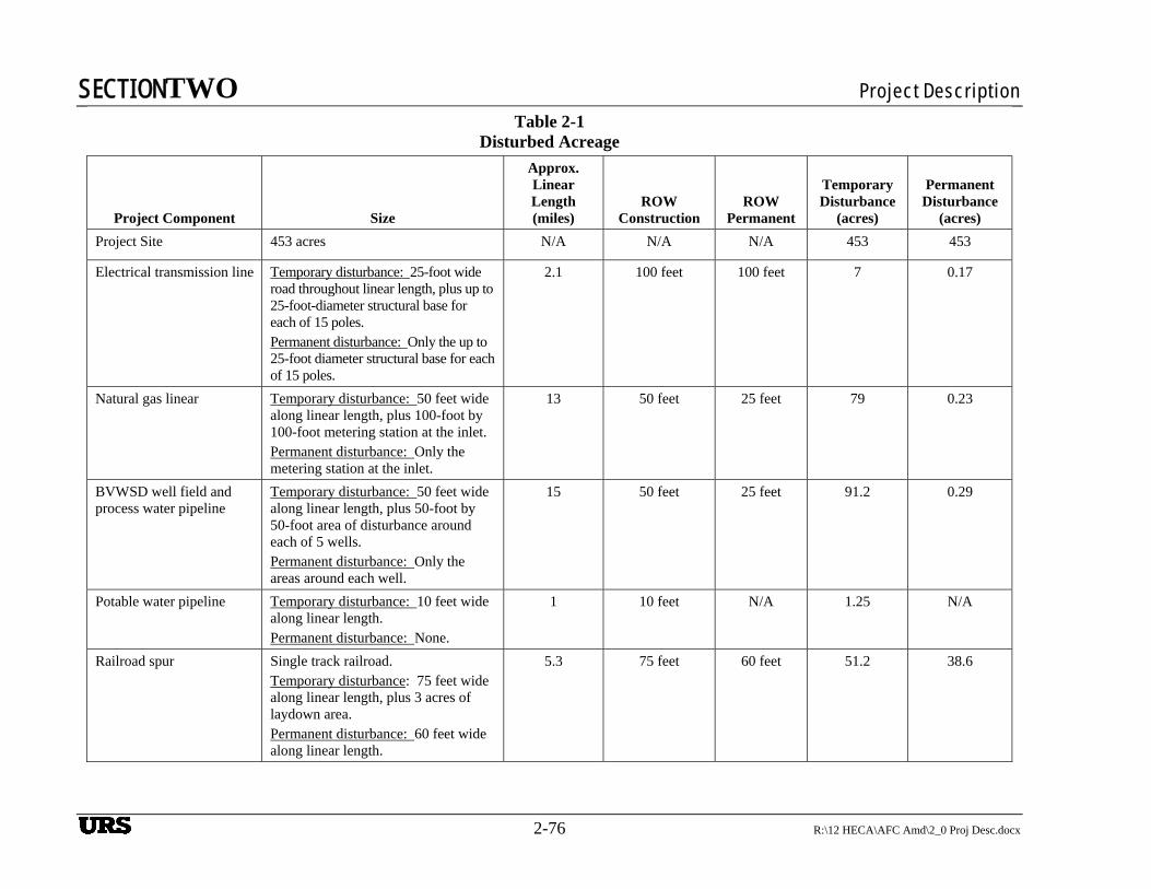
SECTIONTWO Project Description
2-76 R:\12 HECA\AFC Amd\2_0 Proj Desc.docx
Table 2-1 Disturbed Acreage
Project Component Size
Approx. Linear Length (miles)
ROW Construction
ROW Permanent
Temporary Disturbance
(acres)
Permanent Disturbance
(acres)
Project Site 453 acres N/A N/A N/A 453 453
Electrical transmission line Temporary disturbance: 25-foot wide road throughout linear length, plus up to 25-foot-diameter structural base for each of 15 poles. Permanent disturbance: Only the up to 25-foot diameter structural base for each of 15 poles.
2.1 100 feet 100 feet 7 0.17
Natural gas linear Temporary disturbance: 50 feet wide along linear length, plus 100-foot by 100-foot metering station at the inlet. Permanent disturbance: Only the metering station at the inlet.
13 50 feet 25 feet 79 0.23
BVWSD well field and process water pipeline
Temporary disturbance: 50 feet wide along linear length, plus 50-foot by 50-foot area of disturbance around each of 5 wells. Permanent disturbance: Only the areas around each well.
15 50 feet 25 feet 91.2 0.29
Potable water pipeline Temporary disturbance: 10 feet wide along linear length. Permanent disturbance: None.
1 10 feet N/A 1.25 N/A
Railroad spur Single track railroad. Temporary disturbance: 75 feet wide along linear length, plus 3 acres of laydown area. Permanent disturbance: 60 feet wide along linear length.
5.3 75 feet 60 feet 51.2 38.6
URS
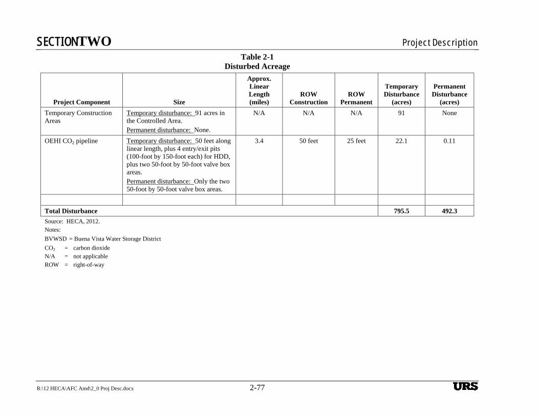
SECTIONTWO Project Description
R:\12 HECA\AFC Amd\2_0 Proj Desc.docx 2-77
Table 2-1 Disturbed Acreage
Project Component Size
Approx. Linear Length (miles)
ROW Construction
ROW Permanent
Temporary Disturbance
(acres)
Permanent Disturbance
(acres)
Temporary Construction Areas
Temporary disturbance: 91 acres in the Controlled Area. Permanent disturbance: None.
N/A N/A N/A 91 None
OEHI CO2 pipeline Temporary disturbance: 50 feet along linear length, plus 4 entry/exit pits (100-foot by 150-foot each) for HDD, plus two 50-foot by 50-foot valve box areas. Permanent disturbance: Only the two 50-foot by 50-foot valve box areas.
3.4 50 feet 25 feet 22.1 0.11
Total Disturbance 795.5 492.3
Source: HECA, 2012. Notes:
BVWSD = Buena Vista Water Storage District
CO2 = carbon dioxide N/A = not applicable ROW = right-of-way
URS
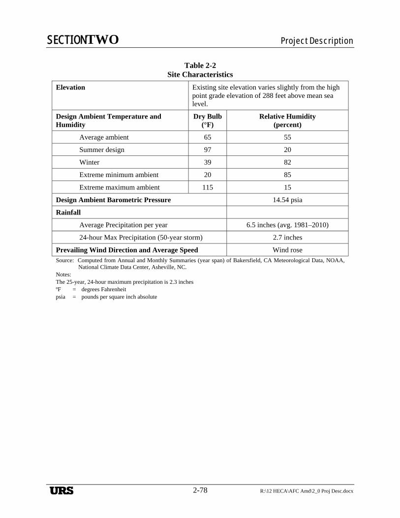
SECTIONTWO Project Description
2-78 R:\12 HECA\AFC Amd\2_0 Proj Desc.docx
Table 2-2 Site Characteristics
Elevation Existing site elevation varies slightly from the high point grade elevation of 288 feet above mean sea level.
Design Ambient Temperature and Humidity
Dry Bulb(°F)
Relative Humidity (percent)
Average ambient 65 55
Summer design 97 20
Winter 39 82
Extreme minimum ambient 20 85
Extreme maximum ambient 115 15
Design Ambient Barometric Pressure 14.54 psia
Rainfall
Average Precipitation per year 6.5 inches (avg. 1981–2010)
24-hour Max Precipitation (50-year storm) 2.7 inches
Prevailing Wind Direction and Average Speed Wind rose
Source: Computed from Annual and Monthly Summaries (year span) of Bakersfield, CA Meteorological Data, NOAA, National Climate Data Center, Asheville, NC.
Notes: The 25-year, 24-hour maximum precipitation is 2.3 inches ºF = degrees Fahrenheit psia = pounds per square inch absolute
URS
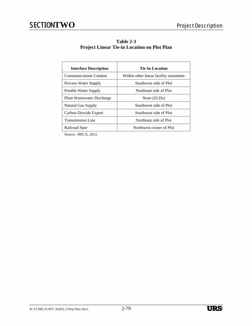
SECTIONTWO Project Description
R:\12 HECA\AFC Amd\2_0 Proj Desc.docx 2-79 2-79
Table 2-3
Project Linear Tie-in Location on Plot Plan
Interface Description Tie-In Location
Communications Conduit Within other linear facility easements
Process Water Supply Southwest side of Plot
Potable Water Supply Northeast side of Plot
Plant Wastewater Discharge None (ZLDs)
Natural Gas Supply Southwest side of Plot
Carbon Dioxide Export Southwest side of Plot
Transmission Line Northeast side of Plot
Railroad Spur Northwest corner of Plot
Source: HECA, 2012.
URS
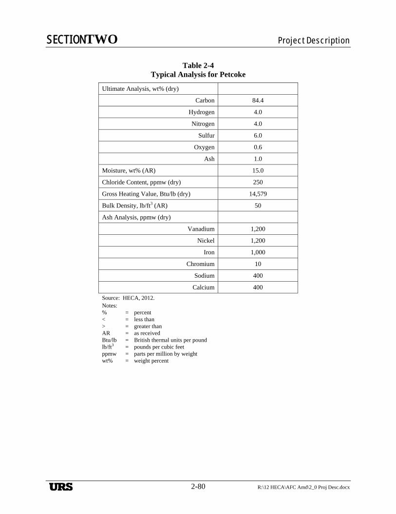
SECTIONTWO Project Description
2-80 R:\12 HECA\AFC Amd\2_0 Proj Desc.docx
Table 2-4
Typical Analysis for Petcoke
Ultimate Analysis, wt% (dry)
Carbon 84.4
Hydrogen 4.0
Nitrogen 4.0
Sulfur 6.0
Oxygen 0.6
Ash 1.0
Moisture, wt% (AR) 15.0
Chloride Content, ppmw (dry) 250
Gross Heating Value, Btu/lb (dry) 14,579
Bulk Density, lb/ft3 (AR) 50
Ash Analysis, ppmw (dry)
Vanadium 1,200
Nickel 1,200
Iron 1,000
Chromium 10
Sodium 400
Calcium 400
Source: HECA, 2012. Notes: % = percent < = less than > = greater than AR = as received Btu/lb = British thermal units per pound lb/ft3 = pounds per cubic feet ppmw = parts per million by weight wt% = weight percent
URS

SECTIONTWO Project Description
R:\12 HECA\AFC Amd\2_0 Proj Desc.docx 2-81 2-81
Table 2-5
Typical Analysis of Sub-Bituminous Coal
Ultimate Analysis, wt% (dry)
Carbon 60.4
Hydrogen 4.5
Nitrogen 1.0
Sulfur 1.09
Oxygen 11.7
Ash 21.3
Moisture, wt% (AR) 14.8
Gross Heating Value, Btu/lb (dry) 10,860
Mercury Content, ppmw (dry whole coal basis) 0.09
Ash Mineral Analysis, wt% (ignited basis)
Silicon Oxide 59.3
Aluminum Oxide 22.9
Titanium Dioxide 1.0
Sulfur Trioxide 3.4
Calcium Oxide 4.8
Potassium Oxide 1.1
Magnesium Oxide 1.0
Sodium Oxide 0.4
Iron Oxide 5.7
Phosphorous Oxide 0.1
Strontium Oxide 0.1
Barium Oxide 0.2
Manganese Dioxide < 0.1
Source: HECA, 2012.
Notes: < = less than AR = as received (with delivered free moisture) Btu/lb = British thermal units per pound ppmw = parts per million by weight wt% = weight percent
URS
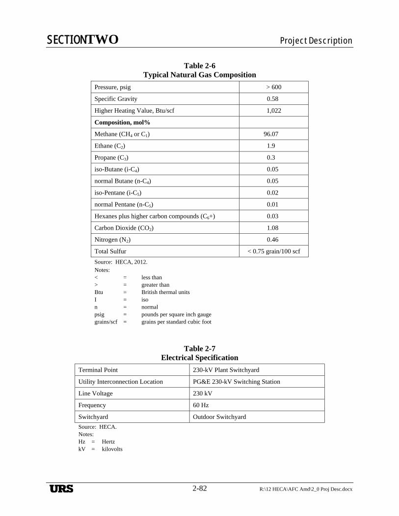
SECTIONTWO Project Description
2-82 R:\12 HECA\AFC Amd\2_0 Proj Desc.docx
Table 2-6
Typical Natural Gas Composition
Pressure, psig > 600
Specific Gravity 0.58
Higher Heating Value, Btu/scf 1,022
Composition, mol%
Methane (CH4 or C1) 96.07
Ethane (C2) 1.9
Propane (C3) 0.3
iso-Butane (i-C4) 0.05
normal Butane (n-C4) 0.05
iso-Pentane (i-C5) 0.02
normal Pentane (n-C5) 0.01
Hexanes plus higher carbon compounds (C6+) 0.03
Carbon Dioxide (CO2) 1.08
Nitrogen (N2) 0.46
Total Sulfur < 0.75 grain/100 scf
Source: HECA, 2012. Notes: < = less than > = greater than Btu = British thermal units I = iso n = normal psig = pounds per square inch gauge grains/scf = grains per standard cubic foot
Table 2-7 Electrical Specification
Terminal Point 230-kV Plant Switchyard
Utility Interconnection Location PG&E 230-kV Switching Station
Line Voltage 230 kV
Frequency 60 Hz
Switchyard Outdoor Switchyard
Source: HECA. Notes: Hz = Hertz kV = kilovolts
URS
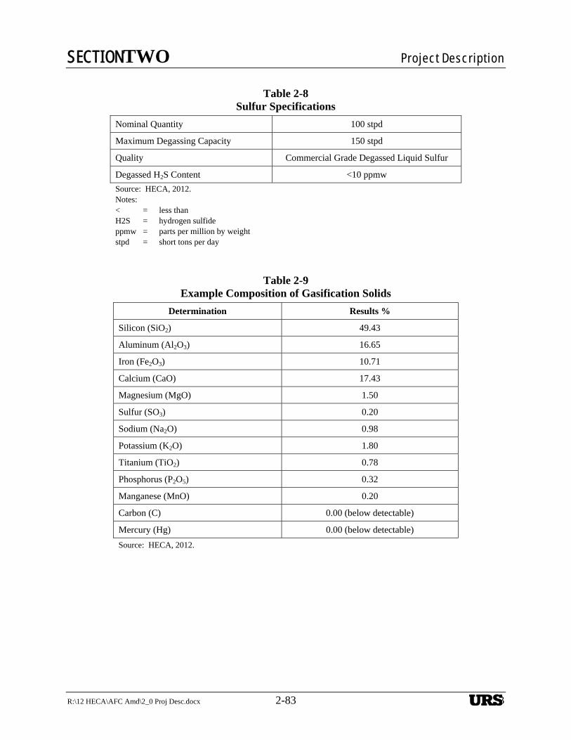
SECTIONTWO Project Description
R:\12 HECA\AFC Amd\2_0 Proj Desc.docx 2-83 2-83
Table 2-8 Sulfur Specifications
Nominal Quantity 100 stpd
Maximum Degassing Capacity 150 stpd
Quality Commercial Grade Degassed Liquid Sulfur
Degassed H2S Content <10 ppmw
Source: HECA, 2012. Notes: < = less than H2S = hydrogen sulfide ppmw = parts per million by weight stpd = short tons per day
Table 2-9 Example Composition of Gasification Solids
Determination Results %
Silicon (SiO2) 49.43
Aluminum (Al2O3) 16.65
Iron (Fe2O3) 10.71
Calcium (CaO) 17.43
Magnesium (MgO) 1.50
Sulfur (SO3) 0.20
Sodium (Na2O) 0.98
Potassium (K2O) 1.80
Titanium (TiO2) 0.78
Phosphorus (P2O5) 0.32
Manganese (MnO) 0.20
Carbon (C) 0.00 (below detectable)
Mercury (Hg) 0.00 (below detectable)
Source: HECA, 2012.
URS
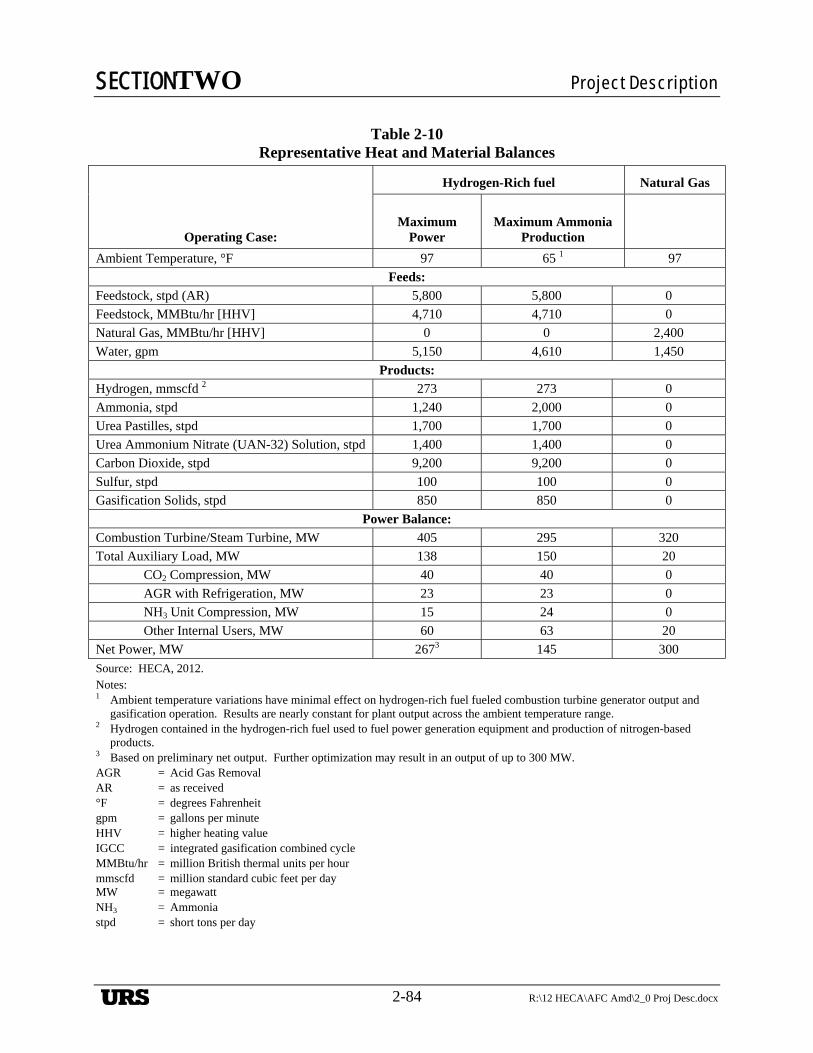
SECTIONTWO Project Description
2-84 R:\12 HECA\AFC Amd\2_0 Proj Desc.docx
Table 2-10
Representative Heat and Material Balances
Operating Case:
Hydrogen-Rich fuel Natural Gas
Maximum
Power
Maximum Ammonia
Production
Ambient Temperature, °F 97 65 1 97
Feeds:
Feedstock, stpd (AR) 5,800 5,800 0
Feedstock, MMBtu/hr [HHV] 4,710 4,710 0
Natural Gas, MMBtu/hr [HHV] 0 0 2,400
Water, gpm 5,150 4,610 1,450
Products: Hydrogen, mmscfd 2 273 273 0
Ammonia, stpd 1,240 2,000 0
Urea Pastilles, stpd 1,700 1,700 0
Urea Ammonium Nitrate (UAN-32) Solution, stpd 1,400 1,400 0
Carbon Dioxide, stpd 9,200 9,200 0
Sulfur, stpd 100 100 0
Gasification Solids, stpd 850 850 0
Power Balance:
Combustion Turbine/Steam Turbine, MW 405 295 320
Total Auxiliary Load, MW 138 150 20
CO2 Compression, MW 40 40 0
AGR with Refrigeration, MW 23 23 0
NH3 Unit Compression, MW 15 24 0
Other Internal Users, MW 60 63 20
Net Power, MW 2673 145 300
Source: HECA, 2012. Notes: 1 Ambient temperature variations have minimal effect on hydrogen-rich fuel fueled combustion turbine generator output and
gasification operation. Results are nearly constant for plant output across the ambient temperature range. 2 Hydrogen contained in the hydrogen-rich fuel used to fuel power generation equipment and production of nitrogen-based
products. 3 Based on preliminary net output. Further optimization may result in an output of up to 300 MW. AGR = Acid Gas Removal AR = as received °F = degrees Fahrenheit gpm = gallons per minute HHV = higher heating value IGCC = integrated gasification combined cycle MMBtu/hr = million British thermal units per hour mmscfd = million standard cubic feet per day MW = megawatt NH3 = Ammonia stpd = short tons per day
URS
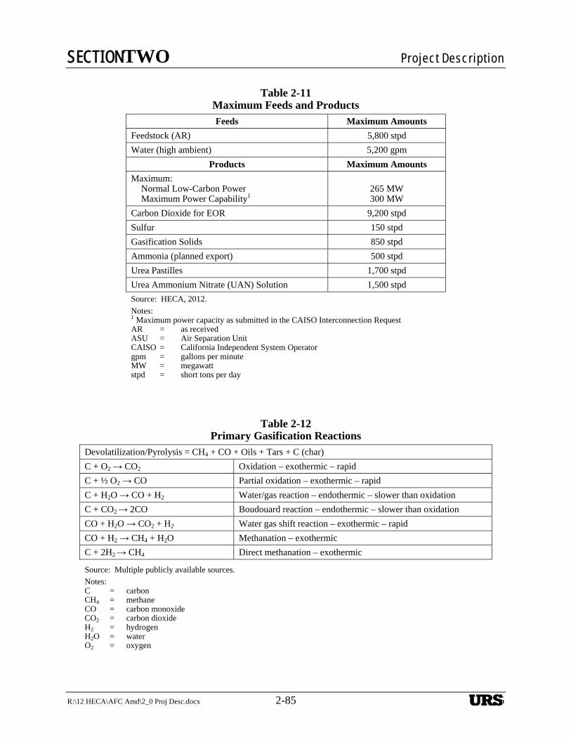
SECTIONTWO Project Description
R:\12 HECA\AFC Amd\2_0 Proj Desc.docx 2-85 2-85
Table 2-11 Maximum Feeds and Products
Feeds Maximum Amounts
Feedstock (AR) 5,800 stpd
Water (high ambient) 5,200 gpm
Products Maximum Amounts
Maximum: Normal Low-Carbon Power Maximum Power Capability1
265 MW 300 MW
Carbon Dioxide for EOR 9,200 stpd
Sulfur 150 stpd
Gasification Solids 850 stpd
Ammonia (planned export) 500 stpd
Urea Pastilles 1,700 stpd
Urea Ammonium Nitrate (UAN) Solution 1,500 stpd
Source: HECA, 2012.
Notes: 1 Maximum power capacity as submitted in the CAISO Interconnection Request
AR = as received ASU = Air Separation Unit CAISO = California Independent System Operator gpm = gallons per minute MW = megawatt stpd = short tons per day
Table 2-12 Primary Gasification Reactions
Devolatilization/Pyrolysis = CH4 + CO + Oils + Tars + C (char)
C + O2 → CO2 Oxidation – exothermic – rapid
C + ½ O2 → CO Partial oxidation – exothermic – rapid
C + H2O → CO + H2 Water/gas reaction – endothermic – slower than oxidation
C + CO2 → 2CO Boudouard reaction – endothermic – slower than oxidation
CO + H2O → CO2 + H2 Water gas shift reaction – exothermic – rapid
CO + H2 → CH4 + H2O Methanation – exothermic
C + 2H2 → CH4 Direct methanation – exothermic
Source: Multiple publicly available sources.
Notes: C = carbon CH4 = methane CO = carbon monoxide CO2 = carbon dioxide H2 = hydrogen H2O = water O2 = oxygen
URS
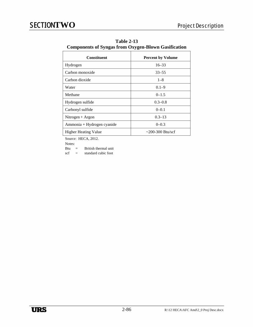
SECTIONTWO Project Description
2-86 R:\12 HECA\AFC Amd\2_0 Proj Desc.docx
Table 2-13 Components of Syngas from Oxygen-Blown Gasification
Constituent Percent by Volume
Hydrogen 16–33
Carbon monoxide 33–55
Carbon dioxide 1–8
Water 0.1–9
Methane 0–1.5
Hydrogen sulfide 0.3–0.8
Carbonyl sulfide 0–0.1
Nitrogen + Argon 0.3–13
Ammonia + Hydrogen cyanide 0–0.3
Higher Heating Value ~200-300 Btu/scf
Source: HECA, 2012. Notes: Btu = British thermal unit scf = standard cubic foot
URS
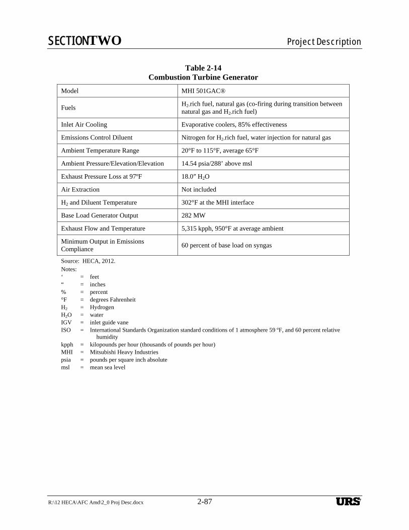
SECTIONTWO Project Description
R:\12 HECA\AFC Amd\2_0 Proj Desc.docx 2-87 2-87
Table 2-14
Combustion Turbine Generator
Model MHI 501GAC®
Fuels H2-rich fuel, natural gas (co-firing during transition between natural gas and H2-rich fuel)
Inlet Air Cooling Evaporative coolers, 85% effectiveness
Emissions Control Diluent Nitrogen for H2-rich fuel, water injection for natural gas
Ambient Temperature Range 20°F to 115°F, average 65°F
Ambient Pressure/Elevation/Elevation 14.54 psia/288’ above msl
Exhaust Pressure Loss at 97ºF 18.0″ H2O
Air Extraction Not included
H2 and Diluent Temperature 302°F at the MHI interface
Base Load Generator Output 282 MW
Exhaust Flow and Temperature 5,315 kpph, 950°F at average ambient
Minimum Output in Emissions Compliance
60 percent of base load on syngas
Source: HECA, 2012. Notes: ‘ = feet “ = inches % = percent °F = degrees Fahrenheit H2 = Hydrogen H2O = water IGV = inlet guide vane ISO = International Standards Organization standard conditions of 1 atmosphere 59 ºF, and 60 percent relative
humidity kpph = kilopounds per hour (thousands of pounds per hour) MHI = Mitsubishi Heavy Industries psia = pounds per square inch absolute msl = mean sea level
URS
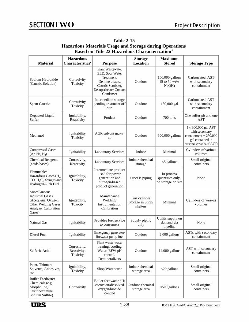
SECTIONTWO Project Description
2-88 R:\12 HECA\AFC Amd\2_0 Proj Desc.docx
Table 2-15 Hazardous Materials Usage and Storage during Operations
Based on Title 22 Hazardous Characterization1
Material Hazardous
Characteristics2 Purpose Storage Location
Maximum Stored Storage Type
Sodium Hydroxide (Caustic Solution)
Corrosivity Toxicity
Plant Wastewater ZLD, Sour Water
Treatment, Demineralizers,
Caustic Scrubber, Desuperheater Contact
Condenser
Outdoor 150,000 gallons
(5 to 50 wt% NaOH)
Carbon steel AST with secondary
containment
Spent Caustic Corrosivity
Toxicity
Intermediate storage pending treatment off
site Outdoor 150,000 gal
Carbon steel AST with secondary
containment
Degassed Liquid Sulfur
Ignitability, Reactivity Product Outdoor 700 tons
One sulfur pit and one AST
Methanol Ignitability
Toxicity AGR solvent make-
up Outdoor 300,000 gallons
1 300,000 gal AST with secondary
containment + 250,000 gal contained in
process vessels of AGR
Compressed Gases (Ar, He, H2)
Ignitability Laboratory Services Indoor Minimal Cylinders of various
volumes
Chemical Reagents (acids/bases)
Corrosivity, Reactivity Laboratory Services
Indoor chemical storage <5 gallons
Small original containers
Flammable/Hazardous Gases (H2, CO, H2S), Syngas and Hydrogen-Rich Fuel
Ignitability, Toxicity
Intermediate product used for power generation and nitrogen-based
product generation
Process piping In process
quantities only, no storage on site
None
Miscellaneous Industrial Gases (Acetylene, Oxygen, Other Welding Gases, Analyzer Calibration Gases)
Ignitability, Toxicity
Maintenance Welding/
Instrumentation Calibration
Gas cylinder Storage in Shop/
shelters Minimal
Cylinders of various volumes
Natural Gas Ignitability Provides fuel service
to consumers Supply piping
only
Utility supply on demand via
pipeline None
Diesel Fuel Ignitability Emergency generator/firewater pump fuel Outdoor 2,000 gallons
ASTs with secondary containment
Sulfuric Acid Corrosivity, Reactivity, Toxicity
Plant waste water treating, cooling Water, BFW pH
control. Demineralizers
Outdoor 14,000 gallons AST with secondary
containment
Paint, Thinners Solvents, Adhesives, etc.
Ignitability, Toxicity Shop/Warehouse
Indoor chemical storage area <20 gallons
Small original containers
Boiler Feedwater Chemicals (e.g., Morpholine, Cyclohexamine, Sodium Sulfite)
Corrosivity
Boiler feedwater pH/corrosion/dissolved
oxygen/biocide control
Outdoor chemical storage area <500 gallons
Small original containers
URS
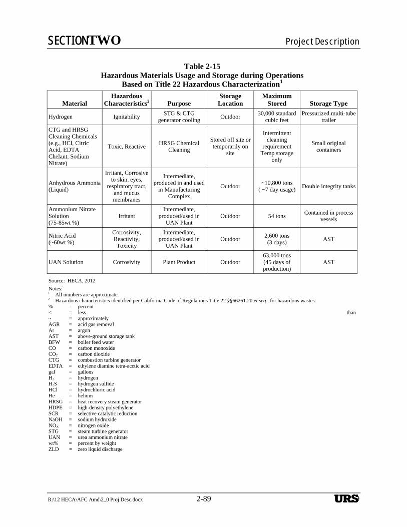
SECTIONTWO Project Description
R:\12 HECA\AFC Amd\2_0 Proj Desc.docx 2-89 2-89
Table 2-15 Hazardous Materials Usage and Storage during Operations
Based on Title 22 Hazardous Characterization1
Material Hazardous
Characteristics2 Purpose Storage Location
Maximum Stored Storage Type
Hydrogen Ignitability STG & CTG
generator cooling Outdoor 30,000 standard
cubic feet Pressurized multi-tube
trailer
CTG and HRSG Cleaning Chemicals (e.g., HCl, Citric Acid, EDTA Chelant, Sodium Nitrate)
Toxic, Reactive HRSG Chemical
Cleaning
Stored off site or temporarily on
site
Intermittent cleaning
requirement Temp storage
only
Small original containers
Anhydrous Ammonia (Liquid)
Irritant, Corrosive to skin, eyes,
respiratory tract, and mucus membranes
Intermediate, produced in and used
in Manufacturing Complex
Outdoor ~10,800 tons
( ~7 day usage) Double integrity tanks
Ammonium Nitrate Solution (75-85wt %)
Irritant Intermediate,
produced/used in UAN Plant
Outdoor 54 tons Contained in process
vessels
Nitric Acid (~60wt %)
Corrosivity, Reactivity, Toxicity
Intermediate, produced/used in
UAN Plant Outdoor
2,600 tons (3 days) AST
UAN Solution Corrosivity Plant Product Outdoor 63,000 tons (45 days of production)
AST
Source: HECA, 2012
Notes:: 1 All numbers are approximate. 2 Hazardous characteristics identified per California Code of Regulations Title 22 §§66261.20 et seq., for hazardous wastes. % = percent < = less than~ = approximately AGR = acid gas removal Ar = argon AST = above-ground storage tank BFW = boiler feed water CO = carbon monoxide CO2 = carbon dioxide CTG = combustion turbine generator EDTA = ethylene diamine tetra-acetic acid gal = gallons H2 = hydrogen H2S = hydrogen sulfide HCl = hydrochloric acid He = helium HRSG = heat recovery steam generator HDPE = high-density polyethylene SCR = selective catalytic reduction NaOH = sodium hydroxide NOX = nitrogen oxide STG = steam turbine generator UAN = urea ammonium nitrate wt% = percent by weight ZLD = zero liquid discharge
URS
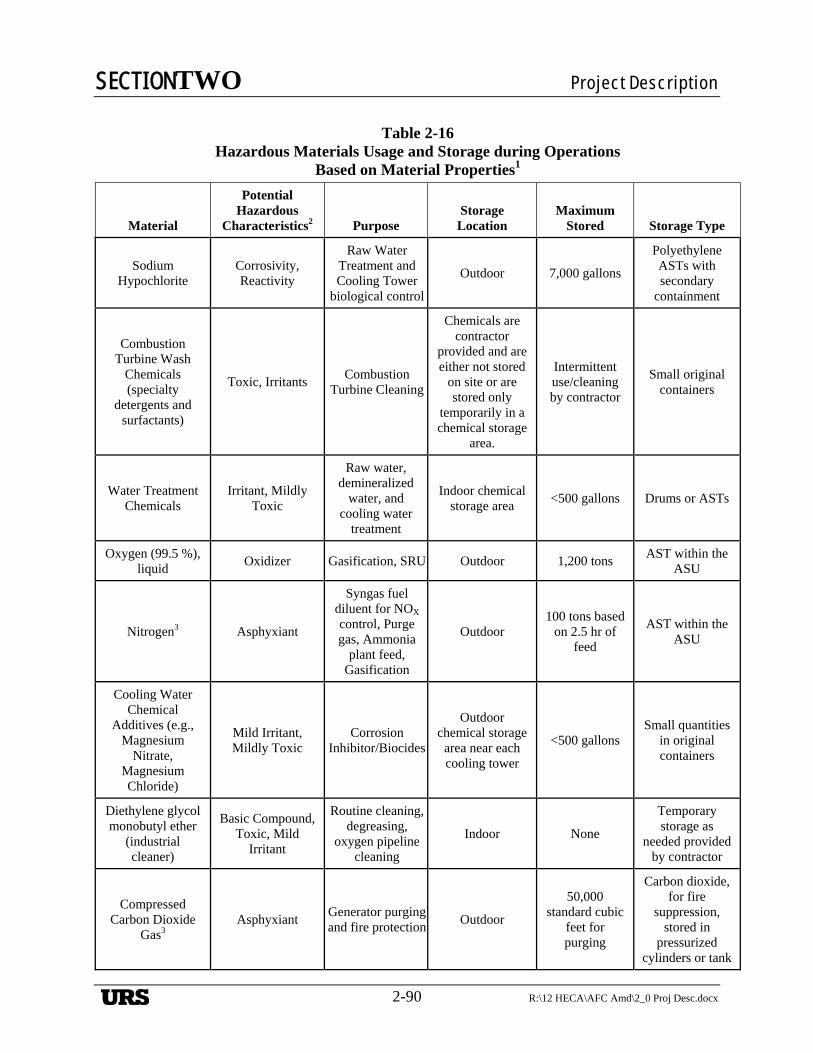
SECTIONTWO Project Description
2-90 R:\12 HECA\AFC Amd\2_0 Proj Desc.docx
Table 2-16 Hazardous Materials Usage and Storage during Operations
Based on Material Properties1
Material
Potential Hazardous
Characteristics2 Purpose Storage
Location Maximum
Stored Storage Type
Sodium Hypochlorite
Corrosivity, Reactivity
Raw Water Treatment and Cooling Tower
biological control
Outdoor 7,000 gallons
Polyethylene ASTs with secondary
containment
Combustion Turbine Wash
Chemicals (specialty
detergents and surfactants)
Toxic, Irritants Combustion
Turbine Cleaning
Chemicals are contractor
provided and are either not stored
on site or are stored only
temporarily in a chemical storage
area.
Intermittent use/cleaning by contractor
Small original containers
Water Treatment Chemicals
Irritant, Mildly Toxic
Raw water, demineralized
water, and cooling water
treatment
Indoor chemical storage area
<500 gallons Drums or ASTs
Oxygen (99.5 %), liquid
Oxidizer Gasification, SRU Outdoor 1,200 tons AST within the
ASU
Nitrogen3 Asphyxiant
Syngas fuel diluent for NOX control, Purge gas, Ammonia
plant feed, Gasification
Outdoor 100 tons based
on 2.5 hr of feed
AST within the ASU
Cooling Water Chemical
Additives (e.g., Magnesium
Nitrate, Magnesium Chloride)
Mild Irritant, Mildly Toxic
Corrosion Inhibitor/Biocides
Outdoor chemical storage
area near each cooling tower
<500 gallons Small quantities
in original containers
Diethylene glycol monobutyl ether
(industrial cleaner)
Basic Compound, Toxic, Mild
Irritant
Routine cleaning, degreasing,
oxygen pipeline cleaning
Indoor None
Temporary storage as
needed provided by contractor
Compressed Carbon Dioxide
Gas3 Asphyxiant
Generator purging and fire protection
Outdoor
50,000 standard cubic
feet for purging
Carbon dioxide, for fire
suppression, stored in
pressurized cylinders or tank
URS
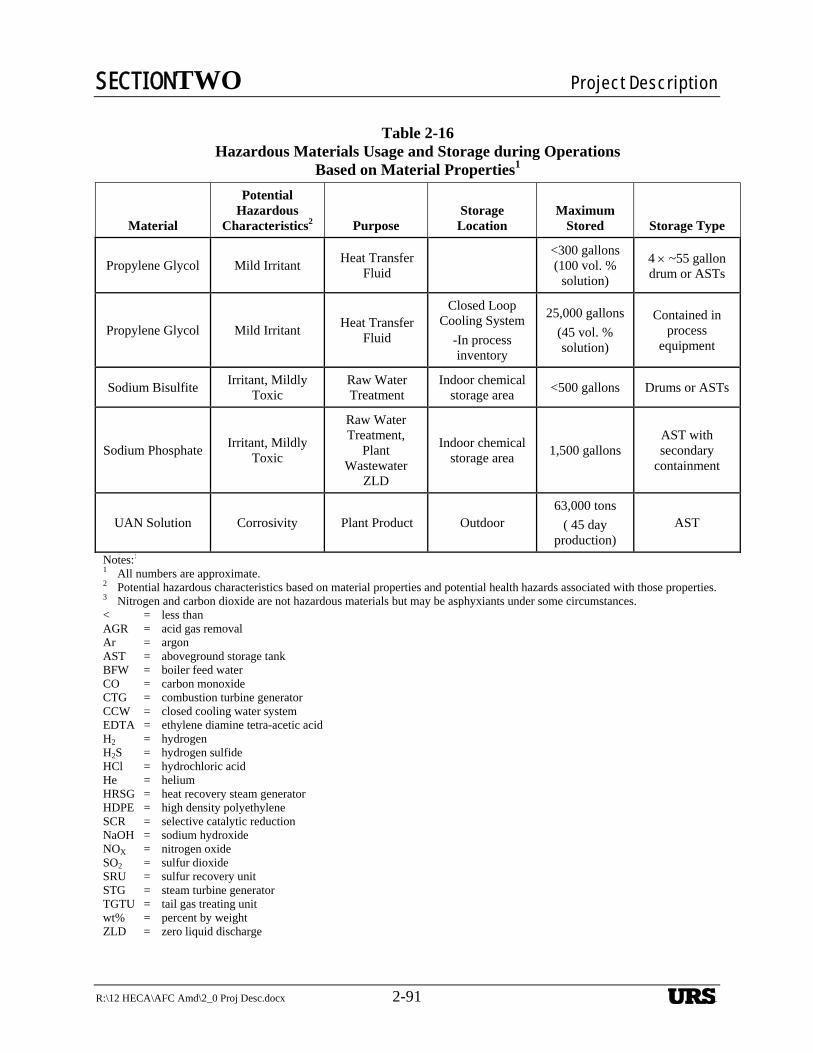
SECTIONTWO Project Description
R:\12 HECA\AFC Amd\2_0 Proj Desc.docx 2-91 2-91
Table 2-16 Hazardous Materials Usage and Storage during Operations
Based on Material Properties1
Material
Potential Hazardous
Characteristics2 Purpose Storage
Location Maximum
Stored Storage Type
Propylene Glycol Mild Irritant Heat Transfer
Fluid
<300 gallons (100 vol. %
solution)
4 ~55 gallon drum or ASTs
Propylene Glycol Mild Irritant Heat Transfer
Fluid
Closed Loop Cooling System
-In process inventory
25,000 gallons
(45 vol. % solution)
Contained in process
equipment
Sodium Bisulfite Irritant, Mildly
Toxic Raw Water Treatment
Indoor chemical storage area
<500 gallons Drums or ASTs
Sodium Phosphate Irritant, Mildly
Toxic
Raw Water Treatment,
Plant Wastewater
ZLD
Indoor chemical storage area
1,500 gallons AST with secondary
containment
UAN Solution Corrosivity Plant Product Outdoor 63,000 tons
( 45 day production)
AST
Notes:: 1 All numbers are approximate. 2 Potential hazardous characteristics based on material properties and potential health hazards associated with those properties. 3 Nitrogen and carbon dioxide are not hazardous materials but may be asphyxiants under some circumstances. < = less than AGR = acid gas removal Ar = argon AST = aboveground storage tank BFW = boiler feed water CO = carbon monoxide CTG = combustion turbine generator CCW = closed cooling water system EDTA = ethylene diamine tetra-acetic acid H2 = hydrogen H2S = hydrogen sulfide HCl = hydrochloric acid He = helium HRSG = heat recovery steam generator HDPE = high density polyethylene SCR = selective catalytic reduction NaOH = sodium hydroxide NOX = nitrogen oxide SO2 = sulfur dioxide SRU = sulfur recovery unit STG = steam turbine generator TGTU = tail gas treating unit wt% = percent by weight ZLD = zero liquid discharge
URS
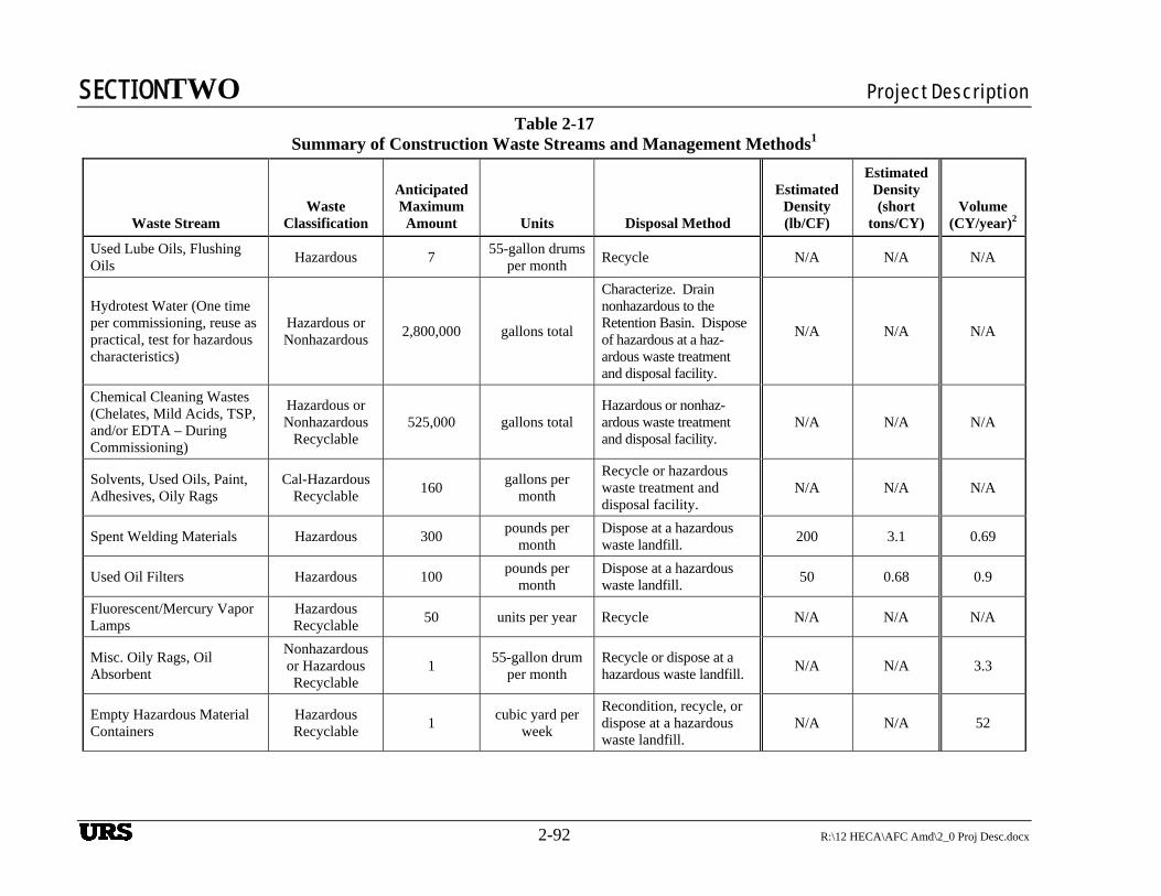
SECTIONTWO Project Description
2-92 R:\12 HECA\AFC Amd\2_0 Proj Desc.docx
Table 2-17
Summary of Construction Waste Streams and Management Methods1
Waste Stream Waste
Classification
Anticipated Maximum Amount Units Disposal Method
Estimated Density (lb/CF)
Estimated Density (short
tons/CY) Volume
(CY/year)2
Used Lube Oils, Flushing Oils
Hazardous 7 55-gallon drums
per month Recycle N/A N/A N/A
Hydrotest Water (One time per commissioning, reuse as practical, test for hazardous characteristics)
Hazardous or Nonhazardous
2,800,000 gallons total
Characterize. Drain nonhazardous to the Retention Basin. Dispose of hazardous at a haz-ardous waste treatment and disposal facility.
N/A N/A N/A
Chemical Cleaning Wastes (Chelates, Mild Acids, TSP, and/or EDTA – During Commissioning)
Hazardous or Nonhazardous
Recyclable 525,000 gallons total
Hazardous or nonhaz-ardous waste treatment and disposal facility.
N/A N/A N/A
Solvents, Used Oils, Paint, Adhesives, Oily Rags
Cal-Hazardous Recyclable
160 gallons per
month
Recycle or hazardous waste treatment and disposal facility.
N/A N/A N/A
Spent Welding Materials Hazardous 300 pounds per
month Dispose at a hazardous waste landfill.
200 3.1 0.69
Used Oil Filters Hazardous 100 pounds per
month Dispose at a hazardous waste landfill.
50 0.68 0.9
Fluorescent/Mercury Vapor Lamps
Hazardous Recyclable
50 units per year Recycle N/A N/A N/A
Misc. Oily Rags, Oil Absorbent
Nonhazardous or Hazardous Recyclable
1 55-gallon drum
per month Recycle or dispose at a hazardous waste landfill.
N/A N/A 3.3
Empty Hazardous Material Containers
Hazardous Recyclable
1 cubic yard per
week
Recondition, recycle, or dispose at a hazardous waste landfill.
N/A N/A 52
URS
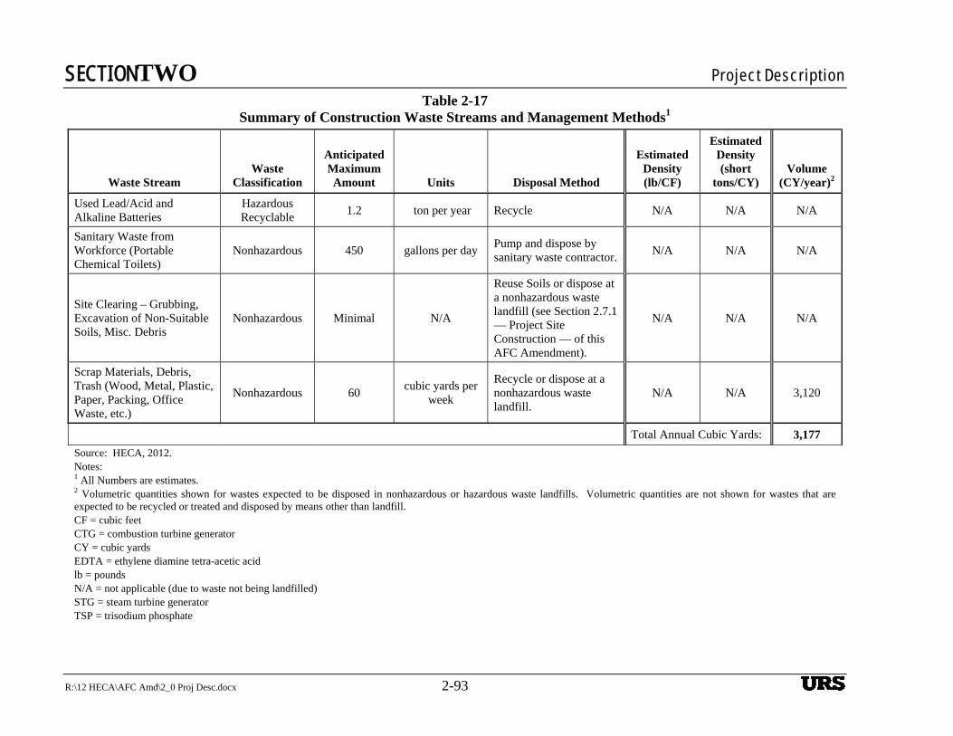
SECTIONTWO Project Description
R:\12 HECA\AFC Amd\2_0 Proj Desc.docx 2-93
Table 2-17 Summary of Construction Waste Streams and Management Methods1
Waste Stream Waste
Classification
Anticipated Maximum Amount Units Disposal Method
Estimated Density (lb/CF)
Estimated Density (short
tons/CY) Volume
(CY/year)2
Used Lead/Acid and Alkaline Batteries
Hazardous Recyclable
1.2 ton per year Recycle N/A N/A N/A
Sanitary Waste from Workforce (Portable Chemical Toilets)
Nonhazardous 450 gallons per day Pump and dispose by sanitary waste contractor.
N/A N/A N/A
Site Clearing – Grubbing, Excavation of Non-Suitable Soils, Misc. Debris
Nonhazardous Minimal N/A
Reuse Soils or dispose at a nonhazardous waste landfill (see Section 2.7.1 — Project Site Construction — of this AFC Amendment).
N/A N/A N/A
Scrap Materials, Debris, Trash (Wood, Metal, Plastic, Paper, Packing, Office Waste, etc.)
Nonhazardous 60 cubic yards per
week
Recycle or dispose at a nonhazardous waste landfill.
N/A N/A 3,120
Total Annual Cubic Yards: 3,177
Source: HECA, 2012. Notes: 1 All Numbers are estimates. 2 Volumetric quantities shown for wastes expected to be disposed in nonhazardous or hazardous waste landfills. Volumetric quantities are not shown for wastes that are expected to be recycled or treated and disposed by means other than landfill. CF = cubic feet CTG = combustion turbine generator CY = cubic yards EDTA = ethylene diamine tetra-acetic acid lb = pounds N/A = not applicable (due to waste not being landfilled) STG = steam turbine generator TSP = trisodium phosphate
URS
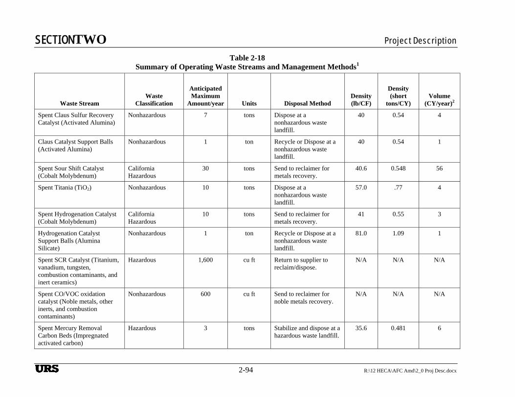
SECTIONTWO Project Description
2-94 R:\12 HECA\AFC Amd\2_0 Proj Desc.docx
Table 2-18 Summary of Operating Waste Streams and Management Methods1
Waste Stream Waste
Classification
Anticipated Maximum
Amount/year Units Disposal Method Density (lb/CF)
Density (short
tons/CY) Volume
(CY/year)2
Spent Claus Sulfur Recovery Catalyst (Activated Alumina)
Nonhazardous 7 tons Dispose at a nonhazardous waste landfill.
40 0.54 4
Claus Catalyst Support Balls (Activated Alumina)
Nonhazardous 1 ton Recycle or Dispose at a nonhazardous waste landfill.
40 0.54 1
Spent Sour Shift Catalyst (Cobalt Molybdenum)
California Hazardous
30 tons Send to reclaimer for metals recovery.
40.6 0.548 56
Spent Titania (TiO2) Nonhazardous 10 tons Dispose at a nonhazardous waste landfill.
57.0 .77 4
Spent Hydrogenation Catalyst (Cobalt Molybdenum)
California Hazardous
10 tons Send to reclaimer for metals recovery.
41 0.55 3
Hydrogenation Catalyst Support Balls (Alumina Silicate)
Nonhazardous 1 ton Recycle or Dispose at a nonhazardous waste landfill.
81.0 1.09 1
Spent SCR Catalyst (Titanium, vanadium, tungsten, combustion contaminants, and inert ceramics)
Hazardous 1,600 cu ft Return to supplier to reclaim/dispose.
N/A N/A N/A
Spent CO/VOC oxidation catalyst (Noble metals, other inerts, and combustion contaminants)
Nonhazardous 600 cu ft Send to reclaimer for noble metals recovery.
N/A N/A N/A
Spent Mercury Removal Carbon Beds (Impregnated activated carbon)
Hazardous 3 tons Stabilize and dispose at a hazardous waste landfill.
35.6 0.481 6
URS
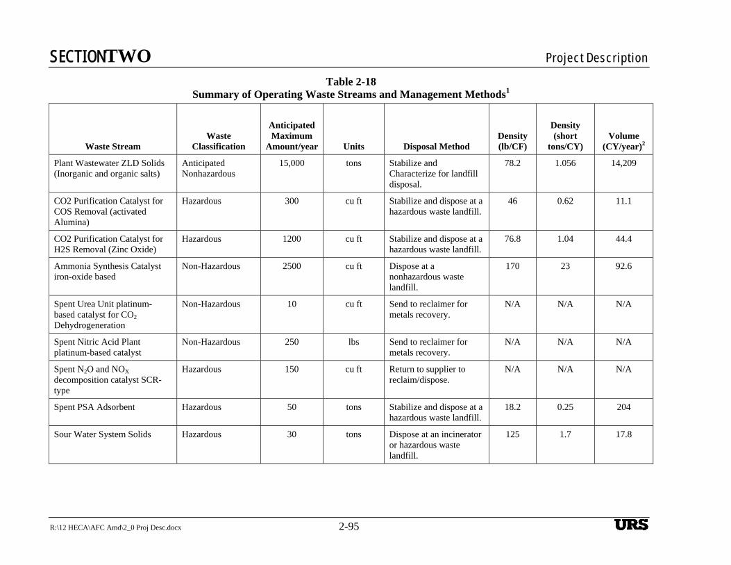
SECTIONTWO Project Description
R:\12 HECA\AFC Amd\2_0 Proj Desc.docx 2-95
Table 2-18 Summary of Operating Waste Streams and Management Methods1
Waste Stream Waste
Classification
Anticipated Maximum
Amount/year Units Disposal Method Density (lb/CF)
Density (short
tons/CY) Volume
(CY/year)2
Plant Wastewater ZLD Solids (Inorganic and organic salts)
Anticipated Nonhazardous
15,000 tons Stabilize and Characterize for landfill disposal.
78.2 1.056 14,209
CO2 Purification Catalyst for COS Removal (activated Alumina)
Hazardous 300 cu ft Stabilize and dispose at a hazardous waste landfill.
46 0.62 11.1
CO2 Purification Catalyst for H2S Removal (Zinc Oxide)
Hazardous 1200 cu ft Stabilize and dispose at a hazardous waste landfill.
76.8 1.04 44.4
Ammonia Synthesis Catalyst iron-oxide based
Non-Hazardous 2500 cu ft Dispose at a nonhazardous waste landfill.
170 23 92.6
Spent Urea Unit platinum-based catalyst for CO2 Dehydrogeneration
Non-Hazardous 10 cu ft Send to reclaimer for metals recovery.
N/A N/A N/A
Spent Nitric Acid Plant platinum-based catalyst
Non-Hazardous 250 lbs Send to reclaimer for metals recovery.
N/A N/A N/A
Spent N2O and NOX decomposition catalyst SCR-type
Hazardous 150 cu ft Return to supplier to reclaim/dispose.
N/A N/A N/A
Spent PSA Adsorbent Hazardous 50 tons Stabilize and dispose at a hazardous waste landfill.
18.2 0.25 204
Sour Water System Solids Hazardous 30 tons Dispose at an incinerator or hazardous waste landfill.
125 1.7 17.8
URS
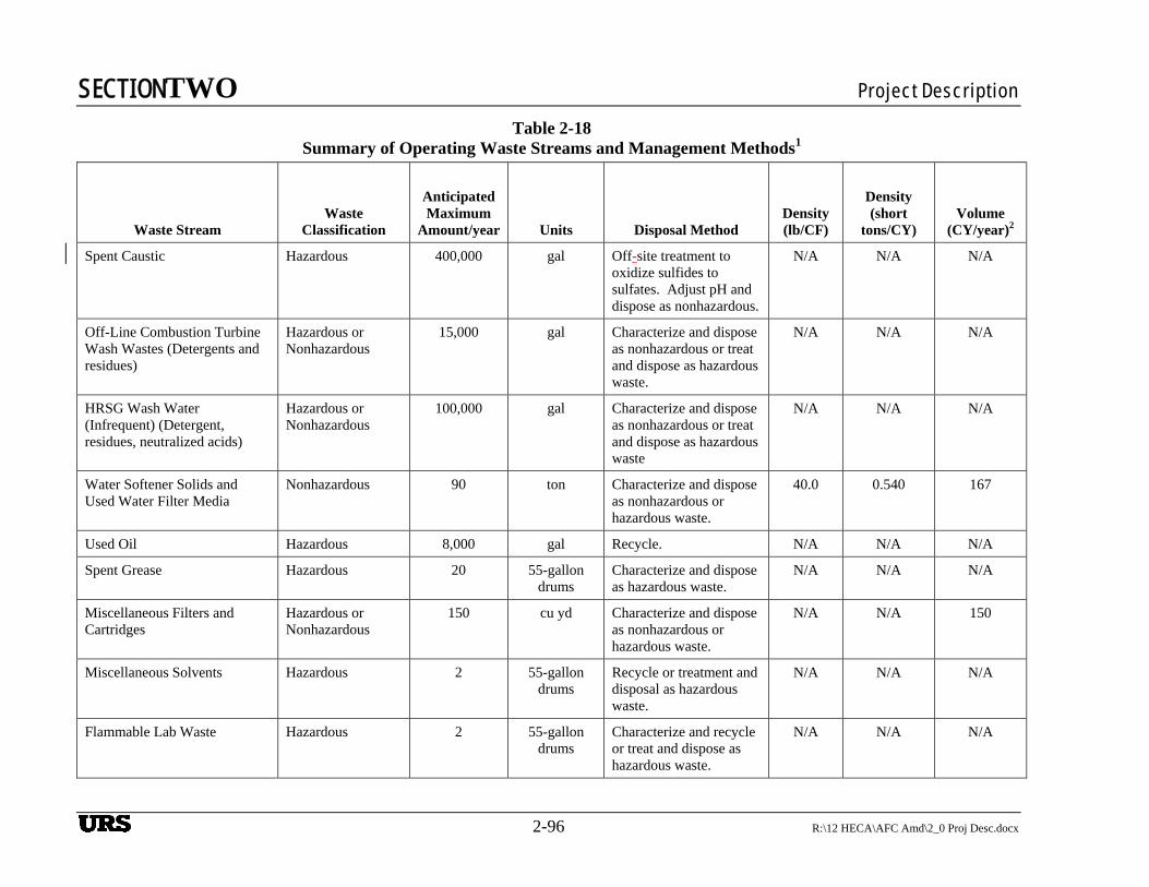
SECTIONTWO Project Description
2-96 R:\12 HECA\AFC Amd\2_0 Proj Desc.docx
Table 2-18 Summary of Operating Waste Streams and Management Methods1
Waste Stream Waste
Classification
Anticipated Maximum
Amount/year Units Disposal Method Density (lb/CF)
Density (short
tons/CY) Volume
(CY/year)2
Spent Caustic Hazardous 400,000 gal Off-site treatment to oxidize sulfides to sulfates. Adjust pH and dispose as nonhazardous.
N/A N/A N/A
Off-Line Combustion Turbine Wash Wastes (Detergents and residues)
Hazardous or Nonhazardous
15,000 gal Characterize and dispose as nonhazardous or treat and dispose as hazardous waste.
N/A N/A N/A
HRSG Wash Water (Infrequent) (Detergent, residues, neutralized acids)
Hazardous or Nonhazardous
100,000 gal Characterize and dispose as nonhazardous or treat and dispose as hazardous waste
N/A N/A N/A
Water Softener Solids and Used Water Filter Media
Nonhazardous 90 ton Characterize and dispose as nonhazardous or hazardous waste.
40.0 0.540 167
Used Oil Hazardous 8,000 gal Recycle. N/A N/A N/A
Spent Grease Hazardous 20 55-gallon drums
Characterize and dispose as hazardous waste.
N/A N/A N/A
Miscellaneous Filters and Cartridges
Hazardous or Nonhazardous
150 cu yd Characterize and dispose as nonhazardous or hazardous waste.
N/A N/A 150
Miscellaneous Solvents Hazardous 2 55-gallon drums
Recycle or treatment and disposal as hazardous waste.
N/A N/A N/A
Flammable Lab Waste Hazardous 2 55-gallon drums
Characterize and recycle or treat and dispose as hazardous waste.
N/A N/A N/A
URS
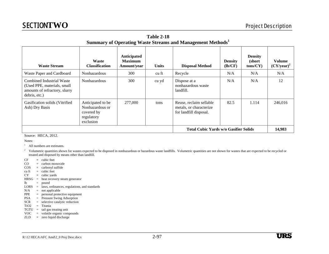
SECTIONTWO Project Description
R:\12 HECA\AFC Amd\2_0 Proj Desc.docx 2-97
Table 2-18 Summary of Operating Waste Streams and Management Methods1
Waste Stream Waste
Classification
Anticipated Maximum
Amount/year Units Disposal Method Density (lb/CF)
Density (short
tons/CY) Volume
(CY/year)2
Waste Paper and Cardboard Nonhazardous 300 cu ft Recycle N/A N/A N/A
Combined Industrial Waste (Used PPE, materials, small amounts of refractory, slurry debris, etc.)
Nonhazardous 300 cu yd Dispose at a nonhazardous waste landfill.
N/A N/A 12
Gasification solids (Vitrified Ash) Dry Basis
Anticipated to be Nonhazardous or covered by regulatory exclusion
277,000 tons Reuse, reclaim sellable metals, or characterize for landfill disposal.
82.5 1.114 246,016
Total Cubic Yards w/o Gasifier Solids 14,983
Source: HECA, 2012. Notes: 1 All numbers are estimates. 2 Volumetric quantities shown for wastes expected to be disposed in nonhazardous or hazardous waste landfills. Volumetric quantities are not shown for wastes that are expected to be recycled or
treated and disposed by means other than landfill.
CF = cubic feet CO = carbon monoxide COS = carbonyl sulfide cu ft = cubic feet CY = cubic yards HRSG = heat recovery steam generator lb = pound LORS = laws, ordinances, regulations, and standards N/A = not applicable PPE = personal protective equipment PSA = Pressure Swing Adsorption SCR = selective catalytic reduction TiO2 = Titania TGTU = tail gas treating unit VOC = volatile organic compounds ZLD = zero liquid discharge
URS
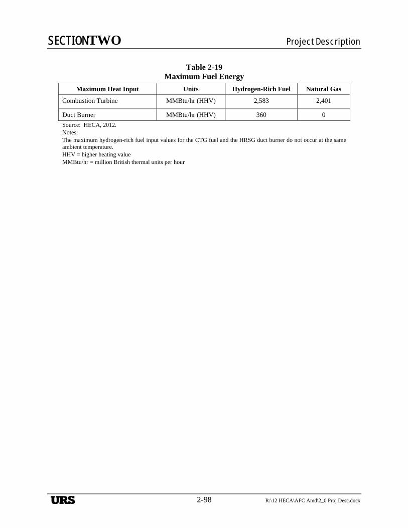
SECTIONTWO Project Description
2-98 R:\12 HECA\AFC Amd\2_0 Proj Desc.docx
Table 2-19
Maximum Fuel Energy
Maximum Heat Input Units Hydrogen-Rich Fuel Natural Gas
Combustion Turbine MMBtu/hr (HHV) 2,583 2,401
Duct Burner MMBtu/hr (HHV) 360 0
Source: HECA, 2012. Notes: The maximum hydrogen-rich fuel input values for the CTG fuel and the HRSG duct burner do not occur at the same ambient temperature. HHV = higher heating value MMBtu/hr = million British thermal units per hour
URS
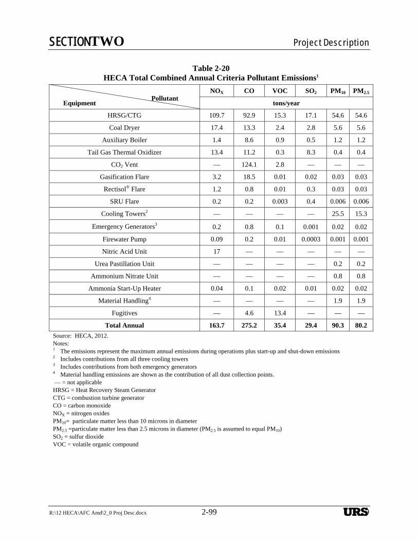
SECTIONTWO Project Description
R:\12 HECA\AFC Amd\2_0 Proj Desc.docx 2-99 2-99
Table 2-20 HECA Total Combined Annual Criteria Pollutant Emissions1
Equipment Pollutant
NOX CO VOC SO2 PM10 PM2.5
tons/year
HRSG/CTG 109.7 92.9 15.3 17.1 54.6 54.6
Coal Dryer 17.4 13.3 2.4 2.8 5.6 5.6
Auxiliary Boiler 1.4 8.6 0.9 0.5 1.2 1.2
Tail Gas Thermal Oxidizer 13.4 11.2 0.3 8.3 0.4 0.4
CO2 Vent — 124.1 2.8 — — —
Gasification Flare 3.2 18.5 0.01 0.02 0.03 0.03
Rectisol® Flare 1.2 0.8 0.01 0.3 0.03 0.03
SRU Flare 0.2 0.2 0.003 0.4 0.006 0.006
Cooling Towers2 — — — — 25.5 15.3
Emergency Generators3 0.2 0.8 0.1 0.001 0.02 0.02
Firewater Pump 0.09 0.2 0.01 0.0003 0.001 0.001
Nitric Acid Unit 17 — — — — —
Urea Pastillation Unit — — — — 0.2 0.2
Ammonium Nitrate Unit — — — — 0.8 0.8
Ammonia Start-Up Heater 0.04 0.1 0.02 0.01 0.02 0.02
Material Handling4 — — — — 1.9 1.9
Fugitives — 4.6 13.4 — — —
Total Annual 163.7 275.2 35.4 29.4 90.3 80.2
Source: HECA, 2012. Notes: 1 The emissions represent the maximum annual emissions during operations plus start-up and shut-down emissions 2 Includes contributions from all three cooling towers 3 Includes contributions from both emergency generators 4 Material handling emissions are shown as the contribution of all dust collection points. — = not applicable
HRSG = Heat Recovery Steam Generator CTG = combustion turbine generator CO = carbon monoxide NOX = nitrogen oxides PM10= particulate matter less than 10 microns in diameter PM2.5 =particulate matter less than 2.5 microns in diameter (PM2.5 is assumed to equal PM10) SO2 = sulfur dioxide VOC = volatile organic compound
-------------
URS

SECTIONTWO Project Description
2-100 R:\12 HECA\AFC Amd\2_0 Proj Desc.docx
Table 2-21
Material Delivery
Material Mode Distribution Point Maximum Delivery
Rate
Petcoke Truck Santa Barbara County/Los
Angeles County 55/day
Coal
Rail1 Various Western mines 2 unit trains/day3
Truck2 Transloading terminal in
Wasco 244/day4
Miscellaneous (e.g., chemicals, equipment
maintenance, etc.) Truck Various5 5/day
Source: HECA 2012. Notes: 1 Only rail delivery of coal occurs during Alternative 1. 2 Only truck delivery of coal occurs during Alternative 2. 3 Average delivery rate is 2.1 unit trains per week. 4 Average delivery rate is 183 trucks per day. 5 Materials will be purchased in Kern County, as practical. The same number of petcoke and miscellaneous trucks are expected during either Alternative 1 or 2.
URS
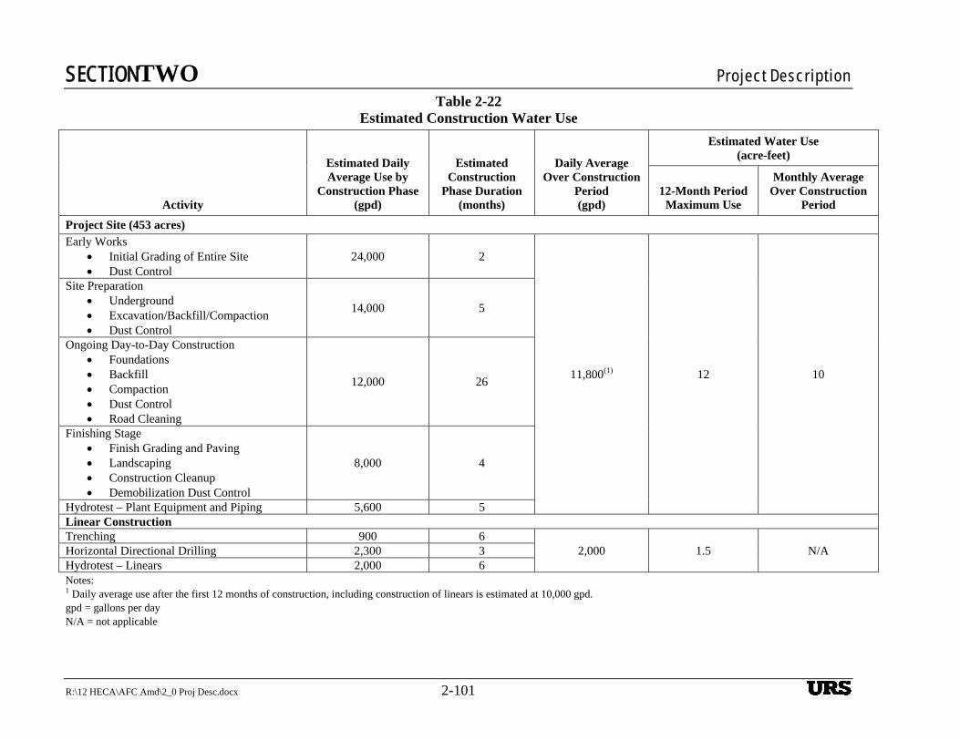
SECTIONTWO Project Description
R:\12 HECA\AFC Amd\2_0 Proj Desc.docx 2-101
Table 2-22 Estimated Construction Water Use
Activity
Estimated Daily Average Use by
Construction Phase(gpd)
Estimated Construction
Phase Duration (months)
Daily Average Over Construction
Period (gpd)
Estimated Water Use (acre-feet)
12-Month Period Maximum Use
Monthly Average Over Construction
Period
Project Site (453 acres) Early Works
Initial Grading of Entire Site Dust Control
24,000 2
11,800(1) 12 10
Site Preparation Underground Excavation/Backfill/Compaction Dust Control
14,000 5
Ongoing Day-to-Day Construction Foundations Backfill Compaction Dust Control Road Cleaning
12,000 26
Finishing Stage Finish Grading and Paving Landscaping Construction Cleanup Demobilization Dust Control
8,000 4
Hydrotest – Plant Equipment and Piping 5,600 5 Linear Construction Trenching 900 6
2,000 1.5 N/A Horizontal Directional Drilling 2,300 3 Hydrotest – Linears 2,000 6 Notes: 1 Daily average use after the first 12 months of construction, including construction of linears is estimated at 10,000 gpd. gpd = gallons per day N/A = not applicable
URS
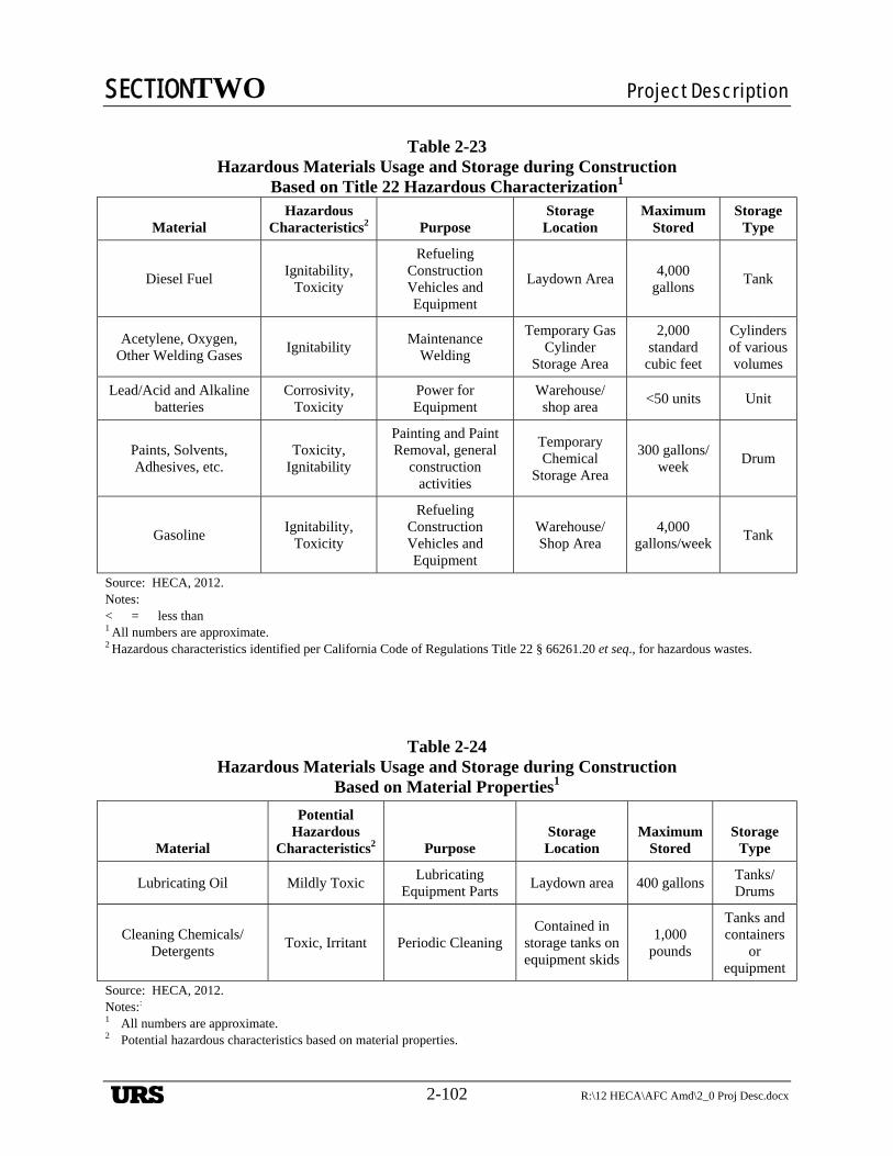
SECTIONTWO Project Description
2-102 R:\12 HECA\AFC Amd\2_0 Proj Desc.docx
Table 2-23 Hazardous Materials Usage and Storage during Construction
Based on Title 22 Hazardous Characterization1
Material Hazardous
Characteristics2 Purpose Storage
Location Maximum
Stored Storage
Type
Diesel Fuel Ignitability,
Toxicity
Refueling Construction Vehicles and Equipment
Laydown Area 4,000
gallons Tank
Acetylene, Oxygen, Other Welding Gases
Ignitability Maintenance
Welding
Temporary Gas Cylinder
Storage Area
2,000 standard
cubic feet
Cylinders of various volumes
Lead/Acid and Alkaline batteries
Corrosivity, Toxicity
Power for Equipment
Warehouse/ shop area
<50 units Unit
Paints, Solvents, Adhesives, etc.
Toxicity, Ignitability
Painting and Paint Removal, general
construction activities
Temporary Chemical
Storage Area
300 gallons/week
Drum
Gasoline Ignitability,
Toxicity
Refueling Construction Vehicles and Equipment
Warehouse/ Shop Area
4,000 gallons/week
Tank
Source: HECA, 2012. Notes: < = less than 1 All numbers are approximate. 2 Hazardous characteristics identified per California Code of Regulations Title 22 § 66261.20 et seq., for hazardous wastes.
Table 2-24 Hazardous Materials Usage and Storage during Construction
Based on Material Properties1
Material
Potential Hazardous
Characteristics2 Purpose Storage
Location Maximum
Stored Storage
Type
Lubricating Oil Mildly Toxic Lubricating
Equipment Parts Laydown area 400 gallons
Tanks/Drums
Cleaning Chemicals/Detergents
Toxic, Irritant Periodic Cleaning Contained in
storage tanks on equipment skids
1,000 pounds
Tanks and containers
or equipment
Source: HECA, 2012. Notes:: 1 All numbers are approximate. 2 Potential hazardous characteristics based on material properties.
URS
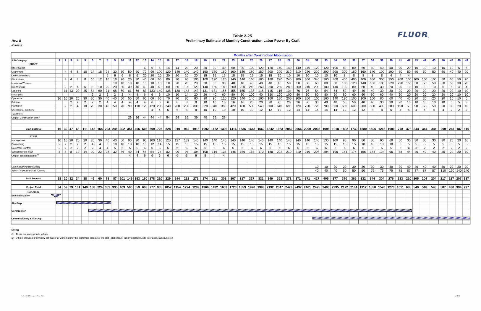
Rev. 54/11/2012
Job Category 1 2 3 4 5 6 7 8 9 10 11 12 13 14 15 16 17 18 19 20 21 22 23 24 25 26 27 28 29 30 31 32 33 34 35 36 37 38 39 40 41 42 43 44 45 46 47 48 49CRAFT
Boilermakers 6 6 6 14 14 20 20 30 30 40 60 80 100 120 120 140 140 140 140 120 120 100 80 80 60 60 40 40 20 20 10 10 10 10 10 6 6Carpenters 4 4 8 10 14 18 24 30 50 50 60 70 90 100 120 140 140 140 150 150 160 160 180 180 180 200 200 210 210 220 220 200 200 200 180 160 140 100 100 50 50 50 50 50 50 40 40 20Cement Finishers 6 6 6 6 6 20 20 20 20 20 20 20 15 15 15 15 15 15 15 15 10 10 10 10 10 10 10 8 8 8 8 8 4 4 4Electricians 4 4 8 8 10 12 16 18 20 20 30 40 60 60 80 90 90 100 100 120 120 140 140 160 160 180 220 240 280 300 340 360 400 400 400 400 350 300 250 200 100 100 100 100 50 50 50 20Insulation Workers 10 10 10 10 10 10 10 10 20 20 20 30 30 30 40 40 40 40 40 40 50 50 60 60 80 80 100 120 140 160 180 220 220 150 50 50 50 50 50 30 20Iron Workers 2 2 4 6 10 10 20 20 30 30 40 40 40 60 60 80 100 120 140 160 180 200 220 240 260 260 280 280 260 240 200 180 140 100 80 60 40 30 20 20 10 10 10 10 6 6 4 4Laborers 11 13 22 45 54 60 71 68 60 61 66 83 133 149 138 138 143 143 131 131 155 155 155 138 115 115 115 104 76 76 54 54 54 52 49 40 40 30 30 20 20 20 20 20 20 20 10 10Millwrights 2 2 2 2 2 4 4 6 6 6 10 10 14 20 26 40 60 80 80 100 40 120 120 100 80 80 80 80 80 80 60 60 60 60 40 30 20 20 20 20 20 20 10 10Operators 16 16 20 20 30 30 30 40 40 50 50 50 60 60 60 70 70 80 80 90 90 110 120 140 140 160 160 180 200 200 200 160 160 140 120 100 100 100 80 60 40 40 20 20 20 20 10 10 5Painters 2 2 2 2 2 4 4 4 4 4 4 6 6 6 8 8 8 10 10 16 16 16 20 20 20 26 26 26 30 30 40 40 50 50 40 40 30 30 20 10 10 10 10 10 5 5 3Pipefitters 2 2 4 10 20 30 40 50 70 90 110 120 120 200 240 260 280 300 320 340 380 420 460 500 540 600 640 680 720 720 720 700 660 600 600 500 500 400 200 150 50 50 50 50 50 30 20 10Sheet Metal Workers 4 4 6 6 8 8 10 10 10 10 10 10 12 12 12 12 14 14 14 14 14 12 12 12 8 8 6 4 4 4 4 4 4 2 2 2Teamsters
Off plot Construction craft 2 26 26 44 44 44 54 54 39 39 40 26 26
Craft Subtotal 16 39 47 68 111 142 164 223 248 302 351 406 503 599 725 828 910 962 1018 1092 1152 1302 1416 1536 1643 1662 1842 1983 2052 2066 2090 2008 1998 1918 1802 1739 1580 1506 1266 1000 778 478 344 344 344 290 243 187 110
STAFF
Management 10 10 20 20 20 20 30 40 40 50 90 90 90 100 110 120 127 139 140 140 140 140 140 140 140 140 140 140 140 140 140 140 130 100 95 90 80 80 60 60 50 30 30 30 30 30 20 20 10Engineering 2 2 2 2 2 4 4 6 10 10 10 10 10 12 14 15 15 15 15 15 15 15 15 15 15 15 15 15 15 15 15 15 15 15 15 15 10 10 10 10 5 5 5 5 5 5 5 5 5Document Control 2 2 2 2 2 2 4 4 5 5 5 5 6 6 6 6 6 6 6 6 6 6 6 6 6 6 6 6 6 6 6 6 6 6 6 6 6 5 5 5 5 4 3 2 2 2 2 2 2Subcontractors Staff 4 6 8 10 14 20 22 28 32 36 40 44 48 54 74 82 90 96 104 108 116 136 146 156 166 170 188 202 210 210 210 206 204 196 184 174 156 144 124 96 68 44 40 40 40 40 20 20 10Off plot construction staff 2 4 4 6 6 6 6 6 6 6 5 4 4
Commissioning (by Owner) 10 10 20 20 30 30 30 30 30 30 40 40 40 40 30 20 20 20Admin / Operating Staff (Owner) 40 40 40 50 50 50 75 75 75 75 87 87 87 87 110 120 140 140
Staff Subtotal 18 20 32 34 38 46 60 78 87 101 149 153 160 178 210 229 244 262 271 274 281 301 307 317 327 331 349 363 371 371 371 417 405 377 370 365 332 344 304 276 233 210 205 204 204 217 187 207 187
Project Total 34 59 79 101 149 188 224 301 335 403 500 559 663 777 935 1057 1154 1224 1289 1366 1432 1603 1723 1853 1970 1993 2192 2347 2423 2437 2461 2425 2403 2295 2172 2104 1912 1850 1570 1276 1011 688 549 548 548 507 430 394 297
ScheduleSite Mobilization
Site Prep
Construction
Commissioning & Start-Up
Notes:
(1) These are approximate values
(2) Off plot includes preliminary estimates for work that may be performed outside of the plot ( plot linears, facility upgrades, site interfaces, rail spur, etc.)
Preliminary Estimate of Monthly Construction Labor Power By Craft
Months after Construction Mobilization
Table 2-25 ®
Table 2-25 HECA Manpower_04-11-2012.xls April 2012
FLUOR
'<4: r ,,,, 'Z '//.
'///. ,,,, '//. ,,,, ,,,, '//. ,,,, ,,,, ,,,, '//. ,,,, '//. '//. '//. '//. ,,,,
'/. '//. '/. '/. '//. '/. '/. '//. '/. '/. '/. '/. '//. '/. '/. '/.

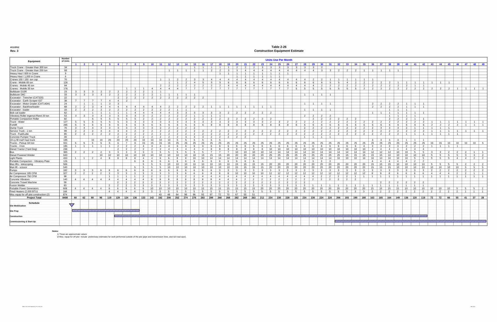
4/11/2012
Rev. 3
Numberof Units
1 2 3 4 5 6 7 8 9 10 11 12 13 14 15 16 17 18 19 20 21 22 23 24 25 26 27 28 29 30 31 32 33 34 35 36 37 38 39 40 41 42 43 44 45 46 47 48 49Truck Crane - Greater than 300 ton 34 1 1 1 1 1 2 2 2 3 3 3 3 3 3 3 2Truck Crane - Greater than 200 ton 68 1 1 1 1 1 2 2 3 3 4 4 4 4 4 4 4 4 4 3 3 2 2 2 1 1 1 1 1Heavy Haul / 600 tn Crane 9 1 1 1 1 1 1 1 1 1Heavy Haul / 1,000 tn Crane 6 1 1 1 1 1 1Cranes 100 / 150 ton cap 70 1 1 2 2 3 3 4 4 4 4 4 4 4 4 4 4 4 4 2 2 1 1 1 1 1 1Crane - Mobile 65 ton 126 1 1 2 4 5 5 5 6 6 6 6 6 6 6 6 6 6 6 6 5 5 4 2 2 2 2 2 1 1 1 1 1 1 1Cranes - Mobile 45 ton 84 2 2 2 2 2 2 2 2 4 4 4 4 4 4 4 4 4 4 4 2 2 2 2 2 2 2 2 2 2 2 1 1Cranes - Mobile 35 ton 176 1 1 1 4 4 4 4 7 7 7 7 7 7 7 7 7 7 7 7 7 5 5 5 5 5 5 5 5 2 2 2 2 2 2 2 2 2 2 2 1 1 1 1Bulldozer D10R 23 3 3 3 2 2 2 2 2 2 1 1Bulldozer D6C 33 3 3 3 3 2 2 2 2 2 2 1 1 1 1 1 1 1 1 1Excavator - Trencher (CAT320) 22 2 2 2 2 2 2 2 2 2 2 2Excavator - Earth Scraper 637 38 7 7 7 7 4 4 2Excavator - Motor Grader (CAT140H) 24 1 1 1 3 3 1 1 1 1 2 2 2 2 1 1 1Excavator - Backhoe/loader 68 2 2 3 4 4 4 4 4 4 4 4 2 2 2 2 2 1 1 1 1 1 1 1 1 2 2 2 2 1 1 1Excavator - loader 33 2 2 2 2 2 2 2 2 2 2 2 2 1 1 1 1 1 1 1 1 1Bob cat loader 62 1 1 1 1 1 4 4 4 4 4 3 3 3 3 3 3 2 2 2 2 2 2 1 1 1 1 1 1 1Vibratory Roller Ingersol-Rand 20 ton 53 3 3 3 3 3 3 3 3 3 2 2 2 2 2 1 1 1 1 2 2 2 2 1 1 1 1Portable Compaction Roller 82 5 5 5 5 5 5 2 2 2 2 2 2 2 2 2 2 2 2 2 2 2 2 2 2 2 2 2 2 2 2 2 1 1Truck - Water 127 5 5 5 5 5 5 3 3 3 3 3 3 3 3 3 3 3 3 3 3 3 3 3 2 3 2 2 2 2 2 2 2 2 2 2 2 2 2 2 2 2 2 1 1 1 1 1 1 1Forklift 285 6 6 6 6 6 6 6 6 6 6 6 6 6 6 6 6 8 8 8 8 8 8 8 8 8 8 8 6 6 6 6 6 6 6 6 6 6 6 6 6 6 6 2 2 2 2 1 1 1Dump Truck 76 3 4 4 3 3 3 3 3 3 3 2 2 2 2 2 2 2 2 2 2 2 2 2 2 3 3 3 2 1 1 1 1 1Service Truck - 1 ton 99 2 2 2 4 4 4 4 2 2 2 2 2 2 2 2 2 2 2 2 2 2 2 2 2 2 2 2 2 2 2 2 2 2 2 2 2 2 2 2 2 2 2 1 1 1 1 1 1 1Truck - Fuel/Lube 85 2 2 2 2 2 2 2 2 2 2 2 2 2 2 2 2 2 2 2 2 2 2 2 2 2 2 2 2 2 2 2 2 2 2 2 2 2 2 2 1 1 1 1 1 1 1Concrete Pumper Truck 39 2 2 2 2 2 2 2 2 3 3 3 2 2 2 2 2 1 1 1 118 cy fill mat'l haul truck 185 10 10 20 20 20 20 10 10 10 10 5 5 5 5 5 5 3 3 3 3 1 1 1Trucks - Pickup 3/4 ton 931 5 5 5 5 5 6 7 8 15 15 15 15 25 25 25 25 25 25 25 25 25 25 25 25 25 25 25 25 25 25 25 25 25 25 25 25 25 25 25 25 25 25 15 15 10 10 10 10 5Trucks - 3 ton 185 1 1 1 1 1 2 2 2 4 4 4 4 6 6 6 6 6 6 6 6 6 6 6 6 6 6 6 6 6 6 6 6 6 6 4 3 3 3 3 2 2 2 1 1 1 1Diesel Tractor (Yard Dog) 236 2 2 2 2 2 2 4 4 4 4 4 8 8 8 8 8 8 8 10 10 10 10 10 10 10 10 10 10 10 10 4 4 4 4 4 4 4Bus 365 2 2 2 2 3 3 3 3 3 3 5 5 5 5 5 5 7 7 7 10 10 10 10 14 14 14 14 14 14 14 14 14 14 14 14 12 12 12 10 10 5 5 3 3 2 2 2 1 1Diesel Powered Welder 643 10 10 10 10 10 10 10 10 10 10 10 10 15 15 15 20 20 20 20 20 25 25 25 25 25 25 25 25 25 15 15 15 15 15 10 10 10 10 10 5 5 5 5 3 3 2Light Plants 433 1 1 2 4 8 8 8 8 4 4 6 6 8 8 10 10 14 14 14 14 14 14 14 14 14 14 14 14 14 14 14 10 10 10 10 10 10 10 10 10 5 5 5 5 5 4 4 2 2Portable Compaction - Vibratory Plate 126 6 6 6 6 6 6 6 6 6 6 6 6 6 6 6 3 3 3 3 4 4 4 4 4 2 2Man lifts - telescoping 506 5 5 5 10 10 10 10 10 10 10 10 15 15 15 15 20 20 20 20 20 20 20 20 20 20 20 20 15 15 15 10 10 10 10 5 5 5 5 2 2 2Man lift - scissor 540 5 5 5 5 10 10 10 10 10 10 10 10 15 15 15 15 20 20 20 20 20 20 20 20 20 20 20 20 15 15 15 10 10 10 10 10 10 10 10 5 5 5Pumps 182 3 3 3 6 6 6 6 6 6 6 6 6 6 6 6 6 6 3 3 3 3 3 3 3 3 3 3 3 3 3 3 3 3 3 3 3 3 3 3 3 3 3 2 2 2 2 2 2 2Air Compressor 185 CFM 327 2 2 2 2 3 3 3 3 3 3 3 3 3 6 6 6 8 8 8 10 10 10 10 12 12 12 12 12 12 12 12 12 12 12 12 8 8 8 6 6 6 6 4 4 4 2 2 1 1Air Compressor 750 CFM 98 1 1 1 1 2 2 2 2 2 2 2 4 4 4 4 4 4 4 4 4 4 4 4 4 4 2 2 2 2 1 1 1 1 1 1 1 1 1 1 1 1 1 1 1 1Concrete Vibrators 140 4 4 4 4 4 4 4 4 4 8 8 8 8 8 8 8 8 4 4 4 2 2 2 2 2 2 2 2 2 2 2 2 2 2Concrete Trowel Machine 58 2 2 2 2 2 2 2 2 2 2 2 2 2 2 2 2 2 2 2 2 2 2 2 2 2 2 2 2 2Fusion Welder 83 2 2 2 3 3 3 3 3 3 3 3 3 3 3 3 3 3 3 3 3 3 3 3 3 1 1 1 1 1 1 1 1 1 1 1 1 1 1Portable Power Generators 608 4 4 4 4 6 6 6 6 6 10 10 10 10 10 10 15 15 15 15 15 15 15 20 20 20 20 20 20 20 20 20 20 20 20 20 15 15 15 15 10 10 10 10 10 10 5 5 5 2Fired Heaters (2,000 BTU) 166 4 4 4 4 3 3 5 5 5 5 5 5 5 5 5 5 5 5 5 5 5 5 5 5 5 5 5 5 3 3 3 2 2 2 2 2 2 2 2 2 2 2 1 1 1Misc equip for off plot construction (2) 874 43 48 84 98 96 93 97 72 70 67 55 51
Project Total 8408 60 62 80 96 119 129 124 136 133 142 192 208 252 274 276 283 299 268 268 282 269 263 212 234 230 228 225 234 230 224 220 206 193 190 180 163 165 164 149 136 120 119 72 72 66 55 41 37 28
ScheduleSite Mobilization
Site Prep
Construction
Commissioning & Start-Up
Notes:
1 These are approximate values2 Misc. equip for off plot include preliminary estimates for work performed outside of the plot (pipe and transmission lines, and rail road spur).
Equipment Units Use Per Month
Table 2-26Construction Equipment Estimate
Table 2-26 Constr Equip Est_04-11-2012.xls April 2012
········ · ······· · ··· · ······· · ··· · ··········· · ······· · ··· · ······ · ··· · ···"1<'7 ·
------------------------------------------------------------ ----------------------

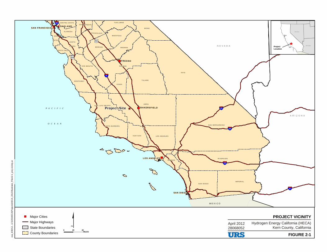
OA KLAND
FRES NO
LOS ANGE LES
SAN DI EGO
SAN F RANCIS CO
N E V A D A
A R I Z O N A
U T A H
P A C I F I C
O C E A N
I N Y O
K E R N
S A N B E R N A R D I N O
F R E S N O
R I V E R S I D E
T U L A R E
M O N O
M O N T E R E Y
L O S A N G E L E S
M A D E R AM E R C E D
K I N G S
V E N T U R A
T U O L U M N E
S A N L U I S O B I S P O
S A N TA B A R B A R A
M A R I P O S A
S TA N I S L A U S
S A N B E N I TO
S A N J O A Q U I N
S A N TA
C L A R A
A L A M E D A
C O N T R A C O S TA
S A N TA C R U Z
S A N
M AT E O
BAKERSF IEL D
S A N D I E G O
I M P E R I A L
OR A N G E
M E X I C O
99
101
40
15
10
5
8
80
April 201228068052
Hydrogen Energy California (HECA)Kern County, California
FIGURE 2-1
PROJECT VICINITY
Project SiteProject SiteProject Site
vsa_
4/30
/12.
..U:\G
IS\H
EC
A\P
roje
cts\
HE
CA
_201
2\Ill
ustr
ator
_File
s\2-
1_pr
oj v
icin
ity.a
i
Major Cities
Major Highways
State Boundaries
County Boundaries0 4020
MILES
ProjectLocation
NEVADA
ARI ZONA
■
CJ
URS
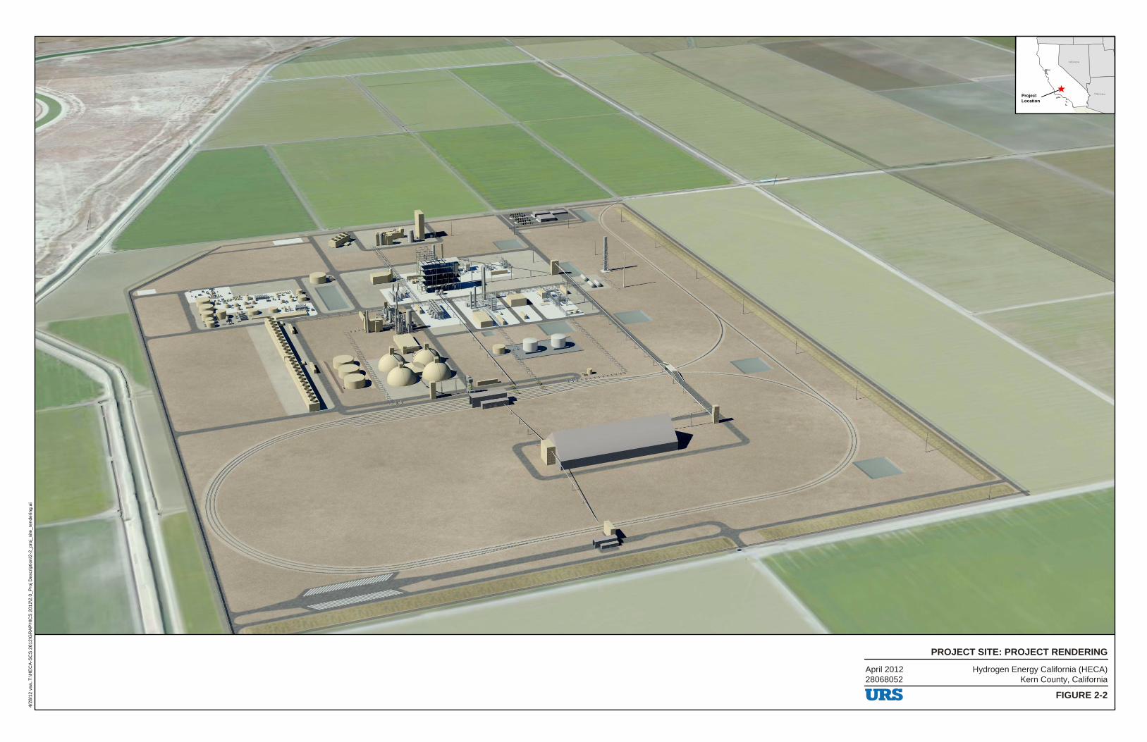
Hydrogen Energy California (HECA)Kern County, California
FIGURE 2-2
PROJECT SITE: PROJECT RENDERING
4/28
/12
vsa.
.T:\H
EC
A-S
CS
201
2\G
RA
PH
ICS
201
2\2.
0_P
roj D
escr
iptio
n\2-
2_pr
oj_s
ite_r
ende
ring.
ai
April 201228068052
ProjectLocation
NEVADA
ARI ZONA
''
.--d~¢~~~,~~6~~ - -~
URS
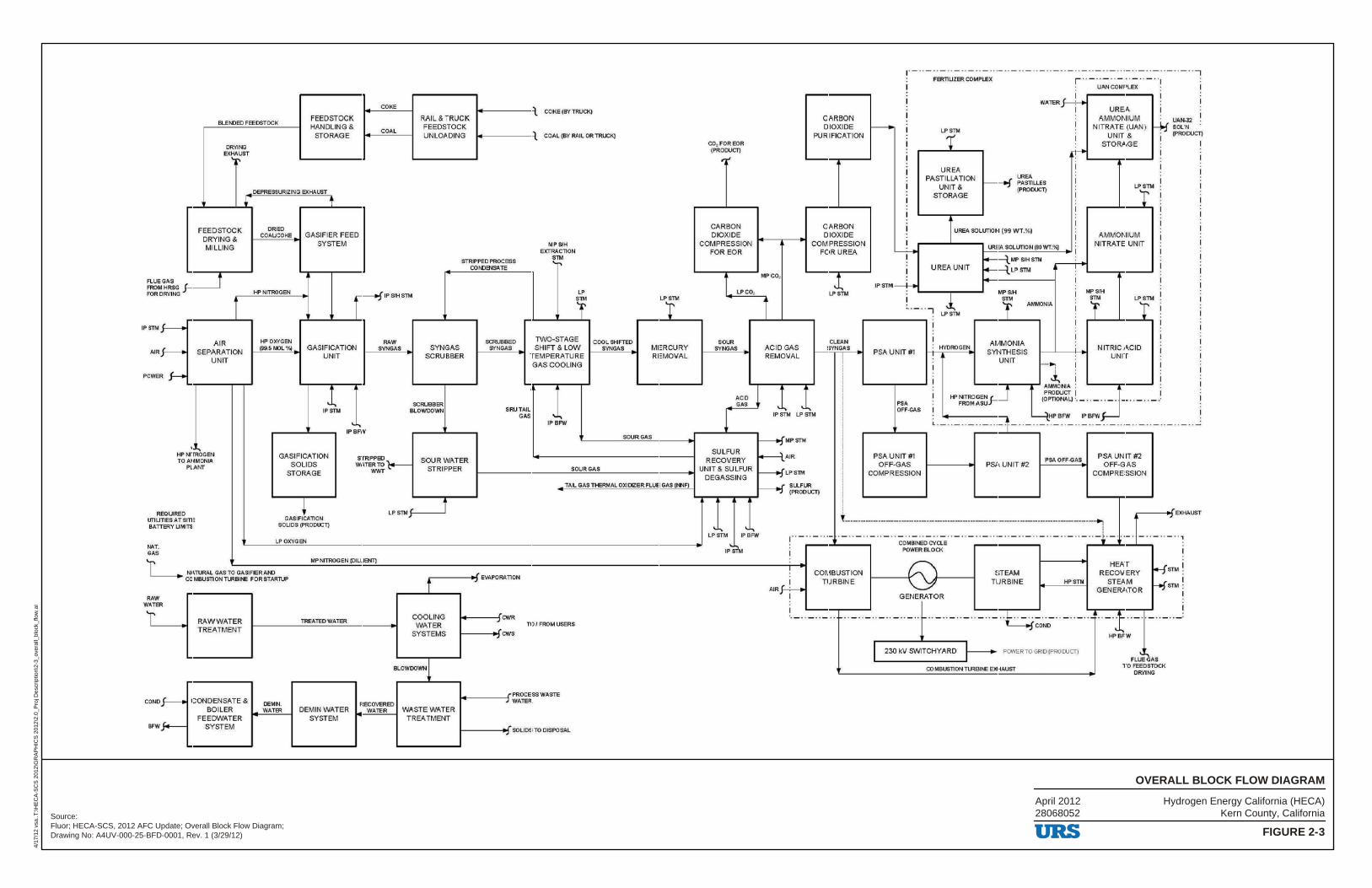
Hydrogen Energy California (HECA)Kern County, California
FIGURE 2-3
OVERALL BLOCK FLOW DIAGRAM
4/17
/12
vsa.
.T:\H
EC
A-S
CS
201
2\G
RA
PH
ICS
201
2\2.
0_P
roj D
escr
iptio
n\2-
3_ov
eral
l_bl
ock_
flow
.ai
Source:Fluor; HECA-SCS, 2012 AFC Update; Overall Block Flow Diagram;Drawing No: A4UV-000-25-BFD-0001, Rev. 1 (3/29/12)
April 201228068052
IPSTM
AIR
POWE
91.Ef.OED FEEDSTOCK FEEDSTOCK HANDLING &
STORAGE
00.._.,NG EXHAUST
'jl"
FEEDSTOCK DRYING& MILLING
DEPRESSURIZING EXHAUST
ORlED COAUCOKE GASIFIER FEED
1-----+1 SYSTEM
COKE
COAL
R.AILII TRUCK FEEDSTOCK UNLOADING
, COKE (BY TRUCK)
M-------1 ' , COAL (BY RAIL OR TRUCK)
MPSIH ElITRACTIOSJ
CO, FOREOR IPROOUCT)
~,;
CARBON DIOXIDE
COMPRESSION FOR EOR
STRIPPED PROCESS STM ......
J--. AIR
J--. SEPARATION UNIT
R f-
,.., HP ,..TROGEN TO AMMON LO.
PLANT
1-f' NITROGEN IPSMSTM
ff' OXYGEN (59.5 MOL %l GASIFICATION
RAW SVNGAS SYNGAS
UNIT
1 IPSTM
GASIFICATION SOLIDS
STORAGE
SCRUBBER
SCRUBBER SLOWDOWN
' IPBFW
STIRlPP8'. ).,,____ WATER TO_ I:"
WWT
SOUR WATER STRIPPER
CO~elSATE
LP
r SCRUBBED TINO-STAGE
SVNGAS SHIFT & LOW TEMPERATURE
SRUTAIL GAS
GAS COOLING
... .. IPBFW
LPtTM
COOL SHIFTED SYNGAS MERCURY
REMOVAL
SOUFtG.O.S
LPCO,
SOU'l SVNGAS
ACID GAS
SULFUR RECOVERY
,_ _________ s_o_u_R_G_AS ___________ UNIT & SULFUR
DEGASSING
MPCO,
l ACID GAS REMOVAL
1 1
CARBON DIOXIDE
PURIFICATION
CARBON DIOXIDE
COMPRESSION FOR UREA
CLEAN SVNGAS
I i I ! I i I
IP STM LP i>TM !
f---+fMPSTM
~AIR
f---+f LP sm
IPSTM--i-.,
PSA UNIT #1
PSA OFF-GI'.$
PSA UNIT #1 OFF-GAS
COMPRESSION
FER11UZER COMPLEX
··-··-··-··-- ·-- · - · ·-·--·-· ·-·-··7 r ··- ··- ·· -··-··-·
LPSn.
r UREA
PASTILLA TION UNIT &
STORAGE f---f
I WATER}--+-..
I
UAN COMPLEX
UREA AMMONIUM
: NITRATE (UAN ) I UNIT&
STORAGE
UAJ,1.;12 ~ SOL'N
• [PRODUCT]
I I .~.._ ___ ___. I
UREA PASTIU.ES (PRODUCT)
I
I
I
I
I
I
LPt1M:
I UR!;A SOLllrlON (99 WT.%) AMMONIUM
NITRATE UNIT
I
I
I
I
I UREA UNIT
l LPSn.
HYDROGEN
U'lEA SOLUTION (80 WT.'JQ _ I
f+-----l MP SIH STh4
f4----l LP STM
MPSM SfM
I
'f AMMONIA
AMMONIA SYNTHESIS
UNIT
PSA UNIT #2 PSAOFF-GAS
MPSIH
T I
I
LPt1M I
NITRIC ACID UNIT
PSA UNIT #2 OFF-GAS
COMPRESSION
TAIL GAS THERMAL OXIDIZER FLUE GAS [tl'JF) f---+f SU..F~
-.--.--..,...-- (PRODUCT)
REQUREO UTIUllESATSITE BATTERY LIMITS
NAT. GAS
GASIF!AllON SO LI OS (PRO OU:T)
LP OXYGEN
LPSThl:1-----'
L NATURAL GAS TO GA~FIERA~ COMBUSTION TUUllNE FOR STARTUP
MP NITIROGEN iC<LUENT)
RAW WATER
COND
BFW
R.o.WWATER TREATMENT
CONDENSATE & BOILER
FEEDWATER SYSTEM
OEMIN. WATER
TREATED WATER
DEMIN WATER SYSTEM
ir------1>\J EVAPORATION
COOLING WATER
SYSTEMS
BLOWDOWNl
RECOVERED WATER WASTE WATER
TREATMENT
-----;,CWR
1-----tCOI, CWS
TOI FROWIUSERS
l------1-. SOLIDS TO DISPOSAL
' ...... ~ ...
LPSTM IPBFW
,.., IPSTM
! -I
AJR .f---::---1
I
r----i~ ," EXHAUST
------------------------------------------------------~ I
' - · · - ··- ., - · · -··- .. -- · - ·· - ·· - ··- ·· - ··- · ·- ·· - ··-· ·-· ·- --- i ·- ··- · -· ·- ·· -· ·,
COMBUSTION TURBINE
COMBlNED CVQ.E POWER BLO CK
GENERATOR
STEAM TURBINE HPSTM
w '
HEAT RECOVERY
STEAM GENERATOR
HSTM I
I f-+f STM .
I
··-· ·- ·· -· ·-· ·-··- ·· -· ·-· ·- ··-··- L ·- ··- ·· -··-··-· ·- ··-··t-··-· L_-, COND J.,_
I 230 kV SWITCHYARD POWER TO GRID iPROOOCT)
CD MBUSTION ~BlNE EJOlAUST
URS
HPBFW
~
FLl.eGAS TO FEED STOCK
DRYING
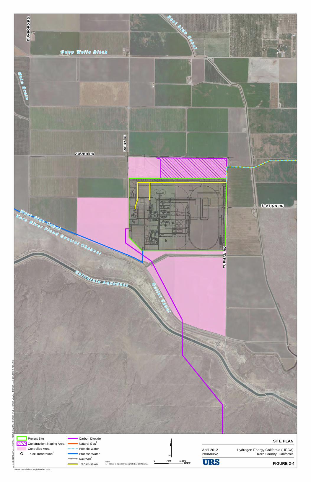
STOCKDALE HWY
ADOHR RD
TUPM
AN RD
DAIRY
RD
STATION RD
DUNF
ORD R
D
C a l i f o r n i a A q u e d u c t
E a s t S i d e C a n a l
K e r n R i v e r F l o o d C o n t r o l C h a n n e l
D e e p W e l l s D i t c h
W e s t S i d e C a n a l
Ma i n D r a i n
A r i z o n a D i t c h
O u t l e t C a n a l
$Source: Aerial Photo, Digital Globe, 2008.
Project Site
Construction Staging Area
Controlled Area
Truck Turnaround1
Carbon Dioxide
Natural Gas1
Potable Water
Process Water
Railroad1
Transmission
SITE PLANHydrogen Energy California (HECA)
Kern County, California
0 1,500750FEET FIGURE 2-4
ed U
:\GIS
\HE
CA
\Pro
ject
s\H
EC
A_
2012
\SU
BM
ITT
AL
\PU
BLI
C_
Fig
2_4
_HE
CA
_pl
otp
lan
_P
UB
LIC
.mxd
4/
29/
201
2 2
:24
:54
PM
April 201228068052
Note:1. Feature temporarily designated as confidential
c:::J ~
0 -+--+
= URS
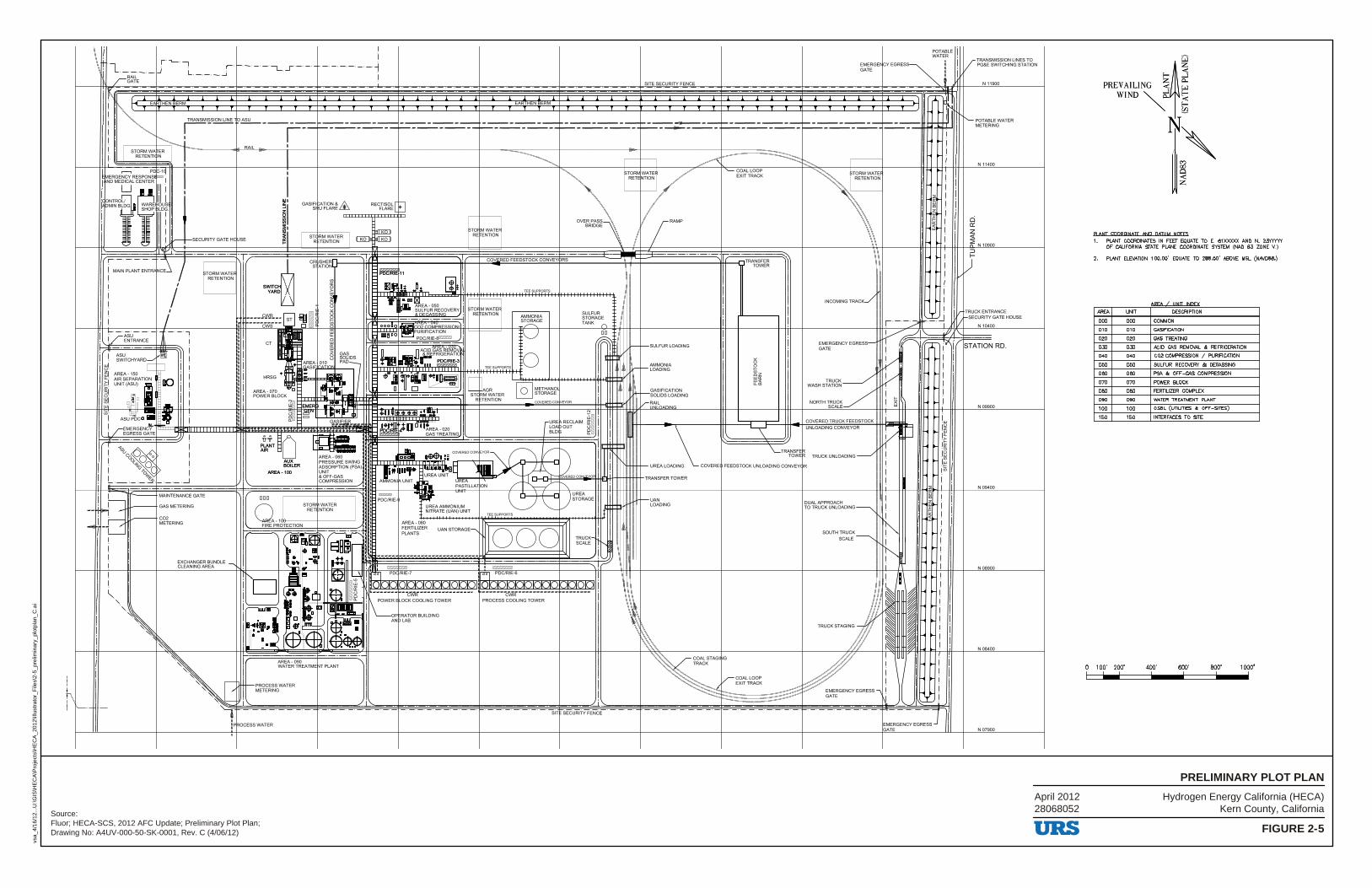
PRELIM
Hydrogen Energy California (HECA)Kern County, California
FIGURE 2-5
PRELIMINARY PLOT PLAN
vsa_
4/16
/12.
..U:\G
IS\H
EC
A\P
roje
cts\
HE
CA
_201
2\Ill
ustr
ator
_File
s\2-
5_pr
elim
inar
y_pl
otpl
an_C
.ai
Source:Fluor; HECA-SCS, 2012 AFC Update; Preliminary Plot Plan;Drawing No: A4UV-000-50-SK-0001, Rev. C (4/06/12)
April 201228068052
I
~'
SITE SECURITY FENCE
~~~~LE I EMERGEI\CYEGRES;~ i I GATE I I
¾ ' ' ' ' ' '
' 1 '""T ~ r' E THEN BERM EARTHEN BERM ~ I I"-. i
! ! ! ! ! !
~ ~l~SIONLINE O~------ ___________________________________ _..,___ ________________________ ,
-~ I ,--------------------------------------------!'----- ---------------·- --IIH',.-1~!-'
",.~'--.._ti I
' I ! ST~~~,:-;', ~R ,--------•-'RA"""IL---~---+-----------+---------l----=--~------1--------r----1-h---------.--.~-+-._-.. ------· .. ::==:_:_~~" ~
.-, Pl C-1j MERGENCY RESPONS ?71'
1 ND MEDICAL CENTER 1 ' LJ 111
SHOP LDG
I! , I I. , I
1 g~r:~,'iiG 1 'ARE L
! i 1.,--1--SECURllY GATE HC USE
! rMAINPLANTENTR N~ /
i I
i / tTORMW:T~ -r ~
RETENTION I I ,
i SWITCH 'x' i YARD /\
CR SHER S ATION
IEli Ii _0.
COVERED FEEDSTOCK CONVEY RS
00 \ I
ii I
TRANSFER TOWER
INCOMING TRACK_/
! ! ! ! ! ! ! ! ! !
! ! ! ! !
I !
r TRANSMISSION LINES TO / PG&E SWITCHING STATION
N 11900
'---- POTABLE WATER METERING
ci Cl'.
~
N 11400
~ N 10900 ::,
i I
i / i ----~lfcR ___ B ~~ STOI MWATER RE ENTION
, I
,· •• 1
1L'L i . -/1 I
[r TRUCK ENTRANCE /1-sECURITYGATE HOUSE
N 10400
~! ffil AREA-150 u.• AIR SEPARATION DO ~! UNIT (ASU) i '31 u· Iii ~! uJ~I~ -.
! !
AREA- 070 POWER BLOCK
.ttT~o AIR ~
AUX BOILER
AREA-100
1---PROCESS WATER METERING
EMER • l , .. _.
G:-~~---
.._ AREA-060 PRESSURE SWING ADSORPTION (PSA) UNIT & OFF-GAS COMPRESSION
- AGR ST< RM WATER
R TENTION
0 WMETHANOL ~STORAGE
- COVERED cm lrEvoR
□□ : /; ::,; /;
•-L--SULFUR LOADING
\~~ i !: i v-~t~k1□~~: I I I 't '\ ' ,, ''\ I ;,. : ~il,....1--- GASIFICATION I : : I yVi) SOLIDS LOADING
EMERGENCY EGRESSGATE
TRUCK;______/' WASH STATION
NORTH TRUC~/ SCAL
!
!
-t=..:.......... ~TATION RD.
N09900
N 09400
N08900
N08400
I,\.__ __ -f
l=.MERGENCY EGRESS J hATE
SIT SECURITY FENCE
: F ROCESS WATER N07900
URS
~~
f- ~
PREVAILING '.;;j ~ WIND ~O: g
i~ Pl ANT COORDINATE AND QATLJM NOTFS 1. PLANT COORDINATES IN FEET EQUATE TO E. 61XXXXX AND N. 2:rt'<YYY
OF CALIFORNIA STATE PLANE COORDINATE SYSTEM (NAO 83 ZONE V.)
2. PLANT ELEVATION 100.00' EQUATE TO 288.50' ABOVE MSL (NAVD88.)
•~~• I • •••~ •••-~ ..
AREA UNIT DESCRIPTION
000 000 COMMON
010 010 GASIFICATION
020 020 GAS TREATING
030 03D ACID GAS REMOVAL & REFRIGERATION
0-40 0-40 CO2 COMPRESSION / PURIFICATION
050 050 SULFUR RECOVERY & DEGASSING
D60 06D PSA & OFF-GAS COMPRESSION
070 070 POWER BLOCK
080 08D FERTILIZER COMPLEX
090 090 WATER TREATMENT PLANT
100 1D0 OSBL (UTILITIES & OFF-SITES)
150 150 INTERFACES TO SITE
0 100' 200' 4-00' 600' 800' 1000'
I 1.....1 I I I I
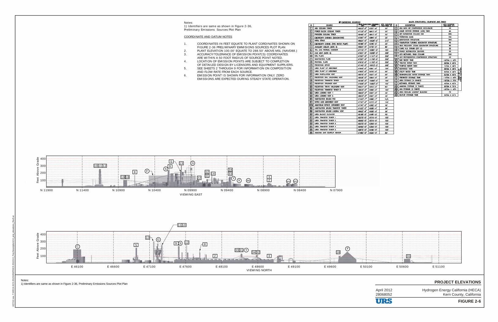
100
N 09900 N 09400 N 08900 N 08400 N 07900N 10400N 10900N 11400N 11900
E 47100 E 47600 E 48100 E 48600 E 49100 E 49600 E 50100 E 50600 E 51100E 46600E 46100
200
300
400
Feet
Abo
ve G
rade
VIEWING EAST
100
200
300
400
Feet
Abo
ve G
rade
VIEWING NORTH
G
W2W4BB
S
G
F
F
CY
YX
18
8
12 8
19
9
S9
33
33
31
31
34
34
32
32 14
135
13
5
22
20
10 1211
1110
2
2
3
3
Notes:1) Identifiers are same as shown in Figure 2-36,Preliminary Emissions Sources Plot Plan
COORDINATE AND DATUM NOTES
1. COORDINATES IN FEET EQUATE TO PLANT CORDINATES SHOWN ON FIGURE 2-36 PRELIMINARY EMMISIONS SOURCES PLOT PLAN2. PLANT ELEVATION 100.00' EQUATE TO 288.50' ABOVE MSL (NAVD88.)3. ACCURACY/TOLERANCE OF EMISSION POINT(S) COORDINATES ARE WITHIN A 50 FOOT RADIUS OF SOURCE POINT NOTED.4. LOCATION OF EMISSION POINTS ARE SUBJECT TO COMPLETION OF DETAILED DESIGN BY LICENSORS AND EQUIPMENT SUPPLIERS.5. SEE SHEETS 2 THROUGH 9 FOR INFORMATION ON COMPOSITION AND FLOW RATE FROM EACH SOURCE.6. EMISSION POINT IS SHOWN FOR INFORMATION ONLY. ZERO EMISSIONS ARE EXPECTED DURING STEADY STATE OPERATION.
18
Hydrogen Energy California (HECA)Kern County, California
FIGURE 2-6
4/27
/12
vsa.
.T:\H
EC
A-S
CS
201
2\G
RA
PH
ICS
201
2\2.
0_P
roj D
escr
iptio
n\2-
6_pr
oj_e
leva
tions
_Rev
5.ai
April 201228068052
PROJECT ELEVATIONSNotes:1) Identifiers are same as shown in Figure 2-36, Preliminary Emissions Sources Plot Plan
0 EMISSKlr:.S SCIIBtiES I) SOURCE
[!J ASU COOLING TOWER ...,..._ .. 00 POWER BLOCK COOLING TOWER 47732•-o·
rn PROCESS COOLING TOWER 48480'-D"
I!] EMERGENCY ENGINES (GENERATORS) 47067'-s·
m:J HRSG STACK 48924"-0-
III EMERGENCY ENGINE (FIRE WAlER PUMP) ..,..._ .. [[) AUXILIARY BOILER (NOTE 8) 48824°-0"
II] TAIL GAS lHERMAL OXIDIZER 47713'-7"
I!] CO2 I/ENT (NOIE 8) 47001'-D"
m SRU RARE 412e-r-o·
l!Il GASIFICATION FIARE 47287'-0"
rn REC11SOL RARE 47810'-0"
Ii]] FEEDSroCK DRIER 47140'-3.
I!!) UREA PLANT HP ABSORBER 47850'-0-
rn UREA PLANT LP ABSORBER 47802'-o·
rn UREA PA.STlLLATION VENT 48075'-o·
rn FEEDSTOCK RM.. UNLOADING VENT 490315•-o•
rn FEEDSTOCK TRANSFER TOWER 49720•-o·
I!!] FEEDSTOCK CRUSHER VENT 47208'-o•
~ FEEDSTOCK TRUCK UNI..CW)ING VENT 50831'-0-
~ FEEDSTOCK TRANSFER TOWER B 49833'-o·
~ UREA UW>ING VENT 1 48902'-0"
~ UREA UW>ING VENT 2 48942'-o·
~ G.'ISIFOTION SOI.JDS PAD 47323'-7"
RZI NITRIC ACID ABSORBER VENT 47797'-0"
1ml AMMONUM NITRATE SCRUBBER VENT 477&-r-o·
~ GASIFICATION SOLIDS TRANSFER TOWER 47322'-2"
rm GASIFICATION SOI.JDS LOADING VENT 48932'-s·
ll!ll UREA BUCKET ELEVA.TOR 48198'-0"
Iii] UREA 1RANSFER TOWER 1 48370'-0-
~ UREA 1RANSFER TOWER 2 4BOOO'-o• ~ UREA 1RANSFER TOWER 3 48370'-0-
Ii!) UREA 1RANSFER TOWER 4 48SBO'-o·
~ UREA 1RANSFER TOWER 5 48875'-0"
I!!) AMMONA UNIT STNmJP HEATER 47495•-o•
-------------- 1 -----------------------1 ---------------------- - 1- ------------------- -- 1------------------------- - - T ------~ ::::::::::::::::::::::::: O--:-o;-_ ::::::::::::::: ----- _LI~~~ ------ r ---------------------- 1 -
--------------1- -----------!- ---- ---~----[_ _I ________ ____ _ __ I_
----------- -- -- -- ,- -- __ :: :: :: :: =---------1: ______ -- -- -- -- -- -- -- - - 1-1 I - -1-
- - - - - - - - - -- -- -- --~- ------------------1 -----------------------1------------------ r- ------------------1 ----------------------- 1 ------------ -~□-- ------------------1 ---------------------- +
I - _________________ J_ __ J_ --------------- + --------- -~--------
-------------1 :t :[TI: -------- 1 --------- ! -1 - - --------------[- :u -----------[-
I- - - ➔-- - - - - - - - - - - ------1- -----------------1-
------ 1- J:: -1 I
7-
- 1 ----------------- 1- -----------------
' r --------------------- -1 ----------------------- 1 ------------------------ , -
-1 I
-7 -➔
I ---------------------➔
___ I
I -------- i --- ----------------------- ➔ - -----------------
I ---- r-- -------------------~ ---------------------
1
-I I
-I -I I 1
---------➔- r::r:JC} 1=:c:E --------------------~ --------------1-
:J: ~l;:::==:fl~ --r-~~~~s...t -1 :1 I
--------------------- T ----------- --------- f I I
----------------------- 1 ----------------------- r
-----------------------➔ ----------------------- ,
--------------------- -L O --------- l -----------------------1- ------------,
::: ____________________ J_ --------- c -..---1
MA.IDB SIBIICDIBES EQIHeMEta &t!ID: It.HIS ,__.,,;:,m I) llESCRFllON =~
9657'-e· 05• A ASU IMIN AIR COMPRESSOR ENCLOSURE 40
8813' o· 05• • LIQUID OXYGEN Sl1JRAGE (I.DX) TANK 90
8813' O" 55• C AR SEPARA'TK»I COWMN CAN 200
9884' o· ,,,,. F FEEDSR>CK BARN 1BO
10035'-o· 213' • GASIFICATION STRUCIURE JOO
9348'-o· ,,,,. 0 COMBUSTION lURBINE GENERATOR STRUCTURE BO p HEAT RECCWERY Sl'EAM GENERATOR STRUcnJRE 90
9730' O" 80'
10881'-0· 100· Q FLARE K.O. DRlAIS (QTY 3) 36
R POWER DISTRIBUTION CENTERS 25 10208'41" 2BO' s AGR METHANOL WASH ca.LIMN 236 11147°-0· 200'
T AGR REFRIGERAllON COMPRESSOR STRUCT\JRE 40 111159'41" 200'
RAW WAlER TANK 100'DIA X 48'H 11153•-o· 250•
TREATED WAlER TANK 95'1M X 40"H 10013•-3• JOO' PURIFIED WATER TANK 715'1M X 48"H 8581'-0" 130' BACKWASH TANK Sl!i'DIA. X 48°H 9575'-0" ... UTIUTY WATER TANK 50'1M X 32'H
9527'-o· 50• DEMINERALIZED WATER SIORAGE TANK 52'1M X 40"H ' 9804' .. 30• X FIREWATER STORAGE TANK 110'DIA X 48'H
10805'-o· 100' y UREA STORAGE (4 DOMES) 182°01A X 70°H
10BOl5'-o• 100' z MEl'HANOL Sl'ORAGE TANK 40'1M X 40'H
9810'-0" BO' AMMONIA SIORAGE (2 TANKS) 90'1M X 70'H
9808' o· 100' UAN ST0RAllE (3 TANKS) 120'DIA X 48'H
SHS87' O" 30• UREA RECLAIM L0ADOUT BUILDING 7C
9687' O" 30• SULFUR SIORAGE TANK 30'1M X 24'H
9888'-7" N/A 11373'-D" 1415'
9392•-o· 40•
9928'-4" 30•
9928'-e· 30•
-·-o· 50•
9574'-0" 100'
9S74'-o• 100'
9384°-0· 100'
9384'-0" 100'
9489'-o· 100'
9000'-0" 80'
---------------- 1- -------------------- - 1-----------------1- -T-
l I ---------------------- 7 ----------------------- , ---
----------------------~ -----------------------1---
1 I -----------------1 -----------------------l-
----------------------1- -----------------,- -
::::::::::::::::::::: ~ r -□ -- ::::::::: 1 : :i: -
URS
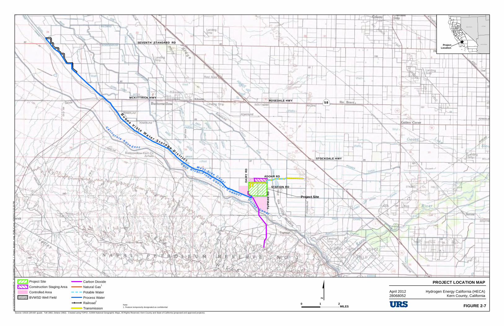
B u e n a V i s t a W a t e r S t o r a g e D i s t r i c t
Project Site
W e s t S i d e C a n a l
K e r n R i v e r F l o o d C o n t r o l C h a n n e l
STOCKDALE HWY
ADOHR RD
DAIRY
RD
SEVENTH STANDARD RD
O u t l e t C a n a l
|ÿ58
TUPM
AN RD
C a l i f o r n i a A q u e d u c t
STATION RD
MCKITTRICK HWY ROSEDALE HWY
$Source: USGS (30'x60' quads: Taft 1982, Delano 1982). Created using TOPO!, ©2006 National Geographic Maps, All Rights Reserved. Kern County and State of California (proposed and approved projects).
Project Site
Construction Staging Area
Controlled Area
BVWSD Well Field
Carbon Dioxide
Natural Gas1
Potable Water
Process Water
Railroad1
Transmission
PROJECT LOCATION MAPHydrogen Energy California (HECA)
Kern County, CaliforniaApril 201228068052
ProjectLocation
^
NE V A D AUTA H
A RI Z ON A
0 21 MILES FIGURE 2-7
ed U
:\GIS
\HE
CA
\Pro
ject
s\H
EC
A_
2012
\SU
BM
ITT
AL
\Fig
2_7
_Pro
ject
_lo
catio
n_m
ap_
PU
BL
IC.m
xd
4/2
9/2
012
3:2
2:3
3 P
M
Note:1. Feature temporarily designated as confidential
rzzJ ~
~ - URS =
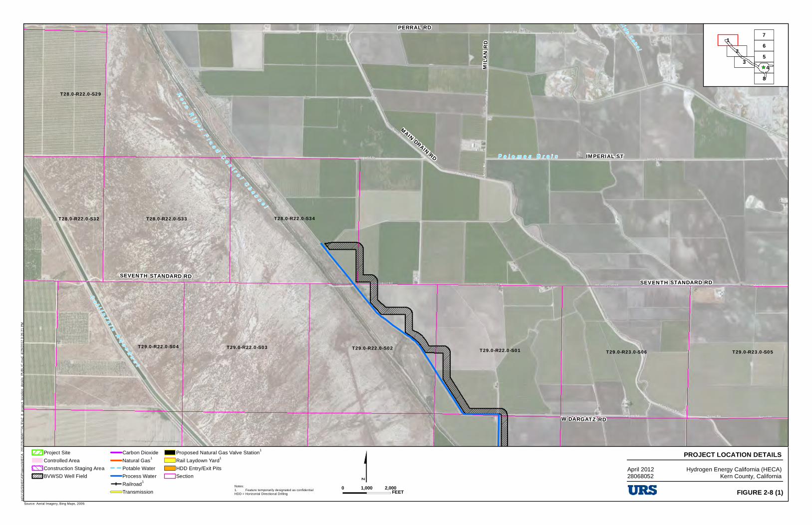
SEVENTH STANDARD RD
MAIN DRAIN RD
MILAN
RD
IMPERIAL ST
PERRAL RD
W DARGATZ RD
SEVENTH STANDARD RD
K e r n R i v e r F l o o d C o n t r o l C h a n n e l
C a l i f o r n i a A q u e d u c t
P a l o m a s D r a i n
East S i de Cana l
T28.0-R22.0-S29
T28.0-R22.0-S34T28.0-R22.0-S33T28.0-R22.0-S32
T29.0-R23.0-S05T29.0-R23.0-S06T29.0-R22.0-S01T29.0-R22.0-S02T29.0-R22.0-S03T29.0-R22.0-S04
$Source: Aerial Imagery, Bing Maps, 2009.
Project Site
Controlled Area
Construction Staging Area
BVWSD Well Field
Carbon Dioxide
Natural Gas1
Potable Water
Process Water
Railroad1
Transmission
Proposed Natural Gas Valve Station1
Rail Laydown Yard1
HDD Entry/Exit Pits
Section
PROJECT LOCATION DETAILSHydrogen Energy California (HECA)
Kern County, California
_̂
12
3
7
48
56
0 2,0001,000 FEET FIGURE 2-8 (1)
ed U
:\G
IS\H
EC
A\P
roje
cts\
HE
CA
_201
2\S
UB
MIT
TA
L\F
ig2_
8_pr
oje
ct_
loca
tion_
deta
ils_
PU
BL
IC.m
xd 4
/29
/20
12 3
:26
:21
PM
Notes:1. Feature temporarily designated as confidentialHDD = Horizontal Directional Drilling
April 201228068052
IZZI -c::::J c:51 -- CJ ('.ml c::::J
URS -=
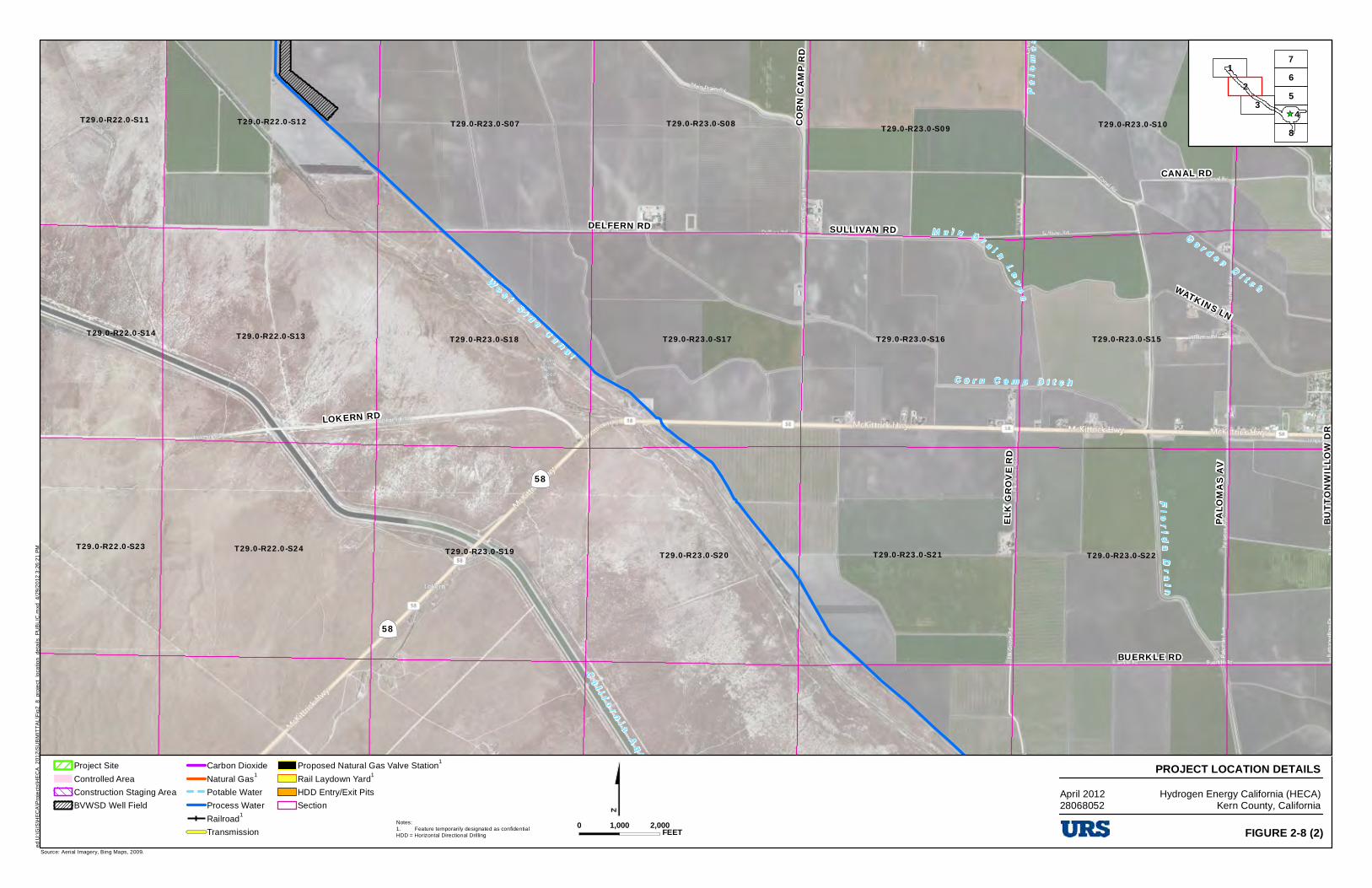
CORN
CAMP
RD
BUTTO
NWILL
OW DR
PALO
MAS A
V
DELFERN RD
CANAL RD
ELK GR
OVE R
D
WATKINS LN
SULLIVAN RD
BUTT
ONWI
LLOW D
R
BUERKLE RD
LOKERN RD
|ÿ58
|ÿ58
W e s t S i d e C a n a l
C o r n C a m p D i t c h
Pal
om
as D
r ai n
Fl o
r i da D
r a i n
M a i n D r a i n L e v e e
G a r d e n D i t c h
C a l i f o r n i a A q u e d u c t
T29.0-R23.0-S10T29.0-R23.0-S09T29.0-R23.0-S08T29.0-R23.0-S07T29.0-R22.0-S11 T29.0-R22.0-S12
T29.0-R23.0-S15T29.0-R23.0-S17 T29.0-R23.0-S16T29.0-R23.0-S18T29.0-R22.0-S14 T29.0-R22.0-S13
T29.0-R23.0-S22T29.0-R23.0-S21T29.0-R23.0-S20T29.0-R22.0-S23 T29.0-R22.0-S24 T29.0-R23.0-S19
$Source: Aerial Imagery, Bing Maps, 2009.
Project Site
Controlled Area
Construction Staging Area
BVWSD Well Field
Carbon Dioxide
Natural Gas1
Potable Water
Process Water
Railroad1
Transmission
Proposed Natural Gas Valve Station1
Rail Laydown Yard1
HDD Entry/Exit Pits
Section
PROJECT LOCATION DETAILSHydrogen Energy California (HECA)
Kern County, California
_̂
12
3
7
48
56
0 2,0001,000 FEET FIGURE 2-8 (2)
ed U
:\G
IS\H
EC
A\P
roje
cts\
HE
CA
_201
2\S
UB
MIT
TA
L\F
ig2_
8_pr
oje
ct_
loca
tion_
deta
ils_
PU
BL
IC.m
xd 4
/29
/20
12 3
:26
:21
PM
Notes:1. Feature temporarily designated as confidentialHDD = Horizontal Directional Drilling
April 201228068052
IZZI -c::::J c:51 -- CJ ('.ml c::::J
URS -=
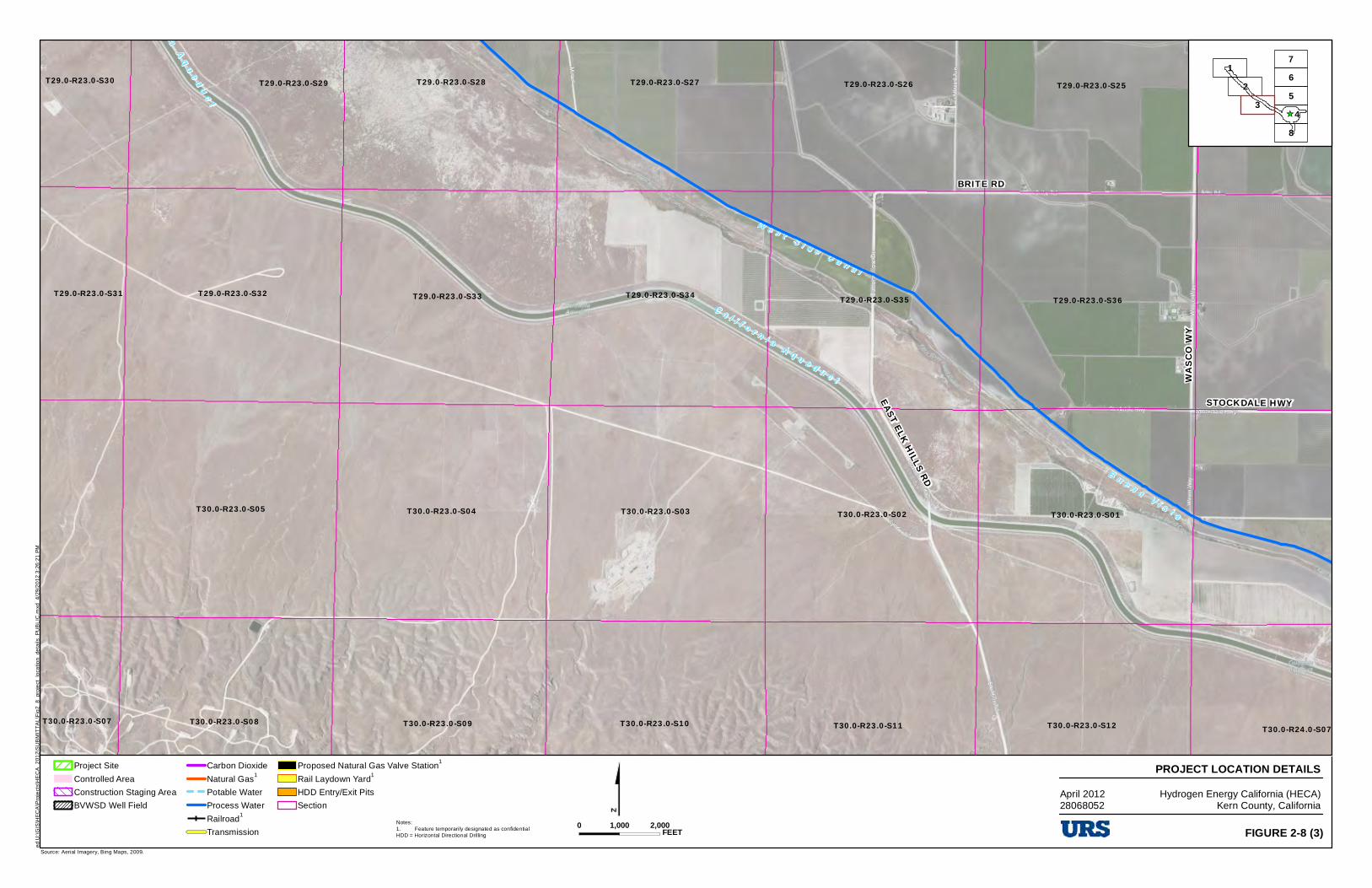
STOCKDALE HWY
WASC
O WY
EAST ELK HILLS RD
BRITE RD
C a l i f o r n i a A q u e d u c t
B u e n a V i s t a
W e s t S i d e C a n a l
C a l i f o r n i a A q u e d u c t
T29.0-R23.0-S25T29.0-R23.0-S26T29.0-R23.0-S27T29.0-R23.0-S28T29.0-R23.0-S29T29.0-R23.0-S30
T29.0-R23.0-S36T29.0-R23.0-S35T29.0-R23.0-S34T29.0-R23.0-S33T29.0-R23.0-S32T29.0-R23.0-S31
T30.0-R23.0-S01T30.0-R23.0-S02T30.0-R23.0-S03T30.0-R23.0-S04T30.0-R23.0-S05
T30.0-R24.0-S07T30.0-R23.0-S12T30.0-R23.0-S11T30.0-R23.0-S10T30.0-R23.0-S09T30.0-R23.0-S08T30.0-R23.0-S07
$Source: Aerial Imagery, Bing Maps, 2009.
Project Site
Controlled Area
Construction Staging Area
BVWSD Well Field
Carbon Dioxide
Natural Gas1
Potable Water
Process Water
Railroad1
Transmission
Proposed Natural Gas Valve Station1
Rail Laydown Yard1
HDD Entry/Exit Pits
Section
PROJECT LOCATION DETAILSHydrogen Energy California (HECA)
Kern County, California
_̂
12
3
7
48
56
0 2,0001,000 FEET FIGURE 2-8 (3)
ed U
:\G
IS\H
EC
A\P
roje
cts\
HE
CA
_201
2\S
UB
MIT
TA
L\F
ig2_
8_pr
oje
ct_
loca
tion_
deta
ils_
PU
BL
IC.m
xd 4
/29
/20
12 3
:26
:21
PM
Notes:1. Feature temporarily designated as confidentialHDD = Horizontal Directional Drilling
April 201228068052
IZZI
c:51 ('.ml -= URS
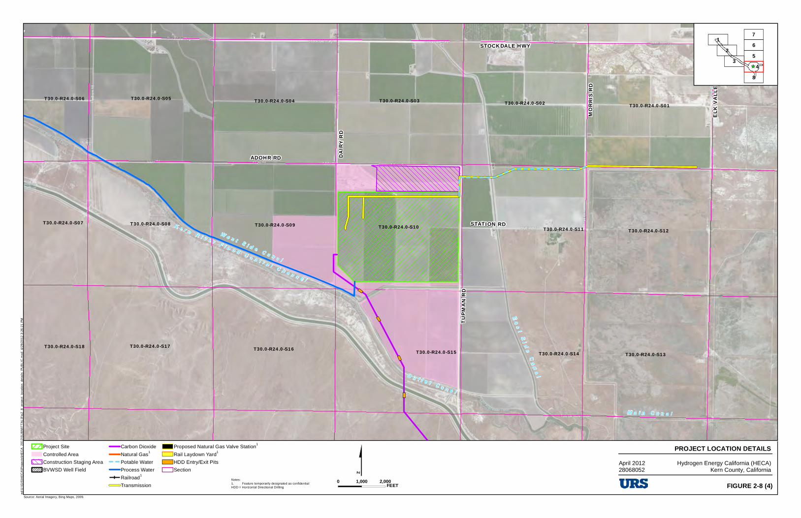
STOCKDALE HWY
ADOHR RD
TUP M
A N R D
MOR R
IS R D
DAIR Y
RD
STATION RD
ELK V
A LLE Y
RD
STOCKDALE HWY
W e s t S i d e C a n a l
M a i n C a n a l
K e r n R i v e r F l o o d C o n t r o l C h a n n e l
O u t l e t C a n a l
E a s t S i d e Ca n a l
T30.0-R24.0-S01T30.0-R24.0-S02T30.0-R24.0-S03T30.0-R24.0-S04T30.0-R24.0-S05T30.0-R24.0-S06
T30.0-R24.0-S12T30.0-R24.0-S11T30.0-R24.0-S10T30.0-R24.0-S09T30.0-R24.0-S08T30.0-R24.0-S07
T30.0-R24.0-S14 T30.0-R24.0-S13T30.0-R24.0-S15T30.0-R24.0-S16T30.0-R24.0-S17T30.0-R24.0-S18
$Source: Aerial Imagery, Bing Maps, 2009.
Project Site
Controlled Area
Construction Staging Area
BVWSD Well Field
Carbon Dioxide
Natural Gas1
Potable Water
Process Water
Railroad1
Transmission
Proposed Natural Gas Valve Station1
Rail Laydown Yard1
HDD Entry/Exit Pits
Section
PROJECT LOCATION DETAILSHydrogen Energy California (HECA)
Kern County, California
_̂
12
3
7
48
56
0 2,0001,000 FEET FIGURE 2-8 (4)
ed U
:\G
IS\H
EC
A\P
roje
cts\
HE
CA
_201
2\S
UB
MIT
TA
L\F
ig2_
8_pr
oje
ct_
loca
tion_
deta
ils_
PU
BL
IC.m
xd 4
/29
/20
12 3
:26
:21
PM
Notes:1. Feature temporarily designated as confidentialHDD = Horizontal Directional Drilling
April 201228068052
- =
IZZI -c::::J c:51 -- CJ ('.ml c::::J
URS -=
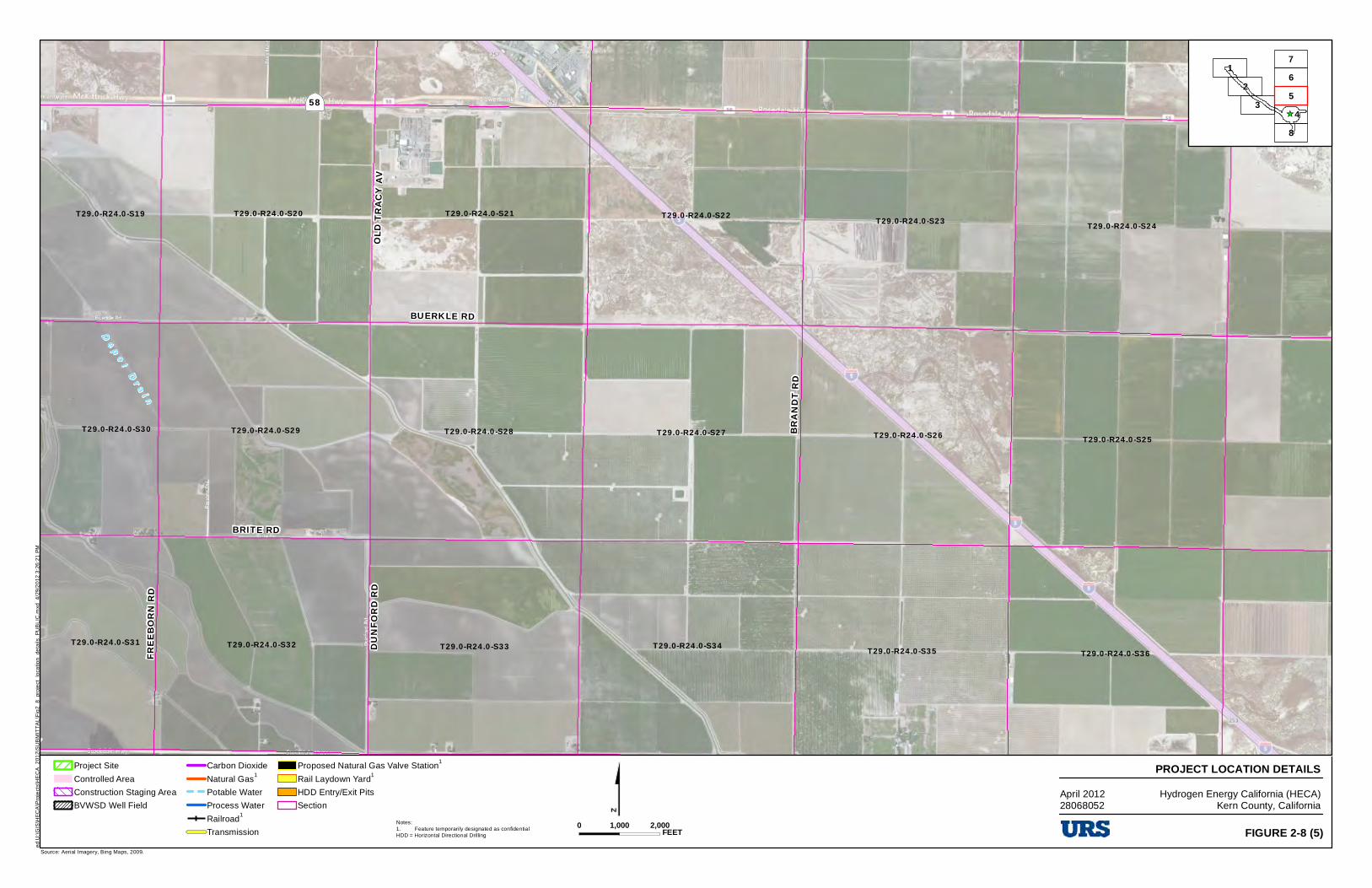
STOCKDALE HWY
BUERKLE RD
BRITE RD
DUNF
ORD R
D
FREE
BORN
RD
BOLTH
OUSE
LN
OLD T
RACY
AV
|ÿ58
BRAN
DT RD
STOCKDALE HWY
D e p o t D r a i n
T29.0-R24.0-S21 T29.0-R24.0-S22 T29.0-R24.0-S23 T29.0-R24.0-S24T29.0-R24.0-S20T29.0-R24.0-S19
T29.0-R24.0-S27 T29.0-R24.0-S26 T29.0-R24.0-S25T29.0-R24.0-S28T29.0-R24.0-S29T29.0-R24.0-S30
T29.0-R24.0-S36T29.0-R24.0-S35T29.0-R24.0-S34T29.0-R24.0-S33T29.0-R24.0-S32T29.0-R24.0-S31
$Source: Aerial Imagery, Bing Maps, 2009.
Project Site
Controlled Area
Construction Staging Area
BVWSD Well Field
Carbon Dioxide
Natural Gas1
Potable Water
Process Water
Railroad1
Transmission
Proposed Natural Gas Valve Station1
Rail Laydown Yard1
HDD Entry/Exit Pits
Section
PROJECT LOCATION DETAILSHydrogen Energy California (HECA)
Kern County, California
_̂
12
3
7
48
56
0 2,0001,000 FEET FIGURE 2-8 (5)
ed U
:\G
IS\H
EC
A\P
roje
cts\
HE
CA
_201
2\S
UB
MIT
TA
L\F
ig2_
8_pr
oje
ct_
loca
tion_
deta
ils_
PU
BL
IC.m
xd 4
/29
/20
12 3
:26
:21
PM
Notes:1. Feature temporarily designated as confidentialHDD = Horizontal Directional Drilling
April 201228068052
IZZI -c::::J c:51 -- CJ ('.ml c::::J
URS -=
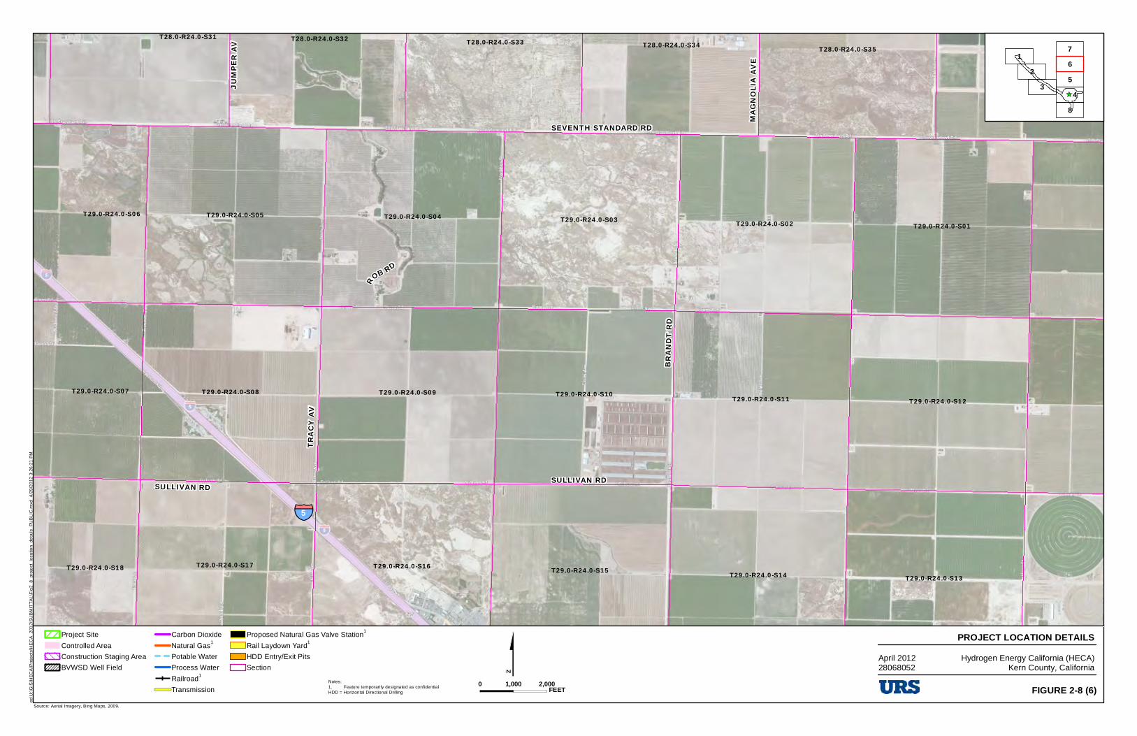
TRAC
Y AV
B RA N
D T RD
SULLIVAN RD
JUMP
E R AV
BOLTH
OUSE
LN
ROB RD
SULLIVAN RD
§̈¦5
SEVENTH STANDARD RD MAGN
OLIA
AVE
T28.0-R24.0-S34 T28.0-R24.0-S36T28.0-R24.0-S33 T28.0-R24.0-S35
T28.0-R24.0-S31 T28.0-R24.0-S32
T29.0-R24.0-S01T29.0-R24.0-S03 T29.0-R24.0-S02T29.0-R24.0-S04T29.0-R24.0-S05T29.0-R24.0-S06
T29.0-R24.0-S12T29.0-R24.0-S11T29.0-R24.0-S10T29.0-R24.0-S09T29.0-R24.0-S08T29.0-R24.0-S07
T29.0-R24.0-S15 T29.0-R24.0-S14 T29.0-R24.0-S13T29.0-R24.0-S16T29.0-R24.0-S18 T29.0-R24.0-S17
$Source: Aerial Imagery, Bing Maps, 2009.
Project Site
Controlled Area
Construction Staging Area
BVWSD Well Field
Carbon Dioxide
Natural Gas1
Potable Water
Process Water
Railroad1
Transmission
Proposed Natural Gas Valve Station1
Rail Laydown Yard1
HDD Entry/Exit Pits
Section
PROJECT LOCATION DETAILSHydrogen Energy California (HECA)
Kern County, California
_̂
12
3
7
48
56
0 2,0001,000 FEET FIGURE 2-8 (6)
ed U
:\G
IS\H
EC
A\P
roje
cts\
HE
CA
_201
2\S
UB
MIT
TA
L\F
ig2_
8_pr
oje
ct_
loca
tion_
deta
ils_
PU
BL
IC.m
xd 4
/29
/20
12 3
:26
:21
PM
Notes:1. Feature temporarily designated as confidentialHDD = Horizontal Directional Drilling
April 201228068052
■
IZZI -c::::J c:51 -- CJ ('.ml c::::J
URS -=
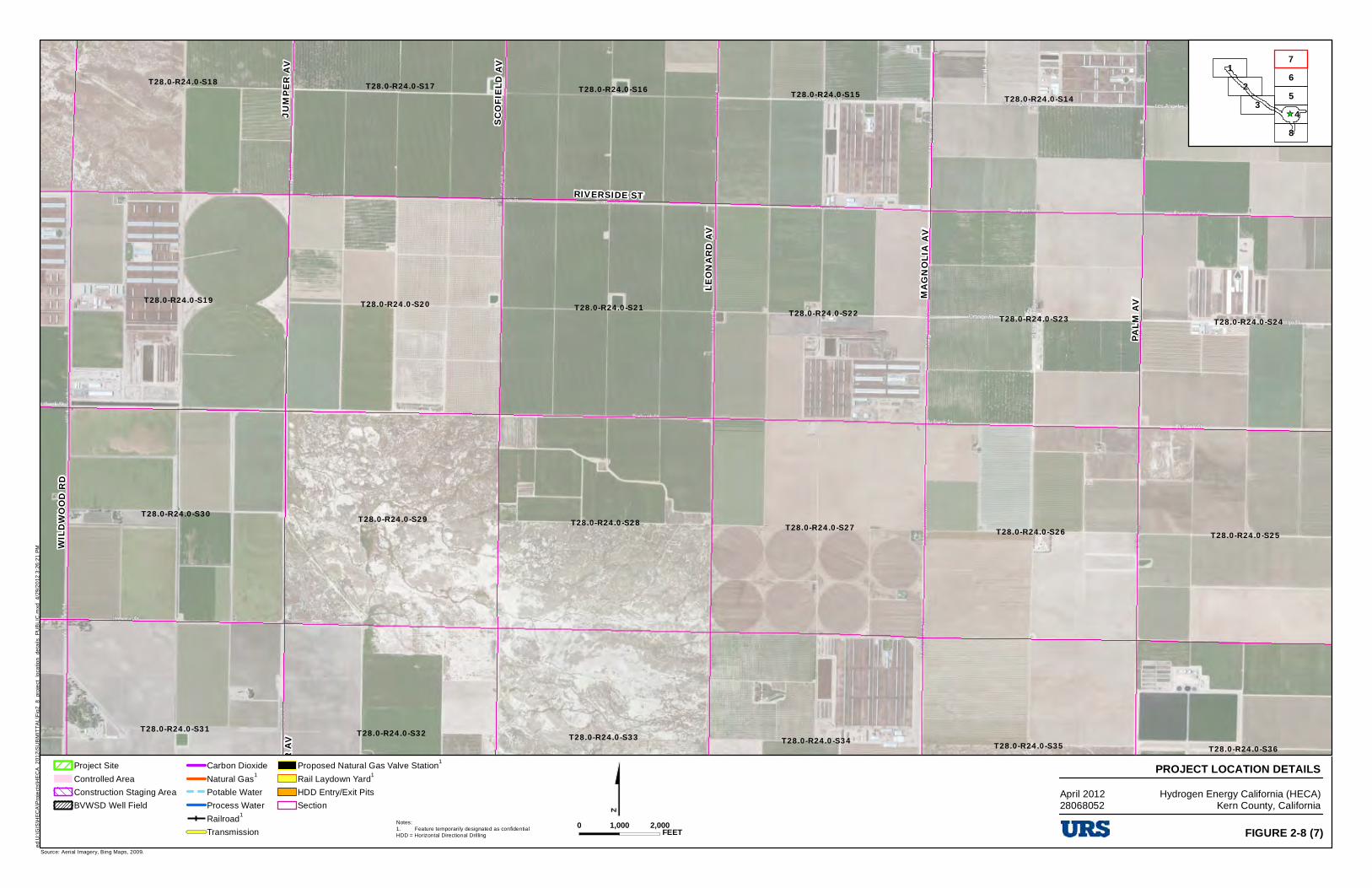
MAGN
OLIA
AV
WILDW
OOD R
D
JUM P
ER A V
PALM
AV
LEONA
RD AV
SCOF
IELD A
V
RIVERSIDE ST
JUMP
ER AV
MAG N
OLIA
AVE
T28.0-R24.0-S13T28.0-R24.0-S14T28.0-R24.0-S15T28.0-R24.0-S16T28.0-R24.0-S17T28.0-R24.0-S18
T28.0-R24.0-S20 T28.0-R24.0-S21T28.0-R24.0-S19T28.0-R24.0-S22 T28.0-R24.0-S24T28.0-R24.0-S23
T28.0-R24.0-S28 T28.0-R24.0-S27T28.0-R24.0-S29T28.0-R24.0-S25T28.0-R24.0-S26
T28.0-R24.0-S30
T28.0-R24.0-S34 T28.0-R24.0-S36T28.0-R24.0-S33 T28.0-R24.0-S35
T28.0-R24.0-S31 T28.0-R24.0-S32
$Source: Aerial Imagery, Bing Maps, 2009.
Project Site
Controlled Area
Construction Staging Area
BVWSD Well Field
Carbon Dioxide
Natural Gas1
Potable Water
Process Water
Railroad1
Transmission
Proposed Natural Gas Valve Station1
Rail Laydown Yard1
HDD Entry/Exit Pits
Section
PROJECT LOCATION DETAILSHydrogen Energy California (HECA)
Kern County, California
_̂
12
3
7
48
56
0 2,0001,000 FEET FIGURE 2-8 (7)
ed U
:\G
IS\H
EC
A\P
roje
cts\
HE
CA
_201
2\S
UB
MIT
TA
L\F
ig2_
8_pr
oje
ct_
loca
tion_
deta
ils_
PU
BL
IC.m
xd 4
/29
/20
12 3
:26
:21
PM
Notes:1. Feature temporarily designated as confidentialHDD = Horizontal Directional Drilling
April 201228068052
..
IZZI -c::::J c:51 -- CJ ('.ml c::::J
URS -=
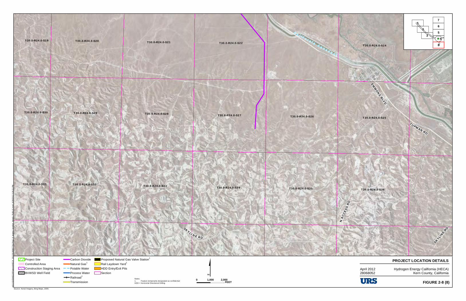
N ACCE
SS RD
EMMONS BLVD
TUPMAN RD
SKYLI NE RD
SKYLINE RD
C a l i f o r n i a A q u e d u c t
T30.0-R24.0-S24T30.0-R24.0-S21 T30.0-R24.0-S22T30.0-R24.0-S20T30.0-R24.0-S19
T30.0-R24.0-S25T30.0-R24.0-S26T30.0-R24.0-S27T30.0-R24.0-S28T30.0-R24.0-S29T30.0-R24.0-S30
T30.0-R24.0-S36T30.0-R24.0-S35T30.0-R24.0-S34T30.0-R24.0-S33T30.0-R24.0-S32T30.0-R24.0-S31
$Source: Aerial Imagery, Bing Maps, 2009.
Project Site
Controlled Area
Construction Staging Area
BVWSD Well Field
Carbon Dioxide
Natural Gas1
Potable Water
Process Water
Railroad1
Transmission
Proposed Natural Gas Valve Station1
Rail Laydown Yard1
HDD Entry/Exit Pits
Section
PROJECT LOCATION DETAILSHydrogen Energy California (HECA)
Kern County, California
_̂
12
3
7
48
56
0 2,0001,000 FEET FIGURE 2-8 (8)
ed U
:\G
IS\H
EC
A\P
roje
cts\
HE
CA
_201
2\S
UB
MIT
TA
L\F
ig2_
8_pr
oje
ct_
loca
tion_
deta
ils_
PU
BL
IC.m
xd 4
/29
/20
12 3
:26
:21
PM
Notes:1. Feature temporarily designated as confidentialHDD = Horizontal Directional Drilling
April 201228068052
IZZI
c:51 ('.ml -= URS
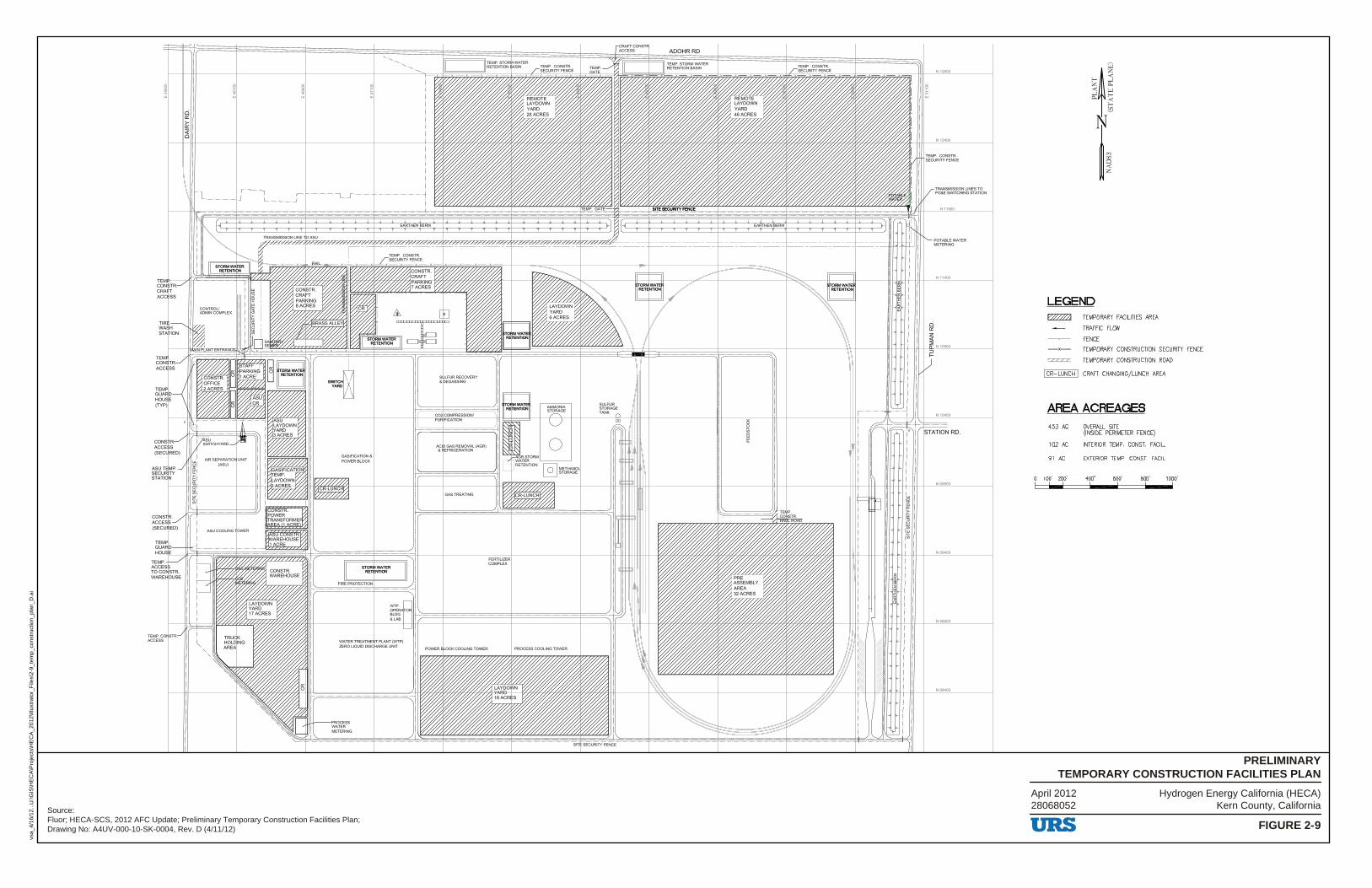
Hydrogen Energy California (HECA)Kern County, California
FIGURE 2-9
PRELIMINARYTEMPORARY CONSTRUCTION FACILITIES PLAN
vsa_
4/16
/12.
..U:\G
IS\H
EC
A\P
roje
cts\
HE
CA
_201
2\Ill
ustr
ator
_File
s\2-
9_te
mp_
cons
truc
tion_
plan
_D.a
i
Source:Fluor; HECA-SCS, 2012 AFC Update; Preliminary Temporary Construction Facilities Plan;Drawing No: A4UV-000-10-SK-0004, Rev. D (4/11/12)
April 201228068052
WATER TREATME T PLANT (WTP) ZERO LIQUID DIS ARGE UNIT
S LFUR RECOVERY &DEGASSING
CO COMPRESSION/ PU IFICATKlN
ACI GAS REMOVAL (AGR) & EFRIGERATION
FERTILIZER COMPLEX
N12900
TRANSMISSION LINES TO PG&E SWITCHING STATION
N.11900
POTABLE WATER METERING
LEGEND ~ TEMPORARY FACILITIES AREA
g TRAFFIC FLOW
N08900
FENCE
TEMPORARY CONSTRUCTION SECURITY FENCE
= TEMPORARY CONSTRUCTION ROAD
I CR-LUNCH I CRAFT CHANGING/LUNCH AREA
AREA ACREAGES OVERALL SITE (INSIDE PERIMETER FENCE)
INTERIOR TEMP. CONST. FACIL.
453 AC
102 AC
91 AC EXTERIOR TEMP. CONST. FACIL.
100' 200' 400' 600' 800' 1000' - ' ' ' '
URS
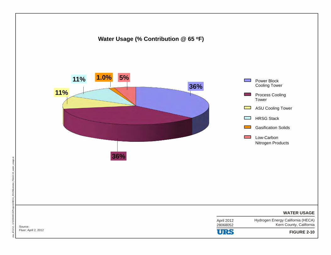
36%
36%
11%
11% 1.0% 5%
Water Usage (% Contribution @ 65 oF)
Power BlockCooling Tower
Process CoolingTower
ASU Cooling Tower
HRSG Stack
Gasification Solids
Low-CarbonNitrogen Products
Hydrogen Energy California (HECA)Kern County, California
FIGURE 2-10
WATER USAGE
vsa_
4/11
/12.
..U:\G
IS\H
EC
A\P
roje
cts\
HE
CA
_201
2\Ill
ustr
ator
_File
s\2-
10_w
ater
_usa
ge.a
i
Source:Fluor; April 2, 2012
April 201228068052
URS
-c::::J
c::::J
c::::J
c::::J
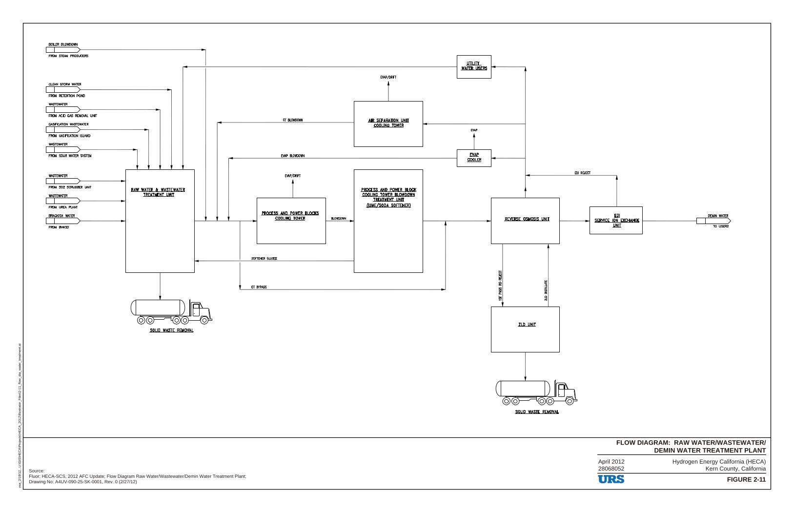
Hydrogen Energy California (HECA)Kern County, California
FIGURE 2-11
FLOW DIAGRAM: RAW WATER/WASTEWATER/DEMIN WATER TREATMENT PLANT
vsa_
2/19
/12.
..U:\G
IS\H
EC
A\P
roje
cts\
HE
CA
_201
2\Ill
ustr
ator
_File
s\2-
11_f
low
_dia
_wat
er_t
reat
men
t.ai
Source:Fluor; HECA-SCS, 2012 AFC Update; Flow Diagram Raw Water/Wastewater/Demin Water Treatment Plant;Drawing No: A4UV-090-25-SK-0001, Rev. 0 (2/27/12)
April 201228068052
BOILER Bl.OWDOWN
FROM STEAM PRODUCERS I )>-----------.. I
CLfAN STORM WAlER
I I :>----------------,~ FROM REIENTION POND
WASTEWAlER
I I FROM ACID GAS REMOVAL UNIT
GASIFICA110N WASTEWATER
I I ~>-------------FROM GASIFICA110N ISIAND
WASTEWAlER
I I FROM SOUR WAlER SYSTEM
WASTEWAlER
I I FROM S02 SCRUBBER UNIT
WASTEWAlER
I I FROM UREA Pl.ANT
BRACKISH WAlER
I I FROM 111/WSD
RAW WAJER I: WASTEWATER TREATMENT UNIT
I ) Ira (Q) ~ 1<9)(9)-----' 0
soup WASTE REMOVAL
er BlOWDDWN
E.VAP BLOWOOWN
E.VAP/DRIFT
r PROCESS ANP POWER BLOCKS
COOLING TOWER
SOFTENER SLUDGE
er l!l'PASS
BLOWDDWN
E.VAP/DRIFT
AIR SEPARATION UNIT COOLING TOWER
PROCESS ANP POWER BLOCK COOLING TOWER BLOWPOWN
TREATMENT UNIT CLIME/SODA SOFTENER}
UTILITY WATER USERS
E.VAP
t _EYAe
.cooLER
EDI R£.JECf
REVERSE OSMOSIS UNIT
ZLD....l1HlI
'
soup WASTE REMOVAL
.El2I SERVICE ION EXCHANGE 1-----------l
.wm
URS
DEMIN WAlER
I > TO USERS
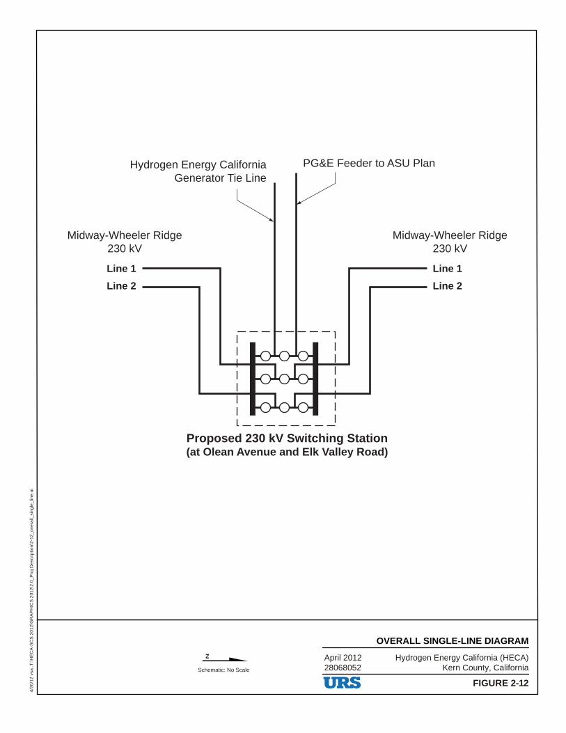
Schematic: No Scale
Midway-Wheeler Ridge230 kV
Midway-Wheeler Ridge230 kV
Hydrogen Energy CaliforniaGenerator Tie Line
Proposed 230 kV Switching Station(at Olean Avenue and Elk Valley Road)
PG&E Feeder to ASU Plan
Line 1
Line 2
Line 1
Line 2
Hydrogen Energy California (HECA)Kern County, California
April 201228068052
FIGURE 2-12
OVERALL SINGLE-LINE DIAGRAM
4/26
/12
vsa.
.T:\H
EC
A-S
CS
201
2\G
RA
PH
ICS
201
2\2.
0_P
roj D
escr
iptio
n\2-
12_o
vera
ll_si
ngle
_lin
e.ai
z
---1 ----1 I I
I I
-URS
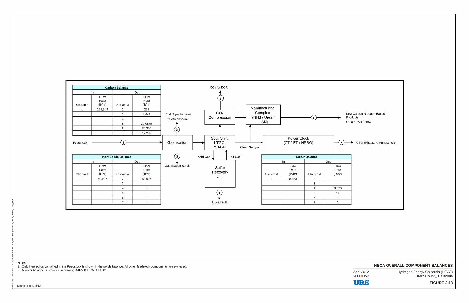
Stream #
FlowRate(lb/hr) Stream #
FlowRate(lb/hr)
1 264,544 2 265
3 3,041 Coal Dryer Exhaust Low Carbon Nitrogen-BasedProducts4 - to AtmosphereUrea / UAN / NH3
5 207,655
6 36,350
7 17,233
Feedstock CTG Exhaust to Atmosphere
Clean Syngas
Acid Gas Tail Gas
Stream #
FlowRate(lb/hr) Stream #
FlowRate(lb/hr)
Gasification Solids
Stream #
FlowRate(lb/hr) Stream #
FlowRate(lb/hr)
1 69,925 2 69,925 1 8,383 2 -
3 - 3 -
4 - 4 8,370
5 - 5 11
6 - 6 -
7 - Liquid Sulfur 7 2
Sulfur Balance
Carbon Balance
Inert Solids Balance
In Out
In Out In Out
CO2 for EOR
GasificationSour Shift,
LTGC,& AGR
SulfurRecovery
Unit
Power Block(CT / ST / HRSG)
CO2Compression
ManufacturingComplex
(NH3 / Urea /UAN)
1
2
4
5
7
6
3
Hydrogen Energy California (HECA)Kern County, California
FIGURE 2-13
HECA OVERALL COMPONENT BALANCES
4/24
/12
vsa.
.T:\H
EC
A-S
CS
201
2\G
RA
PH
ICS
201
2\2.
0_P
roj D
escr
iptio
n\2-
13_H
EC
A_o
vera
ll_co
mp_
bal.a
i
Source: Fluor, 2012
Notes:1. Only inert solids contained in the Feedstock is shown in the solids balance. All other feedstock components are excluded.2. A water balance is provided in drawing A4UV-090-25-SK-0001. April 2012
28068052
-~ ~
Q ~
- -. ~
9 1 r
URS
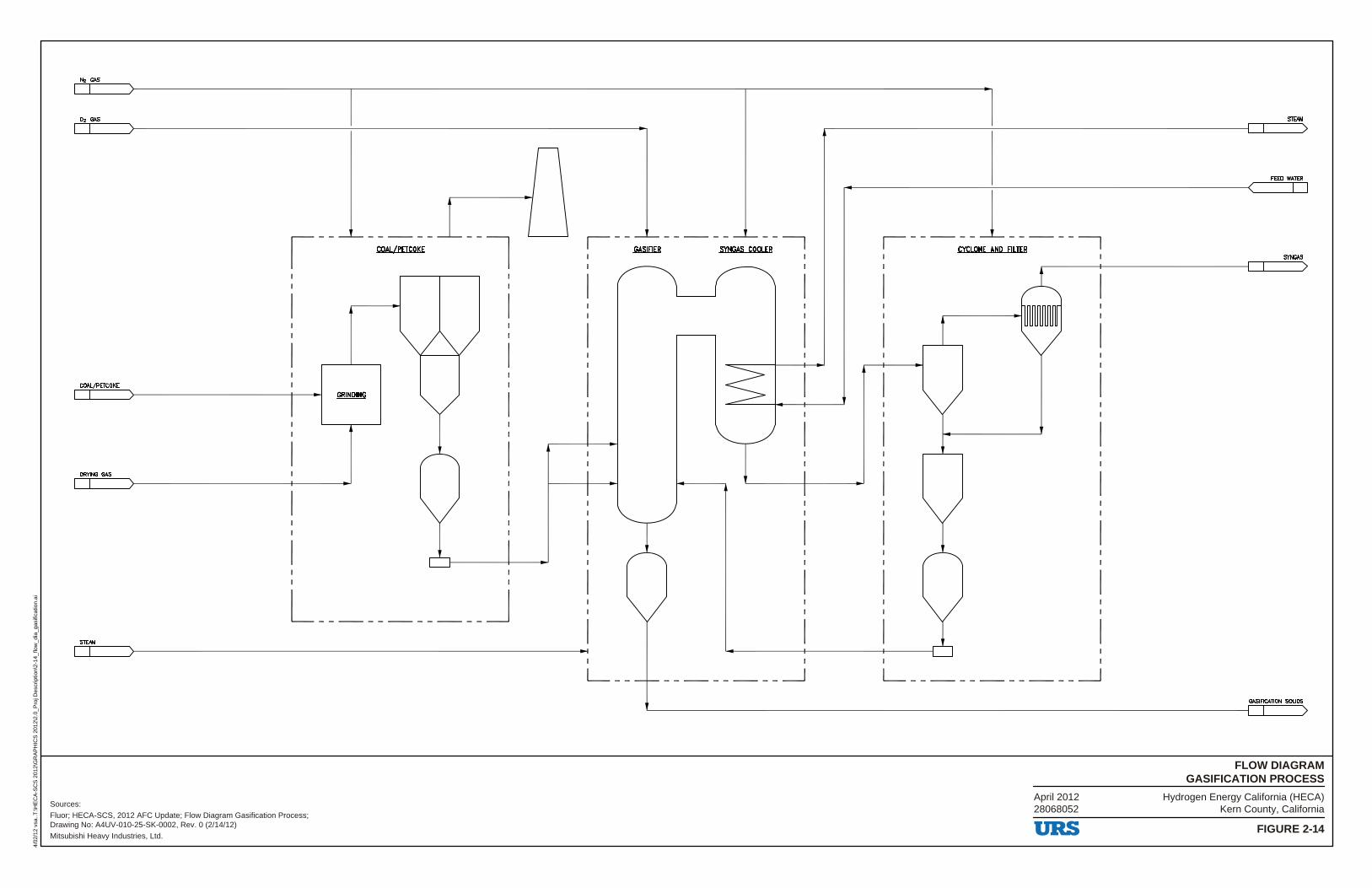
Hydrogen Energy California (HECA)Kern County, California
FIGURE 2-14
FLOW DIAGRAMGASIFICATION PROCESS
4/02
/12
vsa.
.T:\H
EC
A-S
CS
201
2\G
RA
PH
ICS
201
2\2.
0_P
roj D
escr
iptio
n\2-
14_f
low
_dia
_gas
ifica
tion.
ai
Sources:
Fluor; HECA-SCS, 2012 AFC Update; Flow Diagram Gasification Process;Drawing No: A4UV-010-25-SK-0002, Rev. 0 (2/14/12)
Mitsubishi Heavy Industries, Ltd.
April 201228068052
N2 GAS
02 GAS
COAL/PETCOKE
ccw./PETCOKE
DRYING GAS
L ___________ J
I - - GASIFIER - - -- - ;NGAS COO~R- I I
I
L __ ________ _J
FEED WAlER
r- -- -- -l __ - -------, I CYCLONE AND FILTER I I I
I
L ___________ _J
GASIFICATION SOLIDS
URS
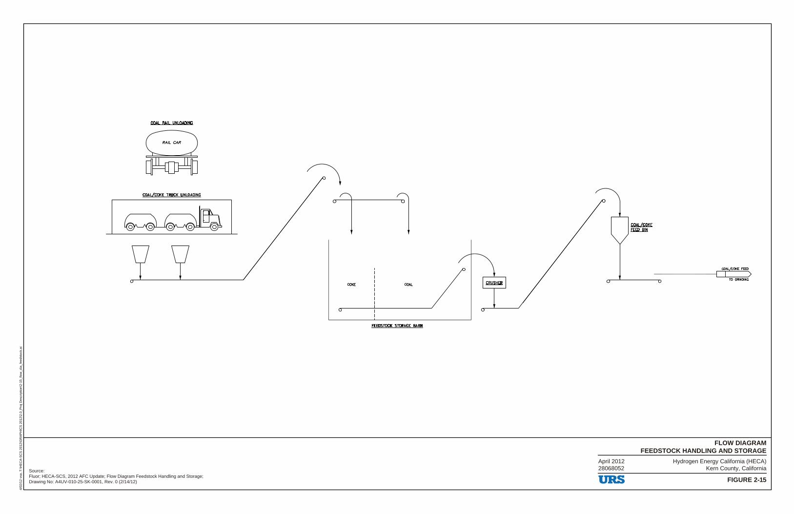
Hydrogen Energy California (HECA)Kern County, California
FIGURE 2-15
FLOW DIAGRAMFEEDSTOCK HANDLING AND STORAGE
4/02
/12
vsa.
.T:\H
EC
A-S
CS
201
2\G
RA
PH
ICS
201
2\2.
0_P
roj D
escr
iptio
n\2-
15_f
low
_dia
_fee
dsto
ck.a
i
Source:Fluor; HECA-SCS, 2012 AFC Update; Flow Diagram Feedstock Handling and Storage;Drawing No: A4UV-010-25-SK-0001, Rev. 0 (2/14/12)
April 201228068052
COAL RAIL UNLOADING
COAL/COKE TRUCK UNLOADING
COKE COAL
FEEDSTOCK STORAGE BARN
URS
COAL/COKE FEED BIN
COAL/COKE FEED
TO GRINDING
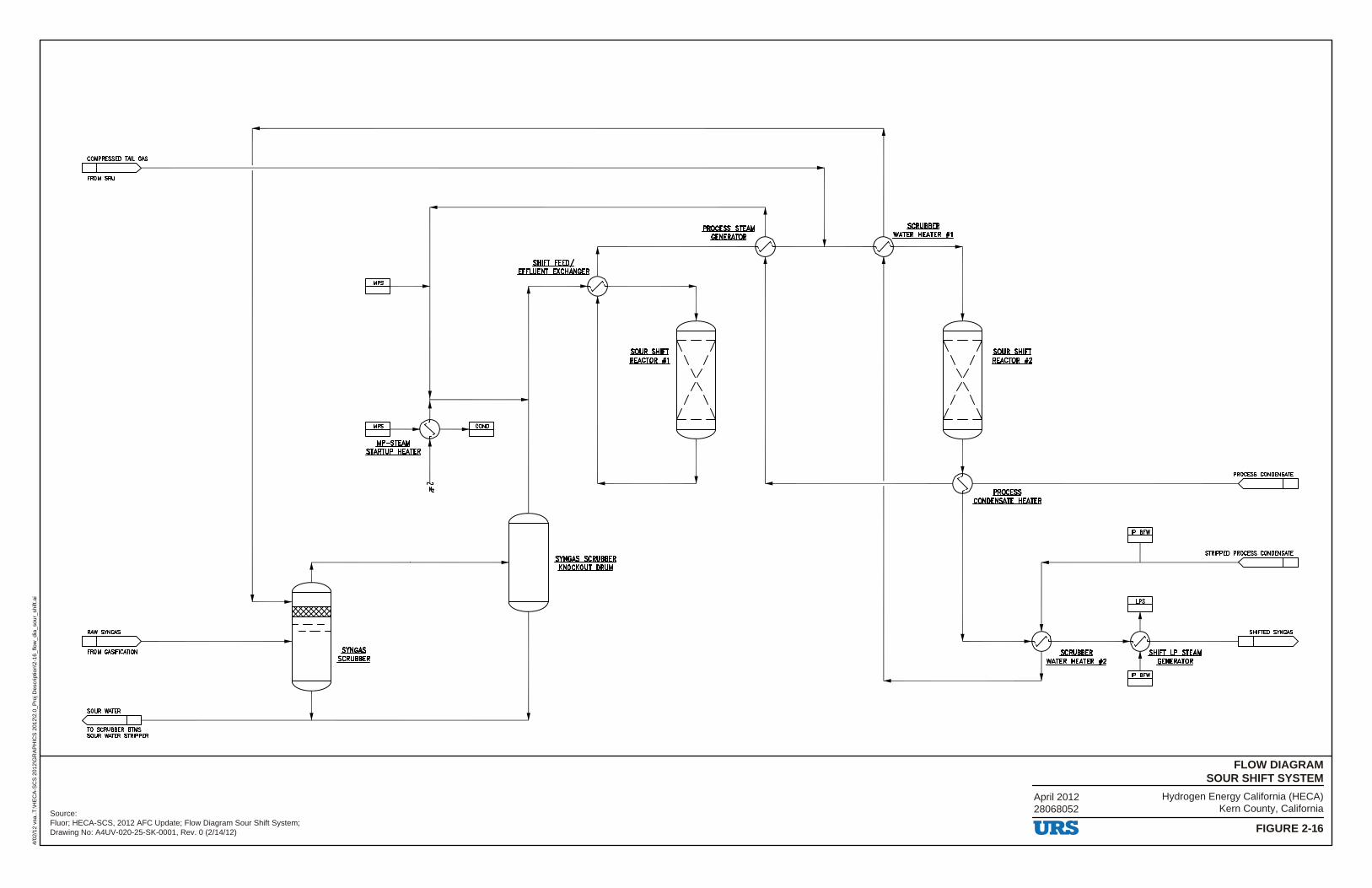
Hydrogen Energy California (HECA)Kern County, California
FIGURE 2-16
FLOW DIAGRAMSOUR SHIFT SYSTEM
4/02
/12
vsa.
.T:\H
EC
A-S
CS
201
2\G
RA
PH
ICS
201
2\2.
0_P
roj D
escr
iptio
n\2-
16_f
low
_dia
_sou
r_sh
ift.a
i
Source:Fluor; HECA-SCS, 2012 AFC Update; Flow Diagram Sour Shift System;Drawing No: A4UV-020-25-SK-0001, Rev. 0 (2/14/12)
April 201228068052
COMPRESSED TAIL GAS
FROM SRU
RAW SYNGAS
FROM GASIFICATION
SOUR WATER
TO SCRUBBER BTMS SOUR WATER STRIPPER
SYNGAS SCRUBBER
MPS
SHIFT FEED/ EEFLUENT EXCHANGER
SVNGAS SCRUBBER KNOCKOUT DRUM
SOUR SHlfT REACTOR f1
PROCESS STEAM GENERATOR
\ I \I /\
I \
~ WATER HEATER #1
4----_J_ ___ -----1,./..._-------
\ I \I /\
I \
SOUR SHlfT REACTOR f2
PROCESS CONDENSATE
------------'-------l~t-------------------~ .fROCESS ..._ ___ .___.
CONDENSATE HEATER
URS
SHIEI LP STEAM GENERATOR
STRIPPED PROCESS CONDENSATE
SHIFTED SYNGAS
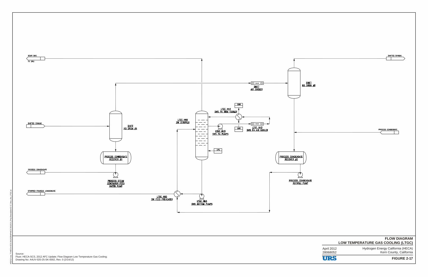
Hydrogen Energy California (HECA)Kern County, California
FIGURE 2-17
FLOW DIAGRAMLOW TEMPERATURE GAS COOLING (LTGC)
4/02
/12
vsa.
.T:\H
EC
A-S
CS
201
2\G
RA
PH
ICS
201
2\2.
0_P
roj D
escr
iptio
n\2-
17_f
low
_dia
_LT
GC
.ai
Source:Fluor; HECA-SCS, 2012 AFC Update; Flow Diagram Low Temperature Gas Cooling;Drawing No: A4UV-020-25-SK-0002, Rev. 0 (2/14/12)
April 201228068052
SOUR GAS
TO SRU
--------------------~------------ic-~~----~ .sHIEI
.sHIEI KO DRUM f2
SHIFlED SYNGAS
.sHIEI KO DRUM #1
PROCESS CONDENSATE RECEIVER #1
PROCESS CONDENS..:LTE ____________________ ?"f'\
PROCESS STEAM GENERATOR FEED
WATER PUMP
LTGC NH3 SW STRIPPER
STRIPPED PROCESS~CO:N:DEN~S..::TE~-------------------------------;-:;-:;:;:-:;;~-7 ~ i-----------,,....,_ .IJGk...t!H.3
SW FEED PREHEATER .IJGk...t!H.3
sws BOTTOM PUMPS
AIR COOLER
LTGC NH3 SWS PA TRIM COOLER
--------'-------ic - ~
~ sws ~OLER .IJGk...t!H.3 sws PA PUMPS
lPS
PROCESS CONDENSATE RECEIVER #2
PROCESS CONDENSATE RECVCLE PUMP
SHIFTED SYNGAS
PROCESS CONDENSATE
URS
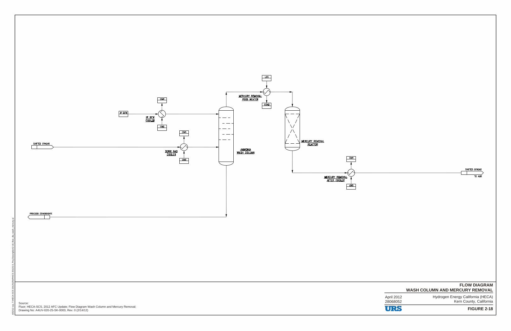
Hydrogen Energy California (HECA)Kern County, California
FIGURE 2-18
FLOW DIAGRAMWASH COLUMN AND MERCURY REMOVAL
4/02
/12
vsa.
.T:\H
EC
A-S
CS
201
2\G
RA
PH
ICS
201
2\2.
0_P
roj D
escr
iptio
n\2-
18_f
low
_dia
_was
h_m
ercu
ry.a
i
Source:Fluor; HECA-SCS, 2012 AFC Update; Flow Diagram Wash Column and Mercury Removal;Drawing No: A4UV-020-25-SK-0003, Rev. 0 (2/14/12)
April 201228068052
IP BFW
SHIFTED -
PROCESS CONDENSATE
.lf....BEYt
m2LEB
~ m2LEB
.AMMQl!IA WASH COWMN
\ I \I /\
I \
URS
SHIFTED SYNGAS
TO MlR
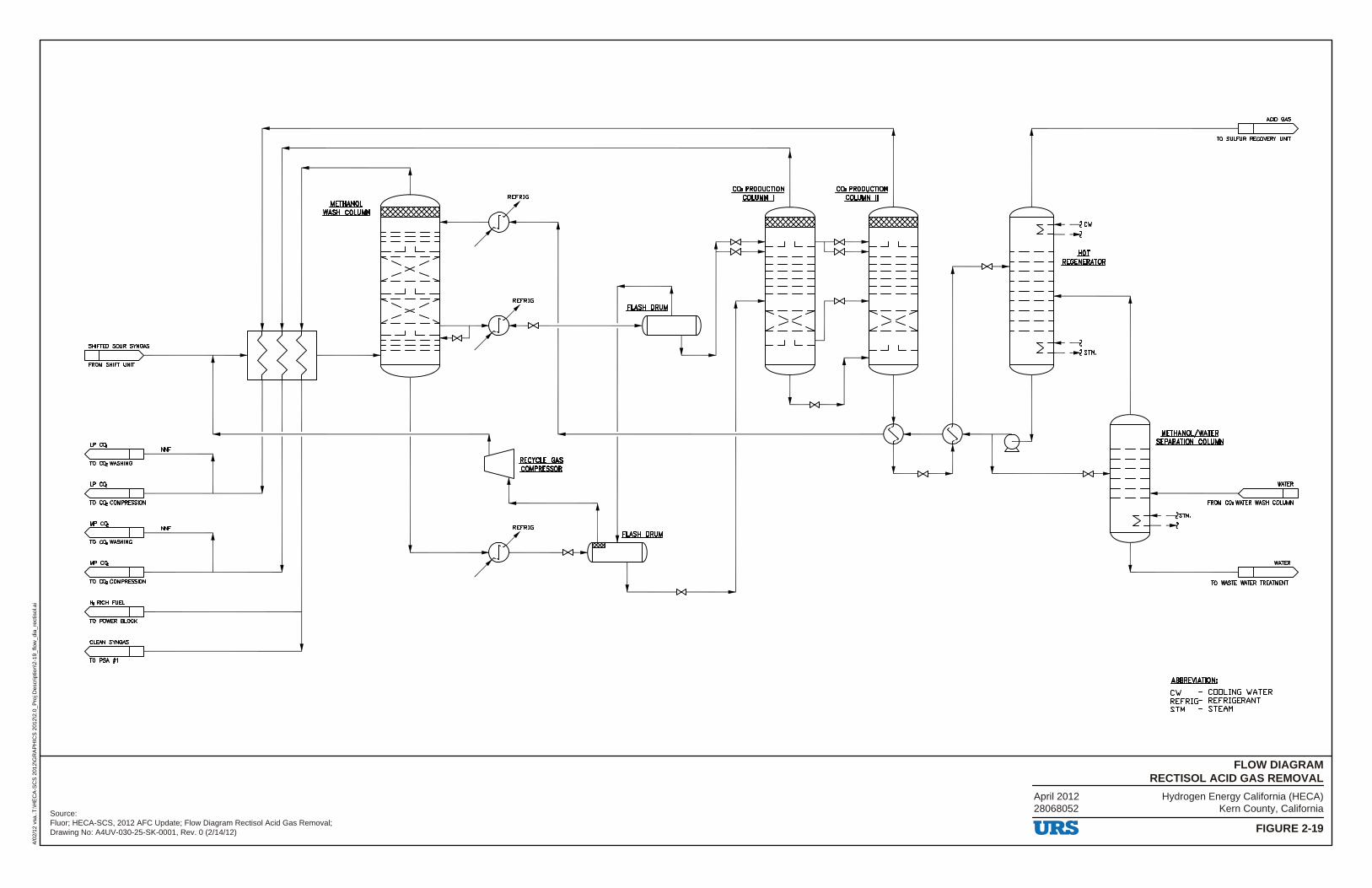
Hydrogen Energy California (HECA)Kern County, California
FIGURE 2-19
FLOW DIAGRAMRECTISOL ACID GAS REMOVAL
4/02
/12
vsa.
.T:\H
EC
A-S
CS
201
2\G
RA
PH
ICS
201
2\2.
0_P
roj D
escr
iptio
n\2-
19_f
low
_dia
_rec
tisol
.ai
Source:Fluor; HECA-SCS, 2012 AFC Update; Flow Diagram Rectisol Acid Gas Removal;Drawing No: A4UV-030-25-SK-0001, Rev. 0 (2/14/12)
April 201228068052
SHIFTED SOUR SYN~
FROM SHIFT UNIT
IP CQ,
TO CQ, WASHING
IP CQ,
TO CQ, COMPRESSION
MP CQ,
TO CQ,WASHING
MP CQ,
TO CQ, COMPRESSION
l'e RICH FUEL
TO POWER BLOCK
CLEAN SYN~
TO PSA f1
.MEil:W!QI. WASH COLUMN
NNF
NNF
RECYCLE GAS COMPRESSOR
REFRIG
co. PRODUCTION .mLU.MILI
_J L
----_J L
co. PRODUCTION .coLUMN....U
_J L
----
-----iClf
--z .lillI
REGENERATOR
-----i -+-2STM.
URS
ACID~
TO SULFUR RECOVERY UNIT
METHANOL/WATER SEPARATION COLUMN
WAml
FROM CO. WATER WASH COWMN
-----iSTM,
--z
WAml
TO WASTE WATER TREATMENT
ABBREVIATION:
CIJ - CODLING IJATER REFRIG- REFRIGERANT STM - STEAM
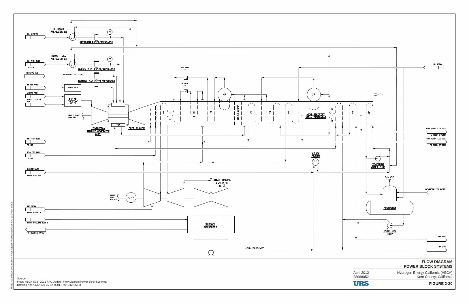
Hydrogen Energy California (HECA)Kern County, California
FIGURE 2-20
FLOW DIAGRAMPOWER BLOCK SYSTEMS
4/02
/12
vsa.
.T:\H
EC
A-S
CS
201
2\G
RA
PH
ICS
201
2\2.
0_P
roj D
escr
iptio
n\2-
20_f
low
_dia
_pow
er_b
lock
.ai
Source:Fluor; HECA-SCS, 2012 AFC Update; Flow Diagram Power Block Systems;Drawing No: A4UV-070-25-SK-0001, Rev. 0 (2/14/12)
April 201228068052
' NITROGEN
~ PREHEATER f2 N2 DILUTION /~I\
I I , '
NITROGEN EILIERfSEPARAT~
' I I lbBl!:11 EIIEL
~~ eBEIIWEB ~ H2 RICH FUEL / ,-.[\
I I ; LP STEAM 10 CTG
l:lz Rl!:11 E!.!EL EILIERiSEl!ARAillR HP BFW ~ I I
NAnJRAI. GAS
I I ; NORMAU.Y NO FLOW - -
0-NATURAL GAS FILTERfSEPARATOR '
DEMIN WATER IP BFW
I I ) WIile! SKID NNF
l WATER FOR HP) I I I ; 1 t ~AP COOLERS INLET AIR -AIR FlllER/EVAP I I I I I I I I COOLER - - - - - - -I I ; ,------J f---
( l l ) ( 1 ( 1 ( 1 l ) l'" r 1 ( 1 ( 1 r----_ ~ ~ f ) I I I I I - I § I I I I - g,) ~ f I; - I l 111 J I ; I I : I I I!: I I I ~ I I I ~ I I(,) IIW BE!:~EBY I I ~ I I !:l I
SING!£ SHAFT ~ ( (;'l - Ii I - (,) WITH Sl'G
~ I ) l ) I l ) l ) I I l ) SJEAM GEHERAillB ( ~ ) I I I I I ~ ,------J
i. ----~ - - I I - - - I I TCA
T t COMBUSTION ' i DUCT BURNERS
T LOW lEMP FLUE GAS
TURBINE GENERATOR I ) .(CIG)
I I I I 10 FEED DRYERS
He RICH FUEL .I t I HIGH lEMP FLUE GAS
I I > I I > I 10 DB 10 FEED DRYERS
PSA OFF GAS .I I I .I
.Hf....!:W I I > .!:QQLEB
-t2 10 DB
f I I ~ IEMeERlt:!G -WAIER euMe
CONDENSAlE
' I I ~ FROM PROCESS
STEAM TURBINE X GEt:!ERAillB .!Siro
=1~~ ~ =~ = ~~ DEMINERAI..IZED WATER
I I u '
HP STEAM ~ ~ ~~ I I ~ PEAERAIQB
FROM GASIFIER
I I ,
" FROM COOUNG 10WER -.sl!BEA!:E ~ !:Qt:!PEt:!SEB
< I lellle BEW 10 COOLING TOWER !l!.Mf
HP BFW
I >
COLD CONDENSAlE ' IP BFW
I )
~
URS
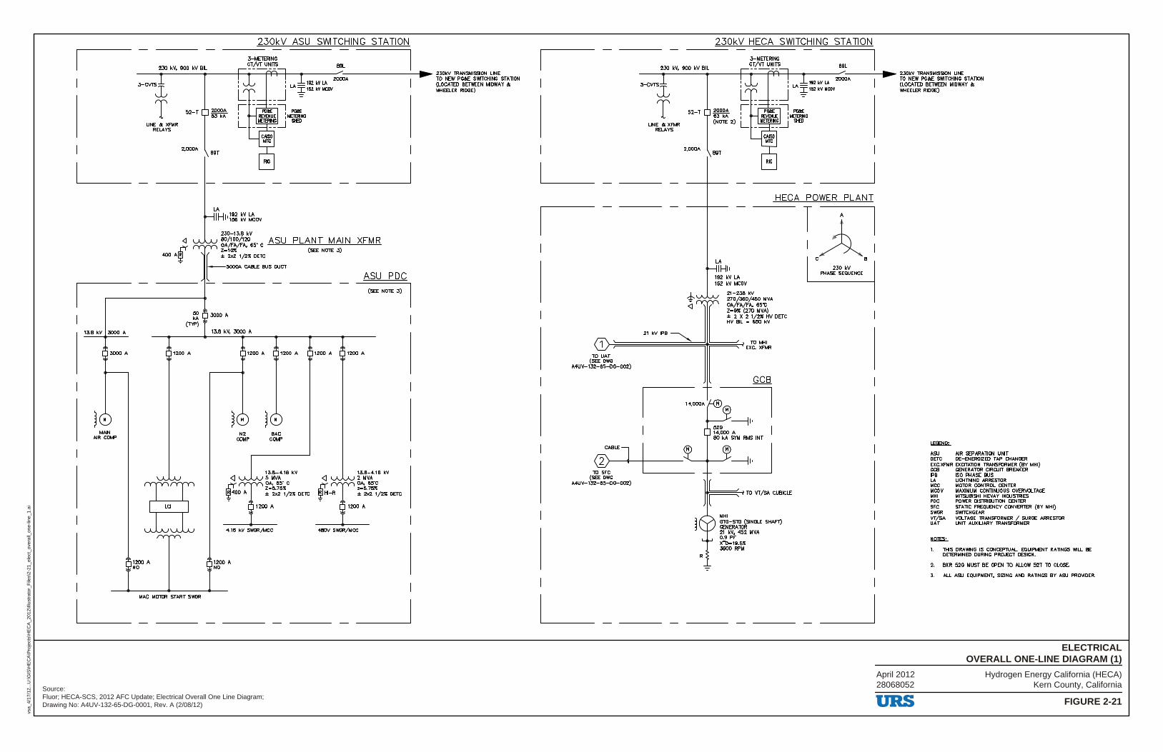
Hydrogen Energy California (HECA)Kern County, California
FIGURE 2-21
ELECTRICALOVERALL ONE-LINE DIAGRAM (1)
vsa_
4/17
/12.
..U:\G
IS\H
EC
A\P
roje
cts\
HE
CA
_201
2\Ill
ustr
ator
_File
s\2-
21_e
lect
_ove
rall_
one-
line_
1.ai
Source:Fluor; HECA-SCS, 2012 AFC Update; Electrical Overall One Line Diagram;Drawing No: A4UV-132-65-DG-0001, Rev. A (2/08/12)
April 201228068052
13.8 kV 3000 A
3000 A
MAIN AIR COMP
230 kV, 900 kV BIL
23OkV ASU SWITCHING STATION
3-MElERING CT/VT UNITS 89L
------------+---<1t-----i+l-+----<11--lS2-k"_" __ 20_,,00. -A---------►~ ~O~~ ~t:rl~~~~E STATION
3-CVTS LA • = (LOCATED BElVEEN MIDWAY &: i I 152 kV IICOV \WIEELER RIDGE)
T LINE & XFMR
RELA'l'S
52-T
2,000A
50 kA
(TYi')
1200 A
1200 A NO
MAC MOTOR START SWGR
2000A 63 kA
89T
3000 A
13.8 kV, 3000 A
<I
1200 A
N2 COMP
1200 A
BAC COMP
13.8-4.16 kV 5 MVA OA, 65" C 2=5.75" :I: 2x2 1/2" DETC
4.16 kV SWGR/MCC
1200 A NO
1200 A
<I
ASU PDC
(SEE NOTE 3) I
1200 A
13.8-4.16 kV 2 MVA OA, 65'C z=5.75" :I: 2x2 1/2" DETC
480V SWGR/MCC
I
230 kV, 900 kV BIL
23OkV HECA SWITCHING STATION
3-MElERING CT/VT UNITS 89L
--------1-----+---<11-----i+l-+-----11--lS2-k"_'_ .-2,,,00.0 --A-----1►.- ~O~~ ~t:rl~~~~E STATION
3-CVTS LA • = (LOCATED BElVEEN MIDWAY &: i I 152 kV IICOV \WIEELER RIDGE)
T LINE &: XFMR
RELA'l'S
52-T
2,000A
¾ <I
2000A 63 kA (NOTE 2)
89T
HECA POWER PLANT
21-238 kV
2•9" (270 MVA) :I: 2 X 2 1/2" HV DETC HV BIL = 650 kV
TTl 1~1
C B
230 kV PHASE SEQUENCE
1 ~2~¾!~45i5~VA
21 kVIPB =-::,..,, ~~j[ EXw.mR TO UAT (SEE DWG
A4UV-132-65-DG-002)
GCB
L_
TO VT /sA CUBICLE
MHI GTG-STG (SINGLE SHAFT} GENERATOR 21 kV, 452 MVA 0.9 PF X''D•19.5" 3600 RPM
_J
URS
LEGEtlll:.
ASU AIR SEPARATION UNIT DETC DE-ENERGIZED TAP CHANGER EXC.XFMR EXCITATION TRANSFORMER (BY MHI) GCB GENERA TOR CIRCUIT BREAKER IPB ISO PHASE BUS LA LIGHTNING ARRESTOR MCC MOTOR CONTROL CENTER MCOV MAXIMUM CONTINUOUS OVERVOLTAGE MHI MITSUBISHI HEVAY INDUSTRIES PDC POWER DISTRIBUTION CENTER SFC STATIC FREQUENCY CONVERTER (BY MHI) SWGR SWITCHGEAR VT/SA VOLTAGE TRANSFORMER / SURGE ARRESTOR UAT UNIT AUXILIARY TRANSFORMER
tllllES:..
1. THIS DRAWING IS CONCEPTUAL EQUIPMENT RATINGS WILL BE DElERMINED DURING PROJECT DESIGN.
2. BKR 52G MUST BE OPEN TO ALLOW 52T TO CLOSE.
3. ALL ASU EQUIPMENT, SIZING AND RA TINGS BY ASU PROI/IDER.
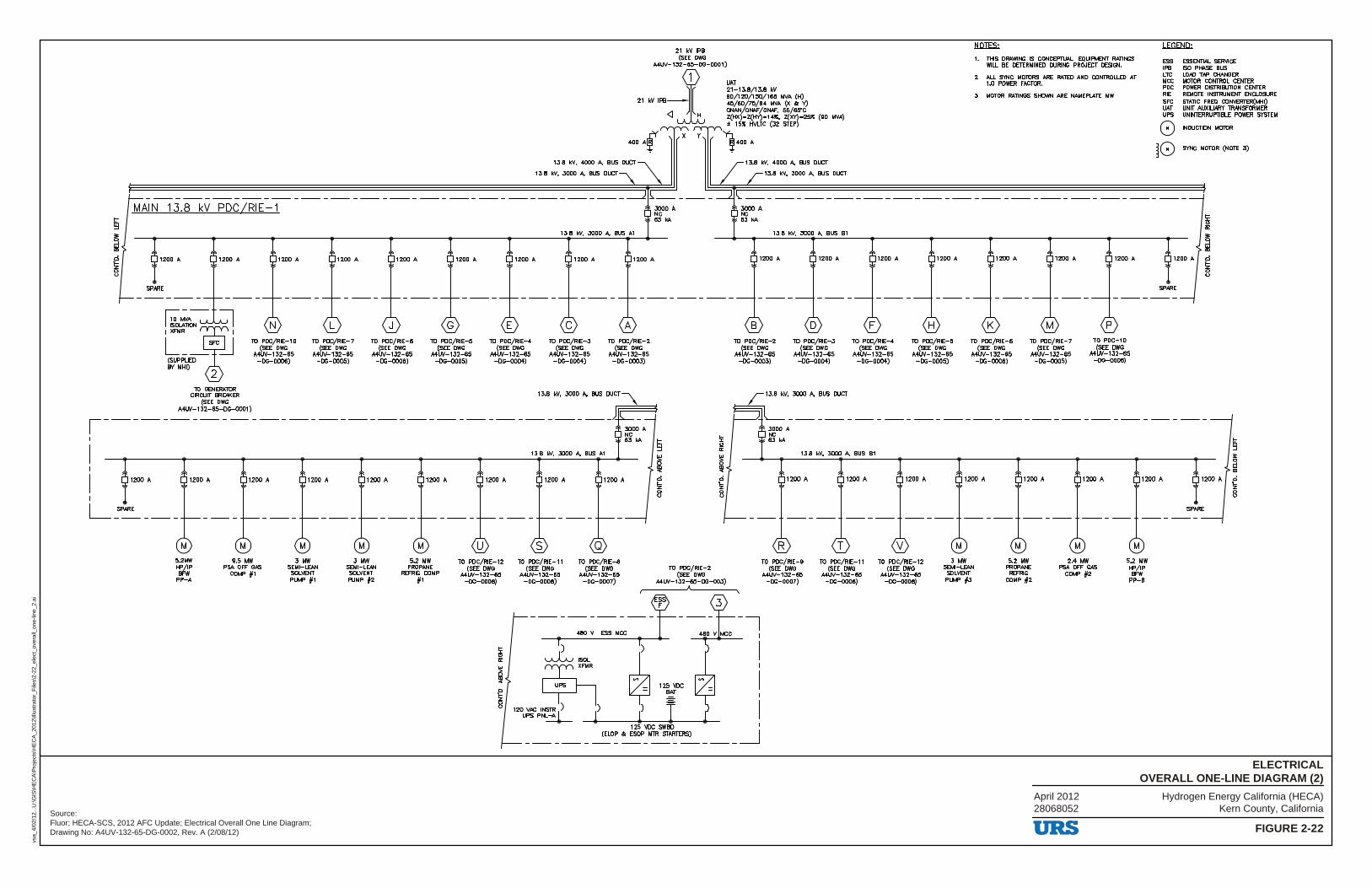
Hydrogen Energy California (HECA)Kern County, California
FIGURE 2-22
ELECTRICALOVERALL ONE-LINE DIAGRAM (2)
vsa_
4/02
/12.
..U:\G
IS\H
EC
A\P
roje
cts\
HE
CA
_201
2\Ill
ustr
ator
_File
s\2-
22_e
lect
_ove
rall_
one-
line_
2.ai
Source:Fluor; HECA-SCS, 2012 AFC Update; Electrical Overall One Line Diagram;Drawing No: A4UV-132-65-DG-0002, Rev. A (2/08/12)
April 201228068052
21 kV IPB (SEE DWG
" w :<l-13i~I[-H-,$;w.:!J,:; - 00 45/60/75/84 WA (X o!c Y) ONAN/ONAF /ONAF, 55/65'C Z(HX)-Z(HY)-14ll:, Z(XY)-25ll: (90 WA) ± 15ll: tM.TC (32 STEP)
13.8 kV, 3000 A, BUS DUCT 13.8 kV, 3000 A, BUS DUCT
1::iQIES:.
1. THIS DRAWING IS CONCEPTUAL. EQUIPMENT RATINGS WILL BE DETERMINED DURING PROJECT DESIGN.
2. ALL SYNC MOlORS ARE RATED ANO CONTROLLED AT 1.0 POWER F,crQR,
3. MOTOR RATINGS SHOWN ARE NAMEPLATE MW.
.w.Et:ill;_
ESS IPB LTC MCC PDC RIE SFC UAT UPS
ESSENTlAL SERVICE ISO PHASE BUS LOAD TAP CHANGER MOlOR CONTROL CENTER POWER DISTRIBUTION CENTER REMOTE INSTRUMENT ENCLOSURE STATIC FREQ CONVERTER(MHI) UNIT AUXILIARY TRANSFORMER UNINTERRUPTIBLE POWER SYSTEM
INDUCT10N MOlOR
SYNC MOTOR (NOTE 3)
'" W, - rn: •~ r_X ___ - 1400 A
------------------------------------------------- ---------------------------------------------MAIN 13.8 kV PDC/RIE-1
1200 A 1200 A
SPARE
rii~N!~ I XFMR I
L __ sFCd_J (SUPPLIED BY MHI)
2
TO PDC/RIE-10 (SEE OWG
MW-132-65 -DG-0006)
TO GENERATOR CIRCUIT BREAKER
(SEE DWG MW-132-65-DG-0001)
TO PDC/RIE-7 (SEE DWG
MW-132-65 -DG-0005)
TO PDC/RIE-6 (SEE DWG
A4W-132-65 -DG-0006)
TO PDC/RIE-5 (SEE DWG
MW-132-65 -DG-0005)
TO PDC/RIE-4 (SEE DWG
MW-132-65 -DG-0004)
13.8 kV, 3000 A, BUS A1
TO PDC/RIE-3 (SEE DWG
MW-132-65 -DG-0004)
TO PDC/RIE-2 (SEE OWG
MW-132-65 -DG-0003)
,----------------------------------1
I I
I 1200 A
I
L SPARE
-------
5.2MW HP/IP BFW
PP-A
9.5 MW PSA OFF GAS
COMP #1
3 MW SEMI-LEAN SOLVENT PUMP #1
3 MW SEMI-LEAN SOLVENT PUMP #2
5.2 MW PROPANE
REFRIG COMP #1
TO PDC/RIE-12 (SEE OWG
MW-132-65 -OG-0006)
13.8 kV, 3000 A, BUS A1
TO PDC/RIE-11 (SEE DWG
MW-132-65 -DG-0006)
TO PDC/RIE-8 (SEE OWG
A4W-132-65 -DG-0007)
3000 A NC 63 kA
t ~
i ci ~ 8
TO PDC/RIE-2
!i: ~
i ci ~ 8
{SEE DWG MW-132-65-DG-003)
13.8 kV, 3000 A, BUS 81
TO PDC/RIE-2 (SEE DWG
MW-132-65 -DG-0003)
TO PDC/RIE-3 (SEE OWG
MW-132-65 -DG-0004)
13.8 kV, 3000 A, BUS DUCT
TO PDC/RIE-4 (SEE DWG
MW-132-65 -DG-0004)
13.8 kV, 3000 A, BUS 81
TO PDC/RIE-5 (SEE DWG
MW-132-65 -DG-0005)
TO PDC/RIE-6 (SEE DWG
MW-132-65 -DG-0006)
TO PDC/RIE-7 (SEE DWG
MW-132-65 -DG-0005)
TO PDC-10 (SEE DWG
MW-132-65 -DG-0006)
TO PDC/RIE-9 (SEE DWG
MW-132-65 -DG-0007)
TO PDC/RIE-11 (SEE DWG
MW-132-65 -DG-0006)
TO PDC/RIE-12 {SEE OWG
MW-132-65 -OG-0006)
3 MW SEMI-LEAN
SOLVENT PUMP #3
5.2 MW PROPANE
REFRIG COMP #2
2.4 MW PSA OFF GAS
COMP #2
5.2 MW HP/IP BFW
PP-8
URS
t ~
~ .., a,
1200 A ci
~ SPARE
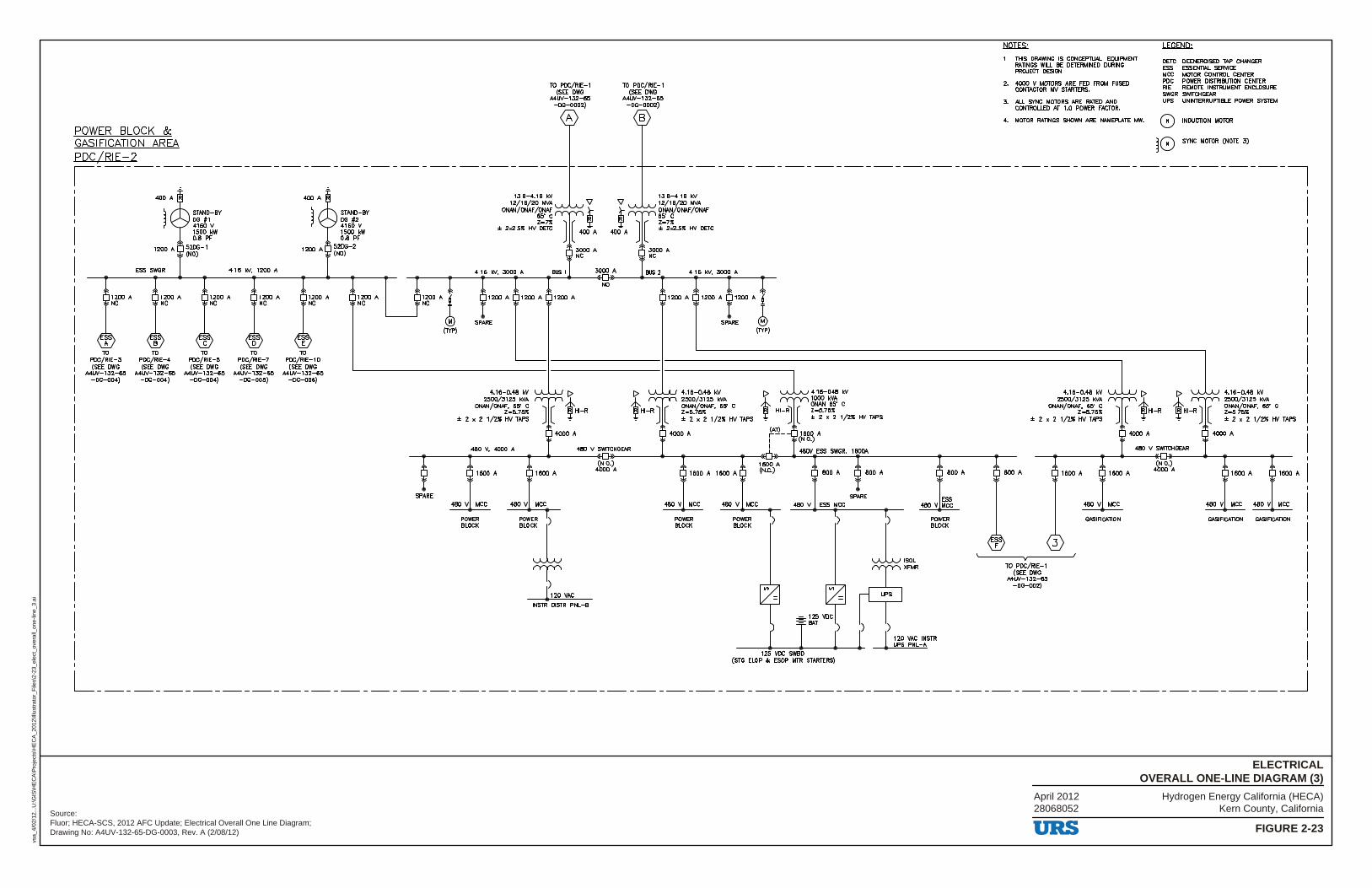
Hydrogen Energy California (HECA)Kern County, California
FIGURE 2-23
ELECTRICALOVERALL ONE-LINE DIAGRAM (3)
vsa_
4/02
/12.
..U:\G
IS\H
EC
A\P
roje
cts\
HE
CA
_201
2\Ill
ustr
ator
_File
s\2-
23_e
lect
_ove
rall_
one-
line_
3.ai
Source:Fluor; HECA-SCS, 2012 AFC Update; Electrical Overall One Line Diagram;Drawing No: A4UV-132-65-DG-0003, Rev. A (2/08/12)
April 201228068052
POWER BLOCK & GASIFICATION AREA PDC/RIE-2
TO PDC/RIE-1 (SEE DWG
MlN-132-65 -DG-0002)
TO PDC/RIE-1 (SEE DWG
A4lN-132-65 -DG-0002)
A B
liQIES.;_
1. THIS DRAWING IS CONCEP1\JAL EQUIPMENT RATINGS WIil. BE DETERMINED DURING PROJECT DESIGN.
2. -4000 V MOTORS ARE FED FROM FUSED CONTACTOR MV STARTERS.
3. All. S't'NC MOTORS ARE RATED AND CONTROIJ.ED AT 1.0 POWER FACTOR.
.L.Emil2;_
DETC ESS MCC PDC RIE SWGR UPS
DEENERGISED TAP CHANGER ESSENTIAL SERVICE MOTOR CONTROL CENTER POWER DISTRIBUTION CENTER REMOTE INSTRUMENT ENCLOSURE SWITCHGEAR UNINTERRUPTIBLE POWER SYSTEM
4. MOTOR RATINGS SHOWN ARE NAMEPLATE MW. 0 INDUCTION MOTOR
~ 0 S't'NC MOTOR (NOTE 3) ,----- ~ --------- ~ --------------------- -------------------------------------------7
TO PDC/RIE-3 (SEE DWG
A4lN-132-65 -OG-004)
ESS SWGR
TO PDC/RIE-4 (SEE DWG
MlN-132-65 -OG-004)
STAND-BY 0G #1 4160 V 1500 kW 0.8 PF
TO PDC/RIE-5 (SEE DWG
MlN-132-65 -DG-004)
4.16 kV, 1200 A
TO PDC/RIE-7 (SEE DWG
MW-132-65 -DG-005)
TO PDC/RIE-10
(SEE DWG MW-132-65
-OG-006)
STAND-BY DG #2 4160 V 1500 kW 0.8 PF
1200 A NC
1200 A l
NC !
13.8-4.16 kV 12/16/20 MVA
ONAN/ONAF /ONAF 65" C z-ni:
± 2x2.5X HV DETC
4.16 kV, 3000 A BUS 1
1200 A 1200 A 1200 A
SPARE (TYP)
SPARE
4.16-0.48 kV 2500/3125 kVA
ONAN/ONAF, 65" C Z=5.75X
± 2 x 2 1/2X HV TAPS
480 V, 4000 A
1600 A 1600 A
480 V MCC 480 V MCC
POWER BLOCK
3000 A
NO
480 V SWITCHGEAR
(N.O.) 4000 A
INSTR DISTR PNL-B
13.8-4.16 kV 12/16/20 MVA ONAN/ONAF /ONAF 65' C z-1x ± 2x2.5X HV DETC
BUS 2 4.16 kV, 3000 A
1200 A 1200 A 1200 A i
SPARE
4.16-0.48 kV 2500/3125 kVA ONAN/ONAF, 65' C Z=5.75X ± 2 x 2 1/2X HV TAPS
1600 A 1600 A
J (TYP)
[> l 4.16-048 kV
ONAN 65" C ½ 1000 kVA
HI-R~ [ Z=5. 75X ~ J ±2x21/2XHVTAPS
ft!)_ 1600 A I (N.O.) I
480V ESS SWGR, 1600\
1600 A (N.C.) 800 A 800 A
SPARE 480 V MCC 480 V MCC 480 V ESS MCC
POWER BLOCK
POWER BLOCK
) )
loo, /2XFMR
800 A
ESS 480 V MCC
POWER BLOCK
!) r=~= 1)1, ----1-0----------------l ~~~ ~~~~STR
125 VDC SWBD (STG ELOP & ESOP MTR STARTERS)
4.16-0.48 kV 2500/3125 kVA
ONAN/ONAF, 65" C Z=5.75X
± 2 x 2 1/2X HV TAPS
4000 A
480 V SWITCHGEAR
1600 A
(N.O.) 4000 A
TO PDC/RIE-1 (SEE DWG
MW-132-65 -OG-002)
GASIFICATION
4.16-0.48 kV 2500/3125 kVA ONAN/ONAF, 65" C Z=5.75X ± 2 x 2 1/2X HV TAPS
1600 A 1600 A
480 V MCC 480 V MCC
GASIFICATION GASIFICATION
L _________________________________________________________________________________ _J
URS
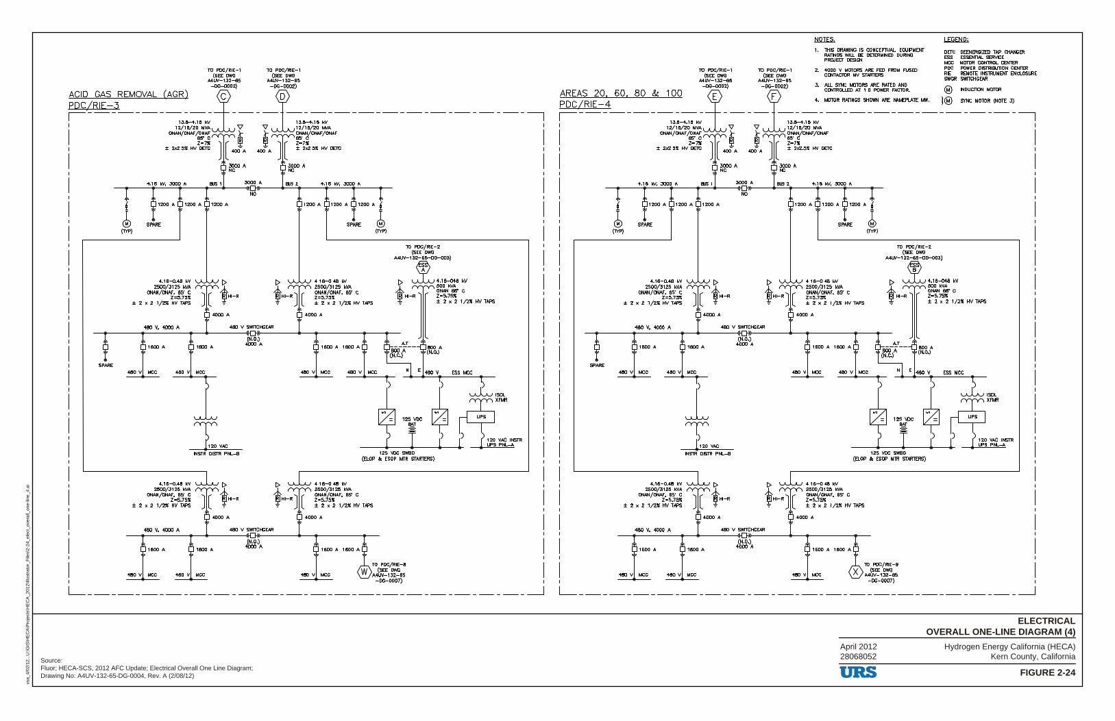
Hydrogen Energy California (HECA)Kern County, California
FIGURE 2-24
ELECTRICALOVERALL ONE-LINE DIAGRAM (4)
vsa_
4/02
/12.
..U:\G
IS\H
EC
A\P
roje
cts\
HE
CA
_201
2\Ill
ustr
ator
_File
s\2-
24_e
lect
_ove
rall_
one-
line_
4.ai
Source:Fluor; HECA-SCS, 2012 AFC Update; Electrical Overall One Line Diagram;Drawing No: A4UV-132-65-DG-0004, Rev. A (2/08/12)
April 201228068052
TO PDC/RIE-1 TO PDC/RIE-1 (SEE DWG (SEE DWG
A4lN-132-65 MlN-132-65 -DG-0002) -DG-0002)
ACID GAS REMOVAL (AGR) l ! PDC/RIE-3 I --- --- --- - 1~/186/~~6~ -V - V ;~J,-;;;~g :A -- - -- - -- - -- - -- - -- - -- --- - I
ONAN/ONAF /ONAF £ £ ONAN/ONAF /ONAF
SPARE
r-7i ~ ~ r-1~ ± 2x2.5ll: HV DETC ] [ 400 A 400- A ] [ ± 2x2.5ll: HV DETC
4.16 11!1, 3000 A BUS 1
l 1200 A 1200 A 1200 A
J SPARE (IYP)
1600 A 1600 A
480 V MCC 480 V MCC
3000 A NC
3000 A
NO
_L_ 4.16-0.48 II!/
2500/3125 11!/A ONAN/ONAF, 65" C
Z•5.75ll: ± 2 x 2 1/2" HV TAPS
480 V, 4000 A
1600 A
INSTR DISTR PNL-B
480 V SWITCHGEAR
1600 A
(N.O.) 4000 A
3000 A NC
BUS 2 4.16 11!1, 3000 A
1200 A 1200 A 1200 A i
SPARE J (IYP)
1600 A 1600 A A.T.
800 A (N.C.)
800 A (N.O.)
480 V MCC 480 V MCC ESS MCC
4.16-0.48 II!/ 2500/3125 11!/A ONAN/ONAF, 65" C Z•5.75ll:
$) $) ~~~R 125 VDC = UPS
~T
r I r r r i~n~~~STR
125 VDC SWBD (ELOP & ESOP MTR STARTERS)
± 2 x 2 1/2" HV TAPS
1600 A 1600 A
TO PDC/RIE-8 (SEE DWG
480 V MCC 480 V MCC 480 V MCC MW-132-65 -DG-0007)
L_ _____________________________________ _J
TO PDC/RIE-1 TO PDC/RIE-1 (SEE DWG (SEE DWG
MlN-132-65 MW-132-65
.NQIES;_
1. THIS DRAWING IS CONCEPTUAL EQUIPMENT RATINGS WILL BE DEIERMINED DURING PROJECT DESIGN.
2. 4000 V MOTORS ARE FED FROM FUSED CONTACTOR W STARTERS.
lEGEt,lQ;,
DETC DEENERGIZED TAP CHANGER ESS ESSENTIAL SERVICE MCC MOTOR CONTROL CENTER PDC POWER DISTRIBUTION CENTER RIE REMOTE INSTRUMENT ENCLOSURE SWGR SWITCHGEAR
AREAS 20, 60, 80 & 100 -100;
002' -:tDG~000
2)
3' ~~it~R1~l~~JE~~- ® INDUCTION MOTOR
PDC/RIE-4 4. MOTOR RATINGS SHOWN ARE NAMEPLATE MW. l® SYNC MOTOR (NOTE 3) ,----------- ------------------------, 13.8-4.16 II!/ 13.8-4.16 II!/
12/16/20 WA V V 12/16/20 WA ONAN/ONAF /ONAF £ £ ONAN/ONAF /ONAF
r-7i ~ ~ r-1~ ± 2x2.5ll: HV DETC ] [ 400 A 400- A ] [ ± 2x2.5ll: HV DETC
4.16 11!1, 3000 A BUS 1
3000 A NC
3000 A
NO
3000 A NC
BUS 2 4.16 11!1, 3000 A
l 1200 A 1200 A 1200 A 1200 A 1200 A 1200" 1
J SPARE (IYP)
4.16-0.48 II!/ 2500/3125 11!/A
ONAN/ONAF, 65" C Z•5.75ll:
± 2 x 21/2" HVTAPS
480 V, 4000 A 480 V SWITCHGEAR
SPARE
4.16-0.48 II!/ 2500/3125 11!/A ONAN/ONAF, 65" C Z•5.75ll: ± 2 x 2 1/2" HV TAPS
J (IYP)
TO PDC/RIE-2 (SEE DWG
MlN-132-65-DG-003)
[> ~4.16-048 II!/
! ± 2 x 2 1/2" HV TAPS ✓.:b-HI-R] [ r+.:~- c
- ..... ---------------~Di>------+-.... -------.... -
SPARE
1600 A 1600 A
480 V MCC 480 V MCC
l T l 120 VN:.
(N.O.) 4000 A
INSTR DISTR PNL-B
4.16-0.48 II!/ 2500/3125 11!/A
ONAN/ONAF, 65" C Z•5.75ll:
± 2 x 2 1/2" HV TAPS
480 V, 4000 A
1600 A 1600 A
480 V SWITCHGEAR
(N.O.) 4000 A
1600 A 1600 A 600 A (N.O.)
480 V MCC 480 V MCC ESS MCC
4.16-0.48 II!/ 2500/3125 11!/A ONAN/ONAF, 65" C Z•5.75ll:
$) $) ~~~R 125 VDC = UPS
~T
r r r l) r i~ ~';;L!STR
125 VDC SWBD (ELOP & ESOP MTR STARTERS)
± 2 x 2 1/2" HV TAPS
1600 A 1600 A
TO PDC/RIE-9 (SEE DWG
480 V MCC 480 V MCC 480 V MCC MW-132-65 -DG-0007)
L_ _____________________________________ _J
URS
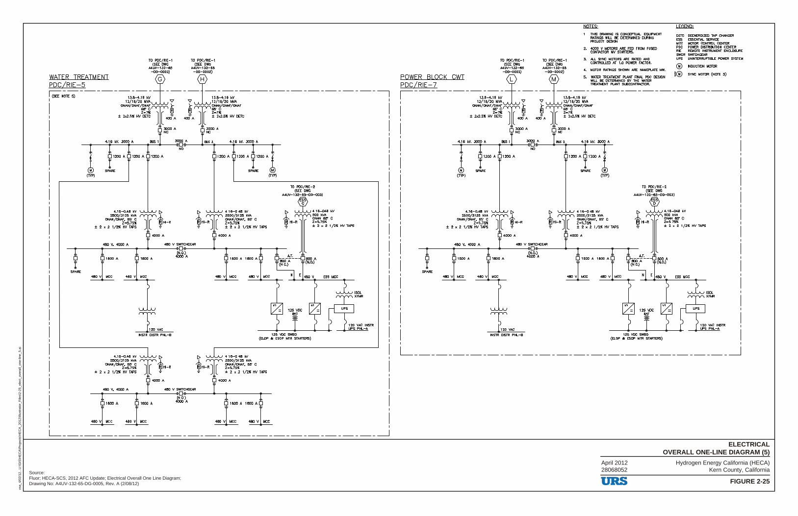
Hydrogen Energy California (HECA)Kern County, California
FIGURE 2-25
ELECTRICALOVERALL ONE-LINE DIAGRAM (5)
vsa_
4/02
/12.
..U:\G
IS\H
EC
A\P
roje
cts\
HE
CA
_201
2\Ill
ustr
ator
_File
s\2-
25_e
lect
_ove
rall_
one-
line_
5.ai
Source:Fluor; HECA-SCS, 2012 AFC Update; Electrical Overall One Line Diagram;Drawing No: A4UV-132-65-DG-0005, Rev. A (2/08/12)
April 201228068052
TO PDC/RIE-1 TO PDC/RIE-1 (SEE DWG (SEE DWG
A4UV-132-65 MUV-132-65 -DG-0002) -DG-0002)
WATER TREATMENT l :t PDC/RIE-5 I (SEE NOlE 5) - -- - -- - 1~;;88/~~6~ - V - V ]~J;;,,~g :A ------------------------I
ONAN/ONAF /ONAF _t _t ONAN/ONAF /ONAF
SPARE
f"Ti ~ ~ f,i ± 2x2.5ll: HV DETC ] [ 400 A 400- A ] [ ± 2x2.5ll: HV DETC
4.16 kV, 3000 A BUS 1
l 1200 A 1200 A 1200 A
J SPARE (JYP)
1600 A
480 V MCC 480 V MCC
3000 A NC
3000 A
NO
L 4.16-0.48 kV
2500/3125 kVA ONAN/ONAF, 65' C
Z•5.75ll: ± 2 x 2 1/2" HV TAPS
480 V, 4000 A
1600 A
INSTR DISTR PNL-B
480 V SWITCHGEAR
1600 A
(N.O.) 4000 A
480 V MCC 480 V MCC
3000 A NC
BUS 2 4.16 kV, 3000 A
1200 A 1200 A 1200 A !
SPARE J (JYP)
480 V MCC 480 V MCC
800 A (N.O.)
ESS MCC
$) $) ~ISOL
125-VDC .,, = ~ XFMR
~T LT r r r r r ~~ ~~~~STR 125 VDC SWBD
(ELOP & ESOP MTR STARTERS)
4.16-0.48 kV 2500/3125 kVA ONAN/ONAF, 65' C Z•5.75ll: ± 2 x 2 1/2" HV TAPS
1600 A 1600 A
480 V MCC 480 V MCC
L_ _____________________________________ _J
TO PDC/RIE-1 TO PDC/RIE-1 (SEE DWG (SEE DWG
MUV-132-65 MUV-132-65 -DG-0002) -DG-0002)
.l::l.QIES.;_
1. THIS DRAWING IS CONCEPTUAL. EQUIPMENT RATINGS WIil. BE DElERMINED DURING PROJECT DESIGN.
2. -4000 V MOTORS ARE FED FROM FUSED CONTACTOR MV STARTERS.
3. All. SYNC MOTORS ARE RATED AND CONTROLLED AT 1.0 POWER FACTOR.
4. MOTOR RATINGS SHOWN ARE NAMEPLATE MW.
.w.Et:ill;_
DETC DEENERGIZED TAP CHANGER ESS ESSENT1AL SERVICE MCC MOTOR CONTROL CENTER PDC POWIER DISTRIBUTION CENTER RIE REMOlE INSTRUMENT ENCLOSURE SWGR SWITCHGEAR UPS UNINTERRUPTIBLE POWER SYSTEM
@ INDUCTION MOTOR
j@ SYNC MOTOR (NOlE 3)
p DC/RI E - 7 TREATMENT PLANT SUBCONTRACTOR.
POWER BLOCK CWT ! =t 5. WATER TREATMENT PLANT FINAL PDC DESIGN WIil. BE DETERMINED BY THE WATER
I ---------- 1~J188/!~6~ -V - V ]~J;;,,~g :A -- - -- - -- - -- - -- --- --- --- -7 ONAN/ONAF /ONAF _t _t ONAN/ONAF /ONAF
f"Ti ~ ~ f,i ± 2x2.5ll: HV DETC ] [ 400 A 400- A ] [ ± 2x2.5ll: HV DETC
4.16 kV, 3000 A BUS 1
l 1200 A 1200 A
J SPARE (JYP)
4.16-0.48 kV 2500/3125 kVA
ONAN/ONAF, 65' C Z•5.75ll:
± 2 x 21/2" HVTAPS
480 V, -4000 A
3000 A NC
3000 A
NO
480 V SWITCHGEAR
3000 A NC
BUS 2 4.16 kV, 3000 A
1200 A 1200 A !
SPARE J (JYP)
4.16-0.48 kV 2500/3125 kVA ONAN/ONAF, 65' C Z•5.75ll: ± 2 x 2 1/2" HV TAPS
TO PDC/RIE-2 (SEE DWG
MUV-132-65-DG-003)
[> ~4.16-048 kV
! ±2x21/2"HVTAPS ✓,h HI-R l l r.+.:~· C
-..------...----...... _.---~D+---...... -...-----.----'1-1600 A
SPARE
480 V MCC 480 V MCC
l T l 120 VN:.
INSTR DISTR PNL-B
(N.O.) 4000 A
480 V MCC 480 V MCC
800 A (N.O.)
ESS MCC
$) $) ~ISOL
125-VDC .,, = ~ XFMR
~T LT r r r r r ~~ ~1rl~~STR
125 VDC SWBD (ELOP & ESOP MTR STARTERS)
L _____________________________________ _J
URS
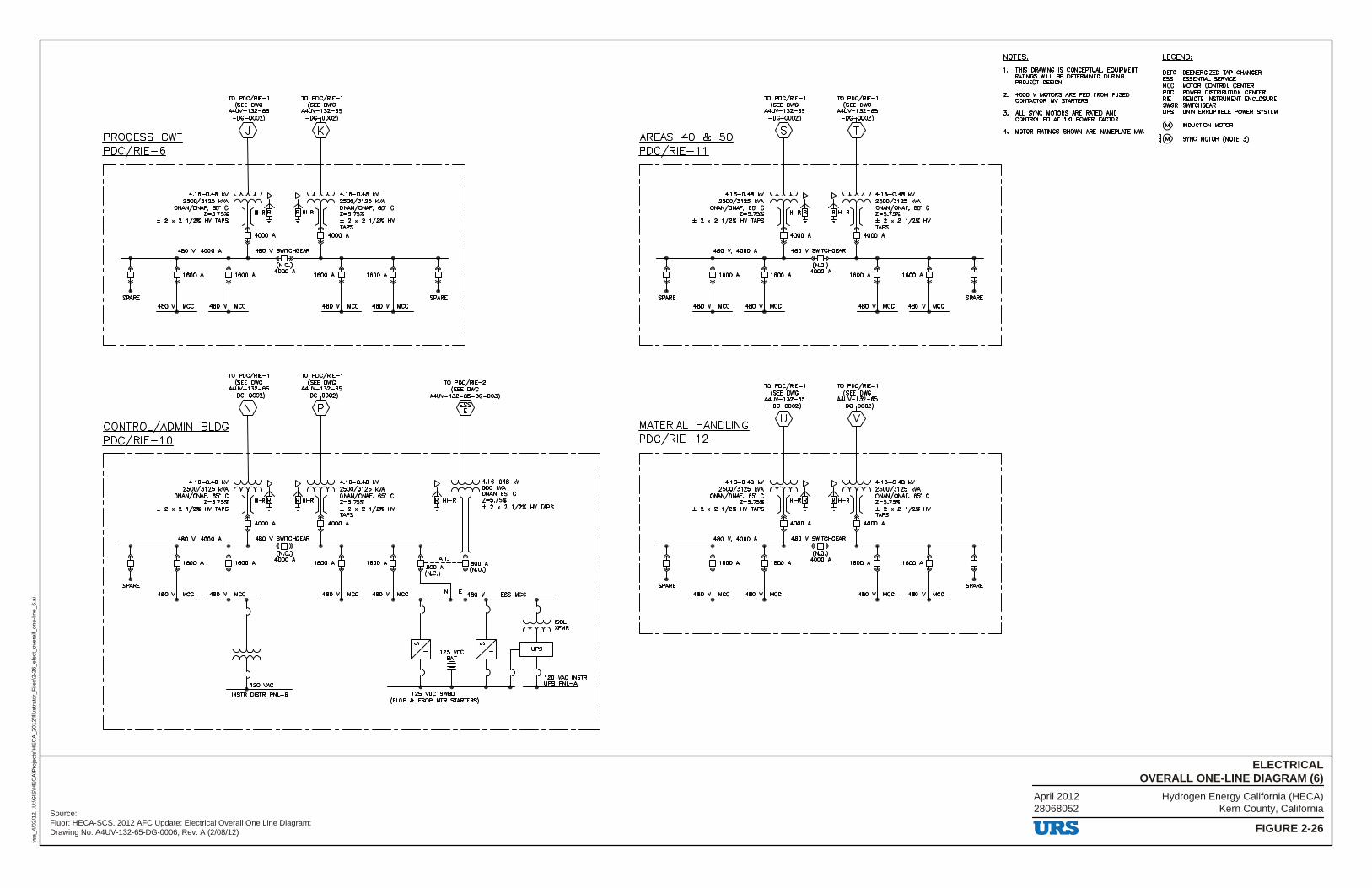
Hydrogen Energy California (HECA)Kern County, California
FIGURE 2-26
ELECTRICALOVERALL ONE-LINE DIAGRAM (6)
vsa_
4/02
/12.
..U:\G
IS\H
EC
A\P
roje
cts\
HE
CA
_201
2\Ill
ustr
ator
_File
s\2-
26_e
lect
_ove
rall_
one-
line_
6.ai
Source:Fluor; HECA-SCS, 2012 AFC Update; Electrical Overall One Line Diagram;Drawing No: A4UV-132-65-DG-0006, Rev. A (2/08/12)
April 201228068052
TO PDC/RIE-1 (SEE DWG
MUV-132-65 -DG-0002)
PROCESS CWT PDC/RIE-6
SPARE
4.16-0.48 kV 2500/3125 kVA
ONAN/ONAF, 65' C Z•5.75ll:
± 2 x 2 1/2ll: HY TAPS
480 V, 4000 A
480 V MCC 480 V MCC
480 V SWITCHGEAR
4.16-0.48 kV 2500/3125 kVA ONAN/ONAF, 65' C Z•5.75ll: ±2x21/2ll:HY TAPS
4000 A
1600 A 1600 A
480 V MCC 480 V MCC
SPARE
I L _______________________ _J
TO PDC/RIE-1 (SEE DWG
MUV-132-65 -DG-0002)
CONTROL/ADMIN BLDG PDC/RIE-10 ,--------
N
TO POC/RIE-1 (SEE DWG
MUV-132-65 -DG 0002)
p
TO PDC/RIE-2 (SEE DWG
MUV-132-65-DG-003)
E
-
___.._ _____ o,_~_50_;·_g~-8;-_~_2':_65_!""_1 ______ 4)._~~-. ..,.4)._~~-H ______ !>-~-80-_{_r_~_5_~_~_c ___ ___.,__i~ HI-R l l Z=5.75ll: I~ ~I Z=5.75ll: ~ ± 2 x 2 1/2ll: HY TAPS ± 2 x 2 1/2" HY
TAPS
4000 A
480 V, 4000 A 480 V SWITCHGEAR
(N.O.)
4.18-048 kV 500 kVA ONAN 65" C Z•5.75ll: ± 2 x 2 1/2" HY TAPS
1600 A 1600 A 4000"
SPARE
480 V MCC 480 V MCC
l T l 120 VN:,
INSTR DISTR PNL-B
1600 A 1600 A
480 V MCC 480 V MCC
600" (N.O.)
ESS MCC
L _______________________________ _J
AREAS 40 & 50 PDC/RIE-11
TO POC/RIE-1 (SEE DWG
MUV-132-65 -DG-0002)
4.16-0.48 kV 2500/3125 kVA
ONAN/ONAF, 65' C Z•5.75ll:
± 2 x 2 1/2" HY TAPS
480 V, 4000 A 480 V SWITCHGEAR
1600 A
SPARE
480 V MCC
1600 A
480 V MCC
(N.O.) 4000 A
4.16-0.48 kV 2500/3125 kVA ONAN/ONAF, 65' C Z•5.75ll: ± 2 X 2 1/2" HY TAPS
4000"
1600 A 1600 A
480 V MCC 480 V MCC
SPARE
I L _______________________ _J
TO POC/RIE-1 (SEE DWG
MUV-132-65 -DG-0002)
MATERIAL HANDLING PDC/RIE-12 ,---------1
I I
I I
4.18-0.48 kV 2500/3125 kVA
ONAN/ONAF, 65' C Z=5.75ll:
± 2 x 2 1/2" HY TAPS
I 480 V, 4000 A 480 V SWITCHGEAR
I
I 1600 A
I SPARE
I 480 V MCC
1600 A
480 V MCC
(N.O.) 4000 A
---------7
4.18-0.48 kV 2500/3125 kVA ONAN/ONAF, 65' C Z=5.75ll: ± 2 X 2 1/2" HY TAPS
4000"
1600 A 1600 A
480 V MCC 480 V MCC
I
I I
I I
I I
I SPARE I
I I L _______________________ _J
NQIES;_
1. THIS DRAWING IS CONCEPTIJAL. EQUIPMENT RATINGS WILL BE DETERMINED DURING PROJECT DESIGN.
2. 4000 V MOTORS ARE FED FROM FUSED CONTACTOR MV STARTERS.
3. ALL SYNC MOTORS ARE RATED AND CONTROLLED AT 1.0 POWER FACTOR.
4. MOTOR RATINGS SHOWN ARE NAMEPLATE MW.
URS
.LEG.EMll;_
DETC DEENERGIZED TAP CHANGER ESS ESSENTW. SERVICE MCC MOTOR CONTROL CENTER PDC POWIER DISTRIBUTION CENTER RIE REMOTE INSTRUMENT ENCLOSURE SWGR SWITCHGEAR UPS UNINTERRUPTIBLE POWER SYSTEM
@ INDUCllON MOTOR
l® SYNC MOTOR (NOTE 3)
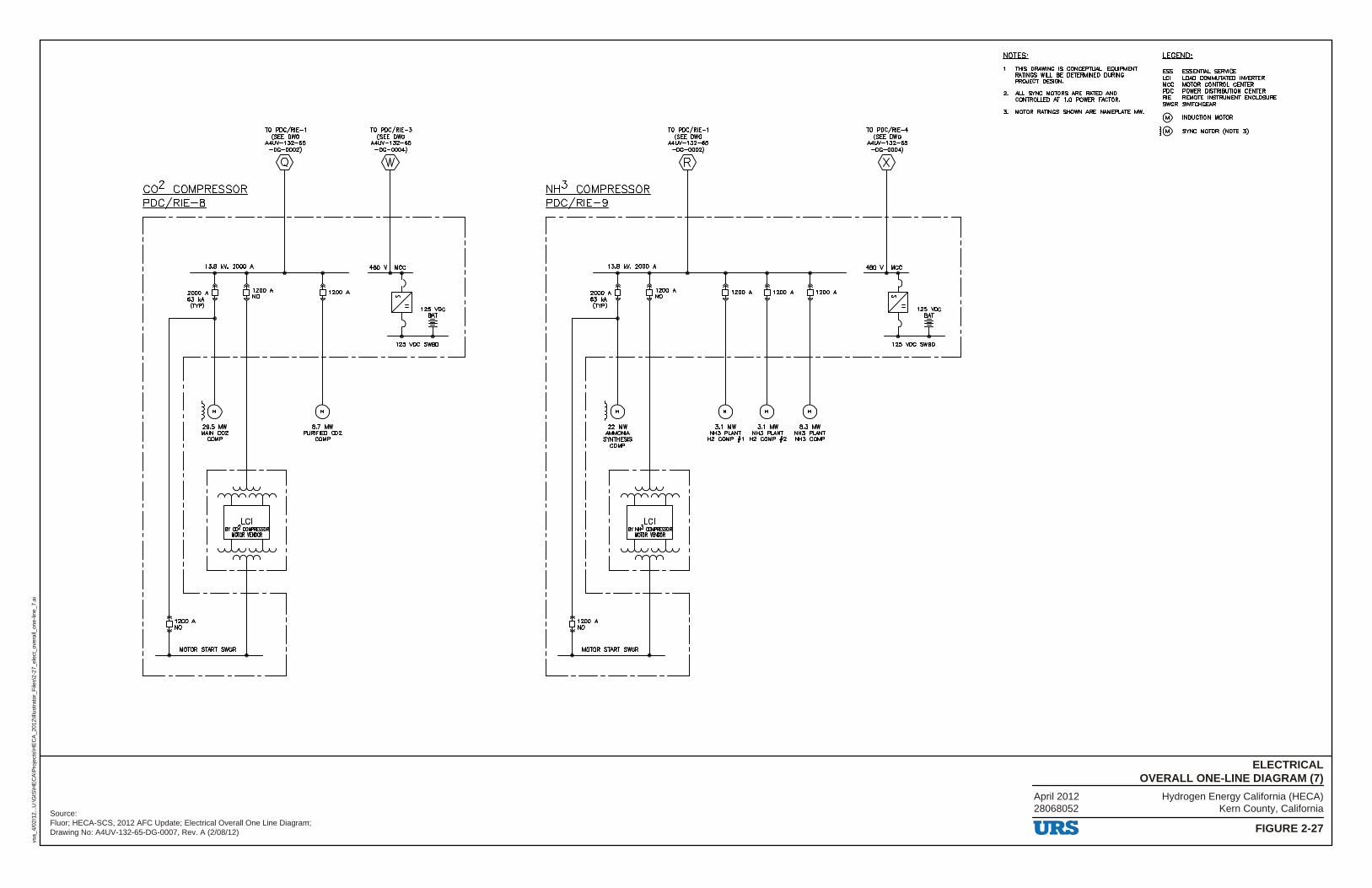
Hydrogen Energy California (HECA)Kern County, California
FIGURE 2-27
ELECTRICALOVERALL ONE-LINE DIAGRAM (7)
vsa_
4/02
/12.
..U:\G
IS\H
EC
A\P
roje
cts\
HE
CA
_201
2\Ill
ustr
ator
_File
s\2-
27_e
lect
_ove
rall_
one-
line_
7.ai
Source:Fluor; HECA-SCS, 2012 AFC Update; Electrical Overall One Line Diagram;Drawing No: A4UV-132-65-DG-0007, Rev. A (2/08/12)
April 201228068052
co2 COMPRESSOR PDC/RIE-8
TO PDC/RIE-1 (SEE DWG
MIN-132-85 -DG-0002)
Q
,-------13.8 kV, 2000 A
2000 A 63 kA (IYP)
1200 A NO
29.5 MW MAIN CO2
COMP
MOTOR START SWGR
1200 A NO
8.7 MW PURIFIED CO2
COMP
TO PDC/RIE-3 (SEE DWG
MUV-132-85 -DG-0004)
w
NH3 COMPRESSOR PDC/RIE-9
TO PDC/RIE-1 (SEE DWG
A4UV-132-85 -DG-0002)
R
13.8 kV, 2000 A
2000 A 63 kA (IYP)
1200 A NO
22 MW AMMONIA
SYNlHESIS COMP
MOTOR START SWGR
1200 A NO
1200 A 1200 A
3.1 MW 3.1 MW 8.3 MW NH3 PLANT NH3 PLANT NH3 PLANT
H2 COMP f1 H2 COMP f2 NH3 COMP
TO PDC/RIE-4 (SEE DWG
MIN-132-85 -DG-0004)
X
NQIES;_
1. lHIS DRAWING IS CONCEPTIJAL EQUIPMENT RATINGS WILL BE DETERMINED DURING PROJECT DESIGN.
2. ALL SYNC MOTORS ARE RATED AND CONTROLLED AT 1.0 POWER FACTOR.
3. MOTOR RATINGS SHOWN ARE NAMEPLATE MW.
URS
w.EtiQ;_
ESS ESSENTIAL SERVICE LCI LOAD COMMUTATED INVERTER MCC MOTOR CONTROL CENTER PDC POWER DISTRIBUTION CENTER RIE REMOTE INSTRUMENT ENCLOSURE SWGR SWITCHGEAR
@ INDUCTION MOTOR
l® SYNC MOTOR (NOTE 3)
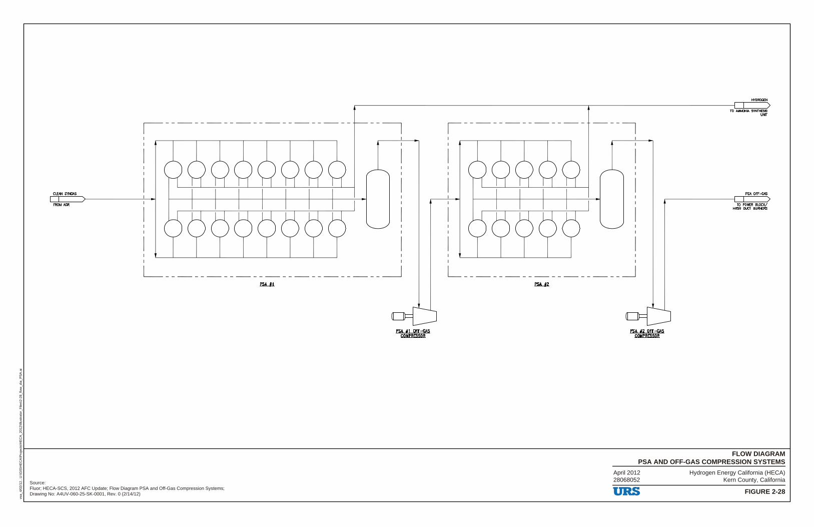
Hydrogen Energy California (HECA)Kern County, California
FIGURE 2-28
FLOW DIAGRAMPSA AND OFF-GAS COMPRESSION SYSTEMS
vsa_
4/02
/12.
..U:\G
IS\H
EC
A\P
roje
cts\
HE
CA
_201
2\Ill
ustr
ator
_File
s\2-
28_f
low
_dia
_PS
A.a
i
Source:Fluor; HECA-SCS, 2012 AFC Update; Flow Diagram PSA and Off-Gas Compression Systems;Drawing No: A4UV-060-25-SK-0001, Rev. 0 (2/14/12)
April 201228068052
CLEAN SYNGAS
FROM NlR
,--------------------
L _________ _ fSA....l1.
___________ _J
PSA #1 Off-GAS COMPRESSOR
L ______ _ fSA....12.
_______ _J
PSA #2 Off-GAS COMPRESSOR
URS
HYDROGEN
10 AMMONIA SYNTHESIS UNIT
PSA OFF-GAS
10 POWER BLOCK/ HRSG DUCT BURNERS
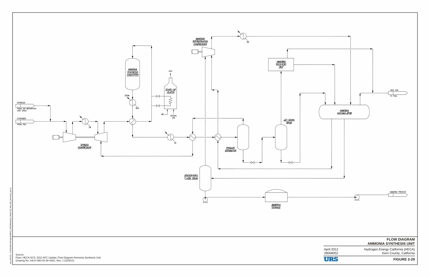
Hydrogen Energy California (HECA)Kern County, California
FIGURE 2-29
FLOW DIAGRAMAMMONIA SYNTHESIS UNIT
vsa_
4/11
/12.
..U:\G
IS\H
EC
A\P
roje
cts\
HE
CA
_201
2\Ill
ustr
ator
_File
s\2-
29_f
low
_dia
_am
mon
ia_s
yn.a
i
Source:Fluor; HECA-SCS, 2012 AFC Update; Flow Diagram Ammonia Synthesis Unit;Drawing No: A4UV-080-25-SK-0001, Rev. 1 (3/29/12)
April 201228068052
NITROGEN
FROM AIR SEPARATION UNIT (ASU)
HYDROGEN
FROM PSA cw
SYNGAS COMPRESSOR
AMMONIA SYNTHESIS CONVERTER
VENT
START-UP HEATER
cw
...1-------+'~,+-----,
ATMOSPHERIC FLASH DRUM
PRIMARY SEPARATOR
cw
AMMONIA RECOVERY
UNIT
AMMONIA STORAGE
LET-DOWN DRUM
AMMONIA ACCUMULATOR
URS
VENT GAS
TO FUEL
AMMONIA PRODUCT
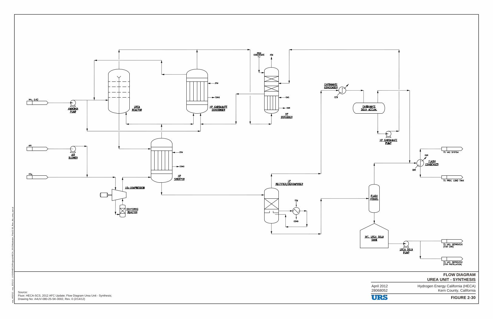
Hydrogen Energy California (HECA)Kern County, California
FIGURE 2-30
FLOW DIAGRAMUREA UNIT - SYNTHESIS
vsa_
4/02
/12.
..vsa
_3/2
1/12
...U
:\GIS
\HE
CA
\Pro
ject
s\H
EC
A_2
012\
Illus
trat
or_F
iles\
2-30
_flo
w_d
ia_u
rea_
syn.
ai
Source:Fluor; HECA-SCS, 2012 AFC Update; Flow Diagram Urea Unit - Synthesis;Drawing No: A4UV-080-25-SK-0002, Rev. 0 (2/14/12)
April 201228068052
NHo (LIQ)
AIR
CO2
AIR .BLQWER
.uw .REACmB
CO2 COMPRESSOR
.PElfl'.PROll .REACmB
S1II
COND
.HP .$lRllliR
S1II
COND
HP CARBAMAJE CONDENSER
coN'cmfs.\lE Alli
.HP SCRUBBER
.Le RECTIFIER/DECOMPOSER
COND.
ccw
CARBAMATE soLN ACCUM,
flASH ---------~mm
INT. UREA SOL,N .IAt:!K
URS
cws
FL.ASH CONDENSER
TO VAC SYSTEM
TO PROC COND TANK
TO VAC. SEPARATOR (FOR UAN)
TO VAC. SEPARATOR (FOR PASTIUATION)
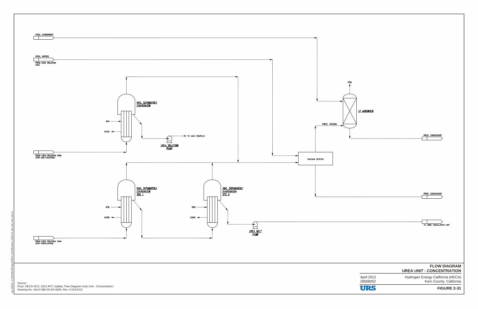
Hydrogen Energy California (HECA)Kern County, California
FIGURE 2-31
FLOW DIAGRAMUREA UNIT - CONCENTRATION
vsa_
4/02
/12.
..U:\G
IS\H
EC
A\P
roje
cts\
HE
CA
_201
2\Ill
ustr
ator
_File
s\2-
31_f
low
_dia
_ure
a_co
nc.a
i
Source:Fluor; HECA-SCS, 2012 AFC Update; Flow Diagram Urea Unit - Concentration;Drawing No: A4UV-080-25-SK-0003, Rev. 0 (2/14/12)
April 201228068052
PROC. CONDENSATE
PROC. VAPORS
FROM UREA SOLUTION TANK
FROM UREA SOLUTION TANK (FOR UAN SOLUTION)
FROM UREA SOLUTION TANK (FOR PASTILIATION)
SIM
COND
SIM
COND
VAC. SEPARATOR/ EVAPORATOR
YAC, SEPARATOR/ EVAPORATOR .sm..i
STM
COND
VAC, SEPARATOR/ EVAPORATOR .sm...z
PROC. VAPORS
VACUUM SYSTEM
ATM.
LP ABSORBER
PROC. CONDENSATE
PROC. CONDENSATE
TO UREA PASTILIATION UNIT
URS
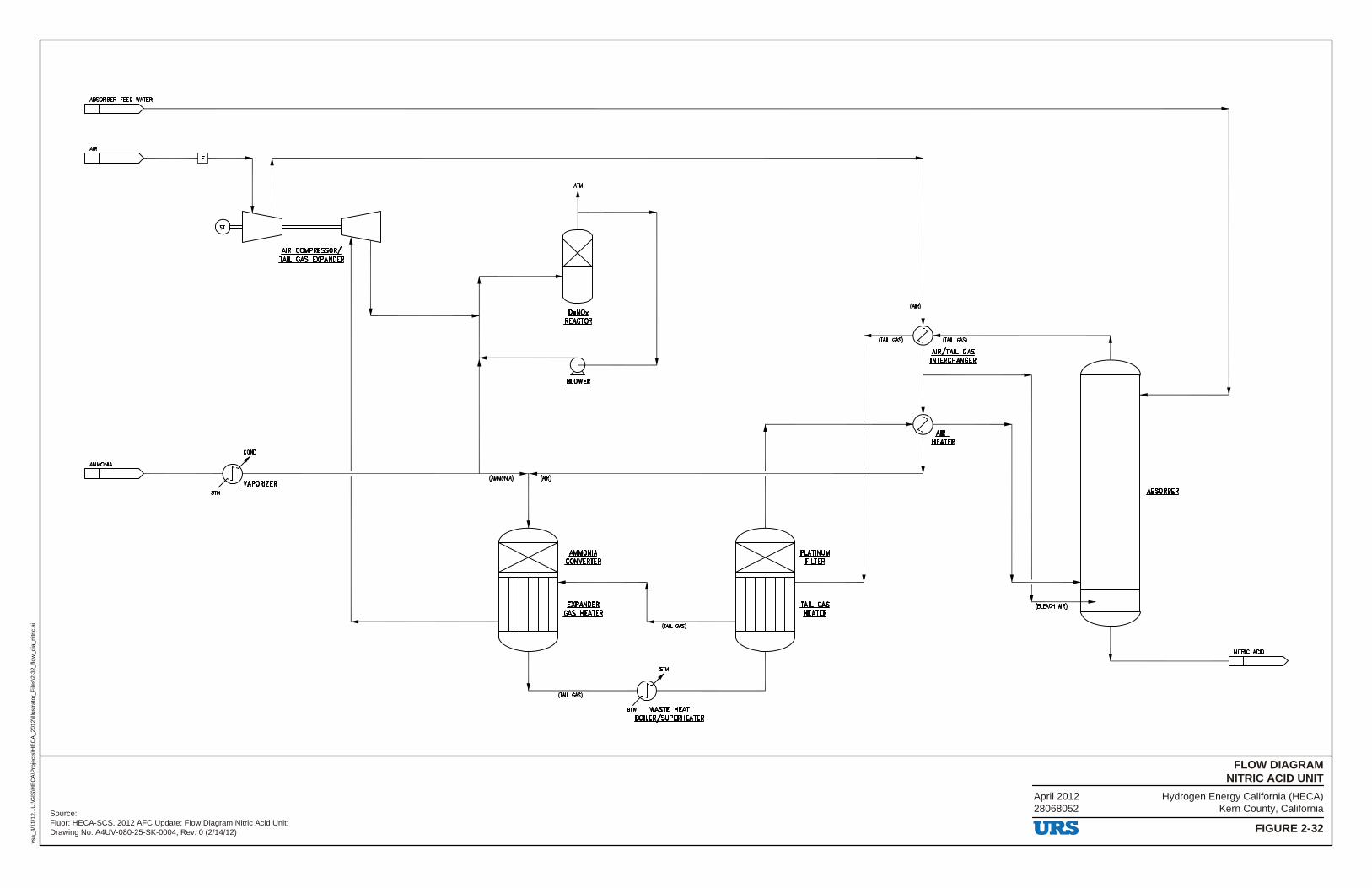
Hydrogen Energy California (HECA)Kern County, California
FIGURE 2-32
FLOW DIAGRAMNITRIC ACID UNIT
vsa_
4/11
/12.
..U:\G
IS\H
EC
A\P
roje
cts\
HE
CA
_201
2\Ill
ustr
ator
_File
s\2-
32_f
low
_dia
_nitr
ic.a
i
Source:Fluor; HECA-SCS, 2012 AFC Update; Flow Diagram Nitric Acid Unit;Drawing No: A4UV-080-25-SK-0004, Rev. 0 (2/14/12)
April 201228068052
ABSORBER FEED WATER
I I
AIR
r.__---'1'--__ _/:--------l r 1---------
ST
COND
AMMONIA
I I I VAPORIZER
STM
AIR COMPRESSOR/ JAIL GAS EXPANDER
r---
-
(AMMONIA) (AIR)
I><
AlM
DeNOx .REACIOB
Ll .BLOWER
AMMQtllA CONVEBIER
EXPANDER GAS l!EAIER
(TAIL GAS)
(TAIL GAS)
STM
I BFW WASIE l!EAI
BOILER {sUPERl!EAIER
r>< .fLAIIHl1M .Ell.I£B
!AIL GAS .lfEAI£R
(TAIL GAS)
(MR)
rJ'-~~ (TAIL GAS) 1 AlffllAIL GAS
IHIERCl!AHGER
0.MB... HEATER
(BL£ACH AIR)
NITRIC ACID
I )
URS
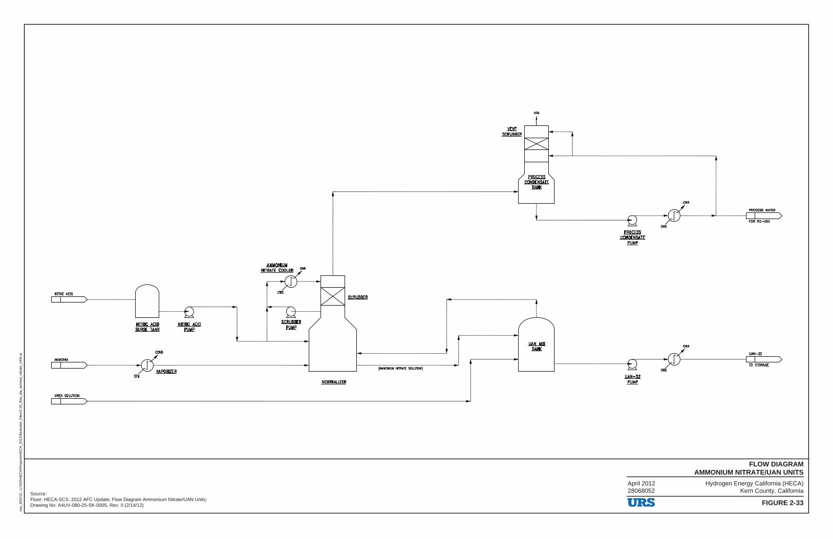
Hydrogen Energy California (HECA)Kern County, California
FIGURE 2-33
FLOW DIAGRAMAMMONIUM NITRATE/UAN UNITS
vsa_
4/02
/12.
..U:\G
IS\H
EC
A\P
roje
cts\
HE
CA
_201
2\Ill
ustr
ator
_File
s\2-
33_f
low
_dia
_am
mon
_nitr
ate_
UA
N.a
i
Source:Fluor; HECA-SCS, 2012 AFC Update; Flow Diagram Ammonium Nitrate/UAN Units;Drawing No: A4UV-080-25-SK-0005, Rev. 0 (2/14/12)
April 201228068052
NITRIC ICID
AMMONIA
UREA SOLI/TION
NITRIC ACID SURGE TANK
S1ll
NITRIC ACID .fl1Me
cws
_5CRllBSER
.fl1Me
(AMMONIUM NllRAlE SOI.IJTION)
NEUTRALIZER
Alli
PROCESS CONDENSATE
.JANK
.l!AlL.MIX .JANK
.fBQWli CONDENSATE
.fl1Me
~ .fl1Me
URS
PROCESS WATER
FOR RE-USE cws
UAN-32
TO STORAGE
cws
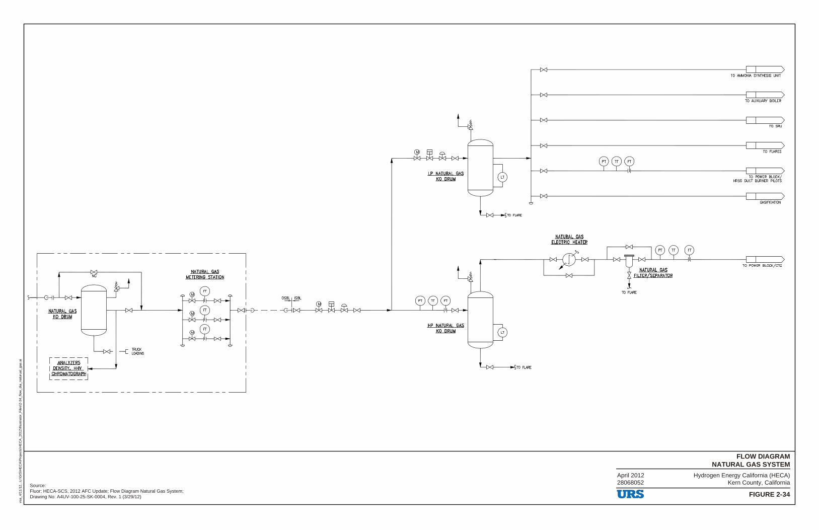
Hydrogen Energy California (HECA)Kern County, California
FIGURE 2-34
FLOW DIAGRAMNATURAL GAS SYSTEM
vsa_
4/11
/12.
..U:\G
IS\H
EC
A\P
roje
cts\
HE
CA
_201
2\Ill
ustr
ator
_File
s\2-
34_f
low
_dia
_nat
urua
l_ga
s.ai
Source:Fluor; HECA-SCS, 2012 AFC Update; Flow Diagram Natural Gas System;Drawing No: A4UV-100-25-SK-0004, Rev. 1 (3/29/12)
April 201228068052
NATURAL GAS METERING STATION
I OSB~ I ISBL
LP NATURAL GAS KO DRUM
NATURAL GAS KO DRUM
I-'.)- - - --C---I IXl-------f::Ki---Ol<:1--l')l(l..---f>d----.L-------1.-_L__
---[
1 ANALYZERS 7
TRUCK LOADING
I
I I DENSITY, HHV ----~ I I [CHROMATOGRAP~ I
L---- ______________ _J
HP NATURAL GAS KO DRUM
L---4X'f------l~TO FLARE
NATURAL GAS ELECTRIC HEATER
NATURAL GAS FILTER/SEPARATOR
TO FLARE
URS
TO AMMONIA SYNTHESIS UNIT
TO AUXILIARY BOILER
TO SRU
TO FLARES
TO POWER BLOCK/ HRSG DUCT BURNER PILOTS
GASIFICATION
TO POWER BLOCK/CTG
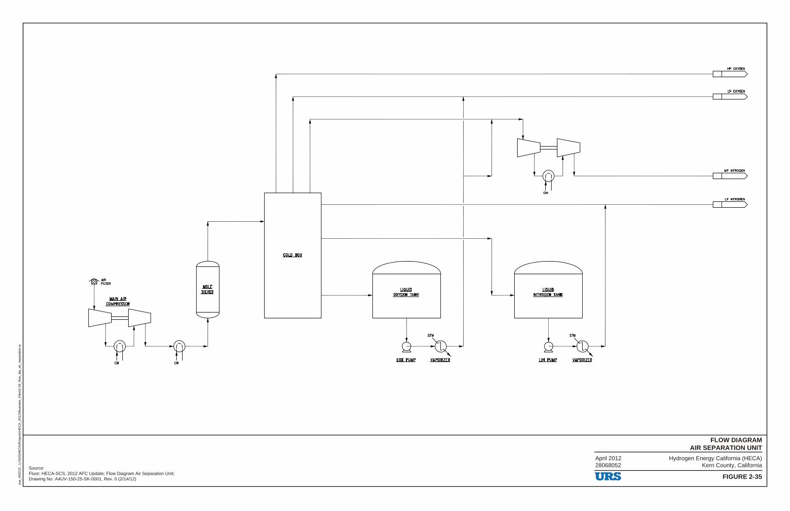
Hydrogen Energy California (HECA)Kern County, California
FIGURE 2-35
FLOW DIAGRAMAIR SEPARATION UNIT
vsa_
4/02
/12.
..U:\G
IS\H
EC
A\P
roje
cts\
HE
CA
_201
2\Ill
ustr
ator
_File
s\2-
35_f
low
_dia
_air_
sepa
ratio
n.ai
Source:Fluor; HECA-SCS, 2012 AFC Update; Flow Diagram Air Separation Unit;Drawing No: A4UV-150-25-SK-0001, Rev. 0 (2/14/12)
April 201228068052
(1tl (1tl
.Mlll£ .st.Em ..LIQl!lll
QXYGEN TANK
SIM
(1tl
..LIQl!lll NITROGEN TANK
SIM
HP OXYGEN
LP OXYGEN
MP NITROGEN
LP NITROGEN
URS
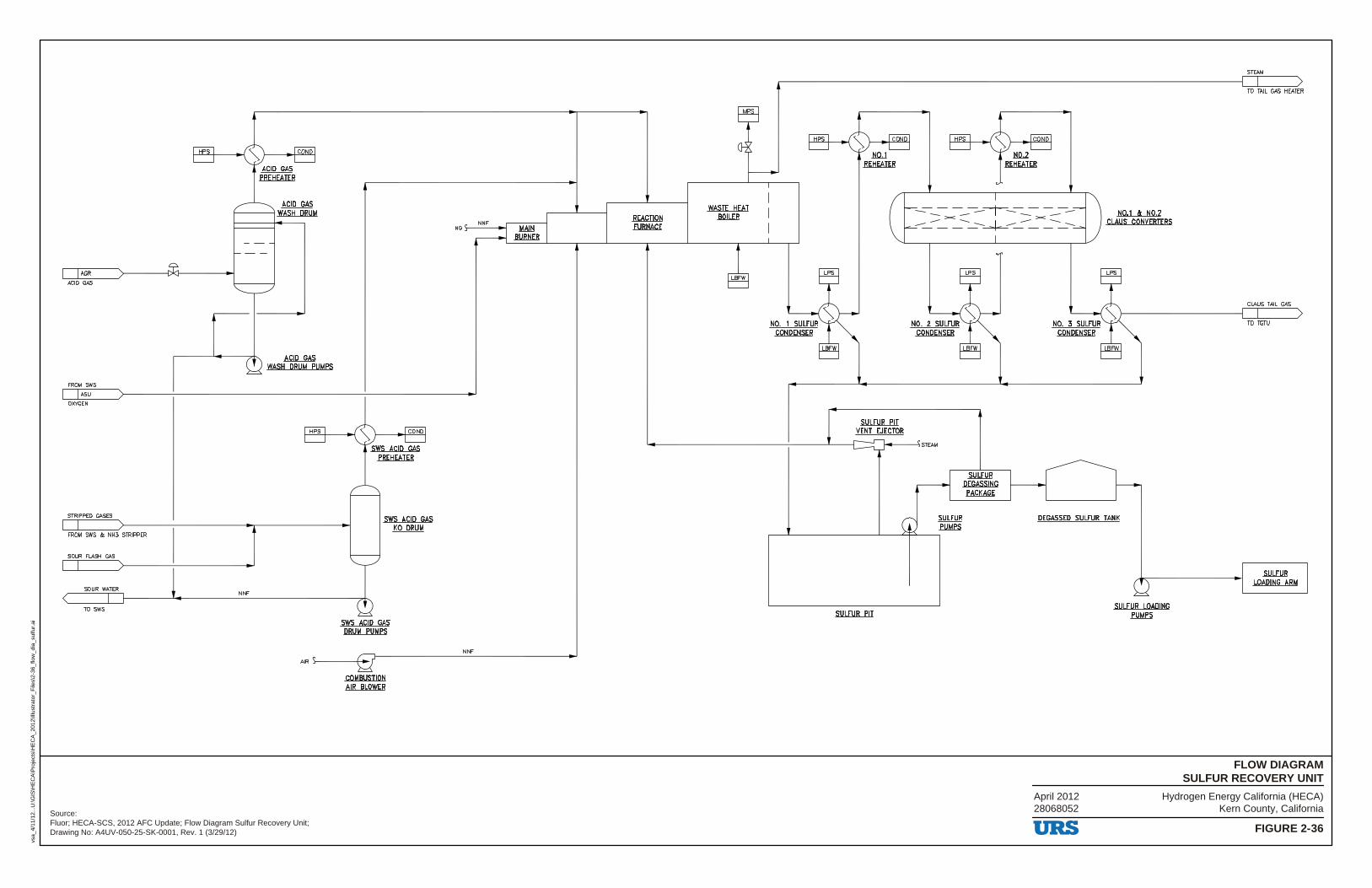
Hydrogen Energy California (HECA)Kern County, California
FIGURE 2-36
FLOW DIAGRAMSULFUR RECOVERY UNIT
vsa_
4/11
/12.
..U:\G
IS\H
EC
A\P
roje
cts\
HE
CA
_201
2\Ill
ustr
ator
_File
s\2-
36_f
low
_dia
_sul
fur.
ai
Source:Fluor; HECA-SCS, 2012 AFC Update; Flow Diagram Sulfur Recovery Unit;Drawing No: A4UV-050-25-SK-0001, Rev. 1 (3/29/12)
April 201228068052
AGR
ACID GAS
FROM SWS
ASU
OXYGEN
STRIPPED GASES
FROM SWS & NH3 STRIPPER
SOUR FLASH GAS
SOUR WATER
TO SWS
ACID GAS 1------1 WASH DRUM
NNF
ACID GAS WASH DRUM PUMPS
SWS ACID GAS KO DRUM
NNF
.!,!Alli BURNER
REACTION FURNACE
WASTE HEAT BOILER
JiQ,J_ REHEATER
SULFUR PIT
-- -- -- -----r -- -- -- -->< >< -- -- --~ -- -- --
SULFUR DEGASSING PACKAGE
N0.1 & N0.2 CLAUS CONVERTERS
SULFUR PUMPS
DEGASSED SULFUR TANK
URS
SULFUR LOADING PUMPS
STEAM
TO TAIL GAS HEATER
CLAUS TAIL GAS
TO TGTU
SULFUR LOADING ARM

Hydrogen Energy California (HECA)Kern County, California
FIGURE 2-37
FLOW DIAGRAMTAIL GAS TREATING UNIT
vsa_
4/02
/12.
..U:\G
IS\H
EC
A\P
roje
cts\
HE
CA
_201
2\Ill
ustr
ator
_File
s\2-
37_f
low
_dia
_tai
l_ga
s.ai
Source:Fluor; HECA-SCS, 2012 AFC Update; Flow Diagram Tail Gas Treating Unit;Drawing No: A4UV-050-25-SK-0002, Rev. 0 (2/14/12)
April 201228068052
NORMALLY NO FLOW
CLEAN SYNGAS
FROM WASTE HEAT BOILER
CLAUS TAIL GAS
FROM SRIJ
~-----~~ ~
~ HWtB
TRIM HEATER
=-----= -----=====-===== HYDROGENATION
.REACTOR
CONTACT CONDENSER/ DESUPERHEATER
REACTOR EffLUENT .cool.ER
DESUPERHEATER .PUMPS
.tQHTACT CONDENSER COOLER
THERMAL .QXlPlZEB
URS
~ COMPRESSOR
AIR
FUEL
RECYCLE GAS
TO SHIFT UNIT
SOUR WATER
TO SWS
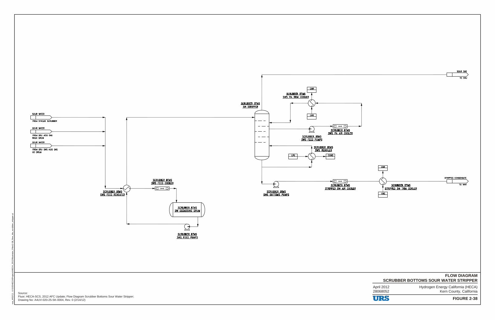
Hydrogen Energy California (HECA)Kern County, California
FIGURE 2-38
FLOW DIAGRAMSCRUBBER BOTTOMS SOUR WATER STRIPPER
vsa_
4/02
/12.
..U:\G
IS\H
EC
A\P
roje
cts\
HE
CA
_201
2\Ill
ustr
ator
_File
s\2-
38_f
low
_dia
_scr
ubbe
r_st
rippe
r.ai
Source:Fluor; HECA-SCS, 2012 AFC Update; Flow Diagram Scrubber Bottoms Sour Water Stripper;Drawing No: A4UV-020-25-SK-0004, Rev. 0 (2/14/12)
April 201228068052
SOUR WATER
FROM SYNGAS SCRUBBER
SOUR WATER
FROM SRIJ ACID GAS WASH DRUM
SOUR WATER
FROM SRIJ SWS ACID GAS KO DRUM
SCRUBBER BTMS sws fEED COOLER
~---/4------~c - ::::> SCRUBBER BTMS
SWS F'EED REH EATER
SCRUBBER BTMS SW DEGASSING DRUM
SCRUBBER BTMS SWS F'EED PUMPS
SCRUBBER BTMS SW STRIPPER
SCRUBBER BTMS SWS PA TRIM COOLER
.,....,c--------c - ::::>>------
SCRUBBER BTMS SWS F'EED PUMPS
SCRUBBER BTMS sws PA AIR COOLER
-------------------c - ::>>----------I
SCRUBBER BTMS SWS BOTTOMS PUMPS
SCRUBBER BTMS STRIPPED SW AIR COOLER
SCRUBBER BTMS STRIPPED SW TRIM COOLER
URS
SOUR GAS
TO SRU
STRIPPED CONDENSATE
TO wwr
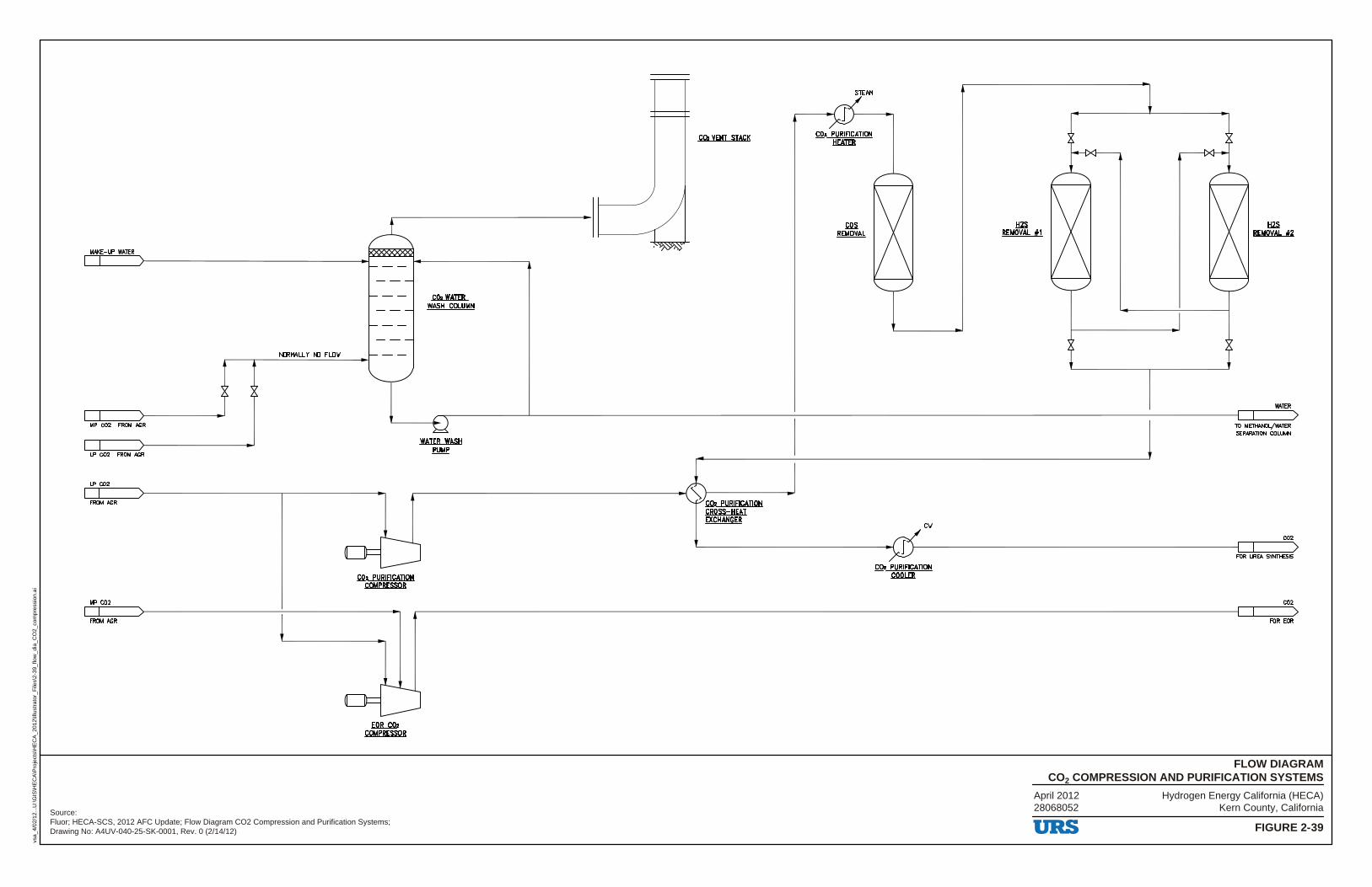
Hydrogen Energy California (HECA)Kern County, California
FIGURE 2-39
FLOW DIAGRAMCO2 COMPRESSION AND PURIFICATION SYSTEMS
vsa_
4/02
/12.
..U:\G
IS\H
EC
A\P
roje
cts\
HE
CA
_201
2\Ill
ustr
ator
_File
s\2-
39_f
low
_dia
_CO
2_co
mpr
essi
on.a
i
Source:Fluor; HECA-SCS, 2012 AFC Update; Flow Diagram CO2 Compression and Purification Systems;Drawing No: A4UV-040-25-SK-0001, Rev. 0 (2/14/12)
April 201228068052
MAKE-UP WATER
N□RMALL Y N□ FL□'w
MP CO2 FROM AGR
LP CO2 FROM AGR
LP CO2
FROM AGR
MP CO2
FROM AGR
CO.WATER WASH COWMN
WATER WASH PUMP
co. VENT STACK
~---------------..i, >------
CO. PURIFICATION COMPRESSOR
,EOR__C0,2 COMPRESSOR
CO2 PURIEICAIION CROSS-HEAT EXCHANGER
STEAM
.cos. .REMOYAL
C'w
.HZS. REMOVAL #1
URS
.HZS. REMOVAL f2
WATER
TO M~OI../WATER SEPARATION COLUMN
CO2
FOR URE'A SYNTHESIS
CO2
FOR EOR
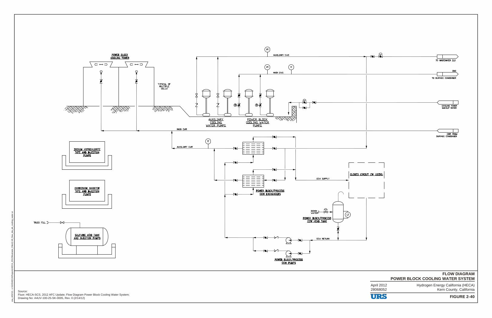
Hydrogen Energy California (HECA)Kern County, California
FIGURE 2-40
FLOW DIAGRAMPOWER BLOCK COOLING WATER SYSTEM
vsa_
4/02
/12.
..U:\G
IS\H
EC
A\P
roje
cts\
HE
CA
_201
2\Ill
ustr
ator
_File
s\2-
40_f
low
_dia
_pb_
cool
ing_
wat
er.a
i
Source:Fluor; HECA-SCS, 2012 AFC Update; Flow Diagram Power Block Cooling Water System;Drawing No: A4UV-100-25-SK-0005, Rev. 0 (2/14/12)
April 201228068052
c-:::,
SODIUM HYPQCHLQRITE TOTE AND INJECTION
POWER BLOCK COOLING TOWER
n'-------.fl!MPS -~
CORROSION INHIBITOR TOTE AND INJECTION
n'-------.f!!MPS -~
TRUCK FILL 7-----{XI---------,
SULFURIC ACID TANK AND INJECTION PUMPS
c-:::,
TYPICAL □F MULTIPLE
CELLS
MAIN C\IR
AUXILIARY C\IR
AUXILIARY C\IS
MAIN C\IS
POWER BLOCK/PROCESS ccw EXCHANGERS
CC\/ SUPPLY
e~1:Rt---D'<l--i POWER BLOCK/PROCESS L_ _ _..r
ccw HEAP TANK
CC\/ RETLRN
,--7 I CLOSED CIRCUIT cw USERS; I
L __ _J
URS
TO WASTEWATER ZLD
cws
TO SURFACE CONDENSER
CWR FROM SURFACE CONDENSER

Hydrogen Energy California (HECA)Kern County, California
FIGURE 2-41
FLOW DIAGRAMGASIFICATION AND RECTISOL FLARE SYSTEMS
vsa_
4/11
/12.
..U:\G
IS\H
EC
A\P
roje
cts\
HE
CA
_201
2\Ill
ustr
ator
_File
s\2-
41_f
low
_dia
_gas
_rec
tisol
.ai
Source:Fluor; HECA-SCS, 2012 AFC Update; Flow Diagram Gasification and Rectisol Flare Systems;Drawing No: A4UV-100-25-SK-0001, Rev. 0 (2/14/12)
April 201228068052
FIARE HEADER
RECTISOL FIARE RELIEF FROM AGR UNIT
PSV ~FIER
... z z
~FIER POWER START-UP BLOCK AGR
... ... ... z z z z z z
LIAN AMMONIA UREA SHIFT COMPLEX SYNlHESIS SYNlHESIS
... ... ... ... z z z z z z z z
NNF
... z z
TO SRU FIARE
GASIEICAJION fl.ARE .KlLl2RllM
RECTISOL fl.ARE .KlLl2RllM
NNF -~-----ow SOUR WATER
GASIEICAJION fl.ARE KO DRUM PUMP
NNF -~--='------1~ SOUR WATER
RECTISOL fl.ARE KO DRUM PUMP
PLANT AIR
NATURAi. GAS
IGNITION MONITORING PANEL
IGNITlON LINES TO PILOlS
TO PILOlS
ASSIST GAS (IF REQUIRED)
ASSIST GAS (IF REQUIRED)
TO PILOlS
NATURAi. GAS t I
PLANTAIR S-=~ IGNITION LINES TO PILOlS ►
IGNITION MONITORING .PAN.EL
URS
GASIFICATION fl.ARE
RECTISOL fl.ARE
_LEGEND
NNF DENOTES NORMAI..LY NO FLOW
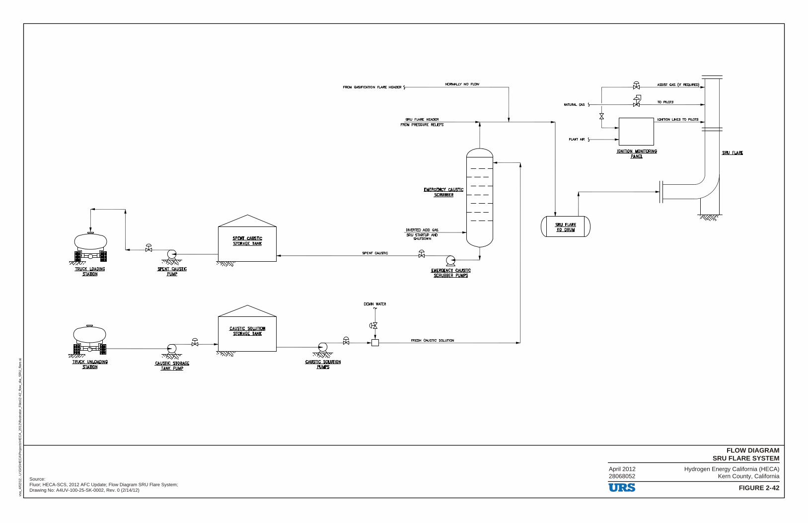
Hydrogen Energy California (HECA)Kern County, California
FIGURE 2-42
FLOW DIAGRAMSRU FLARE SYSTEM
vsa_
4/02
/12.
..U:\G
IS\H
EC
A\P
roje
cts\
HE
CA
_201
2\Ill
ustr
ator
_File
s\2-
42_f
low
_dia
_SR
U_f
lare
.ai
Source:Fluor; HECA-SCS, 2012 AFC Update; Flow Diagram SRU Flare System;Drawing No: A4UV-100-25-SK-0002, Rev. 0 (2/14/12)
April 201228068052
SPENT CAUSTIC STORAGE TANK
CAUSTIC SOWJION STORAGE TANK
NORMALLY NO FLOW FROM GASIFICATION FLARE HEADER \-------------------,
SPENT CAUSTIC
DEMIN WATER
SRU FLARE HEADER FROM PRESSURE RELIEFS
EMERGENCY CAUSTIC .scRl1SBER
DIVERTED ACID GAS SRU STARTUP AND
SHIJIDOWN
FRESH CAUSTIC SOI..UTION
NAl\JRAI. GAS
PLANT AIR
SRU EL.ARE KO DRUM
IGNITION MONITORING .fAtiEL
URS
ASSIST GAS (IF REQUIRED)
10 PILOlS
IGNmON LINES 10 PILOlS
SRU EL.ARE
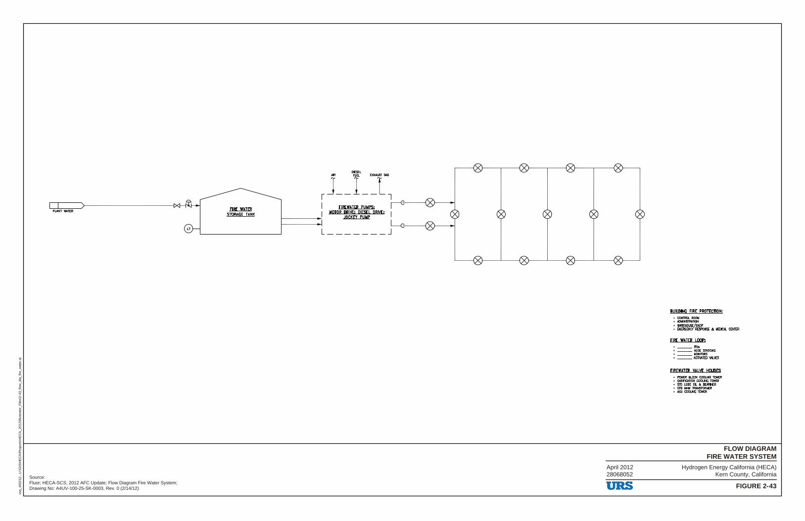
Hydrogen Energy California (HECA)Kern County, California
FIGURE 2-43
FLOW DIAGRAMFIRE WATER SYSTEM
vsa_
4/02
/12.
..U:\G
IS\H
EC
A\P
roje
cts\
HE
CA
_201
2\Ill
ustr
ator
_File
s\2-
43_f
low
_dia
_fire
_wat
er.a
i
Source:Fluor; HECA-SCS, 2012 AFC Update; Flow Diagram Fire Water System;Drawing No: A4UV-100-25-SK-0003, Rev. 0 (2/14/12)
April 201228068052
~======>~---------~1><1--1~ PLNIT WATER EIRE WATER STORAGE TANK
DIESa
) __ i_ 1~7 FIREWATER PUMPS;
MOTOR DRIVE; DIESEL DRIVE; JOCKEY PUMP
~ I 4;------{
L _______ J
URS
BUILDING EIRE PROTECTION; • COll1ROl ROOM • 14l111NISTRA11DN • WAREHOUSE/SHOP • EMERGENCY RESPONSE a. MEDICAL CENTER
EIRE WATER LOOP; • __ piv,,
• __ HOSE SfAllONS • __ IIONRORS • __ AClll'AlID Yl,I.VES
FIREWATER VALVE HOUSES • POWER 111..00< COOLING TOWER • GASIFICATIDN COOLING TOWER • srG WBE OIL a. BEARINGS • CTG MAIN lRANSFORMER • ASU COOLING TOWER
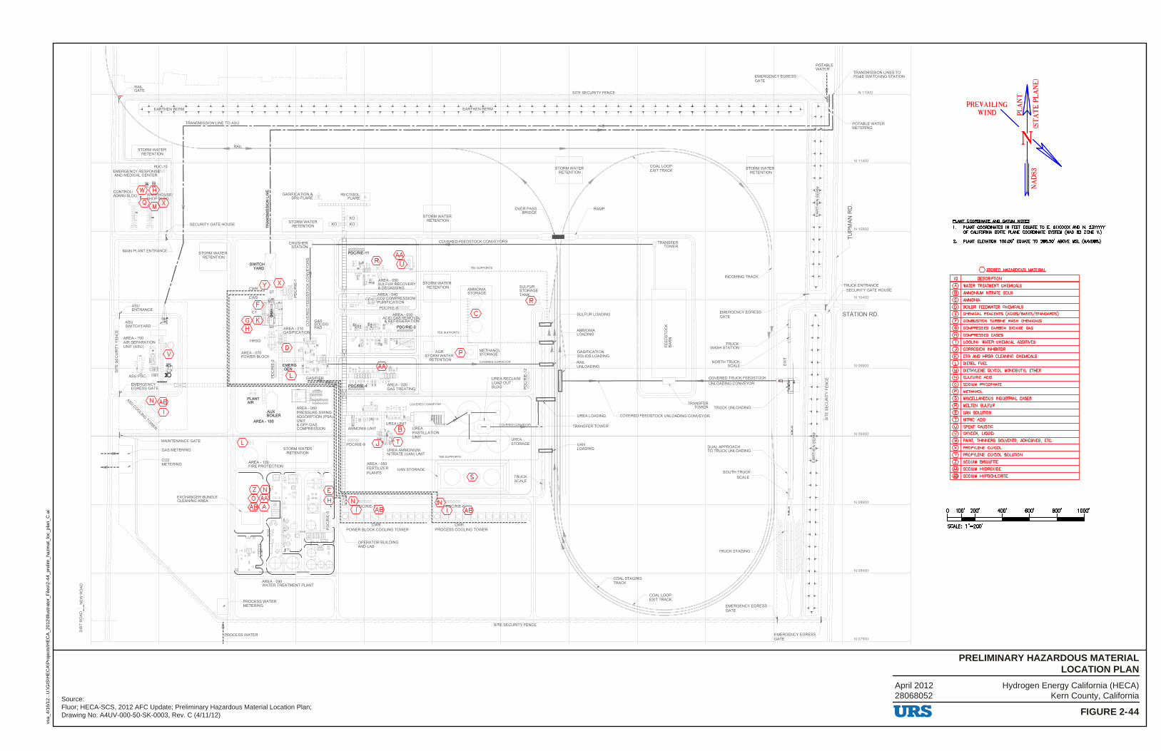
Hydrogen Energy California (HECA)Kern County, California
FIGURE 2-44
PRELIMINARY HAZARDOUS MATERIALLOCATION PLAN
vsa_
4/16
/12.
..U:\G
IS\H
EC
A\P
roje
cts\
HE
CA
_201
2\Ill
ustr
ator
_File
s\2-
44_p
relim
_haz
mat
_loc
_pla
n_C
.ai
Source:Fluor; HECA-SCS, 2012 AFC Update; Preliminary Hazardous Material Location Plan;Drawing No: A4UV-000-50-SK-0003, Rev. C (4/11/12)
April 201228068052
N 11900
POTABLE WATER METERING
N 11400
N09900
N09400
N08900
N 08400
N07900
URS
~~
E- «: PREY AILING ~ ~
WIND ~ ~ g
i~ Pl MI COOBPIN!JE AND P&TllN NQJfS
1. PLANT COORDINATES IN FEEr EDUAlE lU E. encxxxx AND N. 2MY'f'fY OF CAURlRNIA SfAlE PLANE COORDINA1E S'ISIDI (NAO l!3 ZONE V.)
2. PLANT ELEVA.110N 100.00' EQUAlE lU 288.50' M!DI£. MSL (NAYD88.)
QSJDBEP HA7ARPOIJS MtilfRIAI
ID DESCRIPTION
@ WATER lREATMENT CHEMICALS
@ AMMONIUM NITRATE SOLN
© AMMONIA
@ BOILER FEEDWATER CHEMICALS
® CHEMICAL REAGENTS (ACIDS/BASES/STANDARDS)
® COMBUSTION TURBINE WASH CHEMICALS
© COMPRESSED CARBON DIOXIDE GAS
® COMPRESSED GASES
(D COOLING WATER CHEMICAL ADDITIVES
Q) CORROSION INHIBITOR
® CTG AND HRSG CLEANING CHEMICALS
(D DIESEL FUEL
® DIETHYL.ENE GLYCOL MONOBUTYL ETHER
® SULFURIC ACID
@ SODIUM PHOSPHATE
® METHANOL
@ MISCEUANEOUS INDUSTRIAL GASES
® MOLTEN SULFUR
® LIAN SOLUTION
CT) NITRIC ACID
@ SPENT CAUSTIC
('f) OXYGEN, LIQUID
® PAINT, THINNERS SOLVENTS, ADHESIVES, ETC.
® PROPYLENE GLYCOL
@ PROPYLENE GLYCOL SOWTION
ill SODUIM BISULATE
@ SODIUM HYDROXIDE
@ SODIUM HYPOCHLORITE
? 1ap· 21!0' 400' -, 600' -, 800' -,
SCALE: 1"=200'
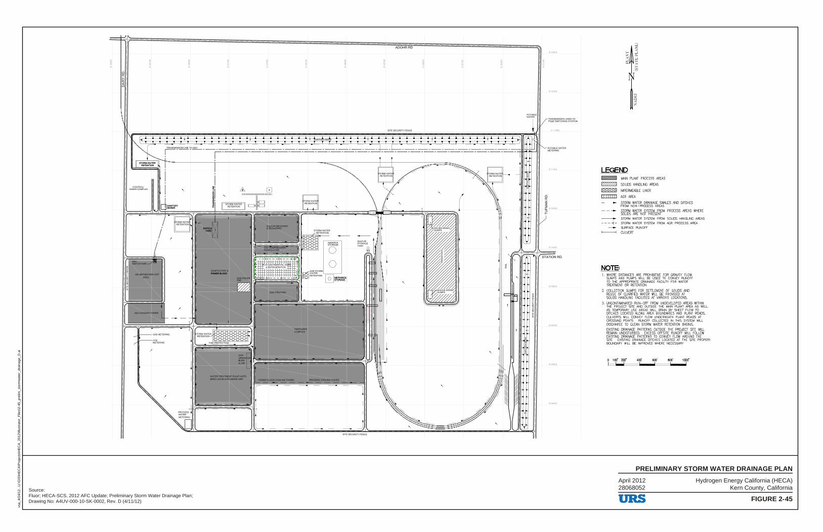
Hydrogen Energy California (HECA)Kern County, California
FIGURE 2-45
PRELIMINARY STORM WATER DRAINAGE PLAN
vsa_
4/24
/12.
..U:\G
IS\H
EC
A\P
roje
cts\
HE
CA
_201
2\Ill
ustr
ator
_File
s\2-
45_p
relim
_sto
rmw
ater
_dra
inag
e_D
.ai
Source:Fluor; HECA-SCS, 2012 AFC Update; Preliminary Storm Water Drainage Plan;Drawing No: A4UV-000-10-SK-0002, Rev. D (4/11/12)
April 201228068052
ADOHRRD
f::.: p_~.: . .::=: l ~ t: -~ :•l : ~: .2: _~: •v-t: .: : _~:•: E2 ~: :~:.-:~ :~ :~.:~•: l::>
,i ~WATER I l~NTION
CONTROLJ .A.DMIN COMPLEX
AIU -MIIOMA110N lNT _,
MUCOCILNl31CMa
I -
-CO2 METERING
/
/
/
~
;~~\ 11, DD
I I I --· -II.CICIC
I I
I I WATBI 1RU PLANT {WIP) ZIN> IJQUD 0IICHMGa INT
I I,,_, i
CCOlN>-
l
J
~ ~
TRANSMISSION LINES TO PG&E SWITCI-ING STATION
N.11900
POTABLE WATER METERING
~ N10900 :, f--
)
LEGEND c::::::::J MAIN PLANT PROCESS AREAS
~ SOLIDS HANDLING AREAS
~ IMPERMEABLE LINER
[LLLLL□ AGR AREA
► STORM WATER DRAINAGE SWALES AND DITCHES FROM NON-PROCESS AREAS
- - -- STORM WATER SYSTEM FROM PROCESS AREAS WHERE SOLIDS ARE NOT PRESENT
---- STORM WATER SYSTEM FROM SOLIDS HANDLING AREAS - - - ;: • STORM WATER SYSTEM FROM AGR PROCESS AREA
--- SURFACE RUNOFF >----< CULVERT
NOTE= 1. WHERE DISTANCES ARE PROHIBITIVE FOR GRAVITY FLOW,
SUMPS AND PUMPS WIUL BE USED TO CONVEY RUNOFF TO THE APPROPRIATE DRAINAGE FACILITY FOR WATER TREATMENT OR RETENTION.
2. COLLECTION SUMPS FOR SETTLEMENT OF SOLIDS AND REUSE OF CLARIFIED WATER WILL BE PROVIDED AT SOLIDS HANDLING FACILrllES AT VARIOUS LOCATIONS.
3. UNCONTAMINATED RUN-OFF FROM UNDEVELOPED AREAS WITHIN THE PROJECT SITE AND OUTSIDE THE MAIN PLANT AREA AS WELL AS TEMPORARY USE AREAS WILL DRAIN BY SHEET FLOW TO DITCHES LOCATED ALONG AREA BOUNDARIES AND PLANT ROADS. CULVERTS WILL CONVEY FLOW UNDERNEATH PLANT ROADS AT CROSSING POINTS. RUNOFF COLLECTED IN THIS SYSTEM WILL DISCHARGE TO CLEAN STORM WATER RETENTION BASINS. EXISTING DRAINAGE PATTERNS OUTSIDE THE PROJECT SITE WILL REMAIN UNDISTURBED. EXCESS OFFSrTE RUNOFF WILL FOULOW EXISTING DRAINAGE PATTERNS TO CONVEY FLOW AROUND THE srrE. EXISTING DRAINAGE DITCHES LOCATED AT THE SITE PROPER) BOUNDARY WILL BE IMPROVED WHERE NECESSARY.
100' 200' 400' 600' BOO' 1000' - I I I I
URS
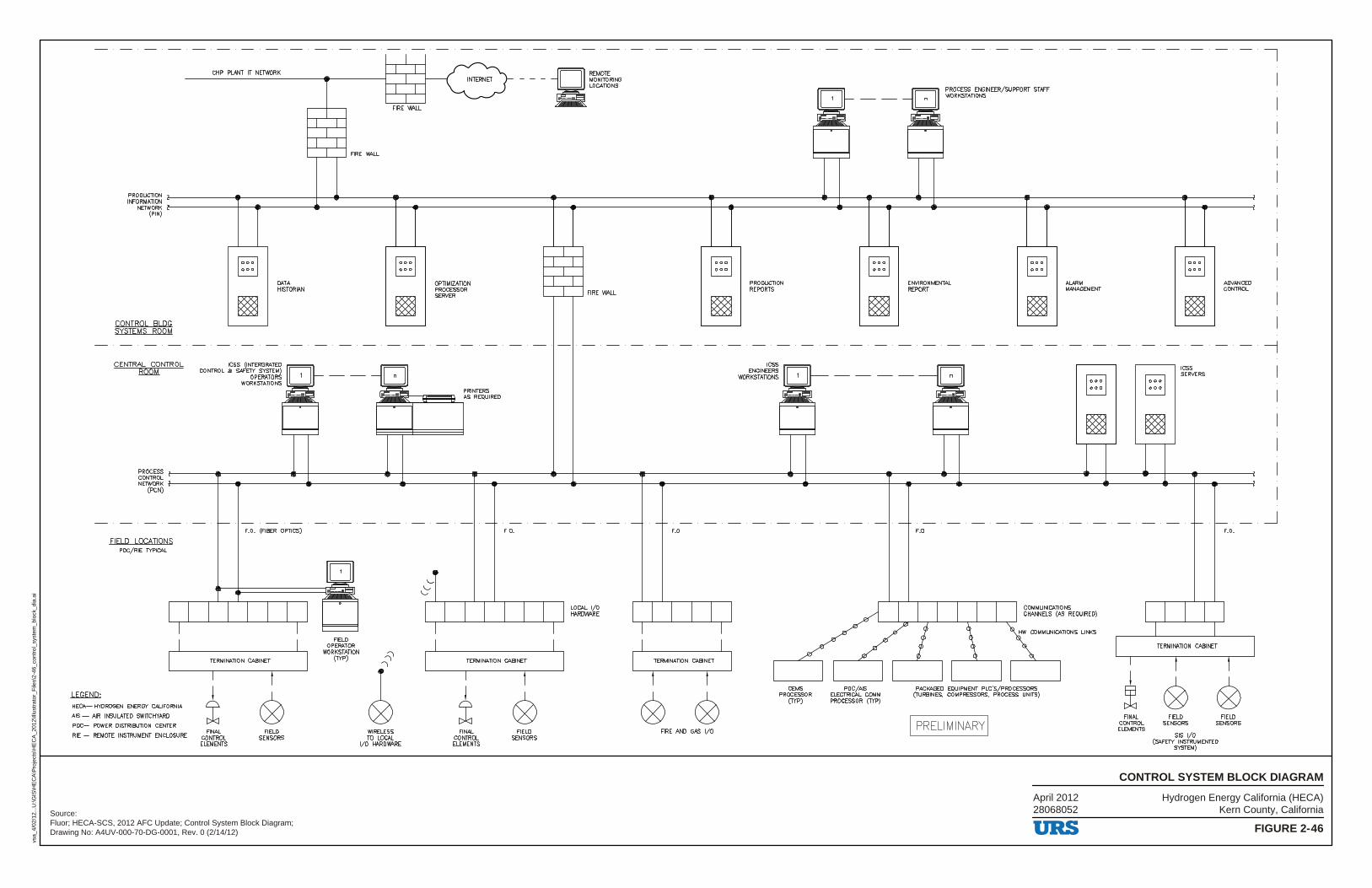
Hydrogen Energy California (HECA)Kern County, California
FIGURE 2-46
CONTROL SYSTEM BLOCK DIAGRAM
vsa_
4/02
/12.
..U:\G
IS\H
EC
A\P
roje
cts\
HE
CA
_201
2\Ill
ustr
ator
_File
s\2-
46_c
ontr
ol_s
yste
m_b
lock
_dia
.ai
Source:Fluor; HECA-SCS, 2012 AFC Update; Control System Block Diagram;Drawing No: A4UV-000-70-DG-0001, Rev. 0 (2/14/12)
April 201228068052
LEGEND:
PRODUCTION INFORMATION
NETWORK (PIN)
CONTROL BLDG SYSTEMS ROOM
CENTRAL CONTROL ROOM
PROCESS CONTROL NETWORK
(PCN)
FIELD LOCATIONS PDC/RIE TYPICAL
HECA-HYDROGEN ENERGY CALIFORNIA
AIS - AIR INSULATED SWITCHYARD
PDC- POWER DISTRIBUTION CENTER
RIE - REMOTE INSTRUMENT ENCLOSURE
CHP PLANT IT NETWORK
~ □
DATA HISTORIAN
ICSS (INTERGRATED CONTROL & SAFETY SYSTEM)
OPERATORS WORKSTATIONS
F.O. (FIBER OPTICS)
TERMINATION CABINET
± 0 FINAL FIELD
CONTROL SENSORS ELEMENTS
FIELD OPERATOR
WORKSTATION (TYP)
~ □
WIRELESS TO LOCAL
1/0 HARDWARE
OPTIMIZATION PROCESSOR SERVER
PRINTERS AS REQUIRED
F.O.
RBAOTE - - - MONITORING
LOCATIONS
•
._____,~~~ FIRE WALL
LOCAL 1/0 HARDWARE
TERMINATION CABINET
± 0 FINAL FIELD
CONTROL SENSORS ELEMENTS
F.O.
~ □
TERMINATION CABINET
FIRE AND GAS 1/0
PRODUCTION REPORTS
CEMS PROCESSOR
(TYP)
~ □
PDC/AIS ELECTRICAL COMM PROCESSOR (TYP)
PROCESS ENGINEER/SUPPORT STAFF WORKSTATIONS
ENVIRONMENTAL REPORT
F.O.
ALARM MANAGEMENT
COMMUNICATIONS CHANNELS (AS REQUIRED)
HW COMMUNICATIONS LINKS
PACKAGED EQUIPMENT PLC'S/PROCESSORS (TURBINES, COMPRESSORS, PROCESS UNITS)
I PRELIMINARY I
URS
FINAL CONTROL ELEMENTS
ICSS SERVERS
TERMINATION CABINET
ADVANCED CONTROL
F.O.
FIELD SENSORS
FIELD SENSORS
SIS 1/0 (SAFETY INSTRUMENTED
SYSTEM)
7 I
I --j
_J
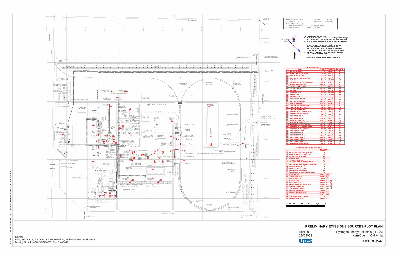
PRELIMIN
Hydrogen Energy California (HECA)Kern County, California
FIGURE 2-47
PRELIMINARY EMISSIONS SOURCES PLOT PLAN
vsa_
4/24
/12.
..U:\G
IS\H
EC
A\P
roje
cts\
HE
CA
_201
2\Ill
ustr
ator
_File
s\2-
47_p
relim
_em
issi
ons_
plot
plan
_E.a
i
Source:Fluor; HECA-SCS, 2012 AFC Update; Preliminary Emissions Sources Plot Plan;Drawing No: A4UV-000-50-SK-0002, Rev. E (4/04/12)
April 201228068052
,_ ,,- -
ADOHRRD ----=--~----=----=-------=- -=--=--=-----==--~----=-=-~I--
I '
t F ROCESS WATER
,;, 'SECURITY FENCE
~~GEN CY EGRESS _JI I I
DWA #20001: (CALCULATED) NORTHING EASTING
STATE PLANE COORD. 2312983.492 6151072.772
NAD83 ZONE V (U.S. FEET)
LATITUDE: 35"20'25.11200" LONGITUDE: 119"22'36.21665"
LATITUDE: 35.340309" LONGITUDE: 119.37672"
Pl ANI COOBIJNAIF MID MD IN M'llES f-- <
PREVAILING j ~ ~~
1. PLANT COORDINATES IN FEET EQUATE TO E. '51XXXXX AND N. 2MYrN OF" CAUFORNIA STATE PLANE COORDIIIM.TE SYSTEM (NAO 8J ZONE V.)
WIND ~ g 2. PLANT El...f.VATION 100.00' EQUATE TO ~• N!JOlf. MSL (flM.VDM.)
~
[!J [I]
rn [I] [!]
[!] [!] [I] [!] Im)
liil H!I Im liII HID I!!]
liZl HID nil ~ ~ ~ ~ ~ Im lg'/,ll
~ ~ 1!21 l!ll ~ ~ ~ 1!21 ~
ID
i~ J. ACCURACY /TOLERANCE OF EMISSION POINT{S) COOROINi\TES
ARE WITHIN A SO FOOT RADIUS OF' SOURCE POINT NOTED.
4-. LOCATK>N Of EMISSION POINTS ARE SUBJECT TO COMPLETION OF DEl'AILED DESIGN B'I' UCENSORS AND EQUIPMENT SUPPLIERS.
5. SEE SHEETS 2 THROUGH 9 FOR INFORMATION ON COMPOSITION AND FUlW RATE FROM EACH SOURCE.
S. EMISSION POINT IS SHOWN FOR INFORIMTION ONLY. ZERO EMISSIONS ARE EXPECTED DURING STEADY STATE OPERATION.
fB EMl~O~S SO!lBCES SOURCE ~ .... , ..
ASU COOLING TOWER 48053'--0" 9557'-8" ,.. POWER BLOCK COOUNG TOWER 4n:n·-o· 8813'-o· ,,. PROCESS COOLING TOWER 48460'-o· as13•-o· ,,. EMERGENCY ENGIJIES (GENERATORS) 47067'--s· 9884'-o· 20'
HRSG STACK 46924'-o· 10035•-o· 213'
EMERGENCY ENGINE (FIRE WATER PUMP) 46789'-o· 9348'-o· 20'
NJXIL.IARY BOILER (NOTE 8) 48924'-o• 9730'-o• 80'
TAIL GAS THERMAL. OXIDIZER •n13•-1· 10681'-o· 185'
CO2 VENT (NOTE 6) 47501•-o· 10208'-o· 200'
SRU FIARE 472e7'-o· 11147'-o· 250'
GASIFICATION FLARE 47287'-o· 111!5tt-o· 200'
RECTISOL Fl.ARE 47610'-o· 11153•-o· 250'
FEEDSTOCK DRYER 47140•--3• 1001J'-J· ,,.. UREA PLANT HP ABSORBER 478!50'-o· gse1·-o· 1,0'
UREA PLANT LP ABSORBER 47802'-o· 9575•-o· 50'
UREA PASTIUATION VENT 49075•-o· 9521•-o· 50'
FEEDSTOCK RAIL UNl..lW)ING VENT 49035•-o· 9804'-o· ,O'
FEEDSTOCK TRANSFER TOWER 48726'-o· 10805'-o· 100'
FEEDSTOCK CRUSHER VENT 47208'-o· ,oeos·-o· 100'
FEEDSTOCK TRUCK UNI..O\DING VENT 506J1'--0· ga10·-o· 00'
FEEDSTOCK TRANSFER TOWER B 49833'-o· 9806'-o· 100'
UREA LOADING VENT 1 48a02'-0· lil&s1·-o· ,O'
UREA LOADING VENT 2 48942'--o· 9687'-o· ,o'
GASIFICATION SOLIDS P.-D 47323•-1· 9868'-r N/A
NITRIC ACID ABSORBER VENT 4n97•-o· 9373•-o· .... AMMONIUM NITRATE SCRUBBER VENT 4ne1·--o· 9392•-o· 40'
GASIFICATION SOLIDS 'TRANSFER TOWER 47322•-2· 9929•-4• ,O'
GASIFICA.TION SOLIDS l..lW)ING VENT 48932'-8· lillil28'-6· ,O'
URD. BUCKEi' ELEVA.TOR 48196'--o• 9-485'-o• 50'
UREA TRANSFER TOWER 1 48370'-o· 9574•-o· 100'
UR:D. TRANSFER: TOWER 2 48580'-o· 9574'-o· 100'
URD. TRANSFER TOWER 3 48370'-o· 9354•-o· 100'
URD. TRANSFER: TOWER 4 48580'-o· 9354•-o· 100'
UR:D. TRANSFER: TOWER 5 48875'-o· 9469'-o· 100'
AMMONIA UNIT STARTUP HEATER 47495•-o· 9500•-o· 80'
YUJB SIBIICDIBES/ EAIHPYEHI AND P.NKS
DESCRIPTION
A ASU MAIN AIR COMPRESSOR ENCLOSURE
LIQUID OXYGEN STORAGE: (LOX) TANK
AIR SEPARAllON COWMN CAN 20D
F FEEDSTOCK BARN 100
G GASIFICATION STRUCTURE ,.. 0 COMBUSTION nJRBINE GENERATOR STRUCRJRE 5D
HEAT RECOVERY STEAM GENERATOR STRLICnJRE .. FLARE K.O. DRUMS (01Y 3)
POWER DISTRIBUTION CENTERS
AGR ME1lW«JI... WASH COWMN 2'5
T AGR REFRIGERATDI cotiFRESSOR STRUCTURE 40
RAW WATER TANK 100'DIA X 48'H
TREATED WATER TANK 95'DIA. X 40'H
PURIFIED WATER TANK 75'DIA. X 48'H
Bt.CKWASH TANK ~'DIA X 48'H
UTIUTY WATER TANK 50'DIA. X 32'H
DEMINERA.I.IZED WATER STORAGE TANK 52'DIA. X 40'H
FIREWATER STORAGE TANK 110'DIA X 48'H
UREA STORAGE ( 4 DOMES) 182'DIA X 70'H
Z METHANOL. STORAGE: TANK 40'DIA. X 40'H
AMMONIA. STORAGE (2 TANKS) 90'01A. X 70'H
UAN STORAGE (3 TANKS) 120'01A X 48'H
UREA REa.AIM L..Ot.OOUT BUILDING
SUL.FUR STORAGE TANK 30'DIA. X 24'H
o 100' 200' <00' BOO' 1000'
URS
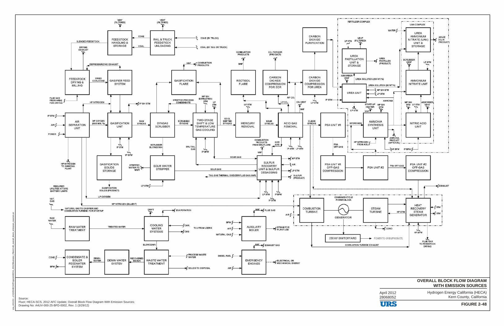
Hydrogen Energy California (HECA)Kern County, California
FIGURE 2-48
OVERALL BLOCK FLOW DIAGRAMWITH EMISSION SOURCES
vsa_
4/11
/12.
..U:\G
IS\H
EC
A\P
roje
cts\
HE
CA
_201
2\Ill
ustr
ator
_File
s\2-
48_o
vera
ll_bl
ock_
emis
sion
_sou
rces
.ai
Source:Fluor; HECA-SCS, 2012 AFC Update; Overall Block Flow Diagram With Emission Sources;Drawing No: A4UV-000-25-BFD-0002, Rev. 1 (3/29/12)
April 201228068052
VlaNT VENT (FIL"TERED)
'f (FIL TEREO)
'f COl<E
FEEDSTOCK RAIL&TRUCK BLEl'OED FEEDSTOCK HANDLING & FEEDSTOCK
DRYING STORAGE COAL UNLOADING
EXHAUST '-:-,
DEPRESSIRIZING EXHAUST
FLUE ~A~G r FROM
FOR DRVING
IPSThlf--
A1Rf--
FEEDSTOCK DRYING & MILLING
t
AIR SEPARATION
UNIT
•
POWER J--+ --------.---
' ... HPNITROGel TD AMMONIA
PLANT
DRIED COAUCOKE
f,f'NfTROGEN
ff' OXYGEN [99,5 MOL 'llj _
f
GASIFIER FEED
-
SYSTEM
GASIFICATION UNIT
IP SIH STM
RAW SYNGAS _ SYNGAS
SCRUBBER
1 IPSTM
SCRUBBER BLOWDOWN
GASIFICATION SOLIDS
STORAGE
' IP BFW
STRIPPED '\..,___ WATER TO_ C---
WWT
SOUR WATER STRIPPER
--1-------<' CO~E IB'I llRLCK)
- ------1' COAL (BY RAIL OR T'Rl.O<) -
GASIFICATION FLARE
SlRIPP ED PROCESS CONDENSATE
SCRUBBED SYNGAS _
MPS/H E>m!.ACTlON
T t TWO-STAGE SHIFT & LOW
TEMPERATURE GAS COOLING
'
SRUTAIL GAS .......
IPBFW
COOL SHIFllED SYNGAS _
COMBUSllON PRODUCTS
, ..,
Ni'E
RECTISOL FLARE
MERCURY REMOVAL
co, FOREOR iPROCUCT)
' .,
CARBON DIOXIDE
COMPRESSION FOR EOR
SOUR SYN:3AS _ ACID GAS
REMOVAL
COMBUSTlON F PRODUCTS ACID
FRO::rFLARE GAS 1 1 IP Sllli LP STM
SOUR GAS --fMPSTM
SOUR GAS 1-------------------------
TAIL GAS Tl-ERMAL OJQDZER FLUE GAS (r,.t,jF)
SULFUR RECOVERY
UNIT & SULFUR D EGA S SING
-----t A IR
--fLPSTM
----f SLI..FUR
CARBON DIOXIDE
PURIFICATION
CARBON DIOXIDE
COMPRESSION FOR UREA
J, LPSlN
-··-· · - ·· - · ·-··- ··-·· - ··- · ·-·· -··-· · -··-· · -··-··-··-··-· ·-··7
FERTILIZER COMPLEX r ·· - ··- ·· -··- ··-· ·1
UREA PASTILLATION l_ ...r lREA
I--J PASTILLES UNIT & (PROOUC1)
STORAGE
ABSORBER l I ~ UREA soumoN~99 WT.%)
I I
I--UR_ EA_ s_o_L_UT_ O_ N_ l80_ WT_ ,'¼I_ ..., I ~
I
UAN COMPLEX :
UREA AMMONIUM
NITRATE (UAN) UNIT&
STORAGE
SCRUBBER r AMMONIUM
NITRATE UNIT
I
I · UAN.J:2
I Lr SOL"N ~ [PRODUCT)
I
IPSTM--!-
UREA UNIT i,.------{ MP S/H STM
i,.------{ LP $TM _____ __. AMMONIA
START .UP MP SIH I M~IHLPSTM
'.,_.,7 Li HE~ STM
N~f 'f I 'r r -------- I
I CLEAN
SYNGAS _
I i
PSA UNIT #1
I PSA OFF-GAS
I'
PSA UNIT #1 OFF-GAS
COMPRESSION
1
I : HYDROGEN_
AMMONIA SYNTHESIS
UN IT __ ..,
I ..I,
I -NITRIC ACID
UNIT
I
I
I
'--:-~ ---,..--..,.._. AMMONIA l'RODL.CT I
HP NITROGEN (OPTION.ALI ·• _ • • - • , - . FROMASU
~--··- ··-· ·-··-t-··-~H:_~.~ -- ~~~c .. _ .. _ .. _.,_
PSA UNIT#2 PSA OFF-GAS
PSA UNIT tt2 OFF-GAS
COMPRESSION
--i IPRODLCT)
'RE<lUREO UTUTIES AT SITE BATTERY LIMITS
NAT. GAS
GASIFILTION SOLIDS [PRODUCT)
LPOXYG~
li'IP NITROGEN (DILUENT)
LP STM _;o----~
NATURAL GAS TO GASIFIERAI\O --t-► COMBUSTIONTLRBll<E FORSTARTlJP r---, ... : EVA PO RA Tl ON
RAW WATER
CONO
BfW
RAWWATER TREATMEr-!T
CONDENSATE & BOILER
FEEDWATER SYSTEM
OEMIN. WATER
TIREATED WATER COOLING WATER
SYSTEMS
BLOWOOWNl
RECOIIEREO DEMIN WATER WATER WASTE WATER
SYSTEM TREATMENT
_____ __,JCWR
1----~ , cws TOJ FROM USERS
PROCESS WASTE -------t WATER
1------- SOLIDSTO DISPOSAL
BFWf---AIRJ--
NAnJRAL GAS _f-----.
DESEL FUEL
AIR
-..-..... - .... ....., .... ' "
,--. LPSTM
'IP
... __
IPEIFW
~FLUE GAS
I
I AJR f-;---
1
I AUXILIARY
BOILER ____.J STEAM FO R ------J PLANT USE
EMERGENCY ENGINES
EXHAUST GAS
- ----- --- ---------- ·- - ---------- -- -- -~ I
. _ ., _ _____ - ··-· ·- ··- ·· - ·· -' ·-· ·- ·· - ·· - ··-· ·-· ·- ··-'' - ·· - f ·- ·
COMBUSTION TURBINE
COMBINED Cl' CLE POWER BLOCK
GENERATOR
STEAM TURBINE
-
tf STM
. ' HEAT f+-jsr RECOVERY
STEAM f-fsr GENERATOR
··- ·· - ·· - ··- ·· - ·· e-· ·- ··- .. - .. - .. _ __ ),.. ,. - ,. - ··-·· - · ·- ·· - ., ---~ -·-· ·- ·· - ·· '---+:f COND J.,
I
I 230 kV SWITCHYARD POV/ER TO GRID (PRO Cl.JCT)
COMBUSTION TUREMNE EXHAUST
URS
HPEIFW
' ...... FL!£ GAS
TO FEEDSTOCK DRYING
M! I
M: I
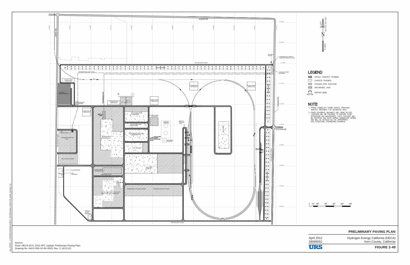
Hydrogen Energy California (HECA)Kern County, California
FIGURE 2-49
PRELIMINARY PAVING PLAN
vsa_
4/16
/12.
..U:\G
IS\H
EC
A\P
roje
cts\
HE
CA
_201
2\Ill
ustr
ator
_File
s\2-
49_p
relim
_pav
ing_
C.a
i
Source:Fluor; HECA-SCS, 2012 AFC Update; Preliminary Paving Plan;Drawing No: A4UV-000-10-SK-0003, Rev. C (4/11/12)
April 201228068052
8 ij
ADOHR RD
SITE SECURITY FENCE - ------- -- -----·-- --- -------· --------· --------- ---------·
WATER !rENTION
I I I AMMONIA
I - - - ~ ~t-t---~V
0 STORM ER ENTION @]
METHANO STORAGE
T l 1 1 SITI SECURITY FENCE l I I T
POTABLE WATER
N12900
TRANSMISSION LINES TO PG&E SWITCHING STATION
N.11900
POTABLE WATER METERING
RD.
N00900
N08900
LEGEND D DJ ~
ll;Hll
TOP
B~M
ASPHALT CONCRETE PAVEMENT
CONCRETE PAVEMENT
CRUSHED ROCK SURFACING
IMPERMEABLE LINER
EARTHEN BERM
NOTE= 1. PAVING SYMBOLOGY SHOWN DEPICTS PROPOSED
SURFACE TREATMENT FOR DELINEATED AREA.
2. PAVED DRIVEWAYS, WALKWAYS AND CRANE ACCESS LOCATIONS WILL BE PROVIDED TO SUPPORT PLANT OPERATIONS AND MAINTENANCE. THESE FEATURES WILL BE IDENTIFIED AND SIZED DURING SUBSEQUENT DESIGN AND WILL BE DETAILED ON THE APPROPRIATE CIVIL/STRUCTURAL ENGINEERING DRAWINGS.
100' 200' 400' 600' 800' 1000' - : : : :
URS
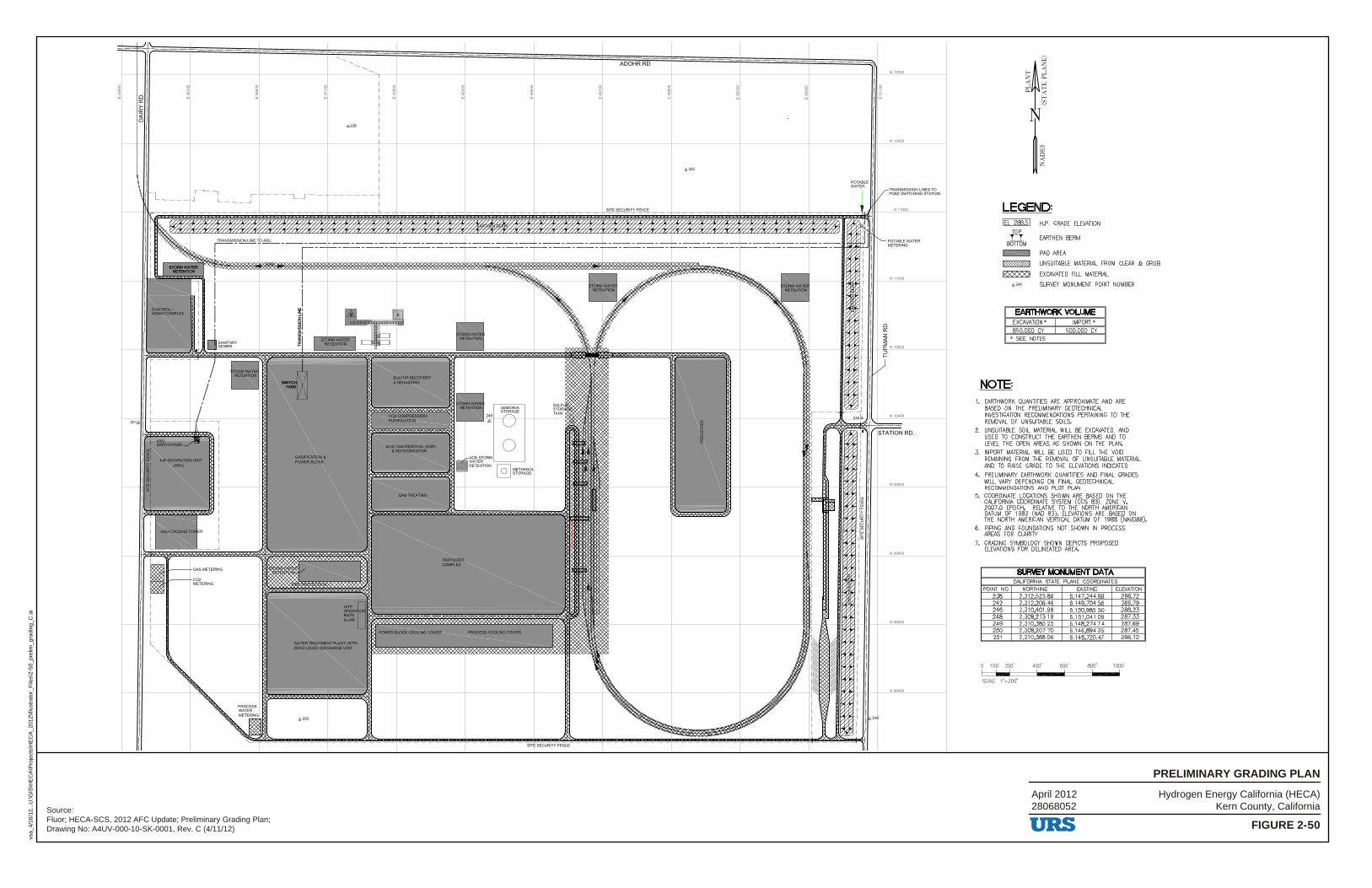
Hydrogen Energy California (HECA)Kern County, California
FIGURE 2-50
PRELIMINARY GRADING PLAN
vsa_
4/16
/12.
..U:\G
IS\H
EC
A\P
roje
cts\
HE
CA
_201
2\Ill
ustr
ator
_File
s\2-
50_p
relim
_gra
ding
_C.a
i
Source:Fluor; HECA-SCS, 2012 AFC Update; Preliminary Grading Plan;Drawing No: A4UV-000-10-SK-0001, Rev. C (4/11/12)
April 201228068052
·"· ~. "· "·
. I ,--1 ----
WA'Tlll'ffla'lll!!Nl'PLMl'(WIP) Z!RO LJQUI) DIICtWIIZ INI'
~. /J,250
"·
....... _,, ·-N:JIJ GM ABIOVAL CM3lt) ·--
... ,... .....
0 ~METHANO L:=:'_J STORAGE
l'RO<lE88COOU,OTOWER
ADOHRRD
J:J,.242
~ ! =· r -• -• -• -• -• -•-• -• 7· -•-• -• -• -• -• -• -• -1-• -• -• -• -• -• -• -• -• r· -• -• -• -•-• -• -• SIT! SeC""'"'"NCE • -• -• -• 7· -• -• -• -•-• -• -• -• -1 -• -• -• -• -• -• -•-• -r• -• -• -• -• -• -• -• -•r -• -•-• -• -•
POTABLE WATER
TRANSMISSION LINES TO PG&E SWITCHING STATION
N_1190Q
RD.
N08900
LEGEND= !EL 288.5! H.P. GRADE ELEVATION
EARTHEN BERM
PAD AREA
B~M
c::::::::J ~
~
UNSUITABLE MATERL.\L FROM CLEAR & GRUB
EXCAVATED FILL MATERIAL
4249 SURVEY MONUMENT POINT NUMBER
EARTHWORK VOLUME EXCAVATION• I IMPORT' 850,000 CY I 500,000 CY
• SEE NOTES
NOTE= 1. EARTHWORK QUANTITIES ARE APPROXIMATE AND ARE
BASED ON THE PRELIMINARY GEOTECHNICAL INVESTIGATION RECOMMENDATIONS PERTAINING TO THE REMOVAL OF UNSUITABLE SOILS.
2. UNSUITABLE SOIL MATERIAL WILL BE EXCAVATED, AND USED TO CONSTRUCT THE EARTHEN BERMS AND TO LEVEL THE OPEN AREAS AS SHOWN ON THE PLAN.
3. IMPORT MATERIAL WILL BE USED TO FILL THE VOID REMAINING FROM THE REMOVAL OF UNSUITABLE MATERIAL AND TO RAISE GRADE TO THE ELEVATIONS INDICATED.
4. PRELIMINARY EARTHWORK QUANTITIES AND FINAL GRADES WILL VARY DEPENDING ON FINAL GEOTECHNICAL RECOMMENDATIONS AND PLOT PLAN.
5. COORDINATE LOCATIONS SHOWN ARE BASED ON THE CALIFORNIA COORDINATE SYSTEM (CCS 83), ZONE V, 20D7.0 EPOCH, RELATIVE TO THt NORTH AMERICAN DATUM OF 1983 (NAD 83). ELEVATIONS ARE BASED ON THE NORTH AMERICAN VERTICAL DATUM OF 1988 (NAVD88).
6. PIPING AND FOUNDATIONS NOT SHOWN IN PROCESS AREAS FOR CLARITY.
7. GRADING SYMBOLOGY SHOWN DEPICTS PROPOSED ELEVATIONS FOR DELINEATED AREA.
SURVEY MONUMENT DATA CALIFORNIA STATE PLANE COORDINATES
POINT NO. NORTHING EASTING ELEVATION 238 2,312,523.86 6 147 244.89 286.72 242 2 312 206.46 6 149 704.56 286.79 246 2 310 401.98 6 150 985.50 288.23 248 2,308,213.18 6 151 041.09 287.33 249 2 310 380.25 6 148 274.74 287.69 250 2,308,207.70 6 146 894.35 287.45 251 2 310 368.06 6 145 720.47 286.12
0 100' 200' 400' 600' 800' 1000'
SCALE: 1 "=200 '
URS
TABLE OF CONTENTS
R:\12 HECA\AFC Amd\3_0 Fac Clos.docx 3-i
3. Section 3 Facility Closure .................................................................... 3-1
3.1 Temporary Closure .................................................................................. 3-1 3.2 Permanent Closure ................................................................................... 3-1
URS

TABLE OF CONTENTS
3-ii R:\12 HECA\AFC Amd\3_0 Fac Clos.docx
This page intentionally left blank.
URS
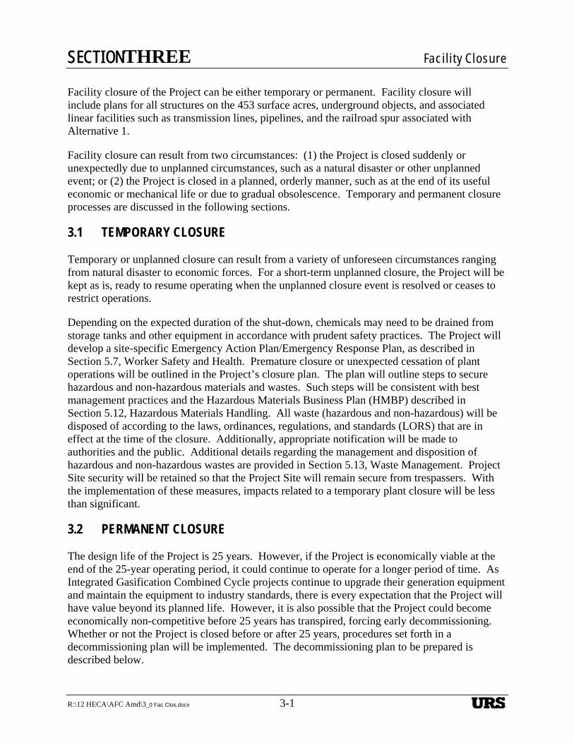
SECTIONTHREE Facility Closure
R:\12 HECA\AFC Amd\3_0 Fac Clos.docx 3-1 3-1
3. Section 3 Facility Closure
Facility closure of the Project can be either temporary or permanent. Facility closure will include plans for all structures on the 453 surface acres, underground objects, and associated linear facilities such as transmission lines, pipelines, and the railroad spur associated with Alternative 1.
Facility closure can result from two circumstances: (1) the Project is closed suddenly or unexpectedly due to unplanned circumstances, such as a natural disaster or other unplanned event; or (2) the Project is closed in a planned, orderly manner, such as at the end of its useful economic or mechanical life or due to gradual obsolescence. Temporary and permanent closure processes are discussed in the following sections.
3.1 TEMPORARY CLOSURE
Temporary or unplanned closure can result from a variety of unforeseen circumstances ranging from natural disaster to economic forces. For a short-term unplanned closure, the Project will be kept as is, ready to resume operating when the unplanned closure event is resolved or ceases to restrict operations.
Depending on the expected duration of the shut-down, chemicals may need to be drained from storage tanks and other equipment in accordance with prudent safety practices. The Project will develop a site-specific Emergency Action Plan/Emergency Response Plan, as described in Section 5.7, Worker Safety and Health. Premature closure or unexpected cessation of plant operations will be outlined in the Project’s closure plan. The plan will outline steps to secure hazardous and non-hazardous materials and wastes. Such steps will be consistent with best management practices and the Hazardous Materials Business Plan (HMBP) described in Section 5.12, Hazardous Materials Handling. All waste (hazardous and non-hazardous) will be disposed of according to the laws, ordinances, regulations, and standards (LORS) that are in effect at the time of the closure. Additionally, appropriate notification will be made to authorities and the public. Additional details regarding the management and disposition of hazardous and non-hazardous wastes are provided in Section 5.13, Waste Management. Project Site security will be retained so that the Project Site will remain secure from trespassers. With the implementation of these measures, impacts related to a temporary plant closure will be less than significant.
3.2 PERMANENT CLOSURE
The design life of the Project is 25 years. However, if the Project is economically viable at the end of the 25-year operating period, it could continue to operate for a longer period of time. As Integrated Gasification Combined Cycle projects continue to upgrade their generation equipment and maintain the equipment to industry standards, there is every expectation that the Project will have value beyond its planned life. However, it is also possible that the Project could become economically non-competitive before 25 years has transpired, forcing early decommissioning. Whether or not the Project is closed before or after 25 years, procedures set forth in a decommissioning plan will be implemented. The decommissioning plan to be prepared is described below.
URS

SECTIONTHREE Facility Closure
3-2 R:\12 HECA\AFC Amd\3_0 Fac Clos.docx
To protect public health, safety, and the environment, the decommissioning plan will be submitted to the California Energy Commission (CEC) for review prior to commencement of permanent closure measures. Such measures may range from extensive mothballing to removal of all equipment and appurtenances, depending on circumstances at the time. However, future conditions that will affect decommissioning decisions are largely unknown at this time. It is therefore appropriate to present decommissioning details to the CEC and other jurisdictional agencies when more information is available and the time for permanent closure has drawn closer. With the implementation of the closure mitigation measures below, impacts related to permanent facility closure will be less than significant.
Closure Mitigation
At the time of Project closure, decommissioning will be completed in a manner that protects the health and safety of the public and workforce and that will have no significant environmental impacts. One year prior to a planned closure, HECA LLC will submit a specific decommissioning plan that will include the following:
Identification, discussion, and scheduling of the proposed decommissioning activities of the Project with the CEC and other appropriate regulatory agencies.
Description of the measures to be taken that will ensure the safe shut-down and decommissioning of all equipment, including the draining and cleaning of all tankage and the removal of any hazardous materials or waste, inactive feedstock storage, etc.
Identification of all applicable LORS in effect at the time and how the specific decommissioning will be accomplished in accordance with LORS.
Required notifications to federal, state, and local agencies, including the CEC.
Consideration of reuse of the land as opposed to taking additional land for future industrial or commercial purposes. Once land is used for industrial or commercial purposes, it rarely reverts back to its natural state. If the Project Site is to return to its agricultural state, the specific decommissioning plan will include discussion covering the removal of all above-ground and underground objects and material and an erosion control plan that is consistent with sound land management practices. In general, the proposed decommissioning measures will attempt to maximize recycling of all facility components. Unused chemicals and oils will be sold or shipped back to the suppliers where practicable. Those not sold back will be collected and disposed of in appropriate landfills or waste collection facilities if they cannot be recycled. Until decommissioning activities have been completed security for the Project Site will be maintained.
In the event of an unplanned closure due to earthquake damage, natural disaster, or other circumstances, the Project owner will meet with the CEC and local agencies and submit a detailed decommissioning closure plan in a timely manner. No decommissioning plan will be submitted for a temporary shut-down.
URS
TABLE OF CONTENTS
R:\12 HECA\AFC Amd\4_0 Elec Trans.docx 4-i
4. Electrical Transmission ........................................................................ 4-1
4.1 Project Description ................................................................................... 4-1 4.2 Route Selection ........................................................................................ 4-1 4.3 Structure Selection ................................................................................... 4-2
4.3.1 General ......................................................................................... 4-2 4.3.2 Structure Weights and Dimensions .............................................. 4-2
4.4 Conductor Selection ................................................................................. 4-2 4.4.1 Introduction .................................................................................. 4-2 4.4.2 Sag and Tension Table ................................................................. 4-3 4.4.3 Conductor Electrical and Mechanical Characteristics ................. 4-3
4.5 Optical Ground Wire................................................................................ 4-3 4.5.1 Optical Ground Wire Selection .................................................... 4-3
4.6 Insulator Selection ................................................................................... 4-3 4.7 Comparison of Tubular Structures and Lattice Towers ........................... 4-4
4.7.1 Lattice Structures ......................................................................... 4-4 4.7.2 Tangent Structures ....................................................................... 4-4
4.8 Construction Methods and Impacts ......................................................... 4-4 4.8.1 Construction Methods .................................................................. 4-4 4.8.2 Permanent Right-of-Way ............................................................. 4-5 4.8.3 Land Disturbance during Construction ........................................ 4-5
4.9 Electric and Magnetic Effects .................................................................. 4-6 4.9.1 Introduction .................................................................................. 4-6 4.9.2 Mitigation of Electric and Magnetic Effects ................................ 4-7 4.9.3 Assumptions for Electrical and Magnetic Effects
Calculations.................................................................................. 4-8 4.9.4 Results .......................................................................................... 4-9
4.10 Aviation Safety ........................................................................................ 4-9 4.11 Environmental Consequences ................................................................ 4-10 4.12 Applicable Laws, Ordinances, Regulations, and Standards .................. 4-10
4.12.1 Design and Construction ............................................................ 4-10 4.12.2 Electric and Magnetic Fields ..................................................... 4-11 4.12.3 Hazardous Shock ....................................................................... 4-11 4.12.4 Communication Interference ..................................................... 4-11 4.12.5 Aviation Safety .......................................................................... 4-11 4.12.6 Fire Hazard ................................................................................. 4-11 4.12.7 Project Transmission Line Jurisdiction ...................................... 4-11
URS
TABLE OF CONTENTS
4-ii R:\12 HECA\AFC Amd\4_0 Elec Trans.docx
Tables
Table 4-1 Tangent Structure Table 4-2 Deadend Structure Table 4-3 Characteristics of Bittern ACSR
Table 4-4 Characteristics of the Optical Ground Wire Table 4-5 Comparison of Lattice and Tubular Steel Structures Table 4-6 Conductor Geometry Table 4-7 Audible Noise Levels Table 4-8 Electric Fields Table 4-9 Magnetic Fields Table 4-10 Radio Influence Table 4-11 Design and Construction LORS Table 4-12 Electric and Magnetic Fields Table 4-13 Hazardous Shock LORS Table 4-14 Communications Interference LORS Table 4-15 Aviation Safety LORS Table 4-16 Fire Hazard LORS Table 4-17 Jurisdiction
Figures
Figure 4-1 Route Alternatives Figure 4–2 Tangent Structure Figure 4–3 Deadend Structure Figure 4-4 Sag and Tension Data – Bittern Figure 4–5 Sag and Tension Data – GW4810 Figure 4–6 Rodurflex Insulating Crossarm Figure 4–7 Combined Load Chart Figure 4–8 Conductor Location Diagram Figure 4–9 Audible Noise Figure 4–10 Electric Field Figure 4–11 Magnetic Field Figure 4–12 Radio Influence
URS
SECTIONFOUR Electrical Transmission
R:\12 HECA\AFC Amd\4_0 Elec Trans.docx 4-1
4. Section 4 Electrical Transmission
4.1 PROJECT DESCRIPTION
Hydrogen Energy California LLC (HECA LLC) is proposing an Integrated Gasification Combined Cycle (IGCC) polygeneration project (hereafter referred to as HECA or the Project). The Project intends to connect to the Pacific Gas and Electric Company (PG&E) Midway Substation via 230-kilovolt (kV) Midway–Wheeler Ridge transmission line and a new PG&E switching station. The PG&E Midway–Wheeler Ridge lines were selected as the Project’s preferred interconnection point because of its proximity to the Project Site, accessibility, and to avoid the significant congestion at the Midway Substation identified in previous studies and reports. Additional details pertaining to the Large-Generator Interconnection Procedure (LGIP) are included in Appendix C. The new PG&E switching station will be approximately 2 miles east of the Project Site. A 230-kV, single-pole, double-circuit capacity transmission line is planned to connect the Project to the PG&E switching station. This line is to be constructed using a single-shaft, galvanized tubular-steel structure with a braced-post insulation system. One circuit will be on each side of the structure. Deadend and angle structures will be similar tubular-steel structures with horizontal davit arms to hold the conductors. The line will incorporate two optical shield wires. These will be used for both operational communications for the power line and for lightning shielding.
4.2 ROUTE SELECTION
The transmission line route between the Project Site and the new PG&E switching station to connect the Project with PG&E via the existing Midway–Wheeler Ridge 230 kV lines is shown on Figure 4-1, Route Alternatives.
The transmission-line route leaves the Project Site east to Tupman Road, continuing north to near Adohr Road, then east to the new PG&E switching station near Elk Valley Road.
Considerations for the selection of this route are listed below:
Feasibility of Land Acquisition. This route involves a minimum number of landowners. Negotiations with them by the Project have been successful in gaining agreements for the transmission line rights-of-way.
Safety and Proximity to Potential Sensitive Receptors (i.e., residences, schools, daycare centers, etc.). There are no residences or other occupied buildings along the entire route.
Overall Economic Feasibility. Due to the close proximity of the interconnection point with the Project Site, the identified route provides the shortest and most direct transmission line available. Options of interconnecting directly with the Midway Substation were reviewed; due to identified congestion in and around the substation, as well as the considerably longer line length, those options were eliminated.
The Project will build the transmission line to result in a less-than-significant impact.
Appendix C, Transmission Network Upgrade, describes the status of the Project’s Interconnection Study, currently ongoing with the California Independent System Operator
URS
SECTIONFOUR Electrical Transmission
4-2 R:\12 HECA\AFC Amd\4_0 Elec Trans.docx
(CAISO), which is assessing the feasibility and associated impacts of providing the grid connection for the Project.
4.3 STRUCTURE SELECTION
4.3.1 General
The type of transmission-line structure was selected based on aesthetics, economics, ease of construction, and to minimize the effect on the land for crop production after construction is complete. The Project has selected the single-pole, tangent structure because this structure has less potential impact on the environment than the lattice steel tower structure.
An example drawing of the single-pole, tangent structure is shown on Figure 4-2, Tangent Structure. An example deadend structure is shown on Figure 4-3, Deadend Structure. The single-pole, tangent structure with braced-post insulators is an attractive alternative to a lattice steel tower. This pole design blends in with the surrounding area, as it is similar to an existing 230-kV line near the Project Site.
The single-pole, tangent structure is economical to fabricate, deliver, and erect. Because it is built in two or three pieces, it can be delivered by truck. Construction requires only one foundation, unlike a lattice structure. A lattice structure also has many small pieces that must be fabricated individually and then assembled at the site. This is further discussed in Section 4.7, Comparison of Tubular Structures and Lattice Towers.
The single-pole, tangent structures, once erected, take up less ground area at the base of each pole. The single-pole structure requires approximately a 6- to 8-foot-diameter area at the base; whereas a four-legged lattice structure may require a 25- or 30-foot-square area. The space within the lattice structure, between the legs, is not usable for crop production.
4.3.2 Structure Weights and Dimensions
Table 4-1, Tangent Structure, shows the approximate height and weight for a typical tangent structure used on this Project. Table 4-2, Deadend Structure, shows the height and weight for a deadend structure.
4.4 CONDUCTOR SELECTION
4.4.1 Introduction
The conductor selected for the preliminary design is 1,272-thousand-circular-mil (kcmil) aluminum conductor steel-reinforced stranding (ACSR). This conductor is also referred to as Bittern ACSR. The ACSR class of conductor has been in use since the 1930s. The overall diameter of the conductor is approximately 1.35inches.
The selection of this conductor considered several factors, including ampacity, weight, strength, sag, cost, application, and consistency with the Project objectives. Bittern ACSR was selected based on these factors. Other conductor types considered included aluminum-steel–supported
URS
SECTIONFOUR Electrical Transmission
R:\12 HECA\AFC Amd\4_0 Elec Trans.docx 4-3
conductor with trapezoidal stranding for the aluminum strands (ACSS), and aluminum conductor composite core (ACCC) conductor family. ACCC conductors have an outer layer of annealed trapezoidal strands and an inner layer consisting of polymer-bound carbon fibers encased in a fiberglass tube. No steel is used. The cost of ACCC is about three times the cost of ACSR. With no significant advantages of ACCC or ACSS over ACSR, the widely used Bittern ACSR conductor type was selected.
4.4.2 Sag and Tension Table
The sag and tension table for the Bittern conductor is shown on Figure 4-4, Sag and Tension Data – Bittern.
4.4.3 Conductor Electrical and Mechanical Characteristics
The conductor characteristics are described in Table 4-3, Characteristics of Bittern ACSR.
4.5 OPTICAL GROUND WIRE
4.5.1 Optical Ground Wire Selection
Currently, two optical ground wires (OPGW) are planned. The OPGW conductor selected is an outer layer of alternating aluminum-clad steel and aluminum wire strands, an aluminum pipe and stainless-steel tube under the outer layer, and 48 strands of single-mode optical fiber inside the stainless tube. The OPGW has the characteristics as shown in Table 4-4, Characteristics of the Optical Ground Wire.
The sag and tension table for the OPGW is shown on Figure 4-5, Sag and Tension Data – GW4810.
The OPGW positioning will be designed to provide 30-degree shielding for lightning protection of the transmission conductors.
4.6 INSULATOR SELECTION
The insulator configuration for the tangent structures is a braced post insulator assembly. The braced-post assembly consists of a horizontal post insulator with an additional insulator extending from the end of the horizontal post insulator up at an angle to the pole. This type of insulation system was selected based on aesthetics to match a similar line in the area of the proposed line. It was also selected to meet the electrical insulation characteristics and mechanical strength requirements necessary to support the selected conductor. This insulation system allows for an attractive, economical, and compact design. These insulators are available from at least three suppliers. A drawing of a typical braced-post insulator assembly is shown on Figure 4-6, Rodurflex Insulating Crossarm. The corresponding combined-loading chart is shown on Figure 4-7, Combined-Load Chart.
URS
SECTIONFOUR Electrical Transmission
4-4 R:\12 HECA\AFC Amd\4_0 Elec Trans.docx
4.7 COMPARISON OF TUBULAR STRUCTURES AND LATTICE TOWERS
4.7.1 Lattice Structures
Single-pole, tangent structures (fabricated from steel) and lattice steel towers are both commonly used for transmission line supporting structures. The lattice steel towers have been around for many years and have been used for lines from 35 kV through 765 kV. Steel poles have gained popularity more recently and are generally used for 15 kV to 345 kV lines. The lattice structure has been used where larger loads, more line-to-ground clearance, or longer spans are desired. Lattice structures tend to be more economical when larger and taller structures are required. Lattice structures tend to be used in rural or open, unpopulated areas where spans can be lengthened. Towers come in many small pieces. Each of the many pieces must be separately manufactured. At each site, each piece must be tracked, accounted for, and assembled into the finished tower. The tower legs take up much more space than the tapered pole, and the space within the legs typically cannot be used for crop production.
4.7.2 Tangent Structures
The Project intends to use single-pole, tangent structures for the transmission towers for the reasons listed below. Single-pole, tangent structures—also known as tapered-steel-pole structures—present a much cleaner appearance than the lattice-type structures. The most common finish on steel poles is simply bare galvanizing. The galvanizing on the pole, although initially appearing as a bright, shiny surface, will rapidly fade to a dull gray appearance. Allowing the steel to oxidize can also be used as a method to blend the pole structure into the surrounding features while, at the same time, the oxidation protects the steel from corrosion. Steel-pole structures have been largely accepted by the public as being more aesthetically pleasing than the lattice-type structures. However, the public is more accepting of the same type of structures being used on the same right-of-way (ROW). The mixing of steel poles and lattice structures causes a perceived visual conflict. The pole structure tends to accent the size and complexity of the adjacent lattice structure, and the presence of the lattice structures detract from the simplicity of the steel-pole structure.
A subjective comparison of various features of the lattice and tubular-steel structures is shown in Table 4-5, Comparison of Lattice and Tubular Steel Structures.
4.8 CONSTRUCTION METHODS AND IMPACTS
4.8.1 Construction Methods
Construction of the line will require installing approximately 26 (15 off site and 11 on site) tubular-steel transmission structures and the supporting foundations. Construction will also involve stringing the conductor and OPGW. After the line is completed, regular preventive maintenance and inspections will be required. An occasional unscheduled repair may also be required.
The line will be built using conventional methods with off-road heavy equipment. The heavy equipment will include truck-mounted foundation-hole drilling equipment, dump trucks, flat-bed tractor-trailer units to bring in reinforcing cages and other supplies, concrete trucks, and
URS
SECTIONFOUR Electrical Transmission
R:\12 HECA\AFC Amd\4_0 Elec Trans.docx 4-5
concrete-pumping trucks. Truck-mounted mobile cranes will be required to set the structures. Smaller support vehicles such as pickups and other service vehicles will also be required. Medium-sized earth-moving equipment will be needed to load surplus spoil material for removal from the site. Specialized truck-mounted equipment will be used for pulling in and sagging the conductors and shield wires.
Temporary primitive roads will need to be constructed within the transmission line ROW, except where the line runs parallel to existing roads. A small area around each structure site will need to be disturbed temporarily during the construction period. Diagrams of the construction sites at each structure, wire stringing (pulling) sites, and other temporary construction areas can be better defined once a final route option and preliminary line design is available. The approximate area that may be temporarily disturbed is quantified in Section 4.8.3. Roadway matting may be used on the road and around the area of each structure to minimize the effects of the construction vehicles and the construction activity. The construction is likely to impact the crop production for a relatively short period of time. Because the time to construct the entire transmission line is estimated to be approximately 3 months, crop production may be impacted intermittently during this time.
After construction has been completed, the line will require a minimal amount of maintenance. Most of the maintenance will be routine and can be scheduled during periods when damage to the crops and the land can be minimized. Maintenance activities can be planned to occur during the dryer periods of the year to minimize soil and crop damage. Again, roadway matting may be used to reduce crop and soil damage, if necessary.
When construction and maintenance activities have been completed, any soil and crop damage can be repaired by tilling to loosen the soil and then replanting.
4.8.2 Permanent Right-of-Way
A typical 230-kV transmission line ROW for this type of line is 100 feet wide, 50 feet on each side. A 100-foot-wide ROW is assumed for the Project design. The total acreage for this ROW would be approximately 25.5 acres, based on a 2.1-mile total line route; however, the permanent disturbance would be comprised only of the poles.
A 6-foot-diameter area will be needed permanently at the base of each structure. Assuming 26 structures, (15 off site and 11 on site), the total area affected will be only about 745 square feet total (424 square feet off site [0.01 acre] and 311 square feet on site).
4.8.3 Land Disturbance during Construction
During construction, an up-to-25-foot-diameter area around each structure will be required to install the structure foundation and to set the structure. Assuming 15 structures off site (26 total), the off-site area disturbed for this activity will be approximately 3.8 acres.
In addition to the area above, construction vehicles will need to drive the ROW for construction. This will require a total area of approximately 6.4 acres, assuming a 25-foot-wide temporary roadway along the entire line, based on a 2.1-mile line route. Part of the line may be adjacent to
URS
SECTIONFOUR Electrical Transmission
4-6 R:\12 HECA\AFC Amd\4_0 Elec Trans.docx
existing roadways. In these areas, it is possible that no temporary roadway will be required. This will reduce the total acreage required for roadway stated above.
Potential impacts associated with the construction and maintenance of the transmission line are addressed by discipline (e.g., biological, cultural, visual) in the respective sections of this AFC Amendment.
4.9 ELECTRIC AND MAGNETIC EFFECTS
4.9.1 Introduction
The electric and magnetic effects studied included audible noise, electric fields, magnetic fields, and radio influence.
Audible noise and radio influence are effects caused by corona. Corona is a luminous discharge caused by ionization of the air surrounding an energized conductor, conductor fittings, and connectors. These discharges are caused by the voltage gradient at the discharge points exceeding a certain critical value.
Corona discharges are affected by altitude, humidity, weather, line voltage, conductor irregularities on the surfaces of the conductors, and the shape of and irregularities on conductor fittings and connectors. The configuration and spacing of the line conductors also has an effect.
Corona effects can be controlled by carefully selecting line conductors and other components for the Project during the detailed design process. Also, corona discharges can be controlled by carefully handling the conductor to prevent damage and surface irregularities. Care should also be taken to make sure that unprotected sharp edges such as conductor ends are not left after the construction is complete.
The most effective approach that can be used during the preliminary design to minimize corona effects is to select an appropriate conductor. For this preliminary design, a conductor with a diameter of approximately 1.35 inches was selected. For 230 kV, at the altitude of this Project (less than 500 feet), the minimum conductor diameter considered appropriate is approximately 1.11 inches. Audible noise is the crackling sound that a person hears when standing under or near a transmission line. This noise will vary in amplitude (intensity) and will lessen with the observer’s increased distance from the line. The amplitude will also vary, increasing during periods of high humidity in the air and precipitation, including rain, sleet, and snow. Again, the noise will decrease as the observer moves away from the line.
Radio influence is the buzzing and crackling one might hear coming from the speaker of an amplitude modulation (AM) broadcast receiver. The influence is typically observed when listening to an AM broadcast band receiver near a transmission line. Nearby amateur radio stations using AM signal receivers may possibly also experience, to a lesser extent, the radio influence from the line. Amateur radio stations typically use higher frequencies. The radio influence is attenuated more quickly as the received frequency and distance from the transmission line is increased. Frequency modulation (FM) modulated signals, unless very weak, will not be affected by the line. With the advent of, and increased use of, new
URS
SECTIONFOUR Electrical Transmission
R:\12 HECA\AFC Amd\4_0 Elec Trans.docx 4-7
technologies such as digital radio, digital television, satellite radio, and MP3 players, the significance of the radio influence has greatly diminished.
The U.S. Federal Communications Commission, in the Code of Federal Regulations (CFR) 47, Part 15, designates electrical lines as incidental emitters of radio frequency signals. These emitters must not interfere with licensed communications services that are operating in their designated service area. Should interference occur, the emitting source is responsible for mitigating the interference. In general, interference from transmission lines in lightly populated areas has not proven to be a significant issue.
Electric and magnetic fields are produced during the operation of a transmission line. These fields are not heard as audible or radio noise. However, the electric and magnetic fields may be experienced in other ways. For example, a person may experience a tingling of the skin or a frizzing of the hair when near a transmission line. A person entering or exiting a vehicle parked under a transmission line may experience a noticeable but innocuous shock as the person touches the vehicle. Voltages can be induced into fences, railroad tracks, waterlines, etc., which are of concern but can be mitigated successfully.
An alternating electric field is generated by the voltage on the energized conductors of the transmission line. Because this line is a double-circuit line, there are six conductors, one for each phase of a three-phase circuit, and two circuits. Conductors at the top of the structure are also used for lightning protection and communications. These conductors are not energized and are not considered in the electric field calculations.
The electric field near the ground produced by the transmission line is influenced by the voltage of the line, the number and configuration of the conductors in relationship to each other and the ground, and the electrical phasing of the conductors in one circuit compared to the other circuit. The electric field strength will be different if one or two circuits are energized.
An alternating magnetic field is generated by the current flowing in the energized conductors of the transmission line. The magnetic field is influenced by the current flowing in the line, as well as the other factors mentioned in the electric field paragraph above. The line voltage is not a direct factor for the magnetic field. The magnetic field strength will be different if one or two circuits are energized and loaded.
4.9.2 Mitigation of Electric and Magnetic Effects
The State of California requires no-cost or low-cost mitigation of the effects of transmission lines. In the case of electric and magnetic effects, mitigation was performed in two basic ways. First, because the power flows of the two circuits are in opposite directions, the same top-to-bottom phasing arrangement of the conductors leads to the lowest magnetic fields. The phasing of the conductors for each circuit in relationship to the other circuit is shown in the assumptions table, Table 4-6, Conductor Geometry. The phasing arrangement shown has the effect of lowering the magnetic fields while increasing the electric field, audible noise and radio influence levels. So, one must decide which of the conditions are most important and merit being reduced.
URS
SECTIONFOUR Electrical Transmission
4-8 R:\12 HECA\AFC Amd\4_0 Elec Trans.docx
Another way the preliminary design has attempted to lower the electric and magnetic field levels is to move the conductors away from the observer. This is accomplished when additional clearance above that which is required is provided. The California General Order 95 (GO-95) requires a minimum conductor clearance to ground of 30 feet for a 230-kV line. The preliminary line design calls for a clearance of 40 feet for a 700-foot span. The additional clearance is also included to make it more difficult for farm machinery and other farming operations to contact or to come close to the conductors.
4.9.3 Assumptions for Electrical and Magnetic Effects Calculations
Several assumptions must be made to predict the levels for each of the electric and magnetic effects. These assumptions are described below.
Table 4-6, Conductor Geometry, describes the configuration, geometry, and phasing of the conductors on the transmission line.
Only the potential electric and magnetic effects of the subject transmission line are considered in this analysis. The existing electric and magnetic fields (EMFs) at the Project Site boundary were assumed to be zero, because the Project Site is in a rural undeveloped area without facilities in close proximity that might emit such EMFs.
A diagram for this geometry is shown on Figure 4-8, Conductor Location Diagram.
The audible noise calculations assume an L50 rain condition, which is not a heavy rain but a moderate, steady rain. The audible noise calculation assumes a system voltage of 242 kV, which is 105 percent of the nominal 230-kV system voltage. The calculations also assume an altitude of 500 feet or less for the Project. Calculations are made for 5 feet above ground, which corresponds to the approximate height of a human ear. This is also the typical elevation used for the sensor for a measuring instrument. The calculations have been run for two conditions: when one circuit is in service and when both circuits are in service.
Similarly, the electric field calculations assume a system voltage of 242 kV and a Project altitude of less than 500 feet. The calculation assumes a height of 3.28 feet above the ground. Calculations for one circuit in service and two circuits in service were performed.
The magnetic field calculations were performed using the maximum current available based on the net output of the facility. Using the plant’s net capacity of 300 megawatts (MW) and a power factor of 0.90, the maximum line current is calculated as 837 amps. Two calculations were performed, one with both transmission line circuits in service, and one calculation with only one generator circuit in service. With only one generator line in service, 837 amps will flow in one line and the other line will have no current flow. The Project expects operation with both circuits in service. The condition where only one circuit would be in service would be rare and would occur for a relatively short period of time. The magnetic field calculations assume an observer height of 3.28 feet above the ground.
The radio influence calculations were performed assuming a system voltage of 242 kV and a Project altitude of 500 feet or less. The calculations assume an observer height of 3.28 feet
URS
SECTIONFOUR Electrical Transmission
R:\12 HECA\AFC Amd\4_0 Elec Trans.docx 4-9
above the ground. The calculations were conducted at a frequency of 1,000 kilohertz, which is the approximate center of the AM broadcast band in the United States.
4.9.4 Results
The results shown below are for values at the edge of the ROW, which is assumed to be 50 feet from the centerline. Two cases are depicted: first with only the HECA Export Circuit energized and loaded, with the air separation unit (ASU) circuit de-energized and not loaded; second with both HECA and ASU circuits energized and loaded to their maximum planned values, 300 MW and 100 MW, respectively.
Table 4-7, Audible Noise Levels, shows the audible noise levels for the line at the edge of the ROW. A graph of the audible noise levels is shown on Figure 4-9, Audible Noise.
Table 4-8, Electric Fields, shows the electric field levels for the line at the edge of the ROW. A graph of electric field levels is shown on Figure 4-10, Electric Field.
Table 4-9, Magnetic Fields, shows the magnetic field levels for the line at the edge of the ROW. A graph of the magnetic field levels is shown on Figure 4-11, Magnetic Field.
Table 4-10, Radio Influence, shows the radio influence levels for the line at the edge of the ROW. A graph of the radio influence levels is shown on Figure 4-12, Radio Influence.
The Project will not cause any significant human health impacts related to EMF exposure. No state standards exist for EMF exposure, and available evidence has not established a link between EMF exposure and significant health impacts. Long-term residential EMF exposure from the proposed Project lines will be reduced with the implementation of design and management measures recommended by the California Public Utilities Commission (CPUC) to reduce EMF exposure. On-site worker or public exposure will be short term and at levels expected for lines of similar design and current-carrying capacity, which does not pose a significant human health hazard. As a result, impacts related to EMF exposure will be less than significant.
4.10 AVIATION SAFETY
Federal Aviation Administration (FAA) Regulations, Title 14 CFR, Part 77, establishes standards for determining obstructions in navigable airspace in the vicinity of airports that are available for public use and are listed in the Airport/Facility Directory. These regulations set forth requirements for notification of proposed obstruction that extends above the earth’s surface. FAA notification is required for any potential obstruction structure erected over 200 feet in height above ground level. Notification is required if the obstruction is greater than specified heights and falls within any restricted airspace in the approach to airports. For airports with runways longer than 3,200 feet, the restricted space extends 20,000 feet (3.3 nautical miles) from the runway, with no obstruction greater than a 100:1 ratio of the distance from the runway. For airports with runways measuring 3,200 feet or less, the restricted space extends 10,000 feet (1.7 nautical miles) with a 50:1 ratio of the distance from the runway. For heliports, the restricted space extends 5,000 feet (0.8 nautical mile) with a 25:1 ratio.
URS
SECTIONFOUR Electrical Transmission
4-10 R:\12 HECA\AFC Amd\4_0 Elec Trans.docx
Buttonwillow Airport is the sole airport within the 20,000-foot restricted space. It is approximately 3.5 miles southwest from the Midway Substation, and the runway length is 3,260 feet. Based on this information, notification will be required only if any structure for the transmission line exceeds approximately 160 feet in height and is 3 miles from the Buttonwillow Airport. As shown on Figure 4-3, the maximum height of the proposed deadend structure is expected to be 115 feet; therefore, the transmission-line structures will not exceed a height of 160 feet.
After the Buttonwillow Airport, the next three airports closest to the Project are the Ford City, Bakersfield, and Gottlieb airports. The Ford City Airport is located approximately 14 miles south of Tupman; the Bakersfield Airport is located approximately 22 miles east of Tupman; and the Gottlieb Airport (private) is located approximately 14 miles east of Buttonwillow. None of these airports is close enough to pose any height notification issues. As a result, impacts related to aviation safety will not be significant.
4.11 ENVIRONMENTAL CONSEQUENCES
The Project transmission line will not result in significant environmental impacts. The Project transmission line and related facilities are not close enough to an airport to pose an aviation hazard according to current FAA criteria. The potential for nuisance shocks will be minimized through grounding the Project’s support structures. There are no permanently occupied buildings along the alignment. EMF, audible noise, and radio influence will be mitigated by constructing the line at least 75 feet from existing occupied buildings and other field-reducing measures required by standard industry practices. Industry standard approaches reasonably ensure that the Project’s lines will not have a significant environmental impact on public health and safety, nor cause any significant impacts related to radio/television communications interference, audible noise, fire hazards, nuisance, or hazardous shocks.
With the implementation of recommended mitigation measures and best management and design practices, the Project will conform with all applicable LORS relating to Transmission Line Safety and Nuisance, and will not result in any significant impacts.
4.12 APPLICABLE LAWS, ORDINANCES, REGULATIONS, AND STANDARDS
This section provides a list of LORS that apply to the interconnecting transmission line and engineering. The following compilation of LORS is in response to Section (h) of Appendix B attached to Article 6, of Chapter 6, of Title 20 of the California Code of Regulations (CCR). Inclusion of these data is further outlined in the California Energy Commission’s (CEC) publication entitled “Rules of Practice and Procedure & Power Plant Site Certification Regulations.”
4.12.1 Design and Construction
Table 4-11, Design and Construction LORS, lists the applicable LORS for the design and construction of the transmission line and substations.
URS
SECTIONFOUR Electrical Transmission
R:\12 HECA\AFC Amd\4_0 Elec Trans.docx 4-11
4.12.2 Electric and Magnetic Fields
The applicable LORS pertaining to electric and magnetic field interference are tabulated in Table 4-12, Electric and Magnetic Fields.
4.12.3 Hazardous Shock
Table 4-13, Hazardous Shock LORS, lists the LORS regarding hazardous shock protection for the Project.
4.12.4 Communication Interference
The applicable LORS pertaining to communication interference are tabulated in Table 4-14, Communications Interference LORS.
4.12.5 Aviation Safety
Table 4-15, Aviation Safety LORS, lists the aviation safety LORS that may apply to the construction and operation of the Project transmission line.
4.12.6 Fire Hazard
Table 4-16, Fire Hazard LORS, tabulates the LORS governing fire hazard protection for the Project transmission line.
4.12.7 Project Transmission Line Jurisdiction
Table 4-17, Jurisdiction, identifies national, state, and local agencies with jurisdiction to issue permits or approvals, conduct inspections, and/or enforce the above-referenced LORS. Table 4-17 also identifies the associated responsibilities of these agencies as they relate to the construction and operation of the Project transmission line.
URS
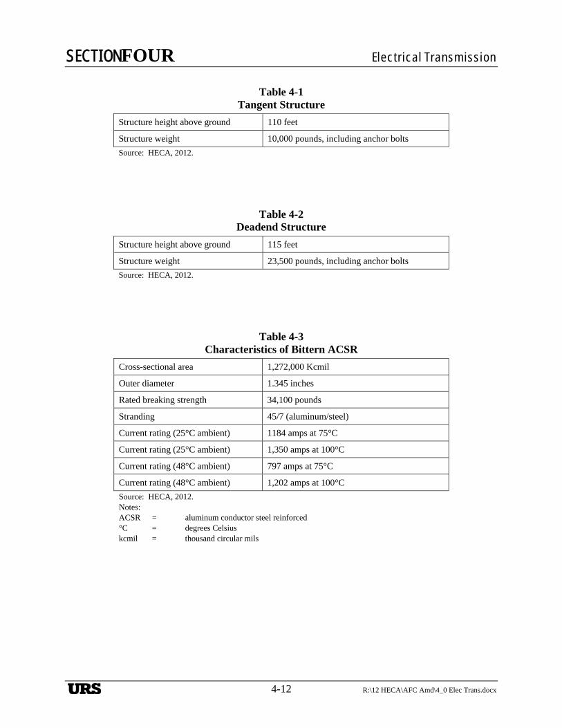
SECTIONFOUR Electrical Transmission
4-12 R:\12 HECA\AFC Amd\4_0 Elec Trans.docx
Table 4-1 Tangent Structure
Structure height above ground 110 feet
Structure weight 10,000 pounds, including anchor bolts
Source: HECA, 2012.
Table 4-2 Deadend Structure
Structure height above ground 115 feet
Structure weight 23,500 pounds, including anchor bolts
Source: HECA, 2012.
Table 4-3 Characteristics of Bittern ACSR
Cross-sectional area 1,272,000 Kcmil
Outer diameter 1.345 inches
Rated breaking strength 34,100 pounds
Stranding 45/7 (aluminum/steel)
Current rating (25°C ambient) 1184 amps at 75°C
Current rating (25°C ambient) 1,350 amps at 100°C
Current rating (48°C ambient) 797 amps at 75°C
Current rating (48°C ambient) 1,202 amps at 100°C
Source: HECA, 2012. Notes: ACSR = aluminum conductor steel reinforced °C = degrees Celsius kcmil = thousand circular mils
URS

SECTIONFOUR Electrical Transmission
R:\12 HECA\AFC Amd\4_0 Elec Trans.docx 4-13
Table 4-4 Characteristics of the Optical Ground Wire
Fault current capability 56 thousand amps
Overall area 0.2208 square inch
Outside diameter 0.646 inch
Weight per 1,000 feet 422 pounds
Fibers included 48
Type of fiber Single-mode
Rated breaking strength 18,053 pounds
Maximum reel ship length 6,000/7,000 feet (wood/steel)
Source: HECA, 2012.
Table 4-5 Comparison of Lattice and Tubular Steel Structures
Feature Lattice Structures Tubular Steel Structures
Voltage 34.5 to 765 kilovolts 15 to 345 kilovolts
Aesthetics Less favorable Good
Components Many Few
Right-of-way Wider Narrower
Span lengths Longer Shorter
Land space for structure Larger (20 to 30 feet square) Smaller (10 to 15 feet in diameter)
Height Above 125 to 150 feet Below 125 to 150 feet
Construction complexity Many pieces—longer to assemble and install
Fewer pieces—assembled and installed more quickly
Foundation requirements Simpler (grillage in some cases, no concrete required), but need four separate excavations
More complex (single concrete pier foundation with rebar, 6 to 10 feet in diameter with 20 to 30 feet depth)
URS
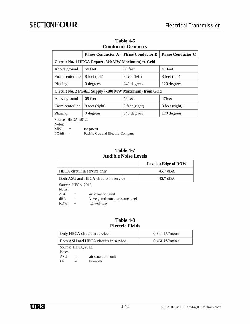
SECTIONFOUR Electrical Transmission
4-14 R:\12 HECA\AFC Amd\4_0 Elec Trans.docx
Table 4-6 Conductor Geometry
Phase Conductor A Phase Conductor B Phase Conductor C
Circuit No. 1 HECA Export (300 MW Maximum) to Grid
Above ground 69 feet 58 feet 47 feet
From centerline 8 feet (left) 8 feet (left) 8 feet (left)
Phasing 0 degrees 240 degrees 120 degrees
Circuit No. 2 PG&E Supply (-100 MW Maximum) from Grid
Above ground 69 feet 58 feet 47feet
From centerline 8 feet (right) 8 feet (right) 8 feet (right)
Phasing 0 degrees 240 degrees 120 degrees
Source: HECA, 2012. Notes: MW = megawatt PG&E = Pacific Gas and Electric Company
Table 4-7 Audible Noise Levels
Level at Edge of ROW
HECA circuit in service only 45.7 dBA
Both ASU and HECA circuits in service 46.7 dBA
Source: HECA, 2012. Notes: ASU = air separation unit dBA = A-weighted sound pressure level ROW = right–of-way
Table 4-8 Electric Fields
Only HECA circuit in service. 0.344 kV/meter
Both ASU and HECA circuits in service. 0.461 kV/meter
Source: HECA, 2012. Notes: ASU = air separation unit kV = kilovolts
URS
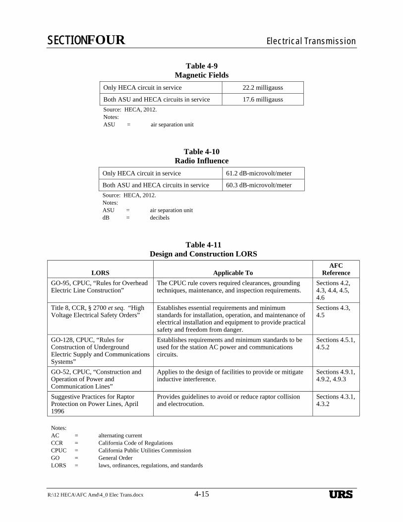
SECTIONFOUR Electrical Transmission
R:\12 HECA\AFC Amd\4_0 Elec Trans.docx 4-15
Table 4-9 Magnetic Fields
Only HECA circuit in service 22.2 milligauss
Both ASU and HECA circuits in service 17.6 milligauss
Source: HECA, 2012. Notes: ASU = air separation unit
Table 4-10 Radio Influence
Only HECA circuit in service 61.2 dB-microvolt/meter
Both ASU and HECA circuits in service 60.3 dB-microvolt/meter
Source: HECA, 2012. Notes: ASU = air separation unit dB = decibels
Table 4-11 Design and Construction LORS
LORS Applicable To AFC
Reference
GO-95, CPUC, “Rules for Overhead Electric Line Construction”
The CPUC rule covers required clearances, grounding techniques, maintenance, and inspection requirements.
Sections 4.2, 4.3, 4.4, 4.5, 4.6
Title 8, CCR, § 2700 et seq. “High Voltage Electrical Safety Orders”
Establishes essential requirements and minimum standards for installation, operation, and maintenance of electrical installation and equipment to provide practical safety and freedom from danger.
Sections 4.3, 4.5
GO-128, CPUC, “Rules for Construction of Underground Electric Supply and Communications Systems”
Establishes requirements and minimum standards to be used for the station AC power and communications circuits.
Sections 4.5.1, 4.5.2
GO-52, CPUC, “Construction and Operation of Power and Communication Lines”
Applies to the design of facilities to provide or mitigate inductive interference.
Sections 4.9.1, 4.9.2, 4.9.3
Suggestive Practices for Raptor Protection on Power Lines, April 1996
Provides guidelines to avoid or reduce raptor collision and electrocution.
Sections 4.3.1, 4.3.2
Notes: AC = alternating current CCR = California Code of Regulations CPUC = California Public Utilities Commission GO = General Order LORS = laws, ordinances, regulations, and standards
URS
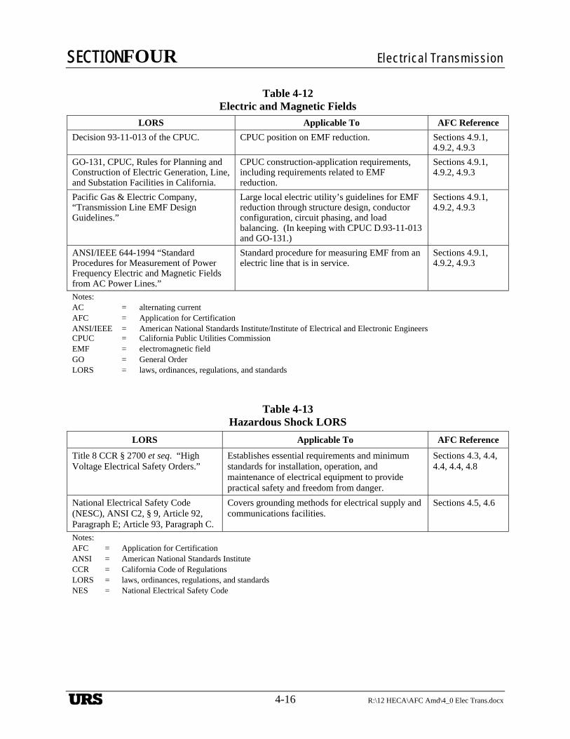
SECTIONFOUR Electrical Transmission
4-16 R:\12 HECA\AFC Amd\4_0 Elec Trans.docx
Table 4-12 Electric and Magnetic Fields
LORS Applicable To AFC Reference
Decision 93-11-013 of the CPUC. CPUC position on EMF reduction. Sections 4.9.1, 4.9.2, 4.9.3
GO-131, CPUC, Rules for Planning and Construction of Electric Generation, Line, and Substation Facilities in California.
CPUC construction-application requirements, including requirements related to EMF reduction.
Sections 4.9.1, 4.9.2, 4.9.3
Pacific Gas & Electric Company, “Transmission Line EMF Design Guidelines.”
Large local electric utility’s guidelines for EMF reduction through structure design, conductor configuration, circuit phasing, and load balancing. (In keeping with CPUC D.93-11-013 and GO-131.)
Sections 4.9.1, 4.9.2, 4.9.3
ANSI/IEEE 644-1994 “Standard Procedures for Measurement of Power Frequency Electric and Magnetic Fields from AC Power Lines.”
Standard procedure for measuring EMF from an electric line that is in service.
Sections 4.9.1, 4.9.2, 4.9.3
Notes: AC = alternating current AFC = Application for Certification ANSI/IEEE = American National Standards Institute/Institute of Electrical and Electronic Engineers CPUC = California Public Utilities Commission EMF = electromagnetic field GO = General Order LORS = laws, ordinances, regulations, and standards
Table 4-13 Hazardous Shock LORS
LORS Applicable To AFC Reference
Title 8 CCR § 2700 et seq. “High Voltage Electrical Safety Orders.”
Establishes essential requirements and minimum standards for installation, operation, and maintenance of electrical equipment to provide practical safety and freedom from danger.
Sections 4.3, 4.4, 4.4, 4.4, 4.8
National Electrical Safety Code (NESC), ANSI C2, § 9, Article 92, Paragraph E; Article 93, Paragraph C.
Covers grounding methods for electrical supply and communications facilities.
Sections 4.5, 4.6
Notes: AFC = Application for Certification ANSI = American National Standards Institute CCR = California Code of Regulations LORS = laws, ordinances, regulations, and standards NES = National Electrical Safety Code
URS
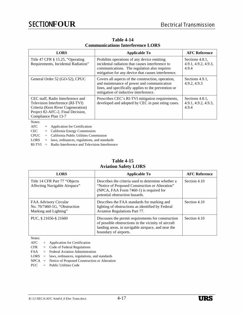
SECTIONFOUR Electrical Transmission
R:\12 HECA\AFC Amd\4_0 Elec Trans.docx 4-17
Table 4-14 Communications Interference LORS
LORS Applicable To AFC Reference
Title 47 CFR § 15.25, “Operating Requirements, Incidental Radiation”
Prohibits operations of any device emitting incidental radiation that causes interference to communications. The regulation also requires mitigation for any device that causes interference.
Sections 4.8.1, 4.9.1, 4.9.2, 4.9.3, 4.9.4
General Order 52 (GO-52), CPUC Covers all aspects of the construction, operation, and maintenance of power and communication lines, and specifically applies to the prevention or mitigation of inductive interference.
Sections 4.9.1, 4.9.2, 4.9.3
CEC staff, Radio Interference and Television Interference (RI-TVI) Criteria (Kern River Cogeneration) Project 82-AFC-2, Final Decision, Compliance Plan 13-7
Prescribes CEC’s RI-TVI mitigation requirements, developed and adopted by CEC in past siting cases.
Sections 4.8.1, 4.9.1, 4.9.2, 4.9.3, 4.9.4
Notes: AFC = Application for Certification CEC = California Energy Commission CPUC = California Public Utilities Commission LORS = laws, ordinances, regulations, and standards RI-TVI = Radio Interference and Television Interference
Table 4-15 Aviation Safety LORS
LORS Applicable To AFC Reference
Title 14 CFR Part 77 “Objects Affecting Navigable Airspace”
Describes the criteria used to determine whether a “Notice of Proposed Construction or Alteration” (NPCA, FAA Form 7460-1) is required for potential obstruction hazards.
Section 4.10
FAA Advisory Circular No. 70/7460-1G, “Obstruction Marking and Lighting”
Describes the FAA standards for marking and lighting of obstructions as identified by Federal Aviation Regulations Part 77.
Section 4.10
PUC, § 21656-§ 21660 Discusses the permit requirements for construction of possible obstructions in the vicinity of aircraft landing areas, in navigable airspace, and near the boundary of airports.
Section 4.10
Notes: AFC = Application for Certification CFR = Code of Federal Regulations FAA = Federal Aviation Administration LORS = laws, ordinances, regulations, and standards NPCA = Notice of Proposed Construction or Alteration PUC = Public Utilities Code
URS
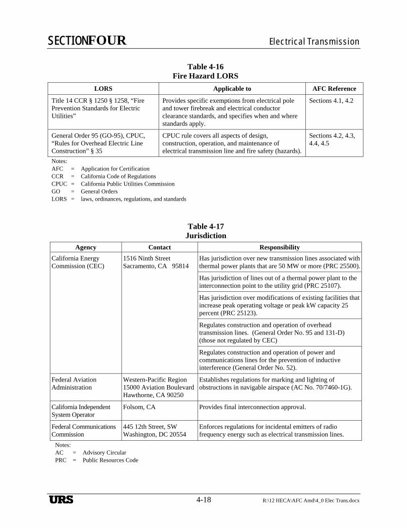
SECTIONFOUR Electrical Transmission
4-18 R:\12 HECA\AFC Amd\4_0 Elec Trans.docx
Table 4-16 Fire Hazard LORS
LORS Applicable to AFC Reference
Title 14 CCR § 1250 § 1258, “Fire Prevention Standards for Electric Utilities”
Provides specific exemptions from electrical pole and tower firebreak and electrical conductor clearance standards, and specifies when and where standards apply.
Sections 4.1, 4.2
General Order 95 (GO-95), CPUC, “Rules for Overhead Electric Line Construction” § 35
CPUC rule covers all aspects of design, construction, operation, and maintenance of electrical transmission line and fire safety (hazards).
Sections 4.2, 4.3, 4.4, 4.5
Notes: AFC = Application for Certification CCR = California Code of Regulations CPUC = California Public Utilities Commission GO = General Orders LORS = laws, ordinances, regulations, and standards
Table 4-17 Jurisdiction
Agency Contact Responsibility
California Energy Commission (CEC)
1516 Ninth Street Sacramento, CA 95814
Has jurisdiction over new transmission lines associated with thermal power plants that are 50 MW or more (PRC 25500).
Has jurisdiction of lines out of a thermal power plant to the interconnection point to the utility grid (PRC 25107).
Has jurisdiction over modifications of existing facilities that increase peak operating voltage or peak kW capacity 25 percent (PRC 25123).
Regulates construction and operation of overhead transmission lines. (General Order No. 95 and 131-D) (those not regulated by CEC)
Regulates construction and operation of power and communications lines for the prevention of inductive interference (General Order No. 52).
Federal Aviation Administration
Western-Pacific Region 15000 Aviation BoulevardHawthorne, CA 90250
Establishes regulations for marking and lighting of obstructions in navigable airspace (AC No. 70/7460-1G).
California Independent System Operator
Folsom, CA Provides final interconnection approval.
Federal Communications Commission
445 12th Street, SW Washington, DC 20554
Enforces regulations for incidental emitters of radio frequency energy such as electrical transmission lines.
Notes: AC = Advisory Circular PRC = Public Resources Code
URS
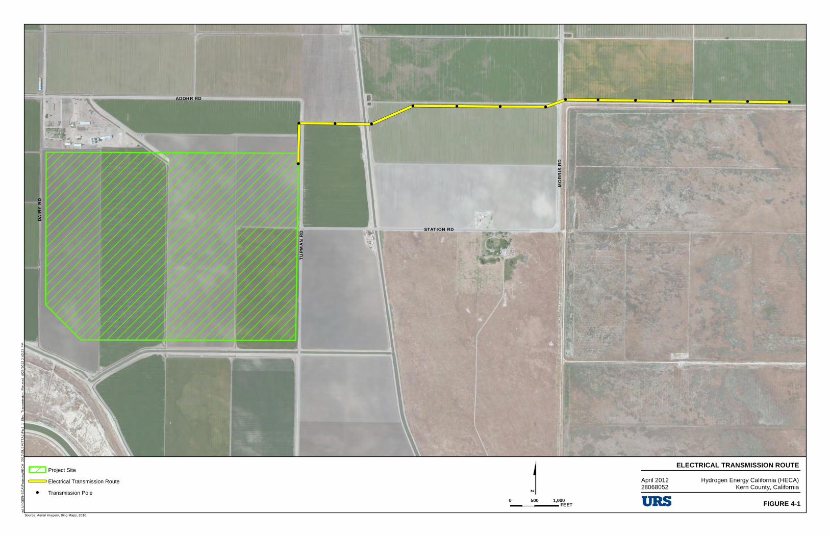
!
! ! !
! ! ! !
! ! ! ! ! ! !ADOHR RD
DAIRY
RD
TUPM
AN RD
MORR
IS RD
STATION RD
$Source: Aerial imagery, Bing Maps, 2010.
Project Site
Electrical Transmission Route
! Transmission Pole
ELECTRICAL TRANSMISSION ROUTEHydrogen Energy California (HECA)
Kern County, CaliforniaApril 201228068052
0 500 1,000FEET FIGURE 4-1
ed U
:\GIS
\HE
CA
\Pro
ject
s\H
EC
A_
2012
\SU
BM
ITT
AL
\Fig
4_1
_Ele
c_T
rans
mis
sio
n_R
te.m
xd 4
/29
/20
12
2:4
3:2
8 P
M
[Z]
=
URS
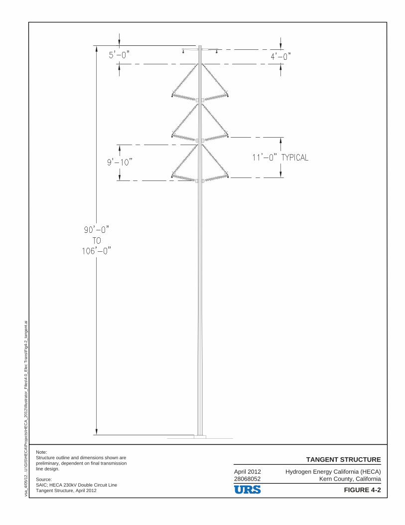
Hydrogen Energy California (HECA)Kern County, California
April 201228068052
FIGURE 4-2
TANGENT STRUCTURE
vsa_
4/05
/12.
..U:\G
IS\H
EC
A\P
roje
cts\
HE
CA
_201
2\Ill
ustr
ator
_File
s\4.
0_E
lec
Tra
ns\F
ig4-
2_ta
ngen
t.ai
Source:SAIC; HECA 230kV Double Circuit LineTangent Structure, April 2012
Note:Structure outline and dimensions shown arepreliminary, dependent on final transmission line design.
s'-o"
,-9'-1 o"
90'-Q" TO
106'-o"
L __
7 11 '-0" TYPICAL
··~ ,,11~- ·· - - _J
URS
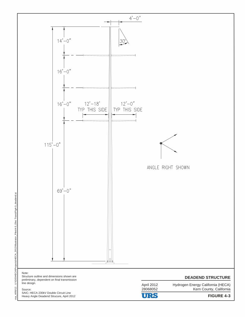
Hydrogen Energy California (HECA)Kern County, California
April 201228068052
FIGURE 4-3
DEADEND STRUCTURE
vsa_
4/05
/12.
..U:\G
IS\H
EC
A\P
roje
cts\
HE
CA
_201
2\Ill
ustr
ator
_File
s\4.
0_E
lec
Tra
ns\F
ig4-
3_de
aden
d.ai
Source:SAIC; HECA 230kV Double Circuit LineHeavy Angle Deadend Strucure, April 2012
Note:Structure outline and dimensions shown arepreliminary, dependent on final transmission line design.
I I 4'-0"
I I
)o" ~ t---1==========1111~
16'-o"
-,-- - --1====11111======1
16'-o" 12'-1s· 12'-o" TYP THIS SIDE TYP THIS SIDE
I I
I I -,-- - --l====il ll======l
115'-o"
ANGLE RIGHT SHOWN
69'-o"
URS
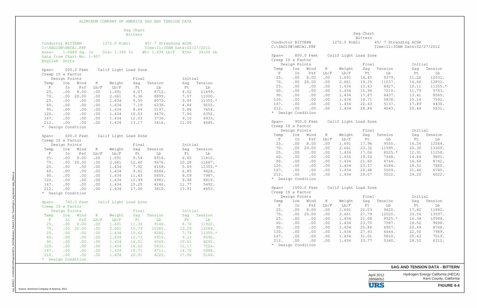
ALUMINUM COMPANY OF AMERICA SAG AND TENSION DATA
Sag Chart Bittern
Conductor BITTERN 1272.0 Kcmil 45/ 7 Stranding ACSR C:\SAG10W\HECA1.PRF Time:11:30AM Date:02/27/2012 Area= 1.0680 Sq. In Dia= 1.345 In Wt= 1.434 Lb/F RTS= 34100 Lb Data from Chart No. 1-957 English Units
Span= 500.0 Feet Calif Light Load Zone Creep IS a Factor Design Points Final Initial Temp Ice Wind K Weight Sag Tension Sag Tension F In Psf Lb/F Lb/F Ft Lb Ft Lb 25. .00 8.00 .00 1.691 6.07 8712. 4.52 11699. 70. .00 20.00 .00 2.661 9.36 8899. 7.57 11000. 25. .00 .00 .00 1.434 5.55 8073. 3.95 11355.* 60. .00 .00 .00 1.434 7.19 6238. 4.84 9255. 90. .00 .00 .00 1.434 8.64 5197. 5.86 7654. 120. .00 .00 .00 1.434 10.03 4479. 7.06 6352. 167. .00 .00 .00 1.434 12.03 3736. 9.10 4933. 212. .00 .00 .00 1.434 13.17 3416. 11.00 4085. * Design Condition
Span= 600.0 Feet Calif Light Load Zone Creep IS a Factor Design Points Final Initial Temp Ice Wind K Weight Sag Tension Sag Tension F In Psf Lb/F Lb/F Ft Lb Ft Lb 25. .00 8.00 .00 1.691 8.54 8918. 6.45 11810. 70. .00 20.00 .00 2.661 12.40 9676. 10.28 11667. 25. .00 .00 .00 1.434 7.92 8158. 5.69 11355.* 60. .00 .00 .00 1.434 9.81 6586. 6.85 9426. 90. .00 .00 .00 1.434 11.43 5655. 8.09 7987. 120. .00 .00 .00 1.434 12.99 4981. 9.48 6815. 167. .00 .00 .00 1.434 15.25 4246. 11.77 5492. 212. .00 .00 .00 1.434 17.00 3812. 13.91 4653. * Design Condition
Span= 700.0 Feet Calif Light Load Zone Creep IS a Factor Design Points Final Initial Temp Ice Wind K Weight Sag Tension Sag Tension F In Psf Lb/F Lb/F Ft Lb Ft Lb 25. .00 8.00 .00 1.691 11.34 9146. 8.70 11922. 70. .00 20.00 .00 2.661 15.74 10385. 13.29 12284. 25. .00 .00 .00 1.434 10.62 8282. 7.74 11355.* 60. .00 .00 .00 1.434 12.73 6910. 9.17 9590. 90. .00 .00 .00 1.434 14.51 6065. 10.61 8291. 120. .00 .00 .00 1.434 16.22 5431. 12.17 7226. 167. .00 .00 .00 1.434 18.71 4711. 14.70 5988. 212. .00 .00 .00 1.434 20.91 4220. 17.06 5166. * Design Condition
Sag Chart Bittern Conductor BITTERN 1272.0 Kcmil 45/ 7 Stranding ACSR C:\SAG10W\HECA1.PRF Time:11:30AM Date:02/27/2012
Span= 800.0 Feet Calif Light Load Zone Creep IS a Factor Design Points Final Initial Temp Ice Wind K Weight Sag Tension Sag Tension F In Psf Lb/F Lb/F Ft Lb Ft Lb 25. .00 8.00 .00 1.691 14.45 9379. 11.26 12031. 70. .00 20.00 .00 2.661 19.35 11037. 16.60 12852. 25. .00 .00 .00 1.434 13.63 8427. 10.11 11355.* 60. .00 .00 .00 1.434 15.94 7210. 11.79 9743. 90. .00 .00 .00 1.434 17.87 6437. 13.41 8565. 120. .00 .00 .00 1.434 19.71 5838. 15.14 7592. 167. .00 .00 .00 1.434 22.43 5137. 17.89 6430. 212. .00 .00 .00 1.434 24.84 4643. 20.44 5631. * Design Condition
Span= 900.0 Feet Calif Light Load Zone Creep IS a Factor Design Points Final Initial Temp Ice Wind K Weight Sag Tension Sag Tension F In Psf Lb/F Lb/F Ft Lb Ft Lb 25. .00 8.00 .00 1.691 17.96 9555. 14.24 12044. 70. .00 20.00 .00 2.661 23.32 11595. 20.30 13309. 25. .00 .00 .00 1.434 17.06 8525.* 12.91 11258. 60. .00 .00 .00 1.434 19.54 7448. 14.84 9801. 90. .00 .00 .00 1.434 21.60 6744. 16.64 8742. 120. .00 .00 .00 1.434 23.57 6184. 18.51 7860. 167. .00 .00 .00 1.434 26.48 5509. 21.46 6785. 212. .00 .00 .00 1.434 29.07 5022. 24.20 6022. * Design Condition
Span= 1000.0 Feet Calif Light Load Zone Creep IS a Factor Design Points Final Initial Temp Ice Wind K Weight Sag Tension Sag Tension F In Psf Lb/F Lb/F Ft Lb Ft Lb 25. .00 8.00 .00 1.691 22.03 9620. 17.82 11882. 70. .00 20.00 .00 2.661 27.79 12020. 24.54 13597. 25. .00 .00 .00 1.434 21.08 8525.* 16.34 10984. 60. .00 .00 .00 1.434 23.70 7587. 18.52 9698. 90. .00 .00 .00 1.434 25.86 6957. 20.49 8768. 120. .00 .00 .00 1.434 27.93 6444. 22.50 7989. 167. .00 .00 .00 1.434 31.01 5810. 25.63 7019. 212. .00 .00 .00 1.434 33.77 5340. 28.52 6312. * Design Condition
Source: Aluminum Company of America, 2012
Hydrogen Energy California (HECA)Kern County, California
SAG AND TENSION DATA - BITTERN
FIGURE 4-4
vsa_
4/05
/12.
..U:\G
IS\H
EC
A\P
roje
cts\
HE
CA
_201
2\Ill
ustr
ator
_File
s\4.
0_E
lec
Tra
ns\F
ig4-
4_sa
g te
nsio
n da
ta_b
itter
n.ai
April 201228068052
URS
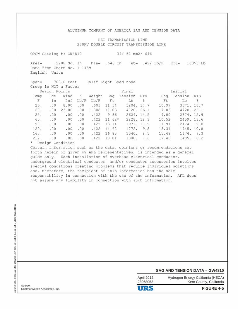
ALUMINUM COMPANY OF AMERICA SAG AND TENSION DATA
HEI TRANSMISSION LINE230KV DOUBLE CIRCUIT TRANSMISSION LINE
OPGW Catalog #: GW4810 34/ 52 mm2/ 646
Area= .2208 Sq. In Dia= .646 In Wt= .422 Lb/F RTS= 18053 LbData from Chart No. 1-1439English Units
Span= 700.0 Feet Calif Light Load ZoneCreep is NOT a Factor
laitinIlaniFstnioPngiseDTemp Ice Wind K Weight Sag Tension RTS Sag Tension RTS
F In Psf Lb/F Lb/F Ft Lb % Ft Lb %25. .00 8.00 .00 .603 11.54 3204. 17.7 10.97 3371. 18.760. .00 23.00 .00 1.308 17.03 4720. 26.1 17.03 4720. 26.125. .00 .00 .00 .422 9.86 2624. 14.5 9.00 2874. 15.960. .00 .00 .00 .422 11.62* 2228. 12.3 10.52 2459. 13.690. .00 .00 .00 .422 13.14 1971. 10.9 11.91 2174. 12.0
120. .00 .00 .00 .422 14.62 1772. 9.8 13.31 1945. 10.8167. .00 .00 .00 .422 16.83 1540. 8.5 15.48 1674. 9.3212. .00 .00 .00 .422 18.81 1380. 7.6 17.46 1485. 8.2
* Design ConditionCertain information such as the data, opinions or recommendations setforth herein or given by AFL representatives, is intended as a generalguide only. Each installation of overhead electrical conductor,underground electrical conductor, and/or conductor accessories involvesspecial conditions creating problems that require individual solutionsand, therefore, the recipient of this information has the soleresponsibility in connection with the use of the information. AFL doesnot assume any liability in connection with such information.
Source:Commonwealth Associates, Inc.
Hydrogen Energy California (HECA)Kern County, California
April 201228068052
FIGURE 4-5
SAG AND TENSION DATA – GW4810
4/26
/12
vsa.
.T:\H
EC
A-S
CS
201
2\G
RA
PH
ICS
201
2\4.
0_E
lec\
Fig
4-5_
data
_GW
4810
.ai
URS
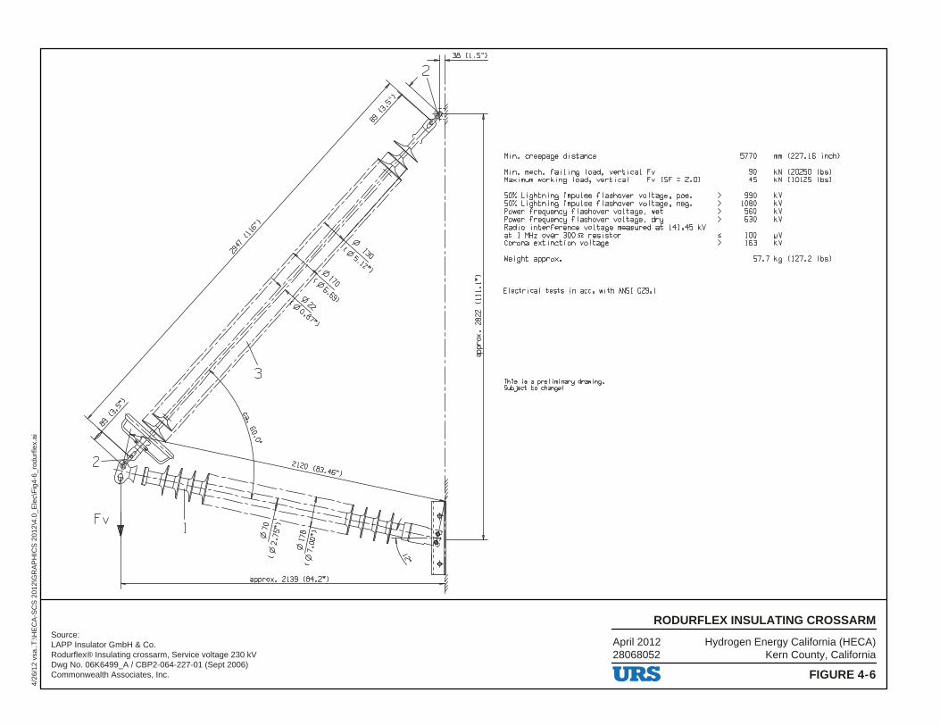
Source:LAPP Insulator GmbH & Co. Rodurflex® Insulating crossarm, Service voltage 230 kVDwg No. 06K6499_A / CBP2-064-227-01 (Sept 2006)Commonwealth Associates, Inc.
Hydrogen Energy California (HECA)Kern County, California
April 201228068052
FIGURE 4-6
RODURFLEX INSULATING CROSSARM
4/26
/12
vsa.
.T:\H
EC
A-S
CS
201
2\G
RA
PH
ICS
201
2\4.
0_E
lec\
Fig
4-6_
rodu
rfle
x.ai
2
..:
ro
Fv
a rox. 2139 (84,2")
Min. creepage di stance
Min. mech. fai I ing load, vertical Fv Maximum working load, vertical Fv CSF = 2.0)
50% Lightning impulse flashover voltage, pos. 50% Lightning impulse flashover voltage, neg. Power frequency f I ashover vo I tage, wet Power frequency f I ashover vo I tage, dry Radio interference voltage measured at 141 . 45 kV at 1 MHz over 300 R res i star Corona ext i net ion vo I tage
Weight approx •
Electrical tests in acc. with ANSI C29. 1
This is a pre I iminary drawing. Subject to change!
URS
> > > >
5770 mm (227. 16 inch)
90 kN (20250 I bs) 45 kN ( 10125 lbs)
990 kV 1080 kV 560 kV 630 kV
100 µV 163 kV
57.7 kg (127.2 lbs)
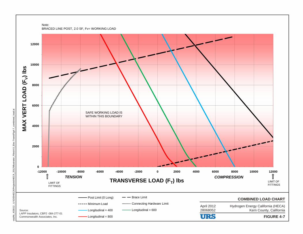
8000
10000
12000
) lb
sV
MA
X V
ER
T L
OA
D (
FNote:BRACED LINE POST, 2.0 SF, Fv= WORKING LOAD
0
2000
4000
6000
-12000 -10000 -8000 -6000 -4000 -2000 0 2000 4000 6000 8000 10000 12000
) lbsTTRANSVERSE LOAD (FTENSION COMPRESSION
SAFE WORKING LOAD ISWITHIN THIS BOUNDARY
LIMIT OF FITTINGS
Source:LAPP Insulators, CBP2 -084-277-01Commonwealth Associates, Inc.
LIMIT OF FITTINGS
Post Limit (0 Long) Brace Limit
Minimum Load Connecting Hardware Limit
Longitudinal = 400 Longitudinal = 600
Longitudinal = 800
Hydrogen Energy California (HECA)Kern County, California
April 201228068052
FIGURE 4-7
COMBINED LOAD CHART
vsa/
hk_4
/26/
12...
U:\G
IS\H
EC
A\P
roje
cts\
HE
CA
_201
2\Ill
ustr
ator
_File
s\4.
0_E
lec
Tra
ns\F
ig4-
7_co
mbi
ned_
load
.ai
URS
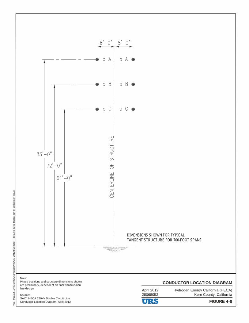
DIMENSIONS SHOWN FOR TYPICAL TANGENT STRUCTURE FOR 700-FOOT SPANS
Hydrogen Energy California (HECA)Kern County, California
April 201228068052
FIGURE 4-8
CONDUCTOR LOCATION DIAGRAM
vsa_
4/19
/12.
..U:\G
IS\H
EC
A\P
roje
cts\
HE
CA
_201
2\Ill
ustr
ator
_File
s\4.
0_E
lec
Tra
ns\F
ig4-
8_co
nduc
tor_
loc.
ai
Source:SAIC; HECA 230kV Double Circuit LineConductor Location Diagram, April 2012
Note:Phase positions and structure dimensions shown are preliminary, dependent on final transmission line design.
s'-o" s'-o" 1 • •I• • 1
--- - •¢Al¢A• I
• ¢ B I ¢ B • -
I
- • ¢ C ¢ C • I
~I ::::) I-u
83'-o" ::::)
O:::'. l---1 (f)
72'-o" LL 0
w 61 '-o" z:1
_J
O:::'. w I-z: t:51
I
I
~
URS
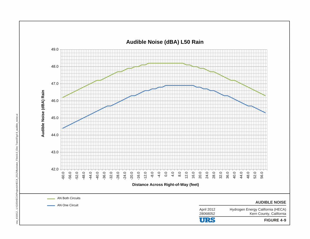
-60.
0
-56.
0
-52.
0
-48.
0
-44.
0
-40.
0
-36.
0
-32.
0
-28.
0
-24.
0
-20.
0
-16.
0
-12.
0
-8.0
-4.0 0.0
4.0
8.0
12.0
16.0
20.0
24.0
28.0
32.0
36.0
40.0
44.0
48.0
52.0
56.0
Au
dib
le N
ois
e (
dB
A)
Ra
in
Distance Across Right-of-Way (feet)
Audible Noise (dBA) L50 Rain
AN Both Circuits
AN One Circuit
42.0
43.0
44.0
45.0
46.0
47.0
48.0
49.0
Hydrogen Energy California (HECA)Kern County, California
April 201228068052
FIGURE 4-9
AUDIBLE NOISE
vsa_
4/19
/12.
..U:\G
IS\H
EC
A\P
roje
cts\
HE
CA
_201
2\Ill
ustr
ator
_File
s\4.
0_E
lec
Tra
ns\F
ig4-
9_au
dibl
e_no
ise.
ai
-
I, . ,.
-I, ..
I, I'll , ,
~
I,
,
ll
--
URS
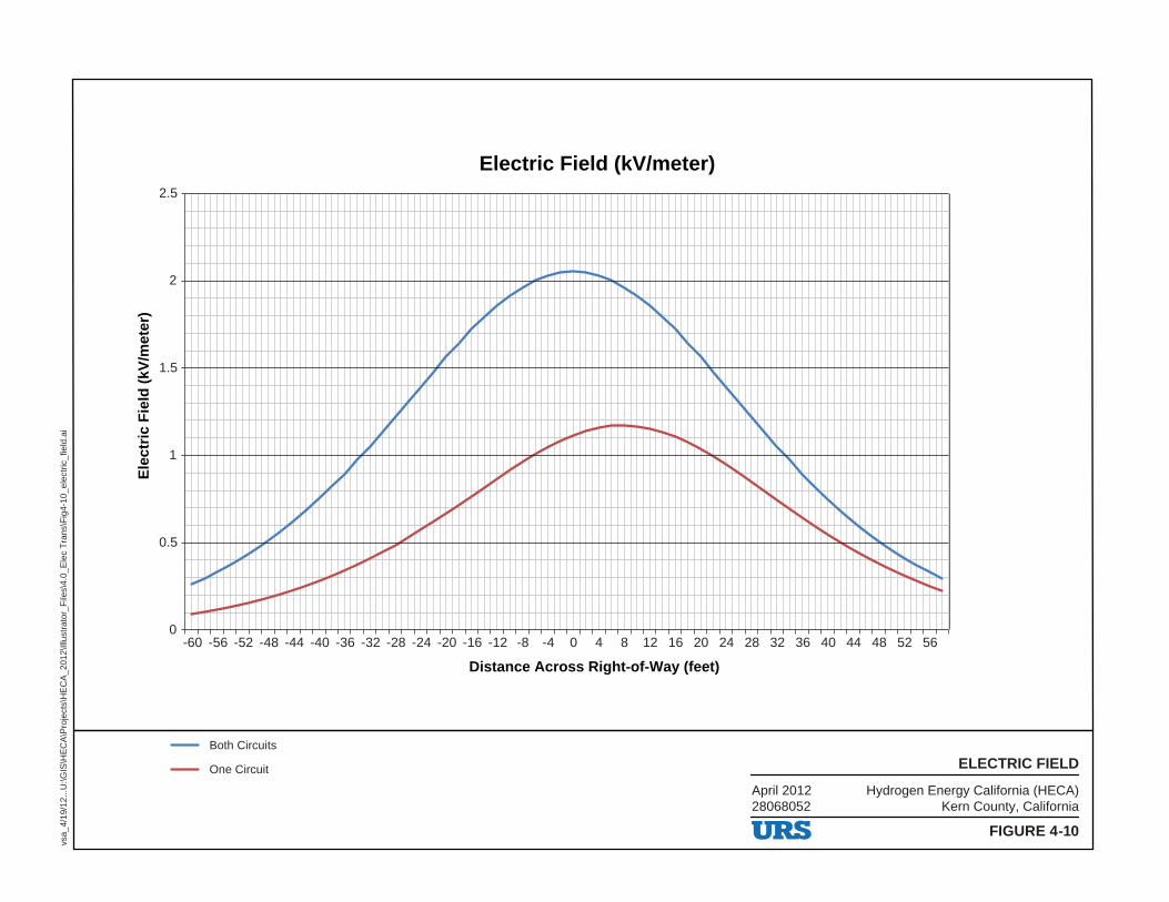
0
0.5
1
1.5
2
2.5
-60 -56 -52 -48 -44 -40 -36 -32 -28 -24 -20 -16 -12 -8 -4 0 4 8 12 16 20 24 28 32 36 40 44 48 52 56
Ele
ctri
c F
ield
(kV
/met
er)
Distance Across Right-of-Way (feet)
Electric Field (kV/meter)
Both Circuits
One Circuit
Hydrogen Energy California (HECA)Kern County, California
April 201228068052
FIGURE 4-10
ELECTRIC FIELD
vsa_
4/19
/12.
..U:\G
IS\H
EC
A\P
roje
cts\
HE
CA
_201
2\Ill
ustr
ator
_File
s\4.
0_E
lec
Tra
ns\F
ig4-
10_e
lect
ric_f
ield
.ai
7 I I I I I I I I I I I
I L
~ ~
J; ~
~ !'I ~
J;
~
~~ ,,. .... I ,.
~
~ 1" " .. ~
I,, ~ .. ~ " ~ ' ,. 11 .. ~ .. I ~
~"' .... ~ ,.~ ~- i.. I
.. I _L I
I I I I I I I I I I I I I I
I I I
I I I I I I I I I I I I I I I I I I l I I 11 I I
~ ., I
I I I 11 I I I I I I I I 11 I I I I I I I I 1 I I I I I
URS
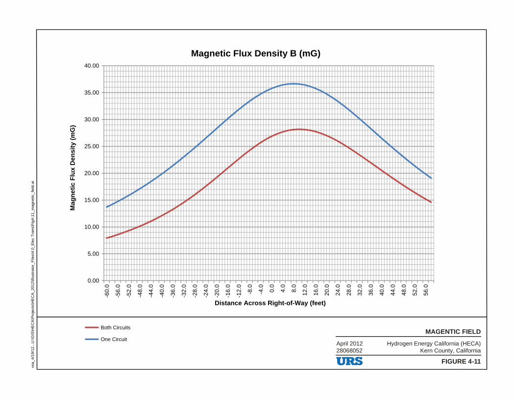
0.00
5.00
10.00
15.00
20.00
25.00
30.00
35.00
40.00
-60.
0
-56.
0
-52.
0
-48.
0
-44.
0
-40.
0
-36.
0
-32.
0
-28.
0
-24.
0
-20.
0
-16.
0
-12.
0
-8.0
-4.0 0.0
4.0
8.0
12.0
16.0
20.0
24.0
28.0
32.0
36.0
40.0
44.0
48.0
52.0
56.0
Mag
net
ic F
lux
Den
sity
(m
G)
Distance Across Right-of-Way (feet)
Magnetic Flux Density B (mG)
Both Circuits
One CircuitHydrogen Energy California (HECA)
Kern County, CaliforniaApril 201228068052
FIGURE 4-11
MAGENTIC FIELD
vsa_
4/19
/12.
..U:\G
IS\H
EC
A\P
roje
cts\
HE
CA
_201
2\Ill
ustr
ator
_File
s\4.
0_E
lec
Tra
ns\F
ig4-
11_m
agne
tic_f
ield
.ai
I I
,
, ~ ,
~
~
I' , , ~
,
~
~
~
I
' ----
URS
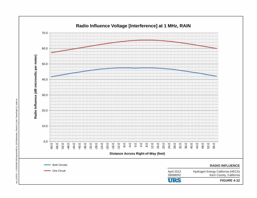
0.0
10.0
20.0
30.0
40.0
50.0
60.0
70.0
-60.
0
-56.
0
-52.
0
-48.
0
-44.
0
-40.
0
-36.
0
-32.
0
-28.
0
-24.
0
-20.
0
-16.
0
-12.
0
-8.0
-4.0 0.0
4.0
8.0
12.0
16.0
20.0
24.0
28.0
32.0
36.0
40.0
44.0
48.0
52.0
56.0
Ra
dio
In
flu
en
ce
(d
B m
icro
volt
s p
er
me
ter)
Distance Across Right-of-Way (feet)
Radio Influence Voltage [Interference] at 1 MHz, RAIN
Both Circuits
One Circuit Hydrogen Energy California (HECA)Kern County, California
April 201228068052
FIGURE 4-12
RADIO INFLUENCE
vsa_
4/19
/12.
..U:\G
IS\H
EC
A\P
roje
cts\
HE
CA
_201
2\Ill
ustr
ator
_File
s\4.
0_E
lec
Tra
ns\F
ig4-
12_r
adio
.ai
~~
~~
~
--
URS
SECTIONFIVE Environmental Information
R:\12 HECA\AFC Amd\5_0 Intro.docx 5-1 1
5. ENVIRONMENTAL INFORMATION
The following sections, 5.1 through 5.16, provide the environmental information required for this Application for Certification (AFC) Amendment:
Section 5.1 Air Quality
Section 5.2 Biological Resources
Section 5.3 Cultural Resources
Section 5.4 Land Use and Agriculture
Section 5.5 Noise
Section 5.6 Public Health
Section 5.7 Worker Safety and Health
Section 5.8 Socioeconomics/Environmental Justice
Section 5.9 Soils
Section 5.10 Traffic and Transportation
Section 5.11 Visual Resources
Section 5.12 Hazardous Materials Handling
Section 5.13 Waste Management
Section 5.14 Water Resources
Section 5.15 Geological Hazards and Resources
Section 5.16 Paleontological Resources
This AFC Amendment supersedes previous application materials in their entirety, unless noted otherwise. Documents submitted to date include the AFC submitted on July 31, 2008, and the Revised AFC submitted on May 28, 2009. CEC Staff issued additional requests for information on August 5, 2011. Responses to these requests are incorporated into this AFC Amendment, as summarized in Table 5.0-1.
URS
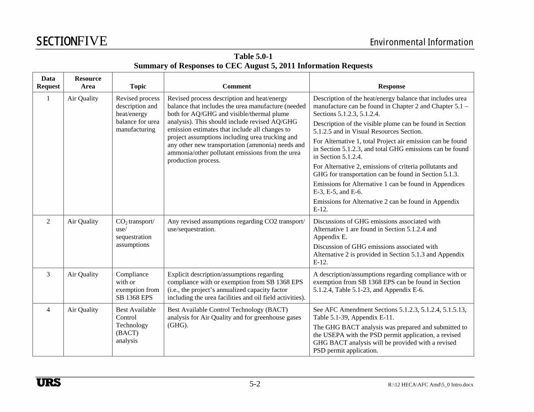
SECTIONFIVE Environmental Information
5-2 R:\12 HECA\AFC Amd\5_0 Intro.docx
Table 5.0-1 Summary of Responses to CEC August 5, 2011 Information Requests
Data Request
Resource Area Topic Comment Response
1 Air Quality Revised process description and heat/energy balance for urea manufacturing
Revised process description and heat/energy balance that includes the urea manufacture (needed both for AQ/GHG and visible/thermal plume analysis). This should include revised AQ/GHG emission estimates that include all changes to project assumptions including urea trucking and any other new transportation (ammonia) needs and ammonia/other pollutant emissions from the urea production process.
Description of the heat/energy balance that includes urea manufacture can be found in Chapter 2 and Chapter 5.1 – Sections 5.1.2.3, 5.1.2.4.
Description of the visible plume can be found in Section 5.1.2.5 and in Visual Resources Section.
For Alternative 1, total Project air emission can be found in Section 5.1.2.3, and total GHG emissions can be found in Section 5.1.2.4.
For Alternative 2, emissions of criteria pollutants and GHG for transportation can be found in Section 5.1.3.
Emissions for Alternative 1 can be found in Appendices E-3, E-5, and E-6.
Emissions for Alternative 2 can be found in Appendix E-12.
2 Air Quality CO2 transport/use/sequestration assumptions
Any revised assumptions regarding CO2 transport/use/sequestration.
Discussions of GHG emissions associated with Alternative 1 are found in Section 5.1.2.4 and Appendix E.
Discussion of GHG emissions associated with Alternative 2 is provided in Section 5.1.3 and Appendix E-12.
3 Air Quality Compliance with or exemption from SB 1368 EPS
Explicit description/assumptions regarding compliance with or exemption from SB 1368 EPS (i.e., the project’s annualized capacity factor including the urea facilities and oil field activities).
A description/assumptions regarding compliance with or exemption from SB 1368 EPS can be found in Section 5.1.2.4, Table 5.1-23, and Appendix E-6.
4 Air Quality Best Available Control Technology (BACT) analysis
Best Available Control Technology (BACT) analysis for Air Quality and for greenhouse gases (GHG).
See AFC Amendment Sections 5.1.2.3, 5.1.2.4, 5.1.5.13, Table 5.1-39, Appendix E-11.
The GHG BACT analysis was prepared and submitted to the USEPA with the PSD permit application, a revised GHG BACT analysis will be provided with a revised PSD permit application.
UBS
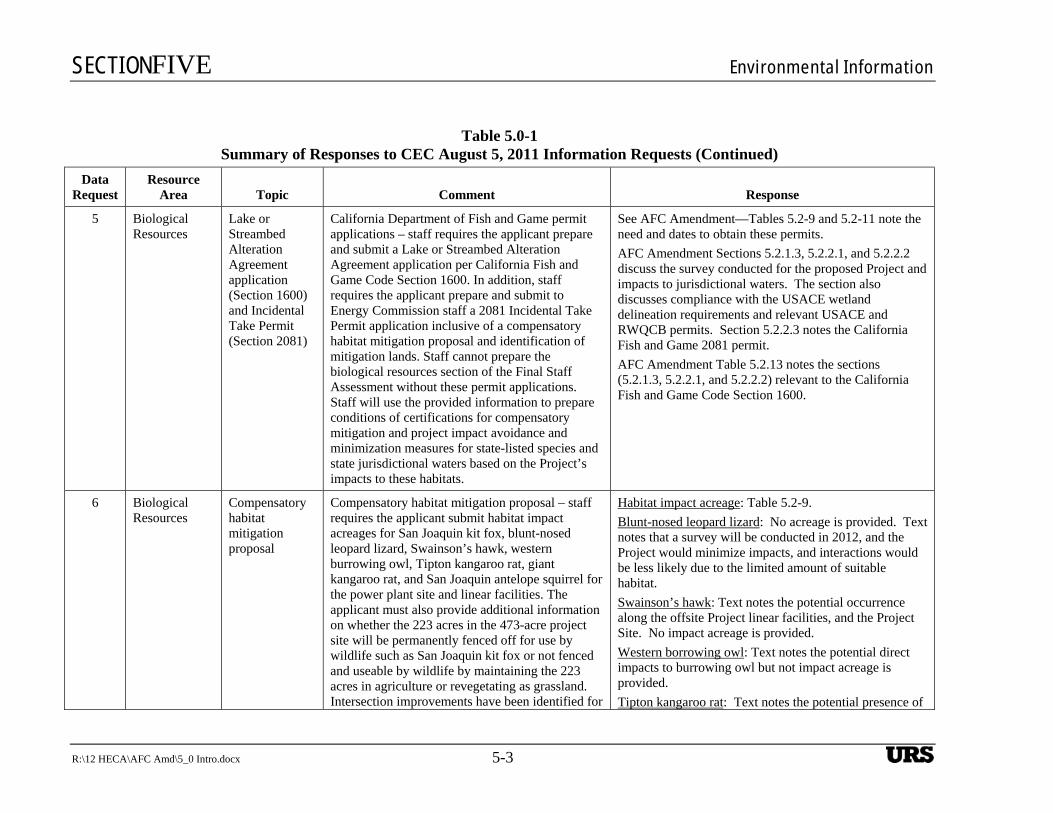
SECTIONFIVE Environmental Information
R:\12 HECA\AFC Amd\5_0 Intro.docx 5-3
Table 5.0-1 Summary of Responses to CEC August 5, 2011 Information Requests (Continued)
Data Request
Resource Area Topic Comment Response
5 Biological Resources
Lake or Streambed Alteration Agreement application (Section 1600) and Incidental Take Permit (Section 2081)
California Department of Fish and Game permit applications – staff requires the applicant prepare and submit a Lake or Streambed Alteration Agreement application per California Fish and Game Code Section 1600. In addition, staff requires the applicant prepare and submit to Energy Commission staff a 2081 Incidental Take Permit application inclusive of a compensatory habitat mitigation proposal and identification of mitigation lands. Staff cannot prepare the biological resources section of the Final Staff Assessment without these permit applications. Staff will use the provided information to prepare conditions of certifications for compensatory mitigation and project impact avoidance and minimization measures for state-listed species and state jurisdictional waters based on the Project’s impacts to these habitats.
See AFC Amendment—Tables 5.2-9 and 5.2-11 note the need and dates to obtain these permits.
AFC Amendment Sections 5.2.1.3, 5.2.2.1, and 5.2.2.2 discuss the survey conducted for the proposed Project and impacts to jurisdictional waters. The section also discusses compliance with the USACE wetland delineation requirements and relevant USACE and RWQCB permits. Section 5.2.2.3 notes the California Fish and Game 2081 permit.
AFC Amendment Table 5.2.13 notes the sections (5.2.1.3, 5.2.2.1, and 5.2.2.2) relevant to the California Fish and Game Code Section 1600.
6 Biological Resources
Compensatory habitat mitigation proposal
Compensatory habitat mitigation proposal – staff requires the applicant submit habitat impact acreages for San Joaquin kit fox, blunt-nosed leopard lizard, Swainson’s hawk, western burrowing owl, Tipton kangaroo rat, giant kangaroo rat, and San Joaquin antelope squirrel for the power plant site and linear facilities. The applicant must also provide additional information on whether the 223 acres in the 473-acre project site will be permanently fenced off for use by wildlife such as San Joaquin kit fox or not fenced and useable by wildlife by maintaining the 223 acres in agriculture or revegetating as grassland. Intersection improvements have been identified for
Habitat impact acreage: Table 5.2-9.
Blunt-nosed leopard lizard: No acreage is provided. Text notes that a survey will be conducted in 2012, and the Project would minimize impacts, and interactions would be less likely due to the limited amount of suitable habitat.
Swainson’s hawk: Text notes the potential occurrence along the offsite Project linear facilities, and the Project Site. No impact acreage is provided.
Western borrowing owl: Text notes the potential direct impacts to burrowing owl but not impact acreage is provided.
Tipton kangaroo rat: Text notes the potential presence of
UBS
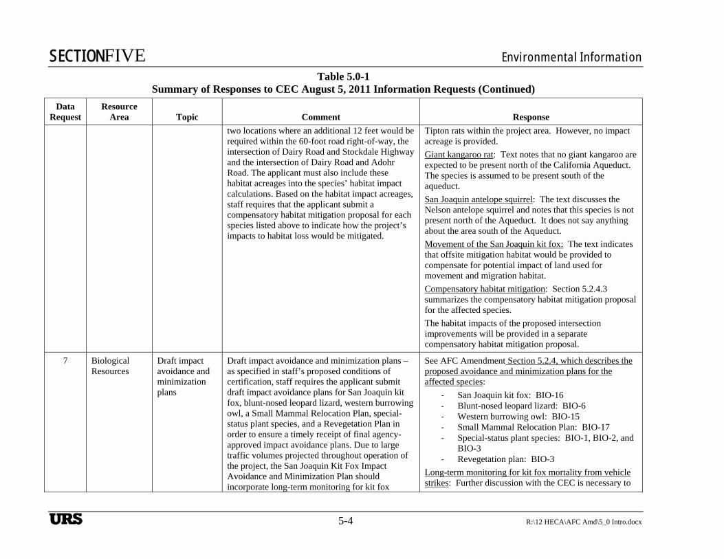
SECTIONFIVE Environmental Information
5-4 R:\12 HECA\AFC Amd\5_0 Intro.docx
Table 5.0-1 Summary of Responses to CEC August 5, 2011 Information Requests (Continued)
Data Request
Resource Area Topic Comment Response
two locations where an additional 12 feet would be required within the 60-foot road right-of-way, the intersection of Dairy Road and Stockdale Highway and the intersection of Dairy Road and Adohr Road. The applicant must also include these habitat acreages into the species’ habitat impact calculations. Based on the habitat impact acreages, staff requires that the applicant submit a compensatory habitat mitigation proposal for each species listed above to indicate how the project’s impacts to habitat loss would be mitigated.
Tipton rats within the project area. However, no impact acreage is provided.
Giant kangaroo rat: Text notes that no giant kangaroo are expected to be present north of the California Aqueduct. The species is assumed to be present south of the aqueduct.
San Joaquin antelope squirrel: The text discusses the Nelson antelope squirrel and notes that this species is not present north of the Aqueduct. It does not say anything about the area south of the Aqueduct.
Movement of the San Joaquin kit fox: The text indicates that offsite mitigation habitat would be provided to compensate for potential impact of land used for movement and migration habitat.
Compensatory habitat mitigation: Section 5.2.4.3 summarizes the compensatory habitat mitigation proposal for the affected species.
The habitat impacts of the proposed intersection improvements will be provided in a separate compensatory habitat mitigation proposal.
7 Biological Resources
Draft impact avoidance and minimization plans
Draft impact avoidance and minimization plans – as specified in staff’s proposed conditions of certification, staff requires the applicant submit draft impact avoidance plans for San Joaquin kit fox, blunt-nosed leopard lizard, western burrowing owl, a Small Mammal Relocation Plan, special-status plant species, and a Revegetation Plan in order to ensure a timely receipt of final agency-approved impact avoidance plans. Due to large traffic volumes projected throughout operation of the project, the San Joaquin Kit Fox Impact Avoidance and Minimization Plan should incorporate long-term monitoring for kit fox
See AFC Amendment Section 5.2.4, which describes the proposed avoidance and minimization plans for the affected species:
‐ San Joaquin kit fox: BIO-16 ‐ Blunt-nosed leopard lizard: BIO-6 ‐ Western burrowing owl: BIO-15 ‐ Small Mammal Relocation Plan: BIO-17 ‐ Special-status plant species: BIO-1, BIO-2, and
BIO-3 ‐ Revegetation plan: BIO-3
Long-term monitoring for kit fox mortality from vehicle strikes: Further discussion with the CEC is necessary to
UBS
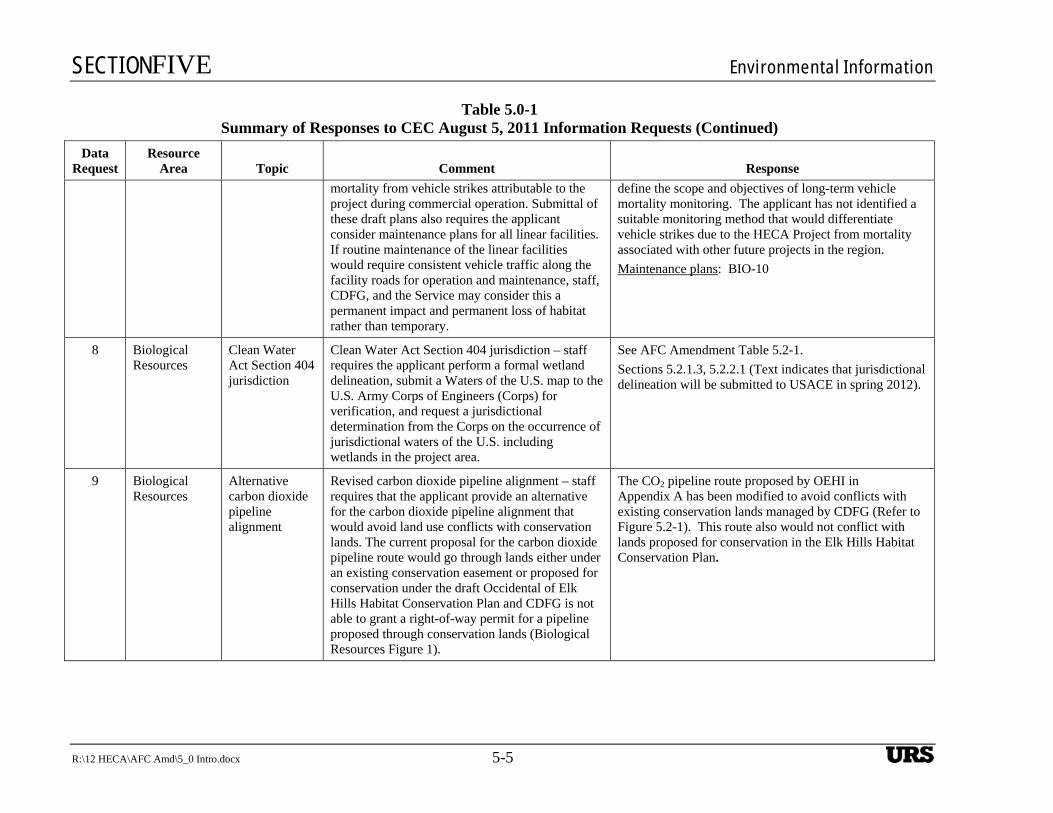
SECTIONFIVE Environmental Information
R:\12 HECA\AFC Amd\5_0 Intro.docx 5-5
Table 5.0-1 Summary of Responses to CEC August 5, 2011 Information Requests (Continued)
Data Request
Resource Area Topic Comment Response
mortality from vehicle strikes attributable to the project during commercial operation. Submittal of these draft plans also requires the applicant consider maintenance plans for all linear facilities. If routine maintenance of the linear facilities would require consistent vehicle traffic along the facility roads for operation and maintenance, staff, CDFG, and the Service may consider this a permanent impact and permanent loss of habitat rather than temporary.
define the scope and objectives of long-term vehicle mortality monitoring. The applicant has not identified a suitable monitoring method that would differentiate vehicle strikes due to the HECA Project from mortality associated with other future projects in the region.
Maintenance plans: BIO-10
8 Biological Resources
Clean Water Act Section 404 jurisdiction
Clean Water Act Section 404 jurisdiction – staff requires the applicant perform a formal wetland delineation, submit a Waters of the U.S. map to the U.S. Army Corps of Engineers (Corps) for verification, and request a jurisdictional determination from the Corps on the occurrence of jurisdictional waters of the U.S. including wetlands in the project area.
See AFC Amendment Table 5.2-1.
Sections 5.2.1.3, 5.2.2.1 (Text indicates that jurisdictional delineation will be submitted to USACE in spring 2012).
9 Biological Resources
Alternative carbon dioxide pipeline alignment
Revised carbon dioxide pipeline alignment – staff requires that the applicant provide an alternative for the carbon dioxide pipeline alignment that would avoid land use conflicts with conservation lands. The current proposal for the carbon dioxide pipeline route would go through lands either under an existing conservation easement or proposed for conservation under the draft Occidental of Elk Hills Habitat Conservation Plan and CDFG is not able to grant a right-of-way permit for a pipeline proposed through conservation lands (Biological Resources Figure 1).
The CO2 pipeline route proposed by OEHI in Appendix A has been modified to avoid conflicts with existing conservation lands managed by CDFG (Refer to Figure 5.2-1). This route also would not conflict with lands proposed for conservation in the Elk Hills Habitat Conservation Plan.
UBS
SECTIONFIVE Environmental Information
5-6 R:\12 HECA\AFC Amd\5_0 Intro.docx
Table 5.0-1 Summary of Responses to CEC August 5, 2011 Information Requests (Continued)
Data Request
Resource Area Topic Comment Response
10 Biological Resources
Golden eagle nest data
Golden eagle nest data – due to changes in the Service’s survey protocols and management of golden eagle nests (Pagel et al 2010) and observation of golden eagles in the project area, staff needs additional information on the occurrence of golden eagle nests within the project area. Staff needs the applicant to provide the results of a literature review, museum records search, and database search for golden eagle nests and territories to determine the project’s effects, if any, to golden eagle nesting territories following the Service’s 2010 survey protocol guidance for this species.
See AFC Amendment Section 5.2.1.4.
11 Biological Resources
San Joaquin kit fox vehicle strike and road mortality analysis
San Joaquin kit fox vehicle strike and road mortality analysis – staff requests that the applicant implement the Probabilistic Measure of Road Lethality paper by Waller et al (2005) using the Poisson model and project hourly traffic volumes or other agency approved method to identify the impacts that project construction and operation traffic may have on San Joaquin kit fox in the project area. This analysis should include an assessment of nighttime traffic and the potential for increased impacts to nocturnal wildlife, in order to appropriately determine the mitigation to offset project impacts of vehicle strikes to San Joaquin kit fox. This data will generate the project’s San Joaquin kit fox incidental take estimate which will be used to calculate the acreage of mitigation lands needed for acquisition to offset the loss of carrying capacity from the project.
See AFC Amendment Section 5.2.2.3, Table 8. Analysis of the traffic impact is provided. The impact model used by URS uses a conservative approach that does not differentiate between daytime and nighttime traffic. Most of the project-related traffic would occur during the daytime hours, which is less sensitive for San Joaquin kit fox. However, the model used in the AFC assumes that traffic-related mortality would increase proportionate to the increase in traffic, and does not address the potential that traffic increases would be concentrated during daytime hours. Therefore, our approach provides a more conservative (higher) estimate of potential vehicle strike mortality for San Joaquin kit fox.
UBS
SECTIONFIVE Environmental Information
R:\12 HECA\AFC Amd\5_0 Intro.docx 5-7
Table 5.0-1 Summary of Responses to CEC August 5, 2011 Information Requests (Continued)
Data Request
Resource Area Topic Comment Response
12 Biological Resources
Additional survey data
Additional survey data – given recent realignment of the natural gas pipeline, the applicant proposed to conduct protocol-level blunt-nosed leopard lizard surveys, special-status plant surveys, a formal field wetland delineation, and focused Swainson’s hawk nest surveys during the appropriate survey windows during 2011(URS 2010o). Staff agrees that the relocated natural gas pipeline alignment must be surveyed during the appropriate survey window for San Joaquin kit fox dens, blunt-nosed leopard lizard, special-status plant species, burrowing owl, Swainson’s hawk, giant kangaroo rat, San Joaquin antelope squirrel, Tipton kangaroo rat, as well as potentially jurisdictional state and federal waters. Staff also requires that the applicant perform focused botanical surveys within all suitable habitat along linear facilities for special-status plant species and GPS all occurrences. This data would then be used in the preparation of the draft Special-status Plant Impact Avoidance and Minimization Plan and impact analysis to determine if the project’s impacts to rare plants would be considered significant.
See AFC Amendment Table 5.2-1.
Blunt-nosed leopard lizard: Conducted in 2010. Text indicates that protocol surveys will be conducted in 2012 and provided to CEC.
Rare plant surveys: Conducted in 2011 and 2012.
Wetland delineation: 2012.
Swainson’s hawk: 2012.
San Joaquin kit fox: 2011.
Mitigation Measures to conduct surveys: BIO-4, BIO-12, BIO-13, BIO-15, BIO-16.
13 Biological Resources
Oxy’s historical wildlife data from long-term monitoring of NPR-1 and NPR-2
Applicant to provide Oxy’s historical wildlife data from long-term monitoring of NPR-1 and NPR-2 (several decades of data was collected during Naval Petroleum Reserve monitoring). Resource agencies have a good handle on which wildlife are present on Elk Hills. San Joaquin kit fox, San Joaquin antelope ground squirrel, giant kangaroo rat, blunt-nose leopard lizard are all threatened and endangered species and assumed present.
AFC Amendment Appendix A-2, Section 4.4 of the SEI includes a discussion of existing biological resources and impact analysis for the CO2 EOR Project. OEHI will provide the Annual Reports from 1995 to 2011 under separate cover. These reports contain historic long-term monitoring data for NPR-1 (EHOF).
UBS
SECTIONFIVE Environmental Information
5-8 R:\12 HECA\AFC Amd\5_0 Intro.docx
Table 5.0-1 Summary of Responses to CEC August 5, 2011 Information Requests (Continued)
Data Request
Resource Area Topic Comment Response
14 Biological Resources
Giant kangaroo rat precincts map
Applicant to map giant kangaroo rat precincts (individual territories) on direct impact areas of Elk Hills. Giant kangaroo rat are assumed present by resource agencies, but a current mapping would be useful. The resource agencies asked for current giant kangaroo rat precinct data for the carbon dioxide pipeline so the same request would likely be made here.
Giant kangaroo rats are only expected to occur south of the California Aqueduct in the OEHI Project area. No giant kangaroo rats or precincts were observed in the BRSA during the 2008, 2009, 2010, or 2011 surveys. Results of the Surveys of the BRSA documented in the AFC Amendment Section 5.2 and in Appendix A.
AFC Amendment Appendix A-2, Section 4.4 (SEI) includes a discussion of existing biological resources and impact analysis for the CO2 EOR Project. However, the OEHI document does not identify the locations.
15 Biological Resources
Swainson’s hawk nests focused survey
Applicant to perform focused surveys for Swainson’s hawk nests. General survey timing: March – August.
See AFC Amendment Section 5.2.1.4. HECA is currently conducting 2012 nesting season surveys for Swainson’s hawks. Additional pre-construction surveys are proposed in the mitigation measure BIO-19.
AFC Amendment Appendix A-2, Section 4.4.1 (SEI): As required by the EHOF HCP, biological pre-activity surveys are conducted by qualified biologist’s prior to ground disturbance activities. Biological data associated with Swainson’s hawk and nests are provided in the EHOF HCP semi-annual and annual reports provided to the wildlife agencies. [NOTE: URS received NPR-1/EHOF 1995-2011 endangered species annual reports on April 24, 2012. We assume that OEHI will provide this information to CEC under separate cover].
16 Biological Resources
Golden eagle nest data
Applicant to provide golden eagle nest data for Elk Hills and surrounding areas. Provide the results of a literature review, museum records search, database search, and check with local raptor groups for golden eagle nests and territories. Depending on this data, USFWS’s Migratory Bird Office may request more detailed field surveys and/or helicopter surveys.
See AFC Amendment Section 5.2.1.4. Text indicates that no golden eagles have been observed during the wildlife or botanical surveys, and there are no documented nest sites within 40 miles of the Project Site.
AFC Amendment Appendix A-2, Section 4.4.1 (SEI): Biological pre-activity surveys are conducted by qualified biologists prior to ground-disturbance activities. Biological data associated with golden eagle and nests are
UBS
SECTIONFIVE Environmental Information
R:\12 HECA\AFC Amd\5_0 Intro.docx 5-9
Table 5.0-1 Summary of Responses to CEC August 5, 2011 Information Requests (Continued)
Data Request
Resource Area Topic Comment Response
provided, if observed in the annual reports provided to the wildlife agencies; and included herewith. [NOTE: NPR-1/EHOF 1995-2011 endangered species annual reports will be provided under separate cover].
17 Biological Resources
Burrowing owl surveys
Applicant to conduct focused burrowing owl surveys (Phase I habitat assessment, Phase II burrow surveys, Phase III owl survey) on Oxy’s direct impact areas. Timing: Phase I and II can be conducted any time of year, Phase III peak nesting season April 15 to July 15.
See AFC Amendment Section 5.2.1.4. HECA is currently conducting 2012 nesting season surveys for burrowing owls. Additional pre-construction surveys are proposed in the mitigation measure BIO-12.
AFC Amendment Appendix A-2, Section 4.4.1 (SEI) states that biological pre-activity surveys would be conducted by qualified biologists prior to ground-disturbance activities. Biological data associated with burrowing owl and nests will be provided, if observed in the annual reports provided to the wildlife agencies. No specific surveys are conducted by OEHI to index burrowing owl population on Elk Hills. Abundance information is collected incidentally during pre-activity surveys and annual monitoring activities including San Joaquin kit fox spotlighting, blunt-nosed leopard lizard surveys, and giant kangaroo rat transect surveys.
18 Biological Resources
Elk Hills focused botanical surveys
Applicant to conduct focused botanical surveys following CDFG 2009 survey guidelines over the direct impact area of Elk Hills. Staff is not sure how current the plant survey data is for Elk Hills although rare plants have been long-studied here. Survey timing is species-specific in the southern San Joaquin Valley, but generally, surveys should be spaced out between February through March/April for annuals. Perennials can be surveyed for later in the season. Consult with DFG on species specific survey timing.
AFC Amendment Appendix A-1: Plant species are listed in the Data Gap Analysis Biological Assessment (February 2011). Hoover’s woolly star is the only special status plant species monitored annually by OEHI. OEHI is not currently conducting additional focused surveys for special status plant species in the OEHI Project area.
UBS
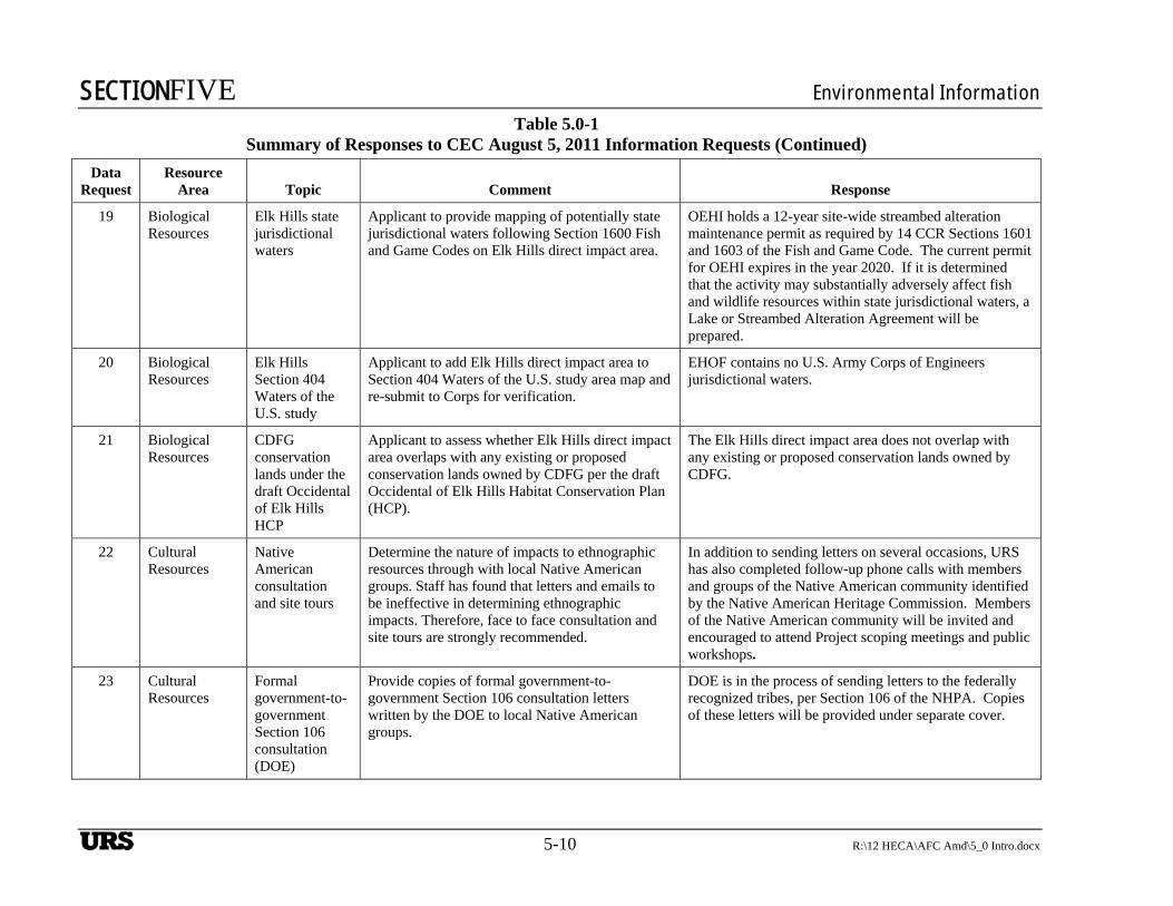
SECTIONFIVE Environmental Information
5-10 R:\12 HECA\AFC Amd\5_0 Intro.docx
Table 5.0-1 Summary of Responses to CEC August 5, 2011 Information Requests (Continued)
Data Request
Resource Area Topic Comment Response
19 Biological Resources
Elk Hills state jurisdictional waters
Applicant to provide mapping of potentially state jurisdictional waters following Section 1600 Fish and Game Codes on Elk Hills direct impact area.
OEHI holds a 12-year site-wide streambed alteration maintenance permit as required by 14 CCR Sections 1601 and 1603 of the Fish and Game Code. The current permit for OEHI expires in the year 2020. If it is determined that the activity may substantially adversely affect fish and wildlife resources within state jurisdictional waters, a Lake or Streambed Alteration Agreement will be prepared.
20 Biological Resources
Elk Hills Section 404 Waters of the U.S. study
Applicant to add Elk Hills direct impact area to Section 404 Waters of the U.S. study area map and re-submit to Corps for verification.
EHOF contains no U.S. Army Corps of Engineers jurisdictional waters.
21 Biological Resources
CDFG conservation lands under the draft Occidental of Elk Hills HCP
Applicant to assess whether Elk Hills direct impact area overlaps with any existing or proposed conservation lands owned by CDFG per the draft Occidental of Elk Hills Habitat Conservation Plan (HCP).
The Elk Hills direct impact area does not overlap with any existing or proposed conservation lands owned by CDFG.
22 Cultural Resources
Native American consultation and site tours
Determine the nature of impacts to ethnographic resources through with local Native American groups. Staff has found that letters and emails to be ineffective in determining ethnographic impacts. Therefore, face to face consultation and site tours are strongly recommended.
In addition to sending letters on several occasions, URS has also completed follow-up phone calls with members and groups of the Native American community identified by the Native American Heritage Commission. Members of the Native American community will be invited and encouraged to attend Project scoping meetings and public workshops.
23 Cultural Resources
Formal government-to-government Section 106 consultation (DOE)
Provide copies of formal government-to-government Section 106 consultation letters written by the DOE to local Native American groups.
DOE is in the process of sending letters to the federally recognized tribes, per Section 106 of the NHPA. Copies of these letters will be provided under separate cover.
UBS
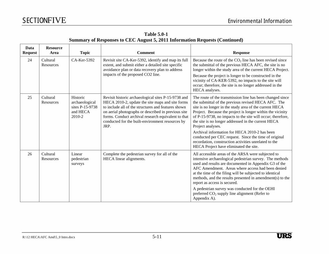
SECTIONFIVE Environmental Information
R:\12 HECA\AFC Amd\5_0 Intro.docx 5-11
Table 5.0-1 Summary of Responses to CEC August 5, 2011 Information Requests (Continued)
Data Request
Resource Area Topic Comment Response
24 Cultural Resources
CA-Ker-5392 Revisit site CA-Ker-5392, identify and map its full extent, and submit either a detailed site specific avoidance plan or data recovery plan to address impacts of the proposed CO2 line.
Because the route of the CO2 line has been revised since the submittal of the previous HECA AFC, the site is no longer within the study area of the current HECA Project.
Because the project is longer to be constructed in the vicinity of CA-KER-5392, no impacts to the site will occur; therefore, the site is no longer addressed in the HECA analyses.
25 Cultural Resources
Historic archaeological sites P-15-9738 and HECA 2010-2
Revisit historic archaeological sites P-15-9738 and HECA 2010-2, update the site maps and site forms to include all of the structures and features shown on aerial photographs or described in previous site forms. Conduct archival research equivalent to that conducted for the built-environment resources by JRP.
The route of the transmission line has been changed since the submittal of the previous revised HECA AFC. The site is no longer in the study area of the current HECA Project. Because the project is longer within the vicinity of P-15-9738, no impacts to the site will occur; therefore, the site is no longer addressed in the current HECA Project analyses.
Archival information for HECA 2010-2 has been conducted per CEC request. Since the time of original recordation, construction activities unrelated to the HECA Project have eliminated the site.
26 Cultural Resources
Linear pedestrian surveys
Complete the pedestrian survey for all of the HECA linear alignments.
All accessible areas of the ARSA were subjected to intensive archaeological pedestrian survey. The methods used and results are documented in Appendix G3 of the AFC Amendment. Areas where access had been denied at the time of the filing will be subjected to identical methods, and the results presented in amendment(s) to the report as access is secured.
A pedestrian survey was conducted for the OEHI preferred CO2 supply line alignment (Refer to Appendix A).
UBS
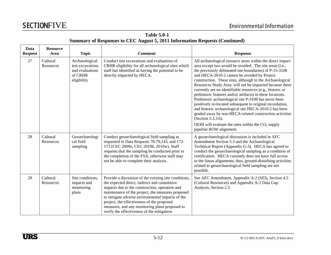
SECTIONFIVE Environmental Information
5-12 R:\12 HECA\AFC Amd\5_0 Intro.docx
Table 5.0-1 Summary of Responses to CEC August 5, 2011 Information Requests (Continued)
Data Request
Resource Area Topic Comment Response
27 Cultural Resources
Archaeological test excavations and evaluations of CRHR eligibility
Conduct test excavations and evaluations of CRHR eligibility for all archaeological sites which staff has identified as having the potential to be directly impacted by HECA.
All archaeological resource areas within the direct impact area except two would be avoided. The site areas (i.e., the previously delineated site boundaries) of P-15-3108 and HECA-2010-2 cannot be avoided by Project construction. These sites, although in the Archaeological Resources Study Area, will not be impacted because there currently are no identifiable resources (e.g., historic or prehistoric features and/or artifacts) in these locations. Prehistoric archaeological site P-3108 has never been positively re-located subsequent to original recordation, and historic archaeological site HECA-2010-2 has been graded away by non-HECA-related construction activities (Section 5.3.3.6).
OEHI will evaluate the sites within the CO2 supply pipeline ROW alignment.
28 Cultural Resources
Geoarchaeological field sampling
Conduct geoarchaeological field sampling as requested in Data Requests 78-79,143, and 172-173 (CEC 2009o, CEC 2010b, 2010w). Staff requests that the sampling be conducted prior to the completion of the FSA, otherwise staff may not be able to complete their analysis.
A geoarchaeological discussion is included in AFC Amendment Section 5.3 and the Archaeological Technical Report (Appendix G-3). HECA has agreed to conduct the geoarchaeological sampling as a condition of certification. HECA currently does not have full access to the linear alignments; thus, ground-disturbing activities related to geoarchaeological field sampling are not possible.
29 Cultural Resources
Site conditions, impacts and monitoring plans
Provide a discussion of the existing site conditions, the expected direct, indirect and cumulative impacts due to the construction, operation and maintenance of the project, the measures proposed to mitigate adverse environmental impacts of the project, the effectiveness of the proposed measures, and any monitoring plans proposed to verify the effectiveness of the mitigation.
See AFC Amendment, Appendix A-2 (SEI), Section 4.5 (Cultural Resources) and Appendix A-1 Data Gap Analysis, Section 2.3.
UBS
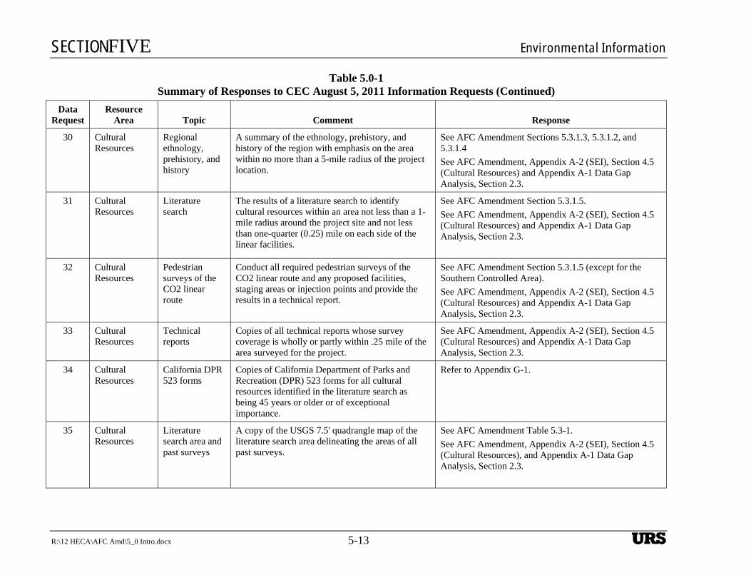
SECTIONFIVE Environmental Information
R:\12 HECA\AFC Amd\5_0 Intro.docx 5-13
Table 5.0-1 Summary of Responses to CEC August 5, 2011 Information Requests (Continued)
Data Request
Resource Area Topic Comment Response
30 Cultural Resources
Regional ethnology, prehistory, and history
A summary of the ethnology, prehistory, and history of the region with emphasis on the area within no more than a 5-mile radius of the project location.
See AFC Amendment Sections 5.3.1.3, 5.3.1.2, and 5.3.1.4
See AFC Amendment, Appendix A-2 (SEI), Section 4.5 (Cultural Resources) and Appendix A-1 Data Gap Analysis, Section 2.3.
31 Cultural Resources
Literature search
The results of a literature search to identify cultural resources within an area not less than a 1-mile radius around the project site and not less than one-quarter (0.25) mile on each side of the linear facilities.
See AFC Amendment Section 5.3.1.5.
See AFC Amendment, Appendix A-2 (SEI), Section 4.5 (Cultural Resources) and Appendix A-1 Data Gap Analysis, Section 2.3.
32 Cultural Resources
Pedestrian surveys of the CO2 linear route
Conduct all required pedestrian surveys of the CO2 linear route and any proposed facilities, staging areas or injection points and provide the results in a technical report.
See AFC Amendment Section 5.3.1.5 (except for the Southern Controlled Area).
See AFC Amendment, Appendix A-2 (SEI), Section 4.5 (Cultural Resources) and Appendix A-1 Data Gap Analysis, Section 2.3.
33 Cultural Resources
Technical reports
Copies of all technical reports whose survey coverage is wholly or partly within .25 mile of the area surveyed for the project.
See AFC Amendment, Appendix A-2 (SEI), Section 4.5 (Cultural Resources) and Appendix A-1 Data Gap Analysis, Section 2.3.
34 Cultural Resources
California DPR 523 forms
Copies of California Department of Parks and Recreation (DPR) 523 forms for all cultural resources identified in the literature search as being 45 years or older or of exceptional importance.
Refer to Appendix G-1.
35 Cultural Resources
Literature search area and past surveys
A copy of the USGS 7.5' quadrangle map of the literature search area delineating the areas of all past surveys.
See AFC Amendment Table 5.3-1.
See AFC Amendment, Appendix A-2 (SEI), Section 4.5 (Cultural Resources), and Appendix A-1 Data Gap Analysis, Section 2.3.
UBS

SECTIONFIVE Environmental Information
5-14 R:\12 HECA\AFC Amd\5_0 Intro.docx
Table 5.0-1 Summary of Responses to CEC August 5, 2011 Information Requests (Continued)
Data Request
Resource Area Topic Comment Response
36 Cultural Resources
Map of previously known and newly identified cultural resources
A map at a scale of 1:24,000 U.S. Geological Survey quadrangle depicting the locations of all previously known and newly identified cultural resources compiled through the research required by Appendix B.
See AFC Amendment, Appendix A-2 (SEI), Section 4.5 (Cultural Resources), and Appendix A-1 Data Gap Analysis, Section 2.3.
37 Land Use Zoning and general plan designations
Please provide the existing zoning and general plan designations(s) for any new project parcels resulting from the HECA project modification, including linears and injection wells.
See AFC Amendment Section 5.4.1.3, Tables 5.4-7 and 5.4-8.
38 Land Use Existing surrounding land uses
Please describe how the HECA project modification would be consistent with existing surrounding land uses.
See AFC Amendment Section 5.4.2.2.
39 Land Use Williamson Act contracted lands
Please state whether the project would contain new Williamson Act contracted lands a result of the HECA project modification.
See AFC Amendment Sections 5.4.1.3 and 5.4.2.4.
40 Land Use Zone change for urea production facility
Please work with the Kern County, Planning and Community Development Department regarding the modified HECA project, including the proposed urea production facility. The addition of this facility may require a zone change. Please discuss this modification with Kern County and let us know if the county would require a zone change and/or general plan change for the urea production facility.
See AFC Amendment Section 5.4.2.5 and 5.4.2.6.
41 Project Description
Project description of urea facilities and EOR/CCS components
Staff will have to perform a complete CEQA review and impact analysis associated with long-term maintenance and operation of both the urea facilities and EOR/Carbon Capture and Sequestration activities. Staff understands that the EOR/Carbon Capture and Sequestration (CCS)
A description of the urea unit is provided in Section 2.4.3. A description of the urea pastillation unit is provided in Section 2.4.4. A description of the urea ammonium nitrate complex is provided in Section 2.4.5.
A description and time line of impacted areas can be found in the Modified CO2 Supply Line Alignment Data
UBS
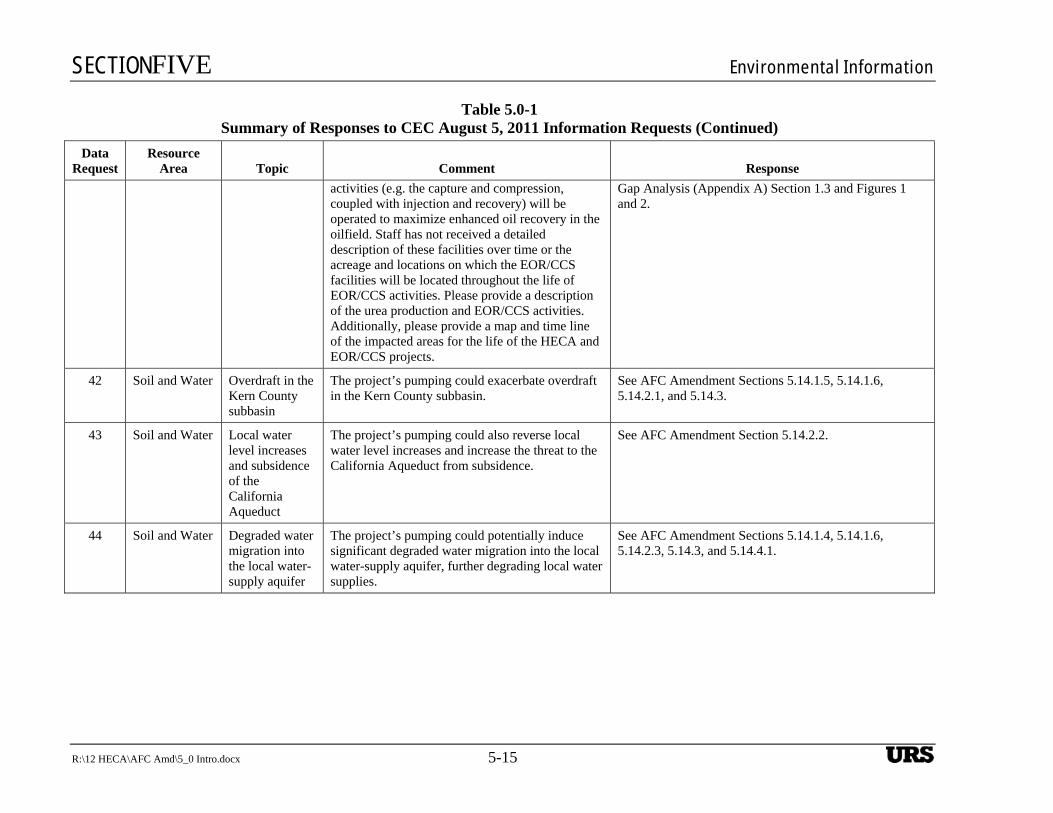
SECTIONFIVE Environmental Information
R:\12 HECA\AFC Amd\5_0 Intro.docx 5-15
Table 5.0-1 Summary of Responses to CEC August 5, 2011 Information Requests (Continued)
Data Request
Resource Area Topic Comment Response
activities (e.g. the capture and compression, coupled with injection and recovery) will be operated to maximize enhanced oil recovery in the oilfield. Staff has not received a detailed description of these facilities over time or the acreage and locations on which the EOR/CCS facilities will be located throughout the life of EOR/CCS activities. Please provide a description of the urea production and EOR/CCS activities. Additionally, please provide a map and time line of the impacted areas for the life of the HECA and EOR/CCS projects.
Gap Analysis (Appendix A) Section 1.3 and Figures 1 and 2.
42 Soil and Water Overdraft in the Kern County subbasin
The project’s pumping could exacerbate overdraft in the Kern County subbasin.
See AFC Amendment Sections 5.14.1.5, 5.14.1.6, 5.14.2.1, and 5.14.3.
43 Soil and Water Local water level increases and subsidence of the California Aqueduct
The project’s pumping could also reverse local water level increases and increase the threat to the California Aqueduct from subsidence.
See AFC Amendment Section 5.14.2.2.
44 Soil and Water Degraded water migration into the local water-supply aquifer
The project’s pumping could potentially induce significant degraded water migration into the local water-supply aquifer, further degrading local water supplies.
See AFC Amendment Sections 5.14.1.4, 5.14.1.6, 5.14.2.3, 5.14.3, and 5.14.4.1.
UBS
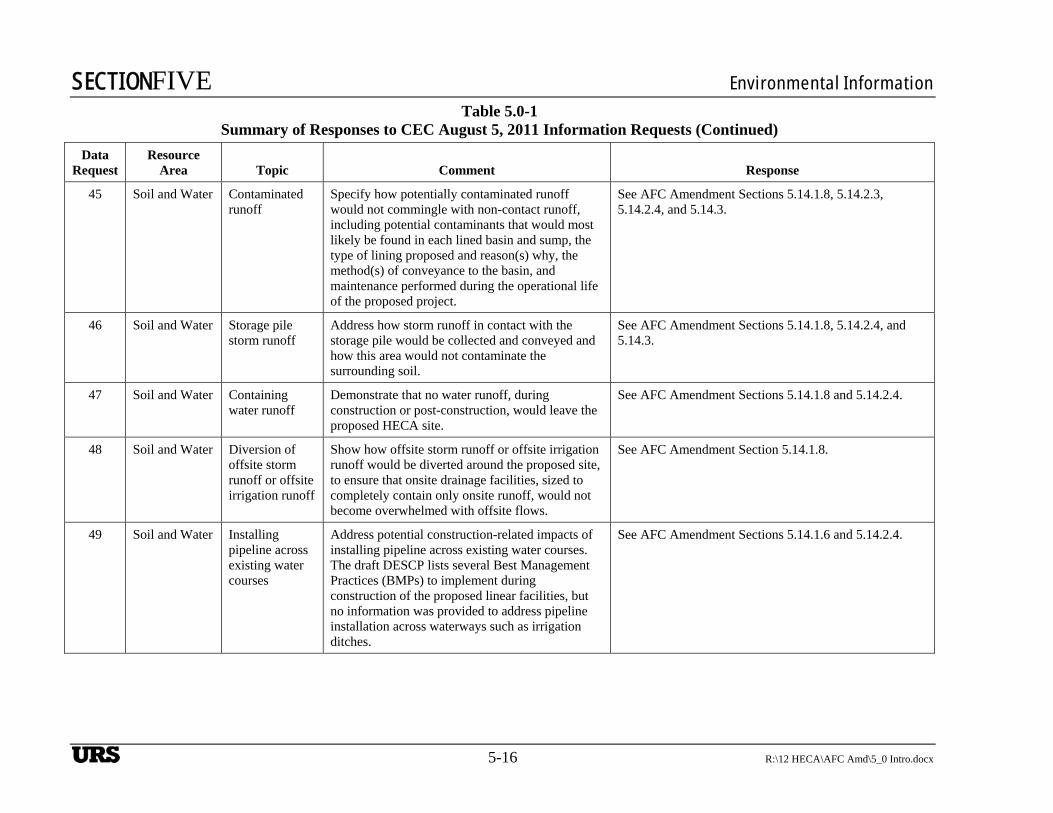
SECTIONFIVE Environmental Information
5-16 R:\12 HECA\AFC Amd\5_0 Intro.docx
Table 5.0-1 Summary of Responses to CEC August 5, 2011 Information Requests (Continued)
Data Request
Resource Area Topic Comment Response
45 Soil and Water Contaminated runoff
Specify how potentially contaminated runoff would not commingle with non-contact runoff, including potential contaminants that would most likely be found in each lined basin and sump, the type of lining proposed and reason(s) why, the method(s) of conveyance to the basin, and maintenance performed during the operational life of the proposed project.
See AFC Amendment Sections 5.14.1.8, 5.14.2.3, 5.14.2.4, and 5.14.3.
46 Soil and Water Storage pile storm runoff
Address how storm runoff in contact with the storage pile would be collected and conveyed and how this area would not contaminate the surrounding soil.
See AFC Amendment Sections 5.14.1.8, 5.14.2.4, and 5.14.3.
47 Soil and Water Containing water runoff
Demonstrate that no water runoff, during construction or post-construction, would leave the proposed HECA site.
See AFC Amendment Sections 5.14.1.8 and 5.14.2.4.
48 Soil and Water Diversion of offsite storm runoff or offsite irrigation runoff
Show how offsite storm runoff or offsite irrigation runoff would be diverted around the proposed site, to ensure that onsite drainage facilities, sized to completely contain only onsite runoff, would not become overwhelmed with offsite flows.
See AFC Amendment Section 5.14.1.8.
49 Soil and Water Installing pipeline across existing water courses
Address potential construction-related impacts of installing pipeline across existing water courses. The draft DESCP lists several Best Management Practices (BMPs) to implement during construction of the proposed linear facilities, but no information was provided to address pipeline installation across waterways such as irrigation ditches.
See AFC Amendment Sections 5.14.1.6 and 5.14.2.4.
UBS
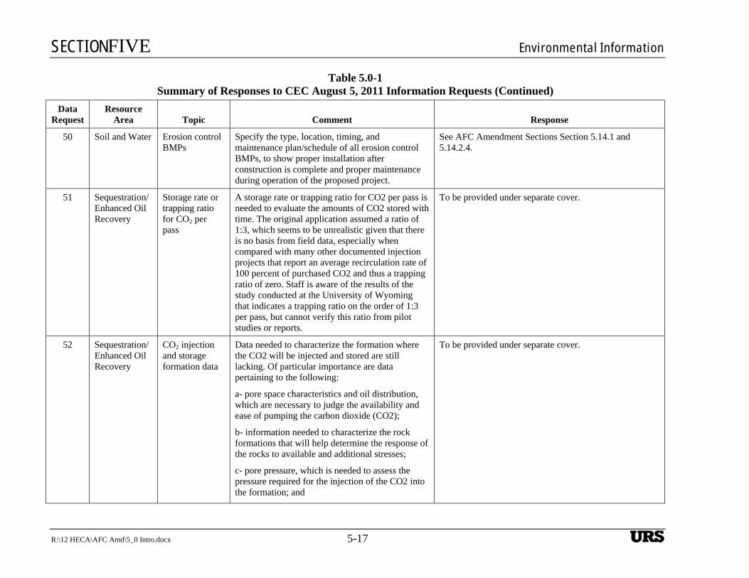
SECTIONFIVE Environmental Information
R:\12 HECA\AFC Amd\5_0 Intro.docx 5-17
Table 5.0-1 Summary of Responses to CEC August 5, 2011 Information Requests (Continued)
Data Request
Resource Area Topic Comment Response
50 Soil and Water Erosion control BMPs
Specify the type, location, timing, and maintenance plan/schedule of all erosion control BMPs, to show proper installation after construction is complete and proper maintenance during operation of the proposed project.
See AFC Amendment Sections Section 5.14.1 and 5.14.2.4.
51 Sequestration/Enhanced Oil Recovery
Storage rate or trapping ratio for CO2 per pass
A storage rate or trapping ratio for CO2 per pass is needed to evaluate the amounts of CO2 stored with time. The original application assumed a ratio of 1:3, which seems to be unrealistic given that there is no basis from field data, especially when compared with many other documented injection projects that report an average recirculation rate of 100 percent of purchased CO2 and thus a trapping ratio of zero. Staff is aware of the results of the study conducted at the University of Wyoming that indicates a trapping ratio on the order of 1:3 per pass, but cannot verify this ratio from pilot studies or reports.
To be provided under separate cover.
52 Sequestration/Enhanced Oil Recovery
CO2 injection and storage formation data
Data needed to characterize the formation where the CO2 will be injected and stored are still lacking. Of particular importance are data pertaining to the following:
a- pore space characteristics and oil distribution, which are necessary to judge the availability and ease of pumping the carbon dioxide (CO2);
b- information needed to characterize the rock formations that will help determine the response of the rocks to available and additional stresses;
c- pore pressure, which is needed to assess the pressure required for the injection of the CO2 into the formation; and
To be provided under separate cover.
UBS
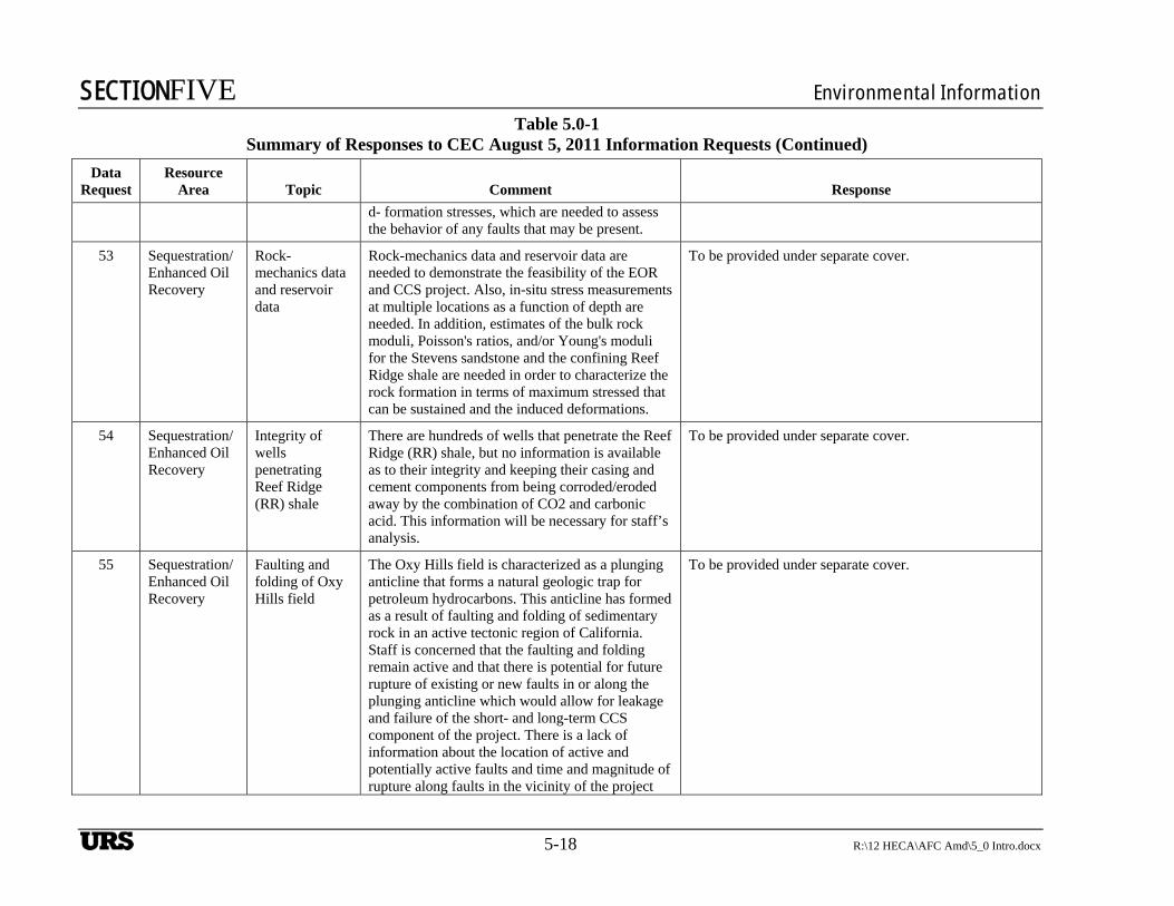
SECTIONFIVE Environmental Information
5-18 R:\12 HECA\AFC Amd\5_0 Intro.docx
Table 5.0-1 Summary of Responses to CEC August 5, 2011 Information Requests (Continued)
Data Request
Resource Area Topic Comment Response
d- formation stresses, which are needed to assess the behavior of any faults that may be present.
53 Sequestration/Enhanced Oil Recovery
Rock-mechanics data and reservoir data
Rock-mechanics data and reservoir data are needed to demonstrate the feasibility of the EOR and CCS project. Also, in-situ stress measurements at multiple locations as a function of depth are needed. In addition, estimates of the bulk rock moduli, Poisson's ratios, and/or Young's moduli for the Stevens sandstone and the confining Reef Ridge shale are needed in order to characterize the rock formation in terms of maximum stressed that can be sustained and the induced deformations.
To be provided under separate cover.
54 Sequestration/Enhanced Oil Recovery
Integrity of wells penetrating Reef Ridge (RR) shale
There are hundreds of wells that penetrate the Reef Ridge (RR) shale, but no information is available as to their integrity and keeping their casing and cement components from being corroded/eroded away by the combination of CO2 and carbonic acid. This information will be necessary for staff’s analysis.
To be provided under separate cover.
55 Sequestration/Enhanced Oil Recovery
Faulting and folding of Oxy Hills field
The Oxy Hills field is characterized as a plunging anticline that forms a natural geologic trap for petroleum hydrocarbons. This anticline has formed as a result of faulting and folding of sedimentary rock in an active tectonic region of California. Staff is concerned that the faulting and folding remain active and that there is potential for future rupture of existing or new faults in or along the plunging anticline which would allow for leakage and failure of the short- and long-term CCS component of the project. There is a lack of information about the location of active and potentially active faults and time and magnitude of rupture along faults in the vicinity of the project
To be provided under separate cover.
UBS
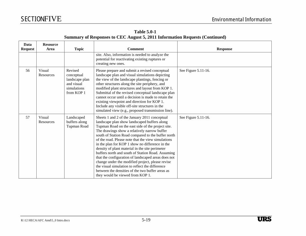
SECTIONFIVE Environmental Information
R:\12 HECA\AFC Amd\5_0 Intro.docx 5-19
Table 5.0-1 Summary of Responses to CEC August 5, 2011 Information Requests (Continued)
Data Request
Resource Area Topic Comment Response
site. Also, information is needed to analyze the potential for reactivating existing ruptures or creating new ones.
56 Visual Resources
Revised conceptual landscape plan and visual simulations from KOP 1
Please prepare and submit a revised conceptual landscape plan and visual simulations depicting the view of the landscape plantings, fencing or other structures along the site periphery, and modified plant structures and layout from KOP 1. Submittal of the revised conceptual landscape plan cannot occur until a decision is made to retain the existing viewpoint and direction for KOP 1. Include any visible off-site structures in the simulated view (e.g., proposed transmission line).
See Figure 5.11-16.
57 Visual Resources
Landscaped buffers along Tupman Road
Sheets 1 and 2 of the January 2011 conceptual landscape plan show landscaped buffers along Tupman Road on the east side of the project site. The drawings show a relatively narrow buffer south of Station Road compared to the buffer north of the road. Please note that the view simulations in the plan for KOP 1 show no difference in the density of plant material in the site perimeter buffers north and south of Station Road. Assuming that the configuration of landscaped areas does not change under the modified project, please revise the visual simulation to reflect the difference between the densities of the two buffer areas as they would be viewed from KOP 1.
See Figure 5.11-16.
UBS
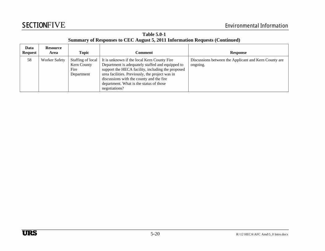
SECTIONFIVE Environmental Information
5-20 R:\12 HECA\AFC Amd\5_0 Intro.docx
Table 5.0-1 Summary of Responses to CEC August 5, 2011 Information Requests (Continued)
Data Request
Resource Area Topic Comment Response
58 Worker Safety Staffing of local Kern County Fire Department
It is unknown if the local Kern County Fire Department is adequately staffed and equipped to support the HECA facility, including the proposed urea facilities. Previously, the project was in discussions with the county and the fire department. What is the status of those negotiations?
Discussions between the Applicant and Kern County are ongoing.
UBS
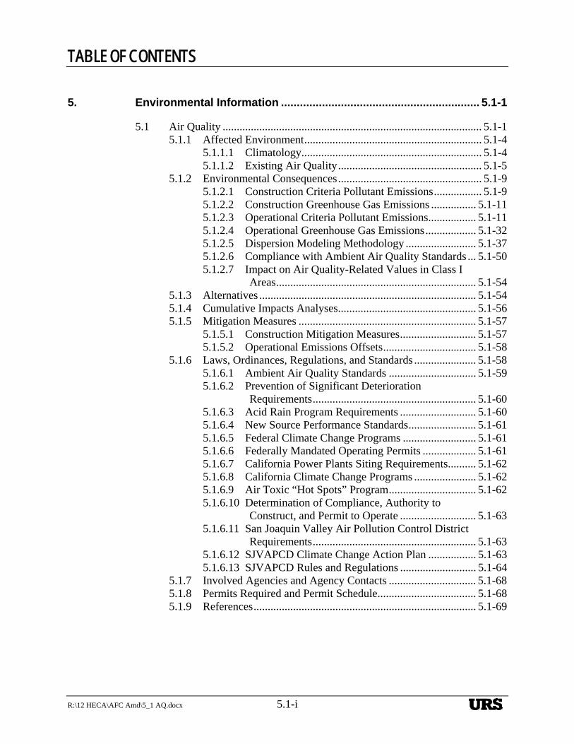
TABLE OF CONTENTS
R:\12 HECA\AFC Amd\5_1 AQ.docx 5.1-i
5. Environmental Information ............................................................... 5.1-1
5.1 Air Quality ............................................................................................ 5.1-1 5.1.1 Affected Environment ............................................................... 5.1-4
5.1.1.1 Climatology................................................................ 5.1-4 5.1.1.2 Existing Air Quality ................................................... 5.1-5
5.1.2 Environmental Consequences ................................................... 5.1-9 5.1.2.1 Construction Criteria Pollutant Emissions ................. 5.1-9 5.1.2.2 Construction Greenhouse Gas Emissions ................ 5.1-11 5.1.2.3 Operational Criteria Pollutant Emissions ................. 5.1-11 5.1.2.4 Operational Greenhouse Gas Emissions .................. 5.1-32 5.1.2.5 Dispersion Modeling Methodology ......................... 5.1-37 5.1.2.6 Compliance with Ambient Air Quality Standards ... 5.1-50 5.1.2.7 Impact on Air Quality-Related Values in Class I
Areas ....................................................................... 5.1-54 5.1.3 Alternatives ............................................................................. 5.1-54 5.1.4 Cumulative Impacts Analyses ................................................. 5.1-56 5.1.5 Mitigation Measures ............................................................... 5.1-57
5.1.5.1 Construction Mitigation Measures ........................... 5.1-57 5.1.5.2 Operational Emissions Offsets ................................. 5.1-58
5.1.6 Laws, Ordinances, Regulations, and Standards ...................... 5.1-58 5.1.6.1 Ambient Air Quality Standards ............................... 5.1-59 5.1.6.2 Prevention of Significant Deterioration
Requirements .......................................................... 5.1-60 5.1.6.3 Acid Rain Program Requirements ........................... 5.1-60 5.1.6.4 New Source Performance Standards ........................ 5.1-61 5.1.6.5 Federal Climate Change Programs .......................... 5.1-61 5.1.6.6 Federally Mandated Operating Permits ................... 5.1-61 5.1.6.7 California Power Plants Siting Requirements.......... 5.1-62 5.1.6.8 California Climate Change Programs ...................... 5.1-62 5.1.6.9 Air Toxic “Hot Spots” Program ............................... 5.1-62 5.1.6.10 Determination of Compliance, Authority to
Construct, and Permit to Operate ........................... 5.1-63 5.1.6.11 San Joaquin Valley Air Pollution Control District
Requirements .......................................................... 5.1-63 5.1.6.12 SJVAPCD Climate Change Action Plan ................. 5.1-63 5.1.6.13 SJVAPCD Rules and Regulations ........................... 5.1-64
5.1.7 Involved Agencies and Agency Contacts ............................... 5.1-68 5.1.8 Permits Required and Permit Schedule ................................... 5.1-68 5.1.9 References ............................................................................... 5.1-69
URS
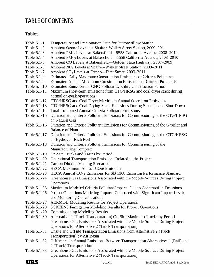
TABLE OF CONTENTS
5.1-ii R:\12 HECA\AFC Amd\5_1 AQ.docx
Tables
Table 5.1-1 Temperature and Precipitation Data for Buttonwillow Station Table 5.1-2 Ambient Ozone Levels at Shafter–Walker Street Station, 2009–2011 Table 5.1-3 Ambient PM10 Levels at Bakersfield—5558 California Avenue, 2008–2010 Table 5.1-4 Ambient PM2.5 Levels at Bakersfield—5558 California Avenue, 2008–2010 Table 5.1-5 Ambient CO Levels at Bakersfield—Golden State Highway, 2007–2009 Table 5.1-6 Ambient NO2 Levels at Shafter–Walker Street Station, 2009–2011 Table 5.1-7 Ambient SO2 Levels at Fresno—First Street, 2009–2011 Table 5.1-8 Estimated Daily Maximum Construction Emissions of Criteria Pollutants Table 5.1-9 Estimated Annual Maximum Construction Emissions of Criteria Pollutants Table 5.1-10 Estimated Emissions of GHG Pollutants, Entire Construction Period Table 5.1-11 Maximum short-term emissions from CTG/HRSG and coal dryer stack during
normal on-peak operations Table 5.1-12 CTG/HRSG and Coal Dryer Maximum Annual Operation Emissions Table 5.1-13 CTG/HRSG and Coal Drying Stack Emissions During Start-Up and Shut-Down Table 5.1-14 Total Combined Annual Criteria Pollutant Emissions Table 5.1-15 Duration and Criteria Pollutant Emissions for Commissioning of the CTG/HRSG
on Natural Gas Table 5.1-16 Duration and Criteria Pollutant Emissions for Commissioning of the Gasifier and
Balance of Plant Table 5.1-17 Duration and Criteria Pollutant Emissions for Commissioning of the CTG/HRSG
on Hydrogen-Rich Fuel Table 5.1-18 Duration and Criteria Pollutant Emissions for Commissioning of the
Manufacturing Complex Table 5.1-19 On-Site Trucks and Trains by Period Table 5.1-20 Operational Transportation Emissions Related to the Project Table 5.1-21 Carbon Dioxide Venting Scenarios Table 5.1-22 HECA Maximum Annual CO2e Emissions Table 5.1-23 HECA Annual CO2e Emissions for SB 1368 Emission Performance Standard Table 5.1-24 Greenhouse Gas Emissions Associated with the Mobile Sources During Project
Operations Table 5.1-25 Maximum Modeled Criteria Pollutant Impacts Due to Construction Emissions Table 5.1-26 Project Operations Modeling Impacts Compared with Significant Impact Levels
and Monitoring Concentrations Table 5.1-27 AERMOD Modeling Results for Project Operations Table 5.1-28 SCREEN3 Fumigation Modeling Results for Project Operations Table 5.1-29 Commissioning Modeling Results Table 5.1-30 Alternative 2 (Truck Transportation) On-Site Maximum Trucks by Period
Greenhouse Gas Emissions Associated with the Mobile Sources During Project Operations for Alternative 2 (Truck Transportation)
Table 5.1-31 Onsite and Offsite Transportation Emissions from Alternative 2 (Truck Transportation) by Air Basin
Table 5.1-32 Difference in Annual Emissions Between Transportation Alternatives 1 (Rail) and 2 (Truck) Transportation
Table 5.1-33 Greenhouse Gas Emissions Associated with the Mobile Sources During Project Operations for Alternative 2 (Truck Transportation)
URS
TABLE OF CONTENTS
R:\12 HECA\AFC Amd\5_1 AQ.docx 5.1-iii
Table 5.1-34 Laws, Ordinances, Regulations, and Standards—Air Quality Table 5.1-35 Relevant Ambient Air Quality Standards Table 5.1-36 Attainment Status for Kern County with Respect to Federal and California
Ambient Air Quality Standards Table 5.1-37 PSD Emission Threshold Triggers for New Stationary Sources Table 5.1-38 Prevention of Significant Deterioration Allowable Increments (µg/m3) Table 5.1-39 Proposed BACT for the Project Table 5.1-40 Involved Agencies and Agency Contacts
Figures
Figure 5.1-1 Near-Field Model Receptor Grid Figure 5.1-2 Far-Field Model Receptor Grid Figure 5.1-3 Locations of Maximum Predicted Ground Level Pollutant Concentrations for the
Operational Project Area
Appendices
Appendix E-1 Seasonal and Annual Wind Roses Appendix E-2 Construction Criteria Pollutant and Greenhouse Gas Emissions Appendix E-3 Operational Criteria Pollutant Emissions Appendix E-4 Responses to PM2.5 Cooling Tower Data Requests from CEC and USEPA Appendix E-5 Offsite Operational Transportation Emissions Appendix E-6 Operational Greenhouse Gas Emissions Appendix E-7 NO2 1-Hour Regional Analysis Appendix E-8 Commissioning Scenario Emissions and Modeling Results Appendix E-9 Fumigation Modeling Results Appendix E-10 Offset Package Appendix E-11 Criteria Pollutant BACT Analysis Appendix E-12 Operational Transportation Emissions for Alternative 2 Appendix E-13 CO2 Vent Study Appendix E-14 Response to CEC Data Request 32
URS

TABLE OF CONTENTS
5.1-iv R:\12 HECA\AFC Amd\5_1 AQ.docx
This page intentionally left blank.
URS
5.1 Air Quality
R:\12 HECA\AFC Amd\5_1 AQ.docx 5.1-1
5. Section 5 FIVE Environmental Information
5.1 AIR QUALITY
Hydrogen Energy California LLC (HECA LLC) is proposing an Integrated Gasification Combined Cycle (IGCC) polygeneration project (HECA or Project). The Project will gasify a fuel blend of 75 percent coal and 25 percent petroleum coke (petcoke) to produce synthesis gas (syngas). Syngas produced via gasification will be purified to hydrogen-rich fuel, and used to generate a nominal 300 megawatts (MW) of low-carbon baseload electricity in a Combined Cycle Power Block, low-carbon nitrogen-based products in an integrated Manufacturing Complex, and carbon dioxide (CO2) for use in enhanced oil recovery (EOR). CO2 from HECA will be transported by pipeline for use in EOR in the adjacent Elk Hills Oil Field (EHOF), which is owned and operated by Occidental of Elk Hills, Inc. (OEHI). The EOR process results in sequestration (storage) of the CO2.
Terms used throughout this section are defined as follows:
Project or HECA. The HECA IGCC electrical generation facility, low-carbon nitrogen-based products Manufacturing Complex, and associated equipment and processes, including its linear facilities.
Project Site or HECA Project Site. The 453-acre parcel of land on which the HECA IGCC electrical generation facility, low-carbon nitrogen-based products Manufacturing Complex, and associated equipment and processes (excluding off-site portions of linear facilities), will be located.
OEHI Project. The use of CO2 for EOR at the EHOF and resulting sequestration, including the CO2 pipeline, EOR processing facility, and associated equipment.
OEHI Project Site. The portion of land within the EHOF on which the OEHI Project will be located and where the CO2 produced by HECA will be used for EOR and resulting sequestration.
Controlled Area. The 653 acres of land adjacent to the Project Site over which HECA will control access and future land uses.
This introduction provides brief descriptions of both the Project and the OEHI Project. Additional HECA Project description details are provided in Section 2.0. Additional OEHI Project description details are provided in Appendix A-1 of this Application for Certification (AFC) Amendment.
HECA Project Linear Facilities
The HECA Project includes the following linear facilities, which extend off the Project Site (see Figure 2-7, Project Location Map):
Electrical transmission line. An approximately 2-mile-long electrical transmission line will interconnect the Project to a future Pacific Gas and Electric Company (PG&E) switching station east of the Project Site.
URS
SECTIONFIVE Environmental Information
5.1-2 R:\12 HECA\AFC Amd\5_1 AQ.docx
Natural gas supply pipeline. An approximately 13-mile-long natural gas interconnection will be made with PG&E natural gas pipelines located north of the Project Site.
Water supply pipelines and wells. An approximately 15-mile-long process water supply line and up to five new groundwater wells will be installed by the Buena Vista Water Storage District (BVWSD) to supply brackish groundwater from northwest of the Project Site. An approximately 1-mile-long water supply line from the West Kern Water District (WKWD) east of the Project Site will provide potable water.
Coal transportation. HECA is considering two alternatives for transporting coal to the Project Site:
— Alternative 1, rail transportation. An approximately 5-mile-long new industrial railroad spur that will connect the Project Site to the existing San Joaquin Valley Railroad (SJVRR) Buttonwillow railroad line, north of the Project Site. This railroad spur will also be used to transport some HECA products to market.
— Alternative 2, truck transportation. An approximately 27-mile-long truck transport route via existing roads from an existing coal transloading facility northeast of the Project Site. This alternative was presented in the 2009 Revised AFC.
OEHI Project
OEHI will be installing the CO2 pipeline from the Project Site to the EHOF, as well as installing the EOR Processing Facility, including any associated wells and pipelines needed in the EHOF for CO2 EOR and sequestration. The following is a brief description of the OEHI Project, which is described in more detail in Appendix A of this AFC Amendment:
CO2 EOR Processing Facility. The CO2 EOR Processing Facility and 13 satellites are expected to occupy approximately 136 acres within the EHOF. The facility will use 720 producing and injection wells: 570 existing wells and 150 new well installations. Approximately 652 miles of new pipeline will also be installed in the EHOF.
CO2 pipeline. An approximately 3-mile-long CO2 pipeline will transfer the CO2 from the HECA Project Site south to the OEHI CO2 EOR Processing Facility.
For the purposes of all Air Quality analyses, impacts were determined outside of both the Project Site and the Controlled Area. HECA LLC will own both the Project Site and the Controlled Area, and will have control over public access and future land use. All temporary construction equipment laydown and parking, including construction parking, offices, and construction laydown areas, will be located on the Project Site and the Controlled Area.
The analysis included in this section focuses on the HECA Project as well as the CO2 pipeline associated with the OEHI Project. The analysis of the CO2 EOR Processing Facility associated with the OEHI Project is included in in Sections 4.3, Air Quality and 4.18, Greenhouse Gas Emissions, of Appendix A-1 of this AFC Amendment.
URS
5.1 Air Quality
R:\12 HECA\AFC Amd\5_1 AQ.docx 5.1-3
This analysis of the potential air quality impacts of the Project was conducted according to California Energy Commission (CEC) power plant siting requirements (CEC, 1997 and 2006). It also addresses U.S. Environmental Protection Agency (USEPA) Prevention of Significant Deterioration (PSD) requirements and San Joaquin Valley Air Pollution Control District (SJVAPCD) permitting requirements for Determination of Compliance/Authority to Construct The analysis is reported as follows:
Section 5.1.1, Affected Environment, describes the local environment surrounding the Project Site. Meteorological data, including wind speed and direction (i.e., wind roses), temperature, relative humidity, and precipitation are discussed, and ambient concentrations for the appropriate criteria pollutants are summarized.
Section 5.1.2, Environmental Consequences, evaluates the Project’s air quality impacts from emissions of nitrogen oxide (NOX), carbon monoxide (CO), sulfur dioxide (SO2), volatile organic compounds (VOCs), particulate matter less than 10 microns in diameter (PM10), and particulate matter less than 2.5 microns in diameter (PM2.5). Emission estimates are presented for these pollutants and greenhouse gases (GHGs) for Project construction and operation over a range of operating modes, including start-up and shut-down. The modeling analysis conducted for nitrogen dioxide (NO2), CO, SO2, PM2.5, and PM10 is presented. Transportation emissions in this section are estimated for coal transportation Alternative 1 (rail transportation).
Section 5.1.3, Alternatives, presents a discussion of coal transportation Alternative 2 (truck transportation), and associated air emissions and impacts.
Section 5.1.4, Cumulative Impacts Analyses, examines the potential impact from any significant emission sources within a 6-mile radius of the Project Site that have been recently permitted or are in the process of being permitted and are not yet operational.
Section 5.1.5, Mitigation Measures, describes the Project’s emission offsets and construction mitigation measures.
Section 5.1.6, Laws, Ordinances, Regulations, and Standards, describes all applicable laws, ordinances, regulations, and standards (LORS). Section 5.1.5 also provides a summary of the best available control technology (BACT) analysis for the Project.
Section 5.1.7, Involved Agencies and Agency Contacts, lists the agency contacts used to conduct the air quality assessment.
Section 5.1.8, Permits Required and Permit Schedule, lists the permits required and provides a permit schedule.
Section 5.1.9, References, lists the references used to conduct the air quality assessment.
Some air quality data are presented in other sections of this AFC Amendment, including an evaluation of toxic air pollutants (see Section 5.6, Public Health), an evaluation of the CO2 vent impacts on worker safety (see Section 5.7, Worker Safety and Appendix E-13, CO2 Vent Study),
URS
SECTIONFIVE Environmental Information
5.1-4 R:\12 HECA\AFC Amd\5_1 AQ.docx
and information related to the fuel characteristics, heat rate, and expected capacity factor of the Project (see Section 2, Project Description).
5.1.1 Affected Environment
This section describes the regional climate and meteorological conditions that influence transport and dispersion of air pollutants and the existing air quality within the Project region. The data presented in this section are representative of the Project Site as well as the Controlled Area, described below.
The Project Site is in a predominantly agricultural area of Kern County, approximately 2 miles northwest of the unincorporated community of Tupman, and approximately 7 miles west of the outermost edge of the city of Bakersfield. The Project Site is within Section 10 of Township 30 South, Range 24 East, in Kern County.
The Project Site consists of approximately 453 acres near Tupman in Kern County, as shown on Figure 2-4, Site Plan. HECA LLC also has control over an additional 653 acres of land adjacent to the Project Site, herein referred to as Controlled Area. HECA LLC will own this property and have control over public access and future land use. For the purposes of this air quality analysis, impacts were determined outside of both the Project Site and the Controlled Area combined.
5.1.1.1 Climatology
The California Air Resources Board (CARB) has divided California into regional air basins according to topographic drainage features. The Project Site is located near the unincorporated community of Tupman, Kern County, within the jurisdiction of the San Joaquin Valley Air Basin (SJVAB).
SJVAB, which is approximately 250 miles long and 35 miles wide, is the second largest air basin in the state. Air pollution, especially the dispersion of air pollutants, is directly related to a region’s topographic features. The SJVAB is defined by the Sierra Nevada Mountains in the east (8,000 to 14,000 feet in elevation), the Coast Range in the west (averaging 3,000 feet in elevation), and the Tehachapi Mountains in the south (6,000 to 8,000 feet in elevation). The valley opens to the sea at the Carquinez Strait, where the San Joaquin–Sacramento Delta empties into San Francisco Bay.
The SJVAB has an inland Mediterranean climate, averaging more than 260 sunny days per year. The valley floor is characterized by warm, dry summers and cooler winters. Long-term average temperature and precipitation data have been collected at Buttonwillow, the surface meteorological station nearest to the Project Site; they are presented in Table 5.1-1. Average low and high temperatures during the summer vary from the high 60s to the mid-90s, respectively, in degrees Fahrenheit (ºF). Summer precipitation is extremely low due to the strong stationary high-pressure system located off the coast that prevents most weather systems from moving through the area. The Project Site receives an average of 6 inches of rain annually. During the winter, average low and high temperatures vary from the mid-30s to the mid-50s, respectively. About 80 percent of the precipitation in the area occurs from November through March, generally in association with storm systems that move through the region.
URS
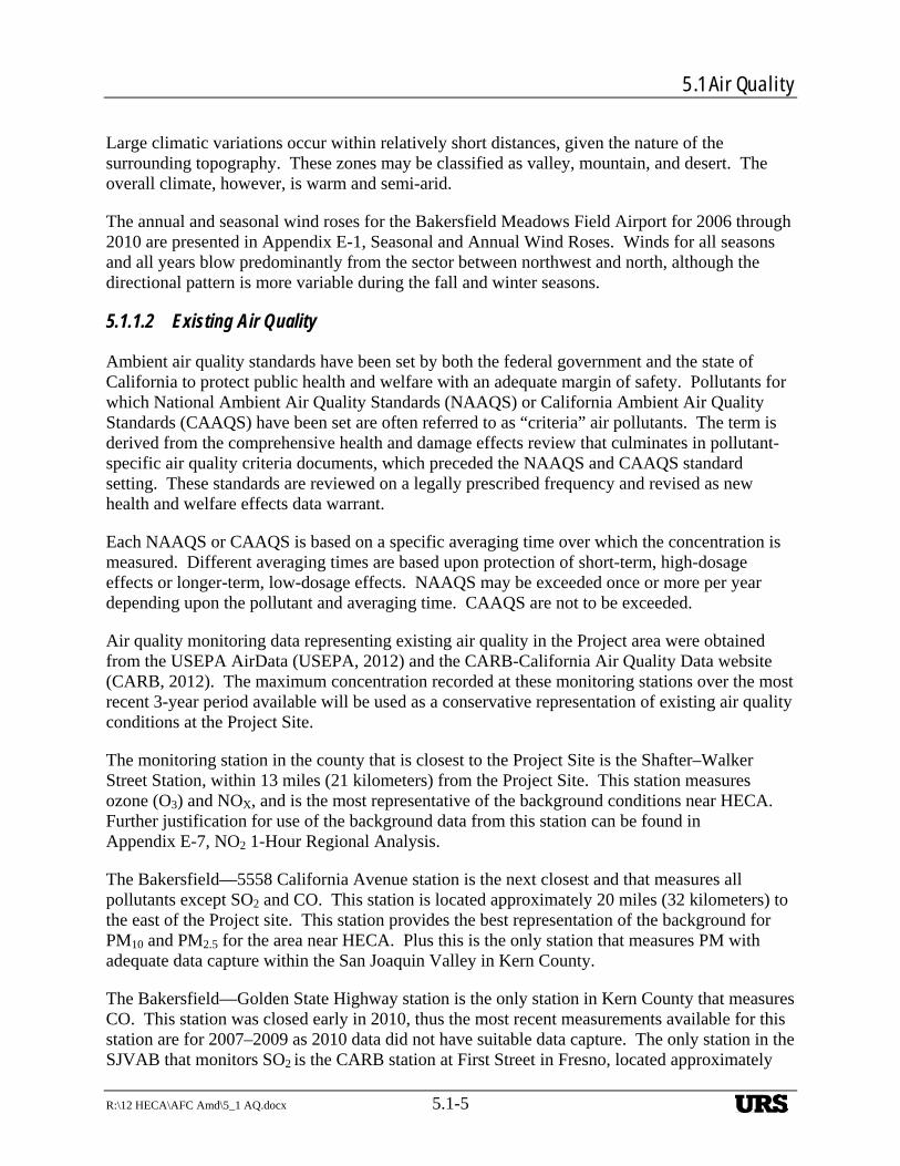
5.1 Air Quality
R:\12 HECA\AFC Amd\5_1 AQ.docx 5.1-5
Large climatic variations occur within relatively short distances, given the nature of the surrounding topography. These zones may be classified as valley, mountain, and desert. The overall climate, however, is warm and semi-arid.
The annual and seasonal wind roses for the Bakersfield Meadows Field Airport for 2006 through 2010 are presented in Appendix E-1, Seasonal and Annual Wind Roses. Winds for all seasons and all years blow predominantly from the sector between northwest and north, although the directional pattern is more variable during the fall and winter seasons.
5.1.1.2 Existing Air Quality
Ambient air quality standards have been set by both the federal government and the state of California to protect public health and welfare with an adequate margin of safety. Pollutants for which National Ambient Air Quality Standards (NAAQS) or California Ambient Air Quality Standards (CAAQS) have been set are often referred to as “criteria” air pollutants. The term is derived from the comprehensive health and damage effects review that culminates in pollutant-specific air quality criteria documents, which preceded the NAAQS and CAAQS standard setting. These standards are reviewed on a legally prescribed frequency and revised as new health and welfare effects data warrant.
Each NAAQS or CAAQS is based on a specific averaging time over which the concentration is measured. Different averaging times are based upon protection of short-term, high-dosage effects or longer-term, low-dosage effects. NAAQS may be exceeded once or more per year depending upon the pollutant and averaging time. CAAQS are not to be exceeded.
Air quality monitoring data representing existing air quality in the Project area were obtained from the USEPA AirData (USEPA, 2012) and the CARB-California Air Quality Data website (CARB, 2012). The maximum concentration recorded at these monitoring stations over the most recent 3-year period available will be used as a conservative representation of existing air quality conditions at the Project Site.
The monitoring station in the county that is closest to the Project Site is the Shafter–Walker Street Station, within 13 miles (21 kilometers) from the Project Site. This station measures ozone (O3) and NOX, and is the most representative of the background conditions near HECA. Further justification for use of the background data from this station can be found in Appendix E-7, NO2 1-Hour Regional Analysis.
The Bakersfield—5558 California Avenue station is the next closest and that measures all pollutants except SO2 and CO. This station is located approximately 20 miles (32 kilometers) to the east of the Project site. This station provides the best representation of the background for PM10 and PM2.5 for the area near HECA. Plus this is the only station that measures PM with adequate data capture within the San Joaquin Valley in Kern County.
The Bakersfield—Golden State Highway station is the only station in Kern County that measures CO. This station was closed early in 2010, thus the most recent measurements available for this station are for 2007–2009 as 2010 data did not have suitable data capture. The only station in the SJVAB that monitors SO2 is the CARB station at First Street in Fresno, located approximately
URS
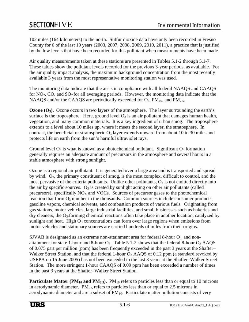
SECTIONFIVE Environmental Information
5.1-6 R:\12 HECA\AFC Amd\5_1 AQ.docx
102 miles (164 kilometers) to the north. Sulfur dioxide data have only been recorded in Fresno County for 6 of the last 10 years (2003, 2007, 2008, 2009, 2010, 2011), a practice that is justified by the low levels that have been recorded for this pollutant when measurements have been made.
Air quality measurements taken at these stations are presented in Tables 5.1-2 through 5.1-7. These tables show the pollutant levels recorded for the previous 3-year periods, as available. For the air quality impact analysis, the maximum background concentration from the most recently available 3 years from the most representative monitoring station was used.
The monitoring data indicate that the air is in compliance with all federal NAAQS and CAAQS for NO2, CO, and SO2 for all averaging periods. However, the monitoring data indicate that the NAAQS and/or the CAAQS are periodically exceeded for O3, PM10, and PM2.5.
Ozone (O3). Ozone occurs in two layers of the atmosphere. The layer surrounding the earth’s surface is the troposphere. Here, ground level O3 is an air pollutant that damages human health, vegetation, and many common materials. It is a key ingredient of urban smog. The troposphere extends to a level about 10 miles up, where it meets the second layer, the stratosphere. In contrast, the beneficial or stratospheric O3 layer extends upward from about 10 to 30 miles and protects life on earth from the sun’s harmful ultraviolet rays.
Ground level O3 is what is known as a photochemical pollutant. Significant O3 formation generally requires an adequate amount of precursors in the atmosphere and several hours in a stable atmosphere with strong sunlight.
Ozone is a regional air pollutant. It is generated over a large area and is transported and spread by wind. O3, the primary constituent of smog, is the most complex, difficult to control, and the most pervasive of the criteria pollutants. Unlike other pollutants, O3 is not emitted directly into the air by specific sources. O3 is created by sunlight acting on other air pollutants (called precursors), specifically NOX and VOCs. Sources of precursor gases to the photochemical reaction that form O3 number in the thousands. Common sources include consumer products, gasoline vapors, chemical solvents, and combustion products of various fuels. Originating from gas stations, motor vehicles, large industrial facilities, and small businesses such as bakeries and dry cleaners, the O3-forming chemical reactions often take place in another location, catalyzed by sunlight and heat. High O3 concentrations can form over large regions when emissions from motor vehicles and stationary sources are carried hundreds of miles from their origins.
SJVAB is designated as an extreme non-attainment area for federal 8-hour O3, and non-attainment for state 1-hour and 8-hour O3. Table 5.1-2 shows that the federal 8-hour O3 AAQS of 0.075 part per million (ppm) has been frequently exceeded in the past 3 years at the Shafter–Walker Street Station, and that the federal 1-hour O3 AAQS of 0.12 ppm (a standard revoked by USEPA on 15 June 2005) has not been exceeded in the last 3 years at the Shafter–Walker Street Station. The more stringent 1-hour CAAQS of 0.09 ppm has been exceeded a number of times in the past 3 years at the Shafter–Walker Street Station.
Particulate Matter (PM10 and PM2.5). PM10 refers to particles less than or equal to 10 microns in aerodynamic diameter. PM2.5 refers to particles less than or equal to 2.5 microns in aerodynamic diameter and are a subset of PM10. Particulate matter pollution consists of very
URS
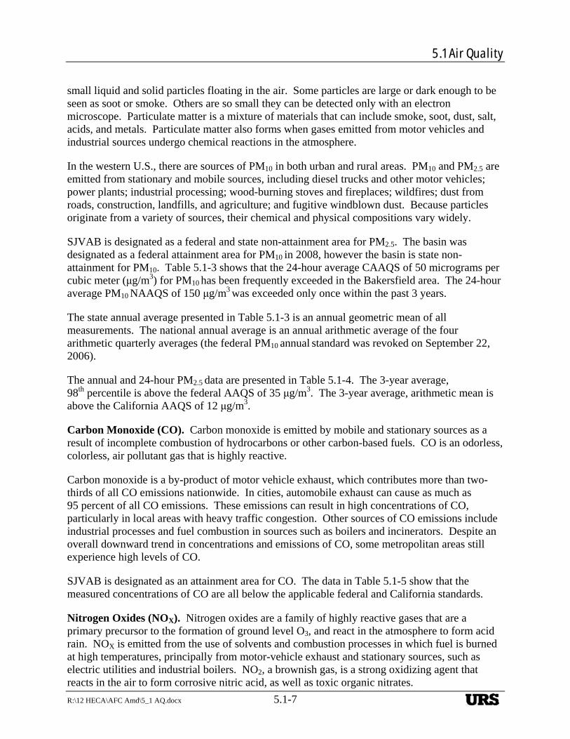
5.1 Air Quality
R:\12 HECA\AFC Amd\5_1 AQ.docx 5.1-7
small liquid and solid particles floating in the air. Some particles are large or dark enough to be seen as soot or smoke. Others are so small they can be detected only with an electron microscope. Particulate matter is a mixture of materials that can include smoke, soot, dust, salt, acids, and metals. Particulate matter also forms when gases emitted from motor vehicles and industrial sources undergo chemical reactions in the atmosphere.
In the western U.S., there are sources of PM10 in both urban and rural areas. PM10 and PM2.5 are emitted from stationary and mobile sources, including diesel trucks and other motor vehicles; power plants; industrial processing; wood-burning stoves and fireplaces; wildfires; dust from roads, construction, landfills, and agriculture; and fugitive windblown dust. Because particles originate from a variety of sources, their chemical and physical compositions vary widely.
SJVAB is designated as a federal and state non-attainment area for PM2.5. The basin was designated as a federal attainment area for PM10 in 2008, however the basin is state non-attainment for PM10. Table 5.1-3 shows that the 24-hour average CAAQS of 50 micrograms per cubic meter (μg/m3) for PM10 has been frequently exceeded in the Bakersfield area. The 24-hour average PM10 NAAQS of 150 μg/m3
was exceeded only once within the past 3 years.
The state annual average presented in Table 5.1-3 is an annual geometric mean of all measurements. The national annual average is an annual arithmetic average of the four arithmetic quarterly averages (the federal PM10 annual standard was revoked on September 22, 2006).
The annual and 24-hour PM2.5 data are presented in Table 5.1-4. The 3-year average, 98th percentile is above the federal AAQS of 35 μg/m3. The 3-year average, arithmetic mean is above the California AAQS of 12 μg/m3.
Carbon Monoxide (CO). Carbon monoxide is emitted by mobile and stationary sources as a result of incomplete combustion of hydrocarbons or other carbon-based fuels. CO is an odorless, colorless, air pollutant gas that is highly reactive.
Carbon monoxide is a by-product of motor vehicle exhaust, which contributes more than two-thirds of all CO emissions nationwide. In cities, automobile exhaust can cause as much as 95 percent of all CO emissions. These emissions can result in high concentrations of CO, particularly in local areas with heavy traffic congestion. Other sources of CO emissions include industrial processes and fuel combustion in sources such as boilers and incinerators. Despite an overall downward trend in concentrations and emissions of CO, some metropolitan areas still experience high levels of CO.
SJVAB is designated as an attainment area for CO. The data in Table 5.1-5 show that the measured concentrations of CO are all below the applicable federal and California standards.
Nitrogen Oxides (NOX). Nitrogen oxides are a family of highly reactive gases that are a primary precursor to the formation of ground level O3, and react in the atmosphere to form acid rain. NOX is emitted from the use of solvents and combustion processes in which fuel is burned at high temperatures, principally from motor-vehicle exhaust and stationary sources, such as electric utilities and industrial boilers. NO2, a brownish gas, is a strong oxidizing agent that reacts in the air to form corrosive nitric acid, as well as toxic organic nitrates.
URS
SECTIONFIVE Environmental Information
5.1-8 R:\12 HECA\AFC Amd\5_1 AQ.docx
SJVAB is designated as an attainment area for NO2. The data in Table 5.1-6 show that the measured concentrations of NO2, are all below the applicable federal and California standards.
Sulfur Dioxide (SO2). Sulfur dioxide is a colorless, irritating gas formed primarily by the combustion of sulfur-containing fossil fuels. Historically, in the late 1970s in the SJVAB portion of Kern County, SO2 was a pollutant of concern, but with the successful application of regulations, the levels have been reduced significantly.
SJVAB is designated as an attainment area for SO2. The data in Table 5.1-7 show that the measured concentrations of SO2 are all below the applicable federal and California standards. Neither CARB or EPA report 3-hour SO2 monitoring values, however, the maximum SO2 3-hour background concentration at the Fresno monitoring station was 0.010 ppm from 2007–2009 (CARB AQMIS, 2009).
Other Pollutants
Volatile Organic Compounds (VOCs). VOCs includes all hydrocarbons except those exempted by CARB. Therefore, VOCs are a set of organic gases based on state rules and regulations. Reactive organic gases (ROG) are similar to VOCs in that they include all organic gases except those exempted by federal law. The list of compounds exempt from the definition of VOCs is included by the SJVAPCD and is presented in District Rule 1102. Both VOCs and ROGs are emitted from incomplete combustion of hydrocarbons or other carbon-based fuels. Combustion engine exhaust from automobiles and trucks, oil refineries, and oil-fueled power plants are the primary sources of hydrocarbons. Another source of hydrocarbons is evaporation from petroleum fuels, solvents, dry cleaning solutions, and paint.
Sulfates (SO3 and SO4). Sulfates are the fully oxidized ionic form of sulfur. Sulfates occur in combination with metal and/or hydrogen ions. In California, emissions of sulfur compounds occur primarily from the combustion of petroleum-derived fuels (e.g., gasoline and diesel fuel) that contain sulfur. This sulfur is oxidized to SO2 during the combustion process and subsequently converted to sulfate compounds in the atmosphere. The conversion of SO2 to sulfates takes place comparatively rapidly and completely in urban areas of California due to regional meteorological features.
Lead (Pb). Lead is a metal that is a natural constituent of air, water, and the biosphere. Lead is neither created nor destroyed in the environment, so it essentially persists forever. Lead was used until recently to increase the octane rating in auto fuel. Since gasoline-powered automobile engines were a major source of airborne Pb through the use of leaded fuels, and the use of leaded fuel has been mostly phased out, the ambient concentrations of Pb have dropped dramatically. Kern County no longer monitors Pb in the ambient air of the SJVAB.
Hydrogen Sulfide (H2S). Hydrogen sulfide is associated with geothermal activity, oil and gas production, refining, sewage treatment plants, and confined animal feeding operations. It has a characteristic rotten-egg odor.
URS
5.1 Air Quality
R:\12 HECA\AFC Amd\5_1 AQ.docx 5.1-9
5.1.2 Environmental Consequences
This section describes the analyses conducted to assess the potential air quality impacts from the Project. Impacts from the Project are considered significant if, when combined with background ambient levels, they will cause an exceedance of an ambient air quality standard, or contribute to an existing exceedance, or if by themselves, they will exceed an applicable PSD significant impact amount. Emissions estimates for both construction and operation of the Project are presented. Dispersion model selection and setup are also described (i.e., emissions scenarios and release parameters, building wake effects, meteorological data, and receptor locations), and analysis results are presented.
5.1.2.1 Construction Criteria Pollutant Emissions
The primary emission sources during construction will include heavy construction equipment, construction vehicles, and fugitive dust from disturbed areas due to grading, excavating, and construction of Project structures. Different areas within the Project Site will be disturbed at different times during the 49-month overall construction period (42 months of site preparation and construction and up to 18 months of commissioning and start-up, with overlap). Estimated land disturbance for major construction activities is summarized in Chapter 2, Project Description.
Construction emissions were calculated from sources in three different categories: on-site sources; sources associated with linear construction (e.g., pipelines, transmission line, rail spur, etc.); and off-site sources. On-site sources include construction equipment, delivery trucks entering the site, and commuter vehicles entering and exiting the site. Linear sources include all construction equipment required for the total linear construction. Off-site sources include worker commuter vehicles and delivery trucks while traveling off site. Trip distances were based on the assumption that workers and delivery trucks are traveling within Kern County.
The schedule of equipment needed during construction and the estimated number of pieces of equipment that would operate during each month of the construction effort is presented in Section 2, Project Description and Appendix E-2, Construction Criteria Pollutant and Greenhouse Gas Emissions. Emissions from equipment will occur over a 49-month construction and commissioning period. The list of fueled equipment needed during each month of the construction effort served as the basis for estimating pollutant emissions throughout the term of construction and helped to identify the periods of probable maximum short-term emissions.
Construction equipment and vehicle exhaust emissions were estimated using equipment lists and construction scheduling information provided by the Project design engineering firm. Mass emissions of criteria pollutants from diesel-fueled construction equipment and vehicles were estimated using equipment specific emission factors from the California Air Resources Board OFFROAD 2007 model (CARB, 2007a). Emission factors specific to Kern County in calendar year 2013 were used. Emission factors for on-road vehicles are based on EMFAC2007 emission factors (CARB, 2007b). While EMFAC2011 was released in September 2011, it is not yet approved by EPA for use in federal projects for NEPA and federal conformity analyses; thus, emission factors from EMFAC2007 were applied. The emissions from the construction phase of the Project will be subject to the General Conformity Rule, as discussed further in
URS
SECTIONFIVE Environmental Information
5.1-10 R:\12 HECA\AFC Amd\5_1 AQ.docx
Section 5.1.2.3. Assumptions used in calculating Project construction emissions include a 49-month construction and commissioning period; 22 construction days per month; and a single-shift workday.
Project emissions are calculated to include all on-site and linear source emissions. The month in which Project emissions are a maximum is Month 6 for PM10 and PM2.5 and Month 17 for CO, VOC, NOX and SOX. Activities in the Month 6 include bulldozing, grading, importing fill, and material handling. Activities in the Month 17 primarily include building construction and construction of off-site linears.
The maximum annual Project emissions were based on the worst 12 consecutive months of the construction period. For PM10 and PM2.5 this occurred in Months 1 through 12; for CO, VOC, NOX and SOX this occurred in Months 13 through 24 of construction. For each pollutant, maximum short-term (daily) Project emissions are shown in Table 5.1-8, and maximum annual Project emissions are shown in Table 5.1-9.
For purposes of modeling, maximum emissions periods were determined using only on-site sources. Linear sources are spread out over a large distance (approximately 39 miles); pollutants will be well dispersed and not have a significant impact on a given receptor. Considering only on-site sources, maximum short-term and annual emissions of PM10 and PM2.5 occurs in Month 6 and Months 1 through 12, respectively. For CO, NOX, and SOX emissions, the month in which short-term on-site emissions reach a maximum is Month 24. The worst-case annual on-site emissions are in Months 20 through 31. On-site emissions used in dispersion modeling are shown in Appendix E-2, Construction Criteria Pollutant and Greenhouse Gas Emissions, and calculated based on the assumptions outlined below:
Fugitive dust emissions resulting from on-site soil disturbances were estimated using USEPA AP-42 emission factors for dirt piling, grading, bulldozing and dirt-pushing, and travel on unpaved roads. A dust control efficiency of 67 percent for Project Site and linear construction activities was assumed to be achieved for these activities by frequent watering and speed control. Estimated land disturbance for major construction activities is summarized in Section 2, Project Description.
Emissions from on-road delivery trucks and worker commute trips were estimated using trip generation information presented in Section 2.7.4, Combined Construction Traffic, and emission factors provided by the EMFAC2007 model for on-road vehicles. Construction workers were assumed to commute to the Project Site from locations within Kern County.
Emissions from off-road construction equipment were estimated using emission factors from the OFFROAD 2007 model. Emission factor selection was based on the type of equipment and the reported horsepower. Emissions were based on the number of pieces of equipment in a given month (from the construction schedule) and an assumed 10-hour work day.
Detailed spreadsheets are provided in Appendix E-2, Construction Criteria Pollutant and Greenhouse Gas Emissions, which have calculations of emissions from all Project construction activities and equipment, as well as the data and assumptions used for the calculations. Table 5.1-8 presents the estimated maximum daily Project on-site, linear, and off-site
URS
5.1 Air Quality
R:\12 HECA\AFC Amd\5_1 AQ.docx 5.1-11
construction emissions. Table 5.1-9 presents the estimated annual maximum Project on-site, linear and off-site construction emissions.
Construction Criteria Pollutant Emissions associated with OEHI EOR
Construction emissions associated with the OEHI Project are analyzed in Section 4.3, Air Quality, of Appendix A-1 of this AFC Amendment. The primary emission sources during construction will include heavy construction equipment, construction personnel vehicle use, and fugitive dust from disturbed areas due to grading, excavating, and construction of OEHI Project facilities. Different areas within the OEHI Project Site will be disturbed at different times during the 20-year construction phase of the proposed OEHI Project. To minimize emissions from the construction phase, OEHI will implement SJVAPCD Regulation VIII dust mitigation measures to reduce PM10 impacts to a level considered less than significant. Emission calculations and Project details can be found in the Appendix A.
5.1.2.2 Construction Greenhouse Gas Emissions
Construction GHG emissions were calculated by using a combination of emission models and emission factors. These models included EMFAC2007, OFFROAD 2007, and California Climate Action Registry (CCAR) General Reporting Guidance (CCAR, 2009). Each model calculates emissions for a different type of source. The equipment inventory, assumptions, and all data used to calculate construction-related GHG emissions are included in Appendix E-2, Construction Criteria Pollutant and Greenhouse Gas Emissions.
Construction GHG emissions are generated by construction equipment and construction vehicles, as well as commuter vehicles and delivery trucks. A summary of Project related GHG emissions over the entire construction period is presented in Table 5.1-10.
Construction GHG Emissions associated with OEHI EOR
Construction GHG emissions associated with the OEHI Project are analyzed in Section 4.18, Greenhouse Gas Emissions, of Appendix A-1 of this AFC Amendment. The primary sources of the OEHI Project GHG emissions during the construction phase are anticipated to be vehicle emissions and construction equipment. Emission calculations and Project details can be found in Appendix A. The analysis contained in Appendix A concludes that GHG emissions associated with the construction of the OEHI Project will not result in a significant adverse impact
5.1.2.3 Operational Criteria Pollutant Emissions
Operational Emissions—Stationary Sources
The Project is an Integrated Gasification Combined Cycle (IGCC) polygeneration project that will produce low carbon baseload electricity, low carbon nitrogen–based products in an integrated Manufacturing Complex, and CO2 for EOR. The Gasification Block will feature a Mitsubishi Heavy Industries (MHI) oxygen-blown dry feed gasifier, Shift, Low Temperature Gas Cooling (LTGC), Mercury Removal, Acid Gas Removal (AGR), Sulfur Recovery, Tail Gas Treating, EOR CO2 Compression Units and associated utilities to produce hydrogen-rich fuel.
URS
SECTIONFIVE Environmental Information
5.1-12 R:\12 HECA\AFC Amd\5_1 AQ.docx
Sulfur and mercury components will be removed, and CO2 will be captured and compressed for EOR and resulting sequestration.
The Combined Cycle Power Block will generate approximately 405 MW of gross power and will provide approximately 300 MW output of low-carbon baseload electricity. The Power Block will feature one MHI 501GAC® combustion turbine generator (CTG) that will be fueled with hydrogen-rich fuel from the gasification plant, and natural gas as a backup fuel; a heat-recovery steam generator (HRSG) with duct firing on a combination of hydrogen-rich fuel and PSA off-gas; and a condensing steam turbine-generator.
The Manufacturing Complex is an integrated complex that will produce approximately 1 million tons per year of nitrogen-based products, including urea, UAN and anhydrous ammonia, to be used in agricultural, transportation, and industrial applications. Process units used in producing the low-carbon, nitrogen-based products are the PSA, Carbon Dioxide Purification and Compression, Ammonia Synthesis, Urea, Urea Pastillation and Storage, Nitric Acid, Ammonium Nitrate, Urea Ammonium Nitrate Units, and associated utilities.
The operational emissions from the Project are mainly generated from the combustion of the hydrogen-rich fuel in the Combined Cycle Power Block. Other emission sources are outlined below. Each emission source can be categorized with the Power Block, Gasification Block, Manufacturing Complex, or ancillary equipment as follows.
Power Block Gasification Block Manufacturing
Complex Ancillary
Equipment Combustion
Turbine (MHI 501GAC®)
Power Block Cooling Tower
Coal Dryer Auxiliary Boiler Gasification Flare Sulfur Recovery Unit
(SRU) Flare Rectisol® Flare Tail Gas Thermal
Oxidizer ASU and Process
Cooling Towers CO2 Vent Material Handling
Dust collection (Feedstock)
Nitric Acid Unit Urea Absorbers Urea Pastillation Ammonium
Nitrate Unit Ammonia
Synthesis Unit Start-Up Heater
Material Handling Dust collection (Urea)
Two Emergency Diesel Generators
Emergency Diesel Firewater Pump
Plant Start-Up This section describes a typical plant-wide start-up that would occur after the commissioning phase. The commissioning and initial start-up of the facility is described later in the commissioning section. HECA LLC anticipates that one to two plant start-ups/shut-downs will be necessary for annual maintenance. This sequence assumes that all the necessary utility and support systems are already in service (plant-distributed control system, fire protection and other
URS
5.1 Air Quality
R:\12 HECA\AFC Amd\5_1 AQ.docx 5.1-13
safety systems, electrical switchyard and in-plant electrical distribution, water treatment, natural gas, steam, instrument and plant air, purge nitrogen, etc.).
The IGCC takes 4 to 6 days from cold start to export of low-carbon power. The following summarizes the start-up sequences. Note that if the IGCC is being restarted after a short outage, when the equipment is still close to operating conditions, the durations of each step will be much shorter than indicated below.
Air Separation Unit Start-Up
The Air Separation Unit (ASU) will require 3 to 4 days to start up and reach full capacity. Because the ASU operates at cryogenic conditions, the start-up sequence includes an extensive cool down and drying period. During this time, the main air compressor and booster air compressor will be operated to provide the auto refrigeration necessary to cool and dry the ASU. Near the end of the start-up sequence, the ASU will begin producing liquid oxygen (LOX) and liquid nitrogen. The LOX is stored to provide a backup oxygen supply to cover a compressor trip or other short ASU outage. The liquid nitrogen storage is provided as a backup supply for the purge nitrogen system. Once the ASU is producing enough oxygen to operate the gasifier, the LOX pumping and vaporization system can be started to make high-pressure oxygen vapor available to the Gasification Unit.
AGR Start-Up
The AGR Unit is assumed to be ready to start (purged with nitrogen and with start-up methanol levels established in the circulating system). Methanol circulation is started and the refrigeration system is started to begin cooling the methanol to operating temperature (approximately minus 40°F). This sequence is expected to take about 2 days and will complete at about the same time that sufficient oxygen is available to start the gasifier.
SRU Start-Up
The SRU is a single train with an oxygen-enriched reaction furnace (thermal reactor) and two modified Claus reactor stages. The SRU reaction furnace is refractory lined. After an extended outage, both the refractory and the SRU catalyst require a gradual heating program that will take about 3 days for initial curing and dryout, and 1 day on subsequent start-ups. The heating is provided by firing natural gas with air in the reaction furnace. The combustion products flow through the reaction furnace, catalyst beds and boilers to the tail gas thermal oxidizer. During the refractory dryout/cure period, the hydrogenation reactor in the TGTU will also be preheated. The hydrogenation reactor catalyst requires pre-sulfiding prior to being put into operation, which will be timed to complete when the SRU is feed-ready and the gasifier is feed-ready.
Gasification Block Start-Up
The MHI gasifier is a dry-feed system and the gasification reaction zone is protected by a membrane wall. This design reduces the amount of time needed to warm the gasifier (as compared to a refractory lined vessel) when preparing the gasifier for start-up. Natural gas will be burned in air inside the gasifier to provide heat during initial warm-up and will be sent to the gasification flare.
URS
SECTIONFIVE Environmental Information
5.1-14 R:\12 HECA\AFC Amd\5_1 AQ.docx
Once the gasifier is up near operating temperature the natural gas will be partially oxidized with O2 which makes a low sulfur syngas. The pressure and flow is then ramped up to allow the start-up of the shift/LTGC and Rectisol® units. Initially the unshifted syngas will be sent to the gasification flare. Once the shift reactors are functioning then the shifted syngas will be sent to the gasification flare. The venting location will then be moved downstream of the Rectisol® absorber and hydrogen-rich fuel will go to the gasification flare. The flaring will continue during the gasifier's transition from natural gas to coal/coke until the hydrogen-rich fuel can be sent to the gas turbine.
The shift reactors require warm up and pre-sulfiding before sour syngas (containing hydrogen sulfide) can be introduced. The shift reactor catalyst is heated by circulating hot nitrogen across the catalyst beds for about 2 days. The nitrogen is heated indirectly with a high-pressure steam heater. Once the catalyst is hot, a small amount of sulfur containing compound is added to the circulating nitrogen. The pre-sulfiding is completed when traces of sulfur are detected in the effluent of the second shift reactor. The shift reactors are then placed in a hot standby condition and ready for feed.
The CO2 compression system will be purged and ready to compress CO2. The CO2 compressor start-up sequence will be timed to coincide with the time the AGR Unit is producing CO2 in sufficient quantity to allow sustained operation of the CO2 compressor.
When the gasifier reaches operating temperature, and the gasifier system has been purged with nitrogen, the gasifier can be started by introducing oxygen to gasify the natural gas, then switching to the coal/petcoke-blend feedstock. Produced raw syngas is sent to Gasification Flare until the system pressure and flow are stabilized. During start-up, the syngas sent to flare is either produced from natural gas or treated in the AGR Unit and will be essentially sulfur-free.
Syngas is diverted through the shift reactors and LTGC sections and then to the AGR Unit. The circulating solution in the AGR Unit then begins absorbing the CO2 in the syngas. Once the CO2 concentration in the rich solution reaches the required level, the flash drums will begin separating CO2 vapor. This CO2 will be washed to remove any traces of methanol and vented at the Rectisol® flare until the flow rate is increased and then vented through the CO2 vent.
Once sufficient hydrogen-rich fuel production is available, the MHI 501GAC® combustion turbine can initiate a switch to 100 percent hydrogen-rich fuel. At this point, the gasifier start-up is complete and operation begins.
Also at this point, the start-up of the PSA and Ammonia Plant is initiated, a process that takes 1 to 2 days. Subsequently, the Urea Plant start-up is initiated over a second 24-hour process.
Power Block Start-Up
The MHI 501GAC® and the MHI steam turbine are on a common shaft, with the common generator located between the combustion turbine (CT) and steam turbine (ST). A clutch is provided between the ST and the generator to allow the CT to start-up independently of the ST. The clutch is disengaged during the following CT start-up sequence.
URS
5.1 Air Quality
R:\12 HECA\AFC Amd\5_1 AQ.docx 5.1-15
Once all the start-up permissives are met, the MHI 501GAC® CT start signal is given and the generator is used as a motor to rotate the combustion turbine and accelerate it until the operation is self-sustaining (static start). The CT compressor is first partially loaded to provide enough air flow and duration to purge the HRSG. Following the purge, natural gas is introduced into the CT combustors, resulting in the CT operation to become self-sustaining and the discontinuation of the static start. Natural gas is required to start-up the combustion turbine. When the combustion turbine reaches 3,600 revolutions per minute (RPM), or “full speed, no load,” it is synchronized with the electrical grid, and the main breaker is closed. Shortly after the CT is synchronized, it is loaded to a minimum or “spinning reserve” load. All the preceding steps are executed automatically by the CT’s control computer system. At this point the HRSG begins warming up and rapidly begins to produce steam. The steam is initially vented, and as pressure builds in the steam system, the atmospheric vents close and the steam flow is diverted to the surface condenser. Once dry superheated steam is available at the ST, the ST start-up sequence can be initiated. The ST can then be accelerated to 3,600 RPM to match speed with the generator shaft. Once the speeds are synchronized, the clutch can be engaged and both the CT and the ST will supply shaft work to the generator. The steam turbine metal temperatures determine how quickly the steam turbine can be loaded. The cold start sequence requires the CT to operate at reduced load (below the emission compliance level) for up to 4 hours. During this time, the CT load is slowly increased to match the steam temperature to the ST metal temperature to heat the ST while minimizing thermal stress. Once the CT reaches the required load, steam is introduced to control nitrogen oxide formation. Once the SCR catalyst reaches the required temperature, ammonia injection is initiated and the HRSG stack emissions will fall to the required compliance levels. The CT can then be loaded normally to base load and the ST will reach a load based on the available steam.
Ammonia Synthesis Unit Start-Up
The Ammonia Synthesis Unit will require about 2 days to start-up and reach full capacity for a cold start-up. First, the circulation of high pressure boiler feedwater through the waste heat boiler, and that of cooling water through the appropriate heat exchangers is started. Then, the syngas compressor is started up and its speed slowly increased with hydrogen and nitrogen feeds. The initial period is used for purging the system and venting the gas (essentially hydrogen and nitrogen) via the flare system in the IGCC complex. The synthesis loop pressure is increased by increasing the compressor speed and syngas flow rate. The start-up heater is switched on to raise the converter catalyst bed temperatures. As the catalyst bed temperature is increased, the exothermic ammonia synthesis reaction starts taking place and ammonia is produced. As the synthesis loop pressure and the converter temperatures are increased, the ammonia refrigeration compressor is brought on line. The chilling provided by this system is used to separate the ammonia product from the main gas stream. The unconverted gas is recycled back to the syngas compressor.
The operating temperatures of the ammonia synthesis converter and the ammonia chillers are next optimized. The start-up heater is then shut down. Then, the synthesis loop pressure is brought to design conditions by increasing the syngas compressor speed and feed rates. At this point, the Ammonia Synthesis Unit is operating at its design capacity and producing cold liquid, warm liquid, and vapor ammonia product streams.
URS
SECTIONFIVE Environmental Information
5.1-16 R:\12 HECA\AFC Amd\5_1 AQ.docx
Urea Unit Start-Up
For a cold-start up, the Urea Unit will require about 18 hours to reach full capacity. First, the circulation of cooling water through the appropriate heat exchangers is started. The CO2 Compressor and the Air Blower are then brought on line at low speed and the CO2 and air are circulated through the following high pressure vessels:
High Pressure (HP) Stripper Urea Reactor HP Carbamate Condenser HP Scrubber
The initial period is used for purging the system and venting CO2 at the urea absorber stacks. Then, the CO2 compressor speed is increased and the above mentioned vessels are pressurized with CO2. Medium pressure (385 psig) steam is then introduced in the HP Stripper to raise the temperature of the system. Steam condensate from the HP Stripper is flashed at low pressure (60 psig) to provide steam for users at this level.
Pressurized liquid ammonia stream is introduced into the Urea Reactor to react with the CO2 stream. The liquid product stream from the Urea reactor consists of urea, carbamate, water, and excess ammonia. This liquid stream is routed to the HP Stripper where carbamate and excess ammonia are separated and recycled to the Urea Reactor with the incoming CO2 feed stream. The bottoms product from the HP Stripper is urea solution containing over 50 weight percent urea. The urea solution is routed to downstream units for further concentration. A 70 weight percent urea solution is first produced in the LP Rectifier and the Flash Vessel. This solution is stored in the intermediate solution tank. From this tank it is pumped to the vacuum separators/evaporators to produce either the 80 weight percent urea stream for use in the UAN complex, or a greater than 99 weight percent urea melt stream for use in the Pastillation Unit.
UAN Unit Start-Up
From a typical cold-start up, the UAN Unit will require about 12 hours to reach full capacity. The UAN Unit consists of a Nitric Acid Unit, Ammonium Nitrate Unit, and a UAN blending unit. It is assumed that both the upstream Ammonia Unit and the Urea Unit are operating normally before the UAN Unit is started-up. The start-up sequence will consist of the following:
Start-up of the Nitric Acid Unit Start-up of the Ammonium Nitrate Unit Start-up of the Urea Ammonium Nitrate Blending Unit
Start-Up of the Nitric Acid Unit
Circulation of boiler feedwater is first started through the Waste Heat Boiler. Then, the air compressor is started up and air is used to pressurize the system consisting of the Ammonia Converter, Tail Gas Heater, Absorber, and all associated heat exchangers. The ammonia vapor stream from the battery limits is then slowly introduced and fed to the Ammonia Converter. A highly exothermic reaction of ammonia with air takes place over platinum catalyst to produce a
URS
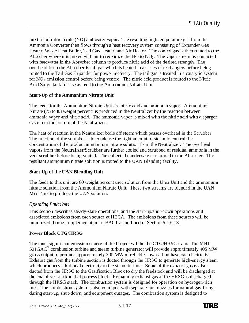
5.1 Air Quality
R:\12 HECA\AFC Amd\5_1 AQ.docx 5.1-17
mixture of nitric oxide (NO) and water vapor. The resulting high temperature gas from the Ammonia Converter then flows through a heat recovery system consisting of Expander Gas Heater, Waste Heat Boiler, Tail Gas Heater, and Air Heater. The cooled gas is then routed to the Absorber where it is mixed with air to reoxidize the NO to NO2. The vapor stream is contacted with feedwater in the Absorber column to produce nitric acid of the desired strength. The overhead from the Absorber is tail gas which is heated in a series of exchangers before being routed to the Tail Gas Expander for power recovery. The tail gas is treated in a catalytic system for NOX emission control before being vented. The nitric acid product is routed to the Nitric Acid Surge tank for use as feed to the Ammonium Nitrate Unit.
Start-Up of the Ammonium Nitrate Unit
The feeds for the Ammonium Nitrate Unit are nitric acid and ammonia vapor. Ammonium Nitrate (75 to 83 weight percent) is produced in the Neutralizer by the reaction between ammonia vapor and nitric acid. The ammonia vapor is mixed with the nitric acid with a sparger system in the bottom of the Neutralizer.
The heat of reaction in the Neutralizer boils off steam which passes overhead in the Scrubber. The function of the scrubber is to condense the right amount of steam to control the concentration of the product ammonium nitrate solution from the Neutralizer. The overhead vapors from the Neutralizer/Scrubber are further cooled and scrubbed of residual ammonia in the vent scrubber before being vented. The collected condensate is returned to the Absorber. The resultant ammonium nitrate solution is routed to the UAN Blending facility.
Start-Up of the UAN Blending Unit
The feeds to this unit are 80 weight percent urea solution from the Urea Unit and the ammonium nitrate solution from the Ammonium Nitrate Unit. These two streams are blended in the UAN Mix Tank to produce the UAN solution.
Operating Emissions This section describes steady-state operations, and the start-up/shut-down operations and associated emissions from each source at HECA. The emissions from these sources will be minimized through implementation of BACT as outlined in Section 5.1.6.13.
Power Block CTG/HRSG
The most significant emission source of the Project will be the CTG/HRSG train. The MHI 501GAC® combustion turbine and steam turbine generator will provide approximately 405 MW gross output to produce approximately 300 MW of reliable, low-carbon baseload electricity. Exhaust gas from the turbine section is ducted through the HRSG to generate high-energy steam which produces additional electricity in the steam turbine. Some of the exhaust gas is also ducted from the HRSG to the Gasification Block to dry the feedstock and will be discharged at the coal dryer stack in that process block. Remaining exhaust gas at the HRSG is discharged through the HRSG stack. The combustion system is designed for operation on hydrogen-rich fuel. The combustion system is also equipped with separate fuel nozzles for natural gas-firing during start-up, shut-down, and equipment outages. The combustion system is designed to
URS
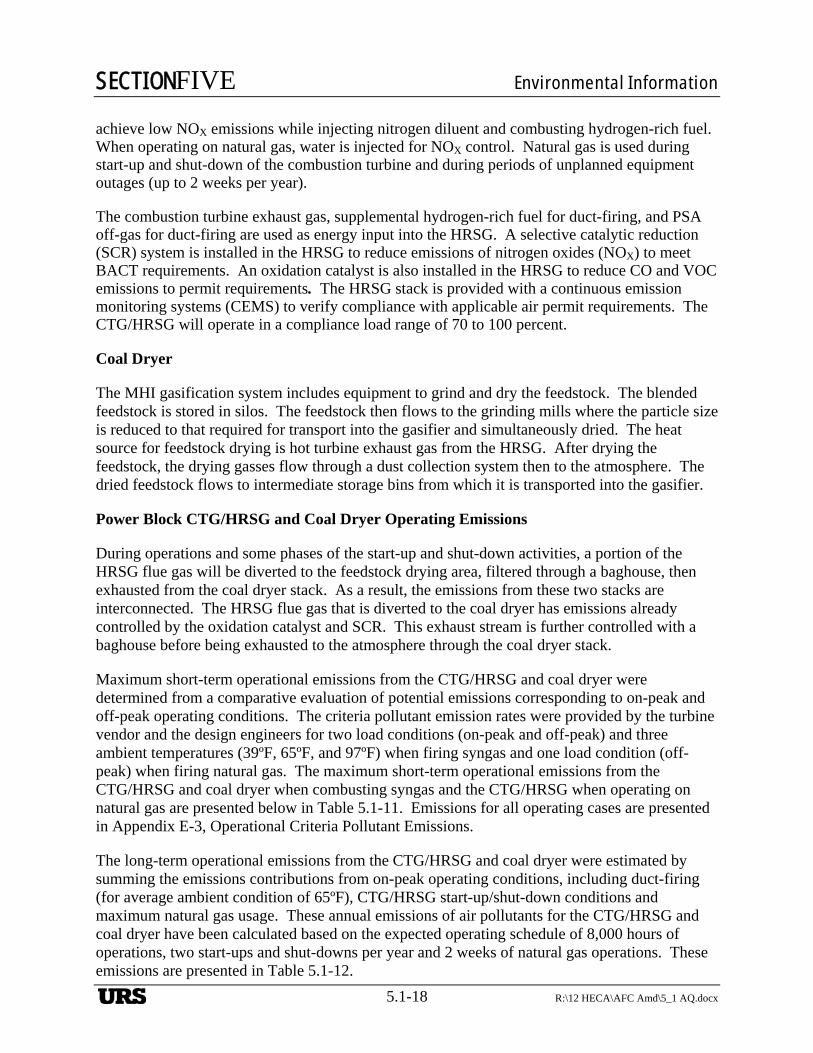
SECTIONFIVE Environmental Information
5.1-18 R:\12 HECA\AFC Amd\5_1 AQ.docx
achieve low NOX emissions while injecting nitrogen diluent and combusting hydrogen-rich fuel. When operating on natural gas, water is injected for NOX control. Natural gas is used during start-up and shut-down of the combustion turbine and during periods of unplanned equipment outages (up to 2 weeks per year).
The combustion turbine exhaust gas, supplemental hydrogen-rich fuel for duct-firing, and PSA off-gas for duct-firing are used as energy input into the HRSG. A selective catalytic reduction (SCR) system is installed in the HRSG to reduce emissions of nitrogen oxides (NOX) to meet BACT requirements. An oxidation catalyst is also installed in the HRSG to reduce CO and VOC emissions to permit requirements. The HRSG stack is provided with a continuous emission monitoring systems (CEMS) to verify compliance with applicable air permit requirements. The CTG/HRSG will operate in a compliance load range of 70 to 100 percent.
Coal Dryer
The MHI gasification system includes equipment to grind and dry the feedstock. The blended feedstock is stored in silos. The feedstock then flows to the grinding mills where the particle size is reduced to that required for transport into the gasifier and simultaneously dried. The heat source for feedstock drying is hot turbine exhaust gas from the HRSG. After drying the feedstock, the drying gasses flow through a dust collection system then to the atmosphere. The dried feedstock flows to intermediate storage bins from which it is transported into the gasifier.
Power Block CTG/HRSG and Coal Dryer Operating Emissions
During operations and some phases of the start-up and shut-down activities, a portion of the HRSG flue gas will be diverted to the feedstock drying area, filtered through a baghouse, then exhausted from the coal dryer stack. As a result, the emissions from these two stacks are interconnected. The HRSG flue gas that is diverted to the coal dryer has emissions already controlled by the oxidation catalyst and SCR. This exhaust stream is further controlled with a baghouse before being exhausted to the atmosphere through the coal dryer stack.
Maximum short-term operational emissions from the CTG/HRSG and coal dryer were determined from a comparative evaluation of potential emissions corresponding to on-peak and off-peak operating conditions. The criteria pollutant emission rates were provided by the turbine vendor and the design engineers for two load conditions (on-peak and off-peak) and three ambient temperatures (39ºF, 65ºF, and 97ºF) when firing syngas and one load condition (off-peak) when firing natural gas. The maximum short-term operational emissions from the CTG/HRSG and coal dryer when combusting syngas and the CTG/HRSG when operating on natural gas are presented below in Table 5.1-11. Emissions for all operating cases are presented in Appendix E-3, Operational Criteria Pollutant Emissions.
The long-term operational emissions from the CTG/HRSG and coal dryer were estimated by summing the emissions contributions from on-peak operating conditions, including duct-firing (for average ambient condition of 65ºF), CTG/HRSG start-up/shut-down conditions and maximum natural gas usage. These annual emissions of air pollutants for the CTG/HRSG and coal dryer have been calculated based on the expected operating schedule of 8,000 hours of operations, two start-ups and shut-downs per year and 2 weeks of natural gas operations. These emissions are presented in Table 5.1-12.
URS
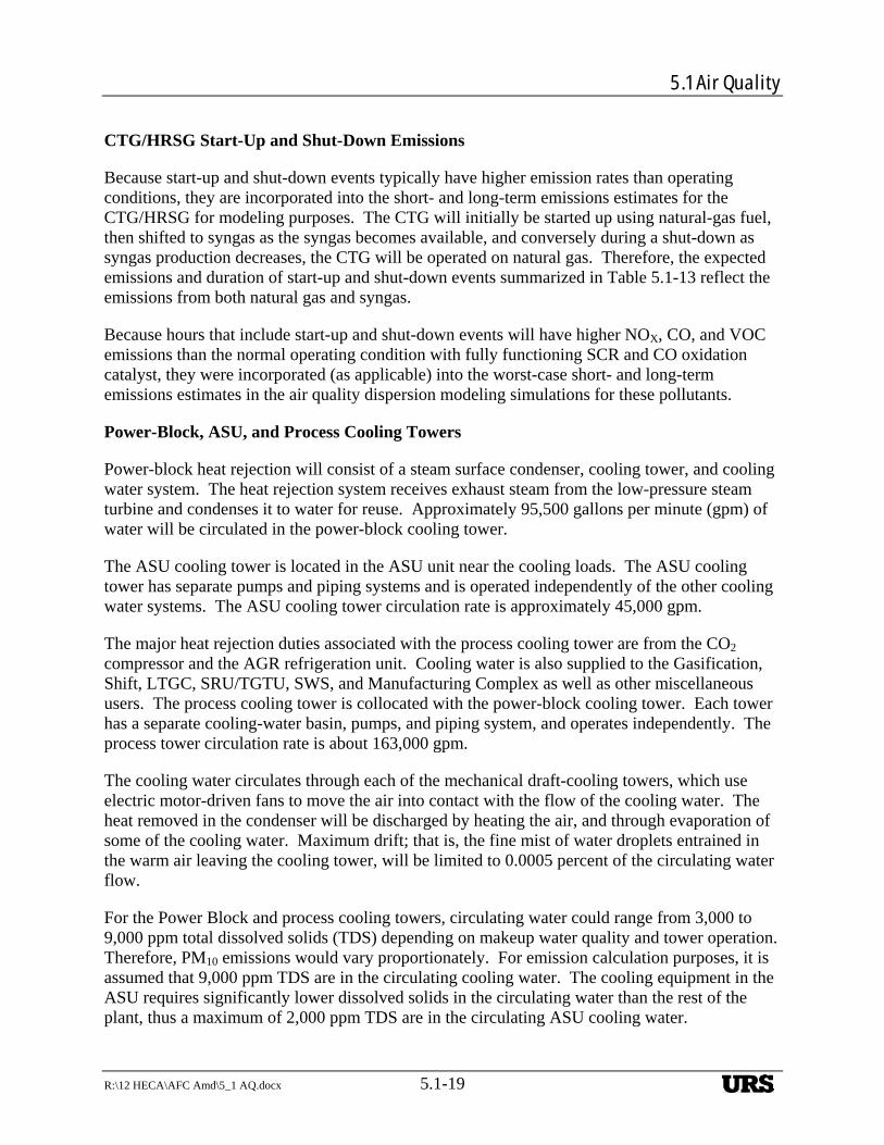
5.1 Air Quality
R:\12 HECA\AFC Amd\5_1 AQ.docx 5.1-19
CTG/HRSG Start-Up and Shut-Down Emissions
Because start-up and shut-down events typically have higher emission rates than operating conditions, they are incorporated into the short- and long-term emissions estimates for the CTG/HRSG for modeling purposes. The CTG will initially be started up using natural-gas fuel, then shifted to syngas as the syngas becomes available, and conversely during a shut-down as syngas production decreases, the CTG will be operated on natural gas. Therefore, the expected emissions and duration of start-up and shut-down events summarized in Table 5.1-13 reflect the emissions from both natural gas and syngas.
Because hours that include start-up and shut-down events will have higher NOX, CO, and VOC emissions than the normal operating condition with fully functioning SCR and CO oxidation catalyst, they were incorporated (as applicable) into the worst-case short- and long-term emissions estimates in the air quality dispersion modeling simulations for these pollutants.
Power-Block, ASU, and Process Cooling Towers
Power-block heat rejection will consist of a steam surface condenser, cooling tower, and cooling water system. The heat rejection system receives exhaust steam from the low-pressure steam turbine and condenses it to water for reuse. Approximately 95,500 gallons per minute (gpm) of water will be circulated in the power-block cooling tower.
The ASU cooling tower is located in the ASU unit near the cooling loads. The ASU cooling tower has separate pumps and piping systems and is operated independently of the other cooling water systems. The ASU cooling tower circulation rate is approximately 45,000 gpm.
The major heat rejection duties associated with the process cooling tower are from the CO2 compressor and the AGR refrigeration unit. Cooling water is also supplied to the Gasification, Shift, LTGC, SRU/TGTU, SWS, and Manufacturing Complex as well as other miscellaneous users. The process cooling tower is collocated with the power-block cooling tower. Each tower has a separate cooling-water basin, pumps, and piping system, and operates independently. The process tower circulation rate is about 163,000 gpm.
The cooling water circulates through each of the mechanical draft-cooling towers, which use electric motor-driven fans to move the air into contact with the flow of the cooling water. The heat removed in the condenser will be discharged by heating the air, and through evaporation of some of the cooling water. Maximum drift; that is, the fine mist of water droplets entrained in the warm air leaving the cooling tower, will be limited to 0.0005 percent of the circulating water flow.
For the Power Block and process cooling towers, circulating water could range from 3,000 to 9,000 ppm total dissolved solids (TDS) depending on makeup water quality and tower operation. Therefore, PM10 emissions would vary proportionately. For emission calculation purposes, it is assumed that 9,000 ppm TDS are in the circulating cooling water. The cooling equipment in the ASU requires significantly lower dissolved solids in the circulating water than the rest of the plant, thus a maximum of 2,000 ppm TDS are in the circulating ASU cooling water.
URS
SECTIONFIVE Environmental Information
5.1-20 R:\12 HECA\AFC Amd\5_1 AQ.docx
The cooling tower total PM emissions are based on the maximum expected total dissolved solids in the cooling water, annual circulating water rate, and the use of a high-efficiency drift eliminator. It is conservatively estimated that total PM emitted from the cooling tower will be equal to PM10 in diameter, and the quantity of PM emissions that are equal to PM2.5 will be 60 percent of the PM10 emissions (a fraction or ratio of 0.6). The basis for the ratio used is described in Response to Data Request 18 (URS, 2009b), and also in “Applicant Comments On The Preliminary Determination Of Compliance For The Hydrogen Energy California (HECA) Project (08-AFC-8),” which is provided in Appendix E-4, Responses to PM2.5 Cooling Tower Data Requests from CEC and USEPA.
Annual emissions from the Power Block, ASU and process cooling tower are presented in Table 5.1-14. Hourly and annual emissions and calculation details are included in Appendix E-3, Operational Criteria Pollutant Emissions.
Auxiliary Boiler
The auxiliary boiler will provide steam to facilitate CTG start-up and for other industrial purposes. The auxiliary boiler will be designed to burn pipeline-quality natural gas at the design maximum fuel flow rate of 213 MMBtu/hour (higher heating value). The auxiliary boiler emissions are based on an annual capacity of 25 percent maximum load operation, or 466 billion Btu per year.
The NOX emissions will be controlled with the installation of SCR and additional flue gas recirculation if necessary. The NOX emissions are based on 5 parts per million volumetric dry (ppmvd) at 3 percent oxygen (O2) with installation of SCR. Carbon monoxide emissions are based on 50 ppmvd at 3 percent O2. Ammonia emissions are based on 5 ppmvd at 3 percent O2. SO2 emissions are based on the sulfur content of the natural gas. PM10, PM2.5, and VOC emissions are based on vendor-supplied emission factors.
A summary of auxiliary boiler emissions is presented in Table 5.1-14. Emissions and calculations are included in Appendix E-3, Operational Criteria Pollutant Emissions.
Gasification, SRU, and Rectisol® Flares
During gasifier start-up, unprocessed/unreacted vent gas is vented to the flaring system. The Gasification Block will operate a gasification flare to safely dispose of gases during gasifier start-up and unplanned power plant upsets or equipment failures. The gasification flare may operate approximately 28 hours per year for start-up and shut-down events.
There will be an SRU flare installed to safely dispose of gas emissions from the AGR source during start-up (after passing via a scrubber), or to oxidize releases during emergency or upset events. The SRU may flare for up to 40 hours per year during plant start-ups.
The Rectisol® flare will be used to safely dispose of low-temperature gas streams during start-up, shut-down, and unplanned upsets or emergency events. The Rectisol® flare may be used for off-specification CO2 during gasifier start-up or shut-down events. It is expected that a maximum of 40 hours per year of flaring for this purpose would be required by this flare.
URS
5.1 Air Quality
R:\12 HECA\AFC Amd\5_1 AQ.docx 5.1-21
During operations, the three flares will have pilot flames that will operate continuously. Emissions from the flares are generated from the continual operation of the natural gas fired pilots and from periodic vent gases that are oxidized during planned start-up/shut-down of the Gasification Block. The annual emissions from each flare were estimated by adding the emissions from continual use of the pilot plus the planned use during gasifier start-up/shut-down events.
A summary of each flare emissions is presented in Table 5.1-14. Emissions and calculations are included in Appendix E-3, Operational Criteria Pollutant Emissions.
Tail Gas Thermal Oxidizer
Associated with the operation of the sulfur recovery process, the Project will incorporate a thermal oxidizer on the tail-gas treating unit (TGTU). The thermal oxidizer will serve as a control device to oxidize any remaining H2S (after scrubbing) and other vent gas that is generated during start-up, shut-down, and times of non-delivery of CO2 product. In addition, miscellaneous oxidizing streams from the gasification area (e.g., atmospheric tank vents and miscellaneous equipment vents) are directed to the thermal oxidizer during operation to prevent nuisance odors. The thermal oxidizer operates at high temperatures, and provides sufficient residence time in order to ensure essentially complete destruction of reduced sulfur compounds like H2S to SO2. The thermal oxidizer fires natural gas continually to reach and maintain the required operating temperature for proper thermal destruction. Pollutant emissions are generated from the firing of natural gas and the periodic oxidation of vent gas during SRU start-up. A summary of the tail gas oxidizer emissions is presented in Table 5.1-14. Emissions and calculations are included in Appendix E-3, Operational Criteria Pollutant Emissions.
Carbon Dioxide Vent
The CO2 vent stack will allow for start-up and intermittent emergency venting of produced CO2 when the CO2 compression, transportation, or injection system is unavailable. The CO2 vent will enable the Project to operate, rather than be disabled, by brief periods when the CO2 injection system is unavailable, and in doing so, prevents gasifier shut-down and subsequent gasifier restart with associated emissions.
A 260-foot stack height was chosen to satisfy HECA’s inherently safe design practices to minimize ground-level CO2 concentrations in the event of a CO2 vent under very low wind speeds. The physical height of the CO2 vent stack of 79.3 meters (260 feet) is within the calculated Good Engineering Practice (GEP) height.
The CO2 vent exhaust stream will be nearly 100 percent CO2, with small amounts of CO, VOC and H2S. A summary of the maximum annual CO2 vent stack emissions is presented in Table 5.1-14. Emissions and calculations are included in Appendix E-3, Operational Criteria Pollutant Emissions.
Ammonia Synthesis Unit Start-Up Heater
The high-purity hydrogen stream, from the Pressure Swing Adsorption (PSA) Unit, and nitrogen, from the ASU, are combined in an exothermic ammonia synthesis reaction that takes place at
URS
SECTIONFIVE Environmental Information
5.1-22 R:\12 HECA\AFC Amd\5_1 AQ.docx
high temperature and high pressure across an iron-based catalyst. There is a large degree of heat integration within the Ammonia Synthesis Unit, and the substantial heat of reaction is recovered and used to generate steam. Cold liquid ammonia is stored in a tank at atmospheric pressure.
There are no normal operating emissions from the ammonia synthesis unit. However, a start-up heater (natural gas-fired) is used to heat the catalyst during a cold start of the unit. A 55-MMBtu/hr natural-gas–fired start-up heater is provided in the ammonia synthesis unit to raise the catalyst-bed temperatures during initial plant commissioning or during start-up after a long period of plant shut-down. The annual heat input for this heater is not expected to exceed 7,700 MMBtu higher heating value, which is equivalent to approximately 140 hours of operation at full capacity.
The heater will use a low-NOX burner to control emissions to 9 ppmvd at 3 percent O2. Carbon monoxide emissions are based on 50 ppmvd at 3 percent O2. PM10, PM2.5 and VOC emissions are based on vendor-supplied emission factors. SO2 emissions are based on 12.65 ppmv total sulfur in pipeline natural gas.
A summary of the ammonia synthesis unit start-up heater emissions is presented in Table 5.1-14. Emissions and calculations are included in Appendix E-3, Operational Criteria Pollutant Emissions.
Urea Absorbers
The purified and compressed CO2 and the liquid ammonia are reacted in the Urea Unit to create a concentrated urea solution, which is pumped to the Urea Pastillation Unit. Lower-concentration urea solution is produced as a feedstock to the urea ammonia nitrate (UAN) Solution Plant. Vacuum evaporator/separator systems are used to produce the required urea solutions.
The off-gases from the urea synthesis process, consisting of inerts (CO2, nitrogen, and water) present in the CO2 feed, process air and unreacted ammonia are cleaned before being vented in the HP scrubber, which operates at an elevated pressure. The off-gases are scrubbed first with process water, and second with clean cold water. In this way, nearly all of the ammonia is scrubbed from the gas. Low pressure off-gases are cleaned in the low-pressure (LP) scrubber, which operates at close to atmospheric pressure. Here, the off-gas is scrubbed with clean cold water to reduce the ammonia content in the vent.
The only emissions associated with the HP and LP Urea Absorbers are ammonia, which are reduced by the wet scrubber. Emissions from the HP and LP Urea Absorbers are presented in Section 5.6, Public Health. Emissions and calculations are included in Appendix E-3, Operational Criteria Pollutant Emissions, and Appendix M, Public Health and Safety.
Urea Pastillation Unit
The pastillation process is used to convert the urea melt into high-quality pastilles. This process is enclosed with a hood, passed through a baghouse, then vented. Limited ammonia and urea dust, which is classified as PM10/PM2.5, are emitted from this source. The HECA pastillation process PM10/PM2.5 emissions will be limited to a grain loading of 0.001 gr/dscf by the
URS
5.1 Air Quality
R:\12 HECA\AFC Amd\5_1 AQ.docx 5.1-23
baghouse. A summary of the Urea Pastillation Unit emissions is presented in Table 5.1-14. Emissions and calculations are included in Appendix E-3, Operational Criteria Pollutant Emissions.
Nitric Acid Unit
Nitric acid production is a three-step process consisting of ammonia oxidation, NO oxidation and absorption. Tail gas from the absorber column will be cleaned before being discharged by catalytic decomposition and reduction of both N2O and NOX.
The N2O emissions are treated in a tertiary reduction system, based on its location at the end of the tail gas heat recovery system. Primary and secondary reduction occurs in the nitric acid unit equipment without any catalysis simply by the high process temperature. In the tertiary reduction, a reducing catalyst that uses high temperature rather than a reducing agent, converts 95 percent of the remaining N2O emission to molecular nitrogen (N2) and NO. The NOX emissions (including the NO formed in the N2O converter) are then reduced in one or more selective catalytic reduction (SCR) units, with injected ammonia as a reducing agent, as is typical for NOX control in flue gas systems. Total NOX emissions from this unit will not exceed 0.2 lb/ton of dry nitric acid or 15 ppmv NOX. The HECA nitric acid plant will have an ammonia emission limit of 5 ppm due to slip from the SCR.
A summary of the nitric acid unit emissions is presented in Table 5.1-14. Emissions and calculations are included in Appendix E-3, Operational Criteria Pollutant Emissions.
Ammonium Nitrate Unit
Ammonia and nitric acid are the feedstocks to the ammonium nitrate unit, which makes the ammonium nitrate solution. The ammonium nitrate unit vent stream contains water vapor and residual ammonium nitrate solution mist that is not removed by the demisting system. If this vent stream with mist is emitted directly to the atmosphere, the mist droplets would evaporate and result in PM emissions. These particulate emissions are substantially reduced by routing the vent stream to a water scrubbing system before discharge to the atmosphere. This vent scrubber condenses the vapor into condensate which then absorbs the previously entrained mist droplets. The condensate stream is either recycled to the neutralizer or mixed with cooling tower blowdown for treatment and disposal. The HECA Project will use a near total condensing vent scrubbing system and the scrubber vent particulate emissions will be less than 0.2 lb/hr. All PM emissions are assumed to be PM2.5 or smaller.
A summary of the ammonium nitrate unit emissions is presented in Table 5.1-14. Emissions and calculations are included in Appendix E-3, Operational Criteria Pollutant Emissions.
Material Handling Dust collection
Particulate matter emissions are associated with the material handling of the feedstock, petcoke and coal, urea, and gasification solids. These operations include bulk material unloading, loading, belt conveying, belt transfer points, silo loading, and feedstock crusher, all controlled with a system of baghouses. Coal and petcoke will be stored in a storage building with separate coal and petcoke storage piles. The transfer conveyors are fully enclosed to control fugitive dust.
URS
SECTIONFIVE Environmental Information
5.1-24 R:\12 HECA\AFC Amd\5_1 AQ.docx
Urea pastilles are stored in four buildings that are fully enclosed with roofing and siding. All PM emissions are assumed to be PM2.5 or smaller.
A summary of the material handling system emissions is presented in Table 5.1-14. Emissions and calculations are included in Appendix E-3, Operational Criteria Pollutant Emissions.
Fugitive Emissions
Fugitive emissions of VOC, CO, NH3, H2S, and trace HAPs and GHGs may occur in some areas of the facility due to leaks in the piping and components. Fugitive emissions are associated primarily with the Gasification Block and the Manufacturing Complex. A leak detection and repair (LDAR) program will be implemented in select process areas to maximize emission reductions. LDAR is the primary established method for controlling fugitive emissions from various pieces of equipment, such as valves and seals.
Potential fugitive VOC emissions from piping components were estimated using the U.S. EPA guidance, Protocol for Equipment Leak Emission Estimates (USEPA, 1995c). The emission factors used in the calculations are for the Synthetic Organic Chemical Manufacturing Industry (SOCMI) factors and are presented in Table 7 of the U.S. EPA guidance document. A LDAR program will be implemented on select process areas with the largest toxic air contaminant (TAC) and VOC fugitive emissions. Because the fugitive emission factors were based on factors for SOCMI facilities, the LDAR program implemented at this facility will meet the National Emission Standard for Hazardous Air Pollutants (NESHAPs) regulations, which are traditionally used at SOCMI facilities.
HECA LLC proposes to apply the LDAR program to the following areas in the Gasification Block, Area #1 (methanol), Area #5 (propylene), Area #7 (hydrogen sulfide [H2S]–laden methanol), Area #8 (CO2-laden methanol), Area #9 (acid gas), and Area #10 (ammonia-laden gas), and all portions of the Manufacturing Complex. These areas were selected because they had the largest uncontrolled emissions for methanol, propylene, hydrogen sulfide and ammonia. The following compounds were included as VOCs (not all compounds are found in the gas in each process area): methanol, propylene, COS, and hydrogen cyanide.
A summary of the fugitive emissions is presented in Table 5.1-14. Emissions and calculations are included in Appendix E-3, Operational Criteria Pollutant Emissions, with additional details in Appendix M, Public Health and Safety.
Emergency Generator Engines and Firewater Pump Engine
The Project will include two 2,922-horsepower standby diesel generators and one 556-horsepower standby firewater pump, located adjacent to the firewater tank. The diesel engines will exclusively combust ultra-low sulfur (15 ppm) No. 2 diesel fuel.
The 2,922-horsepower diesel engines are installed in an outdoor enclosure and will be connected to the 480-volt (V) switchgear. The switchgear supplies essential service power to critical lube oil and cooling pumps, gasification and auxiliary steam systems, gasification quench system, station battery chargers, uninterruptible power supply (UPS), heat tracing, control room and emergency exit lighting, and other critical plant loads. Emissions were estimated based on
URS
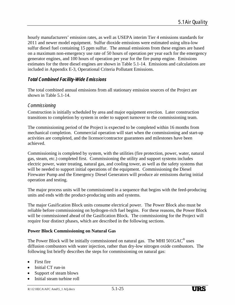
5.1 Air Quality
R:\12 HECA\AFC Amd\5_1 AQ.docx 5.1-25
hourly manufacturers’ emission rates, as well as USEPA interim Tier 4 emissions standards for 2011 and newer model equipment. Sulfur dioxide emissions were estimated using ultra-low sulfur diesel fuel containing 15 ppm sulfur. The annual emissions from these engines are based on a maximum non-emergency use rate of 50 hours of operation per year each for the emergency generator engines, and 100 hours of operation per year for the fire pump engine. Emissions estimates for the three diesel engines are shown in Table 5.1-14. Emissions and calculations are included in Appendix E-3, Operational Criteria Pollutant Emissions.
Total Combined Facility-Wide Emissions
The total combined annual emissions from all stationary emission sources of the Project are shown in Table 5.1-14.
Commissioning Construction is initially scheduled by area and major equipment erection. Later construction transitions to completion by system in order to support turnover to the commissioning team.
The commissioning period of the Project is expected to be completed within 16 months from mechanical completion. Commercial operation will start when the commissioning and start-up activities are completed, and the licensor/contractor guarantees and milestones have been achieved.
Commissioning is completed by system, with the utilities (fire protection, power, water, natural gas, steam, etc.) completed first. Commissioning the utility and support systems includes electric power, water treating, natural gas, and cooling tower, as well as the safety systems that will be needed to support initial operations of the equipment. Commissioning the Diesel Firewater Pump and the Emergency Diesel Generators will produce air emissions during initial operation and testing.
The major process units will be commissioned in a sequence that begins with the feed-producing units and ends with the product-producing units and systems.
The major Gasification Block units consume electrical power. The Power Block also must be reliable before commissioning on hydrogen-rich fuel begins. For these reasons, the Power Block will be commissioned ahead of the Gasification Block. The commissioning for the Project will require four distinct phases, which are described in the following sections.
Power Block Commissioning on Natural Gas
The Power Block will be initially commissioned on natural gas. The MHI 501GAC® uses diffusion combustors with water injection, rather than dry-low nitrogen oxide combustors. The following list briefly describes the steps for commissioning on natural gas:
First fire Initial CT run-in Support of steam blows Initial steam turbine roll
URS
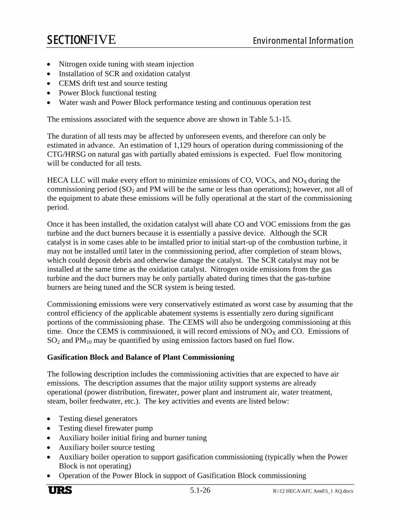
SECTIONFIVE Environmental Information
5.1-26 R:\12 HECA\AFC Amd\5_1 AQ.docx
Nitrogen oxide tuning with steam injection Installation of SCR and oxidation catalyst CEMS drift test and source testing Power Block functional testing Water wash and Power Block performance testing and continuous operation test
The emissions associated with the sequence above are shown in Table 5.1-15.
The duration of all tests may be affected by unforeseen events, and therefore can only be estimated in advance. An estimation of 1,129 hours of operation during commissioning of the CTG/HRSG on natural gas with partially abated emissions is expected. Fuel flow monitoring will be conducted for all tests.
HECA LLC will make every effort to minimize emissions of CO, VOCs, and NOX during the commissioning period (SO2 and PM will be the same or less than operations); however, not all of the equipment to abate these emissions will be fully operational at the start of the commissioning period.
Once it has been installed, the oxidation catalyst will abate CO and VOC emissions from the gas turbine and the duct burners because it is essentially a passive device. Although the SCR catalyst is in some cases able to be installed prior to initial start-up of the combustion turbine, it may not be installed until later in the commissioning period, after completion of steam blows, which could deposit debris and otherwise damage the catalyst. The SCR catalyst may not be installed at the same time as the oxidation catalyst. Nitrogen oxide emissions from the gas turbine and the duct burners may be only partially abated during times that the gas-turbine burners are being tuned and the SCR system is being tested.
Commissioning emissions were very conservatively estimated as worst case by assuming that the control efficiency of the applicable abatement systems is essentially zero during significant portions of the commissioning phase. The CEMS will also be undergoing commissioning at this time. Once the CEMS is commissioned, it will record emissions of NOX and CO. Emissions of SO2 and PM10 may be quantified by using emission factors based on fuel flow.
Gasification Block and Balance of Plant Commissioning
The following description includes the commissioning activities that are expected to have air emissions. The description assumes that the major utility support systems are already operational (power distribution, firewater, power plant and instrument air, water treatment, steam, boiler feedwater, etc.). The key activities and events are listed below:
Testing diesel generators Testing diesel firewater pump Auxiliary boiler initial firing and burner tuning Auxiliary boiler source testing Auxiliary boiler operation to support gasification commissioning (typically when the Power
Block is not operating) Operation of the Power Block in support of Gasification Block commissioning
URS
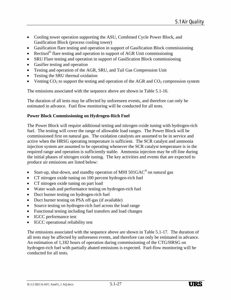
5.1 Air Quality
R:\12 HECA\AFC Amd\5_1 AQ.docx 5.1-27
Cooling tower operation supporting the ASU, Combined Cycle Power Block, and Gasification Block (process cooling tower)
Gasification flare testing and operation in support of Gasification Block commissioning Rectisol® flare testing and operation in support of AGR Unit commissioning SRU Flare testing and operation in support of Gasification Block commissioning Gasifier testing and operation Testing and operation of the AGR, SRU, and Tail Gas Compression Unit Testing the SRU thermal oxidation Venting CO2 to support the testing and operation of the AGR and CO2 compression system
The emissions associated with the sequence above are shown in Table 5.1-16.
The duration of all tests may be affected by unforeseen events, and therefore can only be estimated in advance. Fuel flow monitoring will be conducted for all tests.
Power Block Commissioning on Hydrogen-Rich Fuel
The Power Block will require additional testing and nitrogen oxide tuning with hydrogen-rich fuel. The testing will cover the range of allowable load ranges. The Power Block will be commissioned first on natural gas. The oxidation catalysts are assumed to be in service and active when the HRSG operating temperature is sufficient. The SCR catalyst and ammonia injection system are assumed to be operating whenever the SCR catalyst temperature is in the required range and operation is sufficiently stable. Ammonia injection may be off-line during the initial phases of nitrogen oxide tuning. The key activities and events that are expected to produce air emissions are listed below:
Start-up, shut-down, and standby operation of MHI 501GAC® on natural gas CT nitrogen oxide tuning on 100 percent hydrogen-rich fuel CT nitrogen oxide tuning on part load Water wash and performance testing on hydrogen-rich fuel Duct burner testing on hydrogen-rich fuel Duct burner testing on PSA off-gas (if available) Source testing on hydrogen-rich fuel across the load range Functional testing including fuel transfers and load changes IGCC performance test IGCC operational reliability test
The emissions associated with the sequence above are shown in Table 5.1-17. The duration of all tests may be affected by unforeseen events, and therefore can only be estimated in advance. An estimation of 1,182 hours of operation during commissioning of the CTG/HRSG on hydrogen-rich fuel with partially abated emissions is expected. Fuel-flow monitoring will be conducted for all tests.
URS
SECTIONFIVE Environmental Information
5.1-28 R:\12 HECA\AFC Amd\5_1 AQ.docx
Manufacturing Complex Commissioning
The Manufacturing Complex is comprised of several plants and support systems. High-purity hydrogen and high-purity nitrogen are feedstocks to the Ammonia Synthesis Unit, which produces anhydrous ammonia. Anhydrous ammonia and high-purity CO2 are feedstocks to the Urea Unit. The Urea Unit produces approximately 99 weight percent urea solution that feeds the Urea Pastillation Unit, as well as 80 weight percent urea solution that feeds the Urea Ammonium Nitrate (UAN) Unit. Anhydrous ammonia is the feedstock for the Nitric Acid Unit and the Ammonium Nitrate Unit. The 80 weight percent urea solution and ammonium nitrate solution are feedstocks to the UAN Unit. The key commissioning activities and events that are expected to produce air emissions through the use of fired heaters or flare systems are listed below:
PSA Units 1 and 2 including PSA off-gas compression (brief flaring of hydrogen and PSA off-gas)
High-purity hydrogen compression and nitrogen compression (brief flaring of hydrogen) Test HRSG PSA off-gas duct burner system (if not already completed) Test Ammonia Synthesis Unit (use of start-up heater, brief flaring during catalyst reduction,
and recycle compressor testing) Build ammonia storage inventory CO2 purification and purified CO2 compression (brief venting of CO2) Test Urea Unit (HP loop passivation and heating) Test Urea Pastillation Unit (functional testing including particulate control systems) Test Nitric Acid Unit (tail gas nitrous oxide abator) Test Ammonium Nitrate Unit (ammonium nitrate vent scrubber) Test Urea Ammonium Nitrate (UAN) Unit (neutralizer overhead cleanup scrubber) Manufacturing Complex performance testing IGCC and Manufacturing Complex functional dispatch testing Plant-wide performance test Plant-wide reliability demonstration
The emissions associated with the sequence above are shown in Table 5.1-18. The duration of all tests may be affected by unforeseen events, and therefore can only be estimated in advance. An estimation of 3,388 hours of operation during commissioning from the combination of all Manufacturing Complex sources is expected.
Operational Emissions—Mobile Sources
Mobile Source Emissions—On-Site
On-site truck and train trip emissions were incorporated in the dispersion modeling for CEQA purposes. Trucks and trains delivering feedstock and removing products would travel to the Project Site on a regular basis. The maximum number of truck and train trips by period is summarized in Table 5.1-19. This section describes the emissions from the transportation associated with coal transportation Alternative 1 (rail transportation).
URS
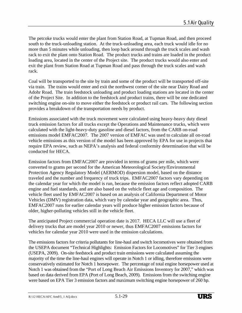
5.1 Air Quality
R:\12 HECA\AFC Amd\5_1 AQ.docx 5.1-29
The petcoke trucks would enter the plant from Station Road, at Tupman Road, and then proceed south to the truck-unloading station. At the truck-unloading area, each truck would idle for no more than 5 minutes while unloading, then loop back around through the truck scales and wash rack to exit the plant onto Station Road. The product trucks and trains are loaded in the product loading area, located in the center of the Project site. The product trucks would also enter and exit the plant from Station Road at Tupman Road and pass through the truck scales and wash rack.
Coal will be transported to the site by train and some of the product will be transported off-site via train. The trains would enter and exit the northwest corner of the site near Dairy Road and Adohr Road. The train feedstock unloading and product loading stations are located in the center of the Project Site. In addition to the feedstock and product trains, there will be one dedicated switching engine on-site to move either the feedstock or product rail cars. The following section provides a breakdown of the transportation needs by product.
Emissions associated with the truck movement were calculated using heavy-heavy duty diesel truck emission factors for all trucks except the Operations and Maintenance trucks, which were calculated with the light-heavy-duty gasoline and diesel factors, from the CARB on-road emissions model EMFAC2007. The 2007 version of EMFAC was used to calculate all on-road vehicle emissions as this version of the model has been approved by EPA for use in projects that require EPA review, such as NEPA’s analysis and federal conformity determination that will be conducted for HECA.
Emission factors from EMFAC2007 are provided in terms of grams per mile, which were converted to grams per second for the American Meteorological Society/Environmental Protection Agency Regulatory Model (AERMOD) dispersion model, based on the distance traveled and the number and frequency of truck trips. EMFAC2007 factors vary depending on the calendar year for which the model is run, because the emission factors reflect adopted CARB engine and fuel standards, and are also based on the vehicle fleet age and composition. The vehicle fleet used by EMFAC2007 is based on an analysis of California Department of Motor Vehicles (DMV) registration data, which vary by calendar year and geographic area. Thus, EMFAC2007 runs for earlier calendar years will produce higher emission factors because of older, higher-polluting vehicles still in the vehicle fleet.
The anticipated Project commercial operation date is 2017. HECA LLC will use a fleet of delivery trucks that are model year 2010 or newer, thus EMFAC2007 emissions factors for vehicles for calendar year 2010 were used in the emission calculations.
The emissions factors for criteria pollutants for line-haul and switch locomotives were obtained from the USEPA document “Technical Highlights: Emission Factors for Locomotives” for Tier 3 engines (USEPA, 2009). On-site feedstock and product train emissions were calculated assuming the majority of the time the line-haul engines will operate in Notch 1 or idling, therefore emissions were conservatively estimated for Notch 1 horsepower. The percentage of total engine horsepower used at Notch 1 was obtained from the “Port of Long Beach Air Emissions Inventory for 2007,” which was based on data derived from EPA (Port of Long Beach, 2009). Emissions from the switching engine were based on EPA Tier 3 emission factors and maximum switching engine horsepower of 260 hp.
URS
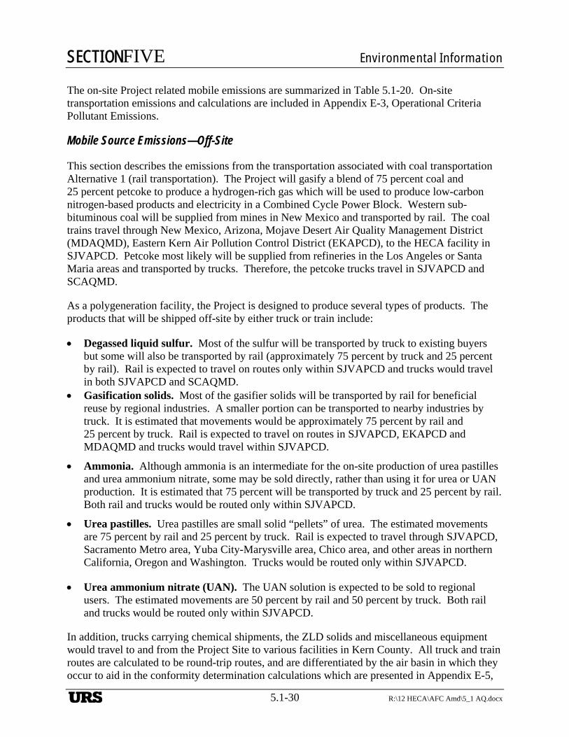
SECTIONFIVE Environmental Information
5.1-30 R:\12 HECA\AFC Amd\5_1 AQ.docx
The on-site Project related mobile emissions are summarized in Table 5.1-20. On-site transportation emissions and calculations are included in Appendix E-3, Operational Criteria Pollutant Emissions.
Mobile Source Emissions—Off-Site
This section describes the emissions from the transportation associated with coal transportation Alternative 1 (rail transportation). The Project will gasify a blend of 75 percent coal and 25 percent petcoke to produce a hydrogen-rich gas which will be used to produce low-carbon nitrogen-based products and electricity in a Combined Cycle Power Block. Western sub-bituminous coal will be supplied from mines in New Mexico and transported by rail. The coal trains travel through New Mexico, Arizona, Mojave Desert Air Quality Management District (MDAQMD), Eastern Kern Air Pollution Control District (EKAPCD), to the HECA facility in SJVAPCD. Petcoke most likely will be supplied from refineries in the Los Angeles or Santa Maria areas and transported by trucks. Therefore, the petcoke trucks travel in SJVAPCD and SCAQMD.
As a polygeneration facility, the Project is designed to produce several types of products. The products that will be shipped off-site by either truck or train include:
Degassed liquid sulfur. Most of the sulfur will be transported by truck to existing buyers but some will also be transported by rail (approximately 75 percent by truck and 25 percent by rail). Rail is expected to travel on routes only within SJVAPCD and trucks would travel in both SJVAPCD and SCAQMD.
Gasification solids. Most of the gasifier solids will be transported by rail for beneficial reuse by regional industries. A smaller portion can be transported to nearby industries by truck. It is estimated that movements would be approximately 75 percent by rail and 25 percent by truck. Rail is expected to travel on routes in SJVAPCD, EKAPCD and MDAQMD and trucks would travel within SJVAPCD.
Ammonia. Although ammonia is an intermediate for the on-site production of urea pastilles and urea ammonium nitrate, some may be sold directly, rather than using it for urea or UAN production. It is estimated that 75 percent will be transported by truck and 25 percent by rail. Both rail and trucks would be routed only within SJVAPCD.
Urea pastilles. Urea pastilles are small solid “pellets” of urea. The estimated movements are 75 percent by rail and 25 percent by truck. Rail is expected to travel through SJVAPCD, Sacramento Metro area, Yuba City-Marysville area, Chico area, and other areas in northern California, Oregon and Washington. Trucks would be routed only within SJVAPCD.
Urea ammonium nitrate (UAN). The UAN solution is expected to be sold to regional users. The estimated movements are 50 percent by rail and 50 percent by truck. Both rail and trucks would be routed only within SJVAPCD.
In addition, trucks carrying chemical shipments, the ZLD solids and miscellaneous equipment would travel to and from the Project Site to various facilities in Kern County. All truck and train routes are calculated to be round-trip routes, and are differentiated by the air basin in which they occur to aid in the conformity determination calculations which are presented in Appendix E-5,
URS
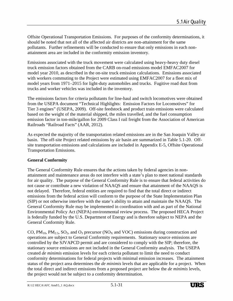
5.1 Air Quality
R:\12 HECA\AFC Amd\5_1 AQ.docx 5.1-31
Offsite Operational Transportation Emissions. For purposes of the conformity determinations, it should be noted that not all of the affected air districts are non-attainment for the same pollutants. Further refinements will be conducted to ensure that only emissions in each non-attainment area are included in the conformity emission inventory.
Emissions associated with the truck movement were calculated using heavy-heavy duty diesel truck emission factors obtained from the CARB on-road emissions model EMFAC2007 for model year 2010, as described in the on-site truck emission calculations. Emissions associated with workers commuting to the Project were estimated using EMFAC2007 for a fleet mix of model years from 1971–2015 for light-duty automobiles and trucks. Fugitive road dust from trucks and worker vehicles was included in the inventory.
The emissions factors for criteria pollutants for line-haul and switch locomotives were obtained from the USEPA document “Technical Highlights: Emission Factors for Locomotives” for Tier 3 engines” (USEPA, 2009). Off-site feedstock and product train emissions were calculated based on the weight of the material shipped, the miles travelled, and the fuel consumption emission factor in ton-mile/gallon for 2009 Class I rail freight from the Association of American Railroads “Railroad Facts” (AAR, 2012).
As expected the majority of the transportation related emissions are in the San Joaquin Valley air basin. The off-site Project related emissions by air basin are summarized in Table 5.1-20. Off-site transportation emissions and calculations are included in Appendix E-5, Offsite Operational Transportation Emissions.
General Conformity
The General Conformity Rule ensures that the actions taken by federal agencies in non-attainment and maintenance areas do not interfere with a state’s plan to meet national standards for air quality. The purpose of the General Conformity Rule is to ensure that federal activities do not cause or contribute a new violation of NAAQS and ensure that attainment of the NAAQS is not delayed. Therefore, federal entities are required to find that the total direct or indirect emissions from the federal action will conform to the purpose of the State Implementation Plan (SIP) or not otherwise interfere with the state’s ability to attain and maintain the NAAQS. The General Conformity Rule may be implemented in coordination with and as part of the National Environmental Policy Act (NEPA) environmental review process. The proposed HECA Project is federally funded by the U.S. Department of Energy and is therefore subject to NEPA and the General Conformity Rule.
CO, PM10, PM2.5, SO2, and O3 precursor (NOX and VOC) emissions during construction and operations are subject to General Conformity requirements. Stationary source emissions are controlled by the SJVAPCD permit and are considered to comply with the SIP; therefore, the stationary source emissions are not included in the General Conformity analysis. The USEPA created de minimis emission levels for each criteria pollutant to limit the need to conduct conformity determinations for federal projects with minimal emission increases. The attainment status of the project area determines the de minimis levels that are applicable for a project. When the total direct and indirect emissions from a proposed project are below the de minimis levels, the project would not be subject to a conformity determination.
URS
SECTIONFIVE Environmental Information
5.1-32 R:\12 HECA\AFC Amd\5_1 AQ.docx
Applicability is based on direct and indirect emissions from the proposed HECA Project, which include off-site truck and rail transportation, on-site truck and rail transportation, and the commuting of worker vehicles. As noted in the Mobile Source Emissions – Off-site section, the Project related vehicles travel through many air quality control regions (AQCR) in California (SJVAPCD, SCAQMD, EKAPCD, MDAQMD, Sacramento Metro area, Yuba City-Marysville area, Chico area), Oregon, Washington, Arizona, and New Mexico. A list of these AQCR, their attainment status and the associated conformity thresholds is provided in Table 5.1-20 and Appendix E-5, Offsite Operational Transportation Emissions.
Emissions allocated to each AQCR were calculated along the transportation routes according to the length of the route and are shown in Table 5.1-20 and Appendix E-5, Offsite Operational Transportation Emissions. It should be noted that not each of the affected air districts is non-attainment for the same non-attainment pollutants. Further refinements will be conducted to ensure only emissions in each non-attainment area are included in the conformity emission inventory. The estimated annual emission rates in each AQCR were compared to the applicability de minimis thresholds. The estimated emission increase due to transportation in most areas, except the NOX emission increase in SJVAPCD, is less than the conformity de minimis levels. The NOX emission increase due to the proposed Project operation associated with transportation in SJVAPCD is greater than the de minimis level of 10 tons per year (TPY). In addition, NOX and VOC emissions during Project construction exceed the de minimis level of 10 TPY. Therefore, a conformity determination will be prepared by HECA LLC and reviewed by SJVAPCD for NOX and VOC as precursors to ozone.
Operational Criteria Pollutant Emissions associated with OEHI EOR
Permitted emissions associated with the OEHI Project include emissions from new equipment installed for the purpose of CO2 EOR and will include process heaters, tanks, fugitive ROG emissions from permitted equipment at the CO2 EOR Processing Facility, and emissions from maintenance activities conducted on emergency use only equipment (i.e., diesel engines used for fire pumps). Diesel emergency engine testing is expected to occur 12 hours per year per engine. The emergency use only flares do not include maintenance allowance since the flares have to be removed from service in order to conduct such maintenance. Mobile source emissions are limited to on-road vehicle emissions from operational phase employees transiting between area residences and the OEHI Project Site.
OEHI will implement mitigation in the form of BACT and LDAR, plus emissions reduction credits (ERCs) will be provided, as required, to offset emission increases from permitted sources ensuring that impacts from emissions are less than significant. Emission calculations and Project details can be found in the Section 4.3, Air Quality, of Appendix A of this AFC Amendment. The analysis contained in Appendix A-1 concludes that emissions from the operation of the OEHI Project will not result in a significant adverse impact.
5.1.2.4 Operational Greenhouse Gas Emissions
Operational Greenhouse Gas Emissions—Stationary Sources
The GHG emissions presented in this section reflect the following key Project objectives:
URS
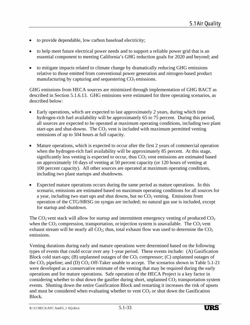
5.1 Air Quality
R:\12 HECA\AFC Amd\5_1 AQ.docx 5.1-33
to provide dependable, low carbon baseload electricity;
to help meet future electrical power needs and to support a reliable power grid that is an essential component to meeting California’s GHG reduction goals for 2020 and beyond; and
to mitigate impacts related to climate change by dramatically reducing GHG emissions relative to those emitted from conventional power generation and nitrogen-based product manufacturing by capturing and sequestering CO2 emissions.
GHG emissions from HECA sources are minimized through implementation of GHG BACT as described in Section 5.1.6.13. GHG emissions were estimated for three operating scenarios, as described below:
Early operations, which are expected to last approximately 2 years, during which time hydrogen-rich fuel availability will be approximately 65 to 75 percent. During this period, all sources are expected to be operated at maximum operating conditions, including two plant start-ups and shut-downs. The CO2 vent is included with maximum permitted venting emissions of up to 504 hours at full capacity.
Mature operations, which is expected to occur after the first 2 years of commercial operation when the hydrogen-rich fuel availability will be approximately 85 percent. At this stage, significantly less venting is expected to occur, thus CO2 vent emissions are estimated based on approximately 10 days of venting at 50 percent capacity (or 120 hours of venting at 100 percent capacity). All other sources are operated at maximum operating conditions, including two plant startups and shutdowns.
Expected mature operations occurs during the same period as mature operations. In this scenario, emissions are estimated based on maximum operating conditions for all sources for a year, including two start ups and shut downs, but no CO2 venting. Emissions from operation of the CTG/HRSG on syngas are included; no natural gas use is included, except for startup and shutdown.
The CO2 vent stack will allow for startup and intermittent emergency venting of produced CO2 when the CO2 compression, transportation, or injection system is unavailable. The CO2 vent exhaust stream will be nearly all CO2; thus, total exhaust flow was used to determine the CO2 emissions.
Venting durations during early and mature operations were determined based on the following types of events that could occur over any 1-year period. These events include: (A) Gasification Block cold start-ups; (B) unplanned outages of the CO2 compressor; (C) unplanned outages of the CO2 pipeline; and (D) CO2 Off-Taker unable to accept. The scenarios shown in Table 5.1-21 were developed as a conservative estimate of the venting that may be required during the early operations and for mature operations. Safe operation of the HECA Project is a key factor in considering whether to shut down the gasifier during short, unplanned CO2 transportation system events. Shutting down the entire Gasification Block and restarting it increases the risk of upsets and must be considered when evaluating whether to vent CO2 or shut down the Gasification Block.
URS
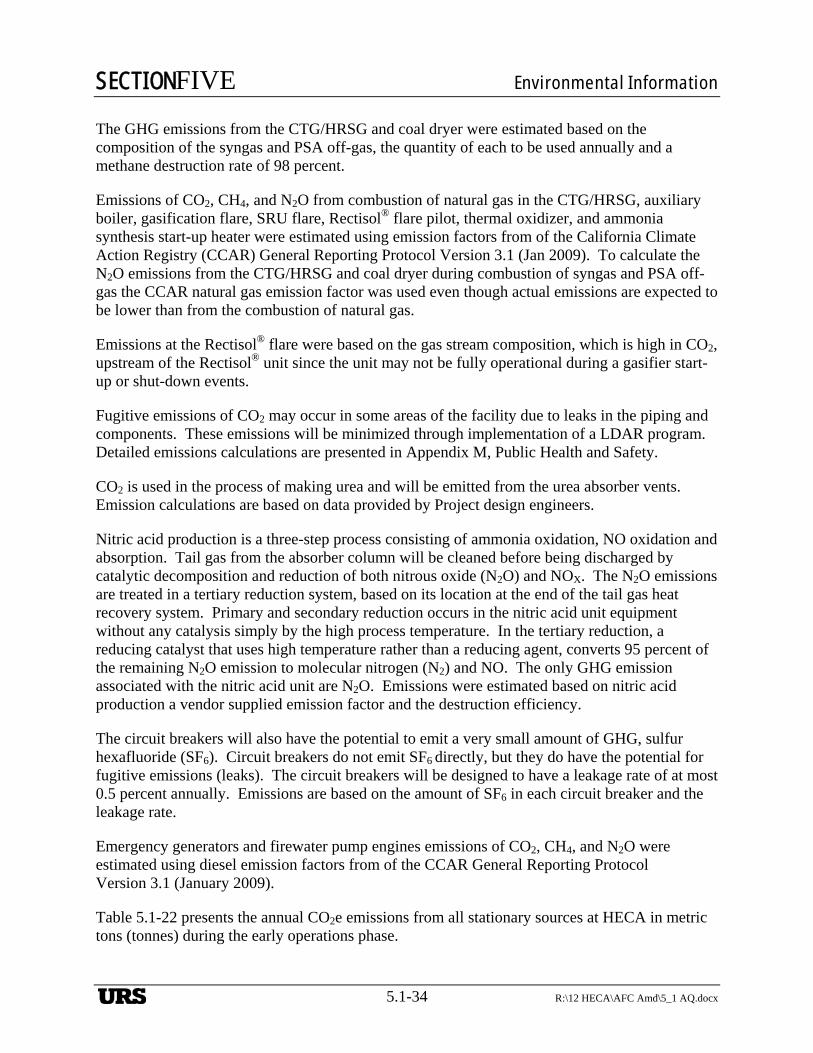
SECTIONFIVE Environmental Information
5.1-34 R:\12 HECA\AFC Amd\5_1 AQ.docx
The GHG emissions from the CTG/HRSG and coal dryer were estimated based on the composition of the syngas and PSA off-gas, the quantity of each to be used annually and a methane destruction rate of 98 percent.
Emissions of CO2, CH4, and N2O from combustion of natural gas in the CTG/HRSG, auxiliary boiler, gasification flare, SRU flare, Rectisol® flare pilot, thermal oxidizer, and ammonia synthesis start-up heater were estimated using emission factors from of the California Climate Action Registry (CCAR) General Reporting Protocol Version 3.1 (Jan 2009). To calculate the N2O emissions from the CTG/HRSG and coal dryer during combustion of syngas and PSA off-gas the CCAR natural gas emission factor was used even though actual emissions are expected to be lower than from the combustion of natural gas.
Emissions at the Rectisol® flare were based on the gas stream composition, which is high in CO2, upstream of the Rectisol® unit since the unit may not be fully operational during a gasifier start-up or shut-down events.
Fugitive emissions of CO2 may occur in some areas of the facility due to leaks in the piping and components. These emissions will be minimized through implementation of a LDAR program. Detailed emissions calculations are presented in Appendix M, Public Health and Safety.
CO2 is used in the process of making urea and will be emitted from the urea absorber vents. Emission calculations are based on data provided by Project design engineers.
Nitric acid production is a three-step process consisting of ammonia oxidation, NO oxidation and absorption. Tail gas from the absorber column will be cleaned before being discharged by catalytic decomposition and reduction of both nitrous oxide (N2O) and NOX. The N2O emissions are treated in a tertiary reduction system, based on its location at the end of the tail gas heat recovery system. Primary and secondary reduction occurs in the nitric acid unit equipment without any catalysis simply by the high process temperature. In the tertiary reduction, a reducing catalyst that uses high temperature rather than a reducing agent, converts 95 percent of the remaining N2O emission to molecular nitrogen (N2) and NO. The only GHG emission associated with the nitric acid unit are N2O. Emissions were estimated based on nitric acid production a vendor supplied emission factor and the destruction efficiency.
The circuit breakers will also have the potential to emit a very small amount of GHG, sulfur hexafluoride (SF6). Circuit breakers do not emit SF6 directly, but they do have the potential for fugitive emissions (leaks). The circuit breakers will be designed to have a leakage rate of at most 0.5 percent annually. Emissions are based on the amount of SF6 in each circuit breaker and the leakage rate.
Emergency generators and firewater pump engines emissions of CO2, CH4, and N2O were estimated using diesel emission factors from of the CCAR General Reporting Protocol Version 3.1 (January 2009).
Table 5.1-22 presents the annual CO2e emissions from all stationary sources at HECA in metric tons (tonnes) during the early operations phase.
URS
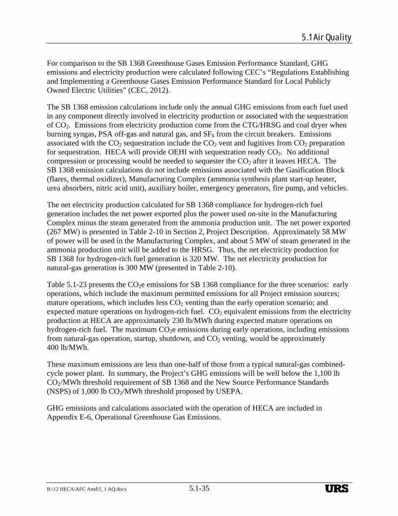
5.1 Air Quality
R:\12 HECA\AFC Amd\5_1 AQ.docx 5.1-35
For comparison to the SB 1368 Greenhouse Gases Emission Performance Standard, GHG emissions and electricity production were calculated following CEC’s “Regulations Establishing and Implementing a Greenhouse Gases Emission Performance Standard for Local Publicly Owned Electric Utilities” (CEC, 2012).
The SB 1368 emission calculations include only the annual GHG emissions from each fuel used in any component directly involved in electricity production or associated with the sequestration of CO2. Emissions from electricity production come from the CTG/HRSG and coal dryer when burning syngas, PSA off-gas and natural gas, and SF6 from the circuit breakers. Emissions associated with the CO2 sequestration include the CO2 vent and fugitives from CO2 preparation for sequestration. HECA will provide OEHI with sequestration ready CO2. No additional compression or processing would be needed to sequester the CO2 after it leaves HECA. The SB 1368 emission calculations do not include emissions associated with the Gasification Block (flares, thermal oxidizer), Manufacturing Complex (ammonia synthesis plant start-up heater, urea absorbers, nitric acid unit), auxiliary boiler, emergency generators, fire pump, and vehicles.
The net electricity production calculated for SB 1368 compliance for hydrogen-rich fuel generation includes the net power exported plus the power used on-site in the Manufacturing Complex minus the steam generated from the ammonia production unit. The net power exported (267 MW) is presented in Table 2-10 in Section 2, Project Description. Approximately 58 MW of power will be used in the Manufacturing Complex, and about 5 MW of steam generated in the ammonia production unit will be added to the HRSG. Thus, the net electricity production for SB 1368 for hydrogen-rich fuel generation is 320 MW. The net electricity production for natural-gas generation is 300 MW (presented in Table 2-10).
Table 5.1-23 presents the CO2e emissions for SB 1368 compliance for the three scenarios: early operations, which include the maximum permitted emissions for all Project emission sources; mature operations, which includes less CO2 venting than the early operation scenario; and expected mature operations on hydrogen-rich fuel. CO2 equivalent emissions from the electricity production at HECA are approximately 230 lb/MWh during expected mature operations on hydrogen-rich fuel. The maximum CO2e emissions during early operations, including emissions from natural-gas operation, startup, shutdown, and CO2 venting, would be approximately 400 lb/MWh.
These maximum emissions are less than one-half of those from a typical natural-gas combined-cycle power plant. In summary, the Project’s GHG emissions will be well below the 1,100 lb CO2/MWh threshold requirement of SB 1368 and the New Source Performance Standards (NSPS) of 1,000 lb CO2/MWh threshold proposed by USEPA.
GHG emissions and calculations associated with the operation of HECA are included in Appendix E-6, Operational Greenhouse Gas Emissions.
URS
SECTIONFIVE Environmental Information
5.1-36 R:\12 HECA\AFC Amd\5_1 AQ.docx
Operational Greenhouse Gas Emissions—Mobile Sources
Mobile Source Emissions—On-Site
This section describes the emissions from the transportation associated with coal transportation Alternative 1 (rail transportation). On-site vehicle GHG emissions are based on the same data as the criteria pollutants emissions described earlier. The emission factors for CO2 from EMFAC2007 were used for the on-road vehicles. The emission factors for N2O and CH4 are based on Table C.4 in the California Climate Action Registry (CCAR) General Reporting Protocol Version 3.1 (January 2009) for diesel and gasoline fueled trucks.
The CO2 emission factors for switching and line-haul locomotives for Tier 3 emissions were used (40 CFR Part 1033, EPA Switch and Line-haul Locomotive Emission Standards). CH4 and N2O factors are from California Climate Action Registry General Reporting Protocol Version 3.1 (January 2009), Table C.6 (Methane and Nitrous Oxide Emission Factors for Non-Highway Vehicles) were used for locomotives.
On-site transportation GHG emissions are presented in Table 5.1-24 and calculation details are included in Appendix E-6, Operational Greenhouse Gas Emissions.
Mobile Source Emissions—Off-Site
This section describes the emissions from the transportation associated with coal transportation Alternative 1 (rail transportation). Off-site vehicle GHG emissions are based on the same data as the criteria pollutants emissions described earlier. The emission factors for CO2 from EMFAC2007 were used for the on-road vehicles. The emission factors for N2O and CH4 are based on Table C.4 in the California Climate Action Registry (CCAR) General Reporting Protocol Version 3.1 (January 2009) for diesel and gasoline fueled trucks.
The CO2 emission factors for switching and line-haul locomotives for Tier 3 emissions were used (40 CFR Part 1033, EPA Switch and Line-haul Locomotive Emission Standards). CH4 and N2O factors are from California Climate Action Registry General Reporting Protocol Version 3.1 (January 2009), Table C.6 (Methane and Nitrous Oxide Emission Factors for Non-Highway Vehicles) were used for locomotives.
Off-site transportation GHG emissions are presented in Table 5.1-24 and calculation details are included in Appendix E-6, Operational Greenhouse Gas Emissions.
Operational GHG Emissions Associated with OEHI EOR
During the operational phase of the OEHI Project there will be various stationary, mobile, and indirect sources. Indirect sources refer to emissions of CO2e produced as a result of generating electrical power consumed by the Project. Of the total estimated operational CO2e emissions, approximately 79 percent would be from indirect sources (e.g., consumption of electric power not generated as part of the OEHI Project). Emission calculations and Project details can be found in Section 4.18, Greenhouse Gas Emissions of Appendix A-1 of this AFC Amendment,
URS
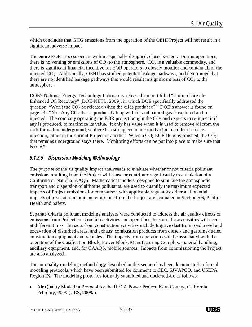
5.1 Air Quality
R:\12 HECA\AFC Amd\5_1 AQ.docx 5.1-37
which concludes that GHG emissions from the operation of the OEHI Project will not result in a significant adverse impact.
The entire EOR process occurs within a specially-designed, closed system. During operations, there is no venting or emissions of CO2 to the atmosphere. CO2 is a valuable commodity, and there is significant financial incentive for EOR operators to closely monitor and contain all of the injected CO2. Additionally, OEHI has studied potential leakage pathways, and determined that there are no identified leakage pathways that would result in significant loss of CO2 to the atmosphere.
DOE's National Energy Technology Laboratory released a report titled “Carbon Dioxide Enhanced Oil Recovery” (DOE-NETL, 2009), in which DOE specifically addressed the question, “Won't the CO2 be released when the oil is produced?” DOE’s answer is found on page 23: “No. Any CO2 that is produced along with oil and natural gas is captured and re-injected. The company operating the EOR project bought the CO2 and expects to re-inject it if any is produced, to maximize its value. It only has value when it is used to remove oil from the rock formation underground, so there is a strong economic motivation to collect it for re-injection, either in the current Project or another. When a CO2 EOR flood is finished, the CO2 that remains underground stays there. Monitoring efforts can be put into place to make sure that is true.”
5.1.2.5 Dispersion Modeling Methodology
The purpose of the air quality impact analyses is to evaluate whether or not criteria pollutant emissions resulting from the Project will cause or contribute significantly to a violation of a California or National AAQS. Mathematical models, designed to simulate the atmospheric transport and dispersion of airborne pollutants, are used to quantify the maximum expected impacts of Project emissions for comparison with applicable regulatory criteria. Potential impacts of toxic air contaminant emissions from the Project are evaluated in Section 5.6, Public Health and Safety.
Separate criteria pollutant modeling analyses were conducted to address the air quality effects of emissions from Project construction activities and operations, because these activities will occur at different times. Impacts from construction activities include fugitive dust from road travel and excavation of disturbed areas, and exhaust combustion products from diesel- and gasoline-fueled construction equipment and vehicles. The impacts from operations will be associated with the operation of the Gasification Block, Power Block, Manufacturing Complex, material handling, ancillary equipment, and, for CAAQS, mobile sources. Impacts from commissioning the Project are also analyzed.
The air quality modeling methodology described in this section has been documented in formal modeling protocols, which have been submitted for comment to CEC, SJVAPCD, and USEPA Region IX. The modeling protocols formally submitted and docketed are as follows:
Air Quality Modeling Protocol for the HECA Power Project, Kern County, California, February, 2009 (URS, 2009a)
URS
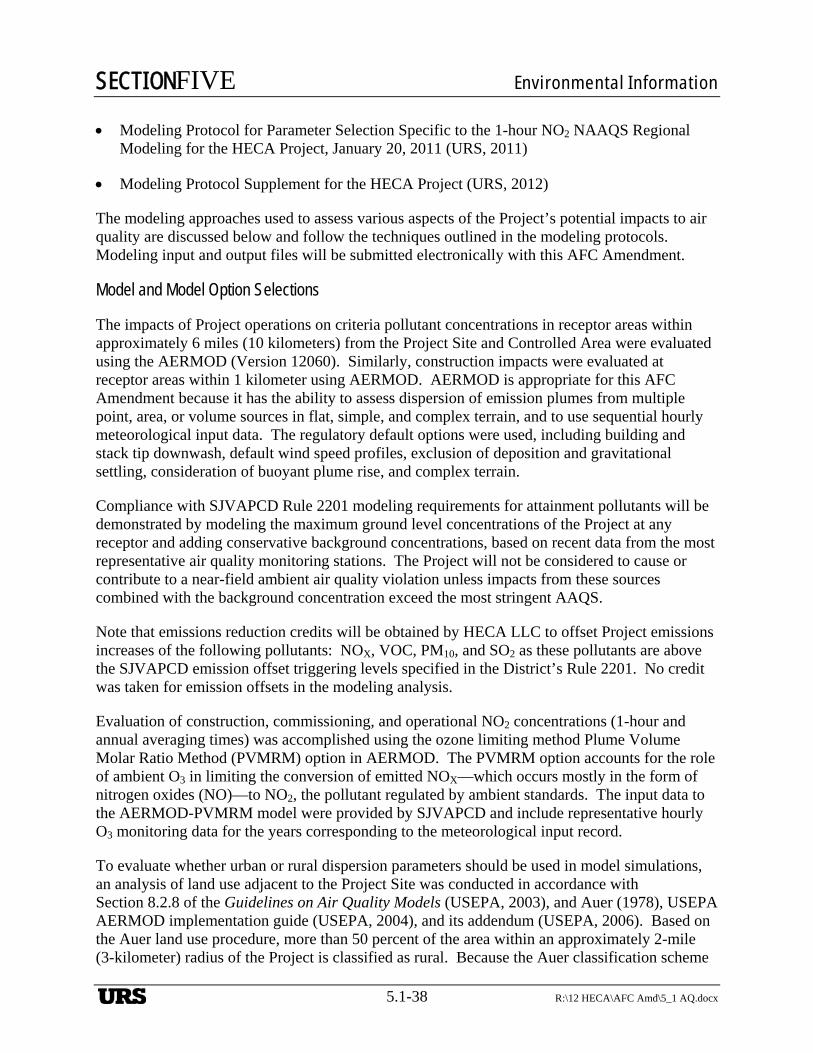
SECTIONFIVE Environmental Information
5.1-38 R:\12 HECA\AFC Amd\5_1 AQ.docx
Modeling Protocol for Parameter Selection Specific to the 1-hour NO2 NAAQS Regional Modeling for the HECA Project, January 20, 2011 (URS, 2011)
Modeling Protocol Supplement for the HECA Project (URS, 2012)
The modeling approaches used to assess various aspects of the Project’s potential impacts to air quality are discussed below and follow the techniques outlined in the modeling protocols. Modeling input and output files will be submitted electronically with this AFC Amendment.
Model and Model Option Selections
The impacts of Project operations on criteria pollutant concentrations in receptor areas within approximately 6 miles (10 kilometers) from the Project Site and Controlled Area were evaluated using the AERMOD (Version 12060). Similarly, construction impacts were evaluated at receptor areas within 1 kilometer using AERMOD. AERMOD is appropriate for this AFC Amendment because it has the ability to assess dispersion of emission plumes from multiple point, area, or volume sources in flat, simple, and complex terrain, and to use sequential hourly meteorological input data. The regulatory default options were used, including building and stack tip downwash, default wind speed profiles, exclusion of deposition and gravitational settling, consideration of buoyant plume rise, and complex terrain.
Compliance with SJVAPCD Rule 2201 modeling requirements for attainment pollutants will be demonstrated by modeling the maximum ground level concentrations of the Project at any receptor and adding conservative background concentrations, based on recent data from the most representative air quality monitoring stations. The Project will not be considered to cause or contribute to a near-field ambient air quality violation unless impacts from these sources combined with the background concentration exceed the most stringent AAQS.
Note that emissions reduction credits will be obtained by HECA LLC to offset Project emissions increases of the following pollutants: NOX, VOC, PM10, and SO2 as these pollutants are above the SJVAPCD emission offset triggering levels specified in the District’s Rule 2201. No credit was taken for emission offsets in the modeling analysis.
Evaluation of construction, commissioning, and operational NO2 concentrations (1-hour and annual averaging times) was accomplished using the ozone limiting method Plume Volume Molar Ratio Method (PVMRM) option in AERMOD. The PVMRM option accounts for the role of ambient O3 in limiting the conversion of emitted NOX—which occurs mostly in the form of nitrogen oxides (NO)—to NO2, the pollutant regulated by ambient standards. The input data to the AERMOD-PVMRM model were provided by SJVAPCD and include representative hourly O3 monitoring data for the years corresponding to the meteorological input record.
To evaluate whether urban or rural dispersion parameters should be used in model simulations, an analysis of land use adjacent to the Project Site was conducted in accordance with Section 8.2.8 of the Guidelines on Air Quality Models (USEPA, 2003), and Auer (1978), USEPA AERMOD implementation guide (USEPA, 2004), and its addendum (USEPA, 2006). Based on the Auer land use procedure, more than 50 percent of the area within an approximately 2-mile (3-kilometer) radius of the Project is classified as rural. Because the Auer classification scheme
URS
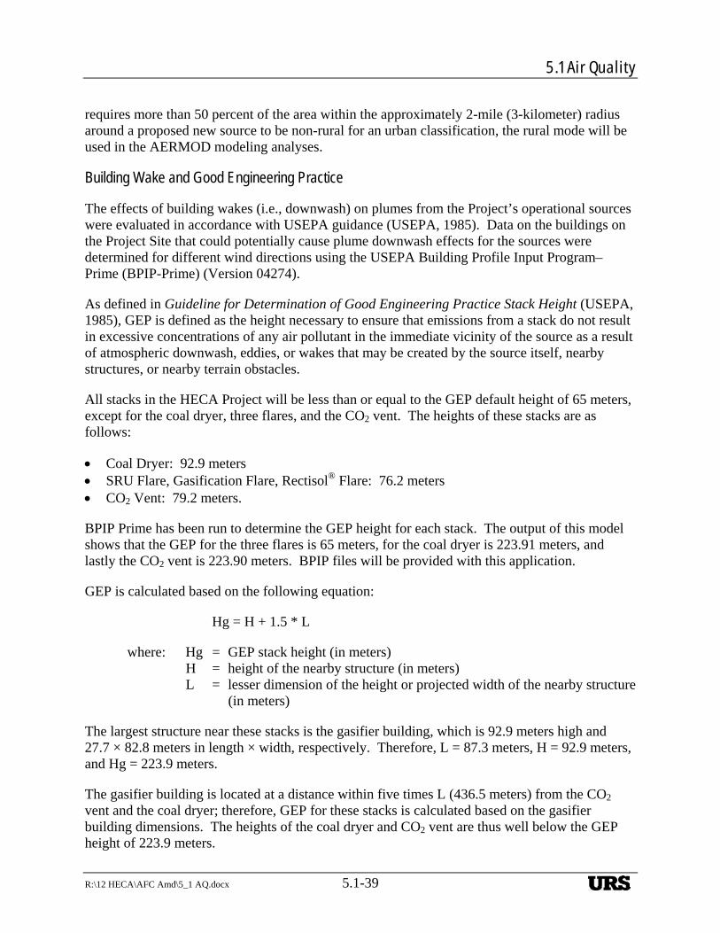
5.1 Air Quality
R:\12 HECA\AFC Amd\5_1 AQ.docx 5.1-39
requires more than 50 percent of the area within the approximately 2-mile (3-kilometer) radius around a proposed new source to be non-rural for an urban classification, the rural mode will be used in the AERMOD modeling analyses.
Building Wake and Good Engineering Practice
The effects of building wakes (i.e., downwash) on plumes from the Project’s operational sources were evaluated in accordance with USEPA guidance (USEPA, 1985). Data on the buildings on the Project Site that could potentially cause plume downwash effects for the sources were determined for different wind directions using the USEPA Building Profile Input Program–Prime (BPIP-Prime) (Version 04274).
As defined in Guideline for Determination of Good Engineering Practice Stack Height (USEPA, 1985), GEP is defined as the height necessary to ensure that emissions from a stack do not result in excessive concentrations of any air pollutant in the immediate vicinity of the source as a result of atmospheric downwash, eddies, or wakes that may be created by the source itself, nearby structures, or nearby terrain obstacles.
All stacks in the HECA Project will be less than or equal to the GEP default height of 65 meters, except for the coal dryer, three flares, and the CO2 vent. The heights of these stacks are as follows:
Coal Dryer: 92.9 meters SRU Flare, Gasification Flare, Rectisol® Flare: 76.2 meters CO2 Vent: 79.2 meters.
BPIP Prime has been run to determine the GEP height for each stack. The output of this model shows that the GEP for the three flares is 65 meters, for the coal dryer is 223.91 meters, and lastly the CO2 vent is 223.90 meters. BPIP files will be provided with this application.
GEP is calculated based on the following equation:
Hg = H + 1.5 * L
where: Hg = GEP stack height (in meters) H = height of the nearby structure (in meters) L = lesser dimension of the height or projected width of the nearby structure
(in meters)
The largest structure near these stacks is the gasifier building, which is 92.9 meters high and 27.7 × 82.8 meters in length × width, respectively. Therefore, L = 87.3 meters, H = 92.9 meters, and Hg = 223.9 meters.
The gasifier building is located at a distance within five times L (436.5 meters) from the CO2 vent and the coal dryer; therefore, GEP for these stacks is calculated based on the gasifier building dimensions. The heights of the coal dryer and CO2 vent are thus well below the GEP height of 223.9 meters.
URS
SECTIONFIVE Environmental Information
5.1-40 R:\12 HECA\AFC Amd\5_1 AQ.docx
The flares are located upwind of the gasification building along its shorter axis, thus L = 27.7 meters and Hg = 134.5 meters. The flares are not within 5 times L (138.5 meters) of the gasification structure or any other structure that is large enough to create downwash for the flares in BPIP Prime. It is important to note that the flares will be built at 76.2 meters tall for safety from a project engineering perspective. However, a 65-meter stack height, or GEP, was used to calculate specific effective stack heights for each flare modeling scenario based on the flare’s heat release rate during that modeling scenario. The effective stack height is the height of the stack plus the height above the stack where the flare flame ends and a plume can begin. The effective stack parameters were calculated using the SCREEN3 technique, and were input into the AERMOD model (USEPA, 1995b). Therefore, the lower 65 meter stack height was used as the stack height in the calculation of the effective stack heights for the flares, rather than the actual stack height. Appendix E-3, Operational Criteria Pollutant Emissions, presents the effective stack parameters for the flares.
The results of the BPIP-Prime analysis were included in the AERMOD input files to enable downwash effects to be simulated. Input and output files for the BPIP-Prime analyses are included in the electronic files submitted with this AFC Amendment.
Meteorological Data
Meteorological data suitable for direct input to AERMOD were obtained from the SJVAPCD website. Hourly surface data for calendar years 2006 through 2010 were obtained from the SJVAPCD at the Bakersfield Airport meteorological station, located on the northern end of the city of Bakersfield, within 20 miles (32.2 kilometers) east-northeast of the Project Site. These data have been pre-processed by the SJVAPCD with the Oakland upper-air data to create an input data set specifically tailored for input to AERMOD. The SJVAPCD prepared these data specifically for use at locations such as the Project Site.
The meteorological data recorded at Bakersfield Airport are acceptable for use at the Project Site for two reasons: proximity and terrain similarity. The Bakersfield Airport is the closest full-time meteorological recording station to the Project Site. The terrain immediately surrounding the Project Site can be categorized as a fairly flat, or gradually sloping rural area in a region with developed oil wells. The terrain around the Bakersfield Airport also consists of relatively flat, or gradually sloping rural or suburban areas. Thus, the land use and the location with respect to near-field terrain features are similar. Both are located in areas of medium surface roughness (as opposed to low surface roughness like bodies of water or grassy prairies, or high surface roughness like highly urbanized cities or forests). Both locations are on the valley floor and are at approximately the same elevation. Additionally, there are no significant terrain features separating the Bakersfield Airport from the Project Site that would cause significant differences in wind or temperature conditions between these respective areas. Therefore, the 5 years of meteorological data selected from the Bakersfield Airport were determined to be representative for the purposes of evaluating the Project’s air quality impacts.
Seasonal and annual wind roses based on the 5 years of Bakersfield Airport surface meteorological data are provided in Appendix E-1, Seasonal and Annual Wind Roses. Winds for all seasons and all years blow predominantly from the sector between northwest and north, although the directional pattern is more variable during the fall and winter seasons.
URS
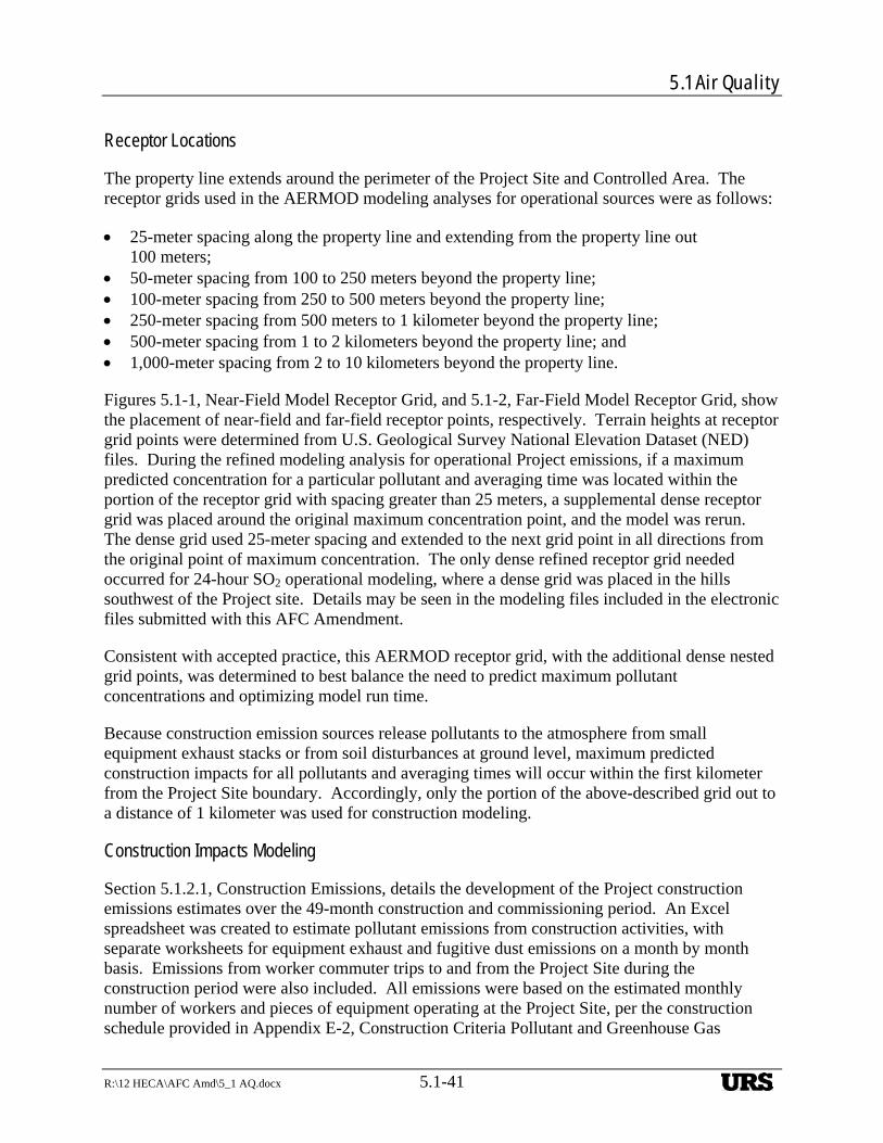
5.1 Air Quality
R:\12 HECA\AFC Amd\5_1 AQ.docx 5.1-41
Receptor Locations
The property line extends around the perimeter of the Project Site and Controlled Area. The receptor grids used in the AERMOD modeling analyses for operational sources were as follows:
25-meter spacing along the property line and extending from the property line out 100 meters;
50-meter spacing from 100 to 250 meters beyond the property line; 100-meter spacing from 250 to 500 meters beyond the property line; 250-meter spacing from 500 meters to 1 kilometer beyond the property line; 500-meter spacing from 1 to 2 kilometers beyond the property line; and 1,000-meter spacing from 2 to 10 kilometers beyond the property line.
Figures 5.1-1, Near-Field Model Receptor Grid, and 5.1-2, Far-Field Model Receptor Grid, show the placement of near-field and far-field receptor points, respectively. Terrain heights at receptor grid points were determined from U.S. Geological Survey National Elevation Dataset (NED) files. During the refined modeling analysis for operational Project emissions, if a maximum predicted concentration for a particular pollutant and averaging time was located within the portion of the receptor grid with spacing greater than 25 meters, a supplemental dense receptor grid was placed around the original maximum concentration point, and the model was rerun. The dense grid used 25-meter spacing and extended to the next grid point in all directions from the original point of maximum concentration. The only dense refined receptor grid needed occurred for 24-hour SO2 operational modeling, where a dense grid was placed in the hills southwest of the Project site. Details may be seen in the modeling files included in the electronic files submitted with this AFC Amendment.
Consistent with accepted practice, this AERMOD receptor grid, with the additional dense nested grid points, was determined to best balance the need to predict maximum pollutant concentrations and optimizing model run time.
Because construction emission sources release pollutants to the atmosphere from small equipment exhaust stacks or from soil disturbances at ground level, maximum predicted construction impacts for all pollutants and averaging times will occur within the first kilometer from the Project Site boundary. Accordingly, only the portion of the above-described grid out to a distance of 1 kilometer was used for construction modeling.
Construction Impacts Modeling
Section 5.1.2.1, Construction Emissions, details the development of the Project construction emissions estimates over the 49-month construction and commissioning period. An Excel spreadsheet was created to estimate pollutant emissions from construction activities, with separate worksheets for equipment exhaust and fugitive dust emissions on a month by month basis. Emissions from worker commuter trips to and from the Project Site during the construction period were also included. All emissions were based on the estimated monthly number of workers and pieces of equipment operating at the Project Site, per the construction schedule provided in Appendix E-2, Construction Criteria Pollutant and Greenhouse Gas
URS
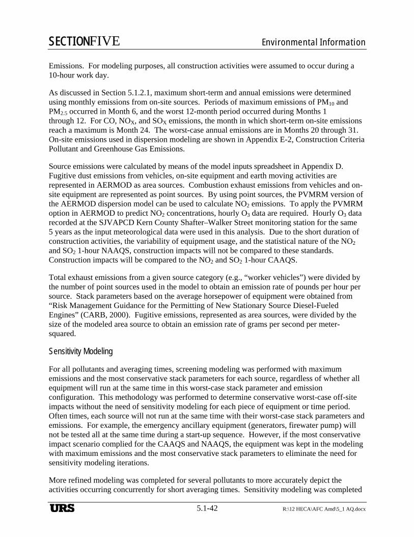
SECTIONFIVE Environmental Information
5.1-42 R:\12 HECA\AFC Amd\5_1 AQ.docx
Emissions. For modeling purposes, all construction activities were assumed to occur during a 10-hour work day.
As discussed in Section 5.1.2.1, maximum short-term and annual emissions were determined using monthly emissions from on-site sources. Periods of maximum emissions of PM10 and PM2.5 occurred in Month 6, and the worst 12-month period occurred during Months 1 through 12. For CO, NOX, and SOX emissions, the month in which short-term on-site emissions reach a maximum is Month 24. The worst-case annual emissions are in Months 20 through 31. On-site emissions used in dispersion modeling are shown in Appendix E-2, Construction Criteria Pollutant and Greenhouse Gas Emissions.
Source emissions were calculated by means of the model inputs spreadsheet in Appendix D. Fugitive dust emissions from vehicles, on-site equipment and earth moving activities are represented in AERMOD as area sources. Combustion exhaust emissions from vehicles and on-site equipment are represented as point sources. By using point sources, the PVMRM version of the AERMOD dispersion model can be used to calculate NO2 emissions. To apply the PVMRM option in AERMOD to predict NO2 concentrations, hourly O3 data are required. Hourly O3 data recorded at the SJVAPCD Kern County Shafter–Walker Street monitoring station for the same 5 years as the input meteorological data were used in this analysis. Due to the short duration of construction activities, the variability of equipment usage, and the statistical nature of the NO2 and SO2 1-hour NAAQS, construction impacts will not be compared to these standards. Construction impacts will be compared to the NO2 and SO2 1-hour CAAQS.
Total exhaust emissions from a given source category (e.g., “worker vehicles”) were divided by the number of point sources used in the model to obtain an emission rate of pounds per hour per source. Stack parameters based on the average horsepower of equipment were obtained from “Risk Management Guidance for the Permitting of New Stationary Source Diesel-Fueled Engines” (CARB, 2000). Fugitive emissions, represented as area sources, were divided by the size of the modeled area source to obtain an emission rate of grams per second per meter-squared.
Sensitivity Modeling
For all pollutants and averaging times, screening modeling was performed with maximum emissions and the most conservative stack parameters for each source, regardless of whether all equipment will run at the same time in this worst-case stack parameter and emission configuration. This methodology was performed to determine conservative worst-case off-site impacts without the need of sensitivity modeling for each piece of equipment or time period. Often times, each source will not run at the same time with their worst-case stack parameters and emissions. For example, the emergency ancillary equipment (generators, firewater pump) will not be tested all at the same time during a start-up sequence. However, if the most conservative impact scenario complied for the CAAQS and NAAQS, the equipment was kept in the modeling with maximum emissions and the most conservative stack parameters to eliminate the need for sensitivity modeling iterations.
More refined modeling was completed for several pollutants to more accurately depict the activities occurring concurrently for short averaging times. Sensitivity modeling was completed
URS

5.1 Air Quality
R:\12 HECA\AFC Amd\5_1 AQ.docx 5.1-43
for CO 1-hour, and it was determined that the CTG/HRSG shutting down scenario (20 percent load burning natural gas) gave higher impacts than the CTG/HRSG starting up scenario. However, the maximum CO 8-hour impact scenario was determined to occur during CTG/HRSG start-up mode when other sources are operating for that duration of time.
It was determined that the coal dryer gave higher short-term SO2 impacts in operations mode than in start-up or shut-down mode, while all other maximum pollutant impacts for the coal dryer occurred during coal dryer start-up mode. Maximum PM10, PM2.5 24-hour, and NO2 1-hour CAAQS impacts occur for a plant start-up period rather than during operations or shut down mode. Finally, maximum NO2 1-hour NAAQS impacts occur when the CTG/HRSG and coal dryer are operating in on-peak power mode rather than off-peak power mode.
Further details on worst-case modeling scenarios for each pollutant and averaging time are described in Section 5.1.2.5.10.
Fumigation Modeling
Fumigation can occur when a stable layer of air lies a short distance above the release point of a plume and unstable air lies below. Especially on sunny mornings with light winds, the heating of the earth’s surface causes a layer of turbulence, which grows in depth over time and may intersect an elevated exhaust plume. The transition from stable to unstable surroundings can rapidly draw a plume down to ground level and create relatively high pollutant concentrations for a short period. Typically, a fumigation analysis is conducted using the USEPA model SCREEN3 when the Project Site is rural and the stack height is greater than 10 meters.
A fumigation analysis was performed using SCREEN3 to calculate concentrations from inversion breakup fumigation. A unit emission rate was used (1 gram per second) in the fumigation modeling to obtain a maximum unit concentration (X/Q) and the model results were scaled to reflect expected Project emissions for each pollutant. Inversion breakup fumigation concentrations were calculated for 1-hour averaging times. Hourly model predictions are conservative, because inversion breakup fumigation is a transitory condition that would most likely affect a given receptor location for only a few minutes at a time.
Atmospheric conditions that could cause fumigation typically do not last for long periods, therefore due to the statistical nature of the NO2 and SO2 1-hour NAAQS, fumigation impacts will not be compared to these standards. Fumigation impacts will be compared to the NO2 and SO2 1-hour CAAQS, plus the 1-hour CO CAAQS.
Because SCREEN3 only models the impacts from one source, the model was run for each of the main sources: the CTG/HRSG, coal dryer, tail-gas thermal oxidizer, and the nitric acid plant operating with parameters and emission rates used in the maximum short-term impact scenarios as described below in Section 5.1.2.5.10.
Fumigation impacts were determined for each source then conservatively summed over all sources using peak predicted fumigation concentrations regardless of location. Further details on fumigation modeling can be found in Appendix E-9, Fumigation Modeling Results.
URS
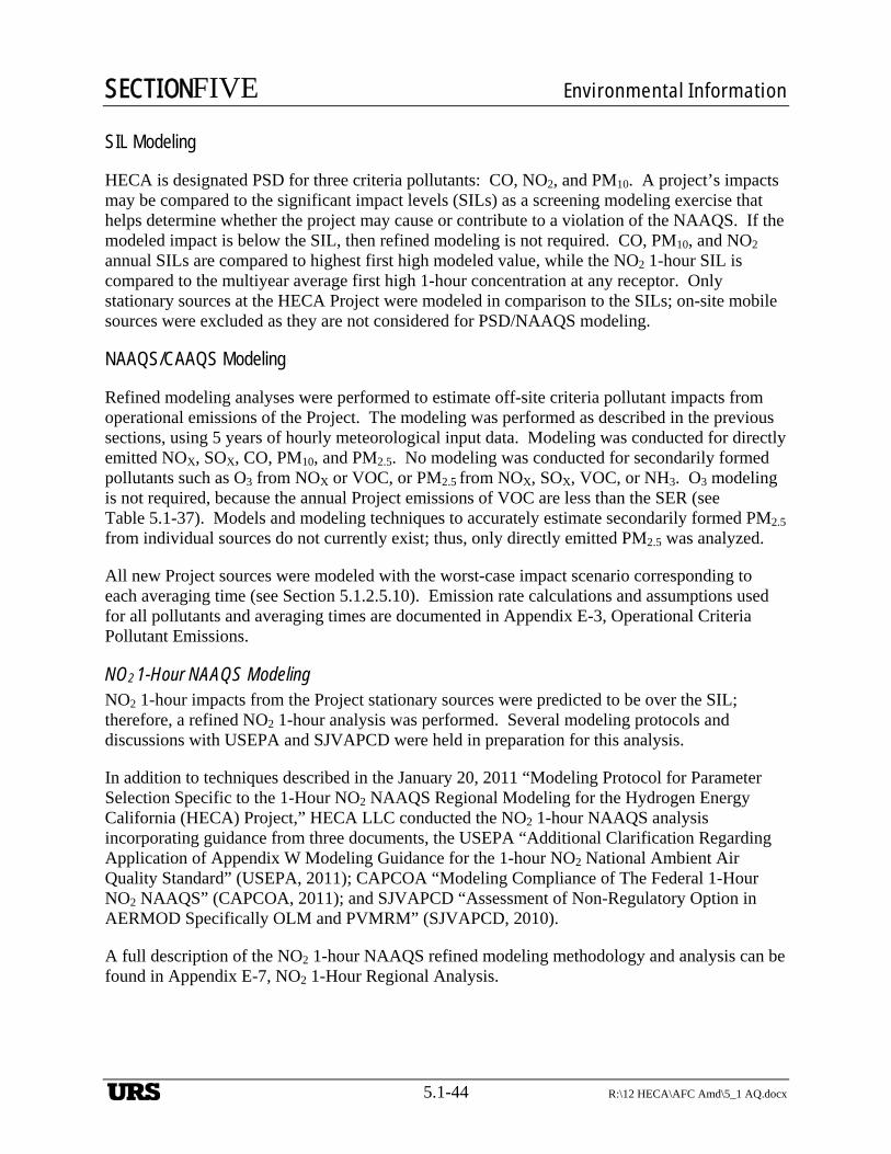
SECTIONFIVE Environmental Information
5.1-44 R:\12 HECA\AFC Amd\5_1 AQ.docx
SIL Modeling
HECA is designated PSD for three criteria pollutants: CO, NO2, and PM10. A project’s impacts may be compared to the significant impact levels (SILs) as a screening modeling exercise that helps determine whether the project may cause or contribute to a violation of the NAAQS. If the modeled impact is below the SIL, then refined modeling is not required. CO, PM10, and NO2
annual SILs are compared to highest first high modeled value, while the NO2 1-hour SIL is compared to the multiyear average first high 1-hour concentration at any receptor. Only stationary sources at the HECA Project were modeled in comparison to the SILs; on-site mobile sources were excluded as they are not considered for PSD/NAAQS modeling.
NAAQS/CAAQS Modeling
Refined modeling analyses were performed to estimate off-site criteria pollutant impacts from operational emissions of the Project. The modeling was performed as described in the previous sections, using 5 years of hourly meteorological input data. Modeling was conducted for directly emitted NOX, SOX, CO, PM10, and PM2.5. No modeling was conducted for secondarily formed pollutants such as O3 from NOX or VOC, or PM2.5 from NOX, SOX, VOC, or NH3. O3 modeling is not required, because the annual Project emissions of VOC are less than the SER (see Table 5.1-37). Models and modeling techniques to accurately estimate secondarily formed PM2.5 from individual sources do not currently exist; thus, only directly emitted PM2.5 was analyzed.
All new Project sources were modeled with the worst-case impact scenario corresponding to each averaging time (see Section 5.1.2.5.10). Emission rate calculations and assumptions used for all pollutants and averaging times are documented in Appendix E-3, Operational Criteria Pollutant Emissions.
NO2 1-Hour NAAQS Modeling NO2 1-hour impacts from the Project stationary sources were predicted to be over the SIL; therefore, a refined NO2 1-hour analysis was performed. Several modeling protocols and discussions with USEPA and SJVAPCD were held in preparation for this analysis.
In addition to techniques described in the January 20, 2011 “Modeling Protocol for Parameter Selection Specific to the 1-Hour NO2 NAAQS Regional Modeling for the Hydrogen Energy California (HECA) Project,” HECA LLC conducted the NO2 1-hour NAAQS analysis incorporating guidance from three documents, the USEPA “Additional Clarification Regarding Application of Appendix W Modeling Guidance for the 1-hour NO2 National Ambient Air Quality Standard” (USEPA, 2011); CAPCOA “Modeling Compliance of The Federal 1-Hour NO2 NAAQS” (CAPCOA, 2011); and SJVAPCD “Assessment of Non-Regulatory Option in AERMOD Specifically OLM and PVMRM” (SJVAPCD, 2010).
A full description of the NO2 1-hour NAAQS refined modeling methodology and analysis can be found in Appendix E-7, NO2 1-Hour Regional Analysis.
URS
5.1 Air Quality
R:\12 HECA\AFC Amd\5_1 AQ.docx 5.1-45
Modeling Scenarios
Operations Emission Scenarios for Modeling Often times, worst-case impact scenarios do not necessarily align with worst-case emissions. Stack parameter variability for different equipment can change the overall estimated impacts on a per pollutant basis. Another defining variable that determines maximum impact scenarios is whether equipment is operating simultaneously, and in what operating mode. The following subsections describe the worst-case modeling scenarios per pollutant and averaging time. Supporting calculations and documentation may be found in Appendix E-3, Operational Criteria Pollutant Emissions.
CO 1-hour
The maximum CO 1-hour impact scenario occurs when the CTG/HRSG is shutting down at 20 percent load burning natural gas during which time the coal dryer and the auxiliary boiler are not operating. The Tail Gas Thermal Oxidizer and CO2 vent both have process venting, while all three flares are in pilot mode. CO fugitives from the gasification, shift, AGR, SRU, and sour water areas are also included. Emergency equipment was not included in this scenario, as it will not be testing during shut-down. Mobile sources are not included for comparison to the NAAQS, while all mobile sources are included for comparison to the CAAQS.
CO 8-hour
The maximum CO 8-hour impact scenario occurs during a plant start-up when the CTG/HRSG and coal dryer are starting up, plus a number other sources are operating or starting. For 0.5 hours the CTG/HRSG operates at 20 percent load on natural gas, for 2 hours the CTG/HRSG and coal dryer operate at 40 percent load on natural gas, and for the remaining portion of the 8-hour period operate at 40 percent load on syngas. The Tail Gas Thermal Oxidizer is in start-up mode with maximum SRU waste gas disposal for the entire 8-hour duration. All flares are flaring in start-up mode. The Rectisol® and SRU flares are flaring at maximum hourly start-up rates. The gasification flare is flaring shifted syngas for 5 hours, with the remaining 3 hours at pilot operations. The CO2 vent has maximum process venting, and the auxiliary boiler is also operating with maximum short-term emissions. The ammonia start-up heater is operating during 5 of the 8 hours in this start-up scenario. Emergency equipment was not included in this scenario, as it will not be testing during start-up. CO fugitives from the gasification, shift, AGR, SRU, and sour water areas are also included. Mobile sources are not included for comparison to the NAAQS, while all mobile sources are included for comparison to the CAAQS.
NO2 1-hour CAAQS
The maximum NO2 1-hour CAAQS impact scenario occurs when the CTG/HRSG and coal dryer are starting up in 40 percent load natural gas mode, with the tail gas thermal oxidizer and ammonia start-up heater are also in start-up mode. All flares are in start-up mode with maximum heat release flaring. The auxiliary boiler and nitric acid plant are operating during this time at peak emission rates. Both emergency generators and the emergency diesel firewater pump are conservatively testing during this hour. It is important to note that all sources were modeled at maximum emission rates, sources with intermittent emissions did not use annualized 1-hour rates
URS
SECTIONFIVE Environmental Information
5.1-46 R:\12 HECA\AFC Amd\5_1 AQ.docx
for the CEQA CAAQS modeling. Finally, all mobile sources are conservatively operating during this time frame.
NO2 1-hour SIL and NAAQS
The maximum NO2 1-hour NAAQS impact scenario for the SIL and NAAQS analyses occurs when the CTG/HRSG and coal dryer are operating in on-peak (Case 1) power mode. Start-up emissions for the CTG/HRSG are limited to 105 hours per year, while shut-down emissions are limited to 18 hours per year. Start-up emissions for the coal dryer are limited to 104 hours per year, with shut-down emissions at 8 hours per year. Annualized maximum 1-hour NO2 start-up/shut-down emission rates for these two sources are lower than their normal NO2 1-hour rates, therefore, the maximum on-peak power normal NO2 1-hour emission rates for the CTG/HRSG and coal dryer were used for the NO2 1-hour SIL and NAAQS analyses. Similarly, the SRU flare and tail gas thermal oxidizer have maximum impacts during operations with pilot and process vent disposal, respectively, rather than during an annualized start-up period. The auxiliary boiler and nitric acid unit operations were included at their peak hourly emission rate. The Rectisol® and gasification flares were included with maximum annualized start-up flaring emission rates, which are higher than their normal rates during pilot mode. The ammonia plant start-up heater also was included with an annualized start-up 1-hour NO2 emission rate. Finally, all three ancillary diesel engines including the two emergency diesel generators and firewater pump are included in the NO2 1-hour SIL and NAAQS modeling with annualized emission rates. Mobile sources are not included in this modeling scenario.
NO2 Annual
Maximum annual emissions for all NOX emitting sources were included in the annual modeling scenarios. Maximum annual emissions include operating emissions plus all start-ups and shut-downs associated with each source. The CTG/HRSG and coal dryer use Case 5 stack parameters, while the flares use effective stack parameters based on each flare’s annualized heat release rate. All other sources are modeled with normal operating stack parameters. Mobile sources are not included for comparison to the NAAQS, while the maximum annual amount of mobile sources are included for comparison to the CAAQS.
PM10 and PM2.5 24-hour
The maximum PM10 and PM2.5 24-hour impact occurs when the CTG/HRSG and coal dryer are operating in start-up mode. Stack parameters for these sources used flow rates based on a start-up at 40 percent load on syngas, because most of the 24-hour start-up period would operate in this mode. Similarly, the tail gas thermal oxidizer and all flares were included with maximum emissions during start-up. All three cooling towers (ASU, Power Block and Process) are operating at maximum 24-hour PM10 and PM2.5 emission rates. The auxiliary boiler is not operating during this time, as it is not expected to operate while the CTG is operating. Both emergency generators are testing for 1 hour in the 24-hour period, while the emergency diesel firewater pump is testing for 2 hours during the 24-hour period. The emergency equipment maximum daily emissions were spread evenly across all hours in the day in AERMOD. The ammonia start-up heater is operating in start-up mode. All sources associated with the manufacturing plant with PM emissions are operating, including the ammonium nitrate unit, and
URS
5.1 Air Quality
R:\12 HECA\AFC Amd\5_1 AQ.docx 5.1-47
the urea pastillation stack; and all material handling sources are operating as well, which include all coal/coke, urea, and gasification solids storage and handling systems. Emission source release points for material handling may be found in Appendix E-3, Operational Criteria Pollutant Emissions. Mobile sources are not included for comparison to the NAAQS, while the maximum daily number of mobile sources are included for comparison to the CAAQS.
PM10 and PM2.5 Annual
Maximum annual emissions from all PM emitting equipment were modeled for the annual modeling scenarios. Maximum annual emissions include operating emissions plus all start-ups and shut-downs associated with each source. The CTG/HRSG and coal dryer use Case 5 stack parameters and emissions, while the flares use effective stack parameters based on each flare’s annualized heat release rate. All other sources are modeled with normal operating stack parameters. Mobile sources are not included for comparison to the NAAQS, while the maximum annual number of mobile sources is included for comparison to the CAAQS.
SO2 1-hour, 3-hour, 24-hour
Maximum SO2 short term impacts occur when the CTG/HRSG is operating at 80 percent load on natural gas, which is the highest SO2 emission rate for the CTG/HRSG, conservatively mixed with the lowest exhaust flow rate (Case 2) that occurs during CTG/HRSG operations in off-peak power mode. Conversely, the coal dryer has the highest short-term SO2 emissions during off-peak power, combined with the lowest flow exhaust rate. Although these two sources will not operate in their worst-case mode at the same time, SO2 short term modeling was completed as described above to minimize the need for several sensitivity runs. The tail gas thermal oxidizer, the ammonia start-up heater, and all three flares are operating with maximum short-term start-up emission rates. Both emergency generators and the emergency diesel firewater pump are conservatively testing for all averaging times. The two emergency generators are both testing for 1 hour in the 24-hour period, while the emergency diesel firewater pump is testing for 2 hours during the 24-hour period. The maximum daily emissions of the emergency equipment were spread evenly across all hours in the day in AERMOD. All sources were modeled with maximum emission rates, sources with intermittent emissions did not use annualized 1-hour rates for the CEQA CAAQS or NAAQS 1-hour modeling. Mobile sources are not included for comparison to the NAAQS, while the maximum number of mobile sources is included for comparison to the CAAQS.
H2S 1-hour
The maximum H2S 1-hour impact scenario occurs when the CO2 vent is venting at maximum short-term H2S emission rates. H2S fugitives from the gasification, shift, AGR, SRU, and sour water areas are also included.
Commissioning Emission Scenarios for Modeling Project engineers provided a number of commissioning emission scenario that represent the worst-case combination of emissions from various sources during the commissioning period. These emission scenarios were modeled with AERMOD to predict the maximum impact during commissioning.
URS
SECTIONFIVE Environmental Information
5.1-48 R:\12 HECA\AFC Amd\5_1 AQ.docx
Due to the short duration of commissioning activities, the variability of equipment usage, and the statistical nature of the NO2 and SO2 1-hour and PM2.5 24-hour NAAQS, commissioning impacts will not be compared to these standards. Commissioning impacts will be compared to the NO2 and SO2 1-hour and PM2.5 24-hour CAAQS. Commissioning impacts will also be compared to the CO 1- and 8-hour, and SO2 3- and 24-hour AAQSs.
Construction activities and commissioning activities overlap, although construction activities will be winding down and commissioning activities can be scheduled such that the emissions from the combination of these activities will be minimal. Therefore, modeling was not conducted with the overlapping emissions. Appendix E-8, Commissioning Scenario Emissions and Modeling Results presents the emissions from each source associated with each scenario. Below is a brief description of the scenarios examined.
Case 1
This scenario reflects the testing of either of the two emergency diesel generator engines while the Power Block cooling tower operates at reduced or no load. This scenario occurs early in the commissioning sequence when utility and support systems are being commissioned. The modeling analyses were conducted for SO2 (1-hour and 24-hour), NO2 (1-hour), CO (1-hour and 8-hour), and PM10 (24-hour).
Case A
This scenario reflects initial, “first fire” operation of the combustion turbine on natural gas at 20 percent load before the SCR and oxidation catalyst are operational. The Power Block cooling tower is also operating at reduced load. The modeling analysis was conducted for CO only, as this case represents the worst-case CO emission rates scenario, while the emissions of other pollutants are overlapped with other scenarios.
Case B
This scenario reflects operation of the combustion turbine on natural gas at 80 percent load before the SCR and oxidation catalysts are operational. This scenario is expected to occurring during tuning the water injection rates for NOX control. The modeling analyses were conducted for SO2 and NO2 since the emissions of other pollutants are overlapped with other scenarios. Case B is the worst-case NO2 emission rate scenario.
Case A2
This scenario occurs during initial operation of the gasifier at 50 percent load while flaring sweet, unshifted syngas in the Gasification Flare. The gasifier operation is supported by Power Block operation (HRSG and coal dryer) on natural gas at 80 percent load, operation of all three cooling towers, and the Tail Gas Thermal Oxidizer. The modeling analyses were conducted for NO2, CO, and PM10. This case represents the worst-case PM10 emission scenario. SO2 emissions are overlapped with, or less conservative, than other scenarios; therefore, this case was not modeled for SO2.
URS
5.1 Air Quality
R:\12 HECA\AFC Amd\5_1 AQ.docx 5.1-49
Case B2
This scenario is similar to Case A2 and occurs later in the start-up sequence when shifted syngas is being sent to the Gasification Flare. This scenario anticipates a potential excursion in the SO2 emissions from the Tail Gas Thermal Oxidizer that could occur briefly before the tail gas is recycled to the shift converters. All three cooling towers would be operated. The modeling analysis was conducted for SO2 only, as this represents the worst-case SO2 scenario, while the emissions of other pollutants are overlapped with other scenarios.
Case C2
This scenario occurs with gasifier operation at 50 percent load while flaring hydrogen-rich fuel gas in the Gasification Flare. This reflects a transitional period before the gas turbine can switch to hydrogen-rich fuel and CO2 is vented before the CO2 compressor is ready to send CO2 to OEHI for EOR. The gasifier operation is supported by Power Block operation at 80 percent load on natural gas. Thermal oxidizer would be operated to support the miscellaneous process vent disposal. All three cooling towers would be operated. The modeling analysis was conducted for CO only, since the emissions of other pollutants are overlapped with other scenarios.
Case D2
This scenario occurs with gasifier operation at 50 percent load while commissioning the hydrogen purification (PSA unit). A combination of mostly hydrogen rich gas plus PSA off-gas is being sent to the Gasification Flare. CO2 is being sent to OEHI for EOR. The Power Block is operated at 80 percent load on natural gas. Thermal oxidizer would be operated to support the miscellaneous process vent disposal. All three cooling towers would be operated. The modeling analysis was conducted for NO2 only, since the emissions of other pollutants are overlapped with other scenarios.
Case E2
This scenario occurs with gasifier operation at 50 percent load and gas turbine operation at 40 percent load which requires some surplus hydrogen-rich fuel to be sent to the gasification flare. This would occur following the gas turbine switch from natural gas to hydrogen rich gas. CO2 may need to be vented during this transition period. Thermal oxidizer would be operated to support the miscellaneous process vent disposal. All three cooling towers would be operated. The modeling analysis was conducted for NO2 and CO.
Case A3
This scenario occurs during commissioning of the Ammonia and Urea units when purified hydrogen is flared and purified CO2 is vented before it can be converted to products. The CO content of the CO2 stream is assumed to be higher than normal, but the flow rate is much lower than normal, so the emission rate is less than normal operations. The Gasification Block and support systems are operating normally. The Power Block is operated at 100 percent load on hydrogen-rich fuel. Thermal oxidizer would be operated to support the miscellaneous process vent disposal. All three cooling towers would be operated. No modeling analysis was conducted
URS
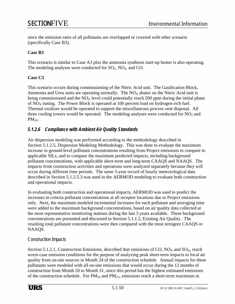
SECTIONFIVE Environmental Information
5.1-50 R:\12 HECA\AFC Amd\5_1 AQ.docx
since the emission rates of all pollutants are overlapped or covered with other scenario (specifically Case B3).
Case B3
This scenario is similar to Case A3 plus the ammonia synthesis start-up heater is also operating. The modeling analyses were conducted for SO2, NO2, and CO.
Case C3
This scenario occurs during commissioning of the Nitric Acid unit. The Gasification Block, Ammonia and Urea units are operating normally. The NOX abator on the Nitric Acid unit is being commissioned and the NOX level could potentially reach 200 ppm during the initial phase of NOX tuning. The Power Block is operated at 100 percent load on hydrogen-rich fuel. Thermal oxidizer would be operated to support the miscellaneous process vent disposal. All three cooling towers would be operated. The modeling analyses were conducted for NO2 and PM10.
5.1.2.6 Compliance with Ambient Air Quality Standards
Air dispersion modeling was performed according to the methodology described in Section 5.1.2.5, Dispersion Modeling Methodology. This was done to evaluate the maximum increase in ground-level pollutant concentrations resulting from Project emissions to compare to applicable SILs, and to compare the maximum predicted impacts, including background pollutant concentrations, with applicable short-term and long-term CAAQS and NAAQS. The impacts from construction activities and operations were analyzed separately because they will occur during different time periods. The same 5-year record of hourly meteorological data described in Section 5.1.2.5.3 was used in the AERMOD modeling to evaluate both construction and operational impacts.
In evaluating both construction and operational impacts, AERMOD was used to predict the increases in criteria pollutant concentrations at all receptor locations due to Project emissions only. Next, the maximum modeled incremental increases for each pollutant and averaging time were added to the maximum background concentrations, based on air quality data collected at the most representative monitoring stations during the last 3 years available. These background concentrations are presented and discussed in Section 5.1.1.2, Existing Air Quality. The resulting total pollutant concentrations were then compared with the most stringent CAAQS or NAAQS.
Construction Impacts
Section 5.1.2.1, Construction Emissions, described that emissions of CO, NOX and SOX, reach worst-case emission conditions for the purpose of analyzing peak short-term impacts to local air quality from on-site sources in Month 24 of the construction schedule. Annual impacts for these pollutants were modeled with all on-site emissions that would occur during the 12 months of construction from Month 20 to Month 31, since this period has the highest estimated emissions of the construction schedule. For PM10 and PM2.5, emissions reach a short-term maximum in
URS
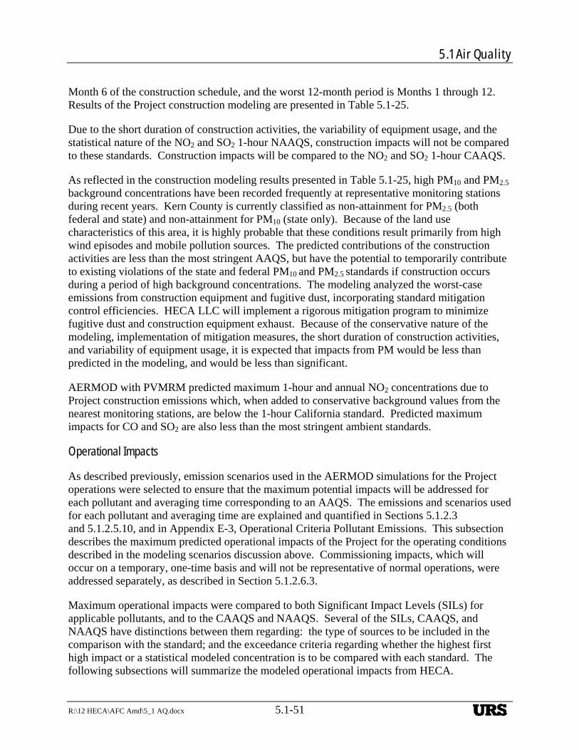
5.1 Air Quality
R:\12 HECA\AFC Amd\5_1 AQ.docx 5.1-51
Month 6 of the construction schedule, and the worst 12-month period is Months 1 through 12. Results of the Project construction modeling are presented in Table 5.1-25.
Due to the short duration of construction activities, the variability of equipment usage, and the statistical nature of the NO2 and SO2 1-hour NAAQS, construction impacts will not be compared to these standards. Construction impacts will be compared to the NO2 and SO2 1-hour CAAQS.
As reflected in the construction modeling results presented in Table 5.1-25, high PM10 and PM2.5
background concentrations have been recorded frequently at representative monitoring stations during recent years. Kern County is currently classified as non-attainment for PM2.5 (both federal and state) and non-attainment for PM10 (state only). Because of the land use characteristics of this area, it is highly probable that these conditions result primarily from high wind episodes and mobile pollution sources. The predicted contributions of the construction activities are less than the most stringent AAQS, but have the potential to temporarily contribute to existing violations of the state and federal PM10 and PM2.5 standards if construction occurs during a period of high background concentrations. The modeling analyzed the worst-case emissions from construction equipment and fugitive dust, incorporating standard mitigation control efficiencies. HECA LLC will implement a rigorous mitigation program to minimize fugitive dust and construction equipment exhaust. Because of the conservative nature of the modeling, implementation of mitigation measures, the short duration of construction activities, and variability of equipment usage, it is expected that impacts from PM would be less than predicted in the modeling, and would be less than significant.
AERMOD with PVMRM predicted maximum 1-hour and annual NO2 concentrations due to Project construction emissions which, when added to conservative background values from the nearest monitoring stations, are below the 1-hour California standard. Predicted maximum impacts for CO and SO2 are also less than the most stringent ambient standards.
Operational Impacts
As described previously, emission scenarios used in the AERMOD simulations for the Project operations were selected to ensure that the maximum potential impacts will be addressed for each pollutant and averaging time corresponding to an AAQS. The emissions and scenarios used for each pollutant and averaging time are explained and quantified in Sections 5.1.2.3 and 5.1.2.5.10, and in Appendix E-3, Operational Criteria Pollutant Emissions. This subsection describes the maximum predicted operational impacts of the Project for the operating conditions described in the modeling scenarios discussion above. Commissioning impacts, which will occur on a temporary, one-time basis and will not be representative of normal operations, were addressed separately, as described in Section 5.1.2.6.3.
Maximum operational impacts were compared to both Significant Impact Levels (SILs) for applicable pollutants, and to the CAAQS and NAAQS. Several of the SILs, CAAQS, and NAAQS have distinctions between them regarding: the type of sources to be included in the comparison with the standard; and the exceedance criteria regarding whether the highest first high impact or a statistical modeled concentration is to be compared with each standard. The following subsections will summarize the modeled operational impacts from HECA.
URS
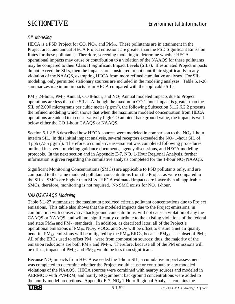
SECTIONFIVE Environmental Information
5.1-52 R:\12 HECA\AFC Amd\5_1 AQ.docx
SIL Modeling HECA is a PSD Project for CO, NO2, and PM10. These pollutants are in attainment in the Project area, and annual HECA Project emissions are greater than the PSD Significant Emission Rates for these pollutants. Therefore, screening modeling to determine whether HECA operational impacts may cause or contribution to a violation of the NAAQS for these pollutants may be compared to their Class II Significant Impact Levels (SILs). If estimated Project impacts do not exceed the SILs, then the impacts are considered to not contribute significantly to any violation of the NAAQS, exempting HECA from more refined cumulative analyses. For SIL modeling, only permitted stationary sources are included in the modeling analyses. Table 5.1-26 summarizes maximum impacts from HECA compared with the applicable SILs.
PM10 24-hour, PM10 Annual, CO 8-hour, and NO2 Annual modeled impacts due to Project operations are less than the SILs. Although the maximum CO 1-hour impact is greater than the SIL of 2,000 micrograms per cubic meter (µg/m3), the following Subsection 5.1.2.6.2.2 presents the refined modeling which shows that when the maximum modeled concentration from HECA operations are added to a conservatively high CO ambient background value, the impact is well below either the CO 1-hour CAAQS or NAAQS.
Section 5.1.2.5.8 described how HECA sources were modeled in comparison to the NO2 1-hour interim SIL. In this initial impact analysis, several receptors exceeded the NO2 1-hour SIL of 4 ppb (7.55 µg/m3). Therefore, a cumulative assessment was completed following procedures outlined in several modeling guidance documents, agency discussions, and HECA modeling protocols. In the next section and in Appendix E-7, NO2 1-Hour Regional Analysis, further information is given regarding the cumulative analysis completed for the 1-hour NO2 NAAQS.
Significant Monitoring Concentrations (SMCs) are applicable to PSD pollutants only, and are compared to the same modeled pollutant concentrations from the Project as were compared to the SILs. SMCs are higher than SILs. HECA estimated impacts are lower than all applicable SMCs, therefore, monitoring is not required. No SMC exists for NO2 1-hour.
NAAQS/CAAQS Modeling Table 5.1-27 summarizes the maximum predicted criteria pollutant concentrations due to Project emissions. This table also shows that the modeled impacts due to the Project emissions, in combination with conservative background concentrations, will not cause a violation of any the CAAQS or NAAQS, and will not significantly contribute to the existing violations of the federal and state PM10 and PM2.5 standards. In addition, as described later, all of the Project’s operational emissions of PM10, NOX, VOCs, and SOX will be offset to ensure a net air quality benefit. PM2.5 emissions will be mitigated by the PM10 ERCs, because PM2.5 is a subset of PM10. All of the ERCs used to offset PM10 were from combustion sources; thus, the majority of the emission reductions are both PM10 and PM2.5. Therefore, because all of the PM emissions will be offset, impacts of PM10 and PM2.5 would be less than significant.
Because NO2 impacts from HECA exceeded the 1-hour SIL, a cumulative impact assessment was completed to determine whether the Project would cause or contribute to any modeled violations of the NAAQS. HECA sources were combined with nearby sources and modeled in AERMOD with PVMRM, and hourly NO2 ambient background concentrations were added to the hourly model predictions. Appendix E-7, NO2 1-Hour Regional Analysis, contains the
URS
5.1 Air Quality
R:\12 HECA\AFC Amd\5_1 AQ.docx 5.1-53
modeling approach, background air quality, emission sources modeled, and modeling result details for the regional analysis. Table 5.1-27 presents the highest of the modeled 5-year average of the 98th percentile of the maximum 1-hour daily concentration (design value) at any receptor, which complies with the 1-hour NO2 NAAQS. This analysis demonstrates that HECA would not cause or contribute to any modeled violations, as the total design value predicted from the HECA sources, the nearby regional sources and background measured concentrations of NO2 are less than the NAAQS.
Figure 5.1-3, Locations of Maximum Predicted Ground Level Pollutant Concentrations from HECA Operations, shows the locations of the maximum predicted operational impacts for all pollutants and averaging times, as these vary by pollutant and averaging time. All peak annual impacts occur on the eastern boundary of the property line, along with the peak CO 1-hour impact, and the NO2 1-hour CAAQS and NAAQS impacts. The peak PM10 and PM2.5 24-hour, H2S 1-hour, and CO 8-hour all occur on the western boundary of the property line. All maximum SO2 short term impacts occur in the hills to the southwest of the Project Site, approximately 3.5 kilometers from the southern boundary of the property line.
Fumigation The predicted peak concentrations from inversion fumigation from Project emissions, including background, are predicted to be below the applicable 1-hour CAAQS, and are presented in Table 5.1-28. Therefore, fumigation modeling complies with all applicable 1-hour ambient air quality standards.
Commissioning
Table 5.1-29 shows the results of the model simulations for the commissioning of the HECA Project. The tabulated impacts are the highest concentrations predicted for each pollutant and averaging time examined from all of the commissioning scenarios.
Table 5.1-29 demonstrates that when the maximum incremental commissioning impacts are added to applicable background concentrations and compared with the most stringent state or national AAQSs, no violations of the applicable standards for these pollutants are predicted to occur.
Effects on Visibility from Plumes
Modern combined-cycle power plants burning gaseous fuel emit particulate matter at levels far below the concentration corresponding to visible smoke. Combustion sources also emit water vapor that sometimes may condense in the atmosphere to form visible plumes. However, the generally warm, dry conditions in Kern County are not conducive to lengthy visible stack plumes. A visible plume analysis was performed for the Project and presented in the AFC that showed visible plumes were infrequent. Data are provided regarding the moisture content of the CTG/HRSG and coal dryer stacks, along with data regarding cooling towers exhaust in Section 5.11, Visual Resources. New visible plume analyses were not conducted as the ambient conditions at the site have not changed to make it more conducive for plume development.
URS
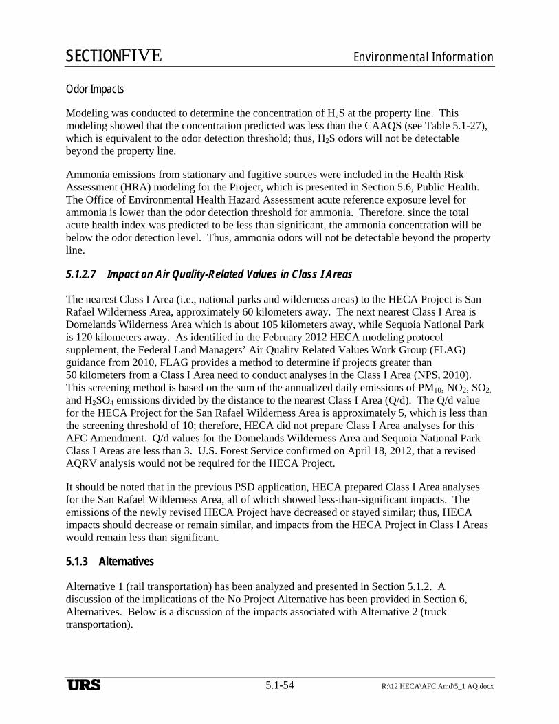
SECTIONFIVE Environmental Information
5.1-54 R:\12 HECA\AFC Amd\5_1 AQ.docx
Odor Impacts
Modeling was conducted to determine the concentration of H2S at the property line. This modeling showed that the concentration predicted was less than the CAAQS (see Table 5.1-27), which is equivalent to the odor detection threshold; thus, H2S odors will not be detectable beyond the property line.
Ammonia emissions from stationary and fugitive sources were included in the Health Risk Assessment (HRA) modeling for the Project, which is presented in Section 5.6, Public Health. The Office of Environmental Health Hazard Assessment acute reference exposure level for ammonia is lower than the odor detection threshold for ammonia. Therefore, since the total acute health index was predicted to be less than significant, the ammonia concentration will be below the odor detection level. Thus, ammonia odors will not be detectable beyond the property line.
5.1.2.7 Impact on Air Quality-Related Values in Class I Areas
The nearest Class I Area (i.e., national parks and wilderness areas) to the HECA Project is San Rafael Wilderness Area, approximately 60 kilometers away. The next nearest Class I Area is Domelands Wilderness Area which is about 105 kilometers away, while Sequoia National Park is 120 kilometers away. As identified in the February 2012 HECA modeling protocol supplement, the Federal Land Managers’ Air Quality Related Values Work Group (FLAG) guidance from 2010, FLAG provides a method to determine if projects greater than 50 kilometers from a Class I Area need to conduct analyses in the Class I Area (NPS, 2010). This screening method is based on the sum of the annualized daily emissions of PM10, NO2, SO2, and H2SO4 emissions divided by the distance to the nearest Class I Area (Q/d). The Q/d value for the HECA Project for the San Rafael Wilderness Area is approximately 5, which is less than the screening threshold of 10; therefore, HECA did not prepare Class I Area analyses for this AFC Amendment. Q/d values for the Domelands Wilderness Area and Sequoia National Park Class I Areas are less than 3. U.S. Forest Service confirmed on April 18, 2012, that a revised AQRV analysis would not be required for the HECA Project.
It should be noted that in the previous PSD application, HECA prepared Class I Area analyses for the San Rafael Wilderness Area, all of which showed less-than-significant impacts. The emissions of the newly revised HECA Project have decreased or stayed similar; thus, HECA impacts should decrease or remain similar, and impacts from the HECA Project in Class I Areas would remain less than significant.
5.1.3 Alternatives
Alternative 1 (rail transportation) has been analyzed and presented in Section 5.1.2. A discussion of the implications of the No Project Alternative has been provided in Section 6, Alternatives. Below is a discussion of the impacts associated with Alternative 2 (truck transportation).
URS
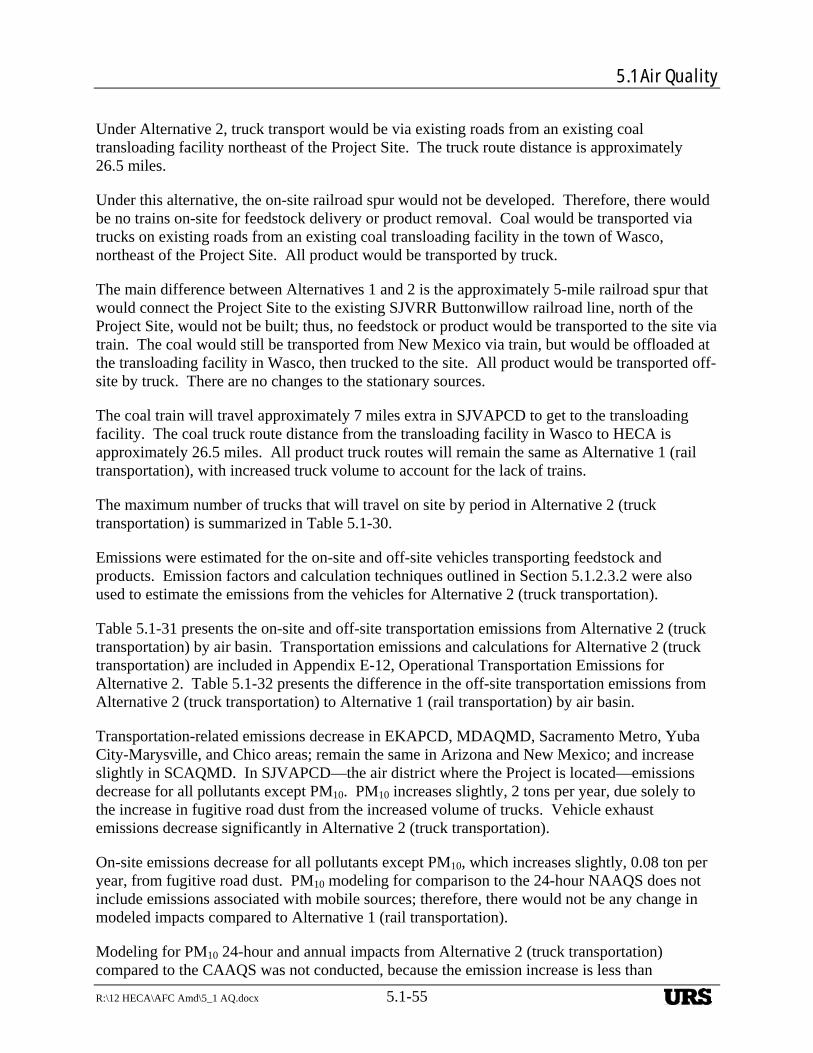
5.1 Air Quality
R:\12 HECA\AFC Amd\5_1 AQ.docx 5.1-55
Under Alternative 2, truck transport would be via existing roads from an existing coal transloading facility northeast of the Project Site. The truck route distance is approximately 26.5 miles.
Under this alternative, the on-site railroad spur would not be developed. Therefore, there would be no trains on-site for feedstock delivery or product removal. Coal would be transported via trucks on existing roads from an existing coal transloading facility in the town of Wasco, northeast of the Project Site. All product would be transported by truck.
The main difference between Alternatives 1 and 2 is the approximately 5-mile railroad spur that would connect the Project Site to the existing SJVRR Buttonwillow railroad line, north of the Project Site, would not be built; thus, no feedstock or product would be transported to the site via train. The coal would still be transported from New Mexico via train, but would be offloaded at the transloading facility in Wasco, then trucked to the site. All product would be transported off-site by truck. There are no changes to the stationary sources.
The coal train will travel approximately 7 miles extra in SJVAPCD to get to the transloading facility. The coal truck route distance from the transloading facility in Wasco to HECA is approximately 26.5 miles. All product truck routes will remain the same as Alternative 1 (rail transportation), with increased truck volume to account for the lack of trains.
The maximum number of trucks that will travel on site by period in Alternative 2 (truck transportation) is summarized in Table 5.1-30.
Emissions were estimated for the on-site and off-site vehicles transporting feedstock and products. Emission factors and calculation techniques outlined in Section 5.1.2.3.2 were also used to estimate the emissions from the vehicles for Alternative 2 (truck transportation).
Table 5.1-31 presents the on-site and off-site transportation emissions from Alternative 2 (truck transportation) by air basin. Transportation emissions and calculations for Alternative 2 (truck transportation) are included in Appendix E-12, Operational Transportation Emissions for Alternative 2. Table 5.1-32 presents the difference in the off-site transportation emissions from Alternative 2 (truck transportation) to Alternative 1 (rail transportation) by air basin.
Transportation-related emissions decrease in EKAPCD, MDAQMD, Sacramento Metro, Yuba City-Marysville, and Chico areas; remain the same in Arizona and New Mexico; and increase slightly in SCAQMD. In SJVAPCD—the air district where the Project is located—emissions decrease for all pollutants except PM10. PM10 increases slightly, 2 tons per year, due solely to the increase in fugitive road dust from the increased volume of trucks. Vehicle exhaust emissions decrease significantly in Alternative 2 (truck transportation).
On-site emissions decrease for all pollutants except PM10, which increases slightly, 0.08 ton per year, from fugitive road dust. PM10 modeling for comparison to the 24-hour NAAQS does not include emissions associated with mobile sources; therefore, there would not be any change in modeled impacts compared to Alternative 1 (rail transportation).
Modeling for PM10 24-hour and annual impacts from Alternative 2 (truck transportation) compared to the CAAQS was not conducted, because the emission increase is less than
URS
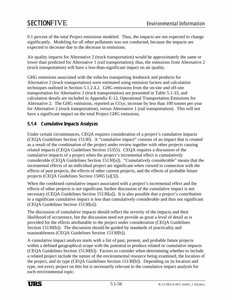
SECTIONFIVE Environmental Information
5.1-56 R:\12 HECA\AFC Amd\5_1 AQ.docx
0.1 percent of the total Project emissions modeled. Thus, the impacts are not expected to change significantly. Modeling for all other pollutants was not conducted, because the impacts are expected to decrease due to the decrease in emissions.
Air quality impacts for Alternative 2 (truck transportation) would be approximately the same or lower than predicted for Alternative 1 (rail transportation); thus, the emissions from Alternative 2 (truck transportation) will have a less-than-significant impact on air quality.
GHG emissions associated with the vehicles transporting feedstock and products for Alternative 2 (truck transportation) were estimated using emission factors and calculation techniques outlined in Section 5.1.2.4.2. GHG emissions from the on-site and off-site transportation for Alternative 2 (truck transportation) are presented in Table 5.1-33, and calculation details are included in Appendix E-12, Operational Transportation Emissions for Alternative 2. The GHG emissions, reported as CO2e, increase by less than 100 tonnes per year for Alternative 2 (truck transportation), versus Alternative 1 (rail transportation). This will not have a significant impact on the total Project GHG emissions.
5.1.4 Cumulative Impacts Analyses
Under certain circumstances, CEQA requires consideration of a project’s cumulative impacts (CEQA Guidelines Section 15130). A “cumulative impact” consists of an impact that is created as a result of the combination of the project under review together with other projects causing related impacts (CEQA Guidelines Section 15355). CEQA requires a discussion of the cumulative impacts of a project when the project’s incremental effect is cumulatively considerable (CEQA Guidelines Section 15130[a]). “Cumulatively considerable” means that the incremental effects of an individual project are significant when viewed in connection with the effects of past projects, the effects of other current projects, and the effects of probable future projects (CEQA Guidelines Section 15065 [a][3]).
When the combined cumulative impact associated with a project’s incremental effect and the effects of other projects is not significant, further discussion of the cumulative impact is not necessary (CEQA Guidelines Section 15130[a]). It is also possible that a project’s contribution to a significant cumulative impact is less than cumulatively considerable and thus not significant (CEQA Guidelines Section 15130[a]).
The discussion of cumulative impacts should reflect the severity of the impacts and their likelihood of occurrence, but the discussion need not provide as great a level of detail as is provided for the effects attributable to the project under consideration (CEQA Guidelines Section 15130[b]). The discussion should be guided by standards of practicality and reasonableness (CEQA Guidelines Section 15130[b]).
A cumulative impact analysis starts with a list of past, present, and probable future projects within a defined geographical scope with the potential to produce related or cumulative impacts (CEQA Guidelines Section 15130[b]). Factors to consider when determining whether to include a related project include the nature of the environmental resource being examined, the location of the project, and its type (CEQA Guidelines Section 15130[b]). Depending on its location and type, not every project on this list is necessarily relevant to the cumulative impact analysis for each environmental topic.
URS
5.1 Air Quality
R:\12 HECA\AFC Amd\5_1 AQ.docx 5.1-57
The purpose of the air quality cumulative analysis is to assess whether the combined effects of the Project and other permitted emission sources within a 6-mile radius of the Project Site would cause or contribute to a violation of any AAQS. For purposes of this analysis, a de minimis emission threshold of 5 tons/per year was applied in addition to the 6-mile radius threshold to determine the list of related projects. To obtain a list of other permitted sources, SJVAPCD was contacted and a public records request was submitted in 2009. SJVAPCD responded with a list of sources, all of which emit less than the 5 tons/year threshold for any single criteria pollutant.. This list is provided in Appendix E-14, Response to CEC Data Request 32. SJVAPCD was again contacted in 2011, and no sources have been permitted in the past few years, or will be permitted in the foreseeable future, within 6 miles of the Project Site with emissions greater than 5 tons/year. Therefore, since no nearby sources were identified, cumulative modeling for CEQA was not conducted.
OEHI prepared a cumulative air quality analysis for the OEHI Project, which is set forth in Section 4.3 of Appendix A-1 of this AFC Amendment, and concludes that emissions from the construction and operation of the OEHI Project will not result in a significant adverse cumulative impact to air quality.
5.1.5 Mitigation Measures
5.1.5.1 Construction Mitigation Measures
The Project will implement all of the SJVAPCD and CEC recommended mitigation measures outlined below, to control emissions during the construction phase of the Project from both fugitive dust and equipment combustion exhaust when feasible.
AIR-1. The following mitigation measures are proposed to control fugitive dust emissions during construction of the Project:
Stabilize the main access roads through the facility with crushed rock or gravel for the purposes of dust control;
Use of either water application, chemical dust suppressant application, or other suppression technique to control dust emissions from on-site unpaved road travel and unpaved parking areas;
Cover all trucks hauling soil, sand, and other loose materials or require all such trucks to maintain at least 2 feet of freeboard;
Limit traffic speeds on all unpaved site areas to 15 miles per hour;
Install sandbags or other erosion control measures to prevent silt runoff to roadways;
Replant vegetation in disturbed areas as quickly as possible;
Inspect and wash as necessary vehicle tires prior to exiting construction site onto paved roadways; and
URS
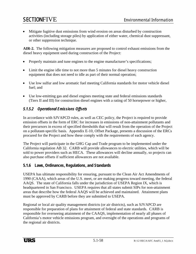
SECTIONFIVE Environmental Information
5.1-58 R:\12 HECA\AFC Amd\5_1 AQ.docx
Mitigate fugitive dust emissions from wind erosion on areas disturbed by construction activities (including storage piles) by application of either water, chemical dust suppressant, or other suppression technique.
AIR-2. The following mitigation measures are proposed to control exhaust emissions from the diesel heavy equipment used during construction of the Project:
Properly maintain and tune engines to the engine manufacturer’s specifications;
Limit the engine idle time to not more than 5 minutes for diesel heavy construction equipment that does not need to idle as part of their normal operation;
Use low sulfur and low aromatic fuel meeting California standards for motor vehicle diesel fuel; and
Use low-emitting gas and diesel engines meeting state and federal emissions standards (Tiers II and III) for construction diesel engines with a rating of 50 horsepower or higher,
5.1.5.2 Operational Emissions Offsets
In accordance with SJVAPCD rules, as well as CEC policy, the Project is required to provide emission offsets in the form of ERC for increases in emissions of non-attainment pollutants and their precursors in excess of specified thresholds that will result from the operation of the Project on a pollutant-specific basis. Appendix E-10, Offset Package, presents a discussion of the ERCs procured for the Project and how these comply with the requirements of each agency.
The Project will participate in the GHG Cap and Trade program to be implemented under the California regulation AB 32. CARB will provide allowances to electric utilities, which will be sold to power providers such as HECA. These allowances will decline annually, so projects can also purchase offsets if sufficient allowances are not available.
5.1.6 Laws, Ordinances, Regulations, and Standards
USEPA has ultimate responsibility for ensuring, pursuant to the Clean Air Act Amendments of 1990 (CAAA), which areas of the U.S. meet, or are making progress toward meeting, the federal AAQS. The state of California falls under the jurisdiction of USEPA Region IX, which is headquartered in San Francisco. USEPA requires that all states submit SIPs for non-attainment areas that describe how the federal AAQS will be achieved and maintained. Attainment plans must be approved by CARB before they are submitted to USEPA.
Regional or local air quality management districts (or air districts), such as SJVAPCD are responsible for preparation of plans for attainment of federal and state standards. CARB is responsible for overseeing attainment of the CAAQS, implementation of nearly all phases of California’s motor vehicle emissions program, and oversight of the operations and programs of the regional air districts.
URS
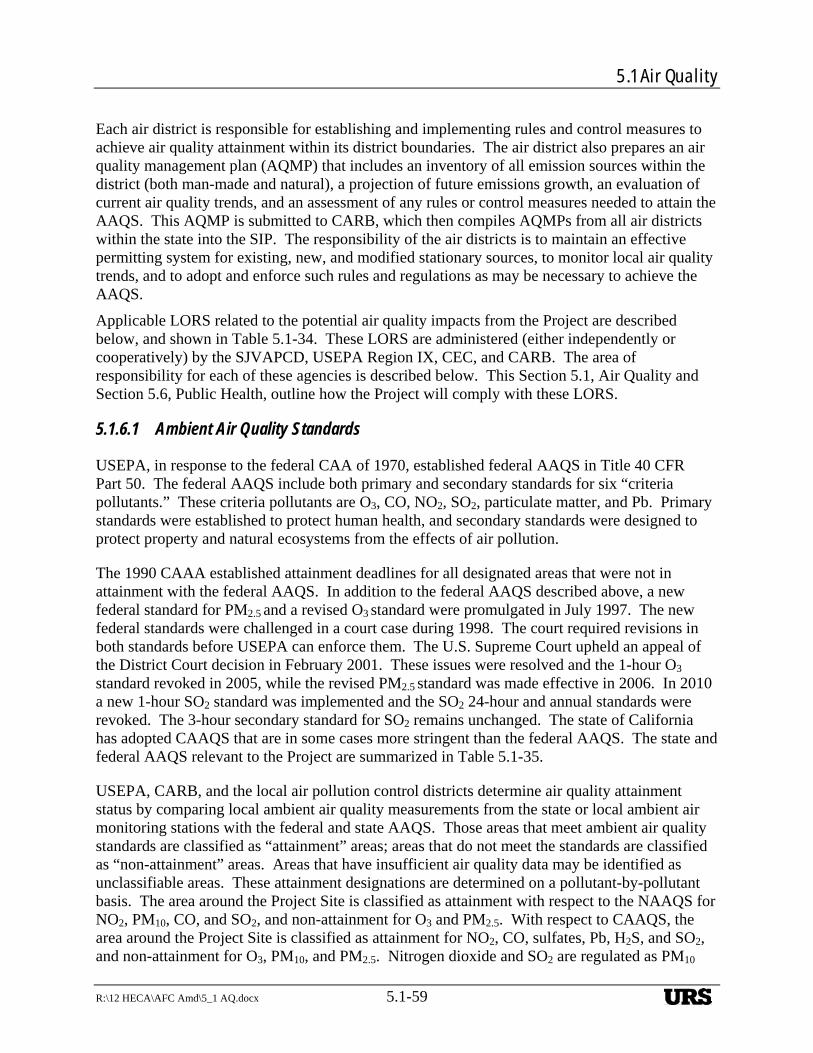
5.1 Air Quality
R:\12 HECA\AFC Amd\5_1 AQ.docx 5.1-59
Each air district is responsible for establishing and implementing rules and control measures to achieve air quality attainment within its district boundaries. The air district also prepares an air quality management plan (AQMP) that includes an inventory of all emission sources within the district (both man-made and natural), a projection of future emissions growth, an evaluation of current air quality trends, and an assessment of any rules or control measures needed to attain the AAQS. This AQMP is submitted to CARB, which then compiles AQMPs from all air districts within the state into the SIP. The responsibility of the air districts is to maintain an effective permitting system for existing, new, and modified stationary sources, to monitor local air quality trends, and to adopt and enforce such rules and regulations as may be necessary to achieve the AAQS.
Applicable LORS related to the potential air quality impacts from the Project are described below, and shown in Table 5.1-34. These LORS are administered (either independently or cooperatively) by the SJVAPCD, USEPA Region IX, CEC, and CARB. The area of responsibility for each of these agencies is described below. This Section 5.1, Air Quality and Section 5.6, Public Health, outline how the Project will comply with these LORS.
5.1.6.1 Ambient Air Quality Standards
USEPA, in response to the federal CAA of 1970, established federal AAQS in Title 40 CFR Part 50. The federal AAQS include both primary and secondary standards for six “criteria pollutants.” These criteria pollutants are O3, CO, NO2, SO2, particulate matter, and Pb. Primary standards were established to protect human health, and secondary standards were designed to protect property and natural ecosystems from the effects of air pollution.
The 1990 CAAA established attainment deadlines for all designated areas that were not in attainment with the federal AAQS. In addition to the federal AAQS described above, a new federal standard for PM2.5 and a revised O3 standard were promulgated in July 1997. The new federal standards were challenged in a court case during 1998. The court required revisions in both standards before USEPA can enforce them. The U.S. Supreme Court upheld an appeal of the District Court decision in February 2001. These issues were resolved and the 1-hour O3
standard revoked in 2005, while the revised PM2.5 standard was made effective in 2006. In 2010 a new 1-hour SO2 standard was implemented and the SO2 24-hour and annual standards were revoked. The 3-hour secondary standard for SO2 remains unchanged. The state of California has adopted CAAQS that are in some cases more stringent than the federal AAQS. The state and federal AAQS relevant to the Project are summarized in Table 5.1-35.
USEPA, CARB, and the local air pollution control districts determine air quality attainment status by comparing local ambient air quality measurements from the state or local ambient air monitoring stations with the federal and state AAQS. Those areas that meet ambient air quality standards are classified as “attainment” areas; areas that do not meet the standards are classified as “non-attainment” areas. Areas that have insufficient air quality data may be identified as unclassifiable areas. These attainment designations are determined on a pollutant-by-pollutant basis. The area around the Project Site is classified as attainment with respect to the NAAQS for NO2, PM10, CO, and SO2, and non-attainment for O3 and PM2.5. With respect to CAAQS, the area around the Project Site is classified as attainment for NO2, CO, sulfates, Pb, H2S, and SO2, and non-attainment for O3, PM10, and PM2.5. Nitrogen dioxide and SO2 are regulated as PM10
URS
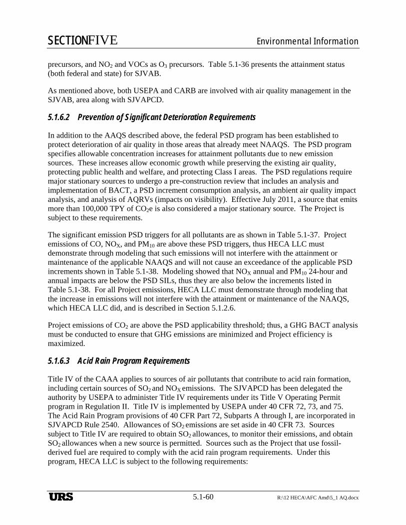
SECTIONFIVE Environmental Information
5.1-60 R:\12 HECA\AFC Amd\5_1 AQ.docx
precursors, and NO2 and VOCs as O3 precursors. Table 5.1-36 presents the attainment status (both federal and state) for SJVAB.
As mentioned above, both USEPA and CARB are involved with air quality management in the SJVAB, area along with SJVAPCD.
5.1.6.2 Prevention of Significant Deterioration Requirements
In addition to the AAQS described above, the federal PSD program has been established to protect deterioration of air quality in those areas that already meet NAAQS. The PSD program specifies allowable concentration increases for attainment pollutants due to new emission sources. These increases allow economic growth while preserving the existing air quality, protecting public health and welfare, and protecting Class I areas. The PSD regulations require major stationary sources to undergo a pre-construction review that includes an analysis and implementation of BACT, a PSD increment consumption analysis, an ambient air quality impact analysis, and analysis of AQRVs (impacts on visibility). Effective July 2011, a source that emits more than 100,000 TPY of CO2e is also considered a major stationary source. The Project is subject to these requirements.
The significant emission PSD triggers for all pollutants are as shown in Table 5.1-37. Project emissions of CO, NOX, and PM10 are above these PSD triggers, thus HECA LLC must demonstrate through modeling that such emissions will not interfere with the attainment or maintenance of the applicable NAAQS and will not cause an exceedance of the applicable PSD increments shown in Table 5.1-38. Modeling showed that NOX annual and PM10 24-hour and annual impacts are below the PSD SILs, thus they are also below the increments listed in Table 5.1-38. For all Project emissions, HECA LLC must demonstrate through modeling that the increase in emissions will not interfere with the attainment or maintenance of the NAAQS, which HECA LLC did, and is described in Section 5.1.2.6.
Project emissions of CO2 are above the PSD applicability threshold; thus, a GHG BACT analysis must be conducted to ensure that GHG emissions are minimized and Project efficiency is maximized.
5.1.6.3 Acid Rain Program Requirements
Title IV of the CAAA applies to sources of air pollutants that contribute to acid rain formation, including certain sources of SO2 and NOX emissions. The SJVAPCD has been delegated the authority by USEPA to administer Title IV requirements under its Title V Operating Permit program in Regulation II. Title IV is implemented by USEPA under 40 CFR 72, 73, and 75. The Acid Rain Program provisions of 40 CFR Part 72, Subparts A through I, are incorporated in SJVAPCD Rule 2540. Allowances of SO2 emissions are set aside in 40 CFR 73. Sources subject to Title IV are required to obtain SO2 allowances, to monitor their emissions, and obtain SO2 allowances when a new source is permitted. Sources such as the Project that use fossil-derived fuel are required to comply with the acid rain program requirements. Under this program, HECA LLC is subject to the following requirements:
URS
5.1 Air Quality
R:\12 HECA\AFC Amd\5_1 AQ.docx 5.1-61
Submittal of an Acid Rain permit application Remain in compliance with SO2 and NOX limitations/allowances Preparation and maintenance of an Acid Rain Compliance Plan Installation and maintenance of emission monitoring system.
The Project is a new facility; therefore, an Acid Rain Permit application will be submitted to SJVAPCD at least 24 months before the date of initial operation of the unit.
To meet the NOX and SO2 requirements, the Project must estimate SO2 and NOX emissions, and monitor NOX emissions with certified CEMSs.
5.1.6.4 New Source Performance Standards
NSPS have been established by USEPA to limit air pollutant emissions from certain types of new and modified stationary sources. The NSPS regulations are contained in 40 CFR 60, and cover nearly 70 source categories. CTG/HRSG is regulated under Subpart Da.
In general, local emission limitation rules or BACT requirements are more restrictive than the NSPS requirements. A case-by-case applicability of NSPS regulations for the sources is further discussed in the BACT analysis in Appendix E-11, Criteria Pollutant BACT Analysis.
5.1.6.5 Federal Climate Change Programs
On April 13, 2012, the USEPA proposed the first Clean Air Act NSPS for emissions of CO2 from future power plants (Standards for Performance for Greenhouse Gas Emissions for New Stationary Sources: Electric Utility Generating Units). EPA is proposing that new fossil‐fuel‐fired power plants meet an output‐based standard of 1,000 pounds of CO2 per megawatt‐hour (lb CO2/MWh gross). This rule is currently in the public comment phase and it is unclear when the rule will be finalized.
USEPA issued the Mandatory Reporting of Greenhouse Gases Rule which requires reporting of GHG data and other relevant information from large sources and suppliers in the United States. The purpose of the rule is to collect accurate and timely GHG data to inform future policy decisions. In general, the Rule is referred to as 40 CFR Part 98 (Part 98). Implementation of Part 98 is referred to as the Greenhouse Gas Reporting Program.
5.1.6.6 Federally Mandated Operating Permits
Title V of the CAAA requires USEPA to develop a federal operating permit program that is implemented under 40 CFR 70. This program is administered by SJVAPCD under Regulation II, Rule 2520. Each major source, Phase II acid rain facility, and other source types designated by USEPA must obtain a Part 70 permit. Permits must contain emission estimates based on potential-to-emit, identification of all emission sources and controls, a compliance plan, and a statement indicating each source’s compliance status. The permits must also incorporate all applicable federal, state, or SJVAPCD orders, rules, and regulations.
URS
SECTIONFIVE Environmental Information
5.1-62 R:\12 HECA\AFC Amd\5_1 AQ.docx
Because the Project will constitute a new stationary source, HECA LLC will submit a complete Title V permit application for a Title V permit to operate within 12 months after Project start-up.
5.1.6.7 California Power Plants Siting Requirements
Under CEQA, CEC has been charged with assessing the environmental impacts of each new power plant and considering the implementation of feasible mitigation measures to prevent potential significant impacts. CEQA Guidelines (Title 14, California Administrative Code, §15002[a][3]) state that the basic purpose of CEQA is to “prevent significant, avoidable damage to the environment by requiring changes in projects through the use of alternatives or mitigation measures when the governmental agency finds the changes to be feasible.”
CEC’s siting regulations require that, except under certain conditions, a new power plant can only be approved if the project complies with all federal, state, and local air quality rules, regulations, standards, guidelines, and ordinances that govern the construction and operation of the project. A project must demonstrate that project emissions will be appropriately controlled to mitigate significant impacts from the project and that it will not jeopardize attainment and maintenance of the AAQS. Cumulative impacts, impacts due to pollutant interaction, and impacts from non-criteria pollutants must also be considered.
5.1.6.8 California Climate Change Programs
Assembly Bill 32 (AB 32) requires the CARB to enact standards that will reduce GHG emissions to 1990 levels by 2020. AB 32 requires the CARB to assign emissions targets to each sector in the California economy and to develop regulatory and market methods to ensure compliance. Emission targets have been established in the CCR Title 20 §2902 – 2904. Additionally, Senate Bill 1368 is a state regulation that has set limits on GHG emissions from utilities. CEC is currently considering whether to modify the current requirements of SB 1368. SB 1368 set an emission performance standard for baseload generation owned by, or under long-term contract to publicly owned utilities, of 1,100 lb/MWh of CO2. The Project will comply with the current version of SB 1368.
The GHG cap and trade regulation under AB 32 became effective January 2012 with a compliance date beginning January 1, 2013. Companies are not given a specific limit on their GHG emissions but must supply a sufficient number of allowances to cover their annual emissions. As the cap declines each year, the total number of allowances issued in the state drops, requiring companies to find the most cost-effective and efficient approaches to reducing their emissions. CARB will provide allowances to industrial sources during the initial period (2013–2014), and those that need additional allowances to cover their emissions can purchase them on the market. Electric utilities will also be given allowances to be sold to power providers such as the Project.
5.1.6.9 Air Toxic “Hot Spots” Program
As required by the California Health and Safety Code §44300, all facilities with criteria air pollutant emissions in excess of 10 tons per year are required to submit air toxic “Hot Spots” emissions information. The operational Project will be required to provide quantitative
URS

5.1 Air Quality
R:\12 HECA\AFC Amd\5_1 AQ.docx 5.1-63
information to the SJVAPCD on the Project’s emissions of toxic air contaminants. This requirement is applicable only after the start of operation. Section 5.6, Public Health, demonstrates that the Project’s emissions of toxic air contaminants impacts from the Project will be less than significant.
5.1.6.10 Determination of Compliance, Authority to Construct, and Permit to Operate
Under Regulation II, Rule 2010, 2070, and 2201, the SJVAPCD administers the air quality regulatory program for the construction, alteration, replacement, and operation of new power plants. As part of the AFC process, the Project will be required to obtain a pre-construction Determination of Compliance (DOC) from the SJVAPCD. Regulation II, Rule 2201 incorporates other SJVAPCD rules that pertain to sources that may emit air contaminants through the issuance of air permits (i.e., ATC and Permit to Operate [PTO]). This permitting process allows the SJVAPCD to adequately review new and modified air pollution sources to ensure compliance with all applicable prohibitory rules and to ensure that appropriate emission controls are used. An ATC allows for the construction of the air pollution source and remains in effect until the PTO application is granted, denied, or cancelled. Projects that are reviewed under the CEC application process must obtain an ATC from the local air district (in this case, SJVAPCD) prior to construction of the new power plant. For power plants under the siting jurisdiction of CEC, the SJVAPCD issues a DOC in lieu of an ATC. The DOC is incorporated into the CEC license. The ATC remains in effect until the PTO application is granted, denied, or cancelled. Once the Project commences operations and demonstrates compliance with the DOC, SJVAPCD will issue a PTO. The PTO specifies conditions that the air pollution source must meet to comply with other air quality standards, and will incorporate applicable DOC requirements. An application for the DOC will be submitted to the SJVAPCD simultaneously with the filing of this AFC Amendment.
5.1.6.11 San Joaquin Valley Air Pollution Control District Requirements
The SJVAPCD has been delegated responsibility for implementing the federal, state, and local regulations on air quality in Kern County to achieve and maintain both state and federal air quality standards; implementing permit programs established for the construction, modification, and operation of sources of air pollution; enforcing air pollution statutes, regulations and prohibitory rules governing non-vehicular sources; and developing programs to reduce emissions from indirect sources. The Project is subject to SJVAPCD regulations that apply to new sources of emissions, to the prohibitory regulations that specify emissions standards, and to the requirements for evaluation of air pollutant impacts for both criteria and toxic air pollutants. The following sections include the evaluation of the Project’s compliance with the applicable SJVAPCD requirements.
5.1.6.12 SJVAPCD Climate Change Action Plan
In December 2009, the SJVAPCD adopted the “Guidance for Valley Land-use Agencies in Addressing GHG Emission Impacts for New Projects under CEQA” and the district policy “Addressing GHG Emission Impacts for Stationary Source Projects under CEQA When Serving as the Lead Agency” (SJVAPCD 2009a, 2009b). The guidance and policy rely on the use of performance based standards, otherwise known as Best Performance Standards, to assess
URS
SECTIONFIVE Environmental Information
5.1-64 R:\12 HECA\AFC Amd\5_1 AQ.docx
significance of project specific GHG emissions on global climate change during the environmental review process, as required by CEQA. This policy applies to projects for which the SJVAPCD has discretionary approval authority over the project and the SJVAPCD serves as the lead agency for CEQA purposes. For this Project, CEC is the lead agency and quantification of GHG emissions is used to determine compliance with adopted regional, statewide or local GHG reductions plans. As such, the SJVAPCD Climate Change Plan performance based standards are not applicable to this Project.
5.1.6.13 SJVAPCD Rules and Regulations
Rule 1080, Stack Monitoring
Outlines facility requirements for continuous monitoring equipment from any facility emitting pollutants for which emission limits have been established. The project will be constructed and operated to comply with the requirements of Rule 1080.
Rule 1081, Source Sampling
Outlines facility design requirements for source sampling from any facility emitting pollutants for which emission limits have been established. The project will be constructed and operated to comply with the requirements of Rule 1081.
Rule 1100, Equipment Breakdown
This rule details the notification and corrective action requirements necessary in an equipment breakdown situation. As operator of the Project, the Applicant will comply with these requirements.
Rule 2010, Permits Required
An ATC and PTO will be required for the Project. The Applicant will submit the required application materials for these permits to SJVAPCD.
Rule 2201, New and Modified Stationary Source Review
This rule outlines the emission standards, the offset requirements and conditions, the required demonstrations that the new source or modification will not cause or contribute to violations of the ambient air quality standards, procedures for power plants under CEC process, methods for calculating project emissions, and required air quality analysis procedures. Compliance with the specific provisions of this rule is discussed below.
Section 4.1, BACT. An Applicant must apply BACT to any new or modified emissions unit that has a potential to emit 2.0 pounds per day or more of any criteria pollutant. The SJVAPCD maintains a list of current BACT standards for specific source categories, which is posted on the District’s website. Appendix E-11, Criteria Pollutant BACT Analysis, provides a formal BACT evaluation for the Project emissions of criteria pollutants. The proposed BACT levels for each
URS
5.1 Air Quality
R:\12 HECA\AFC Amd\5_1 AQ.docx 5.1-65
Project source are shown in Table 5.1-39, Proposed BACT for the Project, and incorporated in the emission calculations.
The Project will produce low-carbon baseload electricity and nitrogen based products by capturing CO2 and transporting it for EOR and sequestration, thus controlling GHG emission to levels substantially below that of other fossil fuel power plants. The GHG BACT analysis has been prepared and submitted to USEPA with the HECA PSD permit application, this analysis will be amended to incorporate Project revisions and submitted with the revised PSD permit application.
Section 4.5, Emissions Offset Requirements. This section of Rule 2201 requires that offsets be provided for a new stationary source with a potential to emit equal to or exceeding the levels shown in the ERC analysis presented in Appendix E-10, Offset Package. Appendix E-10, Offset Package, describes the methods for determining the quantities of emission reduction credits needed to offset emissions from the Project. HECA LLC has already procured sufficient ERCs to mitigate Project emissions of non-attainment pollutant and their precursors.
Section 4.14, Ambient Air Quality Standards. Emissions from a new or modified Stationary Source may not cause or make worse the violation of an AAQS. Modeling used for the purposes of demonstrating compliance with this rule must be consistent with the requirements contained in the most recent edition of USEPA’s Guidelines on Air Quality Models, unless the Air Pollution Control Officer finds that such model is inappropriate for use. After making such a finding, the Air Pollution Control Officer may designate an alternate model only after allowing for public comments and only with the concurrence of CARB or the USEPA.
As described in Section 5.1.2.6, Modeling Results—Compliance with Ambient Air Quality Standards, an air quality modeling analysis has been conducted to demonstrate that the Project will not cause or make worse the violation of any air quality standard.
Section 5.8, Power Plants. This section applies to all power plants proposed to be constructed in the SJVAPCD and for which a Notice of Intention or AFC has been accepted by CEC. It describes the actions to be taken by SJVAPCD to provide information to CEC and CARB to ensure that the project will conform to the District’s rules and regulations. After the application has been submitted to CEC and other responsible agencies, including SJVAPCD, the Air Pollution Control Officer is required to conduct a DOC review. This determination consists of a review identical to that which would be performed if an application for an ATC had been received for the power plant. If the information contained in the AFC does not meet the requirements of this regulation, then the Air Pollution Control Officer is required to so inform CEC within 20 calendar days following receipt of the AFC. In such an instance, the AFC is considered to be incomplete, and is returned to the Applicant for re-submittal.
Section 6.0, Certification of Conformity. This section describes how a new or modified source that is subject to the requirements of Rule 2520 may choose to apply for a certificate of conformity with the procedural requirements of 40 CFR Part 70 for a Federal Operating Permit. A certificate of conformity will allow changes authorized by the ATC permit to be incorporated in the Part 70 permit as administrative permit amendments.
URS
SECTIONFIVE Environmental Information
5.1-66 R:\12 HECA\AFC Amd\5_1 AQ.docx
Rule 2520, Federally Mandated Operating Permits
Provides an administrative mechanism for issuing operating permits for new and modified sources of air contamination accordance with the federal requirements of 40 CFR Part 70. Under this rule, the Project will be required to obtain an operating permit, because it will include emission units that are subject to recently promulgated NSPS, and because it will also require an acid rain permit.
Rule 3010/3020, Permit Fees
This rule and the fee schedules in Rule 3020 establish the filing and permit review fees for specific types of new sources, as well as annual renewal fees and penalty fees for existing sources.
Rule 3110, Air Toxics Fees
This rule applies to facilities subject to the requirements of the Air Toxics “Hot Spots” Information and Assessment Act (§§ 44340 and 44383 of the California Health and Safety Code) and to facilities subject to NESHAPs issued pursuant to §112 of the federal CAA.
Rule 3135, Dust Control Plan Fee
This rule recovers the District’s cost for reviewing Dust Control Plans and conducting site inspections to verify compliance with such plans.
Rule 3170, Federally Mandated Ozone Non-Attainment Fee
The purpose of this rule is to satisfy requirements specified in §185 and §1 82(f) of the CAA. This rule applies to major sources of NOX and VOCs. The fees required pursuant to this section are additional to the permit fees and other fees required under other Rules and Regulations. This rule will cease to be effective when the Administrator of USEPA designates the SJVAPCD to be in attainment of the federal 1-hour standard for O3. The Project will be a major source under either the federal or SJVAPCD definitions, and is subject to Rule 3170.
Rule 4001, New Source Performance Standards
This rule incorporates the federal NSPS from 40 CFR Part 60.
Rule 4002, National Emission Standards for Hazardous Air Pollutants
This rule incorporates the federal NESHAPs from Part 61 and Part 63, Chapter I, Subchapter C, Title 40 CFR.
Rule 4101, Visible Emissions
This rule applies to the opacity of discharges from any single source. Emissions from the sources of the Project will be below threshold opacity levels described in this rule.
URS
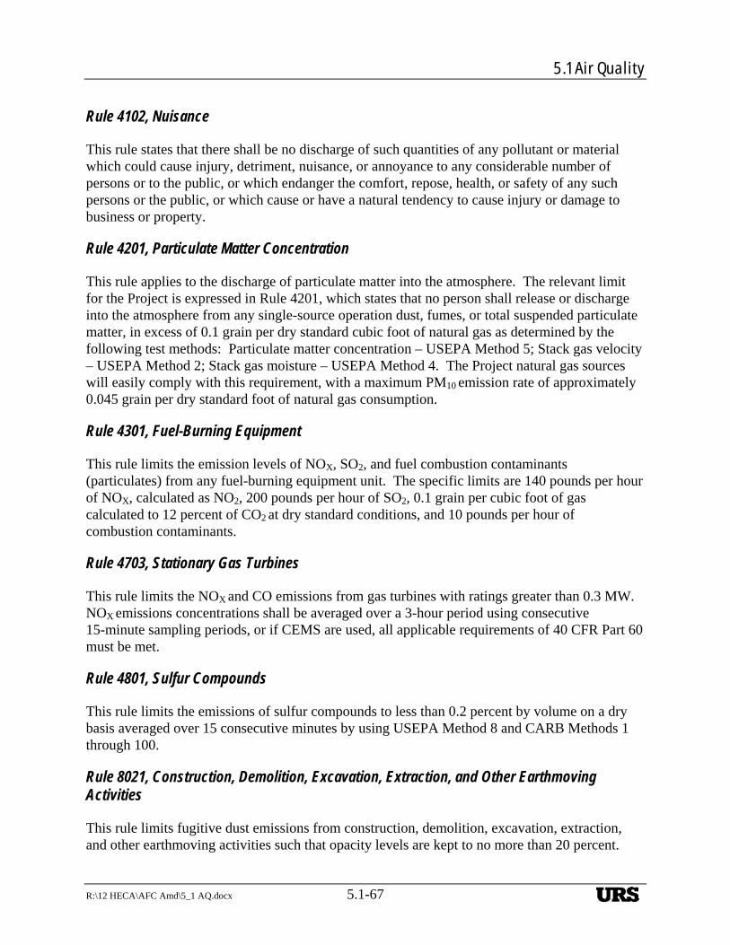
5.1 Air Quality
R:\12 HECA\AFC Amd\5_1 AQ.docx 5.1-67
Rule 4102, Nuisance
This rule states that there shall be no discharge of such quantities of any pollutant or material which could cause injury, detriment, nuisance, or annoyance to any considerable number of persons or to the public, or which endanger the comfort, repose, health, or safety of any such persons or the public, or which cause or have a natural tendency to cause injury or damage to business or property.
Rule 4201, Particulate Matter Concentration
This rule applies to the discharge of particulate matter into the atmosphere. The relevant limit for the Project is expressed in Rule 4201, which states that no person shall release or discharge into the atmosphere from any single-source operation dust, fumes, or total suspended particulate matter, in excess of 0.1 grain per dry standard cubic foot of natural gas as determined by the following test methods: Particulate matter concentration – USEPA Method 5; Stack gas velocity – USEPA Method 2; Stack gas moisture – USEPA Method 4. The Project natural gas sources will easily comply with this requirement, with a maximum PM10 emission rate of approximately 0.045 grain per dry standard foot of natural gas consumption.
Rule 4301, Fuel-Burning Equipment
This rule limits the emission levels of NOX, SO2, and fuel combustion contaminants (particulates) from any fuel-burning equipment unit. The specific limits are 140 pounds per hour of NOX, calculated as NO2, 200 pounds per hour of SO2, 0.1 grain per cubic foot of gas calculated to 12 percent of CO2 at dry standard conditions, and 10 pounds per hour of combustion contaminants.
Rule 4703, Stationary Gas Turbines
This rule limits the NOX and CO emissions from gas turbines with ratings greater than 0.3 MW. NOX emissions concentrations shall be averaged over a 3-hour period using consecutive 15-minute sampling periods, or if CEMS are used, all applicable requirements of 40 CFR Part 60 must be met.
Rule 4801, Sulfur Compounds
This rule limits the emissions of sulfur compounds to less than 0.2 percent by volume on a dry basis averaged over 15 consecutive minutes by using USEPA Method 8 and CARB Methods 1 through 100.
Rule 8021, Construction, Demolition, Excavation, Extraction, and Other Earthmoving Activities
This rule limits fugitive dust emissions from construction, demolition, excavation, extraction, and other earthmoving activities such that opacity levels are kept to no more than 20 percent.
URS
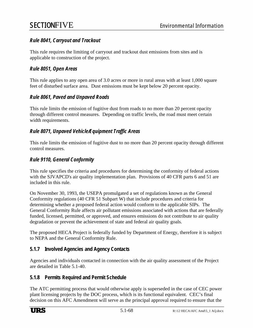
SECTIONFIVE Environmental Information
5.1-68 R:\12 HECA\AFC Amd\5_1 AQ.docx
Rule 8041, Carryout and Trackout
This rule requires the limiting of carryout and trackout dust emissions from sites and is applicable to construction of the project.
Rule 8051, Open Areas
This rule applies to any open area of 3.0 acres or more in rural areas with at least 1,000 square feet of disturbed surface area. Dust emissions must be kept below 20 percent opacity.
Rule 8061, Paved and Unpaved Roads
This rule limits the emission of fugitive dust from roads to no more than 20 percent opacity through different control measures. Depending on traffic levels, the road must meet certain width requirements.
Rule 8071, Unpaved Vehicle/Equipment Traffic Areas
This rule limits the emission of fugitive dust to no more than 20 percent opacity through different control measures.
Rule 9110, General Conformity
This rule specifies the criteria and procedures for determining the conformity of federal actions with the SJVAPCD's air quality implementation plan. Provisions of 40 CFR parts 6 and 51 are included in this rule.
On November 30, 1993, the USEPA promulgated a set of regulations known as the General Conformity regulations (40 CFR 51 Subpart W) that include procedures and criteria for determining whether a proposed federal action would conform to the applicable SIPs. The General Conformity Rule affects air pollutant emissions associated with actions that are federally funded, licensed, permitted, or approved, and ensures emissions do not contribute to air quality degradation or prevent the achievement of state and federal air quality goals.
The proposed HECA Project is federally funded by Department of Energy, therefore it is subject to NEPA and the General Conformity Rule.
5.1.7 Involved Agencies and Agency Contacts
Agencies and individuals contacted in connection with the air quality assessment of the Project are detailed in Table 5.1-40.
5.1.8 Permits Required and Permit Schedule
The ATC permitting process that would otherwise apply is superseded in the case of CEC power plant licensing projects by the DOC process, which is its functional equivalent. CEC’s final decision on this AFC Amendment will serve as the principal approval required to ensure that the
URS
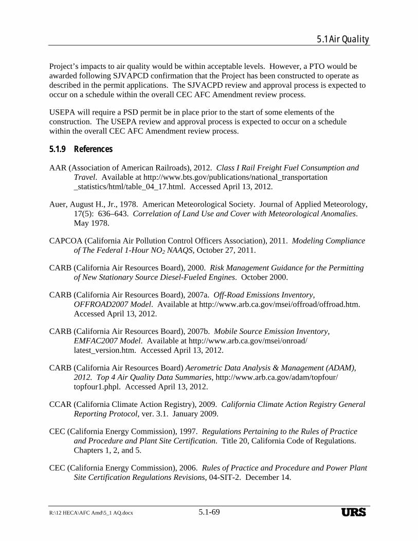
5.1 Air Quality
R:\12 HECA\AFC Amd\5_1 AQ.docx 5.1-69
Project’s impacts to air quality would be within acceptable levels. However, a PTO would be awarded following SJVAPCD confirmation that the Project has been constructed to operate as described in the permit applications. The SJVACPD review and approval process is expected to occur on a schedule within the overall CEC AFC Amendment review process.
USEPA will require a PSD permit be in place prior to the start of some elements of the construction. The USEPA review and approval process is expected to occur on a schedule within the overall CEC AFC Amendment review process.
5.1.9 References
AAR (Association of American Railroads), 2012. Class I Rail Freight Fuel Consumption and Travel. Available at http://www.bts.gov/publications/national_transportation_statistics/html/table_04_17.html. Accessed April 13, 2012.
Auer, August H., Jr., 1978. American Meteorological Society. Journal of Applied Meteorology, 17(5): 636–643. Correlation of Land Use and Cover with Meteorological Anomalies. May 1978.
CAPCOA (California Air Pollution Control Officers Association), 2011. Modeling Compliance of The Federal 1-Hour NO2 NAAQS, October 27, 2011.
CARB (California Air Resources Board), 2000. Risk Management Guidance for the Permitting of New Stationary Source Diesel-Fueled Engines. October 2000.
CARB (California Air Resources Board), 2007a. Off-Road Emissions Inventory, OFFROAD2007 Model. Available at http://www.arb.ca.gov/msei/offroad/offroad.htm. Accessed April 13, 2012.
CARB (California Air Resources Board), 2007b. Mobile Source Emission Inventory, EMFAC2007 Model. Available at http://www.arb.ca.gov/msei/onroad/latest_version.htm. Accessed April 13, 2012.
CARB (California Air Resources Board) Aerometric Data Analysis & Management (ADAM), 2012. Top 4 Air Quality Data Summaries, http://www.arb.ca.gov/adam/topfour/topfour1.phpl. Accessed April 13, 2012.
CCAR (California Climate Action Registry), 2009. California Climate Action Registry General Reporting Protocol, ver. 3.1. January 2009.
CEC (California Energy Commission), 1997. Regulations Pertaining to the Rules of Practice and Procedure and Plant Site Certification. Title 20, California Code of Regulations. Chapters 1, 2, and 5.
CEC (California Energy Commission), 2006. Rules of Practice and Procedure and Power Plant Site Certification Regulations Revisions, 04-SIT-2. December 14.
URS
SECTIONFIVE Environmental Information
5.1-70 R:\12 HECA\AFC Amd\5_1 AQ.docx
CEC (California Energy Commission), 2012. Regulations Establishing and Implementing a Greenhouse Gases Emission Performance Standard for Local Publicly Owned Electric Utilities, Chapter 11. Greenhouse Gases Emission Performance Standard, Article 1, Section 2900 et seq., http://www.energy.ca.gov/emission_standards/regulations/Chapter11_Article1_SB 1368_Regulations.PDF. Accessed April 10, 2012.
DOE-NETL (Department of Energy–National Energy Technology Laboratory), 2009. Carbon Dioxide Enhanced Oil Recovery – Untapped Domestic Energy Supply and Long Term Carbon Storage Solution. DOE/NETL Oil and Natural Gas Technologies, Exploration, and Production Report – CO2 EOR Primer. September 2009.
NPS (National Park Service), 2010. Federal Land Managers’ Air Quality Related Values Work Group (FLAG), Phase I Report – Revised (2010). October.
Port of Long Beach, 2009. Port of Long Beach Air Emissions Inventory – 2007. http://www.polb.com/civica/filebank/blobdload.asp?BlobID=6029. Accessed April 13, 2012.
SJVAPCD (San Joaquin Valley Air Pollution Control District), 2009a. Guidance for Valley Land-use Agencies in Addressing GHG Emission Impacts for New Projects under CEQA. December 17, 2009.
SJVAPCD (San Joaquin Valley Air Pollution Control District), 2009b. Addressing GHG Emission Impacts for Stationary Source Projects under CEQA When Serving as the Lead Agency. December 17, 2009.
SJVAPCD (San Joaquin Valley Air Pollution Control District), 2010. Assessment of Non-Regulatory Option in AERMOD Specifically OLM and PVMRM. September 2010.
URS Corporation, 2009a. Air Quality Modeling Protocol for the Hydrogen Energy California (HECA) Project, Kern County. Prepared by URS for San Joaquin Valley Air Pollution Control District, California Energy Commission, U.S. Environmental Protection Agency Region IX, and National Park Service. February, 2009.
URS Corporation, 2009b. Reponses to CEC Data Requests Set One – Nos. 1 Through 132, Revised Application for Certification (08-AFC-8). November 2009.
URS Corporation, 2010. Reponses to CEC Data Requests Set One (Nos. 1, 2, 11, 17, 31b, 32, 33, 36, 64f, 85 through 90, and 125 through 132), Revised Application for Certification (08-AFC-8). January 2010.
URS Corporation, 2011. Modeling Protocol for Parameter Selection Specific to the 1-hour NO2 NAAQS Regional Modeling for the HECA Project. Prepared by URS for U.S. Environmental Protection Agency, Region IX. January 20, 2011
URS Corporation, 2012. Modeling Protocol Supplement for the HECA Project. Prepared by URS for U.S. Environmental Protection Agency Region IX, California Energy Commission, and San Joaquin Valley Air Pollution Control District. February 21, 2012.
URS
5.1 Air Quality
R:\12 HECA\AFC Amd\5_1 AQ.docx 5.1-71
USEPA (U.S. Environmental Protection Agency), 1985. Guideline for Determination of Good Engineering Stack Height (Technical Support Document for the Stack Height Regulation) (Revised), EPA-450/4-80-023R. Office of Air Quality Planning and Standards, U.S. Environmental Protection Agency, Research Triangle Park, North Carolina. June 1985.
USEPA (U.S. Environmental Protection Agency), 1995b. SCREEN3 Model User’s Guide. EPA-454/B-95-004. September 1995.
USEPA (U.S. Environmental Protection Agency), 1995c. Protocol for Equipment Leak Emission Estimates. EPA-453/R-95-017. November 1995.
USEPA (U.S. Environmental Protection Agency), 2003. Guidelines on Air Quality Models.
USEPA (U.S. Environmental Protection Agency), 2004. User’s Guide for the AMS/EPA Regulatory Model – AERMOD. EPA454-B-03-001. September 2004.
USEPA (U.S. Environmental Protection Agency), 2006. Addendum to User’s Guide for the AMS/EPA Regulatory Model-AERMOD. December 2006.
USEPA (U.S. Environmental Protection Agency), 2009. Technical Highlights: Emission Factors for Locomotives. EPA-420/F-09-025. April 2009.
USEPA (U.S. Environmental Protection Agency), 2011. Additional Clarification Regarding Application of Appendix W Modeling Guidance for the 1-hour NO2 National Ambient Air Quality Standard. March 1, 2011.
USEPA (U.S. Environmental Protection Agency), 2012. AIRS Air Quality Monitoring Data Reports, http://www.epa.gov/airdata/. Accessed April 13, 2012.
Western Regional Climate Center, 2012. Buttonwillow, CA, Period of Record Monthly Climate Summary, http://www.wrcc.dri.edu/cgi-bin/cliMAIN.pl?ca1244. Accessed April 5, 2012.
URS
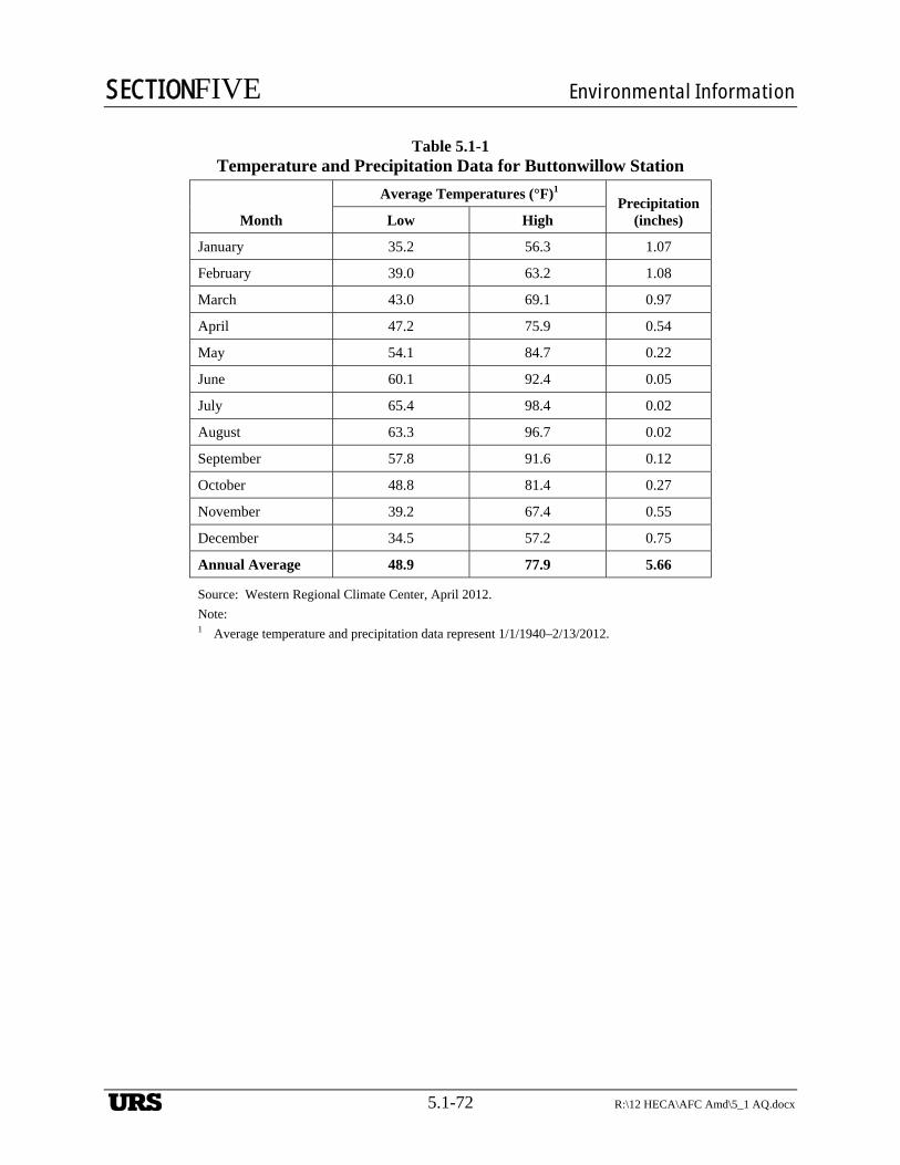
SECTIONFIVE Environmental Information
5.1-72 R:\12 HECA\AFC Amd\5_1 AQ.docx
Table 5.1-1 Temperature and Precipitation Data for Buttonwillow Station
Month
Average Temperatures (°F)1 Precipitation
(inches) Low High
January 35.2 56.3 1.07
February 39.0 63.2 1.08
March 43.0 69.1 0.97
April 47.2 75.9 0.54
May 54.1 84.7 0.22
June 60.1 92.4 0.05
July 65.4 98.4 0.02
August 63.3 96.7 0.02
September 57.8 91.6 0.12
October 48.8 81.4 0.27
November 39.2 67.4 0.55
December 34.5 57.2 0.75
Annual Average 48.9 77.9 5.66
Source: Western Regional Climate Center, April 2012.
Note: 1 Average temperature and precipitation data represent 1/1/1940–2/13/2012.
URS
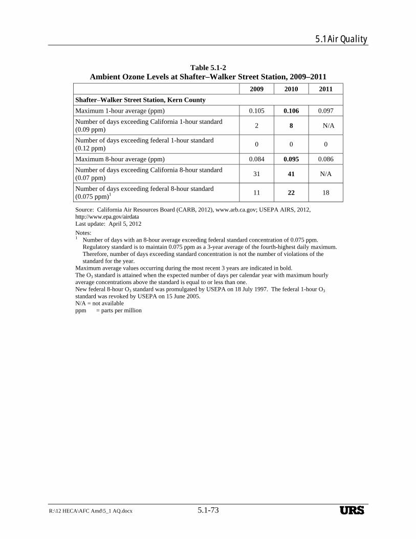
5.1 Air Quality
R:\12 HECA\AFC Amd\5_1 AQ.docx 5.1-73
Table 5.1-2 Ambient Ozone Levels at Shafter–Walker Street Station, 2009–2011
2009 2010 2011
Shafter–Walker Street Station, Kern County
Maximum 1-hour average (ppm) 0.105 0.106 0.097
Number of days exceeding California 1-hour standard (0.09 ppm)
2 8 N/A
Number of days exceeding federal 1-hour standard (0.12 ppm)
0 0 0
Maximum 8-hour average (ppm) 0.084 0.095 0.086
Number of days exceeding California 8-hour standard (0.07 ppm)
31 41 N/A
Number of days exceeding federal 8-hour standard (0.075 ppm)1
11 22 18
Source: California Air Resources Board (CARB, 2012), www.arb.ca.gov; USEPA AIRS, 2012, http://www.epa.gov/airdata Last update: April 5, 2012
Notes: 1 Number of days with an 8-hour average exceeding federal standard concentration of 0.075 ppm.
Regulatory standard is to maintain 0.075 ppm as a 3-year average of the fourth-highest daily maximum. Therefore, number of days exceeding standard concentration is not the number of violations of the standard for the year.
Maximum average values occurring during the most recent 3 years are indicated in bold. The O3 standard is attained when the expected number of days per calendar year with maximum hourly average concentrations above the standard is equal to or less than one. New federal 8-hour O3 standard was promulgated by USEPA on 18 July 1997. The federal 1-hour O3 standard was revoked by USEPA on 15 June 2005. N/A = not available ppm = parts per million
URS
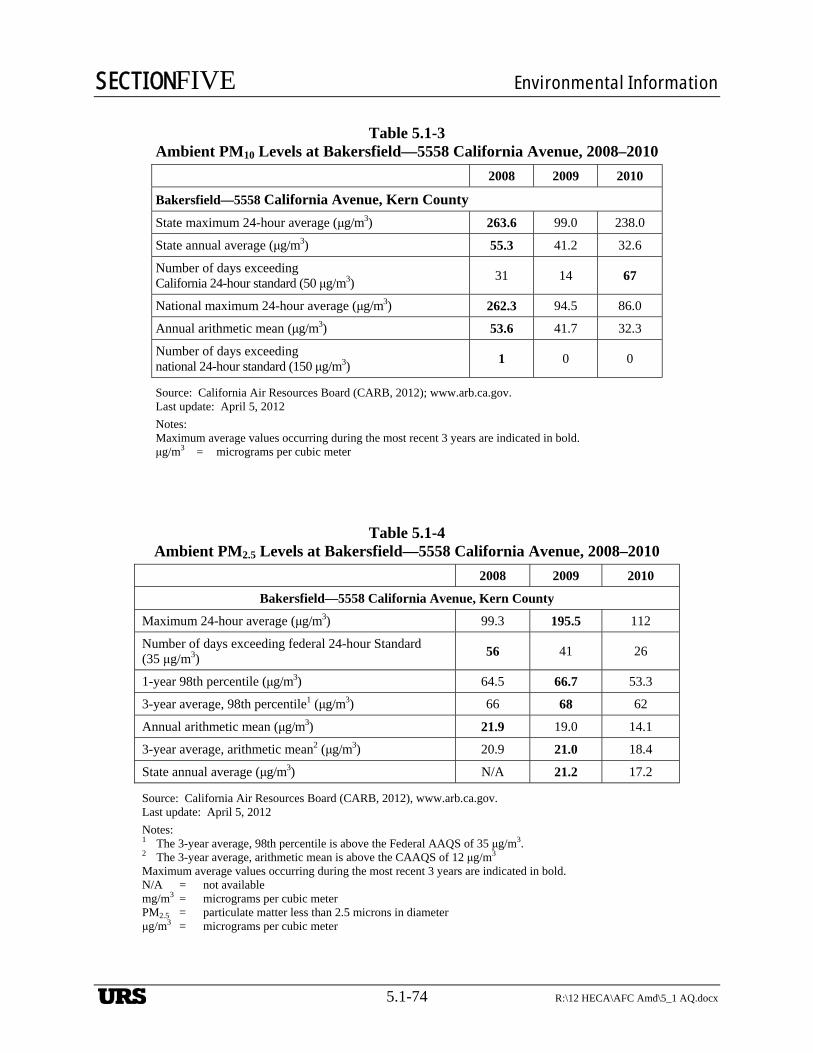
SECTIONFIVE Environmental Information
5.1-74 R:\12 HECA\AFC Amd\5_1 AQ.docx
Table 5.1-3 Ambient PM10 Levels at Bakersfield—5558 California Avenue, 2008–2010
2008 2009 2010
Bakersfield—5558 California Avenue, Kern County
State maximum 24-hour average (μg/m3) 263.6 99.0 238.0
State annual average (μg/m3) 55.3 41.2 32.6
Number of days exceeding California 24-hour standard (50 μg/m3)
31 14 67
National maximum 24-hour average (μg/m3) 262.3 94.5 86.0
Annual arithmetic mean (μg/m3) 53.6 41.7 32.3
Number of days exceeding national 24-hour standard (150 μg/m3)
1 0 0
Source: California Air Resources Board (CARB, 2012); www.arb.ca.gov. Last update: April 5, 2012
Notes: Maximum average values occurring during the most recent 3 years are indicated in bold. μg/m3 = micrograms per cubic meter
Table 5.1-4 Ambient PM2.5 Levels at Bakersfield—5558 California Avenue, 2008–2010
2008 2009 2010
Bakersfield—5558 California Avenue, Kern County
Maximum 24-hour average (μg/m3) 99.3 195.5 112
Number of days exceeding federal 24-hour Standard (35 μg/m3)
56 41 26
1-year 98th percentile (μg/m3) 64.5 66.7 53.3
3-year average, 98th percentile1 (μg/m3) 66 68 62
Annual arithmetic mean (μg/m3) 21.9 19.0 14.1
3-year average, arithmetic mean2 (μg/m3) 20.9 21.0 18.4
State annual average (μg/m3) N/A 21.2 17.2
Source: California Air Resources Board (CARB, 2012), www.arb.ca.gov. Last update: April 5, 2012
Notes: 1 The 3-year average, 98th percentile is above the Federal AAQS of 35 μg/m3. 2 The 3-year average, arithmetic mean is above the CAAQS of 12 μg/m3 Maximum average values occurring during the most recent 3 years are indicated in bold. N/A = not available mg/m3 = micrograms per cubic meter PM2.5 = particulate matter less than 2.5 microns in diameter μg/m3 = micrograms per cubic meter
URS
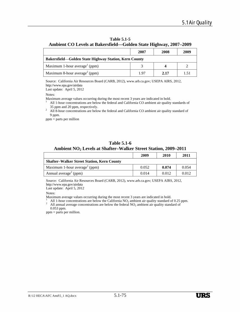
5.1 Air Quality
R:\12 HECA\AFC Amd\5_1 AQ.docx 5.1-75
Table 5.1-5 Ambient CO Levels at Bakersfield—Golden State Highway, 2007–2009
2007 2008 2009
Bakersfield—Golden State Highway Station, Kern County
Maximum 1-hour average1 (ppm) 3 4 2
Maximum 8-hour average2 (ppm) 1.97 2.17 1.51
Source: California Air Resources Board (CARB, 2012), www.arb.ca.gov; USEPA AIRS, 2012, http://www.epa.gov/airdata Last update: April 5, 2012
Notes: Maximum average values occurring during the most recent 3 years are indicated in bold. 1 All 1-hour concentrations are below the federal and California CO ambient air quality standards of
35 ppm and 20 ppm, respectively. 2 All 8-hour concentrations are below the federal and California CO ambient air quality standard of
9 ppm. ppm = parts per million
Table 5.1-6 Ambient NO2 Levels at Shafter–Walker Street Station, 2009–2011
2009 2010 2011
Shafter–Walker Street Station, Kern County
Maximum 1-hour average1 (ppm) 0.052 0.074 0.054
Annual average2 (ppm) 0.014 0.012 0.012
Source: California Air Resources Board (CARB, 2012), www.arb.ca.gov; USEPA AIRS, 2012, http://www.epa.gov/airdata Last update: April 5, 2012
Notes: Maximum average values occurring during the most recent 3 years are indicated in bold. 1 All 1-hour concentrations are below the California NO2 ambient air quality standard of 0.25 ppm. 2 All annual average concentrations are below the federal NO2 ambient air quality standard of
0.053 ppm. ppm = parts per million.
URS
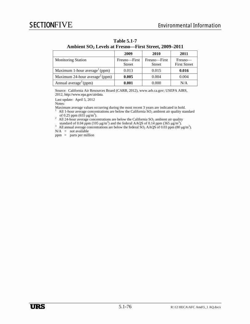
SECTIONFIVE Environmental Information
5.1-76 R:\12 HECA\AFC Amd\5_1 AQ.docx
Table 5.1-7 Ambient SO2 Levels at Fresno—First Street, 2009–2011
2009 2010 2011
Monitoring Station Fresno—First Street
Fresno—First Street
Fresno—First Street
Maximum 1-hour average1 (ppm) 0.013 0.015 0.016
Maximum 24-hour average2 (ppm) 0.005 0.004 0.004
Annual average3 (ppm) 0.001 0.000 N/A
Source: California Air Resources Board (CARB, 2012), www.arb.ca.gov; USEPA AIRS, 2012, http://www.epa.gov/airdata.
Last update: April 5, 2012 Notes: Maximum average values occurring during the most recent 3 years are indicated in bold. 1 All 1-hour average concentrations are below the California SO2 ambient air quality standard
of 0.25 ppm (655 μg/m3). 2 All 24-hour average concentrations are below the California SO2 ambient air quality
standard of 0.04 ppm (105 μg/m3) and the federal AAQS of 0.14 ppm (365 μg/m3). 3 All annual average concentrations are below the federal SO2 AAQS of 0.03 ppm (80 μg/m3). N/A = not available ppm = parts per million
URS
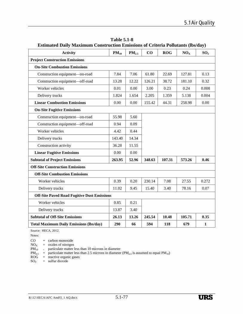
5.1 Air Quality
R:\12 HECA\AFC Amd\5_1 AQ.docx 5.1-77
Table 5.1-8 Estimated Daily Maximum Construction Emissions of Criteria Pollutants (lbs/day)
Activity PM10 PM2.5 CO ROG NOX SO2
Project Construction Emissions
On-Site Combustion Emissions
Construction equipment—on-road 7.84 7.06 61.80 22.69 127.81 0.13
Construction equipment—off-road 13.28 12.22 126.21 38.72 181.10 0.32
Worker vehicles 0.01 0.00 3.00 0.23 0.24 0.008
Delivery trucks 1.824 1.654 2.205 1.359 5.138 0.004
Linear Combustion Emissions 0.00 0.00 155.42 44.31 258.98 0.00
On-Site Fugitive Emissions
Construction equipment—on-road 55.98 5.60
Construction equipment—off-road 0.94 0.09
Worker vehicles 4.42 0.44
Delivery trucks 143.40 14.34
Construction activity 36.28 11.55
Linear Fugitive Emissions 0.00 0.00
Subtotal of Project Emissions 263.95 52.96 348.63 107.31 573.26 0.46
Off-Site Construction Emissions
Off-Site Combustion Emissions
Worker vehicles 0.39 0.20 230.14 7.08 27.55 0.272
Delivery trucks 11.02 9.45 15.40 3.40 78.16 0.07
Off-Site Paved Road Fugitive Dust Emissions
Worker vehicles 0.85 0.21
Delivery trucks 13.87 3.40
Subtotal of Off-Site Emissions 26.13 13.26 245.54 10.48 105.71 0.35
Total Maximum Daily Emissions (lbs/day) 290 66 594 118 679 1
Source: HECA, 2012.
Notes:
CO = carbon monoxide NOX = oxides of nitrogen PM10 = particulate matter less than 10 microns in diameter PM2.5 = particulate matter less than 2.5 microns in diameter (PM2.5 is assumed to equal PM10) ROG = reactive organic gases SO2 = sulfur dioxide
URS
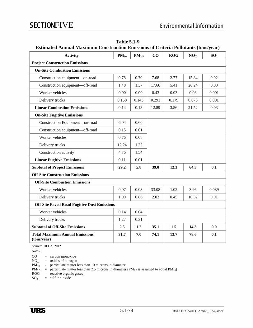
SECTIONFIVE Environmental Information
5.1-78 R:\12 HECA\AFC Amd\5_1 AQ.docx
Table 5.1-9
Estimated Annual Maximum Construction Emissions of Criteria Pollutants (tons/year)
Activity PM10 PM2.5 CO ROG NOX SO2
Project Construction Emissions
On-Site Combustion Emissions
Construction equipment—on-road 0.78 0.70 7.68 2.77 15.84 0.02
Construction equipment—off-road 1.48 1.37 17.68 5.41 26.24 0.03
Worker vehicles 0.00 0.00 0.43 0.03 0.03 0.001
Delivery trucks 0.158 0.143 0.291 0.179 0.678 0.001
Linear Combustion Emissions 0.14 0.13 12.89 3.86 21.52 0.03
On-Site Fugitive Emissions
Construction Equipment—on-road 6.04 0.60
Construction equipment—off-road 0.15 0.01
Worker vehicles 0.76 0.08
Delivery trucks 12.24 1.22
Construction activity 4.76 1.54
Linear Fugitive Emissions 0.11 0.01
Subtotal of Project Emissions 29.2 5.8 39.0 12.3 64.3 0.1
Off-Site Construction Emissions
Off-Site Combustion Emissions
Worker vehicles 0.07 0.03 33.08 1.02 3.96 0.039
Delivery trucks 1.00 0.86 2.03 0.45 10.32 0.01
Off-Site Paved Road Fugitive Dust Emissions
Worker vehicles 0.14 0.04
Delivery trucks 1.27 0.31
Subtotal of Off-Site Emissions 2.5 1.2 35.1 1.5 14.3 0.0
Total Maximum Annual Emissions (tons/year)
31.7 7.0 74.1 13.7 78.6 0.1
Source: HECA, 2012.
Notes:
CO = carbon monoxide NOX = oxides of nitrogen PM10 = particulate matter less than 10 microns in diameter PM2.5 = particulate matter less than 2.5 microns in diameter (PM2.5 is assumed to equal PM10) ROG = reactive organic gases SO2 = sulfur dioxide
URS
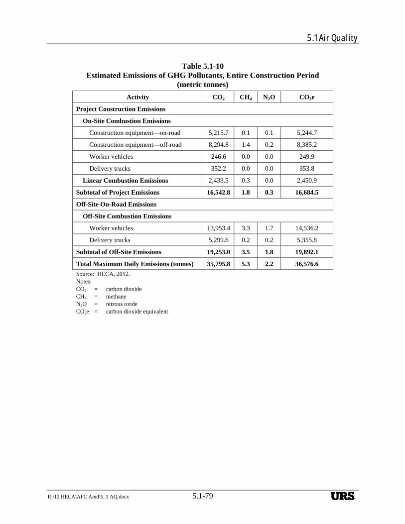
5.1 Air Quality
R:\12 HECA\AFC Amd\5_1 AQ.docx 5.1-79
Table 5.1-10 Estimated Emissions of GHG Pollutants, Entire Construction Period
(metric tonnes)
Activity CO2 CH4 N2O CO2e
Project Construction Emissions
On-Site Combustion Emissions
Construction equipment—on-road 5,215.7 0.1 0.1 5,244.7
Construction equipment—off-road 8,294.8 1.4 0.2 8,385.2
Worker vehicles 246.6 0.0 0.0 249.9
Delivery trucks 352.2 0.0 0.0 353.8
Linear Combustion Emissions 2,433.5 0.3 0.0 2,450.9
Subtotal of Project Emissions 16,542.8 1.8 0.3 16,684.5
Off-Site On-Road Emissions
Off-Site Combustion Emissions
Worker vehicles 13,953.4 3.3 1.7 14,536.2
Delivery trucks 5,299.6 0.2 0.2 5,355.8
Subtotal of Off-Site Emissions 19,253.0 3.5 1.8 19,892.1
Total Maximum Daily Emissions (tonnes) 35,795.8 5.3 2.2 36,576.6
Source: HECA, 2012. Notes: CO2 = carbon dioxide CH4 = methane N2O = nitrous oxide CO2e = carbon dioxide equivalent
URS
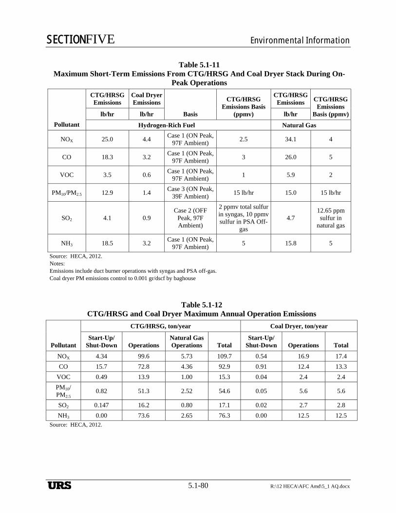
SECTIONFIVE Environmental Information
5.1-80 R:\12 HECA\AFC Amd\5_1 AQ.docx
Table 5.1-11 Maximum Short-Term Emissions From CTG/HRSG And Coal Dryer Stack During On-
Peak Operations
Pollutant
CTG/HRSG Emissions
Coal Dryer Emissions
Basis
CTG/HRSG Emissions Basis
(ppmv)
CTG/HRSG Emissions CTG/HRSG
Emissions Basis (ppmv)lb/hr lb/hr lb/hr
Hydrogen-Rich Fuel Natural Gas
NOX 25.0 4.4 Case 1 (ON Peak,
97F Ambient) 2.5 34.1 4
CO 18.3 3.2 Case 1 (ON Peak,
97F Ambient) 3 26.0 5
VOC 3.5 0.6 Case 1 (ON Peak,
97F Ambient) 1 5.9 2
PM10/PM2.5 12.9 1.4 Case 3 (ON Peak,
39F Ambient) 15 lb/hr 15.0 15 lb/hr
SO2 4.1 0.9 Case 2 (OFF
Peak, 97F Ambient)
2 ppmv total sulfur in syngas, 10 ppmv sulfur in PSA Off-
gas
4.7 12.65 ppm sulfur in
natural gas
NH3 18.5 3.2 Case 1 (ON Peak,
97F Ambient) 5 15.8 5
Source: HECA, 2012. Notes: Emissions include duct burner operations with syngas and PSA off-gas. Coal dryer PM emissions control to 0.001 gr/dscf by baghouse
Table 5.1-12 CTG/HRSG and Coal Dryer Maximum Annual Operation Emissions
Pollutant
CTG/HRSG, ton/year Coal Dryer, ton/year
Start-Up/Shut-Down Operations
Natural Gas Operations Total
Start-Up/Shut-Down Operations Total
NOX 4.34 99.6 5.73 109.7 0.54 16.9 17.4
CO 15.7 72.8 4.36 92.9 0.91 12.4 13.3
VOC 0.49 13.9 1.00 15.3 0.04 2.4 2.4
PM10/PM2.5
0.82 51.3 2.52 54.6 0.05 5.6 5.6
SO2 0.147 16.2 0.80 17.1 0.02 2.7 2.8
NH3 0.00 73.6 2.65 76.3 0.00 12.5 12.5 Source: HECA, 2012.
URS
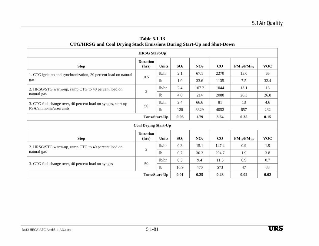
5.1 Air Quality
R:\12 HECA\AFC Amd\5_1 AQ.docx 5.1-81
Table 5.1-13 CTG/HRSG and Coal Drying Stack Emissions During Start-Up and Shut-Down
HRSG Start-Up
Step Duration
(hrs) Units SO2 NOX CO PM10/PM2.5 VOC
1. CTG ignition and synchronization, 20 percent load on natural gas
0.5 lb/hr 2.1 67.1 2270 15.0 65
lb 1.0 33.6 1135 7.5 32.4
2. HRSG/STG warm-up, ramp CTG to 40 percent load on natural gas
2 lb/hr 2.4 107.2 1044 13.1 13
lb 4.8 214 2088 26.3 26.8
3. CTG fuel change over, 40 percent load on syngas, start-up PSA/ammonia/urea units
50 lb/hr 2.4 66.6 81 13 4.6
lb 120 3329 4052 657 232
Tons/Start-Up 0.06 1.79 3.64 0.35 0.15
Coal Drying Start-Up
Step Duration
(hrs) Units SO2 NOX CO PM10/PM2.5 VOC
2. HRSG/STG warm-up, ramp CTG to 40 percent load on natural gas
2 lb/hr 0.3 15.1 147.4 0.9 1.9
lb 0.7 30.3 294.7 1.9 3.8
3. CTG fuel change over, 40 percent load on syngas 50 lb/hr 0.3 9.4 11.5 0.9 0.7
lb 16.9 470 573 47 33
Tons/Start-Up 0.01 0.25 0.43 0.02 0.02
URS
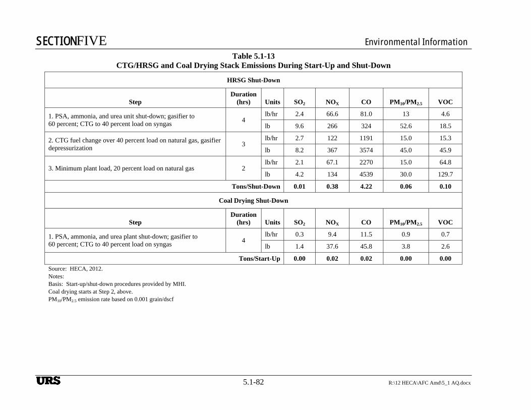
SECTIONFIVE Environmental Information
5.1-82 R:\12 HECA\AFC Amd\5_1 AQ.docx
Table 5.1-13 CTG/HRSG and Coal Drying Stack Emissions During Start-Up and Shut-Down
HRSG Shut-Down
Step Duration
(hrs) Units SO2 NOX CO PM10/PM2.5 VOC
1. PSA, ammonia, and urea unit shut-down; gasifier to 60 percent; CTG to 40 percent load on syngas
4 lb/hr 2.4 66.6 81.0 13 4.6
lb 9.6 266 324 52.6 18.5
2. CTG fuel change over 40 percent load on natural gas, gasifier depressurization
3 lb/hr 2.7 122 1191 15.0 15.3
lb 8.2 367 3574 45.0 45.9
3. Minimum plant load, 20 percent load on natural gas 2 lb/hr 2.1 67.1 2270 15.0 64.8
lb 4.2 134 4539 30.0 129.7
Tons/Shut-Down 0.01 0.38 4.22 0.06 0.10
Coal Drying Shut-Down
Step Duration
(hrs) Units SO2 NOX CO PM10/PM2.5 VOC
1. PSA, ammonia, and urea plant shut-down; gasifier to 60 percent; CTG to 40 percent load on syngas
4 lb/hr 0.3 9.4 11.5 0.9 0.7
lb 1.4 37.6 45.8 3.8 2.6
Tons/Start-Up 0.00 0.02 0.02 0.00 0.00
Source: HECA, 2012. Notes: Basis: Start-up/shut-down procedures provided by MHI. Coal drying starts at Step 2, above. PM10/PM2.5 emission rate based on 0.001 grain/dscf
URS
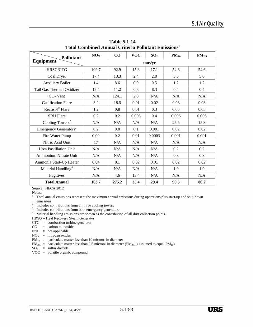
5.1 Air Quality
R:\12 HECA\AFC Amd\5_1 AQ.docx 5.1-83
Table 5.1-14
Total Combined Annual Criteria Pollutant Emissions1
Equipment Pollutant
NOX CO VOC SO2 PM10 PM2.5
tons/yr
HRSG/CTG 109.7 92.9 15.3 17.1 54.6 54.6
Coal Dryer 17.4 13.3 2.4 2.8 5.6 5.6
Auxiliary Boiler 1.4 8.6 0.9 0.5 1.2 1.2
Tail Gas Thermal Oxidizer 13.4 11.2 0.3 8.3 0.4 0.4
CO2 Vent N/A 124.1 2.8 N/A N/A N/A
Gasification Flare 3.2 18.5 0.01 0.02 0.03 0.03
Rectisol® Flare 1.2 0.8 0.01 0.3 0.03 0.03
SRU Flare 0.2 0.2 0.003 0.4 0.006 0.006
Cooling Towers2 N/A N/A N/A N/A 25.5 15.3
Emergency Generators3 0.2 0.8 0.1 0.001 0.02 0.02
Fire Water Pump 0.09 0.2 0.01 0.0003 0.001 0.001
Nitric Acid Unit 17 N/A N/A N/A N/A N/A
Urea Pastillation Unit N/A N/A N/A N/A 0.2 0.2
Ammonium Nitrate Unit N/A N/A N/A N/A 0.8 0.8
Ammonia Start-Up Heater 0.04 0.1 0.02 0.01 0.02 0.02
Material Handling4 N/A N/A N/A N/A 1.9 1.9
Fugitives N/A 4.6 13.4 N/A N/A N/A
Total Annual 163.7 275.2 35.4 29.4 90.3 80.2
Source: HECA 2012 Notes: 1 Total annual emissions represent the maximum annual emissions during operations plus start-up and shut-down
emissions 2 Includes contributions from all three cooling towers 3 Includes contributions from both emergency generators 4 Material handling emissions are shown as the contribution of all dust collection points. HRSG = Heat Recovery Steam Generator CTG = combustion turbine generator CO = carbon monoxide N/A = not applicable NOX = nitrogen oxides PM10 = particulate matter less than 10 microns in diameter PM2.5 = particulate matter less than 2.5 microns in diameter (PM2.5 is assumed to equal PM10) SO2 = sulfur dioxide VOC = volatile organic compound
~
URS
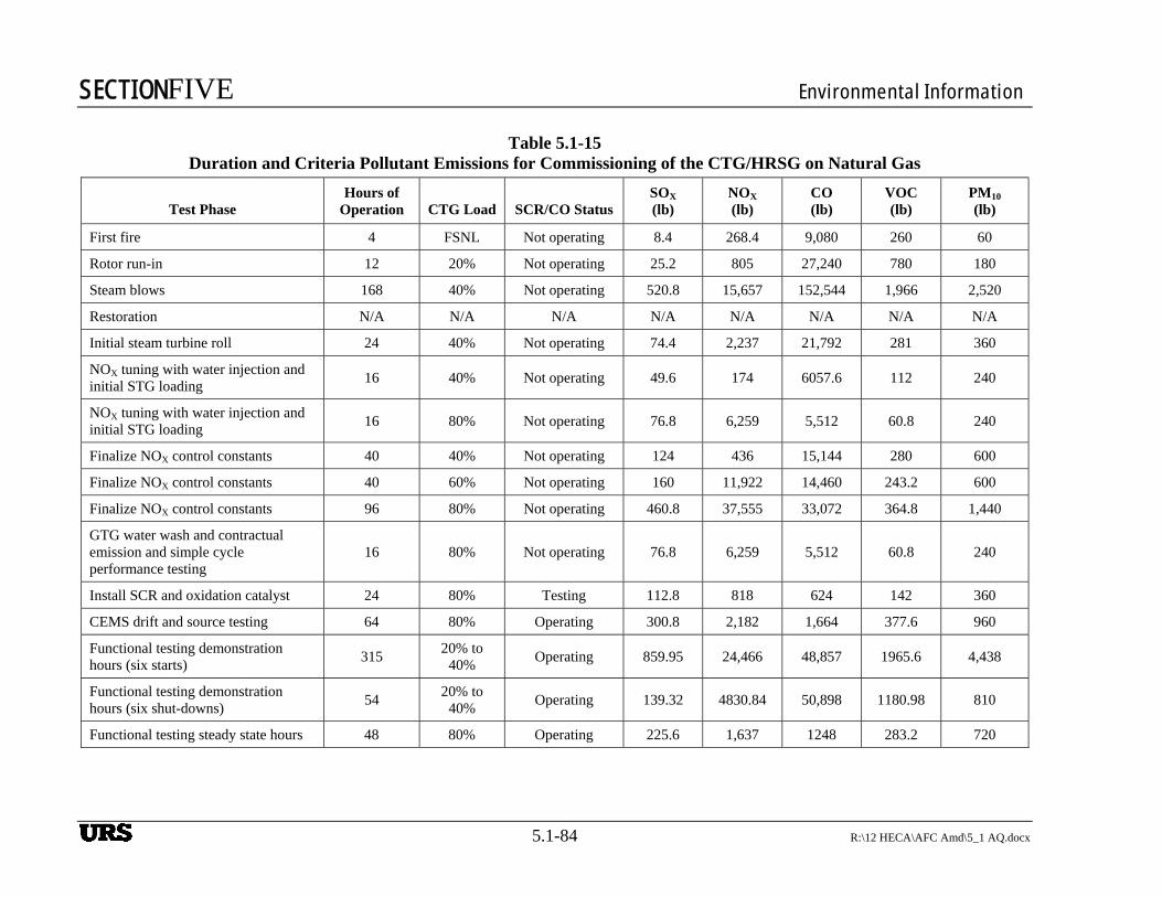
SECTIONFIVE Environmental Information
5.1-84 R:\12 HECA\AFC Amd\5_1 AQ.docx
Table 5.1-15 Duration and Criteria Pollutant Emissions for Commissioning of the CTG/HRSG on Natural Gas
Test Phase Hours of
Operation CTG Load SCR/CO Status SOX (lb)
NOX (lb)
CO (lb)
VOC (lb)
PM10 (lb)
First fire 4 FSNL Not operating 8.4 268.4 9,080 260 60
Rotor run-in 12 20% Not operating 25.2 805 27,240 780 180
Steam blows 168 40% Not operating 520.8 15,657 152,544 1,966 2,520
Restoration N/A N/A N/A N/A N/A N/A N/A N/A
Initial steam turbine roll 24 40% Not operating 74.4 2,237 21,792 281 360
NOX tuning with water injection and initial STG loading
16 40% Not operating 49.6 174 6057.6 112 240
NOX tuning with water injection and initial STG loading
16 80% Not operating 76.8 6,259 5,512 60.8 240
Finalize NOX control constants 40 40% Not operating 124 436 15,144 280 600
Finalize NOX control constants 40 60% Not operating 160 11,922 14,460 243.2 600
Finalize NOX control constants 96 80% Not operating 460.8 37,555 33,072 364.8 1,440
GTG water wash and contractual emission and simple cycle performance testing
16 80% Not operating 76.8 6,259 5,512 60.8 240
Install SCR and oxidation catalyst 24 80% Testing 112.8 818 624 142 360
CEMS drift and source testing 64 80% Operating 300.8 2,182 1,664 377.6 960
Functional testing demonstration hours (six starts)
315 20% to
40% Operating 859.95 24,466 48,857 1965.6 4,438
Functional testing demonstration hours (six shut-downs)
54 20% to
40% Operating 139.32 4830.84 50,898 1180.98 810
Functional testing steady state hours 48 80% Operating 225.6 1,637 1248 283.2 720
URS
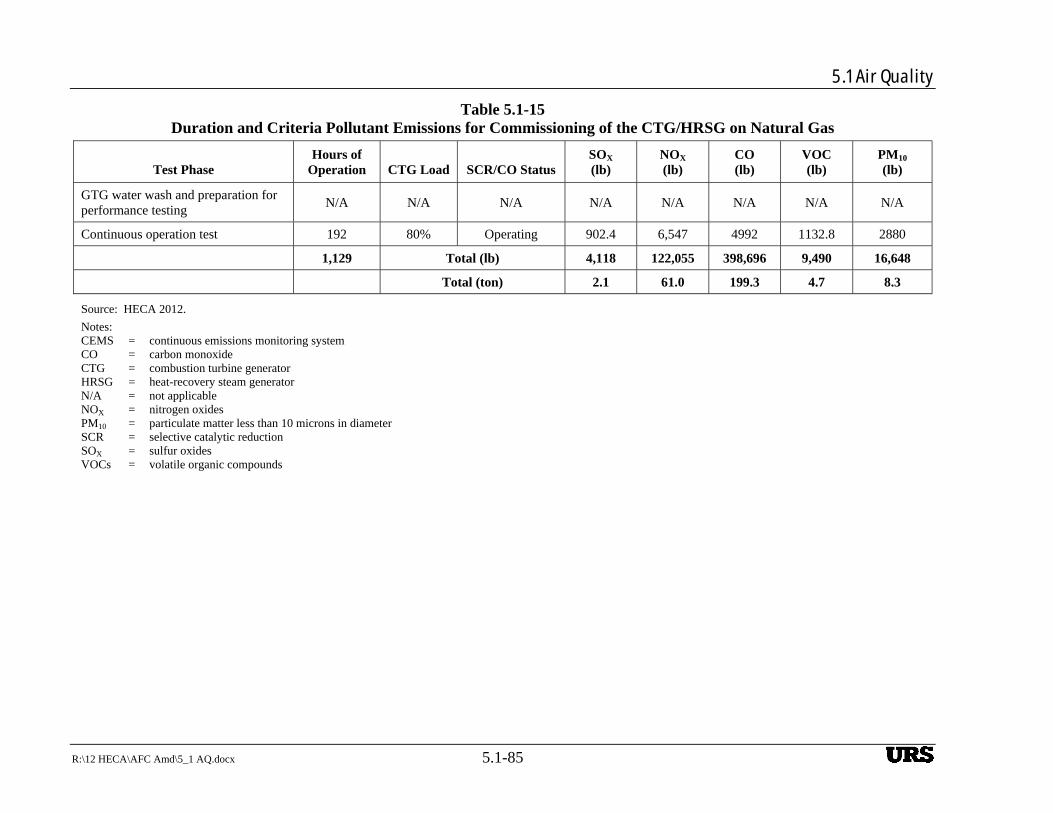
5.1 Air Quality
R:\12 HECA\AFC Amd\5_1 AQ.docx 5.1-85
Table 5.1-15 Duration and Criteria Pollutant Emissions for Commissioning of the CTG/HRSG on Natural Gas
Test Phase Hours of
Operation CTG Load SCR/CO Status SOX (lb)
NOX (lb)
CO (lb)
VOC (lb)
PM10 (lb)
GTG water wash and preparation for performance testing
N/A N/A N/A N/A N/A N/A N/A N/A
Continuous operation test 192 80% Operating 902.4 6,547 4992 1132.8 2880
1,129 Total (lb) 4,118 122,055 398,696 9,490 16,648
Total (ton) 2.1 61.0 199.3 4.7 8.3
Source: HECA 2012.
Notes: CEMS = continuous emissions monitoring system CO = carbon monoxide CTG = combustion turbine generator HRSG = heat-recovery steam generator N/A = not applicable NOX = nitrogen oxides PM10 = particulate matter less than 10 microns in diameter SCR = selective catalytic reduction SOX = sulfur oxides VOCs = volatile organic compounds
URS
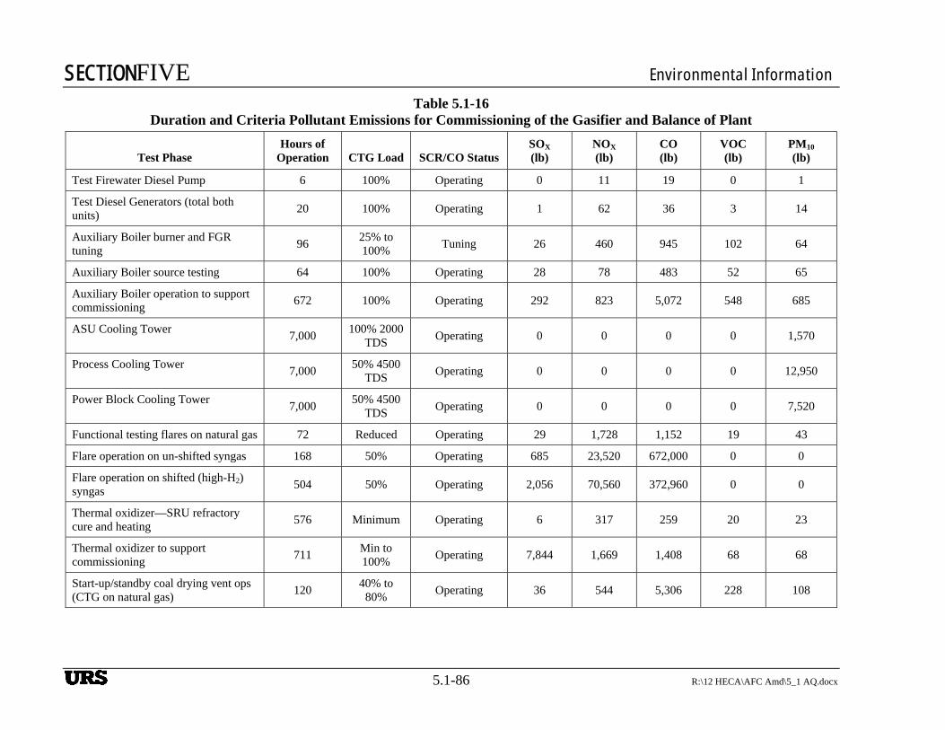
SECTIONFIVE Environmental Information
5.1-86 R:\12 HECA\AFC Amd\5_1 AQ.docx
Table 5.1-16 Duration and Criteria Pollutant Emissions for Commissioning of the Gasifier and Balance of Plant
Test Phase Hours of
Operation CTG Load SCR/CO Status SOX (lb)
NOX (lb)
CO (lb)
VOC (lb)
PM10 (lb)
Test Firewater Diesel Pump 6 100% Operating 0 11 19 0 1
Test Diesel Generators (total both units)
20 100% Operating 1 62 36 3 14
Auxiliary Boiler burner and FGR tuning
96 25% to 100%
Tuning 26 460 945 102 64
Auxiliary Boiler source testing 64 100% Operating 28 78 483 52 65
Auxiliary Boiler operation to support commissioning
672 100% Operating 292 823 5,072 548 685
ASU Cooling Tower 7,000
100% 2000 TDS
Operating 0 0 0 0 1,570
Process Cooling Tower 7,000
50% 4500 TDS
Operating 0 0 0 0 12,950
Power Block Cooling Tower 7,000
50% 4500 TDS
Operating 0 0 0 0 7,520
Functional testing flares on natural gas 72 Reduced Operating 29 1,728 1,152 19 43
Flare operation on un-shifted syngas 168 50% Operating 685 23,520 672,000 0 0
Flare operation on shifted (high-H2) syngas
504 50% Operating 2,056 70,560 372,960 0 0
Thermal oxidizer—SRU refractory cure and heating
576 Minimum Operating 6 317 259 20 23
Thermal oxidizer to support commissioning
711 Min to 100%
Operating 7,844 1,669 1,408 68 68
Start-up/standby coal drying vent ops (CTG on natural gas)
120 40% to
80% Operating 36 544 5,306 228 108
URS
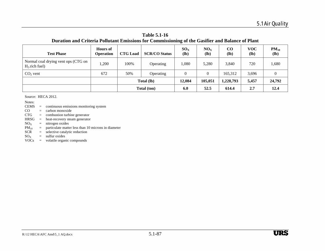
5.1 Air Quality
R:\12 HECA\AFC Amd\5_1 AQ.docx 5.1-87
Table 5.1-16 Duration and Criteria Pollutant Emissions for Commissioning of the Gasifier and Balance of Plant
Test Phase Hours of
Operation CTG Load SCR/CO Status SOX (lb)
NOX (lb)
CO (lb)
VOC (lb)
PM10 (lb)
Normal coal drying vent ops (CTG on H2-rich fuel)
1,200 100% Operating 1,080 5,280 3,840 720 1,680
CO2 vent 672 50% Operating 0 0 165,312 3,696 0
Total (lb) 12,084 105,051 1,228,793 5,457 24,792
Total (ton) 6.0 52.5 614.4 2.7 12.4
Source: HECA 2012.
Notes: CEMS = continuous emissions monitoring system CO = carbon monoxide CTG = combustion turbine generator HRSG = heat-recovery steam generator NOX = nitrogen oxides PM10 = particulate matter less than 10 microns in diameter SCR = selective catalytic reduction SOX = sulfur oxides VOCs = volatile organic compounds
URS
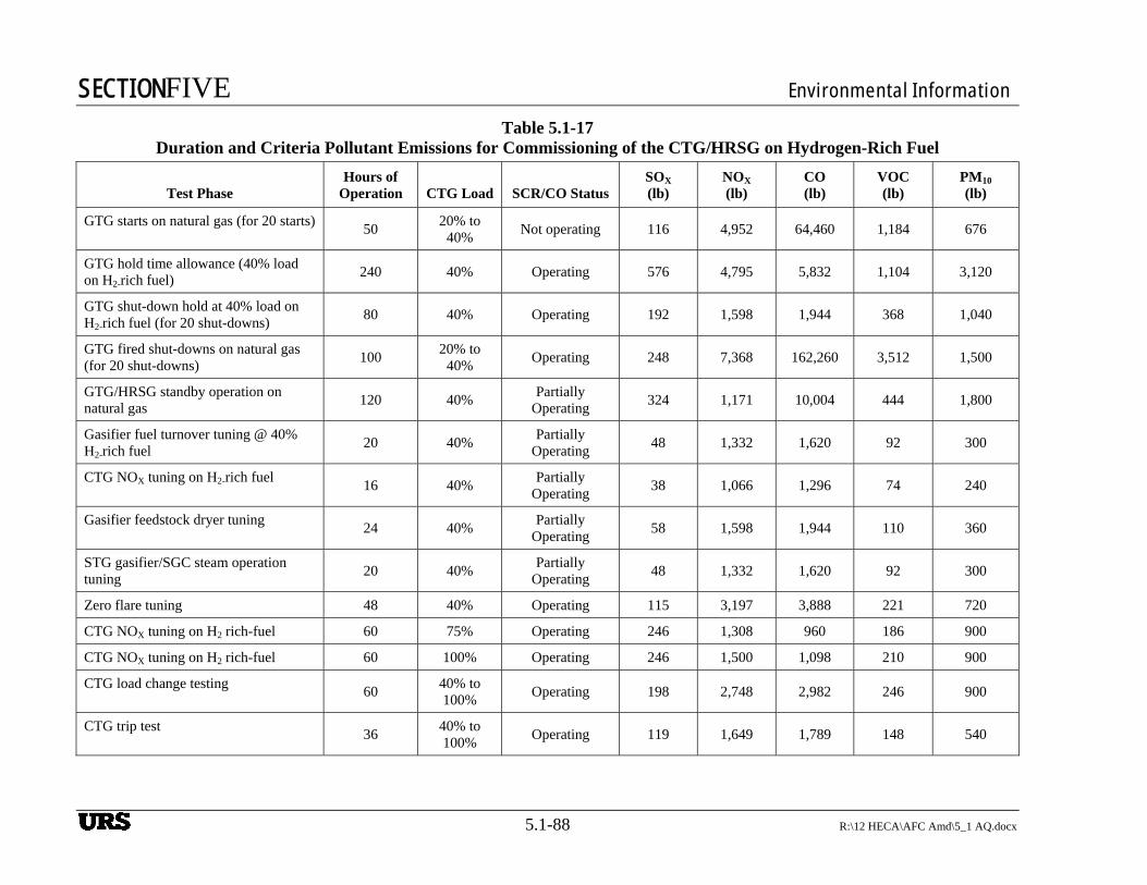
SECTIONFIVE Environmental Information
5.1-88 R:\12 HECA\AFC Amd\5_1 AQ.docx
Table 5.1-17 Duration and Criteria Pollutant Emissions for Commissioning of the CTG/HRSG on Hydrogen-Rich Fuel
Test Phase Hours of
Operation CTG Load SCR/CO Status SOX (lb)
NOX (lb)
CO (lb)
VOC (lb)
PM10 (lb)
GTG starts on natural gas (for 20 starts) 50
20% to 40%
Not operating 116 4,952 64,460 1,184 676
GTG hold time allowance (40% load on H2-rich fuel)
240 40% Operating 576 4,795 5,832 1,104 3,120
GTG shut-down hold at 40% load on H2-rich fuel (for 20 shut-downs)
80 40% Operating 192 1,598 1,944 368 1,040
GTG fired shut-downs on natural gas (for 20 shut-downs)
100 20% to
40% Operating 248 7,368 162,260 3,512 1,500
GTG/HRSG standby operation on natural gas
120 40% Partially
Operating 324 1,171 10,004 444 1,800
Gasifier fuel turnover tuning @ 40% H2-rich fuel
20 40% Partially
Operating 48 1,332 1,620 92 300
CTG NOX tuning on H2-rich fuel 16 40%
Partially Operating
38 1,066 1,296 74 240
Gasifier feedstock dryer tuning 24 40%
Partially Operating
58 1,598 1,944 110 360
STG gasifier/SGC steam operation tuning
20 40% Partially
Operating 48 1,332 1,620 92 300
Zero flare tuning 48 40% Operating 115 3,197 3,888 221 720
CTG NOX tuning on H2 rich-fuel 60 75% Operating 246 1,308 960 186 900
CTG NOX tuning on H2 rich-fuel 60 100% Operating 246 1,500 1,098 210 900
CTG load change testing 60
40% to 100%
Operating 198 2,748 2,982 246 900
CTG trip test 36
40% to 100%
Operating 119 1,649 1,789 148 540
URS
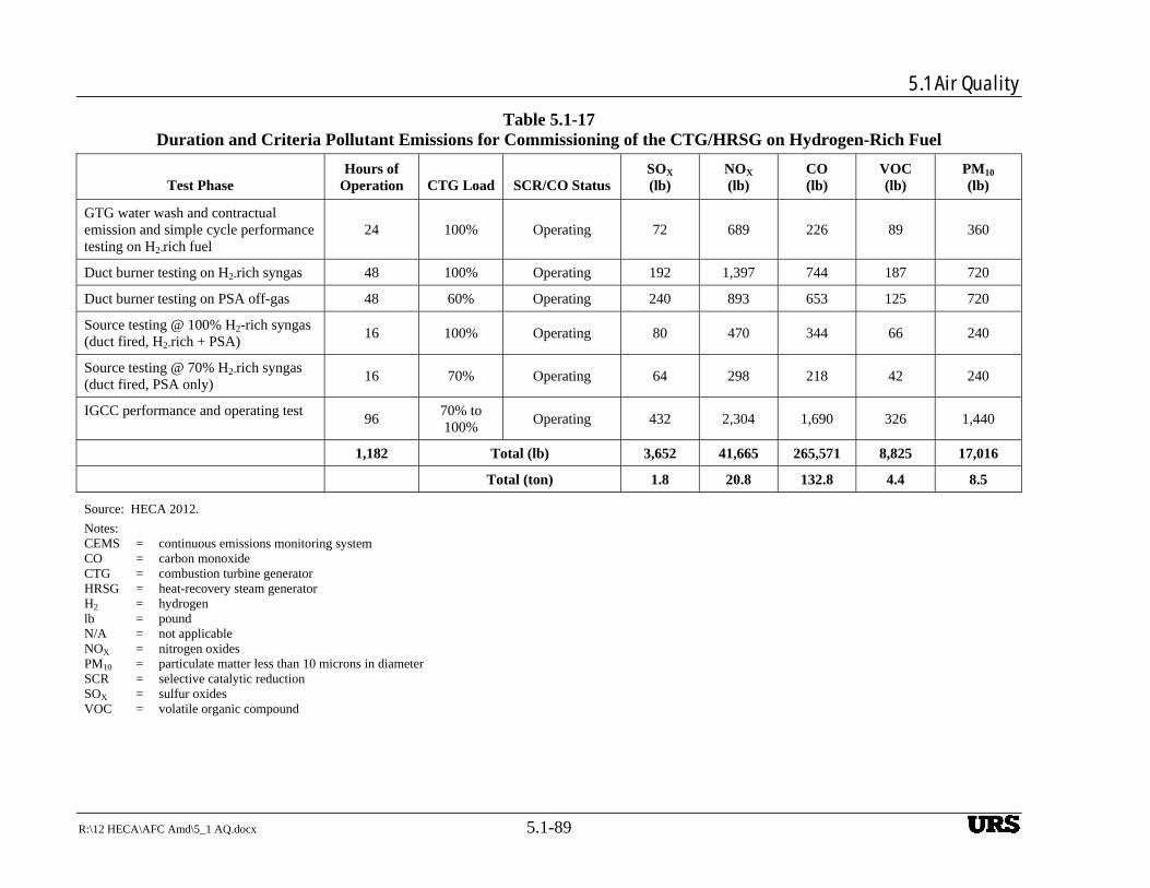
5.1 Air Quality
R:\12 HECA\AFC Amd\5_1 AQ.docx 5.1-89
Table 5.1-17 Duration and Criteria Pollutant Emissions for Commissioning of the CTG/HRSG on Hydrogen-Rich Fuel
Test Phase Hours of
Operation CTG Load SCR/CO Status SOX (lb)
NOX (lb)
CO (lb)
VOC (lb)
PM10 (lb)
GTG water wash and contractual emission and simple cycle performance testing on H2-rich fuel
24 100% Operating 72 689 226 89 360
Duct burner testing on H2-rich syngas 48 100% Operating 192 1,397 744 187 720
Duct burner testing on PSA off-gas 48 60% Operating 240 893 653 125 720
Source testing @ 100% H2-rich syngas (duct fired, H2-rich + PSA)
16 100% Operating 80 470 344 66 240
Source testing @ 70% H2-rich syngas (duct fired, PSA only)
16 70% Operating 64 298 218 42 240
IGCC performance and operating test 96
70% to 100%
Operating 432 2,304 1,690 326 1,440
1,182 Total (lb) 3,652 41,665 265,571 8,825 17,016
Total (ton) 1.8 20.8 132.8 4.4 8.5
Source: HECA 2012.
Notes: CEMS = continuous emissions monitoring system CO = carbon monoxide CTG = combustion turbine generator HRSG = heat-recovery steam generator H2 = hydrogen lb = pound N/A = not applicable NOX = nitrogen oxides PM10 = particulate matter less than 10 microns in diameter SCR = selective catalytic reduction SOX = sulfur oxides VOC = volatile organic compound
URS
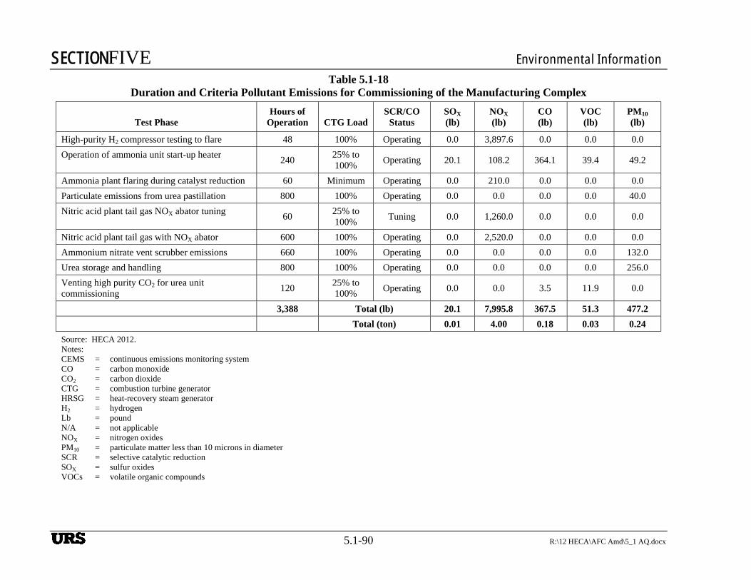
SECTIONFIVE Environmental Information
5.1-90 R:\12 HECA\AFC Amd\5_1 AQ.docx
Table 5.1-18 Duration and Criteria Pollutant Emissions for Commissioning of the Manufacturing Complex
Test Phase Hours of
Operation CTG Load SCR/CO
Status SOX (lb)
NOX (lb)
CO (lb)
VOC (lb)
PM10 (lb)
High-purity H2 compressor testing to flare 48 100% Operating 0.0 3,897.6 0.0 0.0 0.0
Operation of ammonia unit start-up heater 240
25% to 100%
Operating 20.1 108.2 364.1 39.4 49.2
Ammonia plant flaring during catalyst reduction 60 Minimum Operating 0.0 210.0 0.0 0.0 0.0
Particulate emissions from urea pastillation 800 100% Operating 0.0 0.0 0.0 0.0 40.0
Nitric acid plant tail gas NOX abator tuning 60
25% to 100%
Tuning 0.0 1,260.0 0.0 0.0 0.0
Nitric acid plant tail gas with NOX abator 600 100% Operating 0.0 2,520.0 0.0 0.0 0.0
Ammonium nitrate vent scrubber emissions 660 100% Operating 0.0 0.0 0.0 0.0 132.0
Urea storage and handling 800 100% Operating 0.0 0.0 0.0 0.0 256.0
Venting high purity CO2 for urea unit commissioning
120 25% to 100%
Operating 0.0 0.0 3.5 11.9 0.0
3,388 Total (lb) 20.1 7,995.8 367.5 51.3 477.2
Total (ton) 0.01 4.00 0.18 0.03 0.24
Source: HECA 2012. Notes: CEMS = continuous emissions monitoring system CO = carbon monoxide CO2 = carbon dioxide CTG = combustion turbine generator HRSG = heat-recovery steam generator H2 = hydrogen Lb = pound N/A = not applicable NOX = nitrogen oxides PM10 = particulate matter less than 10 microns in diameter SCR = selective catalytic reduction SOX = sulfur oxides VOCs = volatile organic compounds
URS
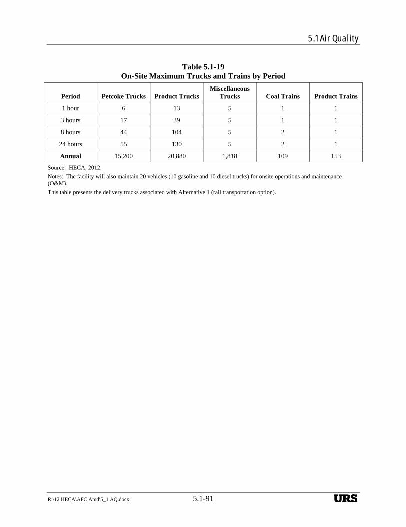
5.1 Air Quality
R:\12 HECA\AFC Amd\5_1 AQ.docx 5.1-91
Table 5.1-19 On-Site Maximum Trucks and Trains by Period
Period Petcoke Trucks Product Trucks Miscellaneous
Trucks Coal Trains Product Trains
1 hour 6 13 5 1 1
3 hours 17 39 5 1 1
8 hours 44 104 5 2 1
24 hours 55 130 5 2 1
Annual 15,200 20,880 1,818 109 153
Source: HECA, 2012.
Notes: The facility will also maintain 20 vehicles (10 gasoline and 10 diesel trucks) for onsite operations and maintenance (O&M).
This table presents the delivery trucks associated with Alternative 1 (rail transportation option).
URS
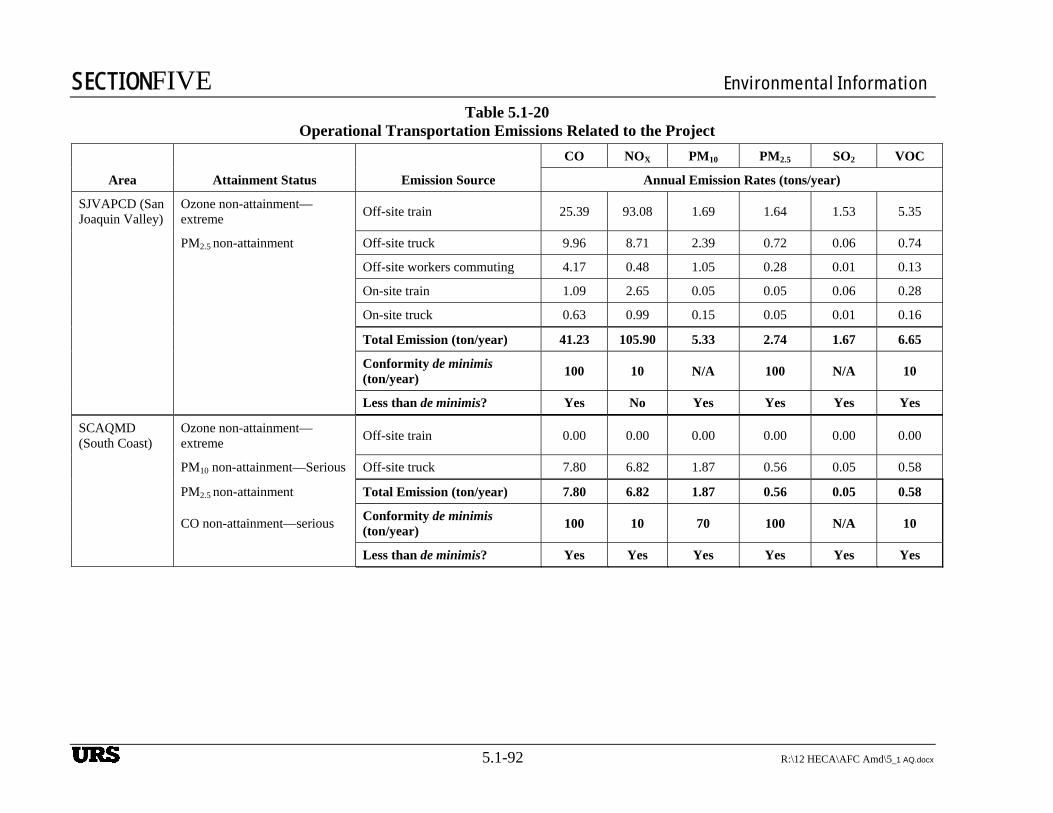
SECTIONFIVE Environmental Information
5.1-92 R:\12 HECA\AFC Amd\5_1 AQ.docx
Table 5.1-20
Operational Transportation Emissions Related to the Project
Area Attainment Status Emission Source
CO NOX PM10 PM2.5 SO2 VOC
Annual Emission Rates (tons/year)
SJVAPCD (San Joaquin Valley)
Ozone non-attainment—extreme
Off-site train 25.39 93.08 1.69 1.64 1.53 5.35
PM2.5 non-attainment Off-site truck 9.96 8.71 2.39 0.72 0.06 0.74
Off-site workers commuting 4.17 0.48 1.05 0.28 0.01 0.13
On-site train 1.09 2.65 0.05 0.05 0.06 0.28
On-site truck 0.63 0.99 0.15 0.05 0.01 0.16
Total Emission (ton/year) 41.23 105.90 5.33 2.74 1.67 6.65
Conformity de minimis (ton/year)
100 10 N/A 100 N/A 10
Less than de minimis? Yes No Yes Yes Yes Yes
SCAQMD (South Coast)
Ozone non-attainment—extreme
Off-site train 0.00 0.00 0.00 0.00 0.00 0.00
PM10 non-attainment—Serious Off-site truck 7.80 6.82 1.87 0.56 0.05 0.58
PM2.5 non-attainment Total Emission (ton/year) 7.80 6.82 1.87 0.56 0.05 0.58
CO non-attainment—serious Conformity de minimis (ton/year)
100 10 70 100 N/A 10
Less than de minimis? Yes Yes Yes Yes Yes Yes
URS
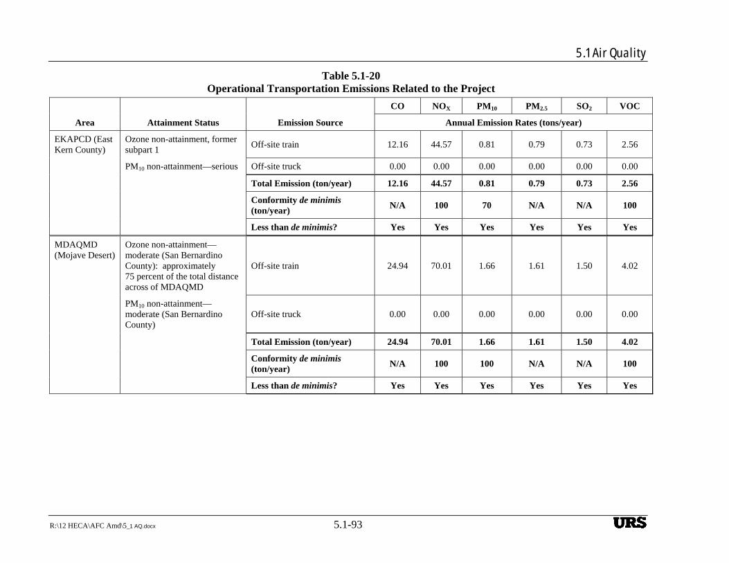
5.1 Air Quality
R:\12 HECA\AFC Amd\5_1 AQ.docx 5.1-93
Table 5.1-20 Operational Transportation Emissions Related to the Project
Area Attainment Status Emission Source
CO NOX PM10 PM2.5 SO2 VOC
Annual Emission Rates (tons/year)
EKAPCD (East Kern County)
Ozone non-attainment, former subpart 1
Off-site train 12.16 44.57 0.81 0.79 0.73 2.56
PM10 non-attainment—serious Off-site truck 0.00 0.00 0.00 0.00 0.00 0.00
Total Emission (ton/year) 12.16 44.57 0.81 0.79 0.73 2.56
Conformity de minimis (ton/year)
N/A 100 70 N/A N/A 100
Less than de minimis? Yes Yes Yes Yes Yes Yes
MDAQMD (Mojave Desert)
Ozone non-attainment— moderate (San Bernardino County): approximately 75 percent of the total distance across of MDAQMD
Off-site train 24.94 70.01 1.66 1.61 1.50 4.02
PM10 non-attainment—moderate (San Bernardino County)
Off-site truck 0.00 0.00 0.00 0.00 0.00 0.00
Total Emission (ton/year) 24.94 70.01 1.66 1.61 1.50 4.02
Conformity de minimis (ton/year)
N/A 100 100 N/A N/A 100
Less than de minimis? Yes Yes Yes Yes Yes Yes
URS
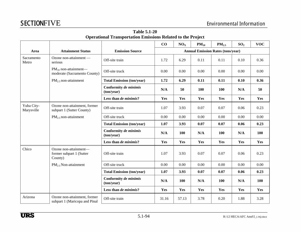
SECTIONFIVE Environmental Information
5.1-94 R:\12 HECA\AFC Amd\5_1 AQ.docx
Table 5.1-20 Operational Transportation Emissions Related to the Project
Area Attainment Status Emission Source
CO NOX PM10 PM2.5 SO2 VOC
Annual Emission Rates (tons/year)
Sacramento Metro
Ozone non-attainment — serious
Off-site train 1.72 6.29 0.11 0.11 0.10 0.36
PM10 non-attainment—moderate (Sacramento County)
Off-site truck 0.00 0.00 0.00 0.00 0.00 0.00
PM2.5 non-attainment Total Emission (ton/year) 1.72 6.29 0.11 0.11 0.10 0.36
Conformity de minimis (ton/year)
N/A 50 100 100 N/A 50
Less than de minimis? Yes Yes Yes Yes Yes Yes
Yuba City-Marysville
Ozone non-attainment, former subpart 1 (Sutter County)
Off-site train 1.07 3.93 0.07 0.07 0.06 0.23
PM2.5 non-attainment Off-site truck 0.00 0.00 0.00 0.00 0.00 0.00
Total Emission (ton/year) 1.07 3.93 0.07 0.07 0.06 0.23
Conformity de minimis (ton/year)
N/A 100 N/A 100 N/A 100
Less than de minimis? Yes Yes Yes Yes Yes Yes
Chico Ozone non-attainment—former subpart 1 (Sutter County)
Off-site train 1.07 3.93 0.07 0.07 0.06 0.23
PM2.5 Non-attainment Off-site truck 0.00 0.00 0.00 0.00 0.00 0.00
Total Emission (ton/year) 1.07 3.93 0.07 0.07 0.06 0.23
Conformity de minimis (ton/year)
N/A 100 N/A 100 N/A 100
Less than de minimis? Yes Yes Yes Yes Yes Yes
Arizona Ozone non-attainment, former subpart 1 (Maricopa and Pinal
Off-site train 31.16 57.13 3.78 0.20 1.88 3.28
URS
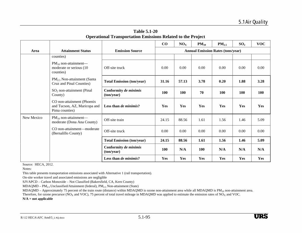
5.1 Air Quality
R:\12 HECA\AFC Amd\5_1 AQ.docx 5.1-95
Table 5.1-20 Operational Transportation Emissions Related to the Project
Area Attainment Status Emission Source
CO NOX PM10 PM2.5 SO2 VOC
Annual Emission Rates (tons/year)
counties)
PM10 non-attainment—moderate or serious (10 counties)
Off-site truck 0.00 0.00 0.00 0.00 0.00 0.00
PM2.5 Non-attainment (Santa Cruz and Pinal Counties)
Total Emission (ton/year) 31.16 57.13 3.78 0.20 1.88 3.28
SO2 non-attainment (Pinal County)
Conformity de minimis (ton/year)
100 100 70 100 100 100
CO non-attainment (Phoenix and Tucson, AZ, Maricopa and Pima counties)
Less than de minimis? Yes Yes Yes Yes Yes Yes
New Mexico PM10 non-attainment— moderate (Dona Ana County)
Off-site train 24.15 88.56 1.61 1.56 1.46 5.09
CO non-attainment—moderate (Bernalillo County)
Off-site truck 0.00 0.00 0.00 0.00 0.00 0.00
Total Emission (ton/year) 24.15 88.56 1.61 1.56 1.46 5.09
Conformity de minimis (ton/year)
100 N/A 100 N/A N/A N/A
Less than de minimis? Yes Yes Yes Yes Yes Yes
Source: HECA, 2012. Notes: This table presents transportation emissions associated with Alternative 1 (rail transportation). On-site worker travel and associated emissions are negligible SJVAPCD – Carbon Monoxide – Not Classified (Bakersfield, CA, Kern County) MDAQMD – PM2.5 Unclassified/Attainment (federal), PM2.5 Non-attainment (State) MDAQMD – Approximately 75 percent of the train route (distance) within MDAQMD is ozone non-attainment area while all MDAQMD is PM10 non-attainment area. Therefore, for ozone precursor (NOX and VOC), 75 percent of total travel mileage in MDAQMD was applied to estimate the emission rates of NOX and VOC. N/A = not applicable
URS
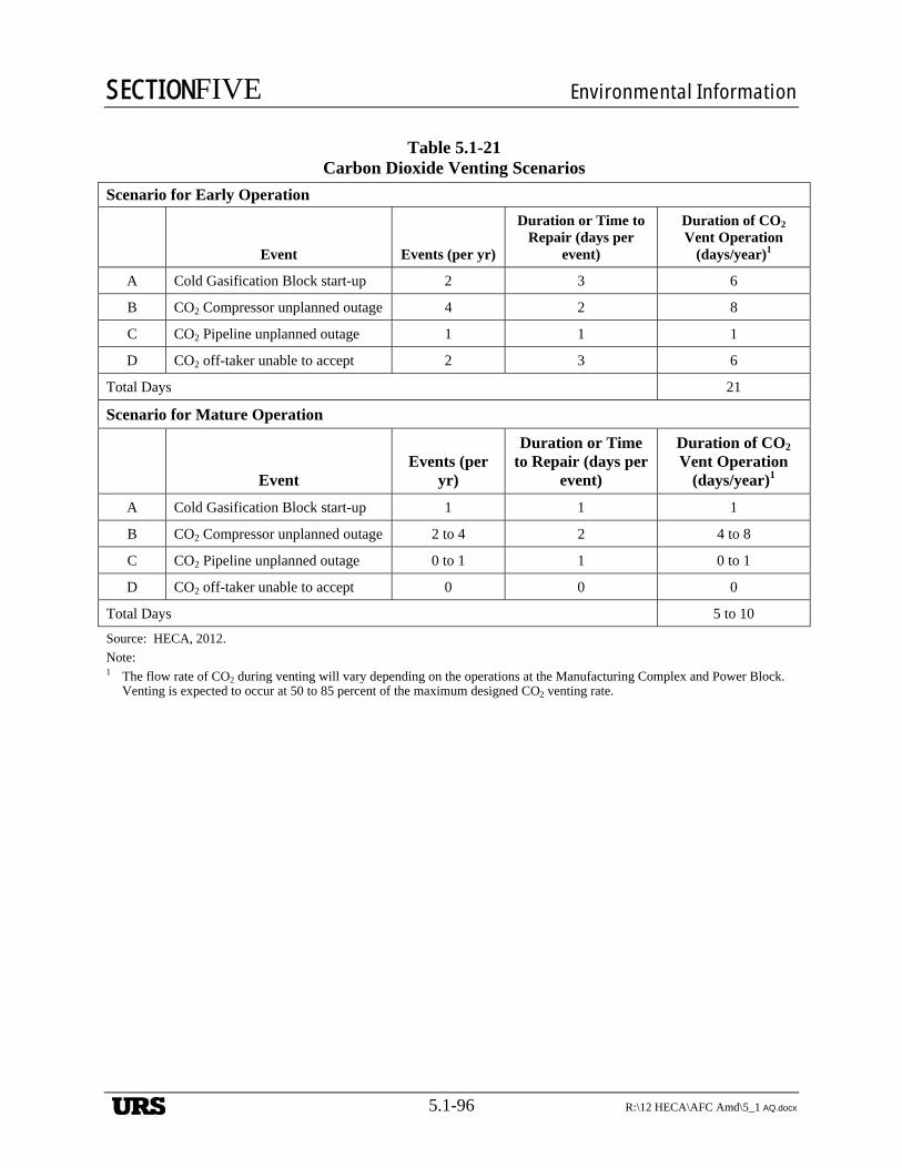
SECTIONFIVE Environmental Information
5.1-96 R:\12 HECA\AFC Amd\5_1 AQ.docx
Table 5.1-21 Carbon Dioxide Venting Scenarios
Scenario for Early Operation
Event Events (per yr)
Duration or Time to Repair (days per
event)
Duration of CO2 Vent Operation
(days/year)1
A Cold Gasification Block start-up 2 3 6
B CO2 Compressor unplanned outage 4 2 8
C CO2 Pipeline unplanned outage 1 1 1
D CO2 off-taker unable to accept 2 3 6
Total Days 21
Scenario for Mature Operation
Event Events (per
yr)
Duration or Time to Repair (days per
event)
Duration of CO2 Vent Operation
(days/year)1
A Cold Gasification Block start-up 1 1 1
B CO2 Compressor unplanned outage 2 to 4 2 4 to 8
C CO2 Pipeline unplanned outage 0 to 1 1 0 to 1
D CO2 off-taker unable to accept 0 0 0
Total Days 5 to 10
Source: HECA, 2012.
Note: 1 The flow rate of CO2 during venting will vary depending on the operations at the Manufacturing Complex and Power Block.
Venting is expected to occur at 50 to 85 percent of the maximum designed CO2 venting rate.
URS
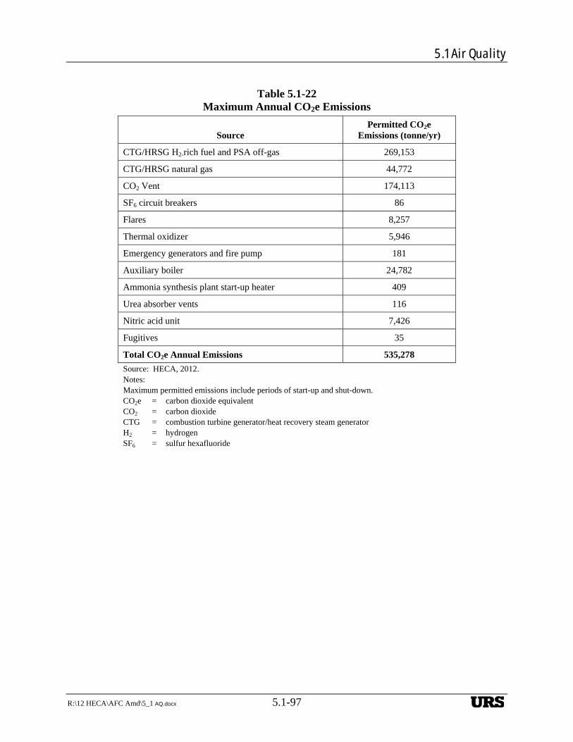
5.1 Air Quality
R:\12 HECA\AFC Amd\5_1 AQ.docx 5.1-97
Table 5.1-22 Maximum Annual CO2e Emissions
Source Permitted CO2e
Emissions (tonne/yr)
CTG/HRSG H2-rich fuel and PSA off-gas 269,153
CTG/HRSG natural gas 44,772
CO2 Vent 174,113
SF6 circuit breakers 86
Flares 8,257
Thermal oxidizer 5,946
Emergency generators and fire pump 181
Auxiliary boiler 24,782
Ammonia synthesis plant start-up heater 409
Urea absorber vents 116
Nitric acid unit 7,426
Fugitives 35
Total CO2e Annual Emissions 535,278
Source: HECA, 2012. Notes: Maximum permitted emissions include periods of start-up and shut-down. CO2e = carbon dioxide equivalent CO2 = carbon dioxide CTG = combustion turbine generator/heat recovery steam generator H2 = hydrogen SF6 = sulfur hexafluoride
URS
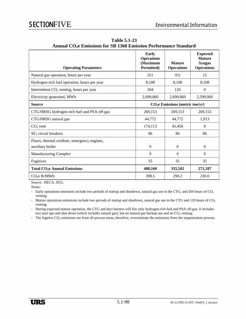
SECTIONFIVE Environmental Information
5.1-98 R:\12 HECA\AFC Amd\5_1 AQ.docx
Table 5.1-23 Annual CO2e Emissions for SB 1368 Emission Performance Standard
Operating Parameters
Early Operations (Maximum Permitted)
Mature Operations
Expected Mature Syngas
Operations
Natural gas operation, hours per year 351 351 15
Hydrogen-rich fuel operation, hours per year 8,108 8,108 8,108
Intermittent CO2 venting, hours per year 504 120 0
Electricity generated, MWh 2,699,860 2,699,860 2,599,060
Source CO2e Emissions (metric ton/yr)
CTG/HRSG hydrogen-rich fuel and PSA off-gas 269,153 269,153 269,153
CTG/HRSG natural gas 44,772 44,772 1,913
CO2 vent 174,113 41,456 0
SF6 circuit breakers 86 86 86
Flares, thermal oxidizer, emergency engines,
auxiliary boiler 0 0 0
Manufacturing Complex 0 0 0
Fugitives 35 35 35
Total CO2e Annual Emissions 488,160 355,502 271,187
CO2e lb/MWh 398.5 290.2 230.0
Source: HECA, 2012. Notes: - Early operations emissions include two periods of startup and shutdown, natural gas use in the CTG, and 504 hours of CO2
venting. - Mature operations emissions include two periods of startup and shutdown, natural gas use in the CTG and 120 hours of CO2
venting. - During expected mature operation, the CTG and duct burners will fire only hydrogen-rich fuel and PSA off-gas; it includes
two start ups and shut down (which includes natural gas), but no natural gas backup use and no CO2 venting. - The fugitive CO2 emissions are from all process areas; therefore, overestimate the emissions from the sequestration process.
URS

5.1 Air Quality
R:\12 HECA\AFC Amd\5_1 AQ.docx 5.1-99
Table 5.1-24 Greenhouse Gas Emissions Associated with the Mobile
Sources During Project Operations
Source Annual CO2e Emissions
(tonne/yr)
On-site trucks 413
On-site trains 291
Off-site workers commuting 824
Off-site trucks 10,866
Off-site trains 45,226
Total CO2e Annual Emissions 57,619
Source: HECA, 2012.
Notes:
This table presents transportation emissions associated with Alternative 1 (rail transportation option).
On-site worker travel and associated emissions are negligible.
URS
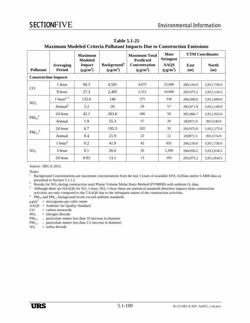
SECTIONFIVE Environmental Information
5.1-100 R:\12 HECA\AFC Amd\5_1 AQ.docx
Table 5.1-25 Maximum Modeled Criteria Pollutant Impacts Due to Construction Emissions
Pollutant Averaging
Period
Maximum Modeled Impact (g/m3)
Background1 (g/m3)
Maximum Total Predicted
Concentration (g/m3)
Most Stringent
AAQS (g/m3)
UTM Coordinates
East (m)
North (m)
Construction Impacts
CO 1 hour 94.3 4,581 4,675 23,000 284,150.0 3,911,750.0
8 hour 27.3 2,485 2,512 10,000 283,975.2 3,912,134.5
NO2 1 hour2, 3 135.0 140 275 339 284,500.0 3,911,600.0
Annual2 3.2 26 29 57 283,971.9 3,912,149.9
PM104
24 hour 42.1 263.6 306 50 283,966.7 3,911,925.0
Annual 1.9 55.3 57 20 283971.9 3912149.9
PM2.54
24 hour 6.7 195.5 202 35 283,975.0 3,912,275.0
Annual 0.4 21.9 22 12 283972.5 3912174.9
SO2
1 hour4 0.2 41.9 42 655 284,150.0 3,911,750.0
3 hour 0.1 26.0 26 1,300 284,050.2 3,912,034.5
24 hour 0.03 13.1 13 105 283,975.2 3,911,934.5
Source: HECA 2012.
Notes: 1 Background Concentrations are maximum concentrations from the last 3 years of available EPA AirData and/or CARB data as
presented in Section 5.1.1.2. 2 Results for NO2 during construction used Plume Volume Molar Ratio Method (PVMRM) with ambient O3 data. 3 Although there are NAAQS for SO2 1-hour, NO2 1-hour these are statistical standards therefore impacts from construction
activities are only compared to the CAAQS due to the infrequent nature of the construction activities. 4 PM10 and PM2.5 background levels exceed ambient standards. g/m3 = micrograms per cubic meter AAQS = Ambient Air Quality Standard CO = carbon monoxide NO2 = nitrogen dioxide PM10 = particulate matter less than 10 microns in diameter PM2.5 = particulate matter less than 2.5 microns in diameter SO2 = sulfur dioxide
URS
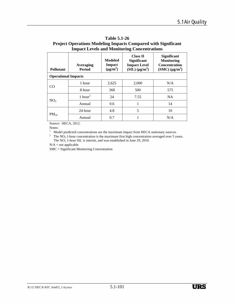
5.1 Air Quality
R:\12 HECA\AFC Amd\5_1 AQ.docx 5.1-101
Table 5.1-26 Project Operations Modeling Impacts Compared with Significant
Impact Levels and Monitoring Concentrations
Pollutant Averaging
Period
Modeled Impact (µg/m3)
Class II Significant
Impact Level (SIL) (µg/m3)
Significant Monitoring
Concentration (SMC) (µg/m3)
Operational Impacts
CO 1 hour 2,625 2,000 N/A
8 hour 368 500 575
NO2 1 hour2 24 7.55 NA
Annual 0.6 1 14
PM10 24 hour 4.8 5 10
Annual 0.7 1 N/A
Source: HECA, 2012. Notes: 1 Model predicted concentrations are the maximum impact from HECA stationary sources. 2 The NO2 1-hour concentration is the maximum first high concentration averaged over 5 years.
The NO2 1-hour SIL is interim, and was established in June 29, 2010. N/A = not applicable SMC = Significant Monitoring Concentration
URS


