Embed Size (px)
Citation preview

THE MECHANICAL PROCEDURE MANUAL
FOR
HUDSON AND TERRAPLANE SERVICE MEN
The Hudson Motor Car Company has throughout its existence endeav-ored to build into its products the highest quality of material and work-manship to insure the purchaser economical, trouble free transportation.
THE success in this endeavor is attested to by the unusually high percent-age of total cars built since the organization of the company in 1909, which still continue to be operated as motor vehicles. There are recorded, in addition, many cases wherein the age of the vehicle obsoleted it for its original purpose and the engine and other mechanical units have been removed and are being utilized as power units for farm machinery, saw mills, pumps, boats, etc.
The Hudson Motor Car Company realizes that even with maximum diligence in design and manufacture, the reputation of its products depends to a large extent upon intelligent and regular servicing and has prepared this manual as a guide and a help to the thousands of men, many of whom for more than 25 years have diligently striven to maintain the performance and reputation, in their respective localities, of Hudson built cars through careful and efficient service. To these men belong much credit for the reputation of Hudson built products and this manual is therefore dedicated to them, The Hudson Terraplane Service Men.
No. 2583
Section 1 Page 1
Purpose The purpose of the Mechanical Procedure Manual is to supply information of value in diagnosis and repair includ-ing information on changes which affect procedure in ser-vicing.
Flat Rate The procedures given in this manual are identical to those followed in setting time allowances for FlatRate Schedules and should be valuable as a guide where actual shop time does not compare favorably with the schedules. A study of the operations together with the tool equipment used in their performance should enable each Hudson Terraplane Service Station to offer its owners reli-able service at a reasonable cost.
Inspection Service This manual does not go into the details of pre- delivery, 500 and 1500 mile inspections as these vary somewhat with each yearly model, however, particular attention should be paid to carrying out these inspections in accordance with the procedure given on the inspection cards which are available from the factory for each model while in production.The items included in these inspections are those which experience has shown require attention during the early life of the car to insure long, carefree service, in addition to items, which though checked carefully at the time of manu-facture require additional checks to insure proper operation. The owner when accepting delivery of the car expects it to be in perfect condition. A good first impression will aid you in your future contacts as well as do much to insure satisfac-tory performance of the car. Make these inspections care-fully and file the inspection card as a permanent part of the record of the car.
Keys and Locks A record of the key numbers made on the pre- delivery card, in the space provided, will help you render a valuable service to your owners in cases of lost keys.
Warranty and Owners Service Policy The Warranty and Owners Service Policy is fully covered in the General Service Policies Manual which should he referred to on any question of Owner, Dealer, Distributor or Factory responsibility.
Special Tools All special tools referred to or illustrated in this manual have been developed through the cooperation of the Hudson Motor Car Company Service Department with the Hinck-ley-Myers Co. of Jackson, Michigan.
Special tools are developed only where it is found that such a tool is essential to good workmanship or the time saving is sufficient to warrant its cost. The tools are of highest quality and are sold direct by the tool manufacturer to make them available to Hudson and Terraplane Distributors andDealers at minimum cost. For complete list of tools and shop equipment refer to the Hinckley-Myers Tool Manual of Authorized Tools and Equipment for Hudson and Terra- plane Distributors and Dealers.
Parts Books Individual parts lists are available for each yearly model while a master Parts Book showing interchangeability of parts on models from 1930 through 1936 is also available. These books and the numerical parts price list should be used as reference for parts information.
Service Bulletins Service Bulletins issued from time to time should be filed in the Bulletin Binder with cross reference entered on the sheet provided at the front of each section of this manual. These references will serve to keep the Mechanical Proce-dure Manual up-to- date pending the issue of additional Manual pages.
Reference Sheets Reference Sheets covering individual units are prepared for ready reference by the mechanic. Each mechanic should have his own file of Reference Sheets.
Hudson-Terraplane Service Magazine The service Magazine is published monthly and contains timely service information, which should be tied in with the material in this manual. Index this information on the sheets provided in front of each section.
Material for Magazine The technical information in the magazine is based on the experience of the Engineering, Manufacturing and Service divisions at the factory and also on reports and suggestions received from Distributor and Dealer Service Departments. Any suggestions for improved methods of servicing, short cuts, special tools, etc., developed in the Servicing of Hudson and Terraplanes which will assist you in your work will also assist the thousands of other Service Men. Submit your suggestions to the Technical Division of the Factory Service Department, so that they may be passed on through the medium of Hudson-Terraplane Service.
Copyright 1936 byHUDSON MOTOR CAR CO.
All Rights Reserved
Section 1 Page 2

MECHANICAL PROCEDURE MANUAL Page 1
SECTION 2
LUBRICATIONService Magazine—Reference Sheet and Service Bulletin Reference
Bulletin orReference SheetNo. MagazineIssue and Page
Date Subject DETAILS OF INFORMATION

MECHANICAL PROCEDURE MANUALSECTION 2
Page 3
LUBRICATION The correct lubrication of all working parts is of prime importance to the life, performance and economy of oper-ation of the automobile. Correct lubrication requires the use of the recommended type and grade of lubricant, properly applied, in the right quantities and at the speci-fied intervals. The recommended specifications are in most instances confined to S.A.E. viscosity numbers. These numbers simply classify lubricants according to viscosity or fluid-ity but without reference to any other characteristics or properties.
THE REFINER OR MARKETER SUPPLYING THE LUBRICANT IS RESPONSIBLE FOR THE QUALITY OF ITS PRODUCT. THEIR REPUTATION IS YOUR BEST INDICATION OF QUALITY.
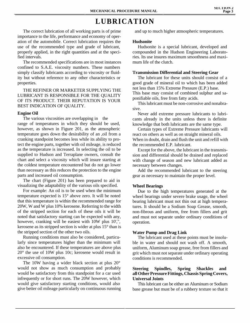
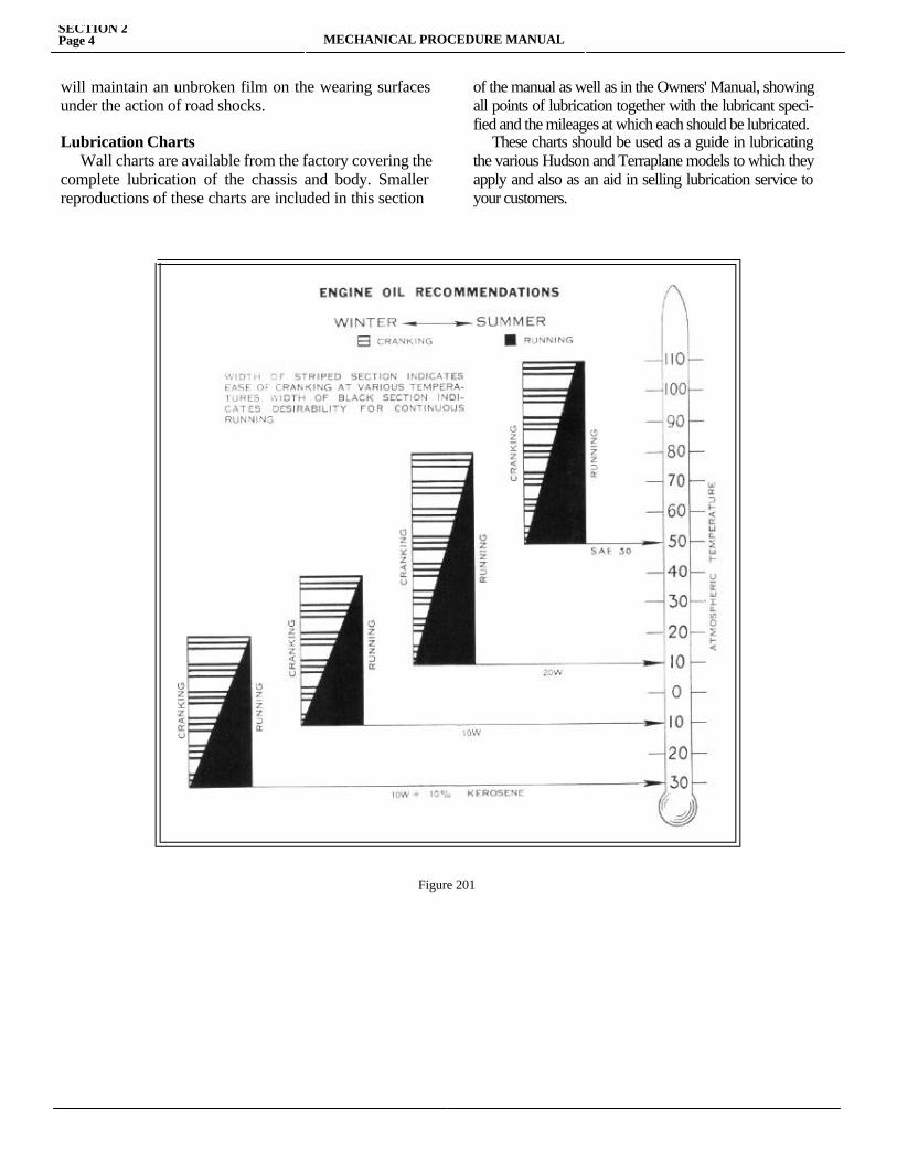
Engine Oil The various viscosities are overlapping in therange of temperatures in which they should be used, however, as shown in Figure 201, as the atmospheric temperature goes down the desirability of an ,oil from a cranking standpoint becomes less while its ability to pro-tect the engine parts, together with oil mileage, is reduced as the temperature is increased. In selecting the oil to be supplied to Hudson and Terraplane owners, consult the chart and select a viscosity which will insure starting at the coldest temperature encountered but do not go lower than necessary as this reduces the protection to the engine parts and increased oil consumption. The chart (Figure 201) has been prepared to aid in visualizing the adaptability of the various oils specified. For example: An oil is to be used when the minimum temperature expected is 15° above zero. It will be noted that this temperature is within the recommended range for 20W, W and W plus 10% kerosene. Referring to the width of the stripped section for each of these oils it will be noted that satisfactory starting can be expected with any, however, cranking will be easiest with 10W plus 10',", kerosene as its stripped section is wider at plus 15° than is the stripped section of the other two oils. Running conditions must also be considered, particu-larly since temperatures higher than the minimum will also be encountered. If these temperatures are above plus 20° the use of 10W plus 10c; kerosene would result in excessive oil consumption. The 10W having a wider black section at plus 20° would not show as much consumption and probably would be satisfactory from this standpoint for a car used infrequently or for short runs. The 20W however, which would give satisfactory starting conditions, would also give better oil mileage particularly on continuous running
and up to much higher atmospheric temperatures.
Hudsonite Hudsonite is a special lubricant, developed and compounded in the Hudson Engineering Laborato-ries. Its use insures maximum smoothness and maxi-mum life of the clutch.
Transmission Differential and Steering Gear The lubricant for these units should consist of a good grade of mineral oil to which has been added not less than 15% Extreme Pressure (E.P.) base.This base may consist of combined sulphur and sa-ponifiable oils, free from fatty acids. This lubricant must be non-corrosive and nonabra-sive. Never add extreme pressure lubricants to lubri-cants already in the units unless there is definite knowledge that both lubricants are the same type. Certain types of Extreme Pressure lubricants will react on others as well as on straight mineral oils.When in doubt, drain and flush the unit and refill with the recommended E.P. lubricant. Except for the above, the lubricant in the transmis-sion and differential should be drained and replaced with change of season and new lubricant added as necessary between changes. Add the recommended lubricant to the steering gear as necessary to maintain the proper level.
Wheel Bearings Due to the high temperatures generated at the wheel bearings under severe brake usage, the wheel bearing lubricant must not thin out at high tempera-tures. It should be a Sodium Soap Grease, smooth, non-fibrous and uniform, free from fillers and grit and must not separate under ordinary conditions of operation.
Water Pump and Drag Link The lubricant used at these points must be insolu-ble in water and should not wash off. A smooth, uniform, Aluminum soap grease, free from fillers and grit which must not separate under ordinary operating conditions is recommended.
Steering Spindles, Spring Shackles and all Other Pressure Fittings, Chassis Spring Covers,Universal Joints This lubricant can be either an Aluminum or Sodium base grease but must be of a rubbery texture so that it
SECTION 2Page 4 MECHANICAL PROCEDURE MANUAL
will maintain an unbroken film on the wearing surfaces under the action of road shocks.
Lubrication Charts Wall charts are available from the factory covering the complete lubrication of the chassis and body. Smaller reproductions of these charts are included in this section
of the manual as well as in the Owners' Manual, showing all points of lubrication together with the lubricant speci-fied and the mileages at which each should be lubricated. These charts should be used as a guide in lubricating the various Hudson and Terraplane models to which they apply and also as an aid in selling lubrication service to your customers.
Figure 201

SECTION 3
ENGINE TUNE-UPService Magazine—Reference Sheet and Service Bullet in Reference
Bulletin orReference SheetNo. MagazineIssue and Page
Date Subject DETAILS OF INFORMATION
MECHANICAL PROCEDURE MANUAL Page 1

MECHANICAL PROCEDURE MANUALSECTION 3
Page 3
ENGINE TUNE-UP
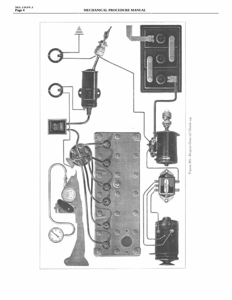
The Engine Tune-up procedure has been divided into two groups. The first is the over-all check-up to determine the need for a tune-up and to help the service salesman show the owner the need for it. The second division is the step-by-step procedure for making a complete tune-up.Engine Over-all Check-up The instruments used are an accurate ammeter and voltmeter, ignition high tension tester and vacuum gauge. Figure 301, shows the correct connections for the over-all check-up.A—VOLTMETER—Connection—Battery side ignition switch to ground.
a. All switches off. Voltage of less than 6 indicates, Battery discharged, worn out or loose connections between battery and ignition switch(Correction—Tests-4-5-6-7).
b. Ignition on—Distributor points closed.Voltage drop of more than 0.2 volts below reading at (a) indicates loose connections. (Correction—check connections between battery and ignition lock and tests 6 and 7).
c. Cranking Engine with starter—Ignition off— Engine warm.When starter button is pressed voltmeter hand should drop back to 3 to 4 volts and return quickly to 5 to 534 volts. (Slow return of hand indicates discharged or worn out battery. Drop only to 4-1/2 to 5 volts and slow return to 5 indicates corroded terminals, poor battery cable, poor contact of start-ing motor brushes or commutator.(Correction Tests 4-5-6-7).
B —VACUUM GAUGE—Connect to windshield wiper manifold connection. Warm up engine thoroughly. Gauge reading should be 18 to 21 with engine idling.
a. Low and uneven reading.—Poor Compression or ignition (Test 1).
b. Jerky action of gauge hand Sticky or burntvalve—valve tappet adjustment too close (Test 3).
c. Gauge hand vibrates more at high engine speed than at idle—weak valve springs—replace valve springs.
d. Low steady reading—Intake manifold leak or late ignition timing—Test 15 replace manifold gaskets if necessary.
e. Floating motion of gauge hand—Rich carburetor mixture Correction—Carburetor idle screw adjustment—check float level and float valve if necessary .
f. Constant vibration of gauge hand—earlyignition (Test 15).
C IGNITION TEST.a. Ignition on—distributor points closed. Ammeter read-
ing 5 to 6 amperes. (4 to 5 amperes with distributor resistor)—High reading—shorted primary winding or shorted distributor resistor.Low reading--Poor connections from ignition coil to distributor to ground or corroded distributor points (Test 11).
b. Engine running at idle—Open high tension test gap to 7 M. M. Irregular spark in tester with a steady amme-ter reading indicates— weak coil or poor condenser, high tension wires, distributor cap, rotor arm or spark plugs. (Test 11-12-13-14).
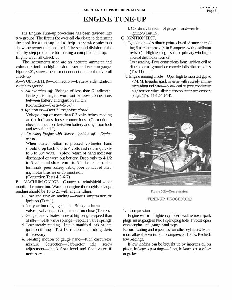
1. Compression Engine warm Tighten cylinder head, remove spark plugs, insert gauge in No. 1 spark plug hole. Throttle open, crank engine until gauge hand stops. Record reading and repeat test on other cylinders. Maxi-mum allowable variation in compression 10 lbs. Recheck low readings. If low reading can be brought up by inserting oil on piston, leakage is past rings—if not, leakage is past valves or gasket.
SECTION 3Page 4 MECHANICAL PROCEDURE MANUAL
MECHANICAL PROCEDURE MANUALSECTION 3
Page 5
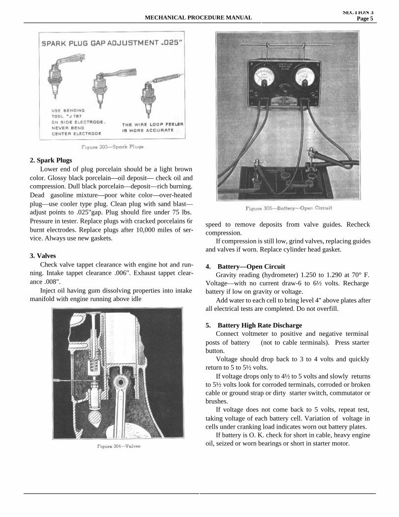
2. Spark Plugs Lower end of plug porcelain should be a light brown color. Glossy black porcelain—oil deposit— check oil and compression. Dull black porcelain—deposit—rich burning. Dead gasoline mixture—poor white color—over-heated plug—use cooler type plug. Clean plug with sand blast—adjust points to .025"gap. Plug should fire under 75 lbs. Pressure in tester. Replace plugs with cracked porcelains 6r burnt electrodes. Replace plugs after 10,000 miles of ser-vice. Always use new gaskets.
3. Valves Check valve tappet clearance with engine hot and run-ning. Intake tappet clearance .006". Exhaust tappet clear-ance .008". Inject oil having gum dissolving properties into intake manifold with engine running above idle
speed to remove deposits from valve guides. Recheck compression. If compression is still low, grind valves, replacing guides and valves if worn. Replace cylinder head gasket.
4. Battery—Open Circuit Gravity reading (hydrometer) 1.250 to 1.290 at 70° F. Voltage—with no current draw-6 to 6½ volts. Recharge battery if low on gravity or voltage. Add water to each cell to bring level 4" above plates after all electrical tests are completed. Do not overfill.
5. Battery High Rate Discharge Connect voltmeter to positive and negative terminal posts of battery (not to cable terminals). Press starter button. Voltage should drop back to 3 to 4 volts and quickly return to 5 to 5½ volts. If voltage drops only to 4½ to 5 volts and slowly returns to 5½ volts look for corroded terminals, corroded or broken cable or ground strap or dirty starter switch, commutator or brushes. If voltage does not come back to 5 volts, repeat test, taking voltage of each battery cell. Variation of voltage in cells under cranking load indicates worn out battery plates. If battery is O. K. check for short in cable, heavy engine oil, seized or worn bearings or short in starter motor.
SECTION 3Page 6 MECHANICAL PROCEDURE MANUAL
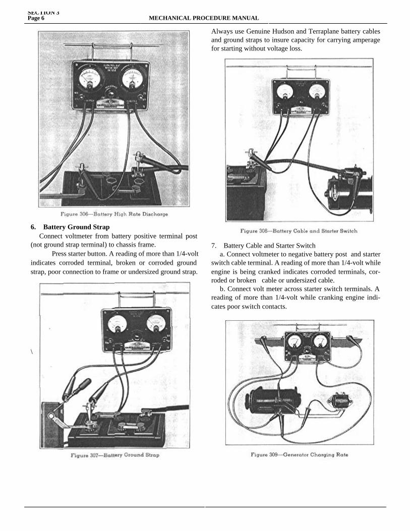
6. Battery Ground Strap Connect voltmeter from battery positive terminal post (not ground strap terminal) to chassis frame. Press starter button. A reading of more than 1/4-volt indicates corroded terminal, broken or corroded ground strap, poor connection to frame or undersized ground strap.
\
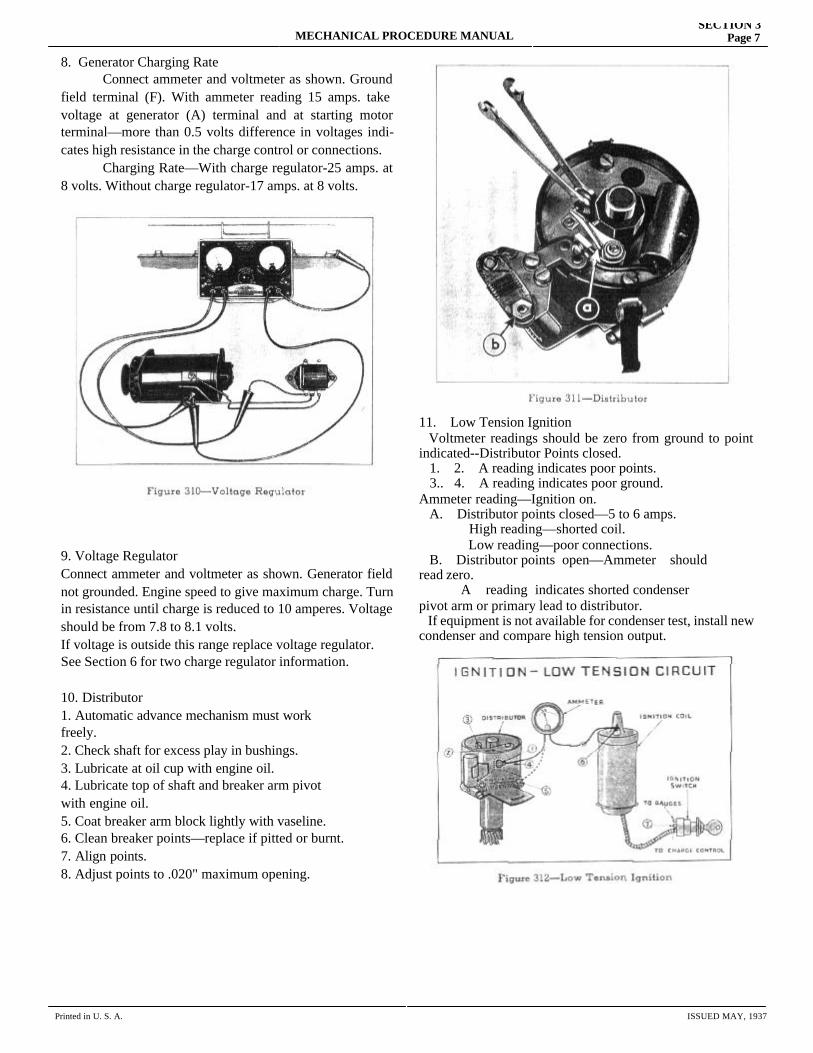
Always use Genuine Hudson and Terraplane battery cables and ground straps to insure capacity for carrying amperage for starting without voltage loss.
7. Battery Cable and Starter Switch a. Connect voltmeter to negative battery post and starter switch cable terminal. A reading of more than 1/4-volt while engine is being cranked indicates corroded terminals, cor-roded or broken cable or undersized cable. b. Connect volt meter across starter switch terminals. A reading of more than 1/4-volt while cranking engine indi-cates poor switch contacts.
MECHANICAL PROCEDURE MANUALSECTION 3
Page 7
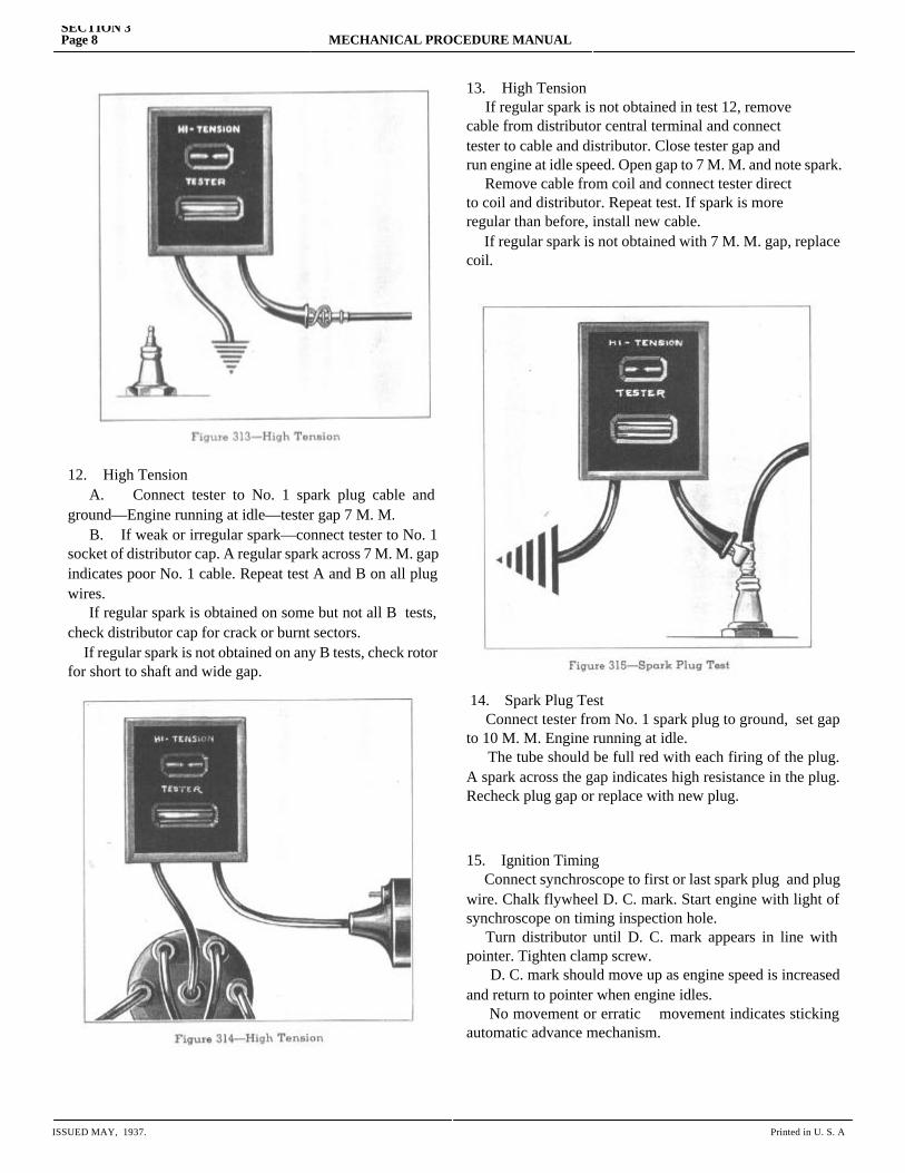
8. Generator Charging Rate Connect ammeter and voltmeter as shown. Ground field terminal (F). With ammeter reading 15 amps. take voltage at generator (A) terminal and at starting motor terminal—more than 0.5 volts difference in voltages indi-cates high resistance in the charge control or connections. Charging Rate—With charge regulator-25 amps. at 8 volts. Without charge regulator-17 amps. at 8 volts.
9. Voltage RegulatorConnect ammeter and voltmeter as shown. Generator field not grounded. Engine speed to give maximum charge. Turn in resistance until charge is reduced to 10 amperes. Voltage should be from 7.8 to 8.1 volts.If voltage is outside this range replace voltage regulator.See Section 6 for two charge regulator information.
10. Distributor1. Automatic advance mechanism must workfreely.2. Check shaft for excess play in bushings.3. Lubricate at oil cup with engine oil.4. Lubricate top of shaft and breaker arm pivotwith engine oil.5. Coat breaker arm block lightly with vaseline.6. Clean breaker points—replace if pitted or burnt.7. Align points.8. Adjust points to .020" maximum opening.
11. Low Tension Ignition Voltmeter readings should be zero from ground to point indicated--Distributor Points closed. 1. 2. A reading indicates poor points. 3.. 4. A reading indicates poor ground.Ammeter reading—Ignition on. A. Distributor points closed—5 to 6 amps.
High reading—shorted coil. Low reading—poor connections.
B. Distributor points open—Ammeter shouldread zero. A reading indicates shorted condenserpivot arm or primary lead to distributor. If equipment is not available for condenser test, install new condenser and compare high tension output.
Printed in U. S. A. ISSUED MAY, 1937
SECTION 3Page 8 MECHANICAL PROCEDURE MANUAL
12. High Tension A. Connect tester to No. 1 spark plug cable and ground—Engine running at idle—tester gap 7 M. M. B. If weak or irregular spark—connect tester to No. 1 socket of distributor cap. A regular spark across 7 M. M. gap indicates poor No. 1 cable. Repeat test A and B on all plug wires. If regular spark is obtained on some but not all B tests, check distributor cap for crack or burnt sectors. If regular spark is not obtained on any B tests, check rotor for short to shaft and wide gap.
13. High Tension If regular spark is not obtained in test 12, remove cable from distributor central terminal and connect tester to cable and distributor. Close tester gap and run engine at idle speed. Open gap to 7 M. M. and note spark. Remove cable from coil and connect tester direct to coil and distributor. Repeat test. If spark is more regular than before, install new cable. If regular spark is not obtained with 7 M. M. gap, replace coil.
14. Spark Plug Test Connect tester from No. 1 spark plug to ground, set gap to 10 M. M. Engine running at idle. The tube should be full red with each firing of the plug. A spark across the gap indicates high resistance in the plug. Recheck plug gap or replace with new plug.
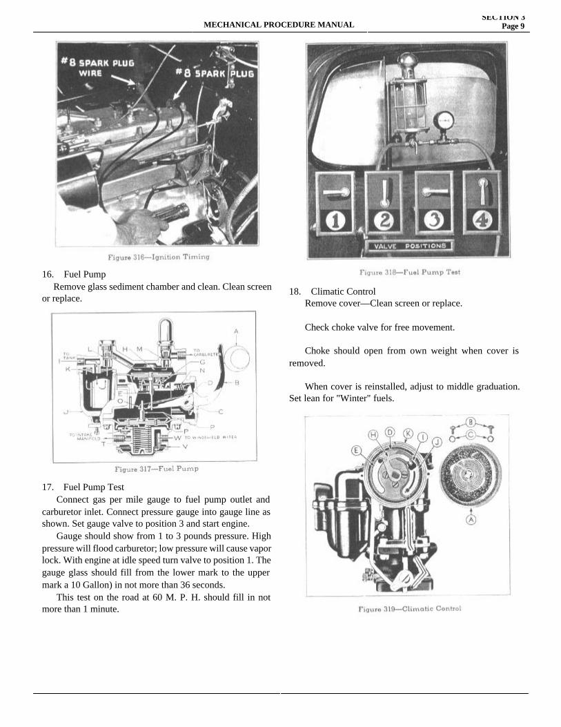
15. Ignition Timing Connect synchroscope to first or last spark plug and plug wire. Chalk flywheel D. C. mark. Start engine with light of synchroscope on timing inspection hole. Turn distributor until D. C. mark appears in line with pointer. Tighten clamp screw. D. C. mark should move up as engine speed is increased and return to pointer when engine idles. No movement or erratic movement indicates sticking automatic advance mechanism.
ISSUED MAY, 1937. Printed in U. S. A
MECHANICAL PROCEDURE MANUALSECTION 3
Page 9
16. Fuel Pump Remove glass sediment chamber and clean. Clean screen or replace.
17. Fuel Pump Test Connect gas per mile gauge to fuel pump outlet and carburetor inlet. Connect pressure gauge into gauge line as shown. Set gauge valve to position 3 and start engine. Gauge should show from 1 to 3 pounds pressure. High pressure will flood carburetor; low pressure will cause vapor lock. With engine at idle speed turn valve to position 1. The gauge glass should fill from the lower mark to the upper mark a 10 Gallon) in not more than 36 seconds. This test on the road at 60 M. P. H. should fill in not more than 1 minute.
18. Climatic Control Remove cover—Clean screen or replace.
Check choke valve for free movement.
Choke should open from own weight when cover is removed.
When cover is reinstalled, adjust to middle graduation. Set lean for "Winter" fuels.
SECTION 3MECHANICAL PROCEDURE MANUAL
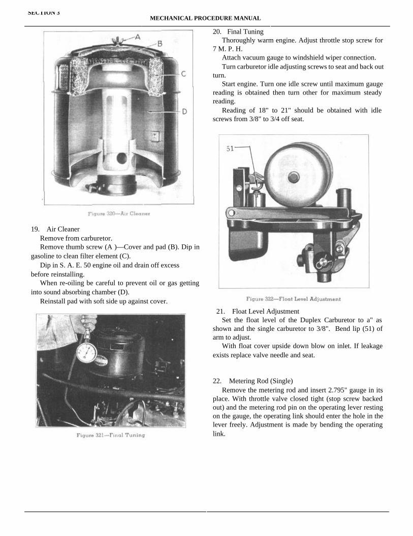
19. Air Cleaner Remove from carburetor. Remove thumb screw (A )—Cover and pad (B). Dip in gasoline to clean filter element (C). Dip in S. A. E. 50 engine oil and drain off excessbefore reinstalling. When re-oiling be careful to prevent oil or gas getting into sound absorbing chamber (D). Reinstall pad with soft side up against cover.
20. Final Tuning Thoroughly warm engine. Adjust throttle stop screw for 7 M. P. H. Attach vacuum gauge to windshield wiper connection. Turn carburetor idle adjusting screws to seat and back out turn. Start engine. Turn one idle screw until maximum gauge reading is obtained then turn other for maximum steady reading. Reading of 18" to 21" should be obtained with idle screws from 3/8" to 3/4 off seat.
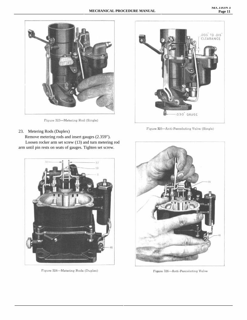
21. Float Level Adjustment Set the float level of the Duplex Carburetor to a" as shown and the single carburetor to 3/8". Bend lip (51) of arm to adjust. With float cover upside down blow on inlet. If leakage exists replace valve needle and seat.
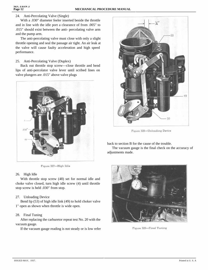
22. Metering Rod (Single) Remove the metering rod and insert 2.795" gauge in its place. With throttle valve closed tight (stop screw backed out) and the metering rod pin on the operating lever resting on the gauge, the operating link should enter the hole in the lever freely. Adjustment is made by bending the operating link.
MECHANICAL PROCEDURE MANUALSECTION 3
Page 11
23. Metering Rods (Duplex) Remove metering rods and insert gauges (2.359"). Loosen rocker arm set screw (13) and turn metering rod arm until pin rests on seats of gauges. Tighten set screw.
SECTION 3Page 12 MECHANICAL PROCEDURE MANUAL
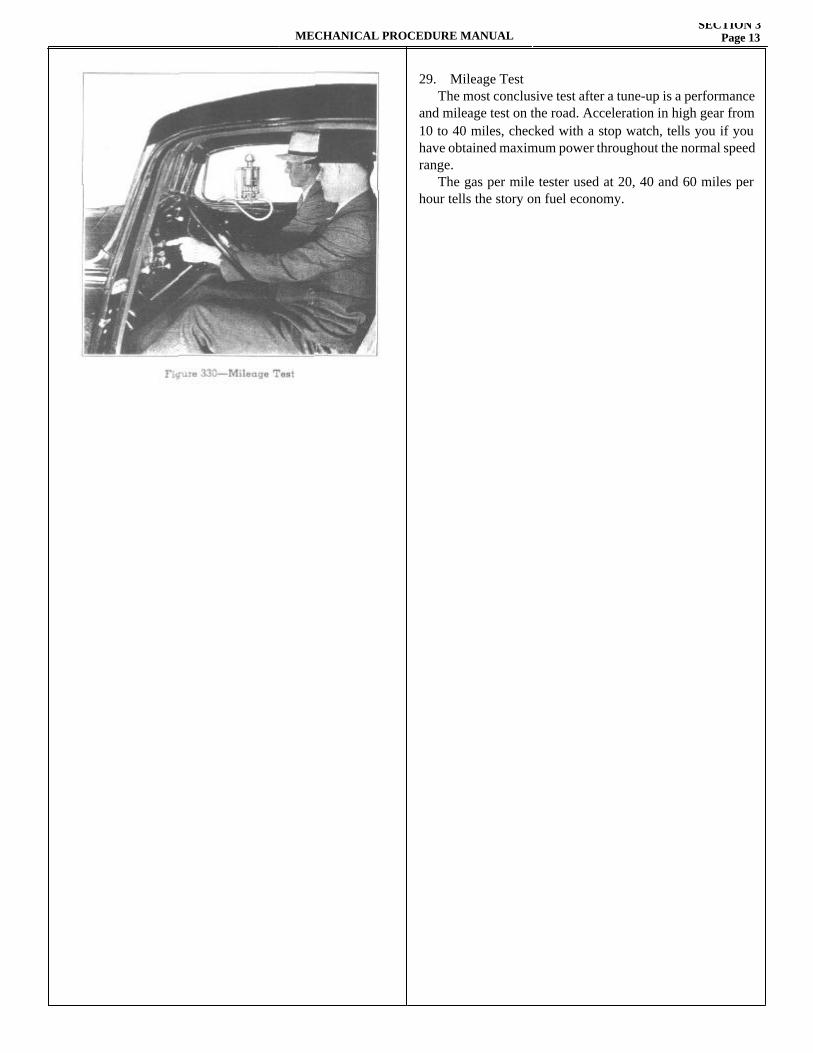
24. Anti-Percolating Valve (Single) With a .030" diameter feeler inserted beside the throttle and in line with the idle port a clearance of from .005" to .015" should exist between the anti- percolating valve arm and the pump arm. The anti-percolating valve must close with only a slight throttle opening and seal the passage air tight. An air leak at the valve will cause faulty acceleration and high speed performance.
25. Anti-Percolating Valve (Duplex) Back out throttle stop screw—close throttle and bend lips of anti-percolator valve lever until scribed lines on valve plungers are .015" above valve plugs
26. High Idle With throttle stop screw (48) set for normal idle and choke valve closed, turn high idle screw (4) until throttle stop screw is held .030" from stop.
27. Unloading Device Bend lip (53) of high idle link (49) to hold choker valve 1" open as shown when throttle is wide open.
28. Final Tuning After replacing the carburetor repeat test No. 20 with the vacuum gauge. If the vacuum gauge reading is not steady or is low refer
back to section B for the cause of the trouble. The vacuum gauge is the final check on the accuracy of adjustments made.
ISSUED MAY, 1937. Printed in U. S. A
MECHANICAL PROCEDURE MANUALSECTION 3
Page 13
29. Mileage Test The most conclusive test after a tune-up is a performance and mileage test on the road. Acceleration in high gear from 10 to 40 miles, checked with a stop watch, tells you if you have obtained maximum power throughout the normal speed range. The gas per mile tester used at 20, 40 and 60 miles per hour tells the story on fuel economy.


MECHANICAL PROCEDURE MANUAL Page 1
SECTION 4
CARBURETOR AND FUEL PUMPService Magazine—Reference Sheet and Service Bullet in Reference
Bulletin orReference SheetNo. MagazineIssue and Page
Date Subject DETAILS OF INFORMATION

MECHANICAL PROCEDURE MANUALSECTION 4
Page 3
DownDraft
TripleVenturi
ManualChoke
ClimatizedControl
AutomaticFast Idle
AntiPercolator
SlowThrottleRetard
Singleor
Dual
1934Terraplane KSTerraplane KTerraplane KUHudson 81935Terraplane SpecialTerraplane De LuxeHudson 6Hudson 81936Terraplane De LuxeTerraplane CustomHudson 6Hudson 81937Terraplane De LuxeTerraplane CustomHudson 6Hudson 8
xxxx
xxxx
xxxx
xxxx
xxxx
xxxx
xxxx
xxxx
x
x
x
x
xxx
xxx
xxx
xxx
xxx
xxx
xxx
xxx
xxxx
xxxx
xxxx
xxxx
xxxx
xxxx
SingleSingleSingleSingle
SingleSingleSingleSingle
SingleSingleSingleSingle
SingleDualDualDual
Regardless of the features included in the various carbu-retors, their basic function is the same so that the following description will apply to all carburetors except as noted.
CARBURETOR OPERATION
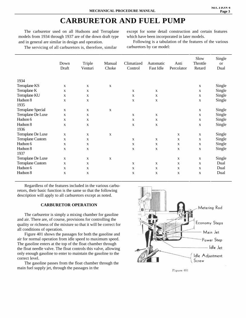
The carburetor is simply a mixing chamber for gasoline and air. There are, of course, provisions for controlling the quality or richness of the mixture so that it will be correct for all conditions of operation. Figure 401 shows the passages for both the gasoline and air for normal operation from idle speed to maximum speed. The gasoline enters at the top of the float chamber through the float needle valve. The float controls this valve, allowing only enough gasoline to enter to maintain the gasoline to the correct level. The gasoline passes from the float chamber through the main fuel supply jet, through the passages in the
CARBURETOR AND FUEL PUMP The carburetor used on all Hudsons and Terraplane models from 1934 through 1937 are of the down draft type and in general are similar in design and operation. The servicing of all carburetors is, therefore, similar
except for some detail construction and certain features which have been incorporated in later models. Following is a tabulation of the features of the various carburetors by car model:
SECTION 4Page 4 MECHANICAL PROCEDURE MANUAL
carburetor body to the main nozzle and also into the idle jet. The mouth of the main nozzle and idle jet are slightly higher than the normal level of fuel in the float chamber so that fuel will stand near the end of the nozzle but will not run out.
Low Speed Operation When the engine is cranked with the throttle in the position shown in Figure 401 (idle setting) a vacuum is created below the throttle. This causes air under atmo-spheric pressure to push past the edge of the throttle, however, the volume that can pass is so small that it will not cause high enough velocity past the main nozzle to pick up any fuel. The vacuum below the throttle valve, however, also causes air to flow into the idle inlet port through the small passage to the right of the carburetor throat, picking up gasoline from the idling jet and delivering it into the carbu-retor throat through the upper idle outlet port just below the
throttle and the lower outlet port in which the idle adjust-ment screw is located. This is a rich mixture of fuel which mixes with the air passing the throttle to give a correct mixture for starting and idling. The quality of the mixture is determined by the setting of the idle adjusting screw, while the quantity is determined by the amount of the upper outlet port exposed below the throttle valve. As the throttle is opened, more of the upper idle port is exposed allowing more mixture to enter the carburetor and
also increasing the amount of air passing the throttle. This increases the engine speed. As the amount of air passing the throttle increases, the velocity of the air past the main nozzle is increased so that fuel is drawn out of the nozzle into the air stream. The opening of the throttle allows the manifold vacuum to extend upward so that the difference in vacuum between the idle inlet port and outlet ports is decreased and the flow of air through the idle bypass is decreased. At speeds above 20 m.p.h. no fuel is supplied through the idle by-pass. The idle adjustment, therefore, has no effect on performance or gaso-line consumption at speeds above 20 m.p.h.
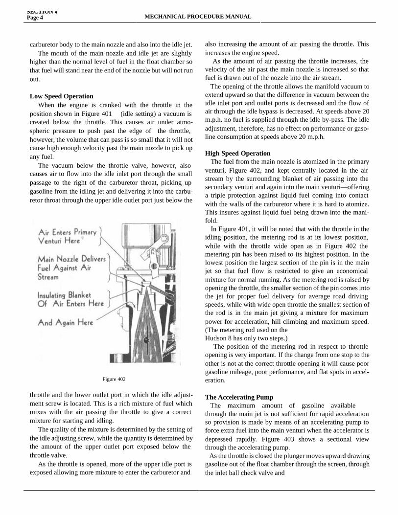
High Speed Operation The fuel from the main nozzle is atomized in the primary venturi, Figure 402, and kept centrally located in the air stream by the surrounding blanket of air passing into the secondary venturi and again into the main venturi—offering a triple protection against liquid fuel coming into contact with the walls of the carburetor where it is hard to atomize. This insures against liquid fuel being drawn into the mani-fold. In Figure 401, it will be noted that with the throttle in the idling position, the metering rod is at its lowest position, while with the throttle wide open as in Figure 402 the metering pin has been raised to its highest position. In the lowest position the largest section of the pin is in the main jet so that fuel flow is restricted to give an economical mixture for normal running. As the metering rod is raised by opening the throttle, the smaller section of the pin comes into the jet for proper fuel delivery for average road driving speeds, while with wide open throttle the smallest section of the rod is in the main jet giving a mixture for maximum power for acceleration, hill climbing and maximum speed. (The metering rod used on theHudson 8 has only two steps.) The position of the metering rod in respect to throttle opening is very important. If the change from one stop to the other is not at the correct throttle opening it will cause poor gasoline mileage, poor performance, and flat spots in accel-eration.
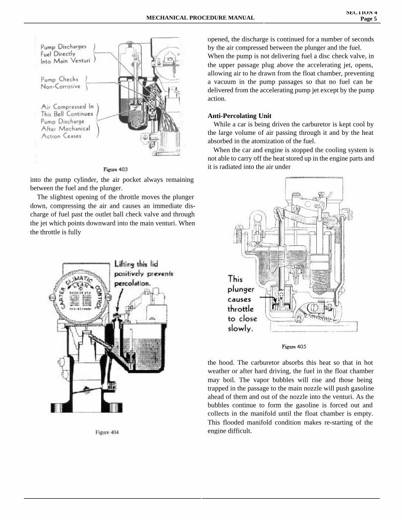
The Accelerating Pump The maximum amount of gasoline availablethrough the main jet is not sufficient for rapid acceleration so provision is made by means of an accelerating pump to force extra fuel into the main venturi when the accelerator is depressed rapidly. Figure 403 shows a sectional view through the accelerating pump. As the throttle is closed the plunger moves upward drawing gasoline out of the float chamber through the screen, through the inlet ball check valve and
Figure 402
MECHANICAL PROCEDURE MANUALSECTION 4
Page 5
into the pump cylinder, the air pocket always remaining between the fuel and the plunger. The slightest opening of the throttle moves the plunger down, compressing the air and causes an immediate dis-charge of fuel past the outlet ball check valve and through the jet which points downward into the main venturi. When the throttle is fully
opened, the discharge is continued for a number of seconds by the air compressed between the plunger and the fuel. When the pump is not delivering fuel a disc check valve, in the upper passage plug above the accelerating jet, opens, allowing air to he drawn from the float chamber, preventing a vacuum in the pump passages so that no fuel can be delivered from the accelerating pump jet except by the pump action.
Anti-Percolating Unit While a car is being driven the carburetor is kept cool by the large volume of air passing through it and by the heat absorbed in the atomization of the fuel. When the car and engine is stopped the cooling system is not able to carry off the heat stored up in the engine parts and it is radiated into the air under
the hood. The carburetor absorbs this heat so that in hot weather or after hard driving, the fuel in the float chamber may boil. The vapor bubbles will rise and those being trapped in the passage to the main nozzle will push gasoline ahead of them and out of the nozzle into the venturi. As the bubbles continue to form the gasoline is forced out and collects in the manifold until the float chamber is empty. This flooded manifold condition makes re-starting of the engine difficult. Figure 404
SECTION 4Page 6 MECHANICAL PROCEDURE MANUAL
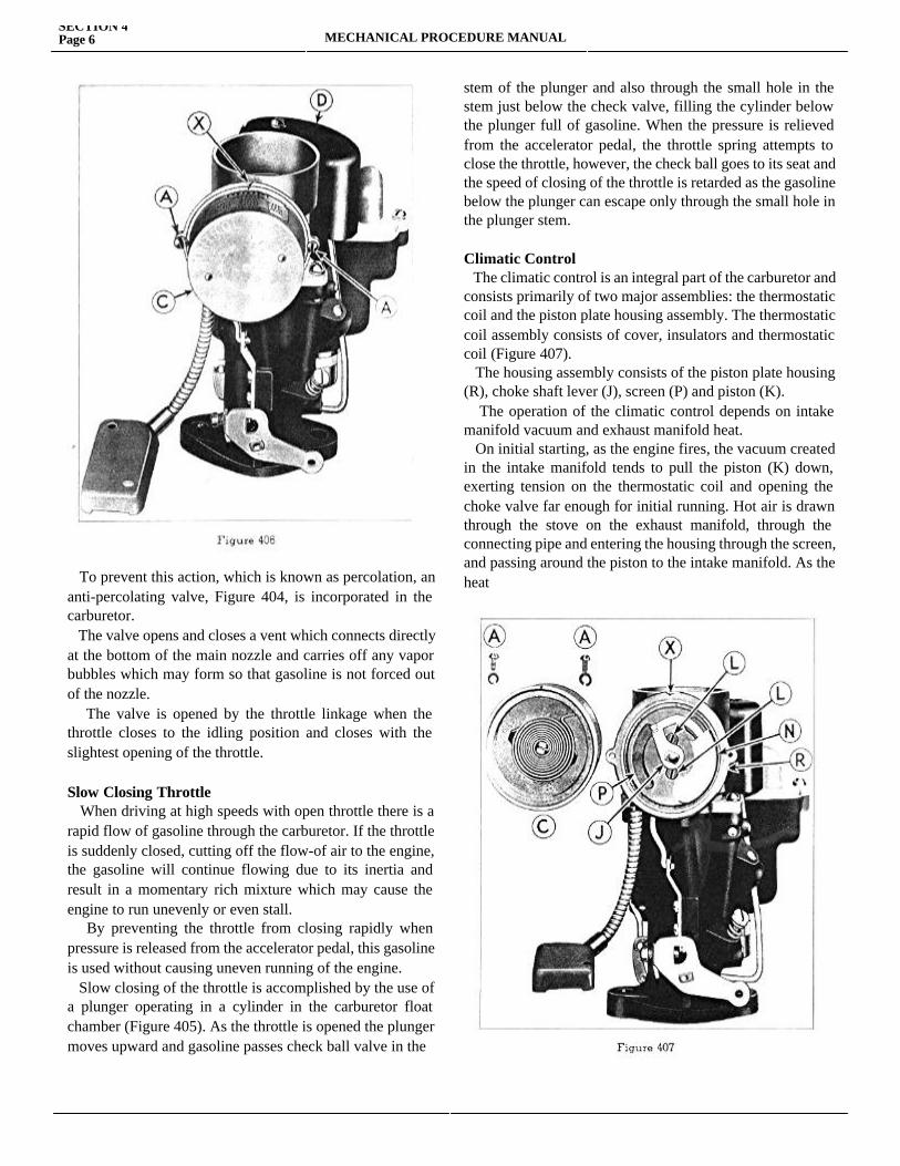
To prevent this action, which is known as percolation, an anti-percolating valve, Figure 404, is incorporated in the carburetor. The valve opens and closes a vent which connects directly at the bottom of the main nozzle and carries off any vapor bubbles which may form so that gasoline is not forced out of the nozzle. The valve is opened by the throttle linkage when the throttle closes to the idling position and closes with the slightest opening of the throttle. Slow Closing Throttle When driving at high speeds with open throttle there is a rapid flow of gasoline through the carburetor. If the throttle is suddenly closed, cutting off the flow-of air to the engine, the gasoline will continue flowing due to its inertia and result in a momentary rich mixture which may cause the engine to run unevenly or even stall. By preventing the throttle from closing rapidly when pressure is released from the accelerator pedal, this gasoline is used without causing uneven running of the engine. Slow closing of the throttle is accomplished by the use of a plunger operating in a cylinder in the carburetor float chamber (Figure 405). As the throttle is opened the plunger moves upward and gasoline passes check ball valve in the
stem of the plunger and also through the small hole in the stem just below the check valve, filling the cylinder below the plunger full of gasoline. When the pressure is relieved from the accelerator pedal, the throttle spring attempts to close the throttle, however, the check ball goes to its seat and the speed of closing of the throttle is retarded as the gasoline below the plunger can escape only through the small hole in the plunger stem.
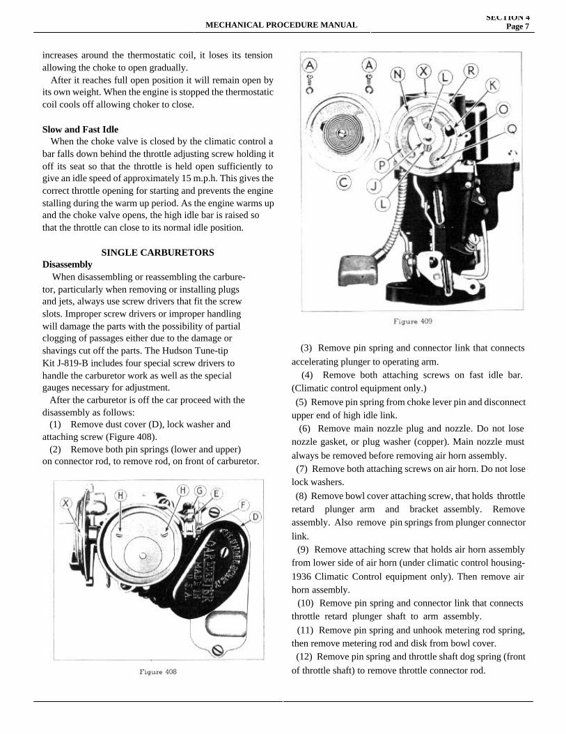
Climatic Control The climatic control is an integral part of the carburetor and consists primarily of two major assemblies: the thermostatic coil and the piston plate housing assembly. The thermostatic coil assembly consists of cover, insulators and thermostatic coil (Figure 407). The housing assembly consists of the piston plate housing (R), choke shaft lever (J), screen (P) and piston (K). The operation of the climatic control depends on intake manifold vacuum and exhaust manifold heat. On initial starting, as the engine fires, the vacuum created in the intake manifold tends to pull the piston (K) down, exerting tension on the thermostatic coil and opening the choke valve far enough for initial running. Hot air is drawn through the stove on the exhaust manifold, through the connecting pipe and entering the housing through the screen, and passing around the piston to the intake manifold. As the heat
MECHANICAL PROCEDURE MANUALSECTION 4
Page 7
increases around the thermostatic coil, it loses its tension allowing the choke to open gradually. After it reaches full open position it will remain open by its own weight. When the engine is stopped the thermostatic coil cools off allowing choker to close.
Slow and Fast Idle When the choke valve is closed by the climatic control a bar falls down behind the throttle adjusting screw holding it off its seat so that the throttle is held open sufficiently to give an idle speed of approximately 15 m.p.h. This gives the correct throttle opening for starting and prevents the engine stalling during the warm up period. As the engine warms up and the choke valve opens, the high idle bar is raised so that the throttle can close to its normal idle position.
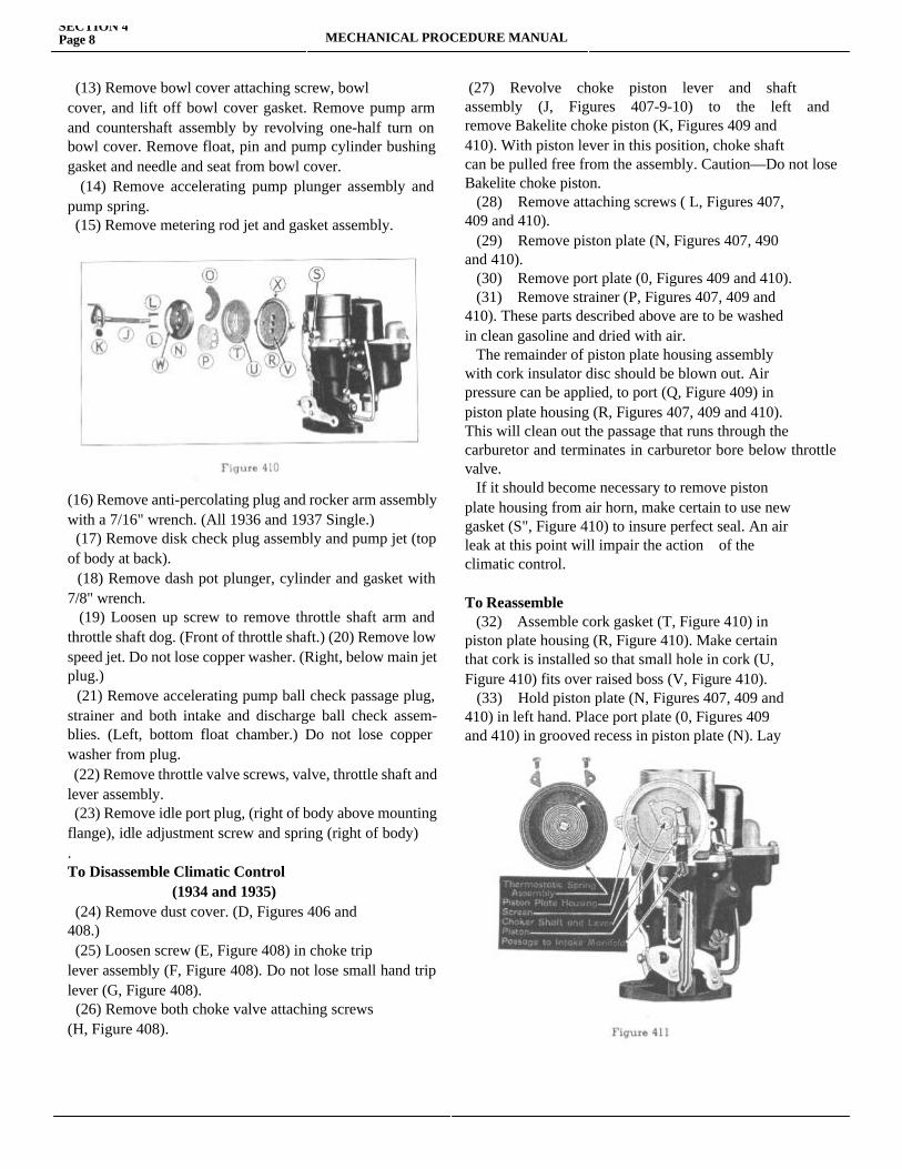
SINGLE CARBURETORS Disassembly When disassembling or reassembling the carbure- tor, particularly when removing or installing plugs and jets, always use screw drivers that fit the screw slots. Improper screw drivers or improper handling will damage the parts with the possibility of partial clogging of passages either due to the damage or shavings cut off the parts. The Hudson Tune-tip Kit J-819-B includes four special screw drivers to handle the carburetor work as well as the special gauges necessary for adjustment. After the carburetor is off the car proceed with the disassembly as follows: (1) Remove dust cover (D), lock washer and attaching screw (Figure 408). (2) Remove both pin springs (lower and upper) on connector rod, to remove rod, on front of carburetor.
(3) Remove pin spring and connector link that connects accelerating plunger to operating arm. (4) Remove both attaching screws on fast idle bar. (Climatic control equipment only.) (5) Remove pin spring from choke lever pin and disconnect upper end of high idle link. (6) Remove main nozzle plug and nozzle. Do not lose nozzle gasket, or plug washer (copper). Main nozzle must always be removed before removing air horn assembly. (7) Remove both attaching screws on air horn. Do not lose lock washers. (8) Remove bowl cover attaching screw, that holds throttle retard plunger arm and bracket assembly. Remove assembly. Also remove pin springs from plunger connector link. (9) Remove attaching screw that holds air horn assembly from lower side of air horn (under climatic control housing-1936 Climatic Control equipment only). Then remove air horn assembly. (10) Remove pin spring and connector link that connects throttle retard plunger shaft to arm assembly. (11) Remove pin spring and unhook metering rod spring, then remove metering rod and disk from bowl cover. (12) Remove pin spring and throttle shaft dog spring (front of throttle shaft) to remove throttle connector rod.
(13) Remove bowl cover attaching screw, bowl cover, and lift off bowl cover gasket. Remove pump arm and countershaft assembly by revolving one-half turn on bowl cover. Remove float, pin and pump cylinder bushing gasket and needle and seat from bowl cover. (14) Remove accelerating pump plunger assembly and pump spring. (15) Remove metering rod jet and gasket assembly.
(16) Remove anti-percolating plug and rocker arm assembly with a 7/16" wrench. (All 1936 and 1937 Single.) (17) Remove disk check plug assembly and pump jet (top of body at back). (18) Remove dash pot plunger, cylinder and gasket with 7/8" wrench. (19) Loosen up screw to remove throttle shaft arm and throttle shaft dog. (Front of throttle shaft.) (20) Remove low speed jet. Do not lose copper washer. (Right, below main jet plug.) (21) Remove accelerating pump ball check passage plug, strainer and both intake and discharge ball check assem-blies. (Left, bottom float chamber.) Do not lose copper washer from plug. (22) Remove throttle valve screws, valve, throttle shaft and lever assembly. (23) Remove idle port plug, (right of body above mounting flange), idle adjustment screw and spring (right of body). To Disassemble Climatic Control (1934 and 1935) (24) Remove dust cover. (D, Figures 406 and 408.) (25) Loosen screw (E, Figure 408) in choke trip lever assembly (F, Figure 408). Do not lose small hand trip lever (G, Figure 408). (26) Remove both choke valve attaching screws (H, Figure 408).
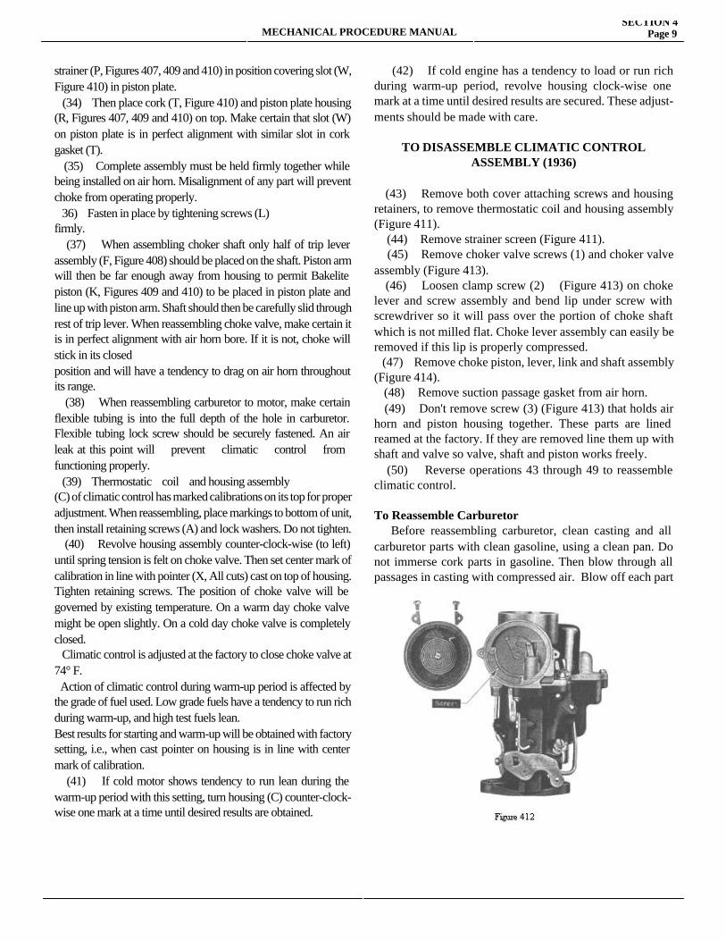
(27) Revolve choke piston lever and shaft assembly (J, Figures 407-9-10) to the left and remove Bakelite choke piston (K, Figures 409 and 410). With piston lever in this position, choke shaft can be pulled free from the assembly. Caution—Do not lose Bakelite choke piston. (28) Remove attaching screws ( L, Figures 407, 409 and 410). (29) Remove piston plate (N, Figures 407, 490 and 410). (30) Remove port plate (0, Figures 409 and 410). (31) Remove strainer (P, Figures 407, 409 and 410). These parts described above are to be washed in clean gasoline and dried with air. The remainder of piston plate housing assembly with cork insulator disc should be blown out. Air pressure can be applied, to port (Q, Figure 409) in piston plate housing (R, Figures 407, 409 and 410). This will clean out the passage that runs through the carburetor and terminates in carburetor bore below throttle valve. If it should become necessary to remove piston plate housing from air horn, make certain to use new gasket (S", Figure 410) to insure perfect seal. An air leak at this point will impair the action of the climatic control.
To Reassemble (32) Assemble cork gasket (T, Figure 410) in piston plate housing (R, Figure 410). Make certain that cork is installed so that small hole in cork (U, Figure 410) fits over raised boss (V, Figure 410). (33) Hold piston plate (N, Figures 407, 409 and 410) in left hand. Place port plate (0, Figures 409 and 410) in grooved recess in piston plate (N). Lay
SECTION 4Page 8 MECHANICAL PROCEDURE MANUAL
MECHANICAL PROCEDURE MANUALSECTION 4
Page 9
strainer (P, Figures 407, 409 and 410) in position covering slot (W, Figure 410) in piston plate. (34) Then place cork (T, Figure 410) and piston plate housing (R, Figures 407, 409 and 410) on top. Make certain that slot (W) on piston plate is in perfect alignment with similar slot in cork gasket (T). (35) Complete assembly must be held firmly together while being installed on air horn. Misalignment of any part will prevent choke from operating properly. 36) Fasten in place by tightening screws (L)firmly. (37) When assembling choker shaft only half of trip lever assembly (F, Figure 408) should be placed on the shaft. Piston arm will then be far enough away from housing to permit Bakelite piston (K, Figures 409 and 410) to be placed in piston plate and line up with piston arm. Shaft should then be carefully slid through rest of trip lever. When reassembling choke valve, make certain it is in perfect alignment with air horn bore. If it is not, choke will stick in its closedposition and will have a tendency to drag on air horn throughout its range. (38) When reassembling carburetor to motor, make certain flexible tubing is into the full depth of the hole in carburetor. Flexible tubing lock screw should be securely fastened. An air leak at this point will prevent climatic control from functioning properly. (39) Thermostatic coil and housing assembly(C) of climatic control has marked calibrations on its top for proper adjustment. When reassembling, place markings to bottom of unit, then install retaining screws (A) and lock washers. Do not tighten. (40) Revolve housing assembly counter-clock-wise (to left) until spring tension is felt on choke valve. Then set center mark of calibration in line with pointer (X, All cuts) cast on top of housing. Tighten retaining screws. The position of choke valve will be governed by existing temperature. On a warm day choke valve might be open slightly. On a cold day choke valve is completely closed. Climatic control is adjusted at the factory to close choke valve at 74° F. Action of climatic control during warm-up period is affected by the grade of fuel used. Low grade fuels have a tendency to run rich during warm-up, and high test fuels lean.Best results for starting and warm-up will be obtained with factory setting, i.e., when cast pointer on housing is in line with center mark of calibration. (41) If cold motor shows tendency to run lean during the warm-up period with this setting, turn housing (C) counter-clock-wise one mark at a time until desired results are obtained.
(42) If cold engine has a tendency to load or run rich during warm-up period, revolve housing clock-wise one mark at a time until desired results are secured. These adjust-ments should be made with care.
TO DISASSEMBLE CLIMATIC CONTROLASSEMBLY (1936)
(43) Remove both cover attaching screws and housing retainers, to remove thermostatic coil and housing assembly (Figure 411). (44) Remove strainer screen (Figure 411). (45) Remove choker valve screws (1) and choker valve assembly (Figure 413). (46) Loosen clamp screw (2) (Figure 413) on choke lever and screw assembly and bend lip under screw with screwdriver so it will pass over the portion of choke shaft which is not milled flat. Choke lever assembly can easily be removed if this lip is properly compressed. (47) Remove choke piston, lever, link and shaft assembly (Figure 414). (48) Remove suction passage gasket from air horn. (49) Don't remove screw (3) (Figure 413) that holds air horn and piston housing together. These parts are lined reamed at the factory. If they are removed line them up with shaft and valve so valve, shaft and piston works freely. (50) Reverse operations 43 through 49 to reassemble climatic control.
To Reassemble Carburetor Before reassembling carburetor, clean casting and all carburetor parts with clean gasoline, using a clean pan. Do not immerse cork parts in gasoline. Then blow through all passages in casting with compressed air. Blow off each part
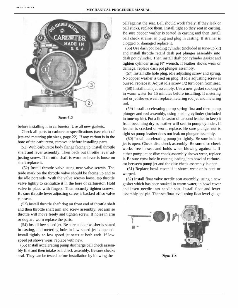
before installing it in carburetor. Use all new gaskets. Check all parts to carburetor specifications (see chart of jets and metering pin sizes, page 22). If any carbon is in the bore of the carburetor, remove it before installing parts. (51) With carburetor body flange facing up, install throttle shaft and lever assembly. Then back out throttle lever ad-justing screw. If throttle shaft is worn or lever is loose on shaft replace it. (52) Install throttle valve using new valve screws. The trade mark on the throttle valve should be facing up and to the idle port side. With the valve screws loose, tap throttle valve lightly to centralize it in the bore of carburetor. Hold valve in place with fingers. Then securely tighten screws. Be sure throttle lever adjusting screw is backed off so valve can seat. (53) Install throttle shaft dog on front end of throttle shaft and then throttle shaft arm and screw assembly. Set arm so throttle will move freely and tighten screw. If holes in arm or dog are worn replace the parts. (54) Install low speed jet. Be sure copper washer is seated in casting, and metering hole in low speed jet is opened. Install tightly so low speed jet seats at both ends. If low speed jet shows wear, replace with new. (55) Install accelerating pump discharge ball check assem-bly first and then intake ball check assembly. Be sure checks seal. They can be tested before installation by blowing the
ball against the seat. Ball should work freely. If they leak or ball sticks, replace them. Install tight so they seat in casting. Be sure copper washer is seated in casting and then install ball check strainer in plug and plug in casting. If strainer is clogged or damaged replace it. (56) Use dash pot loading cylinder (included in tune-up kit) and install throttle retard dash pot plunger assembly into dash pot cylinder. Then install dash pot cylinder gasket and tighten cylinder using N" wrench. If leather shows wear or damage, replace dash pot plunger assembly. (57) Install idle hole plug, idle adjusting screw and spring. No copper washer is used on plug. If idle adjusting screw is burred, replace it. Adjust idle screw 1/2 turn open from seat. (58) Install main jet assembly. Use a new gasket soaking it in warm water for 15 minutes before installing. If metering rod or jet shows wear, replace metering rod jet and metering rod. (59) Install accelerating pump spring first and then pump plunger and rod assembly, using loading cylinder (included in tune-up kit). Put a little castor oil around leather to keep it from becoming dry so leather will seal in pump cylinder. If leather is cracked or worn, replace. Be sure plunger nut is tight so pump leather does not leak on plunger assembly. (60) Install accelerating pump jet tightly. Be sure hole in jet is open. Check disc check assembly. Be sure disc check works free in seat and holds when blowing against it. If either pump jet or disc check assembly shows wear, replace it. Be sure cross hole in casting leading into bowl of carbure-tor between pump jet and the disc check assembly is open. (61) Replace bowl cover if it shows wear or is bent or warped. (62) Install float valve needle seat assembly, using a new gasket which has been soaked in warm water, in bowl cover and insert needle into needle seat. Install float and lever assembly and pin. Then set float level, using float level gauge
SECTION 4MECHANICAL PROCEDURE MANUAL
MECHANICAL PROCEDURE MANUALSECTION 4
Page 11
to carburetor specifications of 3/8" (Figure 415). Be sure the gauge rests on the cover gasket flange. Adjustment is ob-tained by bending the lip on float arm which contacts nee-dle. Do not bend on float in adjusting it as damage will result. If intake needle or seat shows wear or damage, replace both. If holes in float or float pin are worn or out of round, or float is loaded with gas, replace float. Float pin should be replaced if it shows wear. (63) Install a new pump cylinder bushing gasket in bowl cover. (64) Install pump arm and countershaft assembly on bowl cover. If hole in arm is worn or out of round, or countershaft is loose on arm, replace assembly. Be sure vent hole is opened in bowl cover. (Below countershaft.)
(65) Lay bowl cover gasket on body casting. Install bowl cover, tighten bowl cover with attaching screws and lock washers pulling screws down evenly. (66) Install pump connector link and pin spring. Pump has three settings: long stroke for extremely cold temperature, center and short stroke for summer or hot temperatures.
Metering Rod Adjustment
(67) Correct setting of metering rod is important. Metering rod position should be checked when carburetors are ser-viced or when leaner than standards rods are installed. Correct procedure is as follows:
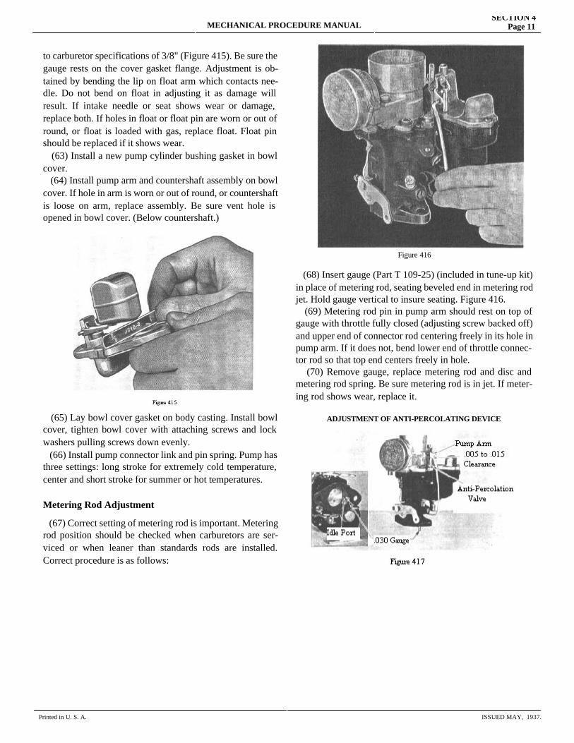
Figure 416
(68) Insert gauge (Part T 109-25) (included in tune-up kit) in place of metering rod, seating beveled end in metering rod jet. Hold gauge vertical to insure seating. Figure 416. (69) Metering rod pin in pump arm should rest on top of gauge with throttle fully closed (adjusting screw backed off) and upper end of connector rod centering freely in its hole in pump arm. If it does not, bend lower end of throttle connec-tor rod so that top end centers freely in hole. (70) Remove gauge, replace metering rod and disc and metering rod spring. Be sure metering rod is in jet. If meter-ing rod shows wear, replace it.
ADJUSTMENT OF ANTI-PERCOLATING DEVICE
Printed in U. S. A. ISSUED MAY, 1937.
Anti-Percolating Valve Adjustment (1936 and 1937—Single)
(71) Install anti-percolating plug and rocker arm assembly using 7/16" wrench. To adjust anti- percolator: set throttle valve at .030" opening between edge of valve and bore of carburetor on same side as port hole. Use a gauge .030" diameter (tool J-882 included in tune-up kit). Be sure to place gauge in front of idle port hole (insert Figure 417). Adjust rocker arm for .010" clearance (plus or minus .005") between rocker arm lip and pump arm (Figure 417). Check with narrow feeler gauge.
To Assemble Air Horn to Body
(72) Install fast idle block and link assembly on choker lever pin (1936 Climatic Control only).
(73) Install new suction passage gasket in piston housing casting (Climatic Control only).
(74) Install air horn assembly and throttle retard dash pot arm and bracket assembly by removing one of the bowl cover attaching screws. Tighten air horn and bowl cover attaching screws and lock washer.
(75) Install attaching screw and lock washer beneath piston plate housing on 1936 Climatic Control.
(76) Install connector link on throttle retard dash pot plunger shaft and dash pot arm and bracket assembly, and then insert pin spring.
(77) Install dash pot connector rod and pin springs being sure of placing the bend in rod towards the body flange. Rod connects dash pot arm and bracket assembly to throttle shaft dog. If rod shows wear or damage, replace.
Figure 418
Figure 419
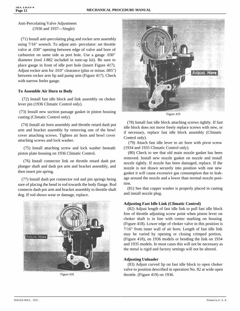
(78) Install fast idle block attaching screws tightly. If fast idle block does not move freely replace screws with new, or if necessary, replace fast idle block assembly (Climatic Control only). (79) Attach fast idle lever to air horn with pivot screw (1934 and 1935 Climatic Control only). (80) Check to see that old main nozzle gasket has been removed. Install new nozzle gasket on nozzle and install nozzle tightly. If nozzle has been damaged, replace. If the nozzle is not drawn securely into position with one new gasket it will cause excessive gas consumption due to leak-age around the nozzle and a lower than normal nozzle posi-tion. (81) See that copper washer is properly placed in casting and install nozzle plug.
Adjusting Fast Idle Link (Climatic Control) (82) Adjust length of fast idle link to pull fast idle block free of throttle adjusting screw point when piston lever on choker shaft is in line with center marking on housing (Figure 418). Lower edge of choker valve in this position is 7/16" from inner wall of air horn. Length of fast idle link may be varied by opening or closing crimped portion, (Figure 418), on 1936 models or bending the link on 1934 and 1935 models. In most cases this will not be necessary as the metal is rigid and factory settings will not be altered.
Adjusting Unloader (83) Adjust curved lip on fast idle block to open choker valve to position described in operation No. 82 at wide open throttle. (Figure 419) on 1936.
SECTION 4Page 12 MECHANICAL PROCEDURE MANUAL
ISSUED MAY, 1937. Printed in U. S. A
MECHANICAL PROCEDURE MANUALSECTION 4
Page 13
Figure 420
models. On 1934 and 1935 models bend the finger on the accelerator pump lever which strikes against the pin in throttle lever (F), (Figure 408.)
Adjusting Climatic Control (84) Check thermostatic housing and coil assembly. If cork insulating strip has shrunk or is damaged, install new strip. If balance of assembly shows damage entire unit must be replaced. (85) Install thermostatic housing and coil assembly with word "Climatic" at bottom and turn counter-clockwise until center marking on piston housing is aligned with mark on thermostat housing. (86) Install housing retainers and attaching screws and tighten securely. (87) Adjust lip of choker lever (1936 only), so that with choker wide open and throttle wide open, choker is held in wide open position. Care should be taken that spring is in the groove between pin and lever. When throttle is closed, choker valve releases. (88) Pack dust cover attaching screw hole in bowl cover with graphite grease and install dust cover and attaching screw and lock washer. Carburetor is now ready for installation on manifold.
HUDSON AND TERRAPLANEDUAL CARBURETORS—1937
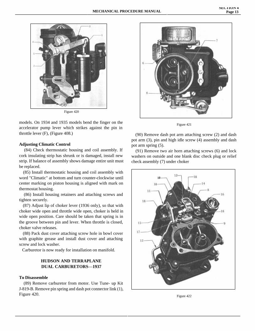
To Disassemble (89) Remove carburetor from motor. Use Tune- up Kit J-819-B. Remove pin spring and dash pot connector link (1), Figure 420.
Figure 421
(90) Remove dash pot arm attaching screw (2) and dash pot arm (3), pin and high idle screw (4) assembly and dash pot arm spring (5). (91) Remove two air horn attaching screws (6) and lock washers on outside and one blank disc check plug or relief check assembly (7) under choker
Figure 422
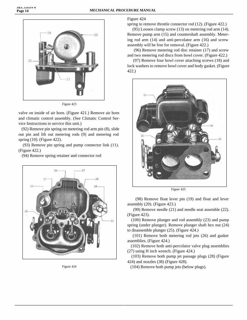
Figure 423
valve on inside of air horn. (Figure 421.) Remove air horn and climatic control assembly. (See Climatic Control Ser-vice Instructions to service this unit.) (92) Remove pin spring on metering rod arm pin (8), slide out pin and lift out metering rods (9) and metering rod spring (10). (Figure 422). (93) Remove pin spring and pump connector link (11). (Figure 422.) (94) Remove spring retainer and connector rod
Figure 424
Figure 424spring to remove throttle connector rod (12). (Figure 422.) (95) Loosen clamp screw (13) on metering rod arm (14). Remove pump arm (15) and countershaft assembly. Meter-ing rod arm (14) and anti-percolator arm (16) and screw assembly will be free for removal. (Figure 422.) (96) Remove metering rod disc retainer (17) and screw and two metering rod discs from bowl cover. (Figure 422.) (97) Remove four bowl cover attaching screws (18) and lock washers to remove bowl cover and body gasket. (Figure 422.)
Figure 425
(98) Remove float lever pin (19) and float and lever assembly (20). (Figure 423.) (99) Remove needle (21) and needle seat assemble (22). (Figure 423). (100) Remove plunger and rod assembly (23) and pump spring (under plunger). Remove plunger shaft hex nut (24) to disassemble plunger (25). (Figure 424.) (101) Remove both metering rod jets (26) and gasket assemblies. (Figure 424.) (102) Remove both anti-percolator valve plug assemblies (27) using H inch wrench. (Figure 424.) (103) Remove both pump jet passage plugs (28) (Figure 424) and nozzles (38) (Figure 428). (104) Remove both pump jets (below plugs).
SECTION 4Page 14 MECHANICAL PROCEDURE MANUAL
MECHANICAL PROCEDURE MANUALSECTION 4
Page 15
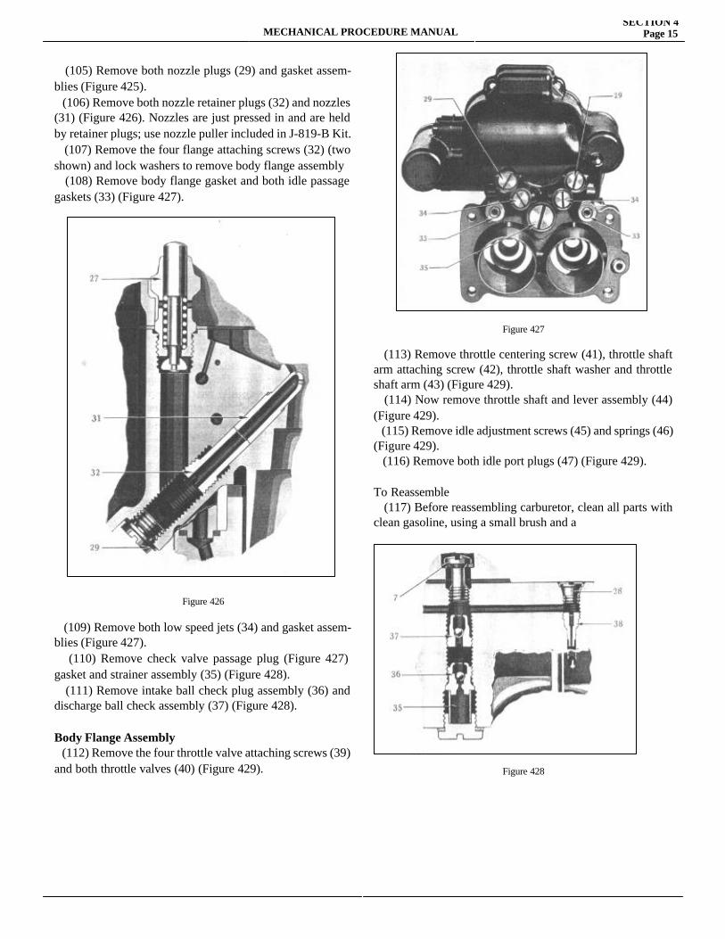
(105) Remove both nozzle plugs (29) and gasket assem-blies (Figure 425). (106) Remove both nozzle retainer plugs (32) and nozzles (31) (Figure 426). Nozzles are just pressed in and are held by retainer plugs; use nozzle puller included in J-819-B Kit. (107) Remove the four flange attaching screws (32) (two shown) and lock washers to remove body flange assembly (108) Remove body flange gasket and both idle passage gaskets (33) (Figure 427).
Figure 426
(109) Remove both low speed jets (34) and gasket assem-blies (Figure 427). (110) Remove check valve passage plug (Figure 427) gasket and strainer assembly (35) (Figure 428). (111) Remove intake ball check plug assembly (36) and discharge ball check assembly (37) (Figure 428).
Body Flange Assembly (112) Remove the four throttle valve attaching screws (39) and both throttle valves (40) (Figure 429).
Figure 427
(113) Remove throttle centering screw (41), throttle shaft arm attaching screw (42), throttle shaft washer and throttle shaft arm (43) (Figure 429). (114) Now remove throttle shaft and lever assembly (44) (Figure 429). (115) Remove idle adjustment screws (45) and springs (46) (Figure 429). (116) Remove both idle port plugs (47) (Figure 429).
To Reassemble (117) Before reassembling carburetor, clean all parts with clean gasoline, using a small brush and a
Figure 428
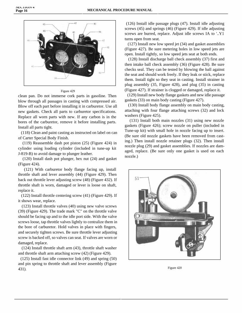
Figure 429
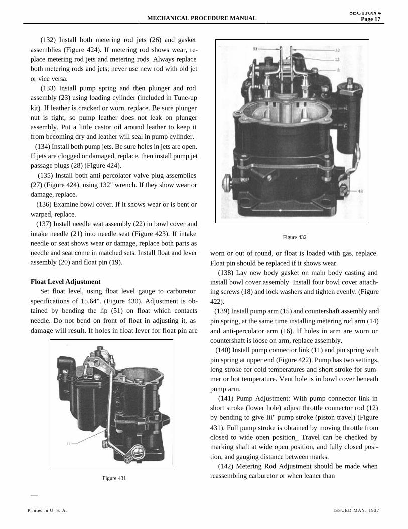
clean pan. Do not immerse cork parts in gasoline. Then blow through all passages in casting with compressed air. Blow off each part before installing it in carburetor. Use all new gaskets. Check all parts to carburetor specifications. Replace all worn parts with new. If any carbon is in the bores of the carburetor, remove it before installing parts. Install all parts tight. (118) Clean and paint casting as instructed on label on can of Carter Special Body Finish. (119) Reassemble dash pot piston (25) (Figure 424) in cylinder using loading cylinder (included in tune-up kit J-819-B) to avoid damage to plunger leather. (120) Install dash pot plunger, hex nut (24) and gasket (Figure 424). (121) With carburetor body flange facing up, install throttle shaft and lever assembly (44) (Figure 429). Then back out throttle lever adjusting screw (48) (Figure 432). If throttle shaft is worn, damaged or lever is loose on shaft, replace it. (122) Install throttle centering screw (41) (Figure 429). If it shows wear, replace. (123) Install throttle valves (40) using new valve screws (39) (Figure 429). The trade mark "C" on the throttle valve should be facing up and to the idle port side. With the valve screws loose, tap throttle valves lightly to centralize them in the bore of carburetor. Hold valves in place with fingers, and securely tighten screws. Be sure throttle lever adjusting screw is backed off, so valves can seat. If valves are worn or damaged, replace. (124) Install throttle shaft arm (43), throttle shaft washer and throttle shaft arm attaching screw (42) (Figure 429). (125) Install fast idle connector link (49) and spring (50) and pin spring to throttle shaft and lever assembly (Figure 431).
(126) Install idle passage plugs (47). Install idle adjusting screws (45) and springs (46) (Figure 429). If idle adjusting screws are burred, replace. Adjust idle screws IA to '..Y1 turns open from seat. (127) Install new low speed jet (34) and gasket assemblies (Figure 427). Be sure metering holes in low speed jets are open. Install tightly, so low speed jets seat at both ends. (128) Install discharge ball check assembly (37) first and then intake ball check assembly (36) (Figure 428). Be sure checks seal. They can be tested by blowing the ball against the seat and should work freely. If they leak or stick, replace them. Install tight so they seat in casting. Install strainer in plug assembly (35, Figure 428), and plug (35) in casting (Figure 427). If strainer is clogged or damaged, replace it. (129) Install new body flange gaskets and new idle passage gaskets (33) on main body casting (Figure 427). (130) Install body flange assembly on main body casting, attaching with four flange attaching screws (32) and lock washers (Figure 425). (131) Install both main nozzles (31) using new nozzle gaskets (Figure 426); screw nozzle on puller (included in Tune-up kit) with small hole in nozzle facing up to insert. (Be sure old nozzle gaskets have been removed from cast-ing.) Then install nozzle retainer plugs (32). Then install nozzle plug (29) and gasket assemblies. If nozzles are dam-aged, replace. (Be sure only one gasket is used on each nozzle.)
Figure 420
SECTION 4Page 16 MECHANICAL PROCEDURE MANUAL
MECHANICAL PROCEDURE MANUALSECTION 4
Page 17
(132) Install both metering rod jets (26) and gasket assemblies (Figure 424). If metering rod shows wear, re-place metering rod jets and metering rods. Always replace both metering rods and jets; never use new rod with old jet or vice versa. (133) Install pump spring and then plunger and rod assembly (23) using loading cylinder (included in Tune-up kit). If leather is cracked or worn, replace. Be sure plunger nut is tight, so pump leather does not leak on plunger assembly. Put a little castor oil around leather to keep it from becoming dry and leather will seal in pump cylinder. (134) Install both pump jets. Be sure holes in jets are open. If jets are clogged or damaged, replace, then install pump jet passage plugs (28) (Figure 424). (135) Install both anti-percolator valve plug assemblies (27) (Figure 424), using 132" wrench. If they show wear or damage, replace. (136) Examine bowl cover. If it shows wear or is bent or warped, replace. (137) Install needle seat assembly (22) in bowl cover and intake needle (21) into needle seat (Figure 423). If intake needle or seat shows wear or damage, replace both parts as needle and seat come in matched sets. Install float and lever assembly (20) and float pin (19).
Float Level Adjustment Set float level, using float level gauge to carburetor specifications of 15.64". (Figure 430). Adjustment is ob-tained by bending the lip (51) on float which contacts needle. Do not bend on front of float in adjusting it, as damage will result. If holes in float lever for float pin are
Figure 431
—
Figure 432
worn or out of round, or float is loaded with gas, replace. Float pin should be replaced if it shows wear. (138) Lay new body gasket on main body casting and install bowl cover assembly. Install four bowl cover attach-ing screws (18) and lock washers and tighten evenly. (Figure 422). (139) Install pump arm (15) and countershaft assembly and pin spring, at the same time installing metering rod arm (14) and anti-percolator arm (16). If holes in arm are worn or countershaft is loose on arm, replace assembly. (140) Install pump connector link (11) and pin spring with pin spring at upper end (Figure 422). Pump has two settings, long stroke for cold temperatures and short stroke for sum-mer or hot temperature. Vent hole is in bowl cover beneath pump arm. (141) Pump Adjustment: With pump connector link in short stroke (lower hole) adjust throttle connector rod (12) by bending to give Iii" pump stroke (piston travel) (Figure 431). Full pump stroke is obtained by moving throttle from closed to wide open position_ Travel can be checked by marking shaft at wide open position, and fully closed posi-tion, and gauging distance between marks. (142) Metering Rod Adjustment should be made when reassembling carburetor or when leaner than
Printed in U. S. A. ISSUED MAY. 1937
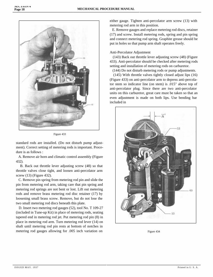
Figure 433
standard rods are installed. (Do not disturb pump adjust-ment). Correct setting of metering rods is important. Proce-dure is as follows : A. Remove air horn and climatic control assembly (Figure 432). B. Back out throttle lever adjusting screw (48) so that throttle valves close tight, and loosen anti-percolator arm screw (13) (Figure 432). C. Remove pin spring from metering rod pin and slide the pin from metering rod arm, taking care that pin spring and metering rod springs are not bent or lost. Lift out metering rods and remove brass metering rod disc retainer (17) by loosening small brass screw. Remove, but do not lose the two small metering rod discs beneath this plate. D. Insert two metering rod gauges (52), tool No. T 109-27 (included in Tune-up Kit) in place of metering rods, seating tapered end in metering rod jet. Put metering rod pin (8) in place in metering rod arm. Turn metering rod lever (14) on shaft until metering rod pin rests at bottom of notches in metering rod gauges allowing for .005 inch variation on either
either gauge. Tighten anti-percolator arm screw (13) with metering rod arm in this position. E. Remove gauges and replace metering rod discs, retainer (17) and screw. Install metering rods, spring and pin spring and connect metering rod spring. Graphite grease should be put in holes so that pump arm shaft operates freely.
Anti-Percolator Adjustment (143) Back out throttle lever adjusting screw (48) (Figure 433). Anti-percolator should be checked after metering rods setting and installation of metering rods on carburetor. (144) Do not disturb metering rods or pump adjustments. (145) With throttle valves tightly closed adjust lips (16) (Figure 433) on anti-percolator arm to depress anti-percola-tor stem so indicator line (on stem) is .015" above top of anti-percolator plug. Since there are two anti-percolator units on this carburetor, great care must be taken so that an even adjustment is made on both lips. Use bending bar included in
Figure 434
SECTION 4Page 18 MECHANICAL PROCEDURE MANUAL
ISSUED MAY. 1937 Printed in U. S. A.
MECHANICAL PROCEDURE MANUALSECTION 4
Page 19
Tune-up Kit as shown in Figure 433, while holding throttle closed. (146) Install air horn assembly. Tighten screws evenly. (Do not forget screw inside bore of air horn.) (147) Install dash pot arm, pin and screw assembly. Then install dash pot connector link and pin spring.
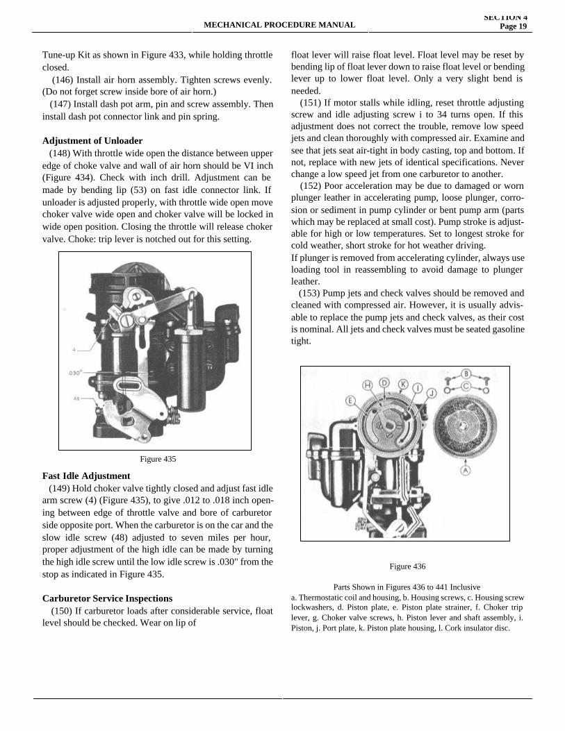
Adjustment of Unloader (148) With throttle wide open the distance between upper edge of choke valve and wall of air horn should be VI inch (Figure 434). Check with inch drill. Adjustment can be made by bending lip (53) on fast idle connector link. If unloader is adjusted properly, with throttle wide open move choker valve wide open and choker valve will be locked in wide open position. Closing the throttle will release choker valve. Choke: trip lever is notched out for this setting.
Figure 435
Fast Idle Adjustment (149) Hold choker valve tightly closed and adjust fast idle arm screw (4) (Figure 435), to give .012 to .018 inch open-ing between edge of throttle valve and bore of carburetor side opposite port. When the carburetor is on the car and the slow idle screw (48) adjusted to seven miles per hour, proper adjustment of the high idle can be made by turning the high idle screw until the low idle screw is .030" from the stop as indicated in Figure 435.
Carburetor Service Inspections (150) If carburetor loads after considerable service, float level should be checked. Wear on lip of
float lever will raise float level. Float level may be reset by bending lip of float lever down to raise float level or bending lever up to lower float level. Only a very slight bend is needed. (151) If motor stalls while idling, reset throttle adjusting screw and idle adjusting screw i to 34 turns open. If this adjustment does not correct the trouble, remove low speed jets and clean thoroughly with compressed air. Examine and see that jets seat air-tight in body casting, top and bottom. If not, replace with new jets of identical specifications. Never change a low speed jet from one carburetor to another. (152) Poor acceleration may be due to damaged or worn plunger leather in accelerating pump, loose plunger, corro-sion or sediment in pump cylinder or bent pump arm (parts which may be replaced at small cost). Pump stroke is adjust-able for high or low temperatures. Set to longest stroke for cold weather, short stroke for hot weather driving.If plunger is removed from accelerating cylinder, always use loading tool in reassembling to avoid damage to plunger leather. (153) Pump jets and check valves should be removed and cleaned with compressed air. However, it is usually advis-able to replace the pump jets and check valves, as their cost is nominal. All jets and check valves must be seated gasoline tight.
Figure 436
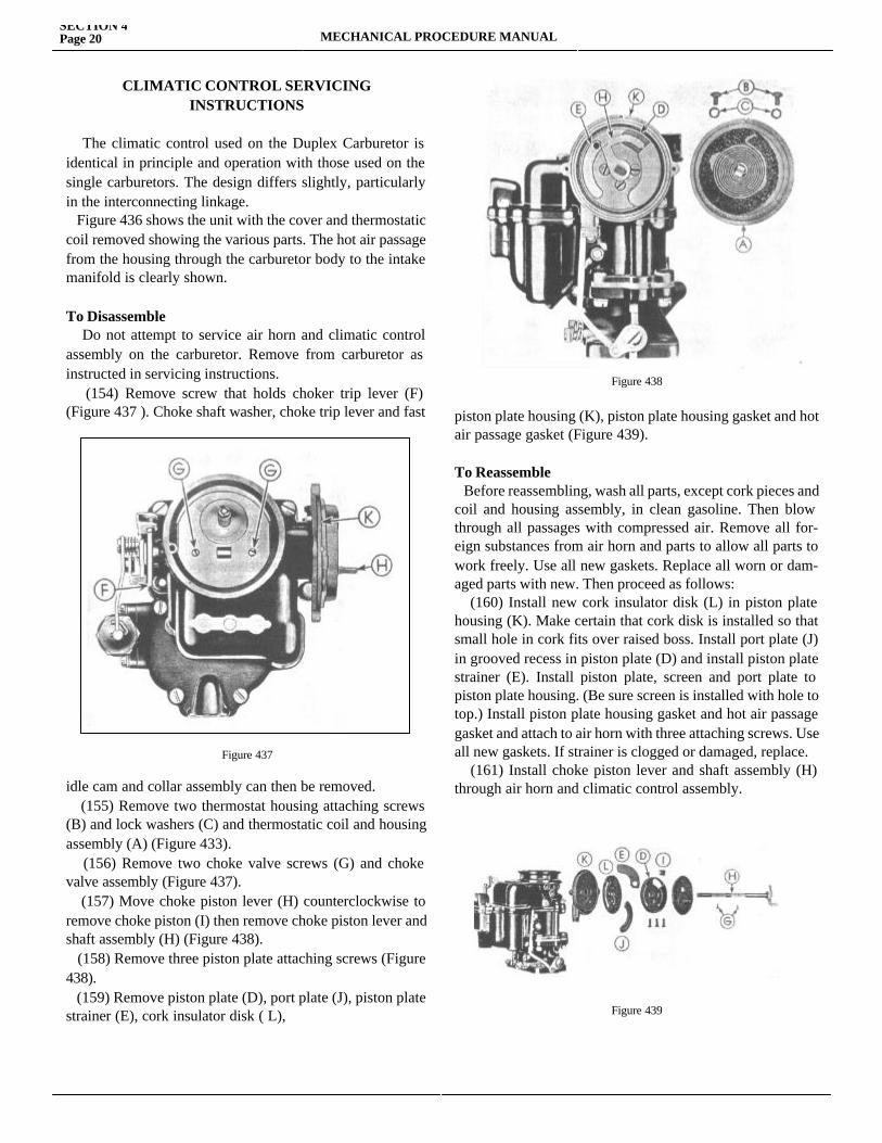
Parts Shown in Figures 436 to 441 Inclusivea. Thermostatic coil and housing, b. Housing screws, c. Housing screw lockwashers, d. Piston plate, e. Piston plate strainer, f. Choker trip lever, g. Choker valve screws, h. Piston lever and shaft assembly, i. Piston, j. Port plate, k. Piston plate housing, l. Cork insulator disc.
CLIMATIC CONTROL SERVICINGINSTRUCTIONS
The climatic control used on the Duplex Carburetor is identical in principle and operation with those used on the single carburetors. The design differs slightly, particularly in the interconnecting linkage. Figure 436 shows the unit with the cover and thermostatic coil removed showing the various parts. The hot air passage from the housing through the carburetor body to the intake manifold is clearly shown.
To Disassemble Do not attempt to service air horn and climatic control assembly on the carburetor. Remove from carburetor as instructed in servicing instructions. (154) Remove screw that holds choker trip lever (F) (Figure 437 ). Choke shaft washer, choke trip lever and fast
Figure 437
idle cam and collar assembly can then be removed. (155) Remove two thermostat housing attaching screws (B) and lock washers (C) and thermostatic coil and housing assembly (A) (Figure 433). (156) Remove two choke valve screws (G) and choke valve assembly (Figure 437). (157) Move choke piston lever (H) counterclockwise to remove choke piston (I) then remove choke piston lever and shaft assembly (H) (Figure 438). (158) Remove three piston plate attaching screws (Figure 438). (159) Remove piston plate (D), port plate (J), piston plate strainer (E), cork insulator disk ( L),
Figure 438
piston plate housing (K), piston plate housing gasket and hot air passage gasket (Figure 439).
To Reassemble Before reassembling, wash all parts, except cork pieces and coil and housing assembly, in clean gasoline. Then blow through all passages with compressed air. Remove all for-eign substances from air horn and parts to allow all parts to work freely. Use all new gaskets. Replace all worn or dam-aged parts with new. Then proceed as follows: (160) Install new cork insulator disk (L) in piston plate housing (K). Make certain that cork disk is installed so that small hole in cork fits over raised boss. Install port plate (J) in grooved recess in piston plate (D) and install piston plate strainer (E). Install piston plate, screen and port plate to piston plate housing. (Be sure screen is installed with hole to top.) Install piston plate housing gasket and hot air passage gasket and attach to air horn with three attaching screws. Use all new gaskets. If strainer is clogged or damaged, replace. (161) Install choke piston lever and shaft assembly (H) through air horn and climatic control assembly.
Figure 439
SECTION 4Page 20 MECHANICAL PROCEDURE MANUAL
MECHANICAL PROCEDURE MANUALSECTION 4
Page 21
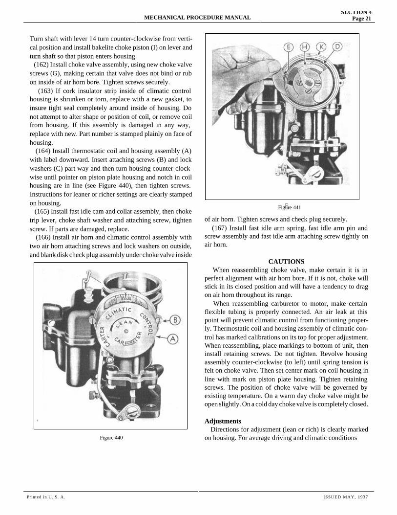
Turn shaft with lever 14 turn counter-clockwise from verti-cal position and install bakelite choke piston (I) on lever and turn shaft so that piston enters housing. (162) Install choke valve assembly, using new choke valve screws (G), making certain that valve does not bind or rub on inside of air horn bore. Tighten screws securely. (163) If cork insulator strip inside of climatic control housing is shrunken or torn, replace with a new gasket, to insure tight seal completely around inside of housing. Do not attempt to alter shape or position of coil, or remove coil from housing. If this assembly is damaged in any way, replace with new. Part number is stamped plainly on face of housing. (164) Install thermostatic coil and housing assembly (A) with label downward. Insert attaching screws (B) and lock washers (C) part way and then turn housing counter-clock-wise until pointer on piston plate housing and notch in coil housing are in line (see Figure 440), then tighten screws. Instructions for leaner or richer settings are clearly stamped on housing. (165) Install fast idle cam and collar assembly, then choke trip lever, choke shaft washer and attaching screw, tighten screw. If parts are damaged, replace. (166) Install air horn and climatic control assembly with two air horn attaching screws and lock washers on outside, and blank disk check plug assembly under choke valve inside
Figure 440
F
of air horn. Tighten screws and check plug securely. (167) Install fast idle arm spring, fast idle arm pin and screw assembly and fast idle arm attaching screw tightly on air horn.
CAUTIONS When reassembling choke valve, make certain it is in perfect alignment with air horn bore. If it is not, choke will stick in its closed position and will have a tendency to drag on air horn throughout its range. When reassembling carburetor to motor, make certain flexible tubing is properly connected. An air leak at this point will prevent climatic control from functioning proper-ly. Thermostatic coil and housing assembly of climatic con-trol has marked calibrations on its top for proper adjustment. When reassembling, place markings to bottom of unit, then install retaining screws. Do not tighten. Revolve housing assembly counter-clockwise (to left) until spring tension is felt on choke valve. Then set center mark on coil housing in line with mark on piston plate housing. Tighten retaining screws. The position of choke valve will be governed by existing temperature. On a warm day choke valve might be open slightly. On a cold day choke valve is completely closed.
Adjustments Directions for adjustment (lean or rich) is clearly marked on housing. For average driving and climatic conditions
Figure 441
Printed in U. S. A. ISSUED MAY, 1937
conditions, center index mark on coil housing should be in line with pointer. (See Figure 440). Action of climatic control during warm-up period is affected by grade of fuel used. Make no adjustment until motor is cold. If cold motor shows a tendency to run lean during the warm-up period turn housing counter-clockwise one mark at a time to richen it until desired results are obtained. If cold engine has a tendency to load or run rich during the warm-up period, revolve choke housing clockwise one mark at a time to lean it out, until desired results are secured. These adjustments should be made with care and between adjustments motor must be thoroughly cooled off. At least four hours should be used to cool motor.
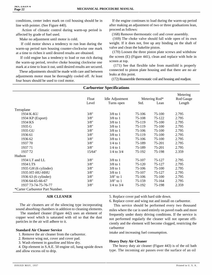
If the engine continues to load during the warm-up period after making an adjustment of two or three graduations lean, proceed as follows: (168) Remove thermostatic coil and cover assembly. (169) The choke valve should fall wide open of its own weight. If it does not, free up any binding on the shaft of valve and clean the bakelite piston. (170) Loosen the three piston plate screws and withdraw the screen (E) (Figure 441), clean and replace with hole in screen at top. (171) See that flexible tube from manifold is properly connected to piston plate housing and that there are no air leaks at this point. (172) Reassemble thermostatic coil and housing and readjust.
SECTION 4Page 22 MECHANICAL PROCEDURE MANUAL
Carburetor Specifications
FloatLevel
Idle AdjustmentTurns open
Metering Rod* Std. Lean
MeteringRod Gauge
Length
Terraplane1934 K-KU1934 KP (Export)1934 KS1935 G1935 GU1936 611936 621937 701937 711937 72
Hudson1934 LT and LL1934 LTS1935 GH (6 cylinder)1935 HT-HU-HHU1936 63 (6 cylinder)1936 64-65-66-671937 73-74-75-76-77
*Carter Carburetor Part Number.
3/8"3/8"3/8"3/8"3/8"3/8"3/8"3/8"3/8"15/64"
3/8"3/8"3/8"3/8"3/8"3/8"3/8"
3/8 to 13/8 to 13/8 to 13/8 to 13/8 to 13/8 to 13/8 to 11/4 to 11/4 to 11/4 to 3/4
3/8 to 13/8 to 13/8 to 13/8 to 13/8" to 13/8" to 11/4 to 3/4
75-10675-10875-11975-11975-10675-11975-10675-18975-18975-192
75-10775-12075-10675-10775-10675-15975-192
75-10075-12275-10075-10075-10075-10075-10075-20175-20175-198
75-12775-12775-10075-12775-10075-16475-198
2.7952.7952.7952.7952.7952.7952.7952.7952.7952.359
2.7952.7952.7952.7952.7952.7952.359
AIR CLEANER
The air cleaners are of the silencing type incorporating sound absorbing chambers in addition to cleaning elements. The standard cleaner (Figure 442) uses an element of copper wool which is saturated with oil so that the dust particles in the air will adhere to it.
Standard Air Cleaner Service 1. Remove the air cleaner from the carburetor. 2. Remove wing nut, cover and cover pad. 3. Wash element in gasoline and blow dry. 4. Dip element in S.A.E. 50 engine oil, hang upside down and allow excess oil to drip.
5. Replace cover pad with hard side down.6. Replace cover and wing nut and install on carburetor. This service should be performed every two thousand miles where the car is used entirely on paved roads and more frequently under dusty driving conditions. If the service is not performed regularly the cleaner will not operate effi-ciently and the element will become clogged, restricting the carburetorintake and increasing fuel consumption.
Heavy Duty Air Cleaner The heavy duty air cleaner (Figure 443) is of the oil bath type. The incoming air passes over the surface of an oil
ISSUED MAY, 1937 Printed in U. S. A.
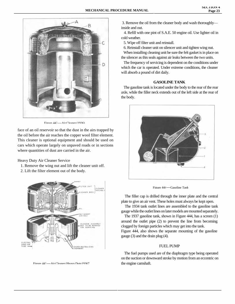
MECHANICAL PROCEDURE MANUALSECTION 4
Page 23
face of an oil reservoir so that the dust in the airs trapped by the oil before the air reaches the copper wool filter element. This cleaner is optional equipment and should be used on cars which operate largely on unpaved roads or in sections where quantities of dust are carried in the air.
Heavy Duty Air Cleaner Service 1. Remove the wing nut and lift the cleaner unit off. 2. Lift the filter element out of the body.
3. Remove the oil from the cleaner body and wash thoroughly—inside and out. 4. Refill with one pint of S.A.E. 50 engine oil. Use lighter oil in cold weather. 5. Wipe off filter unit and reinstall. 6. Reinstall cleaner unit on silencer unit and tighten wing nut. When installing cleaning unit be sure the felt gasket is in place on the silencer as this seals against air leaks between the two units. The frequency of servicing is dependent on the conditions under which the car is operated. Under extreme conditions, the cleaner will absorb a pound of dirt daily.
GASOLINE TANK The gasoline tank is located under the body to the rear of the rear axle, while the filler neck extends out of the left side at the rear of the body.
The filler cap is drilled through the inner plate and the central plate to give an air vent. These holes must always be kept open. The 1934 tank outlet lines are assembled to the gasoline tank gauge while the outlet lines on later models are mounted separately. The 1937 gasoline tank, shown in Figure 444, has a screen (1) around the outlet pipe (2) to prevent the line from becoming clogged by foreign particles which may get into the tank.Figure 444, also shows the separate mounting of the gasoline gauge (3) and the drain plug (4).
FUEL PUMP
The fuel pumps used are of the diaphragm type being operated on the suction or downward stroke by motion from an eccentric on the engine camshaft.
Figure 442—Air Cleaner (1936)
Figure 443—Air Cleaner (Heavy Duty19367
Figure 444—Gasoline Tank
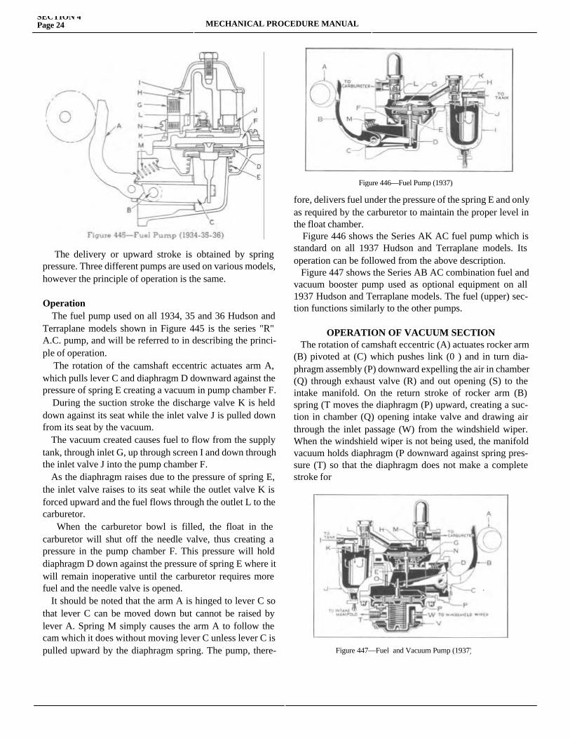
The delivery or upward stroke is obtained by spring pressure. Three different pumps are used on various models, however the principle of operation is the same.
Operation The fuel pump used on all 1934, 35 and 36 Hudson and Terraplane models shown in Figure 445 is the series "R" A.C. pump, and will be referred to in describing the princi-ple of operation. The rotation of the camshaft eccentric actuates arm A, which pulls lever C and diaphragm D downward against the pressure of spring E creating a vacuum in pump chamber F. During the suction stroke the discharge valve K is held down against its seat while the inlet valve J is pulled down from its seat by the vacuum. The vacuum created causes fuel to flow from the supply tank, through inlet G, up through screen I and down through the inlet valve J into the pump chamber F. As the diaphragm raises due to the pressure of spring E, the inlet valve raises to its seat while the outlet valve K is forced upward and the fuel flows through the outlet L to the carburetor. When the carburetor bowl is filled, the float in the carburetor will shut off the needle valve, thus creating a pressure in the pump chamber F. This pressure will hold diaphragm D down against the pressure of spring E where it will remain inoperative until the carburetor requires more fuel and the needle valve is opened. It should be noted that the arm A is hinged to lever C so that lever C can be moved down but cannot be raised by lever A. Spring M simply causes the arm A to follow the cam which it does without moving lever C unless lever C is pulled upward by the diaphragm spring. The pump, there-fore, delivers fuel
fore, delivers fuel under the pressure of the spring E and only as required by the carburetor to maintain the proper level in the float chamber. Figure 446 shows the Series AK AC fuel pump which is standard on all 1937 Hudson and Terraplane models. Its operation can be followed from the above description. Figure 447 shows the Series AB AC combination fuel and vacuum booster pump used as optional equipment on all 1937 Hudson and Terraplane models. The fuel (upper) sec-tion functions similarly to the other pumps.
OPERATION OF VACUUM SECTION The rotation of camshaft eccentric (A) actuates rocker arm (B) pivoted at (C) which pushes link (0 ) and in turn dia-phragm assembly (P) downward expelling the air in chamber (Q) through exhaust valve (R) and out opening (S) to the intake manifold. On the return stroke of rocker arm (B) spring (T moves the diaphragm (P) upward, creating a suc-tion in chamber (Q) opening intake valve and drawing air through the inlet passage (W) from the windshield wiper. When the windshield wiper is not being used, the manifold vacuum holds diaphragm (P downward against spring pres-sure (T) so that the diaphragm does not make a complete stroke for
SECTION 4Page 24 MECHANICAL PROCEDURE MANUAL
Figure 446—Fuel Pump (1937)
Figure 447—Fuel and Vacuum Pump (1937)
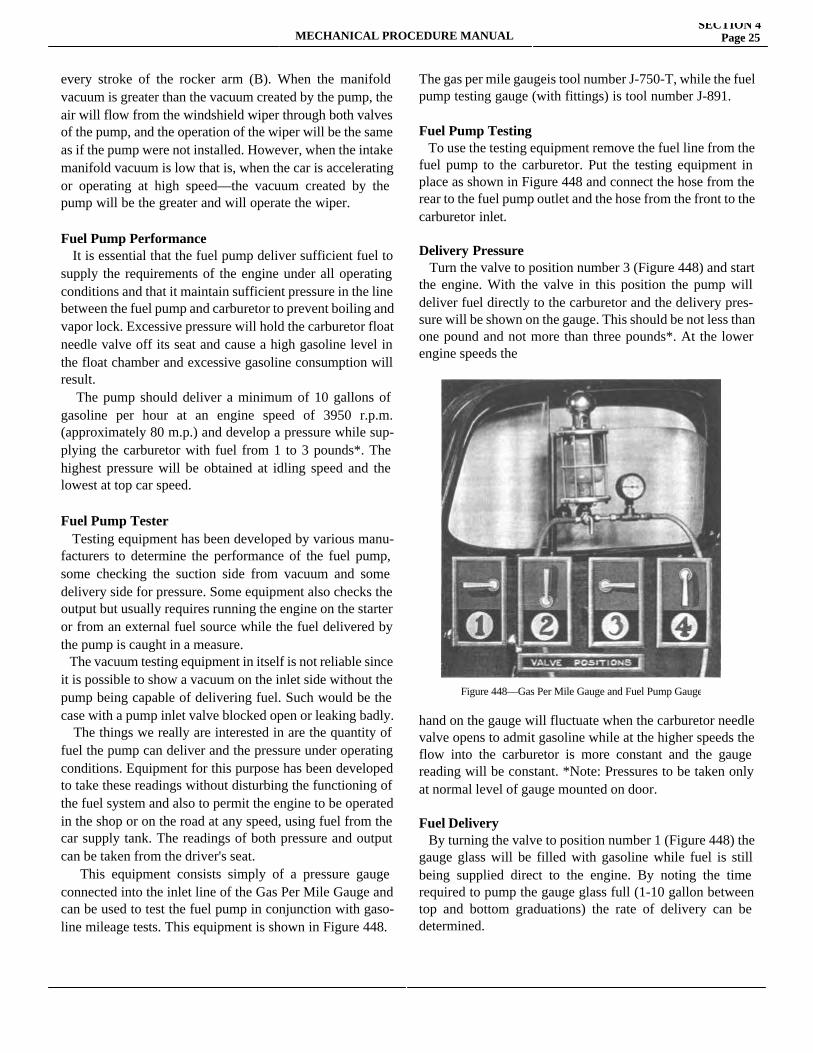
MECHANICAL PROCEDURE MANUALSECTION 4
Page 25
every stroke of the rocker arm (B). When the manifold vacuum is greater than the vacuum created by the pump, the air will flow from the windshield wiper through both valves of the pump, and the operation of the wiper will be the same as if the pump were not installed. However, when the intake manifold vacuum is low that is, when the car is accelerating or operating at high speed—the vacuum created by the pump will be the greater and will operate the wiper.
Fuel Pump Performance It is essential that the fuel pump deliver sufficient fuel to supply the requirements of the engine under all operating conditions and that it maintain sufficient pressure in the line between the fuel pump and carburetor to prevent boiling and vapor lock. Excessive pressure will hold the carburetor float needle valve off its seat and cause a high gasoline level in the float chamber and excessive gasoline consumption will result. The pump should deliver a minimum of 10 gallons of gasoline per hour at an engine speed of 3950 r.p.m. (approximately 80 m.p.) and develop a pressure while sup-plying the carburetor with fuel from 1 to 3 pounds*. The highest pressure will be obtained at idling speed and the lowest at top car speed.
Fuel Pump Tester Testing equipment has been developed by various manu-facturers to determine the performance of the fuel pump, some checking the suction side from vacuum and some delivery side for pressure. Some equipment also checks the output but usually requires running the engine on the starter or from an external fuel source while the fuel delivered by the pump is caught in a measure. The vacuum testing equipment in itself is not reliable since it is possible to show a vacuum on the inlet side without the pump being capable of delivering fuel. Such would be the case with a pump inlet valve blocked open or leaking badly. The things we really are interested in are the quantity of fuel the pump can deliver and the pressure under operating conditions. Equipment for this purpose has been developed to take these readings without disturbing the functioning of the fuel system and also to permit the engine to be operated in the shop or on the road at any speed, using fuel from the car supply tank. The readings of both pressure and output can be taken from the driver's seat. This equipment consists simply of a pressure gauge connected into the inlet line of the Gas Per Mile Gauge and can be used to test the fuel pump in conjunction with gaso-line mileage tests. This equipment is shown in Figure 448.
The gas per mile gaugeis tool number J-750-T, while the fuel pump testing gauge (with fittings) is tool number J-891.
Fuel Pump Testing To use the testing equipment remove the fuel line from the fuel pump to the carburetor. Put the testing equipment in place as shown in Figure 448 and connect the hose from the rear to the fuel pump outlet and the hose from the front to the carburetor inlet.
Delivery Pressure Turn the valve to position number 3 (Figure 448) and start the engine. With the valve in this position the pump will deliver fuel directly to the carburetor and the delivery pres-sure will be shown on the gauge. This should be not less than one pound and not more than three pounds*. At the lower engine speeds the
hand on the gauge will fluctuate when the carburetor needle valve opens to admit gasoline while at the higher speeds the flow into the carburetor is more constant and the gauge reading will be constant. *Note: Pressures to be taken only at normal level of gauge mounted on door.
Fuel Delivery By turning the valve to position number 1 (Figure 448) the gauge glass will be filled with gasoline while fuel is still being supplied direct to the engine. By noting the time required to pump the gauge glass full (1-10 gallon between top and bottom graduations) the rate of delivery can be determined.
Figure 448—Gas Per Mile Gauge and Fuel Pump Gauge
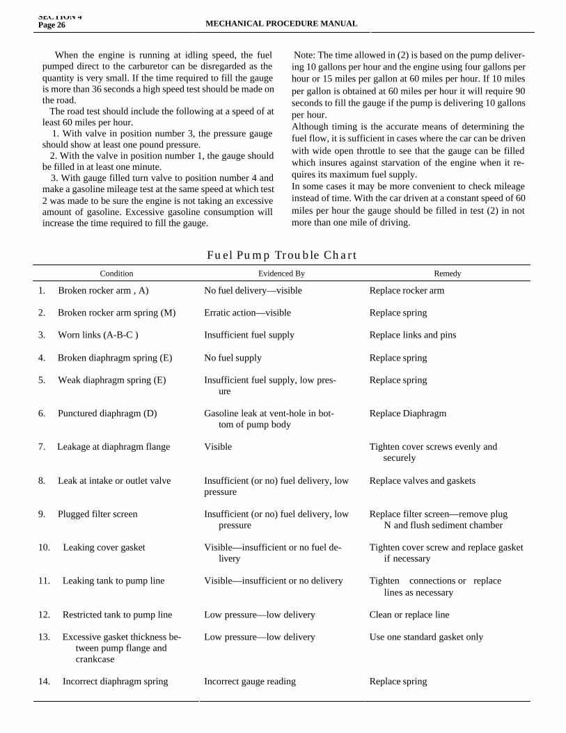
When the engine is running at idling speed, the fuel pumped direct to the carburetor can be disregarded as the quantity is very small. If the time required to fill the gauge is more than 36 seconds a high speed test should be made on the road. The road test should include the following at a speed of at least 60 miles per hour. 1. With valve in position number 3, the pressure gauge should show at least one pound pressure. 2. With the valve in position number 1, the gauge should be filled in at least one minute. 3. With gauge filled turn valve to position number 4 and make a gasoline mileage test at the same speed at which test 2 was made to be sure the engine is not taking an excessive amount of gasoline. Excessive gasoline consumption will increase the time required to fill the gauge.
Note: The time allowed in (2) is based on the pump deliver-ing 10 gallons per hour and the engine using four gallons per hour or 15 miles per gallon at 60 miles per hour. If 10 miles per gallon is obtained at 60 miles per hour it will require 90 seconds to fill the gauge if the pump is delivering 10 gallons per hour.Although timing is the accurate means of determining the fuel flow, it is sufficient in cases where the car can be driven with wide open throttle to see that the gauge can be filled which insures against starvation of the engine when it re-quires its maximum fuel supply.In some cases it may be more convenient to check mileage instead of time. With the car driven at a constant speed of 60 miles per hour the gauge should be filled in test (2) in not more than one mile of driving.
SECTION 4Page 26 MECHANICAL PROCEDURE MANUAL
Fuel Pump Trouble ChartCondition Evidenced By Remedy
1. Broken rocker arm , A)
2. Broken rocker arm spring (M)
3. Worn links (A-B-C )
4. Broken diaphragm spring (E)
5. Weak diaphragm spring (E)
6. Punctured diaphragm (D)
7. Leakage at diaphragm flange
8. Leak at intake or outlet valve
9. Plugged filter screen
10. Leaking cover gasket
11. Leaking tank to pump line
12. Restricted tank to pump line
13. Excessive gasket thickness be- tween pump flange and crankcase
14. Incorrect diaphragm spring
No fuel delivery—visible
Erratic action—visible
Insufficient fuel supply
No fuel supply
Insufficient fuel supply, low pres- ure
Gasoline leak at vent-hole in bot- tom of pump body
Visible
Insufficient (or no) fuel delivery, low pressure
Insufficient (or no) fuel delivery, low pressure
Visible—insufficient or no fuel de- livery
Visible—insufficient or no delivery
Low pressure—low delivery
Low pressure—low delivery
Incorrect gauge reading
Replace rocker arm
Replace spring
Replace links and pins
Replace spring
Replace spring
Replace Diaphragm
Tighten cover screws evenly and securely
Replace valves and gaskets
Replace filter screen—remove plug N and flush sediment chamber
Tighten cover screw and replace gasket if necessary
Tighten connections or replace lines as necessary
Clean or replace line
Use one standard gasket only
Replace spring
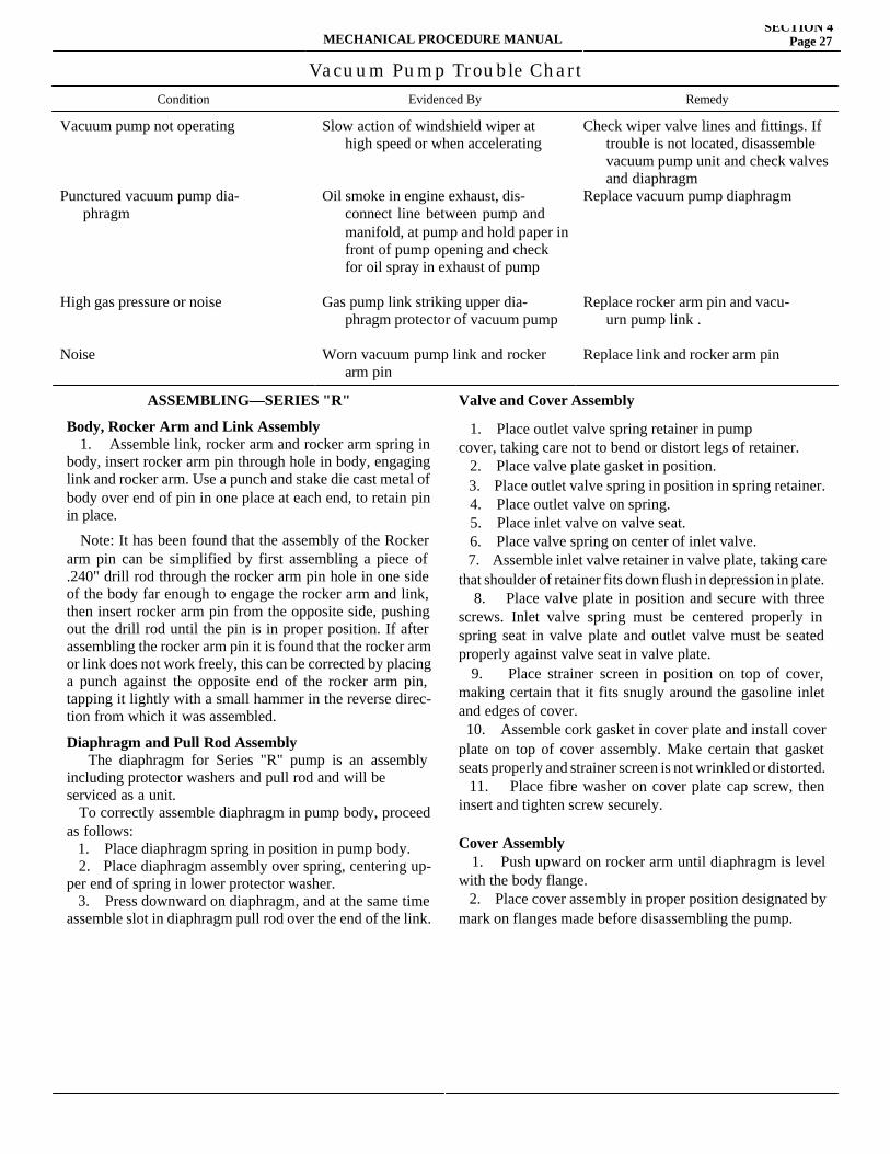
MECHANICAL PROCEDURE MANUALSECTION 4
Page 27
Vacuum Pump Trouble ChartCondition Evidenced By Remedy
Vacuum pump not operating
Punctured vacuum pump dia- phragm
High gas pressure or noise
Noise
Slow action of windshield wiper at high speed or when accelerating
Oil smoke in engine exhaust, dis- connect line between pump and manifold, at pump and hold paper in front of pump opening and check for oil spray in exhaust of pump
Gas pump link striking upper dia- phragm protector of vacuum pump
Worn vacuum pump link and rocker arm pin
Check wiper valve lines and fittings. If trouble is not located, disassemble vacuum pump unit and check valves and diaphragmReplace vacuum pump diaphragm
Replace rocker arm pin and vacu- urn pump link .
Replace link and rocker arm pin
ASSEMBLING—SERIES "R"
Body, Rocker Arm and Link Assembly 1. Assemble link, rocker arm and rocker arm spring in body, insert rocker arm pin through hole in body, engaging link and rocker arm. Use a punch and stake die cast metal of body over end of pin in one place at each end, to retain pin in place.
Note: It has been found that the assembly of the Rocker arm pin can be simplified by first assembling a piece of .240" drill rod through the rocker arm pin hole in one side of the body far enough to engage the rocker arm and link, then insert rocker arm pin from the opposite side, pushing out the drill rod until the pin is in proper position. If after assembling the rocker arm pin it is found that the rocker arm or link does not work freely, this can be corrected by placing a punch against the opposite end of the rocker arm pin, tapping it lightly with a small hammer in the reverse direc-tion from which it was assembled.
Diaphragm and Pull Rod Assembly The diaphragm for Series "R" pump is an assembly including protector washers and pull rod and will beserviced as a unit. To correctly assemble diaphragm in pump body, proceed as follows: 1. Place diaphragm spring in position in pump body. 2. Place diaphragm assembly over spring, centering up-per end of spring in lower protector washer. 3. Press downward on diaphragm, and at the same time assemble slot in diaphragm pull rod over the end of the link.
Valve and Cover Assembly
1. Place outlet valve spring retainer in pumpcover, taking care not to bend or distort legs of retainer. 2. Place valve plate gasket in position. 3. Place outlet valve spring in position in spring retainer. 4. Place outlet valve on spring. 5. Place inlet valve on valve seat. 6. Place valve spring on center of inlet valve. 7. Assemble inlet valve retainer in valve plate, taking care that shoulder of retainer fits down flush in depression in plate. 8. Place valve plate in position and secure with three screws. Inlet valve spring must be centered properly in spring seat in valve plate and outlet valve must be seated properly against valve seat in valve plate. 9. Place strainer screen in position on top of cover, making certain that it fits snugly around the gasoline inlet and edges of cover. 10. Assemble cork gasket in cover plate and install cover plate on top of cover assembly. Make certain that gasket seats properly and strainer screen is not wrinkled or distorted. 11. Place fibre washer on cover plate cap screw, then insert and tighten screw securely.
Cover Assembly 1. Push upward on rocker arm until diaphragm is level with the body flange. 2. Place cover assembly in proper position designated by mark on flanges made before disassembling the pump.
SECTION 4Page 28 MECHANICAL PROCEDURE MANUAL
3. Install cover screws and lockwashers, tightening only until they barely engage lockwashers. 4. Release rocker arm, which will place the diaphragm in its highest position. then— 5. Tighten cover screws alternately and securely.
ASSEMBLING SERIES "A K"
Body, Rocker Arm and Link Assembly 1. Assemble link, rocker arm and rocker arm spring in body. Insert rocker arm pin through hole in body, engaging link and rocker arm. Use a punch and stake die cast metal of body over end of pin in one place at each end, to retain pin in place. Note: It has been found that the assembly of the rocker arm pin can be simplified by first assembling a piece of .240" drill rod through- the rocker arm pin hole in one side of the body far enough to engage the rocker arm and link, then insert rocker arm pin from the opposite side, pushing out the drill rod until the pin is in proper position. If after assembling the rocker arm pin it is found that the rocker arm or link does not work freely, this can be corrected by placing a punch against the opposite end of the rocker arm pin, tapping it lightly with a small hammer in the reverse direction from which it was assembled.
Diaphragm and Pull Rod Assembly The Diaphragm for Series "AK" pump is an assembly including protector washers and pull rod and will be serviced as a unit. To correctly assemble diaphragm in pump body, proceed as follows: 1. Place diaphragm spring, in position in pump body. 2. Place diaphragm assembly over spring, centering upper end of spring in lower protector washer. 3. Press downward on diaphragm, and at the same time assemble slot in diaphragm pull rod over the end of the link.
Valve and Cover Assembly 1. Blow out valve chamber and make certain that no foreign particles are present which might prevent valve from seating properly. Also observe that no burrs or irregularities exist in the valve seat and that the valve seat is securely held in place in the upper cover. 2. Place a drop of Finol on the fibre valve, and put in proper position in valve chamber. Be certain that valve lies flat against the valve seat and is not standing on edge or tipped. 3. Insert valve spring on top of valve. 4. Place fibre gasket on valve plug and then place stem of valve plug into the coil spring and tighten plug securely. Be certain that the stem of the valve plug does not distort the valve
spring but fits properly inside of it.
Cover Assembly 1. Push upward on rocker arm until diaphragm is level with the body flange. 2. Place cover assembly in proper position designated by mark on flanges made before disassembling the pump. 3. Install cover screws and lockwashers, tightening only until they barely engage lockwashers. 4. Release rocker arm, which will place the diaphragm in its highest position then 5. Tighten cover screws alternately and securely.
PROCEDURE IN ASSEMBLING SERIES "AB" Body, Rocker Arm and Links Assembly 1. Assemble rocker arm, fuel link, link spacer and vacuum links on rocker arm pin bushing in same relative position as when removed from the pump. 2. Place the hooked end of one of the Vacuum links on top of the other vacuum link (this is necessary to permit assem-bly in body). 3. Place assembly of links, rocker arm, link spacer and rocker arm pin bushing in body, making sure that rocker arm spring seats properly on ear of link spacer. 4. Assemble rocker arm pin in position. Place washer over end of pin, then swedge counterbored end of pin over se-curely against washer.
Assembling Fuel Diaphragm in Pump Invert body, rocker arm and links assembly allowing link to fall against body stop. (Hooked end of one. vacuum link should be on top of the other vacuum link during assembly.) Insert a small tool or screw driver to hold link in this posi-tion. Place diaphragm spring in position in lower diaphragm protector washer, then insert pull rod and diaphragm assem-bly in position in body. By depressing the diaphragm spring, hook the pull rod over the hooked end of the link. Make sure that the diaphragm spring is seated properly in body and in the lower diaphragm protector washer.
Valve and Cover Assembly 1. Blow out valve chamber and make certain that no foreign particles are present which might prevent valve from seating properly. Also observe that no burrs or irregularities exist in the valve seat and that the valve seat is securely held in place in the upper cover. 2. Place a drop of Finol on the fibre valve, and put in proper position in valve chamber. Be certain that valve lies flat against the valve seat and is not standing on edge or tipped. 3. Insert valve spring on top of valve.
MECHANICAL PROCEDURE MANUALSECTION 4
Page 29
4. Place fibre gasket on valve plug and then place stem of valve plug into the coil spring and tighten plug securely. Be certain that the stem of the valve plug does not distort the valve spring but fits properly inside of it.
Assembly of Fuel Pump Cover Assembly to Body 1. Line up screw holes in top cover with holes in diaphragm and body. Insert and tighten screws until cover is drawn up to within 1/8” of the body, then push upward on pull rod, forcing the diaphragm to its full, highest position, then while in this posi-tion, tighten cover screws alternately and securely.
Strainer Assembly 1. Assemble screen in pump cover. Make certain that its fits snugly around the gasoline inlet and edges of casting. 2. Place strainer gasket next to screen, then assemble glass bowl and bail.
Vacuum Pump Assembly The vacuum pump body is furnished with the inlet valve seat assembled. 1. Place fibre inlet valve in position on top of brass inlet valve seat in body. 2. Place inlet valve spring on top of inlet valve. 3. Place die-cast valve stop plate (spider-shaped) on top of valve spring with top coil of spring seating in recess in bottom of spider. 4. Place outlet valve spring in position, centering the coils of the spring in the round recess. 5. Press the die-cast inlet valve stop (spider- shaped) down-ward with finger against inlet valve spring pressure. Make certain that valve spring is properly centered in inlet valve stop, and that legs of inlet valve stop fit down into the recess in the body. 6. Place fibre outlet valve in position on top of outlet valve spring. 7. With inlet valve stop held down, slide valve retainer gasket into its proper position continuing to hold down the inlet valve stop. Place valve retainer in position on top of gasket. IMPOR-TANT: Be certain that valve retainer is right side up. The countersunk holes in valve retainer must face upward. 8. Secure valve retainer in position with fiat head screws, tightening center screws first and end screw last. 9. Turn vacuum pump body over and place screen in position. Screen should lie flat and fit properly around shoulders of screw holes in body. 10. Place bottom cover gasket in position on top of screen, lining up screw holes. 11. Assemble bottom cover, using four screws.
Assembly of Vacuum Pump Unit to Body 1. Place completed assembly of body and fuel
pump unit in an inverted position in bench vise. 2. Place diaphragm assembly in position making sure that slot in pull rod engages hooks on both vacuum links properly and that screw holes in diaphragm match up with screw holes in body. 3. Place diaphragm spring in position on diaphragm. 4. Lay assembled vacuum pump unit in position on body, centering the diaphragm spring around the boss in the vac-uum pump body and lining up marks made before disassem-bling making sure that theholes in the diaphragm match up properly with the screw holes in body flanges. 5. Press in on rocker arm, holding diaphragm even with flat surface of flange on body. While in this position, insert and tighten body screws until vacuum pump unit is drawn down to about from pump body, then release the rocker arm, permitting the diaphragm spring to force the diaphragm to its highest position. Then tighten screws alternately and securely.
Assembly on Motor Extreme care should be used in reassembling the pump to the car so that the cam surface of the rocker arm rests against the eccentric and not under it. If the cam surface of the rocker arm is placed under the eccentric, breakage of the rocker arm will result.
Service Hints Never stretch or in any way change the tension of the valve spring as this will change the pressure of the spring against the valve and reduce the capacity of the pump, particularly under extreme conditions. Always use new valve springs if the old springs are at all questionable.
Valves Do not replace the fibre valves with make-shift valves, such as steel balls, metal discs, etc. The fibre valve has proven superior to all other types of valves under all condi-tions.
Gum in Gasoline and Sticking Valves There have been some reports in the field of fuel pump operation being impaired due to a gum-like substance form-ing on the valves and making it impossible to operate prop-erly. Investigation has shown that this gum is contained in some fuels, particularly in cheaper so-called cut-rate brands. When this trouble is encountered in connection with the fuel pump, it is necessary to thoroughly clean and polish the pump valves, valve seats and gas strainer parts to insure correct operation of the pump. It is possible that the trouble will be overcome with a different grade of gasoline.
Printed in U. S. A. ISSUED MAY, 1937 ISSUED MAY, 1937
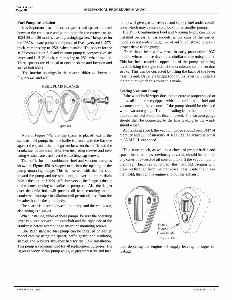
SECTION 4Page 30 MECHANICAL PROCEDURE MANUAL
Fuel Pump Installation It is important that the correct gasket and spacer be used between the crankcase and pump to obtain the correct stroke. 1934-35 and 36 models use only a single gasket. The spacer for the 1937 standard pump is composed of five layers and is .275" thick, compressing to .250" when installed. The spacer for the 1937 combination fuel and vacuum pump is composed of six layers and is .312" thick, compressing to .281" when installed. These spacers are identical in outside shape and location and size of bolt holes. The interior openings in the spacers differ as shown in Figures 449 and 450.
FUEL PUMP FLANGE
Figure 449
Note in Figure 449, that the spacer is placed next to the standard fuel pump, then the baffle is placed with the flat side against the spacer, then the gasket between the baffle and the crankcase. In this installation two insulating sleeves and insu-lating washers are used over the attaching cap screws. The baffle for the combination fuel and vacuum pump as shown in Figure 450 is shaped to fit into the opening of the pump mounting flange. This is inserted with the flat side toward the pump and the small tongue over the return drain hole at the bottom. If this baffle is reversed, the flange at the top of the center opening will strike the pump arm. Also the flapper over the drain hole will prevent oil from returning to the crankcase. Improper installation will permit oil loss from the breather hole in the pump body. The spacer is placed between the pump and the crankcase, also acting as a gasket. When installing either of these pumps, be sure the operating lever is placed between the camshaft and the right side of the crankcase before attempting to insert the mounting screws. The 1937 standard fuel pump can be installed on earlier model cars by using the spacer, baffle gasket and insulating sleeves and washers also specified for the 1937 installation. This pump is recommended for all replacement purposes. The larger capacity of this pump will give greater reserve and fuel
pump will give greater reserve and supply fuel under condi-tions which may cause vapor lock in the smaller pumps. The 1937 Combination Fuel and Vacuum Pump can not be installed on earlier car models as the cam of the earlier models is not wide enough nor of sufficient stroke to give a proper drive to the pump. There have been a few cases in early production 1937 models where a noise developed similar to one noisy tappet. This has been traced to upper end of the pump operating lever striking the right side of the crankcase on the suction stroke. This can be corrected by filing the back of the lever near the end. Usually a bright spot on the lever will indicate the point at which this contact is made.
Testing Vacuum Pump If the windshield wiper does not operate at proper speed or not at all on a car equipped with the combination fuel and vacuum pump, the vacuum of the pump should be checked with a vacuum gauge. The line leading from the pump to the intake manifold should be disconnected. The vacuum gauge should then be connected to the line leading to the wind-shield wiper. At cranking speed, the vacuum gauge should read 8M" of mercury and 11" of mercury at 1800 R.P.M. which is equal to 35 M.P.H. car speed.
This same check, as well as a check of proper baffle and spacer installation as previously covered, should be made in any cases of excessive oil consumption. If the vacuum pump diaphragm becomes punctured, the manifold vacuum will draw oil through from the crankcase, pass it into the intake manifold, through the engine and out the exhaust,
thus depleting the engine oil supply leaving no signs of leakage.
ISSUED MAY, 1937 Printed in U. S. A.

MECHANICAL PROCEDURE MANUAL Page 1
SECTION 5
COOLING SYSTEMService Magazine—Reference Sheet and Service Bullet in Reference
Bulletin orReference SheetNo. MagazineIssue and Page
Date Subject DETAILS OF INFORMATION

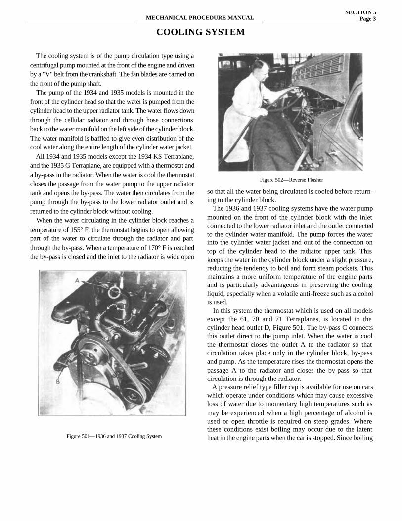
MECHANICAL PROCEDURE MANUALSECTION 5
Page 3
COOLING SYSTEM
The cooling system is of the pump circulation type using a centrifugal pump mounted at the front of the engine and driven by a "V" belt from the crankshaft. The fan blades are carried on the front of the pump shaft. The pump of the 1934 and 1935 models is mounted in the front of the cylinder head so that the water is pumped from the cylinder head to the upper radiator tank. The water flows down through the cellular radiator and through hose connections back to the water manifold on the left side of the cylinder block. The water manifold is baffled to give even distribution of the cool water along the entire length of the cylinder water jacket. All 1934 and 1935 models except the 1934 KS Terraplane, and the 1935 G Terraplane, are equipped with a thermostat and a by-pass in the radiator. When the water is cool the thermostat closes the passage from the water pump to the upper radiator tank and opens the by-pass. The water then circulates from the pump through the by-pass to the lower radiator outlet and is returned to the cylinder block without cooling. When the water circulating in the cylinder block reaches a temperature of 155° F, the thermostat begins to open allowing part of the water to circulate through the radiator and part through the by-pass. When a temperature of 170° F is reached the by-pass is closed and the inlet to the radiator is wide open so
so that all the water being circulated is cooled before return-ing to the cylinder block. The 1936 and 1937 cooling systems have the water pump mounted on the front of the cylinder block with the inlet connected to the lower radiator inlet and the outlet connected to the cylinder water manifold. The pump forces the water into the cylinder water jacket and out of the connection on top of the cylinder head to the radiator upper tank. This keeps the water in the cylinder block under a slight pressure, reducing the tendency to boil and form steam pockets. This maintains a more uniform temperature of the engine parts and is particularly advantageous in preserving the cooling liquid, especially when a volatile anti-freeze such as alcohol is used. In this system the thermostat which is used on all models except the 61, 70 and 71 Terraplanes, is located in the cylinder head outlet D, Figure 501. The by-pass C connects this outlet direct to the pump inlet. When the water is cool the thermostat closes the outlet A to the radiator so that circulation takes place only in the cylinder block, by-pass and pump. As the temperature rises the thermostat opens the passage A to the radiator and closes the by-pass so that circulation is through the radiator. A pressure relief type filler cap is available for use on cars which operate under conditions which may cause excessive loss of water due to momentary high temperatures such as may be experienced when a high percentage of alcohol is used or open throttle is required on steep grades. Where these conditions exist boiling may occur due to the latent heat in the engine parts when the car is stopped. Since boilingFigure 501—1936 and 1937 Cooling System
Figure 502—Reverse Flusher
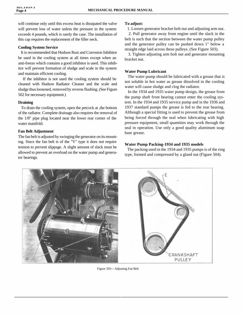
SECTION 5Page 4 MECHANICAL PROCEDURE MANUAL
will continue only until this excess heat is dissipated the valve will prevent loss of water unless the pressure in the system exceeds 4 pounds, which is rarely the case. The installation of this cap requires the replacement of the filler neck.
Cooling System Service It is recommended that Hudson Rust and Corrosion Inhibitor be used in the cooling system at all times except when an anti-freeze which contains a good inhibitor is used. This inhib-itor will prevent formation of sludge and scale in the system and maintain efficient cooling. If the inhibitor is not used the cooling system should be cleaned with Hudson Radiator Cleaner and the scale and sludge thus loosened, removed by reverse flushing. (See Figure 502 for necessary equipment.)
Draining To drain the cooling system, open the petcock at ,the bottom of the radiator. Complete drainage also requires the removal of the 1/8" pipe plug located near the lower rear corner of the water manifold.
Fan Belt AdjustmentThe fan belt is adjusted by swinging the generator on its mount-ing. Since the fan belt is of the "V" type it does not require tension to prevent slippage. A slight amount of slack must be allowed to prevent an overload on the water pump and genera-tor bearings.
To adjust: 1. Loosen generator bracket bolt nut and adjusting arm nut. 2. Pull generator away from engine until the slack in the belt is such that the section between the water pump pulley and the generator pulley can be pushed down 1" below a straight edge laid across these pulleys. (See Figure 503). 3. Tighten adjusting arm bolt nut and generator mounting bracket nut.
Water Pump Lubricant The water pump should be lubricated with a grease that is not soluble in hot water as grease dissolved in the cooling water will cause sludge and clog the radiator. In the 1934 and 1935 water pump design, the grease from the pump shaft front bearing cannot enter the cooling sys-tem. In the 1934 and 1935 service pump and in the 1936 and 1937 standard pumps the grease is fed to the rear bearing. Although a special fitting is used to prevent the grease from being forced through the seal when lubricating with high pressure equipment, small quantities may work through the seal in operation. Use only a good quality aluminum soap base grease.
Water Pump Packing-1934 and 1935 models The packing used in the 1934 and 1935 pumps is of the ring type, formed and compressed by a gland nut (Figure 504).
Figure 503—Adjusting Fan Belt
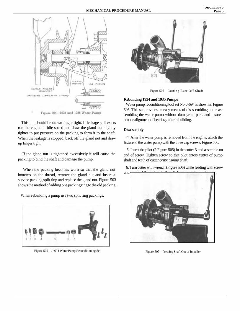
MECHANICAL PROCEDURE MANUALSECTION 5
Page 5
This nut should be drawn finger tight. If leakage still exists run the engine at idle speed and draw the gland nut slightly tighter to put pressure on the packing to form it to the shaft. When the leakage is stopped, back off the gland nut and draw up finger tight. If the gland nut is tightened excessively it will cause the packing to bind the shaft and damage the pump.
When the packing becomes worn so that the gland nut bottoms on the thread, remove the gland nut and insert a service packing split ring and replace the gland nut. Figure 503 shows the method of adding one packing ring to the old packing.
When rebuilding a pump use two split ring packings.
Rebuilding 1934 and 1935 Pumps Water pump reconditioning tool set No. J-694 is shown in Figure 505. This set provides an easy means of disassembling and reas-sembling the water pump without damage to parts and insures proper alignment of bearings after rebuilding.
Disassembly
4. After the water pump is removed from the engine, attach the fixture to the water pump with the three cap screws. Figure 506. 5. Insert the pilot (2 Figure 505) in the cutter 3 and assemble on end of screw. Tighten screw so that pilot enters center of pump shaft and teeth of cutter come against shaft.
6. Turn cutter with wrench (Figure 506) while feeding with screw until swaged flange is cut off shaft. Remove cutter and center.
Figure 505—J=694 Water Pump Reconditioning Set
Figure 506—Cutting Burr Off Shaft
Figure 507—Pressing Shaft Out of Impeller
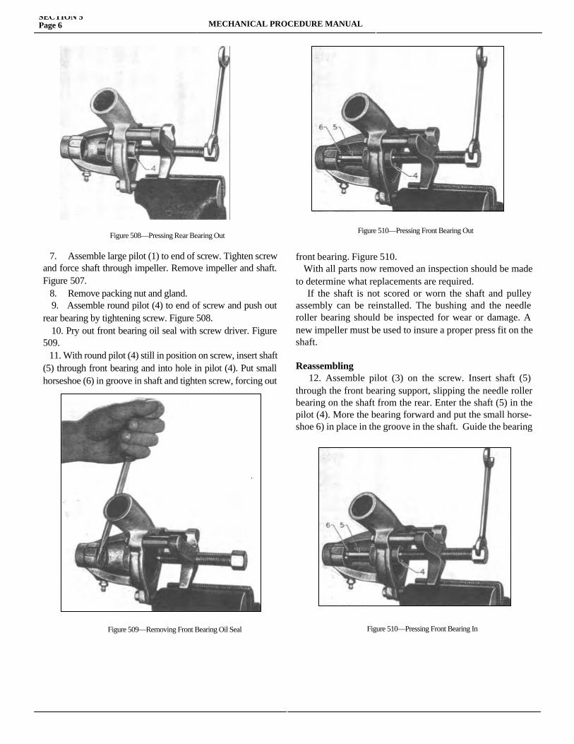
SECTION 5Page 6 MECHANICAL PROCEDURE MANUAL
7. Assemble large pilot (1) to end of screw. Tighten screw and force shaft through impeller. Remove impeller and shaft. Figure 507. 8. Remove packing nut and gland. 9. Assemble round pilot (4) to end of screw and push out rear bearing by tightening screw. Figure 508. 10. Pry out front bearing oil seal with screw driver. Figure 509. 11. With round pilot (4) still in position on screw, insert shaft (5) through front bearing and into hole in pilot (4). Put small horseshoe (6) in groove in shaft and tighten screw, forcing out
front bearing. Figure 510. With all parts now removed an inspection should be made to determine what replacements are required. If the shaft is not scored or worn the shaft and pulley assembly can be reinstalled. The bushing and the needle roller bearing should be inspected for wear or damage. A new impeller must be used to insure a proper press fit on the shaft.
Reassembling 12. Assemble pilot (3) on the screw. Insert shaft (5) through the front bearing support, slipping the needle roller bearing on the shaft from the rear. Enter the shaft (5) in the pilot (4). More the bearing forward and put the small horse-shoe 6) in place in the groove in the shaft. Guide the bearing
Figure 508—Pressing Rear Bearing Out
Figure 509—Removing Front Bearing Oil Seal
Figure 510—Pressing Front Bearing Out
Figure 510—Pressing Front Bearing In
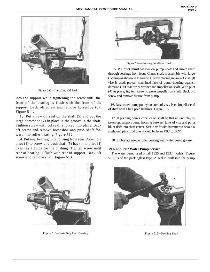
MECHANICAL PROCEDURE MANUALSECTION 5
Page 7
into the support while tightening the screw until the front of the bearing is flush with the front of the support. Back off screw and remove horseshoe (6). Figure 511. 13. Put a new oil seal on the shaft (5) and put the large horseshoe (7) in place in the groove in the shaft. Tighten screw until oil seal is forced into place. Back off screw and remove horseshoe and push shaft for-ward into roller bearing. Figure 512. 14. Put rear bearing into housing from rear. Assemble pilot (4) to screw and push shaft (5) back into pilot (4) to act as a guide for the bushing. Tighten screw until rear of bearing is flush with rear of support. Back off screw and remove shaft. Figure 513.
15. Put front thrust washer on pump shaft and insert shaft through bearings from front. Clamp shaft in assembly with large C clamp as shown in Figure 514, or by placing in jaws of vise. (If vise is used, protect machined face of pump housing against damage.) Put rear thrust washer and impeller on shaft. With pilot (4) in place, tighten screw to press impeller on shaft. Back off screw and remove fixture from pump.
16. Rest water pump pulley on anvil of vise. Peen impeller end of shaft with a ball peen hammer. Figure 515.
17. If peening draws impeller on shaft so that all end play is taken up, support pump housing between jaws of vise and put a blunt drift into shaft center. Strike drift with hammer to obtain a slight end play. End play should be from .005' to .009". 18 . Lubricate needle roller bearing with water pump grease.
1936 and 1937 Water Pump Service The water pump used on all 1936 and 1937 models (Figure 516), is of the packingless type. A seal is built into the pump between
Figure 512—Installing Oil Seal
Figure 513—Installing Rear Bearing
Figure 514—Pressing Impeller on Shaft
Figure 515—Peening Shaft
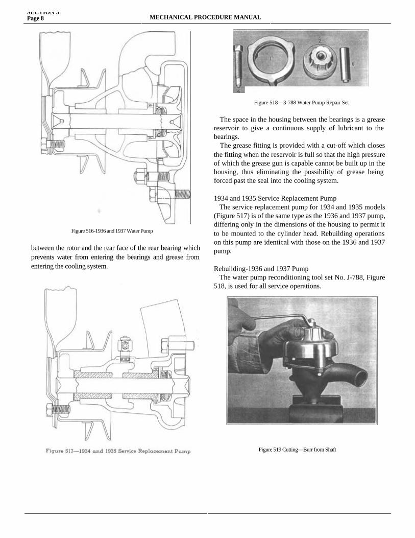
SECTION 5Page 8 MECHANICAL PROCEDURE MANUAL
between the rotor and the rear face of the rear bearing which prevents water from entering the bearings and grease from entering the cooling system.
The space in the housing between the bearings is a grease reservoir to give a continuous supply of lubricant to the bearings. The grease fitting is provided with a cut-off which closes the fitting when the reservoir is full so that the high pressure of which the grease gun is capable cannot be built up in the housing, thus eliminating the possibility of grease being forced past the seal into the cooling system.
1934 and 1935 Service Replacement Pump The service replacement pump for 1934 and 1935 models (Figure 517) is of the same type as the 1936 and 1937 pump, differing only in the dimensions of the housing to permit it to be mounted to the cylinder head. Rebuilding operations on this pump are identical with those on the 1936 and 1937 pump.
Rebuilding-1936 and 1937 Pump The water pump reconditioning tool set No. J-788, Figure 518, is used for all service operations.
Figure 516-1936 and 1937 Water Pump
Figure 518—3-788 Water Pump Repair Set
Figure 519 Cutting—Burr from Shaft
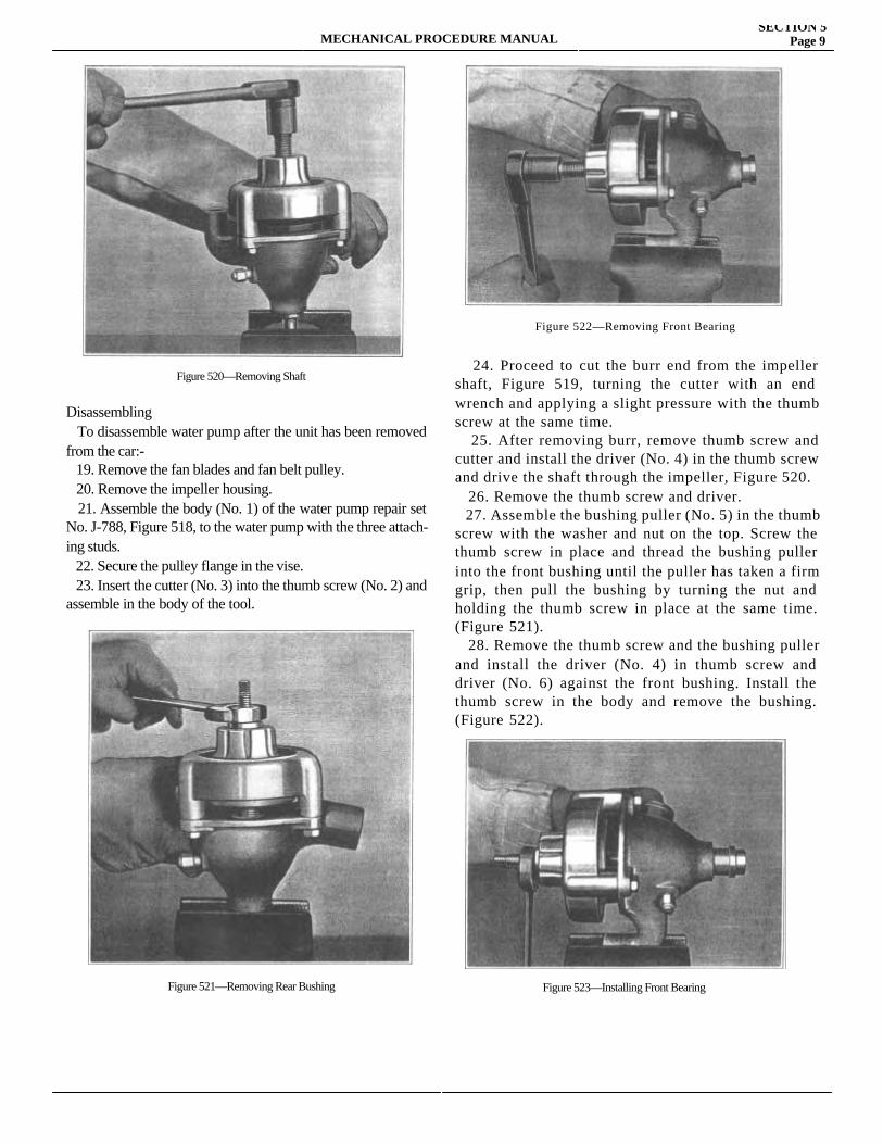
MECHANICAL PROCEDURE MANUALSECTION 5
Page 9
Disassembling To disassemble water pump after the unit has been removed from the car:- 19. Remove the fan blades and fan belt pulley. 20. Remove the impeller housing. 21. Assemble the body (No. 1) of the water pump repair set No. J-788, Figure 518, to the water pump with the three attach-ing studs. 22. Secure the pulley flange in the vise. 23. Insert the cutter (No. 3) into the thumb screw (No. 2) and assemble in the body of the tool.
24. Proceed to cut the burr end from the impeller shaft, Figure 519, turning the cutter with an end wrench and applying a slight pressure with the thumb screw at the same time. 25. After removing burr, remove thumb screw and cutter and install the driver (No. 4) in the thumb screw and drive the shaft through the impeller, Figure 520. 26. Remove the thumb screw and driver. 27. Assemble the bushing puller (No. 5) in the thumb screw with the washer and nut on the top. Screw the thumb screw in place and thread the bushing puller into the front bushing until the puller has taken a firm grip, then pull the bushing by turning the nut and holding the thumb screw in place at the same time. (Figure 521). 28. Remove the thumb screw and the bushing puller and install the driver (No. 4) in thumb screw and driver (No. 6) against the front bushing. Install the thumb screw in the body and remove the bushing. (Figure 522).
Figure 520—Removing Shaft
Figure 521—Removing Rear Bushing
Figure 522—Removing Front Bearing
Figure 523—Installing Front Bearing
SECTION 5MECHANICAL PROCEDURE MANUAL
29. Remove the oil seal retaining ring and disassemble oil seal. Check the oil seal and thrust washer and assemble in order; tension spring, oil seal, thrust washer and retaining ring. 30. Install rear bushing so that it is just started into the water pump body then insert the puller through the bushing and pump body. Install the washer and nut and pull the bushing into place. 31. Remove the bushing puller and install the front bushing and thumb screw. Insert the bushing puller through both bush-ings and thumb screw, install the washer and nut and pull the front bushing into place. (Figure 523).
29. Remove the oil seal retaining ring and disassemble oil seal. Check the oil seal and thrust washer and assemble in order; tension spring, oil seal, thrust washer and retaining ring. 30. Install rear bushing so that it is just started into the water pump body then insert the puller through the bushing and pump body. Install the washer and nut and pull the bushing into place. 31. Remove the bushing puller and install the front bushing and thumb screw. Insert the bushing puller through both bushings and thumb screw, install the washer and nut and pull the front bushing into place. (Figure 523).

SECTION 6
ELECTRICALService Magazine—Reference Sheet and Service Bullet in Reference
Bulletin orReference SheetNo. MagazineIssue and Page
Date Subject DETAILS OF INFORMATION
MECHANICAL PROCEDURE MANUAL Page 1

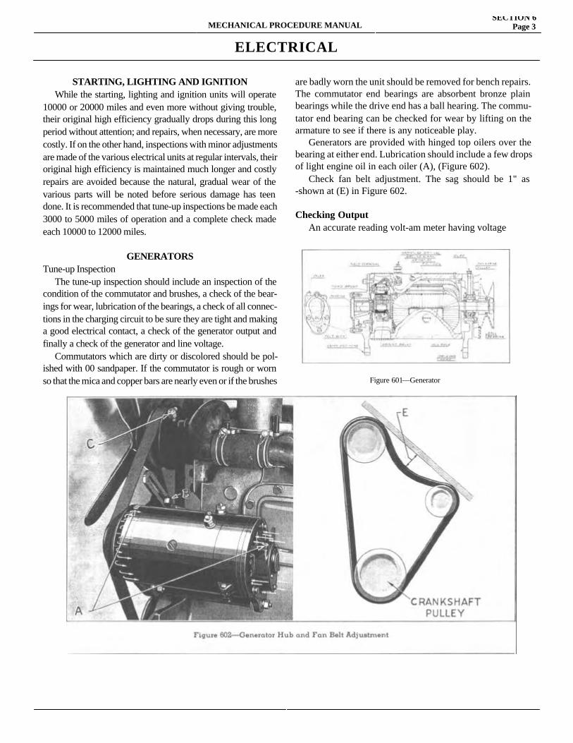
MECHANICAL PROCEDURE MANUALSECTION 6
Page 3
ELECTRICAL
STARTING, LIGHTING AND IGNITION While the starting, lighting and ignition units will operate 10000 or 20000 miles and even more without giving trouble, their original high efficiency gradually drops during this long period without attention; and repairs, when necessary, are more costly. If on the other hand, inspections with minor adjustments are made of the various electrical units at regular intervals, their original high efficiency is maintained much longer and costly repairs are avoided because the natural, gradual wear of the various parts will be noted before serious damage has teen done. It is recommended that tune-up inspections be made each 3000 to 5000 miles of operation and a complete check made each 10000 to 12000 miles.
GENERATORS Tune-up Inspection The tune-up inspection should include an inspection of the condition of the commutator and brushes, a check of the bear-ings for wear, lubrication of the bearings, a check of all connec-tions in the charging circuit to be sure they are tight and making a good electrical contact, a check of the generator output and finally a check of the generator and line voltage. Commutators which are dirty or discolored should be pol-ished with 00 sandpaper. If the commutator is rough or worn so that the mica and copper bars are nearly even or if the brushes
are badly worn the unit should be removed for bench repairs.The commutator end bearings are absorbent bronze plain bearings while the drive end has a ball hearing. The commu-tator end bearing can be checked for wear by lifting on the armature to see if there is any noticeable play. Generators are provided with hinged top oilers over the bearing at either end. Lubrication should include a few drops of light engine oil in each oiler (A), (Figure 602). Check fan belt adjustment. The sag should be 1" as -shown at (E) in Figure 602.
Checking Output An accurate reading volt-am meter having voltage
Figure 601—Generator
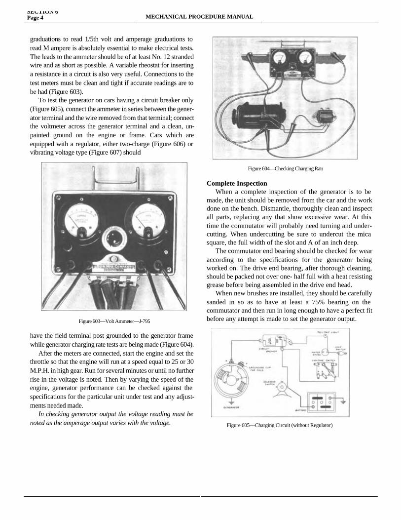
SECTION 6Page 4 MECHANICAL PROCEDURE MANUAL
graduations to read 1/5th volt and amperage graduations to read M ampere is absolutely essential to make electrical tests. The leads to the ammeter should be of at least No. 12 stranded wire and as short as possible. A variable rheostat for inserting a resistance in a circuit is also very useful. Connections to the test meters must be clean and tight if accurate readings are to be had (Figure 603). To test the generator on cars having a circuit breaker only (Figure 605), connect the ammeter in series between the gener-ator terminal and the wire removed from that terminal; connect the voltmeter across the generator terminal and a clean, un-painted ground on the engine or frame. Cars which are equipped with a regulator, either two-charge (Figure 606) or vibrating voltage type (Figure 607) should
have the field terminal post grounded to the generator frame while generator charging rate tests are being made (Figure 604). After the meters are connected, start the engine and set the throttle so that the engine will run at a speed equal to 25 or 30 M.P.H. in high gear. Run for several minutes or until no further rise in the voltage is noted. Then by varying the speed of the engine, generator performance can be checked against the specifications for the particular unit under test and any adjust-ments needed made. In checking generator output the voltage reading must be noted as the amperage output varies with the voltage.
Complete Inspection When a complete inspection of the generator is to be made, the unit should be removed from the car and the work done on the bench. Dismantle, thoroughly clean and inspect all parts, replacing any that show excessive wear. At this time the commutator will probably need turning and under-cutting. When undercutting be sure to undercut the mica square, the full width of the slot and A of an inch deep. The commutator end bearing should be checked for wear according to the specifications for the generator being worked on. The drive end bearing, after thorough cleaning, should be packed not over one- half full with a heat resisting grease before being assembled in the drive end head. When new brushes are installed, they should be carefully sanded in so as to have at least a 75% bearing on the commutator and then run in long enough to have a perfect fit before any attempt is made to set the generator output.Figure 603—Volt Ammeter—J-795
Figure 604—Checking Charging Rate
Figure 605—Charging Circuit (without Regulator)
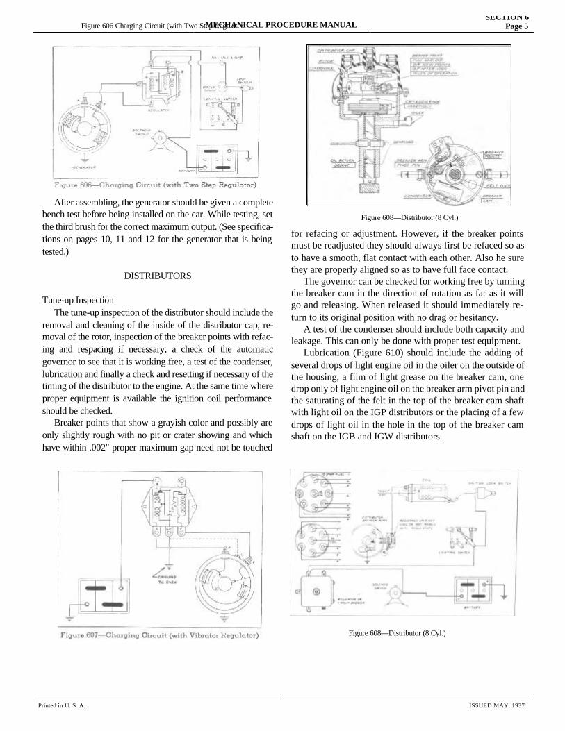
MECHANICAL PROCEDURE MANUALSECTION 6
Page 5
After assembling, the generator should be given a complete bench test before being installed on the car. While testing, set the third brush for the correct maximum output. (See specifica-tions on pages 10, 11 and 12 for the generator that is being tested.)
DISTRIBUTORS
Tune-up Inspection The tune-up inspection of the distributor should include the removal and cleaning of the inside of the distributor cap, re-moval of the rotor, inspection of the breaker points with refac-ing and respacing if necessary, a check of the automatic governor to see that it is working free, a test of the condenser, lubrication and finally a check and resetting if necessary of the timing of the distributor to the engine. At the same time where proper equipment is available the ignition coil performance should be checked. Breaker points that show a grayish color and possibly are only slightly rough with no pit or crater showing and which have within .002" proper maximum gap need not be touched for refacing or
for refacing or adjustment. However, if the breaker points must be readjusted they should always first be refaced so as to have a smooth, flat contact with each other. Also he sure they are properly aligned so as to have full face contact. The governor can be checked for working free by turning the breaker cam in the direction of rotation as far as it will go and releasing. When released it should immediately re-turn to its original position with no drag or hesitancy. A test of the condenser should include both capacity and leakage. This can only be done with proper test equipment. Lubrication (Figure 610) should include the adding of several drops of light engine oil in the oiler on the outside of the housing, a film of light grease on the breaker cam, one drop only of light engine oil on the breaker arm pivot pin and the saturating of the felt in the top of the breaker cam shaft with light oil on the IGP distributors or the placing of a few drops of light oil in the hole in the top of the breaker cam shaft on the IGB and IGW distributors.
Figure 606 Charging Circuit (with Two Step Regulator
Figure 608—Distributor (8 Cyl.)
Figure 608—Distributor (8 Cyl.)
Printed in U. S. A. ISSUED MAY, 1937
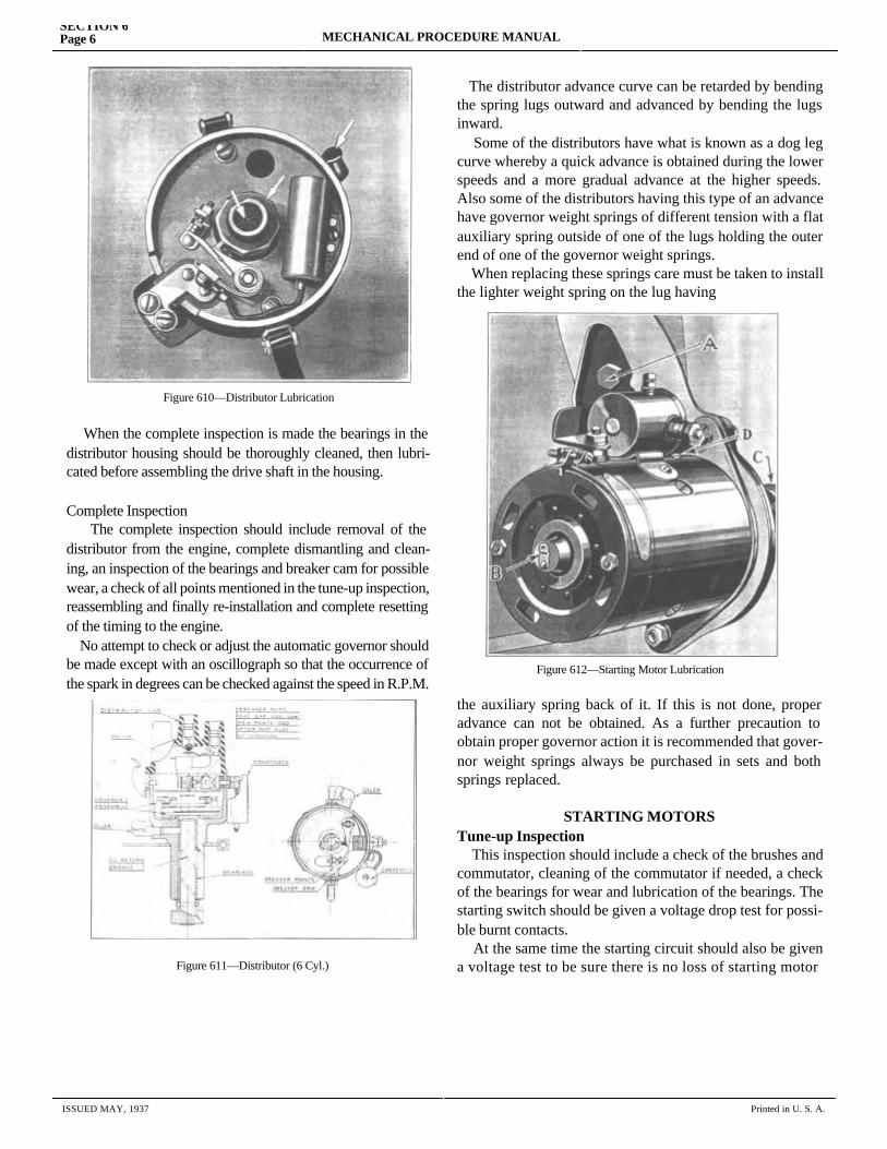
SECTION 6Page 6 MECHANICAL PROCEDURE MANUAL
When the complete inspection is made the bearings in the distributor housing should be thoroughly cleaned, then lubri-cated before assembling the drive shaft in the housing.
Complete Inspection The complete inspection should include removal of the distributor from the engine, complete dismantling and clean-ing, an inspection of the bearings and breaker cam for possible wear, a check of all points mentioned in the tune-up inspection, reassembling and finally re-installation and complete resetting of the timing to the engine. No attempt to check or adjust the automatic governor should be made except with an oscillograph so that the occurrence of the spark in degrees can be checked against the speed in R.P.M.
The distributor advance curve can be retarded by bending the spring lugs outward and advanced by bending the lugs inward. Some of the distributors have what is known as a dog leg curve whereby a quick advance is obtained during the lower speeds and a more gradual advance at the higher speeds. Also some of the distributors having this type of an advance have governor weight springs of different tension with a flat auxiliary spring outside of one of the lugs holding the outer end of one of the governor weight springs. When replacing these springs care must be taken to install the lighter weight spring on the lug having
the auxiliary spring back of it. If this is not done, proper advance can not be obtained. As a further precaution to obtain proper governor action it is recommended that gover-nor weight springs always be purchased in sets and both springs replaced.
STARTING MOTORSTune-up Inspection This inspection should include a check of the brushes and commutator, cleaning of the commutator if needed, a check of the bearings for wear and lubrication of the bearings. The starting switch should be given a voltage drop test for possi-ble burnt contacts. At the same time the starting circuit should also be given a voltage test to be sure there is no loss of starting motor
ISSUED MAY, 1937 Printed in U. S. A.
Figure 610—Distributor Lubrication
Figure 611—Distributor (6 Cyl.)
Figure 612—Starting Motor Lubrication
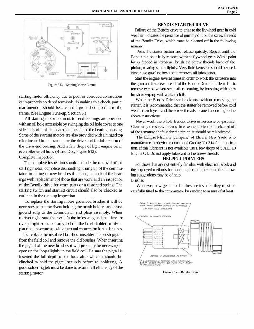
MECHANICAL PROCEDURE MANUALSECTION 6
Page 7
starting motor efficiency due to poor or corroded connections or improperly soldered terminals. In making this check, partic-ular attention should be given the ground connection to the frame. (See Engine Tune-up, Section 3.) All starting motor commutator end bearings are provided with an oil hole accessible by swinging the oil hole cover to one side. This oil hole is located on the end of the bearing housing. Some of the starting motors are also provided with a hinged top oiler located in the frame near the drive end for lubrication of the drive end bearing. Add a few drops of light engine oil in each oiler or oil hole. (B and Dac, Figure 612).Complete Inspection The complete inspection should include the removal of the starting motor, complete dismantling, truing up of the commu-tator, installing of new brushes if needed, a check of the bear-ings with replacement of those that are worn and an inspection of the Bendix drive for worn parts or a distorted spring. The starting switch and starting circuit should also be checked as outlined in the tune-up inspection. To replace the starting motor grounded brushes it will be necessary to cut the rivets holding the brush holders and brush ground strip to the commutator end plate assembly. When re-riveting be sure the rivets fit the holes snug and that they are riveted tight so as not only to hold the brush holder firmly in place but to secure a positive ground connection for the brushes. To replace the insulated brushes, unsolder the brush pigtail from the field coil and remove the old brushes. When inserting the pigtail of the new brushes it will probably be necessary to open up the loop slightly in the field coil. Be sure the pigtail is inserted the full depth of the loop after which it should be clinched to hold the pigtail securely before re- soldering. A good soldering job must be done to assure full efficiency of the starting motor.
BENDIX STARTER DRIVE Failure of the Bendix drive to engage the flywheel gear in cold weather indicates the presence of gummy dirt on the screw threads of the Bendix Drive, which must be cleaned off in the following manner: Press the starter button and release quickly. Repeat until the Bendix pinion is fully meshed with the flywheel gear. With a paint brush dipped in kerosene, brush the screw threads back of the pinion, rotating same slightly. Very little kerosene should be used. Never use gasoline because it removes all lubrication. Start the engine several times in order to work the kerosene into the gum on the screw threads of the Bendix Drive. It is desirable to remove excessive kerosene, after cleaning, by brushing with a dry brush or wiping with a clean cloth. While the Bendix Drive can be cleaned without removing the starter, it is recommended that the starter be removed before cold weather each year and the screw threads cleaned according to the above instructions. Never wash the whole Bendix Drive in kerosene or gasoline. Clean only the screw threads. In case the lubrication is cleaned off of the armature shaft under the pinion, it should be relubricated. The Eclipse Machine Company, of Elmira, New York, who manufacture the device, recommend Gredag No. 314 for relubrica-tion. If this lubricant is not available use a few drops of S.A.E. 10 Engine Oil. Do not apply lubricant to the screw threads.
HELPFUL POINTERS For those that are not entirely familiar with electrical work and the approved methods for handling certain operations the follow-ing suggestions may be of help.Brushes Whenever new generator brushes are installed they must be carefully fitted to the commutator by sanding to assure of at least
Figure 613—Starting Motor Circuit
Figure 614—Bendix Drive
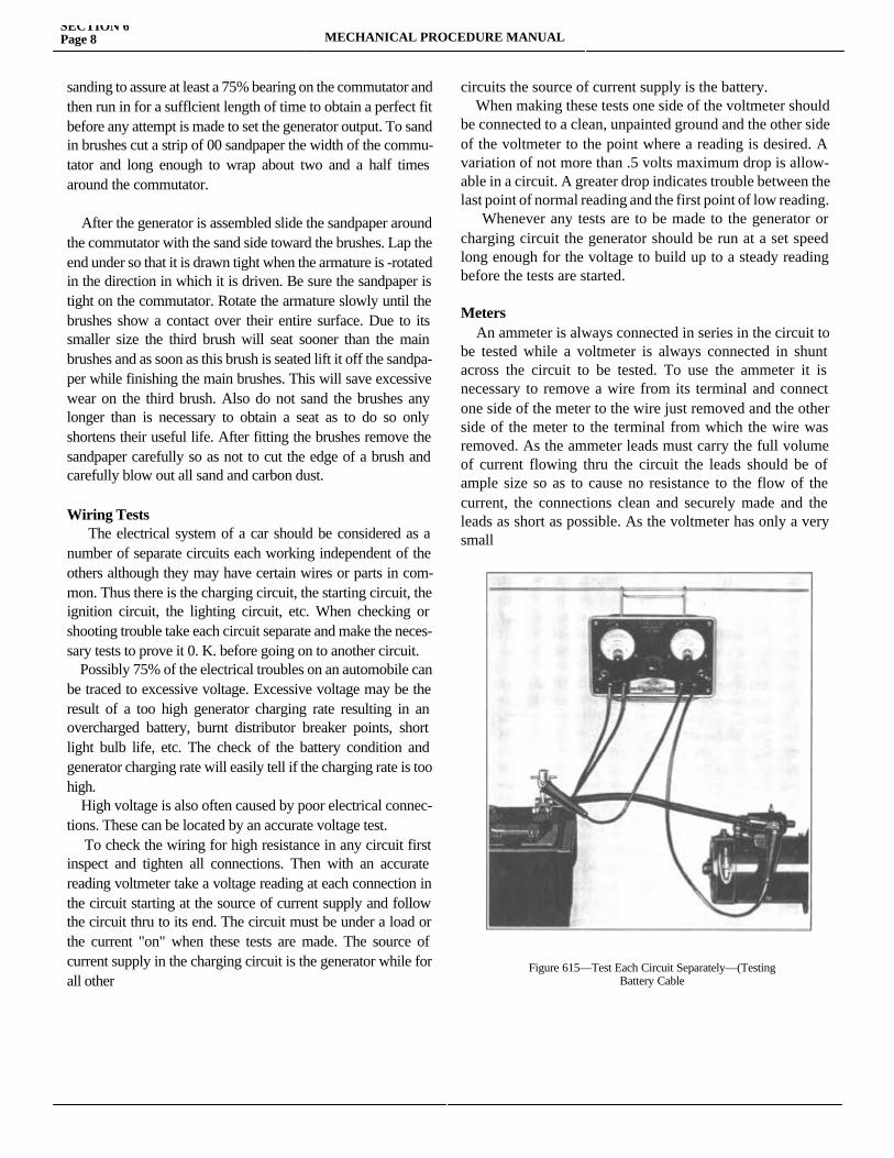
SECTION 6Page 8 MECHANICAL PROCEDURE MANUAL
sanding to assure at least a 75% bearing on the commutator and then run in for a sufflcient length of time to obtain a perfect fit before any attempt is made to set the generator output. To sand in brushes cut a strip of 00 sandpaper the width of the commu-tator and long enough to wrap about two and a half times around the commutator.
After the generator is assembled slide the sandpaper around the commutator with the sand side toward the brushes. Lap the end under so that it is drawn tight when the armature is -rotated in the direction in which it is driven. Be sure the sandpaper is tight on the commutator. Rotate the armature slowly until the brushes show a contact over their entire surface. Due to its smaller size the third brush will seat sooner than the main brushes and as soon as this brush is seated lift it off the sandpa-per while finishing the main brushes. This will save excessive wear on the third brush. Also do not sand the brushes any longer than is necessary to obtain a seat as to do so only shortens their useful life. After fitting the brushes remove the sandpaper carefully so as not to cut the edge of a brush and carefully blow out all sand and carbon dust.
Wiring Tests The electrical system of a car should be considered as a number of separate circuits each working independent of the others although they may have certain wires or parts in com-mon. Thus there is the charging circuit, the starting circuit, the ignition circuit, the lighting circuit, etc. When checking or shooting trouble take each circuit separate and make the neces-sary tests to prove it 0. K. before going on to another circuit. Possibly 75% of the electrical troubles on an automobile can be traced to excessive voltage. Excessive voltage may be the result of a too high generator charging rate resulting in an overcharged battery, burnt distributor breaker points, short light bulb life, etc. The check of the battery condition and generator charging rate will easily tell if the charging rate is too high. High voltage is also often caused by poor electrical connec-tions. These can be located by an accurate voltage test. To check the wiring for high resistance in any circuit first inspect and tighten all connections. Then with an accurate reading voltmeter take a voltage reading at each connection in the circuit starting at the source of current supply and follow the circuit thru to its end. The circuit must be under a load or the current "on" when these tests are made. The source of current supply in the charging circuit is the generator while for all other
circuits the source of current supply is the battery. When making these tests one side of the voltmeter should be connected to a clean, unpainted ground and the other side of the voltmeter to the point where a reading is desired. A variation of not more than .5 volts maximum drop is allow-able in a circuit. A greater drop indicates trouble between the last point of normal reading and the first point of low reading. Whenever any tests are to be made to the generator or charging circuit the generator should be run at a set speed long enough for the voltage to build up to a steady reading before the tests are started.
Meters An ammeter is always connected in series in the circuit to be tested while a voltmeter is always connected in shunt across the circuit to be tested. To use the ammeter it is necessary to remove a wire from its terminal and connect one side of the meter to the wire just removed and the other side of the meter to the terminal from which the wire was removed. As the ammeter leads must carry the full volume of current flowing thru the circuit the leads should be of ample size so as to cause no resistance to the flow of the current, the connections clean and securely made and the leads as short as possible. As the voltmeter has only a very small
Figure 615—Test Each Circuit Separately—(TestingBattery Cable
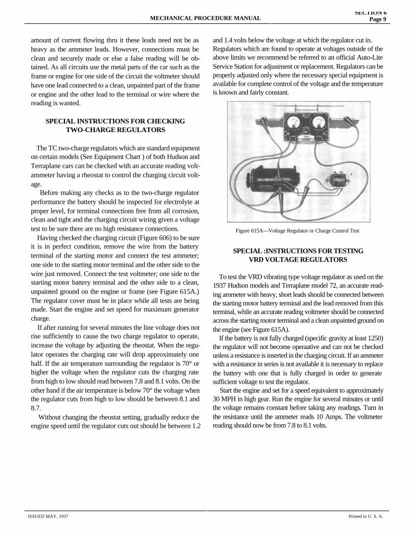
MECHANICAL PROCEDURE MANUALSECTION 6
Page 9
amount of current flowing thru it these leads need not be as heavy as the ammeter leads. However, connections must be clean and securely made or else a false reading will be ob-tained. As all circuits use the metal parts of the car such as the frame or engine for one side of the circuit the voltmeter should have one lead connected to a clean, unpainted part of the frame or engine and the other lead to the terminal or wire where the reading is wanted.
SPECIAL INSTRUCTIONS FOR CHECKINGTWO-CHARGE REGULATORS
The TC two-charge regulators which are standard equipment on certain models (See Equipment Chart ) of both Hudson and Terraplane cars can be checked with an accurate reading volt-ammeter having a rheostat to control the charging circuit volt-age. Before making any checks as to the two-charge regulator performance the battery should be inspected for electrolyte at proper level, for terminal connections free from all corrosion, clean and tight and the charging circuit wiring given a voltage test to be sure there are no high resistance connections. Having checked the charging circuit (Figure 606) to be sure it is in perfect condition, remove the wire from the battery terminal of the starting motor and connect the test ammeter; one side to the starting motor terminal and the other side to the wire just removed. Connect the test voltmeter; one side to the starting motor battery terminal and the other side to a clean, unpainted ground on the engine or frame (see Figure 615A.) The regulator cover must be in place while all tests are being made. Start the engine and set speed for maximum generator charge. If after running for several minutes the line voltage does not rise sufficiently to cause the two charge regulator to operate, increase the voltage by adjusting the rheostat. When the regu-lator operates the charging rate will drop approximately one half. If the air temperature surrounding the regulator is 70° or higher the voltage when the regulator cuts the charging rate from high to low should read between 7.8 and 8.1 volts. On the other hand if the air temperature is below 70° the voltage when the regulator cuts from high to low should be between 8.1 and 8.7. Without changing the rheostat setting, gradually reduce the engine speed until the regulator cuts out should be between 1.2
and 1.4 volts below the voltage at which the regulator cut in.Regulators which are found to operate at voltages outside of the above limits we recommend be referred to an official Auto-Lite Service Station for adjustment or replacement. Regulators can be properly adjusted only where the necessary special equipment is available for complete control of the voltage and the temperature is known and fairly constant.
SPECIAL :INSTRUCTIONS FOR TESTINGVRD VOLTAGE REGULATORS
To test the VRD vibrating type voltage regulator as used on the 1937 Hudson models and Terraplane model 72, an accurate read-ing ammeter with heavy, short leads should be connected between the starting motor battery terminal and the lead removed from this terminal, while an accurate reading voltmeter should be connected across the starting motor terminal and a clean unpainted ground on the engine (see Figure 615A). If the battery is not fully charged (specific gravity at least 1250) the regulator will not become operaative and can not be checked unless a resistance is inserted in the charging circuit. If an ammeter with a resistance in series is not available it is necessary to replace the battery with one that is fully charged in order to generate sufficient voltage to test the regulator. Start the engine and set for a speed equivalent to approximately 30 MPH in high gear. Run the engine for several minutes or until the voltage remains constant before taking any readings. Turn in the resistance until the ammeter reads 10 Amps. The voltmeter reading should now be from 7.8 to 8.1 volts.
Figure 615A—Voltage Regulator or Charge Control Test
ISSUED MAY, 1937 Printed in U. S. A.
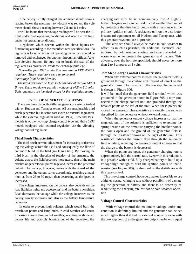
SECTION 6Page 9A MECHANICAL PROCEDURE MANUAL
If the battery is fully charged, the ammeter should show a reading below the maximum to which it was set and the volt-meter should show a reading between 7.8 and 8.1 volts. It will be found that the voltage readings will be near the 8.1 limit under cold operating conditions and near the 7.8 limit under hot operating conditions. Regulators which operate within the above figures are functioning according to the manufacturers' specifications. If a regulator is found which is not operating correctly it should be removed and exchanged for another through an official Auto-Lite Service Station. Be sure not to break the seal of the regulator as a broken seal voids the exchange privilege. Note—The first 1937 production cars used a VRD 4003 A regulator. These regulators were set to controlthe voltage from 7.4 to 7.9 volts. The regulators used on later 1937 cars are of the VRD 4003 B type. These regulators permit a voltage of p7.8 to 8.1 volts. Both regulators are identical except for the regulation setting .
TYPES OF GENERATOR SYSTEMS There are three distinctly different generator systems to deal with on Hudson and Terraplane cars. All use an adjustable third brush generator, but in some cases with no external regulation, while the external regulation used on 1934, 1935 and 1936 models is of the two step charge control type and those 1937 models equipped with external regulation use the vibrating voltage control regulators.
Third Brush Characteristics The third brush permits adjustment for increasing or decreas-ing the voltage across the field and consequently the flow of current to build up the field (see Figure 605). By moving the third brush in the direction of rotation of the armature, the voltage across the field becomes more nearly that of the main brushes or generator output voltage and increases the generator output. The voltage, however, varies with the speed of the generator and the output varies accordingly, reaching a maxi-mum at from 25 to 30 m.p.h. then decreasing as the speed is increased. The voltage impressed on the battery also depends on the load (ignition lights and accessories) and the battery condition. Load decreases the voltage while the voltage increases as the battery gravity increases and also as the battery temperature decreases. In order to prevent high voltages which would burn the distributor points and lamp bulbs in cold weather and cause excessive current flow in hot weather, resulting in shortened battery life and possibly burning out of the generator, the charging
charging rate must be set comparatively low. A slightly higher charging rate can be used in cold weather than in hot by protecting the distributor points with a resistance in the primary ignition circuit. A resistance unit on the distributor is standard equipment on all Hudson and Terraplanes with this generator system (see Figure 609). This advance should always be made in cold weather to offset, as much as possible, the additional electrical load imposed by cold weather starting and again retarded for warm weather to protect the generator and battery. This advance, over the hot rate specified, should never be more than 2 to 3 amperes at 8 volts.
Two Step Charge Control Characteristics When any external control is used, the generator field is grounded through the control unit instead of direct to the generator frame. The circuit with the two step charge control is shown in Figure 606.It will be noted that the generator field terminal which was grounded to the generator frame in Figure 605 is now con-nected to the charge control unit and grounded through the breaker points at the left of the unit. When these points are closed the generator characteristics are exactly the same as described for the generator without external control. When the generator output voltage increases so that the magnetic pull of the solenoid is sufficient to overcome the spring tension on the armature carrying the breaker points, the points open and the ground of the generator field is through the resistance shown on the right of the unit. This resistance reduces the current flow through the generator field winding, reducing the generator output voltage so that the charge to the battery is decreased. When the points are open, the generator charging rate is approximately half the normal rate. Even with this reduction, it is possible with a cold, fully charged battery to build up a voltage high enough to burn the ignition points so that a resistor (see Figure 609), is also used on the distributor with this type control. This two charge control, however, makes it possible to use a higher normal charging rate without possibility of damag-ing the generator or battery and there is no necessity of readjusting the charging rate for hot or cold weather opera-tion.
Voltage Control Characteristics With voltage control the maximum voltage under any condition is definitely limited and the generator can be set much higher than if it had no external control or even with the two step control as the generator output can be only equal to the ability of
Printed in U. S. A. ISSUED MAY, 1937
MECHANICAL PROCEDURE MANUALSECTION 6
Page 9B
to the ability of the load and battery to absorb current at the maximum available voltage.
By selecting this maximum voltage point to which the voltage regulator is set so that it is not high enough to cause burning of the distributor points nor high enough to cause an excessive flow of current into the battery when hot, the maximum current which can be safely handled is always available.
In order to get satisfactory results it is absolutely essential that the voltage regulator function within the limits speci-fied. There is no resistor used on the distributor with this type control so that a higher voltage will burn the points. A lower voltage will reduce the current available and result in a run down battery.
One-tenth of a volt becomes a really important factor in the functioning of the system and only accurate volt and ammeters should be used in testing this system. One-tenth volt reduction in the voltage of regulation may reduce the current supplied to the battery as much as 20%.
Always test the generator charging rate and voltage regulator accurately with reliable instruments.
Battery Voltage
When either the two charge control or the vibrating voltage regulator is used, the ability of a battery to accept a normal charge is an important factor. A healthy battery at 80° F. and 1.280 gravity should accept 15 amperes charge with 8.25 volts or less, while 7.9 volts under the same conditions should give a charge to the battery of at least 5 amperes. If appreciably higher voltages (even 1/10 volt) are required to give these charging rates, the battery can not be kept charged under normal operating conditions.
Where higher than normal battery charging voltages are encountered, the battery is probably sulphated. It should be discharged and recharged double its ampere hour rating. If the charging voltage does not become normal, the battery should be replaced.
Reversing Generator Field
Any generator having the field grounded externally, as is the case with all external control systems, may become reversed in polarity if a hot wire from the battery comes in contact with the external field connection.
If the engine is started with the polarity reversed, the generator will produce a current flowing in the same direc-tion as that produced by the battery. When the generator voltage becomes high enough to close the relay points, an extremely heavy current will flow through the relay in the reverse of the normal direction. This reverse flow through the relay will separate the points but, due to the high current flowing, an arcing will occur which will burn the points. The generator will again close the points and, due to their burnt condition, they will probably stick. After the engine is stopped the points will not open and the battery will run down.
In the 1937 models it has been found that the generator field polarity will be reversed if the wire from the battery to the B terminal of the regulator, strikes the regulator case or, if in tightening the screw which holds this wire, the screw-driver comes in contact with the "B" terminal and the case at the same time.
In order to reduce this possibility, the regulator ground wire which was originally attached to the generator frame (see dotted line—Figure 607) has been replaced by a shorter wire which is connected from the "GD" terminal of the regulator to the body dash.
Where the ground wire is attached to the generator, it is recommended that another wire be connected to the "GD" terminal as shown in Figure 607. This should be attached to the body dash by one of the screws which hold the automatic clutch linkage bracket to the dash. Be sure the paint is removed from the dash to insure a good electrical contact.
There is no way to absolutely prevent the generator from being reversed, so the generator should be "flashed" after any wires have been disconnected and replaced. Flashing is done by connecting a jumper wire to the starting motor battery terminal and tapping it several times against the "A" terminal of the generator.
To check the generator after flashing it, simply start the engine and speed it up. The generator signal light should go out and stay out as long as the engine is running above idle speed. Now turn off the ignition until the engine stops then turn it on again. The generator signal light should come on indicating that the relay points are not stuck.
Ignition System Testing
Complete information on testing the ignition system is included in the Engine Tune-up (section 3).
ISSUED MAY, 1937 Printed in U. S. A.
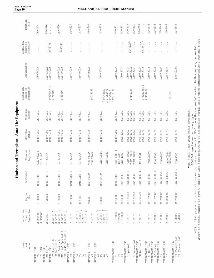
Hud
son
and
Ter
rapl
ane-
-Aut
o-L
ite E
quip
men
t
Name
and
Model
Serial No.
Start of
Production
Engine
No.
Generator
Relay or
Regulator
Starting
Motor
Starting
Switch
Serial No.
Start of
Production
Distributor
Serial No.
Start of
Production
Ignition
Coil
HUDSON 1934
LL
LT, LTS
HUDSON 1935
GH Big 6
HUDSON 1935
HT Special 8
HU De Luxe 8
HHU Custom 8
HTL 124' Special 8
HUL 124" De Luxe 8
HUDSON 6, 1936
63
HUDSON 8, 1936
64
65
66
67
HUDSON 6, 1937
73
HUDSON 8, 1937
74
75
76
77
TERRAPLANE 1934
K
KU
KS
TERRAPLANE 1935
G Special
G Commercial
TERRAPLANE 1935
GU De Luxe 6
TERRAPLANE 1936
61 De Luxe
TERRAPLANE 1935
62 Custom
TERRAPLANE 1937
71
TERRAPLANE 1937
72
TERRAPLANE 1937
70 (Commercial)
78 (Commercial)
S-252000
S-950000
S-53202
S-54101
S-55101
S-56101
S-57101
S-58101
S-63101
S-64101
S-65101
S-66101
S-67101
S-73101
S-75101
S-74101
S-76101
S-77101
S-373000
S-21500
S-373000
S-51101
S-51101
S-52101
S-61101
S-62101
S-71101
S-72101
S-70101
S-78101
E-30000
E-70000
E-55000
E-79000
E-1000
90000
18000
E-48000
E-48000
E-103000
E-103000
E-103000
E-157000
E-157000
E-250000
E-250000
E-250000
GBK-4602
GBK-4602-1
GBK-4602-1
GAR-4701-6
GAR-4701-6
GCJ-4803A
GCJ-4803A
GBK-4602
GAM-4503
GBK-4601-2
GAM-4503
GBK-4602-1
GAR-4702
GAR-4701-6
GCJ-4804A-1
GCJ-4803A
GCJ-4804A-1
CBA-4002 &
TC-4102A
TC-4304A
TC-4304A
TC-4304A
TC-4304A
VRD-4003A
VRD-4003B
VRD-4003A
VRD-4003B
CBA-4002 &
TC-4102A
CBA-4002
†CBA-4002
†CBA-4003
†CBA-4002
TC-4304A
†CBA-4003
TC-4304A
*CBA-4003
VRD-4003A
VRD-4003B
*CBA4003
MAB-4061
MAB-4060
MAB-4074
MAB-4061
MAB-4075
MAB-4075
MAB-4075
MAB-4075
MAB-4075
MAB-4060
MAB-4060
MAB-4060
MAB-4074
MAB-4060
MAB-4060
MAB-4074
MAB-4075
MAB-4075
MAB-4075
MAB-4075
MAB-4075
SS-4001
SS-4001
SS-4001
SS-4001
SS-4001
SS-4001
SS-4001
SS-4001
SS-4001
SS-4001
SS-4001
SS-4001
SS-4001
SS-4001
SS-4001
SS-4001
SS-4001
SS-4001
SS-4001
SS-4001
SS-4001
S-536449 &
E-76665
E-63836
S-733169
S-742520
S-751471
S-76639
S-771761
E-143134
S-5210966 &
E-143134
727154
IGP-4001A
IGB-4301A
IGB-4301B
IGP-4001A
IGP-4001B
IGB-4301B
IGP-4001B
IGW-4013A
IGP-4008A
IGB-4301A
IGB-4301A
IGB-4301A
IGB-4301B
IGB-4301A
IGB-4301A
IGB-4301B
IGB-4301B
IGB-4301B
IGW-4012A
IGW-4013A
IGW-4012A
. . . . . .
. . . . . .
E-73791
. . . . .
E-65247
. . . . .
. . . . .
. . . . .
. . . . .
. . . . .
. . . . .
. . . . .
E-128077
. . . . .
. . . . .
E-128077
. . . . .
. . . . .
. . . . .
. . . . .
. . . . .
CE-4304
IG-4616
. . . .
CE-4606
. . . .
IG-4633
CE-4617
IG-4644
CE-4625
IG-4311
IG-4311
IG-4616
. . . .
IG-4311
IG-4616
. . . .
IG-4633
IG-4633
IG-4644
IG-4644
IG-4644
*VRD-4003B used when radio equipped.
†TC4304A used when radio equipped.
NOTE: "S-" preceding a serial number indicates car serial; "E-" preceding a serial number indicates engine serial.
Where no serial number is given, unit is used from beginning of production serial and engine numbers—columns two and three.
SECTION 6Page 10 MECHANICAL PROCEDURE MANUAL
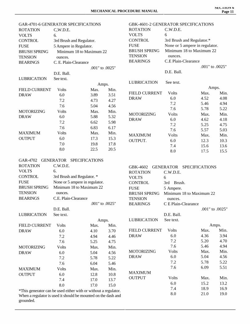
MECHANICAL PROCEDURE MANUALSECTION 6
Page 11
GAR-4701-6 GENERATOR SPECIFICATIONSROTATION C,W.D.E.VOLTS 6.CONTROL 3rd Brush and Regulator.FUSE 5 Ampere in Regulator.BRUSH SPRING Minimum 18 to Maximum 22TENSION ounces.BEARINGS C. E. Plain-Clearance .001" to .0025" D.E. Ball.LUBRICATION See text. Amps.FIELD CURRENT Volts Max. Min.DRAW 6.0 3.89 3.51 7.2 4.73 4.27 7.6 5.04 4.56MOTORIZING Volts Max. Min.DRAW 6.0 5.88 5.32 7.2 6.62 5.98 7.6 6.83 6.17MAXIMUM Volts Max. Min.OUTPUT 6.0 17.3 15.3 7.0 19.8 17.8 8.0 22.5 20.5
GAR-4702 GENERATOR SPECIFICATIONSROTATION C.W.D.E.VOLTS 6.CONTROL 3rd Brush and Regulator. *FUSE None or 5 ampere in regulator.BRUSH SPRING Minimum 18 to Maximum 22TENSION ounces.BEARINGS C.E. Plain-Clearance .001" to .0025" D.E. Ball.LUBRICATION See text. Amps.FIELD CURRENT Volts Max. Min.DRAW 6.0 4.10 3.70 7.2 4.94 4.46 7.6 5.25 4.75MOTORIZING Volts Max. Min.DRAW 6.0 5.04 4.56 7.2 5.78 5.22 7.6 6.04 5.46MAXIMUM Volts Max. Min.OUTPUT 6.0 12.8 10.8 7.4 17.0 13.7 8.0 17.0 15.0*This generator can be used either with or without a regulator.When a regulator is used it should be mounted on the dash and grounded.
GBK-4601-2 GENERATOR SPECIFICATIONS ROTATION C.W.D.E.VOLTS 6CONTROL 3rd Brush and Regulator.*FUSE None or 5 ampere in regulator.BRUSH SPRING Minimum 18 to Maximum 22TENSION ounces.BEARINGS C.E Plain-Clearance .001" to .0025" D.E. Ball. LUBRICATION See text. Amps.FIELD CURRENT Volts Max. Min.DRAW 6.0 4.52 4.08 7.2 5.46 4.94 7.6 5.78 5.22MOTORIZING Volts Max. Min.DRAW 6.0 4.62 4.18 7.2 5.25 4.75 7.6 5.57 5.03MAXIMUM Volts Max. Min.OUTPUT. 6.0 12.3 10.3 7.4 15.6 13.6 8.0 17.5 15.5
GBK-4602 GENERATOR SPECIFICATIONS ROTATION C.W.D.E.VOLTS 6CONTROL 3rd Brush.FUSE 5 Ampere.BRUSH SPRING Minimum 18 to Maximum 22TENSION ounces.BEARINGS C E Plain-Clearance .001" to .0025" D.E. Ball.LUBRICATION See text. Amps.FIELD CURRENT Volts Max. Min.DRAW 6.0 4.36 3.94 7.2 5.20 4.70 7.6 5.46 4.94MOTORIZING Volts Max. Min.DRAW 6.0 5.04 4.56 7.2 5.78 5.22 7.6 6.09 5.51MAXIMUM OUTPUT Volts Max. Min. 6.0 15.2 13.2 7.4 18.9 16.9 8.0 21.0 19.0
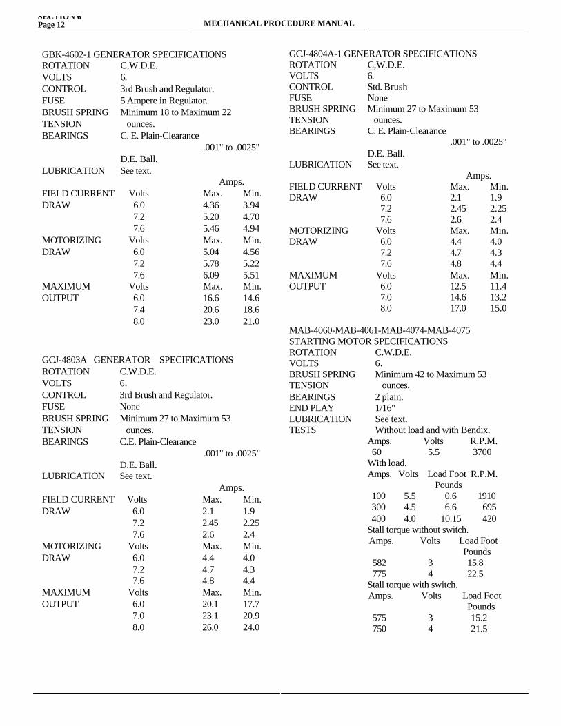
SECTION 6Page 12 MECHANICAL PROCEDURE MANUAL
GBK-4602-1 GENERATOR SPECIFICATIONSROTATION C,W.D.E.VOLTS 6.CONTROL 3rd Brush and Regulator.FUSE 5 Ampere in Regulator.BRUSH SPRING Minimum 18 to Maximum 22TENSION ounces.BEARINGS C. E. Plain-Clearance .001" to .0025" D.E. Ball.LUBRICATION See text. Amps.FIELD CURRENT Volts Max. Min.DRAW 6.0 4.36 3.94 7.2 5.20 4.70 7.6 5.46 4.94MOTORIZING Volts Max. Min.DRAW 6.0 5.04 4.56 7.2 5.78 5.22 7.6 6.09 5.51MAXIMUM Volts Max. Min.OUTPUT 6.0 16.6 14.6 7.4 20.6 18.6 8.0 23.0 21.0
GCJ-4803A GENERATOR SPECIFICATIONSROTATION C.W.D.E.VOLTS 6.CONTROL 3rd Brush and Regulator. FUSE None BRUSH SPRING Minimum 27 to Maximum 53TENSION ounces.BEARINGS C.E. Plain-Clearance .001" to .0025" D.E. Ball.LUBRICATION See text. Amps.FIELD CURRENT Volts Max. Min.DRAW 6.0 2.1 1.9 7.2 2.45 2.25 7.6 2.6 2.4MOTORIZING Volts Max. Min.DRAW 6.0 4.4 4.0 7.2 4.7 4.3 7.6 4.8 4.4MAXIMUM Volts Max. Min.OUTPUT 6.0 20.1 17.7 7.0 23.1 20.9 8.0 26.0 24.0
GCJ-4804A-1 GENERATOR SPECIFICATIONSROTATION C,W.D.E.VOLTS 6.CONTROL Std. BrushFUSE NoneBRUSH SPRING Minimum 27 to Maximum 53TENSION ounces.BEARINGS C. E. Plain-Clearance .001" to .0025" D.E. Ball.LUBRICATION See text. Amps.FIELD CURRENT Volts Max. Min.DRAW 6.0 2.1 1.9 7.2 2.45 2.25 7.6 2.6 2.4MOTORIZING Volts Max. Min.DRAW 6.0 4.4 4.0 7.2 4.7 4.3 7.6 4.8 4.4MAXIMUM Volts Max. Min.OUTPUT 6.0 12.5 11.4 7.0 14.6 13.2 8.0 17.0 15.0
MAB-4060-MAB-4061-MAB-4074-MAB-4075STARTING MOTOR SPECIFICATIONS ROTATION C.W.D.E.VOLTS 6.BRUSH SPRING Minimum 42 to Maximum 53TENSION ounces.BEARINGS 2 plain.END PLAY 1/16"LUBRICATION See text.TESTS Without load and with Bendix. Amps. Volts R.P.M. 60 5.5 3700 With load. Amps. Volts Load Foot R.P.M. Pounds 100 5.5 0.6 1910 300 4.5 6.6 695 400 4.0 10.15 420 Stall torque without switch. Amps. Volts Load Foot Pounds 582 3 15.8 775 4 22.5 Stall torque with switch. Amps. Volts Load Foot Pounds 575 3 15.2 750 4 21.5
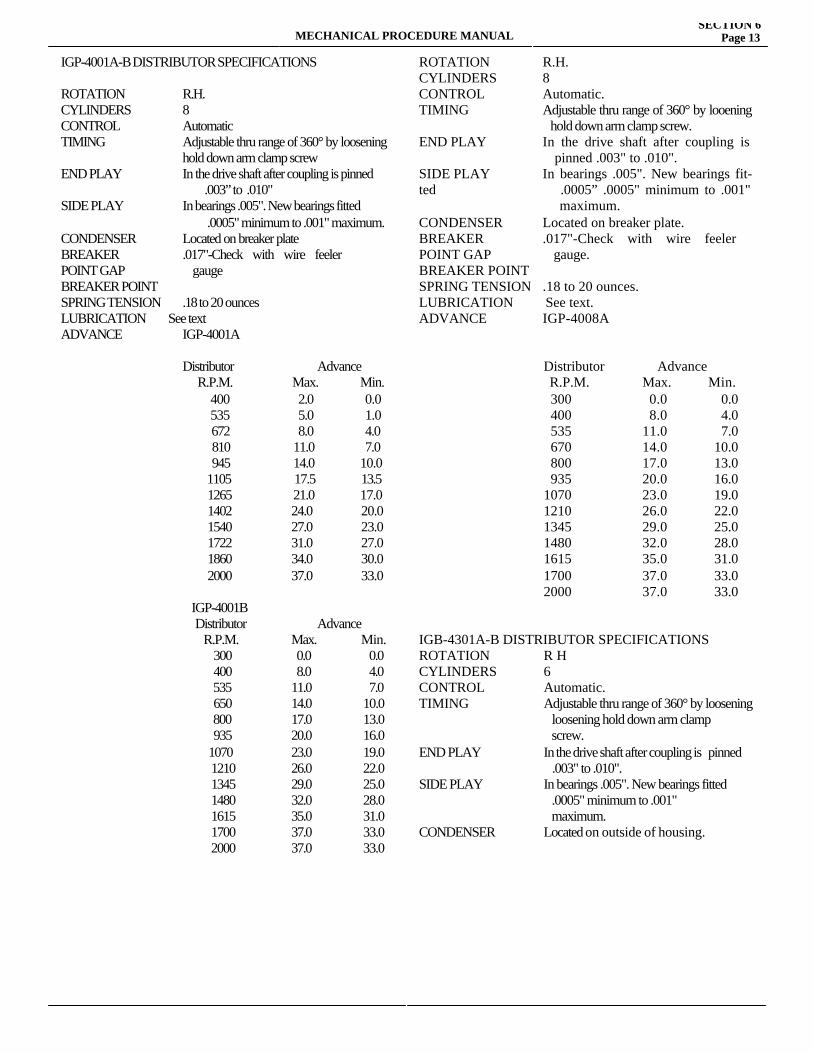
MECHANICAL PROCEDURE MANUALSECTION 6
Page 13
IGP-4001A-B DISTRIBUTOR SPECIFICATIONS
ROTATION R.H. CYLINDERS 8CONTROL AutomaticTIMING Adjustable thru range of 360° by loosening hold down arm clamp screwEND PLAY In the drive shaft after coupling is pinned .003” to .010"SIDE PLAY In bearings .005". New bearings fitted .0005" minimum to .001" maximum.CONDENSER Located on breaker plateBREAKER .017"-Check with wire feelerPOINT GAP gaugeBREAKER POINT SPRING TENSION .18 to 20 ounces LUBRICATION See textADVANCE IGP-4001A
Distributor Advance R.P.M. Max. Min. 400 2.0 0.0 535 5.0 1.0
672 8.0 4.0 810 11.0 7.0 945 14.0 10.0
1105 17.5 13.51265 21.0 17.01402 24.0 20.01540 27.0 23.01722 31.0 27.01860 34.0 30.02000 37.0 33.0
IGP-4001B Distributor Advance R.P.M. Max. Min.
300 0.0 0.0 400 8.0 4.0 535 11.0 7.0 650 14.0 10.0 800 17.0 13.0 935 20.0 16.01070 23.0 19.0 1210 26.0 22.0 1345 29.0 25.0 1480 32.0 28.0 1615 35.0 31.0 1700 37.0 33.0 2000 37.0 33.0
ROTATION R.H.CYLINDERS 8CONTROL Automatic.TIMING Adjustable thru range of 360° by looening hold down arm clamp screw.END PLAY In the drive shaft after coupling is pinned pinned .003" to .010".SIDE PLAY In bearings .005". New bearings fit-ted .0005 .0005” .0005" minimum to .001" maximum maximum.CONDENSER Located on breaker plate.BREAKER .017"-Check with wire feelerPOINT GAP gauge.BREAKER POINT SPRING TENSION .18 to 20 ounces. LUBRICATION See text.ADVANCE IGP-4008A
Distributor Advance R.P.M. Max. Min. 300 0.0 0.0 400 8.0 4.0 535 11.0 7.0 670 14.0 10.0 800 17.0 13.0 935 20.0 16.0 1070 23.0 19.0 1210 26.0 22.0 1345 29.0 25.0 1480 32.0 28.0 1615 35.0 31.0 1700 37.0 33.0 2000 37.0 33.0 IGB-4301A-B DISTRIBUTOR SPECIFICATIONS ROTATION R HCYLINDERS 6CONTROL Automatic.TIMING Adjustable thru range of 360° by loosening loosening hold down arm clamp screw.END PLAY In the drive shaft after coupling is pinned .003" to .010".SIDE PLAY In bearings .005". New bearings fitted .0005" minimum to .001" maximum.CONDENSER Located on outside of housing.
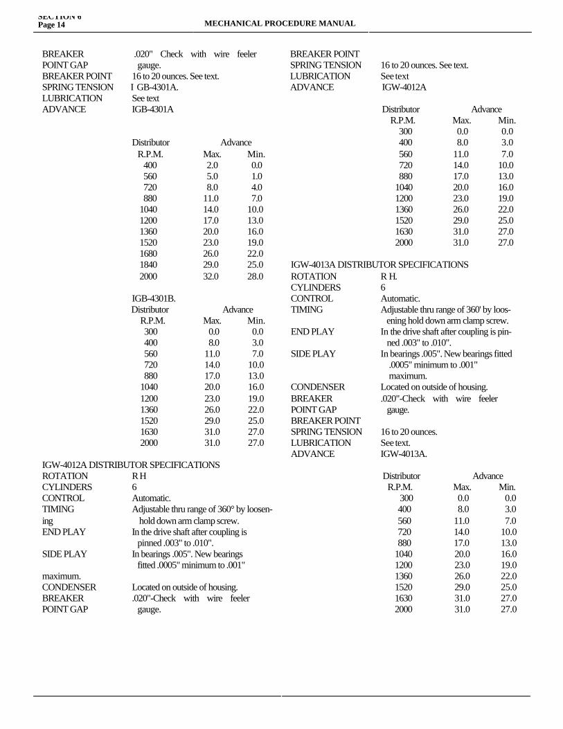
SECTION 6Page 14 MECHANICAL PROCEDURE MANUAL
BREAKER .020" Check with wire feelerPOINT GAP gauge.BREAKER POINT 16 to 20 ounces. See text.SPRING TENSION I GB-4301A.LUBRICATION See textADVANCE IGB-4301A
Distributor Advance R.P.M. Max. Min. 400 2.0 0.0 560 5.0 1.0 720 8.0 4.0 880 11.0 7.0 1040 14.0 10.0 1200 17.0 13.0 1360 20.0 16.0 1520 23.0 19.0 1680 26.0 22.0 1840 29.0 25.0 2000 32.0 28.0
IGB-4301B. Distributor Advance R.P.M. Max. Min. 300 0.0 0.0 400 8.0 3.0 560 11.0 7.0 720 14.0 10.0 880 17.0 13.0 1040 20.0 16.0 1200 23.0 19.0 1360 26.0 22.0 1520 29.0 25.0 1630 31.0 27.0 2000 31.0 27.0
IGW-4012A DISTRIBUTOR SPECIFICATIONS ROTATION R HCYLINDERS 6CONTROL Automatic.TIMING Adjustable thru range of 360° by loosen-ing hold down arm clamp screw.END PLAY In the drive shaft after coupling is pinned .003" to .010".SIDE PLAY In bearings .005". New bearings fitted .0005" minimum to .001" maximum.CONDENSER Located on outside of housing.BREAKER .020"-Check with wire feelerPOINT GAP gauge.
BREAKER POINTSPRING TENSION 16 to 20 ounces. See text.LUBRICATION See textADVANCE IGW-4012A
Distributor Advance R.P.M. Max. Min.
300 0.0 0.0 400 8.0 3.0 560 11.0 7.0 720 14.0 10.0 880 17.0 13.01040 20.0 16.01200 23.0 19.01360 26.0 22.01520 29.0 25.01630 31.0 27.02000 31.0 27.0
IGW-4013A DISTRIBUTOR SPECIFICATIONS ROTATION R H.CYLINDERS 6CONTROL Automatic.TIMING Adjustable thru range of 360' by loos- ening hold down arm clamp screw.END PLAY In the drive shaft after coupling is pin- ned .003" to .010".SIDE PLAY In bearings .005". New bearings fitted .0005" minimum to .001" maximum.CONDENSER Located on outside of housing.BREAKER .020"-Check with wire feelerPOINT GAP gauge.BREAKER POINT SPRING TENSION 16 to 20 ounces.LUBRICATION See text.ADVANCE IGW-4013A. Distributor Advance R.P.M. Max. Min.
300 0.0 0.0 400 8.0 3.0 560 11.0 7.0 720 14.0 10.0 880 17.0 13.0 1040 20.0 16.0 1200 23.0 19.0 1360 26.0 22.0 1520 29.0 25.0 1630 31.0 27.0 2000 31.0 27.0
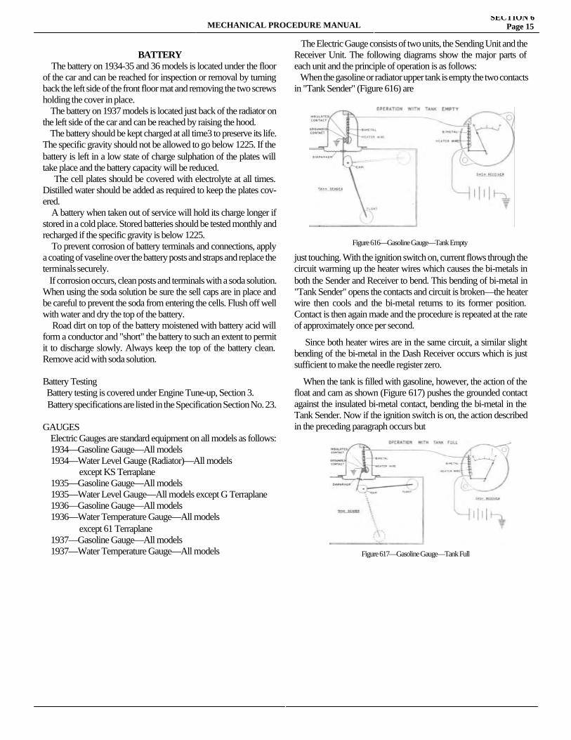
MECHANICAL PROCEDURE MANUALSECTION 6
Page 15
BATTERY The battery on 1934-35 and 36 models is located under the floor of the car and can be reached for inspection or removal by turning back the left side of the front floor mat and removing the two screws holding the cover in place. The battery on 1937 models is located just back of the radiator on the left side of the car and can be reached by raising the hood. The battery should be kept charged at all time3 to preserve its life. The specific gravity should not be allowed to go below 1225. If the battery is left in a low state of charge sulphation of the plates will take place and the battery capacity will be reduced. The cell plates should be covered with electrolyte at all times. Distilled water should be added as required to keep the plates cov-ered. A battery when taken out of service will hold its charge longer if stored in a cold place. Stored batteries should be tested monthly and recharged if the specific gravity is below 1225. To prevent corrosion of battery terminals and connections, apply a coating of vaseline over the battery posts and straps and replace the terminals securely. If corrosion occurs, clean posts and terminals with a soda solution. When using the soda solution be sure the sell caps are in place and be careful to prevent the soda from entering the cells. Flush off well with water and dry the top of the battery. Road dirt on top of the battery moistened with battery acid will form a conductor and "short" the battery to such an extent to permit it to discharge slowly. Always keep the top of the battery clean. Remove acid with soda solution.
Battery Testing Battery testing is covered under Engine Tune-up, Section 3. Battery specifications are listed in the Specification Section No. 23.
GAUGES Electric Gauges are standard equipment on all models as follows: 1934—Gasoline Gauge—All models 1934—Water Level Gauge (Radiator)—All models except KS Terraplane 1935—Gasoline Gauge—All models 1935—Water Level Gauge—All models except G Terraplane 1936—Gasoline Gauge—All models 1936—Water Temperature Gauge—All models except 61 Terraplane 1937—Gasoline Gauge—All models 1937—Water Temperature Gauge—All models
The Electric Gauge consists of two units, the Sending Unit and the Receiver Unit. The following diagrams show the major parts of each unit and the principle of operation is as follows: When the gasoline or radiator upper tank is empty the two contacts in "Tank Sender" (Figure 616) are
just touching. With the ignition switch on, current flows through the circuit warming up the heater wires which causes the bi-metals in both the Sender and Receiver to bend. This bending of bi-metal in "Tank Sender" opens the contacts and circuit is broken—the heater wire then cools and the bi-metal returns to its former position. Contact is then again made and the procedure is repeated at the rate of approximately once per second.
Since both heater wires are in the same circuit, a similar slight bending of the bi-metal in the Dash Receiver occurs which is just sufficient to make the needle register zero.
When the tank is filled with gasoline, however, the action of the float and cam as shown (Figure 617) pushes the grounded contact against the insulated bi-metal contact, bending the bi-metal in the Tank Sender. Now if the ignition switch is on, the action described in the preceding paragraph occurs but
Figure 616—Gasoline Gauge—Tank Empty
Figure 617—Gasoline Gauge—Tank Full
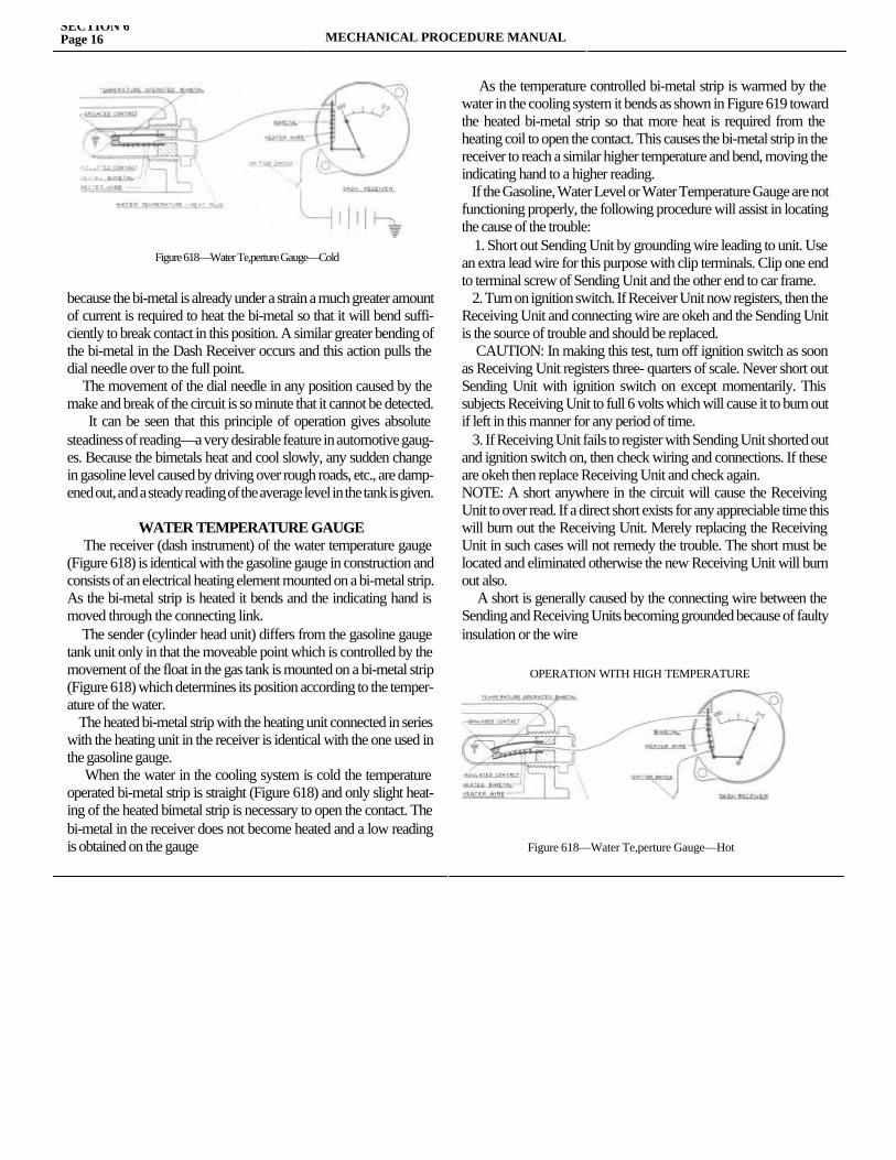
SECTION 6Page 16 MECHANICAL PROCEDURE MANUAL
because the bi-metal is already under a strain a much greater amount of current is required to heat the bi-metal so that it will bend suffi-ciently to break contact in this position. A similar greater bending of the bi-metal in the Dash Receiver occurs and this action pulls the dial needle over to the full point. The movement of the dial needle in any position caused by the make and break of the circuit is so minute that it cannot be detected. It can be seen that this principle of operation gives absolute steadiness of reading—a very desirable feature in automotive gaug-es. Because the bimetals heat and cool slowly, any sudden change in gasoline level caused by driving over rough roads, etc., are damp-ened out, and a steady reading of the average level in the tank is given.
WATER TEMPERATURE GAUGE The receiver (dash instrument) of the water temperature gauge (Figure 618) is identical with the gasoline gauge in construction and consists of an electrical heating element mounted on a bi-metal strip. As the bi-metal strip is heated it bends and the indicating hand is moved through the connecting link. The sender (cylinder head unit) differs from the gasoline gauge tank unit only in that the moveable point which is controlled by the movement of the float in the gas tank is mounted on a bi-metal strip (Figure 618) which determines its position according to the temper-ature of the water. The heated bi-metal strip with the heating unit connected in series with the heating unit in the receiver is identical with the one used in the gasoline gauge. When the water in the cooling system is cold the temperature operated bi-metal strip is straight (Figure 618) and only slight heat-ing of the heated bimetal strip is necessary to open the contact. The bi-metal in the receiver does not become heated and a low reading is obtained on the gauge
As the temperature controlled bi-metal strip is warmed by the water in the cooling system it bends as shown in Figure 619 toward the heated bi-metal strip so that more heat is required from the heating coil to open the contact. This causes the bi-metal strip in the receiver to reach a similar higher temperature and bend, moving the indicating hand to a higher reading. If the Gasoline, Water Level or Water Temperature Gauge are not functioning properly, the following procedure will assist in locating the cause of the trouble: 1. Short out Sending Unit by grounding wire leading to unit. Use an extra lead wire for this purpose with clip terminals. Clip one end to terminal screw of Sending Unit and the other end to car frame. 2. Turn on ignition switch. If Receiver Unit now registers, then the Receiving Unit and connecting wire are okeh and the Sending Unit is the source of trouble and should be replaced. CAUTION: In making this test, turn off ignition switch as soon as Receiving Unit registers three- quarters of scale. Never short out Sending Unit with ignition switch on except momentarily. This subjects Receiving Unit to full 6 volts which will cause it to burn out if left in this manner for any period of time. 3. If Receiving Unit fails to register with Sending Unit shorted out and ignition switch on, then check wiring and connections. If these are okeh then replace Receiving Unit and check again.NOTE: A short anywhere in the circuit will cause the Receiving Unit to over read. If a direct short exists for any appreciable time this will burn out the Receiving Unit. Merely replacing the Receiving Unit in such cases will not remedy the trouble. The short must be located and eliminated otherwise the new Receiving Unit will burn out also. A short is generally caused by the connecting wire between the Sending and Receiving Units becoming grounded because of faulty insulation or the wire
Figure 618—Water Te,perture Gauge—Cold
OPERATION WITH HIGH TEMPERATURE
Figure 618—Water Te,perture Gauge—Hot
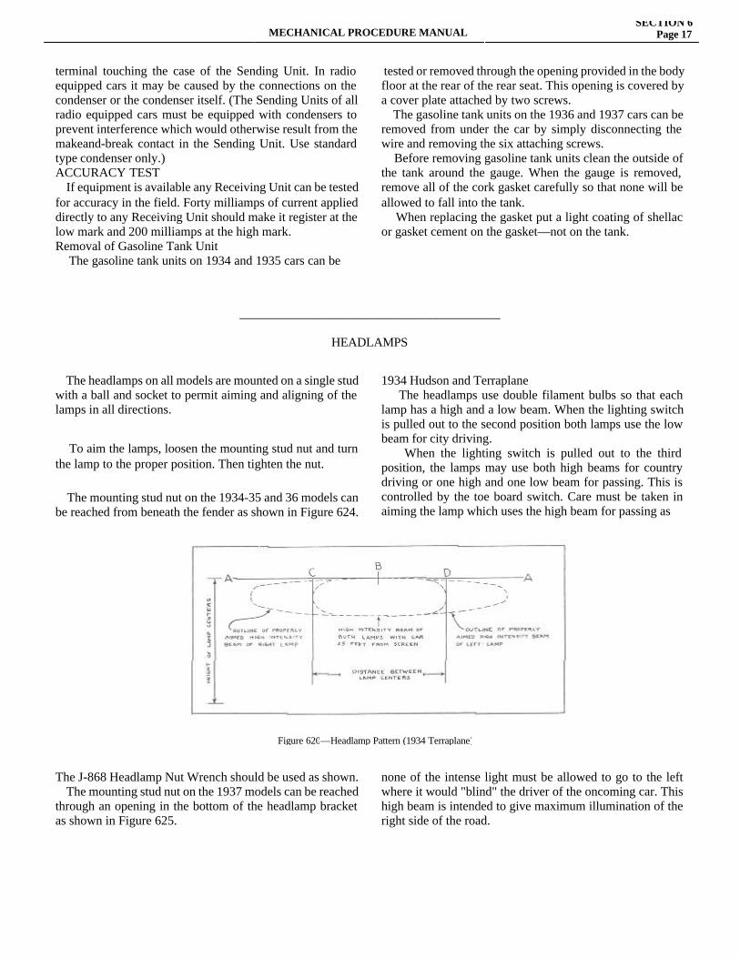
MECHANICAL PROCEDURE MANUALSECTION 6
Page 17
terminal touching the case of the Sending Unit. In radio equipped cars it may be caused by the connections on the condenser or the condenser itself. (The Sending Units of all radio equipped cars must be equipped with condensers to prevent interference which would otherwise result from the makeand-break contact in the Sending Unit. Use standard type condenser only.)ACCURACY TEST If equipment is available any Receiving Unit can be tested for accuracy in the field. Forty milliamps of current applied directly to any Receiving Unit should make it register at the low mark and 200 milliamps at the high mark.Removal of Gasoline Tank Unit The gasoline tank units on 1934 and 1935 cars can be
tested or removed through the opening provided in the body floor at the rear of the rear seat. This opening is covered by a cover plate attached by two screws. The gasoline tank units on the 1936 and 1937 cars can be removed from under the car by simply disconnecting the wire and removing the six attaching screws. Before removing gasoline tank units clean the outside of the tank around the gauge. When the gauge is removed, remove all of the cork gasket carefully so that none will be allowed to fall into the tank. When replacing the gasket put a light coating of shellac or gasket cement on the gasket—not on the tank.
_________________________________________
HEADLAMPS
The headlamps on all models are mounted on a single stud with a ball and socket to permit aiming and aligning of the lamps in all directions.
To aim the lamps, loosen the mounting stud nut and turn the lamp to the proper position. Then tighten the nut.
The mounting stud nut on the 1934-35 and 36 models can be reached from beneath the fender as shown in Figure 624.
1934 Hudson and Terraplane The headlamps use double filament bulbs so that each lamp has a high and a low beam. When the lighting switch is pulled out to the second position both lamps use the low beam for city driving. When the lighting switch is pulled out to the third position, the lamps may use both high beams for country driving or one high and one low beam for passing. This is controlled by the toe board switch. Care must be taken in aiming the lamp which uses the high beam for passing as
The J-868 Headlamp Nut Wrench should be used as shown. The mounting stud nut on the 1937 models can be reached through an opening in the bottom of the headlamp bracket as shown in Figure 625.
none of the intense light must be allowed to go to the left where it would "blind" the driver of the oncoming car. This high beam is intended to give maximum illumination of the right side of the road.
Figure 620—Headlamp Pattern (1934 Terraplane)
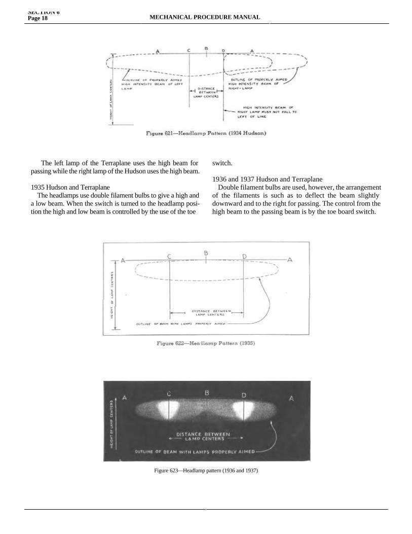
SECTION 6Page 18 MECHANICAL PROCEDURE MANUAL
The left lamp of the Terraplane uses the high beam for passing while the right lamp of the Hudson uses the high beam.
1935 Hudson and Terraplane The headlamps use double filament bulbs to give a high and a low beam. When the switch is turned to the headlamp posi-tion the high and low beam is controlled by the use of the toe
switch.
1936 and 1937 Hudson and Terraplane Double filament bulbs are used, however, the arrangement of the filaments is such as to deflect the beam slightly downward and to the right for passing. The control from the high beam to the passing beam is by the toe board switch.
Figure 623—Headlamp pattern (1936 and 1937)
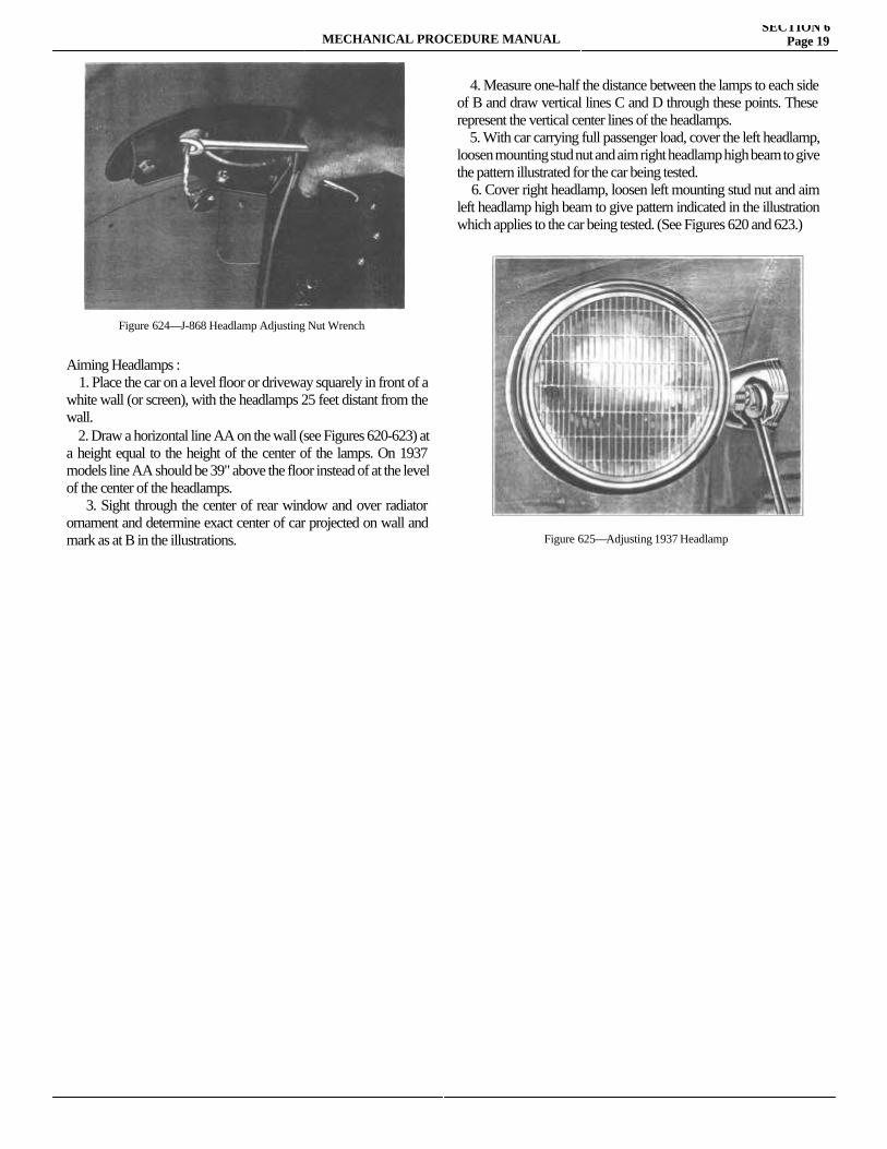
MECHANICAL PROCEDURE MANUALSECTION 6
Page 19
Aiming Headlamps : 1. Place the car on a level floor or driveway squarely in front of a white wall (or screen), with the headlamps 25 feet distant from the wall. 2. Draw a horizontal line AA on the wall (see Figures 620-623) at a height equal to the height of the center of the lamps. On 1937 models line AA should be 39" above the floor instead of at the level of the center of the headlamps. 3. Sight through the center of rear window and over radiator ornament and determine exact center of car projected on wall and mark as at B in the illustrations.
4. Measure one-half the distance between the lamps to each side of B and draw vertical lines C and D through these points. These represent the vertical center lines of the headlamps. 5. With car carrying full passenger load, cover the left headlamp, loosen mounting stud nut and aim right headlamp high beam to give the pattern illustrated for the car being tested. 6. Cover right headlamp, loosen left mounting stud nut and aim left headlamp high beam to give pattern indicated in the illustration which applies to the car being tested. (See Figures 620 and 623.)
Figure 624—J-868 Headlamp Adjusting Nut Wrench
Figure 625—Adjusting 1937 Headlamp
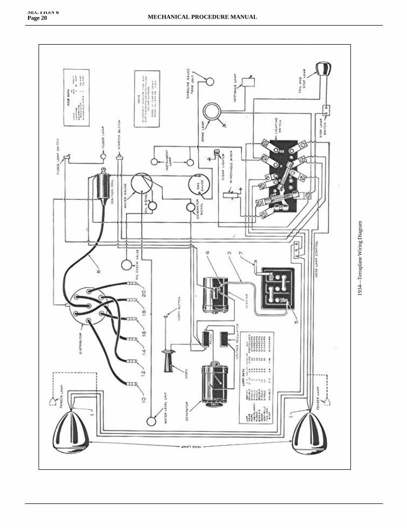
SECTION 6Page 20 MECHANICAL PROCEDURE MANUAL
1934
—Te
rrap
lane
Wiri
ng D
iagr
am
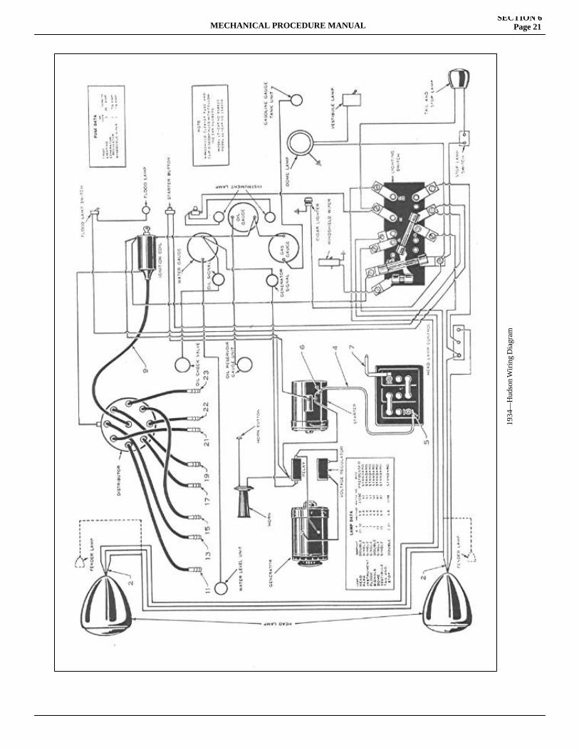
MECHANICAL PROCEDURE MANUALSECTION 6
Page 21
1934
—H
udso
n W
iring
Dia
gram
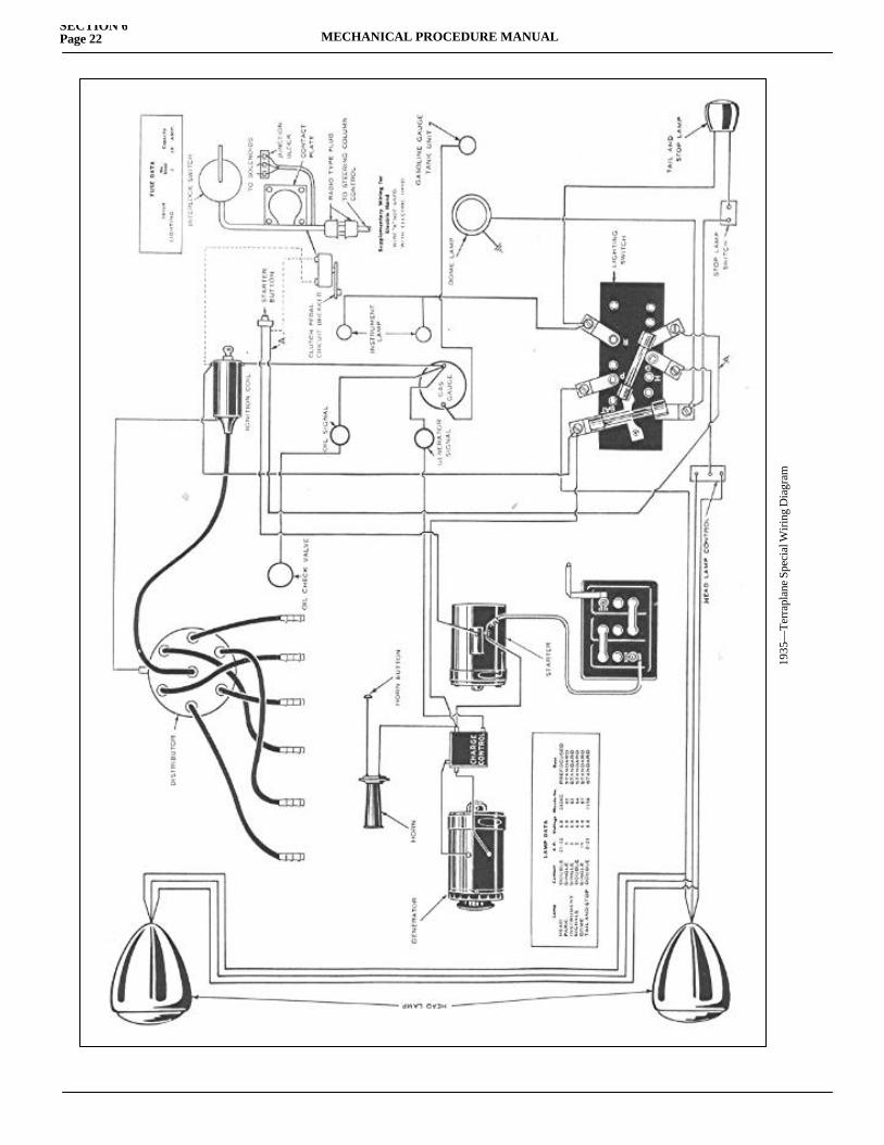
SECTION 6Page 22 MECHANICAL PROCEDURE MANUAL
1935
—Te
rrap
lane
Spe
cial
Wiri
ng D
iagr
am
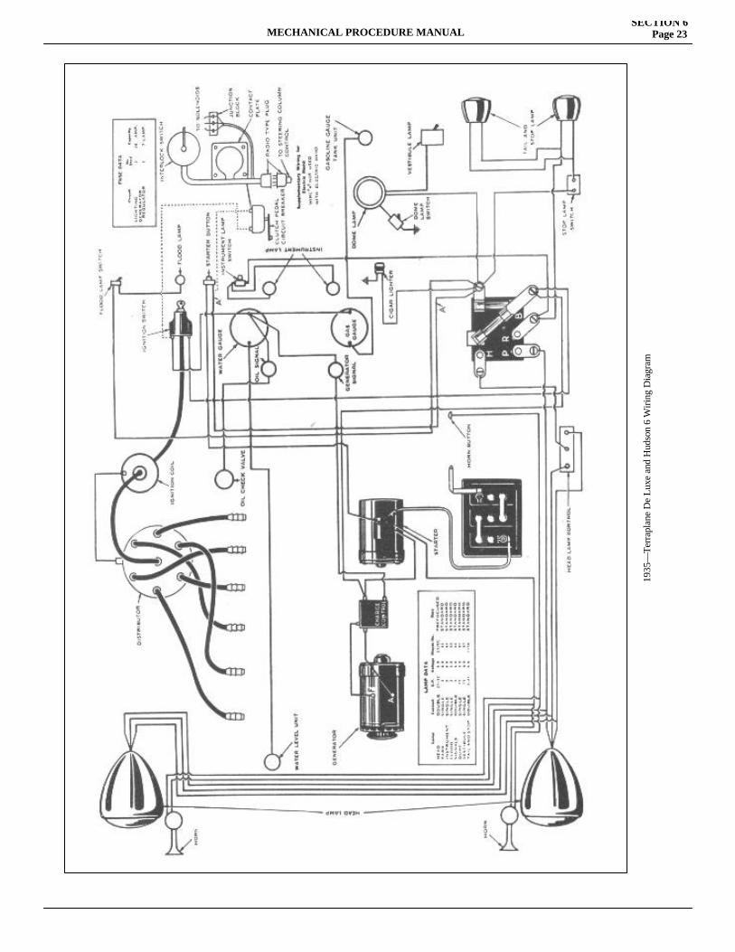
MECHANICAL PROCEDURE MANUALSECTION 6
Page 23
1935
—Te
rrap
lane
De
Luxe
and
Hud
son
6 W
iring
Dia
gram
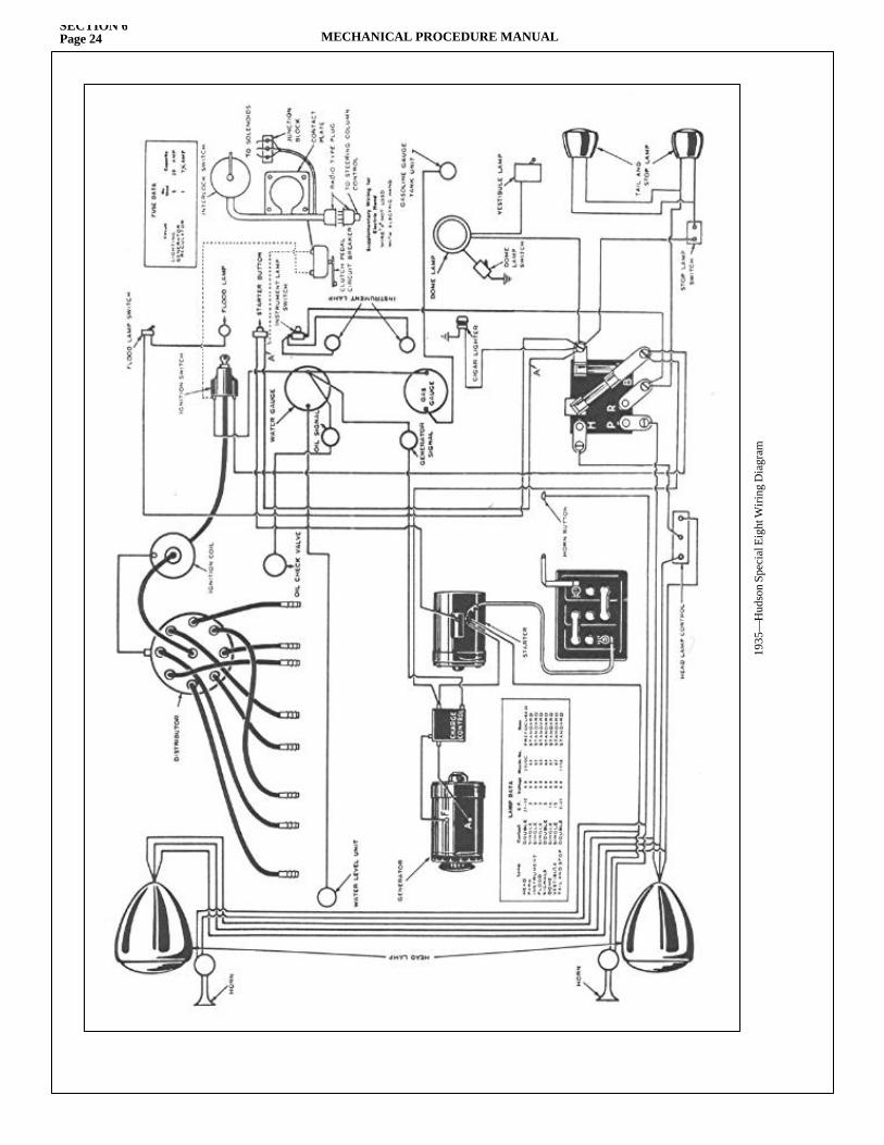
SECTION 6Page 24 MECHANICAL PROCEDURE MANUAL
1935
—H
udso
n Sp
ecia
l Eig
ht W
iring
Dia
gram
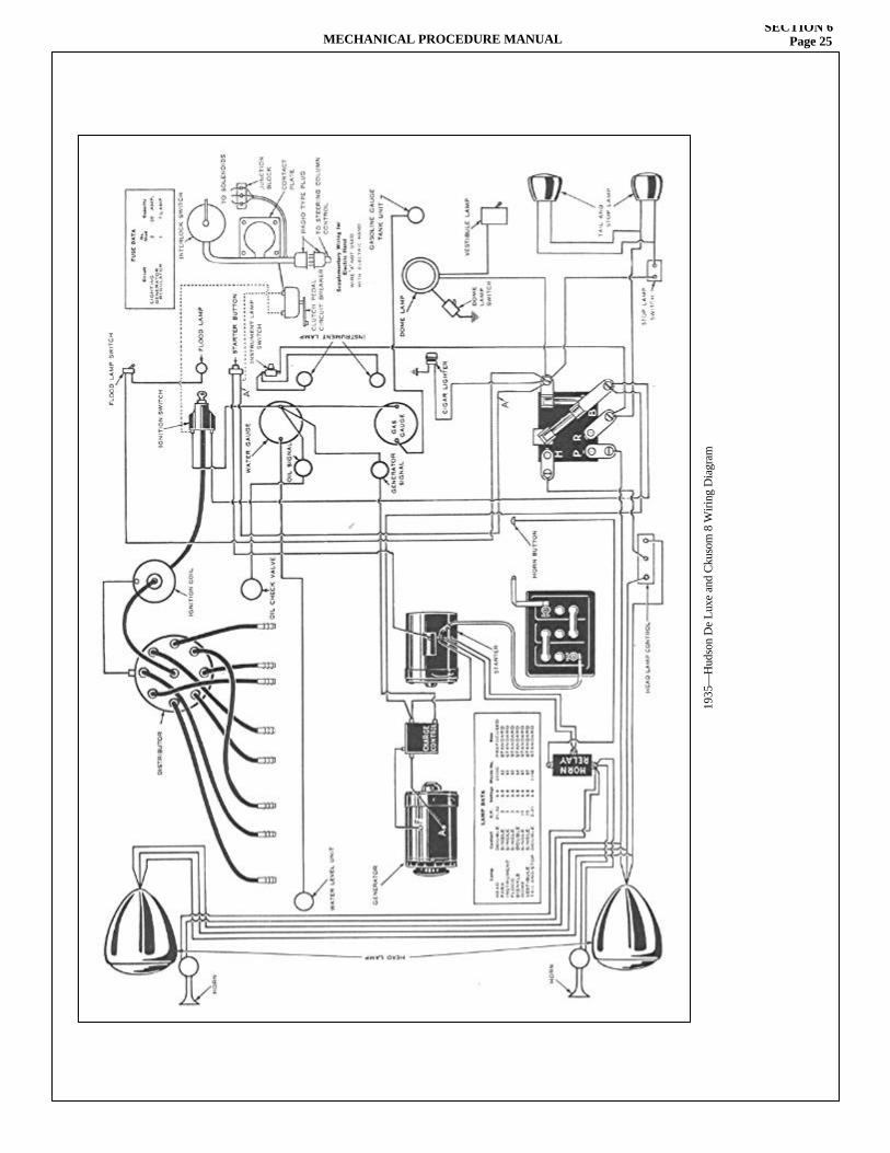
MECHANICAL PROCEDURE MANUALSECTION 6
Page 25
1935
—H
udso
n D
e Lu
xe a
nd C
kuso
m 8
Wiri
ng D
iagr
am
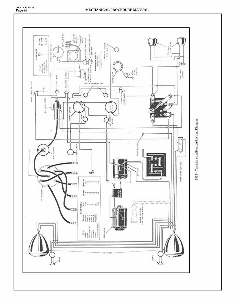
SECTION 6Page 26 MECHANICAL PROCEDURE MANUAL
1935
—Te
rrap
lane
and
Hud
son
6 W
iring
Dia
gram
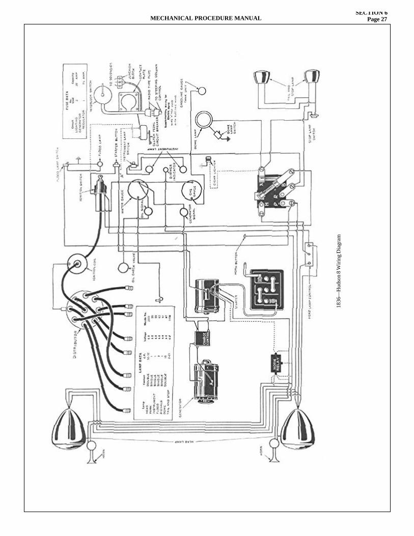
MECHANICAL PROCEDURE MANUALSECTION 6
Page 27
1836
—H
udso
n 8
Wiri
ng D
iagr
am
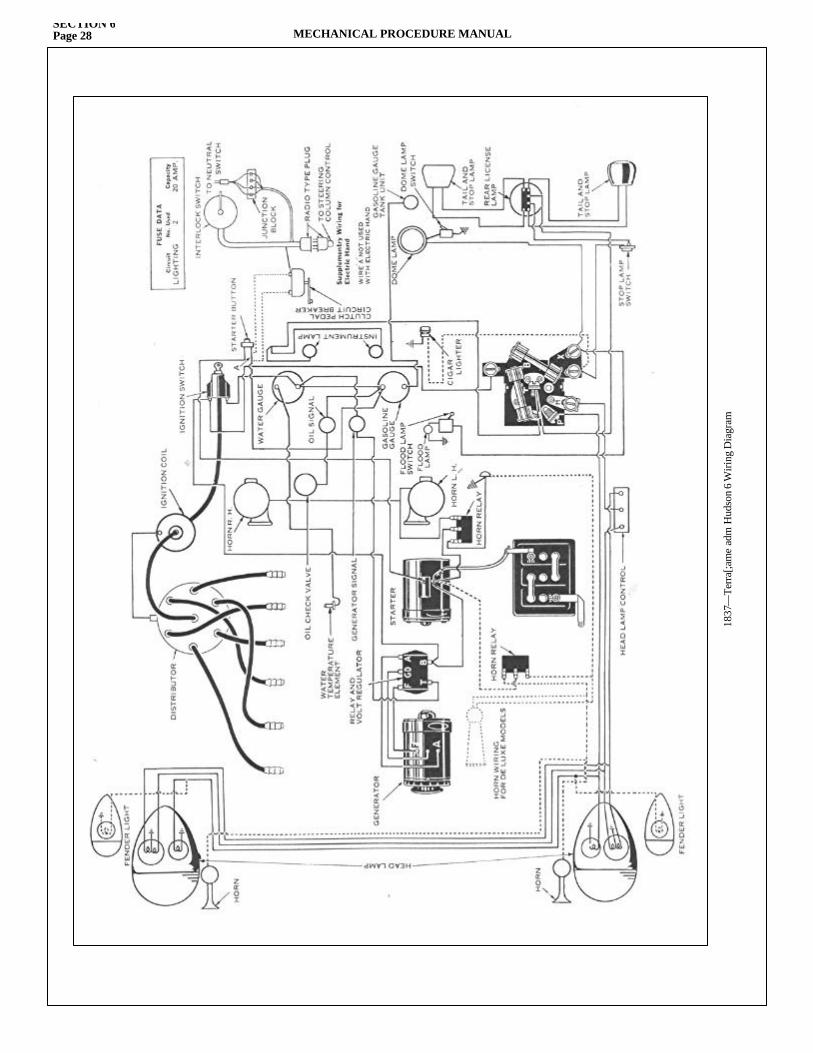
SECTION 6Page 28 MECHANICAL PROCEDURE MANUAL
1837
—Te
rra[
;am
e ad
m H
udso
n 6
Wiri
ng D
iagr
am
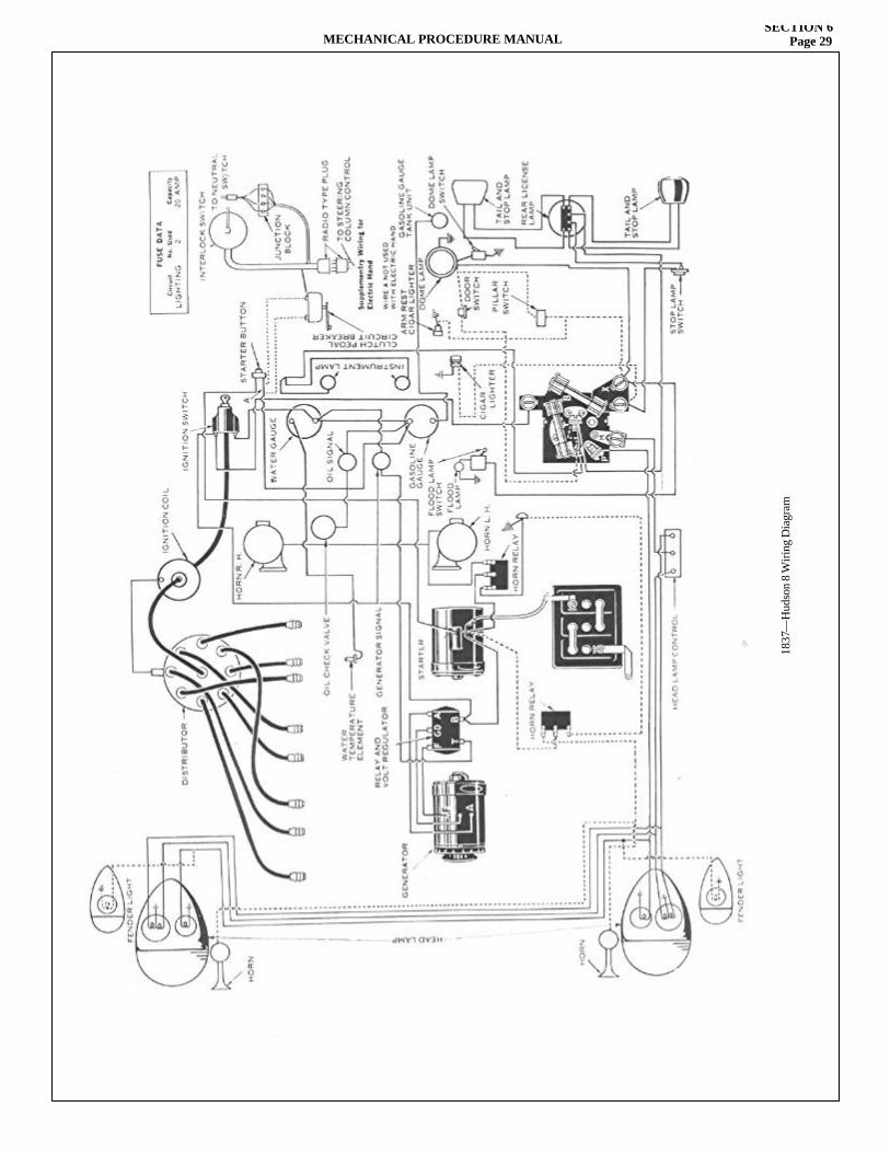
MECHANICAL PROCEDURE MANUALSECTION 6
Page 29
1837
—H
udso
n 8
Wiri
ng D
iagr
am


SECTION 7
ENGINEService Magazine—Reference Sheet and Service Bullet in Reference
Bulletin orReference SheetNo. MagazineIssue and Page
Date Subject DETAILS OF INFORMATION
MECHANICAL PROCEDURE MANUAL Page 1

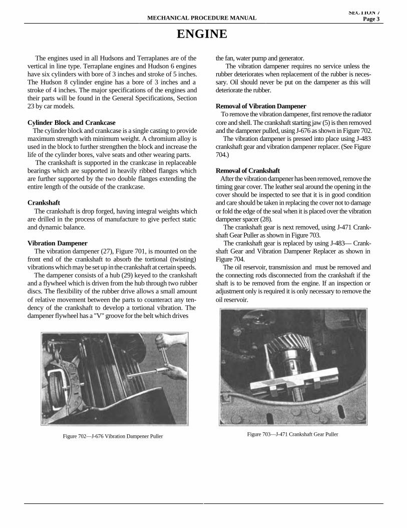
MECHANICAL PROCEDURE MANUALSECTION 7
Page 3
ENGINE
The engines used in all Hudsons and Terraplanes are of the vertical in line type. Terraplane engines and Hudson 6 engines have six cylinders with bore of 3 inches and stroke of 5 inches. The Hudson 8 cylinder engine has a bore of 3 inches and a stroke of 4 inches. The major specifications of the engines and their parts will be found in the General Specifications, Section 23 by car models.
Cylinder Block and Crankcase The cylinder block and crankcase is a single casting to provide maximum strength with minimum weight. A chromium alloy is used in the block to further strengthen the block and increase the life of the cylinder bores, valve seats and other wearing parts. The crankshaft is supported in the crankcase in replaceable bearings which are supported in heavily ribbed flanges which are further supported by the two double flanges extending the entire length of the outside of the crankcase.
Crankshaft The crankshaft is drop forged, having integral weights which are drilled in the process of manufacture to give perfect static and dynamic balance.
Vibration Dampener The vibration dampener (27), Figure 701, is mounted on the front end of the crankshaft to absorb the tortional (twisting) vibrations which may be set up in the crankshaft at certain speeds. The dampener consists of a hub (29) keyed to the crankshaft and a flywheel which is driven from the hub through two rubber discs. The flexibility of the rubber drive allows a small amount of relative movement between the parts to counteract any ten-dency of the crankshaft to develop a tortional vibration. The dampener flywheel has a "V" groove for the belt which drivesthe
the fan, water pump and generator. The vibration dampener requires no service unless the rubber deteriorates when replacement of the rubber is neces-sary. Oil should never be put on the dampener as this will deteriorate the rubber.
Removal of Vibration Dampener To remove the vibration dampener, first remove the radiator core and shell. The crankshaft starting jaw (5) is then removed and the dampener pulled, using J-676 as shown in Figure 702. The vibration dampener is pressed into place using J-483 crankshaft gear and vibration dampener replacer. (See Figure 704.)
Removal of Crankshaft After the vibration dampener has been removed, remove the timing gear cover. The leather seal around the opening in the cover should be inspected to see that it is in good condition and care should be taken in replacing the cover not to damage or fold the edge of the seal when it is placed over the vibration dampener spacer (28). The crankshaft gear is next removed, using J-471 Crank-shaft Gear Puller as shown in Figure 703. The crankshaft gear is replaced by using J-483— Crank-shaft Gear and Vibration Dampener Replacer as shown in Figure 704. The oil reservoir, transmission and must be removed and the connecting rods disconnected from the crankshaft if the shaft is to be removed from the engine. If an inspection or adjustment only is required it is only necessary to remove the oil reservoir.
Figure 702—J-676 Vibration Dampener Puller Figure 703—J-471 Crankshaft Gear Puller
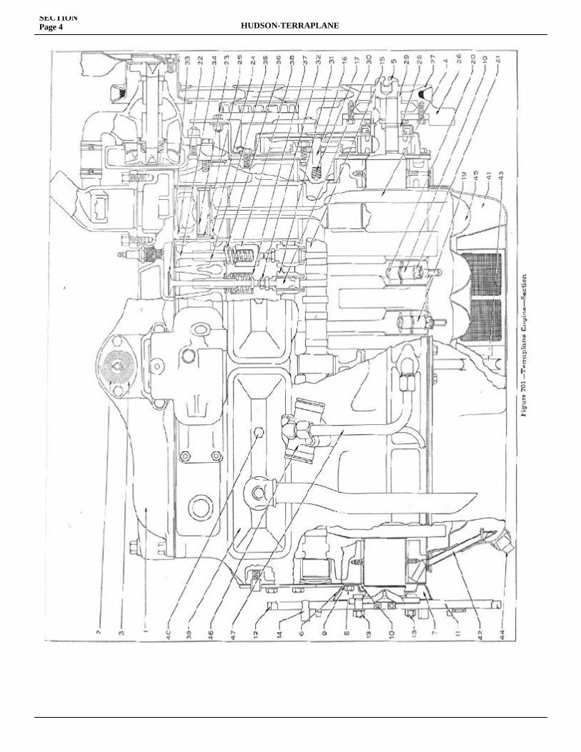
SECTION Page 4 HUDSON-TERRAPLANE
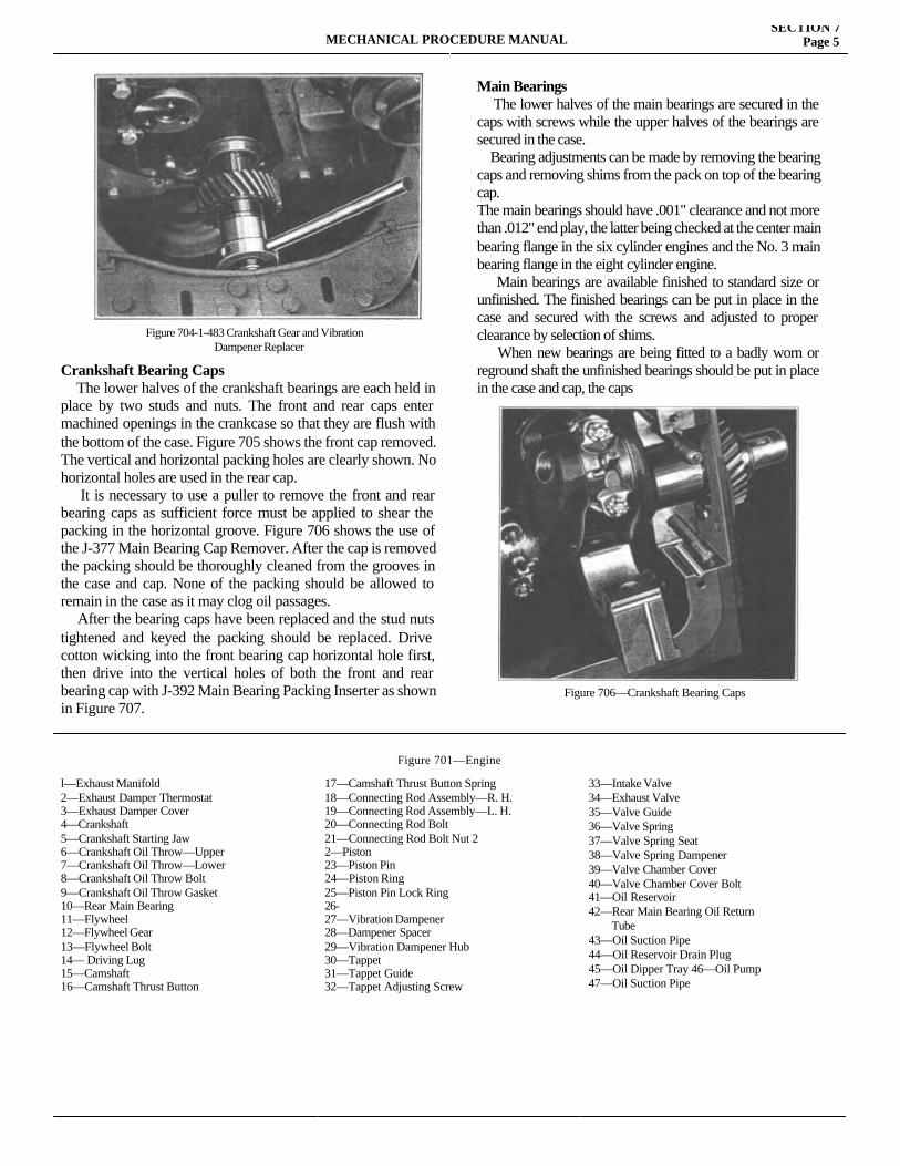
MECHANICAL PROCEDURE MANUALSECTION 7
Page 5
Crankshaft Bearing Caps The lower halves of the crankshaft bearings are each held in place by two studs and nuts. The front and rear caps enter machined openings in the crankcase so that they are flush with the bottom of the case. Figure 705 shows the front cap removed. The vertical and horizontal packing holes are clearly shown. No horizontal holes are used in the rear cap. It is necessary to use a puller to remove the front and rear bearing caps as sufficient force must be applied to shear the packing in the horizontal groove. Figure 706 shows the use of the J-377 Main Bearing Cap Remover. After the cap is removed the packing should be thoroughly cleaned from the grooves in the case and cap. None of the packing should be allowed to remain in the case as it may clog oil passages. After the bearing caps have been replaced and the stud nuts tightened and keyed the packing should be replaced. Drive cotton wicking into the front bearing cap horizontal hole first, then drive into the vertical holes of both the front and rear bearing cap with J-392 Main Bearing Packing Inserter as shown in Figure 707.
Main Bearings The lower halves of the main bearings are secured in the caps with screws while the upper halves of the bearings are secured in the case. Bearing adjustments can be made by removing the bearing caps and removing shims from the pack on top of the bearing cap.The main bearings should have .001" clearance and not more than .012" end play, the latter being checked at the center main bearing flange in the six cylinder engines and the No. 3 main bearing flange in the eight cylinder engine. Main bearings are available finished to standard size or unfinished. The finished bearings can be put in place in the case and secured with the screws and adjusted to proper clearance by selection of shims. When new bearings are being fitted to a badly worn or reground shaft the unfinished bearings should be put in place in the case and cap, the caps
Figure 704-1-483 Crankshaft Gear and VibrationDampener Replacer
Figure 706—Crankshaft Bearing Caps
Figure 701—Engine
l—Exhaust Manifold2—Exhaust Damper Thermostat3—Exhaust Damper Cover4—Crankshaft5—Crankshaft Starting Jaw6—Crankshaft Oil Throw—Upper7—Crankshaft Oil Throw—Lower8—Crankshaft Oil Throw Bolt9—Crankshaft Oil Throw Gasket10—Rear Main Bearing11—Flywheel12—Flywheel Gear13—Flywheel Bolt14— Driving Lug15—Camshaft16—Camshaft Thrust Button
17—Camshaft Thrust Button Spring18—Connecting Rod Assembly—R. H.19—Connecting Rod Assembly—L. H.20—Connecting Rod Bolt21—Connecting Rod Bolt Nut 22—Piston23—Piston Pin24—Piston Ring25—Piston Pin Lock Ring26-27—Vibration Dampener28—Dampener Spacer29—Vibration Dampener Hub30—Tappet31—Tappet Guide32—Tappet Adjusting Screw
33—Intake Valve34—Exhaust Valve 35—Valve Guide 36—Valve Spring 37—Valve Spring Seat38—Valve Spring Dampener 39—Valve Chamber Cover40—Valve Chamber Cover Bolt 41—Oil Reservoir42—Rear Main Bearing Oil Return Tube43—Oil Suction Pipe44—Oil Reservoir Drain Plug45—Oil Dipper Tray 46—Oil Pump47—Oil Suction Pipe
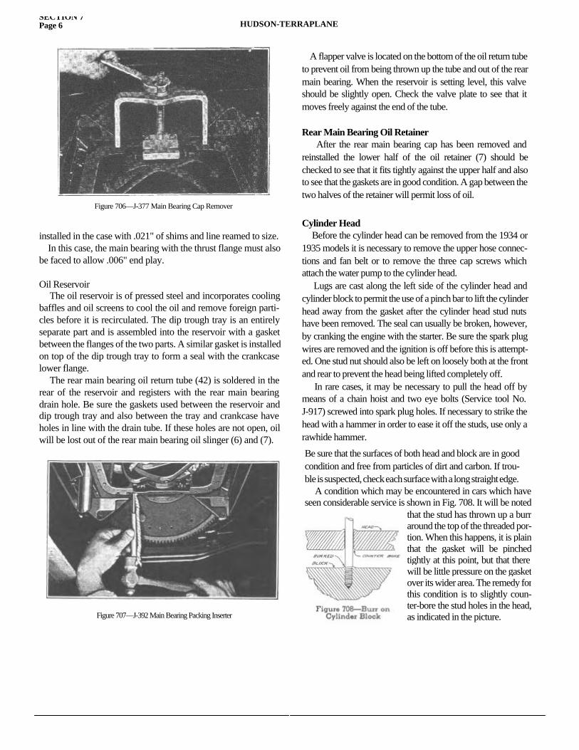
SECTION 7Page 6 HUDSON-TERRAPLANE
installed in the case with .021" of shims and line reamed to size. In this case, the main bearing with the thrust flange must also be faced to allow .006" end play.
Oil Reservoir The oil reservoir is of pressed steel and incorporates cooling baffles and oil screens to cool the oil and remove foreign parti-cles before it is recirculated. The dip trough tray is an entirely separate part and is assembled into the reservoir with a gasket between the flanges of the two parts. A similar gasket is installed on top of the dip trough tray to form a seal with the crankcase lower flange. The rear main bearing oil return tube (42) is soldered in the rear of the reservoir and registers with the rear main bearing drain hole. Be sure the gaskets used between the reservoir and dip trough tray and also between the tray and crankcase have holes in line with the drain tube. If these holes are not open, oil will be lost out of the rear main bearing oil slinger (6) and (7).
A flapper valve is located on the bottom of the oil return tube to prevent oil from being thrown up the tube and out of the rear main bearing. When the reservoir is setting level, this valve should be slightly open. Check the valve plate to see that it moves freely against the end of the tube.
Rear Main Bearing Oil Retainer After the rear main bearing cap has been removed and reinstalled the lower half of the oil retainer (7) should be checked to see that it fits tightly against the upper half and also to see that the gaskets are in good condition. A gap between the two halves of the retainer will permit loss of oil.
Cylinder Head Before the cylinder head can be removed from the 1934 or 1935 models it is necessary to remove the upper hose connec-tions and fan belt or to remove the three cap screws which attach the water pump to the cylinder head. Lugs are cast along the left side of the cylinder head and cylinder block to permit the use of a pinch bar to lift the cylinder head away from the gasket after the cylinder head stud nuts have been removed. The seal can usually be broken, however, by cranking the engine with the starter. Be sure the spark plug wires are removed and the ignition is off before this is attempt-ed. One stud nut should also be left on loosely both at the front and rear to prevent the head being lifted completely off. In rare cases, it may be necessary to pull the head off by means of a chain hoist and two eye bolts (Service tool No. J-917) screwed into spark plug holes. If necessary to strike the head with a hammer in order to ease it off the studs, use only a rawhide hammer.
Figure 706—J-377 Main Bearing Cap Remover
Figure 707—J-392 Main Bearing Packing Inserter
Be sure that the surfaces of both head and block are in good condition and free from particles of dirt and carbon. If trou-ble is suspected, check each surface with a long straight edge. A condition which may be encountered in cars which have seen considerable service is shown in Fig. 708. It will be noted
that the stud has thrown up a burr around the top of the threaded por-tion. When this happens, it is plain that the gasket will be pinched tightly at this point, but that there will be little pressure on the gasket over its wider area. The remedy for this condition is to slightly coun-ter-bore the stud holes in the head, as indicated in the picture.
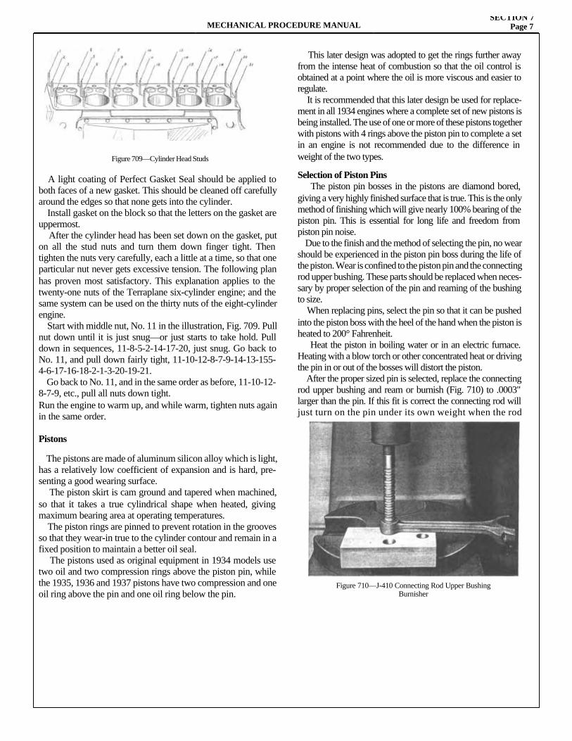
MECHANICAL PROCEDURE MANUALSECTION 7
Page 7
A light coating of Perfect Gasket Seal should be applied to both faces of a new gasket. This should be cleaned off carefully around the edges so that none gets into the cylinder. Install gasket on the block so that the letters on the gasket are uppermost. After the cylinder head has been set down on the gasket, put on all the stud nuts and turn them down finger tight. Then tighten the nuts very carefully, each a little at a time, so that one particular nut never gets excessive tension. The following plan has proven most satisfactory. This explanation applies to the twenty-one nuts of the Terraplane six-cylinder engine; and the same system can be used on the thirty nuts of the eight-cylinder engine. Start with middle nut, No. 11 in the illustration, Fig. 709. Pull nut down until it is just snug—or just starts to take hold. Pull down in sequences, 11-8-5-2-14-17-20, just snug. Go back to No. 11, and pull down fairly tight, 11-10-12-8-7-9-14-13-155-4-6-17-16-18-2-1-3-20-19-21. Go back to No. 11, and in the same order as before, 11-10-12-8-7-9, etc., pull all nuts down tight.Run the engine to warm up, and while warm, tighten nuts again in the same order.
Pistons
The pistons are made of aluminum silicon alloy which is light, has a relatively low coefficient of expansion and is hard, pre-senting a good wearing surface. The piston skirt is cam ground and tapered when machined, so that it takes a true cylindrical shape when heated, giving maximum bearing area at operating temperatures. The piston rings are pinned to prevent rotation in the grooves so that they wear-in true to the cylinder contour and remain in a fixed position to maintain a better oil seal. The pistons used as original equipment in 1934 models use two oil and two compression rings above the piston pin, while the 1935, 1936 and 1937 pistons have two compression and one oil ring above the pin and one oil ring below the pin.
This later design was adopted to get the rings further away from the intense heat of combustion so that the oil control is obtained at a point where the oil is more viscous and easier to regulate. It is recommended that this later design be used for replace-ment in all 1934 engines where a complete set of new pistons is being installed. The use of one or more of these pistons together with pistons with 4 rings above the piston pin to complete a set in an engine is not recommended due to the difference in weight of the two types.
Selection of Piston Pins The piston pin bosses in the pistons are diamond bored, giving a very highly finished surface that is true. This is the only method of finishing which will give nearly 100% bearing of the piston pin. This is essential for long life and freedom from piston pin noise. Due to the finish and the method of selecting the pin, no wear should be experienced in the piston pin boss during the life of the piston. Wear is confined to the piston pin and the connecting rod upper bushing. These parts should be replaced when neces-sary by proper selection of the pin and reaming of the bushing to size. When replacing pins, select the pin so that it can be pushed into the piston boss with the heel of the hand when the piston is heated to 200° Fahrenheit. Heat the piston in boiling water or in an electric furnace. Heating with a blow torch or other concentrated heat or driving the pin in or out of the bosses will distort the piston. After the proper sized pin is selected, replace the connecting rod upper bushing and ream or burnish (Fig. 710) to .0003" larger than the pin. If this fit is correct the connecting rod will just turn on the pin under its own weight when the rod
Figure 709—Cylinder Head Studs
Figure 710—J-410 Connecting Rod Upper BushingBurnisher
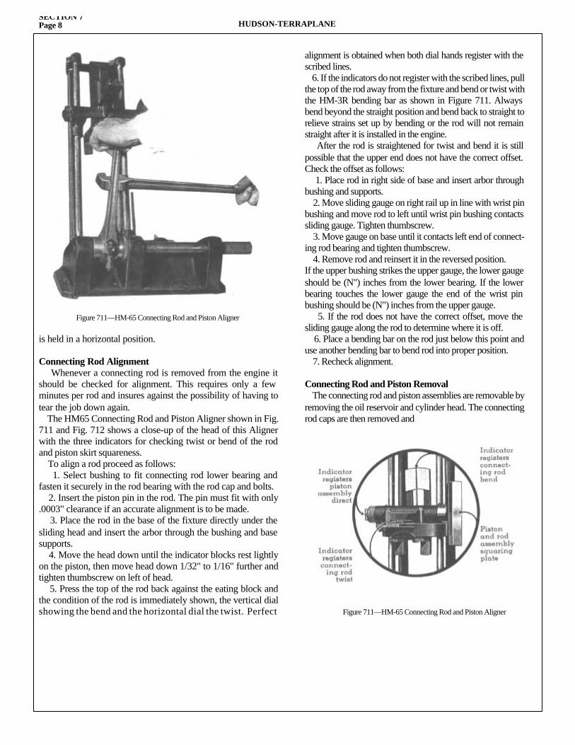
SECTION 7Page 8 HUDSON-TERRAPLANE
is held in a horizontal position.
Connecting Rod Alignment Whenever a connecting rod is removed from the engine it should be checked for alignment. This requires only a few minutes per rod and insures against the possibility of having to tear the job down again. The HM65 Connecting Rod and Piston Aligner shown in Fig. 711 and Fig. 712 shows a close-up of the head of this Aligner with the three indicators for checking twist or bend of the rod and piston skirt squareness. To align a rod proceed as follows: 1. Select bushing to fit connecting rod lower bearing and fasten it securely in the rod bearing with the rod cap and bolts. 2. Insert the piston pin in the rod. The pin must fit with only .0003" clearance if an accurate alignment is to be made. 3. Place the rod in the base of the fixture directly under the sliding head and insert the arbor through the bushing and base supports. 4. Move the head down until the indicator blocks rest lightly on the piston, then move head down 1/32" to 1/16" further and tighten thumbscrew on left of head. 5. Press the top of the rod back against the eating block and the condition of the rod is immediately shown, the vertical dial showing the bend and the horizontal dial the twist. Perfect
alignment is obtained when both dial hands register with the scribed lines. 6. If the indicators do not register with the scribed lines, pull the top of the rod away from the fixture and bend or twist with the HM-3R bending bar as shown in Figure 711. Always bend beyond the straight position and bend back to straight to relieve strains set up by bending or the rod will not remain straight after it is installed in the engine. After the rod is straightened for twist and bend it is still possible that the upper end does not have the correct offset. Check the offset as follows: 1. Place rod in right side of base and insert arbor through bushing and supports. 2. Move sliding gauge on right rail up in line with wrist pin bushing and move rod to left until wrist pin bushing contacts sliding gauge. Tighten thumbscrew. 3. Move gauge on base until it contacts left end of connect-ing rod bearing and tighten thumbscrew. 4. Remove rod and reinsert it in the reversed position.If the upper bushing strikes the upper gauge, the lower gauge should be (N") inches from the lower bearing. If the lower bearing touches the lower gauge the end of the wrist pin bushing should be (N") inches from the upper gauge. 5. If the rod does not have the correct offset, move the sliding gauge along the rod to determine where it is off. 6. Place a bending bar on the rod just below this point and use another bending bar to bend rod into proper position. 7. Recheck alignment.
Connecting Rod and Piston Removal The connecting rod and piston assemblies are removable by removing the oil reservoir and cylinder head. The connecting rod caps are then removed and
Figure 711—HM-65 Connecting Rod and Piston Aligner
Figure 711—HM-65 Connecting Rod and Piston Aligner
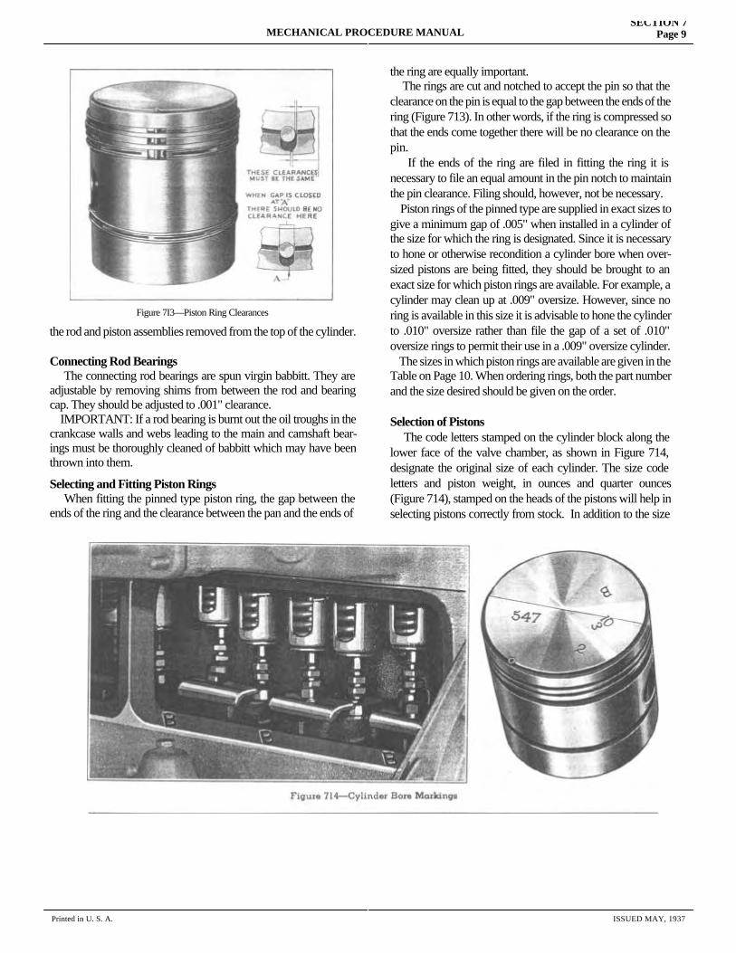
MECHANICAL PROCEDURE MANUALSECTION 7
Page 9
the rod and piston assemblies removed from the top of the cylinder.
Connecting Rod Bearings The connecting rod bearings are spun virgin babbitt. They are adjustable by removing shims from between the rod and bearing cap. They should be adjusted to .001" clearance. IMPORTANT: If a rod bearing is burnt out the oil troughs in the crankcase walls and webs leading to the main and camshaft bear-ings must be thoroughly cleaned of babbitt which may have been thrown into them.
Selecting and Fitting Piston Rings When fitting the pinned type piston ring, the gap between the ends of the ring and the clearance between the pan and the ends of
the ring are equally important. The rings are cut and notched to accept the pin so that the clearance on the pin is equal to the gap between the ends of the ring (Figure 713). In other words, if the ring is compressed so that the ends come together there will be no clearance on the pin. If the ends of the ring are filed in fitting the ring it is necessary to file an equal amount in the pin notch to maintain the pin clearance. Filing should, however, not be necessary. Piston rings of the pinned type are supplied in exact sizes to give a minimum gap of .005" when installed in a cylinder of the size for which the ring is designated. Since it is necessary to hone or otherwise recondition a cylinder bore when over-sized pistons are being fitted, they should be brought to an exact size for which piston rings are available. For example, a cylinder may clean up at .009" oversize. However, since no ring is available in this size it is advisable to hone the cylinder to .010" oversize rather than file the gap of a set of .010" oversize rings to permit their use in a .009" oversize cylinder. The sizes in which piston rings are available are given in the Table on Page 10. When ordering rings, both the part number and the size desired should be given on the order.
Selection of Pistons The code letters stamped on the cylinder block along the lower face of the valve chamber, as shown in Figure 714, designate the original size of each cylinder. The size code letters and piston weight, in ounces and quarter ounces (Figure 714), stamped on the heads of the pistons will help in selecting pistons correctly from stock. In addition to the size and
Figure 7I3—Piston Ring Clearances
Printed in U. S. A. ISSUED MAY, 1937
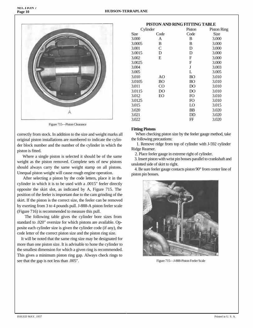
SECTION 7Page 10 HUDSON-TERRAPLANE
correctly from stock. In addition to the size and weight marks all original piston installations are numbered to indicate the cylin-der block number and the number of the cylinder in which the piston is fitted. Where a single piston is selected it should be of the same weight as the piston removed. Complete sets of new pistons should always carry the same weight stamp on all pistons. Unequal piston weight will cause rough engine operation. After selecting a piston by the code letters, place it in the cylinder in which it is to be used with a .0015" feeler directly opposite the skirt slot, as indicated by A, Figure 715. The position of the feeler is important due to the cam grinding of the skirt. If the piston is the correct size, the feeler can be removed by exerting from 3 to 4 pounds pull. J-888-A piston feeler scale (Figure 716) is recommended to measure this pull. The following table gives the cylinder bore sizes from standard to .020" oversize for which pistons are available. Op-posite each cylinder size is given the cylinder code (if any), the code letter of the correct piston size and the piston ring size. It will be noted that the same ring size may be designated for more than one piston size. It is advisable to hone the cylinder to the smallest dimension for which a given ring is recommended. This gives a minimum piston ring gap. Always check rings to see that the gap is not less than .005".
PISTON AND RING FITTING TABLE Cylinder Piston Piston Ring Size Code Code Size 3.000 A B 3.000 3.0005 B B 3.000 3.001 C D 3.000 3.0015 D D 3.000 3.002 E F 3.000 3.0025 F 3.000 3.004 J 3.003 3.005 L 3.005 3.010 AO BO 3.010 3.0105 BO BO 3.010 3.011 CO DO 3.010 3.0115 DO DO 3.010 3.012 EO FO 3.010 3.0125 FO 3.010 3.015 LO 3.015 3.020 BB 3.020 3.021 DD 3.020 3.022 FF 3.020 Fitting Pistons When checking piston size by the feeler gauge method, take the following precautions: 1. Remove ridge from top of cylinder with J-592 cylinder Ridge Reamer. 2. Place feeler gauge in extreme right of cylinder. 3. Insert piston with wrist pin bosses parallel to crankshaft and unslotted side of skirt to right. 4. Be sure feeler gauge contacts piston 90° from center line of piston pin bosses.
ISSUED MAY, 1937 Printed in U. S. A.
Figure 715—Piston Clearance
Figure 715—J-888-Piston Feeler Scale
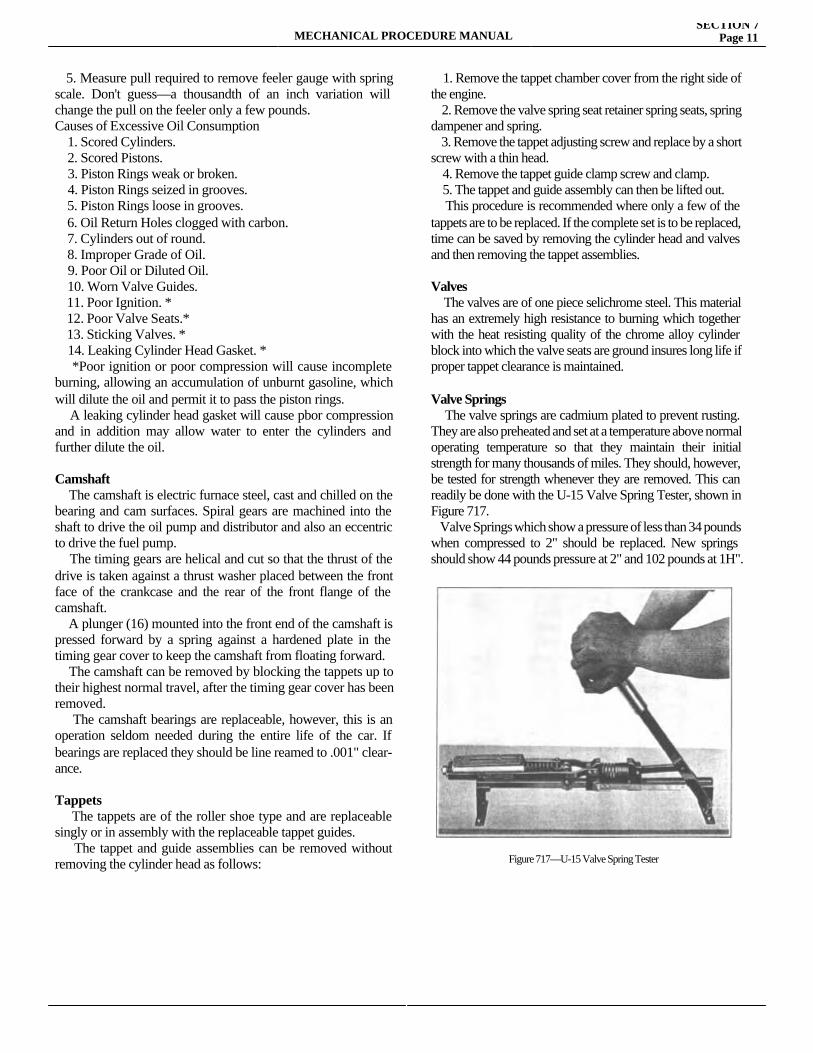
MECHANICAL PROCEDURE MANUALSECTION 7
Page 11
5. Measure pull required to remove feeler gauge with spring scale. Don't guess—a thousandth of an inch variation will change the pull on the feeler only a few pounds.Causes of Excessive Oil Consumption 1. Scored Cylinders. 2. Scored Pistons. 3. Piston Rings weak or broken. 4. Piston Rings seized in grooves. 5. Piston Rings loose in grooves. 6. Oil Return Holes clogged with carbon. 7. Cylinders out of round. 8. Improper Grade of Oil. 9. Poor Oil or Diluted Oil. 10. Worn Valve Guides. 11. Poor Ignition. * 12. Poor Valve Seats.* 13. Sticking Valves. * 14. Leaking Cylinder Head Gasket. * *Poor ignition or poor compression will cause incomplete burning, allowing an accumulation of unburnt gasoline, which will dilute the oil and permit it to pass the piston rings. A leaking cylinder head gasket will cause pbor compression and in addition may allow water to enter the cylinders and further dilute the oil.
Camshaft The camshaft is electric furnace steel, cast and chilled on the bearing and cam surfaces. Spiral gears are machined into the shaft to drive the oil pump and distributor and also an eccentric to drive the fuel pump. The timing gears are helical and cut so that the thrust of the drive is taken against a thrust washer placed between the front face of the crankcase and the rear of the front flange of the camshaft. A plunger (16) mounted into the front end of the camshaft is pressed forward by a spring against a hardened plate in the timing gear cover to keep the camshaft from floating forward. The camshaft can be removed by blocking the tappets up to their highest normal travel, after the timing gear cover has been removed. The camshaft bearings are replaceable, however, this is an operation seldom needed during the entire life of the car. If bearings are replaced they should be line reamed to .001" clear-ance.
Tappets The tappets are of the roller shoe type and are replaceable singly or in assembly with the replaceable tappet guides. The tappet and guide assemblies can be removed without removing the cylinder head as follows:
1. Remove the tappet chamber cover from the right side of the engine. 2. Remove the valve spring seat retainer spring seats, spring dampener and spring. 3. Remove the tappet adjusting screw and replace by a short screw with a thin head. 4. Remove the tappet guide clamp screw and clamp. 5. The tappet and guide assembly can then be lifted out. This procedure is recommended where only a few of the tappets are to be replaced. If the complete set is to be replaced, time can be saved by removing the cylinder head and valves and then removing the tappet assemblies.
Valves The valves are of one piece selichrome steel. This material has an extremely high resistance to burning which together with the heat resisting quality of the chrome alloy cylinder block into which the valve seats are ground insures long life if proper tappet clearance is maintained.
Valve Springs The valve springs are cadmium plated to prevent rusting. They are also preheated and set at a temperature above normal operating temperature so that they maintain their initial strength for many thousands of miles. They should, however, be tested for strength whenever they are removed. This can readily be done with the U-15 Valve Spring Tester, shown in Figure 717. Valve Springs which show a pressure of less than 34 pounds when compressed to 2" should be replaced. New springs should show 44 pounds pressure at 2" and 102 pounds at 1H".
Figure 717—U-15 Valve Spring Tester
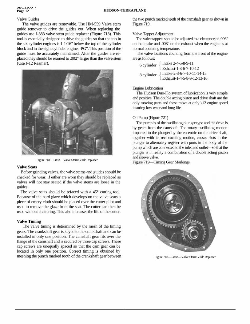
SECTION 7Page 12 HUDSON-TERRAPLANE
Valve Guides The valve guides are removable. Use HM-559 Valve stem guide remover to drive the guides out. When replacing the guides use J-883 valve stem guide replacer (Figure 718). This tool is especially designed to drive the guides so that the top in the six cylinder engines is 1-1/16" below the top of the cylinder block and in the eight cylinder engine, -PG". This position of the guide must be accurately maintained. After the guides are re-placed they should be reamed to .002" larger than the valve stem (Use J-12 Reamer).
Valve Seats Before grinding valves, the valve stems and guides should be checked for wear. If either are worn they should be replaced as valves will not stay seated if the valve stems are loose in the guides. The valve seats should be refaced with a 45° cutting tool. Because of the hard glaze which develops on the valve seats a piece of emery cloth should be placed over the cutter pilot and used to remove the glaze from the seat. The cutter can then be used without chattering. This also increases the life of the cutter.
Valve Timing The valve timing is determined by the mesh of the timing gears. The crankshaft gear is keyed to the crankshaft and can be installed in only one position. The camshaft gear fits over the flange of the camshaft and is secured by three cap screws. These cap screws are unequally spaced so that the cam gear can be located in only one position. Correct timing is obtained by meshing the punch marked tooth of the crankshaft gear between
the two punch marked teeth of the camshaft gear as shown in Figure 719.
Valve Tappet Adjustment The valve tappets should be adjusted to a clearance of .006" on the intake and .008" on the exhaust when the engine is at normal operating temperature. The valve locations counting from the front of the engine are as follows:
Intake 2-4-5-8-9-11 Exhaust-1-3-6-7-10-12 Intake-2-3-6-7-10-11-14-15 Exhaust-1-4-5-8-9-12-13-16
Engine Lubrication The Hudson Duo-Flo system of lubrication is very simple and positive. The double acting piston and drive shaft are the only moving parts and these move at only '/12 engine speed insuring low wear and long life.
Oil Pump (Figure 721) The pump is of the oscillating plunger type and the drive is by gears from the camshaft. The rotary oscillating motion imparted to the plunger by the eccentric on the drive shaft, together with its reciprocating motion, causes slots in the plunger to alternately register with ports in the body of the pump which are connected to the inlet and outlet—so that the plunger is in reality a combination of a double acting piston and sleeve valve.Figure 719—Timing Gear MarkingsFigure 718—J-883—Valve Stern Guide Replacer
6 cylinder
8 cylinder
Figure 718—J-883—Valve Stern Guide Replacer
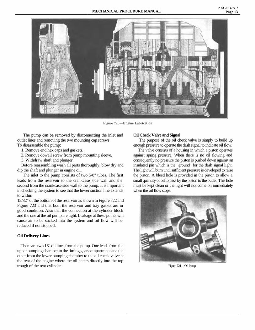
MECHANICAL PROCEDURE MANUALSECTION 7
Page 13
The pump can be removed by disconnecting the inlet and outlet lines and removing the two mounting cap screws.To disassemble the pump: 1. Remove end hex caps and gaskets. 2. Remove dowell screw from pump mounting sleeve. 3. Withdraw shaft and plunger. Before reassembling wash all parts thoroughly, blow dry and dip the shaft and plunger in engine oil. The inlet to the pump consists of two 5/8" tubes. The first leads from the reservoir to the crankcase side wall and the second from the crankcase side wall to the pump. It is important in checking the system to see that the lower suction line extends to within15/32" of the bottom of the reservoir as shown in Figure 722 and Figure 723 and that both the reservoir and tray gasket are in good condition. Also that the connection at the cylinder block and the one at the oil pump are tight. Leakage at these points will cause air to be sucked into the system and oil flow will be reduced if not stopped.
Oil Delivery Lines
There are two 16" oil lines from the pump. One leads from the upper pumping chamber to the timing gear compartment and the other from the lower pumping chamber to the oil check valve at the rear of the engine where the oil enters directly into the top trough of the rear cylinder.
Oil Check Valve and Signal The purpose of the oil check valve is simply to build up enough pressure to operate the dash signal to indicate oil flow. The valve consists of a housing in which a piston operates against spring pressure. When there is no oil flowing and consequently no pressure the piston is pushed down against an insulated pin which is the "ground" for the dash signal light. The light will burn until sufficient pressure is developed to raise the piston. A bleed hole is provided in the piston to allow a small quantity of oil to pass by the piston to the outlet. This hole must be kept clean or the light will not come on immediately when the oil flow stops.
Figure 720—Engine Lubrication
Figure 721—Oil Pump
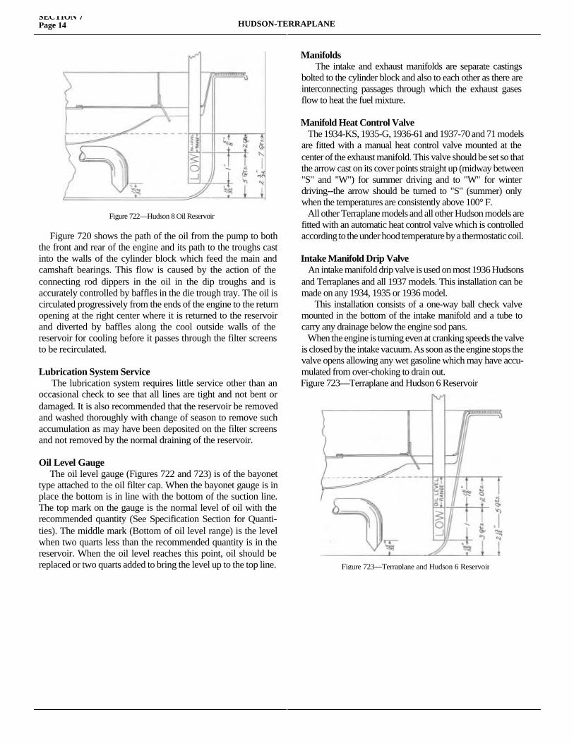
SECTION 7Page 14 HUDSON-TERRAPLANE
Figure 720 shows the path of the oil from the pump to both the front and rear of the engine and its path to the troughs cast into the walls of the cylinder block which feed the main and camshaft bearings. This flow is caused by the action of the connecting rod dippers in the oil in the dip troughs and is accurately controlled by baffles in the die trough tray. The oil is circulated progressively from the ends of the engine to the return opening at the right center where it is returned to the reservoir and diverted by baffles along the cool outside walls of the reservoir for cooling before it passes through the filter screens to be recirculated.
Lubrication System Service The lubrication system requires little service other than an occasional check to see that all lines are tight and not bent or damaged. It is also recommended that the reservoir be removed and washed thoroughly with change of season to remove such accumulation as may have been deposited on the filter screens and not removed by the normal draining of the reservoir.
Oil Level Gauge The oil level gauge (Figures 722 and 723) is of the bayonet type attached to the oil filter cap. When the bayonet gauge is in place the bottom is in line with the bottom of the suction line. The top mark on the gauge is the normal level of oil with the recommended quantity (See Specification Section for Quanti-ties). The middle mark (Bottom of oil level range) is the level when two quarts less than the recommended quantity is in the reservoir. When the oil level reaches this point, oil should be replaced or two quarts added to bring the level up to the top line.
Manifolds The intake and exhaust manifolds are separate castings bolted to the cylinder block and also to each other as there are interconnecting passages through which the exhaust gases flow to heat the fuel mixture.
Manifold Heat Control Valve The 1934-KS, 1935-G, 1936-61 and 1937-70 and 71 models are fitted with a manual heat control valve mounted at the center of the exhaust manifold. This valve should be set so that the arrow cast on its cover points straight up (midway between "S" and "W") for summer driving and to "W" for winter driving--the arrow should be turned to "S" (summer) only when the temperatures are consistently above 100° F. All other Terraplane models and all other Hudson models are fitted with an automatic heat control valve which is controlled according to the under hood temperature by a thermostatic coil.
Intake Manifold Drip Valve An intake manifold drip valve is used on most 1936 Hudsons and Terraplanes and all 1937 models. This installation can be made on any 1934, 1935 or 1936 model. This installation consists of a one-way ball check valve mounted in the bottom of the intake manifold and a tube to carry any drainage below the engine sod pans. When the engine is turning even at cranking speeds the valve is closed by the intake vacuum. As soon as the engine stops the valve opens allowing any wet gasoline which may have accu-mulated from over-choking to drain out.Figure 723—Terraplane and Hudson 6 Reservoir
Figure 722—Hudson 8 Oil Reservoir
Figure 723—Terraplane and Hudson 6 Reservoir
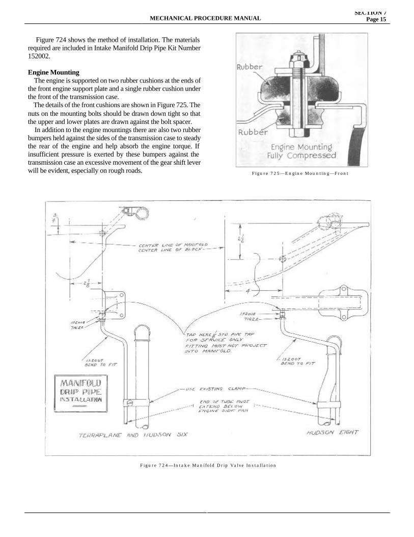
MECHANICAL PROCEDURE MANUALSECTION 7
Page 15
Figure 724 shows the method of installation. The materials required are included in Intake Manifold Drip Pipe Kit Number 152002.
Engine Mounting The engine is supported on two rubber cushions at the ends of the front engine support plate and a single rubber cushion under the front of the transmission case. The details of the front cushions are shown in Figure 725. The nuts on the mounting bolts should be drawn down tight so that the upper and lower plates are drawn against the bolt spacer. In addition to the engine mountings there are also two rubber bumpers held against the sides of the transmission case to steady the rear of the engine and help absorb the engine torque. If insufficient pressure is exerted by these bumpers against the transmission case an excessive movement of the gear shift lever will be evident, especially on rough roads. Figure 725—Engine Mounting—Front
Figure 724—Intake Manifold Drip Valve Installation

SECTION 8
CLUTCHService Magazine—Reference Sheet and Service Bullet in Reference
Bulletin orReference SheetNo. MagazineIssue and Page
Date Subject DETAILS OF INFORMATION
MECHANICAL PROCEDURE MANUAL Page 1

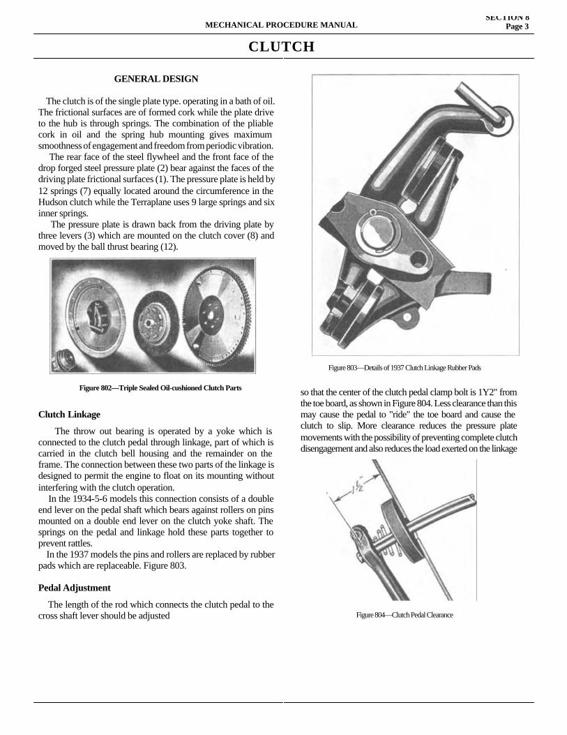
CLUTCH
GENERAL DESIGN The clutch is of the single plate type. operating in a bath of oil. The frictional surfaces are of formed cork while the plate drive to the hub is through springs. The combination of the pliable cork in oil and the spring hub mounting gives maximum smoothness of engagement and freedom from periodic vibration. The rear face of the steel flywheel and the front face of the drop forged steel pressure plate (2) bear against the faces of the driving plate frictional surfaces (1). The pressure plate is held by 12 springs (7) equally located around the circumference in the Hudson clutch while the Terraplane uses 9 large springs and six inner springs. The pressure plate is drawn back from the driving plate by three levers (3) which are mounted on the clutch cover (8) and moved by the ball thrust bearing (12).
Clutch Linkage
The throw out bearing is operated by a yoke which is connected to the clutch pedal through linkage, part of which is carried in the clutch bell housing and the remainder on the frame. The connection between these two parts of the linkage is designed to permit the engine to float on its mounting without interfering with the clutch operation. In the 1934-5-6 models this connection consists of a double end lever on the pedal shaft which bears against rollers on pins mounted on a double end lever on the clutch yoke shaft. The springs on the pedal and linkage hold these parts together to prevent rattles. In the 1937 models the pins and rollers are replaced by rubber pads which are replaceable. Figure 803.
Pedal Adjustment
The length of the rod which connects the clutch pedal to the cross shaft lever should be adjusted
so that the center of the clutch pedal clamp bolt is 1Y2" from the toe board, as shown in Figure 804. Less clearance than this may cause the pedal to "ride" the toe board and cause the clutch to slip. More clearance reduces the pressure plate movements with the possibility of preventing complete clutch disengagement and also reduces the load exerted on the linkage
MECHANICAL PROCEDURE MANUALSECTION 8
Page 3
Figure 802—Triple Sealed Oil-cushioned Clutch Parts
Figure 803—Details of 1937 Clutch Linkage Rubber Pads
Figure 804—Clutch Pedal Clearance
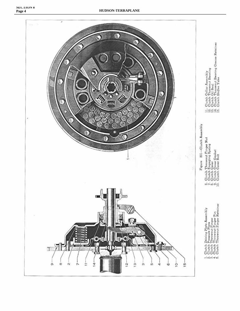
SECTION 8Page 4 HUDSON-TERRAPLANE
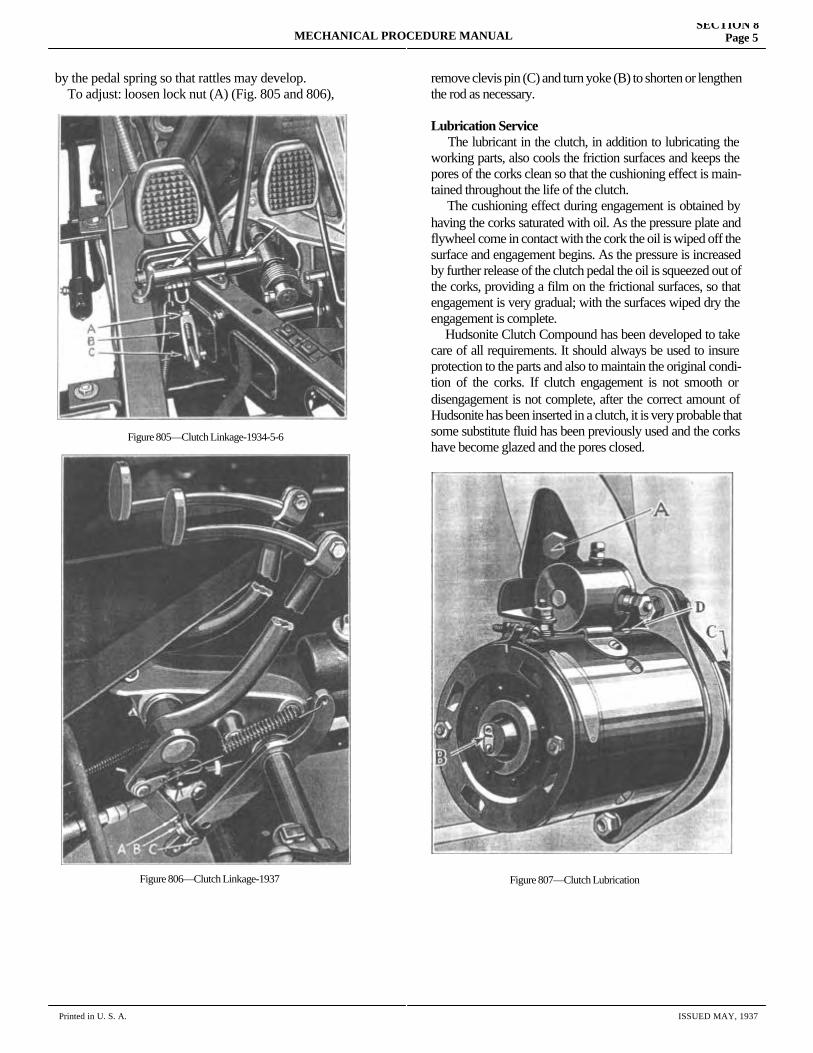
by the pedal spring so that rattles may develop. To adjust: loosen lock nut (A) (Fig. 805 and 806),
remove clevis pin (C) and turn yoke (B) to shorten or lengthen the rod as necessary.
Lubrication Service The lubricant in the clutch, in addition to lubricating the working parts, also cools the friction surfaces and keeps the pores of the corks clean so that the cushioning effect is main-tained throughout the life of the clutch. The cushioning effect during engagement is obtained by having the corks saturated with oil. As the pressure plate and flywheel come in contact with the cork the oil is wiped off the surface and engagement begins. As the pressure is increased by further release of the clutch pedal the oil is squeezed out of the corks, providing a film on the frictional surfaces, so that engagement is very gradual; with the surfaces wiped dry the engagement is complete. Hudsonite Clutch Compound has been developed to take care of all requirements. It should always be used to insure protection to the parts and also to maintain the original condi-tion of the corks. If clutch engagement is not smooth or disengagement is not complete, after the correct amount of Hudsonite has been inserted in a clutch, it is very probable that some substitute fluid has been previously used and the corks have become glazed and the pores closed.
MECHANICAL PROCEDURE MANUALSECTION 8
Page 5
Printed in U. S. A. ISSUED MAY, 1937
Figure 805—Clutch Linkage-1934-5-6
Figure 806—Clutch Linkage-1937 Figure 807—Clutch Lubrication
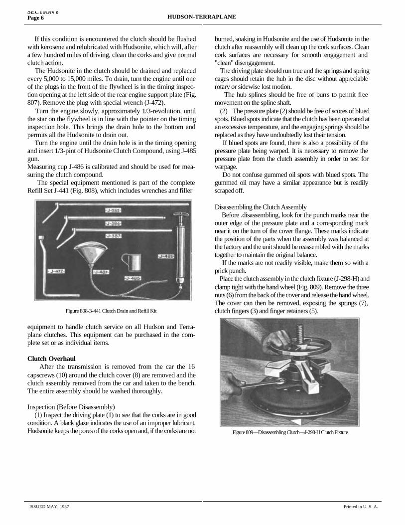
If this condition is encountered the clutch should be flushed with kerosene and relubricated with Hudsonite, which will, after a few hundred miles of driving, clean the corks and give normal clutch action. The Hudsonite in the clutch should be drained and replaced every 5,000 to 15,000 miles. To drain, turn the engine until one of the plugs in the front of the flywheel is in the timing inspec-tion opening at the left side of the rear engine support plate (Fig. 807). Remove the plug with special wrench (J-472). Turn the engine slowly, approximately 1/3-revolution, until the star on the flywheel is in line with the pointer on the timing inspection hole. This brings the drain hole to the bottom and permits all the Hudsonite to drain out. Turn the engine until the drain hole is in the timing opening and insert 1/3-pint of Hudsonite Clutch Compound, using J-485 gun.Measuring cup J-486 is calibrated and should be used for mea-suring the clutch compound. The special equipment mentioned is part of the complete Refill Set J-441 (Fig. 808), which includes wrenches and filler
equipment to handle clutch service on all Hudson and Terra-plane clutches. This equipment can be purchased in the com-plete set or as individual items.
Clutch Overhaul After the transmission is removed from the car the 16 capscrews (10) around the clutch cover (8) are removed and the clutch assembly removed from the car and taken to the bench. The entire assembly should be washed thoroughly.
Inspection (Before Disassembly) (1) Inspect the driving plate (1) to see that the corks are in good condition. A black glaze indicates the use of an improper lubricant. Hudsonite keeps the pores of the corks open and, if the corks are not
burned, soaking in Hudsonite and the use of Hudsonite in the clutch after reassembly will clean up the cork surfaces. Clean cork surfaces are necessary for smooth engagement and "clean" disengagement. The driving plate should run true and the springs and spring cages should retain the hub in the disc without appreciable rotary or sidewise lost motion. The hub splines should be free of burrs to permit free movement on the spline shaft. (2) The pressure plate (2) should be free of scores of blued spots. Blued spots indicate that the clutch has been operated at an excessive temperature, and the engaging springs should be replaced as they have undoubtedly lost their tension. If blued spots are found, there is also a possibility of the pressure plate being warped. It is necessary to remove the pressure plate from the clutch assembly in order to test for warpage. Do not confuse gummed oil spots with blued spots. The gummed oil may have a similar appearance but is readily scraped off.
Disassembling the Clutch Assembly Before .disassembling, look for the punch marks near the outer edge of the pressure plate and a corresponding mark near it on the turn of the cover flange. These marks indicate the position of the parts when the assembly was balanced at the factory and the unit should be reassembled with the marks together to maintain the original balance. If the marks are not readily visible, make them so with a prick punch. Place the clutch assembly in the clutch fixture (J-298-H) and clamp tight with the hand wheel (Fig. 809). Remove the three nuts (6) from the back of the cover and release the hand wheel. The cover can then be removed, exposing the springs (7), clutch fingers (3) and finger retainers (5).
SECTION 8Page 6 HUDSON-TERRAPLANE
ISSUED MAY, 1937 Printed in U. S. A.
Figure 808-3-441 Clutch Drain and Refill Kit
Figure 809—Disassembling Clutch—J-298-H Clutch Fixture
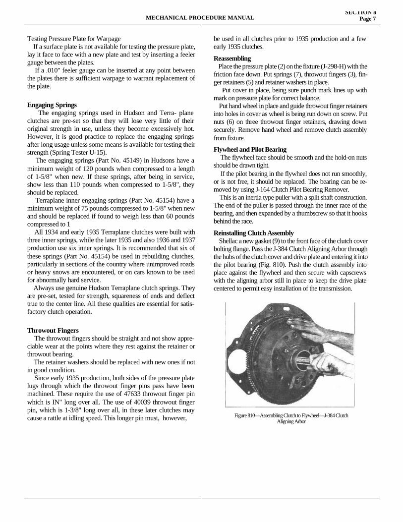
Testing Pressure Plate for Warpage If a surface plate is not available for testing the pressure plate, lay it face to face with a new plate and test by inserting a feeler gauge between the plates. If a .010" feeler gauge can be inserted at any point between the plates there is sufficient warpage to warrant replacement of the plate.
Engaging Springs The engaging springs used in Hudson and Terra- plane clutches are pre-set so that they will lose very little of their original strength in use, unless they become excessively hot. However, it is good practice to replace the engaging springs after long usage unless some means is available for testing their strength (Spring Tester U-15). The engaging springs (Part No. 45149) in Hudsons have a minimum weight of 120 pounds when compressed to a length of 1-5/8" when new. If these springs, after being in service, show less than 110 pounds when compressed to 1-5/8", they should be replaced. Terraplane inner engaging springs (Part No. 45154) have a minimum weight of 75 pounds compressed to 1-5/8" when new and should be replaced if found to weigh less than 60 pounds compressed to 1 All 1934 and early 1935 Terraplane clutches were built with three inner springs, while the later 1935 and also 1936 and 1937 production use six inner springs. It is recommended that six of these springs (Part No. 45154) be used in rebuilding clutches, particularly in sections of the country where unimproved roads or heavy snows are encountered, or on cars known to be used for abnormally hard service. Always use genuine Hudson Terraplane clutch springs. They are pre-set, tested for strength, squareness of ends and deflect true to the center line. All these qualities are essential for satis-factory clutch operation.
Throwout Fingers The throwout fingers should be straight and not show appre-ciable wear at the points where they rest against the retainer or throwout bearing. The retainer washers should be replaced with new ones if not in good condition. Since early 1935 production, both sides of the pressure plate lugs through which the throwout finger pins pass have been machined. These require the use of 47633 throwout finger pin which is IN" long over all. The use of 40039 throwout finger pin, which is 1-3/8" long over all, in these later clutches may cause a rattle at idling speed. This longer pin must, however,
be used in all clutches prior to 1935 production and a few early 1935 clutches.
Reassembling Place the pressure plate (2) on the fixture (J-298-H) with the friction face down. Put springs (7), throwout fingers (3), fin-ger retainers (5) and retainer washers in place. Put cover in place, being sure punch mark lines up with mark on pressure plate for correct balance. Put hand wheel in place and guide throwout finger retainers into holes in cover as wheel is being run down on screw. Put nuts (6) on three throwout finger retainers, drawing down securely. Remove hand wheel and remove clutch assembly from fixture.
Flywheel and Pilot Bearing The flywheel face should be smooth and the hold-on nuts should be drawn tight. If the pilot bearing in the flywheel does not run smoothly, or is not free, it should be replaced. The bearing can be re-moved by using J-164 Clutch Pilot Bearing Remover. This is an inertia type puller with a split shaft construction. The end of the puller is passed through the inner race of the bearing, and then expanded by a thumbscrew so that it hooks behind the race.
Reinstalling Clutch Assembly Shellac a new gasket (9) to the front face of the clutch cover bolting flange. Pass the J-384 Clutch Aligning Arbor through the hubs of the clutch cover and drive plate and entering it into the pilot bearing (Fig. 810). Push the clutch assembly into place against the flywheel and then secure with capscrews with the aligning arbor still in place to keep the drive plate centered to permit easy installation of the transmission.
MECHANICAL PROCEDURE MANUALSECTION 8
Page 7
Figure 810—Assembling Clutch to Flywheel—J-384 Clutch Aligning Arbor
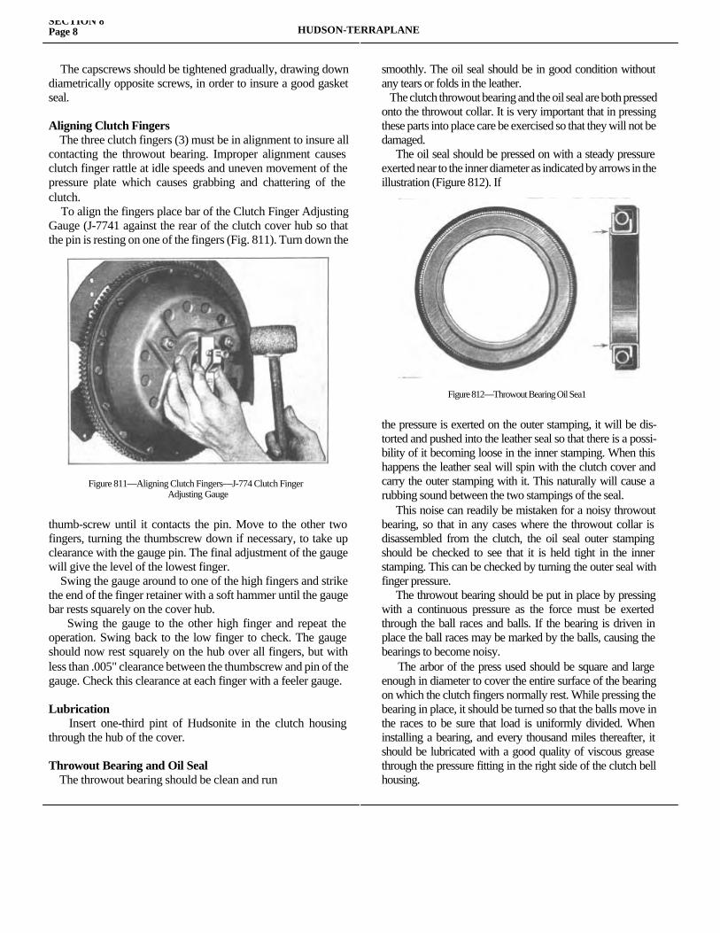
The capscrews should be tightened gradually, drawing down diametrically opposite screws, in order to insure a good gasket seal.
Aligning Clutch Fingers The three clutch fingers (3) must be in alignment to insure all contacting the throwout bearing. Improper alignment causes clutch finger rattle at idle speeds and uneven movement of the pressure plate which causes grabbing and chattering of the clutch. To align the fingers place bar of the Clutch Finger Adjusting Gauge (J-7741 against the rear of the clutch cover hub so that the pin is resting on one of the fingers (Fig. 811). Turn down the thumb-
thumb-screw until it contacts the pin. Move to the other two fingers, turning the thumbscrew down if necessary, to take up clearance with the gauge pin. The final adjustment of the gauge will give the level of the lowest finger. Swing the gauge around to one of the high fingers and strike the end of the finger retainer with a soft hammer until the gauge bar rests squarely on the cover hub. Swing the gauge to the other high finger and repeat the operation. Swing back to the low finger to check. The gauge should now rest squarely on the hub over all fingers, but with less than .005" clearance between the thumbscrew and pin of the gauge. Check this clearance at each finger with a feeler gauge.
Lubrication Insert one-third pint of Hudsonite in the clutch housing through the hub of the cover.
Throwout Bearing and Oil Seal The throwout bearing should be clean and run
smoothly. The oil seal should be in good condition without any tears or folds in the leather. The clutch throwout bearing and the oil seal are both pressed onto the throwout collar. It is very important that in pressing these parts into place care be exercised so that they will not be damaged. The oil seal should be pressed on with a steady pressure exerted near to the inner diameter as indicated by arrows in the illustration (Figure 812). If
the pressure is exerted on the outer stamping, it will be dis-torted and pushed into the leather seal so that there is a possi-bility of it becoming loose in the inner stamping. When this happens the leather seal will spin with the clutch cover and carry the outer stamping with it. This naturally will cause a rubbing sound between the two stampings of the seal. This noise can readily be mistaken for a noisy throwout bearing, so that in any cases where the throwout collar is disassembled from the clutch, the oil seal outer stamping should be checked to see that it is held tight in the inner stamping. This can be checked by turning the outer seal with finger pressure. The throwout bearing should be put in place by pressing with a continuous pressure as the force must be exerted through the ball races and balls. If the bearing is driven in place the ball races may be marked by the balls, causing the bearings to become noisy. The arbor of the press used should be square and large enough in diameter to cover the entire surface of the bearing on which the clutch fingers normally rest. While pressing the bearing in place, it should be turned so that the balls move in the races to be sure that load is uniformly divided. When installing a bearing, and every thousand miles thereafter, it should be lubricated with a good quality of viscous grease through the pressure fitting in the right side of the clutch bell housing.
SECTION 8Page 8 HUDSON-TERRAPLANE
Figure 811—Aligning Clutch Fingers—J-774 Clutch FingerAdjusting Gauge
Figure 812—Throwout Bearing Oil Sea1

SECTION 9
AUTOMATIC CLUTCHService Magazine—Reference Sheet and Service Bullet in Reference
Bulletin orReference SheetNo. MagazineIssue and Page
Date Subject DETAILS OF INFORMATION
MECHANICAL PROCEDURE MANUAL Page 1

MECHANICAL PROCEDURE MANUALSECTION 9
Page 3
Printed in U. S. A. ISSUED MAY, 1937
AUTOMATIC CLUTCH
AUTOMATIC CLUTCH CONTROL The principle of operation of the Automatic Clutch Mecha-nism used on all Hudson and Terraplane models is the same, however, there are detail changes which have been made to time the engagement more accurately with the throttle operation. In the 1937 models an electric control is incorporated to eliminate coasting in high gear when the foot is taken from the accelerator pedal.
AUTOMATIC CLUTCH OPERATIONS
Disengagement When the cut off plunger (10) Figure 901, which is operated by the dash control is pulled out, vacuum from the engine intake manifold is admitted to the accelerator plunger (11) which controls the vacuum to the power cylinder. When the plunger is pulled out (accelerator pedal released) the vacuum enters the front of the power cylinder so that the piston (3 is moved forward and air enters the rear of the power cylinder through the atmospheric check valve (6) and the air by pass (1).The forward movement of the piston disengages the clutch.
Engagement The accelerator plunger moves in when the accelerator pedal is depressed, moving the radial slot (14) away from the vacuum port, cutting off the vacuum to the power cylinder and bringing the longitudinal slot (15) in line with the port so that air can enter the front of the power cylinder. The air entering the front of the cylinder permits the clutch springs to pull the piston backward forcing air out of the rear of the cylinder through the air by pass (1) in the piston rod (2). It will be noted that the air by pass extends only to within about 1-1/2" of the piston so that it is closed as soon as its inner end enters the piston rod seal (4) in the cylinder head. Up to this point the piston is allowed to move rapidly to bring the clutch plates to the point where they are just ready to begin to engage. Now since the air by pass (1) is closed and the atmospheric check valve (6) is held against its seat by air pressure from inside the cylinder, the only means of escape for the air is through the bleed line leading from the front of the cylinder to the cushion control or pendulum valve (19). When the car is at rest or accelerating normally the pendulum (14) hangs straight down and holds the cushion control valve radial slot in line with the ports so that air can pass through to a
port communicating with the cylinder in which the accelerator plunger (11) operates. The air passes from this port into the taper slot (16) and escapes. The further the accelerator plunger is pushed in, the deeper the portion of the taper slot in commu-nication with the air port so that the rate of air bleed is in-creased as the throttle is opened giving slow clutch engagement on low throttle and rapid engagement on open throttle. If the engagement is too rapid on open throttle tending to jerk the car, the pendulum swings backward partially or com-pletely closing the air bleed and arresting the clutch engage-ment and insuring a smooth get away.
Details of Control A comparison of the earlier design shown in Figure 901 with the 1937 design shown in Figure 903 will show the detail differences in the control valves and particularly the air filter in the 1937 design which prevents dirt entering the vacuum chamber during engagement of the clutch. The solenoid cut off valve is also clearly shown in Figure 903.
Adjustment There are three major adjustments which must always be performed in the following order. 1. Piston Rod Length. 2. Throttle Rod Lash. 3. Cushion Control Valve Spring Pressure.
Purpose of Adjustments 1. The piston rod length is important as the inner end of the air by-pass (1) must enter the piston seal (4) just as the clutch plates are about to engage and arrest the fast motion of engagement of the clutch. If the piston rod is too long the clutch will grab and tend to stall the engine. If too short, the engagement will be slow and the engine will race before the clutch engages. The piston rod length must be adjusted occasionally to compensate for clutch facing wear. 2. The Throttle Rod Lash (lost motion) has a two-fold purpose: First, it permits moving the accelerator plunger in to the point of cutting off the vacuum from the intake manifold so that the clutch may be brought up to the point of engagement before the throttle starts to open and the engine speeds up. Second, it makes it possible to drive the car even at idle speed without the clutch disengaging. Too little lash will cause the engine to speed up before the clutch engages and will also make it impossible to drive the car at idle speed.
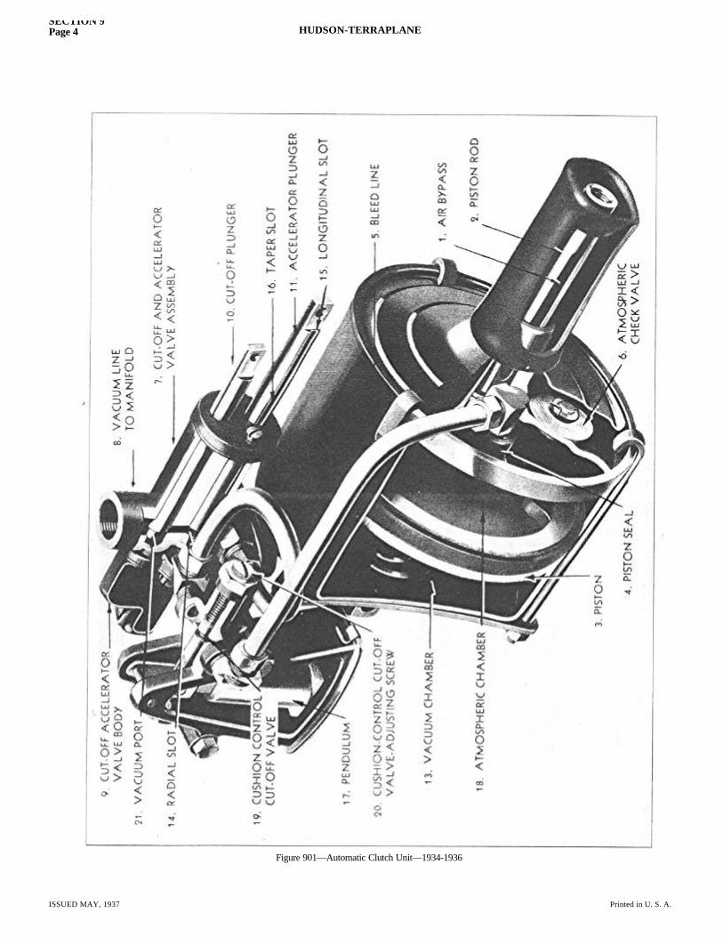
SECTION 9Page 4 HUDSON-TERRAPLANE
ISSUED MAY, 1937 Printed in U. S. A.
Figure 901—Automatic Clutch Unit—1934-1936
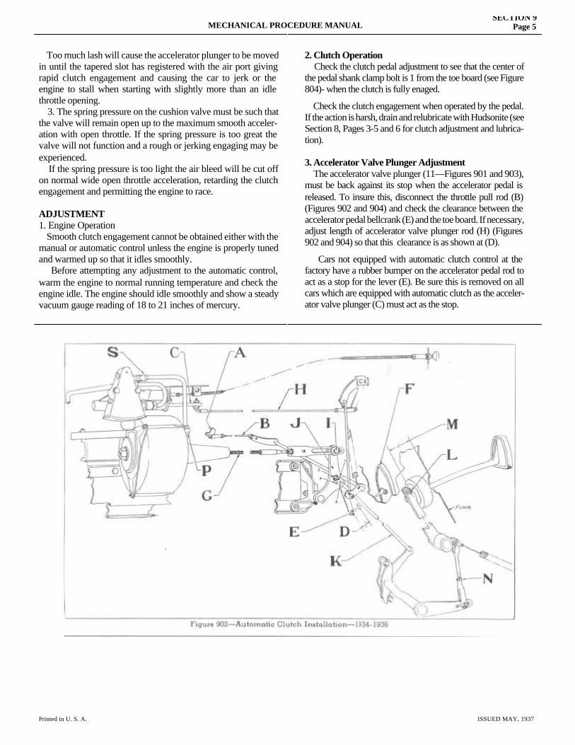
MECHANICAL PROCEDURE MANUALSECTION 9
Page 5
Printed in U. S. A. ISSUED MAY, 1937
Too much lash will cause the accelerator plunger to be moved in until the tapered slot has registered with the air port giving rapid clutch engagement and causing the car to jerk or the engine to stall when starting with slightly more than an idle throttle opening. 3. The spring pressure on the cushion valve must be such that the valve will remain open up to the maximum smooth acceler-ation with open throttle. If the spring pressure is too great the valve will not function and a rough or jerking engaging may be experienced. If the spring pressure is too light the air bleed will be cut off on normal wide open throttle acceleration, retarding the clutch engagement and permitting the engine to race.
ADJUSTMENT1. Engine Operation Smooth clutch engagement cannot be obtained either with the manual or automatic control unless the engine is properly tuned and warmed up so that it idles smoothly. Before attempting any adjustment to the automatic control, warm the engine to normal running temperature and check the engine idle. The engine should idle smoothly and show a steady vacuum gauge reading of 18 to 21 inches of mercury.
2. Clutch Operation Check the clutch pedal adjustment to see that the center of the pedal shank clamp bolt is 1 from the toe board (see Figure 804)- when the clutch is fully enaged.
Check the clutch engagement when operated by the pedal. If the action is harsh, drain and relubricate with Hudsonite (see Section 8, Pages 3-5 and 6 for clutch adjustment and lubrica-tion).
3. Accelerator Valve Plunger Adjustment The accelerator valve plunger (11—Figures 901 and 903), must be back against its stop when the accelerator pedal is released. To insure this, disconnect the throttle pull rod (B) (Figures 902 and 904) and check the clearance between the accelerator pedal bellcrank (E) and the toe board. If necessary, adjust length of accelerator valve plunger rod (H) (Figures 902 and 904) so that this clearance is as shown at (D).
Cars not equipped with automatic clutch control at the factory have a rubber bumper on the accelerator pedal rod to act as a stop for the lever (E). Be sure this is removed on all cars which are equipped with automatic clutch as the acceler-ator valve plunger (C) must act as the stop.
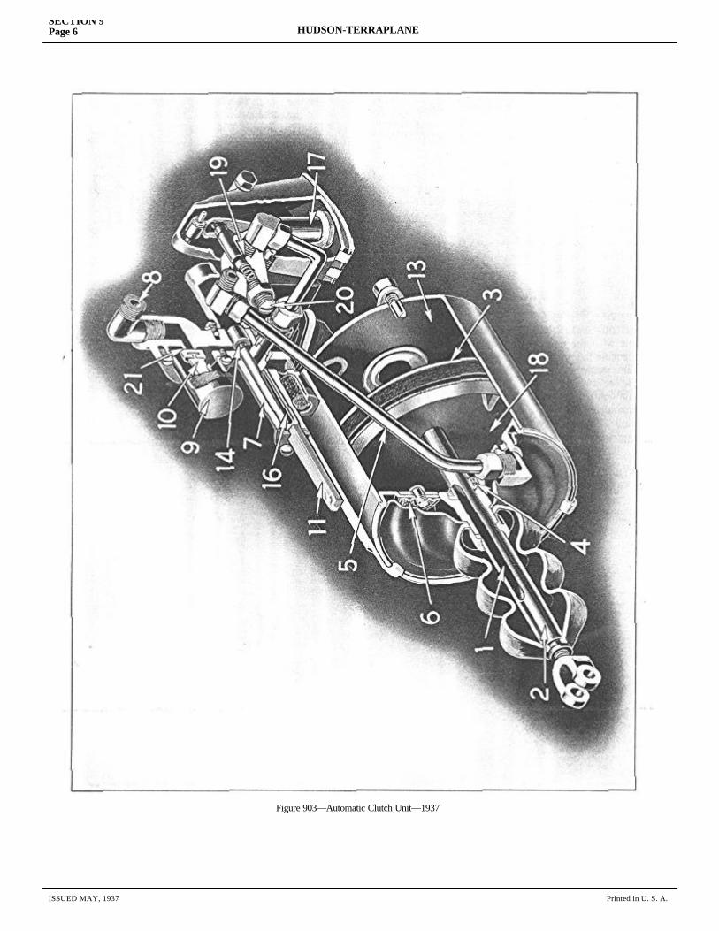
SECTION 9Page 6 HUDSON-TERRAPLANE
ISSUED MAY, 1937 Printed in U. S. A.
Figure 903—Automatic Clutch Unit—1937
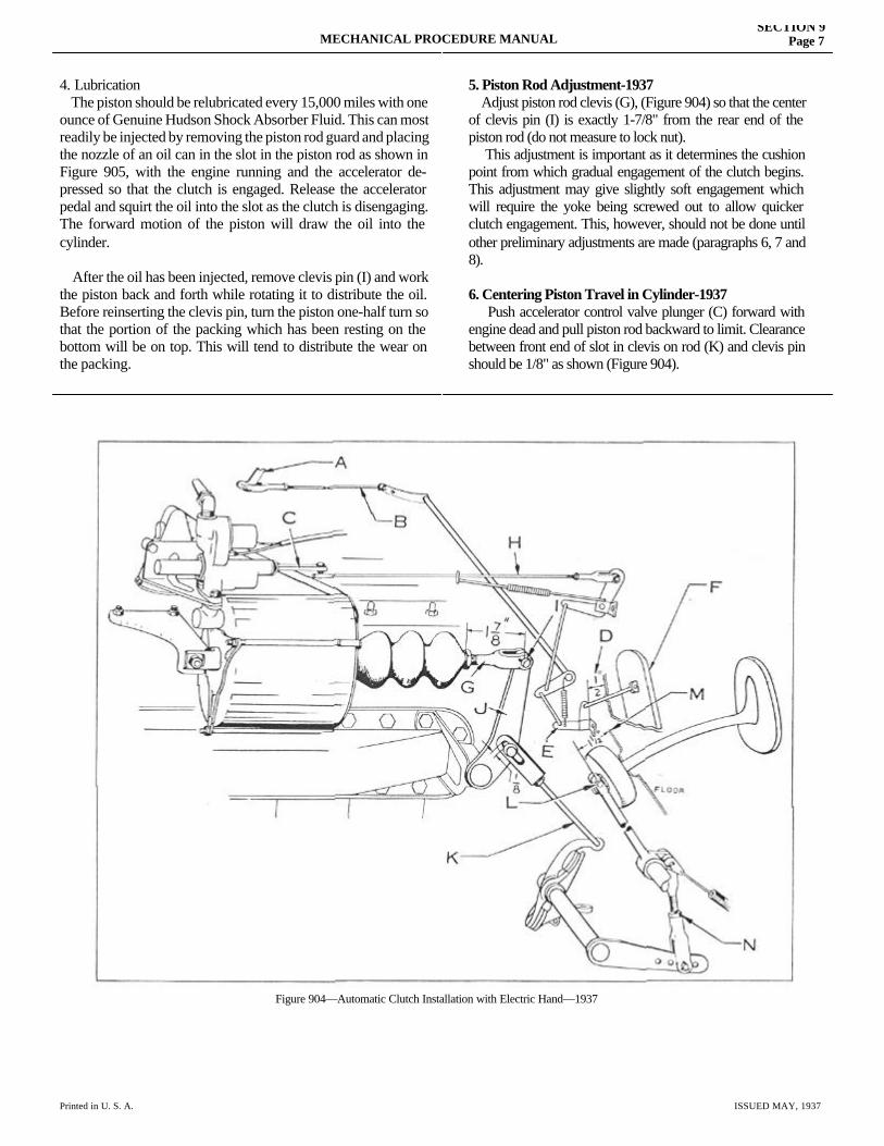
MECHANICAL PROCEDURE MANUALSECTION 9
Page 7
Printed in U. S. A. ISSUED MAY, 1937
4. Lubrication The piston should be relubricated every 15,000 miles with one ounce of Genuine Hudson Shock Absorber Fluid. This can most readily be injected by removing the piston rod guard and placing the nozzle of an oil can in the slot in the piston rod as shown in Figure 905, with the engine running and the accelerator de-pressed so that the clutch is engaged. Release the accelerator pedal and squirt the oil into the slot as the clutch is disengaging. The forward motion of the piston will draw the oil into the cylinder.
After the oil has been injected, remove clevis pin (I) and work the piston back and forth while rotating it to distribute the oil. Before reinserting the clevis pin, turn the piston one-half turn so that the portion of the packing which has been resting on the bottom will be on top. This will tend to distribute the wear on the packing.
5. Piston Rod Adjustment-1937 Adjust piston rod clevis (G), (Figure 904) so that the center of clevis pin (I) is exactly 1-7/8" from the rear end of the piston rod (do not measure to lock nut). This adjustment is important as it determines the cushion point from which gradual engagement of the clutch begins. This adjustment may give slightly soft engagement which will require the yoke being screwed out to allow quicker clutch engagement. This, however, should not be done until other preliminary adjustments are made (paragraphs 6, 7 and 8).
6. Centering Piston Travel in Cylinder-1937 Push accelerator control valve plunger (C) forward with engine dead and pull piston rod backward to limit. Clearance between front end of slot in clevis on rod (K) and clevis pin should be 1/8" as shown (Figure 904).
Figure 904—Automatic Clutch Installation with Electric Hand—1937
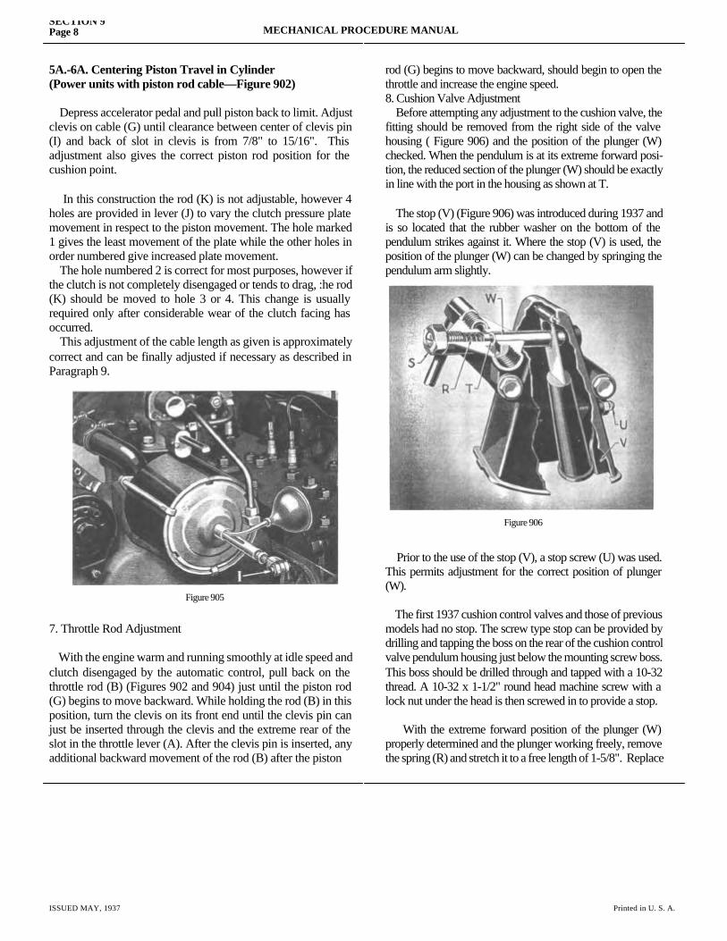
SECTION 9Page 8 MECHANICAL PROCEDURE MANUAL
ISSUED MAY, 1937 Printed in U. S. A.
5A.-6A. Centering Piston Travel in Cylinder(Power units with piston rod cable—Figure 902)
Depress accelerator pedal and pull piston back to limit. Adjust clevis on cable (G) until clearance between center of clevis pin (I) and back of slot in clevis is from 7/8" to 15/16". This adjustment also gives the correct piston rod position for the cushion point.
In this construction the rod (K) is not adjustable, however 4 holes are provided in lever (J) to vary the clutch pressure plate movement in respect to the piston movement. The hole marked 1 gives the least movement of the plate while the other holes in order numbered give increased plate movement. The hole numbered 2 is correct for most purposes, however if the clutch is not completely disengaged or tends to drag, :he rod (K) should be moved to hole 3 or 4. This change is usually required only after considerable wear of the clutch facing has occurred. This adjustment of the cable length as given is approximately correct and can be finally adjusted if necessary as described in Paragraph 9.
7. Throttle Rod Adjustment
With the engine warm and running smoothly at idle speed and clutch disengaged by the automatic control, pull back on the throttle rod (B) (Figures 902 and 904) just until the piston rod (G) begins to move backward. While holding the rod (B) in this position, turn the clevis on its front end until the clevis pin can just be inserted through the clevis and the extreme rear of the slot in the throttle lever (A). After the clevis pin is inserted, any additional backward movement of the rod (B) after the piston
rod (G) begins to move backward, should begin to open the throttle and increase the engine speed.8. Cushion Valve Adjustment Before attempting any adjustment to the cushion valve, the fitting should be removed from the right side of the valve housing ( Figure 906) and the position of the plunger (W) checked. When the pendulum is at its extreme forward posi-tion, the reduced section of the plunger (W) should be exactly in line with the port in the housing as shown at T.
The stop (V) (Figure 906) was introduced during 1937 and is so located that the rubber washer on the bottom of the pendulum strikes against it. Where the stop (V) is used, the position of the plunger (W) can be changed by springing the pendulum arm slightly.
Prior to the use of the stop (V), a stop screw (U) was used. This permits adjustment for the correct position of plunger (W).
The first 1937 cushion control valves and those of previous models had no stop. The screw type stop can be provided by drilling and tapping the boss on the rear of the cushion control valve pendulum housing just below the mounting screw boss. This boss should be drilled through and tapped with a 10-32 thread. A 10-32 x 1-1/2" round head machine screw with a lock nut under the head is then screwed in to provide a stop.
With the extreme forward position of the plunger (W) properly determined and the plunger working freely, remove the spring (R) and stretch it to a free length of 1-5/8". Replace
Figure 905
Figure 906
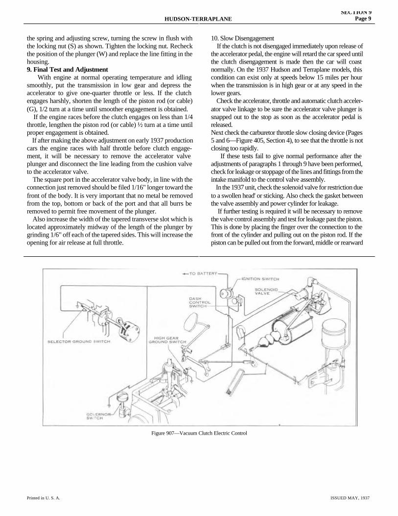
HUDSON-TERRAPLANESECTION 9
Page 9
Printed in U. S. A. ISSUED MAY, 1937
the spring and adjusting screw, turning the screw in flush with the locking nut (S) as shown. Tighten the locking nut. Recheck the position of the plunger (W) and replace the line fitting in the housing.9. Final Test and Adjustment With engine at normal operating temperature and idling smoothly, put the transmission in low gear and depress the accelerator to give one-quarter throttle or less. If the clutch engages harshly, shorten the length of the piston rod (or cable) (G), 1/2 turn at a time until smoother engagement is obtained. If the engine races before the clutch engages on less than 1/4 throttle, lengthen the piston rod (or cable) ½ turn at a time until proper engagement is obtained. If after making the above adjustment on early 1937 production cars the engine races with half throttle before clutch engage-ment, it will be necessary to remove the accelerator valve plunger and disconnect the line leading from the cushion valve to the accelerator valve. The square port in the accelerator valve body, in line with the connection just removed should be filed 1/16" longer toward the front of the body. It is very important that no metal be removed from the top, bottom or back of the port and that all burrs be removed to permit free movement of the plunger. Also increase the width of the tapered transverse slot which is located approximately midway of the length of the plunger by grinding 1/6" off each of the tapered sides. This will increase the opening for air release at full throttle.
10. Slow Disengagement If the clutch is not disengaged immediately upon release of the accelerator pedal, the engine will retard the car speed until the clutch disengagement is made then the car will coast normally. On the 1937 Hudson and Terraplane models, this condition can exist only at speeds below 15 miles per hour when the transmission is in high gear or at any speed in the lower gears. Check the accelerator, throttle and automatic clutch acceler-ator valve linkage to be sure the accelerator valve plunger is snapped out to the stop as soon as the accelerator pedal is released.Next check the carburetor throttle slow closing device (Pages 5 and 6—Figure 405, Section 4), to see that the throttle is not closing too rapidly. If these tests fail to give normal performance after the adjustments of paragraphs 1 through 9 have been performed, check for leakage or stoppage of the lines and fittings from the intake manifold to the control valve assembly. In the 1937 unit, check the solenoid valve for restriction due to a swollen head' or sticking. Also check the gasket between the valve assembly and power cylinder for leakage. If further testing is required it will be necessary to remove the valve control assembly and test for leakage past the piston. This is done by placing the finger over the connection to the front of the cylinder and pulling out on the piston rod. If the piston can be pulled out from the forward, middle or rearward
Figure 907—Vacuum Clutch Electric Control
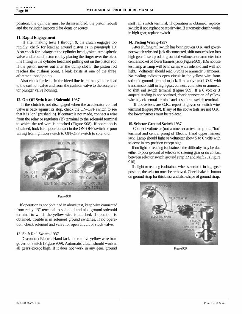
SECTION 9Page 10 MECHANICAL PROCECDURE MANUAL
ISSUED MAY, 1937 Printed in U. S. A.
position, the cylinder must be disassembled, the piston rebuilt and the cylinder inspected for dents or scores.
11. Rapid Engagement If after making tests 1 through 9, the clutch engages too rapidly, check for leakage around piston as in paragraph 10. Also check for leakage at the cylinder head gasket, atmospheric valve and around piston rod by placing the finger over the bleed line fitting in the cylinder head and pulling out on the piston rod. If the piston moves out after the dump slot in the piston rod reaches the cushion point, a leak exists at one of the three aforementioned points. Also check for leaks in the bleed line from the cylinder head to the cushion valve and from the cushion valve to the accelera-tor plunger valve housing.
12. On-Off Switch and Solenoid-1937 If the clutch is not disengaged when the accelerator control valve is back against its stop, check the ON-OFF switch to see that it is "on" (pushed in). If contact is not made, connect a wire from the relay or regulator (B) terminal to the solenoid terminal to which the red wire is attached (Figure 908). If operation is obtained, look for a poor contact in the ON-OFF switch or poor wiring from ignition switch to ON-OFF switch to solenoid.
If operation is not obtained in above test, keep wire connected from relay "B" terminal to solenoid and also ground solenoid terminal to which the yellow wire is attached. If operation is obtained, trouble is in solenoid ground switches. If no opera- tion, check solenoid and valve for open circuit or stuck valve.
13. Shift Rail Switch-1937 Disconnect Electric Hand Jack and remove yellow wire from governor switch (Figure 909). Automatic clutch should work in all gears except high. If it does not work in any gear, ground shift rail switch
shift rail switch terminal. If operation is obtained, replace switch; if not, replace or repair wire. If automatic clutch works in high gear, replace switch.
14. Testing Wiring-1937 After shifting rail switch has been proven O.K. and gover-nor switch wire and jack disconnected, shift transmission into high gear. Insert prod of grounded voltmeter or ammeter into central socket of lower harness jack (Figure 909). (Do not use test lamp as lamp will be in series with solenoid and will not light.) Voltmeter should read 6 volts or ammeter 3 amperes. No reading indicates open circuit in the yellow wire from solenoid ground terminal to jack. If the above test is O.K. with transmission still in high gear, connect voltmeter or ammeter to shift rail switch terminal (Figure 909). If a 6 volt or 3 ampere reading is not obtained, check connection of yellow wire at jack central terminal and at shift rail switch terminal. If above tests are O.K., repeat at governor switch wire terminal (Figure 909). If any of the above tests are not O.K., the lower harness must be replaced.
15. Selector Ground Switch-1937 Connect voltmeter (not ammeter) or test lamp to a "hot" terminal and central prong of Electric Hand upper harness jack. Lamp should light or voltmeter show 5 to 6 volts with selector in any position except high. If no light or reading is obtained, the difficulty may be due either to poor ground of selector to steering gear or no contact between selector switch ground strap 22 and shaft 23 (Figure 910). If a light or reading is obtained when selector is in high gear position, the selector must be removed. Check bakelite button on ground strap for thickness and also shape of ground strap.
Figure 908
Figure 909

HUDSON-TERRAPLANESECTION 9
Page 11
Printed in U. S. A. ISSUED MAY, 1937
16. Governor Switch-1937 This test can be made on road or with rear wheels jacked up. With transmission in high gear—selector in high gear and yellow wire connected to governor, start engine. With clutch held out by foot pedal, automatic clutch should operate as accelerator pedal is depressed and released. If not, replace gov-ernor switch.
With clutch engaged, transmission in high and selector in high, increase engine speed until speedometer registers 25 m.p.h. When foot is removed from accelerator, clutch should remain engaged until speedometer shows 20 m.p.h. but should be disengaged before speedometer shows 16 m.p.h. on deceleration. If disengagement does not take place within this speed range, replace governor switch.
Figure 910—Figure 910—Electric Hand Selector with Automatic Clutch Ground Switch-1937


SECTION 10
TRANSMISSIONService Magazine—Reference Sheet and Service Bullet in Reference
Bulletin orReference SheetNo. MagazineIssue and Page
Date Subject DETAILS OF INFORMATION
MECHANICAL PROCEDURE MANUAL Page 1

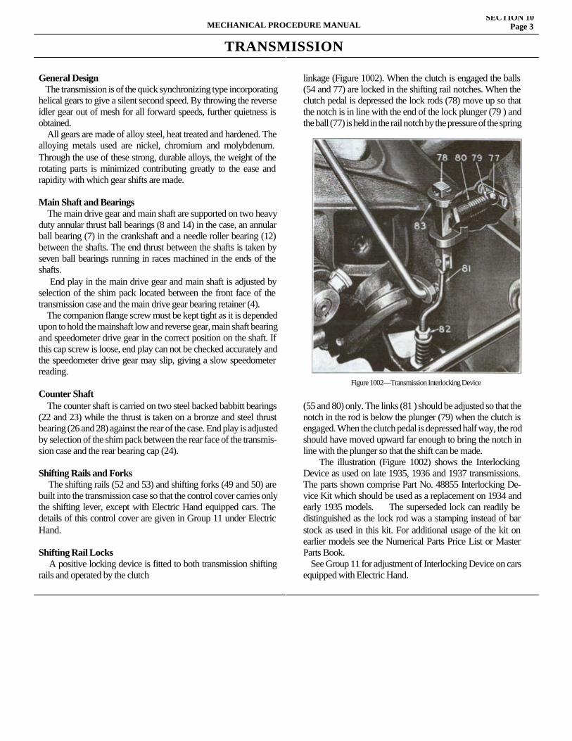
TRANSMISSION
General Design The transmission is of the quick synchronizing type incorporating helical gears to give a silent second speed. By throwing the reverse idler gear out of mesh for all forward speeds, further quietness is obtained. All gears are made of alloy steel, heat treated and hardened. The alloying metals used are nickel, chromium and molybdenum. Through the use of these strong, durable alloys, the weight of the rotating parts is minimized contributing greatly to the ease and rapidity with which gear shifts are made.
Main Shaft and Bearings The main drive gear and main shaft are supported on two heavy duty annular thrust ball bearings (8 and 14) in the case, an annular ball bearing (7) in the crankshaft and a needle roller bearing (12) between the shafts. The end thrust between the shafts is taken by seven ball bearings running in races machined in the ends of the shafts. End play in the main drive gear and main shaft is adjusted by selection of the shim pack located between the front face of the transmission case and the main drive gear bearing retainer (4). The companion flange screw must be kept tight as it is depended upon to hold the mainshaft low and reverse gear, main shaft bearing and speedometer drive gear in the correct position on the shaft. If this cap screw is loose, end play can not be checked accurately and the speedometer drive gear may slip, giving a slow speedometer reading.
Counter Shaft The counter shaft is carried on two steel backed babbitt bearings (22 and 23) while the thrust is taken on a bronze and steel thrust bearing (26 and 28) against the rear of the case. End play is adjusted by selection of the shim pack between the rear face of the transmis-sion case and the rear bearing cap (24).
Shifting Rails and Forks The shifting rails (52 and 53) and shifting forks (49 and 50) are built into the transmission case so that the control cover carries only the shifting lever, except with Electric Hand equipped cars. The details of this control cover are given in Group 11 under Electric Hand.
Shifting Rail Locks A positive locking device is fitted to both transmission shifting rails and operated by the clutch
linkage (Figure 1002). When the clutch is engaged the balls (54 and 77) are locked in the shifting rail notches. When the clutch pedal is depressed the lock rods (78) move up so that the notch is in line with the end of the lock plunger (79 ) and the ball (77) is held in the rail notch by the pressure of the spring
(55 and 80) only. The links (81 ) should be adjusted so that the notch in the rod is below the plunger (79) when the clutch is engaged. When the clutch pedal is depressed half way, the rod should have moved upward far enough to bring the notch in line with the plunger so that the shift can be made. The illustration (Figure 1002) shows the Interlocking Device as used on late 1935, 1936 and 1937 transmissions. The parts shown comprise Part No. 48855 Interlocking De-vice Kit which should be used as a replacement on 1934 and early 1935 models. The superseded lock can readily be distinguished as the lock rod was a stamping instead of bar stock as used in this kit. For additional usage of the kit on earlier models see the Numerical Parts Price List or Master Parts Book. See Group 11 for adjustment of Interlocking Device on cars equipped with Electric Hand.
MECHANICAL PROCEDURE MANUALSECTION 10
Page 3
Figure 1002—Transmission Interlocking Device
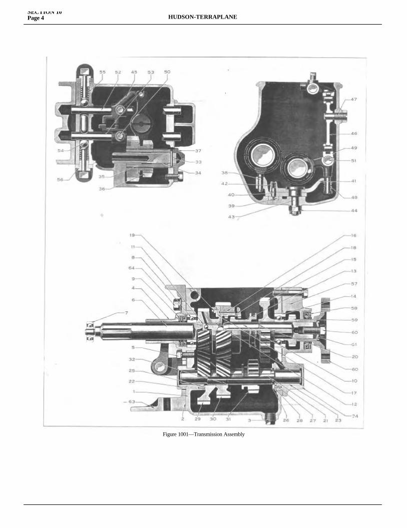
SECTION 10Page 4 HUDSON-TERRAPLANE
Figure 1001—Transmission Assembly
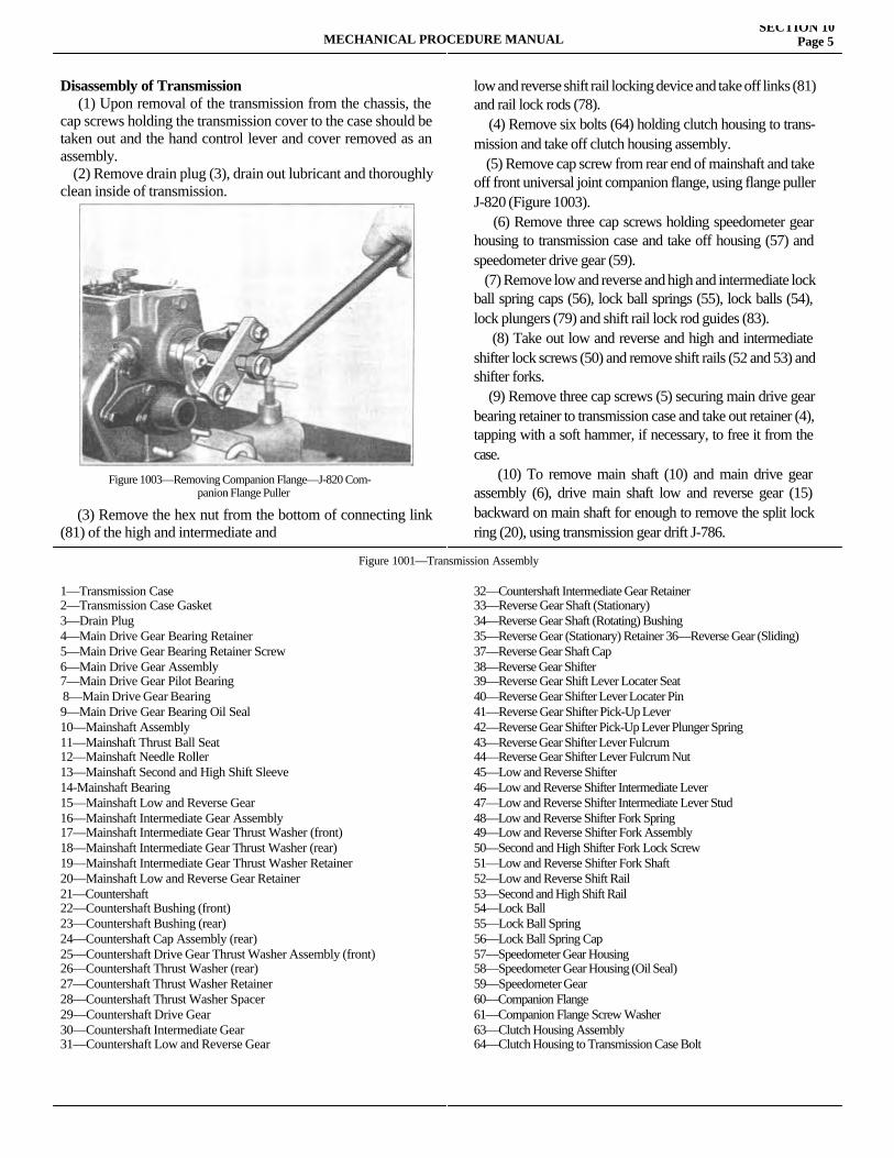
Disassembly of Transmission (1) Upon removal of the transmission from the chassis, the cap screws holding the transmission cover to the case should be taken out and the hand control lever and cover removed as an assembly. (2) Remove drain plug (3), drain out lubricant and thoroughly clean inside of transmission.
(3) Remove the hex nut from the bottom of connecting link (81) of the high and intermediate and
low and reverse shift rail locking device and take off links (81) and rail lock rods (78). (4) Remove six bolts (64) holding clutch housing to trans-mission and take off clutch housing assembly. (5) Remove cap screw from rear end of mainshaft and take off front universal joint companion flange, using flange puller J-820 (Figure 1003). (6) Remove three cap screws holding speedometer gear housing to transmission case and take off housing (57) and speedometer drive gear (59). (7) Remove low and reverse and high and intermediate lock ball spring caps (56), lock ball springs (55), lock balls (54), lock plungers (79) and shift rail lock rod guides (83). (8) Take out low and reverse and high and intermediate shifter lock screws (50) and remove shift rails (52 and 53) and shifter forks. (9) Remove three cap screws (5) securing main drive gear bearing retainer to transmission case and take out retainer (4), tapping with a soft hammer, if necessary, to free it from the case. (10) To remove main shaft (10) and main drive gear assembly (6), drive main shaft low and reverse gear (15) backward on main shaft for enough to remove the split lock ring (20), using transmission gear drift J-786.
1—Transmission Case2—Transmission Case Gasket3—Drain Plug4—Main Drive Gear Bearing Retainer 5—Main Drive Gear Bearing Retainer Screw 6—Main Drive Gear Assembly7—Main Drive Gear Pilot Bearing 8—Main Drive Gear Bearing9—Main Drive Gear Bearing Oil Seal 10—Mainshaft Assembly11—Mainshaft Thrust Ball Seat12—Mainshaft Needle Roller13—Mainshaft Second and High Shift Sleeve 14-Mainshaft Bearing15—Mainshaft Low and Reverse Gear 16—Mainshaft Intermediate Gear Assembly17—Mainshaft Intermediate Gear Thrust Washer (front) 18—Mainshaft Intermediate Gear Thrust Washer (rear) 19—Mainshaft Intermediate Gear Thrust Washer Retainer 20—Mainshaft Low and Reverse Gear Retainer 21—Countershaft22—Countershaft Bushing (front)23—Countershaft Bushing (rear)24—Countershaft Cap Assembly (rear) 25—Countershaft Drive Gear Thrust Washer Assembly (front)26—Countershaft Thrust Washer (rear) 27—Countershaft Thrust Washer Retainer 28—Countershaft Thrust Washer Spacer 29—Countershaft Drive Gear30—Countershaft Intermediate Gear 31—Countershaft Low and Reverse Gear
32—Countershaft Intermediate Gear Retainer33—Reverse Gear Shaft (Stationary)34—Reverse Gear Shaft (Rotating) Bushing35—Reverse Gear (Stationary) Retainer 36—Reverse Gear (Sliding)37—Reverse Gear Shaft Cap38—Reverse Gear Shifter39—Reverse Gear Shift Lever Locater Seat40—Reverse Gear Shifter Lever Locater Pin41—Reverse Gear Shifter Pick-Up Lever42—Reverse Gear Shifter Pick-Up Lever Plunger Spring43—Reverse Gear Shifter Lever Fulcrum44—Reverse Gear Shifter Lever Fulcrum Nut45—Low and Reverse Shifter46—Low and Reverse Shifter Intermediate Lever47—Low and Reverse Shifter Intermediate Lever Stud 48—Low and Reverse Shifter Fork Spring49—Low and Reverse Shifter Fork Assembly50—Second and High Shifter Fork Lock Screw51—Low and Reverse Shifter Fork Shaft52—Low and Reverse Shift Rail53—Second and High Shift Rail54—Lock Ball55—Lock Ball Spring56—Lock Ball Spring Cap57—Speedometer Gear Housing58—Speedometer Gear Housing (Oil Seal)59—Speedometer Gear60—Companion Flange61—Companion Flange Screw Washer63—Clutch Housing Assembly64—Clutch Housing to Transmission Case Bolt
MECHANICAL PROCEDURE MANUALSECTION 10
Page 5
Figure 1003—Removing Companion Flange—J-820 Com-panion Flange Puller
Figure 1001—Transmission Assembly
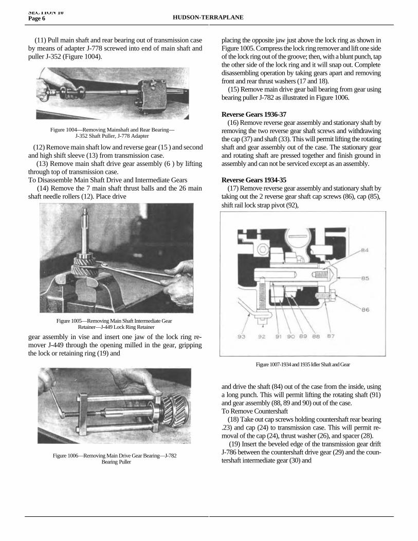
(11) Pull main shaft and rear bearing out of transmission case by means of adapter J-778 screwed into end of main shaft and puller J-352 (Figure 1004).
(12) Remove main shaft low and reverse gear (15 ) and second and high shift sleeve (13) from transmission case. (13) Remove main shaft drive gear assembly (6 ) by lifting through top of transmission case.To Disassemble Main Shaft Drive and Intermediate Gears (14) Remove the 7 main shaft thrust balls and the 26 main shaft needle rollers (12). Place drive
gear assembly in vise and insert one jaw of the lock ring re-mover J-449 through the opening milled in the gear, gripping the lock or retaining ring (19) and
placing the opposite jaw just above the lock ring as shown in Figure 1005. Compress the lock ring remover and lift one side of the lock ring out of the groove; then, with a blunt punch, tap the other side of the lock ring and it will snap out. Complete disassembling operation by taking gears apart and removing front and rear thrust washers (17 and 18). (15) Remove main drive gear ball bearing from gear using bearing puller J-782 as illustrated in Figure 1006.
Reverse Gears 1936-37 (16) Remove reverse gear assembly and stationary shaft by removing the two reverse gear shaft screws and withdrawing the cap (37) and shaft (33). This will permit lifting the rotating shaft and gear assembly out of the case. The stationary gear and rotating shaft are pressed together and finish ground in assembly and can not be serviced except as an assembly.
Reverse Gears 1934-35 (17) Remove reverse gear assembly and stationary shaft by taking out the 2 reverse gear shaft cap screws (86), cap (85), shift rail lock strap pivot (92),
and drive the shaft (84) out of the case from the inside, using a long punch. This will permit lifting the rotating shaft (91) and gear assembly (88, 89 and 90) out of the case.To Remove Countershaft (18) Take out cap screws holding countershaft rear bearing .23) and cap (24) to transmission case. This will permit re-moval of the cap (24), thrust washer (26), and spacer (28). (19) Insert the beveled edge of the transmission gear drift J-786 between the countershaft drive gear (29) and the coun-tershaft intermediate gear (30) and
SECTION 10Page 6 HUDSON-TERRAPLANE
Figure 1004—Removing Mainshaft and Rear Bearing—J-352 Shaft Puller, J-778 Adapter
Figure 1005—Removing Main Shaft Intermediate GearRetainer—J-449 Lock Ring Retainer
Figure 1006—Removing Main Drive Gear Bearing—J-782Bearing Puller
Figure 1007-1934 and 1935 Idler Shaft and Gear
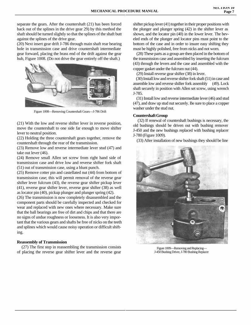
separate the gears. After the countershaft (21) has been forced back out of the splines in the drive gear 29) by this method the shaft should be turned slightly so that the splines of the shaft butt against the splines of the drive gear.(20) Next insert gear drift J-786 through main shaft rear bearing hole in transmission case and drive countershaft intermediate gear forward, placing the brass end of the drift against the gear hub, Figure 1008. (Do not drive the gear entirely off the shaft.)
(21) With the low and reverse shifter lever in reverse position, move the countershaft to one side far enough to move shifter lever to neutral position.(22) Holding the three countershaft gears together, remove the countershaft through the rear of the transmission.(23) Remove low and reverse intermediate lever stud (47) and take out lever (46).(24) Remove small Allen set screw from right hand side of transmission case and drive low and reverse shifter fork shaft (51) out of transmission case, using a blunt punch.(25) Remove cotter pin and castellated nut (44) from bottom of transmission case; this will permit removal of the reverse gear shifter lever fulcrum (43), the reverse gear shifter pickup lever (41), reverse gear shifter lever, reverse gear shifter (38) as well as locator pin (40), pickup plunger and plunger spring (42).(26) The transmission is now completely disassembled and the component parts should be carefully inspected and checked for wear and replaced with new ones where necessary. Make sure that the ball bearings are free of dirt and chips and that there are no signs of undue roughness or looseness. It is also very impor-tant that the various gears and shafts be free of nicks on the teeth and splines which would cause noisy operation or difficult shift-ing.
Reassembly of Transmission (27) The first step in reassembling the transmission consists of placing the reverse gear shifter lever and the reverse gear shifter
shifter pickup lever (41) together in their proper positions with the plunger and plunger spring (42) in the shifter lever as shown, and the locator pin (40) in the lower lever. The bev-eled ends of the plunger and locator pins must point to the bottom of the case and in order to insure easy shifting they must be highly polished, free from nicks and not worn. (28) These parts as a group are then placed in the bottom of the transmission case and assembled by inserting the fulcrum (43) through the levers and the case and assembled with the copper gasket under the fulcrum nut (44). (29) Install reverse gear shifter (38) in lever. (30) Install low and reverse shifter fork shaft (51) in case and assemble low and reverse shifter fork assembly (49). Lock shaft securely in position with Allen set screw, using wrench J-785. (31) Install low and reverse intermediate lever (46) and stud (47), and draw up stud nut securely. Be sure to place a copper washer under the stud nut.
Countershaft Group (32) If renewal of countershaft bushings is necessary, the old bushings should be driven out with bushing remover J-450 and the new bushings replaced with bushing replacer J-780 (Figure 1009). (33) After installation of new bushings they should be line
MECHANICAL PROCEDURE MANUALSECTION 10
Page 7
Figure 1008—Removing Countershaft Gears—J-786 Drift
Figure 1009—Removing and Replacing—J-450 Bushing Driver, J-780 Bushing Replacer
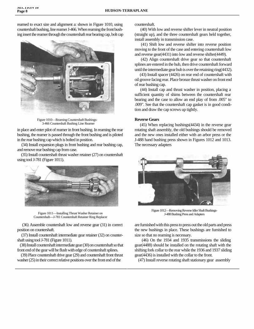
reamed to exact size and alignment a: shown in Figure 1010, using countershaft bushing, line reamer J-466. When reaming the front bush-ing insert the reamer through the countershaft rear bearing cap, bolt cap
in place and enter pilot of reamer in front bushing. In reaming the rear bushing, the reamer is passed through the front bushing and is piloted in the rear bushing cap which is bolted in position. (34) Install expansion plugs in front bushing and rear bushing cap, and remove rear bushing cap from case. (35) Install countershaft thrust washer retainer (27) on countershaft using tool J-781 (Figure 1011).
(36) Assemble countershaft low and reverse gear (31) in correct position on countershaft. (37) Install countershaft intermediate gear retainer (32) on counter-shaft using tool J-781 (Figure 1011). (38) Install countershaft intermediate gear (30) on countershaft so that front end of the gear will be flush with edge of countershaft splines. (39) Place countershaft drive gear (29) and countershaft front thrust washer (25) in their correct relative positions over the front end of the
countershaft. (40) With low and reverse shifter lever in neutral position (straight up), and the three countershaft gears held together, install assembly in transmission case. (41) Shift low and reverse shifter into reverse position moving to the front of the case and entering countershaft low and reverse gear(4431) into low and reverse shifter(4449). (42) Align countershaft drive gear so that countershaft splines are entered in the hub, then drive countershaft forward until the intermediate gear hub is over the retaining ring(4432). (43) Install spacer (4426) on rear end of countershaft with oil groove facing rear. Place bronze thrust washer on front end of rear bushing cap. (44) Install cap and thrust washer in position, placing a sufficient quantity of shims between the countershaft rear bearing and the case to allow an end play of from .005" to .009". See that the countershaft cap gasket is in good condi-tion and draw the cap screws up tightly.
Reverse Gears (45) When replacing bushings(4434) in the reverse gear rotating shaft assembly, the old bushings should be removed and the new ones installed either with an arbor press or the J-488 hand bushing press shown in Figures 1012 and 1013. The necessary adapters
are furnished with this press to press out the old parts and press the new bushings in place. These bushings are furnished to size so that no reaming is necessary. (46) On the 1934 and 1935 transmissions the sliding gear(4488) should be installed on the rotating shaft with the shifting fork collar to the rear while the 1936 and 1937 sliding gear(4436) is installed with the collar to the front. (47) Install reverse rotating shaft stationary gear assembly
SECTION 10Page 8 HUDSON-TERRAPLANE
Figure 1010—Reaming Countershaft Bushings-3-466 Countershaft Bushing Line Reamer
Figure 1011—Installing Thrust Washer Retainer onCountershaft—J-781 Countershaft Retainer Ring Replacer
Figure 1012—Removing Reverse Idler Shaft Bushings- J-488 Bushing Press and Adapters
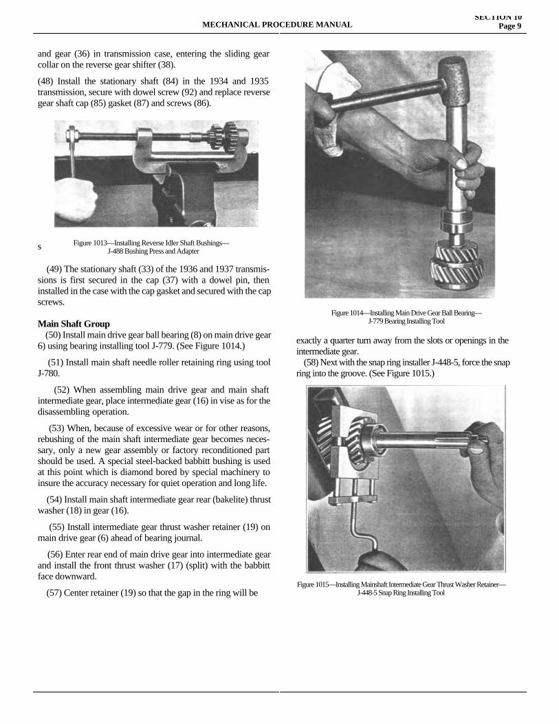
and gear (36) in transmission case, entering the sliding gear collar on the reverse gear shifter (38). (48) Install the stationary shaft (84) in the 1934 and 1935 transmission, secure with dowel screw (92) and replace reverse gear shaft cap (85) gasket (87) and screws (86).
s
(49) The stationary shaft (33) of the 1936 and 1937 transmis-sions is first secured in the cap (37) with a dowel pin, then installed in the case with the cap gasket and secured with the cap screws.
Main Shaft Group (50) Install main drive gear ball bearing (8) on main drive gear 6) using bearing installing tool J-779. (See Figure 1014.)
(51) Install main shaft needle roller retaining ring using tool J-780.
(52) When assembling main drive gear and main shaft intermediate gear, place intermediate gear (16) in vise as for the disassembling operation.
(53) When, because of excessive wear or for other reasons, rebushing of the main shaft intermediate gear becomes neces-sary, only a new gear assembly or factory reconditioned part should be used. A special steel-backed babbitt bushing is used at this point which is diamond bored by special machinery to insure the accuracy necessary for quiet operation and long life.
(54) Install main shaft intermediate gear rear (bakelite) thrust washer (18) in gear (16).
(55) Install intermediate gear thrust washer retainer (19) on main drive gear (6) ahead of bearing journal.
(56) Enter rear end of main drive gear into intermediate gear and install the front thrust washer (17) (split) with the babbitt face downward.
(57) Center retainer (19) so that the gap in the ring will be
exactly a quarter turn away from the slots or openings in the intermediate gear. (58) Next with the snap ring installer J-448-5, force the snap ring into the groove. (See Figure 1015.)
MECHANICAL PROCEDURE MANUALSECTION 10
Page 9
Figure 1013—Installing Reverse Idler Shaft Bushings—J-488 Bushing Press and Adapter
Figure 1014—Installing Main Drive Gear Ball Bearing—J-779 Bearing Installing Tool
Figure 1015—Installing Mainshaft Intermediate Gear Thrust Washer Retainer—J-448-5 Snap Ring Installing Tool
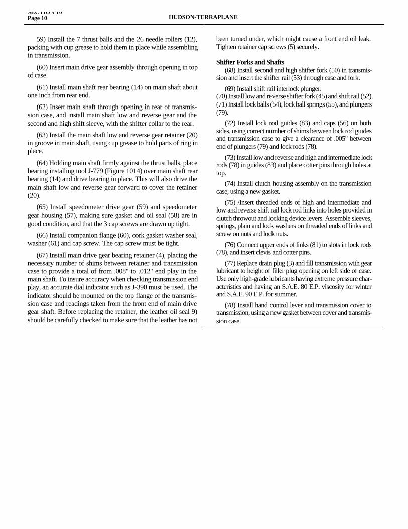
59) Install the 7 thrust balls and the 26 needle rollers (12), packing with cup grease to hold them in place while assembling in transmission.
(60) Insert main drive gear assembly through opening in top of case.
(61) Install main shaft rear bearing (14) on main shaft about one inch from rear end.
(62) Insert main shaft through opening in rear of transmis-sion case, and install main shaft low and reverse gear and the second and high shift sleeve, with the shifter collar to the rear.
(63) Install the main shaft low and reverse gear retainer (20) in groove in main shaft, using cup grease to hold parts of ring in place.
(64) Holding main shaft firmly against the thrust balls, place bearing installing tool J-779 (Figure 1014) over main shaft rear bearing (14) and drive bearing in place. This will also drive the main shaft low and reverse gear forward to cover the retainer (20).
(65) Install speedometer drive gear (59) and speedometer gear housing (57), making sure gasket and oil seal (58) are in good condition, and that the 3 cap screws are drawn up tight.
(66) Install companion flange (60), cork gasket washer seal, washer (61) and cap screw. The cap screw must be tight.
(67) Install main drive gear bearing retainer (4), placing the necessary number of shims between retainer and transmission case to provide a total of from .008" to .012" end play in the main shaft. To insure accuracy when checking transmission end play, an accurate dial indicator such as J-390 must be used. The indicator should be mounted on the top flange of the transmis-sion case and readings taken from the front end of main drive gear shaft. Before replacing the retainer, the leather oil seal 9) should be carefully checked to make sure that the leather has not
been turned under, which might cause a front end oil leak. Tighten retainer cap screws (5) securely.
Shifter Forks and Shafts (68) Install second and high shifter fork (50) in transmis-sion and insert the shifter rail (53) through case and fork.
(69) Install shift rail interlock plunger.(70) Install low and reverse shifter fork (45) and shift rail (52).(71) Install lock balls (54), lock ball springs (55), and plungers (79). (72) Install lock rod guides (83) and caps (56) on both sides, using correct number of shims between lock rod guides and transmission case to give a clearance of .005" between end of plungers (79) and lock rods (78).
(73) Install low and reverse and high and intermediate lock rods (78) in guides (83) and place cotter pins through holes at top. (74) Install clutch housing assembly on the transmission case, using a new gasket.
(75) /Insert threaded ends of high and intermediate and low and reverse shift rail lock rod links into holes provided in clutch throwout and locking device levers. Assemble sleeves, springs, plain and lock washers on threaded ends of links and screw on nuts and lock nuts.
(76) Connect upper ends of links (81) to slots in lock rods (78), and insert clevis and cotter pins.
(77) Replace drain plug (3) and fill transmission with gear lubricant to height of filler plug opening on left side of case. Use only high-grade lubricants having extreme pressure char-acteristics and having an S.A.E. 80 E.P. viscosity for winter and S.A.E. 90 E.P. for summer.
(78) Install hand control lever and transmission cover to transmission, using a new gasket between cover and transmis-sion case.
SECTION 10Page 10 HUDSON-TERRAPLANE

SECTION 11
THE ELECTRIC HANDService Magazine—Reference Sheet and Service Bullet in Reference
Bulletin orReference SheetNo. MagazineIssue and Page
Date Subject DETAILS OF INFORMATION
MECHANICAL PROCEDURE MANUAL Page 1

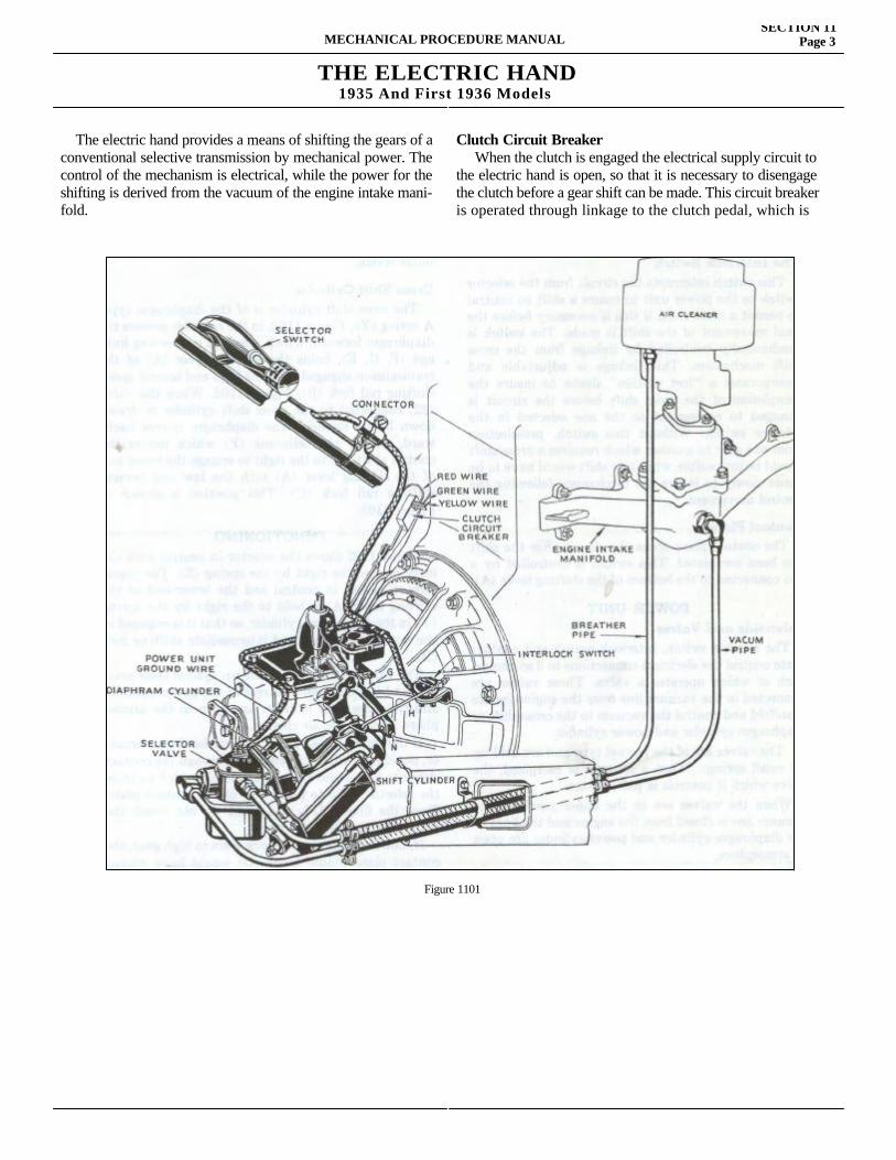
THE ELECTRIC HAND1935 And First 1936 Models
The electric hand provides a means of shifting the gears of a conventional selective transmission by mechanical power. The control of the mechanism is electrical, while the power for the shifting is derived from the vacuum of the engine intake mani-fold.
Clutch Circuit BreakerWhen the clutch is engaged the electrical supply circuit to
the electric hand is open, so that it is necessary to disengage the clutch before a gear shift can be made. This circuit breaker is operated through linkage to the clutch pedal, which is
MECHANICAL PROCEDURE MANUALSECTION 11
Page 3
Figure 1101
SECTION 11Page 4 HUDSON-TERRAPLANE
adjustable to determine the exact amount of clutch disengage-ment before the circuit is closed and a shift made and also the amount of clutch engagement before the power is again cut off.
The Selector Switch The selection of the gear desired in the transmission is made by moving the lever of the selector switch to the corresponding position in the H plate of the selector switch housing. This selects the proper circuit to control the shifting mechanism.
The Interlock Switch This switch interrupts the circuit from the selector switch to the power unit to insure a shift to neutral to permit a cross shift, if this is necessary before the final movement of the shift is made. The switch is mechanically controlled by linkage from the cross shift mechanism. This linkage is adjustable and incor-porates a "lost motion" sleeve to insure the completion of the cross shift before the circuit is changed to correspond to the one selected in the selector switch. Without this switch, preselection from one gear to another which requires a cross shift would be impossible, while any shift would have to be made slowly to insure the mechanism following the control movement.
Contact Plate The contact plate opens the circuit after the shift has been completed. This switch is controlled by a rod connected to the bottom of the shifting lever (A).
POWER UNITSolenoids and Valves The selector switch, interlock switch and contact plate control the electrical connections to 3 solenoids, each of which operates a valve. These valves are connected in the vacuum line from the engine intake manifold and control the vacuum to the cross shift or diaphragm cylinder and power cylinder. The valves are of the poppet type and are held up by small springs. When a solenoid is energized, the valve which it con-trols is pulled down. When the valves are in the upper position, the vacuum line is closed from the engine and the lines to the diaphragm cylinder and power cylinder are open to atmosphere. When the valves are in their lower position, the vacuum line from the engine is connected to the diaphragm cylinder or power cylinder. One valve controls the cross shift, one the forward and one the rearward movement of the transmission shifting rails.
Power Cylinder The power cylinder has a vacuum operated piston which provides the power for the forward and rearward movement for shifting the gears. When the valve (21) Figure 1102 in the vacuum line to the rear of the power cylinder is drawn down by its solenoid, opening the vacuum line, the piston moves backward. When the valve (20) in the vacuum line to the front of the power cylinder is drawn down by its solenoid, the piston moves forward. The movement of the piston is trans-mitted to the shifting lever (A) through the control cross shaft (E) and inner and outer levers.
Cross Shift Cylinder The cross shift cylinder is of the diaphragm type. A spring (Y), Figure 1102, in the cylinder presses the diaphragm for-ward, which, through connecting linkage (F, G, E), holds the shifting lever (A) of the transmission engaged with the high and second speed shifting rail fork (B), Figure 1102. When the valve (22) connected to the cross shift cylinder is drawn down by its solenoid, the diaphragm moves backward, pulling the bellcrank (F) which moves the control 'Shaft (E) to the right to engage the lower end of the shifting lever (A) with the low and reverse shifting rail fork (C). This position is shown in Figure 1103.
FUNCTIONING Figure 1102 shows the selector in neutral with the lever held to the right by the spring (Z). The transmission is also in neutral and the lower end of the shifting lever (A) is held to the right by the spring (Y) in the diaphragm cylinder, so that it is engaged in the notch of the high and intermediate shifting fork (B). The valves 20, 21 and 22 are up against their seats so that both the front and rear of the power cylinder and the cross shift cylinder are open to the atmosphere through the air cleaner. If the clutch is depressed, closing the circuit breaker, the circuit will be closed to 10, through the contact sleeve to 9, to 3 and 1 on the interlock switch to 13 on the selector to 15 to plate (W) of the contact plate. Since the fingers L-L and M-M do not touch the plate (W), the circuit is open. If, however, the transmission were in high gear, the contact plate sliding block 0) would have moved forward to the position of insert (A). The fingers (M-M) would be contacting plate (W) and would close the circuit to plate (I: to solenoid No. 2. The valve 21 would be pulled down connecting the rear of the power cylinder to the vacuum, so that the piston would move backward and, through the linkage (G, E and A), move
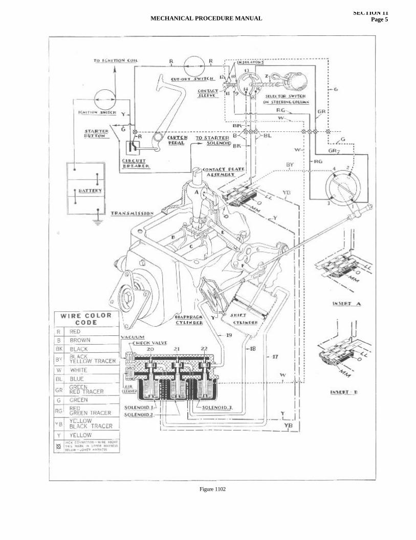
MECHANICAL PROCEDURE MANUALSECTION 11
Page 5
Figure 1102
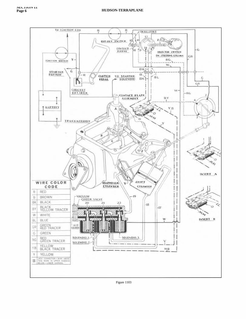
SECTION 11Page 6 HUDSON-TERRAPLANE
Figure 1103
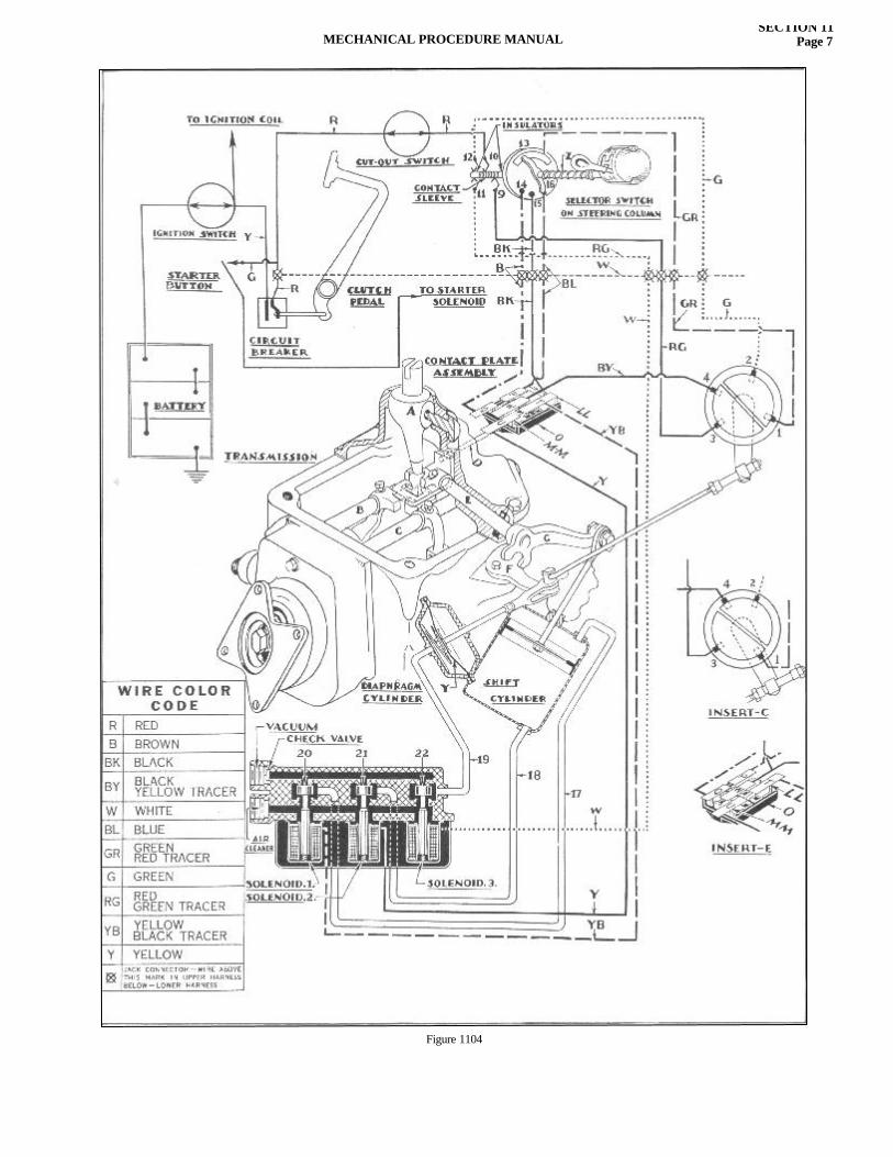
MECHANICAL PROCEDURE MANUALSECTION 11
Page 7
Figure 1104
SECTION 11Page 8 HUDSON-TERRAPLANE
the shifting rail (B) backward. The rod (D) would also be moved backward, pulling the contact plate sliding block until the fin-gers (M-M) break contact with the bar (W). When circuit is broken, the valve 21 raises to its seat and the shift is completed to neutral. If the transmission had been moved to second gear, the contact plate would have been in the position shown in insert (B), completing the circuit from (W), through fingers (L-L) to plate (T) to solenoid No. 1, opening the vacuum to the front of the power cylinder so that the piston would be moved forward, bringing the transmission into neutral where the fingers (L-L) would break contact with bar (W) and the shift would be com-pleted to neutral. Figure 1103 shows the same condition as in Figure 1102, except the selector lever has been pushed to the left but is still in the neutral position. It will be noted that the circuit from 10 in the selector switch is now completed through the contact sleeve to both 11 and 12. The circuit from 11 is direct to solenoid No. 3 so that valve No. 22 is drawn down, connecting the cross shift cylinder to the vacuum. The diaphragm has moved backward, rotating bell-crank (F) which pulls lever (G), shaft (E) and the lever (A) to the right so that (A) is engaged in the notch of the shifting fork of rail (C) which controls the shift into low and reverse gears. The circuit from 12 is to 2 and 1 on the interlock switch, to 13 to 15 on the selector switch to bar (W) on the contact plate. Now following the same procedure as under Figure 1102 it will be seen that, if the transmission were in low gear, the contact plate would be in the position of insert (A) (same as for high gear), energizing solenoid 2 and the shift would be to neutral. If the transmission were in reverse, the contact plate would be in the position of insert (B) (same as for second gear), energizing solenoid (1) and the shift would be to neutral. Referring again to Figure 1102 it will be seen that if the selector lever is moved to the high gear position (transmission in neutral), the circuit will be completed as before to 13 on the selector switch, then to 16 to (P) on the contact plate through the fingers (L-L) to (T) to solenoid 1 and the shifting rail (B) will be moved forward until the contact plate reaches the position of insert (A) when the fingers (L-L) will move off of bar (P) opening the circuit. If the selector lever is now moved to the second gear position (transmission in high or neutral), the circuit from 13 is to 14 on the selector switch to bar (Q) through the fingers (M-M) to bar (U), to solenoid 2 and the movement of the rail (B) will be
backward until the fingers (M-M) move off of bar (Q) open-ing the circuit as in insert (B). Referring to Figure 1103, the action will be the same for low and reverse as just explained for high and second as the lever (A) is held in engagement with the shifting rail (C) and all other circuits are identical. Figure 1104 shows the selector lever in the high gear position and the transmission in low gear. In order to shift from low to high, the power cylinder piston must first move backward and bring the transmission to neutral. We find that the circuit is correct for this as indicated by the solid lines from 10 to 9 and 3 to 4 on the interlock to bar (W) on the contact plate. The circuit is closed from (W) through the fingers (M-M) to bar (U) to solenoid 2 so that the movement will be backward until the fingers (M-M) break contact with the bar (W) which occurs when the transmission is in neutral. When the transmission shifting rail (C) reaches the neutral position, the force of the spring (Y) in the diaphragm cylinder will pull the shifting lever (A) to the left into engagement with the notch of the high and second shifting fork (B). As the cross shift is completed the interlock switch will be moved to the position shown in insert (C).Now the circuit from 3 in the interlock switch is to 1 to 13 to 16 to bar (P) in the contact plate. The contact plate having moved back in coming to neutral (insert E) the contact is now completed from (P) through fingers (L-L) to (T) to solenoid 1 and the piston is moved forward, moving rail (B) forward to the high gear position where the fingers (L-L) open the con-tact with bar (P) as at the beginning of the shift from low gear. Had the selector lever been set in the second gear position, Figure 1104, the movement to neutral would have been the same as for high gear. From neutral the movement would have been backward to second (instead of forward to high), as the circuit would have been completed from 13 to 14 (instead of to 16) to bar (Q) through (M-M) to (U) to solenoid 2. Also had the transmission been in reverse instead of low, the contact plate would have been to the rear (insert B) and the circuit from bar (W) would have been through fingers (L-L) to bar (T) to solenoid 1 and the movement would have been forward to neutral. Figure 1105 shows the transmission in high gear and the selector in low gear position. Here again it will be seen that the original circuit (full lines) is through the interlock switch to bar (W) to bring the transmission to neutral. When the lever (A) reaches the neutral position it will be drawn to the right to engage with the fork on shifting rail (C), since the circuit is complete from 11 to solenoid 3 and the interlock switch will
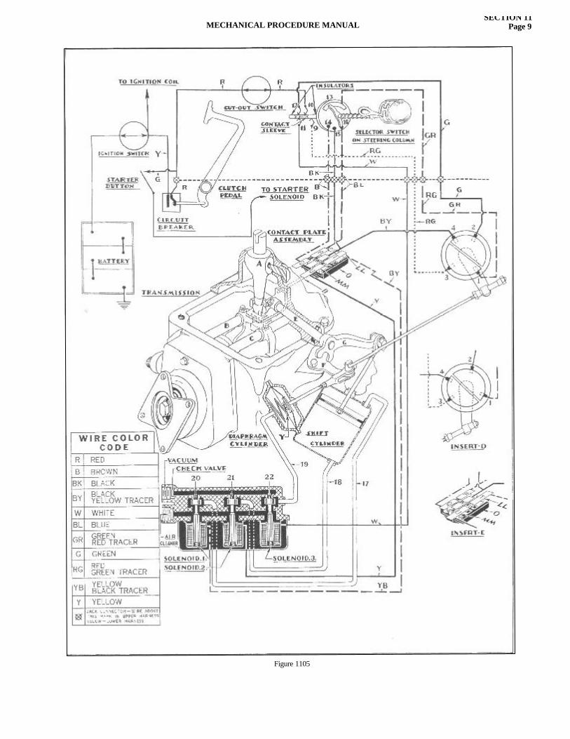
MECHANICAL PROCEDURE MANUALSECTION 11
Page 9
Figure 1105
SECTION 11Page 10 HUDSON-TERRAPLANE
be rotated to the position of insert (D). The circuit from 2 on the interlock switch is now to 1 and follows the path indicated by the broken lines to plate (P) on the contact plate. Since the contact plate has been moved to the neutral position (insert E), the circuit is now completed from (P) through (L-L) to (T) to solenoid 1 so that the shifting rail (C) is moved forward to the low gear position. Had the selector switch been set in reverse, connecting 13 and 14, the circuit (shown in dot and dash) would have been com-pleted to (Q) through (M-M) to (U) to solenoid No. 2, causing a normal neutral to reverse shift.
MECHANICAL ADJUSTMENT The entire mechanical adjustment is so important to proper functioning that it should be made carefully with every servicing of the electric hand. The recommended procedure is as follows:
The Clutch Circuit Breaker-1935 With clutch fully engaged, the pointer on the lever should be in line with the arrow on top of the circuit breaker housing. To adjust: 1 When equipped with automaticclutch control—loosen clamp bolt nut on bracket mounted on vacuum clutch rod and slide clip until pointer is in line with arrow. Tighten lock nut. 2—When not equipped with automatic clutch control remove cotter key from circuit breaker lever pin. Loosen lock nut on operating rod and remove rod end from lever pin. Turn rod end until it will slip on pin with pointer in line with arrow on housing. Insert cotter pin and tighten lock nut. The position of the circuit breaker lever is important. If the contact is made with too little clutch pedal movement, the clutch will still be engaged when the shift is made and if a gear has been preselected the shift will be made while the engine is driving the car. If the contact requires too much pedal move-ment, the shift will not be completed should the gears butt teeth. It is necessary to have a slight clutch drag before the circuit is broken to turn the gears and insure engagement. It may be necessary, therefore, to set circuit breaker slightly ahead of indicating arrow.
The Clutch Circuit Breaker-1936-1937 This clutch circuit breaker has lost motion built into the switch so that the clutch pedal must be depressed far enough to disengage the clutch before the electric hand circuit is closed, but the circuit will not be opened until the clutch is almost fully
engaged. If the clutch is not disengaged before the shift is made, it will cause the gears to clash. Opening of the electric hand circuit before the clutch has started to engage will result in failure of the gears to mesh, if the car is not in motion and the gear teeth strike end to end. The lock nut (B) should be loosened and yoke Figure 1106, on the rod, which operates the clutch circuit breaker should be
adjusted so that the clutch pedal must be depressed halfway to the toe board before the circuit is closed. The upper insert in Figure 1106 shows the position of the parts inside the circuit breaker at the point where the circuit is closed. (D) is the stationary contact and (E) the sliding contact. At the time the circuit is closed the transmission shifting rail locks must be released so that the shift can be made. The lower insert in Figure 1106 shows the proper position of the lock bar link (C) and plunger (F). After adjusting the circuit breaker for point of closing, check to be sure that the clutch has begun to take hold before the circuit is opened. This check is most readily made by running the engine and putting the transmission in low or reverse gear. Allow the clutch pedal to come up slowly. The car should start to move before the "click" of the cross shaft linkage is heard, indicating that the electric hand circuit has been opened. The insert of the circuit breaker in Figure 1107 shows the position of the parts at the point where the circuit is opened, while the shifting rail lock bars must be down, as shown in the lower insert (Figure 1107), to insure the transmission being
Figure 1106
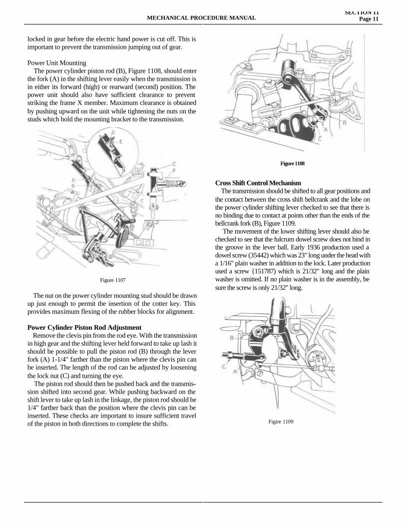
MECHANICAL PROCEDURE MANUALSECTION 11
Page 11
locked in gear before the electric hand power is cut off. This is important to prevent the transmission jumping out of gear.
Power Unit Mounting The power cylinder piston rod (B), Figure 1108, should enter the fork (A) in the shifting lever easily when the transmission is in either its forward (high) or rearward (second) position. The power unit should also have sufficient clearance to prevent striking the frame X member. Maximum clearance is obtained by pushing upward on the unit while tightening the nuts on the studs which hold the mounting bracket to the transmission.
The nut on the power cylinder mounting stud should be drawn up just enough to permit the insertion of the cotter key. This provides maximum flexing of the rubber blocks for alignment.
Power Cylinder Piston Rod Adjustment Remove the clevis pin from the rod eye. With the transmission in high gear and the shifting lever held forward to take up lash it should be possible to pull the piston rod (B) through the lever fork (A) 1-1/4" farther than the piston where the clevis pin can be inserted. The length of the rod can be adjusted by loosening the lock nut (C) and turning the eye. The piston rod should then be pushed back and the transmis-sion shifted into second gear. While pushing backward on the shift lever to take up lash in the linkage, the piston rod should be 1/4" farther back than the position where the clevis pin can be inserted. These checks are important to insure sufficient travel of the piston in both directions to complete the shifts.
Cross Shift Control Mechanism The transmission should be shifted to all gear positions and the contact between the cross shift bellcrank and the lobe on the power cylinder shifting lever checked to see that there is no binding due to contact at points other than the ends of the bellcrank fork (B), Figure 1109. The movement of the lower shifting lever should also be checked to see that the fulcrum dowel screw does not bind in the groove in the lever ball. Early 1936 production used a dowel screw (35442) which was 23" long under the head with a 1/16" plain washer in addition to the lock. Later production used a screw {151787) which is 21/32" long and the plain washer is omitted. If no plain washer is in the assembly, be sure the screw is only 21/32" long.
Figure 1107
Figure 1108
Figire 1109
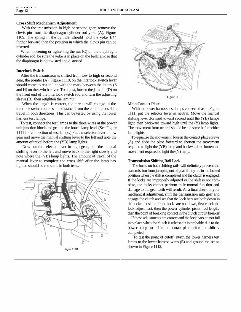
SECTION 11Page 12 HUDSON-TERRAPLANE
Cross Shift Mechanism Adjustment With the transmission in high or second gear, remove the clevis pin from the diaphragm cylinder rod yoke (A), Figure 1109. The spring in the cylinder should hold the yoke 1/4" farther forward than the position in which the clevis pin can be inserted. When loosening or tightening the nut (C) on the diaphragm cylinder rod, be sure the yoke is in place on the bellcrank so that the diaphragm is not twisted and distorted.
Interlock Switch After the transmission is shifted from low to high or second gear, the pointer (A), Figure 1110, on the interlock switch lever should come to rest in line with the mark between the letters (S and H) on the switch cover. To adjust, loosen the jam nut (D) on the front end of the interlock switch rod and turn the adjusting sleeve (B), then retighten the jam nut. When the length is correct, the circuit will change in the interlock switch at the same distance from the end of cross shift travel in both directions. This can be tested by using the lower harness test lamps. To test, connect the test lamps to the three wires at the power unit junction block and ground the fourth lamp lead. (See Figure 1111 for connection of test lamps.) Put the selector lever in low gear and move the manual shifting lever to the left and note the amount of travel before the (YB) lamp lights. Now put the selector lever in high gear, pull the manual shifting lever to the left and move back to the right slowly and note where the (YB) lamp lights. The amount of travel of the manual lever to complete the cross shift after the lamp has lighted should be the same in both tests.
Main Contact Plate With the lower harness test lamps connected as in Figure 1111, put the selector lever in neutral. Move the manual shifting lever .forward toward second until the (YB) lamps light, then backward toward high until the (Y) lamp lights. The movement from neutral should be the same before either lamp lights. To equalize the movement, loosen the contact plate screws (A) and slide the plate forward to shorten the movement required to light the (YB) lamp and backward to shorten the movement required to light the (Y) lamp.
Transmission Shifting Rail Lock The locks on both shifting rails will definitely prevent the transmission from jumping out of gear if they are in the locked position when the shift is completed and the clutch is engaged. If the locks are improperly adjusted or the shift is not com-plete, the locks cannot perform their normal function and damage to the gear teeth will result. As a final check of your mechanical adjustment, shift the transmission into gear and engage the clutch and see that the lock bars are both down in the locked position. If the locks are not down, first check the lock adjustment, then the power cylinder piston rod length, then the point of breaking contact in the clutch circuit breaker. If these adjustments are correct and the lock bars do not fall into place when the clutch is released it is probably due to the power being cut off in the contact plate before the shift is completed. To test the point of cutoff, attach the lower harness test lamps to the lower harness wires (E) and ground the set as shown in Figure 1112.
Figure 1110
Figure 1110
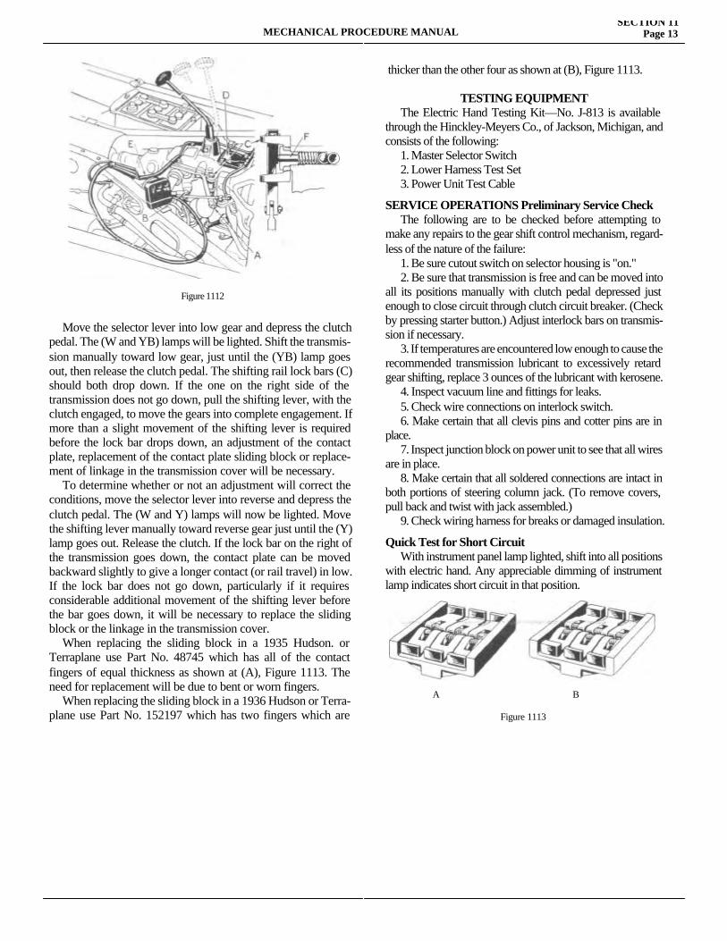
MECHANICAL PROCEDURE MANUALSECTION 11
Page 13
Move the selector lever into low gear and depress the clutch pedal. The (W and YB) lamps will be lighted. Shift the transmis-sion manually toward low gear, just until the (YB) lamp goes out, then release the clutch pedal. The shifting rail lock bars (C) should both drop down. If the one on the right side of the transmission does not go down, pull the shifting lever, with the clutch engaged, to move the gears into complete engagement. If more than a slight movement of the shifting lever is required before the lock bar drops down, an adjustment of the contact plate, replacement of the contact plate sliding block or replace-ment of linkage in the transmission cover will be necessary. To determine whether or not an adjustment will correct the conditions, move the selector lever into reverse and depress the clutch pedal. The (W and Y) lamps will now be lighted. Move the shifting lever manually toward reverse gear just until the (Y) lamp goes out. Release the clutch. If the lock bar on the right of the transmission goes down, the contact plate can be moved backward slightly to give a longer contact (or rail travel) in low. If the lock bar does not go down, particularly if it requires considerable additional movement of the shifting lever before the bar goes down, it will be necessary to replace the sliding block or the linkage in the transmission cover. When replacing the sliding block in a 1935 Hudson. or Terraplane use Part No. 48745 which has all of the contact fingers of equal thickness as shown at (A), Figure 1113. The need for replacement will be due to bent or worn fingers. When replacing the sliding block in a 1936 Hudson or Terra-plane use Part No. 152197 which has two fingers which are thicker
thicker than the other four as shown at (B), Figure 1113.
TESTING EQUIPMENT The Electric Hand Testing Kit—No. J-813 is available through the Hinckley-Meyers Co., of Jackson, Michigan, and consists of the following: 1. Master Selector Switch 2. Lower Harness Test Set 3. Power Unit Test Cable
SERVICE OPERATIONS Preliminary Service Check The following are to be checked before attempting to make any repairs to the gear shift control mechanism, regard-less of the nature of the failure: 1. Be sure cutout switch on selector housing is "on." 2. Be sure that transmission is free and can be moved into all its positions manually with clutch pedal depressed just enough to close circuit through clutch circuit breaker. (Check by pressing starter button.) Adjust interlock bars on transmis-sion if necessary. 3. If temperatures are encountered low enough to cause the recommended transmission lubricant to excessively retard gear shifting, replace 3 ounces of the lubricant with kerosene. 4. Inspect vacuum line and fittings for leaks. 5. Check wire connections on interlock switch. 6. Make certain that all clevis pins and cotter pins are in place. 7. Inspect junction block on power unit to see that all wires are in place. 8. Make certain that all soldered connections are intact in both portions of steering column jack. (To remove covers, pull back and twist with jack assembled.) 9. Check wiring harness for breaks or damaged insulation.
Quick Test for Short Circuit With instrument panel lamp lighted, shift into all positions with electric hand. Any appreciable dimming of instrument lamp indicates short circuit in that position.
Figure 1112
A B
Figure 1113
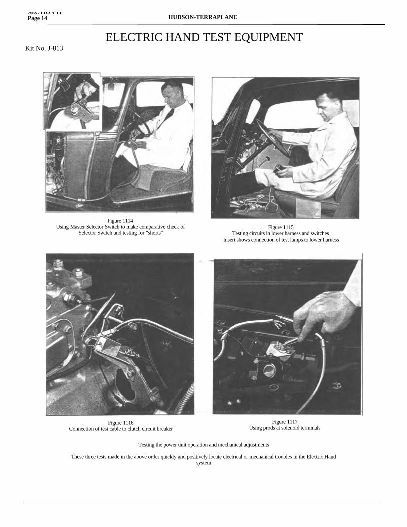
SECTION 11Page 14 HUDSON-TERRAPLANE
ELECTRIC HAND TEST EQUIPMENTKit No. J-813
Figure 1114Using Master Selector Switch to make comparative check of
Selector Switch and testing for "shorts"Figure 1115
Testing circuits in lower harness and switchesInsert shows connection of test lamps to lower harness
Figure 1116Connection of test cable to clutch circuit breaker
Figure 1117Using prods at solenoid terminals
Testing the power unit operation and mechanical adjustments
These three tests made in the above order quickly and positively locate electrical or mechanical troubles in the Electric Handsystem
MECHANICAL PROCEDURE MANUALSECTION 11
Page 15
Gears Are Shifted with Clutch Engaged Probably short circuit in clutch circuit breaker or improper adjustment of circuit breaker. 1. Check and if necessary adjust clutch circuit breaker. 2. Turn on ignition switch and press starter button; if starter operates with clutch fully engaged, replace circuit breaker.
Complete Failure of Electric Hand to Function After setting pointer and arrow on circuit breaker in line on 1935 models and the notch in the forward end of the circuit breaker rod flush with the housing on 1936 models, turn on ignition switch, depress clutch pedal and press starter button. If starter functions, circuit is closed through circuit breaker. If starter does not function, attach grounded test lamp to yellow wire terminal of circuit breaker. No light indicates open circuit from ignition switch to circuit breaker. Light indicates circuit breaker circuit open. Replace circuit breaker.
Failure of Electric Hand to Function in Any or All Positions If a proper circuit is proven through the circuit breaker and operation is still faulty, disconnect the separable jack on the bottom of the steering column and insert the jack from a master selector switch and wire assembly. (This unit does not require any ground.) If the system functions properly when using this selector switch instead of the one mounted on the car, the difficulty is in the selector. See note on page 15 if Master Selector Lamp lights. Do not replace selector until short circuit is removed.
Testing the Shifting Mechanism 1. Connect power unit test cable to the terminal on the clutch circuit breaker to which the red wire is attached. This wire should be hot only when the clutch is disengaged. 2. With the engine running and the clutch disengaged (rear wheels of car jacked up)—touch the front post (YB) of the junction block on the shifting unit with test prod. The transmis-sion should shift into high gear. Touch rear post (Y) and the transmission should shift to second gear. 3. Shift the transmission to neutral manually— First touch center post (W) with the test prod and the cross shift should be made. Still contacting (W), touch front post (YB) with second test prod. The transmission should shift into low. Touch rear post (Y), still contacting (W), and the shift should be made to reverse. If shift is not made when one of the posts is contacted, connect an accurate ammeter to the hot wire and to the terminal. A
current draw of approximately 2.5 amperes indicates that the solenoid is 0. K. A higher amperage indicates a short and a low amperage an open circuit. CAUTION: A dead short circuit in a solenoid will burn out ammeter if permanent connection is made. If the current draw is correct, the trouble may be due to the valve plunger sticking in its upward position, a vacuum leak-age in the lines or units or a mechanical drag in the mechanism. Disconnect the shifting cylinder piston rod from the shifting lever or the diaphragm cylinder from the cross shift bell crank. If these do not function after disconnecting the linkage, the entire power unit should be rebuilt.
Testing Circuits in Lower Harness and Switches If only partial functioning or complete failure is experienced after the Master Selector has been plugged in, test the com-plete circuits at the solenoid junction block with lower harness test lamp set. (This test must be performed with a Selector Switch known to be O.K.) A. Remove the three wires on end of wiring harness from junction block on selector valve. B. Insert these three wires into clips on lower harness test set, in correct position according to color. C. Attach ground clip to a clean metal ground on car. D. Turn ignition switch "on." Turn cutout switch "on" and hold clutch fully disengaged. E. Place selector lever in neutral. Place transmission in neutral manually. When shift lever is moved a short distance toward "second," test lamp (YB) should light. When shift lever is moved a short distance toward "high," test lamp (Y) should light. F. With transmission in neutral, move selector lever to low. Test lamp (W) only must light. G. Transmission remains in neutral. When selector lever is moved into "second" position, test lamp (Y) should light. When selector lever is moved into "high" position, the test lamp (YB) should light. Selector in low or in reverse lamp (W) only should light. H. As the transmission is shifted manually to correspond to any position chosen at the selector switch, the proper lamps, as indicated in (G), should remain lighted during the shift. However, lamp (Y) or (YB), whichever is lighted, should go out when the shift is completed. Lamp (W) alone will remain lighted in "low" or "reverse" position.
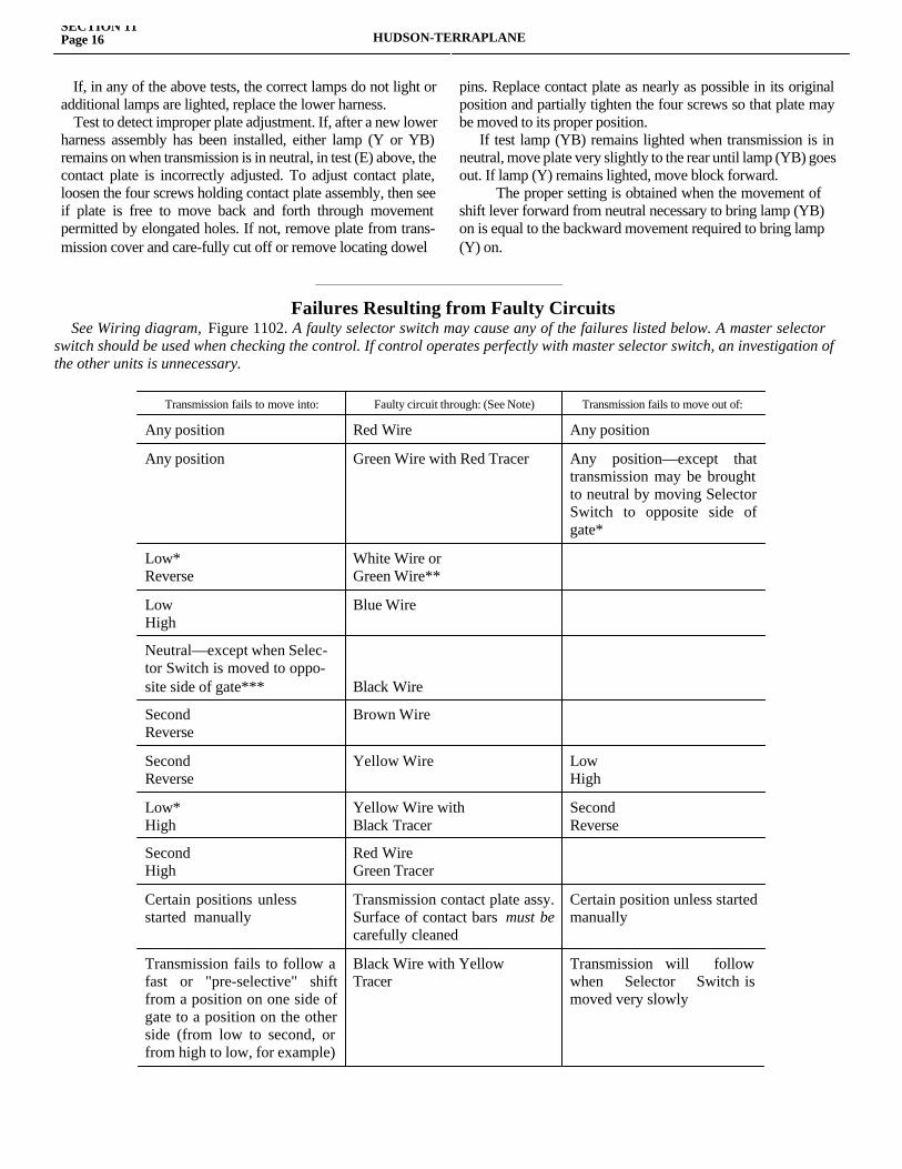
SECTION 11Page 16 HUDSON-TERRAPLANE
If, in any of the above tests, the correct lamps do not light or additional lamps are lighted, replace the lower harness. Test to detect improper plate adjustment. If, after a new lower harness assembly has been installed, either lamp (Y or YB) remains on when transmission is in neutral, in test (E) above, the contact plate is incorrectly adjusted. To adjust contact plate, loosen the four screws holding contact plate assembly, then see if plate is free to move back and forth through movement permitted by elongated holes. If not, remove plate from trans-mission cover and care-fully cut off or remove locating dowel
pins. Replace contact plate as nearly as possible in its original position and partially tighten the four screws so that plate may be moved to its proper position. If test lamp (YB) remains lighted when transmission is in neutral, move plate very slightly to the rear until lamp (YB) goes out. If lamp (Y) remains lighted, move block forward.
The proper setting is obtained when the movement of shift lever forward from neutral necessary to bring lamp (YB) on is equal to the backward movement required to bring lamp (Y) on.
________________________________________________________
Transmission fails to move into: Faulty circuit through: (See Note) Transmission fails to move out of:
Any position Red Wire Any position
Any position Green Wire with Red Tracer Any position—except that transmission may be brought to neutral by moving Selector Switch to opposite side of gate*
Low* Reverse
White Wire or Green Wire**
Low High
Blue Wire
Neutral—except when Selec-tor Switch is moved to oppo-site side of gate*** Black Wire
Second Reverse
Brown Wire
Second Reverse
Yellow Wire Low High
Low* High
Yellow Wire withBlack Tracer
Second Reverse
SecondHigh
Red Wire Green Tracer
Certain positions unless started manually
Transmission contact plate assy. Surface of contact bars must be carefully cleaned
Certain position unless started manually
Transmission fails to follow a fast or "pre-selective" shift from a position on one side of gate to a position on the other side (from low to second, or from high to low, for example)
Black Wire with Yellow Tracer
Transmission will follow when Selector Switch is moved very slowly
Failures Resulting from Faulty Circuits See Wiring diagram, Figure 1102. A faulty selector switch may cause any of the failures listed below. A master selector switch should be used when checking the control. If control operates perfectly with master selector switch, an investigation of the other units is unnecessary.
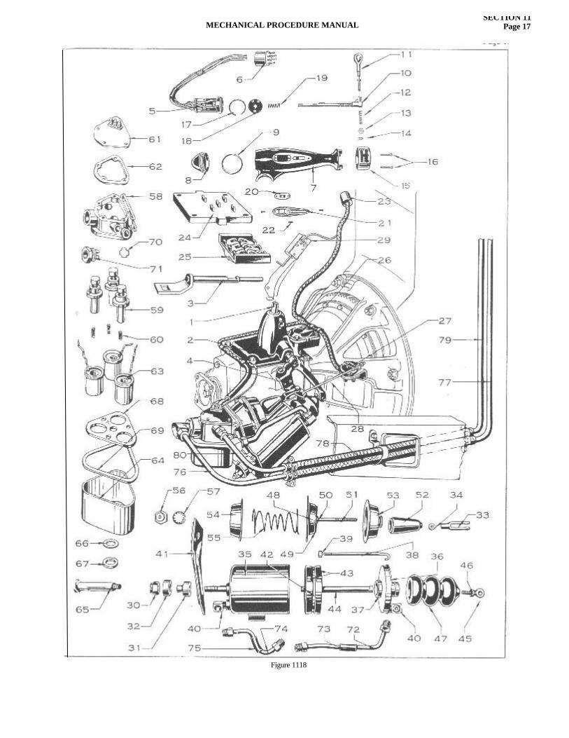
MECHANICAL PROCEDURE MANUALSECTION 11
Page 17
Figure 1118
SECTION 11Page 18 HUDSON-TERRAPLANE
To Check Position of Interlock Switch 1. Place the transmission in low gear and the selector switch in high gear and depress the clutch. Lamp (Y) should light and remain lighted until the transmission is shifted (manually) to neutral. Lamp (YB) should be lighted when cross shift to second and high side is completed. If lamp (YB) is lighted before the cross shift is practically completed, the interlock switch is not in proper position and should be adjusted so that the pointer on its lever is in line with the mark on the housing when the transmis-sion is in high gear. If adjustment does not give proper opera-tion, replace the interlock switch.
NOTE: Faulty circuit may be caused by either a short or an open circuit. In most cases, failure will be due to an open circuit or poor connection, but when a short is encountered, Master Selec-tor Switch fuse will blow. When this occurs, lamp adjacent to fuse should burn at full brilliance. (A 6-8 volt, 32 CP, single contact bulb must be used.) Allow Master Switch to remain in position which caused fuse to below (i.e., in a position in which bulb burns at full brilliance). Then check faulty circuit for a short. When short is located and eliminated, bulb will burn at approximately half brilliance—which is normal. After short has been eliminated, insert new 7-1/2 ampere fuse and check opera-tion of control in all positions.
SELECTOR SWITCH-1936-37NOTE: Operations 1 through 10 can be performed without removing the selector from the car or after the selector has been removed. Figures in parenthesis refer to Figure 1118 unless otherwise noted.
Selector Lever, Shaft and H Plate 1. Remove 2 screws (16) from H plate cap (15). 2. Hold cap to right and remove washer retainer (14); washer (13), spring (12) and lever (11). 3. Turn selector switch shaft (10) 3/4 turn clockwise (from right) and withdraw. 4. Replace parts removed by reversing operations 1, 2 and 3.
Selector Switch Cutout Switch 5. Remove the three screws (22) in the cutout switch plate and remove plate (21). 6. Lift switch and unsolder wires. 7. Replace switch and switch plate by reversing operations 5 and 6.
If test lamps do not burn at full brilliance and a good fuse is in place in the Master Selector, or when the Standard Selector is being used, check the voltage at the power unit terminals. If the voltage is one volt or more below the battery voltage, contacts and connections must be checked. Solder all harness bullet terminals to wire to insure good electrical contact.(*) If green wire with red tracer is damaged, transmission will not move out of neutral position into any other position, but if it is placed in high position manually, it may be brought to neutral by moving Selector Lever into "Low." If placed in low position manually, it may be brought to neutral by .placing Selector Lever in "high."(**) If green wire is damaged, shift lever will still move back and forth with Selector Lever as the latter is moved from left to right.If white wire is damaged, shift lever will remain on the second and high side, even though Selector Lever is moved back and forth from right to left. (***) If black wire is damaged, it is impossible to place transmission in neutral by merely moving Selector Lever to "Neutral." However, if transmission its in either second or high position, it may be placed in neutral by moving Selector Lever to "Neutral" and then as far to the left as possible. Transmission may be moved into and out of every position, except neutral, in the normal manner.
Connector Assembly (Harness Jack) 8. Remove cap from jack (6) by lifting until lock lug is out of groove in jack base and turn cap turn. 9. Separate male and female halves of jack and unsolder wires. 10. Reinstall by reversing operations 8 and 9. CAUTION: Be sure wires are soldered securely to proper terminals. See Figure 1119 for wire color codes.
Selector Switch Assembly—Remove 11. Remove connector (6)—see operations 8 and 9. 12. Remove piece of loom from selector wiring harness. 13. Remove selector switch cap (8) and washer (9). 14. Loosen selector housing mounting bolt nut (inside housing). 15. Slide selector housing downward to remove. 16. With-draw wires from steering column jacket tube.
_______________________________________
Removal Installation Repair
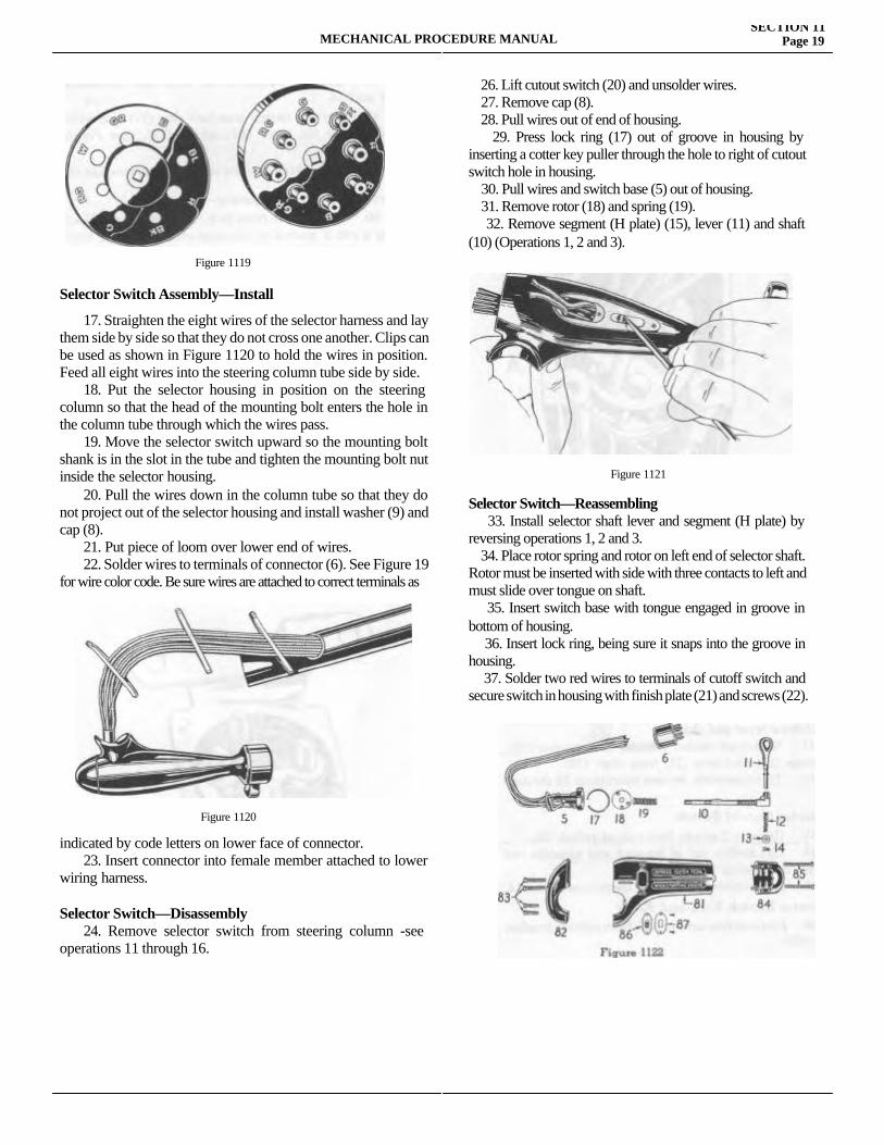
MECHANICAL PROCEDURE MANUALSECTION 11
Page 19
Selector Switch Assembly—Install
17. Straighten the eight wires of the selector harness and lay them side by side so that they do not cross one another. Clips can be used as shown in Figure 1120 to hold the wires in position. Feed all eight wires into the steering column tube side by side. 18. Put the selector housing in position on the steering column so that the head of the mounting bolt enters the hole in the column tube through which the wires pass. 19. Move the selector switch upward so the mounting bolt shank is in the slot in the tube and tighten the mounting bolt nut inside the selector housing. 20. Pull the wires down in the column tube so that they do not project out of the selector housing and install washer (9) and cap (8). 21. Put piece of loom over lower end of wires. 22. Solder wires to terminals of connector (6). See Figure 19 for wire color code. Be sure wires are attached to correct terminals as
indicated by code letters on lower face of connector. 23. Insert connector into female member attached to lower wiring harness.
Selector Switch—Disassembly 24. Remove selector switch from steering column -see operations 11 through 16.
26. Lift cutout switch (20) and unsolder wires. 27. Remove cap (8). 28. Pull wires out of end of housing. 29. Press lock ring (17) out of groove in housing by inserting a cotter key puller through the hole to right of cutout switch hole in housing. 30. Pull wires and switch base (5) out of housing. 31. Remove rotor (18) and spring (19). 32. Remove segment (H plate) (15), lever (11) and shaft (10) (Operations 1, 2 and 3).
Selector Switch—Reassembling 33. Install selector shaft lever and segment (H plate) by reversing operations 1, 2 and 3. 34. Place rotor spring and rotor on left end of selector shaft. Rotor must be inserted with side with three contacts to left and must slide over tongue on shaft. 35. Insert switch base with tongue engaged in groove in bottom of housing. 36. Insert lock ring, being sure it snaps into the groove in housing. 37. Solder two red wires to terminals of cutoff switch and secure switch in housing with finish plate (21) and screws (22).
Figure 1119
Figure 1120
Figure 1121
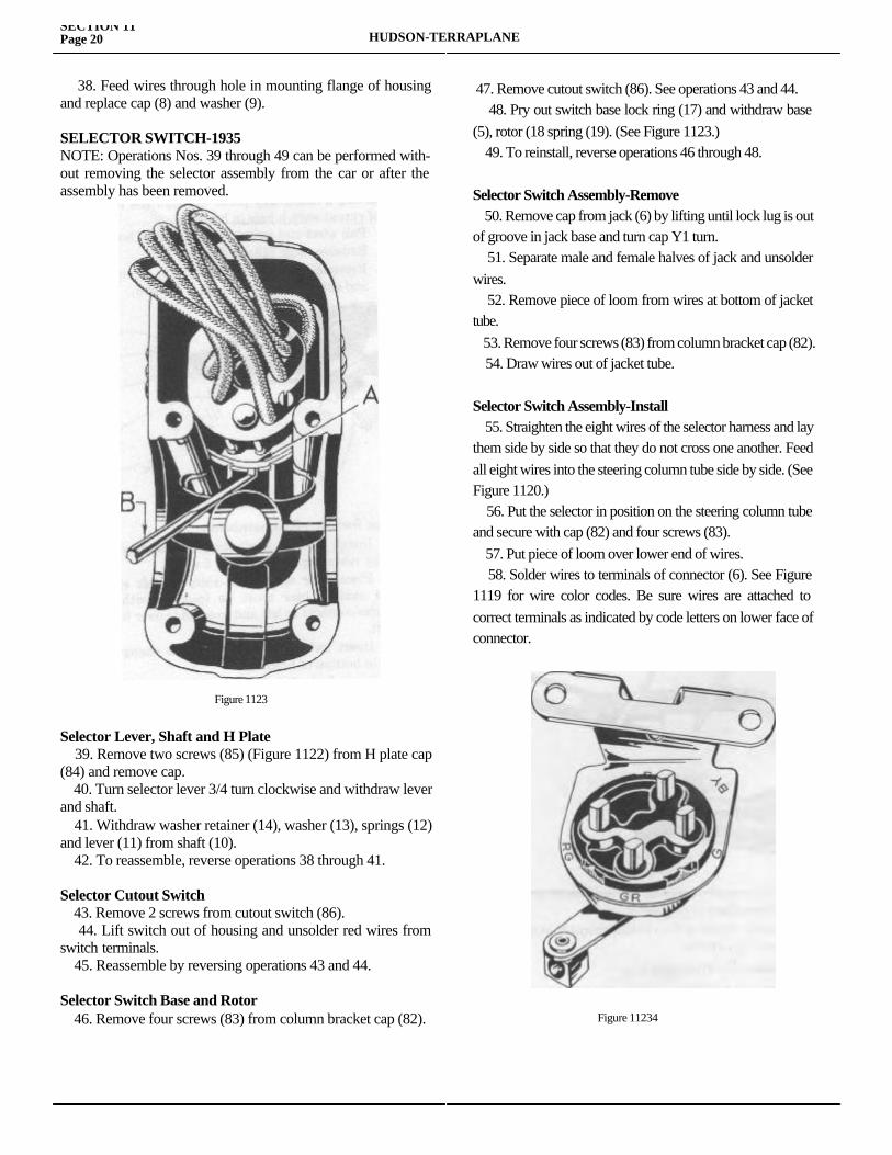
SECTION 11Page 20 HUDSON-TERRAPLANE
38. Feed wires through hole in mounting flange of housing and replace cap (8) and washer (9).
SELECTOR SWITCH-1935NOTE: Operations Nos. 39 through 49 can be performed with-out removing the selector assembly from the car or after the assembly has been removed.
Selector Lever, Shaft and H Plate 39. Remove two screws (85) (Figure 1122) from H plate cap (84) and remove cap. 40. Turn selector lever 3/4 turn clockwise and withdraw lever and shaft. 41. Withdraw washer retainer (14), washer (13), springs (12) and lever (11) from shaft (10). 42. To reassemble, reverse operations 38 through 41.
Selector Cutout Switch 43. Remove 2 screws from cutout switch (86). 44. Lift switch out of housing and unsolder red wires from switch terminals. 45. Reassemble by reversing operations 43 and 44.
Selector Switch Base and Rotor 46. Remove four screws (83) from column bracket cap (82).
47. Remove cutout switch (86). See operations 43 and 44. 48. Pry out switch base lock ring (17) and withdraw base (5), rotor (18 spring (19). (See Figure 1123.) 49. To reinstall, reverse operations 46 through 48.
Selector Switch Assembly-Remove 50. Remove cap from jack (6) by lifting until lock lug is out of groove in jack base and turn cap Y1 turn. 51. Separate male and female halves of jack and unsolder wires. 52. Remove piece of loom from wires at bottom of jacket tube. 53. Remove four screws (83) from column bracket cap (82). 54. Draw wires out of jacket tube.
Selector Switch Assembly-Install 55. Straighten the eight wires of the selector harness and lay them side by side so that they do not cross one another. Feed all eight wires into the steering column tube side by side. (See Figure 1120.) 56. Put the selector in position on the steering column tube and secure with cap (82) and four screws (83). 57. Put piece of loom over lower end of wires. 58. Solder wires to terminals of connector (6). See Figure 1119 for wire color codes. Be sure wires are attached to correct terminals as indicated by code letters on lower face of connector.
Figure 1123
Figure 11234
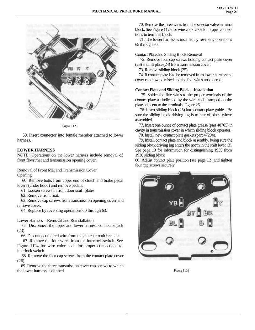
MECHANICAL PROCEDURE MANUALSECTION 11
Page 21
59. Insert connector into female member attached to lower harness.
LOWER HARNESSNOTE: Operations on the lower harness include removal of front floor mat and transmission opening cover.
Removal of Front Mat and Transmission CoverOpening 60. Remove bolts from upper end of clutch and brake pedal levers (under hood) and remove pedals. 61. Loosen screws in front door scuff plates. 62. Remove front mat. 63. Remove cap screws from transmission opening cover and remove cover. 64. Replace by reversing operations 60 through 63.
Lower Harness—Removal and Reinstallation 65. Disconnect the upper and lower harness connector jack (23). 66. Disconnect the red wire from the clutch circuit breaker. 67. Remove the four wires from the interlock switch. See Figure 1124 for wire color code for proper connections to interlock switch. 68. Remove the four cap screws from the contact plate cover (26). 69. Remove the three transmission cover cap screws to which the lower harness is clipped.
70. Remove the three wires from the selector valve terminal block. See Figure 1125 for wire color code for proper connec-tions to terminal block. 71. The lower harness is installed by reversing operations 65 through 70.
Contact Plate and Sliding Block Removal 72. Remove four cap screws holding contact plate cover (26) and lift plate (24) from transmission cover. 73. Remove sliding block (25). 74. If contact plate is to be removed from lower harness the cover can now be raised and the five wires unsoldered.
Contact Plate and Sliding Block—Installation 75. Solder the five wires to the proper terminals of the contact plate as indicated by the wire code stamped on the plate adjacent to the terminals. Figure 26. 76. Insert sliding block (25) into contact plate guides. Be sure the sliding block driving lug is to rear of block where assembled. 77. Insert one ounce of contact plate grease (part 48705) in cavity in transmission cover in which sliding block operates. 78. Install new contact plate gasket (part 47204). 79. Install contact plate and block assembly, being sure the sliding block driving lug enters the notch in the shift lever (3). See page 13 for information for distinguishing 1935 from 1936 sliding block.80. Adjust contact plate position (see page 12) and tighten four cap screws securely.
Figure 1125
Figure 1126
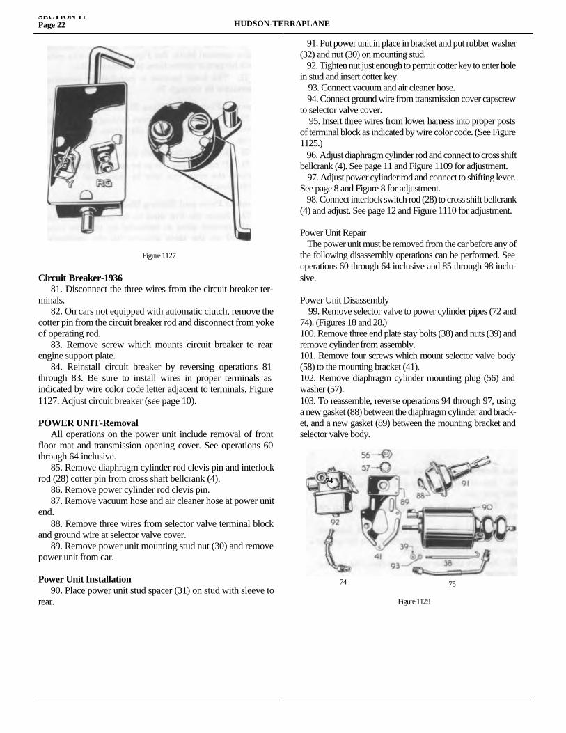
SECTION 11Page 22 HUDSON-TERRAPLANE
Circuit Breaker-1936 81. Disconnect the three wires from the circuit breaker ter-minals. 82. On cars not equipped with automatic clutch, remove the cotter pin from the circuit breaker rod and disconnect from yoke of operating rod. 83. Remove screw which mounts circuit breaker to rear engine support plate. 84. Reinstall circuit breaker by reversing operations 81 through 83. Be sure to install wires in proper terminals as indicated by wire color code letter adjacent to terminals, Figure 1127. Adjust circuit breaker (see page 10).
POWER UNIT-Removal All operations on the power unit include removal of front floor mat and transmission opening cover. See operations 60 through 64 inclusive. 85. Remove diaphragm cylinder rod clevis pin and interlock rod (28) cotter pin from cross shaft bellcrank (4). 86. Remove power cylinder rod clevis pin. 87. Remove vacuum hose and air cleaner hose at power unit end. 88. Remove three wires from selector valve terminal block and ground wire at selector valve cover. 89. Remove power unit mounting stud nut (30) and remove power unit from car.
Power Unit Installation 90. Place power unit stud spacer (31) on stud with sleeve to rear.
91. Put power unit in place in bracket and put rubber washer (32) and nut (30) on mounting stud. 92. Tighten nut just enough to permit cotter key to enter hole in stud and insert cotter key. 93. Connect vacuum and air cleaner hose. 94. Connect ground wire from transmission cover capscrew to selector valve cover. 95. Insert three wires from lower harness into proper posts of terminal block as indicated by wire color code. (See Figure 1125.) 96. Adjust diaphragm cylinder rod and connect to cross shift bellcrank (4). See page 11 and Figure 1109 for adjustment. 97. Adjust power cylinder rod and connect to shifting lever. See page 8 and Figure 8 for adjustment. 98. Connect interlock switch rod (28) to cross shift bellcrank (4) and adjust. See page 12 and Figure 1110 for adjustment.
Power Unit Repair The power unit must be removed from the car before any of the following disassembly operations can be performed. See operations 60 through 64 inclusive and 85 through 98 inclu-sive.
Power Unit Disassembly 99. Remove selector valve to power cylinder pipes (72 and 74). (Figures 18 and 28.)100. Remove three end plate stay bolts (38) and nuts (39) and remove cylinder from assembly.101. Remove four screws which mount selector valve body (58) to the mounting bracket (41).102. Remove diaphragm cylinder mounting plug (56) and washer (57).103. To reassemble, reverse operations 94 through 97, using a new gasket (88) between the diaphragm cylinder and brack-et, and a new gasket (89) between the mounting bracket and selector valve body.
Figure 1127
74
7474
75
Figure 1128
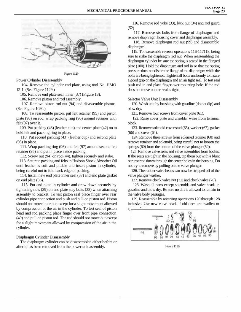
MECHANICAL PROCEDURE MANUALSECTION 11
Page 23
Power Cylinder Disassembly 104. Remove the cylinder end plate, using tool No. HMO 12-1. (See Figure 1129.) 105. Remove end plate seal, inner (37) (Figure 18). 106. Remove piston and rod assembly. 107. Remove piston rod nut (94) and disassemble pistons. (See Figure 1030.) 108. To reassemble piston, put felt retainer (95) and piston plate (98) on rod, wrap packing ring (96) around retainer with felt (97) over it. 109. Put packing (43) (leather cup) and center plate (42) on to hold felt and packing ring in place. 110. Put second packing (43) (leather cup) and second plate (98) in place. 111. Wrap packing ring (96) and felt (97) around second felt retainer (95) and put in place inside packing. 112. Screw nut (94) on rod (44), tighten securely and stake. 113. Saturate packing and felts in Hudson Shock Absorber Oil until leather is soft and pliable and insert piston in cylinder, being careful not to fold back edge of packing. 114. Install new end plate inner seal (37) and end plate gasket on end plate (36). 115. Put end plate in cylinder and draw down securely by tightening nuts (39) on end plate stay bolts (38) when attaching assembly to bracket. To test piston seal place finger over rear cylinder pipe connection and push and pull on piston rod. Piston should not move in or out except for a slight movement allowed by compression of the air in the cylinder. To test seal of piston head and rod packing place finger over front pipe connection (40) and pull on piston rod. The rod should not move out except for a slight movement allowed by compression of the air in the cylinder.
Diaphragm Cylinder Disassembly The diaphragm cylinder can be disassembled either before or after it has been removed from the power unit assembly.
116. Remove rod yoke (33), lock nut (34) and rod guard (52). 117. Remove six bolts from flange of diaphragm and remove diaphragm housing cover and diaphragm assembly. 118. Remove diaphragm rod nut (99) and disassemble diaphragm. 119. To reassemble reverse operations 116-117118, being sure to stake the diaphragm rod nut. When reassembling the diaphragm cylinder be sure the spring is seated in the flanged plate (100). Hold the diaphragm and rod in so that the spring pressure does not distort the flange of the diaphragm while the bolts are being tightened. Tighten all bolts uniformly to insure a good grip on the diaphragm and an air tight seal. To test seal push rod in and place finger over mounting hole. If the rod does not move out the seal is tight.
Selector Valve Unit Disassembly 120. Wash unit by brushing with gasoline (do not dip) and blow dry. 121. Remove four screws from cover plate (61). 122. Raise cover plate and unsolder wires from terminal block. 123. Remove solenoid cover stud (65), washer (67), gasket (66) and cover (64). 124. Remove three screws from solenoid retainer (68) and remove retainer and solenoid, being careful not to loosen the springs (60) from the bottom of the valve plunger (59). 125. Remove valve seats and valve assemblies from bodies. If the seats are tight in the housing, tap them out with a blunt bar inserted down through the center holes in the housing. Do not try to remove by pulling on the valve plunger. 126. The rubber valve heads can now be stripped off of the valve plunger washer. 127. Remove check valve nut (71) and check valve (70). 128. Wash all parts except solenoids and valve heads in gasoline and blow dry. Be sure no dirt is allowed to remain in the valve body passages. 129. Reassemble by reversing operations 120 through 128 inclusive. Use new valve heads if old ones are swollen or spongy from
Figure 1129
Figure 1129
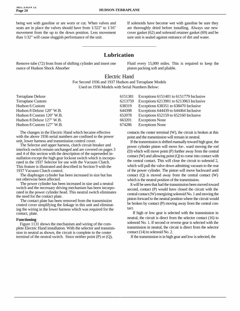
SECTION 11Page 24 HUDSON-TERRAPLANE
being wet with gasoline or are worn or cut. When valves and seats are in place the valves should have from 1/322" to 1/16" movement from the up to the down position. Less movement than 1/32" will cause sluggish performance of the unit.
If solenoids have become wet with gasoline be sure they are thoroughly dried before installing. Always use new cover gasket (62) and solenoid retainer gasket (69) and be sure unit is sealed against entrance of dirt and water.
_____________________________________
LubricationRemove tube (72) from front of shifting cylinder and insert one ounce of Hudson Shock Absorber
Fluid every 15,000 miles. This is required to keep the piston packing soft and pliable.
Electric HandFor Second 1936 and 1937 Hudson and Terraplane Models
Used on 1936 Models with Serial Numbers Below:
Terraplane Deluxe 6151381 Exceptions 6151401 to 6151779 InclusiveTerraplane Custom 6213759 Exceptions 6213901 to 6213963 InclusiveHudson 6 Custom 638319 Exceptions 638351 to 638470 InclusiveHudson 8 Deluxe 120" W.B. 644398 Exceptions 644439 to 644464 InclusiveHudson 8 Custom 120" W.B. 652078 Exceptions 652159 to 652160 InclusiveHudson 8 Deluxe 127" W.B. 663201 Exceptions NoneHudson 8 Custom 127" W.B. 674286 Exceptions None
The changes in the Electric Hand which became effective with the above 1936 serial numbers are confined to the power unit, lower harness and transmission control cover. The Selector and upper harness, clutch circuit breaker and interlock switch remain unchanged and are covered on pages 3 and 4 of this section with the description of the superseded in-stallation except the high gear lockout switch which is incorpo-rated in the 1937 Selector for use with the Vacuum Clutch. This feature is illustrated and described in Section 9 with the 1937 Vacuum Clutch control. The diaphragm cylinder has been increased in size but has not otherwise been affected. The power cylinder has been increased in size and a neutral switch and the necessary driving mechanism has been incorpo-rated in the power cylinder head. This neutral switch eliminates the need for the contact plate. The contact plate has been removed from the transmission control cover simplifying the linkage in this unit and eliminat-ing the wiring in the lower harness which was required for the contact, plate.Functioning Figure 1131 shows the mechanism and wiring of the com-plete Electric Hand installation. With the selector and transmis-sion in neutral as shown, the circuit is complete to the center terminal of the neutral switch. Since neither point (P) or (Q),
contacts the center terminal (W), the circuit is broken at this point and the transmission will remain in neutral. If the transmission is shifted manually toward high gear, the power cylinder piston will move for-. ward moving the rod (D) which will move point (P) further away from the central contact (W) and allowing point (Q) to come into contact with the central contact. This will close the circuit to solenoid 2, which will pull the valve down admitting vacuum to the rear of the power cylinder. The piston will move backward until contact (Q) is moved away from the central contact (W) which is the neutral position of the transmission. It will be seen that had the transmission been moved toward second, contact (P) would have closed the circuit with the central contact (W) energizing solenoid No. 1 and moving the piston forward to the neutral position where the circuit would be broken by contact (P) moving away from the central con-tact. If high or low gear is selected with the transmission in neutral, the circuit is direct from the selector contact (16) to solenoid No. 1. If second or reverse gear is selected with the transmission in neutral, the circuit is direct from the selector contact (14) to solenoid No. 2. If the transmission is in high gear and low is selected, the
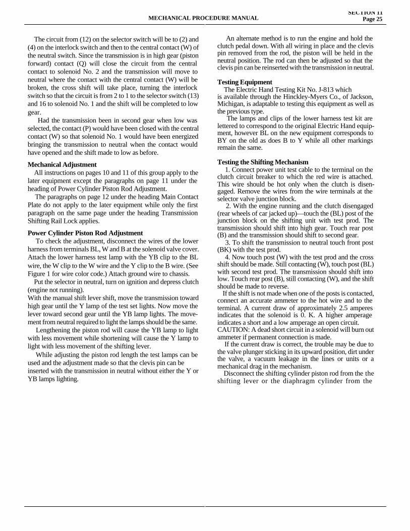
MECHANICAL PROCEDURE MANUALSECTION 11
Page 25
The circuit from (12) on the selector switch will be to (2) and (4) on the interlock switch and then to the central contact (W) of the neutral switch. Since the transmission is in high gear (piston forward) contact (Q) will close the circuit from the central contact to solenoid No. 2 and the transmission will move to neutral where the contact with the central contact (W) will be broken, the cross shift will take place, turning the interlock switch so that the circuit is from 2 to 1 to the selector switch (13) and 16 to solenoid No. 1 and the shift will be completed to low gear. Had the transmission been in second gear when low was selected, the contact (P) would have been closed with the central contact (W) so that solenoid No. 1 would have been energized bringing the transmission to neutral when the contact would have opened and the shift made to low as before.
Mechanical Adjustment All instructions on pages 10 and 11 of this group apply to the later equipment except the paragraphs on page 11 under the heading of Power Cylinder Piston Rod Adjustment. The paragraphs on page 12 under the heading Main Contact Plate do not apply to the later equipment while only the first paragraph on the same page under the heading Transmission Shifting Rail Lock applies.
Power Cylinder Piston Rod Adjustment To check the adjustment, disconnect the wires of the lower harness from terminals BL, W and B at the solenoid valve cover. Attach the lower harness test lamp with the YB clip to the BL wire, the W clip to the W wire and the Y clip to the B wire. (See Figure 1 for wire color code.) Attach ground wire to chassis. Put the selector in neutral, turn on ignition and depress clutch (engine not running).With the manual shift lever shift, move the transmission toward high gear until the Y lamp of the test set lights. Now move the lever toward second gear until the YB lamp lights. The move-ment from neutral required to light the lamps should be the same. Lengthening the piston rod will cause the YB lamp to light with less movement while shortening will cause the Y lamp to light with less movement of the shifting lever. While adjusting the piston rod length the test lamps can be used and the adjustment made so that the clevis pin can beinserted with the transmission in neutral without either the Y or YB lamps lighting.
An alternate method is to run the engine and hold the clutch pedal down. With all wiring in place and the clevis pin removed from the rod, the piston will be held in the neutral position. The rod can then be adjusted so that the clevis pin can be reinserted with the transmission in neutral.
Testing Equipment The Electric Hand Testing Kit No. J-813 whichis available through the Hinckley-Myers Co., of Jackson, Michigan, is adaptable to testing this equipment as well as the previous type. The lamps and clips of the lower harness test kit are lettered to correspond to the original Electric Hand equip-ment, however BL on the new equipment corresponds to BY on the old as does B to Y while all other markings remain the same.
Testing the Shifting Mechanism 1. Connect power unit test cable to the terminal on the clutch circuit breaker to which the red wire is attached. This wire should be hot only when the clutch is disen-gaged. Remove the wires from the wire terminals at the selector valve junction block. 2. With the engine running and the clutch disengaged (rear wheels of car jacked up)—touch the (BL) post of the junction block on the shifting unit with test prod. The transmission should shift into high gear. Touch rear post (B) and the transmission should shift to second gear. 3. To shift the transmission to neutral touch front post (BK) with the test prod. 4. Now touch post (W) with the test prod and the cross shift should be made. Still contacting (W), touch post (BL) with second test prod. The transmission should shift into low. Touch rear post (B), still contacting (W), and the shift should be made to reverse. If the shift is not made when one of the posts is contacted, connect an accurate ammeter to the hot wire and to the terminal. A current draw of approximately 2.5 amperes indicates that the solenoid is 0. K. A higher amperage indicates a short and a low amperage an open circuit.CAUTION: A dead short circuit in a solenoid will burn out ammeter if permanent connection is made. If the current draw is correct, the trouble may be due to the valve plunger sticking in its upward position, dirt under the valve, a vacuum leakage in the lines or units or a mechanical drag in the mechanism. Disconnect the shifting cylinder piston rod from the the shifting lever or the diaphragm cylinder from the cross
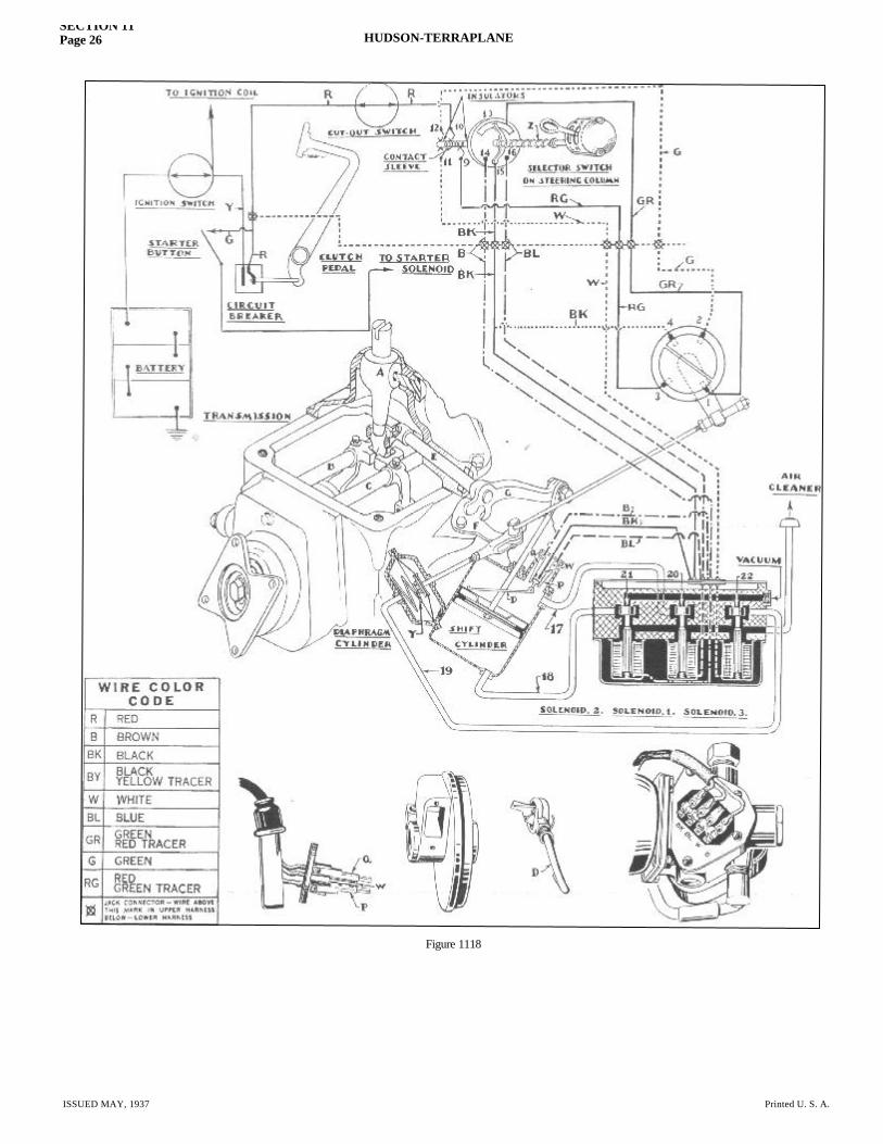
Figure 1118
SECTION 11Page 26 HUDSON-TERRAPLANE
ISSUED MAY, 1937 Printed U. S. A.
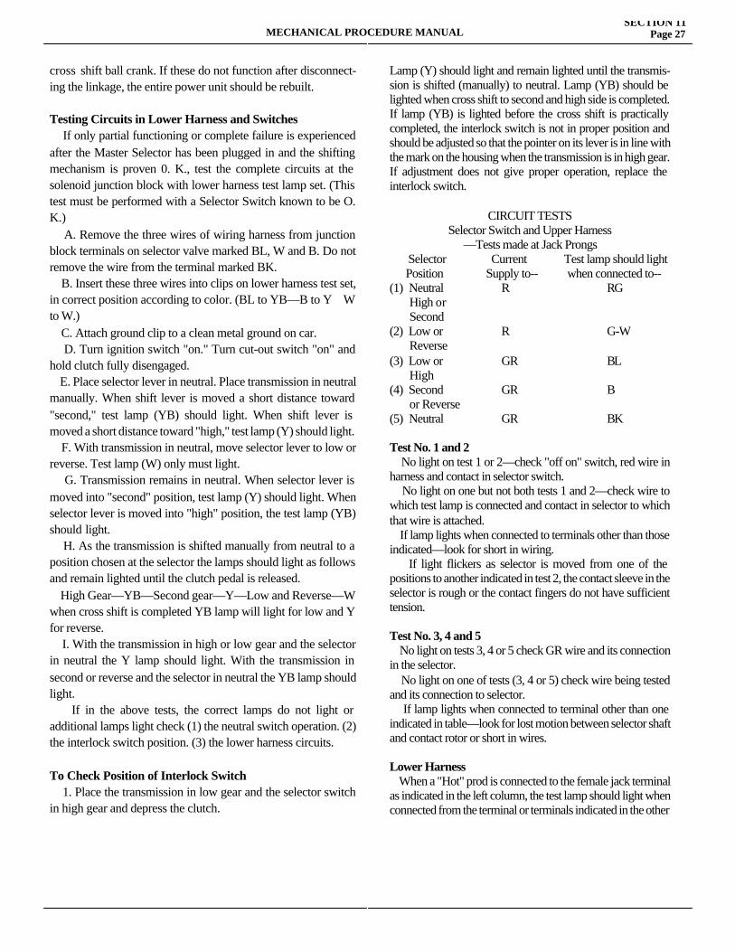
MECHANICAL PROCEDURE MANUALSECTION 11
Page 27
cross shift ball crank. If these do not function after disconnect-ing the linkage, the entire power unit should be rebuilt.
Testing Circuits in Lower Harness and Switches If only partial functioning or complete failure is experienced after the Master Selector has been plugged in and the shifting mechanism is proven 0. K., test the complete circuits at the solenoid junction block with lower harness test lamp set. (This test must be performed with a Selector Switch known to be O. K.) A. Remove the three wires of wiring harness from junction block terminals on selector valve marked BL, W and B. Do not remove the wire from the terminal marked BK. B. Insert these three wires into clips on lower harness test set, in correct position according to color. (BL to YB—B to Y W to W.) C. Attach ground clip to a clean metal ground on car. D. Turn ignition switch "on." Turn cut-out switch "on" and hold clutch fully disengaged. E. Place selector lever in neutral. Place transmission in neutral manually. When shift lever is moved a short distance toward "second," test lamp (YB) should light. When shift lever is moved a short distance toward "high," test lamp (Y) should light. F. With transmission in neutral, move selector lever to low or reverse. Test lamp (W) only must light. G. Transmission remains in neutral. When selector lever is moved into "second" position, test lamp (Y) should light. When selector lever is moved into "high" position, the test lamp (YB) should light. H. As the transmission is shifted manually from neutral to a position chosen at the selector the lamps should light as follows and remain lighted until the clutch pedal is released. High Gear—YB—Second gear—Y—Low and Reverse—W when cross shift is completed YB lamp will light for low and Y for reverse. I. With the transmission in high or low gear and the selector in neutral the Y lamp should light. With the transmission in second or reverse and the selector in neutral the YB lamp should light. If in the above tests, the correct lamps do not light or additional lamps light check (1) the neutral switch operation. (2) the interlock switch position. (3) the lower harness circuits.
To Check Position of Interlock Switch 1. Place the transmission in low gear and the selector switch in high gear and depress the clutch.
Lamp (Y) should light and remain lighted until the transmis-sion is shifted (manually) to neutral. Lamp (YB) should be lighted when cross shift to second and high side is completed. If lamp (YB) is lighted before the cross shift is practically completed, the interlock switch is not in proper position and should be adjusted so that the pointer on its lever is in line with the mark on the housing when the transmission is in high gear. If adjustment does not give proper operation, replace the interlock switch.
CIRCUIT TESTSSelector Switch and Upper Harness
—Tests made at Jack Prongs Selector Current Test lamp should light Position Supply to-- when connected to--(1) Neutral R RG High or Second(2) Low or R G-W Reverse(3) Low or GR BL High(4) Second GR B or Reverse(5) Neutral GR BK
Test No. 1 and 2 No light on test 1 or 2—check "off on" switch, red wire in harness and contact in selector switch. No light on one but not both tests 1 and 2—check wire to which test lamp is connected and contact in selector to which that wire is attached. If lamp lights when connected to terminals other than those indicated—look for short in wiring. If light flickers as selector is moved from one of the positions to another indicated in test 2, the contact sleeve in the selector is rough or the contact fingers do not have sufficient tension.
Test No. 3, 4 and 5 No light on tests 3, 4 or 5 check GR wire and its connection in the selector. No light on one of tests (3, 4 or 5) check wire being tested and its connection to selector. If lamp lights when connected to terminal other than one indicated in table—look for lost motion between selector shaft and contact rotor or short in wires.
Lower Harness When a "Hot" prod is connected to the female jack terminal as indicated in the left column, the test lamp should light when connected from the terminal or terminals indicated in the other
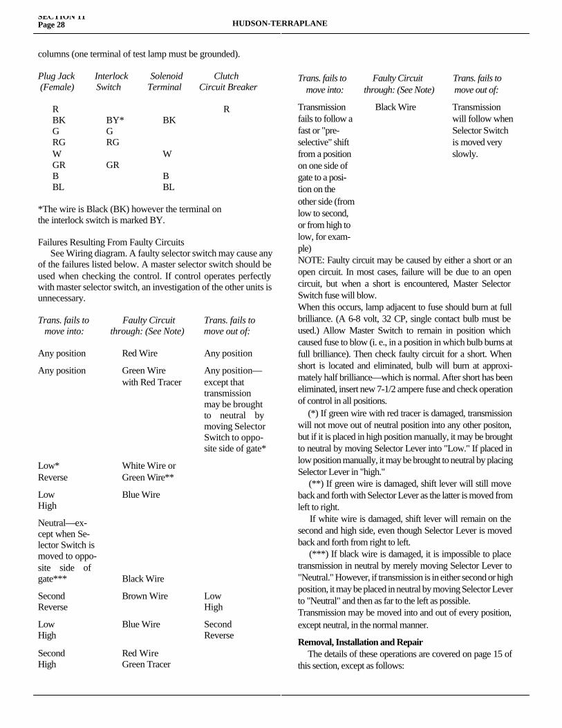
SECTION 11Page 28 HUDSON-TERRAPLANE
columns (one terminal of test lamp must be grounded).
Plug Jack Interlock Solenoid Clutch (Female) Switch Terminal Circuit Breaker
R R BK BY* BK G G RG RG W W GR GR B B BL BL
*The wire is Black (BK) however the terminal onthe interlock switch is marked BY.
Failures Resulting From Faulty Circuits See Wiring diagram. A faulty selector switch may cause any of the failures listed below. A master selector switch should be used when checking the control. If control operates perfectly with master selector switch, an investigation of the other units is unnecessary.
Trans. fails to Faulty Circuit Trans. fails to move into: through: (See Note) move out of:
Any position Red Wire Any position
Any position Green Wire Any position— with Red Tracer except that transmission may be brought to neutral by moving Selector Switch to oppo- site side of gate*
Low* White Wire orReverse Green Wire**
Low Blue WireHigh
Neutral—ex-cept when Se-lector Switch ismoved to oppo-site side ofgate*** Black Wire
Second Brown Wire LowReverse High
Low Blue Wire SecondHigh Reverse
Second Red WireHigh Green Tracer
Trans. fails to Faulty Circuit Trans. fails to move into: through: (See Note) move out of:
Transmission Black Wire Transmissionfails to follow a will follow whenfast or "pre- Selector Switchselective" shift is moved veryfrom a position slowly.on one side ofgate to a posi-tion on theother side (fromlow to second,or from high tolow, for exam-ple)NOTE: Faulty circuit may be caused by either a short or an open circuit. In most cases, failure will be due to an open circuit, but when a short is encountered, Master Selector Switch fuse will blow.When this occurs, lamp adjacent to fuse should burn at full brilliance. (A 6-8 volt, 32 CP, single contact bulb must be used.) Allow Master Switch to remain in position which caused fuse to blow (i. e., in a position in which bulb burns at full brilliance). Then check faulty circuit for a short. When short is located and eliminated, bulb will burn at approxi-mately half brilliance—which is normal. After short has been eliminated, insert new 7-1/2 ampere fuse and check operation of control in all positions. (*) If green wire with red tracer is damaged, transmission will not move out of neutral position into any other positon, but if it is placed in high position manually, it may be brought to neutral by moving Selector Lever into "Low." If placed in low position manually, it may be brought to neutral by placing Selector Lever in "high." (**) If green wire is damaged, shift lever will still move back and forth with Selector Lever as the latter is moved from left to right. If white wire is damaged, shift lever will remain on the second and high side, even though Selector Lever is moved back and forth from right to left. (***) If black wire is damaged, it is impossible to place transmission in neutral by merely moving Selector Lever to "Neutral." However, if transmission is in either second or high position, it may be placed in neutral by moving Selector Lever to "Neutral" and then as far to the left as possible.Transmission may be moved into and out of every position, except neutral, in the normal manner.
Removal, Installation and Repair The details of these operations are covered on page 15 of this section, except as follows:

MECHANICAL PROCEDURE MANUALSECTION 11
Page 29
(1) A rubber grommet is assembled in the power cylinder pilot pin hole in the mounting bracket before the power unit is mounted. (2) The lower harness is clipped to the right front and rear and left rear transmission cover screws only. (3) Before removing the power cylinder end plate (operation 104, page 00) remove the two screws from the neutral switch cover and withdraw the switch. (See Figure 1131.) After the end plate has been removed the two screws can be
removed from the neutral switch operating bracket and the mechanism removed. When reinstalling the mechanism be sure the gasket is in good condition. Both the inner and outer piston rod seals can be removed and replaced.
When reinstalling the neutral switch in the end plate the operating lever must lie between the two bakelite arms carrying the movable points of the neutral switch.

SECTION 12
PROPELLER SHAFT AND UNIVERSAL JOINTSService Magazine—Reference Sheet and Service Bullet in Reference
Bulletin orReference SheetNo. MagazineIssue and Page
Date Subject DETAILS OF INFORMATION
MECHANICAL PROCEDURE MANUAL Page 1

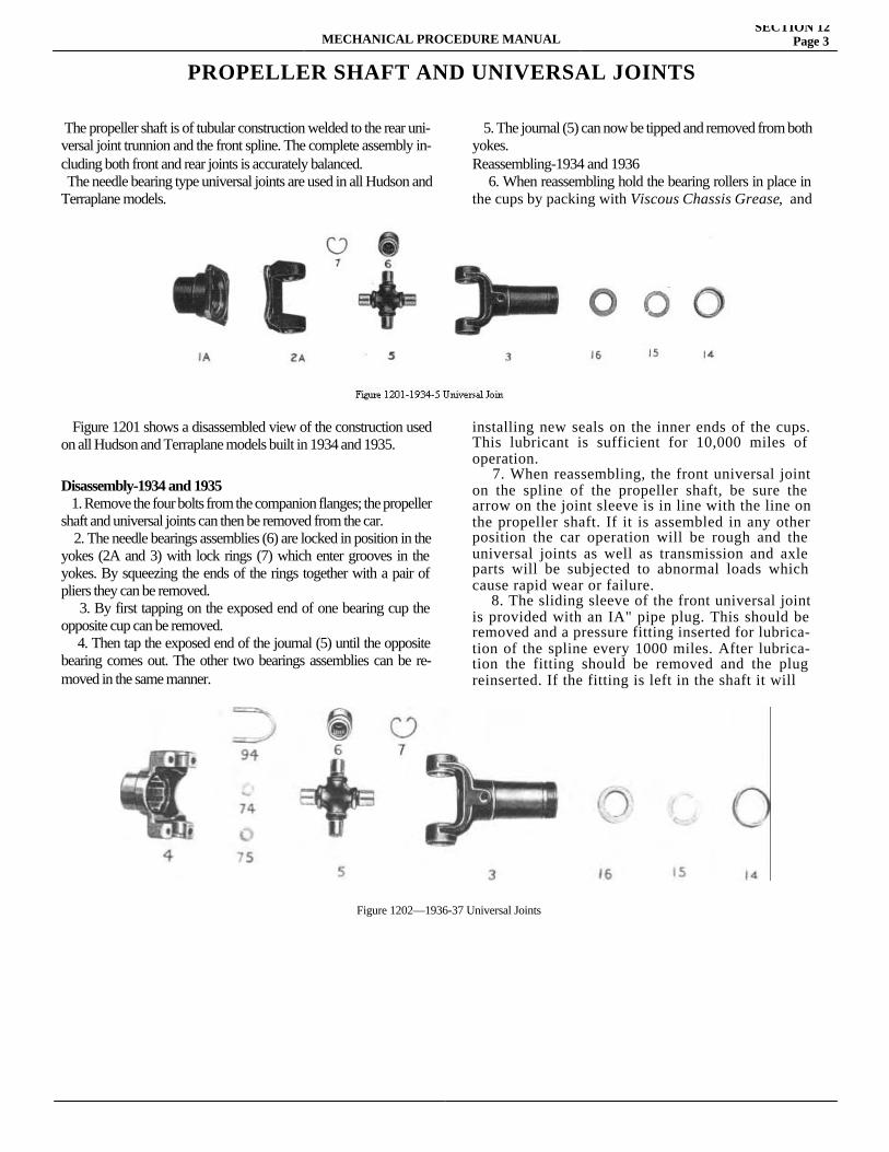
MECHANICAL PROCEDURE MANUALSECTION 12
Page 3
PROPELLER SHAFT AND UNIVERSAL JOINTS
The propeller shaft is of tubular construction welded to the rear uni-versal joint trunnion and the front spline. The complete assembly in-cluding both front and rear joints is accurately balanced. The needle bearing type universal joints are used in all Hudson and Terraplane models.
Figure 1201 shows a disassembled view of the construction used on all Hudson and Terraplane models built in 1934 and 1935.
Disassembly-1934 and 1935 1. Remove the four bolts from the companion flanges; the propeller shaft and universal joints can then be removed from the car. 2. The needle bearings assemblies (6) are locked in position in the yokes (2A and 3) with lock rings (7) which enter grooves in the yokes. By squeezing the ends of the rings together with a pair of pliers they can be removed. 3. By first tapping on the exposed end of one bearing cup the opposite cup can be removed. 4. Then tap the exposed end of the journal (5) until the opposite bearing comes out. The other two bearings assemblies can be re-moved in the same manner.
5. The journal (5) can now be tipped and removed from both yokes.Reassembling-1934 and 1936 6. When reassembling hold the bearing rollers in place in the cups by packing with Viscous Chassis Grease, and
installing new seals on the inner ends of the cups. This lubricant is sufficient for 10,000 miles of operation. 7. When reassembling, the front universal joint on the spline of the propeller shaft, be sure the arrow on the joint sleeve is in line with the line on the propeller shaft. If it is assembled in any other position the car operation will be rough and the universal joints as well as transmission and axle parts will be subjected to abnormal loads which cause rapid wear or failure. 8. The sliding sleeve of the front universal joint is provided with an IA" pipe plug. This should be removed and a pressure fitting inserted for lubrica-tion of the spline every 1000 miles. After lubrica-tion the fitting should be removed and the plug reinserted. If the fitting is left in the shaft it will
Figure 1202—1936-37 Universal Joints
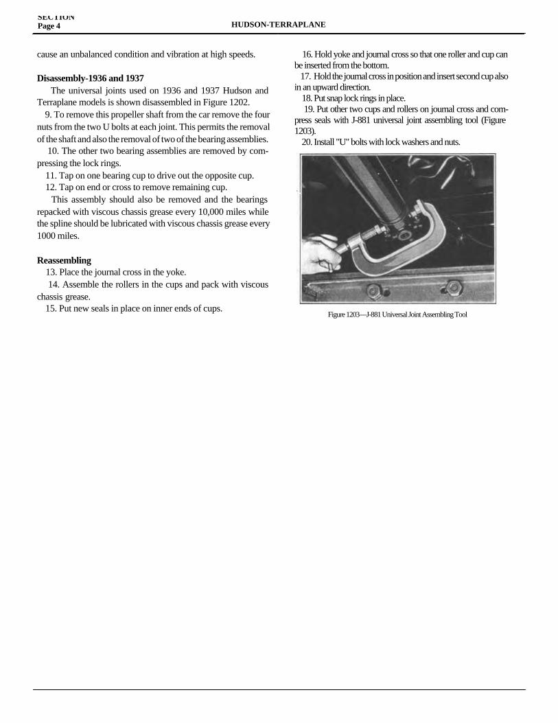
SECTION Page 4 HUDSON-TERRAPLANE
cause an unbalanced condition and vibration at high speeds.
Disassembly-1936 and 1937 The universal joints used on 1936 and 1937 Hudson and Terraplane models is shown disassembled in Figure 1202. 9. To remove this propeller shaft from the car remove the four nuts from the two U bolts at each joint. This permits the removal of the shaft and also the removal of two of the bearing assemblies. 10. The other two bearing assemblies are removed by com-pressing the lock rings. 11. Tap on one bearing cup to drive out the opposite cup. 12. Tap on end or cross to remove remaining cup. This assembly should also be removed and the bearings repacked with viscous chassis grease every 10,000 miles while the spline should be lubricated with viscous chassis grease every 1000 miles.
Reassembling 13. Place the journal cross in the yoke. 14. Assemble the rollers in the cups and pack with viscous chassis grease. 15. Put new seals in place on inner ends of cups.
16. Hold yoke and journal cross so that one roller and cup can be inserted from the bottom. 17. Hold the journal cross in position and insert second cup also in an upward direction. 18. Put snap lock rings in place. 19. Put other two cups and rollers on journal cross and com-press seals with J-881 universal joint assembling tool (Figure 1203). 20. Install "U" bolts with lock washers and nuts.
Figure 1203—J-881 Universal Joint Assembling Tool

MECHANICAL PROCEDURE MANUAL Page 1
SECTION 13
REAR AXLEService Magazine—Reference Sheet and Service Bullet in Reference
Bulletin orReference SheetNo. MagazineIssue and Page
Date Subject DETAILS OF INFORMATION

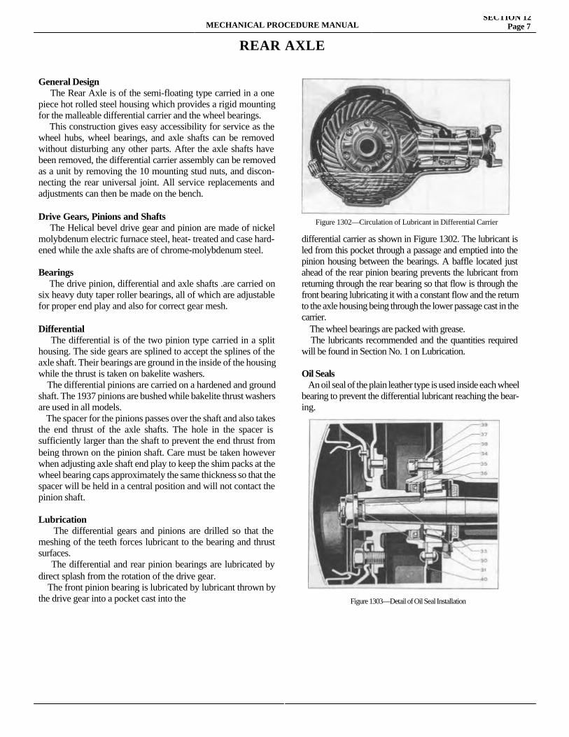
MECHANICAL PROCEDURE MANUALSECTION 12
Page 7
REAR AXLE
General Design The Rear Axle is of the semi-floating type carried in a one piece hot rolled steel housing which provides a rigid mounting for the malleable differential carrier and the wheel bearings. This construction gives easy accessibility for service as the wheel hubs, wheel bearings, and axle shafts can be removed without disturbing any other parts. After the axle shafts have been removed, the differential carrier assembly can be removed as a unit by removing the 10 mounting stud nuts, and discon-necting the rear universal joint. All service replacements and adjustments can then be made on the bench.
Drive Gears, Pinions and Shafts The Helical bevel drive gear and pinion are made of nickel molybdenum electric furnace steel, heat- treated and case hard-ened while the axle shafts are of chrome-molybdenum steel.
Bearings The drive pinion, differential and axle shafts .are carried on six heavy duty taper roller bearings, all of which are adjustable for proper end play and also for correct gear mesh.
Differential The differential is of the two pinion type carried in a split housing. The side gears are splined to accept the splines of the axle shaft. Their bearings are ground in the inside of the housing while the thrust is taken on bakelite washers. The differential pinions are carried on a hardened and ground shaft. The 1937 pinions are bushed while bakelite thrust washers are used in all models. The spacer for the pinions passes over the shaft and also takes the end thrust of the axle shafts. The hole in the spacer is sufficiently larger than the shaft to prevent the end thrust from being thrown on the pinion shaft. Care must be taken however when adjusting axle shaft end play to keep the shim packs at the wheel bearing caps approximately the same thickness so that the spacer will be held in a central position and will not contact the pinion shaft.
Lubrication The differential gears and pinions are drilled so that the meshing of the teeth forces lubricant to the bearing and thrust surfaces. The differential and rear pinion bearings are lubricated by direct splash from the rotation of the drive gear. The front pinion bearing is lubricated by lubricant thrown by the drive gear into a pocket cast into the
differential carrier as shown in Figure 1302. The lubricant is led from this pocket through a passage and emptied into the pinion housing between the bearings. A baffle located just ahead of the rear pinion bearing prevents the lubricant from returning through the rear bearing so that flow is through the front bearing lubricating it with a constant flow and the return to the axle housing being through the lower passage cast in the carrier. The wheel bearings are packed with grease. The lubricants recommended and the quantities required will be found in Section No. 1 on Lubrication.
Oil Seals An oil seal of the plain leather type is used inside each wheel bearing to prevent the differential lubricant reaching the bear-ing.
Figure 1302—Circulation of Lubricant in Differential Carrier
Figure 1303—Detail of Oil Seal Installation
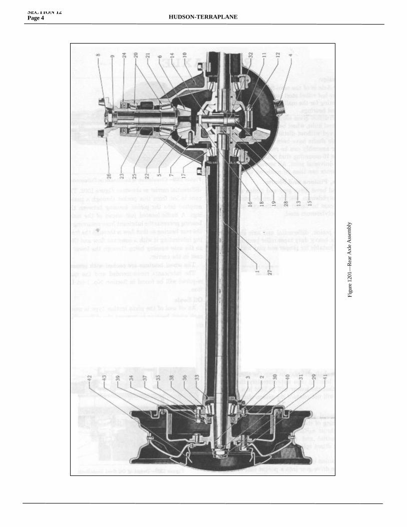
SECTION 12Page 4 HUDSON-TERRAPLANE
Figu
re 1
201—
Rea
r Axl
e A
ssem
bly
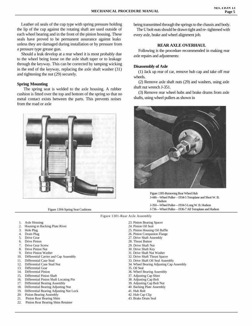
MECHANICAL PROCEDURE MANUALSECTION 13
Page 5
Leather oil seals of the cup type with spring pressure holding the lip of the cup against the rotating shaft are used outside of each wheel bearing and in the front of the pinion housing. These seals have proved to be permanent assurance against leaks unless they are damaged during installation or by pressure from a pressure type grease gun. Should a leak develop at a rear wheel it is most probably due to the wheel being loose on the axle shaft taper or to leakage through the keyway. This can be corrected by tamping wicking in the end of the keyway, replacing the axle shaft washer (31) and tightening the nut (29) securely.
Spring Mounting The spring seat is welded to the axle housing. A rubber cushion is fitted over the top and bottom of the spring so that no metal contact exists between the parts. This prevents noises from the road or axle
Figure 1304-Spring Seat Cushions
being transmitted through the springs to the chassis and body. The U bolt nuts should be drawn tight and re- tightened with every axle, brake and wheel alignment job.
REAR AXLE OVERHAUL Following is the procedure recommended in making rear axle repairs and adjustments:
Disassembly of Axle (1) Jack up rear of car, remove hub cap and take off rear wheels. (2) Remove axle shaft nuts (29) and washers, using axle shaft nut wrench J-351. (3) Remove rear wheel hubs and brake drums from axle shafts, using wheel pullers as shown in
Figure 1305-Removing Rear Wheel HubJ-446—Wheel Puller—1934-5 Terraplane and Short W. B. HudsonJ-350—Wheel Puller—1934-5 Long W. B. Hudson
J-736—Wheel Puller—1936-7 All Terraplane and Hudson
Figure 1301-Rear Axle Assembly
1. Axle Housing 2. Housing to Backing Plate Rivet 3. Hole Plug 4. Drain Plug 5. Drive Gear 6. Drive Pinion 7. Drive Gear Screw 8. Drive Pinion Nut 9. Drive Pinion Washer10. Differential Carrier and Cap Assembly11. Differential Case Stud12. Differential Case Stud Nut13. Differential Gear14. Differential Pinion15. Differential Pinion Shaft16. Differential Pinion Shaft Locating Pin17. Differential Bearing Assembly18. Differential Bearing Adjusting Nut19. Differential Bearing Adjusting Nut Lock20. Pinion Bearing Assembly21. Pinion Rear Bearing Shim22. Pinion Rear Bearing Shim Retainer
23. Pinion Bearing Spacer 24. Pinion Oil Seal 25. Pinion Housing Oil Baffle26. Pinion Companion Flange27. Drive Shaft Assembly28. Thrust Button29. Drive Shaft Nut30. Drive Shaft Key31. Drive Shaft Nut Washer32. Drive Shaft Thrust Spacer33. Drive Shaft Oil Seal Assembly34. Wheel Bearing Adjusting Cap Assembly35. Oil Seal36. Wheel Bearing Assembly37. Adjusting Cap Shim38. Adjusting Cap Bolt39. Adjusting Cap Bolt Nut40. Backing Plate Assembly41. Hub Bolt42. Hub Cap Clip43. Brake Drum Seal
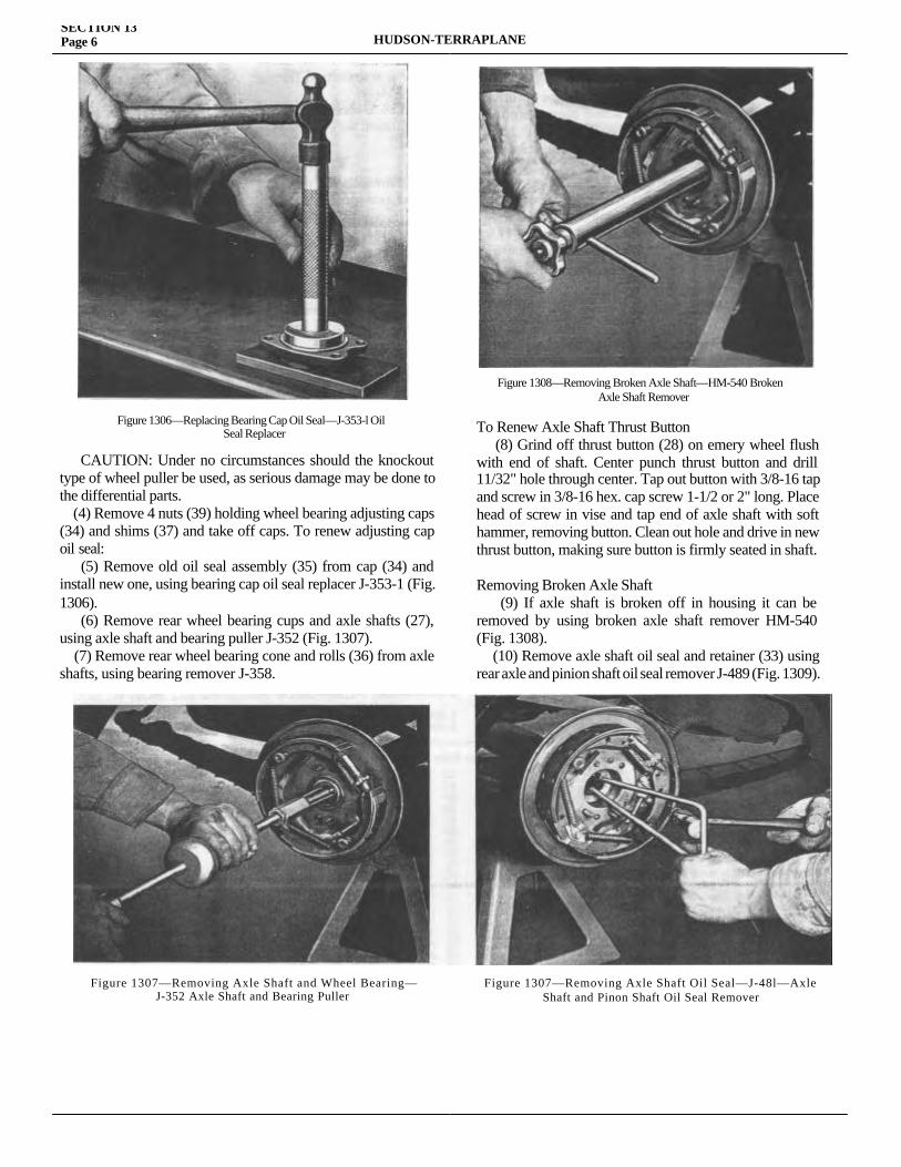
SECTION 13Page 6 HUDSON-TERRAPLANE
CAUTION: Under no circumstances should the knockout type of wheel puller be used, as serious damage may be done to the differential parts. (4) Remove 4 nuts (39) holding wheel bearing adjusting caps (34) and shims (37) and take off caps. To renew adjusting cap oil seal: (5) Remove old oil seal assembly (35) from cap (34) and install new one, using bearing cap oil seal replacer J-353-1 (Fig. 1306). (6) Remove rear wheel bearing cups and axle shafts (27), using axle shaft and bearing puller J-352 (Fig. 1307). (7) Remove rear wheel bearing cone and rolls (36) from axle shafts, using bearing remover J-358.
To Renew Axle Shaft Thrust Button (8) Grind off thrust button (28) on emery wheel flush with end of shaft. Center punch thrust button and drill 11/32" hole through center. Tap out button with 3/8-16 tap and screw in 3/8-16 hex. cap screw 1-1/2 or 2" long. Place head of screw in vise and tap end of axle shaft with soft hammer, removing button. Clean out hole and drive in new thrust button, making sure button is firmly seated in shaft.
Removing Broken Axle Shaft (9) If axle shaft is broken off in housing it can be removed by using broken axle shaft remover HM-540 (Fig. 1308). (10) Remove axle shaft oil seal and retainer (33) using rear axle and pinion shaft oil seal remover J-489 (Fig. 1309).
Figure 1306—Replacing Bearing Cap Oil Seal—J-353-l OilSeal Replacer
Figure 1308—Removing Broken Axle Shaft—HM-540 BrokenAxle Shaft Remover
Figure 1307—Removing Axle Shaft and Wheel Bearing—J-352 Axle Shaft and Bearing Puller
Figure 1307—Removing Axle Shaft Oil Seal—J-48l—AxleShaft and Pinon Shaft Oil Seal Remover
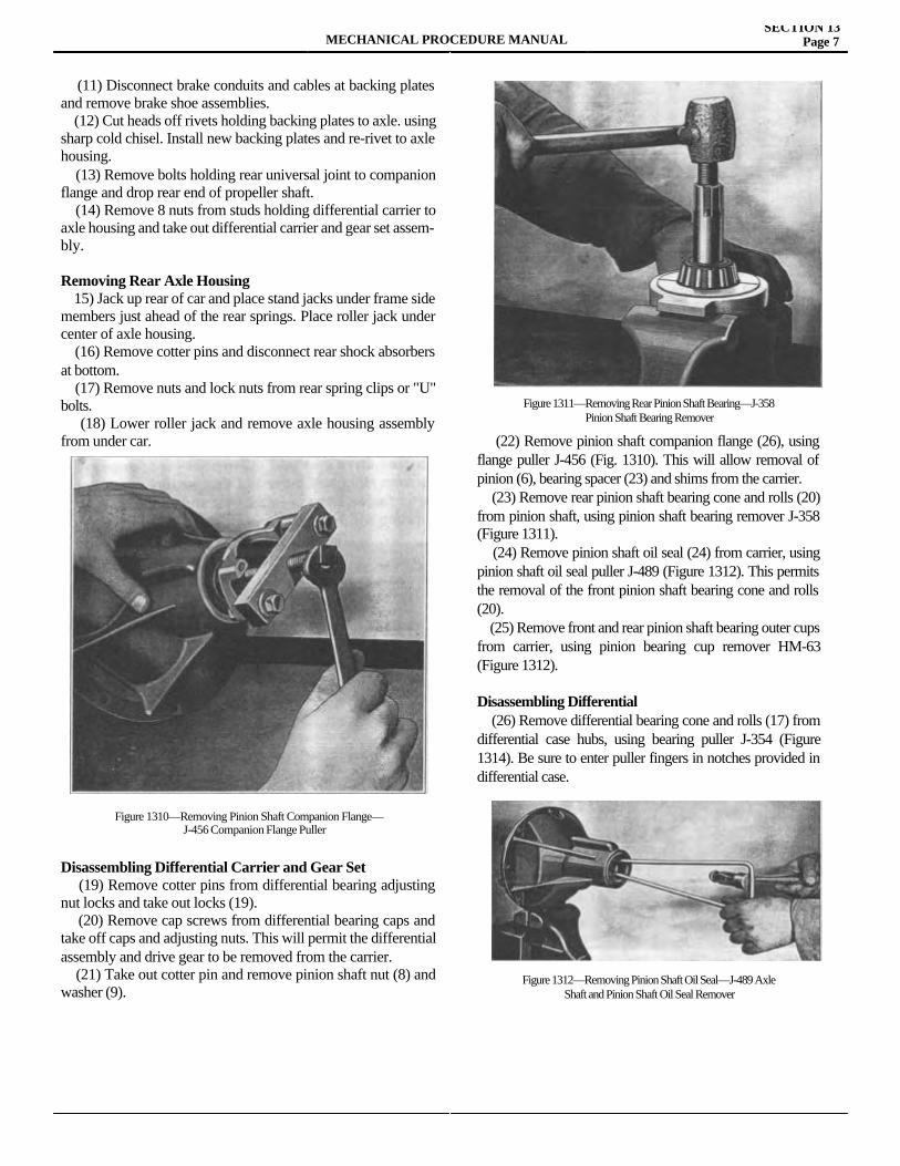
MECHANICAL PROCEDURE MANUALSECTION 13
Page 7
(11) Disconnect brake conduits and cables at backing plates and remove brake shoe assemblies. (12) Cut heads off rivets holding backing plates to axle. using sharp cold chisel. Install new backing plates and re-rivet to axle housing. (13) Remove bolts holding rear universal joint to companion flange and drop rear end of propeller shaft. (14) Remove 8 nuts from studs holding differential carrier to axle housing and take out differential carrier and gear set assem-bly.
Removing Rear Axle Housing 15) Jack up rear of car and place stand jacks under frame side members just ahead of the rear springs. Place roller jack under center of axle housing. (16) Remove cotter pins and disconnect rear shock absorbers at bottom. (17) Remove nuts and lock nuts from rear spring clips or "U" bolts. (18) Lower roller jack and remove axle housing assembly from under car.
Disassembling Differential Carrier and Gear Set (19) Remove cotter pins from differential bearing adjusting nut locks and take out locks (19). (20) Remove cap screws from differential bearing caps and take off caps and adjusting nuts. This will permit the differential assembly and drive gear to be removed from the carrier. (21) Take out cotter pin and remove pinion shaft nut (8) and washer (9).
(22) Remove pinion shaft companion flange (26), using flange puller J-456 (Fig. 1310). This will allow removal of pinion (6), bearing spacer (23) and shims from the carrier. (23) Remove rear pinion shaft bearing cone and rolls (20) from pinion shaft, using pinion shaft bearing remover J-358 (Figure 1311). (24) Remove pinion shaft oil seal (24) from carrier, using pinion shaft oil seal puller J-489 (Figure 1312). This permits the removal of the front pinion shaft bearing cone and rolls (20). (25) Remove front and rear pinion shaft bearing outer cups from carrier, using pinion bearing cup remover HM-63 (Figure 1312).
Disassembling Differential (26) Remove differential bearing cone and rolls (17) from differential case hubs, using bearing puller J-354 (Figure 1314). Be sure to enter puller fingers in notches provided in differential case.
Figure 1312—Removing Pinion Shaft Oil Seal—J-489 AxleShaft and Pinion Shaft Oil Seal Remover
Figure 1310—Removing Pinion Shaft Companion Flange—J-456 Companion Flange Puller
Figure 1311—Removing Rear Pinion Shaft Bearing—J-358Pinion Shaft Bearing Remover
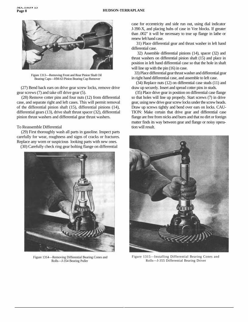
SECTION 13Page 8 HUDSON-TERRAPLANE
(27) Bend back ears on drive gear screw locks, remove drive gear screws (7) and take off drive gear (5). (28) Remove cotter pins and four nuts (12) from differential case, and separate right and left cases. This will permit removal of the differential pinion shaft (15), differential pinions (14), differential gears (13), drive shaft thrust spacer (32), differential pinion thrust washers and differential gear thrust washers.
To Reassemble Differential (29) First thoroughly wash all parts in gasoline. Inspect parts carefully for wear, roughness and signs of cracks or fractures. Replace any worn or suspicious looking parts with new ones. (30) Carefully check ring gear bolting flange on differential
case for eccentricity and side run out, using dial indicator J-390-X, and placing hubs of case in Vee blocks. If greater than .002" it will be necessary to true up flange in lathe or renew left hand case. 31) Place differential gear and thrust washer in left hand differential case. 32) Assemble differential pinions (14), spacer (32) and thrust washers on differential pinion shaft (15) and place in position in left hand differential case so that the hole in shaft will line up with the pin (16) in case. 33) Place differential gear thrust washer and differential gear in right hand differential case, and assemble to left case. (34) Replace nuts (12) on differential case studs (11) and draw up securely. Insert and spread cotter pins in studs. (35) Place drive gear in position on differential case flange so that holes will line up properly. Start screws (7) in drive gear, using new drive gear screw locks under the screw heads. Draw up screws tightly and bend over ears on locks. CAU-TION: Make certain that drive gear and differential case flange are free from nicks and burrs and that no dirt or foreign matter finds its way between gear and flange or noisy opera-tion will result.
Figure 1313—Removing Front and Rear Pinion Shaft OilBearing Caps—HM-63 Pinion Bearing Cup Remover
Figure 1314—Removing Differential Bearing Cones andRolls—J-354 Bearing Puller
Figure 1315—Installing Differential Bearing Cones andRolls—J-355 Differential Bearing Driver
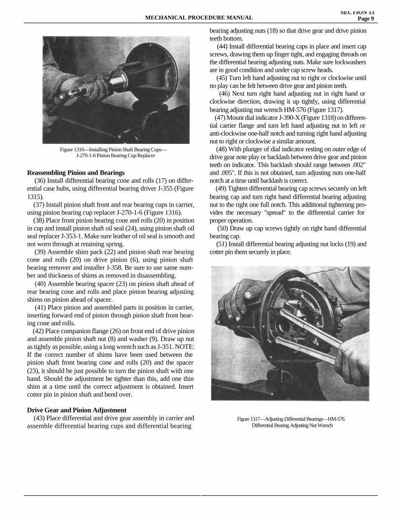
MECHANICAL PROCEDURE MANUALSECTION 13
Page 9
Reassembling Pinion and Bearings (36) Install differential bearing cone and rolls (17) on differ-ential case hubs, using differential bearing driver J-355 (Figure 1315). (37) Install pinion shaft front and rear bearing cups in carrier, using pinion bearing cup replacer J-270-1-6 (Figure 1316). (38) Place front pinion bearing cone and rolls (20) in position in cup and install pinion shaft oil seal (24), using pinion shaft oil seal replacer J-353-1. Make sure leather of oil seal is smooth and not worn through at retaining spring. (39) Assemble shim pack (22) and pinion shaft rear bearing cone and rolls (20) on drive pinion (6), using pinion shaft bearing remover and installer J-358. Be sure to use same num-ber and thickness of shims as removed in disassembling. (40) Assemble bearing spacer (23) on pinion shaft ahead of rear bearing cone and rolls and place pinion bearing adjusting shims on pinion ahead of spacer. (41) Place pinion and assembled parts in position in carrier, inserting forward end of pinion through pinion shaft front bear-ing cone and rolls. (42) Place companion flange (26) on front end of drive pinion and assemble pinion shaft nut (8) and washer (9). Draw up nut as tightly as possible, using a long wrench such as J-351. NOTE: If the correct number of shims have been used between the pinion shaft front bearing cone and rolls (20) and the spacer (23), it should be just possible to turn the pinion shaft with one hand. Should the adjustment be tighter than this, add one thin shim at a time until the correct adjustment is obtained. Insert cotter pin in pinion shaft and bend over.
Drive Gear and Pinion Adjustment (43) Place differential and drive gear assembly in carrier and assemble differential bearing cups and differential bearing
bearing adjusting nuts (18) so that drive gear and drive pinion teeth bottom. (44) Install differential bearing caps in place and insert cap screws, drawing them up finger tight, and engaging threads on the differential bearing adjusting nuts. Make sure lockwashers are in good condition and under cap screw heads. (45) Turn left hand adjusting nut to right or clockwise until no play can be felt between drive gear and pinion teeth. (46) Next turn right hand adjusting nut in right hand or clockwise direction, drawing it up tightly, using differential bearing adjusting nut wrench HM-576 (Figure 1317). (47) Mount dial indicator J-390-X (Figure 1318) on differen-tial carrier flange and turn left hand adjusting nut to left or anti-clockwise one-half notch and turning right hand adjusting nut to right or clockwise a similar amount. (48) With plunger of dial indicator resting on outer edge of drive gear note play or backlash between drive gear and pinion teeth on indicator. This backlash should range between .002" and .005". If this is not obtained, turn adjusting nuts one-half notch at a time until backlash is correct. (49) Tighten differential bearing cap screws securely on left bearing cap and turn right hand differential bearing adjusting nut to the right one full notch. This additional tightening pro-vides the necessary "spread" to the differential carrier for proper operation. (50) Draw up cap screws tightly on right hand differential bearing cap. (51) Install differential bearing adjusting nut locks (19) and cotter pin them securely in place.
Figure 1316—Installing Pinion Shaft Bearing Cups—J-270-1-6 Pinion Bearing Cup Replacer
Figure 1317—Adjusting Differential Bearings—HM-576Differential Bearing Adjusting Nut Wrench
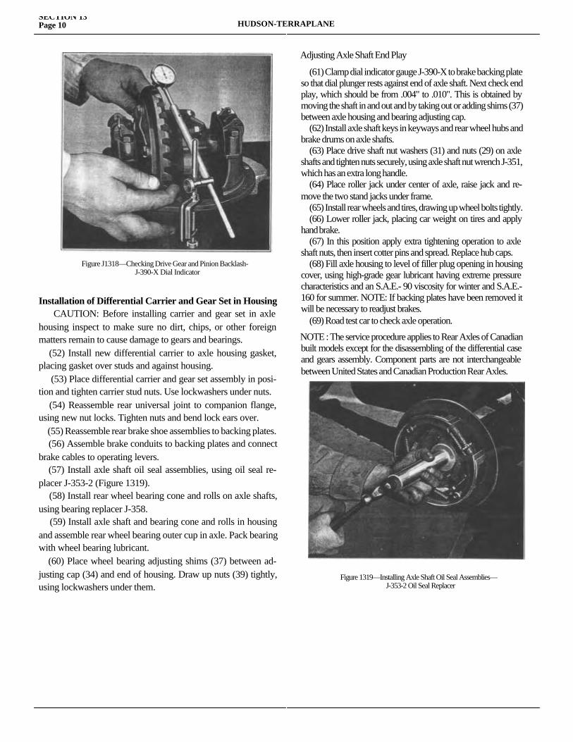
SECTION 13Page 10 HUDSON-TERRAPLANE
Installation of Differential Carrier and Gear Set in Housing CAUTION: Before installing carrier and gear set in axle housing inspect to make sure no dirt, chips, or other foreign matters remain to cause damage to gears and bearings. (52) Install new differential carrier to axle housing gasket, placing gasket over studs and against housing. (53) Place differential carrier and gear set assembly in posi-tion and tighten carrier stud nuts. Use lockwashers under nuts. (54) Reassemble rear universal joint to companion flange, using new nut locks. Tighten nuts and bend lock ears over. (55) Reassemble rear brake shoe assemblies to backing plates. (56) Assemble brake conduits to backing plates and connect brake cables to operating levers. (57) Install axle shaft oil seal assemblies, using oil seal re-placer J-353-2 (Figure 1319). (58) Install rear wheel bearing cone and rolls on axle shafts, using bearing replacer J-358. (59) Install axle shaft and bearing cone and rolls in housing and assemble rear wheel bearing outer cup in axle. Pack bearing with wheel bearing lubricant. (60) Place wheel bearing adjusting shims (37) between ad-justing cap (34) and end of housing. Draw up nuts (39) tightly, using lockwashers under them.
Adjusting Axle Shaft End Play
(61) Clamp dial indicator gauge J-390-X to brake backing plate so that dial plunger rests against end of axle shaft. Next check end play, which should be from .004" to .010". This is obtained by moving the shaft in and out and by taking out or adding shims (37) between axle housing and bearing adjusting cap. (62) Install axle shaft keys in keyways and rear wheel hubs and brake drums on axle shafts. (63) Place drive shaft nut washers (31) and nuts (29) on axle shafts and tighten nuts securely, using axle shaft nut wrench J-351, which has an extra long handle. (64) Place roller jack under center of axle, raise jack and re-move the two stand jacks under frame. (65) Install rear wheels and tires, drawing up wheel bolts tightly. (66) Lower roller jack, placing car weight on tires and apply hand brake. (67) In this position apply extra tightening operation to axle shaft nuts, then insert cotter pins and spread. Replace hub caps. (68) Fill axle housing to level of filler plug opening in housing cover, using high-grade gear lubricant having extreme pressure characteristics and an S.A.E.- 90 viscosity for winter and S.A.E.-160 for summer. NOTE: If backing plates have been removed it will be necessary to readjust brakes. (69) Road test car to check axle operation.
NOTE : The service procedure applies to Rear Axles of Canadian built models except for the disassembling of the differential case and gears assembly. Component parts are not interchangeable between United States and Canadian Production Rear Axles.
Figure J1318—Checking Drive Gear and Pinion Backlash-J-390-X Dial Indicator
Figure 1319—Installing Axle Shaft Oil Seal Assemblies—J-353-2 Oil Seal Replacer

MECHANICAL PROCEDURE MANUAL Page 1
SECTION 14
BRAKESService Magazine—Reference Sheet and Service Bullet in Reference
Bulletin orReference SheetNo. MagazineIssue and Page
Date Subject DETAILS OF INFORMATION

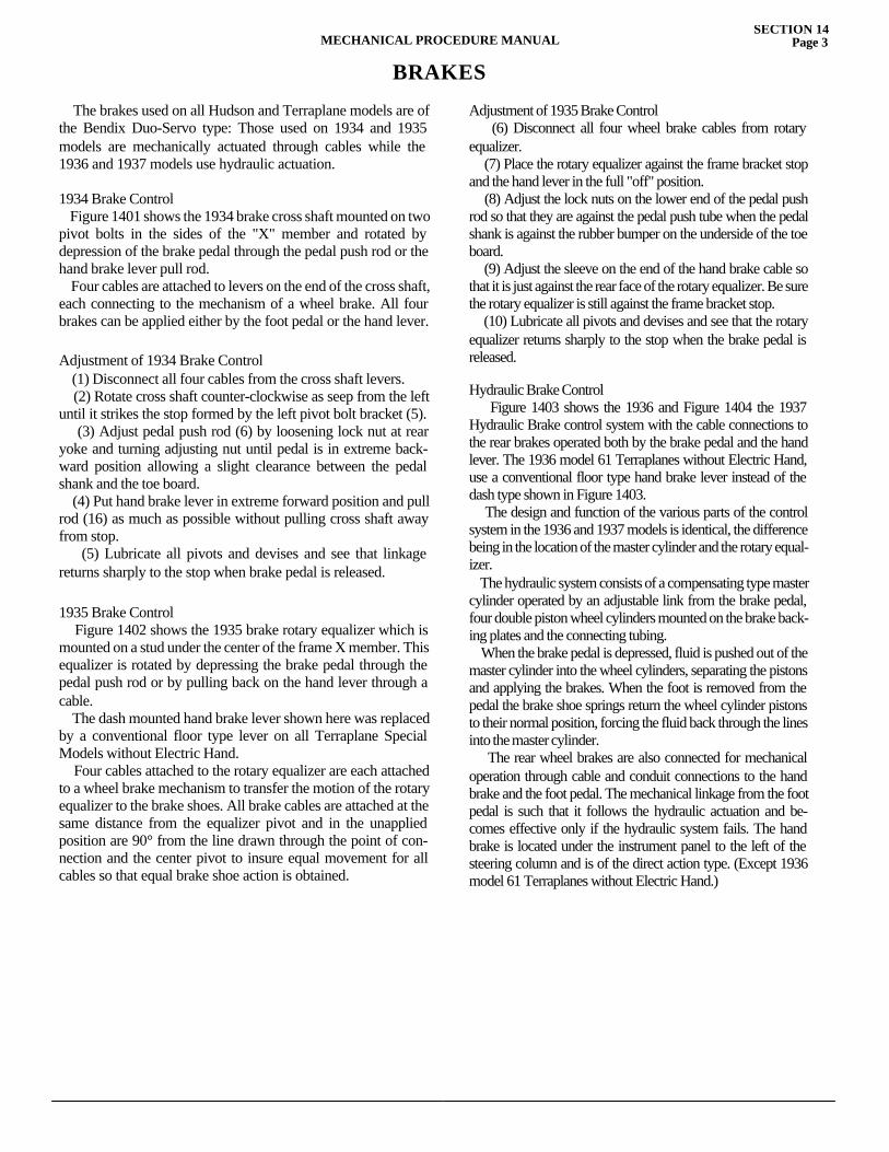
MECHANICAL PROCEDURE MANUALSECTION 14
Page 3
BRAKES
The brakes used on all Hudson and Terraplane models are of the Bendix Duo-Servo type: Those used on 1934 and 1935 models are mechanically actuated through cables while the 1936 and 1937 models use hydraulic actuation.
1934 Brake Control Figure 1401 shows the 1934 brake cross shaft mounted on two pivot bolts in the sides of the "X" member and rotated by depression of the brake pedal through the pedal push rod or the hand brake lever pull rod. Four cables are attached to levers on the end of the cross shaft, each connecting to the mechanism of a wheel brake. All four brakes can be applied either by the foot pedal or the hand lever.
Adjustment of 1934 Brake Control (1) Disconnect all four cables from the cross shaft levers. (2) Rotate cross shaft counter-clockwise as seep from the left until it strikes the stop formed by the left pivot bolt bracket (5). (3) Adjust pedal push rod (6) by loosening lock nut at rear yoke and turning adjusting nut until pedal is in extreme back-ward position allowing a slight clearance between the pedal shank and the toe board. (4) Put hand brake lever in extreme forward position and pull rod (16) as much as possible without pulling cross shaft away from stop. (5) Lubricate all pivots and devises and see that linkage returns sharply to the stop when brake pedal is released.
1935 Brake Control Figure 1402 shows the 1935 brake rotary equalizer which is mounted on a stud under the center of the frame X member. This equalizer is rotated by depressing the brake pedal through the pedal push rod or by pulling back on the hand lever through a cable. The dash mounted hand brake lever shown here was replaced by a conventional floor type lever on all Terraplane Special Models without Electric Hand. Four cables attached to the rotary equalizer are each attached to a wheel brake mechanism to transfer the motion of the rotary equalizer to the brake shoes. All brake cables are attached at the same distance from the equalizer pivot and in the unapplied position are 90° from the line drawn through the point of con-nection and the center pivot to insure equal movement for all cables so that equal brake shoe action is obtained.
Adjustment of 1935 Brake Control (6) Disconnect all four wheel brake cables from rotary equalizer. (7) Place the rotary equalizer against the frame bracket stop and the hand lever in the full "off" position. (8) Adjust the lock nuts on the lower end of the pedal push rod so that they are against the pedal push tube when the pedal shank is against the rubber bumper on the underside of the toe board. (9) Adjust the sleeve on the end of the hand brake cable so that it is just against the rear face of the rotary equalizer. Be sure the rotary equalizer is still against the frame bracket stop. (10) Lubricate all pivots and devises and see that the rotary equalizer returns sharply to the stop when the brake pedal is released.
Hydraulic Brake Control Figure 1403 shows the 1936 and Figure 1404 the 1937 Hydraulic Brake control system with the cable connections to the rear brakes operated both by the brake pedal and the hand lever. The 1936 model 61 Terraplanes without Electric Hand, use a conventional floor type hand brake lever instead of the dash type shown in Figure 1403. The design and function of the various parts of the control system in the 1936 and 1937 models is identical, the difference being in the location of the master cylinder and the rotary equal-izer. The hydraulic system consists of a compensating type master cylinder operated by an adjustable link from the brake pedal, four double piston wheel cylinders mounted on the brake back-ing plates and the connecting tubing. When the brake pedal is depressed, fluid is pushed out of the master cylinder into the wheel cylinders, separating the pistons and applying the brakes. When the foot is removed from the pedal the brake shoe springs return the wheel cylinder pistons to their normal position, forcing the fluid back through the lines into the master cylinder. The rear wheel brakes are also connected for mechanical operation through cable and conduit connections to the hand brake and the foot pedal. The mechanical linkage from the foot pedal is such that it follows the hydraulic actuation and be-comes effective only if the hydraulic system fails. The hand brake is located under the instrument panel to the left of the steering column and is of the direct action type. (Except 1936 model 61 Terraplanes without Electric Hand.)
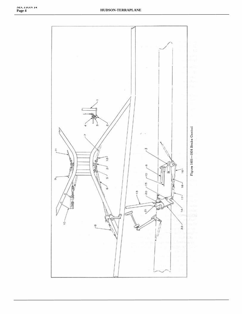
SECTION 14Page 4 HUDSON-TERRAPLANE
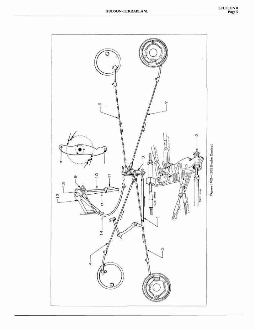
HUDSON-TERRAPLANESECTION 8
Page 5
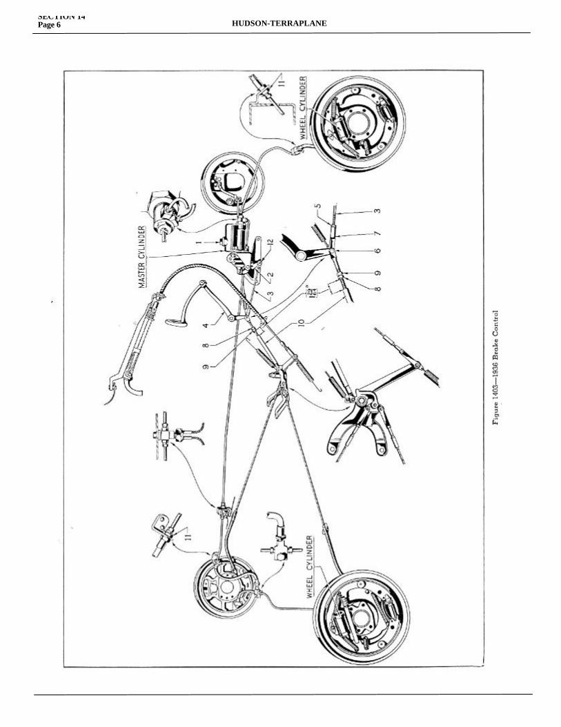
SECTION 14Page 6 HUDSON-TERRAPLANE
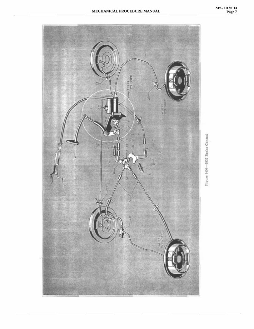
MECHANICAL PROCEDURE MANUALSECTION 14
Page 7
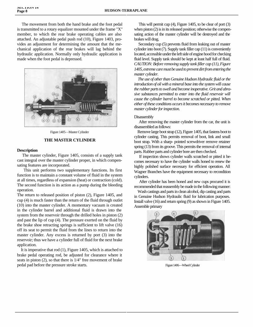
The movement from both the hand brake and the foot pedal is transmitted to a rotary equalizer mounted under the frame "X" member, to which the rear brake operating cables are also attached. An adjustable pedal push rod (10), Figure 1403, pro-vides an adjustment for determining the amount that the me-chanical application of the rear brakes will lag behind the hydraulic application. Normally only hydraulic application is made when the foot pedal is depressed.
Figure 1405—Master Cylinder
THE MASTER CYLINDER
Description The master cylinder, Figure 1405, consists of a supply tank cast integral over the master cylinder proper, in which compen-sating features are incorporated. This unit performs two supplementary functions. Its first function is to maintain a constant volume of fluid in the system at all times, regardless of expansion (heat) or contraction (cold). The second function is its action as a pump during the bleeding operation.The return to released position of piston (2), Figure 1405, and cup (4) is much faster than the return of the fluid through outlet (10) into the master cylinder. A momentary vacuum is created in the cylinder barrel and additional fluid is drawn into the system from the reservoir through the drilled holes in piston (2) and past the lip of cup (4). The pressure exerted on the fluid by the brake shoe retracting springs is sufficient to lift valve (16) off its seat to permit the fluid from the lines to return into the master cylinder. Any excess is returned by port (3) into the reservoir; thus we have a cylinder full of fluid for the next brake application. It is imperative that rod (1), Figure 1405, which is attached to brake pedal operating rod, be adjusted for clearance where it seats in piston (2), so that there is 1/4" free movement of brake pedal pad before the pressure stroke starts.
This will permit cup (4), Figure 1405, to be clear of port (3) when piston (2) is in its released position; otherwise the compen-sating action of the master cylinder will be destroyed and the brakes will drag. Secondary cup (5) prevents fluid from leaking out of master cylinder into boot (7). Supply tank filler cap (11) is conveniently located, accessible under the left side of engine hood for checking fluid level. Supply tank should be kept at least half full of fluid. CAUTION: Before removing supply tank filler cap (11), Figure 1405, extreme care must be used to prevent dirt from entering the master cylinder. The use of other than Genuine Hudson Hydraulic fluid or the introduction of oil with a mineral base into the system will cause the rubber parts to swell and become inoperative. Grit and abra-sive substances permitted to enter into the fluid reservoir will cause the cylinder barrel to become scratched or pitted. When either of these conditions occurs it becomes necessary to remove master cylinder for inspection.
Disassembly After removing the master cylinder from the car, the unit is disassembled as follows: Remove large boot strap (12), Figure 1405, that fastens boot to cylinder casting. This permits removal of boot, link and small boot strap. With a sharp- pointed screwdriver remove retainer spring (13) from its groove. This permits the removal of internal parts. Rubber parts and cylinder bore are then checked. If inspection shows cylinder walls scratched or pitted it be-comes necessary to have the cylinder walls honed to renew the highly polished surface necessary for efficient operation. All Wagner Branches have the equipment necessary to recondition cylinders. After cylinder has been honed and new cups procured it is recommended that reassembly be made in the following manner: Wash castings and parts in clean alcohol, dip casting and parts in Genuine Hudson Hydraulic fluid for lubrication purposes. Install valve (16) and return spring (9) as shown in Figure 1405. Assemble primary
Figure 1406—Wheel Cylinder
SECTION 14Page 8 HUDSON-TERRAPLANE
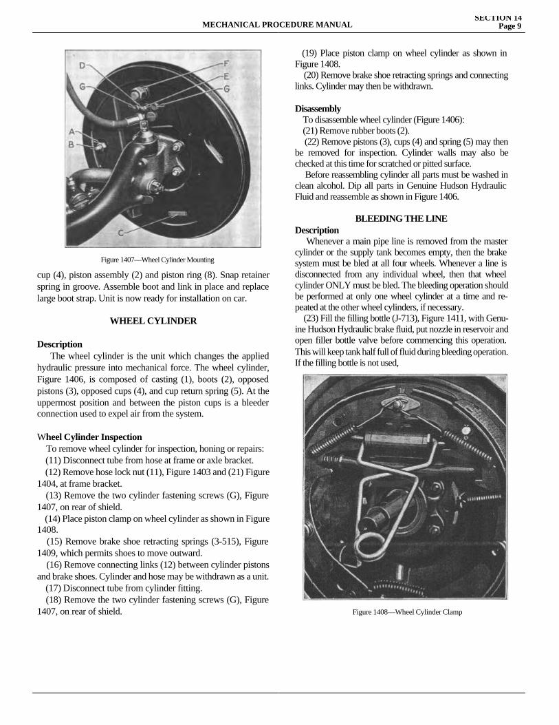
MECHANICAL PROCEDURE MANUALSECTION 14
Page 9
cup (4), piston assembly (2) and piston ring (8). Snap retainer spring in groove. Assemble boot and link in place and replace large boot strap. Unit is now ready for installation on car.
WHEEL CYLINDER
Description The wheel cylinder is the unit which changes the applied hydraulic pressure into mechanical force. The wheel cylinder, Figure 1406, is composed of casting (1), boots (2), opposed pistons (3), opposed cups (4), and cup return spring (5). At the uppermost position and between the piston cups is a bleeder connection used to expel air from the system.
Wheel Cylinder Inspection To remove wheel cylinder for inspection, honing or repairs: (11) Disconnect tube from hose at frame or axle bracket. (12) Remove hose lock nut (11), Figure 1403 and (21) Figure 1404, at frame bracket. (13) Remove the two cylinder fastening screws (G), Figure 1407, on rear of shield. (14) Place piston clamp on wheel cylinder as shown in Figure 1408. (15) Remove brake shoe retracting springs (3-515), Figure 1409, which permits shoes to move outward. (16) Remove connecting links (12) between cylinder pistons and brake shoes. Cylinder and hose may be withdrawn as a unit. (17) Disconnect tube from cylinder fitting. (18) Remove the two cylinder fastening screws (G), Figure 1407, on rear of shield.
(19) Place piston clamp on wheel cylinder as shown in Figure 1408. (20) Remove brake shoe retracting springs and connecting links. Cylinder may then be withdrawn.
Disassembly To disassemble wheel cylinder (Figure 1406): (21) Remove rubber boots (2). (22) Remove pistons (3), cups (4) and spring (5) may then be removed for inspection. Cylinder walls may also be checked at this time for scratched or pitted surface. Before reassembling cylinder all parts must be washed in clean alcohol. Dip all parts in Genuine Hudson Hydraulic Fluid and reassemble as shown in Figure 1406.
BLEEDING THE LINEDescription Whenever a main pipe line is removed from the master cylinder or the supply tank becomes empty, then the brake system must be bled at all four wheels. Whenever a line is disconnected from any individual wheel, then that wheel cylinder ONLY must be bled. The bleeding operation should be performed at only one wheel cylinder at a time and re-peated at the other wheel cylinders, if necessary. (23) Fill the filling bottle (J-713), Figure 1411, with Genu-ine Hudson Hydraulic brake fluid, put nozzle in reservoir and open filler bottle valve before commencing this operation. This will keep tank half full of fluid during bleeding operation. If the filling bottle is not used,
Figure 1407—Wheel Cylinder Mounting
Figure 1408—Wheel Cylinder Clamp
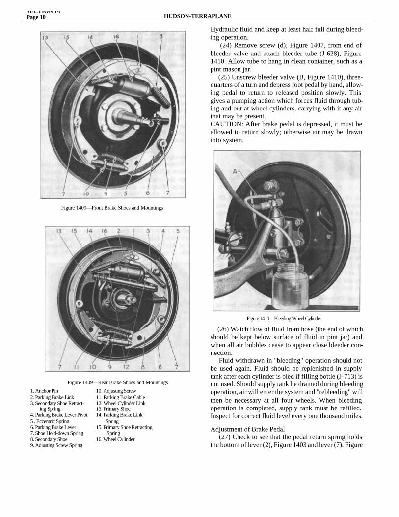
1. Anchor Pin 10. Adjusting Screw2. Parking Brake Link 11. Parking Brake Cable3. Secondary Shoe Retract- 12. Wheel Cylinder Link ing Spring 13. Primary Shoe4. Parking Brake Lever Pivot 14. Parking Brake Link5 . Eccentric Spring Spring6. Parking Brake Lever 15. Primary Shoe Retracting7. Shoe Hold-down Spring Spring8. Secondary Shoe 16. Wheel Cylinder9. Adjusting Screw Spring
Hydraulic fluid and keep at least half full during bleed-ing operation. (24) Remove screw (d), Figure 1407, from end of bleeder valve and attach bleeder tube (J-628), Figure 1410. Allow tube to hang in clean container, such as a pint mason jar. (25) Unscrew bleeder valve (B, Figure 1410), three-quarters of a turn and depress foot pedal by hand, allow-ing pedal to return to released position slowly. This gives a pumping action which forces fluid through tub-ing and out at wheel cylinders, carrying with it any air that may be present.CAUTION: After brake pedal is depressed, it must be allowed to return slowly; otherwise air may be drawn into system.
(26) Watch flow of fluid from hose (the end of which should be kept below surface of fluid in pint jar) and when all air bubbles cease to appear close bleeder con-nection. Fluid withdrawn in "bleeding" operation should not be used again. Fluid should be replenished in supply tank after each cylinder is bled if filling bottle (J-713) is not used. Should supply tank be drained during bleeding operation, air will enter the system and "rebleeding" will then be necessary at all four wheels. When bleeding operation is completed, supply tank must be refilled. Inspect for correct fluid level every one thousand miles.
Adjustment of Brake Pedal (27) Check to see that the pedal return spring holds the bottom of lever (2), Figure 1403 and lever (7). Figure
SECTION 14Page 10 HUDSON-TERRAPLANE
Figure 1409—Front Brake Shoes and Mountings
Figure 1409—Rear Brake Shoes and Mountings
Figure 1410—Bleeding Wheel Cylinder
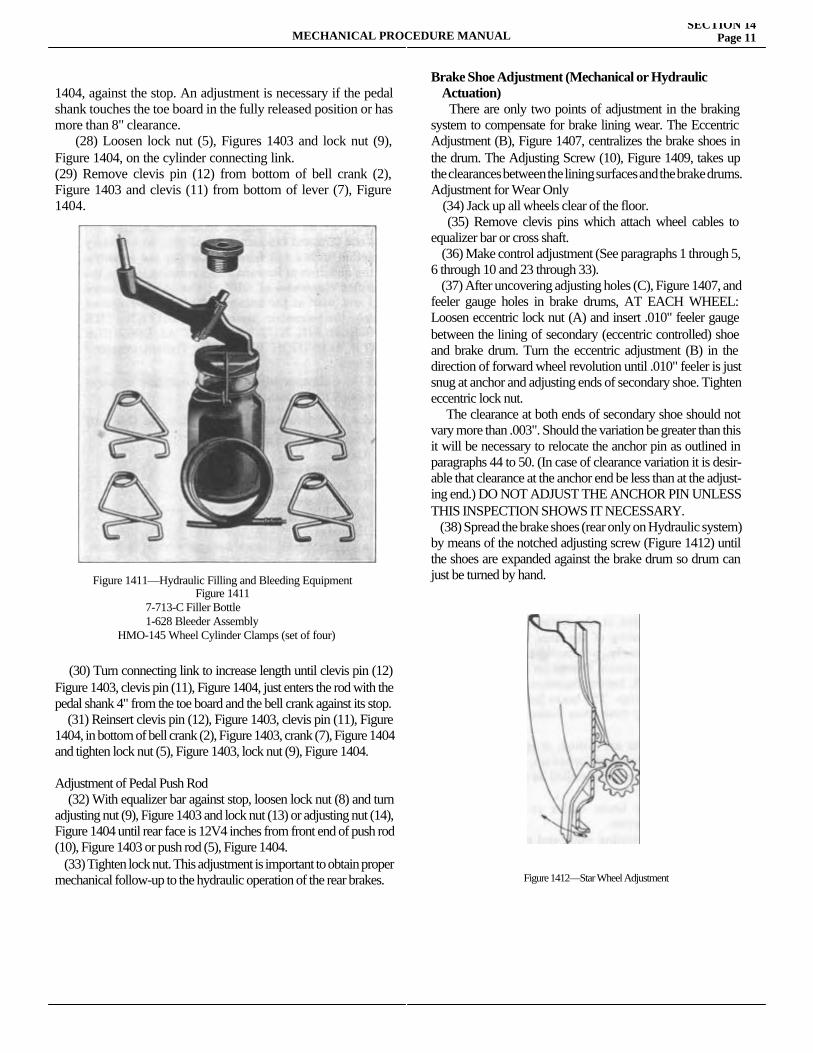
MECHANICAL PROCEDURE MANUALSECTION 14
Page 11
1404, against the stop. An adjustment is necessary if the pedal shank touches the toe board in the fully released position or has more than 8" clearance. (28) Loosen lock nut (5), Figures 1403 and lock nut (9), Figure 1404, on the cylinder connecting link.(29) Remove clevis pin (12) from bottom of bell crank (2), Figure 1403 and clevis (11) from bottom of lever (7), Figure 1404.
(30) Turn connecting link to increase length until clevis pin (12) Figure 1403, clevis pin (11), Figure 1404, just enters the rod with the pedal shank 4" from the toe board and the bell crank against its stop. (31) Reinsert clevis pin (12), Figure 1403, clevis pin (11), Figure 1404, in bottom of bell crank (2), Figure 1403, crank (7), Figure 1404 and tighten lock nut (5), Figure 1403, lock nut (9), Figure 1404.
Adjustment of Pedal Push Rod (32) With equalizer bar against stop, loosen lock nut (8) and turn adjusting nut (9), Figure 1403 and lock nut (13) or adjusting nut (14), Figure 1404 until rear face is 12V4 inches from front end of push rod (10), Figure 1403 or push rod (5), Figure 1404. (33) Tighten lock nut. This adjustment is important to obtain proper mechanical follow-up to the hydraulic operation of the rear brakes.
Brake Shoe Adjustment (Mechanical or Hydraulic Actuation) There are only two points of adjustment in the braking system to compensate for brake lining wear. The Eccentric Adjustment (B), Figure 1407, centralizes the brake shoes in the drum. The Adjusting Screw (10), Figure 1409, takes up the clearances between the lining surfaces and the brake drums.Adjustment for Wear Only (34) Jack up all wheels clear of the floor. (35) Remove clevis pins which attach wheel cables to equalizer bar or cross shaft. (36) Make control adjustment (See paragraphs 1 through 5, 6 through 10 and 23 through 33). (37) After uncovering adjusting holes (C), Figure 1407, and feeler gauge holes in brake drums, AT EACH WHEEL: Loosen eccentric lock nut (A) and insert .010" feeler gauge between the lining of secondary (eccentric controlled) shoe and brake drum. Turn the eccentric adjustment (B) in the direction of forward wheel revolution until .010" feeler is just snug at anchor and adjusting ends of secondary shoe. Tighten eccentric lock nut. The clearance at both ends of secondary shoe should not vary more than .003". Should the variation be greater than this it will be necessary to relocate the anchor pin as outlined in paragraphs 44 to 50. (In case of clearance variation it is desir-able that clearance at the anchor end be less than at the adjust-ing end.) DO NOT ADJUST THE ANCHOR PIN UNLESS THIS INSPECTION SHOWS IT NECESSARY. (38) Spread the brake shoes (rear only on Hydraulic system) by means of the notched adjusting screw (Figure 1412) until the shoes are expanded against the brake drum so drum can just be turned by hand.Figure 1411—Hydraulic Filling and Bleeding Equipment
Figure 14117-713-C Filler Bottle1-628 Bleeder Assembly
HMO-145 Wheel Cylinder Clamps (set of four)
Figure 1412—Star Wheel Adjustment
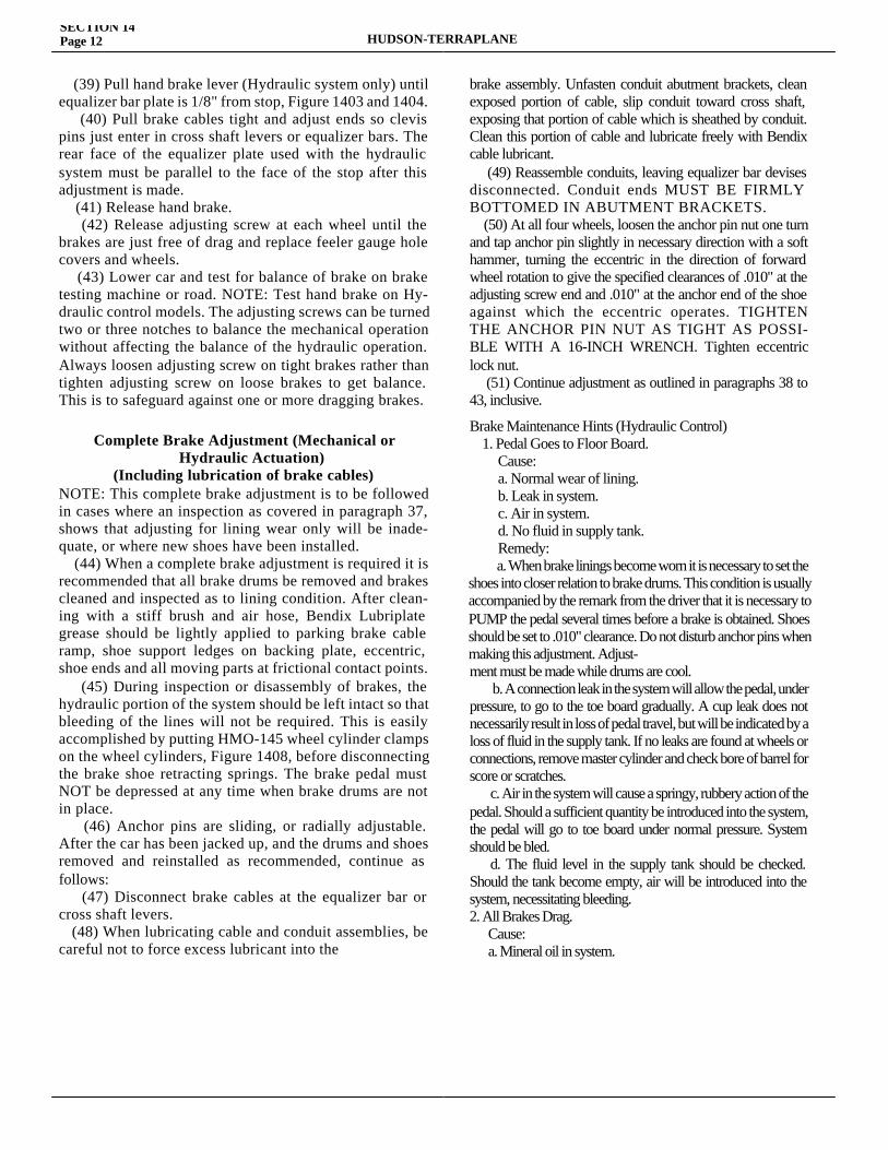
SECTION 14Page 12 HUDSON-TERRAPLANE
(39) Pull hand brake lever (Hydraulic system only) until equalizer bar plate is 1/8" from stop, Figure 1403 and 1404. (40) Pull brake cables tight and adjust ends so clevis pins just enter in cross shaft levers or equalizer bars. The rear face of the equalizer plate used with the hydraulic system must be parallel to the face of the stop after this adjustment is made. (41) Release hand brake. (42) Release adjusting screw at each wheel until the brakes are just free of drag and replace feeler gauge hole covers and wheels. (43) Lower car and test for balance of brake on brake testing machine or road. NOTE: Test hand brake on Hy-draulic control models. The adjusting screws can be turned two or three notches to balance the mechanical operation without affecting the balance of the hydraulic operation. Always loosen adjusting screw on tight brakes rather than tighten adjusting screw on loose brakes to get balance. This is to safeguard against one or more dragging brakes.
Complete Brake Adjustment (Mechanical or Hydraulic Actuation)
(Including lubrication of brake cables)NOTE: This complete brake adjustment is to be followed in cases where an inspection as covered in paragraph 37, shows that adjusting for lining wear only will be inade-quate, or where new shoes have been installed. (44) When a complete brake adjustment is required it is recommended that all brake drums be removed and brakes cleaned and inspected as to lining condition. After clean-ing with a stiff brush and air hose, Bendix Lubriplate grease should be lightly applied to parking brake cable ramp, shoe support ledges on backing plate, eccentric, shoe ends and all moving parts at frictional contact points. (45) During inspection or disassembly of brakes, the hydraulic portion of the system should be left intact so that bleeding of the lines will not be required. This is easily accomplished by putting HMO-145 wheel cylinder clamps on the wheel cylinders, Figure 1408, before disconnecting the brake shoe retracting springs. The brake pedal must NOT be depressed at any time when brake drums are not in place. (46) Anchor pins are sliding, or radially adjustable. After the car has been jacked up, and the drums and shoes removed and reinstalled as recommended, continue as follows: (47) Disconnect brake cables at the equalizer bar or cross shaft levers. (48) When lubricating cable and conduit assemblies, be careful not to force excess lubricant into the
brake assembly. Unfasten conduit abutment brackets, clean exposed portion of cable, slip conduit toward cross shaft, exposing that portion of cable which is sheathed by conduit. Clean this portion of cable and lubricate freely with Bendix cable lubricant. (49) Reassemble conduits, leaving equalizer bar devises disconnected. Conduit ends MUST BE FIRMLY BOTTOMED IN ABUTMENT BRACKETS. (50) At all four wheels, loosen the anchor pin nut one turn and tap anchor pin slightly in necessary direction with a soft hammer, turning the eccentric in the direction of forward wheel rotation to give the specified clearances of .010" at the adjusting screw end and .010" at the anchor end of the shoe against which the eccentric operates. TIGHTEN THE ANCHOR PIN NUT AS TIGHT AS POSSI-BLE WITH A 16-INCH WRENCH. Tighten eccentric lock nut. (51) Continue adjustment as outlined in paragraphs 38 to 43, inclusive.
Brake Maintenance Hints (Hydraulic Control) 1. Pedal Goes to Floor Board.
Cause:a. Normal wear of lining.b. Leak in system.c. Air in system.d. No fluid in supply tank.Remedy:a. When brake linings become worn it is necessary to set the
shoes into closer relation to brake drums. This condition is usually accompanied by the remark from the driver that it is necessary to PUMP the pedal several times before a brake is obtained. Shoes should be set to .010" clearance. Do not disturb anchor pins when making this adjustment. Adjust-ment must be made while drums are cool. b. A connection leak in the system will allow the pedal, under pressure, to go to the toe board gradually. A cup leak does not necessarily result in loss of pedal travel, but will be indicated by a loss of fluid in the supply tank. If no leaks are found at wheels or connections, remove master cylinder and check bore of barrel for score or scratches. c. Air in the system will cause a springy, rubbery action of the pedal. Should a sufficient quantity be introduced into the system, the pedal will go to toe board under normal pressure. System should be bled. d. The fluid level in the supply tank should be checked. Should the tank become empty, air will be introduced into the system, necessitating bleeding.2. All Brakes Drag. Cause: a. Mineral oil in system.
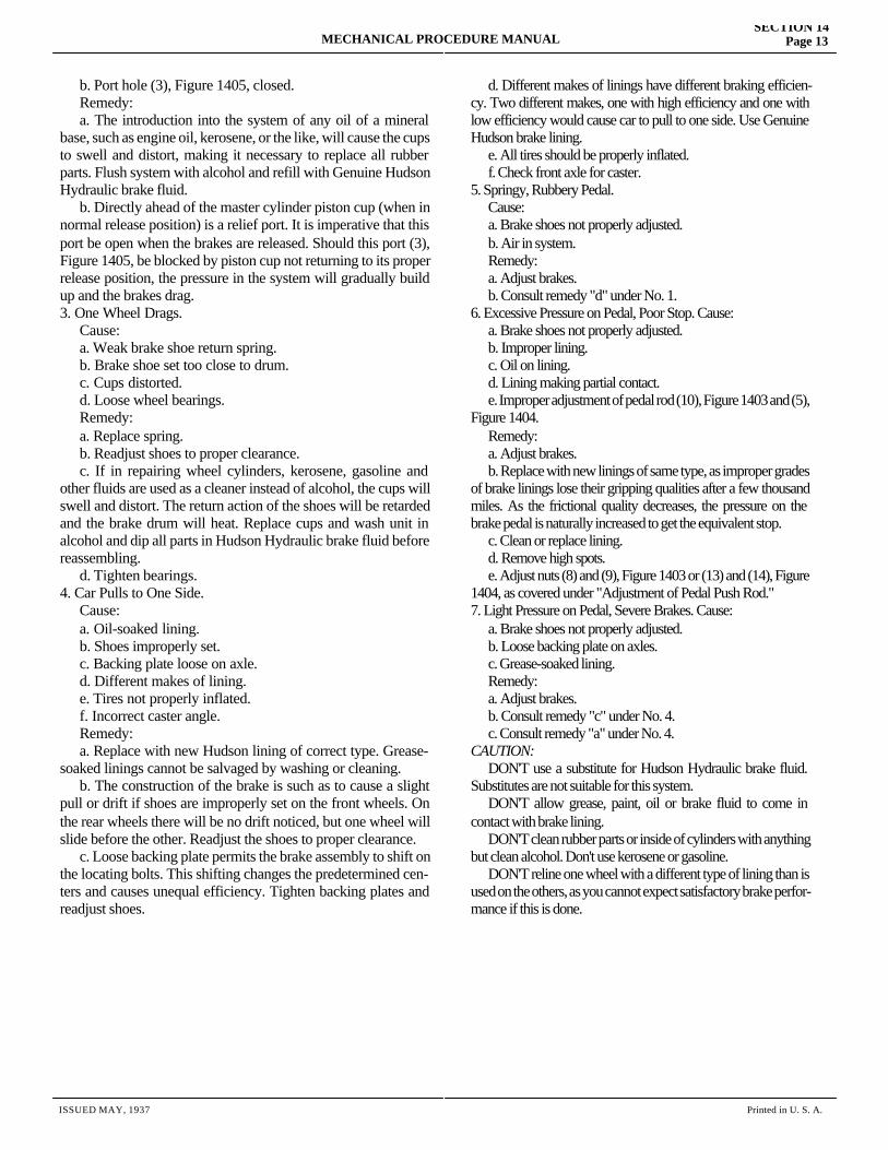
MECHANICAL PROCEDURE MANUALSECTION 14
Page 13
b. Port hole (3), Figure 1405, closed. Remedy: a. The introduction into the system of any oil of a mineral base, such as engine oil, kerosene, or the like, will cause the cups to swell and distort, making it necessary to replace all rubber parts. Flush system with alcohol and refill with Genuine Hudson Hydraulic brake fluid. b. Directly ahead of the master cylinder piston cup (when in normal release position) is a relief port. It is imperative that this port be open when the brakes are released. Should this port (3), Figure 1405, be blocked by piston cup not returning to its proper release position, the pressure in the system will gradually build up and the brakes drag.3. One Wheel Drags. Cause: a. Weak brake shoe return spring. b. Brake shoe set too close to drum. c. Cups distorted. d. Loose wheel bearings. Remedy: a. Replace spring. b. Readjust shoes to proper clearance. c. If in repairing wheel cylinders, kerosene, gasoline and other fluids are used as a cleaner instead of alcohol, the cups will swell and distort. The return action of the shoes will be retarded and the brake drum will heat. Replace cups and wash unit in alcohol and dip all parts in Hudson Hydraulic brake fluid before reassembling. d. Tighten bearings.4. Car Pulls to One Side. Cause: a. Oil-soaked lining. b. Shoes improperly set. c. Backing plate loose on axle. d. Different makes of lining. e. Tires not properly inflated. f. Incorrect caster angle. Remedy: a. Replace with new Hudson lining of correct type. Grease-soaked linings cannot be salvaged by washing or cleaning. b. The construction of the brake is such as to cause a slight pull or drift if shoes are improperly set on the front wheels. On the rear wheels there will be no drift noticed, but one wheel will slide before the other. Readjust the shoes to proper clearance. c. Loose backing plate permits the brake assembly to shift on the locating bolts. This shifting changes the predetermined cen-ters and causes unequal efficiency. Tighten backing plates and readjust shoes.
d. Different makes of linings have different braking efficien-cy. Two different makes, one with high efficiency and one with low efficiency would cause car to pull to one side. Use Genuine Hudson brake lining. e. All tires should be properly inflated. f. Check front axle for caster.5. Springy, Rubbery Pedal. Cause: a. Brake shoes not properly adjusted. b. Air in system. Remedy: a. Adjust brakes. b. Consult remedy "d" under No. 1.6. Excessive Pressure on Pedal, Poor Stop. Cause: a. Brake shoes not properly adjusted. b. Improper lining. c. Oil on lining. d. Lining making partial contact. e. Improper adjustment of pedal rod (10), Figure 1403 and (5), Figure 1404. Remedy: a. Adjust brakes. b. Replace with new linings of same type, as improper grades of brake linings lose their gripping qualities after a few thousand miles. As the frictional quality decreases, the pressure on the brake pedal is naturally increased to get the equivalent stop. c. Clean or replace lining. d. Remove high spots. e. Adjust nuts (8) and (9), Figure 1403 or (13) and (14), Figure 1404, as covered under "Adjustment of Pedal Push Rod."7. Light Pressure on Pedal, Severe Brakes. Cause: a. Brake shoes not properly adjusted. b. Loose backing plate on axles. c. Grease-soaked lining. Remedy: a. Adjust brakes. b. Consult remedy "c" under No. 4. c. Consult remedy "a" under No. 4. CAUTION: DON'T use a substitute for Hudson Hydraulic brake fluid. Substitutes are not suitable for this system. DON'T allow grease, paint, oil or brake fluid to come in contact with brake lining. DON'T clean rubber parts or inside of cylinders with anything but clean alcohol. Don't use kerosene or gasoline. DON'T reline one wheel with a different type of lining than is used on the others, as you cannot expect satisfactory brake perfor-mance if this is done.
ISSUED MAY, 1937 Printed in U. S. A.
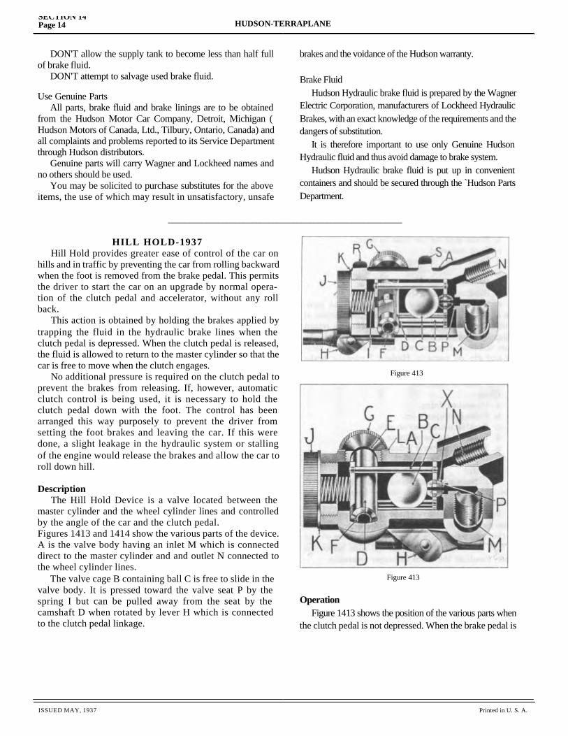
SECTION 14Page 14 HUDSON-TERRAPLANE
ISSUED MAY, 1937 Printed in U. S. A.
DON'T allow the supply tank to become less than half full of brake fluid. DON'T attempt to salvage used brake fluid.
Use Genuine Parts All parts, brake fluid and brake linings are to be obtained from the Hudson Motor Car Company, Detroit, Michigan ( Hudson Motors of Canada, Ltd., Tilbury, Ontario, Canada) and all complaints and problems reported to its Service Department through Hudson distributors. Genuine parts will carry Wagner and Lockheed names and no others should be used. You may be solicited to purchase substitutes for the above items, the use of which may result in unsatisfactory, unsafe
HILL HOLD-1937 Hill Hold provides greater ease of control of the car on hills and in traffic by preventing the car from rolling backward when the foot is removed from the brake pedal. This permits the driver to start the car on an upgrade by normal opera-tion of the clutch pedal and accelerator, without any roll back. This action is obtained by holding the brakes applied by trapping the fluid in the hydraulic brake lines when the clutch pedal is depressed. When the clutch pedal is released, the fluid is allowed to return to the master cylinder so that the car is free to move when the clutch engages. No additional pressure is required on the clutch pedal to prevent the brakes from releasing. If, however, automatic clutch control is being used, it is necessary to hold the clutch pedal down with the foot. The control has been arranged this way purposely to prevent the driver from setting the foot brakes and leaving the car. If this were done, a slight leakage in the hydraulic system or stalling of the engine would release the brakes and allow the car to roll down hill.
Description The Hill Hold Device is a valve located between the master cylinder and the wheel cylinder lines and controlled by the angle of the car and the clutch pedal.Figures 1413 and 1414 show the various parts of the device. A is the valve body having an inlet M which is connected direct to the master cylinder and and outlet N connected to the wheel cylinder lines. The valve cage B containing ball C is free to slide in the valve body. It is pressed toward the valve seat P by the spring I but can be pulled away from the seat by the camshaft D when rotated by lever H which is connected to the clutch pedal linkage.
brakes and the voidance of the Hudson warranty.
Brake Fluid Hudson Hydraulic brake fluid is prepared by the Wagner Electric Corporation, manufacturers of Lockheed Hydraulic Brakes, with an exact knowledge of the requirements and the dangers of substitution. It is therefore important to use only Genuine Hudson Hydraulic fluid and thus avoid damage to brake system. Hudson Hydraulic brake fluid is put up in convenient containers and should be secured through the `Hudson Parts Department.
Operation Figure 1413 shows the position of the various parts when the clutch pedal is not depressed. When the brake pedal is
________________________________________________________
Figure 413
Figure 413
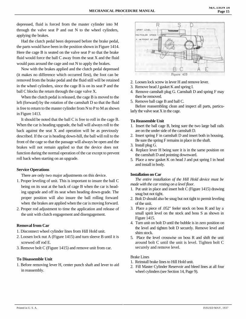
MECHANICAL PROCEDURE MANUALSECTION 14
Page 15
Printed in U. S. A. ISSUED MAY, 1937
depressed, fluid is forced from the master cylinder into M through the valve seat P and out N to the wheel cylinders, applying the brakes. Had the clutch pedal been depressed before the brake pedal, the parts would have been in the position shown in Figure 1414. Here the cage B is seated on the valve seat P so that the brake fluid would force the ball C away from the seat X and the fluid would pass around the cage and out N to apply the brakes. Now with the brakes applied and the clutch pedal depressed (it makes no difference which occurred first), the foot can be removed from the brake pedal and the fluid still will be retained in the wheel cylinders, since the cage B is on its seat P and the ball C blocks the return through the cage valve X. When the clutch pedal is released, the cage B is moved to the left (forward) by the rotation of the camshaft D so that the fluid is free to return to the master cylinder from N to P to M as shown in Figure 1413. It should be noted that the ball C is free to roll in the cage B. When the car is heading upgrade, the ball will always roll to the back against the seat X and operation will be as previously described. If the car is heading down-hill, the ball will roll to the front of the cage so that the passage will always be open and the brakes will not remain applied so that the device does not function during the normal operation of the car except to prevent roll back when starting on an upgrade.
Service Operations There are only two major adjustments on this device.1. Proper leveling of unit. This is important to insure the ball C being on its seat at the back of cage B when the car is head- ing upgrade and off its seat when heading down-grade. The proper position will also insure the ball rolling forward when the brakes are applied when the car is moving forward.2. Proper rod adjustment to time the application and release of the unit with clutch engagement and disengagement.
Removal from Car1. Disconnect wheel cylinder lines from Hill Hold unit.2. Loosen lock nut A (Figure 1415) and turn sleeve B until it is screwed off rod E.3. Remove bolt C (Figure 1415) and remove unit from car.
To Disassemble Unit1. Before removing lever H, center punch shaft and lever to aid in reassembly.
2. Loosen lock screw in lever H and remove lever.3. Remove head J gasket K and spring I.4. Remove camshaft plug G. Camshaft D and spring F may then be removed.5. Remove ball cage B and ball C. Before reassembling clean and inspect all parts, particu-larly the valve seat X in the cage.
To Reassemble Unit1. Insert the ball cage B, being sure the two large ball rails are on the under side of the camshaft D.2. Insert spring F in camshaft D and insert both in housing. Be sure the spring F remains in place in the shaft.3. Install plug G.4. Replace lever H being sure it is in the same position on the camshaft D and pointing downward.5. Place a new gasket K on head J and put spring I in head and install in body.
Installation on Car The entire installation of the Hill Hold device must be made with the car resting on a level floor.1. Put unit in place and insert bolt C (Figure 1415) drawing snug but not tight.2. Bolt D should also be snug but not tight to permit leveling of the unit.3. Place a piece of .052" feeler stock on boss R and lay a small spirit level on the stock and boss S as shown in Figure 1415.4. Turn unit on bolt D until the bubble is in zero position on the level and tighten bolt D securely. Remove level and shim stock.5. Place the level crosswise on boss R and shift the unit around bolt C until the unit is level. Tighten bolt C securely and remove level.
Brake Lines1. Reinstall brake lines to Hill Hold unit.2. Fill Master Cylinder Reservoir and bleed lines at all four wheel cylinders (see Section 14, Page 9).
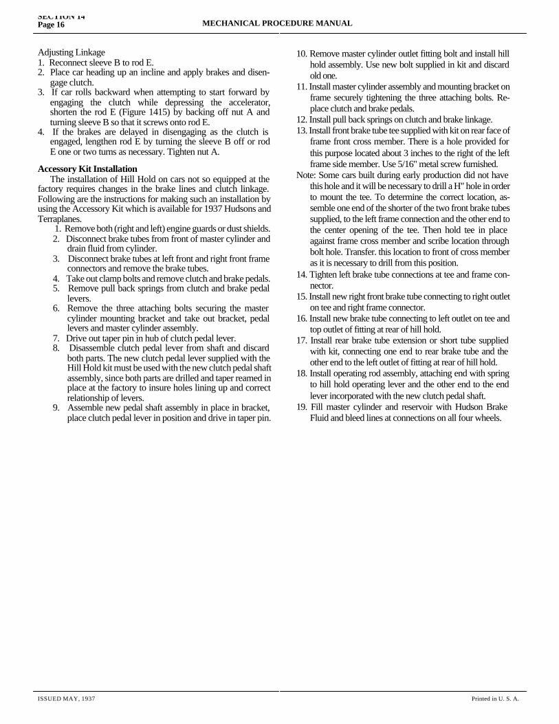
SECTION 14Page 16 MECHANICAL PROCEDURE MANUAL
ISSUED MAY, 1937 Printed in U. S. A.
Adjusting Linkage1. Reconnect sleeve B to rod E.2. Place car heading up an incline and apply brakes and disen- gage clutch.3. If car rolls backward when attempting to start forward by engaging the clutch while depressing the accelerator, shorten the rod E (Figure 1415) by backing off nut A and turning sleeve B so that it screws onto rod E.4. If the brakes are delayed in disengaging as the clutch is engaged, lengthen rod E by turning the sleeve B off or rod E one or two turns as necessary. Tighten nut A.
Accessory Kit Installation The installation of Hill Hold on cars not so equipped at the factory requires changes in the brake lines and clutch linkage. Following are the instructions for making such an installation by using the Accessory Kit which is available for 1937 Hudsons and Terraplanes.
1. Remove both (right and left) engine guards or dust shields.2. Disconnect brake tubes from front of master cylinder and
drain fluid from cylinder.3. Disconnect brake tubes at left front and right front frame
connectors and remove the brake tubes.4. Take out clamp bolts and remove clutch and brake pedals.5. Remove pull back springs from clutch and brake pedal
levers.6. Remove the three attaching bolts securing the master
cylinder mounting bracket and take out bracket, pedal levers and master cylinder assembly.
7. Drive out taper pin in hub of clutch pedal lever.8. Disassemble clutch pedal lever from shaft and discard
both parts. The new clutch pedal lever supplied with the Hill Hold kit must be used with the new clutch pedal shaft assembly, since both parts are drilled and taper reamed in place at the factory to insure holes lining up and correct relationship of levers.
9. Assemble new pedal shaft assembly in place in bracket, place clutch pedal lever in position and drive in taper pin.
10. Remove master cylinder outlet fitting bolt and install hill hold assembly. Use new bolt supplied in kit and discard old one.
11. Install master cylinder assembly and mounting bracket on frame securely tightening the three attaching bolts. Re-place clutch and brake pedals.
12. Install pull back springs on clutch and brake linkage.13. Install front brake tube tee supplied with kit on rear face of
frame front cross member. There is a hole provided for this purpose located about 3 inches to the right of the left frame side member. Use 5/16" metal screw furnished.
Note: Some cars built during early production did not have this hole and it will be necessary to drill a H" hole in order to mount the tee. To determine the correct location, as-semble one end of the shorter of the two front brake tubes supplied, to the left frame connection and the other end to the center opening of the tee. Then hold tee in place against frame cross member and scribe location through bolt hole. Transfer. this location to front of cross member as it is necessary to drill from this position.
14. Tighten left brake tube connections at tee and frame con-nector.
15. Install new right front brake tube connecting to right outlet on tee and right frame connector.
16. Install new brake tube connecting to left outlet on tee and top outlet of fitting at rear of hill hold.
17. Install rear brake tube extension or short tube supplied with kit, connecting one end to rear brake tube and the other end to the left outlet of fitting at rear of hill hold.
18. Install operating rod assembly, attaching end with spring to hill hold operating lever and the other end to the end lever incorporated with the new clutch pedal shaft.
19. Fill master cylinder and reservoir with Hudson Brake Fluid and bleed lines at connections on all four wheels.

SECTION 15
FRONT AXLEService Magazine—Reference Sheet and Service Bullet in Reference
Bulletin orReference SheetNo. MagazineIssue and Page
Date Subject DETAILS OF INFORMATION
MECHANICAL PROCEDURE MANUAL Page 1

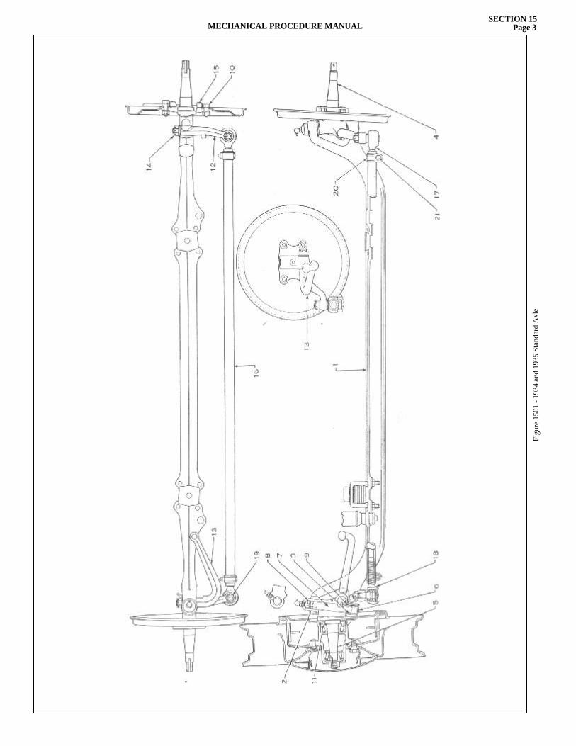
MECHANICAL PROCEDURE MANUALSECTION 15
Page 3
Figu
re 1
501
- 193
4 an
d 19
35 S
tand
ard
Axl
e
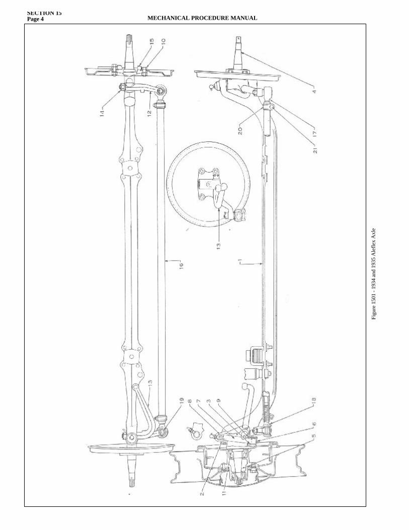
SECTION 15Page 4 MECHANICAL PROCEDURE MANUAL
Figu
re 1
501
- 193
4 an
d 19
35 A
lefle
x A
xle
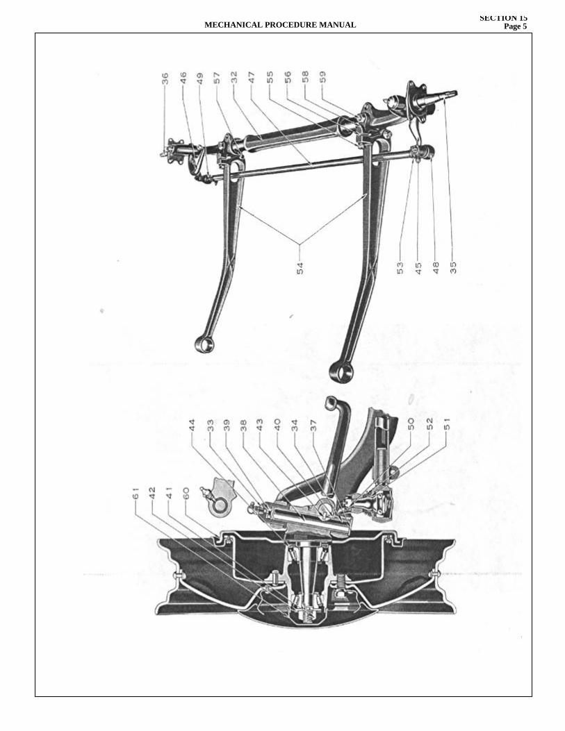
MECHANICAL PROCEDURE MANUALSECTION 15
Page 5
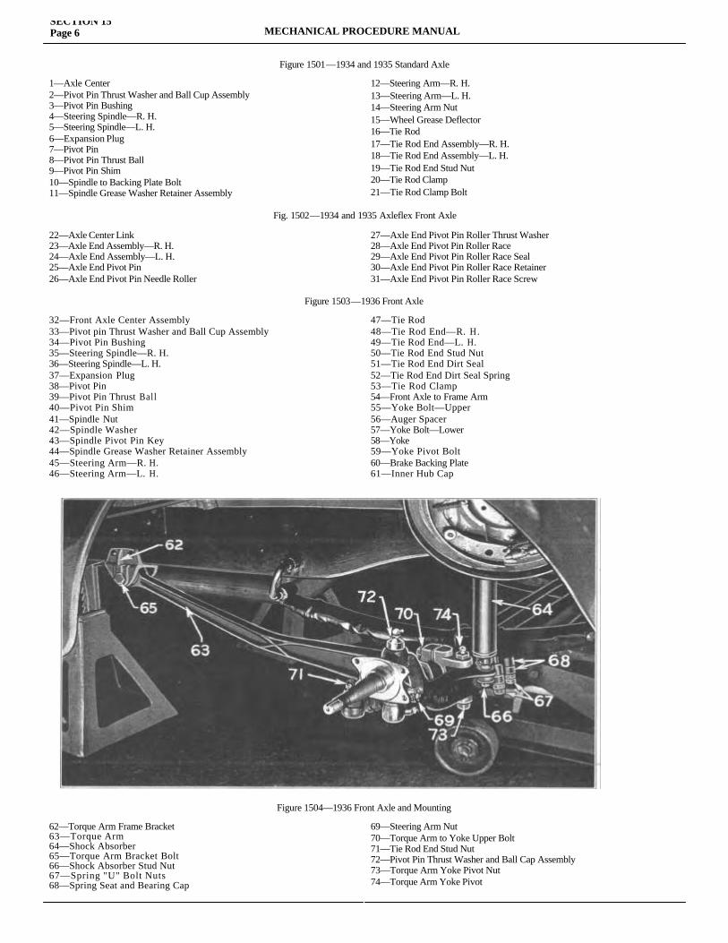
SECTION 15Page 6 MECHANICAL PROCEDURE MANUAL
Figure 1501—1934 and 1935 Standard Axle
1—Axle Center2—Pivot Pin Thrust Washer and Ball Cup Assembly 3—Pivot Pin Bushing4—Steering Spindle—R. H. 5—Steering Spindle—L. H. 6—Expansion Plug7—Pivot Pin8—Pivot Pin Thrust Ball 9—Pivot Pin Shim10—Spindle to Backing Plate Bolt11—Spindle Grease Washer Retainer Assembly
12—Steering Arm—R. H.13—Steering Arm—L. H.14—Steering Arm Nut15—Wheel Grease Deflector16—Tie Rod17—Tie Rod End Assembly—R. H.18—Tie Rod End Assembly—L. H.19—Tie Rod End Stud Nut20—Tie Rod Clamp21—Tie Rod Clamp Bolt
Fig. 1502—1934 and 1935 Axleflex Front Axle
22—Axle Center Link23—Axle End Assembly—R. H. 24—Axle End Assembly—L. H. 25—Axle End Pivot Pin26—Axle End Pivot Pin Needle Roller
27—Axle End Pivot Pin Roller Thrust Washer 28—Axle End Pivot Pin Roller Race29—Axle End Pivot Pin Roller Race Seal 30—Axle End Pivot Pin Roller Race Retainer 31—Axle End Pivot Pin Roller Race Screw
Figure 1503—1936 Front Axle
32—Front Axle Center Assembly33—Pivot pin Thrust Washer and Ball Cup Assembly 34—Pivot Pin Bushing35—Steering Spindle—R. H. 36—Steering Spindle—L. H.37—Expansion Plug38—Pivot Pin39—Pivot Pin Thrust Ball 40—Pivot Pin Shim41—Spindle Nut42—Spindle Washer43—Spindle Pivot Pin Key44—Spindle Grease Washer Retainer Assembly 45—Steering Arm—R. H.46—Steering Arm—L. H.
47—Tie Rod48—Tie Rod End—R. H. 49—Tie Rod End—L. H.50—Tie Rod End Stud Nut 51—Tie Rod End Dirt Seal52—Tie Rod End Dirt Seal Spring 53—Tie Rod Clamp54—Front Axle to Frame Arm 55—Yoke Bolt—Upper 56—Auger Spacer57—Yoke Bolt—Lower 58—Yoke59—Yoke Pivot Bolt 60—Brake Backing Plate 61—Inner Hub Cap
Figure 1504—1936 Front Axle and Mounting
62—Torque Arm Frame Bracket 63—Torque Arm64—Shock Absorber65—Torque Arm Bracket Bolt 66—Shock Absorber Stud Nut 67—Spring "U" Bolt Nuts 68—Spring Seat and Bearing Cap
69—Steering Arm Nut70—Torque Arm to Yoke Upper Bolt71—Tie Rod End Stud Nut72—Pivot Pin Thrust Washer and Ball Cap Assembly 73—Torque Arm Yoke Pivot Nut74—Torque Arm Yoke Pivot
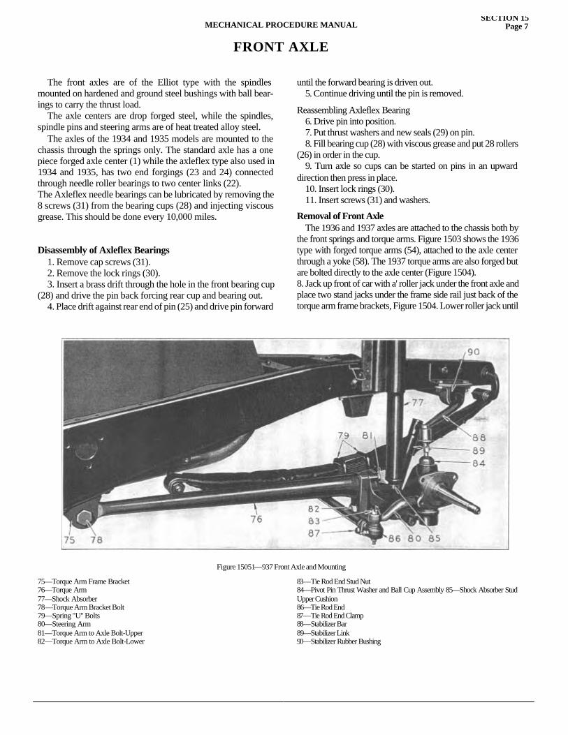
MECHANICAL PROCEDURE MANUALSECTION 15
Page 7
FRONT AXLE
The front axles are of the Elliot type with the spindles mounted on hardened and ground steel bushings with ball bear-ings to carry the thrust load. The axle centers are drop forged steel, while the spindles, spindle pins and steering arms are of heat treated alloy steel. The axles of the 1934 and 1935 models are mounted to the chassis through the springs only. The standard axle has a one piece forged axle center (1) while the axleflex type also used in 1934 and 1935, has two end forgings (23 and 24) connected through needle roller bearings to two center links (22).The Axleflex needle bearings can be lubricated by removing the 8 screws (31) from the bearing cups (28) and injecting viscous grease. This should be done every 10,000 miles.
Disassembly of Axleflex Bearings 1. Remove cap screws (31). 2. Remove the lock rings (30). 3. Insert a brass drift through the hole in the front bearing cup (28) and drive the pin back forcing rear cup and bearing out. 4. Place drift against rear end of pin (25) and drive pin forward
until the forward bearing is driven out. 5. Continue driving until the pin is removed.
Reassembling Axleflex Bearing 6. Drive pin into position. 7. Put thrust washers and new seals (29) on pin. 8. Fill bearing cup (28) with viscous grease and put 28 rollers (26) in order in the cup. 9. Turn axle so cups can be started on pins in an upward direction then press in place. 10. Insert lock rings (30). 11. Insert screws (31) and washers.
Removal of Front Axle The 1936 and 1937 axles are attached to the chassis both by the front springs and torque arms. Figure 1503 shows the 1936 type with forged torque arms (54), attached to the axle center through a yoke (58). The 1937 torque arms are also forged but are bolted directly to the axle center (Figure 1504).8. Jack up front of car with a' roller jack under the front axle and place two stand jacks under the frame side rail just back of the torque arm frame brackets, Figure 1504. Lower roller jack until car
Figure 15051—937 Front Axle and Mounting
75—Torque Arm Frame Bracket 76—Torque Arm77—Shock Absorber78—Torque Arm Bracket Bolt 79—Spring "U" Bolts80—Steering Arm81—Torque Arm to Axle Bolt-Upper 82—Torque Arm to Axle Bolt-Lower
83—Tie Rod End Stud Nut84—Pivot Pin Thrust Washer and Ball Cup Assembly 85—Shock Absorber Stud Upper Cushion86—Tie Rod End87—Tie Rod End Clamp88—Stabilizer Bar89—Stabilizer Link90—Stabilizer Rubber Bushing
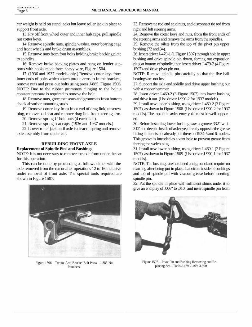
SECTION 15Page 8 MECHANICAL PROCEDURE MANUAL
car weight is held on stand jacks but leave roller jack in place to support front axle. 13. Pry off front wheel outer and inner hub caps, pull spindle nut cotter keys. 14. Remove spindle nuts, spindle washer, outer bearing cage and front wheels and brake drum assemblies. 15. Remove nuts from four bolts holding brake backing plate to spindles. 16. Remove brake backing plates and hang on fender sup-ports with hooks made from heavy wire, Figure 1504. 17. (1936 and 1937 models only.) Remove cotter keys from inner ends of bolts which attach torque arms to frame brackets, remove nuts and press out bolts using press J-885, Figure 1506. NOTE: Due to the rubber grommets clinging to the bolt a constant pressure is required to remove the bolt. 18. Remove nuts, grommet seats and grommets from bottom shock absorber mounting studs. 19. Remove cotter key from front end of drag link, unscrew plug, remove ball seat and remove drag link from steering arm. 20. Remove spring U-bolt nuts (4 each side). 21. Remove spring seat caps. (1936 and 1937 models.) 22. Lower roller jack until axle is clear of spring and remove axle assembly from under car.
REBUILDING FRONT AXLE Replacement of Spindle Pins and BushingsNOTE: It is not necessary to remove the axle from under the car for this operation. This can be done by proceeding as follows either with the axle removed from the car or after operations 12 to 16 inclusive under removal of front axle. The special tools required are shown in Figure 1507.
23. Remove tie rod end stud nuts, and disconnect tie rod from right and left steering arms.24. Remove the cotter keys and nuts, from the front ends of the steering arms and remove the arms from the spindles.25. Remove the oilers from the top of the pivot pin upper bushing (72 and 84).26. Insert driver J-479-1 (1 Figure 1507) through hole in upper bushing and drive spindle pin down, forcing out expansion plug at bottom of spindle, then insert driver J-479-2 (4 Figure 1507) and drive pivot pin out.NOTE: Remove spindle pin carefully so that the five ball bearings are not lost.27. Support the axle end solidly and drive upper bushing out with a copper hammer.28. Insert driver J-469-2 (3 Figure 1507) into lower bushing and drive it out. (Use driver J-990-2 for 1937 models).29. Install new upper bushing, using driver J-469-2 (3 Figure 1507), as shown in Figure 1508. (Use driver J-990-2 for 1937 models). The top of the axle center yoke must be well support-ed.30. Before installing lower bushing saw a groove 332" wide 312' and deep in inside of axle eye, directly opposite the grease fitting if there is not already one there on 1934-5 and 6 models. This groove is intended as a vent hole to prevent grease from forcing the welch plug.31. Install new lower bushing, using driver J-469-1 (2 Figure 1507), as shown in Figure 1509. (Use driver J-990-1 for 1937 models).NOTE: The bushings are hardened and ground and require no reaming after being put in place. Lubricate inside of bushings and top of spindle pin with viscous grease before inserting spindle pin.32. Put the spindle in place with sufficient shims under it to give an end play of .006" to .010" and insert spindle pin from
Figure 1506—Torque Arm Bracket Bolt Press—J-885-NoNumbers
Figure 1507—Pivot Pin and Bushing Removing and Re- placing Set—Tools J-479, J-469, 3-990
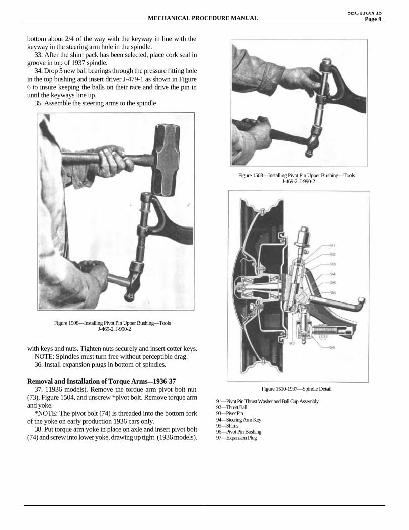
MECHANICAL PROCEDURE MANUALSECTION 15
Page 9
bottom about 2/4 of the way with the keyway in line with the keyway in the steering arm hole in the spindle. 33. After the shim pack has been selected, place cork seal in groove in top of 1937 spindle. 34. Drop 5 new ball bearings through the pressure fitting hole in the top bushing and insert driver J-479-1 as shown in Figure 6 to insure keeping the balls on their race and drive the pin in until the keyways line up. 35. Assemble the steering arms to the spindle
with keys and nuts. Tighten nuts securely and insert cotter keys. NOTE: Spindles must turn free without perceptible drag. 36. Install expansion plugs in bottom of spindles.
Removal and Installation of Torque Arms—1936-37 37. 11936 models). Remove the torque arm pivot bolt nut (73), Figure 1504, and unscrew *pivot bolt. Remove torque arm and yoke. *NOTE: The pivot bolt (74) is threaded into the bottom fork of the yoke on early production 1936 cars only. 38. Put torque arm yoke in place on axle and insert pivot bolt (74) and screw into lower yoke, drawing up tight. (1936 models).
91—Pivot Pin Thrust Washer and Ball Cup Assembly92—Thrust Ball93—Pivot Pin94—Steering Arm Key95—Shims96—Pivot Pin Bushing97—Expansion Plug
Figure 1508—Installing Pivot Pin Upper Bushing—ToolsJ-469-2, J-990-2
Figure 1508—Installing Pivot Pin Upper Bushing—ToolsJ-469-2, J-990-2
Figure 1510-1937—Spindle Detail
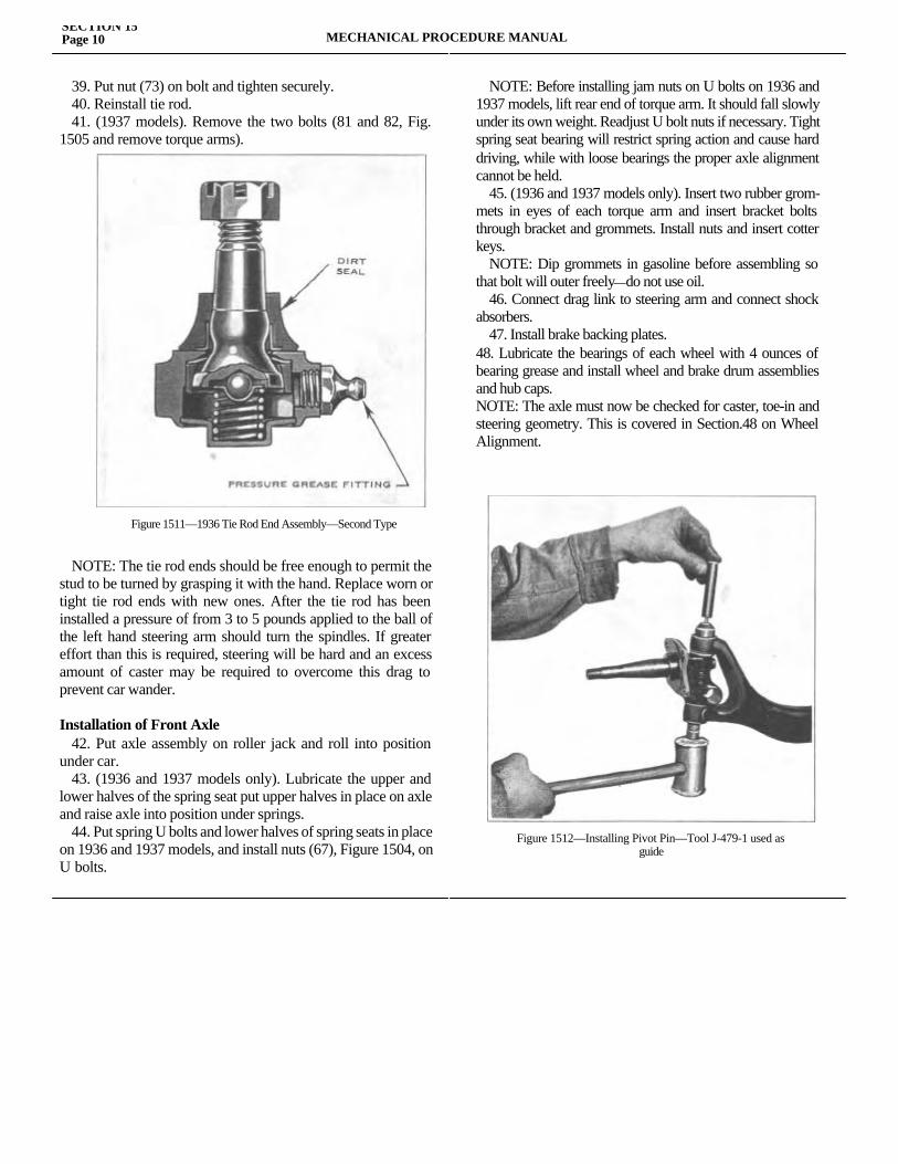
SECTION 15Page 10 MECHANICAL PROCEDURE MANUAL
39. Put nut (73) on bolt and tighten securely. 40. Reinstall tie rod. 41. (1937 models). Remove the two bolts (81 and 82, Fig. 1505 and remove torque arms).
NOTE: The tie rod ends should be free enough to permit the stud to be turned by grasping it with the hand. Replace worn or tight tie rod ends with new ones. After the tie rod has been installed a pressure of from 3 to 5 pounds applied to the ball of the left hand steering arm should turn the spindles. If greater effort than this is required, steering will be hard and an excess amount of caster may be required to overcome this drag to prevent car wander.
Installation of Front Axle 42. Put axle assembly on roller jack and roll into position under car. 43. (1936 and 1937 models only). Lubricate the upper and lower halves of the spring seat put upper halves in place on axle and raise axle into position under springs. 44. Put spring U bolts and lower halves of spring seats in place on 1936 and 1937 models, and install nuts (67), Figure 1504, on U bolts.
NOTE: Before installing jam nuts on U bolts on 1936 and 1937 models, lift rear end of torque arm. It should fall slowly under its own weight. Readjust U bolt nuts if necessary. Tight spring seat bearing will restrict spring action and cause hard driving, while with loose bearings the proper axle alignment cannot be held. 45. (1936 and 1937 models only). Insert two rubber grom-mets in eyes of each torque arm and insert bracket bolts through bracket and grommets. Install nuts and insert cotter keys. NOTE: Dip grommets in gasoline before assembling so that bolt will outer freely—do not use oil. 46. Connect drag link to steering arm and connect shock absorbers. 47. Install brake backing plates.48. Lubricate the bearings of each wheel with 4 ounces of bearing grease and install wheel and brake drum assemblies and hub caps.NOTE: The axle must now be checked for caster, toe-in and steering geometry. This is covered in Section.48 on Wheel Alignment.
Figure 1511—1936 Tie Rod End Assembly—Second Type
Figure 1512—Installing Pivot Pin—Tool J-479-1 used asguide

MECHANICAL PROCEDURE MANUAL Page 1
SECTION 16
STEERING GEARService Magazine—Reference Sheet and Service Bullet in Reference
Bulletin orReference SheetNo. MagazineIssue and Page
Date Subject DETAILS OF INFORMATION

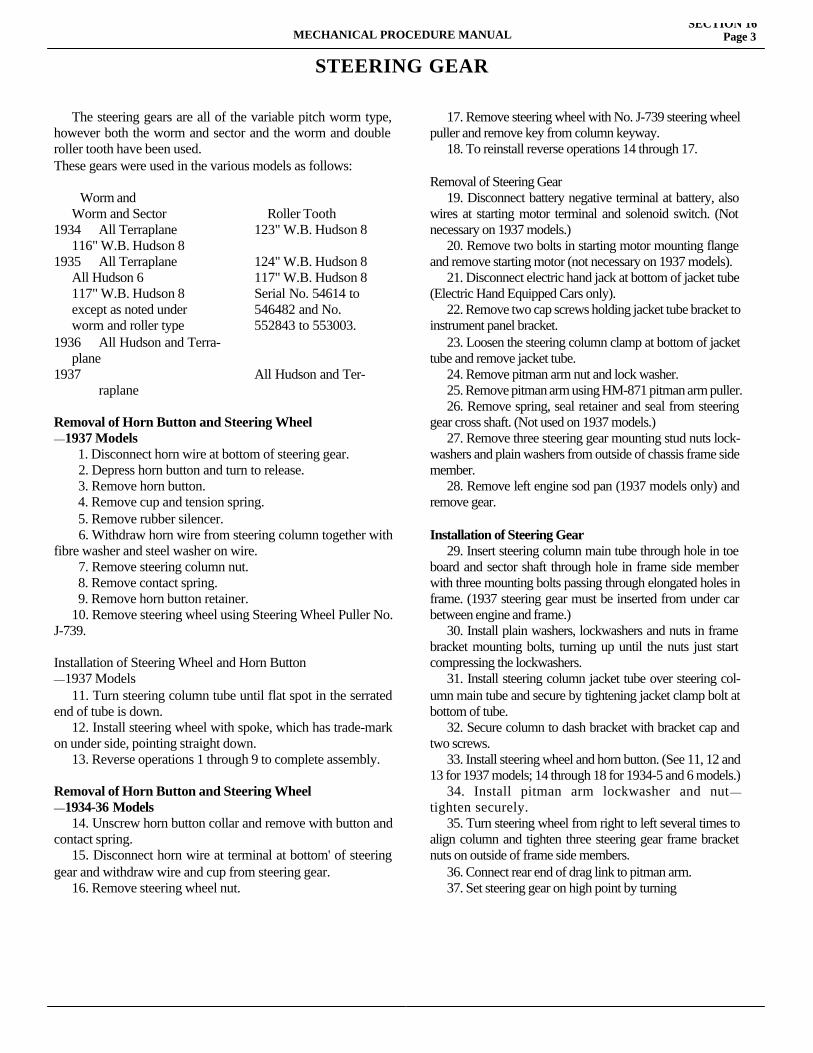
MECHANICAL PROCEDURE MANUALSECTION 16
Page 3
STEERING GEAR
The steering gears are all of the variable pitch worm type, however both the worm and sector and the worm and double roller tooth have been used.These gears were used in the various models as follows:
Worm and Worm and Sector Roller Tooth1934 All Terraplane 123" W.B. Hudson 8 116" W.B. Hudson 81935 All Terraplane 124" W.B. Hudson 8 All Hudson 6 117" W.B. Hudson 8 117" W.B. Hudson 8 Serial No. 54614 to except as noted under 546482 and No. worm and roller type 552843 to 553003.1936 All Hudson and Terra- plane1937 All Hudson and Ter- raplane
Removal of Horn Button and Steering Wheel —1937 Models 1. Disconnect horn wire at bottom of steering gear. 2. Depress horn button and turn to release. 3. Remove horn button. 4. Remove cup and tension spring. 5. Remove rubber silencer. 6. Withdraw horn wire from steering column together with fibre washer and steel washer on wire. 7. Remove steering column nut. 8. Remove contact spring. 9. Remove horn button retainer. 10. Remove steering wheel using Steering Wheel Puller No. J-739.
Installation of Steering Wheel and Horn Button —1937 Models 11. Turn steering column tube until flat spot in the serrated end of tube is down. 12. Install steering wheel with spoke, which has trade-mark on under side, pointing straight down. 13. Reverse operations 1 through 9 to complete assembly.
Removal of Horn Button and Steering Wheel—1934-36 Models 14. Unscrew horn button collar and remove with button and contact spring. 15. Disconnect horn wire at terminal at bottom' of steering gear and withdraw wire and cup from steering gear. 16. Remove steering wheel nut.
17. Remove steering wheel with No. J-739 steering wheel puller and remove key from column keyway. 18. To reinstall reverse operations 14 through 17.
Removal of Steering Gear 19. Disconnect battery negative terminal at battery, also wires at starting motor terminal and solenoid switch. (Not necessary on 1937 models.) 20. Remove two bolts in starting motor mounting flange and remove starting motor (not necessary on 1937 models). 21. Disconnect electric hand jack at bottom of jacket tube (Electric Hand Equipped Cars only). 22. Remove two cap screws holding jacket tube bracket to instrument panel bracket. 23. Loosen the steering column clamp at bottom of jacket tube and remove jacket tube. 24. Remove pitman arm nut and lock washer. 25. Remove pitman arm using HM-871 pitman arm puller. 26. Remove spring, seal retainer and seal from steering gear cross shaft. (Not used on 1937 models.) 27. Remove three steering gear mounting stud nuts lock-washers and plain washers from outside of chassis frame side member. 28. Remove left engine sod pan (1937 models only) and remove gear.
Installation of Steering Gear 29. Insert steering column main tube through hole in toe board and sector shaft through hole in frame side member with three mounting bolts passing through elongated holes in frame. (1937 steering gear must be inserted from under car between engine and frame.) 30. Install plain washers, lockwashers and nuts in frame bracket mounting bolts, turning up until the nuts just start compressing the lockwashers. 31. Install steering column jacket tube over steering col-umn main tube and secure by tightening jacket clamp bolt at bottom of tube. 32. Secure column to dash bracket with bracket cap and two screws. 33. Install steering wheel and horn button. (See 11, 12 and 13 for 1937 models; 14 through 18 for 1934-5 and 6 models.) 34. Install pitman arm lockwasher and nut—tighten securely. 35. Turn steering wheel from right to left several times to align column and tighten three steering gear frame bracket nuts on outside of frame side members. 36. Connect rear end of drag link to pitman arm. 37. Set steering gear on high point by turning
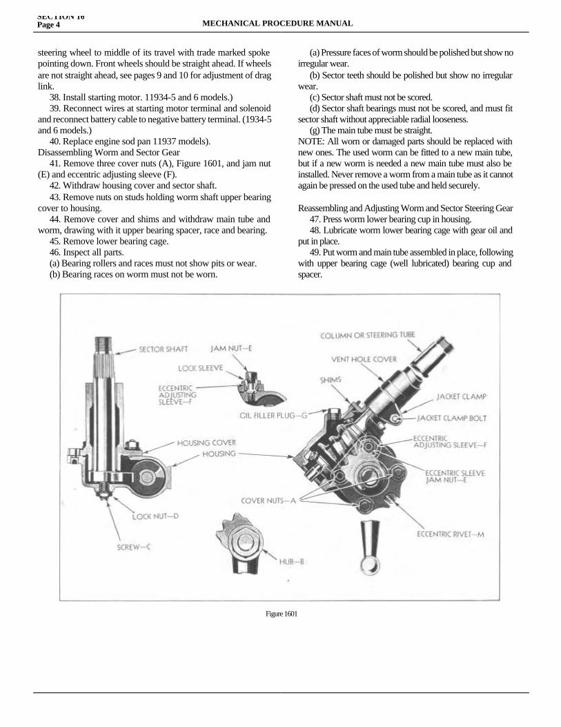
steering wheel to middle of its travel with trade marked spoke pointing down. Front wheels should be straight ahead. If wheels are not straight ahead, see pages 9 and 10 for adjustment of drag link. 38. Install starting motor. 11934-5 and 6 models.) 39. Reconnect wires at starting motor terminal and solenoid and reconnect battery cable to negative battery terminal. (1934-5 and 6 models.) 40. Replace engine sod pan 11937 models).Disassembling Worm and Sector Gear 41. Remove three cover nuts (A), Figure 1601, and jam nut (E) and eccentric adjusting sleeve (F). 42. Withdraw housing cover and sector shaft. 43. Remove nuts on studs holding worm shaft upper bearing cover to housing. 44. Remove cover and shims and withdraw main tube and worm, drawing with it upper bearing spacer, race and bearing. 45. Remove lower bearing cage. 46. Inspect all parts. (a) Bearing rollers and races must not show pits or wear. (b) Bearing races on worm must not be worn.
(a) Pressure faces of worm should be polished but show no irregular wear. (b) Sector teeth should be polished but show no irregular wear. (c) Sector shaft must not be scored. (d) Sector shaft bearings must not be scored, and must fit sector shaft without appreciable radial looseness. (g) The main tube must be straight.NOTE: All worn or damaged parts should be replaced with new ones. The used worm can be fitted to a new main tube, but if a new worm is needed a new main tube must also be installed. Never remove a worm from a main tube as it cannot again be pressed on the used tube and held securely.
Reassembling and Adjusting Worm and Sector Steering Gear 47. Press worm lower bearing cup in housing. 48. Lubricate worm lower bearing cage with gear oil and put in place. 49. Put worm and main tube assembled in place, following with upper bearing cage (well lubricated) bearing cup and spacer.
SECTION 16Page 4 MECHANICAL PROCEDURE MANUAL
Figure 1601
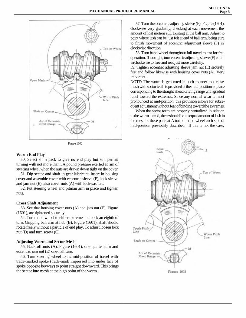
Worm End Play 50. Select shim pack to give no end play but still permit turning with not more than 3A pound pressure exerted at rim of steering wheel when the nuts are drawn down tight on the cover. 51. Dip sector and shaft in gear lubricant, insert in housing cover and assemble cover with eccentric sleeve (F), lock sleeve and jam nut (E), also cover nuts (A) with lockwashers. 52. Put steering wheel and pitman arm in place and tighten nuts.
Cross Shaft Adjustment 53. See that housing cover nuts (A) and jam nut (E), Figure (1601), are tightened securely. 54. Turn hand wheel to either extreme and back an eighth of turn. Gripping ball arm at hub (B), Figure (1601), shaft should rotate freely without a particle of end play. To adjust loosen lock nut (D) and turn screw (C).
Adjusting Worm and Sector Mesh 55. Back off nuts (A), Figure (1601), one-quarter turn and eccentric jam nut (E) one-half turn. 56. Turn steering wheel to its mid-position of travel with trade-marked spoke (trade-mark impressed into under face of spoke opposite keyway) to point straight downward. This brings the sector into mesh at the high point of the worm.
57. Turn the eccentric adjusting sleeve (F), Figure (1601), clockwise very gradually, checking at each movement the amount of lost motion still existing at the ball arm. Adjust to point where lash can be just felt at end of ball arm, being sure to finish movement of eccentric adjustment sleeve (F) in clockwise direction. 58. Turn hand wheel throughout full travel to test for free operation. If too tight, turn eccentric adjusting sleeve (F) coun-terclockwise to free and readjust more carefully.59. Tighten eccentric adjusting sleeve jam nut (E) securely first and follow likewise with housing cover nuts (A). Very important.NOTE: The worm is generated in such manner that close mesh with sector teeth is provided at the mid- position or place corresponding to the straight ahead driving range with gradual relief toward the extremes. Since any normal wear is most pronounced at mid-position, this provision allows for subse-quent adjustment without fear of binding toward the extremes. When the sector teeth are properly centralized in relation to the worm thread, there should be an equal amount of lash in the mesh of these parts at A turn of hand wheel each side of mid-position previously described. If this is not the case, correct
Proper Adjustment
MECHANICAL PROCEDURE MANUALSECTION 16
Page 5
Figure 1602
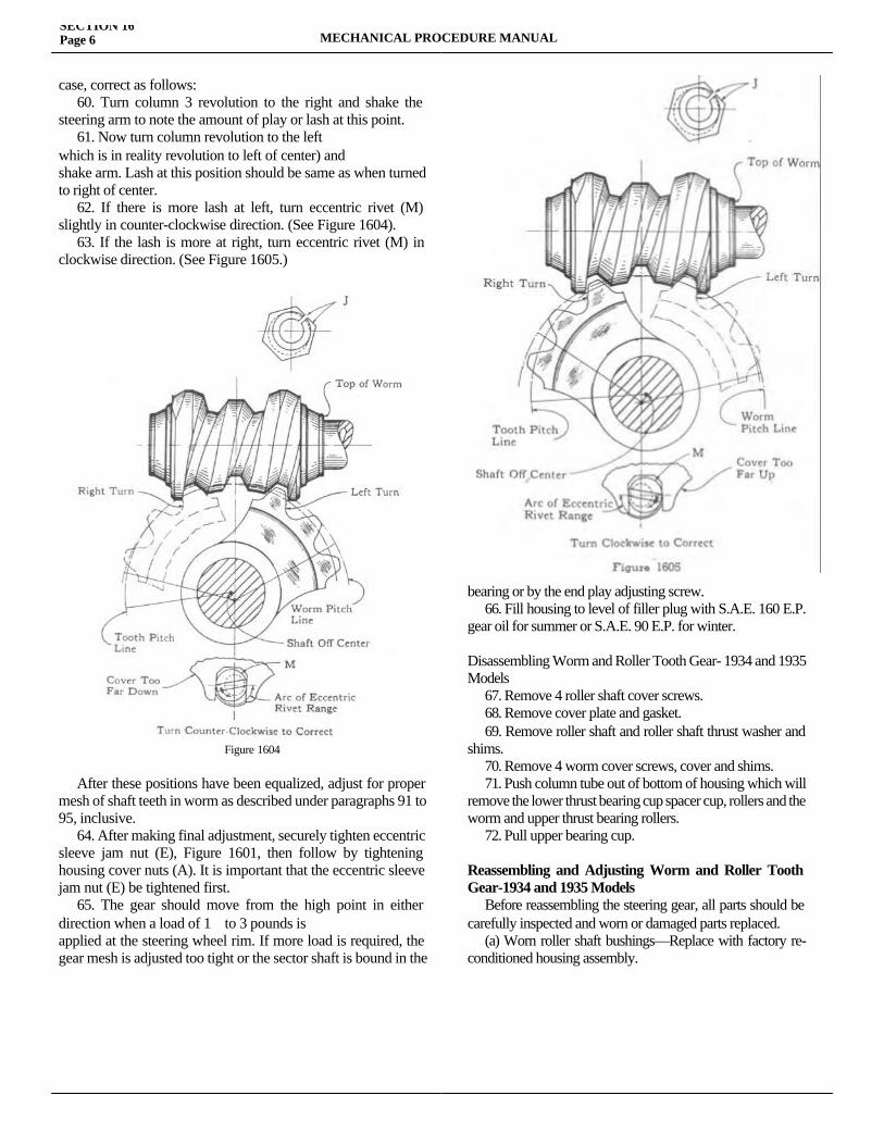
case, correct as follows: 60. Turn column 3 revolution to the right and shake the steering arm to note the amount of play or lash at this point. 61. Now turn column revolution to the leftwhich is in reality revolution to left of center) andshake arm. Lash at this position should be same as when turned to right of center. 62. If there is more lash at left, turn eccentric rivet (M) slightly in counter-clockwise direction. (See Figure 1604). 63. If the lash is more at right, turn eccentric rivet (M) in clockwise direction. (See Figure 1605.)
After these positions have been equalized, adjust for proper mesh of shaft teeth in worm as described under paragraphs 91 to 95, inclusive. 64. After making final adjustment, securely tighten eccentric sleeve jam nut (E), Figure 1601, then follow by tightening housing cover nuts (A). It is important that the eccentric sleeve jam nut (E) be tightened first. 65. The gear should move from the high point in either direction when a load of 1 to 3 pounds isapplied at the steering wheel rim. If more load is required, the gear mesh is adjusted too tight or the sector shaft is bound in the
bearing or by the end play adjusting screw. 66. Fill housing to level of filler plug with S.A.E. 160 E.P. gear oil for summer or S.A.E. 90 E.P. for winter.
Disassembling Worm and Roller Tooth Gear- 1934 and 1935 Models 67. Remove 4 roller shaft cover screws. 68. Remove cover plate and gasket. 69. Remove roller shaft and roller shaft thrust washer and shims. 70. Remove 4 worm cover screws, cover and shims. 71. Push column tube out of bottom of housing which will remove the lower thrust bearing cup spacer cup, rollers and the worm and upper thrust bearing rollers. 72. Pull upper bearing cup.
Reassembling and Adjusting Worm and Roller Tooth Gear-1934 and 1935 Models Before reassembling the steering gear, all parts should be carefully inspected and worn or damaged parts replaced. (a) Worn roller shaft bushings—Replace with factory re-conditioned housing assembly.
SECTION 16Page 6 MECHANICAL PROCEDURE MANUAL
Figure 1604
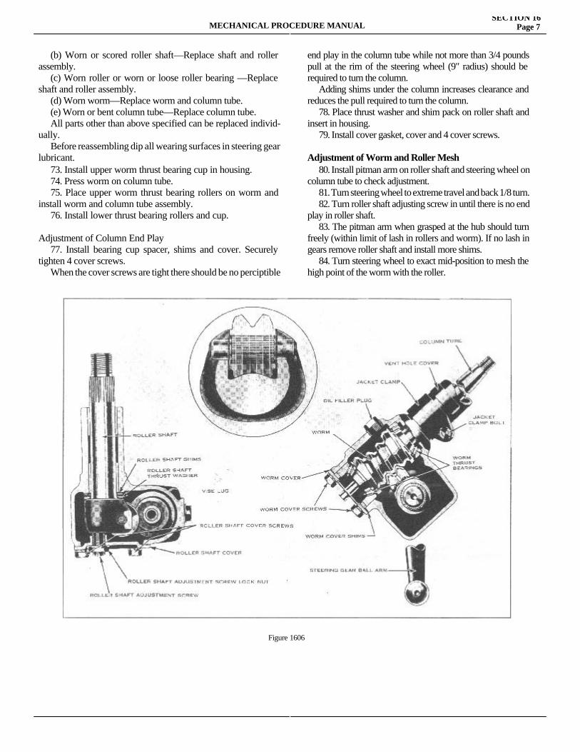
(b) Worn or scored roller shaft—Replace shaft and roller assembly. (c) Worn roller or worn or loose roller bearing —Replace shaft and roller assembly. (d) Worn worm—Replace worm and column tube. (e) Worn or bent column tube—Replace column tube. All parts other than above specified can be replaced individ-ually. Before reassembling dip all wearing surfaces in steering gear lubricant. 73. Install upper worm thrust bearing cup in housing. 74. Press worm on column tube. 75. Place upper worm thrust bearing rollers on worm and install worm and column tube assembly. 76. Install lower thrust bearing rollers and cup.
Adjustment of Column End Play 77. Install bearing cup spacer, shims and cover. Securely tighten 4 cover screws. When the cover screws are tight there should be no perciptible
end play in the column tube while not more than 3/4 pounds pull at the rim of the steering wheel (9" radius) should be required to turn the column. Adding shims under the column increases clearance and reduces the pull required to turn the column. 78. Place thrust washer and shim pack on roller shaft and insert in housing. 79. Install cover gasket, cover and 4 cover screws.
Adjustment of Worm and Roller Mesh 80. Install pitman arm on roller shaft and steering wheel on column tube to check adjustment. 81. Turn steering wheel to extreme travel and back 1/8 turn. 82. Turn roller shaft adjusting screw in until there is no end play in roller shaft. 83. The pitman arm when grasped at the hub should turn freely (within limit of lash in rollers and worm). If no lash in gears remove roller shaft and install more shims. 84. Turn steering wheel to exact mid-position to mesh the high point of the worm with the roller.
MECHANICAL PROCEDURE MANUALSECTION 16
Page 7
Figure 1606
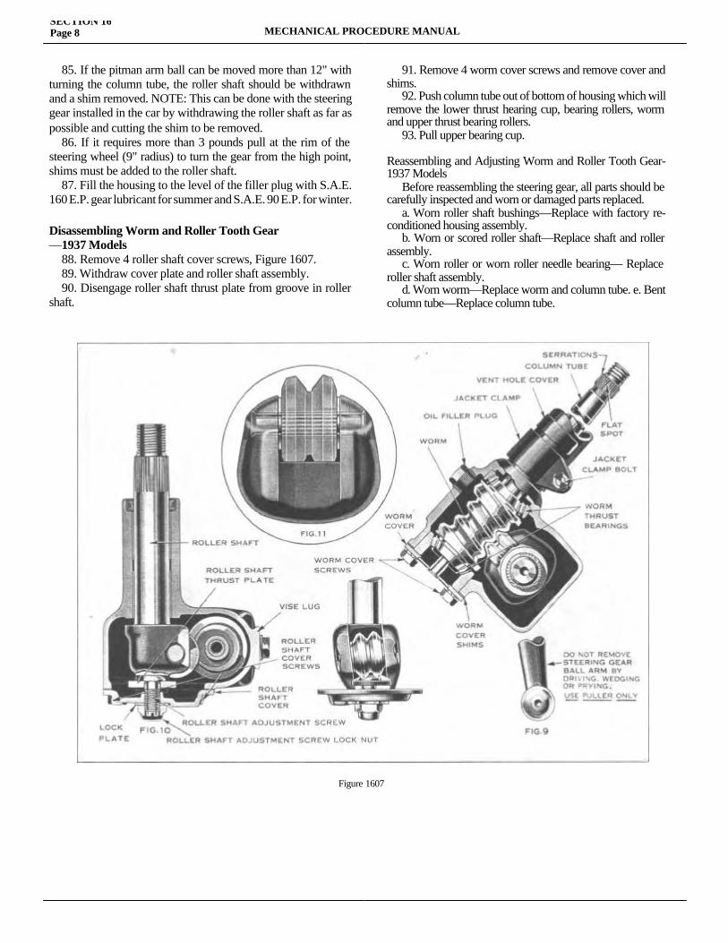
85. If the pitman arm ball can be moved more than 12" with turning the column tube, the roller shaft should be withdrawn and a shim removed. NOTE: This can be done with the steering gear installed in the car by withdrawing the roller shaft as far as possible and cutting the shim to be removed. 86. If it requires more than 3 pounds pull at the rim of the steering wheel (9" radius) to turn the gear from the high point, shims must be added to the roller shaft. 87. Fill the housing to the level of the filler plug with S.A.E. 160 E.P. gear lubricant for summer and S.A.E. 90 E.P. for winter.
Disassembling Worm and Roller Tooth Gear—1937 Models 88. Remove 4 roller shaft cover screws, Figure 1607. 89. Withdraw cover plate and roller shaft assembly. 90. Disengage roller shaft thrust plate from groove in roller shaft.
91. Remove 4 worm cover screws and remove cover and shims. 92. Push column tube out of bottom of housing which will remove the lower thrust hearing cup, bearing rollers, worm and upper thrust bearing rollers. 93. Pull upper bearing cup.
Reassembling and Adjusting Worm and Roller Tooth Gear-1937 Models Before reassembling the steering gear, all parts should be carefully inspected and worn or damaged parts replaced. a. Worn roller shaft bushings—Replace with factory re-conditioned housing assembly. b. Worn or scored roller shaft—Replace shaft and roller assembly. c. Worn roller or worn roller needle bearing— Replace roller shaft assembly. d. Worn worm—Replace worm and column tube. e. Bent column tube—Replace column tube.
SECTION 16Page 8 MECHANICAL PROCEDURE MANUAL
Figure 1607
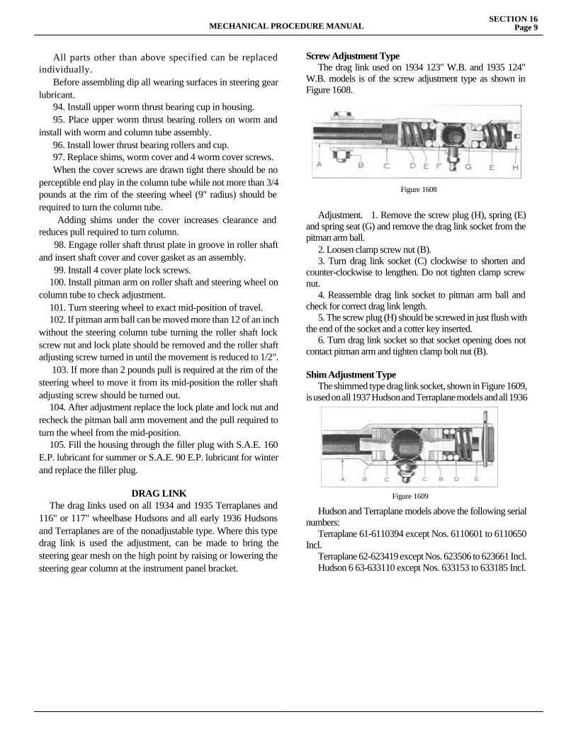
All parts other than above specified can be replaced individually. Before assembling dip all wearing surfaces in steering gear lubricant. 94. Install upper worm thrust bearing cup in housing. 95. Place upper worm thrust bearing rollers on worm and install with worm and column tube assembly. 96. Install lower thrust bearing rollers and cup. 97. Replace shims, worm cover and 4 worm cover screws. When the cover screws are drawn tight there should be no perceptible end play in the column tube while not more than 3/4 pounds at the rim of the steering wheel (9" radius) should be required to turn the column tube. Adding shims under the cover increases clearance and reduces pull required to turn column. 98. Engage roller shaft thrust plate in groove in roller shaft and insert shaft cover and cover gasket as an assembly. 99. Install 4 cover plate lock screws. 100. Install pitman arm on roller shaft and steering wheel on column tube to check adjustment. 101. Turn steering wheel to exact mid-position of travel. 102. If pitman arm ball can be moved more than 12 of an inch without the steering column tube turning the roller shaft lock screw nut and lock plate should be removed and the roller shaft adjusting screw turned in until the movement is reduced to 1/2". 103. If more than 2 pounds pull is required at the rim of the steering wheel to move it from its mid-position the roller shaft adjusting screw should be turned out. 104. After adjustment replace the lock plate and lock nut and recheck the pitman ball arm movement and the pull required to turn the wheel from the mid-position. 105. Fill the housing through the filler plug with S.A.E. 160 E.P. lubricant for summer or S.A.E. 90 E.P. lubricant for winter and replace the filler plug.
DRAG LINK The drag links used on all 1934 and 1935 Terraplanes and 116" or 117" wheelbase Hudsons and all early 1936 Hudsons and Terraplanes are of the nonadjustable type. Where this type drag link is used the adjustment, can be made to bring the steering gear mesh on the high point by raising or lowering the steering gear column at the instrument panel bracket.
Screw Adjustment Type The drag link used on 1934 123" W.B. and 1935 124" W.B. models is of the screw adjustment type as shown in Figure 1608.
Adjustment. 1. Remove the screw plug (H), spring (E) and spring seat (G) and remove the drag link socket from the pitman arm ball. 2. Loosen clamp screw nut (B). 3. Turn drag link socket (C) clockwise to shorten and counter-clockwise to lengthen. Do not tighten clamp screw nut. 4. Reassemble drag link socket to pitman arm ball and check for correct drag link length. 5. The screw plug (H) should be screwed in just flush with the end of the socket and a cotter key inserted. 6. Turn drag link socket so that socket opening does not contact pitman arm and tighten clamp bolt nut (B).
Shim Adjustment Type The shimmed type drag link socket, shown in Figure 1609, is used on all 1937 Hudson and Terraplane models and all 1936
Hudson and Terraplane models above the following serial numbers: Terraplane 61-6110394 except Nos. 6110601 to 6110650 Incl. Terraplane 62-623419 except Nos. 623506 to 623661 Incl. Hudson 6 63-633110 except Nos. 633153 to 633185 Incl.
MECHANICAL PROCEDURE MANUALSECTION 16
Page 9
Figure 1608
Figure 1609
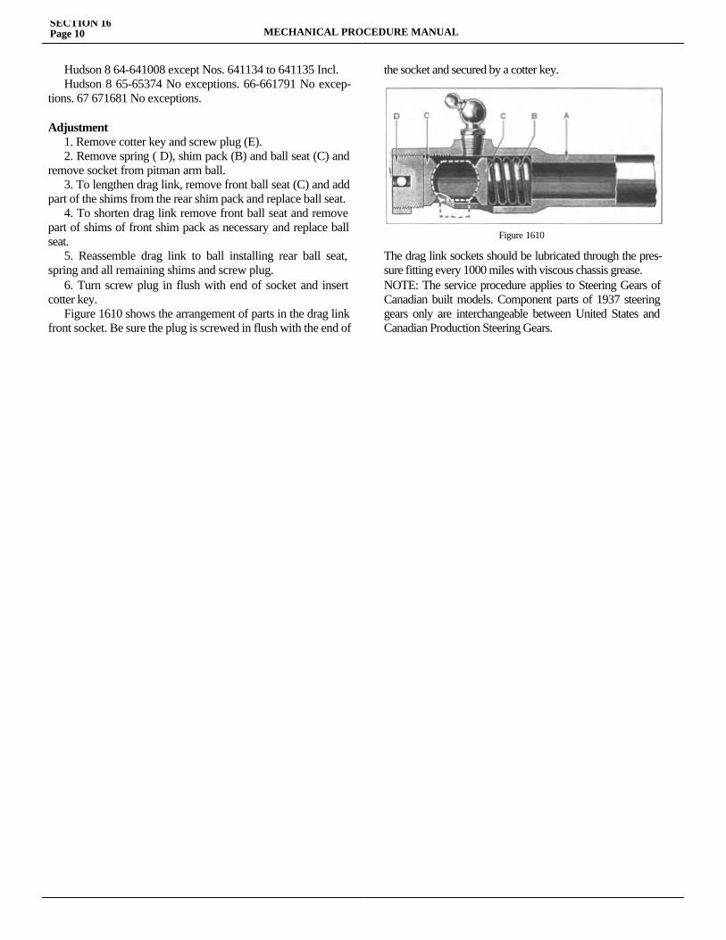
Hudson 8 64-641008 except Nos. 641134 to 641135 Incl. Hudson 8 65-65374 No exceptions. 66-661791 No excep-tions. 67 671681 No exceptions.
Adjustment 1. Remove cotter key and screw plug (E). 2. Remove spring ( D), shim pack (B) and ball seat (C) and remove socket from pitman arm ball. 3. To lengthen drag link, remove front ball seat (C) and add part of the shims from the rear shim pack and replace ball seat. 4. To shorten drag link remove front ball seat and remove part of shims of front shim pack as necessary and replace ball seat. 5. Reassemble drag link to ball installing rear ball seat, spring and all remaining shims and screw plug. 6. Turn screw plug in flush with end of socket and insert cotter key. Figure 1610 shows the arrangement of parts in the drag link front socket. Be sure the plug is screwed in flush with the end of
the socket and secured by a cotter key.
The drag link sockets should be lubricated through the pres-sure fitting every 1000 miles with viscous chassis grease.NOTE: The service procedure applies to Steering Gears of Canadian built models. Component parts of 1937 steering gears only are interchangeable between United States and Canadian Production Steering Gears.
SECTION 16Page 10 MECHANICAL PROCEDURE MANUAL
Figure 1610

SECTION 17FRAME AND SPRINGS
Service Magazine—Reference Sheet and Service Bullet in Reference
Bulletin orReference SheetNo. MagazineIssue and Page
Date Subject DETAILS OF INFORMATION
MECHANICAL PROCEDURE MANUAL Page 1

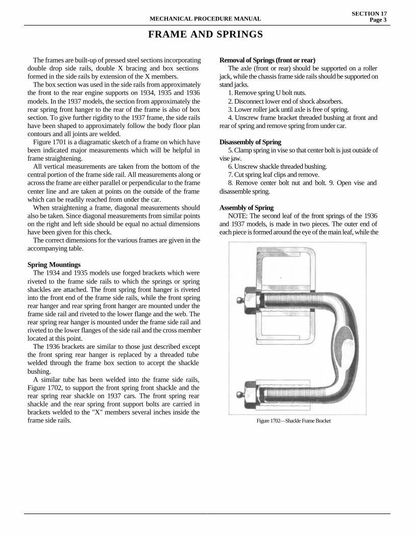
FRAME AND SPRINGS
The frames are built-up of pressed steel sections incorporating double drop side rails, double X bracing and box sections formed in the side rails by extension of the X members. The box section was used in the side rails from approximately the front to the rear engine supports on 1934, 1935 and 1936 models. In the 1937 models, the section from approximately the rear spring front hanger to the rear of the frame is also of box section. To give further rigidity to the 1937 frame, the side rails have been shaped to approximately follow the body floor plan contours and all joints are welded. Figure 1701 is a diagramatic sketch of a frame on which have been indicated major measurements which will be helpful in frame straightening. All vertical measurements are taken from the bottom of the central portion of the frame side rail. All measurements along or across the frame are either parallel or perpendicular to the frame center line and are taken at points on the outside of the frame which can be readily reached from under the car. When straightening a frame, diagonal measurements should also be taken. Since diagonal measurements from similar points on the right and left side should be equal no actual dimensions have been given for this check. The correct dimensions for the various frames are given in the accompanying table.
Spring Mountings The 1934 and 1935 models use forged brackets which were riveted to the frame side rails to which the springs or spring shackles are attached. The front spring front hanger is riveted into the front end of the frame side rails, while the front spring rear hanger and rear spring front hanger are mounted under the frame side rail and riveted to the lower flange and the web. The rear spring rear hanger is mounted under the frame side rail and riveted to the lower flanges of the side rail and the cross member located at this point. The 1936 brackets are similar to those just described except the front spring rear hanger is replaced by a threaded tube welded through the frame box section to accept the shackle bushing. A similar tube has been welded into the frame side rails, Figure 1702, to support the front spring front shackle and the rear spring rear shackle on 1937 cars. The front spring rear shackle and the rear spring front support bolts are carried in brackets welded to the "X" members several inches inside the frame side rails.
Removal of Springs (front or rear) The axle (front or rear) should be supported on a roller jack, while the chassis frame side rails should be supported on stand jacks. 1. Remove spring U bolt nuts. 2. Disconnect lower end of shock absorbers. 3. Lower roller jack until axle is free of spring. 4. Unscrew frame bracket threaded bushing at front and rear of spring and remove spring from under car.
Disassembly of Spring 5. Clamp spring in vise so that center bolt is just outside of vise jaw. 6. Unscrew shackle threaded bushing. 7. Cut spring leaf clips and remove. 8. Remove center bolt nut and bolt. 9. Open vise and disassemble spring.
Assembly of Spring NOTE: The second leaf of the front springs of the 1936 and 1937 models, is made in two pieces. The outer end of each piece is formed around the eye of the main leaf, while the
MECHANICAL PROCEDURE MANUALSECTION 17
Page 3
Figure 1702—Shackle Frame Bracket
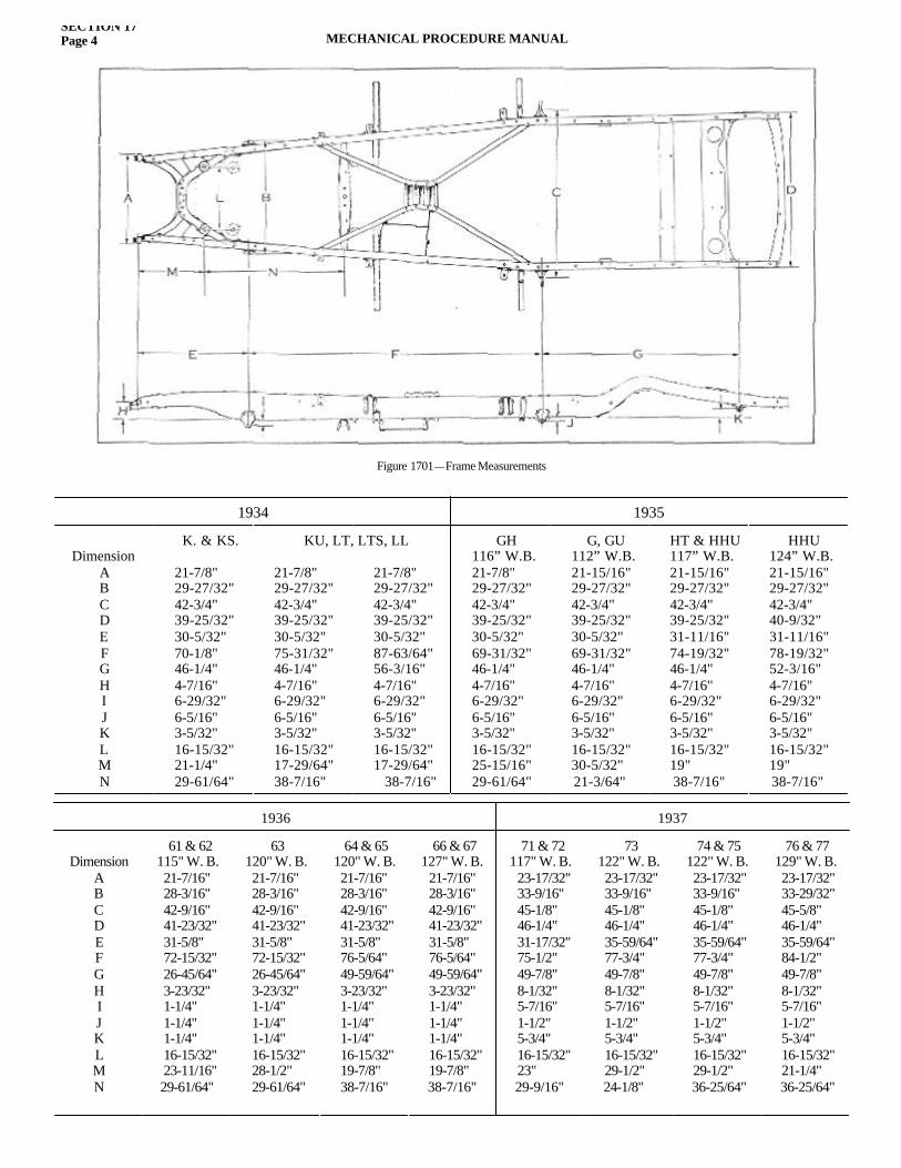
SECTION 17Page 4 MECHANICAL PROCEDURE MANUAL
Figure 1701—Frame Measurements
1934 1935
DimensionABCDEFGHIJKLMN
K. & KS.
21-7/8"29-27/32"42-3/4"39-25/32"30-5/32"70-1/8"46-1/4"4-7/16"6-29/32"6-5/16"3-5/32"16-15/32"21-1/4"29-61/64"
21-7/8"29-27/32"42-3/4"39-25/32"30-5/32"75-31/32"46-1/4"4-7/16"6-29/32"6-5/16"3-5/32"16-15/32"17-29/64"38-7/16"
21-7/8"29-27/32"42-3/4"39-25/32"30-5/32"87-63/64"56-3/16"4-7/16"6-29/32"6-5/16"3-5/32"16-15/32"17-29/64" 38-7/16"
GH116” W.B.21-7/8"29-27/32"42-3/4"39-25/32"30-5/32"69-31/32"46-1/4"4-7/16"6-29/32"6-5/16"3-5/32"16-15/32"25-15/16"29-61/64"
G, GU112” W.B.21-15/16"29-27/32"42-3/4"39-25/32"30-5/32"69-31/32"46-1/4"4-7/16"6-29/32"6-5/16"3-5/32"16-15/32"30-5/32"21-3/64"
HT & HHU117” W.B.21-15/16"29-27/32"42-3/4"39-25/32"31-11/16"74-19/32"46-1/4"4-7/16"6-29/32"6-5/16"3-5/32"16-15/32"19"38-7/16"
HHU124” W.B.21-15/16"29-27/32"42-3/4"40-9/32"31-11/16"78-19/32"52-3/16"4-7/16"6-29/32"6-5/16"3-5/32"16-15/32"19"38-7/16"
KU, LT, LTS, LL
1936 1937
DimensionABCDEFGHIJKLMN
61 & 62115" W. B.21-7/16"28-3/16"42-9/16"41-23/32"31-5/8"72-15/32"26-45/64"3-23/32"1-1/4"1-1/4"1-1/4"16-15/32"23-11/16" 29-61/64"
63120" W. B.21-7/16"28-3/16"42-9/16"41-23/32"31-5/8"72-15/32"26-45/64"3-23/32"1-1/4"1-1/4"1-1/4"16-15/32"28-1/2" 29-61/64"
64 & 65120" W. B.21-7/16"28-3/16"42-9/16"41-23/32"31-5/8"76-5/64"49-59/64"3-23/32"1-1/4"1-1/4"1-1/4"16-15/32"19-7/8" 38-7/16"
66 & 67127" W. B.
21-7/16"28-3/16"42-9/16"41-23/32"31-5/8"76-5/64"49-59/64"3-23/32"1-1/4"1-1/4"1-1/4"16-15/32"19-7/8"
38-7/16"
71 & 72117" W. B.
23-17/32"33-9/16"45-1/8"46-1/4"31-17/32"75-1/2"49-7/8"8-1/32"5-7/16"1-1/2"5-3/4"16-15/32"23"
29-9/16"
73122" W. B.23-17/32"33-9/16"45-1/8"46-1/4"35-59/64"77-3/4"49-7/8"8-1/32"5-7/16"1-1/2"5-3/4"16-15/32"29-1/2"
24-1/8"
74 & 75122" W. B.23-17/32"33-9/16"45-1/8"46-1/4"35-59/64"77-3/4"49-7/8"8-1/32"5-7/16"1-1/2"5-3/4"16-15/32"29-1/2"
36-25/64"
76 & 77129" W. B.23-17/32"33-29/32"45-5/8"46-1/4"35-59/64"84-1/2"49-7/8"8-1/32"5-7/16"1-1/2"5-3/4"16-15/32"21-1/4"
36-25/64"
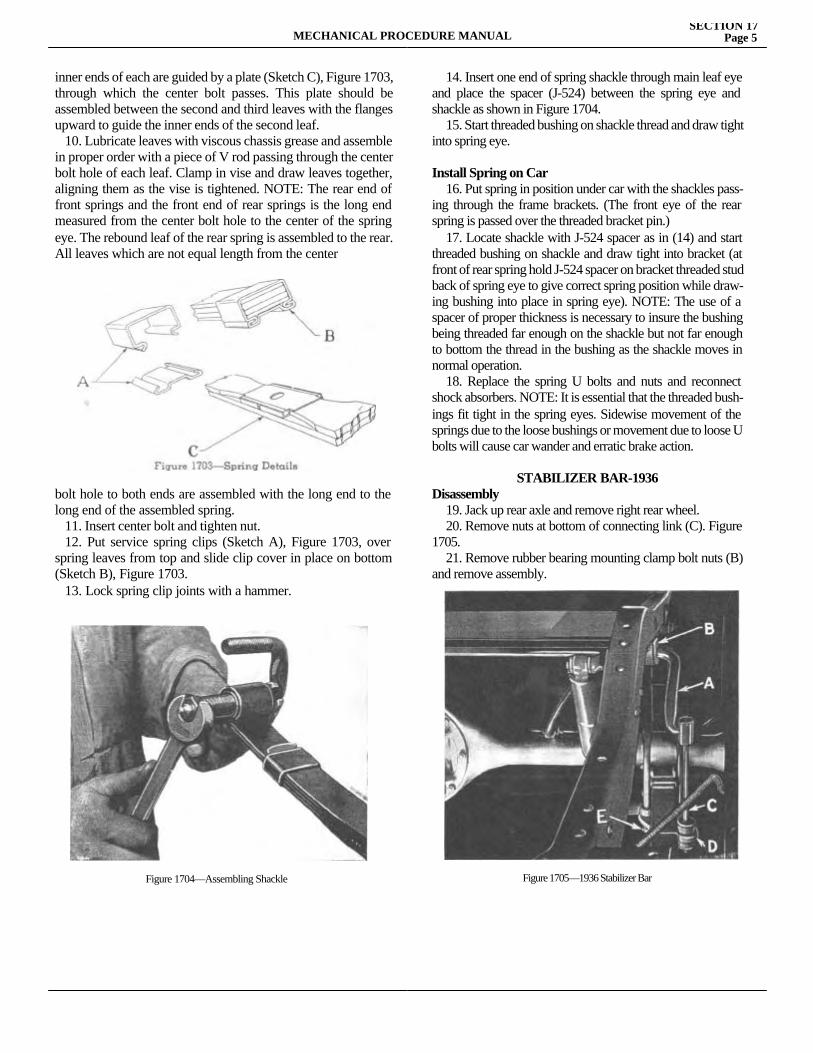
MECHANICAL PROCEDURE MANUALSECTION 17
Page 5
inner ends of each are guided by a plate (Sketch C), Figure 1703, through which the center bolt passes. This plate should be assembled between the second and third leaves with the flanges upward to guide the inner ends of the second leaf. 10. Lubricate leaves with viscous chassis grease and assemble in proper order with a piece of V rod passing through the center bolt hole of each leaf. Clamp in vise and draw leaves together, aligning them as the vise is tightened. NOTE: The rear end of front springs and the front end of rear springs is the long end measured from the center bolt hole to the center of the spring eye. The rebound leaf of the rear spring is assembled to the rear. All leaves which are not equal length from the center
bolt hole to both ends are assembled with the long end to the long end of the assembled spring. 11. Insert center bolt and tighten nut. 12. Put service spring clips (Sketch A), Figure 1703, over spring leaves from top and slide clip cover in place on bottom (Sketch B), Figure 1703. 13. Lock spring clip joints with a hammer.
14. Insert one end of spring shackle through main leaf eye and place the spacer (J-524) between the spring eye and shackle as shown in Figure 1704. 15. Start threaded bushing on shackle thread and draw tight into spring eye.
Install Spring on Car 16. Put spring in position under car with the shackles pass-ing through the frame brackets. (The front eye of the rear spring is passed over the threaded bracket pin.) 17. Locate shackle with J-524 spacer as in (14) and start threaded bushing on shackle and draw tight into bracket (at front of rear spring hold J-524 spacer on bracket threaded stud back of spring eye to give correct spring position while draw-ing bushing into place in spring eye). NOTE: The use of a spacer of proper thickness is necessary to insure the bushing being threaded far enough on the shackle but not far enough to bottom the thread in the bushing as the shackle moves in normal operation. 18. Replace the spring U bolts and nuts and reconnect shock absorbers. NOTE: It is essential that the threaded bush-ings fit tight in the spring eyes. Sidewise movement of the springs due to the loose bushings or movement due to loose U bolts will cause car wander and erratic brake action.
STABILIZER BAR-1936 Disassembly 19. Jack up rear axle and remove right rear wheel. 20. Remove nuts at bottom of connecting link (C). Figure 1705. 21. Remove rubber bearing mounting clamp bolt nuts (B) and remove assembly.
Figure 1704—Assembling Shackle Figure 1705—1936 Stabilizer Bar
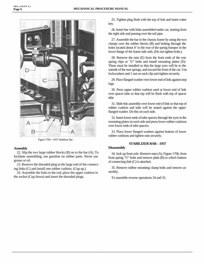
SECTION 17Page 6 MECHANICAL PROCEDURE MANUAL
Assembly 22. Slip the two large rubber blocks (B) on to the bar (A). To facilitate assembling, use gasoline on rubber parts. Never use grease or oil. 23. Remove the threaded plug in the large end of the connect-ing links (C) and install one rubber cushion. (Cup up.) 24. Assemble the links to the rod, place the upper cushion in the socket (Cup down) and insert the threaded plugs.
25. Tighten plug flush with the top of link and insert cotter key.
26. Insert bar with links assembled under car, starting from the right side and passing over the tail pipe.
27. Assemble the bar to the chassis frame by using the two clamps over the rubber blocks (B) and bolting through the holes located about 4" to the rear of the spring bumper in the lower flange of the frame side rails. (Do not tighten bolts.)
28. Remove the nuts (E) from the front ends of the rear spring clips or "U" bolts and install mounting plates (D). These must be installed so that the large eyes will be to the outside of the rear springs, and toward the front of the car. Use lockwashers and 1 nut on each clip and tighten securely.
29. Place flanged washer over lower end of link against stop lugs.
30. Press upper rubber cushion used at lower end of link over spacer tube so that top will be flush with top of spacer tube.
31. Slide this assembly over lower end of link so that top of rubber cushion and tube will be seated against the upper flanged washer. Do this on each side.
32. Insert lower ends of tube spacers through the eyes in the mounting plates on each side and press lower rubber cushions over lower ends of tube spacers.
33. Place lower flanged washers against bottom of lower rubber cushions and tighten nuts securely.
STABILIZER BAR—1937Disassembly
34. Jack up front axle. Remove nuts (A), Figure 1706, from front spring "U" bolts and remove plate (B) to which bottom of connecting link (C) is attached.
35. Remove rubber mounting clamp bolts and remove as-sembly.
To assemble reverse operations 34 and 35.
Figure 1706—1937 Stabilizer Bar

SECTION 18FRONT END ALIGNMENT
Service Magazine—Reference Sheet and Service Bullet in Reference
Bulletin orReference SheetNo. MagazineIssue and Page
Date Subject DETAILS OF INFORMATION
MECHANICAL PROCEDURE MANUAL Page 1

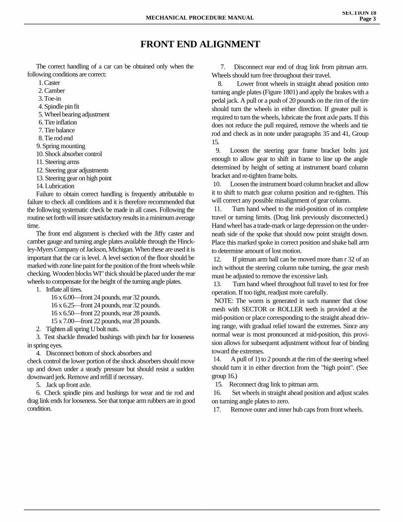
FRONT END ALIGNMENT
The correct handling of a car can be obtained only when the following conditions are correct: 1. Caster 2. Camber 3. Toe-in 4. Spindle pin fit 5. Wheel bearing adjustment 6. Tire inflation 7. Tire balance 8. Tie rod end 9. Spring mounting 10. Shock absorber control 11. Steering arms 12. Steering gear adjustments 13. Steering gear on high point 14. Lubrication Failure to obtain correct handling is frequently attributable to failure to check all conditions and it is therefore recommended that the following systematic check be made in all cases. Following the routine set forth will insure satisfactory results in a minimum average time. The front end alignment is checked with the Jiffy caster and camber gauge and turning angle plates available through the Hinck-ley-Myers Company of Jackson, Michigan. When these are used it is important that the car is level. A level section of the floor should be marked with zone line paint for the position of the front wheels while checking. Wooden blocks WI" thick should be placed under the rear wheels to compensate for the height of the turning angle plates. 1. Inflate all tires.
16 x 6.00—front 24 pounds, rear 32 pounds.16 x 6.25—front 24 pounds, rear 32 pounds.16 x 6.50—front 22 pounds, rear 28 pounds.15 x 7.00—front 22 pounds, rear 28 pounds.
2. Tighten all spring U bolt nuts. 3. Test shackle threaded bushings with pinch bar for looseness in spring eyes. 4. Disconnect bottom of shock absorbers andcheck control the lower portion of the shock absorbers should move up and down under a steady pressure but should resist a sudden downward jerk. Remove and refill if necessary. 5. Jack up front axle. 6. Check spindle pins and bushings for wear and tie rod and drag link ends for looseness. See that torque arm rubbers are in good condition.
7. Disconnect rear end of drag link from pitman arm. Wheels should turn free throughout their travel. 8. Lower front wheels in straight ahead position onto turning angle plates (Figure 1801) and apply the brakes with a pedal jack. A pull or a push of 20 pounds on the rim of the tire should turn the wheels in either direction. If greater pull is required to turn the wheels, lubricate the front axle parts. If this does not reduce the pull required, remove the wheels and tie rod and check as in note under paragraphs 35 and 41, Group 15. 9. Loosen the steering gear frame bracket bolts just enough to allow gear to shift in frame to line up the angle determined by height of setting at instrument board column bracket and re-tighten frame bolts. 10. Loosen the instrument board column bracket and allow it to shift to match gear column position and re-tighten. This will correct any possible misalignment of gear column. 11. Turn hand wheel to the mid-position of its complete travel or turning limits. (Drag link previously disconnected.) Hand wheel has a trade-mark or large depression on the under-neath side of the spoke that should now point straight down. Place this marked spoke in correct position and shake ball arm to determine amount of lost motion. 12. If pitman arm ball can be moved more than r 32 of an inch without the steering column tube turning, the gear mesh must be adjusted to remove the excessive lash. 13. Turn hand wheel throughout full travel to test for free operation. If too tight, readjust more carefully. NOTE: The worm is generated in such manner that close mesh with SECTOR or ROLLER teeth is provided at the mid-position or place corresponding to the straight ahead driv-ing range, with gradual relief toward the extremes. Since any normal wear is most pronounced at mid-position, this provi-sion allows for subsequent adjustment without fear of binding toward the extremes. 14. A pull of 1) to 2 pounds at the rim of the steering wheel should turn it in either direction from the "high point". (See group 16.) 15. Reconnect drag link to pitman arm. 16. Set wheels in straight ahead position and adjust scales on turning angle plates to zero. 17. Remove outer and inner hub caps from front wheels.
MECHANICAL PROCEDURE MANUALSECTION 18
Page 3
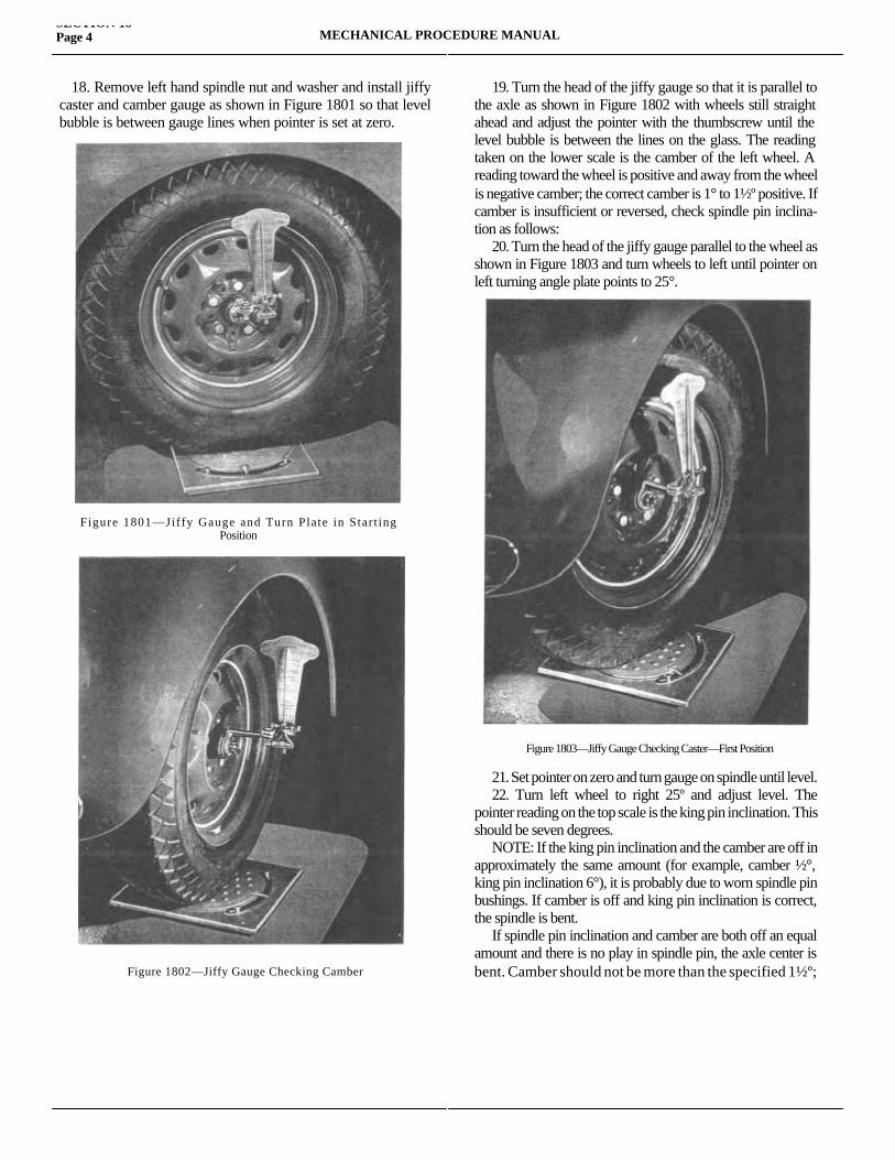
18. Remove left hand spindle nut and washer and install jiffy caster and camber gauge as shown in Figure 1801 so that level bubble is between gauge lines when pointer is set at zero.
19. Turn the head of the jiffy gauge so that it is parallel to the axle as shown in Figure 1802 with wheels still straight ahead and adjust the pointer with the thumbscrew until the level bubble is between the lines on the glass. The reading taken on the lower scale is the camber of the left wheel. A reading toward the wheel is positive and away from the wheel is negative camber; the correct camber is 1° to 1½º positive. If camber is insufficient or reversed, check spindle pin inclina-tion as follows: 20. Turn the head of the jiffy gauge parallel to the wheel as shown in Figure 1803 and turn wheels to left until pointer on left turning angle plate points to 25°.
21. Set pointer on zero and turn gauge on spindle until level. 22. Turn left wheel to right 25º and adjust level. The pointer reading on the top scale is the king pin inclination. This should be seven degrees. NOTE: If the king pin inclination and the camber are off in approximately the same amount (for example, camber ½°, king pin inclination 6°), it is probably due to worn spindle pin bushings. If camber is off and king pin inclination is correct, the spindle is bent. If spindle pin inclination and camber are both off an equal amount and there is no play in spindle pin, the axle center is bent. Camber should not be more than the specified 1½º;
SECTION 18Page 4 MECHANICAL PROCEDURE MANUAL
Figure 1801—Jiffy Gauge and Turn Plate in Star t ingPosition
Figure 1802—Jiffy Gauge Checking Camber
Figure 1803—Jiffy Gauge Checking Caster—First Position
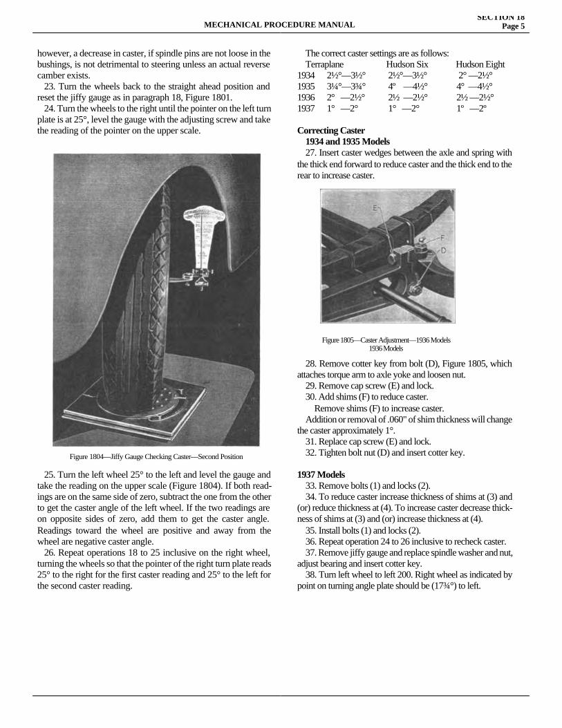
however, a decrease in caster, if spindle pins are not loose in the bushings, is not detrimental to steering unless an actual reverse camber exists. 23. Turn the wheels back to the straight ahead position and reset the jiffy gauge as in paragraph 18, Figure 1801. 24. Turn the wheels to the right until the pointer on the left turn plate is at 25°, level the gauge with the adjusting screw and take the reading of the pointer on the upper scale.
25. Turn the left wheel 25° to the left and level the gauge and take the reading on the upper scale (Figure 1804). If both read-ings are on the same side of zero, subtract the one from the other to get the caster angle of the left wheel. If the two readings are on opposite sides of zero, add them to get the caster angle. Readings toward the wheel are positive and away from the wheel are negative caster angle. 26. Repeat operations 18 to 25 inclusive on the right wheel, turning the wheels so that the pointer of the right turn plate reads 25° to the right for the first caster reading and 25° to the left for the second caster reading.
The correct caster settings are as follows: Terraplane Hudson Six Hudson Eight 1934 2½°—3½° 2½°—3½° 2° —2½°1935 3¼°—3¾° 4º —4½° 4° —4½°1936 2° —2½° 2½ —2½° 2½ —2½° 1937 1° —2° 1° —2° 1º —2º
Correcting Caster 1934 and 1935 Models 27. Insert caster wedges between the axle and spring with the thick end forward to reduce caster and the thick end to the rear to increase caster.
28. Remove cotter key from bolt (D), Figure 1805, which attaches torque arm to axle yoke and loosen nut. 29. Remove cap screw (E) and lock. 30. Add shims (F) to reduce caster. Remove shims (F) to increase caster. Addition or removal of .060" of shim thickness will change the caster approximately 1°. 31. Replace cap screw (E) and lock. 32. Tighten bolt nut (D) and insert cotter key.
1937 Models 33. Remove bolts (1) and locks (2). 34. To reduce caster increase thickness of shims at (3) and (or) reduce thickness at (4). To increase caster decrease thick-ness of shims at (3) and (or) increase thickness at (4). 35. Install bolts (1) and locks (2). 36. Repeat operation 24 to 26 inclusive to recheck caster. 37. Remove jiffy gauge and replace spindle washer and nut, adjust bearing and insert cotter key. 38. Turn left wheel to left 200. Right wheel as indicated by point on turning angle plate should be (17¾°) to left.
MECHANICAL PROCEDURE MANUALSECTION 18
Page 5
Figure 1804—Jiffy Gauge Checking Caster—Second Position
Figure 1805—Caster Adjustment—1936 Models1936 Models
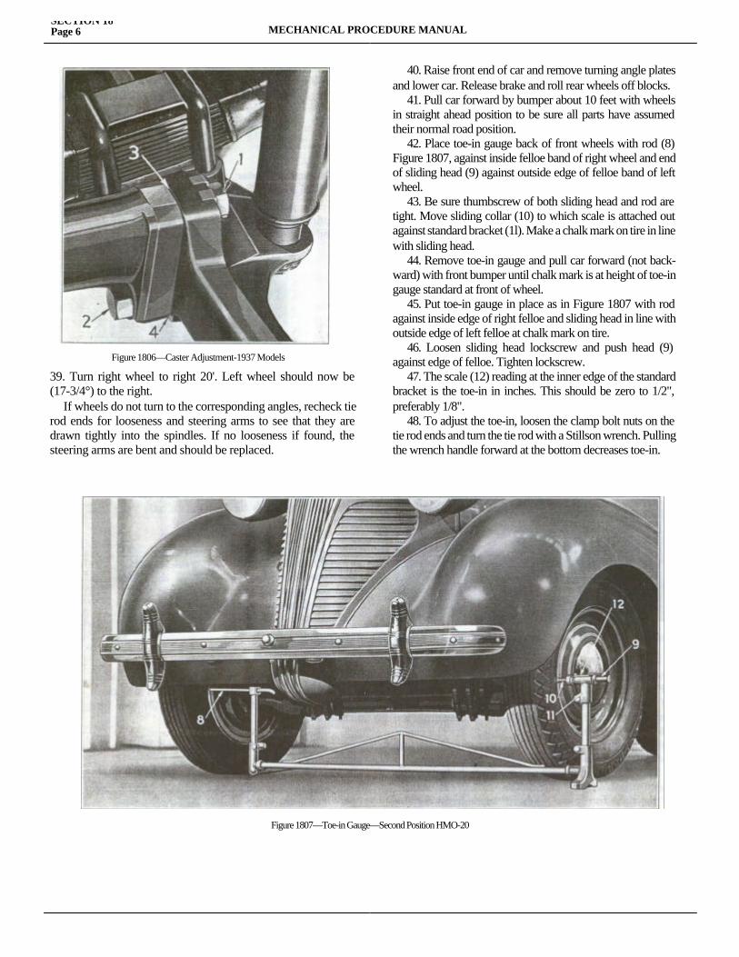
39. Turn right wheel to right 20'. Left wheel should now be (17-3/4°) to the right. If wheels do not turn to the corresponding angles, recheck tie rod ends for looseness and steering arms to see that they are drawn tightly into the spindles. If no looseness if found, the steering arms are bent and should be replaced.
40. Raise front end of car and remove turning angle plates and lower car. Release brake and roll rear wheels off blocks. 41. Pull car forward by bumper about 10 feet with wheels in straight ahead position to be sure all parts have assumed their normal road position. 42. Place toe-in gauge back of front wheels with rod (8) Figure 1807, against inside felloe band of right wheel and end of sliding head (9) against outside edge of felloe band of left wheel. 43. Be sure thumbscrew of both sliding head and rod are tight. Move sliding collar (10) to which scale is attached out against standard bracket (1l). Make a chalk mark on tire in line with sliding head. 44. Remove toe-in gauge and pull car forward (not back-ward) with front bumper until chalk mark is at height of toe-in gauge standard at front of wheel. 45. Put toe-in gauge in place as in Figure 1807 with rod against inside edge of right felloe and sliding head in line with outside edge of left felloe at chalk mark on tire. 46. Loosen sliding head lockscrew and push head (9) against edge of felloe. Tighten lockscrew. 47. The scale (12) reading at the inner edge of the standard bracket is the toe-in in inches. This should be zero to 1/2", preferably 1/8". 48. To adjust the toe-in, loosen the clamp bolt nuts on the tie rod ends and turn the tie rod with a Stillson wrench. Pulling the wrench handle forward at the bottom decreases toe-in.
SECTION 18Page 6 MECHANICAL PROCEDURE MANUAL
Figure 1806—Caster Adjustment-1937 Models
Figure 1807—Toe-in Gauge—Second Position HMO-20

49. After getting correct toe-in, tighten tie rod end clamp bolt nuts. 50. Set wheels straight ahead and check steering wheel to see that trade-marked spoke is pointing straight down. 51. If front wheels are not straight ahead, adjust drag link length or change height of steering column. Lengthening the drag link will turn front wheels to left. Lowering steering column will turn front wheel to the left.
wheel to the left. NOTE: Whenever the thickness of shims is changed to increase or decrease caster on 1936 or 1937 models, it is necessary to put the steering gear back on the high point. 52. Reconnect the drag link to the pitman arm and lubricate thoroughly.
MECHANICAL PROCEDURE MANUALSECTION 18
Page 7


SECTION 19SHOCK ABSORBERS
Service Magazine—Reference Sheet and Service Bullet in Reference
Bulletin orReference SheetNo. MagazineIssue and Page
Date Subject DETAILS OF INFORMATION
MECHANICAL PROCEDURE MANUAL Page 1

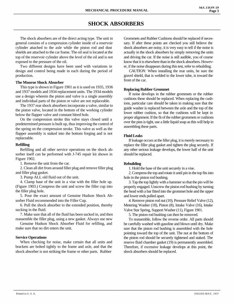
SHOCK ABSORBERS
The shock absorbers are of the direct acting type. The unit in general consists of a compression cylinder inside of a reservoir cylinder attached to the axle while the piston rod and dust shields are attached to the car frame. The oil seal is located at the top of the reservoir cylinder above the level of the oil and is not exposed to the pressure of the oil. Two different designs have been used with variations in design and control being made in each during the period of production.
The Monroe Shock Absorber This type is shown in Figure 1901 as it is used on 1935, 1936 and 1937 models and 1934 replacement units. The 1934 models use a design wherein the piston and valve is a single assembly and individual parts of the piston or valve are not replaceable. The 1937 rear shock absorbers incorporate a valve, similar to the piston valve, located in the bottom of the working cylinder below the flapper valve and constant bleed hole. On the compression stroke this valve stays closed until a predetermined pressure is built up, thus improving the control of the spring on the compression stroke. This valve as well as the flapper assembly is staked into the bottom forging and is not replaceable.
Refilling Refilling and all other service operations on the shock ab-sorber itself can be performed with J-745 repair kit shown in Figure 1902. 1. Remove the unit from the car. 2. Clean all dirt from around filler plug and remove filler plug and filler plug gasket. 3. Pump ALL old fluid out of the unit. 4. Clamp base of the unit in a vise with the filler hole up. (Figure 1903.) Compress the unit and screw the filler cup into the filler plug hole. 5. Pour the exact amount of Genuine Hudson Shock Ab-sorber Fluid recommended into the Filler Cup. 6. Pull the shock absorber to the extended position, thereby sucking in the fluid. 7. Make sure that all of the fluid has been sucked in, and then reassemble the filler plug, using a new gasket. Always use new Genuine Hudson Shock Absorber Fluid for refilling, and make sure that no dirt enters the unit.
Service Operations When checking for noise, make certain that all units and brackets are bolted tightly to the frame and axle, and that the shock absorber is not striking the frame or other parts. Rubber
Grommets and Rubber Cushions should be replaced if neces-sary. If after these points are checked you still believe the shock absorbers are noisy, it is very easy to tell if the noise is actually in the shock absorbers by simply removing the units and driving the car. If the noise is still audible, you of course know that it is elsewhere than in the shock absorbers. Howev-er, if the noise disappears during this test, refer to rebuilding. CAUTION: When installing the rear units, be sure the gravel shield, that is welded to the lower tube, is toward the front of the car.
Replacing Rubber Grommet If noise develops in the rubber grommets or the rubber cushions these should be replaced. When replacing the cush-ions, particular care should be taken in making sure that the guide washer is replaced between the axle and the top of the lower rubber cushion, so that the cushions will be kept in proper alignment. If the fit of the rubber grommets or cushions over the pins is tight, use a little liquid soap as this will help in assembling these parts.
Fluid Leaks If leakage occurs at the filler plug, it is merely necessary to replace the filler plug gasket and tighten the plug securely. If any other serious leakage develops, the lower half of the unit should be replaced.
Rebuilding 1. Hold the base of the unit securely in a vise. 2. Compress the top and rotate it until pin in the top fits into hole in the piston rod bushing. 3. Tap the top lightly with a hammer so that the pin will be properly engaged. Unscrew the piston rod bushing by turning the head with a bar fitted into the grommet hole and the upper and lower ends pulled apart. 4. Remove piston rod nut (10), Pressure Relief Valve (12), Metering Washer (18), Piston (8), Intake Valve (16), Intake Valve Star Spring, Support Washer (11), Figure 1901. 5. The piston rod bushing can then be removed. To reassemble, follow the reverse order. All parts should be carefully washed with gasoline and blown until dry. Make sure that the piston rod bushing is assembled with the hole pointing toward the top of the unit. The nut at the bottom of the piston rod should be securely tightened and staked. The reserve fluid chamber gasket (19) is permanently assembled. Therefore, if excessive leakage develops at this point, the shock absorbers should be replaced.
MECHANICAL PROCEDURE MANUALSECTION 19
Page 3
Printed in U. S. A. ISSUED MAY, 1937
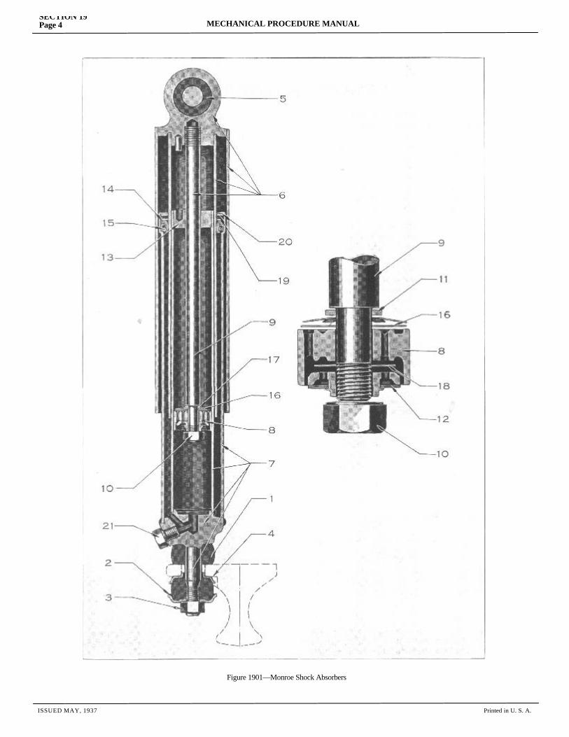
ISSUED MAY, 1937 Printed in U. S. A.
SECTION 19Page 4 MECHANICAL PROCEDURE MANUAL
Figure 1901—Monroe Shock Absorbers
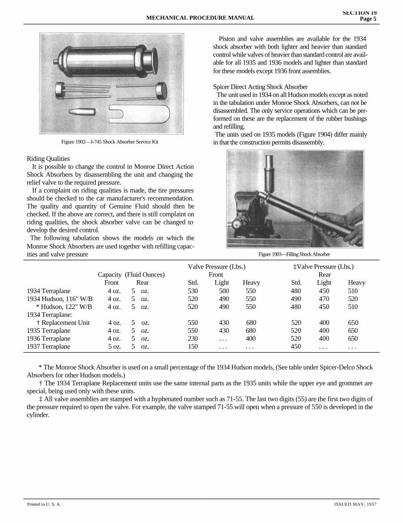
Printed in U. S. A. ISSUED MAY, 1937
MECHANICAL PROCEDURE MANUALSECTION 19
Page 5
Riding Qualities It is possible to change the control in Monroe Direct Action Shock Absorbers by disassembling the unit and changing the relief valve to the required pressure. If a complaint on riding qualities is made, the tire pressures should be checked to the car manufacturer's recommendation. The quality and quantity of Genuine Fluid should then be checked. If the above are correct, and there is still complaint on riding qualities, the shock absorber valve can be changed to develop the desired control. The following tabulation shows the models on which the Monroe Shock Absorbers are used together with refilling capac-ities and valve pressure
Piston and valve assemblies are available for the 1934 shock absorber with both lighter and heavier than standard control while valves of heavier than standard control are avail-able for all 1935 and 1936 models and lighter than standard for these models except 1936 front assemblies.
Spicer Direct Acting Shock Absorber The unit used in 1934 on all Hudson models except as noted in the tabulation under Monroe Shock Absorbers, can not be disassembled. The only service operations which can be per-formed on these are the replacement of the rubber bushings and refilling. The units used on 1935 models (Figure 1904) differ mainly in that the construction permits disassembly.
Valve Pressure (Lbs.) ‡Valve Pressure (Lbs.) Capacity (Fluid Ounces) Front Rear Front Rear Std. Light Heavy Std. Light Heavy1934 Terraplane 4 oz. 5 oz. 530 500 550 480 450 5101934 Hudson, 116" W/B 4 oz. 5 oz. 520 490 550 490 470 520 * Hudson, 122" W/B 4 oz. 5 oz. 520 490 550 480 450 5101934 Terraplane: † Replacement Unit 4 oz. 5 oz. 550 430 680 520 400 6501935 Terraplane 4 oz. 5 oz. 550 430 680 520 400 6501936 Terraplane 4 oz. 5 oz. 230 . . . 400 520 400 6501937 Terraplane 5 oz. 5 oz. 150 . . . . . . 450 . . . . . .
* The Monroe Shock Absorber is used on a small percentage of the 1934 Hudson models, (See table under Spicer-Delco ShockAbsorbers for other Hudson models.) † The 1934 Terraplane Replacement units use the same internal parts as the 1935 units while the upper eye and grommet are special, being used only with these units. ‡ All valve assemblies are stamped with a hyphenated number such as 71-55. The last two digits (55) are the first two digits of the pressure required to open the valve. For example, the valve stamped 71-55 will open when a pressure of 550 is developed in the cylinder.
Figure 1902—J-745 Shock Absorber Service Kit
Figure 1903—Filling Shock Absorber
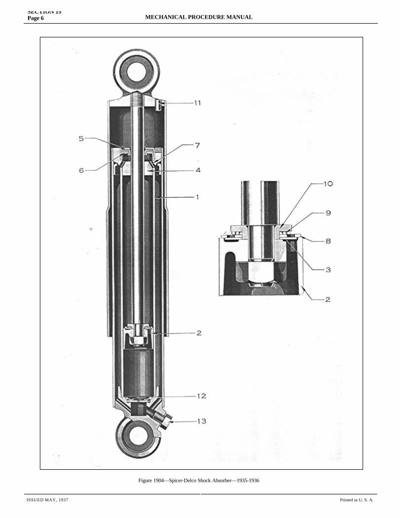
ISSUED MAY, 1937 Printed in U. S. A.
SECTION 19Page 6 MECHANICAL PROCEDURE MANUAL
Figure 1904—Spicer-Delco Shock Absorber—1935-1936
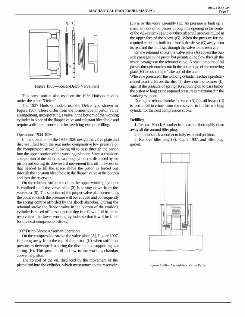
MECHANICAL PROCEDURE MANUALSECTION 19
Page 7
This same unit is also used on the 1936 Hudson models under the name "Delco." The 1937 Hudson models use the Delco type shown in Figure 1907. These differ from the former type in piston valve arrangement, incorporating a valve in the bottom of the working cylinder in place of the flapper valve and constant bleed hole and require a different procedure for servicing except refilling.
Operation, 1934-1936 In the operation of the 1934-1936 design the valve plate and disc are lifted from the seat under comparative low pressure on the compression stroke allowing oil to pass through the piston into the upper portion of the working cylinder. Since a consider-able portion of the oil in the working cylinder is displaced by the piston rod during its downward movement this oil in excess of that needed to fill the space above the piston is forced out through the constant bleed hole in the flapper valve at the bottom and into the reservoir. On the rebound stroke the oil in the upper working cylinder is confined until the valve plate (3) is sprung down from the valve disc (8). The selection of the proper valve plate determines the point at which the pressure will be relieved and consequently the spring control afforded by the shock absorber. During the rebound stroke the flapper valve in the bottom of the working cylinder is raised off its seat permitting free flow of oil from the reservoir to the lower working cylinder so that it will be filled for the next compression stroke.
1937 Delco Shock Absorber Operation On the compression stroke the valve plate (A), Figure 1907, is sprung away from the top of the piston (C) when sufficient pressure is developed to spring the disc and the supporting star spring (B). This permits oil to flow to the working chamber above the piston. The control of the oil, displaced by the movement of the piston rod into the cylinder, which must return to the reservoir
(D) is by the valve assembly (E). As pressure is built up a small amount of oil passes through the opening in the center of the valve stem (F) and out through small grooves milled in the upper face of the sleeve (G). When the pressure for the required control is built up it forces the sleeve (G) away from its seat and the oil flows through the valve to the reservoir. On the rebound stroke the valve plate (A) covers the out-side passages in the piston but permits oil to flow through the inside passages to the rebound valve. A small amount of oil passes through notches out in the outer edge of the metering plate (H) to cushion the "take up" of the unit.When the pressure in the working cylinder reaches a predeter-mined point it forces the disc (J) down on the retainer (L) against the pressure of spring (K) allowing oil to pass below the piston so long as the required pressure is maintained in the working cylinder. During the rebound stroke the valve (N) lifts off its seat (E) to permit oil to return from the reservoir to fill the working cylinder for the next compression stroke.
Refilling 1. Remove Shock Absorber from car and thoroughly clean away all dirt around filler plug. 2. Pull out shock absorber to fully extended position. 3. Remove filler plug (P), Figure 1907, and filler plug gasket.
Figure 1905—Spicer-Delco Valve Parts
Figure 1906—Assembling Valve Parts
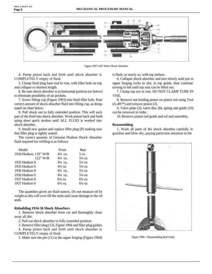
SECTION 19Page 8 MECHANICAL PROCEDURE MANUAL
4. Pump piston back and forth until shock absorber is COMPLETELY empty of fluid. 5. Clamp fluid plug base end in vise, with filler hole on top, and collapse to shortest length. 6. Be sure shock absorber is in horizontal position (or below) to eliminate possibility of air pockets. 7. Screw filling cup (Figure 1903) into fluid filler hole. Pour correct amount of shock absorber fluid into filling cup, as desig-nated on chart below. 8. Pull shock out to fully extended position. This will suck part of the fluid into shock absorber. Work piston back and forth using short quick strokes until ALL FLUID is worked into shock absorber. 9. Install new gasket and replace filler plug (P) making sure that filler plug is tightly seated. The correct quantity of Genuine Hudson Shock Absorber fluid required for refilling is as follows:
Model Front Rear1934 Hudson, 116" W/B 4¾ oz. 5 oz. 122" W/B 4¾ oz. 5¼ oz1935 Hudson 8 4¾ oz. 5¼ oz1935 Hudson 6 4¾ oz. 5¼ oz1936 Hudson 8 4¾ oz.. 5¼ oz1936 Hudson 6 4¾ oz. 5¼ oz1937 Hudson 8 6¼ oz 6¼ oz1937 Hudson 6 6¼ oz. 6¼ oz
The quantities given are fluid ounces. Do not measure oil by weight as this will over-fill the units and cause damage to the oil seals.
Rebuilding 1934-36 Shock Absorbers 1. Remove shock absorber from car and thoroughly clean away all dirt. 2. Pull out shock absorber to fully extended position. 3. Remove filler plug (13), Figure 1904 and filler plug gasket. 4. Pump piston back and forth until shock absorber is COMPLETELY empty of fluid. 5. Make sure the pin (11) in the upper forging (Figure 1904)
is flush, or nearly so, with top surface. 6. Collapse shock absorber and turn slowly until pin in upper forging locks in slot, in top guide, then continue turning to left until top unit can be lifted out. 7. Clamp top eye in vise. DO NOT CLAMP TUBE IN VISE. 8. Remove nut holding piston on piston rod using Tool (A-497*) and remove piston (2). 9. Valve plate (3), valve disc (8), spring and guide (10) can be removed in order. 10. Remove piston rod guide and oil seal assembly.
Reassembling 1. Wash all parts of the shock absorber carefully in gasoline and blow dry, paying particular attention to the
Figure 1908—Disassembling Rod Guide
Figure 1907-1937 Delco Shock Absorber
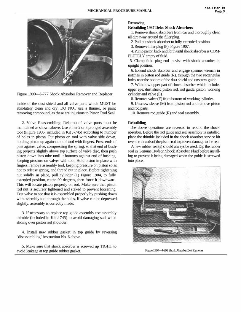
MECHANICAL PROCEDURE MANUALSECTION 19
Page 9
Figure 1909—J-777 Shock Absorber Remover and Replacer
inside of the dust shield and all valve parts which MUST be absolutely clean and dry. DO NOT use a thinner, or paint removing compound, as these are injurious to Piston Rod Seal.
2. Valve Reassembling: Relation of valve parts must be maintained as shown above. Use either 2 or 3 pronged assembly tool (Figure 1905, included in Kit J-745) according to number of holes in piston. Put piston on tool with valve side down, holding piston up against top of tool with fingers. Press ends of pins against valve, compressing the spring, so that end of bush-ing projects slightly above top surface of valve disc, then push piston down into tube until it bottoms against end of bushing, keeping pressure on valves with tool. Hold piston in place with fingers, remove assembly tool, keeping pressure on piston so as not to release spring, and thread nut in place. Before tightening nut solidly in place, pull cylinder (1) Figure 1904, to fully extended position, rotate 90 degrees, then force it downward. This will locate piston properly on rod. Make sure that piston rod nut is securely tightened and staked to prevent loosening. Test valve to see that it is assembled properly by pushing down with assembly tool through the holes. If valve can be depressed slightly, assembly is correctly made.
3. If necessary to replace top guide assembly use assembly thimble (included in Kit J-745) to avoid damaging seal when sliding over piston rod shoulder.
4. Install new rubber gasket in top guide by reversing "disassembling" instruction No. 6 above.
5. Make sure that shock absorber is screwed up TIGHT to avoid leakage at top guide rubber gasket.
RemovingRebuilding 1937 Delco Shock Absorbers 1. Remove shock absorbers from car and thoroughly clean all dirt away around the filler plug. 2. Pull out shock absorber to fully extended position. 3. Remove filler plug (P), Figure 1907. 4. Pump piston back and forth until shock absorber is COM-PLETELY empty of fluid. 5. Clamp fluid plug end in vise with shock absorber in upright position. 6. Extend shock absorber and engage spanner wrench in notches in piston rod guide (R), through the two rectangular holes near the bottom of the dust shield and unscrew guide. 7. Withdraw upper part of shock absorber which includes upper eye, dust shield piston rod, rod guide, piston, working cylinder and valve (E). 8. Remove valve (E) from bottom of working cylinder. 9. Unscrew sleeve (M) from piston rod and remove piston and rod parts. 10. Remove rod guide (R) and seal assembly.
Rebuilding The above operations are reversed to rebuild the shock absorber. Before the rod guide and seal assembly is installed, place the thimble included in the shock absorber service kit over the threads of the piston rod to prevent damage to the seal. A new rubber seal(s) should always be used. Dip the rubber seal in Genuine Hudson Shock Absorber Fluid before install-ing to prevent it being damaged when the guide is screwed into place.
Figure 1910—J-991 Shock Absorber Bolt Remover
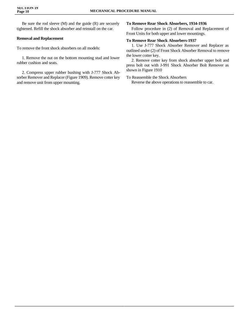
SECTION 19Page 10 MECHANICAL PROCEDURE MANUAL
Be sure the rod sleeve (M) and the guide (R) are securely tightened. Refill the shock absorber and reinstall on the car.
Removal and Replacement
To remove the front shock absorbers on all models:
1. Remove the nut on the bottom mounting stud and lower rubber cushion and seats.
2. Compress upper rubber bushing with J-777 Shock Ab-sorber Remover and Replacer (Figure 1909). Remove cotter key and remove unit from upper mounting.
To Remove Rear Shock Absorbers, 1934-1936 Follow procedure in (2) of Removal and Replacement of Front Units for both upper and lower mountings.
To Remove Rear Shock Absorbers-1937 1. Use J-777 Shock Absorber Remover and Replacer as outlined under (2) of Front Shock Absorber Removal to remove the lower cotter key. 2. Remove cotter key from shock absorber upper bolt and press bolt out with J-991 Shock Absorber Bolt Remover as shown in Figure 1910
To Reassemble the Shock AbsorbersReverse the above operations to reassemble to car.

SECTION 20WHEELS AND TIRES
Service Magazine—Reference Sheet and Service Bullet in Reference
Bulletin orReference SheetNo. MagazineIssue and Page
Date Subject DETAILS OF INFORMATION
MECHANICAL PROCEDURE MANUAL Page 1

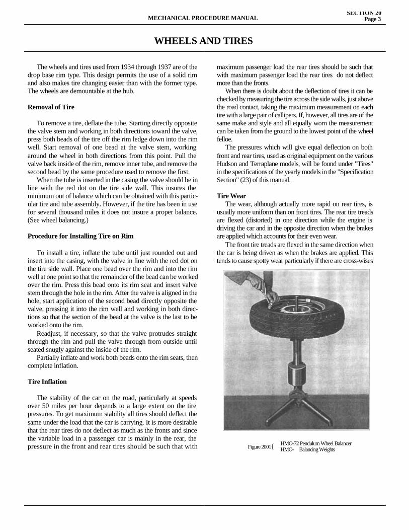
MECHANICAL PROCEDURE MANUALSECTION 20
Page 3
WHEELS AND TIRES
The wheels and tires used from 1934 through 1937 are of the drop base rim type. This design permits the use of a solid rim and also makes tire changing easier than with the former type. The wheels are demountable at the hub.
Removal of Tire
To remove a tire, deflate the tube. Starting directly opposite the valve stem and working in both directions toward the valve, press both beads of the tire off the rim ledge down into the rim well. Start removal of one bead at the valve stem, working around the wheel in both directions from this point. Pull the valve back inside of the rim, remove inner tube, and remove the second bead by the same procedure used to remove the first. When the tube is inserted in the casing the valve should be in line with the red dot on the tire side wall. This insures the minimum out of balance which can be obtained with this partic-ular tire and tube assembly. However, if the tire has been in use for several thousand miles it does not insure a proper balance. (See wheel balancing.)
Procedure for Installing Tire on Rim
To install a tire, inflate the tube until just rounded out and insert into the casing, with the valve in line with the red dot on the tire side wall. Place one bead over the rim and into the rim well at one point so that the remainder of the bead can be worked over the rim. Press this bead onto its rim seat and insert valve stem through the hole in the rim. After the valve is aligned in the hole, start application of the second bead directly opposite the valve, pressing it into the rim well and working in both direc-tions so that the section of the bead at the valve is the last to be worked onto the rim. Readjust, if necessary, so that the valve protrudes straight through the rim and pull the valve through from outside until seated snugly against the inside of the rim. Partially inflate and work both beads onto the rim seats, then complete inflation.
Tire Inflation
The stability of the car on the road, particularly at speeds over 50 miles per hour depends to a large extent on the tire pressures. To get maximum stability all tires should deflect the same under the load that the car is carrying. It is more desirable that the rear tires do not deflect as much as the fronts and since the variable load in a passenger car is mainly in the rear, the pressure in the front and rear tires should be such that with
maximum passenger load the rear tires should be such that with maximum passenger load the rear tires do not deflect more than the fronts. When there is doubt about the deflection of tires it can be checked by measuring the tire across the side walls, just above the road contact, taking the maximum measurement on each tire with a large pair of callipers. If, however, all tires are of the same make and style and all equally worn the measurement can be taken from the ground to the lowest point of the wheel felloe. The pressures which will give equal deflection on both front and rear tires, used as original equipment on the various Hudson and Terraplane models, will be found under "Tires" in the specifications of the yearly models in the "Specification Section" (23) of this manual.
Tire Wear The wear, although actually more rapid on rear tires, is usually more uniform than on front tires. The rear tire treads are flexed (distorted) in one direction while the engine is driving the car and in the opposite direction when the brakes are applied which accounts for their even wear. The front tire treads are flexed in the same direction when the car is being driven as when the brakes are applied. This tends to cause spotty wear particularly if there are cross-wises
Figure 2001{ HMO-72 Pendulum Wheel BalancerHMO- Balancing Weights
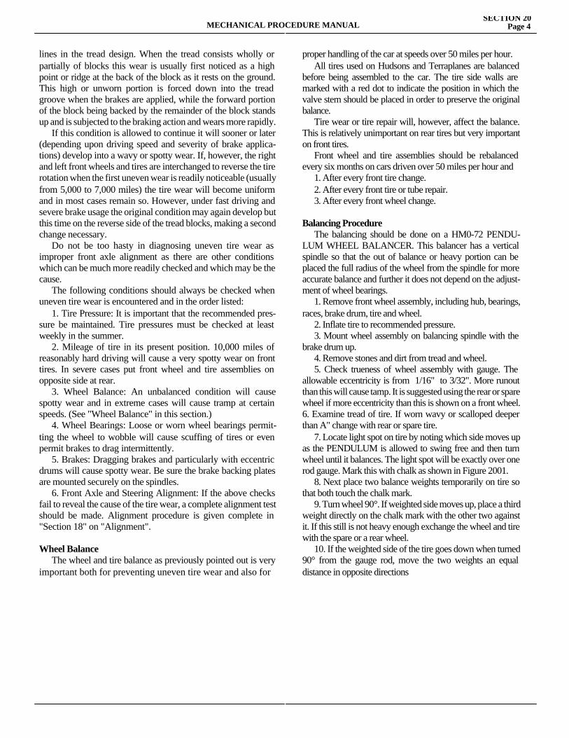
MECHANICAL PROCEDURE MANUALSECTION 20
Page 4
lines in the tread design. When the tread consists wholly or partially of blocks this wear is usually first noticed as a high point or ridge at the back of the block as it rests on the ground. This high or unworn portion is forced down into the tread groove when the brakes are applied, while the forward portion of the block being backed by the remainder of the block stands up and is subjected to the braking action and wears more rapidly. If this condition is allowed to continue it will sooner or later (depending upon driving speed and severity of brake applica-tions) develop into a wavy or spotty wear. If, however, the right and left front wheels and tires are interchanged to reverse the tire rotation when the first uneven wear is readily noticeable (usually from 5,000 to 7,000 miles) the tire wear will become uniform and in most cases remain so. However, under fast driving and severe brake usage the original condition may again develop but this time on the reverse side of the tread blocks, making a second change necessary. Do not be too hasty in diagnosing uneven tire wear as improper front axle alignment as there are other conditions which can be much more readily checked and which may be the cause. The following conditions should always be checked when uneven tire wear is encountered and in the order listed: 1. Tire Pressure: It is important that the recommended pres-sure be maintained. Tire pressures must be checked at least weekly in the summer. 2. Mileage of tire in its present position. 10,000 miles of reasonably hard driving will cause a very spotty wear on front tires. In severe cases put front wheel and tire assemblies on opposite side at rear. 3. Wheel Balance: An unbalanced condition will cause spotty wear and in extreme cases will cause tramp at certain speeds. (See "Wheel Balance" in this section.) 4. Wheel Bearings: Loose or worn wheel bearings permit-ting the wheel to wobble will cause scuffing of tires or even permit brakes to drag intermittently. 5. Brakes: Dragging brakes and particularly with eccentric drums will cause spotty wear. Be sure the brake backing plates are mounted securely on the spindles. 6. Front Axle and Steering Alignment: If the above checks fail to reveal the cause of the tire wear, a complete alignment test should be made. Alignment procedure is given complete in "Section 18" on "Alignment".
Wheel Balance The wheel and tire balance as previously pointed out is very important both for preventing uneven tire wear and also for
proper handling of the car at speeds over 50 miles per hour. All tires used on Hudsons and Terraplanes are balanced before being assembled to the car. The tire side walls are marked with a red dot to indicate the position in which the valve stem should be placed in order to preserve the original balance. Tire wear or tire repair will, however, affect the balance. This is relatively unimportant on rear tires but very important on front tires. Front wheel and tire assemblies should be rebalanced every six months on cars driven over 50 miles per hour and 1. After every front tire change. 2. After every front tire or tube repair. 3. After every front wheel change.
Balancing Procedure The balancing should be done on a HM0-72 PENDU-LUM WHEEL BALANCER. This balancer has a vertical spindle so that the out of balance or heavy portion can be placed the full radius of the wheel from the spindle for more accurate balance and further it does not depend on the adjust-ment of wheel bearings. 1. Remove front wheel assembly, including hub, bearings, races, brake drum, tire and wheel. 2. Inflate tire to recommended pressure. 3. Mount wheel assembly on balancing spindle with the brake drum up. 4. Remove stones and dirt from tread and wheel. 5. Check trueness of wheel assembly with gauge. The allowable eccentricity is from 1/16" to 3/32". More runout than this will cause tamp. It is suggested using the rear or spare wheel if more eccentricity than this is shown on a front wheel.6. Examine tread of tire. If worn wavy or scalloped deeper than A" change with rear or spare tire. 7. Locate light spot on tire by noting which side moves up as the PENDULUM is allowed to swing free and then turn wheel until it balances. The light spot will be exactly over one rod gauge. Mark this with chalk as shown in Figure 2001. 8. Next place two balance weights temporarily on tire so that both touch the chalk mark. 9. Turn wheel 90°. If weighted side moves up, place a third weight directly on the chalk mark with the other two against it. If this still is not heavy enough exchange the wheel and tire with the spare or a rear wheel. 10. If the weighted side of the tire goes down when turned 90° from the gauge rod, move the two weights an equal distance in opposite directions

MECHANICAL PROCEDURE MANUALSECTION 20
Page 5
from the chalk mark until the wheel balances. When a third weight is necessary it should remain directly on the chalk mark and the two end weights only moved for balancing. 11. Remember, when the weights go up, move them closer together; when they go down, move them farther apart. 12. When the PENDULUM pointer registers zero with the wheel turned in any direction, the assembly is in balance. Force
the lip of the weights between the tire and felloe band and lock with the set screws. Be sure the weight fits snug on the felloe before the set screw is tightened. If necessary bend the lip. 13. Remove the wheel from the test stand and reinstall onthe car. Be sure the wheel bearings are properly lubricated, correctly adjusted and the cotter key is secured in place.


SECTION 21BODIES
Service Magazine—Reference Sheet and Service Bullet in Reference
Bulletin orReference SheetNo. MagazineIssue and Page
Date Subject DETAILS OF INFORMATION
MECHANICAL PROCEDURE MANUAL Page 1

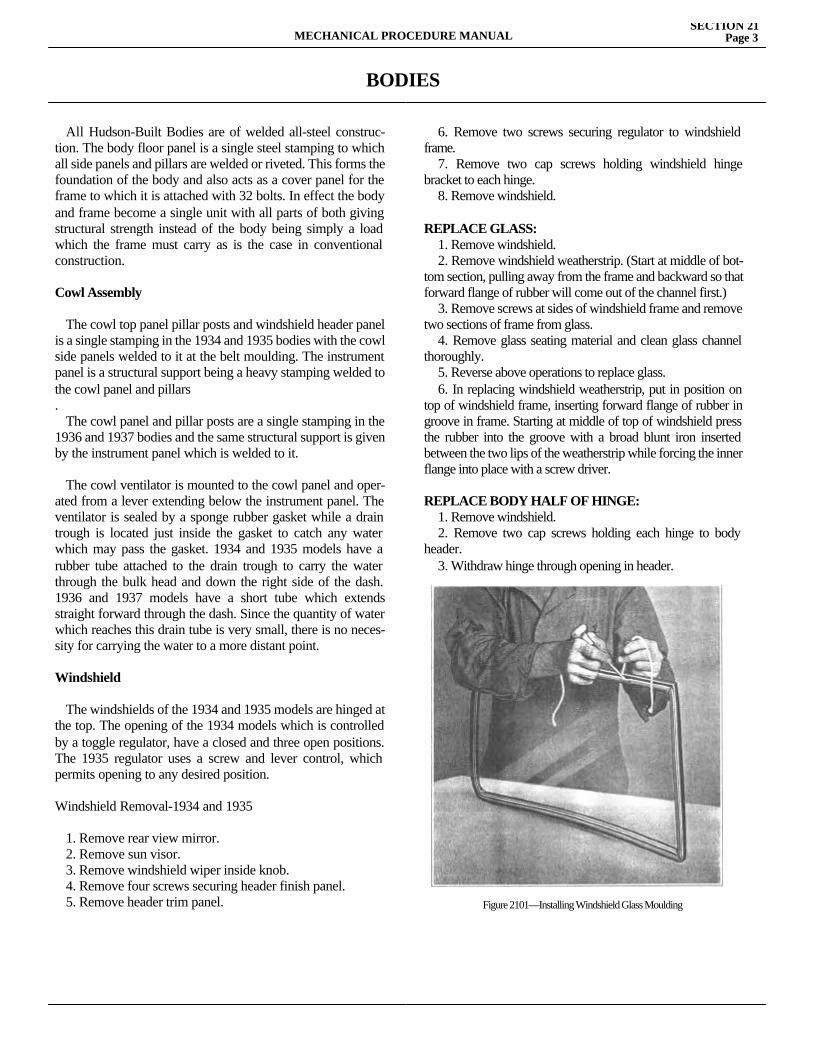
BODIES
All Hudson-Built Bodies are of welded all-steel construc-tion. The body floor panel is a single steel stamping to which all side panels and pillars are welded or riveted. This forms the foundation of the body and also acts as a cover panel for the frame to which it is attached with 32 bolts. In effect the body and frame become a single unit with all parts of both giving structural strength instead of the body being simply a load which the frame must carry as is the case in conventional construction.
Cowl Assembly
The cowl top panel pillar posts and windshield header panel is a single stamping in the 1934 and 1935 bodies with the cowl side panels welded to it at the belt moulding. The instrument panel is a structural support being a heavy stamping welded to the cowl panel and pillars. The cowl panel and pillar posts are a single stamping in the 1936 and 1937 bodies and the same structural support is given by the instrument panel which is welded to it.
The cowl ventilator is mounted to the cowl panel and oper-ated from a lever extending below the instrument panel. The ventilator is sealed by a sponge rubber gasket while a drain trough is located just inside the gasket to catch any water which may pass the gasket. 1934 and 1935 models have a rubber tube attached to the drain trough to carry the water through the bulk head and down the right side of the dash. 1936 and 1937 models have a short tube which extends straight forward through the dash. Since the quantity of water which reaches this drain tube is very small, there is no neces-sity for carrying the water to a more distant point.
Windshield
The windshields of the 1934 and 1935 models are hinged at the top. The opening of the 1934 models which is controlled by a toggle regulator, have a closed and three open positions. The 1935 regulator uses a screw and lever control, which permits opening to any desired position.
Windshield Removal-1934 and 1935
1. Remove rear view mirror. 2. Remove sun visor. 3. Remove windshield wiper inside knob. 4. Remove four screws securing header finish panel. 5. Remove header trim panel.
6. Remove two screws securing regulator to windshield frame. 7. Remove two cap screws holding windshield hinge bracket to each hinge. 8. Remove windshield.
REPLACE GLASS: 1. Remove windshield. 2. Remove windshield weatherstrip. (Start at middle of bot-tom section, pulling away from the frame and backward so that forward flange of rubber will come out of the channel first.) 3. Remove screws at sides of windshield frame and remove two sections of frame from glass. 4. Remove glass seating material and clean glass channel thoroughly. 5. Reverse above operations to replace glass. 6. In replacing windshield weatherstrip, put in position on top of windshield frame, inserting forward flange of rubber in groove in frame. Starting at middle of top of windshield press the rubber into the groove with a broad blunt iron inserted between the two lips of the weatherstrip while forcing the inner flange into place with a screw driver.
REPLACE BODY HALF OF HINGE: 1. Remove windshield. 2. Remove two cap screws holding each hinge to body header. 3. Withdraw hinge through opening in header.
Figure 2101—Installing Windshield Glass Moulding
MECHANICAL PROCEDURE MANUALSECTION 21
Page 3
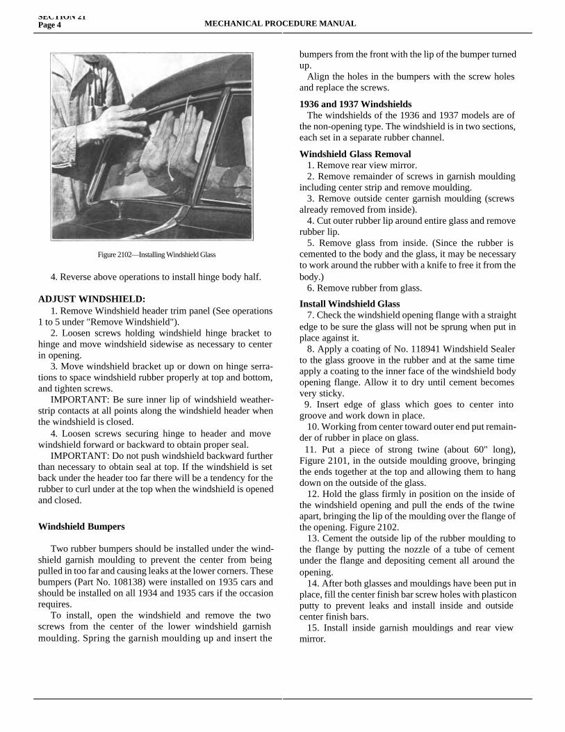
SECTION 21Page 4 MECHANICAL PROCEDURE MANUAL
4. Reverse above operations to install hinge body half.
ADJUST WINDSHIELD: 1. Remove Windshield header trim panel (See operations 1 to 5 under "Remove Windshield"). 2. Loosen screws holding windshield hinge bracket to hinge and move windshield sidewise as necessary to center in opening. 3. Move windshield bracket up or down on hinge serra-tions to space windshield rubber properly at top and bottom, and tighten screws. IMPORTANT: Be sure inner lip of windshield weather-strip contacts at all points along the windshield header when the windshield is closed. 4. Loosen screws securing hinge to header and move windshield forward or backward to obtain proper seal. IMPORTANT: Do not push windshield backward further than necessary to obtain seal at top. If the windshield is set back under the header too far there will be a tendency for the rubber to curl under at the top when the windshield is opened and closed.
Windshield Bumpers
Two rubber bumpers should be installed under the wind-shield garnish moulding to prevent the center from being pulled in too far and causing leaks at the lower corners. These bumpers (Part No. 108138) were installed on 1935 cars and should be installed on all 1934 and 1935 cars if the occasion requires. To install, open the windshield and remove the two screws from the center of the lower windshield garnish moulding. Spring the garnish moulding up and insert the
bumpers from the front with the lip of the bumper turned up. Align the holes in the bumpers with the screw holes and replace the screws.
1936 and 1937 Windshields The windshields of the 1936 and 1937 models are of the non-opening type. The windshield is in two sections, each set in a separate rubber channel.
Windshield Glass Removal 1. Remove rear view mirror. 2. Remove remainder of screws in garnish moulding including center strip and remove moulding. 3. Remove outside center garnish moulding (screws already removed from inside). 4. Cut outer rubber lip around entire glass and remove rubber lip. 5. Remove glass from inside. (Since the rubber is cemented to the body and the glass, it may be necessary to work around the rubber with a knife to free it from the body.) 6. Remove rubber from glass.
Install Windshield Glass 7. Check the windshield opening flange with a straight edge to be sure the glass will not be sprung when put in place against it. 8. Apply a coating of No. 118941 Windshield Sealer to the glass groove in the rubber and at the same time apply a coating to the inner face of the windshield body opening flange. Allow it to dry until cement becomes very sticky. 9. Insert edge of glass which goes to center into groove and work down in place. 10. Working from center toward outer end put remain-der of rubber in place on glass. 11. Put a piece of strong twine (about 60" long), Figure 2101, in the outside moulding groove, bringing the ends together at the top and allowing them to hang down on the outside of the glass. 12. Hold the glass firmly in position on the inside of the windshield opening and pull the ends of the twine apart, bringing the lip of the moulding over the flange of the opening. Figure 2102. 13. Cement the outside lip of the rubber moulding to the flange by putting the nozzle of a tube of cement under the flange and depositing cement all around the opening. 14. After both glasses and mouldings have been put in place, fill the center finish bar screw holes with plasticon putty to prevent leaks and install inside and outside center finish bars. 15. Install inside garnish mouldings and rear view mirror.
Figure 2102—Installing Windshield Glass
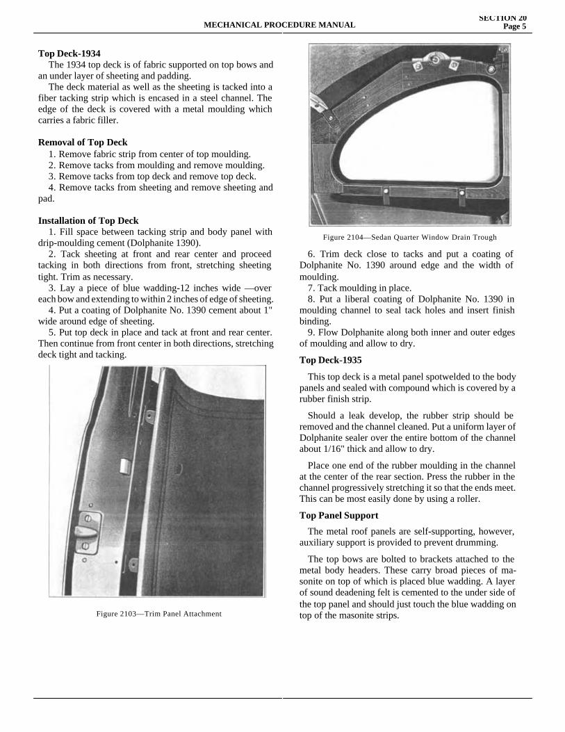
MECHANICAL PROCEDURE MANUALSECTION 20
Page 5
Top Deck-1934 The 1934 top deck is of fabric supported on top bows and an under layer of sheeting and padding. The deck material as well as the sheeting is tacked into a fiber tacking strip which is encased in a steel channel. The edge of the deck is covered with a metal moulding which carries a fabric filler.
Removal of Top Deck 1. Remove fabric strip from center of top moulding. 2. Remove tacks from moulding and remove moulding. 3. Remove tacks from top deck and remove top deck. 4. Remove tacks from sheeting and remove sheeting and pad.
Installation of Top Deck 1. Fill space between tacking strip and body panel with drip-moulding cement (Dolphanite 1390). 2. Tack sheeting at front and rear center and proceed tacking in both directions from front, stretching sheeting tight. Trim as necessary. 3. Lay a piece of blue wadding-12 inches wide —over each bow and extending to within 2 inches of edge of sheeting. 4. Put a coating of Dolphanite No. 1390 cement about 1" wide around edge of sheeting. 5. Put top deck in place and tack at front and rear center. Then continue from front center in both directions, stretching deck tight and tacking.
6. Trim deck close to tacks and put a coating of Dolphanite No. 1390 around edge and the width of moulding. 7. Tack moulding in place. 8. Put a liberal coating of Dolphanite No. 1390 in moulding channel to seal tack holes and insert finish binding. 9. Flow Dolphanite along both inner and outer edges of moulding and allow to dry.
Top Deck-1935
This top deck is a metal panel spotwelded to the body panels and sealed with compound which is covered by a rubber finish strip.
Should a leak develop, the rubber strip should be removed and the channel cleaned. Put a uniform layer of Dolphanite sealer over the entire bottom of the channel about 1/16" thick and allow to dry.
Place one end of the rubber moulding in the channel at the center of the rear section. Press the rubber in the channel progressively stretching it so that the ends meet. This can be most easily done by using a roller.
Top Panel Support
The metal roof panels are self-supporting, however, auxiliary support is provided to prevent drumming.
The top bows are bolted to brackets attached to the metal body headers. These carry broad pieces of ma-sonite on top of which is placed blue wadding. A layer of sound deadening felt is cemented to the under side of the top panel and should just touch the blue wadding on top of the masonite strips.Figure 2103—Trim Panel Attachment
Figure 2104—Sedan Quarter Window Drain Trough
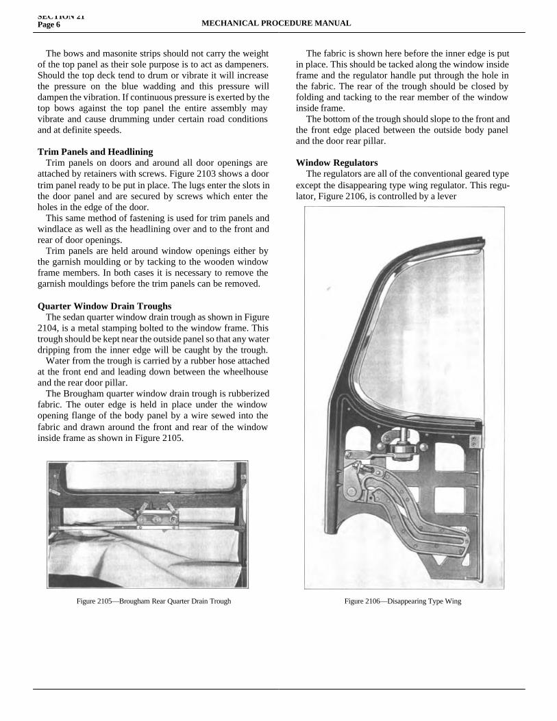
SECTION 21Page 6 MECHANICAL PROCEDURE MANUAL
The bows and masonite strips should not carry the weight of the top panel as their sole purpose is to act as dampeners. Should the top deck tend to drum or vibrate it will increase the pressure on the blue wadding and this pressure will dampen the vibration. If continuous pressure is exerted by the top bows against the top panel the entire assembly may vibrate and cause drumming under certain road conditions and at definite speeds.
Trim Panels and Headlining Trim panels on doors and around all door openings are attached by retainers with screws. Figure 2103 shows a door trim panel ready to be put in place. The lugs enter the slots in the door panel and are secured by screws which enter the holes in the edge of the door. This same method of fastening is used for trim panels and windlace as well as the headlining over and to the front and rear of door openings. Trim panels are held around window openings either by the garnish moulding or by tacking to the wooden window frame members. In both cases it is necessary to remove the garnish mouldings before the trim panels can be removed.
Quarter Window Drain Troughs The sedan quarter window drain trough as shown in Figure 2104, is a metal stamping bolted to the window frame. This trough should be kept near the outside panel so that any water dripping from the inner edge will be caught by the trough. Water from the trough is carried by a rubber hose attached at the front end and leading down between the wheelhouse and the rear door pillar. The Brougham quarter window drain trough is rubberized fabric. The outer edge is held in place under the window opening flange of the body panel by a wire sewed into the fabric and drawn around the front and rear of the window inside frame as shown in Figure 2105.
Figure 2105—Brougham Rear Quarter Drain Trough
The fabric is shown here before the inner edge is put in place. This should be tacked along the window inside frame and the regulator handle put through the hole in the fabric. The rear of the trough should be closed by folding and tacking to the rear member of the window inside frame. The bottom of the trough should slope to the front and the front edge placed between the outside body panel and the door rear pillar.
Window Regulators The regulators are all of the conventional geared type except the disappearing type wing regulator. This regu-lator, Figure 2106, is controlled by a lever
Figure 2106—Disappearing Type Wing
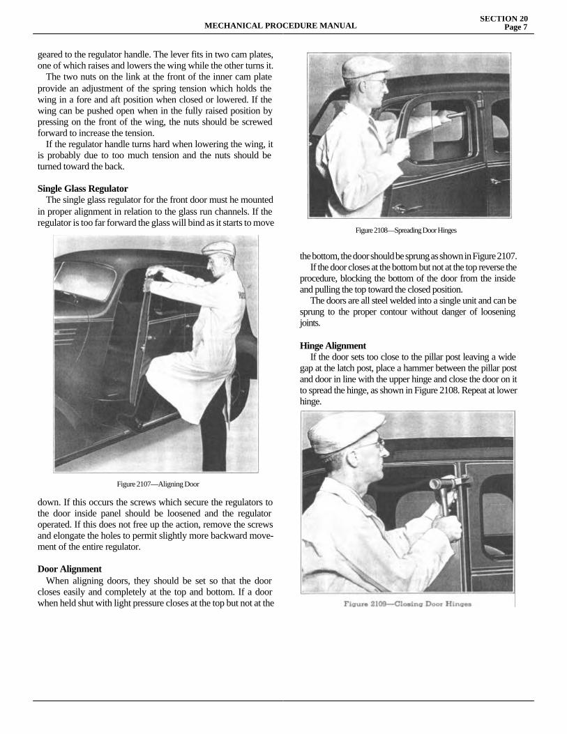
MECHANICAL PROCEDURE MANUALSECTION 20
Page 7
geared to the regulator handle. The lever fits in two cam plates, one of which raises and lowers the wing while the other turns it. The two nuts on the link at the front of the inner cam plate provide an adjustment of the spring tension which holds the wing in a fore and aft position when closed or lowered. If the wing can be pushed open when in the fully raised position by pressing on the front of the wing, the nuts should be screwed forward to increase the tension. If the regulator handle turns hard when lowering the wing, it is probably due to too much tension and the nuts should be turned toward the back.
Single Glass Regulator The single glass regulator for the front door must he mounted in proper alignment in relation to the glass run channels. If the regulator is too far forward the glass will bind as it starts to move
down. If this occurs the screws which secure the regulators to the door inside panel should be loosened and the regulator operated. If this does not free up the action, remove the screws and elongate the holes to permit slightly more backward move-ment of the entire regulator.
Door Alignment When aligning doors, they should be set so that the door closes easily and completely at the top and bottom. If a door when held shut with light pressure closes at the top but not at the
the bottom, the door should be sprung as shown in Figure 2107. If the door closes at the bottom but not at the top reverse the procedure, blocking the bottom of the door from the inside and pulling the top toward the closed position. The doors are all steel welded into a single unit and can be sprung to the proper contour without danger of loosening joints.
Hinge Alignment If the door sets too close to the pillar post leaving a wide gap at the latch post, place a hammer between the pillar post and door in line with the upper hinge and close the door on it to spread the hinge, as shown in Figure 2108. Repeat at lower hinge.
Figure 2107—Aligning Door
Figure 2108—Spreading Door Hinges
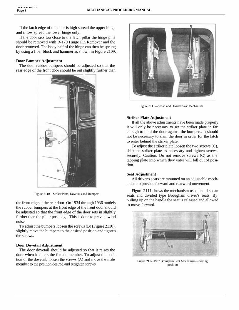
SECTION 21Page 8 MECHANICAL PROCEDURE MANUAL
If the latch edge of the door is high spread the upper hinge and if low spread the lower hinge only. If the door sets too close to the latch pillar the hinge pins should be removed with B-170 Hinge Pin Remover and the door removed. The body half of the hinge can then be sprung by using a fiber block and hammer as shown in Figure 2109.
Door Bumper Adjustment The door rubber bumpers should be adjusted so that the rear edge of the front door should be out slightly further than
the front edge of the rear door. On 1934 through 1936 models the rubber bumpers at the front edge of the front door should be adjusted so that the front edge of the door sets in slightly further than the pillar post edge. This is done to prevent wind noise. To adjust the bumpers loosen the screws (B) (Figure 2110), slightly move the bumpers to the desired position and tighten the screws.
Door Dovetail Adjustment The door dovetail should be adjusted so that it raises the door when it enters the female member. To adjust the posi-tion of the dovetail, loosen the screws (A) and move the male member to the position desired and retighten screws.
Striker Plate Adjustment If all the above adjustments have been made properly it will only be necessary to set the striker plate in far enough to hold the door against the bumpers. It should not be necessary to slam the door in order for the latch to enter behind the striker plate. To adjust the striker plate loosen the two screws (C), shift the striker plate as necessary and tighten screws securely. Caution: Do not remove screws (C) as the tapping plate into which they enter will fall out of posi-tion.
Seat Adjustment All driver's seats are mounted on an adjustable mech-anism to provide forward and rearward movement.
Figure 2111 shows the mechanism used on all sedan seats and divided type Brougham driver's seats. By pulling up on the handle the seat is released and allowed to move forward.
Figure 2112-1937 Brougham Seat Mechanism—drivingposition
Figure 2110—Striker Plate, Dovetails and Bumpers
Figure 2111—Sedan and Divided Seat Mechanism
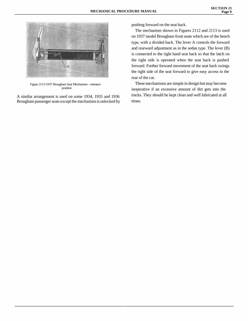
MECHANICAL PROCEDURE MANUALSECTION 21
Page 9
A similar arrangement is used on some 1934, 1935 and 1936 Brougham passenger seats except the mechanism is unlocked by
pushing forward on the seat back. The mechanism shown in Figures 2112 and 2113 is used on 1937 model Brougham front seats which are of the bench type, with a divided back. The lever A controls the forward and rearward adjustment as in the sedan type. The lever (B) is connected to the right hand seat back so that the latch on the right side is operated when the seat back is pushed forward. Further forward movement of the seat back swings the right side of the seat forward to give easy access to the rear of the car. These mechanisms are simple in design but may become inoperative if an excessive amount of dirt gets into the tracks. They should be kept clean and well lubricated at all times.
Figure 2113-1937 Brougham Seat Mechanism—entranceposition


SECTION 22RADIO
Service Magazine—Reference Sheet and Service Bullet in Reference
Bulletin orReference SheetNo. MagazineIssue and Page
Date Subject DETAILS OF INFORMATION
MECHANICAL PROCEDURE MANUAL Page 1

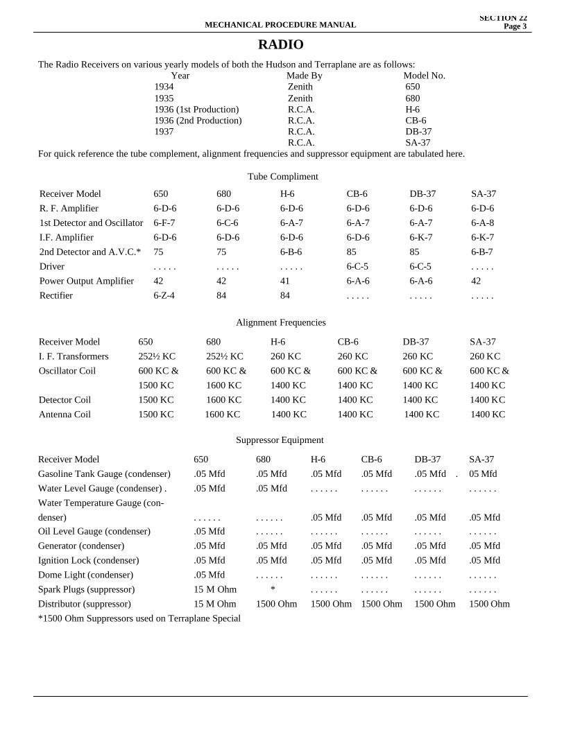
MECHANICAL PROCEDURE MANUALSECTION 22
Page 3
RADIOThe Radio Receivers on various yearly models of both the Hudson and Terraplane are as follows: Year Made By Model No. 1934 Zenith 650 1935 Zenith 680 1936 (1st Production) R.C.A. H-6 1936 (2nd Production) R.C.A. CB-6 1937 R.C.A. DB-37 R.C.A. SA-37For quick reference the tube complement, alignment frequencies and suppressor equipment are tabulated here.
Tube Compliment
Receiver ModelR. F. Amplifier 1st Detector and Oscillator I.F. Amplifier 2nd Detector and A.V.C.* Driver Power Output Amplifier Rectifier
6506-D-66-F-76-D-675. . . . .426-Z-4
6806-D-66-C-66-D-675. . . . .4284
H-66-D-66-A-76-D-66-B-6. . . . .4184
CB-66-D-66-A-76-D-6856-C-56-A-6. . . . .
DB-376-D-66-A-76-K-7856-C-56-A-6. . . . .
SA-376-D-66-A-86-K-76-B-7. . . . .42. . . . .
Alignment Frequencies
Receiver Model 650 680 H-6 CB-6 DB-37 SA-37I. F. Transformers 252½ KC 252½ KC 260 KC 260 KC 260 KC 260 KCOscillator Coil 600 KC & 600 KC & 600 KC & 600 KC & 600 KC & 600 KC & 1500 KC 1600 KC 1400 KC 1400 KC 1400 KC 1400 KCDetector Coil 1500 KC 1600 KC 1400 KC 1400 KC 1400 KC 1400 KCAntenna Coil 1500 KC 1600 KC 1400 KC 1400 KC 1400 KC 1400 KC
Suppressor Equipment
Receiver Model 650 680 H-6 CB-6 DB-37 SA-37Gasoline Tank Gauge (condenser) .05 Mfd .05 Mfd .05 Mfd .05 Mfd .05 Mfd . 05 MfdWater Level Gauge (condenser) . .05 Mfd .05 Mfd . . . . . . . . . . . . . . . . . . . . . . . .Water Temperature Gauge (con-denser) . . . . . . . . . . . . .05 Mfd .05 Mfd .05 Mfd .05 MfdOil Level Gauge (condenser) .05 Mfd . . . . . . . . . . . . . . . . . . . . . . . . . . . . . .Generator (condenser) .05 Mfd .05 Mfd .05 Mfd .05 Mfd .05 Mfd .05 MfdIgnition Lock (condenser) .05 Mfd .05 Mfd .05 Mfd .05 Mfd .05 Mfd .05 MfdDome Light (condenser) .05 Mfd . . . . . . . . . . . . . . . . . . . . . . . . . . . . . .Spark Plugs (suppressor) 15 M Ohm * . . . . . . . . . . . . . . . . . . . . . . . .Distributor (suppressor) 15 M Ohm 1500 Ohm 1500 Ohm 1500 Ohm 1500 Ohm 1500 Ohm*1500 Ohm Suppressors used on Terraplane Special
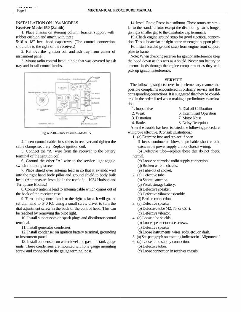
SECTION 22Page 4 MECHANICAL PROCEDURE MANUAL
INSTALLATION ON 1934 MODELSReceiver Model 650 (Zenith) 1. Place chassis on steering column bracket support with rubber cushion and attach with three5/16 x 18" hex. head capscrews. (The control connections should be to the right of the receiver.) 2. Remove the ignition coil and ash tray from center of instrument panel. 3. Mount radio control head in hole that was covered by ash tray and install control knobs.
4. Insert control cables in sockets in receiver and tighten the cable clamps securely. Replace ignition coil. 5. Connect the "A" wire from the receiver to the battery terminal of the ignition coil. 6. Ground the other "A" wire to the service light toggle switch mounting screw. 7. Place shield over antenna lead in so that it extends well into the right hand body pillar and ground shield to body bulk head. (Antennas are installed in the roof of all 1934 Hudson and Terraplane Bodies.) 8. Connect antenna lead to antenna cable which comes out of the back of the receiver case. 9. Turn tuning control knob to the right as far as it will go and set dial hand to 540 KC using a small screw driver to turn the dial adjustment screw in the back of the control head. This can be reached by removing the pilot light. 10. Install suppressors on spark plugs and distributor central terminal. 11. Install generator condenser. 12. Install condenser on ignition battery terminal, grounding to instrument panel. 13. Install condensers on water level and gasoline tank gauge units. These condensers are mounted with one gauge mounting screw and connected to the gauge terminal post.
14. Install Radio Rotor in distributor. These rotors are simi-lar to the standard rotor except the distributing bar is longer giving a smaller gap to the distributor cap terminals. 15. Check engine ground strap for good electrical connec-tion. This is located at the right of the rear engine support plate. 16. Install braided ground strap from engine front support plate to frame. Note: When checking receiver for ignition interference keep the hood down as this acts as a shield. Never run battery or antenna leads through the engine compartment as they will pick up ignition interference.
SERVICE The following subjects cover in an elementary manner the possible complaints encountered in ordinary service and the corresponding corrections. It is suggested that they be consid-ered in the order listed when making a preliminary examina-tion. 1. Inoperative 5. Dial off Calibration 2. Weak 6. Intermittent Operation 3. Distortion 7. Motor Noise 4. Rattles 8. Noisy Reception After the trouble has been isolated, the following procedure will prove effective. (Consult illustrations.)
1. (a) Examine fuse and replace if open. If fuses continue to blow, a probable short circuit exists in the power supply unit or chassis wiring. (b) Defective tube—replace those that do not check normal. (c) Loose or corroded radio supply connection. (d) Broken wire in chassis. (e) Tube out of socket.2. (a) Defective tube. (b) Shorted antenna. (c) Weak storage battery. (d) Defective speaker. (e) Defective vibrator assembly. (f) Broken connection.3. (a) Defective speaker. (b) Defective tube (42, 75, or 6Z4). (c) Defective vibrator.4. (a) Loose tube shields. (b) Loose speaker or case screws. (c) Defective speaker (d) Loose instruments, wires, rods, etc., on dash.5. (a) See paragraph on resetting indicator in "Alignment."6. (a) Loose radio supply connection. (b) Defective tubes. (c) Loose connection in receiver chassis.
Figure 2201—Tube Position—Model 650
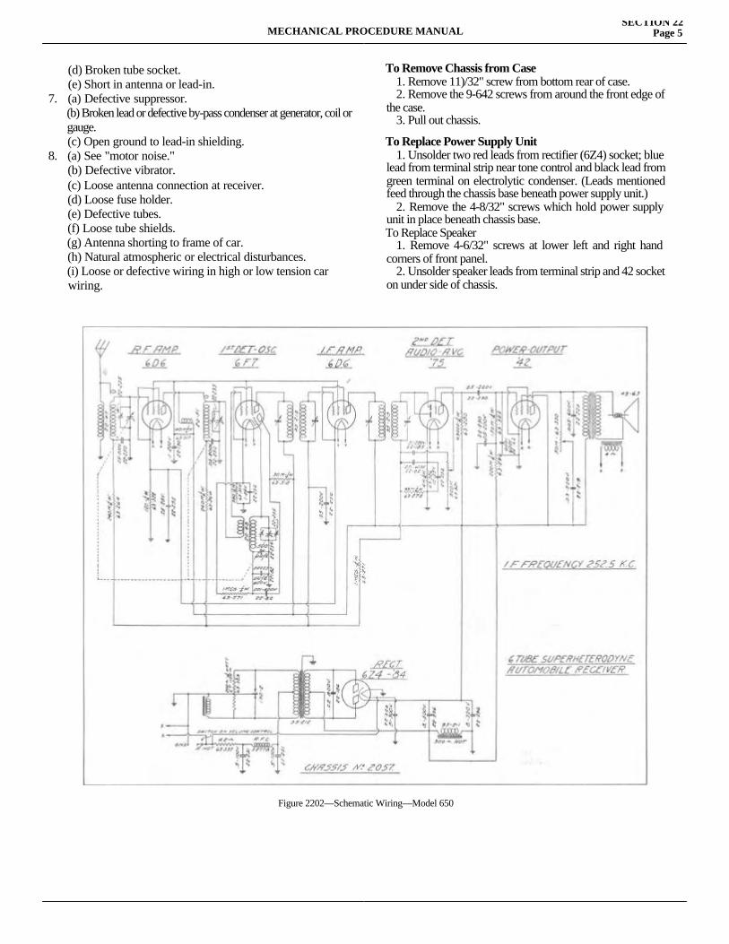
MECHANICAL PROCEDURE MANUALSECTION 22
Page 5
(d) Broken tube socket.(e) Short in antenna or lead-in.
7. (a) Defective suppressor. (b) Broken lead or defective by-pass condenser at generator, coil or gauge. (c) Open ground to lead-in shielding.8. (a) See "motor noise." (b) Defective vibrator. (c) Loose antenna connection at receiver. (d) Loose fuse holder. (e) Defective tubes. (f) Loose tube shields. (g) Antenna shorting to frame of car. (h) Natural atmospheric or electrical disturbances. (i) Loose or defective wiring in high or low tension car wiring.
To Remove Chassis from Case 1. Remove 11)/32" screw from bottom rear of case. 2. Remove the 9-642 screws from around the front edge of the case. 3. Pull out chassis.
To Replace Power Supply Unit 1. Unsolder two red leads from rectifier (6Z4) socket; blue lead from terminal strip near tone control and black lead from green terminal on electrolytic condenser. (Leads mentioned feed through the chassis base beneath power supply unit.) 2. Remove the 4-8/32" screws which hold power supply unit in place beneath chassis base.To Replace Speaker 1. Remove 4-6/32" screws at lower left and right hand corners of front panel. 2. Unsolder speaker leads from terminal strip and 42 socket on under side of chassis.
Figure 2202—Schematic Wiring—Model 650
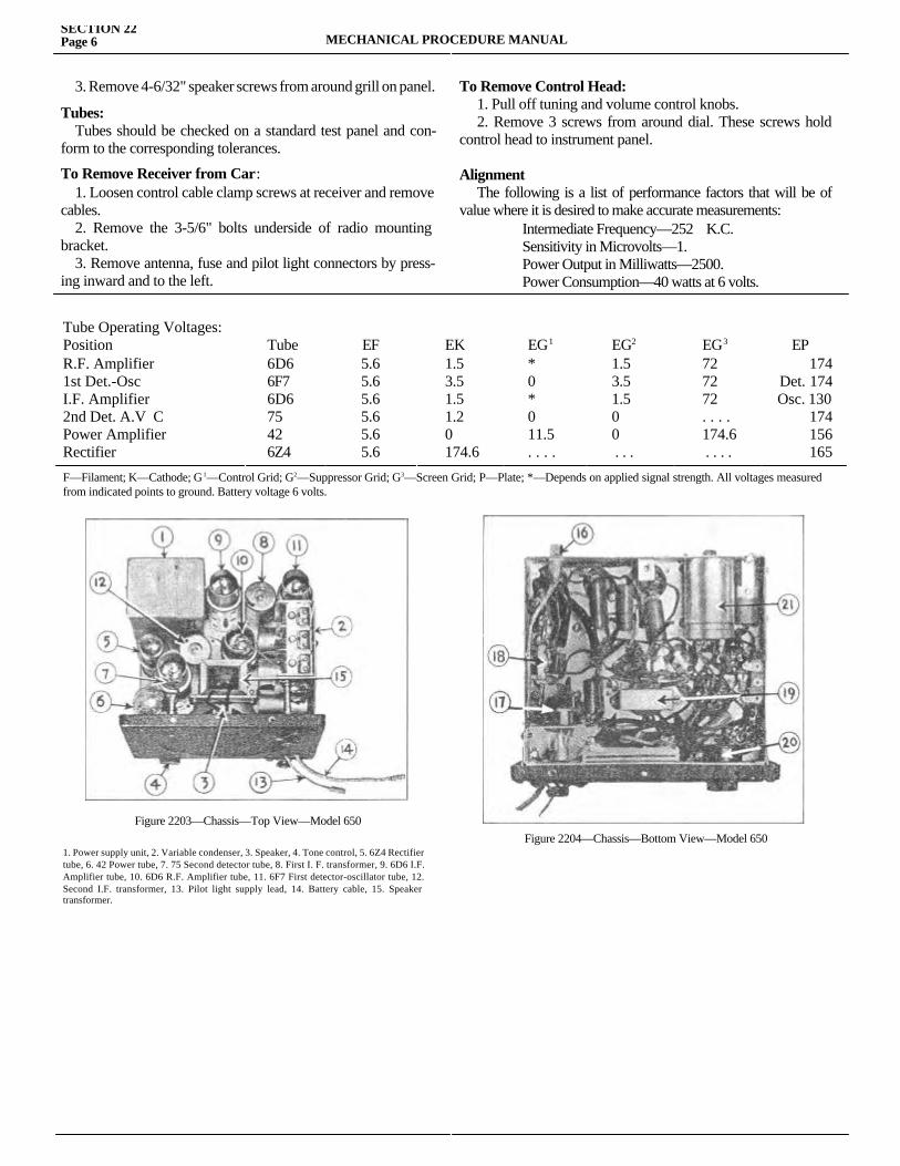
SECTION 22Page 6 MECHANICAL PROCEDURE MANUAL
3. Remove 4-6/32" speaker screws from around grill on panel.
Tubes: Tubes should be checked on a standard test panel and con-form to the corresponding tolerances.
To Remove Receiver from Car: 1. Loosen control cable clamp screws at receiver and remove cables. 2. Remove the 3-5/6" bolts underside of radio mounting bracket. 3. Remove antenna, fuse and pilot light connectors by press-ing inward and to the left.
To Remove Control Head: 1. Pull off tuning and volume control knobs. 2. Remove 3 screws from around dial. These screws hold control head to instrument panel.
Alignment The following is a list of performance factors that will be of value where it is desired to make accurate measurements: Intermediate Frequency—252 K.C. Sensitivity in Microvolts—1. Power Output in Milliwatts—2500. Power Consumption—40 watts at 6 volts.
Tube Operating Voltages:PositionR.F. Amplifier 1st Det.-Osc I.F. Amplifier 2nd Det. A.V C Power Amplifier Rectifier
Tube6D66F76D675426Z4
EF5.65.65.65.65.65.6
EK1.53.51.51.20174.6
EG1
*0*011.5. . . .
EG2
1.53.51.500 . . .
EG3
727272. . . .174.6 . . . .
EP174
Det. 174 Osc. 130
174156165
F—Filament; K—Cathode; G1—Control Grid; G2—Suppressor Grid; G3—Screen Grid; P—Plate; *—Depends on applied signal strength. All voltages measured from indicated points to ground. Battery voltage 6 volts.
1. Power supply unit, 2. Variable condenser, 3. Speaker, 4. Tone control, 5. 6Z4 Rectifier tube, 6. 42 Power tube, 7. 75 Second detector tube, 8. First I. F. transformer, 9. 6D6 I.F. Amplifier tube, 10. 6D6 R.F. Amplifier tube, 11. 6F7 First detector-oscillator tube, 12. Second I.F. transformer, 13. Pilot light supply lead, 14. Battery cable, 15. Speaker transformer.
Figure 2203—Chassis—Top View—Model 650Figure 2204—Chassis—Bottom View—Model 650
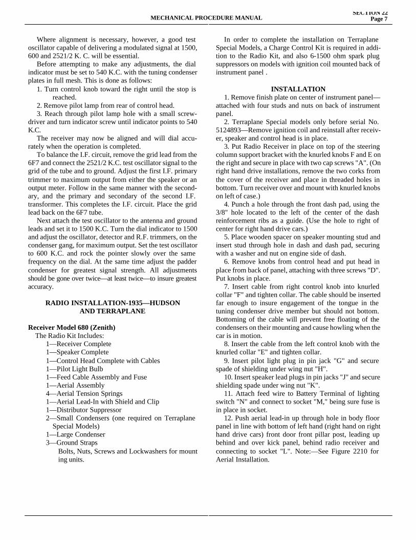
MECHANICAL PROCEDURE MANUALSECTION 22
Page 7
Where alignment is necessary, however, a good test oscillator capable of delivering a modulated signal at 1500, 600 and 2521/2 K. C. will be essential. Before attempting to make any adjustments, the dial indicator must be set to 540 K.C. with the tuning condenser plates in full mesh. This is done as follows: 1. Turn control knob toward the right until the stop is reached. 2. Remove pilot lamp from rear of control head. 3. Reach through pilot lamp hole with a small screw-driver and turn indicator screw until indicator points to 540 K.C. The receiver may now be aligned and will dial accu-rately when the operation is completed. To balance the I.F. circuit, remove the grid lead from the 6F7 and connect the 2521/2 K.C. test oscillator signal to the grid of the tube and to ground. Adjust the first I.F. primary trimmer to maximum output from either the speaker or an output meter. Follow in the same manner with the second-ary, and the primary and secondary of the second I.F. transformer. This completes the I.F. circuit. Place the grid lead back on the 6F7 tube. Next attach the test oscillator to the antenna and ground leads and set it to 1500 K.C. Turn the dial indicator to 1500 and adjust the oscillator, detector and R.F. trimmers, on the condenser gang, for maximum output. Set the test oscillator to 600 K.C. and rock the pointer slowly over the same frequency on the dial. At the same time adjust the padder condenser for greatest signal strength. All adjustments should be gone over twice—at least twice—to insure greatest accuracy.
RADIO INSTALLATION-1935—HUDSONAND TERRAPLANE
Receiver Model 680 (Zenith) The Radio Kit Includes:
1—Receiver Complete1—Speaker Complete1—Control Head Complete with Cables 1—Pilot Light Bulb1—Feed Cable Assembly and Fuse1—Aerial Assembly4—Aerial Tension Springs1—Aerial Lead-In with Shield and Clip1—Distributor Suppressor2—Small Condensers (one required on Terraplane Special Models)1—Large Condenser3—Ground Straps Bolts, Nuts, Screws and Lockwashers for mount ing units.
In order to complete the installation on Terraplane Special Models, a Charge Control Kit is required in addi-tion to the Radio Kit, and also 6-1500 ohm spark plug suppressors on models with ignition coil mounted back of instrument panel .
INSTALLATION 1. Remove finish plate on center of instrument panel—attached with four studs and nuts on back of instrument panel. 2. Terraplane Special models only before serial No. 5124893—Remove ignition coil and reinstall after receiv-er, speaker and control head is in place. 3. Put Radio Receiver in place on top of the steering column support bracket with the knurled knobs F and E on the right and secure in place with two cap screws "A". (On right hand drive installations, remove the two corks from the cover of the receiver and place in threaded holes in bottom. Turn receiver over and mount with knurled knobs on left of case.) 4. Punch a hole through the front dash pad, using the 3/8" hole located to the left of the center of the dash reinforcement ribs as a guide. (Use the hole to right of center for right hand drive cars.) 5. Place wooden spacer on speaker mounting stud and insert stud through hole in dash and dash pad, securing with a washer and nut on engine side of dash. 6. Remove knobs from control head and put head in place from back of panel, attaching with three screws "D". Put knobs in place. 7. Insert cable from right control knob into knurled collar "F" and tighten collar. The cable should be inserted far enough to insure engagement of the tongue in the tuning condenser drive member but should not bottom. Bottoming of the cable will prevent free floating of the condensers on their mounting and cause howling when the car is in motion. 8. Insert the cable from the left control knob with the knurled collar "E" and tighten collar. 9. Insert pilot light plug in pin jack "G" and secure spade of shielding under wing nut "H". 10. Insert speaker lead plugs in pin jacks "J" and secure shielding spade under wing nut "K". 11. Attach feed wire to Battery Terminal of lighting switch "N" and connect to socket "M," being sure fuse is in place in socket. 12. Push aerial lead-in up through hole in body floor panel in line with bottom of left hand (right hand on right hand drive cars) front door front pillar post, leading up behind and over kick panel, behind radio receiver and connecting to socket "L". Note:—See Figure 2210 for Aerial Installation.
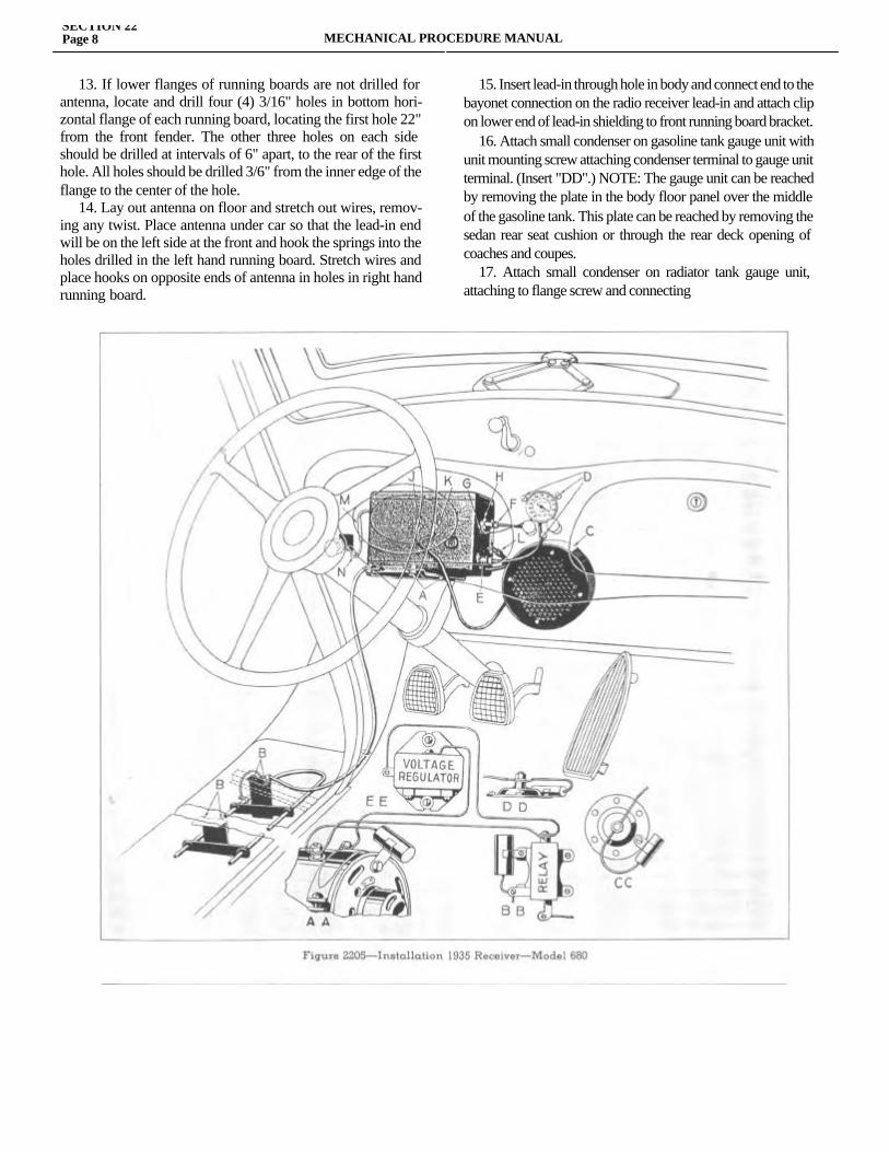
SECTION 22Page 8 MECHANICAL PROCEDURE MANUAL
13. If lower flanges of running boards are not drilled for antenna, locate and drill four (4) 3/16" holes in bottom hori-zontal flange of each running board, locating the first hole 22" from the front fender. The other three holes on each side should be drilled at intervals of 6" apart, to the rear of the first hole. All holes should be drilled 3/6" from the inner edge of the flange to the center of the hole. 14. Lay out antenna on floor and stretch out wires, remov-ing any twist. Place antenna under car so that the lead-in end will be on the left side at the front and hook the springs into the holes drilled in the left hand running board. Stretch wires and place hooks on opposite ends of antenna in holes in right hand running board.
15. Insert lead-in through hole in body and connect end to the bayonet connection on the radio receiver lead-in and attach clip on lower end of lead-in shielding to front running board bracket. 16. Attach small condenser on gasoline tank gauge unit with unit mounting screw attaching condenser terminal to gauge unit terminal. (Insert "DD".) NOTE: The gauge unit can be reached by removing the plate in the body floor panel over the middle of the gasoline tank. This plate can be reached by removing the sedan rear seat cushion or through the rear deck opening of coaches and coupes. 17. Attach small condenser on radiator tank gauge unit, attaching to flange screw and connecting
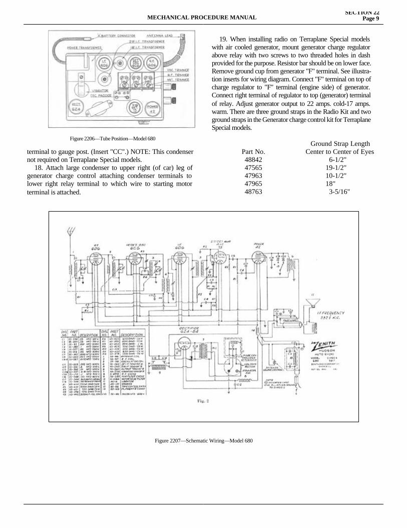
MECHANICAL PROCEDURE MANUALSECTION 22
Page 9
terminal to gauge post. (Insert "CC".) NOTE: This condenser not required on Terraplane Special models. 18. Attach large condenser to upper right (of car) leg of generator charge control attaching condenser terminals to lower right relay terminal to which wire to starting motor terminal is attached.
19. When installing radio on Terraplane Special models with air cooled generator, mount generator charge regulator above relay with two screws to two threaded holes in dash provided for the purpose. Resistor bar should be on lower face. Remove ground cup from generator "F" terminal. See illustra-tion inserts for wiring diagram. Connect "F" terminal on top of charge regulator to "F" terminal (engine side) of generator. Connect right terminal of regulator to top (generator) terminal of relay. Adjust generator output to 22 amps. cold-17 amps. warm. There are three ground straps in the Radio Kit and two ground straps in the Generator charge control kit for Terraplane Special models.
Figure 2206—Tube Position—Model 680
Part No.4884247565479634796548763
Ground Strap LengthCenter to Center of Eyes
6-1/2"19-1/2"10-1/2"18" 3-5/16"
Figure 2207—Schematic Wiring—Model 680
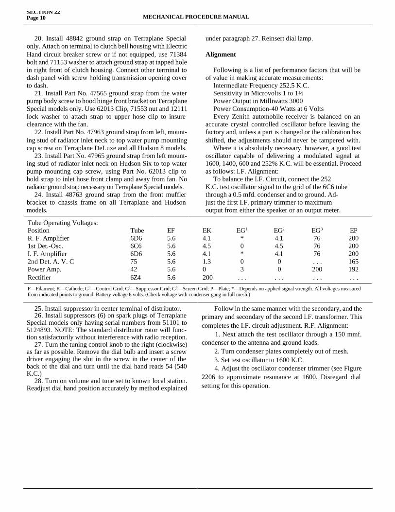
SECTION 22Page 10 MECHANICAL PROCEDURE MANUAL
20. Install 48842 ground strap on Terraplane Special only. Attach on terminal to clutch bell housing with Electric Hand circuit breaker screw or if not equipped, use 71384 bolt and 71153 washer to attach ground strap at tapped hole in right front of clutch housing. Connect other terminal to dash panel with screw holding transmission opening cover to dash. 21. Install Part No. 47565 ground strap from the water pump body screw to hood hinge front bracket on Terraplane Special models only. Use 62013 Clip, 71553 nut and 12111 lock washer to attach strap to upper hose clip to insure clearance with the fan. 22. Install Part No. 47963 ground strap from left, mount-ing stud of radiator inlet neck to top water pump mounting cap screw on Terraplane DeLuxe and all Hudson 8 models. 23. Install Part No. 47965 ground strap from left mount-ing stud of radiator inlet neck on Hudson Six to top water pump mounting cap screw, using Part No. 62013 clip to hold strap to inlet hose front clamp and away from fan. No radiator ground strap necessary on Terraplane Special models. 24. Install 48763 ground strap from the front muffler bracket to chassis frame on all Terraplane and Hudson models.
under paragraph 27. Reinsert dial lamp.
Alignment
Following is a list of performance factors that will be of value in making accurate measurements: Intermediate Frequency 252.5 K.C. Sensitivity in Microvolts 1 to 1½ Power Output in Milliwatts 3000 Power Consumption-40 Watts at 6 Volts Every Zenith automobile receiver is balanced on an accurate crystal controlled oscillator before leaving the factory and, unless a part is changed or the calibration has shifted, the adjustments should never be tampered with. Where it is absolutely necessary, however, a good test oscillator capable of delivering a modulated signal at 1600, 1400, 600 and 252% K.C. will be essential. Proceed as follows: I.F. Alignment: To balance the I.F. Circuit, connect the 252K.C. test oscillator signal to the grid of the 6C6 tubethrough a 0.5 mfd. condenser and to ground. Ad-just the first I.F. primary trimmer to maximumoutput from either the speaker or an output meter.
Tube Operating Voltages: PositionR. F. Amplifier 1st Det.-Osc. I. F. Amplifier 2nd Det. A. V. C Power Amp. Rectifier
Tube6D66C66D675426Z4
EF5.65.65.65.65.65.6
EK4.14.54.11.30200
EG1
*0*03
. . .
EG2
4.14.54.100
. . .
EG3
767676. . .200. . .
EP200200200165192. . .
F—Filament; K—Cathode; G1—Control Grid; G2—Suppressor Grid; G3—Screen Grid; P—Plate; *—Depends on applied signal strength. All voltages measured from indicated points to ground. Battery voltage 6 volts. (Check voltage with condenser gang in full mesh.)
25. Install suppressor in center terminal of distributor. 26. Install suppressors (6) on spark plugs of Terraplane Special models only having serial numbers from 51101 to 5124893. NOTE: The standard distributor rotor will func-tion satisfactorily without interference with radio reception. 27. Turn the tuning control knob to the right (clockwise) as far as possible. Remove the dial bulb and insert a screw driver engaging the slot in the screw in the center of the back of the dial and turn until the dial hand reads 54 (540 K.C.) 28. Turn on volume and tune set to known local station. Readjust dial hand position accurately by method explained
Follow in the same manner with the secondary, and the primary and secondary of the second I.F. transformer. This completes the I.F. circuit adjustment. R.F. Alignment: 1. Next attach the test oscillator through a 150 mmf. condenser to the antenna and ground leads. 2. Turn condenser plates completely out of mesh. 3. Set test oscillator to 1600 K.C. 4. Adjust the oscillator condenser trimmer (see Figure 2206 to approximate resonance at 1600. Disregard dial setting for this operation.
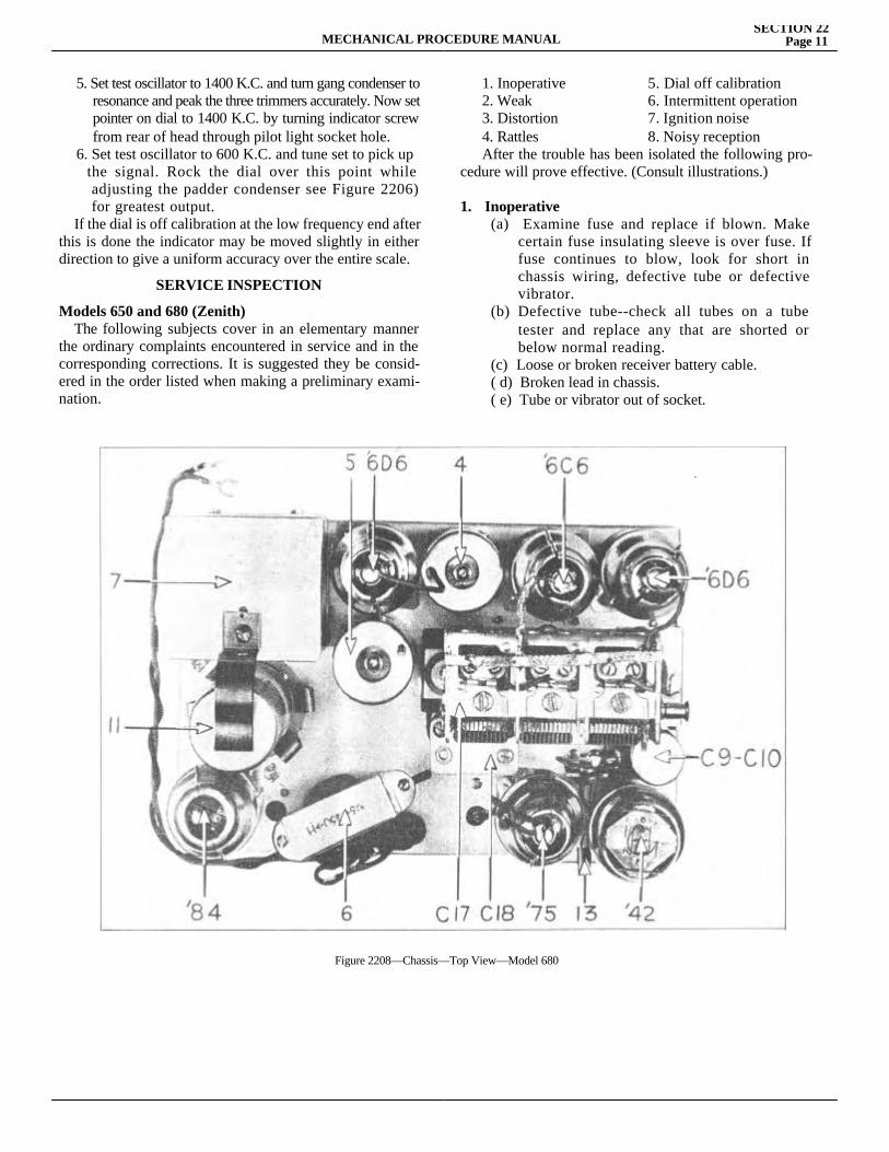
MECHANICAL PROCEDURE MANUALSECTION 22
Page 11
5. Set test oscillator to 1400 K.C. and turn gang condenser to resonance and peak the three trimmers accurately. Now set pointer on dial to 1400 K.C. by turning indicator screw from rear of head through pilot light socket hole.6. Set test oscillator to 600 K.C. and tune set to pick up the signal. Rock the dial over this point while adjusting the padder condenser see Figure 2206) for greatest output.
If the dial is off calibration at the low frequency end after this is done the indicator may be moved slightly in either direction to give a uniform accuracy over the entire scale.
SERVICE INSPECTION
Models 650 and 680 (Zenith) The following subjects cover in an elementary manner the ordinary complaints encountered in service and in the corresponding corrections. It is suggested they be consid-ered in the order listed when making a preliminary exami-nation.
1. Inoperative 5. Dial off calibration2. Weak 6. Intermittent operation3. Distortion 7. Ignition noise4. Rattles 8. Noisy reception
After the trouble has been isolated the following pro-cedure will prove effective. (Consult illustrations.)
1. Inoperative(a) Examine fuse and replace if blown. Make certain fuse insulating sleeve is over fuse. If fuse continues to blow, look for short in chassis wiring, defective tube or defective vibrator.(b) Defective tube--check all tubes on a tube tester and replace any that are shorted or below normal reading.(c) Loose or broken receiver battery cable.( d) Broken lead in chassis.( e) Tube or vibrator out of socket.
Figure 2208—Chassis—Top View—Model 680
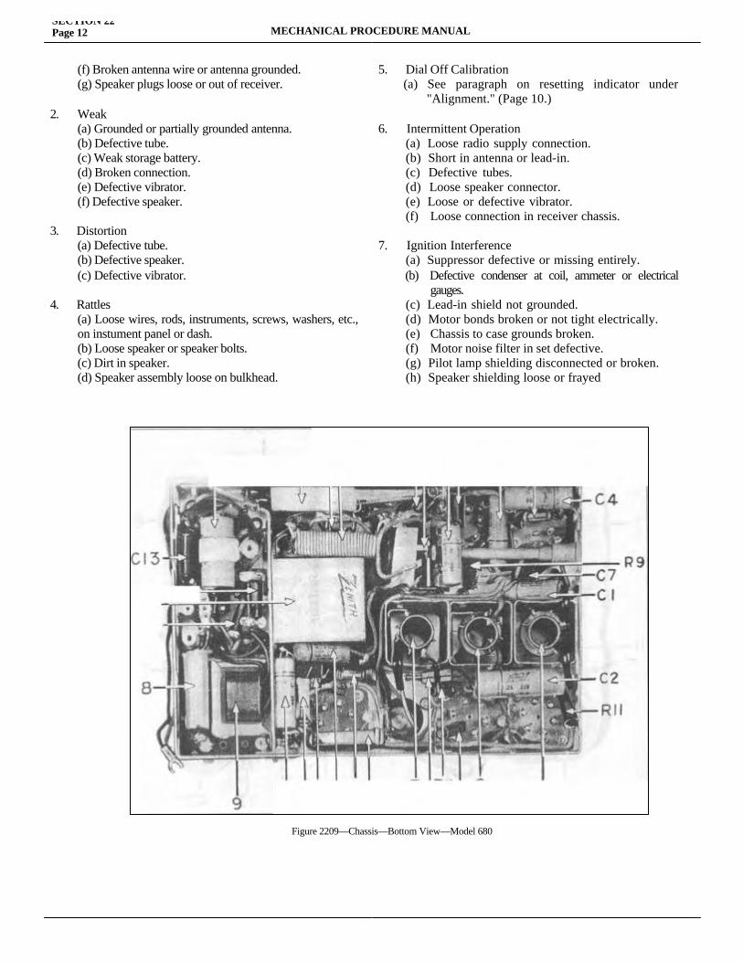
SECTION 22Page 12 MECHANICAL PROCEDURE MANUAL
(f) Broken antenna wire or antenna grounded.(g) Speaker plugs loose or out of receiver.
2. Weak(a) Grounded or partially grounded antenna.(b) Defective tube.(c) Weak storage battery.(d) Broken connection.(e) Defective vibrator.(f) Defective speaker.
3. Distortion(a) Defective tube.(b) Defective speaker.(c) Defective vibrator.
4. Rattles(a) Loose wires, rods, instruments, screws, washers, etc., on instument panel or dash.(b) Loose speaker or speaker bolts.(c) Dirt in speaker.(d) Speaker assembly loose on bulkhead.
5. Dial Off Calibration (a) See paragraph on resetting indicator under "Alignment." (Page 10.)
6. Intermittent Operation (a) Loose radio supply connection. (b) Short in antenna or lead-in. (c) Defective tubes. (d) Loose speaker connector. (e) Loose or defective vibrator. (f) Loose connection in receiver chassis.
7. Ignition Interference (a) Suppressor defective or missing entirely. (b) Defective condenser at coil, ammeter or electrical gauges. (c) Lead-in shield not grounded. (d) Motor bonds broken or not tight electrically. (e) Chassis to case grounds broken. (f) Motor noise filter in set defective. (g) Pilot lamp shielding disconnected or broken. (h) Speaker shielding loose or frayed
Figure 2209—Chassis—Bottom View—Model 680
MECHANICAL PROCEDURE MANUALSECTION 22
Page 13
8. Noisy Reception(a) See "ignition Interference". (7).(b) Defective vibrator.(c) Loose antenna connection.(d) Loose fuse holder.(e) Defective tubes.(f) Loose tube shields.(g) Antenna shorting to frame of car.h) Natural atmospheric or electrical disturbances.(i) Loose or defective high or low tension wiring.
To Remove Receiver from Car1. Disconnect antenna lead from receiver at connector.2. Disconnect "A" lead at fuse receptacle.3. Remove tuning cables by loosening knurled cable clamps at receiver.4. Take out pilot light lead and shield connections.5. Do likewise with speaker connections.6. Take out the two mounting bolts from beneath mount ing bracket.
To Remove Speaker1. Loosen wing nut and remove ground lead.2. Pull the two speaker plugs from receiver case.3. Remove speaker mounting nut from motor side.4. Take speaker unit out from under cowl.
To Remove Control Unit1. Take out three head mounting screws from front of instrument panel.2. Draw head out from rear.
To Remove Chassis from Case (Chassis does NOT have to be removed from case for ordinary repairs or service as removal of top lid per- mits easy access to tubes and vibrator.)1. Remove top and bottom covers.2. Remove ground lug from "A" filter.3. Remove hot lead from "A" filter.4. Disconnect "A" filter bond from case.5. Remove leads from speaker jacks and ground lead to outer case.6. Disconnect three bonds from chassis to case on bot- tom side.7. Remove four rubber mounting screws from sides of case.
The Radio Kit Includes:1—Receiver Complete1—Speaker Complete1—Control Head Complete with Cables1—Pilot Light Bulb
1—Feed Cable Assembly and Fuse1—Aerial Assembly1—Aerial Lead-In with Shield and Clip 1—Distributor Suppressor2—Small Condensers (one required on Terraplane De Luxe models)1—Large Condenser1—Ground Strap3—Ground Forks Bolts, Nuts, Screws and Lock Washers for Mounting units. In order to complete the installation on Terraplane DeLuxe models, a Charge Control (Part No. 47979) is required in addition to the Radio Kit.
INSTALLATION-1936 MODELS-H-6RECEIVER
1. Lift floor mat and install three ground forks (Part No. 151210) to front, rear and left of floor board open-ing so that spring fingers contact transmission control housing. (See insert EE, Figure 2210.) The paint must be removed from the floor panel and transmission tower to provide good electrical contact. A spacer (Part No. 151435) should be placed under each ground fork and the parts secured to the floor board with two screws (Part No. 71648) and three tapping plates (Part No. 151436). 2. Remove finish plate from center of instrument panel-attached with studs and nuts on back of panel. 3. Put the Radio Receiver in place on top of the steering column support bracket with the control shaft connections E and F on the right, and secure with two cap screws "A". On right-hand drive models, the re-ceiver is mounted with the control shaft connections to the left. NOTE: There are three threaded holes in the bottom of the receiver so that it can be mounted in 1934 and 1935 models as well as 1936. 4. Punch a hole through the front dash pad, using the 3/8" hole located just above the center of the dash reinforcement ribs as a guide. 5. Place wooden spacer on speaker mounting stud and insert stud through hole in dash and dash pad, securing with a washer and nut on the engine side of dash. 6. Remove the control knobs from the control head, and also the nuts located behind the knobs. Insert control head from back of panel, securing by replacing nuts, and then replace control knobs. 7. Insert the driving tongue of the control cable from the right (tuning) knob into the rear (front on right-hand drive) socket F and tighten nut and the driving tongue of the control cable from the left (volume) knob into the
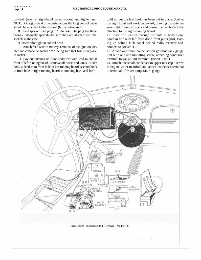
SECTION 22Page 14 MECHANICAL PROCEDURE MANUAL
forward (rear on right-hand drive) socket and tighten nut. NOTE: On right-hand drive installations the long control cable should be attached to the volume (left) control knob. 8. Insert speaker lead plug "J" into case. The plug has three prongs, unequally spaced—be sure they are aligned with the sockets in the case. 9. Insert pilot light in control head. 10. Attach feed wire to Battery Terminal of the ignition lock "N" and connect to socket "M", being sure that fuse is in place in socket. 11. Lay out antenna on floor under car with lead-in end at front of left running board. Remove all twists and kinks. Attach hook at lead-in to front hole in left running board, second hook to front hole in right running board, continuing back and forth
until all but the last hook has been put in place. Start at the right front and work backward, drawing the antenna wire tight to take up slack and permit the last hook to be attached to the right running board.12. Insert the lead-in through the hole in body floor panel in line with left front door, front pillar post, lead-ing up behind kick panel behind radio receiver and connect to socket "L."13. Attach one small condenser on gasoline tank gauge unit with one unit mounting screw, attaching condenser terminal to gauge unit terminal. (Insert "DD").14. Attach one small condenser to upper rear cap " screw in engine water manifold and attach condenser terminal to terminal of water temperature gauge
Figure 2210—Installation-1936 Receiver—Model H-6
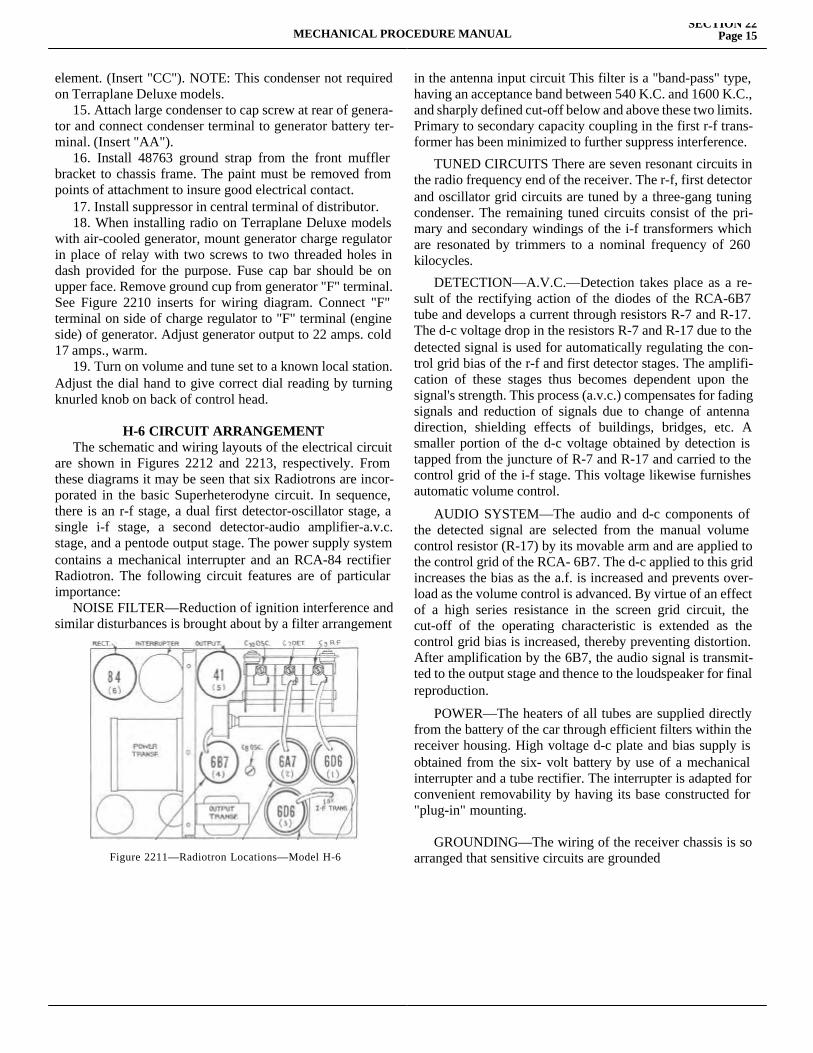
MECHANICAL PROCEDURE MANUALSECTION 22
Page 15
element. (Insert "CC"). NOTE: This condenser not required on Terraplane Deluxe models. 15. Attach large condenser to cap screw at rear of genera-tor and connect condenser terminal to generator battery ter-minal. (Insert "AA"). 16. Install 48763 ground strap from the front muffler bracket to chassis frame. The paint must be removed from points of attachment to insure good electrical contact. 17. Install suppressor in central terminal of distributor. 18. When installing radio on Terraplane Deluxe models with air-cooled generator, mount generator charge regulator in place of relay with two screws to two threaded holes in dash provided for the purpose. Fuse cap bar should be on upper face. Remove ground cup from generator "F" terminal. See Figure 2210 inserts for wiring diagram. Connect "F" terminal on side of charge regulator to "F" terminal (engine side) of generator. Adjust generator output to 22 amps. cold 17 amps., warm. 19. Turn on volume and tune set to a known local station. Adjust the dial hand to give correct dial reading by turning knurled knob on back of control head.
H-6 CIRCUIT ARRANGEMENT The schematic and wiring layouts of the electrical circuit are shown in Figures 2212 and 2213, respectively. From these diagrams it may be seen that six Radiotrons are incor-porated in the basic Superheterodyne circuit. In sequence, there is an r-f stage, a dual first detector-oscillator stage, a single i-f stage, a second detector-audio amplifier-a.v.c. stage, and a pentode output stage. The power supply system contains a mechanical interrupter and an RCA-84 rectifier Radiotron. The following circuit features are of particular importance: NOISE FILTER—Reduction of ignition interference and similar disturbances is brought about by a filter arrangement
in the antenna input circuit This filter is a "band-pass" type, having an acceptance band between 540 K.C. and 1600 K.C., and sharply defined cut-off below and above these two limits. Primary to secondary capacity coupling in the first r-f trans-former has been minimized to further suppress interference.
TUNED CIRCUITS There are seven resonant circuits in the radio frequency end of the receiver. The r-f, first detector and oscillator grid circuits are tuned by a three-gang tuning condenser. The remaining tuned circuits consist of the pri-mary and secondary windings of the i-f transformers which are resonated by trimmers to a nominal frequency of 260 kilocycles.
DETECTION—A.V.C.—Detection takes place as a re-sult of the rectifying action of the diodes of the RCA-6B7 tube and develops a current through resistors R-7 and R-17. The d-c voltage drop in the resistors R-7 and R-17 due to the detected signal is used for automatically regulating the con-trol grid bias of the r-f and first detector stages. The amplifi-cation of these stages thus becomes dependent upon the signal's strength. This process (a.v.c.) compensates for fading signals and reduction of signals due to change of antenna direction, shielding effects of buildings, bridges, etc. A smaller portion of the d-c voltage obtained by detection is tapped from the juncture of R-7 and R-17 and carried to the control grid of the i-f stage. This voltage likewise furnishes automatic volume control.
AUDIO SYSTEM—The audio and d-c components of the detected signal are selected from the manual volume control resistor (R-17) by its movable arm and are applied to the control grid of the RCA- 6B7. The d-c applied to this grid increases the bias as the a.f. is increased and prevents over-load as the volume control is advanced. By virtue of an effect of a high series resistance in the screen grid circuit, the cut-off of the operating characteristic is extended as the control grid bias is increased, thereby preventing distortion. After amplification by the 6B7, the audio signal is transmit-ted to the output stage and thence to the loudspeaker for final reproduction.
POWER—The heaters of all tubes are supplied directly from the battery of the car through efficient filters within the receiver housing. High voltage d-c plate and bias supply is obtained from the six- volt battery by use of a mechanical interrupter and a tube rectifier. The interrupter is adapted for convenient removability by having its base constructed for "plug-in" mounting.
GROUNDING—The wiring of the receiver chassis is so arranged that sensitive circuits are groundedFigure 2211—Radiotron Locations—Model H-6
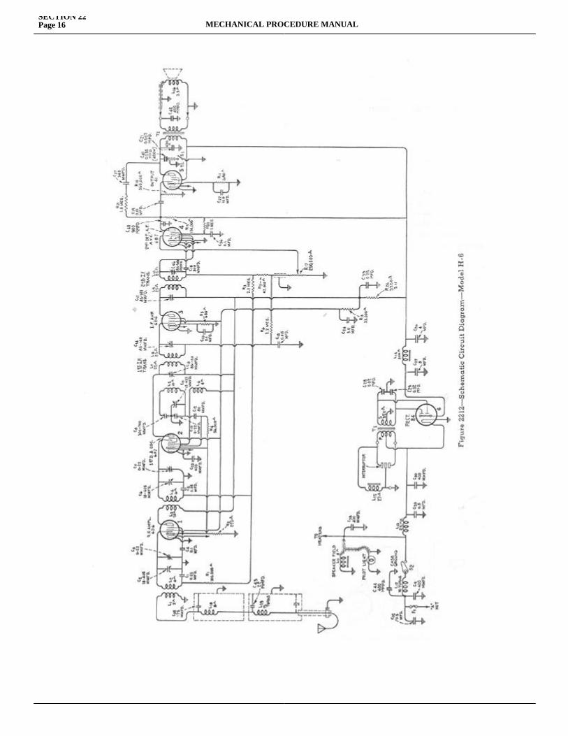
SECTION 22Page 16 MECHANICAL PROCEDURE MANUAL
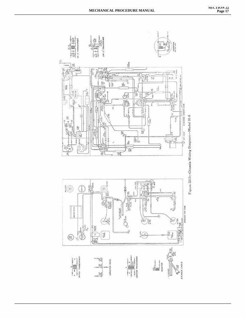
MECHANICAL PROCEDURE MANUALSECTION 22
Page 17
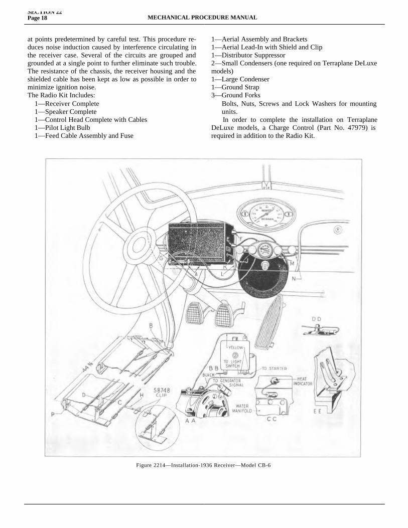
SECTION 22Page 18 MECHANICAL PROCEDURE MANUAL
at points predetermined by careful test. This procedure re-duces noise induction caused by interference circulating in the receiver case. Several of the circuits are grouped and grounded at a single point to further eliminate such trouble. The resistance of the chassis, the receiver housing and the shielded cable has been kept as low as possible in order to minimize ignition noise.The Radio Kit Includes: 1—Receiver Complete 1—Speaker Complete 1—Control Head Complete with Cables 1—Pilot Light Bulb 1—Feed Cable Assembly and Fuse
1—Aerial Assembly and Brackets1—Aerial Lead-In with Shield and Clip1—Distributor Suppressor2—Small Condensers (one required on Terraplane DeLuxe models)1—Large Condenser1—Ground Strap3—Ground Forks Bolts, Nuts, Screws and Lock Washers for mounting units. In order to complete the installation on Terraplane DeLuxe models, a Charge Control (Part No. 47979) is required in addition to the Radio Kit.
Figure 2214—Installation-1936 Receiver—Model CB-6
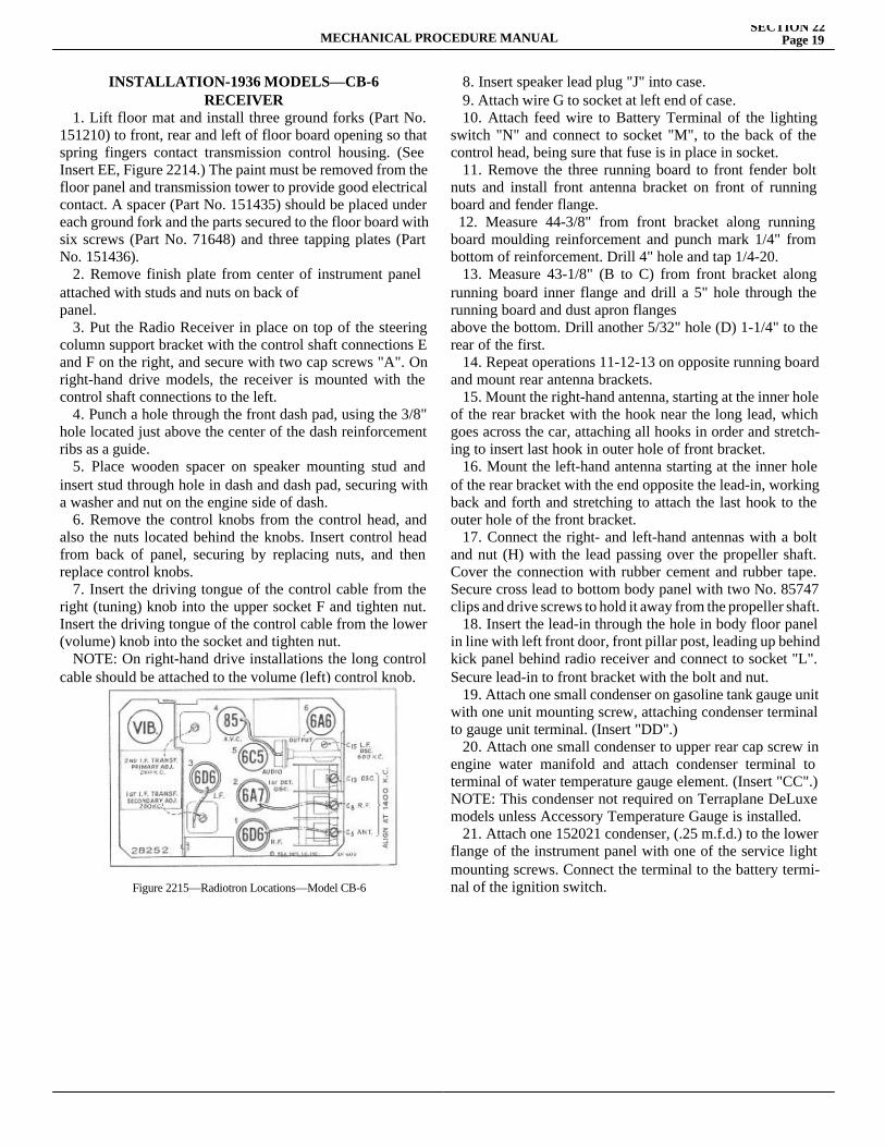
MECHANICAL PROCEDURE MANUALSECTION 22
Page 19
INSTALLATION-1936 MODELS—CB-6RECEIVER
1. Lift floor mat and install three ground forks (Part No. 151210) to front, rear and left of floor board opening so that spring fingers contact transmission control housing. (See Insert EE, Figure 2214.) The paint must be removed from the floor panel and transmission tower to provide good electrical contact. A spacer (Part No. 151435) should be placed under each ground fork and the parts secured to the floor board with six screws (Part No. 71648) and three tapping plates (Part No. 151436). 2. Remove finish plate from center of instrument panel attached with studs and nuts on back ofpanel. 3. Put the Radio Receiver in place on top of the steering column support bracket with the control shaft connections E and F on the right, and secure with two cap screws "A". On right-hand drive models, the receiver is mounted with the control shaft connections to the left. 4. Punch a hole through the front dash pad, using the 3/8" hole located just above the center of the dash reinforcement ribs as a guide. 5. Place wooden spacer on speaker mounting stud and insert stud through hole in dash and dash pad, securing with a washer and nut on the engine side of dash. 6. Remove the control knobs from the control head, and also the nuts located behind the knobs. Insert control head from back of panel, securing by replacing nuts, and then replace control knobs. 7. Insert the driving tongue of the control cable from the right (tuning) knob into the upper socket F and tighten nut. Insert the driving tongue of the control cable from the lower (volume) knob into the socket and tighten nut. NOTE: On right-hand drive installations the long control cable should be attached to the volume (left) control knob.
8. Insert speaker lead plug "J" into case. 9. Attach wire G to socket at left end of case. 10. Attach feed wire to Battery Terminal of the lighting switch "N" and connect to socket "M", to the back of the control head, being sure that fuse is in place in socket. 11. Remove the three running board to front fender bolt nuts and install front antenna bracket on front of running board and fender flange. 12. Measure 44-3/8" from front bracket along running board moulding reinforcement and punch mark 1/4" from bottom of reinforcement. Drill 4" hole and tap 1/4-20. 13. Measure 43-1/8" (B to C) from front bracket along running board inner flange and drill a 5" hole through the running board and dust apron flangesabove the bottom. Drill another 5/32" hole (D) 1-1/4" to the rear of the first. 14. Repeat operations 11-12-13 on opposite running board and mount rear antenna brackets. 15. Mount the right-hand antenna, starting at the inner hole of the rear bracket with the hook near the long lead, which goes across the car, attaching all hooks in order and stretch-ing to insert last hook in outer hole of front bracket. 16. Mount the left-hand antenna starting at the inner hole of the rear bracket with the end opposite the lead-in, working back and forth and stretching to attach the last hook to the outer hole of the front bracket. 17. Connect the right- and left-hand antennas with a bolt and nut (H) with the lead passing over the propeller shaft. Cover the connection with rubber cement and rubber tape. Secure cross lead to bottom body panel with two No. 85747 clips and drive screws to hold it away from the propeller shaft. 18. Insert the lead-in through the hole in body floor panel in line with left front door, front pillar post, leading up behind kick panel behind radio receiver and connect to socket "L". Secure lead-in to front bracket with the bolt and nut. 19. Attach one small condenser on gasoline tank gauge unit with one unit mounting screw, attaching condenser terminal to gauge unit terminal. (Insert "DD".) 20. Attach one small condenser to upper rear cap screw in engine water manifold and attach condenser terminal to terminal of water temperature gauge element. (Insert "CC".) NOTE: This condenser not required on Terraplane DeLuxe models unless Accessory Temperature Gauge is installed. 21. Attach one 152021 condenser, (.25 m.f.d.) to the lower flange of the instrument panel with one of the service light mounting screws. Connect the terminal to the battery termi-nal of the ignition switch.Figure 2215—Radiotron Locations—Model CB-6
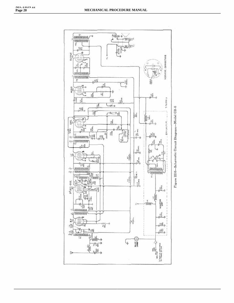
SECTION 22Page 20 MECHANICAL PROCEDURE MANUAL
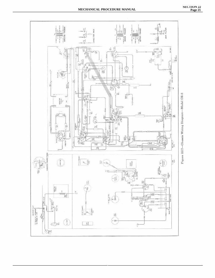
MECHANICAL PROCEDURE MANUALSECTION 22
Page 21
SECTION 22Page 22 MECHANICAL PROCEDURE MANUAL
22. Attach large condenser to cap screw at rear of gener-ator and connect condenser terminal to generator "A" termi-nal. (Insert "AA".) 23. Install 48763 ground strap from the front muffler bracket to chassis frame. The paint must be removed from points of attachment to insure good electrical contact. 24. Install suppressor in central terminal of distributor. 25. When installing radio on Terraplane DeLuxe models with air-cooled generator, mount generator charge regulator in place of relay with two screws to two threaded holes in cowl side panel provided for the purpose. Fuse cap should be on upper face. Remove ground cup from generator "F" terminal. See Figure 2214 inserts for wiring diagram. Con-nect "FLD" terminal on side of charge regulator to "F" terminal (engine side) of generator. Adjust generator output to 22 amps., cold 17 amps., warm. 26. Turn on volume and tune set to a known local station. Adjust the dial hand to give correct dial reading by turning knurled knob on back of control head.
CB6 CIRCUIT ARRANGEMENT The schematic and wiring layouts of the electrical circuit are shown in Figures 2216 and 2217, respectively. From these diagrams it may be seen that six Radiotrons are incor-porated in the basic superheterodyne circuit. In sequence, there is an r-f stage, a dual first detector-oscillator stage, a single i-f stage, a second detector-audio amplifier a.v.c. stage, a driver stage, and a class "B" output stage. The power supply system contains a mechanical interrupter and rectifier. The following circuit features are of particular importance: NOISE FILTER Reduction of ignition inter-ference and similar disturbances are brought about by filter arrangements in the antenna input circuit and the "A" bat-tery input lead. This antenna filter, L-1, C-1, and C-2, is a "low-pass" type, having an acceptance band below 1600 K.C. The inductance L-2 is for the purpose of shunting out power line hum pickup. TUNED CIRCUITS There are seven resonant circuits in the radio frequency end of the receiver. The r-f, first detec-tor, and oscillator grid circuits are tuned by a three-gang tuning condenser. The remaining tuned circuits consist of the primary and secondary windings of the i-f transformers, which resonate with fixed condensers and are tuned by adjustable iron cores to a nominal frequency of 260 kilocy-cles. DETECTION—Detection takes place as a result of the rectifying action of one of the diodes of the RCA-85 tube, the
RCA-85 tube, the current being developed through resis-tors R-20 and R-21. The audio component of this current is coupled through capacitor C-23 to the one megohm volume control R-9. The arm of this volume control is connected to the grid of the RCA-85 tube, thus giving a means of continuously varying the voltage input to the audio amplifier.A.V.C.—The a.v.c. diode of the RCA-85 tube is coupled through capacitor C-25 to the primary of the second i-f transformer. Due to the rectifying action of this diode, a current is developed through resistor R-13. The d-c volt-age drop in this resistor is used for automatically regulat-ing the control grid bias of the r-f, first detector, and i-f stages, the voltage being applied through a suitable filter network. Due to the fact that the a.v.c. diode returns through resistor R-13 to a point which is 15 volts negative with respect to its cathode, the a.v.c. action is delayed until the input signal reaches a predetermined level. This gives more uniform output for widely varying signal strengths into the antenna.AUDIO SYSTEM As mentioned under "De-tection", the audio component of the detected signal is selected from the manual volume control and applied to the control grid of the RCA-85 tube. The plate circuit of this tube is connected through capacitor C-27 to the control grid of the driver tube, an RCA-6C5. The plate circuit of the driver tube is coupled through the driver transformer T-1 to the control grids of the class "B" output tube, RCA-6A6. This tube is coupled through the output transformer T-2 to the loudspeaker.The Radio Kit includes:1—Receiver Complete1—Speaker Complete1—Control Head Complete with Cables1—Pilot Light Bulb1—Feed Cable Assembly and Fuse 1—Aerial Assembly and Brackets1—Aerial Lead-In with Shield and Clip1—Distributor Suppressor2—Small Condensers (one required on Terraplane DeLuxe models)1—Large Condenser1—Ground Strap3—Ground ForksBolts, Nuts, Screws and Lock Washers for mounting units.In order to complete the installation on Terraplane De-Luxe models, a Charge Control is required in addition to the Radio Kit.
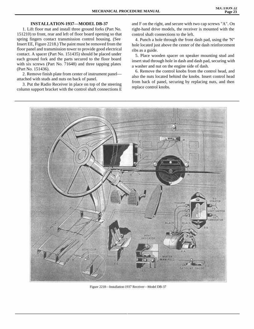
MECHANICAL PROCEDURE MANUALSECTION 22
Page 23
INSTALLATION-1937—MODEL DB-37 1. Lift floor mat and install three ground forks (Part No. 151210) to front, rear and left of floor board opening so that spring fingers contact transmission control housing. (See Insert EE, Figure 2218.) The paint must be removed from the floor panel and transmission tower to provide good electrical contact. A spacer (Part No. 151435) should be placed under each ground fork and the parts secured to the floor board with six screws (Part No. 71648) and three tapping plates (Part No. 151436). 2. Remove finish plate from center of instrument panel—attached with studs and nuts on back of panel. 3. Put the Radio Receiver in place on top of the steering column support bracket with the control shaft connections E
and F on the right, and secure with two cap screws "A". On right-hand drive models, the receiver is mounted with the control shaft connections to the left. 4. Punch a hole through the front dash pad, using the 'N" hole located just above the center of the dash reinforcement ribs as a guide. 5. Place wooden spacer on speaker mounting stud and insert stud through hole in dash and dash pad, securing with a washer and nut on the engine side of dash. 6. Remove the control knobs from the control head, and also the nuts located behind the knobs. Insert control head from back of panel, securing by replacing nuts, and then replace control knobs.
Figure 2218—Installation-1937 Receiver—Model DB-37
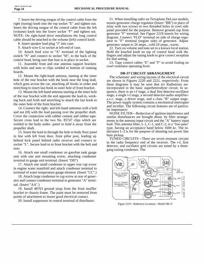
SECTION 22Page 24 MECHANICAL PROCEDURE MANUAL
7. Insert the driving tongue of the control cable from the right (tuning) knob into the top socket "E" and tighten nut. Insert the driving tongue of the control cable from the left (volume) knob into the lower socket "F" and tighten nut. NOTE: On right-hand drive installations the long control cable should be attached to the volume (left) control knob. 8. Insert speaker lead plug "J" into case. 9. Attach wire G to socket at left end of case. 10. Attach feed wire to "X" terminal of the lighting switch "N" and connect to socket "M", to the back of the control head, being sure that fuse is in place in socket. 11. Assemble front and rear antenna support brackets with bolts and nuts to clips welded to bottom of running boards. 12. Mount the right-hand antenna, starting at the inner hole of the rear bracket with the hook near the long lead, which goes across the car, attaching all hooks in order and stretching to insert last hook in outer hole of front bracket. 13. Mount the left-hand antenna starting at the inner hole of the rear bracket with the end opposite the lead-in, work-ing back and forth and stretching to attach the last hook to the outer hole of the front bracket. 14. Connect the right- and left-hand antennas with a bolt and nut (H) with the lead passing over the propeller shaft. Cover the connection with rubber cement and rubber tape. Secure cross lead to the two No. 85747 clips which are welded to the body under- panel to hold it away from the propeller shaft. 15. Insert the lead-in through the hole in body floor panel in line with left front door, front pillar post, leading up behind kick panel behind radio receiver and connect to socket "L". Secure lead-in to front bracket with the bolt and nuts. 16. Attach one small condenser on gasoline tank gauge unit with one unit mounting screw, attaching condenser terminal to gauge unit terminal. (Insert "DD") 17. Attach one small condenser to upper rear cap screw in engine water manifold and attach condenser terminal to terminal of water temperature gauge element. (Insert "CC".) 18. Attach large condenser to cap screw at rear of gener-ator and connect condenser terminal to generator "A" termi-nal. (Insert "AA".) 19. Install 48763 ground strap from the front muffler bracket to chassis frame. The paint must be removed from points of attachment to insure good electrical contact. 20. Install suppressor in central terminal of distributor.
21. When installing radio on Terraplane DeLuxe models, mount generator charge regulator (Insert "BB") in place of relay with two screws to two threaded holes in cowl side panel provided for the purpose. Remove ground cup from generator "F" terminal. See Figure 2218 inserts for wiring diagram. Connect "FLD" terminal on side of charge regu-lator to "F" terminal (engine side) of generator. Adjust generator output to 26 amps., cold-24 amps., warm. 22. Turn on volume and tune set to a known local station. Hold the knurled knob on top of control head with the fingers and adjust the tuning knob to give correct reception for dial setting. 23. Tape control cables "E" and "F" to avoid fouling on cowl ventilator operating lever.
DB-37 CIRCUIT ARRANGEMENT The schematic and wiring layouts of the electrical circuit are shown in Figures 2220 and 2221, respectively. From these diagrams it may be seen that six Radiotrons are incorporated in the basic superheterodyne circuit. In se-quence, there is an r-f stage, a dual first detector-oscillator stage, a single i-f stage, a second detector-audio amplifier-a.v.c. stage, a driver stage, and a class "B" output stage. The power supply system contains a mechanical interrupter and rectifier. The following circuit features are of particu-lar importance: NOISE FILTER—Reduction of ignition interference and similar disturbances are brought about. by filter arrange-ments in the antenna input circuit and the "A" battery input lead. This antenna filter, L-1, C-1, and C-2, is a "low-pass" type, having an acceptance band below 1600 kc. The in-ductance L-2 is for the purpose of shunting out power line hum pickup. TUNED CIRCUITS—There are seven resonant circuits in the radio frequency end of the receiver. The r-f, first detector, and oscillator grid circuits are tuned by a three-gang tuning condenser. The
Figure 2219—Radiotron Locations—Model DB-37
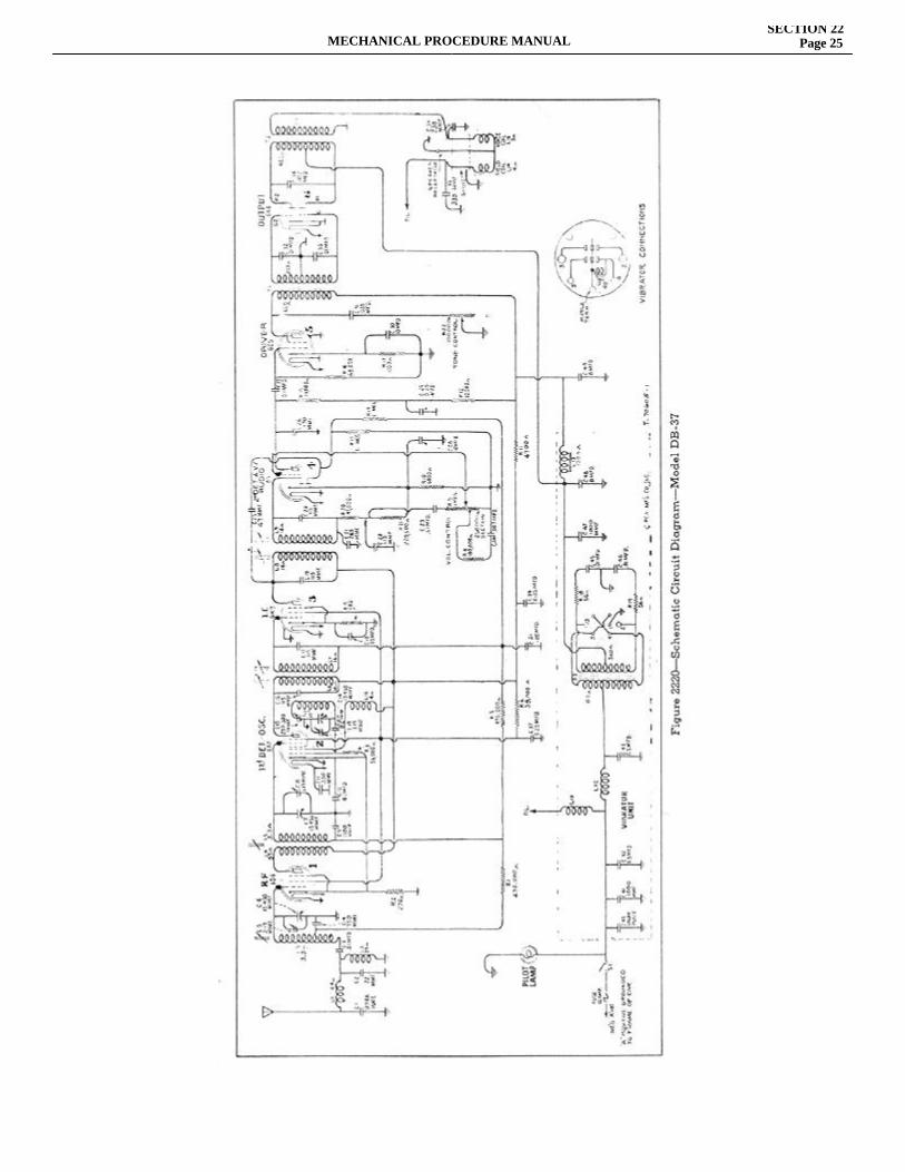
MECHANICAL PROCEDURE MANUALSECTION 22
Page 25
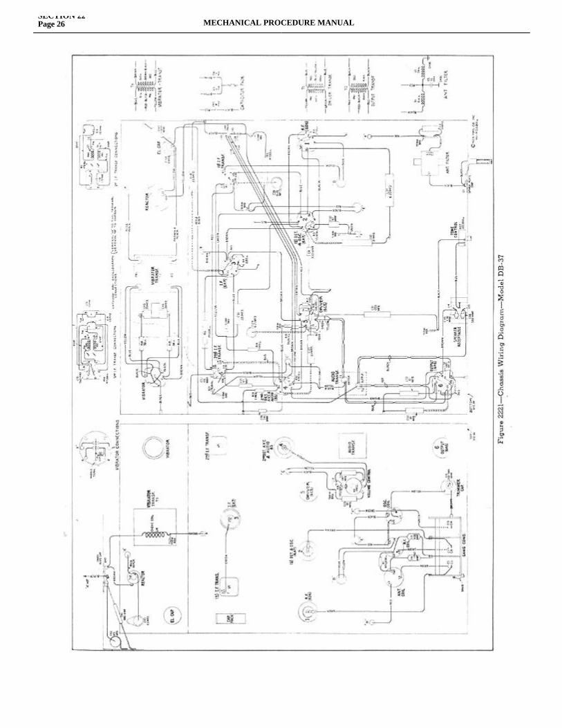
SECTION 22Page 26 MECHANICAL PROCEDURE MANUAL
MECHANICAL PROCEDURE MANUALSECTION 22
Page 27
rprimary and secondary windings of the i-f transformers, which resonate with fixed condensers and are tuned by adjustable magnetic cores to a nominal frequency of 260 kilocycles.
DETECTION Detection takes place as a resultof the rectifying action of one of the diodes of the RCA-85 tube, the voltage being developed across resistors R-20 and R-21. The audio component of this voltage is coupled through capacitor C-23 to the one megohm volume control R-9. The arm of this volume control is connected to the grid of the RCA-85 tube, thus giving a means of continuously varying the voltage input to the audio amplifier.
A.V.C.—The a.v.c. diode of the RCA-85 tube is coupled through capacitor C-25 to the primary of the second i-f transformer. Due to the rectifying action of this diode, a current is developed through resistor R-13. The d-c voltage drop in this resistor is used for automatically regulating the control grid bias of the r-f, first detector, and i-f stages, the voltage being applied through a suitable filter network. Due to the fact that the a.v.c. diode returns through resistor R-13 to a point which is 14 volts negative with respect to its cathode, the a.v.c. action is delayed until the input signal reaches a predetermined level. This gives more uniform output for widely varying signal strengths into the antenna.
AUDIO SYSTEM—As mentioned under "Detection", the audio component of the detected signal is selected from the manual volume control and applied to the control grid of the RCA-85 tube. The plate circuit of this tube is connected through capacitor C-27 to the control grid of the driver tube, an RCA-6C5. The plate circuit of the driver tube is coupled through the driver transformer T-1 to the control grids of the class"B"output tube, RCA-6-A6. This tube is coupled through the output transformer T-2 to the loudspeaker.The Radio Kit Includes: 1—Receiver Complete 1—Control Head Complete with Cables 1—Pilot Light Bulb 1—Feed Cable Assembly and Fuse 1—Aerial Assembly and Brackets 1—Aerial Lead-In with Shield and Clip 1—Distributor Suppressor 2—Small Condensers 1—Large Condenser 1—Ground Strap 3—Ground Forks Bolts, Nuts, Screws and Lock Washers for mounting units.
In order to complete the installation on Terraplane DeLuxe models, a Charge Control is required in addition to the Radio Kit.
RADIO INSTALLATION-1937-MODEL S.A. 37
1. Lift floor mat and install three ground forks (Part No. 151210) to front, rear and left of floor board opening so that spring fingers contact transmission control housing. (See Insert EE, Figure 2222.) The paint must be removed from the floor panel and transmission tower to provide good electrical contact. A spacer (Part No. 151435) should be placed under each ground fork and the parts secured to the floor board with six screws (Part No. 71648) and three tapping plates (Part No. 151436). 2. Remove finish plate from center of instrument panel attached with studs and nuts on back ofpanel. 3. Put the Radio Receiver in place on top of the steering column support bracket with the control shaft connections E and F on the right, and secure with two cap screws "A". On the right-hand drive models, the receiver is mounted with the control shaft connections to the left. A spacer (Part No. 153847) should be placed under the inside or left hand attaching screw head before assembling the screw on right-hand drive installation only. 4. Remove the control knobs from the control head, and also the nuts located behind the knobs. Insert control head from back of panel, securing by replacing nuts, and then replace control knobs. 5. Insert the driving tongue of the control cable from the right (tuning) knob into the front socket "E" and tighten nut. Insert the driving tongue of the control cable from the left (volume) knob into the rear socket "F" and tighten nut. 6. Attach wire (G) to socket at left end of case. 7. Attach feed wire to "X" Terminal of the lighting switch "N" and connect to socket "M", to the control head, being sure that fuse is in place in socket. 8. Assemble front and rear antenna support brackets with bolts and nuts to clips welded to bottom of running boards. 9. Mount the right-hand antenna, starting at the inner hole of the rear bracket with the hook near the long lead, which goes across the car, attaching all hooks in order and stretching to insert last hook in outer hole of front bracket. 10. Mount the left-hand antenna starting at the inner hole of the rear bracket with the end opposite the lead-in, working back and forth and stretching
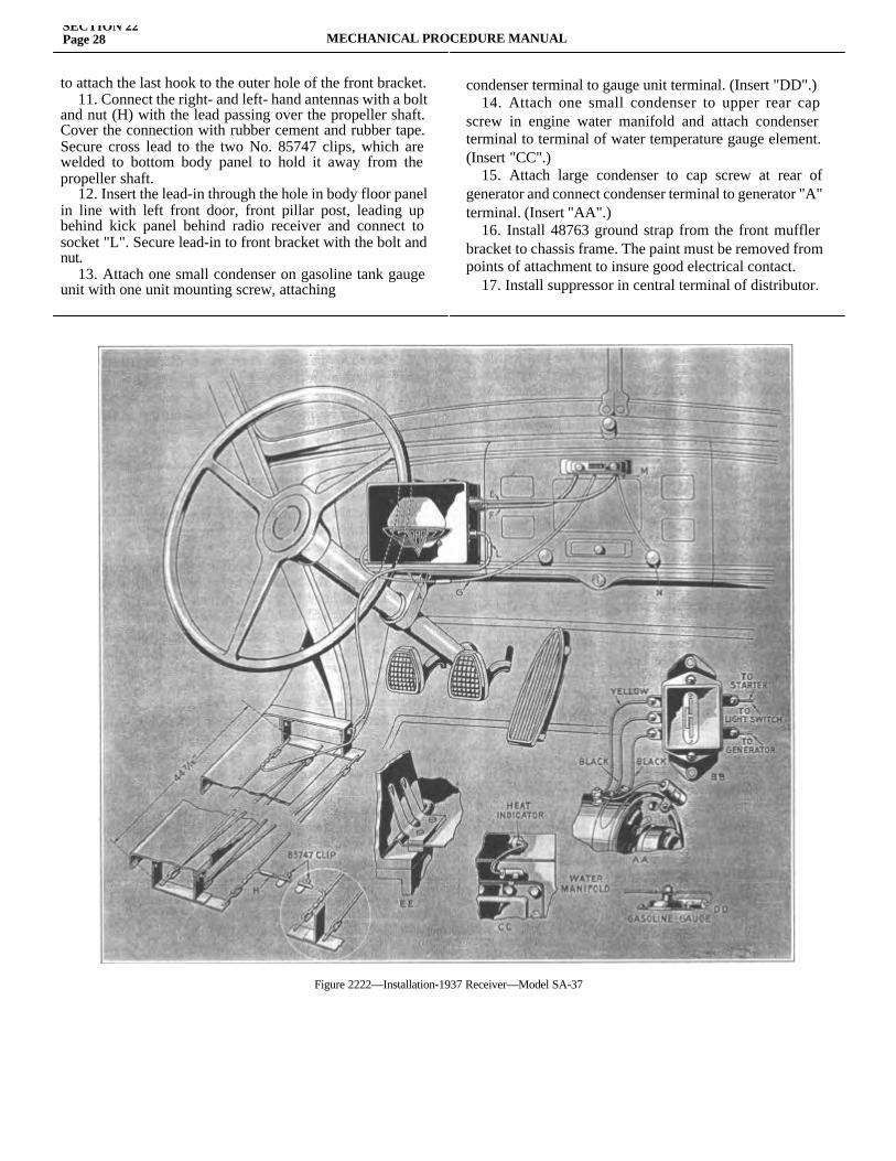
SECTION 22Page 28 MECHANICAL PROCEDURE MANUAL
to attach the last hook to the outer hole of the front bracket. 11. Connect the right- and left- hand antennas with a bolt and nut (H) with the lead passing over the propeller shaft. Cover the connection with rubber cement and rubber tape. Secure cross lead to the two No. 85747 clips, which are welded to bottom body panel to hold it away from the propeller shaft. 12. Insert the lead-in through the hole in body floor panel in line with left front door, front pillar post, leading up behind kick panel behind radio receiver and connect to socket "L". Secure lead-in to front bracket with the bolt and nut. 13. Attach one small condenser on gasoline tank gauge unit with one unit mounting screw, attaching
condenser terminal to gauge unit terminal. (Insert "DD".) 14. Attach one small condenser to upper rear cap screw in engine water manifold and attach condenser terminal to terminal of water temperature gauge element. (Insert "CC".) 15. Attach large condenser to cap screw at rear of generator and connect condenser terminal to generator "A" terminal. (Insert "AA".) 16. Install 48763 ground strap from the front muffler bracket to chassis frame. The paint must be removed from points of attachment to insure good electrical contact. 17. Install suppressor in central terminal of distributor.
Figure 2222—Installation-1937 Receiver—Model SA-37
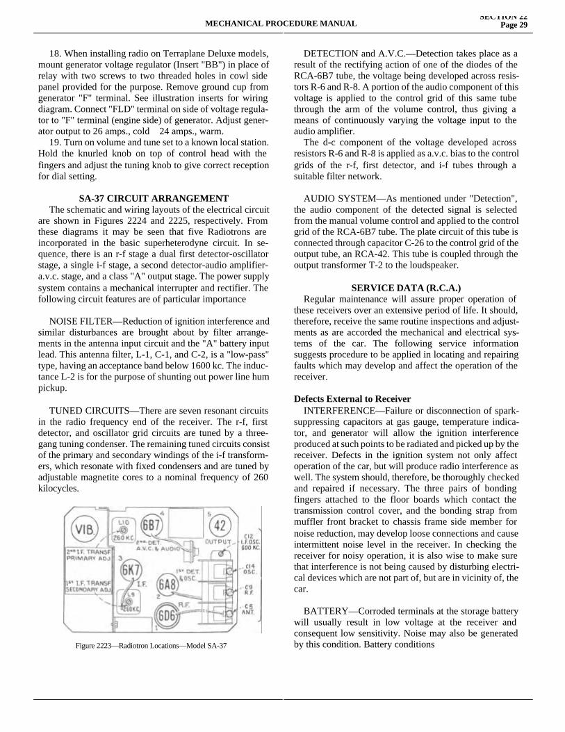
MECHANICAL PROCEDURE MANUALSECTION 22
Page 29
18. When installing radio on Terraplane Deluxe models, mount generator voltage regulator (Insert "BB") in place of relay with two screws to two threaded holes in cowl side panel provided for the purpose. Remove ground cup from generator "F" terminal. See illustration inserts for wiring diagram. Connect "FLD" terminal on side of voltage regula-tor to "F" terminal (engine side) of generator. Adjust gener-ator output to 26 amps., cold 24 amps., warm. 19. Turn on volume and tune set to a known local station. Hold the knurled knob on top of control head with the fingers and adjust the tuning knob to give correct reception for dial setting.
SA-37 CIRCUIT ARRANGEMENT The schematic and wiring layouts of the electrical circuit are shown in Figures 2224 and 2225, respectively. From these diagrams it may be seen that five Radiotrons are incorporated in the basic superheterodyne circuit. In se-quence, there is an r-f stage a dual first detector-oscillator stage, a single i-f stage, a second detector-audio amplifier-a.v.c. stage, and a class "A" output stage. The power supply system contains a mechanical interrupter and rectifier. The following circuit features are of particular importance
NOISE FILTER—Reduction of ignition interference and similar disturbances are brought about by filter arrange-ments in the antenna input circuit and the "A" battery input lead. This antenna filter, L-1, C-1, and C-2, is a "low-pass" type, having an acceptance band below 1600 kc. The induc-tance L-2 is for the purpose of shunting out power line hum pickup.
TUNED CIRCUITS—There are seven resonant circuits in the radio frequency end of the receiver. The r-f, first detector, and oscillator grid circuits are tuned by a three-gang tuning condenser. The remaining tuned circuits consist of the primary and secondary windings of the i-f transform-ers, which resonate with fixed condensers and are tuned by adjustable magnetite cores to a nominal frequency of 260 kilocycles.
DETECTION and A.V.C.—Detection takes place as a result of the rectifying action of one of the diodes of the RCA-6B7 tube, the voltage being developed across resis-tors R-6 and R-8. A portion of the audio component of this voltage is applied to the control grid of this same tube through the arm of the volume control, thus giving a means of continuously varying the voltage input to the audio amplifier. The d-c component of the voltage developed across resistors R-6 and R-8 is applied as a.v.c. bias to the control grids of the r-f, first detector, and i-f tubes through a suitable filter network.
AUDIO SYSTEM—As mentioned under "Detection", the audio component of the detected signal is selected from the manual volume control and applied to the control grid of the RCA-6B7 tube. The plate circuit of this tube is connected through capacitor C-26 to the control grid of the output tube, an RCA-42. This tube is coupled through the output transformer T-2 to the loudspeaker.
SERVICE DATA (R.C.A.) Regular maintenance will assure proper operation of these receivers over an extensive period of life. It should, therefore, receive the same routine inspections and adjust-ments as are accorded the mechanical and electrical sys-tems of the car. The following service information suggests procedure to be applied in locating and repairing faults which may develop and affect the operation of the receiver.
Defects External to Receiver INTERFERENCE—Failure or disconnection of spark-suppressing capacitors at gas gauge, temperature indica-tor, and generator will allow the ignition interference produced at such points to be radiated and picked up by the receiver. Defects in the ignition system not only affect operation of the car, but will produce radio interference as well. The system should, therefore, be thoroughly checked and repaired if necessary. The three pairs of bonding fingers attached to the floor boards which contact the transmission control cover, and the bonding strap from muffler front bracket to chassis frame side member for noise reduction, may develop loose connections and cause intermittent noise level in the receiver. In checking the receiver for noisy operation, it is also wise to make sure that interference is not being caused by disturbing electri-cal devices which are not part of, but are in vicinity of, the car.
BATTERY—Corroded terminals at the storage battery will usually result in low voltage at the receiver and consequent low sensitivity. Noise may also be generated by this condition. Battery conditionsFigure 2223—Radiotron Locations—Model SA-37
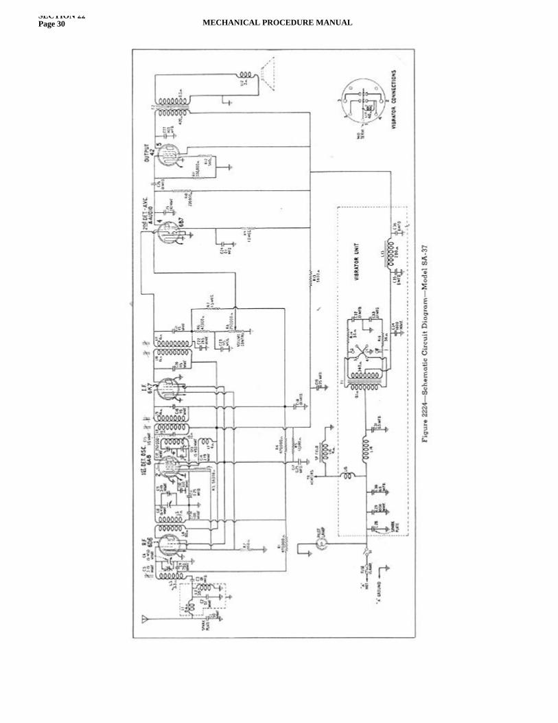
SECTION 22Page 30 MECHANICAL PROCEDURE MANUAL
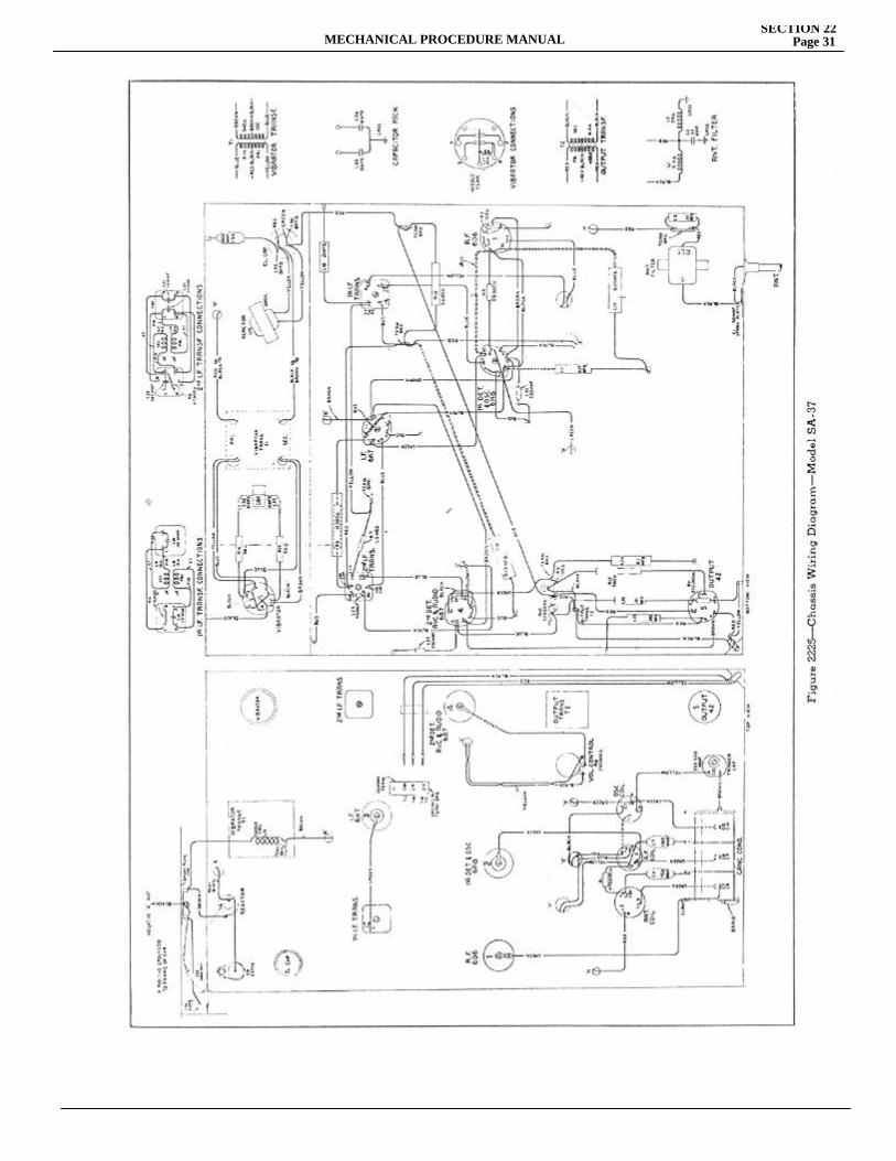
MECHANICAL PROCEDURE MANUALSECTION 22
Page 31
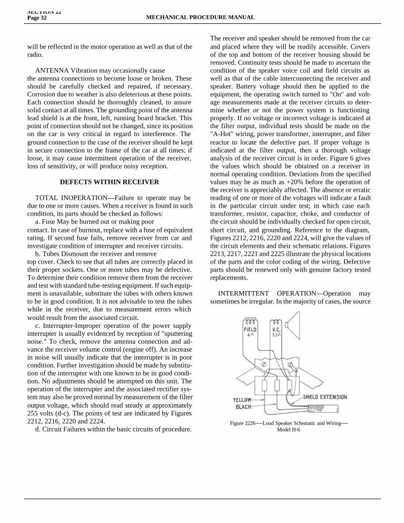
SECTION 22Page 32 MECHANICAL PROCEDURE MANUAL
will be reflected in the motor operation as well as that of the radio.
ANTENNA Vibration may occasionally causethe antenna connections to become loose or broken. These should be carefully checked and repaired, if necessary. Corrosion due to weather is also deleterious at these points. Each connection should be thoroughly cleaned, to assure solid contact at all times. The grounding point of the antenna lead shield is at the front, left, running board bracket. This point of connection should not be changed, since its position on the car is very critical in regard to interference. The ground connection to the case of the receiver should be kept in secure connection to the frame of the car at all times; if loose, it may cause intermittent operation of the receiver, loss of sensitivity, or will produce noisy reception.
DEFECTS WITHIN RECEIVER
TOTAL INOPERATION—Failure to operate may be due to one or more causes. When a receiver is found in such condition, its parts should be checked as follows: a. Fuse May be burned out or making poorcontact. In case of burnout, replace with a fuse of equivalent rating. If second fuse fails, remove receiver from car and investigate condition of interrupter and receiver circuits. b. Tubes Dismount the receiver and removetop cover. Check to see that all tubes are correctly placed in their proper sockets. One or more tubes may be defective. To determine their condition remove them from the receiver and test with standard tube-testing equipment. If such equip-ment is unavailable, substitute the tubes with others known to be in good condition. It is not advisable to test the tubes while in the receiver, due to measurement errors which would result from the associated circuit. c. Interrupter-Improper operation of the power supply interrupter is usually evidenced by reception of "sputtering noise." To check, remove the antenna connection and ad-vance the receiver volume control (engine off). An increase in noise will usually indicate that the interrupter is in poor condition. Further investigation should be made by substitu-tion of the interrupter with one known to be in good condi-tion. No adjustments should be attempted on this unit. The operation of the interrupter and the associated rectifier sys-tem may also be proved normal by measurement of the filter output voltage, which should read steady at approximately 255 volts (d-c). The points of test are indicated by Figures 2212, 2216, 2220 and 2224. d. Circuit Failures within the basic circuits of procedure.
The receiver and speaker should be removed from the car and placed where they will be readily accessible. Covers of the top and bottom of the receiver housing should be removed. Continuity tests should be made to ascertain the condition of the speaker voice coil and field circuits as well as that of the cable interconnecting the receiver and speaker. Battery voltage should then be applied to the equipment, the operating switch turned to "On" and volt-age measurements made at the receiver circuits to deter-mine whether or not the power system is functioning properly. If no voltage or incorrect voltage is indicated at the filter output, individual tests should be made on the "A-Hot" wiring, power transformer, interrupter, and filter reactor to locate the defective part. If proper voltage is indicated at the filter output, then a thorough voltage analysis of the receiver circuit is in order. Figure 6 gives the values which should be obtained on a receiver in normal operating condition. Deviations from the specified values may be as much as +20% before the operation of the receiver is appreciably affected. The absence or erratic reading of one or more of the voltages will indicate a fault in the particular circuit under test; in which case each transformer, resistor, capacitor, choke, and conductor of the circuit should be individually checked for open circuit, short circuit, and grounding. Reference to the diagram, Figures 2212, 2216, 2220 and 2224, will give the values of the circuit elements and their schematic relations. Figures 2213, 2217, 2221 and 2225 illustrate the physical locations of the parts and the color coding of the wiring. Defective parts should be renewed only with genuine factory tested replacements.
INTERMITTENT OPERATION—Operation may sometimes be irregular. In the majority of cases, the source
Figure 2226—Loud Speaker Schematic and Wiring—Model H-6
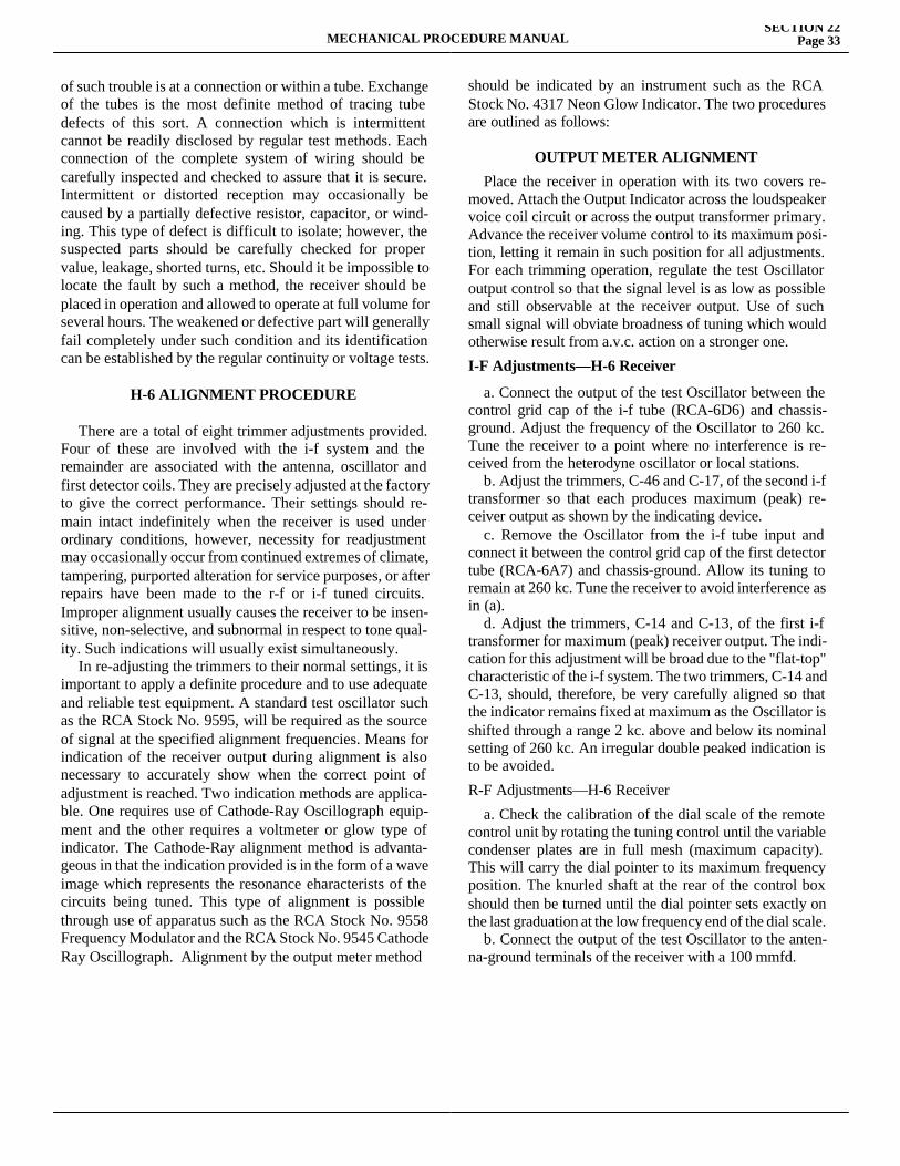
MECHANICAL PROCEDURE MANUALSECTION 22
Page 33
of such trouble is at a connection or within a tube. Exchange of the tubes is the most definite method of tracing tube defects of this sort. A connection which is intermittent cannot be readily disclosed by regular test methods. Each connection of the complete system of wiring should be carefully inspected and checked to assure that it is secure. Intermittent or distorted reception may occasionally be caused by a partially defective resistor, capacitor, or wind-ing. This type of defect is difficult to isolate; however, the suspected parts should be carefully checked for proper value, leakage, shorted turns, etc. Should it be impossible to locate the fault by such a method, the receiver should be placed in operation and allowed to operate at full volume for several hours. The weakened or defective part will generally fail completely under such condition and its identification can be established by the regular continuity or voltage tests.
H-6 ALIGNMENT PROCEDURE
There are a total of eight trimmer adjustments provided. Four of these are involved with the i-f system and the remainder are associated with the antenna, oscillator and first detector coils. They are precisely adjusted at the factory to give the correct performance. Their settings should re-main intact indefinitely when the receiver is used under ordinary conditions, however, necessity for readjustment may occasionally occur from continued extremes of climate, tampering, purported alteration for service purposes, or after repairs have been made to the r-f or i-f tuned circuits. Improper alignment usually causes the receiver to be insen-sitive, non-selective, and subnormal in respect to tone qual-ity. Such indications will usually exist simultaneously. In re-adjusting the trimmers to their normal settings, it is important to apply a definite procedure and to use adequate and reliable test equipment. A standard test oscillator such as the RCA Stock No. 9595, will be required as the source of signal at the specified alignment frequencies. Means for indication of the receiver output during alignment is also necessary to accurately show when the correct point of adjustment is reached. Two indication methods are applica-ble. One requires use of Cathode-Ray Oscillograph equip-ment and the other requires a voltmeter or glow type of indicator. The Cathode-Ray alignment method is advanta-geous in that the indication provided is in the form of a wave image which represents the resonance eharacterists of the circuits being tuned. This type of alignment is possible through use of apparatus such as the RCA Stock No. 9558 Frequency Modulator and the RCA Stock No. 9545 Cathode Ray Oscillograph. Alignment by the output meter method
should be indicated by an instrument such as the RCA Stock No. 4317 Neon Glow Indicator. The two procedures are outlined as follows:
OUTPUT METER ALIGNMENT
Place the receiver in operation with its two covers re-moved. Attach the Output Indicator across the loudspeaker voice coil circuit or across the output transformer primary. Advance the receiver volume control to its maximum posi-tion, letting it remain in such position for all adjustments. For each trimming operation, regulate the test Oscillator output control so that the signal level is as low as possible and still observable at the receiver output. Use of such small signal will obviate broadness of tuning which would otherwise result from a.v.c. action on a stronger one.
I-F Adjustments—H-6 Receiver
a. Connect the output of the test Oscillator between the control grid cap of the i-f tube (RCA-6D6) and chassis-ground. Adjust the frequency of the Oscillator to 260 kc. Tune the receiver to a point where no interference is re-ceived from the heterodyne oscillator or local stations. b. Adjust the trimmers, C-46 and C-17, of the second i-f transformer so that each produces maximum (peak) re-ceiver output as shown by the indicating device. c. Remove the Oscillator from the i-f tube input and connect it between the control grid cap of the first detector tube (RCA-6A7) and chassis-ground. Allow its tuning to remain at 260 kc. Tune the receiver to avoid interference as in (a). d. Adjust the trimmers, C-14 and C-13, of the first i-f transformer for maximum (peak) receiver output. The indi-cation for this adjustment will be broad due to the "flat-top" characteristic of the i-f system. The two trimmers, C-14 and C-13, should, therefore, be very carefully aligned so that the indicator remains fixed at maximum as the Oscillator is shifted through a range 2 kc. above and below its nominal setting of 260 kc. An irregular double peaked indication is to be avoided.
R-F Adjustments—H-6 Receiver
a. Check the calibration of the dial scale of the remote control unit by rotating the tuning control until the variable condenser plates are in full mesh (maximum capacity). This will carry the dial pointer to its maximum frequency position. The knurled shaft at the rear of the control box should then be turned until the dial pointer sets exactly on the last graduation at the low frequency end of the dial scale. b. Connect the output of the test Oscillator to the anten-na-ground terminals of the receiver with a 100 mmfd.
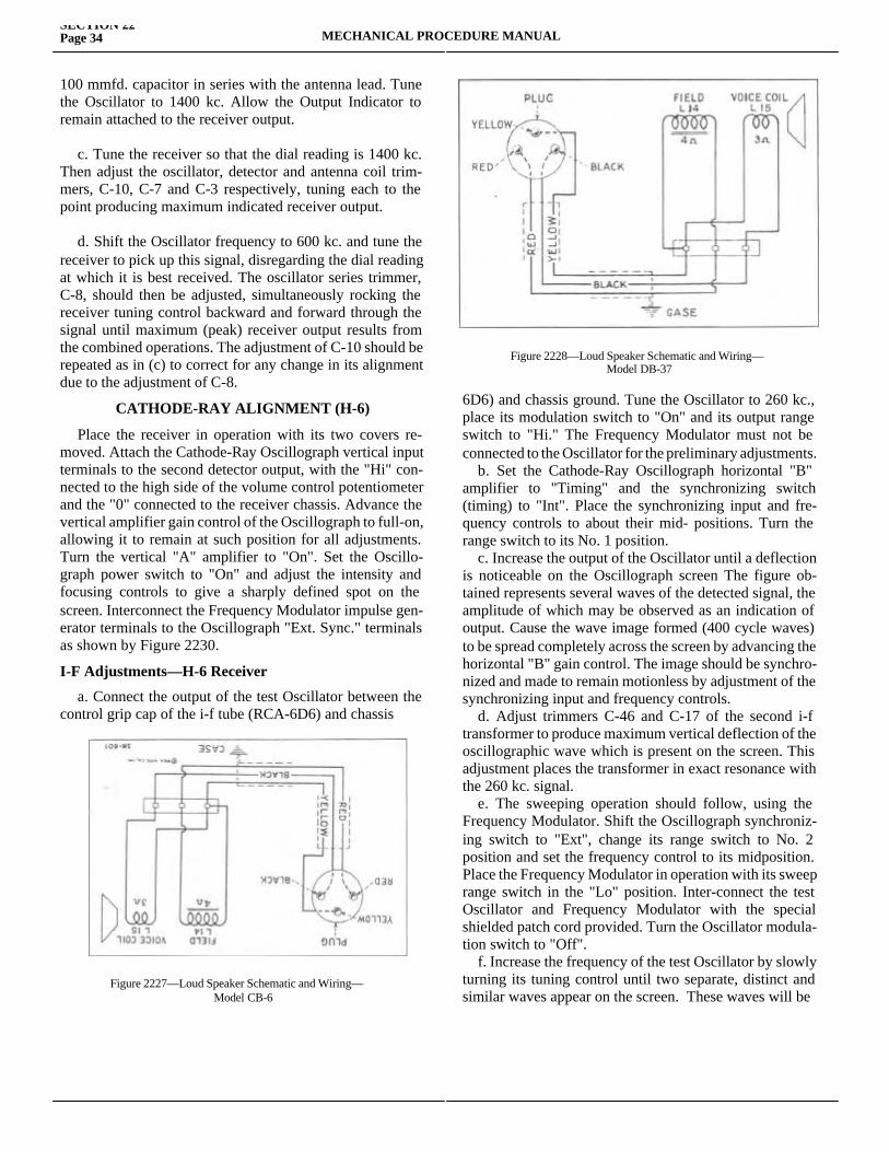
SECTION 22Page 34 MECHANICAL PROCEDURE MANUAL
100 mmfd. capacitor in series with the antenna lead. Tune the Oscillator to 1400 kc. Allow the Output Indicator to remain attached to the receiver output.
c. Tune the receiver so that the dial reading is 1400 kc. Then adjust the oscillator, detector and antenna coil trim-mers, C-10, C-7 and C-3 respectively, tuning each to the point producing maximum indicated receiver output.
d. Shift the Oscillator frequency to 600 kc. and tune the receiver to pick up this signal, disregarding the dial reading at which it is best received. The oscillator series trimmer, C-8, should then be adjusted, simultaneously rocking the receiver tuning control backward and forward through the signal until maximum (peak) receiver output results from the combined operations. The adjustment of C-10 should be repeated as in (c) to correct for any change in its alignment due to the adjustment of C-8.
CATHODE-RAY ALIGNMENT (H-6)
Place the receiver in operation with its two covers re-moved. Attach the Cathode-Ray Oscillograph vertical input terminals to the second detector output, with the "Hi" con-nected to the high side of the volume control potentiometer and the "0" connected to the receiver chassis. Advance the vertical amplifier gain control of the Oscillograph to full-on, allowing it to remain at such position for all adjustments. Turn the vertical "A" amplifier to "On". Set the Oscillo-graph power switch to "On" and adjust the intensity and focusing controls to give a sharply defined spot on the screen. Interconnect the Frequency Modulator impulse gen-erator terminals to the Oscillograph "Ext. Sync." terminals as shown by Figure 2230.
I-F Adjustments—H-6 Receiver
a. Connect the output of the test Oscillator between the control grip cap of the i-f tube (RCA-6D6) and chassis
6D6) and chassis ground. Tune the Oscillator to 260 kc., place its modulation switch to "On" and its output range switch to "Hi." The Frequency Modulator must not be connected to the Oscillator for the preliminary adjustments. b. Set the Cathode-Ray Oscillograph horizontal "B" amplifier to "Timing" and the synchronizing switch (timing) to "Int". Place the synchronizing input and fre-quency controls to about their mid- positions. Turn the range switch to its No. 1 position. c. Increase the output of the Oscillator until a deflection is noticeable on the Oscillograph screen The figure ob-tained represents several waves of the detected signal, the amplitude of which may be observed as an indication of output. Cause the wave image formed (400 cycle waves) to be spread completely across the screen by advancing the horizontal "B" gain control. The image should be synchro-nized and made to remain motionless by adjustment of the synchronizing input and frequency controls. d. Adjust trimmers C-46 and C-17 of the second i-f transformer to produce maximum vertical deflection of the oscillographic wave which is present on the screen. This adjustment places the transformer in exact resonance with the 260 kc. signal. e. The sweeping operation should follow, using the Frequency Modulator. Shift the Oscillograph synchroniz-ing switch to "Ext", change its range switch to No. 2 position and set the frequency control to its midposition. Place the Frequency Modulator in operation with its sweep range switch in the "Lo" position. Inter-connect the test Oscillator and Frequency Modulator with the special shielded patch cord provided. Turn the Oscillator modula-tion switch to "Off". f. Increase the frequency of the test Oscillator by slowly turning its tuning control until two separate, distinct and similar waves appear on the screen. These waves will be
Figure 2227—Loud Speaker Schematic and Wiring—Model CB-6
Figure 2228—Loud Speaker Schematic and Wiring—Model DB-37
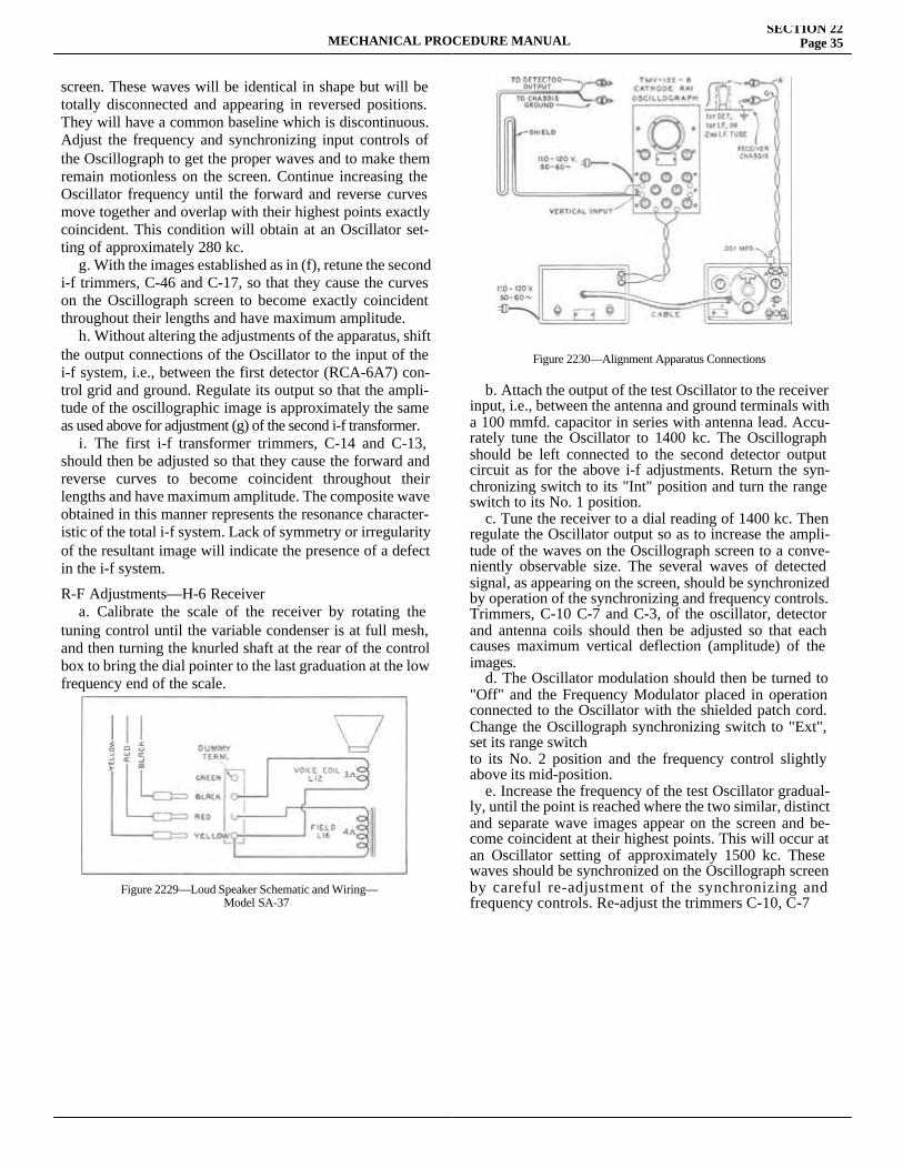
MECHANICAL PROCEDURE MANUALSECTION 22
Page 35
screen. These waves will be identical in shape but will be totally disconnected and appearing in reversed positions. They will have a common baseline which is discontinuous. Adjust the frequency and synchronizing input controls of the Oscillograph to get the proper waves and to make them remain motionless on the screen. Continue increasing the Oscillator frequency until the forward and reverse curves move together and overlap with their highest points exactly coincident. This condition will obtain at an Oscillator set-ting of approximately 280 kc. g. With the images established as in (f), retune the second i-f trimmers, C-46 and C-17, so that they cause the curves on the Oscillograph screen to become exactly coincident throughout their lengths and have maximum amplitude. h. Without altering the adjustments of the apparatus, shift the output connections of the Oscillator to the input of the i-f system, i.e., between the first detector (RCA-6A7) con-trol grid and ground. Regulate its output so that the ampli-tude of the oscillographic image is approximately the same as used above for adjustment (g) of the second i-f transformer. i. The first i-f transformer trimmers, C-14 and C-13, should then be adjusted so that they cause the forward and reverse curves to become coincident throughout their lengths and have maximum amplitude. The composite wave obtained in this manner represents the resonance character-istic of the total i-f system. Lack of symmetry or irregularity of the resultant image will indicate the presence of a defect in the i-f system.
R-F Adjustments—H-6 Receiver a. Calibrate the scale of the receiver by rotating the tuning control until the variable condenser is at full mesh, and then turning the knurled shaft at the rear of the control box to bring the dial pointer to the last graduation at the low frequency end of the scale.
b. Attach the output of the test Oscillator to the receiver input, i.e., between the antenna and ground terminals with a 100 mmfd. capacitor in series with antenna lead. Accu-rately tune the Oscillator to 1400 kc. The Oscillograph should be left connected to the second detector output circuit as for the above i-f adjustments. Return the syn-chronizing switch to its "Int" position and turn the range switch to its No. 1 position. c. Tune the receiver to a dial reading of 1400 kc. Then regulate the Oscillator output so as to increase the ampli-tude of the waves on the Oscillograph screen to a conve-niently observable size. The several waves of detected signal, as appearing on the screen, should be synchronized by operation of the synchronizing and frequency controls. Trimmers, C-10 C-7 and C-3, of the oscillator, detector and antenna coils should then be adjusted so that each causes maximum vertical deflection (amplitude) of the images. d. The Oscillator modulation should then be turned to "Off" and the Frequency Modulator placed in operation connected to the Oscillator with the shielded patch cord. Change the Oscillograph synchronizing switch to "Ext", set its range switchto its No. 2 position and the frequency control slightly above its mid-position. e. Increase the frequency of the test Oscillator gradual-ly, until the point is reached where the two similar, distinct and separate wave images appear on the screen and be-come coincident at their highest points. This will occur at an Oscillator setting of approximately 1500 kc. These waves should be synchronized on the Oscillograph screen by careful re-adjustment of the synchronizing and frequency controls. Re-adjust the trimmers C-10, C-7
Figure 2229—Loud Speaker Schematic and Wiring—Model SA-37
Figure 2230—Alignment Apparatus Connections
SECTION 22Page 36 MECHANICAL PROCEDURE MANUAL
and C-3 to produce complete coincidence at maximum amplitude of the two waves. f. Disconnect the Frequency Modulator from the Oscilla-tor. Switch the modulation switch of the Oscillator to "on" and tune the Oscillator to 600 kc. Set the synchronizing switch of the Oscillograph to "Int" and turn the range switch to No. 1 position. g. Tune the receiver station selector control so as to pick up the 600 kc. signal, disregarding the dial reading at which it is best received. h. Change the Oscillograph synchronizing switch to "Ext" and place the Oscillator modulation switch to "Off". Interconnect the Frequency Modulator and Oscillator with the special shielded patch cord. Return the range control of the Oscillograph to its No. 2 position and set the frequency control slightly above its mid-position. i. Shift the test Oscillator to its 200-400 kc. range and tune it to the point at which the forward and reverse waves show on the Oscillograph screen. This condition will obtain at an Oscillator setting of approximately 230 kc. The signal obtained from the Oscillator for this adjustment will be the third harmonic of 200 kc. An increase in the Oscillator output may be necessary. The trimmer C-8 should then be adjusted to the point which produces maximum amplitude
of the oscillographic images. It will not be necessary to rock the tuning control for this adjustment, inasmuch as the Frequency Modulator is varying the signal in an equiv-alent manner. j. Retune trimmers C-10, C-7 and C-3 as in (c), (d) and (e) to correct for any change in high frequency alignment which may have been caused by the adjustment of C-8.
ALIGNMENT PROCEDURE—RECEIVERMODELS CB-6, DB-37 and SA-37
All of the adjustable circuits of this receiver have been properly aligned at the factory to give correct perfor-mance, and their settings should remain intact indefinitely when the receiver is used under ordinary conditions. How-ever, necessity for readjustment may occasionally occur from continued extremes of climate, tampering, purported alteration for service purposes, or after repairs have been made to the r-f or i-f tuned circuits. Improper alignment usually causes the receiver to be insensitive, non-selective, and subnormal in respect to tone quality. Such indications will usually exist simultaneously.In readjusting the tuning circuits, it is important to apply a definite procedure and to use adequate and reliable test equipment. A standard test oscillator, such as the RCA stock
Figure 2231—Radiotron Socket Voltages—Model H-6
MECHANICAL PROCEDURE MANUALSECTION 22
Page 37
Stock No. 9595, will be required as the source of signal at the specified alignment frequencies. Means for indication of the receiver output during alignment is also necessary to accurately show when the correct point of adjustment is reached. Two indication methods are applicable. One re-quires use of cathode-ray oscillograph equipment, and the other requires a voltmeter or glow type of indicator. The cathode-ray alignment method is advantageous in that the indication provided is in the form of a wave image which represents the resonance characteristics of the circuits being tuned. This type of alignment is possible through use of apparatus such as the RCA Stock No. 9558 Frequency Modulator and the. RCA Stock No. 9545 Cathode Ray Oscillograph. Alignment by the output meter method should be indicated by an instrument such as the RCA Stock No. 4317 Neon Glow Indicator. The two procedures are outlined as follows:
OUTPUT METER ALIGNMENT Place the receiver in operation with its two covers re-moved. Attach the output indicator across the loudspeaker voice coil circuit. Advance the receiver volume control to its maximum position, letting it remain in such position for all adjustments. For each adjusting operation, regulate the test oscillator output control so that the signal level is as low as possible and still observable at the receiver output. Use of such small signal will obviate broadness of tuning which would otherwise result from a.v.c. action on a stronger one.
I-F Adjustments a. Connect the output of the test oscillator to the control grid cap of the i-f tube through a 0.25 mfd. capacitor and connect the ground of the oscillator to the receiver chassis. Adjust the frequency of the oscillator to 260 kc. Tune the receiver to a point
where no interference is received from the heterodyne oscilla-tor or local stations. b. Adjust the two screws (attached to magnetite cores) of the second i-f transformer, one on top and one on bottom, until maximum output is produced by the indicating device. c. Remove the oscillator from the i-f tube input and connect it between the control grid cap of the first detector tube and chassis-ground, using the 0.25 mfd. capacitor as previously. Allow its tuning to remain at 260 kc. Tune the receiver to avoid interference as in (a). d. Adjust the two screws of the first i-f transformer for maximum (peak) receiver output. The indication for this ad-justment will be broad due to the "flat-top" characteristic of the i-f system. The two screws should, therefore, be very carefully adjusted so that the indicator remains fixed at maximum as the oscillator is shifted through a range 2 kc. above and below its normal setting of 260 kc. An irregular double-peaked indica-tion is to be avoided.
R-F Adjustments NOTE: To eliminate vibrator interference, it may be advis-able to replace the bottom cover before making the r-f adjust-ments. a. Check the calibration of the dial scale of the remote control unit by rotating the tuning control until the variable condenser plates are in full mesh (maximum capacity). This will carry the dial scale to its minimum frequency position. The slotted screw-head on the top of the control box should then be turned until the dial scale sets exactly on the last graduation at the low-frequency end of the dial scale. b. Connect the output of the test oscillator to the antenna-ground cable of the receiver with a 300 mmfd. capacitor in series with the antenna lead. If the antenna lead-in is used, the value of this capacitor should be 210 mmfd. Tune the oscillator to 1,400 kc. Allow the output indicator to remain attached to the receiver output.Figure 2232—Radiotron Socket Voltages—Model CB-6
Figure 2233—Radiotron Socket Voltages—Model DB-37
SECTION 22Page 38 MECHANICAL PROCEDURE MANUAL
c. Tune the receiver so that the dial reading is 1,400 kc. Then adjust the oscillator, detector, and antenna coil trim-mers, C-13, C-8 and C-5 respectively, on the CB-6 and DB-37 receivers and trimmers C-14, C-9 and C-5 on SA-37 receivers, tuning each to the point producting maximum indicated receiver output. d. Shift the oscillator frequency to 600 kc. and tune the receiver to pick up this signal, disregarding the dial reading at which it is best received. The oscillator series trimmer, C-15 on the CB-6 and DB-37 and C-12 on the SA-37, should then be adjusted, simultaneously rocking the receiver tuning control backward and forward through the signal until maximum (peak) receiver output results from the com-bined operations. The adjustment of oscillator, detector and antenna coil trimmers should be repeated as in (c) to correct for any change in their alignment due to the adjustment of C-15. NOTE: The antenna coil of the CB-6, DB-37 and SA-37 and the r-f coils of the DB-37 have magnetite cores which are adjusted at the factory for the correct inductance. These adjustments should not be disturbed.
CATHODE-RAY ALIGNMENT(CB-6—DB-37—SA-37)
Attach the cathode-ray oscillograph vertical input termi-nals to the second detector output, with the "Hi" connected to the junction of the two resistors, R-20 and R-21, on the CB-6 and DB-37 and R-6 and R-8 on the SA-37 and the "0" connected to the receiver chassis. Advance the vertical amplifier gain control of the oscillograph to full-on, allow-ing it to remain at such position for all adjustments. Turn the vertical "A" amplifier to "On". Set the oscillograph power switch to "On" and adjust the intensity and focusing controls to give a sharply defined spot on the screen. Interconnect the frequency modulator impulse generator terminals to the oscillograph "Ext. Sync." terminals, as shown by Figure 2230.
I-F Adjustments
a. Connect the output of the test oscillator to the control grid cap of the i-f tube through a 0.25 mfd. capacitor and connect the ground of the oscillator to the receiver chassis. Tune the oscillator to 260 kc, place its modulation switch to "On" and its output range switch to "Hi". The frequency modulator must not be connected to the oscillator for the preliminary adjustments. b. Set the cathode-ray oscillograph horizontal "B" ampli-fier to "Timing" and the synchronizing switch (timing) to "Int". Place the synchronizing input and frequency controls to about their mid-positions. Turn the range switch to its No. 1 position.
c. Increase the output of the oscillator until a deflection is noticeable on the oscillograph screen. The figure ob-tained represents several waves of the detected signal, the amplitude of which may be observed as an indication of output. Case the wave image formed (400-cycle waves) to be spread completely across the screen by advancing the horizontal "B" gain control. The image should be synchro-nized and made to remain motionless by adjustment of the synchronizing input and frequency controls. d. Adjust the two screws (attached to magnetite cores) of the second i-f transformer, one on top and one on bottom, to produce maximum vertical deflection of the oscillographic wave which is present on the screen. This adjustment places the transformer in exact resonance with the 260 kc. signal. e. The sweeping operation should follow using the frequency modulator. Shift the oscillograph synchronizing switch to "Ext.", change its range switch to No. 2 position and set the frequency control to its mid-position. Place the frequency modulator in operation, with its sweep range switch in the "Lo" position. Interconnect the test oscillator and frequency modulator with the special shielded patch cord provided. Turn the oscillator modulation switch to "Off". f. Increase the frequency of the test oscillator by slowly turning its tuning control until two separate, distinct, and similar waves appear on the screen. These waves will be identical in shape, but will be totally disconnected and appearing in reversed position. They will have a common base line, which is discontinuous. Adjust the frequency and synchronizing input controls of the oscillograph to get the proper waves and to make them remain motionless on the screen. Continue increasing the oscillator frequency until the forward and reverse curves move together and overlap, with their highest points exactly coincident. This condition will obtain at an oscillator setting of approxi-mately 360 kc.
Figure 2234—Radiotron Socket Voltages—Model SA-37
MECHANICAL PROCEDURE MANUALSECTION 22
Page 39
g. With the images established as in (f), readjust the two screws on the second i-f transformer so that they cause the curves on the oscillograph screen to become exactly coinci-dent throughout their lengths and have maximum amplitude. h. Without altering the adjustments of the apparatus, shift the output connections of the oscillator to the input of the i-f system, i.e., between the first detector control grid and ground through a 0.25 mfd. capacitor. Regulate its output so that the amplitude of the oscillographic image is approxi-mately the same as used above for adjustment (g) of the second i-f transformer. i. The two first i-f transformer adjustment screws, one on top and one on bottom, should then be adjusted so that they cause the forward and reverse curves to become coincident throughout their lengths and have maximum amplitude. The composite wave obtained in this manner represents the resonance characteristic of the total i-f system. Lack of symmetry or irregularity of the resultant image will indicate the presence of a defect in the i-f system.
R-F Adjustments
a. Calibrate the receiver dial scale by rotating the tuning control until the variable condenser is in full mesh. The slotted screw-head on the top of the control box should then be turned until the dial scale rests exactly on the last gradu-ation at the low-frequency end. b. Attach the output of the test oscillator to the receiver input, i.e., between the antenna-ground cable, with a 300 mmfd. capacitor in series with antenna lead. If the antenna lead-in is used, the value of this capacitor should be 210 mmfd. Accurately tune the oscillator to 1,400 kc. The oscil-lograph should be left connected to the second detector output circuit as for the above i-f adjustments. Return the synchronizing switch to its "Int." position and turn the range switch to its No. 1 position. c. Tune the receiver to a dial reading of 1,400 kc. Adjust trimmers C-13, C-8 and C-5 of the oscillator, detector, and antenna coils of the CB-6 and DB-37 receivers and C-14, C-9 and C-5 of the SA-37 so that each causes maximum vertical deflection (amplitude) of the images. The output of the oscillator should be regulated so that the waves on the oscillograph screen are of a convenient observable size. Adjustment of the synchronizing and frequency controls on the oscillograph will cause the waves to remain motionless on the screen. d. The oscillator modulation should then be turned to "Off" and the frequency modulator placed in operation, connected to the oscillator with the shielded patch cord.
Change the oscillograph synchronizing switch to "Ext.", set its range switch to its No. 2 position and the frequency control slightly above its mid-position. e. Increase the frequency of the test oscillator gradually, until the point is reached where the two similar, distinct, and separate wave images appear on the screen and be-come coincident at their highest points. This will occur at an oscillator setting of approximately 1,500 kc. These waves should be synchronized on the oscillograph screen by careful readjustment of the synchronizing and fre-quency controls. Readjust trimmers, as covered under (c), to produce complete coincidence at maximum amplitude of the two waves. f. Disconnect the frequency modulator from the oscilla-tor. Place the modulation switch of the oscillator to "On" and tune the oscillator to 600 kc. Set the synchronizing switch of the oscillograph to "Int." and turn the range switch to No. 1 position. g. Tune the receiver station selector control so as to pick up the 600 kc. signal, disregarding the dial reading at which it is best received. h. Change the oscillograph synchronizing switch to "Ext." and place the oscillator modulation switch to "Off". Interconnect the frequency modulator and oscillator with the special shielded patch cord. Return the range control of the oscillograph to its No. 2 position and set the frequency control slightly above its mid-position. i. Shift the test oscillator to its 200-400 kc. range and tune it to the point at which the forward and reverse waves show on the oscillograph screen. This condition will be obtained at an oscillator setting of approximately 230 kc. The signal obtained from the oscillator for this adjustment will be the third harmonic of 200 kc. An increase in the oscillator output may be necessary. The trimmer C-15 of the CB-6 and DB-37 and trimmer C-12 of the SA-37 receiver should then be adjusted to the point which pro-duces maximum amplitude of the oscillographic images. It will not be necessary to rock the tuning control for this adjustment, inasmuch as the frequency modulator is vary-ing the Signal in an equivalent manner. j. Retune trimmers as in (c), (d), and (e) to correct for any change in high-frequency alignment which may have been caused by the adjustment of C-15. (C-12 in SA-37 receiver). After the receiver has been replaced in the car, it may be necessary to make a final correction of the dial scale by tuning in a station of known frequency and adjusting the scale by means of the slotted screw-head on the top of the control head.
SECTION 22Page 40 MECHANICAL PROCEDURE MANUAL
TUNING CONDENSER DRIVE Smooth control should be obtained over the entire tuning range of the variable condenser. If irregularity is present, check the action of the gear mechanism for binding or backlash at every point within the tuning range. A bind may be due to improper mesh between the worm gear and the large gears on the condenser shaft. To correct such a condi-tion, loosen the screws holding the gear plate and adjust the mesh of the gears to a position which gives smooth opera-tions. Gear backlash is prevented by the small compression spring between the two large gears on the rotor shaft.
The mechanical interrupter used in the power system is constructed with a plug-in base, so as to be easily removed from the receiver. Its adjustments have been correctly set during manufacture by means of special equipment. In cases of faulty operation of the interrupter, a renewal should be made. The symmetrical plug-in base on this device per, mits the unit to be placed in its socket so as to give correct output voltage polarity on an automobile with either a positive or negative "A" ground. For installation with positive "A" ground, insert vibrator so positive (+) symbol is nearest label on vibrator compartment partition; for negative "A" ground, insert with negative ( — ) symbol nearest label. The 1936 and 1937 Hudsons and Terraplanes have positive (+) battery grounded.
Radiotrons
Deterioration of tubes and their approach to failure is usually evidenced by noisy or intermittent operation, loss of sensitivity, and distorted tone quality. When suspected as faulty, the tubes should be removed from the receiver and checked with standard tube testing apparatus. It is not feasible
feasible to test the tubes while in the receiver, due to measurement inaccuracies which would result from the effects of the circuits.
Receiver Housing The screws holding the receiver chassis to the case must all be in place and tightly installed, inasmuch as they appreciably affect the ground resistance of the assembly and will consequently have a bearing on the amount of ignition noise received.
Radiotron Socket Voltages Operating conditions of the basic circuits of this instru-ment may be determined by measuring the voltages ap-plied to the tube elements. Figure 6 shows the voltage values from the socket contacts to ground and appearing across the heater contacts (H-H). Each value as specified should hold within +20 % when this instrument is nor-mally operative, with all tubes intact and rated voltage applied. Variations in excess of this limit will usually be indicative of trouble. The voltages given on this diagram are actual measured voltages, and are obtained with the voltmeter load in the circuit. To fulfill the conditions under which the d-c voltages were measured requires a 1,000-ohm-per-volt d-c voltme-ter having ranges of 10, 50, 250, and 500 volts. Voltages below 10 volts should be measured on the 10-volt scale; between 10 and 50 on the 50-volt scale; between 50 and 250 on the 250-volt scale, and above 250 on the 500-volt scale. For meters of the 1,000-ohm-per-volt type, but ranges other than above, use the nearest ranges to those specified. If the range is higher the voltage may be higher, if the range is lower the voltage may be lower; either condition depending on the percentage of circuit current drawn by the meter.

SECTION 23SERVICE INFORMATION AND ADJUSTMENTS
Service Magazine—Reference Sheet and Service Bullet in Reference
Bulletin orReference SheetNo. MagazineIssue and Page
Date Subject DETAILS OF INFORMATION
MECHANICAL PROCEDURE MANUAL Page 1

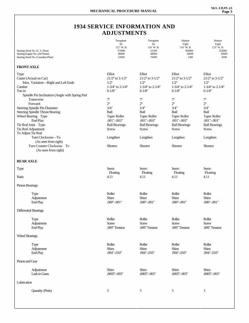
MECHANICAL PROCEDURE MANUALSECTION 23
Page 3
1934 SERVICE INFORMATION ANDADJUSTMENTS
Starting Serial No. (U. S. Plant)Starting Engine No. (All Plants)Starting Serial No. (Canadian Plant)
TerraplaneSix
112" W. B.3730004800052000
TerraplaneSix
116" W. B.215004800076000
Hudson Eight
116" W. B.950000300001300
Hudson Eight
123" W. B.252000
300008100
FRONT AXLE
Type Caster (Actual on Car) Max. Variation—Right and Left Ends Camber Toe-in Spindle Pin Inclination (Angle with Spring Pad Transverse Forward Steering Spindle Pin Diameter Steering Spindle Thrust Bearing Wheel Bearing Type End Play Tie Rod Joint Type Tie Rod Adjustment To Adjust Tie Rod Turn Clockwise—To (As seen from right) Turn Counter Clockwise To (As seen from right)
Elliot21/2° to 3-1/2º1/2º1-3/4° to 2-1/4°0-1/8"
7°2°3/4"BallTaper Roller.001"-.003"Ball BearingsScrew
Lengthen
Shorten
Elliot21/2° to 3-1/2º1/2º1-3/4° to 2-1/4°0-1/8"
7°2°3/4"BallTaper Roller.001"-.003"Ball BearingsScrew
Lengthen
Shorten
Elliot21/2° to 3-1/2º1/2º1-3/4° to 2-1/4°0-1/8"
7°2°3/4"BallTaper Roller.001"-.003"Ball BearingsScrew
Lengthen
Shorten
Elliot21/2° to 3-1/2º1/2º1-3/4° to 2-1/4°0-1/8"
7°2°3/4"BallTaper Roller.001"-.003"Ball BearingsScrew
Lengthen
Shorten
REAR AXLE
Type
Ratio
Pinion Bearings
Type Adjustment End Play
Differential Bearings
Type Adjustment End Play
Wheel Bearings
Type Adjustment End Play
Pinion and Gear
Adjustment Lash in Gears
Lubrication
Quantity (Pints)
Semi- Floating4.11
RollerShim.000"-.001"
RollerScrew.009" Tension
RollerShim.004"-.010"
Shim.0005"-.003"
3
Semi- Floating4.11
RollerShim.000"-.001"
RollerScrew.009" Tension
RollerShim.004"-.010"
Shim.0005"-.003"
3
Semi- Floating4.11
RollerShim.000"-.001"
RollerScrew.009" Tension
RollerShim.004"-.010"
Shim.0005"-.003"
3
Semi- Floating4.11
RollerShim.000"-.001"
RollerScrew.009" Tension
RollerShim.004"-.010"
Shim.0005"-.003"
3
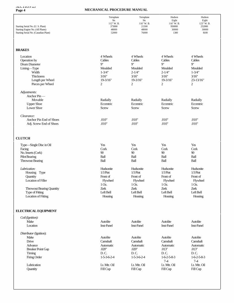
SECTION 23Page 4 MECHANICAL PROCEDURE MANUAL
Starting Serial No. (U. S. Plant)Starting Engine No. (All Plants)Starting Serial No. (Canadian Plant)
TerraplaneSix
112" W. B.3730004800052000
TerraplaneSix
116" W. B.215004800076000
Hudson Eight
116" W. B.95000030000
1300
Hudson Eight
123" W. B.252000300008100
BRAKES
Location Operation by Drum Diameter Lining—Type Width Thickness Length per Wheel Pieces per Wheel
Adjustments: Anchor Pin — Movable Upper Shoe Lower Shoe
Clearance: Anchor Pin End of Shoes Adj. Screw End of Shoes
4 WheelsCables9"Moulded1-3/4"3/16"19-3/16"2
RadiallyEccentricScrew
.010"
.010"
4 WheelsCables9"Moulded2-1/4"3/16"19-3/16"2
RadiallyEccentricScrew
.010"
.010"
4 WheelsCables9"Moulded2-1/4"3/16"19-3/16"2
RadiallyEccentricScrew
.010"
.010"
4 WheelsCables9"Moulded1-3/4"3/16"23-13/16"2
RadiallyEccentricScrew
.010"
.010"
CLUTCH
Type—Single Disc in Oil Facing No. Inserts (Cork) Pilot Bearing Throwout Bearing
Lubrication: Housing Type Quantity Location of Filler
Throwout Bearing Quantity Type of Fitting Location of Fitting
YesCork90BallBall
Hudsonite1/3 PintFront of Flywheel1 Oz.ZerkLeft Bell Housing
YesCork90BallBall
Hudsonite1/3 PintFront of Flywheel1 Oz.ZerkLeft Bell Housing
YesCork90BallBall
Hudsonite1/3 PintFront of Flywheel1 Oz.ZerkLeft Bell Housing
YesCork90BallBall
Hudsonite1/3 PintFront of Flywheel1 Oz.ZerkLeft Bell Housing
ELECTRICAL EQUIPMENT
Coil (Ignition): Make Location
Distributor (Ignition): Make Drive Advance Breaker Point Gap Timing Firing Order
Lubrication Quantity
AutoliteInst-Panel
AutoliteCamshaftAutomatic.020"D. C.1-5-3-6-2-4
Lt. Mtr. OilFill Cup
AutoliteInst-Panel
AutoliteCamshaftAutomatic.020"D. C.1-5-3-6-2-4
Lt. Mtr. OilFill Cup
AutoliteInst-Panel
AutoliteCamshaftAutomatic.013"D. C.1-6-2-5-8-3 7-4Lt. Mtr. OilFill Cup
AutoliteInst-Panel
AutoliteCamshaftAutomatic.013"D. C.1-6-2-5-8-3 7-4Lt. Mtr. OilFill Cup
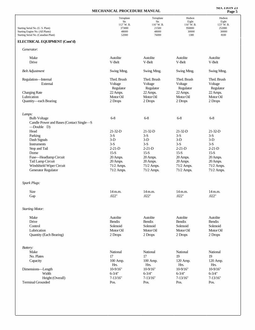
MECHANICAL PROCEDURE MANUALSECTION 23
Page 5
Starting Serial No. (U. S. Plant)Starting Engine No. (All Plants)Starting Serial No. (Canadian Plant)
TerraplaneSix
112" W. B.3730004800052000
TerraplaneSix
116" W. B.215004800076000
Hudson Eight
116" W. B.950000
300001300
Hudson Eight
123" W. B.252000300008100
ELECTRICAL EQUIPMENT (Cont’d)
Generator:
Make Drive
Belt Adjustment
Regulation—Internal External
Charging Rate Lubrication Quantity—each Bearing
Lamps: Bulb Voltage Candle Power and Bases (Contact Single—S —Double D) Head Parking Dash Signals Instruments Stop and Tail Dome Fuse—Headlamp Circuit Tail Lamp Circuit Windshield Wiper Circuit Generator Regulator
Spark Plugs:
Size Gap
Starting Motor:
Make Drive Control Lubrication Quantity (Each Bearing)
Battery: Make No. Plates Capacity
Dimensions—Length Width Height (Overall) Terminal Grounded
AutoliteV-Belt
Swing Mtng.
Thrd. BrushVoltage Regulator22 Amps.Motor Oil2 Drops
6-8
21-32-D3-S3-D3-S2-21-D15-S20 Amps.20 Amps.71/2 Amps.71/2 Amps.
14 m.m..022"
AutoliteBendixSolenoidMotor Oil2 Drops
National17100 Amp. Hrs.10-9/16"6-3/4"7-13/16"Pos.
AutoliteV-Belt
Swing Mtng.
Thrd. BrushVoltage Regulator22 Amps.Motor Oil2 Drops
6-8
21-32-D3-S3-D3-S2-21-D15-S20 Amps.20 Amps.71/2 Amps.71/2 Amps.
14 m.m..022"
AutoliteBendixSolenoidMotor Oil2 Drops
National17100 Amp. Hrs.10-9/16"6-3/4"7-13/16"Pos.
AutoliteV-Belt
Swing Mtng.
Thrd. BrushVoltage Regulator22 Amps.Motor Oil2 Drops
6-8
21-32-D3-S3-D3-S2-21-D15-S20 Amps.20 Amps.71/2 Amps.71/2 Amps.
14 m.m..022"
AutoliteBendixSolenoidMotor Oil2 Drops
National19120 Amp. Hrs.10-9/16"6-3/4"7-13/16"Pos.
AutoliteV-Belt
Swing Mtng.
Thrd. BrushVoltage Regulator22 Amps.Motor Oil2 Drops
6-8
21-32-D3-S3-D3-S2-21-D15-S20 Amps.20 Amps.71/2 Amps.71/2 Amps.
14 m.m..022"
AutoliteBendixSolenoidMotor Oil2 Drops
National19120 Amp. Hrs.10-9/16"6-3/4"7-13/16"Pos.
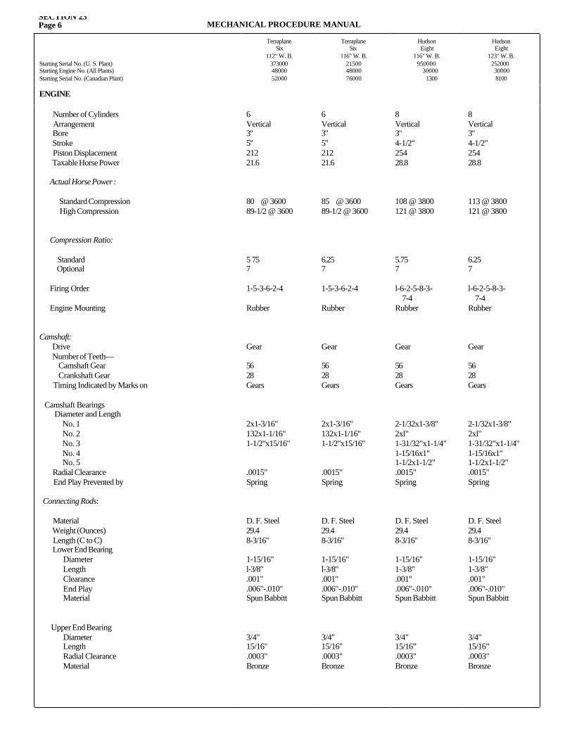
SECTION 23Page 6 MECHANICAL PROCEDURE MANUAL
Starting Serial No. (U. S. Plant)Starting Engine No. (All Plants)Starting Serial No. (Canadian Plant)
TerraplaneSix
112" W. B.3730004800052000
TerraplaneSix
116" W. B.215004800076000
Hudson Eight
116" W. B. 950000
300001300
Hudson Eight
123" W. B.252000300008100
ENGINE
Number of Cylinders Arrangement Bore Stroke Piston Displacement Taxable Horse Power Actual Horse Power :
Standard Compression High Compression
Compression Ratio:
Standard Optional Firing Order
Engine Mounting
Camshaft: Drive Number of Teeth— Camshaft Gear Crankshaft Gear Timing Indicated by Marks on
Camshaft Bearings Diameter and Length No. 1 No. 2 No. 3 No. 4 No. 5 Radial Clearance End Play Prevented by
Connecting Rods:
Material Weight (Ounces) Length (C to C) Lower End Bearing Diameter Length Clearance End Play Material
Upper End Bearing Diameter Length Radial Clearance Material
6Vertical3"5"21221.6
80 @ 360089-1/2 @ 3600
5 757
1-5-3-6-2-4
Rubber
Gear
5628Gears
2x1-3/16"132x1-1/16"1-1/2"x15/16"
.0015"Spring
D. F. Steel29.48-3/16"
1-15/16"l-3/8".001".006"-.010"Spun Babbitt
3/4"15/16".0003"Bronze
6Vertical3"5"21221.6
85 @ 360089-1/2 @ 3600
6.257
1-5-3-6-2-4
Rubber
Gear
5628Gears
2x1-3/16"132x1-1/16"1-1/2"x15/16"
.0015"Spring
D. F. Steel29.48-3/16"
1-15/16"l-3/8".001".006"-.010"Spun Babbitt
3/4"15/16".0003"Bronze
8Vertical3"4-1/2"25428.8
108 @ 3800121 @ 3800
5.757
l-6-2-5-8-3- 7-4Rubber
Gear
5628Gears
2-1/32x1-3/8"2xl"1-31/32"x1-1/4"1-15/16x1"1-1/2x1-1/2".0015"Spring
D. F. Steel29.48-3/16"
1-15/16"1-3/8".001".006"-.010"Spun Babbitt
3/4"15/16”.0003"Bronze
8Vertical3"4-1/2"25428.8
113 @ 3800121 @ 3800
6.257
l-6-2-5-8-3- 7-4Rubber
Gear
5628Gears
2-1/32x1-3/8"2xl"1-31/32"x1-1/4"1-15/16x1"1-1/2x1-1/2".0015"Spring
D. F. Steel29.48-3/16"
1-15/16"1-3/8".001".006"-.010"Spun Babbitt
3/4"15/16”.0003"Bronze
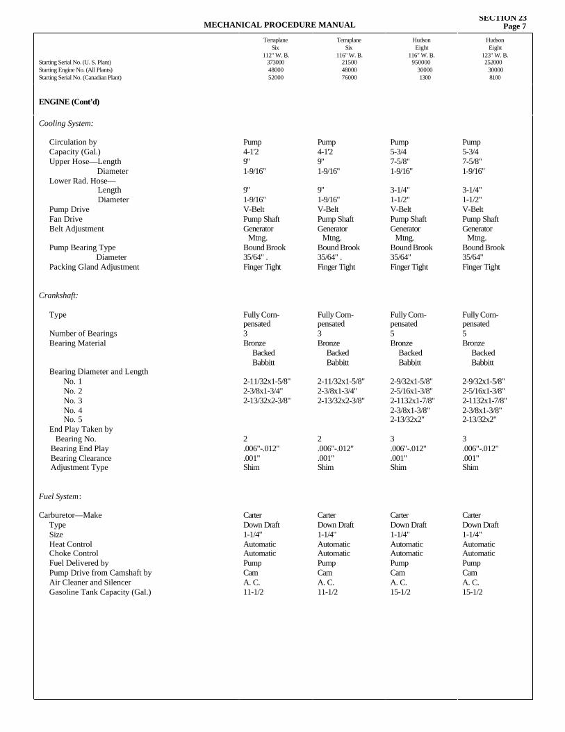
MECHANICAL PROCEDURE MANUALSECTION 23
Page 7
Starting Serial No. (U. S. Plant)Starting Engine No. (All Plants)Starting Serial No. (Canadian Plant)
TerraplaneSix
112" W. B.3730004800052000
TerraplaneSix
116" W. B.215004800076000
Hudson Eight
116" W. B. 950000
300001300
Hudson Eight
123" W. B.252000
300008100
ENGINE (Cont’d)
Cooling System:
Circulation by Capacity (Gal.) Upper Hose—Length Diameter Lower Rad. Hose— Length Diameter Pump Drive Fan Drive Belt Adjustment
Pump Bearing Type Diameter Packing Gland Adjustment
Crankshaft:
Type
Number of Bearings Bearing Material
Bearing Diameter and Length No. 1 No. 2 No. 3 No. 4 No. 5
End Play Taken by Bearing No.
Bearing End Play Bearing Clearance Adjustment Type
Fuel System:
Carburetor—Make Type Size Heat Control Choke Control Fuel Delivered by Pump Drive from Camshaft byAir Cleaner and Silencer Gasoline Tank Capacity (Gal.)
Pump4-1'29"1-9/16"
9"1-9/16"V-BeltPump ShaftGenerator Mtng.Bound Brook35/64" .Finger Tight
Fully Corn-pensated3Bronze Backed Babbitt
2-11/32x1-5/8"2-3/8x1-3/4"2-13/32x2-3/8"
2.006"-.012".001"Shim
CarterDown Draft1-1/4" AutomaticAutomaticPumpCamA. C.11-1/2
Pump4-1'29"1-9/16"
9"1-9/16"V-BeltPump ShaftGenerator Mtng.Bound Brook35/64" .Finger Tight
Fully Corn-pensated3Bronze Backed Babbitt
2-11/32x1-5/8"2-3/8x1-3/4"2-13/32x2-3/8"
2.006"-.012".001"Shim
CarterDown Draft1-1/4" AutomaticAutomaticPumpCamA. C.11-1/2
Pump5-3/47-5/8"1-9/16"
3-1/4"1-1/2"V-BeltPump ShaftGenerator Mtng.Bound Brook35/64"Finger Tight
Fully Corn-pensated5Bronze Backed Babbitt
2-9/32x1-5/8"2-5/16x1-3/8"2-1132x1-7/8"2-3/8x1-3/8"2-13/32x2"
3.006"-.012".001"Shim
CarterDown Draft1-1/4"AutomaticAutomaticPumpCamA. C.15-1/2
Pump5-3/47-5/8"1-9/16"
3-1/4"1-1/2"V-BeltPump ShaftGenerator Mtng.Bound Brook35/64"Finger Tight
Fully Corn-pensated5Bronze Backed Babbitt
2-9/32x1-5/8"2-5/16x1-3/8"2-1132x1-7/8"2-3/8x1-3/8"2-13/32x2"
3.006"-.012".001"Shim
CarterDown Draft1-1/4"AutomaticAutomaticPumpCamA. C.15-1/2
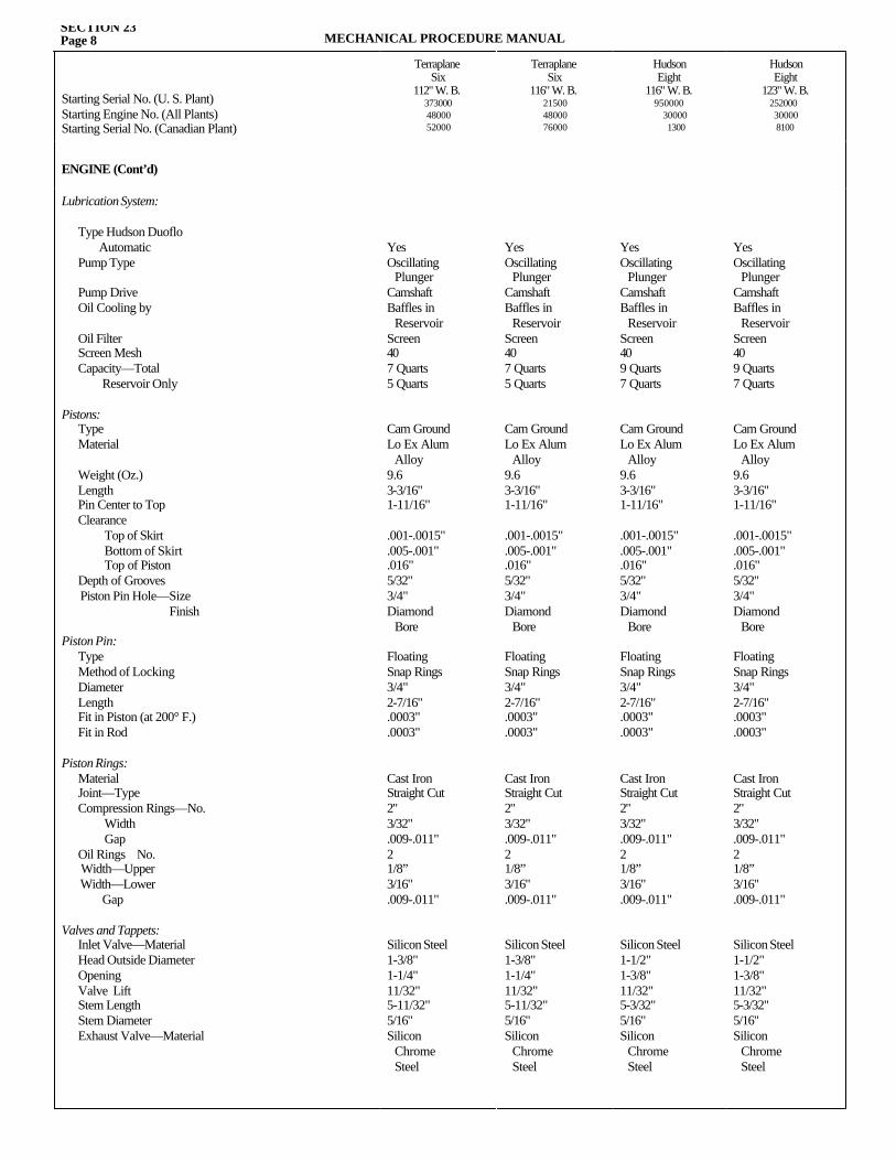
SECTION 23Page 8 MECHANICAL PROCEDURE MANUAL
Starting Serial No. (U. S. Plant)Starting Engine No. (All Plants)Starting Serial No. (Canadian Plant)
TerraplaneSix
112" W. B.3730004800052000
TerraplaneSix
116" W. B.215004800076000
Hudson Eight
116" W. B. 950000
300001300
Hudson Eight
123" W. B.252000300008100
ENGINE (Cont’d)
Lubrication System:
Type Hudson Duoflo Automatic Pump Type
Pump Drive Oil Cooling by
Oil Filter Screen Mesh Capacity—Total Reservoir Only
Pistons: Type Material
Weight (Oz.) Length Pin Center to Top Clearance Top of Skirt Bottom of Skirt Top of Piston Depth of Grooves Piston Pin Hole—Size Finish
Piston Pin: Type Method of Locking Diameter Length Fit in Piston (at 200° F.) Fit in Rod
Piston Rings: Material Joint—Type Compression Rings—No. Width Gap Oil Rings No. Width—Upper Width—Lower Gap
Valves and Tappets: Inlet Valve—Material Head Outside Diameter Opening Valve Lift Stem Length Stem Diameter Exhaust Valve—Material
YesOscillating PlungerCamshaftBaffles in ReservoirScreen407 Quarts5 Quarts
Cam GroundLo Ex Alum Alloy9.63-3/16"1-11/16"
.001-.0015"
.005-.001"
.016"5/32"3/4"Diamond Bore
FloatingSnap Rings3/4"2-7/16".0003".0003"
Cast IronStraight Cut2"3/32".009-.011"21/8”3/16".009-.011"
Silicon Steel1-3/8"1-1/4"11/32"5-11/32"5/16"Silicon Chrome Steel
YesOscillating PlungerCamshaftBaffles in ReservoirScreen409 Quarts7 Quarts
Cam GroundLo Ex Alum Alloy9.63-3/16"1-11/16"
.001-.0015"
.005-.001"
.016"5/32"3/4"Diamond Bore
FloatingSnap Rings3/4"2-7/16".0003".0003"
Cast IronStraight Cut2"3/32".009-.011"21/8”3/16".009-.011"
Silicon Steel1-1/2"1-3/8"11/32"5-3/32"5/16"Silicon Chrome Steel
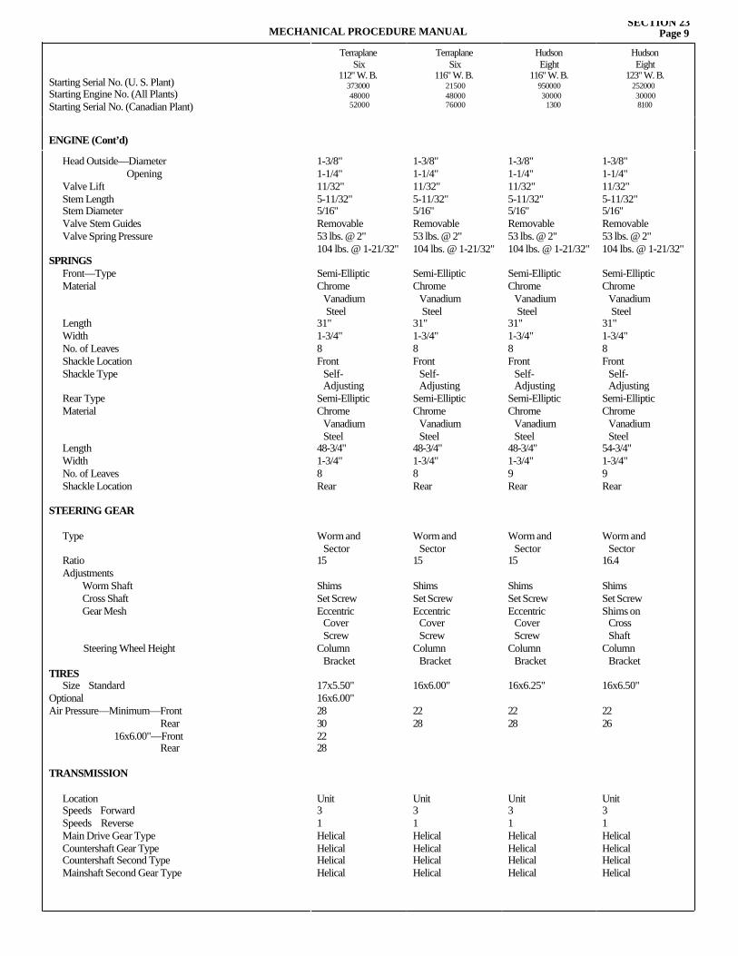
MECHANICAL PROCEDURE MANUALSECTION 23
Page 9
Starting Serial No. (U. S. Plant)Starting Engine No. (All Plants)Starting Serial No. (Canadian Plant)
TerraplaneSix
112" W. B.3730004800052000
TerraplaneSix
116" W. B.215004800076000
Hudson Eight
116" W. B.95000030000
1300
Hudson Eight
123" W. B.252000300008100
ENGINE (Cont’d)
Head Outside—Diameter Opening Valve Lift Stem Length Stem Diameter Valve Stem Guides Valve Spring Pressure
SPRINGS Front—Type Material
Length Width No. of Leaves Shackle Location Shackle Type
Rear Type Material
Length Width No. of Leaves Shackle Location
STEERING GEAR
Type
Ratio Adjustments Worm Shaft Cross Shaft Gear Mesh
Steering Wheel Height
TIRES Size Standard Optional Air Pressure—Minimum—Front Rear 16x6.00"—Front Rear
TRANSMISSION
Location Speeds Forward Speeds Reverse Main Drive Gear Type Countershaft Gear Type Countershaft Second Type Mainshaft Second Gear Type
1-3/8"1-1/4"11/32"5-11/32"5/16"Removable53 lbs. @ 2"104 lbs. @ 1-21/32"
Semi-EllipticChrome Vanadium Steel31"1-3/4"8Front Self- AdjustingSemi-EllipticChrome Vanadium Steel48-3/4"1-3/4"8Rear
Worm and Sector15
ShimsSet ScrewEccentric Cover ScrewColumn Bracket
17x5.50"16x6.00"28302228
Unit31HelicalHelicalHelicalHelical
1-3/8"1-1/4"11/32"5-11/32"5/16"Removable53 lbs. @ 2"104 lbs. @ 1-21/32"
Semi-EllipticChrome Vanadium Steel31"1-3/4"8Front Self- AdjustingSemi-EllipticChrome Vanadium Steel48-3/4"1-3/4"8Rear
Worm and Sector15
ShimsSet ScrewEccentric Cover ScrewColumn Bracket
16x6.00"
2228
Unit31HelicalHelicalHelicalHelical
1-3/8"1-1/4"11/32"5-11/32"5/16"Removable53 lbs. @ 2"104 lbs. @ 1-21/32"
Semi-EllipticChrome Vanadium Steel31"1-3/4"8Front Self- AdjustingSemi-EllipticChrome Vanadium Steel48-3/4"1-3/4"9Rear
Worm and Sector15
ShimsSet ScrewEccentric Cover ScrewColumn Bracket
16x6.25"
2228
Unit31HelicalHelicalHelicalHelical
1-3/8"1-1/4"11/32"5-11/32"5/16"Removable53 lbs. @ 2"104 lbs. @ 1-21/32"
Semi-EllipticChrome Vanadium Steel31"1-3/4"8Front Self- AdjustingSemi-EllipticChrome Vanadium Steel54-3/4"1-3/4"9Rear
Worm and Sector16.4
ShimsSet ScrewShims on Cross ShaftColumn Bracket
16x6.50"
2226
Unit31HelicalHelicalHelicalHelical
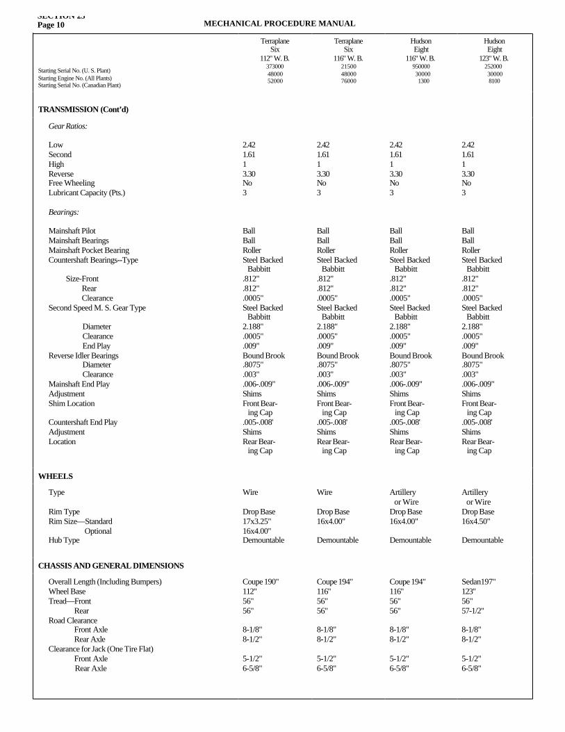
SECTION 23Page 10 MECHANICAL PROCEDURE MANUAL
Starting Serial No. (U. S. Plant)Starting Engine No. (All Plants)Starting Serial No. (Canadian Plant)
TerraplaneSix
112" W. B.3730004800052000
TerraplaneSix
116" W. B.215004800076000
Hudson Eight
116" W. B.950000300001300
Hudson Eight
123" W. B.252000300008100
TRANSMISSION (Cont’d)
Gear Ratios:
Low Second High Reverse Free Wheeling Lubricant Capacity (Pts.)
Bearings:
Mainshaft Pilot Mainshaft Bearings Mainshaft Pocket Bearing Countershaft Bearings--Type
Size-Front Rear Clearance Second Speed M. S. Gear Type
Diameter Clearance End Play
Reverse Idler Bearings Diameter Clearance
Mainshaft End Play Adjustment Shim Location
Countershaft End Play Adjustment Location
2.421.6113.30No3
BallBallRollerSteel Backed Babbitt.812".812".0005"Steel Backed Babbitt2.188".0005".009"Bound Brook.8075".003".006-.009"ShimsFront Bear- ing Cap.005-.008'ShimsRear Bear- ing Cap
2.421.6113.30No3
BallBallRollerSteel Backed Babbitt.812".812".0005"Steel Backed Babbitt2.188".0005".009"Bound Brook.8075".003".006-.009"ShimsFront Bear- ing Cap.005-.008'ShimsRear Bear- ing Cap
2.421.6113.30No3
BallBallRollerSteel Backed Babbitt.812".812".0005"Steel Backed Babbitt2.188".0005".009"Bound Brook.8075".003".006-.009"ShimsFront Bear- ing Cap.005-.008'ShimsRear Bear- ing Cap
2.421.6113.30No3
BallBallRollerSteel Backed Babbitt.812".812".0005"Steel Backed Babbitt2.188".0005".009"Bound Brook.8075".003".006-.009"ShimsFront Bear- ing Cap.005-.008'ShimsRear Bear- ing Cap
WHEELS
Type
Rim Type Rim Size—Standard Optional
Hub Type
Wire
Drop Base17x3.25"16x4.00"Demountable
Wire
Drop Base16x4.00"
Demountable
Artillery or WireDrop Base16x4.00"
Demountable
Artillery or WireDrop Base16x4.50"
Demountable
CHASSIS AND GENERAL DIMENSIONS
Overall Length (Including Bumpers)Wheel Base Tread—Front Rear Road Clearance Front Axle Rear Axle Clearance for Jack (One Tire Flat) Front Axle
Rear Axle
Coupe 190"112"56"56"
8-1/8"8-1/2"
5-1/2"6-5/8"
Coupe 194"116"56"56"
8-1/8"8-1/2"
5-1/2"6-5/8"
Coupe 194"116"56"56"
8-1/8"8-1/2"
5-1/2"6-5/8"
Sedan197"123"56"57-1/2"
8-1/8"8-1/2"
5-1/2"6-5/8"
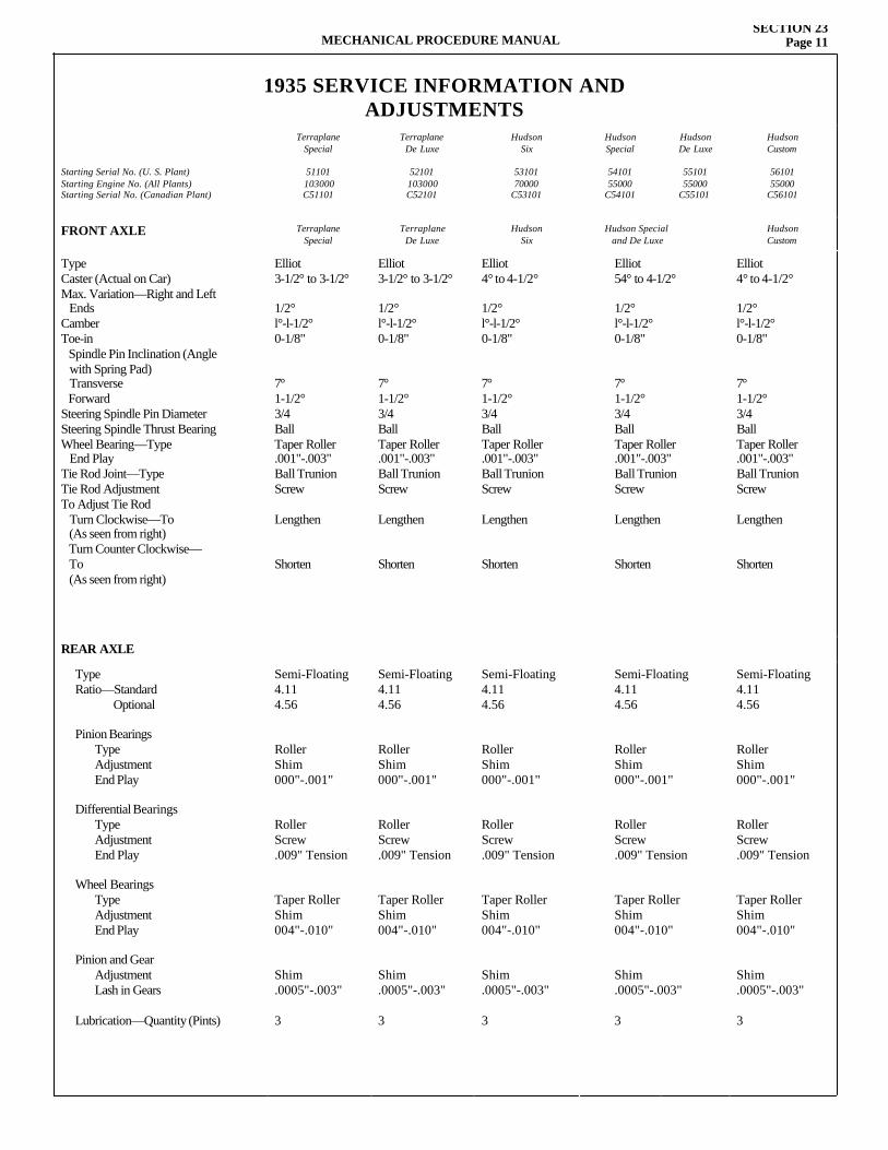
MECHANICAL PROCEDURE MANUALSECTION 23
Page 11
1935 SERVICE INFORMATION ANDADJUSTMENTS
Starting Serial No. (U. S. Plant)Starting Engine No. (All Plants)Starting Serial No. (Canadian Plant)
TerraplaneSpecial
51101103000C51101
TerraplaneDe Luxe
52101103000C52101
HudsonSix
5310170000
C53101
HudsonSpecial
5410155000
C54101
HudsonDe Luxe
5510155000
C55101
HudsonCustom
5610155000
C56101
FRONT AXLE TerraplaneSpecial
Terraplane De Luxe
HudsonSix
Hudson Special and De Luxe
HudsonCustom
Type Caster (Actual on Car) Max. Variation—Right and Left Ends Camber Toe-in Spindle Pin Inclination (Angle with Spring Pad) Transverse Forward Steering Spindle Pin Diameter Steering Spindle Thrust Bearing Wheel Bearing—Type End Play Tie Rod Joint—Type Tie Rod Adjustment To Adjust Tie Rod Turn Clockwise—To (As seen from right) Turn Counter Clockwise— To (As seen from right)
Elliot3-1/2° to 3-1/2°
1/2°l°-l-1/2°0-1/8"
7°1-1/2°3/4BallTaper Roller.001"-.003"Ball TrunionScrew
Lengthen
Shorten
Elliot3-1/2° to 3-1/2°
1/2°l°-l-1/2°0-1/8"
7°1-1/2°3/4BallTaper Roller.001"-.003"Ball TrunionScrew
Lengthen
Shorten
Elliot4° to 4-1/2°
1/2°l°-l-1/2°0-1/8"
7°1-1/2°3/4BallTaper Roller.001"-.003"Ball TrunionScrew
Lengthen
Shorten
Elliot54° to 4-1/2°
1/2°l°-l-1/2°0-1/8"
7°1-1/2°3/4BallTaper Roller.001"-.003"Ball TrunionScrew
Lengthen
Shorten
Elliot4° to 4-1/2°
1/2°l°-l-1/2°0-1/8"
7°1-1/2°3/4BallTaper Roller.001"-.003"Ball TrunionScrew
Lengthen
Shorten
REAR AXLE
Type Ratio—Standard Optional
Pinion Bearings Type Adjustment End Play
Differential Bearings Type Adjustment End Play
Wheel Bearings Type Adjustment End Play
Pinion and Gear Adjustment Lash in Gears
Lubrication—Quantity (Pints)
Semi-Floating4.114.56
RollerShim000"-.001"
RollerScrew.009" Tension
Taper RollerShim004"-.010"
Shim.0005"-.003"
3
Semi-Floating4.114.56
RollerShim000"-.001"
RollerScrew.009" Tension
Taper RollerShim004"-.010"
Shim.0005"-.003"
3
Semi-Floating4.114.56
RollerShim000"-.001"
RollerScrew.009" Tension
Taper RollerShim004"-.010"
Shim.0005"-.003"
3
Semi-Floating4.114.56
RollerShim000"-.001"
RollerScrew.009" Tension
Taper RollerShim004"-.010"
Shim.0005"-.003"
3
Semi-Floating4.114.56
RollerShim000"-.001"
RollerScrew.009" Tension
Taper RollerShim004"-.010"
Shim.0005"-.003"
3
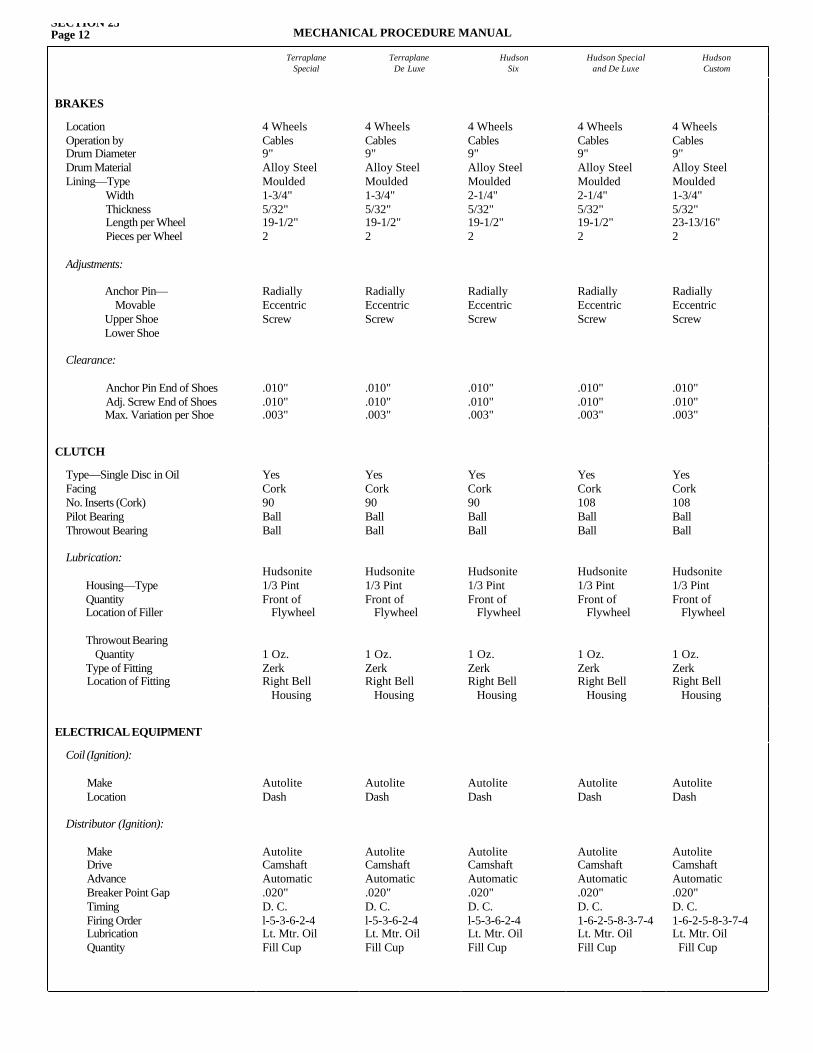
SECTION 23Page 12 MECHANICAL PROCEDURE MANUAL
TerraplaneSpecial
TerraplaneDe Luxe
HudsonSix
Hudson Specialand De Luxe
HudsonCustom
BRAKES
Location Operation by Drum Diameter Drum Material Lining—Type Width Thickness Length per Wheel Pieces per Wheel
Adjustments:
Anchor Pin— Movable Upper Shoe Lower Shoe
Clearance:
Anchor Pin End of ShoesAdj. Screw End of ShoesMax. Variation per Shoe
4 WheelsCables9"Alloy SteelMoulded1-3/4"5/32" 19-1/2"2
RadiallyEccentricScrew
.010"
.010"
.003"
4 WheelsCables9"Alloy SteelMoulded1-3/4"5/32" 19-1/2"2
RadiallyEccentricScrew
.010"
.010"
.003"
4 WheelsCables9"Alloy SteelMoulded2-1/4"5/32" 19-1/2"2
RadiallyEccentricScrew
.010"
.010"
.003"
4 WheelsCables9"Alloy SteelMoulded2-1/4"5/32" 19-1/2"2
RadiallyEccentricScrew
.010"
.010"
.003"
4 WheelsCables9"Alloy SteelMoulded1-3/4"5/32" 23-13/16"2
RadiallyEccentricScrew
.010"
.010"
.003"
CLUTCH
Type—Single Disc in Oil Facing No. Inserts (Cork) Pilot Bearing Throwout Bearing
Lubrication:
Housing—Type Quantity Location of Filler
Throwout Bearing Quantity Type of Fitting Location of Fitting
YesCork90BallBall
Hudsonite1/3 PintFront of Flywheel
1 Oz.ZerkRight Bell Housing
YesCork90BallBall
Hudsonite1/3 PintFront of Flywheel
1 Oz.ZerkRight Bell Housing
YesCork90BallBall
Hudsonite1/3 PintFront of Flywheel
1 Oz.ZerkRight Bell Housing
YesCork108BallBall
Hudsonite1/3 PintFront of Flywheel
1 Oz.ZerkRight Bell Housing
YesCork108BallBall
Hudsonite1/3 PintFront of Flywheel
1 Oz.ZerkRight Bell Housing
ELECTRICAL EQUIPMENT
Coil (Ignition):
Make Location
Distributor (Ignition):
Make Drive Advance Breaker Point Gap Timing Firing Order Lubrication Quantity
AutoliteDash
AutoliteCamshaftAutomatic.020"D. C.l-5-3-6-2-4Lt. Mtr. OilFill Cup
AutoliteDash
AutoliteCamshaftAutomatic.020"D. C.l-5-3-6-2-4Lt. Mtr. OilFill Cup
AutoliteDash
AutoliteCamshaftAutomatic.020"D. C.l-5-3-6-2-4Lt. Mtr. OilFill Cup
AutoliteDash
AutoliteCamshaftAutomatic.020"D. C.1-6-2-5-8-3-7-4Lt. Mtr. OilFill Cup
AutoliteDash
AutoliteCamshaftAutomatic.020"D. C.1-6-2-5-8-3-7-4Lt. Mtr. OilFill Cup
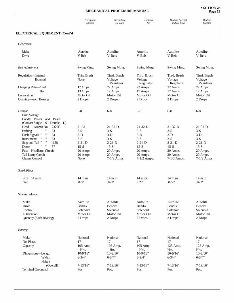
MECHANICAL PROCEDURE MANUALSECTION 23
Page 13
TerraplaneSpecial
TerraplaneDe Luxe
HudsonSix
Hudson Specialand De Luxe
HudsonCustom
ELECTRICAL EQUIPMENT (Cont’d
Generator:
Make Drive
Belt Adjustment
Regulation—Internal External
Charging Rate—Cold Hot Lubrication Quantity—each Bearing
Lamps:Bulb Voltage Candle Power and Bases(Contact Single—S—Double—D)Head Mazda No. 2320C Parking " " 63 Dash Signals " " 64 Instruments " " 63 Stop and Tail " " 1158 Dome " " 87 Fuse Headlamp CircuitTail Lamp CircuitCharge Control
Spark Plugs:
Size 14 m.m. Gap
Starting Motor:
Make Drive Control Lubrication Quantity (Each Bearing)
Battery:
Make No. Plates Capacity Dimensions—Length Width Height (Overall) Terminal Grounded
AutoliteV-Belt
Swing Mtng.
Third BrushNone
17 Amps13 AmpsMotor Oil2 Drops
6-8
21-323-S3-D3-S2-21-D15-S20 Amps20 AmpsNone
14 m.m..022"
AutoliteBendixSolenoidMotor Oil2 Drops
National17105 Amp. Hrs.10-9/16"6-3/4"
7-13/16"Pos.
AutoliteV-Bels
Swing Mtng.
Thrd. BrushVoltage Regulator22 Amps.17 Amps.Motor Oil2 Drops
6-8
21-32-D3-S3-D3-S2-21-D15-S20 Amps.20 Amps.7-1/2 Amps.
14 m.m..022"
AutoliteBendixSolenoidMotor Oil2 Drops
National17105 Amp. Hrs.10-9/16"6-3/4"
7-13/16"Pos.
AutoliteV-Bels
Swing Mtng.
Thrd. BrushVoltage Regulator22 Amps.17 Amps.Motor Oil2 Drops
6-8
21-32-D3-S3-D3-S2-21-D15-S20 Amps.20 Amps.7-1/2 Amps.
14 m.m..022"
AutoliteBendixSolenoidMotor Oil2 Drops
National17105 Amp. Hrs.10-9/16"6-3/4"
7-13/16"Pos.
AutoliteV-Bels
Swing Mtng.
Thrd. BrushVoltage Regulator22 Amps.17 Amps.Motor Oil2 Drops
6-8
21-32-D3-S3-D3-S2-21-D15-S20 Amps.20 Amps.7-1/2 Amps.
14 m.m..022"
AutoliteBendixSolenoidMotor Oil2 Drops
National17125 Amp.Hrs.10-9/16"6-3/4"
7-13/16"Pos.
AutoliteV-Bels
Swing Mtng.
Thrd. BrushVoltage Regulator22 Amps.17 Amps.Motor Oil2 Drops
6-8
21-32-D3-S3-D3-S2-21-D15-S20 Amps.20 Amps.7-1/2 Amps.
14 m.m..022"
AutoliteBendixSolenoidMotor Oil2 Drops
National17125 Amp.Hrs.10-9/16"6-3/4"
7-13/16"Pos.
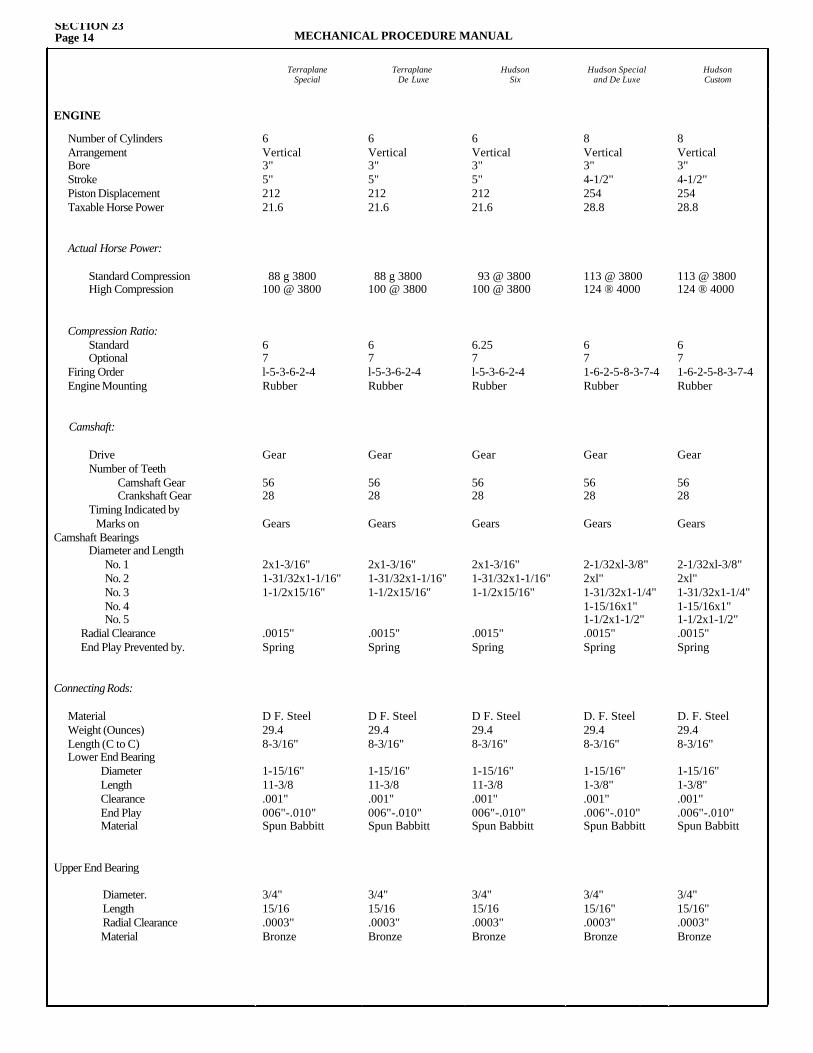
SECTION 23Page 14 MECHANICAL PROCEDURE MANUAL
TerraplaneSpecial
TerraplaneDe Luxe
HudsonSix
Hudson Specialand De Luxe
HudsonCustom
ENGINE
Number of Cylinders Arrangement Bore Stroke Piston Displacement Taxable Horse Power
Actual Horse Power:
Standard Compression High Compression
Compression Ratio: Standard Optional Firing Order Engine Mounting
Camshaft:
Drive Number of Teeth Camshaft Gear Crankshaft Gear Timing Indicated by Marks on Camshaft Bearings Diameter and Length
No. 1 No. 2 No. 3 No. 4 No. 5
Radial Clearance End Play Prevented by.
Connecting Rods:
Material Weight (Ounces) Length (C to C) Lower End Bearing
Diameter Length Clearance End Play Material
Upper End Bearing
Diameter. Length Radial Clearance Material
6Vertical3"5"21221.6
88 g 3800100 @ 3800
67l-5-3-6-2-4Rubber
Gear
5628
Gears
2x1-3/16"1-31/32x1-1/16"1-1/2x15/16"
.0015"Spring
D F. Steel29.48-3/16"
1-15/16"11-3/8.001"006"-.010"Spun Babbitt
3/4"15/16.0003"Bronze
6Vertical3"5"21221.6
88 g 3800100 @ 3800
67l-5-3-6-2-4Rubber
Gear
5628
Gears
2x1-3/16"1-31/32x1-1/16"1-1/2x15/16"
.0015"Spring
D F. Steel29.48-3/16"
1-15/16"11-3/8.001"006"-.010"Spun Babbitt
3/4"15/16.0003"Bronze
6Vertical3"5"21221.6
93 @ 3800100 @ 3800
6.257l-5-3-6-2-4Rubber
Gear
5628
Gears
2x1-3/16"1-31/32x1-1/16"1-1/2x15/16"
.0015"Spring
D F. Steel29.48-3/16"
1-15/16"11-3/8.001"006"-.010"Spun Babbitt
3/4"15/16.0003"Bronze
8Vertical3"4-1/2"25428.8
113 @ 3800124 ® 4000
671-6-2-5-8-3-7-4Rubber
Gear
5628
Gears
2-1/32xl-3/8"2xl"1-31/32x1-1/4"1-15/16x1"1-1/2x1-1/2".0015"Spring
D. F. Steel29.48-3/16"
1-15/16"1-3/8".001".006"-.010"Spun Babbitt
3/4"15/16".0003"Bronze
8Vertical3"4-1/2"25428.8
113 @ 3800124 ® 4000
671-6-2-5-8-3-7-4Rubber
Gear
5628
Gears
2-1/32xl-3/8"2xl"1-31/32x1-1/4"1-15/16x1"1-1/2x1-1/2".0015"Spring
D. F. Steel29.48-3/16"
1-15/16"1-3/8".001".006"-.010"Spun Babbitt
3/4"15/16".0003"Bronze
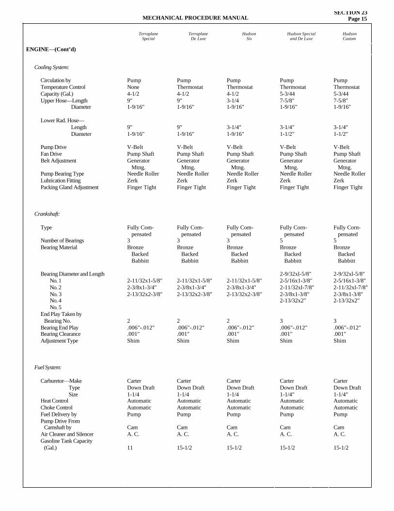
MECHANICAL PROCEDURE MANUALSECTION 23
Page 15
TerraplaneSpecial
TerraplaneDe Luxe
HudsonSix
Hudson Specialand De Luxe
HudsonCustom
ENGINE—(Cont’d)
Cooling System:
Circulation by Temperature Control Capacity (Gal.) Upper Hose—Length Diameter
Lower Rad. Hose— Length Diameter
Pump Drive Fan Drive Belt Adjustment
Pump Bearing Type Lubrication Fitting Packing Gland Adjustment
Crankshaft:
Type
Number of Bearings Bearing Material
Bearing Diameter and LengthNo. 1 No. 2 No. 3 No. 4 No. 5
End Play Taken by Bearing No. Bearing End Play Bearing Clearance Adjustment Type
Fuel System:
Carburetor—Make TypeSize
Heat Control Choke Control Fuel Delivery by Pump Drive From Camshaft by Air Cleaner and SilencerGasoline Tank Capacity (Gal.)
PumpNone4-1/29"1-9/16"
9"1-9/16"
V-BeltPump ShaftGenerator Mtng.Needle RollerZerkFinger Tight
Fully Com- pensated3Bronze Backed Babbitt
2-11/32x1-5/8"2-3/8x1-3/4"2-13/32x2-3/8"
2.006"-.012".001"Shim
CarterDown Draft1-1/4AutomaticAutomaticPump
CamA. C.
11
PumpThermostat4-1/29"1-9/16"
9"1-9/16"
V-BeltPump ShaftGenerator Mtng.Needle RollerZerkFinger Tight
Fully Com- pensated3Bronze Backed Babbitt
2-11/32x1-5/8"2-3/8x1-3/4"2-13/32x2-3/8"
2.006"-.012".001"Shim
CarterDown Draft1-1/4AutomaticAutomaticPump
CamA. C.
15-1/2
PumpThermostat4-1/23-1/41-9/16"
3-1/4"1-9/16"
V-BeltPump ShaftGenerator Mtng.Needle RollerZerkFinger Tight
Fully Com- pensated3Bronze Backed Babbitt
2-11/32x1-5/8"2-3/8x1-3/4"2-13/32x2-3/8"
2.006"-.012".001"Shim
CarterDown Draft1-1/4AutomaticAutomaticPump
CamA. C.
15-1/2
PumpThermostat5-3/447-5/8"1-9/16"
3-1/4"1-1/2"
V-BeltPump ShaftGenerator Mtng.Needle RollerZerkFinger Tight
Fully Corn- pensated5Bronze Backed Babbitt
2-9/32xl-5/8"2-5/16x1-3/8"2-11/32xl-7/8"2-3/8x1-3/8"2-13/32x2"
3.006"-.012".001"Shim
CarterDown Draft1-1/4"AutomaticAutomaticPump
CamA. C.
15-1/2
PumpThermostat5-3/447-5/8"1-9/16"
3-1/4"1-1/2"
V-BeltPump ShaftGenerator Mtng.Needle RollerZerkFinger Tight
Fully Corn- pensated5Bronze Backed Babbitt
2-9/32xl-5/8"2-5/16x1-3/8"2-11/32xl-7/8"2-3/8x1-3/8"2-13/32x2"
3.006"-.012".001"Shim
CarterDown Draft1-1/4"AutomaticAutomaticPump
CamA. C.
15-1/2
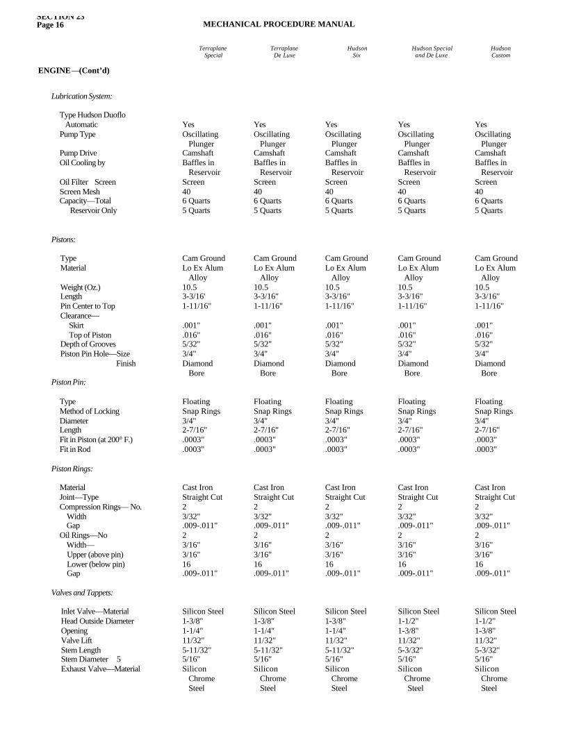
SECTION 23Page 16 MECHANICAL PROCEDURE MANUAL
TerraplaneSpecial
TerraplaneDe Luxe
HudsonSix
Hudson Specialand De Luxe
HudsonCustom
ENGINE—(Cont’d)
Lubrication System:
Type Hudson Duoflo Automatic Pump Type
Pump Drive Oil Cooling by
Oil Filter ScreenScreen Mesh Capacity—Total Reservoir Only
Pistons:
Type Material
Weight (Oz.) Length Pin Center to Top Clearance— Skirt Top of Piston Depth of Grooves Piston Pin Hole—Size Finish
Piston Pin:
Type Method of Locking Diameter Length Fit in Piston (at 200° F.)Fit in Rod
Piston Rings:
Material Joint—Type Compression Rings— No. Width GapOil Rings—No Width— Upper (above pin) Lower (below pin) Gap
Valves and Tappets:
Inlet Valve—Material Head Outside DiameterOpening Valve Lift Stem Length Stem Diameter 5Exhaust Valve—Material
YesOscillating PlungerCamshaftBaffles in ReservoirScreen406 Quarts5 Quarts
Cam GroundLo Ex Alum Alloy10.53-3/16'1-11/16"
.001"
.016"5/32"3/4"Diamond Bore
FloatingSnap Rings3/4"2-7/16".0003".0003"
Cast IronStraight Cut23/32".009-.011"23/16"3/16"16.009-.011"
Silicon Steel1-3/8"1-1/4"11/32"5-11/32"5/16"Silicon Chrome Steel
YesOscillating PlungerCamshaftBaffles in ReservoirScreen406 Quarts5 Quarts
Cam GroundLo Ex Alum Alloy10.53-3/16"1-11/16"
.001"
.016"5/32"3/4"Diamond Bore
FloatingSnap Rings3/4"2-7/16".0003".0003"
Cast IronStraight Cut23/32".009-.011"23/16"3/16"16.009-.011"
Silicon Steel1-1/2"1-3/8"11/32"5-3/32"5/16"Silicon Chrome Steel
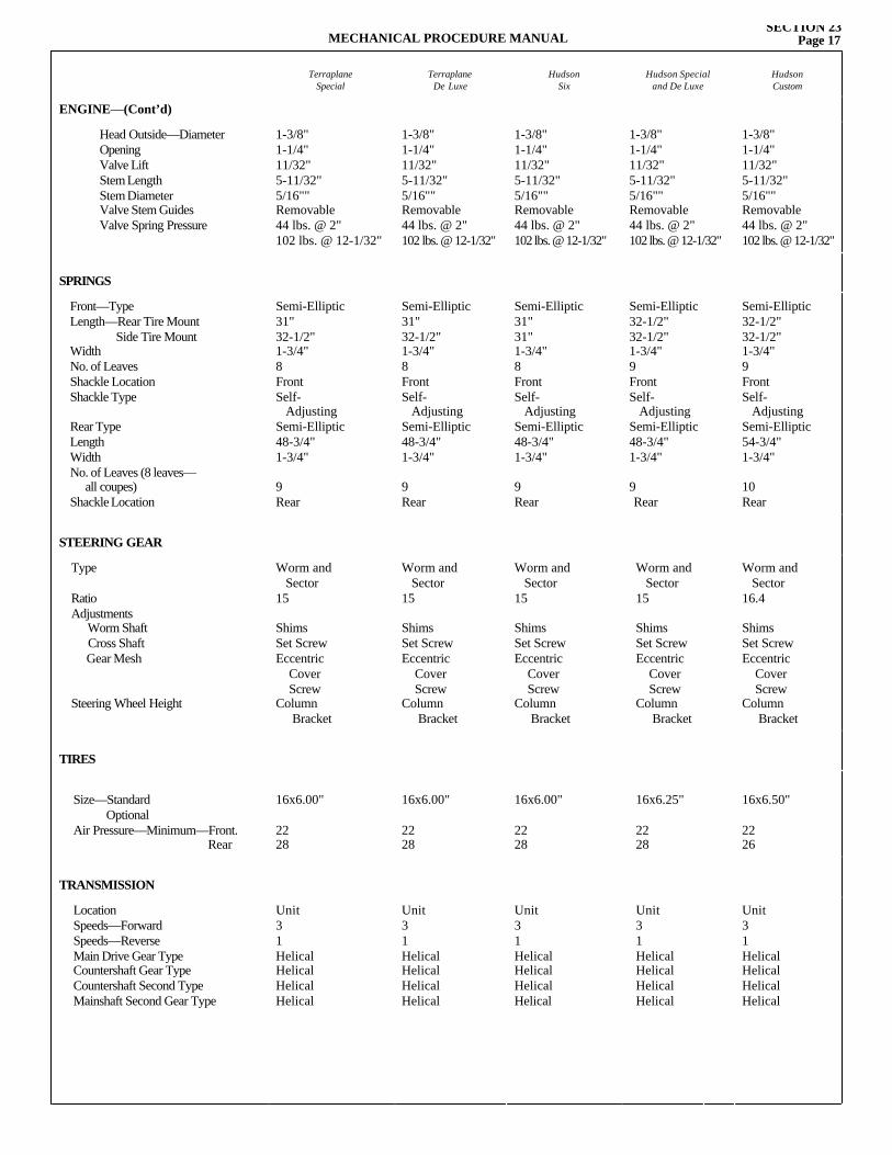
MECHANICAL PROCEDURE MANUALSECTION 23
Page 17
TerraplaneSpecial
TerraplaneDe Luxe
HudsonSix
Hudson Specialand De Luxe
HudsonCustom
ENGINE—(Cont’d)
Head Outside—DiameterOpeningValve Lift Stem Length Stem Diameter Valve Stem Guides Valve Spring Pressure
1-3/8"1-1/4"11/32"5-11/32"5/16""Removable44 lbs. @ 2" 102 lbs. @ 12-1/32"
1-3/8"1-1/4"11/32"5-11/32"5/16""Removable44 lbs. @ 2" 102 lbs. @ 12-1/32"
1-3/8"1-1/4"11/32"5-11/32"5/16""Removable44 lbs. @ 2" 102 lbs. @ 12-1/32"
1-3/8"1-1/4"11/32"5-11/32"5/16""Removable44 lbs. @ 2" 102 lbs. @ 12-1/32"
1-3/8"1-1/4"11/32"5-11/32"5/16""Removable44 lbs. @ 2" 102 lbs. @ 12-1/32"
SPRINGS
Front—Type Length—Rear Tire Mount Side Tire Mount Width No. of Leaves Shackle Location Shackle Type
Rear Type Length Width No. of Leaves (8 leaves— all coupes) Shackle Location
Semi-Elliptic31"32-1/2"1-3/4"8FrontSelf- AdjustingSemi-Elliptic48-3/4"1-3/4"
9Rear
Semi-Elliptic31"32-1/2"1-3/4"8FrontSelf- AdjustingSemi-Elliptic48-3/4"1-3/4"
9Rear
Semi-Elliptic31"31"1-3/4"8FrontSelf- AdjustingSemi-Elliptic48-3/4"1-3/4"
9Rear
Semi-Elliptic32-1/2"32-1/2"1-3/4"9FrontSelf- AdjustingSemi-Elliptic48-3/4"1-3/4"
9Rear
Semi-Elliptic32-1/2"32-1/2"1-3/4"9FrontSelf- AdjustingSemi-Elliptic54-3/4"1-3/4"
10Rear
STEERING GEAR
Type
Ratio Adjustments Worm Shaft Cross Shaft Gear Mesh
Steering Wheel Height
Worm and Sector15
ShimsSet ScrewEccentric Cover ScrewColumn Bracket
Worm and Sector15
ShimsSet ScrewEccentric Cover ScrewColumn Bracket
Worm and Sector15
ShimsSet ScrewEccentric Cover ScrewColumn Bracket
Worm and Sector15
ShimsSet ScrewEccentric Cover ScrewColumn Bracket
Worm and Sector16.4
ShimsSet ScrewEccentric Cover ScrewColumn Bracket
TIRES
Size—Standard Optional Air Pressure—Minimum—Front. Rear
16x6.00"
2228
16x6.00"
2228
16x6.00"
2228
16x6.25"
2228
16x6.50"
2226
TRANSMISSION
Location Speeds—Forward Speeds—Reverse Main Drive Gear Type Countershaft Gear Type Countershaft Second Type Mainshaft Second Gear Type
Unit31HelicalHelicalHelicalHelical
Unit31HelicalHelicalHelicalHelical
Unit31HelicalHelicalHelicalHelical
Unit31HelicalHelicalHelicalHelical
Unit31HelicalHelicalHelicalHelical
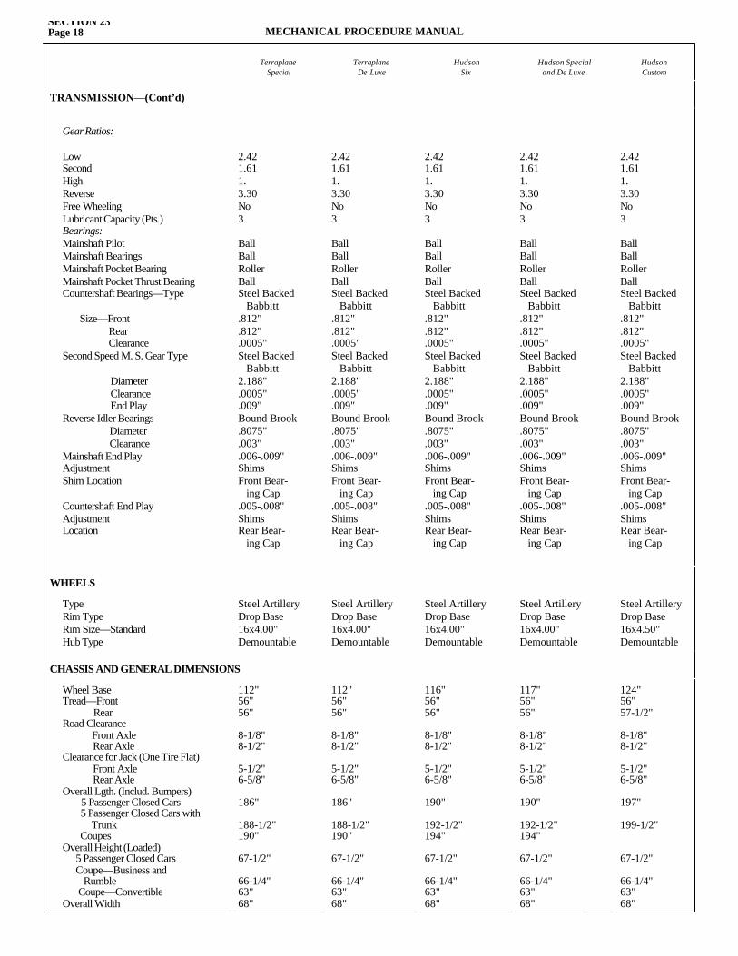
SECTION 23Page 18 MECHANICAL PROCEDURE MANUAL
TerraplaneSpecial
TerraplaneDe Luxe
HudsonSix
Hudson Specialand De Luxe
HudsonCustom
TRANSMISSION—(Cont’d)
Gear Ratios:
Low Second High Reverse Free Wheeling Lubricant Capacity (Pts.)Bearings:Mainshaft Pilot Mainshaft Bearings Mainshaft Pocket Bearing Mainshaft Pocket Thrust BearingCountershaft Bearings—Type
Size—Front Rear Clearance
Second Speed M. S. Gear Type
Diameter Clearance End Play
Reverse Idler Bearings Diameter Clearance
Mainshaft End Play Adjustment Shim Location
Countershaft End Play Adjustment Location
2.421.611.3.30No3
BallBallRollerBallSteel Backed Babbitt.812".812".0005"Steel Backed Babbitt2.188".0005".009"Bound Brook.8075".003".006-.009"ShimsFront Bear- ing Cap.005-.008"ShimsRear Bear- ing Cap
2.421.611.3.30No3
BallBallRollerBallSteel Backed Babbitt.812".812".0005"Steel Backed Babbitt2.188".0005".009"Bound Brook.8075".003".006-.009"ShimsFront Bear- ing Cap.005-.008"ShimsRear Bear- ing Cap
2.421.611.3.30No3
BallBallRollerBallSteel Backed Babbitt.812".812".0005"Steel Backed Babbitt2.188".0005".009"Bound Brook.8075".003".006-.009"ShimsFront Bear- ing Cap.005-.008"ShimsRear Bear- ing Cap
2.421.611.3.30No3
BallBallRollerBallSteel Backed Babbitt.812".812".0005"Steel Backed Babbitt2.188".0005".009"Bound Brook.8075".003".006-.009"ShimsFront Bear- ing Cap.005-.008"ShimsRear Bear- ing Cap
2.421.611.3.30No3
BallBallRollerBallSteel Backed Babbitt.812".812".0005"Steel Backed Babbitt2.188".0005".009"Bound Brook.8075".003".006-.009"ShimsFront Bear- ing Cap.005-.008"ShimsRear Bear- ing Cap
WHEELS
Type Rim Type Rim Size—Standard Hub Type
Steel ArtilleryDrop Base16x4.00"Demountable
Steel ArtilleryDrop Base16x4.00"Demountable
Steel ArtilleryDrop Base16x4.00"Demountable
Steel ArtilleryDrop Base16x4.00"Demountable
Steel ArtilleryDrop Base16x4.50"Demountable
CHASSIS AND GENERAL DIMENSIONS
Wheel Base Tread—Front Rear Road Clearance Front Axle Rear Axle Clearance for Jack (One Tire Flat) Front Axle Rear Axle Overall Lgth. (Includ. Bumpers) 5 Passenger Closed Cars 5 Passenger Closed Cars with Trunk Coupes Overall Height (Loaded) 5 Passenger Closed Cars Coupe—Business and Rumble Coupe—Convertible Overall Width
112"56"56"
8-1/8"8-1/2"
5-1/2"6-5/8"
186"
188-1/2"190"
67-1/2"
66-1/4"63"68"
112"56"56"
8-1/8"8-1/2"
5-1/2"6-5/8"
186"
188-1/2"190"
67-1/2"
66-1/4"63"68"
116"56"56"
8-1/8"8-1/2"
5-1/2"6-5/8"
190"
192-1/2"194"
67-1/2"
66-1/4"63"68"
117"56"56"
8-1/8"8-1/2"
5-1/2"6-5/8"
190"
192-1/2"194"
67-1/2"
66-1/4"63"68"
124"56"57-1/2"
8-1/8"8-1/2"
5-1/2"6-5/8"
197"
199-1/2"
67-1/2"
66-1/4"63"68"
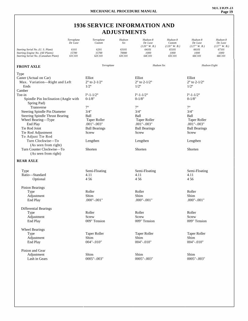
FRONT AXLE Terraplane Hudson Six Hudson Eight
Type Caster (Actual on Car) Max. Variation—Right and Left Ends Camber Toe-in
Spindle Pin Inclination (Angle with Spring Pad) Transverse Steering Spindle Pin DiameterSteering Spindle Thrust BearingWheel Bearing—Type End Play Tie Rod Joint Tie Rod Adjustment To Adjust Tie Rod Turn Clockwise—To (As seen from right)Turn Counter Clockwise—To
(As seen from right)
Elliot2° to 2-1/2°1/2º l°-1-1/2°0-1/8"
7°3/4"Ball Taper Roller.001"-.003"Ball BearingsScrew
Lengthen
Shorten
Elliot2° to 2-1/2°1/2º l°-1-1/2°0-1/8"
7°3/4"Ball Taper Roller.001"-.003"Ball BearingsScrew
Lengthen
Shorten
Elliot2° to 2-1/2°1/2º l°-1-1/2°0-1/8"
7°3/4"Ball Taper Roller.001"-.003"Ball BearingsScrew
Lengthen
Shorten
REAR AXLE
Type Ratio—Standard Optional
Pinion BearingsType Adjustment End Play
Differential BearingsType Adjustment End Play
Wheel BearingsType Adjustment End Play
Pinion and GearAdjustment Lash in Gears
Semi-Floating4.114 56
RollerShim.000"-.001"
RollerScrew009" Tension
Taper RollerShim004"-.010"
Shim0005"-.003"
Semi-Floating4.114 56
RollerShim.000"-.001"
RollerScrew009" Tension
Taper RollerShim004"-.010"
Shim0005"-.003"
Semi-Floating4.114 56
RollerShim.000"-.001"
RollerScrew009" Tension
Taper RollerShim004"-.010"
Shim0005"-.003"
1936 SERVICE INFORMATION ANDADJUSTMENTS
Starting Serial No. (U. S. Plant)Starting Engine No. (All Plants)Starting Serial No. (Canadian Plant)
TerraplaneDe Luxe
610115700
61C101
TerraplaneCustom
620115700
62C101
HudsonSix
6310170000
63C101
Hudson 8De Luxe
(120” W. B.)641011000
64C101
Hudson 8Custom
(120” W. B.)651011000
65C101
Hudson 8De Luxe
(127” W. B.)661011000
66C101
Hudson 8De Luxe
(127” W. B.)671011000
66C101
MECHANICAL PROCEDURE MANUALSECTION 23
Page 19
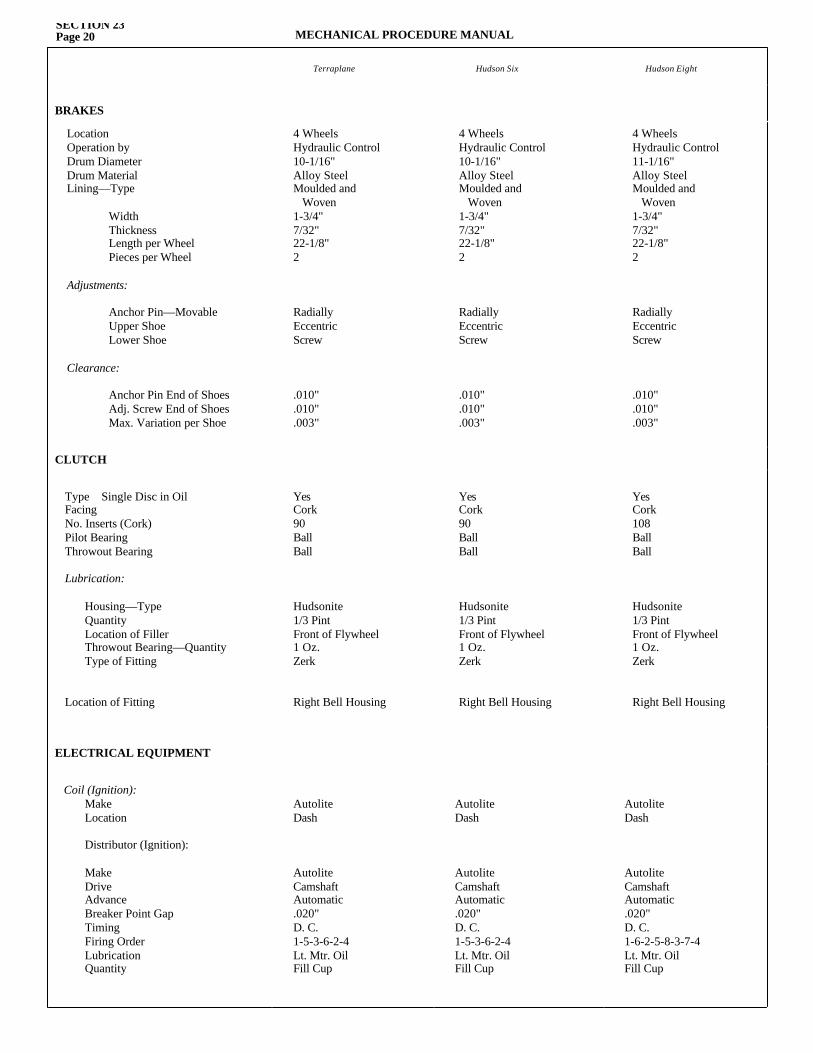
Terraplane Hudson Six Hudson Eight
BRAKES
Location Operation by Drum Diameter Drum Material Lining—Type Width Thickness Length per Wheel Pieces per Wheel
Adjustments:
Anchor Pin—Movable Upper Shoe Lower Shoe
Clearance:
Anchor Pin End of ShoesAdj. Screw End of Shoes Max. Variation per Shoe
4 WheelsHydraulic Control10-1/16"Alloy SteelMoulded and Woven1-3/4"7/32"22-1/8"2
RadiallyEccentricScrew
.010"
.010"
.003"
4 WheelsHydraulic Control10-1/16"Alloy SteelMoulded and Woven1-3/4"7/32"22-1/8"2
RadiallyEccentricScrew
.010"
.010"
.003"
4 WheelsHydraulic Control11-1/16"Alloy SteelMoulded and Woven1-3/4"7/32"22-1/8"2
RadiallyEccentricScrew
.010"
.010"
.003"
CLUTCH
Type Single Disc in Oil Facing No. Inserts (Cork) Pilot Bearing Throwout Bearing
Lubrication:
Housing—Type Quantity Location of Filler Throwout Bearing—Quantity Type of Fitting
Location of Fitting
YesCork90BallBall
Hudsonite1/3 PintFront of Flywheel1 Oz.Zerk
Right Bell Housing
YesCork90BallBall
Hudsonite1/3 PintFront of Flywheel1 Oz.Zerk
Right Bell Housing
YesCork108BallBall
Hudsonite1/3 PintFront of Flywheel1 Oz.Zerk
Right Bell Housing
ELECTRICAL EQUIPMENT
Coil (Ignition):Make Location
Distributor (Ignition):
Make Drive Advance Breaker Point Gap Timing Firing Order Lubrication Quantity
AutoliteDash
AutoliteCamshaftAutomatic.020"D. C.1-5-3-6-2-4Lt. Mtr. OilFill Cup
AutoliteDash
AutoliteCamshaftAutomatic.020"D. C.1-5-3-6-2-4Lt. Mtr. OilFill Cup
AutoliteDash
AutoliteCamshaftAutomatic.020"D. C.1-6-2-5-8-3-7-4Lt. Mtr. OilFill Cup
SECTION 23Page 20 MECHANICAL PROCEDURE MANUAL
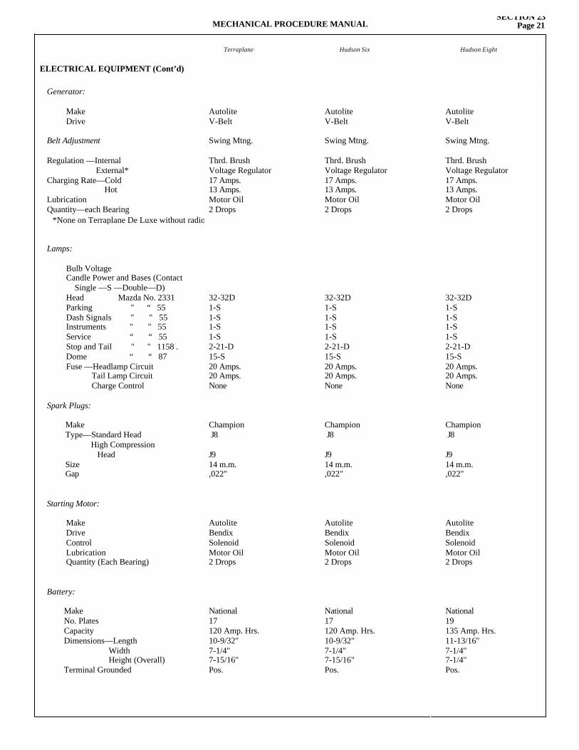
MECHANICAL PROCEDURE MANUALSECTION 23
Page 21
Terraplane Hudson Six Hudson Eight
ELECTRICAL EQUIPMENT (Cont’d)
Generator:
Make Drive
Belt Adjustment
Regulation —Internal External* Charging Rate—Cold Hot Lubrication Quantity—each Bearing
Lamps:
Bulb Voltage Candle Power and Bases (Contact Single —S —Double—D)Head Mazda No. 2331Parking " “ 55Dash Signals " " 55Instruments " " 55Service “ “ 55Stop and Tail " " 1158 . Dome “ “ 87Fuse —Headlamp Circuit Tail Lamp Circuit Charge Control
Spark Plugs:
Make Type—Standard Head High Compression Head Size Gap
Starting Motor:
Make Drive Control Lubrication Quantity (Each Bearing)
Battery:
Make No. Plates Capacity Dimensions—Length Width Height (Overall)Terminal Grounded
AutoliteV-Belt
Swing Mtng.
Thrd. BrushVoltage Regulator17 Amps.13 Amps.Motor Oil2 Drops
32-32D1-S1-S1-S1-S2-21-D15-S20 Amps.20 Amps.None
Champion J8
J914 m.m.,022"
AutoliteBendixSolenoidMotor Oil2 Drops
National17120 Amp. Hrs.10-9/32"7-1/4"7-15/16"Pos.
AutoliteV-Belt
Swing Mtng.
Thrd. BrushVoltage Regulator17 Amps.13 Amps.Motor Oil2 Drops
32-32D1-S1-S1-S1-S2-21-D15-S20 Amps.20 Amps.None
Champion J8
J914 m.m.,022"
AutoliteBendixSolenoidMotor Oil2 Drops
National17120 Amp. Hrs.10-9/32"7-1/4"7-15/16"Pos.
AutoliteV-Belt
Swing Mtng.
Thrd. BrushVoltage Regulator17 Amps.13 Amps.Motor Oil2 Drops
32-32D1-S1-S1-S1-S2-21-D15-S20 Amps.20 Amps.None
Champion J8
J914 m.m.,022"
AutoliteBendixSolenoidMotor Oil2 Drops
National19135 Amp. Hrs.11-13/16"7-1/4"7-1/4"Pos.
*None on Terraplane De Luxe without radio
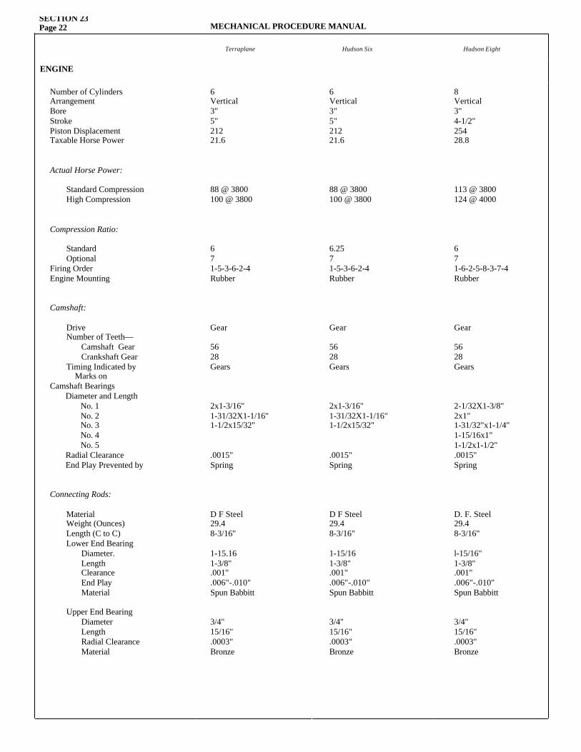
SECTION 23Page 22 MECHANICAL PROCEDURE MANUAL
Terraplane Hudson Six Hudson Eight
ENGINE
Number of Cylinders Arrangement Bore Stroke Piston Displacement Taxable Horse Power
Actual Horse Power:
Standard Compression High Compression
Compression Ratio:
Standard Optional
Firing Order Engine Mounting
Camshaft:
Drive Number of Teeth— Camshaft Gear Crankshaft Gear Timing Indicated by Marks on
Camshaft BearingsDiameter and Length No. 1 No. 2 No. 3 No. 4 No. 5 Radial Clearance End Play Prevented by
Connecting Rods:
Material Weight (Ounces) Length (C to C) Lower End Bearing Diameter. Length Clearance End Play Material
Upper End Bearing Diameter Length Radial Clearance Material
6Vertical3"5"21221.6
88 @ 3800100 @ 3800
671-5-3-6-2-4Rubber
Gear
5628Gears
2x1-3/16"1-31/32X1-1/16"1-1/2x15/32"
.0015"Spring
D F Steel29.48-3/16"
1-15.161-3/8".001".006"-.010"Spun Babbitt
3/4"15/16".0003"Bronze
6Vertical3"5"21221.6
88 @ 3800100 @ 3800
6.2571-5-3-6-2-4Rubber
Gear
5628Gears
2x1-3/16"1-31/32X1-1/16"1-1/2x15/32"
.0015"Spring
D F Steel29.48-3/16"
1-15/161-3/8".001".006"-.010"Spun Babbitt
3/4"15/16".0003"Bronze
8Vertical3"4-1/2"25428.8
113 @ 3800124 @ 4000
671-6-2-5-8-3-7-4Rubber
Gear
5628Gears
2-1/32X1-3/8"2x1"1-31/32"x1-1/4"1-15/16x1"1-1/2x1-1/2".0015"Spring
D. F. Steel29.48-3/16"
l-15/16"1-3/8".001".006"-.010"Spun Babbitt
3/4"15/16".0003"Bronze
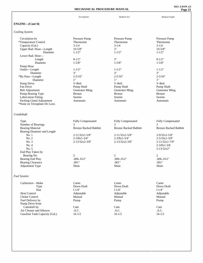
MECHANICAL PROCEDURE MANUALSECTION 23
Page 23
Terraplane Hudson Six Hudson Eight
ENGINE—(Cont’d)
Cooling System:
Circulation by *Temperature Control Capacity (Gal.) Upper Rad. Hose—Length Diameter Lower Rad. Hose— Length Diameter Pump Hose Outlet—Length Diameter*By-Pass—Length Diameter Pump Drive Fan Drive Belt Adjustment Pump Bearing Type Lubrication Fitting Packing Gland Adjustment*None on Terraplane De Luxe.
Crankshaft:
Type Number of Bearings Bearing Material Bearing Diameter and Length No. 1 No. 2 No. 3 No. 4 No. 5 End Play Taken by Bearing No. Bearing End Play Bearing Clearance Adjustment Type
Fuel System:
Carburetor—Make Type Size Heat Control Choke Control Fuel Delivery by Pump Drive from Camshaft by Air Cleaner and Silencer Gasoline Tank Capacity (Gal.)
Pressure PumpThermostat3-1/410-5/8"1-1/2"
8-1/2"1-5/8"
1-1/2"3"2-5/16"1"V-BeltPump ShaftGenerator Mtng.BronzeSemiteAutomatic
Fully Compensated3Bronze Backed Babbitt
2-11/32x1-5/8"2-3/8x1-3/4"2-13/32x2-3/8"
2.006-.012".001"Shim
CarterDown Draftl-1/4"AdjustableManualPump
Cam.A.C.16-1/2
Pressure PumpThermostat3-1/43"1-1/2"
3"1-5/8"
1-1/2"3"2-5/16"1"V-BeltPump ShaftGenerator Mtng.BronzeSemiteAutomatic
Fully Compensated3Bronze Backed Babbitt
2-11/32x1-5/8"2-3/8x1-3/4"2-13/32x2-3/8"
2.006-.012".001"Shim
CarterDown Draftl-1/4"AdjustableManualPump
Cam.A.C.16-1/2
Pressure PumpThermostat3-1/410-5/8"1-1/2"
8-1/2"1-5/8"
1-1/2"3"2-5/16"1"V-BeltPump ShaftGenerator Mtng.BronzeSemiteAutomatic
Fully Compensated3Bronze Backed Babbitt
2-9/32x1-5/8"2-5/16x1-3/8"2-11/32x1-7/8"2-3/8x1-3/82-13/32x2”
2.006-.012".001"Shim
CarterDown Draftl-1/4"AdjustableManualPump
Cam.A.C.16-1/2
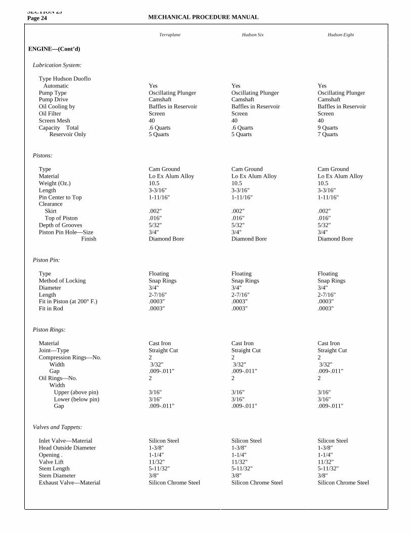
SECTION 23Page 24 MECHANICAL PROCEDURE MANUAL
Terraplane Hudson Six Hudson Eight
ENGINE—(Cont’d)
Lubrication System:
Type Hudson Duoflo Automatic Pump Type Pump Drive Oil Cooling by Oil Filter Screen Mesh Capacity Total Reservoir Only
Pistons:
Type Material Weight (Oz.) Length Pin Center to Top Clearance Skirt Top of Piston Depth of Grooves Piston Pin Hole—Size Finish
Piston Pin:
Type Method of Locking Diameter Length Fit in Piston (at 200° F.) Fit in Rod
Piston Rings:
Material Joint—Type Compression Rings—No. Width Gap Oil Rings—No. Width Upper (above pin) Lower (below pin) Gap
Valves and Tappets:
Inlet Valve—Material Head Outside Diameter Opening . Valve Lift Stem Length Stem DiameterExhaust Valve—Material
YesOscillating PlungerCamshaftBaffles in ReservoirScreen40.6 Quarts5 Quarts
Cam GroundLo Ex Alum Alloy10.53-3/16"1-11/16"
.002"
.016"5/32"3/4"Diamond Bore
FloatingSnap Rings3/4"2-7/16".0003".0003"
Cast IronStraight Cut2 3/32".009-.011"2
3/16"3/16".009-.011"
Silicon Steel1-3/8"1-1/4"11/32"5-11/32"3/8"Silicon Chrome Steel
YesOscillating PlungerCamshaftBaffles in ReservoirScreen409 Quarts7 Quarts
Cam GroundLo Ex Alum Alloy10.53-3/16"1-11/16"
.002"
.016"5/32"3/4"Diamond Bore
FloatingSnap Rings3/4"2-7/16".0003".0003"
Cast IronStraight Cut2 3/32".009-.011"2
3/16"3/16".009-.011"
Silicon Steel1-3/8"1-1/4"11/32"5-11/32"3/8"Silicon Chrome Steel
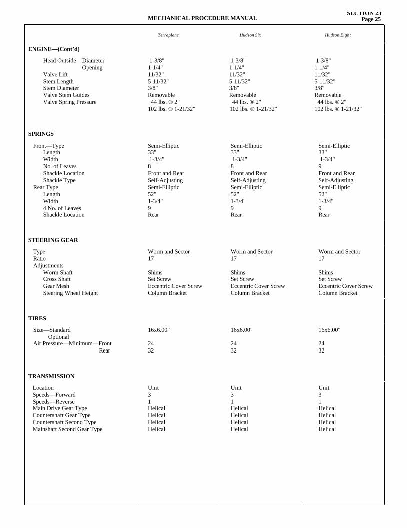
MECHANICAL PROCEDURE MANUALSECTION 23
Page 25
Terraplane Hudson Six Hudson Eight
ENGINE—(Cont’d)
Head Outside—Diameter Opening Valve Lift Stem Length Stem Diameter Valve Stem Guides Valve Spring Pressure
1-3/8"1-1/4"11/32"5-11/32"3/8"Removable 44 lbs. ® 2"102 lbs. ® 1-21/32"
1-3/8"1-1/4"11/32"5-11/32"3/8"Removable 44 lbs. ® 2"102 lbs. ® 1-21/32"
1-3/8"1-1/4"11/32"5-11/32"3/8"Removable 44 lbs. ® 2"102 lbs. ® 1-21/32"
SPRINGS
Front—Type Length Width No. of Leaves Shackle Location Shackle Type
Rear Type Length Width 4 No. of Leaves Shackle Location
Semi-Elliptic33" 1-3/4"8Front and RearSelf-AdjustingSemi-Elliptic52"1-3/4"9Rear
Semi-Elliptic33" 1-3/4"8Front and RearSelf-AdjustingSemi-Elliptic52"1-3/4"9Rear
Semi-Elliptic33" 1-3/4"9Front and RearSelf-AdjustingSemi-Elliptic52"1-3/4"9Rear
STEERING GEAR
Type Ratio Adjustments
Worm Shaft Cross Shaft Gear Mesh Steering Wheel Height
Worm and Sector17
ShimsSet ScrewEccentric Cover ScrewColumn Bracket
Worm and Sector17
ShimsSet ScrewEccentric Cover ScrewColumn Bracket
Worm and Sector17
ShimsSet ScrewEccentric Cover ScrewColumn Bracket
TIRES
Size—Standard Optional Air Pressure—Minimum—Front Rear
16x6.00"
2432
16x6.00"
2432
16x6.00"
2432
TRANSMISSION
Location Speeds—Forward Speeds—Reverse Main Drive Gear Type Countershaft Gear Type Countershaft Second Type Mainshaft Second Gear Type
Unit31HelicalHelicalHelicalHelical
Unit31HelicalHelicalHelicalHelical
Unit31HelicalHelicalHelicalHelical
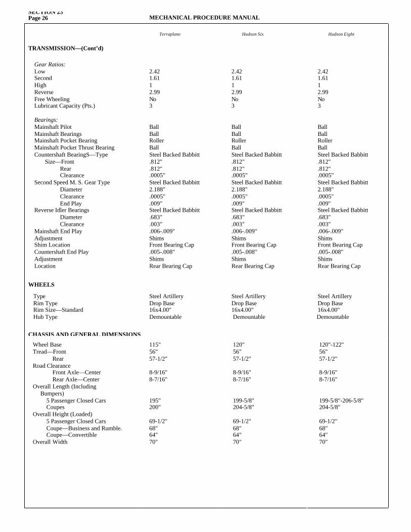
SECTION 23Page 26 MECHANICAL PROCEDURE MANUAL
Terraplane Hudson Six Hudson Eight
TRANSMISSION—(Cont’d)
Gear Ratios:Low Second High Reverse Free Wheeling Lubricant Capacity (Pts.)
Bearings:Mainshaft Pilot Mainshaft Bearings Mainshaft Pocket BearingMainshaft Pocket Thrust BearingCountershaft BearingS—Type Size—Front Rear Clearance Second Speed M. S. Gear Type Diameter Clearance End Play Reverse Idler Bearings Diameter Clearance Mainshaft End Play Adjustment Shim Location Countershaft End Play Adjustment Location
2.421.611 2.99No3
BallBallRollerBallSteel Backed Babbitt.812".812".0005"Steel Backed Babbitt2.188".0005".009"Steel Backed Babbitt.683".003".006-.009"ShimsFront Bearing Cap.005-.008"ShimsRear Bearing Cap
2.421.611 2.99No3
BallBallRollerBallSteel Backed Babbitt.812".812".0005"Steel Backed Babbitt2.188".0005".009"Steel Backed Babbitt.683".003".006-.009"ShimsFront Bearing Cap.005-.008"ShimsRear Bearing Cap
2.421.611 2.99No3
BallBallRollerBallSteel Backed Babbitt.812".812".0005"Steel Backed Babbitt2.188".0005".009"Steel Backed Babbitt.683".003".006-.009"ShimsFront Bearing Cap.005-.008"ShimsRear Bearing Cap
WHEELS
Type Rim Type Rim Size—Standard Hub Type
Steel ArtilleryDrop Base16x4.00"Demountable
Steel ArtilleryDrop Base16x4.00"Demountable
Steel ArtilleryDrop Base16x4.00"Demountable
Wheel Base Tread—Front Rear Road Clearance Front Axle—Center Rear Axle—Center Overall Length (Including Bumpers) 5 Passenger Closed Cars Coupes Overall Height (Loaded) 5 Passenger Closed Cars Coupe—Business and Rumble. Coupe—Convertible Overall Width
115"56"57-1/2"
8-9/16"8-7/16"
195"200"
69-1/2"68"64"70"
120"56"57-1/2"
8-9/16"8-7/16"
199-5/8"204-5/8"
69-1/2"68"64"70"
120"-122"56"57-1/2"
8-9/16"8-7/16"
199-5/8"-206-5/8"204-5/8"
69-1/2"68"64"70"
CHASSIS AND GENERAL DIMENSIONS
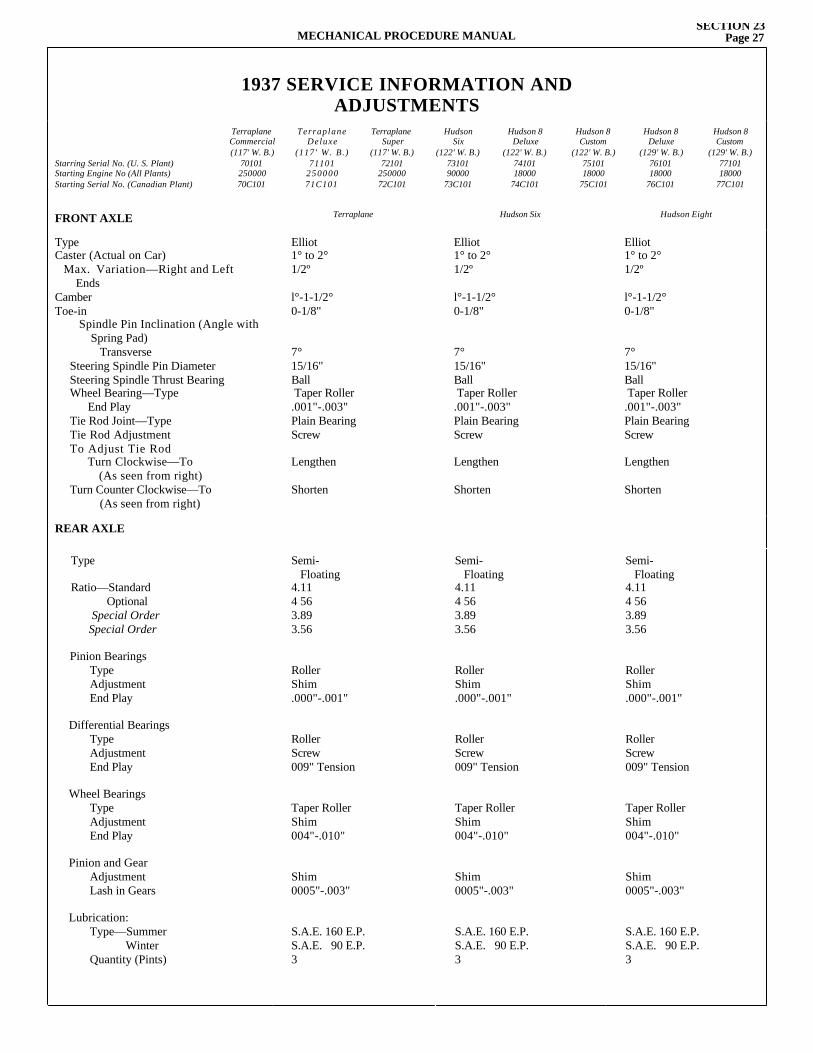
FRONT AXLE Terraplane Hudson Six Hudson Eight
Type Caster (Actual on Car) Max. Variation—Right and Left Ends Camber Toe-in
Spindle Pin Inclination (Angle with Spring Pad) Transverse Steering Spindle Pin DiameterSteering Spindle Thrust BearingWheel Bearing—Type End Play Tie Rod Joint—Type Tie Rod Adjustment To Adjust Tie Rod Turn Clockwise—To (As seen from right)Turn Counter Clockwise—To
(As seen from right)
Elliot1° to 2°1/2º l°-1-1/2°0-1/8"
7°15/16"Ball Taper Roller.001"-.003"Plain BearingScrew
Lengthen
Shorten
Elliot1° to 2°1/2º l°-1-1/2°0-1/8"
7°15/16"Ball Taper Roller.001"-.003"Plain BearingScrew
Lengthen
Shorten
Elliot1° to 2°1/2º l°-1-1/2°0-1/8"
7°15/16"Ball Taper Roller.001"-.003"Plain BearingScrew
Lengthen
Shorten
REAR AXLE
Type
Ratio—Standard Optional Special Order Special Order
Pinion BearingsType Adjustment End Play
Differential BearingsType Adjustment End Play
Wheel BearingsType Adjustment End Play
Pinion and GearAdjustment Lash in Gears
Lubrication:Type—Summer WinterQuantity (Pints)
Semi- Floating4.114 563.893.56
RollerShim.000"-.001"
RollerScrew009" Tension
Taper RollerShim004"-.010"
Shim0005"-.003"
S.A.E. 160 E.P.S.A.E. 90 E.P.3
Semi- Floating4.114 563.893.56
RollerShim.000"-.001"
RollerScrew009" Tension
Taper RollerShim004"-.010"
Shim0005"-.003"
S.A.E. 160 E.P.S.A.E. 90 E.P.3
Semi- Floating4.114 563.893.56
RollerShim.000"-.001"
RollerScrew009" Tension
Taper RollerShim004"-.010"
Shim0005"-.003"
S.A.E. 160 E.P.S.A.E. 90 E.P.3
1937 SERVICE INFORMATION ANDADJUSTMENTS
Starring Serial No. (U. S. Plant)Starting Engine No (All Plants)Starting Serial No. (Canadian Plant)
TerraplaneCommercial(117' W. B.)
7010125000070C101
TerraplaneDeluxe
(117' W. B.)71101
25000071C101
TerraplaneSuper
(117' W. B.)72101
25000072C101
HudsonSix
(122' W. B.)7310190000
73C101
Hudson 8Deluxe
(122' W. B.)7410118000
74C101
Hudson 8Custom
(122' W. B.)7510118000
75C101
Hudson 8Deluxe
(129' W. B.)7610118000
76C101
Hudson 8Custom
(129' W. B.)7710118000
77C101
MECHANICAL PROCEDURE MANUALSECTION 23
Page 27
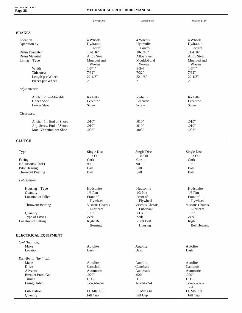
SECTION 23Page 28 MECHANICAL PROCEDURE MANUAL
Terraplane Hudson Six Hudson Eight
BRAKES
Location Operation by
Drum Diameter Drum Material Lining—Type Width Thickness Length per Wheel Pieces per Wheel
Adjustments:
Anchor Pin—Movable Upper Shoe Lower Shoe
Clearance:
Anchor Pin End of ShoesAdj. Screw End of Shoes Max. Variation per Shoe
4 WheelsHydraulic Control10-1/16"Alloy SteelMoulded and Woven1-3/4"7/32"22-1/8"2
RadiallyEccentricScrew
.010"
.010"
.003"
4 WheelsHydraulic Control10-1/16"Alloy SteelMoulded and Woven1-3/4"7/32"22-1/8"2
RadiallyEccentricScrew
.010"
.010"
.003"
4 WheelsHydraulic Control11-1/16"Alloy SteelMoulded and Woven1-3/4"7/32"22-1/8"2
RadiallyEccentricScrew
.010"
.010"
.003"
CLUTCH
Type
Facing No. Inserts (Cork) Pilot Bearing Throwout Bearing
Lubrication:
Housing—Type Quantity Location of Filler
Throwout Bearing
Quantity Type of Fitting
Location of Fitting
Single Disc in Oil Cork90BallBall
Hudsonite1/3 PintFront of FlywheelViscous Chassis Lubricant1 Oz.ZerkRight Bell Housing
Single Disc in Oil Cork90BallBall
Hudsonite1/3 PintFront of FlywheelViscous Chassis Lubricant1 Oz.ZerkRight Bell Housing
Single Disc in Oil Cork108BallBall
Hudsonite1/3 PintFront of Flywheel
Viscous Chassis Lubricant1 Oz.ZerkRight Bell Housing
ELECTRICAL EQUIPMENT
Coil (Ignition):Make Location
Distributor (Ignition):Make Drive Advance Breaker Point Gap Timing Firing Order Lubrication Quantity
AutoliteDash
AutoliteCamshaftAutomatic.020"D. C.1-5-3-6-2-4
Lt. Mtr. OilFill Cup
AutoliteDash
AutoliteCamshaftAutomatic.020"D. C.1-5-3-6-2-4
Lt. Mtr. OilFill Cup
AutoliteDash
AutoliteCamshaftAutomatic.020"D. C.1-6-2-5-8-3- 7-4Lt. Mtr. Oil
Fill Cup
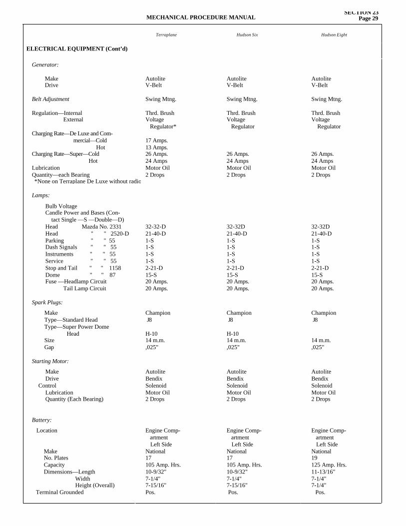
MECHANICAL PROCEDURE MANUALSECTION 23
Page 29
Terraplane Hudson Six Hudson Eight
ELECTRICAL EQUIPMENT (Cont’d)
Generator:
Make Drive
Belt Adjustment
Regulation—Internal External
Charging Rate—De Luxe and Com- mercial—Cold HotCharging Rate—Super—Cold Hot Lubrication Quantity—each Bearing
Lamps:
Bulb Voltage Candle Power and Bases (Con- tact Single —S —Double—D)Head Mazda No. 2331Head " " 2520-DParking " " 55Dash Signals " " 55Instruments " " 55Service " " 55Stop and Tail " " 1158 Dome " " 87Fuse —Headlamp Circuit Tail Lamp Circuit
Spark Plugs:
Make Type—Standard Head Type—Super Power Dome Head Size Gap
Starting Motor:
Make Drive
Control Lubrication Quantity (Each Bearing)
Battery:
Location
Make No. Plates Capacity Dimensions—Length Width Height (Overall)
Terminal Grounded
AutoliteV-Belt
Swing Mtng.
Thrd. BrushVoltage Regulator*
17 Amps.13 Amps.26 Amps.24 AmpsMotor Oil2 Drops
32-32-D21-40-D1-S1-S1-S1-S2-21-D15-S20 Amps.20 Amps.
Champion J8
H-1014 m.m.,025"
AutoliteBendixSolenoidMotor Oil2 Drops
Engine Comp- artment Left SideNational17105 Amp. Hrs.10-9/32"7-1/4"7-15/16"Pos.
AutoliteV-Belt
Swing Mtng.
Thrd. BrushVoltage Regulator
26 Amps.24 AmpsMotor Oil2 Drops
32-32D21-40-D1-S1-S1-S1-S2-21-D15-S20 Amps.20 Amps.
Champion J8
H-1014 m.m.,025"
AutoliteBendixSolenoidMotor Oil2 Drops
Engine Comp- artment Left SideNational17105 Amp. Hrs.10-9/32"7-1/4"7-15/16"Pos.
AutoliteV-Belt
Swing Mtng.
Thrd. BrushVoltage Regulator
26 Amps.24 AmpsMotor Oil2 Drops
32-32D21-40-D1-S1-S1-S1-S2-21-D15-S20 Amps.20 Amps.
Champion J8
14 m.m.,025"
AutoliteBendixSolenoidMotor Oil2 Drops
Engine Comp- artment Left SideNational19125 Amp. Hrs.11-13/16"7-1/4"7-1/4"
Pos.
*None on Terraplane De Luxe without radio
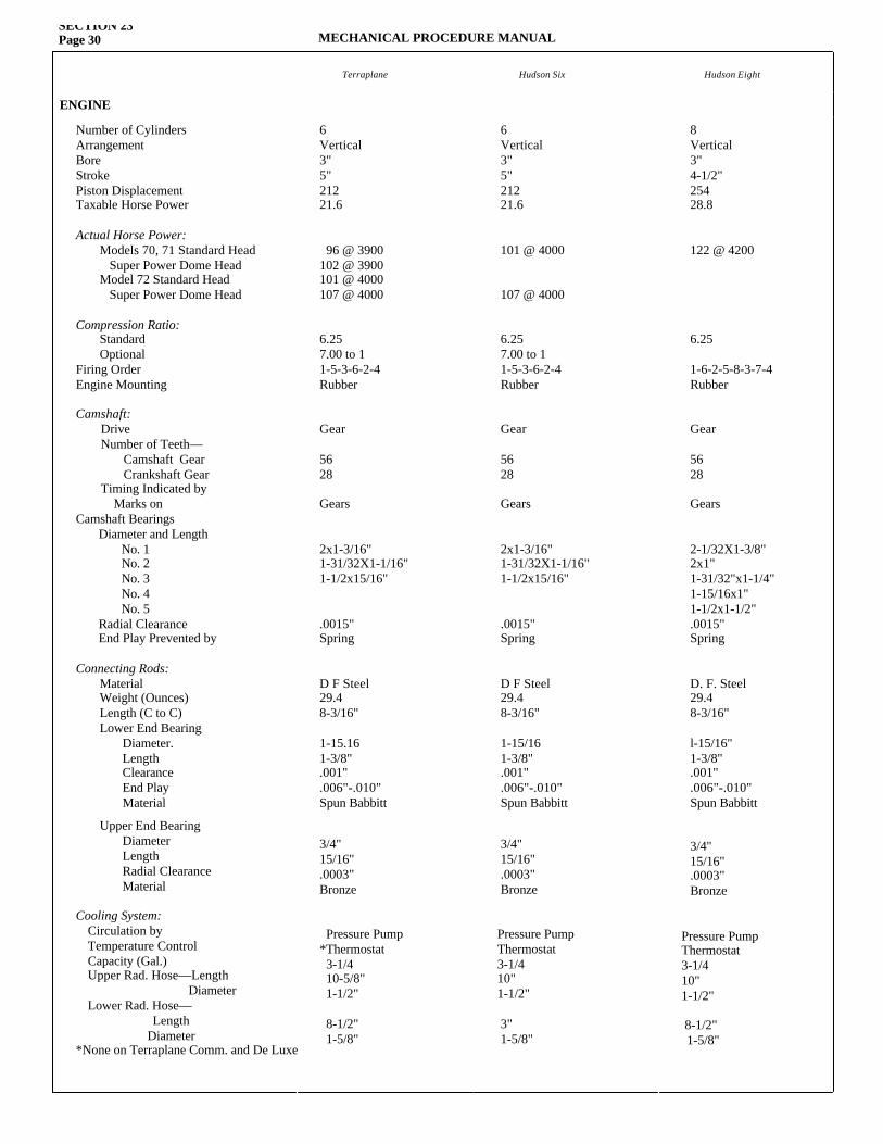
SECTION 23Page 30 MECHANICAL PROCEDURE MANUAL
Terraplane Hudson Six Hudson Eight
ENGINE
Number of Cylinders Arrangement Bore Stroke Piston Displacement Taxable Horse Power
Actual Horse Power:Models 70, 71 Standard Head Super Power Dome HeadModel 72 Standard Head Super Power Dome Head
Compression Ratio:
Standard Optional
Firing Order Engine Mounting
Camshaft:Drive Number of Teeth— Camshaft Gear Crankshaft Gear Timing Indicated by Marks on
Camshaft BearingsDiameter and Length No. 1 No. 2 No. 3 No. 4 No. 5 Radial Clearance End Play Prevented by
Connecting Rods:Material Weight (Ounces) Length (C to C) Lower End Bearing Diameter. Length Clearance End Play Material
Upper End Bearing Diameter Length Radial Clearance Material
Cooling System: Circulation by Temperature Control Capacity (Gal.) Upper Rad. Hose—Length Diameter Lower Rad. Hose— Length
Diameter
6Vertical3"5"21221.6
96 @ 3900102 @ 3900101 @ 4000107 @ 4000
6.257.00 to 11-5-3-6-2-4Rubber
Gear
5628
Gears
2x1-3/16"1-31/32X1-1/16"1-1/2x15/16"
.0015"Spring
D F Steel29.48-3/16"
1-15.161-3/8".001".006"-.010"Spun Babbitt
3/4"15/16".0003"Bronze
Pressure Pump*Thermostat 3-1/4 10-5/8" 1-1/2"
8-1/2" 1-5/8"
6Vertical3"5"21221.6
101 @ 4000
107 @ 4000
6.257.00 to 11-5-3-6-2-4Rubber
Gear
5628
Gears
2x1-3/16"1-31/32X1-1/16"1-1/2x15/16"
.0015"Spring
D F Steel29.48-3/16"
1-15/161-3/8".001".006"-.010"Spun Babbitt
3/4"15/16".0003"Bronze
Pressure PumpThermostat3-1/410"1-1/2"
3"1-5/8"
8Vertical3"4-1/2"25428.8
122 @ 4200
6.25
1-6-2-5-8-3-7-4Rubber
Gear
5628
Gears
2-1/32X1-3/8"2x1"1-31/32"x1-1/4"1-15/16x1"1-1/2x1-1/2".0015"Spring
D. F. Steel29.48-3/16"
l-15/16"1-3/8".001".006"-.010"Spun Babbitt
3/4"15/16".0003"Bronze
Pressure PumpThermostat3-1/410"1-1/2"
8-1/2" 1-5/8"
*None on Terraplane Comm. and De Luxe
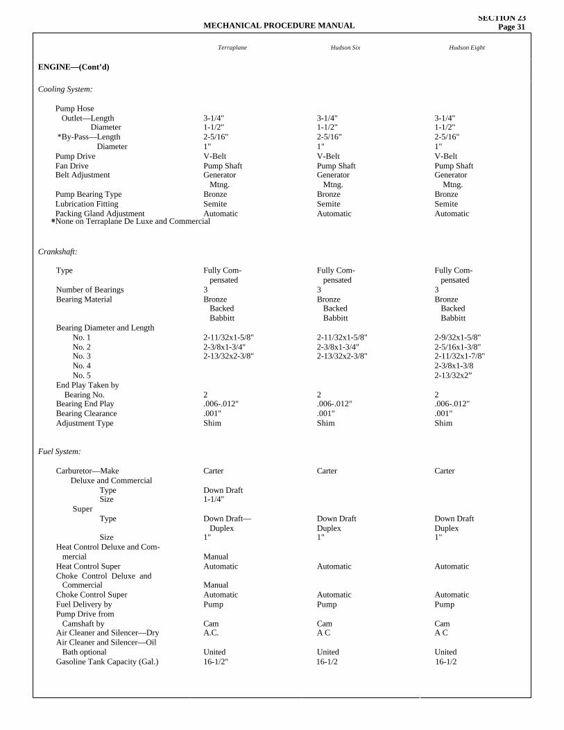
MECHANICAL PROCEDURE MANUALSECTION 23
Page 31
Terraplane Hudson Six Hudson Eight
ENGINE—(Cont’d)
Cooling System:
Pump Hose Outlet—Length Diameter *By-Pass—Length Diameter Pump Drive Fan Drive Belt Adjustment
Pump Bearing Type Lubrication Fitting Packing Gland Adjustment*
Crankshaft:
Type
Number of Bearings Bearing Material
Bearing Diameter and Length No. 1 No. 2 No. 3 No. 4 No. 5 End Play Taken by Bearing No. Bearing End Play Bearing Clearance Adjustment Type
Fuel System:
Carburetor—Make Deluxe and Commercial Type Size Super Type
Size Heat Control Deluxe and Com- mercial Heat Control Super Choke Control Deluxe and CommercialChoke Control SuperFuel Delivery byPump Drive from Camshaft byAir Cleaner and Silencer—DryAir Cleaner and Silencer—Oil Bath optional
Gasoline Tank Capacity (Gal.)
3-1/4"1-1/2"2-5/16"1"V-BeltPump ShaftGenerator Mtng.BronzeSemiteAutomatic
Fully Com- pensated3Bronze Backed Babbitt
2-11/32x1-5/8"2-3/8x1-3/4"2-13/32x2-3/8"
2.006-.012".001"Shim
Carter
Down Draft1-1/4"
Down Draft— Duplex1"
ManualAutomatic
ManualAutomaticPump
CamA.C.
United16-1/2"
3-1/4"1-1/2"2-5/16"1"V-BeltPump ShaftGenerator Mtng.BronzeSemiteAutomatic
Fully Com- pensated3Bronze Backed Babbitt
2-11/32x1-5/8"2-3/8x1-3/4"2-13/32x2-3/8"
2.006-.012".001"Shim
Carter
Down DraftDuplex1"
Automatic
AutomaticPump
CamA C
United16-1/2
3-1/4"1-1/2"2-5/16"1"V-BeltPump ShaftGenerator Mtng.BronzeSemiteAutomatic
Fully Com- pensated3Bronze Backed Babbitt
2-9/32x1-5/8"2-5/16x1-3/8"2-11/32x1-7/8"2-3/8x1-3/82-13/32x2”
2.006-.012".001"Shim
Carter
Down DraftDuplex1"
Automatic
AutomaticPump
CamA C
United16-1/2
*None on Terraplane De Luxe and Commercial
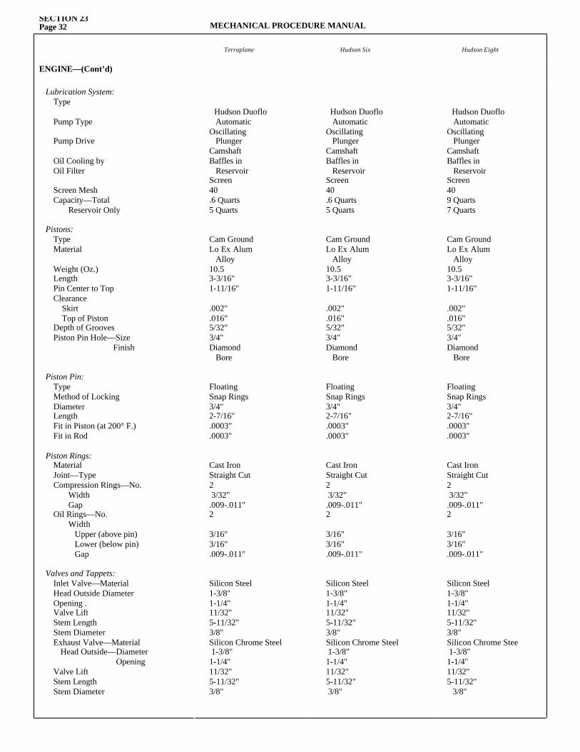
SECTION 23Page 32 MECHANICAL PROCEDURE MANUAL
Terraplane Hudson Six Hudson Eight
ENGINE—(Cont’d)
Lubrication System:Type Pump Type
Pump Drive
Oil Cooling by Oil Filter
Screen Mesh Capacity—Total Reservoir Only
Pistons:Type Material
Weight (Oz.) Length Pin Center to Top Clearance Skirt Top of Piston Depth of Grooves Piston Pin Hole—Size Finish
Piston Pin:Type Method of Locking Diameter Length Fit in Piston (at 200° F.) Fit in Rod
Piston Rings:Material Joint—Type Compression Rings—No. Width Gap Oil Rings—No. Width Upper (above pin) Lower (below pin) Gap
Valves and Tappets:Inlet Valve—Material Head Outside Diameter Opening . Valve Lift Stem Length Stem DiameterExhaust Valve—Material
Head Outside—Diameter Opening
Valve Lift Stem Length Stem Diameter
Hudson Duoflo AutomaticOscillating PlungerCamshaftBaffles in ReservoirScreen40.6 Quarts5 Quarts
Cam GroundLo Ex Alum Alloy10.53-3/16"1-11/16"
.002"
.016"5/32"3/4"Diamond Bore
FloatingSnap Rings3/4"2-7/16".0003".0003"
Cast IronStraight Cut2 3/32".009-.011"2
3/16"3/16".009-.011"
Silicon Steel1-3/8"1-1/4"11/32"5-11/32"3/8"Silicon Chrome Steel 1-3/8"1-1/4"11/32"5-11/32"3/8"
Hudson Duoflo AutomaticOscillating PlungerCamshaftBaffles in ReservoirScreen409 Quarts7 Quarts
Cam GroundLo Ex Alum Alloy10.53-3/16"1-11/16"
.002"
.016"5/32"3/4"Diamond Bore
FloatingSnap Rings3/4"2-7/16".0003".0003"
Cast IronStraight Cut2 3/32".009-.011"2
3/16"3/16".009-.011"
Silicon Steel1-3/8"1-1/4"11/32"5-11/32"3/8"Silicon Chrome Stee 1-3/8"1-1/4"11/32"5-11/32"
3/8"
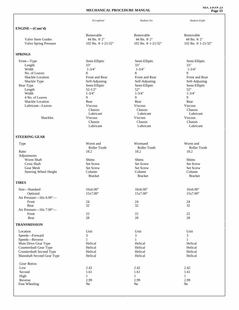
MECHANICAL PROCEDURE MANUALSECTION 23
Page 33
Terraplane Hudson Six Hudson Eight
ENGINE—(Cont’d)
Valve Stem Guides Valve Spring Pressure
Removable 44 lbs. ® 2"102 lbs. ® 1-21/32"
Removable 44 lbs. ® 2"102 lbs. ® 1-21/32"
Removable 44 lbs. ® 2"102 lbs. ® 1-21/32"
SPRINGS
Front—Type Length Width No. of Leaves Shackle Location Shackle Type
Rear Type Length Width 4 No. of Leaves Shackle Location Lubricant—Leaves
Shackles
Semi-Elliptic33" 1-3/4"8Front and RearSelf-AdjustingSemi-Elliptic52-1/2"1-3/4"9RearViscous Chassis LubricantViscous Chassis Lubricant
Semi-Elliptic33" 1-3/4"8Front and RearSelf-AdjustingSemi-Elliptic52"1-3/4"9RearViscous Chassis LubricantViscous Chassis Lubricant
Semi-Elliptic33" 1-3/4"9Front and RearSelf-AdjustingSemi-Elliptic52"1-3/4"9Rear
Viscous Chassis
LubricantViscous Chassis
Lubricant
STEERING GEAR
Type
Ratio Adjustments
Worm Shaft Cross Shaft Gear Mesh Steering Wheel Height
Worm and Roller Tooth18.2
ShimsSet ScrewSet ScrewColumn Bracket
Wormand Roller Tooth18.2
ShimsSet ScrewSet ScrewColumn Bracket
Worm and Roller Tooth18.2
ShimsSet ScrewSet ScrewColumn Bracket
TIRES
Size—Standard Optional Air Pressure—16x 6.00"—
FrontRear
Air Pressure—16x 7.00"—FrontRear
16x6.00"15x7.00"
2432
2228
16x6.00"15x7.00"
2432
2228
16x6.00"15x7.00"
2432
2228
TRANSMISSION
Location Speeds—Forward Speeds—Reverse Main Drive Gear Type Countershaft Gear Type Countershaft Second Type Mainshaft Second Gear Type
Gear Ratios:Low Second High Reverse Free Wheeling
Unit31HelicalHelicalHelicalHelical
2.421.611 2.99No
Unit31HelicalHelicalHelicalHelical
2.421.611 2.99No
Unit31HelicalHelicalHelicalHelical
2.421.611 2.99No
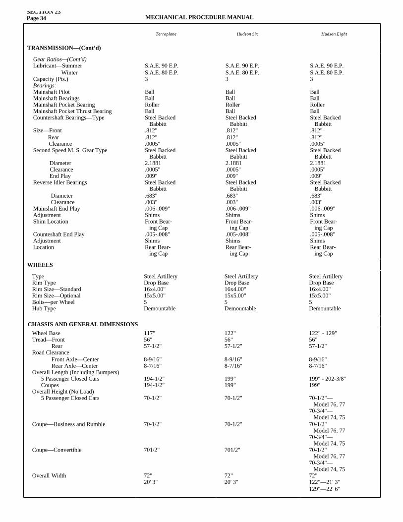
SECTION 23Page 34 MECHANICAL PROCEDURE MANUAL
Terraplane Hudson Six Hudson Eight
TRANSMISSION—(Cont’d)
Gear Ratios—(Cont'd)Lubricant—Summer Winter Capacity (Pts.) Bearings:Mainshaft Pilot Mainshaft Bearings Mainshaft Pocket Bearing Mainshaft Pocket Thrust Bearing Countershaft Bearings—Type
Size—Front Rear Clearance Second Speed M. S. Gear Type
Diameter Clearance End Play Reverse Idler Bearings
Diameter Clearance Mainshaft End Play Adjustment Shim Location
Counteshaft End Play Adjustment Location
S.A.E. 90 E.P.S.A.E. 80 E.P.3 Ball Ball Roller Ball Steel Backed Babbitt .812" .812" .0005" Steel Backed Babbitt 2.1881 .0005" .009" Steel Backed Babbitt .683" .003" .006-.009" Shims Front Bear- ing Cap .005-.008" Shims Rear Bear- ing Cap
S.A.E. 90 E.P.S.A.E. 80 E.P.3 Ball Ball Roller Ball Steel Backed Babbitt .812" .812" .0005" Steel Backed Babbitt 2.1881 .0005" .009" Steel Backed Babbitt .683" .003" .006-.009" Shims Front Bear- ing Cap .005-.008" Shims Rear Bear- ing Cap
S.A.E. 90 E.P.S.A.E. 80 E.P.3 Ball Ball Roller Ball Steel Backed Babbitt .812" .812" .0005" Steel Backed Babbitt 2.1881 .0005" .009" Steel Backed Babbitt .683" .003" .006-.009" Shims Front Bear- ing Cap .005-.008" Shims Rear Bear- ing Cap
WHEELS
Type Rim Type Rim Size—Standard Rim Size—Optional Bolts—per Wheel Hub Type
Steel ArtilleryDrop Base16x4.00"15x5.00"5Demountable
Steel ArtilleryDrop Base16x4.00"15x5.00"5Demountable
Steel ArtilleryDrop Base16x4.00"15x5.00"5Demountable
Wheel Base Tread—Front Rear Road Clearance Front Axle—Center Rear Axle—CenterOverall Length (Including Bumpers) 5 Passenger Closed Cars Coupes Overall Height (No Load) 5 Passenger Closed Cars
Coupe—Business and Rumble
Coupe—Convertible
Overall Width
117"56"57-1/2"
8-9/16"8-7/16"
194-1/2"194-1/2"
70-1/2"
70-1/2"
701/2"
72"20' 3"
122"56"57-1/2"
8-9/16"8-7/16"
199"199"
70-1/2"
70-1/2"
701/2"
72"20' 3"
122" - 129"56"57-1/2"
8-9/16"8-7/16"
199" - 202-3/8"199"
70-1/2"— Model 76, 7770-3/4"— Model 74, 7570-1/2" Model 76, 7770-3/4"— Model 74, 7570-1/2" Model 76, 7770-3/4"— Model 74, 7572"122"—21' 3"129"—22' 6"
CHASSIS AND GENERAL DIMENSIONS