Embed Size (px)
Citation preview
arX
iv:p
hysi
cs/9
7020
16v2
[ph
ysic
s.ac
c-ph
] 1
8 Fe
b 19
97
HIGH ENERGY COLLIDERS
R. B. Palmer, J. C. Gallardo
Center for Accelerator Physics
Brookhaven National LaboratoryUpton, NY 11973-5000, USA
February 2, 2008
Abstract
We consider the high energy physics advantages, disadvantages andluminosity requirements of hadron (pp, pp̄), lepton (e+e−, µ+µ− ) andphoton-photon colliders. Technical problems in obtaining increasedenergy in each type of machine are presented. The machines relativesize are also discussed.
1 Introduction
Particle colliders are only the last evolution of a long history of devicesused to study the violent collisions of particles on one another. Earlierversions used accelerated beams impinging on fixed targets. Fig. 1shows the equivalent beam energy of such machines, plotted versusthe year of their introduction. The early data given was taken fromthe original plot by Livingston[1]. For hadron, i.e. proton or proton-antiproton, machines (Fig. 1a), it shows an increase from around 105
eV with a rectifier generator in 1930, to 1015 eV at the Tevatron (atFermilab near Chicago) in 1988. This represents an increase of morethan a factor of about 33 per decade (the Livingston line, shown asthe dash-line) over 6 decades. By 2005 we expect to have the LargeHadron Collider (at CERN, Switzerland) with an equivalent beamenergy of 1017 eV, which will almost exactly continue this trend. The
1
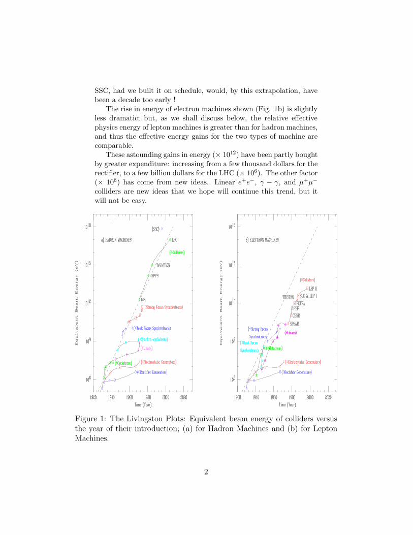
SSC, had we built it on schedule, would, by this extrapolation, havebeen a decade too early !
The rise in energy of electron machines shown (Fig. 1b) is slightlyless dramatic; but, as we shall discuss below, the relative effectivephysics energy of lepton machines is greater than for hadron machines,and thus the effective energy gains for the two types of machine arecomparable.
These astounding gains in energy (× 1012) have been partly boughtby greater expenditure: increasing from a few thousand dollars for therectifier, to a few billion dollars for the LHC (× 106). The other factor(× 106) has come from new ideas. Linear e+e−, γ − γ, and µ+µ−
colliders are new ideas that we hope will continue this trend, but itwill not be easy.
Figure 1: The Livingston Plots: Equivalent beam energy of colliders versusthe year of their introduction; (a) for Hadron Machines and (b) for LeptonMachines.
2
2 Physics Considerations
2.1 General.
Hadron-hadron colliders (pp or pp̄) generate interactions between themany constituents of the hadrons (gluons, quarks and antiquarks);the initial states are not defined and most interactions occur at rela-tively low energy, generating a very large background of uninterestingevents. The rate of the highest energy events is a little higher forantiproton-proton machines, because the antiproton contains valenceantiquarks that can annihilate on the quarks in the proton. But thisis a small effect for colliders above a few TeV, when the interactionsare dominated by interactions between quarks and antiquarks in theirseas, and between the gluons. In either case the individual parton-parton interaction energies (the energies used for physics) are a rel-atively small fraction of the total center of mass energy. This is adisadvantage when compared with lepton machines. An advantage,however, is that all final states are accessible. In addition, as we sawin Figs. 1, hadron machines have been available with higher energiesthan lepton devices, and, as a result, most initial discoveries in Ele-mentary Particle Physics have been made with hadron machines.
In contrast, lepton-antilepton collider generate interactions be-tween the fundamental point-like constituents in their beams, the re-actions produced are relatively simple to understand, the full machineenergies are available for physics and there is negligible background oflow energy events. If the center of mass energy is set equal to the massof a suitable state of interest, then there can be a large cross sectionin the s-channel, in which a single state is generated by the interac-tion. In this case, the mass and quantum numbers of the state areconstrained by the initial beams. If the energy spread of the beams issufficiently narrow, then precision determination of masses and widthsare possible.
A gamma-gamma collider, like the lepton-antilepton machines,would have all the machine energy available for physics, and wouldhave well defined initial states, but these states would be differentfrom those with the lepton machines, and thus be complementary tothem.
For most purposes (technical considerations aside) e+e−and µ+µ−
colliders would be equivalent. But in the particular case of s-channelHiggs boson production, the cross section, being proportional to the
3
mass squared, is more than 40,000 times greater for muons than elec-trons. When technical considerations are included, the situation ismore complicated. Muon beams are harder to polarize and muoncolliders will have much higher backgrounds from decay products ofthe muons. On the other hand muon collider interactions will requireless radiative correction and will have less energy spread from beam-strahlung.
Each type of collider has its own advantages and disadvantages forHigh Energy Physics: they would be complementary.
2.2 Required Luminosity for Lepton Collid-
ers.
In lepton machines the full center of mass of the leptons is available forthe final state of interest and a “physics energy” Ephy can be definedthat is equal to the total center of mass energy.
Ephy = Ec of m (1)
Since fundamental cross sections fall as the square of the center ofmass energies involved, so, for a given rate of events, the luminosityof a collider must rise as the square of its energy. A reasonable targetluminosity is one that would give 10,000 events per unit of R peryear (the cross section for lepton pair production is one R, the totalcross section is about 20 R, and somewhat energy dependent as newchannels open up):
Lreq. ≈ 1034 (cm−2s−1)
(
Ephy
1 (TeV)
)2
(2)
2.3 The Effective Physics Energies of Hadron
Colliders.
Hadrons, being composite, have their energy divided between theirvarious constituents. A typical collision of constituents will thus havesignificantly less energy than that of the initial hadrons. Studies donein Snowmass 82 and 96 suggest that, for a range of studies, and giventhe required luminosity (as defined in Eq. 2), then the hadron ma-chine’s effective “physics” energy is between about 1/3 and 1/10 of itstotal. We will take a value of 1/7:
Ephy(L = Lreq.) ≈Ec of m
7
4
The same studies have also concluded that a factor of 10 in luminosityis worth about a factor of 2 in effective physics energy, this beingapproximately equivalent to:
Ephy(L) = Ephy(L = Lreq.)
(
L
Lreq
)0.3
From which, with Eq. 2, one obtains:
Ephy ≈
(
Ec of m
7(TeV )
)0.6 (L
1034(cm−2s−1)
)0.2
(TeV ) (3)
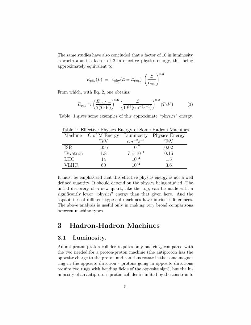
Table 1 gives some examples of this approximate “physics” energy.
Table 1: Effective Physics Energy of Some Hadron MachinesMachine C of M Energy Luminosity Physics Energy
TeV cm−2s−1 TeVISR .056 1032 0.02Tevatron 1.8 7 × 1031 0.16LHC 14 1034 1.5VLHC 60 1034 3.6
It must be emphasized that this effective physics energy is not a welldefined quantity. It should depend on the physics being studied. Theinitial discovery of a new quark, like the top, can be made with asignificantly lower “physics” energy than that given here. And thecapabilities of different types of machines have intrinsic differences.The above analysis is useful only in making very broad comparisonsbetween machine types.
3 Hadron-Hadron Machines
3.1 Luminosity.
An antiproton-proton collider requires only one ring, compared withthe two needed for a proton-proton machine (the antiproton has theopposite charge to the proton and can thus rotate in the same magnetring in the opposite direction - protons going in opposite directionsrequire two rings with bending fields of the opposite sign), but the lu-minosity of an antiproton- proton collider is limited by the constraints
5
in antiproton production. A luminosity of at least 1032 cm−2s−1
is expected at the antiproton-proton Tevatron; and a luminosity of1033 cm−2s−1 may be achievable, but the LHC, a proton-proton ma-chine, is planned to have a luminosity of 1034 cm−2s−1: an order ofmagnitude higher. Since the required luminosity rises with energy,proton-proton machines seem to be favored for future hadron collid-ers.
The LHC and other future proton-proton machines might[2] beupgradable to 1035 cm−2s−1, but radiation damage to a detector wouldthen be a severe problem. The 60 TeV Really Large Hadron Colliders(RLHC: high and low field versions) discussed at Snowmass are beingdesigned as proton-proton machines with luminosities of 1034 cm−2s−1
and it seems reasonable to assume that this is the highest practicalvalue.
3.2 Size and Cost.
The size of hadron-hadron machines is limited by the field of the mag-nets used in their arcs. A cost minimum is obtained when a balanceis achieved between costs that are linear in length, and those that risewith magnetic field. The optimum field will depend on the technolo-gies used both for the the linear components (tunnel, access, distri-bution, survey, position monitors, mountings, magnet ends, etc) andthose of the magnets themselves, including the type of superconductorused.
The first hadron collider, the 60 GeV ISR at CERN, used conven-tional iron pole magnets at a field less than 2 T. The only currenthadron collider, the 2 TeV Tevatron, at FNAL, uses NbTi supercon-ducting magnets at approximately 4 ◦K giving a bending field of about4.5 T. The 14 TeV Large Hadron Collider (LHC), under constructionat CERN, plans to use the same material at 1.8 ◦K yielding bendingfields of about 8.5T.
Future colliders may use new materials allowing even higher mag-netic fields. Model magnets have been made with Nb3Sn, and studiesare underway on the use of high Tc superconductor. Bi2Sr2Ca1Cu2O8
(BSCCO) material is currently available in useful lengths as powder-in-Ag tube processed tape. It has a higher critical temperature andfield than conventional superconductors, but, even at 4 ◦K, its currentdensity is less than Nb3Sn at all fields below 15 T. It is thus unsuitablefor most accelerator magnets. In contrast YBa2Cu3O7 (YBCO) ma-
6
terial has a current density above that for Nb3Sn (4 ◦K), at all fieldsand temperatures below 20 ◦K. But this material must be deposited onspecially treated metallic substrates and is not yet available in lengthsgreater than 1 m. It is reasonable to assume, however, that it will beavailable in useful lengths in the not too distant future. it mean forhadron colliders.
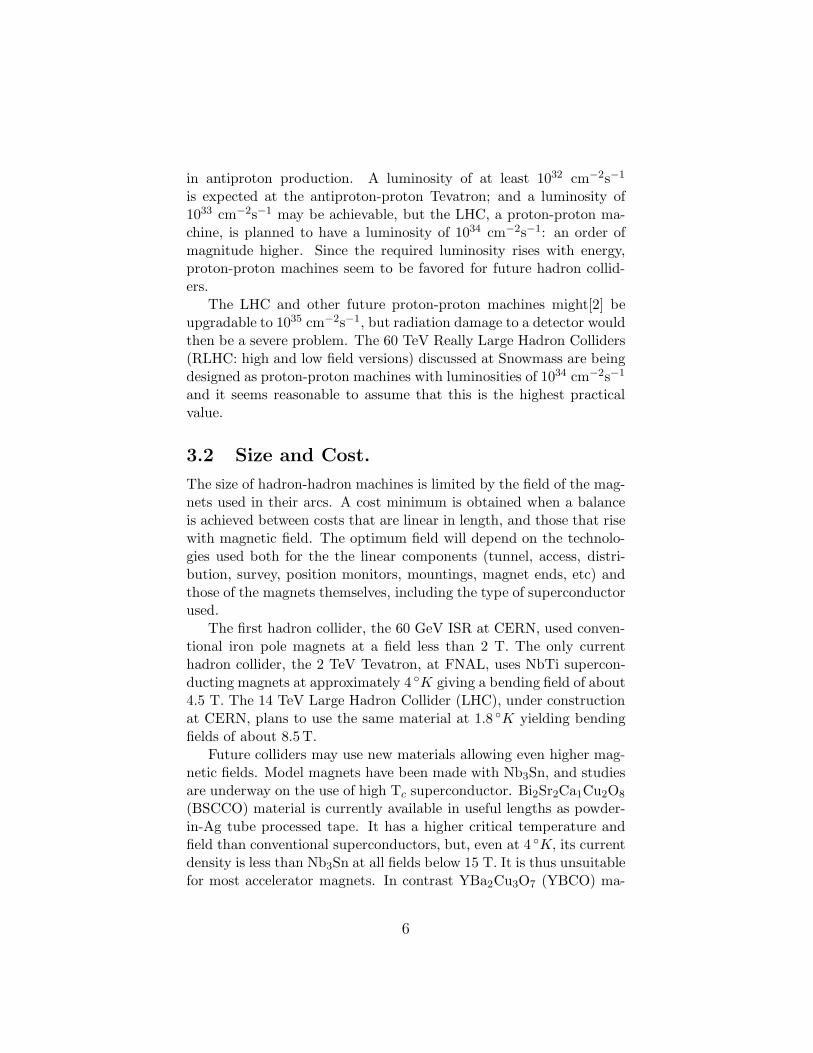
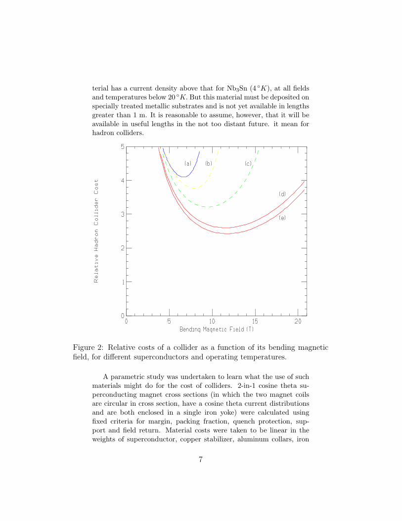
Figure 2: Relative costs of a collider as a function of its bending magneticfield, for different superconductors and operating temperatures.
A parametric study was undertaken to learn what the use of suchmaterials might do for the cost of colliders. 2-in-1 cosine theta su-perconducting magnet cross sections (in which the two magnet coilsare circular in cross section, have a cosine theta current distributionsand are both enclosed in a single iron yoke) were calculated usingfixed criteria for margin, packing fraction, quench protection, sup-port and field return. Material costs were taken to be linear in theweights of superconductor, copper stabilizer, aluminum collars, iron
7
yoke and stainless steel support tube. The cryogenic costs were takento be inversely proportional to the operating temperature, and linearin the outer surface area of the cold mass. Tunnel, access, vacuum,alignment, focusing, and diagnostic costs were taken to be linear withtunnel length. The relative values of the cost dependencies were scaledfrom LHC estimates.
Results are shown in Fig. 2. Costs were calculated assuming NbTiat (a) 4 ◦K, and (b) 1.8 ◦K, Nb3 Sn at (c) 4 ◦K and YBCO High Tc at20 ◦K (d) and (e). NbTi and Nb3 Sn costs per unit weight were takento be the same; YBCO was taken to be either equal to NbTi (in (d)),or 4 times NbTi (in (e)). It is seen that the optimum field moves fromabout 6 T for NbTi at 4 ◦K to about 12 T for YBCO at 20 ◦K; whilethe total cost falls by almost a factor of 2.
One may note that the optimized cost per unit length remainsapproximately constant. This might have been expected: at the costminimum, the cost of linear and field dependent terms are matched,and the total remains about twice that of the linear terms.
The above study assumes this particular type of magnet and maynot be indicative of the optimization for radically different designs.A group at FNAL[3] is considering an iron dominated, alternatinggradient, continuous, single turn collider magnet design (Low fieldRLHC). Its field would be only 2 T and circumference very large (350km for 60 TeV), but with its simplicity and with tunneling innovations,it is hoped to make its cost lower than the smaller high field designs.There are however greater problems in achieving high luminosity withsuch a machine than with the higher field designs.
4 Circular e+e−Machines
4.1 Luminosity.
The luminosities of most circular electron-positron colliders have beenbetween 1031 and 1032 cm−2s−1, CESR is fast approaching 1033 cm−2s−1
and machines are now being constructed with even higher values.Thus, at least in principle, luminosity does not seem to be a limi-tation (although it may be noted that the 0.2 TeV electron- positroncollider LEP has a luminosity below the requirement of Eq.2).
8
4.2 Size and Cost.
At energies below 100 MeV, using a reasonable bending field, the sizeand cost of a circular electron machine is approximately proportionalto its energy. But at higher energies, if the bending field B is main-tained, the energy lost ∆Vturn to synchrotron radiation rises rapidly
∆Vturn ∝E4
R m4∝
E3 B
m4(4)
and soon becomes excessive (R is the radius of the ring). A costminimum is then obtained when the cost of the ring is balanced bythe cost of the rf needed to replace the synchrotron energy loss. If thering cost is proportional to its circumference, and the rf is proportionalto its voltage then the size and cost of an optimized machine rises asthe square of its energy.
The highest energy circular e+e−collider is the LEP at CERNwhich has a circumference of 27 km, and will achieve a maximumcenter of mass energy of about 0.2 TeV. Using the predicted scaling, a0.5 TeV circular collider would have to have a 170 km circumference,and would be very expensive.
5 e+e−Linear Colliders
For energies much above that of LEP (0.2 TeV) it is probably imprac-tical to build a circular electron collider. The only possibility thenis to build two electron linacs facing one another. Interactions occurat the center, and the electrons, after they have interacted, must bediscarded. The size of such colliders is now dominated by the lengthof the two linacs and is inversely proportional to the average accel-erating gradient in those structures. In current proposals[4] usingconventional rf, these lengths are far greater than the circumferencesof hadron machines of the same beam energy, but as noted in section2.3, the effective physics energy of a lepton machine is higher thanthat of a hadron machine with the same beam energy, thus offsettingsome of this disadvantage.
5.1 Luminosity.
The luminosity L of a linear collider can be written:
L =1
4πE
N
σx
Pbeam
σy
ncollisions (5)
9
where σx and σy are average beam spot sizes including any pincheffects, and we take σx to be much greater than σy. E is the beamenergy, Pbeam is the total beam power, and, in this case, ncollisions = 1.This can be expressed[8] as,
L ≈1
4πE
nγ
2roα U(Υ)
Pbeam
σy
(6)
where the quantum correction U(Υ) is given by
U(Υ) ≈
√
1
1 + Υ2/3(7)
with
Υ ≈2F2r
2o
α
N γ
σz σx(8)
F2 ≈ 0.43, ro is the classical electromagnetic radius, α is the fine-structure constant, and σz is the rms bunch length. The quantumcorrection Υ is close to unity for all proposed machines with energyless than 2 TeV, and this term is often omitted[5]. Even in a 5 TeVdesign[6], an Υ of 21 gives a suppression factor of only 3. nγ is thenumber of photons emitted by one electron as it passes through theother bunch. If nγ is significantly greater than one, then problems areencountered with backgrounds of electron pairs and mini-jets, or withunacceptable beamstrahlung energy loss. Thus nγ can be taken as arough criterion of these effects and constrained to a fixed value. Wethen find:
L ∝1
E
Pbeam
σy U(Υ)
which may be compared to the required luminosity that increases asthe square of energy, giving the requirement:
Pbeam
σy U(Υ)∝ E3. (9)
It is this requirement that makes it hard to design very high energylinear colliders. High beam power demands high efficiencies and heavywall power consumption. A small σy requires tight tolerances, lowbeam emittances and strong final focus. And a small value of U(Υ) ishard to obtain because of its weak dependence on Υ (∝ Υ−1/3).
10
5.2 Conventional RF.
The gradients for structures have limits that are frequency dependent,but the real limit on accelerating gradients in these designs come froma trade off between the cost of rf power against the cost of length. Theuse of high frequencies reduces the stored energy in the cavities, re-ducing the rf costs and allowing higher accelerating gradients: theoptimized gradients being roughly proportional to the frequency upto a limit of approximately 250MeV/m at a frequency of the order of100GHz. One might thus conclude then that higher frequencies shouldalways be preferred. There are however counterbalancing considera-tions from the requirements of luminosity.
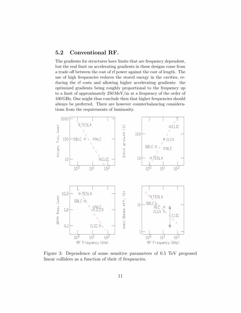
Figure 3: Dependence of some sensitive parameters of 0.5 TeV proposedlinear colliders as a function of their rf frequencies.
11
Fig. 3, using parameters from current 0.5 TeV linear collider pro-posals [4], plots some relevant parameters against the rf frequency.One sees that as the frequencies rise,
• the required alignment tolerances get tighter;
• the resolution of beam position monitors must also be better;and
• despite these better alignments, the calculated emittance growthduring acceleration is worse; and
• the wall-power to beam-power efficiencies are also less.
Thus while length and cost considerations may favor high frequencies,yet luminosity considerations would prefer lower frequencies.
5.3 Superconducting RF.
If, however, the rf costs can be reduced, for instance when supercon-ducting cavities are used, then there will be no trade off between rfpower cost and length and higher gradients would lower the length andthus the cost. Unfortunately the gradients achievable in currently op-erating niobium superconducting cavities is lower than that planned inthe higher frequency conventional rf colliders. Theoretically the limitis about 40 MV/m, but practically 25 MV/m is as high as seems pos-sible. Nb3Sn and high Tc materials may allow higher field gradientsin the future.
The removal of the requirements for very high peak rf power al-lows the choice of longer wavelengths (the TESLA collaboration isproposing 23 cm at 1.3 GHz) thus greatly relieving the emittance re-quirements and tolerances, for a given luminosity.
At the current 25 MeV per meter gradients, the length and costof a superconducting machine is probably higher than for the conven-tional rf designs. With greater luminosity more certain, its proponentscan argue that it is worth the greater price. If, using new supercon-ductors, higher gradients become possible, thus reducing lengths andcosts, then the advantages of a superconducting solution might be-come overwhelming.
5.4 At Higher Energies.
At higher energies (as expected from Eq. 9), obtaining the requiredluminosity gets harder. Fig.4 shows the dependency of some example
12
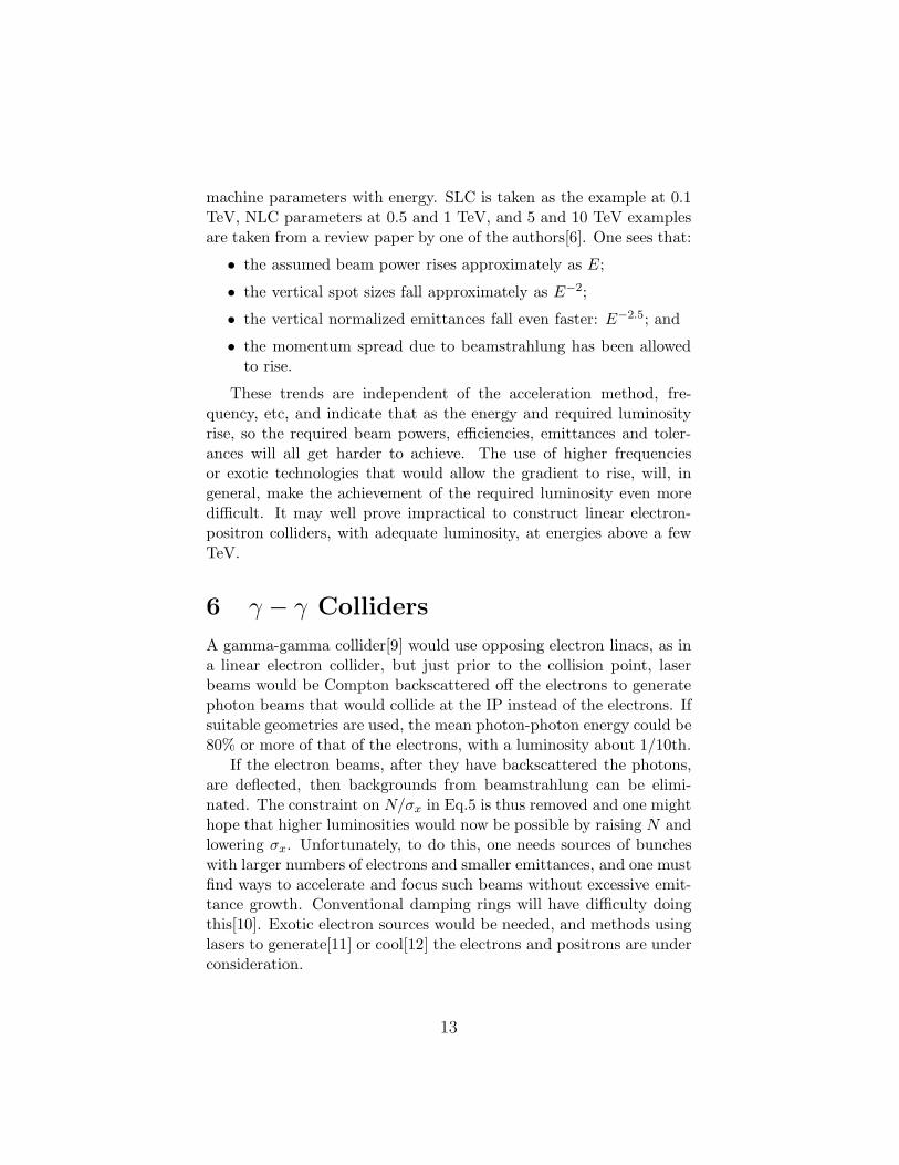
machine parameters with energy. SLC is taken as the example at 0.1TeV, NLC parameters at 0.5 and 1 TeV, and 5 and 10 TeV examplesare taken from a review paper by one of the authors[6]. One sees that:
• the assumed beam power rises approximately as E;
• the vertical spot sizes fall approximately as E−2;
• the vertical normalized emittances fall even faster: E−2.5; and
• the momentum spread due to beamstrahlung has been allowedto rise.
These trends are independent of the acceleration method, fre-quency, etc, and indicate that as the energy and required luminosityrise, so the required beam powers, efficiencies, emittances and toler-ances will all get harder to achieve. The use of higher frequenciesor exotic technologies that would allow the gradient to rise, will, ingeneral, make the achievement of the required luminosity even moredifficult. It may well prove impractical to construct linear electron-positron colliders, with adequate luminosity, at energies above a fewTeV.
6 γ − γ Colliders
A gamma-gamma collider[9] would use opposing electron linacs, as ina linear electron collider, but just prior to the collision point, laserbeams would be Compton backscattered off the electrons to generatephoton beams that would collide at the IP instead of the electrons. Ifsuitable geometries are used, the mean photon-photon energy could be80% or more of that of the electrons, with a luminosity about 1/10th.
If the electron beams, after they have backscattered the photons,are deflected, then backgrounds from beamstrahlung can be elimi-nated. The constraint on N/σx in Eq.5 is thus removed and one mighthope that higher luminosities would now be possible by raising N andlowering σx. Unfortunately, to do this, one needs sources of buncheswith larger numbers of electrons and smaller emittances, and one mustfind ways to accelerate and focus such beams without excessive emit-tance growth. Conventional damping rings will have difficulty doingthis[10]. Exotic electron sources would be needed, and methods usinglasers to generate[11] or cool[12] the electrons and positrons are underconsideration.
13
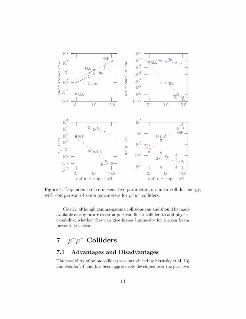
Figure 4: Dependence of some sensitive parameters on linear collider energy,with comparison of same parameters for µ+µ− colliders.
Clearly, although gamma-gamma collisions can and should be madeavailable at any future electron-positron linear collider, to add physicscapability, whether they can give higher luminosity for a given beampower is less clear.
7 µ+µ− Colliders
7.1 Advantages and Disadvantages
The possibility of muon colliders was introduced by Skrinsky et al.[13]and Neuffer[14] and has been aggressively developed over the past two
14
years in a series of meetings and workshops[15, 16, 17, 18, 19].The main advantages of muons, as opposed to electrons, for a
lepton collider are:
• The synchrotron radiation, that forces high energy electron col-liders to be linear, is (see Eq. 4) inversely proportional to thefourth power of mass: It is negligible in muon colliders. Thusa muon collider can be circular. In practice this means in canbe smaller. The linacs for the SLAC proposal for a 0.5 TeVNext Linear Collider would be 20 km long. The ring for a muoncollider of the same energy would be only about 1.3 km circum-ference.
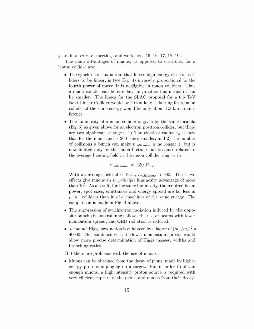
• The luminosity of a muon collider is given by the same formula(Eq. 5) as given above for an electron positron collider, but thereare two significant changes: 1) The classical radius ro is nowthat for the muon and is 200 times smaller; and 2) the numberof collisions a bunch can make ncollisions is no longer 1, but isnow limited only by the muon lifetime and becomes related tothe average bending field in the muon collider ring, with
ncollisions ≈ 150 Bave
With an average field of 6 Tesla, ncollisions ≈ 900. These twoeffects give muons an in principle luminosity advantage of morethan 105. As a result, for the same luminosity, the required beampower, spot sizes, emittances and energy spread are far less inµ+µ− colliders than in e+e−machines of the same energy. Thecomparison is made in Fig. 4 above.
• The suppression of synchrotron radiation induced by the oppo-site bunch (beamstrahlung) allows the use of beams with lowermomentum spread, and QED radiation is reduced.
• s-channel Higgs production is enhanced by a factor of (mµ/me)2 ≈
40000. This combined with the lower momentum spreads wouldallow more precise determination of Higgs masses, widths andbranching ratios.
But there are problems with the use of muons:
• Muons can be obtained from the decay of pions, made by higherenergy protons impinging on a target. But in order to obtainenough muons, a high intensity proton source is required withvery efficient capture of the pions, and muons from their decay.
15
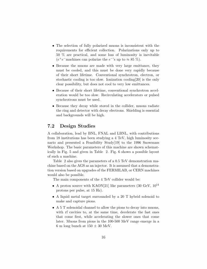
• The selection of fully polarized muons is inconsistent with therequirements for efficient collection. Polarizations only up to50 % are practical, and some loss of luminosity is inevitable(e+e−machines can polarize the e−’s up to ≈ 85 %).
• Because the muons are made with very large emittance, theymust be cooled, and this must be done very rapidly becauseof their short lifetime. Conventional synchrotron, electron, orstochastic cooling is too slow. Ionization cooling[20] is the onlyclear possibility, but does not cool to very low emittances.
• Because of their short lifetime, conventional synchrotron accel-eration would be too slow. Recirculating accelerators or pulsedsynchrotrons must be used.
• Because they decay while stored in the collider, muons radiatethe ring and detector with decay electrons. Shielding is essentialand backgrounds will be high.
7.2 Design Studies
A collaboration, lead by BNL, FNAL and LBNL, with contributionsfrom 18 institutions has been studying a 4 TeV, high luminosity sce-nario and presented a Feasibility Study[19] to the 1996 SnowmassWorkshop. The basic parameters of this machine are shown schemat-ically in Fig. 5 and given in Table 2. Fig. 6 shows a possible layoutof such a machine.
Table 2 also gives the parameters of a 0.5 TeV demonstration ma-chine based on the AGS as an injector. It is assumed that a demonstra-tion version based on upgrades of the FERMILAB, or CERN machineswould also be possible.
The main components of the 4 TeV collider would be:
• A proton source with KAON[21] like parameters (30 GeV, 1014
protons per pulse, at 15 Hz).
• A liquid metal target surrounded by a 20 T hybrid solenoid tomake and capture pions.
• A 5 T solenoidal channel to allow the pions to decay into muons,with rf cavities to, at the same time, decelerate the fast onesthat come first, while accelerating the slower ones that comelater. Muons from pions in the 100-500 MeV range emerge in a6 m long bunch at 150 ± 30 MeV.
16
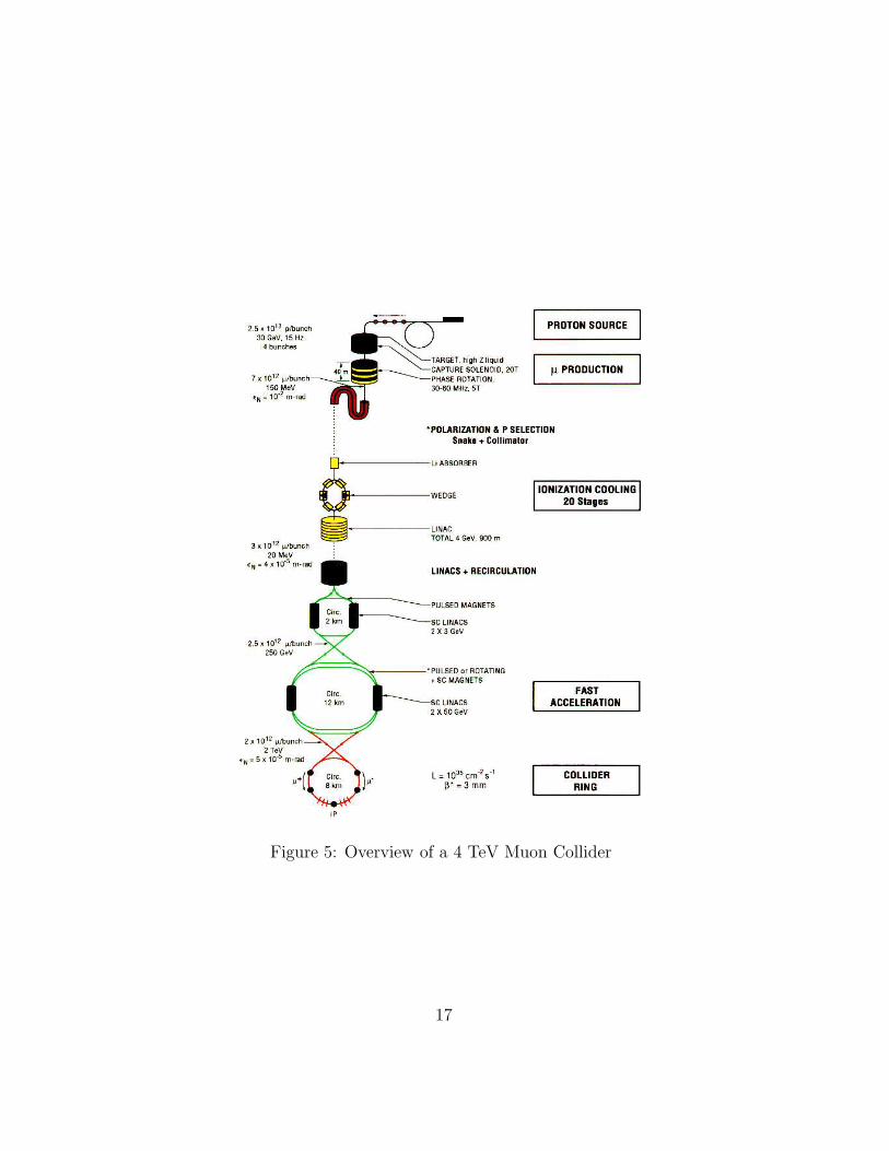
Figure 5: Overview of a 4 TeV Muon Collider
17
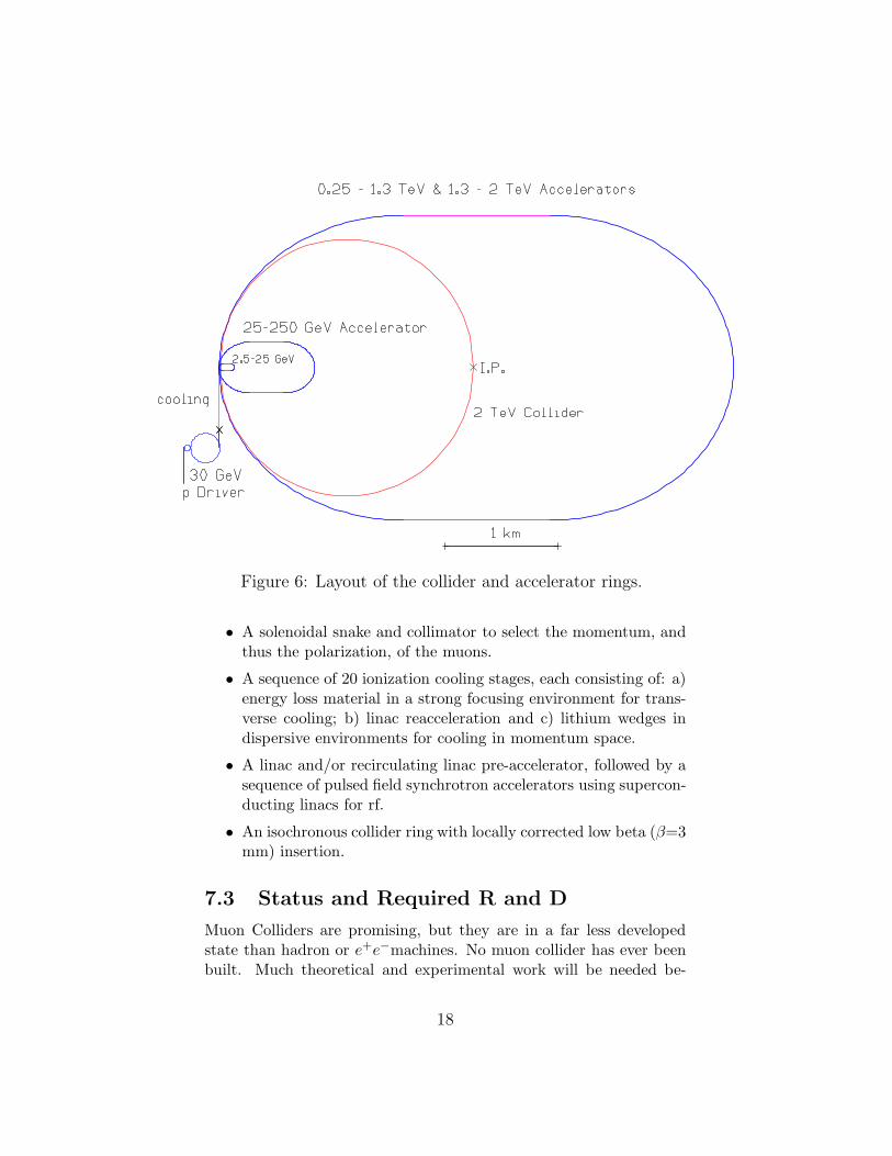
Figure 6: Layout of the collider and accelerator rings.
• A solenoidal snake and collimator to select the momentum, andthus the polarization, of the muons.
• A sequence of 20 ionization cooling stages, each consisting of: a)energy loss material in a strong focusing environment for trans-verse cooling; b) linac reacceleration and c) lithium wedges indispersive environments for cooling in momentum space.
• A linac and/or recirculating linac pre-accelerator, followed by asequence of pulsed field synchrotron accelerators using supercon-ducting linacs for rf.
• An isochronous collider ring with locally corrected low beta (β=3mm) insertion.
7.3 Status and Required R and D
Muon Colliders are promising, but they are in a far less developedstate than hadron or e+e−machines. No muon collider has ever beenbuilt. Much theoretical and experimental work will be needed be-
18
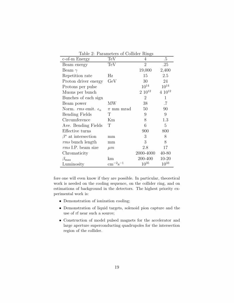
Table 2: Parameters of Collider Ringsc-of-m Energy TeV 4 .5Beam energy TeV 2 .25Beam γ 19,000 2,400Repetition rate Hz 15 2.5Proton driver energy GeV 30 24Protons per pulse 1014 1014
Muons per bunch 2 1012 4 1012
Bunches of each sign 2 1Beam power MW 38 .7Norm. rms emit. ǫn π mm mrad 50 90Bending Fields T 9 9Circumference Km 8 1.3Ave. Bending Fields T 6 5Effective turns 900 800β∗ at intersection mm 3 8rms bunch length mm 3 8rms I.P. beam size µm 2.8 17Chromaticity 2000-4000 40-80βmax km 200-400 10-20Luminosity cm−2s−1 1035 1033
fore one will even know if they are possible. In particular, theoreticalwork is needed on the cooling sequence, on the collider ring, and onestimations of background in the detectors. The highest priority ex-perimental work is:
• Demonstration of ionization cooling;
• Demonstration of liquid targets, solenoid pion capture and theuse of rf near such a source;
• Construction of model pulsed magnets for the accelerator andlarge aperture superconducting quadrupoles for the intersectionregion of the collider.
19
8 Comparison of Machines
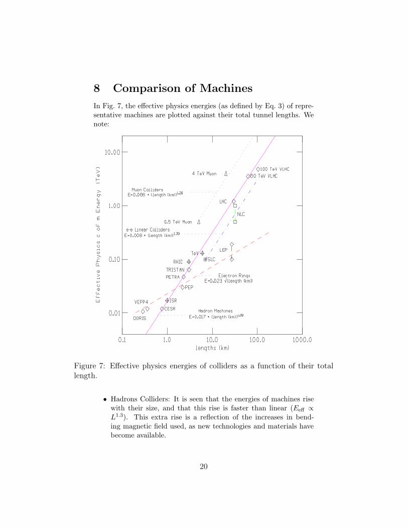
In Fig. 7, the effective physics energies (as defined by Eq. 3) of repre-sentative machines are plotted against their total tunnel lengths. Wenote:
Figure 7: Effective physics energies of colliders as a function of their totallength.
• Hadrons Colliders: It is seen that the energies of machines risewith their size, and that this rise is faster than linear (Eeff ∝
L1.3). This extra rise is a reflection of the increases in bend-ing magnetic field used, as new technologies and materials havebecome available.
20
• Circular Electron-Positron Colliders: The energies of these ma-chines rise approximately as the square root of their size, as ex-pected from the cost optimization discussed in section 4 above.
• Linear Electron-Positron Colliders: The SLAC Linear Collideris the only existing machine of this type. One example of aproposed machine (the NLC) is plotted. The line drawn has thesame slope as for the hadron machines and implies a similar risein accelerating gradient, as technologies advance.
• Muon-Muon Colliders: Only the 4 TeV collider, discussed above,and the 0.5 TeV demonstration machine have been plotted. Theline drawn has the same slope as for the hadron machines.
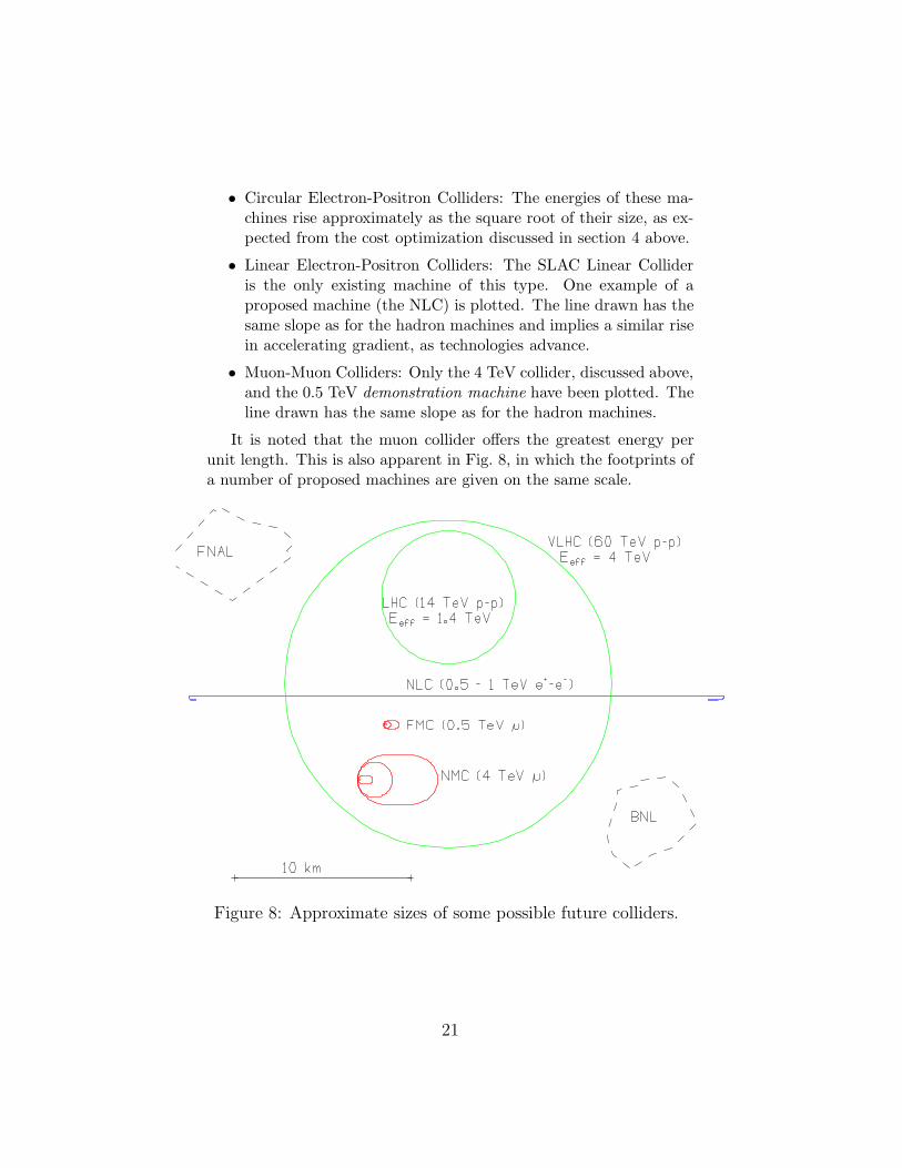
It is noted that the muon collider offers the greatest energy perunit length. This is also apparent in Fig. 8, in which the footprints ofa number of proposed machines are given on the same scale.
Figure 8: Approximate sizes of some possible future colliders.
21
9 Conclusions
Our conclusions, with the caveat that they are indeed only our opin-ions, are:
• The LHC is a well optimized and appropriate next step towardshigh effective physics energy.
• A Very Large Hadron Collider with energy greater than the SSC(e.g. 60 TeV c-of-m) and cost somewhat less than the SSC, maywell be possible with the use of high Tc superconductors thatmay become available.
• A “Next Linear Collider” is the only clean way to complementthe LHC with a lepton machine, and the only way to do sosoon. But it appears that even a 0.5 TeV collider may be moreexpensive than the LHC, has significantly less effective physicsenergy, and will be technically challenging. Obtaining the designluminosity may not be easy.
• Extrapolating conventional rf e+e−linear colliders to energiesabove 1 or 2 TeV will be very difficult. Raising the rf frequencycan reduce length and probably cost for a given energy, but ob-taining luminosity increasing as the square of energy, as required,may not be feasible.
• Laser driven accelerators are becoming more realistic and can beexpected to have a significantly lower cost per TeV. But the ratioof luminosity to wall power is likely to be significantly worse thanfor conventional rf driven machines. Colliders using such tech-nologies are thus unlikely to achieve the very high luminositiesneeded for physics research at higher energies.
• A higher gradient superconducting Linac collider using Nb3Snor high Tc materials, if it became technically possible, could bethe most economical way to attain the required luminosities ina higher energy e+e−collider.
• Gamma-gamma collisions can and should be obtained at anyfuture electron-positron linear collider. They would add physicscapability to such a machine, but, despite their freedom from thebeamstrahlung constraint, may not achieve higher luminosity.
• A Muon Collider, being circular, could be far smaller than aconventional rf e+e−linear collider of the same energy. Very pre-liminary estimates suggest that it would also be significantly
22
less expensive. The ratio of luminosity to wall power for suchmachines, above 2 TeV, may be better than that for electronpositron machines, and extrapolation to a center of mass energyof 4 TeV does not seem unreasonable. If research and develop-ment can show that it is practical, then a 0.5 TeV muon collidercould be a useful complement to e+e−colliders, and, at higherenergies (e.g. 4 TeV), could be a viable alternative.
10 Acknowledgments
We acknowledge important contributions from many colleagues, es-pecially those that contributed to the feasibitity study submitted tothe Snowmass Workshop 96 Proceedings[19] from which much of thematerial and some text for this report, has been taken: In particularwe acknowledge the contributions of the Editors of each one of thechapters of the µ+µ− Collider: A Feasibility Study: V. Barger, J.Norem, R. Noble, H. Kirk, R. Fernow, D. Neuffer, J. Wurtele, D. Lis-sauer, M. Murtagh, S. Geer, N. Mokhov and D. Cline. This research
was supported by the U.S. Department of Energy under Contract No.DE-ACO2-76-CH00016 and DE-AC03-76SF00515.
11 Discusion
R.Taylor: I was afraid if it was going to run over but it worked wellbecause we spent hardly any time on what is wrong with muon collid-ers compared to the length of time we spent on what was wrong withlinear colliders. (laugh)K.Henry: So what’s wrong with the muon colliders? (laugh)Palmer: I can tell you which parts of the muon collider keep me awakeat night. That changes, of course, from week to week. Enormousprogress has been made even in last few months. The collider latticehad been a problem, but doesn’t worry me any more. We also hada serious difficulty in the transverse cooling lattices. When we firsttried tracking particles through, some muons never came out. Theywere hitting resonances. Now we understand that problem and havetracked through transverse cooling sections that work.
But we have not done energy cooling yet. We know theoreticallyhow to do it, but we haven’t got a realistic lattice and tracked muons
23
through it. Having been burnt once, I will have sleepless nights untilwe get past that hurdle.
The collider ring may have instability problems that are not fullyunderstood. We think that it will have to have BNS damping appliedby using RF quadrupoles, but we haven’t worked that out.
We haven’t done many things that need to be done, but I do notyet see any insuperable problems. I do not sleep that badly. (laugh)Erich Vogt: Have you considered using surface muons which have beenconsidered at KEK as an alternative muon source?Palmer: Yes, but we need bunches with very large numbers of muonsin order to get luminosity. It seems to be difficult to get them fromsurface muons. And there is a more basic problem, we need bothcharges, I do not think this is possible with surface muons.Edward Witten: What fraction of muons decay before entering thering?Palmer: With the parameters we’ve considered, about three-fourthsare lost. Half decay during the cooling sequence, and half of theremainder decay during acceleration.Alfred Mann: It would be interesting to hear about the shieldingproblems that arise in the muon-muon collider.Palmer: I think I know what you’re trying to get at. (laugh) Theradiation from decay electrons in the ring itself can be shielded rela-tively easily. Dumping 2 Tev muons is more difficult because it takes2 km of concrete to stop them, but that too is ok. The problem youmay be hinting at, which I didn’t mention because we are not yet sureabout the calculation, is radiation from neutrinos. Muons decaying ina straight section of the collider ring produce a neutrino beam withopening angle of 1/γ that, for a 4 TeV collider, is only a meter ortwo wide 35 km away. The neutrino cross section is small, but risinglinearly with energy, and there are 20 mega-watts of power in thatbeam. The resulting radiation level appears to be close to the legallimit. You can’t shield it and it always breaks ground somewhere be-cause unfortunately the earth is round. (laugh) It rises as the fourthpower of the energy and is only inverse with the machine depth. Thus,even if a 4 TeV µ+µ− collider is just ok, a 10 Tev collider is probablyimpractical.Leon Lederman: Going back to the beginning of your talk on theLivingston Plot, you said that there is a 106 rise of cost rise for a 1012
rise in energy so we are 106 cleverer.(laugh) Did you include inflationin those numbers?
24
Palmer: Yes, I did, but I may not have done it right. Down the bottomI had 100 Kev and I said to myself what I could buy that now for afew thousand dollars. This is not fair because in 1930 you could notbuy one and it must have taken quite a bit of labor to build one. Idid not try and estimate that cost.
References
[1] M. S. Livington, High Energy Accelerators, Interscience, NY(1954).
[2] A. W. Chao, R. B. Palmer, L. Evans, J, Gareyte, R. H. Siemann,Hadron Colliders (SSC/LHC), Proc.1990 Summer Study on HighEnergy Physics, Snowmass, (1990) p. 667.
[3] S. Holmes for the RLHC Group, Summary Report, presentationat the Snowmass Workshop 96, to be published.
[4] International Linear Collider Technical Review Committee Re-port, SLAC-R-95-471, (1995)
[5] See for example, H. Murayama and M. Peskin, Physics Op-portunities of e+e− Linear Colliders, SLAC-PUB-7149/LBNL-38808/UCB-PTH-96/18, June 1996; to appera in Annual Reviewof Nuclear and Particle Physics.
[6] R. B. Palmer,Prospects for High Energy e+e−Linear Colliders,Annu. Rev. Nucl. Part. Sci. (1990) 40, p 529-92.
[7] N. Akasaka, Dark current simulation in high gradient acceleratingstructure EPAC96 Proceedings, pp. 483 Sitges, Barcelona, Spain,June 1996), Institute of Physics Publishing
[8] P. Chen and K. Yokoya, Phys. Rev. D38 987 (1988); P. Chen,SLAC-PUB-4823 (1987); K. Yokoya and P. Chen, lecture at theUS-CERN Accelerator School, Hilton Head, South Carolina, 1990(unpublished); Report No. KeK 91-2,1991.
[9] V. Telnov, Nucl. Instr. and Meth. A294, (1990) 72; A Sec-ond Interaction Region for Gamma-Gamma, Gamma-Electronand Electron-Electron Collisions for NLC, Ed. K-J Kim, LBNL-38985, LLNL-UCRL-ID 124182, SLAC-PUB-95-7192.
[10] R. B. Palmer,Accelerator parameters for γ − γ colliders; Nucl.Inst. and Meth., A355 (1995) 150-153.
25
[11] P. Chen and R. Palmer, Coherent Pair Creation as a PosittronSource for Linear Colliders, AIP Press, ed. J. Wurtele, Confer-ence Proceedings 279, 1993.
[12] V. Telnov, Laser Cooling of Electron Beams for linear colliders;NSF-ITP-96-142 and SLAC-PUB 7337
[13] E. A. Perevedentsev and A. N. Skrinsky, Proc. 12th Int. Conf. onHigh Energy Accelerators, F. T. Cole and R. Donaldson, Eds.,(1983) 485; A. N. Skrinsky and V.V. Parkhomchuk, Sov. J. ofNucl. Physics 12, (1981) 3; Early Concepts for µ+µ− Collidersand High Energy µ Storage Rings, Physics Potential & Develop-ment of µ+µ− Colliders. 2nd Workshop, Sausalito, CA, Ed. D.Cline, AIP Press, Woodbury, New York, (1995).
[14] D. Neuffer, IEEE Trans. NS-28, (1981) 2034.
[15] Proceedings of the Mini-Workshop on µ+µ− Colliders: Parti-cle Physics and Design, Napa CA, Nucl Inst. and Meth., A350
(1994) ; Proceedings of the Muon Collider Workshop, February22, 1993, Los Alamos National Laboratory Report LA- UR-93-866 (1993) and Physics Potential & Development of µ+µ− Col-liders 2nd Workshop, Sausalito, CA, Ed. D. Cline, AIP Press,Woodbury, New York, (1995).
[16] Transparencies at the 2 + 2 TeV µ+µ− Collider CollaborationMeeting, Feb 6-8, 1995, BNL, compiled by Juan C. Gallardo;transparencies at the 2 + 2 TeV µ+µ− Collider CollaborationMeeting, July 11-13, 1995, FERMILAB, compiled by Robert No-ble; Proceedings of the 9th Advanced ICFA Beam DynamicsWorkshop, Ed. J. C. Gallardo, AIP Press, Conference Proceed-ings 372 (1996).
[17] D. V. Neuffer and R. B. Palmer, Proc. European Particle Acc.Conf., London (1994); M. Tigner, in Advanced Accelerator Con-cepts, Port Jefferson, NY 1992, AIP Conf. Proc. 279, 1 (1993).
[18] R. B. Palmer et al., Monte Carlo Simulations of Muon Produc-tion, Physics Potential & Development of µ+µ− Colliders 2nd
Workshop, Sausalito, CA, Ed. D. Cline, AIP Press, Woodbury,New York, pp. 108 (1995); R. B. Palmer, et al., Muon ColliderDesign, in Proceedings of the Symposium on Physics Potential& Development of µ+µ− Colliders, Nucl. Phys B (Proc. Suppl.)51A (1996)
26
[19] µ+µ− collider, A Feasibility Study, BNL-52503, FermiLab-Conf-96/092, LBNL-38946, submitted to the Proceedings of the Snow-mass96 Workshop.
[20] A. N. Skrinsky and V. V. Parkhomchuk, Methods of cooling beamsof charged particles, Sov. J. part. Nucl. 12 223 (1981); D. Neuf-fer, Principles and Applications of Muon Cooling, Part. Acc. 14
75 (1983); R. C. Fernow and J. C. Gallardo, Muon TransverseIonization Cooling: Stochastic Approach, Phys. Rev. E52 1039(1995)
[21] KAON Factory Study, Accelerator Design Study Report, TRI-UMF, Vancouver, B.C. Canada.
27


