Embed Size (px)
Citation preview
Hierarchical Hybrid Modeling of EmbeddedSystems ?R. Alur, T. Dang, J. Esposito, R. Fierro, Y. Hur, F. Ivan�ci�c, V. Kumar, I. Lee,P. Mishra, G. Pappas, and O. SokolskyUniversity of Pennsylvaniahttp://www.seas.upenn.edu/hybrid/Abstract. This paper describes the modeling language Charon formodular design of interacting hybrid systems. The language allows spec-i�cation of architectural as well as behavioral hierarchy, and discrete aswell as continuous activities. The modular structure of the language isnot merely syntactic, but is exploited by analysis tools, and is supportedby a formal semantics with an accompanying compositional theory ofre�nement. We illustrate the bene�ts of Charon in design of embeddedcontrol software using examples from automated highways concerningvehicle coordination.1 IntroductionAn embedded system typically consists of a collection of digital programs thatinteract with each other and with an analog environment. Examples of embed-ded systems include manufacturing controllers, automotive controllers, enginecontrollers, avionic systems, medical devices, micro-electromechanical systems,and robots. As computing tasks performed by embedded devices become moresophisticated, the need for a sound discipline for writing embedded software be-comes more apparent (c.f [23]). Model-based design paradigm, with its promisefor greater design automation and formal guarantees of reliability, is particularlyattractive given the following trends.Software Design Notations. Modern object-oriented design paradigmssuch as Uni�ed Modeling Language (UML) allow speci�cation of the architec-ture and control at high levels of abstraction in a modular fashion, and beargreat promise as a solution to managing the complexity at all stages of thesoftware design cycle [7]. There are emerging tools such as RationalRose (seewww.rational.com) that support modeling, simulation, and code generation,and are increasingly becoming popular in domains such as automotive softwareand avionics.Control Engineering. Traditionally control engineers have used tools forcontinuous di�erential equations such asMatlab (see www.mathworks.com) formodeling of the plant behavior, for deriving and optimizing control laws, andfor validating functionality and performance of the model through analysis and? Supported by DARPA MoBIES grant F33615-00-C-1707
simulation. Tools such as Simulink recently augmented the continuous modelingwith state-machine-based modeling of discrete control.Formal Veri�cation Tools. Model checking is emerging as an e�ectivetechnique for debugging of high-level models (see [10] for a survey). Model check-ers such as SMV [26] and SPIN [20] have been successful in revealing subtle errorsin cache coherency protocols in multiprocessors and communication protocols incomputer networks. In recent years, the model checking paradigm has been suc-cessfully extended to models with continuous variables leading to tools such asUPPAAL [22], HyTech [18], and CheckMate [8].This paper describes our modeling language, Charon, that is suitable forhigh-level speci�cation of interacting embedded systems. We proceed to discussthe three distinguishing aspects of Charon.Hybrid Modeling. Traditionally, control theory and related engineeringdisciplines, have addressed the problem of designing robust control laws to en-sure optimal performance of processes with continuous dynamics. This approachto system design largely ignores the problem of implementing control laws as apiece of software and issues related to concurrency and communication. Com-puter science and software engineering, on the other hand, have an entirelydiscrete view of the world, which abstracts from the physical characteristics ofthe environment to which the software is reacting to, and is typically unable toguarantee safety and/or performance of the embedded device as a whole. Anembedded system consisting of sensors, actuators, plant, and control softwareis best viewed as a hybrid system. The relevance of hybrid modeling has beendemonstrated in various applications such as coordinating robot systems [2],automobiles [6], aircrafts [29], and chemical process control systems [13].Early formal models for hybrid systems include phase transition systems [25]and hybrid automata [1]. While modularity in hybrid speci�cations has beenaddressed in languages such as hybrid I/O automata [24], Charon allows richerspeci�cations. Discrete updates in Charon are speci�ed by guarded actions la-beling transitions connecting the modes. Some of the variables in Charon canbe declared analog, and they ow continuously during continuous updates thatmodel passage of time. The evolution of analog variables can be constrained inthree ways: di�erential constraints (e.g. by equations such as _x = f(x; u)), al-gebraic constraints (e.g. by equations such as y = g(x; u)), and invariants (e.g.jx� yj � ") which limit the allowed durations of ows.Hierarchical Modeling. Modern software design paradigms promote hi-erarchy as one of the key constructs for structuring complex speci�cations. Weare concerned with two distinct notions of hierarchy. In architectural hierarchy ,a system with a collection of communicating agents is constructed by parallelcomposition of atomic agents, and in behavioral hierarchy , the behavior of anindividual agent is described by hierarchical sequential composition. The for-mer hierarchy is present in almost all concurrency formalisms, and the latter,while present in all block-structured programming languages, was introduced forstate-machine-based modeling in Statecharts [17].
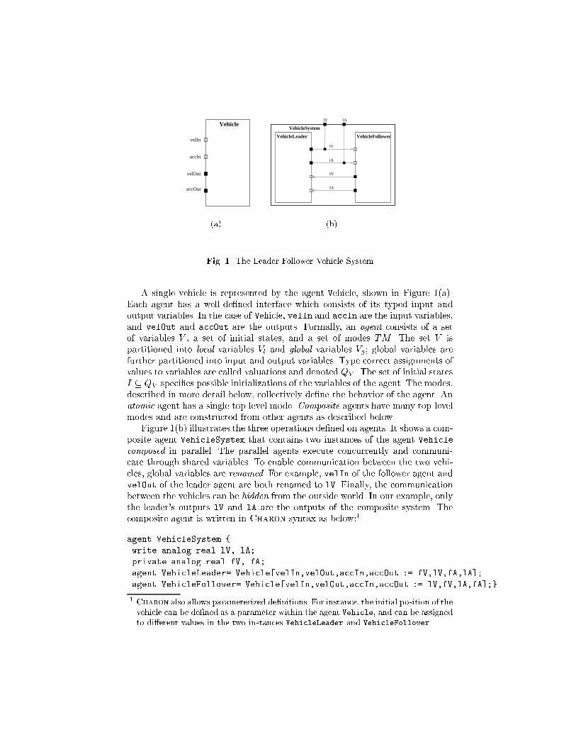
In Charon, the building block for describing the system architecture is anagent that communicates with its environment via shared variables. The lan-guage supports the operations of composition of agents to model concurrency,hiding of variables to restrict sharing of information, and instantiation of agentsto support reuse. The building block for describing ow of control inside anatomic agent is a mode. A mode is basically a hierarchical state machine, thatis, a mode can have submodes and transitions connecting them. Variables can bedeclared locally inside any mode with standard scoping rules for visibility. Modescan be connected to each other only via well-de�ned entry and exit points. Weallow sharing of modes so that the same mode de�nition can be instantiated inmultiple contexts. To support exceptions , the language allows group transitionsfrom default exit points that are applicable to all enclosing modes, and to sup-port history retention, the language allows default entry transitions that restorethe local state within a mode from the most recent exit.Compositional Semantics. Formal semantics leads to de�nitions of seman-tic equivalence (or re�nement) of speci�cations based on their observable behav-iors, and compositional means that semantics of a component can be constructedfrom the semantics of its subcomponents. Such formal compositional semanticsis a cornerstone of concurrency frameworks such as CSP [19] and CCS [27], and isa prerequisite for developing modular reasoning principles such as compositionalmodel checking and systematic design principles such as stepwise re�nement.The global nature of time makes it challenging to de�ne semantics of hybridcomponents in a modular fashion. For rich hierarchical speci�cations, featuressuch as as group transitions, exceptions, and history retention, cause additionaldi�culties.Charon supports observational trace semantics for both modes and agents [4].The key result is that the set of traces of a mode can be constructed from thetraces of its submodes. This result leads to a compositional notion of re�nementfor modes. Suppose we obtain an implementation design I from a speci�cationdesign S simply by locally replacing some submode N in S by a submode M .Then, to show I re�nes S, it su�ces to show that M re�nes N .Overview. The remaining paper is organized as follows. In Section 2, wepresent the features of the language Charon, and in Section 3 we describethe formal semantics and accompanying compositional re�nement calculus. Weuse examples from the automotive experimental platform of the DARPA's Mo-BIES program for illustrative purposes. Section 4 gives a summary of the designtoolkit, and we conclude in Section 5 with pointers to ongoing research on formalanalysis.2 Modeling Language2.1 Agents and Architectural HierarchyWe present an example from the MoBIES Automotive Open Experimental Plat-form (OEP) to illustrate the features ofCharon. Figures 1, 2, and 3 areCharonagent diagrams illustrating the architectural hierarchy of a team of two vehicles.
Vehicle
accOut
velOut
accIn
velIn
(a)VehicleFollower
fA
fV
lA
lV
VehicleLeader
VehicleSystem
lV lA
(b)Fig. 1. The Leader-Follower Vehicle SystemA single vehicle is represented by the agent Vehicle, shown in Figure 1(a).Each agent has a well-de�ned interface which consists of its typed input andoutput variables. In the case of Vehicle, velIn and accIn are the input variables,and velOut and accOut are the outputs. Formally, an agent consists of a setof variables V , a set of initial states, and a set of modes TM . The set V ispartitioned into local variables Vl and global variables Vg ; global variables arefurther partitioned into input and output variables. Type correct assignments ofvalues to variables are called valuations and denoted QV . The set of initial statesI � QV speci�es possible initializations of the variables of the agent. The modes,described in more detail below, collectively de�ne the behavior of the agent. Anatomic agent has a single top-level mode. Composite agents have many top-levelmodes and are constructed from other agents as described below.Figure 1(b) illustrates the three operations de�ned on agents. It shows a com-posite agent VehicleSystem that contains two instances of the agent Vehiclecomposed in parallel. The parallel agents execute concurrently and communi-cate through shared variables. To enable communication between the two vehi-cles, global variables are renamed. For example, velIn of the follower agent andvelOut of the leader agent are both renamed to lV. Finally, the communicationbetween the vehicles can be hidden from the outside world. In our example, onlythe leader's outputs lV and lA are the outputs of the composite system. Thecomposite agent is written in Charon syntax as below:1agent VehicleSystem {write analog real lV, lA;private analog real fV, fA;agent VehicleLeader= Vehicle[velIn,velOut,accIn,accOut := fV,lV,fA,lA];agent VehicleFollower= Vehicle[velIn,velOut,accIn,accOut := lV,fV,lA,fA];}1 Charon also allows parameterized de�nitions. For instance, the initial position of thevehicle can be de�ned as a parameter within the agent Vehicle, and can be assignedto di�erent values in the two instances VehicleLeader and VehicleFollower.
VehiclePlant
xDot_hslCarSensorRegulationController
Vehicle
xDDot_hsl
u_isl
xDD
ot
xDot
velIn
accIn
velOut
accOut
xDDot: plant acceleration
u_isl: desired acceleration
xDot_hsl: sensed plant velocity
xDDot_hsl: sensed plant acceleration
xDot: plant velocity Fig. 2. The Vehicle AgentDynamicSensorDynamicController
VehiclePlant
u_isl xDDot
xDot
ud
PowerTrain v
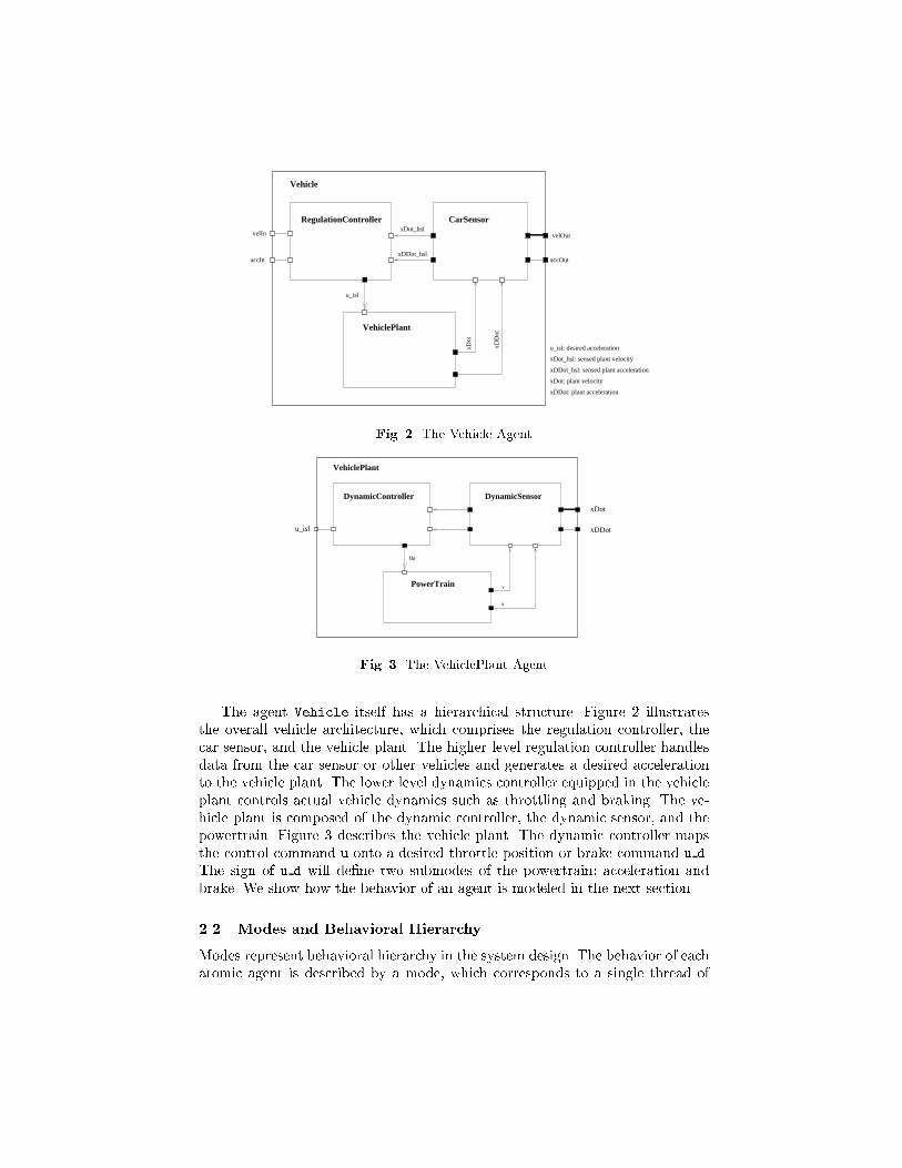
aFig. 3. The VehiclePlant AgentThe agent Vehicle itself has a hierarchical structure. Figure 2 illustratesthe overall vehicle architecture, which comprises the regulation controller, thecar sensor, and the vehicle plant. The higher level regulation controller handlesdata from the car sensor or other vehicles and generates a desired accelerationto the vehicle plant. The lower level dynamics controller equipped in the vehicleplant controls actual vehicle dynamics such as throttling and braking. The ve-hicle plant is composed of the dynamic controller, the dynamic sensor, and thepowertrain. Figure 3 describes the vehicle plant. The dynamic controller mapsthe control command u onto a desired throttle position or brake command u d.The sign of u d will de�ne two submodes of the powertrain: acceleration andbrake. We show how the behavior of an agent is modeled in the next section.2.2 Modes and Behavioral HierarchyModes represent behavioral hierarchy in the system design. The behavior of eachatomic agent is described by a mode, which corresponds to a single thread of
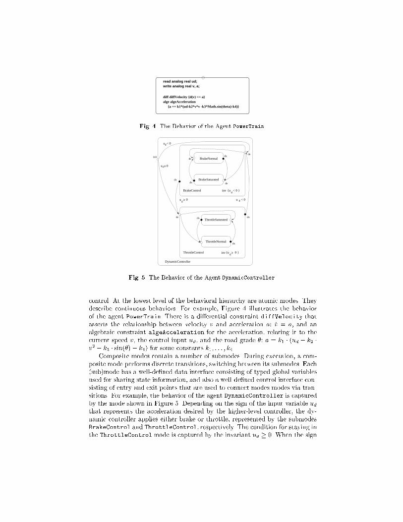
read analog real ud;write analog real v, a;
{a == k1*(ud-k2*v*v -k3*Math.sin(theta)-k4)}alge algeAccelerationdiff diffVelocity {d(v) == a}Fig. 4. The Behavior of the Agent PowerTrain
BrakeNormal
ThrottleNormal
BrakeSaturated
ThrottleSaturated
{u 0 }d
d{u < 0 }inv
d
inv
u < 0
du 0
dx
dx
ThrottleControl
de
BrakeControl
dx
dxdx
dx
de
de
de
du 0
init
u < 0d
≥
≥
≥
DynamicControllerFig. 5. The Behavior of the Agent DynamicControllercontrol. At the lowest level of the behavioral hierarchy are atomic modes. Theydescribe continuous behaviors. For example, Figure 4 illustrates the behaviorof the agent PowerTrain. There is a di�erential constraint diffVelocity thatasserts the relationship between velocity v and acceleration a: _v = a, and analgebraic constraint algeAcceleration for the acceleration, relating it to thecurrent speed v, the control input ud, and the road grade �: a = k1 � (ud � k2 �v2 � k3 � sin(�) � k4) for some constants k1; : : : ; k4.Composite modes contain a number of submodes. During execution, a com-posite mode performs discrete transitions, switching between its submodes. Each(sub)mode has a well-de�ned data interface consisting of typed global variablesused for sharing state information, and also a well-de�ned control interface con-sisting of entry and exit points that are used to connect modes modes via tran-sitions. For example, the behavior of the agent DynamicController is capturedby the mode shown in Figure 5. Depending on the sign of the input variable udthat represents the acceleration desired by the higher-level controller, the dy-namic controller applies either brake or throttle, represented by the submodesBrakeControl and ThrottleControl, respectively. The condition for staying inthe ThrottleControlmode is captured by the invariant ud � 0. When the sign
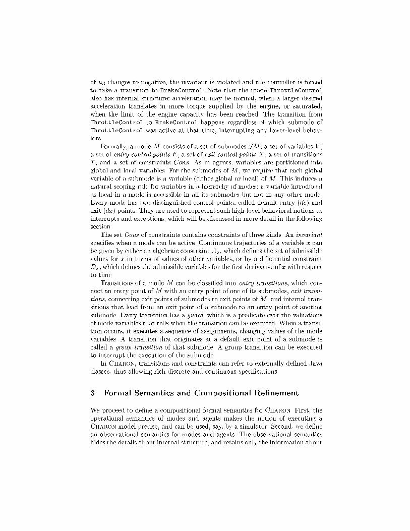
of ud changes to negative, the invariant is violated and the controller is forcedto take a transition to BrakeControl. Note that the mode ThrottleControlalso has internal structure: acceleration may be normal, when a larger desiredacceleration translates in more torque supplied by the engine, or saturated,when the limit of the engine capacity has been reached. The transition fromThrottleControl to BrakeControl happens regardless of which submode ofThrottleControl was active at that time, interrupting any lower-level behav-iors.Formally, a mode M consists of a set of submodes SM , a set of variables V ,a set of entry control points E, a set of exit control points X , a set of transitionsT , and a set of constraints Cons. As in agents, variables are partitioned intoglobal and local variables. For the submodes of M , we require that each globalvariable of a submode is a variable (either global or local) of M . This induces anatural scoping rule for variables in a hierarchy of modes: a variable introducedas local in a mode is accessible in all its submodes but not in any other mode.Every mode has two distinguished control points, called default entry (de) andexit (dx) points. They are used to represent such high-level behavioral notions asinterrupts and exceptions, which will be discussed in more detail in the followingsection.The set Cons of constraints contains constraints of three kinds. An invariantspeci�es when a mode can be active. Continuous trajectories of a variable x canbe given by either an algebraic constraint Ax, which de�nes the set of admissiblevalues for x in terms of values of other variables, or by a di�erential constraintDx, which de�nes the admissible variables for the �rst derivative of x with respectto time.Transitions of a mode M can be classi�ed into entry transitions, which con-nect an entry point of M with an entry point of one of its submodes, exit transi-tions, connecting exit points of submodes to exit points of M , and internal tran-sitions that lead from an exit point of a submode to an entry point of anothersubmode. Every transition has a guard, which is a predicate over the valuationsof mode variables that tells when the transition can be executed. When a transi-tion occurs, it executes a sequence of assignments, changing values of the modevariables. A transition that originates at a default exit point of a submode iscalled a group transition of that submode. A group transition can be executedto interrupt the execution of the submode.In Charon, transitions and constraints can refer to externally de�ned Javaclasses, thus allowing rich discrete and continuous speci�cations.3 Formal Semantics and Compositional Re�nementWe proceed to de�ne a compositional formal semantics for Charon. First, theoperational semantics of modes and agents makes the notion of executing aCharon model precise, and can be used, say, by a simulator. Second, we de�nean observational semantics for modes and agents. The observational semanticshides the details about internal structure, and retains only the information about
inputs and outputs. Informally, the observational semantics consists of the staticinterface (such as the global variables and entry/exit points) and dynamic in-terface consisting of the traces, that is, sequences of updates to global variables.Third, for modularity, we show that our semantics is compositional. This meansthat the set of traces of a component can be de�ned from the set of traces ofits subcomponents. Intuitively, this means that the observational semantics cap-tures all the information that is needed to determine how a component interactswith its environment. Finally, we de�ne a notion of re�nement (or equivalence)for modes/agents. This allows us, for instance, to relate di�erent models of theagent PowerTrain. We can establish that the abstract (simpli�ed) version ofpowertrain re�nes the detailed version, and then, to analyze the system of ve-hicles, use the abstract version instead of the detailed one. The compositionalrules about re�nement form the basis for analysis in a system with multiplecomponents, each with a simpli�ed and a detailed model.3.1 Formal semantics of modesIntuitive semantics. Before presenting the semantics formally, we give theintuition for mode executions. A mode can engage in discrete or continuous be-havior. During an execution, the mode and its environment either take turnsmaking discrete steps or take a continuous step together. Discrete and continu-ous steps of the mode alternate. During a continuous step, the mode follows acontinuous trajectory that satis�es the constraints of the mode. In addition, theset of possible trajectories may be restricted by the environment of the mode.In particular, when the mode invariant is violated, the mode must terminate itscontinuous step and take one of its outgoing transitions. A discrete step of themode is a �nite sequence of discrete steps of the submodes and enabled transi-tions of the mode itself. A discrete step begins in the current state of the modeand ends when it reaches an exit point or when the mode decides to yield con-trol to the environment and lets it make the choice of the next step. Technically,when the mode ends its discrete step in one of its submodes, it returns control tothe environment via its default exit point. The closure construction, describedbelow, ensures that the mode can yield control at appropriate moments, andthat the discrete control state of the mode is restored when the environmentschedules the next discrete step.Preemption. An execution of a mode can be preempted by a group tran-sition. A group transition of a mode originates at the default exit of the mode.During any discrete step of the mode, control can be transferred to the defaultexit and an enabled group transition can be selected. There is no priority be-tween the transitions of a mode and its group transitions. When an executionof a mode is preempted, the control state of the mode is recorded in a specialhistory variable, a new local variable that we introduce into every mode. Then,when the mode is entered through the default entry point next time, the controlstate of the mode is restored according to the history variable.The history variable and active submodes. In order to record thelocation of discrete control during executions, we introduce a new local variable
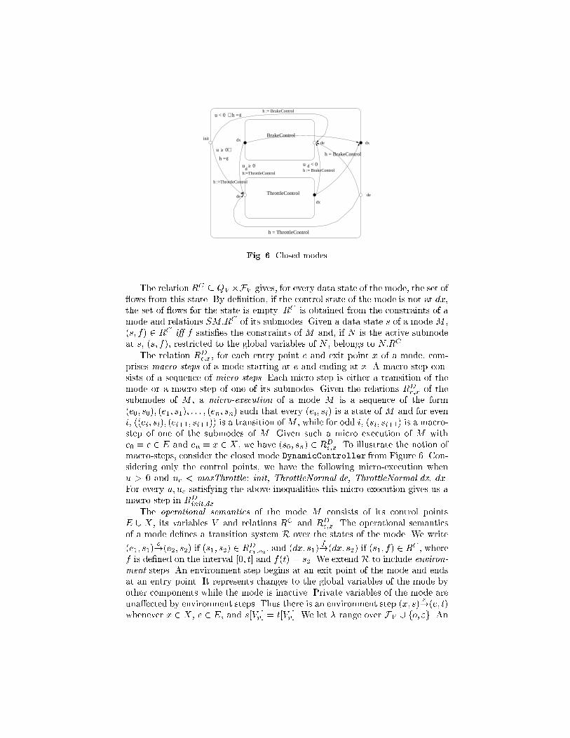
h into each mode that has submodes. The history variable h of a mode M hasthe names of the submodes of M as values, or a special value � that is used todenote that the mode does not have control. A submode N of M is called activewhen the history variable of M has the value N .Flows. To precisely de�ne continuous trajectories of a mode, we introducethe notion of a ow. A ow for a set V of variables is a di�erentiable functionf from a closed interval of non-negative reals [0; �] to QV . We refer to � as theduration of the ow. We denote a set of ows for V as FV .Syntactic restrictions on modes. In order to ensure that the semantics ofa mode is well-de�ned, we impose several restrictions on mode structure. First,we assume that the set of di�erential and algebraic constraints in a mode alwayshas a non-empty set of ows that satisfy them. This is needed to ensure that theset of behaviors of a mode is non-empty. Furthermore, we require that the modecannot be blocked at any of its non-default control points. This means that thedisjunction of all guards originating from a control point evaluates to true.State of a mode. We de�ne the state of a mode in terms of all variables ofthe mode and its submodes, including the local variables on all levels. We use V�for the set of all variables. The set of local variables of a mode together with thelocal variables of the submodes are called the private variables and is denotedas Vp.The state of a mode M is a pair (c; s), where c is the location of discretecontrol in the mode and s 2 QM:V� . Whenever the mode has control, it residesin one of its control points, that is, c 2M:C. Given a state (c; s) of M , we referto c as the control state of M and to s as the data state of M .Closure of a mode. Closure construction is a technical device to allow themode to interrupt its execution and to maintain its history variable. Transitionsof the mode are modi�ed to update the history variable h after a transition isexecuted. Each entry or internal transition assigns the name of the destinationmode to h, and exit transitions assign � to h. In addition, default entry and exittransitions are added to the set of transitions of the mode. These default tran-sitions do not a�ect the history variable and allow us to interrupt an executionand then resume it later from the same point.The default entry and exit transitions are added in the following way. Foreach submode N of M , the closure adds a default exit transition from N:dx toM:dx. This transition does not change any variables of the mode and is alwaysenabled. Default entry transitions are used to restore the local control state ofM . A default entry transition that leads from a default entry ofM to the defaultentry of a submode N is enabled if h = N . Furthermore, we make sure that thedefault entry transitions do not interfere with regular entry transitions originat-ing from de. The closure changes each such transition so that it is enabled onlyif h = �. The closure construction for the mode DynamicController introducedin Section 2 is illustrated in Figure 6.Operational semantics. An operational view of a closed mode M with theset of variables V consists of a continuous relation RC and, for each pair c1 2 E,c2 2 X , a discrete relation RDc1;c2 .
du < 0h =
h := BrakeControl
init
dx
de
BrakeControl
ε
h := BrakeControl
dxdx
dh:=ThrottleControl
u 0
h = ThrottleControl
u < 0 h =
ThrottleControl dede
ε
u 0
h :=ThrottleControl
h = BrakeControl
≥
∧
≥ ∧
Fig. 6. Closed modesThe relation RC � QV �FV gives, for every data state of the mode, the set of ows from this state. By de�nition, if the control state of the mode is not at dx,the set of ows for the state is empty. RC is obtained from the constraints of amode and relations SM:RC of its submodes. Given a data state s of a mode M ,(s; f) 2 RC i� f satis�es the constraints of M and, if N is the active submodeat s, (s; f), restricted to the global variables of N , belongs to N:RC .The relation RDe;x, for each entry point e and exit point x of a mode, com-prises macro-steps of a mode starting at e and ending at x. A macro step con-sists of a sequence of micro-steps. Each micro-step is either a transition of themode or a macro-step of one of its submodes. Given the relations RDe;x of thesubmodes of M , a micro-execution of a mode M is a sequence of the form(e0; s0); (e1; s1); : : : ; (en; sn) such that every (ei; si) is a state of M and for eveni, ((ei; si); (ei+1; si+1)) is a transition ofM , while for odd i, (si; si+1) is a macro-step of one of the submodes of M . Given such a micro execution of M withe0 = e 2 E and en = x 2 X , we have (s0; sn) 2 RDe;x. To illustrate the notion ofmacro-steps, consider the closed mode DynamicController from Figure 6. Con-sidering only the control points, we have the following micro-execution whenu > 0 and uc < maxThrottle: init, ThrottleNormal.de, ThrottleNormal.dx, dx.For every u; uc satisfying the above inequalities this micro-execution gives us amacro-step in RDinit;dx.The operational semantics of the mode M consists of its control pointsE [ X , its variables V and relations RC and RDe;x. The operational semanticsof a mode de�nes a transition system R over the states of the mode. We write(e1; s1) o!(e2; s2) if (s1; s2) 2 RDe1;e2 , and (dx; s1) f!(dx; s2) if (s1; f) 2 RC , wheref is de�ned on the interval [0; t] and f(t) = s2. We extend R to include environ-ment steps. An environment step begins at an exit point of the mode and endsat an entry point. It represents changes to the global variables of the mode byother components while the mode is inactive. Private variables of the mode areuna�ected by environment steps. Thus there is an environment step (x; s) "!(e; t)whenever x 2 X , e 2 E, and s[Vp] = t[Vp]. We let � range over FV [ fo; "g. An
execution of a mode is now a path through the graph of R:(e0; s0) �1! (e1; s1) �2! : : : �n!(en; sn):Trace semantics. To be able to de�ne a re�nement relation between modes,we consider a trace semantics for modes. A trace of the mode is a projection ofits executions onto the global variables of the mode. The trace semantics for Mis given by its control points E and X , its global variables Vg , and its set of itstraces LM .In de�ning compositional and hierarchical semantics, one has to decide, whatdetails of the behavior of lower-level components are observable at higher levels.In our approach, the e�ect of a discrete step that updates only local variables ofa mode is not observable by its environment, but stoppage of time introducedby such a step is observable. For example, consider two systems, one of whichis always idle, while the other updates a local variable every second. These twosystems are di�erent, since the second one does not have ows more than onesecond long. De�ning a modular semantics in a way that such distinction is notmade seems much more di�cult.3.2 Trace semantics for agentsAn execution of an agent follows a trajectory, which starts in one of the initialstates and is a sequence of ows interleaved with discrete updates to the variablesof the agent. An execution of A is constructed from the relations RC and RD ofits top-level mode. For a �xed initial state s0, each mode M 2 TM starts outin the state (initM ; sM ), where initM is the non-default entry point of M ands0[M:V ] = sM . Note that as long as there is a mode M whose control state isat initM , no continuous steps are possible. However, any discrete step of such amode will come from RDinitM ;dx and bring the control state ofM to dx. Therefore,any execution of an agent A = hTM; V; Ii with jTM j = k will start with exactlyk discrete initialization steps. At that point, every top-level mode of A will beat its default exit point, allowing an alternation of continuous steps from RCand discrete steps from RDde;dx. The choice of a continuous step involving allmodes or a discrete step in one of the modes is left to the environment. Beforeeach discrete step, there is an environment step, which takes the control pointof the chosen mode from dx to de and leaves all the private variables of alltop-level modes intact. After that, a discrete step of the chosen mode happens,bringing control back to dx. Thus, an execution of A with jTM j = k is a sequences0 o! s1 o! : : : sk �1! sk+1 �2! : : : such that{ The �rst k steps are discrete and initialize the top-level modes of A.{ for every i � k, one of the following holds:� the ith step is a continuous step, in which every mode takes part, or� the ith step is a discrete environment step, or� the ith step is a discrete step by one of the modes and the private vari-ables of all other modes are unchanged.
...
...
...
...
...... ...N1<M
k
M
k M11 M1
M
M M
C1
N
1 k < Nk< N1
<
<C
M
1
Mk Mk
C2
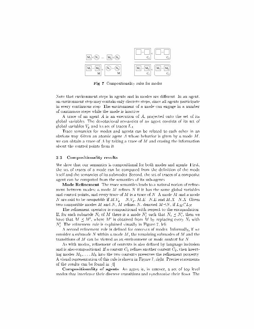
C2Fig. 7. Compositionality rules for modesNote that environment steps in agents and in modes are di�erent. In an agent,an environment step may contain only discrete steps, since all agents participatein every continuous step. The environment of a mode can engage in a numberof continuous steps while the mode is inactive.A trace of an agent A is an execution of A, projected onto the set of itsglobal variables. The denotational semantics of an agent consists of its set ofglobal variables Vg and its set of traces LA.Trace semantics for modes and agents can be related to each other in anobvious way. Given an atomic agent A whose behavior is given by a mode M ,we can obtain a trace of A by taking a trace of M and erasing the informationabout the control points from it.3.3 Compositionality resultsWe show that our semantics is compositional for both modes and agents. First,the set of traces of a mode can be computed from the de�nition of the modeitself and the semantics of its submodes. Second, the set of traces of a compositeagent can be computed from the semantics of its sub-agents.Mode Re�nement. The trace semantics leads to a natural notion of re�ne-ment between modes: a mode M re�nes N if it has the same global variablesand control points, and every trace of M is a trace of N . A mode M and a modeN are said to be compatible if M:Vg = N:Vg , M:E=N:E andM:X=N:X . Giventwo compatible modes M and N , M re�nes N , denoted M�N , if LM�LN .The re�nement operator is compositional with respect to the encapsulation.If, for each submode Ni of M there is a mode N 0i such that Ni � N 0i , then wehave that M � M 0, where M 0 is obtained from M by replacing every Ni withN 0i . The re�nement rule is explained visually in Figure 7, left.A second re�nement rule is de�ned for contexts of modes. Informally, if weconsider a submode N within a mode M , the remaining submodes of M and thetransitions of M can be viewed as an environment or mode context for N .As with modes, re�nement of contexts is also de�ned by language inclusionand is also compositional. If a context C1 re�nes another context C2, then insert-ing modes M1; : : : ;Mk into the two contexts preserves the re�nement property.A visual representation of this rule is shown in Figure 7, right. Precise statementsof the results can be found in [4].Compositionality of agents. An agent is, in essence, a set of top levelmodes that interleave their discrete transitions and synchronize their ows. The
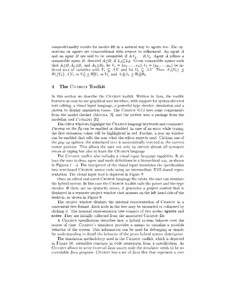
compositionality results for modes lift in a natural way to agents too. The op-erations on agents are compositional with respect to re�nement. An agent Aand an agent B are said to be compatible if A:Vg = B:Vg . Agent A re�nes acompatible agent B, denoted A�B, if LA�LB . Given compatible agents suchthat A�B;A1�B1 and A2�B2, let V1 = fx1; : : : ; xng; V2 = fy1; : : : ; yng be in-dexed sets of variables with V1 � A:V and let Vh � A:V . Then AnfVhg �BnfVhg; A[V1 := V2] � B[V1 := V2] and A1jjA2 � B1jjB24 The Charon ToolkitIn this section we describe the Charon toolkit. Written in Java, the toolkitfeatures an easy-to use graphical user interface, with support for syntax-directedtext editing, a visual input language, a powerful type-checker, simulation and aplotter to display simulation traces. The Charon GUI uses some componentsfrom the model checker jMocha [3], and the plotter uses a package from themodeling tool Ptolemy [12].The editor windows highlight theCharon language keywords and comments.Parsing on the y can be enabled or disabled. In case of an error while typing,the �rst erroneous token will be highlighted in red. Further, a pop up windowcan be enabled that tells the user what the editor expects next. Clicking one ofthe pop up options, the associated text is automatically inserted at the currentcursor position. This allows the user not only to correct almost all syntacticerrors at typing but also to learn the Charon language.The Charon toolkit also includes a visual input language capability. It al-lows the user to draw agent and mode de�nitions in a hierarchical way, as shownin Figures 1 { 5. The interpreter of the visual input translates the speci�cationinto text-based Charon source code using an intermediate XML-based repre-sentation. The visual input tool is depicted in Figure 8.Once an edited and saved Charon language �le exists, the user can simulatethe hybrid system. In this case the Charon toolkit calls the parser and the typechecker. If there are no syntactic errors, it generates a project context that isdisplayed in a separate project window that appears on the left hand side of thedesktop, as shown in Figure 9.The project window displays the internal representation of Charon in aconvenient tree format. Each node in the tree may be expanded or collapsed byclicking it. The internal representation tree consists of two nodes: agents andmodes. They are initially collected from the associated Charon �le.A Charon speci�cation describes how a hybrid system behaves over thecourse of time. Charon's simulator provides a means to visualize a possiblebehavior of the system. This information can be used for debugging or simplyfor understanding in detail the behavior of the given hybrid system description.The simulation methodology used in the Charon toolkit, which is depictedin Figure 10, resembles concepts in code generation from a speci�cation. AsCharon allows to write external Java source code the simulator needs to be anexecutable Java program. Charon has a set of Java �les that represent a core
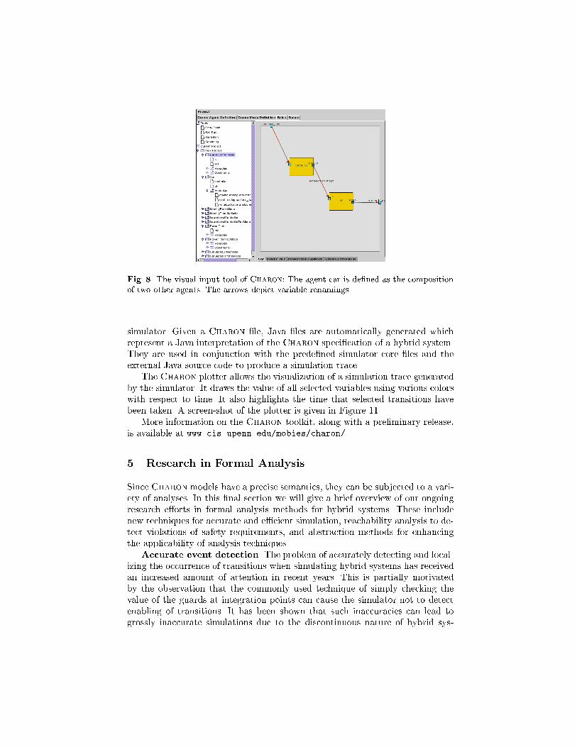
Fig. 8. The visual input tool of Charon: The agent car is de�ned as the compositionof two other agents. The arrows depict variable renamings.simulator. Given a Charon �le, Java �les are automatically generated whichrepresent a Java interpretation of the Charon speci�cation of a hybrid system.They are used in conjunction with the prede�ned simulator core �les and theexternal Java source code to produce a simulation trace.The Charon plotter allows the visualization of a simulation trace generatedby the simulator. It draws the value of all selected variables using various colorswith respect to time. It also highlights the time that selected transitions havebeen taken. A screen-shot of the plotter is given in Figure 11.More information on the Charon toolkit, along with a preliminary release,is available at www.cis.upenn.edu/mobies/charon/.5 Research in Formal AnalysisSince Charon models have a precise semantics, they can be subjected to a vari-ety of analyses. In this �nal section we will give a brief overview of our ongoingresearch e�orts in formal analysis methods for hybrid systems. These includenew techniques for accurate and e�cient simulation, reachability analysis to de-tect violations of safety requirements, and abstraction methods for enhancingthe applicability of analysis techniques.Accurate event detection. The problem of accurately detecting and local-izing the occurrence of transitions when simulating hybrid systems has receivedan increased amount of attention in recent years. This is partially motivatedby the observation that the commonly used technique of simply checking thevalue of the guards at integration points can cause the simulator not to detectenabling of transitions. It has been shown that such inaccuracies can lead togrossly inaccurate simulations due to the discontinuous nature of hybrid sys-
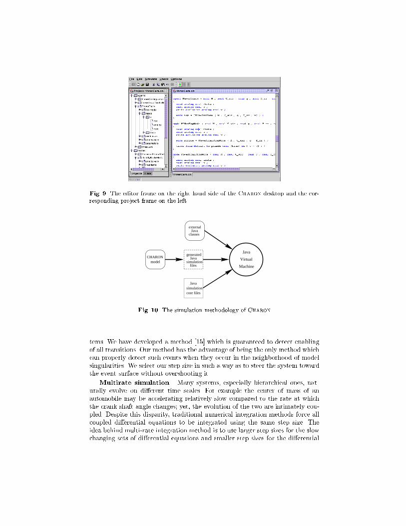
Fig. 9. The editor frame on the right hand side of the Charon desktop and the cor-responding project frame on the leftCHARON
model
externalJava
classes
Javasimulationcore files
filessimulation
Javagenerated
Java
Virtual
Machine
Fig. 10. The simulation methodology of Charontems. We have developed a method [15] which is guaranteed to detect enablingof all transitions. Our method has the advantage of being the only method whichcan properly detect such events when they occur in the neighborhood of modelsingularities. We select our step size in such a way as to steer the system towardthe event surface without overshooting it.Multirate simulation. Many systems, especially hierarchical ones, nat-urally evolve on di�erent time scales. For example the center of mass of anautomobile may be accelerating relatively slow compared to the rate at whichthe crank shaft angle changes; yet, the evolution of the two are intimately cou-pled. Despite this disparity, traditional numerical integration methods force allcoupled di�erential equations to be integrated using the same step size. Theidea behind multi-rate integration method is to use larger step sizes for the slowchanging sets of di�erential equations and smaller step sizes for the di�erential
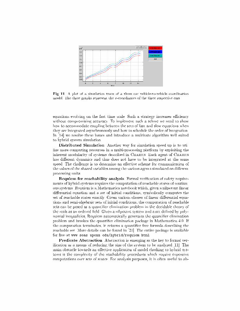
Fig. 11. A plot of a simulation trace of a three car vehicle-to-vehicle coordinationmodel. The three graphs represent the x-coordinates of the three respective cars.equations evolving on the fast time scale. Such a strategy increases e�ciencywithout compromising accuracy. To implement such a schme we need to showhow to accommodate coupling between the sets of fast and slow equations whenthey are integrated asynchronously and how to schedule the order of integration.In [14] we resolve these issues and introduce a multirate algorithm well suitedto hybrid system simulation.Distributed Simulation. Another way for simulation speed-up is to uti-lize more computing resources in a multi-processing platform by exploiting theinherent modularity of systems described in Charon. Each agent of Charonhas di�erent dynamics and thus does not have to be integrated at the samespeed. The challenge is to determine an e�ective scheme for communication ofthe values of the shared variables among the various agents simulated on di�erentprocessing units.Requiem for reachability analysis. Formal veri�cation of safety require-ments of hybrid systems requires the computation of reachable states of continu-ous systems. Requiem is a Mathematica notebook which, given a nilpotent lineardi�erential equation and a set of initial conditions, symbolically computes theset of reachable states exactly. Given various classes of linear di�erential equa-tions and semi-algebraic sets of initial conditions, the computation of reachablesets can be posed as a quanti�er elimination problem in the decidable theory ofthe reals as an ordered �eld. Given a nilpotent system and a set de�ned by poly-nomial inequalities, Requiem automatically generates the quanti�er eliminationproblem and invokes the quanti�er elimination package in Mathematica 4.0. Ifthe computation terminates, it returns a quanti�er free formula describing thereachable set. More details can be found in [21]. The entire package is availablefor free at www.seas.upenn.edu/hybrid/requiem.html.Predicate Abstraction. Abstraction is emerging as the key to formal ver-i�cation as a means of reducing the size of the system to be analyzed [11]. Themain obstacle towards an e�ective application of model checking to hybrid sys-tems is the complexity of the reachability procedures which require expensivecomputations over sets of states. For analysis purposes, it is often useful to ab-
stract a system in a way that preserves the properties being analyzed whilehiding the details that are of no interest [5]. We build upon notion of predicateabstraction [28] for formal analysis of hybrid systems. Using a set of booleanpredicates, that are crucial with respect to the property to be veri�ed, we con-struct a �nite partition of the state space of the hybrid system. The states of theabstracted system correspond to truth assignments to the set of predicates. Byusing conservative reachability approximations we guarantee that if the prop-erty holds in the abstracted system, then it also holds in the concrete systemrepresented by the hybrid system. Conversely, if the property does not hold inthe abstract system, then it may or may not hold in the concrete system. Inthe latter case, the concrete system will be checked against the counter-examplefound during the model checking of the abstract system. If a trace correspond-ing to the counter-example is feasible in the concrete system we have establishedthe property to be false. This procedure can also help discover new predicatesthat can be used to re�ne the abstraction, as it is suggested in [9] for analysisof discrete systems. The combination of this method for �nding new predicatesand our abstraction procedure thus provides an e�ective way to apply a �nitestate model checking approach to hybrid systems.Multi-robot coordination. We develop a hybrid system framework andthe software architecture for the deployment of multiple autonomous robotsin an unstructured and unknown environment with applications ranging fromscouting and reconnaissance, to search and rescue and manipulation tasks. Oursoftware framework allows a modular and hierarchical approach to programmingdeliberative and reactive behaviors in autonomous operation. Formal de�nitionsfor sequential composition, hierarchical composition, and parallel compositionallow the bottom-up development of complex software systems. We demonstratethe algorithms and software on an experimental testbed that involves a groupof car-like robots using a single omni-directional camera as a sensor withoutexplicit use of odometry. More information can be found in [2, 16].References1. R. Alur, C. Courcoubetis, N. Halbwachs, T.A. Henzinger, P. Ho, X. Nicollin,A. Olivero, J. Sifakis, and S. Yovine. The algorithmic analysis of hybrid systems.Theoretical Computer Science, 138:3{34, 1995.2. R. Alur, A. Das, J. Esposito, R. Fierro, Y. Hur, G. Grudic, V. Kumar, I. Lee, J. P.Ostrowski, G. Pappas, J. Southall, J. Spletzer, and C. J. Taylor. A framework andarchitecture for multirobot coordination. In Proc. ISER00, Seventh Intl. Symp. onExperimental Robotics, pages 289{299, 2000.3. R. Alur, L. de Alfaro, R. Grosu, T.A. Henzinger, M. Kang, R. Majumdar, F. Mang,C.M. Kirsch, and B.Y. Wang. Mocha: A model checking tool that exploits designstructure. In Proc. 23rd Intl. Conf. on Software Engineering, pages 835{836, 2001.4. R. Alur, R. Grosu, I. Lee, and O. Sokolsky. Compositional re�nement for hierar-chical hybrid systems. In Hybrid Systems : Computation and Control, LNCS 2034,pages 33{48, 2001.5. R. Alur, T. Henzinger, G. La�erriere, and G. Pappas. Discrete abstractions ofhybrid systems. Proceedings of the IEEE, 88(7):971{984, July 2000.
6. A. Balluchi, L. Benvenuti, M. Di Benedetto, C. Pinello, and A. Sangiovanni-Vicentelli. Automotive engine control and hybrid systems: Challenges and op-portunities. Proceedings of the IEEE, 88(7):888{912, July 2000.7. G. Booch, I. Jacobson, and J. Rumbaugh. Uni�ed Modeling Language User Guide.Addison Wesley, 1997.8. A. Chutinan and B. Krogh. Veri�cation of polyhedral-invariant hybrid automatausing polygonal ow pipe approximations. In Hybrid Systems : Computation andControl, LNCS 1569, 1999.9. E. Clarke, O. Grumberg, S. Jha, Y. Lu, and H. Veith. Counterexample-guidedabstraction re�nement. In Computer Aided Veri�cation, pages 154{169, 2000.10. E.M. Clarke and R.P. Kurshan. Computer-aided veri�cation. IEEE Spectrum,33(6):61{67, 1996.11. S. Das, D. Dill, and S. Park. Experience with predicate abstraction. In ComputerAided Veri�cation, 11th Intl. Conf., LNCS 1633, pages 160{171, 1999.12. J. Davis, M. Goel, C. Hylands, B. Kienhuis, E.A. Lee, J. Liu, X. Liu, L. Muliadi,S. Neuendor�er, J. Reekie, N. Smyth, J. Tsay, and Y. Xiong. Overview of thePtolemy project. Technical Report UCB/ERL M99/37, 1999.13. S. Engell, S. Kowalewski, C. Schulz, and O. Stursberg. Continuous-discrete inter-actions in chemical processing plants. Proc. of the IEEE, 88(7):1050{1068, 2000.14. J. Esposito and V. Kumar. E�cient dynamic simulation of robotic systems withhierarchy. In Intl. Conf. on Robotics and Automation, pages 2818{2823, 2001.15. J. Esposito, V. Kumar, and G. Pappas. Accurate event detection for simulatinghybrid systems. In Hybrid Systems : Computation and Control, LNCS 2034, pages204{217, 2001.16. R. Fierro, A. Das, V. Kumar, and J. P. Ostrowski. Hybrid control of formationsof robots. Proc. Int. Conf. Robot. Automat., pages 157{162, 2001.17. D. Harel. Statecharts: A visual formalism for complex systems. Science of Com-puter Programming, 8:231{274, 1987.18. T.A. Henzinger, P. Ho, and H. Wong-Toi. HyTech: the next generation. In Proc.TACAS'95, LNCS 1019, pages 41{71, 1995.19. C.A.R. Hoare. Communicating Sequential Processes. Prentice-Hall, 1985.20. G.J. Holzmann. The model checker SPIN. IEEE Trans. on Software Engineering,23(5):279{295, 1997.21. G. La�erriere, G. Pappas, and S. Yovine. Symbolic reachability computation forfamilies of linear vector �elds. Journal of Symbolic Computation, 2001.22. K. Larsen, P. Pettersson, and W. Yi. Uppaal in a nutshell. Springer Intl. Journalof Software Tools for Technology Transfer, 1, 1997.23. E.A. Lee. What's ahead for embedded software. IEEE Computer, pages 18{26,September 2000.24. N. Lynch, R. Segala, F. Vaandrager, and H. Weinberg. Hybrid I/O automata. InHybrid Systems III: Veri�cation and Control, LNCS 1066, pages 496{510, 1996.25. O. Maler, Z. Manna, and A. Pnueli. From timed to hybrid systems. In Real-Time:Theory in Practice, REX Workshop, LNCS 600, pages 447{484, 1991.26. K. McMillan. Symbolic model checking: an approach to the state explosion problem.Kluwer Academic Publishers, 1993.27. R. Milner. A Calculus of Communicating Systems. LNCS 92, 1980.28. S. Graf and H. Saidi. Construction of abstract state graphs with PVS. In Proc.9th Intl. Conf. on Computer Aided Veri�cation, LNCS 1254, 1997.29. C. Tomlin, G. Pappas, and S. Sastry. Con ict resolution for air tra�c management:A study in multi-agent hybrid systems. IEEE Trans. Automatic Control, 43(4):509{521, 1998.