Embed Size (px)
Citation preview
Available online at www.sciencedirect.com
www.elsevier.com/locate/actamat
ScienceDirect
Acta Materialia 72 (2014) 167–177
Hexagonal BN-encapsulated ZrB2 particle by nitride boronizing
Ji Zou a,b,c,⇑, Jingjing Liu c, Guo-Jun Zhang b,⇑, Shuigen Huang c, Jef Vleugels c,⇑,Omer Van der Biest c, James Zhijian Shen a
a Department of Materials and Environmental Chemistry, Arrhenius Laboratory, Stockholm University, S-106 91 Stockholm, Swedenb State Key Laboratory of High Performance Ceramics and Superfine Microstructures, Shanghai Institute of Ceramics, Shanghai 200050,
People’s Republic of Chinac Department of Metallurgy and Materials Engineering (MTM), KU Leuven, B-3001 Heverlee, Belgium
Received 6 November 2013; received in revised form 19 March 2014; accepted 20 March 2014Available online 20 April 2014
Abstract
A facile method based on an in situ reaction, called nitride boronizing, was first developed to directly coat ZrB2 particles with a nano-scale hexagonal boron nitride (h-BN) film. The crystallinity of the BN coating and the diameters of the ZrB2 particles could be tailoredby changing the reaction conditions. A mechanism was proposed from thermodynamic calculations to clarify the formation of a core–shell nanostructure, i.e. the shock heat generated by the exothermal reaction. The core–shell ZrB2 powders showed excellent sinterabilityand the advantage in producing dense h-BN texture-free composites. Even when sintered at 2000 �C for 20 min and under a uniaxialpressure of 60 MPa, no texture created by h-BN was observed. The isotropic bending strength (�300 MPa) of ZrB2–37 vol.% BN ceram-ics from core–shell precursor powders were investigated and compared with ceramics of the same nominal composition, but densifiedfrom commercial powders containing highly aligned h-BN grains. The nitride boronizing approach could be explored to synthesize otherh-BN-coated IVB group transition metal borides.� 2014 Acta Materialia Inc. Published by Elsevier Ltd. All rights reserved.
Keywords: Ceramic material; Core–shell structure; Ultra-high-temperature ceramics; Nanoparticles
1. Introduction
Research on the coating of one-dimensional andtwo-dimensional nanostructures by hexagonal boronnitride (h-BN) layers has been attracting much interest inrecent years [1–4]. Due to the intrinsic high thermalstability and excellent chemical inertness of h-BN [5], itsexistence on the surface of SiC [6] and Al18B4O33 [7] whis-kers can effectively depress the serious interfacial reactions
http://dx.doi.org/10.1016/j.actamat.2014.03.054
1359-6454/� 2014 Acta Materialia Inc. Published by Elsevier Ltd. All rights r
⇑ Corresponding authors. Address: Department of Materials andEnvironmental Chemistry, Arrhenius Laboratory, Stockholm University,S-106 91 Stockholm, Sweden. Tel.: +46 8 163081 (J. Zou). Tel.: +86 2152411080 (G.-J. Zhang). Tel.: +32 16 321244 (J. Vleugels).
E-mail addresses: [email protected] (J. Zou), [email protected](G.-J. Zhang), [email protected] (J. Vleugels).
between the whisker and the metal matrix. Such a thinh-BN coating can also improve various properties of thesenanostructures, e.g. the high-temperature stability of Si3N4
powders [8] and ultraviolet blocking ability of CeO2
powders [9]. In the area of structural ceramics, the additionof a low-modulus h-BN phase into a strong, high-modulusceramic matrix can effectively modulate the thermalstresses generated inside the composite during the thermalshock, thus simultaneously increasing the correspondingcrack propagation resistance of the desired composites[10]. However, it is a challenging task to homogeneouslydisperse fine h-BN particles into a matrix ceramic powderby conventional ball-milling.
In addition, many previously reported properties ofboron nitride containing ceramics (BNCCs) are achievedfrom ceramics containing dispersed h-BN with a flake-like
eserved.

168 J. Zou et al. / Acta Materialia 72 (2014) 167–177
geometry, while laminar h-BN grain can be easily alignedperpendicular to the pressure direction when prepared byhot pressing or spark plasma sintering (SPS). This behaviorcauses the anisotropic properties of as-sintered BNCCs andrestricts their applications to a certain extent [11]. Utilizingnano-sized BN as raw powders has enabled the successfulproduction of BN texture-free ceramics [12]; however, thiswill result in the loss of flake-like nature of the h-BN grainsand as well as certain properties. It is possible to partiallyovercome these difficulties by starting from h-BN-coatedcore–shell powders. For example, Si3N4 ceramics with ran-domly dispersed fine h-BN grains could be densified fromh-BN-coated Si3N4 core–shell powders. It has been provedthat this approach can significantly improve the strength ofSi3N4–h-BN ceramics while maintaining their goodmachinability [13]. Similar improvements were alsoachieved by using h-BN-coated powders in other BNCCs,such as SiC–BN [14] and Al2O3–BN [15] ceramics.
Solution chemistry has been widely developed to coatBN precursors on the surface of starting ceramic powder.A mixture of boric acid (H3BO3) and urea (CO(NH2)2)solutions is commonly used as the precursor for h-BN[13–15], as coated h-BN film will crystallize during the sub-sequent high-temperature heat treatment in nitrogen oreven in an ammonia atmosphere. When H3BO3 isemployed, the formation of segregations and hard agglom-erates during the drying process presents a problem. Toavoid this, hydrophilic ammonium biborate hydrate (NH4-
HB4O7–3H2O) was selected as a BN precursor to prepareBN nanofilm-coated a-Si3N4 particles [16]. Another wayto obtain BN coatings on nanostructures involves chemicalvapor deposition. B2O2 and SiO vapors stemming from thereaction between SiO2 and B can produce SiC nanowireswith uniform BN coatings via epitaxial growth in the pres-ence of nickel catalyst [6]. Regardless of the solution or gas-eous approach, it is clear that the quality of the final BNcoatings is very sensitive to many experimental parameters,e.g. the surface status of the raw powders, the amounts,even the position of the precursors in the crucible and thegas flow rate during ammonia post heat treatment. There-fore, high-quality core–shell powders have been difficult toachieve, especially in terms of reproducibility. Meanwhile,choosing ammonia as the medium for nitrogenization athigh temperatures definitely increases the risk and the costfor the experiments as well.
The special combinations of high electrical conductivity,excellent thermal shock resistance and corrosion resistancemake TiB2– and ZrB2–h-BN based ceramics well suited tovarious applications in the energy, aerospace, steel metal-lurgy and metallizing industries [17,18]. In light of this, anovel reactive route, named nitride boronizing, was firstdeveloped for realizing the BN nanocoatings on ZrB2 pow-ders in this paper. A similar approach can be explored tosynthesize other IVB group transition metal boride pow-ders with a similar h-BN coating. High-quality core–shellpowders with better reproductivity could be prepared, sinceno external gas needs to be involved. In order to
demonstrate the advantages of the core–shell powders inproducing texture-free BNCCs, the sintering cycle is delib-erately programmed at a higher temperature and a longerholding time to elongate the h-BN flakes. Finally, themechanism for the formation of core–shell powders duringnitride boronizing will be discussed.
2. Experimental procedure
2.1. Powder synthesis
Commercially available ZrN (>99.8%, average particlesize 10 lm, ZR-301, Atlantic Equipment Engineers, Bergen-field, NJ) and amorphous boron (>96.5%, specific surfacearea >10 m2 g�1, H.C. Starck, Germany) powders werechosen as the starting materials in this study. In order toobtain a more homogeneous distribution of ZrN particlesin boron powders, both of these were mixed multidirection-ally in ethanol for 24 h using 3Y–ZrO2 balls. Thecomposition of the powder mixture contained 3 mol boronand 1 mol ZrN; this molar ratio was selected based onReaction (1):
ZrNþ 3B ¼ ZrB2 þ BN ð1ÞAfter mixing, the solvent was removed from the slurry
by rotary evaporation and then the obtained powders weredried at 90 �C for another 12 h in an oven.
2.1.1. Route IFirst, powders were synthesized using an SPS apparatus
(Type HP D 25/1, FCT System, Rauenstein, Germany) in avacuum. As-blended raw powders were loaded into a SPSdie with an axial pressure of 4 MPa applied on the top ofthe powders during the whole synthesis process. The diewith an inner diameter of 30 mm was further surroundedby a layer of porous carbon felt insulation and the temper-ature was measured by a vertically placed pyrometerfocused near the center of the sample [19]. Due to this spe-cial set-up, the temperature deviation along the radialdirection of the die at 1300 �C is within 10 �C. The heatingrate is 100 �C min�1, holding time is 3 min and variousholding temperatures from 800 to 1550 �C were tested.The process was designated as route I and correspondingpowder mixture is referred to as powder I. In order toinvestigate the formation mechanism for the core–shellpowders, several extra cycles were performed to igniteReaction (1) under different electrical fields. For theseexperiments, the voltages were slowly increased to desiredvalues from 4.09 to 4.41 V.
2.1.2. Routes II and III
When an optimized reaction temperature was acquiredfrom route I, a further two heating protocols were appliedto obtain ZrB2–BN powders. The heating cycles were com-pleted in a commonly used graphite furnace without exter-nal pressure (route II) or with 4 MPa external pressure(route III) on top of the powders and a longer holding of

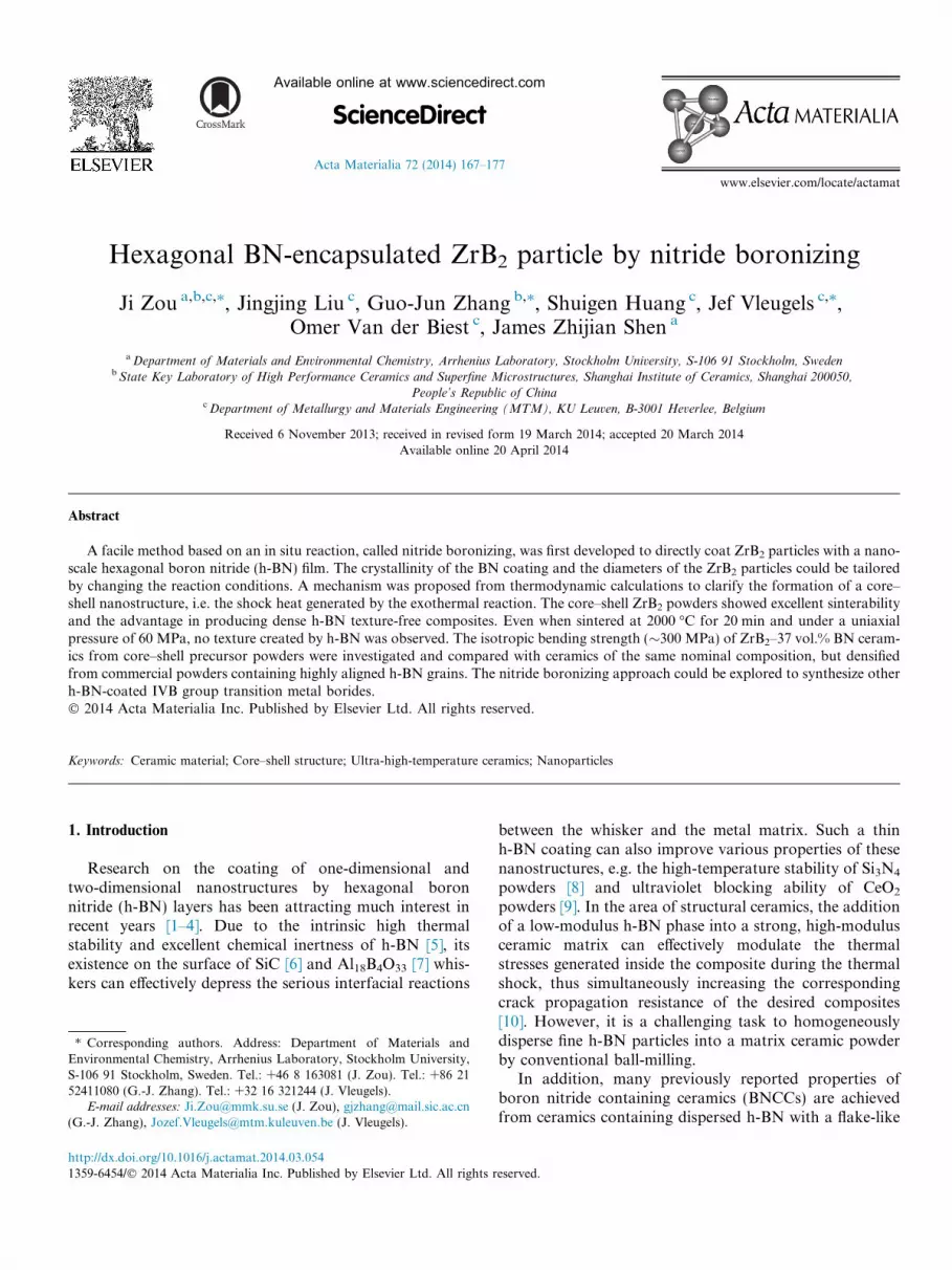
Fig. 1. XRD patterns of ZrN–B powder mixtures heat-treated atdifferent temperatures. ZrN–B starting powders (a), 800 �C (b), 1000 �C(c), 1300 �C (d) and 1550 �C (e). The oxygen and nitrogen contents ofZrN–B heated powders as a function of heat treatment temperaturesare shown in (f).
J. Zou et al. / Acta Materialia 72 (2014) 167–177 169
30 min were adopted . These two processes were designatedas routes II and III, and the as-obtained powders arereferred to as powder II and powder III, respectively.
2.2. Sample preparation and sintering
To explore the advantage of the core–shell ZrB2–BNpowders, the obtained products from route I were gentlycrushed into powders and sieved through a 60-mesh sievebefore subsequent SPS, in order to obtain dense ceramics.A moderate heating rate of 100 �C min�1 and 60 MPa uni-axial pressure was used. At 1100, 1300, 1550, 1700 and2000 �C the core–shell ZrB2–BN powders were held for20 min. Commercial ZrB2 and BN powders, with a nomi-nal composition the same as the core–shell powder, weremixed and prepared as described in Section 2.1. The corre-sponding powders were sintered by SPS at 2000 �C usingthe same heating and pressure parameters as for thecore–shell powders.
2.3. Sample characterization
Both of the powders and ceramics were analyzed byX-ray diffraction (XRD) with Cu Ka radiation (40 kVand 40 mA, Siemens D500 diffractometer). X-ray polefigures with {0001} reflection of the h-BN phase weremeasured by the same machine on several polishedceramics to investigate the possible alignment of BN grainsduring the sintering. Fourier transform infrared spectro-scopic (FT-IR) absorption was measured on a high-resolution Thermo Nicolet FT-IR spectrometer with theerror of ±0.2 cm�1. The oxygen and nitrogen contents ofas-synthesized powders at different temperatures weredetected by a Nitrogen/Oxygen Exterminator (TC600,Leco Corporation, USA). The detailed microstructures ofobtained samples were characterized by scanning electronmicroscopy (SEM, XL30-FEG, FEI, Eindhoven, theNetherlands) and transmission electron microscopy(TEM, JEM2100, JEOL, Japan) at 200 kV.
For the strength test, as-densified samples were cut intoseveral rectangular bars with dimensions of 2.5 mm �2 mm � 25 mm, and all their tensile surfaces were mirrorpolished and chamfered. Flexural strength was measuredby a three-point bending method on a universal testingmachine (INSTRON-1195) at a span length of 20 mmand a cross-head speed of 0.5 mm min�1. Strength databoth parallel and perpendicular to the SPS pressingdirection were recorded.
3. Results
3.1. Reaction study in different heating conditions
There are only three elements and a few compounds inthe Zr–B–N ternary systems. In order to avoid gaseousphases, such as N2, taking part in the reaction, the onlypossible way to form ZrB2–BN in the Zr–B–N system isthrough the reaction between ZrN and B (Reaction (1)).
Assuming the pressure in the system is maintained at1 atm, the standard molar Gibbs energy change DGo
m
� �of
Reaction (1) is �206.07 kJ at 300 K. Apparently, ZrN isnot stable in the presence of boron, even at room temper-ature, based on thermodynamic considerations. However,XRD patterns (Fig. 1a–c) showed that Reaction (1) wasrestricted by some kinetic factors, since ZrN still could beclearly indexed as the main phase after soaking at1000 �C for 3 min. Another feature appearing in thesepatterns (Fig. 1b and c) is that several peaks with lowintensity, belonging to t-ZrO2, could be well identifiedwhen powders were heated at 800–1000 �C, while thesepeaks can hardly be recognized in the starting powdermixtures (Fig. 1a). Though the diffraction peaks of zirconiaappeared when temperature increased, the measured oxy-gen contents in the as-heated sample gradually decreased(Fig. 1f).
The formation of ZrO2 peaks indicates that the dis-solved oxygen, from either raw powders or the mixing pro-cess, could separate from the initial ZrN powders duringheating. Its preferential combination with the Zr is onepossible way to form an oxide in ZrN–B systems (Fig. 1band c). Similar phenomena have been observed during heat

170 J. Zou et al. / Acta Materialia 72 (2014) 167–177
treatment of NbN powders [20]. Meanwhile, the reductionof oxygen content from room temperature to 1300 �C inFig. 1f implies that ZrO2 impurities could be removed fromthe powders by the other routes existing in this system, e.g.in the borothermal reduction by boron; previous experi-ments indicate that borothermal reaction becomes favor-able above 800 �C. No ZrO2 peaks could be detectedabove 1300 �C due to such self-cleaning reactions. All theZrN peaks disappeared when the holding temperaturewas increased to 1300 �C (Fig. 1d); the occurrence ofZrB2 and h-BN peaks revealed that Reaction (1) proceededto completion in the temperature range 1000–1300 �C.
According to the results from SPS (route I), the synthe-sis temperature (route II) was initially set as 1300 �C in thegraphite furnace. However, besides the formation of ZrB2,a substantial amount of unreacted ZrN was still present inthe corresponding XRD pattern (Fig. 2a). Moreover, theamounts of residual ZrN phase could not be eliminatedby further continuously increasing the temperature to1600 �C, and it seemed that Reaction (1) was never foundto proceed toward completion by route II. However, ZrNpeaks disappeared when a pressure of 4 MPa was verticallyapplied on the top of the powders at 1300 �C (route III,Fig. 2a). Generally speaking, the involvement of such asmall loading should not have any impact on the reactionprogress, since the favorable temperature for Reaction (1)only relies on the thermodynamic data of its reactantsand products, and the kinetic factors, such as diffusioncoefficient. In principle, all these essentials should not besignificantly changed by such a gentle pressure.
As a matter of fact, a considerable volume expansion of17.8 vol.% will be generated by Reaction (1), based on thedensity differences between reactants and products. Inroute II, reaction took place without any space restrictionor external loading, leading to poor contacts of the reac-tants in the expanded green body. Therefore, an uncom-pleted reaction occurred between ZrN and B. However,in the similar route III, the space was more restrained sincean external load of 4 MPa was applied. Hence, pure
Fig. 2. (a) XRD patterns (a) and FT-IR spectra (b) of BN-co
ZrB2–BN powders were obtained as a result of the tightercontact between the reactants (Fig. 2a).
3.2. The characterization of the core–shell powders
All the ZrN had changed into ZrB2 through route III,but the representative (002) reflection of h-BN at 26.7�could hardly be observed in the obtained powders(Fig. 2a, route III). This implies that the newly formedBN might be different from the crystallized hexagonal type.From the FT-IR spectrum of powder I displayed inFig. 2b, we can see the B–N–B out-of-plane vibration dis-tinctly at 790 cm�1 as well as the absorption band attrib-uted to the in-plane B–N transverse vibration at1380 cm�1. Both are the characteristic peaks of sp2-bondedBN, as either h-BN or turbostratic-BN (t-BN) type [10].Nevertheless, the absorption band of powder III broad-ened a little at 1380 cm�1, compared to that in powder I.Apparently, the degree of crystallinity of BN from powderIII is much lower than that in powder I, especially for thedegree of in-plane B–N structure ordering. These observa-tions imply that BN formed by route III might belong tot-BN, which was further confirmed by the quasi-orderedstructures in the high-resolution TEM (HRTEM) imagespresented in Fig. 3f.
The ZrB2–BN powders produced exhibit a typical core–shell structure, no matter what route has been adopted(Fig. 3a and d). Individual ZrB2 particles, encapsulatedby a low-contrast phase, could be clearly identified inFig. 3a and d. The distance between two adjacent h-BNlayers in the shell is �0.33 nm, as expected, based on thegood contrast along the surface direction in Fig. 3b ande. A layer structure, more or less ordered, with a similarinterplanar spacing in the perpendicular c-direction,implies that the shell materials are h- or t-BN. Thoughthe layer structures have some similarities between powdersI and III, several differences still could be distinguished: (i)the discontinuous and random rotation of BN layers ismore pronounced in powder III (Fig. 3e); (ii) when
ated ZrB2 powders reacted by different routes at 1300 �C.

Fig. 3. Images exposed by TEM and HRTEM to illustrate the microstructures of the synthesized ZrB2–BN powders at 1300 �C. The overall morphologyof powder I is shown in (a) and its core–shell particle structure is shown in detail in (b). The HRTEM picture of a boron nitride area of powder I and thecorresponding energy dispersive X-ray spectra proving the hexagonal crystallinity are shown in (c, g) and (i), respectively. The overall morphology ofreacted powder from route III is illustrated in (d) and its core–shell particle structure is shown in detail in (e). One HRTEM image of quasi-ordered, t-BNin powder III is shown accompanied with its energy dispersive X-ray spectra in (f) and (h), respectively.
J. Zou et al. / Acta Materialia 72 (2014) 167–177 171
observed through the [0001] zone axis of BN by TEM,resolved lattice fringes and clear selected-area electron dif-fraction (SAED) patterns could be acquired from powder I(Fig. 3c and g). This reflects a high degree of crystallinity inthe corresponding hexagonal B–N–B basal plane in h-BN.On the contrary, no long-range ordered diffraction spotswere found in the basal plane of BN in powder III(Fig. 3f and h). Combining these findings with the XRDand FT-IR results, it shows that the BN coating on theZrB2 particles by route I and route III are h-BN andt-BN, respectively.
Measured average particle sizes for the coated powders Iand III are 190 and 107 nm, respectively. Obviously, thesevalues are about two magnitudes smaller than the precur-sor powder of ZrN, with an average size of 10 lm, espe-cially from route III. Such size refinement indicates thatso-called “nitride boronizing” is a potential top-downmethod to synthesize ZrB2 powders on the nanoscale aswell. Another merit of this approach is to avoid using finestarting powders, since it is not so easy to find fine nitridepowders with high purity. The thickness of BN film on
ZrB2 powder was roughly estimated as 4–6 nm fromFig. 3b and e, irrespective of the route used.
On the basis of Reaction (1), the calculated volume frac-tion of h-BN in ZrB2–BN composite powders is 37%,implying that there is still a considerable amount of h-BN existing independently from the ZrB2 particles in eachpowder (Fig. 3a, d and i). Most such dispersed, dissociativeand flake-like BN grains were only composed of three tofive layers (Fig. 3i) and could be classified as boron nitridenanosheets, which is just analogous to that of well-knowngrapheme [21].
3.3. The possibility of applying nitride boronizing to other
BN@boride core shell nanostructures
Hexagonal BN-coated TiB2 powders could be obtainedby simply replacing the ZrN with TiN, according to thereaction between TiN and B at 1400 �C. Typical TEMimages are shown in Fig. 4. The morphology of core–shellpowders is similar to that found in ZrB2; however, thethickness of the coated BN film (�12 nm) seems to be

Fig. 4. HRTEM images of as-synthesized BN@TiB2 powders from route (I) (a, c) and route (III) (b, d).
172 J. Zou et al. / Acta Materialia 72 (2014) 167–177
2–3 times larger than that of 4–6 nm in BN@ZrB2 particles(Fig. 3b and e). The difference might be related to thehigher reactive temperature and different starting particlesize of the nitride adopted in this work, which will be inves-tigated in detail in the near future. These images also indi-cate that allowing the current to pass through the precursoris beneficial to eliminating the intergranular amorphousfilm between the TiB2 grain and the BN film (Fig. 4a andc), since oxygen contaminations were only detected in thecore–shell powders from route III (Fig. 4b and d).
3.4. ZrB2–BN ceramics sintered by core–shell powders
The h-BN-coated ZrB2 powders from route I show excel-lent sinterability. The relative density of ZrB2–37 vol.%BN (ZN) ceramics SPS sintered at 1100 �C is as high as91% of theoretical density (TD). The value is similar to thatreported for ZrB2–35 vol.% BN–12 vol.% SiC ceramics sin-tered at 2000 �C by commercially available powders (92%TD) [22]. Note that the latter temperature was 900 �Chigher than that required by the core–shell powdersproduced through nitride boronizing. The density of ZNceramics increased with SPS temperature and reachedfull density after holding at 1550 �C for 7 min. In thispaper, special attention is paid to the ZN and ZBN(ZrB2–37 vol.% BN sintered by commercial powders) sin-tered by SPS at relatively higher temperatures and for alonger time, i.e. 2000 �C and 20 min, to let the BN flakebecome coarse intentionally, as explained Section 1.
As expected, the measured three-point flexural strengthof the ZBN ceramics differed in bending directions. Whenthe tensile surface of the bar is parallel to the pressingdirection during SPS, the measured strength value is181 ± 27 MPa (k). This is much lower than the directionperpendicular to the SPS pressing, 259 ± 11 MPa (\). Inthe former case, more h-BN platelets were oriented perpen-dicular to applied tensile stresses. Defects and microcrackslocated around the edge of h-BN basal plane may act as afracture origin and reduce the strength [23,24]. Moreover,the weak cleavage plane of h-BN is also situated perpendic-ular to this direction. All of these factors may be responsi-ble for the lower strength in this direction.
Lamellar h-BN grains 4–5 lm long are highly alignedand oriented perpendicular to the SPS pressing directionin ZBN ceramics (Fig. 5a). The {0001} pole figure ofh-BN clearly shows a concentric shape around the centralpoint (Fig. 5c). The degree of texture could bequantitatively calculated by the multiples of a randomdistribution (MRD), i.e. the maximum h-BN intensitiesare 4.7 times the random one at the center of the polefigures in ZBN.
On the contrary, ZN ceramics exhibited a similarstrength value along two directions (k, 295 ± 31 MPa and\, 312 ± 19 MPa). These values indirectly reflected thenon-preferred orientation distribution of h-BN in ZN(Fig. 5b), in spite of the fact that the length of the h-BNflake (3–4 lm) is slightly shorter than that in ZBN(4–5 lm). The maximum value of MRD in Fig. 5d is 1.8,

Fig. 5. The fracture morphologies and h-BN {0001} pole figures from ZN (a, c) and ZBN (b, d) ceramics.
J. Zou et al. / Acta Materialia 72 (2014) 167–177 173
indicating that the distribution of {000 1} peaks in the ste-reographic projection is rather homogenous.
The results above illustrate that in addition to the supe-rior sinterability, the development of h-BN-coated ZrB2
powders has the substantial advantage of producing com-posites with a random distribution of h-BN flakes, whichcan possess isotropic mechanical properties. Such a distri-bution of h-BN flakes in ZrB2 matrix can be interpretedin at least two ways: (i) benefiting from the tightly adherentconnections between ZrB2 and BN (Fig. 3a and d), thedestruction of such core–shell structures as well as thealignment of h-BN at low temperature under a uniaxialloading by SPS is difficult; (ii) at a low temperature(1100 �C), ZN ceramics have already reached 91% TD.Apparently, it is difficult to realize the preferred growthof h-BN in an already dense composite – even the sinteringtemperature was increased.
4. Discussion
4.1. Thermodynamic consideration in ZrN–B systems
The SPS system used here is designed to provide a rapidpower feedback based on the proportion–integration–differentiation (PID) control, i.e. during the sinteringprocess, the temperature is regulated in real time and achange in the power supply can be quickly achieved byadjusting the input current and voltage. The temperature,current, voltage and total power consumption for route Icould be recorded and a typical one is plotted vs. time, asshown in Fig. 6a. All the parameter curves are nearly linear
with a similar slope. However, as soon as the temperaturereached �1095 �C, a sharp temperature rise occurred,despite the PID control shutting off the current (I), voltage(U) and total power consumption (P) to zero. Meanwhile,the powders have already changed into pure ZrB2 andh-BN, consistent with the XRD result. Therefore, theoccurrence of an exothermic reaction initiated at�1095 �C is confirmed.
Reaction (1) is an exothermic reaction since it has a highpositive molar enthalpy change DH I
T o
� �over a wide tem-
perature range (300–3000 K). Hence, there is a possibilityof igniting the self-propagating high-temperature synthesis(SHS) process by this reaction. The adiabatic temperature(Tad) of Reaction (1) could be calculated from Eq. (2)below. It has been empirically proven that the SHS processwill not take place unless Tad > 1800 K [25].
DH IT o¼Z T ad
T o
ðCp;ZrB2þ Cp;BNÞdT ð2Þ
where Cp;ZrB2and Cp;BN are the heat capacities of ZrB2 and
BN, respectively. In the general case, To is set as 300 K, asthe calculated Tad becomes 1870 K, which is slightly higherthan the requirement for initiating SHS.
In fact, the nitride boronizing reaction occurred at1095 �C rather than at room temperature. If this is takeninto account, a much higher Tad of 3000 K will be calcu-lated. Furthermore, once it was initiated, an exothermalSHS process will push local temperatures at the reactionfront to a higher value. Another complication that mightoccur at an extreme local temperature is the decompositionof ZrN and the loss of nitrogen therefrom (Fig. 7).

Fig. 6. (a) Recorded SPS parameter (temperature, current, voltage and power consumption) plotted vs. time during heating by route I. (b) Recordedtemperature curves and corresponding voltage levels adopted. (c) The calculated resistance under different voltages from (b) as a function of processingtime; the curve for an empty graphite die is also included in (c) for comparison. An enlarged region in (a) is shown in (d); label “A” in (d) shows where theintermediate products were collected for further examination.
174 J. Zou et al. / Acta Materialia 72 (2014) 167–177
Thermodynamic prediction shows that an associatedReaction (3) is more favorable in that case:
ZrNþ 2B ¼ ZrB2 þ 0:5N2ðgÞ ð3Þ
Fig. 7. Calculated molar contents at 1 bar pressure of the reactedproducts from a mix of (1 mol ZrN + 3 mol B) for temperatures rangingfrom 300 to 3000 �C. The regions for the measured reactive temperature(MT) and adiabatic temperature of Reaction (1) (AT) are marked.
The nitrogen contents in the heat-treated powders, afterholding temperatures of up to 1550 �C, are summarizedin Fig. 1f. The N contents remain at a stable value of�8.7 wt.%, which is close to the nominal composition ofnitrogen in the precursor ZrN–B powder. Thus, almostno nitrogen was lost by using route I and any influenceof Reaction (3) is limited. On the basis of a propagatingSHS process, a hypothetical “heat-shock model” for theformation mechanism of the core–shell structure by nitrideboronizing can be described, which might account for thetwo-magnitude grain reduction. This is schematicallydrawn in Fig. 8 and will be described stepwise in the textbelow.
4.2. Heat-shock model for the formation of the core–shell
structure
Though the raw powders of ZrN (�10 lm) and B(<2 lm) were considered to be mixed homogeneously, aparticle size inhomogeneity may inevitably exist, as d10
and d50 of boron powder are 0.1 and 1.5 lm, respectively.Therefore, some regions in the green compact may containpowders with a slightly higher packing density, as illus-trated in Fig. 8a. The SPS induced electrical field (E) at
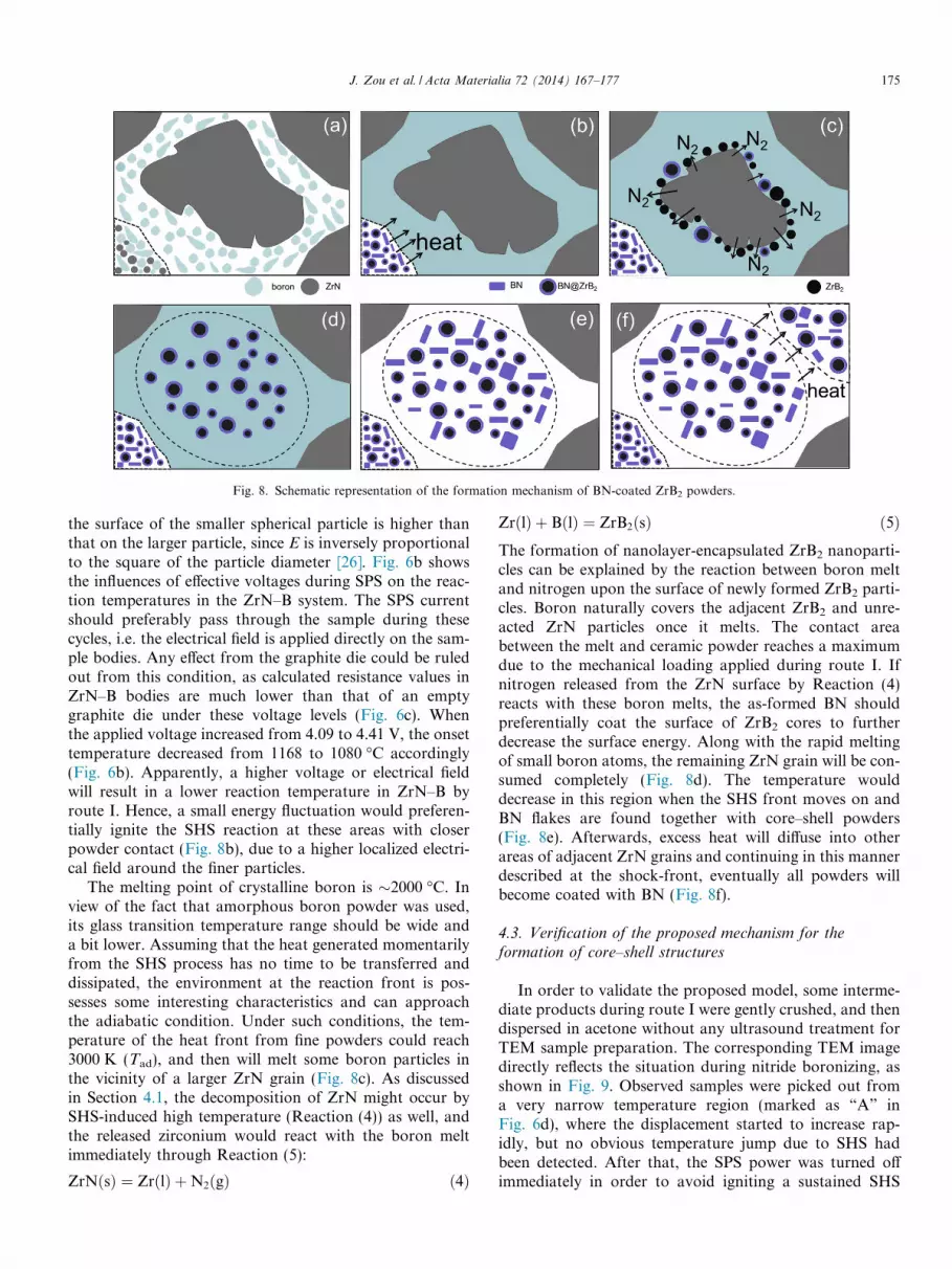
Fig. 8. Schematic representation of the formation mechanism of BN-coated ZrB2 powders.
J. Zou et al. / Acta Materialia 72 (2014) 167–177 175
the surface of the smaller spherical particle is higher thanthat on the larger particle, since E is inversely proportionalto the square of the particle diameter [26]. Fig. 6b showsthe influences of effective voltages during SPS on the reac-tion temperatures in the ZrN–B system. The SPS currentshould preferably pass through the sample during thesecycles, i.e. the electrical field is applied directly on the sam-ple bodies. Any effect from the graphite die could be ruledout from this condition, as calculated resistance values inZrN–B bodies are much lower than that of an emptygraphite die under these voltage levels (Fig. 6c). Whenthe applied voltage increased from 4.09 to 4.41 V, the onsettemperature decreased from 1168 to 1080 �C accordingly(Fig. 6b). Apparently, a higher voltage or electrical fieldwill result in a lower reaction temperature in ZrN–B byroute I. Hence, a small energy fluctuation would preferen-tially ignite the SHS reaction at these areas with closerpowder contact (Fig. 8b), due to a higher localized electri-cal field around the finer particles.
The melting point of crystalline boron is �2000 �C. Inview of the fact that amorphous boron powder was used,its glass transition temperature range should be wide anda bit lower. Assuming that the heat generated momentarilyfrom the SHS process has no time to be transferred anddissipated, the environment at the reaction front is pos-sesses some interesting characteristics and can approachthe adiabatic condition. Under such conditions, the tem-perature of the heat front from fine powders could reach3000 K (Tad), and then will melt some boron particles inthe vicinity of a larger ZrN grain (Fig. 8c). As discussedin Section 4.1, the decomposition of ZrN might occur bySHS-induced high temperature (Reaction (4)) as well, andthe released zirconium would react with the boron meltimmediately through Reaction (5):
ZrNðsÞ ¼ ZrðlÞ þN2ðgÞ ð4Þ
ZrðlÞ þ BðlÞ ¼ ZrB2ðsÞ ð5ÞThe formation of nanolayer-encapsulated ZrB2 nanoparti-cles can be explained by the reaction between boron meltand nitrogen upon the surface of newly formed ZrB2 parti-cles. Boron naturally covers the adjacent ZrB2 and unre-acted ZrN particles once it melts. The contact areabetween the melt and ceramic powder reaches a maximumdue to the mechanical loading applied during route I. Ifnitrogen released from the ZrN surface by Reaction (4)reacts with these boron melts, the as-formed BN shouldpreferentially coat the surface of ZrB2 cores to furtherdecrease the surface energy. Along with the rapid meltingof small boron atoms, the remaining ZrN grain will be con-sumed completely (Fig. 8d). The temperature woulddecrease in this region when the SHS front moves on andBN flakes are found together with core–shell powders(Fig. 8e). Afterwards, excess heat will diffuse into otherareas of adjacent ZrN grains and continuing in this mannerdescribed at the shock-front, eventually all powders willbecome coated with BN (Fig. 8f).
4.3. Verification of the proposed mechanism for the
formation of core–shell structures
In order to validate the proposed model, some interme-diate products during route I were gently crushed, and thendispersed in acetone without any ultrasound treatment forTEM sample preparation. The corresponding TEM imagedirectly reflects the situation during nitride boronizing, asshown in Fig. 9. Observed samples were picked out froma very narrow temperature region (marked as “A” inFig. 6d), where the displacement started to increase rap-idly, but no obvious temperature jump due to SHS hadbeen detected. After that, the SPS power was turned offimmediately in order to avoid igniting a sustained SHS

Fig. 9. (a) The overall morphology of the intermediate SHS product observed by TEM. Detailed areas in (a), marked as “B” and “C”, are displayed with ahigher magnification in (d) and (e), respectively. (b) The ED pattern of one ZrN grain, arrowed “A” in (a). (c) The XRD pattern of the intermediatepowders. EDS (f) shows that the labeled area “D” with a brighter contrast in (e) mainly contains boron.
176 J. Zou et al. / Acta Materialia 72 (2014) 167–177
reaction. The XRD pattern of the intermediate shows a ser-ies of ZrB2 peaks appearing together with unreacted ZrNphase (Fig. 9c). Undoubtedly, fine BN@ZrB2 powders(Fig. 9d) and larger particles (Fig. 9a) coexist in the interme-diate; the electron diffraction pattern (Fig. 9b) implies thatthe larger particle (marked A in Fig. 9a) is unreactedZrN. The lack of any fine ZrN particles in Fig. 9a confirmedthat Reaction (1) actually started from fine particles asdescribed in Section 4.2. Details in Fig. 9e also reveal thata number of fine ZrB2 particles are located on one largerZrN grain. Moreover, no isolated and separated boronpowders could be clearly recognized from Fig. 9a. Never-theless, a thin coating with a brighter contrast was foundaround the ZrN grain (Fig. 9e); the dominant element fromenergy-dispersive X-ray spectroscopy (EDS) in that area(Fig. 9f) is boron. In short, all the accumulated evidencein Fig. 9 is very close to what we proposed in Fig. 8c.
The only uncertainty in the proposed mechanism iswhether nitrogen appears during the boronizing process.A similar BN coating on iron nanoparticles has beenreported by heating mixtures of Fe2O3 and boron in a nitro-gen atmosphere [27], indicating that a similar mechanismshould exist in the present work, i.e. nitrogen participatesin the boronizing process as we assumed (Fig. 8c). In fact,the temperature during route I will seldom go to thatextreme (Tad), as the system is not adiabatic. Therefore, itis pertinent that the proposed mechanism shown in Fig. 8is only valid at the SHS shock front and in a referred flashmoment. Nitrogen may only act as an intermediate, but it iscrucial to the process for forming a BN capsule. The
nitrogen contents in Fig. 1f also supported the fact that vir-tually no nitrogen was lost in this nitride boronizingprocess.
5. Conclusion
Nano-sized BN-coated ZrB2 powders have been synthe-sized by a simple nitride boronizing route using ZrN andamorphous boron powders as precursor materials. BN-coated ZrB2 powders with 37 vol.% BN could be obtainedby heat treatment at 1300 �C, either in SPS apparatus orin a graphite furnace with a minimal axial pressure of4 MPa. These two processes differed in that the coatingswere h-BN and t-BN, respectively. Pressureless sinteringgave a poor reaction and failed to yield pure core–shell pow-ders since volume expansion partially isolated the reactants.HRTEM shows a perfect cohesion between the ZrB2 coreand the BN shell materials from routes I and III. A “heat-shock model” at the SHS process front has been suggestedto explain the possible mechanism for the high grain sizereduction and formation of a core–shell structure, and thesewere verified by a series of experimental results. The nitrideboronizing approach could be easily copied to produceh-BN-coated transition metal boride powders, e.g. TiB2.Furthermore, the ZrB2–BN core–shell powders have a sub-stantial ability to obtain texture-free BN based compositeswith typical flake-like BN grains, even treated at high tem-perature (2000 �C) and high pressure (60 MPa) for 20 min.
This study potentially solves the alignment of h-BNflakes in ceramics and will pave the way for novel

J. Zou et al. / Acta Materialia 72 (2014) 167–177 177
fundamental and application studies of BNCCs. Theunique boride–h-BN composites with large h-BN flakesand isotropic bending strength of �300 MPa will surelyimprove their reliability in many applications in the areaof energy, aerospace and steel metallurgy. Typical productsmight be side dams for thin-stripe casting, evaporationboats for aluminum metalizing and thermal protectionparts for hypersonic flight vehicles.
Acknowledgements
This work was financially supported by National Sci-ence Foundation of China (No. 51272266) and the grantsfrom Berzelii Center EXSELENT on Porous Materials.The work was also funded by the Research Fund of KULeuven (GOA/08/007). This paper is dedicated to Prof.Pei-Ling Wang and Prof Omer Van der Biest on the occa-sion of their retirements after about 40 years’ excellentresearch on advanced ceramics. We would also like toacknowledge the careful and constructive comments ofthe reviewers.
References
[1] Paine RT, Narula CK, Schaeffer R, Datye AK. Chem Mater1989;1:486.
[2] Chatterjee S, Luo ZT, Acerce M, Douglas MY, Johnson AT,Sneddon L. Chem Mater 2011;23:4414.
[3] Levendorf MP, Kim CJ, Brown L, Huang PY, Havener RW, MullerDA, et al. Nature 2012;488:627.
[4] Lim HS, Oh JW, Kim SY, Yoo MJ, Park SD, Lee WS. Chem Mater2013;25:3315.
[5] Golberg D, Bando Y, Huang Y, Terao T, Mitome M, Tang CC, et al.ACS Nano 2010;4:2979.
[6] Tang CC, Bando Y, Sato T, Kurashima K. Adv Mater 2002;14:1046.[7] Song HS, Zhang J, Lin J, Liu SJ, Luo JJ, Huang Y, et al. J Phys
Chem C 2007;111:1136.[8] Zhang GJ. J Am Ceram Soc 2009;92:745.[9] Masui M, Hirai H, Hamada R, Imanaka N, Adachi GY, Sakata T,
et al. J Mater Chem 2003;13:622.[10] Shuba R, Chen IW. J Am Ceram Soc 2006;89:1147.[11] Kusunose T, Sekino T, Ando Y. Nanotechnology 2008;19:275603.[12] Buchheit AA, Hilmas GE, Fahrenholtz WG, Deason DM, Wang H.
Mater Sci Eng A 2008;494:239.[13] Kusunose T, Sekino T, Choa YH, Niihara K. J Am Ceram Soc
2002;85:2678.[14] Zhang GJ, Beppu Y, Ohji T, Kanzaki S. Acta Mater 2001;49:77.[15] Zhang GJ, Yang JF, Ando M, Ohji T, Kanzaki S. Acta Mater
2004;52:1823.[16] Li JG, Gao L. J Mater Chem 2003;13:628.[17] Eichler J, Lesniak C. J Eur Ceram Soc 2008;28:1105.[18] Wu WW, Xiao WL, Estili M, Zhang GJ, Sakka Y. Scr Mater
2013;68:889.[19] Vanmeensel K, Laptev A, Hennicke J, Vleugels J, Van der Biest O.
Acta Mater 2005;53:4379.[20] Ran SL, Gao L. J Am Ceram Soc 2008;91:599.[21] Novoselov KS, Geim AK, Morozov SV, Jiang D, Zhang Y, Dubonos
SV, et al. Science 2004;306:666.[22] O. Kida, Y. Segawa, United States Patent, No. 4; 668: 643.[23] Trice RW, Halloran JW. J Am Ceram Soc 1999;82:2563.[24] Wu WW, Estili M, Toshiyuki N, Zhang GJ, Yoshio S. Mater Sci Eng
A 2013;582:41.[25] Munir ZA, Tamburini UA. Mater Sci Rep 1989;3:227.[26] Chaim R. Mater Sci Eng A 2007;443:25.[27] Tokoro H, Fujii S, Oku T. J Mater Chem 2004;14:253.


