Embed Size (px)
Citation preview
;-
-' . ..,.
,~l - ;.. {
.~ -' - ·.
DOT/FAA/RD-90/7
Research and Development Service Washington, D.C. 20591
FAA WJH Technical Center lllllllllllllllllllllllllllllllllllllllillllllllll
00093409
PAA WJH Technical Centcl' Tech Center Library Atlaatk City • Nl 08405
,.
-Helicopter Rejected Takeoff Airspace Requirements
Edwin D. McConkey Robert J. Hawley Robert K. Anoll
. Systems Control Technology, Inc. ·. 1611 N. Kent Street, Suite 910
Arlington, VA 22209
August 1991
Final Report
This document is available to the public through the National Technicallnformo.tion
_ Service, Springfield, Virginia 22161.
U.S. Department of Transportation
Federal Aviation Administration
AIWLABLEJN ELECTRONIC FORMA;
This document is disseminated under th~ sponsorship of the U.S. Department of Transportation in the interest of information exchange. The United States Government assumes no liability for the contents or use thereof.
•
-· •
Technical Report Documentation Page
1. Report No. 2. Government Accession No. 3. Recipient's Catalog No.
DOT/FAA/RD-90/7
4. Title and Subtitle 5. Report Date August 1991
Helicopter Rejected Takeoff Airspace Requirements 6. Pertorming Organization Code
7. Author (s) 8. Pertorming Organization Report No.
Edwin D. McConkey, Robert J. Hawley, Robert K. Anoll SCT 91RR-28
9. Pertorming ·organization Name and Address Systems Control Technology, Inc. 1611 North Kent Street, Suite 910 Arlington, Virginia 22209
12. Sponsoring Agency Name and Address U.S. Department of Transportation Federal Aviation Administration 800 Independence Avenue, S.W. Washington, D.C. 20591
15. Supplementary Notes
ARD- 30 - Vertical Flight Program Office AAS - 1 00 - Design and Operations Criteria Division
16. Abstract
10. Work Unit No. (TRAIS)
11. Contract or Grant No. DTFA01-87-C-00014
13. Type Report and Period Covered
Final Report
14. Sponsoring Agency Code ARD-30
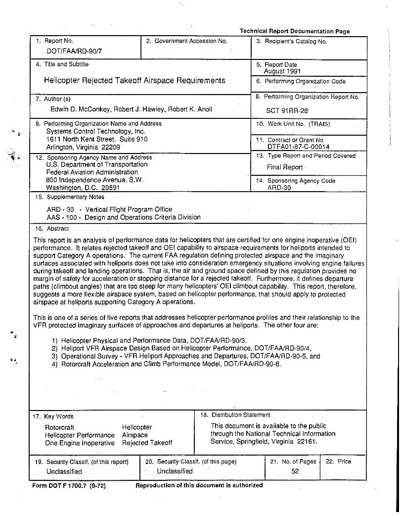
This report is an analysis of performance data for helicopters that are certified for one engine inoperative (OEI) performance. It relates rejected takeoff and OEI capability to airspace requirements for heliports intended to support Category A operations. The current FAA regulation defining protected airspace and the imaginary surfaces associated with heliports does not take into consideration emergency situations involving engine failures during takeoff and landing operations. That is, the air and ground space defined by this regulation provides no margin of safety for acceleration or stopping distance for a rejected takeoff. Furthermore, it defines departure paths (climbout angles) that are too steep for many helicopters' OEI climbout capability. This report, therefore, suggests a more flexible airspace system, based on helicopter performance, that should apply to protected airspace at heliports supporting Category A operations.
This is one of a series of five reports that addresses helicopter performance profiles and their relationship to the VFR protected imaginary surfaces of approaches and departures at heliports. The other four are:
1) Helicopter Physical and Performance Data, DOT/FAA/RD-90/3, 2) Heliport VFR Airspace Design Based on Helicopter Performance, DOT/FAA/RD-90/4, 3) Operational Survey- VFR Heliport Approaches and Departures, DOT/FAA/RD-90-5, and 4) Rotorcraft Acceleration and Climb Performance Model, DOT/FAA/RD-90-6.
17. Key Words
Rotorcraft Helicopter Performance One Engine Inoperative
Helicopter Airspace Rejected Takeoff
'
18. Distribution Statement
This document is available to the public through the National Technical Information Service, Springfield, Virginia 22161.
19. Security Class if. (of this report)
Unclassified
20. Security Ciassif. (of this page) 21. No. of Pages 22. Price
Unclassified 52
Form DOT F 1700.7 (8·72) Reproduction of this document is authorized
•'
• .!
.. i
. -·
i
...
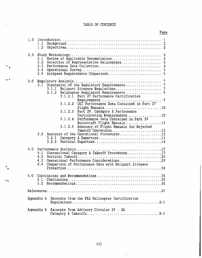
TABLE OF CONTENTS
Page
1. 0 Introduction. . . . . . . . . . . . . . . . . . . . . . . . . . . . . . . . . . . . . . . . . . . . . . . . . . . . . 1 1 . 1 Background . . . . . . . . . . . . . . . . . . . . . . . . . . . . . . . . . . . . . . . . . . . . . . . . . . 2 1.2 Objectives .................................................. 2
2. 0 Study Methodology ............... ·. . . . . . . . . . . . . . . . . . . . . . . . . . . . . . . . . 3 2.1 Review of Applicable Documentation .......................... 3 2.2 Selection of Representative Helicopters ..................... 3 2.3 Performance Data Collection ................................. 4 2. 4 Operational Survey. . . . . . . . . . . . . . . . . . . . . . . . . . . . . . . . . . . . . . . . . . 5 2.5 Airspace Requirements Comparison ............................ 5
3. 0 Regulatory Analysis ......................... :. . . . . . . . . . . . . . . . . . . . 7 3.1 Discussion of the Regulatory Requirements ................... 7
3.1.1 Heliport Airspace Regulations ........................ 7 3.1.2 Helicopter Regulatory Requirements ................... 9
3.1.2.1 Part 27 Performance Certification Requirements. . . . . . . . . . . . . . . . . . . . . . . . . . . . . . . . 9
3.1.2.2 OEI Performance Data Contained in Part 27 Flight Manuals .............................. 10
3.1.2.3 Part 29, Category A Performance Certification Requirements .................. 10
3.1.2.4 Performance Data Contained in Part 29 Rotorcraft Flight Manuals ................... 12
3.1.2.5 Adequacy of Flight Manuals for Rejected Takeoff Operations .......................... 13
3.2 Analysis of the Operational Procedures ...................... 13 3.2.1 Category A Departure ................................. 13 3.2.2 Vertical Departure ................................... 14
4. 0 Performance Analysis ............................................. 17 4.1 Conventional Category A Takeoff Procedures .................. 17 4. 2 Vertical Takeoff ............ · ................................ 29 4.3 Operational Performance Considerations ...................... 29 4.4 Comparison of Performance Data with Heliport Airspace
Protection .................................................. 3 4
5.0 Conclusions and Recommendations .................................. 35 5.1 Conclusions ................................................. 35 5. 2 Recommendations ............................................. 35
References ........................... c ••••••••••••••••••••••••••••••••• 37
Appendix A Excerpts from the FAA Helicopter Certification Regulations .... ; ......................................... A-1
Appendix B Excerpts from Advisory Circular 29 - 2A Category A Takeoffs ...................................... B-1
iii
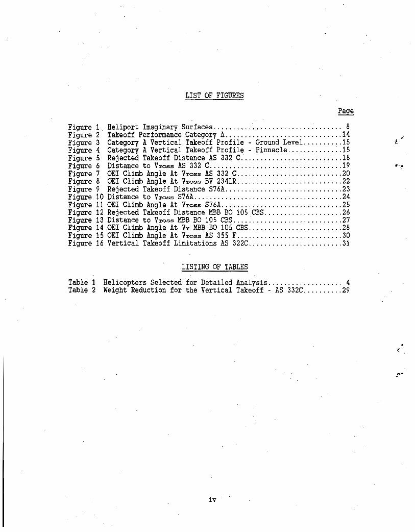
LIST OF FIGURES
Page
Figure 1 Heliport Imaginary Surfaces .......... -............... : ....... 8 Figure 2 Takeoff Performance Category A .............................. 14 Figure 3 Category A Vertical Takeoff Profile- Ground Level .......... 15 Figure 4 Category A Vertical Takeoff Profile- Pinnacle ............ :.15 Figure 5 Rejected Takeoff Distance AS 332 C .......................... 18 Figure 6 Distance to VToss AS 332 C .................................. 19 Figure 7 OEI Climb Angle At VToss AS 332 C ........................... 20 Figure 8 OEI Climb Angle At VToss BV 234LR ........................... 22 Figure 9 Rejected Takeoff Distance S76A .............................. 23 Figure 10 Distance to VTo~s S76A ...................................... 24 Figure 11 OEI Climb Angle At VToss S76A .. ~ ............................ 25 Figure 12 Rejected Takeoff Distance MBB BO 105 CBS .................... 26 Figure 13 Distance to VToss MBB BO 105 CBS ............................ 27 Figure 14 OEI Climb Angle At VY MBB BO 105 CBS ........................ 28 Figure 15 OEI Climb Angle At VToss AS 355 F ........................... 30 Figure 16 Vertical Takeoff Limitations AS 322C ........................ 31
LISTING OF TABLES
Table 1 Helicopters Selected for Detailed Analysis ................... 4 Table 2 Weight Reduction for the Vertical Takeoff- AS 332C .......... 29
•
iv ·
••
1.0 INTRODUCTION
The current Federal regulation defining protected airspace surfaces around heliports is based on helicopters performing norma! takeoff and landing operations. Emergency situations involving engine failures are not considered in the establishment of these protected surfaces.
In an effort to develop a better understanding of the implications of failed engine conditions on city-center heliport development and heliport protected airspace requirements, the FAA initiated a study project to collect data regarding the performance of representative Category A helicopters in the current civil fleet. This report contains the data, analyses, conclusions and recommendations that were produced by that study.
This report is one of a series of five that addresses.helicopter performance profiles and their relationships to approach and departure protected surfaces around heliports. The others are:
Helicopter Physical and Performance Data, DOT/FAA/RD-90/~: ..
Contains. physical and performance data for eight civil helicopters. The data were taken from a number of sources to include aircraft flight manuals, industry publications, and computer performance simulations.
Operational Survey - VFR Heliport Approaches and Departures, DOT/FAA/RD-90/5:
Presents the results of a field survey which collected pilots' opinions about their helicopter performance and operational considerations. Survey results are compared with the performance data contained in "Helicopter Physical and Pei:formance Data."
Heliport VFR Airspace Based on Helicop~er Performance, . DOT/FAA/RD-_90/4:
Applies the data contained in DOT/FAA/RD-90/3 and DOT/FAA/RD-90/5 to the issue of vertical airspace protected surfaces around the heliport. Additionally, the report develops a heliport airspace/helicopter performance.system that allows operational credit for performance capability. ·
. . Rotorcraft Acceleration and Climb Performance Model, DOT/FAA/RD-90/6:
Presents the methodology and computer programs used to develop the helicopter departure profiles presented in "Helicopter Physical and Performance Data."
The report contained herein is an analysis of· performance data for helicopters that are certificated to have one engine inoperative (OEI) performance capability. This capability is known in the industry as Category A. These data were developed from information contained in the helicopter flight man~als. The report relates rejected takeoff and OEI performance capability to airspace requirements for those heliports where Category A operations are of, concern.
1 .1 BACKGROUND
The study of airspace requirements for failed engine situations naturally limits the scope of the effort to multiengine rotorcraft. The single engine aircraft with a failed engine is obviously going to be forced to land. Because the failure can occur anywhere along the takeoff path, the resultant protected airspace must be large to accommodate an autorotation to a landing in a clear area.
Pilots of multiengine.rotorcraft however are faced with a choice in a failed engine situation: reject the takeoff and land, or continue the takeoff with one engine inoperative (OEI). In developing certification criteria for transport category rotorcraft, the FAA has carefully considered the failed engine scenario. Specific requirements, established under Category A, are contained in the regulations under Title 14 of the Code of Federal Regulations (14 CFR), Part 29, Transport Category Rotorcraft. While it is recognized that only a small portion of the helicopter population is certified for Category A, and an even smaller number actually operate Category A, forecasts of increases in Part 29 operations over time and their impact on the industry must be considered in the development of heliport design standards. For those rotorcraft certified under Part 27,Normal Category Rotorcraft, (rotorcraft with a maximum gross weight of 6,000 pounds or less), there are no specific requirements to demonstrate Category A capabilities. However, some manufacturers of multiengine helicopters choose to provide some Category A performance data in the helicopter flight manuals even though it is not required.
In pursuing this investigation, a considerable amount of helicopter performance data were generated for the helicopters that were selected for detailed analysis. It is appropriate to note that it was not the intent of this study to perform a comparative analysis of the performance capabilities of these aircraft. The performance data presented in this report and its two companion reports were developed using assumptions and guidelines specifically aimed at investigating the design of heliports in confined areas. Therefore, these data do not necessarily reflect the performance capabilities of these helicopters in a broader operational or economic context.
1.2 OBJECTIVES
The overall objective of this study was to recommend improvements to airspace protection surfaces at heliports based on rejected takeoff and OEI takeoff conditions. In pursuing this objective, the following areas of study were taken into consideration:
a. applicable parts of the heliport airspace protection regulation and supporting documentation,
b. applicable parts of the helicopter certification regulations and supporting documentation,
c. takeoff procedures used in the certification of the helicopter,
d. takeoff procedures r~commended in the helicopter flight manuals,
e. performance data contained in the helicopter flight manuals, and
f. data from other sources found in the open literature. 2
-~·
. ;
.. .
2.0 STUDY METHODOLOGY
The methodology used to investigate heliport airspace requirements based on OEI helicopter performance is described in this section.
2.1 REVIEW OF APPLICABLE DOCUMENTATION
The study was initiated with a review of the applicable FAA regulatory documents, primarily Title 14 of the Code of Federal Regulations (14 CFR) and FAA Advisory Circulars (AC). In particular, the following parts of the regulations were reviewed:
14 CFR Part 77, Objects Affecting Navigable Airspace; Subpart C, Obstruction Standards: Paragraph 77.29, Airport imaginary surfaces for heliports,
14 CFR·Part 27, Airworthiness Standards: Normal Category Rotorcraft, Subpart B, Flight - Performance, and
14 CFR Part 29, Airworthiness Standards: Transport Category Rotorcraft, Subpart B, Flight - Performance.
In addition the companion Advisory Circulars relating to these regulations were reviewed. These ACs included:
AC 150/5390-2, "Heliport Design," January 4, 1988,
AC 27-1, "Certification of Normal Category Rotorcraft," August 29, 1985, and
AC 29-2A, "Certification of Transport Category Rotorcraft," September 16, 1987.
Next, available sources of helicopter performance data were reviewed. These included helicopter flight manuals and reports in the open literature.
2.2 SELECTION OF REPRESENTATIVE HELICOPTERS
Following an initial evaluation of capabilities, a representative set of helicopters was selected for detailed OEI performance assessments. Selected helicopters along with basic capabilities data are shown in table 1. The selection of these helicopters was based on a combination of factors to include availability of data, mix of weights, mix of IFR and VFR, and mix of normal and transport category rotorcraft.
3
TABLE 1 HELICOPTERS SELECTED FOR DETAILED ANALYSIS
Percent of Gross No. of Twin Turbine
Helicopter Wt (lbs) Engines Fleet IFR/VFR
Aerospatiale 355F 5,071 2 12.4 VFR/IFR MBB BO 105 CBS 5,291 2 12.6 VFR Sikorsky S76A 10,500 2 16.5 · VFR/IFR Aerospatiale 332C 18,959 2 0.2 Boeing Vertol 234LR 48,500 2 0.5
VFR - Certified for Visual Flight Rules Operations IFR - Certified for Instrument Flight Rules Operations NCR - Normal Category Rotorcraft
VFR/IFR VFR/IFR
TCR/A/B - Transport Category Rotorcraft, Categories A and B TCR/A - Transport Category Rotorcraft, Category A
2.3 PERFORMANCE DATA COLLECTION
Performance Category
NCR NCR TCR/A/B TCR/A/B
- TCR/A
Helicopter flight manuals were used as the primary source of takeoff performance data.- These data are in the form of engineering graphs and must be organized into a meaningful operational context. Conditions of weight, temperature and field elevation were selected for this purpose. These conditions included: ·
a. aircraft weight - 70, 85 and 100 percent of maximum gross weight•,
b. field elevation - sea level, 2000 and 4000 feet, and c. temperatures- ISA and ISA + 20 degrees c··.
• Weights were reduced to the maximum allowable under the applicable _density altitude·· conditions.
··IsA - temperature profile of the. International Standard Atmosphere.
In addition, profiles were evaluated for applicable takeo:f procedures, to include:·
a. Category A·takeoff procedures, b. vertical takeoff procedures, where applicable, and c. OEI climbout procedures.
The following speeds are performance related and are used throughout fo~ comparison:
a. VToss - Takeoff Safety Speed. The speed at which 100 FPM rate of climb is assured for all combinations of weight, altitude, temperature and center of gravity, for which takeoffs are to be scheduled. VToss is determined with the landing gear extended, the critical engine inoperative and the remaining engine(s) within approved operating limits.
4
~
i
b. VY - Best Rate of Climb Speed. The speed at which the maximum rate of climb can be achieved.
2.4 OPERATIONAL SURVEY
A survey was performed of 88 operators performing various missions in locations throughout the United States~ The survey was performed to collect information on current practices for VFR arrival and departure procedures at heliports. The intent of the survey was to supplement helicopter performance information derived from certification data with subjective performance information derived from current operational practices.
The survey did not specifically address safety issues such as rejected takeoff, OEI takeoff, or loss of engine procedures. However, during the course of the survey some information on topics related to these safety issues was obtained. This information is discussed in section 4.3, Operational Performance Considerations.·
2.5 AIRSPACE REQUIREMENTS COMPARISON
Following the data collection effort was a comparison of the OEI takeoff performance data with the current heliport design standards. The analysis identified areas where OEI performance is unable to meet the protected airspace requirements established in these standards.
The results of these comparisons were summarized into a set of requirements for heliport protection surfaces to account for the possibility of an engine failure on takeoff. The final activity in the investigation was identification of specific conclusions and recommendations based on the findings of the research effort.
5
I~
. .
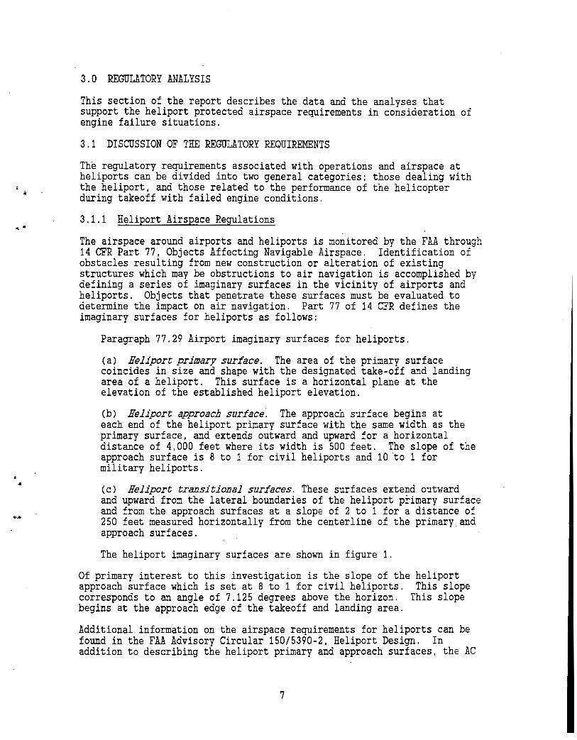
3.0 REGULATORY ANALYSIS
This section of the report describes the data and the analyses that support the heliport protected airspace requirements in consideration of engine failure situations.
3.1 DISCUSSION OF THE REGULATORY REQUIREMENTS
The regulatory requirements associated with operations and airspace at heliports can be divided into two general categories; those dealing with the heliport, and those related to the performance of the helicopter during takeoff with failed engine conditions.
3.1.1 Heliport Airspace Regulations
The airspace around airports and heliports is monitored by the FAA through 14 CFR Part 77, Objects Affecting Navigable Airspace. Identification of obstacles resulting from nevi construction or alteration of existing structures which may be obstructions to air navigation is accomplished by defining a series of imaginary surfaces in the vicinity of airports and heliports. Objects that penetrate these surfaces must be evaluated to determine the impact on air navigation. Part 77 of 14 CFR defines the imaginary surfaces for heliports as follows:
Paragraph 77.29 Airport imaginary surfaces for heliports.
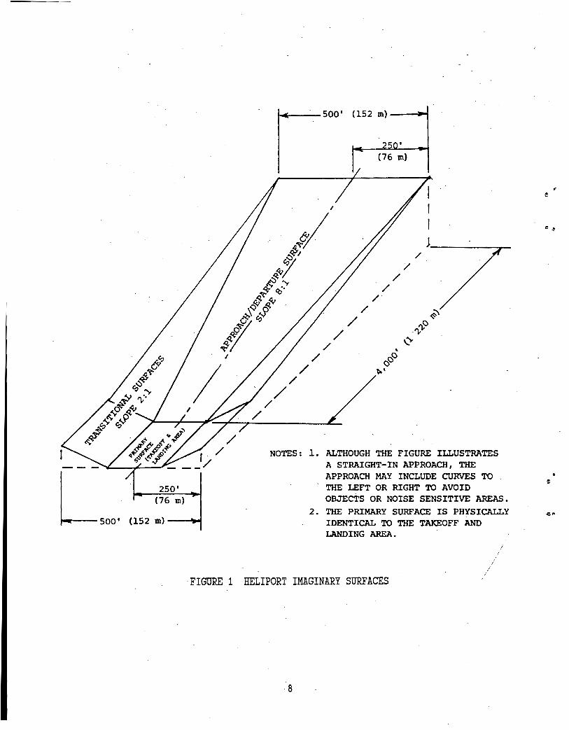
(a) Heliport primary surface. The area of the primary surface coincides in size and shape with the designated take-off and landing area of a heliport. This surface is a horizontal plane at the elevation of the established heliport elevation.
(b) Heliport approach surface: The approach surface begins at each end of the heliport primary surface with the same width as the primary surface, and extends outward and upward for a horizontal distance of 4,000 feet where its width is 500 feet. The slope of the approach surface is 8 to 1 for civil heliports and 10 to 1 for military heliports. ·
(c) Heliport transitional surfaces. These surfaces extend outward and upward from the lateral boundaries of the heliport primary surface and from the approach surfaces at a slope of 2 to 1 for a distance of 250 feet measured horizontally from the centerline of the primary_and approach surfaces.
The heliport imaginary surfaces are shown in figure 1.
Of primary interest to this investigation is the slope of the approach surface which is set at 8 to 1 for civil heliports. corresponds to an angle of 7.125 degrees above the horizon. begins at the approach edge of the takeoff and landing area.
heliport This slope
This slope
Additional information on the airspace requirements for heliports can be found in the FAA Advisory Circular 150/5390-2, Heliport Design. In addition to describing the heliport primary and approach surfaces, the AC
7
/ I /
~--7'--~- - - /
LSOO' 250'
(76 m}
(152 m} ----'1.-t
/
/ /
/ /
/ /
2 ' r-(76 m)
/ /
/ /
/
/ /
/
NOTES : 1. ALTHOUGH THE FIGURE ILLUSTRATES A STRAIGHT-IN APPROACH, THE APPROACH MAY INCLUDE CURVES TO THE LEFT OR RIGHT TO AVOID OBJECTS OR NOISE SENSITIVE AREAS.
2. THE PRIMARY SURFACE IS PHYSICALLY IDENTICAL TO THE TAKEOFF AND LANDING AREA.
,FIGURE 1 HELIPORT IMAGINARY SURFACES
8
• •
defines a visual approach and departure protection area which coincides with the first 280 feet of the heliport approach surface nearest the heliport primary surface. The AC recommends that the heliport operator own or control the property underlying the protection area, that it be reasonably free of surface irregularities or objects, while permitting heliport related uses which do not create a hazardous condition.
Heliport Design (AC 150/5390-2) standards are advisory only, unless the heliport is a public use facility that is funded or administered by the federal government.
3.1.2 Helicopter Regulatory Requirements
Helicopters are certified by the FAA under 14 CFR, Parts 27 and 29. Part 27 applies to Normal Category Rotorcraft with maximum weight of 6,000 pounds. Part 29, Transport Category Rotorcraft, applies to helicopters weighing over 6,000 pounds. Part 29 helicopters are further divided into Category A or Category B. Current Category A and Category B requirements are stated below, however, helicopters certified prior to 1983 do not have the seating requirements applied.
All helicopters with maximum weight greater than 20,000 pounds, and having 10 or more passenger seats, must meet Category A requirements. Helicopters weighing more than 20,000 pounds, but having nine or less passenger seats, may be certified as Category B providing the helicopter meets Category A requirements in the areas of strength (subpart C), design and construction (subpart D), powerplant (subpart E) and equipment (subpart F). Part 29 helicopters weighing 20,000 pounds or less and having 10 or more passenger seats may be certified as Category B providing the helicopter meets Category A requirements for strength, design and construction, powerplant and equipment, as well as the one engine inoperative (para 29.67) and conditions to determine the limiting height-speed envelope required by para 29.79 and 29.1513.
Part 29 helicopters_weighing 20,000 pounds or less and having nine or less passenger seats may be certified as Category B.
3.1.2.1 Part 27 Performance Certification Requirements
The performance requirements of interest in this investigation are contained in paragraphs:
27.51 Takeoff; and 27.67 Climb: one engine inoperative (OEI).
Appendix A contains applicable sections of .the regulations for reference purposes. The following paragraphs summarize the main elements of these regulations as they apply to rejected takeoff and OEI climbout operations for normal category rotorcraft. ·
9
· General
Performance requirements must be met for still air and standard atmosphere, must correspond to the engine power available under ·. particular atmospheric conditions, and be based upon approved eng1ne power less installation losses and losses associated with the operation of accessories.
Takeoff
The takeoff procedure must not require exceptional piloting skill or exceptionally favorable conditions.
Takeoffs must be made in such a manner that a landing can be made safely at any point along the flight path in the event of an engine failure.
Climb with One Engine Inoperative (OEI)
At VY, or at a speed for minimum rate of descent, the steady rate of climb (or descent) must be determined at maximum gross weight, with one engine inoperative, and maximum continuous power (except when 30-min power certification is requested).
3.1.2.2 OEI Performance Data Contained in Part 27 Flight Manuals
The MBB BO 105 manual contained nearly as much Category A takeoff performance information as did the three Part 29 aircraft. Rejected takeoff distances and distances to achieve Takeoff Safety Speed (VToss) were available iri engineering graph formats. The MBB BOlOS and the AS 355F manuals contained OEI rate of climb data at VY, but not at VToss.
3.1.2.3 Part 29, Category A Performance Certification Requirements
The performance requirements of interest in this investigation are contained in Paragraphs:
29.51 Takeoff data: general; 29.53 Takeoff: Category A; 29.59 Takeoff path: Category A; and 29.65 Climb: one engine inoperative.
Appendix A contains applicable sections of the regulations. The following paragraphs summarize the main elements of these regulations as they apply to takeoff and approach operations. Appendix B contains applicable sections from FAA Advisory Circular 29-2A, Certification of Transport Category Rotorcraft, applicable to rejected takeoff and OEI climbout requirements.
General
Performance requirements must be met for still air and standard atmosphere, must correspond to the engine power available under particular atmospheric conditions, and be based upon approved engine power less installation losses and losses associated with the operation of accessories.
10
~-
..
....
Takeoff Data: General
No takeoff applicable to demonstrating the performance of the aircraft for certification shall require exceptional piloting skill or exceptionally favorable conditions.
Takeoff: Category A
The takeoff performance must show that, if one engine fails at any time after the start of takeoff, the aircraft can either return to, and stop safely on the takeoff area, or continue the takeoff and climbout to attain at least:
VToss and an altitude of 35 feet and then climb to 100 feet above the takeoff surface. VToss is the minimum speed at which 100 fpm rate of climb can be achieved·while avoiding the limiting H-V envelope.
150ft/min. rate of climb at 1,000 feet above the takeoff surface with maximum continuous power (30-min where certified), and the landing gear retracted. The speed at 1,000 feet above the surface is either VY or as selected by the applicant.
A critical decision point (CDP) must be established which defines the combination of speed and height which determines whether, in the ever.t of an engine failure, the takeoff could continue. The CDP must be obtained while avoiding the H-V envelope.
Takeoff Path: Category A
The rejected takeoff path must be established with not more than takeoff power on each engine from the start of takeoff to the CDP. At or prior to this point the critical engine is failed and the rotorcraft is brought to a safe stop to establish the rejected takeoff distance.
Similarly, in the flyalway case, the takeoff path must be established with the same conditions up to the CDP. At or after CDP, the critical engine is failed and the rotorcraft must be accelerated to achieve VToss and a positive rate of climb at 35 feet or more above the ground. The helicopter mus~then be capable of meeting the climb requirements for one engine inoperative (see below) .
Climb: One Engine Inoperative
For Category A, a steady rate of climb at VToss, out of ground effect (OGE) of 100 ft/min must be achieved with approved power on the remaining engine, most unfavorable CG, landing gear extended, increasing to 150ft/min 1,000 feet above the takeoff area at VY, landing gear retracted.
11
3.1.2.4 Performance Data Contained in Part 29 Rotorcraft Flight Manuals
OEI related flight performance data is contained in the flight manuals of the three transport category helicopters used in this investigation. These manuals provide information that closely matches the requirements of 14 CFR Part 29. These data are much more comprehensive than those found in the flight manuals of normal category rotorcraft.
The information provided in these flight manuals for Category A performance is useful. in evaluating the helicopter's performance for rejected takeoff and OEI·climbout operations. The departure information is quite complete up to the point where the VToss speed is reached. After that point in the departure, the manuals differ in the information provided. All manuals present data on the OEI climbouts at VY.
The following performance data is taken from helicopter flight manuals as noted.
Sikorsky S76A performance data under various weights and temperature conditions:
Category A . Rejected takeoff distance at maximum allowable weight Distance to achieve VToss at maximum allowable weight OEI rate of climb at VToss, 2.5 minute power, gear down OEI rate of climb at VY, 30 minute power, gear up OEI rate of climb at VY, maximum continuous power, gear up VY as a function of altitude
Aerospatiale AS 332 C performance data under various weights and temperature conditions:
Category A Accelerate stop distance (accelerate to CDP, decelerate to
a full stop after engine failure at CDP) Distance to climb to 35 feet height at VToss (accelerate
to CDP, engine.fails at CDP, acceleration continues to VToss) .
Distance to climb from 35 feet height to 200 feet height . with OEI, gear down, takeoff power · . Distance to accelerate from VToss to VY with OEI,
gear up Distance to climb from 200 feet to 1,000 feet at VY with
OEI, gear up OEI rate of climb at 45 knots, 2.5 minute power, gear down OEI rate of climb at VY, 30 minute power, gear up
Boeing BV 234LR performance data under various weights and temperature· conditions:
Category A Takeoff distance (applies to both rejected takeoff and
acceleration to VToss) OEI rate of climb at VToss, 30 minute power
12
ii
•
-
OEI rate of climb at VY, 30 minute power VToss as a function of altitude AEO rate of climb at VY, maximum continuous power
3.1.2.5 Adequacy of Flight Manuals for Rejected Takeoff Operations
One of the two normal category rotorcraft flight manuals reviewed in this study provides the pilot with sufficient performance data for failed engine operations during takeoff. The other manual was lacking in distance and some climb related data. Neither the rejected takeoff data nor the distance to achieve VToss were provided.
The three transport category rotorcraft manuals provide adequate information regarding Category A departure performance of the helicopters. However, one manual provided rejected takeoff distance and distance to achieve VToss only at the maximum allowable weight.
It is noted that the lack of specific information is not intended to be a criticism of the manufacturers. These manuals contain data supporting the requirements in 14 CFR Parts 27 and 29. Adding new requirements to the regulations can be equated to adding additional cost to the manufacturers to demonstrate these certification requirements, a cost ultimately passed to the customer in the price of the helicopter. However, as a result of this and companion studies additional flight manual information on takeoff performance may be recommended.
3.2 ANALYSIS OF THE OPERATIONAL PROCEDURES
The flight manuals describe departure and approach procedures that are recommended by the manufacturers. The procedures that are described vary widely in the amount of detail that is provided. The following paragraphs present a summary of the procedures.
3.2.1 Category A Departure
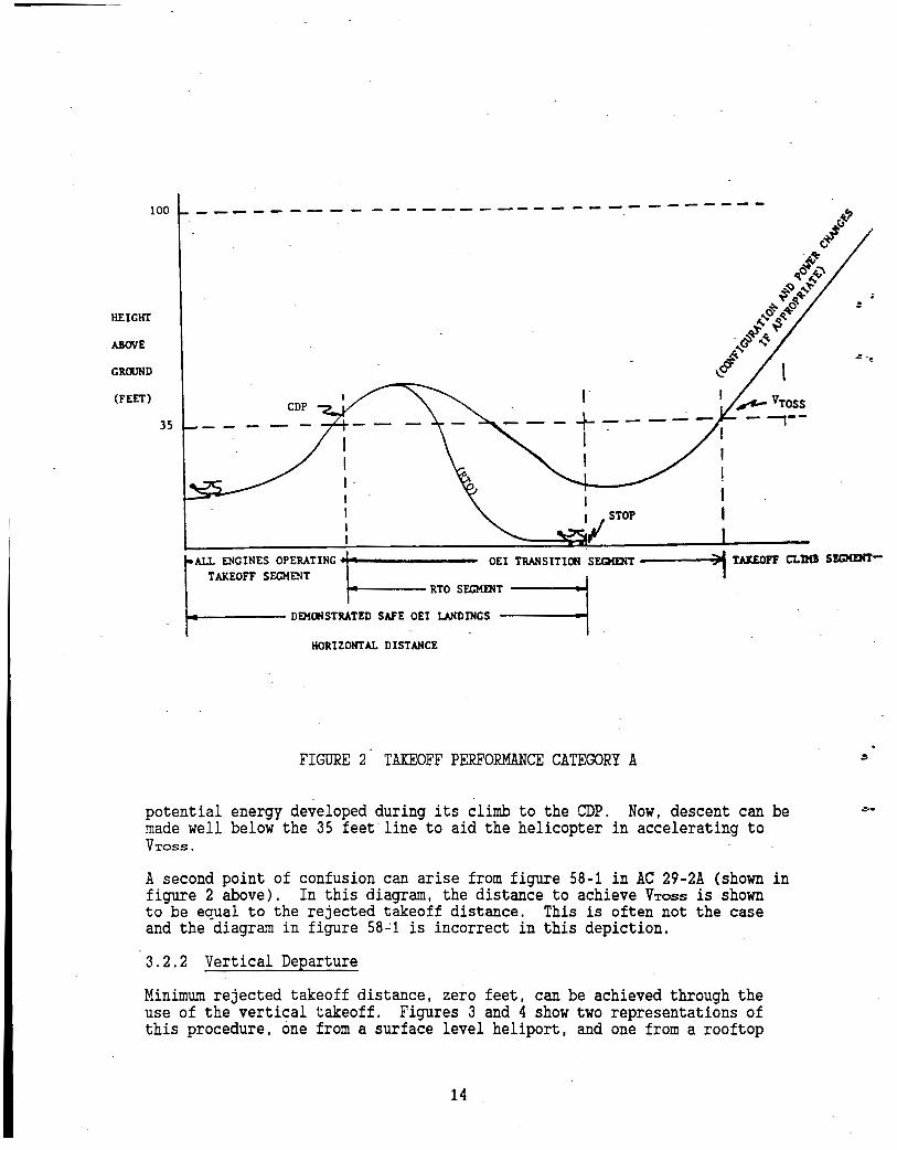
The takeoff profile for the Category A takeoff is shown in figure 2. The helicopter is brought to a hover in ground effect. The aircraft is accelerated through effective translational lift followed by an accelerating climb to the CDP. If an engine fails prior to the CDP, the takeoff is aborted and the aircraft follows the rejected takeoff profile shown in the figure.
In the event of an engine failure after the CDP, the helicopter-can continue to·takeoff. With the aircraft's remaining engine(s) at maximum approved power, the aircraft is descended, below 35 feet if required, to gain speed. The aircraft is accelerated to VToss and a positive rate of climb must be.
· established at 35 feet ·or greater. OEI climb capability must be at least 100 ft/min with the gear extended: .The distance .to achieve VToss is · · measured at the point where the helicopter achieves a positive rate of climb and a 35 feet height above the surface with a speed of VToss or greater.
There have been several points of confusion over the years regarding this · procedure. Originally, the aircraft was not allowed to descend below the 35 feet height during the acceleration to VToss. This position has been changed to one of allowing the aircraft to take maximum advan~age of the
13
100
HEIGHT
ABOVE
GROOND
(FEET)
35
--------- ----------------------
CDP I
+-----1 I I I
! t I
ALL ENGINES OPERATING 1: OEI TRANSITION SEGMENT
TAKEOFF SEGMENT ~ t----- RTO SEGMENT
1 LUEOFF CLDO SEGHEHT-
DEliCIISTRATED SAFE OEI LANDINGS
HORIZONTAL DISTANCE
FIGURE 2 TAKEOFF PERFORMANCE CATEGORY A
potential energy developed during its climb to the CDP. Now, descent can be made well below the 35 feet line to aid the helicopter in accelerating to VToss.
A second point of confusion can arise from figure 58-1 in AC 29-2A (shown in figure 2 above). In this diagram, the distance to achieve VToss is shown to be equal to the rejected takeoff distance. This is often not the case and the diagram in figure 58~1 is incorrect in this depiction.
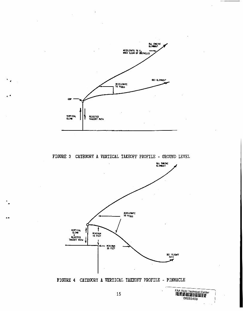
3.2.2 Vertical Departure
Minimum rejected takeoff distance, zero feet, can be achieved through the use of the vertical takeoff. Figures 3 and 4 show two representations of this procedure, one from a surface level heliport, and one from a rooftop
14
• ii
<> •
..
vtiTJCAL CUIIl t ~ ILJtCTDI
lAllOFr PAlM
FIGURE 3 CATEGORY A VERTICAL TAKEOFF PROFILE - GROUND LEVEL
ACCELUATE ro •ross
FIGURE 4 CATEGORY A VERTICAL TAKEOFF PROFILE - PINNACLE
15 FAA WJH Technical c t ) I m1111 Ill~ IIIII IIIII IIIII !Ill/ IIIII IIIII 11mH1 er I
00093409 i I
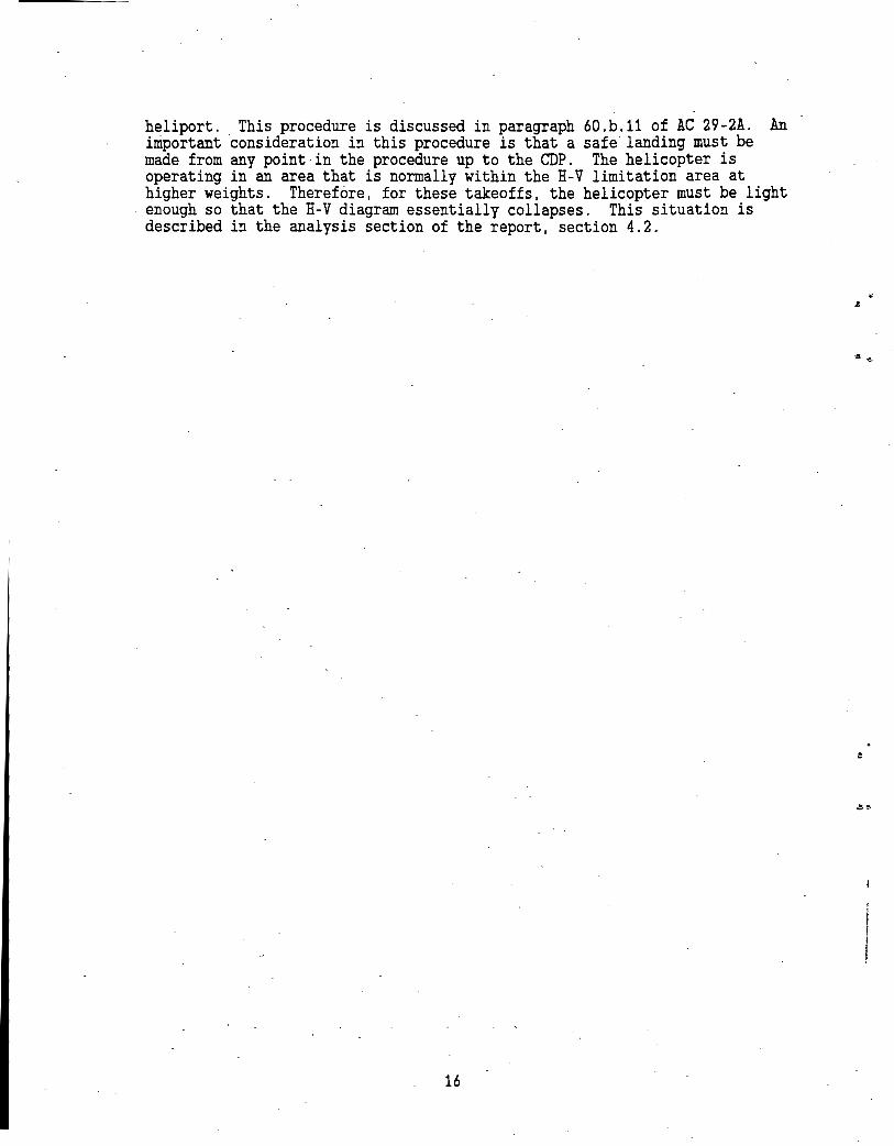
heliport .. This procedure is discussed in paragraph 60.b.11 of AC 29-2A. An important consideration in this procedure is that a safe landing must be made from any point·in the procedure up to the CDP. The helicopter is operating in an area that is normally within the H-V limitation area at higher weights. Therefore, for these takeoffs, the helicopter must be light enough so that the H-V diagram essentially collapses. This situation is described in the analysis section of the report, section 4.2.
16
e
•
., .
•
4.0 PERFORMANCE ANALYSIS
Rejected takeoff distance and distance to VToss data were read directly from graphs contained in the flight manuals for the AS 332C, BV 234LR, S76A and the BO 105CBS. The BV 234LR manual contained one set of curves that represented both the rejected takeoff distance and the distance to VToss. The S76A manual contained these two distance values for the maximum allowable aircraft weight only. The AS 355F manual did not contain either OEI takeoff distance parameter.
OEI climb angle data at VToss were derived from rate of climb data. The rate of climb values were read directly from the graphs contained in the flight manuals. The climb angles were estimated using the formula:
Tan(Climb Angle);Vertical Rate of Climb/True Airspeed.
The true airspeed was derived from the stated indicated airspeed corrected for density altitude. This formula assumes that the true airspeed represents the horizontal component of aircraft velocity. Climb angle curves at a speed of VToss were developed for the three transport category rotorcraft, the AS 332C, the BV 234LR, and the S76A. Climb angle curves at a speed of VY were developed for two normal category rotorcraft, .the AS 355F and the BO 105 CBS. VY is the only speed for which data are published in the AS 355F and BO 105 CBS manuals. At VY, both the vertical rate of climb and the true airspeed are greater ~han these same two parameters at VToss. These data for· the normal category rotorcraft are presented for information purposes only. These curves should not be compared directly with the climb angle .curves of the three transport category r6torcraft at VToss.
4.1 CONVENTIONAL CATEGORY A TAKEOFF PROCEDURES
AS 332C
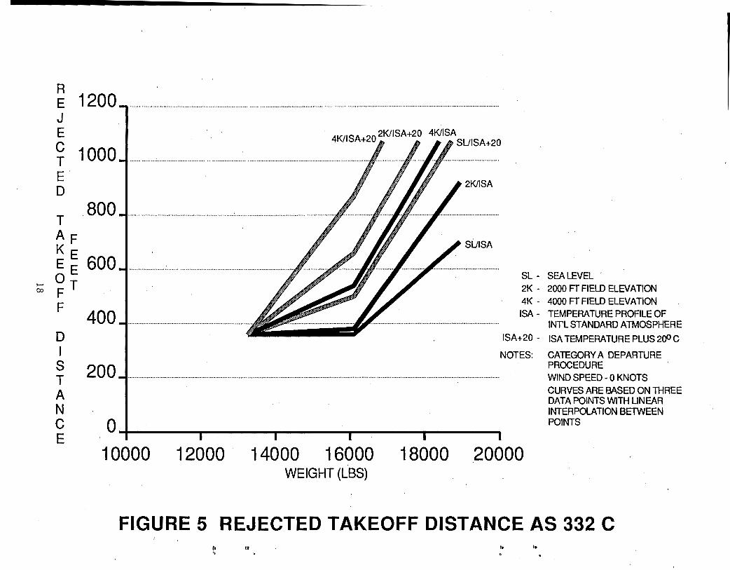
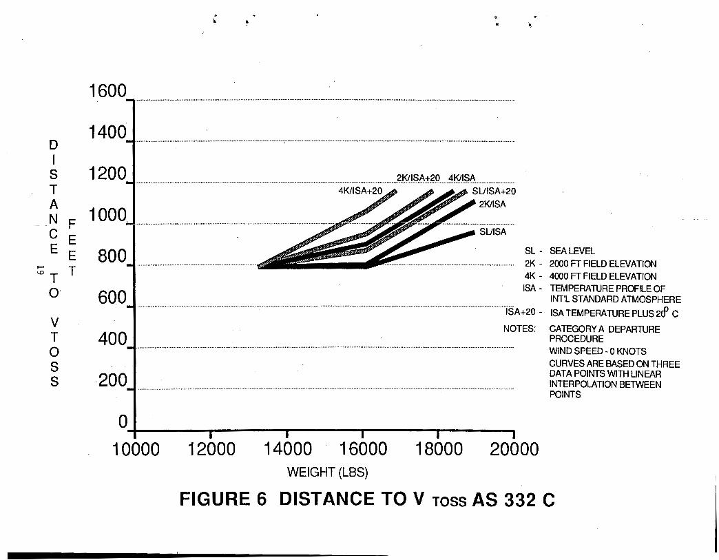
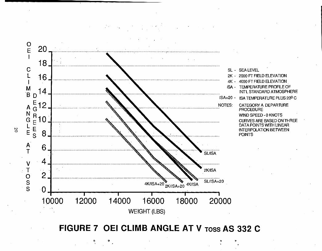
Figures 5 through 7 present rejected takeoff distance, distance to accelerate to VToss and climb angle at VToss. VToss for this aircraft is 45 knots. ·
From figure 5 it can be seen that the rejected takeoff distance ranges from 350 to 1,100 feet depending on aircraft weight and density altitude conditions: The curves show that as the weight and density altitude increase, the rejected takeoff distance also increases.
Figure 6 shows that the distance required to achieve VToss following an engine failure at the CDP for the AS 332C ranges from 790 feet to about 1 , 200 feet. The curves shmr that this parameter is also affected by aircraft weight and density altitude in a manner similar to those for rejected takeoff.
Figure 7 shows that the climb angle at VToss ranges from a high of about 20 degrees for the standard day, light aircraft condition to a low of about 1.5 degrees for the heavy aircraft at high density altitudes. These curves also show a strong relationship to aircraft·weight and density altitude · conditions.
17
R E J E c T E D
T AF KE EE
~ ~T F
D I s T A N c E
1200-................................................................. .
1 000 - .............. : .............. ..
800-.............................................. .
600
400 ........................................................................ ..
2K/ISA+20 4KIISA 4K/ISA+20 ... ... .... .... SUISA+20
SL - SEA LEVEL . 2K- 2000 FT'FIELD ELEVATION 4K - 4000 FT FIELD ELEVATION ISA - TEMPERATURE PROFILE OF
~ .............................. ,....................................................................... INTL STANDARD ATMOSPHERE
ISA+20 - ISA TEMPERATURE PLUS 2rfJ C
NOTES: CATEGORYA.DEPARTURE
200 ................................................................................................................................................................................................................... . PROCEDURE WIND SPEED- 0 KNOTS CURVES ARE BASED ON THREE DATA POINTS WITH LINEAR INTERPOLATION BETWEEN POINTS 0 I I I I I I
10000 12000 ' 14000 16000 18000 20000 WEIGHT (LBS)
FIGURE 5 REJECTED TAKEOFF DISTANCE AS 332 C I• '•
tt ,. . ••
D I s T A N F C E E E
~ T T 0
v T 0 s s
. ~
1600
~ ¢<
• .,
1~·····························-·········································-·--·············-··········································································-·-···········--········•••o.••························
..................................................................................................................................................... J~!S!.!.§.A..±.?..Q ..... ~!S!.!$.~ ..................... .
1000 "'-1··················
800
400 ....................................... . -.~ ............. .
200
SUISA+20 21</ISA
SUI SA
SL - SEA LEVEL 2K- 2000 FTFIELD ELEVATION 4K- 4000 FTFIELD ELEVATION ISA - TEMPERATURE PROFILE OF
INT'L STANDARD ATMOSPHERE ···········································································································rsA+20 - ISA TEMPERATURE PLUS 2cf C
NOTES: CATEGORY A DEPARTURE PROCEDURE WIND SPEED- 0 KNOTS CURVES ARE BASED ON THREE DATA POINTS WITH LINEAR INTERPOLATION BETWEEN POINTS
0 I I I I I I 10000 12000 14000 16000 18000 20000
WEIGHT (LBS)
FIGURE 6 DISTANCE TO V ross AS 332 C
N 0
0 E 20 I
18 SL - SEA LEVEL c
L I
16 ........................................................................... , .................... , ............................................................................................................. . 2K - 2000 FT FIELD ELEVATION 4K- 4000 FTFIELD ELEVATION
·~ D 14 .............. "····························································-~ A ~12 ................... . N R . G E 10 ~-·········:···························································_.~ L E E 8 s . A T
v
ISA - TEMPERATURE PROFILE OF INT'L STANDARD ATMOSPHERE
ISA+20 - ISA TEMPERATURE PLUS 200 C
NOTES: CATEGORY A DEPARTURE PROCEDURE WIND SPEED - 0 KNOTS CURVES ARE BASED ON THREE DATA POINTS WITH LINEAR INTERPOLATION BETWEEN POINTS
·T 0 s
·s ~ 1=~:----::~~;=-wooo 20
SUISA+20
10000 12000 18000 20000 16000 14000 , I
. WEIGHT (LBS)
FIGURE 7 OEI CLIMB ANGLE AT V ross AS 332 C f• tt ,,
\0 '• :<
.-
,. .
•
BV 234LR
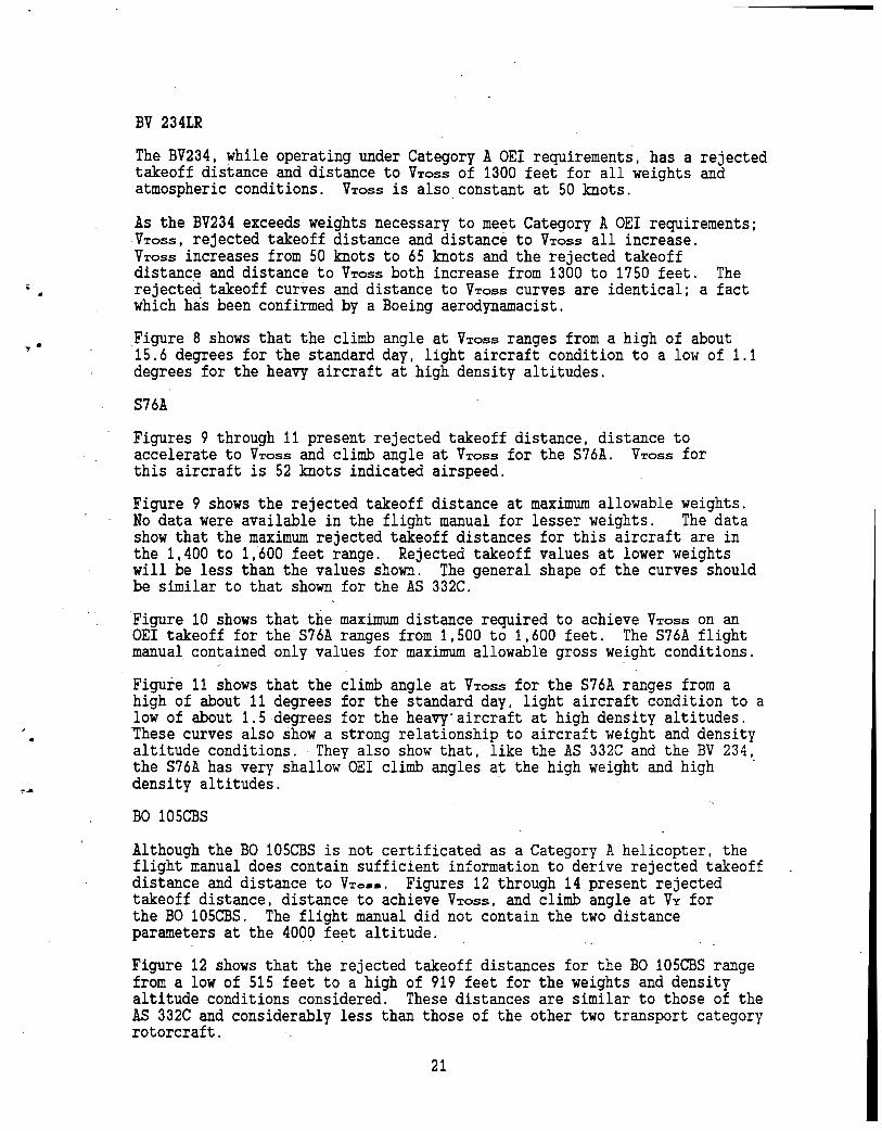
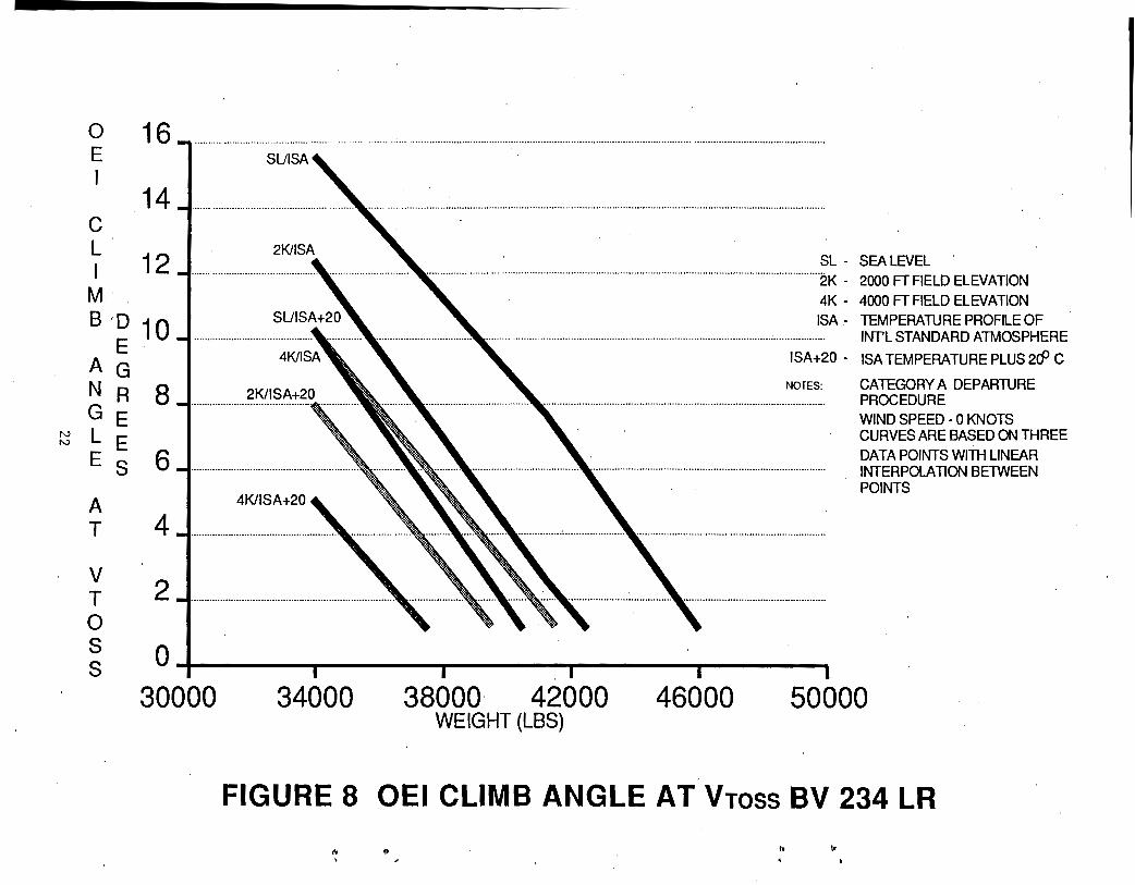
The BV234, while operating under Category A OEI requirements, has a rejected takeoff distance and distance to VToss of 1300 feet for all weights and atmospheric conditions. VToss is also.constant at 50 knots.
As the BV234 exceeds weights necessary to meet Category A OEI requirements; VToss, rejected takeoff distance and distance to VToss all increase. VToss increases from 50 knots to 65 knots and the rejected takeoff distance and distance to VToss both increase from 1300 to 1750 feet. The rejected takeoff curves and distance to VToss curves are identical; a fact which has been confirmed by a Boeing aerodynamacist.
Figure 8 shows that the climb angle at VToss ranges from a high of about 15.6 degrees for the standard day, light aircraft condition to a low of 1.1 degrees for the heavy aircraft at high density altitudes.
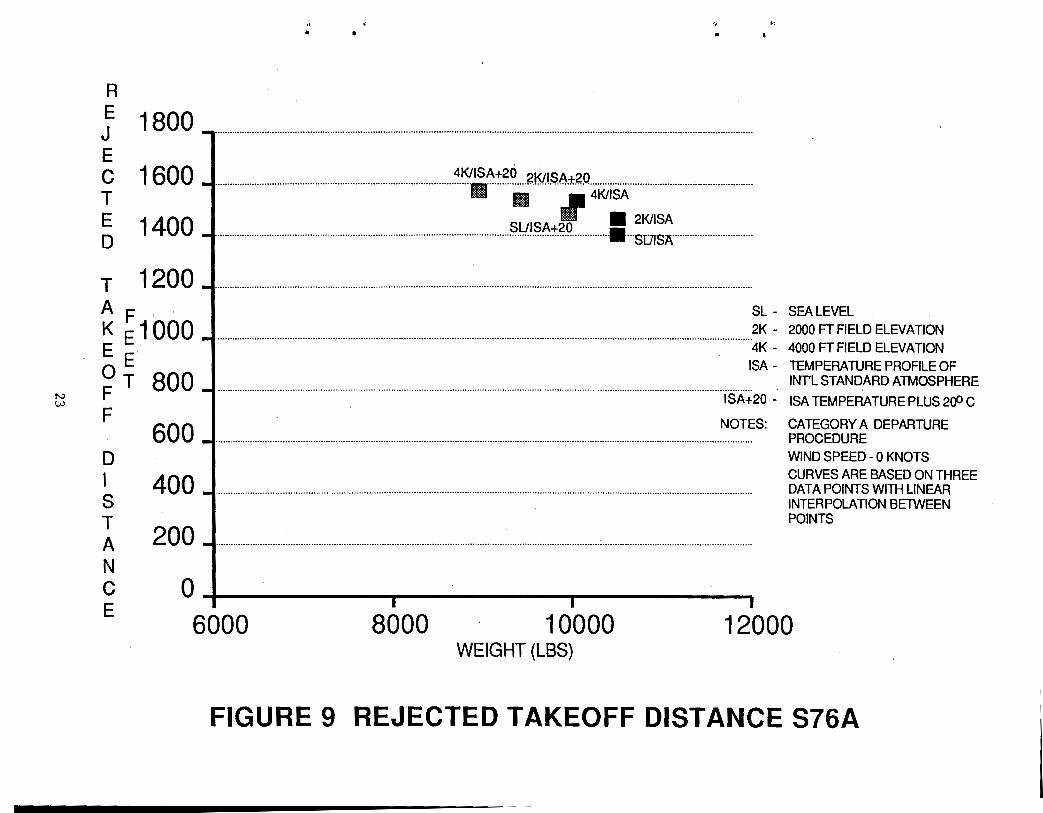
S76A
Figures 9 through 11 present rejected takeoff distance, distance to accelerate to VToss and climb angle at VToss for the S76A. VToss for this aircraft is 52 knots indicated airspeed.
Figure 9 shows the rejected takeoff distance at maximum allowable weights. No data were available in the flight manual for lesser weights. · The data show that the maximum rejected takeoff distances for this aircraft are in the 1,400 to 1,600 feet range. Rejected takeoff values at lower weights will be less than the values shown. The general shape of the curves should be similar to that shown for the AS 332C.
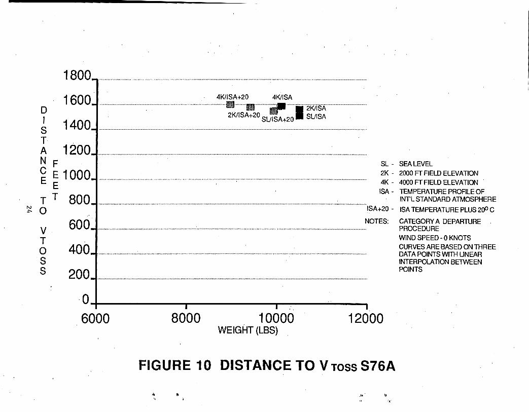
Figure 10 shows that 'the maximum distance required to achieve VToss on an OEI takeoff for the S76A ranges from 1,500 to 1,600 feet. The S76A flight manual contained only values for maximum allowable gross weight conditions.
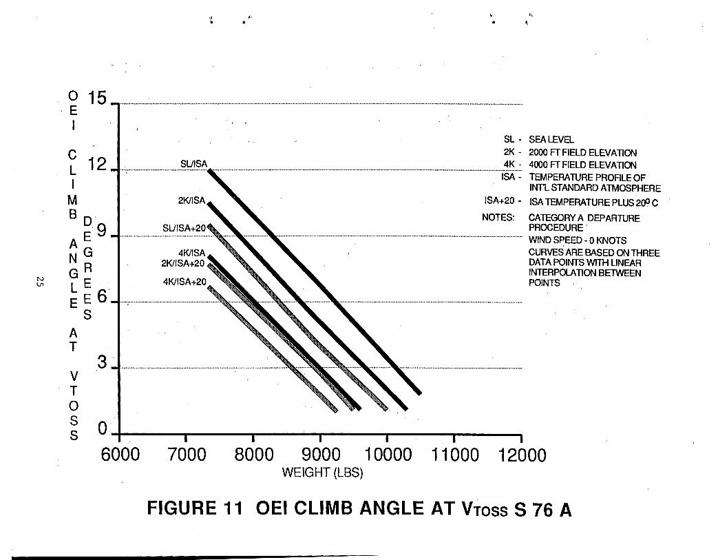
Figure 11 shows that the climb angle at VToss for the S76A ranges from a high of about 11 degrees for the standard day, light aircraft condition to a low of about 1.5 degrees for the heavy·aircraft at high density altitudes. These curves also show a strong relationship to aircraft weight and density altitude conditions. ·They also show that, like the AS 332C and the BV 234, the S76A has very shallow OEI climb angles at the high weight and high density altitudes. ·
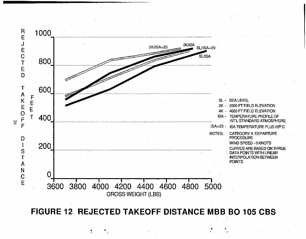
BO 105CBS
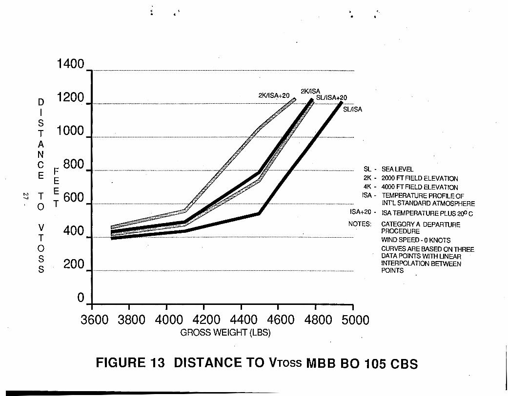
Although the BO 105CBS is not certificated as a Category A helicopter, the flight manual does contain sufficient information to derive rejected takeoff distance and distance to VTosa. Figures 12 through 14 present rejected takeoff distance, distance to achieve VToss, and climb angle at VY for the BO 105CBS. The flight manual did not contain the two distance parameters at the 4000 feet altitude.
Figure 12 shows that the rejected takeoff distances for the BO 105CBS range from a low of 515 feet to a high of 919 feet for the weights and density altitude conditions considered. These distances are similar to those of the AS 332C and considerably less than those of the other two transport category rotorcraft. ·
21
.......... 0 16-............................................... E I
14 c L 12 I
SL - SEA LEVEL ... ····················································································································2K - 2000 FT FIELD ELEVATION
M 4K- 4000 FTFIELD ELEVATION
B ·o 10 E·
ISA - TEMPERATURE PROFILE OF INT'L STANDARD ATMOSPHERE
AG N R G E
~ L E E S
A T
v T 0 s s
8
6
4 ....................................... ·················:'1111.:····················'~
2 ·············································· ...............
ISA+20 - ISA TEMPERATURE PLUS 2cP C
NOTES: CATEGORY A DEPARTURE PROCEDURE WIND SPEED- 0 KNOTS CURVES ARE BASED ON THREE DATA POINTS WITH LINEAR INTERPOLATION BETWEEN POINTS
0 I I I I I I
30000 34000 38000 42000 WEIGHT (LBS)
46000 50000
FIGURE 8 OEI CLIMB ANGLE AT Vross BV 234 LR
" ' (t
,, ,,
N w
R E J E c T E D
1800
,, .. "' •
--···························--······················-················-················································································································································
1600 _J ............................................................................................... ~~/~~IS~::.~~----?K!.!$A±.?..Q ............................... . ...................................
liB r.I4K!ISA
1 40 0 .J ..................................................................................................................... §.!!~.§~_:f:_?.9 ............... 1---~~~~---·-················-···-····-·
., •
T 1200 --·-········-······-----------------------------------------------------------------·-·············-----···········································-·····--····-----·--·--············································ A - SL - SEA LEVEL
~ ~ 1 000 -·-····································· -·································· - ···································································!~ : !: ~ ~:~~ ~~~~~ 0 E ISA- TEMPERATURE PROFILE OF
F T 800 ·································································-···················································································-···················································is·A+2o - ::·~~:~~:~~R~~~::~E F
D I s T A N c E
600
400 -t---
200
0 I I
6000 8000 10000 WEIGHT (LBS)
NOTES:
l
CATEGORY A DEPARTURE PROCEDURE WIND SPEED - 0 KNOTS CURVES ARE BASED ON THREE DATA POINTS WITH LINEAR INTERPOLATION BETWEEN POINTS
12000
FIGURE 9 REJECTED TAKEOFF DISTANCE S76A
1800 4K/ISA+20 4KIISA
D
~ 1400
··················································-····-·······-···································mll······················m--······-
1·········2kii"si\······················-·········
. - 2K/ISA+20 SUISA+20 SUISA
T A 1200 ..................................................................................................................................................................................................................... . N F
~ E 1000 E
SL - SEA LEVEL 2K- 2000 FTFIELD ELEVATION 4K - 4000 FT FIELD ELEVATION ISA - TEMPERATURE PROFILE OF
INTL STANDARD ATMOSPHERE T T 800 ~ 0
·············································-·········-··························································································································································ISA+20 - ISA TEMPERATURE PLUS 200 C
v. T 0 s
.S
6001-·······- -·-·············· NOTES:
400,........... -···················-····················-
200
. 0-J-----r---~--,---::----------, 6000 8000 10000 12000
WEIGHT (LBS)
FIGURE 10 DISTANCE TO VToss S76A
" .. ~1 * ,, '~ I~'
CATEGORY A DEPARTURE PROCEDURE WIND SPEED- 0 KNOTS CURVES ARE BASED ON THREE DATA POINTS WITH LINEAR INTERPOLATION BETWEEN POINTS
N V1
0 15 ·E
I
~ 12 I
M
,, ,, " .. ..
• ,, .,
SL - SEA LEVEL 2K - 2000 FT FIELD ELEVATION
SUISA 4K- 4000 FTFIELD ELEVATION ........................................................................................................................................................................................................................................... ISA - TEMPERATURE PROFILE OF
INTLSTANDARDATMOSPHERE
21</ISA..... ' ISA+20 - ISA TEMPERATURE PLUS 200 C
NOTES: CATEGORY A DEPARTURE B D E··9..,. ...................................................... ,
AG N R G
SUISA+20 PROCEDURE' ·············································································································································· WIND SPEED- 0 KNOTS
41</ISA 2K/ISA+20
L E. E E 6·..,.····:·················································
4K/ISA+20
CURVES ARE BASED ON THREE DATA POINTS WITH LINEAR INTERPOLATION BETWEEN POINTS
A T
v T 0 s s
s
3 -1································································································""
0 1. I I I I .1 I 6000 7000 8000 9000 1 0000 ' 11 000 12000
WEIGHT (LBS)
FIGURE 11 OEI CLIMB ANGLE AT Vross S 76 A
R 1000 E J E c T E D
T A F K E E E
~ T 400 N
SL - SEA LEVEL 2K- 2000 FTFIELD ELEVATION 4K - 4000 FT FIELD ELEVATION ISA - TEMPERATURE PROFILE OF
INT'L STANDARD ATMOSPHERE a-. F ISA+20 - ISA TEMPERATURE PLUS 2r:fJ C
D I s T A N c E
NOTES: CATEGORY A DEPARTURE PROCEDURE
200
0 I I I I I I I I
3600 3800 4000 4200 4400 4600 4800 . 5000 GROSS WEIGHT (LBS)
WIND SPEED- 0 KNOTS CURVES ARE BASED ON THREE DATA POINTS WITH LINEAR INTERPOLATION BETWEEN POINTS
FIGURE 12 REJECTED TAKEOFF DISTANCE MBB 80 105 CBS
!It • "
,. •
, •·
D I s T A N
1400
1200
1000
C F 800 E E
,, • '
21</ISA
~
•
2K/ISA+20 SUISA+20 ...................................................................................................................................................... : ....... 4. ....... -A. .................. ~SUISA
~-•
SL - SEA LEVEL 2K- 2000 FTFIELD ELEVATION 4K- 4000 FTFIELD ELEVATION ISA - TEMPERATURE PROFILE OF ~ T E 600
0 T -t·············································································-n INTL STANDARD ATMOSPHERE ISA+20 - ISA TEMPERATURE PLUS 200 C
v T 0 s s
400 NOTES: CATEGORY A DEPARTURE
PROCEDURE
200 -t·················--··································································································································································
0 I I I I I I I I
3600 3800 4000 4200 4400 4600 4800 5000 GROSS WEIGHT (LBS)
WIND SPEED- 0 KNOTS CURVES ARE BASED ON THREE DATA POINTS WITH LINEAR INTERPOLATION BElWEEN POINTS
FIGURE 13 DISTANCE TO Vross MBB 80 105 CBS
c L I D
··········-·· 10 -···································--···------·--···--·-····-········---···········-··-········-··········-·······------··············---···----···········-··········-····--·--·········-···········-
8 ~~-···-------·--············-·········----·-·········-·--·················--·········--------··---·-----··-······-··-········--·-·······-·········---······--·······--·-········-·······----·-···-----·····--··-······-
SL - SEA LEVEL 2K - 2000 FT FIELD ELEVATION 4K- 4000 FT FIELD ELEVATION ISA- TEMPERATURE PROFILE OF
INT'L STANDARD ATMOSPHERE
ISA+20 - ISA TEMPERATURE PLUS 200 C
ME 6 NOTES: CATEGORY A DEPARTURE !:x""-·-~-------·········-·-··--·-----·········-·········--···-········------·······---······----···--··--·-······----·······-·-····-----······--·-···········-··--·-···-··- PROCEDURE
B G R
A E ~ N E
G S L E
4
2
0
"-----~·-·-········---····-··----····----·····--····------··············---·--·--·--····------··········---------·-·--
I I I I I I I
WIND SPEED - 0 KNOTS CURVES ARE BASED ON THREE DATA POINTS WITH LINEAR INTERPOLATION BETWEEN POINTS
3700 4000. 4300 4600 4900 5200 5500 GROSS WEIGHT (LBS)
.FIGURE 14 OEI CLIMB ANGLE AT Vy MBB BO 105 CBS ... It
" lo
• It ·~
..
. .
...
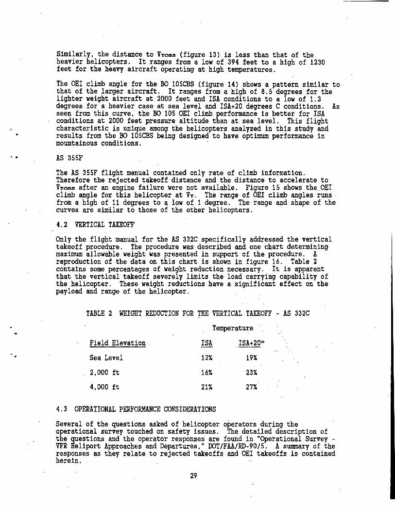
Similarly, the distance to VToss (figure 13) is less than that of the heavier helicopters. It ranges from a low of 394 feet to a high of 1230 feet for the heavy aircraft operating at high temperatures. ·
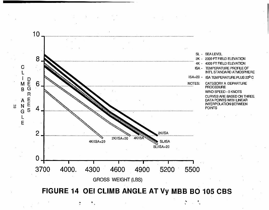
The OEI climb angle for the B0 105CBS (figure 14) shows a pattern similar to that of the larger aircraft. It ranges from a high of 8.5 degrees for the lighter weight aircraft at 2000 feet and !SA conditions to a low of 1.3 degrees for a heavier case at sea level and ISA+20 degrees C conditions. As seen from this curve, the BO 105 OEI climb performance is better for ISA conditions at 2000 feet pressure altitude than at sea level. This flight characteristic is unique among the helicopters analyzed in this study and results from the BO 105CBS being designed to have optimum performance in mountainous conditions. · ·
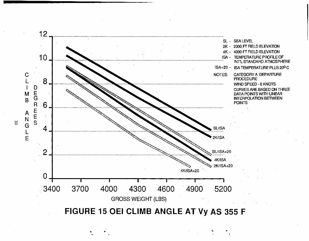
AS 355F
The AS 355F flight manual contained only rate of climb information. Therefore the rejected takeoff distance and the distance to accelerate to VToss after an engine failure were not available. Figure 15 shows the OEI climb angle for this helicopter at VY. The range of OEI climb angles runs from a high of 11 degrees to a low of 1 degree. The range and shape of the curves are similar to those of the other helicopters.
4.2 VERTICAL TAKEOFF
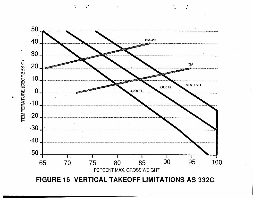
Only the flight manual for the AS 332C specifically addressed the vertical takeoff procedure. The procedure was described and one chart determining maximum allowable weight was presented in support of the procedure. A reproduction of the data on this chart is shown in figure 16. Table 2 contains some percentages of weight reduction necessary. It is apparent that the vertical takeoff severely limits the load carrying capability of the helicopter. These weight reductions have a significant effect on the payload and range of the helicopter.
TABLE 2 WEIGHT REDUCTION FOR THE VERTICAL TAKEOFF - AS 332C
Field Elevation
Sea Level
2,000 ft
4,000 ft
ISA
12%
16%
21%
Temperature
ISA+20o
19%
23%
27%
4.3 OPERATIONAL PERFORMANCE CONSIDERATIONS
Several of the questions asked of helicopter operators during the operational survey touched on safety issues. The detailed description of the questions and the operator responses are found in "Operational Survey -VFR Heliport Approaches and Departures," DOT/FAA/RD-90/5. A summary of the responses as they relate to rejected takeoffs and OEI takeoffs is contained herein.
29
12
.10
c L 8 I D
M E G.
B R 6 A E N E
~ G s. 4 L E
2
SL - SEA LEVEL 2K- 2000 FTFIELD ELEVATION 4K- 4000 FT FIELD ELEVATION ISA - TEMPERATURE PROFILE OF ................................................................................................................................................................................ · INT'L STANDARD ATMOSPHERE
ISA+20 - ISA TEMPERATURE PLUS 200 C
NOTES: · CATEGORY A DEPARTURE PROCEDURE
··················-····································································································· WIND SPEED- 0 KNOTS
4KIISA+20
SUI SA
2KIISA
SUISA+20
4KIISA -~ 2KIISA+20
CURVES ARE BASED ON THREE DATA POINTS WITH LINEAR INTERPOLATION BETWEEN POINTS
01 I I I I I I
"3400 3700 4000 4300 4600 .. 4900 5200 GROSS WEIGHT (LBS)
FIGURE 15 OEI CLIMB ANGLE AT Vy AS 355 F
... .. lo lt
. ~
w .....
50
40
30 -0 20 en w w a: 10 (9 w 0 -w 0 a: :J
~. -10 w 0..
a5 -20 ~
-30
-40
., *
~~--
~
•
.................................................................................................................
·······························································································································································································""'·················································-"'
-50~--~----~----.----.----~---.--~4 65 70 75. 80 85 90 95 100
PERCENT MAX. GROSS WEIGHT
FIGURE 16 VERTICAL TAKEOFF LIMITATIONS AS 332C
Safety concerns: An overwhelming majority of the pilots expressed concerns about vertical and/or steep approaches and departures. Almost half of these pilots indicated that the use of these procedures is appropriate only when
. needed or required by the mission.
Preferred takeoff procedures: The question regarding preferred takeoff procedures was divided into two parts, unrestricted area procedures and confined area procedures. In both instances the pilots responded by . describing two types of takeoff procedures.·.
A.· Unrestricted Area
The responses for unrestricted areas fell into two broad categories:
o Type #1 - Takeoff: This technique began with lift-off to a normal hover (i.e., 3 to 5 feet), followed by an acceleration to forward flight. The target airspeed and altitude most often mentioned was a 1 knot (or 1 mile-per-hour) rate of increase in airspeed for each foot of altitude gained.
~·
o Type #2 - Takeoff: This takeoff method used the same 3 to 5 feet hover as the starting point; however, accelerating to VToss was a predominant consideration throughout the maneuver. This was the procedure most often selected by the twin-engine operators.
The breakdown of responses to takeoff procedures in an unrestricted area correlated with whether pilots were operating single or twin engine helicopters. Of the 42 single engine helicopter pilots surveyed, 41 indicated they were using the type #1 takeoff. Of the 21 twin engine helicopter pilots surveyed, 8 indicated they were using type #1 takeoffs and 20 indicated they were using type #2. Only 2 of the 71 responses could not be described by either takeoff type.
Changing helicopter gross weights did require minor changes in the techniques, mainly in power application and adjusting for acceleration rates. The basic technique, however, continued to be the same.
B. Confined Area
While small variations from operator to operator existed within the group of surveyed pilots, two types of confined area takeoff techniques emerged. In all types of operations, the pilots advocated making maximum use of available area.
o Confined Area Takeoff Type #1: This technique was described as lift-off to a normal hover (i.e., 3 to 5 feet) and, after assuring there was sufficient reserve power to achieve the necessary climb angle, a departure at a constant climb angle needed to clear the obstruction was initiated. Airspeed beyond translational lift would be accepted, but obstacle clearance was the major objective. Once the obstacle was cleared, a normal departure climb was initiated. The application of takeoff power versus using only the power needed to perform the climb was however a major difference between operators.
32
..
o Confined Area Takeoff Type #2: This takeoff technique also started from a 3 to 5 foot hover; however, acceleration to takeoff safety speed was secondary only to clearing the obstacle. This was most often mentioned by twin engine helicopter operators. While some operators indicated a desire to climb vertically until above the obstacle and accelerate · forward to climbing flight, these operators-were in the minority. The use of the most shallow departure angle arid the full area was also advocated. ·
The breakdown of responses to confined area operations also correlated with whether pilots were operating single or twin engine helicopters. Of the 65 responses, 45 indicated using Type #1 takeoffs and 20 reported using Type #2. All single engine operators with one exception reported using Type #1 procedures. Interviews with the aircraft manufacturers revealed they were using the same two basic types of takeoffs/landings. Category A takeoffs fall within the Type #2 classification.
Twin-engine helicopter operators; concerned with continuing after an engine failure, valued the safety margin that airspeed above VToss provided them. The majority of these same twin engine helicopter operators believed that engine power above published limits could be used if absolutely necessary after the first engine failed.
Most pilots did not feel extraordinary precautionary measures were justified in dealing with the possibility of a potential engine failure. However, most pilots believed that good operating practices should be adhered to;· including a willingness to risk potential aircraft or engine damage in order to preserve passenger and crew safety.
Desirability of acceleration distance: The helicopter operators responded that they wanted sufficient acceleration distance to reach effective translational lift so that performance increases could be realized. However, no operators advocated a level acceleration much beyond the speed required to reach effective translational lift. Many pilots responded that given the availability of additional space at a heliport, the takeoff would start at the furthest point from the departure end of the heliport. This technique maximizes the acceleration distance and minimizes the required obstacle plane slope. ·
A number of respondents indicated that zero acceleration distance was needed even when climbing out at steep angles. These operators placed very little value on acceleration distance. However,· most respondents indicated that · some acceleration distance was desirable for steep takeoff slopes (2:1 and 3:1). A value of 200 feet was most'often mentioned as an "ideal" distance with a range of answers typically from 0 to 500 feet. At the shallower slopes (5:1 and 8:1), 0 feet and 100 feet of acceleration distance were the most commori responses with an "ideal" distance ranging from 0 to 300 feet for both slopes.
Clearly from these responses, rejected takeoff distances and OEI climbout slopes are not an overriding concern for the operators in the survey. A reason that is often mentioned for this lack of concern is that turbine engines are very reliable and pilots have confidence that an engine loss on takeoff is a rare event.
33
Passenger transport operations: -Appendix A of the operational survey presents a historical perspective of helicopter passenger transport operations from 1952 through 1990. I~ addition .. the operat~onal . requirements in terms of takeoff/landing categories are reviewed. It IS apparent that through the years there has been a wide diversity of takeoff/landing requirements applied, ranging from "zero field length" Category A through Category B, with several intermediate steps in between. The FAA's policy regarding these operations appears to have relaxed over the
_ last several years culminating with the approval of Special Federal Aviation Regulation (SFAR) 38-2, Certification and Operating Requirements, effective June 4, 1985. This SFAR effectively eliminated rotorcraft operations under 14 CFR Part 127, Certification and Operations of Scheduled Air Carrier with Helicopters, and put all commercial helicopter operations under 14 CFR Part 135 during the effective period of SFAR 38-2.
4.4 COMPARISON OF PERFORMANCE DATA WITH HELIPORT AIRSPACE PROTECTION
The heliport airspace protection begins sloping upward at the edge of the takeoff and landing area at a slope of 8:1 or 7.125 degrees. The helicopters surveyed in this study, at a minimum, needed 400 feet to reject a takeoff and 800 feet to achieve an acceleration to VToss if an engine failed at the CDP. In some cases the helicopter needed upwards of 1,300 feet of distance protection. Similarly, the climb angles achievable after reaching VToss varied as a function of the helicopter weight and density altitude. In many cases, climb angles of 1 degree were observed under conditions of high weights and high density altitude. It is apparent that the current Part 77 airspace rules are inadequate as a means of protecting airspace around heliports for helicopters needing to use Category A takeoff procedures.
There is a large variance in the data for the pertinent measurements used in this_ study, to include rejected takeoff distance, distance to achieve VToss, and in the OEI climb angle achievable after reaching VToss. These variances are both a function of the helicopter performance and the density altitude conditions at the heliport at the time of the operation. These variances make it very difficult to suggest a single set of values for establishing protected airspace requirements. Rather, the variability I suggests the need for a flexible set of requirements to accommodate both the development needs of the heliport owner/proponent, and the operational needs of the heliport user.
Replacing the single heliport imaginary surface with a surface or surfaces that give operational credit for helicopter performance as recommended in the companion report "Heliport VFR Airspace Design Based on Helicopter Performance," DOT/FAA/RD-90/4 can be applied to the airspace requirements for OEI, situations as well. This system of classification uses acceleration distance and climb angle parameters to define the performance related airspace protection requirements at heliports. It allows certain trade-offs to be made between available airspace, helicopter performance, and protection of the airspace from man-made or natural objects.
34
.,
5.0 CONCLUSIONS AND RECOMMENDATIONS
5.1 CONCLUSIONS
The current heliport airspace protection surfaces contained in 14 CFR Part 77 and AC 150/5390-2, Heliport Design, are inadequate to cover the range of helicopters and conditions that are encountered during rejected ta~eoff or climbout with one engine inoperative.
Helicopters that are required to perform Category A type takeoffs require between 400 and 1,600 feet of area to either reject a takeoff or to accelerate to VToss and perform an OEI climbout. The current airspace protection surface begins at the edge of the helipad which provides no room for acceleration or rejected takeoff .
The climbout angle requirements in the current standard are too steep for many of the OEI climbout conditions that will be encountered. The climbout angles identified in the study ranged from a high of 20 degrees to a low of 1° for helicopters operating with Category A OEI restrictions. The standard 8:1 slope, 7.125 degrees, is too steep for most OEI climbout cases observed in this study.
The vertical climbout procedure can be used to minimize the rejected takeoff distance. However, this procedure has some significant weight penalties associated with it which will affect the payload and range capability of the helicopter.
The FAA policy on takeoff and landing requirements for scheduled rotorcraft air carrier operations has been·inconsistently applied over the years from 1952 through 1990. The requirements have ranged from "zero field length" Category A requirements for rooftop operations to Category B operations at both ground and rooftop locations.
5.2 RECOMMENDATIONS
The single heliport imaginary surface.should be replaced with a surface or surfaces which give operational credit for helicopter performance, such as developed in "Heliport VFR Airspace Design Based on Helicopter Performance," DOT/FAA/RD-90/4. The techniques described in this report should be investigated for application to the airspace protection at heliports supporting Category A operations.
The FAA and the helicopter industry both need to better articulate the economic and safety issues associated with scheduled passenger and other commercial operations at heliports. The aircraft certification requirements are quite clear regarding takeoff and landing requirements. The operational application of these requirements are considerably less clear. If rotorcraft and powered-lift vehicles are to be seriously considered for enhancing the capacity of the airspace system, as is being widely discussed, takeoff and landing requirements at heliports must reflect safe and economically effective operations. This effort should be a part of an overall effort to better define takeoff and landing requirements at heliports for commercial rotorcraft and powered-lift vehicles.
35

".,.
REFERENCES
1. Code of Federal Regulations (CFR), 14 CFR Part 77, Objects Affecting Navigable Airspace; Subpart C, Obstruction Standards; Paragraph 77.29, Airport Imaginary Surfaces for Heliports.
2. Code of Federal Regulations (CFR), 14 CFR Part 27, Airworthiness Standards: Normal Category Rotorcraft, Subpart B, FlightPerformance.
3. Code of Federal Regulations (CFR), 14 CFR Part 29, Airworthiness Standards: Transport Category Rotorcraft, Subpart B, FlightPerformance.
4.
5.
6.
7.
8.
9.
FAA AC 150/5390-2, "Heliport Design," January 4, 1988.
FAA AC 27-1, "Certification of Normal Category Rotorcraft," August 29, 1985.
FAA AC 29-2A, "Certification of Transport Category Rotorcraft," September 16, 1987.
DOT/FAA/RD-80/58, "Study of Helicopter Performance and Terminal Instrument Procedures," PACER Systems, Inc., June 1980.
DOT/FAA/RD-80/107, "Study of Heliport Airspace and Real Estate Requirements," PACER Systems, Inc. , August 1980.
DOT/FAA/RD-81/35, "Development of a Heliport Classification Method and an Analysis of Heliport Real Estate and Airspace Requirements," PACER Systems, Inc., June 1981.
10 "Boeing Vertol 234 Flight Manual," Boeing Helicopter Company, Philadelphia, PA.
11. "AS 332 C Flight Manual", Aerospatiale Helicopter Corporation, Marignane, Cedex (France), October 14, 1981.
12. "Bell Model 206B Jet Ranger - III Flight Manual," Bell Helicopter Textron, Fort Worth, TX, Revision 15, November 11, 1986.
13. "MBB BO 105 Flight Manual," MBB Helicopter Corporation, West Chester, PA, Revised April 22, 1983.
14. "AS 355F Flight Manual," Aerospatiale Helicopter Corporation, Marignane, Cedex (France), November 20, 1981.
15. "Sikorsky S-76A Flight Manual," Sikorsky Aircraft, Stratford, Connecticut, November 21, 1978.
16. "Enstrom F28F Operator's Manual and FAA Approved Rotorcraft Flight Manual," The Enstrom Helicopter Corporation, Menominee, Michigan, Revised January 8, 1986. ·
17. "Hughes 500E, Model 369E Flight Manual, " Hughes Helicopters, Inc. , Culver City, California, November 23, 1982.
37

..
APPENDIX A EXCERPTS FROM THE FAA HELICOPTER
CERTIFICATION REGULATIONS
SELECTED PARAGRAPHS FROM: 14 CFR PART 27 14 CFR PART 29
Part 27 - Normal Category Rotorcraft
Subpart A - General
27.1 Applicability.
(a) This part prescribes airworthiness standards for the issue of type certificates, and changes to those certificates, for normal category rotorcraft with maximum weights of 6,000 pounds or less.
(b) Each person who applies under Part 21 for such a certificate or change must shown compliance with the applicable requirements of this part.
Subpart B - Flight
Performance
27. 45 General.
(a) Unless otherwise prescribed, the performance requirements of this subpart must be met for still air and a standard atmosphere.
(b) The performance must correspond to the engine power available under the particular ambient atmospheric conditions, the particular flight condition, and the relative humidity specified in paragraphs (d) and (e) of this section, as appropriate.
(c) The available power must correspond to engine power, not exceeding the approved power, less -
(1) Installationlosses; and (2) The power absorbed by the accessories and services appropriate
to the particular ambient atmospheric conditions and the particular flight condition.
(d) For reciprocating engine-powered rotorcraft, the performance, as affected by engine power, must be based on a relative humidity of 80 percent in a standard atmosphere.
(e) For turbine engine-powered rotorcraft, the performance, as affected by engine power, must be based on a relative humidity of -
(1) 80 percent, at and below standard temperature; and (2) 34 percent, at an above standard temperature plus 50 degrees
F. Between these two temperatures, the relative humidity must vary linearly.
(f) For turbine-engine-powered rotorcraft, a means must be provided to permit the pilot to determine prior to takeoff that each engine is capable of developing the power necessary to achieve the applicable rotorcraft performance prescribed in this subpart.
27.51 Takeoff.
(a)-The takeoff, with takeoff power and r.p.m., and with the extreme forward center of gravity -
(1) May not require exceptional piloting skill or exceptionally favorable conditions; and
(2) Must be made in such a manner that a landing can be made safely at any point along the flight path if an engine fails.
(b) Paragraph (a) of this section must be met throughout the ranges of -
(1) Altitude, from standard sea level conditions to the maximum altitude capability of the rotorcraft, or 7,000 feet, whichever is less; and ·
(2) Weight, from the maximum weight (at sea level) to each lesser weight selected by the applicant for each altitude covered by paragraph (b)(1) of this section.
27.67 Climb: one engine inoperative.
For multiengine helicopters, the steady rate of climb (or descent), at Vy (or at the speed for minimum rate of descent), must be determined with-
(a) Maximum weight; (b) One engine inoperative; and (c) Maximum continuous power on the other engines and (for helicopters
for with certification for the use of 30-minute power is requested) at 30-minute power.
27.71 Glide performance.
For single-engine helicopters and multi-engine helicopters that do not meet the Category A engine isolation requirements of Part 29 of this chapter, the minimum rate of descent airspeed and the best angle-of-glide airspeed must be determined in autorotation at -
(a) Maximum weight; and (b) Rotor speed(s) selected by the applicant.
A-2
• •
Part 29 - Transport Category Rotorcraft
Subpart A - General
29.1 Applicability.
(a) This part prescribes airworthiness standards for the issue of type certificates, and changes to those certificates, for transport category rotorcraft.
(b) Transport category rotorcraft must be certificated in accordance with either the Category A or Category B requirements of this part. A multiengine rotorcraft may be type certificated as both Category A and Category B with appropriate and different operating limitations for each category. ·
(c) Rotorcraft with a maximum weight greater than 20,000 pounds and 10 or more passenger seats must be type certificated as Category A rotorcraft.
(d) Rotorcraft with a maximum weight greater than 20,000 pounds and nine or less passenger seats may be type certificated as Category B rotorcraft provided the Category A requirements of Subparts C, D, E, and F of this part are met.
(e) Rotorcraft with a maximum weight of 20,000 pounds or less but with 10 or more passenger seats may be type certificated as Category B rotorcraft provided the Category A requirements of 29.67(a)(2), 29.79, 29.1517, and of Subparts C, D, E, and F of this part are met.
(f) Rotorcraft with a maximum weight of 20,000 pounds r less and nine or less passenger seats may be type certificated as Category B rotorcraft.
(g) Each person who applies under Part 21 for a certificate or change described in paragraphs (a) through (f) of this section must show compliance with the applicable requirements of this part.
Subpart B - Flight
Performance
29.45. General.
(a) The performance prescribed in this subpart must be determined -(1) With normal piloting skill and; (2) Without exceptionally favorable conditions.
(b) Compliance with the performance requirements of this subpart must be shown -
(1) For still air at sea level with a standard atmosphere and; (2) For the approved range of atmospheric variables.
(c) The available power must correspond to engine power, not exceeding the approved power, less -
(1) Installation losses; and (2) The power absorbed by the accessories and services at the
values for which certification is requested and approved. (d) For reciprocating engine-powered rotorcraft, the performance, as
affected by engine power, must be based on a relative humidity of 80 percent in a standard atmosphere.
(e) For turbine engine-powered rotorcraft, the performance, as affected by engine power, must be based on a relative humidity of -
A-3
(1) 80 percent, at and below standard temperature; and · (2) 34 percent, at and above standard temperature plus 50 degrees
F. Between these two temperatures, the relative humidity must vary linearly.
(f) For turbine-engine-power rotorcraft, a means must be provided to permit the pilot to determine prior to takeoff that each engine is capable of developing the power necessary to achieve the applicable rotorcraft performance prescribed in this subpart. ·
29.51 Takeoff data: general.
(a) The takeoff data required by 29.53(b), 29.59, 29.63, and 29.67(a)(1) and (2) must be determined-
(1) At each weight, altitude, and temperature selected by the applicant; and
(2) With the operating engines within approved operating limitations.
(b) Takeoff data must-(1) Be determined on a smooth, dry, hard surface; and, (2) Be corrected to assume a level takeoff surface.
(c) No takeoff made to determine the data required by this section may require exceptional piloting skill or alertness, or exceptionally favorable conditions.
29.53 Takeoff: Category A.
(a) General. The takeoff performance must be determined and scheduled so that, if one engine fails at any time after the start of takeoff, the rotorcraft can-
(1) Return to, and stop safely on, the takeoff area; or (2) Continue the takeoff and climbout, and attain a configuration
and airspeed allowing compliance with 29.67(a)(2). (b) Critical decision point. The critical decision point must be a
combination of height and speed selected by the applicant in establishing the flight paths under 29.59. The critical decision point must be obtained so as to avoid the critical a1eas of the limiting height-speed envelope established under 29.79.
29.59 Tikeoff path: Category A.
(a) The takeoff climb-out path, and the rejected takeoff path must be established so that the takeoff, climb-out and rejected takeoff are accomplished with a safe, smooth transition between each stage of the maneuver. The takeoff may be begun in any manner if-
(1) The takeoff surface is defined; and (2) Adequate safeguards are maintained to ensure proper center of
gravity and control positions. (b) The rejected takeoff path must be established with not more than
takeoff power on each engine from the start of takeoff to the critical decision point, at which point it is assumed that the critical engine becomes inoperative and that the rotorcraft is brought to a safe stop.
(c) The takeoff climbout path must be established with not more than takeoff power on each engine from the start of takeoff to the critical decision point, at which point it is assumed that the critical engine
A-4
•
becomes inoperative and remains inoperative for the rest of the takeoff. The rotorcraft must be accelerated to achieve the takeoff safety speed and a height of 35 feet above the ground or greater and the climbout must be made-
(1) At not less than the takeoff safety speed used in meeting the rate of climb requirements of 29.67(a)(1); and
(2) So that the airspeed and configuration used in meeting the climb requirement of 29.67(a)(2) ·are attained.
29.67 Climb: one engine inoperative.
(a) For Category A rotorcraft, the following apply: (1) The steady rate of climb without ground effect must be at
least 100 feet per minute for each weight, altitude, and temperature for which takeoff and landing data are to be scheduled, with -
(i) The critical engine inoperative and the remaining engines within approved operating limitations;
(ii) The most unfavorable center of gravity; (iii) The landing gear extended; (iv) The takeoff safety speed selected by the applicant; and (v) Cowl flaps or other means of controlling the
engine-cooling air supply in the position that provides adequate cooling at the temperatures and altitudes for which certification is requested.
(2) The steady rate of climb without ground effect must be at least 150 feet per minute 1,000 feet above the takeoff and landing surfaces for each weight, altitude, and temperature for which takeoff and landing data are to be scheduled, with -
(i) The critical engine inoperative and the remaining engines at maximum continuous power, or (for helicopters for which certification for the use of 30-minute power, is requested), at 30-minute power;
(ii) The most unfavorable center of gravity; (iii) The landing gear retracted; (iv) A speed selected by the applicant; and (v) Cowl flaps, or other means of controlling the
engine-cooling air supply, in the position that provides adequate cooling at the temperatures and altitudes for which certification is requested.
(3) The steady rate of climb, in feet per minute, at any altitude at which the rotorcraft is expected to operate, and at any weight within the range of weights for which certification is requested, must be determined with -
(i) The critical engine inoperative, and the remaining engines at maximum continuous power and (for helicopters for which certification for the use of 30-minute power is requested), at 30-minute power;
(ii) The most unfavorable center of gravity; (iii) The landing gear retracted; (iv) The speed selected by the applicant; and (v) Cowl flaps or other means of controlling the
engine-cooling air supply in the position that provides adequate cooling at the temperatures and altitudes for which certification is requested.
(b) For multiengine category B helicopters meeting the requirements for category A in 29.79, the steady rate of climb (or descent) must be determined at the speed for the best rate of climb (or minimum rate of descent) with one engine inoperative and the remaining engines at maximum continuous power and (for helicopters for which certification for the use of 30-minute power is requested), at 30-minute power.
A-5
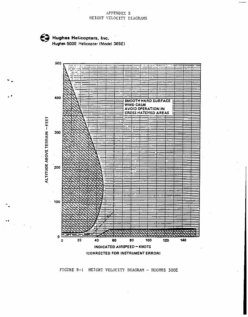
1-w w u. I z < c: c: w 1-w > 0 al < w c :l I-I..J <
APPENDIX B HEIGHT \'ELOCITY DIAGRANS
Hughes Helicopters, Inc. Hughes SOOE Helicopter (Model 369E)
500
:=:1- -.-----.- ·- -·-- -.--·· ' .. ·-=r=:--r- ·-i t-= ·---t I I :
. I;.--
40 60
SMOOTH HARD SURFACE WINO CALM AVOID OPERATION IN CROSS HATCHED AREAS
·-r--·
80 100 .120
INDICATED AIRSPEED-KNOTS
(CORRECTED FOR INSTRUMENT ERROR)
FIGURE B-1 HEIGHT VELOCITY DIAGRAM - HUGHES 500E
·-1---
140
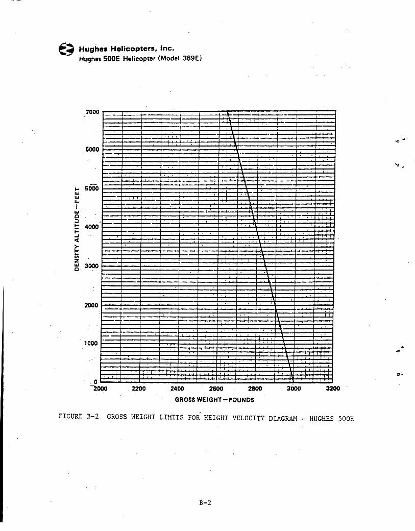
Hughes Helicopters, Inc. Hughes 500E Helicopter (Model 369E)
--+----+-
6000
t;j . 5000 ~--w u. I w 0 ::;)
t: 4000 1- 1-·-r-..J < > 1-u; z w 3000 0
2000
t-'. 1000
0 . ~000
--·
-....- .. ->---'-·
. 2200 2400 . 2600 2800
GROSS WEIGHT-POUNDS
3000 3200
FIGURE B-2 GROSS HEIGHT LIHITS FOR HEIGHT VELOCITY DIAGRAM - HUGHES SOOI:
B-2
.... -,~
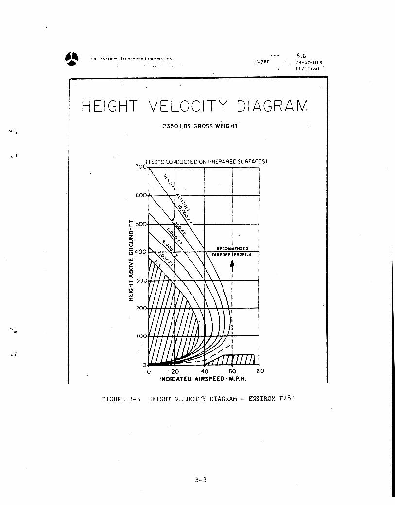
..
.... ~, ............................ , .. _,,, .. , r-7Kr
..... s.s ~H-AC-018
11/17/HU
HEIGHT VELOCITY DIAGRAM 23~0 LBS GROSS WEIGHT
(TESTS CONDUCTED ON PREPARED SURFACESl 700T-----~------r------r----~
t 500+-~--~~~--~· -~------~----~ I
0 z ;::) 0 ~400 LU > g ct ~ 300~~~~~~~~~~_,----~ :X: ~ w :X:
oWJ~~~t:fLUJlflLJ 0 . 20 40 60 80
INDICATED AIRSPEED· M.P.H.
FIGURE B-3 HEIGHT VELOCITY DIAGRAM - ENSTROM F28F
B-3
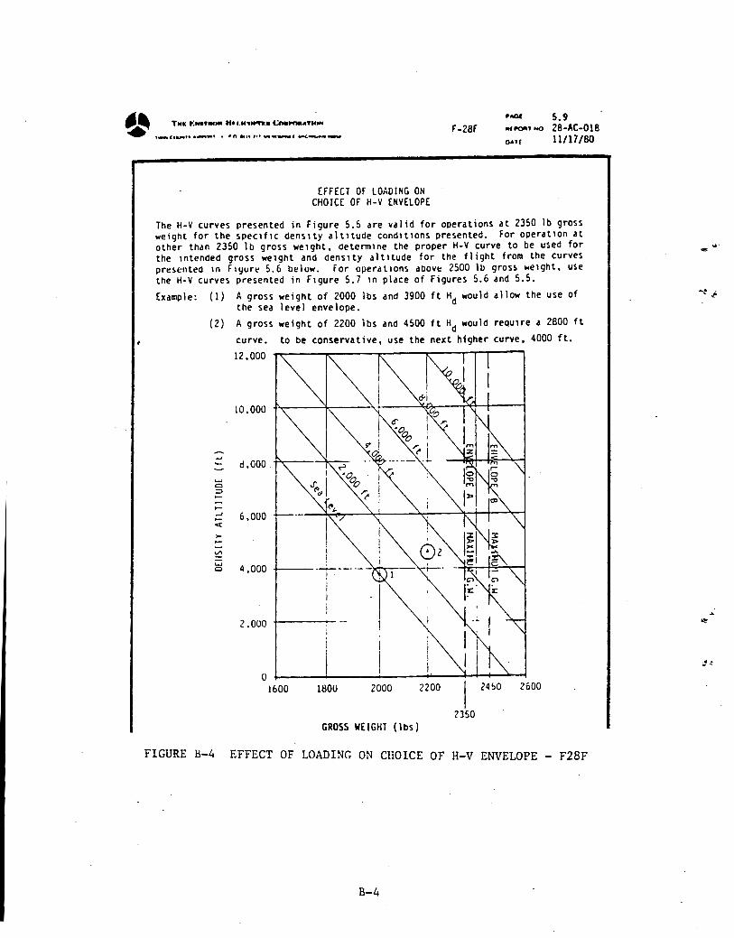
·~ TMI: t: ... ., .. ,. Hti.IC'I ........ l.:n...,.ATNNf
~ •-<•.,..•• ._..,., • •n .... ,,, .,.. ... .....,. • ....c.~ ......
EFFECT OF LOADING ON CHOICE OF H-V ENVELOPE
.. _ 5.9
F-28f Aff'll'" ooo 28-AC-018 OAH 11/lJ/80
The H-V curves presented in Figure 5.5 are valid for operations at 2350 lb gross weight for the spec1f1c dens1ty altltude cond1t1ons presented. For operat1on at other than 2350 lb gross we1ght, determlne the proper H-V curve to be used for the 1ntended gross weight and denslty altitude for the flight from the curves pr~~cnl~d 10 F1yur~ 5.6 below. For operdllOns dbOve 2500 lb gros~ weight, use the H-V curves presented in F1gure 5.7 1n place of Figures 5.6 and 5.5.
Example: (1) A gross weight of 2000 lbs and 3900 ft Hd would allow the use of the sea level envelope.
(2) A gross weight of 2200 lbs and 4500 ft Hd would requ1re a 2800 ft
curve. to be conservative, use the next higher curve, 4000 ft.
....
...... 0 ::>
,_ ..J ,_ «>:
V"'
...... 0
12.000
d,OOO
6,000
4,000
2.000
0 1600
I I I I
i .__.._ --· ---I
I I
1800 2000 2200
I 24!l0 2600
2350 GROSS WEIGHT (lbs)
FIGURE B-4 EFFECT OF LOADING ON CHOICE OF H-V ENVELOPE - F28F
B-4
... e
... ~
~~
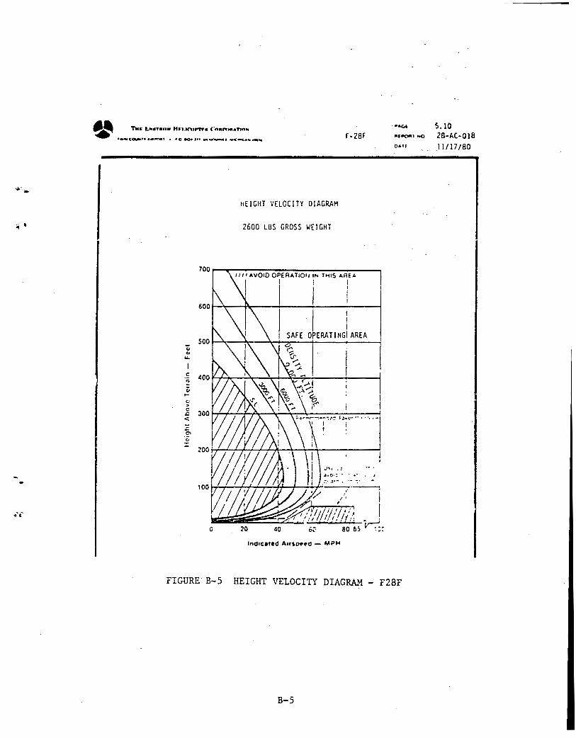
1 •
... ..
•---ca..,..•• ··~' • •o .0• ''' _,._.......,. -.<.-c;.a .. ._,. r-28r
~ ... .....
c
"' Oi .... " > 0
&; <::
0'> c..
HEIGHT VELOCITY DIAGRAM
2600 LBS GROSS WEIGHT
700~-r--------~--~--~--~~--~ Ill I AVOID OPERA TIOII IN THIS AREA
500
I I I
I i I 1
OPERATING! AREA
.)~I ; !
•·o·: - ... -::· _,.- . ·~ ~·
j...,L..,:_.:._,'-f+~'-H:.....,'"--f+t-''---. -~ 'V /: I
I
0
lndrcated Arrso••o - MPH
FIGURE-B-5 HEIGHT VELOCITY DIAGRAM- F28F
B-5
5.10 2B-AC·OI8 ll/17/80
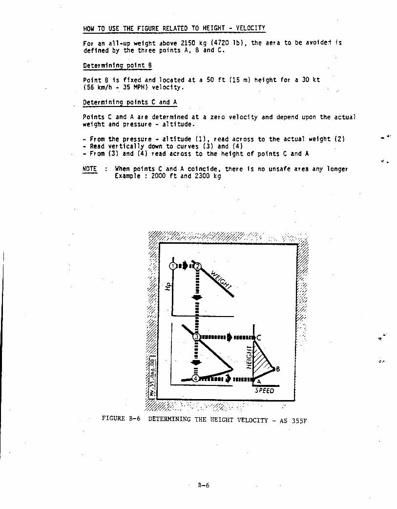
HOW TO USE THE FIGURE RELATED TO HEIGHT - VELOCITY
For an all-up weight above 2150 ~g {4720 lb}, the aera to be avo1de1 ;s defined by the three points A, B and C.
Determining point B
Point 8 fs fixed and located at a 50 ft (15 m) height for a 30 kt (56 km/h ·~ 35 MPH) velocity.
Determining points C and A
Points C and A are determined at a zero velocity and depend upon the actual weight and pressure- altitude.
-From the pressure- altitude (1), read across to the actual weight (2} - Read vertically down to curves {3) and (4) - From (3) and (4) read across to the height of points C and A
NOTE When points C and A coincide, there fs no unsafe area any longer Example : 2000 ft and 2300 kg
FIGURE B-6 DETERMINING THE HEIGHT VELOCITY - AS 355F
B-6
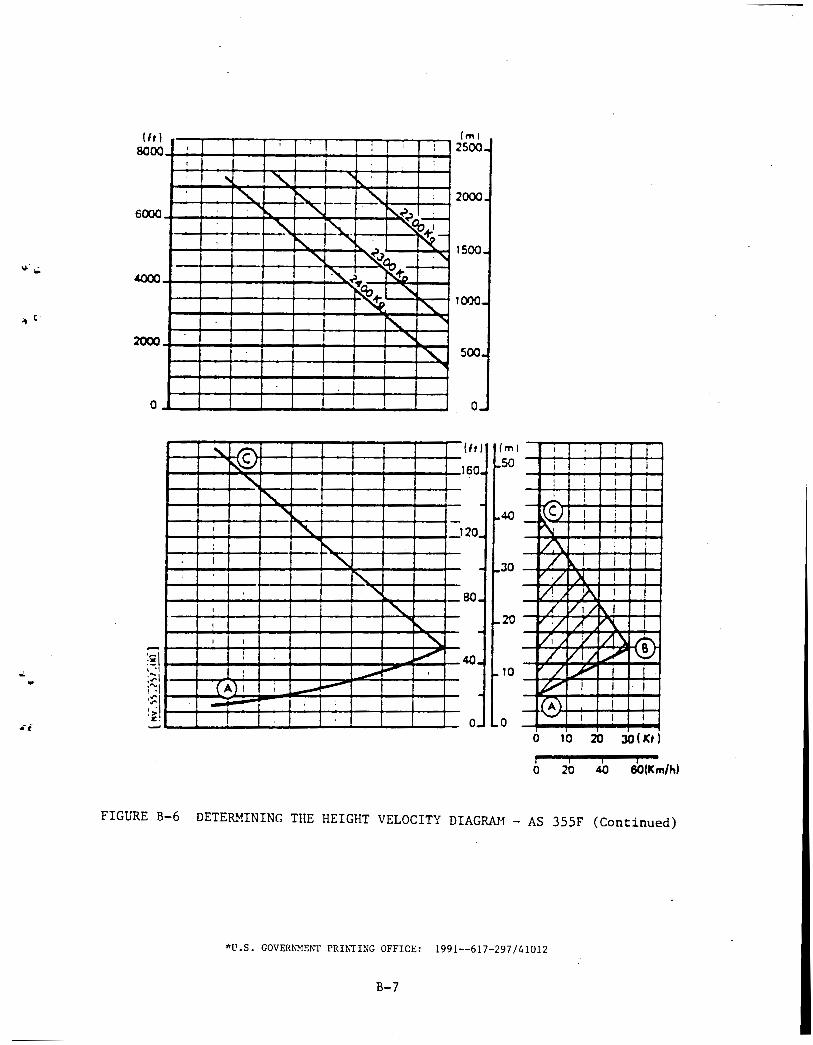
...
(ml UtI .---..---,---~,-r--,--.--r--r,-r-:-1 .--:-: 1 2500 ~00~~·~--+-~--~--+-~--·~--+-~
2000
0
' f'..~ 1 ~
" ' -I " 1 20 : ~ I ~
I
"' ' ....... 80 I "' I ~ I ' ~
I v ' 40 : ......... - '
(A) I I ---.--I _,.. i
'
(m}
50
40
30
20
10
I I l I I I I
! ! I l I ! ! I -- [CJ I i l
r'\: I I I
IL\. i ! J
/ ~I I l V/ X I l V1 9\ I I
/ VI/ !\I 1 / A ~ I v, / y I~ ~ / V1.1 ./ / .A' I J
w I I I
~ I 1 -I I I
' 0 10 20 JO(Kt)
0 20 40 60(1Cm/h)
FIGURE B-6 DETERMINING THE HEIGHT VELOCITY DIAGIWf - AS 355F (Continued)
*U.S. GOVERNMENT PRINTING OFFICE: 1991--617-297/41012
B-7
... ...
·,
/ ;